samsung electronics - k-vent
TRANSCRIPT
SAMSUNG ELECTRONICS
S A M S U N G DV MT M Air Conditioner
SAMSUNG DVM Air Conditioner
Technical Manual
DVM E-D/B(cover)-E<03759 3/21/02 6:48 PM Page 1
1. DVM system series1-1. What is DVM?1-2. Features of DVM 1-3. DVM vs VAV
67
12
2. DVM line-up2-1. Numbering system of
model2-2. Combination
1420
IIOverview
1. Remote controller
3. Transmitter
7. S-Net
1-1. Wireless remote controller1-2. Wired remote controller1-3. Centralized controller1-4. Function controller
2466
5. Assigning address5-1. Indoor unit5-2. Outdoor unit
2526
4. Installation4-1. Wireless remote controller4-2. Wired remote controller4-3. Centralized controller4-4. Function controller4-5. Receiver & display unit -
concealed type4-6. Receiver & display unit -
standard type4-7. Transmitter
10111419
21
2223
2. Receiver & displayunit (Duct type)
2-1. Concealed type2-2. Standard type
78
6. Indoor unit PCBoption code
6-1. PCB option code input method6-2. Option code
2732
3. Functional parts andsafety devices
3-1. 1-way cassette type3-2. 4-way cassette type3-3. Duct type (Low silhouette)3-4. Duct type (Built-in)3-5. Duct type (High pressure)3-6. Wall-mounted type3-7. Floor standing type3-8. Ceiling type
3434353636373838
8. Indoor unit PCBoption code
9. Building managementsystem
IIIIControlsystem
1. Features1-1. 1-way cassette type1-2. 4-way cassette type1-3. Duct type1-4. Wall-mounted type1-5. Floor standing type1-6. Ceiling type
2468
1012
2. Specification2-1. 1-way cassette type2-2. 4-way cassette type2-3. Duct type (Low silhouette)2-4. Duct type (Built-in)2-5. Duct type (High pressure)2-6. Wall-mounted type2-7. Floor standing type2-8. Ceiling type
1416182024263032
4. Capacity table4-1. 50Hz4-2. 60Hz
3945
5. Dimension5-1. 1-way cassette type5-2. 4-way cassette type5-3. Duct type (Low silhouette)5-4. Duct type (Built-in)5-5. Duct type (High pressure)5-6. Wall-mounted type5-7. Floor standing type5-8. Ceiling type5-9. Wireless remote controller /
Receiver5-10. Wired remote controller5-11. Option controller
5152545557586061
627072
IIIIIIIndoor
unit
DVM E-D/B(chapter1)-E<03759 3/21/02 6:55 PM Page 2
6. Refrigerant system diagram(Cooling only & heat pump)
6-1. Refrigerant system diagram6-2. Main parts status
7373
7. Piping and refnetjoint selection
7-1. Refrigerant piping system diagram7-2. Piping selection7-3. Refnet joint selection
333334
3. Functional parts andsafety devices
3-1. Outdoor unit3-2. Super cooler
813
8. Consideration for outdoor unit selection
8-1. Change of capacity dependingon refrigerant piping length
8-2. Condition of operating restriction
46
47
1. Unit selection (with cooling load)
3. Connecting the indoorunit refrigerant pipe
9. Velocity of air flow &temperature distribution
9-1. 1-way cassette type9-2. 4-way cassette type9-3. Wall-mounted type9-4. Ceiling type
102103105107
12. Electronic expansionvalve kit
12-1. Design12-2. Status depending on the
combination
113
113
7. Electric circuit diagram7-1. 1-way cassette type7-2. 4-way cassette type7-3. Duct type7-4. Wall-mounted type7-5. Floor standing type7-6. Ceiling type
747678808284
8. Noise level8. Noise level8-1. Overall8-2. Octave band level
8687
10. Fan specifications10-1. Duct type(Low silhouette)10-2. Duct type(Built-in)10-3. Duct type(High pressure)
108109110
11. Panel11-1. 1-way cassette type11-2. 4-way cassette type
111112
13. Options
2. Specification2-1. 50Hz2-2. 60Hz
46
4. Capacity table4-1. 50Hz4-2. 60Hz
1420
5. Dimension5-1. Upward (2-FAN)5-2. Onward5-3. Upward (1-FAN)5-4. Upward (Super cooler)
31323334
6. Refrigerant system diagram6-1. Cooling only6-2. Heat pump
3538
7. Electric circuit diagram7-1. Cooling only7-2. Heat pump
4244
9. Noise level
10. Options
IIVVOutdoor
unit
1. Product1-1. Preparation for installation1-2. Deciding on where to install
the air conditioner1-3. Space requirements for the
air conditioner1-4. Accessories1-5. Installation
2
3
48
11
2. Panel2-1. 1-way cassette type2-2. 4-way cassette type2-3. Duct type (Built-in)
131516
5. Drain pump installation5-1. Accessories5-2. Installation
2222
6. Wiring6-1. Overall system configuration6-2. Cable specification for outdoor unit6-3. Connection cord specification6-4. Wiring diagram6-5. Connection cord wiring diagram6-6. Power wiring and communication
wiring configuration6-7. Communication cable connection
2324242425
2526
8. Charge/recovery of refrigerant8-1. Refrigerant charging8-2. Additional refrigerant amount
calculation method8-3. Recovery of refrigerant
35
3637
4. Drain hose installation
9. Testing operation
10. Cautions for refrigerant leaks
VVInstallation
DVM E-D/B(chapter1)-E<03759 3/21/02 6:55 PM Page 3
1. DVM system series
2. DVM line-up2-1. Numbering system of model2-2. Combination
1420
1-1. What is DVM?1-2. Features of DVM 1-3. DVM vs VAV
67
12
I Overview
DVM E-D/B(chapter1)-E<03759 3/21/02 6:55 PM Page 5
I 6
I. Overview
1. DVM system series
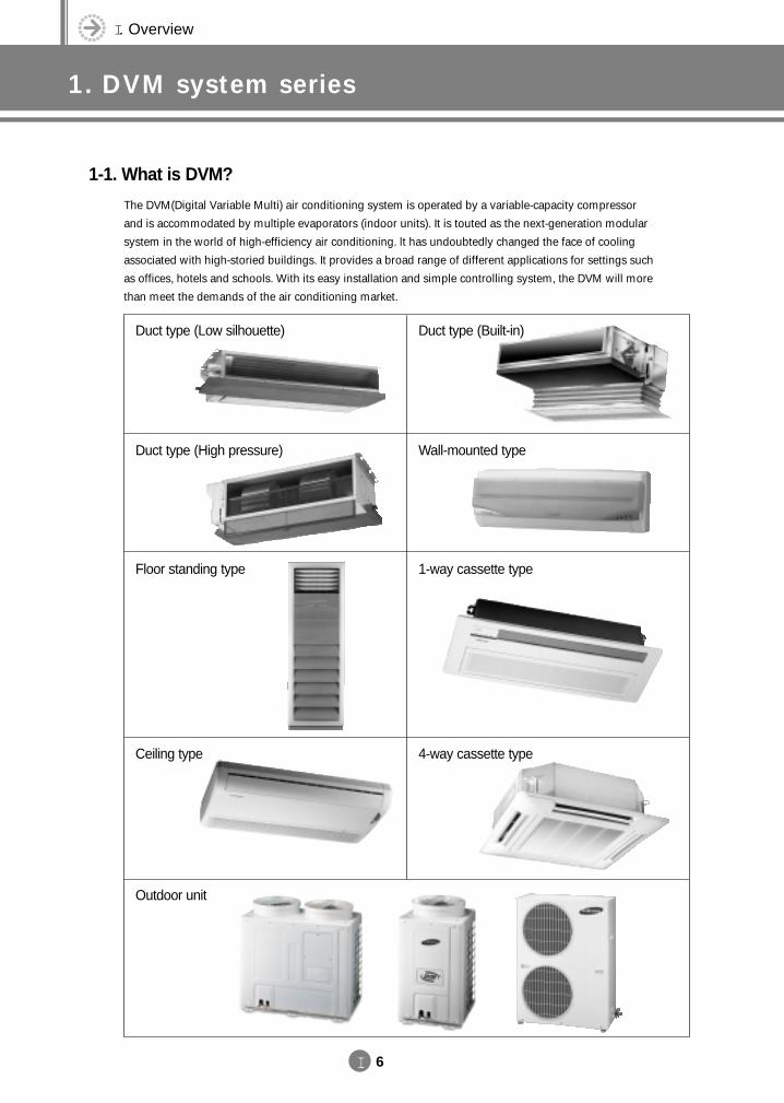
1-1. What is DVM?
The DVM(Digital Variable Multi) air conditioning system is operated by a variable-capacity compressor
and is accommodated by multiple evaporators (indoor units). It is touted as the next-generation modular
system in the world of high-efficiency air conditioning. lt has undoubtedly changed the face of cooling
associated with high-storied buildings. It provides a broad range of different applications for settings such
as offices, hotels and schools. With its easy installation and simple controlling system, the DVM will more
than meet the demands of the air conditioning market.
Ceiling type
Outdoor unit
4-way cassette type
Floor standing type 1-way cassette type
Duct type (Low silhouette) Duct type (Built-in)
Duct type (High pressure) Wall-mounted type
DVM E-D/B(chapter1)-E<03759 3/21/02 6:55 PM Page 6
I 7
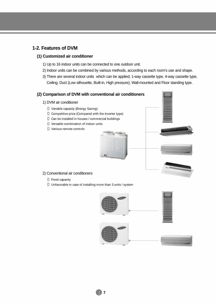
1-2. Features of DVM
(1) Customized air conditioner
1) Up to 16 indoor units can be connected to one outdoor unit.
2) Indoor units can be combined by various methods, according to each room’s use and shape.
3) There are several indoor units which can be applied; 1-way cassette type, 4-way cassette type,
Ceiling, Duct (Low silhouette, Built-in, High pressure), Wall-mounted and Floor standing type.
(2) Comparison of DVM with conventional air conditioners
1) DVM air conditioner
① Variable capacity (Energy Saving)
② Competitive price (Compared with the Inverter type)
③ Can be installed in houses / commercial buildings
④ Versatile combination of indoor units
⑤ Various remote controls
2) Conventional air conditioners
① Fixed capacity
② Unfavorable in case of installing more than 3 units / system
DVM E-D/B(chapter1)-E<03759 3/21/02 6:55 PM Page 7
I 8
I. Overview
1. DVM system series
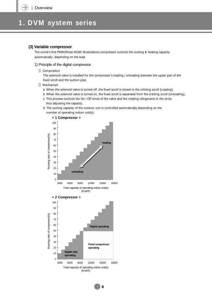
(3) Variable compressor The world’s first PWM(Pulse Width Modulation) compressor controls the cooling & heating capacity
automatically, depending on the load.
1) Principle of the digital compressor
① CompositionThe solenoid valve is installed for the compressor´s loading / unloading between the upper part of thefixed scroll and the suction pipe.
② Mechanisma. When the solenoid valve is turned off, the fixed scroll is closed to the orbiting scroll (Loading),b. When the solenoid valve is turned on, the fixed scroll is separated from the orbiting scroll (Unloading),c. This process controls the On / Off times of the valve and the rotating refrigerants in the circle,
thus adjusting the capacity.d. The cooling capacity of the outdoor unit is controlled automatically,depending on the
number of operating indoor unit(s).
Total capacity of operating indoor unit(s)(kcal/h)
100
90
80
70
60
50
40
30
20
10
03000 6000 9000 12000 15000 18000
Run
ning
ratio
of c
ompr
esso
r(%
)
unloading
loading
< 1 Compressor >
Total capacity of operating indoor unit(s)(kcal/h)
100
90
80
70
60
50
40
30
20
10
03000 6000 9000 12000 15000 18000
Run
ning
ratio
of c
ompr
esso
r(%
)
Fixed compressoroperating
Digital operating
Digital onlyoperating
< 2 Compressor >
DVM E-D/B(chapter1)-E<03759 3/21/02 6:55 PM Page 8
I 9
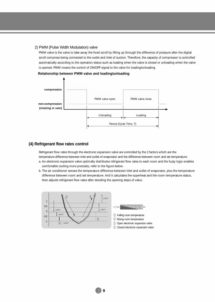
2) PWM (Pulse Width Modulation) valvePWM valve is the valve to take away the fixed scroll by lifting up through the difference of pressure after the digital
scroll compress being connected to the outlet and inlet of suction. Therefore, the capacity of compressor is controlled
automatically according to the operation status such as loading when the valve is closed or unloading when the valve
is opened. PWM means the control of ON/OFF signal to the valve for loading/unloading.
(4) Refrigerant flow rates control
Refrigerant flow rates through the electronic expansion valve are controlled by the 2 factors which are the temperature difference between inlet and outlet of evaporator and the difference between room and set temperature.a. An electronic expansion valve optimally distributes refrigerant flow rates to each room and the fuzzy logic enables
comfortable cooling more precisely; refer to the figure below.b. The air conditioner senses the temperature difference between inlet and outlet of evaporator, plus the temperature
difference between room and set temperature. And it calculates the superheat and the room temperature status,then adjusts refrigerant flow rates after deciding the opening steps of valve.
① Falling room temperature
② Rising room temperature
③ Open electronic expansion valve
④ Closed electronic expansion valve
1
0.5
0
-0.5
-1
① ②
③
④
Relationship between PWM valve and loading/unloading
PWM valve open PWM valve close
Unloading
Period (Cycle Time, T)
Loading
compression
non-compression(rotating in vain)
DVM E-D/B(chapter1)-E<03759 3/21/02 6:55 PM Page 9
I 10
I. Overview
1. DVM system series
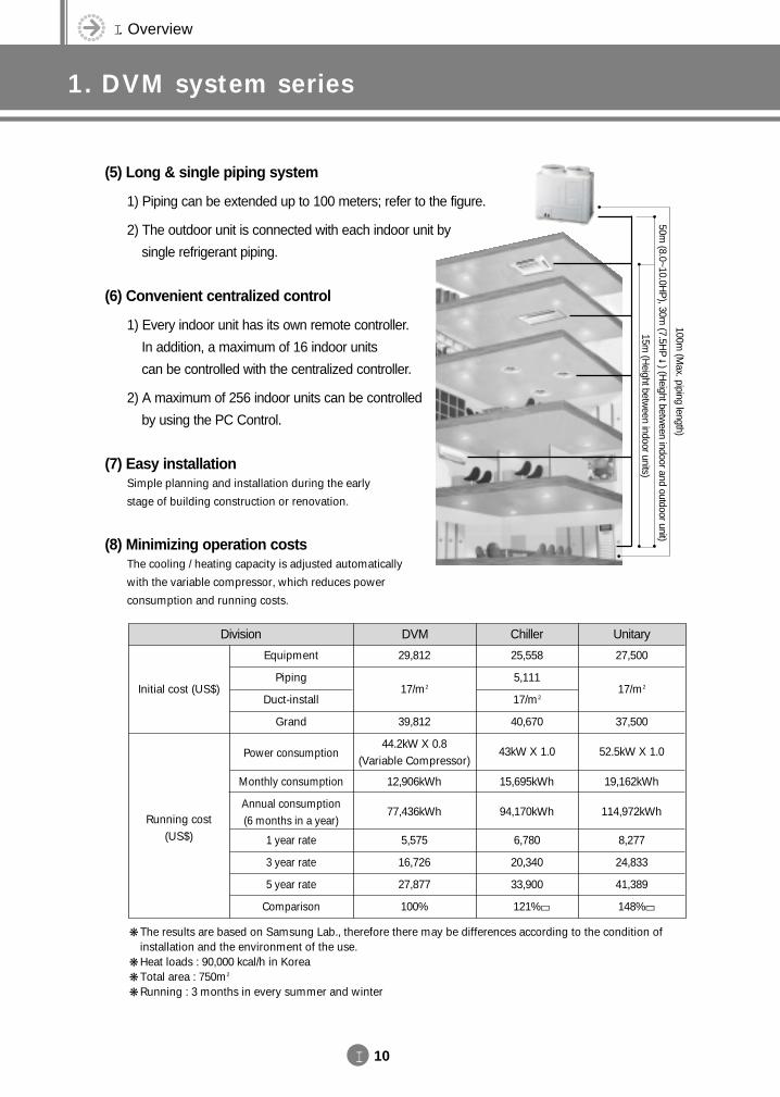
(5) Long & single piping system
1) Piping can be extended up to 100 meters; refer to the figure.
2) The outdoor unit is connected with each indoor unit by
single refrigerant piping.
(6) Convenient centralized control
1) Every indoor unit has its own remote controller.
In addition, a maximum of 16 indoor units
can be controlled with the centralized controller.
2) A maximum of 256 indoor units can be controlled
by using the PC Control.
(7) Easy installation Simple planning and installation during the early
stage of building construction or renovation.
(8) Minimizing operation costs The cooling / heating capacity is adjusted automatically
with the variable compressor, which reduces power
consumption and running costs.
15m (H
eight between indoor units)
100m (M
ax. piping length)
50m (8.0~10.0H
P), 30m
(7.5HP
) (Height betw
een indoor and outdoor unit)
Initial cost (US$)
Running cost (US$)
DVMDivision
Equipment
Piping
Duct-install
Grand
Power consumption
Monthly consumption
Annual consumption(6 months in a year)
1 year rate
3 year rate
5 year rate
Comparison
27,500
17/m2
37,500
52.5kW X 1.0
19,162kWh
114,972kWh
8,277
24,833
41,389
148%
Chiller Unitary
The results are based on Samsung Lab., therefore there may be differences according to the condition ofinstallation and the environment of the use.
Heat loads : 90,000 kcal/h in Korea Total area : 750m2
Running : 3 months in every summer and winter
29,812
17/m2
39,812
44.2kW X 0.8(Variable Compressor)
12,906kWh
77,436kWh
5,575
16,726
27,877
100%
25,558
5,111
17/m2
40,670
43kW X 1.0
15,695kWh
94,170kWh
6,780
20,340
33,900
121% →→
DVM E-D/B(chapter1)-E<03759 3/21/02 6:55 PM Page 10
I 11
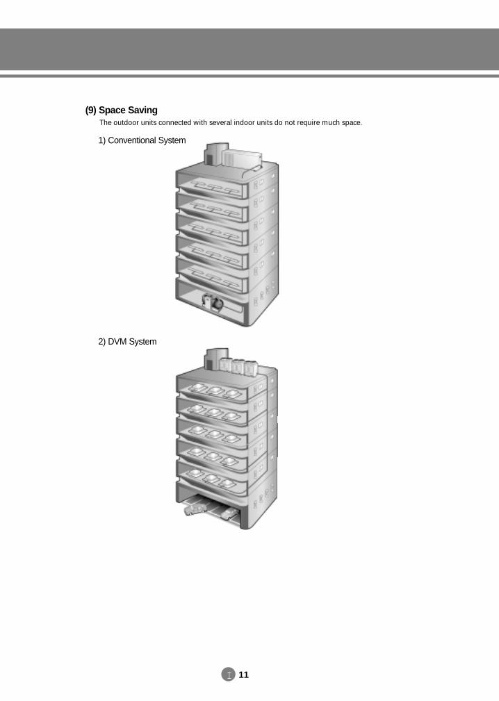
(9) Space SavingThe outdoor units connected with several indoor units do not require much space.
1) Conventional System
2) DVM System
DVM E-D/B(chapter1)-E<03759 3/21/02 6:55 PM Page 11
I 12
I. Overview
1. DVM system series
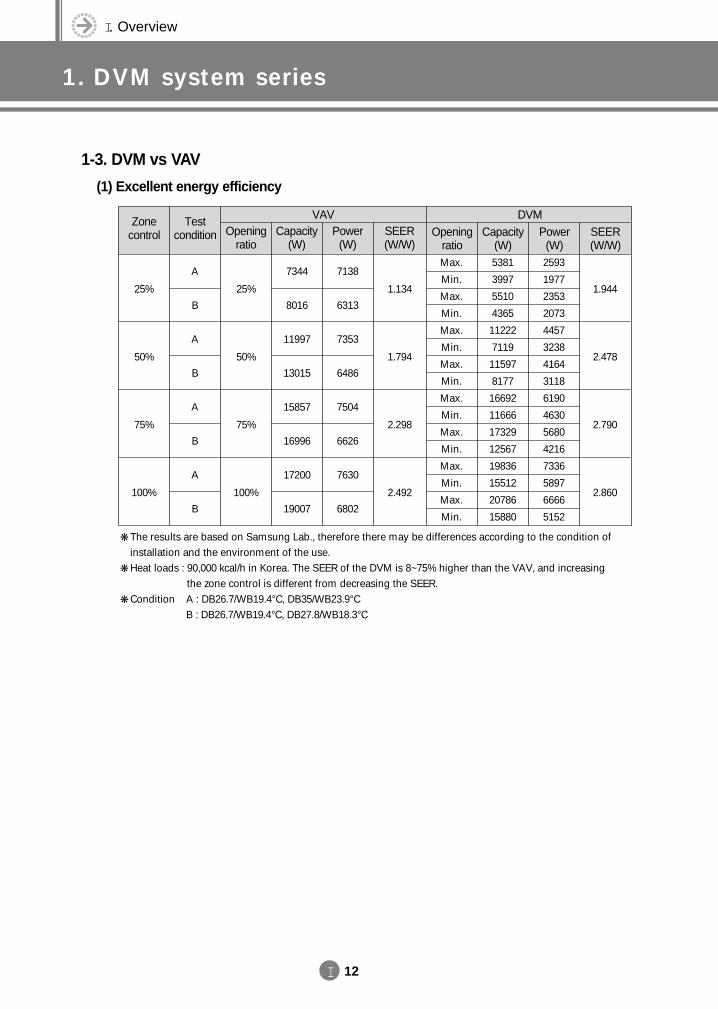
25%
50%
75%
100%
A
B
A
B
A
B
A
B
25%
50%
75%
100%
7344
8016
11997
13015
15857
16996
17200
19007
7138
6313
7353
6486
7504
6626
7630
6802
1.134
1.794
2.298
2.492
Max.
Min.
Max.
Min.
Max.
Min.
Max.
Min.
Max.
Min.
Max.
Min.
Max.
Min.
Max.
Min.
5381
3997
5510
4365
11222
7119
11597
8177
16692
11666
17329
12567
19836
15512
20786
15880
2593
1977
2353
2073
4457
3238
4164
3118
6190
4630
5680
4216
7336
5897
6666
5152
1.944
2.478
2.790
2.860
Zonecontrol
Test condition Opening
ratioCapacity
(W)Power
(W)SEER(W/W)
Openingratio
Capacity(W)
Power(W)
SEER(W/W)
DVMVAV
The results are based on Samsung Lab., therefore there may be differences according to the condition ofinstallation and the environment of the use.
Heat loads : 90,000 kcal/h in Korea. The SEER of the DVM is 8~75% higher than the VAV, and increasing the zone control is different from decreasing the SEER.
Condition A : DB26.7/WB19.4°C, DB35/WB23.9°C B : DB26.7/WB19.4°C, DB27.8/WB18.3°C
1-3. DVM vs VAV
(1) Excellent energy efficiency
DVM E-D/B(chapter1)-E<03759 3/21/02 6:55 PM Page 12
I 13
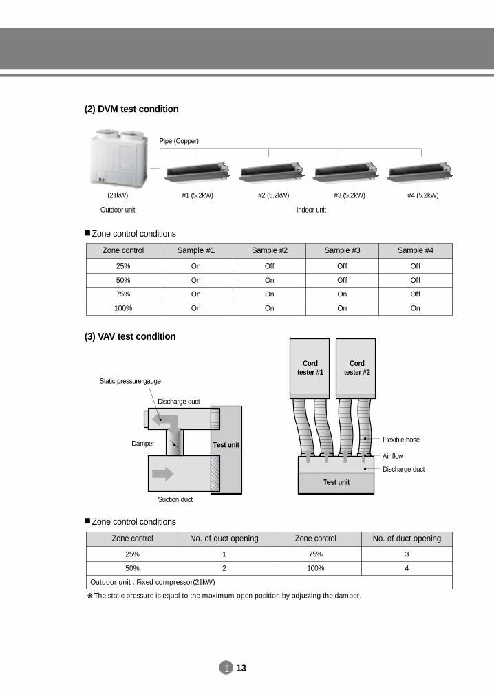
(2) DVM test condition
(3) VAV test condition
The static pressure is equal to the maximum open position by adjusting the damper.
#1 (5.2kW) #2 (5.2kW) #3 (5.2kW) #4 (5.2kW)
Indoor unitOutdoor unit
(21kW)
Pipe (Copper)
Static pressure gauge
Damper
Test unit
Cord tester #1
Cord tester #2
Flexible hose
Air flow
Discharge duct
Suction duct
Discharge duct
Test unit
Zone control conditions
Zone control Sample #1 Sample #2 Sample #3
Off
On
On
On
On
On
On
On
25%
50%
75%
100%
Off
Off
On
On
Sample #4
Off
Off
Off
On
Zone control conditions
Zone control No. of duct opening Zone control No. of duct opening
75%
100%
1
2
25%
50%
3
4
Outdoor unit : Fixed compressor(21kW)
DVM E-D/B(chapter1)-E<03759 3/21/02 6:55 PM Page 13
③②
I 14
I. Overview
2. DVM line-up
2-1. Numbering system of model
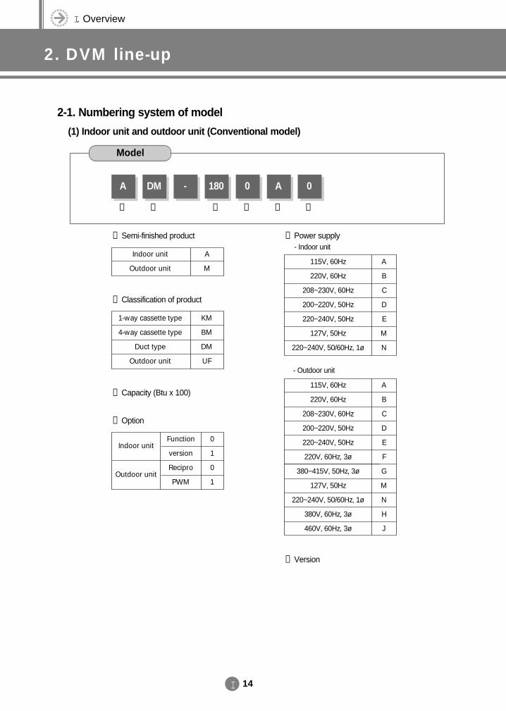
(1) Indoor unit and outdoor unit (Conventional model)
① Semi-finished product
② Classification of product
DM
①
A - 180 0
④
A
⑤
0
⑥
Model
1-way cassette type
4-way cassette type
Duct type
Outdoor unit
KM
BM
DM
UF
③ Capacity (Btu x 100)
④ Option
Indoor unit
Outdoor unit
Function
version
Recipro
PWM
0
1
0
1
Indoor unit
Outdoor unit
A
MA
B
C
D
E
M
N
115V, 60Hz
220V, 60Hz
208~230V, 60Hz
200~220V, 50Hz
220~240V, 50Hz
127V, 50Hz
220~240V, 50/60Hz, 1ø
⑤ Power supply- Indoor unit
- Outdoor unit
⑥ Version
A
B
C
D
E
F
G
M
N
H
J
115V, 60Hz
220V, 60Hz
208~230V, 60Hz
200~220V, 50Hz
220~240V, 50Hz
220V, 60Hz, 3ø
380~415V, 50Hz, 3ø
127V, 50Hz
220~240V, 50/60Hz, 1ø
380V, 60Hz, 3ø
460V, 60Hz, 3ø
DVM E-D/B(chapter1)-E<03759 3/21/02 6:55 PM Page 14
I 15
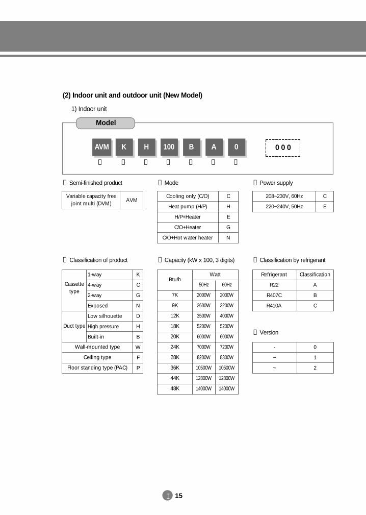
(2) Indoor unit and outdoor unit (New Model)
1) Indoor unit
① Semi-finished product
② Classification of product
AVM
①
K
②
H
③
100
④
B
⑤
A
⑥
0
⑦
Model
1-way
4-way
2-way
Exposed
Low silhouette
High pressure
Built-in
Wall-mounted type
Ceiling type
Floor standing type (PAC)
Cassettetype
Duct type
K
C
G
N
D
H
B
W
F
P
③ Mode
C
H
E
G
N
Cooling only (C/O)
Heat pump (H/P)
H/P+Heater
C/O+Heater
C/O+Hot water heater
Variable capacity freejoint multi (DVM)
AVM
⑦ Version
0
1
2
-
~
~
⑥ Classification by refrigerant
Classification
A
B
C
Refrigerant
R22
R407C
R410A
0 0 0
④ Capacity (kW x 100, 3 digits)
Btu/hWatt
7K
9K
12K
18K
20K
24K
28K
36K
44K
48K
50Hz
2000W
2600W
3500W
5200W
6000W
7000W
8200W
10500W
12800W
14000W
60Hz
2000W
3200W
4000W
5200W
6000W
7200W
8300W
10500W
12800W
14000W
C
E
208~230V, 60Hz
220~240V, 50Hz
⑤ Power supply
DVM E-D/B(chapter1)-E<03759 3/21/02 6:55 PM Page 15
I 16
I. Overview
2. DVM line-up
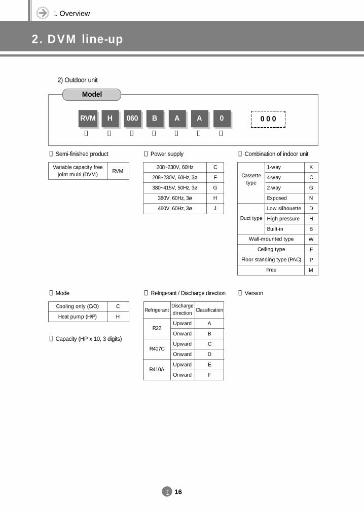
2) Outdoor unit
① Semi-finished product ⑥ Combination of indoor unit
RVM
①
H
②
060
③
B
④
A
⑤
A
⑥
0
⑦
Model
② Mode
③ Capacity (HP x 10, 3 digits)
C
H
Cooling only (C/O)
Heat pump (H/P)
Variable capacity freejoint multi (DVM)
RVM
⑦ Version
④ Power supply
0 0 0
⑤ Refrigerant / Discharge direction
Refrigerant
R22
R407C
R410A
Dischargedirection
Upward
Onward
Upward
Onward
Upward
Onward
Classification
A
B
C
D
E
F
C
F
G
H
J
208~230V, 60Hz
208~230V, 60Hz, 3ø
380~415V, 50Hz, 3ø
380V, 60Hz, 3ø
460V, 60Hz, 3ø
1-way
4-way
2-way
Exposed
Low silhouette
High pressure
Built-in
Wall-mounted type
Ceiling type
Floor standing type (PAC)
Free
Cassettetype
Duct type
K
C
G
N
D
H
B
W
F
P
M
DVM E-D/B(chapter1)-E<03759 3/21/02 6:55 PM Page 16
I 17
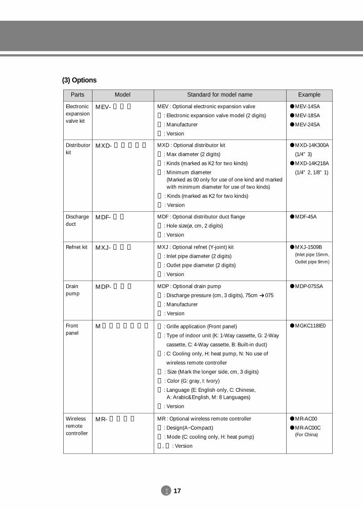
(3) Options
Parts Model Example
MEV-14SA
MEV-18SA
MEV-24SA
MEV : Optional electronic expansion valve
① : Electronic expansion valve model (2 digits)
② : Manufacturer
③ : Version
MXD : Optional distributor kit
① : Max diameter (2 digits)
② : Kinds (marked as K2 for two kinds)
③ : Minimum diameter(Marked as 00 only for use of one kind and markedwith minimum diameter for use of two kinds)
④ : Kinds (marked as K2 for two kinds)
⑤ : Version
MEV- ① ② ③
MXD- ① ② ③ ④ ⑤
Electronicexpansionvalve kit
Distributorkit
MXD-14K300A
(1/4” 3)
MXD-14K218A
(1/4” 2, 1/8” 1)
MDF : Optional distributor duct flange
① : Hole size(ø, cm, 2 digits)
② : Version
MDF- ① ②Dischargeduct
MDF-45A
MXJ : Optional refnet (Y-joint) kit
① : Inlet pipe diameter (2 digits)
② : Outlet pipe diameter (2 digits)
③ : Version
MXJ- ① ② ③Refnet kit MXJ-1509B(Inlet pipe 15mm,
Outlet pipe 9mm)
MDP : Optional drain pump
① : Discharge pressure (cm, 3 digits), 75cm 075
② : Manufacturer
③ : Version
MDP- ① ② ③Drainpump
MDP-075SA
① : Grille application (Front panel)
② : Type of indoor unit (K: 1-Way cassette, G: 2-Way
cassette, C: 4-Way cassette, B: Built-in duct)
③ : C: Cooling only, H: heat pump, N: No use of
wireless remote controller
④ : Size (Mark the longer side, cm, 3 digits)
⑤ : Color (G: gray, I: Ivory)
⑥ : Language (E: English only, C: Chinese, A: Arabic&English, M: 8 Languages)
⑦ : Version
M ① ② ③ ④ ⑤ ⑥ ⑦Frontpanel
MGKC118IE0
Standard for model name
MR-AC00
MR-AC00C(For China)
MR : Optional wireless remote controller
① : Design(A~Compact)
② : Mode (C: cooling only, H: heat pump)
③ , ④ : Version
MR- ① ② ③ ④Wirelessremotecontroller
DVM E-D/B(chapter1)-E<03759 3/21/02 6:55 PM Page 17
I 18
I. Overview
2. DVM line-up
Parts Model Example
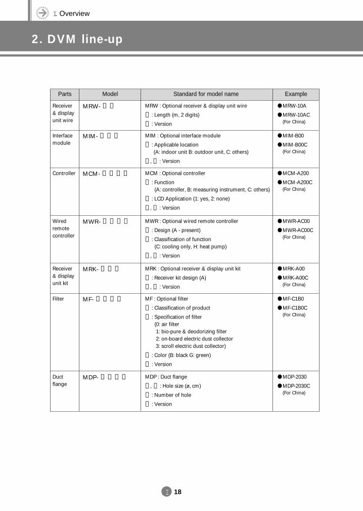
MRW : Optional receiver & display unit wire
① : Length (m, 2 digits)
② : Version
MRW- ① ②Receiver& displayunit wire
MRW-10A
MRW-10AC(For China)
MIM : Optional interface module
① : Applicable location (A: indoor unit B: outdoor unit, C: others)
② , ③ : Version
MIM- ① ② ③Interfacemodule
MIM-B00
MIM-B00C(For China)
MCM : Optional controller
① : Function (A: controller, B: measuring instrument, C: others)
② : LCD Application (1: yes, 2: none)
③ , ④ : Version
MCM- ① ② ③ ④Controller MCM-A200
MCM-A200C(For China)
MWR : Optional wired remote controller
① : Design (A - present)
② : Classification of function (C: cooling only, H: heat pump)
③ , ④ : Version
MWR- ① ② ③ ④Wiredremotecontroller
MWR-AC00
MWR-AC00C(For China)
MRK : Optional receiver & display unit kit
① : Receiver kit design (A)
② , ③ : Version
MRK- ① ② ③Receiver& displayunit kit
MRK-A00
MRK-A00C(For China)
MF : Optional filter
① : Classification of product
② : Specification of filter (0: air filter1: bio-pure & deodorizing filter2: on-board electric dust collector 3: scroll electric dust collector)
③ : Color (B: black G: green)
④ : Version
MF- ① ② ③ ④Filter MF-C1B0
MF-C1B0C(For China)
Standard for model name
MDP-2030
MDP-2030C(For China)
MDP : Duct flange
① , ② : Hole size (ø, cm)
③ : Number of hole
④ : Version
MDP- ① ② ③ ④Ductflange
DVM E-D/B(chapter1)-E<03759 3/21/02 6:55 PM Page 18
I 19
Parts Model ExampleStandard for model name
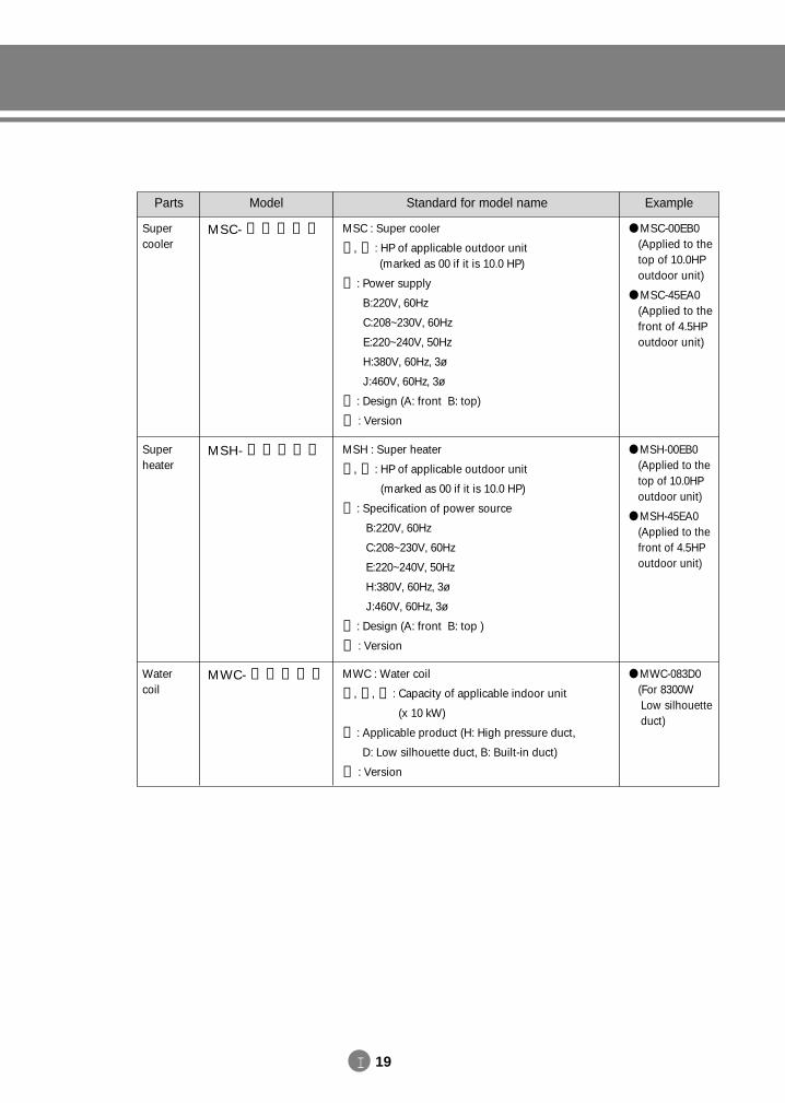
MSC : Super cooler
① , ② : HP of applicable outdoor unit (marked as 00 if it is 10.0 HP)
③ : Power supply
B:220V, 60Hz
C:208~230V, 60Hz
E:220~240V, 50Hz
H:380V, 60Hz, 3ø
J:460V, 60Hz, 3ø
④ : Design (A: front B: top)
⑤ : Version
MSC- ① ② ③ ④ ⑤Supercooler
MSC-00EB0(Applied to thetop of 10.0HPoutdoor unit)
MSC-45EA0(Applied to thefront of 4.5HPoutdoor unit)
MSH : Super heater
① , ② : HP of applicable outdoor unit
(marked as 00 if it is 10.0 HP)
③ : Specification of power source
B:220V, 60Hz
C:208~230V, 60Hz
E:220~240V, 50Hz
H:380V, 60Hz, 3ø
J:460V, 60Hz, 3ø
④ : Design (A: front B: top )
⑤ : Version
MSH- ① ② ③ ④ ⑤Superheater
MSH-00EB0(Applied to thetop of 10.0HPoutdoor unit)
MSH-45EA0(Applied to thefront of 4.5HPoutdoor unit)
MWC : Water coil
① , ② , ③ : Capacity of applicable indoor unit
(x 10 kW)
④ : Applicable product (H: High pressure duct,
D: Low silhouette duct, B: Built-in duct)
⑤ : Version
MWC- ① ② ③ ④ ⑤Watercoil
MWC-083D0(For 8300W Low silhouette duct)
DVM E-D/B(chapter1)-E<03759 3/21/02 6:55 PM Page 19
I 20
I. Overview
2. DVM line-up
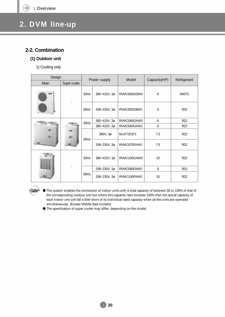
2-2. Combination
(1) Outdoor unit
1) Cooling only
Main Super cooler
DesignPower supply Model
50Hz
60Hz
-
-
380~415V, 3ø
208~230V, 3ø
RVMC060GDM0
RVMC050CBM0
Capacity(HP)
6
5
Refrigerant
R407C
R22
50Hz
60Hz
50Hz
60Hz
380~415V, 3ø
380~415V, 3ø
380V, 3ø
208~230V, 3ø
RVMC060GAM0
RVMC060GAM1
MUF7201F1
RVMC075FAM0
6
6
7.5
7.5
R22
R22
R22
R22
380~415V, 3ø
208~230V, 3ø
208~230V, 3ø
RVMC100GAM0
RVMC080FAM0
RVMC100FAM0
10
8
10
R22
R22
R22
The system enables the connection of indoor units with a total capacity of between 50 to 130% of that ofthe corresponding outdoor unit but where this capacity ratio exceeds 100% then the actual capacity ofeach indoor unit will fall a little short of its individual rated capacity when all the units are operatedsimultaneously. (Except Middle East models)
The specification of super cooler may differ, depending on the model.
DVM E-D/B(chapter1)-E<03759 3/21/02 6:55 PM Page 20
I 21
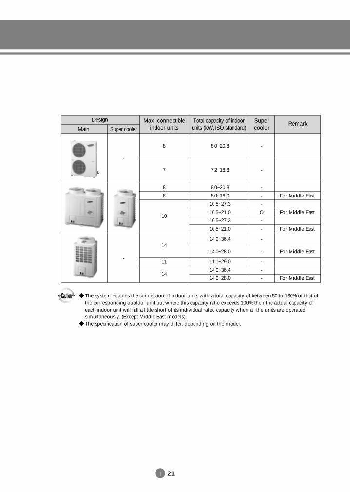
Main Super cooler
Design Max. connectibleindoor units
Total capacity of indoorunits (kW, ISO standard)
Supercooler
8
7
-
-
Remark
8
8
10
-
-
-
O
-
-
For Middle East
For Middle East
For Middle East
14
11
14
8.0~20.8
7.2~18.8
8.0~20.8
8.0~16.0
10.5~27.3
10.5~21.0
10.5~27.3
10.5~21.0
14.0~36.4
14.0~28.0
11.1~29.0
14.0~36.4
14.0~28.0
-
-
-
-
-
For Middle East
For Middle East
The system enables the connection of indoor units with a total capacity of between 50 to 130% of that ofthe corresponding outdoor unit but where this capacity ratio exceeds 100% then the actual capacity ofeach indoor unit will fall a little short of its individual rated capacity when all the units are operatedsimultaneously. (Except Middle East models)
The specification of super cooler may differ, depending on the model.
-
-
DVM E-D/B(chapter1)-E<03759 3/21/02 6:55 PM Page 21
I 22
I. Overview
2. DVM line-up
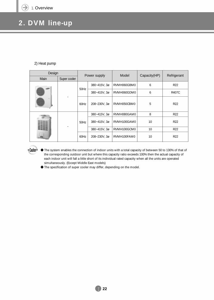
2) Heat pump
Main Super cooler
DesignPower supply Model
50Hz
60Hz
380~415V, 3ø
380~415V, 3ø
208~230V, 3ø
RVMH060GBM0
RVMH060GDM0
RVMH050CBM0
Capacity(HP)
6
6
5
Refrigerant
R22
R407C
R22
50Hz
60Hz
380~415V, 3ø
380~415V, 3ø
380~415V, 3ø
208~230V, 3ø
RVMH080GAM0
RVMH100GAM0
RVMH100GCM0
RVMH100FAM0
8
10
10
10
R22
R22
R22
R22
The system enables the connection of indoor units with a total capacity of between 50 to 130% of that ofthe corresponding outdoor unit but where this capacity ratio exceeds 100% then the actual capacity ofeach indoor unit will fall a little short of its individual rated capacity when all the units are operatedsimultaneously. (Except Middle East models)
The specification of super cooler may differ, depending on the model.
-
-
DVM E-D/B(chapter1)-E<03759 3/21/02 6:55 PM Page 22
I 23
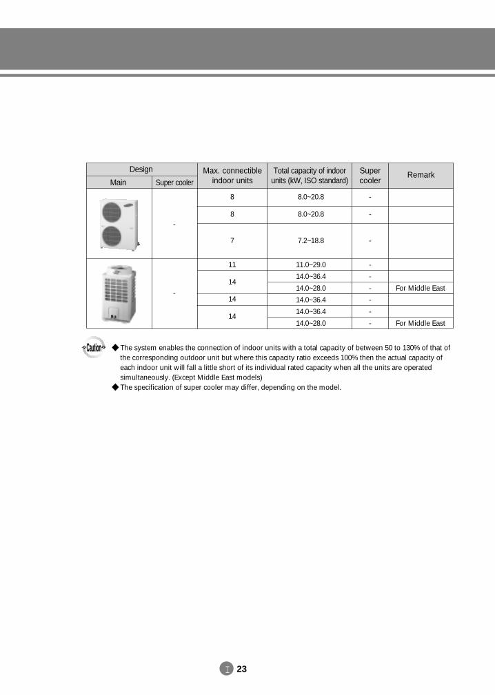
Main Super cooler
Design Max. connectibleindoor units
Total capacity of indoorunits (kW, ISO standard)
Supercooler
8
8
7
-
-
-
Remark
11
14
14
14
-
-
-
-
-
-
For Middle East
For Middle East
8.0~20.8
8.0~20.8
7.2~18.8
11.0~29.0
14.0~36.4
14.0~28.0
14.0~36.4
14.0~36.4
14.0~28.0
The system enables the connection of indoor units with a total capacity of between 50 to 130% of that ofthe corresponding outdoor unit but where this capacity ratio exceeds 100% then the actual capacity ofeach indoor unit will fall a little short of its individual rated capacity when all the units are operatedsimultaneously. (Except Middle East models)
The specification of super cooler may differ, depending on the model.
-
-
DVM E-D/B(chapter1)-E<03759 3/21/02 6:55 PM Page 23
I 24
I. Overview
1. System line-up
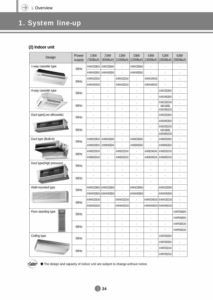
(2) Indoor unit
Design Powersupply
2.0kW(7000Btu/h)
2.6kW(9000Btu/h)
3.2kW(11000Btu/h)
3.5kW(12000Btu/h)
4.0kW(13500Btu/h)
5.2kW(18000Btu/h)
6.0kW(20000Btu/h)
AVMKC020EA0
AVMKH020EA0
AVMKC020CA0
AVMKH020CA0
-
-
-
-
-
-
-
-
AVMBC020EA0
AVMBH020EA0
AVMBC020CA0
AVMBH020CA0
-
-
-
-
AVMWC020EA0
AVMWH020EA0
AVMWC020CA0
AVMWH020CA0
-
-
-
-
-
-
-
-
AVMKC026EA0
AVMKH026EA0
-
-
-
-
-
-
-
-
-
-
AVMBC026EA0
AVMBH026EA0
-
-
-
-
-
-
AVMWC026EA0
AVMWH026EA0
-
-
-
-
-
-
-
-
-
-
-
-
AVMKC032CA0
AVMKH032CA0
-
-
-
-
-
-
-
-
-
-
AVMBC032CA0
AVMBH032CA0
-
-
-
-
-
-
AVMWC032CA0
AVMWH032CA0
-
-
-
-
-
-
-
-
AVMKC035EA0
AVMKH035EA0
-
-
-
-
-
-
-
-
-
-
AVMBC035EA0
AVMBH035EA0
-
-
-
-
-
-
AVMWC035EA0
AVMWH035EA0
-
-
-
-
-
-
-
-
-
-
-
-
AVMKC040CA0
AVMKH040CA0
-
-
-
-
-
-
-
-
-
-
AVMBC040CA0
AVMBH040CA0
-
-
-
-
-
-
AVMWC040CA0
AVMWH040CA0
-
-
-
-
-
-
-
-
-
-
-
-
AVMCC052EA0
AVMCH052EA0
AVMDC052EA0
AVMDH052EA0
AVMBC052EA0
AVMBH052EA0
AVMBC052CA0
AVMBH052CA0
-
-
-
-
AVMWC052EA0
AVMWH052EA0
AVMWC052CA0
AVMWH052CA0
-
-
-
-
AVMFC052EA0
AVMFH052EA0
AVMFC052CA0
AVMFH052CA0
AVMCC052CA0ABM1800B1
AVMCH052CA0
AVMDC052CA0ADM1800B1
AVMDH052CA0
-
-
-
-
-
-
-
-
-
-
-
-
-
-
-
-
-
-
-
-
-
-
-
-
AVMPC060EA0
AVMPH060EA0
AVMPC060CA0
AVMPH060CA0
-
-
-
-
50Hz
60Hz
50Hz
60Hz
50Hz
60Hz
50Hz
60Hz
50Hz
60Hz
50Hz
60Hz
50Hz
60Hz
50Hz
60Hz
The design and capacity of indoor unit are subject to change without notice.
1-way cassette type
4-way cassette type
Duct type(Low silhouette)
Duct type (Built-in)
Duct type(High pressure)
Wall-mounted type
Floor standing type
Ceiling type
DVM E-D/B(chapter1)-E<03759 3/21/02 6:55 PM Page 24
I 25
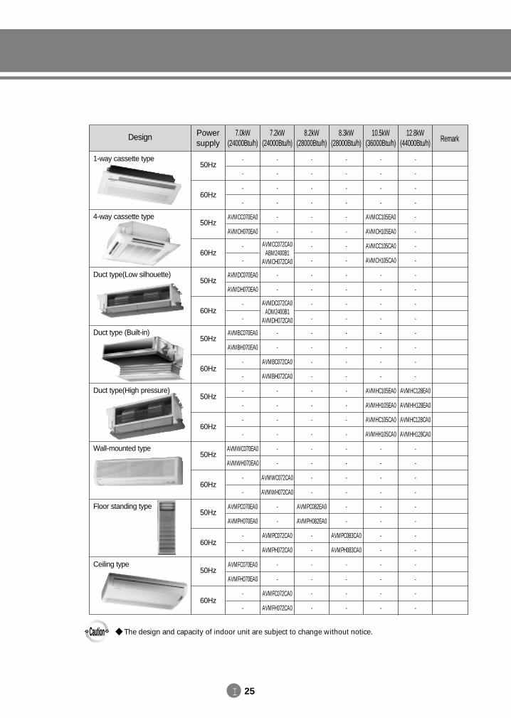
Design Powersupply
7.0kW(24000Btu/h)
7.2kW(24000Btu/h)
8.2kW(28000Btu/h)
8.3kW(28000Btu/h)
10.5kW(36000Btu/h)
12.8kW(44000Btu/h) Remark
-
-
-
-
AVMCC070EA0
AVMCH070EA0
-
-
AVMDC070EA0
AVMDH070EA0
-
-
AVMBC070EA0
AVMBH070EA0
-
-
-
-
-
-
AVMWC070EA0
AVMWH070EA0
-
-
AVMPC070EA0
AVMPH070EA0
-
-
AVMFC070EA0
AVMFH070EA0
-
-
-
-
-
-
-
-
-
-
-
-
AVMBC072CA0
AVMBH072CA0
-
-
-
-
-
-
AVMWC072CA0
AVMWH072CA0
-
-
AVMPC072CA0
AVMPH072CA0
-
-
AVMFC072CA0
AVMFH072CA0
AVMDC072CA0ADM2400B1
AVMDH072CA0
AVMCC072CA0ABM2400B1
AVMCH072CA0
-
-
-
-
-
-
-
-
-
-
-
-
-
-
-
-
-
-
-
-
-
-
-
-
AVMPC082EA0
AVMPH082EA0
-
-
-
-
-
-
-
-
-
-
-
-
-
-
-
-
-
-
-
-
-
-
-
-
-
-
-
-
-
-
-
-
AVMPC083CA0
AVMPH083CA0
-
-
-
-
-
-
-
-
AVMCC105EA0
AVMCH105EA0
AVMCC105CA0
AVMCH105CA0
-
-
-
-
-
-
-
-
AVMHC105EA0
AVMHH105EA0
AVMHC105CA0
AVMHH105CA0
-
-
-
-
-
-
-
-
-
-
-
-
-
-
-
-
-
-
-
-
-
-
-
-
-
-
-
-
AVMHC128EA0
AVMHH128EA0
AVMHC128CA0
AVMHH128CA0
-
-
-
-
-
-
-
-
-
-
-
-
50Hz
60Hz
50Hz
60Hz
50Hz
60Hz
50Hz
60Hz
50Hz
60Hz
50Hz
60Hz
50Hz
60Hz
50Hz
60Hz
The design and capacity of indoor unit are subject to change without notice.
1-way cassette type
4-way cassette type
Duct type(Low silhouette)
Duct type (Built-in)
Duct type(High pressure)
Wall-mounted type
Floor standing type
Ceiling type
DVM E-D/B(chapter1)-E<03759 3/21/02 6:55 PM Page 25
1. Remote controller
2. Receiver & display unit (Duct type)
3. Transmitter
4. Installation
2-1. Concealed type2-2. Standard type
78
4-1. Wireless remote controller4-2. Wired remote controller4-3. Centralized controller4-4. Function controller4-5. Receiver & display unit - concealed type4-6. Receiver & display unit - standard type4-7. Transmitter
10111419212223
1-1. Wireless remote controller1-2. Wired remote controller1-3. Centralized controller1-4. Function controller
2466
5. Assigning address5-1. Indoor unit5-2. Outdoor unit
2526
6. Indoor unit PCB option code6-1. PCB option code input method6-2. Option code
2732
7. S-Net
8. Integrating power distribution system
9. Building management system
IIControl System
DVM E-D/B(chapter1)-E<03759 3/21/02 6:55 PM Page 27
II. Control System
1. Remote controller
II 2
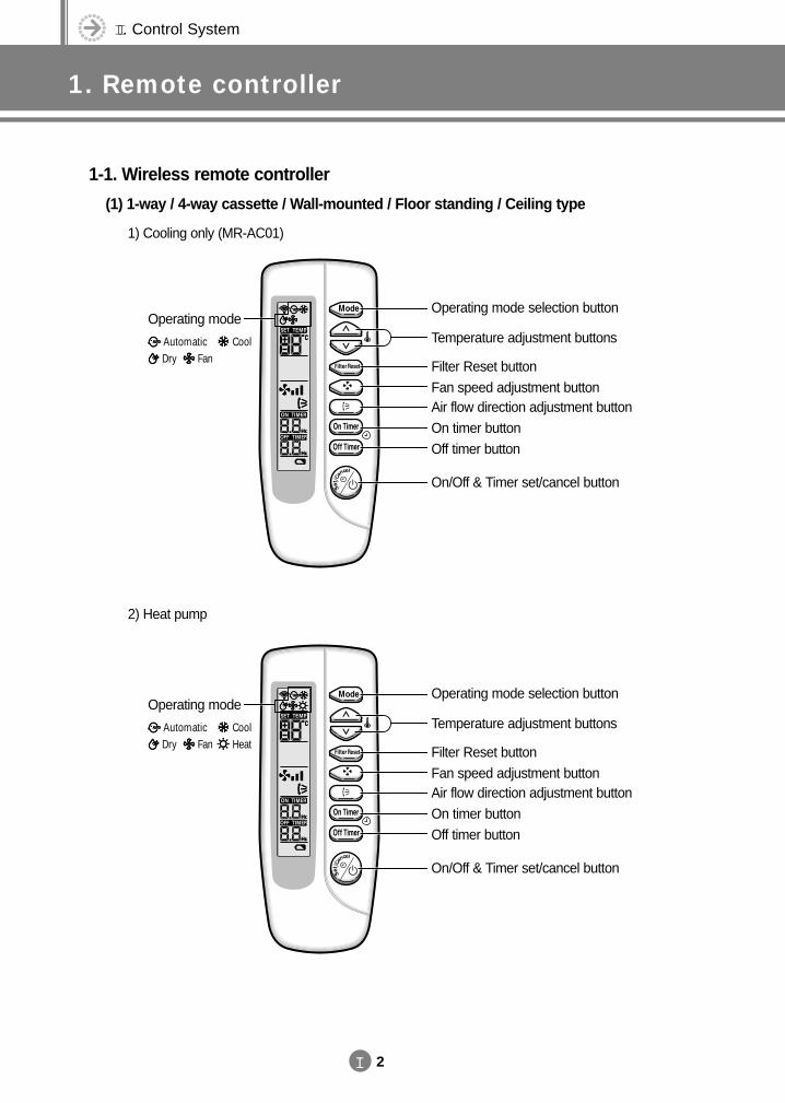
1-1. Wireless remote controller
(1) 1-way / 4-way cassette / Wall-mounted / Floor standing / Ceiling type
1) Cooling only (MR-AC01)
Automatic
Operating mode selection button
Temperature adjustment buttons
Filter Reset button
Fan speed adjustment buttonAir flow direction adjustment button
On timer button
Off timer button
On/Off & Timer set/cancel button
CoolDry Fan
Operating mode
2) Heat pump
Automatic
Operating mode selection button
Temperature adjustment buttons
Filter Reset button
Fan speed adjustment buttonAir flow direction adjustment button
On timer button
Off timer button
On/Off & Timer set/cancel button
CoolDry HeatFan
Operating mode
DVM E-D/B(chapter2)-E<03759 3/21/02 7:32 PM Page 2
II 3
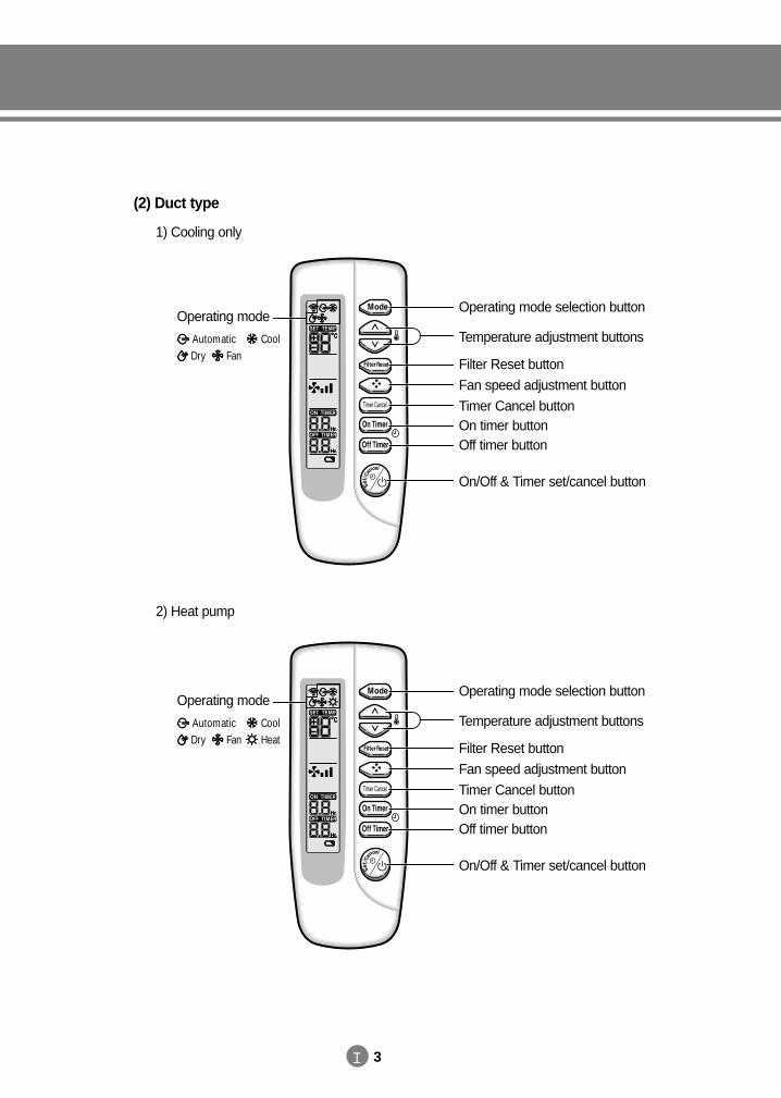
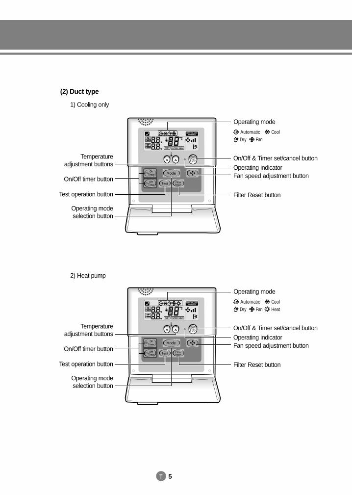
(2) Duct type
1) Cooling only
2) Heat pump
Operating mode selection button
Temperature adjustment buttons
Filter Reset button
Fan speed adjustment button
Timer Cancel buttonOn timer buttonOff timer button
On/Off & Timer set/cancel button
Automatic CoolDry Fan
Operating mode
Operating mode selection button
Temperature adjustment buttons
Filter Reset button
Fan speed adjustment button
Timer Cancel buttonOn timer buttonOff timer button
On/Off & Timer set/cancel button
Automatic CoolDry HeatFan
Operating mode
DVM E-D/B(chapter2)-E<03759 3/21/02 7:32 PM Page 3
II. Control System
1. Remote controller
II 4
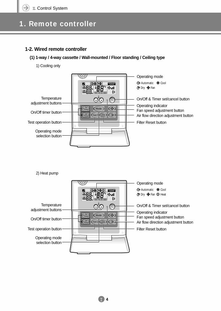
1-2. Wired remote controller
(1) 1-way / 4-way cassette / Wall-mounted / Floor standing / Ceiling type
1) Cooling only
2) Heat pump
On/Off & Timer set/cancel button
Operating indicatorFan speed adjustment buttonAir flow direction adjustment button
Filter Reset button
Temperature adjustment buttons
On/Off timer button
Test operation button
Operating mode selection button
Automatic CoolDry Fan
Operating mode
On/Off & Timer set/cancel button
Operating indicatorFan speed adjustment buttonAir flow direction adjustment button
Filter Reset button
Temperature adjustment buttons
On/Off timer button
Test operation button
Operating mode selection button
Automatic CoolDry HeatFan
Operating mode
DVM E-D/B(chapter2)-E<03759 3/21/02 7:32 PM Page 4
II 5
(2) Duct type
1) Cooling only
2) Heat pump
On/Off & Timer set/cancel button
Operating indicatorFan speed adjustment button
Filter Reset button
Temperature adjustment buttons
On/Off timer button
Test operation button
Operating mode selection button
Automatic CoolDry Fan
Operating mode
On/Off & Timer set/cancel button
Operating indicatorFan speed adjustment button
Filter Reset button
Temperature adjustment buttons
On/Off timer button
Test operation button
Operating mode selection button
Automatic CoolDry HeatFan
Operating mode
DVM E-D/B(chapter2)-E<03759 3/21/02 7:32 PM Page 5
II. Control System
1. Remote controller
II 6
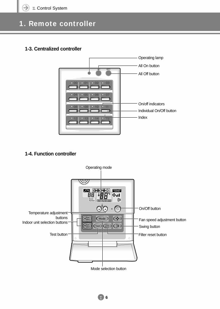
1-3. Centralized controller
1-4. Function controller
Operating lamp
All On button
All Off button
On/off indicators
Individual On/Off button
Index
Mode selection button
Indoor unit selection buttons
Test button Filter reset button
Temperature adjustment buttons
On/Off button
Fan speed adjustment button
Swing button
Operating mode
DVM E-D/B(chapter2)-E<03759 3/21/02 7:32 PM Page 6
2. Receiver & display unit (Duct type)
II 7
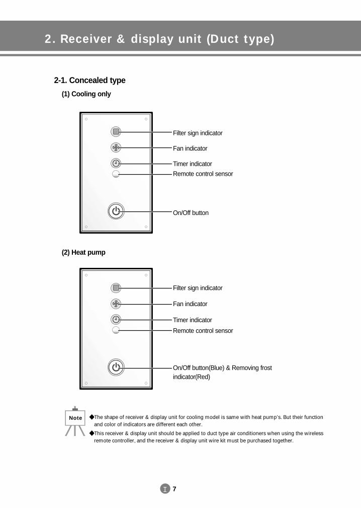
2-1. Concealed type
(1) Cooling only
(2) Heat pump
Filter sign indicator
Fan indicator
Timer indicator
Remote control sensor
On/Off button
Filter sign indicator
Fan indicator
Timer indicator
Remote control sensor
On/Off button(Blue) & Removing frost indicator(Red)
The shape of receiver & display unit for cooling model is same with heat pump’s. But their functionand color of indicators are different each other.
This receiver & display unit should be applied to duct type air conditioners when using the wirelessremote controller, and the receiver & display unit wire kit must be purchased together.
Note
DVM E-D/B(chapter2)-E<03759 3/21/02 7:32 PM Page 7
II. Control System
2. Receiver & display unit (Duct type)
II 8
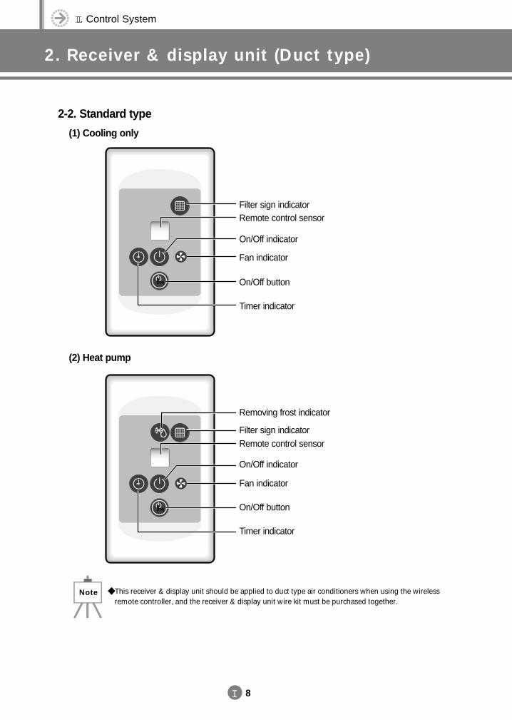
2-2. Standard type
(1) Cooling only
(2) Heat pump
Filter sign indicatorRemote control sensor
On/Off indicator
Fan indicator
On/Off button
Timer indicator
Removing frost indicator
Filter sign indicatorRemote control sensor
On/Off indicator
Fan indicator
On/Off button
Timer indicator
This receiver & display unit should be applied to duct type air conditioners when using the wirelessremote controller, and the receiver & display unit wire kit must be purchased together.
Note
DVM E-D/B(chapter2)-E<03759 3/21/02 7:32 PM Page 8
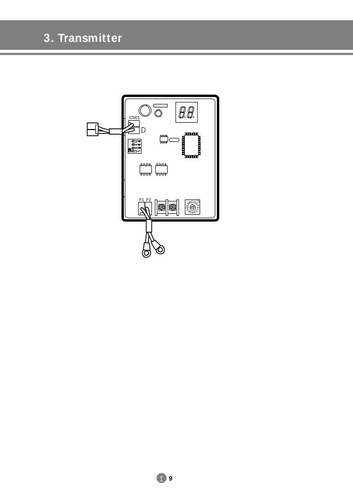
3. Transmitter
II 9
CN01
F1 F2
DVM E-D/B(chapter2)-E<03759 3/21/02 7:32 PM Page 9
II. Control System
4. Installation
II 10
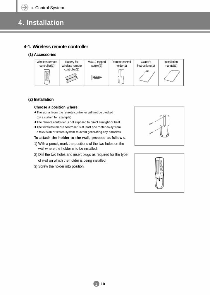
4-1. Wireless remote controller
(1) Accessories
(2) Installation
Choose a position where: The signal from the remote controller will not be blocked
(by a curtain for example) The remote controller is not exposed to direct sunlight or heat The wireless remote controller is at least one meter away from
a television or stereo system to avoid generating any parasites
To attach the holder to the wall, proceed as follows.
1) With a pencil, mark the positions of the two holes on thewall where the holder is to be installed.
2) Drill the two holes and insert plugs as required for the type
of wall on which the holder is being installed.
3) Screw the holder into position.
Wireless remote controller(1)
Battery for wireless remote
controller(2)
M4x12 tapped screw(2)
Remote control holder(1)
Owner’s instructions(1)
Installation manual(1)
DVM E-D/B(chapter2)-E<03759 3/21/02 7:32 PM Page 10
II 11
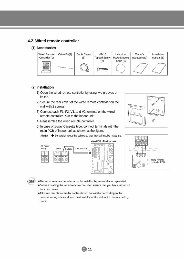
4-2. Wired remote controller
(1) Accessories
(2) Installation 1) Open the wired remote controller by using two grooves on
its top.
2) Secure the rear cover of the wired remote controller on the wall with 2 screws.
3) Connect each F1, F2, V1, and V2 terminal on the wired remote controller PCB to the indoor unit.
4) Reassemble the wired remote controller.
5) In case of 1-way Cassette type, connect terminals with the main PCB of indoor unit as shown at the figure.
Wired RemoteController (1)
Cable-Tie(2) Cable Clamp(5)
M4x16Tapped Screw
(7)
Indoor UnitPower Drawing
Cable (1)
Owner’sinstructions(1)
Installationmanual (1)
AC Powersupply White Black CN43(White)
Main PCB of indoor unit
Wired remotecontroller PCB
Be careful about the cables so that they will not be mixed up.NNNNooootttteeee
The wired remote controller must be installed by an installation specialist. Before installing the wired remote controller, ensure that you have turned off
the main power. All wired remote controller cables should be installed according to the
national wiring rules and you must install it in the wall not to be touched byusers.
DVM E-D/B(chapter2)-E<03759 3/21/02 7:33 PM Page 11
II. Control System
4. Installation
II 12
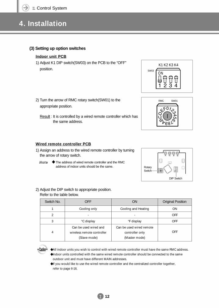
(3) Setting up option switches
Indoor unit PCB
1) Adjust K1 DIP switch(SW03) on the PCB to the “OFF”
position.
2) Turn the arrow of RMC rotary switch(SW01) to the
appropriate position.
Result : It is controlled by a wired remote controller which hasthe same address.
Wired remote controller PCB
1) Assign an address to the wired remote controller by turning the arrow of rotary switch.
2) Adjust the DIP switch to appropriate position. Refer to the table below.
RMC SW01
K1 K2 K3 K4SW03
RotarySwitch
DIP Switch
The address of wired remote controller and the RMCaddress of indoor units should be the same.
NNNNooootttteeee
All indoor units you wish to control with wired remote controller must have the same RMC address. Indoor units controlled with the same wired remote controller should be connected to the same
outdoor unit and must have different MAIN addresses. If you would like to use the wired remote controller and the centralized controller together,
refer to page II-16.
Switch No. OFF
1
2
3
4
Cooling only
-
°C display
Can be used wired and
wireless remote controller
(Slave mode)
ON
Cooling and Heating
-
°F display
Can be used wired remote
controller only
(Master mode)
Original Position
ON
OFF
OFF
OFF
DVM E-D/B(chapter2)-E<03759 3/21/02 7:33 PM Page 12
II 13
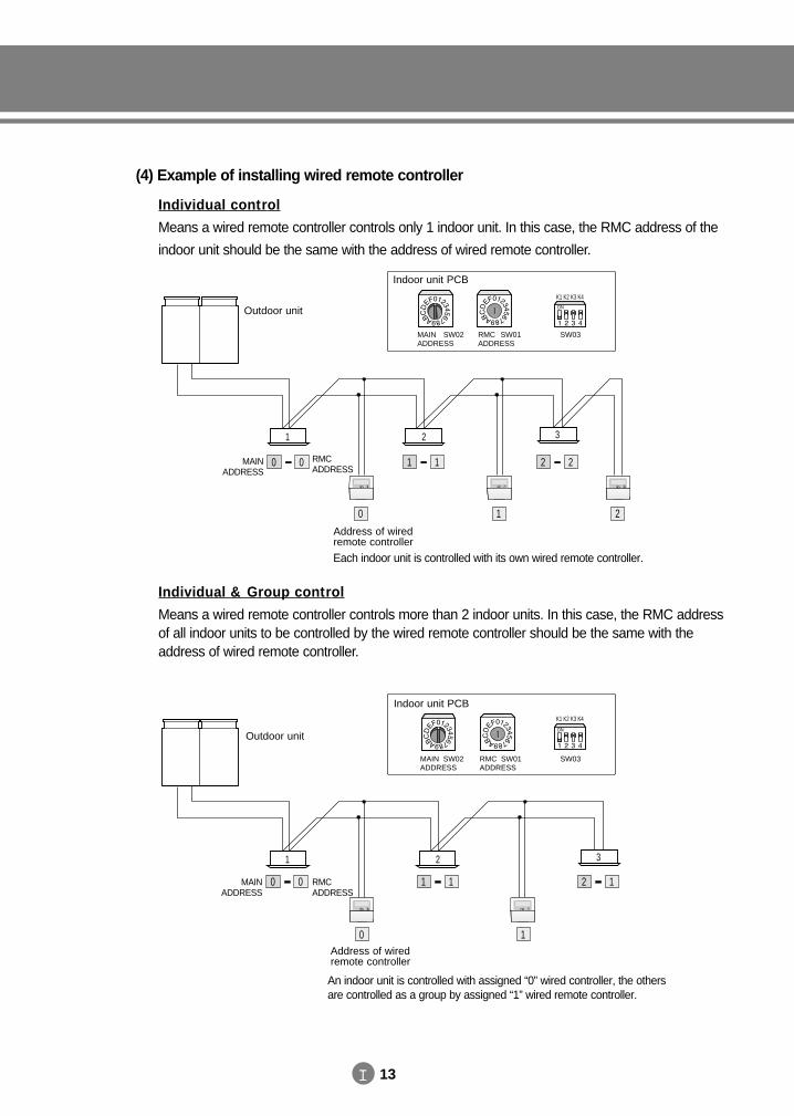
(4) Example of installing wired remote controller
Individual control
Means a wired remote controller controls only 1 indoor unit. In this case, the RMC address of the
indoor unit should be the same with the address of wired remote controller.
Individual & Group control
Means a wired remote controller controls more than 2 indoor units. In this case, the RMC addressof all indoor units to be controlled by the wired remote controller should be the same with theaddress of wired remote controller.
Each indoor unit is controlled with its own wired remote controller.
1 2 3
0 0 1 1 2 2
0 1 2
MAINADDRESS
RMCADDRESS
SW03SW01SW02
K1 K2 K3 K4
Outdoor unit
MAIN ADDRESS
RMCADDRESS
Address of wiredremote controller
MAIN ADDRESS
RMCADDRESS
Address of wiredremote controller
Indoor unit PCB
An indoor unit is controlled with assigned “0” wired controller, the othersare controlled as a group by assigned “1” wired remote controller.
1 2 3
0 0 1 1 2 1
0 1
MAIN SW02ADDRESS
RMC SW01ADDRESS
SW03
K1 K2 K3 K4
Outdoor unit
Indoor unit PCB
DVM E-D/B(chapter2)-E<03759 3/21/02 7:33 PM Page 13
II. Control System
4. Installation
II 14
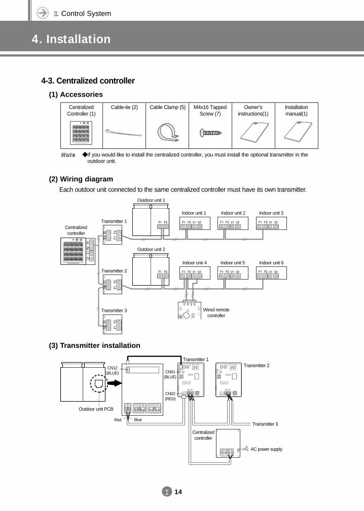
4-3. Centralized controller
(1) Accessories
(2) Wiring diagramEach outdoor unit connected to the same centralized controller must have its own transmitter.
(3) Transmitter installation
CentralizedController (1)
Cable-tie (2) Cable Clamp (5) M4x16 TappedScrew (7)
Owner’s instructions(1)
Installation manual(1)
Outdoor unit 1
Transmitter 1
Transmitter 2
Transmitter 3
Centralizedcontroller
Indoor unit 1 Indoor unit 2 Indoor unit 3
Outdoor unit 2
Indoor unit 4
Wired remotecontroller
Indoor unit 5 Indoor unit 6
If you would like to install the centralized controller, you must install the optional transmitter in theoutdoor unit.
NNNNooootttteeee
Transmitter 1Transmitter 2
CN01(BLUE)
CN12(BLUE)
CN02(RED)
Transmitter 3
AC power supply
Centralizedcontroller
Outdoor unit PCB
Red Blue
DVM E-D/B(chapter2)-E<03759 3/21/02 7:33 PM Page 14
II 15
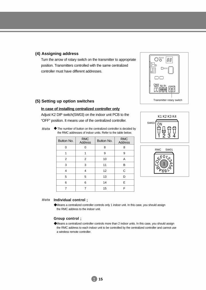
(4) Assigning addressTurn the arrow of rotary switch on the transmitter to appropriate
position. Transmitters controlled with the same centralized
controller must have different addresses.
Transmitter rotary switch(5) Setting up option switches
In case of installing centralized controller only
Adjust K2 DIP switch(SW03) on the indoor unit PCB to the
“OFF” position. It means use of the centralized controller.
0
1
2
3
4
5
6
7
Button No.
0
1
2
3
4
5
6
7
RMCAddress
8
9
10
11
12
13
14
15
Button No.
8
9
A
B
C
D
E
F
RMCAddress
K1 K2 K3 K4
RMC SW01
SW03
The number of button on the centralized controller is decided bythe RMC addresses of indoor units. Refer to the table below.
NNNNooootttteeee
Individual control ; Means a centralized controller controls only 1 indoor unit. In this case, you should assign
the RMC address to the indoor unit.
Group control ; Means a centralized controller controls more than 2 indoor units. In this case, you should assign
the RMC address to each indoor unit to be controlled by the centralized controller and cannot use a wireless remote controller.
NNNNooootttteeee
DVM E-D/B(chapter2)-E<03759 3/21/02 7:33 PM Page 15
II. Control System
4. Installation
II 16
In Case of Installing wired remote controller together
1) Adjust K2 DIP switch(SW03) on the indoor unit PCB to the
“OFF” position. It means use of the centralized controller.
2) Adjust K1 DIP switch(SW03) on the indoor unit PCB to the
“OFF” position. It means use of the wired remote controller.
3) Assign an address to the wired remote controller by turning
the arrow of rotary switch.RMC SW01
K1 K2 K3 K4
SW03
K1 K2 K3 K4
SW03
The number of button on the centralized controller is decided bythe RMC addresses of indoor units. Refer to the table below.
NNNNooootttteeee
The address of wired remote controller and the RMC addressof indoor units should be the same.
NNNNooootttteeee
If an indoor unit’s RMC address is ‘0’, the indoor unit will beoperated by the address ‘0’ wired remote controller and theaddress ‘0’ centralized controller.
EEEExxxxaaaammmmpppplllleeee
0
1
2
3
4
5
6
7
Button No.
0
1
2
3
4
5
6
7
RMCAddress
8
9
10
11
12
13
14
15
Button No.
8
9
A
B
C
D
E
F
RMCAddress
A group is made up of indoor units controlled with the same wired remotecontroller.
If the wired remote controller is installed for group controlling, you caninstall/use the centralized controller to control the same group.
DVM E-D/B(chapter2)-E<03759 3/21/02 7:33 PM Page 16
II 17
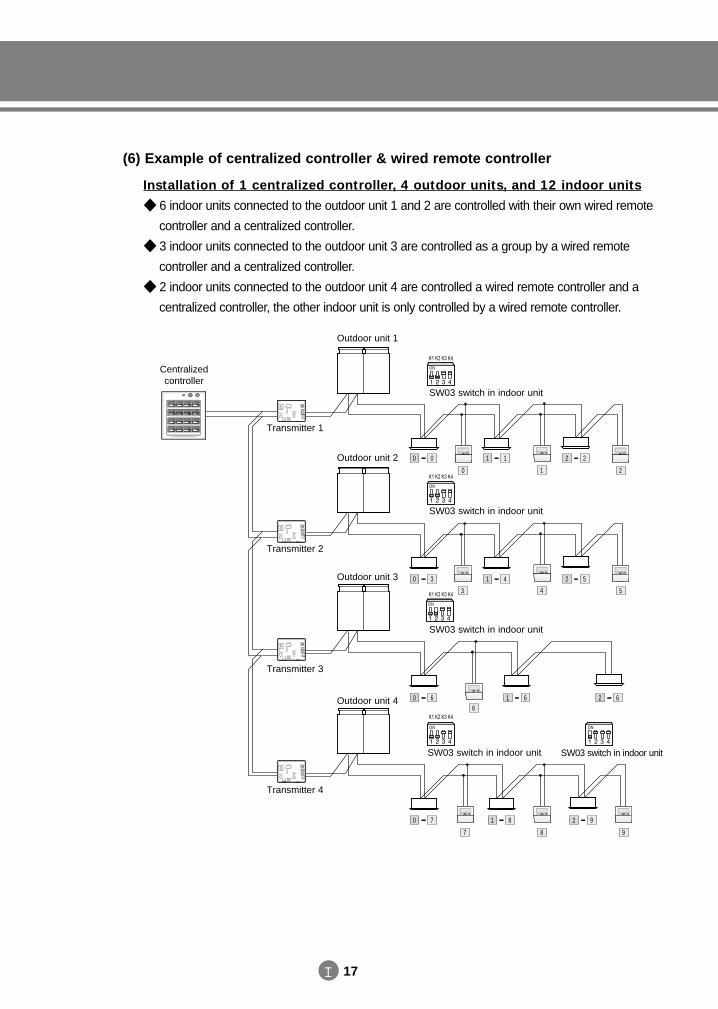
(6) Example of centralized controller & wired remote controller
Installation of 1 centralized controller, 4 outdoor units, and 12 indoor units
6 indoor units connected to the outdoor unit 1 and 2 are controlled with their own wired remote
controller and a centralized controller.
3 indoor units connected to the outdoor unit 3 are controlled as a group by a wired remote
controller and a centralized controller.
2 indoor units connected to the outdoor unit 4 are controlled a wired remote controller and a
centralized controller, the other indoor unit is only controlled by a wired remote controller.
0 0 1 1 2 2
0 3 1 4 2 5
0 6 1 6 2 6
0 7 1 8 2 9
0 1 2
3 4 5
6
7 8 9
Outdoor unit 1
Outdoor unit 2
Outdoor unit 3
Outdoor unit 4
Transmitter 1
Transmitter 2
Transmitter 3
Transmitter 4
Centralizedcontroller
SW03 switch in indoor unit
SW03 switch in indoor unit
SW03 switch in indoor unit
SW03 switch in indoor unit SW03 switch in indoor unit
DVM E-D/B(chapter2)-E<03759 3/21/02 7:33 PM Page 17
II. Control System
4. Installation
II 18
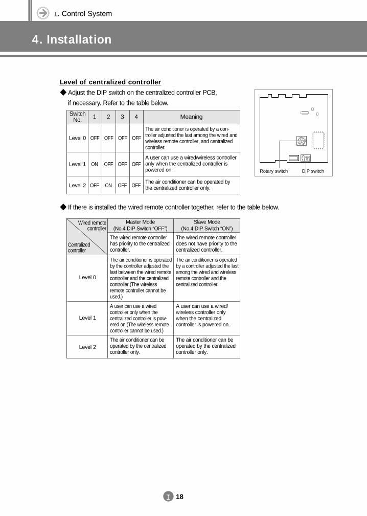
Level of centralized controller
Adjust the DIP switch on the centralized controller PCB,
if necessary. Refer to the table below.
If there is installed the wired remote controller together, refer to the table below.
Level 0
Level 1
Level 2
The wired remote controllerhas priority to the centralizedcontroller.
The wired remote controllerdoes not have priority to thecentralized controller.
The air conditioner is operatedby the controller adjusted thelast between the wired remotecontroller and the centralizedcontroller.(The wireless remote controller cannot beused.)
The air conditioner is operatedby a controller adjusted the lastamong the wired and wirelessremote controller and the centralized controller.
A user can use a wired controller only when the centralized controller is pow-ered on.(The wireless remotecontroller cannot be used.)
A user can use a wired/wireless controller onlywhen the centralized controller is powered on.
Wired remotecontroller
Centralized controller
Master Mode(No.4 DIP Switch “OFF”)
Slave Mode(No.4 DIP Switch “ON”)
The air conditioner can beoperated by the centralizedcontroller only.
The air conditioner can beoperated by the centralizedcontroller only.
DIP switchRotary switch
Level 0 OFF OFF OFF OFF
Level 1 ON OFF OFF OFF
Level 2 OFF ON OFF OFF
SwitchNo. 1 2 3 4 Meaning
The air conditioner is operated by a con-troller adjusted the last among the wired andwireless remote controller, and centralizedcontroller.
A user can use a wired/wireless controlleronly when the centralized controller ispowered on.
The air conditioner can be operated bythe centralized controller only.
DVM E-D/B(chapter2)-E<03759 3/21/02 7:33 PM Page 18
II 19
4-4. Function controller
(1) Accessories
(2) Installation 1) Disassemble the function controller by using a groove on its
top.
2) Secure the rear cover of the function controller on the wall with two screws.
3) Connect the C1 and C2 terminals in the function controller to the same terminals in the centralized controller.
4) Reassemble the function controller.
Functioncontroller (1)
Cable-tie(2) Cable clamp(6)
M4x16Tapped screw
(7)
Owner’sinstructions(1)
Installationmanual (1)
You must align the same terminal when connecting cables. If the cables are connected improperly,the function controller will not work.
The adaptor is not supplied with the function controller. Keep the polarity below when connecting the adaptor.- V1 : DC +12V, V2 : DC Ground
Centralized controller
Adaptor
Function controller
Function controller PCB
Rated input
Rated output
220V-240V/50~60Hz
DC8.5V 100mA
DVM E-D/B(chapter2)-E<03759 3/21/02 7:33 PM Page 19
II. Control System
4. Installation
II 20
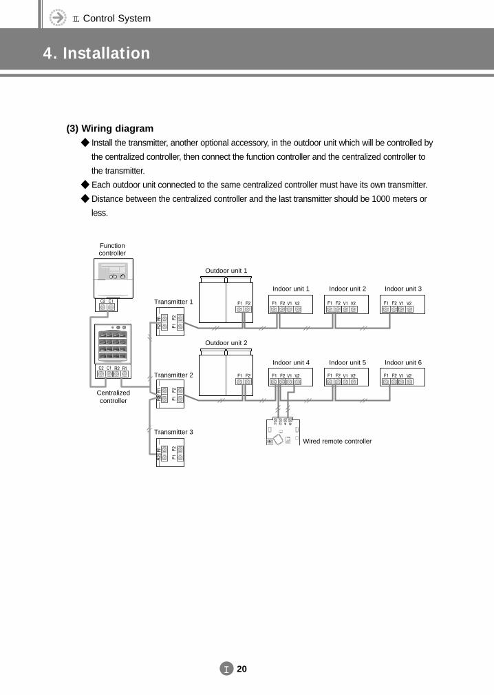
(3) Wiring diagram Install the transmitter, another optional accessory, in the outdoor unit which will be controlled by
the centralized controller, then connect the function controller and the centralized controller to
the transmitter.
Each outdoor unit connected to the same centralized controller must have its own transmitter.
Distance between the centralized controller and the last transmitter should be 1000 meters or
less.
Functioncontroller
Centralizedcontroller
Transmitter 1
Outdoor unit 1
Indoor unit 1 Indoor unit 2 Indoor unit 3
Indoor unit 4
Wired remote controller
Indoor unit 5 Indoor unit 6
Outdoor unit 2
Transmitter 2
Transmitter 3
DVM E-D/B(chapter2)-E<03759 3/21/02 7:33 PM Page 20
II 21
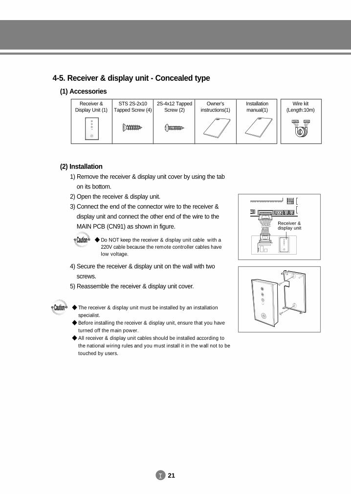
4-5. Receiver & display unit - Concealed type
(1) Accessories
(2) Installation 1) Remove the receiver & display unit cover by using the tab
on its bottom.
2) Open the receiver & display unit.
3) Connect the end of the connector wire to the receiver &
display unit and connect the other end of the wire to the
MAIN PCB (CN91) as shown in figure.
4) Secure the receiver & display unit on the wall with two
screws.
5) Reassemble the receiver & display unit cover.
The receiver & display unit must be installed by an installation specialist.
Before installing the receiver & display unit, ensure that you haveturned off the main power.
All receiver & display unit cables should be installed according tothe national wiring rules and you must install it in the wall not to betouched by users.
Do NOT keep the receiver & display unit cable with a220V cable because the remote controller cables havelow voltage.
Receiver &Display Unit (1)
STS 2S-2x10Tapped Screw (4)
2S-4x12 TappedScrew (2)
Owner’s instructions(1)
Installation manual(1)
Wire kit(Length:10m)
Receiver &display unit
DVM E-D/B(chapter2)-E<03759 3/21/02 7:33 PM Page 21
II. Control System
4. Installation
II 22
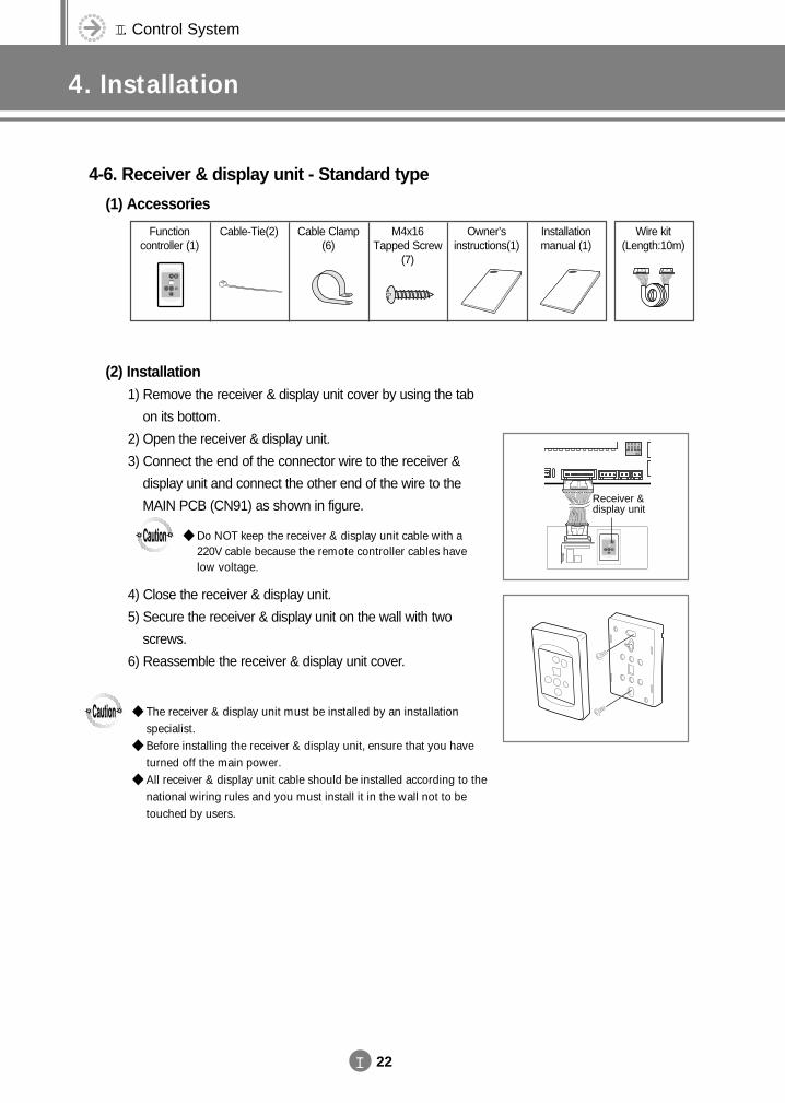
4-6. Receiver & display unit - Standard type
(1) Accessories
(2) Installation 1) Remove the receiver & display unit cover by using the tab
on its bottom.
2) Open the receiver & display unit.
3) Connect the end of the connector wire to the receiver &
display unit and connect the other end of the wire to the
MAIN PCB (CN91) as shown in figure.
4) Close the receiver & display unit.
5) Secure the receiver & display unit on the wall with two
screws.
6) Reassemble the receiver & display unit cover.
The receiver & display unit must be installed by an installation specialist.
Before installing the receiver & display unit, ensure that you haveturned off the main power.
All receiver & display unit cable should be installed according to thenational wiring rules and you must install it in the wall not to betouched by users.
Do NOT keep the receiver & display unit cable with a220V cable because the remote controller cables havelow voltage.
Receiver &display unit
Functioncontroller (1)
Cable-Tie(2) Cable Clamp(6)
M4x16Tapped Screw
(7)
Owner’sinstructions(1)
Installationmanual (1)
Wire kit(Length:10m)
DVM E-D/B(chapter2)-E<03759 3/21/02 7:33 PM Page 22
II 23
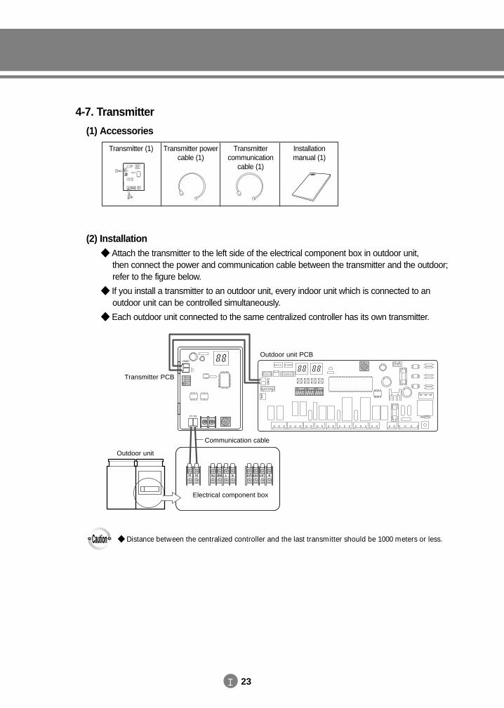
4-7. Transmitter
(1) Accessories
(2) Installation Attach the transmitter to the left side of the electrical component box in outdoor unit,
then connect the power and communication cable between the transmitter and the outdoor;refer to the figure below.
If you install a transmitter to an outdoor unit, every indoor unit which is connected to an outdoor unit can be controlled simultaneously.
Each outdoor unit connected to the same centralized controller has its own transmitter.
Distance between the centralized controller and the last transmitter should be 1000 meters or less.
Transmitter (1)
CN01
F1 F2
Transmitter powercable (1)
Transmitter communication
cable (1)
Installation manual (1)
CN01
F1 F2
CN
12
Outdoor unit
Communication cable
Transmitter PCB
Outdoor unit PCB
Electrical component box
DVM E-D/B(chapter2)-E<03759 3/21/02 7:33 PM Page 23
II. Control System
4. Installation
II 24
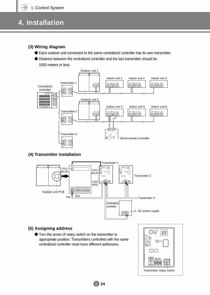
(3) Wiring diagram Each outdoor unit connected to the same centralized controller has its own transmitter.
Distance between the centralized controller and the last transmitter should be
1000 meters or less.
(4) Transmitter installation
(5) Assigning address Turn the arrow of rotary switch on the transmitter to
appropriate position. Transmitters controlled with the samecentralized controller must have different addresses.
Outdoor unit 1
Transmitter 1
Transmitter 2
Transmitter 3
Centralizedcontroller
Indoor unit 1 Indoor unit 2 Indoor unit 3
Outdoor unit 2
Indoor unit 4
Wired remote controller
Indoor unit 5 Indoor unit 6
Transmitter 1
Transmitter 2
CN01(BLUE)
CN12(BLUE)
CN02(RED)
Transmitter 3
AC power supply
Centralizedcontroller
Outdoor unit PCB
Red Blue
Transmitter rotary switch
DVM E-D/B(chapter2)-E<03759 3/21/02 7:33 PM Page 24
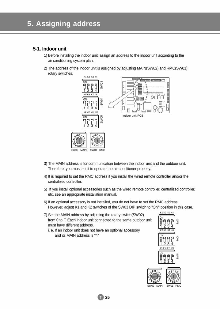
5. Assigning address
II 25
5-1. Indoor unit1) Before installing the indoor unit, assign an address to the indoor unit according to the
air conditioning system plan.
2) The address of the indoor unit is assigned by adjusting MAIN(SW02) and RMC(SW01) rotary switches.
3) The MAIN address is for communication between the indoor unit and the outdoor unit.Therefore, you must set it to operate the air conditioner properly.
4) It is required to set the RMC address if you install the wired remote controller and/or the centralized controller.
5) If you install optional accessories such as the wired remote controller, centralized controller,etc. see an appropriate installation manual.
6) If an optional accessory is not installed, you do not have to set the RMC address. However, adjust K1 and K2 switches of the SW03 DIP switch to "ON" position in this case.
7) Set the MAIN address by adjusting the rotary switch(SW02) from 0 to F. Each indoor unit connected to the same outdoor unit must have different address.i. e. If an indoor unit does not have an optional accessory
and its MAIN address is "4"
K1 K2 K3 K4
K5 K6 K7 K8
K9 K10 K11 K12
SW02 MAIN SW01 RMC
Indoor unit PCB
SW
03S
W04
SW
05
K1 K2 K3 K4
K5 K6 K7 K8
K9 K10 K11 K12
SW02 MAIN SW01 RMC
SW03
SW04
SW05
DVM E-D/B(chapter2)-E<03759 3/21/02 7:33 PM Page 25
II. Control System
5. Assigning address
II 26
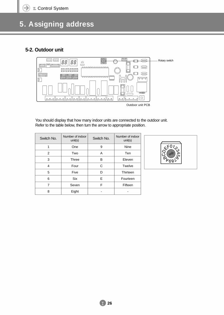
5-2. Outdoor unit
You should display that how many indoor units are connected to the outdoor unit.Refer to the table below, then turn the arrow to appropriate position.
Rotary switch
Outdoor unit PCB
1
2
3
4
5
6
7
8
One
Two
Three
Four
Five
Six
Seven
Eight
9
A
B
C
D
E
F
-
Nine
Ten
Eleven
Twelve
Thirteen
Fourteen
Fifteen
-
Switch No. Number of indoorunit(s) Switch No. Number of indoor
unit(s)
DVM E-D/B(chapter2)-E<03759 3/21/02 7:33 PM Page 26
6. Indoor unit PCB option code
II 27
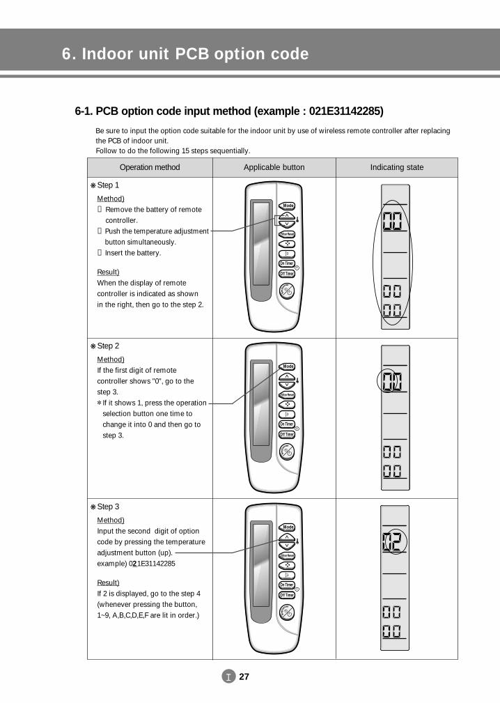
6-1. PCB option code input method (example : 021E31142285)
Be sure to input the option code suitable for the indoor unit by use of wireless remote controller after replacing the PCB of indoor unit.Follow to do the following 15 steps sequentially.
Operation method Applicable button Indicating state
Step 1
Method)① Remove the battery of remote
controller.② Push the temperature adjustment
button simultaneously.③ Insert the battery.
Result)When the display of remote controller is indicated as shown in the right, then go to the step 2.
Step 2
Method)If the first digit of remote controller shows "0", go to thestep 3. If it shows 1, press the operation
selection button one time tochange it into 0 and then go tostep 3.
Step 3
Method)Input the second digit of optioncode by pressing the temperatureadjustment button (up). example) 021E31142285
Result)If 2 is displayed, go to the step 4(whenever pressing the button,1~9, A,B,C,D,E,F are lit in order.)
DVM E-D/B(chapter2)-E<03759 3/21/02 7:33 PM Page 27
II. Control System
6. Indoor unit PCB option code
II 28
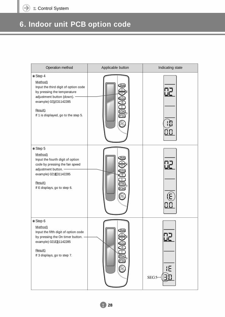
Operation method Applicable button Indicating state
Step 4
Method)Input the third digit of option codeby pressing the temperatureadjustment button (down). example) 021E31142285
Result)If 1 is displayed, go to the step 5.
Step 5
Method)Input the fourth digit of optioncode by pressing the fan speedadjustment button. example) 021E31142285
Result)If E displays, go to step 6.
Step 6
Method)Input the fifth digit of option codeby pressing the On timer button.example) 021E31142285
Result)If 3 displays, go to step 7.
DVM E-D/B(chapter2)-E<03759 3/21/02 7:33 PM Page 28
II 29
Operation method Applicable button Indicating state
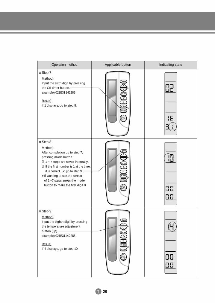
Step 7
Method)Input the sixth digit by pressingthe Off timer button. example) 021E31142285
Result)If 1 displays, go to step 8.
Step 8
Method)After completion up to step 7,pressing mode button.① 1 ~ 7 steps are saved internally.② If the first number is 1 at the time,
it is correct. So go to step 9. If wanting to see the screen
of 2 ~7 steps, press the modebutton to make the first digit 0.
Step 9
Method)Input the eighth digit by pressingthe temperature adjustment button (up).example) 021E31142285
Result)If 4 displays, go to step 10.
DVM E-D/B(chapter2)-E<03759 3/21/02 7:33 PM Page 29
II. Control System
6. Indoor unit PCB option code
II 30
Operation method Applicable button Indicating state
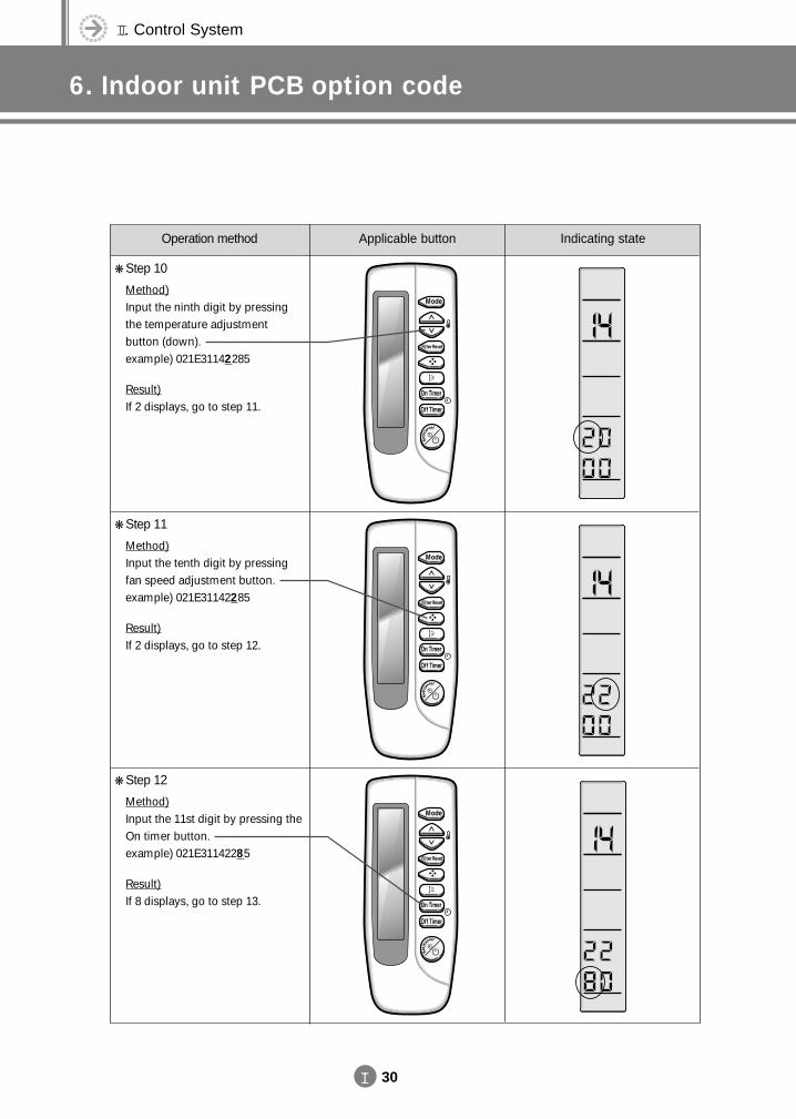
Step 10
Method)Input the ninth digit by pressingthe temperature adjustment button (down). example) 021E31142285
Result)If 2 displays, go to step 11.
Step 11
Method)Input the tenth digit by pressingfan speed adjustment button. example) 021E31142285
Result)If 2 displays, go to step 12.
Step 12
Method)Input the 11st digit by pressing theOn timer button. example) 021E31142285
Result)If 8 displays, go to step 13.
DVM E-D/B(chapter2)-E<03759 3/21/02 7:33 PM Page 30
II 31
Operation method Applicable button Indicating state
Step 13
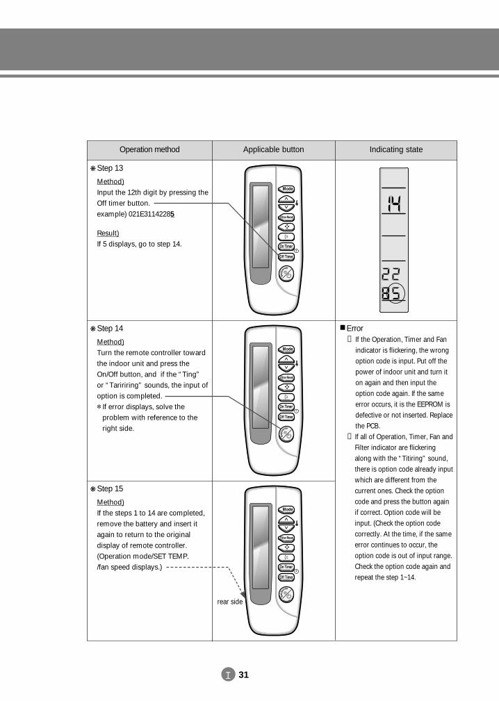
Method)Input the 12th digit by pressing theOff timer button. example) 021E31142285
Result)If 5 displays, go to step 14.
Step 14
Method)Turn the remote controller towardthe indoor unit and press theOn/Off button, and if the “Ting”or “Taririring” sounds, the input ofoption is completed. If error displays, solve the
problem with reference to theright side.
Error① If the Operation, Timer and Fan
indicator is flickering, the wrongoption code is input. Put off thepower of indoor unit and turn iton again and then input theoption code again. If the sameerror occurs, it is the EEPROM isdefective or not inserted. Replacethe PCB.
② If all of Operation, Timer, Fan andFilter indicator are flickeringalong with the “Titiring” sound,there is option code already inputwhich are different from the current ones. Check the optioncode and press the button againif correct. Option code will beinput. (Check the option code correctly. At the time, if the sameerror continues to occur, theoption code is out of input range.Check the option code again andrepeat the step 1~14.
Step 15
Method)If the steps 1 to 14 are completed,remove the battery and insert itagain to return to the original display of remote controller.(Operation mode/SET TEMP./fan speed displays.)
rear side
DVM E-D/B(chapter2)-E<03759 3/21/02 7:33 PM Page 31
II. Control System
6. Indoor unit PCB option code
II 32
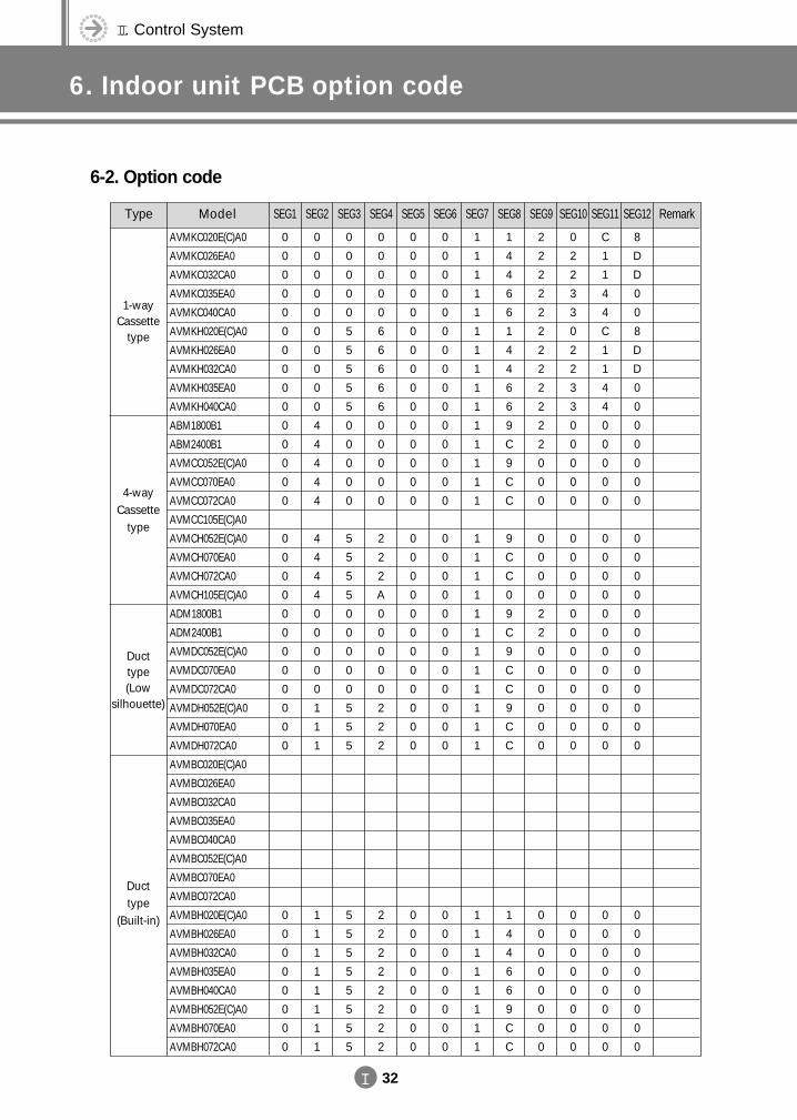
6-2. Option code
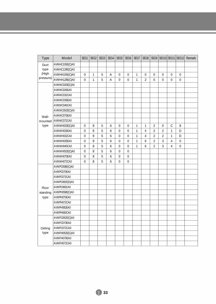
Type Model SEG1 SEG2 SEG3 SEG4 SEG5 SEG6 SEG7 SEG8 SEG9 SEG10 SEG11 SEG12 Remark
AVMKC020E(C)A0
AVMKC026EA0
AVMKC032CA0
AVMKC035EA0
AVMKC040CA0
AVMKH020E(C)A0
AVMKH026EA0
AVMKH032CA0
AVMKH035EA0
AVMKH040CA0
ABM1800B1
ABM2400B1
AVMCC052E(C)A0
AVMCC070EA0
AVMCC072CA0
AVMCC105E(C)A0
AVMCH052E(C)A0
AVMCH070EA0
AVMCH072CA0
AVMCH105E(C)A0
ADM1800B1
ADM2400B1
AVMDC052E(C)A0
AVMDC070EA0
AVMDC072CA0
AVMDH052E(C)A0
AVMDH070EA0
AVMDH072CA0
AVMBC020E(C)A0
AVMBC026EA0
AVMBC032CA0
AVMBC035EA0
AVMBC040CA0
AVMBC052E(C)A0
AVMBC070EA0
AVMBC072CA0
AVMBH020E(C)A0
AVMBH026EA0
AVMBH032CA0
AVMBH035EA0
AVMBH040CA0
AVMBH052E(C)A0
AVMBH070EA0
AVMBH072CA0
0
0
0
0
0
0
0
0
0
0
0
0
0
0
0
0
0
0
0
0
0
0
0
0
0
0
0
0
0
0
0
0
0
0
0
0
0
0
0
0
0
0
0
0
0
4
4
4
4
4
4
4
4
4
0
0
0
0
0
1
1
1
1
1
1
1
1
1
1
1
0
0
0
0
0
5
5
5
5
5
0
0
0
0
0
5
5
5
5
0
0
0
0
0
5
5
5
5
5
5
5
5
5
5
5
0
0
0
0
0
6
6
6
6
6
0
0
0
0
0
2
2
2
A
0
0
0
0
0
2
2
2
2
2
2
2
2
2
2
2
0
0
0
0
0
0
0
0
0
0
0
0
0
0
0
0
0
0
0
0
0
0
0
0
0
0
0
0
0
0
0
0
0
0
0
0
0
0
0
0
0
0
0
0
0
0
0
0
0
0
0
0
0
0
0
0
0
0
0
0
0
0
0
0
0
0
0
0
0
0
1
1
1
1
1
1
1
1
1
1
1
1
1
1
1
1
1
1
1
1
1
1
1
1
1
1
1
1
1
1
1
1
1
1
1
1
4
4
6
6
1
4
4
6
6
9
C
9
C
C
9
C
C
0
9
C
9
C
C
9
C
C
1
4
4
6
6
9
C
C
2
2
2
2
2
2
2
2
2
2
2
2
0
0
0
0
0
0
0
2
2
0
0
0
0
0
0
0
0
0
0
0
0
0
0
0
2
2
3
3
0
2
2
3
3
0
0
0
0
0
0
0
0
0
0
0
0
0
0
0
0
0
0
0
0
0
0
0
0
0
C
1
1
4
4
C
1
1
4
4
0
0
0
0
0
0
0
0
0
0
0
0
0
0
0
0
0
0
0
0
0
0
0
0
0
8
D
D
0
0
8
D
D
0
0
0
0
0
0
0
0
0
0
0
0
0
0
0
0
0
0
0
0
0
0
0
0
0
0
0
1-wayCassette
type
4-wayCassette
type
Ducttype(Low
silhouette)
Ducttype
(Built-in)
DVM E-D/B(chapter2)-E<03759 3/21/02 7:33 PM Page 32
II 33
Type Model SEG1 SEG2 SEG3 SEG4 SEG5 SEG6 SEG7 SEG8 SEG9 SEG10 SEG11 SEG12 Remark
AVMHC105E(C)A0
AVMHC128E(C)A0
AVMHH105E(C)A0
AVMHH128E(C)A0
AVMWC020E(C)A0
AVMWC026EA0
AVMWC032CA0
AVMWC035EA0
AVMWC040CA0
AVMWC052E(C)A0
AVMWC070EA0
AVMWC072CA0
AVMWH020E(C)A0
AVMWH026EA0
AVMWH032CA0
AVMWH035EA0
AVMWH040CA0
AVMWH052E(C)A0
AVMWH070EA0
AVMWH072CA0
AVMPC058E(C)A0
AVMPC070EA0
AVMPC072CA0
AVMPC082E(D)A0
AVMPC083CA0
AVMPH058E(C)A0
AVMPH070EA0
AVMPH072CA0
AVMPH082EA0
AVMPH083CA0
AVMFC052E(C)A0
AVMFC070EA0
AVMFC072CA0
AVMFH052E(C)A0
AVMFH070EA0
AVMFH072CA0
0
0
0
0
0
0
0
0
0
0
1
1
8
8
8
8
8
8
8
8
5
5
5
5
5
5
5
5
5
5
A
A
6
6
6
6
6
6
6
6
0
0
0
0
0
0
0
0
0
0
0
0
0
0
0
0
0
0
0
0
1
1
1
1
1
1
1
0
2
1
4
4
6
6
0
0
2
2
2
2
2
0
0
0
2
2
3
3
0
0
C
1
1
4
4
0
0
8
D
D
0
0
Ducttype(High
pressure)
Wall-mounted
type
Floorstanding
type
Ceilingtype
DVM E-D/B(chapter2)-E<03759 3/21/02 7:33 PM Page 33
II. Control System
7. S-Net
II 34
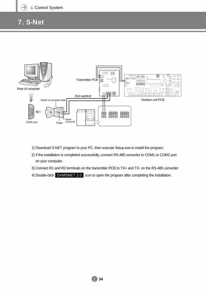
1) Download S-NET program to your PC, then execute Setup.exe to install the program.
2) If the installation is completed successfully, connect RS-485 converter to COM1 or COM2 port
on your computer.
3) Connect R1 and R2 terminals on the transmitter PCB to TX+ and TX- on the RS-485 converter.
4) Double-click DVMSNET 2.0 icon to open the program after completing the installation.
1
2
3
4
5
6
7
8
9
COM1 port
Switch of converter slide
Power ConnectorPower
Rear of computer
Outdoor unit PCB
Transmitter PCB
(Not supplied)
DVM E-D/B(chapter2)-E<03759 3/21/02 7:33 PM Page 34
8. Integrating power distribution system
II 35
DVM E-D/B(chapter2)-E<03759 3/21/02 7:33 PM Page 35
II. Control System
9. Building management system
II 36
DVM E-D/B(chapter2)-E<03759 3/21/02 7:33 PM Page 36

1. Features
III Indoor unit
1-1. 1-way cassette type1-2. 4-way cassette type1-3. Duct type1-4. Wall-mounted type1-5. Floor standing type1-6. Ceiling type
2468
1012
6. Refrigerant system diagram(Cooling only & heat pump)6-1. Refrigerant system diagram6-2. Main parts status
7373
9. Velocity of air flow & temperature distribution9-1. 1-way cassette type9-2. 4-way cassette type9-3. Wall-mounted type9-4. Ceiling type
102103105107
2. Specification2-1. 1-way cassette type2-2. 4-way cassette type2-3. Duct type (Low silhouette)2-4. Duct type (Built-in)2-5. Duct type (High pressure)2-6. Wall-mounted type2-7. Floor standing type2-8. Ceiling type
1416182024263032
3. Functional parts and safety devices3-1. 1-way cassette type3-2. 4-way cassette type3-3. Duct type (Low silhouette)3-4. Duct type (Built-in)3-5. Duct type (High pressure)3-6. Wall-mounted type3-7. Floor standing type3-8. Ceiling type
3434353636373838
4. Capacity table4-1. 50Hz4-2. 60Hz
3945
5. Dimension5-1. 1-way cassette type5-2. 4-way cassette type5-3. Duct type (Low silhouette)5-4. Duct type (Built-in)5-5. Duct type (High pressure)5-6. Wall-mounted type5-7. Floor standing type5-8. Ceiling type5-9. Wireless remote controller / Receiver5-10. Wired remote controller5-11. Option controller
5152545557586061627072
7. Electric circuit diagram7-1. 1-way cassette type7-2. 4-way cassette type7-3. Duct type7-4. Wall-mounted type7-5. Floor standing type7-6. Ceiling type
747678808284
8. Noise level8-1. Overall8-2. Octave band level
8687
10. Fan specifications10-1. Duct type(Low silhouette)10-2. Duct type(Built-in)10-3. Duct type(High pressure)
108109110
11. Panel11-1. 1-way cassette type11-2. 4-way cassette type
111112
12. Electronic expansion valve kit12-1. Design12-2. Status depending on the
combination
113
113
13. Options
DVM E-D/B(chapter2)-E<03759 3/21/02 7:33 PM Page 37
III. Indoor unit
1. Features
III 2
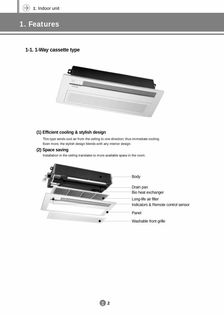
1-1. 1-Way cassette type
(1) Efficient cooling & stylish designThis type sends cool air from the ceiling to one direction; thus immediate cooling. Even more, the stylish design blends with any interior design.
(2) Space savingInstallation in the ceiling translates to more available space in the room.
Body
Drain panBio heat exchanger
Long-life air filterIndicators & Remote control sensor
Panel
Washable front grille
DVM E-D/B(chapter3-1)-E<03759 3/21/02 7:33 PM Page 2
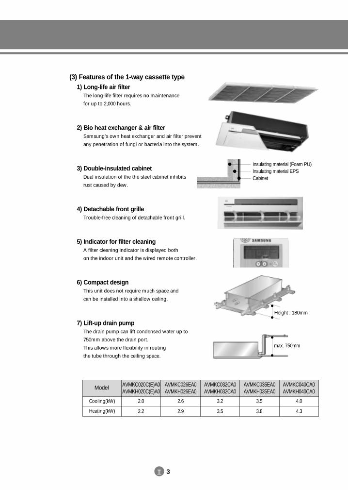
III 3
(3) Features of the 1-way cassette type1) Long-life air filter
The long-life filter requires no maintenance
for up to 2,000 hours.
2) Bio heat exchanger & air filterSamsung’s own heat exchanger and air filter prevent
any penetration of fungi or bacteria into the system.
3) Double-insulated cabinetDual insulation of the the steel cabinet inhibits
rust caused by dew.
4) Detachable front grilleTrouble-free cleaning of detachable front grill.
5) Indicator for filter cleaningA filter cleaning indicator is displayed both
on the indoor unit and the wired remote controller.
6) Compact designThis unit does not require much space and
can be installed into a shallow ceiling.
7) Lift-up drain pumpThe drain pump can lift condensed water up to
750mm above the drain port.
This allows more flexibility in routing
the tube through the ceiling space.
max. 750mm
Insulating material (Foam PU)Insulating material EPSCabinet
Model AVMKC020C(E)A0AVMKH020C(E)A0
AVMKC026EA0AVMKH026EA0
AVMKC032CA0AVMKH032CA0
AVMKC035EA0AVMKH035EA0
AVMKC040CA0AVMKH040CA0
Cooling(kW)
Heating(kW)
2.0
2.2
2.6
2.9
3.2
3.5
3.5
3.8
4.0
4.3
Height : 180mm
DVM E-D/B(chapter3-1)-E<03759 3/21/02 7:33 PM Page 3
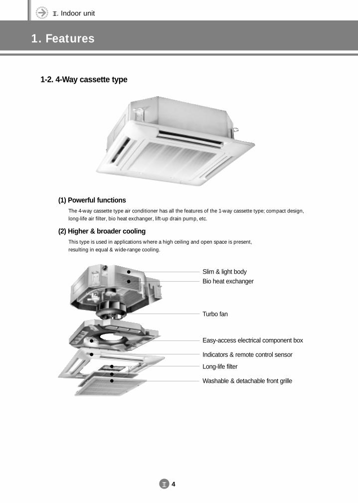
(1) Powerful functionsThe 4-way cassette type air conditioner has all the features of the 1-way cassette type; compact design, long-life air filter, bio heat exchanger, lift-up drain pump, etc.
(2) Higher & broader coolingThis type is used in applications where a high ceiling and open space is present, resulting in equal & wide-range cooling.
III. Indoor unit
1. Features
III 4
1-2. 4-Way cassette type
Slim & light body
Bio heat exchanger
Turbo fan
Easy-access electrical component box
Indicators & remote control sensor
Long-life filter
Washable & detachable front grille
DVM E-D/B(chapter3-1)-E<03759 3/21/02 7:33 PM Page 4
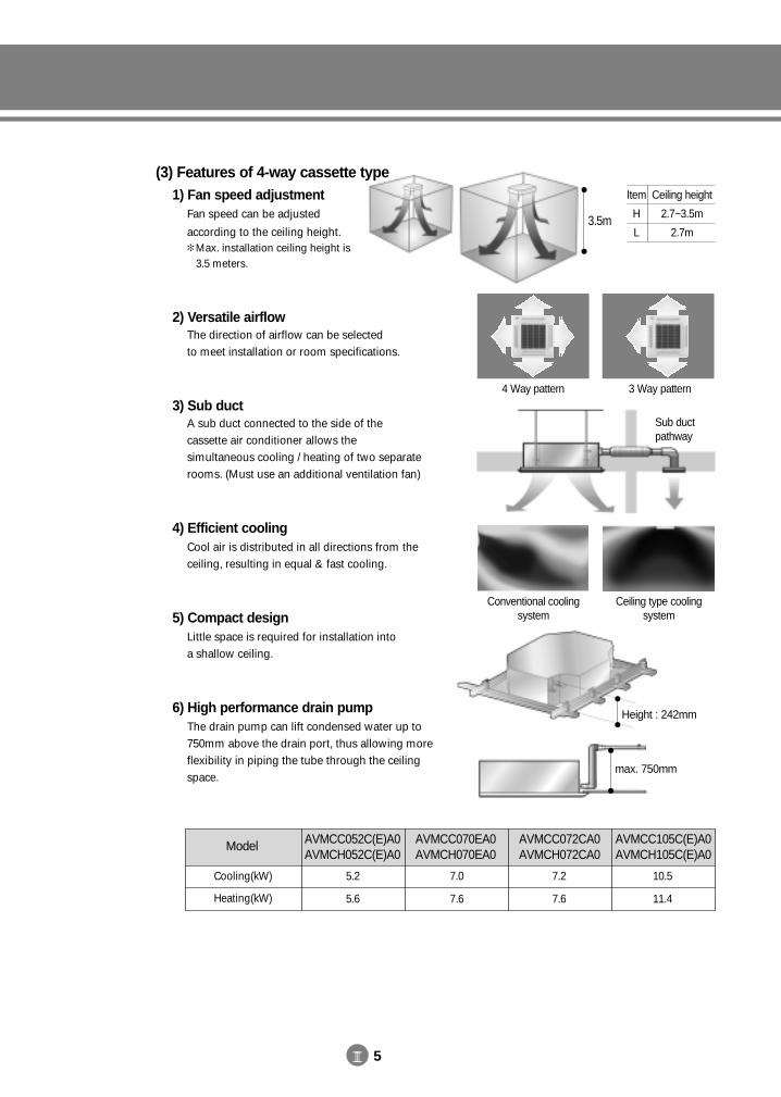
III 5
Item
H
L
Ceiling height
2.7~3.5m
2.7m
Sub duct pathway
4 Way pattern 3 Way pattern
Conventional cooling system
Ceiling type cooling system
max. 750mm
Model AVMCC052C(E)A0AVMCH052C(E)A0
AVMCC070EA0AVMCH070EA0
AVMCC072CA0AVMCH072CA0
AVMCC105C(E)A0AVMCH105C(E)A0
Cooling(kW)
Heating(kW)
5.2
5.6
7.0
7.6
7.2
7.6
10.5
11.4
3.5m
Height : 242mm
(3) Features of 4-way cassette type1) Fan speed adjustment
Fan speed can be adjusted
according to the ceiling height. Max. installation ceiling height is
3.5 meters.
2) Versatile airflowThe direction of airflow can be selected to meet installation or room specifications.
3) Sub ductA sub duct connected to the side of the cassette air conditioner allows the simultaneous cooling / heating of two separate rooms. (Must use an additional ventilation fan)
4) Efficient coolingCool air is distributed in all directions from the ceiling, resulting in equal & fast cooling.
5) Compact designLittle space is required for installation into a shallow ceiling.
6) High performance drain pumpThe drain pump can lift condensed water up to 750mm above the drain port, thus allowing more flexibility in piping the tube through the ceiling space.
DVM E-D/B(chapter3-1)-E<03759 3/21/02 7:33 PM Page 5
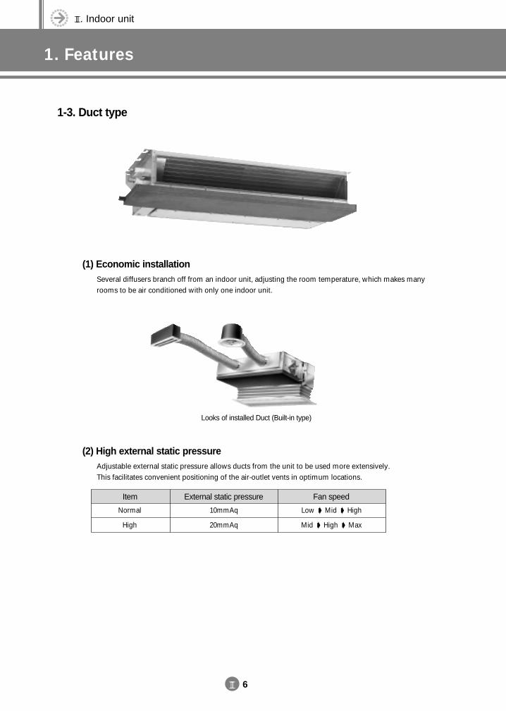
III. Indoor unit
1. Features
III 6
1-3. Duct type
(2) High external static pressureAdjustable external static pressure allows ducts from the unit to be used more extensively. This facilitates convenient positioning of the air-outlet vents in optimum locations.
(1) Economic installationSeveral diffusers branch off from an indoor unit, adjusting the room temperature, which makes many rooms to be air conditioned with only one indoor unit.
Item
Normal
High
External static pressure
10mmAq
20mmAq
Fan speed
Low Mid High
Mid High Max
Looks of installed Duct (Built-in type)
DVM E-D/B(chapter3-1)-E<03759 3/21/02 7:33 PM Page 6
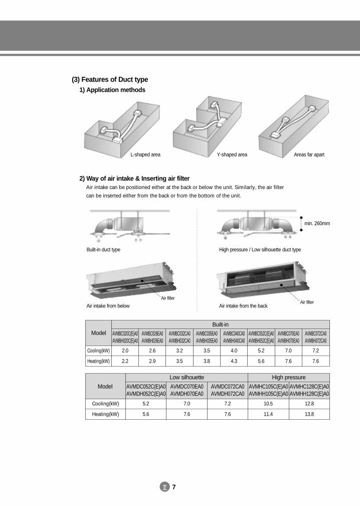
III 7
(3) Features of Duct type1) Application methods
2) Way of air intake & Inserting air filterAir intake can be positioned either at the back or below the unit. Similarly, the air filter
can be inserted either from the back or from the bottom of the unit.
min. 260mm
Built-in duct type High pressure / Low silhouette duct type
Air intake from below
L-shaped area Y-shaped area Areas far apart
Air intake from the back
Air filterAir filter
ModelBuilt-in
AVMBC020C(E)A0AVMBH020C(E)A0
Cooling(kW)
Heating(kW)
2.0
2.2
AVMBC026EA0AVMBH026EA0
2.6
2.9
AVMBC032CA0AVMBH032CA0
3.2
3.5
AVMBC035EA0AVMBH035EA0
3.5
3.8
AVMBC040CA0AVMBH040CA0
4.0
4.3
AVMBC052C(E)A0AVMBH052C(E)A0
5.2
5.6
AVMBC070EA0AVMBH070EA0
7.0
7.6
AVMBC072CA0AVMBH072CA0
7.2
7.6
Model AVMDC052C(E)A0AVMDH052C(E)A0
AVMDC070EA0AVMDH070EA0
AVMDC072CA0AVMDH072CA0
AVMHC105C(E)A0AVMHH105C(E)A0
AVMHC128C(E)A0AVMHH128C(E)A0
Cooling(kW)
Heating(kW)
5.2
5.6
7.0
7.6
7.2
7.6
10.5
11.4
12.8
13.8
Low silhouette High pressure
DVM E-D/B(chapter3-1)-E<03759 3/21/02 7:34 PM Page 7
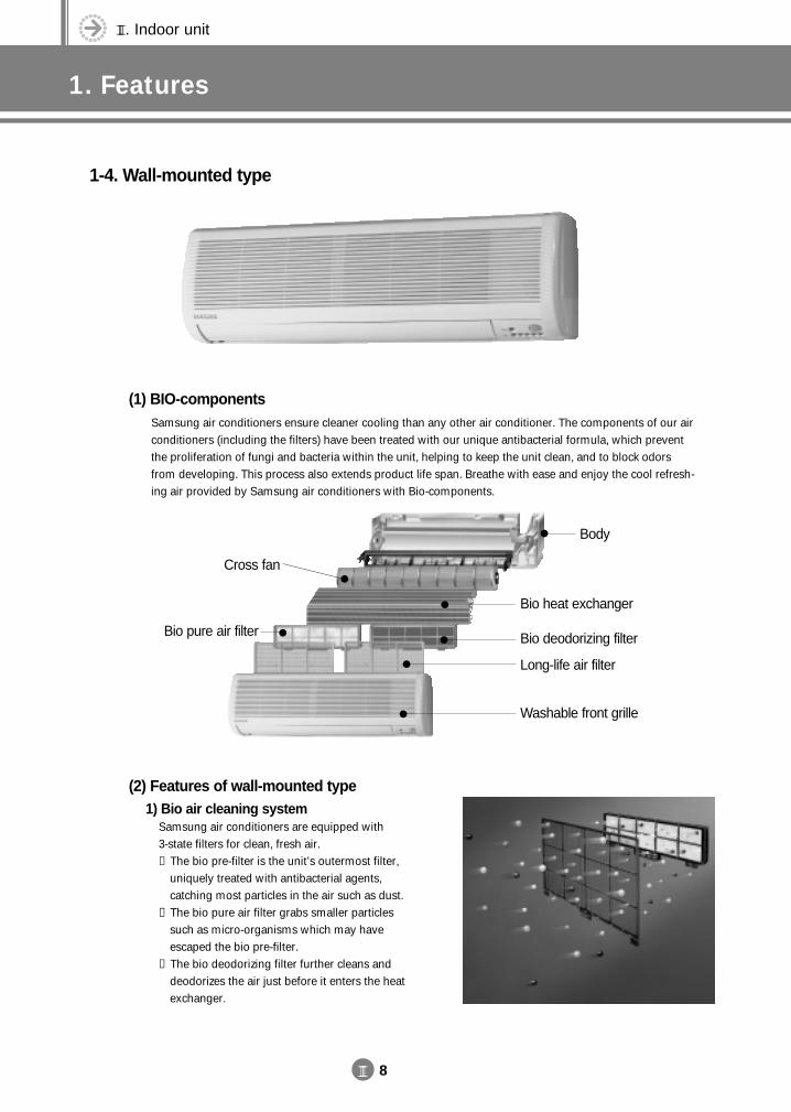
III. Indoor unit
1. Features
III 8
1-4. Wall-mounted type
(1) BIO-componentsSamsung air conditioners ensure cleaner cooling than any other air conditioner. The components of our air conditioners (including the filters) have been treated with our unique antibacterial formula, which preventthe proliferation of fungi and bacteria within the unit, helping to keep the unit clean, and to block odorsfrom developing. This process also extends product life span. Breathe with ease and enjoy the cool refresh-ing air provided by Samsung air conditioners with Bio-components.
Body
Washable front grille
Bio heat exchanger
Cross fan
Bio pure air filter Bio deodorizing filter
Long-life air filter
(2) Features of wall-mounted type1) Bio air cleaning system
Samsung air conditioners are equipped with 3-state filters for clean, fresh air.① The bio pre-filter is the unit’s outermost filter,
uniquely treated with antibacterial agents, catching most particles in the air such as dust.
② The bio pure air filter grabs smaller particles such as micro-organisms which may have escaped the bio pre-filter.
③ The bio deodorizing filter further cleans anddeodorizes the air just before it enters the heatexchanger.
DVM E-D/B(chapter3-1)-E<03759 3/21/02 7:34 PM Page 8
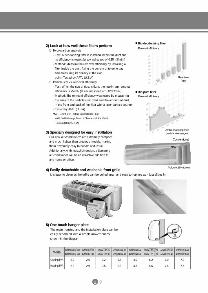
III 9
Bio pure filter
Ambient atmosphericparticle size ranges
Removal efficiency
2) Look at how well these filters perform① Hydrocarbon analysis
- Test: A deodorizing filter is installed within the duct and its efficiency is tested.(at a wind speed of 0.35m3/min.)
- Method: Measure the removal efficiency by installing a filter inside the duct, fixing the density of toluene gas and measuring its density at the exit point.-Tested by AFTL (U.S.A)
② Particle size vs. removal efficiency- Test: When the size of dust is 5µm, the maximum removal
efficiency is 75.6%. (at a wind speed of 1.42m3/min.)- Method: The removal efficiency was tested by measuring
the sizes of the particles removed and the amount of dust in the front and back of the filter with a laser particle counter.
- Tested by AFTL (U.S.A) AFTL(Air Filter Testing Laboratories, Inc.)
4632 Old laGrange Road, 1 Chestwood, KY 40014
Tel/Fax:(502) 222-5729
3) Specially designed for easy installationOur new air conditioners are extremely compact and much lighter than previous models, making them extremely easy to handle and install. Additionally, with its stylish design, a Samsung air conditioner will be an attractive addition to any home or office.
4) Easily detachable and washable front grilleIt is easy to clean as the grille can be pulled apart and easy to replace as it just slides in.
Bio deodorizing filter
Removal efficiency
Real time (min)
Volume 28% Down
Conventional
New
5) One-touch hanger plateThe main housing and the installation plate can beeasily separated with a simple movement as shown in the diagram.
ModelAVMWC020C(E)A0AVMWH020C(E)A0
Cooling(kW)
Heating(kW)
2.0
2.2
AVMWC026EA0AVMWH026EA0
2.6
2.9
AVMWC032CA0AVMWH032CA0
3.2
3.5
AVMWC035EA0AVMWH035EA0
3.5
3.8
AVMWC040CA0AVMWH040CA0
4.0
4.3
AVMWC052C(E)A0AVMWH052C(E)A0
5.2
5.6
AVMWC070EA0AVMWH070EA0
7.0
7.6
AVMWC072CA0AVMWH072CA0
7.2
7.6
DVM E-D/B(chapter3-1)-E<03759 3/21/02 7:34 PM Page 9
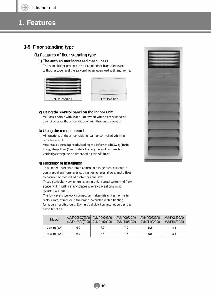
III. Indoor unit
1. Features
III 10
1-5. Floor standing type
(1) Features of floor standing type1) The auto shutter increased clean liness
The auto shutter protects the air conditioner from dust even without a cover and the air conditioner goes well with any home.
2) Using the control panel on the indoor unitYou can operate with indoor unit when you do not wish to or cannot operate the air conditioner with the remote control.
3) Using the remote controlAll functions of the air conditioner can be controlled with theremote control.Automatic operating mode/cooling mode/dry mode/3way(Turbo,Long, Sleep timer)/fan mode/adjusting the air flow direction vertically/setting the on timer/setting the off timer.
4) Flexibility of installationThis unit will sustain climate control in a large area. Suitable incommercial environments such as restaurants, shops, and officesto ensure the comfort of customers and staff.These particularly stylish units, using only a small amount of floorspace, will install in many places where conventional split systems will not fit.The low-level pipe work connection makes this unit attractive inrestaurants, offices or in the home. Available with a heating function or cooling only. Each model also has auto-louvers and aturbo function.
‘On’ Position ‘Off’ Position
Model AVMPC060C(E)A0AVMPH060C(E)A0
AVMPC070EA0AVMPH070EA0
AVMPC072CA0AVMPH072CA0
AVMPC082EA0AVMPH082EA0
AVMPC083CA0AVMPH083CA0
Cooling(kW)
Heating(kW)
6.0
6.4
7.0
7.6
7.2
7.6
8.2
8.8
8.3
8.8
DVM E-D/B(chapter3-1)-E<03759 3/21/02 7:34 PM Page 10
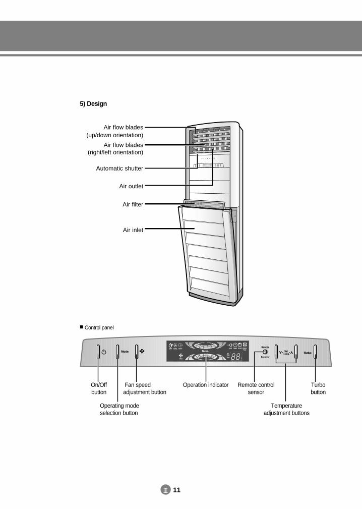
III 11
5) Design
Air flow blades(up/down orientation)
Air flow blades(right/left orientation)
Automatic shutter
Air outlet
Air filter
Air inlet
Operation indicator Remote controlsensor
Turbo button
On/Off button
Fan speedadjustment button
Temperatureadjustment buttons
Operating modeselection button
Control panel
DVM E-D/B(chapter3-1)-E<03759 3/21/02 7:34 PM Page 11
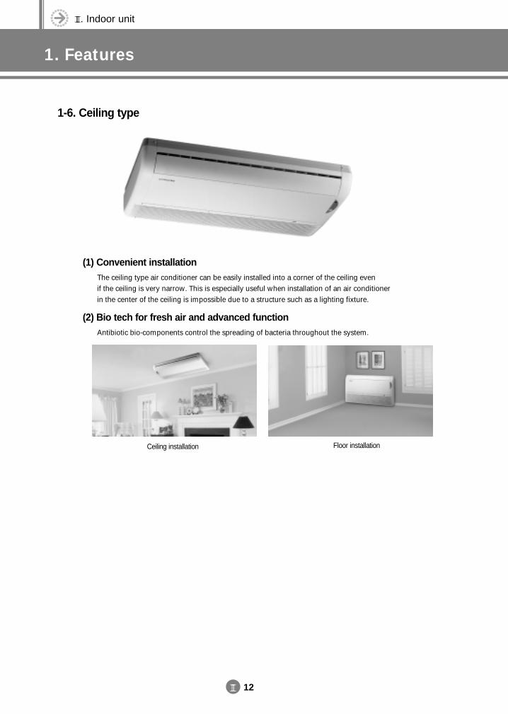
III. Indoor unit
1. Features
III 12
1-6. Ceiling type
(1) Convenient installationThe ceiling type air conditioner can be easily installed into a corner of the ceiling even if the ceiling is very narrow. This is especially useful when installation of an air conditioner in the center of the ceiling is impossible due to a structure such as a lighting fixture.
(2) Bio tech for fresh air and advanced functionAntibiotic bio-components control the spreading of bacteria throughout the system.
Ceiling installation Floor installation
DVM E-D/B(chapter3-1)-E<03759 3/21/02 7:34 PM Page 12
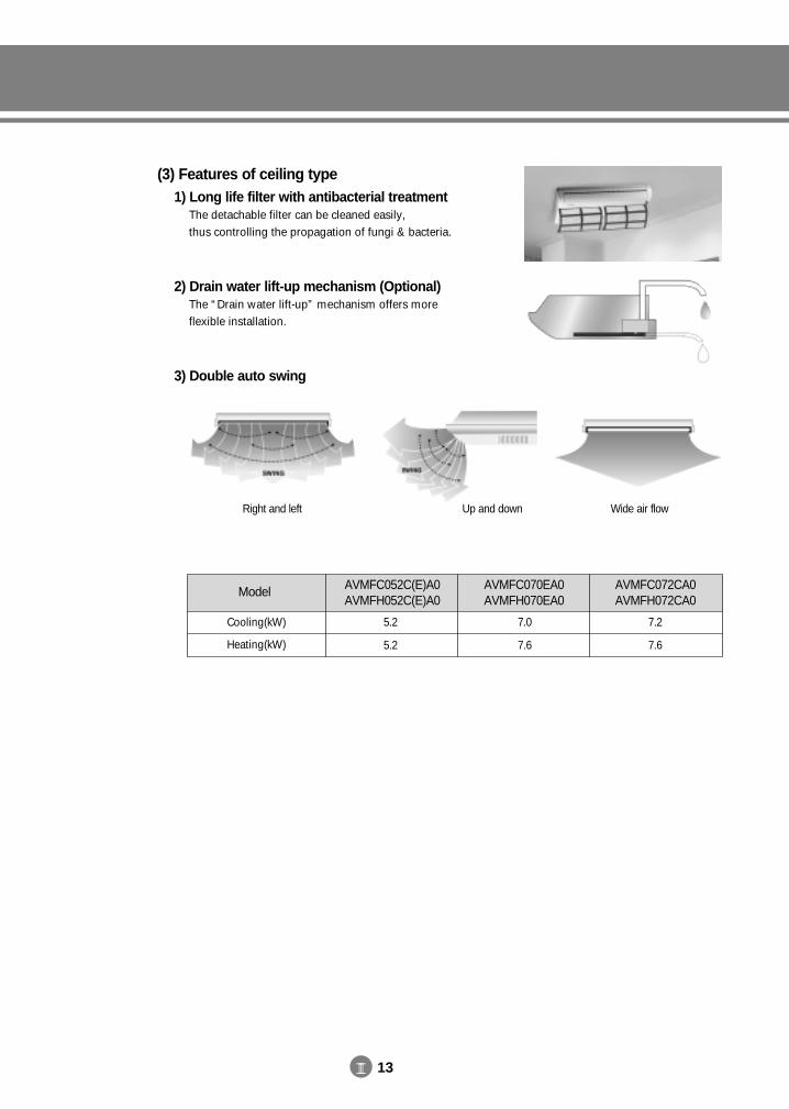
III 13
(3) Features of ceiling type1) Long life filter with antibacterial treatment
The detachable filter can be cleaned easily, thus controlling the propagation of fungi & bacteria.
2) Drain water lift-up mechanism (Optional)The “Drain water lift-up” mechanism offers more flexible installation.
3) Double auto swing
Right and left Up and down Wide air flow
Model AVMFC052C(E)A0AVMFH052C(E)A0
AVMFC070EA0AVMFH070EA0
AVMFC072CA0AVMFH072CA0
Cooling(kW)
Heating(kW)
5.2
5.2
7.0
7.6
7.2
7.6
DVM E-D/B(chapter3-1)-E<03759 3/21/02 7:34 PM Page 13
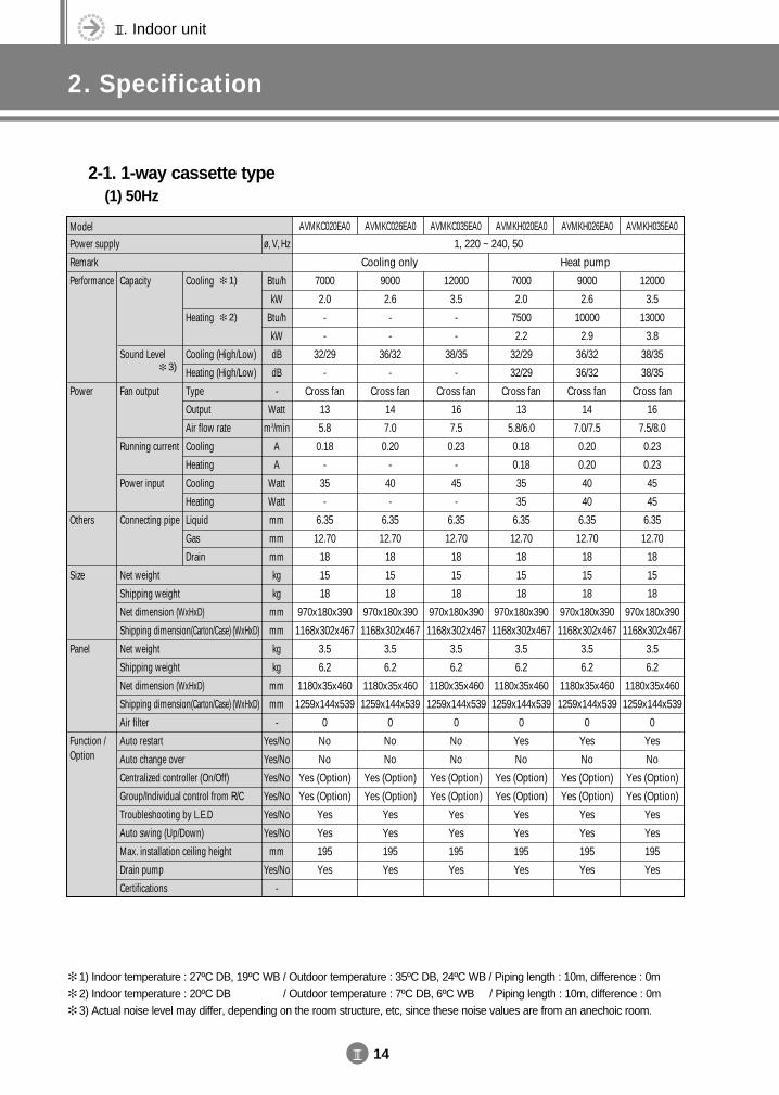
III. Indoor unit
2. Specification
III 14
ModelPower supply
Remark
Performance
Power
Others
Size
Panel
Function /Option
Cooling
Heating
Cooling (High/Low)
Heating (High/Low)
Type
Output
Air flow rate
Cooling
Heating
Cooling
Heating
Liquid
Gas
Drain
Capacity
Sound Level
Fan output
Running current
Power input
Connecting pipe
Net weight
Shipping weight
Net dimension (WxHxD)
Shipping dimension(Carton/Case) (WxHxD)
Net weight
Shipping weight
Net dimension (WxHxD)
Shipping dimension(Carton/Case) (WxHxD)
Air filter
Auto restart
Auto change over
Centralized controller (On/Off)
Group/Individual control from R/C
Troubleshooting by L.E.D
Auto swing (Up/Down)
Max. installation ceiling height
Drain pump
Certifications
AVMKC020EA0 AVMKC026EA0 AVMKC035EA0 AVMKH020EA0 AVMKH026EA0 AVMKH035EA0
1, 220 ~ 240, 50
7000
2.0
-
-
32/29
-
Cross fan
13
5.8
0.18
-
35
-
6.35
12.70
18
15
18
970x180x390
1168x302x467
3.5
6.2
1180x35x460
1259x144x539
0
No
No
Yes (Option)
Yes (Option)
Yes
Yes
195
Yes
9000
2.6
-
-
36/32
-
Cross fan
14
7.0
0.20
-
40
-
6.35
12.70
18
15
18
970x180x390
1168x302x467
3.5
6.2
1180x35x460
1259x144x539
0
No
No
Yes (Option)
Yes (Option)
Yes
Yes
195
Yes
12000
3.5
-
-
38/35
-
Cross fan
16
7.5
0.23
-
45
-
6.35
12.70
18
15
18
970x180x390
1168x302x467
3.5
6.2
1180x35x460
1259x144x539
0
No
No
Yes (Option)
Yes (Option)
Yes
Yes
195
Yes
7000
2.0
7500
2.2
32/29
32/29
Cross fan
13
5.8/6.0
0.18
0.18
35
35
6.35
12.70
18
15
18
970x180x390
1168x302x467
3.5
6.2
1180x35x460
1259x144x539
0
Yes
No
Yes (Option)
Yes (Option)
Yes
Yes
195
Yes
9000
2.6
10000
2.9
36/32
36/32
Cross fan
14
7.0/7.5
0.20
0.20
40
40
6.35
12.70
18
15
18
970x180x390
1168x302x467
3.5
6.2
1180x35x460
1259x144x539
0
Yes
No
Yes (Option)
Yes (Option)
Yes
Yes
195
Yes
12000
3.5
13000
3.8
38/35
38/35
Cross fan
16
7.5/8.0
0.23
0.23
45
45
6.35
12.70
18
15
18
970x180x390
1168x302x467
3.5
6.2
1180x35x460
1259x144x539
0
Yes
No
Yes (Option)
Yes (Option)
Yes
Yes
195
Yes
Cooling only Heat pump
Btu/h
kW
Btu/h
kW
dB
dB
-
Watt
m3/min
A
A
Watt
Watt
mm
mm
mm
kg
kg
mm
mm
kg
kg
mm
mm
-
Yes/No
Yes/No
Yes/No
Yes/No
Yes/No
Yes/No
mm
Yes/No
-
ø, V, Hz
2-1. 1-way cassette type(1) 50Hz
1) Indoor temperature : 27ºC DB, 19ºC WB / Outdoor temperature : 35ºC DB, 24ºC WB / Piping length : 10m, difference : 0m 2) Indoor temperature : 20ºC DB, 19ºC WB / Outdoor temperature : 7ºC DB, 6ºC WB / Piping length : 10m, difference : 0m 3) Actual noise level may differ, depending on the room structure, etc, since these noise values are from an anechoic room.
1)
2)
3)
DVM E-D/B(chapter3-1)-E<03759 3/21/02 7:34 PM Page 14
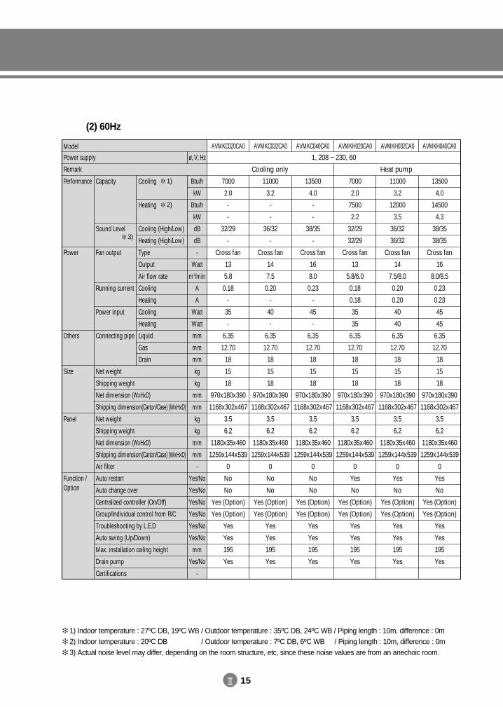
III 15
ModelPower supply
Remark
Performance
Power
Others
Size
Panel
Function /Option
Cooling
Heating
Cooling (High/Low)
Heating (High/Low)
Type
Output
Air flow rate
Cooling
Heating
Cooling
Heating
Liquid
Gas
Drain
Capacity
Sound Level
Fan output
Running current
Power input
Connecting pipe
Net weight
Shipping weight
Net dimension (WxHxD)
Shipping dimension(Carton/Case) (WxHxD)
Net weight
Shipping weight
Net dimension (WxHxD)
Shipping dimension(Carton/Case) (WxHxD)
Air filter
Auto restart
Auto change over
Centralized controller (On/Off)
Group/Individual control from R/C
Troubleshooting by L.E.D
Auto swing (Up/Down)
Max. installation ceiling height
Drain pump
Certifications
AVMKC020CA0 AVMKC032CA0 AVMKC040CA0 AVMKH020CA0 AVMKH032CA0 AVMKH040CA0
1, 208 ~ 230, 60
7000
2.0
-
-
32/29
-
Cross fan
13
5.8
0.18
-
35
-
6.35
12.70
18
15
18
970x180x390
1168x302x467
3.5
6.2
1180x35x460
1259x144x539
0
No
No
Yes (Option)
Yes (Option)
Yes
Yes
195
Yes
11000
3.2
-
-
36/32
-
Cross fan
14
7.5
0.20
-
40
-
6.35
12.70
18
15
18
970x180x390
1168x302x467
3.5
6.2
1180x35x460
1259x144x539
0
No
No
Yes (Option)
Yes (Option)
Yes
Yes
195
Yes
13500
4.0
-
-
38/35
-
Cross fan
16
8.0
0.23
-
45
-
6.35
12.70
18
15
18
970x180x390
1168x302x467
3.5
6.2
1180x35x460
1259x144x539
0
No
No
Yes (Option)
Yes (Option)
Yes
Yes
195
Yes
7000
2.0
7500
2.2
32/29
32/29
Cross fan
13
5.8/6.0
0.18
0.18
35
35
6.35
12.70
18
15
18
970x180x390
1168x302x467
3.5
6.2
1180x35x460
1259x144x539
0
Yes
No
Yes (Option)
Yes (Option)
Yes
Yes
195
Yes
11000
3.2
12000
3.5
36/32
36/32
Cross fan
14
7.5/8.0
0.20
0.20
40
40
6.35
12.70
18
15
18
970x180x390
1168x302x467
3.5
6.2
1180x35x460
1259x144x539
0
Yes
No
Yes (Option)
Yes (Option)
Yes
Yes
195
Yes
13500
4.0
14500
4.3
38/35
38/35
Cross fan
16
8.0/8.5
0.23
0.23
45
45
6.35
12.70
18
15
18
970x180x390
1168x302x467
3.5
6.2
1180x35x460
1259x144x539
0
Yes
No
Yes (Option)
Yes (Option)
Yes
Yes
195
Yes
Cooling only Heat pump
Btu/h
kW
Btu/h
kW
dB
dB
-
Watt
m3/min
A
A
Watt
Watt
mm
mm
mm
kg
kg
mm
mm
kg
kg
mm
mm
-
Yes/No
Yes/No
Yes/No
Yes/No
Yes/No
Yes/No
mm
Yes/No
-
ø, V, Hz
(2) 60Hz
1) Indoor temperature : 27ºC DB, 19ºC WB / Outdoor temperature : 35ºC DB, 24ºC WB / Piping length : 10m, difference : 0m 2) Indoor temperature : 20ºC DB, 19ºC WB / Outdoor temperature : 7ºC DB, 6ºC WB / Piping length : 10m, difference : 0m 3) Actual noise level may differ, depending on the room structure, etc, since these noise values are from an anechoic room.
1)
2)
3)
DVM E-D/B(chapter3-1)-E<03759 3/21/02 7:34 PM Page 15
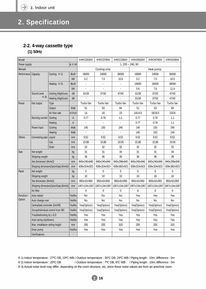
III. Indoor unit
2. Specification
III 16
2-2. 4-way cassette type(1) 50Hz
ModelPower supply
Remark
Performance
Power
Others
Size
Panel
Function /Option
Cooling
Heating
Cooling (High/Low)
Heating (High/Low)
Type
Output
Air flow rate
Cooling
Heating
Cooling
Heating
Liquid
Gas
Drain
Capacity
Sound Level
Fan output
Running current
Power input
Connecting pipe
Net weight
Shipping weight
Net dimension (WxHxD)
Shipping dimension(Carton/Case) (WxHxD)
Net weight
Shipping weight
Net dimension (WxHxD)
Shipping dimension(Carton/Case) (WxHxD)
Air filter
Auto restart
Auto change over
Centralized controller (On/Off)
Group/Individual control from R/C
Troubleshooting by L.E.D
Auto swing (Up/Down)
Max. installation ceiling height
Drain pump
Certifications
AVMCC052EA0 AVMCC070EA0 AVMCC105EA0 AVMCH052EA0 AVMCH070EA0 AVMCH105EA0
1, 220 ~ 240, 50
18000
5.2
-
-
31/28
-
Turbo fan
51
14
0.77
-
145
-
9.52
15.88
32
31
36
840x240x840
939x324x923
5
10
950x42x950
1067x134x1067
0
No
No
Yes(Option)
Yes(Option)
Yes
Yes
255
Yes
24000
7.0
-
-
37/32
-
Turbo fan
53
18
0.78
-
150
-
9.52
15.88
32
31
36
840x240x840
939x324x923
5
10
950x42x950
1067x134x1067
0
No
No
Yes(Option)
Yes(Option)
Yes
Yes
255
Yes
36000
10.5
-
-
47/42
-
Turbo fan
84
23
1.1
-
240
-
9.52
19.05
32
34
39
840x298x840
939x382x923
5
10
950x42x950
1067x134x1067
0
No
No
Yes(Option)
Yes(Option)
Yes
Yes
315
Yes
18000
5.2
19000
5.6
31/28
31/28
Turbo fan
51
14/14.5
0.77
0.77
145
145
9.52
15.88
32
31
36
840x240x840
939x324x923
5
10
950x42x950
1067x134x1067
0
Yes
No
Yes(Option)
Yes(Option)
Yes
Yes
255
Yes
24000
7.0
26000
7.6
37/32
37/32
Turbo fan
53
18/18.5
0.78
0.78
150
150
9.52
15.88
32
31
36
840x240x840
939x324x923
5
10
950x42x950
1067x134x1067
0
Yes
No
Yes(Option)
Yes(Option)
Yes
Yes
255
Yes
36000
10.5
39000
11.4
47/42
47/42
Turbo fan
84
23/24
1.1
1.1
240
240
9.52
19.05
32
34
39
840x298x840
939x382x923
5
10
950x42x950
1067x134x1067
0
Yes
No
Yes(Option)
Yes(Option)
Yes
Yes
315
Yes
Cooling only Heat pump
Btu/h
kW
Btu/h
kW
dB
dB
-
Watt
m3/min
A
A
Watt
Watt
mm
mm
mm
kg
kg
mm
mm
kg
kg
mm
mm
-
Yes/No
Yes/No
Yes/No
Yes/No
Yes/No
Yes/No
mm
Yes/No
-
ø, V, Hz
1) Indoor temperature : 27ºC DB, 19ºC WB / Outdoor temperature : 35ºC DB, 24ºC WB / Piping length : 10m, difference : 0m 2) Indoor temperature : 20ºC DB, 19ºC WB / Outdoor temperature : 7ºC DB, 6ºC WB / Piping length : 10m, difference : 0m 3) Actual noise level may differ, depending on the room structure, etc, since these noise values are from an anechoic room.
1)
2)
3)
DVM E-D/B(chapter3-1)-E<03759 3/21/02 7:34 PM Page 16
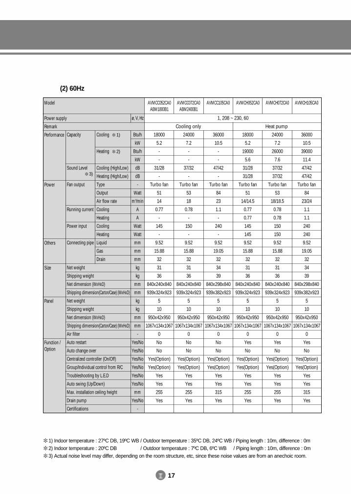
III 17
(2) 60Hz
Model
Power supply
Remark
Performance
Power
Others
Size
Panel
Function /Option
Cooling
Heating
Cooling (High/Low)
Heating (High/Low)
Type
Output
Air flow rate
Cooling
Heating
Cooling
Heating
Liquid
Gas
Drain
Capacity
Sound Level
Fan output
Running current
Power input
Connecting pipe
Net weight
Shipping weight
Net dimension (WxHxD)
Shipping dimension(Carton/Case) (WxHxD)
Net weight
Shipping weight
Net dimension (WxHxD)
Shipping dimension(Carton/Case) (WxHxD)
Air filter
Auto restart
Auto change over
Centralized controller (On/Off)
Group/Individual control from R/C
Troubleshooting by L.E.D
Auto swing (Up/Down)
Max. installation ceiling height
Drain pump
Certifications
AVMCC052CA0ABM1800B1
AVMCC072CA0ABM2400B1
AVMCC105CA0 AVMCH052CA0 AVMCH072CA0 AVMCH105CA0
1, 208 ~ 230, 60
18000
5.2
-
-
31/28
-
Turbo fan
51
14
0.77
-
145
-
9.52
15.88
32
31
36
840x240x840
939x324x923
5
10
950x42x950
1067x134x1067
0
No
No
Yes(Option)
Yes(Option)
Yes
Yes
255
Yes
24000
7.2
-
-
37/32
-
Turbo fan
53
18
0.78
-
150
-
9.52
15.88
32
31
36
840x240x840
939x324x923
5
10
950x42x950
1067x134x1067
0
No
No
Yes(Option)
Yes(Option)
Yes
Yes
255
Yes
36000
10.5
-
-
47/42
-
Turbo fan
84
23
1.1
-
240
-
9.52
19.05
32
34
39
840x298x840
939x382x923
5
10
950x42x950
1067x134x1067
0
No
No
Yes(Option)
Yes(Option)
Yes
Yes
315
Yes
18000
5.2
19000
5.6
31/28
31/28
Turbo fan
51
14/14.5
0.77
0.77
145
145
9.52
15.88
32
31
36
840x240x840
939x324x923
5
10
950x42x950
1067x134x1067
0
Yes
No
Yes(Option)
Yes(Option)
Yes
Yes
255
Yes
24000
7.2
26000
7.6
37/32
37/32
Turbo fan
53
18/18.5
0.78
0.78
150
150
9.52
15.88
32
31
36
840x240x840
939x324x923
5
10
950x42x950
1067x134x1067
0
Yes
No
Yes(Option)
Yes(Option)
Yes
Yes
255
Yes
36000
10.5
39000
11.4
47/42
47/42
Turbo fan
84
23/24
1.1
1.1
240
240
9.52
19.05
32
34
39
840x298x840
939x382x923
5
10
950x42x950
1067x134x1067
0
Yes
No
Yes(Option)
Yes(Option)
Yes
Yes
315
Yes
Cooling only Heat pump
Btu/h
kW
Btu/h
kW
dB
dB
-
Watt
m3/min
A
A
Watt
Watt
mm
mm
mm
kg
kg
mm
mm
kg
kg
mm
mm
-
Yes/No
Yes/No
Yes/No
Yes/No
Yes/No
Yes/No
mm
Yes/No
-
ø, V, Hz
1) Indoor temperature : 27ºC DB, 19ºC WB / Outdoor temperature : 35ºC DB, 24ºC WB / Piping length : 10m, difference : 0m 2) Indoor temperature : 20ºC DB, 19ºC WB / Outdoor temperature : 7ºC DB, 6ºC WB / Piping length : 10m, difference : 0m 3) Actual noise level may differ, depending on the room structure, etc, since these noise values are from an anechoic room.
1)
2)
3)
DVM E-D/B(chapter3-1)-E<03759 3/21/02 7:34 PM Page 17
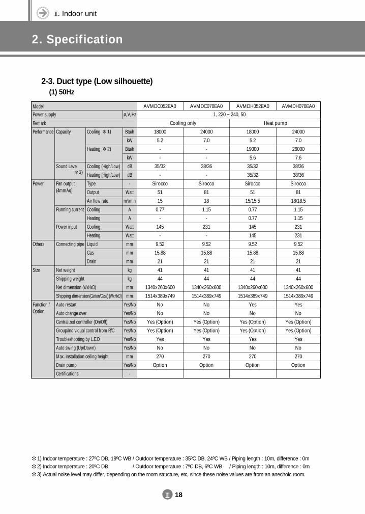
III. Indoor unit
2. Specification
III 18
2-3. Duct type (Low silhouette)(1) 50Hz
ModelPower supply
Remark
Performance
Power
Others
Size
Function /Option
Cooling
Heating
Cooling (High/Low)
Heating (High/Low)
Type
Output
Air flow rate
Cooling
Heating
Cooling
Heating
Liquid
Gas
Drain
Capacity
Sound Level
Fan output(4mmAq)
Running current
Power input
Connecting pipe
Net weight
Shipping weight
Net dimension (WxHxD)
Shipping dimension(Carton/Case) (WxHxD)
Auto restart
Auto change over
Centralized controller (On/Off)
Group/Individual control from R/C
Troubleshooting by L.E.D
Auto swing (Up/Down)
Max. installation ceiling height
Drain pump
Certifications
AVMDC052EA0 AVMDC070EA0 AVMDH052EA0 AVMDH070EA0
1, 220 ~ 240, 50
18000
5.2
-
-
35/32
-
Sirocco
51
15
0.77
-
145
-
9.52
15.88
21
41
44
1340x260x600
1514x389x749
No
No
Yes (Option)
Yes (Option)
Yes
No
270
Option
24000
7.0
-
-
38/36
-
Sirocco
81
18
1.15
-
231
-
9.52
15.88
21
41
44
1340x260x600
1514x389x749
No
No
Yes (Option)
Yes (Option)
Yes
No
270
Option
18000
5.2
19000
5.6
35/32
35/32
Sirocco
51
15/15.5
0.77
0.77
145
145
9.52
15.88
21
41
44
1340x260x600
1514x389x749
Yes
No
Yes (Option)
Yes (Option)
Yes
No
270
Option
24000
7.0
26000
7.6
38/36
38/36
Sirocco
81
18/18.5
1.15
1.15
231
231
9.52
15.88
21
41
44
1340x260x600
1514x389x749
Yes
No
Yes (Option)
Yes (Option)
Yes
No
270
Option
Cooling only Heat pump
Btu/h
kW
Btu/h
kW
dB
dB
-
Watt
m3/min
A
A
Watt
Watt
mm
mm
mm
kg
kg
mm
mm
Yes/No
Yes/No
Yes/No
Yes/No
Yes/No
Yes/No
mm
Yes/No
-
ø, V, Hz
1) Indoor temperature : 27ºC DB, 19ºC WB / Outdoor temperature : 35ºC DB, 24ºC WB / Piping length : 10m, difference : 0m 2) Indoor temperature : 20ºC DB, 19ºC WB / Outdoor temperature : 7ºC DB, 6ºC WB / Piping length : 10m, difference : 0m 3) Actual noise level may differ, depending on the room structure, etc, since these noise values are from an anechoic room.
1)
2)
3)
DVM E-D/B(chapter3-1)-E<03759 3/21/02 7:34 PM Page 18
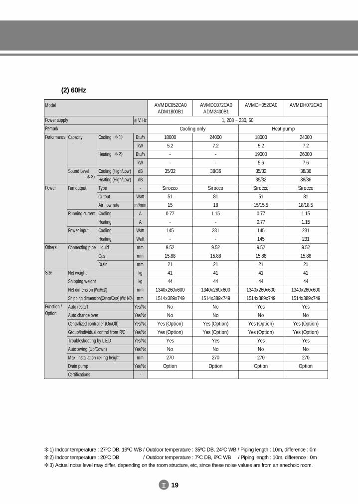
III 19
(2) 60Hz
Model
Power supply
Remark
Performance
Power
Others
Size
Function /Option
Cooling
Heating
Cooling (High/Low)
Heating (High/Low)
Type
Output
Air flow rate
Cooling
Heating
Cooling
Heating
Liquid
Gas
Drain
Capacity
Sound Level
Fan output
Running current
Power input
Connecting pipe
Net weight
Shipping weight
Net dimension (WxHxD)
Shipping dimension(Carton/Case) (WxHxD)
Auto restart
Auto change over
Centralized controller (On/Off)
Group/Individual control from R/C
Troubleshooting by L.E.D
Auto swing (Up/Down)
Max. installation ceiling height
Drain pump
Certifications
AVMDC052CA0ADM1800B1
AVMDC072CA0ADM2400B1
AVMDH052CA0 AVMDH072CA0
1, 208 ~ 230, 60
18000
5.2
-
-
35/32
-
Sirocco
51
15
0.77
-
145
-
9.52
15.88
21
41
44
1340x260x600
1514x389x749
No
No
Yes (Option)
Yes (Option)
Yes
No
270
Option
24000
7.2
-
-
38/36
-
Sirocco
81
18
1.15
-
231
-
9.52
15.88
21
41
44
1340x260x600
1514x389x749
No
No
Yes (Option)
Yes (Option)
Yes
No
270
Option
18000
5.2
19000
5.6
35/32
35/32
Sirocco
51
15/15.5
0.77
0.77
145
145
9.52
15.88
21
41
44
1340x260x600
1514x389x749
Yes
No
Yes (Option)
Yes (Option)
Yes
No
270
Option
24000
7.2
26000
7.6
38/36
38/36
Sirocco
81
18/18.5
1.15
1.15
231
231
9.52
15.88
21
41
44
1340x260x600
1514x389x749
Yes
No
Yes (Option)
Yes (Option)
Yes
No
270
Option
Cooling only Heat pump
Btu/h
kW
Btu/h
kW
dB
dB
-
Watt
m3/min
A
A
Watt
Watt
mm
mm
mm
kg
kg
mm
mm
Yes/No
Yes/No
Yes/No
Yes/No
Yes/No
Yes/No
mm
Yes/No
-
ø, V, Hz
1) Indoor temperature : 27ºC DB, 19ºC WB / Outdoor temperature : 35ºC DB, 24ºC WB / Piping length : 10m, difference : 0m 2) Indoor temperature : 20ºC DB, 19ºC WB / Outdoor temperature : 7ºC DB, 6ºC WB / Piping length : 10m, difference : 0m 3) Actual noise level may differ, depending on the room structure, etc, since these noise values are from an anechoic room.
1)
2)
3)
DVM E-D/B(chapter3-1)-E<03759 3/21/02 7:34 PM Page 19
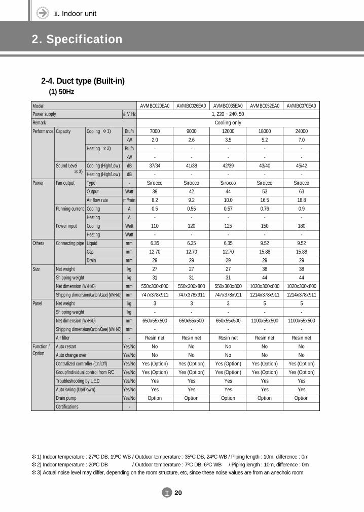
III. Indoor unit
2. Specification
III 20
2-4. Duct type (Built-in)(1) 50Hz
ModelPower supply
Remark
Performance
Power
Others
Size
Panel
Function /Option
Cooling
Heating
Cooling (High/Low)
Heating (High/Low)
Type
Output
Air flow rate
Cooling
Heating
Cooling
Heating
Liquid
Gas
Drain
Capacity
Sound Level
Fan output
Running current
Power input
Connecting pipe
Net weight
Shipping weight
Net dimension (WxHxD)
Shipping dimension(Carton/Case) (WxHxD)
Net weight
Shipping weight
Net dimension (WxHxD)
Shipping dimension(Carton/Case) (WxHxD)
Air filter
Auto restart
Auto change over
Centralized controller (On/Off)
Group/Individual control from R/C
Troubleshooting by L.E.D
Auto swing (Up/Down)
Drain pump
Certifications
AVMBC020EA0 AVMBC026EA0 AVMBC035EA0 AVMBC052EA0 AVMBC070EA0
1, 220 ~ 240, 50
7000
2.0
-
-
37/34
-
Sirocco
39
8.2
0.5
-
110
-
6.35
12.70
29
27
31
550x300x800
747x378x911
3
-
650x55x500
-
Resin net
No
No
Yes (Option)
Yes (Option)
Yes
Yes
Option
9000
2.6
-
-
41/38
-
Sirocco
42
9.2
0.55
-
120
-
6.35
12.70
29
27
31
550x300x800
747x378x911
3
-
650x55x500
-
Resin net
No
No
Yes (Option)
Yes (Option)
Yes
Yes
Option
12000
3.5
-
-
42/39
-
Sirocco
44
10.0
0.57
-
125
-
6.35
12.70
29
27
31
550x300x800
747x378x911
3
-
650x55x500
-
Resin net
No
No
Yes (Option)
Yes (Option)
Yes
Yes
Option
18000
5.2
-
-
43/40
-
Sirocco
53
16.5
0.76
-
150
-
9.52
15.88
29
38
44
1020x300x800
1214x378x911
5
-
1100x55x500
-
Resin net
No
No
Yes (Option)
Yes (Option)
Yes
Yes
Option
24000
7.0
-
-
45/42
-
Sirocco
63
18.8
0.9
-
180
-
9.52
15.88
29
38
44
1020x300x800
1214x378x911
5
-
1100x55x500
-
Resin net
No
No
Yes (Option)
Yes (Option)
Yes
Yes
Option
Cooling only
Btu/h
kW
Btu/h
kW
dB
dB
-
Watt
m3/min
A
A
Watt
Watt
mm
mm
mm
kg
kg
mm
mm
kg
kg
mm
mm
-
Yes/No
Yes/No
Yes/No
Yes/No
Yes/No
Yes/No
Yes/No
-
ø, V, Hz
1) Indoor temperature : 27ºC DB, 19ºC WB / Outdoor temperature : 35ºC DB, 24ºC WB / Piping length : 10m, difference : 0m 2) Indoor temperature : 20ºC DB, 19ºC WB / Outdoor temperature : 7ºC DB, 6ºC WB / Piping length : 10m, difference : 0m 3) Actual noise level may differ, depending on the room structure, etc, since these noise values are from an anechoic room.
1)
2)
3)
DVM E-D/B(chapter3-1)-E<03759 3/21/02 7:34 PM Page 20
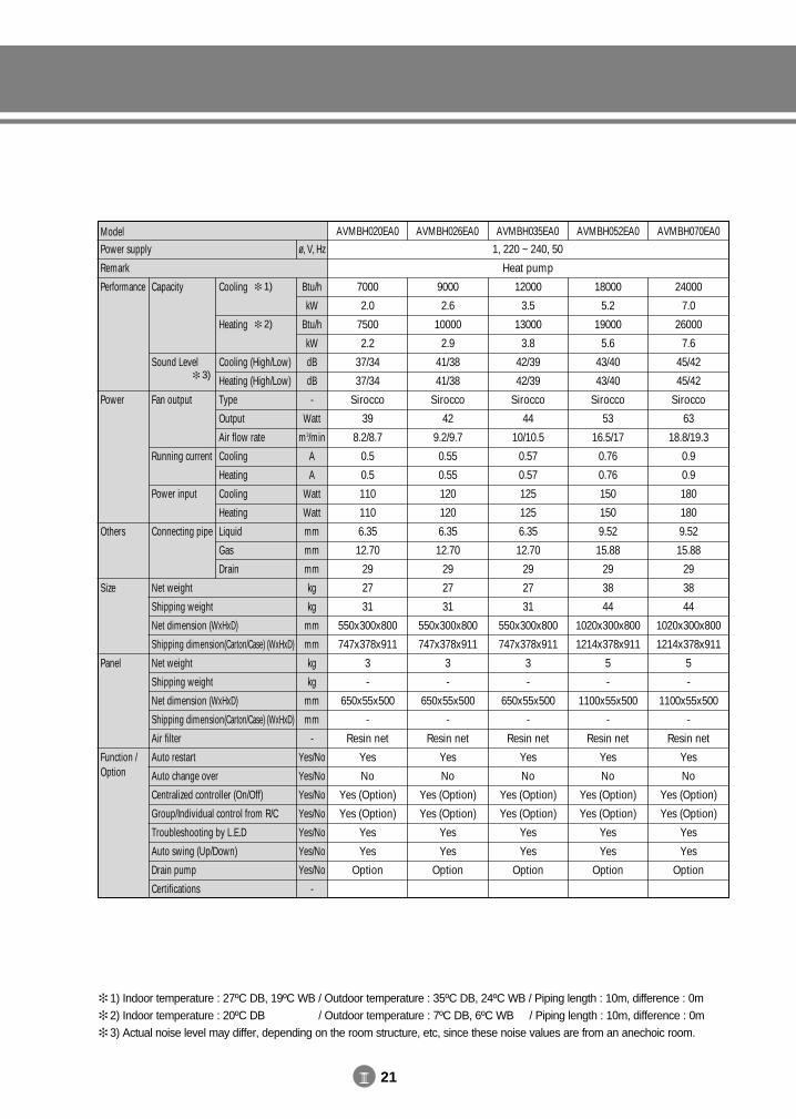
III 21
ModelPower supply
Remark
Performance
Power
Others
Size
Panel
Function /Option
Cooling
Heating
Cooling (High/Low)
Heating (High/Low)
Type
Output
Air flow rate
Cooling
Heating
Cooling
Heating
Liquid
Gas
Drain
Capacity
Sound Level
Fan output
Running current
Power input
Connecting pipe
Net weight
Shipping weight
Net dimension (WxHxD)
Shipping dimension(Carton/Case) (WxHxD)
Net weight
Shipping weight
Net dimension (WxHxD)
Shipping dimension(Carton/Case) (WxHxD)
Air filter
Auto restart
Auto change over
Centralized controller (On/Off)
Group/Individual control from R/C
Troubleshooting by L.E.D
Auto swing (Up/Down)
Drain pump
Certifications
AVMBH020EA0 AVMBH026EA0 AVMBH035EA0 AVMBH052EA0 AVMBH070EA0
1, 220 ~ 240, 50
7000
2.0
7500
2.2
37/34
37/34
Sirocco
39
8.2/8.7
0.5
0.5
110
110
6.35
12.70
29
27
31
550x300x800
747x378x911
3
-
650x55x500
-
Resin net
Yes
No
Yes (Option)
Yes (Option)
Yes
Yes
Option
9000
2.6
10000
2.9
41/38
41/38
Sirocco
42
9.2/9.7
0.55
0.55
120
120
6.35
12.70
29
27
31
550x300x800
747x378x911
3
-
650x55x500
-
Resin net
Yes
No
Yes (Option)
Yes (Option)
Yes
Yes
Option
12000
3.5
13000
3.8
42/39
42/39
Sirocco
44
10/10.5
0.57
0.57
125
125
6.35
12.70
29
27
31
550x300x800
747x378x911
3
-
650x55x500
-
Resin net
Yes
No
Yes (Option)
Yes (Option)
Yes
Yes
Option
18000
5.2
19000
5.6
43/40
43/40
Sirocco
53
16.5/17
0.76
0.76
150
150
9.52
15.88
29
38
44
1020x300x800
1214x378x911
5
-
1100x55x500
-
Resin net
Yes
No
Yes (Option)
Yes (Option)
Yes
Yes
Option
24000
7.0
26000
7.6
45/42
45/42
Sirocco
63
18.8/19.3
0.9
0.9
180
180
9.52
15.88
29
38
44
1020x300x800
1214x378x911
5
-
1100x55x500
-
Resin net
Yes
No
Yes (Option)
Yes (Option)
Yes
Yes
Option
Heat pump
Btu/h
kW
Btu/h
kW
dB
dB
-
Watt
m3/min
A
A
Watt
Watt
mm
mm
mm
kg
kg
mm
mm
kg
kg
mm
mm
-
Yes/No
Yes/No
Yes/No
Yes/No
Yes/No
Yes/No
Yes/No
-
ø, V, Hz
1) Indoor temperature : 27ºC DB, 19ºC WB / Outdoor temperature : 35ºC DB, 24ºC WB / Piping length : 10m, difference : 0m 2) Indoor temperature : 20ºC DB, 19ºC WB / Outdoor temperature : 7ºC DB, 6ºC WB / Piping length : 10m, difference : 0m 3) Actual noise level may differ, depending on the room structure, etc, since these noise values are from an anechoic room.
1)
2)
3)
DVM E-D/B(chapter3-1)-E<03759 3/21/02 7:34 PM Page 21
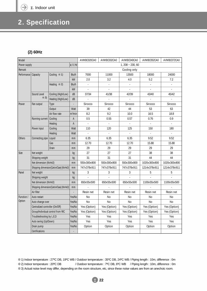
III. Indoor unit
2. Specification
III 22
(2) 60Hz
ModelPower supply
Remark
Performance
Power
Others
Size
Panel
Function /Option
Cooling
Heating
Cooling (High/Low)
Heating (High/Low)
Type
Output
Air flow rate
Cooling
Heating
Cooling
Heating
Liquid
Gas
Drain
Capacity
Sound Level
Fan output
Running current
Power input
Connecting pipe
Net weight
Shipping weight
Net dimension (WxHxD)
Shipping dimension(Carton/Case) (WxHxD)
Net weight
Shipping weight
Net dimension (WxHxD)
Shipping dimension(Carton/Case) (WxHxD)
Air filter
Auto restart
Auto change over
Centralized controller (On/Off)
Group/Individual control from R/C
Troubleshooting by L.E.D
Auto swing (Up/Down)
Drain pump
Certifications
AVMBC020CA0 AVMBC032CA0 AVMBC040CA0 AVMBC052CA0 AVMBC072CA0
1, 208 ~ 230, 60
7000
2.0
-
-
37/34
-
Sirocco
39
8.2
0.5
-
110
-
6.35
12.70
29
27
31
550x300x800
747x378x911
3
-
650x55x500
-
Resin net
No
No
Yes (Option)
Yes (Option)
Yes
Yes
Option
11000
3.2
-
-
41/38
-
Sirocco
42
9.2
0.55
-
120
-
6.35
12.70
29
27
31
550x300x800
747x378x911
3
-
650x55x500
-
Resin net
No
No
Yes (Option)
Yes (Option)
Yes
Yes
Option
13500
4.0
-
-
42/39
-
Sirocco
44
10.0
0.57
-
125
-
6.35
12.70
29
27
31
550x300x800
747x378x911
3
-
650x55x500
-
Resin net
No
No
Yes (Option)
Yes (Option)
Yes
Yes
Option
18000
5.2
-
-
43/40
-
Sirocco
53
16.5
0.76
-
150
-
9.52
15.88
29
38
44
1020x300x800
1214x378x911
5
-
1100x55x500
-
Resin net
No
No
Yes (Option)
Yes (Option)
Yes
Yes
Option
24000
7.2
-
-
45/42
-
Sirocco
63
18.8
0.9
-
180
-
9.52
15.88
29
38
44
1020x300x800
1214x378x911
5
-
1100x55x500
-
Resin net
No
No
Yes (Option)
Yes (Option)
Yes
Yes
Option
Cooling only
Btu/h
kW
Btu/h
kW
dB
dB
-
Watt
m3/min
A
A
Watt
Watt
mm
mm
mm
kg
kg
mm
mm
kg
kg
mm
mm
-
Yes/No
Yes/No
Yes/No
Yes/No
Yes/No
Yes/No
Yes/No
-
ø, V, Hz
1) Indoor temperature : 27ºC DB, 19ºC WB / Outdoor temperature : 35ºC DB, 24ºC WB / Piping length : 10m, difference : 0m 2) Indoor temperature : 20ºC DB, 19ºC WB / Outdoor temperature : 7ºC DB, 6ºC WB / Piping length : 10m, difference : 0m 3) Actual noise level may differ, depending on the room structure, etc, since these noise values are from an anechoic room.
1)
2)
3)
DVM E-D/B(chapter3-1)-E<03759 3/21/02 7:34 PM Page 22

III 23
ModelPower supply
Remark
Performance
Power
Others
Size
Panel
Function /Option
Cooling
Heating
Cooling (High/Low)
Heating (High/Low)
Type
Output
Air flow rate
Cooling
Heating
Cooling
Heating
Liquid
Gas
Drain
Capacity
Sound Level
Fan output
Running current
Power input
Connecting pipe
Net weight
Shipping weight
Net dimension (WxHxD)
Shipping dimension(Carton/Case) (WxHxD)
Net weight
Shipping weight
Net dimension (WxHxD)
Shipping dimension(Carton/Case) (WxHxD)
Air filter
Auto restart
Auto change over
Centralized controller (On/Off)
Group/Individual control from R/C
Troubleshooting by L.E.D
Auto swing (Up/Down)
Drain pump
Certifications
AVMBH020CA0 AVMBH032CA0 AVMBH040CA0 AVMBH052CA0 AVMBH072CA0
1, 208 ~ 230, 60
7000
2.0
7500
2.2
37/34
37/34
Sirocco
39
8.2/8.7
0.5
0.5
110
110
6.35
12.70
29
27
31
550x300x800
747x378x911
3
-
650x55x500
-
Resin net
Yes
No
Yes (Option)
Yes (Option)
Yes
Yes
Option
11000
3.2
12000
3.5
41/38
41/38
Sirocco
42
9.2/9.7
0.55
0.55
120
120
6.35
12.70
29
27
31
550x300x800
747x378x911
3
-
650x55x500
-
Resin net
Yes
No
Yes (Option)
Yes (Option)
Yes
Yes
Option
13500
4.0
14500
4.3
42/39
42/39
Sirocco
44
10/10.5
0.57
0.57
125
125
6.35
12.70
29
27
31
550x300x800
747x378x911
3
-
650x55x500
-
Resin net
Yes
No
Yes (Option)
Yes (Option)
Yes
Yes
Option
18000
5.2
19000
5.6
43/40
43/40
Sirocco
53
16.5/17
0.76
0.76
150
150
9.52
15.88
29
38
44
1020x300x800
1214x378x911
5
-
1110x55x500
-
Resin net
Yes
No
Yes (Option)
Yes (Option)
Yes
Yes
Option
24000
7.2
26000
7.6
45/42
45/42
Sirocco
63
18.8/19.3
0.9
0.9
180
180
9.52
15.88
29
38
44
1020x300x800
1214x378x911
5
-
1110x55x500
-
Resin net
Yes
No
Yes (Option)
Yes (Option)
Yes
Yes
Option
Heat pump
Btu/h
kW
Btu/h
kW
dB
dB
-
Watt
m3/min
A
A
Watt
Watt
mm
mm
mm
kg
kg
mm
mm
kg
kg
mm
mm
-
Yes/No
Yes/No
Yes/No
Yes/No
Yes/No
Yes/No
Yes/No
-
ø, V, Hz
1) Indoor temperature : 27ºC DB, 19ºC WB / Outdoor temperature : 35ºC DB, 24ºC WB / Piping length : 10m, difference : 0m 2) Indoor temperature : 20ºC DB, 19ºC WB / Outdoor temperature : 7ºC DB, 6ºC WB / Piping length : 10m, difference : 0m 3) Actual noise level may differ, depending on the room structure, etc, since these noise values are from an anechoic room.
1)
2)
3)
DVM E-D/B(chapter3-1)-E<03759 3/21/02 7:34 PM Page 23
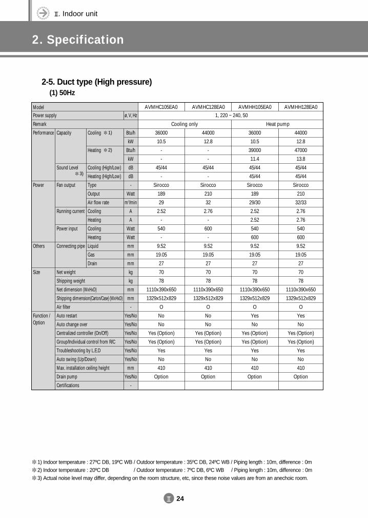
III. Indoor unit
2. Specification
III 24
2-5. Duct type (High pressure)(1) 50Hz
ModelPower supply
Remark
Performance
Power
Others
Size
Function /Option
Cooling
Heating
Cooling (High/Low)
Heating (High/Low)
Type
Output
Air flow rate
Cooling
Heating
Cooling
Heating
Liquid
Gas
Drain
Capacity
Sound Level
Fan output
Running current
Power input
Connecting pipe
Net weight
Shipping weight
Net dimension (WxHxD)
Shipping dimension(Carton/Case) (WxHxD)
Air filter
Auto restart
Auto change over
Centralized controller (On/Off)
Group/Individual control from R/C
Troubleshooting by L.E.D
Auto swing (Up/Down)
Max. installation ceiling height
Drain pump
Certifications
AVMHC105EA0 AVMHC128EA0 AVMHH105EA0 AVMHH128EA0
1, 220 ~ 240, 50
36000
10.5
-
-
45/44
-
Sirocco
189
29
2.52
-
540
-
9.52
19.05
27
70
78
1110x390x650
1329x512x829
O
No
No
Yes (Option)
Yes (Option)
Yes
No
410
Option
44000
12.8
-
-
45/44
-
Sirocco
210
32
2.76
-
600
-
9.52
19.05
27
70
78
1110x390x650
1329x512x829
O
No
No
Yes (Option)
Yes (Option)
Yes
No
410
Option
36000
10.5
39000
11.4
45/44
45/44
Sirocco
189
29/30
2.52
2.52
540
600
9.52
19.05
27
70
78
1110x390x650
1329x512x829
O
Yes
No
Yes (Option)
Yes (Option)
Yes
No
410
Option
44000
12.8
47000
13.8
45/44
45/44
Sirocco
210
32/33
2.76
2.76
540
600
9.52
19.05
27
70
78
1110x390x650
1329x512x829
O
Yes
No
Yes (Option)
Yes (Option)
Yes
No
410
Option
Cooling only Heat pump
Btu/h
kW
Btu/h
kW
dB
dB
-
Watt
m3/min
A
A
Watt
Watt
mm
mm
mm
kg
kg
mm
mm
-
Yes/No
Yes/No
Yes/No
Yes/No
Yes/No
Yes/No
mm
Yes/No
-
ø, V, Hz
1) Indoor temperature : 27ºC DB, 19ºC WB / Outdoor temperature : 35ºC DB, 24ºC WB / Piping length : 10m, difference : 0m 2) Indoor temperature : 20ºC DB, 19ºC WB / Outdoor temperature : 7ºC DB, 6ºC WB / Piping length : 10m, difference : 0m 3) Actual noise level may differ, depending on the room structure, etc, since these noise values are from an anechoic room.
1)
2)
3)
DVM E-D/B(chapter3-1)-E<03759 3/21/02 7:34 PM Page 24
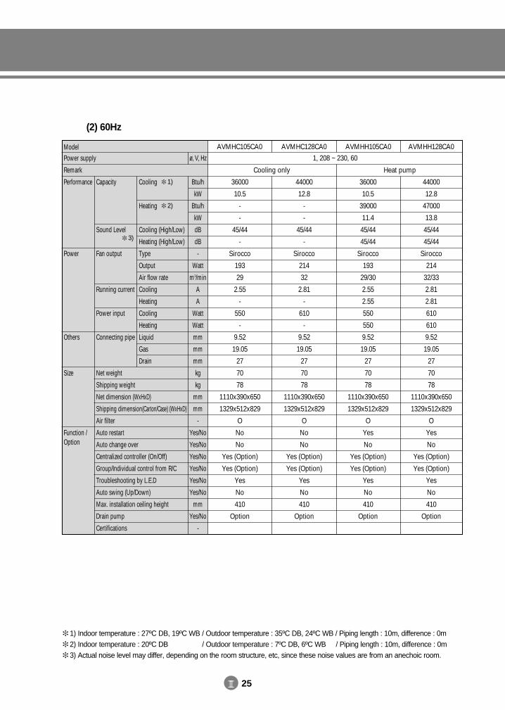
III 25
(2) 60Hz
ModelPower supply
Remark
Performance
Power
Others
Size
Function /Option
Cooling
Heating
Cooling (High/Low)
Heating (High/Low)
Type
Output
Air flow rate
Cooling
Heating
Cooling
Heating
Liquid
Gas
Drain
Capacity
Sound Level
Fan output
Running current
Power input
Connecting pipe
Net weight
Shipping weight
Net dimension (WxHxD)
Shipping dimension(Carton/Case) (WxHxD)
Air filter
Auto restart
Auto change over
Centralized controller (On/Off)
Group/Individual control from R/C
Troubleshooting by L.E.D
Auto swing (Up/Down)
Max. installation ceiling height
Drain pump
Certifications
AVMHC105CA0 AVMHC128CA0 AVMHH105CA0 AVMHH128CA0
1, 208 ~ 230, 60
36000
10.5
-
-
45/44
-
Sirocco
193
29
2.55
-
550
-
9.52
19.05
27
70
78
1110x390x650
1329x512x829
O
No
No
Yes (Option)
Yes (Option)
Yes
No
410
Option
44000
12.8
-
-
45/44
-
Sirocco
214
32
2.81
-
610
-
9.52
19.05
27
70
78
1110x390x650
1329x512x829
O
No
No
Yes (Option)
Yes (Option)
Yes
No
410
Option
36000
10.5
39000
11.4
45/44
45/44
Sirocco
193
29/30
2.55
2.55
550
550
9.52
19.05
27
70
78
1110x390x650
1329x512x829
O
Yes
No
Yes (Option)
Yes (Option)
Yes
No
410
Option
44000
12.8
47000
13.8
45/44
45/44
Sirocco
214
32/33
2.81
2.81
610
610
9.52
19.05
27
70
78
1110x390x650
1329x512x829
O
Yes
No
Yes (Option)
Yes (Option)
Yes
No
410
Option
Cooling only Heat pump
Btu/h
kW
Btu/h
kW
dB
dB
-
Watt
m3/min
A
A
Watt
Watt
mm
mm
mm
kg
kg
mm
mm
-
Yes/No
Yes/No
Yes/No
Yes/No
Yes/No
Yes/No
mm
Yes/No
-
ø, V, Hz
1) Indoor temperature : 27ºC DB, 19ºC WB / Outdoor temperature : 35ºC DB, 24ºC WB / Piping length : 10m, difference : 0m 2) Indoor temperature : 20ºC DB, 19ºC WB / Outdoor temperature : 7ºC DB, 6ºC WB / Piping length : 10m, difference : 0m 3) Actual noise level may differ, depending on the room structure, etc, since these noise values are from an anechoic room.
1)
2)
3)
DVM E-D/B(chapter3-1)-E<03759 3/21/02 7:34 PM Page 25
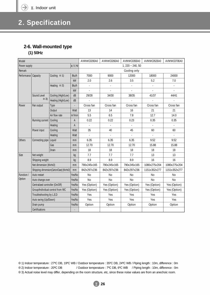
III. Indoor unit
2. Specification
III 26
2-6. Wall-mounted type(1) 50Hz
ModelPower supply
Remark
Performance
Power
Others
Size
Function /Option
Cooling
Heating
Cooling (High/Low)
Heating (High/Low)
Type
Output
Air flow rate
Cooling
Heating
Cooling
Heating
Liquid
Gas
Drain
Capacity
Sound Level
Fan output
Running current
Power input
Connecting pipe
Net weight
Shipping weight
Net dimension (WxHxD)
Shipping dimension(Carton/Case) (WxHxD)
Auto restart
Auto change over
Centralized controller (On/Off)
Group/Individual control from R/C
Troubleshooting by L.E.D
Auto swing (Up/Down)
Drain pump
Certifications
AVMWC020EA0 AVMWC026EA0 AVMWC035EA0 AVMWC052EA0 AVMWC070EA0
1, 220 ~ 240, 50
7000
2.0
-
-
29/28
-
Cross fan
13
5.5
0.22
-
35
-
6.35
12.70
18
7.7
8.9
790x245x165
842x297x236
No
No
Yes (Option)
Yes (Option)
Yes
Yes
Option
9000
2.6
-
-
34/30
-
Cross fan
14
6.5
0.22
-
40
-
6.35
12.70
18
7.7
8.9
790x245x165
842x297x236
No
No
Yes (Option)
Yes (Option)
Yes
Yes
Option
12000
3.5
-
-
38/35
-
Cross fan
16
7.8
0.23
-
45
-
6.35
12.70
18
7.7
8.9
790x245x165
842x297x236
No
No
Yes (Option)
Yes (Option)
Yes
Yes
Option
18000
5.2
-
-
41/37
-
Cross fan
21
12.7
0.35
-
60
-
9.52
15.88
18
13
16
1080x275x204
1151x352x277
No
No
Yes (Option)
Yes (Option)
Yes
Yes
Option
24000
7.0
-
-
44/41
-
Cross fan
21
14.0
0.35
-
60
-
9.52
15.88
18
13
16
1080x275x204
1151x352x277
No
No
Yes (Option)
Yes (Option)
Yes
Yes
Option
Cooling only
Btu/h
kW
Btu/h
kW
dB
dB
-
Watt
m3/min
A
A
Watt
Watt
mm
mm
mm
kg
kg
mm
mm
Yes/No
Yes/No
Yes/No
Yes/No
Yes/No
Yes/No
Yes/No
-
ø, V, Hz
1) Indoor temperature : 27ºC DB, 19ºC WB / Outdoor temperature : 35ºC DB, 24ºC WB / Piping length : 10m, difference : 0m 2) Indoor temperature : 20ºC DB, 19ºC WB / Outdoor temperature : 7ºC DB, 6ºC WB / Piping length : 10m, difference : 0m 3) Actual noise level may differ, depending on the room structure, etc, since these noise values are from an anechoic room.
1)
2)
3)
DVM E-D/B(chapter3-1)-E<03759 3/21/02 7:34 PM Page 26
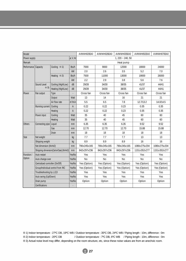
III 27
ModelPower supply
Remark
Performance
Power
Others
Size
Function /Option
Cooling
Heating
Cooling (High/Low)
Heating (High/Low)
Type
Output
Air flow rate
Cooling
Heating
Cooling
Heating
Liquid
Gas
Drain
Capacity
Sound Level
Fan output
Running current
Power input
Connecting pipe
Net weight
Shipping weight
Net dimension (WxHxD)
Shipping dimension(Carton/Case) (WxHxD)
Auto restart
Auto change over
Centralized controller (On/Off)
Group/Individual control from R/C
Troubleshooting by L.E.D
Auto swing (Up/Down)
Drain pump
Certifications
AVMWH020EA0 AVMWH026EA0 AVMWH035EA0 AVMWH052EA0 AVMWH070EA0
1, 220 ~ 240, 50
7000
2.0
7500
2.2
29/28
29/28
Cross fan
13
5.5
0.22
0.22
35
35
6.35
12.70
18
7.7
8.9
790x245x165
842x297x236
Yes
No
Yes (Option)
Yes (Option)
Yes
Yes
Option
9000
2.6
11000
2.9
34/30
34/30
Cross fan
14
6.5
0.22
0.22
40
40
6.35
12.70
18
7.7
8.9
790x245x165
842x297x236
Yes
No
Yes (Option)
Yes (Option)
Yes
Yes
Option
12000
3.5
13000
3.8
38/35
38/35
Cross fan
16
7.8
0.23
0.23
45
45
6.35
12.70
18
7.7
8.9
790x245x165
842x297x236
Yes
No
Yes (Option)
Yes (Option)
Yes
Yes
Option
18000
5.2
19000
5.6
41/37
41/37
Cross fan
21
12.7/13.2
0.35
0.35
60
60
9.52
15.88
18
13
16
1080x275x204
1151x352x277
Yes
No
Yes (Option)
Yes (Option)
Yes
Yes
Option
24000
7.0
26000
7.6
44/41
44/41
Cross fan
21
14.0/14.5
0.35
0.35
60
60
9.52
15.88
18
13
16
1080x275x204
1151x352x277
Yes
No
Yes (Option)
Yes (Option)
Yes
Yes
Option
Heat pump
Btu/h
kW
Btu/h
kW
dB
dB
-
Watt
m3/min
A
A
Watt
Watt
mm
mm
mm
kg
kg
mm
mm
Yes/No
Yes/No
Yes/No
Yes/No
Yes/No
Yes/No
Yes/No
-
ø, V, Hz
1) Indoor temperature : 27ºC DB, 19ºC WB / Outdoor temperature : 35ºC DB, 24ºC WB / Piping length : 10m, difference : 0m 2) Indoor temperature : 20ºC DB, 19ºC WB / Outdoor temperature : 7ºC DB, 6ºC WB / Piping length : 10m, difference : 0m 3) Actual noise level may differ, depending on the room structure, etc, since these noise values are from an anechoic room.
1)
2)
3)
DVM E-D/B(chapter3-1)-E<03759 3/21/02 7:34 PM Page 27
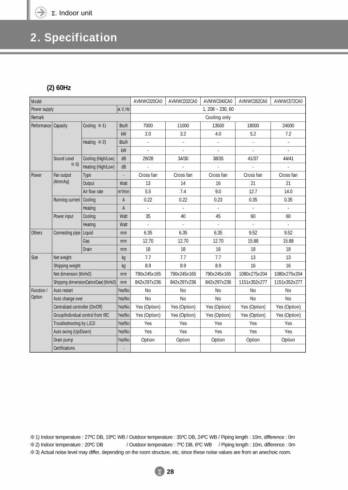
III. Indoor unit
2. Specification
III 28
(2) 60Hz
ModelPower supply
Remark
Performance
Power
Others
Size
Function /Option
Cooling
Heating
Cooling (High/Low)
Heating (High/Low)
Type
Output
Air flow rate
Cooling
Heating
Cooling
Heating
Liquid
Gas
Drain
Capacity
Sound Level
Fan output(4mmAq)
Running current
Power input
Connecting pipe
Net weight
Shipping weight
Net dimension (WxHxD)
Shipping dimension(Carton/Case) (WxHxD)
Auto restart
Auto change over
Centralized controller (On/Off)
Group/Individual control from R/C
Troubleshooting by L.E.D
Auto swing (Up/Down)
Drain pump
Certifications
AVMWC020CA0 AVMWC032CA0 AVMWC040CA0 AVMWC052CA0 AVMWC072CA0
1, 208 ~ 230, 60
7000
2.0
-
-
29/28
-
Cross fan
13
5.5
0.22
-
35
-
6.35
12.70
18
7.7
8.9
790x245x165
842x297x236
No
No
Yes (Option)
Yes (Option)
Yes
Yes
Option
11000
3.2
-
-
34/30
-
Cross fan
14
7.4
0.22
-
40
-
6.35
12.70
18
7.7
8.9
790x245x165
842x297x236
No
No
Yes (Option)
Yes (Option)
Yes
Yes
Option
13500
4.0
-
-
38/35
-
Cross fan
16
9.0
0.23
-
45
-
6.35
12.70
18
7.7
8.9
790x245x165
842x297x236
No
No
Yes (Option)
Yes (Option)
Yes
Yes
Option
18000
5.2
-
-
41/37
-
Cross fan
21
12.7
0.35
-
60
-
9.52
15.88
18
13
16
1080x275x204
1151x352x277
No
No
Yes (Option)
Yes (Option)
Yes
Yes
Option
24000
7.2
-
-
44/41
-
Cross fan
21
14.0
0.35
-
60
-
9.52
15.88
18
13
16
1080x275x204
1151x352x277
No
No
Yes (Option)
Yes (Option)
Yes
Yes
Option
Cooling only
Btu/h
kW
Btu/h
kW
dB
dB
-
Watt
m3/min
A
A
Watt
Watt
mm
mm
mm
kg
kg
mm
mm
Yes/No
Yes/No
Yes/No
Yes/No
Yes/No
Yes/No
Yes/No
-
ø, V, Hz
1) Indoor temperature : 27ºC DB, 19ºC WB / Outdoor temperature : 35ºC DB, 24ºC WB / Piping length : 10m, difference : 0m 2) Indoor temperature : 20ºC DB, 19ºC WB / Outdoor temperature : 7ºC DB, 6ºC WB / Piping length : 10m, difference : 0m 3) Actual noise level may differ, depending on the room structure, etc, since these noise values are from an anechoic room.
1)
2)
3)
DVM E-D/B(chapter3-1)-E<03759 3/21/02 7:34 PM Page 28
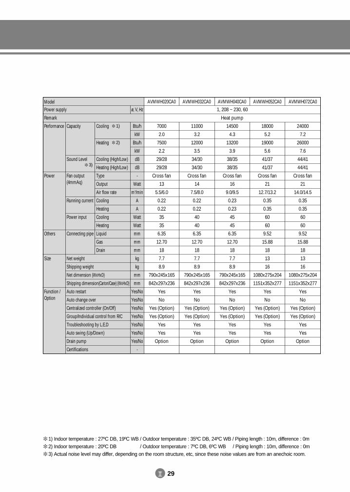
III 29
ModelPower supply
Remark
Performance
Power
Others
Size
Function /Option
Cooling
Heating
Cooling (High/Low)
Heating (High/Low)
Type
Output
Air flow rate
Cooling
Heating
Cooling
Heating
Liquid
Gas
Drain
Capacity
Sound Level
Fan output(4mmAq)
Running current
Power input
Connecting pipe
Net weight
Shipping weight
Net dimension (WxHxD)
Shipping dimension(Carton/Case) (WxHxD)
Auto restart
Auto change over
Centralized controller (On/Off)
Group/Individual control from R/C
Troubleshooting by L.E.D
Auto swing (Up/Down)
Drain pump
Certifications
AVMWH020CA0 AVMWH032CA0 AVMWH040CA0 AVMWH052CA0 AVMWH072CA0
1, 208 ~ 230, 60
7000
2.0
7500
2.2
29/28
29/28
Cross fan
13
5.5/6.0
0.22
0.22
35
35
6.35
12.70
18
7.7
8.9
790x245x165
842x297x236
Yes
No
Yes (Option)
Yes (Option)
Yes
Yes
Option
11000
3.2
12000
3.5
34/30
34/30
Cross fan
14
7.5/8.0
0.22
0.22
40
40
6.35
12.70
18
7.7
8.9
790x245x165
842x297x236
Yes
No
Yes (Option)
Yes (Option)
Yes
Yes
Option
14500
4.3
13200
3.9
38/35
38/35
Cross fan
16
9.0/9.5
0.23
0.23
45
45
6.35
12.70
18
7.7
8.9
790x245x165
842x297x236
Yes
No
Yes (Option)
Yes (Option)
Yes
Yes
Option
18000
5.2
19000
5.6
41/37
41/37
Cross fan
21
12.7/13.2
0.35
0.35
60
60
9.52
15.88
18
13
16
1080x275x204
1151x352x277
Yes
No
Yes (Option)
Yes (Option)
Yes
Yes
Option
24000
7.2
26000
7.6
44/41
44/41
Cross fan
21
14.0/14.5
0.35
0.35
60
60
9.52
15.88
18
13
16
1080x275x204
1151x352x277
Yes
No
Yes (Option)
Yes (Option)
Yes
Yes
Option
Heat pump
Btu/h
kW
Btu/h
kW
dB
dB
-
Watt
m3/min
A
A
Watt
Watt
mm
mm
mm
kg
kg
mm
mm
Yes/No
Yes/No
Yes/No
Yes/No
Yes/No
Yes/No
Yes/No
-
ø, V, Hz
1) Indoor temperature : 27ºC DB, 19ºC WB / Outdoor temperature : 35ºC DB, 24ºC WB / Piping length : 10m, difference : 0m 2) Indoor temperature : 20ºC DB, 19ºC WB / Outdoor temperature : 7ºC DB, 6ºC WB / Piping length : 10m, difference : 0m 3) Actual noise level may differ, depending on the room structure, etc, since these noise values are from an anechoic room.
1)
2)
3)
DVM E-D/B(chapter3-1)-E<03759 3/21/02 7:34 PM Page 29
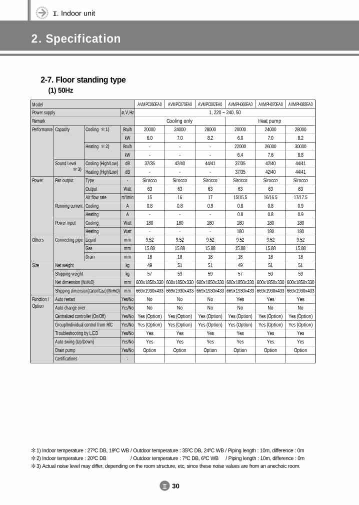
III. Indoor unit
2. Specification
III 30
2-7. Floor standing type(1) 50Hz
ModelPower supply
Remark
Performance
Power
Others
Size
Function /Option
Cooling
Heating
Cooling (High/Low)
Heating (High/Low)
Type
Output
Air flow rate
Cooling
Heating
Cooling
Heating
Liquid
Gas
Drain
Capacity
Sound Level
Fan output
Running current
Power input
Connecting pipe
Net weight
Shipping weight
Net dimension (WxHxD)
Shipping dimension(Carton/Case) (WxHxD)
Auto restart
Auto change over
Centralized controller (On/Off)
Group/Individual control from R/C
Troubleshooting by L.E.D
Auto swing (Up/Down)
Drain pump
Certifications
AVMPC060EA0 AVMPC070EA0 AVMPC082EA0 AVMPH060EA0 AVMPH070EA0 AVMPH082EA0
1, 220 ~ 240, 50
20000
6.0
-
-
37/35
-
Sirocco
63
15
0.8
-
180
-
9.52
15.88
18
49
57
600x1850x330
669x1930x433
No
No
Yes (Option)
Yes (Option)
Yes
Yes
Option
24000
7.0
-
-
42/40
-
Sirocco
63
16
0.8
-
180
-
9.52
15.88
18
51
59
600x1850x330
669x1930x433
No
No
Yes (Option)
Yes (Option)
Yes
Yes
Option
28000
8.2
-
-
44/41
-
Sirocco
63
17
0.9
-
180
-
9.52
15.88
18
51
59
600x1850x330
669x1930x433
No
No
Yes (Option)
Yes (Option)
Yes
Yes
Option
20000
6.0
22000
6.4
37/35
37/35
Sirocco
63
15/15.5
0.8
0.8
180
180
9.52
15.88
18
49
57
600x1850x330
669x1930x433
Yes
No
Yes (Option)
Yes (Option)
Yes
Yes
Option
24000
7.0
26000
7.6
42/40
42/40
Sirocco
63
16/16.5
0.8
0.8
180
180
9.52
15.88
18
51
59
600x1850x330
669x1930x433
Yes
No
Yes (Option)
Yes (Option)
Yes
Yes
Option
28000
8.2
30000
8.8
44/41
44/41
Sirocco
63
17/17.5
0.9
0.9
180
180
9.52
15.88
18
51
59
600x1850x330
669x1930x433
Yes
No
Yes (Option)
Yes (Option)
Yes
Yes
Option
Cooling only Heat pump
Btu/h
kW
Btu/h
kW
dB
dB
-
Watt
m3/min
A
A
Watt
Watt
mm
mm
mm
kg
kg
mm
mm
Yes/No
Yes/No
Yes/No
Yes/No
Yes/No
Yes/No
Yes/No
-
ø, V, Hz
1) Indoor temperature : 27ºC DB, 19ºC WB / Outdoor temperature : 35ºC DB, 24ºC WB / Piping length : 10m, difference : 0m 2) Indoor temperature : 20ºC DB, 19ºC WB / Outdoor temperature : 7ºC DB, 6ºC WB / Piping length : 10m, difference : 0m 3) Actual noise level may differ, depending on the room structure, etc, since these noise values are from an anechoic room.
1)
2)
3)
DVM E-D/B(chapter3-1)-E<03759 3/21/02 7:34 PM Page 30
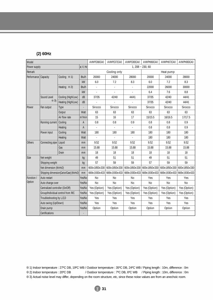
III 31
(2) 60Hz
ModelPower supply
Remark
Performance
Power
Others
Size
Function /Option
Cooling
Heating
Cooling (High/Low)
Heating (High/Low)
Type
Output
Air flow rate
Cooling
Heating
Cooling
Heating
Liquid
Gas
Drain
Capacity
Sound Level
Fan output
Running current
Power input
Connecting pipe
Net weight
Shipping weight
Net dimension (WxHxD)
Shipping dimension(Carton/Case) (WxHxD)
Auto restart
Auto change over
Centralized controller (On/Off)
Group/Individual control from R/C
Troubleshooting by L.E.D
Auto swing (Up/Down)
Drain pump
Certifications
AVMPC060CA0 AVMPC072CA0 AVMPC083CA0 AVMPH060CA0 AVMPH072CA0 AVMPH083CA0
1, 208 ~ 230, 60
20000
6.0
-
-
37/35
-
Sirocco
63
15
0.8
-
180
-
9.52
15.88
18
49
57
600x1850x330
669x1930x433
No
No
Yes (Option)
Yes (Option)
Yes
Yes
Option
24000
7.2
-
-
42/40
-
Sirocco
63
16
0.8
-
180
-
9.52
15.88
18
51
59
600x1850x330
669x1930x433
No
No
Yes (Option)
Yes (Option)
Yes
Yes
Option
28000
8.3
-
-
44/41
-
Sirocco
63
17
0.9
-
180
-
9.52
15.88
18
51
59
600x1850x330
669x1930x433
No
No
Yes (Option)
Yes (Option)
Yes
Yes
Option
20000
6.0
22000
6.4
37/35
37/35
Sirocco
63
15/15.5
0.8
0.8
180
180
9.52
15.88
18
49
57
600x1850x330
669x1930x433
Yes
No
Yes (Option)
Yes (Option)
Yes
Yes
Option
24000
7.2
26000
7.6
42/40
42/40
Sirocco
63
16/16.5
0.8
0.8
180
180
9.52
15.88
18
51
59
600x1850x330
669x1930x433
Yes
No
Yes (Option)
Yes (Option)
Yes
Yes
Option
28000
8.3
30000
8.8
44/41
44/41
Sirocco
63
17/17.5
0.9
0.9
180
180
9.52
15.88
18
51
59
600x1850x330
669x1930x433
Yes
No
Yes (Option)
Yes (Option)
Yes
Yes
Option
Cooling only Heat pump
Btu/h
kW
Btu/h
kW
dB
dB
-
Watt
m3/min
A
A
Watt
Watt
mm
mm
mm
kg
kg
mm
mm
Yes/No
Yes/No
Yes/No
Yes/No
Yes/No
Yes/No
Yes/No
-
ø, V, Hz
1) Indoor temperature : 27ºC DB, 19ºC WB / Outdoor temperature : 35ºC DB, 24ºC WB / Piping length : 10m, difference : 0m 2) Indoor temperature : 20ºC DB, 19ºC WB / Outdoor temperature : 7ºC DB, 6ºC WB / Piping length : 10m, difference : 0m 3) Actual noise level may differ, depending on the room structure, etc, since these noise values are from an anechoic room.
1)
2)
3)
DVM E-D/B(chapter3-1)-E<03759 3/21/02 7:34 PM Page 31
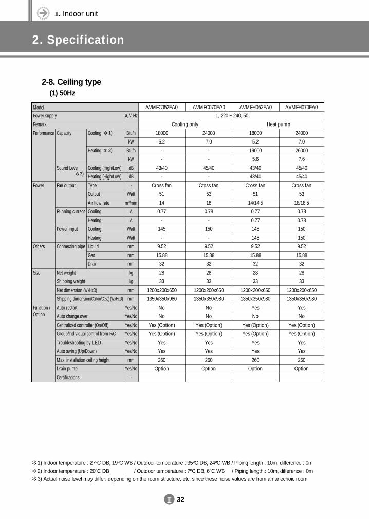
III. Indoor unit
2. Specification
III 32
2-8. Ceiling type(1) 50Hz
ModelPower supply
Remark
Performance
Power
Others
Size
Function /Option
Cooling
Heating
Cooling (High/Low)
Heating (High/Low)
Type
Output
Air flow rate
Cooling
Heating
Cooling
Heating
Liquid
Gas
Drain
Capacity
Sound Level
Fan output
Running current
Power input
Connecting pipe
Net weight
Shipping weight
Net dimension (WxHxD)
Shipping dimension(Carton/Case) (WxHxD)
Auto restart
Auto change over
Centralized controller (On/Off)
Group/Individual control from R/C
Troubleshooting by L.E.D
Auto swing (Up/Down)
Max. installation ceiling height
Drain pump
Certifications
AVMFC052EA0 AVMFC070EA0 AVMFH052EA0 AVMFH070EA0
1, 220 ~ 240, 50
18000
5.2
-
-
43/40
-
Cross fan
51
14
0.77
-
145
-
9.52
15.88
32
28
33
1200x200x650
1350x350x980
No
No
Yes (Option)
Yes (Option)
Yes
Yes
260
Option
24000
7.0
-
-
45/40
-
Cross fan
53
18
0.78
-
150
-
9.52
15.88
32
28
33
1200x200x650
1350x350x980
No
No
Yes (Option)
Yes (Option)
Yes
Yes
260
Option
18000
5.2
19000
5.6
43/40
43/40
Cross fan
51
14/14.5
0.77
0.77
145
145
9.52
15.88
32
28
33
1200x200x650
1350x350x980
Yes
No
Yes (Option)
Yes (Option)
Yes
Yes
260
Option
24000
7.0
26000
7.6
45/40
45/40
Cross fan
53
18/18.5
0.78
0.78
150
150
9.52
15.88
32
28
33
1200x200x650
1350x350x980
Yes
No
Yes (Option)
Yes (Option)
Yes
Yes
260
Option
Cooling only Heat pump
Btu/h
kW
Btu/h
kW
dB
dB
-
Watt
m3/min
A
A
Watt
Watt
mm
mm
mm
kg
kg
mm
mm
Yes/No
Yes/No
Yes/No
Yes/No
Yes/No
Yes/No
mm
Yes/No
-
ø, V, Hz
1) Indoor temperature : 27ºC DB, 19ºC WB / Outdoor temperature : 35ºC DB, 24ºC WB / Piping length : 10m, difference : 0m 2) Indoor temperature : 20ºC DB, 19ºC WB / Outdoor temperature : 7ºC DB, 6ºC WB / Piping length : 10m, difference : 0m 3) Actual noise level may differ, depending on the room structure, etc, since these noise values are from an anechoic room.
1)
2)
3)
DVM E-D/B(chapter3-1)-E<03759 3/21/02 7:34 PM Page 32
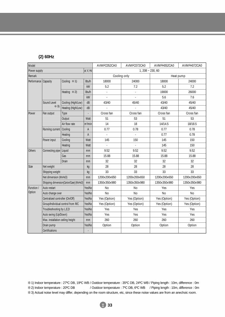
III 33
(2) 60Hz
ModelPower supply
Remark
Performance
Power
Others
Size
Function /Option
Cooling
Heating
Cooling (High/Low)
Heating (High/Low)
Type
Output
Air flow rate
Cooling
Heating
Cooling
Heating
Liquid
Gas
Drain
Capacity
Sound Level
Fan output
Running current
Power input
Connecting pipe
Net weight
Shipping weight
Net dimension (WxHxD)
Shipping dimension(Carton/Case) (WxHxD)
Auto restart
Auto change over
Centralized controller (On/Off)
Group/Individual control from R/C
Troubleshooting by L.E.D
Auto swing (Up/Down)
Max. installation ceiling height
Drain pump
Certifications
AVMFC052CA0 AVMFC072CA0 AVMFH052CA0 AVMFH072CA0
1, 208 ~ 230, 60
18000
5.2
-
-
43/40
-
Cross fan
51
14
0.77
-
145
-
9.52
15.88
32
28
33
1200x200x650
1350x350x980
No
No
Yes (Option)
Yes (Option)
Yes
Yes
260
Option
24000
7.2
-
-
45/40
-
Cross fan
53
18
0.78
-
150
-
9.52
15.88
32
28
33
1200x200x650
1350x350x980
No
No
Yes (Option)
Yes (Option)
Yes
Yes
260
Option
18000
5.2
19000
5.6
43/40
43/40
Cross fan
51
14/14.5
0.77
0.77
145
145
9.52
15.88
32
28
33
1200x200x650
1350x350x980
Yes
No
Yes (Option)
Yes (Option)
Yes
Yes
260
Option
24000
7.2
26000
7.6
45/40
45/40
Cross fan
53
18/18.5
0.78
0.78
150
150
9.52
15.88
32
28
33
1200x200x650
1350x350x980
Yes
No
Yes (Option)
Yes (Option)
Yes
Yes
260
Option
Cooling only Heat pump
Btu/h
kW
Btu/h
kW
dB
dB
-
Watt
m3/min
A
A
Watt
Watt
mm
mm
mm
kg
kg
mm
mm
Yes/No
Yes/No
Yes/No
Yes/No
Yes/No
Yes/No
mm
Yes/No
-
ø, V, Hz
1) Indoor temperature : 27ºC DB, 19ºC WB / Outdoor temperature : 35ºC DB, 24ºC WB / Piping length : 10m, difference : 0m 2) Indoor temperature : 20ºC DB, 19ºC WB / Outdoor temperature : 7ºC DB, 6ºC WB / Piping length : 10m, difference : 0m 3) Actual noise level may differ, depending on the room structure, etc, since these noise values are from an anechoic room.
1)
2)
3)
DVM E-D/B(chapter3-1)-E<03759 3/21/02 7:34 PM Page 33
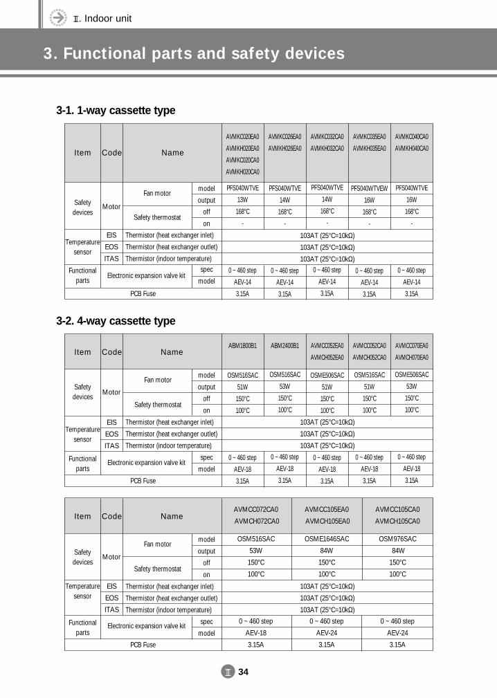
III. Indoor unit
3. Functional parts and safety devices
III 34
3-1. 1-way cassette type
3-2. 4-way cassette type
Item Code Name
AVMKC020EA0
AVMKH020EA0
AVMKC020CA0
AVMKH020CA0
PFS040WTVE
13W
168°C
-
0 ~ 460 step
AEV-14
3.15A
AVMKC026EA0
AVMKH026EA0
PFS040WTVE
14W
168°C
-
0 ~ 460 step
AEV-14
3.15A
AVMKC032CA0
AVMKH032CA0
PFS040WTVE
14W
168°C
-
0 ~ 460 step
AEV-14
3.15A
AVMKC035EA0
AVMKH035EA0
PFS040WTVEW
16W
168°C
-
0 ~ 460 step
AEV-14
3.15A
AVMKC040CA0
AVMKH040CA0
PFS040WTVE
16W
168°C
-
0 ~ 460 step
AEV-14
3.15A
Fan motor
Safety thermostat
Electronic expansion valve kit
Thermistor (heat exchanger inlet)
Thermistor (heat exchanger outlet)
Thermistor (indoor temperature)
model
output
off
on
spec
model
103AT (25°C=10kΩ)
103AT (25°C=10kΩ)
103AT (25°C=10kΩ)
Motor
EIS
EOS
ITAS
Safety devices
Functional parts
PCB Fuse
Temperature sensor
Item Code NameABM1800B1
OSM516SAC
51W
150°C
100°C
0 ~ 460 step
AEV-18
3.15A
ABM2400B1
OSM516SAC
53W
150°C
100°C
0 ~ 460 step
AEV-18
3.15A
AVMCC052EA0
AVMCH052EA0
OSME506SAC
51W
150°C
100°C
0 ~ 460 step
AEV-18
3.15A
AVMCC052CA0
AVMCH052CA0
OSM516SAC
51W
150°C
100°C
0 ~ 460 step
AEV-18
3.15A
AVMCC070EA0
AVMCH070EA0
OSME506SAC
53W
150°C
100°C
0 ~ 460 step
AEV-18
3.15A
Fan motor
Safety thermostat
Electronic expansion valve kit
Thermistor (heat exchanger inlet)
Thermistor (heat exchanger outlet)
Thermistor (indoor temperature)
model
output
off
on
spec
model
103AT (25°C=10kΩ)
103AT (25°C=10kΩ)
103AT (25°C=10kΩ)
Motor
EIS
EOS
ITAS
Safety devices
Functional parts
Temperature sensor
Item Code NameAVMCC072CA0
AVMCH072CA0
AVMCC105EA0
AVMCH105EA0
AVMCC105CA0
AVMCH105CA0
OSM516SAC
53W
150°C
100°C
0 ~ 460 step
AEV-18
3.15A
OSME1646SAC
84W
150°C
100°C
0 ~ 460 step
AEV-24
3.15A
OSM976SAC
84W
150°C
100°C
0 ~ 460 step
AEV-24
3.15A
Fan motor
Safety thermostat
Electronic expansion valve kit
Thermistor (heat exchanger inlet)
Thermistor (heat exchanger outlet)
Thermistor (indoor temperature)
model
output
off
on
spec
model
103AT (25°C=10kΩ)
103AT (25°C=10kΩ)
103AT (25°C=10kΩ)
Motor
EIS
EOS
ITAS
Safety devices
Temperature sensor
Functional parts
PCB Fuse
PCB Fuse
DVM E-D/B(chapter3-1)-E<03759 3/21/02 7:34 PM Page 34
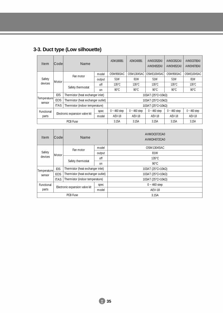
III 35
3-3. Duct type (Low silhouette)
Item Code NameAVMDC072CA0
AVMDH072CA0
OSM1304SAC
81W
135°C
90°C
103AT (25°C=10kΩ)
103AT (25°C=10kΩ)
103AT (25°C=10kΩ)
0 ~ 460 step
AEV-18
3.15A
Fan motor
Safety thermostat
Thermistor (heat exchanger inlet)
Thermistor (heat exchanger outlet)
Thermistor (indoor temperature)
Electronic expansion valve kit
model
output
off
on
spec
model
Motor
EIS
EOS
ITAS
Safety devices
Temperature sensor
Functional parts
Item Code NameADM1800B1 ADM2400B1 AVMDC052EA0
AVMDH052EA0
AVMDC052CA0
AVMDH052CA0
AVMDC070EA0
AVMDH070EA0
OSM956SAC
51W
135°C
90°C
0 ~ 460 step
AEV-18
3.15A
OSM1304SAC
81W
135°C
90°C
0 ~ 460 step
AEV-18
3.15A
OSME1004SAC
51W
135°C
90°C
0 ~ 460 step
AEV-18
3.15A
OSM956SAC
51W
135°C
90°C
0 ~ 460 step
AEV-18
3.15A
OSME1004SAC
81W
135°C
90°C
0 ~ 460 step
AEV-18
3.15A
Fan motor
Safety thermostat
Thermistor (heat exchanger inlet)
Thermistor (heat exchanger outlet)
Thermistor (indoor temperature)
Electronic expansion valve kit
model
output
off
on
spec
model
103AT (25°C=10kΩ)
103AT (25°C=10kΩ)
103AT (25°C=10kΩ)
Motor
EIS
EOS
ITAS
Safety devices
Temperature sensor
Functional parts
PCB Fuse
PCB Fuse
DVM E-D/B(chapter3-1)-E<03759 3/21/02 7:34 PM Page 35
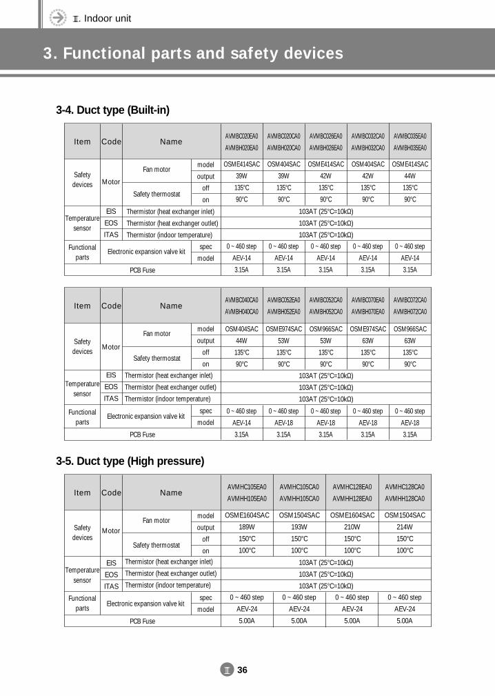
III. Indoor unit
3. Functional parts and safety devices
III 36
3-4. Duct type (Built-in)
3-5. Duct type (High pressure)
Item Code NameAVMBC040CA0
AVMBH040CA0
AVMBC052EA0
AVMBH052EA0
AVMBC052CA0
AVMBH052CA0
AVMBC070EA0
AVMBH070EA0
AVMBC072CA0
AVMBH072CA0
OSM404SAC
44W
135°C
90°C
0 ~ 460 step
AEV-14
3.15A
OSME974SAC
53W
135°C
90°C
0 ~ 460 step
AEV-18
3.15A
OSM966SAC
53W
135°C
90°C
0 ~ 460 step
AEV-18
3.15A
OSME974SAC
63W
135°C
90°C
0 ~ 460 step
AEV-18
3.15A
OSM966SAC
63W
135°C
90°C
0 ~ 460 step
AEV-18
3.15A
Fan motor
Safety thermostat
Thermistor (heat exchanger inlet)
Thermistor (heat exchanger outlet)
Thermistor (indoor temperature)
Electronic expansion valve kit
model
output
off
on
spec
model
103AT (25°C=10kΩ)
103AT (25°C=10kΩ)
103AT (25°C=10kΩ)
Motor
EIS
EOS
ITAS
Safety devices
Temperature sensor
Functional parts
Item Code NameAVMHC105EA0
AVMHH105EA0
AVMHC105CA0
AVMHH105CA0
AVMHC128EA0
AVMHH128EA0
AVMHC128CA0
AVMHH128CA0
OSME1604SAC
189W
150°C
100°C
0 ~ 460 step
AEV-24
5.00A
OSM1504SAC
193W
150°C
100°C
0 ~ 460 step
AEV-24
5.00A
OSME1604SAC
210W
150°C
100°C
0 ~ 460 step
AEV-24
5.00A
OSM1504SAC
214W
150°C
100°C
0 ~ 460 step
AEV-24
5.00A
Fan motor
Safety thermostat
Thermistor (heat exchanger inlet)
Thermistor (heat exchanger outlet)
Thermistor (indoor temperature)
Electronic expansion valve kit
model
output
off
on
spec
model
103AT (25°C=10kΩ)
103AT (25°C=10kΩ)
103AT (25°C=10kΩ)
Motor
EIS
EOS
ITAS
Safety devices
Temperature sensor
Functional parts
Item Code NameAVMBC020EA0
AVMBH020EA0
AVMBC020CA0
AVMBH020CA0
AVMBC026EA0
AVMBH026EA0
AVMBC032CA0
AVMBH032CA0
AVMBC035EA0
AVMBH035EA0
OSME414SAC
39W
135°C
90°C
0 ~ 460 step
AEV-14
3.15A
OSM404SAC
39W
135°C
90°C
0 ~ 460 step
AEV-14
3.15A
OSME414SAC
42W
135°C
90°C
0 ~ 460 step
AEV-14
3.15A
OSM404SAC
42W
135°C
90°C
0 ~ 460 step
AEV-14
3.15A
OSME414SAC
44W
135°C
90°C
0 ~ 460 step
AEV-14
3.15A
Fan motor
Safety thermostat
Electronic expansion valve kit
Thermistor (heat exchanger inlet)
Thermistor (heat exchanger outlet)
Thermistor (indoor temperature)
model
output
off
on
spec
model
103AT (25°C=10kΩ)
103AT (25°C=10kΩ)
103AT (25°C=10kΩ)
Motor
EIS
EOS
ITAS
Safety devices
Temperature sensor
Functional parts
PCB Fuse
PCB Fuse
PCB Fuse
DVM E-D/B(chapter3-1)-E<03759 3/21/02 7:34 PM Page 36
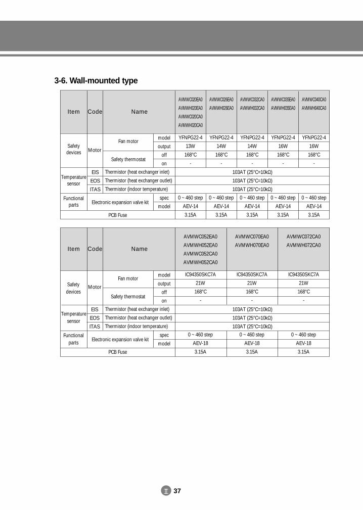
III 37
3-6. Wall-mounted type
Item Code Name
AVMWC020EA0
AVMWH020EA0
AVMWC020CA0
AVMWH020CA0
AVMWC026EA0
AVMWH026EA0
AVMWC032CA0
AVMWH032CA0
AVMWC035EA0
AVMWH035EA0
AVMWC040CA0
AVMWH040CA0
Fan motor
Safety thermostat
Thermistor (heat exchanger inlet)
Thermistor (heat exchanger outlet)
Thermistor (indoor temperature)
Electronic expansion valve kit
model
output
off
on
spec
model
Motor
EIS
EOS
ITAS
Safety devices
Temperature sensor
Functional parts
Item Code Name
AVMWC052EA0
AVMWH052EA0
AVMWC052CA0
AVMWH052CA0
AVMWC070EA0
AVMWH070EA0
AVMWC072CA0
AVMWH072CA0
YFNPG22-4
13W
168°C
-
0 ~ 460 step
AEV-14
3.15A
YFNPG22-4
14W
168°C
-
0 ~ 460 step
AEV-14
3.15A
YFNPG22-4
14W
168°C
-
0 ~ 460 step
AEV-14
3.15A
YFNPG22-4
16W
168°C
-
0 ~ 460 step
AEV-14
3.15A
YFNPG22-4
16W
168°C
-
0 ~ 460 step
AEV-14
3.15A
IC94350SKC7A
21W
168°C
-
0 ~ 460 step
AEV-18
3.15A
IC94350SKC7A
21W
168°C
-
0 ~ 460 step
AEV-18
3.15A
IC94350SKC7A
21W
168°C
-
0 ~ 460 step
AEV-18
3.15A
Fan motor
Safety thermostat
Thermistor (heat exchanger inlet)
Thermistor (heat exchanger outlet)
Thermistor (indoor temperature)
Electronic expansion valve kit
model
output
off
on
spec
model
103AT (25°C=10kΩ)
103AT (25°C=10kΩ)
103AT (25°C=10kΩ)
Motor
EIS
EOS
ITAS
Safety devices
Temperature sensor
Functional parts
PCB Fuse
PCB Fuse
103AT (25°C=10kΩ)
103AT (25°C=10kΩ)
103AT (25°C=10kΩ)
DVM E-D/B(chapter3-1)-E<03759 3/21/02 7:34 PM Page 37
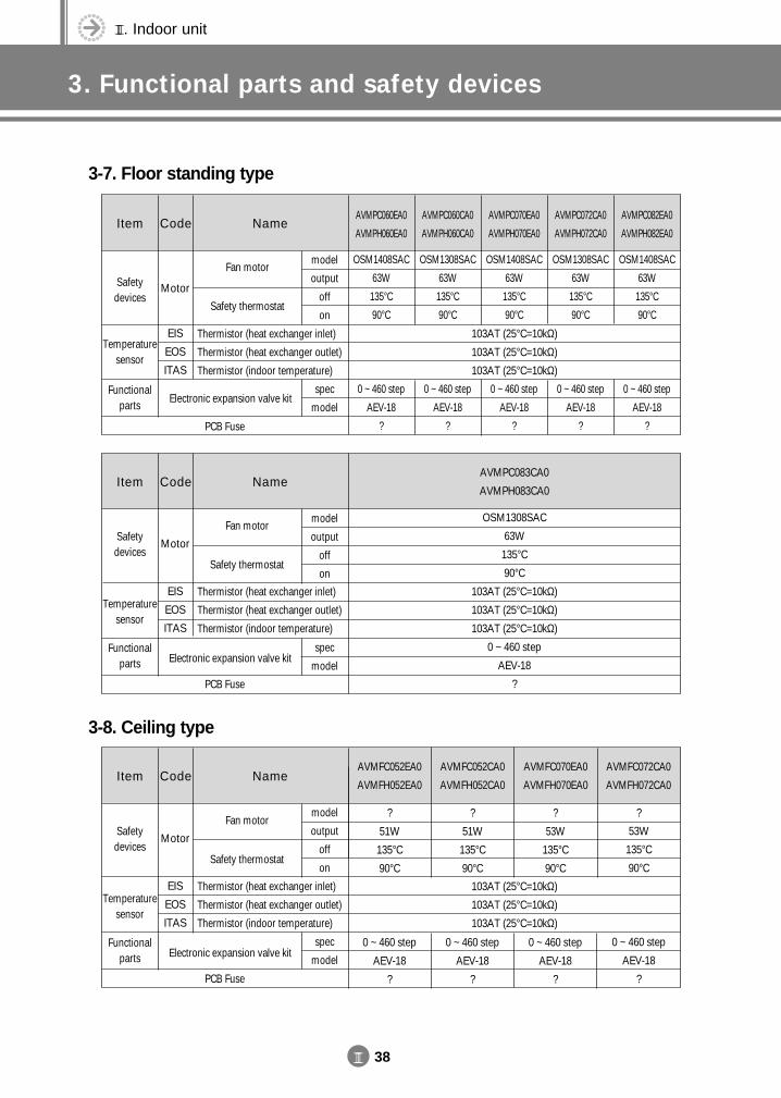
III. Indoor unit
3. Functional parts and safety devices
III 38
3-7. Floor standing type
3-8. Ceiling type
Item Code NameAVMPC060EA0
AVMPH060EA0
AVMPC060CA0
AVMPH060CA0
AVMPC070EA0
AVMPH070EA0
AVMPC072CA0
AVMPH072CA0
AVMPC082EA0
AVMPH082EA0
OSM1408SAC
63W
135°C
90°C
0 ~ 460 step
AEV-18
?
OSM1308SAC
63W
135°C
90°C
0 ~ 460 step
AEV-18
?
OSM1408SAC
63W
135°C
90°C
0 ~ 460 step
AEV-18
?
OSM1308SAC
63W
135°C
90°C
0 ~ 460 step
AEV-18
?
OSM1408SAC
63W
135°C
90°C
0 ~ 460 step
AEV-18
?
Fan motor
Safety thermostat
Thermistor (heat exchanger inlet)
Thermistor (heat exchanger outlet)
Thermistor (indoor temperature)
Electronic expansion valve kit
model
output
off
on
spec
model
103AT (25°C=10kΩ)
103AT (25°C=10kΩ)
103AT (25°C=10kΩ)
Motor
EIS
EOS
ITAS
Safety devices
Temperature sensor
Functional parts
Item Code NameAVMFC052EA0
AVMFH052EA0
AVMFC052CA0
AVMFH052CA0
AVMFC070EA0
AVMFH070EA0
AVMFC072CA0
AVMFH072CA0
?
51W
135°C
90°C
0 ~ 460 step
AEV-18
?
?
51W
135°C
90°C
0 ~ 460 step
AEV-18
?
?
53W
135°C
90°C
0 ~ 460 step
AEV-18
?
?
53W
135°C
90°C
0 ~ 460 step
AEV-18
?
model
output
off
on
spec
model
103AT (25°C=10kΩ)
103AT (25°C=10kΩ)
103AT (25°C=10kΩ)
Item Code NameAVMPC083CA0
AVMPH083CA0
OSM1308SAC
63W
135°C
90°C
103AT (25°C=10kΩ)
103AT (25°C=10kΩ)
103AT (25°C=10kΩ)
0 ~ 460 step
AEV-18
?
Fan motor
Safety thermostat
Thermistor (heat exchanger inlet)
Thermistor (heat exchanger outlet)
Thermistor (indoor temperature)
Electronic expansion valve kit
model
output
off
on
spec
model
Motor
EIS
EOS
ITAS
Safety devices
Temperature sensor
Functional parts
PCB Fuse
PCB Fuse
PCB Fuse
Fan motor
Safety thermostat
Thermistor (heat exchanger inlet)
Thermistor (heat exchanger outlet)
Thermistor (indoor temperature)
Electronic expansion valve kit
Motor
EIS
EOS
ITAS
Safety devices
Temperature sensor
Functional parts
DVM E-D/B(chapter3-1)-E<03759 3/21/02 7:34 PM Page 38
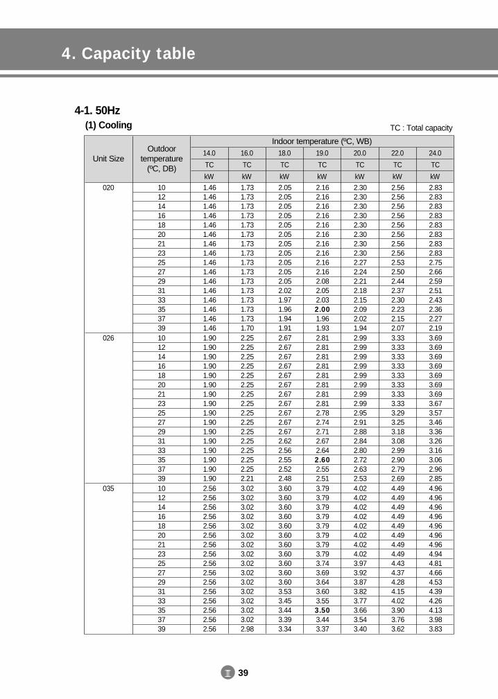
III 39
4. Capacity table
Unit SizeOutdoor
temperature(ºC, DB)
14.0
TC
kW
16.0
TC
kW
18.0
TC
kW
19.0
TC
kW
20.0
TC
kW
22.0
TC
kW
24.0
TC
kW101214161820212325272931333537391012141618202123252729313335373910121416182021232527293133353739
1.461.461.461.461.461.461.461.461.461.461.461.461.461.461.461.461.901.901.901.901.901.901.901.901.901.901.901.901.901.901.901.902.562.562.562.562.562.562.562.562.562.562.562.562.562.562.562.56
1.731.731.731.731.731.731.731.731.731.731.731.731.731.731.731.702.252.252.252.252.252.252.252.252.252.252.252.252.252.252.252.213.023.023.023.023.023.023.023.023.023.023.023.023.023.023.022.98
2.052.052.052.052.052.052.052.052.052.052.052.021.971.961.941.912.672.672.672.672.672.672.672.672.672.672.672.622.562.552.522.483.603.603.603.603.603.603.603.603.603.603.603.533.453.443.393.34
2.162.162.162.162.162.162.162.162.162.162.082.052.032.001.961.932.812.812.812.812.812.812.812.812.782.742.712.672.642.602.552.513.793.793.793.793.793.793.793.793.743.693.643.603.553.503.443.37
2.302.302.302.302.302.302.302.302.272.242.212.182.152.092.021.942.992.992.992.992.992.992.992.992.952.912.882.842.802.722.632.534.024.024.024.024.024.024.024.023.973.923.873.823.773.663.543.40
2.562.562.562.562.562.562.562.562.532.502.442.372.302.232.152.073.333.333.333.333.333.333.333.333.293.253.183.082.992.902.792.694.494.494.494.494.494.494.494.494.434.374.284.154.023.903.763.62
2.832.832.832.832.832.832.832.832.752.662.592.512.432.362.272.193.693.693.693.693.693.693.693.673.573.463.363.263.163.062.962.854.964.964.964.964.964.964.964.944.814.664.534.394.264.133.983.83
4-1. 50Hz(1) Cooling
Indoor temperature (ºC, WB)
020
026
035
TC : Total capacity
DVM E-D/B(chapter3-1)-E<03759 3/21/02 7:34 PM Page 39
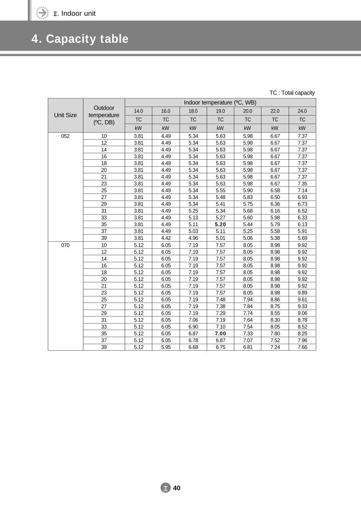
III. Indoor unit
4. Capacity table
III 40
Unit SizeOutdoor
temperature(ºC, DB)
14.0
TC
kW
16.0
TC
kW
18.0
TC
kW
19.0
TC
kW
20.0
TC
kW
22.0
TC
kW
24.0
TC
kW1012141618202123252729313335373910121416182021232527293133353739
3.813.813.813.813.813.813.813.813.813.813.813.813.813.813.813.815.125.125.125.125.125.125.125.125.125.125.125.125.125.125.125.12
4.494.494.494.494.494.494.494.494.494.494.494.494.494.494.494.426.056.056.056.056.056.056.056.056.056.056.056.056.056.056.055.95
5.345.345.345.345.345.345.345.345.345.345.345.255.135.115.034.967.197.197.197.197.197.197.197.197.197.197.197.066.906.876.786.68
5.635.635.635.635.635.635.635.635.555.485.415.345.275.205.115.017.577.577.577.577.577.577.577.577.487.387.297.197.107.006.876.75
5.985.985.985.985.985.985.985.985.905.835.755.685.605.445.255.068.058.058.058.058.058.058.058.057.947.847.747.647.547.337.076.81
6.676.676.676.676.676.676.676.676.586.506.366.165.985.795.585.388.988.988.988.988.988.988.988.988.868.758.558.308.057.807.527.24
7.377.377.377.377.377.377.377.357.146.936.736.526.336.135.915.699.929.929.929.929.929.929.929.899.619.339.068.788.528.257.967.66
Indoor temperature (ºC, WB)
052
070
TC : Total capacity
DVM E-D/B(chapter3-1)-E<03759 3/21/02 7:34 PM Page 40
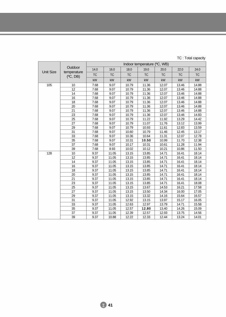
III 41
Unit SizeOutdoor
temperature(ºC, DB)
14.0
TC
kW
16.0
TC
kW
18.0
TC
kW
19.0
TC
kW
20.0
TC
kW
22.0
TC
kW
24.0
TC
kW1012141618202123252729313335373910121416182021232527293133353739
7.687.687.687.687.687.687.687.687.687.687.687.687.687.687.687.689.379.379.379.379.379.379.379.379.379.379.379.379.379.379.379.37
9.079.079.079.079.079.079.079.079.079.079.079.079.079.079.078.9311.0511.0511.0511.0511.0511.0511.0511.0511.0511.0511.0511.0511.0511.0511.0510.88
10.7910.7910.7910.7910.7910.7910.7910.7910.7910.7910.7910.6010.3610.3110.1710.0213.1513.1513.1513.1513.1513.1513.1513.1513.1513.1513.1512.9212.6312.5712.3912.22
11.3611.3611.3611.3611.3611.3611.3611.3611.2211.0710.9310.7910.6410.5010.3110.1213.8513.8513.8513.8513.8513.8513.8513.8513.6713.5013.3213.1512.9712.8012.5712.33
12.0712.0712.0712.0712.0712.0712.0712.0711.9211.7611.6111.4611.3110.9910.6110.2114.7114.7114.7114.7114.7114.7114.7114.7114.5314.3414.1613.9713.7913.4012.9312.44
13.4613.4613.4613.4613.4613.4613.4613.4613.2913.1212.8312.4512.0711.7011.2810.8616.4116.4116.4116.4116.4116.4116.4116.4116.2116.0015.6415.1714.7114.2613.7513.24
14.8814.8814.8814.8814.8814.8814.8814.8314.4213.9913.5913.1712.7812.3811.9411.5018.1418.1418.1418.1418.1418.1418.1418.0817.5817.0516.5716.0515.5815.0914.5614.01
Indoor temperature (ºC, WB)
105
128
TC : Total capacity
DVM E-D/B(chapter3-1)-E<03759 3/21/02 7:34 PM Page 41
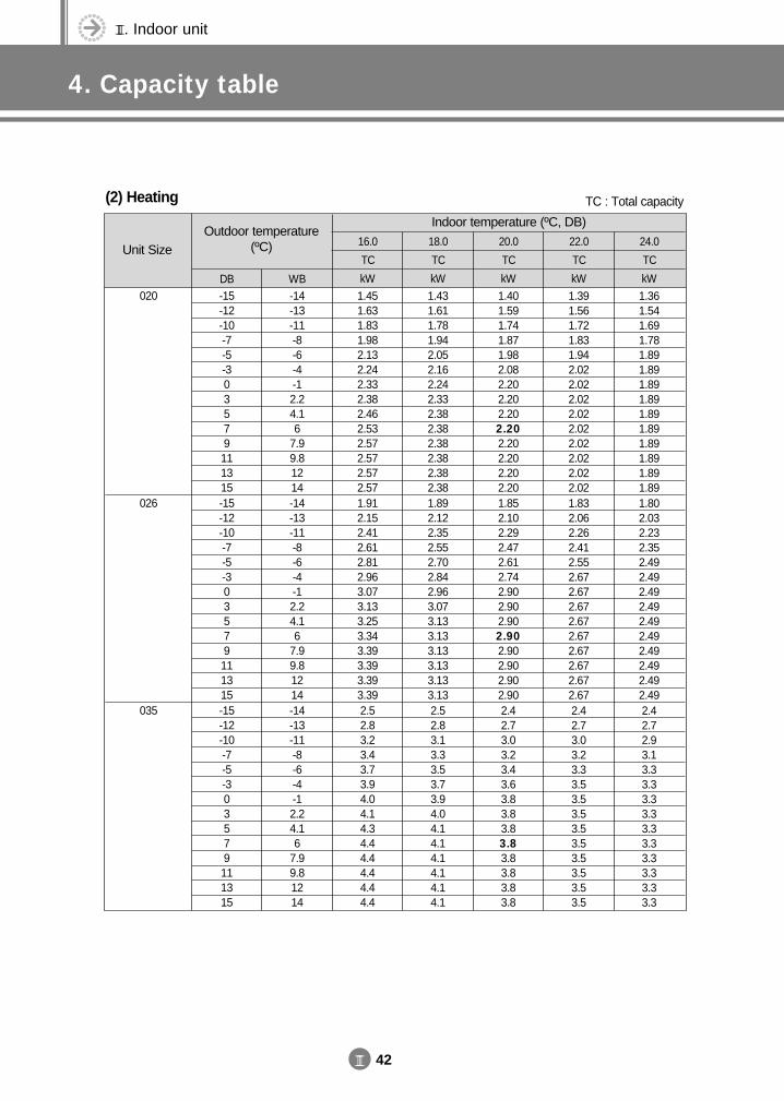
III. Indoor unit
4. Capacity table
III 42
Unit SizeOutdoor temperature
(ºC) 16.0
TC
kW
18.0
TC
kW
20.0
TC
kW
22.0
TC
kW
24.0
TC
kWDB WB-15-12-10-7-5-303579111315-15-12-10-7-5-303579111315-15-12-10-7-5-303579111315
-14-13-11-8-6-4-12.24.16
7.99.81214-14-13-11-8-6-4-12.24.16
7.99.81214-14-13-11-8-6-4-12.24.16
7.99.81214
1.451.631.831.982.132.242.332.382.462.532.572.572.572.571.912.152.412.612.812.963.073.133.253.343.393.393.393.392.52.83.23.43.73.94.04.14.34.44.44.44.44.4
1.431.611.781.942.052.162.242.332.382.382.382.382.382.381.892.122.352.552.702.842.963.073.133.133.133.133.133.132.52.83.13.33.53.73.94.04.14.14.14.14.14.1
1.401.591.741.871.982.082.202.202.202.202.202.202.202.201.852.102.292.472.612.742.902.902.902.902.902.902.902.902.42.73.03.23.43.63.83.83.83.83.83.83.83.8
1.391.561.721.831.942.022.022.022.022.022.022.022.022.021.832.062.262.412.552.672.672.672.672.672.672.672.672.672.42.73.03.23.33.53.53.53.53.53.53.53.53.5
1.361.541.691.781.891.891.891.891.891.891.891.891.891.891.802.032.232.352.492.492.492.492.492.492.492.492.492.492.42.72.93.13.33.33.33.33.33.33.33.33.33.3
(2) Heating
Indoor temperature (ºC, DB)
020
026
035
TC : Total capacity
DVM E-D/B(chapter3-2)-E<03759 3/21/02 7:37 PM Page 42

III 43
Unit SizeOutdoor temperature
(ºC) 16.0
TC
kW
18.0
TC
kW
20.0
TC
kW
22.0
TC
kW
24.0
TC
kWDB WB-15-12-10-7-5-303579111315-15-12-10-7-5-303579111315-15-12-10-7-5-303579111315
-14-13-11-8-6-4-12.24.16
7.99.81214-14-13-11-8-6-4-12.24.16
7.99.81214-14-13-11-8-6-4-12.24.16
7.99.81214
3.74.14.65.05.45.75.96.06.36.46.66.66.66.65.05.66.36.87.47.88.18.28.58.78.98.98.98.97.58.49.510.311.111.612.112.312.813.113.313.313.313.3
3.64.14.54.95.25.55.75.96.06.06.06.06.06.04.95.56.26.77.17.47.88.18.28.28.28.28.28.27.48.39.210.010.611.211.612.112.312.312.312.312.312.3
3.64.04.44.85.05.35.65.65.65.65.65.65.65.64.85.56.06.56.87.27.67.67.67.67.67.67.67.67.38.29.09.710.210.811.411.411.411.411.411.411.411.4
3.54.04.44.64.95.25.25.25.25.25.25.25.25.24.85.45.96.36.77.07.07.07.07.07.07.07.07.07.28.18.99.510.010.510.510.510.510.510.510.510.510.5
3.53.94.34.54.84.84.84.84.84.84.84.84.84.84.75.35.96.26.56.56.56.56.56.56.56.56.56.57.18.08.89.29.89.89.89.89.89.89.89.89.89.8
Indoor temperature (ºC, DB)
052
070
105
TC : Total capacity
DVM E-D/B(chapter3-2)-E<03759 3/21/02 7:37 PM Page 43

III. Indoor unit
4. Capacity table
III 44
TC : Total capacity
Unit SizeOutdoor temperature
(ºC) 16.0
TC
kW
18.0
TC
kW
20.0
TC
kW
22.0
TC
kW
24.0
TC
kWDB WB-15-12-10-7-5-303579111315
-14-13-11-8-6-4-12.24.16
7.99.81214
9.110.211.512.413.414.114.614.915.515.916.116.116.116.1
9.010.111.212.112.813.514.114.614.914.914.914.914.914.9
8.810.010.911.812.413.013.813.813.813.813.813.813.813.8
8.79.810.811.512.112.712.712.712.712.712.712.712.712.7
8.69.710.611.211.911.911.911.911.911.911.911.911.911.9
Indoor temperature (ºC, DB)
128
DVM E-D/B(chapter3-2)-E<03759 3/21/02 7:37 PM Page 44
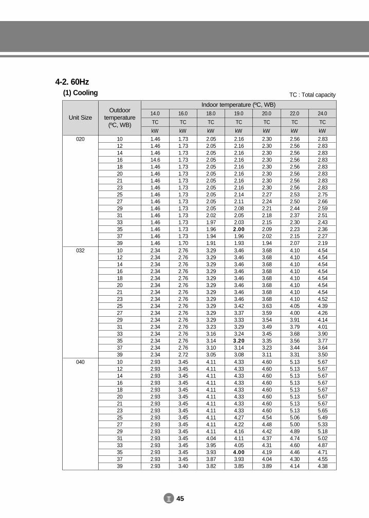
III 45
Unit SizeOutdoor
temperature(ºC, WB)
14.0
TC
kW
16.0
TC
kW
18.0
TC
kW
19.0
TC
kW
20.0
TC
kW
22.0
TC
kW
24.0
TC
kW101214161820212325272931333537391012141618202123252729313335373910121416182021232527293133353739
1.461.461.4614.61.461.461.461.461.461.461.461.461.461.461.461.462.342.342.342.342.342.342.342.342.342.342.342.342.342.342.342.342.932.932.932.932.932.932.932.932.932.932.932.932.932.932.932.93
1.731.731.731.731.731.731.731.731.731.731.731.731.731.731.731.702.762.762.762.762.762.762.762.762.762.762.762.762.762.762.762.723.453.453.453.453.453.453.453.453.453.453.453.453.453.453.453.40
2.052.052.052.052.052.052.052.052.052.052.052.021.971.961.941.913.293.293.293.293.293.293.293.293.293.293.293.233.163.143.103.054.114.114.114.114.114.114.114.114.114.114.114.043.953.933.873.82
2.162.162.162.162.162.162.162.162.142.112.082.052.032.001.961.933.463.463.463.463.463.463.463.463.423.373.333.293.243.203.143.084.334.334.334.334.334.334.334.334.274.224.164.114.054.003.933.85
2.302.302.302.302.302.302.302.302.272.242.212.182.152.092.021.943.683.683.683.683.683.683.683.683.633.593.543.493.453.353.233.114.604.604.604.604.604.604.604.604.544.484.424.374.314.194.043.89
2.562.562.562.562.562.562.562.562.532.502.442.372.302.232.152.074.104.104.104.104.104.104.104.104.054.003.913.793.683.563.443.315.135.135.135.135.135.135.135.135.065.004.894.744.604.464.304.14
2.832.832.832.832.832.832.832.832.752.662.592.512.432.362.272.194.544.544.544.544.544.544.544.524.394.264.144.013.903.773.643.505.675.675.675.675.675.675.675.655.495.335.185.024.874.714.554.38
4-2. 60Hz(1) Cooling
Indoor temperature (ºC, WB)
020
032
040
TC : Total capacity
DVM E-D/B(chapter3-2)-E<03759 3/21/02 7:37 PM Page 45
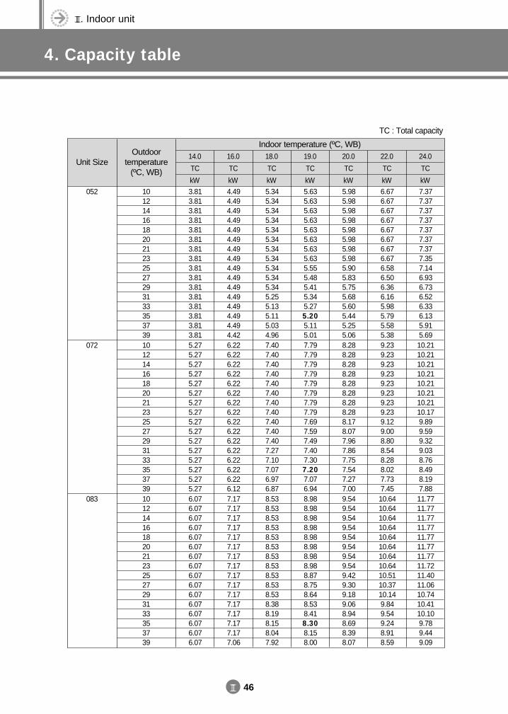
III. Indoor unit
4. Capacity table
III 46
Unit SizeOutdoor
temperature(ºC, WB)
14.0
TC
kW
16.0
TC
kW
18.0
TC
kW
19.0
TC
kW
20.0
TC
kW
22.0
TC
kW
24.0
TC
kW101214161820212325272931333537391012141618202123252729313335373910121416182021232527293133353739
3.813.813.813.813.813.813.813.813.813.813.813.813.813.813.813.815.275.275.275.275.275.275.275.275.275.275.275.275.275.275.275.276.076.076.076.076.076.076.076.076.076.076.076.076.076.076.076.07
4.494.494.494.494.494.494.494.494.494.494.494.494.494.494.494.426.226.226.226.226.226.226.226.226.226.226.226.226.226.226.226.127.177.177.177.177.177.177.177.177.177.177.177.177.177.177.177.06
5.345.345.345.345.345.345.345.345.345.345.345.255.135.115.034.967.407.407.407.407.407.407.407.407.407.407.407.277.107.076.976.878.538.538.538.538.538.538.538.538.538.538.538.388.198.158.047.92
5.635.635.635.635.635.635.635.635.555.485.415.345.275.205.115.017.797.797.797.797.797.797.797.797.697.597.497.407.307.207.076.948.988.988.988.988.988.988.988.988.878.758.648.538.418.308.158.00
5.985.985.985.985.985.985.985.985.905.835.755.685.605.445.255.068.288.288.288.288.288.288.288.288.178.077.967.867.757.547.277.009.549.549.549.549.549.549.549.549.429.309.189.068.948.698.398.07
6.676.676.676.676.676.676.676.676.586.506.366.165.985.795.585.389.239.239.239.239.239.239.239.239.129.008.808.548.288.027.737.4510.6410.6410.6410.6410.6410.6410.6410.6410.5110.3710.149.849.549.248.918.59
7.377.377.377.377.377.377.377.357.146.936.736.526.336.135.915.6910.2110.2110.2110.2110.2110.2110.2110.179.899.599.329.038.768.498.197.8811.7711.7711.7711.7711.7711.7711.7711.7211.4011.0610.7410.4110.109.789.449.09
Indoor temperature (ºC, WB)
052
072
083
TC : Total capacity
DVM E-D/B(chapter3-2)-E<03759 3/21/02 7:37 PM Page 46
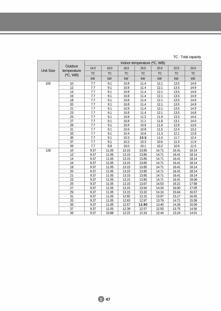
III 47
Unit SizeOutdoor
temperature(ºC, WB)
14.0
TC
kW
16.0
TC
kW
18.0
TC
kW
19.0
TC
kW
20.0
TC
kW
22.0
TC
kW
24.0
TC
kW1012141618202123252729313335373910121416182021232527293133353739
7.77.77.77.77.77.77.77.77.77.77.77.77.77.77.77.79.379.379.379.379.379.379.379.379.379.379.379.379.379.379.379.37
9.19.19.19.19.19.19.19.19.19.19.19.19.19.19.18.9
11.0511.0511.0511.0511.0511.0511.0511.0511.0511.0511.0511.0511.0511.0511.0510.88
10.810.810.810.810.810.810.810.810.810.810.810.610.410.310.210.013.1513.1513.1513.1513.1513.1513.1513.1513.1513.1513.1512.9212.6312.5712.3912.22
11.411.411.411.411.411.411.411.411.211.110.910.810.610.510.310.113.8513.8513.8513.8513.8513.8513.8513.8513.6713.5013.3213.1512.9712.8012.5712.33
12.112.112.112.112.112.112.112.111.911.811.611.511.311.010.610.214.7114.7114.7114.7114.7114.7114.7114.7114.5314.3414.1613.9713.7913.4012.9312.44
13.513.513.513.513.513.513.513.513.313.112.812.412.111.711.310.916.4116.4116.4116.4116.4116.4116.4116.4116.2116.0015.6415.1714.7114.2613.7513.24
14.914.914.914.914.914.914.914.814.414.013.613.212.812.411.911.518.1418.1418.1418.1418.1418.1418.1418.0817.5817.0516.5716.0515.5815.0914.5614.01
Indoor temperature (ºC, WB)
105
128
TC : Total capacity
DVM E-D/B(chapter3-2)-E<03759 3/21/02 7:37 PM Page 47
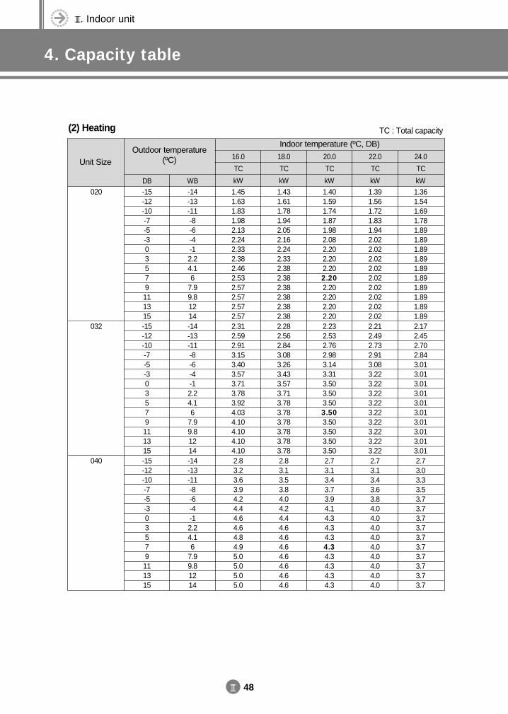
III. Indoor unit
4. Capacity table
III 48
(2) Heating
Unit SizeOutdoor temperature
(ºC) 16.0
TC
kW
18.0
TC
kW
20.0
TC
kW
22.0
TC
kW
24.0
TC
kWDB WB-15-12-10-7-5-303579111315-15-12-10-7-5-303579111315-15-12-10-7-5-303579111315
-14-13-11-8-6-4-12.24.16
7.99.81214-14-13-11-8-6-4-12.24.16
7.99.81214-14-13-11-8-6-4-12.24.16
7.99.81214
1.451.631.831.982.132.242.332.382.462.532.572.572.572.572.312.592.913.153.403.573.713.783.924.034.104.104.104.102.83.23.63.94.24.44.64.64.84.95.05.05.05.0
1.431.611.781.942.052.162.242.332.382.382.382.382.382.382.282.562.843.083.263.433.573.713.783.783.783.783.783.782.83.13.53.84.04.24.44.64.64.64.64.64.64.6
1.401.591.741.871.982.082.202.202.202.202.202.202.202.202.232.532.762.983.143.313.503.503.503.503.503.503.503.502.73.13.43.73.94.14.34.34.34.34.34.34.34.3
1.391.561.721.831.942.022.022.022.022.022.022.022.022.022.212.492.732.913.083.223.223.223.223.223.223.223.223.222.73.13.43.63.84.04.04.04.04.04.04.04.04.0
1.361.541.691.781.891.891.891.891.891.891.891.891.891.892.172.452.702.843.013.013.013.013.013.013.013.013.013.012.73.03.33.53.73.73.73.73.73.73.73.73.73.7
Indoor temperature (ºC, DB)
020
032
040
TC : Total capacity
DVM E-D/B(chapter3-2)-E<03759 3/21/02 7:37 PM Page 48
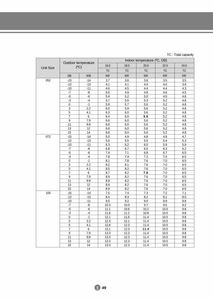
III 49
Unit SizeOutdoor temperature
(ºC) 16.0
TC
kW
18.0
TC
kW
20.0
TC
kW
22.0
TC
kW
24.0
TC
kWDB WB-15-12-10-7-5-303579111315-15-12-10-7-5-303579111315-15-12-10-7-5-303579111315
-14-13-11-8-6-4-12.24.16
7.99.81214-14-13-11-8-6-4-12.24.16
7.99.81214-14-13-11-8-6-4-12.24.16
7.99.81214
3.74.14.65.05.45.75.96.06.36.46.66.66.66.65.05.66.36.87.47.88.18.28.58.78.98.98.98.97.58.49.510.311.111.612.112.312.813.113.313.313.313.3
3.64.14.54.95.25.55.75.96.06.06.06.06.06.04.95.56.26.77.17.47.88.18.28.28.28.28.28.27.48.39.210.010.611.211.612.112.312.312.312.312.312.3
3.64.04.44.85.05.35.65.65.65.65.65.65.65.64.85.56.06.56.87.27.67.67.67.67.67.67.67.67.38.29.09.710.210.811.411.411.411.411.411.411.411.4
3.54.04.44.64.95.25.25.25.25.25.25.25.25.24.85.45.96.36.77.07.07.07.07.07.07.07.07.07.28.18.99.510.010.510.510.510.510.510.510.510.510.5
3.53.94.34.54.84.84.84.84.84.84.84.84.84.84.75.35.96.26.56.56.56.56.56.56.56.56.56.57.18.08.89.29.89.89.89.89.89.89.89.89.89.8
Indoor temperature (ºC, DB)
052
072
105
TC : Total capacity
DVM E-D/B(chapter3-2)-E<03759 3/21/02 7:37 PM Page 49
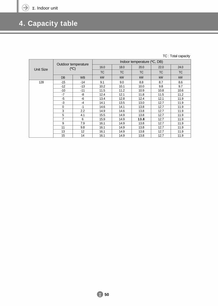
III. Indoor unit
4. Capacity table
III 50
Unit SizeOutdoor temperature
(ºC) 16.0
TC
kW
18.0
TC
kW
20.0
TC
kW
22.0
TC
kW
24.0
TC
kWDB WB-15-12-10-7-5-303579111315
-14-13-11-8-6-4-12.24.16
7.99.81214
9.110.211.512.413.414.114.614.915.515.916.116.116.116.1
9.010.111.212.112.813.514.114.614.914.914.914.914.914.9
8.810.010.911.812.413.013.813.813.813.813.813.813.813.8
8.79.810.811.512.112.712.712.712.712.712.712.712.712.7
8.69.710.611.211.911.911.911.911.911.911.911.911.911.9
Indoor temperature (ºC, DB)
128
TC : Total capacity
DVM E-D/B(chapter3-2)-E<03759 3/21/02 7:37 PM Page 50
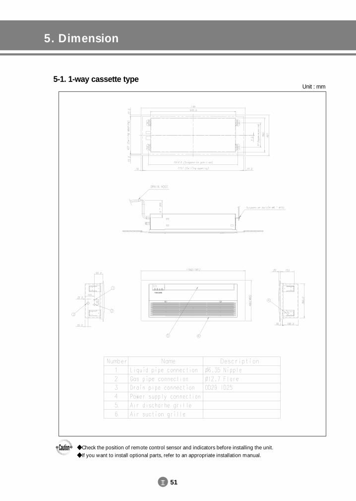
III 51
5. Dimension
5-1. 1-way cassette typeUnit : mm
Check the position of remote control sensor and indicators before installing the unit. If you want to install optional parts, refer to an appropriate installation manual.
DVM E-D/B(chapter3-2)-E<03759 3/21/02 7:37 PM Page 51
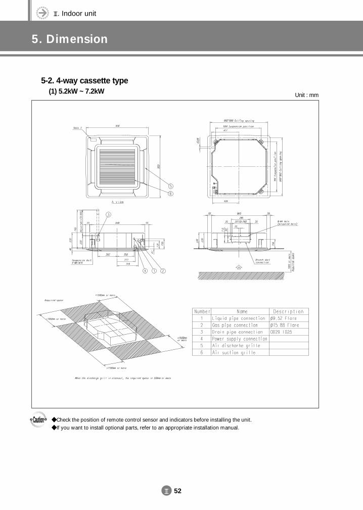
III. Indoor unit
5. Dimension
III 52
5-2. 4-way cassette type(1) 5.2kW ~ 7.2kW Unit : mm
Check the position of remote control sensor and indicators before installing the unit. If you want to install optional parts, refer to an appropriate installation manual.
DVM E-D/B(chapter3-2)-E<03759 3/21/02 7:37 PM Page 52
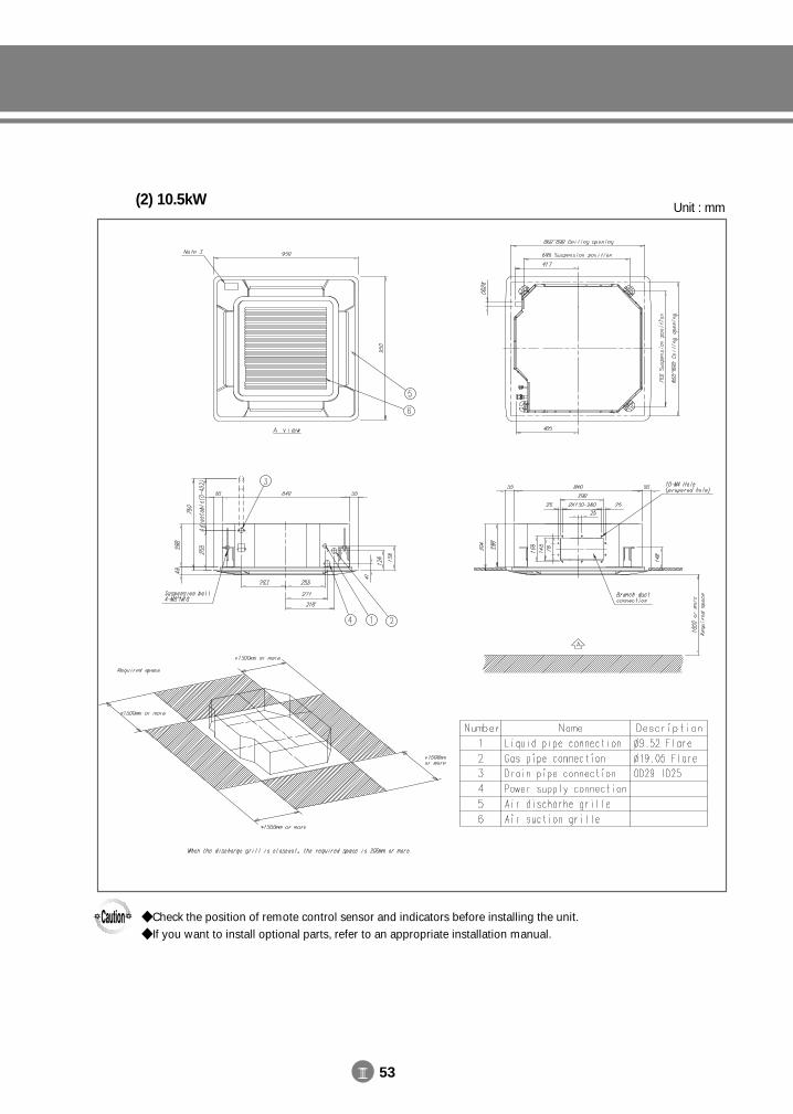
III 53
(2) 10.5kW Unit : mm
Check the position of remote control sensor and indicators before installing the unit. If you want to install optional parts, refer to an appropriate installation manual.
DVM E-D/B(chapter3-2)-E<03759 3/21/02 7:37 PM Page 53
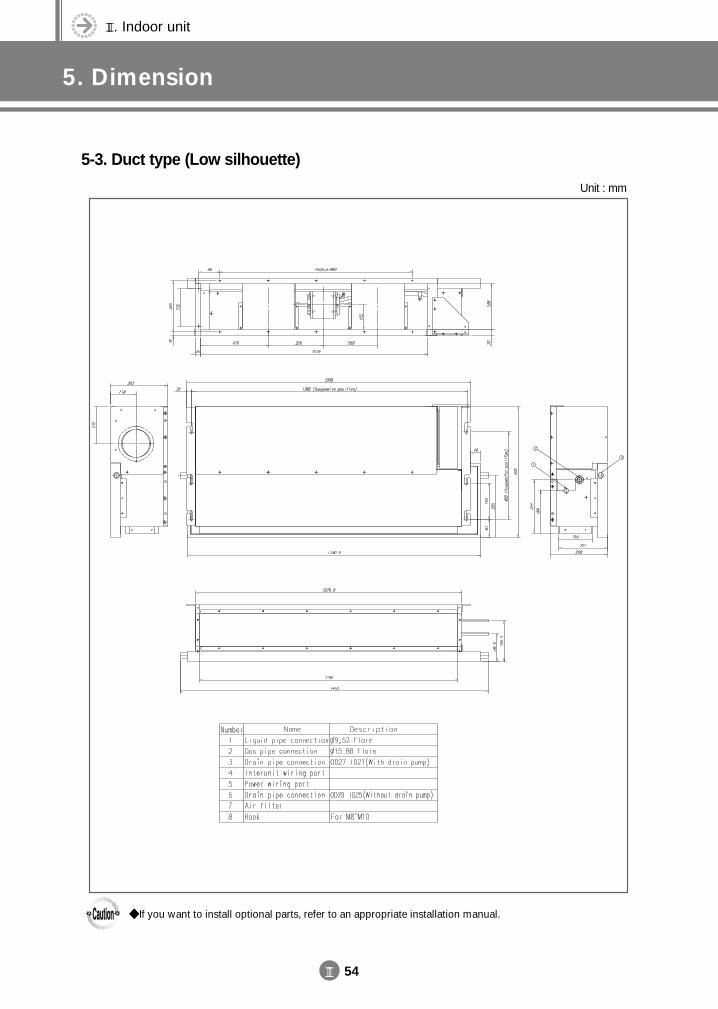
III. Indoor unit
5. Dimension
III 54
5-3. Duct type (Low silhouette)
Unit : mm
If you want to install optional parts, refer to an appropriate installation manual.
DVM E-D/B(chapter3-2)-E<03759 3/21/02 7:37 PM Page 54
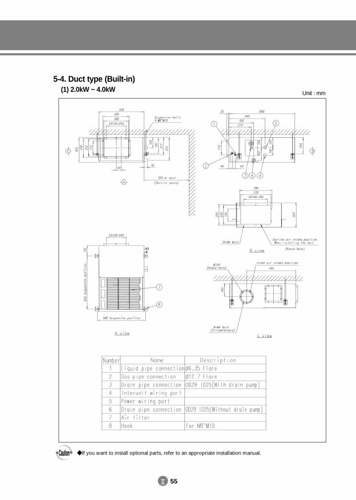
III 55
5-4. Duct type (Built-in)(1) 2.0kW ~ 4.0kW Unit : mm
If you want to install optional parts, refer to an appropriate installation manual.
DVM E-D/B(chapter3-2)-E<03759 3/21/02 7:37 PM Page 55
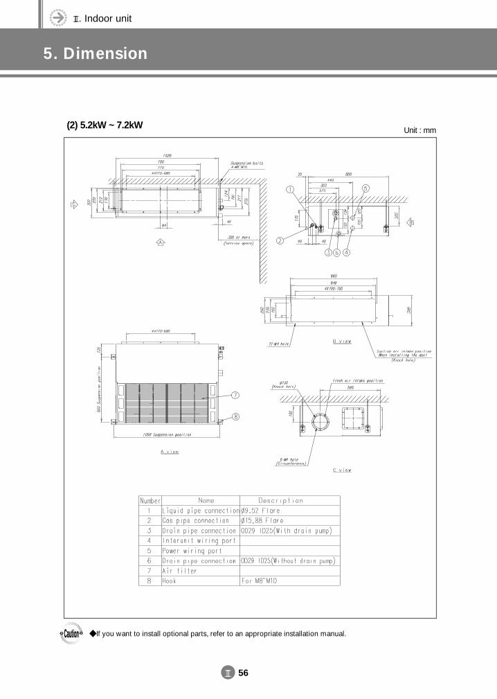
III. Indoor unit
5. Dimension
III 56
(2) 5.2kW ~ 7.2kW Unit : mm
If you want to install optional parts, refer to an appropriate installation manual.
DVM E-D/B(chapter3-2)-E<03759 3/21/02 7:37 PM Page 56
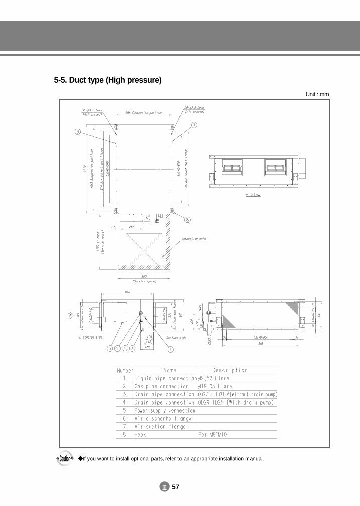
III 57
5-5. Duct type (High pressure)
Unit : mm
If you want to install optional parts, refer to an appropriate installation manual.
DVM E-D/B(chapter3-2)-E<03759 3/21/02 7:37 PM Page 57
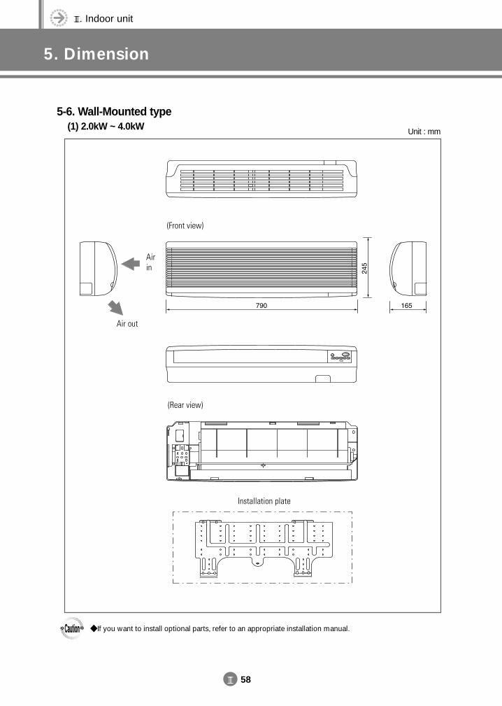
III. Indoor unit
5. Dimension
III 58
5-6. Wall-Mounted type(1) 2.0kW ~ 4.0kW Unit : mm
If you want to install optional parts, refer to an appropriate installation manual.
DVM E-D/B(chapter3-2)-E<03759 3/21/02 7:37 PM Page 58
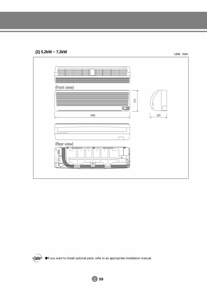
III 59
(2) 5.2kW ~ 7.2kW Unit : mm
If you want to install optional parts, refer to an appropriate installation manual.
DVM E-D/B(chapter3-2)-E<03759 3/21/02 7:37 PM Page 59
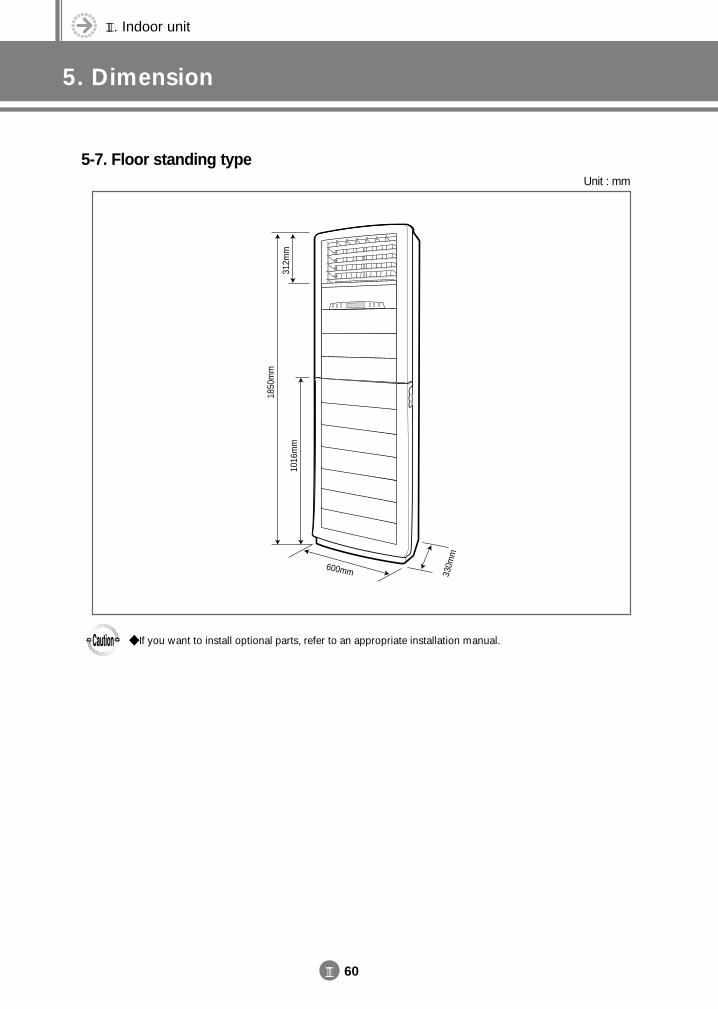
III. Indoor unit
5. Dimension
III 60
5-7. Floor standing type
1850
mm
312m
m10
16m
m
600mm 330m
m
Unit : mm
If you want to install optional parts, refer to an appropriate installation manual.
DVM E-D/B(chapter3-2)-E<03759 3/21/02 7:37 PM Page 60
III 61
5-8. Ceiling typeUnit : mm
DVM E-D/B(chapter3-2)-E<03759 3/21/02 7:37 PM Page 61
III. Indoor unit
5. Dimension
III 62
5-9. Wireless remote controller / Receiver(1) For 1-way cassette / 4-way cassette / Wall-mounted / Floor standing / Ceiling type
(AVMK / AVMC / AVMW / AVMP / AVMF ) MR-AC01
MR-AH01
DVM E-D/B(chapter3-2)-E<03759 3/21/02 7:37 PM Page 62
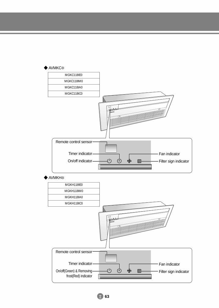
III 63
AVMKC
MGKC118IE0
MGKC118IM0
MGKC118IA0
MGKC118IC0
AVMKH
MGKH118IE0
MGKH118IM0
MGKH118IA0
MGKH118IC0
Fan indicator
Filter sign indicator
Remote control sensor
Timer indicator
On/off indicator
Fan indicator
Filter sign indicator
Remote control sensor
Timer indicator
On/off(Green) & Removingfrost(Red) indicator
DVM E-D/B(chapter3-2)-E<03759 3/21/02 7:37 PM Page 63
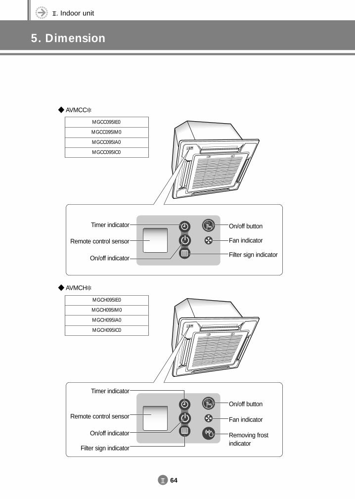
III. Indoor unit
5. Dimension
III 64
AVMCC
MGCC095IE0
MGCC095IM0
MGCC095IA0
MGCC095IC0
AVMCH
MGCH095IE0
MGCH095IM0
MGCH095IA0
MGCH095IC0
On/off button
Fan indicator
Filter sign indicator
Timer indicator
Remote control sensor
On/off indicator
On/off button
Fan indicator
Removing frostindicator
Timer indicator
Remote control sensor
On/off indicator
Filter sign indicator
DVM E-D/B(chapter3-2)-E<03759 3/21/02 7:37 PM Page 64
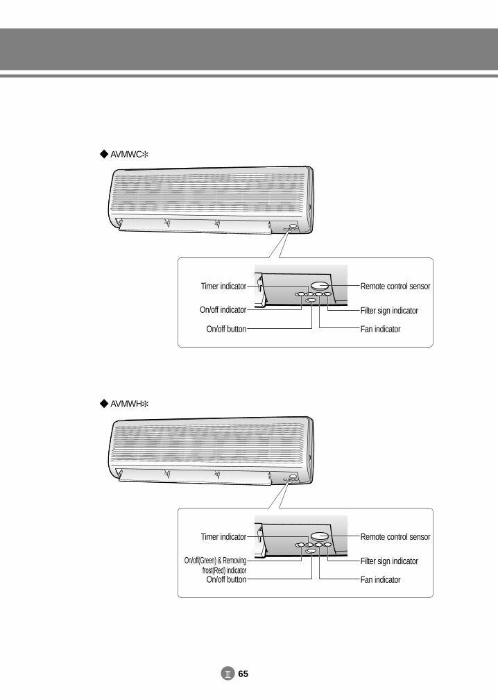
III 65
AVMWC
AVMWH
Remote control sensor
Filter sign indicator
Fan indicator
Timer indicator
On/off indicator
On/off button
Remote control sensor
Filter sign indicator
Fan indicator
Timer indicator
On/off(Green) & Removing frost(Red) indicatorOn/off button
DVM E-D/B(chapter3-2)-E<03759 3/21/02 7:37 PM Page 65
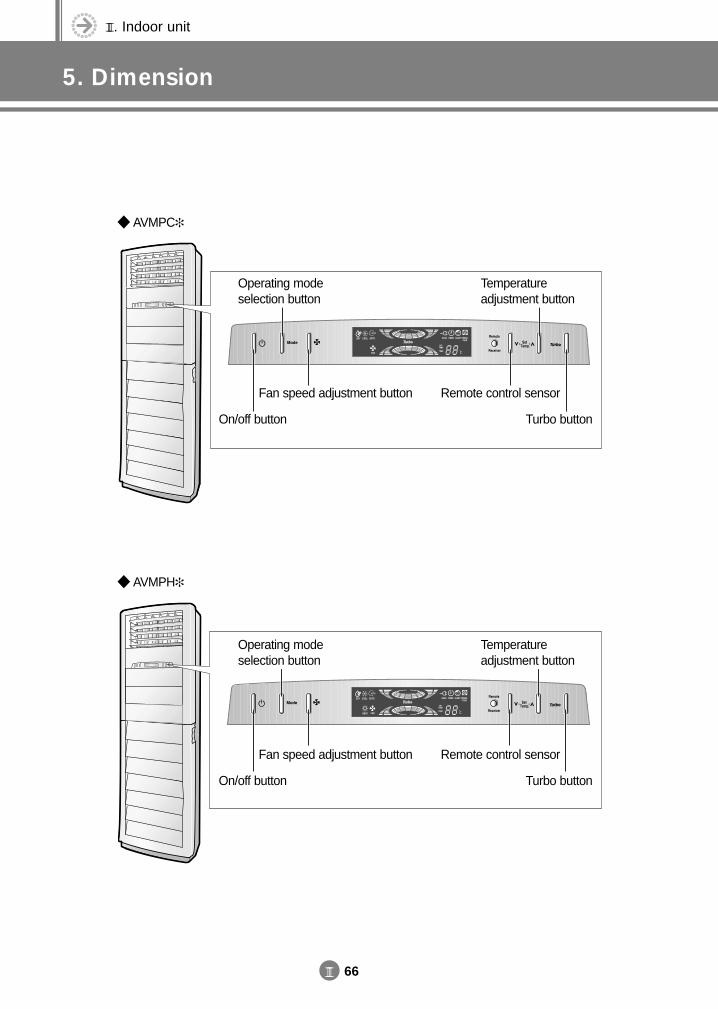
III. Indoor unit
5. Dimension
III 66
AVMPC
AVMPH
On/off button Turbo button
Operating modeselection button
Temperatureadjustment button
Fan speed adjustment button Remote control sensor
On/off button Turbo button
Operating modeselection button
Temperatureadjustment button
Fan speed adjustment button Remote control sensor
DVM E-D/B(chapter3-2)-E<03759 3/21/02 7:37 PM Page 66
III 67
AVMFC
AVMFH
DVM E-D/B(chapter3-2)-E<03759 3/21/02 7:37 PM Page 67
III. Indoor unit
5. Dimension
III 68
(2) For duct type (AVMD / AVMB / AVMH ) MR-AC00
MR-AH00
DVM E-D/B(chapter3-2)-E<03759 3/21/02 7:37 PM Page 68
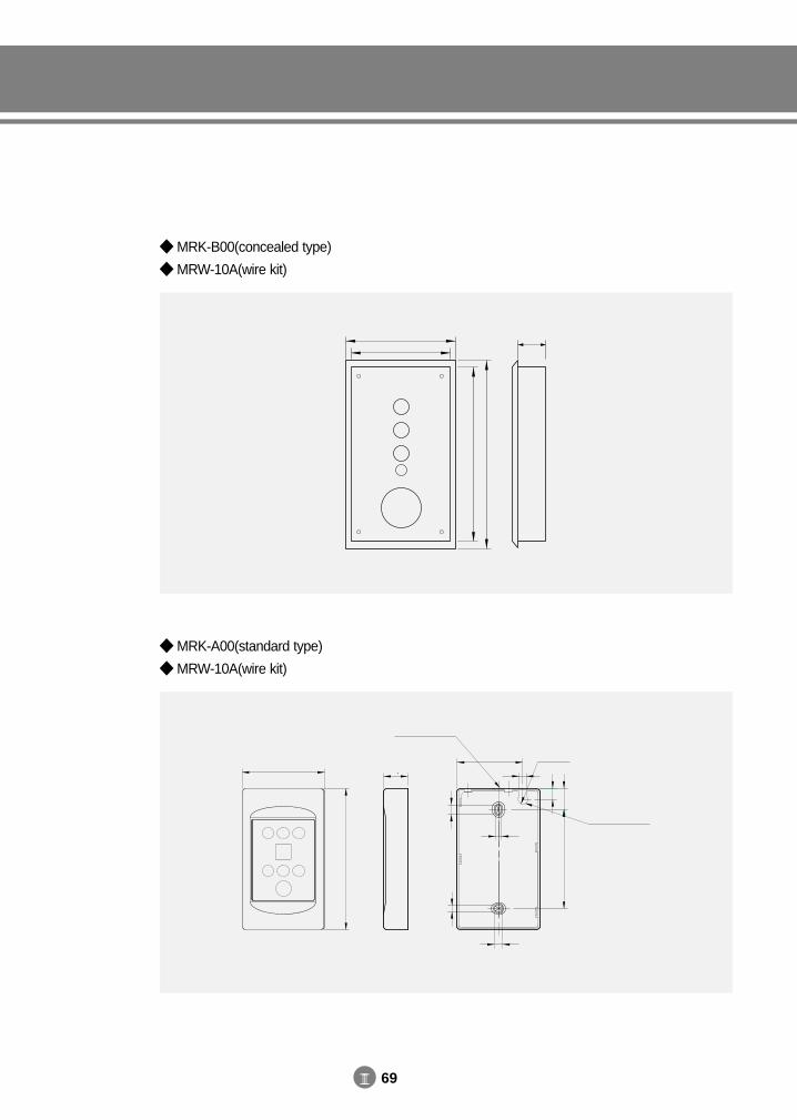
III 69
MRK-B00(concealed type)
MRW-10A(wire kit)
MRK-A00(standard type)
MRW-10A(wire kit)
DVM E-D/B(chapter3-2)-E<03759 3/21/02 7:37 PM Page 69
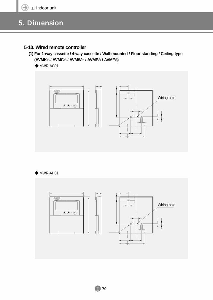
III. Indoor unit
5. Dimension
III 70
5-10. Wired remote controller(1) For 1-way cassette / 4-way cassette / Wall-mounted / Floor standing / Ceiling type
(AVMK / AVMC / AVMW / AVMP / AVMF ) MWR-AC01
MWR-AH01
Wiring hole
Wiring hole
DVM E-D/B(chapter3-2)-E<03759 3/21/02 7:37 PM Page 70
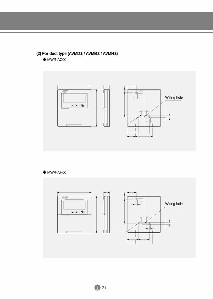
III 71
(2) For duct type (AVMD / AVMB / AVMH ) MWR-AC00
MWR-AH00
Wiring hole
Wiring hole
DVM E-D/B(chapter3-2)-E<03759 3/21/02 7:37 PM Page 71
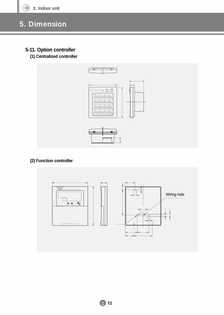
III. Indoor unit
5. Dimension
III 72
5-11. Option controller(1) Centralized controller
(2) Function controller
Wiring hole
DVM E-D/B(chapter3-2)-E<03759 3/21/02 7:37 PM Page 72
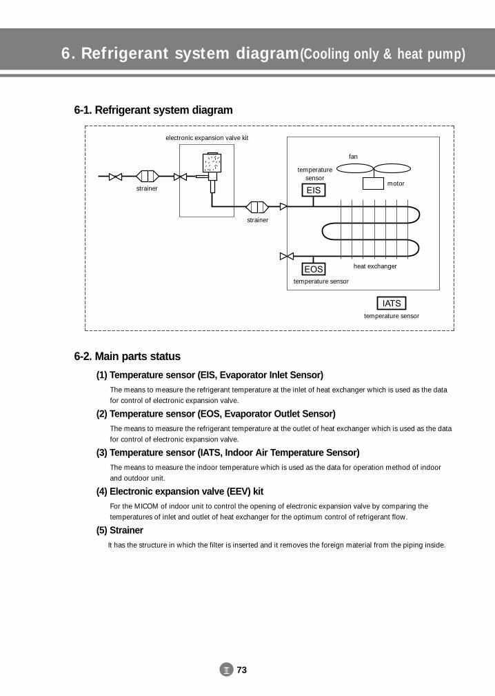
III 73
6. Refrigerant system diagram(Cooling only & heat pump)
6-1. Refrigerant system diagram
6-2. Main parts status
(1) Temperature sensor (EIS, Evaporator Inlet Sensor)The means to measure the refrigerant temperature at the inlet of heat exchanger which is used as the data for control of electronic expansion valve.
(2) Temperature sensor (EOS, Evaporator Outlet Sensor) The means to measure the refrigerant temperature at the outlet of heat exchanger which is used as the data for control of electronic expansion valve.
(3) Temperature sensor (IATS, Indoor Air Temperature Sensor)The means to measure the indoor temperature which is used as the data for operation method of indoor and outdoor unit.
(4) Electronic expansion valve (EEV) kitFor the MICOM of indoor unit to control the opening of electronic expansion valve by comparing the temperatures of inlet and outlet of heat exchanger for the optimum control of refrigerant flow.
(5) StrainerIt has the structure in which the filter is inserted and it removes the foreign material from the piping inside.
motor
fan
temperature sensor
temperature sensor
temperature sensor
heat exchanger
electronic expansion valve kit
strainer
strainer
DVM E-D/B(chapter3-2)-E<03759 3/21/02 7:37 PM Page 73
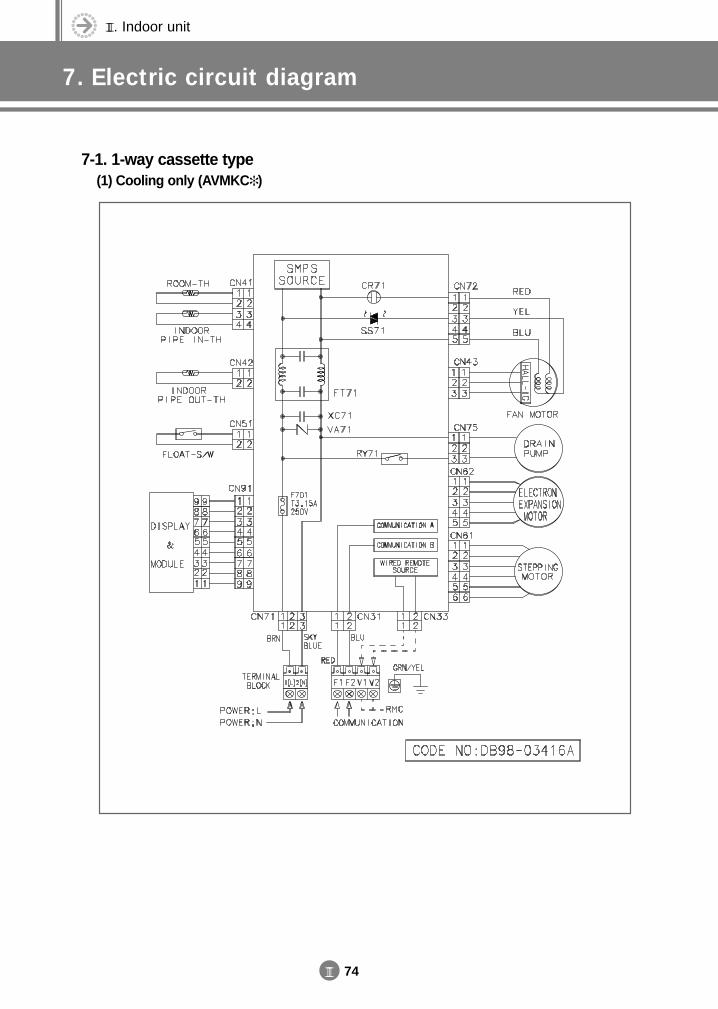
III. Indoor unit
7. Electric circuit diagram
III 74
7-1. 1-way cassette type(1) Cooling only (AVMKC )
DVM E-D/B(chapter3-2)-E<03759 3/21/02 7:37 PM Page 74
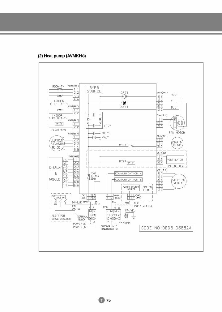
III 75
(2) Heat pump (AVMKH )
DVM E-D/B(chapter3-2)-E<03759 3/21/02 7:37 PM Page 75
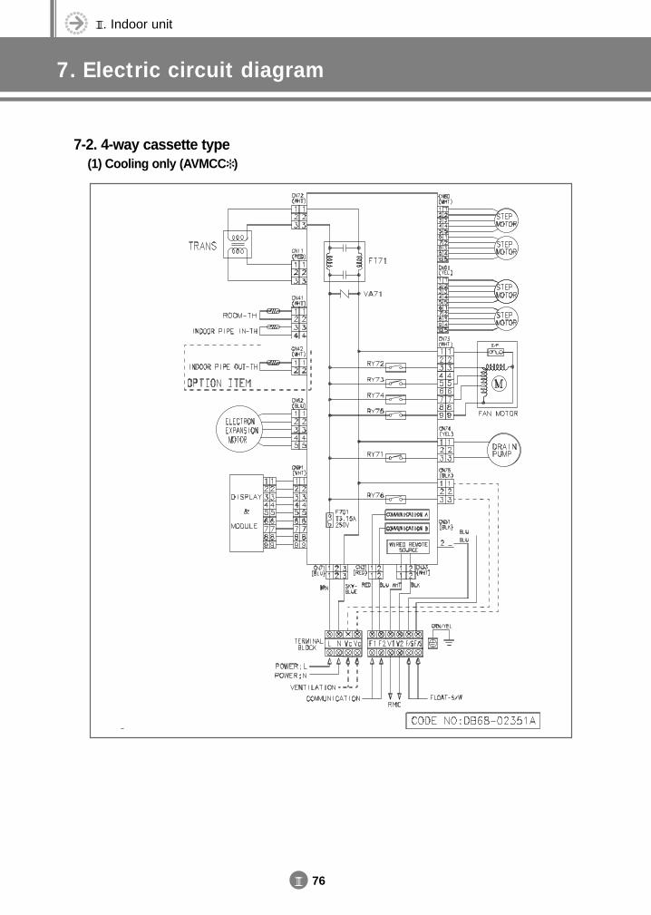
III. Indoor unit
7. Electric circuit diagram
III 76
7-2. 4-way cassette type(1) Cooling only (AVMCC )
DVM E-D/B(chapter3-2)-E<03759 3/21/02 7:37 PM Page 76
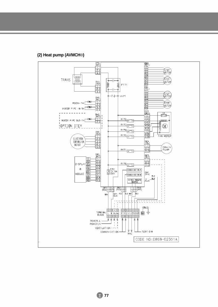
III 77
(2) Heat pump (AVMCH )
DVM E-D/B(chapter3-2)-E<03759 3/21/02 7:37 PM Page 77
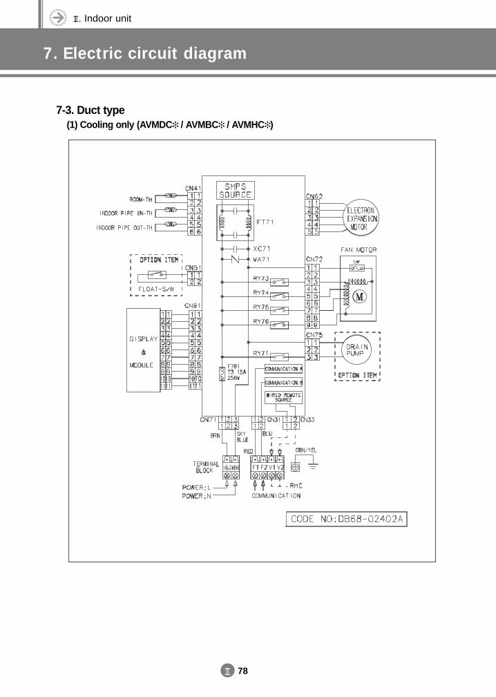
III. Indoor unit
7. Electric circuit diagram
III 78
7-3. Duct type(1) Cooling only (AVMDC / AVMBC / AVMHC )
DVM E-D/B(chapter3-2)-E<03759 3/21/02 7:37 PM Page 78
III 79
(2) Heat pump (AVMDH / AVMBH / AVMHH )
DVM E-D/B(chapter3-2)-E<03759 3/21/02 7:37 PM Page 79

III. Indoor unit
7. Electric circuit diagram
III 80
7-4. Wall-mounted type(1) Cooling only (AVMWC )
DVM E-D/B(chapter3-2)-E<03759 3/21/02 7:37 PM Page 80
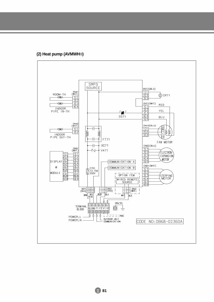
III 81
(2) Heat pump (AVMWH )
DVM E-D/B(chapter3-2)-E<03759 3/21/02 7:37 PM Page 81
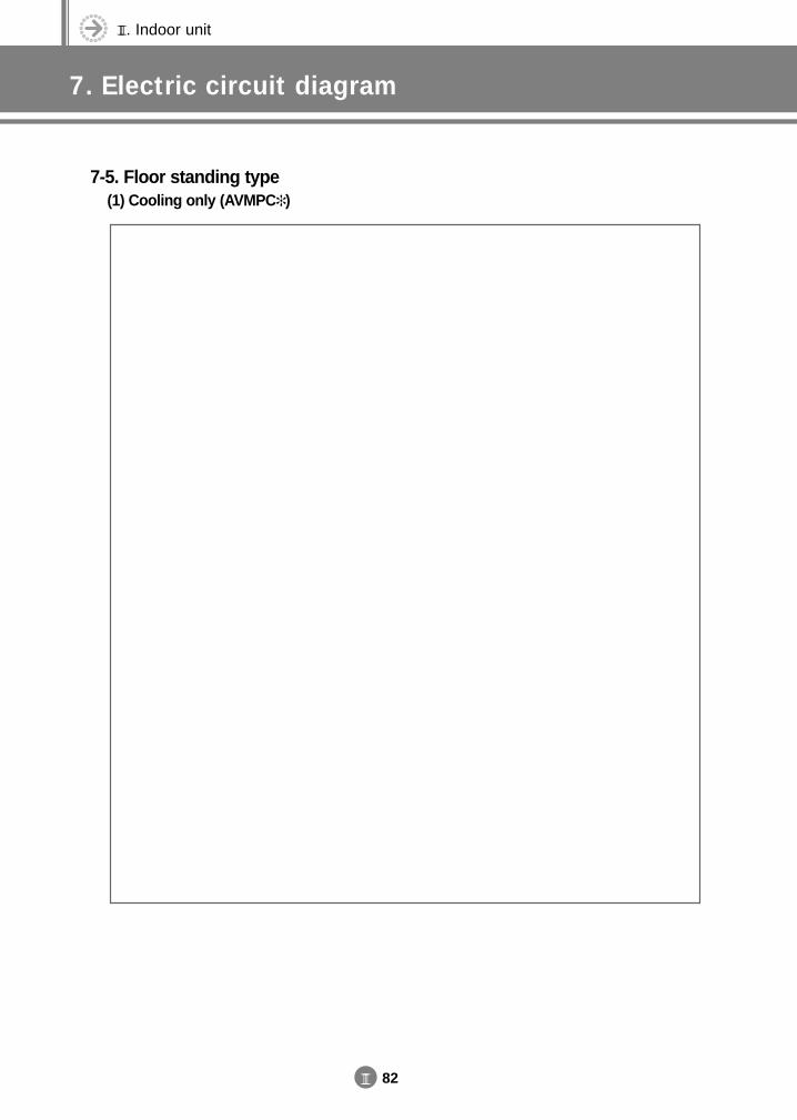
III. Indoor unit
7. Electric circuit diagram
III 82
7-5. Floor standing type(1) Cooling only (AVMPC )
DVM E-D/B(chapter3-3)-E<03759 3/21/02 7:38 PM Page 82
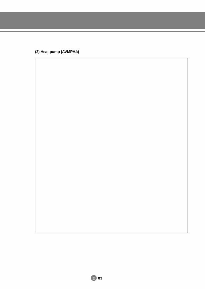
III 83
(2) Heat pump (AVMPH )
DVM E-D/B(chapter3-3)-E<03759 3/21/02 7:38 PM Page 83
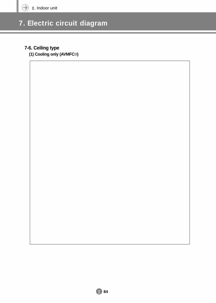
III. Indoor unit
7. Electric circuit diagram
III 84
7-6. Ceiling type(1) Cooling only (AVMFC )
DVM E-D/B(chapter3-3)-E<03759 3/21/02 7:38 PM Page 84

III 85
(2) Heat pump (AVMFH )
DVM E-D/B(chapter3-3)-E<03759 3/21/02 7:38 PM Page 85
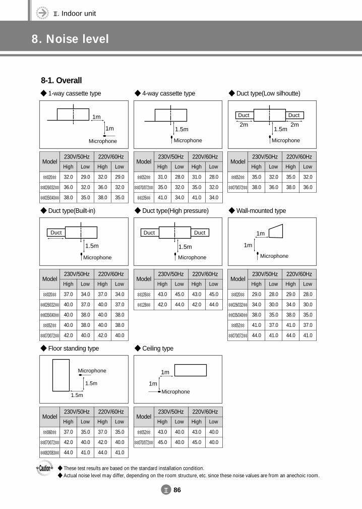
III. Indoor unit
8. Noise level
III 86
8-1. Overall 1-way cassette type
1m
1m
Microphone
Model230V/50Hz 220V/60Hz
High
32.0
36.0
38.0
020
026/032
035/040
Low
29.0
32.0
35.0
Low
29.0
32.0
35.0
High
32.0
36.0
38.0
4-way cassette type
1.5m
Microphone
Model230V/50Hz 220V/60Hz
High
31.0
35.0
41.0
052
070/072
105
Low
28.0
32.0
34.0
Low
28.0
32.0
34.0
High
31.0
35.0
41.0
Duct type(Low silhoutte)
1.5m2m 2m
DuctDuct
Microphone
Model230V/50Hz 220V/60Hz
High
35.0
38.0
052
070/072
Low
32.0
36.0
Low
32.0
36.0
High
35.0
38.0
Duct type(Built-in)
1.5m
Duct
Microphone
Model230V/50Hz 220V/60Hz
High
37.0
40.0
40.0
40.0
42.0
020
026/032
035/040
052
070/072
Low
34.0
37.0
38.0
38.0
40.0
Low
34.0
37.0
38.0
38.0
40.0
High
37.0
40.0
40.0
40.0
42.0
Model230V/50Hz 220V/60Hz
High
29.0
34.0
38.0
41.0
44.0
020
026/032
035/040
052
070/072
Low
28.0
30.0
35.0
37.0
41.0
Low
28.0
30.0
35.0
37.0
41.0
High
29.0
34.0
38.0
41.0
44.0
Duct type(High pressure)
1.5m
Duct Duct
Microphone
Wall-mounted type
1m
1m
Microphone
Model230V/50Hz 220V/60Hz
High
43.0
42.0
105
128
Low
45.0
44.0
Low
45.0
44.0
High
43.0
42.0
Floor standing type
1.5m
1.5m
Microphone
Model230V/50Hz 220V/60Hz
High
37.0
42.0
44.0
060
070/072
082/083
Low
35.0
40.0
41.0
Low
35.0
40.0
41.0
High
37.0
42.0
44.0
Ceiling type
1m
1mMicrophone
Model230V/50Hz 220V/60Hz
High
43.0
45.0
052
070/072
Low
40.0
40.0
Low
40.0
40.0
High
43.0
45.0
These test results are based on the standard installation condition. Actual noise level may differ, depending on the room structure, etc. since these noise values are from an anechoic room.
DVM E-D/B(chapter3-3)-E<03759 3/21/02 7:38 PM Page 86
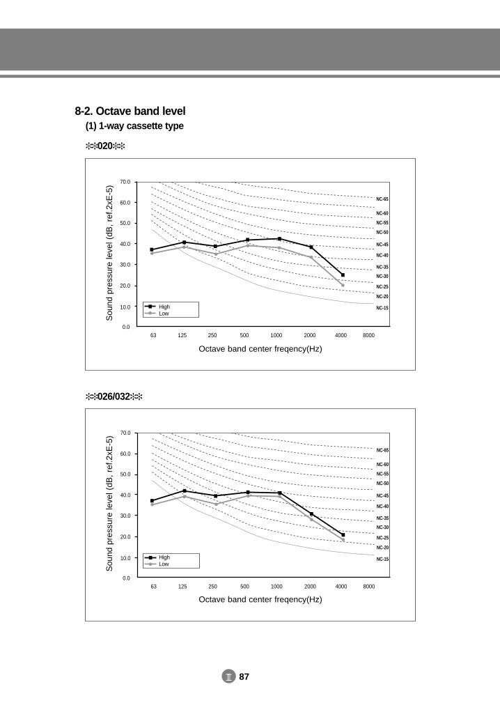
III 87
020
Sou
nd p
ress
ure
leve
l (dB
, re
f.2xE
-5) 70.0
60.0
50.0
40.0
30.0
20.0
10.0
0.063 125 250 500 1000 40002000 8000
NC-65
NC-60
NC-55
NC-50
NC-45
NC-40
NC-35
NC-30
NC-25
NC-20
NC-15
Octave band center freqency(Hz)
HighLow
026/032
Sou
nd p
ress
ure
leve
l (dB
, re
f.2xE
-5) 70.0
60.0
50.0
40.0
30.0
20.0
10.0
0.063 125 250 500 1000 40002000 8000
NC-65
NC-60
NC-55
NC-50
NC-45
NC-40
NC-35
NC-30
NC-25
NC-20
NC-15
Octave band center freqency(Hz)
HighLow
8-2. Octave band level(1) 1-way cassette type
DVM E-D/B(chapter3-3)-E<03759 3/21/02 7:38 PM Page 87
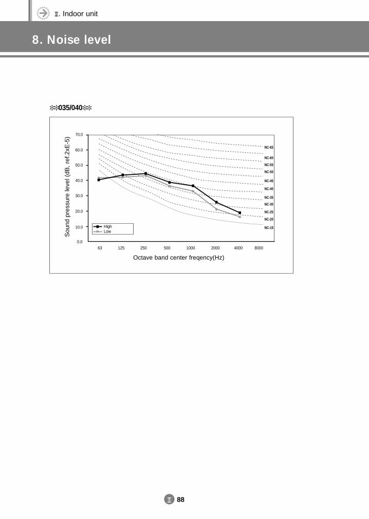
III. Indoor unit
8. Noise level
III 88
035/040
Sou
nd p
ress
ure
leve
l (dB
, re
f.2xE
-5) 70.0
60.0
50.0
40.0
30.0
20.0
10.0
0.063 125 250 500 1000 40002000 8000
NC-65
NC-60
NC-55
NC-50
NC-45
NC-40
NC-35
NC-30
NC-25
NC-20
NC-15
Octave band center freqency(Hz)
HighLow
DVM E-D/B(chapter3-3)-E<03759 3/21/02 7:38 PM Page 88
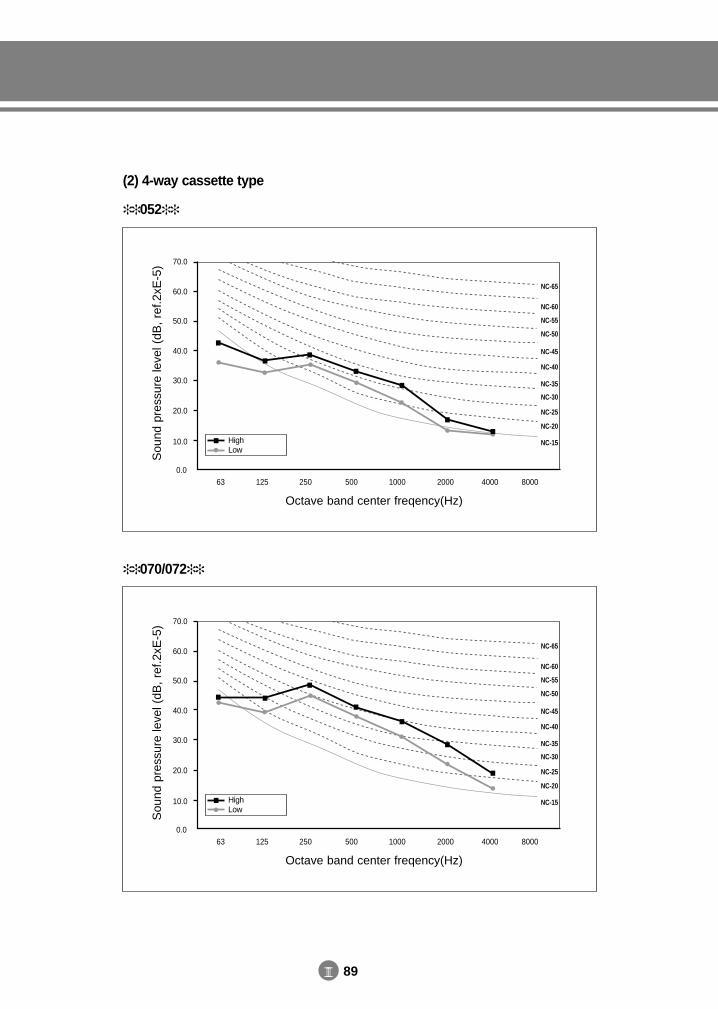
III 89
052
Sou
nd p
ress
ure
leve
l (dB
, re
f.2xE
-5) 70.0
60.0
50.0
40.0
30.0
20.0
10.0
0.063 125 250 500 1000 40002000 8000
NC-65
NC-60
NC-55
NC-50
NC-45
NC-40
NC-35
NC-30
NC-25
NC-20
NC-15
Octave band center freqency(Hz)
HighLow
(2) 4-way cassette type
070/072
Sou
nd p
ress
ure
leve
l (dB
, re
f.2xE
-5) 70.0
60.0
50.0
40.0
30.0
20.0
10.0
0.063 125 250 500 1000 40002000 8000
NC-65
NC-60
NC-55
NC-50
NC-45
NC-40
NC-35
NC-30
NC-25
NC-20
NC-15
Octave band center freqency(Hz)
HighLow
DVM E-D/B(chapter3-3)-E<03759 3/21/02 7:38 PM Page 89
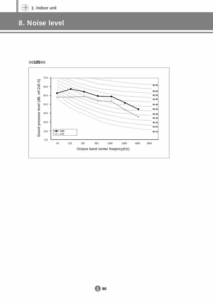
III. Indoor unit
8. Noise level
III 90
105
Sou
nd p
ress
ure
leve
l (dB
, re
f.2xE
-5) 70.0
60.0
50.0
40.0
30.0
20.0
10.0
0.063 125 250 500 1000 40002000 8000
NC-65
NC-60
NC-55
NC-50
NC-45
NC-40
NC-35
NC-30
NC-25
NC-20
NC-15
Octave band center freqency(Hz)
HighLow
DVM E-D/B(chapter3-3)-E<03759 3/21/02 7:38 PM Page 90
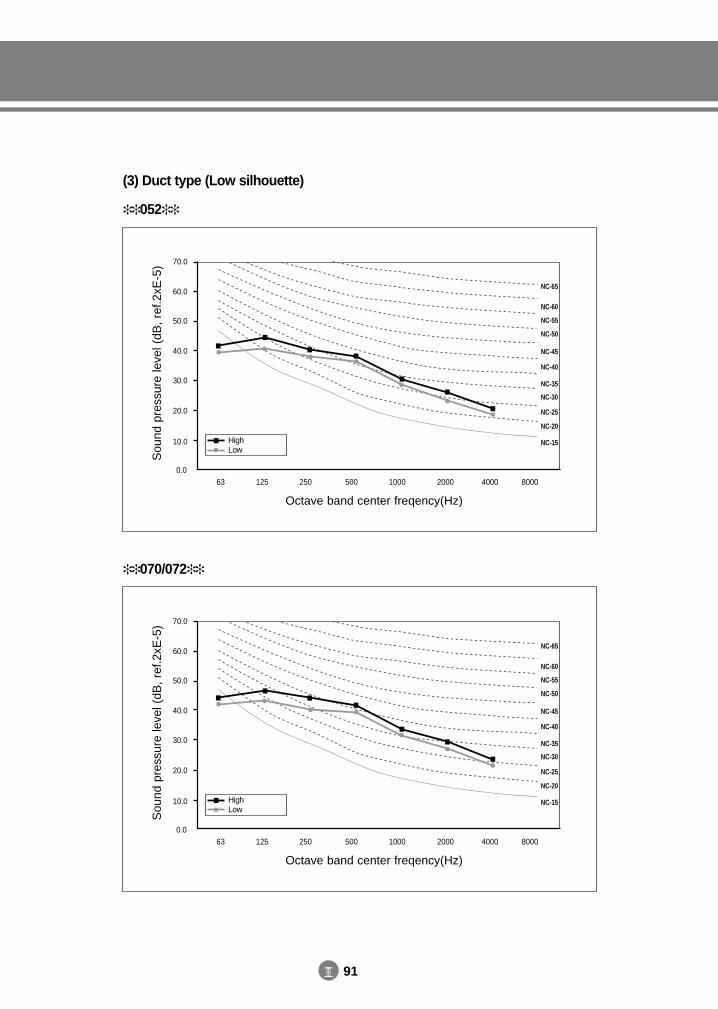
III 91
052
Sou
nd p
ress
ure
leve
l (dB
, re
f.2xE
-5) 70.0
60.0
50.0
40.0
30.0
20.0
10.0
0.063 125 250 500 1000 40002000 8000
NC-65
NC-60
NC-55
NC-50
NC-45
NC-40
NC-35
NC-30
NC-25
NC-20
NC-15
Octave band center freqency(Hz)
HighLow
(3) Duct type (Low silhouette)
070/072
Sou
nd p
ress
ure
leve
l (dB
, re
f.2xE
-5) 70.0
60.0
50.0
40.0
30.0
20.0
10.0
0.063 125 250 500 1000 40002000 8000
NC-65
NC-60
NC-55
NC-50
NC-45
NC-40
NC-35
NC-30
NC-25
NC-20
NC-15
Octave band center freqency(Hz)
HighLow
DVM E-D/B(chapter3-3)-E<03759 3/21/02 7:38 PM Page 91
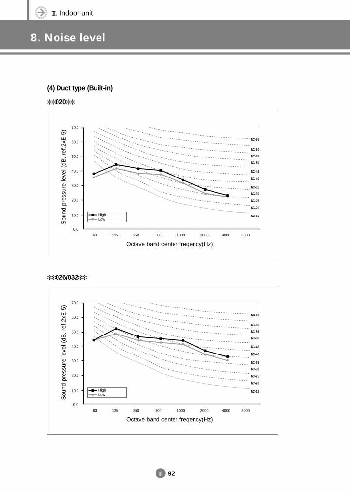
III. Indoor unit
8. Noise level
III 92
020
Sou
nd p
ress
ure
leve
l (dB
, re
f.2xE
-5) 70.0
60.0
50.0
40.0
30.0
20.0
10.0
0.063 125 250 500 1000 40002000 8000
NC-65
NC-60
NC-55
NC-50
NC-45
NC-40
NC-35
NC-30
NC-25
NC-20
NC-15
Octave band center freqency(Hz)
HighLow
(4) Duct type (Built-in)
026/032
Sou
nd p
ress
ure
leve
l (dB
, re
f.2xE
-5) 70.0
60.0
50.0
40.0
30.0
20.0
10.0
0.063 125 250 500 1000 40002000 8000
NC-65
NC-60
NC-55
NC-50
NC-45
NC-40
NC-35
NC-30
NC-25
NC-20
NC-15
Octave band center freqency(Hz)
HighLow
DVM E-D/B(chapter3-3)-E<03759 3/21/02 7:38 PM Page 92
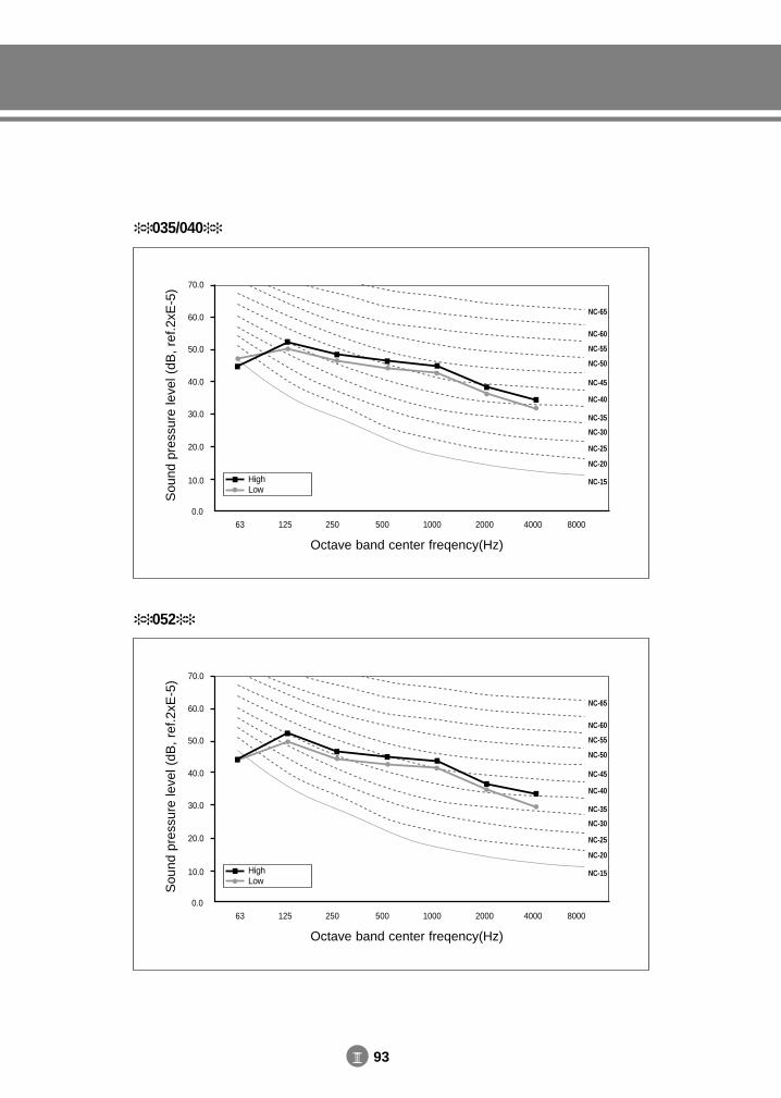
III 93
035/040
Sou
nd p
ress
ure
leve
l (dB
, re
f.2xE
-5) 70.0
60.0
50.0
40.0
30.0
20.0
10.0
0.063 125 250 500 1000 40002000 8000
NC-65
NC-60
NC-55
NC-50
NC-45
NC-40
NC-35
NC-30
NC-25
NC-20
NC-15
Octave band center freqency(Hz)
HighLow
052
Sou
nd p
ress
ure
leve
l (dB
, re
f.2xE
-5) 70.0
60.0
50.0
40.0
30.0
20.0
10.0
0.063 125 250 500 1000 40002000 8000
NC-65
NC-60
NC-55
NC-50
NC-45
NC-40
NC-35
NC-30
NC-25
NC-20
NC-15
Octave band center freqency(Hz)
HighLow
DVM E-D/B(chapter3-3)-E<03759 3/21/02 7:38 PM Page 93
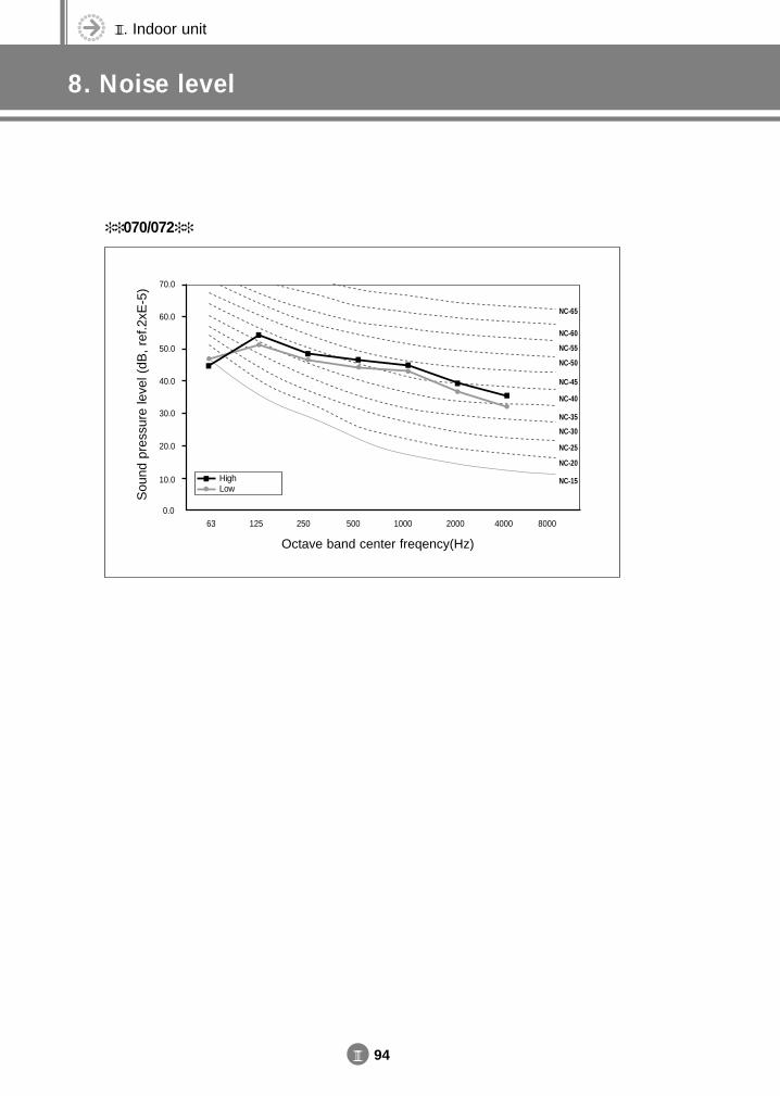
III. Indoor unit
8. Noise level
III 94
070/072
Sou
nd p
ress
ure
leve
l (dB
, re
f.2xE
-5) 70.0
60.0
50.0
40.0
30.0
20.0
10.0
0.063 125 250 500 1000 40002000 8000
NC-65
NC-60
NC-55
NC-50
NC-45
NC-40
NC-35
NC-30
NC-25
NC-20
NC-15
Octave band center freqency(Hz)
HighLow
DVM E-D/B(chapter3-3)-E<03759 3/21/02 7:38 PM Page 94
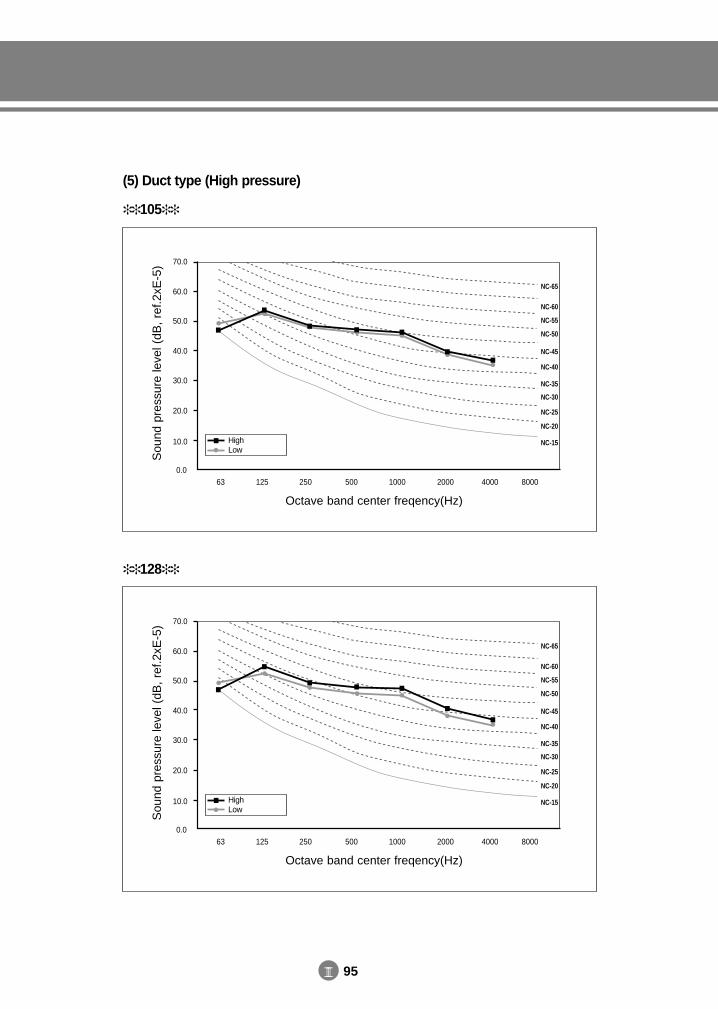
III 95
105
Sou
nd p
ress
ure
leve
l (dB
, re
f.2xE
-5) 70.0
60.0
50.0
40.0
30.0
20.0
10.0
0.063 125 250 500 1000 40002000 8000
NC-65
NC-60
NC-55
NC-50
NC-45
NC-40
NC-35
NC-30
NC-25
NC-20
NC-15
Octave band center freqency(Hz)
HighLow
(5) Duct type (High pressure)
128
Sou
nd p
ress
ure
leve
l (dB
, re
f.2xE
-5) 70.0
60.0
50.0
40.0
30.0
20.0
10.0
0.063 125 250 500 1000 40002000 8000
NC-65
NC-60
NC-55
NC-50
NC-45
NC-40
NC-35
NC-30
NC-25
NC-20
NC-15
Octave band center freqency(Hz)
HighLow
DVM E-D/B(chapter3-3)-E<03759 3/21/02 7:38 PM Page 95
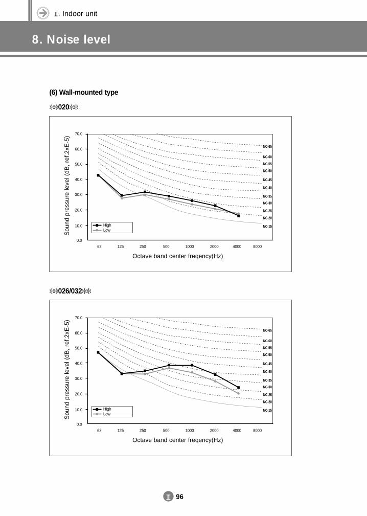
III. Indoor unit
8. Noise level
III 96
020
Sou
nd p
ress
ure
leve
l (dB
, re
f.2xE
-5) 70.0
60.0
50.0
40.0
30.0
20.0
10.0
0.063 125 250 500 1000 40002000 8000
NC-65
NC-60
NC-55
NC-50
NC-45
NC-40
NC-35
NC-30
NC-25
NC-20
NC-15
Octave band center freqency(Hz)
HighLow
(6) Wall-mounted type
026/032
Sou
nd p
ress
ure
leve
l (dB
, re
f.2xE
-5) 70.0
60.0
50.0
40.0
30.0
20.0
10.0
0.063 125 250 500 1000 40002000 8000
NC-65
NC-60
NC-55
NC-50
NC-45
NC-40
NC-35
NC-30
NC-25
NC-20
NC-15
Octave band center freqency(Hz)
HighLow
DVM E-D/B(chapter3-3)-E<03759 3/21/02 7:38 PM Page 96
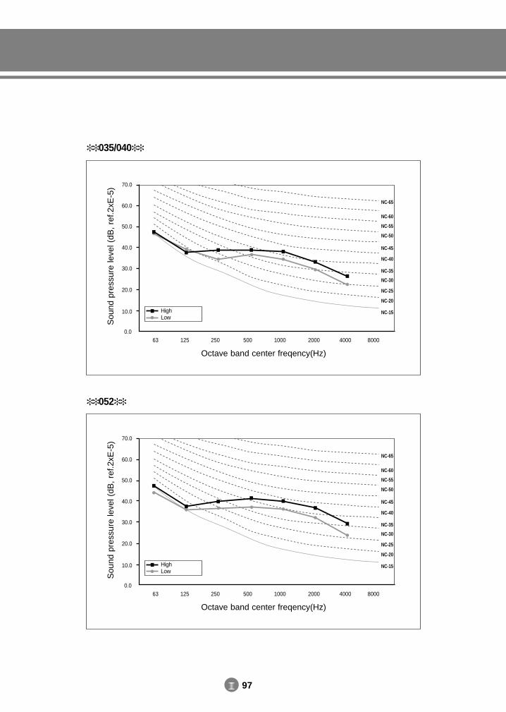
III 97
035/040
Sou
nd p
ress
ure
leve
l (dB
, re
f.2xE
-5) 70.0
60.0
50.0
40.0
30.0
20.0
10.0
0.063 125 250 500 1000 40002000 8000
NC-65
NC-60
NC-55
NC-50
NC-45
NC-40
NC-35
NC-30
NC-25
NC-20
NC-15
Octave band center freqency(Hz)
HighLow
052
Sou
nd p
ress
ure
leve
l (dB
, re
f.2xE
-5) 70.0
60.0
50.0
40.0
30.0
20.0
10.0
0.063 125 250 500 1000 40002000 8000
NC-65
NC-60
NC-55
NC-50
NC-45
NC-40
NC-35
NC-30
NC-25
NC-20
NC-15
Octave band center freqency(Hz)
HighLow
DVM E-D/B(chapter3-3)-E<03759 3/21/02 7:38 PM Page 97
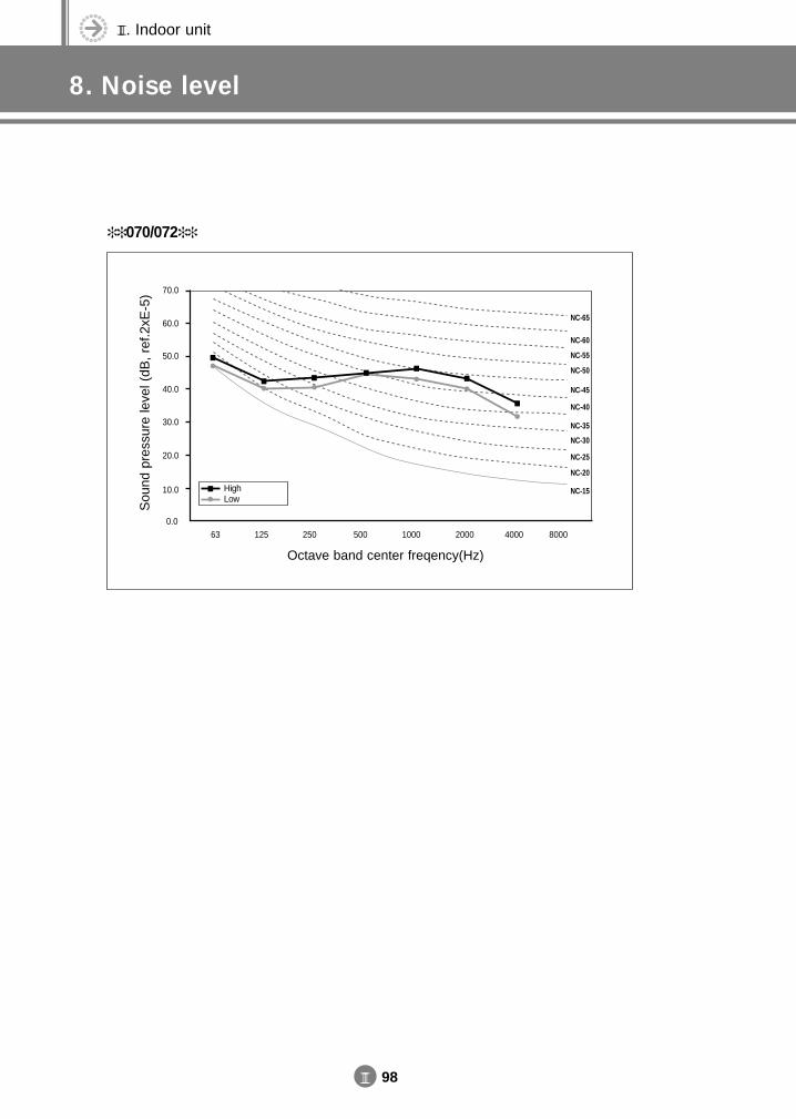
III. Indoor unit
8. Noise level
III 98
070/072
Sou
nd p
ress
ure
leve
l (dB
, re
f.2xE
-5) 70.0
60.0
50.0
40.0
30.0
20.0
10.0
0.063 125 250 500 1000 40002000 8000
NC-65
NC-60
NC-55
NC-50
NC-45
NC-40
NC-35
NC-30
NC-25
NC-20
NC-15
Octave band center freqency(Hz)
HighLow
DVM E-D/B(chapter3-3)-E<03759 3/21/02 7:38 PM Page 98
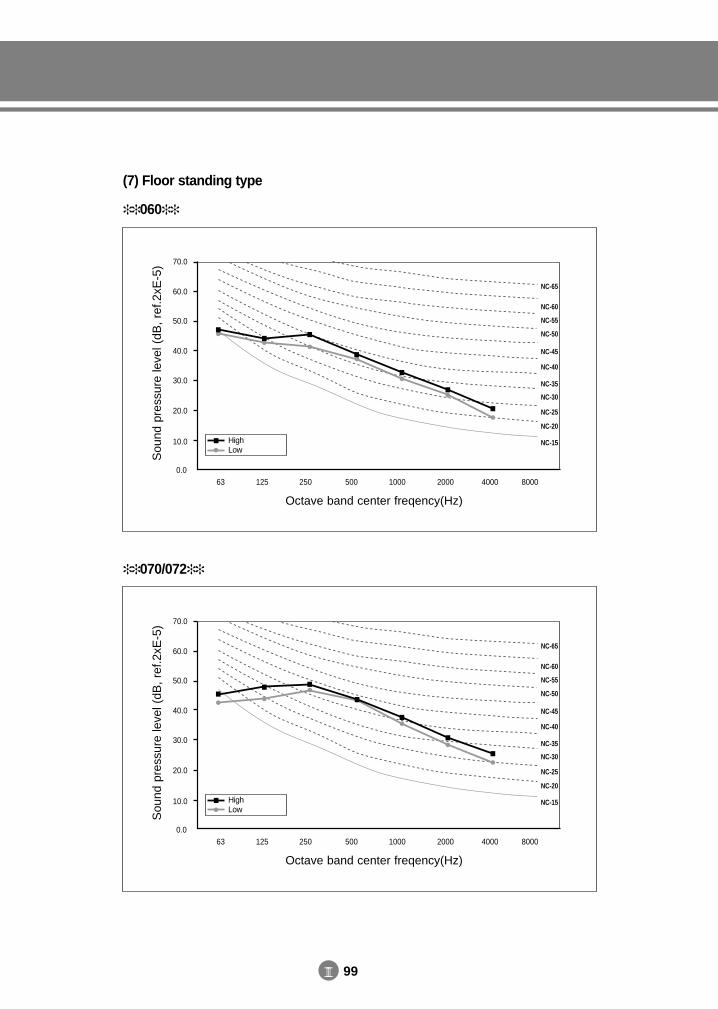
III 99
060
Sou
nd p
ress
ure
leve
l (dB
, re
f.2xE
-5) 70.0
60.0
50.0
40.0
30.0
20.0
10.0
0.063 125 250 500 1000 40002000 8000
NC-65
NC-60
NC-55
NC-50
NC-45
NC-40
NC-35
NC-30
NC-25
NC-20
NC-15
Octave band center freqency(Hz)
HighLow
(7) Floor standing type
070/072
Sou
nd p
ress
ure
leve
l (dB
, re
f.2xE
-5) 70.0
60.0
50.0
40.0
30.0
20.0
10.0
0.063 125 250 500 1000 40002000 8000
NC-65
NC-60
NC-55
NC-50
NC-45
NC-40
NC-35
NC-30
NC-25
NC-20
NC-15
Octave band center freqency(Hz)
HighLow
DVM E-D/B(chapter3-3)-E<03759 3/21/02 7:38 PM Page 99
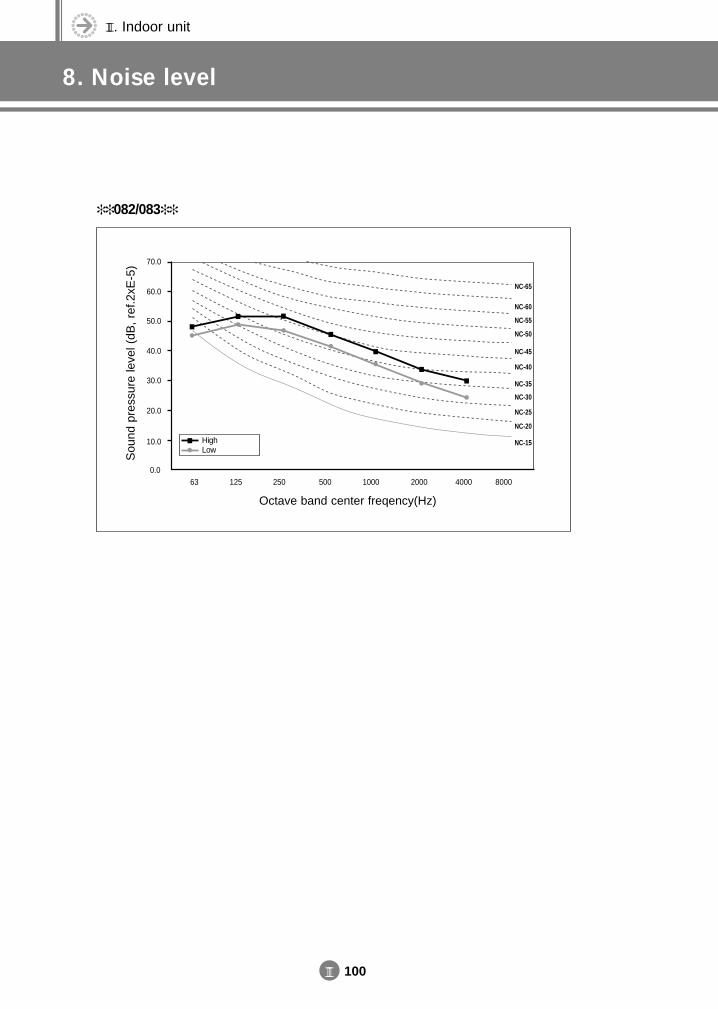
III. Indoor unit
8. Noise level
III 100
082/083
Sou
nd p
ress
ure
leve
l (dB
, re
f.2xE
-5) 70.0
60.0
50.0
40.0
30.0
20.0
10.0
0.063 125 250 500 1000 40002000 8000
NC-65
NC-60
NC-55
NC-50
NC-45
NC-40
NC-35
NC-30
NC-25
NC-20
NC-15
Octave band center freqency(Hz)
HighLow
DVM E-D/B(chapter3-3)-E<03759 3/21/02 7:38 PM Page 100
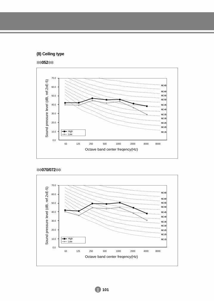
III 101
052
Sou
nd p
ress
ure
leve
l (dB
, re
f.2xE
-5) 70.0
60.0
50.0
40.0
30.0
20.0
10.0
0.063 125 250 500 1000 40002000 8000
NC-65
NC-60
NC-55
NC-50
NC-45
NC-40
NC-35
NC-30
NC-25
NC-20
NC-15
Octave band center freqency(Hz)
HighLow
(8) Ceiling type
070/072
Sou
nd p
ress
ure
leve
l (dB
, re
f.2xE
-5) 70.0
60.0
50.0
40.0
30.0
20.0
10.0
0.063 125 250 500 1000 40002000 8000
NC-65
NC-60
NC-55
NC-50
NC-45
NC-40
NC-35
NC-30
NC-25
NC-20
NC-15
Octave band center freqency(Hz)
HighLow
DVM E-D/B(chapter3-3)-E<03759 3/21/02 7:38 PM Page 101
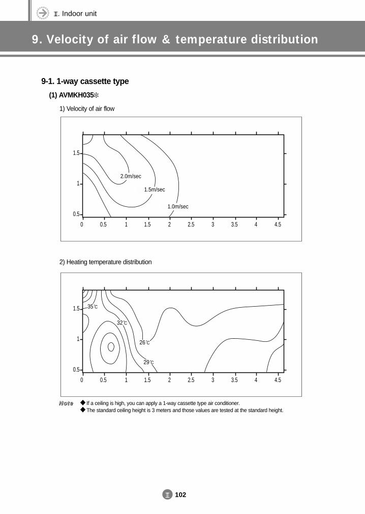
III. Indoor unit
9. Velocity of air flow & temperature distribution
III 102
9-1. 1-way cassette type
(1) AVMKH035
1) Velocity of air flow
2) Heating temperature distribution
If a ceiling is high, you can apply a 1-way cassette type air conditioner. The standard ceiling height is 3 meters and those values are tested at the standard height.
NNNNooootttteeee
1.5
1
0.5
0 0.5 1 1.5 2 2.5 3 3.5 4 4.5
2.0m/sec
1.5m/sec
1.0m/sec
1.5
1
0.5
0 0.5 1 1.5 2 2.5 3 3.5 4 4.5
29 C
26 C
35 C
32 C
DVM E-D/B(chapter3-3)-E<03759 3/21/02 7:38 PM Page 102
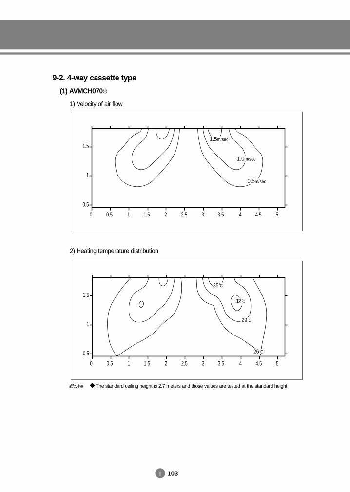
III 103
9-2. 4-way cassette type
(1) AVMCH070
1) Velocity of air flow
2) Heating temperature distribution
The standard ceiling height is 2.7 meters and those values are tested at the standard height.NNNNooootttteeee
1.5
1
0.5
0 0.5 1 1.5 2 2.5 3 3.5 4 4.5 5
1.0m/sec
0.5m/sec
1.5m/sec
1.5
1
0.5
0 0.5 1 1.5 2 2.5 3 3.5 4 4.5 5
26 C
35 C
32 C
29 C
DVM E-D/B(chapter3-3)-E<03759 3/21/02 7:38 PM Page 103
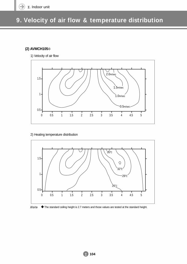
III. Indoor unit
9. Velocity of air flow & temperature distribution
III 104
(2) AVMCH105
1) Velocity of air flow
2) Heating temperature distribution
The standard ceiling height is 2.7 meters and those values are tested at the standard height.NNNNooootttteeee
1.5
1
0.5
0 0.5 1 1.5 2 2.5 3 3.5 4 4.5 5
0.5m/sec
1.0m/sec
1.5m/sec
2.0m/sec
1.5
1
0.5
0 0.5 1 1.5 2 2.5 3 3.5 4 4.5 5
35 C
32 C
29 C
26 C
DVM E-D/B(chapter3-3)-E<03759 3/21/02 7:38 PM Page 104
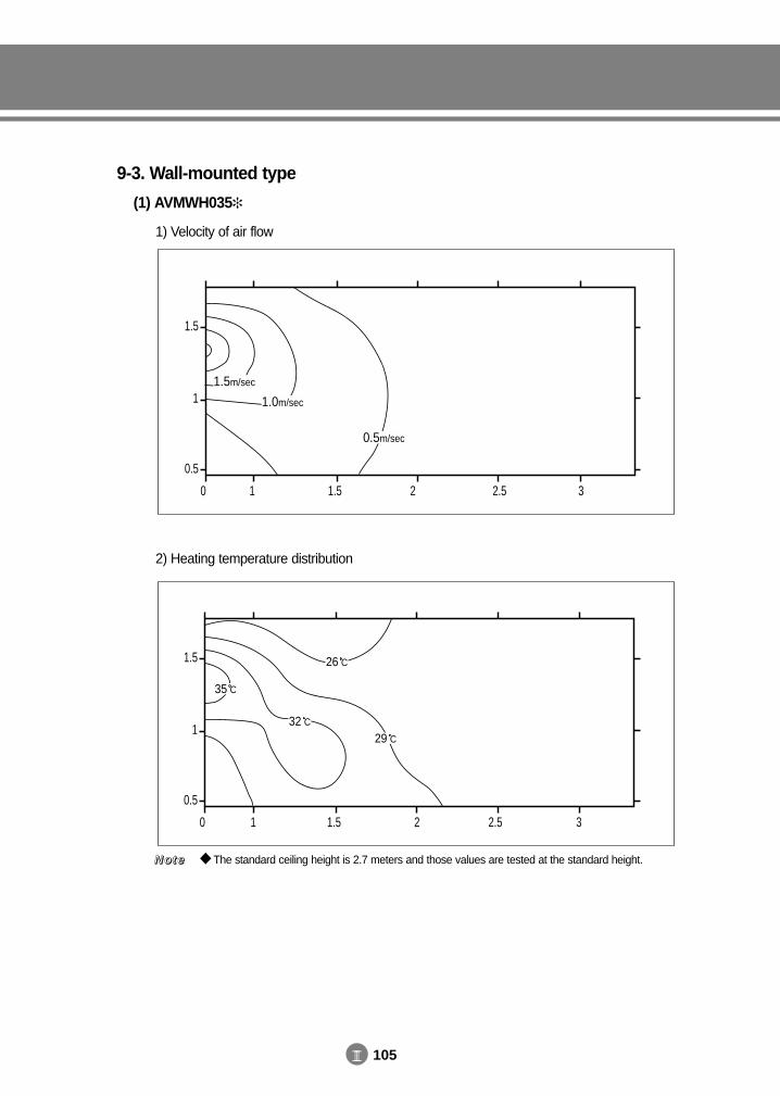
III 105
9-3. Wall-mounted type
(1) AVMWH035
1) Velocity of air flow
2) Heating temperature distribution
The standard ceiling height is 2.7 meters and those values are tested at the standard height.NNNNooootttteeee
1.5
1
0.5
0 1 1.5 2 2.5 3
0.5m/sec
1.0m/sec
1.5m/sec
1.5
1
0.5
0 1 1.5 2 2.5 3
35 C
32 C
26 C
29 C
DVM E-D/B(chapter3-3)-E<03759 3/21/02 7:38 PM Page 105
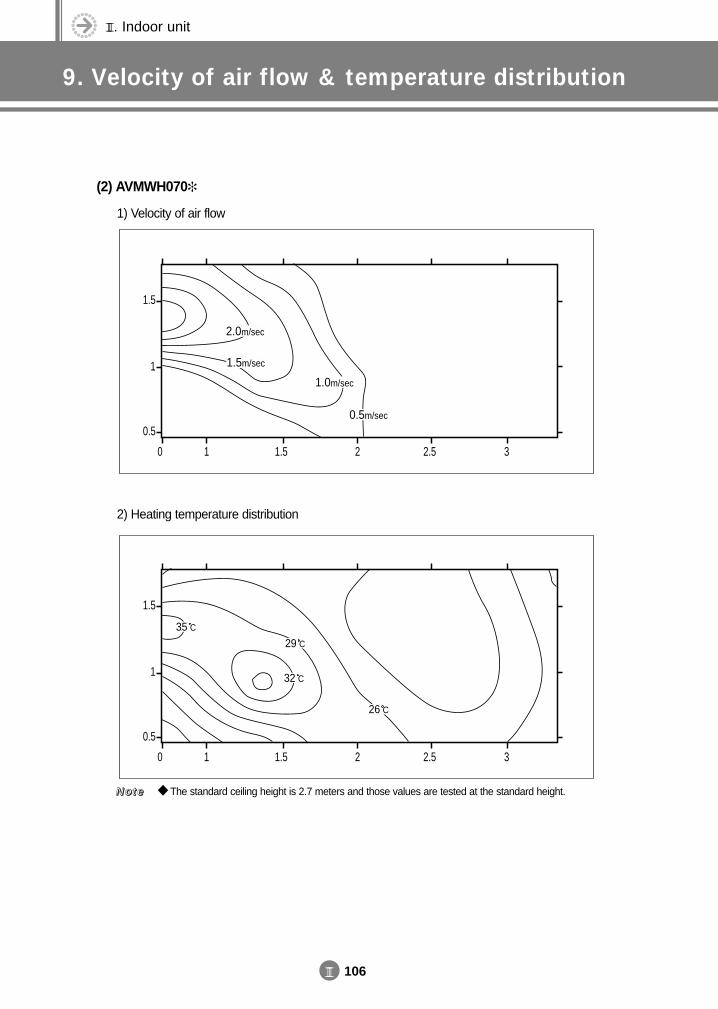
III. Indoor unit
9. Velocity of air flow & temperature distribution
III 106
(2) AVMWH070
1) Velocity of air flow
2) Heating temperature distribution
The standard ceiling height is 2.7 meters and those values are tested at the standard height.NNNNooootttteeee
1.5
1
0.5
0 1 1.5 2 2.5 3
0.5m/sec
1.5m/sec
1.0m/sec
2.0m/sec
1.5
1
0.5
0 1 1.5 2 2.5 3
35 C29 C
32 C
26 C
DVM E-D/B(chapter3-3)-E<03759 3/21/02 7:38 PM Page 106
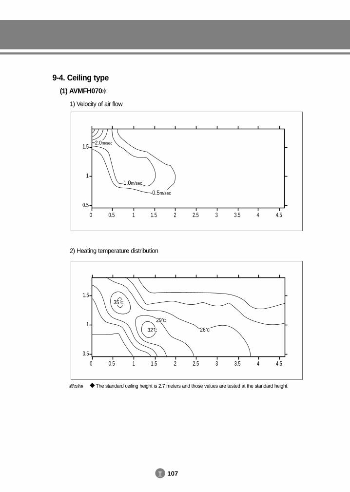
III 107
9-4. Ceiling type
(1) AVMFH070
1) Velocity of air flow
2) Heating temperature distribution
The standard ceiling height is 2.7 meters and those values are tested at the standard height.NNNNooootttteeee
1.5
1
0.5
0 0.5 1 1.5 2 2.5 3 3.5 4 4.5
0.5m/sec
2.0m/sec
1.0m/sec
1.5
1
0.5
0 0.5 1 1.5 2 2.5 3 3.5 4 4.5
26 C
29 C
32 C
35 C
DVM E-D/B(chapter3-3)-E<03759 3/21/02 7:38 PM Page 107
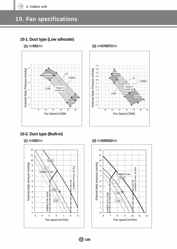
III. Indoor unit
10. Fan specifications
III 108
10-1. Duct type (Low silhoutte)
(1) 052 (2) 070/072
10-2. Duct type (Built-in)
(1) 020 (2) 026/032
Ext
erna
l Sta
tic P
ress
ure
(mm
Aq)
Fan Speed (CMM)10
3
4
5
6
7
8
9
10
11
12
13
14
12 14 16 18 20 22
HITURBO
LOW
Reliable
Range ofnormal use
ReliableE
xter
nal s
tatic
pre
ssur
e (m
mA
q)
10
9
11
12
8
7
6
5
4
3
2
1
06 7 8 9 10 11 12
LOW
MID
HI
TURBO
Fan speed (m3/min)
Lim
itatio
n of
min
. air
flow
Lim
itatio
n of
max
. air
flow
Limitation of use
Ext
erna
l sta
tic p
ress
ure
(mm
Aq)
10
9
11
12
8
7
6
5
4
3
2
1
03 4 5 6 7 8 9
LOW
MID
HI
TURBO
Fan speed (m3/min)
Limitation of use
Lim
itatio
n of
max
. air
flow
Lim
itatio
n of
min
. air
flow
Ext
erna
l Sta
tic P
ress
ure
(mm
Aq)
Fan Speed (CMM)9
3
4
5
6
7
8
10 11 13 14 15
HI
TURBO
LOW
Reliable
Range ofnormal use
Reliable
DVM E-D/B(chapter3-3)-E<03759 3/21/02 7:38 PM Page 108
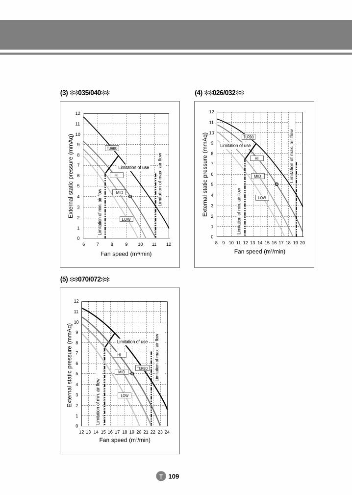
III 109
(3) 035/040 (4) 026/032
Ext
erna
l sta
tic p
ress
ure
(mm
Aq) 10
9
11
12
8
7
6
5
4
3
2
1
06 7 8 9 10 11 12
LOW
MID
HI
TURBO
Fan speed (m3/min)
Lim
itatio
n of
min
. air
flow
Lim
itatio
n of
max
. ai
r flo
w
Limitation of use
Ext
erna
l sta
tic p
ress
ure
(mm
Aq) 10
9
11
12
8
7
6
5
4
3
2
1
08 9 10 11 12 13 14 15 16 17 18 19 20
LOW
MID
HI
TURBO
Fan speed (m3/min)
Lim
itatio
n of
min
. air
flow
Lim
itatio
n of
max
. ai
r flo
w
Limitation of use
(5) 070/072
Ext
erna
l sta
tic p
ress
ure
(mm
Aq)
10
9
11
12
8
7
6
5
4
3
2
1
012 13 14 15 16 17 18 19 20 21 22 23 24
LOW
MID
HI
TURBO
Fan speed (m3/min)
Lim
itatio
n of
min
. air
flow Li
mita
tion
of m
ax. a
ir flo
w
Limitation of use
DVM E-D/B(chapter3-3)-E<03759 3/21/02 7:38 PM Page 109
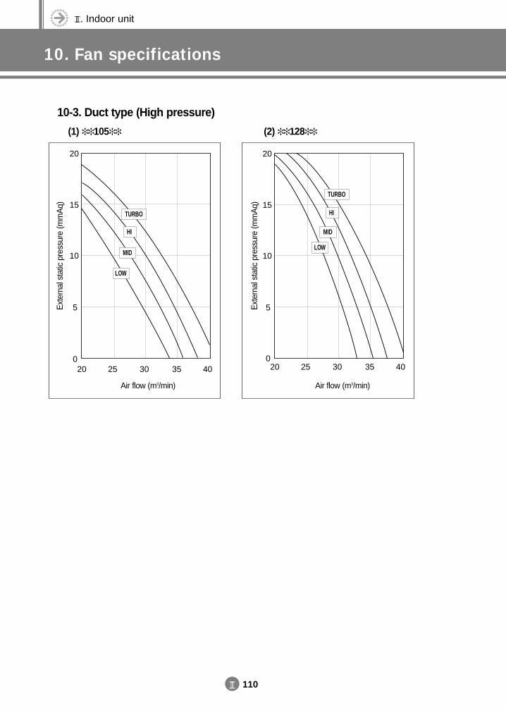
III. Indoor unit
10. Fan specifications
III 110
10-3. Duct type (High pressure)
(1) 105 (2) 128
20
15
10
5
020 25 30 35 40
TURBO
MID
LOW
HI
20
15
10
5
020 25 30 35 40
TURBO
MID
LOW
HI
Air flow (m3/min)
Ext
erna
l sta
tic p
ress
ure
(mm
Aq)
Ext
erna
l sta
tic p
ress
ure
(mm
Aq)
Air flow (m3/min)
DVM E-D/B(chapter3-3)-E<03759 3/21/02 7:38 PM Page 110
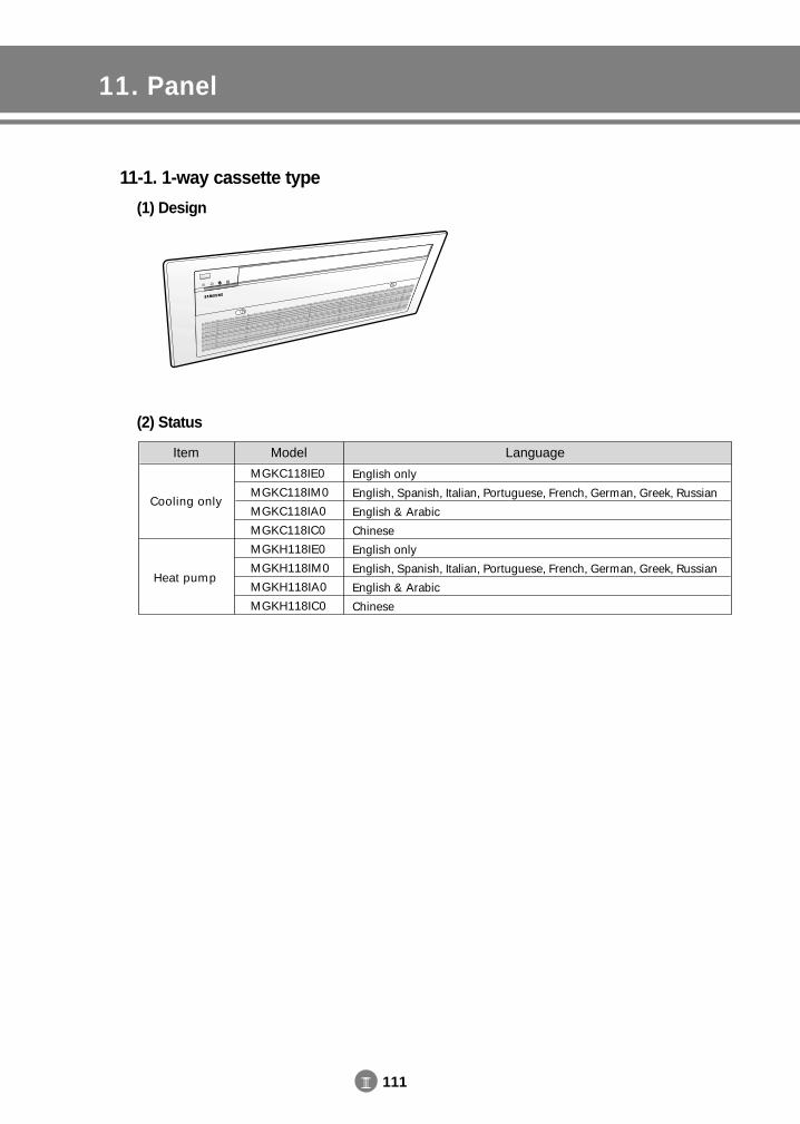
III 111
11. Panel
11-1. 1-way cassette type
(1) Design
(2) Status
Item
Cooling only
Heat pump
Model
MGKC118IE0
MGKC118IM0
MGKC118IA0
MGKC118IC0
MGKH118IE0
MGKH118IM0
MGKH118IA0
MGKH118IC0
Language
English only
English, Spanish, Italian, Portuguese, French, German, Greek, Russian
English & Arabic
Chinese
English only
English, Spanish, Italian, Portuguese, French, German, Greek, Russian
English & Arabic
Chinese
DVM E-D/B(chapter3-3)-E<03759 3/21/02 7:38 PM Page 111
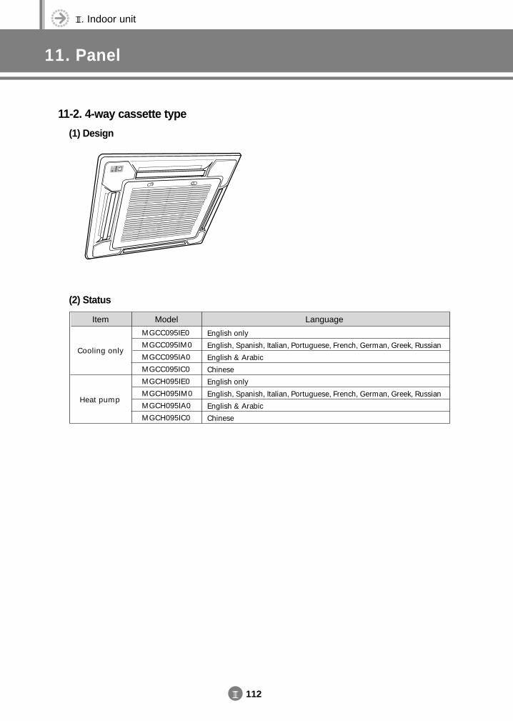
III. Indoor unit
11. Panel
III 112
Item
Cooling only
Heat pump
Model
MGCC095IE0
MGCC095IM0
MGCC095IA0
MGCC095IC0
MGCH095IE0
MGCH095IM0
MGCH095IA0
MGCH095IC0
Language
English only
English, Spanish, Italian, Portuguese, French, German, Greek, Russian
English & Arabic
Chinese
English only
English, Spanish, Italian, Portuguese, French, German, Greek, Russian
English & Arabic
Chinese
11-2. 4-way cassette type
(1) Design
(2) Status
DVM E-D/B(chapter3-3)-E<03759 3/21/02 7:38 PM Page 112
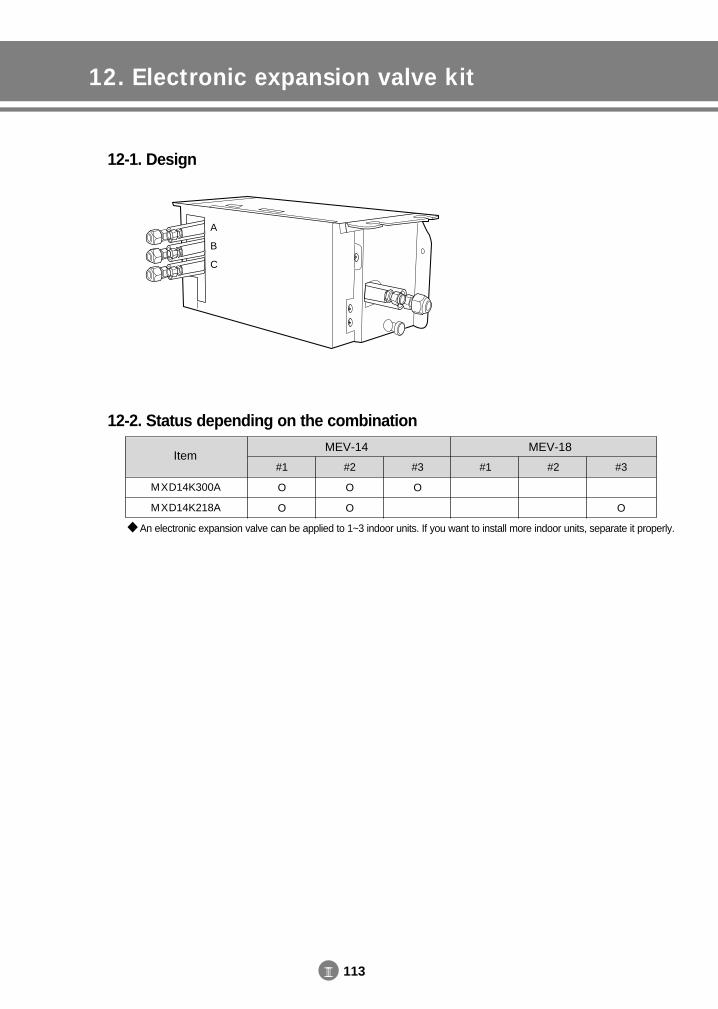
III 113
12. Electronic expansion valve kit
12-1. Design
12-2. Status depending on the combination
A
B
C
ItemMEV-14 MEV-18
#1
O
O
#2
O
O
#3
O
#1 #2 #3
O
MXD14K300A
MXD14K218A
An electronic expansion valve can be applied to 1~3 indoor units. If you want to install more indoor units, separate it properly.
DVM E-D/B(chapter3-3)-E<03759 3/21/02 7:38 PM Page 113
III. Indoor unit
13. Options
III 114
ItemPanel
O
O
O
O
-
-
-
-
-
-
-
-
-
-
-
-
Electronic expansion valve
kit
O
O
Integrated
Integrated
Integrated
Integrated
Integrated
Integrated
Integrated
Integrated
O
O
O
O
O
O
Remote controller
O
O
O
O
O
O
O
O
O
O
O
O
O
O
O
O
Drain pump
Integrated
Integrated
Integrated
Integrated
O
O
O
O
O
O
-
-
-
-
-
-
C/O
H/P
C/O
H/P
C/O
H/P
C/O
H/P
C/O
H/P
C/O
H/P
C/O
H/P
C/O
H/P
1-way cassette type
4-way cassette type
Duct type
Wall-mounted type
Floor standing type
Ceiling type
Low silhouette
Built-in
High pressure
Mandatory items
For specifications of panel and electronic expansion valve, refer to pages 111~113 at this chapter. In case of the wireless remote controller, which is the option for duct type, wireless remote controller,
receiver & display unit wire and receiver & display unit should be purchased together.
NNNNooootttteeee
DVM E-D/B(chapter3-3)-E<03759 3/21/02 7:38 PM Page 114
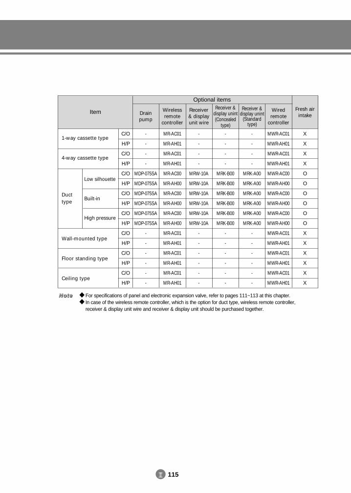
III 115
Item Drainpump
-
-
-
-
MDP-075SA
MDP-075SA
MDP-075SA
MDP-075SA
MDP-075SA
MDP-075SA
-
-
-
-
-
-
Wirelessremote
controller
MR-AC01
MR-AH01
MR-AC01
MR-AH01
MR-AC00
MR-AH00
MR-AC00
MR-AH00
MR-AC00
MR-AH00
MR-AC01
MR-AH01
MR-AC01
MR-AH01
MR-AC01
MR-AH01
Receiver& displayunit wire
-
-
-
-
MRW-10A
MRW-10A
MRW-10A
MRW-10A
MRW-10A
MRW-10A
-
-
-
-
-
-
Receiver &display unint(Concealed
type)
-
-
-
-
MRK-B00
MRK-B00
MRK-B00
MRK-B00
MRK-B00
MRK-B00
-
-
-
-
-
-
Receiver &display unint
(Standardtype)
-
-
-
-
MRK-A00
MRK-A00
MRK-A00
MRK-A00
MRK-A00
MRK-A00
-
-
-
-
-
-
Wiredremote
controller
Fresh airintake
MWR-AC01
MWR-AH01
MWR-AC01
MWR-AH01
MWR-AC00
MWR-AH00
MWR-AC00
MWR-AH00
MWR-AC00
MWR-AH00
MWR-AC01
MWR-AH01
MWR-AC01
MWR-AH01
MWR-AC01
MWR-AH01
X
X
X
X
O
O
O
O
O
O
X
X
X
X
X
X
C/O
H/P
C/O
H/P
C/O
H/P
C/O
H/P
C/O
H/P
C/O
H/P
C/O
H/P
C/O
H/P
1-way cassette type
4-way cassette type
Duct type
Wall-mounted type
Floor standing type
Ceiling type
Low silhouette
Built-in
High pressure
Optional items
For specifications of panel and electronic expansion valve, refer to pages 111~113 at this chapter. In case of the wireless remote controller, which is the option for duct type, wireless remote controller,
receiver & display unit wire and receiver & display unit should be purchased together.
NNNNooootttteeee
DVM E-D/B(chapter3-3)-E<03759 3/21/02 7:38 PM Page 115

III 116
DVM E-D/B(chapter3-3)-E<03759 3/21/02 7:38 PM Page 116
1. Selection of outdoor units(based on cooling load)
2. Specification2-1. 50Hz2-2. 60Hz
46
4. Capacity table4-1. 50Hz4-2. 60Hz
1420
5. Dimension5-1. Upward (2-FAN)5-2. Onward5-3. Upward (1-FAN)5-4. Upward (Super cooler)
31323334
6. Refrigerant system diagram6-1. Cooling6-2. Heating
3538
7. Electric circuit diagram7-1. Cooling only7-2. Heat pump
4244
8. Consideration for outdoor unit selection8-1. Change of capacity depending on
refrigerant piping length8-2. Condition of operating restriction
4546
9. Noise level
10 Options
3. Functional parts and safety devices3-1. Outdoor unit3-2. Super cooler
813
IVOutdoor unit
DVM E-D/B(chapter3-3)-E<03759 3/21/02 7:38 PM Page 117
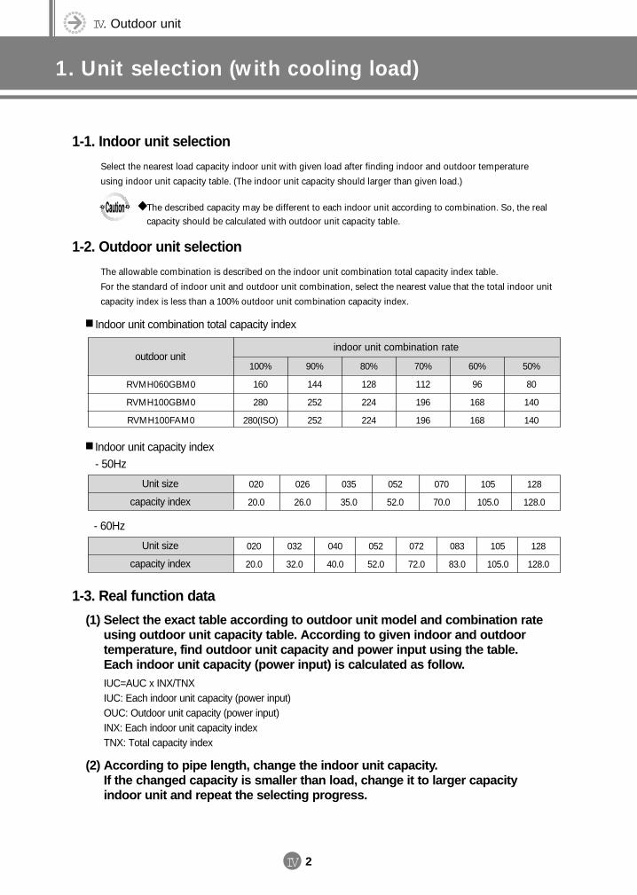
IV. Outdoor unit
1. Unit selection (with cooling load)
IV 2
1-1. Indoor unit selection
Select the nearest load capacity indoor unit with given load after finding indoor and outdoor temperature
using indoor unit capacity table. (The indoor unit capacity should larger than given load.)
1-2. Outdoor unit selection
The allowable combination is described on the indoor unit combination total capacity index table.
For the standard of indoor unit and outdoor unit combination, select the nearest value that the total indoor unit
capacity index is less than a 100% outdoor unit combination capacity index.
1-3. Real function data
(1) Select the exact table according to outdoor unit model and combination rate using outdoor unit capacity table. According to given indoor and outdoor temperature, find outdoor unit capacity and power input using the table. Each indoor unit capacity (power input) is calculated as follow.IUC=AUC x INX/TNXIUC: Each indoor unit capacity (power input)OUC: Outdoor unit capacity (power input)INX: Each indoor unit capacity indexTNX: Total capacity index
(2) According to pipe length, change the indoor unit capacity. If the changed capacity is smaller than load, change it to larger capacityindoor unit and repeat the selecting progress.
The described capacity may be different to each indoor unit according to combination. So, the realcapacity should be calculated with outdoor unit capacity table.
Indoor unit combination total capacity index
outdoor unitindoor unit combination rate
100%
160
280
280(ISO)
90%
144
252
252
80%
128
224
224
70%
112
196
196
60%
96
168
168
50%
80
140
140
RVMH060GBM0
RVMH100GBM0
RVMH100FAM0
Indoor unit capacity index
- 50Hz
Unit size
capacity index
020
20.0
026
26.0
035
35.0
052
52.0
070
70.0
105
105.0
128
128.0
- 60Hz
Unit size
capacity index
020
20.0
032
32.0
040
40.0
052
52.0
072
72.0
083
83.0
105
105.0
128
128.0
DVM E-D/B(chapter4-1)-E<03759 3/21/02 7:39 PM Page 2
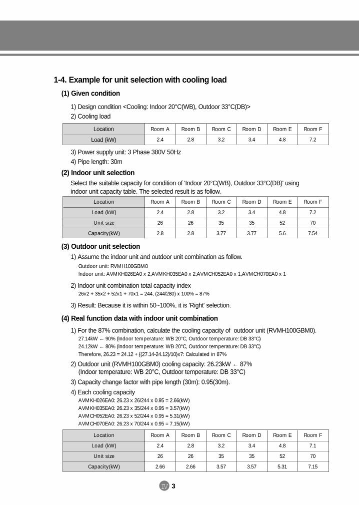
IV 3
Room A
2.4
26
2.8
Room B
2.8
26
2.8
Room C
3.2
35
3.77
Room D
3.4
35
3.77
Room E
4.8
52
5.6
Room F
7.2
70
7.54
Location
Load (kW)
Unit size
Capacity(kW)
Room A
2.4
26
2.66
Room B
2.8
26
2.66
Room C
3.2
35
3.57
Room D
3.4
35
3.57
Room E
4.8
52
5.31
Room F
7.1
70
7.15
Location
Load (kW)
Unit size
Capacity(kW)
Location
Load (kW)
Room A
2.4
Room B
2.8
Room C
3.2
Room D
3.4
Room E
4.8
Room F
7.2
1-4. Example for unit selection with cooling load
(1) Given condition
1) Design condition <Cooling: Indoor 20°C(WB), Outdoor 33°C(DB)>
2) Cooling load
3) Power supply unit: 3 Phase 380V 50Hz
4) Pipe length: 30m
(2) Indoor unit selectionSelect the suitable capacity for condition of 'Indoor 20°C(WB), Outdoor 33°C(DB)' using indoor unit capacity table. The selected result is as follow.
(3) Outdoor unit selection1) Assume the indoor unit and outdoor unit combination as follow.
Outdoor unit: RVMH100GBM0Indoor unit: AVMKH026EA0 x 2,AVMKH035EA0 x 2,AVMCH052EA0 x 1,AVMCH070EA0 x 1
2) Indoor unit combination total capacity index26x2 + 35x2 + 52x1 + 70x1 = 244, (244/280) x 100% = 87%
3) Result: Because it is within 50~100%, it is 'Right' selection.
(4) Real function data with indoor unit combination
1) For the 87% combination, calculate the cooling capacity of outdoor unit (RVMH100GBM0).27.14kW ← 90% (Indoor temperature: WB 20°C, Outdoor temperature: DB 33°C)24.12kW ← 80% (Indoor temperature: WB 20°C, Outdoor temperature: DB 33°C)Therefore, 26.23 = 24.12 + (27.14-24.12)/10x7: Calculated in 87%
2) Outdoor unit (RVMH100GBM0) cooling capacity: 26.23kW ← 87% (Indoor temperature: WB 20°C, Outdoor temperature: DB 33°C)
3) Capacity change factor with pipe length (30m): 0.95(30m).
4) Each cooling capacityAVMKH026EA0: 26.23 x 26/244 x 0.95 = 2.66(kW)AVMKH035EA0: 26.23 x 35/244 x 0.95 = 3.57(kW)AVMCH052EA0: 26.23 x 52/244 x 0.95 = 5.31(kW)AVMCH070EA0: 26.23 x 70/244 x 0.95 = 7.15(kW)
DVM E-D/B(chapter4-1)-E<03759 3/21/02 7:39 PM Page 3
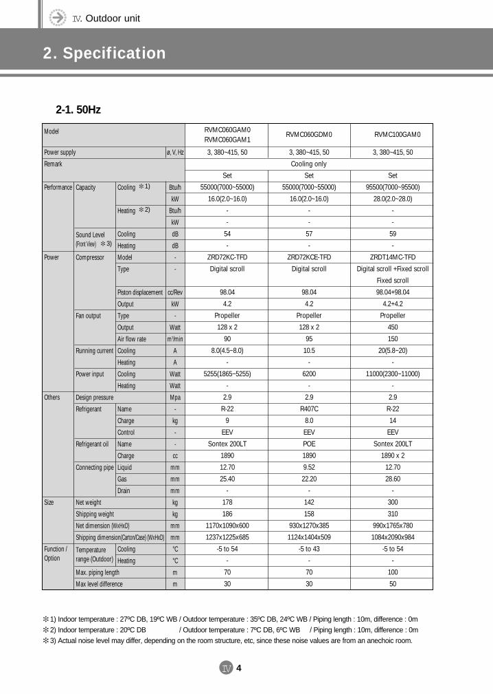
IV. Outdoor unit
2. Specification
IV 4
2-1. 50Hz
Model
Power supply
Remark
Performance
Power
Others
Size
Function /Option
RVMC060GAM0RVMC060GAM1
RVMC060GDM0 RVMC100GAM0
3, 380~415, 50
Set
55000(7000~55000)
16.0(2.0~16.0)
-
-
54
-
ZRD72KC-TFD
Digital scroll
98.04
4.2
Propeller
128 x 2
90
8.0(4.5~8.0)
-
5255(1865~5255)
-
2.9
R-22
9
EEV
Sontex 200LT
1890
12.70
25.40
-
178
186
1170x1090x600
1237x1225x685
-5 to 54
-
70
30
Set
55000(7000~55000)
16.0(2.0~16.0)
-
-
57
-
ZRD72KCE-TFD
Digital scroll
98.04
4.2
Propeller
128 x 2
95
10.5
-
6200
-
2.9
R407C
8.0
EEV
POE
1890
9.52
22.20
-
142
158
930x1270x385
1124x1404x509
-5 to 43
-
70
30
Set
95500(7000~95500)
28.0(2.0~28.0)
-
-
59
-
ZRDT14MC-TFD
Digital scroll +Fixed scroll
Fixed scroll
98.04+98.04
4.2+4.2
Propeller
450
150
20(5.8~20)
-
11000(2300~11000)
-
2.9
R-22
14
EEV
Sontex 200LT
1890 x 2
12.70
28.60
-
300
310
990x1765x780
1084x2090x984
-5 to 54
-
100
50
3, 380~415, 50
Cooling only
3, 380~415, 50
Btu/h
kW
Btu/h
kW
dB
dB
-
-
cc/Rev
kW
-
Watt
m3/min
A
A
Watt
Watt
Mpa
-
kg
-
-
cc
mm
mm
mm
kg
kg
mm
mm
°C
°C
m
m
ø, V, Hz
Capacity
Sound Level(Front View)
Compressor
Fan output
Running current
Power input
Design pressure
Refrigerant
Refrigerant oil
Connecting pipe
Net weight
Shipping weight
Net dimension (WxHxD)
Shipping dimension(Carton/Case) (WxHxD)
Temperature range (Outdoor)
Max. piping length
Max level difference
Cooling
Heating
Cooling
Heating
Model
Type
Piston displacement
Output
Type
Output
Air flow rate
Cooling
Heating
Cooling
Heating
Name
Charge
Control
Name
Charge
Liquid
Gas
Drain
Cooling
Heating
1) Indoor temperature : 27ºC DB, 19ºC WB / Outdoor temperature : 35ºC DB, 24ºC WB / Piping length : 10m, difference : 0m 2) Indoor temperature : 20ºC DB, 19ºC WB / Outdoor temperature : 7ºC DB, 6ºC WB / Piping length : 10m, difference : 0m 3) Actual noise level may differ, depending on the room structure, etc, since these noise values are from an anechoic room.
1)
2)
3)
DVM E-D/B(chapter4-1)-E<03759 3/21/02 7:39 PM Page 4
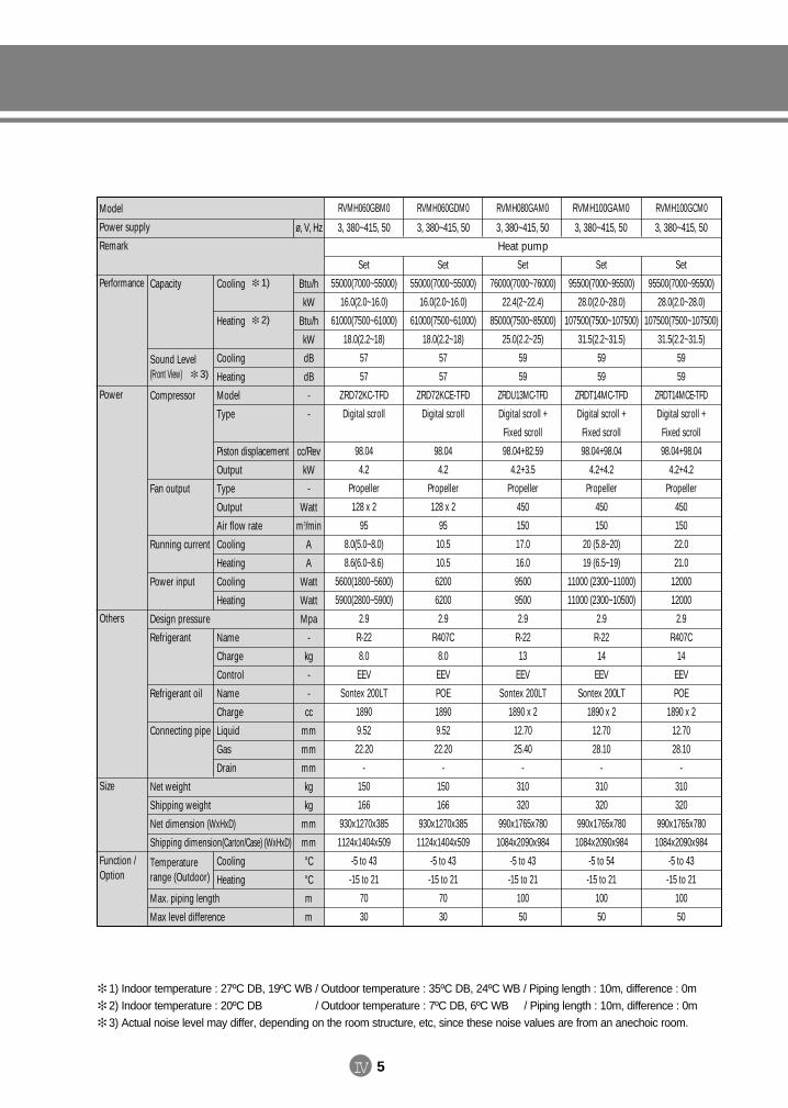
IV 5
Model
Power supply
Remark
Performance
Power
Others
Size
Function /Option
RVMH060GBM0 RVMH060GDM0 RVMH080GAM0 RVMH100GAM0 RVMH100GCM0
3, 380~415, 50
Set
55000(7000~55000)
16.0(2.0~16.0)
61000(7500~61000)
18.0(2.2~18)
57
57
ZRD72KC-TFD
Digital scroll
98.04
4.2
Propeller
128 x 2
95
8.0(5.0~8.0)
8.6(6.0~8.6)
5600(1800~5600)
5900(2800~5900)
2.9
R-22
8.0
EEV
Sontex 200LT
1890
9.52
22.20
-
150
166
930x1270x385
1124x1404x509
-5 to 43
-15 to 21
70
30
Set
55000(7000~55000)
16.0(2.0~16.0)
61000(7500~61000)
18.0(2.2~18)
57
57
ZRD72KCE-TFD
Digital scroll
98.04
4.2
Propeller
128 x 2
95
10.5
10.5
6200
6200
2.9
R407C
8.0
EEV
POE
1890
9.52
22.20
-
150
166
930x1270x385
1124x1404x509
-5 to 43
-15 to 21
70
30
Set
76000(7000~76000)
22.4(2~22.4)
85000(7500~85000)
25.0(2.2~25)
59
59
ZRDU13MC-TFD
Digital scroll +
Fixed scroll
98.04+82.59
4.2+3.5
Propeller
450
150
17.0
16.0
9500
9500
2.9
R-22
13
EEV
Sontex 200LT
1890 x 2
12.70
25.40
-
310
320
990x1765x780
1084x2090x984
-5 to 43
-15 to 21
100
50
Set
95500(7000~95500)
28.0(2.0~28.0)
107500(7500~107500)
31.5(2.2~31.5)
59
59
ZRDT14MC-TFD
Digital scroll +
Fixed scroll
98.04+98.04
4.2+4.2
Propeller
450
150
20 (5.8~20)
19 (6.5~19)
11000 (2300~11000)
11000 (2300~10500)
2.9
R-22
14
EEV
Sontex 200LT
1890 x 2
12.70
28.10
-
310
320
990x1765x780
1084x2090x984
-5 to 54
-15 to 21
100
50
Set
95500(7000~95500)
28.0(2.0~28.0)
107500(7500~107500)
31.5(2.2~31.5)
59
59
ZRDT14MCE-TFD
Digital scroll +
Fixed scroll
98.04+98.04
4.2+4.2
Propeller
450
150
22.0
21.0
12000
12000
2.9
R407C
14
EEV
POE
1890 x 2
12.70
28.10
-
310
320
990x1765x780
1084x2090x984
-5 to 43
-15 to 21
100
50
3, 380~415, 50 3, 380~415, 503, 380~415, 50
Heat pump
3, 380~415, 50
Btu/h
kW
Btu/h
kW
dB
dB
-
-
cc/Rev
kW
-
Watt
m3/min
A
A
Watt
Watt
Mpa
-
kg
-
-
cc
mm
mm
mm
kg
kg
mm
mm
°C
°C
m
m
ø, V, Hz
Capacity
Sound Level(Front View)
Compressor
Fan output
Running current
Power input
Design pressure
Refrigerant
Refrigerant oil
Connecting pipe
Net weight
Shipping weight
Net dimension (WxHxD)
Shipping dimension(Carton/Case) (WxHxD)
Temperature range (Outdoor)
Max. piping length
Max level difference
Cooling
Heating
Cooling
Heating
Model
Type
Piston displacement
Output
Type
Output
Air flow rate
Cooling
Heating
Cooling
Heating
Name
Charge
Control
Name
Charge
Liquid
Gas
Drain
Cooling
Heating
1) Indoor temperature : 27ºC DB, 19ºC WB / Outdoor temperature : 35ºC DB, 24ºC WB / Piping length : 10m, difference : 0m 2) Indoor temperature : 20ºC DB, 19ºC WB / Outdoor temperature : 7ºC DB, 6ºC WB / Piping length : 10m, difference : 0m 3) Actual noise level may differ, depending on the room structure, etc, since these noise values are from an anechoic room.
1)
2)
3)
DVM E-D/B(chapter4-1)-E<03759 3/21/02 7:39 PM Page 5
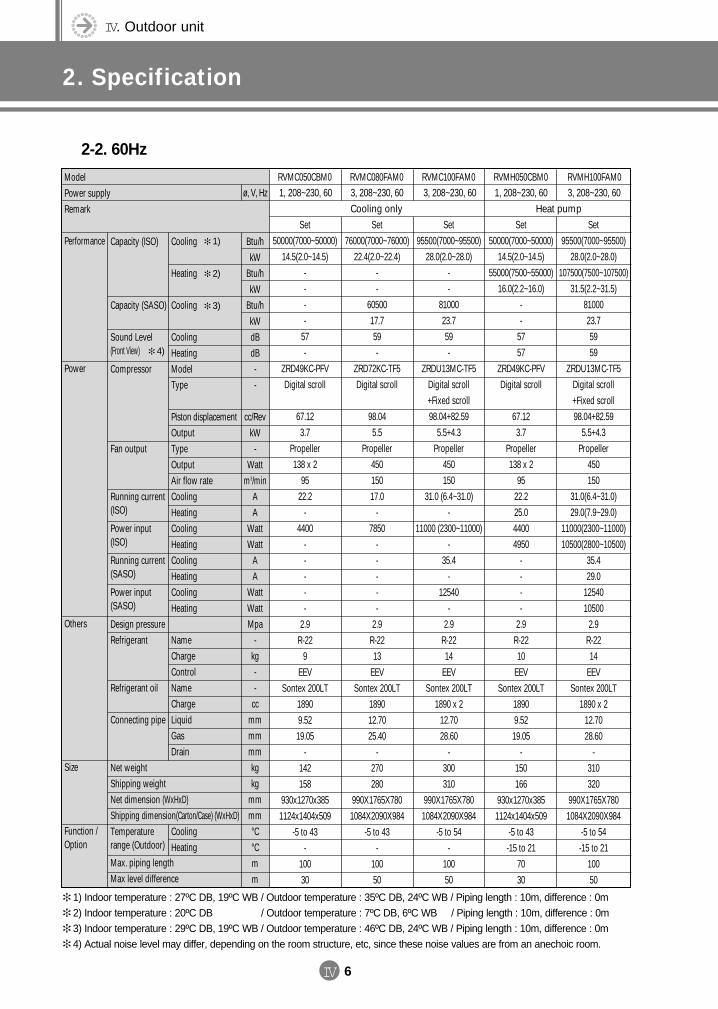
IV. Outdoor unit
2. Specification
IV 6
2-2. 60Hz
Cooling
Heating
Cooling
CoolingHeatingModelType
Piston displacementOutputTypeOutputAir flow rateCoolingHeatingCoolingHeatingCoolingHeatingCoolingHeating
NameChargeControlNameChargeLiquidGasDrain
CoolingHeating
Btu/hkW
Btu/hkW
Btu/hkWdBdB--
cc/RevkW
-Watt
m3/minAA
WattWatt
AA
WattWattMpa
-kg--
ccmmmmmmkgkg
mmmm°C°Cmm
Capacity (ISO)
Capacity (SASO)
Sound Level(Front View)
Compressor
Fan output
Running current(ISO)
Power input(ISO)
Running current(SASO)
Power input(SASO)
Design pressureRefrigerant
Refrigerant oil
Connecting pipe
Net weightShipping weightNet dimension (WxHxD)Shipping dimension(Carton/Case) (WxHxD)Temperature range (Outdoor)
Max. piping lengthMax level difference
ModelPower supplyRemark
Performance
Power
Others
Size
Function /Option
RVMC050CBM0 RVMC080FAM0 RVMC100FAM0 RVMH100FAM01, 208~230, 60
Set50000(7000~50000)
14.5(2.0~14.5)----
57-
ZRD49KC-PFVDigital scroll
67.123.7
Propeller138 x 2
9522.2
-4400
-----
2.9R-22
9EEV
Sontex 200LT18909.5219.05
-142158
930x1270x3851124x1404x509
-5 to 43-
10030
Set95500(7000~95500)
28.0(2.0~28.0)107500(7500~107500)
31.5(2.2~31.5)8100023.75959
ZRDU13MC-TF5Digital scroll +Fixed scroll98.04+82.59
5.5+4.3Propeller
450150
31.0(6.4~31.0)29.0(7.9~29.0)
11000(2300~11000)10500(2800~10500)
35.429.0
1254010500
2.9R-2214
EEVSontex 200LT
1890 x 212.7028.60
-310320
990X1765X7801084X2090X984
-5 to 54-15 to 21
10050
Cooling only3, 208~230, 60ø, V, Hz
Set76000(7000~76000)
22.4(2.0~22.4)--
6050017.759-
ZRD72KC-TF5Digital scroll
98.045.5
Propeller45015017.0
-7850
-----
2.9R-2213
EEVSontex 200LT
189012.7025.40
-270280
990X1765X7801084X2090X984
-5 to 43-
10050
Set95500(7000~95500)
28.0(2.0~28.0)--
8100023.759-
ZRDU13MC-TF5Digital scroll +Fixed scroll98.04+82.59
5.5+4.3Propeller
450150
31.0 (6.4~31.0)-
11000 (2300~11000)-
35.4-
12540-
2.9R-2214
EEVSontex 200LT
1890 x 212.7028.60
-300310
990X1765X7801084X2090X984
-5 to 54-
10050
3, 208~230, 60 3, 208~230, 60Heat pump
RVMH050CBM0
Set50000(7000~50000)
14.5(2.0~14.5)55000(7500~55000)
16.0(2.2~16.0)--
5757
ZRD49KC-PFVDigital scroll
67.123.7
Propeller138 x 2
9522.225.044004950
----
2.9R-2210
EEVSontex 200LT
18909.5219.05
-150166
930x1270x3851124x1404x509
-5 to 43-15 to 21
7030
1, 208~230, 60
1) Indoor temperature : 27ºC DB, 19ºC WB / Outdoor temperature : 35ºC DB, 24ºC WB / Piping length : 10m, difference : 0m 2) Indoor temperature : 20ºC DB, 19ºC WB / Outdoor temperature : 7ºC DB, 6ºC WB / Piping length : 10m, difference : 0m 3) Indoor temperature : 29ºC DB, 19ºC WB / Outdoor temperature : 46ºC DB, 24ºC WB / Piping length : 10m, difference : 0m 4) Actual noise level may differ, depending on the room structure, etc, since these noise values are from an anechoic room.
1)
2)
3)
4)
DVM E-D/B(chapter4-1)-E<03759 3/21/02 7:39 PM Page 6
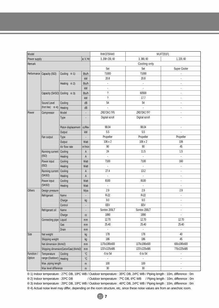
IV 7
Cooling
Heating
Cooling
CoolingHeatingModelType
Piston displacementOutputTypeOutputAir flow rateCoolingHeatingCoolingHeatingCoolingHeatingCoolingHeating
NameChargeControlNameChargeLiquidGasDrain
CoolingHeating
Btu/hkW
Btu/hkW
Btu/hkWdBdB--
cc/RevkW
-Watt
m3/minAA
WattWatt
AA
WattWattMpa
-kg--
ccmmmmmmkgkg
mmmm°C°Cmm
Capacity (ISO)
Capacity (SASO)
Sound Level(Front View)
Compressor
Fan output
Running current(ISO)
Power input(ISO)
Running current(SASO)
Power input(SASO)
Design pressureRefrigerant
Refrigerant oil
Connecting pipe
Net weightShipping weightNet dimension (WxHxD)Shipping dimension(Carton/Case) (WxHxD)Temperature range (Outdoor)
Max. piping lengthMax level difference
ModelPower supplyRemark
Performance
Power
Others
Size
Function /Option
RVMC075FAM03, 208~230, 60
Set7100020.8
--??
54-
ZRD72KC-TF5Digital scroll
98.045.5
Propeller106 x 2
9024-
7100-
27.4-
8100-
2.9R-229.0EEV
Sontex 200LT189012.7025.40
-178186
1170x1090x6001237x1225x685
-5 to 54-
10030
Cooling onlyø, V, Hz
MUF7201F1
Set7100020.8
--
6050017.754-
ZRD72KC-TF7Digital scroll
98.045.5
Propeller106 x 2
9011.5
-7100
-13.2
-8100
-2.9
R-229.0EEV
Sontex 200LT189012.7025.40
-178186
1170x1090x6001237x1225x685
-5 to 54-
10030
Super Cooler----------
--
Propeller106451.5-
160-----
2.9-----
12.7025.40
-4045
600x1090x600770x1225x685
----
3, 380, 60 1, 220, 60
1) Indoor temperature : 27ºC DB, 19ºC WB / Outdoor temperature : 35ºC DB, 24ºC WB / Piping length : 10m, difference : 0m 2) Indoor temperature : 20ºC DB, 19ºC WB / Outdoor temperature : 7ºC DB, 6ºC WB / Piping length : 10m, difference : 0m 3) Indoor temperature : 29ºC DB, 19ºC WB / Outdoor temperature : 46ºC DB, 24ºC WB / Piping length : 10m, difference : 0m 4) Actual noise level may differ, depending on the room structure, etc, since these noise values are from an anechoic room.
1)
2)
3)
4)
DVM E-D/B(chapter4-1)-E<03759 3/21/02 7:39 PM Page 7
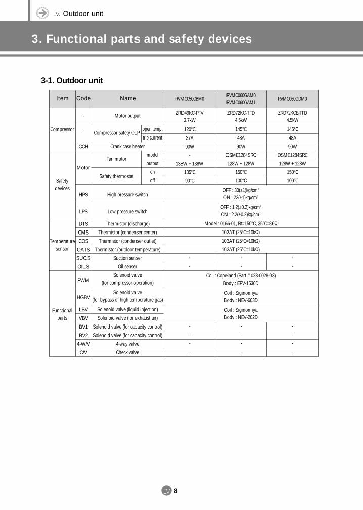
IV. Outdoor unit
3. Functional parts and safety devices
IV 8
3-1. Outdoor unit
Item Code Name RVMC050CBM0 RVMC060GDM0
Motor output
Compressor safety OLP
Crank case heater
Fan motor
Safety thermostat
open temp.
trip current
model
output
on
off
RVMC060GAM0RVMC060GAM1
ZRD72KC-TFD4.5kW
145°C
48A
90W
OSME1284SRC
128W + 128W
150°C
100°C
ZRD49KC-PFV3.7kW
120°C
37A
90W
-
138W + 138W
135°C
90°C
ZRD72KCE-TFD4.5kW
145°C
48A
90W
OSME1284SRC
128W + 128W
150°C
100°C
-
-
CCH
Motor
Compressor
Safety devices
High pressure switch
Low pressure switch
Thermistor (discharge)
Thermistor (condenser center)
Thermistor (condenser outlet)
Thermistor (outdoor temperature)
Suction senser
Oil senser
Solenoid valve(for compressor operation)
Solenoid valve(for bypass of high temperature gas)
Solenoid valve (liquid injection)
Solenoid valve (for exhaust air)
Solenoid valve (for capacity control)
Solenoid valve (for capacity control)
4-way valve
Check valve
-
-
-
-
-
-
-
-
-
-
-
-
-
-
-
-
-
-
HPS
LPS
DTS
CMS
COS
OATS
SUC.S
OIL.S
PWM
HGBV
LBV
VBV
BV1
BV2
4-W/V
C/V
Temperature sensor
Functional parts
OFF : 30(±1)kg/cm2
ON : 22(±1)kg/cm2
OFF : 1.2(±0.2)kg/cm2
ON : 2.2(±0.2)kg/cm2
Model : 0166-01, Rt=150°C, 25°C=86Ω103AT (25°C=10kΩ)
103AT (25°C=10kΩ)
103AT (25°C=10kΩ)
Coil : Copeland (Part # 023-0028-03)Body : EPV-1530D
Coil : SiginomiyaBody : NEV-603D
Coil : SiginomiyaBody : NEV-202D
DVM E-D/B(chapter4-1)-E<03759 3/21/02 7:39 PM Page 8
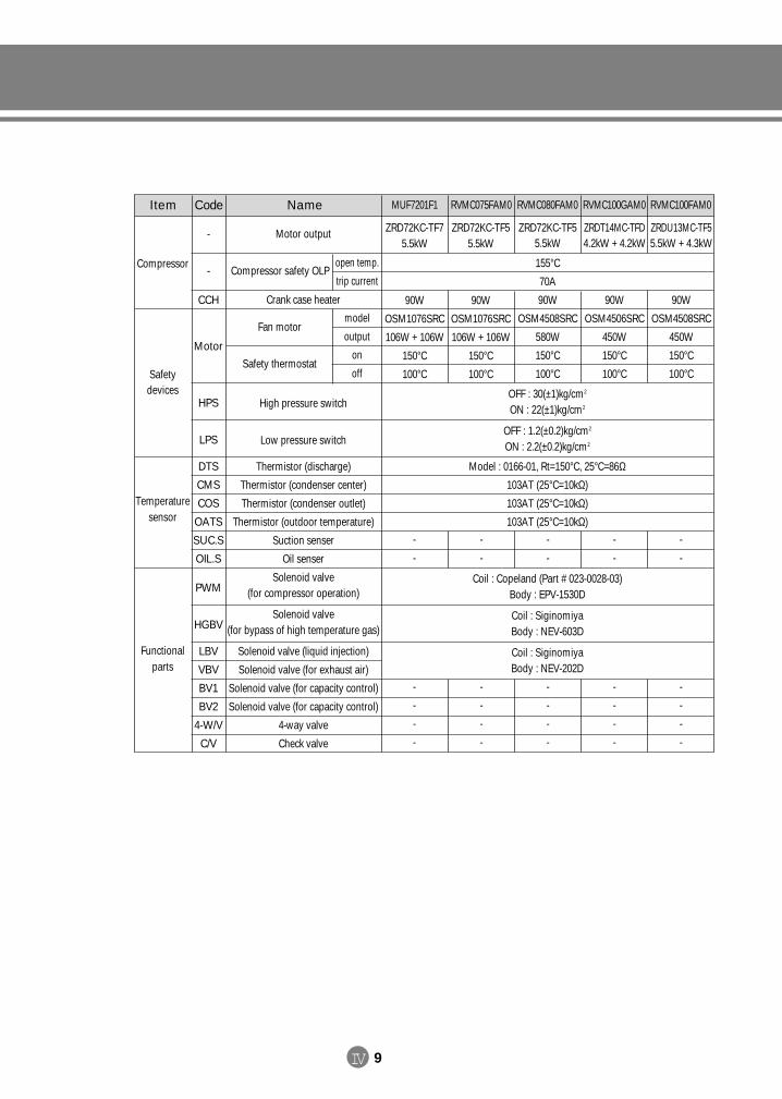
IV 9
Item Code Name MUF7201F1 RVMC100GAM0
Motor output
Compressor safety OLP
Crank case heater
Fan motor
Safety thermostat
open temp.
trip current
model
output
on
off
RVMC080FAM0
-
-
CCH
Motor
Compressor
Safety devices
Temperature sensor
Functional parts
High pressure switch
Low pressure switch
Thermistor (discharge)
Thermistor (condenser center)
Thermistor (condenser outlet)
Thermistor (outdoor temperature)
Suction senser
Oil senser
Solenoid valve(for compressor operation)
Solenoid valve(for bypass of high temperature gas)
Solenoid valve (liquid injection)
Solenoid valve (for exhaust air)
Solenoid valve (for capacity control)
Solenoid valve (for capacity control)
4-way valve
Check valve
HPS
LPS
DTS
CMS
COS
OATS
SUC.S
OIL.S
PWM
HGBV
LBV
VBV
BV1
BV2
4-W/V
C/V
-
-
-
-
-
-
-
-
-
-
-
-
-
-
-
-
-
-
-
-
-
-
-
-
-
-
-
-
-
-
OFF : 30(±1)kg/cm2
ON : 22(±1)kg/cm2
OFF : 1.2(±0.2)kg/cm2
ON : 2.2(±0.2)kg/cm2
Model : 0166-01, Rt=150°C, 25°C=86Ω103AT (25°C=10kΩ)
103AT (25°C=10kΩ)
103AT (25°C=10kΩ)
Coil : Copeland (Part # 023-0028-03)Body : EPV-1530D
Coil : SiginomiyaBody : NEV-603D
Coil : SiginomiyaBody : NEV-202D
RVMC075FAM0
ZRD72KC-TF75.5kW
90W
OSM1076SRC
106W + 106W
150°C
100°C
ZRD72KC-TF55.5kW
90W
OSM1076SRC
106W + 106W
150°C
100°C
ZRD72KC-TF55.5kW
155°C
70A
90W
OSM4508SRC
580W
150°C
100°C
ZRDT14MC-TFD4.2kW + 4.2kW
90W
OSM4506SRC
450W
150°C
100°C
ZRDU13MC-TF55.5kW + 4.3kW
90W
OSM4508SRC
450W
150°C
100°C
RVMC100FAM0
DVM E-D/B(chapter4-1)-E<03759 3/21/02 7:39 PM Page 9
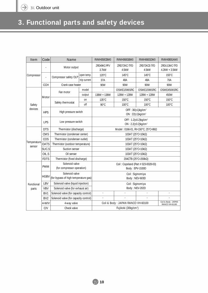
IV. Outdoor unit
3. Functional parts and safety devices
IV 10
Item Code Name RVMH050CBM0 RVMH080GAM0RVMH060GDM0
Motor output
Compressor safety OLP
Crank case heater
Fan motor
Safety thermostat
High pressure switch
Low pressure switch
Thermistor (discharge)
Thermistor (condenser center)
Thermistor (condenser outlet)
Thermistor (outdoor temperature)
Suction senser
Oil senser
Thermistor (fixed discharge)
Solenoid valve(for compressor operation)
Solenoid valve(for bypass of high temperature gas)
Solenoid valve (liquid injection)
Solenoid valve (for exhaust air)
Solenoid valve (for capacity control)
Solenoid valve (for capacity control)
4-way valve
Check valve
open temp.
trip current
model
output
on
off
RVMH060GBM0
ZRD72KC-TFD4.5kW
145°C
48A
90W
OSME1596SRC
128W + 128W
150°C
100°C
ZRD49KC-PFV3.7kW
120°C
37A
90W
-
138W + 138W
135°C
90°C
ZRD72KCE-TFD4.5kW
145°C
48A
90W
OSME1596SRC
128W + 128W
150°C
100°C
ZRDU13MC-TFD4.2kW + 3.5kW
155°C
70A
90W
OSME4506SRC
450W
150°C
100°C
OFF : 30(±1)kg/cm2
ON : 22(±1)kg/cm2
OFF : 1.2(±0.2)kg/cm2
ON : 2.2(±0.2)kg/cm2
Model : 0166-01, Rt=150°C, 25°C=86Ω103AT (25°C=10kΩ)
103AT (25°C=10kΩ)
103AT (25°C=10kΩ)
103AT (25°C=10kΩ)
103AT (25°C=10kΩ)
204CTB (25°C=200kΩ)
Coil : Copeland (Part # 023-0028-03)Body : EPV-1530D
Coil : SiginomiyaBody : NEV-603D
Coil : SiginomiyaBody : NEV-202D
-
-
CCH
Motor
HPS
LPS
DTS
CMS
COS
OATS
SUC.S
OIL.S
FDTS
PWM
HGBV
LBV
VBV
BV1
BV2
4-W/V
C/V
Compressor
Safety devices
Temperature sensor
Functional parts
-
-
-
-
-
-
-
-
Coil & Body : JAPAN RANCO VH-60100
Fujikoki (30kg/cm2)
Coil & Body : JAPANRANCO VH-61100
DVM E-D/B(chapter4-1)-E<03759 3/21/02 7:39 PM Page 10
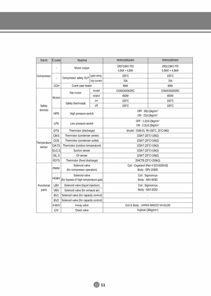
IV 11
Item Code Name
Motor output
Compressor safety OLP
Crank case heater
Fan motor
Safety thermostat
High pressure switch
Low pressure switch
Thermistor (discharge)
Thermistor (condenser center)
Thermistor (condenser outlet)
Thermistor (outdoor temperature)
Suction senser
Oil senser
Thermistor (fixed discharge)
Solenoid valve(for compressor operation)
Solenoid valve(for bypass of high temperature gas)
Solenoid valve (liquid injection)
Solenoid valve (for exhaust air)
Solenoid valve (for capacity control)
Solenoid valve (for capacity control)
4-way valve
Check valve
open temp.
trip current
model
output
on
off
-
-
CCH
Motor
HPS
LPS
DTS
CMS
COS
OATS
SUC.S
OIL.S
FDTS
PWM
HGBV
LBV
VBV
BV1
BV2
4-W/V
C/V
Compressor
Safety devices
Temperature sensor
Functional parts
RVMH100GAM0
ZRDT14MC-TFD4.2kW + 4.2kW
155°C
70A
90W
OSME4506SRC
450W
150°C
100°C
ZRDU13MC-TF55.5kW + 4.3kW
155°C
70A
90W
OSME4508SRC
450W
150°C
100°C
RVMH100FAM0
OFF : 30(±1)kg/cm2
ON : 22(±1)kg/cm2
OFF : 1.2(±0.2)kg/cm2
ON : 2.2(±0.2)kg/cm2
Model : 0166-01, Rt=150°C, 25°C=86Ω103AT (25°C=10kΩ)
103AT (25°C=10kΩ)
103AT (25°C=10kΩ)
103AT (25°C=10kΩ)
103AT (25°C=10kΩ)
204CTB (25°C=200kΩ)
Coil : Copeland (Part # 023-0028-03)Body : EPV-1530D
Coil : SiginomiyaBody : NEV-603D
Coil : SiginomiyaBody : NEV-202D
--
Coil & Body : JAPAN RANCO VH-61100
Fujikoki (30kg/cm2)
DVM E-D/B(chapter4-1)-E<03759 3/21/02 7:39 PM Page 11
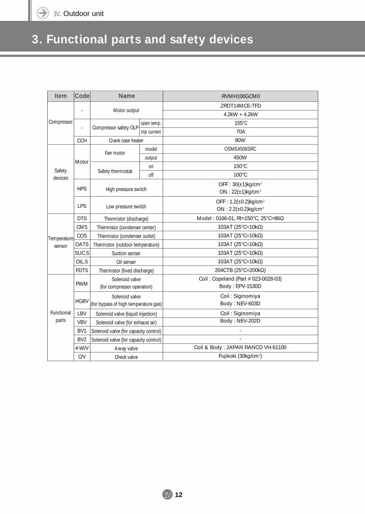
IV. Outdoor unit
3. Functional parts and safety devices
IV 12
Item Code Name RVMH100GCM0
Motor output
Compressor safety OLP
Crank case heater
Fan motor
Safety thermostat
High pressure switch
Low pressure switch
Thermistor (discharge)
Thermistor (condenser center)
Thermistor (condenser outlet)
Thermistor (outdoor temperature)
Suction senser
Oil senser
Thermistor (fixed discharge)
Solenoid valve(for compressor operation)
Solenoid valve(for bypass of high temperature gas)
Solenoid valve (liquid injection)
Solenoid valve (for exhaust air)
Solenoid valve (for capacity control)
Solenoid valve (for capacity control)
4-way valve
Check valve
90W
OSME4506SRC
450W
150°C
100°C
ZRDT14MCE-TFD
4.2kW + 4.2kW
155°C
70A
OFF : 30(±1)kg/cm2
ON : 22(±1)kg/cm2
OFF : 1.2(±0.2)kg/cm2
ON : 2.2(±0.2)kg/cm2
Model : 0166-01, Rt=150°C, 25°C=86Ω103AT (25°C=10kΩ)
103AT (25°C=10kΩ)
103AT (25°C=10kΩ)
103AT (25°C=10kΩ)
103AT (25°C=10kΩ)
204CTB (25°C=200kΩ)
Coil : Copeland (Part # 023-0028-03)Body : EPV-1530D
Coil : SiginomiyaBody : NEV-603D
Coil : SiginomiyaBody : NEV-202D
--
Coil & Body : JAPAN RANCO VH-61100
Fujikoki (30kg/cm2)
-
-
CCH
Motor
HPS
LPS
DTS
CMS
COS
OATS
SUC.S
OIL.S
FDTS
PWM
HGBV
LBV
VBV
BV1
BV2
4-W/V
C/V
Compressor
Safety devices
Temperature sensor
Functional parts
open temp.
trip current
model
output
on
off
DVM E-D/B(chapter4-1)-E<03759 3/21/02 7:39 PM Page 12
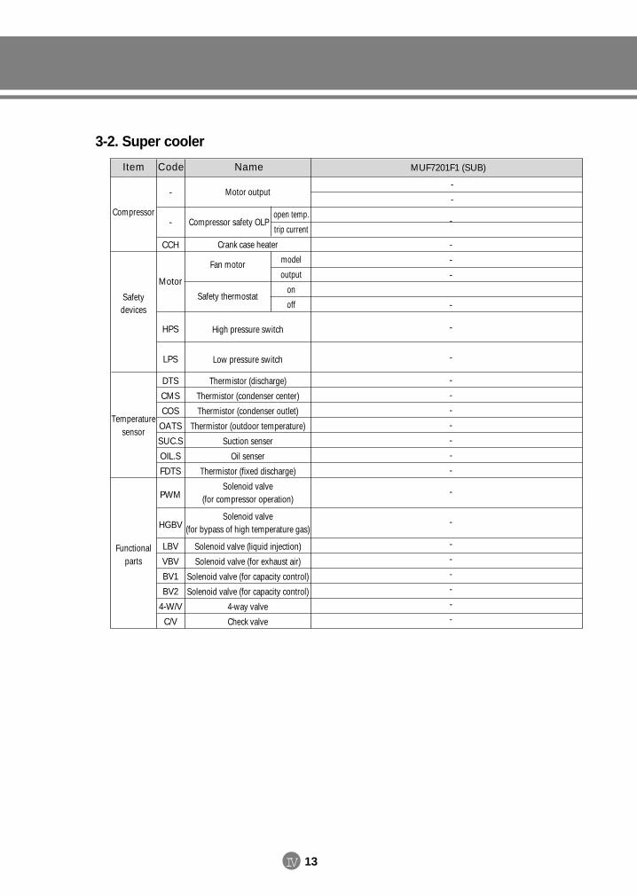
IV 13
3-2. Super cooler
Item Code Name MUF7201F1 (SUB)
Motor output
Compressor safety OLP
Crank case heater
Fan motor
Safety thermostat
High pressure switch
Low pressure switch
Thermistor (discharge)
Thermistor (condenser center)
Thermistor (condenser outlet)
Thermistor (outdoor temperature)
Suction senser
Oil senser
Thermistor (fixed discharge)
Solenoid valve(for compressor operation)
Solenoid valve(for bypass of high temperature gas)
Solenoid valve (liquid injection)
Solenoid valve (for exhaust air)
Solenoid valve (for capacity control)
Solenoid valve (for capacity control)
4-way valve
Check valve
-
-
-
-
-
-
-
-
-
-
-
-
-
-
-
-
-
-
-
-
-
-
-
-
-
-
CCH
Motor
HPS
LPS
DTS
CMS
COS
OATS
SUC.S
OIL.S
FDTS
PWM
HGBV
LBV
VBV
BV1
BV2
4-W/V
C/V
Compressor
Safety devices
Temperature sensor
Functional parts
open temp.
trip current
model
output
on
off
DVM E-D/B(chapter4-1)-E<03759 3/21/02 7:39 PM Page 13
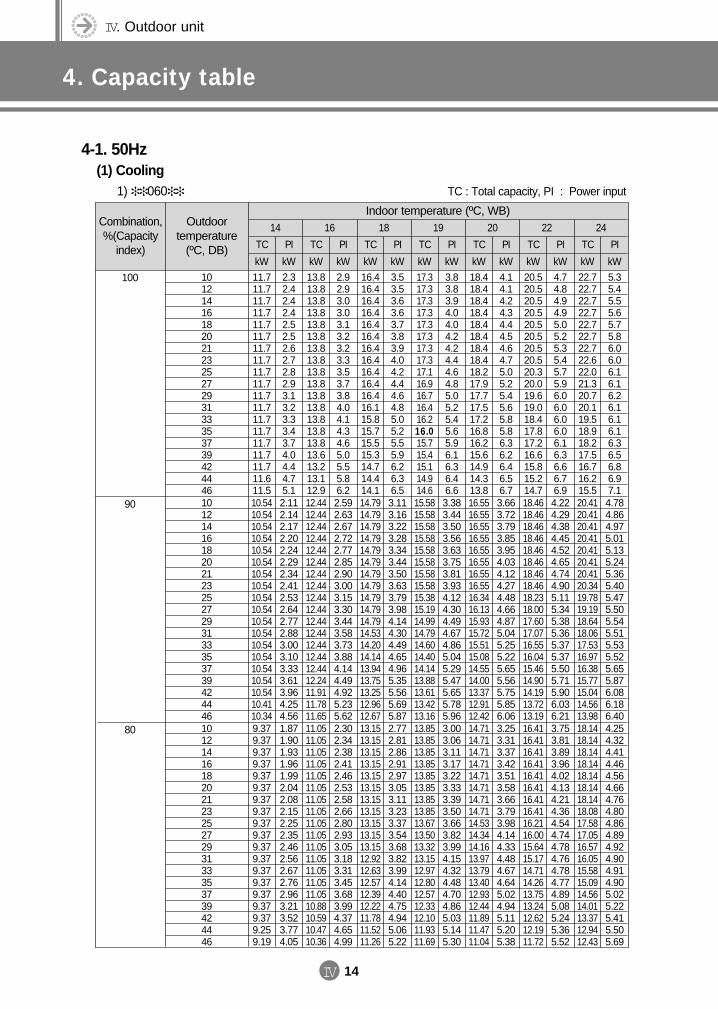
IV. Outdoor unit
4. Capacity table
IV 14
Combination,%(Capacity
index)
Outdoor temperature
(ºC, DB)
14 16 18 19 20 22 24
TC
kW
TC
kW
TC
kW
TC
kW
TC
kW
TC
kW
TC
kW
PI
kW
PI
kW
PI
kW
PI
kW
PI
kW
PI
kW
PI
kW10121416182021232527293133353739424446
11.711.711.711.711.711.711.711.711.711.711.711.711.711.711.711.711.711.611.5
2.32.42.42.42.52.52.62.72.82.93.13.23.33.43.74.04.44.75.1
13.813.813.813.813.813.813.813.813.813.813.813.813.813.813.813.613.213.112.9
2.92.93.03.03.13.23.23.33.53.73.84.04.14.34.65.05.55.86.2
16.416.416.416.416.416.416.416.416.416.416.416.115.815.715.515.314.714.414.1
3.53.53.63.63.73.83.94.04.24.44.64.85.05.25.55.96.26.36.5
17.317.317.317.317.317.317.317.317.116.916.716.416.216.015.715.415.114.914.6
3.83.83.94.04.04.24.24.44.64.85.05.25.45.65.96.16.36.46.6
18.418.418.418.418.418.418.418.418.217.917.717.517.216.816.215.614.914.313.8
4.14.14.24.34.44.54.64.75.05.25.45.65.85.86.36.26.46.56.7
20.520.520.520.520.520.520.520.520.320.019.619.018.417.817.216.615.815.214.7
4.74.84.94.95.05.25.35.45.75.96.06.06.06.06.16.36.66.76.9
22.722.722.722.722.722.722.722.622.021.320.720.119.518.918.217.516.716.215.5
5.35.45.55.65.75.86.06.06.16.16.26.16.16.16.36.56.86.97.1
4-1. 50Hz(1) Cooling
1) 060
Indoor temperature (ºC, WB)
100
10121416182021232527293133353739424446
10.5410.5410.5410.5410.5410.5410.5410.5410.5410.5410.5410.5410.5410.5410.5410.5410.5410.4110.34
2.112.142.172.202.242.292.342.412.532.642.772.883.003.103.333.613.964.254.56
12.4412.4412.4412.4412.4412.4412.4412.4412.4412.4412.4412.4412.4412.4412.4412.2411.9111.7811.65
2.592.632.672.722.772.852.903.003.153.303.443.583.733.884.144.494.925.235.62
14.7914.7914.7914.7914.7914.7914.7914.7914.7914.7914.7914.5314.2014.1413.9413.7513.2512.9612.67
3.113.163.223.283.343.443.503.633.793.984.144.304.494.654.965.355.565.695.87
15.5815.5815.5815.5815.5815.5815.5815.5815.3815.1914.9914.7914.6014.4014.1413.8813.6113.4213.16
3.383.443.503.563.633.753.813.934.124.304.494.674.865.045.295.475.655.785.96
16.5516.5516.5516.5516.5516.5516.5516.5516.3416.1315.9315.7215.5115.0814.5514.0013.3712.9112.42
3.663.723.793.853.954.034.124.274.484.664.875.045.255.225.655.565.755.856.06
18.4618.4618.4618.4618.4618.4618.4618.4618.2318.0017.6017.0716.5516.0415.4614.9014.1913.7213.19
4.224.294.384.454.524.654.744.905.115.345.385.365.375.375.505.715.906.036.21
20.4120.4120.4120.4120.4120.4120.4120.3419.7819.1918.6418.0617.5316.9716.3815.7715.0414.5613.98
4.784.864.975.015.135.245.365.405.475.505.545.515.535.525.655.876.086.186.40
90
10121416182021232527293133353739424446
9.379.379.379.379.379.379.379.379.379.379.379.379.379.379.379.379.379.259.19
1.871.901.931.961.992.042.082.152.252.352.462.562.672.762.963.213.523.774.05
11.0511.0511.0511.0511.0511.0511.0511.0511.0511.0511.0511.0511.0511.0511.0510.8810.5910.4710.36
2.302.342.382.412.462.532.582.662.802.933.053.183.313.453.683.994.374.654.99
13.1513.1513.1513.1513.1513.1513.1513.1513.1513.1513.1512.9212.6312.5712.3912.2211.7811.5211.26
2.772.812.862.912.973.053.113.233.373.543.683.823.994.144.404.754.945.065.22
13.8513.8513.8513.8513.8513.8513.8513.8513.6713.5013.3213.1512.9712.8012.5712.3312.1011.9311.69
3.003.063.113.173.223.333.393.503.663.823.994.154.324.484.704.865.035.145.30
14.7114.7114.7114.7114.7114.7114.7114.7114.5314.3414.1613.9713.7913.4012.9312.4411.8911.4711.04
3.253.313.373.423.513.583.663.793.984.144.334.484.674.645.024.945.115.205.38
16.4116.4116.4116.4116.4116.4116.4116.4116.2116.0015.6415.1714.7114.2613.7513.2412.6212.1911.72
3.753.813.893.964.024.134.214.364.544.744.784.764.784.774.895.085.245.365.52
18.1418.1418.1418.1418.1418.1418.1418.0817.5817.0516.5716.0515.5815.0914.5614.0113.3712.9412.43
4.254.324.414.464.564.664.764.804.864.894.924.904.914.905.025.225.415.505.69
80
TC : Total capacity, PI : Power input
DVM E-D/B(chapter4-1)-E<03759 3/21/02 7:39 PM Page 14

IV 15
Combination,%(Capacity
index)
Outdoor temperature
(ºC, DB)
14 16 18 19 20 22 24
TC
kW
TC
kW
TC
kW
TC
kW
TC
kW
TC
kW
TC
kW
PI
kW
PI
kW
PI
kW
PI
kW
PI
kW
PI
kW
PI
kW8.208.208.208.208.208.208.208.208.208.208.208.208.208.208.208.208.208.098.04
1.641.661.681.711.741.781.821.881.972.062.152.242.332.412.592.803.083.303.54
9.679.679.679.679.679.679.679.679.679.679.679.679.679.679.679.529.279.169.06
2.022.052.082.112.162.212.262.332.452.572.672.792.903.023.223.493.824.074.37
11.5111.5111.5111.5111.5111.5111.5111.5111.5111.5111.5111.3011.0511.0010.8410.6910.3010.089.86
2.422.462.502.552.602.672.722.832.953.093.223.343.493.623.854.164.334.434.56
12.1212.1212.1212.1212.1212.1212.1212.1211.9611.8111.6611.5111.3511.2011.0010.7910.5910.4410.23
2.632.682.722.772.822.922.963.063.203.353.493.633.783.924.114.254.404.504.64
12.8712.8712.8712.8712.8712.8712.8712.8712.7112.5512.3912.2212.0611.7311.3210.8910.4010.049.66
2.852.902.953.003.073.133.203.323.483.623.793.924.094.064.394.334.474.554.71
14.3614.3614.3614.3614.3614.3614.3614.3614.1814.0013.6913.2812.8712.4812.0311.5911.0410.6710.26
3.283.333.413.463.523.623.683.813.974.154.184.174.184.184.274.444.594.694.83
15.8815.8815.8815.8815.8815.8815.8815.8215.3814.9214.4914.0513.6313.2012.7412.2611.7011.3210.87
3.723.783.863.903.994.084.174.204.254.284.314.294.304.294.394.564.734.814.98
Indoor temperature (ºC, WB)
70
10121416182021232527293133353739424446
7.037.037.037.037.037.037.037.037.037.037.037.037.037.037.037.037.036.946.89
1.411.421.441.471.491.531.561.611.691.761.841.922.002.072.222.402.642.833.04
8.298.298.298.298.298.298.298.298.298.298.298.298.298.298.298.167.947.857.77
1.731.751.781.811.851.901.942.002.102.202.292.392.482.582.762.993.283.493.75
9.869.869.869.869.869.869.869.869.869.869.869.699.479.439.299.168.838.648.45
2.072.112.152.182.232.292.332.422.532.652.762.872.993.103.303.573.713.793.91
10.3910.3910.3910.3910.3910.3910.3910.3910.2510.129.999.869.739.609.439.259.088.958.77
2.252.292.342.382.422.502.542.622.752.872.993.113.243.363.523.653.773.863.97
11.0311.0311.0311.0311.0311.0311.0311.0310.9010.7610.6210.4810.3410.059.709.338.918.618.28
2.442.482.532.572.632.682.752.842.993.113.253.363.503.483.763.713.833.904.04
12.3112.3112.3112.3112.3112.3112.3112.3112.1512.0011.7311.3811.0310.6910.319.939.469.158.79
2.812.862.922.973.023.103.163.273.403.563.593.573.583.583.663.813.934.024.14
13.6113.6113.6113.6113.6113.6113.6113.5613.1812.7912.4212.0411.6911.3110.9210.5110.039.709.32
3.193.243.313.343.423.493.573.603.653.673.693.673.683.683.763.914.064.124.27
60
10121416182021232527293133353739424446
5.855.855.855.855.855.855.855.855.855.855.855.855.855.855.855.855.855.785.75
1.171.191.201.221.241.271.301.341.411.471.541.601.671.721.852.002.202.362.53
6.916.916.916.916.916.916.916.916.916.916.916.916.916.916.916.806.626.556.47
1.441.461.491.511.541.581.611.661.751.831.911.992.072.152.302.502.732.913.12
8.228.228.228.228.228.228.228.228.228.228.228.077.897.857.757.647.367.207.04
1.731.761.791.821.861.911.952.022.102.212.302.392.492.582.752.973.093.163.26
8.658.658.658.658.658.658.658.658.558.448.338.228.118.007.857.717.567.457.31
1.881.911.951.982.012.082.122.192.292.392.492.602.702.802.943.043.143.213.31
9.209.209.209.209.209.209.209.209.088.968.858.738.628.388.087.787.437.176.90
2.032.072.112.142.192.242.292.372.492.592.702.802.922.903.143.093.193.253.36
10.2610.2610.2610.2610.2610.2610.2610.2610.1310.009.789.489.208.918.598.287.887.627.33
2.352.382.432.472.512.582.632.722.842.972.992.982.992.983.053.173.283.353.45
11.3411.3411.3411.3411.3411.3411.3411.3010.9910.6610.3510.039.749.439.108.768.368.097.77
2.662.702.762.782.852.912.983.003.043.063.083.063.073.073.143.263.383.443.55
50
TC : Total capacity, PI : Power input
10121416182021232527293133353739424446
DVM E-D/B(chapter4-1)-E<03759 3/21/02 7:39 PM Page 15
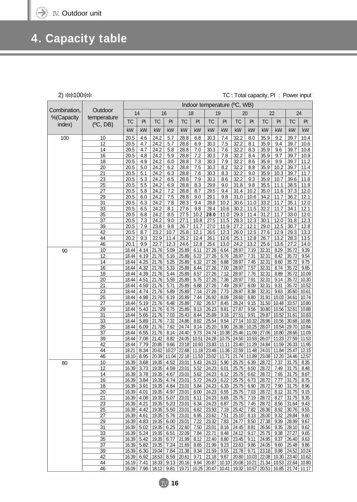
IV. Outdoor unit
4. Capacity table
IV 16
Combination,%(Capacity
index)
Outdoor temperature
(ºC, DB)
14 16 18 19 20 22 24
TC
kW
TC
kW
TC
kW
TC
kW
TC
kW
TC
kW
TC
kW
PI
kW
PI
kW
PI
kW
PI
kW
PI
kW
PI
kW
PI
kW10121416182021232527293133353739424446
20.520.520.520.520.520.520.520.520.520.520.520.520.520.520.520.520.520.220.1
4.64.74.74.84.95.05.15.35.55.86.06.36.56.87.37.98.79.39.9
24.224.224.224.224.224.224.224.224.224.224.224.224.224.224.223.823.222.922.7
5.75.75.85.96.06.26.36.56.97.27.57.88.18.59.09.810.711.412.3
28.828.828.828.828.828.828.828.828.828.828.828.327.627.527.126.725.825.224.6
6.86.97.07.27.37.57.67.98.38.79.09.49.810.210.811.712.112.412.8
30.330.330.330.330.330.330.330.329.929.529.128.828.428.027.527.026.526.125.6
7.47.57.67.87.98.28.38.69.09.49.810.210.611.011.511.912.312.613.0
32.232.232.232.232.232.232.232.231.831.431.030.630.229.328.327.226.025.124.2
8.08.18.38.48.68.89.09.39.810.210.611.011.511.412.312.112.512.813.2
35.935.935.935.935.935.935.935.935.535.034.233.232.231.230.129.027.626.725.6
9.29.49.69.79.910.210.310.711.111.611.711.711.711.712.012.512.913.213.6
39.739.739.739.739.739.739.739.638.537.336.235.134.133.031.830.729.328.327.2
10.410.610.810.911.211.411.711.811.912.012.112.012.112.012.312.813.313.514.0
2) 100
Indoor temperature (ºC, WB)
100
10121416182021232527293133353739424446
18.4418.4418.4418.4418.4418.4418.4418.4418.4418.4418.4418.4418.4418.4418.4418.4418.4418.2118.10
4.144.194.254.324.394.514.594.744.985.195.435.655.896.096.557.087.798.348.95
21.7621.7621.7621.7621.7621.7621.7621.7621.7621.7621.7621.7621.7621.7621.7621.4220.8520.6220.39
5.095.165.255.335.445.595.715.896.196.486.757.037.327.628.148.829.6610.2711.04
25.8925.8925.8925.8925.8925.8925.8925.8925.8925.8925.8925.4324.8624.7424.4024.0523.1822.6822.18
6.116.226.326.446.576.756.887.147.447.828.138.448.829.149.7310.5110.9311.1811.53
27.2627.2627.2627.2627.2627.2627.2627.2626.9226.5726.2325.8925.5425.2024.7424.2823.8323.4823.02
6.646.766.887.007.127.367.497.738.098.458.819.189.549.9010.3810.7511.1111.3611.71
28.9728.9728.9728.9728.9728.9728.9728.9728.6028.2427.8727.5127.1426.3825.4624.5023.4022.5921.74
7.197.317.457.577.767.918.098.388.809.159.569.9110.3210.2511.0910.9311.2911.4811.89
32.3132.3132.3132.3132.3132.3132.3132.3131.9131.5030.8029.8728.9628.0727.0626.0724.8424.0123.08
8.298.428.608.748.899.149.319.6310.0310.4810.5610.5210.5610.5410.8011.2311.5911.8412.20
35.7235.7235.7235.7235.7235.7235.7235.6034.6133.5732.6131.6130.6829.7028.6627.5926.3325.4724.46
9.399.549.759.8510.0910.3010.5210.6110.7410.8010.8810.8310.8610.8411.0911.5311.9512.1512.57
90
10121416182021232527293133353739424446
16.3916.3916.3916.3916.3916.3916.3916.3916.3916.3916.3916.3916.3916.3916.3916.3916.3916.1916.09
3.683.733.783.843.914.014.084.214.424.614.835.025.245.425.826.306.927.417.96
19.3519.3519.3519.3519.3519.3519.3519.3519.3519.3519.3519.3519.3519.3519.3519.0418.5318.3318.12
4.524.594.674.744.844.975.075.235.505.766.006.256.516.777.247.848.599.139.81
23.0123.0123.0123.0123.0123.0123.0123.0123.0123.0123.0122.6022.0921.9921.6921.3820.6120.1619.71
5.435.525.625.725.846.006.116.346.626.957.227.507.848.128.659.349.719.9410.25
24.2324.2324.2324.2324.2324.2324.2324.2323.9323.6223.3223.0122.7122.4021.9921.5921.1820.8720.47
5.906.016.126.226.336.556.656.877.197.517.838.168.488.809.239.559.8710.1010.41
25.7525.7525.7525.7525.7525.7525.7525.7525.4225.1024.7724.4524.1223.4522.6321.7820.8020.0819.32
6.396.506.626.736.907.037.197.457.828.138.508.819.179.119.869.7110.0310.2110.57
28.7228.7228.7228.7228.7228.7228.7228.7228.3628.0027.3826.5625.7524.9524.0523.1822.0821.3420.51
7.377.497.657.777.908.128.278.568.929.329.399.359.389.379.609.9810.3010.5310.85
31.7531.7531.7531.7531.7531.7531.7531.6430.7629.8428.9928.1027.2726.4025.4824.5223.4022.6421.74
8.358.488.678.758.969.159.359.439.559.609.679.629.659.639.8610.2410.6210.8011.17
80
TC : Total capacity, PI : Power input
DVM E-D/B(chapter4-1)-E<03759 3/21/02 7:39 PM Page 16
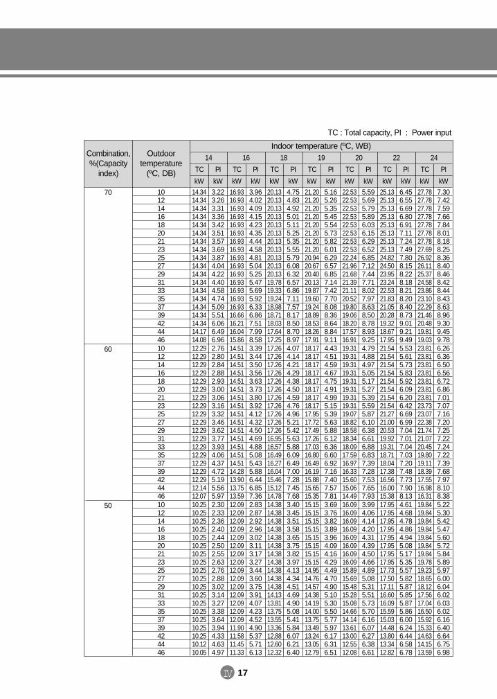
IV 17
Combination,%(Capacity
index)
Outdoor temperature
(ºC, DB)
14 16 18 19 20 22 24
TC
kW
TC
kW
TC
kW
TC
kW
TC
kW
TC
kW
TC
kW
PI
kW
PI
kW
PI
kW
PI
kW
PI
kW
PI
kW
PI
kW10121416182021232527293133353739424446
14.3414.3414.3414.3414.3414.3414.3414.3414.3414.3414.3414.3414.3414.3414.3414.3414.3414.1714.08
3.223.263.313.363.423.513.573.693.874.044.224.404.584.745.095.516.066.496.96
16.9316.9316.9316.9316.9316.9316.9316.9316.9316.9316.9316.9316.9316.9316.9316.6616.2116.0415.86
3.964.024.094.154.234.354.444.584.815.045.255.475.695.926.336.867.517.998.58
20.1320.1320.1320.1320.1320.1320.1320.1320.1320.1320.1319.7819.3319.2418.9818.7118.0317.6417.25
4.754.834.925.015.115.255.355.555.796.086.326.576.867.117.578.178.508.708.97
21.2021.2021.2021.2021.2021.2021.2021.2020.9420.6720.4020.1319.8719.6019.2418.8918.5318.2617.91
5.165.265.355.455.545.735.826.016.296.576.857.147.427.708.088.368.648.849.11
22.5322.5322.5322.5322.5322.5322.5322.5322.2421.9621.6821.3921.1120.5219.8019.0618.2017.5716.91
5.595.695.795.896.036.156.296.526.857.127.447.718.027.978.638.508.788.939.25
25.1325.1325.1325.1325.1325.1325.1325.1324.8224.5023.9523.2422.5321.8321.0520.2819.3218.6717.95
6.456.556.696.806.917.117.247.497.808.158.228.188.218.208.408.739.019.219.49
27.7827.7827.7827.7827.7827.7827.7827.6926.9226.1125.3724.5823.8623.1022.2921.4620.4819.8119.03
7.307.427.597.667.848.018.188.258.368.408.468.428.448.438.638.969.309.459.78
Indoor temperature (ºC, WB)
70
10121416182021232527293133353739424446
12.2912.2912.2912.2912.2912.2912.2912.2912.2912.2912.2912.2912.2912.2912.2912.2912.2912.1412.07
2.762.802.842.882.933.003.063.163.323.463.623.773.934.064.374.725.195.565.97
14.5114.5114.5114.5114.5114.5114.5114.5114.5114.5114.5114.5114.5114.5114.5114.2813.9013.7513.59
3.393.443.503.563.633.733.803.924.124.324.504.694.885.085.435.886.446.857.36
17.2617.2617.2617.2617.2617.2617.2617.2617.2617.2617.2616.9516.5716.4916.2716.0415.4615.1214.78
4.074.144.214.294.384.504.594.764.965.215.425.635.886.096.497.007.287.457.68
18.1718.1718.1718.1718.1718.1718.1718.1717.9517.7217.4917.2617.0316.8016.4916.1915.8815.6515.35
4.434.514.594.674.754.914.995.155.395.635.886.126.366.606.927.167.407.577.81
19.3119.3119.3119.3119.3119.3119.3119.3119.0718.8218.5818.3418.0917.5916.9716.3315.6015.0614.49
4.794.884.975.055.175.275.395.595.876.106.386.616.886.837.397.287.537.657.93
21.5421.5421.5421.5421.5421.5421.5421.5421.2721.0020.5319.9219.3118.7118.0417.3816.5616.0015.38
5.535.615.735.835.926.096.206.426.696.997.047.017.047.037.207.487.737.908.13
23.8123.8123.8123.8123.8123.8123.8123.7323.0722.3821.7421.0720.4519.8019.1118.3917.5516.9816.31
6.266.366.506.566.726.867.017.077.167.207.257.227.247.227.397.687.978.108.38
60
10121416182021232527293133353739424446
10.2510.2510.2510.2510.2510.2510.2510.2510.2510.2510.2510.2510.2510.2510.2510.2510.2510.1210.05
2.302.332.362.402.442.502.552.632.762.883.023.143.273.383.643.944.334.634.97
12.0912.0912.0912.0912.0912.0912.0912.0912.0912.0912.0912.0912.0912.0912.0911.9011.5811.4511.33
2.832.872.922.963.023.113.173.273.443.603.753.914.074.234.524.905.375.716.13
14.3814.3814.3814.3814.3814.3814.3814.3814.3814.3814.3814.1313.8113.7513.5513.3612.8812.6012.32
3.403.453.513.583.653.753.823.974.134.344.514.694.905.085.415.846.076.216.40
15.1515.1515.1515.1515.1515.1515.1515.1514.9514.7614.5714.3814.1914.0013.7513.4913.2413.0512.79
3.693.763.823.893.964.094.164.294.494.704.905.105.305.505.775.976.176.316.51
16.0916.0916.0916.0916.0916.0916.0916.0915.8915.6915.4815.2815.0814.6614.1413.6113.0012.5512.08
3.994.064.144.204.314.394.504.664.895.085.315.515.735.706.166.076.276.386.61
17.9517.9517.9517.9517.9517.9517.9517.9517.7317.5017.1116.6016.0915.5915.0314.4813.8013.3412.82
4.614.684.784.864.945.085.175.355.575.825.875.855.875.866.006.246.446.586.78
19.8419.8419.8419.8419.8419.8419.8419.7819.2318.6518.1217.5617.0416.5015.9215.3314.6314.1513.59
5.225.305.425.475.605.725.845.895.976.006.046.026.036.026.166.406.646.756.98
50
TC : Total capacity, PI : Power input
DVM E-D/B(chapter4-1)-E<03759 3/21/02 7:39 PM Page 17
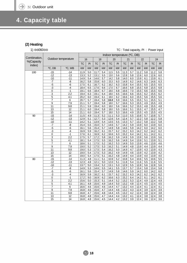
IV. Outdoor unit
4. Capacity table
IV 18
Combination,%(Capacity
index)
Outdoor temperature 16 18 20 21 22 24
ºC, DB ºC, WB
TC
kW
TC
kW
TC
kW
TC
kW
TC
kW
TC
kW
PI
kW
PI
kW
PI
kW
PI
kW
PI
kW
PI
kW-15-12-10-7-5-303579111315
-14-13-11-8-6-4-12.24.16
7.99.81214
11.913.314.916.217.518.419.119.420.220.721.121.121.121.1
5.05.25.45.86.16.56.66.36.05.75.75.96.06.0
11.713.114.615.816.717.618.419.119.419.419.419.419.419.4
5.45.55.76.06.26.66.76.46.15.85.86.05.85.7
11.513.014.215.316.217.018.018.018.018.018.018.018.018.0
5.55.65.86.06.36.76.86.56.25.95.75.65.55.3
11.312.814.014.915.816.616.616.616.616.616.616.616.616.6
5.75.86.06.26.46.87.06.66.05.55.35.25.14.9
11.212.613.914.615.515.515.515.515.515.515.515.515.515.5
5.86.06.16.36.56.86.66.25.65.14.94.84.74.5
11.212.613.914.615.515.515.515.515.515.515.515.515.515.5
5.86.06.16.36.56.86.66.25.65.14.94.84.74.5
(2) Heating1) 060
Indoor temperature (ºC, DB)
100
-15-12-10-7-5-303579111315
-14-13-11-8-6-4-12.24.16
7.99.81214
11.512.914.215.416.116.917.617.518.118.619.019.019.019.0
4.95.15.15.55.65.96.15.75.45.15.25.35.45.4
11.312.713.915.015.416.216.917.217.517.517.517.517.517.5
5.25.35.45.75.76.16.25.85.55.25.35.45.35.1
11.112.613.514.614.915.716.616.216.216.216.216.216.216.2
5.35.45.55.75.86.26.35.95.65.35.15.04.94.8
11.012.413.314.214.615.215.214.914.914.914.914.914.914.9
5.55.75.75.95.96.36.45.95.45.04.84.74.64.4
10.812.213.213.914.214.214.213.913.913.913.913.913.913.9
5.75.85.86.06.06.26.15.65.14.64.44.34.24.0
10.812.213.213.914.214.214.213.913.913.913.913.913.913.9
5.75.85.86.06.06.26.15.65.14.64.44.34.24.0
90
-15-12-10-7-5-303579111315
-14-13-11-8-6-4-12.24.16
7.99.81214
11.312.313.714.916.116.917.215.616.116.616.816.816.816.8
4.84.85.05.35.65.99.05.04.84.64.64.74.84.8
11.112.113.414.615.416.216.915.315.615.615.615.615.615.6
5.15.05.25.55.76.16.25.14.94.64.74.84.74.5
10.912.013.114.114.915.716.614.414.414.414.414.414.414.4
5.25.15.35.55.86.26.35.25.04.74.64.54.44.2
10.811.812.913.714.615.215.213.213.213.213.213.213.213.2
5.45.45.55.75.96.36.45.34.84.44.34.24.13.9
10.611.612.813.414.214.214.212.412.412.412.412.412.412.4
5.55.55.65.86.06.26.14.94.54.13.93.83.83.6
10.611.612.813.414.214.214.212.412.412.412.412.412.412.4
5.55.55.65.86.06.26.14.94.54.13.93.83.83.6
80
TC : Total capacity, PI : Power input
DVM E-D/B(chapter4-1)-E<03759 3/21/02 7:39 PM Page 18
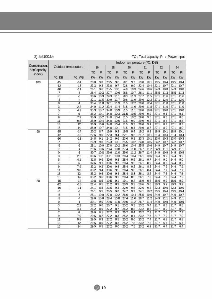
IV 19
2) 100 TC : Total capacity, PI : Power input
Combination,%(Capacity
index)
Outdoor temperature 16 18 20 21 22 24
ºC, DB ºC, WB
TC
kW
TC
kW
TC
kW
TC
kW
TC
kW
TC
kW
PI
kW
PI
kW
PI
kW
PI
kW
PI
kW
PI
kW-15-12-10-7-5-303579111315
-14-13-11-8-6-4-12.24.16
7.99.81214
20.823.326.128.430.632.133.434.035.336.236.936.936.936.9
9.09.39.610.310.911.511.811.210.710.110.210.410.610.7
20.523.025.527.729.330.932.133.434.034.034.034.034.034.0
9.69.710.110.611.111.711.911.410.910.310.410.610.410.1
20.122.824.926.828.329.831.531.531.531.531.531.531.531.5
9.79.910.310.711.311.912.211.611.110.510.29.99.79.4
19.822.424.626.127.729.029.029.029.029.029.029.029.029.0
10.110.410.611.111.512.212.411.810.89.99.59.39.18.7
19.522.124.325.527.127.127.127.127.127.127.127.127.127.1
10.410.710.811.311.612.011.811.010.09.18.88.58.38.0
19.522.124.325.527.127.127.127.127.127.127.127.127.127.1
10.410.710.811.311.612.011.811.010.09.18.88.58.38.0
Indoor temperature (ºC, DB)
100
-15-12-10-7-5-303579111315
-14-13-11-8-6-4-12.24.16
7.99.81214
20.222.624.826.928.129.630.730.631.832.633.233.233.233.2
8.79.09.19.810.010.610.810.19.69.19.29.49.69.6
19.922.324.226.327.028.429.630.130.630.630.630.630.630.6
9.39.49.610.110.210.811.010.39.89.39.49.59.49.1
19.522.123.625.526.027.429.028.428.428.428.428.428.428.4
9.49.69.810.210.411.011.210.49.99.59.29.08.88.5
19.221.723.324.825.526.726.726.126.126.126.126.126.126.1
9.810.110.110.510.611.211.410.69.78.98.58.48.27.8
18.921.423.024.224.924.924.924.424.424.424.424.424.424.4
10.110.410.310.710.711.110.99.99.08.27.97.77.57.2
18.921.423.024.224.924.924.924.424.424.424.424.424.424.4
10.110.410.310.710.711.110.99.99.08.27.97.77.57.2
90
-15-12-10-7-5-303579111315
-14-13-11-8-6-4-12.24.16
7.99.81214
19.821.424.126.128.129.630.127.228.229.029.529.529.529.5
8.58.58.89.510.010.69.09.08.58.18.28.38.58.5
19.521.223.525.527.028.429.626.727.227.227.227.227.227.2
9.18.99.39.810.210.811.09.18.78.38.38.58.38.0
19.120.922.924.726.027.429.025.225.225.225.225.225.225.2
9.29.29.59.910.411.011.29.38.88.48.18.07.87.5
18.920.622.624.125.526.726.723.223.223.223.223.223.223.2
9.69.69.810.210.611.211.49.48.67.97.67.47.26.9
18.620.322.323.524.924.924.921.721.721.721.721.721.721.7
9.99.910.010.410.711.110.98.88.07.37.06.86.76.4
18.620.322.323.524.924.924.921.721.721.721.721.721.721.7
9.99.910.010.410.711.110.98.88.07.37.06.86.76.4
80
DVM E-D/B(chapter4-1)-E<03759 3/21/02 7:39 PM Page 19
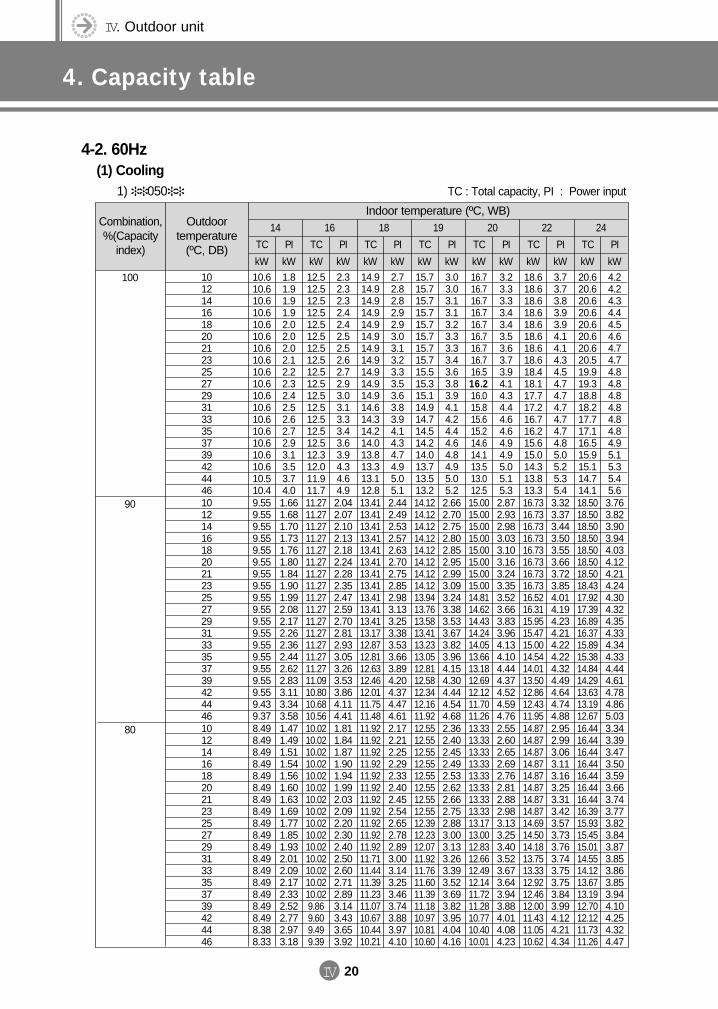
IV. Outdoor unit
4. Capacity table
IV 20
Combination,%(Capacity
index)
Outdoor temperature
(ºC, DB)
14 16 18 19 20 22 24
TC
kW
TC
kW
TC
kW
TC
kW
TC
kW
TC
kW
TC
kW
PI
kW
PI
kW
PI
kW
PI
kW
PI
kW
PI
kW
PI
kW10121416182021232527293133353739424446
10.610.610.610.610.610.610.610.610.610.610.610.610.610.610.610.610.610.510.4
1.81.91.91.92.02.02.02.12.22.32.42.52.62.72.93.13.53.74.0
12.512.512.512.512.512.512.512.512.512.512.512.512.512.512.512.312.011.911.7
2.32.32.32.42.42.52.52.62.72.93.03.13.33.43.63.94.34.64.9
14.914.914.914.914.914.914.914.914.914.914.914.614.314.214.013.813.313.112.8
2.72.82.82.92.93.03.13.23.33.53.63.83.94.14.34.74.95.05.1
15.715.715.715.715.715.715.715.715.515.315.114.914.714.514.214.013.713.513.2
3.03.03.13.13.23.33.33.43.63.83.94.14.24.44.64.84.95.05.2
16.716.716.716.716.716.716.716.716.516.216.015.815.615.214.614.113.513.012.5
3.23.33.33.43.43.53.63.73.94.14.34.44.64.64.94.95.05.15.3
18.618.618.618.618.618.618.618.618.418.117.717.216.716.215.615.014.313.813.3
3.73.73.83.93.94.14.14.34.54.74.74.74.74.74.85.05.25.35.4
20.620.620.620.620.620.620.620.519.919.318.818.217.717.116.515.915.114.714.1
4.24.24.34.44.54.64.74.74.84.84.84.84.84.84.95.15.35.45.6
4-2. 60Hz(1) Cooling
1) 050
Indoor temperature (ºC, WB)
100
10121416182021232527293133353739424446
9.559.559.559.559.559.559.559.559.559.559.559.559.559.559.559.559.559.439.37
1.661.681.701.731.761.801.841.901.992.082.172.262.362.442.622.833.113.343.58
11.2711.2711.2711.2711.2711.2711.2711.2711.2711.2711.2711.2711.2711.2711.2711.0910.8010.6810.56
2.042.072.102.132.182.242.282.352.472.592.702.812.933.053.263.533.864.114.41
13.4113.4113.4113.4113.4113.4113.4113.4113.4113.4113.4113.1712.8712.8112.6312.4612.0111.7511.48
2.442.492.532.572.632.702.752.852.983.133.253.383.533.663.894.204.374.474.61
14.1214.1214.1214.1214.1214.1214.1214.1213.9413.7613.5813.4113.2313.0512.8112.5812.3412.1611.92
2.662.702.752.802.852.952.993.093.243.383.533.673.823.964.154.304.444.544.68
15.0015.0015.0015.0015.0015.0015.0015.0014.8114.6214.4314.2414.0513.6613.1812.6912.1211.7011.26
2.872.932.983.033.103.163.243.353.523.663.833.964.134.104.444.374.524.594.76
16.7316.7316.7316.7316.7316.7316.7316.7316.5216.3115.9515.4715.0014.5414.0113.5012.8612.4311.95
3.323.373.443.503.553.663.723.854.014.194.234.214.224.224.324.494.644.744.88
18.5018.5018.5018.5018.5018.5018.5018.4317.9217.3916.8916.3715.8915.3814.8414.2913.6313.1912.67
3.763.823.903.944.034.124.214.244.304.324.354.334.344.334.444.614.784.865.03
90
10121416182021232527293133353739424446
8.498.498.498.498.498.498.498.498.498.498.498.498.498.498.498.498.498.388.33
1.471.491.511.541.561.601.631.691.771.851.932.012.092.172.332.522.772.973.18
10.0210.0210.0210.0210.0210.0210.0210.0210.0210.0210.0210.0210.0210.0210.029.869.609.499.39
1.811.841.871.901.941.992.032.092.202.302.402.502.602.712.893.143.433.653.92
11.9211.9211.9211.9211.9211.9211.9211.9211.9211.9211.9211.7111.4411.3911.2311.0710.6710.4410.21
2.172.212.252.292.332.402.452.542.652.782.893.003.143.253.463.743.883.974.10
12.5512.5512.5512.5512.5512.5512.5512.5512.3912.2312.0711.9211.7611.6011.3911.1810.9710.8110.60
2.362.402.452.492.532.622.662.752.883.003.133.263.393.523.693.823.954.044.16
13.3313.3313.3313.3313.3313.3313.3313.3313.1713.0012.8312.6612.4912.1411.7211.2810.7710.4010.01
2.552.602.652.692.762.812.882.983.133.253.403.523.673.643.943.884.014.084.23
14.8714.8714.8714.8714.8714.8714.8714.8714.6914.5014.1813.7513.3312.9212.4612.0011.4311.0510.62
2.952.993.063.113.163.253.313.423.573.733.763.743.753.753.843.994.124.214.34
16.4416.4416.4416.4416.4416.4416.4416.3915.9315.4515.0114.5514.1213.6713.1912.7012.1211.7311.26
3.343.393.473.503.593.663.743.773.823.843.873.853.863.853.944.104.254.324.47
80
TC : Total capacity, PI : Power input
DVM E-D/B(chapter4-1)-E<03759 3/21/02 7:39 PM Page 20
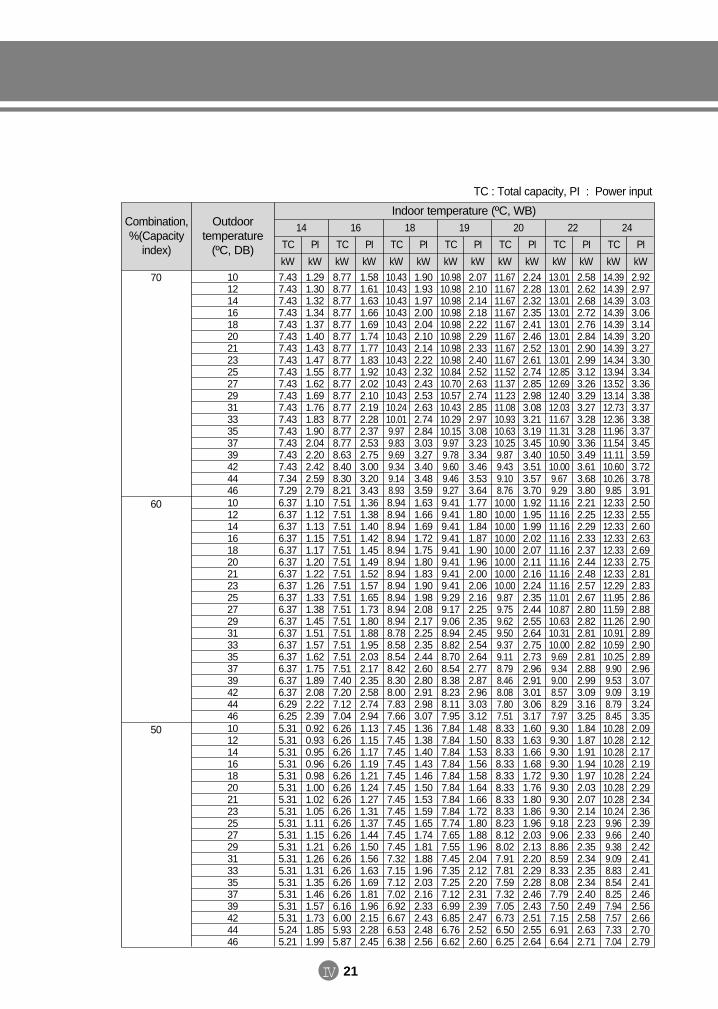
IV 21
Combination,%(Capacity
index)
Outdoor temperature
(ºC, DB)
14 16 18 19 20 22 24
TC
kW
TC
kW
TC
kW
TC
kW
TC
kW
TC
kW
TC
kW
PI
kW
PI
kW
PI
kW
PI
kW
PI
kW
PI
kW
PI
kW10121416182021232527293133353739424446
7.437.437.437.437.437.437.437.437.437.437.437.437.437.437.437.437.437.347.29
1.291.301.321.341.371.401.431.471.551.621.691.761.831.902.042.202.422.592.79
8.778.778.778.778.778.778.778.778.778.778.778.778.778.778.778.638.408.308.21
1.581.611.631.661.691.741.771.831.922.022.102.192.282.372.532.753.003.203.43
10.4310.4310.4310.4310.4310.4310.4310.4310.4310.4310.4310.2410.019.979.839.699.349.148.93
1.901.931.972.002.042.102.142.222.322.432.532.632.742.843.033.273.403.483.59
10.9810.9810.9810.9810.9810.9810.9810.9810.8410.7010.5710.4310.2910.159.979.789.609.469.27
2.072.102.142.182.222.292.332.402.522.632.742.852.973.083.233.343.463.533.64
11.6711.6711.6711.6711.6711.6711.6711.6711.5211.3711.2311.0810.9310.6310.259.879.439.108.76
2.242.282.322.352.412.462.522.612.742.852.983.083.213.193.453.403.513.573.70
13.0113.0113.0113.0113.0113.0113.0113.0112.8512.6912.4012.0311.6711.3110.9010.5010.009.679.29
2.582.622.682.722.762.842.902.993.123.263.293.273.283.283.363.493.613.683.80
14.3914.3914.3914.3914.3914.3914.3914.3413.9413.5213.1412.7312.3611.9611.5411.1110.6010.269.85
2.922.973.033.063.143.203.273.303.343.363.383.373.383.373.453.593.723.783.91
Indoor temperature (ºC, WB)
70
10121416182021232527293133353739424446
6.376.376.376.376.376.376.376.376.376.376.376.376.376.376.376.376.376.296.25
1.101.121.131.151.171.201.221.261.331.381.451.511.571.621.751.892.082.222.39
7.517.517.517.517.517.517.517.517.517.517.517.517.517.517.517.407.207.127.04
1.361.381.401.421.451.491.521.571.651.731.801.881.952.032.172.352.582.742.94
8.948.948.948.948.948.948.948.948.948.948.948.788.588.548.428.308.007.837.66
1.631.661.691.721.751.801.831.901.982.082.172.252.352.442.602.802.912.983.07
9.419.419.419.419.419.419.419.419.299.179.068.948.828.708.548.388.238.117.95
1.771.801.841.871.901.962.002.062.162.252.352.452.542.642.772.872.963.033.12
10.0010.0010.0010.0010.0010.0010.0010.009.879.759.629.509.379.118.798.468.087.807.51
1.921.951.992.022.072.112.162.242.352.442.552.642.752.732.962.913.013.063.17
11.1611.1611.1611.1611.1611.1611.1611.1611.0110.8710.6310.3110.009.699.349.008.578.297.97
2.212.252.292.332.372.442.482.572.672.802.822.812.822.812.882.993.093.163.25
12.3312.3312.3312.3312.3312.3312.3312.2911.9511.5911.2610.9110.5910.259.909.539.098.798.45
2.502.552.602.632.692.752.812.832.862.882.902.892.902.892.963.073.193.243.35
60
10121416182021232527293133353739424446
5.315.315.315.315.315.315.315.315.315.315.315.315.315.315.315.315.315.245.21
0.920.930.950.960.981.001.021.051.111.151.211.261.311.351.461.571.731.851.99
6.266.266.266.266.266.266.266.266.266.266.266.266.266.266.266.166.005.935.87
1.131.151.171.191.211.241.271.311.371.441.501.561.631.691.811.962.152.282.45
7.457.457.457.457.457.457.457.457.457.457.457.327.157.127.026.926.676.536.38
1.361.381.401.431.461.501.531.591.651.741.811.881.962.032.162.332.432.482.56
7.847.847.847.847.847.847.847.847.747.657.557.457.357.257.126.996.856.766.62
1.481.501.531.561.581.641.661.721.801.881.962.042.122.202.312.392.472.522.60
8.338.338.338.338.338.338.338.338.238.128.027.917.817.597.327.056.736.506.25
1.601.631.661.681.721.761.801.861.962.032.132.202.292.282.462.432.512.552.64
9.309.309.309.309.309.309.309.309.189.068.868.598.338.087.797.507.156.916.64
1.841.871.911.941.972.032.072.142.232.332.352.342.352.342.402.492.582.632.71
10.2810.2810.2810.2810.2810.2810.2810.249.969.669.389.098.838.548.257.947.577.337.04
2.092.122.172.192.242.292.342.362.392.402.422.412.412.412.462.562.662.702.79
50
TC : Total capacity, PI : Power input
DVM E-D/B(chapter4-1)-E<03759 3/21/02 7:39 PM Page 21
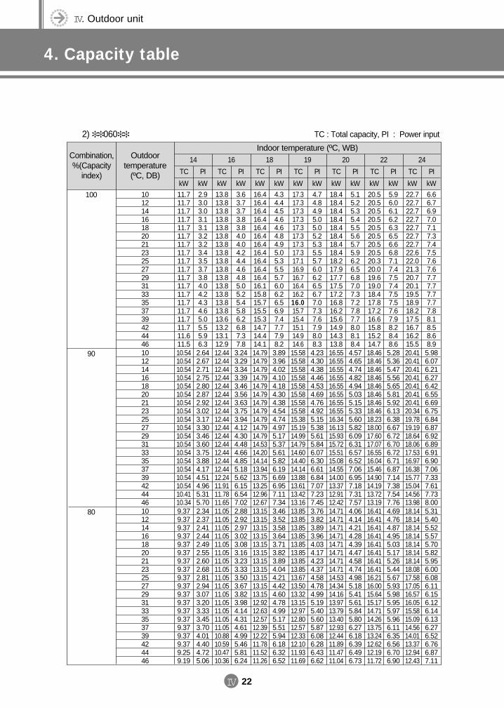
IV. Outdoor unit
4. Capacity table
IV 22
Combination,%(Capacity
index)
Outdoor temperature
(ºC, DB)
14 16 18 19 20 22 24
TC
kW
TC
kW
TC
kW
TC
kW
TC
kW
TC
kW
TC
kW
PI
kW
PI
kW
PI
kW
PI
kW
PI
kW
PI
kW
PI
kW10121416182021232527293133353739424446
11.711.711.711.711.711.711.711.711.711.711.711.711.711.711.711.711.711.611.5
2.93.03.03.13.13.23.23.43.53.73.84.04.24.34.65.05.55.96.3
13.813.813.813.813.813.813.813.813.813.813.813.813.813.813.813.613.213.112.9
3.63.73.73.83.84.04.04.24.44.64.85.05.25.45.86.26.87.37.8
16.416.416.416.416.416.416.416.416.416.416.416.115.815.715.515.314.714.414.1
4.34.44.54.64.64.84.95.05.35.55.76.06.26.56.97.47.77.98.2
17.317.317.317.317.317.317.317.317.116.916.716.416.216.015.715.415.114.914.6
4.74.84.95.05.05.25.35.55.76.06.26.56.77.07.37.67.98.08.3
18.418.418.418.418.418.418.418.418.217.917.717.517.216.816.215.614.914.313.8
5.15.25.35.45.55.65.75.96.26.56.87.07.37.27.87.78.08.18.4
20.520.520.520.520.520.520.520.520.320.019.619.018.417.817.216.615.815.214.7
5.96.06.16.26.36.56.66.87.17.47.57.47.57.57.67.98.28.48.6
22.722.722.722.722.722.722.722.622.021.320.720.119.518.918.217.516.716.215.5
6.66.76.97.07.17.37.47.57.67.67.77.77.77.77.88.18.58.68.9
2) 060
Indoor temperature (ºC, WB)
100
10121416182021232527293133353739424446
10.5410.5410.5410.5410.5410.5410.5410.5410.5410.5410.5410.5410.5410.5410.5410.5410.5410.4110.34
2.642.672.712.752.802.872.923.023.173.303.463.603.753.884.174.514.965.315.70
12.4412.4412.4412.4412.4412.4412.4412.4412.4412.4412.4412.4412.4412.4412.4412.2411.9111.7811.65
3.243.293.343.393.463.563.633.753.944.124.304.484.664.855.185.626.156.547.02
14.7914.7914.7914.7914.7914.7914.7914.7914.7914.7914.7914.5314.2014.1413.9413.7513.2512.9612.67
3.893.964.024.104.184.304.384.544.744.975.175.375.615.826.196.696.957.117.34
15.5815.5815.5815.5815.5815.5815.5815.5815.3815.1914.9914.7914.6014.4014.1413.8813.6113.4213.16
4.234.304.384.464.534.694.764.925.155.385.615.846.076.306.616.847.077.237.45
16.5516.5516.5516.5516.5516.5516.5516.5516.3416.1315.9315.7215.5115.0814.5514.0013.3712.9112.42
4.574.654.744.824.945.035.155.335.605.826.096.316.576.527.066.957.187.317.57
18.4618.4618.4618.4618.4618.4618.4618.4618.2318.0017.6017.0716.5516.0415.4614.9014.1913.7213.19
5.285.365.475.565.655.815.926.136.386.676.726.706.726.716.877.147.387.547.76
20.4120.4120.4120.4120.4120.4120.4120.3419.7819.1918.6418.0617.5316.9716.3815.7715.0414.5613.98
5.986.076.216.276.426.556.696.756.846.876.926.896.916.907.067.337.617.738.00
90
10121416182021232527293133353739424446
9.379.379.379.379.379.379.379.379.379.379.379.379.379.379.379.379.379.259.19
2.342.372.412.442.492.552.602.682.812.943.073.203.333.453.704.014.404.725.06
11.0511.0511.0511.0511.0511.0511.0511.0511.0511.0511.0511.0511.0511.0511.0510.8810.5910.4710.36
2.882.922.973.023.083.163.233.333.503.673.823.984.144.314.614.995.465.816.24
13.1513.1513.1513.1513.1513.1513.1513.1513.1513.1513.1512.9212.6312.5712.3912.2211.7811.5211.26
3.463.523.583.643.713.823.894.044.214.424.604.784.995.175.515.946.186.326.52
13.8513.8513.8513.8513.8513.8513.8513.8513.6713.5013.3213.1512.9712.8012.5712.3312.1011.9311.69
3.763.823.893.964.034.174.234.374.584.784.995.195.405.605.876.086.286.436.62
14.7114.7114.7114.7114.7114.7114.7114.7114.5314.3414.1613.9713.7913.4012.9312.4411.8911.4711.04
4.064.144.214.284.394.474.584.744.985.185.415.615.845.806.276.186.396.496.73
16.4116.4116.4116.4116.4116.4116.4116.4116.2116.0015.6415.1714.7114.2613.7513.2412.6212.1911.72
4.694.764.874.955.035.175.265.445.675.935.985.955.975.966.116.356.566.706.90
18.1418.1418.1418.1418.1418.1418.1418.0817.5817.0516.5716.0515.5815.0914.5614.0113.3712.9412.43
5.315.405.525.575.705.825.956.006.086.116.156.126.146.136.276.526.766.877.11
80
TC : Total capacity, PI : Power input
DVM E-D/B(chapter4-1)-E<03759 3/21/02 7:39 PM Page 22
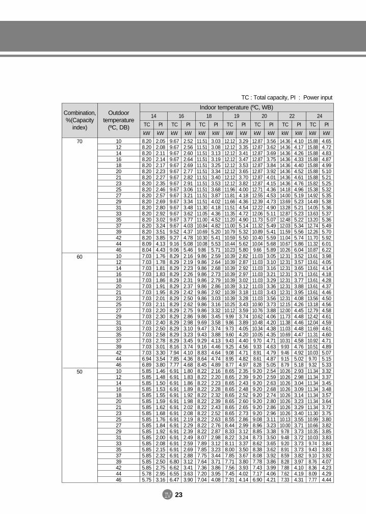
IV 23
Combination,%(Capacity
index)
Outdoor temperature
(ºC, DB)
14 16 18 19 20 22 24
TC
kW
TC
kW
TC
kW
TC
kW
TC
kW
TC
kW
TC
kW
PI
kW
PI
kW
PI
kW
PI
kW
PI
kW
PI
kW
PI
kW10121416182021232527293133353739424446
8.208.208.208.208.208.208.208.208.208.208.208.208.208.208.208.208.208.098.04
2.052.082.112.142.172.232.272.352.462.572.692.802.923.023.243.513.854.134.43
9.679.679.679.679.679.679.679.679.679.679.679.679.679.679.679.529.279.169.06
2.522.562.602.642.692.772.822.913.063.213.343.483.623.774.034.374.785.085.46
11.5111.5111.5111.5111.5111.5111.5111.5111.5111.5111.5111.3011.0511.0010.8410.6910.3010.089.86
3.033.083.133.193.253.343.403.533.683.874.024.184.364.524.825.205.415.535.71
12.1212.1212.1212.1212.1212.1212.1212.1211.9611.8111.6611.5111.3511.2011.0010.7910.5910.4410.23
3.293.353.413.473.533.653.703.824.004.184.364.544.724.905.145.325.505.625.80
12.8712.8712.8712.8712.8712.8712.8712.8712.7112.5512.3912.2212.0611.7311.3210.8910.4010.049.66
3.563.623.693.753.843.924.014.154.364.534.734.905.115.075.495.415.595.685.89
14.3614.3614.3614.3614.3614.3614.3614.3614.1814.0013.6913.2812.8712.4812.0311.5911.0410.6710.26
4.104.174.264.334.404.524.614.764.965.195.235.215.235.225.345.565.745.866.04
15.8815.8815.8815.8815.8815.8815.8815.8215.3814.9214.4914.0513.6313.2012.7412.2611.7011.3210.87
4.654.724.834.874.995.105.215.255.325.355.385.365.375.365.495.705.926.016.22
Indoor temperature (ºC, WB)
70
10121416182021232527293133353739424446
7.037.037.037.037.037.037.037.037.037.037.037.037.037.037.037.037.036.946.89
1.761.781.811.831.861.911.952.012.112.202.302.402.502.582.783.013.303.543.80
8.298.298.298.298.298.298.298.298.298.298.298.298.298.298.298.167.947.857.77
2.162.192.232.262.312.372.422.502.622.752.862.983.103.233.453.744.104.364.68
9.869.869.869.869.869.869.869.869.869.869.869.699.479.439.299.168.838.648.45
2.592.642.682.732.792.862.923.033.163.323.453.583.743.884.134.464.644.744.89
10.3910.3910.3910.3910.3910.3910.3910.3910.2510.129.999.869.739.609.439.259.088.958.77
2.822.872.922.973.023.123.183.283.433.593.743.894.054.204.404.564.714.824.97
11.0311.0311.0311.0311.0311.0311.0311.0310.9010.7610.6210.4810.3410.059.709.338.918.618.28
3.053.103.163.213.293.363.433.563.733.884.064.204.384.354.714.634.794.875.05
12.3112.3112.3112.3112.3112.3112.3112.3112.1512.0011.7311.3811.0310.6910.319.939.469.158.79
3.523.573.653.713.773.883.954.084.264.454.484.464.484.474.584.764.925.025.18
13.6113.6113.6113.6113.6113.6113.6113.5613.1812.7912.4212.0411.6911.3110.9210.5110.039.709.32
3.984.054.144.184.284.374.464.504.564.584.614.594.614.604.714.895.075.155.33
60
10121416182021232527293133353739424446
5.855.855.855.855.855.855.855.855.855.855.855.855.855.855.855.855.855.785.75
1.461.481.501.531.551.591.621.681.761.841.922.002.082.152.322.502.752.953.16
6.916.916.916.916.916.916.916.916.916.916.916.916.916.916.916.806.626.556.47
1.801.831.861.891.921.982.022.082.192.292.392.492.592.692.883.123.413.633.90
8.228.228.228.228.228.228.228.228.228.228.228.077.897.857.757.647.367.207.04
2.162.202.232.282.322.392.432.522.632.762.872.983.123.233.443.713.863.954.08
8.658.658.658.658.658.658.658.658.558.448.338.228.118.007.857.717.567.457.31
2.352.392.432.482.522.602.652.732.862.993.123.243.373.503.673.803.934.024.14
9.209.209.209.209.209.209.209.209.088.968.858.738.628.388.087.787.437.176.90
2.542.592.632.682.742.802.862.963.113.233.383.503.653.623.923.863.994.064.21
10.2610.2610.2610.2610.2610.2610.2610.2610.1310.009.789.489.208.918.598.287.887.627.33
2.932.983.043.093.143.233.293.403.553.713.733.723.733.733.823.974.104.194.31
11.3411.3411.3411.3411.3411.3411.3411.3010.9910.6610.3510.039.749.439.108.768.368.097.77
3.323.373.453.483.573.643.723.753.803.823.853.833.843.833.924.074.234.294.44
50
TC : Total capacity, PI : Power input
DVM E-D/B(chapter4-1)-E<03759 3/21/02 7:39 PM Page 23
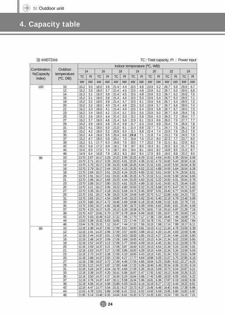
IV. Outdoor unit
4. Capacity table
IV 24
Combination,%(Capacity
index)
Outdoor temperature
(ºC, DB)
14 16 18 19 20 22 24
TC
kW
TC
kW
TC
kW
TC
kW
TC
kW
TC
kW
TC
kW
PI
kW
PI
kW
PI
kW
PI
kW
PI
kW
PI
kW
PI
kW10121416182021232527293133353739424446
15.215.215.215.215.215.215.215.215.215.215.215.215.215.215.215.215.215.014.9
3.03.03.13.13.23.23.33.43.63.73.94.14.24.44.75.15.66.06.4
18.018.018.018.018.018.018.018.018.018.018.018.018.018.018.017.717.217.016.8
3.63.73.83.83.94.04.14.24.44.64.85.05.25.55.86.36.97.47.9
21.421.421.421.421.421.421.421.421.421.421.421.020.520.420.119.919.118.718.3
4.44.54.54.64.74.84.95.15.35.65.86.16.36.67.07.57.88.08.3
22.522.522.522.522.522.522.522.522.221.921.721.421.120.820.420.019.719.419.0
4.84.84.95.05.15.35.45.55.86.16.36.66.87.17.47.78.08.18.4
23.923.923.923.923.923.923.923.923.623.323.022.722.421.821.020.219.318.617.9
5.25.25.35.45.65.75.86.06.36.66.97.17.47.48.07.88.18.28.5
26.726.726.726.726.726.726.726.726.326.025.424.723.923.222.321.520.519.819.0
5.96.06.26.36.46.66.76.97.27.57.67.57.67.67.78.18.38.58.8
29.529.529.529.529.529.529.529.428.627.726.926.125.324.523.722.821.721.020.2
6.76.87.07.17.27.47.57.67.77.77.87.87.87.88.08.38.68.79.0
3) 072
Indoor temperature (ºC, WB)
100
10121416182021232527293133353739424446
13.7013.7013.7013.7013.7013.7013.7013.7013.7013.7013.7013.7013.7013.7013.7013.7013.7013.5313.44
2.672.712.752.792.842.912.963.063.213.353.513.653.803.934.234.575.035.385.78
16.1716.1716.1716.1716.1716.1716.1716.1716.1716.1716.1716.1716.1716.1716.1715.9115.4915.3215.15
3.283.333.393.443.513.613.683.803.994.184.364.544.724.925.255.706.236.637.12
19.2319.2319.2319.2319.2319.2319.2319.2319.2319.2319.2318.8918.4618.3818.1217.8717.2216.8516.47
3.954.014.084.154.244.364.444.614.805.045.245.455.695.906.286.787.057.227.44
20.2520.2520.2520.2520.2520.2520.2520.2520.0019.7419.4919.2318.9818.7218.3818.0417.7017.4417.10
4.294.364.444.524.604.754.834.995.225.455.695.926.166.396.706.947.177.337.56
21.5221.5221.5221.5221.5221.5221.5221.5221.2520.9720.7020.4320.1619.6018.9118.2017.3816.7816.15
4.644.724.814.885.015.115.225.415.685.916.176.406.666.627.167.057.297.417.68
24.0024.0024.0024.0024.0024.0024.0024.0023.7023.4022.8822.1921.5220.8520.1019.3718.4517.8317.14
5.355.445.555.645.745.906.016.216.476.776.826.796.816.816.977.257.487.647.88
26.5426.5426.5426.5426.5426.5426.5426.4425.7124.9424.2323.4822.7922.0621.2920.5019.5618.9218.17
6.066.166.306.366.516.656.796.856.936.977.026.997.016.997.167.447.717.848.11
90
10121416182021232527293133353739424446
12.1812.1812.1812.1812.1812.1812.1812.1812.1812.1812.1812.1812.1812.1812.1812.1812.1812.0311.95
2.382.412.442.482.522.592.632.722.862.983.123.243.383.503.764.064.474.785.14
14.3714.3714.3714.3714.3714.3714.3714.3714.3714.3714.3714.3714.3714.3714.3714.1413.7713.6113.46
2.922.963.013.063.123.213.273.383.553.723.874.044.204.374.675.065.545.896.33
17.0917.0917.0917.0917.0917.0917.0917.0917.0917.0917.0916.7916.4116.3416.1115.8815.3114.9814.64
3.513.573.633.693.773.873.954.104.274.484.664.845.065.245.586.036.276.416.61
18.0018.0018.0018.0018.0018.0018.0018.0017.7717.5517.3217.0916.8716.6416.3416.0315.7315.5115.20
3.813.883.954.024.094.234.294.434.644.855.065.265.475.685.966.166.376.526.72
19.1319.1319.1319.1319.1319.1319.1319.1318.8918.6418.4018.1617.9217.4216.8116.1815.4514.9214.35
4.124.204.274.344.454.544.644.815.055.255.495.695.925.886.366.276.486.596.82
21.3421.3421.3421.3421.3421.3421.3421.3421.0720.8020.3419.7319.1318.5317.8717.2216.4015.8515.24
4.764.834.945.025.105.245.345.525.756.026.066.046.066.056.196.446.656.807.00
23.5923.5923.5923.5923.5923.5923.5923.5122.8522.1721.5320.8720.2619.6118.9318.2217.3816.8216.15
5.395.485.605.655.795.916.046.096.166.206.246.216.236.226.366.616.866.977.21
80
TC : Total capacity, PI : Power input
DVM E-D/B(chapter4-1)-E<03759 3/21/02 7:39 PM Page 24
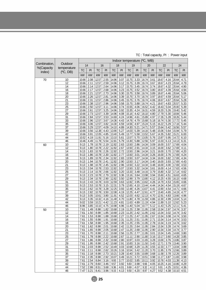
IV 25
Combination,%(Capacity
index)
Outdoor temperature
(ºC, DB)
14 16 18 19 20 22 24
TC
kW
TC
kW
TC
kW
TC
kW
TC
kW
TC
kW
TC
kW
PI
kW
PI
kW
PI
kW
PI
kW
PI
kW
PI
kW
PI
kW10121416182021232527293133353739424446
10.6610.6610.6610.6610.6610.6610.6610.6610.6610.6610.6610.6610.6610.6610.6610.6610.6610.5210.46
2.082.112.142.172.212.262.312.382.502.612.732.842.963.063.293.563.914.194.49
12.5712.5712.5712.5712.5712.5712.5712.5712.5712.5712.5712.5712.5712.5712.5712.3812.0511.9111.78
2.552.592.642.682.732.812.862.963.113.253.393.533.673.824.094.434.855.165.54
14.9614.9614.9614.9614.9614.9614.9614.9614.9614.9614.9614.6914.3614.3014.1013.9013.4013.1012.81
3.073.123.173.233.303.393.453.583.743.924.084.244.434.594.895.275.495.615.79
15.7515.7515.7515.7515.7515.7515.7515.7515.5515.3515.1614.9614.7614.5614.3014.0313.7713.5713.30
3.333.393.453.523.583.703.763.884.064.244.424.614.794.975.215.395.585.705.88
16.7416.7416.7416.7416.7416.7416.7416.7416.5216.3116.1015.8915.6815.2414.7114.1613.5213.0512.56
3.613.673.743.803.893.974.064.214.424.594.804.975.185.155.575.485.675.765.97
18.6718.6718.6718.6718.6718.6718.6718.6718.4318.2017.7917.2616.7416.2215.6415.0614.3513.8713.33
4.164.234.324.394.464.594.674.835.045.265.305.285.305.295.425.645.825.956.13
20.6420.6420.6420.6420.6420.6420.6420.5720.0019.4018.8418.2617.7217.1616.5615.9415.2114.7214.13
4.714.794.904.945.065.175.285.335.395.425.465.445.455.445.575.796.006.106.31
Indoor temperature (ºC, WB)
70
10121416182021232527293133353739424446
9.139.139.139.139.139.139.139.139.139.139.139.139.139.139.139.139.139.028.96
1.781.801.831.861.891.941.982.042.142.232.342.432.532.622.823.053.353.593.85
10.7810.7810.7810.7810.7810.7810.7810.7810.7810.7810.7810.7810.7810.7810.7810.6110.3210.2110.10
2.192.222.262.302.342.412.452.532.662.792.903.033.153.283.503.804.164.424.75
12.8212.8212.8212.8212.8212.8212.8212.8212.8212.8212.8212.5912.3112.2512.0811.9111.4811.2310.98
2.632.672.722.772.832.902.963.073.203.363.503.633.793.934.194.524.704.814.96
13.5013.5013.5013.5013.5013.5013.5013.5013.3313.1612.9912.8212.6512.4812.2512.0311.8011.6311.40
2.862.912.963.013.073.173.223.323.483.643.793.954.104.264.474.624.784.895.04
14.3414.3414.3414.3414.3414.3414.3414.3414.1613.9813.8013.6213.4413.0712.6112.1311.5911.1910.77
3.093.153.213.263.343.403.483.613.793.944.124.264.444.414.774.704.864.945.12
16.0016.0016.0016.0016.0016.0016.0016.0015.8015.6015.2514.7914.3413.9013.4012.9112.3011.8911.43
3.573.623.703.763.823.934.004.144.324.514.554.534.544.544.654.834.995.105.25
17.6917.6917.6917.6917.6917.6917.6917.6317.1416.6316.1515.6515.1914.7114.1913.6613.0412.6212.11
4.044.114.204.244.344.434.534.564.624.654.684.664.674.664.774.965.145.235.41
60
10121416182021232527293133353739424446
7.617.617.617.617.617.617.617.617.617.617.617.617.617.617.617.617.617.527.47
1.491.501.531.551.581.621.651.701.781.861.952.032.112.182.352.542.792.993.21
8.988.988.988.988.988.988.988.988.988.988.988.988.988.988.988.848.608.518.41
1.821.851.881.911.952.012.052.112.222.322.422.522.622.732.923.163.463.683.96
10.6810.6810.6810.6810.6810.6810.6810.6810.6810.6810.6810.4910.2610.2110.079.939.579.369.15
2.192.232.272.312.352.422.472.562.672.802.913.033.163.283.493.773.924.014.13
11.2511.2511.2511.2511.2511.2511.2511.2511.1110.9710.8310.6810.5410.4010.2110.029.839.699.50
2.382.422.472.512.552.642.682.772.903.033.163.293.423.553.723.853.984.074.20
11.9511.9511.9511.9511.9511.9511.9511.9511.8011.6511.5011.3511.2010.8910.5110.119.669.328.97
2.582.622.672.712.782.842.903.013.163.283.433.553.703.683.983.924.054.124.27
13.3413.3413.3413.3413.3413.3413.3413.3413.1713.0012.7112.3311.9511.5811.1710.7610.259.919.52
2.973.023.083.143.193.283.343.453.603.763.793.773.793.783.874.034.164.254.38
14.7414.7414.7414.7414.7414.7414.7414.6914.2813.8613.4613.0412.6612.2611.8311.3910.8610.5110.10
3.373.423.503.533.623.693.773.803.853.873.903.883.893.893.984.134.294.364.51
50
TC : Total capacity, PI : Power input
DVM E-D/B(chapter4-1)-E<03759 3/21/02 7:39 PM Page 25

IV. Outdoor unit
4. Capacity table
IV 26
Combination,%(Capacity
index)
Outdoor temperature
(ºC, DB)
14 16 18 19 20 22 24
TC
kW
TC
kW
TC
kW
TC
kW
TC
kW
TC
kW
TC
kW
PI
kW
PI
kW
PI
kW
PI
kW
PI
kW
PI
kW
PI
kW10121416182021232527293133353739424446
20.520.520.520.520.520.520.520.520.520.520.520.520.520.520.520.520.520.220.1
4.64.74.74.84.95.05.15.35.55.86.06.36.56.87.37.98.79.39.9
24.224.224.224.224.224.224.224.224.224.224.224.224.224.224.223.823.222.922.7
5.75.75.85.96.06.26.36.56.97.27.57.88.18.59.09.810.711.412.3
28.828.828.828.828.828.828.828.828.828.828.828.327.627.527.126.725.825.224.6
6.86.97.07.27.37.57.67.98.38.79.09.49.810.210.811.712.112.412.8
30.330.330.330.330.330.330.330.329.929.529.128.828.428.027.527.026.526.125.6
7.47.57.67.87.98.28.38.69.09.49.810.210.611.011.511.912.312.613.0
32.232.232.232.232.232.232.232.231.831.431.030.630.229.328.327.226.025.124.2
8.08.18.38.48.68.89.09.39.810.210.611.011.511.412.312.112.512.813.2
35.935.935.935.935.935.935.935.935.535.034.233.232.231.230.129.027.626.725.6
9.29.49.69.79.910.210.310.711.111.611.711.711.711.712.012.512.913.213.6
39.739.739.739.739.739.739.739.638.537.336.235.134.133.031.830.729.328.327.2
10.410.610.810.911.211.411.711.811.912.012.112.012.112.012.312.813.313.514.0
4) 100
Indoor temperature (ºC, WB)
100
10121416182021232527293133353739424446
18.4418.4418.4418.4418.4418.4418.4418.4418.4418.4418.4418.4418.4418.4418.4418.4418.4418.2118.10
4.144.194.254.324.394.514.594.744.985.195.435.655.896.096.557.087.798.348.95
21.7621.7621.7621.7621.7621.7621.7621.7621.7621.7621.7621.7621.7621.7621.7621.4220.8520.6220.39
5.095.165.255.335.445.595.715.896.196.486.757.037.327.628.148.829.6610.2711.04
25.8925.8925.8925.8925.8925.8925.8925.8925.8925.8925.8925.4324.8624.7424.4024.0523.1822.6822.18
6.116.226.326.446.576.756.887.147.447.828.138.448.829.149.7310.5110.9311.1811.53
27.2627.2627.2627.2627.2627.2627.2627.2626.9226.5726.2325.8925.5425.2024.7424.2823.8323.4823.02
6.646.766.887.007.127.367.497.738.098.458.819.189.549.9010.3810.7511.1111.3611.71
28.9728.9728.9728.9728.9728.9728.9728.9728.6028.2427.8727.5127.1426.3825.4624.5023.4022.5921.74
7.197.317.457.577.767.918.098.388.809.159.569.9110.3210.2511.0910.9311.2911.4811.89
32.3132.3132.3132.3132.3132.3132.3132.3131.9131.5030.8029.8728.9628.0727.0626.0724.8424.0123.08
8.298.428.608.748.899.149.319.6310.0310.4810.5610.5210.5610.5410.8011.2311.5911.8412.20
35.7235.7235.7235.7235.7235.7235.7235.6034.6133.5732.6131.6130.6829.7028.6627.5926.3325.4724.46
9.399.549.759.8510.0910.3010.5210.6110.7410.8010.8810.8310.8610.8411.0911.5311.9512.1512.57
90
10121416182021232527293133353739424446
16.3916.3916.3916.3916.3916.3916.3916.3916.3916.3916.3916.3916.3916.3916.3916.3916.3916.1916.09
3.683.733.783.843.914.014.084.214.424.614.835.025.245.425.826.306.927.417.96
19.3519.3519.3519.3519.3519.3519.3519.3519.3519.3519.3519.3519.3519.3519.3519.0418.5318.3318.12
4.524.594.674.744.844.975.075.235.505.766.006.256.516.777.247.848.599.139.81
23.0123.0123.0123.0123.0123.0123.0123.0123.0123.0123.0122.6022.0921.9921.6921.3820.6120.1619.71
5.435.525.625.725.846.006.116.346.626.957.227.507.848.128.659.349.719.9410.25
24.2324.2324.2324.2324.2324.2324.2324.2323.9323.6223.3223.0122.7122.4021.9921.5921.1820.8720.47
5.906.016.126.226.336.556.656.877.197.517.838.168.488.809.239.559.8710.1010.41
25.7525.7525.7525.7525.7525.7525.7525.7525.4225.1024.7724.4524.1223.4522.6321.7820.8020.0819.32
6.396.506.626.736.907.037.197.457.828.138.508.819.179.119.869.7110.0310.2110.57
28.7228.7228.7228.7228.7228.7228.7228.7228.3628.0027.3826.5625.7524.9524.0523.1822.0821.3420.51
7.377.497.657.777.908.128.278.568.929.329.399.359.389.379.609.9810.3010.5310.85
31.7531.7531.7531.7531.7531.7531.7531.6430.7629.8428.9928.1027.2726.4025.4824.5223.4022.6421.74
8.358.488.678.758.969.159.359.439.559.609.679.629.659.639.8610.2410.6210.8011.17
80
TC : Total capacity, PI : Power input
DVM E-D/B(chapter4-1)-E<03759 3/21/02 7:39 PM Page 26

IV 27
Combination,%(Capacity
index)
Outdoor temperature
(ºC, DB)
14 16 18 19 20 22 24
TC
kW
TC
kW
TC
kW
TC
kW
TC
kW
TC
kW
TC
kW
PI
kW
PI
kW
PI
kW
PI
kW
PI
kW
PI
kW
PI
kW10121416182021232527293133353739424446
14.3414.3414.3414.3414.3414.3414.3414.3414.3414.3414.3414.3414.3414.3414.3414.3414.3414.1714.08
3.223.263.313.363.423.513.573.693.874.044.224.404.584.745.095.516.066.496.96
16.9316.9316.9316.9316.9316.9316.9316.9316.9316.9316.9316.9316.9316.9316.9316.6616.2116.0415.86
3.964.024.094.154.234.354.444.584.815.045.255.475.695.926.336.867.517.998.58
20.1320.1320.1320.1320.1320.1320.1320.1320.1320.1320.1319.7819.3319.2418.9818.7118.0317.6417.25
4.754.834.925.015.115.255.355.555.796.086.326.576.867.117.578.178.508.708.97
21.2021.2021.2021.2021.2021.2021.2021.2020.9420.6720.4020.1319.8719.6019.2418.8918.5318.2617.91
5.165.265.355.455.545.735.826.016.296.576.857.147.427.708.088.368.648.849.11
22.5322.5322.5322.5322.5322.5322.5322.5322.2421.9621.6821.3921.1120.5219.8019.0618.2017.5716.91
5.595.695.795.896.036.156.296.526.857.127.447.718.027.978.638.508.788.939.25
25.1325.1325.1325.1325.1325.1325.1325.1324.8224.5023.9523.2422.5321.8321.0520.2819.3218.6717.95
6.456.556.696.806.917.117.247.497.808.158.228.188.218.208.408.739.019.219.49
27.7827.7827.7827.7827.7827.7827.7827.6926.9226.1125.3724.5823.8623.1022.2921.4620.4819.8119.03
7.307.427.597.667.848.018.188.258.368.408.468.428.448.438.638.969.309.459.78
Indoor temperature (ºC, WB)
70
10121416182021232527293133353739424446
12.2912.2912.2912.2912.2912.2912.2912.2912.2912.2912.2912.2912.2912.2912.2912.2912.2912.1412.07
2.762.802.842.882.933.003.063.163.323.463.623.773.934.064.374.725.195.565.97
14.5114.5114.5114.5114.5114.5114.5114.5114.5114.5114.5114.5114.5114.5114.5114.2813.9013.7513.59
3.393.443.503.563.633.733.803.924.124.324.504.694.885.085.435.886.446.857.36
17.2617.2617.2617.2617.2617.2617.2617.2617.2617.2617.2616.9516.5716.4916.2716.0415.4615.1214.78
4.074.144.214.294.384.504.594.764.965.215.425.635.886.096.497.007.287.457.68
18.1718.1718.1718.1718.1718.1718.1718.1717.9517.7217.4917.2617.0316.8016.4916.1915.8815.6515.35
4.434.514.594.674.754.914.995.155.395.635.886.126.366.606.927.167.407.577.81
19.3119.3119.3119.3119.3119.3119.3119.3119.0718.8218.5818.3418.0917.5916.9716.3315.6015.0614.49
4.794.884.975.055.175.275.395.595.876.106.386.616.886.837.397.287.537.657.93
21.5421.5421.5421.5421.5421.5421.5421.5421.2721.0020.5319.9219.3118.7118.0417.3816.5616.0015.38
5.535.615.735.835.926.096.206.426.696.997.047.017.047.037.207.487.737.908.13
23.8123.8123.8123.8123.8123.8123.8123.7323.0722.3821.7421.0720.4519.8019.1118.3917.5516.9816.31
6.266.366.506.566.726.867.017.077.167.207.257.227.247.227.397.687.978.108.38
60
10121416182021232527293133353739424446
10.2510.2510.2510.2510.2510.2510.2510.2510.2510.2510.2510.2510.2510.2510.2510.2510.2510.1210.05
2.302.332.362.402.442.502.552.632.762.883.023.143.273.383.643.944.334.634.97
12.0912.0912.0912.0912.0912.0912.0912.0912.0912.0912.0912.0912.0912.0912.0911.9011.5811.4511.33
2.832.872.922.963.023.113.173.273.443.603.753.914.074.234.524.905.375.716.13
14.3814.3814.3814.3814.3814.3814.3814.3814.3814.3814.3814.1313.8113.7513.5513.3612.8812.6012.32
3.403.453.513.583.653.753.823.974.134.344.514.694.905.085.415.846.076.216.40
15.1515.1515.1515.1515.1515.1515.1515.1514.9514.7614.5714.3814.1914.0013.7513.4913.2413.0512.79
3.693.763.823.893.964.094.164.294.494.704.905.105.305.505.775.976.176.316.51
16.0916.0916.0916.0916.0916.0916.0916.0915.8915.6915.4815.2815.0814.6614.1413.6113.0012.5512.08
3.994.064.144.204.314.394.504.664.895.085.315.515.735.706.166.076.276.386.61
17.9517.9517.9517.9517.9517.9517.9517.9517.7317.5017.1116.6016.0915.5915.0314.4813.8013.3412.82
4.614.684.784.864.945.085.175.355.575.825.875.855.875.866.006.246.446.586.78
19.8419.8419.8419.8419.8419.8419.8419.7819.2318.6518.1217.5617.0416.5015.9215.3314.6314.1513.59
5.225.305.425.475.605.725.845.895.976.006.046.026.036.026.166.406.646.756.98
50
TC : Total capacity, PI : Power input
DVM E-D/B(chapter4-1)-E<03759 3/21/02 7:39 PM Page 27
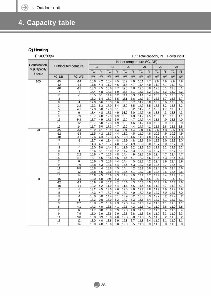
IV. Outdoor unit
4. Capacity table
IV 28
Combination,%(Capacity
index)
Outdoor temperature 16 18 20 21 22 24
ºC, DB ºC, WB
TC
kW
TC
kW
TC
kW
TC
kW
TC
kW
TC
kW
PI
kW
PI
kW
PI
kW
PI
kW
PI
kW
PI
kW-15-12-10-7-5-303579111315
-14-13-11-8-6-4-12.24.16
7.99.81214
10.611.813.314.415.516.317.017.317.918.418.718.718.718.7
4.24.44.54.85.15.45.65.35.04.84.84.95.05.0
10.411.713.014.114.915.716.317.017.317.317.317.317.317.3
4.54.64.75.05.25.55.65.45.14.94.95.04.94.7
10.211.612.613.614.415.116.016.016.016.016.016.016.016.0
4.64.74.85.15.35.65.75.55.25.04.84.74.64.4
10.111.412.513.314.114.714.714.714.714.714.714.714.714.7
4.74.95.05.25.45.75.85.55.14.64.54.44.34.1
9.911.212.313.013.813.813.813.813.813.813.813.813.813.8
4.95.15.15.35.55.75.65.24.74.34.14.03.93.8
9.911.212.313.013.813.813.813.813.813.813.813.813.813.8
4.95.15.15.35.55.75.65.24.74.34.14.03.93.8
(2) Heating1) 050
Indoor temperature (ºC, DB)
100
-15-12-10-7-5-303579111315
-14-13-11-8-6-4-12.24.16
7.99.81214
10.211.512.613.714.315.015.615.616.116.616.816.816.816.8
4.14.24.34.64.75.05.14.74.54.34.34.44.54.5
10.111.312.313.413.714.415.015.315.615.615.615.615.615.6
4.44.44.54.84.85.15.24.84.64.44.44.54.44.3
9.911.212.012.913.213.914.714.414.414.414.414.414.414.4
4.44.54.64.84.95.25.34.94.74.54.34.24.14.0
9.811.011.912.613.013.513.513.213.213.213.213.213.213.2
4.64.84.85.05.05.35.45.04.64.24.03.93.83.7
9.610.911.712.312.712.712.712.412.412.412.412.412.412.4
4.84.94.95.05.05.25.14.74.33.93.73.63.53.4
9.610.911.712.312.712.712.712.412.412.412.412.412.412.4
4.84.94.95.05.05.25.14.74.33.93.73.63.53.4
90
-15-12-10-7-5-303579111315
-14-13-11-8-6-4-12.24.16
7.99.81214
10.010.912.213.214.315.015.313.814.314.715.015.015.015.0
4.04.04.24.54.75.09.04.24.03.83.93.94.04.0
9.910.711.913.013.714.415.013.613.813.813.813.813.813.8
4.34.24.44.64.85.15.24.34.13.93.94.03.93.8
9.710.611.612.513.213.914.712.812.812.812.812.812.812.8
4.44.34.54.64.95.25.34.44.24.03.83.83.73.5
9.610.511.512.213.013.513.511.811.811.811.811.811.811.8
4.54.54.64.85.05.35.44.44.13.73.63.53.43.3
9.410.311.311.912.712.712.711.011.011.011.011.011.011.0
4.74.64.74.95.05.25.14.13.83.43.33.23.13.0
9.410.311.311.912.712.712.711.011.011.011.011.011.011.0
4.74.64.74.95.05.25.14.13.83.43.33.23.13.0
80
TC : Total capacity, PI : Power input
DVM E-D/B(chapter4-1)-E<03759 3/21/02 7:39 PM Page 28
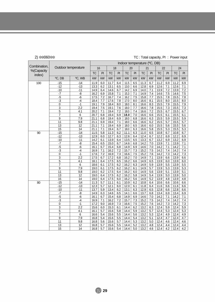
IV 29
2) 060 TC : Total capacity, PI : Power input
Combination,%(Capacity
index)
Outdoor temperature 16 18 20 21 22 24
ºC, DB ºC, WB
TC
kW
TC
kW
TC
kW
TC
kW
TC
kW
TC
kW
PI
kW
PI
kW
PI
kW
PI
kW
PI
kW
PI
kW-15-12-10-7-5-303579111315
-14-13-11-8-6-4-12.24.16
7.99.81214
11.913.314.916.217.518.419.119.420.220.721.121.121.121.1
6.06.26.46.97.27.77.97.57.16.86.86.97.17.1
11.713.114.615.816.717.618.419.119.419.419.419.419.419.4
6.46.56.77.17.47.88.07.67.26.96.97.16.96.7
11.513.014.215.316.217.018.018.018.018.018.018.018.018.0
6.56.66.97.17.58.08.17.77.47.06.86.66.56.3
11.312.814.014.915.816.616.616.616.616.616.616.616.616.6
6.76.97.17.47.78.18.37.87.26.66.36.26.05.8
11.212.613.914.615.515.515.515.515.515.515.515.515.515.5
6.97.17.27.57.88.07.97.36.76.15.95.75.65.3
11.212.613.914.615.515.515.515.515.515.515.515.515.515.5
6.97.17.27.57.88.07.97.36.76.15.95.75.65.3
Indoor temperature (ºC, DB)
100
-15-12-10-7-5-303579111315
-14-13-11-8-6-4-12.24.16
7.99.81214
11.512.914.215.416.116.917.617.518.118.619.019.019.019.0
5.86.06.16.56.77.17.26.76.46.16.16.26.46.4
11.312.713.915.015.416.216.917.217.517.517.517.517.517.5
6.26.36.46.76.87.27.36.86.56.26.26.46.26.0
11.112.613.514.614.915.716.616.216.216.216.216.216.216.2
6.36.46.56.86.97.37.57.06.66.36.16.05.85.6
11.012.413.314.214.615.215.214.914.914.914.914.914.914.9
6.56.76.77.07.07.57.67.16.55.95.75.65.45.2
10.812.213.213.914.214.214.213.913.913.913.913.913.913.9
6.76.96.97.17.17.47.36.66.05.55.35.15.04.8
10.812.213.213.914.214.214.213.913.913.913.913.913.913.9
6.76.96.97.17.17.47.36.66.05.55.35.15.04.8
90
-15-12-10-7-5-303579111315
-14-13-11-8-6-4-12.24.16
7.99.81214
11.312.313.714.916.116.917.215.616.116.616.816.816.816.8
5.75.75.96.36.77.19.06.05.75.45.45.65.75.7
11.112.113.414.615.416.216.915.315.615.615.615.615.615.6
6.16.06.26.56.87.27.36.15.85.55.55.75.55.4
10.912.013.114.114.915.716.614.414.414.414.414.414.414.4
6.26.16.36.66.97.37.56.25.95.65.45.35.25.0
10.811.812.913.714.615.215.213.213.213.213.213.213.213.2
6.46.46.56.87.07.57.66.35.75.35.15.04.84.6
10.611.612.813.414.214.214.212.412.412.412.412.412.412.4
6.66.66.66.97.17.47.35.95.34.94.74.64.44.2
10.611.612.813.414.214.214.212.412.412.412.412.412.412.4
6.66.66.66.97.17.47.35.95.34.94.74.64.44.2
80
DVM E-D/B(chapter4-1)-E<03759 3/21/02 7:39 PM Page 29
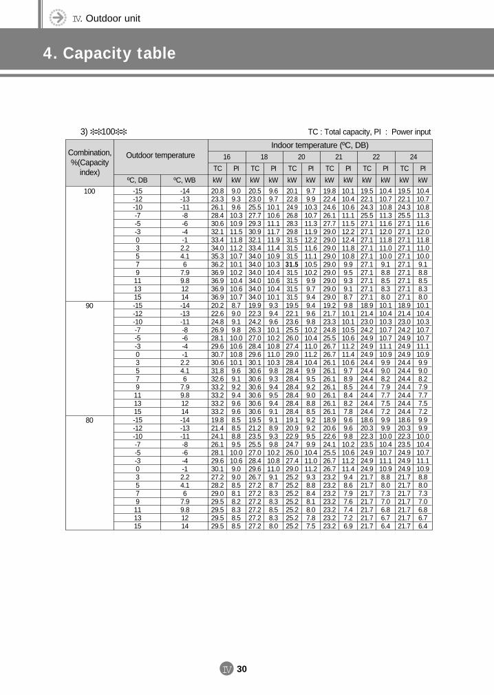
IV. Outdoor unit
4. Capacity table
IV 30
3) 100 TC : Total capacity, PI : Power input
Combination,%(Capacity
index)
Outdoor temperature 16 18 20 21 22 24
ºC, DB ºC, WB
TC
kW
TC
kW
TC
kW
TC
kW
TC
kW
TC
kW
PI
kW
PI
kW
PI
kW
PI
kW
PI
kW
PI
kW-15-12-10-7-5-303579111315
-14-13-11-8-6-4-12.24.16
7.99.81214
20.823.326.128.430.632.133.434.035.336.236.936.936.936.9
9.09.39.610.310.911.511.811.210.710.110.210.410.610.7
20.523.025.527.729.330.932.133.434.034.034.034.034.034.0
9.69.710.110.611.111.711.911.410.910.310.410.610.410.1
20.122.824.926.828.329.831.531.531.531.531.531.531.531.5
9.79.910.310.711.311.912.211.611.110.510.29.99.79.4
19.822.424.626.127.729.029.029.029.029.029.029.029.029.0
10.110.410.611.111.512.212.411.810.89.99.59.39.18.7
19.522.124.325.527.127.127.127.127.127.127.127.127.127.1
10.410.710.811.311.612.011.811.010.09.18.88.58.38.0
19.522.124.325.527.127.127.127.127.127.127.127.127.127.1
10.410.710.811.311.612.011.811.010.09.18.88.58.38.0
Indoor temperature (ºC, DB)
100
-15-12-10-7-5-303579111315
-14-13-11-8-6-4-12.24.16
7.99.81214
20.222.624.826.928.129.630.730.631.832.633.233.233.233.2
8.79.09.19.810.010.610.810.19.69.19.29.49.69.6
19.922.324.226.327.028.429.630.130.630.630.630.630.630.6
9.39.49.610.110.210.811.010.39.89.39.49.59.49.1
19.522.123.625.526.027.429.028.428.428.428.428.428.428.4
9.49.69.810.210.411.011.210.49.99.59.29.08.88.5
19.221.723.324.825.526.726.726.126.126.126.126.126.126.1
9.810.110.110.510.611.211.410.69.78.98.58.48.27.8
18.921.423.024.224.924.924.924.424.424.424.424.424.424.4
10.110.410.310.710.711.110.99.99.08.27.97.77.57.2
18.921.423.024.224.924.924.924.424.424.424.424.424.424.4
10.110.410.310.710.711.110.99.99.08.27.97.77.57.2
90
-15-12-10-7-5-303579111315
-14-13-11-8-6-4-12.24.16
7.99.81214
19.821.424.126.128.129.630.127.228.229.029.529.529.529.5
8.58.58.89.510.010.69.09.08.58.18.28.38.58.5
19.521.223.525.527.028.429.626.727.227.227.227.227.227.2
9.18.99.39.810.210.811.09.18.78.38.38.58.38.0
19.120.922.924.726.027.429.025.225.225.225.225.225.225.2
9.29.29.59.910.411.011.29.38.88.48.18.07.87.5
18.920.622.624.125.526.726.723.223.223.223.223.223.223.2
9.69.69.810.210.611.211.49.48.67.97.67.47.26.9
18.620.322.323.524.924.924.921.721.721.721.721.721.721.7
9.99.910.010.410.711.110.98.88.07.37.06.86.76.4
18.620.322.323.524.924.924.921.721.721.721.721.721.721.7
9.99.910.010.410.711.110.98.88.07.37.06.86.76.4
80
DVM E-D/B(chapter4-1)-E<03759 3/21/02 7:39 PM Page 30
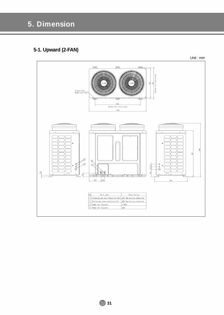
IV 31
5. Dimension
5-1. Upward (2-FAN)Unit : mm
DVM E-D/B(chapter4-1)-E<03759 3/21/02 7:39 PM Page 31
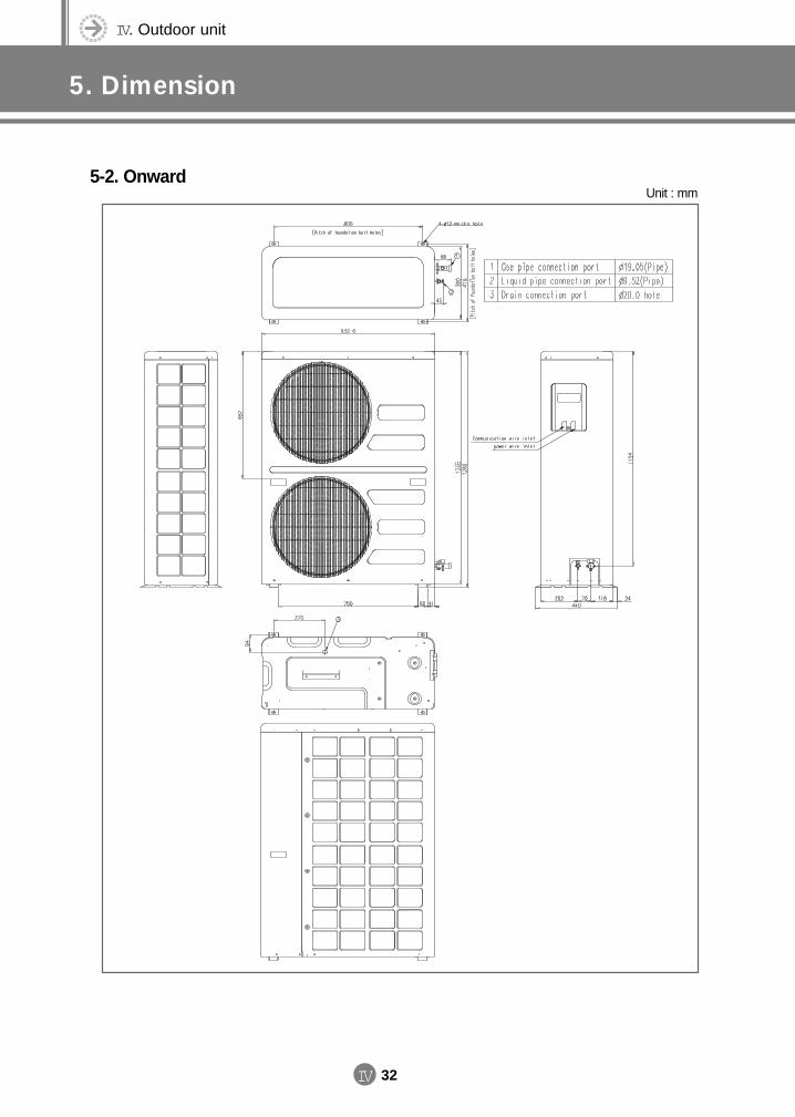
IV. Outdoor unit
5. Dimension
IV 32
5-2. OnwardUnit : mm
DVM E-D/B(chapter4-2)-E<03759 3/21/02 7:39 PM Page 32
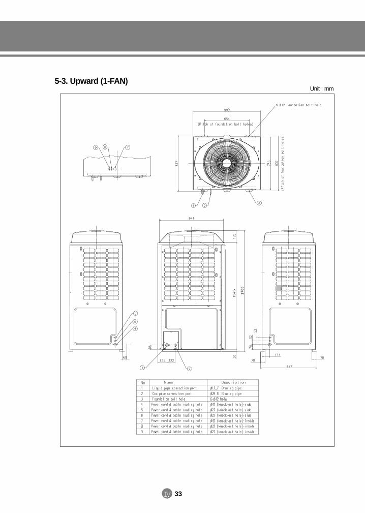
IV 33
5-3. Upward (1-FAN)
1765
1575
Unit : mm
DVM E-D/B(chapter4-2)-E<03759 3/21/02 7:40 PM Page 33
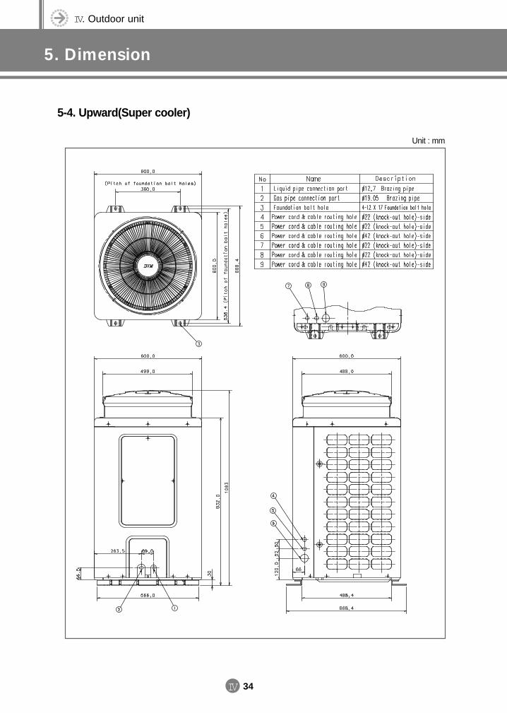
IV. Outdoor unit
5. Dimension
IV 34
5-4. Upward(Super cooler)
Unit : mm
DVM E-D/B(chapter4-2)-E<03759 3/21/02 7:40 PM Page 34
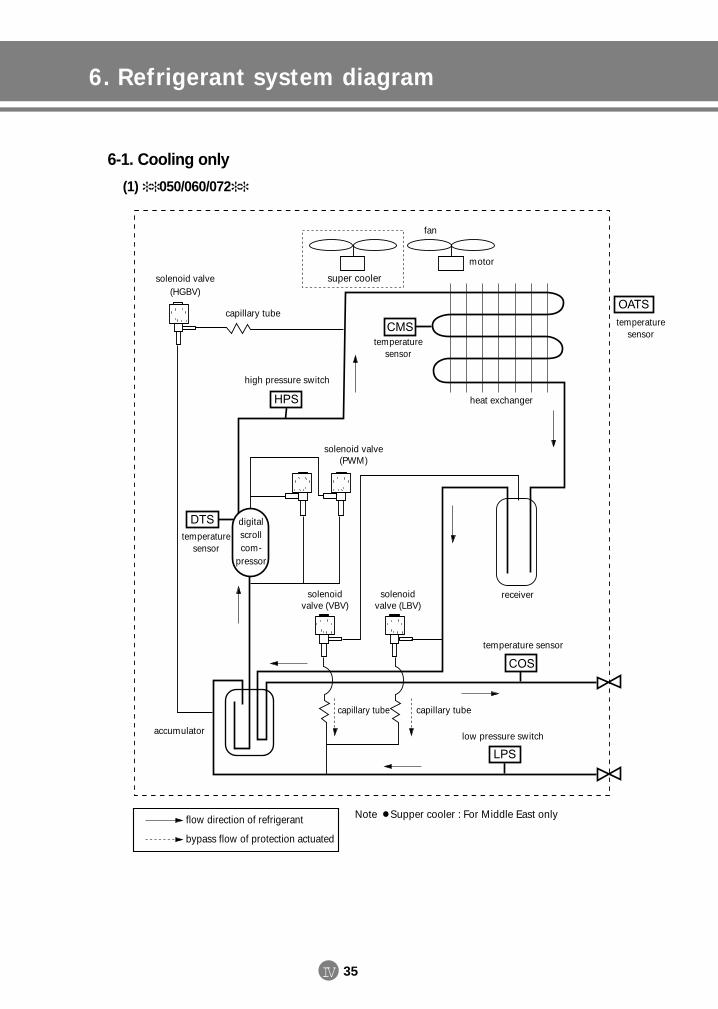
IV 35
6. Refrigerant system diagram
6-1. Cooling only
(1) 050/060/072
fan
motor
super cooler
temperaturesensor
temperaturesensor
temperature sensor
heat exchanger
high pressure switch
low pressure switch
temperaturesensor
digital scroll com-
pressor
solenoidvalve (VBV)
solenoid valve(HGBV)
solenoidvalve (LBV)
solenoid valve(PWM)
receiver
capillary tube
capillary tube
capillary tube
accumulator
flow direction of refrigerant
bypass flow of protection actuated
Note Supper cooler : For Middle East only
DVM E-D/B(chapter4-2)-E<03759 3/21/02 7:40 PM Page 35
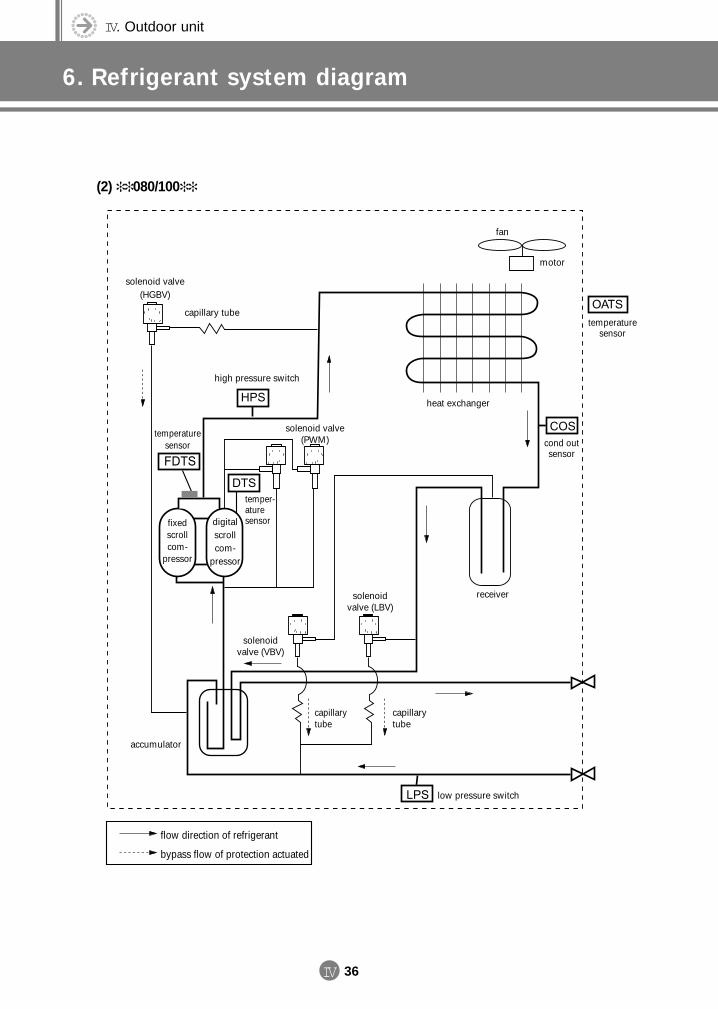
IV. Outdoor unit
6. Refrigerant system diagram
IV 36
(2) 080/100
temperaturesensor
temper-aturesensor
fan
motor
temperaturesensor
cond outsensor
heat exchanger
high pressure switch
low pressure switch
fixed scrollcom-
pressor
digital scroll com-
pressor
solenoidvalve (VBV)
solenoid valve(HGBV)
solenoidvalve (LBV)
solenoid valve(PWM)
receiver
capillarytube
capillary tube
capillarytube
accumulator
flow direction of refrigerant
bypass flow of protection actuated
DVM E-D/B(chapter4-2)-E<03759 3/21/02 7:40 PM Page 36
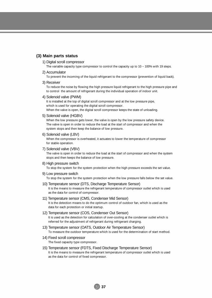
IV 37
(3) Main parts status1) Digital scroll compressor
The variable capacity type compressor to control the capacity up to 10 ~ 100% with 19 steps.
2) AccumulatorTo prevent the incoming of the liquid refrigerant to the compressor (prevention of liquid back).
3) ReceiverTo reduce the noise by flowing the high pressure liquid refrigerant to the high pressure pipe and to control the amount of refrigerant during the individual operation of indoor unit.
4) Solenoid valve (PWM)It is installed at the top of digital scroll compressor and at the low pressure pipe, which is used for operating the digital scroll compressor. When the valve is open, the digital scroll compressor keeps the state of unloading.
5) Solenoid valve (HGBV) When the low pressure gets lower, the valve is open by the low pressure safety device. The valve is open in order to reduce the load at the start of compressor and when the system stops and then keep the balance of low pressure.
6) Solenoid valve (LBV) When the compressor is overheated, it actuates to lower the temperature of compressor for stable operation.
7) Solenoid valve (VBV)The valve is open in order to reduce the load at the start of compressor and when the system stops and then keeps the balance of low pressure.
8) High pressure switchTo stop the system for the system protection when the high pressure exceeds the set value.
9) Low pressure switch To stop the system for the system protection when the low pressure falls below the set value.
10) Temperature sensor (DTS, Discharge Temperature Sensor)It is the means to measure the refrigerant temperature of compressor outlet which is used as the data for control of compressor.
11) Temperature sensor (CMS, Condenser Mid Sensor) It is the detection means to do the optimum control of outdoor fan, which is used as the data for each protection or initial startup.
12) Temperature sensor (COS, Condenser Out Sensor) It is used as the detection for calculation of over-cooling at the condenser outlet which is referred for the adjustment of refrigerant during refrigerant charging.
13) Temperature sensor (OATS, Outdoor Air Temperature Sensor) To measure the outdoor temperature which is used for the determination of start method.
14) Fixed scroll compressorThe fixed capacity type compressor.
15) Temperature sensor (FDTS, Fixed Discharge Temperature Sensor)It is the means to measure the refrigerant temperature of compressor outlet which is used as the data for control of fixed compressor.
DVM E-D/B(chapter4-2)-E<03759 3/21/02 7:40 PM Page 37
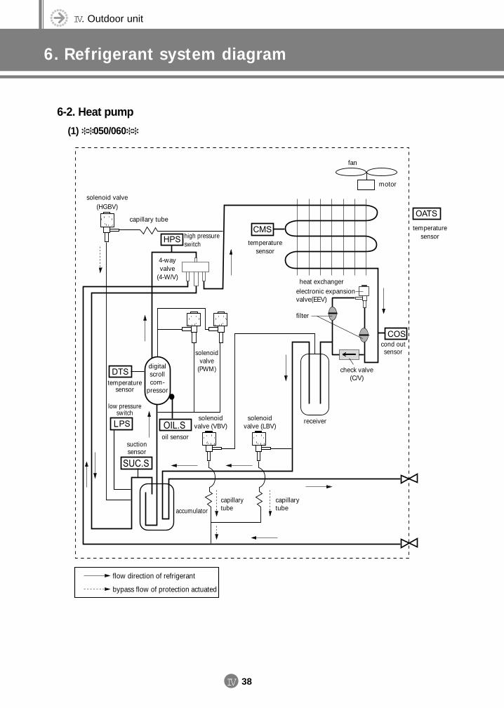
IV. Outdoor unit
6. Refrigerant system diagram
IV 38
6-2. Heat pump
(1) 050/060
fan
motor
temperaturesensor
temperaturesensor
heat exchanger
high pressureswitch
4-wayvalve
(4-W/V)
temperaturesensor
low pressureswitch
digital scroll com-
pressor
solenoidvalve (VBV)
solenoid valve(HGBV)
solenoidvalve (LBV)
solenoidvalve
(PWM)
receiver
check valve(C/V)
filter
electronic expansion valve(EEV)
capillarytube
capillary tube
capillarytubeaccumulator
flow direction of refrigerant
bypass flow of protection actuated
oil sensorsuction sensor
cond outsensor
DVM E-D/B(chapter4-2)-E<03759 3/21/02 7:40 PM Page 38
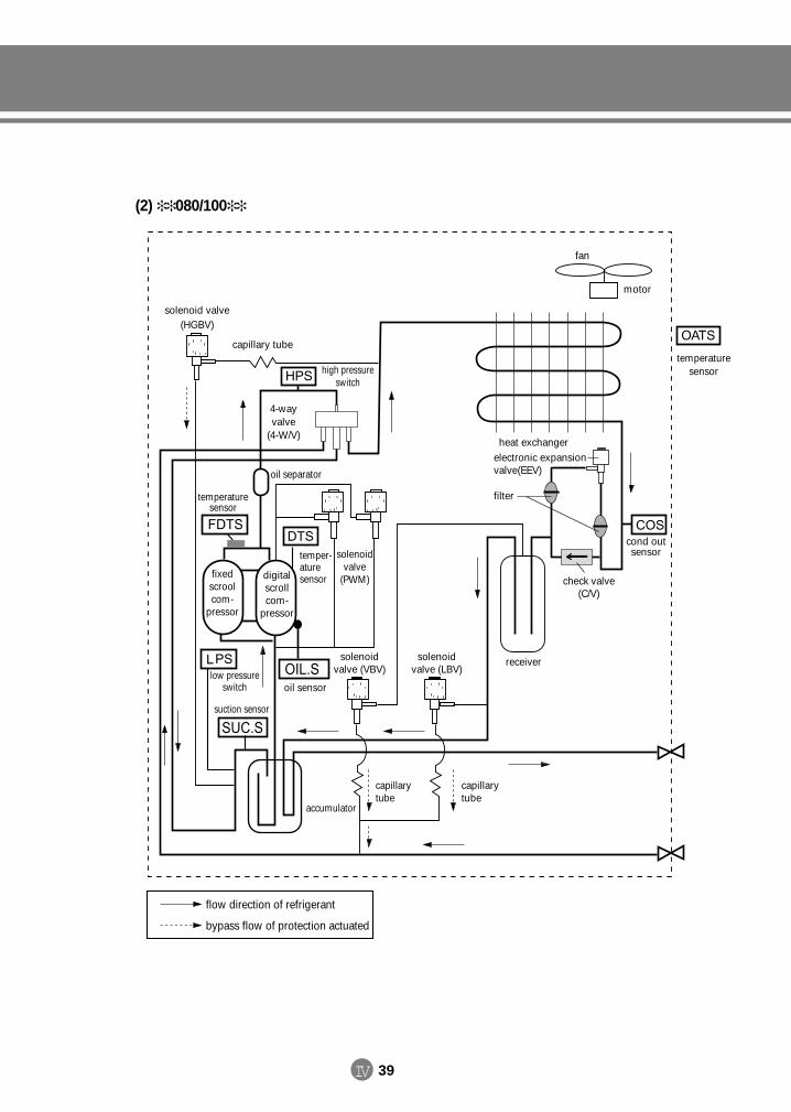
IV 39
(2) 080/100
fan
motor
temperaturesensor
cond outsensor
heat exchanger
high pressureswitch
4-wayvalve
(4-W/V)
digital scroll com-
pressor
solenoidvalve (VBV)
solenoid valve(HGBV)
solenoidvalve (LBV)
solenoidvalve
(PWM)
receiver
check valve(C/V)
filter
electronic expansion valve(EEV)
capillarytube
capillary tube
capillarytube
accumulator
flow direction of refrigerant
bypass flow of protection actuated
fixed scroolcom-
pressor
suction sensor
low pressureswitch
temperaturesensor
oil separator
temper-aturesensor
oil sensor
DVM E-D/B(chapter4-2)-E<03759 3/21/02 7:40 PM Page 39
IV. Outdoor unit
6. Refrigerant system diagram
IV 40
(3) Main parts status1) Digital scroll compressor
The variable capacity type compressor to control the capacity up to 10 ~ 100% with 19 steps
2) AccumulatorTo prevent the incoming of the liquid refrigerant to the compressor (prevention of liquid back).
3) ReceiverTo reduce the noise by flowing the high pressure liquid refrigerant to the high pressure pipe and to control the amount of refrigerant during the individual operation of indoor unit.
4) Solenoid valve (PWM)It is installed at the top of digital scroll compressor and at the low pressure pipe, which is used for operatingthe digital scroll compressor. When the valve is open, the digital scroll compressor keeps the state of unloading.
5) Solenoid valve (HGBV) When the low pressure gets lower, the valve is open by the low pressure safety device. The valve is open inorder to reduce the load at the start of compressor and when the system stops and then keep the balance oflow pressure.
6) Solenoid valve (LBV) When the compressor is overheated, it actuates to lower the temperature of compressor for stable operation.
7) Solenoid valve (VBV)The valve is open in order to reduce the load at the start of compressor and when the system stops and thenkeeps the balance of low pressure.
8) High pressure switchTo stop the system for the system protection when the high pressure exceeds the set value.
9) Temperature sensor (DTS, Discharge Temperature Sensor)It is the means to measure the refrigerant temperature of compressor outlet which is used as the data for control of compressor.
10) Temperature sensor (COS, Condenser Out Sensor) When heating, used for defrost control by sensing outdoor heat exchanger temperature.
DVM E-D/B(chapter4-2)-E<03759 3/21/02 7:40 PM Page 40
IV 41
11) Temperature sensor (OATS, Outdoor Air Temperature Sensor) To measure the outdoor temperature which is used for the determination of start method.
12) Fixed scroll compressorThe fixed capacity type compressor.
13) 4-way valve (4-W/V)It enables the change between cooling and heating by reversing the flow direction of refrigerant.
14) Electronic expansion valve (EEV)By sensing suction temperature and low pressure, controls the suction super heat and mass flow of refrigerant.
15) Check valve (C/V)To reduce the loss of pressure at the electronic expansion valve while cooling and to prevent the over-loadof the compressor.
16) SUC.S (Suction sensor)To control EEV for optimized suction super heat to control over-heating at the electronic expansion valve by the temperature of the compressor suction part when heating.
17) OIL.S (Oil sensor)To control EEV against liquid back and low dilution of oil to protect the compressor by measuring the tem-perature of oil used for controling SUMP at low temperature in cooling / heating mode.
18) Temperature sensor (FDTS, Fixed Discharge Temperature Sensor)It is the means to measure the refrigerant temperature of compressor outlet which is used as the data forcontrol of fixed compressor.
DVM E-D/B(chapter4-2)-E<03759 3/21/02 7:40 PM Page 41
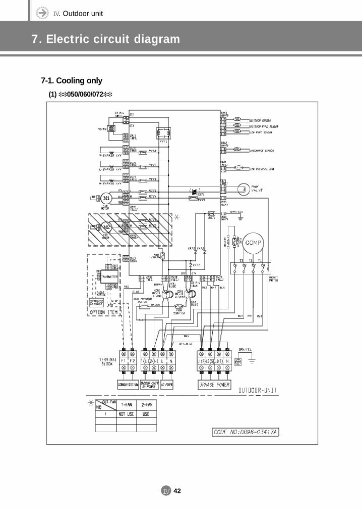
IV. Outdoor unit
7. Electric circuit diagram
IV 42
7-1. Cooling only
(1) 050/060/072
DVM E-D/B(chapter4-2)-E<03759 3/21/02 7:40 PM Page 42
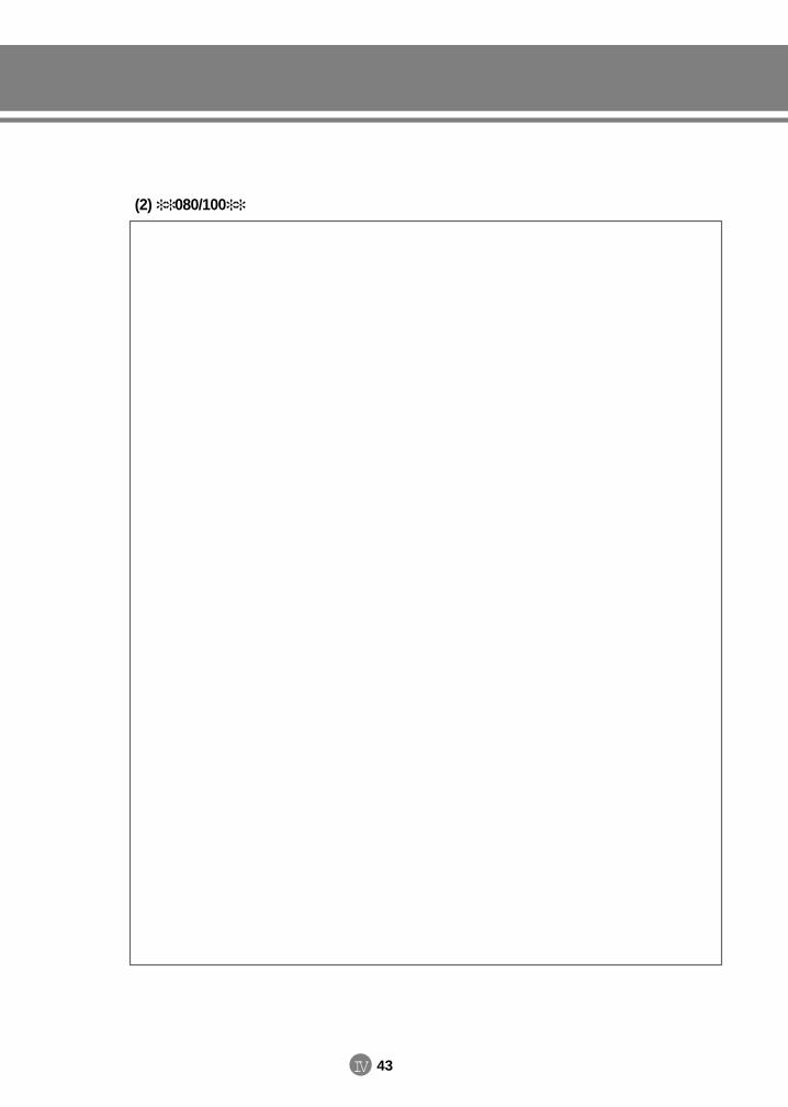
IV 43
(2) 080/100
DVM E-D/B(chapter4-2)-E<03759 3/21/02 7:40 PM Page 43
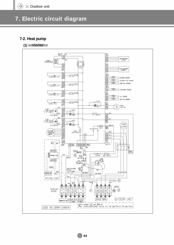
IV. Outdoor unit
7. Electric circuit diagram
IV 44
7-2. Heat pump
(1) 050/060
DVM E-D/B(chapter4-2)-E<03759 3/21/02 7:40 PM Page 44
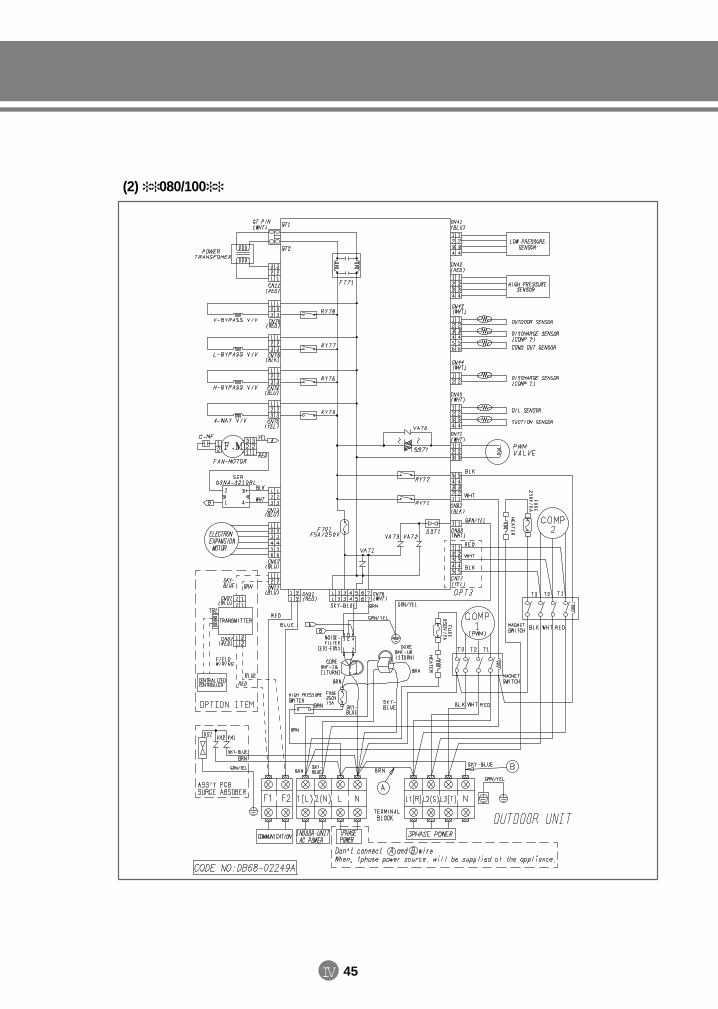
IV 45
(2) 080/100
DVM E-D/B(chapter4-2)-E<03759 3/21/02 7:40 PM Page 45
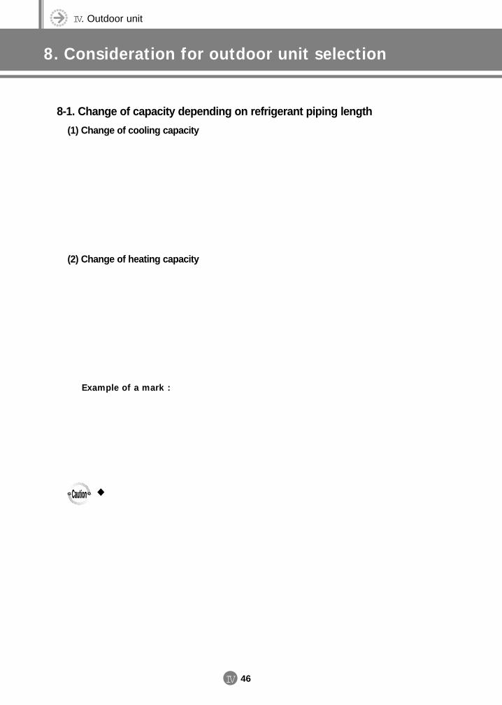
IV. Outdoor unit
8. Consideration for outdoor unit selection
IV 46
8-1. Change of capacity depending on refrigerant piping length
(1) Change of cooling capacity
(2) Change of heating capacity
Example of a mark :
DVM E-D/B(chapter4-2)-E<03759 3/21/02 7:40 PM Page 46
IV 47
8-2. Condition of operating restriction
(1) Cooling
(2) Heating
(3) Cautions for characteristics of heating capacity
DVM E-D/B(chapter4-2)-E<03759 3/21/02 7:40 PM Page 47
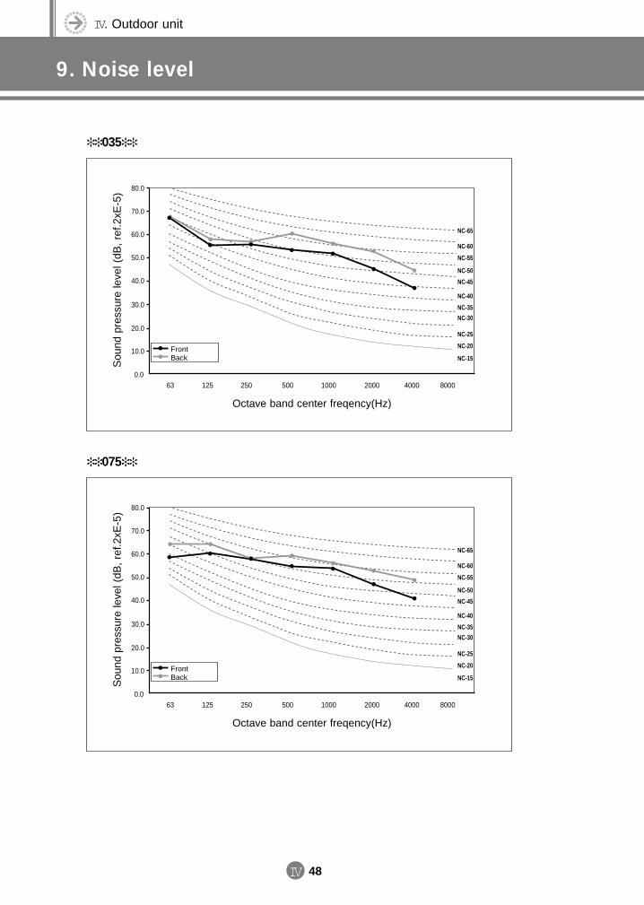
IV. Outdoor unit
9. Noise level
IV 48
035
Sou
nd p
ress
ure
leve
l (dB
, re
f.2xE
-5) 80.0
70.0
60.0
50.0
40.0
30.0
20.0
10.0
0.063 125 250 500 1000 40002000 8000
NC-65
NC-60
NC-55
NC-50
NC-45
NC-40
NC-35
NC-30
NC-25
NC-20
NC-15
Octave band center freqency(Hz)
FrontBack
075
Sou
nd p
ress
ure
leve
l (dB
, re
f.2xE
-5) 80.0
70.0
60.0
50.0
40.0
30.0
20.0
10.0
0.063 125 250 500 1000 40002000 8000
NC-65
NC-60
NC-55
NC-50
NC-45
NC-40
NC-35
NC-30
NC-25
NC-20
NC-15
Octave band center freqency(Hz)
FrontBack
DVM E-D/B(chapter4-2)-E<03759 3/21/02 7:40 PM Page 48
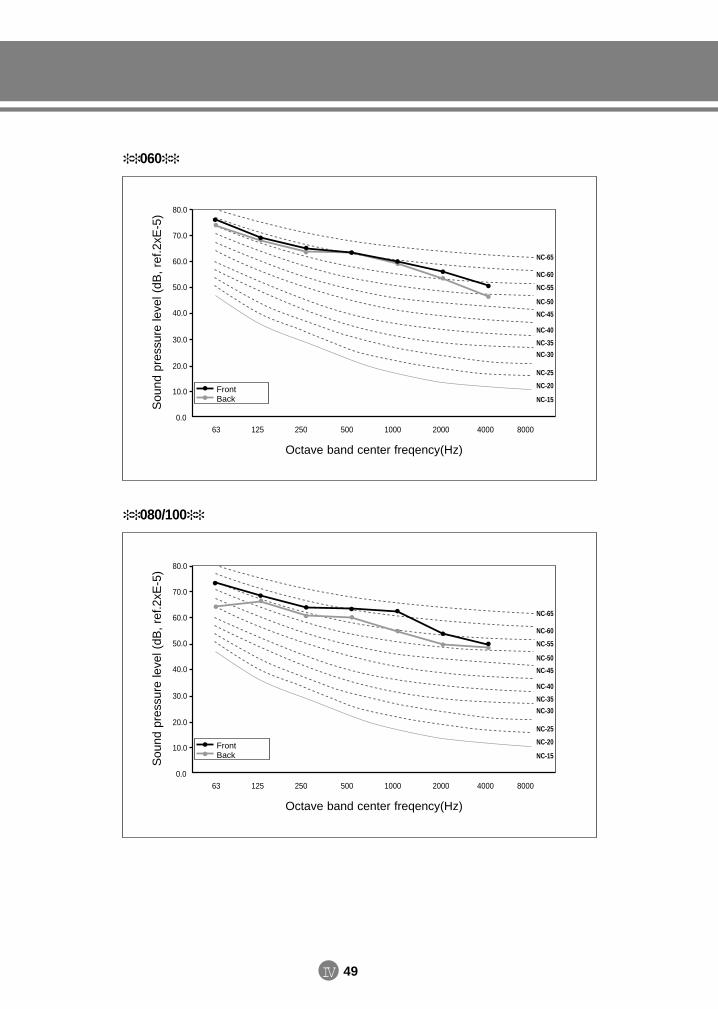
IV 49
060S
ound
pre
ssur
e le
vel (
dB,
ref.2
xE-5
) 80.0
70.0
60.0
50.0
40.0
30.0
20.0
10.0
0.063 125 250 500 1000 40002000 8000
NC-65
NC-60
NC-55
NC-50
NC-45
NC-40
NC-35
NC-30
NC-25
NC-20
NC-15
Octave band center freqency(Hz)
FrontBack
080/100
Sou
nd p
ress
ure
leve
l (dB
, re
f.2xE
-5) 80.0
70.0
60.0
50.0
40.0
30.0
20.0
10.0
0.063 125 250 500 1000 40002000 8000
NC-65
NC-60
NC-55
NC-50
NC-45
NC-40
NC-35
NC-30
NC-25
NC-20
NC-15
Octave band center freqency(Hz)
FrontBack
DVM E-D/B(chapter4-2)-E<03759 3/21/02 7:40 PM Page 49
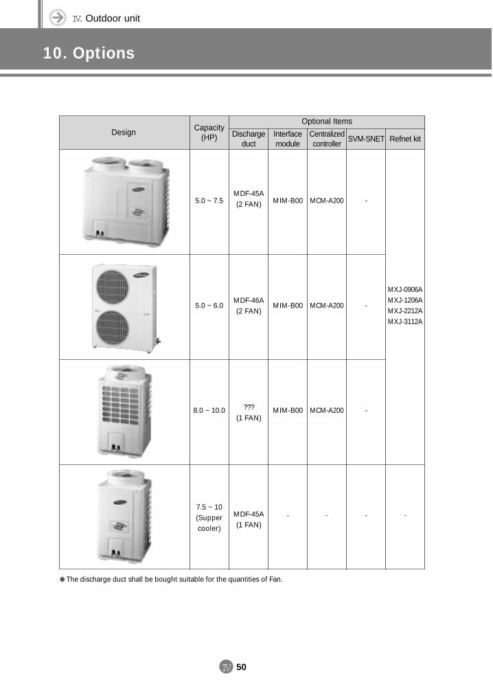
IV. Outdoor unit
10. Options
IV 50
The discharge duct shall be bought suitable for the quantities of Fan.
Optional Items
Refnet kitSVM-SNETCentralizedcontroller
Interfacemodule
Dischargeduct
Capacity(HP)
Design
5.0 ~ 7.5
5.0 ~ 6.0
8.0 ~ 10.0
7.5 ~ 10(Suppercooler)
MDF-45A(2 FAN)
MDF-46A(2 FAN)
???(1 FAN)
MDF-45A(1 FAN)
MIM-B00
MIM-B00
MIM-B00
-
MCM-A200
MCM-A200
MCM-A200
-
-
-
-
-
MXJ-0906AMXJ-1206AMXJ-2212AMXJ-3112A
-
DVM E-D/B(chapter4-2)-E<03759 3/21/02 7:40 PM Page 50
1. Product1-1. Preparation for installation1-2. Deciding on where to install the air conditioner1-3. Space requirements for the air conditioner1-4. Accessories1-5. Installation
2348
11
2. Panel2-1. 1-way cassette type2-2. 4-way cassette type2-3. Duct type (Built-in)
131516
4. Drain hose installation
5. Drain pump installation5-1. Accessories5-2. Installation
2222
6. Wiring6-1. Overall system configuration6-2. Cable specification for outdoor unit6-3. Connection cord specification6-4. Wiring diagram6-5. Connection cord wiring diagram6-6. Power wiring and communication wiring
configuration6-7. Communication cable connection
2324242425
2526
7. Piping and refnet joint selection7-1. Refrigerant piping system diagram7-2. Piping selection7-3. Refnet joint selection
333334
8. Charge/recovery of refrigerant8-1. Refrigerant charging8-2. Additional refrigerant amount calculation method8-3. Recovery of refrigerant
353637
9. Testing operation
10. Cautions for refrigerant leaks
3. Connecting the indoor unit refrigerant pipe
V Installation
DVM E-D/B(chapter4-2)-E<03759 3/21/02 7:40 PM Page 51
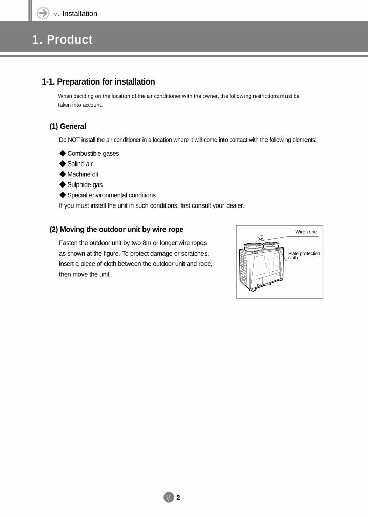
V. Installation
1. Product
V 2
1-1. Preparation for installation
When deciding on the location of the air conditioner with the owner, the following restrictions must be
taken into account.
(1) General
Do NOT install the air conditioner in a location where it will come into contact with the following elements:
Combustible gases
Saline air
Machine oil
Sulphide gas
Special environmental conditions
If you must install the unit in such conditions, first consult your dealer.
(2) Moving the outdoor unit by wire rope
Fasten the outdoor unit by two 8m or longer wire ropes
as shown at the figure. To protect damage or scratches,
insert a piece of cloth between the outdoor unit and rope,
then move the unit.
Plate protectioncloth
Wire rope
DVM E-D/B(chapter5)-E<03759 3/21/02 7:40 PM Page 2
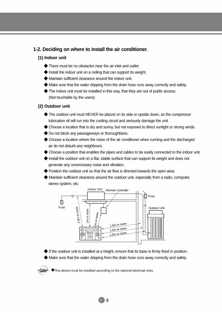
V 3
1-2. Deciding on where to install the air conditioner.
(1) Indoor unit
There must be no obstacles near the air inlet and outlet.
Install the indoor unit on a ceiling that can support its weight.
Maintain sufficient clearance around the indoor unit.
Make sure that the water dripping from the drain hose runs away correctly and safely.
The indoor unit must be installed in this way, that they are out of public access.
(Not touchable by the users)
(2) Outdoor unit
The outdoor unit must NEVER be placed on its side or upside down, as the compressor
lubrication oil will run into the cooling circuit and seriously damage the unit.
Choose a location that is dry and sunny, but not exposed to direct sunlight or strong winds.
Do not block any passageways or thoroughfares.
Choose a location where the noise of the air conditioner when running and the discharged
air do not disturb any neighbours.
Choose a position that enables the pipes and cables to be easily connected to the indoor unit.
Install the outdoor unit on a flat, stable surface that can support its weight and does not
generate any unnecessary noise and vibration.
Position the outdoor unit so that the air flow is directed towards the open area.
Maintain sufficient clearance around the outdoor unit, especially from a radio, computer,
stereo system, etc.
If the outdoor unit is installed at a height, ensure that its base is firmly fixed in position.
Make sure that the water dripping from the drain hose runs away correctly and safely.
1.5m or more
Indoor Unit
Fuse
Outdoor Unit
Remote Controller
1m o
r m
ore
1m o
r mor
e
1.5m
or m
ore
1.5m or more
1.5m or more
Fuse
Stereo
This device must be installed according to the national electrical rules.
DVM E-D/B(chapter5)-E<03759 3/21/02 7:40 PM Page 3
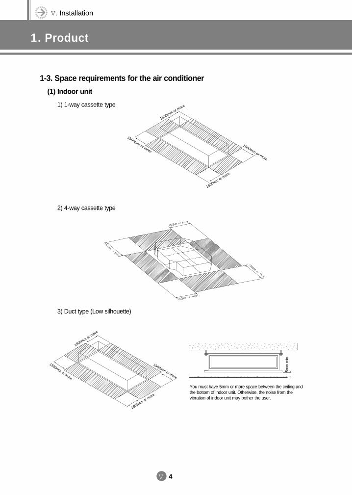
V. Installation
1. Product
V 4
1-3. Space requirements for the air conditioner
(1) Indoor unit
1) 1-way cassette type
2) 4-way cassette type
3) Duct type (Low silhouette)
1500mm or more
1500mm or more
1500mm or more
1500mm or more
You must have 5mm or more space between the ceiling andthe bottom of indoor unit. Otherwise, the noise from thevibration of indoor unit may bother the user.
5mm
min
1500mm or more
1500mm or more
1500mm or more
1500mm or more
DVM E-D/B(chapter5)-E<03759 3/21/02 7:40 PM Page 4
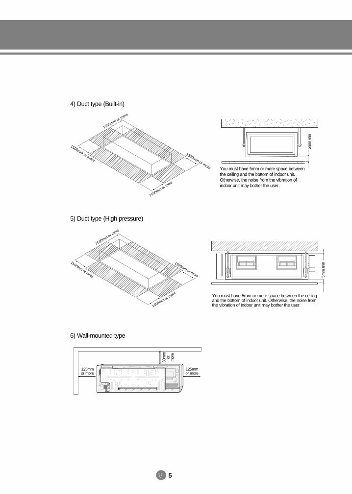
V 5
4) Duct type (Built-in)
5) Duct type (High pressure)
You must have 5mm or more space betweenthe ceiling and the bottom of indoor unit.Otherwise, the noise from the vibration ofindoor unit may bother the user.
5mm
min
1500mm or more
1500mm or more
1500mm or more
1500mm or more
6) Wall-mounted type
You must have 5mm or more space between the ceilingand the bottom of indoor unit. Otherwise, the noise fromthe vibration of indoor unit may bother the user.
5mm
min
30m
mor
mor
e
1500mm or more
1500mm or more
1500mm or more
1500mm or more
125mmor more
125mmor more
DVM E-D/B(chapter5)-E<03759 3/21/02 7:40 PM Page 5
V. Installation
1. Product
V 6
7) Floor standing type
8) Ceiling type
DVM E-D/B(chapter5)-E<03759 3/21/02 7:40 PM Page 6
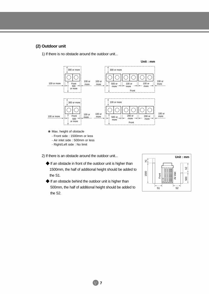
V 7
(2) Outdoor unit
1) If there is no obstacle around the outdoor unit...
2) If there is an obstacle around the outdoor unit...
If an obstacle in front of the outdoor unit is higher than
1500mm, the half of additional height should be added to
the S1.
If an obstacle behind the outdoor unit is higher than
500mm, the half of additional height should be added to
the S2.S1 S2
Unit : mm
1500
h1
500
h2
Air
inle
t
Fron
t
Max. height of obstacle- Front side : 1500mm or less- Air inlet side : 500mm or less- Right/Left side : No limit
100 or more100 ormore
100 ormore
300 or more
Front500
or moreFront
300 or more
500 ormore
100 ormore
100 ormore
100 ormore
100 or more100 ormore
300 or more
Front500
or more Front
100 or more
500 ormore
200 ormore
200 ormore
100 ormore
100 ormore
Unit : mm
DVM E-D/B(chapter5)-E<03759 3/21/02 7:40 PM Page 7
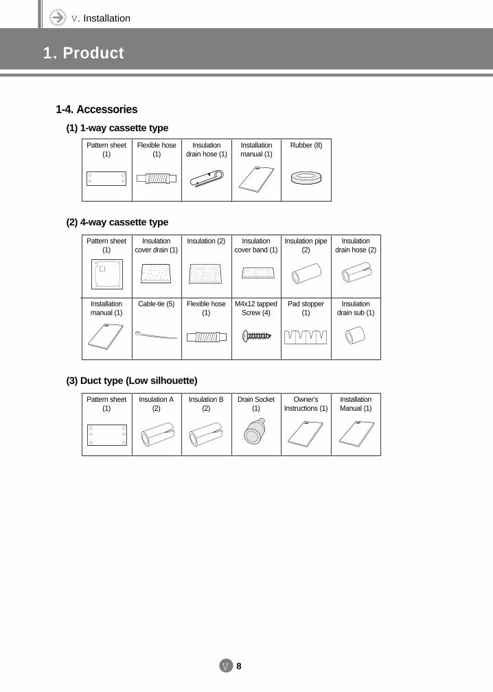
V. Installation
1. Product
V 8
1-4. Accessories
(1) 1-way cassette type
Pattern sheet(1)
Flexible hose(1)
Insulationdrain hose (1)
Installationmanual (1)
Rubber (8)
(2) 4-way cassette type
Pattern sheet(1)
Insulationcover drain (1)
Insulation (2) Insulationcover band (1)
Insulation pipe(2)
Insulationdrain hose (2)
(3) Duct type (Low silhouette)
Pattern sheet(1)
Insulation A(2)
Insulation B(2)
Drain Socket(1)
Owner’sInstructions (1)
InstallationManual (1)
Installationmanual (1)
Cable-tie (5) Flexible hose(1)
M4x12 tappedScrew (4)
Pad stopper(1)
Insulationdrain sub (1)
DVM E-D/B(chapter5)-E<03759 3/21/02 7:40 PM Page 8
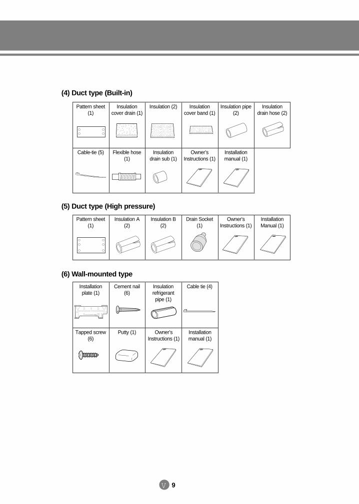
V 9
Pattern sheet(1)
Insulation A(2)
Insulation B(2)
Drain Socket(1)
Owner’sInstructions (1)
InstallationManual (1)
(4) Duct type (Built-in)
Pattern sheet(1)
Insulationcover drain (1)
Insulation (2) Insulationcover band (1)
Insulation pipe(2)
Insulationdrain hose (2)
Cable-tie (5) Flexible hose(1)
Insulationdrain sub (1)
Owner’sInstructions (1)
Installationmanual (1)
Installationplate (1)
Cement nail(6)
Insulationrefrigerantpipe (1)
Cable tie (4)
Tapped screw(6)
Putty (1) Owner’sInstructions (1)
Installationmanual (1)
(5) Duct type (High pressure)
(6) Wall-mounted type
DVM E-D/B(chapter5)-E<03759 3/21/02 7:40 PM Page 9
V. Installation
1. Product
V 10
(7) Floor standing type
(6) Ceiling type
DVM E-D/B(chapter5)-E<03759 3/21/02 7:40 PM Page 10
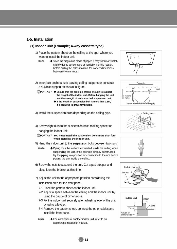
V 11
1-5. Installation
(1) Indoor unit (Example; 4-way cassette type)
1) Place the pattern sheet on the ceiling at the spot where youwant to install the indoor unit.
2) Insert bolt anchors, use existing ceiling supports or constructa suitable support as shown in figure.
3) Install the suspension bolts depending on the ceiling type.
4) Screw eight nuts to the suspension bolts making space for
hanging the indoor unit.
5) Hang the indoor unit to the suspension bolts between two nuts.
6) Screw the nuts to suspend the unit. Cut a pad stopper and
place it on the bracket at this time.
7) Adjust the unit to the appropriate position considering the
installation area for the front panel.
7-1 Place the pattern sheet on the indoor unit.7-2 Adjust a space between the ceiling and the indoor unit by
using the gauge of dimensions.7-3 Fix the indoor unit securely after adjusting level of the unit
by using a leveler.7-4 Remove the pattern sheet, connect the other cables and
install the front panel.
Concrete
Suspension bolt(M8)-field supply
Hole in anchorHole in plug
Insert
Ceiling support
20mmIndoor Unit
Ceiling
Gauge ofDimensions
17mm
Pad stopper
Bracket
Ensure that the ceiling is strong enough to support the weight of the indoor unit. Before hanging the unit,test the strength of each attached suspension bolt.
If the length of suspension bolt is more than 1.5m, it is required to prevent vibration.
IMPORTANT
You must install the suspension bolts more than fourwhen installing the indoor unit.
IMPORTANT
Piping must be laid and connected inside the ceiling when suspending the unit. If the ceiling is already constructed, lay the piping into position for connection to the unit before placing the unit inside the ceiling.
NNNNooootttteeee
For installation of another indoor unit, refer to an appropriate installation manual.
NNNNooootttteeee
Since the diagram is made of paper, it may shrink or stretch slightly due to temperature or humidity. For this reason,before drilling the holes maintain the correct dimensionsbetween the markings.
NNNNooootttteeee
DVM E-D/B(chapter5)-E<03759 3/21/02 7:40 PM Page 11
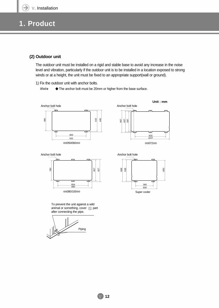
V. Installation
1. Product
V 12
(2) Outdoor unit
The outdoor unit must be installed on a rigid and stable base to avoid any increase in the noise level and vibration, particularly if the outdoor unit is to be installed in a location exposed to strongwinds or at a height, the unit must be fixed to an appropriate support(wall or ground).
1) Fix the outdoor unit with anchor bolts. The anchor bolt must be 20mm or higher from the base surface.NNNNooootttteeee
9201157
667
637
597
Piping
072 050/060
To prevent the unit against a wild animal or something, cover partafter connecting the pipe.
800
932
390
416
440
080/100
654990
780
807
827
Anchor bolt hole
Anchor bolt holeAnchor bolt hole
Super cooler
600360
638
600
668
Anchor bolt hole
Unit : mm
DVM E-D/B(chapter5)-E<03759 3/21/02 7:40 PM Page 12
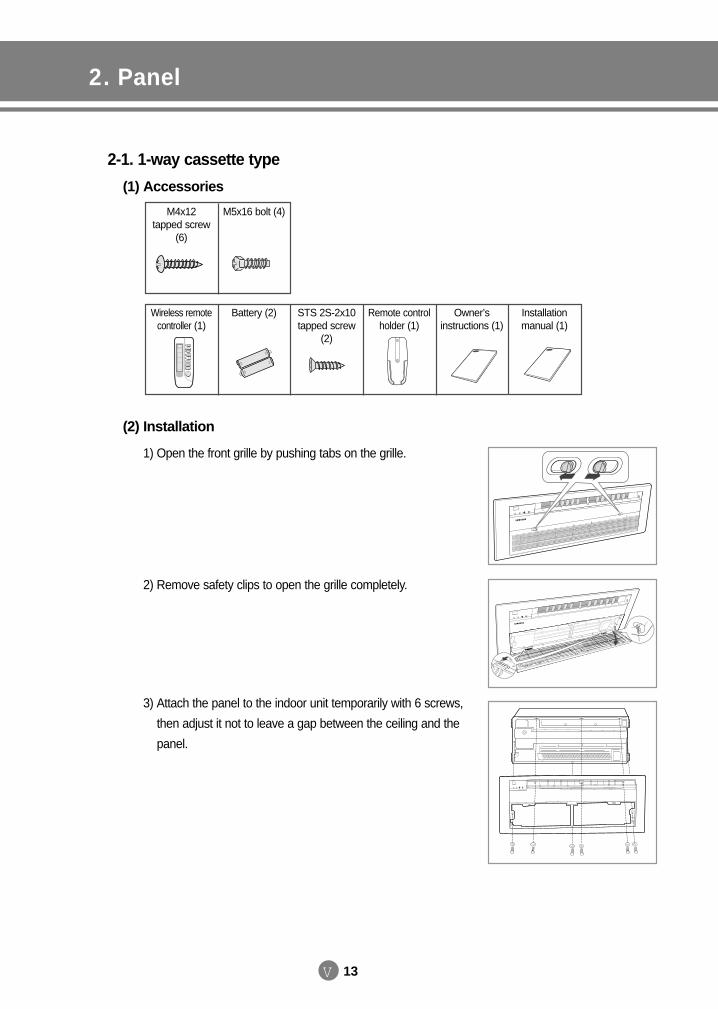
V 13
2. Panel
2-1. 1-way cassette type
(1) Accessories
(2) Installation
M4x12 tapped screw
(6)
M5x16 bolt (4)
Wireless remotecontroller (1)
Battery (2) STS 2S-2x10 tapped screw
(2)
Remote controlholder (1)
Owner’sinstructions (1)
Installationmanual (1)
1) Open the front grille by pushing tabs on the grille.
2) Remove safety clips to open the grille completely.
3) Attach the panel to the indoor unit temporarily with 6 screws,
then adjust it not to leave a gap between the ceiling and the
panel.
DVM E-D/B(chapter5)-E<03759 3/21/02 7:40 PM Page 13
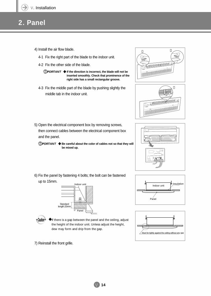
V. Installation
2. Panel
V 14
4) Install the air flow blade.
4-1 Fix the right part of the blade to the indoor unit.
4-2 Fix the other side of the blade.
4-3 Fix the middle part of the blade by pushing slightly the
middle tab in the indoor unit.
5) Open the electrical component box by removing screws,
then connect cables between the electrical component box
and the panel.
6) Fix the panel by fastening 4 bolts; the bolt can be fastened
up to 15mm.
7) Reinstall the front grille.
➁ ①
➂
Indoor unit
Panel
Insulation
Must for tightly against the ceiling without any gap
If the direction is incorrect, the blade will not be inserted smoothly. Check that prominence of theright side has a small rectangular groove.
IMPORTANT
Be careful about the color of cables not so that they will be mixed up.
IMPORTANT
Panel
Standardlength:20mm
Indoor unit
If there is a gap between the panel and the ceiling, adjustthe height of the indoor unit. Unless adjust the height,dew may form and drip from the gap.
DVM E-D/B(chapter5)-E<03759 3/21/02 7:40 PM Page 14
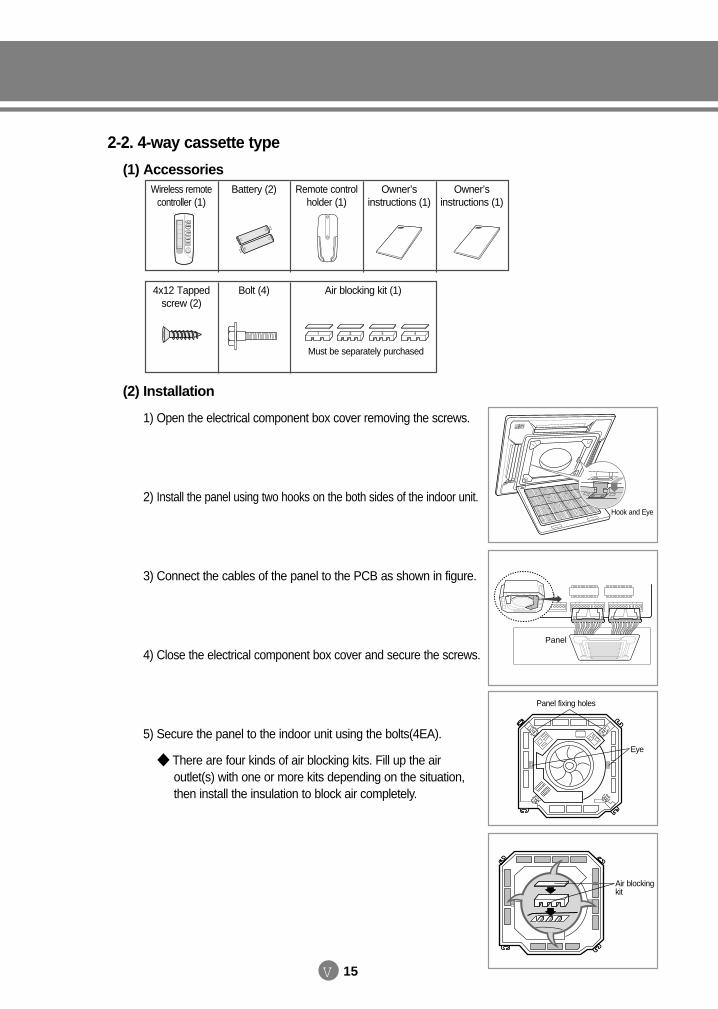
V 15
4x12 Tappedscrew (2)
Bolt (4) Air blocking kit (1)
Wireless remotecontroller (1)
Battery (2) Remote controlholder (1)
Owner’sinstructions (1)
Owner’sinstructions (1)
(2) Installation
1) Open the electrical component box cover removing the screws.
2) Install the panel using two hooks on the both sides of the indoor unit.
3) Connect the cables of the panel to the PCB as shown in figure.
4) Close the electrical component box cover and secure the screws.
5) Secure the panel to the indoor unit using the bolts(4EA).
There are four kinds of air blocking kits. Fill up the air outlet(s) with one or more kits depending on the situation,then install the insulation to block air completely.
Hook and Eye
Eye
Panel fixing holes
Air blockingkit
Panel
Must be separately purchased
2-2. 4-way cassette type
(1) Accessories
DVM E-D/B(chapter5)-E<03759 3/21/02 7:40 PM Page 15
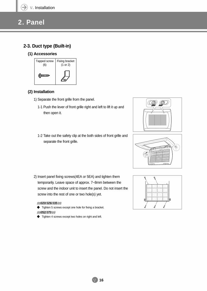
V. Installation
2. Panel
V 16
Tapped screw(6)
Fixing bracket(1 or 2)
1) Separate the front grille from the panel.
1-1 Push the lever of front grille right and left to lift it up and
then open it.
1-2 Take out the safety clip at the both sides of front grille and
separate the front grille.
2) Insert panel fixing screws(4EA or 5EA) and tighten them
temporarily. Leave space of approx. 7~8mm between the
screw and the indoor unit to insert the panel. Do not insert the
screw into the rest of one or two hole(s) yet.
020/026/035
Tighten 5 screws except one hole for fixing a bracket.
052/070
Tighten 4 screws except two holes on right and left.
2-3. Duct type (Built-in)
(1) Accessories
(2) Installation
DVM E-D/B(chapter5)-E<03759 3/21/02 7:40 PM Page 16
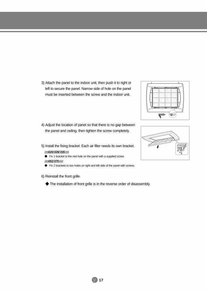
V 17
3) Attach the panel to the indoor unit, then push it to right or
left to secure the panel. Narrow side of hole on the panel
must be inserted between the screw and the indoor unit.
4) Adjust the location of panel so that there is no gap between
the panel and ceiling, then tighten the screw completely.
5) Install the fixing bracket. Each air filter needs its own bracket.
6) Reinstall the front grille.
The installation of front grille is in the reverse order of disassembly.
020/026/035
Fix 1 bracket to the rest hole on the panel with a supplied screw.
052/070
Fix 2 brackets to two holes on right and left side of the panel with screws.
DVM E-D/B(chapter5)-E<03759 3/21/02 7:40 PM Page 17
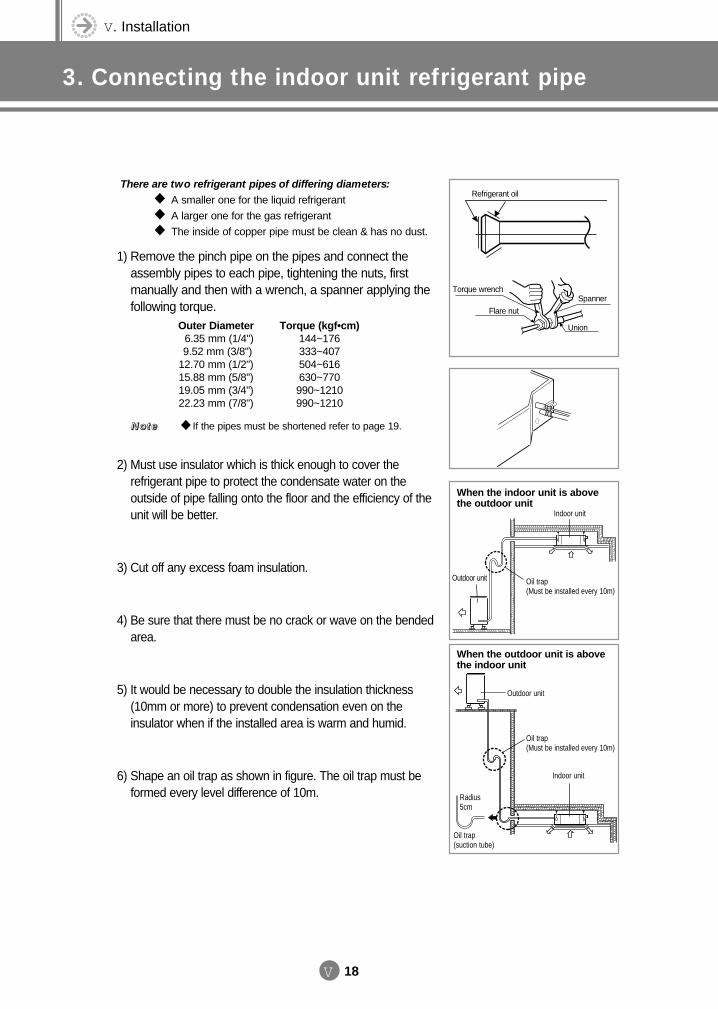
V. Installation
3. Connecting the indoor unit refrigerant pipe
V 18
1) Remove the pinch pipe on the pipes and connect theassembly pipes to each pipe, tightening the nuts, first manually and then with a wrench, a spanner applying thefollowing torque.
2) Must use insulator which is thick enough to cover the refrigerant pipe to protect the condensate water on the outside of pipe falling onto the floor and the efficiency of theunit will be better.
3) Cut off any excess foam insulation.
4) Be sure that there must be no crack or wave on the bended area.
5) It would be necessary to double the insulation thickness(10mm or more) to prevent condensation even on the insulator when if the installed area is warm and humid.
6) Shape an oil trap as shown in figure. The oil trap must be formed every level difference of 10m.
Refrigerant oil
Torque wrench
Flare nut
Union
Spanner
Radius 5cm
Oil trap(suction tube)
Outdoor unit
Indoor unit
Oil trap(Must be installed every 10m)
Oil trap(Must be installed every 10m)
Outdoor unit
Indoor unit
When the outdoor unit is abovethe indoor unit
When the indoor unit is abovethe outdoor unit
There are two refrigerant pipes of differing diameters:
A smaller one for the liquid refrigerant A larger one for the gas refrigerant The inside of copper pipe must be clean & has no dust.
If the pipes must be shortened refer to page 19.NNNNooootttteeee
Outer Diameter Torque (kgf•cm)6.35 mm (1/4") 144~1769.52 mm (3/8") 333~407
12.70 mm (1/2") 504~61615.88 mm (5/8") 630~77019.05 mm (3/4") 990~121022.23 mm (7/8") 990~1210
DVM E-D/B(chapter5)-E<03759 3/21/02 7:40 PM Page 18
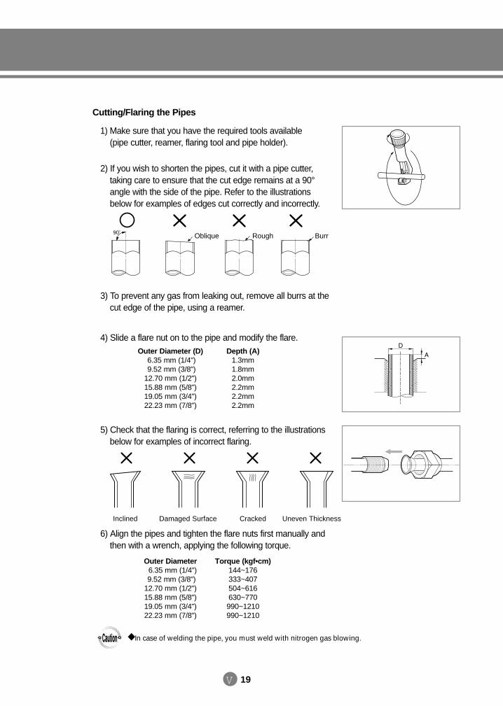
V 19
Cutting/Flaring the Pipes
1) Make sure that you have the required tools available (pipe cutter, reamer, flaring tool and pipe holder).
2) If you wish to shorten the pipes, cut it with a pipe cutter, taking care to ensure that the cut edge remains at a 90°angle with the side of the pipe. Refer to the illustrationsbelow for examples of edges cut correctly and incorrectly.
3) To prevent any gas from leaking out, remove all burrs at thecut edge of the pipe, using a reamer.
4) Slide a flare nut on to the pipe and modify the flare.
5) Check that the flaring is correct, referring to the illustrations below for examples of incorrect flaring.
6) Align the pipes and tighten the flare nuts first manually and then with a wrench, applying the following torque.
Outer Diameter Torque (kgf•cm)6.35 mm (1/4") 144~1769.52 mm (3/8") 333~407
12.70 mm (1/2") 504~61615.88 mm (5/8") 630~77019.05 mm (3/4") 990~121022.23 mm (7/8") 990~1210
Outer Diameter (D) Depth (A)6.35 mm (1/4") 1.3mm9.52 mm (3/8") 1.8mm
12.70 mm (1/2") 2.0mm15.88 mm (5/8") 2.2mm19.05 mm (3/4") 2.2mm22.23 mm (7/8") 2.2mm
90O
Oblique Rough Burr
Inclined Damaged Surface Cracked Uneven Thickness
In case of welding the pipe, you must weld with nitrogen gas blowing.
DVM E-D/B(chapter5)-E<03759 3/21/02 7:40 PM Page 19
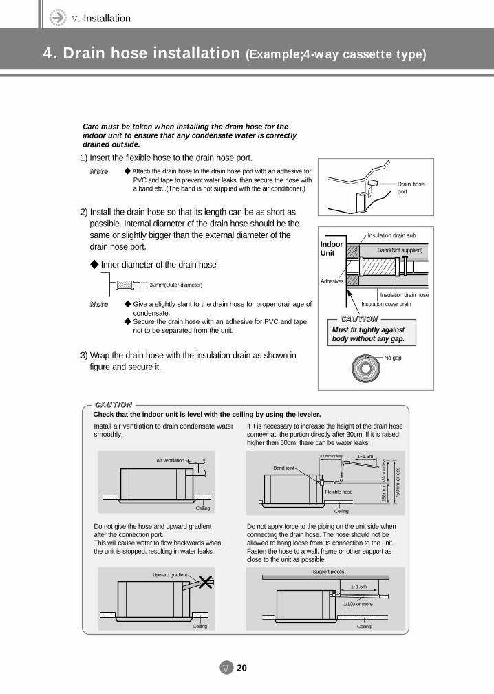
V. Installation
4. Drain hose installation (Example;4-way cassette type)
V 20
CCCCAAAAUUUUTTTTIIIIOOOONNNN
Must fit tightly against
body without any gap.
Drain hoseport
Insulation drain sub
Adhesives
Insulation cover drain
No gap
Insulation drain hose
Band(Not supplied)IndoorUnit
CCCCAAAAUUUUTTTTIIIIOOOONNNN
Install air ventilation to drain condensate watersmoothly.
Check that the indoor unit is level with the ceiling by using the leveler.
If it is necessary to increase the height of the drain hosesomewhat, the portion directly after 30cm. If it is raisedhigher than 50cm, there can be water leaks.
Air ventilation
Ceiling
300mm or less 1~1.5m
492m
m o
r les
s25
8mm
750m
m o
r le
ss
Do not give the hose and upward gradient after the connection port. This will cause water to flow backwards when the unit is stopped, resulting in water leaks.
Do not apply force to the piping on the unit side whenconnecting the drain hose. The hose should not beallowed to hang loose from its connection to the unit.Fasten the hose to a wall, frame or other support asclose to the unit as possible.
Upward gradientSupport pieces
1~1.5m
1/100 or more
Flexible hose
Band joint
Ceiling
Ceiling Ceiling
1) Insert the flexible hose to the drain hose port.
2) Install the drain hose so that its length can be as short as possible. Internal diameter of the drain hose should be thesame or slightly bigger than the external diameter of thedrain hose port.
Inner diameter of the drain hose
3) Wrap the drain hose with the insulation drain as shown infigure and secure it.
Care must be taken when installing the drain hose for the
indoor unit to ensure that any condensate water is correctly
drained outside.
Give a slightly slant to the drain hose for proper drainage of condensate.
Secure the drain hose with an adhesive for PVC and tapenot to be separated from the unit.
NNNNooootttteeee
Attach the drain hose to the drain hose port with an adhesive for PVC and tape to prevent water leaks, then secure the hose witha band etc..(The band is not supplied with the air conditioner.)
NNNNooootttteeee
32mm(Outer diameter)
DVM E-D/B(chapter5)-E<03759 3/21/02 7:40 PM Page 20
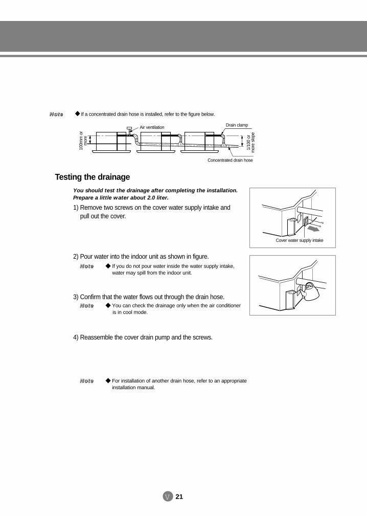
V 21
If a concentrated drain hose is installed, refer to the figure below.NNNNooootttteeee
Drain clampAir ventilation
Concentrated drain hose
1/10
0 or
mor
e sl
ope
100m
m o
rm
ore
Testing the drainage
1) Remove two screws on the cover water supply intake and pull out the cover.
2) Pour water into the indoor unit as shown in figure.
3) Confirm that the water flows out through the drain hose.
4) Reassemble the cover drain pump and the screws.
Cover water supply intake
You should test the drainage after completing the installation.
Prepare a little water about 2.0 liter.
You can check the drainage only when the air conditioner is in cool mode.
NNNNooootttteeee
For installation of another drain hose, refer to an appropriateinstallation manual.
NNNNooootttteeee
If you do not pour water inside the water supply intake, water may spill from the indoor unit.
NNNNooootttteeee
DVM E-D/B(chapter5)-E<03759 3/21/02 7:40 PM Page 21
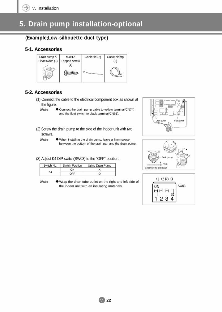
V. Installation
5. Drain pump installation-optional
(Example;Low-silhouette duct type)
V 22
K1 K2 K3 K4
SW03
Drain pump
Drain pump
7mm
Bottom of the drain pan
Float switch
5-1. Accessories
5-2. Accessories
Drain pump &Float switch (1)
M4x12 Tapped screw
(4)
Cable-tie (2) Cable clamp(2)
(1) Connect the cable to the electrical component box as shown atthe figure.
(2) Screw the drain pump to the side of the indoor unit with two screws.
(3) Adjust K4 DIP switch(SW03) to the "OFF" position.
Wrap the drain tube outlet on the right and left side ofthe indoor unit with an insulating materials.
NNNNooootttteeee
When installing the drain pump, leave a 7mm spacebetween the bottom of the drain pan and the drain pump.
NNNNooootttteeee
Connect the drain pump cable to yellow terminal(CN74)and the float switch to black terminal(CN51).
NNNNooootttteeee
Switch No.
K4
Switch PositionONOFF
Using Drain PumpXO
DVM E-D/B(chapter5)-E<03759 3/21/02 7:40 PM Page 22

V 23
6. Wiring
Caution All wiring and parts shall be the rated ones. For details of wiring, refer to the circuit diagram attached onto the outdoor unit. The electrical work shall be performed by the qualified electrical worker. The circuit diagram for wiring shows only the concept and so the details for actual work is not described. This air conditioner is consist of 3 phase 4 wire system and so the main circuit breaker to block the power
shall be installed in the integrated manner. Be sure to install the circuit breaker and fuse on power cable of each equipment. Connect the wires to the terminals without excessive force and arrange the wires with the cover or other
parts so that it may not be loosened. If it is loosened, it may cause the overheating, electrical shock and fire.
distribution board machine room
wireless remote controller
3 Phase and single phase ELB application
1 Phase ELB application (Using the distributor kit)
wireless remotecontroller receiver
wireless remotecontroller
MCCB 3 phase 4 wire
single phase2 wire
outdoor unit indoor unit
power supply cablecommunication cable
communication cable
1-way cassette type1-way cassette typeduct type
3 phase 3 wire single phase 2 wire Earth wire
ELB MCCB
MCCBELB
machine room
wireless remotecontroller
wireless remotecontroller
wireless remotecontroller
single phase 2 wiresoutdoor unit indoor unit
1-way cassette type
single phase 2 wires Earth wire
ELB MCCB
power supply cablecommunication cable
communication cable
distributor kit
6-1. Overall system configuration (example)
DVM E-D/B(chapter5)-E<03759 3/21/02 7:40 PM Page 23
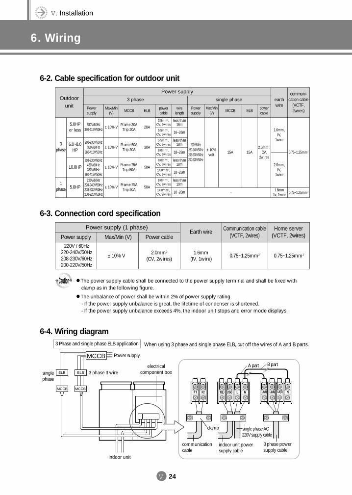
V. Installation
6. Wiring
V 24
MCCB
ELB ELB
MCCB MCCB
Power supply
singlephase
3 phase 3 wireelectrical
component box
indoor unit powersupply cable
single phase AC220V supply cable
3 phase powersupply cable
communicationcable
clamp
A part B part
When using 3 phase and single phase ELB, cut off the wires of A and B parts.
Power supply (1 phase)
Max/Min (V) Power cablePower supply
Communication cable(VCTF, 2wires)
Earth wire Home server (VCTF, 2wires)
220V / 60Hz220-240V/50Hz208-230V/60Hz200-220V/50Hz
± 10% V 0.75~1.25mm20.75~1.25mm21.6mm(IV, 1wire)
2.0mm2
(CV, 2wires)
Power supplyOutdoor
unit
5.0HP or less
3 phase
1 phase
3 phase single phase earthwire
communi-cation cable
(VCTF,2wires)
3 Phase and single phase ELB application
Powersupply
Max/Min(V)
MCCB ELBpowercable
wirelength
Powersupply
Max/Min(V)
MCCB ELBpowercable
380V/60Hz380-415V/50Hz
± 10% VFrame:30ATrip:20A
20A
6.0~8.0HP
208-230V/60Hz380V/60Hz
380-415V/50Hz± 10% V
Frame:50ATrip:30A
30A
less than16m
16~26m
3.5mm2,CV, 3wires
5.5mm2,CV, 3wires
less than18m
18~28m
5.5mm2,CV, 3wires
8.0mm2,CV, 3wires 15A
-
15A2.0mm2,
CV,2wires
1.6mm,IV,
1wire
2.0mm,IV,
1wire
0.75~1.25mm2
0.75~1.25mm21.6mm 1v, 1wire
220V/60Hz220-240V/50Hz208-230V/60Hz200-220V/50Hz
± 10%volt
indoor unit
The power supply cable shall be connected to the power supply terminal and shall be fixed with clamp as in the following figure.
The unbalance of power shall be within 2% of power supply rating. - If the power supply unbalance is great, the lifetime of condenser is shortened. - If the power supply unbalance exceeds 4%, the indoor unit stops and error mode displays.
10.0HP208-230V/60Hz
460V/60Hz380V/60Hz
380-415V/50Hz
± 10% VFrame:75ATrip:50A
50A
less than18m
18~28m
8.0mm2,CV, 3wires
14.0mm2,CV, 3wires
5.0HP
220V/60Hz220-240V/50Hz208-230V/60Hz200-220V/50Hz
± 10% VFrame:75ATrip:50A
50A
less than10m
10~20m
8.0mm2,CV, 2wires
14.0mm2,CV, 2wires
6-2. Cable specification for outdoor unit
6-3. Connection cord specification
6-4. Wiring diagram
DVM E-D/B(chapter5)-E<03759 3/21/02 7:40 PM Page 24
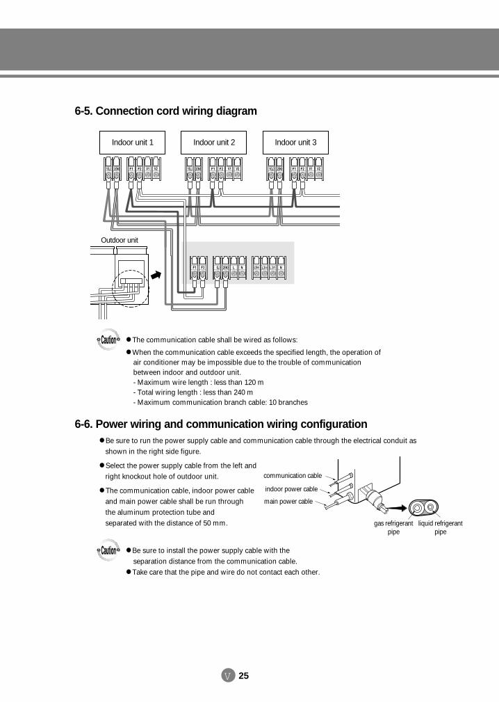
V 25
Be sure to run the power supply cable and communication cable through the electrical conduit as shown in the right side figure.
Select the power supply cable from the left and right knockout hole of outdoor unit.
The communication cable, indoor power cable and main power cable shall be run through the aluminum protection tube and separated with the distance of 50 mm.
communication cable
indoor power cable
main power cable
Indoor unit 1
Outdoor unit
Indoor unit 2 Indoor unit 3
The communication cable shall be wired as follows:
When the communication cable exceeds the specified length, the operation of air conditioner may be impossible due to the trouble of communicationbetween indoor and outdoor unit. - Maximum wire length : less than 120 m- Total wiring length : less than 240 m- Maximum communication branch cable: 10 branches
Be sure to install the power supply cable with the separation distance from the communication cable.
Take care that the pipe and wire do not contact each other.
liquid refrigerantpipe
gas refrigerant pipe
6-5. Connection cord wiring diagram
6-6. Power wiring and communication wiring configuration
DVM E-D/B(chapter5)-E<03759 3/21/02 7:40 PM Page 25
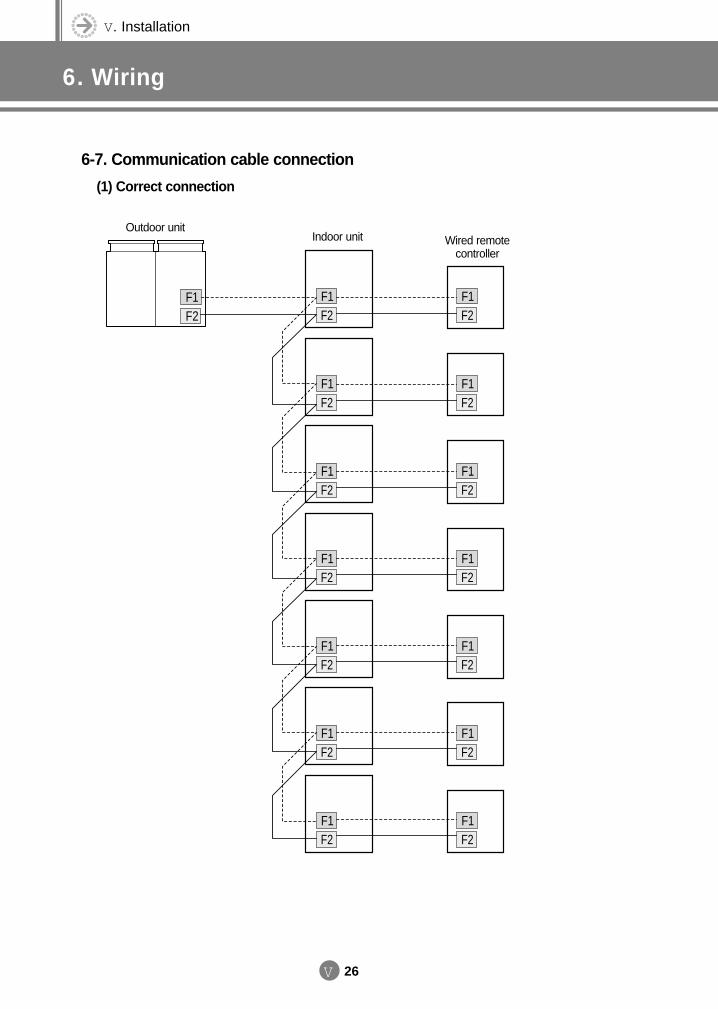
V. Installation
6. Wiring
V 26
F1F2
F1F2
F1F2
F1F2
F1F2
F1F2
F1F2
F1F2
F1F2
F1F2
F1F2
F1F2
F1F2
F1F2
F1F2
Outdoor unitIndoor unit Wired remote
controller
6-7. Communication cable connection
(1) Correct connection
DVM E-D/B(chapter5)-E<03759 3/21/02 7:40 PM Page 26
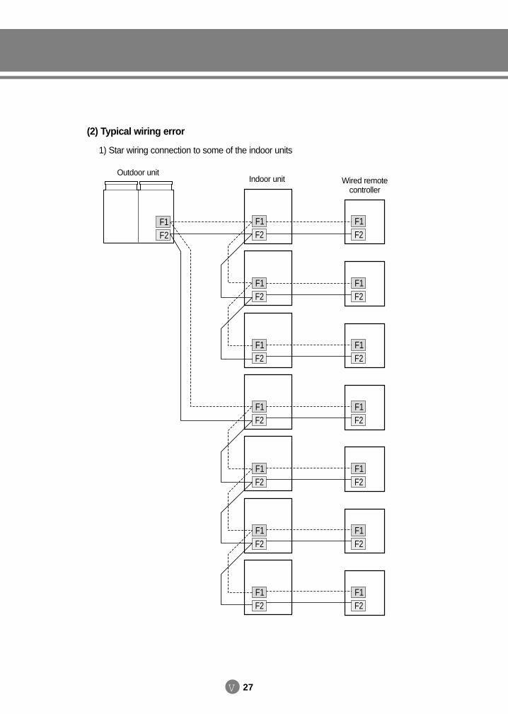
V 27
(2) Typical wiring error
1) Star wiring connection to some of the indoor units
F1F2
F1F2
F1F2
F1F2
F1F2
F1F2
F1F2
F1F2
F1F2
F1F2
F1F2
F1F2
F1F2
F1F2
F1F2
Outdoor unitIndoor unit Wired remote
controller
DVM E-D/B(chapter5)-E<03759 3/21/02 7:40 PM Page 27
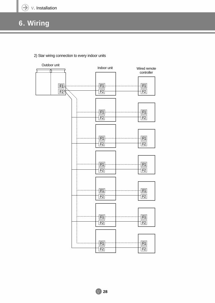
V. Installation
6. Wiring
V 28
2) Star wiring connection to every indoor units
F1F2
F1F2
F1F2
F1F2
F1F2
F1F2
F1F2
F1F2
F1F2
F1F2
F1F2
F1F2
F1F2
F1F2
F1F2
Outdoor unitIndoor unit Wired remote
controller
DVM E-D/B(chapter5)-E<03759 3/21/02 7:40 PM Page 28

V 29
3) Reverse wiring between indoor and outdoor units
F1F2
F1F2
F1F2
F1F2
F1F2
F1F2
F1F2
F1F2
F1F2
F1F2
F1F2
F1F2
F1F2
F1F2
F1F2
Outdoor unitIndoor unit Wired remote
controller
Reverse
DVM E-D/B(chapter5)-E<03759 3/21/02 7:40 PM Page 29
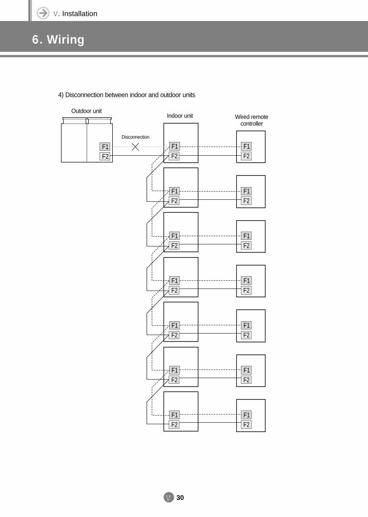
V. Installation
6. Wiring
V 30
4) Disconnection between indoor and outdoor units
F1F2
F1F2
F1F2
F1F2
F1F2
F1F2
F1F2
F1F2
F1F2
F1F2
F1F2
F1F2
F1F2
F1F2
F1F2
Outdoor unitIndoor unit Wired remote
controller
Disconnection
DVM E-D/B(chapter5)-E<03759 3/21/02 7:40 PM Page 30
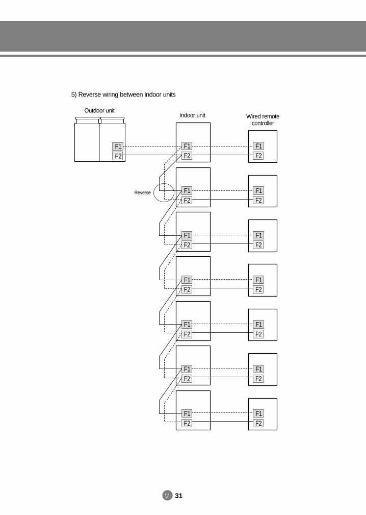
V 31
5) Reverse wiring between indoor units
F1F2
F1F2
F1F2
F1F2
F1F2
F1F2
F1F2
F1F2
F1F2
F1F2
F1F2
F1F2
F1F2
F1F2
F1F2
Outdoor unitIndoor unit Wired remote
controller
Reverse
DVM E-D/B(chapter5)-E<03759 3/21/02 7:40 PM Page 31
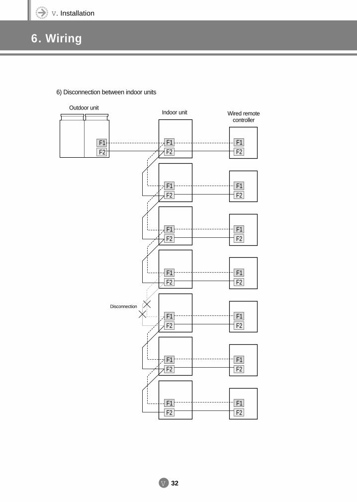
V. Installation
6. Wiring
V 32
6) Disconnection between indoor units
F1F2
F1F2
F1F2
F1F2
F1F2
F1F2
F1F2
F1F2
F1F2
F1F2
F1F2
F1F2
F1F2
F1F2
F1F2
Outdoor unitIndoor unit Wired remote
controller
Disconnection
DVM E-D/B(chapter5)-E<03759 3/21/02 7:40 PM Page 32
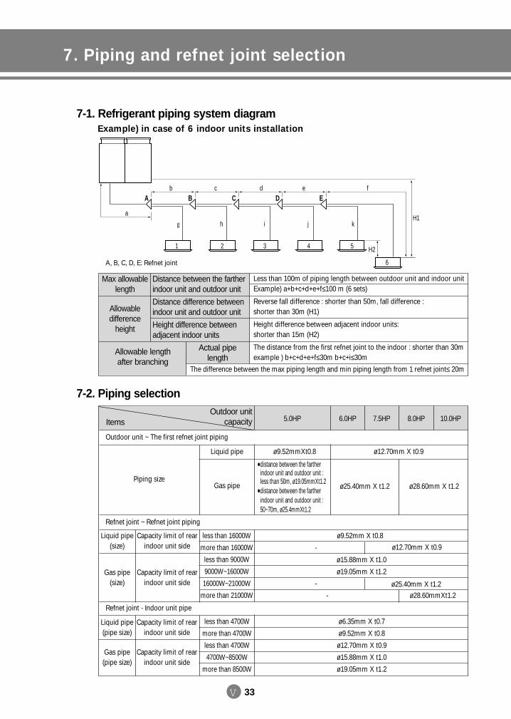
V 33
7. Piping and refnet joint selection
A
a
b
1 2 3 4 5
6
c d e
hg i j k
f
H1
H2
B C D E
A, B, C, D, E: Refnet joint
Less than 100m of piping length between outdoor unit and indoor unit Example) a+b+c+d+e+f≤100 m (6 sets)
Reverse fall difference : shorter than 50m, fall difference : shorter than 30m (H1)
Height difference between adjacent indoor units: shorter than 15m (H2)
The distance from the first refnet joint to the indoor : shorter than 30m example ) b+c+d+e+f≤30m b+c+i≤30m
The difference between the max piping length and min piping length from 1 refnet joint≤ 20m
Max allowablelength
Allowable difference
height
Allowable length after branching
Distance between the farther indoor unit and outdoor unit
Distance difference between indoor unit and outdoor unit
Height difference between adjacent indoor units
Actual pipelength
Outdoor unit ~ The first refnet joint piping
Refnet joint ~ Refnet joint piping
Refnet joint - Indoor unit pipe
Piping size
Liquid pipe (size)
Gas pipe (size)
Capacity limit of rearindoor unit side
Capacity limit of rear indoor unit side
Capacity limit of rearindoor unit side
Capacity limit of rear indoor unit side
Liquid pipe (pipe size)
Gas pipe (pipe size)
Liquid pipe
Gas pipe
less than 16000W
more than 16000W
less than 9000W
9000W~16000W
16000W~21000W
more than 21000W
less than 4700W
more than 4700W
less than 4700W
4700W~8500W
more than 8500W
ø9.52mmXt0.8
distance between the fartherindoor unit and outdoor unit : less than 50m, ø19.05mmXt1.2
distance between the fartherindoor unit and outdoor unit :50~70m, ø25.4mmXt1.2
-
-
-
ø15.88mm X t1.0
ø19.05mm X t1.2
ø9.52mm X t0.8
ø6.35mm X t0.7
ø9.52mm X t0.8
ø12.70mm X t0.9
ø15.88mm X t1.0
ø19.05mm X t1.2
ø12.70mm X t0.9
ø28.60mmXt1.2ø25.40mm X t1.2
ø12.70mm X t0.9
ø28.60mm X t1.2ø25.40mm X t1.2
ItemsOutdoor unit
capacity 6.0HP5.0HP 7.5HP 8.0HP 10.0HP
7-1. Refrigerant piping system diagram Example) in case of 6 indoor units installation
7-2. Piping selection
DVM E-D/B(chapter5)-E<03759 3/21/02 7:40 PM Page 33
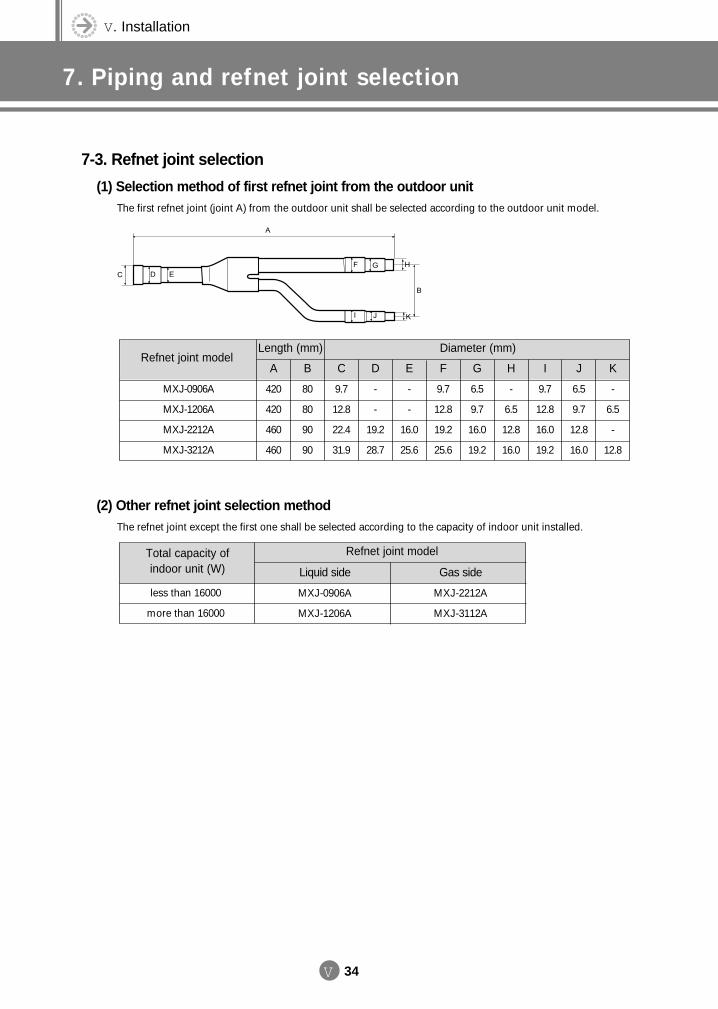
V. Installation
7. Piping and refnet joint selection
V 34
Refnet joint modelLength (mm)
A
420
420
460
460
B
80
80
90
90
C
9.7
12.8
22.4
31.9
D
-
-
19.2
28.7
E
-
-
16.0
25.6
F
9.7
12.8
19.2
25.6
G
6.5
9.7
16.0
19.2
H
-
6.5
12.8
16.0
I
9.7
12.8
16.0
19.2
J
6.5
9.7
12.8
16.0
K
-
6.5
-
12.8
Diameter (mm)
MXJ-0906A
MXJ-1206A
MXJ-2212A
MXJ-3212A
(2) Other refnet joint selection methodThe refnet joint except the first one shall be selected according to the capacity of indoor unit installed.
Total capacity of indoor unit (W)
less than 16000
more than 16000
Refnet joint model
Liquid side
MXJ-0906A
MXJ-1206A
Gas side
MXJ-2212A
MXJ-3112A
7-3. Refnet joint selection
(1) Selection method of first refnet joint from the outdoor unit The first refnet joint (joint A) from the outdoor unit shall be selected according to the outdoor unit model.
DVM E-D/B(chapter5)-E<03759 3/21/02 7:40 PM Page 34
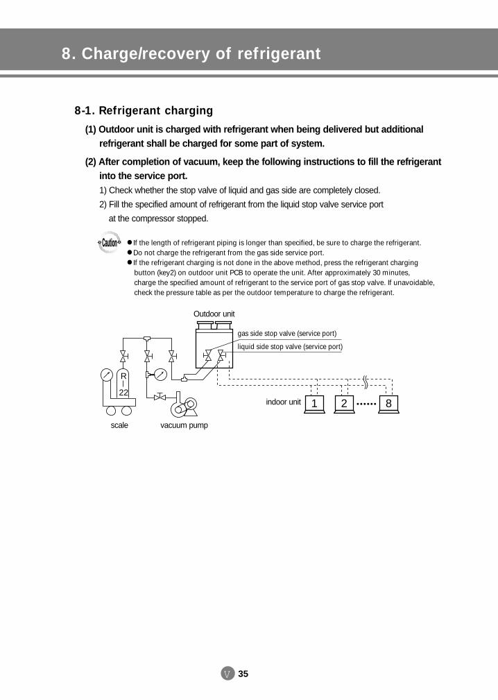
V 35
8. Charge/recovery of refrigerant
8-1. Refrigerant charging
(1) Outdoor unit is charged with refrigerant when being delivered but additional refrigerant shall be charged for some part of system.
(2) After completion of vacuum, keep the following instructions to fill the refrigerant into the service port. 1) Check whether the stop valve of liquid and gas side are completely closed.
2) Fill the specified amount of refrigerant from the liquid stop valve service port
at the compressor stopped.
If the length of refrigerant piping is longer than specified, be sure to charge the refrigerant. Do not charge the refrigerant from the gas side service port. If the refrigerant charging is not done in the above method, press the refrigerant charging
button (key2) on outdoor unit PCB to operate the unit. After approximately 30 minutes, charge the specified amount of refrigerant to the service port of gas stop valve. If unavoidable,check the pressure table as per the outdoor temperature to charge the refrigerant.
gas side stop valve (service port)
liquid side stop valve (service port)
21 8
R
22
scale vacuum pump
indoor unit
Outdoor unit
DVM E-D/B(chapter5)-E<03759 3/21/02 7:40 PM Page 35
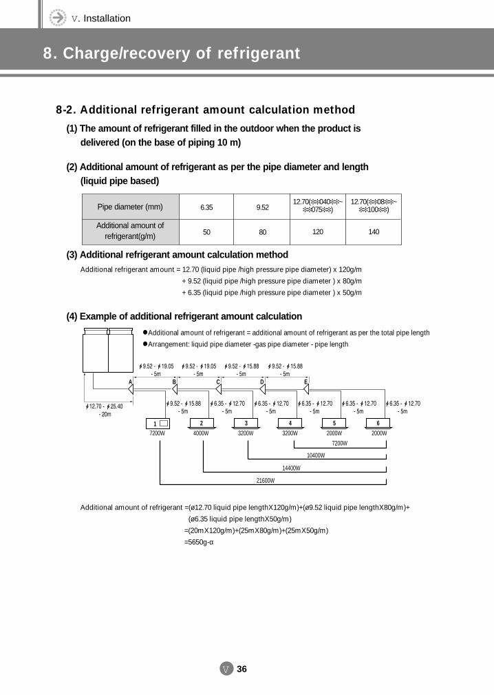
V. Installation
8. Charge/recovery of refrigerant
V 36
8-2. Additional refrigerant amount calculation method
(1) The amount of refrigerant filled in the outdoor when the product is delivered (on the base of piping 10 m)
(2) Additional amount of refrigerant as per the pipe diameter and length (liquid pipe based)
Pipe diameter (mm)
Additional amount of refrigerant(g/m)
6.35
50
9.52
80
12.70( 040 ~ 075 )
120
12.70( 08 ~ 100 )
140
(3) Additional refrigerant amount calculation methodAdditional refrigerant amount = 12.70 (liquid pipe /high pressure pipe diameter) x 120g/m
+ 9.52 (liquid pipe /high pressure pipe diameter ) x 80g/m
+ 6.35 (liquid pipe /high pressure pipe diameter ) x 50g/m
(4) Example of additional refrigerant amount calculation
Additional amount of refrigerant = additional amount of refrigerant as per the total pipe length Arrangement: liquid pipe diameter -gas pipe diameter - pipe length
Additional amount of refrigerant =(ø12.70 liquid pipe lengthX120g/m)+(ø9.52 liquid pipe lengthX80g/m)+
(ø6.35 liquid pipe lengthX50g/m)
=(20mX120g/m)+(25mX80g/m)+(25mX50g/m)
=5650g-α
A B C D E
1 2 3 4 5 6
7200W
10400W
14400W
21600W
7200W 4000W 3200W 3200W 2000W 2000W
DVM E-D/B(chapter5)-E<03759 3/21/02 7:40 PM Page 36
V 37
8-3. Recovery of refrigerant
(1) Close the service valve of liquid side and then press the refrigerant recovery button on outdoor PCB.
(2) When the low pressure is getting lower enough, close the service valve to press the refrigerant recovery button again or press key 3. Pressing the button stops thecompressor.
(3) When total amount of refrigerant in the pipe is more than 15kg, the refrigerant may not be recovered completely even though the refrigerant recovery (pump down) isperformed. So care must be taken.
(4) The pump down time shall not exceed 5 minutes.
DVM E-D/B(chapter5)-E<03759 3/21/02 7:40 PM Page 37
V. Installation
9. Testing operation
V 38
Cautions for operation Put the power 6 hours before initial operation so that the crank case heater may be heated. When doing the retry of initial operation after main power off, start the operation 2 and half hours after power on. If the heater is not heated, the operation can not be started for 2 hours after power on for
the protection of compressor. (Ch displays on the PCB display part at the time.)
(1) Check the power between outdoor unit and distribution board. (3 phase tester recommended) Compressor power : L1(R) L2(S) L3(T) - red white black (Care must be taken so that
the color and order may not be changed.) 220V power: L N
(2) Check the indoor unit ① Check whether the power source of each indoor unit and the communication cables are correctly connected.
(Communication cable marked as F1, F2)- If the communication cable is changed each other with the power cable, it might cause the damage to PCB. - There is no color marking on the power supply cable but be sure to check the color of communication cable
since the cable has the polarity.
② Check whether the addresses are correctly assigned to each indoor unit. - The address switch is available from “0”.- The address of each indoor unit shall be assigned differently.
③ Check whether the connections for temperature sensor, electronic expansion valve and drain pumps are all connected.
(3) Check the outdoor unit① Set the numbers of indoor unit on the outdoor unit PCB.
- If there are all 3 outdoor units, set so that the arrow mark is shown on “3”.
② Check on the outdoor unit PCB whether the outdoor unit capacity code and Dip switch are correct. (It is delivered with the setting in factory and so there is not necessary to set separately).
(4) Once the check of power supply, indoor and outdoor unit is completed, connect to the outdoor unit the PC in which the A/S program is installed, and then put thepower of the outdoor unit on.
(5) Once the power is on to the outdoor unit, the outdoor performs the tracking to check the connected indoor unit and options.- At the time the left side of outdoor unit PCB display part shows the detection of communication response with 0 - F
address and if there comes the response, the address of indoor unit responded displays on the right side display.
(6) Once the tracking of approximately 20 seconds is completed, the following steps are proceeded when comparing the numbers of indoor units set in PCB and thoseresponded through communication, if they are same, but if they are not same, E2Error displays on the PCB display. - For E2 error, check whether the indoor unit set switch on PCB is correct or whether the installation and address setting is correct if there is an indoor unit not responding.
- Press Key3 after check and retry the Tracking.
DVM E-D/B(chapter5)-E<03759 3/21/02 7:40 PM Page 38
V 39
(7) If Ch displays on the PCB display after tracking, it is the state of compressor not preheated, which means the operation is possible after 2 and half hours. (Supply the power and preheat the compressor).
(8) If the preheating of compressor is completed, the communication is performed between indoor unit connected and options. It is the normal at the time when theaddress on the right display is shown as many as shown on the left side display.
(9) Check through the PC connected with outdoor unit whether the data is correct from temperature sensor and electronic expansion valve.
(10) Once the above process is all completed, press the test operation button on PCB.- Check before pressing key whether all the service valves are open.
(11) Check the high and low pressure through the manifold gauge .- Refer to the pressure table separately provided as per the outdoor temperature and piping length.
- Since the high pressure and low pressure varies at the initial operation, take the input data 20 minutes
after the start of compressor at least.
- Since the compressor may reciprocate if there is loud noise or if the low and high pressure do not vary,
check the power L1(R)-L2(S)-L3(T) from (1). If there is not trouble in the power but the problems continues
to occur, check the wire connected to the compressor.
(12) Check through the PC connected to the outdoor unit. - Check the temperature, RPM, power and opening of electronic expansion valve for each indoor unit.
- Check whether the compressor discharge, condenser outlet temperature, outdoor fan are operated.
(13) During the test operation, check whether error is shown on the outdoor PCB.- Test operation shall be continued for more than 2 hours continuously at least.
- After the long initial operation of outdoor unit, check whether the condensate is well treated.
(14) Press again the test button to complete the test operation. (Operation completion of whole rooms)
(15) If the test operation mode is completed, operate one indoor unit only in cooling mode.- The operation shall be continued for more than 30 minutes for one unit and then check the temperature
of indoor unit connected through PC to check the leak of electronic expansion valve. If there is no problem,
put off the indoor unit which is operating and operate another indoor unit to check the electronic expansion
valve leak as in the above manner.
Neglect the RCS on the compressor power incoming and check the order of T1-L1(R)-red, T2-L2(S)-white, T3-L3(T)-black.
DVM E-D/B(chapter5)-E<03759 3/21/02 7:40 PM Page 39
V. Installation
10. Cautions for refrigerant leaks
V 40
10-1. IntroductionThe DVM system, like most other air conditioning systems, uses R-22 as its refrigerant. R-22 itself is an
entirely safe non-toxic, non-combustible refrigerant but care must nevertheless be taken to ensure that the
air conditioning facilities are installed in a room which is sufficiently large to avoid a *dangerous
concentration of refrigerant gas in the unlikely event of a serious leak in the system.
* Dangerous concentrationDangerous concentration means the maximum concentration of CFC gas which can be dealt quickly and with
without damage to the person in the case of a leak of refrigerant into the air. The unit of measurement of the
dangerous concentration is kg/m3 (the weight in kg of CFC gas in 1m3 of air) for ease of calculation.
Dangerous concentration of R-22: 0.3kg/m3
Outdoor unit
Indoor unit
System No. 1Direction ofrefrigerant flow
Room where refrigerant leak has occurred (Outflow of all the refrigerant in System No. 1)
DVM E-D/B(chapter5)-E<03759 3/21/02 7:40 PM Page 40
V 41
(Amount of refrigerant in asingle indoor unit system)
Amount of refrigerant withwhich the system is chargedbefore leaving the factory
(Additional charging amount) =Total amount of refrigerant(kg)in the system
+
10-2. Procedure for checking dangerous Concentration
Check the dangerous concentration in accordance with steps 1~4 below and take whatever action is necessary.
(1) Calculate the amount of refrigerant(kg) charged to each system separately.
Where a single refrigerant facility is divided into 2 entirely independent refrigerant systems thenuse the amounts of refrigerant with which each separate system is charged.
NNNNooootttteeee
Amount of refrigerant addedlocally in accordance with thelength or diameter of therefrigerant piping
(2) Calculate the smallest room volume(m3)In a case like the following calculate the volume of (1), (2) as a single room or as the smallest room.
1) Where there are no smaller room divisions
Outdoor unit
Indoor unit
2) Where there is a room division but there is an opening between the rooms sufficiently large topermit a free flow of air back and forth. (Where there is an opening without a door or wherethere are openings above and below the door which are each equivalent in size to 0.15% ormore of the floor area.)
Outdoor unit
Indoor unit
Opening between rooms
Partition
DVM E-D/B(chapter5)-E<03759 3/21/02 7:40 PM Page 41
V. Installation
10. Cautions for refrigerant leaks
V 42
3) Where there is a gas leak detection alarm device linked to a mechanical ventilator in the smallest room then the next smallest room will become the measurement target.
If the result of the above calculation exceeds the dangerous concentration level then make similarcalculations for the second the third smallest room and so on until the result falls short of the dangerous concentration level.
Outdoor unit
Indoor unit
Ventilator
Smallestroom
Second smallestroom
(3) Calculate the refrigerant density using the results of the calculations in steps 1 and2 above.
Total volume of refrigerant inthe refrigerant system
Size(m3) of smallest room inwhich there is an indoor unitinstalled
≤ Dangerous concentration(kg/m3)- In the case of R-22: 0.3kg/m3
DVM E-D/B(chapter5)-E<03759 3/21/02 7:40 PM Page 42
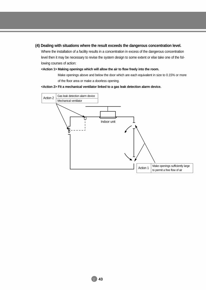
V 43
(4) Dealing with situations where the result exceeds the dangerous concentration level.Where the installation of a facility results in a concentration in excess of the dangerous concentration
level then it may be necessary to revise the system design to some extent or else take one of the fol-
lowing courses of action:
<Action 1> Making openings which will allow the air to flow freely into the room.
Make openings above and below the door which are each equivalent in size to 0.15% or more
of the floor area or make a doorless opening.
<Action 2> Fit a mechanical ventilator linked to a gas leak detection alarm device.
Indoor unit
Action 2Gas leak detection alarm device
Mechanical ventilator
Action 1Make openings sufficiently largeto permit a free flow of air
DVM E-D/B(chapter5)-E<03759 3/21/02 7:40 PM Page 43

SAMSUNG DVM Air Conditioner
Technical Manual
DB98-03759A(1)2002.03.
DVM E-D/B(cover)-E<03759 3/21/02 6:48 PM Page 1