unit – i – basics of robotics – smr 1401
TRANSCRIPT
SCHOOL OF MECHANICAL ENGINEERING
DEPARTMENT OF MECHANICAL ENGINEERING
UNIT – I – BASICS OF ROBOTICS – SMR 1401
UNIT I INTRODUCTION AND ROBOTIC KINEMATICS
Definition of a Robot
• "A reprogrammable, multifunctional manipulator designed to move material, parts, tools, or
specialized devices through various programmed motions for the performance of a variety of tasks" .
Or a simpler version
• An automatic device that performs functions normally ascribed to humans or a machine in the form of a human.
A general-purpose, programmable machine possessing certain anthropomorphic characteristics
Hazardous work environments
Repetitive work cycle
Consistency and accuracy
Difficult handling task for humans
Multi shift operations Reprogrammable, flexible
Interfaced to other computer systems
Need of Industrial Robots
• Repetitive tasks that robots can do 24/7.
• Robots never get sick or need time off.
• Robots can do tasks considered too dangerous for humans.
• Robots can operate equipment to much higher precision than humans. • May be cheaper over the long term
• May be able to perform tasks that are impossible for humans
Robots are also used for the following tasks:
• Dirty Tasks
• Repetitive tasks
• Dangerous tasks • Impossible tasks
• Robots assisting the handicapped.
First, they are hardworking and reliable. They can do dangerous work or work that is very boring
or tiring for humans. They can work around the clock without complaining and without needing rest, food
or vacations. And robots can go places that humans cannot, such as the surface of Mars, deep under the
ocean or inside the radioactive parts of a nuclear power plant
Asimov’s Laws of Robotics (1942)
• A robot may not injure a human being, or, through inaction, allow a human being to come to harm
• A robot must obey orders given it by human beings, except where such orders would conflict with the
First Law.
• A robot must protect its own existence as long as such protection does not conflict with the First or
Second Law.
Robot Anatomy
Fig 1.1 Robot Anatomy
Main Components of Industrial Robots
Arm or Manipulator
End effectors
Drive Mechanism
Controller
Custom features: e.g. sensors and transducers
Manipulator consists of joints and links
Joints provide relative motion
Links are rigid members between joints
Various joint types: linear and rotary
Each joint provides a “degree-of-freedom”
Body-and-arm – for positioning of objects in the robot's work volume
Wrist assembly – for orientation of objects
Translational motion
Linear joint (type L) Rotational joint (type R)
Orthogonal joint (type O) Twisting joint (type T)
Revolving joint (type V)
Rotary motion
Fig 1.2 Robot Joints
Classification of robots based on robots configuration
Polar Coordinate Body-and-Arm Assembly
Consists of a sliding arm (L joint) actuated relative to the body, which can rotate about both a
vertical axis (T joint) and horizontal axis (R joint) Notation TRL:
Fig 1.3 Polar Configuration
Cylindrical Body-and-Arm Assembly
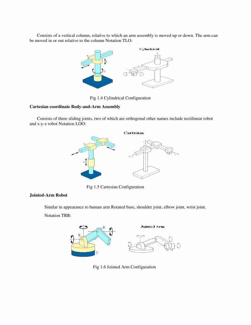
Consists of a vertical column, relative to which an arm assembly is moved up or down. The arm can be moved in or out relative to the column Notation TLO:
Fig 1.4 Cylindrical Configuration
Cartesian coordinate Body-and-Arm Assembly
Consists of three sliding joints, two of which are orthogonal other names include rectilinear robot
and x-y-z robot Notation LOO:
Fig 1.5 Cartesian Configuration
Jointed-Arm Robot
Similar in appearance to human arm Rotated base, shoulder joint, elbow joint, wrist joint.
Notation TRR:
Fig 1.6 Jointed Arm Configuration
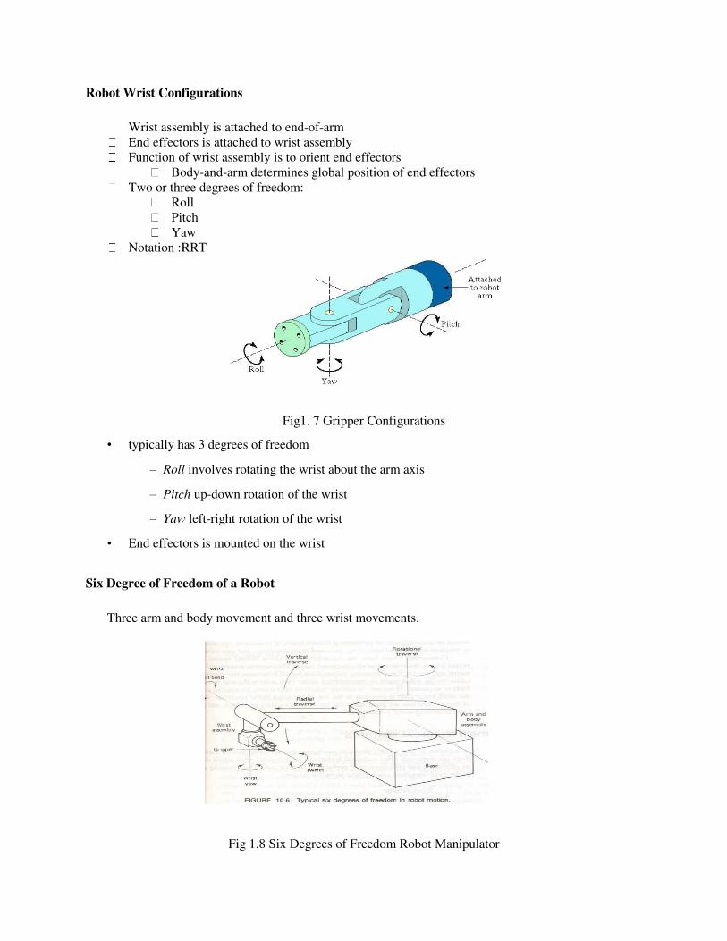
Robot Wrist Configurations
Wrist assembly is attached to end-of-arm
End effectors is attached to wrist assembly
Function of wrist assembly is to orient end effectors
Body-and-arm determines global position of end effectors
Two or three degrees of freedom:
Roll
Pitch
Yaw
Notation :RRT
Fig1. 7 Gripper Configurations
• typically has 3 degrees of freedom
– Roll involves rotating the wrist about the arm axis
– Pitch up-down rotation of the wrist
– Yaw left-right rotation of the wrist
• End effectors is mounted on the wrist
Six Degree of Freedom of a Robot
Three arm and body movement and three wrist movements.
Fig 1.8 Six Degrees of Freedom Robot Manipulator
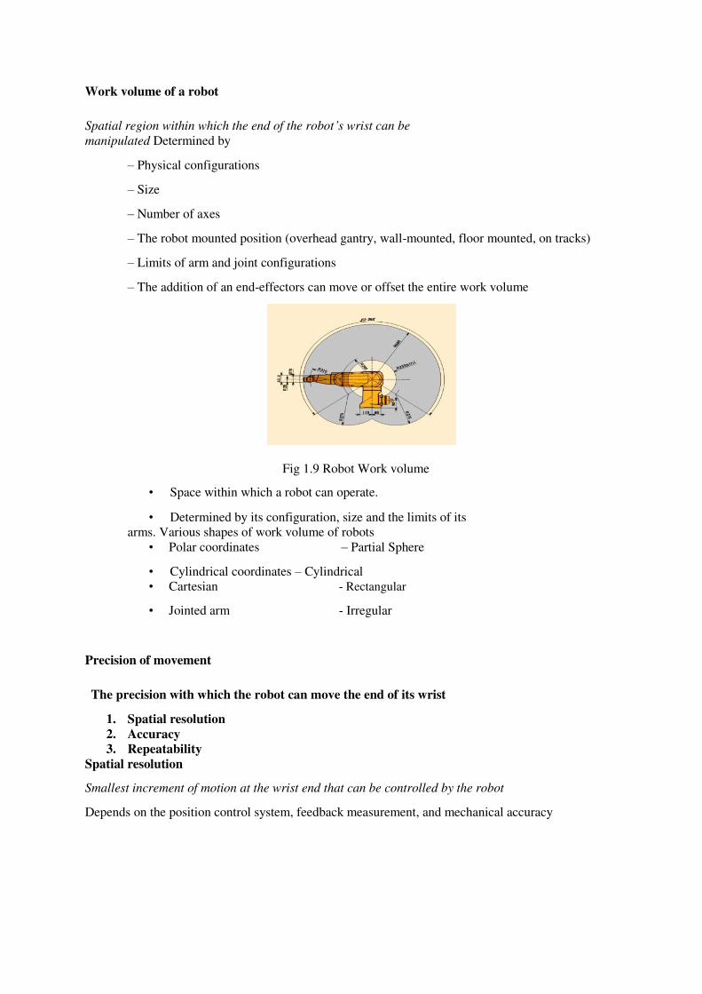
Work volume of a robot
Spatial region within which the end of the robot’s wrist can be
manipulated Determined by
– Physical configurations
– Size
– Number of axes
– The robot mounted position (overhead gantry, wall-mounted, floor mounted, on tracks)
– Limits of arm and joint configurations
– The addition of an end-effectors can move or offset the entire work volume
Fig 1.9 Robot Work volume
• Space within which a robot can operate.
• Determined by its configuration, size and the limits of its
arms. Various shapes of work volume of robots
• Polar coordinates – Partial Sphere
• Cylindrical coordinates – Cylindrical
• Cartesian - Rectangular
• Jointed arm - Irregular
Precision of movement
The precision with which the robot can move the end of its wrist
1. Spatial resolution
2. Accuracy
3. Repeatability
Spatial resolution
Smallest increment of motion at the wrist end that can be controlled by the robot
Depends on the position control system, feedback measurement, and mechanical accuracy
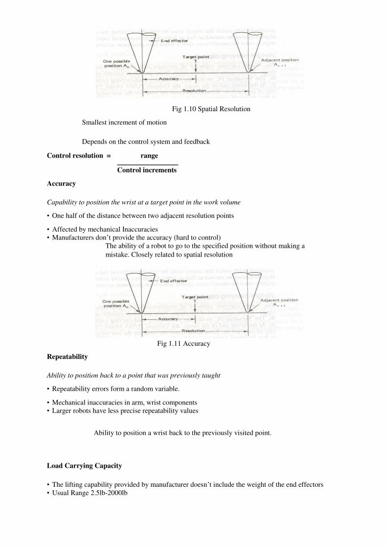
Fig 1.10 Spatial Resolution
Smallest increment of motion
Depends on the control system and feedback
Control resolution = range
Control increments
Accuracy
Capability to position the wrist at a target point in the work volume
• One half of the distance between two adjacent resolution points
• Affected by mechanical Inaccuracies
• Manufacturers don’t provide the accuracy (hard to control)
The ability of a robot to go to the specified position without making a
mistake. Closely related to spatial resolution
Fig 1.11 Accuracy
Repeatability
Ability to position back to a point that was previously taught
• Repeatability errors form a random variable.
• Mechanical inaccuracies in arm, wrist components
• Larger robots have less precise repeatability values
Ability to position a wrist back to the previously visited point.
Load Carrying Capacity
• The lifting capability provided by manufacturer doesn’t include the weight of the end effectors
• Usual Range 2.5lb-2000lb
• Condition to be satisfied:
Load Capability > Total Wt. of work piece +Wt. of end effectors + Safety range
Speed of movement
Speed with which the robot can manipulate the end
effectors Acceleration/deceleration times are crucial for
cycle time. •Determined by
Weight of the
object Distance
moved
Precision with which object must be positioned
The amount of distance per unit time at which the robot can
move. Speed of the end effectors
Determined by the weight of the object
End Effectors
The special tooling for a robot that enables it to perform a specific task
Two types:
Grippers – to grasp and manipulate objects (e.g., parts) during work cycle
Tools – to perform a process, e.g., spot welding, spray painting
Device attached to the robot’s wrist to perform a specific task
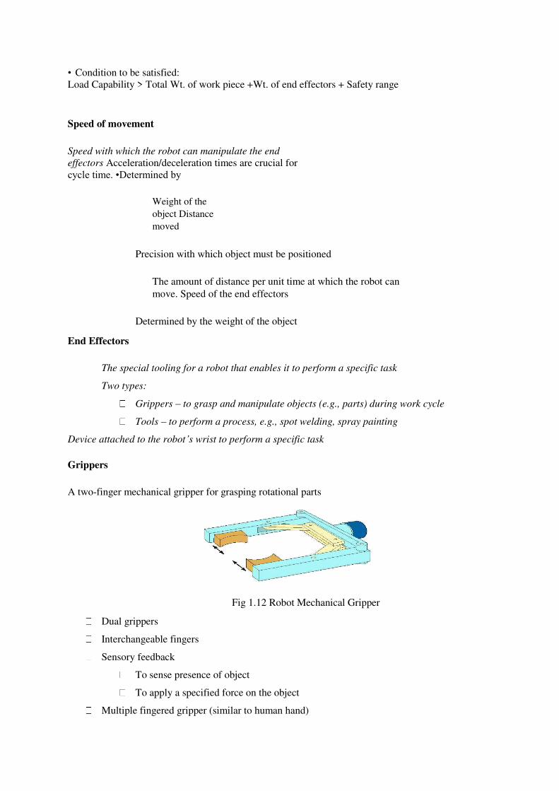
Grippers
A two-finger mechanical gripper for grasping rotational parts
Fig 1.12 Robot Mechanical Gripper
Dual grippers
Interchangeable fingers
Sensory feedback
To sense presence of object
To apply a specified force on the object
Multiple fingered gripper (similar to human hand)
Standard gripper products to reduce the amount of custom design required
– Mechanical Grippers
– Suction cups or vacuum cups
– Magnetized grippers
– Hooks
– Scoops (to carry fluids)
– Spot Welding gun
– Arc Welding tools
– Spray painting gun
– Drilling Spindle
– Grinders, Wire brushes
– Heating torches
Sensors in robotics
Two basic categories of sensors used in industrial robots:
1. Internal - used to control position and velocity of the manipulator joints 2. External - used to coordinate the operation of the robot with other equipment in the work cell
Tactile - touch sensors and force sensors
Proximity - when an object is close to the sensor
Optical -
Machine vision
Other sensors - temperature, voltage, etc.
Types of sensors:
Tactile sensors (touch sensors, force sensors, tactile array sensors)
Proximity and range sensors (optical sensors, acoustical sensors, electromagnetic sensors)
Miscellaneous sensors (transducers and sensors which sense variables such temperature,
pressure, fluid flow, thermocouples, voice
sensors) Machine vision systems
Uses of sensors:
Safety monitoring
Interlocks in work cell control
Part inspection for quality control
Determining positions and related information about objects
Desirable features of sensors:
Accuracy Operation
range Speed of
response
Calibration
Reliability
Cost and ease of operation
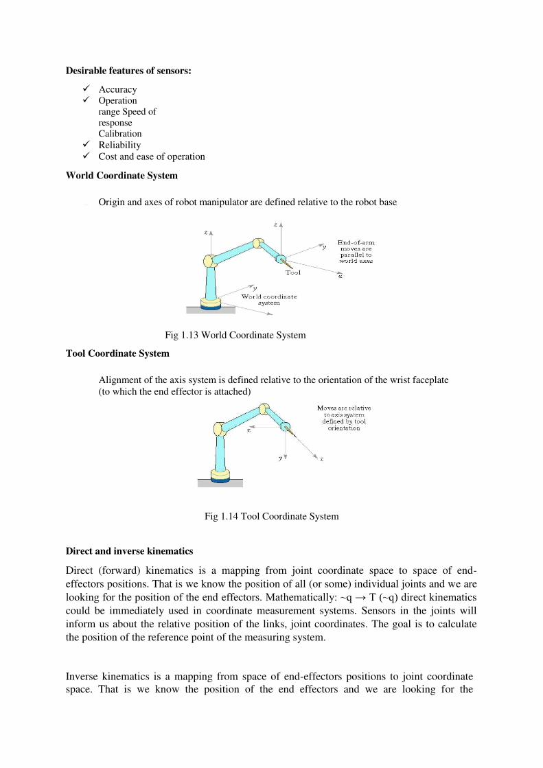
World Coordinate System
Origin and axes of robot manipulator are defined relative to the robot base
Fig 1.13 World Coordinate System
Tool Coordinate System
Alignment of the axis system is defined relative to the orientation of the wrist faceplate
(to which the end effector is attached)
Fig 1.14 Tool Coordinate System
Direct and inverse kinematics
Direct (forward) kinematics is a mapping from joint coordinate space to space of end-
effectors positions. That is we know the position of all (or some) individual joints and we are
looking for the position of the end effectors. Mathematically: ~q → T (~q) direct kinematics could be immediately used in coordinate measurement systems. Sensors in the joints will
inform us about the relative position of the links, joint coordinates. The goal is to calculate
the position of the reference point of the measuring system.
Inverse kinematics is a mapping from space of end-effectors positions to joint coordinate
space. That is we know the position of the end effectors and we are looking for the
coordinates of all individual joints. Mathematically: T → ~q(T) Inverse kinema cs is needed in robot control, one knows the required position of the gripper, but for control the joint
coordinates are needed.
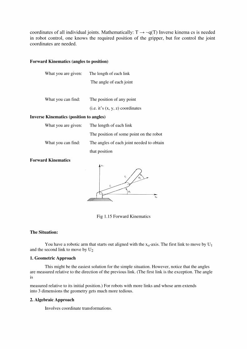
Forward Kinematics (angles to position)
What you are given: The length of each link
The angle of each joint
What you can find: The position of any point
(i.e. it’s (x, y, z) coordinates
Inverse Kinematics (position to angles)
What you are given: The length of each link
The position of some point on the robot
What you can find: The angles of each joint needed to obtain
Forward Kinematics
that position
Fig 1.15 Forward Kinematics
The Situation:
You have a robotic arm that starts out aligned with the xo-axis. The first link to move by U1
and the second link to move by U2
1. Geometric Approach
This might be the easiest solution for the simple situation. However, notice that the angles
are measured relative to the direction of the previous link. (The first link is the exception. The angle
is
measured relative to its initial position.) For robots with more links and whose arm extends
into 3 dimensions the geometry gets much more tedious.
2. Algebraic Approach
Involves coordinate transformations.
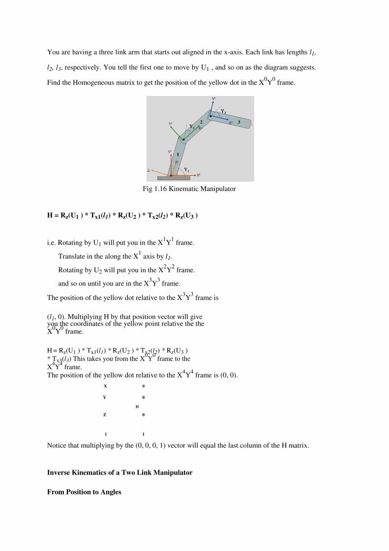
You are having a three link arm that starts out aligned in the x-axis. Each link has lengths l1,
l2, l3, respectively. You tell the first one to move by U1 , and so on as the diagram suggests.
Find the Homogeneous matrix to get the position of the yellow dot in the X0Y
0 frame.
Fig 1.16 Kinematic Manipulator
H = Rz(U1 ) * Tx1(l1) * Rz(U2 ) * Tx2(l2) * Rz(U3 )
i.e. Rotating by U1 will put you in the X1Y
1 frame.
Translate in the along the X1 axis by l1.
Rotating by U2 will put you in the X2Y
2 frame.
and so on until you are in the X3Y
3 frame.
The position of the yellow dot relative to the X3Y
3 frame is
(l1, 0). Multiplying H by that position vector will give you the coordinates of the yellow point relative the the X
0Y
0 frame.
H = Rz(U1 ) * Tx1(l1) * Rz(U2 ) * Tx2(l2) * Rz(U3 )
* Tx3(l3) This takes you from the X0Y
0 frame to the
X4Y
4 frame.
The position of the yellow dot relative to the X4Y
4 frame is (0, 0).
X 0
Y 0
Z
H
0
1
1
Notice that multiplying by the (0, 0, 0, 1) vector will equal the last column of the H matrix.
Inverse Kinematics of a Two Link Manipulator
From Position to Angles
Given: l1, l2 , x , y
Find: U1, U2
Redundancy:
A unique solution to this problem does not exist. Notice, that using the “givens” two
solutions are possible.
****************************

SCHOOL OF MECHANICAL ENGINEERING
DEPARTMENT OF MECHANICAL ENGINEERING
UNIT – II – ROBOT END EFFECTORS – SMR 1401
UNIT II ROBOT DRIVES AND CONTROL
Robot Control Systems
Limited sequence control – pick-and-place operations using mechanical stops to set
positions
Playback with point-to-point control – records work cycle as a sequence of points,
then plays back the sequence during program execution
Playback with continuous path control – greater memory capacity and/or interpolation
capability to execute paths (in addition to points)
Intelligent control – exhibits behavior that makes it seem intelligent, e.g., responds to
sensor inputs, makes decisions, communicates with humans
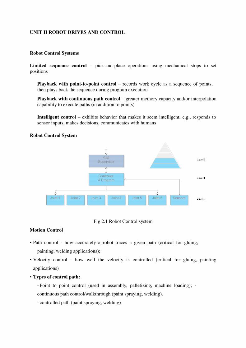
Robot Control System
Fig 2.1 Robot Control system
Motion Control
• Path control - how accurately a robot traces a given path (critical for gluing,
painting, welding applications);
• Velocity control - how well the velocity is controlled (critical for gluing, painting
applications)
• Types of control path:
- Point to point control (used in assembly, palletizing, machine loading); -
continuous path control/walkthrough (paint spraying, welding).
- controlled path (paint spraying, welding)
Limited sequence control – pick-and-place operations using mechanical stops to set
positions
Playback with point-to-point control – records work cycle as a sequence of points,
then plays back the sequence during program execution
Playback with continuous path control – greater memory capacity and/or
interpolation capability to execute paths (in addition to points)
Intelligent control – exhibits behaviour that makes it seem intelligent, e.g.,
responds to sensor inputs, makes decisions, communicates with humans
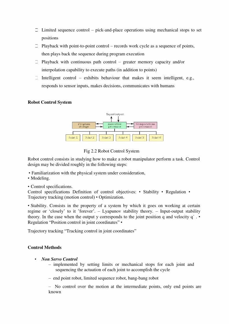
Robot Control System
Fig 2.2 Robot Control System
Robot control consists in studying how to make a robot manipulator perform a task. Control
design may be divided roughly in the following steps:
• Familiarization with the physical system under consideration, • Modeling.
• Control specifications.
Control specifications Definition of control objectives: • Stability • Regulation • Trajectory tracking (motion control) • Optimization.
• Stability. Consists in the property of a system by which it goes on working at certain
regime or ‘closely’ to it ’forever’. – Lyapunov stability theory. – Input-output stability
theory. In the case when the output y corresponds to the joint position q and velocity q˙ . • Regulation “Position control in joint coordinates” •
Trajectory tracking “Tracking control in joint coordinates”
Control Methods
• Non Servo Control – implemented by setting limits or mechanical stops for each joint and
sequencing the actuation of each joint to accomplish the cycle
– end point robot, limited sequence robot, bang-bang robot
– No control over the motion at the intermediate points, only end points are
known
• Programming accomplished by
– setting desired sequence of moves
– adjusting end stops for each axis accordingly
Servo Control
– Point to point Control
– Continuous Path Control
– Closed Loop control used to monitor position, velocity (other variables) of each
joint
– the sequence of moves is controlled by a “squencer”, which uses feedback
received
from the end stops to index to next step in the program
• Low cost and easy to maintain, reliable
• relatively high speed
• repeatability of up to 0.01 inch
• limited flexibility • typically hydraulic, pneumatic drives
Point-to-Point Control
• Only the end points are programmed, the path used to connect the end points are
computed by the controller
• user can control velocity, and may permit linear or piece wise linear motion
• Feedback control is used during motion to ascertain that individual joints have
achieved desired location
• Often used hydraulic drives, recent trend towards servomotors
• loads up to 500lb and large reach
• Applications
• pick and place type operations
• palletizing
• machine loading
• In addition to the control over the endpoints, the path taken by the end
effectors can be controlled
• Path is controlled by manipulating the joints throughout the entire motion, via
closed loop control
• Applications:
– spray painting, polishing, grinding, arc welding
Sensors in Robotics
Two basic categories of sensors used in industrial robots:
1. Internal - used to control position and velocity of the manipulator joints
2. External - used to coordinate the operation of the robot with other equipment in the
work cell Tactile - touch sensors and force sensors
Proximity - when an object is close to the
sensor Optical -
Machine vision
Other sensors - temperature, voltage, etc.
Electric Drive system
Uses electric motors to actuate individual joints
Preferred drive system in today's robots
Electric motor (stepper, servo, less strength, better accuracy and repeatability
Hydraulic Drive system
Uses hydraulic pistons and rotary vane actuators
Noted for their high power and lift capacity
Hydraulic (mechanical, high strength)
Pneumatic Drive system
Typically limited to smaller robots and simple material transfer applications Pneumatic (quick, less strength)
Hydraulic Drive system
– High strength and high speed
– Large robots, Takes floor space
– Mechanical Simplicity
– Used usually for heavy payloads
Electric Motor (Servo/Stepper) Drive system
– High accuracy and repeatability
– Low cost
– Less floor space
– Easy maintenance
Pneumatic Drive system
– Smaller units, quick assembly
– High cycle rate
– Easy maintenance
Electro hydraulic servo valves
An electro hydraulic servo valve (EHSV) is an electrically operated valve that controls how
hydraulic fluid is ported to an actuator. Servo valves and servo-proportional valves are
operated by transforming a changing analogue or digital input signal into a smooth set of
movements in a hydraulic cylinder. Servo valves can provide precise control of position,
velocity, pressure and force with good post movement damping characteristics.
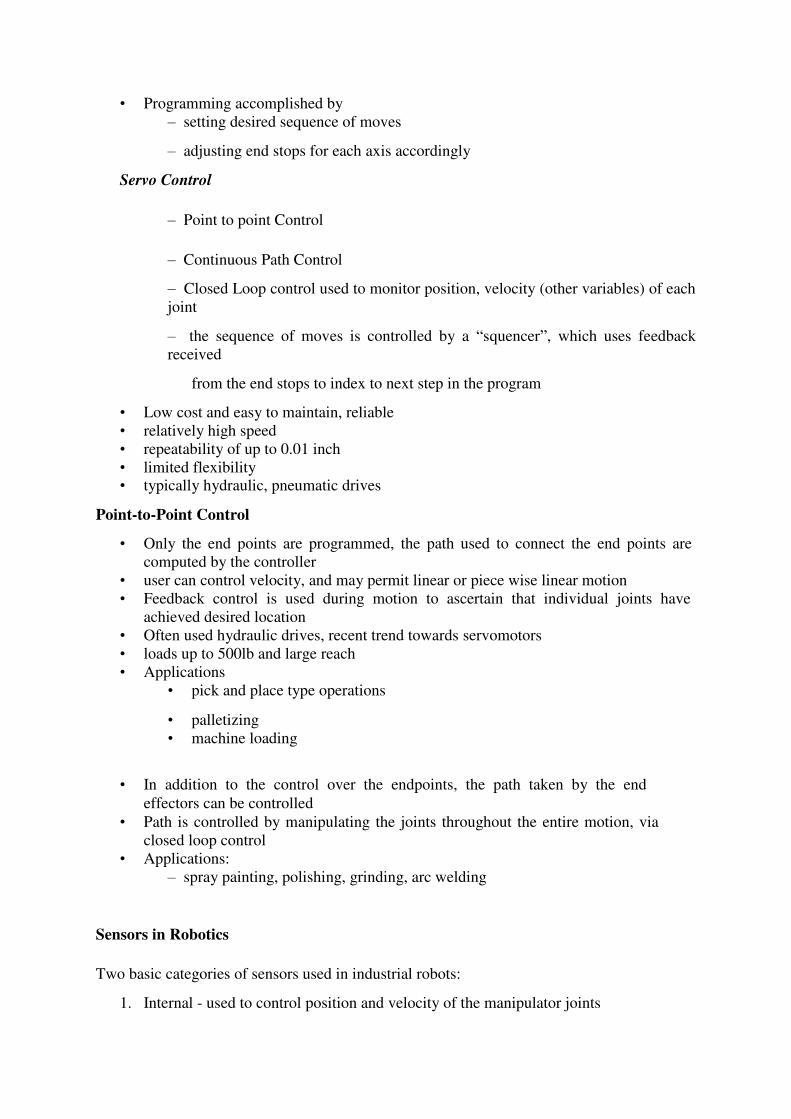
In its simplest form a servo or a servomechanism is a control system which measures its own
output and forces the output to quickly and accurately follow a command signal, se Figure 1-
1. In this way, the effect of anomalies in the control device itself and in the load can be
minimized as well as the influence of external disturbances. A servomechanism can be
designed to control almost any physical quantities, e.g. motion, force, pressure, temperature,
electrical voltage or current.
Fig 2.3 Basic Servo Mechanics
Capabilities of electro-hydraulic servos When rapid and precise control of sizeable loads is
required an electro-hydraulic servo is often the best approach to the problem. Generally
speaking, the hydraulic servo actuator provides fast response, high force and short stroke
characteristics. The main advantages of hydraulic components are.
• Easy and accurate control of work table position and velocity
• Good stiffness characteristics
• Zero back-lash
• Rapid response to change in speed or direction
• Low rate of wear
There are several significant advantages of hydraulic servo drives over electric motor drives:
♦ Hydraulic drives have substantially higher power to weight ratios
resulting in higher machine frame resonant frequencies for a given power
level.
♦ Hydraulic actuators are stiffer than electric drives, resulting in higher
loop gain capability, greater accuracy and better frequency response.
♦ Hydraulic servos give smoother performance at low speeds and have a wide
speed range without special control circuits.
♦ Hydraulic systems are to a great extent self-cooling and can be
operated in stall condition indefinitely without damage.
♦ Both hydraulic and electric drives are very reliable provided that
maintenance is followed.
♦ Hydraulic servos are usually less expensive for system above several
horsepower, especially if the hydraulic power supply is shared between
several actuators.
End Effectors Types
1) Standard Grippers (Angular and parallel, Pneumatic, hydraulic, electric, spring
powered, Power-opened and Spring-closed)
2) Vacuum Grippers (Single or multiple, use venturi or vacuum pump)
3) Vacuum Surfaces (Multiple suction ports, to grasp cloth materials, flat surfaces, sheet
material)
4) Electromagnetic Grippers (often used in conjunction with standard grippers)
5) Air-Pressure Grippers (balloon type)
1. Pneumatic fingers
2. Mandrel grippers
3. Pin grippers
6) Special Purpose Grippers (Hooking devices, custom positioners or tools)
7) Welding (MIG /TIG, Plasma Arc, Laser, Spot)
8) Pressure Sprayers (painting, water jet cutting, cleaning)
9) Hot Cutting type (laser, plasma, de-flashers-hot knife)
10) Buffing/Grinding/De-burring type
11) Drilling/Milling type
12) Dispensing type (adhesive, sealant, foam)
Mechanical Grippers
Mechanical grippers are used to pick up, move, place, or hold parts in an automated system.
They can be used in harsh or dangerous
VACUUM GRIPPERS: for non-ferrous components with flat and smooth surfaces, grippers
can be built using standard vacuum cups or pads made of rubber-like materials. Not suitable
for components with curved surfaces or with holes.
Vacuum grippers
Vacuum-grippers become in suction cups, the suctions cups is made of rubber. The suction
cups are connected through tubes with under pressure devices for picking up items and for
releasing items air is pumped out into the suction cups. The under pressure can be created
with the following devices:
The vacuum grippers use suction cups (vacuum cups) as pick up devices. There are different
types of suction cups and the cups are generally made of polyurethane or rubber and can be
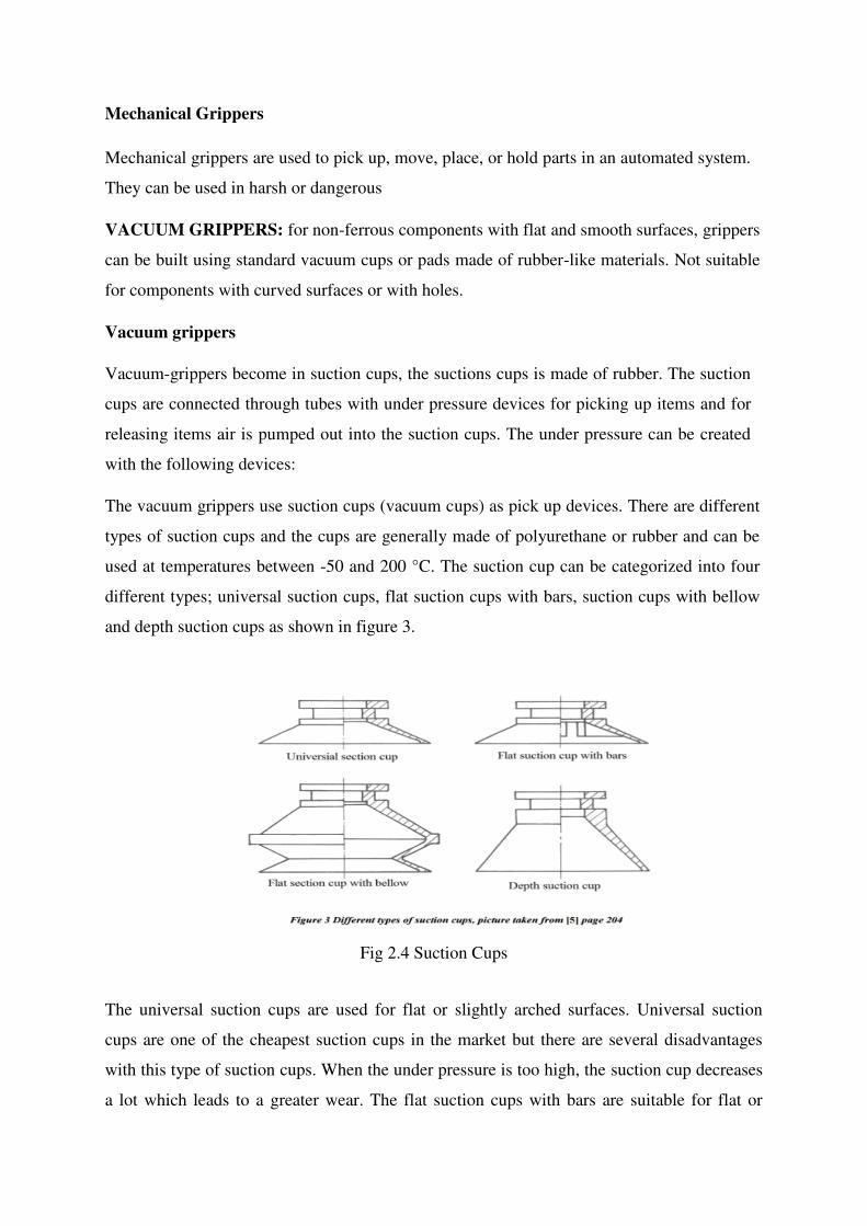
used at temperatures between -50 and 200 °C. The suction cup can be categorized into four
different types; universal suction cups, flat suction cups with bars, suction cups with bellow
and depth suction cups as shown in figure 3.
Fig 2.4 Suction Cups
The universal suction cups are used for flat or slightly arched surfaces. Universal suction
cups are one of the cheapest suction cups in the market but there are several disadvantages
with this type of suction cups. When the under pressure is too high, the suction cup decreases
a lot which leads to a greater wear. The flat suction cups with bars are suitable for flat or
flexible items that need assistance when lifted. These types of suction cups provides a small
movement under load and maintains the area that the under pressure is acting on, this reduces
the wear of the flat suction cup with bars, this leads to a faster and safer movement. Suction
cups with bellows are usually used for curved surfaces, for example when separation is
needed or when a smaller item is being gripped and needs a shorter movement. This type of
suction cups can be used in several areas but they allow a lot of movement at gripping and
low stability with small under pressure. The depth suction cup can be used for surfaces that
are very irregular and curved or when an item needs to be lifted over an edge. [5] Items with
rough surfaces (surface roughness ≤ 5 µm for some types of suction cups) or items that are
made of porous material will have difficulty with vacuum grippers. An item with holes, slots
and gaps on the surfaces is not recommended to be handled with vacuum grippers. The air in
the suction is sucked out with one of the techniques described earlier, if the material is porous
or has holes on its surface; it will be difficult to suck out the air. In such cases the leakage of
air can be reduced if smaller suction cups are used. Figure 4 shows different types of suction
cups.
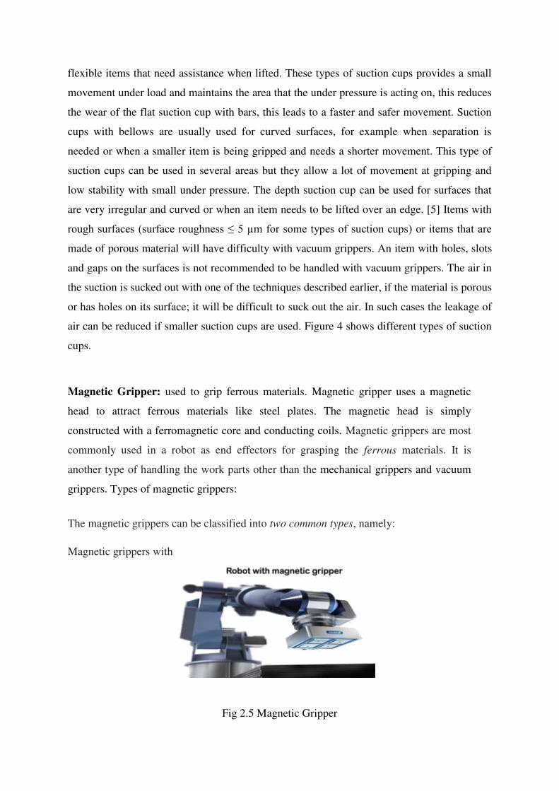
Magnetic Gripper: used to grip ferrous materials. Magnetic gripper uses a magnetic
head to attract ferrous materials like steel plates. The magnetic head is simply
constructed with a ferromagnetic core and conducting coils. Magnetic grippers are most
commonly used in a robot as end effectors for grasping the ferrous materials. It is
another type of handling the work parts other than the mechanical grippers and vacuum
grippers. Types of magnetic grippers:
The magnetic grippers can be classified into two common types, namely:
Magnetic grippers with
Fig 2.5 Magnetic Gripper
Electromagnets:
Electromagnetic grippers include a controller unit and a DC power for handling the materials.
This type of grippers is easy to control, and very effective in releasing the part at the end of
the operation than the permanent magnets. If the work part gripped is to be released, the
polarity level is minimized by the controller unit before the electromagnet is turned off. This
process will certainly help in removing the magnetism on the work parts. As a result, a best
way of releasing the materials is possible in this gripper.
Permanent magnets:
The permanent magnets do not require any sort of external power as like the electromagnets
for handling the materials. After this gripper grasps a work part, an additional device called
as stripper push – off pin will be required to separate the work part from the magnet. This
device is incorporated at the sides of the gripper.
The advantage of this permanent magnet gripper is that it can be used in hazardous
applications like explosion-proof apparatus because of no electrical circuit. Moreover, there
is no possibility of spark production as well.
Benefits:
This gripper only requires one surface to grasp
the materials. The grasping of materials is done
very quickly.
It does not require separate designs for handling different size of materials.
It is capable of grasping materials with holes, which is unfeasible in the vacuum grippers.
Drawbacks:
The gripped work part has the chance of slipping out when it is
moving quickly. Sometimes oil in the surface can reduce the
strength of the gripper.
The machining chips may stick to the gripper during unloading.

SCHOOL OF MECHANICAL ENGINEERING
DEPARTMENT OF MECHANICAL ENGINEERING
UNIT – III – ROBOT KINEMATICS AND DYNAMICS – SMR 1401
ROBOT KINEMATICS
Robot kinematics applies geometry to the study of the movement of multi-degree of
freedom kinematic chains that form the structure of robotic systems. The emphasis on geometry means
that the links of the robot are modeled as rigid bodies and its joints are assumed to provide pure
rotation or translation.
Robot kinematics studies the relationship between the dimensions and connectivity of
kinematic chains and the position, velocity and acceleration of each of the links in the robotic system, in
order to plan and control movement and to compute actuator forces and torques. The relationship
between mass and inertia properties, motion, and the associated forces and torques is studied as part
of robot dynamics. The robot kinematics concepts related to both open and closed kinematics chains.
Forward kinematics is distinguished from inverse kinematics.
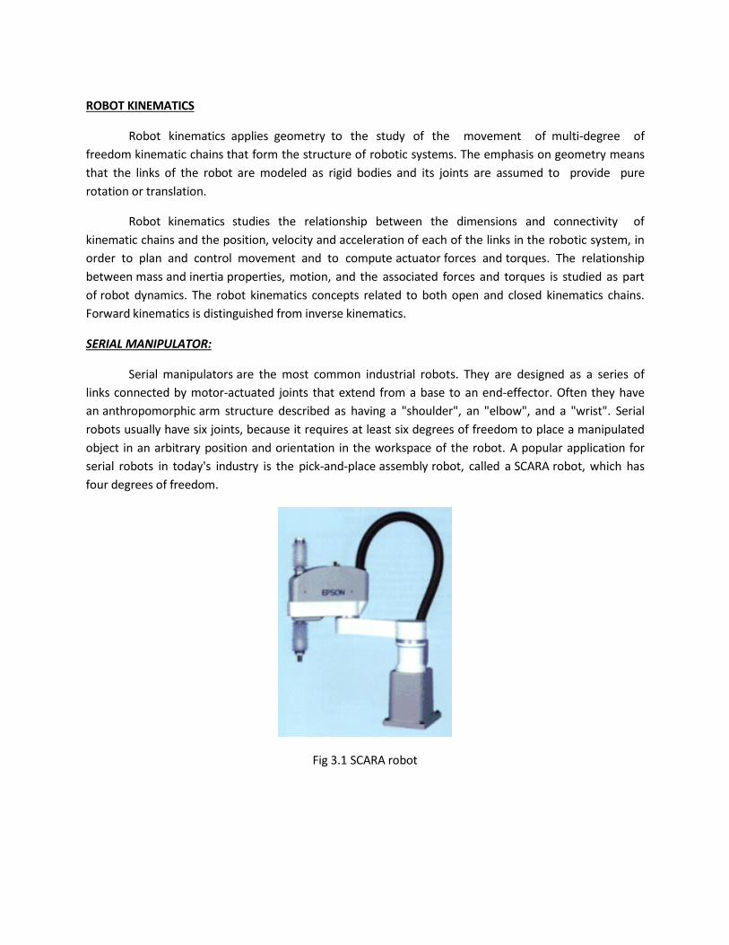
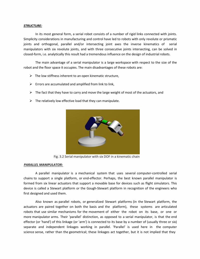
SERIAL MANIPULATOR:
Serial manipulators are the most common industrial robots. They are designed as a series of
links connected by motor-actuated joints that extend from a base to an end-effector. Often they have
an anthropomorphic arm structure described as having a "shoulder", an "elbow", and a "wrist". Serial
robots usually have six joints, because it requires at least six degrees of freedom to place a manipulated
object in an arbitrary position and orientation in the workspace of the robot. A popular application for
serial robots in today's industry is the pick-and-place assembly robot, called a SCARA robot, which has
four degrees of freedom.
Fig 3.1 SCARA robot
STRUCTURE:
In its most general form, a serial robot consists of a number of rigid links connected with joints.
Simplicity considerations in manufacturing and control have led to robots with only revolute or prismatic
joints and orthogonal, parallel and/or intersecting joint axes the inverse kinematics of serial
manipulators with six revolute joints, and with three consecutive joints intersecting, can be solved in
closed-form, i.e. analytically this result had a tremendous influence on the design of industrial robots.
The main advantage of a serial manipulator is a large workspace with respect to the size of the
robot and the floor space it occupies. The main disadvantages of these robots are:
The low stiffness inherent to an open kinematic structure,
Errors are accumulated and amplified from link to link,
The fact that they have to carry and move the large weight of most of the actuators, and
The relatively low effective load that they can manipulate.
A parallel manipulator is a mechanical system that uses several computer-controlled serial
chains to support a single platform, or end-effector. Perhaps, the best known parallel manipulator is
formed from six linear actuators that support a movable base for devices such as flight simulators. This
device is called a Stewart platform or the Gough-Stewart platform in recognition of the engineers who
first designed and used them.
Also known as parallel robots, or generalized Stewart platforms (in the Stewart platform, the
actuators are paired together on both the basis and the platform), these systems are articulated
robots that use similar mechanisms for the movement of either the robot on its base, or one or
more manipulator arms. Their 'parallel' distinction, as opposed to a serial manipulator, is that the end
effector (or 'hand') of this linkage (or 'arm') is connected to its base by a number of (usually three or six)
separate and independent linkages working in parallel. 'Parallel' is used here in the computer
science sense, rather than the geometrical; these linkages act together, but it is not implied that they
PARALLEL MANIPULATOR:
Fig. 3.2 Serial manipulator with six DOF in a kinematic chain
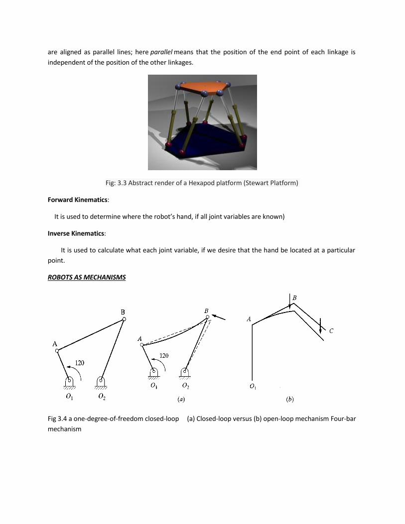
are aligned as parallel lines; here parallel means that the position of the end point of each linkage is
independent of the position of the other linkages.
Forward Kinematics:
It is used to determine where the robot’s hand, if all joint variables are known)
Inverse Kinematics:
It is used to calculate what each joint variable, if we desire that the hand be located at a particular
point.
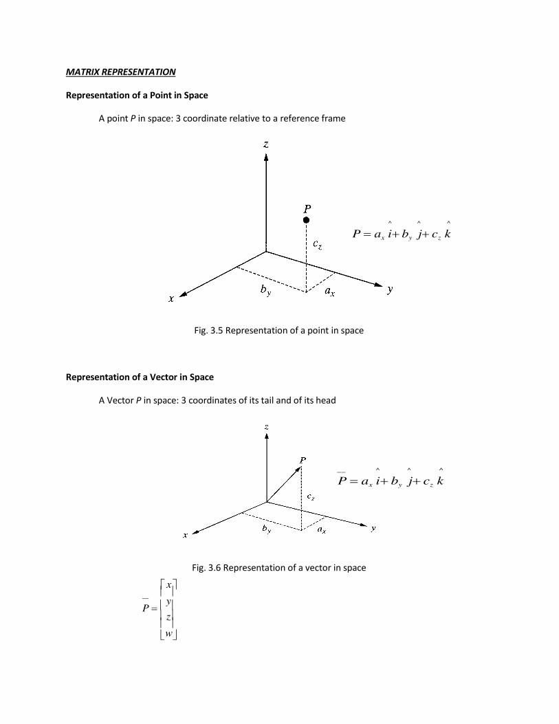
ROBOTS AS MECHANISMS
Fig 3.4 a one-degree-of-freedom closed-loop (a) Closed-loop versus (b) open-loop mechanism Four-bar
mechanism
Fig: 3.3 Abstract render of a Hexapod platform (Stewart Platform)
MATRIX REPRESENTATION
Representation of a Point in Space
A point P in space: 3 coordinate relative to a reference frame
^ ^ ^
P ax iby jcz k
Fig. 3.5 Representation of a point in space
Representation of a Vector in Space
A Vector P in space: 3 coordinates of its tail and of its head
__ ^ ^ ^
P ax iby jcz k
x
Fig. 3.6 Representation of a vector in space
__ P
y z w
P
y
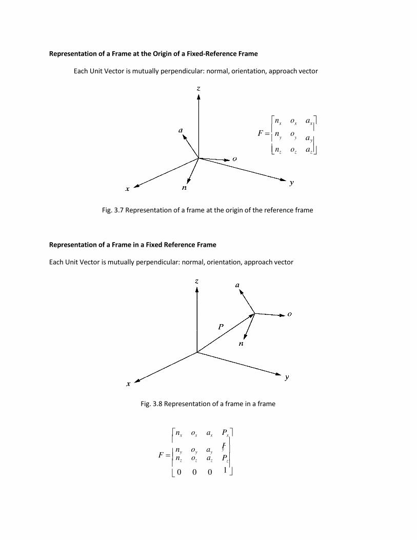
Representation of a Frame at the Origin of a Fixed-Reference Frame
Each Unit Vector is mutually perpendicular: normal, orientation, approach vector
nx ox ax F n o
ay
nz oz az
Fig. 3.7 Representation of a frame at the origin of the reference frame
Representation of a Frame in a Fixed Reference Frame
Each Unit Vector is mutually perpendicular: normal, orientation, approach vector
Fig. 3.8 Representation of a frame in a frame
nx ox ax
F ny oy ay
nz oz az
0 0 0
Px
y Pz 1
y
P
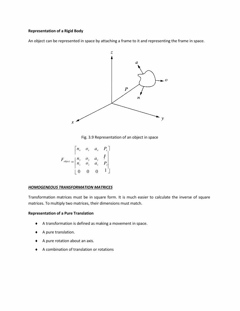
Representation of a Rigid Body
An object can be represented in space by attaching a frame to it and representing the frame in space.
Fig. 3.9 Representation of an object in space
Fobject
nx ox ax
ny oy ay
nz oz az
0 0 0
Px
y Pz
HOMOGENEOUS TRANSFORMATION MATRICES
Transformation matrices must be in square form. It is much easier to calculate the inverse of square
matrices. To multiply two matrices, their dimensions must match.
Representation of a Pure Translation
A transformation is defined as making a movement in space.
A pure translation.
A pure rotation about an axis.
A combination of translation or rotations
1
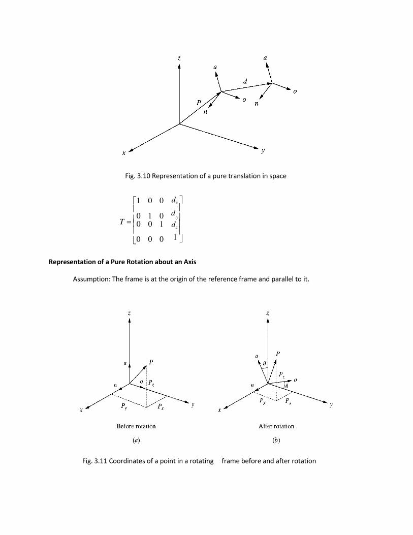
Fig. 3.10 Representation of a pure translation in space
1 0 0
T 0 1 0 0 0 1 0 0 0
dx
y dz
Representation of a Pure Rotation about an Axis
Assumption: The frame is at the origin of the reference frame and parallel to it.
Fig. 3.11 Coordinates of a point in a rotating frame before and after rotation
d
1
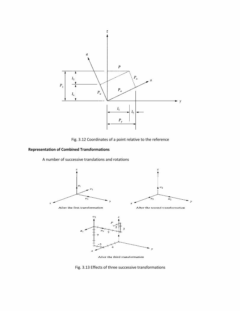
Fig. 3.12 Coordinates of a point relative to the reference
Representation of Combined Transformations
A number of successive translations and rotations
Fig. 3.13 Effects of three successive transformations
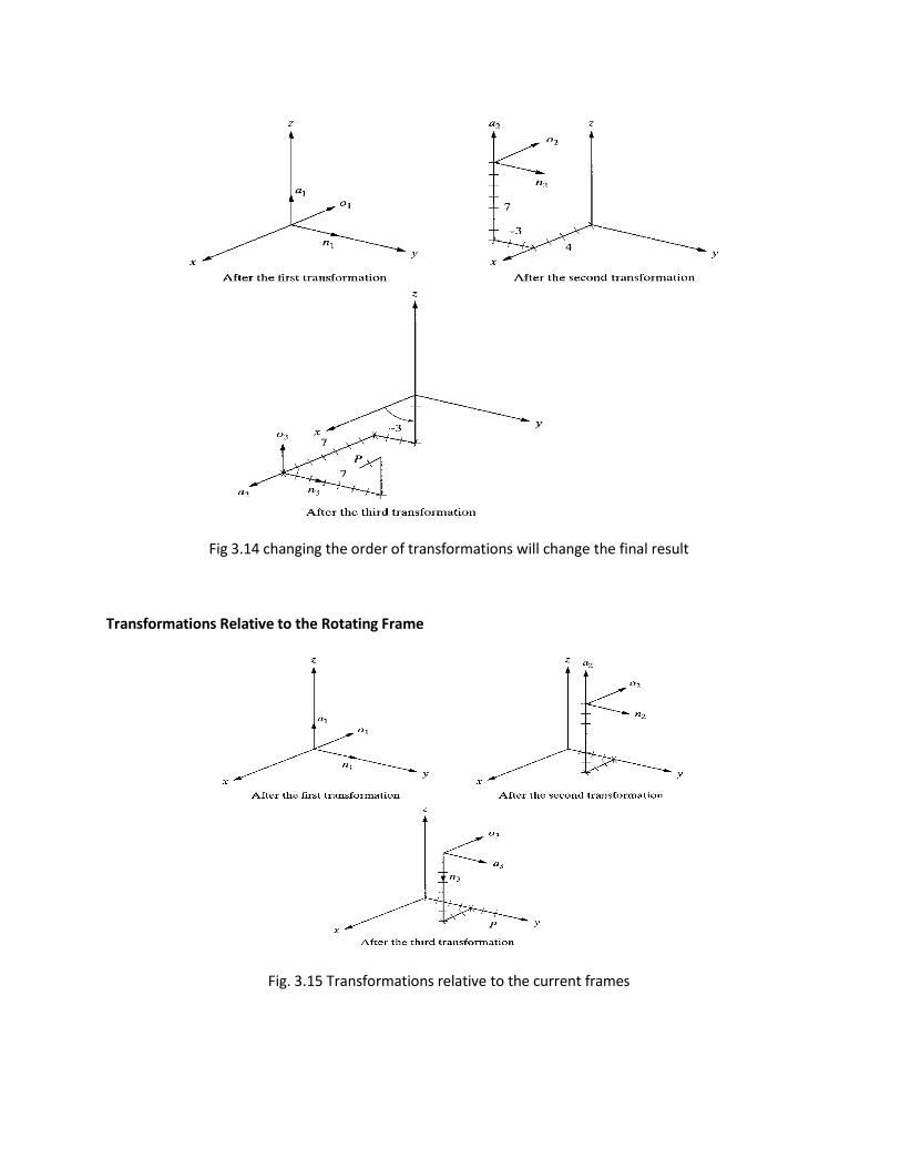
Fig 3.14 changing the order of transformations will change the final result
Transformations Relative to the Rotating Frame
Fig. 3.15 Transformations relative to the current frames
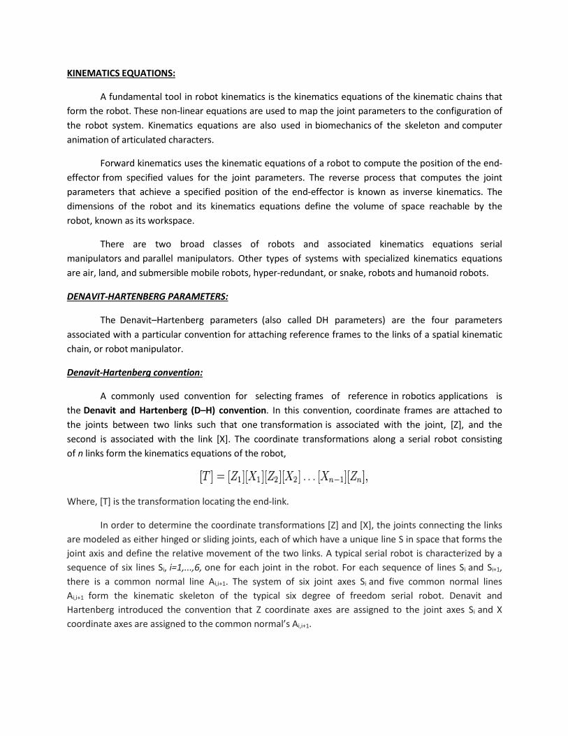
KINEMATICS EQUATIONS:
A fundamental tool in robot kinematics is the kinematics equations of the kinematic chains that
form the robot. These non-linear equations are used to map the joint parameters to the configuration of
the robot system. Kinematics equations are also used in biomechanics of the skeleton and computer
animation of articulated characters.
Forward kinematics uses the kinematic equations of a robot to compute the position of the end-
effector from specified values for the joint parameters. The reverse process that computes the joint
parameters that achieve a specified position of the end-effector is known as inverse kinematics. The
dimensions of the robot and its kinematics equations define the volume of space reachable by the
robot, known as its workspace.
There are two broad classes of robots and associated kinematics equations serial
manipulators and parallel manipulators. Other types of systems with specialized kinematics equations
are air, land, and submersible mobile robots, hyper-redundant, or snake, robots and humanoid robots.
DENAVIT-HARTENBERG PARAMETERS:
The Denavit–Hartenberg parameters (also called DH parameters) are the four parameters
associated with a particular convention for attaching reference frames to the links of a spatial kinematic
chain, or robot manipulator.
Denavit-Hartenberg convention:
A commonly used convention for selecting frames of reference in robotics applications is
the Denavit and Hartenberg (D–H) convention. In this convention, coordinate frames are attached to
the joints between two links such that one transformation is associated with the joint, [Z], and the
second is associated with the link [X]. The coordinate transformations along a serial robot consisting
of n links form the kinematics equations of the robot,
Where, [T] is the transformation locating the end-link.
In order to determine the coordinate transformations [Z] and [X], the joints connecting the links
are modeled as either hinged or sliding joints, each of which have a unique line S in space that forms the
joint axis and define the relative movement of the two links. A typical serial robot is characterized by a
sequence of six lines Si, i=1,...,6, one for each joint in the robot. For each sequence of lines Si and Si+1,
there is a common normal line Ai,i+1. The system of six joint axes Si and five common normal lines
Ai,i+1 form the kinematic skeleton of the typical six degree of freedom serial robot. Denavit and
Hartenberg introduced the convention that Z coordinate axes are assigned to the joint axes Si and X
coordinate axes are assigned to the common normal’s Ai,i+1.
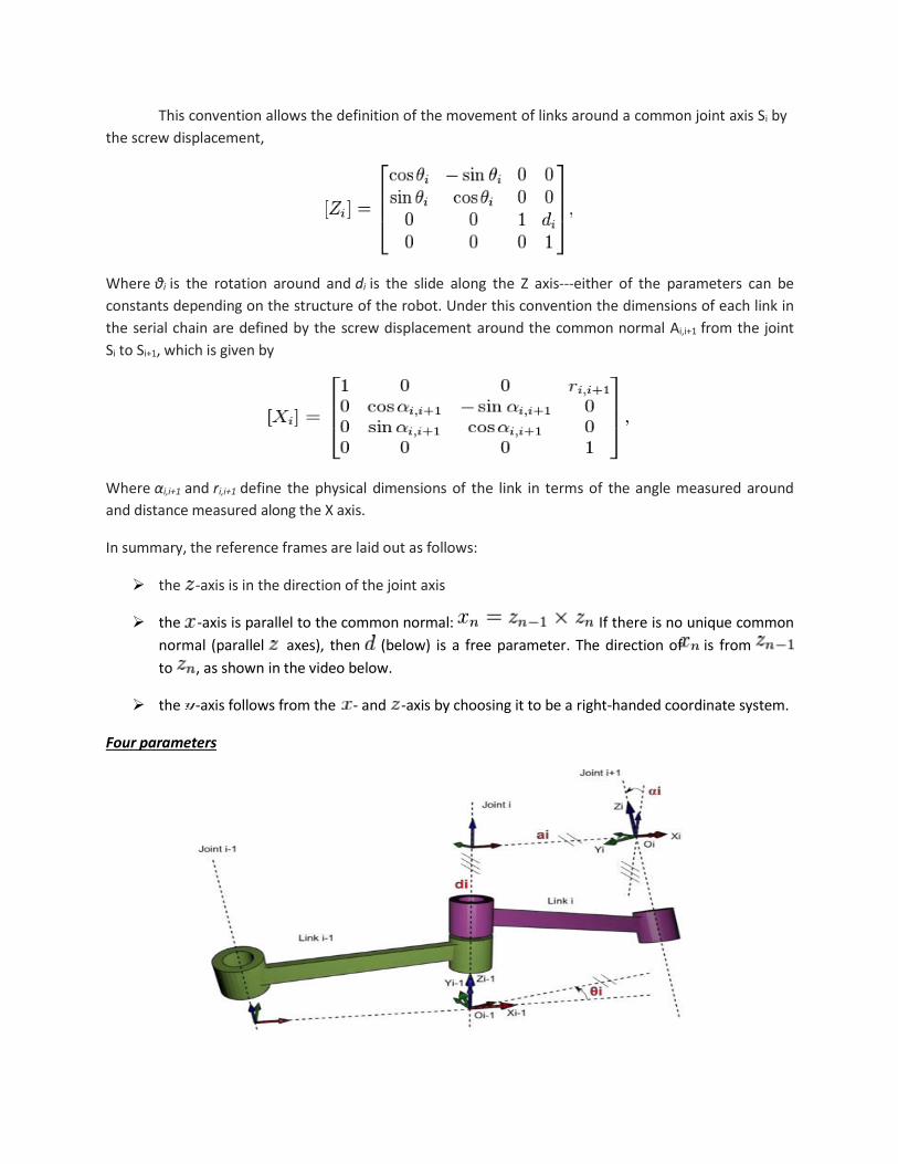
This convention allows the definition of the movement of links around a common joint axis Si by
the screw displacement,
Where θi is the rotation around and di is the slide along the Z axis---either of the parameters can be
constants depending on the structure of the robot. Under this convention the dimensions of each link in
the serial chain are defined by the screw displacement around the common normal Ai,i+1 from the joint
Si to Si+1, which is given by
Where αi,i+1 and ri,i+1 define the physical dimensions of the link in terms of the angle measured around
and distance measured along the X axis.
In summary, the reference frames are laid out as follows:
the -axis is in the direction of the joint axis
the -axis is parallel to the common normal: If there is no unique common
normal (parallel axes), then (below) is a free parameter. The direction of is from
to , as shown in the video below.
the -axis follows from the - and -axis by choosing it to be a right-handed coordinate system.
Four parameters
The transformation the following four parameters known as D–H parameters:
d: offset along previous z to the common normal
θ: angle about previous z, from old x to new x
r: length of the common normal. Assuming a revolute joint, this is the radius about
previous z.
α: angle about common normal, from old z axis to new z axis
There is some choice in frame layout as to whether the previous x axis or the next x points along the
common normal. The latter system allows branching chains more efficiently, as multiple frames can all
point away from their common ancestor, but in the alternative layout the ancestor can only point
toward one successor. Thus the commonly used notation places each down-chain x axis collinear with
the common normal, yielding the transformation calculations shown below.
We can note constraints on the relationships between the axes:
-axis is perpendicular to both the and axes
-axis intersects both and axes
Origin of joint is at the intersection of and
completes a right-handed reference frame based on and
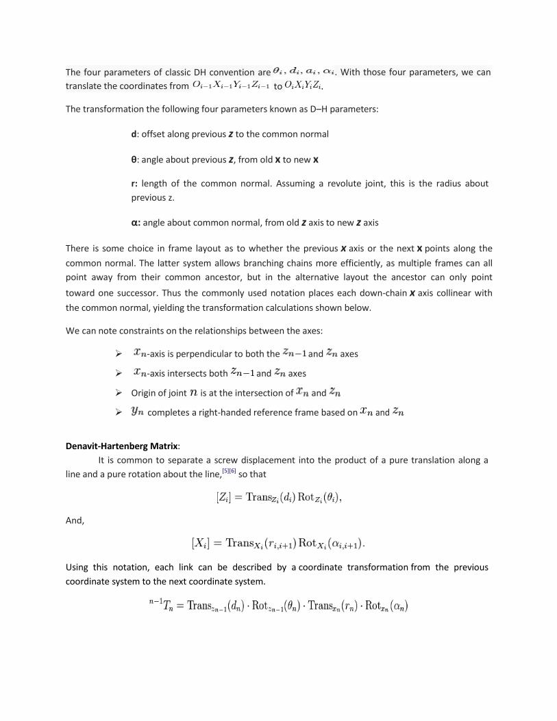
Denavit-Hartenberg Matrix:
It is common to separate a screw displacement into the product of a pure translation along a
line and a pure rotation about the line,[5][6]
so that
And,
Using this notation, each link can be described by a coordinate transformation from the previous
coordinate system to the next coordinate system.
The four parameters of classic DH convention are
translate the coordinates from
. With those four parameters, we can
to .
Note that this is the product of two screw displacements, the matrices associated with these operations
are:
This gives:
Where R is the 3×3 sub matrix describing rotation and T is the 3×1 sub matrix describing translation.
DENAVIT-HARTENBERG REPRESENTATION OF FORWARD KINEMATIC EQUATIONS OF ROBOT:
Denavit-Hartenberg Representation:
1. Simple way of modeling robot links and joints for any robot configuration, regardless of its
sequence or complexity.
2. Transformations in any coordinates are possible.
3. Any possible combinations of joints and links and all-revolute articulated robots can be
represented
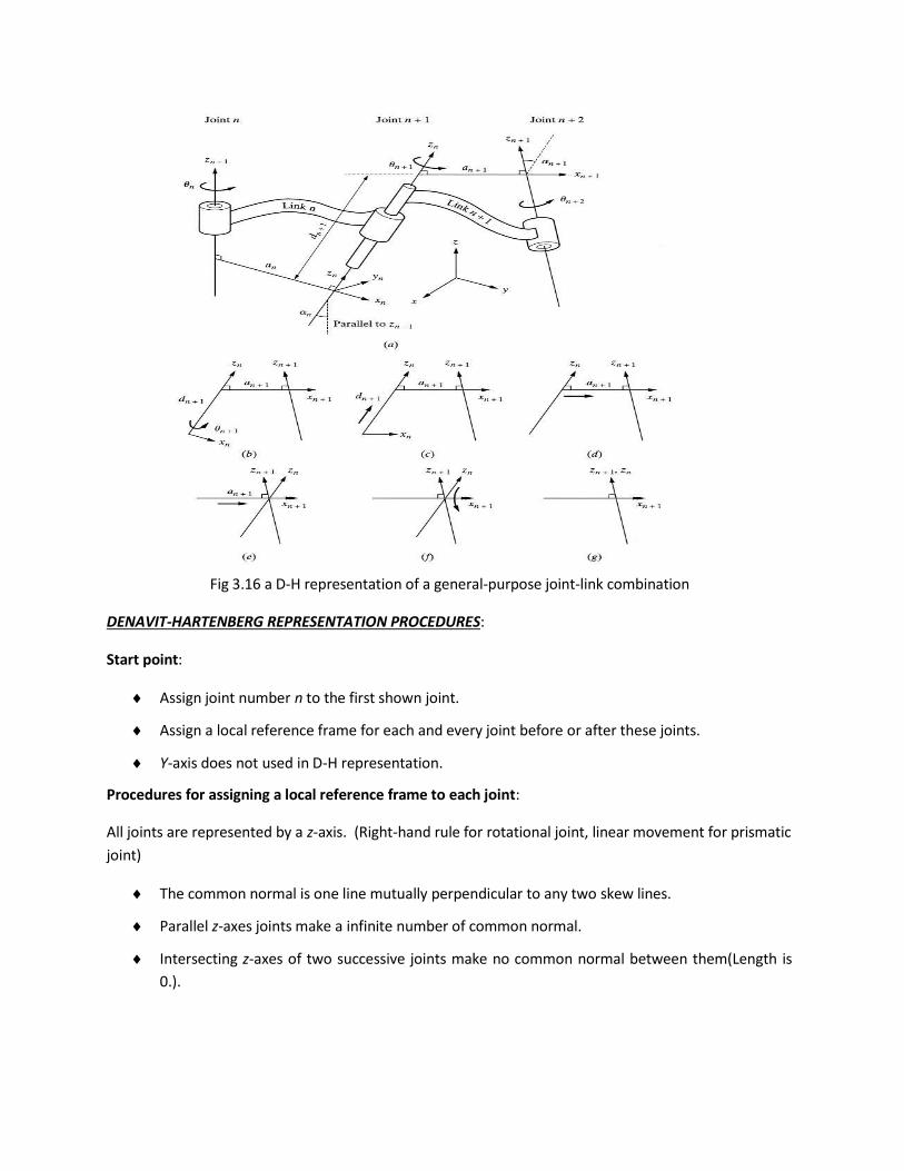
Fig 3.16 a D-H representation of a general-purpose joint-link combination
DENAVIT-HARTENBERG REPRESENTATION PROCEDURES:
Start point:
Assign joint number n to the first shown joint.
Assign a local reference frame for each and every joint before or after these joints.
Y-axis does not used in D-H representation.
Procedures for assigning a local reference frame to each joint:
All joints are represented by a z-axis. (Right-hand rule for rotational joint, linear movement for prismatic
joint)
The common normal is one line mutually perpendicular to any two skew lines.
Parallel z-axes joints make a infinite number of common normal.
Intersecting z-axes of two successive joints make no common normal between them(Length is
0.).
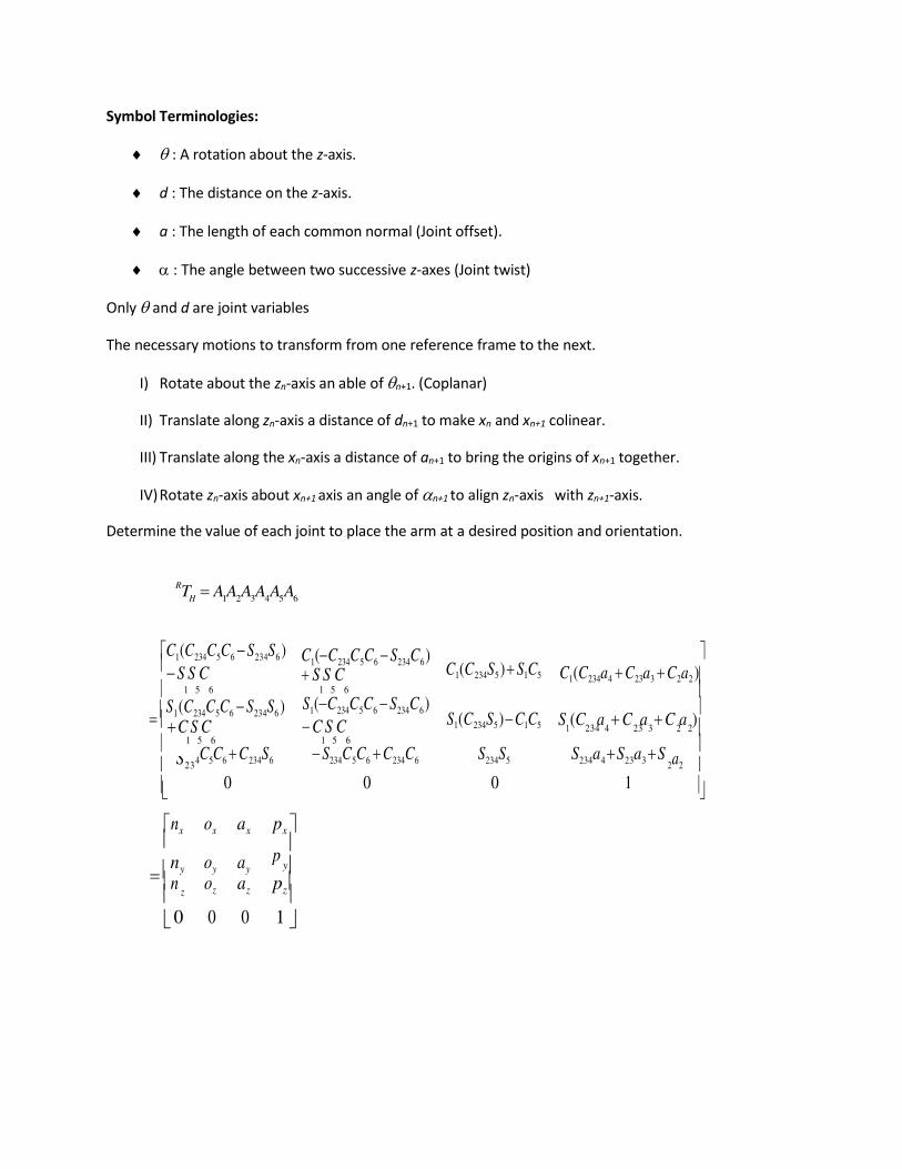
H 1 2 3 4 5 6
S (C a C a C a )
z
Symbol Terminologies:
: A rotation about the z-axis.
d : The distance on the z-axis.
a : The length of each common normal (Joint offset).
: The angle between two successive z-axes (Joint twist)
Only and d are joint variables
The necessary motions to transform from one reference frame to the next.
I) Rotate about the zn-axis an able of n+1. (Coplanar)
II) Translate along zn-axis a distance of dn+1 to make xn and xn+1 colinear.
III) Translate along the xn-axis a distance of an+1 to bring the origins of xn+1 together.
IV) Rotate zn-axis about xn+1 axis an angle of n+1 to align zn-axis with zn+1-axis.
Determine the value of each joint to place the arm at a desired position and orientation.
RT A A A A A A
C1 (C234C5C6 S234S6 ) S S C C1 (C234C5C6 S234C6 ) S S C C1 (C234S5 ) S1C5
C1 (C234a4 C23a3 C2a2 )
1 5 6 1 5 6
S1 (C234C5C6 S234S6 ) C S C
S1 (C234C5C6 S234C6 ) C S C S1 (C234S5 ) C1C5
1 234 4 23 3 2 2
1 5 6 1 5 6 4C5C6 C234S6 S234C5C6 C234C6 S234S5 S234a4 S23a3 S
nx ox ax
ny oy ay
px
y n oz az
pz
0 0 0 1
p
S23 2a2 0 0 0 1
n
0
y
3
o a
o a
1
5
6
THE INVERSE KINEMATIC SOLUTION OF ROBOT:
nx ox ax
1 y y y
px
y 1 A1 nz oz az
0 0
A1
pz
[RHS ] A2 A3 A4 A5 A6
C1
0
S1 0 0 1
0nx ox ax
y y y
px
y A2 A3 A4 A5 A6
1 p tan
px
2 tan 1
(C3a3 a2 )( pz S234a4 ) S3a3 ( pxC1 py S1 C234a4 )
(C3a3 a2 )( pxC1 py S1 C234a4 ) S3a3 (Pz S234a4 )
S tan
1
3
C3
4 234 2 3
tan1 C
234(C
1a
x S
1a
y ) S
234a
z
S1ax C1ay
S (C n S n ) S n
tan1 234 1 x 1 y 234 z
S234 (C1ox S1oy ) C234o
z
INVERSE KINEMATIC PROGRAM OF ROBOTS:
A robot has a predictable path on a straight line, or an unpredictable path on a straight line.
A predictable path is necessary to recalculate joint variables. (Between 50 to 200 times a
second)
To make the robot follow a straight line, it is necessary to break the line into many small
sections.
All unnecessary computations should be eliminated.
p
1
n p 0
S1 C1 0 0 nz oz az pz
0
0 0 1
0 0
0 1
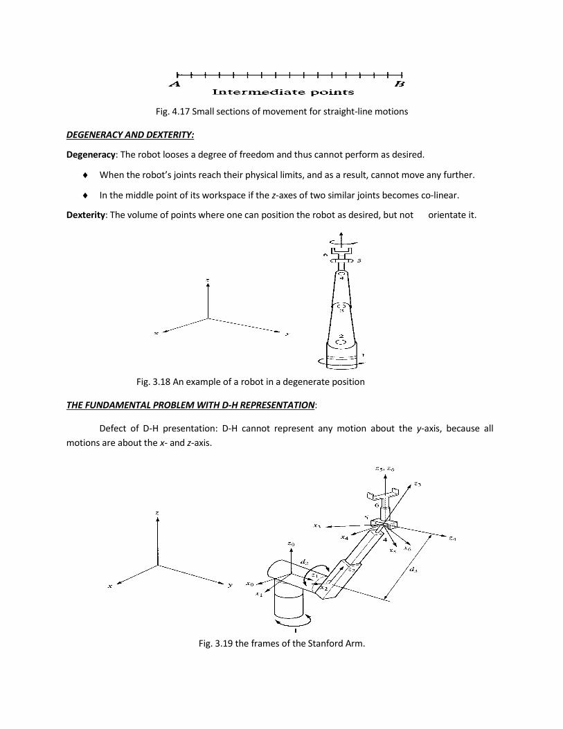
Fig. 4.17 Small sections of movement for straight-line motions
DEGENERACY AND DEXTERITY:
Degeneracy: The robot looses a degree of freedom and thus cannot perform as desired.
When the robot’s joints reach their physical limits, and as a result, cannot move any further.
In the middle point of its workspace if the z-axes of two similar joints becomes co-linear.
Dexterity: The volume of points where one can position the robot as desired, but not orientate it.
Fig. 3.18 An example of a robot in a degenerate position
THE FUNDAMENTAL PROBLEM WITH D-H REPRESENTATION:
Defect of D-H presentation: D-H cannot represent any motion about the y-axis, because all
motions are about the x- and z-axis.
Fig. 3.19 the frames of the Stanford Arm.
# d a
1 1 0 0 -90
2 2 d1 0 90
3 0 d1 0 0
4 4 0 0 -90
5 5 0 0 90
6 6 0 0 0
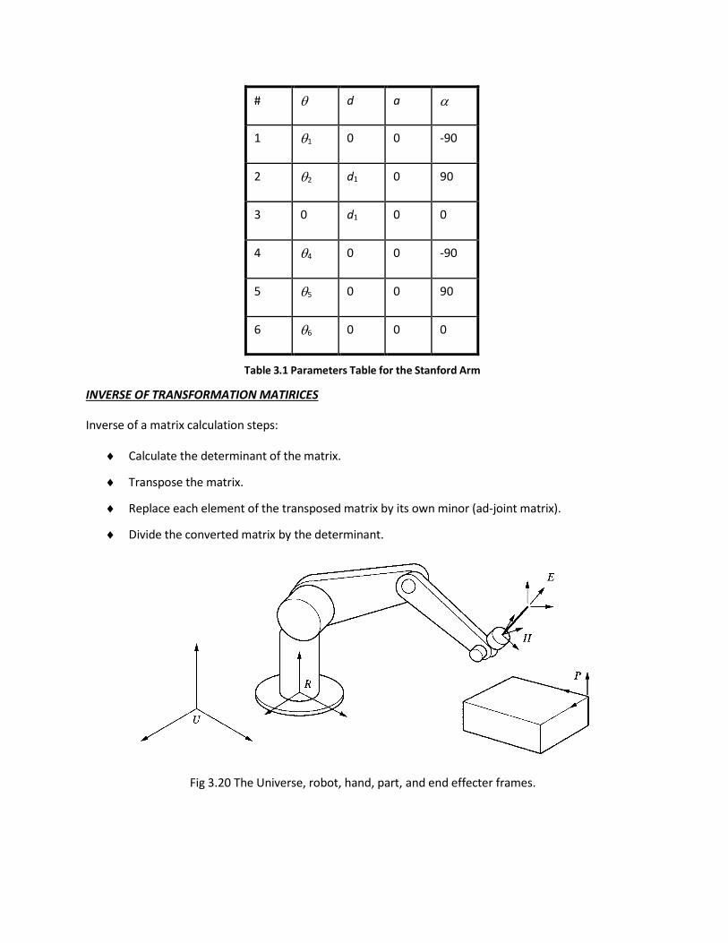
Table 3.1 Parameters Table for the Stanford Arm
INVERSE OF TRANSFORMATION MATIRICES
Inverse of a matrix calculation steps:
Calculate the determinant of the matrix.
Transpose the matrix.
Replace each element of the transposed matrix by its own minor (ad-joint matrix).
Divide the converted matrix by the determinant.
Fig 3.20 The Universe, robot, hand, part, and end effecter frames.
T
P
FORWARD AND INVERSE KINEMATICS OF ROBOTS:
Forward Kinematics Analysis:
Calculating the position and orientation of the hand of the robot.
If all robot joint variables are known, one can calculate where the robot is at any instant.
Fig. 3.21 The hand frame of the robot relative to the reference frame
Forward Kinematics and Inverse Kinematics equation for position analysis:
a) Cartesian (gantry, rectangular) coordinates.
b) Cylindrical coordinates.
c) Spherical coordinates.
d) Articulated (anthropomorphic, or all-revolute) coordinates
Forward and Inverse Kinematics Equations for Position
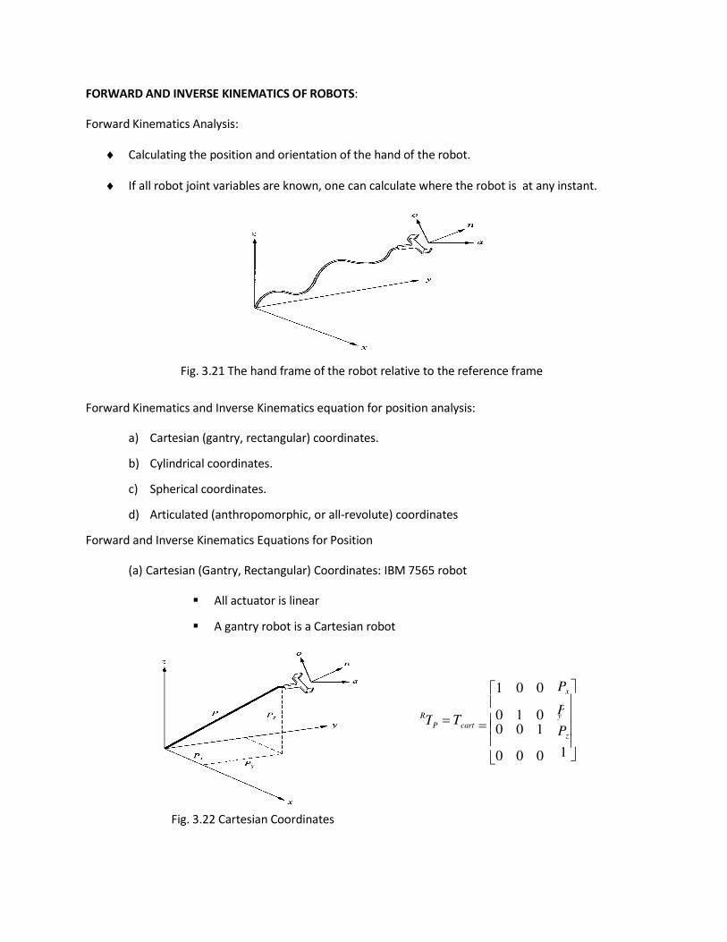
(a) Cartesian (Gantry, Rectangular) Coordinates: IBM 7565 robot
All actuator is linear
A gantry robot is a Cartesian robot
Fig. 3.22 Cartesian Coordinates
P Tcart
1 0 0
0 1 0 0 0 1 0 0 0
Px
y Pz 1
R
P cyl
P sph
0
(b) Cylindrical Coordinates: 2 Linear translations and 1 rotation
translation of r along the x-axis
rotation of about the z-axis
translation of l along the z-axis
RT T (r,,l) Trans(0,0,l)Rot(z,)Trans(r,0,0)
RT T
C
S
S
C0 rC0 rS
P cyl 0
0 1 l
0 0 1
Fig. 3.23 Cylindrical Coordinates
(c) Spherical Coordinates: 1 linear translation and 2 rotations
translation of r along the z-axis
rotation of about the y-axis
rotation of along the z-axis
RT T (r, , l) Rot(z, )Rot(y, )Trans(0,0,)
RT T
CCCS
S C
SC SS
rSCrSS
Fig. 3.24 Spherical Coordinates
P sph S 0 C 0 0
rC
0
1
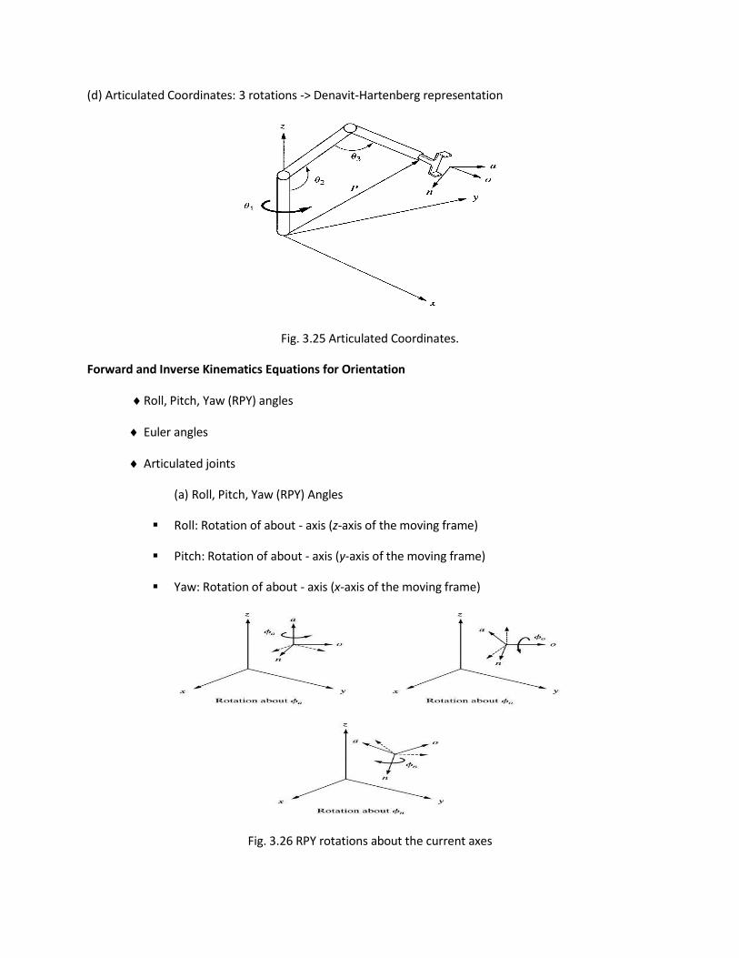
(d) Articulated Coordinates: 3 rotations -> Denavit-Hartenberg representation
Fig. 3.25 Articulated Coordinates.
Forward and Inverse Kinematics Equations for Orientation
Roll, Pitch, Yaw (RPY) angles
Euler angles
Articulated joints
(a) Roll, Pitch, Yaw (RPY) Angles
Roll: Rotation of about - axis (z-axis of the moving frame)
Pitch: Rotation of about - axis (y-axis of the moving frame)
Yaw: Rotation of about - axis (x-axis of the moving frame)
Fig. 3.26 RPY rotations about the current axes
R
(b) Euler Angles
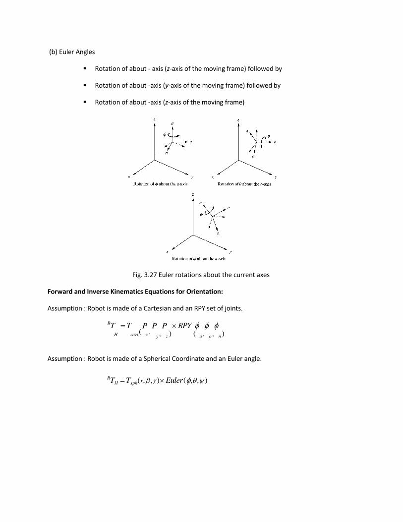
Rotation of about - axis (z-axis of the moving frame) followed by
Rotation of about -axis (y-axis of the moving frame) followed by
Rotation of about -axis (z-axis of the moving frame)
Fig. 3.27 Euler rotations about the current axes
Forward and Inverse Kinematics Equations for Orientation:
Assumption : Robot is made of a Cartesian and an RPY set of joints.
RT T P P P RPY
H cart ( x , y , z ) ( a , o , n )
Assumption : Robot is made of a Spherical Coordinate and an Euler angle.
TH Tsph(r, , ) Euler (,,)

SCHOOL OF MECHANICAL ENGINEERING
DEPARTMENT OF MECHANICAL ENGINEERING
UNIT – IV – MACHINE VISION SYSTEM – SMR 1401
UNIT IV MACHINE VISION SYSTEM
Sensors are devices that can sense and measure physical properties of the environment,
E.g. temperature, luminance, resistance to touch,
weight, size, etc. The key phenomenon is
transduction
Transduction (engineering) is a process that converts one type of energy to another
Transducer
a device that converts a primary form of energy into a corresponding signal with a
different energy form Primary Energy Forms: mechanical, thermal, electromagnetic,
optical, chemical, etc.
take form of a sensor or an
Actuator Sensor (e.g.,
thermometer)
a device that detects/measures a signal
or stimulus acquires information from
the “real world”
Tactile sensing
Touch and tactile sensor are devices which measures the parameters of a contact
between the sensor and an object. This interaction obtained is confined to a small
defined region. This contrasts with a force and torque sensor that measures the total
forces being applied to an object. In the consideration of tactile and touch sensing, the
following definitions are commonly used:
Touch Sensing
This is the detection and measurement of a contact force at a defined point. A touch
sensor can also be restricted to binary information, namely touch, and no touch.
Tactile Sensing
This is the detection and measurement of the spatial distribution of forces
perpendicular to a predetermined sensory area, and the subsequent interpretation of
the spatial information. A tactile-sensing array can be considered to be a coordinated
group of touch sensors.
Force/torque sensors
Force/torque sensors are often used in combination with tactile arrays to provide
information for force control. A single force/torque sensor can sense loads anywhere
on the distal link of a manipulator and, not being subject to the same packaging
constraints as a “skin” sensor, can generally provide more precise force measurements
at higher bandwidth. If the geometry of the manipulator link is defined, and if single-
point contact can be assumed (as in the case of a robot finger with a hemispherical tip
contacting locally convex surfaces), then a force/torque sensor can provide
information about the contact location by ratios of forces and moments in a technique
called “intrinsic tactile sensing”
Proximity sensor
A proximity sensor is a sensor able to detect the presence of nearby objects without
any physical contact. A proximity sensor often emits an electromagnetic field or a
beam of electromagnetic radiation (infrared, for instance), and looks for changes in
the field or return signal. The object being sensed is often referred to as the proximity
sensor's target. Different proximity sensor targets demand different sensors. For
example, a capacitive or photoelectric sensor might be suitable for a plastic target; an
inductive proximity .sensor always requires a metal target. The maximum distance
that this sensor can detect is defined "nominal range". Some sensors have adjustments
of the nominal range or means to report a graduated detection distance. Proximity
sensors can have a high reliability and long functional life because of the absence of
mechanical parts and lack of physical contact between sensor and the sensed object.
Proximity sensors are commonly used on smart phones to detect (and skip) accidental
touch screen taps when held to the ear during a call. They are also used in machine
vibration monitoring to measure the variation in distance between a shaft and its
support bearing. This is common in large steam turbines, compressors, and motors
that use sleeve-type bearings.
Ranging sensors
Ranging sensors include sensors that require no physical contact with the object being
detected. They allow a robot to see an obstacle without actually having to come into
contact with it. This can prevent possible entanglement, allow for better obstacle
avoidance (over touch-feedback methods), and possibly allow software to distinguish
between obstacles of different shapes and sizes. There are several methods used to
allow a sensor to detect obstacles from a distance. Below are a few common methods
ranging in complexity and capability from very basic to very intricate. The following
examples are only made to give a general understanding of many common types of
ranging and proximity sensors as they commonly apply to robotics.
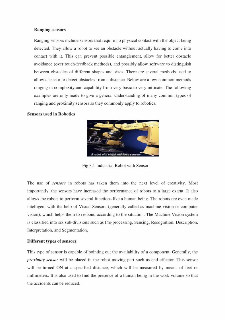
Sensors used in Robotics
Fig 3.1 Industrial Robot with Sensor
The use of sensors in robots has taken them into the next level of creativity. Most
importantly, the sensors have increased the performance of robots to a large extent. It also
allows the robots to perform several functions like a human being. The robots are even made
intelligent with the help of Visual Sensors (generally called as machine vision or computer
vision), which helps them to respond according to the situation. The Machine Vision system
is classified into six sub-divisions such as Pre-processing, Sensing, Recognition, Description,
Interpretation, and Segmentation.
Different types of sensors:
This type of sensor is capable of pointing out the availability of a component. Generally, the
proximity sensor will be placed in the robot moving part such as end effector. This sensor
will be turned ON at a specified distance, which will be measured by means of feet or
millimeters. It is also used to find the presence of a human being in the work volume so that
the accidents can be reduced.
Range Sensor:
Range Sensor is implemented in the end effector of a robot to calculate the distance between
the sensor and a work part. The values for the distance can be given by the workers on visual
data. It can evaluate the size of images and analysis of common objects. The range is
measured using the Sonar receivers & transmitters or two TV cameras.
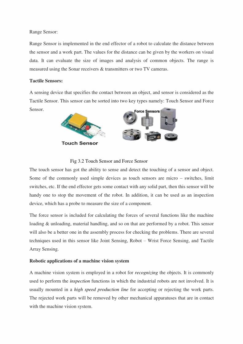
Tactile Sensors:
A sensing device that specifies the contact between an object, and sensor is considered as the
Tactile Sensor. This sensor can be sorted into two key types namely: Touch Sensor and Force
Sensor.
Fig 3.2 Touch Sensor and Force Sensor
The touch sensor has got the ability to sense and detect the touching of a sensor and object.
Some of the commonly used simple devices as touch sensors are micro – switches, limit
switches, etc. If the end effector gets some contact with any solid part, then this sensor will be
handy one to stop the movement of the robot. In addition, it can be used as an inspection
device, which has a probe to measure the size of a component.
The force sensor is included for calculating the forces of several functions like the machine
loading & unloading, material handling, and so on that are performed by a robot. This sensor
will also be a better one in the assembly process for checking the problems. There are several
techniques used in this sensor like Joint Sensing, Robot – Wrist Force Sensing, and Tactile
Array Sensing.
Robotic applications of a machine vision system
A machine vision system is employed in a robot for recognizing the objects. It is commonly
used to perform the inspection functions in which the industrial robots are not involved. It is
usually mounted in a high speed production line for accepting or rejecting the work parts.
The rejected work parts will be removed by other mechanical apparatuses that are in contact
with the machine vision system.
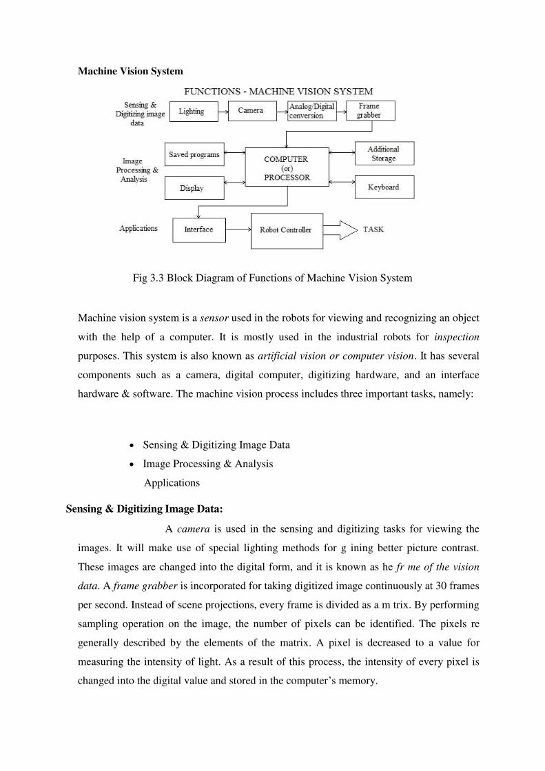
Machine Vision System
Fig 3.3 Block Diagram of Functions of Machine Vision System
Machine vision system is a sensor used in the robots for viewing and recognizing an object
with the help of a computer. It is mostly used in the industrial robots for inspection
purposes. This system is also known as artificial vision or computer vision. It has several
components such as a camera, digital computer, digitizing hardware, and an interface
hardware & software. The machine vision process includes three important tasks, namely:
Sensing & Digitizing Image Data
Image Processing & Analysis
Applications
Sensing & Digitizing Image Data:
A camera is used in the sensing and digitizing tasks for viewing the
images. It will make use of special lighting methods for g ining better picture contrast.
These images are changed into the digital form, and it is known as he fr me of the vision
data. A frame grabber is incorporated for taking digitized image continuously at 30 frames
per second. Instead of scene projections, every frame is divided as a m trix. By performing
sampling operation on the image, the number of pixels can be identified. The pixels re
generally described by the elements of the matrix. A pixel is decreased to a value for
measuring the intensity of light. As a result of this process, the intensity of every pixel is
changed into the digital value and stored in the computer’s memory.
Image Processing & Analysis:
In this funct on, the image interpretation and data reduction processes are
done. The threshold of an image frame is developed a binary image for reducing the data.
The data reduction will help in converting the frame from raw image data to the feature
value data. The feature value data can be calculated via computer programming. This is
performed by matching the image descriptors like size and appearance with the previously
stored data on the computer.
The image processing and analysis function will be made more effective by
training the machine vision system regularly. There are several data collected in the training
process like length of perimeter, outer & inner diameter, area, and so on. Here, the camera
will be very helpful to identify the match between the computer models and new objects of
feature value data.
Applications:
Some of the important applications of the machine vision system in the robots are:
Inspection
Orientation
Part Identification
Location
Signal conversion
Our interface modules are the links between the real physical process and the control system.
Use the [EEx ia]-version of this function modules to assure a save data transmission from the
potentially explosive area to the non-hazardous area and vice-versa. Select the respective
product properties below. The right-hand column adjusts the product list immediately and
displays only products corresponding to your specifications.
Image Processing
Robotic vision continues to be treated including different methods for processing,
analyzing, and understanding. All these methods produce infor ation that is translated into
decisions for robots. From start to capture images and to the final decision of the robot, a
wide range of technologies and algorithms are used like a committee of filtering and
decisions.
Another object with other colors accompanied by different sizes. A robotic vision system has
to make the distinction between objects and in almost all cases has to tracking these objects.
Applied in the real world for robotic applications, these ma hine vision systems are designed
to duplicate the abilities of the human vision system using programming code and electronic
parts. As human eyes can detect and track many objects in the same time, robotic vision
systems seem to pass the difficulty in detecting and tracking many objects at the same time.
Machine Vision
A robotic system f nds ts place in many fields from industry and robotic services.
Even is used for identification or navigation, these systems are under continuing
improvements with new features like 3D support, filtering, or detection of light intensity
applied to an object.
Applications and benefits for robotic vision systems used in industry or for service robots:
automating process;
object detection;
estimation by counting any type of moving;
applications for security and surveillance;
used in inspection to remove the parts with defects;
defense applications;
used by autonomous vehicle or mobile robots for navigation;
for interaction in computer-human interaction;
Object tracking software
A tracking system has a well-defined role and this is to observe the persons
or objects when these are under moving. In addition, the tracking software is capable of
predicting the direction of motion and recognizes the object or persons.OpenCV is the
most popular and used machine vision library with open-source code and comprehensive
documentation. Starting with image processing, 3D vision and tracking, fitting and many
other features, the system include more than 2500 algorithms. The library interfaces have
support for C++, C, Python and Java (in work), and also can run under Windows, Linux,
Android or Mac operating systems.
SwisTrack
Used for object tracking and recognition, SwisTrack is one of the most
advanced tools used in machine vision applications. This tracking tool required only a
video camera for tracking objects in a wide range of situations. Inside, SwisTrack is
designed with a flexible architecture and uses OpenCV library. This flexibility opens the
gates for implementing new components in order to meet the requirements of the user.
visual navigation
Autonomous navigation is one of the mo t important characteristics for a
mobile robot. Because of slipping and some incorrigible drift errors for sensors, it is
difficult for a mobile robot to realize self-location after long dist nce n vigation. In this
paper, the perceptual landmarks were used to solve this problem, and he visu l serving
control was adopted for the robot to realize self-location. At the same ime, in order to
detect and extract the artificial landmarks robustly under different illumin ting conditions,
the color model of the landmarks was built in the HSV color space. These functions were
all tested in real time under experiment conditions.
Edge Detector
Edge Detector Robot from IdeaFires is an innovative approach towards
Robotics Learning. This is a simple autonomous Robot fitted with Controller and Sensor

modules. The Edge Detector Robot senses the edges of table or any surface and turns the
robot in such a way that it prevents it from fall ng.
SCHOOL OF MECHANICAL ENGINEERING
DEPARTMENT OF MECHANICAL ENGINEERING
UNIT – V – ROBOT PROGRAMMING– SMR 1401
Robot Programming
According to the consistent performance by the robots in
industries, the robot programming can be divided in two common
types such as:
Leadthrough Programming Method
Textual Robot Languages
Leadthrough Programming Method:
During this programming method, the traveling of robots is based on the
desired movements, and it is stored in the external controller memory. There are
two modes of a control system in this method such as a run mode and teach mode.
The program is taught in the teach mode, and it is executed in the run mode. The
lead through programming method can be done by two methods namely:
Powered Leadthrough Method
Manual Leadthrough Method
a) Powered Leadthrough Method:
The powered leadthrough is the common programming method in the
industries. A teach pendant is incorporated in this method for controlling the
motors available in the joints. It is also used to operate the robot wrist and arm
through a sequence of points. The playback of an operation is done by recording
these points. The control of complex geometric moves is difficultto perform in the
teach pendant. As a result, this method is good for point to point movements. Some
of the key applications are spot welding, machine loading & unloading, and part
transfer process.
b) Manual Leadthrough Method:
In this method, the robot’s end effector is moved physically by the
programmer at the desired movements. Sometimes, it may be difficult to move
large r b t arm manually. To get rid of it ateach button is implemented in the wrist
for special programming. The manual leadthrough method is also known as Walk
Through method. It is mainly used to perform continuous path movements. This
methodisbestforspraypaintingandarc welding operations.
Textual Robot Languages:
In 1973, WAVE language was developed, nd it is the first textual robot
language as well. It is used to interface the machine vision sys em with the robot.
Then AL language was introduced in 1974 for controlling multiple robot arms
during arm coordination. VAL was nvented in 1979, and it is the common textu l
robot language. Later, this language was dated in 1984, and called as VAL II. The
IBM Corpor tion has established their two own languages such as AMLand
AUTOPASS, which is used for the assembly operations.
Other important textual robot languages are Manufacturing Control Language
(MCL), RAIL, and Automatic Programmed Tooling (APT) anguages.
Robot Programming Methods
There are three bas c methods for programming industrial robots but
currently over 90% are programmed using the each method.
Teach Method
The logic for the program can be generated either using a menu based
system or simply using a text editor but the main characteristic of this method is the
means by which the robot is taught the positional data. A teach pendant with
controls to drive the robot in a number of different co-ordinate systems is used to
manually drive the robot to the desired locations.
These locations are then stored with names that can be used within the robot
program. The co-ordinate systems available on a standard jointed arm robot are :-
JointCo-ordinates
The robot joints are driven independently in either direction.
Global Co-ordinates
The tool centre point of the robot can be driven along the X, Y or Z axes of
the robots global axis system. Rotations of the tool around these axes can also be
performed
Tool Co-ordinates
Similar to the global co-ordinate system but the axes of this one are
attached to the tool centre point of the robot and therefore move with it.
This system is especially useful when the tool is near to the workpiece.
Workpiece Co-ordinates
With many robots it is possible to set up a co-ordinate system at any point
within the working area. These can be especially useful where small adjustments to
the program are required as it is easier to make them along a major axis of the co-
ordinate system than along a general line. The effect of this is similar to moving the
position and orientation of the global co-ordinate system.
This method of programming is very simple to use where simple
movements are required. It does have the disadvantage that the robot can be out of
production for a long time during reprogramming. While this is not a problem
where robots do the sa e task for their entire life, this is becoming less common and
some robotic welding syste s are performing tasks only a few times before being
reprogrammed.
Lead Through
This system of programming was initially popular but has now almost
disappeared. It is still however used by many paint spraying robots. The
robot is programmed by being physically moved through the task by an
operator. This is exceedingly difficult where large robots are being used and
sometimes a smaller version of the robot is u ed for this purpose. Any
hesitations or inaccuracies that are introduced into the progr m c nnot be
edited out easily without reprogramming the whole task. The robot con
roller simply records the joint positions at a fixed time interval and then
plays this back.
Off-line Programming
Similar to the way in which CAD systems re being used to generate NC
programs for milling machines it is also possible to program robots from CAD
data. The CAD models of the components are used along with mo e s of the robots
being used and the fixturing required. The program structure is built up in much the
same way as for teach programming but intelligent tools are available which allow
the CAD data to be used to generate sequences of location and process information.
At present there are only a few companies using this technology as it is still in its
infancy but its use ncreas ng each year. The benefits of this form of programming
are:-
· Reduced down time for programming.
· Programming tools make programming easier.
· Enables concurrent engineering and reduces product lead time.
· Assists cell design and allows process optimisation
Programming Languages for Robotics
This article is all about giving an introduction about some of the
programming languages which are used to design Robots.
There are many programming languages which we use while building
Robots, we have a few programming languages which we always prefer to use in
designing. Actually the programming languages which we use mainly depend on
the hardware one is using in building robots. Some of them are- URBI, C and
BASIC. URBI is an open source language. In this article we will try to know more
about these languages. Let's start with URBI.
URBI : URBI stands for Universal Real-time Behavior Interface. It is a
client/server based interpreted language in which Robot works as a client and
controller as a server. It makes us to learn about the commands which we give to
Robots and receive messages from them. The interpreter and wrapped server are
called as "URBI Engine". The URBI Engine uses commands from Client and
receives messages to it. This language allows user to work on basic Perception-
action principle. The users just have to write some simple loops on the basis of this
principle directly in URBI.
PYTHON : There is another language which is used in designing Robots. Python
is an object-oriented language which is used to access and control Robots. Python
is an interpreted language; this language has an application in working with mobile
robots, particularly those manufactured by different companies. With python it is
possible to use a single program for controlling many different robots. However
Python is slower than C++ but it has so e good sides as well as it proved very easy
to interact with robots using this language, it is highly portable and can be run in
windows and MAC OSX plus it can easily be extendable using C and C++
language. Python is a very reliable language for string manipulation and text pro
essing.
ROBOTC : Other Languages which we use are C,C++ and C # etc. or their
implementation, like ROBOTC, ROBOTC is an implementation of C language. If
we are designing a simple
Robot, we do not need assembly code, but in complex de igning we need well-
defined codes. ROBOTC is another programming language which is C-based. It is
actually a text based programming language. The commands which we w nt to give
to our Robot, first written on the screen in the form of simple text, now as we know
that Robot is a kind of machine and a machine only understands machine langu ge.
So these commands need to be converted in machine language so that robot can
easily underst nd and do whatever it is instructed to do.
Although commands are given in text form (called as codes) but this
language is very specific about the commands which is provi ed as instruction. If
we do even a minor change in given text it will not accept it command. If the
command which is provided to it is correct it colorizes that text, and we came to
know that the given command in text form is correct (as we have shown in our
example gi en below). Programming done in ROBOTC is very easy to do.
Commands given are very stra ghtforward. Like if we want our robot to switch on
any hardware part, we just have to give code regarding to that action in text form.
Suppose we want robot to turn motor of port, we just have to give command in this
way:
Although program above is not exactly shown in the way in which it should
be written, this is just to provide you a visualization of what we have told you. This
is not written in an appropriate manner.ROBOTC provide advantage of speed, a
Robot programmed in ROBOTC programming supports 45 times more speed than
provided by other programming based on C plus it has a very powerful debugging
feature.
ROBOTICS.NXT :
ROBOTICS.NXT has a support for a simple message-based control. It direct
commands, nxt-upload is one of its programs which is used to upload any file. It
works on Linux. After getting introduction on programming languages, it becomes
necessary to know something about MRDS as well, MRDS is an environment
which is designed especially for controlling robots.
Microsoft Robotics Developer Studio
Microsoft Robotics Developer Studio is an environment given for
simulation purpose of Robots. It is based on a .net library concurrent
implementation. This environment has support so that we can add other services as
well. It has features which not only include creating and debugging Robot
Applications but also it becomes easy to interact with sensors directly. C#
programming language is used as a primary language in it. It has 4 main
components:
Visual Programming Language (VPL)
Visual simulation environment (VSE)
Concurrency and coordination Runtime is a synchronous progra ing library
based on .net framework. Although it is a component of MRDS but it can be used
with any application. DSS is also a .net runtime environment, In DSS services are
exp sed as resources which one can access through programs. DSS uses DSSP
(Decentralizes software services protocol) and HTTP.
If we want to graphics and visual effects in our programming, we use VPL.
Visual Programming language is a programming language which allows us to
create programs by doing manipulations in programming languages graphic lly. We
use boxes and arrows in this kind of programming while we want to show dataflow
kind of hings.
Visual programming langu ge h s huge application in animations. The last
component which we are going to describe is Visual Simulation Environment. VSE
provides simulates physical objects. Visual Simulation environment is an
integrated environment for picture-based, object oriented and component based
applications of simulation.
Programming in robotics is a very vast topic that we cant cover in a single
article. This is just an introduction for those who want to get an idea about using
languages in building of robots
Motion Commands and the Control of Effectors
Real-time systems are slaves to the clock. They achieve the illusion
of smooth behavior by rapidly updating set of control signals many times per
second. For example, to smoothly turn a robot's head to the right, the head must
accelerate, travel at constant velocity for a while, and then decelerate. This is
accomplished by making many small adjustments to the motor torques. Another
example: to get the robot's LEDs to blink repeatedly, they must be turned on for a
certain period of time, then turned off for another length of time, and so forth. To
get them to glow steadily at medium intensity, they must be turned on and off very
rapidly.
The robot's operating system updates the states of all the effectors
(servos, motors, LEDs, etc.) every few milliseconds. Each update is called a
"frame", and can accommodate simultaneous changes to any number of effectors.
On the AIBO, updates occur every 8 milliseconds and frames are buffered four at a
time, so the application must have a new buffer available every 32 milliseconds;
other robots may use different update intervals. In Tekkotsu these buffers of frames
are produced by the MotionManager, whose job is to execute a collection of
simultaneously active MotionCommands (MCs) of various types every few
milliseconds. The results of these MotionCommands are assembled into a buffer
that is passed to the operating system (Aperios for the AIBO, or Linux for other
robots). Suppose we want the robot to blink its LEDs on and off at a rate of once
per second. What we need is a MotionCommand that will calculate new states for
the LEDs each time the MotionManager asks for an update. LedMC, a subclass of
both Motion Command and LedEngine, performs this service. If we create an
instance of LedMC, tell it the frequency at which to blink the LEDs, and add it to
the MotionManager's list of active MCs, then it will do all the work for us. There's
just one catch: our application is running in the Main process, while the
MotionManager runs in a separate Motion process. This is necessary to assure that
potentially lengthy computations taking place in Main don't prevent Motion from
running every few milliseconds. So how can we communicate with our
MotionCommand while at the same time making it available to the Motion
Manager.
Applications of Industrial Robots
Machine Loading
Machine loading The first application of industrial robots was in unloading
die-casting machines. In die casting the two halves of a mould or die are held together
in a press while molten metal, typically zinc or aluminium, is injected under pressure.
The die is cooled by water; when the metal has solidified the press opens and a robot
extracts the casting and dips it in a quench tank to cool it further. The robot then
places the casting in a trim press where the unwanted parts are cut off. The robot often
grips the casting by the sprue. (The sprue is the part of the casting which has
solidified in the channels through which molten metal is pumped to the casting
proper. Several castings may be made at once; in this case they are connected to the
sprue by runners. When the sprue and runners are cut off by the trim press, the press
must automatically eject the casting(s) onto a conveyor.
Spray Painting
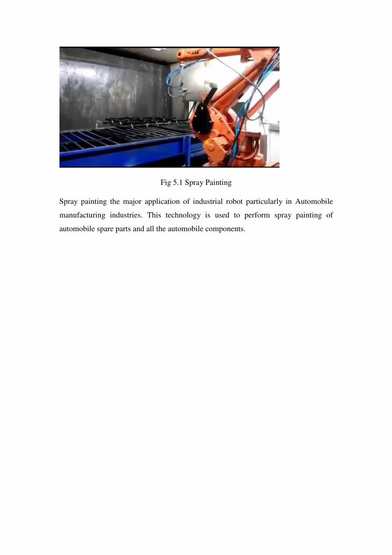
Fig 5.1 Spray Painting
Spray painting the major application of industrial robot particularly in Automobile
manufacturing industries. This technology is used to perform spray painting of
automobile spare parts and all the automobile components.