unfired pressure vessels
TRANSCRIPT
BSI Standards Publication
BS EN 13445-5:2014
Unfired pressure vesselsPart 5: Inspection and testing
BS EN 13445-5:2014 BRITISH STANDARD
National foreword
This British Standard is the UK implementation of EN 13445-5:2014.It supersedes BS EN 13445-5:2009+A4:2013 which is withdrawn.
The UK participation in its preparation was entrusted to TechnicalCommittee PVE/1, Pressure Vessels.
A list of organizations represented on this committee can beobtained on request to its secretary.
This publication does not purport to include all the necessaryprovisions of a contract. Users are responsible for its correctapplication.
© The British Standards Institution 2014. Published by BSI StandardsLimited 2014
ISBN 978 0 580 86800 9
ICS 23.020.30
Compliance with a British Standard cannot confer immunity fromlegal obligations.
This British Standard was published under the authority of theStandards Policy and Strategy Committee on 30 September 2014.
Amendments issued since publication
Date Text affected
BS EN 13445-5:2014
EUROPEAN STANDARD
NORME EUROPÉENNE
EUROPÄISCHE NORM
EN 13445-5
September 2014
ICS 23.020.30 Supersedes EN 13445-5:2009
English Version
Unfired pressure vessels - Part 5: Inspection and testing
Récipients sous pression non soumis à la flamme - Partie 5: Inspection et contrôle
Unbefeuerte Druckbehälter - Teil 5: Inspektion und Prüfung
This European Standard was approved by CEN on 19 August 2014. CEN members are bound to comply with the CEN/CENELEC Internal Regulations which stipulate the conditions for giving this European Standard the status of a national standard without any alteration. Up-to-date lists and bibliographical references concerning such national standards may be obtained on application to the CEN-CENELEC Management Centre or to any CEN member. This European Standard exists in three official versions (English, French, German). A version in any other language made by translation under the responsibility of a CEN member into its own language and notified to the CEN-CENELEC Management Centre has the same status as the official versions. CEN members are the national standards bodies of Austria, Belgium, Bulgaria, Croatia, Cyprus, Czech Republic, Denmark, Estonia, Finland, Former Yugoslav Republic of Macedonia, France, Germany, Greece, Hungary, Iceland, Ireland, Italy, Latvia, Lithuania, Luxembourg, Malta, Netherlands, Norway, Poland, Portugal, Romania, Slovakia, Slovenia, Spain, Sweden, Switzerland, Turkey and United Kingdom.
EUROPEAN COMMITTEE FOR STANDARDIZATION C O M I T É E U R OP É E N D E N O R M A LI S A T I O N EUR O P Ä IS C HES KOM I TE E F ÜR NOR M UNG
CEN-CENELEC Management Centre: Avenue Marnix 17, B-1000 Brussels
© 2014 CEN All rights of exploitation in any form and by any means reserved worldwide for CEN national Members.
Ref. No. EN 13445-5:2014 E
BS EN 13445-5:2014EN 13445-5:2014 (E) Issue 1 (2014-09)
2
Contents Page
Foreword ..............................................................................................................................................................5
1 Scope ......................................................................................................................................................7
2 Normative references ............................................................................................................................7
3 Terms and definitions ...........................................................................................................................8
4 Performance of inspection and testing ...............................................................................................9 4.1 General ....................................................................................................................................................9 4.2 Inspection ...............................................................................................................................................9 4.3 Non-destructive testing (NDT) ..............................................................................................................9
5 Technical documentation ...................................................................................................................10 5.1 General ..................................................................................................................................................10 5.2 Information to be contained in the technical documentation .........................................................10 5.2.1 General ..................................................................................................................................................10 5.2.2 General description of the pressure vessel ......................................................................................10 5.2.3 Design and construction drawings ....................................................................................................10 5.2.4 Descriptions and explanations necessary for an understanding of the drawings and diagrams
and the operation of the pressure vessel .........................................................................................11 5.2.5 Results of design calculations and examinations carried out ........................................................11 5.2.6 Test reports ..........................................................................................................................................12 5.2.7 Technical/manufacturing schedule ....................................................................................................12 5.3 Design review .......................................................................................................................................13 5.3.1 General ..................................................................................................................................................13 5.3.2 Design review .......................................................................................................................................13
6 Inspection and testing during fabrication .........................................................................................14 6.1 General ..................................................................................................................................................14 6.2 Manufacturing procedures and construction drawings ..................................................................14 6.3 Material traceability .............................................................................................................................14 6.3.1 General ..................................................................................................................................................14 6.3.2 Special Conditions - Material marking ..............................................................................................14 6.4 Preparation for manufacturing processes ........................................................................................14 6.4.1 General ..................................................................................................................................................14 6.4.2 Joint preparation testing .....................................................................................................................15 6.4.3 Inspection of vessel supports ............................................................................................................15 6.4.4 Inspection associated with forming ...................................................................................................15 6.4.5 Testing of areas subject to significant through thickness tensile stress......................................15 6.5 Welding .................................................................................................................................................15 6.5.1 General ..................................................................................................................................................15 6.5.2 Verification of welder and welding operator qualification and procedures qualification ............16 6.5.3 Inspection of repairs ...........................................................................................................................16 6.6 Non-destructive testing of welded joints ..........................................................................................16 6.6.1 Extent of non-destructive testing .......................................................................................................16 6.6.2 Determination of extent of non-destructive testing .........................................................................19 6.6.3 Performing non-destructive testing ...................................................................................................27 6.6.4 Description and acceptance level of imperfections .........................................................................28 6.6.5 Stage of performance ..........................................................................................................................28 6.6.6 Procedure for non-destructive retesting ...........................................................................................28 6.6.7 Non-destructive testing documentation ............................................................................................28 6.7 Destructive testing...............................................................................................................................29 6.7.1 Extent of destructive testing ..............................................................................................................29 6.7.2 Schedule for destructive testing ........................................................................................................29 6.7.3 Verification of destructive tests .........................................................................................................29 6.7.4 Records .................................................................................................................................................29 6.8 Heat-treatment ......................................................................................................................................29
BS EN 13445-5:2014EN 13445-5:2014 (E)
Issue 1 (2014-09)
3
7 Subcontracted items ........................................................................................................................... 29 7.1 General.................................................................................................................................................. 29 7.2 Subcontracted welding related activities .......................................................................................... 30 7.3 Subcontracted non-destructive testing activities ............................................................................ 30 7.3.1 Use of contract NDT personnel at the premises of the vessel manufacturer ............................... 30 7.3.2 Subcontracting of NDT at a subcontractors premises .................................................................... 30
8 Miscellaneous tests ............................................................................................................................. 30
9 Calibration ............................................................................................................................................ 31 9.1 General.................................................................................................................................................. 31 9.2 Calibration procedure ......................................................................................................................... 31 9.2.1 General.................................................................................................................................................. 31 9.2.2 Calibration ............................................................................................................................................ 31 9.2.3 Frequency ............................................................................................................................................. 32 9.3 Identification ........................................................................................................................................ 32 9.4 Registration .......................................................................................................................................... 32
10 Final assessment ................................................................................................................................. 33 10.1 General.................................................................................................................................................. 33 10.2 Extent of final assessment ................................................................................................................. 33 10.2.1 Visual and dimensional inspection .................................................................................................... 33 10.2.2 Review of documentation ................................................................................................................... 34 10.2.3 Proof test .............................................................................................................................................. 34 10.2.4 Post pressure test inspection ............................................................................................................ 43 10.2.5 Inspection of safety accessories. ...................................................................................................... 44
11 Marking and declaration of compliance with the standard. ............................................................ 44 11.1 General.................................................................................................................................................. 44 11.2 Marking method ................................................................................................................................... 44 11.2.1 General.................................................................................................................................................. 44 11.2.2 Direct stamping .................................................................................................................................... 44 11.2.3 Nameplate ............................................................................................................................................. 44 11.3 Marking units ....................................................................................................................................... 45 11.4 Marking contents ................................................................................................................................. 45 11.5 Declaration of compliance with the standard ................................................................................... 46
12 Documents ........................................................................................................................................... 46 12.1 Type of documents .............................................................................................................................. 46 12.2 Control and access of documents ..................................................................................................... 47 12.3 Retention of documents ...................................................................................................................... 47
Annex A (normative) Inspection and testing of serially produced pressure vessels .............................. 48 A.1 Introduction .......................................................................................................................................... 48 A.2 Limitations for vessels permitted to be classified as serially produced ....................................... 48 A.3 Limitations for model .......................................................................................................................... 48 A.4 Prototype test ....................................................................................................................................... 49 A.5 Model acceptance ................................................................................................................................ 49 A.6 Quality or manufacturing plan ........................................................................................................... 49 A.7 Inspection, non-destructive testing and pressure testing .............................................................. 50 A.7.1 Introduction .......................................................................................................................................... 50 A.7.2 General NDT procedure for serially produced pressure vessels ................................................... 50 A.7.3 Pressure test for serially produced pressure vessels ..................................................................... 50 A.8 Marking ................................................................................................................................................. 50 A.9 Documentation / Certification............................................................................................................. 50
Annex B (normative) Detailed dimensional requirements for pressure vessels ...................................... 51
Annex C (normative) Access and inspection openings, closing mechanisms and special locking elements ............................................................................................................................................... 53
C.1 General.................................................................................................................................................. 53 C.2 Types and dimensions of access and inspection openings ........................................................... 53 C.2.1 Sightholes ............................................................................................................................................ 53 C.2.2 Handholes ............................................................................................................................................ 53
BS EN 13445-5:2014EN 13445-5:2014 (E) Issue 1 (2014-09)
4
C.2.3 Headholes .............................................................................................................................................53 C.2.4 Manholes ..............................................................................................................................................54 C.2.5 Rescue holes ........................................................................................................................................54 C.3 Types, location and minimum number of access and inspection openings. ................................54 C.4 Alternative requirements for sightholes openings on small vessels .............................................56 C.5 Closing mechanisms and special locking elements ........................................................................56 C.5.1 Purpose .................................................................................................................................................56 C.5.2 Definitions ............................................................................................................................................56 C.5.3 Materials of construction, design ......................................................................................................56 C.5.4 Screw clamps .......................................................................................................................................57 C.5.5 Hinged bolts .........................................................................................................................................58 C.5.6 Yoke-type closures ..............................................................................................................................58 C.5.7 Quick opening and closing devices ...................................................................................................59
Annex D (informative) Leak Testing ..............................................................................................................65 D.1 General ..................................................................................................................................................65 D.2 Leak testing personnel ........................................................................................................................65
Annex E (informative) Acoustic emission .....................................................................................................66 E.1 General ..................................................................................................................................................66 E.2 Useful standards ..................................................................................................................................66 E.3 Acoustic emission personnel .............................................................................................................66 E.4 Additional requirements .....................................................................................................................66
Annex F (normative) Inspection and testing of pressure vessels or parts subject to creep ...................68 F.1 General ..................................................................................................................................................68 F.2 Extent of inspection and testing ........................................................................................................68 F.3 Performance of NDT and acceptance criteria ...................................................................................70 F.4 Documents ...........................................................................................................................................70
Annex G (normative) Inspection and testing of pressure vessels subject to cyclic loads ......................71 G.1 General ..................................................................................................................................................71 G.2 Extent of inspection and testing ........................................................................................................71 G.3 Performance and acceptance criteria ................................................................................................71 G.4 Technical documentation, additional requirements ........................................................................72
Annex H (informative) Declaration of compliance with this standard .......................................................73
Annex I (informative) Specific tests during construction to assist in-service inspection .......................75 I.1 General ..................................................................................................................................................75 I.2 Metallographic investigation ..............................................................................................................75 I.3 Hardness measurements ....................................................................................................................75 I.4 Dimensional measurements ...............................................................................................................76
Annex Y (informative) History of EN 13445-5 ...............................................................................................77 Y.1 Differences between EN 13445-5:2009 and EN 13445-5:2014 .........................................................77
Annex ZA (informative) Relationship between this European Standard and the Essential Requirements of the EU Pressure Equipment Directive 97/23/EC .................................................78
Bibliography ......................................................................................................................................................79

BS EN 13445-5:2014EN 13445-5:2014 (E)
Issue 1 (2014-09)
5
Foreword
This document (EN 13445-5:2014) has been prepared by Technical Committee CEN/TC 54 “Unfired pressure vessels”, the secretariat of which is held by BSI.
This European Standard shall be given the status of a national standard, either by publication of an identical text or by endorsement, at the latest by December 2014, and conflicting national standards shall be withdrawn at the latest by December 2014.
Attention is drawn to the possibility that some of the elements of this document may be the subject of patent rights. CEN [and/or CENELEC] shall not be held responsible for identifying any or all such patent rights.
This document has been prepared under a mandate given to CEN by the European Commission and the European Free Trade Association, and supports essential requirements of EU Directive(s).
For relationship with EU Directive(s), see informative annex ZA, which is an integral part of this document.
This European Standard consists of the following Parts:
Part 1: General.
Part 2: Materials.
Part 3: Design.
Part 4: Fabrication.
Part 5: Inspection and testing.
Part 6: Requirements for the design and fabrication of pressure vessels and pressure parts constructed from spheroidal graphite cast iron.
CR 13445-7, Unfired pressure vessels — Part 7: Guidance on the use of conformity assessment procedures.
Part 8: Additional requirements for pressure vessels of aluminium and aluminium alloys.
CEN/TR 13445-9, Unfired pressure vessels — Part 9: Conformance of EN 13445 series to ISO 16528
Although these Parts may be obtained separately, it should be recognised that the Parts are inter-dependant. As such the manufacture of unfired pressure vessels requires the application of all the relevant Parts in order for the requirements of the Standard to be satisfactorily fulfilled.
Corrections to the standard interpretations where several options seem possible are conducted through the Migration Help Desk (MHD). Information related to the Help Desk can be found at http://www.unm.fr ([email protected]). A form for submitting questions can be downloaded from the link to the MHD website. After subject experts have agreed an answer, the answer will be communicated to the questioner. Corrected pages will be given specific issue number and issued by CEN according to CEN Rules. Interpretation sheets will be posted on the website of the MHD.
This document supersedes EN 13445-5:2009. This new edition incorporates the Amendments which have been approved previously by CEN members, and the corrected pages up to Issue 5 without any further technical change. Annex Y provides details of significant technical changes between this European Standard and the previous edition.

BS EN 13445-5:2014EN 13445-5:2014 (E) Issue 1 (2014-09)
6
Amendments to this new edition may be issued from time to time and then used immediately as alternatives to rules contained herein. It is intended to deliver a new Issue of EN 13445:2014 each year, starting with the present document as Issue 1, consolidating these Amendments and including other identified corrections.
According to the CEN-CENELEC Internal Regulations, the national standards organizations of the following countries are bound to implement this European Standard: Austria, Belgium, Bulgaria, Croatia, Cyprus, Czech Republic, Denmark, Estonia, Finland, Former Yugoslav Republic of Macedonia, France, Germany, Greece, Hungary, Iceland, Ireland, Italy, Latvia, Lithuania, Luxembourg, Malta, Netherlands, Norway, Poland, Portugal, Romania, Slovakia, Slovenia, Spain, Sweden, Switzerland, Turkey and the United Kingdom.
BS EN 13445-5:2014EN 13445-5:2014 (E)
Issue 1 (2014-09)
7
1 Scope
This Part of this European Standard specifies the inspection and testing of individual and serially produced pressure vessels made of steels in accordance with EN 13445-2:2014.
Special provisions for cyclic operation are given in Annex G of this Part.
Special provisions for vessels or vessel parts working in the creep range are given in Annex F and Annex I of this Part.
NOTE The responsibilities of parties involved in the conformity assessment procedures are given in Directive 97/23/EC. Guidance on this can be found in CR 13445-7.
2 Normative references
The following documents, in whole or in part, are normatively referenced in this document and are indispensable for its application. For dated references, only the edition cited applies. For undated references, the latest edition of the referenced document (including any amendments) applies.
EN 287-1:20111), Qualification test of welders — Fusion welding — Part 1: Steels
CEN/TR 764-6:2012, Pressure equipment — Part 6: Structure and content of operating instructions
EN 1779:1999, EN 1779:1999/A1:2003, Non-destructive testing — Leak testing — Criteria for method and technique selection
EN 13445-1:2014, Unfired pressure vessels — Part 1: General
EN 13445-2:2014, Unfired pressure vessels — Part 2: Materials
EN 13445-3:2014, Unfired pressure vessels — Part 3: Design
EN 13445-4:2014, Unfired pressure vessels — Part 4: Fabrication
EN ISO 4063:2010, Welding and allied processes — Nomenclature of processes and reference numbers (ISO 4063:2009, Corrected version 2010-03-01)
EN ISO 4136:2012, Destructive tests on welds in metallic materials — Transverse tensile test (ISO 4136:2012)
EN ISO 5817:2014, Welding — Fusion-welded joints in steel, nickel, titanium and their alloys (beam welding excluded) – Quality levels for imperfections (ISO 5817:2014)
EN ISO 6520-1:2007, Welding and allied processes — Classification of geometric imperfections in metallic materials — Part 1: Fusion welding (ISO 6520-1:2007)
EN ISO 9712:2012, Non-destructive testing — Qualification and certification of NDT personnel (ISO 9712:2012)
EN ISO 14732:2013, Welding personnel — Qualification testing of welding operators and weld setters for mechanized and automatic welding of metallic materials (ISO 14732:2013)
EN ISO 17635:2010, Non-destructive testing of welds — General rules for metallic materials (ISO 17635:2010)
1) EN ISO 9606-1 has been published in 2013 replaces EN 287-1. CEN has decided to have a transition period for EN 287-1. As a consequence, EN 287-1 is valid until October 2015.
BS EN 13445-5:2014EN 13445-5:2014 (E) Issue 1 (2014-09)
8
3 Terms and definitions
For the purposes of this European Standard the following terms and definitions apply.
3.1 design review procedure by which a manufacturer ascertains and declares that the design meets the requirements of this standard
3.2 design approval procedure by which a responsible authority ascertains that the design meets the requirements of this standard
3.3 testing group grouping which determines the appropriate level of non-destructive testing (NDT) on a welded joint
Note 1 to entry: There are four testing groups.
3.4 inspection survey activity which assesses the compliance of the pressure vessel to the technical specification
Note 1 to entry: It is a major activity, undertaken mainly by the manufacturer during design, manufacture and testing of equipment. It can be complemented by inspection by other parties. Inspection includes the assessment of testing activities.
3.5 testing procedure used to verify vessel compliance with the technical requirements of this standard by one or more tests
3.6 technical specification document stating requirements for a product or a procedure
3.7 repair action or series of actions of rectifying a condition in either base material or weld to establish compliance with this standard
3.8 serial production manufacture of identical vessels or parts which subsequently are joined to form a complete vessel and which are manufactured to a single model acceptance, using the same manufacturing procedure involving a continuous fabrication process
Note 1 to entry: The definitions 3.8 to 3.13 relate to serially produced pressure vessels as described in Annex A.
3.9 continuous fabrication process process where the welding of the main seams and branch welds is essentially continuous, that means there are no stoppages or fabrication break-downs requiring resetting of the welding machine and/or NDT equipment
Note 1 to entry: Adjustments to the welding machine within the welding procedure limitations do not qualify as resetting the welding machine.
BS EN 13445-5:2014EN 13445-5:2014 (E)
Issue 1 (2014-09)
9
Note 2 to entry: The definitions 3.8 to 3.13 relate to serially produced pressure vessels as described in Annex A.
3.10 model acceptance procedure which ascertains that a representative sample of the production (a prototype vessel/part) meets the requirements of this standard in respect of design, manufacturing and testing
Note 1 to entry: Model acceptance is conducted by the manufacturer or the responsible authority depending on the conformity assessment module chosen.
Note 2 to entry: The definitions 3.8 to 3.13 relate to serially produced pressure vessels as described in Annex A.
3.11 prototype vessel/part first or representative sample of a series of pressure vessels/parts covered by a single model acceptance
Note 1 to entry: The definitions 3.8 to 3.13 relate to serially produced pressure vessels as described in Annex A.
3.12 batch of vessels part of a series where the welding of the main weld joints and branch welds has been essentially continuously produced by the same welding procedures
Note 1 to entry: The definitions 3.8 to 3.13 relate to serially produced pressure vessels as described in Annex A.
3.13 shift period of time per day during which the welders and welding operators remain the same
Note 1 to entry: The definitions 3.8 to 3.13 relate to serially produced pressure vessels as described in Annex A.
3.14 joint batch several joints made by the same welder or welding operator using a single welding procedure specification
4 Performance of inspection and testing
4.1 General
Each individual vessel shall be inspected during construction and upon completion. Inspections shall be made to ensure that in all respects the design, materials, manufacturing, and testing comply with the requirements of this standard. Documented evidence shall be prepared to verify implementation of this requirement.
4.2 Inspection
Inspection shall be carried out by the manufacturer to verify that all requirements of this standard have been met. The level of non-destructive testing (NDT) shall be dependent on the testing group as described in 4.3.
All inspections shall be carried out by qualified personnel.
4.3 Non-destructive testing (NDT)
The type and amount of non-destructive testing of a pressure vessel shall be based upon the testing group or combination of testing groups when permitted in 6.6.1.2 (see Table 6.6.1-1: testing groups for steel pressure vessels and Table 6.6.2-1: extent of non-destructive testing).
BS EN 13445-5:2014EN 13445-5:2014 (E) Issue 1 (2014-09)
10
5 Technical documentation
5.1 General
The vessel manufacturer shall document those items listed in 5.2, which shall be reviewed in accordance with 5.3, prior to manufacture commencing.
The manufacturer shall state which vessels are covered by the same design.
5.2 Information to be contained in the technical documentation
5.2.1 General
For the purposes of this standard the following types of documents shall be considered necessary as technical documentation.
5.2.2 General description of the pressure vessel
a) Name of vessel manufacturer and subcontractors, if applicable;
b) Location/s of vessel manufacturer and sub-contractors, if applicable;
c) Document describing design data and special consideration which covers:
1) maximum and minimum allowable pressures, design pressures and test pressures in bar for each compartment (vacuum with minus sign);
2) capacity in litres for each compartment;
3) maximum and minimum design temperatures;
4) nature and location of marking of the pressure vessel, nameplate or stamp;
5) the fluid group.
6) if the vessel is designed for cyclic operation the allowed numbers of cycles, the range of action (as defined in EN 13445-3:2014, 5.3.1) during the cycle and the locations where the cumulative fatigue damage index D (as defined in EN 13445-3:2014, Clauses 17 and 18) is greater than 0,8. The maximum permissible peaking shall also be given.
7) If the vessel is working in the creep range, the following additional information:
the design life (e.g. 100 000 h) and expected life for each load case
the parts of the vessel which are subjected to creep
the value of the weld creep strength reduction factor which has been used for each weld joint subjected to creep
whether lifetime monitoring, as defined in Clause 19 of EN 13445-3:2014, is being applied or not.
5.2.3 Design and construction drawings
The manufacturer analysis of hazards identifying those which apply to the pressure vessel on account of action (as defined in EN 13445-3:2014, 5.3.1) shall be documented and be of sufficient detail.
BS EN 13445-5:2014EN 13445-5:2014 (E)
Issue 1 (2014-09)
11
Details of the design including the design methods adopted, performance criteria and construction drawings shall be provided. Guidance about the detailed dimensional information that shall be provided is given in Annex B. Process diagrams, sub-assemblies or other data relevant to design shall also be maintained.
5.2.4 Descriptions and explanations necessary for an understanding of the drawings and diagrams and the operation of the pressure vessel
a) operating instructions;
b) special checks to be carried out e.g. tests envisaged on closures, bellows, clamping bolts, etc.
c) operational position if this is significant with regard to the safety evaluation.
5.2.5 Results of design calculations and examinations carried out
5.2.5.1 Design calculations shall be provided by the vessel manufacturer to the extent necessary to demonstrate compliance to this standard.
Supporting detailed drawings shall be prepared with all dimension notations marked. At least on the pressure vessel general arrangement drawing, the testing group(s) shall be clearly identified.
5.2.5.2 If calculations are made with the aid of a computer software in order to comply with this standard, then at least the following data shall be presented:
a) explanation of notations;
b) input values;
c) reference number of the standard including edition and reference number of the equation;
d) results of intermediate equations;
e) calculated minimum thickness without additions or the calculated stress and its comparison to the allowable stress;
f) wastage (corrosion) allowance;
g) thickness tolerance (negative thickness tolerance);
h) the chosen thickness.
5.2.5.3 In the event that stress analysis is carried out with the finite element method or other equivalent design methods they shall be documented as follows:
a) input data;
b) graphs which show;
1) the element subdivision (mesh size);
2) the stresses, e.g. as line or arrow figures or equal stress curves; stress curves of surfaces;
3) the displacements;
c) boundary conditions;
d) the stresses in the most critical areas;
BS EN 13445-5:2014EN 13445-5:2014 (E) Issue 1 (2014-09)
12
e) where appropriate, the dividing and classifying of the stresses into different stress categories;
f) the comparison of stress intensities and the allowable stress values.
5.2.5.4 In specific cases the following information shall be given:
a) type of post weld heat treatment and, where necessary, type and extent of associated material tests;
b) construction sequence schedule if the testing is to be carried out in several steps;
c) fluid(s) being contained and its (their) specific gravity, if this is required for the design of the vessel;
d) pressure testing medium, if the initial or the periodic pressure tests are to be carried out with a medium other than water, the test minimum metal temperature for proof tests (both hydrostatic and pneumatic);
e) position of the vessel in the pressure tests (e.g. horizontal or vertical), if this is significant with regard to the safety evaluation;
f) maximum and minimum liquid levels, if these are required with regard to the safety evaluation;
g) static supplementary forces, e.g. bearing forces, wind and snow loads. An extra calculation shall be presented if the supplementary forces essentially affect the design of the pressure vessel;
h) cyclic and dynamic loading, including seismic loading, where applicable;
i) additional requirements based on other regulations;
j) purchaser’s requirements based on the vessel operating conditions in addition to the requirements of this standard;
k) possible corrosion attack, especially in crevices, which shall be taken into account;
l) joint coefficient.
5.2.6 Test reports
These shall consist, as a minimum, of the following:
a) welding procedure qualification records, certificates of qualification of welding personnel;
b) material certificates;
c) the content of the manufacturing records, including measurement of peaking for vessels subject to cyclic loads;
5.2.7 Technical/manufacturing schedule
This shall consist of the following information:
a) the welding processes to be used for the pressure containing parts and welding of any temporary or other attachments to pressure containing parts. The following data are required for the testing:
1) weld location, shape and preparation and where necessary build up of the layers and treatment of welds;
2) welding process (in the case of multiple processes, identification of the process against the weld joint);
3) welding consumables (classification according to the relevant European Standards or trade names);
BS EN 13445-5:2014EN 13445-5:2014 (E)
Issue 1 (2014-09)
13
4) type and extent of production test, number of test plates, non-destructive tests;
If some of the data listed before are not available for the design review, then these shall be completed before finishing the manufacture.
b) special checks to be carried out e.g. the tests envisaged on closures, bellows, clamping, bolts;
c) any pertinent details relative to vessel design and data required in specific cases;
1) additional wall thickness if this is required by the purchaser;
2) operational position if this is significant with regard to the safety evaluation;
3) location and size of inspection and access openings and also closing mechanisms and special locking elements in accordance with Annex C;
4) special equipment to enter the pressure vessel (e.g. spiral stairs, climbing irons);
5) linings, e.g. of refractory and inserts, if significant with regard to the safety evaluation;
6) marking of the welds that will be made on the construction site;
7) proposals on safety;
8) proposals on process requirements such as drainage etc.
5.3 Design review
5.3.1 General
A design review and documented acceptance shall be conducted in all cases. It shall include the year of edition and the number of issue of the standard used, with reference to possible used Amendments.
In particular the review shall include design calculations in accordance with the requirements of this standard, taking into consideration the supporting information of the manufacturer analysis of hazards, and the technical/manufacturing schedule in respect of its intended services. Following the design the pressure vessel shall be manufactured in accordance with the approved manufacturing drawings.
5.3.2 Design review
The design review shall consist of, but not be limited to, the following areas:
a) the suitability of material for intended use;
b) welding processes and consumables;
c) the access to perform the required levels of inspections and tests based on proposed vessel construction geometry;
d) the suitability of openings and closures in meeting the requirements of Annex C of this standard;
e) the provision and adequacy of safety accessories against the requirements of this standard for individual pressure vessels or devices which are contained within the pressure system or assembly. Alternatively the parties responsible for satisfying the provision of safety accessories shall be identified;
BS EN 13445-5:2014EN 13445-5:2014 (E) Issue 1 (2014-09)
14
f) the adequacy of proposed pressure retaining boundary (thickness, vessel geometry, weld joint geometry etc.) for design conditions against those required by the design requirements of this standard;
g) the adequacy of the stress analysis method in accordance with 5.2.5.3;
h) manufacturing and test procedures.
6 Inspection and testing during fabrication
6.1 General
The inspection and testing activities during fabrication, described in this clause, shall be the responsibility of the manufacturer and shall be fully implemented for all pressure vessels.
NOTE For guidance on use of conformity assessment procedures, see CEN/TR 13445-7.
6.2 Manufacturing procedures and construction drawings
The manufacturer shall ensure that all construction drawings and manufacturing procedures reviewed and approved at the design stage in Clause 5, shall be available at the appropriate work area and shall be fully implemented in manufacturing. Inspection records shall document the use of the correct and appropriate procedures, and/or drawings including revision status at the time the inspection is performed.
6.3 Material traceability
6.3.1 General
The vessel manufacturer shall have and maintain an identification system for materials used in fabrication so that all material subject to stress due to pressure and those welded thereto in the completed vessel can be traced to its origin. This includes the use of welding consumable. The identification system used shall satisfy the requirements of EN 13445-4:2014.
Procedures to ensure material traceability, including transfer of markings, shall be performed throughout fabrication and records maintained to document the method used from those permitted in EN 13445-4:2014 (i.e. direct markings visible on the completed vessel, a direct coded marking on the vessel or tabulation/as built sketches). Final records shall include all material certification required by this standard.
6.3.2 Special Conditions - Material marking
Where service conditions prohibit die-stamping for material identification (see EN 13445-4:2014) and when so specified by the purchase order, the manufacturer of the base materials shall mark the required data on the materials in a manner which will allow positive identification during inspection upon delivery. The markings shall be recorded so that each item of material will be positively identified in its position in the completed vessel (e.g. material/position list) and shall form part of the final records.
6.4 Preparation for manufacturing processes
6.4.1 General
Preparation for manufacturing processes such as edge preparation, vessel supports for formed parts prior to welding and forming shall be controlled and inspected to ensure that such activities are not detrimental to the completed vessel.
BS EN 13445-5:2014EN 13445-5:2014 (E)
Issue 1 (2014-09)
15
6.4.2 Joint preparation testing
The extent to which edges are dressed prior to testing shall be in accordance with EN 13445-4:2014. All joint preparations shall be subject to visual inspection prior to any welding. Defects such as laminations, cracks and slag inclusion shall be removed prior to welding. In case of an increased probability of occurrence of imperfections or when imperfections have been detected, a visual inspection shall be supplemented by additional non-destructive testing.
The result of joint preparation testing shall be recorded in the NDT inspection schedule.
6.4.3 Inspection of vessel supports
All tack welds associated with bars, jacks, clamps, or other appropriate means used to hold the edges of vessel parts and/or provide support in welding shall be inspected.
Welds of permanent attachments to pressure parts shall be examined to the extent described in Table 6.6.2-1 (line 21).
Welds of temporary attachments shall be examined after removal for surface cracks to the extent described in Table 6.6.2-1 (line 22).
Any repairs necessary following removal of temporary attachments shall be tested as described in 6.5.3.
6.4.4 Inspection associated with forming
Prior to any forming the material to be formed shall be subject to visual inspection and thickness measurement in accordance with the requirements of EN 13445-4:2014. The result of the inspection shall be documented.
6.4.5 Testing of areas subject to significant through thickness tensile stress
In case of an increased probability of internal damage in areas subject to significant through thickness tensile stress caused by welding, these areas shall be examined for internal imperfections prior to welding. The result of the inspection shall be documented.
6.5 Welding
6.5.1 General
Permanent backing strip and joggle joints shall be subject to the same type of non-destructive testing and acceptance criteria as a single-sided butt weld.
Welds in all testing groups shall be subject to in-process inspections, especially welds of testing groups 3 or 4 not required to be subject to NDT under Table 6.6.1.2-1 shall be specifically subject to visual inspection at the "fit-up" and "chip back of second side of sound metal" stages.
All finished welding shall be subject to visual inspection. In addition, depending on the testing group, the finished welds shall be subject to NDT in accordance with Tables 6.6.1-1 and 6.6.2-1 for that type of weld.
BS EN 13445-5:2014EN 13445-5:2014 (E) Issue 1 (2014-09)
16
6.5.2 Verification of welder and welding operator qualification and procedures qualification
The vessel manufacturer shall verify that welding has been done only by welders and operators who have been approved under the requirements of EN 287-1:20112) and EN ISO 14732:2013. Welding procedures shall be qualified in accordance with EN 13445-4:2014.
Welder and welding operators identification shall be controlled in accordance with EN 13445-4:2014.
Traceability of the welder and welding operator shall be monitored by inspection throughout construction of the pressure vessel and shall be verified at the final assessment, see 10.2.2.
6.5.3 Inspection of repairs
All welded repairs shall be subject to the same non-destructive testing requirements as those which detected the imperfection. This includes the same acceptance criteria. Such repairs shall be carried out using approved weld procedures and approved welders and welding operators. The extent of testing of repairs shall comply with Table 6.6.2-1 and cover 100 % of the area repaired.
Non welded repairs by surface dressing are permissible providing that the area of repair is subject to NDT according to Table 6.6.2-1 and free from unacceptable imperfections, see 6.6.5 for retesting requirements. For material groups 1.1 and 8.1 only visual testing (VT) is required.
Weld metal deposited to restore base material shall be subject to non-destructive testing for the full surface area involved, using Magnetic Particle Testing (MT) or Penetrant Testing (PT).
6.6 Non-destructive testing of welded joints
6.6.1 Extent of non-destructive testing
6.6.1.1 General
The required extent of non-destructive testing depends both on the testing group and the type of the welded joints. Guidance to determine the required extent of testing is given in the following clauses.
For serially produced pressure vessels an alternative route is given in Annex A. This annex is not applicable to vessels or vessel parts designed according to Design by Analysis – Direct Route of Annex B of EN 13445-3:2014 or designed according to 6.3 of EN 13445-3:2014. This annex is not applicable for vessels or vessel parts working in the creep range.
6.6.1.2 Use of testing groups
6.6.1.2.1 General
The extent of non-destructive testing of welded joints for final acceptance purposes shall depend upon the testing group or subgroup of the welded joint under consideration.
In Table 6.6.1-1, testing groups 1, 2, 3 and 4 apply below the creep range. Testing groups 1, 2 and 3 are subdivided into sub-groups 1a, 1b, 2a, 2b, 3a, 3b, in order to reflect crack sensitivity of the material. In Table F.2-1 of Annex F, testing sub-groups 1c and 3c apply to creep.
2) EN ISO 9606-1 has been published in 2013 replaces EN 287-1. CEN has decided to have a transition period for EN 287-1. As a consequence, EN 287-1 is valid until October 2015.
BS EN 13445-5:2014EN 13445-5:2014 (E)
Issue 1 (2014-09)
17
NOTE 1 The testing groups or sub-groups take into consideration the manufacturing difficulties associated with different groups of steel, maximum thickness, welding process, service temperature range and joint coefficient. It is intended that any of the testing groups will provide adequate integrity for typical applications within the limitations contained within Tables 6.6.1-1 and F.2-1.
NOTE 2 The weld joint coefficient is not used in design by the experimental method without calculation.
NOTE 3 For vessels (or vessel parts) designed according to Design by Analysis – Direct Route of Annex B of EN 13445-3:2014 or designed according to 6.3 of EN 13445-3:2014, only testing group 1 is permissible.
NOTE 4 Further restrictions are given in Annex A of EN 13445-3:2014.
For vessels (or vessel parts) working in the creep range only testing groups 1c and 3c are permissible. The extent of NDT is given in Table F.2-1 of Annex F. Testing groups 1, 2 and 3 are permissible for any welded joint not subjected to creep.
6.6.1.2.2 Testing groups 1, 2 and 3
It is intended that a single testing group is applied to the entire vessel.
When the vessel is made of several sections (courses), a combination of testing groups 1, 2, and 3 is permissible providing that the requirements of Table 6.6.1-1 are met.
If a combination of testing groups is necessary for a vessel made of several parts designed according to different methods (e.g. one part according to DBF and another part according to DBA alternative route or creep range), the following shall apply:
a) in each section (course) of the vessel, the testing group of the shell governing welded joints, where present, shall determine the minimum testing group for all the welds, including the nozzle welds, in that section;
b) the testing group of the weld between two welded sections of different testing groups shall be the more stringent of the two testing groups;
c) the minimum testing group (i.e. the one with the lower level of NDT) of the welds between a welded component and a seamless one (not welded), or between two seamless components, shall be determined by the available thickness (i.e. actual thickness less tolerances less corrosion allowance) at the weld. Where the available thickness is greater than 1,17 (this is equivalent to 1/0,85) times the minimum thickness, the testing group of the weld shall be 3 as a minimum requirement. Otherwise it shall be testing group 1 or 2 according to Table 6.6.1-1.
6.6.1.2.3 Testing group 4
Testing group 4 shall be used as a single group for the entire vessel and shall not be used with any other testing group.
6.6.1.2.4 Demonstration of satisfactory experience for testing group 2
Satisfactory experience shall be a minimum amount of welds or vessels of successfully produced and tested within the scope/parameters of the Welding Procedure Qualification (WPQR), as given below:
in case of groups 1.1, 1.2 and 8.1 materials, the successful production is 25 consecutive pressure vessels or 50 consecutive metres of governing welded joints;
in case of materials of other groups, it is 50 consecutive pressure vessels or consecutive 100 m of governing welded joints;
BS EN 13445-5:2014EN 13445-5:2014 (E) Issue 1 (2014-09)
18
experience in material group 3.1 covers experience in material groups 1.1, 1.2 and 1.3;
experience in material group 1.3 covers experience in material groups 1.1, 1.2;
experience is accepted as long as there is a valid Welding Procedure Qualification (WPQR) for a more critical or at least a comparable material.
Any imperfection requiring repair by welding during the process of demonstrating experience shall require that the manufacturer start again the complete demonstration process.
Subsequently, (after demonstration of experience) isolated imperfections shall be handled in accordance with 6.5.3 and shall not affect the demonstration of experience.
However, multiple, systematic or process imperfections shall be investigated, corrected and the full demonstration of experience repeated. Such imperfections tend to be repetitive and similar in nature. They can be the result of inadequate welding parameters (e.g. resulting from equipment malfunction, a too large range of parameters, incorrect use of parameters within the range of qualification) or operator error. In the case of inadequate parameters, consideration of requalification of the Welding Procedure Specification (WPS) should be performed.
Documentary evidence of the process of demonstration of experience shall be maintained by the manufacturer.
BS EN 13445-5:2014EN 13445-5:2014 (E)
Issue 1 (2014-09)
19
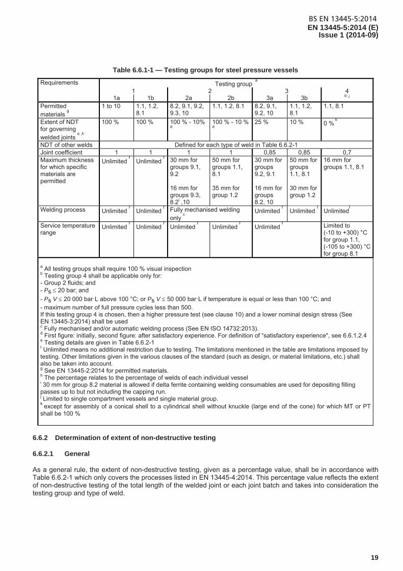
Table 6.6.1-1 — Testing groups for steel pressure vessels
Requirements Testing group a
1 2 3 4 1a 1b 2a 2b 3a 3b b ,j
Permitted materials
g
1 to 10 1.1, 1.2, 8.1
8.2, 9.1, 9.2, 9.3, 10
1.1, 1.2, 8.1 8.2, 9.1, 9.2, 10
1.1, 1.2, 8.1
1.1, 8.1
Extent of NDT for governing welded joints
e ,h
100 % 100 % 100 % - 10% d
100 % - 10 % d
25 % 10 % 0 % k
NDT of other welds Defined for each type of weld in Table 6.6.2-1 Joint coefficient 1 1 1 1 0,85 0,85 0,7 Maximum thickness for which specific materials are permitted
Unlimited f Unlimited
f 30 mm for
groups 9.1, 9.2 16 mm for groups 9.3, 8.2i ,10
50 mm for groups 1.1, 8.1 35 mm for group 1.2
30 mm for groups 9.2, 9.1 16 mm for groups 8.2, 10
50 mm for groups 1.1, 8.1 30 mm for group 1.2
16 mm for groups 1.1, 8.1
Welding process Unlimited f Unlimited
f Fully mechanised welding
only c
Unlimited f Unlimited
f Unlimited
f
Service temperature range
Unlimited f Unlimited
f Unlimited
f Unlimited
f Unlimited
f Limited to
(-10 to +300) °C for group 1.1, (-105 to +300) °C for group 8.1
a All testing groups shall require 100 % visual inspection b Testing group 4 shall be applicable only for: - Group 2 fluids; and - Ps 20 bar; and
- Ps V 20 000 bar·L above 100 °C; or Ps V 50 000 bar·L if temperature is equal or less than 100 °C; and - maximum number of full pressure cycles less than 500. If this testing group 4 is chosen, then a higher pressure test (see clause 10) and a lower nominal design stress (See EN 13445-3:2014) shall be used c Fully mechanised and/or automatic welding process (See EN ISO 14732:2013). d First figure: initially, second figure: after satisfactory experience. For definition of “satisfactory experience", see 6.6.1.2.4 e Testing details are given in Table 6.6.2-1 f Unlimited means no additional restriction due to testing. The limitations mentioned in the table are limitations imposed by testing. Other limitations given in the various clauses of the standard (such as design, or material limitations, etc.) shall also be taken into account. g See EN 13445-2:2014 for permitted materials. h The percentage relates to the percentage of welds of each individual vessel i 30 mm for group 8.2 material is allowed if delta ferrite containing welding consumables are used for depositing filling passes up to but not including the capping run. j Limited to single compartment vessels and single material group. k except for assembly of a conical shell to a cylindrical shell without knuckle (large end of the cone) for which MT or PT shall be 100 %
6.6.2 Determination of extent of non-destructive testing
6.6.2.1 General
As a general rule, the extent of non-destructive testing, given as a percentage value, shall be in accordance with Table 6.6.2-1 which only covers the processes listed in EN 13445-4:2014. This percentage value reflects the extent of non-destructive testing of the total length of the welded joint or each joint batch and takes into consideration the testing group and type of weld.
BS EN 13445-5:2014EN 13445-5:2014 (E) Issue 1 (2014-09)
20
For vessels designed by experimental methods, the required extent of non-destructive testing of welded joints shall be determined according to the rules given in Table 6.6.2-1.
In case where it is not obvious whether the welded joint is a governing one or not, due to the complex shape of the vessel and/or the particular location of that joint, a conservative assumption shall be made, i.e. the welded joint shall be considered as a governing welded joint and tested accordingly.
NOTE For definition of governing welded joint, see EN 13445-3:2014, definition 3.13. For examples of governing welded joints, see EN 13445-3:2014, 5.6.
If no weld is present in the vessel or vessel part, testing group 1 shall be assumed.
6.6.2.2 Welded joints covered by Table 6.6.2-1
Table 6.6.2-1 applies to all joints, except those described in 6.6.2.3.
6.6.2.3 Other welded joints
6.6.2.3.1 General
Special problems arising from elements such as those described below are not covered in Table 6.6.2-1 and shall be considered for all butt-welded joints especially for longitudinal/governing joints:
single run one side governing welds;
joints between dissimilar materials or dissimilar consumables.
6.6.2.3.2 Single run governing welds made by manual welding procedure
For volumetric NDT of single runs, one of the two options below shall be used:
a) NDT extent shall be as prescribed in Table 6.6.2-1 conditional upon a hydrotest at a higher test pressure performed as specified in 10.2.3.3.1, Table 10.2.3.3.1-1 with control of peaking and excess weld.
b) NDT extent prescribed in Table 6.6.2-1 shall be multiplied by 2 without exceeding 100 % but not less than 25 % for longitudinal and 10 % for circumferential. When there is a change which could influence the performance of the welding process (e.g. before changing the copper bar or the gas, after changing the wire or the powder and production test specimens, before changing the copper bar or gas and after changing wire) additional NDT shall be performed at the start of those seams.
6.6.2.3.3 Non destructive testing of joints between dissimilar materials or dissimilar consumables
NDT on these joints must be performed to a specific written procedure with additional attention to interpretation of the results.
6.6.2.3.4 Non destructive testing of welding joints in supporting structures
Butt joints (full penetration or partial penetration) subjected to tensile stress shall have 10 % NDT
Fillet welds in tension or shear shall have 10 % NDT (PT or MT) if the throat thickness is more than 12 mm.
BS EN 13445-5:2014EN 13445-5:2014 (E)
Issue 1 (2014-09)
21
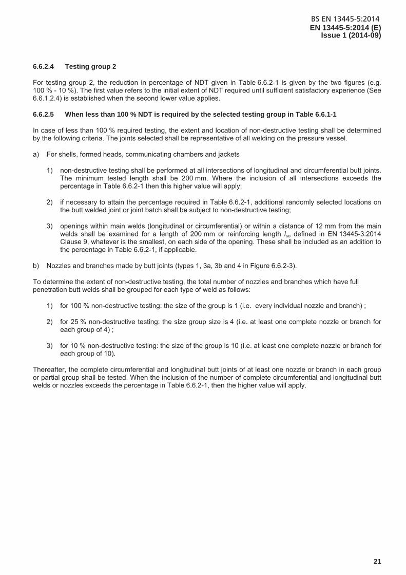
6.6.2.4 Testing group 2
For testing group 2, the reduction in percentage of NDT given in Table 6.6.2-1 is given by the two figures (e.g. 100 % - 10 %). The first value refers to the initial extent of NDT required until sufficient satisfactory experience (See 6.6.1.2.4) is established when the second lower value applies.
6.6.2.5 When less than 100 % NDT is required by the selected testing group in Table 6.6.1-1
In case of less than 100 % required testing, the extent and location of non-destructive testing shall be determined by the following criteria. The joints selected shall be representative of all welding on the pressure vessel.
a) For shells, formed heads, communicating chambers and jackets
1) non-destructive testing shall be performed at all intersections of longitudinal and circumferential butt joints. The minimum tested length shall be 200 mm. Where the inclusion of all intersections exceeds the percentage in Table 6.6.2-1 then this higher value will apply;
2) if necessary to attain the percentage required in Table 6.6.2-1, additional randomly selected locations on the butt welded joint or joint batch shall be subject to non-destructive testing;
3) openings within main welds (longitudinal or circumferential) or within a distance of 12 mm from the main welds shall be examined for a length of 200 mm or reinforcing length lso defined in EN 13445-3:2014 Clause 9, whatever is the smallest, on each side of the opening. These shall be included as an addition to the percentage in Table 6.6.2-1, if applicable.
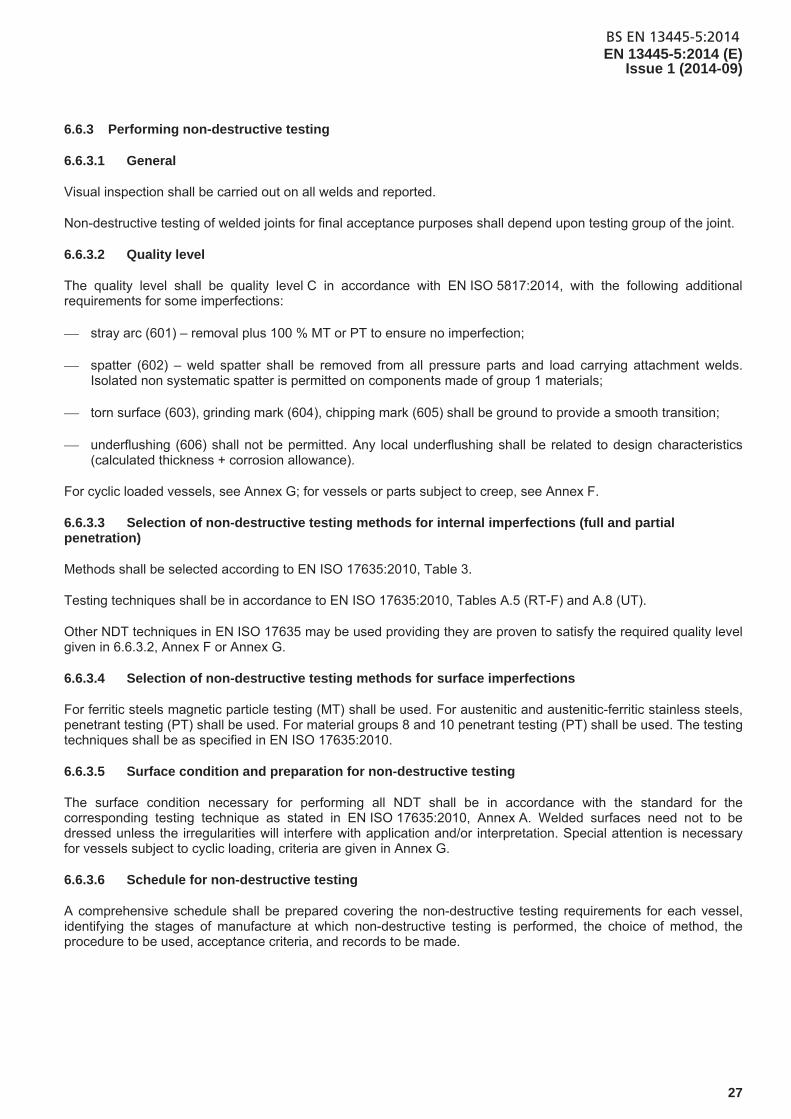
b) Nozzles and branches made by butt joints (types 1, 3a, 3b and 4 in Figure 6.6.2-3).
To determine the extent of non-destructive testing, the total number of nozzles and branches which have full penetration butt welds shall be grouped for each type of weld as follows:
1) for 100 % non-destructive testing: the size of the group is 1 (i.e. every individual nozzle and branch) ;
2) for 25 % non-destructive testing: the size group size is 4 (i.e. at least one complete nozzle or branch for each group of 4) ;
3) for 10 % non-destructive testing: the size of the group is 10 (i.e. at least one complete nozzle or branch for each group of 10).
Thereafter, the complete circumferential and longitudinal butt joints of at least one nozzle or branch in each group or partial group shall be tested. When the inclusion of the number of complete circumferential and longitudinal butt welds or nozzles exceeds the percentage in Table 6.6.2-1, then the higher value will apply.
BS EN 13445-5:2014
EN 13445-5:2014 (E) Issue 1 (2014-09)
22
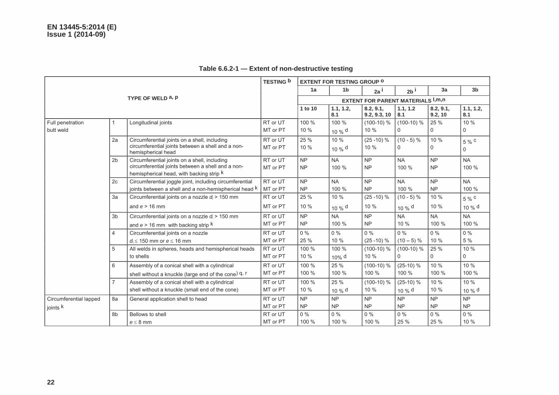
Table 6.6.2-1 — Extent of non-destructive testing
TYPE OF WELD a, p
TESTING b EXTENT FOR TESTING GROUP o
1a 1b 2a i 2b i 3a 3b
EXTENT FOR PARENT MATERIALS l,m,n
1 to 10 1.1, 1.2, 8.1
8.2, 9.1, 9.2, 9.3, 10
1.1, 1.2 8.1
8.2, 9.1, 9.2, 10
1.1, 1.2, 8.1
Full penetration
butt weld
1 Longitudinal joints RT or UT 100 % 100 % (100-10) % (100-10) % 25 % 10 %
MT or PT 10 % 10 % d 10 % 0 0 0
2a Circumferential joints on a shell, including circumferential joints between a shell and a non-hemispherical head
RT or UT
MT or PT
25 %
10 %
10 %
10 % d
(25 -10) %
10 %
(10 - 5) %
0
10 %
0 5 % c
0
2b Circumferential joints on a shell, including circumferential joints between a shell and a non-
hemispherical head, with backing strip k
RT or UT
MT or PT
NP
NP
NA
100 %
NP
NP
NA
100 %
NP
NP
NA
100 %
2c Circumferential joggle joint, including circumferential
joints between a shell and a non-hemispherical head k
RT or UT
MT or PT
NP
NP
NA
100 %
NP
NP
NA
100 %
NP
NP
NA
100 %
3a Circumferential joints on a nozzle di > 150 mm RT or UT 25 % 10 % (25 -10) % (10 - 5) % 10 % 5 % c
and e > 16 mm MT or PT 10 % 10 % d 10 % 10 % d 10 % 10 % d
3b Circumferential joints on a nozzle di > 150 mm RT or UT NP NA NP NA NA NA
and e > 16 mm with backing strip k MT or PT NP 100 % NP 10 % 100 % 100 %
4 Circumferential joints on a nozzle RT or UT 0 % 0 % 0 % 0 % 0 % 0 %
di 150 mm or e 16 mm MT or PT 25 % 10 % (25 -10) % (10 – 5) % 10 % 5 %
5 All welds in spheres, heads and hemispherical heads RT or UT 100 % 100 % (100-10) % (100-10) % 25 % 10 %
to shells MT or PT 10 % 10% d 10 % 0 0 0
6 Assembly of a conical shell with a cylindrical RT or UT 100 % 25 % (100-10) % (25-10) % 10 % 10 %
shell without a knuckle (large end of the cone) q, r MT or PT 100 % 100 % 100 % 100 % 100 % 100 %
7 Assembly of a conical shell with a cylindrical RT or UT 100 % 25 % (100-10) % (25-10) % 10 % 10 %
shell without a knuckle (small end of the cone) MT or PT 10 % 10 % d 10 % 10 % d 10 % 10 % d
Circumferential lapped
joints k
8a General application shell to head RT or UT NP NP NP NP NP NP
MT or PT NP NP NP NP NP NP
8b Bellows to shell RT or UT 0 % 0 % 0 % 0 % 0 % 0 %
e 8 mm MT or PT 100 % 100 % 100 % 25 % 25 % 10 %
BS EN 13445-5:2014
EN 13445-5:2014 (E) Issue 1 (2014-09)
23
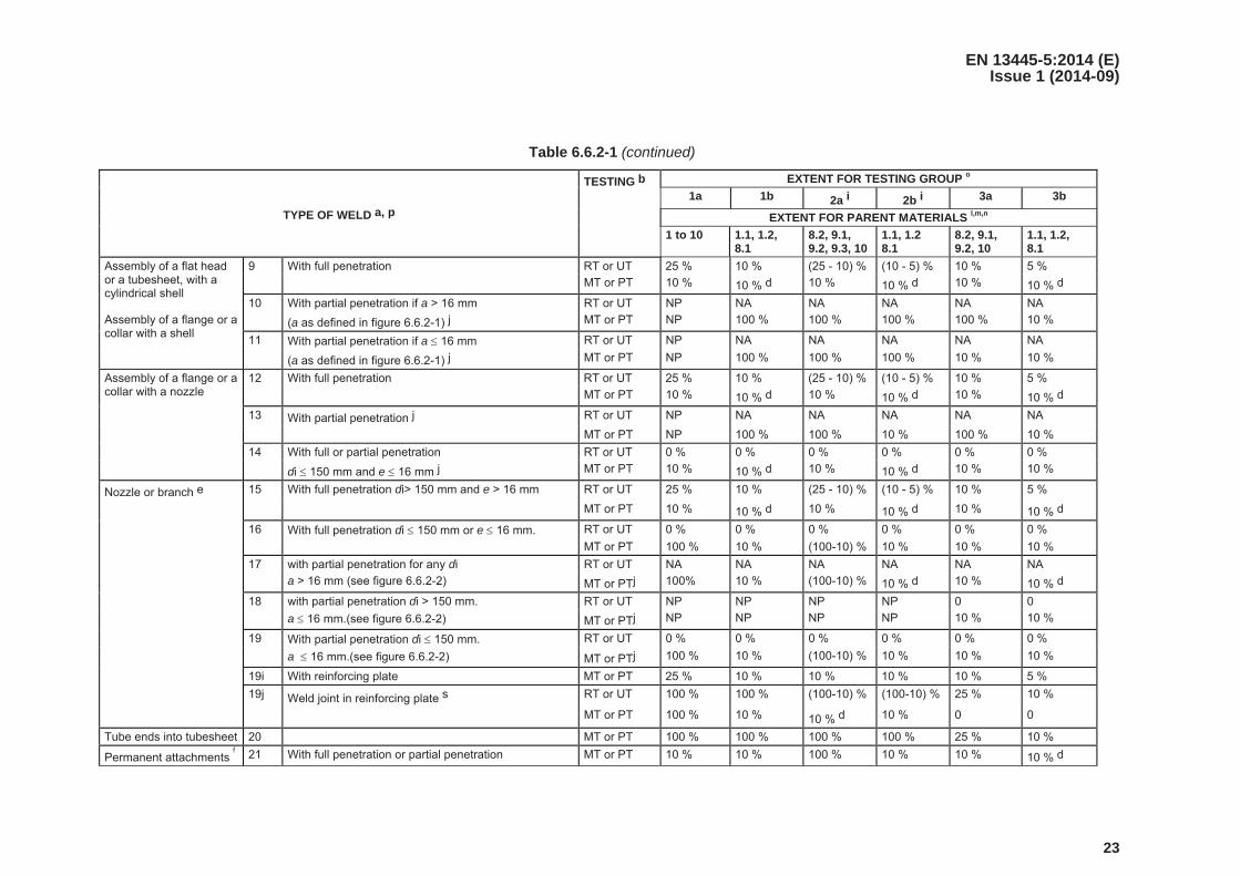
Table 6.6.2-1 (continued)
TYPE OF WELD a, p
TESTING b EXTENT FOR TESTING GROUP o
1a 1b 2a i 2b i 3a 3b
EXTENT FOR PARENT MATERIALS l,m,n
1 to 10 1.1, 1.2, 8.1
8.2, 9.1, 9.2, 9.3, 10
1.1, 1.2 8.1
8.2, 9.1, 9.2, 10
1.1, 1.2, 8.1
Assembly of a flat head or a tubesheet, with a cylindrical shell
9 With full penetration RT or UT 25 % 10 % (25 - 10) % (10 - 5) % 10 % 5 %
MT or PT 10 % 10 % d 10 % 10 % d 10 % 10 % d
10 With partial penetration if a > 16 mm RT or UT NP NA NA NA NA NA
Assembly of a flange or a collar with a shell
(a as defined in figure 6.6.2-1) j MT or PT NP 100 % 100 % 100 % 100 % 10 %
11 With partial penetration if a 16 mm RT or UT NP NA NA NA NA NA
(a as defined in figure 6.6.2-1) j MT or PT NP 100 % 100 % 100 % 10 % 10 %
Assembly of a flange or a collar with a nozzle
12 With full penetration RT or UT 25 % 10 % (25 - 10) % (10 - 5) % 10 % 5 %
MT or PT 10 % 10 % d 10 % 10 % d 10 % 10 % d
13 With partial penetration j RT or UT NP NA NA NA NA NA
MT or PT NP 100 % 100 % 10 % 100 % 10 %
14 With full or partial penetration RT or UT 0 % 0 % 0 % 0 % 0 % 0 %
di 150 mm and e 16 mm j MT or PT 10 % 10 % d 10 % 10 % d 10 % 10 %
Nozzle or branch e 15 With full penetration di> 150 mm and e > 16 mm RT or UT 25 % 10 % (25 - 10) % (10 - 5) % 10 % 5 %
MT or PT 10 % 10 % d 10 % 10 % d 10 % 10 % d
16 With full penetration di 150 mm or e 16 mm. RT or UT 0 % 0 % 0 % 0 % 0 % 0 %
MT or PT 100 % 10 % (100-10) % 10 % 10 % 10 %
17 with partial penetration for any di RT or UT NA NA NA NA NA NA
a > 16 mm (see figure 6.6.2-2) MT or PTj 100% 10 % (100-10) % 10 % d 10 % 10 % d
18 with partial penetration di > 150 mm. RT or UT NP NP NP NP 0 0
a 16 mm.(see figure 6.6.2-2) MT or PTj NP NP NP NP 10 % 10 %
19 With partial penetration di 150 mm. RT or UT 0 % 0 % 0 % 0 % 0 % 0 %
a 16 mm.(see figure 6.6.2-2) MT or PTj 100 % 10 % (100-10) % 10 % 10 % 10 %
19i With reinforcing plate MT or PT 25 % 10 % 10 % 10 % 10 % 5 %
19j Weld joint in reinforcing plate s RT or UT 100 % 100 % (100-10) % (100-10) % 25 % 10 %
MT or PT 100 % 10 % 10 % d 10 % 0 0
Tube ends into tubesheet 20 MT or PT 100 % 100 % 100 % 100 % 25 % 10 %
Permanent attachments f 21 With full penetration or partial penetration MT or PT 10 % 10 % 100 % 10 % 10 % 10 % d
BS EN 13445-5:2014
EN 13445-5:2014 (E) Issue 1 (2014-09)
24
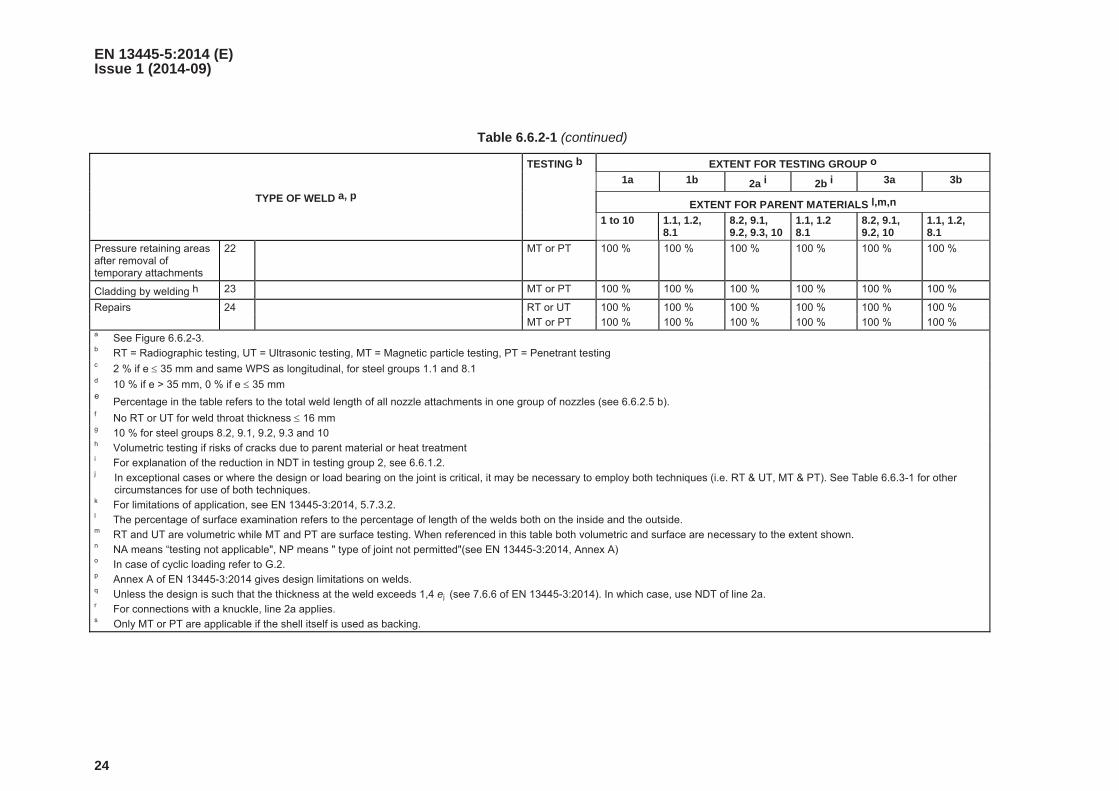
Table 6.6.2-1 (continued)
TYPE OF WELD a, p
TESTING b EXTENT FOR TESTING GROUP o
1a 1b 2a i 2b i 3a 3b
EXTENT FOR PARENT MATERIALS l,m,n
1 to 10 1.1, 1.2, 8.1
8.2, 9.1, 9.2, 9.3, 10
1.1, 1.2 8.1
8.2, 9.1, 9.2, 10
1.1, 1.2, 8.1
Pressure retaining areas after removal of temporary attachments
22 MT or PT 100 % 100 % 100 % 100 % 100 % 100 %
Cladding by welding h 23 MT or PT 100 % 100 % 100 % 100 % 100 % 100 %
Repairs 24 RT or UT 100 % 100 % 100 % 100 % 100 % 100 %
MT or PT 100 % 100 % 100 % 100 % 100 % 100 % a See Figure 6.6.2-3. b RT = Radiographic testing, UT = Ultrasonic testing, MT = Magnetic particle testing, PT = Penetrant testing c 2 % if e 35 mm and same WPS as longitudinal, for steel groups 1.1 and 8.1 d 10 % if e > 35 mm, 0 % if e 35 mm e Percentage in the table refers to the total weld length of all nozzle attachments in one group of nozzles (see 6.6.2.5 b). f No RT or UT for weld throat thickness 16 mm g 10 % for steel groups 8.2, 9.1, 9.2, 9.3 and 10 h Volumetric testing if risks of cracks due to parent material or heat treatment i For explanation of the reduction in NDT in testing group 2, see 6.6.1.2. j In exceptional cases or where the design or load bearing on the joint is critical, it may be necessary to employ both techniques (i.e. RT & UT, MT & PT). See Table 6.6.3-1 for other
circumstances for use of both techniques. k For limitations of application, see EN 13445-3:2014, 5.7.3.2. l The percentage of surface examination refers to the percentage of length of the welds both on the inside and the outside. m RT and UT are volumetric while MT and PT are surface testing. When referenced in this table both volumetric and surface are necessary to the extent shown. n NA means “testing not applicable", NP means " type of joint not permitted"(see EN 13445-3:2014, Annex A) o In case of cyclic loading refer to G.2. p Annex A of EN 13445-3:2014 gives design limitations on welds. q Unless the design is such that the thickness at the weld exceeds 1,4 ej (see 7.6.6 of EN 13445-3:2014). In which case, use NDT of line 2a. r For connections with a knuckle, line 2a applies. s Only MT or PT are applicable if the shell itself is used as backing.
BS EN 13445-5:2014EN 13445-5:2014 (E)
Issue 1 (2014-09)
25
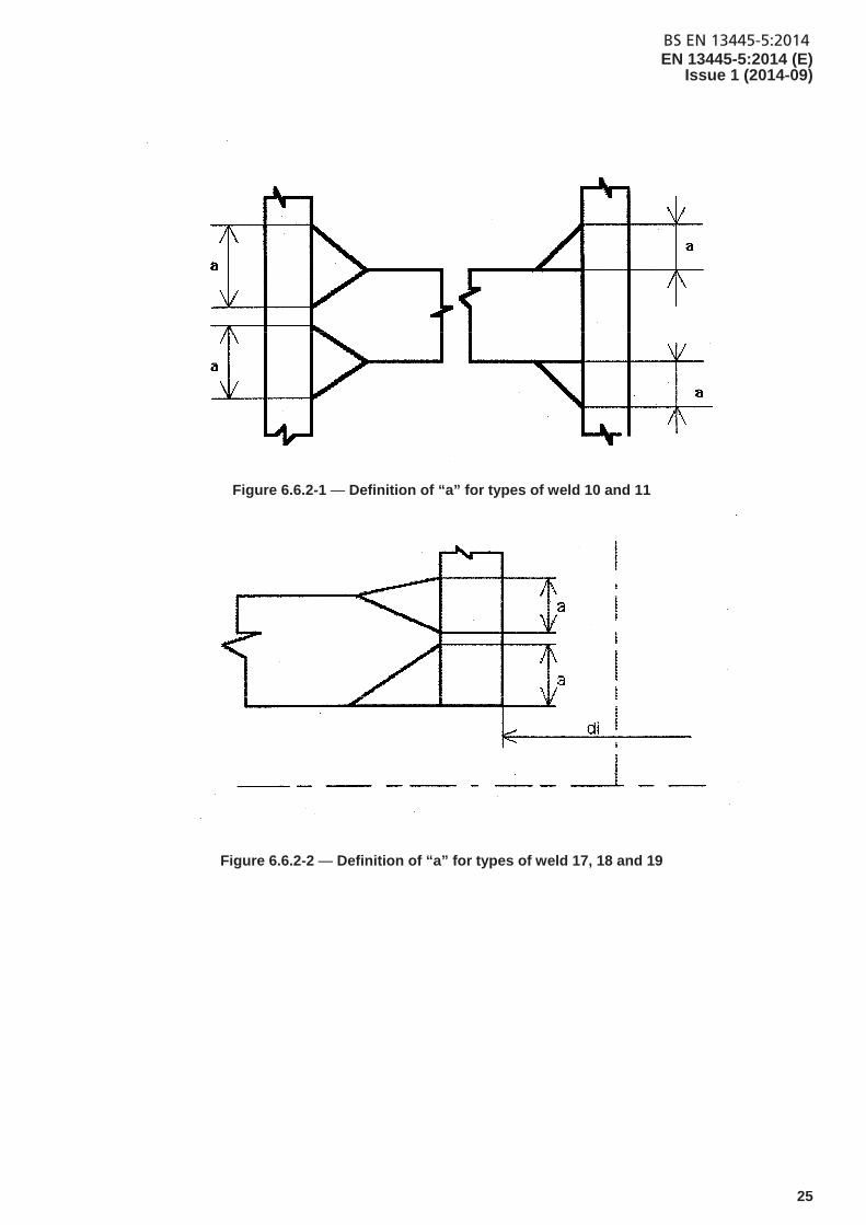
Figure 6.6.2-1 — Definition of “a” for types of weld 10 and 11
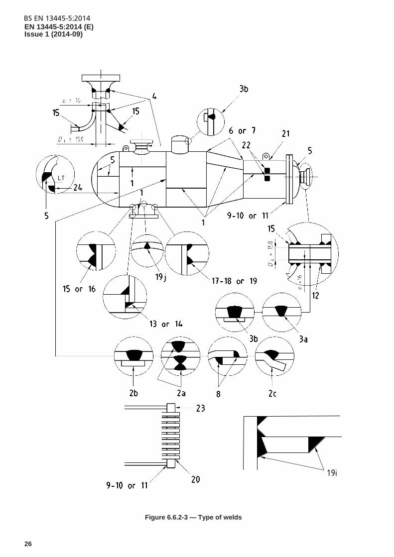
Figure 6.6.2-2 — Definition of “a” for types of weld 17, 18 and 19
BS EN 13445-5:2014EN 13445-5:2014 (E) Issue 1 (2014-09)
26
19i
Figure 6.6.2-3 — Type of welds
BS EN 13445-5:2014EN 13445-5:2014 (E)
Issue 1 (2014-09)
27
6.6.3 Performing non-destructive testing
6.6.3.1 General
Visual inspection shall be carried out on all welds and reported.
Non-destructive testing of welded joints for final acceptance purposes shall depend upon testing group of the joint.
6.6.3.2 Quality level
The quality level shall be quality level C in accordance with EN ISO 5817:2014, with the following additional requirements for some imperfections:
stray arc (601) – removal plus 100 % MT or PT to ensure no imperfection;
spatter (602) – weld spatter shall be removed from all pressure parts and load carrying attachment welds. Isolated non systematic spatter is permitted on components made of group 1 materials;
torn surface (603), grinding mark (604), chipping mark (605) shall be ground to provide a smooth transition;
underflushing (606) shall not be permitted. Any local underflushing shall be related to design characteristics (calculated thickness + corrosion allowance).
For cyclic loaded vessels, see Annex G; for vessels or parts subject to creep, see Annex F.
6.6.3.3 Selection of non-destructive testing methods for internal imperfections (full and partial penetration)
Methods shall be selected according to EN ISO 17635:2010, Table 3.
Testing techniques shall be in accordance to EN ISO 17635:2010, Tables A.5 (RT-F) and A.8 (UT).
Other NDT techniques in EN ISO 17635 may be used providing they are proven to satisfy the required quality level given in 6.6.3.2, Annex F or Annex G.
6.6.3.4 Selection of non-destructive testing methods for surface imperfections
For ferritic steels magnetic particle testing (MT) shall be used. For austenitic and austenitic-ferritic stainless steels, penetrant testing (PT) shall be used. For material groups 8 and 10 penetrant testing (PT) shall be used. The testing techniques shall be as specified in EN ISO 17635:2010.
6.6.3.5 Surface condition and preparation for non-destructive testing
The surface condition necessary for performing all NDT shall be in accordance with the standard for the corresponding testing technique as stated in EN ISO 17635:2010, Annex A. Welded surfaces need not to be dressed unless the irregularities will interfere with application and/or interpretation. Special attention is necessary for vessels subject to cyclic loading, criteria are given in Annex G.
6.6.3.6 Schedule for non-destructive testing
A comprehensive schedule shall be prepared covering the non-destructive testing requirements for each vessel, identifying the stages of manufacture at which non-destructive testing is performed, the choice of method, the procedure to be used, acceptance criteria, and records to be made.
BS EN 13445-5:2014EN 13445-5:2014 (E) Issue 1 (2014-09)
28
6.6.3.7 Qualification of non-destructive testing personnel
Non-destructive testing personnel shall be qualified and certified in accordance with EN ISO 9712:2012 except for visual inspection for which personnel shall be qualified but need not be certified. Non-destructive testing personnel shall hold an appropriate certificate of competence (e.g. personnel certification on non-destructive testing level 1, 2 or 3 as appropriate).
6.6.4 Description and acceptance level of imperfections
The terminology used to describe the imperfection shall be in accordance with EN ISO 6520-1:2007.
Depending on the quality levels specified in 6.6.3.2, Annex F or Annex G, testing techniques and acceptance levels shall be selected according to EN ISO 17635:2010, Annex A.
6.6.5 Stage of performance
The non-destructive testing shall be carried out after completion of post-weld heat treatment (PWHT) but before the proof test in all testing groups.
Where a material is not sensitive to PWHT cracking e.g. material groups 1.1 and 8.1, NDT may be performed before PWHT.
All vessels shall be inspected during and after the manufacturing process to assure the quality of the finished welds. Such inspections include joint geometry, dimensional checking, alignment, etc.
In particular, testing group 4 vessels shall be inspected during fabrication both in the initial assembly and after preparation of the joint from the second side in double welded seams.
6.6.6 Procedure for non-destructive retesting
The locations selected under a) and b) of 6.6.2.5 shall be deemed to be representative of the welds inspected (welded joint or joint batch). An imperfection detected on the circumferential joint shall be considered as representing the condition of the whole circumferential joint or joint batch. A defect detected on the longitudinal joint shall be considered as representing the condition of the whole longitudinal joint or joint batch. An imperfection detected on a nozzle or branch shall be considered as representing the condition of the group of nozzles or branches. According to the defect type, retesting shall be as follows:
If the sample contains defects in excess of that permitted in the acceptance criteria, then two further random samples shall be non-destructively tested and the results assessed against the original criteria. Each of the further samples shall be at least the same length as the original. If these two further samples are acceptable, the original sample shall be repaired and reassessed using the same non-destructive testing technique. If one or both of further samples fail, then 100 % of the welded joint or joint batch shall be tested.
6.6.7 Non-destructive testing documentation
All NDT shall be performed in accordance with written procedures and by qualified personnel, as specified in 6.6.3.7. In support of NDT activities written test reports shall be prepared in accordance with the standards referred to in EN ISO 17635:2010.
The documentation described above, sufficient to verify the scope of NDT performed, shall form part of the documents described in Clause 12.
BS EN 13445-5:2014EN 13445-5:2014 (E)
Issue 1 (2014-09)
29
6.7 Destructive testing
6.7.1 Extent of destructive testing
The level of destructive tests shall be in accordance with EN 13445-2:2014 and EN 13445-4:2014.
6.7.2 Schedule for destructive testing
The vessel manufacturer shall be responsible for preparing a comprehensive schedule covering the destructive testing requirements for each vessel or series of vessels, identifying the stages of manufacture at which the destructive testing is performed, the choice of tests, the testing procedure to be used, acceptance criteria and records required to be made.
6.7.3 Verification of destructive tests
The following activities shall be witnessed:
identification/validation of test coupons;
mechanical testing;
preparation or certification of test reports.
6.7.4 Records
All documentation associated with destructive testing in accordance with this standard shall form part of the final documentation in accordance with clause 12 and shall be readily available.
6.8 Heat-treatment
Heat-treatments shall be performed in accordance with written procedures and verified by inspection. Such procedures shall describe the parameters critical to the heat-treatment process. The procedures shall cover the appropriate criteria depending on the heat treatment process. As a minimum this shall include where appropriate:
a) rate of heating;
b) hold or soak time and temperature;
c) rate of cooling;
d) heating medium and furnace type;
e) type and number of temperature measuring devices;
f) support of equipment (if applicable);
g) records and scope of information to be contained.
7 Subcontracted items
7.1 General
The vessel manufacturer completing any work on a complete vessel or part of a vessel shall declare that any work done by others also complies with the requirements of this standard.
NOTE Some types of work which may be subcontracted by the vessel manufacturer and performed by other organizations would include:
BS EN 13445-5:2014EN 13445-5:2014 (E) Issue 1 (2014-09)
30
a) design
b) purchasing of materials
c) cutting
d) forming
e) welding area activities,
f) heat treatment.
g) non-destructive testing.
For example of subcontractor’s form, see EN 13445-4:2014, Annex B.
7.2 Subcontracted welding related activities
Subcontracted welding related activities shall be in accordance with EN 13445-4:2014.
7.3 Subcontracted non-destructive testing activities
7.3.1 Use of contract NDT personnel at the premises of the vessel manufacturer
The vessel manufacturer shall be responsible for assuring that NDT personnel, not in the full-time employ of the manufacturer, are trained, qualified and certified in accordance with EN ISO 9712:2012. Adequately documented records shall be provided so that the vessel manufacturer can verify the qualifications of personnel and such records shall be retained and made readily available.
All NDT shall be conducted against written procedures and the results documented and retained in accordance with the vessels manufacturers NDT requirements. The vessel manufacturer shall be responsible for assuring that all such procedures are fully implemented. The vessel manufacturer shall ensure that records are maintained which address the use of subcontracted personnel to the activities they undertake and shall have the authority to assign and remove NDT personnel at his discretion. The vessel manufacturer shall be responsible for retaining all records of work undertaken by subcontracted personnel in accordance with Clause 12.
7.3.2 Subcontracting of NDT at a subcontractors premises
Any NDT which is performed at a subcontractors location shall be undertaken under the responsibility of the vessel manufacturer. All personnel used shall be trained, qualified and certified in accordance with EN ISO 9712:2012 and adequate records supporting their qualification shall be maintained by the vessel manufacturer. All procedures shall be documented and all test results shall be made available and all copies retained by the vessel manufacturer.
NOTE The vessel manufacturer shall ensure that those parties with responsibilities under the Conformity Assessment Procedures shall be given free access to the extent they consider necessary to fulfil their duties and obligations.
8 Miscellaneous tests
For guidelines on leak testing, see Annex D.
BS EN 13445-5:2014EN 13445-5:2014 (E)
Issue 1 (2014-09)
31
9 Calibration
9.1 General
All measurement and test equipment used for final acceptance of vessels shall be calibrated in accordance with 9.2 to 9.4 and written procedures.
When used in this clause, calibration is an all encompassing term involving the use of procedures and testing equipment to determine the accuracy of equipment.
Certain types of equipment once initially calibrated may thereafter be validated. Examples of validated equipment are densitometers and welding equipment.
NOTE The equipment to be calibrated includes but is not limited to:
a) Tensile testing machines;
b) impact test machines;
c) hardness tester;
d) non-destructive testing equipment including densitometer and step wedge comparison films;
e) pressure gauges;
f) furnace and contact thermocouples;
g) time/temperature recorders;
h) dimensional measuring equipment;
i) welding equipment (see EN ISO 17662).
9.2 Calibration procedure
9.2.1 General
Procedures shall be prepared for each type of equipment showing:
a) the scope of activities and those responsible for conducting the calibration;
b) reference to the European Standards or National Standards, where not available secondary standards/gauges, if used;
c) calibration frequency;
d) acceptance criteria.
Wherever possible European or National Standards shall be used. When such standards do not exist the calibration method shall be approved as specified in the procedures.
9.2.2 Calibration
Calibration of measurement, testing and test equipment used on pressure vessels for final acceptance shall always be the responsibility of the vessel manufacturer.
BS EN 13445-5:2014EN 13445-5:2014 (E) Issue 1 (2014-09)
32
With the exception of the special equipment specified in Table 9.2.2-1, the vessel manufacturer shall either perform the calibration itself or shall subcontract to a nationally accredited testing laboratory (NATL). The NATL shall provide certified records of calibration and has suitable reference standards whose accuracy is traceable to European/National Standards.
Table 9.2.2-1 — Special equipment — Calibration frequency and performance
Equipment Frequency Performance
Tensile Testing Machines and associated equipment
1 year National accredited testing laboratory (NATL)
Charpy Impact Machine and associated measurement apparatus
1 year NATL
Hardness Tester 1 year NATL Master pressure gauges 1 year NATL
9.2.3 Frequency
The frequency of calibration of an equipment shall either be in accordance with Table 9.2.2-1 or in an applicable European/National standard or, if such does not exist and is not covered in Table 9.2.2-1, to the recommendations by the measuring equipment manufacturer.
9.3 Identification
All measuring, testing and test equipment shall be identified by marking the item or its container/box with a unique identification serial number.
In addition to its identification number the equipment should have a calibration sticker giving a visual identification as to its status.
9.4 Registration
9.4.1 All equipment within the calibration system shall be documented on a list which as a minimum shall show:
a) who is responsible for calibration, department, individual, subcontractor;
b) items identification serial number;
c) item location;
d) calibration procedure number.
9.4.2 Record shall be kept for individual items indicating:
a) calibration date;
b) its "as-found" condition or the "actual measured" condition;
c) identification of standard or master gauge used.
All records relating to calibration shall be available.
BS EN 13445-5:2014EN 13445-5:2014 (E)
Issue 1 (2014-09)
33
10 Final assessment
10.1 General
Each completed pressure vessel designed and constructed to this standard shall be subject to a final assessment for compliance with the requirements of the approved construction drawings and this standard.
If due to internal elements (i.e. tube bundles, trays etc.) internal examination is not possible upon completion of the pressure vessel, then the vessel manufacturer shall have assured that those elements were subject to final examination prior to their assembly.
The final assessment consists of:
a visual and dimensional inspection of the vessel;
an examination of the documentation;
a proof test;
a post proof test examination;
inspection of safety accessories.
Those performing the final assessment shall have access to all of the files/records as per Clause 12 relevant to the pressure vessel under examination.
10.2 Extent of final assessment
10.2.1 Visual and dimensional inspection
The visual and dimensional inspection shall be performed following completion of all welding activities and post-weld heat treatments but before application of any coating, irrespective of type, and before the proof test. If the pressure vessel is to be partially or totally assembled on site, the vessel manufacturer shall determine elements which can receive protective coatings prior to dispatch to site.
Provisions shall be made to allow safe access to all areas of the pressure vessel in order to conduct this examination. Also provision of adequate lighting, calibrated measurement equipment and dimensional aids shall be assured to those performing the examination.
The scope of the visual and dimensional inspection shall include, but not be limited to, the following:
check of compliance of construction with the approved vessel manufacturing drawings including dimensional requirements to the tolerances specified on the drawings and in this standard. Annex B provides a list of items that shall be given attention. The results of the dimensional examination ("as built condition") shall be documented on the certificate of dimensional report;
check of the condition of a completed pressure vessel with particular attention to finished weld joints, nozzle connections and attachments in respect of weld profile, peaking measurement and general weld geometry in compliance with the approved manufacturing drawings and this standard;
check of material markings for traceability of material against documented records;
check of welders and NDT identification on the vessel against documentation, if applicable.
BS EN 13445-5:2014EN 13445-5:2014 (E) Issue 1 (2014-09)
34
Any remedial actions resulting from this inspection shall be accomplished, re-examined and cleared prior to the proof test.
10.2.2 Review of documentation
The scope of the examination of documentation shall include, but not be limited to, the check of documents (e.g. test certificates of the welding procedures qualification, certificates of the welders qualification, certificates for NDT personnel certification, production tests reports, NDT reports, postweld heat-treatments records, dimensional checking records, etc.).
The extent of the review and all deviations shall be reported. Any remedial actions resulting from this inspection shall be accomplished, re-inspected and cleared prior to the proof test.
10.2.3 Proof test
10.2.3.1 General
All vessels shall be subjected to a proof test to demonstrate the integrity of the finished product.
However, pressure testing on a statistical basis may be carried out when all the following conditions are met:
The vessels shall be serially produced as defined in 3.8, 3.9 and 3.12 ; a stoppage in vessel production greater than three consecutive days requires the designation of a new batch;
The vessel category according to Directive 97/23/EC shall not be greater than I;
At least 2 % of vessels shall be tested. At least two vessels from each fabrication batch shall be tested. Vessels shall be selected randomly;
If one or more pressure vessels fail the pressure test, all vessels in the same batch shall be pressure tested. If other vessels in this batch fail the pressure test, the whole of the immediately preceding and subsequent batches shall be pressure tested.
NOTE Other inspection and testing provisions of serially produced vessels are given in Annex A.
The proof test is part of the final assessment.
The hydrostatic pressure test shall be the standard proof test.
If this is not practical then it may be substituted by:
a) pneumatic test. Pneumatic testing is potentially a much more dangerous operation than hydrostatic testing. Therefore it is permitted to be carried out but only subject to the following conditions:
for vessels having such a design and construction that it is not practicable for them to be filled with liquid;
for vessels that are to be used in processes where even small traces of liquid cannot be tolerated;
following early consultation at the design stage.
b) combined hydrostatic/pneumatic test. In some cases it may be desirable to test a vessel when it is partly filled with liquid. This is as dangerous as the pneumatic test.
10.2.3.2 Basic requirements
10.2.3.2.1 The proof test shall be carried out under controlled conditions, with appropriate safety precautions and equipment, and in such a way that the persons responsible for the test are able to make inspections of all pressurized parts.
10.2.3.2.2 Where practicable the finished vessel shall be proof tested after all fabrication has been completed and all inspections have been performed. However, operations that influence the inspectability of the pressurized vessel, such as: painting, insulation, brickwork, rubber lining, leadlining, galvanizing, enamelling etc., shall be carried out following satisfactory completion of the proof test.
BS EN 13445-5:2014EN 13445-5:2014 (E)
Issue 1 (2014-09)
35
NOTE When a vessel receives a lining or coating by a process which could be damaged during pressure testing, it is permissible to reduce the proof test pressure after completion of lining to not less than 1,1 times the maximum allowable pressure PS provided that the standard proof test has been applied before lining.
For coated or lined vessels which have jackets attached after the lining process (but not welded directly to the lined vessel) the jacket shall be subject to a proof test of 1,25 . PS.
10.2.3.2.3 The pressure equipment shall be provided with the prescribed marking (e.g. nameplate) at the time when the proof test is performed at the latest, and when there are a number of pressurized compartments at the time when the final proof test is performed.
10.2.3.2.4 If it is not practicable, due to size or mode of manufacture, to proof test a complete vessel the test procedure to be followed shall be approved at the design stage.
10.2.3.2.5 If water is used as the test fluid, the quality of the water used shall be such as to prevent corrosion.
NOTE Where other liquids are used additional precautions may be necessary depending on the nature of the liquid.
10.2.3.2.6 All temporary pipes and connections and blanking devices shall be designed to withstand the test pressure and shall not form a part of what is to be supplied with the vessel. Following the performance of the proof test, all pipes and connections and blanking devices shall be either removed at once or positively marked in order to prevent incorrect use. In case of bolted connections the bolts supplied shall be used and the tightening shall be uniform and to a degree no greater that necessary for sealing purposes.
10.2.3.2.7 Vessels which have been repaired during or following the pressure test shall again be subjected to the specified proof test after completion of the repair and any required post weld heat treatment (PWHT).
10.2.3.2.8 No vessel shall be subject to any form of shock loading such as hammer testing when undergoing proof testing.
10.2.3.2.9 All deviations from these basic requirements shall be approved at the design stage.
10.2.3.3 Standard hydrostatic test
10.2.3.3.1 For a single-compartment vessel3) subjected to internal pressure, working below the creep range, and designed according to testing group 1, 2 or 3, the test pressure, applied as internal pressure at the highest point of the chamber of the vessel for either horizontal or vertical test positions, shall be as specified in a). The modifications of the test pressure due to the hydrostatic pressure are specified in b).
Special provisions are given in c) for single-run governing welds and in d) for complete vessels or parts of vessels working in the creep range.
a) The test pressure shall be determined by the greater of:
d
adt 1,25
Tf
fPP
(10.2.3.3.1-1)
or
3) The case of multi-compartment vessels is covered in 10.2.3.3.3
BS EN 13445-5:2014EN 13445-5:2014 (E) Issue 1 (2014-09)
36
st 1,43 PP (10.2.3.3.1-2)
where:
tP is the test pressure measured at the highest point of the chamber of the vessel in the test position;
dP and dT are the coincident design pressure and design temperature values for the maximum pressure load
case;
sP is the maximum allowable pressure of the vessel;
af is the nominal design stress for normal operating load cases of the material of the part under consideration at
the test temperature;
dTf is the nominal design stress for normal operating load cases of the material of the part under consideration at
temperature dT ;
Since the ratio d
a
Tf
f depends on the material of the part under consideration, the value d
a
Tf
f to be used for
calculation of tP shall not be less than the smallest ratio obtained considering the different materials of the main
pressure bearing parts (e.g. shells, ends, tubesheets of heat exchangers, tube bundles, main flanges but ignoring bolting associated to main flanges). Main pressure bearing parts do not include pressure rated standard flanges and bolting designed without calculation according to the rules of 11.4.2 of EN 13445-3:2014.
NOTE 1 The rules of 11.4.2 of EN 13445-3:2014 deal with the use of standard flanges without calculation.
tP , sP , af and dTf shall have consistent units.
The maximum pressure load case is that set of coincident design pressure and design temperature which gives the highest test pressure.
If the bolting associated with the main flanges is overstressed due to the test pressure, the test pressure may be reduced until the bolt stresses are acceptable.
The design of the vessel shall be such that in no part the test pressure exceeds the maximum permissible pressure for testing load cases defined in 5.3.2.3 of EN 13445-3:2014 according to the relevant design rules of EN 13445-3:2014. For Design By Formulae (DBF) and Design By Analysis (DBA) according to Annex C, the maximum permissible pressure is determined using the nominal design stress given in Table 6-1 for testing load cases. For DBA – Direct Route according to Annex B, the maximum permissible pressure is determined using the safety coefficients for testing load cases given in Tables B.8-3 and B.8-4.
NOTE 2 For testing load cases during final assessment the corrosion allowance may be ignored (but not for any in service test).
NOTE 3 The pressure test is not aimed to dimension the pressure vessel. However, possible increase of the thickness of tall vessels tested in the vertical position may be necessary to meet the criteria of EN 13445-3:2014.
b) For vessels with hydrostatic pressure during operation which exceeds 3 % of the design pressure the test pressure shall be modified according to equation 10.2.3.3.1-3:
)( testhyd,opehyd,tmodt, PPPP but always: tmodt, PP (10.2.3.3.1-3)
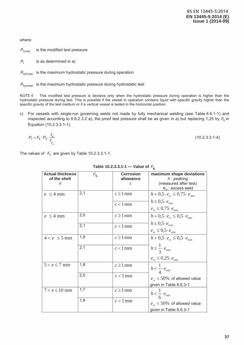
BS EN 13445-5:2014EN 13445-5:2014 (E)
Issue 1 (2014-09)
37
where:
modt,P is the modified test pressure
tP is as determined in a)
opehyd,P is the maximum hydrostatic pressure during operation
testhyd,P is the maximum hydrostatic pressure during hydrostatic test
NOTE 4 This modified test pressure is decisive only when the hydrostatic pressure during operation is higher than the hydrostatic pressure during test. This is possible if the vessel in operation contains liquid with specific gravity higher than the specific gravity of the test medium or if a vertical vessel is tested in the horizontal position.
c) For vessels with single-run governing welds not made by fully mechanical welding (see Table 6.6.1-1) and inspected according to 6.6.2.3.2 a), the proof test pressure shall be as given in a) but replacing 1,25 by kF in
Equation (10.2.3.3.1-1).
d
adkt
Tf
fPFP (10.2.3.3.1-4)
The values of kF are given by Table 10.2.3.3.1-1.
Table 10.2.3.3.1-1 — Value of kF
Actual thickness of the shell
e
kF Corrosion allowance
c
maximum shape deviationsh : peaking
(measured after test)
we : excess weld
mm4e 2,1 mm 1c
minw 75,05,0 eeh
min5,0 eh
minw 75,0 ee mm 1c
mm4e 2,0 mm 1c
minw 5,05,0 eeh
min5,0 eh
minw 5,0 ee 2,1 mm 1c
mm54 e 1,9 mm 1c
minw 5,05,0 eeh
min3
1eh
minw 25,0 ee
2,1 mm 1c
mm75 e 1,8 mm 1c min4
1eh
%50w e of allowed value
given in Table 6.6.3-1
2,0 mm 1c
mm107 e 1,7 mm 1c min6
1eh
%50w e of allowed value
given in Table 6.6.3-1
1,9 mm 1c
BS EN 13445-5:2014EN 13445-5:2014 (E) Issue 1 (2014-09)
38
In Table 10.2.3.3.1-1:
mine is the minimum possible fabrication thickness, as defined in EN 13445-3:2014
h is the peaking after test, measured as defined in EN 13445-4:2014
we is the excess weld, as illustrated by h in number 1.9 of EN ISO 5817:2014
The circumferential membrane stress c
in the main seams with the actual or nominal thickness shall not exceed
the nominal design stress testf given in Table 6-1 of EN 13445-3:2014 for testing and exceptional load cases but
shall be greater or equal to test850 f, .
During the hydrotest a value of 1 for the joint coefficient z defined in EN 13445-1:2014 shall be used.
It is acceptable to replace the actual or nominal thickness by mine .
d) For complete vessels or parts of vessels working in the creep range, the test pressure shall be calculated as in a) above but with dTf replaced by
dnc,Tf the nominal design stress for normal operating load cases of the
material of the part under consideration at design temperature dT of the maximum pressure load case, using
time-independent material characteristics.
If the required time-independent characteristics are not available in the materials standard at that temperature they may be determined as follows:
For vessels designed to testing group 1c (see Table F.2-1): at the highest temperature for which time-independent characteristics are available in the materials standard;
For vessels designed to testing group 3c (see Table F.2-1): using Annex S of EN 13445-3:2014;
Alternatively time-dependent material characteristics can be taken.
From the three methods described above for determining the nominal design stresses for normal operating load cases, a consistent method shall be used for all parts.
NOTE 5 The level of the test pressure has no relevance to the safety of the vessel with respect to creep behaviour. It has been established to assure consistency with operation below the creep range.
NOTE 6 Use of the time-independent characteristics at the highest temperature for which they are available in the materials standard (when no such characteristics are available at dT ), gives a lower test pressure, but nevertheless provides adequate
demonstration of strength in the context of testing group 1c.
NOTE 7 The nominal design stress values given in Annex S of EN 13445-3:2014 are based on a logical extrapolation into the creep range of the time-independent characteristics given in the materials standard below the creep range.
NOTE 8 Use of the time-dependent material characteristics gives a higher test pressure and therefore assures a conservative demonstration of strength.
10.2.3.3.2 For testing group 4 vessels the test pressure shall not be less than that determined by the following equations:
For materials of the Group 1.1:
mm 1 if c
BS EN 13445-5:2014EN 13445-5:2014 (E)
Issue 1 (2014-09)
39
mine 0,5 weld)excess 0,5 peaking (measured and
ce
e
f
fPP
2,2
min
minadt
d
T
(10.2.3.3.2-1)
or
mm 1 if c
and (measured peaking + 0,5 excess weld) ≤ min
0,75 e
and measured peaking ≤ min 0,5 e
and measured excess weld ≤ min
0,75 e
ce
e
f
fPP
2,0
min
minadt
d
T
(10.2.3.3.2-2)
where
mine is the minimum possible fabrication thickness of the section under consideration, as indicated on the
drawings, see 5.2.3 of EN 13445-3:2014.
c is the corrosion allowance, as indicated on the drawings
For other symbols see 10.2.3.3.1.
The peaking may be measured after the hydrostatic test and the excessive weld may be measured after grinding if applied before the hydrostatic test.
For materials of the Group 8.1:
d
adt 1,85
Tf
fPP (10.2.3.3.2-3)
if (measured peaking + 0,5 excess weld) ≤ min 0,5 e (10.2.3.3.2-4)
The applied test pressure shall include the amount of any static head acting in service and in testing at the point under consideration. However, the static pressure caused by the content of the vessel during service and/or testing does not need to be taken into account if it does not increase the stress in the wall by more than 5 %.
For vessels constructed using testing group 4, the maximum allowable stress in the test conditions (see EN 13445-3:2014, Clause 6) shall not be exceeded. This may require an increase in the relevant thicknesses or dimensions (e.g. vessel wall thickness, flange, bolt diameter, etc.). In no circumstances, shall the hydrostatic test pressure be reduced from that specified above.
10.2.3.3.3 In the case of multi-compartment vessels each chamber, when designed as separate vessels, shall be tested independently with the appropriate standard test pressure without support from pressure in any adjoining chamber.
If the common elements are designed for a larger differential pressure than the design pressure of the adjacent chambers, the test pressure shall subject the common elements to at least their design differential pressure as well as meeting the requirements for each independent chamber.
BS EN 13445-5:2014EN 13445-5:2014 (E) Issue 1 (2014-09)
40
For vessels with common dividing walls designed for the maximum differential pressure that can possibly occur during start up, operation and shutdown, and where the differential pressure is less than the higher pressure in the adjacent chambers, then the common elements shall be subjected to a test pressure calculated in accordance with
10.2.3.3.1 where dP and dT are the coincident design differential pressure and design temperature values for the
maximum differential pressure load case. The test pressure of pressure equipment made of several communicating compartments shall be the lower bound of the test pressures of the various compartments.
10.2.3.3.4 For full or partial jacketed vessels, the inner vessel shall be subject to the maximum differential pressure caused by the vacuum in the adjacent chamber. An identical approach shall apply in determining the test pressure for the jacket.
Therefore the determination of the test pressure given by Equations (10.2.3.3.1-1) and (10.2.3.3.1-2) for full or
partial vacuum is modified by replacing dP by vP d in Equation (10.2.3.3.1-1) and sP by vP s in
formula (10.2.3.3.1-2)
where
v = 0,1 (full vacuum);
v 0,1 (partial vacuum);
v = 0 (no vacuum).
In the above formulae, the pressures are expressed in MPa.
For vessels of full or partial vacuum in ½ coil or ½ pipe or box channels designed to EN 13445-3:2014, as illustrated in Figure 8.5-11 or 8.5-12, the external pressure caused by vacuum can be ignored when determining the test pressure.
Where it is reasonably practicable, single wall vessels subject to operation under vacuum conditions should be tested under vacuum or applied external pressure to simulate vacuum conditions.
The pressure whether resulting from external pressure or from vacuum should be 1,25 times the external design pressure, if possible, but in no case less than the external design pressure.
10.2.3.3.5 The temperature of the pressurization liquid shall satisfy all of the following requirements:
a) 5 K above solidification point;
b) 10 K below atmospheric boiling point;
c) and shall be of sufficient temperature that the risk of brittle fracture is avoided (See EN 13445-2:2014, Annex B).
Thick wall vessels shall not be pressurized until the metal temperature is approximately equal with the pressurisation medium. During the hydrostatic test the vessel external shall remain dry. If the toughness of the material or of the component imposes a limit on the test temperature according to Annex B of EN 13445-2:2014 or on the rate at which the pressure is increased, account shall be taken of this and documented in the test data certificate.
10.2.3.3.6 Vents shall be provided at all high points of the vessel to purge possible air pockets while filling the vessel. There shall also be adequate venting before drainage to prevent collapse particularly in the case of large thin wall vessels. Attention shall be given to the support of the vessel during test to protect individuals from additional risk and the vessel from damage.
10.2.3.3.7 Glasses of sight glasses shall be submitted to an individual proof test at 2 times the design pressure prior to fitting them on to the vessel. During the proof test of the vessel, measures shall be taken to protect the personnel from bursting of the glasses e.g. protection covers.
BS EN 13445-5:2014EN 13445-5:2014 (E)
Issue 1 (2014-09)
41
10.2.3.3.8 Pressure of vessels under test shall be gradually increased to a value of approximately 50 % of the specified test pressure, thereafter the pressure shall be increased in stages of approximately 10 % of the specified test pressure until this is reached.
NOTE For pressure test of maximum 15 bar, the pressure may be gradually increased until to reach the specified test pressure.
The required test pressure shall be maintained for not less than 30 min. At no stage shall the vessel be approached for close examination until the pressure has been positively reduced by at least 10 % to a level lower than that previously attained. The pressure shall be maintained at the specified close examination level for a sufficient length of time to permit a visual inspection to be made of all surfaces and joints.
10.2.3.4 Pneumatic test
10.2.3.4.1
NOTE 1 Attention is drawn to national regulations, with respect to the hazard involved in proof testing using a compressible medium.
NOTE 2 Consideration may be given to the use of acoustic emission during the test, see Annex E.
Due to the hazard involved in proof testing using a compressible medium, special consideration shall be given to such factors as:
a) location of the vessel and its position relative to factors such as other buildings, plants, public roads, and areas open to public and all other equipment and structures in the vicinity of the vessel to be tested;
b) maintaining during the test the highest practicable standards of safety and ensuring that only personnel involved in the testing have access to the testing area, that if the testing is not performed in a special room the region in the immediate vicinity of the testing area is sealed off and warning signs used highlighting the danger zone and prohibited area;
c) resistance of the vessel materials to fast running shear fracture and the absolute necessity of avoiding brittle fracture;
d) metal temperature at test shall be at least 25 °C above TM or TR as applicable required in this standard for vessels which have not been previously subjected to a hydrostatic test at a pressure exceeding pneumatic test pressure. Attention is drawn to the fact that if the gas pressure is let down to the vessel under test from high pressure storage, its temperature will fall. Therefore the pressurising equipment shall be such that the temperature of the gas entering the vessel exceeds the minimum temperature indicated;
e) the extent of remote monitoring provided during the test.
10.2.3.4.2 The pneumatic test pressure shall be in accordance with 10.2.3.3.1 for testing group 1, 2 and 3 vessels and 10.2.3.3.2 for testing group 4 vessels. Vessels subjected to this pressure shall be located in an enclosed and restricted area, e.g. a special chamber capable of withstanding explosion or being properly anchored in a water basin and adequate measures being taken to prevent parts shooting away in the case of explosion. Alternatively, the vessel shall be located in an area, a sufficient distance away from individuals (public or manufacturer's employees) such that in the case of explosion people will not be affected by the blast.
BS EN 13445-5:2014EN 13445-5:2014 (E) Issue 1 (2014-09)
42
Exceptionally, for testing groups 1 and 2 vessels, when the diameter exceeds 1 m and/or the length exceeds 3 m, a test may be performed at a test pressure that is 1,1 times the maximum allowable pressure sP . In this case, the
extent of NDT shall be as follows: 100 % of the longitudinal welds shall be subject to volumetric non-destructive examination and at least 10 % of the main circumferential welds and all ‘T’ junctions and flat ends to shell shall be subject to volumetric examination. In addition, 100 % of nozzle to shell welds, full and partial penetration attachment welds to the pressure boundary, flat ends to shells and areas where temporary attachments have been removed shall be subjected to 100 % PT/MT.
10.2.3.4.3 The pressure shall be gradually increased to a value of 50 % of the required test pressure. Thereafter the pressure shall be increased in steps of approximately 10 % of the required test pressure until this is reached. The pressure shall then be reduced to the inspection pressure iP :
T
a s i f
fPP (10.2.3.4.3-1)
and held during the inspection of the vessel.
If the reduced pneumatic test pressure of 1,1 times sP is used, the inspection pressure shall be limited to 0,9 times
sP .
10.2.3.5 Combined hydrostatic/pneumatic test
10.2.3.5.1 The pneumatic pressure is applied above the liquid and at no point in the vessel shall the total pressure applied during test cause the general membrane stress to exceed value specified in EN 13445-3:2014. All requirements as detailed in 10.2.3.4 shall apply.
10.2.3.5.2 If during filling, pre-pressurizing, etc., strain measurements are to be performed values given in EN 13445-3:2014 shall not be exceeded.
10.2.3.6 Jacketed vessels
Where the inner vessel of a jacketed vessel is designed to operate at atmospheric pressure or under vacuum conditions, the test pressure need only apply to the jacket space. In such cases Ps shall be taken as the differential design pressure between the jacket and the inner vessel for the purpose of calculating test pressure in accordance with 10.2.3. 3 or 10.2.3.4.
10.2.3.7 Low pressure leak test
If a gas leak test is carried out before the hydrostatic or pneumatic acceptance test, the test pressure shall not exceed 10 % of the design pressure or 0,5 bar whichever is less. See also Annex D.
10.2.3.8 Test pressure in excess of 100 bar or metal/medium temperatures greater than 50 °C
In the case of proof tests using water with test pressures in excess of 100 bar, or in the case of hydrostatic pressure tests with the medium employed for the tests at temperatures greater than 50 °C, one of the following shall be observed:
a) the proof tests shall be performed in a room or in a section of a shop to which, during the course of the test, only the personnel involved in the testing have access; or
b) if a special room is not available, suitable safeguards shall be adopted e.g. the setting up of protective walls. The region in the immediate vicinity of the pressure vessel that is to be tested shall be sealed off, and warning signs shall be utilized to designate this region as a danger zone and prohibited area.
BS EN 13445-5:2014EN 13445-5:2014 (E)
Issue 1 (2014-09)
43
It shall be possible to determine the pressure that is indicated from a safe distance or from a safeguarded point.
Direct examination is permitted to be carried out only when the pressure vessel has been subjected to the test pressure for a period of 30 min and when, subsequently, in the case of hydrostatic pressure tests the pressure has been reduced to around the permissible service pressure.
10.2.3.9 Acceptance criteria
During the proof test the vessel shall show no signs of general plastic yielding. Local deformation which is identified by visual inspection and which is cause for concern shall be referred to the designer for reconciliation against the design specification. During the proof test no leaks are permitted from the pressure envelope.
10.2.3.10 Records
For each proof test a report shall be issued, and the following data shall be recorded:
vessel manufacturer and identification of the pressure vessel;
name of inspector and the responsible authority if applicable;
test pressure;
pressurization medium, if water is not used, and medium temperature;
holding time of the test pressure;
identification of test gauges;
conclusions.
If a written test programme has been followed, reference shall be made to this programme.
10.2.3.11 Pressure gauges
When dial indicating and recording pressure gauge(s) are used, they shall have the dial graduated over a range of about double the intended maximum pressure, but in no case shall the range be less than 1,5 nor more than 4 times that pressure.
When components are to be proof tested, the indicating gauge(s) shall be connected to the component, or to the component from a remote location, with the gauge(s) readily visible to the operator controlling the pressure throughout the duration of pressurising, testing and de pressurising or venting of the component. For large vessels and systems when more than one gauge is specified, or required, a recording type gauge is recommended, and it is substituted for one of the indicating type gauges.
All indicating and recording type gauges used shall be calibrated against a standard dead weight tester, a calibrated master gauge or a mercury column, and re-calibrated at least once a year, unless specified differently by this standard. All gauges used shall provide results accurate to within the listed accuracy of the standard and shall be re-calibrated at any time that there is reason to believe they are in error.
For the possible case of a wrong indicating manometer the test pressure shall not be exceeded, e.g. monitored with a second calibrated manometer.
10.2.4 Post pressure test inspection
This is a visual inspection which shall be carried out after the pressure test and after the vessel has been drained and cleaned.
BS EN 13445-5:2014EN 13445-5:2014 (E) Issue 1 (2014-09)
44
The inspection shall determine if there has been any deterioration resulting from the pressure test. The scope shall also cover the fitting, if applicable, of safety accessories, operation of quick release doors or similar devices and the application and accuracy of markings as required by Clause 11 and the approved manufacturing drawings.
The application of surface coatings shall also be included in this inspection.
The extent of the inspections and all deviations shall be reported.
10.2.5 Inspection of safety accessories.
For assemblies the safety accessories shall be checked for full compliance with this standard.
11 Marking and declaration of compliance with the standard.
11.1 General
Equipment and accessories manufactured in accordance with all the requirements of this standard shall be marked with the number of this standard and year.
The required marking shall be located in a conspicuous place so that it will be accessible after installation.
11.2 Marking method
11.2.1 General
The marking shall be done:
by direct stamping on the equipment;
on a separate nameplate which shall be permanently attached to the equipment or accessory;
on a pad, bracket or structure which is directly and permanently attached to the equipment or accessory.
11.2.2 Direct stamping
When the required marking is applied directly to the equipment or accessory, "low stress" stamps shall be used. The height of the characters shall not be less than 5 mm.
Direct stamping shall not be used on equipment manufactured of:
steel plates less than 6 mm thick;
quenched and tempered materials less than 12 mm thick;
or as otherwise prohibited by this standard.
11.2.3 Nameplate
Nameplates shall be made of material suitable for the intended service and with a thickness sufficient to withstand distortion due to the application of the marking and be compatible with the method of attachment. The minimum thickness shall be not less than 1 mm.
Marking shall be done in characters not less than 5 mm high and shall be produced by casting, etching, embossing, debossing, stamping or engraving, including the identification of EN 13445.
BS EN 13445-5:2014EN 13445-5:2014 (E)
Issue 1 (2014-09)
45
The marking may be applied before the nameplate is affixed to the equipment providing the vessel manufacturer ensures that the nameplate is applied to the correct equipment.
The nameplate shall be attached in such a way that removal would require the wilful destruction of the nameplate or its attachment system.
The nameplate shall remain visible and legible for the lifetime of the vessel.
11.3 Marking units
The units of measurement used in marking or stamping the equipment and accessories shall follow the SI units. The unit “bar” for pressure shall be used.
11.4 Marking contents
The nameplate shall contain the following information. As a minimum the requirements of a) and b) below shall be fully marked. Depending on the type of equipment the requirements of c) shall be marked.
a) All equipment
1) Administrative information
vessel manufacturer's name or symbol and address;
reference to this standard, i.e. EN 13445, and applicable edition;
NOTE Marking of EN 13445 means that all applicable Parts have been applied.
year of manufacture;
type and series or batch identification and serial number identifying the equipment;
2) Technical data
maximum allowable pressure Ps in bar;
maximum allowable temperature Tsmax in °C
minimum allowable temperature Tsmin in °C;
b) Depending on type of equipment, supplementary information
identification of fluids, including warning symbols if applicable;
design pressure Pd in bar;
design temperature Td in °C;
test pressure Pt in bar and date
internal volume in L;
safety accessories set pressure in bar;
equipment output in kW;
voltage supply in V;
BS EN 13445-5:2014EN 13445-5:2014 (E) Issue 1 (2014-09)
46
intended use;
filling ratio in kg/L;
maximum filling mass in kg;
tare mass in kg;
fluid group;
removable parts made traceable to equipment of which they form a part.
c) where necessary, warnings fixed to the pressure equipment drawing attention to foreseeable misuse which experience has shown may occur.
11.5 Declaration of compliance with the standard
The written declaration of compliance with the standard shall be based upon the appropriate form in accordance with Annex H.
12 Documents
12.1 Type of documents
The documents will vary depending on the type and complexity of the pressure vessel, however, to the extent applicable the following elements shall be covered:
an index of the documents for each pressure vessel against its serial identification number;
technical specification of equipment;
manufacturers analysis of hazard;
the design and manufacturing schedule;
design calculations and drawings (including a list of all drawings with revision status);
design review, design approval (if applicable);
model acceptance, type approval (if applicable);
tabulated list of materials used in the pressure vessel;
material certification including welding consumables;
procedures for assuring material traceability;
quality plans (if applicable) or testing schedule;
forming procedures;
data related to the preparation of component parts (e.g. forming, chamfering);
lists of approved welding procedure specifications used and approved welders and/or welding operators;
BS EN 13445-5:2014EN 13445-5:2014 (E)
Issue 1 (2014-09)
47
list of any subcontracted services or parts;
results of production test coupons (if applicable);
list of NDT procedures and qualified personnel used;
NDT test reports;
PWHT procedures and results (time/temperature charts);
copies of non conformity reports, repair procedures;
report of final examination and post pressure test examination;
report of proof test;
dimensional report (as built condition);
record of marking and nameplate details (rubbing, photography or other);
copy of written declaration of compliance with this standard;
operating instructions in accordance with CEN/TR 764-6:2012.
12.2 Control and access of documents
The above documents shall be readily available to the relevant bodies, see CR 13445-7:2002, Annex C.
All documents shall be legible and fully identifiable with the pressure vessel concerned. The documents shall be protected against deterioration and damage.
12.3 Retention of documents
After completion of the pressure vessel, stamping and certification, the vessel manufacturer or his agent shall be responsible for the safe-keeping of all documents for a minimum period of 10 years. During this period such documents shall be readily available to the relevant National Authorities responsible for inspection during the lifetime of the equipment in service.
BS EN 13445-5:2014EN 13445-5:2014 (E) Issue 1 (2014-09)
48
Annex A (normative)
Inspection and testing of serially produced pressure vessels
A.1 Introduction
Inspection and testing of serially produced vessels manufactured according to this standard may have reduction according to this Annex A. The vessel shall be within the limitations of this Annex to be classified as serially produced and have model acceptance as defined in 3.10 according to this Annex. A stoppage in vessel production greater than three consecutive days requires the designation of a new batch.
This Annex describes the level of inspection and testing of serially produced pressure vessels in accordance with this standard to permit reduced levels of NDT during serial production. The inspection and testing plan has to be described in the documents that are part of model acceptance.
NOTE See Clause 3 for terms and definitions which are specifically relevant to serially produced pressure vessels of this annex.
A.2 Limitations for vessels permitted to be classified as serially produced
Pressure vessels serially produced under the same technical documentation may be inspected and tested as described in A.7 providing all the following limitations can be satisfied.
a) The design and construction of the vessels is limited to testing group 2b or 3b (Table 6.6.1-1) and material groups 1.1, 1.2 and 8.1 only.
NOTE A possible extension to other testing groups and materials can be envisaged later
b) The shell thickness does not exceed 16 mm.
c) All governing longitudinal welded joints and main circumferential welded joints are welded by a fully mechanised or an automatic welding process.
d) The diameter of joggle joints shall not exceed 1 600 mm.
e) The number of vessels shall be ten or more in one batch.
f) A quality plan or manufacturing plan (A.6) shall be available.
A.3 Limitations for model
The scope of pressure vessels built under the same technical documentation can be depending on size, pressure or pressure range, nozzle connections and material specifications.
Vessels are considered of the same model, if they comply with all the following:
a) same working conditions and same types of support, for example saddle, ring, bracket, skirt, legs;
b) manufactured by same manufacturer using the same processes;
BS EN 13445-5:2014EN 13445-5:2014 (E)
Issue 1 (2014-09)
49
c) same geometrical form except for variation in nozzle position;
d) same material specification as indicated in the technical documents and the relevant welding procedure qualification;
e) same weld materials/weld consumables as allowed by the welding procedure qualification;
f) same length, diameter and wall thickness in the case of external pressure;
g) variation in the length, except those affecting the size of inspection openings or design, are permitted;
h) nozzle variations (location, orientation or number of nozzles) are acceptable if they do not affect the design;
i) same arrangement of tube plate layout in heat exchangers;
j) same classification group of fluid.
A.4 Prototype test
The inspections and tests shall be conducted on each prototype vessel representing a single model acceptance.
A.5 Model acceptance
Where the prototype vessel satisfies the explicit requirements of this standard, a model acceptance shall be issued. The model acceptance shall contain all necessary data for identification of the approved model, conclusions of the examination and a list of the relevant parts of the technical documentation.
All modification to the model acceptance shall be assessed to ensure that they do not affect compliance with this standard or prescribed conditions for use. The assessment shall be documented in an additional report traceable to the original model acceptance. The modification shall comply with model limitation requirements as described in A.3.
The information to be presented for different vessel parts in the model acceptance shall include the information as required by normative Annex B.
A.6 Quality or manufacturing plan
Before production commences, a detailed manufacturing or quality plan shall be prepared by the manufacturer. This plan shall indicate the inspection or sampling points and the frequency of testing. Provision shall be made within the plan for rejected or re-worked components to be re-inspected and an identifiable scrap area defined for rejected parts. The plan shall ensure the following:
a) materials used in the manufacture of the vessels comply with the materials standards or specifications as specified;
b) all variables in the manufacturing procedures that affect the integrity of the vessel are specified, monitored and controlled;
c) testing and inspection of the vessel is done at least at the frequency given in this standard, using appropriate test methods;
d) inspection functions within the manufacturer’s organisation are clearly prescribed.
BS EN 13445-5:2014EN 13445-5:2014 (E) Issue 1 (2014-09)
50
A.7 Inspection, non-destructive testing and pressure testing
A.7.1 Introduction
Inspection of manufacturing activities shall generally be in accordance with 6.1 with the following additional requirements to reflect aspects to address pressure vessels produced serially.
A.7.2 General NDT procedure for serially produced pressure vessels
A.7.2.1 First vessel in each series
The inspection and testing of the first vessel in a series shall be made on a prototype with additional testing (in addition to normal requirements of this standard) as follows:
a) whole length of governing welds shall be 100 % tested by UT or RT with the acceptance criteria given in Table 6.6.3-1. Other welds shall have 10 % appropriate NDT (other than visual) defined by the manufacturer.
b) final assessment including proof test in accordance with 10.2.
A.7.2.2 Testing in each batch
At least 20 % of all vessels in each batch shall have testing as required in Table 6.6.2-1.
A.7.3 Pressure test for serially produced pressure vessels
Every vessel shall be pressure tested in accordance with 10.2.3.
NOTE Subclause 10.2.3.1 deals with pressure testing on statistical basis for serially produced vessels.
Where some time elapses between pressure test and dispatch, e.g. stock vessels, assurance shall be made that no deterioration or damage has occurred in the interim period.
A.8 Marking
Where a temporary nameplate has been attached it shall be assured that the permanent plate conforms in all respects to Clause 11.
A.9 Documentation / Certification
A declaration of compliance with this standard shall be issued for each vessel. The declaration shall state clearly the batch or series or individual numbers of the vessels covered. Records of manufacture described in Clause 12 shall be retained.
BS EN 13445-5:2014EN 13445-5:2014 (E)
Issue 1 (2014-09)
51
Annex B (normative)
Detailed dimensional requirements for pressure vessels
Particular attention shall be given to ensure that the following information is included for the various items to facilitate calculation and constructional assessment:
a) dished ends: crown radius, inside corner radius, or ellipsoidal shape plus minimum thickness after forming and inside/outside diameter; forming method and heat treatment;
b) shell barrel: thickness, diameter, linear alignment tolerance if applicable;
c) flanges (including blind flanges): type, standard and rating or, if special: minimum thickness, drilling, inside and outside diameters, hub dimensions and facing details and weld details; additional NDT where cut from plate material;
d) bolting: diameter, type of thread, length of bolt, number of bolts, tapping depth for studs and thickness of metal between bottom of stud holes and pressure retaining surface;
e) gaskets: type, rating, material, thickness, inside and outside diameters and gasket seating data;
f) nozzles: wall thickness (minimum), outside diameter, method of attachment to vessel, dimensions and projection into vessel; loads to be specified if applicable; location of openings to each other and main welded joints;
g) welds: weld profiles and sizes plus dimensional details of the weld preparation e.g. gap, nose thickness, preparation angle;
h) reinforcing plates for nozzles, supports, lifting lugs etc.: plate dimensions required including width x length x thickness and radius of corners including angle of support reinforcing plates, plus bleed hole details;
i) tubeplates (heat exchangers): drilling arrangements of tubeholes, i.e. pattern, number of holes, dimensions of tubes (e.g. outside diameter and wall thickness), minimum thickness of plate, weld details;
j) covers: dimensions including minimum thickness, drilling size of bolt holes and pitch circle diameter;
k) conical sections: included angle of cone, radius of knuckle to shell (if applicable) ; diameter at large and small ends of cone, minimum thickness and straight length of cone;
l) supports (horizontal vessel): number off, dimensions including number and thickness of webs and flanges, baseplate, foundation bolt hole pitch and diameters ; distance from tangent line of dished ends to centre of supports, distance between supports and height of vessel centre line to support foot baseplate;
m) supports (vertical vessel): skirt dimensions including diameter, height, thickness, method of attachment to shell, dished end ; if supports are used, number off thickness of webs, height, etc., base ring diameters, inside and outside, thickness, number and pitch of foundation bolt holes and diameter;
BS EN 13445-5:2014EN 13445-5:2014 (E) Issue 1 (2014-09)
52
n) lifting lugs: number off, thickness, hole size lifting angle, lug dimensions, location or lugs;
o) flat plates: length, width and thickness including stiffener characteristics (cross section, number of, pitch, weld details), if fitted;
p) bellows: spring rate, pressure, diameter, allowable axial, lateral and angular movements, allowable number of cycles;
q) safety valves: number, size and set pressure and capacity ; specifications/code and approval; minimum flow area;
r) internals: weld details (welds to vessel wall);
s) tolerances: including special tolerances, if applicable;
t) bursting disc: type including housing, rating;
u) weights: fabrication, transport and lifting weights.
BS EN 13445-5:2014EN 13445-5:2014 (E)
Issue 1 (2014-09)
53
Annex C (normative)
Access and inspection openings, closing mechanisms and special locking
elements
C.1 General
All vessels shall be provided with openings adequate in size and number to allow access for internal inspection and cleaning. For vessels for which access is difficult because of internals, e.g. tubular heat exchangers, other means of ensuring the safe condition of the pressure vessel shall be specified by the manufacturer in his instructions for use.
The number, size and location of inspection openings shall be in accordance with the requirements given in C.2 and C.3.
The limits for the height of necks or rings given in C.2 may be exceeded if the internal dimensions are increased accordingly. Rings and necks of conical shape shall have an inclination of at least 15°; for inclinations less than 15° the limits for cylindrical shapes apply. Access and inspection openings of the type in which the internal pressure forces the cover plate against a flat gasket shall have a total clearance between the neck or ring and the spigot or recess of such covers not exceeding 3 mm, i.e. 1,5 mm all round, and the spigot depth shall be sufficient to trap the gasket.
C.2 Types and dimensions of access and inspection openings
C.2.1 Sightholes
Sightholes are openings with an inside diameter of at least 50 mm (large sightholes); sightholes with an inside diameter of 30 mm (small sightholes) can be accepted for small vessels. The flange height shall not exceed the diameter of the opening.
C.2.2 Handholes
A handhole for cleaning shall be not less than 80 mm x 100 mm or shall have an inside diameter of 100 mm.
A handhole for inspection shall be not less than 100 mm x 150 mm or shall have an inside diameter of 120 mm. The height of the neck or ring shall not exceed 65 mm, or 100 mm if the neck or ring is conical.
C.2.3 Headholes
Headholes are openings through which the head, an arm and a lamp can be introduced simultaneously. Headhole dimensions shall be not less than 220 mm x 320 mm or 320 mm inside diameter. The height of the neck or ring shall not exceed 100 mm or 120 mm in the case of a conical shape.
BS EN 13445-5:2014EN 13445-5:2014 (E) Issue 1 (2014-09)
54
C.2.4 Manholes
Manholes are opening through which a person not carrying any auxiliary equipment can enter and leave the vessel. Manhole dimensions shall not be less than 320 mm x 420 mm or 420 mm inside diameter. The height of the neck or ring shall not exceed 150 mm, unless the minimum diameter is greater than 460 mm diameter or at least 460 mm x 410 mm oval.
C.2.5 Rescue holes
Rescue holes are holes permitting entry and exit of a person equipped with rescue and protective equipment. They shall be 600 mm in diameter. If it is not possible, due to design considerations, to achieve an opening of 600 mm, the size of a rescue hole can be reduced to not less than 500 mm provided the height of the neck does not exceed 250 mm. In this case, special equipment shall allow safe access inside the vessel.
C.3 Types, location and minimum number of access and inspection openings.
Inspection openings shall preferably allow an inspection of the longitudinal and circumferential seams from the inside of the vessel and especially high stressed and high risk areas.
High stressed areas are e.g. corner joints, knuckles and areas around larger openings.
Areas of high risk are e.g. the fluid sump or the bottom of the vessel, the area of the fluid level and areas at which corrosion or erosion might occur due to the experience.
The types, location and minimum number of inspection openings required for all vessels other than spherical vessels shall be in accordance with Table C.3-1, for spherical vessels in Table C.3-2. Additional inspection openings may be required if, due to the design, the access is not possible.
Detachable ends or covers, flanged connections from which piping, instruments, or similar attachments can be removed may replace all the other examination holes if, by their dimensions and position, a general view of the interior is provided which is at least equivalent to that obtained by the examination holes which otherwise would be required.
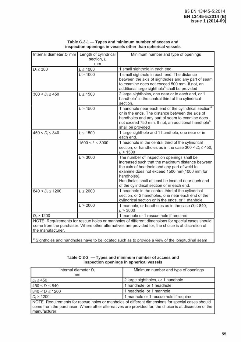
BS EN 13445-5:2014EN 13445-5:2014 (E)
Issue 1 (2014-09)
55
Table C.3-1 — Types and minimum number of access and inspection openings in vessels other than spherical vessels
Internal diameter Di mm Length of cylindrical section, L
mm
Minimum number and type of openings
Di 300 L 1000 1 small sighthole in each end. L > 1000 1 small sighthole in each end. The distance
between the axis of sightholes and any part of seam to examine does not exceed 500 mm. If not, an additional large sightholea shall be provided
300 < Di 450 L 1500 2 large sightholes, one near or in each end, or 1 handholea in the central third of the cylindrical section.
L > 1500 1 handhole near each end of the cylindrical sectiona or in the ends. The distance between the axis of handholes and any part of seam to examine does not exceed 750 mm. If not, an additional handholea shall be provided
450 < Di 840 L 1500 1 large sighthole and 1 handhole, one near or in each end.
1500 < L 3000 1 headhole in the central third of the cylindrical section, or handholes as in the case 300 < Di 450, L > 1500
L > 3000 The number of inspection openings shall be increased such that the maximum distance between the axis of headhole and any part of weld to examine does not exceed 1500 mm(1000 mm for handholes). Handholes shall at least be located near each end of the cylindrical section or in each end.
840 < Di 1200 L 2000 1 headhole in the central third of the cylindrical section, or 2 handholes, one near each end of the cylindrical section or in the ends, or 1 manhole.
L > 2000 1 manhole, or headholes as in the case Di 840, L > 3000
Di > 1200 1 manhole or 1 rescue hole if required NOTE Requirements for rescue holes or manholes of different dimensions for special cases should come from the purchaser. Where other alternatives are provided for, the choice is at discretion of the manufacturer. a Sightholes and handholes have to be located such as to provide a view of the longitudinal seam
Table C.3-2 — Types and minimum number of access and inspection openings in spherical vessels
Internal diameter Di mm
Minimum number and type of openings
Di 450 2 large sightholes, or 1 handhole
450 < Di 840 1 handhole, or 1 headhole
840 < Di 1200 1 headhole, or 1 manhole Di > 1200 1 manhole or 1 rescue hole if required NOTE Requirements for rescue holes or manholes of different dimensions for special cases should come from the purchaser. Where other alternatives are provided for, the choice is at discretion of the manufacturer
BS EN 13445-5:2014EN 13445-5:2014 (E) Issue 1 (2014-09)
56
C.4 Alternative requirements for sightholes openings on small vessels
For vessels with internal diameter lower than or equal to 300 mm the requirements of C.2 and C.3 and Table C.3-1 may be modified as follows:
a) The inside diameter of the sightholes shall be large enough to permit proper internal cleaning and shall not be less than: 19 mm for vessels with an internal diameter up to and including 300 mm;
b) If through these smaller sightholes the internal surface is not completly visible, then the visual inspection shall be supplemented by an additional inspection method which shall be detailed by the manufacturer in his instructions.
C.5 Closing mechanisms and special locking elements
C.5.1 Purpose
This clause deals with the requirements for all types of closures.
C.5.2 Definitions
C.5.2.1 opening and closing devices parts of a vessel which can be removed for operation activities, for example: examination, draining or venting, filling or discharge
C.5.2.2 quick opening and closing devices all types of opening and closing devices with a single control which can be opened and closed faster than those with several locking elements, each of which requires to be operated individually
C.5.3 Materials of construction, design
Opening and closing devices shall be designed and manufactured so that their tightness is ensured even under test pressure and that they cannot be opened inadvertently while under pressure.
Suitable materials shall be used from those permitted in EN 13445-2:2014 for all elements of opening and closing devices. Design requirements of EN 13445-3:2014 and manufacturing requirements of EN 13445-4:2014 shall apply.
In opening and closing devices with several locking elements, these parts shall be designed and machined so that under operating conditions the load is distributed evenly among them.
In determining the permissible pressure per unit area of opening and closing devices (e.g. cams on bayonet-type opening and closing devices), both the quality of the surface (i.e. machined) and the alignment of the bayonets (i.e. machined alignment) need to be taken into consideration.
For fully machined and aligned elements giving uniformity of load distribution 100 % of allowable permissible unit area may be used.
For those not fully machined the allowable permissible unit area shall not exceed 75 %.
For a possible weakening of the closing elements by wear or corrosion, calculated dimensions shall be increased by adequate allowances.
For opening and closing devices with more than 3 locking elements, the theoretical, i.e. calculated stress load acting on each locking element, shall be increased by at least 20 %.
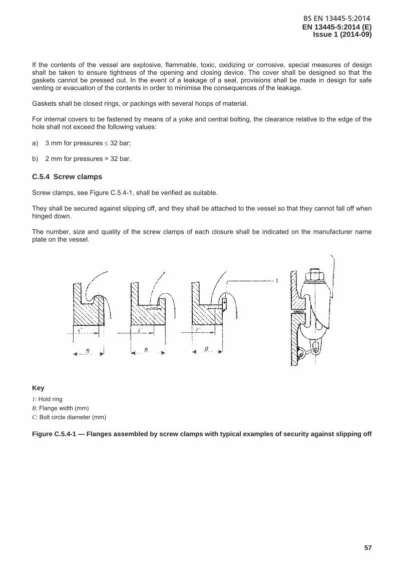
BS EN 13445-5:2014EN 13445-5:2014 (E)
Issue 1 (2014-09)
57
If the contents of the vessel are explosive, flammable, toxic, oxidizing or corrosive, special measures of design shall be taken to ensure tightness of the opening and closing device. The cover shall be designed so that the gaskets cannot be pressed out. In the event of a leakage of a seal, provisions shall be made in design for safe venting or evacuation of the contents in order to minimise the consequences of the leakage.
Gaskets shall be closed rings, or packings with several hoops of material.
For internal covers to be fastened by means of a yoke and central bolting, the clearance relative to the edge of the hole shall not exceed the following values:
a) 3 mm for pressures 32 bar;
b) 2 mm for pressures > 32 bar.
C.5.4 Screw clamps
Screw clamps, see Figure C.5.4-1, shall be verified as suitable.
They shall be secured against slipping off, and they shall be attached to the vessel so that they cannot fall off when hinged down.
The number, size and quality of the screw clamps of each closure shall be indicated on the manufacturer name plate on the vessel.
Key
1: Hold ring
B: Flange width (mm)
C: Bolt circle diameter (mm)
Figure C.5.4-1 — Flanges assembled by screw clamps with typical examples of security against slipping off
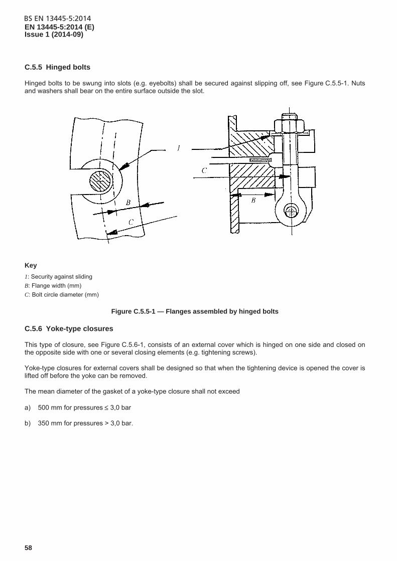
BS EN 13445-5:2014EN 13445-5:2014 (E) Issue 1 (2014-09)
58
C.5.5 Hinged bolts
Hinged bolts to be swung into slots (e.g. eyebolts) shall be secured against slipping off, see Figure C.5.5-1. Nuts and washers shall bear on the entire surface outside the slot.
Key
1: Security against sliding
B: Flange width (mm)
C: Bolt circle diameter (mm)
Figure C.5.5-1 — Flanges assembled by hinged bolts
C.5.6 Yoke-type closures
This type of closure, see Figure C.5.6-1, consists of an external cover which is hinged on one side and closed on the opposite side with one or several closing elements (e.g. tightening screws).
Yoke-type closures for external covers shall be designed so that when the tightening device is opened the cover is lifted off before the yoke can be removed.
The mean diameter of the gasket of a yoke-type closure shall not exceed
a) 500 mm for pressures 3,0 bar
b) 350 mm for pressures > 3,0 bar.
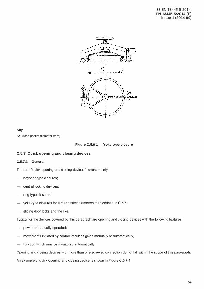
BS EN 13445-5:2014EN 13445-5:2014 (E)
Issue 1 (2014-09)
59
Key
D: Mean gasket diameter (mm)
Figure C.5.6-1 — Yoke-type closure
C.5.7 Quick opening and closing devices
C.5.7.1 General
The term "quick opening and closing devices" covers mainly:
bayonet-type closures;
central locking devices;
ring-type closures;
yoke-type closures for larger gasket diameters than defined in C.5.6;
sliding door locks and the like.
Typical for the devices covered by this paragraph are opening and closing devices with the following features:
power or manually operated;
movements initiated by control impulses given manually or automatically,
function which may be monitored automatically.
Opening and closing devices with more than one screwed connection do not fall within the scope of this paragraph.
An example of quick opening and closing device is shown in Figure C.5.7-1.
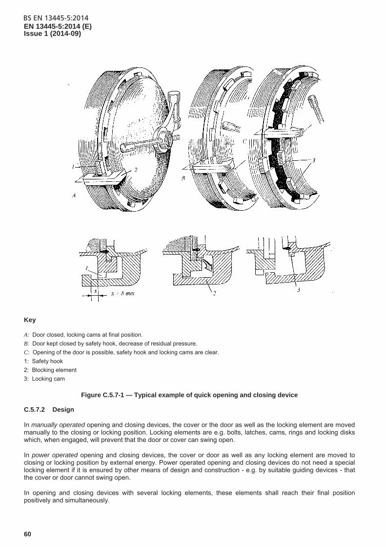
BS EN 13445-5:2014EN 13445-5:2014 (E) Issue 1 (2014-09)
60
Key
A: Door closed, locking cams at final position.
B: Door kept closed by safety hook, decrease of residual pressure.
C: Opening of the door is possible, safety hook and locking cams are clear.
1: Safety hook
2: Blocking element
3: Locking cam
Figure C.5.7-1 — Typical example of quick opening and closing device
C.5.7.2 Design
In manually operated opening and closing devices, the cover or the door as well as the locking element are moved manually to the closing or locking position. Locking elements are e.g. bolts, latches, cams, rings and locking disks which, when engaged, will prevent that the door or cover can swing open.
In power operated opening and closing devices, the cover or door as well as any locking element are moved to closing or locking position by external energy. Power operated opening and closing devices do not need a special locking element if it is ensured by other means of design and construction - e.g. by suitable guiding devices - that the cover or door cannot swing open.
In opening and closing devices with several locking elements, these elements shall reach their final position positively and simultaneously.
BS EN 13445-5:2014EN 13445-5:2014 (E)
Issue 1 (2014-09)
61
C.5.7.3 Safety devices
C.5.7.3.1 General
Quick opening and closing devices shall be designed and arranged so that:
their function cannot be impaired or rendered ineffective by the contents of the vessel;
they are protected against fouling and against tampering by unauthorized persons;
maintenance and function checks are possible at any time.
All moving parts which could cause an accident shall be so designed and/or safeguarded that persons will not be endangered.
Safety devices shall be provided on moving parts, such as:
covers or guards on drives;
contact stops on sliding doors;
non-contact barriers;
impulse contact controls on power operated doors and covers.
C.5.7.3.2 Prevention of pressurisation
Vessels fitted with quick opening access covers or doors shall be provided with devices which ensure that the vessel cannot be pressurised unless the access door is completely closed, the securing mechanism fully engaged and the initial load has been supplied to the sealing element.
In mechanisms with several interconnected locking elements, the element shall reach their final position positively and simultaneously.
Manually operated locking mechanisms shall be deemed to comply with this requirement if, after the closing operation, the cover or door is shut, the locking elements are in position and their final position is monitored.
Monitoring of the locking element can be achieved e.g. by:
a) pressure warning device (e.g. a small opening to the inside of the vessel) which can only be closed when the locking elements are in the locked position, or;
b) an interlocking device between the door locking mechanism and the pressurising system, or;
c) a limit switch(s), in the case of remotely controlled pressure inlet to the vessel or pressure venting valves.
Pressure warning devices dependent upon an opening shall have an internal diameter of at least 8 mm. Where there is a risk of blockage, it shall be possible to manually clear the blockage without endangering the operator.
For interlocking devices where pressure is applied from an external source, the interlock shall be situated between the door locking mechanism and the pressurising fluid inlet valve.
BS EN 13445-5:2014EN 13445-5:2014 (E) Issue 1 (2014-09)
62
If pressure is raised by energy input into the vessel, the interlocking arrangements shall be between the door locking mechanism and the source of energy. Where pressure is applied by a pump, it shall not be possible for the pump to pressurise the system unless the door securing mechanism is fully engaged.
Power operated mechanisms shall be deemed to comply with this requirement if the closed position of the cover or door is monitored so that the vessel can only be pressurised when the cover or door is completely closed and the locking mechanism is fully engaged as specified by the manufacturer.
C.5.7.3.3 Depressurisation
Vessels fitted with quick opening access doors shall be provided with devices which ensure that the source of pressure is isolated and the vessel vented to reduce the internal pressure to atmospheric conditions before the closure or door securing mechanism can be disengaged.
The hazard analysis shall consider the effects of the vented fluid on the operator.
C.5.7.3.4 Residual pressure and temperature warning
Vessels fitted with quick opening access doors shall be provided with devices which:
a) warn the operator of any residual pressure, any remaining fluid which can leak out, and any process fluid at an unsafe temperature, and;
b) ensure that the temperature of the process fluid has been reduced to a safe level, or any toxic fluids that can leak out the vessel have been completely removed before the closure or door securing mechanism can be disengaged.
This may be achieved by providing indicators and warning devices so that the person opening the door is not put at risk.
Where the door seal is prone to sticking, devices shall be provided which either:
1) break the seal before all the locking elements are disengaged, or;
2) restrict the door opening to not more than 8 mm until a harmless residual pressure has been reached.
This requirement may also be achieved by instrument and control measures. In this case, the following requirements also apply:
I) the reduction of pressure down to a harmless level shall be monitored by at least two independent pressure sensors, and;
II) the signal to open the door or cover shall become active only when the pressure venting valve has reached its open position and the signal for equilibrium between internal and external pressure has been given.
If one of these signals is not interrupted during the next pressure cycle, the process shall be brought to a safe state, and,
a) in the case of electrical power failure or failure of a control medium (e.g. instrument air), all processes shall be interrupted or controlled so that persons will not be endangered, and;
b) if it is possible for the cover or door to swing open, then one of the devices described in C.5.7.3.5 shall be fitted.
NOTE A pressure is considered harmless if the forces generated on the door, by the pressure, are too small to cause injury to persons standing in front of it and if it opens in an uncontrolled manner.
BS EN 13445-5:2014EN 13445-5:2014 (E)
Issue 1 (2014-09)
63
Similarly, if a vessel contains other material, in containers or otherwise, in addition to the process fluid, the temperature of these too shall be monitored.
This can be achieved by using an interlock arrangement incorporating a temperature sensing device located in that part of the vessel or contents which is/are expected to remain at the highest temperature at the end of the process.
C.5.7.3.5 Door movement restriction
Vessels fitted with quick opening access doors shall be provided with devices which ensure that the closure does not open violently because of any residual pressure remaining in the vessel.
This can be achieved by fitting the cover or door with a safety device which ensures that:
a) the cover or door cannot swing open, or;
b) the opening process requires several consecutive manipulations or several manual turns so that the cover or door can only be opened when a harmless residual pressure has been reached.
Each power operated door shall be provided with at least one easily accessible and prominently placed shutdown device. These devices shall not be self-resetting. When any of these devices are operated:
a) any residual movement of the door shall not create a hazard, and;
b) all other components related to safety shall return to a safe condition, e.g. valves, seals etc., used to control the flow of fluids, and;
c) use of a special tool, key or code shall be required to reset the shutdown device, in order to restore the normal control system, and such resetting shall not cause a hazard.
C.5.7.3.6 Inflatable or pressure activated seals
The additional requirements set down below have been established for door closures with inflatable or pressure-activated seals.
a) gaskets utilising an auxiliary sealing pressure shall not be regarded as being part of the locking elements;
b) persons shall not be endangered during the build-up, release or unintended loss of the auxiliary sealing pressure;
c) gaskets shall only be pressurised when the locking element has reached its fully engaged position;
d) the valve allowing pressurised fluid to enter the vessel shall only be opened after the sealing pressure of the gasket has reached its design value;
e) during the door opening process, the signal “pressure venting valve open, vessel depressurised” (e.g. from the two pressure sensors) shall initiate the step “release auxiliary sealing pressure” before the cover or door is unlocked;
f) a device shall be fitted such that if the door seal pressure falls below the minimum pressure specified by the manufacturer, then:
entry of fluid into the vessel shall be prevented, and;
the operation shall abort and be brought to a safe state, and;
BS EN 13445-5:2014EN 13445-5:2014 (E) Issue 1 (2014-09)
64
a fault condition shall be indicated, and;
the door shall remain closed, and;
no hazard shall be caused.
C.5.7.4 Testing
The functions according the requirements of this standard shall be tested within the final test of the pressure vessel at the manufacturers. If it is not possible it shall be tested in the installed conditions of the pressure vessel before being put into service.
All quick opening and closing devices used in series production vessels shall be subject to a model acceptance procedure.
In the case of quick opening and closing devices not using a model acceptance procedure and used in one off vessels, they may be only used subject to a design review and functional test prior to operation.
C.5.7.5 Marking
Each device shall be marked with the following information:
a) Identification of the manufacturer,
b) Identification of the device,
c) Identification of limitation of operating parameters and temperatures.
C.5.7.6 Operating and maintenance instructions
The manufacturer shall compile, and hand over to the purchaser/user, operating and maintenance instructions for operating personnel.
These instructions shall contain at least the following information:
The service/maintenance-intervals. These shall be specified and observed.
That the user shall keep maintenance records.
Checks of the closing mechanism with regard to deformations, wear, damage etc. and indications on the replacement of worn parts that may become necessary.
That where necessary, the manufacturer shall prescribe measures and, if required, also tolerances. The replaceable parts subject to wear shall be clearly identified in the maintenance manual with their designation and materials specifications, to be in compliance with type examination or approval.
That other materials may be used only after prior consultation with the manufacturer of the quick opening and closing device and after due consideration of the special operating conditions.
That operating personnel shall be given adequate instructions and training for safe operations.
That the operating instructions shall be set out in printed form and shall be available on the site where the vessel is operated.
BS EN 13445-5:2014EN 13445-5:2014 (E)
Issue 1 (2014-09)
65
Annex D (informative)
Leak Testing
D.1 General
Criteria for the selection of a suitable leak testing method are given in EN 1779:1999. Bubble test is specified in EN 1593, helium test in EN 13185, and pressure change test in EN 13184.
Any low pressure leak test should be carried out prior to any hydrostatic pressure test.
D.2 Leak testing personnel
Personnel performing leak testing should be qualified in accordance with EN ISO 9712:2012.
BS EN 13445-5:2014EN 13445-5:2014 (E) Issue 1 (2014-09)
66
Annex E (informative)
Acoustic emission
E.1 General
The acoustic emission technology, as described in this annex, is not intended as a replacement of the mandatory testing and examination requirements but as a complementary measure for pneumatic test and combined hydrostatic/pneumatic test.
The method may be applied to pressure vessels of simple geometry, e.g. spheres and cylinders with dished or flat ends and should not be used for pressure vessels with discontinuities and pressure vessels with joggle joints and/or welds on backing strips.
E.2 Useful standards
The standards which apply to acoustic emission are listed in Bibliography.
E.3 Acoustic emission personnel
Personnel performing acoustic emission should be qualified to EN ISO 9712:2012.
E.4 Additional requirements
The preparation, test performance and reporting should be performed according to EN 14584. The number of the sensors should be sufficient to achieve 100 % volumetric monitoring of the tested pressure equipment.
The pressurisation rate should not exceed 1 % of the maximum test pressure per minute.
The measurement should be continued also during the depressurisation till the pressure iP for the visual inspection
of the pressure equipment is reached.
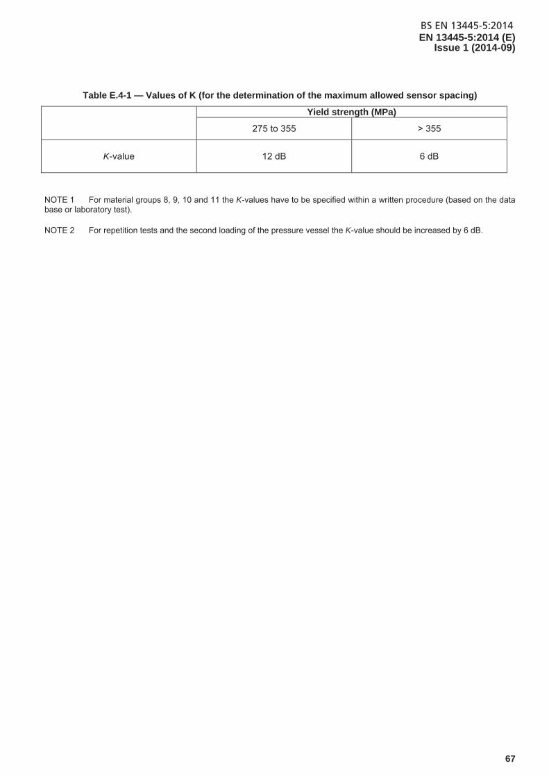
BS EN 13445-5:2014EN 13445-5:2014 (E)
Issue 1 (2014-09)
67
Table E.4-1 — Values of K (for the determination of the maximum allowed sensor spacing)
Yield strength (MPa)
275 to 355 > 355
K-value 12 dB 6 dB
NOTE 1 For material groups 8, 9, 10 and 11 the K-values have to be specified within a written procedure (based on the data base or laboratory test).
NOTE 2 For repetition tests and the second loading of the pressure vessel the K-value should be increased by 6 dB.
BS EN 13445-5:2014EN 13445-5:2014 (E) Issue 1 (2014-09)
68
Annex F (normative)
Inspection and testing of pressure vessels or parts subject to creep
F.1 General
For vessels or vessel parts subject to creep, Quality Level B of EN ISO 5817:2014 is the reference quality level for maximum allowable imperfection in these areas. The absence of surface imperfections (no undercut, no root concavity and no lack of penetration) and the necessity of smooth transitions are essential. Similarly, shape imperfections, such as peaking, may be critical and the manufacturing tolerances specified in EN 13445-4:2014 shall be respected. In particular, the maximum peaking of EN 13445-4:2014 or the value permitted by the design methods of EN 13445-3:2014 shall not be exceeded.
Extent of Non-Destructive Testing (NDT) of this annex is based on the general requirements of testing sub-groups 1c and 3c, as defined in Table F.2-1.
If lifetime monitoring is a design option, any procedure for control and testing shall be part of the Instructions for use prepared by the manufacturer.
NOTE Supplementary tests may also be prescribed by the manufacturer. These tests will be specified in the Instructions for use.
F.2 Extent of inspection and testing
In addition to the requirements of 6.6.2, all areas subject to creep shall be inspected by NDT, according to Table F.2-1.
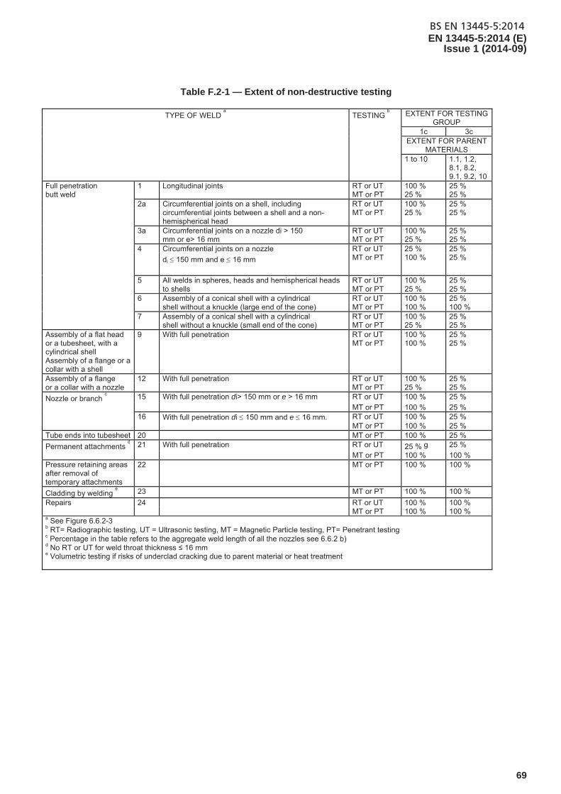
BS EN 13445-5:2014EN 13445-5:2014 (E)
Issue 1 (2014-09)
69
Table F.2-1 — Extent of non-destructive testing
TYPE OF WELD a TESTING
b EXTENT FOR TESTING
GROUP 1c 3c EXTENT FOR PARENT
MATERIALS 1 to 10 1.1, 1.2,
8.1, 8.2, 9.1, 9.2, 10
Full penetration 1 Longitudinal joints RT or UT 100 % 25 % butt weld MT or PT 25 % 25 % 2a Circumferential joints on a shell, including RT or UT 100 % 25 % circumferential joints between a shell and a non-
hemispherical head MT or PT 25 % 25 %
3a Circumferential joints on a nozzle di > 150 RT or UT 100 % 25 % mm or e> 16 mm MT or PT 25 % 25 % 4 Circumferential joints on a nozzle RT or UT 25 % 25 % di 150 mm and e 16 mm MT or PT 100 % 25 %
5 All welds in spheres, heads and hemispherical heads RT or UT 100 % 25 % to shells MT or PT 25 % 25 % 6 Assembly of a conical shell with a cylindrical RT or UT 100 % 25 % shell without a knuckle (large end of the cone) MT or PT 100 % 100 % 7 Assembly of a conical shell with a cylindrical RT or UT 100 % 25 % shell without a knuckle (small end of the cone) MT or PT 25 % 25 % Assembly of a flat head 9 With full penetration RT or UT 100 % 25 % or a tubesheet, with a cylindrical shell Assembly of a flange or a collar with a shell
MT or PT 100 % 25 %
Assembly of a flange 12 With full penetration RT or UT 100 % 25 % or a collar with a nozzle MT or PT 25 % 25 %
Nozzle or branch c 15 With full penetration di> 150 mm or e > 16 mm RT or UT 100 % 25 %
MT or PT 100 % 25 % 16 With full penetration di 150 mm and e 16 mm. RT or UT 100 % 25 % MT or PT 100 % 25 % Tube ends into tubesheet 20 MT or PT 100 % 25 %
Permanent attachments d 21 With full penetration RT or UT 25 % g 25 %
MT or PT 100 % 100 % Pressure retaining areas after removal of temporary attachments
22 MT or PT 100 % 100 %
Cladding by welding e 23 MT or PT 100 % 100 %
Repairs 24 RT or UT 100 % 100 % MT or PT 100 % 100 % a See Figure 6.6.2-3 b RT= Radiographic testing, UT = Ultrasonic testing, MT = Magnetic Particle testing, PT= Penetrant testing c Percentage in the table refers to the aggregate weld length of all the nozzles see 6.6.2 b) d No RT or UT for weld throat thickness ≤ 16 mm e Volumetric testing if risks of underclad cracking due to parent material or heat treatment
BS EN 13445-5:2014EN 13445-5:2014 (E) Issue 1 (2014-09)
70
F.3 Performance of NDT and acceptance criteria
The quality level shall be quality level B in accordance with EN ISO 5817:2014, with the following additional requirements for some imperfections:
stray arc (601) – removal plus 100 % MT or PT to ensure no imperfection;
spatter (602) – weld spatter shall be removed from all pressure parts and load carrying attachment welds. Isolated non systematic spatter is permitted on components made of group 1 materials;
torn surface (603), grinding mark (604), chipping mark (605) shall be ground to provide a smooth transition;
underflushing (606) shall not be permitted. Any local underflushing shall be related to design characteristics (calculated thickness + corrosion allowance).
F.4 Documents
In addition to the requirements of 12.3, for vessels or parts designed for creep, all NDT records shall be retained for the whole design life of the vessel.
BS EN 13445-5:2014EN 13445-5:2014 (E)
Issue 1 (2014-09)
71
Annex G (normative)
Inspection and testing of pressure vessels subject to cyclic loads
G.1 General
To avoid fatigue damage in case of cyclic loading, more severe inspection and testing requirements are needed for
critical areas of the pressure vessels, i.e. areas that can limit the lifetime of the vessel for 500eq n full range or
equivalent pressure cycles (See EN 13445-3:2014, 17.2.16 or 18.10.5 for definition of critical areas).
To reflect this, Quality Level B of EN ISO 5817:2014 is the reference quality level for maximum allowable welds imperfections in these critical areas.
For cyclic loaded vessels the absence of surface imperfections (no undercut, no root concavity, no lack of penetration for full penetration welds) and the necessity of smooth transitions are essential. Only smooth transitions are allowed, see EN 13445-3:2014, Annex A.
Similarly, shape imperfections such as peaking are absolutely critical and the maximum permissible peaking of EN 13445-4:2014, 5.4.4 or the value permitted in the fatigue analysis of Clauses 17 and 18 of EN 13445-3:2014 and referred to below, shall not be exceeded.
These testing requirements are in addition to the general vessel testing requirements based on the vessel testing groups 1, 2 or 3.
All critical areas shall be clearly designated in the design documentation, see Clause 5 and EN 13445-3:2014.
G.2 Extent of inspection and testing
In addition to the requirements of 6.6.2, all locations where cumulative fatigue damage index D is greater than 0,8, the surfaces shall be 100 % inspected, visually and by other NDT.
G.3 Performance and acceptance criteria
The quality level shall be quality level B in accordance with EN ISO 5817:2014, with the following additional requirements for some imperfections:
stray arc (601) – removal plus 100 % MT or PT to ensure no imperfection;
spatter (602) – weld spatter shall be removed from all pressure parts and load carrying attachment welds. Isolated non systematic spatter is permitted on components made of group 1 materials;
torn surface (603), grinding mark (604), chipping mark (605) shall be ground to provide a smooth transition;
underflushing (606) shall not be permitted. Any local underflushing shall be related to design characteristics (calculated thickness + corrosion allowance).

BS EN 13445-5:2014EN 13445-5:2014 (E) Issue 1 (2014-09)
72
G.4 Technical documentation, additional requirements
The supporting detailed construction drawings are required to clearly locate the critical areas identified in the design fatigue analysis. In addition, the maximum permissible peaking and other critical imperfections shall also be given in the drawings.
A test report shall prepared documenting the measured values of peaking and other critical imperfections identified on the drawings.
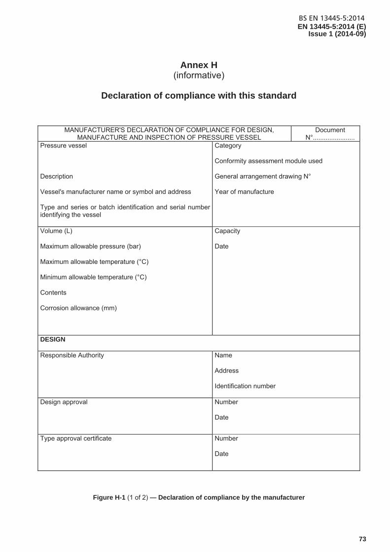
BS EN 13445-5:2014EN 13445-5:2014 (E)
Issue 1 (2014-09)
73
Annex H (informative)
Declaration of compliance with this standard
MANUFACTURER'S DECLARATION OF COMPLIANCE FOR DESIGN, MANUFACTURE AND INSPECTION OF PRESSURE VESSEL
Document N°.......................
Pressure vessel
Description
Vessel's manufacturer name or symbol and address
Type and series or batch identification and serial number identifying the vessel
Category
Conformity assessment module used
General arrangement drawing N°
Year of manufacture
Volume (L)
Maximum allowable pressure (bar)
Maximum allowable temperature (°C)
Minimum allowable temperature (°C)
Contents
Corrosion allowance (mm)
Capacity
Date
DESIGN
Responsible Authority Name
Address
Identification number
Design approval Number
Date
Type approval certificate Number
Date
Figure H-1 (1 of 2) — Declaration of compliance by the manufacturer
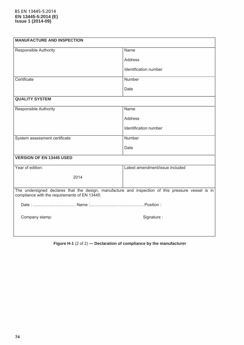
BS EN 13445-5:2014EN 13445-5:2014 (E) Issue 1 (2014-09)
74
MANUFACTURE AND INSPECTION
Responsible Authority Name
Address
Identification number
Certificate Number
Date
QUALITY SYSTEM
Responsible Authority Name
Address
Identification number
System assessment certificate Number
Date
VERSION OF EN 13445 USED
Year of edition:
2014
Latest amendment/issue included
The undersigned declares that the design, manufacture and inspection of this pressure vessel is in compliance with the requirements of EN 13445.
Date : ...................................... Name :......................... ...................... Position :
Company stamp: Signature :
Figure H-1 (2 of 2) — Declaration of compliance by the manufacturer
BS EN 13445-5:2014EN 13445-5:2014 (E)
Issue 1 (2014-09)
75
Annex I (informative)
Specific tests during construction to assist in-service inspection
I.1 General
This annex provides guidance on tests which may be made during fabrication to provide baseline data for inspection in service. It should be considered in conjunction with Annex M of EN 13445-3:2014.
I.2 Metallographic investigation
Metallographic investigation of welded joints and base material may be used to record the initial material structure and to be able to assess material ageing at future inspections. The following requirements apply:
Replicas should be performed at the end of the fabrication process (after all heat treatments, welding, etc);
Number and extent of replicas should be representative of the critical regions for creep damage, e.g. welds operating at high stress and temperature;
Replica locations should include base material, HAZ and welded material. Areas of larger stress and temperature should be preferred;
Replicas should be stored in a proper way and kept for the whole life of the vessel.
I.3 Hardness measurements
Hardness measurements of welded joints and base material may be used to record the initial material condition and to be able to assess material ageing at future inspections. The following requirements apply:
Hardness measurements should be performed at the end of the fabrication process (after all heat treatments, welding, etc);
Number and extent of hardness measurements should be representative of the size and complexity of the pressure vessel, and the critical zones for creep damage;
Hardness records should be stored in a proper way and kept for the whole life of the vessel.
BS EN 13445-5:2014EN 13445-5:2014 (E) Issue 1 (2014-09)
76
I.4 Dimensional measurements
High precision diameter measurements of creep designed components may be taken during fabrication to assess the evolution of creep deformation.
The precision on the measurement of diameter should be as follows:
Diameter up to 100 mm 0,01 mm
100 mm < Diameter ≤ 500 mm 0,02 mm
500 mm < Diameter ≤ 1 000 mm 0,05 mm
Diameter > 1000 mm 0,1 mm
Measurements of circumference or other key dimensions may also be taken.
BS EN 13445-5:2014EN 13445-5:2014 (E)
Issue 1 (2014-09)
77
Annex Y (informative)
History of EN 13445-5
Y.1 Differences between EN 13445-5:2009 and EN 13445-5:2014
The 2014 edition of EN 13445-5 contains the 2009 edition of the standard and all Amendment(s) and/or correction(s) issued in the meantime.
Significant technical changes include:
— the modification of the requirements of the test on a statistical basis. These requirements are transferred from Annex A to paragraph 10.2.3.9;
— the modification of the requirements of Annex A of the inspection and control of mass-produced pressure vessels;
— the modification of the pneumatic test of vessels in the control groups 1 and 2: decreasing the test pressure is possible with increase in the range of CND;
— the extension of the scope to pressure vessels designed for cyclic operation.
NOTE The changes referred include the significant technical changes but is not an exhaustive list of all modifications.
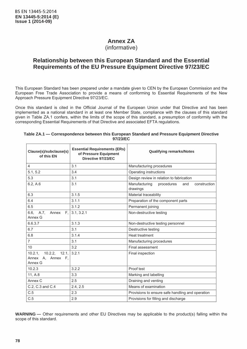
BS EN 13445-5:2014EN 13445-5:2014 (E) Issue 1 (2014-09)
78
Annex ZA (informative)
Relationship between this European Standard and the Essential Requirements of the EU Pressure Equipment Directive 97/23/EC
This European Standard has been prepared under a mandate given to CEN by the European Commission and the European Free Trade Association to provide a means of conforming to Essential Requirements of the New Approach Pressure Equipment Directive 97/23/EC.
Once this standard is cited in the Official Journal of the European Union under that Directive and has been implemented as a national standard in at least one Member State, compliance with the clauses of this standard given in Table ZA.1 confers, within the limits of the scope of this standard, a presumption of conformity with the corresponding Essential Requirements of that Directive and associated EFTA regulations.
Table ZA.1 — Correspondence between this European Standard and Pressure Equipment Directive 97/23/EC
Clause(s)/subclause(s) of this EN
Essential Requirements (ERs) of Pressure Equipment
Directive 97/23/EC
Qualifying remarks/Notes
4 3.1 Manufacturing procedures
5.1, 5.2 3.4 Operating instructions
5.3 3.1 Design review in relation to fabrication
6.2, A.6 3.1 Manufacturing procedures and construction drawings
6.3 3.1.5 Material traceability
6.4 3.1.1 Preparation of the component parts
6.5 3.1.2 Permanent joining
6.6, A.7, Annex F, Annex G
3.1, 3.2.1 Non-destructive testing
6.6.3.7 3.1.3 Non-destructive testing personnel
6.7 3.1 Destructive testing
6.8 3.1.4 Heat treatment
7 3.1 Manufacturing procedures
10 3.2 Final assessment
10.2.1, 10.2.2, 12.1, Annex A, Annex F, Annex G
3.2.1 Final inspection
10.2.3 3.2.2 Proof test
11, A.8 3.3 Marking and labelling
Annex C 2.5 Draining and venting
C.2, C.3 and C.4 2.4, 2.5 Means of examination
C.5 2.3 Provisions to ensure safe handling and operation
C.5 2.9 Provisions for filling and discharge
WARNING — Other requirements and other EU Directives may be applicable to the product(s) falling within the scope of this standard.
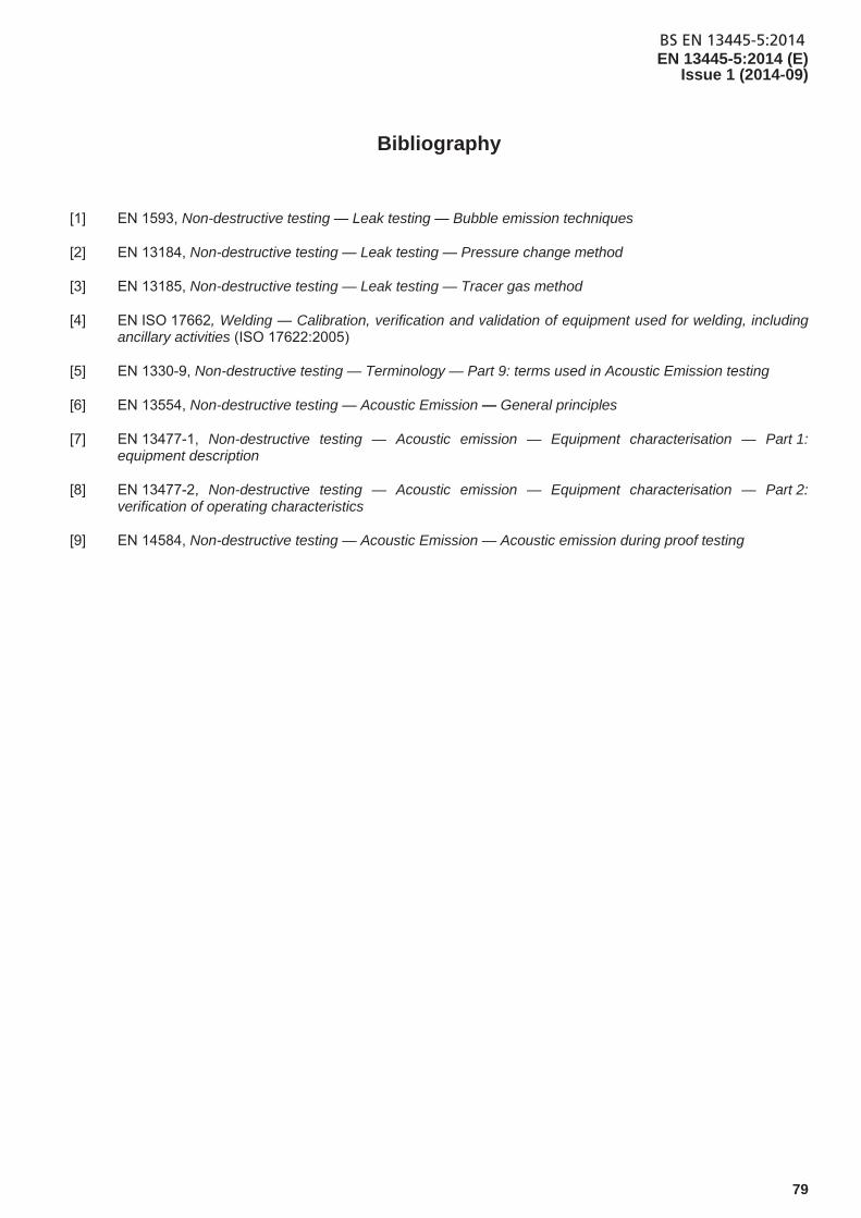
BS EN 13445-5:2014EN 13445-5:2014 (E)
Issue 1 (2014-09)
79
Bibliography
[1] EN 1593, Non-destructive testing — Leak testing — Bubble emission techniques
[2] EN 13184, Non-destructive testing — Leak testing — Pressure change method
[3] EN 13185, Non-destructive testing — Leak testing — Tracer gas method
[4] EN ISO 17662, Welding — Calibration, verification and validation of equipment used for welding, including ancillary activities (ISO 17622:2005)
[5] EN 1330-9, Non-destructive testing — Terminology — Part 9: terms used in Acoustic Emission testing
[6] EN 13554, Non-destructive testing — Acoustic Emission — General principles
[7] EN 13477-1, Non-destructive testing — Acoustic emission — Equipment characterisation — Part 1: equipment description
[8] EN 13477-2, Non-destructive testing — Acoustic emission — Equipment characterisation — Part 2: verification of operating characteristics
[9] EN 14584, Non-destructive testing — Acoustic Emission — Acoustic emission during proof testing

This page deliberately left blank

This page deliberately left blank
BSI is the national body responsible for preparing British Standards and other standards-related publications, information and services.
BSI is incorporated by Royal Charter. British Standards and other standardization products are published by BSI Standards Limited.
British Standards Institution (BSI)
BSI Group Headquarters
389 Chiswick High Road London W4 4AL UK
About usWe bring together business, industry, government, consumers, innovators and others to shape their combined experience and expertise into standards -based solutions.
The knowledge embodied in our standards has been carefully assembled in a dependable format and refined through our open consultation process. Organizations of all sizes and across all sectors choose standards to help them achieve their goals.
Information on standardsWe can provide you with the knowledge that your organization needs to succeed. Find out more about British Standards by visiting our website at bsigroup.com/standards or contacting our Customer Services team or Knowledge Centre.
Buying standardsYou can buy and download PDF versions of BSI publications, including British and adopted European and international standards, through our website at bsigroup.com/shop, where hard copies can also be purchased.
If you need international and foreign standards from other Standards Development Organizations, hard copies can be ordered from our Customer Services team.
SubscriptionsOur range of subscription services are designed to make using standards easier for you. For further information on our subscription products go to bsigroup.com/subscriptions.
With British Standards Online (BSOL) you’ll have instant access to over 55,000 British and adopted European and international standards from your desktop. It’s available 24/7 and is refreshed daily so you’ll always be up to date.
You can keep in touch with standards developments and receive substantial discounts on the purchase price of standards, both in single copy and subscription format, by becoming a BSI Subscribing Member.
PLUS is an updating service exclusive to BSI Subscribing Members. You will automatically receive the latest hard copy of your standards when they’re revised or replaced.
To find out more about becoming a BSI Subscribing Member and the benefits of membership, please visit bsigroup.com/shop.
With a Multi-User Network Licence (MUNL) you are able to host standards publications on your intranet. Licences can cover as few or as many users as you wish. With updates supplied as soon as they’re available, you can be sure your documentation is current. For further information, email [email protected].
RevisionsOur British Standards and other publications are updated by amendment or revision.
We continually improve the quality of our products and services to benefit your business. If you find an inaccuracy or ambiguity within a British Standard or other BSI publication please inform the Knowledge Centre.
CopyrightAll the data, software and documentation set out in all British Standards and other BSI publications are the property of and copyrighted by BSI, or some person or entity that owns copyright in the information used (such as the international standardization bodies) and has formally licensed such information to BSI for commercial publication and use. Except as permitted under the Copyright, Designs and Patents Act 1988 no extract may be reproduced, stored in a retrieval system or transmitted in any form or by any means – electronic, photocopying, recording or otherwise – without prior written permission from BSI. Details and advice can be obtained from the Copyright & Licensing Department.
Useful Contacts:Customer ServicesTel: +44 845 086 9001Email (orders): [email protected] (enquiries): [email protected]
SubscriptionsTel: +44 845 086 9001Email: [email protected]
Knowledge CentreTel: +44 20 8996 7004Email: [email protected]
Copyright & LicensingTel: +44 20 8996 7070Email: [email protected]
NO COPYING WITHOUT BSI PERMISSION EXCEPT AS PERMITTED BY COPYRIGHT LAW