steam vessels and marine engines - survivor library
TRANSCRIPT

^\

CORNELLUNIVERSITYLIBRARY
BOUGHT WITH THE INCOMEOF THE SAGE ENDOWMENTFUND GIVEN IN 1891 BY
HENRY WILLIAMS SAGE

Cornell University Library
VM298 .H85
3 1924 030 901 817Overs
olin


HOWELL'SSteam Vessels and Marine Engines
By G. FOSTER HOWELL.
Being' descriptions and illustrations of some ol the principal Steamships,
Steamboats, Steam Yachts and Tugs built in the United States
during the past live years, together with regular and
special designs of Compound, Triple and
Quadruple-Expansion Yacht and
Marine Pvngines, Etc.
W^ITH A CLOSINCr CHAPTER ON SAILINO SHIPSAND SCHOONER VACHTS.
Pt'btjshrd by the American Shipbt-itjier,
7 CoENTiES vSeip, Xem' York.

iJ
tto mv Jfrtent
(Ibarlcs 36. HDillcr,
Cbls worn 16 ic0pfcttullv Cet^icate^.

PREFACE.
>H1'', object of this book is 1<J provide iia\ ;il architects, sliipl>uilders and engineers with a
) work of reference. No book of tliis particular kind, showing iUnstrations of modern
American marine engines, has ever Ijeen pubHshed in the United vStates. Many
American readers are familiar with that excellent British work, " Maw's Marine Engines," b>'
Wm. H. Maw, and if one goes to a technical book publisher for a copy of a publication uptjn
marine engines, he will be offered one of the many English or Scotch works on that subject,
as no American book can l)e found. The same raa>' be said of works npoii steamships and
yachts. In the preparation of this book I have used se\-eral articles and cuts that have
previoush' appeared in the leading marine and mechanical journals of the United States and
Great Britain. In this connection I will thank in advance the editors and proprietors of the
following papers ; Engmeei intr^The Engineer, London: The Engineer. Xew York; The
Steamship, I^eith, vScotland ; Maritie Engineer, London; Ameriean Engineer, New York;
.Atneriean MiuliinisI , New York ;/'),('<;', New York ; Seienlifie Anierie<nt , New York ;
Cosiier' .
Magazine, New York ; Marine Reiieie, Cleveland, Ohio. New York Jim; ineering Maga-
zine. My thanks are also due Ered J. Miller, Prof. J. G. A. Meyer, W. P. Stephens, Thos.
Main, M.E., Wm. A. F'airburn, of Bath, Me., and others, for professional assistance (loan
of drawings, cuts, etc. ) in connection with the jjublication of this work. If I have omitted
the name of anj' journal or authority from which data or illustrations have been obtained for
this publication, it has been quite unintentional. Although the book is intended principally as
a work on modern American steam ve.ssels and marine engines, I have, in one or two instances,
strayed a little from the plan indicated on the litle-j)age, as is the case in illustrating and
describing the old vSavannah and the British steamers Campania, Lucania, Cit>' of Rome,
America, Empress of Japan, etc., but these additions to the work will doubtless be appreciated
by shipbuilders and engineers. To make the book more intere.sting and complete, portraits of
some of the designers and builders of the vessels and engines shown in these pages have
been added. A few cuts of some well-known marine men are also inserted,
G. FOSTER HOWELL,
Brooklyn, .\. )'., January /, iSi)6. y2 1 LaFAVETTE AvENUE.

TABLE OF CONTENTS.
STEAMSHIPS, STKAxMBoATS. -MARINE i-'.XCIXES, ETC.
American Line Steainship St Loins and En.i^inesCunard Line Twin-Screw Steamer Campania and Engines.American Steamship Savannali.< lid Dnminion Line Steam.ship N'orktrnvnBritish Steamship AmericaSteamship HowardTwin-Screw Passenger Steamers Northwest and Nortliland .
Steamship El Sol.
Twin-Screw Steamer Em]jress of Japan.Anchor I<ine Steamshi]) City of Rome. -
Freij^ht Steamship El RioRed J) Line Steamship Curacoa. .
Wlialeliack Steamer Joseph L. Colliv
Whaleback Steamer Charles W. WelmoreMorgan Line Steamship El NorteEllis iS; Eaves' Induced or .SuctKm LraftThe Sea-Going Steel Tug NottinghamTwin-Screw Steamer City of Lowell.Engines of Steamer Richard PeckEngine of Whaleback Steamer Christopher Cohnnbns.New Steamer Cape Ann . .
Plans and Si>ecifications for an Iron Tug, ....Fire Boat New Voiker and Engines. .
Bttston and Portland Steamer Bay StateBoston Fire Boat No. 44,,
Steel Tug W, G. Wilmot, of New I )rleans.
Stuart's Channel System of Construction, .
Engine of Steamer Nutmeg State . . .
Chapin's Compound Launch Engine.,
Burrell-Johnson's Compound Jlarine EngineThropp's Compound Marine Engine .
Sloat's Fire and Water-Tube Boiler
Tromblee's Compound Yacht Engine .
Compound Engine of Tug Edwin H. MeadBanshee's Steeple EnginesE^orbes' Yacht E^ngineHayes' Compound JMarine Engini-
Smit's Marine EngineSeaburv's Triple-Expansion Yacht ;{ngine.
Wheeler Surfrice Condenser.Volz's Patent Combined Surface Condenser and h'eed-W'ater HeaterWells' Balanced Compound and (Juadruple E\])ausiiin Engine.Chase's Quadruple-Expansion ^larine EngineClark's Compound A'acht EngineDavis-Farrar Yacht EnginesJoy \'alve GearMarshall's Yalve Gear. .
Canfield's Patent Balance Yalve..
Bonner's Patent Compound Balance ValveSullivan's Trijjle-Expansion Yacht EngineE^ngines of the Yacht Neaira . ...Three-Cvlinder Compound Engines of Steamer Pleasure , . .
Donegan & Swift's Launch tjigine ....Lnmgair's Ouadruple-P^xpansion Ivngine
Steeple Compound En.gines of Ferryboat Cincinnati
CoUer's Yacht EngineSee's Ouadruple-Expansion Engines in Tug F;1 ToroRiley lK: Cowley's Launch and Yacht EnginesPaul's Patent Reversing Gear. . .
Compound Engines of the Hoboken Ferr\-boat Bremen<")scdlating Engine of the Connecliiait. ....( iscillating ICngines . .
Compound Beam Engines of tln' Hnuam
Beam Engines.
,,,i... .Settin.g the Yalves of Beam iMigines. . , .
Ill Morris' Compound Marine lingine . ...i,^ Compound Engine of Steam Yacht Dream.13 (hiadruple-F^x-pansion Engines of the Sleainshi]i KensingtoniS Kiugdon's Patent Engine for Steam LaunchesiS Il.nig's Compound Marine F^ngine. .
i.S Composite Steam Light A'es.scl
^5 STEAil YACHTS.26 Composite -\n.\iliar\ Steam Yacht Satanella. . .
27 Steam Yacht F'ree Lance .
27' Steam Yacht Formosa. .
30 Steam Yacht Peregrine. ...30 T\\in-Screw .Steam Yacht Ilirondelle.
30 Steam Yacht Valiant .
33 Steam Yacht Marietta, No. > .........33
i
Auxiliary Steam Yacht Seniiraniis
34 j
Wooden Steam Yacht Chetolah , . , . .
36I
Wooden Steam Yacht Reverie
37 j
Steam Yacht Oneonta ...39 ! Steam Yacht Wapiiti and her Ivngincs.
39 i
Steam Yachts Built li\' Win. Cramp i\; Sons42 Steam Yaclit FHeanor . .
4,S Steam Yacht Rex .
45 Three F'astest Steam \';ichls ..,.,, ,
46 Steam \'aclit Alcedo
47 Steam Yacht Dungeness4S Wooden Steam Yacht Clerinont . . , . ,
49 Steam Yacht Restless . ,
50 Wooden Steam Yaclit Linta50 Wooden Steam Yacht Caly]>so .
,s2I
Steam Yacht Embla.S2 Auxiliary Steam Yacht Wild Duck ....53 !
Fast British Steam Launch Wild Duck
57SAILING SHIPS, SCIKIOXER YACHTS, ETC.
,=;7 Clipper Shi|i Morning Li.ght
.S7 Celebrated Clipper Slii]) Young America57 Wooden Ship Aryan.5IS First .\merican Steel Sailing Ship .
60 Packet Ship Dreadnought62
]
American Wooden Shipentine Roanoke62
I
F'our-Masted Bark Olvmpic.66 -Vmerican Steel Bark
The Largest Sailing Vessel in the World69 Five-Masted Ship Maria Rickmers
vSteel Shipentine SomalieF'our-Masted Ship Falls of Earn
74 ;British Shipentine Afghani.stan
74 R. P. Joy's Schooner Yacht Pilot. . . .
7,S Auxiliary Steam Yacht Utowana76 .Steel Schooner Yacht Lasca79 Reefing TopsailsSi French Schooner Yacht X'eloxSi Pilot Boat for Fernamlina, Fla82 Swedish Schooner \'acht Sveridge.85 The -America.
85 Combined Cruising ami Racing Schooner87 Five-Masted Schooner Gov. Ames,88 Manton's Improved Windlass for Fishermen89 Providence Fisherman's Windlass91 Howell's Automatic Wave Lubricating Life Bno\ . .
93 Ca])tain William Tunibridgt93 'I'ackiug Shi]] ("iff Shon-.
9494
9797
97101
lol
103
104
104107loS
109
109no112
"3"3114117120121
121
121
123126126128
130
130
130132
134
134
13'^
137I3«
142
144144
144145146
145
147
H7147148148
152
LS415415H
LSS
159
159159162
'63163
167

PORTRAITS.Win. H. WcIjIj, Ainericii's Greatest Wooden Sliipljuililer; l'uunil<r
of \Veb>)'s Academy and Home for Sliipbnilders, I'ordluimHeights, N Y.
Cr.iiii|j Sliiplmildin,!; Works, I'hil;
late Iron Slll|)l)uil(ler
the \\'m. Cram]) \' Sons Sin]) ami
Electrii: Co.,
San
Wm. Cram]), Pounder of tin
ilel])hia, I'a.
John Ivoach, Chester, I'a., Lin
Chas. H. Cram]), President c
Engine Building Co.
J. C. Henderson, Ex-Chief Engineer (general1 Edison Systems), New York ....
George W. Melville, Engineer-in-Chief, United States NavyIrving M. Scott, President of the Union Iron Works,
I'Vancisco, CalClement A. Griscom, President International Navigation Co.,
Philaileljjhia, Pa.(tCO. W. Dickie, Manager Union Iron Works, San I'raiicisco, Cal.,Capt, George I,. Norton, Ivditor New York A/ai iiic JuitniiilJohn W. Collins, I'jigineer-in-Chiel' U. S Re\emie Marine
Service, Washington, I). C.W. T. Sylven, Designing and Sn]ieniilenuiiig JMigmecr U. S.
Lighthou.se Service. .
Horace See, Engineer and Na\al Architect, .New \'orkW. II. Jacques, of See i\: Jac(|ues . .
Cieorge V. Sloat, Sui)erintendin,g Engineer, ( )ld Dominion Line,New York . . . . .
Chas. D. Mosher, Engineer and Naval Architect, New YorkE. Piatt vStrattou, Chief Engineer Surveyor to the Record of
American and Foreign vShi]:)ping; Consulting Engineerby Appointment to the Board of Underwriters, New York,
Sonimers N. Smith, M.E., Superintendent Newjiort Ne\vs(A'ir-ginia) vShipbuilding and Dry Dock Co . .
W. F.'Durand, Profes.sor of (Marine) Engineering, Sibley Col-lege, Cornell University, Ithaca, N. Y. ...
John Haug, Engineer and Naval Architect, Philadelphia, Pa.,Chas. R. Hanscom, Naval Architect, Superintendent Bath (Maine)
Iron Works. .
i6,,
17.?
I 7-1
171
175
17.S
176
176
'76
176
177
177
177
b'rank B. King, bjigineer and Naval Architect, SuperintendentMarine Department, Marj-laml Steel Co., S]Mrrow's Point, 17;
Darwin Almy, Inventor and Builder of the .\lm\ Water-TulieBoiler, Providence, K. I . 17S
Ilem-\- Konitzsky, N'aval Architei't anil Paignieir, Pliiladel|Oii;i 17.S
Richanl P. Joy, Detroit, Mich , the Patriot, and Erie ud ami .\d-
vocate of American Shii)])ing Interests 171)
Chas. B. Miller, Founder of the Magnolia Metal Co., New \'ork, 179Chas Ward, of Charle.ston, W. \'a., the Iiuentor .and Builder of
the Ward Boiler . . 1 79l\. E. Roberts, of Red Bank, N. J., Inventor and Builder of the
Roberts Water-Tube Boiler . . 1 79Chas. \i. Hyde, Desi,gning and Constructing Engineer, Bath
( Maine ) Iron Works .... 180Sinclair Stuart, Shi]) and En.gineer Surveyor to the I "nited
States Lloyds, etc., New York . . i.Sn
I bibert Caiifield, Master Mechanic Peiinsvlvania K. K. Slio]is,
Hobokcn, N. J'.
. . ),S<.
Sam'l J. Clarke, .Superiuteniliii'.; baigiiieer Providene'e i\: .Stoiung-tou Line, New ^ork ... i^-o
James S. Doraii, Superintending Engineer I nlern.ilioiial Xa^'iga-tioii Co , New \'ork . ... i.Si
(jeorge Clarke, A.ssistant Sui^erintendent, Ivngineer Americanand Red Star Lines, New York . i.Si
John H. l)ialo,gue, Iron vShipbuilder, Camden, N. J . i,S2
Gustav Hillmann, Naval Architect, Brooklvn, N. Y., Designer of
the Steam Yacht Nourmahal, etc., etc ... 1.S2
T. Jackson ,Shaw, Chief En.gineer the Harlan & HollingsuorthCo., Wilmington, Bel ... . [.S2
James Dredge, of Messrs. Maw & Dredge, Editors LondonE)iginei:riii)( i.s-
Capt. Wm. Tnuibridge, Proprietor Hotel St. George, Brooklvn,N. Y.
'
. .
.' 1S4
Ca]5t. 1. J. ;\Ierritt, of the Merritl Wreckin,g Organization, Xe«-A'ork . . . 184
Philip Hichborn, Chief Constructor, V . S. Navy i(S4
SThAJiSHii' St. P.\ui,.
Erratum.
Ill the description of the engines of steam yacht Cohtmbia,page 121, a t}-pographical error occured. It should read :
There are two low-pressure C3dinders, each 34 inches indiameter, the same as in the dynamite gunboat Vesuvius. Thestroke of pistons is 20 inches.
'
'


S3£?!SBllTOte^SSgfSfSlfp3^gEaCQD03aQDr.i-,m.-inD.-o.-io-:Ky>so^r>-yir-r-^
nrrYyr¥r>-r,.-v^'^".'iryirjL.u/;'^"y^Oi-inn-^rorin ^x";;^
The Amp;rican Line Twin-Screw Passengkr and Mail vSteamkr vSt. lyouis.—By the Wm. Cramp & Sons Ship and Kngine Building Co.

HOWELL'S STEAM VESSELS AND MARINE ENGINES.
The American Line Steamer St. Louis and Engines.
The dimensions of the vessel are as follows : Length overall, 554.2 feet ; length between perpendiculars, 535.8 feet ; ex-
treme beam, 63 feet;gross tonnage, 11,629.21 tons; net ton-
nage, 5,893.73 tons. The St. Louis and St. Paul are sister
ships. Both were built by \Vm. Cramp & Sons.
ENGINES OF THE AJIERICAN LINE STEAMER ST. LOUIS.
The main engines are of the quadruple-expansion t>pe,
with six cylinders working on four cranks, an arrangement de-
signed by the Cramps. There are two high-pressure cylinders,
and each of these is placed over one of the two low-pressurecylinders. The tandem cylinders are at the forward end, the
arrangement being high-pressure and low-pre.ssure working onthe first crank, the same working on the second crank, the
second intermediate on the third crank, and the fir.st intermedi-
ate on the fourth crank. The diameters of the respective
C5"linders are : two high-pressure, 28'j inches ; first intermedi-
ate, 55 inches;.second intermediate, 77 inches
;two low-pres-
sure, 77 inches. The stroke in each case is 5 feet. The cylin-
ders are each .separate castings, and are supported on A-framesat back and front, the conden.ser and its pumps being separate
and placed in the wings of the ship. The supporting framesare cast in two parts, each part having three sides only, withflanges to the outside for bolting together. The niside is thus
entirely' open, so that the soundness of the casting is apparent.
The cylinders are braced longitudinally by cast-iron girders of
box section, which also extend between the forward and aft
cylinder and the ship's bulkhead, so that there is little tendencyto work. The.se bulkheads are .specially stiffened by girders 2
feet deep, built of plates and angle bars. Each high-pressure
cylinder is carried 24 inches alaove the low-pressure cylinder on
cast-iron frames on either .side, and this clearance enables a
manhole to be provided on the top of the low-pressure cylinder
to admit of examination, etc. The main stop valve is in the
engine-room, on the same level as the high-pressure cylinders;
and the inlet to the high-pressure cylinder valves is controlled
by a balanced piston throttle valve on the main pipe. Thesteam pipes, it may be said, are all of steel, lap-welded, with
double-riveted flanges, and the largest is 20 inches in diameter.
Piston valves of the Thom's balanced type are fitted
throughout, and they are operated by the usual double-eccen-
tric link motion, the bent rod being for the a.stern motion.
There are two valves for the low-pres.sure cylinders. Thespindle of the high-pressure cylinder valve is worked from
the low-pressure valve crosshead through a bell-crank lever.
The second intermediate and the two low-pressure cyl-
inders only have jackets, and these drain into water taps whichdischarge into the hot-well tank. Outside all the cylinders are
coated with asbestos, hair- felt, and covered with sheet steel.
Cramp's metallic packing is used throughout. It is somewhatsimiliar to the United States packing, with cast-iron rings com-
pres,sed by a spiral spring. The clearance in the cylinders is on
the top of the pi,stons '4 inch, and below, 5 s inch. The piston-
rods of the high-pressure cylinders are 6 inches in diameter,
and in the other C5dinders8'j inches. The connecting-rod is
fully twice the length of stroke, 1 1 feet 3 inches centers, and
it is Sj4 inches in diameter at top, and 10 inches at bottom.
The connecting-rod at top is not forged with the usual IT-end
for the crosshead pins. The cro.sshead connection is built up.
The top of the rod is squared to a T-piece, with a hole bored
through the two heads. On the bottom of the crosshead itself,
at either side, there is a forged projection, which is screwed
and passed through the holes and bolted. In other words,
the cro.sshead brasses have a steel T-piece with pin forged to
the bottom which pas.ses through the holes on the top of the
connecting-rod. Slipper guides for the crosshead are fitted to
one side of the framing. There is a steel flange fitted on
either side of the column face, and the slipper works inside it.
Between the back of the crosshead and the other frame there is
a small gangway to admit of inspection, and to economize
weight a hoie is bored through the crosshead brasses, which
also have the usual piece for adjustment.
The crank shaft is 21 inches in diameter, the crank
pins 22 inches, the bolts being 5 inches at the bottom of the
thread. The cranks themselves are 16 inches broad, the length
of pin being 3114 inches, and there is a 6-inch hole through
the cranks and pins. The bearings are 26 inches long, and
are of cast steel filled with Parson's metal. They are bolted
down with 4 '2 -inch bolts, and in the bottom water is cir-
culated. Here it may be stated that the bed-plate is of cast-
iron box-.section,3 feet 4 inches deep, and 4 feet 7 inches at
the center, the center part, instead of being fiat, being dished
to the extent of i foot. The ba.ses of the .standards are fitted to
the dished part of the bed-plate as well as the flat portion, so
as to tend to obviate the radial "working," which sets uptorsional vibration and .strains.
The thrust shaft is 21 inches in diameter, and solid, the
diameter over thrust rings being 33 inches. There are 13
horse.shoe collars, each 2^2 inches thick, and the surface onthe ahead side is 6,616 square inches. The length of thethrust shaft is 14 feet, and it is secured to the bed-plate of theengines. The horseshoe rings are adjustable bj' a horizontal
screw with two nuts for each side, which greatl^^ facilitates theremoval of any ring. The turning wheel is immediately aft ofthe thrust shaft. The engine has two cylinders, S inches in
diameter by s inches stroke. The thru.st shaft, by the way, is
placed in a recess, and over it, with entrance from an upperplatform, is the dj'namo-room.
The propeller or line shaft is 19 inches in diameter, alsosolid. It is fitted in lengths of 23 feet, with bearings 14 feet
apart. These bearings are 2 feet long, and have cast-steel
bobies, filled with Par.son's white metal. There is fitted to theafter length of the shaft a portable coupling. It is in halves,and through each half there is a longitudinal feather 5 incheswide and 2 '4 inches deep. The ten bolts were put through thecoupling when at a high temperature, the subsequent contrac-tion giving greater binding to obviate slip. This arrangement,which is not usual, is to facilitate the drawing of the shaft forrepair. The feathers running longitudinally through eachhalf of the coupling would not have prevented the shaft frombacking out when the engine was .going astern, and to over-come this possibility, grooves i inch deep were turned in theshaft, forming collars, which engage in collars and grooves onthe coupling. There is no outboard shaft, the framing andplating of the ship being bossed out in the same way as in mosthigh-.speed twin-screw merchant steamers now. The sternshaft, which is 21 inches in diameter, is covered with a lineriij inches, working in lignum-vitse bearings, con.structed inthe old style in .strips 3i.< inches broad and 1 inch deep, thedivision between the strips allowing water to circulate. ' The

HOWKLL'vS STEAM VESSEI.S AND MARINE ENGINES.
QuADRrpi.E-ExpANSroN EN<iiNi;,s of Sth;ami-;r St. Loris.— Built In- Wm, Cramp & Sons.
stern gland i.s light, but is packed with Tupper s machine-plaited flax packing. The bosses of the propellers are of steel,
with three blades of Parson's bronze, and these, for the pres-
ent, are set at a pitch of 2iy2 feet.
The condensers are, as we have already .stated, separate
from the main engines. They are 7 feet 2 inches in.side diameter,
and the tubes, which are of seamless brass, are i.^ inch in
diameter and 16 feet 83/g inches long. There are six stay rods,
and the tubes are supported at two intermediate points betweenthe tube plates. The total condensing surface is 26, 170 squarefeet. The air-pumps are also placed in the wings of the ship.
There are four for each condenser, and they are of the Worth-ington t},'pe, with steam cylinders 26 inches in diameter and 20
inches stroke. There are 8-inch valves to each of the four
buckets.
We come now to the boilers, which work at 200 pounds
pressure, having been tested to 300 pounds by water pressure.
There are six double-ended and four .single-ended boilers, each
15 feet -^2 inches in diameter, while the former are 20 feet
long, and the latter are 10 feet 4^- inches. The shell plates
are 19-16 inches in thickness, and are quadruple riveted withI '2 -inch rivets. The front plate is flanged inwards. Thereare four furnaces in each end, and these have each separate
combustion chambers. Thus there are in all 64 furnaces.
These are of Fox's corrugated type, and in accordance withlatest practice they are slightly reduced in diameter towardsthe back, so that they may be readil}' withdrawn for repairs
without injuring the front of the boiler. The flues are 3 feet 3inches in diameter, of 19-32 inch thickness of metal, and the
furnaces, which have ordinarj' fire bars, are 6 feet 10 '2 inches
long. There are 416 tubes in the single-ended, and 832 in the
double-ended boilers, the total number of tubes in all boilers


HOWKIX'vS STKAM VKSSELS AND MARINE ENGINES. 13
being 6,656. The number of stay tubes is 32,S in each double-ended boiler. The fire tubes are 234 inches in external diam-eter, and the thickness of metal 11 B. W. G. , while the .stay
tubes are 2^ inches in diameter and >4 inch thick, the dis-
tance between the tube sheets being 7 feet. The tubes, bj' the
way, are fitted with spiral retarders which have given good re-
sults in causing the hot ga.ses to pass in a helical course throughthe tubes, and thus insure prolonged contact with the surface.
The tube plates are 5g inch thick. The diameter of the com-bustion chamber stays at the smallest ba.se is i Yx inches for the
outside row, and iS-k inches for the inside row; by 7 inches
pitch. The total grate area is 1,144 square feet, and the total
heating surface 40,320 square feet. There are six safety valves
on the double-ended, and four on the single-ended boilers, all
of 4 inches diameter.
The installation of boilers is equally divided between twowater-tight compartments. There are thus three double-endedand two single-ended boilers in each, and the installation is
worked under Howden's system of forced draught, by whichthe air is heated before being passed into the furnace. Thestokehold is open, and is specially well ventilated. It is divided
longitudinall}' in the middle line b}' a thin plating or screen,
which comes to within 6 feet of the heads of the stokers. Thedown air shaft is on the one side of this screen, and the other
side is closed in at the top, excepting the in-take for the forced
draught fans. Thus the current of air is brought as near the
stoking floor as possible. There is bunker capacity for carrying
2,500 tons of coal, which will ju.st equal eight days' consump-tion.
The Cunard Line Twin=Screw Steamer Campania.
This splendid specimen of British naval architecture andmarine engineering was constructed at the Fairfield Shipbuild-
ing Works, Govan, Gla.sgow, and is a sister ship to the Lucania.
These works were founded by the late John Elder. The Cam-pania has two sets of triple-expansion engines of 15,000 horse-
power each. The dimensions of the hull are : Length overall, 622 feet ; between perpendiculars, 600 feet ; breadth, 65feet ; tonnage, 12,950. The plates are of steel, 25 feet long,
6 feet wide and i inch thick. Steam is supplied from twelve
main double-ended boilers, 18 feet in diameter and 17 feet long,
each having eight corrugated furnaces, giving a total grate sur-
face of 2,250 square feet. Each boiler weighs nearly 100 tons.
The two funnels, it may be added, are from their lowest section
120 feet high, or about the height of the Eddystone lighthouse.
They are each 21 feet in diameter. The boilers are in two bat-
teries, separated by a coal bunker 65 feet in length. Additionalcoal bunkers are placed over and around the boilers to protect
them from shot in case of war. Natural draught is used,
ventilation being provided by means of immense ventilators
mechanically driven. The boiler plates are iVz inches in
thickness. The bulkhead that divides the two engine-roomsis the only longitudinal bulkhead in the ship.
The engines receive steam at 165 pounds pressure andare triple-expansion, having five cylinders—two high-pressure,
37 inches in diameter ;one intermediate, 79 inches in diameter
:
and two low-pressure cylinders, 98 inches in diameter, with a
stroke of piston in each case of 69 inches. These cylinders are
arranged with one high-pressure cylinder over each low-pressure
cylinder, working tandem on the same rod, and the inter-
mediate cylinder between them. These v\ork three cranks, set
at angles of 120° from each other, the crank shaft being 26
inches in diameter. On her trial trip, with 165 poundspressure and 28 inches vacuum, at 84 revolutions per minute,
the two engines indicated 31,050 hor.se- [jower, and de\'eloped
an average speed of 23.18 knots. The engines are of a
peculiar type, designed to reduce the space into which engines
of great power ma)' be compre.ssed. If the old-fashioned plan of
using three cylinders for triple-expansion had been followed,
it was seen that the low-pressure cylinders in a case of 15,000
horse-power would have been greater in diameter than existing
machinery could produce with accuracy, or than space could
be provided for in the vessels it was proposed to drive. Theplan adopted, therefore, was to divide both the high-pressure
and the low-pressure cylinders into two, to place a small high-
pressure cylinder on the top of a low-pressure, and to put the
pistons in each case on the same piston-rod and work themtandem fashion. The intermediate cylinder stands alone in
the middle of the series, and the piston-rods of each connect
with one of the three cranks of the screw shaft. This arrange-
ment got rid of another difficulty. Formerl}' there appearedIrom the top of the low-pressure cylinders a guide-rod, de.signed
to prevent the large circumference of the piston in these large
cylinders from wearing unevenly ; but, with steam pressure of
over 100 pounds, this guide-rod was a constant source of
difficulty. It is by this five-cylinder arrangement entirely
superseded. The piston of the high-pressure cylinder acts as
a guide-rod for the lower and larger diameter, and the steam is
entirely boxed in. The piston, piston-rods and connecting-
rods of these engines weigh about 120 tons; they have a .stroke
of 69 inches, and at 8i revolutions—the normal speed of the
engines—this enormous weight is moved at a di.stance of
nearly 1,000 feet each minute. The crank shaft is 26 inches
in diameter, and each of the three interchangeable parts weighs
27 tons and is some 27 inches in diameter. These, with
the thrust shaft 14 feet long, make up a total of 110 tons for
each crank shaft. The propeller shaft is 24 inches in diameter,
and is fitted in lengths of 24 feet, each length having twobearings; and the thrust block is fitted with fourteen rings.
The propeller, which is placed on the end of the shaft withoutany interior overhanging bracket, is three-bladed, and eachblade weighs eight tons, or forty-eight tons in all.
American Steamship Savannah.
The first voyages of a .steamship across the Atlantic weremade in 1819 by the Savannah, an American ves.sel carrj--
ing the American flag and manned by an American crew. It
seems eminently proper to preserve an authentic record of the
event connected therewith in our national archives, particularly
since the original log-book of the.se voyages is in the collection
of theU. S. National Museum. So far as is known, no reliable
drawings of the Savannah are in existence. A lithograph,
fault)' in many of the details of the hull, sails and rigging,
has been the basis of all previous illustrations of this historic
ves.sel. In view of this fact, a corrected drawing, based uponearly descriptions of this vessel, together with such details of
description as are extant, has been made by C. H. Hudson,

14 HOWFXI.'S STKAM VESSELS AND MARINE ENGINES.
Thi-; Campania.
The CrNAki) Twin-Scrhw Stkamer CA^rpANiA.

HOWELIv'S STKAM VESSELS AND MARINE ENGINES. 15
Triple-Expansion Engines ok the CA1I^A^'IA.

i6 HOWELL'S STEAM VESSELS AND MARINE ENGINES.
under the supervision of Captain J. W Collins, ex-U. S.
Commissioner of Fish and Fisheries, and Curator of the Section
of Naval Architecture in the National Museum, Washington,D. C, whose familiarity with the history of naval architecture
and the construction of sailing vessels, contemporary with the
Savannah, has enabled him to correct many errors and supply
the deficiency in the original lithograph.
The following notes, explanatory of certain technicalities
in the drawing, have been furnished by Captain Collins; Thehistory of the Savannah shows that she was designed, origin-
ally, for a sailing ship; that her construction was already well
advanced when it was determined to make a steamship of her,
and that she was rigged as a sailing vessel, steam apparentlybeing considered chiefly auxiliary, to be used principally in
calms or with light oi' head winds. The contemporaneouslithograph and all other illustrations of this famous vessel,
represent her as a full-rigged ship, with, however, no sails
loftier than topgallant sails, with her mainmast and foremastmore widely separated than on ships designed for sail alone,
and having a round stern. The sailing ships of that periodwere usually rigged very loftily, commonly carrying royals,
while the almost universal type of stern was square. Never-theless, it is reasonable to suppose that those having charge of
the rig and equipment of the Savaimah may have felt that light
sails, which could be used only in moderate winds, would not
be necessary on a ship having .steam as an auxiliary motivepower, and that her .stern was round is by no means impos-sible. Therefore, not having any authority for changing tlie.se
details, they have been represented as in the original lithograph;
the relative positions of the masts, smokestack, and wheels are
also retained. In all details of hull and rig, with the exceptionof those mentioned, the effort has been to produce a ship of theperiod when the Savannah was built, and special attention hasbeen given to the details of sails and rigging, points in whichall illustrations of this ship, previou.sly extant, were markedlyerroneous and unsatisfactory. The ship is represented as close
hauled on the starboard tack, in a fresh breeze, with her paddle-wheels in motion. She is rising on the slope of an Atlantic
swell, leaning well over to the breeze, while the yeasty wave,curling away from her bow and sweeping in foam along hersides, indicates that .she is moving at a good speed. The fore-
top-gallant sail has ju.st been clewed up and two seamen are seenclimbing the rigging to furl the canvas, while in the distance
another ship is in sight, running before the wind with squareyards.
The Savannah was a full-rigged ship of 350 tons burthen,
and was built at Corlear's Hook, New York, by Francis Fickett
and David Crocker, from designs of Wm. Scarborough, of
Savannah, Ga. At fir.st .she was intended to be used as a .sailing
packet between New York and Havre, France. The keel waslaid in 1818, and the vessel was launched Augu.st 22 of the
same year. While the Sa' annah stood upon the stocks she
attracted the attention of Capt. Moses Rogers, who had beenassociated with Fulton and Stevens in commanding several of
the early .steamboats. It was through his exertions that Scarbo-
rough & Isaacs, a wealthy shipping firm in Savannah, wereinduced to purchase the vessel and fit her with engines wnth a
view of giving to that cit>', which was then one of the mostimportant American seaports, the credit of being the first to in-
augurate a transatlantic steamship line. The Savannah wasequipped with one inclined, direct-acting, low-pre.s.sure engine
of 90 horse-power, the diameter of the cylinder being forty
inches and the stroke 5 feet. Her engine was built byStephen A^'ail at vSpeedwell Iron Works, near Morristown, N.
J. The boilers were built at Elizabeth, N. J., by Daniel Dodor Dodge. The paddle-wheels consisted of eight radial arms,
held in place by one flange, and were arranged to close together
like a fan. They were furnished with a series of joints so that
they could be detached from the .shaft and taken in on deck
when storm or other circumstances require it. Her shaft had
a peculiar joint at each end arranged for the purpose. Thewheelhouse was made of canvas, stretched over an iron rim.
It is unfortunate that no detailed drawing or accurate descrip-
tion of the wheels or machinery is in existence. The vessel
carried 75 tons of coal and 25 cords of wood. The total cost
was about $50,000, including engines and all rigging.
An account book containing a record of the original charges
made against the Savannah for machinery, etc., by the propri-
etors of the Speedwell Iron Works, is now in the possession of
John Lidgerwood, of No. 26 Liberty Street, New York. In
addition to the engines the vessel carried the same complementofspars and .sails as a sailing ship of that period, with the excep-
tion of royal raa.sts. The hull and rigging were constructed
under the direction of Stevens Rogers, afterwards sailing master
of the vessel. The most important difference noticeable in her
rigging, so far as can be determined by engravings extant, is
that her mainmast stood considerabl}' farther aft than it wouldhave been placed on a ship intended to be propelled only by.sails. This modification of the rig was doubtless made to
obtain more space between the foremast and the mainmast, so
that the boilers, engines and coal bunkers could be located nearlj'
in the middle of the ship and still be forward of the maiimiast.The New York Mercantile Advertiser, March 27, 1819,
contained the following; " The new .steamship Savannah is to
lea\'e our harbor to morrow. Who would have had the cour-age 20 years ago to hazard a prediction that in the year 1819 aship of 300 tons burden would be built in the port of New Yorkto navigate the Atlantic propelled by steam ? With admiringthou.sands have we repeatedly viewed this prodigy." MosesRogers, the captain, and Stevens Rogers, the first officer (orsailing-ma.ster, as he was called), although bearing the samesurname, were not related by ties of blood. Theywere, how-ever, brothers-in-law, the latter having married a sister of theformer. Both men were born in New London, Conn., wherethe latter died in August, j868. The well-known captain wasalso chief engineer. The voyage to Liverpool, England, wasmade in 22 days, 14 of the 22 under steam. She then visitedseveral of the continental ports of Europe before returning tothe United States.
The great fire in Savannah in January, 1820, broughtpecuniary embarrassment upon her owners, who, failing in theirefforts to sell the vessel to the Government, were compelled todispose of her elsewhere. Her engines were removed and soldto the Allaire Iron Works, of New York, for $1,600, and putto other purposes. In the Cry.stal Palace exhibition of 1856,the 40-nich cyhnder was exhibited as an historical relic in con-nection with the log-book. After the vessel was divested ofher engines, she ran between New York and Savannah as a.sailing packet for .several years. She ran ashore on LongLsland and went to pieces in 1S22, a few months after the deathof her commander.

i8 HOWELL'S STEAM VESSELS AND MARINE ENGINES.
The Old Dominion Line Steamship Yorivto>\ n.
The steamer shown in the cut represents the Yorktown( and her sister ship, the Jamestown i , which were constructedin 1S94 b}" tlie Delaware River Iron Shipbuilding & lingineWorks, Chester, Pa., for the Xew A'ork and Norfolk, \'a., routeThese ve.ssels are 322 feet in length over all. 300 feet keel, a
beam of 40 feet, and 26 feet 6 inches depth of hold. Theengines are of the triple-expansion condensing type, with C3'l-
inder diameters of 28, 44,'; and 73 inches for the high, inter-
mediate and low-pressure, re.spectivelv, and a common stroke
of 54 inches. The propeller is of the .sectional t>'pe, four-
bladed,and made of manganese bronze. These ships are
pool and New York in the passenger and freight trade. The
most remarkable fact in connection with this ship is that her
model was made b.v an American, Andrew Read, now Superin-
tendent of Webb's' Academy and Home for Shipbuilders, Ford-
ham Heights, N. ^., at the solicitation of F W . J. Hurst,
who was "then Treasurer of the New York Yacht Club. Thedimen.sions of this steamship are: Length, 450 feet; beam, 51
feet ; depth of hold, 38 feet fi inches; with a gross tonnage of
about 6000. She co.st nearly ,/,^2oo,ooo. Her cargo spaces
measure a trifle over 3100 tons in cubic feet, but she will carry
about 2000 tons dead weight and her coal. The America was
sold to the Italian Government several years ago, to be used as
a cruiser.
The Olk Dominio.x hisn StE-A.:mship YorkTowx.—Constructed liy the Delaware Ri\er Iron Shiiilmililing and lingine W'jrks, Che.sler, 1'
each supplied with four steel boilers having a diameter of 13
feet 9 inches, and a length of 12 feet 6 inches, sustaining a
working pre.ssure of 180 pounds to the square inch, which sup-
plies ample steam. Each boiler has three corrugated furnaces
44 inches in diameter. The smokestack is unusually high, to
obtain good natural draught, and measures 86 feet from the grate
to the top and is elliptical, S'j by 6.10 feet.
There are three decks and a hurricane deck. The cabins
are finished in mahogany, and roo first-class and 150
second-class pa.ssengers can be accommodated. Among other
features is the length of forecastle, 86 feet, and the side ports
are on a railway. Two elevators facilitate cargo-handling.
There are accommodations for 40 steerage passengers, andcjuarters for 20 of the crew in the forecastle. , . , .
The British Steamship America.
.MODi:LF,ri fiV AN AIMERTCAN.
One of the handsomest and yacht-like steamships ever
built was the America, built in 10S3 by James & George Thom-.son, of Glasgow, for the National Line, to ply between Liver-
The Steamship Howard.
The Harlan >.\: Hollingsworth Company, of Wilmington,Del., built, in 1S95, a single .screw steamer f)r the Merchants'and Miners' Transportation Company, to run between Baltimoreand Boston. She is a duplicate of the Fairfax, built by the.same firm in 1S91 f )r this line. Her dimensions are: Length onwater line, 270 feet
;length over all, 293.5 ; beam, moulded, 42
feet;depth to third deck, 26 feet
; depth to fourth deck, 34teet. She lias accommodations for 144 first-cla,ss and a fewsecond-class pas.sengers, and is handsomelv fitted and furnishedThe fourth deck is a light hurricane deck, but has steel beamsOn It are three house erections containing the social hall roomsfor first-class passengers, smoking-room, ladies' toilet-roomsand rooms for the engineers. On top of the forward house isthe pilot house and the captain's room, all of which are finishedm hard wood. The mam saloon, which is finished in mahoganyIS located aft of the engine .space on the third deck with a'^laro-estairway leading to the social hall above. On this deck arealso located the galley and rooms for the cooks, oilers andsecond-class pas.sengers, with the crew in the extreme forwardend.

HOWKlJ-.'S STEAM VESSELS AND MARINE ENGINES. 17
,J^
jSitMaww-^wsl^K;
'n^
The Abirrican Stf.amship vSa\'ANNah.—The first ship to cross tlie Atlantic under steam, 1S19.

HOWEIjyS STKAM VESvSKI.S AND MARINE ENGINEvS. 19
Steamship Borrovvdale, Formerly Co:viMANi)Kn by Capt. \V;
TUMBRIDGE, NOW PrOPRIE;TOR OF THE HOTEI, ST. GEORGE.
E-f,
/y '-.
-\
British Steamship America.—Moileleil by an American.
The Mi'.kCHANTs' S; :\Iiners' LiNii SteAiMSHIP Howard.— Built 1 13- the Harlan \' Hollingsworth Co., W'ilniin.i^ton, Del.

20 HOWELL'S STKAM VESSELS AND MARINE EXGINES.
Tript<i£-Exi>ansii)N Knginh of New Stf:amshii' Hdward, of thk Merchants Mtxivrs' Ijni'., EAi.TiirORK, Mn.
The air, feed and bilge-pumps are worked from the low-pressure crossheads ; the circulating-pump is of the centrifugal
t_vpe and is run b_v an independent engine. The high andintermediate-pressure c_vlinders are fitted with piston-valves,
and the low-pressure with a slide-valve, all worked by Stephen-son link motion, and reversed by direct steam gear. Theboilers are four in number, each with three corrugated furnaces,
and built for working under natural draught at a pressure of 160
pounds per sc^uare inch. They are 13 feet 6 inches diameterand II feet 6 inches long, and contain 274 square feet of grate
and 7,780 of heating surface. There is also an auxiliary
boiler 7 feet diameter and 10 feet long, built also for a workingpressure of 160 pounds per square inch. The vessel's speed is
15 knots at sea, loaded.
E>:GINES of the .STE-\MSHIP now.\RD.
These engines are of the direct triple-expansion type, with
inverted cylinders, higli-pre.ssure cylinder, 28 inches diameter;
intermediate, 45 inches diameter ;and low-pressure, 72 inches
diameter;stroke, 48 inches. A pi.ston-valve is used for the
high-pressure cylinder, and double-ported slide-valves for theintermediate and low-pressure cylinders
: the latter valves arefitted with .springs on the back. The piston-rods, tail-rodsand crank shaft, which latter is of the built-up type,' are madeof hammered scrap iron. The valve-rods are made of steel,with balance pi.stons at the upper ends of the intermediate-pres-sure and low-pressure valve-rods.
The lower ends of the piston-rods are secured with nuts towrought-iron crossheads, and the latter have cast-iron shoesfitted with bars of white metal. The packing boxes and glandsare bushed with brass, and fitted with Katzen.stein's metallicpacking. The piston-rods, and the connecting-rods also areinterchangeable. The crosshead-pin brasses are of phosphor-bronze, and the crank-pin brasses are of hard brass, lined withwhite metal
.
The bed plate is made of the box form , cast-ironwith circular recesses for the main bearings, which are made ofhard brass. The water service pipes are of brass, and reducedto suit the requirements tor circulating water through the man,journal brasses. The condenser is of cast-iron, with brass tube

HOWKIJ.'S STEAM \7vSSELS AND MARINI.: ENGINES.
heads arranged for 34 -inch sohd-drawn brass condenser tubeshese are arranged horizontally. The tubes are arranged intwo section,s, water pa.ssing through the tubes in tlie' uppersection and returnuig through the tubes in tlie lower one.1 he tail shaft is lotted with a sleeve extending from wheel-hubto a point 6 inches forward of packing box gland. The sleeveIS bored and shrunk on shaft, and further secured by counter-sunk .screws. The stern tube is made of cast-iron, and secureh'htted into a rece.ss bored into the stern frame of the ship Thebra.ss bushing is fitted with .strips of lignum-vitse placed on endi he thrust block is fitted with bra.ss collars in cast-iron block'lined with white metal, fitted for water circulation, and a tight
by nothing afloat. The construction of these high-speed twin-screw steamships has been planned and carried out with aview of making them not only the most modern and luxuriousbut also the strongest and safest conveyances on the great lakes'
They cost about $600,000 each. The general dimensionsot the.se sister ships are : I.,ength of hull over all 383 feet •
length between perpendiculars, 360 feet; breadth, moulded 44
feet; depth, 26 feet; load drau.ght, 14 feet; water ballasTcapacity, 6S2 tons; load di.splacement, 4,482 tons- tonnagegro.ss regi.stered, 4,244 tons; tonnage, net registered, 2340ton.s. The two main engines are of the quadruple-expan.siontype
:diameter of high-pressure cylinder, 25 inches •
first
Shkar Pi,.4n of the Sth.\mship How.^rd, ok the
box filled with oil for lubrication. The propeller, four-bladedIS 16 feet m diameter, 23 feet pitch, with blades bolted to thehub. The tunnel has a water-tight door aft of the thrustbearing and stuffing box, with gland around .shaft throughbulkhead. The ve.ssel has six water-tight bulkheads. FourScotch boilers furnish steam. The Howard and her machiner^were built by the Harlan & Hollingsworth Companv Wil-mington, Del. '
'
Merch.-vnt,s' .vnd Mixers' Line, B.\t,timore Mn,
Twin=Screw Passenger Steamers North West and NorthLand.
These fast and elegant steamers were built by the GlobeIron Works, Cleveland, Ohio, for the Northern' SteamshipCompany, to ply between Buffalo, N. Y. , and Duluth MinnThe North West and North Land are, except in size surpassed
intermediate, 36 inches; second intermediate, si'^ inches-and low-pres,siire cylinder, 74 inches; strokei 42 inches.'
Total indicated honse-power, 7,000. Twin-.screws, four bladeseach, 13 feet diameter and iS feet pitch. The crank shafts areot wrought-iron of the built-up tvpe ; diameter of .shafts 131,inches
;the crank pins are 14 inches diameter and 16 inches
long. Solid couplings are forged to the shafts The bed plateIS made m four cast-iron sections, planed and bolted togetherThe thrust block is of the horseshoe type, with ca.st-iroti shoesfaced w^h babbitt metal, the sole plate is bolted to the bedplate. The cylinders are without jacket or liners, and thevalve chests are connected by faced joints and turned boltsPiston-valves are adopted for all the cylinders, one for the hieh-pressure cylinder and two for each of the other cvlinders Thevalves are operated by the Joy valve gear and revensed' directby steam and hydraulic gear. The pistons m the high and firstin ermediate cylinders are of cast-iron, and those in the secondintermediate and low-pressure cylinders are of steel cone-

HOWELL'S STEAM VESSELS AND MARINE ENGINES.
shaped;
all the pistons are fitted with single ring packing, andset out with flat bent springs.
The machinery of the vessel embraces, all told, 65 steamcylinders, 26 pump cylinders, 6 centrifugal pumps, 6 fan
blowers, 3 dynamos, one electric ele\-ator, and a steam steerer.
Steam is furnished b)" 2S Belleville water-tube boilers arrangedin three groups. Steam pressure is 195 pounds; engine speetl,
120 revolutions.
The Twin-Scrkw Steamers NcirTh W'I'.st anh North Land.—Built Ijy the CtIoIk- Iron Works, Clcvelaml (")liio

IIOWEI.L'vS STEAM VICSSEES AND MARINE ENGINES. 23
QUADRUPLK-EXI'ANSION EkGINES UV THE STKASIER NORTH WEST.

-M HOWELL S STEAM VESSELS AND MARINE ENGINES.
Engine oi; T\vin-Scrii\v Stkajikr Nukth West.

'I'vviN-SeKhw S'ri';\M)',R Xokth Wbst.
T\viN-ScR]i\v Stkamkr Empress of Japan.
^"^^^
Ml4ri±4'fflUJ±i-t'>^fct*j;WJto
Gkni'Rai, Pr,AN OF Steamship p:mpress of Japax.

Thk M(]Kuax Lini-: Sti..\iisihp Er. Soi,.—Buill In- Win. Cramp & Soi
The Steamship El Sol.
This fine freight steamer was built by Wm. Cramp & Sonsfor the Morgan Tine, in 1S90, for service between New Yorkand New Orleans in connection witli the Southern Pacific
Company'. She was buiU according to the rules of the AmericanvShipmasters' Association. General dimensions of the hull :
I<ength over all, 405 feet ; length on water line, 390 feet 10
inches ; beam, moulded, 4.S feet;depth, moulded to hurricane
deck, 33 feet 9 inches;gross tonnage, 4,522 tons
; net tonnage,
3,021 tons. The El Sol's machinery consists of a triple-
expansion surface-condensing direct-acting marine engine with
inverted cylinders working on cranks at angles of 120°. Thecjdinders are t.2, 52 and 84 inches diameter re.spectively, and
the length of stroke is 54 inches. The valves are of the piston-
slide variet^^ placed on front of engine close to cylinders andactuated by improved Marshall's valve gear. The surface
condenser has 6,400 square feet of cooling surface, water being
furnished by an independent centrifugal circulating-pump. Thecrank shaft is 16 inches in diameter. The screw propeller is
four-bladed, built up and iS feet in diameter. Steam of 160
pounds pres.sure is supplied by three double-ended cylindricalsteel boilers 13 feet 10 inches diameter by 20 feet 6 inches long,having 18 44-inch circular corrugated furnaces, 6 in eachboiler, leading into one common combustion chamber, firedfore-and-aft from two fire-rooms.
Twin=Screw Steamer Empress of Japan.
The cuts show a perspective view and general plan of thesteel .steamship Empress of Japan, sister ship to the Empressof India and Empress of China, built in i.Sgi by the NavalConstruction and Armament Companv at Barrow-in-FurnessEngland, for the Canadian Pacific Railroad Companv andintended for the line between \'ancouver and Hong Kons;The principal dimensions of the vessel are- Length 48s feetover all
;breadth, 51 feet
;mean draught, 24 feet 6 inches She
IS propelled by triple-expansion engines, 32 51 and 8^' by sainches, which on the trial trip developed a~total of o i^o horsepower, giving the ship a speed of tS. s knots an hour

HOWEI.I.\S STEAM VESvSELS AND MARINE ENGINES. 27
ThK ANCHflR 1,INE STI' \.MSHIP CiTV UI' ROME.
The Anchor Line Steamship City of Rome.
This magnificent steamer was built at Barrow-in-Furness,
by the Barrow Shipbuilding Companj' for the Inman Tine.
Owing to the ship not having come up to speed requirements,
.she was thrown back on the builders' hands, and they, unable
to .sell her, made arrangements with the Hendersons, of Glas-
gow, to take her off their hands. Her gross register tonnage is
8,415 tons ; length being 560 feet, breadth of beam 52.3, anddepth of hold 37 feet. Notwithstanding her immense size,
she is on all hands acknowledged to be un.surpassed for
beauty and symmetry even by the fine.st yachts. The vessel
has three funnels. Her displacement on 26 feet draught is 13,500tons. Her screw is 24 feet in diameter. She has three
cylinder compound engines of 10,000 horse-power, one 63-inch
and two 91 -inch cylinders, with a stroke of 66 inches.
The Freight Steamship El Rio.
The El Rio is from the yards of the Newport News ( A^ir-
ginia ) Shipbuilding Company. She runs between New Yorkand New Orleans, carrying freight only, and is owned bythe Morgan line. She is a steel steamer of 4,500 tons register,
and of the following general dimensions : Length betweenstem and after-,side of propeller post, 3S0 feet ; breadth of beam,moulded, 48 feet ; depth from top of keel to top of upper deck
beams of lowest part of sheer, 33.9 feet ; length over all, 406feet. She has three decks and a partial orlop deck at fore endofforehold. On the awning deck are iron houses. Freight
hatches and ports are located so as to handle cargo expedi-
tiously. There are three double-ended Scotch boilers, measur-
ing 20 feet 6 inches in length b}' 13 feet 10 inches in diameter.
The boilers work ordinarily under a steam pressure of 165pounds. Each boiler is provided with six furnaces. Theengine pistons have no tail-rods, but in,stead are fitted with ad-
justable followers. The valves are of the piston-slide variety,
placed on the front of the engine close to the cjdinders, andactuated by the See-Marshall valve gear. The surface con-denser has 6,400 square feet of cooling surface, water beingfurnished by an independent centrifugal circulating-pump.
The crank .shaft is 16 inches in diameter. The propeller is
four-bladed, of the built-up type, and measures 18 feet in
diameter. The bunker capacity of the El Rio is 1,000 tons.
As the coal consumption does not exceed 60 tons per day, the
ship can coal in New York for the round trip, and on return
have at least 200 tons of coal on hand. She is propelled by a
vertical triple-expansion engine with three cranks, placed at
angles of 120°. The cjdinders are 32, 52 and 84by 54 inches
.stroke. The vessel and her machinery were built under the
supervision of Horace See. The Newport News Works is
capable of con.structing the largest merchant steamers or warships afloat, thanks to the enterprise of C. P. Huntington whoput his money in this great Virginian establishment, and to C.
B. Orcutt, the President of the company, for his executive
ability in carrj'ing out the plans of his distinguished chief, whois ranked among the shrewdest financiers of this countr}-.
ENGINE OF STEAMSHIP EL RIO.
This engine is of the triple-expansion type, cylinders 32,
52 and 84 inches diameter, 54 inches stroke. The distribution
of steam in the high-pressure cylinder is controlled b^' onepiston-valve, another valve of the same type performs a
.similar duty for the intermediate cylinder, and two piston-

28 HOWELL'S STEAM VESSELS AND MARINE EXGINES.
Stkamsh IP El Rio.— Built liy the Xt-wport Ne-ws ( VirKun. ,Shi,,lm,l,l,nE .nd Pry Duck Company for the Morgan Line in 1S93.
STF-VMSHIP El, RIO.—Constructed l.y the Newport News (Vir-inia) Shii.huil.linK and Dry Dock Company for llie Alori-an Dine.

HOWELL'S STEAM \'ESSELS AXD MARINI^: ENGINES. 29
Uuipi^K-IixpANsioN Engine of thk Morgan I,rNR Steamship Ei, Rio
valves are used for the low-pressure c^dinder. The steam is
introduced in the middle of each valve, which prevents the
high-pressure steam from coming in contact with tlie valve-
stem stuffing boxes. All are worked b^' See- Marshall valve
gear, and each valve receives its motion from a separate ec-
centric ; the valves are placed as close as possible to their re-
spective cylinders. In the high-pressure and intermediate
valve gear, levers are introduced and connected to the valve
stem and valve gear in such a manner as to cause the weight of
the valve to counterbalance the weight of the connections below
the lever, thereby dispensing with counterbalancing cylinders.
The engines are reversed by steam. The main pistons are pro-
vided with See's patent adjustable followers. Each follower is
cut in three parts, so as to permit of adjustment to compensate
for wear and of centering without the employment of tail-rods,
and will at tlie same time insure a steam-tight piston without un-
due friction. These followers are applicable to horizontal, ver-
tical or inclined engines. The general construction is so plainly
shown that a further description is unnece.ssary. Pistons with
these adjustable followers are now in use on the .steamers Con-
necticut, El Sol, El Sud, El Norte, El Toro, Dorothy, MorganCity, Algiers and New York, and we are informed that they
give excellent satisfaction. The piston-rods of the El Rio are
7 ' J inches diameter ; these and the valve stems are fitted withmetallic packing. The crank shaft is 1614 inches diameter;crank pin i6l-j inches diameter by 16I2 inches long
;crosshead
pins, 8 inches diameter, g'o inches long. The shaft is fitted
with vSmith's adjustable thrust bearing, consisting of go-aheadand backing bearings. The air-pump, single acting, 1332 inches
diameter; .stroke, 2 s inches. Total cooling surface in condenseris 6,400 square feet. An independent centrifugal circulating-
pump is connected to the condenser, .sea bilge and ballast tank.
Steam is furnished by three double-ended boilers 13 feet 10
inches diameter and 2ot2 feet long ; each contains six corru-
gated furnaces 43 inches inside diameter. Total grate surface,
400 square feet ; total heating surface, 10,650 square feet;
working .steam pressure, 165 pounds. The propeller is a built-
up one with four blades; it is iS feet diameter, pitch 22 feet,
true .screw. On her trial trip the El Sud, which is a sister
ship of the El Rio, and whose engine is a duplicate of the onehere shown, developed 3,362 indicated hor.se-power, with a
steam pressure of 165 pounds, and running at a speed of 73revolutions per minute.

3° HOWELL'S STEAM VESSELS AND MARINE ENGINES.
The Reh D Line Steamship Curacoa.— Built by Win. Cramp & Sons, Philadelphia, Pa.
The Red D Line Steamship Curacoa. The Whaleback Steamer Joseph L. Colby.
With this are given two sections and a plan of a steam.ship
built in 1S95 by Wm. Cramp & Sons. This vessel belongs to
the Red D Line, of which Boulton, Bliss & Dallett are man-aging owners, and who use her for their trade between New
York and Maracaibo. In order to
cross the bar at the latter port, the
draught is limited to 10 feet only,
which enables the vessel to carry 900tons dead -weight. The gross ton-
nage is 1,500 tons ;the speed is 11
knots, and 12 knots were made on a
trial of four hours' duration, whichplaces her in the fourth cla.ss of the
U. S. ocean mail service. The en-
gine is of the triple-expansion type, with cylinders 18, 28 and
45 inches diameter, 30 inches stroke. The boilers are of steel,
built for a working pressure of 160 pounds per square inch. Adonkey boiler furnishes steam for all auxiliary purposes. All
the pumps are independent. The hull is of steel, with a steel
deck for half the length of the vessel amidships;there is also
a steel deck house, containing pa.ssenger accommodations, a
foreca,stle for the crew, and turtleback aft, all as shown on
plans. The ve.ssel has five water-tight bulkheads ; also water-
laallast compartment aft of engine, and one at each end of
steamer ; the total capacity of these compartments is about 200
tons. The dimensions of hull are ; Length between perpendi-
culars, 248 feet; beam, moulded, 38 feet; depth, moulded, 17 feet
5 inches. The plans for this vessel were furnished by JohnHaug, consultingengineer and naval architect, Philadelphia, Pa.
This vessel has attracted widespread attention, as .she is
the only American whaleback steamer running on the Atlanticseaboard. vShe has certainly proved herself a splendid sea boat,
having been out in all sorts of weather, in the frost, snow,gales and hurricanes of the past three winters. The Colby is
265 by 36 by 24 feet in size, with a cargo capacity of 2,100gro.ss tons. She was designed by Capt. A. McDougall, ofDuluth, Minn.
Whaleback Steamer Charles W. Wetmore.
This pioneer ocean whaleback steamer was built in 1891by the American Steel Barge Company, West Superior, Wis.,from designs of Capt. Alexander McDougall. Her first voyagewas to Liverpool, from whence she went to San Francisco
;
shortly after her arrival on the Pacific coast she was wreckedon a sand bar in the Columbia River, Oregon. The extra-or-dinary carrying capacity of the vessel may be judged fromthe fact that with dimen.sions of 265 feet long by 38 feet beamand 24 feet depth of hold, .she carried 95,000 bushels of wheat,and actually 87,000 bu.shels on a mean draught of 15 feet 10inches. Her weight capacity was 2,900 tons. She had com-pound engines, 26 and 50 bv 42 inches, built by Samuel FHodge & Co., Detroit, Mich. Boilers, two in number of theScc)tch type, 11. 6 by 11. 6 feet, by the Lake Erie Boiler Works,Buffalo, N. Y.

HOWELL'S stp:am vesselvS and marine engines. 3'
r r r II muir 1 1 s f r f 1- rr r r
\Vhai,hback Steamer Joseph I.. Colby.
Mastless Ocean Whai.eback Steamer Chas. W. Wetmore.

HOWIXL'S STKAM VESSELS AND MARINE ENGINES.
K fc... k
fefeiy.^-^.^^^.^
I. njr Kfrr rrrifrr
^ikl-i i~r[^4-rL,
r
n'-\L n
3 a n n
AVhai.eback Stkamek Chas. \V. Wkt-mork, Siiijwinc; Jury Masts Stuppkd.
^^; ..xk^'^>?y////rT'm\\'\w;^^The Morgan Line Freight STiiAMSi-rii- Ei, XORTE.—Construoteil l.y the Newport News (Virginia
i Shipbuilding and Dry Dock Co.

HOWELL'S STEAM VliSSIvES AND MARINIC ENGINES, 33
The riorgan Line Freight Steamship El Norte. POUNDS OI< WATKR EVAPOKATRD J'ER POUXIJ OF COAE.
This ship was constructed in iSy2 by the Newport News(Virginia) Shipbuilding and Dry Dock Company for theMorgan Line, to ply between New York and New Orleans. Sheis 380 feet long between stem and propeller post and 406 feet
over all; breadth of beam, 48 feet; depth, 33.9 feet; reg-istered tonnage, 4,500. There are three decks" and a partialorlop deck at the fore end of the forehold. The deck housesare of iron. The engine is of vertical triple-expansion t} pe,with three cranks placed at angles of 120 degrees. The cylin-ders are 32, 52 and 84 inches by 54 inches stroke of pi.ston,
working under 167 pounds of steam, which is generated in
three double-ended cylindrical boilers, with three Continentalcorrugated furnaces at each end.

34 HOWHLL'S STUAM VESSELS AXD MARINE ENGINES.
^-^J««JWR**'~,.
Tui'; SKA-(;oiNr, Stkki, Tn; NoTTixi'.HAjr.—BuiU by Joliii II. I)ial(iL;ue S: Son, C;nn(lcn, X. J.
The Sea-Qoing Tug Nottingham.
The illustration is a reproduction from an excellent photo-
graph of the Nottingham, which is the largest and most com-
pletely equipped steel tug ever con.structed in the United States
for towing only. She was designed throughout by H. C.
Wintringham, Havemeyer Building, New York, as he has
made a special study of tugboat recpurements, and was built
under his personal super\'ision b> John H. Dialogue & Son,
Camden, N. J., for the Central Railroad of New Jersey. She
is u.sed for towing coal barges between New York and points
on the New England coa.st from Boston east. The Nottingham
is 140 feet long over all, 27 feet beam and 17 feet depth of
hold. She is built of .steel throughout, mckiding the deck
hou.se, and has three complete water-tight bulkheads dividing
the hull into four compartments, and two partial bulkheads,
one of which can be made water-tight by closing and fastening
one steel door. The steel deck house is lighted and ventilated
by large side lights and contains, in addition to the upper
engine-room and boiler-room, the galley, pantry and me.ss-
room, and .staterooms for the chief engineer, second engineer
and mate. There are two boilers of the Scotch t)-pe, each i r
feet long and 132 inches diameter, with two corrugated .steel
furnaces". The bunkers have a capacity for 156 tons of coal.
The engine is of neat design with the condenser in the backframe, and an open front supported on finished steel columns;it is triple-expansion, the cylinders being ifi'j, 24 and 41inches in diameters, and 3(j inches stroke. Tlie high and in-
termediate-pressure valves are piston \'alves and the low-pres-sure valve a double-ported slide valve. The power is equallydivided among the three cylinders, and as there are no pumpsdriven from the main engine, its motion is very even and freefrom viljration. It has a steam reversing gear, and is handledfrom the lower engine-room. There is a sanitary and bilge-pump, which is kept at work continuall>- forcing water to all partsof the vessel. There are also fire and donkey-pumps. All thepumps are separate and independent, and steam can be kept upwithout running the main engine or wa.sting water, and theauxiliary engines exhaust into the conden.ser. Mr. Wintring-ham, the designer of the Ijoat, has given unusual attention toproiiortioning and arranging all details of hull and machinery,and has succeeded in producing a tug which is economical andsatisfactory in ever>- particular and in advance of the usualpractice.
The Nottingham receives her name from a very celebratedbrand of Pennsylvania coal, the mines of which are owned bythe Central Railroad of New Jersey. On her after smokestackshe carries the company s mark—a white disc with red center.

HOWKI.L'S STEAM VluSSELS AND MARINE ENGINIvS. 35
I t i
iilillW lililW
Thfc Norwich Lini^'s Stkki. Twik-Scrkw Passkncicr Sth.aiikr CiTv of LowKrj,.— Built Ijv the Bath (Maine) Iron Works.
n.P-
Thk Norwich Ijnk's Stei-,i< Twin-Scrkw Passkngkr STHAiiitR City of Lowp:u^.
Bnilt bv the Bath I RIaine) Iron Works from Plans of A. Carv Smith.

36 HOWKLL'S STEAM VESSELS AND MARINE ENGINES.
jtifelVijn
^^-:'^!^^^^^^*«-
Tnh Xi'.w HAViiN Line Sti.. \:\ir,()ATs.
The Twin=Screw Steamer City of Lowt:ll.
This steamboat was built in 1S94 by the Bath (Maine)
Iron Works for the Norwich Line, to run between New York
and New London, Conn. She was designed b\- A. Gary
Smith, New York. Her principal hull dimensions are: Len.gth
over all, ^^(^ feet 'a inch; length on load water line, 319 feet
io-<4 inches; extreme breadth over guards, 66 feet i mcli;
moulded beam, 49 feet 6', inches; load draught, 13 feet; depth
of hold 17 feet 7 inches; tonnage, 2,400 tons. The hull ot
the vessel is coii.structed entirelv of steel with four complete
water-tight bulkheads. She has five decks, named, respec-
tively lower, mam, saloon, gallery and hurricane. The pro-
pelling power consists of two independent sets of vertical, in-
verted, direct-acting, triple-expansion engines, driving ^twm
screws The cvlinders are 26. 40 and 64 Ijy ,V>. the high-
pressure being fitted with a piston valve, and the intermediate
and low-pressure cvlinders with double-ported slides. The
total indicated horse-power, including all auxiliaries, is 4.650
when the main engines are making 125 revolutions per minute,
a piston speed of about 750 feet. The cylinders are supported
by heavy wrought-iron columns in front and cast-steel columns
behind. The piston-rods are of steel, whilst the connecting
and all working rods generally are of wrought iron. The air-
pumps are worked from the low-pressure crosshead, and are of
27-inch diameter witli 12-inch stroke. The condensers are
constructed of composition, and have each a cooling surface of
.1.3^7 square feet. The crank shaft is 1 1 ^4 inches diameter,
and is made of wrought iron with steel crank pins. The pro-
peller wheels are constructed of manganese-bronze, they beingfour-ljladed and 11 feet diameter, with a pitch of about 16 feet.
Steam is supplied by six steel single-ended Scotch return tubu-
lar boilers, each having a length of 12 feet 10 inches and a
diameter of 13 feet 6 inches. They have each three corru-
gated furnaces of 43 inches internal diameter, and are designedfor a working pressure of 165 pounds to the square inch. Theboilers are placed three on the starboard and three on the port
side of a boiler-room the width of the ship, and are 44 feet long,and two tall smoke.stacks, 9 b}^ 7 '_. feet, carry off the refuse gasand smoke. The engines, boilers and coal take up 74 feet of
the vessel's length amidships, the total coal bunker capacitybeing 90 tons, sufficient for the vessel to steam one round trip.
The propelling machinery was designed by Chas. E. Hyde.

HOWEIJ/S STEAM VESSELS AND MARINE ENGINES. 37
Knoinks ok TwiN-SCRiiw vStkamek RiCHARii Pj-xk.— P.uilt 1)y the Harlan & Hollingswortli Co., \Vilmin.t;ton, Del.
Engines of the Steamer Richard Peck.
It is only recently that the screw has begun to replace the
sidewheel in the passenger service on Long Island Sound.How well the twin screw is adapted to the requirements
of that service, in the speed attained and ease of manipula-
tion in the crowded waters of the East River, is de-
monstrated by the success of the Richard Peck, of the NewHaven Line, which created quite a sensation at the time of its
addition to the fleet a few years ago. Her length on the water
line is 300 feet ; over all, 316 feet ;beam, 48 feet ; breadth over
guards, 62 feet ; depth of hold, 18 '2 feet. It is in the motivepower that our readers will be chiefly interested. This is fur-
nished by two triple-expansion engines having 24, 38 and 60-
inch cylinders, and a 30-inch stroke, run regularh^ at 136 revo-
lutions per minute, or 680 feet of piston .speed, and developing,
with an initial pressure of 160 pounds, about 4,250 indicated
horse-power. A good idea of their general appearance andtheir arrangement with reference to the boilers, etc., is con-
veyed by the engraving. The valves are controlled by ordinary
marine link motions operated by means of a steam ram, a single
stroke of which shifts the blocks through the entire length of
the links. The steam rams are operated by the small levers
shown in the center of both engines, and so easily are they
manipulated that one man standing between the engines can
operate both. Piston valves 12 inches in diameter are used on
the high-pressure cylinders, and slide valves on the interme-
diate and low, those on the low-pressure being double-ported.
The valves weigh as follows : high-pressure, 200 pounds;
intermediate, 700; low-pressure, about 1,000 pounds. Theweight of the slide valve is taken up b}' pistons working in
vertical cylinders over the valves, subjected to the steam chest
or receiver pressure below and connected with the condenserabove. There are also provided equalizing valves on all the
C3dinders allowin.g the .steam to escape to the chest or receiver
should the pressure in the cylinder exceed, by compression or
otherwise, the available initial pressure. Each engine has its
own surface condenser of the type ordinarily furnished by the
builders of the hull and machinery, the Harlan & HoUingsworthCompany, of Wilmington, Del. These are parallel with the
engines and behind them. The circulating water is supplied
by centrifugal pumps, one for each engine, operated by small
vertical engines, directly connected to the pump shafts. Shouldan accident occcur to the circulating apparatus or the surface
conden,ser a jet maj^ be used, and an escape valve is providedfor automatically discharging the exhaust to the atmosphere in
case of the total disabling of the condenser. The air-pumpsare vertical single-acting, operated by beams receiving their
motion from the low-pressure crossheads. Two bilge-pumpsare also attached to each beam. From the hot-well the wateris passed throu.gh a hay filter and returned to the boilers by a
10 b)' 6 by 12-inch Blake feed-pump, the speed of which is

38 HDWKLL'S STEAM V]{SSELS AND MARINE ENGINEvS.
controlled b^- a Waters pnnip governor operated by a float inthe filter tank. The exhaust from the Ijoiler feed-pump is
turned into the tank, raising the temperature of the feed some50 degrees. Two Korting I'niversal injectors are used forforcing water iv.nu the fresh-water tanks to the boilers whenthe engines are not in operation, A b)'-pass is provided betweenthe steam and water compartments of the surface condensers,by opening which salt water mav be added to the condensedsteam to make up lo.s.ses, etc. There are also small Blake
water-jacketed, and have also spray pipes for emergencies.
Steam is furnished by six steel Scotch boilers 13 feet in diameter
and 12 feet long, with three furnaces each. The furnaces are
of corrugated steel, and furnished by the Continental Iron
Works, Brooklyn, N, V,, and since boilers of the Scotch type
are coming into considerable use in stationary' practice, will
interest as well the stationary engineer. The corrugations
stiffen the tube against the collapsing pressure to which it is
subjected, and make possible the construction of furnaces of
RxGiNK OK THK Christoi-her CoLrMUFS.— Built 1.V ,S, F, Hodo-e .\: Cr.
pumps for circulating both salt and fresh water through thesaiiitar>- and water service, and a large fire and bilge pumplocated on the .grating above the engine-room as required bylaw. The auxiliary pumps, circulating-pumps, engines, electric
light engine, etc, are run on j'j pounds pressure, the suppl}-from the main boilers passing through a Foster reducing valve.
The engine main shaft is 1 1 inches in diameter, and thecrank pins have the same diameter and a length of 12 inches.The main bearings are lined with Magnolia metal, and thecrank pin boxes with Parsons' white brass. The crosshead pinsrun directly on the brasses. The slides and main bearings are
nn orm thickness sufficientlv thin to allow the heat to be trans-mitted unincumbered with .stiffening rhigs or flanges and of astrength sufi^cent to withstand the pressure demanded bvmodern practice The furnaces in the Peck areT nches indiameter aird 8 feet 5 niches long; and there are in ^ach bo lea total of 65 .square feet of grate surface. Twelve to f^ftee'
z:':^ d aft t^" ^r^'r "^"^ p^^ ^<^-- foot of'^rft^i
:
natural draft the .stacks, two m number, are 7 feet in cliameterand extend about 66 feet above the level of the gra e The

HOWELL'S vSTEAM VKSSKLvS AND MARINE ENGINES. 39
the front of the boilers. There are in each boiler 241 3-inch tubes, each being S feet 4 inches long. The boilers aresurface blown at night and blown off from the bottom eachmorning, and each week one is opened and cleaned, ,so thateach boiler receives a cleaning and internal in.spection once insix weeks. The oil from the main bearings, guides, etc., is
collected in a pit beneath the low-pressure C3'linder, passedthrough a Perfection purifier, and used over and over again.The coal bunker is between the engine and Ijoiler-rooms, andthe coal is discharged from the Ijunker into buckets suspendedfrom overhead tracks, upon which they may be passed to any
Engine of the Whaleback Steamer Christopher Columbus.
This engine was built by Samuel E. Hodge & Co., of
Detroit, Mich., for the World's Fair passenger steamer Chris-topher Columbus, constructed at the yards of the AmericanvSteel Barge Company, West Superior, W'is. Engine, 26, 42and 70 by 40 inches. The high-pressure cylinder is fitted witha piston valve, and the low and intermediate with doubleported slide valves, the port openings being ample for a piston
speed of 770 feet per minute. None of the cylinders arejacketed, Init the high-pressure is fitted with a hard cast-iron
Boston .-vnd GLorcKSTi-,K Link Stk.\mi';r Cai-e Ann.—Constructed by the Xeafie & ],ey\ Ship and Engine Buildin,g Co., Philadelphia, Pa.
part of the fire-room. See's ejector is u.sed for discharging theashes. The boilers are fitted with heaters for promotingcirculation in those portions which lie below the level of thegrates.
The following additional details will be of interest. : Theair-pump is 26 inches in diameter by 13 inches stroke. Thecrank shaft is of wrought iron, built up, 11 inches in diameter,the crank pins being of the same diameter and 12 inches long.
Two of the main journals are 16 inches in diameter, theremaining four being 14 inches. Thickness and breadth oflow-pressure crank web, 9J2 inches; of intermediate, S^-z ;
high-pressure, 6^2 There are five thrust collars on eachshaft, 1-^4 inches wide, spaced 4?4 inches apart, with an outsidediameter of iS inches ; inside diameter, iO;'4 inches. Eachcondenser has 1,036 tubes, 34 of an inch by 16 feet, giving a
cooHng surface of 3,242 square feet to each condenser.
—
Power.
liner. The valves are all worked from the ordinary, independ-ently adju.stable link motion, all joints having liberal wearingsurfaces, and the position of the links is controlled by a com-bined steam and hydraulic reverse gear, and also a worm andscrew hand reverse gear. The crank shaft is of the built-up
type, 13 inches in diameter, and n:ade in three interchangeableparts, with .steel crank pins 12 '2 inches diameter, 14 incheslong. Each crank is provided with a counterbalanoe of suf-
ficient weight to balance the pin and its hubs.
The New Steamer Cape Ann.
This elegant screw steamer was built by Neafie & Levy,Philadelphia, Pa., for the Boston and Gloucester SteamboatCompany, of Boston, to ply between the latter cit>- and

40 HOWEIX'S STEAM A'ESSELS AND MARINE ENGINES.
Plans_1''ijR an iRijx Tl"i;;.—Designed by Heiirv J. Gielow, New York.

HOWELL'S STEAM VESSELS AND MARINE ENGINES, 41
Triple-Expansion Engine oe the Fire Boat New Yorker.
Gloucester, Mass., a distance of thirty miles, which is made bythe new boat in one hour and forty minutes. The Cape Annwas launched on April 6, 1895. She was constructed in five
months. The Cape Ann has a speed of 16 knots, carries 1,000
passengers and is 1S5 feet long, 29 feet beam and 13 feet deep.
She is propelled by a vertical inverted compound engine 23 and
50 b}' 30 inches, running at 145 revolutions per minute, indicat-
ing 1 ,500 horse-power. Her screw is of the built-up style, 9
feet 8 inches in diameter. The steel boilers are of the vScotch
type, two of them being 10.8 feet b}' 12.2 feet, while the third
is 1 1.4 feet by 12.2 feet, carrying a steam pressure of 125 pounds.Each boiler has two corrugated flues, forced draught being used.
The fire-room is air-tight and worked under pressure, air beingsupplied by a special steam fan, delivering 25,000 cubic feet of
air per minute. All pumps are independent. Her hull is
built of steel throughout. She has main, saloon and hurricane
decks ; there are five water-tight bulkheads. The steamer hasa freight capacit}- of 500 tons. She carries a crew of 20 men.Her cost was about $100,000.

42 HOWELL'S STEAM VESSELS AND ^L\RINE ENGINES.
Plans and Specifications for an Iron Tug.
The accompanying illustrations show the general outline
of an iron tugboat, and the general arrangement of its
machinery. We believe the design to be a good one, and the
following data in connection with the cuts will be useful to
some of our readers as matter of reference -in designingsimilar boats. The general dimensions of the hull are : I^ength
over all, ii8 feet; length on water line, iii feet 4 inches:
extreme breadth of beam, 22 feet 3 inches : depth of holdamidships, i i feet 6 inches; load draught of water aft, 10 feet 3inches; least freeboard, 3 feet 7 inches. The boat is to be
driven by an inverted cylinder surface-condensing compoundengine, with two cylinders and cranks at an angle of 90 degrees.
The cylinders to stand fore and aft of each other, the high-
pressure cylinder to be the forward one. The center of low-
pressure cylinder to be 12 inches forward of frame No. 41, andthe center of the shaft to be 4 feet 7 inches below the designedwater line on frame No. 41.
High-pressure cylinder is 20 inches diameter, and low-
pressure cylinder 40 inches diameter ; both for a 2ri-inch stroke
of piston. Steam ports of high-pressure c\-linder not to be
less than 24 square inches, and exhaust not less than 48square inches ; the low-pressure cylinder is to ha\'e doublesteam ports having a combined area of 102 square inches, andan exhau.st area of 136 square inches. The hjwer ends of the
cylinders to be fitted with a small Ijonnet with stuffing box andglnnd, both bushed with composition ; also a brass drain valve
I inch diameter with copper pipes. Bedplate is to be of cast-
iron in one piece, composed of two fore-and-aft box girders 16
inches square, and three transverse box girders 10 inches wideand 16 inches deep. Fore-and-aft girders to have open bottoms,
and transverse girders to be shaped to receive pillow blocks, etc.
All necessary flanges, bosses and lugs for condenser, air-pump,
etc., to be cast on, and all surfaces for flanges and connections
to be planed. A light cast-iron or wrought-iron pan to be
fitted under each crank to receive oil and drip from journals.
The main frame for carrying the cylinders on port side will be
the surface condenser ;cast-iron frames abo\'e having flanges
and through bolts at cylinders and condenser, and crosshead
guides, S-inch face, cast on to the inside. On starboard side
will be two rectangular cast-iron box columns 9 by 10 inches
at cylinders, and 14 by 14 inches at bedplate.
Steam chests to be cast separate, fitted with face joints, andwell bolted to cylinders. The high-pressure steam chest is to be
fitted with a screw valve 2'j inches diameter, for a pass-over
valve, with copper pipes, and all necessary fittings and con-
nections. Valve, seat and stem of composition. Each steam
chest is to be fitted with a i-inch relief valve of composition,
with copper connection to condenser. A relief valve, set at 45pounds, is to be fitted on low-pressure steam chest. Slide
valves to be of the ordinary D form, made of cast iron of as
different texture from the iron of the seats as possible, andscraped to a tight bearing surface. A Me^-er cut-off valve is to
be fitted on back of high-pressure valve, worked by a .separate
eccentric, with right and left-hand screws for adjusting the
point of cut-off. Suitable hand-wheel for operating and an
indicator plate, graduated to show the point of cut-off, is to be
provided. Intermediate receiver is to be of copper pipe 10
inches diameter, and of sufficient thickness to stand a working-
pressure of 50 pounds ; to have composition flanges, faced, with
backing flange to which the pipe is to be riveted and brazed.
The valves are to be worked by a Stephenson link motion;
the Imk to be of the "double-bar" pattern, with a throw ol
about IS inches; to be made of machinery steel, 2^4 inches
deep and i '3-inch face. Main eccentrics to have 2;'^-inch face,^
and cut-off eccentric 2-inch face. Eccentric rods to be made of
machinery steel. Pistons to be of cast iron, double shell,
properly ribbed, with cast-follower fastened with .steel bolts
screwed mto brass nuts. Packing rings to be of cast iron, in
two thicknesses, and set out with steel springs. Piston-rods to
be of mild steel 3'- inches diameter. liach cros.shead is to
have two journals 3.^4 inches diameter and 4 '4 inches long. Oneach side of crosshead there will be a brass .slipper fitted with
taper liner and suitable nut and bolt for making adjustments
for wear. The wearing surface of the bra.ss slippers not to be
less than 96 square inches each. Connecting-rods to be of the
best hammered iron. Crank-shaft pillow blocks to be fitted
with composition boxes babbitted. Forward journal 10 inches
long ; intermediate journal iS inches long and after journal 15
inciies long ; all to be 8 inches diameter. Crank shaft to be
forged in one piece. The bearing surfaces in thrust bearing to
have a maximum pressure of not more than 40 pounds per
scjuare inch. Counterbalance wheel to be of cast iron, well
fastened to after end of crank shaft : to be fitted with suitable
notches so as to serve as a " pry -oft' " wdieel when required,
and also to serve as one disk of coupling. vSurface condenser
to have a coolin.g surface of 1,000 square feet, measured on
outside of tubes ; cast-iron shell i inch thick, and to ha\-e a
length of about S feet i inch between flanges. Midway betweenthe tube heads, longitudinally, a cast-iron plate will be fitted
and secured to shell to support the tubes and keep them fromchattering. Tube heads to be of composition not less than i '4
inch thick, and bolted in place with yellow metal or compositionstanding bolts. Tubes to have cotton packing compres.sed
with suitable glands or followers. Tubes to be 5 fi inch in
diameter, tinned inside and out, and arranged in two nests or
sets, so that the refrigerating water will pass twice throughtubes. A suitable brass cup or valve is to be fitted for intro-
ducing soda to the condenser. Air-pump to be vertical, single
acting, 19 inches diameter and 12 inches .stroke, worked from a
low-pressure crosshead by means of suitable levers and links.
Valve seats to be of gratin.g form and valves of pure rubber.Hot-well to be ca.st on air-pump, concentric with body of pumpand fitted with feed-water connections and outboard delivery.The feed water to be led to a galvanized iron receiving tank fromwhich the feed-pump will draw its supply. Receiving tank to holdnot less than 500 gallons, and to be fitted with approved filter for
separating oil and grease from water. The circulating-pump is
to have a capacity of not less than 600 gallons per minute atordinary .speed, with suitable sized steam cylinder and directconnection. Feed-pump to be No. 4 Knowles' patent pressurepump, 5 1< -.steam cylinder, 3:^4 -inch water cvlinder, both witha stroke of 7 inches. A pipe heater is to be fitted betweenengme and condenser, through which exhaust steam will passfrom low-pressure cylinder to the condenser for increasing thetemperature of the feed-water. There will also be fitted oneNo. 7 Korting Universal injector, with connections to receivingtank and fre.sh-water tank. A bilge ejector is to be furnished,with proper connections for siphoning water from any compart-ment at will. Propeller wheel is to be of cast iron, four-bladed,9 feet diameter, and fitted on shaft with fore-and-aft-key anda large cap outside with keeper. Boiler to be of the Scotchtype, 12 feet 6 inches in diameter, 12 feet long. To be made

HOWELL'S STEAM VESSELS AND MARINE ENGINES. 43
-|f^ £«»(,. CJ Kjl '.W KJ M; Bin. Cap, (Sal.-,)
S I Fire ! I Fh;e ],^v^' ^i
|_
Oi ;0^""'"0 Oi Oil t.ur>l^ yi'-eUnchS^Clfii/Eiishiar'
Oexek.ai. Pi..-\n of thk Imrk Boat New Yorkkr.
of Siemens-Martin steel. It is to have three Fox's patent
corrugated furnaces 36 inches clear inside diameter, and 8 feet
ii5'8 inches long. American lap-welded boiler tubes, 248 in
number, 3 inches diameter, 8 feet io}2 inches long, .spaced not
le.ss than 4 inches between centres; 72 of these tubes to be
stay pipes. Back connections to be 2 feet 5}^ inches long at
bottom and 2 feet 2 J4 inches at top, to be arranged in three
separate compartments, each connected with its proper furnace.
Grate bars of cast-iron in two lengths, each about 3 feet 7
inches long.
The material of hull is to be iron capable of withstanding
a tensile strain of 45,000 pounds per square inch with and
40,000 pounds across the grain. Keel to be formed of a bar of
hammered iron 6>2 by 2 inches, forged in as long lengths as
possible \^ith scarfs iS inches long. Stem of hammered iron
6J2 by 2 inches from keel to load water line, gradually
diminishing to 4'^ by 2 inches at head. Stern post of ham-mered iron 6' J by 2 '2 inches, with suitable eye and hub forged
on for stern pipe and .screw shaft. The rudder post to be 5 by
ly-z inches, with shoe or boss at lower end for foot of rudder
stock. Frames to be of angle iron 3 by 33;-; inches, spaced 21
inches between centres, all to extend in one length from keel
to gunwale. Bulkhead frames to be double. Intermediate
frames, same size, to be worked in center of each frame space,
from stem to frame No. 22, to extend from keel to about 3
feet above load water line. This boat was designed by Henry
J. Gielow, engineer and naval architect. New York.

44 Howi'LL's st1':a.m \esskls and marine engines.
I v:^.k
-^nmmmmsm.^.rtr*'-'^^^^
150ST0N \Nii Portland LrxE Steamkr Ba\- StaTk.
Thk Nkw Woudkn Fike Boat kjr the City oe Boston.—1-luiU by John M. Brooks, East Boston, Mas;

HOWELL'S vSTEAM VESSELS AND MARINE ENGINES. 45
r\ m
CoMPiiuND Engines ok Boston's New Fire Boat.— Built b\- Bmwn & Miller, Jersey Citv, N. J.
Engines of the Fire Boat New Yorker. Boston and Portland Steamer Bay State.
The cut on page 41 shows the triple-expansion engine of the
fire boat New Yorker. The cylinders are 15, 24 and 39 by 24
inches. The illustration represents the engine without the
lagging. The cylinders are lagged with magnesia.
For the high-pressure cylinder a piston valve is used ; the
valve seat is bushed with steel. The area of the steam port is
15 square inches, and that of the exhaust port 30 inches. Forthe intermediate c>diuder a slide valve is used ; area of steamport, 40 square inches, and that of exhaust port, So square
inches. The low-pressure cylinder is provided with a double-
ported slide valve;the combined area of the steam port is 100
square inches, and that of the exhaust 200 square inches.
The Fire Boat New Yorker.
This iron boat was built in 1890 by the John.son Engineer-
ing Works, Harlem, N. Y. , from plans of Wm. Cowles. Thehull is 125 feet long, 26 feet beam and 14^2 feet deep. Herengines were built by Brown & Miller, Jersey City, N. J,, and
the steam generators b}' the PVanklin Boiler Works, Green-
poinrt, L. I.
The hull of this boat was constructed by the New EnglandCo., of Bath, Me. She is owned by the Portland (Maine)Steam Packet Co., and is on the route between the latter place
and Boston, Ma,ss. The Bay State bears a .striking resemblanceto her consort the Portland, but is built in a more substantial
manner and her model is much finer. The hull is as follows ;
Length over all, 292 feet; breadth of beam, 42 feet; overguards, 68 feet; depth of hold, 16 feet; gross tonnage,
2,211.01; net tonnage, 1,537.63. A heavj' hog frame extendsalmost the entire length of the boat, reaching to the seconddeck. It is diagonally braced and strapped with iron.
The vertical beam engine was built by the Portland Co.
,
of Portland, Me. The diameter of cylinder is 62 inches ;
length of stroke, 12 feet. The Portland Co. also furnished the
two steel flue and return tubular boilers The}- are in length
23-; feet; diameter, 144 inches; ten.sile strength, 55,000pounds ; steam allowed, 50 pounds per square inch ; flues in
each boiler, 2; tubes in each boiler, iSo; the longitudinal
seems are double-riveted. There are 146 staterooms and 216
berths, which will accommodate 700 people. The paddle-wheels
are of the Mahoney type, and are 35 feet in diameter.

46 HOWKLL'S STEAM A'F,SSP:I.S AND \[ARINK ENGIN^ES.
Thk STi.Kr. Ti-i-, W. (;. \\"ir.M uilt liv !. \\-. WlieeU-r .\c Co., West H.iy City, Mich.
The Boston Fire Boat No. 44.
The hull of thi.s boat is of wood ( iron would certainly havebeen better for a fire-fighting machine such as she is). Length,no feet over all ; breadth of beam, 26 feet over plank
; depthof hold from top of ceiling to top of deck beam, on frame -,, 10feet
;draught, S feet 6 inches. The hull and joiner work were
built bj- John M, Brooks, of East Boston, and engines, boilersand all machinery, except fire-pumps, by Brown & jNIiller,
Jersey City, N. J. The engines are of the vertical invertedcylinder, direct-acting, compound type. The high-pressurecylinder is 18 inches diameter, low-pressure 36 inches diameter,and 24 inches stroke. The high-pressure valve is of cast iroii
of the pi.ston type;the low-pressure \-alve is a double-ported
slide valve;and both are proportioned for a piston speed of
on wff'.^n'"">,"'? J^^ ''^'''^ sear is of the Miller patent
cut-off type, with double-bar links. Eccentrics and straps ofcast iron, and eccentric rods of wrought iron fitted with strapsgibs, and keys where attached to the links. A^alve stem ..uide;are of ca.st iron and secured to the cylinders, and thev are
fl e M-l ^1
''^/'''''^ ^"^"' '^'^'- 'Th'^ '-eversmg engine is
Imeter rr' ''''" ''^'''''' '^'P^ ^cylinder
7 inches di-
rear side o t r™'"^' '°"T'' f '^™ '^^^^'i^"" ^°1™^"« «" therear .see of the engine, fitted with water slides and fourwrought-iron columns on the front side of the engiiTe Thenet «! with'?' '""•'^T'
^4'°^^^^ ^^^^P under^t^:boSand fitted with four mam bearingsThe conden.ser is of cast iron,' circular in form. Cooling

HDWELL'S STEAM \^ESSELS AND MARINE ENGINE.S. 47
STfAKT's Ckannei, S^'STEM OF CoxsTRrcTiox.— Showing keel, keelsons, intercostals and iloor.s.
surface, i,ioo square feet ;brass tubes tinned inside and out
;
tube sheets of composition ; the cooling .surface being- commen-surate with the power of the boiler. The latter being calcu-
lated to supply steam to propelling engine while fire-pumps are
in operation. The independent air and circulating-pump has
a steam cylinder 12 inches diameter, air cylinder 14 inches andwater cj'linder 14 inches diameter, all u inches stroke.
The propeller is of the built-up tjpe, 8 feet diameter, 12
feet pitch. There are two boilers of the vertical type built for
a working pressure of 120 pounds per square inch. Thickness
of shell, ^- inch ; crown sheets, l^ inch ; tube sheets, '2 inch;
furnace, 11-32 inch; smoke box, 7-16 inch; all of Siemens-
Martin steel. Each boiler contains 542 lap-welded iron tubes 5
feet long, 2 inches diameter, expanded and beaded over at both
ends.
There are two vertical fly-wheel duplex fire-pumps, double
acting, furnished by American Fire Engine Co., of Seneca
Falls, N. Y., with steam cylinders of the compound type.
Steel Tug W. Q. Wilmot, of New Orleans.
This boat, named after her owner, is of steel throughoutand of the following dimensions : Length over all, no feet 6inches ; beam, 23 feet ; extreme draught, 11 feet ; the enginesare triple-expansion, with cylinders 16, 24, 40 inches by 28inches and drive a screw 9 feet 3 inches by 12 feet. The high-pressure cylinder has a pi,ston valve ; the other two cylindershave slides, worked by link motion, which is handled by steamreversing gear.
The boiler is of the Scotch type, 12 feet 6 inches diameterby 12 feet 8 inches long, with three furnaces 40 inches diameterby 8 feet long
;the grate area is 63 square feet
; heating sur-face, 2,000 square feet. On her trial trip, in Saginaw Bav, theWilmot made r6 miles per hour under partial power, develop-ing 700 indicated horse-power on 160 pounds of steam, and 125revolutions per mituite. She was built in 1892 by F w".Wheeler & Co., West Bav Citv, Mich.

4'^ HOWELL'S STEAM VESSELS AND MARINE ENGINEvS.
Stuart's Channel System of Construction.
The channel iron system of construction is excellently
shown in the accompanying illustration, which pictures the
methods employed in the building of a large steel steamer on
the lakes. There has been a good deal of controvensy pro
and con upon the merits of this system, as compared with the
old style of using angel irons on steel plates. The channel
SNstem is the invention of Sinclair Stuart, Ship and Engineer
Surveyor to U. S. Standard Steamship Owners', Builders' andUnderwriters' Association, Limited, British Corporation for the
Survey and Registry of Shipping, and LInited States Lloyds,
New York, and has been used in the yards of the Cleveland
Shipbuilding Co., the Chicago Shipbuilding Co., and others.
The channel system certainly saves a large amount of riveting,
and its advocates claim that it gives the .ship a greater rigidity
where it is most needed, and where rivet heads shear off most.
The saving in rivets is effected by riveting the flanges of
the channeled iron together direct instead of using angle
pieces. The illustration shows the turn of the bilge in the
foreground, no frames being yet set up. The frames will at-
tach where the temporary wooden stringer is seen. The cut
shows more clearly than any description of the work that
might be written how these channel shapes are used for main
frames and floor plates, instead of angle iron and plates riveted
together to form the desired shape.—Cleveland Marine Record.
W'kir.HT's L.\UNCH Encinf:.—6'2, 13 .K N. Tkiixk-Ivxpansign Engink of thk Bridgeport Linl. Stkamer NrTMi;(-. St-.^TK.

HOWELL'vS STEAM VESSELS AND MARINE ENGINES. 49
X3:i
(TT] rm
"TI7~"C
7^1^"
Chapin's Patent Compound Launch Engine.—Desij<ned by John J. Chapin, Yonkers, N. Y.
Engine of Steamer Nutmeg State.
The steamer Nutmeg State was built in 1892 for theBridgeport Steamboat Compan)-, and is now engaged in thepassenger and freight service between New York and Bridge-port, Conn. Her engines are triple-expansion, iS, 27 and42 by 26 inches. At the front side the C3'linders are supportedby three wrought-iron columns 414 inches diameter, and at
the rear side by three cast-iron columns bolted to the top ofcondenser, which forms part of the framing. The coolingsurface in condenser is 1,600 square feet. A single-acting air-
pump is bolted to the condenser and worked by a lever, whichreceives its motion from low-pressure crosshead. The diam-eter of air-pump is 21 inches. Eor the distribution of steamin the horse-power cylinder a piston valve 10I2 inches diam-eter is used
;and double-ported slide valves perform the same
office for intermediate-pressure and low-pre.ssure cylinders.
Steam ports in the intermediate-pressure cylinder are 3 inches
wide and 20 inches long;
in the low-pressure cylinder theyare 3 inches wide and 38 inches long. These valves are actuatedby the ordinary Stephenson link motion, the links being of thedouble-bar type, and the motion reversed by steam. Thediameter of the reversing cylinder is 8 inches. The pistons areof cast iron, fitted with the ordinary cast-iron packing rings heldout by steel springs. Diameter of piston-rods, 3J8 inches
;
diameter of connecting-rods, crosshead end, 35,^ inches; crank
pin end, ^Vs inches diameter; crosshead'pin, 4=3 inches diameter;crank pin, 848 inches diameter and g inches long
; main journals8Sg inches diameter and 12 inches long ; crankwebs, 6}( inchesthick and 16,^-; inches wide. A worm and wheel is attached tothe end of the crank shaft for turning the engine by hand.Diameter of propeller, 9 feet 10 inches
; pitch, 14 feet ; numberof blades, 4. Feed and bilge-pumps are worked from the air-
pump crosshead. The circulating-pump is an independentone. The engine develops 1,000 horse-power
; total consump-tion of coal, 1,600 pounds per hour. Steam is supplied by

5° HOWELL'S STEA^I A'ESSELS AXD ^L\RINE ENGINES.
t\YO cylindrical Ijoilcrs y feet 4 inches diameter and 20 feet
long ; each contain two furnaces 47 inches diameter. Total
grate surface, 100 square feet : working pressure, 160 poundsThe hull is built of wood ; length on water line, 1S3 teet
;
breadth, 34 leet ; mean draught, 9 feet ;displacement, 960
tijns. There are 3.S staterooms and a ladies' cabin on the
saloon deck, and 36 berths for cabin passengers below the
main deck. The enguies were funlt b\" John W. Sullivan,
New York, and the hull b)- Robert Palmer i.\: Sons, Noank,Conn.
Chapin's Compound Launch Enijine.
The engme herewitli shuwn is a single-\"alve compound,having cxdinder-. 3 and U) inches and 5 inches sti'oke. Thecylinders, stecun chest and buttom heails are a smgle disting.
The steam chest is made \'er>' large in diameter in proportion
to the CN'bnders, in urdert'i get large port area with a minimumof valve tra\'el, also to make a recei\-er between the high-pres-
sure and low-pressure c>dinders. The cranks are jilaced di-
rectly opposite, the object of the receiver being to do awa\'
with the shock and pound in the Imv-pressure cylinder, commonin engines exhausting directly from high-]iressure into low-
pressure c\linder when running at a high rate of speed. Thevalve is in one casting, consisting of four discs on a central
colunui. Steam enters tile chest between the two inside discs,
the Course of the steam lieing shown b\- the arrows. The ex-
haust ports at the top and bottom of the steam chest run into
each other at the l.)ack of the chest, and the exhaust steam is
carried away by one ]>ipe. The steam pipe is 2' inches
diameter and the exhaust 3 ' _ inches. The steam chest is fitted
with a cast-iron liner. The liner has bridges across the exhaust
ports, and jjieces cut <iut from either end of the liner into the
exhaust ports. The object of the latter is to open a jiassage
between the ends of the \-al\-e and the chest heads to prex'eiit
any choking, making the \'ah-e perfectl_\- balanci.d at all times.
The valve here shown is designed with ver_\" little lap, and is
intended to admit .steam during about 4 '4 inches of the stroke.
Both pistons are fitted with two self-setting spring rings, and
are attached to the rods b\- a driving fit to a shoulder and a nut
with split pin alio\-e The liigli-]iressure piston is cast heav\-
and weighted to ecpial that of the h)w-pressuie. The rods and
crosshead being the same weight and the cranks being set
opposite, the whole engine is in perfect f)alance. The c_\diiiders
are carried by four cast-steel columns set on an incline. Thehigh-pressure cylinder has lugs cast on each side and a webrunning lialf way up the wall of the cylinder, and the low-
pressure has bosses cast on bottom head to receive the columns.
The latter have a T on each end and are bolted to cylinder andbedplate bv two bolts. The crosshead and piston-rod are of
steel in one ]3iece, the crosshead being extra long, running on
flat guides. The latter are carried lj>- horizontal columns going
through T's on the main columns, with a nut on each side.
The opposite guides are connected, but not shown in drawing,
tying the columns together, making a light and very rigid
frame. The guides are fitted with brass slippers. The con-
necting-rods are 12'.. inches between centers, ha\-ing eyes in
the upper end with solid brass bushings pressed in. The lower
end has the regular box. The crank shaft is of steel 2 '_- inches
diameter. There are four main bearings, two 4 inches and two
31, inches long, all fitted with brass bushings. The reversing
^rear is the regular double-bar link motion. The go-ahead
eccentric rod is' .straight, the off-set coming altogether on the
back-up rod. The top cylinder heads have a -=s-inch ground
joint. The guides are adjustable by the nuts of the columns.
The thrust has three collars running in a bearing cast on the
bedplate. The thrust bearing is babbitted. The bedplate is
cast iron, very strong and light. The engine was designed to
meet specifications calling for a compound engine of the given
size cvliiulers, to make 750 rc\-olulions and occupy little space.
The crank shaft, set as it is, does awa\- with all pocketing of
.steam 111 the receiver, to be held there in compres.sion till the
low-pressure pi.ston is in a po.sition to take it ;but the in.stant
the high-pressure cylinder has finished with its steam, the low-
pressure is ready to take it without further compression, hi-
creasiug the cfiicieiic\- of the engine besides making a very nice
balance". Steam enters the chest and is delivered direct into
the high-pressure cylinder ; after it has done its work there, it
is delivered almost in a straight line across to the low-pressure
and from there into the ci ndeiiser. Although two cylinders
are run with one valve, the port passages are no longer than
other engines and .shorter than most. The valve is \"ery .simple,
finished in one setting in the lathe, making it \-er>- cheap to
build, and, at the same time, a good job. There are no diflicult
or delicate parts about the engine, and is \'er>' eas>- to handle.
The speed at wliich engines of this t>pe can be run .surprises
all who see them. This engine was designed by John J.
Cliapin, Yonkers, N. Y., and is full\- co\-ered b)- patents.
Burrell=Johnson Compound Tlarine Engine.
The cut re])reseiits the 16 and 2,s b>- 18 inches and 14 and26 b\' I.S inch sizes of the tandem compound surface-condensing
marine engine, built by the ]-5urrell-Johiisoii L'on Co. , Yarmouth,Nova Scotia. The steam cylinders are cast with receiver, andconnected between the two with ilanges, and form a reservoir
f(.)r the steam from the high-pressure to the low-pressurecylinders. The condenser .at the back and steel c<ilumns in
front form the frame. The bedplate is of the hollow boxpattern, and fitted with bush metal boxes, liabbitt lined, andhave .good, large and long bearings for crank shaft. The con-necting-rods are of forged steel, fitted with bush metal boxes,babbitt lined. The crank shaft is .also of forged steel, madesolid, with cranks cut out at right angles, with large crankpins All eccentric rods and other parts have a convenientand pr.ictical way for taking up wear. Propeller shaft is offorged steel, with brass slee\-es, shrunk and screw pinned onslialt, where working tlirout;li stern bearing and stuffing box.The pumps are all worked independently of the engine, andcan be regulated to run at the speed required, and have the ad-vantage of the \-acuum when starting the engine. The latteris fitted with steam re\-ersing gear which works with perfectease, and as quickly as desired. The cylinders are coveredwith non-conducting material and lagged with walnut, castiron or mahogany, and fitted with heavy brass bands, or nickel-plated if desired. The engines are built for 125 pounds steampre.ssure, and will run 140 revolutions per minute with allsatety. The engine illustrated is now running in the pas-senger propeller Weymouth, the dimensions of which are asfollows: Length, 104 feet
; beam, iS feet; depth of hold, ]},
feet.

HOWELL'S STEAM VESSELS AND MARIN]- ENGINES. 51
Tanokm Cdmi'oi NI. SURFACE C.NnRNS.NC, ENGINE OF THE STEAMER WEYMOUTH. Trotmi-ieke's Co^IPOUNI) V.^cht Enc.ine.

HOWELL'S STEAM \'ESSELS AND MARINE ENGINES.
THkoiM''s CoMPcrxD MARrxi', Kxotnk.— Built liy John I{. Tliro]ip \" Sons. Sl.ilAT'S FiRK AM) WaTHR-TI'BK BoiI<tR.
Thropp's Compound Marine Engine. Sloat's Fire and Water-Tube Boiler.
A brief description of this engine is as follows; The cylinders
are supported upon hollow cast-iron housings, which are
securely fastened to a substantial bedplate. The latter is con-
structed so as to catch all the waste oil, and overcomes the
saturation of hull with grease. The housings are bored in the
lathe, also bedplate after being babbitted, making the engine
machine-lined. All castings are made of the best charcoal iron,
liard, close and free from sand holes. The valves are of the
balanced piston type, which overcomes the .serious objection
often encountered in high-speed engines, and saves the wearand tear on the link motion and eccentrics. For reversing,
the link motion made of .steel, fitted with case-hardened block
and pin, is used. The crossheads are made of steel, fitted
with brass gifts. The crank shaft is large diameter, made of
steel, with large crank pins, which insure a smooth workingengine. Connecting-rods, eccentric-rods, piston-rods and valve
stems are made of steel. The valve .stem guide is fitted up with
bras.ses, which are adjustable. All wearing parts are built so
as to take up all lost motion. The builders of this engine are
the John E. Thropp & Sons Compan\-, of Trenton, X. J.
George V. Sloat, of Rutherford, N. J., superintending engi-neer of the Old Dominion Steamship Company, New York, haspatented a fire and water-tube boiler, which is shown in theengraving. An engineer will understand it by in.spection ; butlittle explanation is needed. The ordinary return tubularboiler is provided with water table extending front and rear,which are connected with each other by water tubes uponthe side, and a curved water leg, so to call it, amid.shipsof the furnace, taking into the under side of the shell.The action of this combination is to produce a muchmore rapid circulation and a free disengagement of steam,while the heating surface for a given number of cubic feetoccupied by the boiler is greatly increa.sed. It is a wholly self-contained boiler for either land or marine purpcses, and forthe fir.st mentioned duty is highly desirable, from the fact thatIt needs no brickwork or setting of any kind, the onlyexternal casing being a cour.se of fire-brick over the watertubes, from water table to water table, front and back as.shown m section. This brick counse is covered outside withsheet iron, which makes a hand.some finish. Inclined side

HOWELL'vS vSTEAM VESSELS AND MARINE ENGINES. 53
tubes connect the front and rear water spaces, the circulationbeing front to rear in the side tubes, and from the base of tlie
rear water space into the base of the main boiler shell near its
rear end through a large curved connecting tube. The flame,in its pa.ssage rearward, strikes this connecting tube, and heatsthe water in it, thereby cau.sing it to rise into the main body of
the boiler, while the cold water flows from the base of the rearwater space into the tube, thus maintaining a continuous circu-
lalion. The ends of the side tubes come opposite hand-holecovers, there being one cover for each two tubes. The engrav-ing is merely a sketch, .so to speak, showing no working details,
but all facilities are provided foi a thorough examination andaccess to the interior for cleaning and repairs. Mr. Sloat is a
thoroughly practical engineer and knows what is needed for
commercial work. One of these boilers has been in use for
several years on the steamer Albemarle of the (Jld Dominion Dine,and has given good results. It weighs only 20,000 pounds, andis 7 feet front and 14 feet long. It took the place of a lobster-
back boiler weighing 30,000 pounds, 8 feet 6 inches front by 20feet long, requiring twice the water that the present boiler does.
The Tromblee Compound Yacht Engine.
The Cedar Point Foundry Co., Port Henrj', Essex County,N. Y., are the builders of this engine. The cut shows a 4J2and 8 by 7 inches compound engine. vSome of the dimensionsare as follows ; Bedplate, fore-and-aft, 19 inches ; on bear-
ing line, 20 inches ; athwartships, 24 inches. Bottom of bed-
plate to centre of crank shaft, 3^4 inches ; centre of crank shatt
to top of engine, 3 feet 3'„> inches ; face of coupling to centre
of bedplate, 20 niches ; diameter of crank shaft, 2 inches :
steam pipe, 1I2 inches; exhaust, 2 '3 inches. The cylinders
and valve cases are all contained in one casting thereby avoiding
joints. Piston valves are used for both cylinders, driven bylink motion. The cylinders are mounted on cast-iron columnsat the back and turned steel columns at the front. The crankshaft is made from a steel forging and is perfectly balanced.
The crosshead is phosphor-bronze, the adjustments for wearbeing made b}' a sliding wedge vi'orked by a screw. Theeccentric is cast iron and the strap phosphor-bronze. Weight of
engine complete about 775 pounds. These engines are designed
bv Andrew and Theodore Tromblee.
Com|)ound Engine of Tug Edwin H. flead.
The above named tug was built in 1893 by T. S. Marvel &Co., Newburg, N. Y., for the Cornell Steamboat Co., Rondout,
N. Y. The engine was designed by Joseph De Rycke, NewYork. The cylinders are 22 and 44 inches in diameter by 32
inches stroke, and are fitted with automatic relief valves. Thecylinder has a removable valve seat, and the valve is single-
ported, and provided with independent adjustable cut-off valves.
The valve is double-ported, and has a balancing cylinder to
relie\e the weight. The engine has double-bar link motion,
and a steam reversing gear. The crosshead guides are re-
movable, and provided with water channels. The crossheads
are forged and the slides fitted with antifriction metal bolted to
them. The crank and propeller shafts are 9 inches in diameter;
the main bearings are of cast iron, with antifriction metal;the
Sloat's Kirk and AVater-Ti'br Bdii.RR.

54 HOWIU.L'S STEAM A-KSSl'LS AND .MARINE ENGINES.
Ci>M\'nvsi> 1{nc.ini< oi- Ti-c. liiiWix H. AIiiAii.— Buill by T. S, Jhirvel .K: C"., XewlmrKli, X. Y,for the Conifll Steamboat Co., Rondout, N. Y.

HOWKU/S STiJAM X-JCSSKI.S AND MARINJi KNOIM^s.55
Trtpik-Expansiox Stkrplk KX.V,XKS UK THK STRAM.R BA..SHKH,^B„i,t ,„• I,,,„l Br

56 HOWELL'S STEAM X'ESSELS AND MARINE ENGINES.
crankb are forged, and the crank pins are of steel, y inches in
diameter. The thrust shaft has four collars, with removable
horseshoe thrusts. The propeller is four-bladed, 9 feet S
inches by 14 feet 6 inches pitch. There are two steel boilers,
1 1 feet 6 inches diameter by 1 1 feet long with two corrugated
furnaces in each, 42 '< inches diameter ; the working pressure
is no pounds. There is a superheater .S feet in diameter, 5
feet 9 inches high, having an internal corrugated flue 52>-2
inches diameter. There is an auxiliary boiler, 3 feet in diame-
ter by 6 feet high. The throttle valve is a balanced piston ;
and the exhaust from the low pressure passes through a Straight
Line centrifugal grease-extractor and a feed-water heater on its
way to the condenser. The latter has a cooling surface of
1,125 square feet. The tube heads are of brass, provided with
stuffing boxes, which are packed with corset lacing, and held in
place by .screw glands. The air-pump is 18 inches \n diameter by
14 inches stroke. There is one bilge-pump and two feed-pumps,
the latter being 3':; inches in diameter each, and provided with
automatic safety relief valves ; all worked by wrought-iron
beams connected to the low-pressure crosshead. The vessel i.s
of .steel, 122 feet long by 25 feet beam, and has a draught of
II feet 9 inches. She has a speed of 15 miles per hour, the
engines making 115 revolutions per minute, with no pounds
boiler pressure, 12 pounds receiver pressure, and 27 inches
vacuum. This \'essel has towed iS square-ended scows from
no to 120 feet long, with an average load of 500 tons, making
FuKlihb' \'KKTIC.VL Y.\CHT IvN'CINK.- W. D. Hurbes 6c Ci
STEEPr,H Engines oi' the H()1.\-iie.a,d & Dudijn Maii, Stk.vaikr Banshkk.
a total load of 9,000 tons, at the rate of3'j miles per hour,slack water, and has towed 42 empty scows at the rate of 7miles per hour. She is one of 40 tugs owned by the CornellCompany.

HOWELL'S STEAM VESSELS AND MARINE ENGINES. 57
The Banshee's Steeple Engines. The Forbes Yacht Engine.
The London and North Western Railroad Co.'s expresspaddle steamer Banshee was fitted in 1S94 b}' Laird Bros., Birk-enhead, England, with new machinery on the tri-compoundsystem, after the pattern of that made by the same firm for hersister boats, Lily and Violet, several years ago. On her trial
trip from Holyhead to Kish Light the rnn occupied 2 hours 21
minutes, the engines making 36 revolutions with 4,750 in-
dicated horse-power, the return run against the tide with a
rough beam sea atid southerly breeze occupied exactly the sametime with 38 revolutions and 5, 150 indicated hor.se-povver, thespeed for the whole time being 20.42 knots. There is remark-ably little vibration, and the vessel is extremely handy. Themachinery consists of a set of triple-e.xpansion steeple engines.
The cylinders are bolted, without the intervention of any bed-
plate to the engine-room keelsons, by ordinary holding downbolts, and secured to the entablature above by wrought-ironcolumns. The cylinders are placed in line athwartships, the
low-pressure being in the middle, the high-pressure on the port
side, and the medium-pressure on the starboard side. Thepistons and piston-rods, the bowstring cro.sshead pieces, andthe connecting-rods, as well as other parts, are of steel. Owingto the small athwartships space in which it was necessary to
place the three cranks, the vah-e chests are placed on the aft
side and eccentric motion dispensed with. The type of valve
gear adopted is Joy's, which is well known as possessing the
good point of occupying little room. Piston valves are used
for the high-pressure and medium-pressure engines, and a
balanced D-slide for the low-pre.ssure engine. The reversing
gear is attached to the upper framing which supports the
guides, and is worked by a .steam and h3'draulic engine. Thecrank pins, crank shafting, and paddle shafting are of hollow
steel. All the bearings have a very large wearing surface.
The condenser is placed in the fore part of the engine-room.
The circulating water is supplied to it b\- a 16 '2 -inch centri-
fugal pump driven by a compound engine. The air-pumps
are of a special design. There is a vertical triple-expansion
engine placed immediately over the three air-pump c}'linders,
each steam cylinder and pump cylinder being in line, the crank
shaft being placed between. The main feed-pump is .separate,
and there are also auxiliary steam feed-pumps, bilge and fire-
pumps. Steam is generated in six boilers of the locomotive
marine type, at a pres,sure of 155 pounds to the square inch.
They are placed in two groups of three each, in two closed
stokeholds. Air is supplied to the furnaces by two large fans,
situated on the upper deck, driven by two sets of compoundvertical engines. The air pressure is i^ inch of water. Thepaddle-wheels are fitted with curved steel floats of special
design.
The dimensions of the new engines are as follows : Cyl-
inders, 44, 70 and 108 inches by 78 inches stroke. The old
engines were of the oscillating type, with two cylinders 80
inches in diameter, 84 inches stroke. The Banshee's dimen-
sions are : Length, between perpendiculars, 310 feet;beam,
34 feet ;depth of hold, 14 feet 2 inches, and she has a gross
register tonnage of 1,249 tons. Her working draught is about
II feet 3 inches. The Banshee runs between Holyliead,
Wales, and Dublin, Ireland, carrying passengers and the
mail.
An unusual compound engine, built by W D. Eorbes &Co., of 1304 Hudson vStreet, Lloboken, New Jersey, is shown in
the cut. This engine contains no new principles, its claim to
note being ba.sed on constructive details. The usual heavystanchions are eliminated, two-inch bars of machine steel being
substituted. These are braced diagonally by tension rods pro-
vided with a turn buckle for increasing the stress, as plainly
shown. This gives the engine a very neat and light appearance
combined with the requisite strength. The usual round
section coriuecting-rod is dispensed ^\ith, the stuffing boxes are
unusually long, the guides are a departure from the usual
types and are furnished with adju.stable bronze .shoes. Thel;earin,gs are large and preclude all possibility of heating or
excessive wear. It is a high-speed engine, running at 450revolutions, and develops from 125 to 150 horse-power, the
cylinders being 8 by 16, and the stroke 10 inches. The floor
.space is very small for an engine of this pov/er, being 44 by 36
inches, while the height is 74 inches, thus making it especially
desirable where a small space only can be devoted to power.
Messrs. Forbes & Company have installed these engines in
several 70-foot launches with great success.
—
Power, NewYork.
Hayes' Compound Marine Engine.
The cut represents one of the sizes of Hayes' compound sur-
face-condensing engines suited for tugs, yachts or launches.
These engines are designed and built by Edward Hayes, vStony
Stratford, Buckshire, Woherton, England. The engine shownis intended for the .severest description of work in towing, andfor heavy .steam launches where considerable power in runningis necessary. The surface condenser is fitted with brass tubes
and tube plates, the tube ends being secured by screw glandswith cotton washer packing. The slide valves, steam ports,
passages, and the chamber of C)"linder, have proved themselvesto be of the best proportions. This type of engine was placed
in the steam yacht Regalia, which, it will be remembered, wonthe international .steam yacht race on the Paris course at
Argentenie, in June, 18S9.
The Smit Harine Engine.
This triple-expansion engine was designed and built \iy P.
Smit, Jr., of Rotterdam, Holland, and is of 130 horse-power.
The high-pressure cylinder has a diameter of 8 inches, the in-
termediate cylinder of 12 inches, the low-pressure of 20 inches,
all with the same stroke of 14 inches. The diameters are cal-
culated for a boiler pressure of 150 pounds. According to the
diagrams, the power is nearl}' equally divided. With 185 revo-
lutions per minute, the high-pressure cylinder gave out 45.4indicated horse-power ; intermediate, 42 indicated horse-power
;
and the low-pressure, 44 35 indicated horse-power, or a total of
131.75 indicated hor.se-power. These engines consume but a
little quantity of coal, as on the trial trip it onlj" amounted to 34kilograms, or nearly 0.64 kilogram per indicated horse-power,
which is very low for .so small an engine. The novelty of these
engines is the movement of the slide valves which, simple in

ss HOWELL'S STEAM A'ESSELS AND MARINE ENGINES.
The Haves Compounh INIarink En(;ike.
itself, gives a very compact engine, as the cylinders may be as
close together as is consistent with the combination of the cyl-
inders through flanges bolted to each other. The slide valves
are moved by a common eccentric, which is cast on a sleeve of
cast steel, in which is turned a hole, through which the inner
shaft runs. This .shaft is rotated by two cranks or pins fastened
to the outer flanges, which get their rotation from eccentrics
keyed to the crank shaft of the engine. The engine is reversed
by backing the handle, which is placed on a casting on the
foundation. This lever moves the cast-steel sleeve in the usual
way, which turns the eccentrics of the slide valves to the
opposite angle and reverses the engine.
These engines are made in all sizes up to looo indicated
honse-power. The larger ones are fitted with steam reversing
gear, and may be made with link motion without altering the
system. The cylinders are coated with non-conducting material
over which cast-iron mantles are fitted to form a neat and solid
appearance.
The Seabury Triple-Expansion Yacht Engine.
Chas. L. Seabury & Co., Nyack, N. Y., have been careful
in designing a triple-expansion engine to combine all the best
qualities of that class of engine; also to reduce its weight to theminimum, yet having necessary strength. They are accuratelyproportioned to give equal power from each cylinder, great carebeing taken to have no superfluous metal in the revolving

HOWEI.L'S STEAM VESSEIvS AND MARINE ENGINES. 59
Triple-Expansion En(;ini?.—Designed and Built by P. Sinit, Jr., Rotterdam.
parts, allowing a large factor for safet}-; therefore a high rotative
speed can be had with very little noise or vibration. Thebedplate is of close-grained cast iron, of the best design, and
strongly webbed throughout. The main bearings are lined
with the very be.st Babbitt metal, scraped to crank shaft. Crank
shaft, valve shaft, stanchions, valve rods, piston-rods, braces,
rails and levers are made from solid steel stock of best quality.
Connecting-rods and eccentric-rods are forged from solid steel
without welds. All are finished bright and polished.
The crank pin boxes are of be,st bronze, lined with Babbitt
metal. Crossheads are of bronze running in cast-iron slides; all
bearings and wearing surfaces are made extra large, as thej^
are built for heavy and continuous work ; bearings are also ar-
ranged for taking up all wear. All main bearings, crank pin
bearings and crosshead pin bearing bolts are provided with a
simple arrangement for preventing slacking off when running.The thrust bearing is made by turning collars on crank shaft
running in Babbitt-lined grooves in bedplate. Air-pump is
made of bronze and is operated from low-pressure cylinder.
The cylinders are made of the best fine-grained cast iron, boredtrue and fitted with steel pistons and cast-iron rings ; bushingsare also fitted for piston valves which are used, as greater ac-
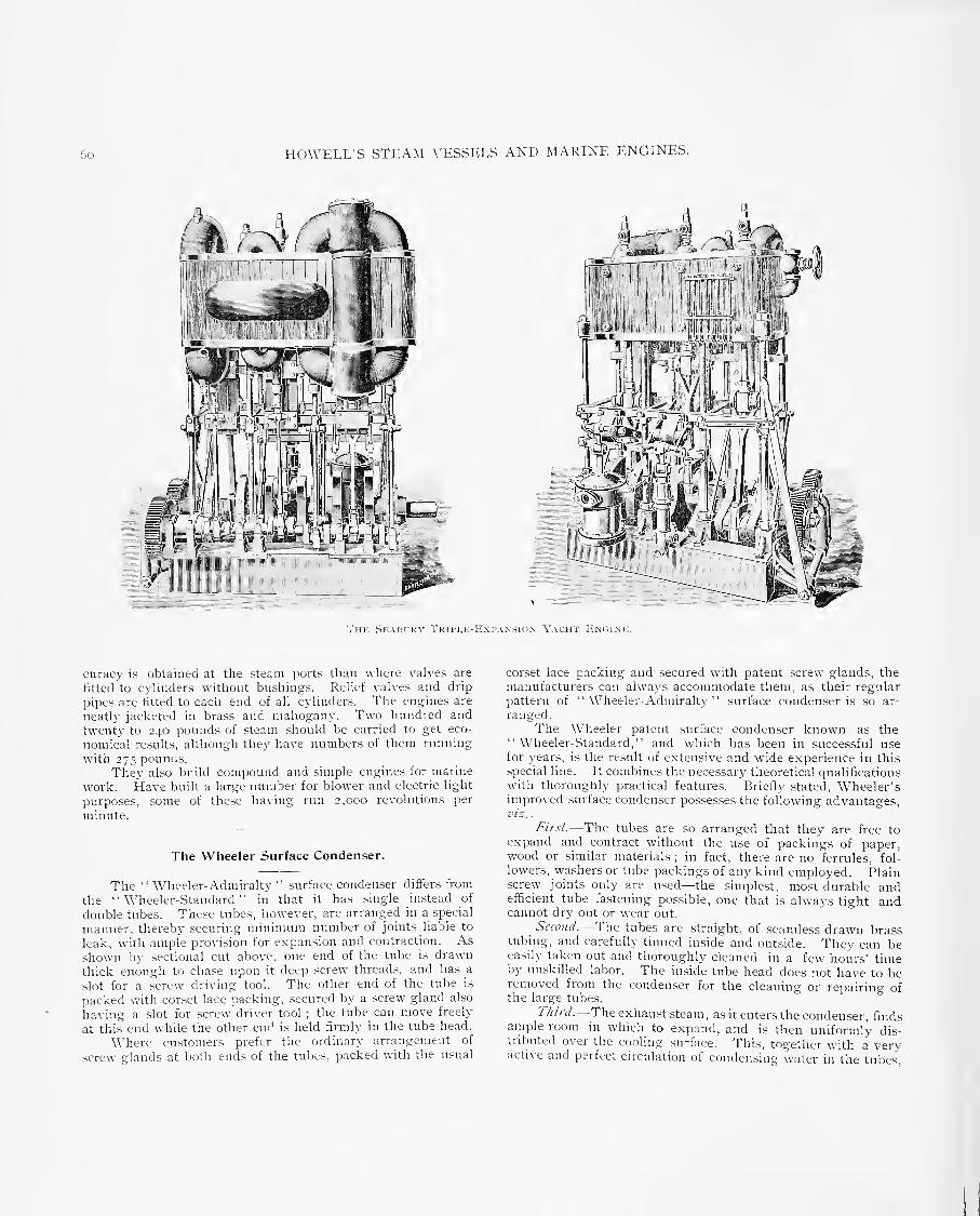
6o HOWELL'S STEAM VESSELS AND MARINE ENGINES.
Thk ,Seaih;kv Tripi.h-Ivxi'anston Yacht Ivncink.
curacy is obtained at the steam ports than where valves are
fitted to cylinders without bushings. Relief valves and drip
pipes are fitted to each end of all cylinders. The engines are
neatly jacketed in brass and mahogany. Two hundred and
twenty to 240 pounds of steam should be carried to get eco-
nomical results, although they have numbers of them running
with 275 pounds.
They also build compound and simple engines for marine
work. Have built a large number for blower and electric light
purposes, some of these having run 2,000 revolutions per
minute.
The Wheeler Surface Condenser.
The " Wheeler-Admiralty " surface condenser differs from
the "Wheeler-Standard" in that it has .single instead of
double tubes. These tubes, however, are arranged in a special
manner, thereby securing minimum number of joints liable to
leak, with ample provision for expansion and contraction. Asshown by sectional cut above, one end of the tube is drawn
thick enough to chase upon it deep screw threads, and has a
slot for a .screw driving tool. The other end of the tube is
packed with corset lace packing, secured by a screw gland also
having a slot for screw driver tool ; the tube can move freely
at this end while the other end is held firmly in the tube head.
Where customers prefer the ordinary arrangement of
screw glands at both ends of the tubes, packed with the usual
corset lace packing and secured with patent .screw glands, the
manufacturers can always accommodate them, as their regular
pattern of " Wheeler- Admiralty " surface conden.ser is so ar-
ranged.
The Wheeler patent surface conden.ser known as the"Wheeler-Standard," and which has been in successful usefor years, is the result of extensive and wide experience in this
special line. It combines the necessary' theoretical qualificationswith thoroughly practical features. Briefly .stated, Wheeler'simproved surface condenser possesses the following advantages,vis .
.
First.—The tubes are so arranged that they are free toexpand and contract without the use of packings of paper,wood or .similar materials
;in fact, there are no ferrules, fol-
lowers, washers or tube packings of any kind employed. Plainscrew joints only are u.sed—the simplest, most durable andefficient tube fastening possible, one that is always tight andcannot dry out or wear out.
^
Second.—The tubes are straight, of seamless drawn brasstubing, and carefully tinned inside and outside. They can beeasily taken out and thoroughly cleaned in a few hours' timeby unskilled labor. The inside tube head does not have to beremoved from the condenser for the cleaning or repairing ofthe large tubes.
T/n?-d.—The exhaust steam, as it enters the condenser, finds
ample room in which to expand, and is then uniformly dis-tributed over the cooling surface. This, together with a veryactive and perfect circulation of condensing water in tiie tubes.

HOWELL'S vSTEAM \'ESSELS AND MARINE ENr.INES. 6i
I iJU'L4 |WLf|||^|||||||||||||||||i|||||||||
RECTANGUr.AR PATTERN OF THIi WHKKrjiR-AnillRAI.TV SCRFACK CONnENSER MOUNTED fl'O.X COMBIXIiD AlR AXD CiRCULATlNG-PUMPS.
produces a more uniform temperature in tlie condenser, makingone portion as efficient as another, and economizing tlie amountof cooling surface and circulating water.
The Wheeler light-weight surface condenser is applied to
small steam vessels, where the minimum of weight and space are
combined with simplicity and greatest efficiencj-.
These improved condensers are made in the smaller sizes,
with shells of brass or hammered copper. The tubes are of
seamless brass, well tinned inside and outside, and are drawnwith great care. These tubes are screwed into the tube heads,
thus making tight and durable joints, a verj' important feature
for conden.sers that are out of use a large part of the year, as
in the case of steam yachts, etc. There are no ferrules,
washers, tube packings, etc., to leak or dry out.
These condensers combine minimum weight with maximumefficiency ; they are more satisfactory' and quite as inexpensiveas keel ( outboard pipe ) condensers, and will give the hot feed-
water—an impossibility with the latter form of condenser.
The substitution of a Wheeler light-weight surface con-
denser for the keel condenser also removes a great impedimentto the speed of a boat. The keel condenser not only gives
chilled feed-water and unsteady vacuum, but is always a
source of trouble and liable to damage from collision with
floating matter or by the boat running aground.
For launches, steam yachts and light-draught steam vessels
plying in fresh water, the Wheeler light-weight jet condenser
is the simplest and most compact condenser in the market. In
weight it is remarkably light—an important consideration. It
can be attached to a connected air-pump and worked by themain engine, or it can be arranged with an independent air-
pump. The latter is a better plan, as vacuum can be formedfor the main engine before starting it, and being independentthe speed of the pump can be regulated to suit the demands of
the engine. With the high rate of speed that marine enginesare now run at it is a great disadvantage to have connectedair-pumps.
The Wheeler light-weight jet condenser is a shell of ham-mered copper or galvanized iron—the exhaust steam pipe, theinjection pipe and the pipe that connects the condenser withthe air-pump are all attached to the large head, which is a
casting made exceedingly light and strong. The injection
water is thoroughly distributed by means of a perforated spraypipe extending through the centre of the condenser. One endof this spra3' pipe is firmly attached to the small flange, on theouter side of which is a convenient handle (see left-hand end of
conden.ser in cutj ; the other end of spray pipe fits over a
nozzle cast on the inner side of the large head, and whichprojects into the condenser a short distance, thus forming a
continuance of the injection pipe outside. When necessary to
clean the spray pipe from dirt, chips or grass brought in by theinjection water, all that is required is to unbolt the smallflange and by means of the handle draw out the .spray pipe.
This convenient feature avoids disturbing any of the piping,
and gives easy access to the interior of the condenser. TheWheeler Condenser and Engineering Company, New York,are the builders of these condensers.

HOWKIX'S STEAM A'ESSELS AND >L\RINE ENGINES.
Thk \'oi,z Patknt CoMBiMKn Surface Condenser and Feed-Water Heaticr.
The Volz Patent Combined Surface Condenser and Feed-
Water Heater.
Marine and stationary engineers using surface condensersare well aware of the difficult5' of retaining the feed-water in
the hot-well at or near the proper temperature due to thevacuum in condenser, particularly in cold weather. Thewater of condensation neces.sarily lowers its temperature as it
passes from the condenser through the air-pump, and fromthence to the hot-well, filter tank and through the feed-pump,as there is considerable radiation of heat from the pipes andother surfaces. As it is very desirable to return the feed-
water to the boilers at as high a temperature as po.ssible, thusnot only economizing fuel but adding to the life of the boiler,
the use of a simple and effective method of heating the feed-
water is of great importance. The A'olz patent combined .sur-
face conden.ser and feed-water heater fully meets this conditionand is very simple in design. It adds but little extra cost and.space, and a high vacuum can l)e maintained, irrespective oftemperature of hot-well; it has given the mo.st satisfactory re-
sults on board of .steam vessels. The heater tubes are locatedin the upper part of the conden.ser, and therefore are exposed to
the hottest steam. The feed-water is consecjuentlj' heated to
within a few degrees of the temperature of the exhau.st .steam.
There is no " choking" of the e.xhaust steam through smalland contracted passages as with ordinary heaters, and there is
no unnecessary back pressure on the feed-pumps. A large
amount of heating surface is obtained, whether the condenseris built either cylindrical or rectangular; furthermore, the
weight and .space sa^-ed over that required for the ordinaryheater (sometimes crowded in exhau.st pipe) is of considerable
value. The engravings show a sectional view and end view(tubes partly exposed) of the patented combined surface con-
denser and feed-water heater, cylindrical type. The exhauststeam enters through the top opening in the usual way, passes
(Aer a scattering plate and then comes in contact first with the
heater tubes and then with the condenser tubes, where after con-densation, it flows to the air-pump, which in turn delivers it tothe hot-well tank. The feed-water is taken by the feed-pumpfrom hot-well and delivered near the top of the upper or feedchamber, as shown by the arrows, then passes twice throughthe heater tubes and finally to boilers. The circulating waterenters the water chamber at the lower nozzle, as .shown, andafter passing through the conden.sing tubes is discharged throughthe upper nozzle at the .same end of the condenser. An auto-matic relief valve is placed on top of conden,ser, the vacuumalways keeping it clo.sed. The tubes of both heater and con-denser are of seamless drawn brass, tinned on both sides, withferrules at each end properly packed. The shell of condenseris usually cast iron. The water chambers and tube heads aremade in one composition casting, with the division plates .separ-ating the feed from the circulating water cast in, thus avoid-ing joints. This feed chamber is made to withstand boilerpre,ssure. Free access to the tubes is provided by the ar-rangement of separate bonnets or heads. The WHieeler Con-denser and Engineering Co., New York, are the builders of theabove de\-ice. The inventor and patentee is Wm. E. Volz.
Wells' Balanced Compound and Ouadruple=ExpansicEngine.
In order to balance all forces it must be a natural balanceThis can only be accomplished bv a double action, where equalsteani pressures are exerted simultaneouslv on opposite cylinderheads, and where all forces are equally applied to opposite sidesot the crank .shaft moving in the .same plane. Anv deviafonfrom the plane produces disturbing and destructive elements
The \\ells .system represents the onlv improvement inprinciple that has ever been made. The important advantagesderived from a balance of forces in the steam engine werepratically unknown until demonstrated by this sy.stem for the

HOWElJ.'vS STEAM VliSSELS AND MARINIC ENGINES.
Wkhs' Patent Ouadruple-Expansion Engine.
rea,son that all engine.s con,structed with a " balance" in view
embraced grave mechanical objections. Hence, the .single-
acting'
' unbalanced' ' reciprocating engine is the onl}"- system that
has proved to be of any value. While the Wells engine
embraces all of the desirable features of the most approved type
in general use, it contains none of its objections. It is double
acting and so designed that all forces acting in the high-pressure
cylinder are held in proper position by the forces acting in the
low-pressure cylinder, producing k perfect balance around the
crank shaft, and preventing vibration and the escape or loss of
power that in all other engines is thrown off through the frame
into the foundation.
BALANCED STEAM PRES.SUEES.
We desire to call especial attention to this important feature
(not contained in any other engine) , as it would be impossible to
obtain a balance without it.
Steam is admitted to both cylinders simultaneously ; duringthe first stroke, the steam pressures upon the middle cylinder
head are exerted against each other ; the force acting upward in
the high-pressure c}linder becomes the support of the force act-
ing downward in the low-pressure cylinder. In the return .stroke
the pressures are exerted upon the top and bottom cylinder
heads in opposite directions, giving a balance of pressures
within the cylinders—a condition that applies to no other type

64 HOW-ELL'S STEAM VESSELS AND MARINE ENGINES.
iffi] o
Weli,s' Patent Balanced Engini;.
of eno-ine, as no strains are communicated to the frame and
bedplate.
B.ALANCED FORCE.S AND MOTIONS.
The force of the steam applied to the high-pressure piston
descending upon one side of the shaft is balanced by the force
of the steam applied to the low-pressure pi.ston ascending upon
the other side, leaving only the weight of the crank shaft and
its connections to be carried by the mam bearing boxes.
Each motion in this eiioTue has a corresponding oppo.site
motion producing a perfect balance at all angles of the cranks
and at all speeds. By this arrangement no strains escape from
the cylinders, and the connecting-rods and cranks become the
sole transmitters and controllers of all forces. It also trans'"ers
the fulcrum from the main bearing boxes to the center of the
shaft. The weights and forces being equally applied to oppo-
site crank pins, moving in opposite direction;; in the same plane
the cranks become the beams, or levers of balance, and there
being no weight of parts to be lifted and no friction due to steampressures to overcome
;the steam forces applied to the pistons
and the momentum foices stored in its mo^ ing parts are all
transformed into crank motion. Its absolute control of these

HOWELL'S STEAM VESSIU.S AND MARINr: ENGINES. 65
Chase's Ouauruple-Expansion Marine Engine.
force,s, for useful effect, greatly increases the power ofthe engine.
It also gives uniforniit}' of motion, its forces being equal around
the circuit of the shaft ; they are gi\-en out in the crank armswhen the steam forces are diminishing, as the pistons are
approaching the end of the stroke, acting the same as an ordin-
ary fly-wheel in carrying them over the centers, producing a
rotary motion.
ITS GREAT IMPORTANCE IN LARGE POWERS.
This principle embraces a very peculiar feature, directly
the reverse of the general practice, which is of the highest import-
ance ; i. e., the advantages gained by balancing the forces in the
Wells engine increase in direct ratio with the bore of cylinder
(tons being balanced in large, versus pounds in small engines ),
while the losses from unbalanced disturbing forces in all otherengines increase in the same ratio. Therefore, the greater thepower, the more important it is to obtain a balance; and therelief of pressures afforded in the main bearing boxes by this
system will readily be seen by multiplying the area of pistonwith the mean steam pressure, and the weight of the recipro-
cating parts by their velocity-. For example, take an enginewith cylinders 18 inches and 36 inches diameter with a meansteam pressure of 30 pounds, and a piston speed of 600 feet
per minute, it relieves the main bearings of 19 tons pressureper stroke of pistons.
The principle embraces the most favorable conditions for
the construction of large engines ; the " balanced" double-act-
ing levers, or cranks, have only their weight and that of the

66 HOWKLL'S STEAM A-ESSELS AND MARINE ENGINES.
rods to support between the main bearings, as they are relieved
from the weight of the steam and the thrust of the rods. Theforces being all transmitted in torsion, they have no tendenc>-
to leave their proper positions.
OrADKUFLEU.
Two of these engines coupled closel_\' together in oneframe, each with cranks set at iSo°, they occupy no more space
than the ordinary fore-and-aft compound, and one-third 1 ess
space than the triple, and embrace all of the advantages namedin the foregoing description of the principle.
To those who are not familiar with this principle some concep-tion of its \-ast importance may be gained by carefully calcu-
lating the useful effect of a perfect balance in the propelling
forces, when applied to a ship equal in power to the Majestic
where the combinded area of the two low-pressure pistons is
20,414 inches multiplied b\' a mean steam pressure of 27'jpounds gives a pressure of 2S0 tons per stroke of pistons ; sup-
posing the moving parts of the engine to wei.gh 60 tons and to
have a velocity of 870 inches per minute, gives a further pres-
sure of 600 tons per stroke or 320 tons in excess of the total
steam pressure, and a condjined pressure of loSo tons perstroke, that must be resisted (that heretofore has never beencontrolled ) by the engine frame bedplate hull of the ship, andfinall}' by the ocean itself, into which a large percentage of the
power escapes.
By the Wells system all forces are concentrated in thecrank shaft, which prevent any escape, and at same time it
relieves the engine frame and hull of all strains and \-ibration
and the journals from heating.
DURAllILITY AND CONSTRUCTION.
Unbalanced weight in motion ( momemtum ) being the onh-element that tends to destroy an engine ; makes it apparent that
balanced weights, balanced steam pressures, and balancedmotions are the qualifications nece.s.sary to produce a durableengine, all of which this design possesses in the highest degree.
Practice proves it to be far more durable than an}' ever con-
structed;although subjected to extreme pressures and speeds,
so far no part of the engine has failed, which is easily accountedfor from the fact that all forces being perfectl}' balanced obvi-
ates vibration, injurious strains, and unnecessarj' friction, the
only elements that tend to destroy the machine. Relieved of
the pressure, the life of the main bearing br)xes becomes prac-
tically unlimited, and the little wear that occurs on the mainjournals will be evenh- distributed around their whole circum-ferance. These engines are built by the Wells Engine Com-pany, New York, from designs of Justin R. Wells.
Chase's Quadruple=Expansion Marine Engine.
The.se illustrations are taken from a working model of a
disconnective quadruple-expansion marine engine built to a
34-inch scale by Erank Chase, of Hartford, Conn,The principal dimensions of the full-sized engine would be :
Diameter of high-pressure cylinder, 14 inches; first inter-
mediate, 22 inches ; second intermediate, ,^2 inches ; low-
pressure, 45 inches ;stroke, 2S inches. Boiler pressure, 200
pounds per square inch. The engine is arranged on the
tandem principle, the high-pressure and first intermediate
cvlinders forming the forward engine, the .second intermediate
and low-pressure cylinders the after engine. The cylinders
are jacketed with steam direct from the boiler, entering through
an inlet valve and dropped into condenser. This enables them
to be thoroughly heated before^opening the throttle. At the
same time a vacuum may be^produced by starting up the
circidating donkey-pump. In addition to the steam jacket is
Ch.\SE'S Y.AI.VB ("xli.JiK AND M.iKINi; G(.>\'F;RN( )R
.
a coating of a.sbe.stos, and a lagging of alternate strips of ma-hogany and white maple, which last has an effective appear-ance. The relief valves at each end of cylinders are madeextra large
; ample pnjvision for draining cylinders andjackets is provided, together with indicator cocks and Gonnec-tKHis. The main valves are all of the piston tvpe, and theirupper portions in the upper cylinders are made slightly larger
;
this excess in area perfectly balances all the valve gearingbeneath. The cylinder pistons are attached to their rods bymeans of an adjustable .screw collar. This arrangement hasthe same feature of rigidity as the usual conical rod and nut,but m case of accident, or for adjustment, allows the pi.ston tobe readily removed. The pi.ston-rods to the lower cylindersare made considerably smaller than usual bv this method thus.slightly increasing the effective cvlinder area. The stuffingb.ixes between the upper and lower c^dinders are each made intwo halves, bolted together, and furnished with split collarbushes. A long sleeve is utilized in place of one set of stuffingboxes
;the .sleeve also serves as as an excellent guide to the

HOWKIX'vS STEAM VESSKLS AND MARINE ENGINEvS. 67
Aw.7We*«'r«iWfi?
Chask's OTiAriRrpi.K-FIxPANSiON Rncinr.
piston-rods. This arrangement dispenses with one set of
stuffing bcsxes, shortens the distance between the cylinders, andenables obstinate cases of hard packing to be more readily
dealt with. The upper C3-linders are supported on six vertical
columns, any of which ma}' be readily removed for overhauling
and repairs. The lower cylinders are supported at the back on
the condenser, and in the front on cast-iron columns, the after
column being utilized as an oil reservoir, and on this columnthe engine counter—which is of verj' simple construction— is
attached. The go-ahead slides are detachable, and the shoes
provided with brushes which dip into oil boxes at the foot of
guides. The condenser is very efficient, the circulating water
being circulated from the pump in two directions—around the
condenser and through the tubes. Targe, easily accessible
doors to the water side, with manhole and hand-holes to thesteam side, are provided
; also snifting valve at lower point.All the pumps, excepting the donkey, are worked from themain engine. There are two feed-pumps with separate airvessels, stop and relief valves
; either pump is sufficient tosupply the boiler under ordinary circumstances. Thev arel:)olted on considerably below the hot- well.
The auxiliary feed may be connected either to the circu-lating water or to an evaporator. The air-pump is singleacting, and placed low down on the condenser. The circulating-pump is double acting, and of sufficient capacitv for water ofany temperature, the supply being, of course, 'regulated bymain injection valve. There are also two bilge-pumps withtheir necessary stop valves and connections. All the pumps

6S HOWKLL'S STEAM VESSELS AND MARINE ENGINES.
are supplied with pet cocks, and the hot-well with water guage,
manhole and vapor pipe.
The crank shaft is in two sections, flanged and secured in
the center by a dowel, which can lie removed readily in case
it is desired to run either engine separately. The main bear-
ings have brass bushes in boxes ; also oil boxes and siphon
pipes. The bearing surfaces throughout the engine are madeextra large and well supplied with means of lubrication. The
Allen .straight link. By the method of suspending this link a
.sort of parallel motion'is obtained, which greatly reduces the
slipping of the block, and gives a quicker admis.sion and cut-off.
By means of a two-way valve to oil c>linder and lever to steam
cylinder, reversing may be done (juickl)- or slowly, and the cut-
off fixed immovable at any point. The hand reverser consists
of a small force-pump connected with the oil vessel, utilizing
the same le-i'ers "as the steam. In connection with the steam
. ^- .^
Co-Mi'orxi) Y-\CHT Exr.ixK, with Air .\xii Fi'.Mi-l'uiir Att.vchiuj.—Desi.yiied iind Built liv the Kdward S. Clark Co., Boston, Ma.ss.
water service for cooling purposes is ample, and has universal
joints for all parts ; also hose connections for extreme cases.
Back of the after-main bearing a gear wheel secured to .shaft
engages with a worm driven from an auxiliary engine. Bymeans of a clutch and swinging bracket the worm may be
thrown out of gear without causing delay. The auxiliary
engine, when not in use as a turning en.gine, serves as a
powerful pump for all purposes. It has two double-acting
steam c^dinders and pumps, and is remarkably compact.
Slotted crossheads are used ; there are no eccentrics ; a camon the shaft gives the necessary lead and cut-off when runningin either direction, and reversing is eft'ected b>- re\-ersing the
steam, all the pipes, etc., being cast with the cylinders andchests.
The main engines are reversed either by hand or steam.
Steam reversing engine consists of a steam and an oil cylinder,
the pistons of which are connected together, and give motion
bv links to the reversing gear, which is a modification of the
re\-ersing gear is a po.sitive governor, T,'ery sensitive in its action,connected by gearing to the shaft, and having perfect controlover the main engine. The cut will explain its action. Fig.I IS a general arrangement. Fig. 2 shows the balance valve tosteam cylinder. Steam is admitted slightly to both .sides ofpiston, and a short movement of valve in either direction by thesensitive go^'ernor reduces the pressure on one .side of pi.ston,the latter, of course, following in the direction of the reducedpressure, and moving the connecting link to valve .spindle nearerto, or farther away from, the center of the slotted link, accord-ing to the speed of engine. The .same movement of the balancedvalve opens the valve to oil cylinder as shown in Fig. 3. Whenthe engine is at its normal .speed the oil piston is locked.Should any great acceleration of speed take place, due, form.stance, to the breaking of the .shaft, the link would be throwninto mid gear, thus shutting off .steam completely from eachand every cylinder in the main engine, nor would steam beagain admitted except b\- operating the ordinary reversino- lever

HOWEIX'S STKAM X'lvSSEIwS AND MARINE IvNGINEvS. 69
which is not in anj' way connected with the antoniatic .r^overnor.The disconnective features of the engine are as luHows : Incase the forward engine breaks down, it is disconnected byremoving the dowel in crank shaft. The vah-e between the twointermediate cyHnders, together with the throttle valve to high-pressure cylinder, is closed, and the auxihary pump used as acirculating pump. vSteam is admitted to the .second intermedi-ate cylinder through the reducing valve, and the after engineis run as a compound condensing engine. This reducing valveis operated by a lever from the starting platform, and isu.seful asa blow through \'alve for turning centers in starting. In casethe after engine breaks down, the connecting-rod is removedfrom crank pin and secured in an out-of-the-way position. Thevalve between the two intermediate cylinders is clo.sed and con-nection made between first intermediate exhaust and condenser.The auxiliary pump is u.sed as an air-pump and the forwardengine then run as a compound engine. The thrust fr(jm thepropeller is taken up on conical r(jllers ruiuiing in oil, fitted
with adjustable plates for wear ; this arrangement reduces thefriction considerably.
The engine takes up very little room fore and aft ; e\'ery
part is accessible for adjustment and repairs, and a .system of
duplication of parts is carried throughout.The Hartford (Cotniecticut) Steam I'oiler Inspection and
Insurance Compan^, is interested in the introdnction of this
engine.
Clark's Compound Yacht Engine.
The two views are from photographs of the engines de-
signed and built for the World's Fair launches. The cylinders
are 6 and 12 inches in diameter b)- S inches stroke; cast in one
piece, with the recei\-er, etc., enclosed inside of the lagging,
which is of cherry, handsomel)' finished and held in place by
brass bands. The vah-e cliamljers are set at right angles to
the crank shaft, which greatly reduces the fore-and-aft .space
of the engine—a very essential point in a small engine-room.
This also brings the valve chambers close together, making a
quick passage of steam from the high to the low-pressure
cylinder, thus doing away with the long outside exhaust pipe
connnon to most compound engines. The cylinders are sup-
ported from the bed of the engine by cast-iron columns on the
back side, forming the guides for crossheads, and on the front
side by three steel posts, planed square in the center, to which
are bolted the bearings for the rocker shafts operating the
piston valves, also the bearings for rever.se lever and braces
from po.st to frame. The crank .shaft is cut from solid steel
forgings, with counterbalance fitted on the two inside cranks,
which have notches in them for baring the engine over when
cold. The crossheads, crank-pin boxes and all .small connec-
tions are made of a high grade of phosphor-bronze, and the
main bearings on the crank shaft are lined with Magnolia
metal. The quadrant is attached to the reverse lever and
made fa.-,t by a clamp on the center post, ,so that when the
engine is in the go-ahead gear, the lever stands in an upright
position and the "quadrant is entirely enclosed in the engine
proper. As will be seen, the air and feed-pumps are fastened to
the engine bed, and are operated from the crank .shal't by means
of a worm and worm gear, which reduces the .speed of the pumpone-fourth the revolution of the engine, reducing the friction
and overconfing all noise made b>' the valves in all high-speed
pumps.The thrust bearing is also connected to the engine bed Ijv
two steel studs, and as the thrust collar is made fast to the
shaft the adjustment is made by the two thru.st bars, whichhave faces lined with fJabbitt metal and held in place by double
loeknnt on the two steel studs. These engines were de.-igned
and built by Edward rf. Clark, Boston, Ma.ss.
The Davis-Farrar Yacht Engine.
The triple-expansion yacht engines shown in cuts havecylinders 7, loii;., lO'-.. by 8 inches stroke. The high-pressure
and intermediate-pressure c>dinders ha\'e piston vah'es, in
cages, bolted to false .seats. Tlie low-pressure cylinder has the
double-ported Allen vah'e ; all are operated 1))' the Da\'is radial
valve .gear. The c) liiiders are supported at the rear b\' a hol-
low cast leg, the metal 1>eing disposed so as to give rigidity
without excessive weight ; at the fr(jnt b}' polished wrought-steel columns, allowing the working parts to be under the eye
of the engineer at all times, and adding greatly to their acces-
sibilit)'. Tlie crosshead is of pulished cast steel, carr3'iiig a
slipper guide at the back, wliicli operates on slides formed byface of the cast leg of trame, and with wrought guides to
take the thrust when Ijacking and Ijeing adjustaljle for wear.
The crosshead pin is secured with a substantial dowel on oneside and with a split Ijush with a keeper nut on the other.
The pin is hollow and is oiled from the center ; the brasses
being grooved t(j thoroughly distribute the oil over the wear-
DAVIS VALVE GEAR
Fig. 2. Fig. .^. Fig. 4
The Davis Radial Valve Gear,

yo
-..rT^ A\D MARINE ENGINES.
HOWELL'S STEAM ^•ESbLLS AND
Thh 1
,,,,,.^.KK.KTMPr.F.,^^s.-^-HTF.,.I^r

HOWELL'S STEAM VESSJvES AND MARINE ENGINES. 71
The Davis-Farrar Tripi^e-Expansion Yacht Engine, with Davis' Radial Vai,ve Gear.

HOWELL'S STKA.M VESSELS AXI) .MARINE ENGINES,
ing- surfaces. The shaft lias couphng forged solid with it.
The cranks have polished discs containing counterbalance
weights. The pillow blocks ha\-e removable bushings, enabling
the wear to be compensated for by shimming or removal at
slight cost. Cylinder heads, steam-chest covers, and all work-ing parts are highly polished. The method of oiling is shownin rear view, a brass pipe extending along the cj'linders, fromwhich smaller pipes Ijranch, conve^•i^g oil to the journals, eachbeing pro\-ided with a cock to regulate the supply-. Theengines have been designed for hard duty under high steampressure, and have repeatedly on all da\' runs turned a 42-inch
wheel, 6 feet pitch, 31(1 re\-olutions per minute, without warmjournals or pins. In two years' service on the x'acht Tallalusa,
a set of these engines have never .-^hown a warm pin or
journal under 185 pounds steam pressure.
Great care is taken with the lialanciiig of the engines.
The steam distribution, as well as the weight in counter-
balances, being carefully decided after extended experimentswith each size engine. The importance of steam distribution
is now very .generally I'ecdgnized by builders of high-speed
en.gines. The valve .gear has been designed with this especial
object in \-iew ; its extreme simplicity will first attract the
attention of the engineer ; in operation it can be compared with
the Corliss only. The fast and .slow travel of the valve occurs
at the desired points, and there is no perceptible difference in
the events of induction, release or compression from full stroke
to any point of cut-olT d(.iwn to zero. It is usually designed to
cut-off at 'j or ? ,-; stroke as nmximum. Its construction can
be understood from cuts, Fi.g. 1 showing the .gear in skeleton.
The eccentric strap has attached to its top and bottom sides an
arm or link, each 12 inches long, the upper link being pivoted
at a point y inches from center of pin connecting it t(i the top
of eccentric strap. This fixed point is supported Ijy a suitable
stand bolted to the engine base. At its outer end is a ([uadrant,
an arm of which extends downward and is connected to the lower
liid-:. It will be seen that the vertical throw of the eccentric,
operating the upper link or lever over its fixed point, carries
its outer end, to which is attached the (juadrant vertically, a
distance governed ])\- the throw of the eccentric and the position
of the " fixed point" or fulcrum, a distance ecjual to the lap
and lead of the valve. The lower link connects the li.iwer armof the quadrant to the bottom of the eccentric strap. Thehorizontal throw of the eccentric imparts a "rocking move-ment" to the quadrant, and it is obvious that the position of the
valve .stem on the quadrant regulates the port opening for
steam;when in the center, zero, there can be 110 port opening
other than the lead, and as it is thrown toward either endmore port opening is olifained. Its action can be seen in
Figs. 2, 3 and 4, In Fi.g. 2 the engine is on the bottomcenter. The throw of the eccentric being down has raised
the valve an an:ount equal to the lap and lead, and it is ready
to take steam at the same time the full horizontal throw of
the eccentiic (its (juiek tra\-el 1 is read)- to throw the lower
arm of the quadrant to the right and rock its outer end up,
giving the port opening with the quickest travel of the
eccentric. Fi.g. 3 shows the port open, and it will be seen that
the vertical throw of the eccentric beginning would tend to
close the port, wdiile the horizontal throw rocks the lower armof the quadrant further, and maintains the valve in its position.
The one throw operating against tlie other, causes the valve to
pause or slow up. In closin,g the steam port, in Fi.g. 4, it will
be seen that the vertical throw of the eccentric is at its quickest
point, while the horizontal throw is at its slowe.st and will have
little effect in opposing it. Two years' .service has developed
no weakness or faults,' and the steam di.stnlmtion given by it is
all that could be desired, giving as it does a quick opening and
closing of the valve with the slow travel at that point that
allows^a free admission and exhau.st, and none of the objection-
able features of the ordinary Stephenson link. These engines
are built by the Davis-Farrar Company, of Erie, Pa.
The Joy Valve Gear.
The cut shows the ingenious arrangement whereby David
Joy, of London, has avoided altogether the u.se of eccentrics.
He obtains the motion irom the connecting-nid, and qualifies
it bv a sliding Idock like Hackworth, or a suspension-rod like
Manshall. The motion thus obtained is a very perfect one for
a slide valve, as the two quick and two slow periods are just
when re(juired. The amount of opening is equal at both ends
(jf the \'alve, and earl>' cuts-off can be effected without exces-
Jon's \',\i.\1.. ( ;|. \K
sive leads and compressions or premature exhau.stings. Thisgear has been applied with great success to locomotives, wherethe saving of space for the eccentrics admits of longer crank pinsand journals
; it has also been taken up by martne engineers.The chief fil)jections to this gear are that it comes in the wayof the principal working parts, and makes them a little difScul'tto get at when working, and also that a small amount of wearon tlie joints of the gear would cause a deflect in the valvemotion, and produce a serious amount of rattle of the "-ear.

HOWELL'S STEAM VESSELS AND MARINE ENGINES. 73
These, however, can be got over by making the pins substantialand all the joints adjustable.
David Joy, of London, has recently designed an arrange-ri:ent of reversing gear for marine engines, by means of whichlink motion is done away with and yet the effect of linking upcan be obtained, whilst reversal of the engine is under perfectcontrol. This result is accomplished by putting a pair of hy-draulic cylinders in the eccentric sheave, and in this way canshift it to an equivalent of any position on the shaft, from full
gear ahead to full gear astern, whilst the intermediate positionnaturally brings it concentric with the shaft, so that the valvehas no motion at all.
The Marshall Valve Gear.
This arrangement of slide-valve gear, which has beenfitted by R. & W. Hawthorne, Leslie & Co., Newcastle-on-Tyne, to a large number of marine engines, including those ofseveral recent ships of the Royal Navy, is illu.'trated in Fig.
103. In this system only one eccentric is u.sed, the end of
re\-ersing le\-er R, an}- desired degree of expansion can be
obtained or the engines reversed as required. In this systemthere are few working parts, and the distrijjution of steamboth for full power and for expansive working is satisfactors-.
Richard vSennett.
Marshall's valve gear is a modification of Hackwortli's,
and differs from it in the method of getting the oblique motionof the rod-end. Fig. 6S shows the plan adopted by F. C.
Marshall, of Newcastle-on-Tyne, and also illustrates general!}'
what has been said of Hackwortli's. Here the eccentric-rod is
hung, by means of a rod fnjm the end of a lever, on a reversingshaft in such a way that it moves on the arc of a circle inclined
to the centre line. The motion is not quite so perfect as withthe inclined sliding bar, and necessitates double ports to the
bottom end of the slide valve in order to get as much openingto .steam there as at the top end ; but there is less friction, and,
on the whole, it works mo.st satisfactorily. The pins require to
be of good size, and they should all have adjustable brasses to
provide for the large amount of wear which of necessity comeson them. A. E. Skaton.
Fig. 103. Marshali- Vai,ve Gear.—From the Marine Engine, by
Richard Sennett.
the eccentric-rod being attached to a rod hung from a pin
on the reversing shaft lever R, by which it is constrained
to move in an arc of a circle inclined to the centre line.
To an intermediate point, P, in the eccentric-rod a connect-
ing link is attached which communicates the necessary motion
to the slide-valve rod. By adjusting the position of the
Marshalls P.itent Valve Gear.
Fig. 6,S. Dr.^wx by A. E. Se.vton, of E.aki.k's Shipbuilding
Works, Huix, Engi.anij.

74 HOWELL'S STEAM VESSELS AND MARINE ENGINES.
I' ^fc \ .rf-'^5£'^''^v
m!>
])ETAii, iiF Marshall's \'ai,\"1'. (iEAK.
Canfield's Patent Balance Valve.
The engraving shows a vertical steeple compound enginewith but a single valve to operate both cylinders. There is noreceiver, the exhaust going direct to the low-pressure c>linder
through the valve itself. The engine, as shown, !;as a high-
pressure cj'linder iS inches diameter, and a low-pressure cylin-
der 36 inches diameter, the steam chests on both cylinders con-
necting with a conduit of sufficient area to equalize the steampressure on both ends of the hollow piston valve, rendering it
perfectly balanced, the difTerence of areas in the tail-rod andvalve stem being so proportioned that the weight of the vah-e
is balanced by the difference of pressure on the top and bottomheads. It will be seen that there is but one ^-alve for both cylin-
ders, the ^'ah•e itself taking the place of a receiver. Tliis ar-
rangement reduces the unavoidable loss in the receivers com-monly used, in the increase of volume and condensation in
passing the steam from one cylinder to the other. The plan is
the device of Hobart Canfield, of Morristown, N. J. In this
system, the valve being jacketted by live steam at boiler pres-
sure, any moisture due to the first expansion is reheated by the
live steam as it passes through the valve from the high to the
low-pressure cylinder, and tlie condensation is reduced \'erv
materiallv. Cards taken from one of these engines witli an
initial pressure of 100 pounds in the high-pressure cylinder,
cutting off at 5,3 stroke, show 26 pounds initial in the low-
pressure cylinder, thus proving that the increase in V(jlume be-
tween the c)dinders is reduced to its lowest terms, for in this
system the pressure is about double that which would be indi-
cated if a common receiver were used.
This system has been practically tested, and the in\'entor,
Mr. Canfield, has several engines from 500 to i,5riO horse-
power in service. The ]">atentee of tlie >,'nlve is Master Me-chanic at the I-'enns_\d\'ania Railroad Shops in Hoboken, N. J.
Ib-'^
STKEiT.r; CoiriMirNi) Hxcine wrrii Caneiiuji's \'.\eve.
Bonner's Patent Compound Balance Valve.
A very ingenious valve has Ijeen designed by John Bonner,Master Mechanic, of Tilnirnn, Cal. This valve simplifies thehandling of compound engines in a marked degree, making it
very economical in both water and fuel. The cut illustrates asteeple compound engine ecpiipped with this valve, which, aswill l)e seen, dispenses with the steam chest and steam recei\'er.An enguie of this desi-riiition, equi]iped with a Bonner com-[)Ound balance valve has Ijeeu in operatKju for the past year in

HOWELL'S STEAM VESSI'ES AND MARINE ENGINES.
-/v;^/^-7-/
Co/iiro^v/n ^fi/^yir£ y^/y
:• i^K
Bonner's Patent Balance Valve.—Designed b^- Jolin Bonner, Tiburon, Cal.
a 30-foot launch with 6 feet beam, and drives the boat 10 miles
an hour. In connection with a water-tube boiler, patented bythe same inventor, stea:n is generated very quickly with a con-
sumption of but little fuel. The dimensions of this engine andboiler are: High-pressure cjdinder, 2-^8 inches; low-pressure
cylinder, 4^4 b^^ 414' inches ; height from base to top of high-
pressure CN'linder, 27 inches. Weight of engine, 90 pounds.
Boiler has 3 square feet of grate surface and a large heating
surface. The boiler weighs, with casing, 350 pounds, andmeasures 20 by 24 b_v 34 inches. The United States Govern-ment license permits a pressure of 250 pounds, although iSo
pounds is about the average used in running the launch.
With this pressure, the 22 '_> -inch propeller wheel makes 350revolutions per minute on a consumption of from 15 to 20
pounds of good steam coal per hour. The construction of
these valves is very .simple, and there is nothing about them to
get out of order. It is so perfectly balanced that b}' its use all
the valve gearing, eccentrics and straps can be made one-third
of the weight of an ordinary engine of the same horse-power.
The engine frame and base are made of steel as light as possible,
combined with strength.
The Sullivan Tri|>le=Expansion Yacht Engine.
The increasing interest now taken in steam yachting hasnecessitated a better class of machinery than heretofore. Speedis now of the first importance, though mo.st owners are par-ticular about the appearance of their engines and wi.sh them to
be as attractive as possible. The illustration represents a triple-
expansion engine built by John W. Sullivan, New York.The cylinders are all three in one casting so as to save weight,the back of columns which carry the guides for the cro.ssheads,are all cast hollow of steel and the bedplate is also of steel forthe same reason. Piston valves are used throughout, driven byBremme gear so that the engine is very open in appearance,easy of access and greatly .simplified. Light steel colunms.support the front of the cylinders. The crank shaft andeccentrics are forged steel in one piece, while the connectingand piston-rods, valve gear and all bolts and nuts are also steel.
The connecting-rods are bored through the centre in order tofurther reduce the weight. The air and two feed-pumps are asingle bronze casting, motion being obtained from the low-pressure engine through the medium of light steel levers and

76 HOWELL'S STliA?»I VESSELS AND MARINE ENGINES.
links. The thrust bearing is arranged on the after end of the
engine bed where it is under the immediate supervision of the
engineer. The space occupied b^' these engines fore and aft is
one-tliird less than is required for tlie ordinary st>de of con-
^truction, while the entire engine can lie oiled and inspected troni
the starting platform. On a recent trial of one of the small sizes
(jf these engines some remarkable results were obtained. Thediameters of the cylinders were 5, .S and 13 inches, respectively,
with a common stroke of 8 inches. With a boiler pressure of
2rio pounds, the number of revolutions made was 400, which is
equal to a piston speed of 533 feet. Calculated percentage of
admission, small cylinder, 70; intermediate cylinder, 60; large
cylinder, 7'j. Horse-po'>\'er estimated 3S, 39'_- and 40' j
,
respectively, or 118 horse-power altogether. The entire weightof engine, including air and two feed-pumps, is 2,480 pounds.The propeller was 38 inches diameter by 6 feet pitch, and the
speed attained was over 17 miles per hour. The vacuummaintained was 26 inches, which is very remarkable consideringthe high number of revolutions, while the engines wereabsolutely noiseless and developed no tendency to heat or
cause trouble in an}' way. On the score of economy these
engines make a most satisfactory showing, furnishing a horse-
power for 1. 6 1 pounds coal per hour, which is equivalent to
less than one ton of coal for ten hours steaming, or a distance
run of about 200 miles.
Engines of the Yacht Neaira.
These engines ( illustrated lj\- Fig. i 1 were designed andpatented by T. Main, Arlington, N. J., and constructed by R.
Wetherill & Co., of Chester, Pa. The Neaira is built of steel,
and is no feet long on the water line, 20 feet beam, and 10
feet deep, with 7 feet 3 inches draught of water aft : meandraught, 5 feet 10 inches ; speed, 13.6 knots an hour.
The engines are of the balanced compound type; the high-
pressure cylinder is 15 inches diameter, and the low-pre.ssure is
28 inches diameter Ijy 16 inches stroke; the cylinders are placed
at an angle of about 23 degrees apart, and the cranks are
directly opposite, so that the working parts of the one engine very
nearly Ijalance similar parts of the other. The pistons work in
opposite directions, consequent!}' the pressure of one piston is
nearh' balanced by that of the other through the crank, andthe pressure on the shaft journals is reduced. This causes a
great reduction of friction in p.issing the centers, and con-
sequently increases the power.These engines require onlj- two journals, which makes a
great reduction of length in a fore-and-aft direction, and which,
in this vessel, allowed for an additional row of .staterooms
athwartship, which was a very great advantage to the owner.The valve motion is taken from the connecting-rods, andpi-^ton x'ah'es are used on both cylinders, which are controlled
fiv one starting handle for .starting, stopping, .going ahead,
backing, or working expansively. And owing to the enginesbeing at an angle to each other thev have no dead centers, l)ut
can be controlled under all conditions.
The surface condenser is located on one side of the engines,
with nidependent air and circulating-pumps under it. Thefeed-pump is also independent. The thrust bearing is bolted to
the bedplate, and accessible in the engine-room. In this t\pe
of engines the journals require less wearing surface than usual,
and tend to remain cool when running fast, owing to the work
,'iiTi,i,i\".\N's TRiPT.r;-I'",xi'ANSioN Y.-\cht Enoine.
on them being light. It is believed that there is no type of
engines before the public to-day so compact as these, or whichadmits of so much power being located in so small a space.vSteam is supplied at a pressure of 125 to 150 pounds by aScotch type of boiler (illustrated by Fig. 2) with two corrugatedfurnaces 33 inches diameter; the boiler is 8 feet diameter by 10feet long, has a steam drum and an air heater located at thebase of the smoke.stack.
T. Main's system of hot blast is fitted to the boiler. Afan blower, driven by a pair of balanced compound engines 3 ! c
and 6 inches diameter by 4'j inches stroke, is used to draw airfrom over the boiler, and forcing it through the air heater intothe closed furnaces
;80 per cent, of this air goes under the
grate, and 20 per cent, of it above, at a temperature of 220degrees. This vessel has run several times from New York toNew London, a dLstance of 1 10 statute miles, in .seven hours,consuming two tons of coal during the run. The engineshave been run at a maximum speed of 1,80 revolutions,with 150 pounds steam, and indicated 348 hor.se-power!They have been u.sed during eight yachting sea.sons, verylittle has been done to them, and they are now in goodcondition. A modified plan of the blowing engines on this yachtis illustrated by Fig. 3, adapting them for u.se on small yachtsor launches, for running dynamos, blowers, or for stationarvv.'ork.

HOWHLL'vS vSTKAM VKvSSELS AND MARINE ENGINES. 77
I'lO. I.
Engines and ]}oiler of Stham Yacht Neaira.

78 HOWELL'S STEAM VESSELS AND iMARINE ENGINES.
KiG. 3-
*:^^, ff- ^^'''Si^-=?lr^"
^ Fig. 4
:Maix',s P.-\TEN'r B.\i,--vNCEr) Engine in Sti'..\m Y.vcht Xe.\ir.\.

HO\VElj;S STEAM \'ESSEES AND MARINE ENGINES. 79
_
When it is an object in addition to compactness to attain ahigh degree of economy of fuel (and it always is or should be)these balanced engines can be arranged as quadruple-expansionengines, fitted with steam jackets, to use steam of 200 to 250pounds pressure, supplied from water-tube boilers, such asBelli'ille, Almy, Roberts or similar boilers, fitted on the hot-blast system. It is claimed such a combination will i)roducean indicated horse-power on one pound of coal per hour whenproperly carried out and worked. Fig. 4 represents the enginesof the Neaira modified as balanced quadruple tandem engines,fitted with steam jackets on three cylinders, and .so arrangedwith movable stuffing boxes that the lower pistons, cylinderheads and valves can be removed without disturbing the uppercylinders, and all this will occupy no more space than an ordi-nary .single upright engine.
Three Cylinder Compound Engines of Steamer Pleasure.
The boat whose engines are illustrated on another page, is
a wooden vessel built in 1894 ^Y F- W. Wheeler & Co., WestBay City, Mich., for the Belle Lsle and Wind.sor Ferry Com-pany. She is to run on the Detroit River, touching at BelleIsle, Windsor, and other sununer resorts. The distance be-
tween stops being too short to olitain the full benefits of a triple-
expansion engine, it was decided to adopt a three-cylindercompound engine, thereby retaining the smooth working of a
triple-crank engine. Tlie high-presstire cylinder is 24 inchesdiameter, and the two low-pressure cylinders are 34 inches
diameter each, with a common stroke of 24 inches. The high-
pressure cylinder is placed in the center so as to equalize
pressures and passages. Each cylinder is fitted with relief
valve, and a 3-inch .starting valve is provided to admit live
steam into both low-pres.sure cylinders. The engine is de-
signed for a piston speed of 500 feet per minute. The ports in
the high-pressure cylinder are 2'- inches wide and ly inches
long, and both low-pressure cylinders have ports 3 inches wideand 26 inches long. The main steam pipe is 7 inches diameter,
the receiver pipe is 8 inches diameter, and the exhaust pipes
leading to condenser are each g'j inches diameter. Thethrottle valve is of the balanced cylindrical type, and fitted with
suitable relief valve so as to work freely. All cylinders are
fitted with valve-chest liners of hard, close-grained cast iron,
with diagonal bridges and ports 2 inches wide The high-
pressure vaU-e is i r inches diameter, fitted with solid ring so as
to be easily renewed, and the low-pressure valves are each 15
inches diameter, fitted with self-.setting spring rings. The out-
side lap on the high-pressure valve is i 3-16 inches on t(.)p, and
I inch on bottom, and 3-16 inch inside lap on bottom ;the low-
pressure valves have I 9-16 inches lap on top, and i^:-; inches
on bottom, with an inside lap of 3-16 inch on bottom. All
valves have a travel of 5 inches, and are worked directlv by
the Stephen.son double bar link motion provided with adju.st-
able cut-off arrangement. Steam is cutoff at 0.75 stroke in
high-pressure cylinder, and 0.65 stroke in low-pressure cylin-
ders when in full gear. All valve stems are of machinery
.steel 2,^4 inches in diameter, and are guided by adjustable valve
stem guides with brass bushings. The engine is provided with
steam reversing .gear, having a cylinder 8 inches diameter and 12
inches stroke, operated by a differential valve motion under easy
control of the engineer. The pi.stons are of cast iron 6 inches
deep fitted with adjustable spring rings. The piston-rods
are of machine .steel 4 inches diameter, secured to crossheads
and pistons by tapered ends and nuts. The crossheads are
of wrought iron, with gudgeons and .slippers forged on. Theslippers are provided with brass gibs 10 inches wide and 14
inches deep. The connecting-rods are of wrought iron 6 feet
between centers, having the upper end forked to suit the
crosshead pins, which are 4 '4 inches diameter and 4 inches
long. The upper ends are turned 3^4 inches diameter, andthe lower ends 4.-^4. inches diameter. All bolts in connecting-
rods are of .steel i -'4 inches diameter at the upper ends, and 2'4
inches at the lower ends. The crank-pin brasses and all mainjournals are lined with Magnolia anti-friction metal in strips.
The cylinders and valve chests have a magnesia covering, andare lagged with highly polished cherry. They are supported
by six cast-iron columns, the port columns being provided
with large bearing surfaces and water jackets for the slides.
Through bolts are used wherever practical throughout the wholeengine. The bedplate is of the box tj-pe cast in one piece,
with six main journals, and raised feet for columns. All mainjournals are provided with cast-iron caps secured by two 2'_-
inch bolts. The crank shaft is made of wrought iron of the
built-up type, and is 9 inches diameter. The crank arms are
5)-< inches thick for the forward low-pressure, 6 inches for higli-
pre.ssure, and 6'- inches for the after low-pressure, with a
conunon width of i6'^4 inches at the pins, and 18 inches at the
shaft.
The cranks are placed 120 decrees apart with the forwardlou'-pressure leading the high-pressure, and the after low-
pressure following. The three thrust collars are forged oncrank .shaft and are 15 •: inches diameter and 2'.^ inches thick.
The thrust bearing is bolted to the bedplate and is of thehorseshoe type, with four cast-iron columns with anti-friction
metal facings adjustable by means of steel bolts and brass nuts.
The collars are designed for a pressure of 50 pounds persquare inch, and a line bearing 9 inches wide is ca.st on the
thrust block to support the shaft, while a similar bearingsupports the line shaft. The stern tube is of cast iron iS feet
long, with an internal bearing at the forward end. The stern
bearing is bolted to the stern post, and is of cast iron with a
cap 20 inches long lined with lignum-vitse, and adjustable bymeans of a rod running through stern post. The line andpropeller shafts are 9 inches diameter, and g^i inches diameterat the bearings. The propeller wheel is 10 feet diameter and13 feet pitch ; it is of the cast-steel dovetail type, patented bythe Dry Dock Iron Company, of Bay City, Mich.
Steam is furnished by two cylindrical return tubularboilers 10 feet in diameter and 12 feet long, designed for a
working pressure of 135 pounds per square inch. Eachboiler has two furnaces, 40 inches diameter and 9 feet 3 incheslong, and 152 3-incli tubes, giving a total grate surface of 7S
square feet, and a total heating surface of 2,554 square feet.
The boilers were built by \A'icks Bros., Saginaw, Mich. All
pumps are independent and were supplied by Dean Bros., of
Indianapolis, Ind. The air-pump is single acting, steamcylinder 12 inches diameter, water cylinder 16 inches diameter,and a stroke of 12 inches. The feed-pump is of the duplex,outside packed, plunger type, 10 by 6 by 12 inches. A suitable
fire-pump, bilge-pump, and water-service pump for tanks are
also provided. The exhaust steam from all pumps passesthrough a feed-water heater, 20 inches diameter with 52 I'/o-

So HOWELL'S STEAM VESSELS AND MARINE ENGINES.
Three Cylinder Compound Engines ok the Fekrv Steaiii'.r I'leaswrk.- Built by ]-'. W. Wheeler ,S: Co., We.st Bay Citv, Mich

HOWEIj;S STEAM VESSELS AND MARINE ENGINES.
inch brass tubes 6 feet long. ()ne of the leature of the boiler-room, which is comrnoflious and well ventilated, is a Kirb^'hydraulic ash ejector, manufactured b_v the Detroil Dr_v DockCompany. By this labor-saving de\'ice the ashes are forcedoverboard by water under pressure from the deck pump. Theprincipal dimensions of the ves.sel are: Length over all, 140feet; length on load water line, 127 feet 4 inches; breadthover guards, 5t feet 6 inches
; beam, moulded, 39 feet 7 inches;
beam on load water line, 36 feet; depth, moulded, 14 feet 5
inches; draught aft, 12 feet ; draught forward, 9 feet. The hull is
built of white oak of very heavy dimen.sions throughout, andshaped forward so as to enable her to easily break through theice encountered during winter .-,er\-ice lie'tween the cities ofDetroit and Windsor. The vessel has three decks, and is
capable of accommodating 2,000 pa.s.sengers. The designs ofhull and machinery were made by the builder's con.structingengineer, S. Anderson.
Donegan «& Swift's Launch Engine.
This engine is very light in weight, and simple in its work-ing parts and design. It is a single engine, with reversing
horse-power.lever, operated on the .side. The .smallest .size, 2 ;
has a 2>2 inch cylinder ; .stroke, 3 inches ; re\'olutions, 250 :
diameter of shaft, i 3-16 inches; height, 22 inches ; base," 12
by 12 inches; weight, 90 pounds. The largest size is 2r) horse-power and of the following dimensions : Cylinder, 7 '4 inches
;
stroke, 8 inches; re\'olutions, 200; diameter of shaft, 2 7-16inches
; height, 52 inches ; base 26 by 30 inches ; weight, 850pounds. These engines are built by Donegan tt vSwift, NewYork.
Lumgair's Quadruple=Expansion Engine.
David Lumgair, of West Bay City, Mich., has two patent^on a quadruple-expansion condensing engine, which, it is
claimed, is suitable for the heaviest marine work. The prin-
ciples can also be applied to the triple-expansion engine for
those who prefer lower steam. The working of this enginewill readily be understood by examination of the accompanyingillustration. Steam from the boiler enters the high-pressurevalve chest through opening «, and enters the lower end of the
cylinder on the top side of the valve, leaving the c^dinder
through the bottom side of the valve. It then enters opening/', and passes through pipe b to the upper end of the valve
chest, and enters the top end of the cylinder on the bottom side
of the upper valve, lea-f ing the cylinder through the top side of
this vah'e, where it enters pipe c, leading to the second inter-
mediate pressure valve chest. The steam enters this cylinder
through the bottom side of the valve, and leaves on the
top side of the valve ; it then passes into the low-pressure
valve chest, enters the valve on the top side, and exhauststhrough this valve into the condenser through opening e. Thehigh-pressure, first mean pressure, and second mean pressure
are piston valves ; the low-pressure valve is a slide valve. Thespaces between the two pistons on each engine are connected to
the condenser. A live steam pipe, v\dth valve connection, is
placed under the valve on the first intermediate pressure.
Donegan & Swift's Launch Engine.
There being always a vacuum between the two pistons, thedifference in area of the two cylinders, multiplied by thevacuum, will give, in the smaU engines shown, 4 honse-powerto the first two cylinders, and 16 horse-power for the other twocylinders, and equals the power gained by the vacuum. It wasfound that by opening the live steam connection with the uppervalve on the high-pressure end, the engine could be forced inca,se of emergency. In trying it on a 12, 17 and 24-inch triple-expansion engine, 25 more turns a minute were made. Theinventor, Mr. Lumgair, claims for the.se engines that they areeasily handled and reverse well. They take up little room inthe boat, there are only two sets of engines to look a'ter andthe pistons are easy to get at. The fir.st co.st is low, and thefuel con.sumption is .small. The following is a key to the letters.shown on the drawing : Cylinders 6, 8 14, ii-^, 15'34-inch by 10-
inch .stroke; a, steam from boiler; /;, high-pressureintermediate
;c, first mean to second mean pressure
;
tween pistons to condenser; e, exhaust to condenser
;
valve and connections, live .steam to first mean prcs.sure.for reversing not shown in plan.
to first
d, he-
's -inch
Valve

82 HOWELL'S STEA^I A'ESSELS AND MARINE ENGINES.
LuMGAiR's Patent OdadrtplE-Expansion Marine Engine.—Designed by David Luni^i^air, West Hay City, Mich.
Steeple Compound Engines of Ferryboat Cincinnati.
The motive power of the Cincinnati consists of two steeple
compound engines, of which we give a perspective view.
The.se engines were designed by H, S. Hayward, Superintend-
ent of motive power, and H. Canfield, and constructed at the
Pennsylvania Railroad Company's shops at Hoboken, N. J.
The high-pressure cylinder of each engine is iS inches diameter;
low-pressure cylinder, 36 inches diameter : stroke, 26 inches.
A distinguishing feature of these engines is the balanced piston
valve, which is the invention of Hobart Caiiiield, Master
Mechanic in charge of the Pennsylvania Railroad shops at
Hoboken. Fig. 3 shows this valve on a larger .scale, and its
action will be readily understood. One valve is u.sed for both
cylinders. When the pistons are at the iijiper end of the
stroke, the valve occupies the position as shown in Fig. 3,
allowing the steam from the lower part of the steam chest to
pass through the upper port of the high-pressure cylinder asindicated by the arrows i ; while the exhaust steam from thehigh-pressure cylinder passes through the lower port, asindicated b>' the arrows 2, into the valve, which is cast hollow,and leads the .steam into the upper port of the low-pressurecylinder, as indicated by arrows 3 ; the exhaust from the low-pressure cylinder pa.sses through the lower port into the upperpart of the chest, as indicated by arrows 4, from whence it flowsthrough the exhaust pipes into the conden.ser. The advantageobtained with the u.se of this valve is that, during the passageof the steam from the high-pre.ssure to the low-pressuVecylinder, condensation is reduced, and a comparatively highpressure is secured in the low-pressure cylinder. The weightof the valve .stem and tail-rod is such as to counterbalance thedifference in pres.sure on the upper and lower ends of the valve.

HOWELT.'vS STEAM VESSELS AND MARINE ENGINES. 83
Its construction is certainly very simple, and it gives excellentresults. In these engines the valves are actuated by a Joygear, but they may be operated by any of the usual motionsIhe mam shafts are coupled between the two engines, so thatm case of an accident to either engine or line of shafting, the}'can be disconnected and used independently. The shaftsextend the entire length of the boat, with a four-bladed
Fig, 3.
—
Can1'IEi,i>'s Bai,anck Vai,ve.
sectional propeller wheel at each end ; these wheels are 8 feet
9 inches diameter, and 13 feet 6 inches pitch, and worktogether in either direction. The diameter of shaft is 9 inches
;
diameter of crank pin, 8 '_> inches; length, gV3 inches. High-pressure piston-rod is 4 inches diameter, and low-pressure
piston-rod is 3 inches diameter.
The condensing apparatus is independent of the mainengines. The condenser is cylindrical, 4 feet 6 inches diameter,
12 feet 3 inches long, and has 1,950 square feet cooling surface. Steeple Compuuxd Engines of Ferryboat Cincinnati.

84 HOWELL'S STEAM VESSELS AND MARINE ENGINES.
^M ^̂^^ar^rir^t^4^^.^^, ,jfl^^^=-^
Thk Coij.ek Yacht Engine.— nc,^i,L;iit;d Ijy B.J. Collt-r, Detroit, Mich.
The cooling water passes through the tubes and is provided
by a lo-inch centrifugal pump, dri\'en at 230 revolutions per
minute, b}- a 7 b\' 7 vertical engine. The air-pump is of the
Knowles pattern, with lo-inch steam cylinder, i;-inch air-
cylinder and 16-inch stroke. Steam is furni.shed b>- two return
tubular fine boilers, 10 feet diameter, 16 inches long. Eachboiler has two furnaces, 42 inches diameter, giving 49 square
feet grate surface and 1,750 square feet heating surface, and is
tested for a working pressure of 120 pounds. Out of the
economical features in the design of a ferryboat for this service
is that it is wasteful to have the boiler power equal to that of
the engine, as over one-half of the boat's time is spent in the
ferry slips. As the engines are idle so long, loss in the boiler
pressure while crossing the river is desirable; so that with
nearly uniform firing the boilers will not " blow off " while
waiting in the ferrj- slips. On the test trips that w'ere made, a
uniform boiler pressure of 97 pounds was maintained for twohours: the main engines made 92 revolutions per minute anddcA-eloped 720 indicated horse-power which gave a speed of
12.2,5 miles per hour. When the boat was stopped and thesteam pressure allowed to reach 115 [)ouik1s, the enginesshowed 1,016 indicated horsepower and two miles were madein eight minutes, or at an average rate of 15 miles per hour;the steam i)ressure at the end of this run had fallen to 88pounds. The tests showed that the boilers burned 15.85pounds of coal jier square foot of grate per hour and "hadevaporated 9.72 pounds of water to one pound of coal. Thereis, in addition to the main boilers, a donkey boiler 42 inches indiameter and 6 feet 9 niches in height
; a Craig circulatingapparatus is fitted in connection with this boiler, by which aunitVirm temperature is maintained throughout the main boilerswhile steam is being raised. The principal dimensions of thehull are as follows : Length over guards, 206 feet ; length ofhull, 200 feet; beam over guards, 65 feet; lieam of hidl, 46feet
;depth from deck to keel, 17 feet; draft, 10 feet 10 inches-
drsplacemeiit, S90 tons. The hull is of iron, built by SamuelL. Moore & Sons Co., of Elizabethport, N. J., from plans andspecifications furnished by the Pennsvlvania Railroad.

HOWELL'vS STKAM VESSELS AND MARINIv EXGINES. »,S
The Coller Yacht Engine.
This engine was designed by B. J. Coller, of Detroit, Miclr,
and IS built by the Coller Steam Yacht and Engine Works, ofthat city. By close examination of the engraving, it will' beseen that the Coller patent valve motion to this engine is takenfrom the connecting-rod, which resnlts in a quicker opening ofthe valve than that of any other engine. These engines arebuilt in sizes from 30 horse-power compound to 600 horse-power triple-expansion.
See's Quadruple=Expansion Engine in Tug El Toro.
The Morgan Line steel tug El Toro (the Bull), con-structed by the Newport News Shipbuilding and Dry DockCompany in 1891, from specifications of Horace See, NewYork, is one of the mo,st complete ve.'^.sels of her kind in theUnited States. The El Toro was designed principally as a fire
boat, to be stationed at Pier 37, North River, and to tow theships of the Morgan Line from that pier, where they go upontheir arrival in port to discharge cargo, to Pier 25, NorthRiver, the lower berth, where the ves.sels are loaded.
The dimensions of the El Toro are as follows : Lengthover all, 90 feet
; beam, moulded, 19 feet ; depth, 10 feet 9inches. Her tonnage is 65.8 net and 130.16 gross. Tlie mainengine is of the vertical surface condensing quadruple-expan-sion t>pe, with two cranks working at right angles to oneanother, two pistons being connected and arranged tandem to
each other. The cylinders are 9^^, I3^j', 183-4' and 26 inchesdiameter, respectively, with 22 inches stroke of piston. Steamof iSo pounds pressure is employed. The lower c_\-liiiders arebolted together, and supported on one side by two columns,which are cast on the condenser, and on the other side by twowrought-irou columns fastened to the bedplate. The cast
columns also form the guides, which are of the slipper slide
variety, with water circulation through the go-ahead face.
The front of the engine is open for examination of the journals.
The upper cylinders are bolted together, each one being sup-
ported on three columns secured to the lower cylinders. All
of the cylinders are fitted with piston .slide valves, o]ierated l)y
the See- Marshall vah'e gear, and rever.sed by steam gear fromthe upper platform. All of the main steam piston and valve-
rods are fitted with the See metallic packing. The condenseris fitted with brass tubes and sheets. An independent cen-
trifugal circulating-pump supplies the condensing water. Theair-pump is driven from the crosshead, as are also the feed andbilge-pumps. There are also two Worthington independentvertical feed, fire and bilge-pumps, arranged either for feed,
fire or bilge service. The circulating-pump is also provided
with a bilge suction for pumping out the boat. A Wassextractor is furnished to remove grease, air, etc., from the
feed-water. The propeller shaft is covered with brass at the
water end, which revolves on a lignum-vitse bearing;the
wheel is a solid true screw of iron, 7 feet in diameter. The boiler
is of steel and of the cylindrical return tubular type, fitted
with two corrugated furnaces leading into one common com-bustion chamber. It is 9}^ feet diameter by 10I2 feet long,
and was built by Hammond & Coon, Buffalo, N. Y.
Sre's Oi-ADRrpr.K-Exp.iNsiox Engtnks in Trr, Ei, Toro.

86HOWELL'S STEAM \ ESSELS AND MARINE ENGINES.
,, i.v s.
Jm..Mm^^,^^^^^'
:-. 5 i^v
RII.EV & COW..,..VS STKAM VaCHT AXl. LAUNCH ENGINES.

HOWI^L'vS STKAM VKSSKLvS AND MARINE ENGINES.
Riley & Cowley's Launch and Yacht Engines.
The small cut represents Riley 6c Cowley's j^.](, and 9 by 6-
inch compound launch engine. Tlie valves are of the pistontype. The cranks are at right angles, thus avoiding any "deadcentres." Rever.sing is effected by means of an improved gear,consisting of one eccentric for each valve keyed upon a loosesleeve placed on forward end of shaft. Loose sleeve is rotatedabout on shalt in either direction by means of a pin engagingin a .spiral in .sleeve and straight spline in shaft, said pin beingmoved forward and aft on shaft by a .second sleeve operated byrack and pinion. A pas.s-over valve introduces live .steam intothe low-pressure valve chest when it is desired. The engine is
provided with a complete automatic oiling apparatus, whereby
complete and stored away for winter. Great economy in fuel
and ease of handling make it most desirable for small yachts,
while its handsome appearance makes it an ornament to the
3acht. This size of engine, with 250 pounds .steam pressure
and 600 revolutions, will develop 5ohor.se-power, and is suitable
for boats from 40 to 50 feet long. These engines are built byRiley & Cowley, South Brooklyn, X. Y.
This firm was called upon in 1891 to build a fast steamlaunch for the Yale Navy, .so-called, the .same being the Yale,College Boat Club. This launch is to follow the regattas, or
races, between rival colleges, and must necessarily be fast andhandy to keep up with the contestants. The committee tried
other builders before Riley & Cowle3', but the ves.sels supplied
were not accepted, as they did not come up to the requirements.
From "Steam and the Marine Engine."—By John Yeo.
all journals are uniformly lubricated with running at highest
speed. Adjustments for taking up the lo.st motion on every
working joint of the engine are also provided, and the bearing
surfaces are of ample area. It will be remarked that the en-
gine presents a very open front, enabling attendant to adjust
and in.spect working parts at all times witli facility, and allow-
ing of repairs to be made without pulling engine apart. One of
the marked features of these engines is the entire absence of
vibration, even at highest speeds. This is due to the care with
which the reciprocating parts are balanced. The ports and
passages are so proportioned that excessive .speeds are possible
without undue frictional resistance to steam in passing through
them. The engine, being free from pumps, delivers its full
power to the propeller, while the pumps, being independent,
may be adjusted to their work. It is self-contained and of ex-
ceeding light weight, and may be readily lifted out of boat
This firm had no difficulty in con.structing a launch to fill thebill, which was to make a boat capable of a mean velocity of 14miles an hour for seven continuous hours. They did this, as
stated, and ran a measured mile in slack water in 3 minutes 15seconds, which is at the rate of 16^-2 miles an hour. Thedetails of the launch are as given herewith :
The hull is 53 feet long over all, 8 feet 6 inches beam, by4 feet deep
;she is an open launch, having a cockpit fore and
aft, with a car-top canopy over engine and boiler, and curtainsto enclose the machinery. The engines are the Riley & Cowleytriple-expansion type, 5, S and ly^ by S inches. The pi.ston
valves are on the side, so as to economize space fore and aft.
The valve motion consists of three gears ; one is keyed on thecrank shaft, one on a three-throw crank .shaft (cranks coinci-
dent with main crank shaft), and one large gear on a movablestud to raise the wheel above or below centre line, so as to give

ss HOWELL'S STEAM VESSELS AND MARINE ENGINES.
angular advance to valves for forward or back motion. Theimpro\'ed rever>ing .gear of this engine was suggested byCharles R. Cowley, sun of the senior member of the firm, andis the fir.st of the kind e\'er used. It marks a new departure in
this branch of marine and mechanical engineering. No links
or eccentrics are used, as the valves are driven by a small three-
throw steel crank shaft, which derives its motiiju from the maincrank .shaft by means of three cut-gear wheels.
The intermediate wheel is ])ro\-ided \^ilh a sliding mechan-ism whereby it ma}* be moved along a line at right angles to a
line connectinc; the two shafts.
Paul's Patent Reversing Gear.
With this gear the motion of the engine is rever.sed by
shifting the eccentric centre across the shaft in a direction at
right angles to the crank, from the ahead to the astern centre
by the nteans shown in sketch. The shaft end is flattened, and
the eccentric eye fitted to it with sufficient clearance at the sides
to allow the necessary travel across the shaft. It is also bored
out to fit a mandril, which, revolving with the shaft, is .shifted
out or in by means of the ordinary reversing lever or wheel
and screw gear. This mandril is fitted at the inner end with
Pauls Patent Eccentric Single Valve Gear, eaual to Link Motion^
This motion gives the proper angular advance to the \ alves
and determines the direction in which the engine will run.
From the crank pins of the valve crank shaft are connecting-
rods attached to the valve stems. The piston valves are fitted
with rings and the .seats are bu.shed with steel. The cross-
heads, valve stems, and piston-rods are also steel. The crank
shaft boxes are of the best composition, and the propeller shaft
is of Tobin bronze : it is 2)2 inches diameter, and the pro-
peller itself is 36 inches diameter, by 5 feet pitch.
The boiler is the Roberts water-tube t>-pe, having 16 square
feet of grate surface. The condenser is copper, of the keel
type, and all pipes are of copper and brass. Under the floor
forward is a copper tank that contains 150 gallons fresh water.
The certificate allows 250 pounds of steam.
a steel pin, which projects through longitudinal slots in theshaft into diagonal slots in the eccentric. The pressure of this
pin on the sides of the diagonal slots, as the mandril is movedout or in, causes the eccentric to move across the shaft. Theeccentric is prevented moving endways on the shaft by a collarand washer. The valves of two cylinders working on cranksat right angles are actuated from one eccentric b>' the arrange-ment shown in dotted lines. The valve immediately over Theeccentric is worked direct, while the other valve, which may bepilaced on centre line of cylinders, or out to front or back, is
worked through weigh shaft and wipers, the motion for thesebeing taken off the strap at right angles to the eye for thedirect wrought valve. For three or more valves the motionis taken from the .strap at points corresponding to the position

HOWELL'S STEAM \'ESSELS AND MARINE ENGINES. 89
of the cranks, with separate weigh shaft and wipers for eachvalve. The special point about this gear is that it has the prop-erties of variable cut-off and uniform lead as perfect as in thebest link motion arrangement, the eccentric travel and valveopening being varied, while the lap and lead remain constant.Matthew Paul & Co., of Dumbarton, Scotland, are the ownersof this patent gear.
Compound Engines of the Hoboken Ferryboat Bremen.
The Hoboken Ferry was theStates to adopt the screw ferryboat.
by a screw at each end of the hull,
first ferry in the LTnited
These boats are propelledone screw pushing and the
illustrations. They were built by the North River Iron Works.The high-pressure C) linders are 20 inches diameter
; low-
pressure cylinders, 36 inches diameter ; stroke, 28 inches.
Each boat is provided with an independent air and circulating-
pumping engine of the Blake .system, with compound .steam
cylinders similar in general design to those furnished for the
United States battleship Maine. They are of the following
dimensions : High-pressure cylinder, 7 inches diameter;low-
pressure cylinder, 14 inches diameter ; stroke, 16 inches.
These work two .single-acting vertical air-pumps 17)4 inches
diameter, and 14 inches stroke. One double-acting horizontal
circulating-water cylinder, 17 inches diameter, 16 inches stroke.
The seats for the salt water valves in the circulating-pump are
P/^U LS pAffEf4J REVeF\S tfNJO C?E/\F\
-W§:sSMm
other pulling, as it were. This principle was first applied here
to the Bergen, whose engines are, however, of the triple-
expansion type. A continuous shaft runs the entire length of
the boat, and is driven by one engine. If the shafts were in
two pieces, and not connected, each screw would, of course,
have to be run by an independent engine. The Bremen and
the Hamburg are sfster boats. Their hulls (steel) were built
by T. S. Marvel & Co., Newburg, N. Y., and the machinery
by the W. & A. Eletcher Company, Hoboken, N. J., in 1S92.
The length of each over all is 222 feet; on water line, 218
feet 6 inches ; breadth over all, 62 feet ;breadth on water line,
35 feet ; draught, light, 10 feet 6 inches ;draught, loaded,
about II feet; depth of hold, 17 feet. The total seating
capacity in each boat will accommodate about 450 p;r.sons.
Each boat has two compound engines, as shown in the
formed in solid composition plates, instead of seats driven into
cast iron. The piston and piston-rods are of composition, and theair and water cylinders are lined with composition. The extraamount of valve area permits the pumps to be run at a high rate
of speed. The initial .steam pressure in the main engines will be
125 pounds, furnished from two horizontal boilers, 9 feet i inchin diameter, and 21 feet long. Each has two corrugated furnaces,
44 inches diameter. Total grate surface, 100 square feet. Theboilers are tested to 250 pounds hydro.static pressure. Thediameter of the crank shaft is g]i inches. The cranks in eachengine are set opposite to each other, and when the engines arecoupled, the center line of cranks in one engine will be perpen-dicular to that of the other, .so that the cranks practically standat 90 degrees apart. The W. & A. Fletcher Company werethe contractors for the entire boat complete.

go HOWELL'S STEAM VESSELS AXD MARINE EXGIXES.
CoilPOUND E>'<jINJiS OF llcjBUKhN i-hKkVbUAT L>i<l:Ml;>i
.

HOWELL'S STKAM VESSELS AND MARINE ENGINES.
Compound Oscii,i,aTing Engine of the Providence and StoninGTox I^ine Steamer Connecticut. —Built by Win. Cramp & Sons, Philadelphia, Pa.
Oscillating Engines of the Connecticut.
The Providence and Stonington Line, throngh the pensist-
ency of the late Capt. David vS. Babcock, several years ago de-
cided to try a compound o.scillating engine in its new freight
steamer Nashua, and with that end in view contracted with the
Morgan Iron "Works for the engine which now propels that
boat, the hull of which, as well as that of the Connecticut,
were built by Robert Palmer & vSon, Noank, Conn. After the
engine was built, it was found that the modified Corliss valve
gear with which it was fitted caused considerable trouble and
anxiety, until Jerome Wheelock, of Worcester, Mass., put in
the Wheelock gear, after which the engine worked like a clock.
The Connecticut was designed by Geo. B. Mallory, New York,
and her machinery was constructed by Wm. Cramp & Sons.
The engine has a high-pressure cylinder 56^^: inches diameter
and low-pres.sure cylinder 104 inches diameter, both being 11
feet .stroke, and both coupled directly to the main shaft. This
shaft carries feathering paddle-wheels, which were originally
28 feet in diameter, and had 12 buckets 14 feet wide and 4I/2
feet deep. The steam pressure ordinarily carried is 120 pounds.
Steam is furni.shed by .six gunboat boilers, each 12':: feet in
diameter and 20 feet 3 inches long. These boilers are placed
three together and are fired from two fire-rooms ; over each is
located a centrifugal fan 6 feet diameter and 5 feet face, supply-ing 30,000 cubic feet of air per minute. The engines makeabout 25 revolutions per minute, and develop 4,500 to 5,000hor.se-power ; the .speed which the boat can attain is 17 knotsper hour. These engines are the largest oscillators ever built.
The total weight of the engines and boilers, including the waterin the latter, is about i,oco tons. The surface condenser has12,000 square feet of tube surface. All the auxiliary engineswork in connection with a separate surface condenser entirely
independent of the main condenser.
The direct-acting engine takes much less room than thebeam engine, and also weighs considerably less than a beamengine of the same capacity. The Connecticut differs from herchief rival, the Pilgrim, in having a wooden instead of an iron
hull. The design of her hull shows a bow line 171 feet long,
or nearly half her length, then a short parallel body, and thenstern lines sharper than those usually seen in other boats of this
class. The principal dimen.sions are as follows : Length overall, 35S feet 6 inches; length on 11 feet load line, 345 feet;
beam outside of hull planking, 48 feet 2 inches ; extremewidth over guards, 87 feet
;depth of hold, 17 feet 3 inches
;
extreme depth forward, 23 feet 6 inches; extreme depth aft,
20 feet.
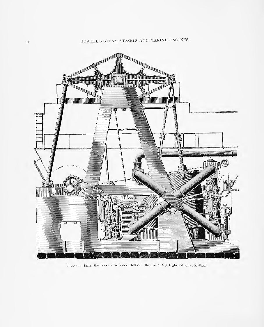
92 HOWELL'S STEAM VESSELS AND 1SL\RINE ENGINES.
Cumi'(h:ni) Beam Exf'.iNRS m- Stkamer Honam.—Built by A. & J. Iii.nlis, fUasgow, Scotland.

HOWELL'S STEAM VESSELS AND MARINE ENGINES. 93
Oscillating Engines.
This type is much more common in England than else-
where. The term applies to a cylinder mounted on trunnions,oscillating on its axis to accommodate the lateral sweep of thecrank, thus dispensing with a connecting-rod, crosshead andgirders, the piston-rod being connected directly to the crankpin.
At first there was a persistent effort to perform steam dis-
tribution by means of, or through, the trunnions so as to dis-
pense with valve gearing, thus reducing a piston steam engineto the most simple form it has ever attained, but these methodshave failed in practice, and oscillating engines are now com-monly made with the usual slide or other valves like fixedengines. The object sought in the oscillating type of engines,aside from simplicity and cheapness, was the saving of room,or their compactness, a feature conspicuous in English practice,
where oscillating engines are in a great many cases set directly
beneath the paddle shafts of steamers, and have given excellent
service. This method is not only applied to small boats, butto large steamers of the highest class plying in the Englishand Irish Channels. The shortening of the stroke of engines,
and various mechanical devices for diminishing the distance
between the piston and crank has rendered the oscillating
arrangement unnecessary. The rapid movement of the cyl-
inders on the inward stroke of the piston produces lateral strains
on the piston-rod, gland and pistons that cause rapid wear andderangement, unless provided for by careful design, goodmaterial and the best of workmanship. In fact, but one firm
in the world has attained complete success with o.scillating
engines, that of Penn & Son, in England.—John Richards, in
Industry, San Francisco, Cal.
Compound Beam Engines of the Honam.
The twin screw is displacnig the single .screw, and the
paddle-wheel is giving place still more decidedly to the .screw
propeller ; while in the method of operating the paddles the
beam engine is destined soon to pass away. One finds several
services which were formerly carried on by paddle steamers
having beam engines now conducted b\' screw steamers. TheBergen, Bremen and Hamburgh of the Hoboken ferry are
cases in point, while several paddle steamers have now been
fitted with other types of engines than that of which the
walking beam was such an attractive feature. It is true, it
required marvelously little attention : but it was far from
economical. It can serve no purpose to sing a requiem—manyof our American friends might claim that it is yet too soon for
that. Certainly, in this country the beam engine belongs to
the pa.st. It never gained any distinct hold on British favor,
although admired by Scott Russell, but several engines of the
type have been made in this country for service in foreign
waters, and a record of modern engineering practice would not
be complete without a reproduction typical of the British
design. A. & J. Inglis, of Glasgow, some years ago madeprobably the most successful engines of this class, and one is
illustrated herewith. These we should have been glad to
describe long ago ; but characteristic modesty on the part of
Messrs. Inglis suggested excuses as frequently as we urged the
claims of our readers. The present time, however, is not
inopportune, since we may be said to be in the transition stage.
vSoon the triple-expansion direct-acting engine will be exten-
sively adopted for paddle steamers, as it already is for screws.
It is not difficult to trace the evolution of the beam engine
as applied to the propulsion of paddle steamers. The great
difficulty in paddle engines was to .get a sufficient length of
stroke of piston, while keeping the engine low in the ship, andminimizing the length of space required. It was soon recog-
nized by Watt, and some American engineers, that the mostnatural and possibly most picturesque arrangement was to
adopt the simple old-fashioned beam used by Newcomen for
the colliery pumps and land engines. While American engi-
neers adopted this system, Robert Napier, Watt, Maudsley,
and Fawcett continued to use the side-lever engine, the first
named bringing it to its perfect stage in the Persia and Scotia.
This side lever may be termed the English form of the beammarine engine. Here it was considered undesirable to ob.struct
the deck with the walking beam, while the adoption of the
side lever enables the engineer to choo.se any proportion of
.stroke and any size of paddle-weel that would best serve the
purposes of the ship. American engineers have continued to
use the beam engine, although, as we have indicated, there are
evidences which encourage the belief that it will be superseded.
Messrs. Inglis were the only firm in this countrj' which largely
adopted the system, and the engines of the Honam, which weillustrate, are a typical design. One of the largest beamengiues constructed, however, was for the Puritan of the Fall
River Line. The Inglis beam engine indicates several
departures in the details when compared witlr the Americanengine of that day, and was more strongly built. The gallows
frame, which supports the main center of beam, instead of
being of wood, as was the usual practice in the United States,
was of steel plates and angles, and of box section. It wassecured to massive box keelsons on the floor of the ship. Thisstyle of framing had not then been adopted b}- an}' other firm,
and it gave great satisfaction. The wooden frame used in
the American engine "wobbled," and allowance had to bemade for this in the clearance between the piston and cylinder
ends, 5 inches being not uncommon. It is easy, therefore, to
understand that there was considerable waste of steam andcon,sequent loss of efficiency. The steel frame—which, by the
wa3', is adopted in America— is perfectly rigid, and only the
ordinary clearance is necessary. The Honam's engines wereon the compound principle, and in this respect aLso were a
departure. The cylinders, as shown on the front elevation,
were inclined towards each other at the head, admitting of thepiston-rods beiiig connected to the one point on the forwardend of the beam. This secured a perfectly balanced motion.In the engines of the Puritan, already referred to, the cylinders
are nearly vertical, and are connected at two points to the
walking beam. The great difference in the size of the twoengines—the Puritan's indicate 7500 and the Honam's only2goo— militate against any reliable compari.-on of results,
more especially as the former is worked under forced draughtwith Sturtevant fans, and has two superheaters utilizing the
waste gases before they pass into the smokestack. It may benoted, however, that the indicated horse-power in the Puritanis at the rate of about 9 per square foot of grate area, while thepower was i indicated horse-power to 3J2' square feet of heatingsurface; in the Honam the results were 9.7 indicated horse-
power to I square foot of grate area, and i indicated horse-

'H HOWELL'S STEAM \-ESSELS AND MARINE ENGINES.
power to 2.73 square feet of heatiug surface. The relative
coal consumption r&sults would be interesting, but they are not
given in the case of the Puritan. In the Inglis boats, fuel
economy has alwa^-s been a marked feature.
The high-pressure cylinder of the Honam's engines is 40inches in diameter, with a stroke of 10 feet, while the low-pres-
sure cylinder is 72 inches in diameter, with a stroke of 9 feet
ID inches, the difference in stroke being due to the inclination
of the cylinders. Double-beat steam and exhaust valves are
provided, while the high-pressure cylinder is fitted with ex-
pansion valves. The surface condenser is placed alongside the
cylinders, as shown in the forward elevation, while the pumpsare worked by a rod from the walking beam, as shown in
the front elevation. The cooling surface is 5395 square feet.
The walking beam, which is constructed in the same waj' as
is u.sually adopted in American vessels, with cast-iron center
and forged steel strap, is 23 feet in length, 11 feet deep, andweighs 14 tons. The secti(m of beam strap is 7 inches by 9inches, and the main center is 14 inches in diameter in the mainbearings. The piston-rod is 5 -=4 inches in diameter in the ca^e of
of the high-pre.ssure, and 7 inches in that of the low-pressureengine, and of steel, while the connecting-rod is 23 feet longfrom center to center, and 13 inches in diameter. The crankshaft is 17' J inches in diameter. The paddle-wheels ha\'e feather-
ing floats, and are entirely of steel. They are 21 feet in diameter,
and the floats are 15 feet by 4 feet. These latter measurementsare very unusual, and it would certainly be ver3' interesting to
know if the builders of some of the recent fast paddle steamershave gone so far as to reduce the diameter of their wheels to
2.1 times the stroke, or to increase the float area to 60 squarefeet. Steam is supplied from three double-ended boilers placed
athwartships and fired from the wings. These boilers are 14feet in diameter and 14 feet long, and have in all 18 furnaces.
The grate area is 297 square feet, and the heating surface 7939square feet. They work at a pressure of 75 pounds, and at 33revolutions the engines developed 2900 indicated horse-power.
The steamer, which, with the engines working at this power,attained a speed of 16}^ knots, is 270 feet long, the breadth,
moulded, being 38 feet, and the extreme breadth 72 feet 6 inches,
the depth, moulded, 13 feet 3 inches, and the extreme 30 feet.
The tonnage is 2800 tons.—London Engineering
.
Stevenson Taylor, Vice-President and General Superin-
tendent of the North River Iron Works, Hoboken, N. J., wroteto the editor of Engineering, under date of September 12, 1893,
as follows :
Sir :—We are verj' much interested in your article " Beam
Engines for Paddle Steamers" (issue of September i, 1S93),
giving an account of the engine of the .steamer Honam, as wewere when you before published (November 9, iS88j a descrip-
tion of this .same .steamer. There are a few inaccuracies to
wliich, in justice to our old friend, the beam engine, we mustcall your attention, and we believe you will be glad to correct
them. I. The wooden frames of the American beam engines
never "wobbled" to the extent that "allowance had to be
made for this in clearance Isetween the pistons and cylinder
ends;" and so far from "5-inch (clearance) being not uncom-mon," we must saj- that in our experience of over 40 years (dur-
ing which time we have built and repaired hundreds of these
engines; we have not seen one engine with 5-inch clearance; i
inch at each end being the usual design for the largest of them.
If there ever was a beam engine with 5-inch clearance at each
end or at both ends, it was because of an egregious blunder and
not from necessity. 2. You refer in a complimentary manner to
the iron frame and keelsons of the steamer Honam, parenthetic-
ally remarking, " which, by the way, is now being adopted in
America." We have a number of boats on our list, as well as
those built by others, built before the Honam, which have iron
or steel engine frames and keelsons, and some of these boats
have wooden hulls. 3. The Puritan has not forced draught. Theblowers mentioned only ventilate the fire-room, which is so open
that no extra air pressure is possible. No exact test for deter-
mining the economy of the Puritan engine has been made, but
on the Citv of Fall River (a boat about the dimen.sions of the
Honam) , belonging to the same line, and having the same style
of engine as the Puritan, careful tests were made in 1883 (.see
Journal of the Franklin Institute, July, 1SS4). These tests
showed an average consumption of 2.04 pounds anthracite coal
per hour per horse-power, and we have reason to believe that
all of the engines built since, of the same st>de, perform just
as well. The City of Fall River, by the way, has a wooden hull,
with a wooden engine frame and keelsons, and both cylinders
have a design clearance of i inch only. The engine framedoes not " wobble." Of course, there is no use in these days
advancing the advantages of the American beam engine. Thetide is setting in other directions, but they ha\'e been, and still
are, extremelv .serviceable,' and, considered all round, are eco-
nomical for work performed.
W. & A. Fletchrr Company.S. T.WLOR, I'icc-Prcsidciit and General Supcrintendeul
.
Beam Engines.
These in theory and in fact represent the best arrangementfor rotative speeds within their limit. Their special features
are that the moving weights are in equilibrium, the pumps areworked direct from the beam, and the strains are more direct
than in other engines. P'or the.se and other reasons they aremore durable.
Their use on ferryboats in this country arises mainly fromthe fact that the machinery, as a whole, is set on its edge, so to
speak, the main working parts above the deck, and the spaceoccupied, a long, narrow strip fore and aft, does not inter-
fere with the deck traffic and loads. It is true, the engine spaceextends up through the cabin and above the roof, but this is
not a great encumbrance. There is also the reason for ferryservice that beam engines fitted with balance puppet valves asmade at this day are ea.sy to ' 'handle
'
' and keep off the centers,because in equilibrium.
For stationary purposes there are the objections of greaterfirst cost, larger proportions because of slower speed, largerspace occupied, but, notwithstanding this, one of the finestplants for duty in cotton mills has just been constructed in Eng-land on the beam system, and the most complete pair of wind-ing engines ever made on this coast are at this time (1S95)under construction at the Union Iron Works in San Francisco.—John Richards, in Indttslry, San Franci.sco, Cal.
Setting the Valves of Beam Engines.
Assuming that the rock-shaft arm is keyed on to the rockshaft in its proper relation to the center line of motion of theeccentric-rod, and that the wipers are keyed on to the rock

HOWELL'S STEAM VESSI'LS AND MARINE ENGINES. 95
Thk Morris Compound Marine Engine.—Built bv the Morris Machine Works. The Morris Single M.\rixe Engine.
shaft in their proper relation to tlie rock .shaft arm, which i.s
always the ca.se in properly constructed engines, the first step is
to ascertain the proper length of the eccentric-rod, and the mostconvenient starting point for doing so is from the center of
motion of the valve gear.
Hence, the first thing to be done in setting beam enginevalves is to set and to hold the rock shaft at the center of its
motion, which is when the lifting-rods are down, the valves
seated, and the lifting-toes adjusted the right distance from the
rock shaft, and .straight with each other, so that the ends of
both wipers will be the same distance from their respective toes.
Next put the main crank on the center, and turn the throw ofthe eccentric directly in line towards the center of the eccentric-hook pin
;then make a fine center-punch mark on the edge of
toe pin, and one on the edge of the hook .strap, and set a pairof compasses corresponding to the distance between those marks,and measure it. Add to that distance half the throw of theeccentric
;reset the compasses to that length, and move the
eccentric until the eccentric punch marks and compasses againcorrespond, and adju.st the length of eccentric-rod so that thehook will just engage the eccentric-hook pin while the eccentricis held at that position
;then slack up the rock shaft so that

y6 HOWELL'S STEAM VESSELS AND MARINE ENGINES.
Thi-. JIdKKis Steeple Compound Eni'.ine, n and ]6 In- s. Tm; CorLTEK & :\IcKen/,ie Compound Kxcine in Yacht Drkam.
it can be mo^-ecL hook on the eccentric-rod, and turn the
eccentric in the direction to raise the required valve until it has
the proper lead ; then ( if tlie engine is of the style that has
two eccentrics and two rock shafts) proceed in tlie same man-
ner with the exhaust valve gear, and the valves are set.
To prove the accurac>' of adjustment, turn the main crank
to its opposite center, and if there is a difference in the lead.
either lengthen or shorten the eccentric-rod to make up halfthe difference, and turn the eccentric to make the other half,fasten the eccentric on the shaft, and the \-alves will be right.There can be no general rule gi\-en as to how the eccentricssliould l)e placed in relation to the crank, as that depends onthe relative arrangement of the lifters, valves, wipers, and rock-shaft arms.— The Eii;^ince>\ New York.

HOWElX'vS STEAM VESSELS AND MARINE ENGINES. 97
The riorris Compound flarine Engine.
This engine is built by the Morris Machine Works, Bald-winsville, N. Y. The engraving is of a 5 by 10 by 6-inchengine. The cylinders are cast .separately and bolted togetherwith a receiver between them. The high-pres.sure cylinder hasa balanced valve of the same type as that used in the StraightLine engine. The valve on the low-pressure cylinder is a com-mon D-valve. The cranks are arranged at an angle of 90degrees to each other. All working parts, such as piston-rod,crosshead, connecting-rod, crank .shaft and link motion, aremade of steel. The cylinders are supported by cast-ironcolumns behind and poli.shed steel rods in front, giving full viewof all the working parts. Oil reservoirs are fitted on the Ijackside of the engine, and by pipes leading from these reservoirsthe crosshead guide, crank pin, and crosshead pin are auto-matically oiled. One of the.se engines, during a recent trial,
ran continuou.sly at 450 revolutions per minute, showing notendency to heat.
The steeple and the fore-and-aft compound engines are
both built with a view to having a strong and substantial
engine, at the same time having a fairly light design and anengine in w'hich every part can be easily seen in operation andreadil}' got at. All the bearings are made to take up, exceptsome of the smaller sizes in the link motion, where small bronzebushings are forced in, which can, when the bearings are worn,be driven out and replaced by new ones.
The small vertical engine shown in the cut is built by the
Morris Machine Works, Baldwinsville, N. Y. The engine is
made in eight sizes, the smallest being 5 bj' 5. It will be
noticed that the engine contains several features not found in
any other, the principal one being the frame, which should at
once commend itself to users of .small vertical engines. Free
accessibility to all parts of the engine can be had at all times.
These engines were designed for hard and continuous service,
and are fitted in the best possible manner. The reciprocative
parts are nicely counterbalanced, which will permit of high
speed without vibration.
Compound Engine of Steam Yacht Dream.
The machinery that drives the fastest steam vessel ever
built in Bridgeport, Conn., is the .subject of this sketch. This
boat is the steam yacht Dream, designed for H. M. Hilhs, co-
proprietor of the Evening Post of that city. The vessel is 60
feet long over all, 12 feet beam, 5 feet deep, and draws 20 inches
forward and 3 feet 4 inches aft. The power required is supplied
by a Herreshoff water-tube boiler. A Worthington double-
acting vacuum pump controls a keel condenser consisting of 48
feet of 3-inch pipe. The engine, as shown in the prospective
view, is a fore-and-aft compound, designed and built by the
Coulter & McKenzie Machine Co., of Bridgeport, Conn. It is
capable of furnishing 75 horse-power, and turns a 3-foot screw
of 4 feet 7 inches pitch 250 turns per minute with 100 pounds
of steam. The high-pressure cylinder is 6 inches in diameter,
the low-pressure 12 inches and the stroke 9 inches. Both
cylinders are cast in one piece. The exhaust from the high-
pressure cylinder passes around that cylinder and into the low-
pressure valve, thus making a receiver and jacket in one and
permitting the passage of steam to the low-pressure cylinder
without piping. The pistons are fitted with a .sectional Dunbarpacking, consisting of a solid center, or "bull" ring, on each
side of which is fitted an L-shaped ring and a square ring,
with good results. These rings are cut in three or four .seg-
ments, as may be desired, and are adju.sted so as to break joints.
The rings are pressed against the walls of the cylinder bymeans of round wire springs of a diameter equal to the inside
width of the rings. This construction insures even and suffi-
cient pressure of the rings against the cylinder. The valves
are of the balanced piston type, made up of a center and twoend pieces held together by the valve stem and fitted with a
steam-tight ring on each end. The live steam enters on the
top of the valve, passes through the center and enters the
cylinder from each end, the exhaust steam pas.sing around the
center, as will be understood. The vah'cs are operated byStephen.son link motion, the connections of which have every
adjustment. The link blocks are bronze bushed, with a hard-
ened and ground steel bush working on a hardened steel pin.
The links are made in halves and bolted together. The cyl-
inders are supported upon six steel columns, which are securely-
fastened to a substantial cast-iron bed piece, making a framewhich permits ready access to every part of the engine for
repairs or adjustment.The Dream is a wooden vessel, built by Geo. W Ma.sters,
Bridgeport, Conn., in 1893. Referring to the illustration of
sectional plan of cylinders : The exhaust from the high-pres-
sure c},'Hnder passes around that cylinder and into the low-pres-
sure valve, thus making a receiver and jacket in one, and per-
mitting the passage of steam to the low-pressure cylinder
without piping.
Quadruple=Expansion Engines of the SteamshipKensington.
The International Navigation Company, of Philadelphia,
Pa., had two large steel twin-screw .steamers built in 1S94 onthe other side of the Atlantic—the Kensington, by James &George Thompson, of Clydebank, Glasgow, and the Southwark,by Wm. Denny & Bros., of Dumbarton, Scotland. Thevessels are sister .ships. The engines are of the quadruple-
expansion t3'pe, direct acting and surface condensing. Thefour cylinders each work a separate crank, and they are so
arranged as to produce the minimum of vibration, the parts
being so disposed as to be practically balanced without the use
of counterweights. The order of the C3'linders from the forwardend is high-pressure, second intermediate, first intermediate,
low-pressure. The sequence of turning is high-pressure, low-
pressure, second intermediate, finst intermediate. Cranks are
at right angles to each other. Diameters of cylinders are as
follows: High-pres.sure, 25^2 inches; first intermediate, 37)2inches; second intermediate, 521-!^ inches; low-pressure, 74inches, with a common stroke of 4 feet 6 inches. The high-
pressure and two intermediate-pressure cylinders are each fitted
with piston valves, and the low-pressure has a double-ported
flat valve. All valves are worked b^- a single eccentric radial
valve gear. It is operated b^- a single eccentric througha quadrant rocking on trunnions. The reversing is obtained
by moving the sliding block attached to the valve spindle fromone end of the quadrant to the other. The lap and lead is
secured by a separate lever worked from the crosshead of the

y8 H(n\']':iX'S STHAM X'ESSELS AND MARIXU KNGINHS.
Vkrtil'ai, SiicTTOx THRijucii Csi.ixru.Ks 01- Cdixtkr ^; McKknsie Yacht Kngink.
Shctkin Plan oi- Cyijndkrs.
iiiaiii engine. This arrangeUK-iU nf \-al\'t iiintidn allows nf the
valves of the engine being ])laeed at the back, thereb}" Ijringing
the centers (if the cylinders nuich clo>er tngether and econo-
mizing space in the engine conqiartnient : and, nf cnnrse,
adding to the cargo ca]xicit>- nf the slii]). The tnlal length nf
the engines is abotit 25 feet, which is much le^s than cnnld be
attained if the ordinary link gear had been used. The revers-
ing .gear is controlled by a Ilrown steam and h\alraulic direct-
acting engine.
In the conslructinn of the engines, cast steel was largeh'
used. The shafting is nf Siemens-Martin .steel. The fotircranks are eacli Innlt u]) se])arately, and are interchangeable.The crank shaft is 14-54 inches in diameter, the thrust shaft14 inches, and the tunnel shaft 14 inches. The thru.st blocksare nl llie ordinary hnrseshne tvjie, of white metal, and tliereare sex'en rings Tlie blades nf the prni)eller are nf manganeselirnnze, while the boss is nf cast steel. There are tliree bladestn each i.rn],eller, the diameter being 17 feet, and the jiitch 20feet. The cnndeirser is ofjlong, and supports the back of thecylinders. It is 19 leet long, nf cast-iron, and is fitted with

HOWELI.'vS STEAM VESSELS AND MARINE ENGINES. 99
:»''
Gp'nerai, Vikw of thk Ouadrupi^k-Expansttix p^xr.iNP.s <)! I'Hi'. lNTp;RNATroNAi, Navicatton" Co.'s TwiN-ScRhw Steamship Kp;NSiNr,T(jN.
brass tubes, the cooling surface being a)jout 10,000 square feet.
The condensing water to each condenser is circulated by a large
centrifugal pump driven by an independent engine. The air-
pumps are driven by a le\-er working from the crosshead of a
low-pre.ssure engine in the usual way. There is also fitted a
large evaporator to produce the neces.sary fresh \\-ater from sea
water to make up the feed, and to avoid the use of salt water
in the boilers. A large feed heater and filtering arrangements
are provided. An auxiliary condenser has, in addition, been
fitted on board, with a separate circulating-pump, so that all of
the auxiliary machinery- in the shi]i is worked separately from
the propelling engines. An installation of Worthington pumps
has been fitted on board.
There are three boilers in the ship, constructed of steel,
and adapted for a working pressure of 200 pounds to the
square inch. Two of the boilers are double-ended, and are 15feet 9 inches in diameter by 21 feet 5 inches long, while thesingle-ended boiler is of the .same diameter, but 11 feet 3 incheslong. There are four furnaces at each end, making twenty in
all, each with a Purves flue. These are 3 feet 4 inches meandiameter, the length of fire bar being 5 feet 9 inches. Thetotal heating surface is 12,176 square feet, and the grate area
is 3S3 square feet. The boilers are fitted with Serve tubes3 '4 inches in diameter, with i-'t; inches .spaces between.There is fitted al.so a .system of induced draught, patented byEllis & Ea\'es. The boilers are in one compartment and

lOO HOWELL'S STKAM \'ESSELS AND MARINE ENGINES.
DRAWINCS of }{Nn \'IK\VS of EnGINKS of THF KF.NSINC/roN.
exhaust into one chimney stack, which is 84 feet high from
the grate level, and elliptical plan, 14 feet by 9 feet. The fans
are 7 feet 6 inches in diameter, and are dri^-en direct bySturtevant engines running under ordinary conditions at a
.speed of 370 revolutions. The fans induce a draught through
the furnaces, the air ha\-ing previou.sly been heated b}- pas.siug
through tubes placed in the way of the waste gases from the
furnaces. The inlet of air to the furnaces is through tubes
placed in a casing o\-er the boiler, thence down a passage in
front of the smoke box at the end of the boilers, and into the
furnaces. The gases from the furnace, after passing through
the boiler, play around the tubes forming the air inlet, and sub-
sequently pass into the funnel at the base of which are the five fans
inducing draught through the passages thus briefly indicated.
At the trials on the measured mile at Skelmorlie, the dis-
placement of the \-e,ssel was 12,400 tons, the draught being,forward, 2 i feet y inches
;aft, 2 i feet 7 inclies; and mean, 2 i feet
s inches. Six runs were made, the mean results being as fol-
lows: Steam pres.sure, 199.5 pounds per square inch; air pres-
sure in stokehold, 3.16 inches; revolutions, port engine,M6.4
; revolutions, stai'board engine, .S6.9; indicated hor.se-
power, both engines, .^,313; vacuum, 27 inches; .speed, 15.
S
knots. The temperature at the base of the funnel was about550 degrees Fahrenheit. On her first trip to Philadelphia thespeed averaged 14. i kn(jts, and on the homeward run 13.7knots, the indicated horse-power being about 7,000.
The dimensions of the hull are : Length between perpen-diculars, 4S0 feet
; breadth, moulded, 57 feet; and depth,
moulded, 40 feet. She is built throughout of Siemens-Martinsteel, and is subdivided Jjy nine water-tight bulkheads.

HOWELL'S STEAM VESSELS AND MARINE ENGINES. lOI
SINGLE COMPOUND.THE
DOUBLE COMPOUND. QUADRUPLE EXPANSION.
'KINGDON" PATENT ENGINE, FOR STEAM LAUNCHES.
Constructed by vSimpson, Stricklanrl & Co., Dartmouth, South Devon, Englanfl.
The Kingdon Patent Engine for Steam Launches.
In these engine.s only one valve is needed to regulate the
admission and emission of steam in the cylinders, ^^'hich are both
double acting, consequently there are no more moving parts
than in a single cylinder engine. The grade of expansion is
directly proportioned to the area of the cylinders, and there is
far less loss of pressure between them than is the case in most
compound engines, owing to the .shortness of the pa.s,sages, and
owing also to the fact that the temperature of the steam is
maintained during its pas.sage through the valve by the live
steam with which it is surrounded. The steam is carried
throughout about nine-tenths of the stroke in all cylinders, and
consequently the effort on the crank .shaft is very uniform.
Both pistons being on the same piston rod, the strains on
the crank .shaft, due to an unequal amount of work being
done in the two cylinders at different portions of the stroke,
are entirely done away with. These engines are constructed
by Simpson, Strickland & Co., Dartmouth, South De^'on,
England.
Haug's Compound Marine Engine.
In the accompanying cut, Fig. i shows a compound marine
engine in which the pistons travel in opposite directions, thecranks being set at i8o degrees. The principal noveltj' in thedesign is the piston valve, which admits steam to the high-pre.ssure cylinder, then exhausts it into the low-pre.ssure
cylinder, and finally into the atmosphere or condenser. Thedistribution of the steam by means of this valve is clearly indi-
cated in Fig. 2, which shows a sectional elevation, a sectional
plan, and a plan of the cylinders and valve. This figure also
ser^'es to show the compactness with which the cj'linders and\-alve may be arranged, the valve being operated by a radial
valve gear. A quadruple-expansion engine can be arrangedon this principle, one set of cranks being placed at 90 degreeswith the other set, as shown in Fig. 3, thereby securing anearly perfect balance of working parts with great uniformity'of motion, and comparative simplicity.
Charles Ward, of Charleston, W. Va., put a small engineof the type shown in Fig. i into the steam launch Mascot,built by him for the War Department, Engineer Corps. Thehull, which is constructed of steel, is 61 feet long, 8 feet i
inch beam, 3 feet 4 inches deep, drawing 7 inches forward and14 inches aft. The engine has cylinders 6'^ and 13 inches in
diameter, 8 inches stroke. During the trial the engine ran atthe rate of 540 revolutions per minute, driving the boat 13 ^''3
miles per hour.

HOWELL'S STKAM \ESSKLS AND MARINE ENGINES.
HAUC'S Cfl.MFOUNl) Marink Kn<,ink.

HOWErj;S STEAM VICSSEES AND MARINE ENGINES. 103
'"'.(/• -i
Haug'S Compound Marine Engine.—Designed by John Hauj<, Philadelphia, Pa
The engine worked non-condensing ; steam was supplied
by a Ward boiler of the launch type, having a grate surface
of 4 square feet, and 80 square feet of heating surface. Theweight of boiler is 965 pounds ; water in the boiler, 1 10 pounds;
engine complete, 1,000 pounds. There was no opportunity to
take indicator diagrams from the engine, but the horse-power
was judged to be from 70 to 75, or one horse-power for every
27 to 30 pounds weight of machinery. The accompanying de-
signs were made by the inventor of the valve, John Hang,
Mechanical Engineer and Naval Architect, Philadelphia, Pa.
Composite Steam Light=Vessel.
On April 11, ICS95, the Lighthouse Board, \\'ashington,
D. C, opened bids for another of the high-class, electrically-
hghted light-ships that have of late been introduced into the
service. The illustration gives an idea of what the boat is
like. This ve.s.sel is of compo.site construction, 112 feet on the
water line, 28 feet 6 inches moulded breadth, and 13 feet
depth of hold. The frame is of steel with steel-plate keel,
steel bilge strake and steel sheer strake. Wood planking is
used from the keel up to the sheer line at the main deck, andfrom that point up to the spar deck steel plate is used. Theframes, floors, keelsons, stringers, beams, shear strake, bilge
strake, strapping, keel plate, etc., are of steel; stem, stern-
post, rudderpost, rudder, false keel, .shoe, .sheathing and gripon stern, bilge keels are of white oak ; keel, planking anddeadwood of long-leaf Georgia or Florida pine. Fastenings in
plank, keel and deadwood are of galvanized iron ; in the woodsheathing, composition spikes. The metal sheathing is 26,
28 and 30-ounce metal, double punched. The propelling engine,
which will, of cour.se, be of use only in moving the vessel to
and from her station or for handling her in case of accident
that might remove her from her moorings, is about 350 hor.se-
power, and of the vertical inverted surface condensing type,
with a single cylinder 20 inches diameter and 22 inches stroke
of piston. There are two main boilers of 300 hor.se-power
each and two auxiliary of about 40 hor.se-power each. Themain boilers, of the Watkin & Dixon type, the .same as those
built by Heipershau.sen Bros. , New York, for several harbor
tugs, are not more than 14 feet long, 8 feet wide and 8 feet 6
inches high from under side of furnace leg to top of shell, the
shell S feet diameter. The electric light plant consists of tw<.)

'->4 HOWELL'S STEAM VESSELS AND MARINE ENGINES.
Plans for a Composite Steam Light Vessei, for the Woods Hon (Mass.) .Station.
of the General Electric Conipan>''s marine .sets known as m. p.
4-S.550, with 5 by 4-inch double-cylinder Sturtevant engines.The co.st of this ve.s.sel was about $70,000. The contractorsfor the construction of the ship were the Bath ( Maine ) IronWorks.
The Composite Auxiliary Steam Yacht Satanella.
This beautiful craft was designed by I. S. White, andbuilt by White Bros., Cowes, Isle of Wight, England, in i.SSi.
.She is a composite vessel, ha\-ing an iron frame planked withwood, and was christened Golden Fleece by her owner, W. H.Roberts. In 1891 .she was brought to America b}- the late
Francis T. Osborne, and afterward became the property of PerryBelmont, of New York, who changed her name as above.Dimensif)ns : Length o\-er all, 136 feet; load water line, ii3'l'
feet; beam, 22)2 feet; draught, 13^/2 feet; net register, 114.97tons; C. H. M., 169. S tons ; has compound engines i3'2 and22 b>- 13 inches, built b}- G. E. Belliss, Birmingham, England.
The Steam Yacht Free Lance.
The dimensions of this vessel are : Length over all, 137feet; load water line, 108 feet; beam, 20 feet; draught, 6 feet 9
inches. Engines, triple-expan.sion, 11,17 and 29 by 20 inches,which develop o^-er 500 indicated honse-power.
Steam is furnished by two Almy water-tube boilers. The.sesteam generators are each 8 feet 4 inches high, 6 feet 4 incheslong, 4 feet 6 inches wide, giving 1600 square feet of heatingsurface and 52 square feet of grate. The owner of the FreeLance is F Augustus Schermerhorn, New York.
The frames are of steel angles 21-^ by 2'A by '4 inches,s])aced 24 inches apart from centers in one' piece from keel tomain deck lodger plate. Floors are of plate steel 3-16 inch deepand are gradually deepened aft on a fair line to stern post.0\'erhang aft is braced with a plate keelson of 8.12 pounds steelcut down on frames and clipped to .skin, and also one under thedeck. There is one center line continuous keelson running frombow to stern, extending above the floor two inches and securedwith a double angle back to back. Sister keelson, between thecenter keelson and bilge, is continuous on each side of platesUnder the engme and boiler space proper, steel keelsons areplaced as required for machinery, and they are gradually taperedforward and aft to strengthen the boat just forward and aft ofengine space. Bulkheads are as follows : Collision bulkhead atbow, of 7.35 pounds steel .stiffened with 1J4 bv i-'r^-inch ano-les-one at fore end of boiler space of same weight; a light one be-tween boiler space and engine-room, merely to keep du.st out •
one aft of engine space, .same as bow, and one at stern tube'

IIOWEIJ.'S STEAM VESSJ'XS AND MARINE ENGINES. 105
P' W
~^r
h
«a::»
¥^
^W*-;g?sr*-T-'*^j^"
COIMPOSITK AllXIIJARY STBAII YaCHT SaTANEW.A.
also two light ones between tlie ensj'ine and Ijoiler-rooni, to Ije
utilized as a coal bunker. The main deck 1)eanis are of steel
angles 2J2 by 2 '2 by '4 inch, one on each frame in one ]iiece
and well secured to .side b^- gus.set plates cur\-ed on inner edge.
All plating is of steel. The main deck is of selected «-hite
pine 2J2' by 2 Jo inches, bolted with special bronze screw bolts,
put in from the bottom, IT. S. Navy style. House deck is of
well-sea.soned mahogan>' tongue and grooved 1^4^ inches thick.
Cabin deck is layed with well-seasoned white pirte iij.' inches
thick. A. Cary Smith was the desi.gner of the yacht.
KNGINES OF THE STEAIM YACIIT FREE LANCE.
With this we gi\'e an illustration of the engine for tlie
.steam )-acht Free Eance, built for F A. Schermerhorn, ofNew York, by Lewis Nixon, at the Crescent Shipyard, Eliza-bethport, N. J., from the designs of A. Car\- Smith, of NewYork, the engines Ijeing designed by Charles C. Bowers, sujier-intending engineer of the .shijn-ard.
The engine is of the inverted direct acting triple-ex]>an-,sion tA-pe, with cylinders 11,17 ^^"d 29 inches diameter and astroke of 20 inches. Tlie c>iiiiders are mounted in the orderof high, intermediate and low-jircssure, with the high-pre.ssurevalve on tlie forward end of the engine, the intermediate jires-
sure valve lietween the high-pressure and intermediate pressurecylinders, and the low-jiressure vah-e on tlie after end of theengine. The steam ports in high-pressure c\-liiider are i -'4 bv

io6 HOWKLL'S STEAINt VESSELS AND MARINE ENGINES.
"•*^'
F. ArClSTlIS SCHERMKKH(IRN-'S STKAM YaC HT I'RKK, T,\XCK.—BuUt l)v Lewis Ni>iU 11, Rli/,al)ethpoil, X. J., from 1 H-Ni^ns of A, C:n-\- Siiiitli
ir3_:^^s
Shear Plan of the Steam Yacht Free Lance. -Rniltll.y T.ewis^Nixoii, KlizaI.ethport, N. J., frr.,„ Desisiis of A. Carv Smith

HOWELL'S vSTEAM VESSKLvS AND MARINE ENGINES. 107
Engtnk ok the Steaii Yacht Free I.anck.
9 inches; intermediate pressure c>-linder, 2 '4 b>- 17 inches.
There are double ports in the low-pre.ssnre cyhnder, each i;'4
by 30 inches. The throttle valve is balanced and fitted with a
relief vah'e. The high-pressure cylinder is fitted with a piston
\'alve 6 inches diameter ; the intermediate pressure c>-linder
with two piston valves each 6 inches diameter, and the low-pres-
sure cylinder with a large double-ported D-.slide valve. Thepiston ^•alves have self-setting spring rings. Liners are fitted
to the steam chests of the high-pressure and intermediate pres-
sure cylinders, and the low-pressure steam chest has a false
seat or liner for the .slide valve to work on. All valves have
4-inch travel and are worked direct by the regular Steven,son
double-bar link. The valve stems of the high-pressure and
intermediate pressure valves are i-'s inches diameter, and for
the low-pressure i -'4 inches. They are made of steel and work
in guides fitted with brass bushings. The eccentrics are of cast-
iron 2 inches wide for the high-pressure, and 2 '4 inches wide
for the intermediate j^re.ssure and low-pre.ssure cylinders, \vith
ca.st-iron straps.
The high-pre.ssure eccentrics are fitted to the end of the
shaft, which is turned down to 2 inches diameter to receive them,
thereby allowing the use of eccentrics of much .smaller diameter
than tho.se of the other cylinders. The engine is supplied with
steam reversing gear having a cylinder 5 inches diameter, 10
inches .stroke, and fitted with gag for adjusting the cut-off;
all are under easy control of the engineer. All pi.stons are cast-
steel di.sks 3 inches deep at sides and attaclied to the rods by a
(juick taper and nut. All the pistons ha\-e two rings side ])y
side, Ijncked uj) 1>_\- a tliird ring of the same widtli as tlie twooutside ones, and in the kjw-pressure jwston the three rings are
reinforced b^- nine helical springs i inch out.side diameter, andabotit I
J4 inches long, made of '/s-inch bra.ss wire. The c\linders
are carried by the conden.ser at the fjack, and three wrought-iron cohnnns in front, which form the frame of the engine.
The l)ed plate is of the girder type 7 feet HSy, inches l<jng, con-
forming to the .shape of the ve.s.sel, and lias 5 main journal bear-
ings. The crank .shaft is of .solid forged steel 6 inches diameter.
The cranks are placed 120 degrees apart in order of high-pres-
sure, intermediate pressure and low-pressure, and are counter-
balanced. The thrust bearing has six collars forged on. All
crank-pin brasses, main bearings and eccentric straps are lined
with anti-friction metal. The condenser is of cast iron 6 feet
1 1 '4 inches between the tube sheets, and has 602 brass tubes
5s inch diameter ; the tulje sheets are "i inch thick. A rotary
circulating-pump i.S inches diameter, witli blades 3 inches wideat tlie root tapering to i ' 2 inches at the outer end, is bolted
onto the end rif the conden.ser and run b\" an .independent
engine with a c>'linder 5 inches diameter by 3 inches .stroke;
also bolted to the condenser and attached direct to the shaft of
the circulating-pump. The air, feed and fire-pumps are all in-
dependent. The engine is fmeh' and substantially built, andfor the speed and ])Ower it de\'elo]ied takes up \'ery little .space,
and all parts are within ea.sy reach of the engineer. The enginewas built by S. L. Moore & Sons, EHzabethport, N. J. Thedimensions of hull areas follows : Length over all, 137 feet
;
on water line, loS feet: beam, 20 feet ; draught, 6 feet 9inches.
The Steam Yacht Formosa.
The hull of this yacht is of mild .steel throughout. Dimen-sions, length overall, 157 feet ; beam, motilded, 22 feet; depth,12 feet 5 inches; draught, with all stores on board, 9 feet 6
inches.
Her maximum .speed under forced draught is about 17
miles ; her continuous speed under natural draught 15 miles,
and she is exceptionalh* free from ^ibration at all speeds.
From her design upwards she is the product of the Atlantic
Works, of East Bo.ston, Mass. The .specifications for hull andmachinery were written by Wm. T. Keougli, engineer of thecompan>'. The lines of the hull are b>- the well-known navalarchitect, Richard F. Keough, of East Boston, and she wasrigged b>- A. B. Low & Co. She was built in 1894 for Geo. F.
Fabyan, of Boston.
KXGINKS OF THp; STE.^JI YACHT FOKMOS.A.
The small half-tone cut represents the engines of steam>-acht Formo.sa, built by the Atlantic W'orks, Ea.st Boston, for
George F. Fabian. This vessel is a sea-going yacht. Herpropelling engines are of the vertical inverted triple-expansion
type, 13)2, 21, 34 by 22 inches. The cylinders are all cast
.separately, bolted together and fitted with outside connectingpassages consisting of copper pipes. The framing is of
vertical steel coltunns sta>'ed with diagonal rods. The con-
denser is c>'lindrical, of cast iron, and contains 1,200 stpiare

io8 HOWELL'S STKAM VESSELS AND MARINE ENGINES.
STEAM Yacht Formosa.—Buill by the Atlantic Work.s, East Bo.ston, Mas.s., for treo. I'. Fabyan.
ft-et of cooliiiL;" surface. Tlic cuiiifjined air and circulatiiig-
]mni]) is of the liorizontal t\-])c. The feed-pump is of the ver-tical (lii])lcx l\i>c, controlU-d .'iiitoniaticalh'. There are also twoother iaiiii]is fwr ,-vner:o pnr])n-,es. She is fitted with threeins]iirators of tile I laiicock lo(onioti\-e t>'iie. The l)oilers areol the Ahin water-tiil ". iM'e, three in mini1:)er, two mainlioilers and (.ne donke;-, l.oder. They are designed and builttor^ a workin-- jiressure of 223 pounds per square inch. Sheis fitted for forced dn, unfit on the clo.sed .stokehold .system, theau' heuig forced in 1)\ means of a Sturtevant fan driven by a])air of engines conn(.-cted direct to the shaft of the fan. Thisarrangen.ienthaspro\ ed \ery satisfactory
, as even at the highestspeed the fire-room i^ nnusualh- cool and comfortable.
The Steam Yacht Peregrine.
Exi'.ixr.s 01- Ste.\m Y.vciit Formosa.
for
all,
2^ f
dral
stor
afte
watA 1
-al
for
sist
inc
This crafi was designed by C. R. Hanscom, Bath, Me.,R. EI. While, of Hoston, .Mass. Dimen.sions
: Length overi,vS teet ;, inches; load water line, 131 feet; beam, extreme,'eet
;depth ..f hold, 13 feet; mean draft, 10 feet'; extreme
It, 10 feet o inches. In the forward hold i.s located the coldage room and large comjiartments for stores, and in ther hold are the engineer's stores, wiue-rooni and three fre.sher t.anks with .1 capacit)' of about 2,,soo gallons of water.arge tank is .also located amidships with a capacity of 3,500Ions ol water, and small tanks are fitted in the engine-roomhot and col.l, salt and fresh water. The motive power con-s of a vertical triple-expansion engine, 14, 21, 34;/; by 22hes. Piston valves are used throughout, and tlie high-pre.s-

HOWEI^L'S STEAM VESvSELS AND MARINE ENGINEvS. 109
STEAM Yacht PerEGRINK.—By the Bath (Maine) Iron Works, for R. H. White, of Boston, Mass.
sure cylinder is placed in the center, the intermediate forwardand the low aft. The condenser forms ])art of the framino; at
the Ijack of the engine, and tlie c^dinders are well supportedand braced b\' steel columns. The propeller is of manganesebronze, four-bladed, with a diameter of S feet 3 inches and a
pitch of about 10 feet. There are two Alm>' water-tube boilers,
built for a working pressure of i<S5 pounds each, occupying a
space 83 inches long, 83 inches wide and 104 inches high. Thegrate surface is 65 square feet, and the heating surface about
2,500 square feet. The designed indicated horse-power is Soo,
and this gi\'es the vessel a speed of over 14 knots. The Bath
Iron Works were the contractors for the hull ( which is of
steel) and machiner>-.
The Steam Yacht Valiant.
Twin-Screw Steam Yacht Hirondelle.
This craft was designed and built by Chas. L. Seabury &Company, Nyack , N. Y. Her dimensions are as follows ; Length
over all, 85 feet ; load water line, 74 feet 9 inches ;beam, 13
feet 6 inches ; draft, 4 feet 6 inches. The keel, stern and stem
post are of white oak, the deadwoods are of oak and yellow pine,
timbers of selected white oak, .steam-bent : the floors or heel
straps of be.st white oak, and planking of selected yellow pine.
She is copper-fastened and riveted. The machinery con.si.'-ts of
two triple-expansion engines, and a Seabury patent safety
water-tube boiler. The galley is forward of the engine-room.
The yacht was built in 1S93 for Caleb G. Evans, New York.
After the iron steam yacht Alva ( built by Harlan & Hol-lingsworth Compan>-, of Wilmington, Del.) was sunk off theMassachusetts coast by the Metropolitan Line steamshipH. F. Dimock, it was decided by her owner, W K. Vander-bilt, ot New Y'ork, to have a large twin-screw yacht built
in England, from plans of St. Claire Byrne, of Liverpool,by Laird Bros., of Birkenhead, England. The Valiant is ofthe following principal dimensions : Length over all, 331 feet
;
on load line, 293 feet; beam, 39 feet ; depth, 25 feet 3 inches
;
tonnage, 2,184; yacht measurement, 1,823 gross register;double bottom for water ballast purposes, 180 tons
; for freshwater, 30 tons, and the fresh water tank capacity is 50 tons.
The deck houses, about 175 feet in length, and the bulwarks areof steel, but the whole paneled in teak. The engines are twin-triple compound. The cylinders are 23, 36 and 55 inches by3 feet stroke
;boilers, two double end and a single end. fifteen
furnaces in all;160 pounds pressure. At a trial in Liverpool
Bay under natural draught, a speed of upwards of 15 '4 knotswas established. This may be assumed to be the ordinarysea-going speed. Under forced draught and full power she ranfor upwards of .six hours, and the mean revolutions being 145per minute; 170 knots was covered in 10 hours and 50 min-utes, giving an average of 15.7 knots. On the measured mile,under forced draught, the mean two runs gave upwards of 17knots, while the mean of the whole series was a fractionbelow. Weather squally and strong breeze, but the result very.satisfactory, as she had 700 tons of coal and stores on board.

HUWb-;JX'S STKAM X'KSSHLS AND MARINE KNGINKS.
^•;y'35!BSSSte:5SS»Bi»«Br.-r-
I- —
TwiN-ScRKw Sxi'.AM Yacht IIiKuxiDii.i.K.—Kuilt li\' CIkis. L. Scalmrv \' Co., for C;ilel. i\. Evans.
sufficiein for a run aero.ss from New York to the [Mediterranean
ports at 15 knot,s .speed without intermediate calh The \'aHant
is the only brig-rigged steam yacht afloat. She even carries a
fore and main royal like a sailing \essel.
The Steam Yacht Harietta, No. 2.
This craft was built in '^9,5, and is the second yacht of her
name built bv the Pusey & Jones Company, Wilmington, Del.,
from plans of Henry J. Gielow, New York, for H. 1!. Moore,
of this city. The designer savs ' In preparing the plans of
the Marietta, the principal ends ni view were good accommoda-
tion and economical maintenance of a rea.sonable high speed
for a cruising craft. The yacht is 142 feet 6 inches over all,
118 feet load"water hue, 16 feet beam, S feet 11 niches depth
of hold, and 6 feet and 6 inches draught. The hull is of mild
steel, the keel being 5 '
.. inches by i 'y. inches
;frames 2 inches
by 2'inches, 3 pounds per foot ;floors 10 inches deep and from
3-16 to '4 inch in thickness;plating from 3-16 inch to 5-16
inch thick. The bulkheads are three in number, a collision
bulkliead forward and one at each end of engine space. The
deck is flush, broken only by a low trunk over the owner's
stateroom. The deck hou.se is 18 feet long, .serving as a social
hall and dining-room, a dumb waiter leading to the galley
below. The crew is berthed in the bow, then conies the cap-
tain's room, galley and engine space. Abaft this there are
four staterooms so arranged with a folding bulkhead between
them that the\- may be thrown into one large room the full
width of the yacht. The saloon is 15 feet long, furnished in
the usual wa\- for da}- use, but with folding berths and cur-
tains by whicli it can be divided into four separate rooms.
Abaft of the saloon is the companion, with toilet-room to port,
and a .stateroom to starboard, while abaft all is the owner's
stateroom, 10 feet long and extending full width of yacht, the
low trunk .giving ample li.ght and head room and superior ven-
tilation The toilet-room is fitted with bath-tub, plumbed for
hot and cold, fre.sh as well as .salt water. The yacht is
lighted by electricity. The engine is triple-expansion, the
diameter f)f cylinders being 12 inches, 18 inches and two 20inches, \vith a uniform piston stroke of 15 inches. The bed-
ulate is of cast steel. The cylinders are supported by eight i '3-
inch steel columns, well connected and braced diagonall}'. All the
moving parts are of steel, as light as due regard for strength as
well as clurability will permit. The bearings and pins are large
so as to run perfectly cool under all conditions. The valvemotion is taken from a parallel shaft, geared to main crankshaft, and the reversing is effected by means of a sleeve on aparallel shaft, one end with a straight slot working on a featherin one of the gear wheels, and the other end having a spiral
slot working on a feather on parallel shaft. By moving this
sleeve in and out the necessary angular advance is obtained for
operating the valves. The latter are all piston valves, fitted
with packing rings to make them tight. The condenser has acopper shell to save weight, and has 482.^ s-inch tubes 5 feet
long. Air and circulating-pumps are of standard make. Thepropeller is four-bladed, 4 feet 9 inches in diameter, of ca.st
iron. The engine is carefully balanced and will be entirelv free

HOWKIX'S STKAM VI'SSICLS AND MARINE l^NCINKS. t r I
W. K. Vankkrbii.T's T\vin-vSckE\\' vSteaim Yacht Valiaxt.—Built l)y Laird Bros., Birkenhead, England.
L_.
The STKAJiI Y.VCHT JUKOK, FORMK^t.I,^ THK JiARIKTTA, N'O. I.

HUWELL'S STEAM VESSELS AND .\L\RINE ENGINES.
Tiiiv STKAjr Yacht Makii'/itv, N(
H B. MddRE'S Steam Yacht Marietta.—Built T>y the Pn.sey & Jones Co., Wilmington, Del., from Plans of Henry J. Gielow. (No. 2).
from vibration, making 310 revolutions ordinarily, but can be
driven in exce.ss of 35orevolution.s per minute. The machinery-
was built by J. W. Sullivan. There are two Roberts water-tube
boilers, 5 feet wide, 7 feet w inches long by 6 feet high, about
24 square feet of grate each, and about Soo square feet of heat-
ing surface each."
Auxiliary Steam Yacht Semiramis.
This vessel is of 703 tons register. She was designed byAlfred H. Brown, of London, for John Eysaght, and built byRamage & Ferguson, Leith, Scotland, in 1S89. She is of steel
throughout. Her dimensions are as follows: Length between

HOWiaj;S vSTlvAM \-KSS1<;LS and marine IvNGINKS.
Saii, Plan ok the Auxiliary Stkam Yacht vSp;miramis.
perpendiculars, 206 feet 4 inches; length, load water line, 194.
feet; beam, extreme, 27 feet i inch, least freeboard, 6 feet;
depth, moulded, 16 feet; depth, hold, 14 feet 6 inches; draft,
extreme, 14 feet 6 inches. Her engines are triple-expansion:
cylinders iS, 29 and 47 inches bj- 33 inches stroke, indicating
730 horse-power. Her bunker capacity- is 150 tons, the con-
sumption at 10 knots being 8 tons, while on 12 tons she has
made a .stead\- speed of 12 knots. It is expected that on long
cruises she could easil>' steam 4,000 miles at 10 knots on her
bunker coal. The total .space given to the machinery is 47 feet
6 inches; engines, 15 feet; boiler, double ended, of steel, jfm
pounds pressure, 27 feet, and athwartships bunker 5 feet 6 inches.
The Wooden Steam Yacht Chetolah.
This entire boat and machinery were designed and built at
Newburyport for Capt. Chas. Tunt, a retired shipmaster of that
place. Hull by L. Marquand, of Salisbury, and machinery b\-
C. R. vSargent, Newburyport, Mass. Dimensions ; Length,
no feet over all, 89 feet water line, 16 feet 6 inches beam, and
when ready for sea, with bunkers full of coal, draws 8 feet (S
inches. The crew are quartered aft. The motive power is a
SCO horse-power triple-expansion engine, with cylinders ii^-,
18, 30 inches by 16 inches stroke, all the cylinders being fitted
with piston valves worked by a radial valve gear, each valve
having an independent cut-off and the whole reversed by steam.
The cylinders set on cast-iron columns with steel posts in front,
giving a very open arrangement and easy of access to all parts
of engine. The cast-iron columns carry the slides, which are
cast with circulating passages for water. Cro.s.sheads are forged
.solid with the piston-rods. Cranks set at 120 degrees and are"built up." Pins are 534 inches diameter by 6 inches long.Shaft, forged steel, 6 inches diameter, covered with brass.
Wheel, 6 feet diameter, 9 feet 6 inches pitch. Steam is furnishedby a Hodge upright tubular boiler 8 feet 9 inches diameter, 9feet high. It has a double furnace with water leg between and750 tubes 2 inches diameter and 6 feet long. Grate surface,
47'- square feet. Shell is i4-inch Spang steel, butt and strapri\-eted. Working pressure 165 pounds. Cruising ( for whichthe boat was especially designed), engine makes about 155revolutions and 1 1 knots. This is found to be the mo.st eco-
nomical speed, all things considered. Under natural draughtthere is no trouble in running engines to 200 revolutions,which show.5 1234 knots by log.
The Wooden Steam Yacht Reverie.
This vessel was designed several years ago by GustavHillmann, the well-known and veteran naval architect of
Brooklyn, N. Y., wdio designed J. J. Astor's magnificent ironsteam yacht Nourmahal. The Reverie was built by SamuelH. Pine, Greenpoint, L. I., for the late Samuel G. Wilcox, butwas afterward sold to Fred. G. Bourne, of New York. Theyachtis j 10 feet long on the water line, i6feet8 inches beam, and8 feet 7 inches deep, and draws 6 feet of water ; her registeredtonnage is 92.15 tons gross and 53.48 tons net. The machin-ery was built under the .supervision of the Babcock & WilcoxCompany, of New York, and con.sists of an inverted condensingtriple-compound engine, with cylinders 11, 16J-2' and 26 inchesdiameter by 12 inches stroke, using 225 pounds pressure. The

"4 HOWKLL'S STEA^[ VESSELS AND .MARINE ENGINES.

Howi'jj/s sT]';am x'KSvSels and MAKINK imCrlNKS. 115
Wooden Stram Yacht Reverie.—Fitted with a Babcock & Wilcox Water-Tube Boiler.

mnJ Li^mjimq^^^gsmx:
Steam Yacht AVai'ITi.— liuilt by 1'. W. Wheek-r ^: Co., West Bay City, Midi., for Isaac Beariiiger, of Sai^inaw, Mich.

HOWEl^L'S STEAM VESSELS AND MARINE ENGINES. 117
— g.Uf UfVeeUv 8,^Q.Uf^%\^au ^au——
~\u.T^s \'6?>K. Scale \'i -- X'k aa^.—
'^S~
TRri'LH-ExFANSiox Enoin]'; of Isaac Braringkr's vStkasi Yacht \Vai>iti.
Steam Yacht Wapiti and Her Engines.
One of the handsomest up-to-date j'achts on the great lakes,
the Wapiti, was completed in July. 1895, at the shipbuilding
yards of F. W. Wheeler & Co., We.st Bay City, Mich. Shereplaces for Isaac Bearinger, of Saginaw, Mich., his old
yacht of the same name. The Wapiti is a steel yacht of the
following dimensions : Length over all, 106 feet 6 niches;
length on water line, 98 feet : beam, moulded, 14 feet 4 inches:
depth, moulded, 7 feet. The hull is built of liiild steel having
tensile strength of from 55,000 to 60,000 pounds per square
inch. The weight of shell plating is from 10 to 121.. poundsper square foot. Frames are spaced 17 inches from center tocenter, and are steel angles 2I; by 2^j by 5 pounds per foot.
The floor plates are 15 inches deep and weigh 10 pounds per.square foot. There is a reverse bar on top of floors 2^2 by 2}^by 4 pounds per square foot. A continuous center keelson madeof two angles 4 b\- 3 by 12 pounds per foot, riveted back toback and strongly connected to reverse frames, runs the entirelength of vessel. These are also three keelsons running thelull length of boat of 3 by 3 by S pound angles riveted back tohack. The bulkwarks are of steel and paneled in.side with

ii8 HoWKI.L'vS ST]-;A.M MvSSia.S AND MARINE ENGINKS.
Skctionai, Views.

HOWELL'S STEAM VESSELS AND ^L\RIN]: EXGINES. irg
T^iti-'C'" f"^'"^-
Stkam VachT Cor,UMHiA,— I'.uiU Iiy Win. Cramp Xi Sons, for J Harvev Ladew, of New York.
niahogan}'. All the woodwork above deck, including cabin.'s,
bulwark.s and seat is of mahogany, with the exception of the
rail, plank shear and hou.se coamings, which are of teak. Thetwo pole spars are ofwhite pine and very light, and step on top
of cabins so as not to occupy valuable space in cabins. Themotive power consi.sts of a triple-expansion engine with cyl-
inders 9, 14 and 23 by 14 inches, driving a Trout wheel 4 feet
6 inches diameter and 6 feet 6 inches pitch. In order to take
up as little fore-and-aft space as possible, the vah-es, which are
all piston type, were put on the side of cylinders and operated
by Marshall radial gear. The cylinders are placed in the order
of high, intermediate and low. The bedplate is cast iron of
the girder type, with five main journals and a tb.rust bearing of
the horseshoe type with two collars cast on. The crank shaft
is .solid forged with cranks at 120 degrees apart, in the following
order: Intermediate, high-pre.ssure and low-pressure. All
working parts are made as light as possible with all rods and
bolts of machinery steel. All main journals and crank-pin
brasses are lined with anti-friction metal. The general .style
of the engine, which is designed for a piston speed of 950 feet
per minute, is very clearly shown by the engraving. The sur-
face condenser is a special style made by Dean Bros., of Indian-apolis, Ind., with combined air and circulating-pumps. Thebrass tubes in condenser are 5/8 inch diameter and 6 feet long,
giving a cooling surface of 385 square feet. The diameter ofair-pump is 9 inches, circulating-pump 9 inches, and steamcylinder 7 inches, with a common stroke of 10 inches. Thetotal weight of the conden.ser and pumps is 4S00 pounds. Steamis supplied by a Roberts safety water-tube boiler, 8 feet 8
inches long, 8 feet 5 inches wide and S feet 4 inches deep. It
contains two furnaces 3 feet 8 inches wide by 7 feet long, withgrates for burning anthracite coal. The steam pressure allowedis 300 pounds per square inch, and at this pressure, with theengine making 350 revolutions per minute, a speed of 16 milesper hour is obtained. A special feature in connection with themachinery is a patent universal roller thrust bearing, made byMichael Schmaltz, of West Bay City, Mich. This bearingconsi.sts of eight conical rollers running between two cast-steel
di.scs, as will readily be .seen by the accompanying illustration.
All parts of this bearing are well adjusted and the friction is
reduced to a minimum, thus tending to increase the number of
revolutions of the engine considerably more than when the

HOWKLL'S STEAM A'KSSEUS AND MARINE 1-:NGINES.
The AuxII.IAR^ Stk^m Yacht Eleanor.—Built bv the Rath (INIainel Iron Works, for\\'m. Slater, ofXnrwich, Conn.
horseslKje design is used. The Wapiti's straigln stem andlow freeboard gives her the appearance of an ocean steamer.
The vessel and her machinery were built from designs of vS.
Anderson, chief engineer with F \\\ Wheeler & Co.
Steam Yachts Built by Wm. Cramp & Sons.
Though steam >'aclit building is not usualh' a profitable
part of the work of a shipyard, the Cramp Company lias from
time to time undertaken the construction of vessels of that
character. The most important of these yachts are enumerated:
The Corsair ( since renamed the Kanapaha ) and the Stranger
were built in iSSo, and delivered to their owners, Messrs.
Charles J. Osboru and George Osgood, of New York, in July
of that year. Tiiey were substantially sister ships, having the
same principal dimensions and type of machinery, with only
minor differences in trim and interior fittings. The>- have
been constantly in use during the 14 years of their existence,
performing satisfactorj- service to their owners at extremeh'
small cost of overhaul and repair. Their dimensions are as
follows: Length, 165 feet; extreme beam, 23 feet ; draught
of water. Corsair, s feet : Stranger, g '4 feet ; displacement
at that drau.ght. Corsair, 2,S'"< tons ; Stranger, 330 tons. Theyare powered with two-cylinder vertical inverted compoundengines, having high-pressure cylinders 24 inches and low-pres-
sure 44 inches diameter with 24 inches stroke. They are each
provided with a pair of single-ender boilers 1 1 feet diameter byi'~i feet fi inches long, and carrying steam at So pounds this
motive machiner}' developed 600 indicated horse-power on trial,
and produced a speed of 13'- to 14 knots. The next important
steam yacht built b)- Cramp was the .\talanla, delivered to Ja>
Gould in June, iS,S3. This yacht was subsequently lengthened
and her jtower increased. Her dimensions, as len.gthened, wereas follows Length on water line, 22,s.'4 feet ; extreme beam,2(Sij feet ; mean draught of water, H' leet 2 inches : displace-
ment at that draught, 617 tons. The Atalanta is propelled b>"
a two-cylinder vertical compound engine, with cylinders
respectively 30 and 5o inches diameter and 30 inches stroke.
Steam is supplied by a pair of doubte-ender return tube boilers
13 feet 4' J inches diameter by 14 feet long. The maximumindicated horse-power developed by the Atalanta s macliiner\-
occurred during the memorable steam \acht race in Long Island
Sound in 1SS6. It was 1,340, and gave her a mean speed of
17.3 knots over a course So' . knots in len,gth. .Subsequenth'Mr. Gould made several extended cruises in her, on one occa-sion \'isiting the Levant as far as Constantinople. She hasremained in the possession of his children since his death. Ini,sS3 the Cramp Company decided to make a practice trial of
the iirinciple of triple-expansion, and not being at that momentable to induce any of their commercial customers to undertakethe innowation in a ship, they Iniilt a steam yacht known for
some time In- her ship\-ard number "246," liut subsequently,when sold to Charles \V Harkne.ss, of Cleveland, Ohio,christened the Peerless. Being powered with one of the first
triple-expansion engines built in America, and the developmentof that type being in its infanc>- elsewhere, the performance of" Number 246" was watched with great interest by the engi-neering profession. Her dimensions are : Length on thewater line, 152 feet 7 inches : extreme beam, 22 feet ; meandraught of water, 8 feet 2 inches
; displacement at thatdraught, 260 tons. Her triple-expansion engine is vertical,three cvliuder
: high-pressure 17 inches, intermediate 24 inchesaiM low-pressure 4c inch es diameter with 22-inch stroke.

HOW'KLTv'S STEAM X'KSSlvLS AND MARINE ENGINES. 121
Steam is supplied l)y one cylindrical boiler 12 feet 10 inchesdiameter b)- 1 2 feet long. The working pressure is 180 pounds,and the resultant maximum indicated horse-power developedin the yacht race already referred to was 816, producing amaximum speed of 17.4 knots per hour under forced draught.It is worthy of note that this early application of triple-expansionin America was made with a steam pressure 213 pounds greaterthan has since been employed here, and 50 pcjunds greater thanhad beeu attempted up to that date abroad. After remainingin possession of the Cramp Company about two years, the Peer-less went into .service on Lake Erie, where she has .since heldthe record for speed over all pleasure craft, and until veryrecently over the entire .steam fleet of the Ckeat Lakes. Infact, she is excelled in speed now only by the ver}- latest andlargest passenger steamers in those waters. During the >earfollowing the advent of the Peerless, a pressure of naval andcommercial work caused the Cramp Company to decline anumber of proposals for steam yachts, until in 1893, J. HarveyLadew, of New York, expressed a desire to own the fastest
pleasure vessel afloat. The result was the beautiful little
vessel represented in the picture and known as the Columbia.Her dimen.sionsare: Length on load water line, 180 feet; lengthover all, 202 feet
;extreme beam, 23 feet ; mean draught
(cruising trim), loi-x feet; displacement at that draught, 526tons; probable best racing draught, g'- feet; displacement at
racing draught, about 436 tons. She is powered with a four-
cylinder triple-expansion engine, cylinder diameters respectively,
high-pres.sure 21 ^^'2 inches, intermediate- pres.sure 31 inches,
and two low-pressure 44 inches each. Steam is supplied bytwo single-ender return tube boilers 12 feet 2 inches diameter
b}' II feet 5 inches long, with a working pressure o*^ 160 pounds,and developing under forced draught a maximum of 1,900
indicated horse-power. The Columbia having been made ready
for trial, left Cramp's yard for New York, and on Tuesday,
December 19, 8:25:41 A. M., Mr. Flagler's hou.se, at Larch-
mont, L. I., bearing directly abeam, she started on trial over
the New York Yacht Club course from Larchmont to the
Pequot House, New London, distant 80.52 knots, which .she
reached at 12:56:24. The mean speed was 17.85 knots equal
to 20.53 statute miles an hour. During this run, between two
intermediate points, namely, Stratford Shoal Light and Falk-
ner's Lsland, a distance of 22 knots, her speed was 18.35 knots.
This was due to the deep water in that part of the cour.se, the
depth in other parts not being sufficient to prevent dragging to
.some extent. At a mean speed of 18 knots this vessel requires
a depth of water at least fifteen times her own draught to avoid
dragging. In view of the difficulties of the course and the fact
that the yacht, when in water of sufficient depth to give her a
fair chance, exceeded 18 knots, she was promptly accepted by
her owner.
The Steam Yacht Eleanor.
The Bath (Maine) Iron Works built the steam yacht
named Eleanor, to the order of William A. Slater, of Norwich,
Conn. The Eleanor was designed by Chas. R. Hanscom. Theprincipal dimensions of the Eleanor are: Length over all, 231
feet; length, load water Hue, 208 feet; length, keel, 1S5 feet;
beam, extreme, 32 feet; depth of hold, 17 feet 5 inches: mean
draught, 13 feet 4 inches; displacement, 1,136 tons. She is con-
structed of steel throughout. The propelling power consists
of a vertical iinerted direct acting triple-expansion engine, with
cylinders 18, 2S and 45 inches diameter by 30 inches stroke.
Steam is supplied by two steel .Scotch boilers, each 12 feet
6' J inches long an<l 12 feet 5 inches diameter. The total grate
surface 120 square feet, and the working pressure 165 pounds.
The propeller is three-bladed, 10 feet 4^4 inches diameter and
II feet 6 inches to 12 feet pitch. The area of her principal
sails is 10,935 square feet. The following are the dimensions
of her spars: Length of mizzen mast, deck to hounds, 43 feet
6 inches; mainmast, deck to hounds, 51 feet; foremast, deck to
hounds, 49 feet; mizzen topmast, including topgallant, 46 feet
6 inches; main topma.st, including topgallant, 53 feet 4 inches;
fore topmast, including topgallant, 54 feet 4 inches; spanker
boom, 56 feet; spanker gaff boom, 34 feet 6 inches; main gaff,
18 feet; fore gaff, 18 feet; bowsprit, 48 feet 6 inches; bowsprit
outboard, 34 feet 6 inches; fore yard, 64 feet; main yard, 64feet; fore topsail yard, 48 feet; main topsail yard, 48 feet; fore
topgallant yard, 33 feet; main topgallant yard, 33 feet.
The Steam Yacht Rex.
This fast wooden steam yacht was designed and built byL. IJoyer's .Sons, New York. Her dimensions are: Lengthover all, 64 feet; water line, 59 7-12 feet; beam, feet;
depth, 4^2 feet; extreme draft at wheel, 3 feet. The keel is
of white oak. Frames are of steam-bent white oak, placed
six inches between centers with hackmatack floor frames,
fastened through keel and keelson with brass screw bolts. Themotive power is a triple-expansion engine of 5, 8^3, 13:^8
inches diameter of cylinders and 9-12-foot stroke of piston.
The engines throughout are carefully and accurately fitted,
perfectly balanced, and have been run 1,000 revolutions per
minute, making 1500 feet piston speed a minute, which is the
highest ever attained by a marine engine. There is practically
no vibration. The boiler, of the Boyer water-tube type, is
made of wrought-iron tubes, screwed together in sections, hasno joints directly attacked by the heat from the furnace, is
provided with a steam drum of steel plate double riveted,
which is entirely removed from the heat of the furnace. It
was subjected to 650 pounds hj'drostatic pressure, and is
allowed 300 pounds of steam pres.sure. It is a great econo-
mizer of fuel, 2,000 pounds of coal being sufficient to cruise
the Rex from 150 to 175 miles at natural draught.
The Three Fastest Steam Yachts.
The small yachts shown running abreast have developedremarkable speed. The figures pubhshed herewith were all
furnished by Chas. D. jMosher.
The Feiseen was built for W B. Cogswell, of Syracuse,N. Y., and was launched in the spring of 1893. She wasafterward sold to the Brazilian Government and fitted up as
a torpedo boat. This boat has a record of 31.6 miles per hour,
having covered a distance of "};( miles in 13 minutes and 45seconds again.st a .slight tide. Her dimensions are : 85 feet
long, 9 feet 8 inches beam and 3 feet 6 inches draught. Thehull is of composite construction, the keelsons, part of the
frames and bulkheads being of steel.

HOWELL'S STEAM VESSELS AND MARIXE ENGINES.
f %TW "^f^
fe%._
I
Thk PItgh-Spked Wooden Steam Yacht Riix.— I)esi,^jne(l aiul built bv ],. l?o\-tr's Sons, New York.
A'\NKEI'; DoOIiI.It,
29. 6 miles per liour.
Feiseex,
U-6 miles per hour.Norwood,
30.5 miles per hour.

HOWELL'S STEAM VESSiaS AND MARINE ENGINES. 123
.Shear Plax of the Composite Steam Yacht Alcedo.
The machinery' consists of a Mosher patent quadruple-
expansion engine, having cylinders 9j<, 13' j, iS and 24
inches in diameter by 10 inches stroke, it having developed 600
horse-power when making about 600 revolutions per minute
under a working pressure of 250 pounds per square inch. Theboiler is of the Mosher water-tube type, with 1200 square feet
of heating surface and 33 square feet of grate surface, and
allows a working pressure of 275 pounds per .square inch.
The Norwood was launched in the .spring of 1S90, having
been built for the late Norman L. Munro. This boat is an
open launch, 63 feet long, 7 feet 3 inches beam and 3 feet
draught of water. She has a cockpit forward and one aft,
each 10 feet long. She is decked over for a distance of 12 feet
forward and 10 feet aft.
In a series of runs over the measured mile course of the Wan-ne.squam Boat Club, on the Merrimac River, in slack water,
she developed a mean speed of 30 miles per hour, having
covered the course during this trial at a rate of 30.5 miles per
hour.
The engine is of the Mosher triple-expan.sion type, having
cylinders 9, i4,ij and 22 inches diameter by 9 inches stroke,
which has indicated 450 horse-power when making about 560
revolutions per minute. The engine is provided with an
inboard surface condenser, independent air and feed-pumps
and blower engines for forced draught. The boiler is of the
Mosher water-tube type, with a working pressure of 275
pounds, having 800 square feet of heating surface and 24 square
feet of grate surface.
The Yankee Doodle, originally known as the Buzz, was
built in the sea.son of 1.SS8-9 for Mr. Mosher's own use. She
is a trunk cabin launch, 50 feet long, 6]4 feet beam and 30
inches draught of water. This launch attained a .speed of 29.6
miles per hour, which record was made during a race on July
4, 1892, on the Schuylkill River, in .slack water, over a
mea.sured mile course, which was covered in 2 minutes i 3-5
seconds. The engines consist of a pair of simple high-pressure
direct acting, each with cylinders 8 inches in diameter and 8
inches stroke, having indicated 194 horse-power when making722 revolutions per minute, with a .steam pres.sure of 150pounds. The boiler has 300 square feet of heating surface and8 square feet of grate surface. The Buzz and Norwood werebuilt at Amesbury, Mass., by Chas. D. Mosher, Engineer andNaval Architect, New York. The Feiseen was designed byWm. Gardner; her engine was built by L. Wright, Jr., of
Newark, N. J., and the hull bv A. B. Wood & Sons, Citv
Island, N. Y.
The Steam Yacht Alcedo.
The Alcedo is a flu.shed-deck steam yacht of composite con-struction, built in 1895, by George Lawley & Son, Cit}- Point,
.South Boston, Mass. , from plans of Waterhouse & Chesebrough,Boston, Mass., and under their supervi,sion, for Geo. W ChildsDrexel, of Philadelphia, Pa. The general dimensions of theyacht are as follows: 124 feet over all, 102 feet load water line,
16 feet 2 inches beam, 6 feet 6 inches draught. The hull is sub-
divided into f^^•e compartments by four steel water-tight bulk-heads. The construction is of rather more than usual strengthfor a vessel of her size. The hull is stiffened by a sy.stem of
steel straps worked diagonally over the frames and deck frames.
The planking of the hull is of Georgia pine, 2 3,^ inches thick.
A peculiarity in the arrangement of this yacht is that the en-
gines are forward of the boiler, which fact enables a gain of a

124 HOWELL'S STEAM VESSELS AND ^L\RINE ENGINES.
4
fi f7iL.ji
--•!-^M^Z.- ''^r^-'- -"
G. W. C. I>rkx}';l's Nl'.w .^TJiAii VachT Ai.cKIio.— Hesigncd by Waterhciuse & Cliesebrou,i;h. Built by Geo. Lawley & Soil,
considerable amount of after-calDin accommodation, owing to
the weight of the boiler and coal being in the after end of the
machinery space, rather than the forward end, as is the usual
arrangement of a yacht of this size Directh- aft of the ma-chinery space and separated from it by a .steel water-tight bulk-
head, and protected from the heat of the boiler and the noise of
the fire-room by an across coal bunker, is the owner's state-
room. The machinery consists of a triple-expansion engine ofgi^, 15 and 24',: inches diameters with a stroke of 13 inches,
built hv the Fore River Engine Co., of Weymouth, Mass.
Steam is furnished b_\' a double fire box water-tube boiler of
the Almv t\-pe, licensed to carr\' a pressure of 250 pounds to
the square inch. The circulating, air, feed and bilge-pumps
are all independent and are arranged to exhaust into the
low-pressure recei\"er of the condenser. Pistons are of cast steel
with spring rings as lighth' constructed as is consistent with
strength; val\-es of cast iron of jiiston type. The>- are actuated
by a side crank shaft dri\-en from main shaft liy steel and raw-
hide gears. The reverse is accomplished with a spiral sleeve,
working on a spiral on side shaft. The spirals and sleeves are
cut from the solid steel, making a compact and durable piece ofmechanism. The engine runs without the slightest vibration,and turns a bronze, four-bladed propeller, 5 feet diameter 7leet pitch, 320 revolutions per minute, with 200 pounds steam.The condenser is 6 feet long, 36 inches diameter, copper shell,
brass heads and tubes, contains 650 feet cooling surface. Thecoal bunkers have a capacity of 18 tons.
sneli,in(t s comp.ined HAND STEER KRTEr.EGR.'VPH.
AND e:ngine-room
Among the novel features in the bridge fixtures of the-\lcedo is the steering apparatus and engine-room telegraph.They are combined in a manner which affords great conven-ience to the wheelsman, permitting him to operate either ofthem without moving from his po.sition. The device was de-signed by J. H, Snelling, of the Marine Manufacturing and Sup-ply Co.
,I s"^ South Street, New York. which company con.structed
the machine. The .steering apparatus is the well-known Snellingsteerer, used generally on yachts of this class, but modified tosuit the .special conditions required. On top of it is mounted

SPELLING'S COIIBINED HAND SXEEKER AND EnGINE-RoOM TELEt;.RAPH.

126 HOWELL'S STEAM VESSELS AND MARINE ENGINES.
Mrs. Lucy C. Carnkgik'S Sti>;am Yacht Dungknkss.— Huilt by the MarvlaTid Steel Co., Sparrow'.-^ roiiit, Md.
the dial and operating le\'er of the telegraph, the supporting
column carrying in its interior the necessary- connections to the
rudder, as well as the connections to a dial in the engine-room,
which latter exhibits on its face a duplicate of the order trans-
mitted from the bridge. The captain, therefore, while steering,
has at hand the means of giving mechanically his orders to the
engineer, and has before him the dial reporting \-isibly to himthe correct reception of these orders from the engine-room.
The machine is entirely of polished brass.
fresh cold air from the top of the hou.se and heating it before it
enters the cabins. The electric in.stallation is \er\' complete,including, besides a full outfit of lamps, special heating appa-ratus for plates, coffee urns, etc. The engines are compound,i,'^, 24 by 18, with a 6-foot wheel. The main boiler is 10 feet
6 inches in diameter and 10 feet long. The yacht was launchedon March 10, 1894. The trial trip was made on April 28, thespeed being 12 miles per hour for a run of 30 miles.
The Steam Yacht Dungeness.The Wooden Steam Yacht Clermont.
This yacht was designed by Geo. B. Mallory, New York,
and was con.structed under his supervision at the works of the
Mar3dand Steel Co., Sparrows Point, Md. Mrs. Lucy C.
Carnegie, of Pittsburg, Pa., for whom she was built, is the
owner of the magnificent estate on Cumberland Island, off the
Georgia Coast, from which the yacht takes its name. Thehull is of steel throughout, the dimensions being : Length
over rail, 120 feet ; load water line, 104 feet ;beam, extreme,
20 feet ; least freeboard, 4 feer ; sheer, .stem, 5 feet ; transom,
I foot ; draught, stem, 5 feet ; sternpost, 7 feet 6 inches. Thedeck house and fittings are of mahogany ; the house is 31 feet
long and from 12 feet to 8 feet wide, with a saloon 22 feet long,
the after portion containing the captain's room, la\'atory, etc.
The owner's and guests' quarters are all forward. The heat-
ing apparatus con.sistsof radiators under the cabin floors, taking
One of the handsomest steam yachts in this port is theClermont, owned by A. Van vSantvoord, of this city, and built tohis order by the "VV & A. Fletcher Co. , Hoboken, k. J. , in 1892.The Clermont has a wooden hull, copper .sheathed, built by H.Lawrence, Greenpoint, L. I.; length on load line, 150 feet 6inches; over all, 160 feet 3 inches; beam, moulded, 25 feet; overplanking, which is 2-incli oak, 25 feet 6 inches ; over guards,43 feet
;depth of hold, amidships, 10 feet 8 inches; draught,
ready for service, steam on, 5 feet 3 inches. The frame.s\reof chestnut and oak, and are 10 inches deep at centers, with25-inch centers. The machinery was built by the North RiverIron Works, Hoboken, N. J., and comprises a beam enginewith one 40-inch cylinder by 6 feet .stroke, suriace conden.sTng,driving feathering wheels 17 feet diameter outside of buckets^by 6 feet 6 inches face
;the buckets are of steel and curved.'

HOWELL'vS STEAM \'ESSKLS AND MARINE ENGINES. 127
A. \'AN Saxtvoord's Wooden Steam Yacht Ceermont.—^Machinery by the \V. & A, Fletcher Co., Hoboken, N. J.
There is one .steel retnrn flue boiler, built for 60 pounds work-
ing pressure;the shell is 8 feet i inch diameter, b.v 9 feet 6
inches wide on front, and a total length of 26 feet. The .steam
chimney is 3 feet 6 inches diameter inside, 6 feet 6 inches out-
side diameter, and 7 feet S inches high. Eorced draught is
provided, to be used if needed. A donkey boiler, to carry 125
pounds per square inch, is also furnished. The actual speed of
the Clermont in dead water is iS miles per hour, with 800 in-
dicated horse-power, and 46 revolutions per minute of the
wheels. The yacht was built for cruising, not for spurting,
but she manages to maintain a high velocity notwithstanding.
The joiner work is by John E. Hoffmire & Son, New York;
the deck houses are 12 feet wide, inahogany outside, quartered
oak and sycamore inside ; the rooms on the main deck com-
prise a smoking-room, 12 by 14 feet forward; captain's andofficers' mess-rooms forward
;engine and donkey boiler-rooms
amidships ; two wash-rooms and water-closets, entrance to gal-
ley, .stairs and extra refrigerator, all amidships outside engineframe. Also, on main deck, entrance to lower saloon, butler's
pantry, dining-room, all aft ; owner's room (very large),
private bathroom, hot and cold water, and water-closet con-necting with it, extreme aft, deck house. The smoking-room,forward, is so fitted and arranged that it can be converted into
a sleeping- room, having wash basins, etc., concealed. Therooms below comprise mates, engineers, firemen and sailors'
quarters forward, galley and .steward's apartments amid.ships,
and dumb waiter from galley to butler's pantry on main deck;
there are three large staterooms for guests aft ; a bathroom.

HOWKLL'S STEAM VESSELS AND MARINE ENGINES.
hot and cold water, and water-closet aft ; a cloak and baggagestoreroom aft ; a ver}' large music room, elegantly furnished
with silk tapestry on the walls and plush cushions, oil paintings,
piano, writing desk, bookcase, etc. Rooms below deck : Miss
Van Santvoord's room—the owner's daughter—is in the ex-
treme aft ; it is elegantly decorated, has private wash-room and
every convenience attached. The advantages of a sidewheel
yacht are, .speed on light draught and quiet running, there
being no vibration whatever on the Clermont, and, lastly, great
comfort and room to move around in.
The Steam Yacht Restless.
The present owner of this iron craft is Hiram W Sibley,
of Rochester, N. Y., who fitted her with new machinery in the
.spring of 1S95. The Restless was built by Houston & Wood-bridge, Linwood (or Marcus Hook), Pa., in 1887. Lengthover all, 131 feet, load water line, 113 feet; beam, 16 feet;
draught, 7.6 feet. She has a Roberts water-tube boiler, 9 by 9
feet, put in with all improvements in March, 1894, whichcarries 200 pounds of steam, working pressure. Her engine
Tripi.E-E-KP.\nsion Kncine of H. \V. Sibley's ,STE.\ir Y.\chT Restle.ss.—Built Ijy F. W. Wlieeler & Co., West Bay City, Mich.
was built by F. W Wheeler & Co., West Bay City. Mich.,
and is of the triple-expansion type, 12, iS and 30 by 16 inches,
driving a Trout propeller wheel, 5 feet 6 inches diameter and 9
feet pitch. The cylinders are placed in the order of high,
intermediate and low, with high-pressure and intermediate
valves between their respective cylinders, and both low-pressure
valves between the intermediate and low cylinders. Dwing to
the limited space, the high-pressure and intermediate cylinders
were cast together, and the intermediate and low-pressure were
connected by a steam belt around the former c}dinder. Theports in the high-pressure c_\'linder are i .^4 by 9 inches, in
the intermediate cylinder 2 'Y by 15 inches, and 3 '4 by 26
inches in the low. The main steam pipe is 5 inches diameter,and the exhau.st pipe to the condenser is 11 inches diameter,both pipes being of copper. The throttle valve is of the bal-anced cylindrical type and fitted with a relief valve. Steam is
admitted in the middle of the high-pressure valve to the high-pressure cylinder, exhausts at both ends directly to the inter-mediate valve, from the middle of which it exhausts into a beltaround tlie intermediate cylinder directly to both ends of thelow-pressure valve, and exhan.sts from the inside of the valvesto the condenser. The cylinders are fitted with piston valvesthroughout, of the following diameters: High-pressure, 5}^inches; intermediate, 8 inches, and two 8 inches on the low-

HOWELL'S STEAM A'ESSELS AND MARINE ENGINES. 129
pressure. The high- pressure valve is fitted with loose rings soas to be easily removed when worn, and has i 1-16 inches lapon top and 31-32 inch lap on bottom, with 1-16 inch exhaustlap on bottom. The intermediate valve is fitted with .self-set-ting spring rings, and has i '/S inches lap on top and i 1-32inches lap on bottom, with ys inch exhaust lap on bottom.The low-pressure valves are also fitted with self-settingspring rings, and have i 3-16 inches lap on top, i 3-32 incheslap on bottom, and if; inch exhaust lap on bottom. Ah valveshave 4 inches travel, and are worked directly by the Stephen.sondouble bar link motion with adjustable cut-off arrangement.
all of .steel. The c)linders are supported b>' three cast-ironcolumns with guides for the slippers, and three wrought-ironcolumns in front. The bedplate is of the girder type with thethrust bearing cast on, and has six main journals. The crankshaft is solid, forged of mild steel 5^' inches diameter, andthe crank pms are 5^2 inches diameter by 7 inches long. Thecranks are placed 120 degrees apart in the sequence of inter-
mediate, high-pressure and low-pressure, and are 2^ inchesthick on high-pressure, 3 inches on intermediate and 3^4 onlow-pressure, all being 7}^ inches wide. The three thrustcollars are forged on the crank shaft and are 11 inches diame-
The Iron Steam Yacht Re.sti,ess.—Owned by Plirani W. ,Sil)le\-, of Rochester, N. Y.
All valve stems are ij4 inches diameter of machinery steel, andwork in adjustable guides fitted with bra.ss bushings. Thelow-pressure valve stems are connected together by a wrought-iron cro.ss-arm, and one set of eccentrics and links work both
valves. The eccentrics are cast iron two inches wide, with
cast-iron straps. The engine is supplied with steam reversing
gear, having a c3'linder 5 inches diameter and 8 inches stroke,
operated by differential valve motion under easy control of the
engineer. All pistons are cast-iron discs, 3^2 inches deep at
sides secured to piston-rods by quick taper and nuts. The pis-
ton-rods are 25?, inches diameter of machinery steel forged
.solid with the crossheads. The .slippers are provided with
brass gibs 11 inches deep by 8 inches wide, and the gudgeon is
3 '4 inches diameter by 5 inches long. The coiurecting-rods
are also of .steel, 40 inches between centers, 2 'c inches diameter
at upper ends and 3',° at lower, with upper end worked to suit
crosshead. The bolts in crossheads are ifh inches
diameter, and in connecting-rods are i'^ inches diameter,
ter, and 1 3^ inches thick. The horseshoe collars are faced withanti-friction metal, and are adjusted by means of .steel bolts andbrass nuts. All crank-pin brasses and main journals are linedwith anti-friction metal. The cylinders are covered with mag-nesia and lagged with highly-polished mahogany. All revers-
ing gear is placed on the back of the engine, thus giving anopen front with free access to all journals and working parts.
The .surface conden.ser is independent of the engine and has79550 inches bra.ss tubes, 19 vS. \V G. 6 feet 6 inches long,giving a cooHng surface of 847 square feet. The air andthe circulating-pumps are of the Blake combined type withsteam cylinder between; size, 8 by 9 by 9 by 10 inches.
Throughout the whole engine everything is finely finished andcompares favorably with the best class of high-speed yachtengines. On the trial trip in Saginaw Bay, the engine made250 revolutions per minute with 200 pounds of steam, andeverything worked nicely. The engine was built from designsmade by S. Anderson, engineer with F. W. Wheeler & Co.

13° HOWELL'S STEAM VESSELS AXD MARINE EXCxINES.
^*^>
—~-^*'^w3?*Sitw!l'^ ~"
^''''^S^BtWaai.
The Woodkn Steam Yacht UnTa.— Built li\' Clias. I,. Se:il)ur\' i\; Cn., Nvack, X. V.
Wooden Steam Yacht Linta.
The illustration of the steam yacht Linta, built by Chas. L-Seabury & Co., of Nyack-on-the-Hudson, for Walter Luttgen.of this city, was taken from a photograph obtained while the
yacht was steaming past the Battery, during the ColumbusNaval Parade, October 1 1 , 1892. She was constructed that sum-mer. Her dimensions are as follows: Length overall, 85 feet;
load water line, 72 feet; beam, 14 feet, draught, ,=; feet. Shewas designed as a small family cruiser, with an average speed
of 12 miles an hour.
The Wooden Steam Yacht Calypso.
Built by the Atlantic Works, of East Bo.ston, in 1894, for
Harry E. Converse, of Maiden, Mass. The hull is of wood.The principal dimensions are
;Length on load water line, 102
feet ; beam, 17 feet ; draught, 7 feet 4 inches, with tanks andbunkers full and all stores on board. Her engines are of the
fore-and-aft vertical inverted direct acting compound type, with
cranks set at 90 degrees. The cylinders are 12 and 22 inches
diameter, and the stroke of piston is 16 inches. The main valves
are of the piston type, and are actuated b3' a Stephenson link
motion. She has a c\lindrical surface condenser with 400square feet of cooling surface. There are two independent feed-
pumps, and a combined air and circulating-pump, all rif the
Blake type. There is a Hancock locomotive inspirator and a
bilge ejector. There is an auxiliary suction pipe and valvefrom the circulating-pump to the bilge for use in case of emerg-enc)-. She has thus three different methods of feeding boilerand four different wa\-s to discharge from the bilge. The boiler
is of the Almy double-tube t>pe, the safety v-ah'c being set for a
working pressure of 130 pounds.
The Steam Yacht Embla.
This craft was built in 1893 by Chas. L Sealnir\' ^: Co.,Nyack, N. Y., for John H. Hanan, New York. The hull is
composite built. Dimen.sions: Length over all, 163 feet; length,waterline, 133 feet; beam, 20 feet; draught, 8 feet. The keelis of white oak, also the stern po.st, .stem post and deadwoods,while frames or timbers are of steel. The reverse frames, keel-sons and deck beams are steel, fa.stened and riveted to frames.There are irve steel bulkheads so arranged as to make water-tight compartments. The machinery is a triple-expansionengine, surface condensing, and two Seabury water-tube boilersof the bent-tube type, specially adapted for large vessels. Coalbunkers are arranged either side and end of boiler-room. Theyhold forty to fifty tons. The boiler water tanks have largecapacity. Her speed is eighteen miles an hour. The builderswere also the designers, but A. Cary Smith represented theowner in .superintending and making inspection of the work asit progressed.

The Wooden Steam Yacht Caia'pso. -Built by the Atlantic Works, East Boston, Mass.
/ ?s
:»'»™SSS2SR-^
'-i*ar"
John H. I-lANAN'h S'l'i'. \m \'achT Emuta.— B"ilt Ijy Chas. L. Seabiirv & Co., Nyack, X. V.

13-^ HOWELL'S STEAM A'ESSELS AND MARINE ENGINES.
Auxiliary Stkam Yacht Wii.d Duck.—Built at the Atlantic Works, East Boston, Mass.
Auxiliary Steam Yacht Wild Duck.
The designs for the .steam yacht shown in the ilkistration
were made by the late lid. Burgess. The view represents the
yacht under sail alone, and she has been proved to work well to
windward, tacking within ten points. She was built in 1S92
for Hon. John M.Forbes, at the Atlantic Works, East Bo.ston.
Her lengtli on the water line is 125 feet, and from the out.side
of stem to outside of rail, aft, 154 feet 6 inches;beam, moulded,
23 feet 6 inches; depth from upper side of deck beam to top
of keel, 12 feet 6 inches ;draught, 7 feet 6 inches. The gen-
eral specification for engine, fxiiler and .screw were made by
Miers Coryell, of New York. The hidl is built of mild steel to
Lloyd's rules. The power consists of two Belleville boilers
furni.shed with .separate and automatic pump. The engineswere designed by Jas. T. Boyd, and are of the triple-expansiontype, 10 inches high-pressure, 14I4 inches intermediate-pre.s.sure,2SI2 inches low-pressure, with iS inches stroke of piston. Thecondenser forms part of the framing of the engine and contains600 square feet of cooling surface. Air and circulating-pumps8 inches .steam, ro inches air and 10 inches water. The pro-peller wheel is of the Bevis patent. The ves.sel is fitted with asteel centerboard 21 feet long, 6 feet yj^ inches wide, hungwith the Burgess hook. The smokestack is telescopic, which,together with the centerboard, are worked from the top ofthe house. In her trial trip, under .steam only, she made a.speed of 10 3-10 knots without any forcing. Revolutions ofengine, 208 per minute. Steam pre.ssure at engine, 180 poundsper square inch.

HOWELL'S vSTEAM VIvSSKLS AND MARINE ENGINES. 133
TRIl'LIi-ExPANSIDN EnGINK OF 36-1'OOT STEAM LAUNCH WILD DuCK.
The Fast British Steam Launch Wilij Duck.—Built by Simpson, Strickland & Co., Dartmouth, South Devon, England.

134 H(nVP:LL'S STlvAM \'ESSI{LS AND MARINE EXGINrvS.
Thi-. \\\)Oiikn ClJi'PER Smi' .AIoKNiNC. I^IC.HT.— lUult l.y Will. Craiiip, of I'liiladelpliia, in 1S5-,.
The Fast British Steam Launch Wild Duck.
The steam launch \\'ild Duck was built by Simpson,Strickland & Co., Dartmouth, South Devon, E;no-land. Theboat is 36 feet long b_\- 6 feet beam, has engines with c_\'linders
3-'4, 6 and 9 inches b>' 5 inches stroke, and a water-tube boiler
of the firm's patent marine t>'pe. Her machinery space is onlv10 feet of her length. On her trial trip she made 16 miles anhour. The working jjressure is i So pounds, and the engineruns at about 750 revolutions. The engine is too .small to in-
dicate satisfactorily at this speed, but from the pressure in thecylinders and the revolutions, the builders estimate the indi-
cated horse-power at aliout 50. The engine is illustrated bv a
front elevation and end elevation at the low-pressure c)linderend. The>- are of the usual design of the firm, with cast-steel
bed frame and back standards, and turned steel vertical columnsin front. The Wild Duck is intended for sea service.
Clipper Ship Morning Light.
The immediate precursor of the modern "ocean gre\-hound," was the clipper ship of the forties and fifties. In the
infancy of steam naviga-tion, the stately clippers,witli their splendid hulls,great spars and enormousspread of canvas often out-stripped the steamers. Oneof the most celebrated andsuccessful clippers of herday was the MorningLi.ght, built by WilliamCramp, in 1853, for the ac-count of Buckner & Mc-Cammon, of Philadelphia.The '
' poetry of the sea'
'
became idylic in these„ ,., ,.
winged ships, which rodethe waves niore like living creatures than like mechanicalstructures The Morning Light has been preserved bv the cun-ning hand of the arti.st, that the generations who .see only trans-atlantic hners in commerce, and hu.ge floating castles bristlino-with turrets and casements and clad with th'ick steel for wai'may know m what kind of ships their forefathers went downto tlie sea. The Morning Light was one of the smallest of the

HOWETj;s STEAM A'ESSIvI.S AND MARINE ENGINES. '35
The CELKBRATkd Clipper Shit Young A:merica.—Built in 1853, by Wm, H. \\'ebb, for Geors;e Daniels, of New York.
clipper ships built bj' \Wm. Cramp during- that period, but none
of the others has been preserved b}- art. The Bridgewater wasnearly twice the tonnage of the Morning Light, as was also the
Manitou. They were all of the .same type, and the shipbuild-
ing records of that time agree that the full-rigged clipper ships
of the Delaware represented the perfection of naval architec-
ture, and for many years spread the fame of the Americanshipyards to ever\- quarter of the globe. Larger sailing ships
have since been built both in wood and iron, but so far as
model, seaworthiness and symmetry are concerned, the>- ha\-e
not been improved upon. The supremacy of Philadelphia in
the shipbuilding art was established before the beginning of the
century, and the sailing record between Cape Henlopen andLiverpool is still held by a Philadelphia ship, the Rebecca Sims,built in 1800, of which further mention will be made. Thusthe competitors whom William Cramp had to meet with at theoutset of his career, were masters of the art, and to hold waywith them he had to build ships rating with the best in theworld. The Morning Light was principalh- emplo_\-ed in theCalifornia trade around Cape Horn, in which she made a num-ber of remarkabh- successful voyages. Though, as already re-
marked, much smaller than other Cramp-built clippers, shewas considered one of the best sea boats, and fastest and mo.st
weatherly sailers of her time.

13^ HOWELL'S STEAM \'ESSELS AND MARINE ENGINES.
Aryan, the Last Wooden Sailing Ship 3.:„.T ,K THE UNIT.D STATES.-Ccstructed 1,y Charles X'. M„,ot, Ph^psburg, Maine.
The Celebrated Clipper Ship Young America.
This country became renowed for its extraordinariI\- fastwooden clipper ships during the years between 1S45 and'i86sbefore steamships had taken the wind out of sails, and thefastest of all these Yankee clippers was the world-renowned\ou.ig America built in New York by America's greatestwooden shipbuilder, Wm. Henry Webb, for George Daniels, andassociates, of I^ ew York. The builder of this .ship is the founderof W ebb s Academy and Home for Shipbuilders, at FordhamHeights, NY He is spoken of as the ' Grand Old Man" ofAmerican shipbuilding. One of the features of this ship thatevery sailor will readily notice, is that she has only a sinrfemizzen topsail, containing three reefs, while the fore and maintopsails are double. Capt. E. C. Baker, ex-Superintendent ofthe I nited States & Brazil Steamship Company, commanded
aees cfn; ft '""' *' ™"^^" "^"^^ "^ ^''' ^'-^'^test pas-sages. Capt. Baker was very proud of his ship and often spoke
o thisZ rf f'^'"^^'1""''*'^" ^'h^'' f^i^"ds and admir° rsof this splendid clipper were Jabez Howes and John Rosen ed
': ? ^'S'^^^r't "'°" -^'^ °"'^^ ^^'«"i^ About the
.*ipleft Philadelphia with a carg "of oTl °b uiif^ KunrFrance, and was never afterward heard fnmi. Thus eiicie fe
i™.;ti ?„"S""'"',"-'"' T-"'='-« --> ra.Sons':
East India' tra k .1 fs ' 'h''' '"' ''' ^^''^°"^'^ ^"^in i.ss,. Hei inainmast was 207 feet in

IIOWKLL'S STKAM \'ESSKLS AXD MARINE ENGINES. 137
l^iifilH.-
i:-^ i^ I .
Thk Stkel ShipknTink Diri{;o.—The First Four-Masted Iron Shiji built in America. Coiistrncteil and Owned by Arthur Sewall & Co., Bath, Maine.
length. She sailed on a voyage from New York to SanFrancisco, from 50 degrees of latitnde in the Atlantic
Ocean to 50 degrees of latitnde in the Pacific Ocean, in six
consecutive days. She made a trip from 'Frisco to New Yorkin S3 days, the fastest on record ; New 'S'ork to Liverpool, iS
days;Liverpool to Melbourne, 81 days. Callaoto Oueenstown,
74 days. Glasgow to Otago, New Zealand, G8 days. Otagoto Callao, 36 days. San F"iancisco to Hong Kong, 47 days.
Manilla to New York, 98 days. She beat the American ships
Invincible and David Crockett and the British clipper Ther-
mopylae on .several occa.sions. The Young America once made15 knots an hour for 80 hours while under comntand of Capt.
Horace T. Bader, of West Yarmouth, Ma.ss. One of her
commanders was the late Capt. David S. Babcock, who wasafterward President of the Providence and Stonington Line,
and the father of W . I. Babcock, General Manager of theChicago (Illinois) Shipbuilding Company. George Howes, ofNew York, says he never saw a more beautiful ship than theYoung America. She had a counter like a pilot boat. A gooddrawing of the Young America will be found in Webbs' Workon Shipbuilding, by Wm. H Webb.
The Wooden Ship Aryan.
The illustration represents the last wooden .ship built inthe United States. The Aryan Cmeaning the last of her race)was launched on July 13, 1893, from the yard of Charles V.Minott, Phipsburg, Maine, and is owned by her builder, Jas.W. Elwell & Co., New York, and Capt. W.R. Dickinson (late

HOWELL'S STEAM VEvSSELS AND MARINE ENGINES.
^

HOWEI^VS STKAM VESSELS AND MARINE ENGINlvS. 139
/C^^^V^&4!<(feW.V,^^*ifttert««^'i
The FAMdrs Vankhk Packet vShip Drkahnought, which was Co^mmaniird by Cattaix S. Samuels.
with 2-inch hard pine. There are two steel commodious deckhouses, the forward and larger one of which contains comfort-
able quarters for the crew, also galley. The smaller deck houseaft is fitted up for the accommodation of all the apprentices andpetty officers, also containing the carpenter's shop. There is a
large full poop aft, in which is the captain's accommodation,and a saloon, 16 feet square, on the starboard side. The mess-
room and pantrj' is in the center, while the officers' cabin andtwo spare staterooms are fitted on the port side, the sail-room
occupying the space right aft. On top of the poop is a steel
chart house which also forms a cabin entrance. The helms-
man is protected by a .steel hood, open on the forward end. A
large flying bridge is fitted, connecting the poop and topgallantforecastle, and proves a great convenience in bad weather.The scantlings of the vessel are equal to Lloyd's. The lowermasts and topma.sts are in one length, measuring 134 feet ; thepole bow.sprit, 67 feet long
; the lower yards, 92 feet long, andthe upper and lower topsail yards are all of steel. A largecrane is fitted on each side of the bow for working the anchors.Though costing a little more than a wooden hull, the advantagewhich steel vessels always have over wooden ones in command-ing freights, has made her as profitable as her big predecessors,Roanoke, Susquehanna, and Shenandoah. The .steel platesand angles used in the construction of this ve.ssel were imported

,-,-r RK^rixr. Ill' THE Tlri \NOKi':.SH'Avinc. I HP, Ik. IN ri RN-r.l-CKLKS
The \X'j'n>i:s bSUU.K.X..KR0AXuKK.^Bunt hy AnUu. SewaU ^ Co., BaU. Mau.e.

HOWELL'S STEAM VESSELS AND MARINE ENGINES. '41
bm> miiimmmmm%''^^-
f-
f^''.,:,^.
,v,":/si
W/M^..:..---: ^,,;y,:'^,-
The GraniTi-: StaT]':.---A T\'pis;al American Wooden Sailing Ship.

'42 HOWELL'S STEAM VESSELS AND MARINE ENGINES.
n
^^^^^m^mimm^mmtmF(iUR-Masticl) Wooden Bark ()lyiipic.—Built by the New Unxland Company, Batli, Me.
from David Colville & Sons, of MotherwelL near Glasgow.
A donkey engine of 20 horse-power works the ship's wind-
lass by means of a messenger chain, and the same motive
power will be utilized in foreign ports for discharging and
taking on cargo. Her anchors w^eigh 6,300 pounds each. The
crew consists of 24 men before the mast, two boatswains, three
mates, cook, steward, carpenter, engineer and four boys. She
is capable of making 131- knots an hour in a good breeze.
We are not aware of the cost of the Dirigo, but a rough estimate
would place the figures at $150,000.
The Packet Ship Dreadnought.
This renowned .ship was built at Newburyport, Mass., in
1853, by Wm. Currier and Jas. T. Townsend, for David Ogden,
Gov.' E^ D. Morgan and Capt. Samuel Samuels, under the super-
vision of the latter. By the sailors she was nicknamed the
" Flying Dutchman." She was what might be termed a .semi-
clipper, and posses,sed the merit of being able to bear driving
as long her .sails and spars would stand. She was 200 feet long
between perpendiculars, 217 feet on deck, 40 feet beam, 26 feet
deep; tonnage, o. m., 1,443; "sL 1,227; carrying capacity, d.w.,
1,700 tons."
It has been said that with a strong leadnig breeze
and all .sails drawing, nothing was ever allowed to pass the
clipper Dreadnought, not even a steamer. Her first return trip
was made in Februarj', 1854. On that voyage she scuddedinto celebrity by reaching Sandy Hook as .soon as the
Cunard steamer Canada, which had left Liverpool one dayearlier. In 1859, made the 3,000 miles from Sandy Hook to
Rock Light, Liverpool, in 13 days and 8 hours ; and in 1S60,
went from .Sandy Hook to parallel of Queenstowii, 2,760 miles,
in the unequalled sailing time of 9 days and 13 hours. InApril 1S69, the famous ship left Liverpool in command of Capt.
Mayhew, bound for San Franci.sco, and was wrecked on themorning of the Fourth of July on Cape Penas, N. E. of theIsland of Terra del Fuego. She had a cargo of 2,000 tons.
Her loss was occa.sioned by her having anchored nearer shorethan was supposed, and when the breakers were discovered shewas becalmed and drifted with the current. The crew, 34 in
all, had hardly time to get into two boats which they succeededin lowering, saving none of their effects but the clothes they hadon, and not a mouthful of provisions. For days they subsistedon the shellfish which they gathered from the rocks at low tide.
By day they pursued their course southward, toward the Straits
of Maire, and on the 17th day after their wreck fell in with theNorwegian bark General Birch, who.se captain, A. Amersden,treated them with all possil.)le kindness and attention. The

HOWELL'S STEAM VESSELS AND MARINE ENGINES. 145
Steei. Bark Projected by Cart. Chas. H. Nelson, oe Boston, Mass.
Birch landed the sufferers at Talcahauno. Ten of them were
left in the hospital at that port, and lost their toes, which were
frost-bitten. Thus ignominiou,sly ended the career of America s
greatest and fastest western ocean passenger ship. The per-
sonality of Capt. Samuels is not less conspicuous than was the
name and fame of his ship. He won an international reputa-
tion in command of the yacht Henrietta, in the ocean yacht
race against the Vesta and Fleetwingin December, 1866. Lapt.
Samuels has added to his laurels by writing a book of lite at sea
,n sailing ships, entitled, "From Forecastle to Cabin,'
publi.shed
by Harper & Bros., New York. This book is the best pen
picture of a .sailor's life, outside of ' 'Two Years Before the Mast,
by Richard H. Dana. Capt. Samuels is now, and has been
for the past six or seven years, one of the proprietors of the
^z^Yor\. Marine Journal of which Capt. George L. Norton is
editor and manager. The Dreadnought was commanded by
Capt. Samuels from the time she was built until iS63^ covering
the period of her career as a Liverpool packet. The Dread-
nought carried a fiery cross painted on her fore top.sail, and
was readily recognized at sea by this characteristic. The
three following stanzas are from a ballad, entitled, " The Dread-
nought,'
' which was once the choice windlass and capstan .song,
or shanty, of both American and British packet ship sailors.
The ballad contained some eight verses.
There's a saucy wild packet, and a packet of fame.
She belongs to New York, and the Dreadnought's her name;
She is bound to the westward where strong winds do blow.
Bound away in the Dreadnought to the westward we go.
Oh ! the Dreadnought's a-bowling down the wild Irish .shore,
Captain Samuels commands her as he's oft done before,
While the sailors like lions walk the decks to and fro,--
Bound away in the Dreadnought to the westward we'll go.
Here's health to the Dreadnought and to all her brave crewl
Here's health to Captain Samuels, and officers, too!
Talk about your flash packets. Swallow Tail and Blue Ball,
But the Dreadnought's the clipper to beat one and all.

144 HOWELL'S STEAM VESSELS AND MARINE ENGINE;S.
American Wooden Shipentine Roanoke. An American Steel Bark.
Tht first fiinr-inasted slii]i, of what we might call the ne\\'
era of American wooden sailing ships, was huilt about the year1S74, hy J. Henr>' Sears, uf Biiston, and called the (Jcean King.This ship was fore-and-aft rigged on tlie jig.ger mast, a-^ all
four-masted American shijjs are. It is enough to swing fore,
main and niizzen \-ards in tacking shi]), and reef and furl sails
on the three masts without adding another set of \ards, whichexperience has pro\-ed are iiseless for jiractical purposes. All
our American four-masters can be comUed on the fingers of onehand. The Roanoke was Iniilt by Arthur Sewall & Co., of
Bath, Me. Her length on the keel is 311 feet, and her length
o\'er all is ^^^i feet. Her extreme lieani is 49. ,, feet, and her
depth 29. I feet, and her drau.ght 27 feet. Her main andmizzen lower masts are 92 feet high, and her fore lower mastis 91 feet hi.gh. Her lower spanker mast is i;S feet hi.gh. TheRoanoke has loaded over 5,oor) tons of general cargo. vShe
carries a crew of about 40 men. The Shenandoah, a sister
ship, is 3,25.^ tons register. The Rappahannock, which wasburned, was 3,053 tons. The Susquehanna is another four-
master of about 2, goo tons register. The half-tone cut of the
Roanoke's rigging shows the modern wrought-iron turn-l)uckles
now u.sed altogether instead of the old-fa.shioned hem]i lan-
yards. One man and a boy can nriw do tlie work of a wdiole
watch in setting up the rigging, and can do it in less than onequarter of the time occupied \>y the old wa_\-. These turn-
buckles were made by the Clex'eland (Ohio) Forge and Iron
Company.
The Four=Masleil Bark Olympic.
The illustration represents the ( )lynipic, the onh" four-
masted bark afloat, and the onl>- wooden ,sailing \-essel capable
of crossing the Atlantic or douliling Cape Horn with a clean-
.swept hold and without a pound of l)allast of an>- kind in the
same. This ^-essel was built in 1S92 bv the Xew Lhi.gland Co.,
of Bath, Me., for Capt. \V. H. Be.s.se, of Xew Bedford, Mass.,
and others. She carries double topgallant yards and a mainskysail. Her deadweight capacity is about 2,3.j(.i tons
:full
capacity for lumber, 1,4010,000 feet on 19 feet of water. Di-
mensions: Length, 224 feet ; beam, 42 feet 2 inches;depth
of hold, 21 feet. vShe is provided with two bow ports, 36 inches
square, and two stern ports 32 inches square, to enable her to
take in spars or long square timber. All the standing rigging,
bobstays and jib guys are set up with screws or turn-buckles, no
deadeyes or lanyards being used even for the topmast rigging.
The Olympic .spreads 80,000 square >-ards of cam-as. Ller fore
and main }-ards are each 84 feet long ; the hatches, three in num-ber, fore, main and niizzen, are each 20 by 16 feet. Carries 233
tons of cargo to the foot. The vessel is especially fitted for the
Oregon timber and spar trade. X. 1). Sinclair and Benjamin
Moore are owners with Capt. Bes.se, whose .son, W vS. Be.s.se,
of Xew York, is the ship's agent at this port. The two most
remarkable points about the Olympic are her rig and tlie fact
that .she can sail \vithout ballast with sk>-sail )-ard aloft, and
still stand u]i as stift' as a church. The lo\\er rigging is rattled
down with galvanized gas pipe, wliicli lasts as long as the
shrouds, the latter being of liest steel wire. The Olympic is
1,469 tons gross and i,4r"j tons net register.
Some twenty years ago there was built by the Harlan &Hollingsworth Co., of Wilmington, Del., an iron bark called
the Iron Age. Since then no iron vessel of that rig has been
constructed in the United States. True it is that the lamented
Commander Henrv R. Gornnge, of the U. S. Navy, constructed
the iron ships T. F. Oakes and Clarence S. Bement, and
Steam AN'haler in Ihe Ice Pack " Boilin.L; Oil.
l-'rozen hi the Ice of Kerin.t; Sea.
A Typical Whahni; Vessel.
ScENK.s IX THr: MoiiiiRx Ami.;rican \Vh.\iasg Industrv.Reproduced from Photographs taken on the spot.

HOWEU;S RTl'.AM VESSIvLS AND MARINE liXrUNES. '45
The Five-Masted Steel Sailing Ship Potosi.
the iron schooner Red Wing, at the yards of the American
Shipbuilding Co., in Philadelphia. One iron sailing ship, the
Tillie E. Starbuck, was also built by John Roach, at Chester,
Pa These and the Dirigo complete the fleet of American
iron sailing vessels. There is one man in New England, Capt
Charles H. Nelson, Boston, Ma.ss., who thinks that the United
States can turn out as good a specimen of a steel square-rigged
vessel as any country in the world, and he has had plans drawn
for the construction of a steel bark of 1,398 tons. Her estima-
ted cost will be about $100,000. A look at the plans will con-
vince the most sceptical of the ultimate success of the bark as
far as her lines, carrying capacity and construction go. Her
length will be 220 feet, 36 feet 8 inches breadth, 22 feet 6
inches depth.
The Largest Sailing Vessel in the World.
A little more than three years have pa.ssed .since the proud
German five-nia.ster Maria Rickmers started from an English
port on her second voyage, from which she never returned.
Only one sailing ves.sel of similar dimensions has been Vaiilt
since I we refer to the French five-ma,ster Ea France) ;but now
Germany has become the posses.sor of the largest sailing ve.ssel
in the world. On June 8, 1895, the five-master Potosi was
launched from the yards of Tecklenborg, and made her first
voyage to Iquique, a distance of 11,000 miles, in 72 days,
arriving at that port early in October. The vessel is owned by
the well-known Hamburg house of F. Eaei.sz.
The Potosi is about 426 feet 6 inches long, 52 feet 5 inches
broad, and 32 feet 9 inches deep. She has a capacity of 6,150
tons, or 550 tons more than that of Ea France. The uninitiated
may obtain a better idea of the great size of this vessel from
the following figures; 5,51 1,500 pounds of iron were u.sed in
its construction, and the vessel, which will make regular trips
to the western coast of South America for saltpeter, can carry
about 13,227 bags of this salt.

146 HOWELL'S STEAM VESSELS AND MARINE ENGINES.
Five-Masted Sl'iiEE Smr Maria RicK^rKRS —Built liv Russell X: Co., Glasgow.
Five=Masted Ship Maria Riclvmers. The Steel Shipentine Somali.
Tliis auxiliary steamer wa.s built in iSg2 ])y Ru.ssell & Co.
,
of Glast;ow, for the Rickmers, of Bremen. Her climen.sions
were : Length over all, 375 feet ; on water line, ;/ir) feet;
beam, 4.S feet : depth, 25 feet S inehes. Her tonnage was3,813 tons, gro.ss
: carrying capacity, ,S,85o tons. She was fitted
with a double bottom and deep midshi]i \\'ater tanks, capable
of holding i,3i:«:> tons water liallast. Her auxiliar>' engine wasof the trijale-expansion t>-]ie, 16, 26 and 42 by 27 inches, of 7.S0
indicated horse-power, Imilt b_\' Kincaid & Co., of Greenock.
After the .ship had made a couple f>f \-o_\'ages, .she went to
Rangoon, loaded rice, and was ne\-er heard fmm after
leaving port. Auxiliary- .steamers ha\-e been tried in the I'nited
States, but have always proved a failure.
It is scarcely necessary to inform anv old sailor that theSomali is an Ehiglish .ship. Look at the cut of her jibs, top-.sailsand topgallant sails. Dimensions: Length, 329.9 feet; beam47 feet; depth, 27 feet; registered tonnage, 3,537 tons. Shecarries a crew of 3S, all told, including four apprentices Herthree forward masts measure 20S feet from deck to truck, andthe jigger ma.st 162 feet; .spanker boon:, 47.6 feet; spanker' gaff,36 feet; bow.sprit, 60 feet from the knightheads out; the lower\-ards 90 feet in length. Her .six to])gallant yards are each 70feet in length. The anchors weigh about three tons each.The .Somali loaded in San Franci.sco 5,700 tons of wheat ona draught of 23 feet, with a freel^oard of 6 feet 8 inches. She

HOWiaL'S STKAM VKSSKLS AND MARINE ENGINES. H7
The ;t,537-Tc)N I'ouR-IMASTriD British Shitentixk Somali.— I'.uilt liv Rus,sell ^^ Co., I'ort (Vla.sj^ow.
is owned by the Hill.sl)oro Shipping Co., of Li\'erpoi)l ; wasbuilt in 1S92 b>- Russell .S: Co., of Port C/lasgow.
Four=nasted Ship Falls of Earn.
The dimensions of this steel ship are 302.2 feet in length,
42.1 feet beam and 24.5 feet depth, 2,279 tons net: and the
weight of .ship complete, i ,6So tons. It ma>- be noticed that all
of the lower masts are much the same length, jv";., 90 feet by
32 inches in diameter, except the jigger mast which is S5.3
feet bv 30 inches in diameter. Tlie rake of the masts is as
follows: Fore, -'4 inch to the foot :main, "8;mizzen, i inch, and
jigger I "s inches. The sta\-e of the bowsprit is 4 \ inches per
foot, the foremast being stepped far enough forward to obviate
the neces,sit>- of a jib l)oom. The lower yards, excepting the
jigger, are square, the latter being 71 feet 6 inches. The total
.spread of canvas is 55,,S20 square feet.—ClcA-eland Marine
Record.
The British Shipentine Afghanistan.
It is not an easy matter to obtain a photograjih of a lar.ge
ship under full .sail. It is only upon the broad ocean that her
full canvas is ordinarily brought into play. It was at the be-
ginning of a voya,ge from the outer harbor of Boston that our
artist correspondent, H. T. Stebbins, happily succeeded in canie-
rizing the four-masted ship Afghanistan, and from his photo-
graph our engraving has been made.
The Afghanistan is a Kriti.sh ship, built in iSSS, of iron,
at Stockton-on-Tees, b}- Richard.son, Duck & Co. Her .gross
re.gi.ster is 2,2^6 tons. Length, 291 feet 2 inches. Beam, 42feet I inch. Depth of hold, 24 feet 3 inches. She is pro\-ided
with steam hoi.sting a])])aratns and all the modern im])ro\-e-
ments. At present the shi]) is in Chinese waters.
—
Siienlific
.-\infrican
.
R. P. Joy's Schooner Yacht Pilot.
This wooden racing schooner yacht was designed byRichard P. Joy, of Detroit, Mich. Dimensions: Length overall, 40 feet : load water line, 28 feet ; overhang, aft, 7 feet
;
forward, 5 feet: draught, 3 feet 8 inches; lea.st freeboard, 2 feet:
sheer, forward, 2 feet : aft, 8 inches; displacement, fresh
water, 6]- tons; lead keel, 2^- tons; lateral plane, withoutboard, Si. 65 square feet ; with board, 97 square feet ; lowercanvas, 839 square feet. The Pilot was designed for a cruiser,
and has comfortable accommodations for six people. She hasproved herself a most seaworthy boat and a fast sailer in
several cruises on the Lakes. The hull is divided into five
water-tight compartments by four bulkheads, which greatly
reduces the danger of smking in case a hole is stove in the
boat. Her hull is of solid construction, the keel, stem andstern post being of oak. The frames also are of oak, steambent. The planking is double, of pine, inside ]^ inch, laid
diagonally, outside .'4 inch. This type of boat is usually .slow
in .stays, as e\-idenced by the behavior of the Vigilant. To

i4> HOWELL'S STEAM VESSELS AXD ^LARIXE ENGINES.
Thk Fiiur-MasTed British Sti-.ki, Saiuxc, Suit Fai.i.s oi-" Kakn. P.uill liy RusscU ^S: Co., (rreenock, Scotland.
overcome this fault the deadwood lias been cut awa^- aft in
Pilot, and she is remarkably quick in coming about. Thecenter of effort is so figured that she is perfectly balanced with-
out the foresail or with the foresail alone, which is a great
convenience in case of a sudden squall, as she can immediately
be brought under shortened canvas without reefing. Theyacht was built by the Detroit Boat Works, being launched on
July 21, 1^9,^, just two months from the time her keel waslaid. The work of construction was very thoroughly done,
and the yacht has proved a credit to her clever designer and
owner, who, by the way, is one of the most enthusiastic friends
and advocates of American shipping.
—
Forest and Stream, N. Y.
Auxiliary Steam Yacht Utovvana.
Was built ill iSyi. by Neafie & \,^i\\\ Philadelphia, Pa.,
for A\' W. Durant, New York, from plans of J. Fjeavor Webb,
Naval Architect and P^iigineer, of this cit}'. She is of steel.
Dimensions; i55..3feet long, 27. S feet beam and 16.5 feet deep.Her motive power is a triple-e-N:]iansion engine, 10, 15 and 25inches diameter of CA'linders Ijy 20 inches stroke, of about 340indicated horse-power. Hackworth valve gear has been adopted.She has one vScotch boiler of about io)'2 feet diameter Viv 9 feet
long, with two furnaces.
The Steel Schooner Yacht Lasca.
This centerboard yacht was built in 1892, bv HenryPiepgras, City Island, N. Y., for John E. Brooks, New York,from plans of A. Gary vSmitli. vSlie is 121 tons gro.ss, and iistons net. Length, 106 feet; beam, 2,^ feet; depth, ii.sfeet.

The IjRitish Tkox ShippintinI'; Ai-ciiANrsTAN.— Ha\-iiig I'aiiiteil Torts, ol.l j\Iaii-of-A\'ar Style.
Thk BKrxisH ST)-;Kr, Shipkxtixe Cosmopoi.itax.

15° HOWELL'S STEAM VESSELS AND MARINE ENGINES.
No I-'OKK OK :Mi/,/,1(X R(i\-AI, KOR Till'; BnVS To IJIOSK IJK FUKI. ON THIS vShip.

HOWKI.L'S STKAM A'KSSIiLS AND MARII^]v EXGIXES. 151
~^
* It
mm ^.(K-ii'y/ :%
Bow Vncw OK AN Oi.o British vSHIl^ thi{ Calcutta, with Stuohinm; Sails Sht.

152 HOWELL'S STEAM VESSELS AND .AL\RINE ENGINES.
American Cijitkr vShip Spartan Running Before a (Iale Thji P.ritish Iron Cupper Ship Garfii;i.d.
Reefing Topsails.
Three hatul-spike raps on tlie forward lialrli,
A hoarse voice shouts down the fo'caslle dim,Startling the sleepinir starboard watcli,
(.)ut of their hunks, their clothes to snatch.
With little thought of life or limb.
"All hands on deck ! d'ye hear the news?Reef topsails all
—'tis the old man's word;
Tumble up, ne\'er mind jackets or shoes !"
Never a TTian wonld dare refuse,
When that stirriu;.; cry is heard.
The weather slirouds are like iron liars.
The leeward backstays curving out.
I<ike steely spear-points gleam the stars
From the "black sky flecked with feathery bars,
Bv the .storm-wind swerved about.
Across the bows, like a sheeted ghost,
Quivers a luminous cloud of spray.
Flooding the forward deck, and mostOf the waist; then, like a charging host,
It rolls to leeward away.
"Miz/.en topsail, clew up and furl;
Clew up your main course now with a will !"
The wheel goes down with a sudden whirl,
"Ease her, ease her, the good old .girl,
Don't let your head sails fill !"
"Ease off lee braces; round in on the weather;
Ease vour halyards; clew down, clew down;Haul oul vour reef tackles, now together!"
Like an angrv bull against his tether,
Heave the folds of the topsails brown.
"Haul taut vour bnntlines, cheerly, men, now !"
The gale sweeps do\vn with a fiercer shriek.
.Shock after shock on the weather bowThunders the head sea, and belowThrobbing timbers groan and creak.
The topsail yards are down on the caps;
Her head lies up in the eyes of the bla.st;
The fiellving sails, with sudden slaps.
Swell out and angrily collapse.
Shaking the head of the springing mast.
Wilder and heavier comes the gale
Out of the heart of the Northern Sea;And the phosphorescent gleamings paleSurge u]) awash of the monkey rail
.Along our down-pressed lee.
"Lav aloft ! lav aloft, boys, and reef.
Don't let my starliolines be last,"
Cries from the deck the sturdN' chief;" 'Twill take a man of muscle and beefTo get tliose ear-rings passed."
Into the riguing, with a shout.Our second and thinl mates foremost spring;
Crackles the ice on the ratlines stout.
As the leaders on the yards lay out.
And the footropes sway and swing.
On the weather end of the jumping vard,One hand on the lift, and one beneath.
Grasping the cringle, and tugging hard,Black Daii, our third, grim and scarred.
Clutches the ear-ring for life or death.
"Light ui) to windward," cries the mate,.\s he rides the surging yard arm end.
And into the work we threw our weight.Every man bound to emulateThe rush of the gale, and the sea's wild .send.
"Haul out to leeward," comes at last.
With a cheering from the fore and main;"Knot your reef-points, and knot them fast;"Weather and lee are the ear rings passed,And over the yard we bend and strain,
"Lay down men, all; and now with a will,vSwing oil your topsail halvards, ami sway;
Ea.se your braces and let her fill.
There's an hour below of the mid-watch still.
Haul taut _\-our bowlines—well all—belay !"
— U'alU'i- niitchcll.

HDWKIJ/S STKAM \']{SS]^LS AND MARINF: ENGINES. 153
Sail Plan of RrcHARn P. Jo\-'s Scu<iiin-i.,r ^"\L^T Prr.oT. The STp;Kr, Schoonkk Yacht I.asca.
Auxiliary- Stkam Yacht Utowana.

154 HOWELL'S STEAM VESSELS AND MARINE ENGINES.
The French Schooner Yacht Velox.
Now that England and America's attention is once moreattracted to schooner yachts through the regattas for this kindof vessel, it may be interesting to publish the plans of a thor-
oughly French >-acht which, although dating several yearsback, gives no leeway to similar foreign yachts. Built in Havrein 1875 by Augustin M. Normand, who obliged us with the
plans, the Velox .shows remarkable improvements and special
features, showing a great ad\-ance over foreign con.structions,
as these novel forms were only applied later to a number of
celebrated foreign }-achts in her wake. 'Mr. Che\-reux, in anelaborate article, published in T/ie I'tT^/// of April 13, 1895, has,
moreover, brought out forcibly these characteristics which are
found in certain racing yachts recently built in England. Theoutlines of the A'elox, a combination of tho.se then in u.se partly
in England and in America, call at first for stability of ballast
and for width of water line. The hull of the Velox is, there-
fore, in reality a conglomeration of two hulls brought together
b}' softened curves, a
broad hull with a weakdepth on the lines of
the celebrated Sapphoand under that upperone another very nar-
row one, very high,
intended to receive the
ballast. The length of
the second receptacle
is so great, in propor-
tion to its width, that
its resistance is hardh'more than the surface
friction, and, notwith-standing the capacity, is such that it can accommodate in a lowdraught, without injuring the stability or .solidity, all the bal-
last necessary. The center volume is placed at a slight distance
from the water line and the dLsplacement rather le.s.sened, .so
that the hight of the metacenter ( half center ) above the center
( which is inversely proportionate of the displacement ) becomescon.siderable. The metacenter is located i meter and 42 centi-
meters above the water line. This is of exceptional value for a
yacht having a great stability of weight. It will be .seen whatenormous distance from the center of gravity to the metacentercould be po.s.sibly obtained if the total of the ballast was lead
and if the lower hull was consequently reduced. The low-
displacement in proportion to the volume of freeboard, allows
the ship to rise \'er>' easily with the wave, and the nautical
qualities are ver}' good indeed. The board lines are compo.sed
of two diagonal and one longitudinal line. The first, runningfrom front to rear, are only present in the center part. Thesecond, running in an oppo.site direction, covers the ends in
connection with a longitudinal outer layer. There are, there-
fore, three thicknes.ses of very thin woodwork in the middleand only two at the ends. These layers, powerfully riveted,
form a surface as rigid as a metallic hull. It was also po.s.sible
to allow a considerable distance between frames which admitted
of a very light construction. Iron stanchions, in.serted into
the sides, bind the bridge and frame and prevent a deformation
of the tran.sver.sal lines.
The keel is very large ( 96 cm. ;, hanging free in the center
and supports a leaden keel. Tlie yacht is not at all intended
for racing, and, moreover, the proportion of lead in the total
make-up of the balla.st is exceptionally weak ( 25'- tons on S7
tons of total weight ). Yet the vessel carried very readily one
of the greatest expanses of canvas of any existing yacht.
Important modification would have been necessary if it was
intended to apply the same .system of outlines to a racing
vacht ; but it appears that the plan gi^•es a maximum of carr\--
iiig power and stability, which is the intrinsic moti\'e power of
a .sailing vacht, as it conditions the quantity of canvas. The
A'elox is b>- her dimen.sions, qualities and beaut>' of shape
before all a high sea ve.s.sel and compares ad\-antageously with
the best English and American yachts of her type. Let us
quote by comparison now as to yachts of her kind, more recent
constructions, like the Ambassadress ; the fine schooner Con-
.stellation, by Burgess; Yampa ;Alcse : and in England, En-
chantress, Cetonia, Waterwitch, etc. Let us compare the \'elox
with the Coronet, which dates but from i,S,S6, and was built by
C. & R. Poillon, Brooklvn, N. Y.

HOWELI^'S STEAM VESSKI^S AND MARINE ENGINES.155
The Celehrathd Frrnch Schooner Yacht \'e;i,ox.

156 HOWELL'S STEAM \'ESSELS AND MARINE ENGINES.
-I
Thk CklkhraTko I'Ki-:NeH Schoonkk Yacht \'kl().\.— Built by M. A. Norniaml, Havre.

HOWKLI/S STKAM VKSSI-XS AND MARINE ENOINIiS. 157
Saii^ Plan ok a Mouern Pilot Boat.—Designed by A. Cary Smith, of New York, for Capt. T. B. Laserre, of Fernandina, Ida.
that she was a much better .sea boat than before, though he wasopposed to the project at first. The explanation was that with
the former short flat counter, the sea struck it with such force
as to loo.sen the oakum. With the new stern the blow wasreceived on a roundino- form that rafsed the boat without the
tremendous shock the old stern used to get. Again, the
schooner Itasca proved what the modern type of >-acht can do
at sea. It is a remarkable fact, that the old yachts rarely madea fast run when the weather was bad. When the sea got upthey were obliged to "heave to," even though the wind mightbe favorable. All the.se points have been given careful consid-
eration in the design of the ]''crnandina boat. First there is a
considerable drag to the keel and a good rake to the .stern post.
These features insure quick staying qualities. The mainmastis placed in the same relative position as that of the Iroquois,
and as the center of buoyancy is in the same position, this boatwill also " lay to " with a main trysail. To insure .small head-sails, the forefoot has been well cut away as head sails givethe most trouble at sea. The masts have considerable rake, as
it was not deemed advisable for .such a boat to carry runners as
yachts do. The fore topmast is very short compared to the
main topmast in order to carry a large jib topsail with the windfree diu'ing siunmer weather, and a small one will be carried to
windward.

i5« HOWELL'S STEAM X'ESSELS AND MARINE ENGINES.
Thk Celkbkatku .Schooner Yacht America.
Thi; S^vEiiTSH R\ciNC, Schooner Yacht Sverihoe.
The Swedish Schooner Yacht Sveridge.
This remarkably fa.st schooner ^vas built at Essiiiger,
Sweden, by Carl A. Anderson, in 1S52. She bears a .strong
resemblance to the America, which she raced off the Isle of
Wight on Uctober 12 of that year, outsailing the former
for a long distance, Init finalh" lost the race b\- the breaking of
the jaws of her gaff. The general appearance of the two
boats is so .similar that we ma>" assume that the designer of
Svericl,ge has at least taken his inspiration from the American
pilot boats, which have retained the same .general type before
and for a time after America. The dimensions of vSveridge
were: Length o-\-cr all, 113 feet irj inches; load water line, 96
feet; beam, extreme, 25 feet S inches; load water line, 24 feet S
inches; draught, 11 feet S inches; displacement,
149.5; area, midsliip section, square feet, ro2.
The America.
long tons,
The schooner >-acht America was built in 1S51, by GeorgeSteers, New York, for a s>'ndicate headed by John C. Stevens,George L. Schu>-ler, and otliers. She was rigged preciselylike a pilot boat of that da)-, with a single jib, a lugfore.sail, and no fore top.sail. She had neither jib boom, foretopma.st nor fore boom. Dimensions of hull; Length on deck,94 feet; on water line, 8,S feet; on keel, 82 feet; beam, 22 feetd inches; depth of hold, 9 feet 3 inches; draught of water, 11feet 6 inches.

HOWEIJ/S vSTEAM VESSKLS AND MARINIv IvNCilNIiS. 159
CoMPOSiTK Schooner Yacht.—Designed ))y Fred. \V. Martin, Superintendent of the Racine (Wis.)Yaclit and Boat Works.
A Combined Cruising and Racing Schooner. Manton's Improved Windlass for Fishermen.
The drawings shown herewith represent a iO(j-foot schooner
vacht who.se dimensions are as follows : Length overall, 100
feet ; length, load water line, 65 feet ;beam, extreme, 20 feet
;
draught, extreme, 13 feet ;displacement, 6.S short tons. Sail
area : Mainsail, 2,472 square feet ;foresail, 1,224 square feet
;
.stay.sail, 624 square feet;
jib, 525 square feet ;total, 4,^45
feet. The vessel is designed as a combined cruising and racing
craft, and her interior will be fitted with two .staterooms, cap-
tain's room, large saloon with six folding berths, galley, and large
forecastle for crew. Her frame will be of compo.site con.struc-
tion, with .single plank below load water line and double plank
above. Decks of white pine laid f(.ire-and-aft for holystone
finish. All hatch coamings, companions, .skylight frames, and
everything above decks, will be of mahogany. The design is
from' the pen of Fred. W. Martin, of the Racine (Wi.sconsin)
Yacht and Boat Works.
The Five=Masted Schooner Gov. Ames.
This ve.s.sel was built in iS,S8 by Leavitt Storer, at Waldo-
boro, Maine, and is 265 feet in length overall, 50 feet beam,^
and 21 feet 6 inches in depth of hold, drawing that draught of
water. She is of 1,700 tons measurement, and has a carrying
capacity of 3,000 tons of coal. She spreads 7.000 yards of
canvas.' Her owner is Capt. C. A. Davis, of Somerset, Ma.ss.
Up to 1 856 the mercantile marine of this country handled
their chains with a wooden windlass with three turns aroundit, operated by a beam. The chain had to be overhauled for-
ward of the windlass before making port, and where the range
was uncertain or unknown, a vessel was liable to go ashore
before the matter could be rectified. Wooden pumps were in use,
and a modern steering wheel was a novelty. In 1856 JamesEmerson brought out his iron windlass, which revolutionized
the old method. A vessel could anchor with any range, with
one or Itoth anchors, without previous arrangement, and one
or both anchors could be taken at once. Joseph P. Manton,
of Providence, R. I., has since brought out many real improve-
ments in this line, such as iron side bitts, improved deck pipes,
pump brake, windlasses, locking gear, taking anchor bydirect steam windlasses, also from donkey, etc.
To meet the requirements of the fishing fleet, a windlass has
been designed expressh' for them which is stronger than
an}' wooden windlass, and the anchor can be taken in one-half
the time. The drum for the rope cable, and wildcat for the
chain, are independent of each other. As the drum revolves
and is easily controlled by a friction band, the cable will la.st
much longer. In anchoring with the chain, it is only required
to shackle the chain to the anchor, and the whole range is
under control.
Some of the advantages that the new windlass possesses
are, that it can be unlocked when under strain, its operation is

i6o HOWl'JJ.'S STEAM \'ESSELS AXU \rARINE IvNGINES.

HOWELL'S STKAM MISSELS AND MARINE ENGINES. i6i
JM—^IliluiiiiiJ
Thp; Manton Pathnt Fisherman's Windlass.
Providence Fishkr.ma.x's Windlass.—Built Ijy the American Ship Windlass Co.

1 62 HOWPXL'S STEAM VESSELS AND MARINE ENGINES.
entirely noiseless, there being no pawls ; it is light, but strong,
and has a large range from speed to power, the change beingquickl}' made.
By its use the life of cables is largely increased, a savingof some moment when their cost is considered. Special formsare made for steam or for using soft-cored wire rope.
The Providence Fisherman's Windlass.
The need of a windlass especially adapted to the require-
ments of fi.shing schooners, engaged in the cod and halibutfisheries, has long been felt. The Providence fi.sherman's
windla.ss, built by the American Ship Windla.ss Company, of
Providence, R. I., fills these requirements, as will be seen byreference to the engraving. The port side of this windlass is
fitted with a wooden or iron barrel or drum to accommodate a
manilla cable of from six to ten inches or even a foot in cir-
cumference, enough room being left between the welps of thewindlass and the deck to allow the splices to pass clear at eachICO fathoms length, when the hawser is swollen beyond its
natural size by being water-soaked. In this improved style
the barrel or body of the windlass revolves with the cable whilethe latter is being paid out, and in this way prevents thewear and tear of rope caused by the friction of coming in con-tact with the sharp edges of the welps, which are bolted on thewindlass body. The Providence pump-brake fisherman's wind-lass differs from, and is an improvement on, all other windlasses in
regard to the barrel revolving in the direction of the cable whenthe anchor is let go. In this respect the manufacturers haveaccomplished .something that was supposed to be impractical
:
in fact, they have made an entirel}' new and original departureto in the workings of a windlass for fi.shing vessels. In additionthe great saving in the wear and tear of the cable, brought aboutby this improved method, it is estimated that 500 fathoms of ma-nilla cable, costing onedollar per fathom, will last at least half aslong again by using the Providence windlass. In handling the
anchors they can be weighed in half the time formerly occupied,as the windlass runs perfectly true and without any lost motion.The anchor can be dropped instantlj', and after touchingbottom the hawser will run out without any overhauling. Thespeed can be regulated by a hand at the brake. Three orfour or even five turns of the hawser may be put round the
windlass, so that in heaving the cable in, only one man is neededabaft the windlass to coil it away. In paying out the cable,
this barrel revolves the same as a fi,shing reel, but is entirely
under control of the man at the wheel or lever. The speed ofeither the cable or chain in running out over the " wild cat
"
on starboard side or the revolving drum on port side, is con-trolled by the friction band, which is actuated either by a lever
or a small hand wheel, with or without spokes; that is, if
there is not room enough between the windlass and traveller
boom to allow of a bar being used. The port side of this
windlass can be worked independent of the starboard side, andvice versa, or both sides may be entirely disconnected from the
main shaft which runs through from end to end, thus turningthe windlass into a powerful winch, and leaving the ends free
and clear for warping or hoi.sting purposes. The levers
attached to the driving ratchet wheel are so arranged that theymay be brought into the center of the working beam, thusprocuring a double purchase for breaking out the anchor, after
which they can be slid out to the ends of the beam, giving a
quick speed again for running the anchor up to the hawse pipe.
On the starboard side the windlass is fitted with a wild cat or
iron grabwheel, to take one inch chain (or any .size desired),
which will run from the chain locker on deck under an iron
roller or pulley, placed abaft the windlass and over the wild
cat, instead of having it come up from the locker below,
directly under the windlass, as is the case on board of coa.sters
and large vessels. The two iron pawls have an attachment
by which they may be kept raised while the slack of
the cable is being hove in, thereby making the windla.ss as
noiseless as a silent-running sewing machine. This noiseless
plan might be highly appreciated by the New England fi.sher-
men, who now stand in mortal dread of being pounced uponby a Dominion cruiser early in the morning, through makingsuch a clatter "heaving short" before dawn. In heaving upan anchor with this improved windlass, only one side need be
used, thus saving the power expended on the old type of
wooden windlass in heaving round the dead weight of the side
not in use, and it also saves the time used in trycing up the
chain on the starboard side. The arrangement of two iron
pawls and one ratchet wheel accomplishes more than the old-
fashioned windlass did with two wheels, besides giving a muchstronger, more compact and convenient machine without anylost motion. The clamps on the new style windlass are madeof heavy gun iron and the pawls of best forged Norway iron,
so strong that they are capable of outlasting the vessel in all
cases. This improved plan of handling ground tackle by meansof the patent fi.sherman's windla.ss inu.st .steadily gain in favorwith vessel owners and builders, as it is exceedingly valuablefor the ease and rapidity of coming to an anchor and gettingunder weigh. The most important point gained by this inven-
HowEr-,i.'s .Sei,f-AcTinc. Rinc, Bi

HOWELL'S STEAM VESSELS AND MARINE ENGINES. 163
tion is the saving in dollars and cents to the user of this im-proved windlass. Hawsers lasting a year, worked over tlie oldwmdlass, will last at least eighteen months or two years on theone here represented, to say nothing of the time and laborsaved by its use. The attention of owners and masters of ourNew England fishing fleet is especially invited to the foregoing.For descriptive catalogue address Frank S. Manton, Agent,Providence, R. I.
Note.—The improved Providence fisherman's windlass, asnow budt by the American Ship Windlass Co. , differs slightlyfrom that shown. The barrel, for one thing, being very muchlarger than that illustrated above.
Howell's Automatic Wave Lubricating Life Buoy.
_
The device consists of a ring Ijuoy in the inner circle ofwhich is placed a rubber tube, about one inch in diameter,which is filled with oil. Tliree or four inches from the ends of
the tube there is inserted a
light brass tube, small enoughto fit snugly into the rubber,
thus forming a tight joint. Oneither side of the brass tubethere is fitted a brass rose ( sim-
ilar to that on a sprinkling canor watering pot ) , \vliich is
soldered to the former. Thereis also fitted a brass cap whichis screwed into the metal tube,
to Ije used for filling the rubberpipe with oil. When the
buo\- is hung at the stern
or on the vessels' quarters,
the oil cannot escape, but the moment the buo}- is cut loose andthrown overboard, the oil automatically and instantaneously
commences to leak out of the ro.ses, no matter which side of
the buoy strikes the water. The most important feature of
this in\'ention is that a man may be seen, or rather, the smoothpatch of water where he is may be kept in sight by those onboard his vessel, even though she has run a couple of miles
away before being brought up into the wind and hove to.
Many men are drowned after falling overboard because the
peo])le on tlie ship lo.se .sight of them before a boat can 1)e
lowered, but this simple and ingenious device proves an anti-
dote to the turmoil going on all around, and provides anartificial mill pond, so to .speak, where the mariner may float
in safety until he is picked up. This device is the invention
of G. Foster Howell, of the Americaji Shipbuilder, but is
owned and manufactured by D. Kahnweiler, 437 Pearl Street,
New York.
Captain William Tumbridge.
Captain William Tumbridge, the proprietor of the HotelSt. George, of Brookhn, N. Y., is a man " with a record," andthat a most eventful and honorable one. He went to .sea at
thirteen years of age; at eighteen was mate of the ship
Veteran, of Li^'crpool, and at twenty-one was a member of the
American vShipmasters' Association. He was in the Federal
Xav\' during the War of the Rebellion, and was one of the
landing party which made the feint, drawing the fire of FortFi.sher, while the real attack was in the rear of the fort. In
iSyS he conmianded the clipper ship vSpartan, which made the
pas.sage from New York to Havre in eighteen daj's ( extraor-
dinary time for a .sailing vessel), and three years afterward,
as captain of the steamship Borrowdale, he reached the headof the Gulf of Bothnia, in latitude 66°, the mo.st northernpoint in the gulf ever attained by a steamship of that size
until that time.
Anchor and Cabi,e.

164 HOWELL'S STEAM VESSELS AXD MARINE ENGINES.
Thp; Star-Spangi,ei) Bannkr.
In thp: Ddi.drums. A Shii' Becai.micd.

HOWEIvL'S STEAM VEvSSELS AND MARINE ENGINES. 165
' Oi<D Gi.oRY "
—
Thk Ambkican Ensign. The United St.^tes Fkigati; Constitution—" Oi.i) Ironsiues."
The Unitij) .States Man-iu'-AVar Kears.vrc.e.

1 66 HOWELL'S STEAM VESSELS AND MARINE ENGINES.
Thh AiiRRicAN Ship Governor Goodwtn,
The Frexch Four-Masted vShip Un

^'"SsSr-
Tacking Ship Off Shore.
Tacking Ship off Shore.
The weather leech of the topsail shivers;
The bowlines strain and the lee shrouds slacken;
The braces are taut and the lithe boom quivers,
As the waves with the coming squall-cloud blacken.
Open one point on the weather bow,Is the lighthouse tall on Fire Island Head
;
There's a shade of doubt on the Captain's brow,
And the pilot watches the heaving lead.
I stand at the wheel, and with eager eye
To sea and to sky and to shore I gaze,
Till the muttered order of " Full and by ''
Is suddenh- changed to " Full for stays!"
The ship bends lower before the breeze.
As her broadside fair to the blast she la3's,
And she swifter springs to the rising seas
As pilot calls " Stand by for stays !
"
It is silence all, as each in his place.
With the gathered coil in his hardened hands,
By tack and bowline, by sheet and brace.
Waiting the watchword, impatient stands.
And the light on Fire Island Head draws near.
As trumpet-winged the pilot's shoutFrom his post on the bowsprit's heel I hear.
With the welcome call of " Ready, about '.
"
No time to spare ; 'tis touch and go,
And the Captain growls, " Down helm ! hard down 1
"
As ni}' weight on the whirling spokes I throw.While heaven grows black with the storm-cloud s frown.
High o'er the knightheads flies the spray,
As we meet the shock of the plunging sea.
And my shoulder stiff to the wheel I lay.
As I answer, " Aye, aj'e, sir, hard a-lee !
"
With the swerving leap of a startled steedThe ship flies fast in the eye of the wind,
The dangerous shoals on the lee recede.
And the headland white we have left behind.
The topsails flutter, the jibs collapse,
And belly and tug at the groaning cleats,
The spanker slaps, and the mainsail flaps.
And thunders the order, " Tacks and sheets !
"
'Mid the rattle of blocks and the tramp of the crew.Hisses the rain of the rushing squall,
The sails are aback from clew to clew,And now is the moment for " Mainsail haul !
"
And the heavy yards, like a baby's toy,
By fifty strong arms are swiftU' swung;
She holds her way, and I look with joy.
For the first white spra}' o'er the bulwarks flung.
Let go and haul !" 'Tis the last command.
And the headsails fill to the blast once more.Astern and to leeward lies the land,
With its breakers white on the shingly shore.
What matters the reef or the rain or the squall,
I steadv the helm for the open sea;
The first mate clamors " Belay there all,"
And the Captain's breath once more comes free.
And so offshore let the good ship fly.
Little care I how the gusts may blow;
In my fo'castle bunk in a jacket dry,
Eight bells have struck and my watch is below.

' LiKi-; A I'ArxThu Ship on a Paintkh Ocean.
' Tkihii ami Tki I-.'
Sanuv Hook Pilot Bcjat James l'. Loubat.

H()\\'i<;li;s sti'.am a'I'.ssi'.ls and marinI', rnginks. 169
%
.^--./.' .. <-
/
y'iMia
WlI.I.lAlI LKAMI'.WiLUAM II. Webb.

II()\\'KLi;S STEAM A'KSSELS AND MARINK ]';Nt'TlNES.
Ji:iHN KiiACit. — I'.iiru oil Cliri^Uii.is Day, iSrv Iiit-il, Jami:ir\- m, 1SS7.

HOWELL'S STliAM VESSELS AND MARIXI' ENGINJvS. 171
Chari^ks ii. Cramp.

172 HOWELL'S STEAM X'ESSELS AND MARINE ENGINES.
J. C. Hl'.XDI-.RSON.

HOWELL'S STEAM VESSELS AND MARIN]' I'NCUNICS. 173
.^',-'»^„
GKf'RC.Ii ^^'. MKLVII.I.E.
Ci.EMKN'T A. GRISCOM
Irving M. Scott.

174 HOWELL'S STEAM \-ESSELS AND MARINE ENGINES.
*s.
Capt. Crho. L. NoK-i'dX. (',i{i). W. DiCKTh

loW'I'LL'S STEAM \'KSSI'LS AND MARINT'. KNrUNKS. 175
John W. Ci:irj.iNS. W. T. Svi,\-KN.
Horace biis.W. H. lACoUHS.

' :»-
:.ji#
Gi'.oKi;,E V. Si.<j \'[-. CHAS. I). SIOSHEK.
^
'^^Sf ^PRi
E. Pl.ATT STkATTd.X. So^^MKKs X. Smith.

IK) \\'Ta,l,'S STKA]\I VI<:SSKI,S ANT) MAKINK P:Xf;iNES, 177
Prof. W. l\ Dukanh.John Haug.
Chas. R. HANSClOt,
I'rank B. KiNi.

178 H()\\'I-,IJ/S STKAM \'E8SI£T.S AND MARINl': KXGINICS-
^Sftl-:
ll\RWIX \lAt\", IIliNKN" Ki IXCIV KN-.

HOWELL'S STEAM \'].;sSI';LS AND MARINE ENGLXES 179
RlCITARD P. JO\-. C'HA.S. B. ailLI^KR.
Char^ks Ward. E. E. Roberts.

I So HUWHLL'S STEAM X'ESSELS AND MARINE ENGINlvS.
y
CH\Rr.ns K. H\'iii:.Si XI \,\\ I; Si'i \i<'i'.
'n
%
HiJLlEKT CAXFri.I.,vSamuei, J. L'r.AkK]...

HOWULL'S STEAM \'ESSKLS AND MARINE 1{X(-,E\ES. i8i
^ ^ <^\
Ja^iKS S. Dokan. r;i';("jRi',iv Ci.AKKi..

I82 HOWELL'S STKAM \ KSSHLS AND MARIXL HNGINKS^
(VrS'l' W" I III, I, MANN.
V?fc
JijHN H. DiALOGUF.T. Jackson Shaw.

HOWKLL'S STUAM X'KSSia.S ANT) MA RINK I'.NfUNKS. iR.^
James DKi{nr;i.:, ni. Mkssrs Maw S; Drhik'.K, Enfrous Lontion " Kncineering.

f
L'aI'T. I. J. IMkkritt. CapT. Wji. Tuiibrid(_,k,
Pin 1,11' lliciiiii M<

BOOKS OF REFERENCEON-ts--
MARINE ENGINEERING.-;« fm»f
Marine Propellers.By Sydney W. Barnaby. 115 pa.tces, _^9 illustrationsand 6 foldint; plates, Svo., clotli $4.25
Screw Propellers and Marine Propulsion.B\- I. McKini Chase. 230 pa^es, illustrated, Svo., cloth 3. 00
The Boilermakers' and Iron Shipbuilders' Com-panion
; comprising a series of original andcarefully calculated Tables.
By James I'oden. 4th edition, 222 pa_t;es, illustrated,
r2nio., cloth 2.00
Steamships and their Machinery from First to Last.By J. W. C. Haldane, C.E. 532 pages, with foldinj,'
plates, illustrations and plans, .Svo., cloth 6.00
The Progress of Marine Engineering from the
time of Watt until the present Day.ByT.Main, M.E. 24Spaf^es, 67 illustrations, j2nio., cloth 3.00
Steam Yachts and Launches ; their Manage-ment and Making.
By C. P. Kunhardt. 267 pages, i6oillu.strations, Svo. .cloth 3.00
Submarine Boats.Bv G. W. Hovgaard. 9.S pages, 12 illustrations, andtwo large folding plates, i2mo., cloth 2.00
The Marine Transport of Petroleum. A Bookfor the use of Shipowners, Shipbuilders, Mer-
chant Captains and Oflficers of Petroleum-
Carrying Vessels.By G. H. Little. 251 pages, 66 illustrations, i2nio., cloth 3.50
Drawing of a Triple-Expansion Engine and the
Pipe Arrangements.On 2 sheets, each 40x25 inches, with index to Engine
and Pipes, in cloth case '-50
Breakdowns at Sea, and how to Repair them.
By A. Richie I.eask. 252 pages, 89 illu.strations,
r2mo., clotli 2.00
Electric Lighting for Marine Engineers ; or,
how to light a ship by the Electric Light,
and how to keep the apparatus in order.
By Sydney F. Walker, M.I.E.E. 293 pages, 134 illus-
trations, i2mo., cloth. $2.00
Useful Hints to Sea-going Engineers ;and how
to Repair and avoid breakdowns.By W. H. Thorn. 203 pages, 36 illustrations and four
folding plates, r2mo., cloth 1.40
Practical Advice for Marine Engineers.By Chas. W. Roberts, M.E. 150 l).ages, 64 illustra-
tions, i2nio., cloth 1.00
Modern American Marine Engines, Boilers andScrew Propellers ; their Design and Con-struction.
By Emory EdA\ards. 146 pages, illustrated, quarto,
cloth 5.00
Theoretical and Practical Ammonia Refriger-
ation. A work of Reference for Engineersand others employed in the management of
Ice and Refrigeration Machinery.Bv I. I. Redwood,'cloth
146 pages, 15 illustrations, i6mo..
A Manual of Marine Engineering ; comprisingthe Designing, Construction and Working of
Marine Machinery.By A. E. Seaton. 5S5 pages, 147 illustrations and two
folding plates, with numerous tables, Svo., cloth
Reed's Engineers' Handbook of the Board of
Trade Examinations for Certificates of Com-petency as First and Second-class Engineers.
By W. H. Thorn. In 2 vols: vol. I—text, 662 pages,
344 illustrations, Svo., cloth; vol. II—36 large
6.00
folding plates, com])lete 4-50
-*5 i»»»^ 5^-
Book.s mailed po.stpaid to any part of the world on receipt of published price. Descriptive circulars free.
SPON <& CHAMBERLAIN,Publishers of Books relating to Civil, Mechanical, Electrical, Mining and Marine Engineering,
the Industrial Arts, Trades and Manufactures.
Try our Sketching Paper. Send for sample. 12 CORTLAND St., New York.

JOHN W. SULLIVAN,BUILDER OF
COMPOUND ^ TRIPLE-EXPANSION
MARINE ENGINES.
PROPELLER WHEELS A SPECIALTY,
384 AND 385 SOUTH STREET.
NEW YORK.
DAVID L. BRADLEY. G. FOSTER HOWELL.
JOH E ^-^
AMERICAN SHIFBIILDER,A Weekly Journal of Naval Architecture, Marine Enjj^ineering,
Commerce, Steam Navigation, Etc.
SUBSCRIPTION. S2. OO PER YEAR. IN ADVANCE: $3.00 TO FOREIGN COUNTRIES.SINGLE COPIES. 10 CENTS. SAMPLE COPY. FREE.
BRADLEY & HOWELL, Editors and Proprietors,
7 Coenties Slip, New York.


').".K/-;.'''.K.''..i1/i^\^i'^i