the greening of passenger vessels
TRANSCRIPT

The Greening of Passenger Vessels
Chris B. McKesson, PE
Thomas R Risley
John J McMullen Associates, Inc
Contact:
Chris McKesson
Apt C-203, 1275 NW Mirage Lane
Silverdale WA 98383
Tel: 360-613-2540 – Fax: 208-248-9440 – email: [email protected]
ABSTRACT
A discussion of the processes, procedures, and technologies that are being deployed on
various passenger vessels to make them Green Friendly.
In recent months JJMA has been involved in several tasks to study and / or reduce the
environmental impacts of passenger vessels. We are currently performing a
comprehensive environmental assessment of a new ferry design for Washington State,
and developing an Ultra-Green concept for Pittsburgh. Earlier in California JJMA
developed the design of the Hydrogen Fuel Cell ferry for WTA.
One picture that emerges is that minimizing ship environmental impact is becoming a
normal element of design engineering, just as reducing fuel consumption has been for
decades. Based on our recent projects, and the associated research in this area, the paper
will discuss what is possible, what is practical, and what is actually being done.

1 Introduction
This paper will present a discussion of the many different ways in which ferries impact
the environment, and some of the ways that a naval architect can minimize ferry
environmental impact. Note however that this paper will not discuss whether these
minimizations are economically justified – that is a decision that must be made on a case-
specific basis. Further, due to the breadth of the subject, our discussions will be rather
superficial. It is our hope, however, that they will serve to point out the breadth of the
investigations that are needed, and the proper pathway for moving to a Greener future.
Just as a naval architect can choose how much to invest in optimizing a hull form, in the
same way the minimization of environmental impact can be studied to a greater or lesser
extent, depending upon the needs and exigencies of the particular project under
consideration. We will present some discussion of the range that such investigations
could take, without actually dictating a recommendation.

2 The Green Ferry Life Cycle Reducing environmental impact should be addressed from a total life cycle point of view.
All phases of the ferry’s life – from design, through construction, operation, and
eventually disposal – should be evaluated for environmental impact and that impact
minimized.
2.1 Green Design
Green Design – which forms most of the content of this paper – consists of designing a
vessel to minimize environmental impact. We do not intend, by this title, to imply some
sort of greening of the design process itself, we leave that to process engineers.
The key point of Green Design is that environmental impact needs to be included in the
design process at the same level as any other engineering parameter. For example, we
are accustomed to a design spiral which balances hull form, resistance and propulsion,
stability, weight, and structural engineering. Each of these elements influences the other,
and a well-known process has developed to address them all.
In Green Design we include Environmental Performance in the design spiral. For
example: As ship size increases environmental impact will tend to increase. As
environmental impact is determined it may drive the use of lighter or heavier
components, affecting weight. Environmental propulsor considerations may affect
speed-power performance. Providing renewable-energy collection devices may impact
ship arrangements.
The key to this process is that a “seat” for the environmental assessment must be
provided at the Design Spiral table, and the environmental performance of the ship must
be accorded importance, just as stability, speed power, or structural integrity is.
Section 3 through 8 of this paper will document some of the mechanisms of ship
environmental impact, and some of the design features or considerations that minimize
these impacts.
2.2 Green Construction
Green Construction, in the building trades, usually refers to the use of recycled materials,
architectural salvage items, and so forth. In shipbuilding many of these same
considerations can apply.
Steel and aluminum are inherently recyclable materials, and there is no reason not to
insist upon the use of recycled metals in the construction of the ship and the ship’s
subcomponents.
Ideally, and this is an area that we have not yet fully explored, the environmental
consideration should take a “Total System” approach which includes the building
process. Thus instead of assessing only the environmental impact of the ship, we draw an

environmental “control volume” around the ship, it’s infrastructure, and the building
process.
As stated, this is an area for future development and we have only the beginnings of ideas
on this line. However, these might include considerations which range as far as, for
example, in one region local environmental considerations might suggest that a
Composite Hulled (FRP) vessel should be built rather than a steel one due to local energy
costs associated with welding. Or perhaps Orca-brand coatings should be specified due
to the VOC limits imposed on paints.
Again, these are merely ideas used to illustrate a field of investigation that we have not
yet fully explored, but that seems ripe for development.
2.3 Green Operation
The way the ship is operated can have a tremendous impact upon the ship’s
environmental performance. We have found that simple differences in the way a
particular captain approaches the dock can significantly change the degree of bottom
scour and sediment transport that takes place. Similarly, the design of the route – how
close it passes to sensitive marine areas, for example – may have a strong effect upon the
impact on animal habitat. We will discuss some of these points in each of the
Environmental Impact areas below.
2.4 Green Disposal
Finally, the way the ship is eventually disposed of can have environmental impact. This
area, we must admit, has received little or no attention to date in our projects. Such
attention is usually given in the form of regulations that control or restrict the operation
of ship breaking within the United States, or that restrict the sale of ships for breaking
overseas.
This would also appear to be an area for future development.
3 Air Emissions Air pollution is where most peoples’ thinking starts. The emission of air pollutants by
shipboard engines has been regulated for some time.
3.1 Current Regulations
The US EPA has issued a number of regulations setting limits on the exhaust emissions
of domestic service gasoline (Spark Ignition) and diesel (Compression Ignition) marine
engines. They have not issued any rules for steam (boilers) or gas turbine marine engines
and for the foreseeable future do not intend to regulate these forms of marine propulsion.
The gasoline engine rules focus primarily on two-cycle engines and for the most part seek
a reduction in hydrocarbon exhaust emissions while actually allowing a slight increase in
NOx. However gasoline engines of the size regulated by the EPA are probably not found
in any great quantity on the types of vessels we are talking about in this paper.
EPA rules for marine diesel engines are found in two separate rule makings.
3.1.1 New Marine Diesel Engines under 37 kW-
The EPA rules for new marine diesel engines less than 37 kW are contained in the
Nonroad Diesel Engine Final rule of 23 October 1998. These rules set emission limits
on the exhaust emissions of NMHC (NonMethane Hydrocarbons), NOx (Oxides of
Nitrogen), CO (Carbon Monoxide), and PM (Particulate Matter) for propulsion and
auxiliary engines. There are no smoke limits for the marine diesel engines covered under
these rules. Depending on the engine power the Tier One rules for these engines were
effective in 1999 and 2000. The Tier Two (more stringent emission limits) rules became
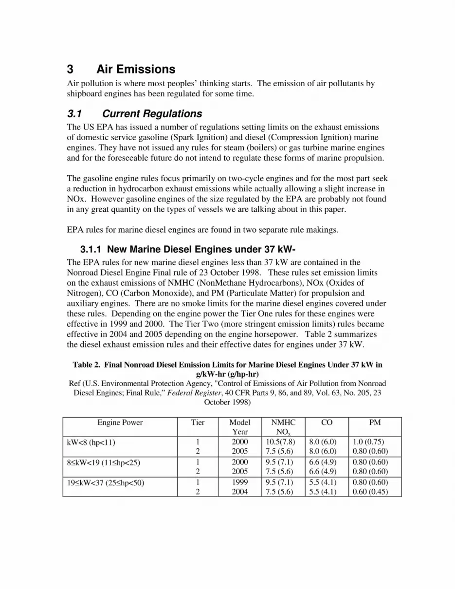
effective in 2004 and 2005 depending on the engine horsepower. Table 2 summarizes
the diesel exhaust emission rules and their effective dates for engines under 37 kW.
Table 2. Final Nonroad Diesel Emission Limits for Marine Diesel Engines Under 37 kW in
g/kW-hr (g/hp-hr)
Ref (U.S. Environmental Protection Agency, "Control of Emissions of Air Pollution from Nonroad
Diesel Engines; Final Rule,” Federal Register, 40 CFR Parts 9, 86, and 89, Vol. 63, No. 205, 23
October 1998)
Engine Power Tier Model
Year
NMHC
NOx
CO PM
kW<8 (hp<11)
1
2
2000
2005
10.5(7.8)
7.5 (5.6)
8.0 (6.0)
8.0 (6.0)
1.0 (0.75)
0.80 (0.60)
8≤kW<19 (11≤hp<25)
1
2
2000
2005
9.5 (7.1)
7.5 (5.6)
6.6 (4.9)
6.6 (4.9)
0.80 (0.60)
0.80 (0.60)
19≤kW<37 (25≤hp<50) 1
2
1999
2004
9.5 (7.1)
7.5 (5.6)
5.5 (4.1)
5.5 (4.1)
0.80 (0.60)
0.60 (0.45)

3.1.2 New Marine Diesel Engines at or above 37 kW
The EPA rules for new marine diesel engines at or above 37 kW are contained in their
final rulemaking published in the Federal Register of 29 December 1999. These rules
cover new marine propulsion and auxiliary diesel engines up to 30 liters/cylinder
displacement. Recreational marine diesel engines were exempted from this rulemaking.
These rules set emission limits on the exhaust emissions of THC (Total Hydrocarbons),
NOx, CO, and PM. There are no smoke limits for the marine diesel engines covered
under these rules. No limits are set for crankcase emissions but the rules do require that
they be routed to the engine intake for combustion or otherwise accounted for in the
exhaust emissions measurements if they are routed to the engine exhaust stream or
directly to the atmosphere. Unlike the nonroad rules these rules invoke the Tier Two
standard requirements and take effect between 2004 to 2007, depending on the size of the
engine. See Table 3 for the effective dates for engines at or above 37 kW.
Table 3. EPA Final Tier Two Marine Diesel Emission Standards and Start Dates for Diesel
Engines at or Above 37 kW (Ref. U.S. Environmental Protection Agency, "Control of Emissions of Air Pollution from New CI
Marine Engines At or Above 37 kW; Final Rule,” 40 CFR Parts 89, 92, and 94, 23 November 1999)
Category Displacement
(liters/cylinder)
Starting
Date NOx +THC
(1)
(g/kW-hr)
PM
(g/kW-hr)
CO
(g/kW-hr)
Power ≥ 37 kW
disp < 0.9
2005 7.5 0.40 5.0
1 0.9≤ disp < 1.2 2004 7.2 0.30 5.0
1.2 ≤ disp < 2.5 2004 7.2 0.20 5.0
2.5 ≤ disp < 5.0 2007 7.2 0.20 5.0
5.0 ≤ disp < 20.0 2007 7.8 0.27 5.0
15.0 ≤ disp < 20.0, and
power < 3000 kW
2007 8.7 0.50 5.0
2 15.0 ≤ disp < 20.0, and
power ≥ 3000 kW
2007 9.8 0.50 5.0
20.0 ≤ disp < 25.0 2007 9.8 0.50 5.0
25.0 ≤ disp < 30.0 2007 11.0 0.50 5.0
3.1.3 IMO Air Pollutant Regulations
The International Maritime Organization (IMO) has completed (finalized) "Regulations
for the Prevention of Air Pollution from Ships", Annex VI to the International
Convention for the Prevention of Pollution from Ships (MARPOL) 73/78. It has been
submitted to the governments of the member states for adoption. In the United States it
will be submitted to Congress for approval (Ratification). The 1997 Protocol has not yet
satisfied the entry-into-force conditions. To date, only two contracting states have
ratified the rules, which amounts to only 4.83% of the total shipping tonnage. The
provisions of the annex shall enter into force 12 months after the date on which not less
than 15 states, the combined merchant fleets of which constitute not less than 50 percent

of the gross tonnage of the world’s merchant shipping, have signed and ratified the
annex.
When the 1997 Protocol enters into force, the requirements of the NOx emission
restrictions will apply retroactively to each diesel engine with a power output of more
than 130 kW, installed on a ship constructed on or after 1 January 2000, or which
undergoes a major conversion on or after 1 January 2000.
Since the annex has not yet gone into force, member countries cannot issue the Engine
International Air Pollution Prevention (EIAPP) certificate that will be provided for an
engine family or engine group after compliance with the NOx Technical Code is
demonstrated. To address this concern, the IMO’s Marine Environmental Protection
Committee (MEPC) has issued Interim Draft Guidelines for the Application of the NOx
Technical Code. These guidelines call on Flag State Administrations to issue a
“Statement of Compliance” upon satisfactory completion of NOx Technical Code
requirements. In this country the EPA has published guidelines for issuance of the
“statement of compliance”, (ref. U.S. Environmental Protection Agency, “Statement of
Compliance,” Letter VPCD-99-02, 19 January 1999).
MARPOL Annex VI regulations apply to merchant ships worldwide. The Annex
specifically includes Regulation 13 for the emissions of nitric oxides (NOx) and
Regulation 14 for the emissions of sulfur oxides (SOx).
Regulation 13 (Annex VI to MARPOL 73/78) applies to each diesel engine with a power
output of more than 130 kW (174 bhp) either installed on a ship constructed on or after 1
January 2000 or which undergoes a major conversion on or after 1 January 2000. The
International Policy does not apply to emergency diesel engines, engines installed in
lifeboats, and any device or equipment intended for use solely in case of emergency.
Regulation 13, Annex VI to MARPOL 73/78, establishes the NOx limit at 17.0 g/kW-hr
when the rated engine speed is less than 130 rpm. Under conditions when the engine-
rated speed is greater than or equal to 130 rpm but less than 2000 rpm, the NOx limit is
45.0 x (engine rated speed)-0.2 g/kW-hr. The NOx limit is 9.8 g/kW-hr when the engine
rated speed is 2000 rpm or greater. See Figure 2 for a visual representation of the
maximum NOx Curve. The diesel engine test cycles, to determine compliance with the
NOx Curve, are specified in Annex VI and are represented by D2, E2, E3 or C1. D2 is
for constant speed auxiliary diesel engines (e.g., Ship Service Generator). E2 is for
constant speed main propulsion engines or engines with variable-pitch propeller (e.g.,
diesel-electric drive). E3 is for propeller-law-operated engines (e.g., main propulsion).
C1 is for variable speed, variable load auxiliary engines (e.g., bow thruster).
Regulation 14, Annex VI to MARPOL 73/78, requires the sulfur content of any fuel used
on board ship not to exceed 4.5% by weight. For fuel within an emission control area,
the fuel-sulfur content shall not exceed 1.5% by weight.

3.1.4 Local Air Emission Restrictions
There are a number of U.S. local marine emission rules that are enforced by coastal states
in their local harbors. Many are directed at visible types of pollution, i.e., smoke. In
Santa Barbara California local regulations severely limit the size and power of tug boats
available to support tankers in their approach to the oil fields in the area. When
proposing a ferry service operators are well advised to check on local laws for marine
emission requirements.
The Scandinavian states have moved a step farther in enforcing marine engine exhaust
emission limits with what is called a "Fairway Fee" for all types of marine propulsion
engines. Essentially the fees are levied against the NOx emissions and fuel that are above
certain limits. In the case of Sweden a NOx limit of 2 g/kWh must be achieved to avoid
the fee and fuel with 1% Sulfur by weight for cargo ships and 0.5% Sulfur by weight for
ferries must be used to avoid the fee. The program has been fairly successful with the
fees being used to reimburse the ship operators for installing emission reduction
equipment and using low sulfur fuel. A number of other Scandinavian and European
countries are considering similar rules.
While these rules may seem distant from our shores, it has been reported that some US
states are considering the enactment of similar requirements. For example, the members
of the Northeast States for Coordinated Air Use Management (NESCAUM) are
considering a number of options to reduce oceangoing vessel emissions and the Swedish
-type refundable fees for low emissions and low sulfur fuel are among those options (Ref:
"Heavy-Duty Diesel Emission Reduction Project Retrofit/Rebuild Component", United
States EPA, EPA 420-R-99-014, June 1999). However, this type of system could force
revenue generating ships from using "green ports" to using "no-fee" ports. This
"Fairway-Fee" system, if adopted, would result in the installation of some emission
reduction equipment on existing as well as new ships since the limits are more stringent
than what EPA and IMO are presently requiring.
3.2 Current state of the art
JJMA conducted a detailed study of the state of the art for the San Francisco Bay Area
Water Transit Authority. That study ran to several hundred pages, and will clearly not be
repeated here. (It is available from the WTA website at www.watertransit.org.) Instead,
we will touch upon the most realistic near-term candidates for ferry emission reduction.
3.2.1 Diesel
Diesel fuel is the fuel of choice for marine vessels, and this will remain true for the
foreseeable future. The list of alternative fuels consists of variations on diesel fuel, plus
the emergence of natural gas as a candidate.
Further, as discussed above, the engine manufacturers are doing all that they can to
improve engine emissions. There is very little that can be done directly to the engine by
the shipowner. The shipowner desiring a greener ship will need to consider
Aftertreatment.
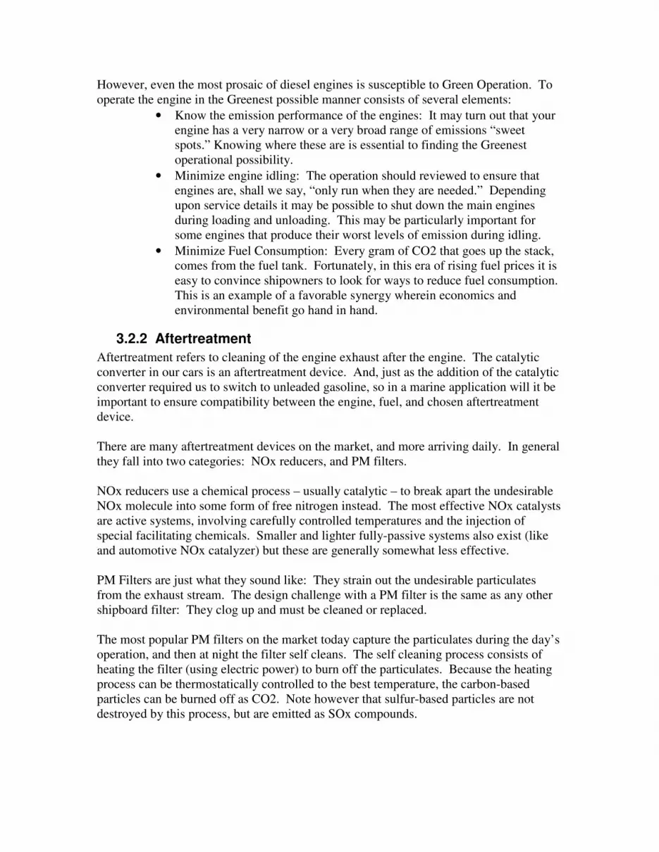
However, even the most prosaic of diesel engines is susceptible to Green Operation. To
operate the engine in the Greenest possible manner consists of several elements:
• Know the emission performance of the engines: It may turn out that your
engine has a very narrow or a very broad range of emissions “sweet
spots.” Knowing where these are is essential to finding the Greenest
operational possibility.
• Minimize engine idling: The operation should reviewed to ensure that
engines are, shall we say, “only run when they are needed.” Depending
upon service details it may be possible to shut down the main engines
during loading and unloading. This may be particularly important for
some engines that produce their worst levels of emission during idling.
• Minimize Fuel Consumption: Every gram of CO2 that goes up the stack,
comes from the fuel tank. Fortunately, in this era of rising fuel prices it is
easy to convince shipowners to look for ways to reduce fuel consumption.
This is an example of a favorable synergy wherein economics and
environmental benefit go hand in hand.
3.2.2 Aftertreatment
Aftertreatment refers to cleaning of the engine exhaust after the engine. The catalytic
converter in our cars is an aftertreatment device. And, just as the addition of the catalytic
converter required us to switch to unleaded gasoline, so in a marine application will it be
important to ensure compatibility between the engine, fuel, and chosen aftertreatment
device.
There are many aftertreatment devices on the market, and more arriving daily. In general
they fall into two categories: NOx reducers, and PM filters.
NOx reducers use a chemical process – usually catalytic – to break apart the undesirable
NOx molecule into some form of free nitrogen instead. The most effective NOx catalysts
are active systems, involving carefully controlled temperatures and the injection of
special facilitating chemicals. Smaller and lighter fully-passive systems also exist (like
and automotive NOx catalyzer) but these are generally somewhat less effective.
PM Filters are just what they sound like: They strain out the undesirable particulates
from the exhaust stream. The design challenge with a PM filter is the same as any other
shipboard filter: They clog up and must be cleaned or replaced.
The most popular PM filters on the market today capture the particulates during the day’s
operation, and then at night the filter self cleans. The self cleaning process consists of
heating the filter (using electric power) to burn off the particulates. Because the heating
process can be thermostatically controlled to the best temperature, the carbon-based
particles can be burned off as CO2. Note however that sulfur-based particles are not
destroyed by this process, but are emitted as SOx compounds.

3.2.3 Alternative Fuels
JJMA’s WTA project included review of hydrogen and many other exotic alternative
fuels. In practical terms, however, only variation of diesel fuel are practical for marine
use.
3.2.3.1 LSD/ULSD
Sulfur oxide (SOx) emissions from marine engines are of great concern environmentally.
The best means of reducing them is to eliminate them at the source: eliminate the sulfur
in the combustion process.
Sulfur is included in diesel fuel for lubricity at high temperature. Much of the sulfur is
naturally occurring. Modern engines, however, are configured to function properly
without relying on sulfur. Switching to Low or Ultra-Low Sulfur Diesel (LSD or ULSD)
eliminates this emission.
Normal diesel fuel has about 3500 ppm sulfur. LSD has about 350 ppm. ULSD has
about 10 – 15 ppm.
Note that in California it is not legal to sell fuel having higher than 140 ppm sulfur, so for
local operators the choice becomes “CARB or ULSD.” This is not true in other states.
3.2.3.2 BioDiesel
Bio-Diesel is diesel fuel made from vegetable stocks. This fuel, because it is synthetic, is
easily made as a zero-sulfur fuel, so using Bio-Diesel is a means to eliminating sulfur
emissions.
Bio-Diesel is, however, also considered to be a means of reducing greenhouse gases
because of the lifecycle consideration of the fuel: The carbon atoms emitted by burning
Bio-Diesel don’t actually increase atmospheric Carbon content, because these carbon
atoms came out of the atmosphere in the first place, when the plants breathed in the CO2
that they use during photosynthesis.
3.2.3.3 Emulsified fuels
Adding moisture to the combustion process can reduce the formation of NOx. This can
be done by directly injecting water into the combustion chamber, but it can also be done
by mixing the water into the fuel stream.
PuriNOX is a representative emulsified fuel. PuriNOX may be thought of as basically a
blend of diesel fuel and 10% water. The challenge is to get the water to stay mixed into
the fuel, and PuriNOX’s trade secret is the blend of emulsifiers used to attain this.
The fact that this is a fuel/water blend also has shipboard implications: For example, we
usually design a fuel system to include fuel / water separators. These separators are
highly effective, and may even separate the PuriNOX into its constituent parts, ruining its

effectiveness. Thus, while PuriNOX appears attractive as a “gas and go” emission
reduction technique, it does also require revisiting the ship’s fuel distribution system.
3.2.3.4 Natural Gas
It is my (McKesson’s) prediction that natural gas will become increasingly common as a
marine fuel. Natural gas possesses attributes that make it very attractive as a fuel, despite
the conventional understand that it’s “dangerous.”
In fact, natural gas has a very narrow range of explosive concentrations. It is quite hard
to maintain a fuel air ratio that is neither too-rich nor too-lean for combustion. Indeed, it
is so hard that natural gas fueled engines are difficult to build, and it is far more common
to see dual-fuel engines, wherein liquid diesel fuel is used to maintain the combustion.
Natural gas, being lighter than air, will dissipate away from any leaks or spills. There is
no danger of it accumulating to explosive levels in bilges, like there is with gasoline or
petroleum gas (propane.)
The challenge with natural gas is that you can’t simply pipe it up to a diesel engine – it
requires a special engine. Natural gas engines are generally either dual fuel using a
diesel “pilot”, or are spark-ignited like gasoline engines.
An increasing number of Scandinavian ferries, including car-carrying ships, use Natural
Gas as their fuel.
3.2.4 Electric Drive
Electric cars make periodic entries into the public eye, but they never penetrate the
market. But recent years have seen the development of a significant market for hybrid
cars. Will we see hybrid ships soon?
3.2.4.1 Diesel Electric
Diesel electric drive has been in service in the marine industry for decades. Most modern
cruise ships are diesel electric. The reason for choice of a conventional diesel electric
drive is one of flexibility: A cruise ship has very high daytime demands for electricity,
and has nighttime demands for propulsion (since they like to transit from one scenic port
to another during the nighttime hours.) As a result, it is desirable to have one prime
mover do both jobs: Make electricity during the day time, and propel the ship at night.
Clearly a diesel electric drive is suited to this employment.
Hybrid drives are somewhat different: In a hybrid drive there is a power accumulator in
the form of a battery bank. The accumulator takes the “peaks and valleys” out of the
power demand, so that the prime mover engine can run at a constant RPM at its most
efficient operating point. In cars and buses these peaks and valleys occur at very short
intervals, representing stop lights, traffic surges, etc.
With ships the peaks and valleys tend to be much farther apart. Even a short-haul ferry
may run at constant throttle for 20 minutes or more. In the case of a car this would be

like freeway driving in flat open country, where it might be possible to go 20 miles
without touching the throttle. Clearly, this is much rarer for a car than for a ship.
Because ships run at constant throttle for longer periods of time, the hybrid philosophy
does not pay off as quickly. Whereas in a hybrid car the battery accumulator bank might
only need to store some minutes of power, for a ship it would like have to store hours of
power. This sizing requirement leads to significant space and weight required for the
battery bank.
3.2.4.2 Alternative-source Electric
One means of reducing a ship’s overall air pollutant emissions is to employ pollution free
means wherever possible. Thus, for example, pollution free solar panels or fuel cells can
be used to augment the ship service power. Note that solar panels produce about 100
Watts per square meter, during sunlight. Thus to generate a single kilowatt of ship
service power will require at least 100 square feet of deck area devoted to solar panels.
Exploring these numbers will convince the reader that solar panels will never replace
shipboard generators, but they may nevertheless be important augments to them.

4 Water Pollution The United Sates Navy and Coast Guard have been developing a set of standards
designed to minimize the discharge of shipboard pollutants into the sea, under the
heading “Uniform National Discharge Standards” or UNDS. The UNDS project has
compiled an impressive list of the various types of waste-water discharges produced by
ships, and this list forms a useful checklist for analysis of any project, civilian or military.
At the present time UNDS has only identified the nature of the discharges. The project
has not yet determined proposed acceptable limits or means of mitigating these
discharges.
The items addressed in the UNDS project are listed in Table 1. Some of the key items
are discussed in the paragraphs following. Much of the following descriptive text is
taken directly from UNDS project source material.
Table 1 – Wastewater discharges that might apply to Ferries (from UNDS project)
• Aqueous Firefighting Foam
• Catapult Water Brake Tank and Post-Launch Retraction Exhaust
• Chain Locker Effluent
• Clean Ballast
• Compensated Fuel Ballast
• Controllable Pitch Propeller Hydraulic Fluid
• Weather Deck Runoff
• Dirty Ballast
• Distillation and Reverse Osmosis Brine
• Elevator Pit Effluent
• Firemain Systems
• Gas Turbine Water Wash
• Graywater
• Hull Coating Leachate
• Motor Gasoline Compensating Discharge
• Non-Oily Machinery Wastewater
• Photographic Laboratory Drains
• Seawater Cooling Overboard Discharge
• Seawater Piping Biofouling Prevention
• Small Boat Engine Wet Exhaust
• Sonar Dome Discharge
• Submarine Bilgewater
• Bilgewater/Oil-Water Separator Discharge
• Underwater Ship Husbandry
• Car Deck Runoff
• Shaft Seal Lubricant
• Fresh Wash-Water Discharge
4.1 Aqueous Firefighting Foam
Aqueous film-forming foam (AFFF) is a common firefighting agent used to extinguish
flammable liquid fires on ships. AFFF is stored on vessels as a concentrated liquid that is
mixed with seawater to create the diluted solution (3-6% AFFF) that is sprayed as foam
on the fire. The solution can be applied with either fire hoses or fixed sprinkler devices.
It is commonly used on vessels with substantial risk of fire, such as ships that carry
aircraft, or in the civilian world fireboats that stand into harm’s way. Car ferries carry a
small quantity of AFFF for fighting vehicle deck fires.
The AFFF discharge produces aqueous foam intended to cool and smother fires. Water
quality criteria for some States include narrative requirements for waters to be free of
floating materials attributable to domestic, industrial, or other controllable sources, or
include narrative criteria prohibiting discharges of foam. AFFF discharges in State
waters would violate such narrative criteria for foam or floating materials.
At present, the best practice for minimizing these discharges is an operational one, such
as the self-imposed prohibition on AFFF discharges in coastal waters by most Armed
Forces vessels. Similar prohibitions, and the use of shore training and testing facilities,
can be used by civilian vessels to mitigate the potential adverse impacts that could result
from the discharge of AFFF.
The constituents of AFFF include water, 2-(2-butoxyethoxy)-ethanol, urea, alkyl sulfate
salts, amphoteric fluoroalkylamide derivative, perfluoroalkyl sulfonate salts,
triethanolamine, and methyl-1H-benzotriazole.
How is this discharge generated? AFFF may be discharged during training, testing, or
maintenance operations. Discharge during normal operation may be minimized by
minimizing on board training, preferring instead to conduct training ashore. Similarly,
portable systems do not require testing afloat.
Discharges of AFFF that occur during firefighting or other shipboard emergency
situations are not incidental to normal operations and are not subject to the requirements
of the UNDS rule.
4.2 Catapult Water Brake Tank and Post-Launch Retraction Exhaust
This applies only to Aircraft Carriers equipped with aircraft-launching catapults. It refers
to the oily water skimmed from the water tank used to stop the forward motion of an
aircraft carrier catapult, and the condensed steam discharged when the catapult is
retracted. This discharge is not applicable for most ferries.
4.3 Chain Locker Effluent
This discharge consists of accumulated precipitation and seawater that is occasionally
emptied from the compartment used to store the vessel's anchor chain. Navy policy

requires that the anchor chain, appendages, and anchor on Navy surface vessels be
washed down with seawater during retrieval to prevent onboard accumulation of
sediment. During washdown, some water adheres to the chain and is brought into the
chain locker as the chain is stored. The chain locker sump accumulates the residual water
and debris that drains from the chain following anchor chain washdown and retrieval, or
washes into the chain locker during heavy weather. Water accumulating in the chain
locker sump is removed by a drainage eductor powered by the shipboard firemain system.
In addition to water, materials collecting in the chain locker sump can include paint chips,
rust, grease, and other debris. Chain locker effluent may contain organic and inorganic
compounds associated with this debris, as well as metals from the sump and from
sacrificial anodes installed in the chain locker to provide cathodic protection.
This discharge can be eliminated on some ferries by eliminating the chain locker during
design. For example, Washington State Ferries (WSF) vessels do not have chain lockers.
WSF vessels use anchor cable, not anchor chain, and the cable is stored on a winch reel.
The cable will entrain water but unlike Navy and Coast Guard vessels the ferries do not
routinely anchor. The anchor is present as an emergency device only and therefore is not
incidental to normal operations.
4.4 Clean Ballast
This item refers to the seawater taken into and discharged from dedicated ballast tanks to
maintain the stability of the vessel and to adjust the buoyancy of submarines. There are
no ballast tanks on most ferries, and thus there is no discharge of this type. Minimizing
the use of ballast tanks, including eliminating them during design, should be an element
in a Green Design and Green Operation plan.
4.5 Compensated Fuel Ballast
This item refers to seawater taken into and discharged from ballast tanks designed to hold
both ballast water and fuel to maintain the stability of the vessel. Compensated fuel
systems such as this should not used on ferries, so that there is no discharge of this type.
4.6 Controllable Pitch Propeller Hydraulic Fluid
This item refers to hydraulic fluid that discharges into the surrounding seawater passing
by propeller blade-to-hub seals as part of normal operation, and the hydraulic fluid
released during in-water maintenance of the propellers. This item is applicable to any
ferry that uses controllable pitch propellers.
Controllable pitch propellers (CPP) are used to control a vessel's speed or direction while
maintaining constant propulsion plant output (i.e., varying the pitch, or "bite," of the
propeller blades allows the propulsion shaft to remain turning at a constant speed). CPP
blade pitch is controlled hydraulically through a system of pumps, pistons, and gears.
Hydraulic oil may be released from CPP assemblies under three conditions: leakage
through CPP seals, releases during underwater CPP repair and maintenance activities, or
releases from equipment used for CPP blade replacement.

How often and where is this discharge generated? According to the UNDS research,
leakage through CPP seals under normal operation is negligible in quantity. CPP
assemblies are designed to operate at 400 psi without leaking. CPP seals are designed to
last five to seven years, which is longer than the interval between mandatory dry-dock
cycles, and are inspected underwater periodically to check for damage or excessive wear.
Because of the hub design and the underwater CPP seal inspections, leaks of hydraulic oil
from CPP hubs are found to be negligible.
During the procedure for in-water CPP blade replacement hydraulic oil is released to the
environment from tools and other equipment. In addition, hydraulic oil could also leak
from the CPP hub during a CPP blade port cover removal.
Clearly, this maintenance discharge can be eliminated by eliminating in-water repair.
The only in-water work to be performed should be inspection. Vessels requiring CPP
repair or maintenance should be drydocked for that purpose.
4.7 Weather Deck Runoff
This item refers to water discharged overboard due to precipitation, washdowns, and
seawater falling on the weather deck of a vessel and discharged overboard through deck
openings. Deck runoff is an intermittent discharge generated when water from
precipitation, washdowns, wave action, or spray falls on the exposed portion of a vessel
such as a weather deck. Note that vehicle deck runoff is addressed below under the
heading of "Well Deck Discharge." Runoff water is discharged overboard through deck
openings and washes overboard any residues that may be present on the deck surface.
All vessels produce deck runoff. This discharge occurs whenever the deck surface is
exposed to water.
Contaminants present on the deck originate from topside equipment components and the
many varied activities that take place on the deck. This discharge could in theory include
many types of residues. However, it should be normal shipboard practice that whenever
any of these substances is present on the deck that it not be rinsed overboard, but instead
be cleaned up by mop, absorbent pad, and similar methods. Thus in practice the
discharge of runoff from ferry decks is contaminated principally by materials discharged
by passengers, such as debris, food and beverage spills, cigarette ash, etc.
4.8 Dirty Ballast
This item refers to using a ship’s empty fuel tanks as ballast tanks. The discharge
consists of seawater taken into and discharged from empty fuel tanks to maintain the
stability of the vessel. This practice should be avoided in the design and operation of
ferries, so that this discharge is not present.
4.9 Distillation and Reverse Osmosis Brine
This refers to concentrated seawater (brine) produced as a byproduct of the processes
used to generate freshwater from seawater. Ships with long open-ocean deployments,

such as military ships, satisfy their freshwater needs by making freshwater out of
seawater using watermaker systems.
The ferry operator should consider the needs of his service and waters in which he sails to
determine whether it is more environmentally effective to fill the ship’s tanks using
shore-supplied water (thus increasing demand on the shore supply) or by making water
on board. If water is made on board, then consideration should be given to fitting of a
brine holding tank which can be discharged when the vessel is on a certain part of her
route. Thus, for example, a hypothetical service from San Francisco to Pittsburg CA
might choose to fit a watermaker to reduce demand upon the California water supply, but
might fit a brine tank which would be discharged only in the vicinity of Alcatraz, in order
to avoid possible adverse effects upon the salinity of the Sacramento River Delta.
4.10 Elevator Pit Effluent
This refers to liquid that may accumulate in, and be discharged from, the sumps of
elevator wells on vessels. Many new ferries are equipped with passenger elevators. The
elevators generally do have a pit. Means should be provided to contain and manage the
materials that accumulate in the pit. For example, if the pit drains to the ship’s bilge then
spills and materials in the elevator shaft will enter the bilge water, and must be treated as
part of that discharge.
4.11 Firemain Systems
This item refers to possible contaminants introduced into the seawater pumped through
the firemain system for firemain testing, maintenance, and training, and to supply water
for the operation of certain vessel systems. Many ships use a “wet type” firemain system,
which means that the firemain piping is normally filled with water. This is particularly
true on vessels where the firemain water is used frequently, including using it for non-
firefighting functions such as bilge eductors, washdown, etc.
Wet type firemain systems distribute seawater for firefighting and other services aboard
ship. Firemain water is provided for firefighting through fire hose stations, sprinkler
systems, and foam proportioners, which inject AFFF into firemain water for distribution
over flammable liquid spills or fire. Firemain water is also directed to other services
including ballast systems, machinery cooling, lubrication, and anchor chain washdown.
Discharges of firemain water incidental to normal vessel operations include anchor chain
washdown, firemain testing, various maintenance and training activities, bypass flow
from the firemain pumps to prevent overheating, and cooling of auxiliary machinery
equipment (e.g., refrigeration plants). Wet firemain systems are continuously charged
with water and pressurized so that the system is available to provide water upon demand.
An environmentally superior system is the dry type firemain system. In a dry type
system the piping is normally filled with air and is thus “dry.” Water is only introduced
to the pipes when actual firefighting takes place (or for testing or training.) Dry firemains
are not continuously charged with water, and consequently do not supply water upon
demand. Dry firemain systems are pressurized only during testing, maintenance or
training exercises, or during emergencies.

UNDS does not apply to discharges of firemain water that occur during firefighting or
other shipboard emergency situations, because they are not incidental to the normal
operation of a vessel. Only “normal” (non-emergency) discharges are covered by the
UNDS.
Nature of Discharge: Samples were collected from three DOD vessels with wet firemain
systems and analyzed to determine the constituents present. Because of longer contact
times between seawater and the piping in wet firemains, and the use of zinc anodes in
some seachests and heat exchangers to control corrosion in systems in constant contact
with seawater, pollutant concentrations in wet firemains are higher than those in dry
firemain systems.
EPA and DOD believe that dry firemain systems reduce the total mass of pollutants
discharged from firemain systems.
4.12 Gas Turbine Water Wash
Gas turbine water wash consists of water periodically discharged while cleaning
internal and external components of propulsion and auxiliary gas turbines. Obviously
this discharge would apply only to ferries that have gas turbines fitted.
Gas turbine water wash is generated in port and in coastal waters, and varies in quantity
depending upon the type of gas turbine and the amount of time it is operated. On most
Navy and MSC gas turbine ships, gas turbine water wash is collected in a dedicated
collection tank and is not discharged overboard within 12nm. On ships without a
dedicated collection tank, this discharge is released as a component of deck runoff or
bilgewater.
Expected constituents of gas turbine water wash are synthetic lubricating oil, grease,
solvent-based cleaning products, hydrocarbon combustion by-products, salts from the
marine environment, and metals leached from metallic turbine surfaces. The
concentration of naphthalene (from solvents) in the discharge is expected to exceed State
acute water quality criteria.
Clearly the deisgn solution to preventing discharge of Gas Turbine wash water is to
provide an on board collection and holding system, and to provide for treatment of the
water ashore (don’t just pump it into the municipal sewer.)
Assuming that a wash-water collection system is fitted, the operational concern becomes
to minimize the cost of shore treatment, and to avoid accidental discharges due to
overfilling the containment system. Both of these are aided by minimizing the amount of
turbine wash to that amount truly necessary as indicated by turbine performance. Avoid
unnecessary turbine washes.
4.13 Graywater
This refers to galley, bath, and shower water, as well as wastewater from lavatory sinks,
laundry, interior deck drains, water fountains, and shop sinks. Gray water on ferries
should be captured and stored on board as part of the sewage collection and holding
system, and discharged for treatment ashore. Solids removed from the greywater (e.g. by
galley sink grease traps) should be discharged as solid waste (garbage.)
4.14 Hull Coating Leachate
This discharge consists of constituents that leach, dissolve, ablate, or erode from hull
paints into the surrounding seawater. Vessel hulls that are continuously exposed to
seawater typically rely on two-part paint systems for under water hull surfaces,
comprised of an anticorrosive coating layer to protect the steel hull from corrosion attack
and an antifouling coating layer to inhibit marine growth. Without an antifouling
coating, marine organisms such as algae and mollusks will attach to the hull, increasing
surface roughness which would increase fuel consumption.
A typical antifouling system leaches a biocide into the water to kill marine organisms in
close contact with the hull surface. Alternative coating systems include new foul-release
systems which use proprietary silicon coatings to provide a "non-stick" surface that
prevents marine organisms from adhering to the hull. While these systems are effective,
they must be used on applications with sufficient service speed to wipe the surface free of
marine growth To be effective, the vessel must travel at a minimum speed of 15 knots to
"wash" away any marine buildup. While a foul-release antifouling system works in
normal operations, extended in-water lay up would require special consideration or hull
scrubbing.
Which vessels generate this discharge? All vessels in the water with biocide based anti-
fouling systems leach biocides.
How often and where is this discharge generated? Hull coatings leach continuously
whenever exposed to water. The coating system is renewed at regularly scheduled dry
dockings every five years.
Nature of Discharge: The rate of biocide release is a property of the anti-fouling system
and is directly proportional to the underwater wetted surface of the hull. Pollutants
expected to be present in this discharge include copper and zinc. The most effective
means to reduce this discharge during design is to minimize ship wetted area. During
operation the most effective means of reducing discharge is to use as hard an antifouling
as is acceptable, with particular desirability being given to the foul-release types if ship
speed is high enough.
4.15 Motor Gasoline Compensating Discharge
This refers to seawater taken into, and discharged from, motor gasoline tanks on some
classes of ships. Gasoline vapors are highly flammable and some ships add seawater to
gasoline tanks to eliminate free space where vapors could accumulate. When this
seawater is eventually discharged, during tank filling operations, it constitutes a
contaminant stream. This is not applicable for most ferries as there are no motor gasoline
tanks aboard the ferries. The only motor gasoline tanks on board most ferries are the
portable tanks associated with the outboard-engine-driven Rescue Boats. These rescue
boat portable tanks should receive minimum use and handling on board. The tanks
should be sent ashore for filling, and there is no need for the tanks to be opened on board,
thus minimizing the opportunity for spills. (This discussion of course excludes the
gasoline tanks in the vehicles carried, but these are regulated by other sources.)
4.16 Non-Oily Machinery Wastewater
This item refers to an intermittent discharge composed of water leakage from equipment
such as distillation plants, water chillers, valve packings, water piping, low- and high-
pressure air compressors, and propulsion engine jacket coolers. Some DOD vessels have
a dedicated Non-Oily Machinery Wastewater collection system. Only wastewater that is
not expected to contain oil is collected in such a system. The discharge is captured in a
dedicated system of drip pans, funnels, and deck drains to prevent mixing with oily bilge
water. Non-oily machinery wastewater from systems and equipment located above the
waterline is drained directly overboard. Non-oily machinery wastewater from systems
and equipment below the waterline is directed to collection tanks prior to overboard
discharge.
Most vessels, including ferries, have no such dedicated non-oily machinery wastewater
system, so this type of wastewater drains directly to the bilge and is part of the bilge
water discharge. For discussion of bilge water discharge see below.
4.17 Photographic Laboratory Drains
This refers to the discharge of laboratory wastewater resulting from processing of
photographic film. Most ferries do not have photographic laboratories. Ferries that do
have photo capabilities should use self contained automated film processors and should
handle the discharge from these units as hazardous waste in accordance with local
regulations.
4.18 Bilgewater/Oil-Water Separator Discharge
This refers to the wastewater from a variety of sources that accumulates in the lowest part
of the vessel (the bilge), and the effluent produced when the wastewater is processed by
an oil water separator. Water entering the hull accumulates in the lowest part of the
vessel. The water caries any oily residue form spills, leaks, drips, etc, down into the
bilges with it. As a result, the bilge water typically has some oil content. Many vessels
have an Oil / Water Separator (OWS) that separates the oil content from the bilge water,
then transfer the oily residue to a waste oil tank and discharges the treated bilge water.
Washington State Ferries has a good system for managing this waste stream. Firstly, no
waste water of any sort is discharged overboard from WSF vessels. Waste water is
treated ashore. Per agreement with local municipal wastewater treatment services WSF
polishes the discharged water to ensure that oil content is below 100 ppm, using a fleet
standard Heli-Sep OWS. This unit has no overboard discharge connection, however, and
is used only to polish and confirm that the processed bilge water oil content is below 100

ppm before discharge to the sewage holding tanks for transfer ashore, along with sewage,
to municipal wastewater treatment facilities. Any bilge sludge that exceeds 100 ppm is
handled as Oily Waste.
4.19 Underwater Ship Husbandry
This item refers to materials discharged during underwater inspection, maintenance,
cleaning, and repair of hulls performed while the vessel is waterborne. Underwater ship
husbandry includes activities such as hull cleaning, welding, non-destructive testing, and
painting operations.
Which vessels generate this discharge? Underwater ship husbandry discharge is created
occasionally by all Navy surface ships and submarines, and Coast Guard vessels. Best
ferry practice, by contrast, is to not perform underwater maintenance, and therefore not
generate this type of discharge. The only underwater services performed would be visual
inspections performed afloat.
4.20 Car Deck Runoff
This item originally refers to water that accumulates from seawater flooding of the
docking well (welldeck) of a military vessel used to transport, load, and unload
amphibious vessels, and from maintenance and freshwater washings of the welldeck and
equipment and vessels stored in the welldeck. This is the UNDS item most similar to
possible runoff from the car decks of ferries, and therefore this UNDS item has been
expanded for the present project to refer to the discharge of spills, drips, leaks, or other
contaminants that may be found on the vehicle decks of the ferries.
How is this discharge generated? This discharge is the water runoff from the vehicle deck
of a vessel used to transport, load, and unload vehicles and equipment. Water from
waves, rain, and similar sources, which runs off the vehicle deck of a ferry, may contain
residual materials that were on the deck prior to wetting. All vehicle-carrying ferries have
the potential to generate this type of discharge.
Nature of Discharge: Depending upon the specific activities conducted on board the
vessel, deck discharges might contain a variety of residual constituents, including oil and
grease, ethylene glycol (antifreeze), metals, solvents, and sea-salt residues. Best
management practice would be require crews to patrol the vehicle deck for obvious spills
or leaks from carried vehicles. Such spills would be cleaned using mops, absorbent pads,
and similar methods in order to minimize the chance of polluted deck runoff. There
should also be spill kits that plug freeing ports for casualties that are bigger than dripping
oil pans.
Conclusion: These existing practices for containment and cleanup of deck spills
demonstrate the availability of controls to reduce contamination of deck discharges and
the potential for causing adverse environmental impacts.
4.21 Shaft Seal Lubricant
This refers to the lubricant that escapes past the oil lubrication stern tube seal into the sea.

How is this discharge generated? Where the ship’s propeller shaft penetrates the hull it is
fitted with a shaft seal. Traditional shaft seals use a gland packing system to prevent the
leakage of bearing oil across the shaft seal. New shaft seals use advanced mechanical
and multiple lip seals to eliminate lubricant leakage. No packing seal is 100% effective
and as a result, some bearing lubricant leaks into the sea.
Which vessels generate this discharge? All vessels with conventional propellers and
shafts that have a lubricated shaft seal generate this discharge. The discharge would
include any leakage of the lubricant past the seal.
There is not a good means of preventing this leakage – if there were one, then the seal
manufacturers would use it. A typical best design practice is to use a good quality shaft
seal with biodegradable lubricant. Such a seal uses three lips (triple redundancy) to
prevent bearing lubricant from leaving the hull. The stern bearing is a phenolic bearing
which has the ability to run on sea water alone in the absence of lubricant. Therefore,
after leak detection the use of a secondary (lower) head tank to reduce the lube oil
pressure will reverse the direction of the leakage (seawater leaking in vs. lube oil leaking
out) resulting in a mixing of the seawater with the lubricant (rather than lubricant mixing
with the sea.) Alternatively, since the bearing can run on sea water alone, the lubricant
could be completely cut off to prevent further leakage.
4.22 Fresh Wash-Water Discharge
This refers to the discharge of fresh water for the fresh water washing of the vehicle deck
and sprinkler system. A ferry with a dry firemain usually has a fresh water back-flushing
system comprised of a 1,500 gallon fresh water storage tank connected to the fire main
system. This arrangement allows fresh water wash down of the vehicle decks and
flushing of the fire sprinkler system.
Nature of discharge: The discharge would include fresh water and any particulates that
might exist in the firemain system or on the vehicle decks. Note that before any fresh
water washdown occurs, the crew should have cleaned up any contaminants on the
weather decks and vehicle decks, therefore minimizing or eliminating contaminants.
At the present time this is probably the best practice for eliminating this discharge type.

5 Soil Impact Ships impact not only the air and the sea, but also the land. Ship land impact falls into
generally two categories: Scour of the seabed due to propeller jet effects, and scour of
the shoreline due to vessel wake wash.
5.1 Prop Scour
Propeller scour can destroy plant beds, overturn animal habitat, dislodge toxic sediments,
and erode shorelines undercutting upland uses. All of these effects are negative.
Propeller scour depends upon the propeller jet velocity and the propeller jet “impact”
area. The impact area will depend upon the size and shape of the propeller jet and the
topography of the seabed.
The effects of the propeller jet will depend upon the sediment size and the nature of the
habitat represented by that portion of seabed.
In general we tend to assume that prop scour is only an issue near a ship’s berth.
However, where vessels operate in shallow water this assumption will not be valid, and
bottom scour should be investigated over those shallow water reaches as well.
Further, while we assume that bottom scour is necessarily propeller-induced, it is possible
that in some extreme shallow water cases the scour could be induced by flow around the
ships hull. We at JJMA have never had a project in which this was the case – yet.
5.1.1 Means of mitigating during Design
Prop scour is exacerbated by prop jet velocity. A lightly-loaded propeller will generally
produce a lower jet velocity, and thus less prop scour. Also, since the scour depends on
the jet hitting the seabed, the more the shaft is angled downward the greater the
opportunity for prop scour. A horizontal shaft line may reduce prop scour.
Waterjets have inherently horizontal discharge plumes, but special attention in their case
needs to be devoted to astern performance. Some waterjet brands discharge the reversing
plume below the keel, resulting in exacerbated seabed scouring. Other brands may
discharge the reverse plume to the left and right at the surface, reducing the depth to
which the jet descends.
Waterjets may also have inlet scouring. Care should be taken to consider the location of
the inlet relative to the seabed, and to obtain inlet suction plume maps from the jet
manufacturer corresponding to the different ship speed and throttle combinations of
interest.
5.1.2 Means of mitigating during Operation
Operational control of prop scour consists mostly of control of the throttle. High throttle
maneuvers, particular in the slip in acceleration or braking, will exacerbate bottom scour.
A “gentle hand” will minimize prop scour. Note that this is the same as is called for in
minimizing air emissions and underwater noise impacts as well.
5.2 Wake Wash
Wake Wash impact has gone from being unknown ten years ago to being a common
design analysis today. Wake wash impact refers to shoreline ‘damage’ caused by the
ship’s wake waves.
We have placed the word ‘damage’ in quotes because one of the first investigations
which must be undertaken in a wake study is to determine what types of impact would
constitute damage. Possible impacts include:
• Breaking waves at beaches endangering bathers
• Sediment transport eroding shoreline structures
• Sediment transport accreting to beaches blocking channels and resculpturing
shorelines
• Wave overtopping causing upland vegetation mortality due to salt spray
• Wave rocking and rolling of moored vessels – at anchorage or in marinas – leading
to personal injury or property damage
• Estuarine drawdown leading to navigational hazard
• Estuarine drawdown leading to fish mortality
• Wave action leading to mortality of crabs and other shore dwellers
• Wave action leading to overtopping of shorebird nests – e.g. California Clapper Rails
• Harmonic excitation of moored structures including navigational markers
Each of the types of damage listed above will be sensitive to a particular combination of
wave heights and periods.
Furthermore, the waves which arrive at the ‘receptor’ are not the same as the waves
which may be measured in the near-field of the ship, because they are modified in height
and length as they propagate. This propagation effect will depend upon details of the
seabed over which they travel.
The result is a very complex behavior, but fortunately one that can in fact be modeled
with modern tools.
5.2.1 Means of mitigating during Design
Wake wash is mitigated during design by attempting to design a hull with minimum
undesirable wake characteristics. This probably means simply minimizing wave energy,
just as is done to minimize propulsion power. But other design aspects might include
selecting the hydrodynamic characteristics of the design (such as waterline lengths in a
multihull) to ensure that wake energy falls into a less harmful band of frequencies.
5.2.2 Means of mitigating during Operation
Wake wash minimization during operation requires knowledge of the ship’s wake / speed
/depth relationship. The ship’s minimum wake speed is not always low-cruise, and

furthermore her minimum wake speed may vary according to the depth of the water at the
moment of interest.
Because of this complexity it is our recommendation that a wake study should be carried
out along the ship’s route to determine where the wake-sensitive reaches lie, and what the
most appropriate wake-minimization speed is in each of those areas. This should be
given to the ship’s master as operational guidance, and must also be used by the ship’s
owner in building his business model, route scheduling, and revenue forecasts.
6 Noise Pollution Noise pollution is a relatively new concern, but one which is growing. In this section we
distinguish between two forms of noise – that which is above water (airborne) and that
which is underwater (waterborne.)
6.1 Airborne
The impact of airborne noise is mostly concerned with impact upon human activities.
Low-level airborne noise may hurt enjoyment along beaches, while higher levels have the
potential to cause operational disturbances. In rare cases the level may be high enough to
cause hearing loss, although this is unlikely for an observer a fair distance from a ferry.
The Danish government has arguably the most aggressive noise standards for ferries. We
have not seen any proposals for new airborne noise limits specific to marine activity, but
we have, in some of our projects, encountered members of the public who live along sea
routes who have complained of the noise of passing vessels. To date I know of nobody
who has tried to apply a shoreside noise ordinance to a passing vessel, but I also have no
reason to think that this is unimaginable.
6.1.1 Means of mitigating during Design
Most design teams already attempt to minimize noise during design. This is usually done
from a desire to create a good ambience on board, but it also benefits the far-field
observer.
Obviously the major design tool for noise control is the selection of the muffler system
on the ship’s engine, but it should also be noted that minimizing total ship power also
reduces noise generated at the source.
6.1.2 Means of mitigating during Operation
Operational noise mitigation is just like the noise abatement procedures followed at most
modern airports. It involves use of gentle throttle settings, and selecting favorable routes.
For example, we might imagine that night time sailings to a certain port might choose to
pass outside of a nearby uninhabited island, rather than between it and the inhabited
shore. Similarly, especially at night when wind is generally less, it may be possible to
use particularly gentle throttle settings on approach and departure. Most operators
already reduce whistle use during nighttime sailings.
6.2 Waterborne
Perhaps surprisingly, underwater noise has received greater public discussion than has
airborne noise. As stated earlier, we believe that noise is going to be the next
environmental topic to receive worldwide attention. There is at least one cove in the
United States that has concerns about underwater noise pollution. The cove is frequented
by humpback whales (an endangered species) and underwater sounds can interfere with
the whales' behavior. The park has a seabed hydrophone which will allow them to
measure ambient noise levels and determine how they are affected by the 10 knot vessel
speed limit imposed in summer when whales are present.

NOAA’s fishery research vessel is designed to meet extra quiet radiated noise
requirements in order not to disturb the fish population that they are researching. In their
battle over the Gaviota terminal, Santa Barbara’s fishing industry claimed that the fish
population decreased significantly due to tankers’ propeller and anchor chain noises,
causing the fishing industry to lose financially. There have even been reports that ocean
background noise levels have risen so dramatically that this is leading to global deafness
in whales.
There are currently two active rulemaking initiatives that we know of that have the
potential to directly affect shipping. The one that has the most impact in this region is the
discussion of regulations to support the listing of Pacific NorthWest Resident Orcas
(killer whales) on the Threatened Species list. Amidst the discussed proposals for
rulemaking at least one commenter has suggested a very aggressive (low) underwater
noise limit, and that exceeding this noise limit would be classified as “taking” this
endangered animal – and thus regulated.
6.2.1 Means of mitigating during Design
The most effective design tool for minimizing underwater noise is to minimize installed
ship power levels. Almost all ship-generated underwater noise is attributable to the
ship’s machinery. Reducing the size of this machinery will reduce the noise level.
There are many machinery design techniques which will further reduce underwater noise
levels. Naval Architects, particularly those active in the design of military vessels, have
full toolboxes of tricks and techniques for designing quiet machinery installations.
6.2.2 Means of mitigating during Operation
The sole tool for operational control of noise is the throttle. It is therefore all the more
important for the ship operator to know where his noise sensitive reaches are, and to
know what operational measures and maneuvers will have impact upon noise. These can
vary widely from route to route and ship to ship, so the point of this discussion is only
that these things need to be studied and documented as part of the operational planning
and guidance.
7 Visual (Aesthetic) Pollution We know of no case where it has happened yet, but we find it easy to imagine that some
jurisdiction will attempt to regulate the “look” of a ferry, because the city fathers find it
objectionable. Perhaps this will take the form of preserving sight corridors. Sight
corridor regulations already have significant affect on the siting and design of ferry
terminals in Seattle. In that case the terminal is not allowed to obstruct a certain
percentage of the view. How long until the ferry boat itself is similarly constrained?
This might take the form of a restriction on maximum size, so that no more than “X” of
the view is blocked. Or it might take the form of a minimum speed requirement, to
guarantee that the ferry doesn’t block anyone’s sight for more than “Y” seconds.
At present we have heard of no specific initiatives to impose such regulations, but there
are some that come very close: The City of San Francisco has an ordinance prohibiting
waterborne advertising. This was enacted when one entrepreneur moored barges along
the city front and put billboards on their decks. However this ordinance has also been
found to prohibit the use of bus-style “wrap around” advertising on the watercraft that
call at the city.
7.1.1 Means of mitigating during Design
Aesthetics is of course an entirely subjective issue. The design point is to dialogue early
on the bounds that will be placed on the “look” of the ship. Fortunately this is already
normal, since most owners do care about the appearance of their vessels. But while the
present status quo is consider only the owner’s preferences, we suggest that it is now
necessary to consider the preferences of those parties that control the waterways you
travel and the ports you service.
7.1.2 Means of mitigating during Operation
At present we can think of no Operational control over aesthetics, except perhaps to keep
the ship tidy and Bristol fashion.

8 Thermal Pollution There are no known underwater heat emission limits for marine vessels. However it is
well known that water temperature changes will influence the migratory behavior of
salmon. This has in the past been a driving factor in some designs of power plant cooling
water discharges, and it is today an area of growing concern. It is not inconceivable that
in the coming years there will be limits placed on the amount of heat that way be
discharged to water from any source.
See:
www.rpi.edu/dept/chem-eng/Biotech-Environ/THERMAL/tte1.htm
www.solon.ac.uk/~engenvir/environment/water/thermal.html
http://onlinedocs.andersonpublishing.com/oac/division-37/chapter-3745/whole.htm

9 Resource Consumption Resource consumption for ferries can be quite a broad subject. Resources include:
Fuel
Fresh Water
Other Consumables
9.1 Fuel Consumption
Fuel consumption is usually considered by ferry designers and operators for economic
reasons. However fuel consumption should be minimized for environmental reasons as
well.
We shall not delve deeply into the well-known naval architectural means of reducing
propulsion fuel consumption. Clearly what they all amount to is to design a ship that is
as easily driven as possible.
Note that this includes considering unconventional hull forms, such as the catamaran,
trimaran, and surface effect ship when appropriate.
However a more interesting facet of fuel consumption is to minimize as well the auxiliary
users of fuel, ancillary to the question of main propulsion. Such consumption includes:
Generator sets
Propulsion engines at idle
Auxiliary boilers
Cooking and Heating
9.1.1 Generator sets
Generator set fuel consumption is minimized not only be selecting a fuel-miser generator,
but also by taking steps to minimize the ship’s electric power demand. This includes use
of compact fluorescent lamps instead of incandescent lamps wehre possible, and the use
of LED lamps for such elements as decorative lighting, navigation lights, panel indicator
lights, escape path lighting, and so forth. It is noteworthy that over the road trucks find it
economic to use LED brake and tail lamps, because of the reduced power consumption
and very long life of these lamps.
Generator fuel consumption can also be minimized by ensuring that generators are “right
sized” so that they operate at economical loading conditions.
9.1.2 Main Engine Idling
Main engine idling should be avoid in order to reduce fuel consumption. This has design
impacts such as providing mooring arrangements so that the ferry doesn’t rely on the
main engines to hold it in the slip. This must of course be balanced against the
consequences of frequent start and stop of the engines. If shut down is impractical, for

example due to a very short port call, then consideration should be given to super-low
idle settings such as found on modern electronically controlled diesels.
9.1.3 Auxiliary boilers
In some cases the fitting of an auxiliary boiler may result in lower fuel consumption than
the alternative – e.g. relying on shipboard electricity for heat. However this decision
should be taken based on an analysis that includes an analysis of the alternatives.
Further, given the fitting of auxiliaries such as boilers, there must be operational
protocols for determining when they are used and when they are to be secured.
Fortunately these protocols can be made from a simple point of view of minimizing fuel
consumption, and this will have environmental and resource conservation benefits as
well.
9.1.4 Cooking and Heating
Heating and cooking loads should not be neglected when attention is being given to
minimizing energy use. The old standby of keeping a diesel fueled cookstove burning at
low heat 24/7 may not be the most economical or most environmentally friendly solution
to the ship’s needs.
Depending on the levels needed on board, electricity may be the most economical source
for both heating and cooking, especially if some portion of the heating load can be borne
by a waste-heat supplied system.
Depending upon the sea temperature, water-sourced heat pumps may be the most
economical means of heating and cooling the ship.
Despite the myriad of options available, the good news is that economics and
environmental friendliness go hand in hand: To a great extent anything that reduces
energy cost is beneficial to sustainability. This means that naval architects and marine
engineers do not need to learn a new set of skills, they simply need to continue to apply
their tools for reducing fuel consumption and cost, happy in the knowledge that this has
environmental benefits as well as economic ones.
9.2 Water Consumption
Water consumption should of course be minimized through the simple expedient of
fitting low-flush toilets, flow control devices on fixtures, and other well-known means. A
perhaps more interesting question is whether the water used on board should be taken
from shore supplies or if it should be made on board by distillation processes.
In some areas the domestic water supply is already stretched to the limit, and American
cities are not immune to occurrences of water rationing. In that case it should be the ferry
designer’s goal to minimize his impact upon such an already strained resource. This
might be accomplished by fitting Reverse Osmosis (RO) water makers to the ship.
But RO units have their own environmental impacts, including the discharge of the brine
by-product, and the energy consumption required to operate them. These factors,
depending on the nature of the waterway and the energy costs, may nudge the designer
back toward using shore-supplied water.
9.3 Other Resources
Other resources used by a ferry include refuse disposal, upland sewage treatment, and
even such esoteric resources as Law Enforcement Services. A goal of the ferry design
should be to manage and minimize all of these resource uses.
Examples include:
• Install on board compactors & shredders to minimize the volume of refuse
disposed of. This minimize the number of times a truck of given size will need to
call at the terminal, which beneficial effects on truck fuel consumption, air
pollution, and probably refuse handling costs.
• Manage the ship’s blackwater stream in dialogue with sewage treatment plant
operator’s guidelines. Sewage systems may have guidelines for maximum
acceptable oil levels, or desired water content in the sewage stream. Managing
the stream to this level via onboard treatment, filtration, and so forth may result in
cost savings passed on by the sewage plant. On the other hand, it may be the
fitting such features to the ship just results in the building of a ‘miniature’ sewage
plant on board, and that the better path is to allow the shore facility to benefit
from the economies of scale, and to not encumber the ship with these ancillary
features. The key here is to enter dialogue with the sewage treatment service
provider and construct a well-thought-out total system, not just an optimization of
the shipboard element.
• Law Enforcement: Law Enforcement personnel usually provide patrol services
near ferry terminals as part of the regular “beat.” The terminal and the passenger
flow should be designed to make this resource-demand manageable. For
example, a well designed terminal and embarkation / debarkation area may be
able to be surveilled from a single location, rather than requiring multiple
personnel, one in each zone. Again, dialogue with local providers is enjoined.
The key in all of this is to think of the ship as a part of the system, and not to stop our
thinking at the edge of the deck plates. Whenever we plug in, or tie up, or pump from, or
otherwise interface with services off the ship we are imposing resource demands upon
those services. Our goal in Green Design should be to minimize the consequences of
those demands. In some cases this will mean abstaining from the demand, and generating
the resource on board. In other cases it will mean the opposite. But in all cases it will
demand a carefully built methodical process of thought and analysis.

10 Conclusion Naval Architects have always included ‘seats’ at the design table for such disciplines as
Structures, Propulsion, and Hydrodynamics. It is our contention that this type of systems
engineering thought process must expand, and that design teams of the future – or of the
present – will need to include place for Environmental Engineering as well.