— electric passenger ferries future charging infrastructure
TRANSCRIPT
Some factors distinguishing this type of traffic are the charging needs and number of stops, for instance in city traffic. The charging power will most likely be above EV car requirements, but be-low those of large vessels with many megawatts and high voltage.
Vessels will need a way to store energy onboard. Three primary options are diesel generator sets, electrochemical battery storage, and fuel cells operating with hydrogen or ammonia. The choice will depend on such factors as travel distance, ship size, and availability of charging/fueling op-tions while at berth. This document will not con-sider the diesel or fuel cell tracks, although some of the aspects of these tracks have relevance here.
There are many factors influencing the design of an electric charging system for battery driven vessels. Above all, systems must be safe for crew and passengers. They should not lead to addition-al unmanageable stress on the vessel like electro-chemical (galvanic) corrosion. In addition, there are economic incentives to avoid long charging times influencing the overall utilization of the ves-sel. Some aspects are highlighted in Figure 1.The propulsion and hotel load (lights, cabin heat-ing, cabin cooling, navigation equipment etc.) energy requirement is dependent on the route and timetable.
Ferry industry association Interferry estimates that the sector transports over 2 billion passen-gers worldwide every year. A substantial part of these ferries are located in major cities. These “water busses” – or small ferries – quickly move passengers across rivers and narrow lakes. There are several benefits for the electrification of these vessels, such as less emissions and noise pollution in urban areas and for passengers, as well as fuel saving cost for the operators. The charging need typically will exceed the leisure boat market but must be easier to manage and handle than the large shipping electrical infra-structure now being developed in major ports as ship-to-shore power. This report focuses on the charging infrastructure of these “small ferries”.
The available battery size will naturally be de-pendent on physical constraints like volume and weight distribution, but will also be dependent on economic optimization.
Battery life and hence overall economy is depend-ent on two factors: calendar life and cycle life. In short, one can deploy too many batteries result-ing in calendar life ageing, where investments are made in capacity that will never be used. If the battery size is too small, deep cycling of the batteries aggravated by high currents will quickly erode life length.
Fossil-free propulsion of small ferries is an important technology for the future. Over the last couple of years we have seen many different implementations utilizing electric drive trains, some of which are summarized in the “Review on electric ferries and charging technologies” [1].
STEFAN THORBURN ABB Corporate Research
[1]“Review on electric ferries and charging technologies”, Sub-report to Elektrifiering av marina urbana transportsystem – Förstudie laddning, Energimyndigheten, 2020
—Electric passenger ferriesFuture charging infrastructure
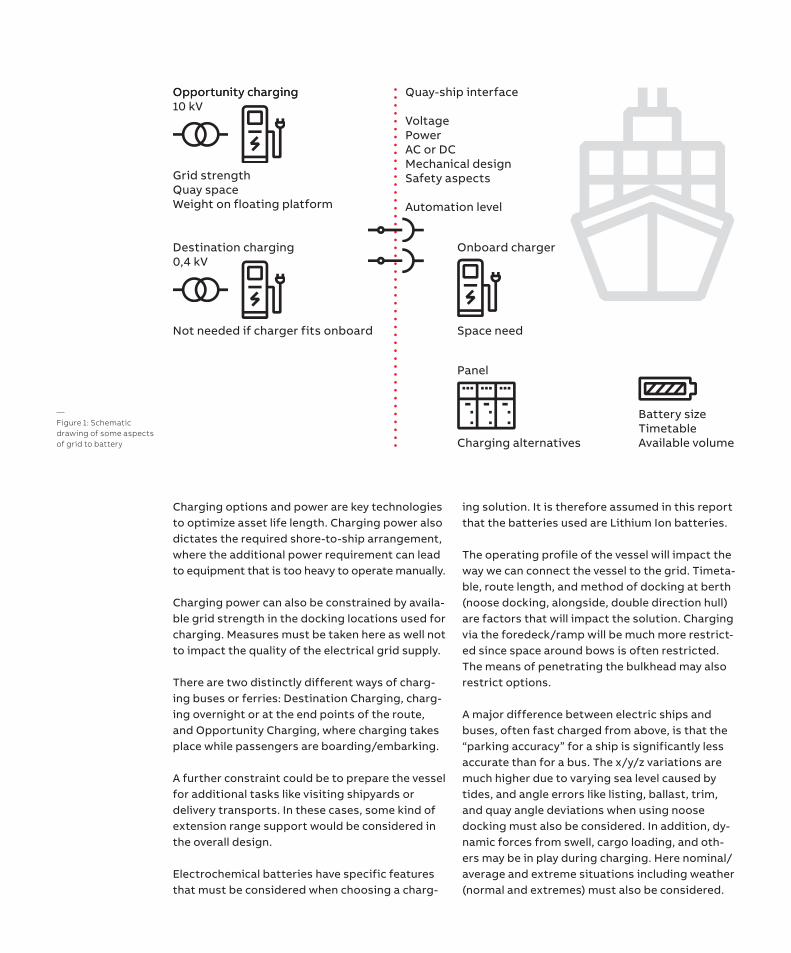
—Figure 1: Schematic drawing of some aspects of grid to battery
Quay-ship interface
VoltagePowerAC or DCMechanical designSafety aspects
Automation level
Onboard charger
Panel
Opportunity charging
Grid strengthQuay spaceWeight on floating platform
Opportunity charging10 kV
Not needed if charger fits onboard
Destination charging0,4 kV
Space need
Charging alternatives
Battery sizeTimetableAvailable volume
Charging options and power are key technologies to optimize asset life length. Charging power also dictates the required shore-to-ship arrangement, where the additional power requirement can lead to equipment that is too heavy to operate manually.
Charging power can also be constrained by availa-ble grid strength in the docking locations used for charging. Measures must be taken here as well not to impact the quality of the electrical grid supply.
There are two distinctly different ways of charg-ing buses or ferries: Destination Charging, charg-ing overnight or at the end points of the route, and Opportunity Charging, where charging takes place while passengers are boarding/embarking.
A further constraint could be to prepare the vessel for additional tasks like visiting shipyards or delivery transports. In these cases, some kind of extension range support would be considered in the overall design.
Electrochemical batteries have specific features that must be considered when choosing a charg-
ing solution. It is therefore assumed in this report that the batteries used are Lithium Ion batteries.
The operating profile of the vessel will impact the way we can connect the vessel to the grid. Timeta-ble, route length, and method of docking at berth (noose docking, alongside, double direction hull) are factors that will impact the solution. Charging via the foredeck/ramp will be much more restrict-ed since space around bows is often restricted. The means of penetrating the bulkhead may also restrict options.
A major difference between electric ships and buses, often fast charged from above, is that the “parking accuracy” for a ship is significantly less accurate than for a bus. The x/y/z variations are much higher due to varying sea level caused by tides, and angle errors like listing, ballast, trim, and quay angle deviations when using noose docking must also be considered. In addition, dy-namic forces from swell, cargo loading, and oth-ers may be in play during charging. Here nominal/average and extreme situations including weather (normal and extremes) must also be considered.
Connection with the electrical grid is anoth-er factor. Traditionally, electrical demand has been rather low in ports and quays, and a much stronger electrical grid than exists today will be required. Figure 3 attempts to summarize some of the relevant aspects.
This report addresses some of these aspects, reviews existing legislation requirements, and provides suggestions that may influence design.
Charging need There are many conflicting interests to be ad-dressed in the design. For retrofits, some will serve to constrain the solution. The list includes: • Route• Timetable• Available charging points• Onboard battery size• Charging power and voltage• Crew handling and manipulation• Docking method• Mooring or not during charging• Anticipated sea and weather conditions over the year• Available space on both dock and vessels
Battery system design and rating Lithium Ion batteries are subject to two types of ageing phenomena: calendar life and cycle life re-sponse. Even on the shelf, a battery will age faster at higher temperatures.
In addition to safety aspects, there are at least five parameters of the battery system of impor-tance during the design phase in order to manage a long cycle life: State of Charge (SoC) Depth of Discharge (DoD), Charging-rate (C-rate), tempera-ture and size in Ah or kWh.
State of Charge, SoC:Represents the available charging remaining in the batteries. A high SoC normally ages the bat-tery faster than a low SoC.
Depth of Discharge, DoD:The amount of battery capacity used between sequential charging intervals is referred to as Depth of Discharge. A smaller DoD will give a (significantly) longer cycle life of the batteries. There are installations where only 20 percent of the capacity is used before the batteries are recharged.
Charging rate or C-rate:C-rate describes how fast the cells are charged/discharged. A 2Ah cell charged with 2 A gives 1C incharging rate. Since the voltage output of the cellmay vary up to 25 percent with State of Charge,the power output in kW will follow SoC.
Increasing C-rates above design limits will ex-pose cells to high temperatures. There are ways to increase the C-rate, including using thicker metal foils inside the battery. These will reduce energy density, increasing the overall volume of the installation.
Temperature:High temperatures will reduce lifespan, while low temperatures will reduce battery capacity. Some battery chemistries can lose all capacity from 15 oC to -40 oC [2]. There may also be a need to control the temperature of the battery system. This would require additional energy that must be supported by the battery system.
Battery size:All the above factors must be combined with charging capacity at the docking locations, avail-able volume in battery room, weight constraints, timetable, route, etc. to create a cost-effective solution that also considers sufficient lifespan and design margins for harsh weather.
The various factors are then combined. Installing a larger battery (more Ah) leads to decreased DoD for a fixed route. Temperature increase during normal operation will also decrease with a larger battery. Most of these factors imply a longer lifespan. Increasing charging power is also possi-ble since more cells are available in parallel, reduc-ing standstill costs while charging, and increasing utilization of the vessel. However, larger capacity means increased investment. It will also be bulkier and add weight to the vessel. For fast vessels, weight is critical to hull resistance and hence energy consumption. At some point, calendar life degradation will become dominant over cycle life, and the investment scenario worsens.
Onboard the ship, space and weight constraints may dictate how much battery volume may be deployed. Batteries are heavy (higher density than bunker fuel) and will impact the seaworthiness of the ship.
[2]https://www.sciencedirect.com/science/article/pii/S1002007118307536
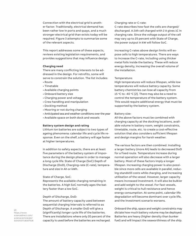
likely significant. There are also capital and per-sonnel costs associated with a longer standstill than the operating profile suggests. The charger can typically be manually operated.
Destination charging and the associated over-night charging have similarities, and design must be balanced between these two options.
Opportunity Charging:Here smaller batteries can be used onboard, while the cost driver is the network of high-power chargers along the route. Short stops also imply an automatic charging solution. Various types of pantograph solutions have been developed for this scenario, in particular for buses. High-power charging also requires dedicated chemistries in the Li-ion battery to withstand the higher C-rates during charging.
There are several factors limiting charging power: • Battery C-rate. By changing the battery chem-
istry, the power and energy capacity of the cellscan be influenced.
• Grid strength • Size and weight of connection arrangement
(cable, arm, manual or automatic)• Available charging time based on operational profile
—Figure 2: ABB shore connection
Classification requirements also require that batteries be placed to allow ventilation to un-manned areas of toxic gases that may occur from the battery system in critical working conditions. Depending on ship design, this limits available space, especially for retrofit solutions. Other safe-ty measures like fire protection will also require space onboard.
Larger battery sizes also dictate additional cables and electrical switchboards in order to manage routine maintenance and electrical fault cases.
Charging Power As mentioned earlier, there are two distinctly different ways of charging a bus or a ferry: Destination Charging, i.e. overnight or at the end points of the route; and Opportunity Charging while passengers are boarding/embarking along the route. Destination charging may be subject to additional grid and charger constraints if many vehicles are gathered in one spot during at one time. This is known as Depot Charging.
Destination charging:With this approach, battery capacity on board is
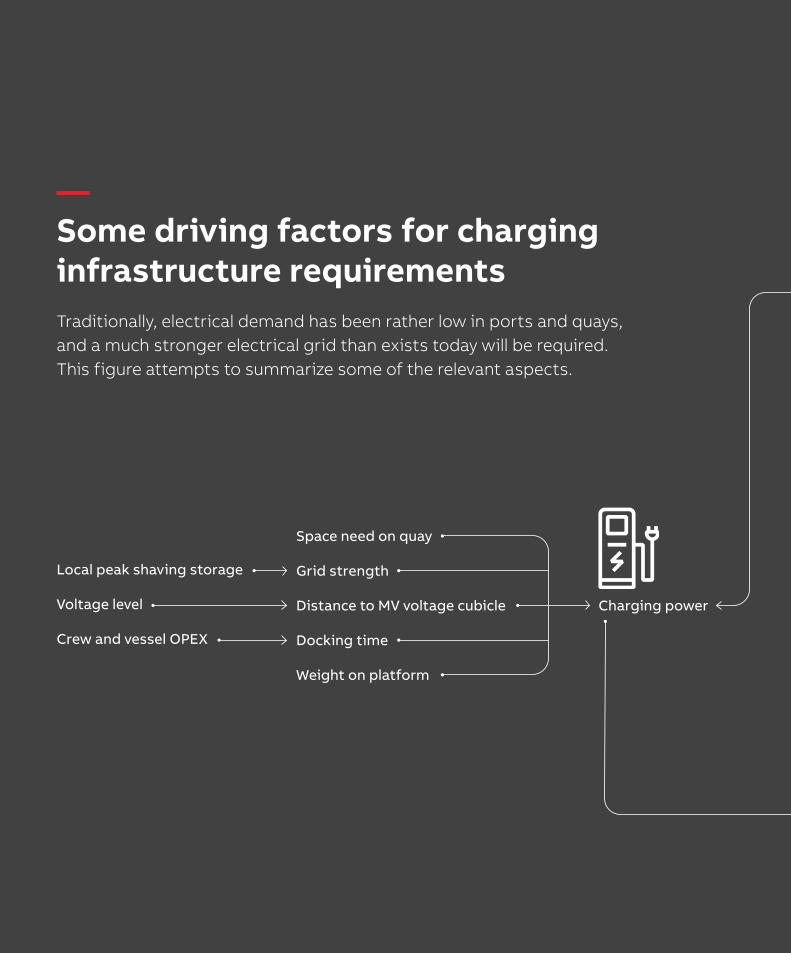
Charging power
Space need on quay
Grid strength
Distance to MV voltage cubicle
Docking time
Weight on platform
Local peak shaving storage
Voltage level
Crew and vessel OPEX
—Some driving factors for charging infrastructure requirementsTraditionally, electrical demand has been rather low in ports and quays, and a much stronger electrical grid than exists today will be required. This figure attempts to summarize some of the relevant aspects.
Battery size
Charging arm/cable characteristics
Efficiency
“Hotel load”
Range extender
Volume need
Weight
Route
Depth of discharge
Battery life length
Battery chemistry
Manual
Automatic
Connection method
Space need on ship
Motors
Drivetrain
Trim
Maneuvering
Weather based route planning
Timetable
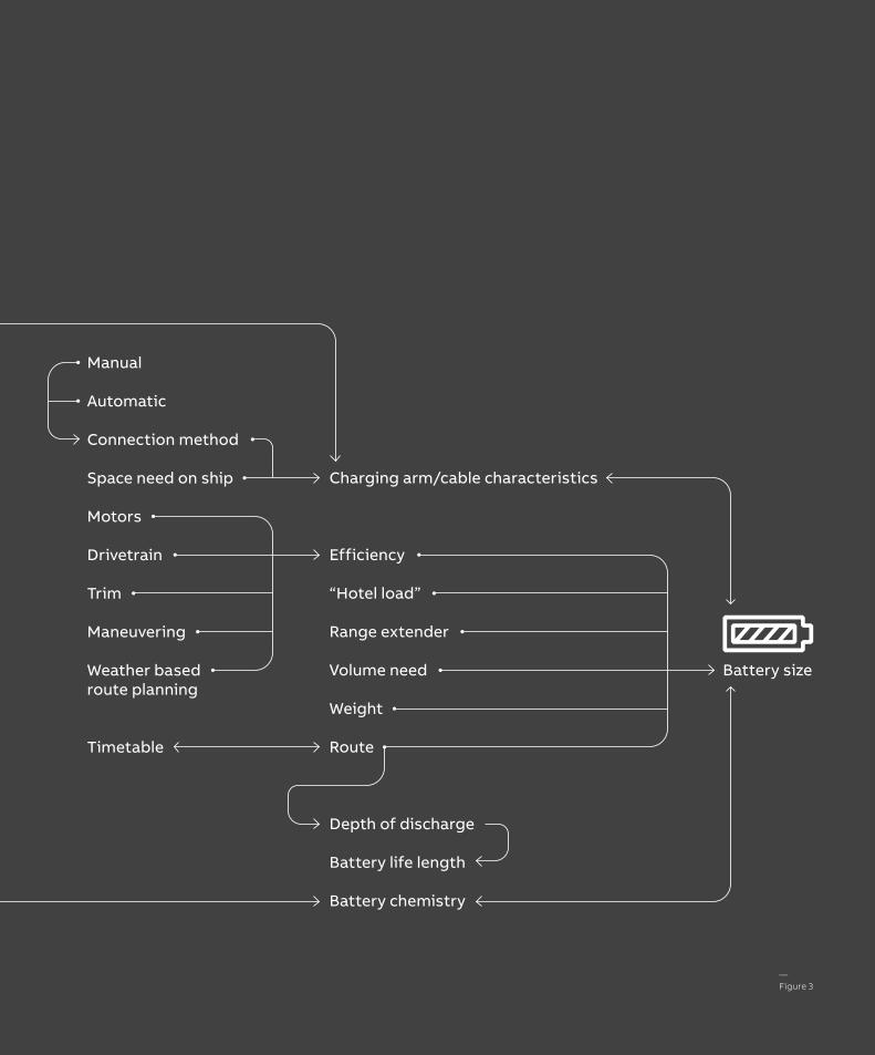
—Figure 3
A contact system for AC power is discussed in [3].
For DC charging it is natural to refer to EV chargers for battery vehicles. Of significance here are available cable lengths and IP protection of contacts. For EV charging, a few meters are sufficient, while for lower power, up to approx-imately 10 meters is suitable, with options for longer lengths. To provide IP protection, most suppliers of EV contacts use IP 54. As discussed later in the document, IP 67 should probably be a requirement.
Fully manual solutions include manual cable with fixed crane arm and EV charger cable.
Assisted, semi-automatic or automatic handling of the connectionFor heavier cables, crew will need support to per-form the connection. The solution will be driven by many factors such as the power and voltage of the charging, preferences considering the time al-lowed for the connection/disconnection, available personnel, and prevailing safety requirements.
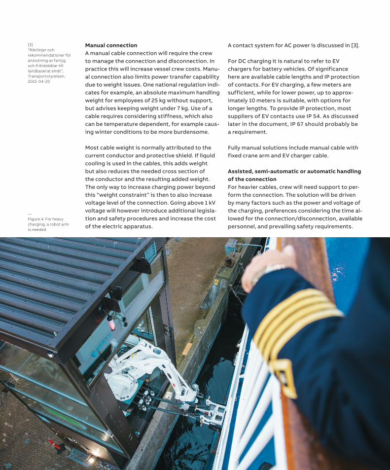
—Figure 4: For heavy charging, a robot arm is needed
[3]”Riktlinjer och rekommendationer för anslutning av fartyg och fritidsbåtar till landbaserat elnät”, Transportstyrelsen, 2015-04-20
Manual connection A manual cable connection will require the crew to manage the connection and disconnection. In practice this will increase vessel crew costs. Manu-al connection also limits power transfer capability due to weight issues. One national regulation indi-cates for example, an absolute maximum handling weight for employees of 25 kg without support, but advises keeping weight under 7 kg. Use of a cable requires considering stiffness, which also can be temperature dependent, for example caus-ing winter conditions to be more burdensome.
Most cable weight is normally attributed to the current conductor and protective shield. If liquid cooling is used in the cables, this adds weight but also reduces the needed cross section of the conductor and the resulting added weight. The only way to increase charging power beyond this “weight constraint” is then to also increase voltage level of the connection. Going above 1 kV voltage will however introduce additional legisla-tion and safety procedures and increase the cost of the electric apparatus.
A first step in assisting the connection is a static arm for lifting the cables. The supporting arm will influence the flexibility of the jetty and the dock-ing procedure. This arm can then be automated in various steps up to the point of a fully automat-ic solution that makes the connection without crew assistance.
Power and voltage levels determine size and weight of the supply cable/s and selection of the plug/s. High currents, say above 400 A, present several challenges. They will either require large cable cross-sections, leading to heavy and stiff cables, or cooling if thinner cables are desired. In addition, the contact resistance in the plug leads to more heat dissipation and will require a higher force between contact surfaces to avoid heating.
Space available on the jetty or ramp, and weight and forces from equipment can also limit options.
For the application intended here, some of the stops are just 90 seconds long, and any charging for that period must in practice be fully automatic.
Some factors to consider for the charging arm: • Mainly ship based solution, shore based, or a
combination.• Available timeslot in timetable for charging de-
termines maximum allowed connection time.• Connection in bow or stern, or on the side of
the vessel.• Speed and force during movement while main-
taining personal safety. High maneuvering speed is often related to higher forces.
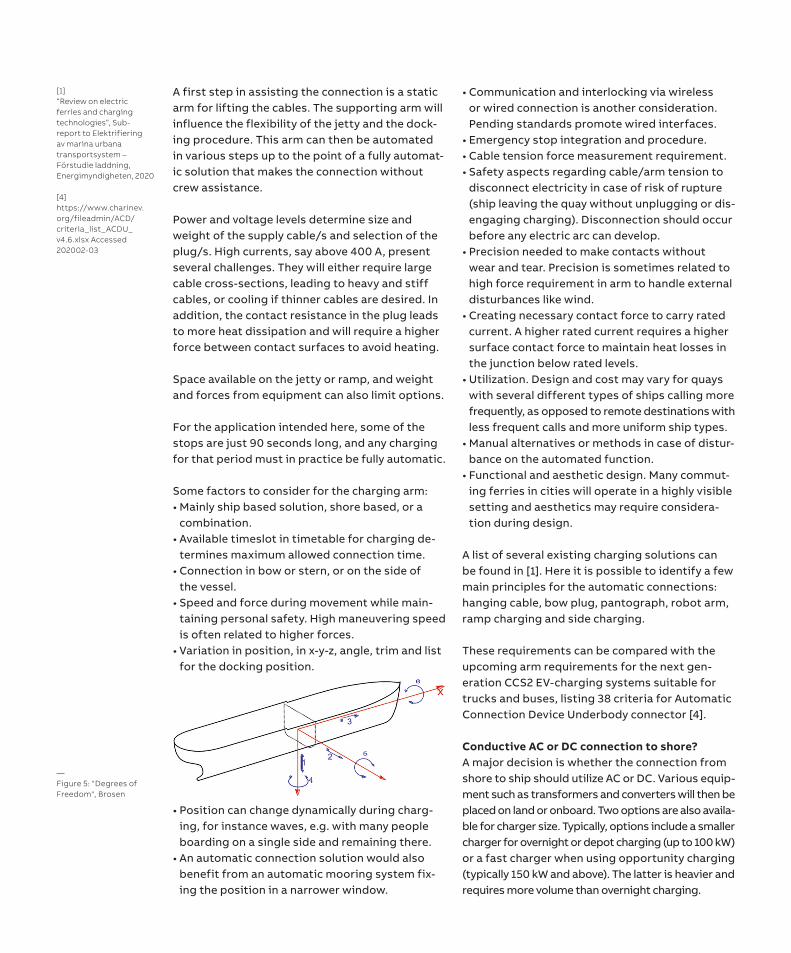
• Variation in position, in x-y-z, angle, trim and listfor the docking position.
• Position can change dynamically during charg-ing, for instance waves, e.g. with many peopleboarding on a single side and remaining there.
• An automatic connection solution would alsobenefit from an automatic mooring system fix-ing the position in a narrower window.
• Communication and interlocking via wirelessor wired connection is another consideration.Pending standards promote wired interfaces.
• Emergency stop integration and procedure.• Cable tension force measurement requirement.• Safety aspects regarding cable/arm tension to
disconnect electricity in case of risk of rupture(ship leaving the quay without unplugging or dis-engaging charging). Disconnection should occurbefore any electric arc can develop.
• Precision needed to make contacts withoutwear and tear. Precision is sometimes related tohigh force requirement in arm to handle externaldisturbances like wind.
• Creating necessary contact force to carry ratedcurrent. A higher rated current requires a highersurface contact force to maintain heat losses inthe junction below rated levels.
• Utilization. Design and cost may vary for quayswith several different types of ships calling morefrequently, as opposed to remote destinations withless frequent calls and more uniform ship types.
• Manual alternatives or methods in case of distur-bance on the automated function.
• Functional and aesthetic design. Many commut-ing ferries in cities will operate in a highly visiblesetting and aesthetics may require considera-tion during design.
A list of several existing charging solutions can be found in [1]. Here it is possible to identify a few main principles for the automatic connections: hanging cable, bow plug, pantograph, robot arm, ramp charging and side charging.
These requirements can be compared with the upcoming arm requirements for the next gen-eration CCS2 EV-charging systems suitable for trucks and buses, listing 38 criteria for Automatic Connection Device Underbody connector [4].
Conductive AC or DC connection to shore? A major decision is whether the connection from shore to ship should utilize AC or DC. Various equip-ment such as transformers and converters will then be placed on land or onboard. Two options are also availa-ble for charger size. Typically, options include a smaller charger for overnight or depot charging (up to 100 kW) or a fast charger when using opportunity charging (typically 150 kW and above). The latter is heavier and requires more volume than overnight charging.
—Figure 5: "Degrees of Freedom", Brosen
[1]“Review on electric ferries and charging technologies”, Sub-report to Elektrifiering av marina urbana transportsystem – Förstudie laddning, Energimyndigheten, 2020
[4]https://www.charinev.org/fileadmin/ACD/criteria_list_ACDU_v4.6.xlsx Accessed 202002-03
Existing standards from the land vehicle industry Several standards from the electric vehicle indus-try can be used as inspiration. Combined Charging System 2, CCS2: Today this standard is normally deployed up to 150 kW and using manually connected conduc-tive charging. More powerful charging is also available, but uses more advanced liquid cooled cables. The prospective maximum length of a 350 kW cable today for an EV application is three meters, possibly increasing to five meters with new regulations. For lower power ratings like 50 kW, 7-8 meter cables are available, with the standard length set at 10 meters. A marine appli-cation may require longer cables, and this must be looked into separately. One aspect is that
most standard EV charger cables today appear to use IP class 54 for water and dust ingress. The marine application probably will require a higher IP class. CCS2 uses wired communication and interlocking circuit.
OppCharge: Several companies support a pantograph-based open contact placed on the roof of buses, going under the brand name OppCharge. The solution can handle up to 600 A and 450 kW charging, but the pantograph solution will probably not be viable as is for marine implementation, since it requires standstill accurate parking. The contact force needed to carry the charging current risks pushing the ship sideways as well in the case of a slight side force component.
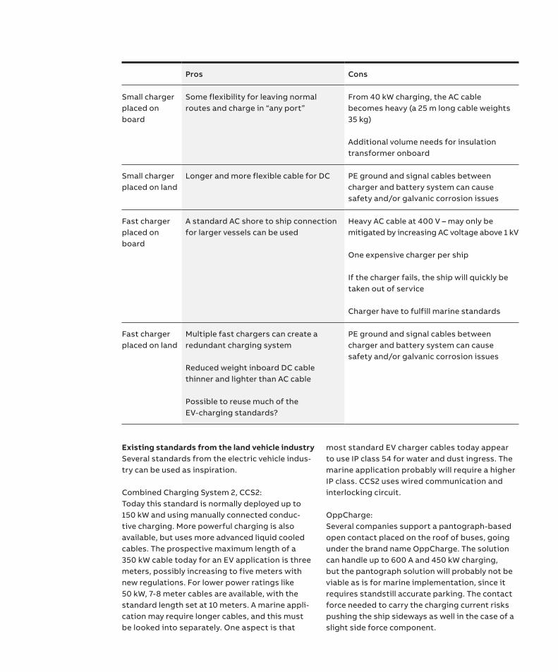
Pros Cons
Small charger placed on board
Some flexibility for leaving normal routes and charge in “any port”
From 40 kW charging, the AC cable becomes heavy (a 25 m long cable weights 35 kg)
Additional volume needs for insulation transformer onboard
Small charger placed on land
Longer and more flexible cable for DC PE ground and signal cables between charger and battery system can cause safety and/or galvanic corrosion issues
Fast charger placed on board
A standard AC shore to ship connection for larger vessels can be used
Heavy AC cable at 400 V – may only be mitigated by increasing AC voltage above 1 kV
One expensive charger per ship
If the charger fails, the ship will quickly be taken out of service
Charger have to fulfill marine standards
Fast charger placed on land
Multiple fast chargers can create a redundant charging system
Reduced weight inboard DC cable thinner and lighter than AC cable
Possible to reuse much of the EV-charging standards?
PE ground and signal cables between charger and battery system can cause safety and/or galvanic corrosion issues
OppCharge uses wireless communication and interlocking circuit. One factor to consider here is that IEC PAS 80005-3, section 4.9 requires hard wired circuits for emergency shutdown, and this should therefore be considered in the design and risk review. Emerging standard for land vehicles: HPCCV CharINev.org More than 150 companies are engaged in the work to define the sequel to CCS2 intended specifically for higher power ranges. In reference [5] the following requirements for next generation charging systems for vehicles are outlined: • High Power Charging for Commercial Vehicles
(HPCCV) shall comply with the holistic system approach of the combined charging system CCS. Compatibility will be a key requirement.
• Up to 1500V and 3000A (Minimum to be defined (200V, 0A)
• Vehicles equipped with an HPCCV should be able to charge from existing CCS infrastructure.
• Coverage of HPCCV power demand via “add-on power extension modules” to the existing connector
• Reuse of Combo 1/2 connector and communication with basic safety concept “as is”
• Communication and basic safety concept shall be compliant with the CCS standard.
• Common set of documents at the interface EV-EVSE for requirements and test cases
• Charging use cases as baseline for requirements and definitions comparable to existing high/medium power solutions
• Support of reverse power transfer • Automated conductive charging as a second step Power grid aspects An important factor before electrifying ferry traf-fic is to consider the existing electrical grid infra-
structure. Harbors and quays have typically been connected to relatively weak electrical grids. This is particularly evident on islands, where grids are often weaker than in urban settings. The charging solution must therefore include constraints in grid strengths.
The grid is divided into different types in order to balance various requirements for high capacity, low loss, high availability and safety. A national high voltage transmission grid is typically oper-ated at 400 kV and feeds power into a meshed re-gional grid feeding a finer surrounding infrastruc-ture, possibly utilizing 130 kV. Running from these substations are a larger number of wires and cables, most often operated at 10 kV, connecting secondary substations across the urbanized area. These secondary substations transform the volt-age level used in buildings, 0.4 kV.
A secondary substation is located within a few hundred meters from any electric outlet and access to a secondary substation will be a pre-requisite for implementing the charging power discussed in this report.
In the following, several aspects are considered in more detail.
Distance to secondary substation A key factor is the physical distance between the secondary substation and the quay. For 0.4 kV and the power ratings discussed here, slightly above EV fast chargers, a shorter distance between the secondary substation and the connection point is desirable.
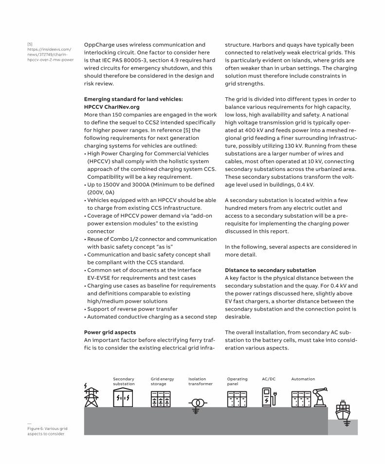
The overall installation, from secondary AC sub-station to the battery cells, must take into consid-eration various aspects.
—Figure 6: Various grid aspects to consider
AC/DCOperating panel
Grid energy storage
AutomationSecondary substation
Isolationtransformer
[5]https://insideevs.com/news/372749/charin-hpccv-over-2-mw-power
The shore side can also be equipped with inter-mediate energy storage. This is required when the grid is weak in relation to charging needs. Fast charging may then be viable from land storage that is slowly recharged between the charging port calls. This method is most feasible when less frequent but rapid charging is desired. It requires an overall grid control and optimization of the charger and storage control.
National legislation must also be considered, and may influence the overall design of equipment on the quays. For instance, in Swedish legislation, there is presently an increased requirement on the housing containing the apparatus at about 436 kW of power at 0.4 kV.
Beyond 1 MVA and 1 kV power ratings, additional requirements emerge between ship and land.
In additional to electric requirements, flooding must also be considered. The potential for flood-ing places higher requirements on water ingress (IPx7) protection for quay installations than normal. EV chargers and secondary substations would also need better corrosion protection of cabinets etc. Stainless steel may be required.
An important factor here is how to handle the differences in docking position. There are two main options to manage height variation. The first includes a solution where the arrangement/crane/arm can handle this height variation, add-ing weight, size and cost. The second option is to place the arrangement on a floating platform that follows sea level variations. This solution would require a flexible arrangement for cables to the platform. Possible solutions are a dedicated cable ramp or some type of cable reel arrangement.
There is also an option to install an energy stor-age device on land, particularly for peak shaving the charging power demand in weak grid loca-tions. A battery for energy storage is the most likely installation, but an emerging option could be to use a fuel cell, especially if a gas facility is already available in the port.
Energy storage can also provide additional grid flexibility in addition to peak shaving. Local grid voltage control and grid frequency support are two areas to be considered by the local grid utility. The most extreme option is to include grid stor-age in a so-called micro grid mode. This option can be used on remote islands where energy stor-age can be used as a backup solution for shorter time periods in case of electric grid outages.
Power quality Connecting a large load on 0.4 kV creates a risk of poor power quality. This must be considered dur-ing design, and solutions are available. Two key aspects are voltage variations, caused by switch-ing charging on and off, and harmonics caused by the conversion from AC to DC.
Some AC/DC converters can be used for compen-sating voltage drop. This functionality can be of value at certain grid points.
System grounding In IEC 60364-7-709, several AC grid connection configurations are presented for connecting the ship to the land grid. They represent a mixed bag of considerations in design, where various types of faults present varying design criteria. Three aspects must be considered; how to handle over-voltage during fault, how to manage fault current magnitude, and how to detect a fault.
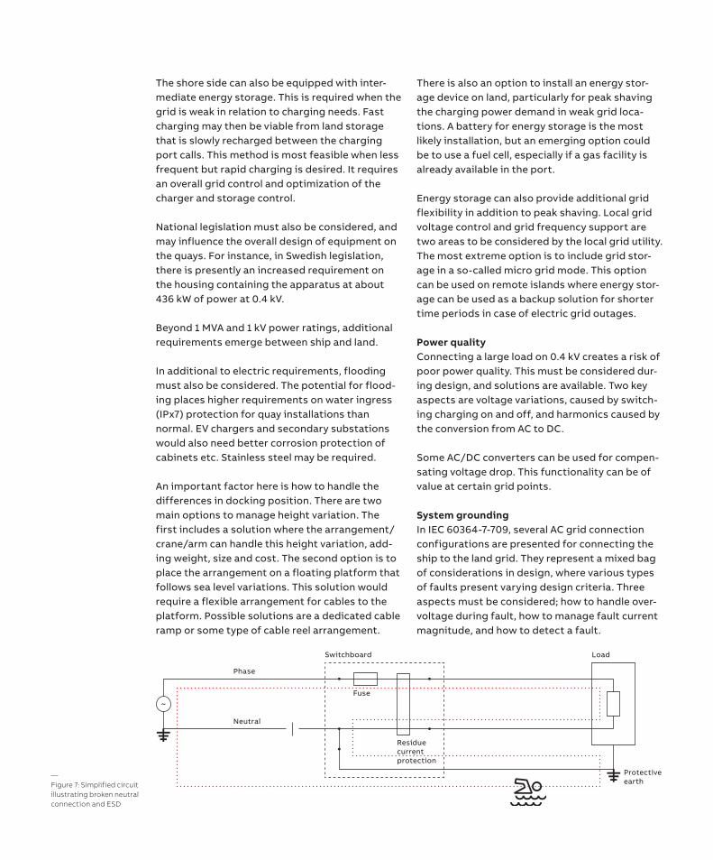
—Figure 7: Simplified circuit illustrating broken neutral connection and ESD
Switchboard Load
Protective earth
Residuecurrentprotection
~Fuse
Phase
Neutral
System grounding and personal safety: The grounding philosophy and methods used are key aspects of protecting human lives in an elec-trical environment. The most important feature of a safe electrical grid is the grounding of metallic parts, which should not carry any electric current.
On land, a copper net or rod is normally buried to create connection to the ground. On a ship, the hull serves at the ground, which in turn uses seawater to ground itself.
In case of insulation failure on electrical wiring, grounding is then used to reroute the current and to make it visible for protection devices interrupt-ing the electrical service. The fuse and the residue current protection (aka. ground fault circuit inter-rupters (GFCIs)) are the most common solutions for managing most fault cases.
When charging a ship from land, the two ground-ing systems must be connected correctly to main-tain personal safety. The most dangerous fault will then occur if the neutral return wiring between the ship hull and the land grounding rod is broken. If an insulation fault occurs in the electrical wiring, the current will go through the PEwire (Protective Earth), the hull, the seawater and the ground, and back to the land station grounding point. Any per-son swimming near the ship can then be exposed to Electric Shock Drowning (ESD). Even a small current through the body is enough to lock or impair muscle control in a leg or an arm, reducing the ability of a person to swim. An overview ESD can be found in [6] where a long list of tragic acci-dents is also listed, mostly in leisure marinas.
While these quays normally attract few swimmers, there are cases where this may be expected to occur.
Figure 7 indicates in a very simplified circuit how a broken neutral circuit in the utility grid can cause ESD, even if the fuse and residue current pro-tection function as intended. It also encourages some additional safety procedures for this type of application. For a 3-phase system, the same phenomena can occur but normally on a smaller magnitude. If the neutral wire is broken, a neutral AC voltage caused by imbalance in the three phases will occur. This current is then pushed through the protective earth through the water.
Utilities should therefore take care in designing a solution to avoid a broken neutral wire. There are also emerging methods for utilities to monitor the integrity of the neutral wire. See for instance [7].
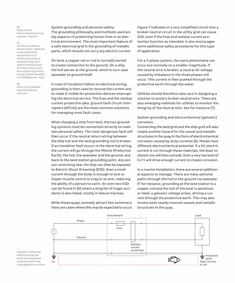
System grounding and electrochemical (galvanic) corrosion: Connecting the land grid and the ship grid will also create another hazard for the vessel and metallic structures in the quay in the form of electrochemical corrosion caused by stray currents [8]. Metals have different electrochemical potential. If a DC electric current is run through these materials, the least re-sistant one will then corrode. Even a very low level of 0.2 V will drive enough current to create corrosion. In a marine installation, there are several addition-al aspects to manage. There are many optional paths through the hull to the ground via seawater. If, for instance, grounding at the land station is a copper rod and the hull of the boat is aluminum or steel, a galvanic voltage arises, driving a cur-rent through the protective earth. This may also involve both nearby moored vessels and metallic structures in the quay.
—Figure 8: Connecting ship hull protective earth and land based protective earth may cause galvanic corrosion
Switchboard Load
Protective earth
Residuecurrentprotection
~Fuse
Phase
Neutral
Steel, bronze,al, etc
Cu
[6]https://www.electricshockdrowning.org/esd--faq.html
[7]Christoforos Menos-Aikateriniadis, “Methods to identify broken neutral fault in LV distribution grids by using existing smart meters infrastructure”, KTH 2019, http://www.diva-portal.org/smash/record .jsf?pid=diva2%3A1372876&dswid=-4292
[8]https://en.wikipedia.org/wiki/Galvanic_corrosion
A vessel will also use several different types of metals like bronze, copper, aluminum and zinc, and the stray current can easily find alternative paths to metallic structures at various points and create corrosion in the least resistant metals.
An important factor here is the DC-battery sys-tem onboard, where grounding of the negative pole of the battery, sometimes applied in leisure craft, will create another possible driving source for leakage currents from the voltage at the posi-tive pole.
System grounding mitigation methods There are several methods to apply in order to reduce the risks with system grounding. Some are effective for both personal safety and corrosion.
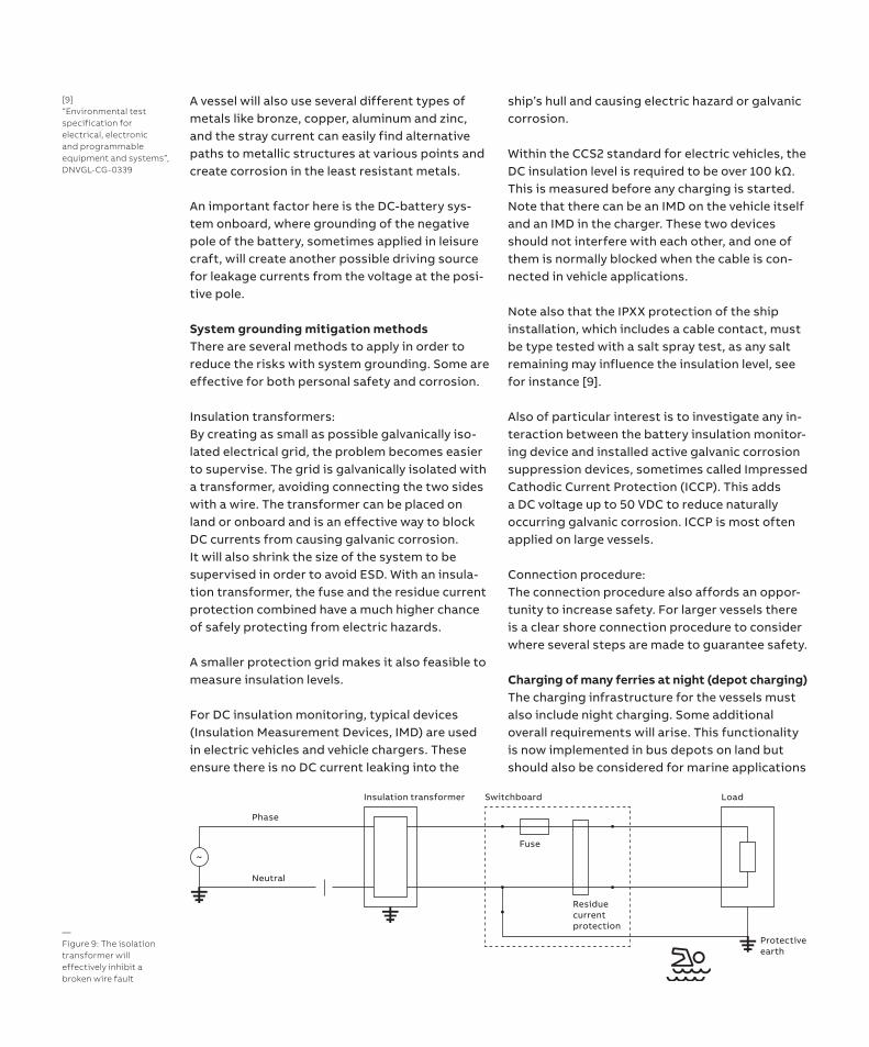
Insulation transformers:By creating as small as possible galvanically iso-lated electrical grid, the problem becomes easier to supervise. The grid is galvanically isolated with a transformer, avoiding connecting the two sides with a wire. The transformer can be placed on land or onboard and is an effective way to block DC currents from causing galvanic corrosion. It will also shrink the size of the system to be supervised in order to avoid ESD. With an insula-tion transformer, the fuse and the residue current protection combined have a much higher chance of safely protecting from electric hazards. A smaller protection grid makes it also feasible to measure insulation levels. For DC insulation monitoring, typical devices (Insulation Measurement Devices, IMD) are used in electric vehicles and vehicle chargers. These ensure there is no DC current leaking into the
ship’s hull and causing electric hazard or galvanic corrosion.
Within the CCS2 standard for electric vehicles, the DC insulation level is required to be over 100 kΩ. This is measured before any charging is started. Note that there can be an IMD on the vehicle itself and an IMD in the charger. These two devices should not interfere with each other, and one of them is normally blocked when the cable is con-nected in vehicle applications.
Note also that the IPXX protection of the ship installation, which includes a cable contact, must be type tested with a salt spray test, as any salt remaining may influence the insulation level, see for instance [9].
Also of particular interest is to investigate any in-teraction between the battery insulation monitor-ing device and installed active galvanic corrosion suppression devices, sometimes called Impressed Cathodic Current Protection (ICCP). This adds a DC voltage up to 50 VDC to reduce naturally occurring galvanic corrosion. ICCP is most often applied on large vessels.
Connection procedure: The connection procedure also affords an oppor-tunity to increase safety. For larger vessels there is a clear shore connection procedure to consider where several steps are made to guarantee safety.
Charging of many ferries at night (depot charging) The charging infrastructure for the vessels must also include night charging. Some additional overall requirements will arise. This functionality is now implemented in bus depots on land but should also be considered for marine applications
—Figure 9: The isolation transformer will effectively inhibit a broken wire fault
Switchboard Load
Protective earth
Residuecurrentprotection
Fuse
Phase
Neutral
Insulation transformer
~
[9]“Environmental test specification for electrical, electronic and programmable equipment and systems”, DNVGL-CG-0339
early in the planning. Some key aspects are sum-marized in the following points: • Need for flexible moorings. Vessels may shift
position, and the charger solution must adapt to this.
• If night mooring differs from opportunity charging with regard to bow/stern or side connection, this may require special arrangements. Aspects discussed earlier such as cable weight and electric power must also be considered.
• Intended power and voltage for night charging and available installed grid power
• There will be a need to optimize the overall charging profiles for many vessels to make best use of transformer capacity and DC converters.
• All vessels should have the intended State of Charge when taken into service.
• Since the vessels are mostly unattended here, there will be a need for supervision to make sure they are charged as intended when returning to operation. Charging of all vessels should therefore be supervised also when unattended.
• The electrical grid design should also be flexible enough to handle variations in how the vessels are moored, or if for instance a battery charger is unavailable. This will serve to promote standard solutions.
• Optimizing electric energy cost International standardsLegislation is not complete for this segment yet. Most international standards are focused on AC rather than DC. Connections must handle galvanic isolation to avoid corrosion in metallic parts on the ship and quay structure. There are two international standards relevant for the actual connection of high voltage cables (typ-ically >> 1 kV and AC) where relevant aspects may be applied, such as pilot wire requirements: • IEC 62613-1; Plugs, socket-outlets and ship cou-
plers for high-voltage shore connection systems (HVSC-Systems) – Part 1: General requirements
• IEC 62613-2; Plugs, socket-outlets and ship cou-plers for high-voltage shore connection systems (HVSC-Systems) – Part 2: Dimensional compat-ibility and interchangeability requirements for accessories to be used by various types of ships
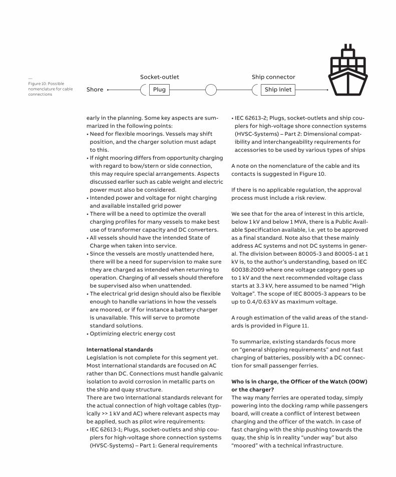
A note on the nomenclature of the cable and its contacts is suggested in Figure 10. If there is no applicable regulation, the approval process must include a risk review.
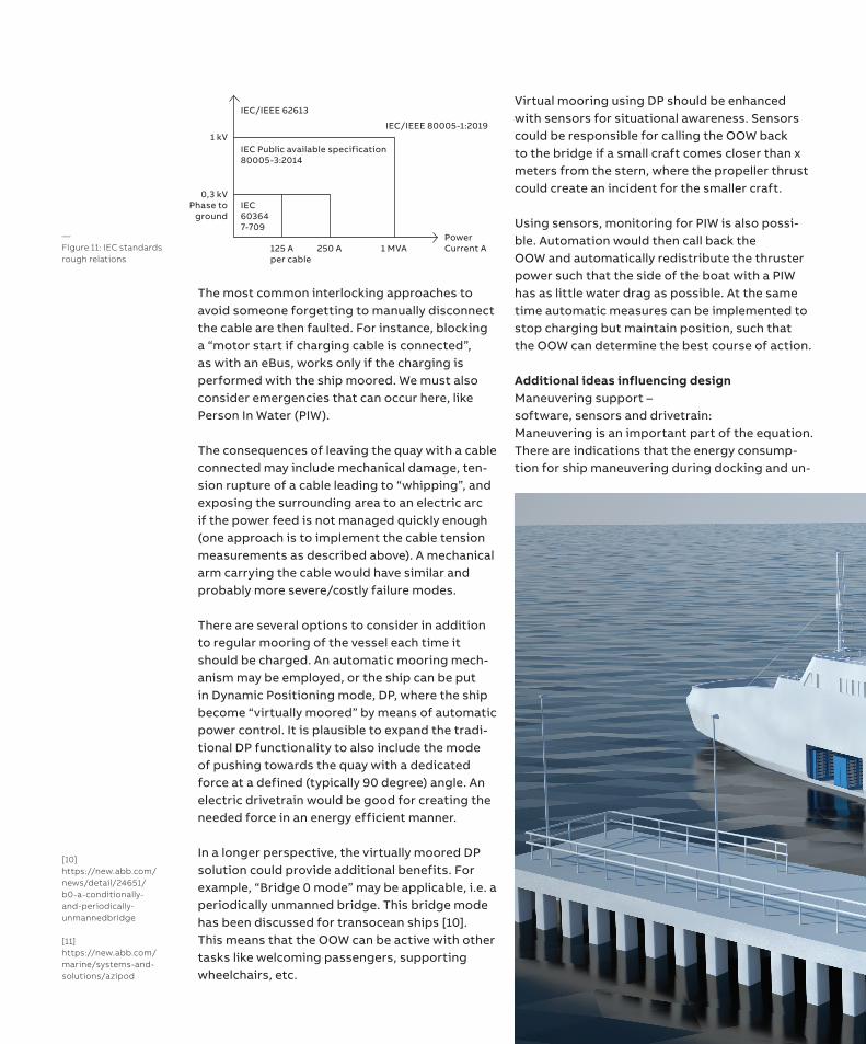
We see that for the area of interest in this article, below 1 kV and below 1 MVA, there is a Public Avail-able Specification available, i.e. yet to be approved as a final standard. Note also that these mainly address AC systems and not DC systems in gener-al. The division between 80005-3 and 80005-1 at 1 kV is, to the author’s understanding, based on IEC 60038:2009 where one voltage category goes up to 1 kV and the next recommended voltage class starts at 3.3 kV, here assumed to be named “High Voltage”. The scope of IEC 80005-3 appears to be up to 0.4/0.63 kV as maximum voltage.
A rough estimation of the valid areas of the stand-ards is provided in Figure 11. To summarize, existing standards focus more on “general shipping requirements” and not fast charging of batteries, possibly with a DC connec-tion for small passenger ferries.
Who is in charge, the Officer of the Watch (OOW) or the charger? The way many ferries are operated today, simply powering into the docking ramp while passengers board, will create a conflict of interest between charging and the officer of the watch. In case of fast charging with the ship pushing towards the quay, the ship is in reality “under way” but also “moored” with a technical infrastructure.
—Figure 10: Possible nomenclature for cable connections
Shore
Socket-outlet
Plug
Ship connector
Ship inlet
The most common interlocking approaches to avoid someone forgetting to manually disconnect the cable are then faulted. For instance, blocking a “motor start if charging cable is connected”, as with an eBus, works only if the charging is performed with the ship moored. We must also consider emergencies that can occur here, like Person In Water (PIW).
The consequences of leaving the quay with a cable connected may include mechanical damage, ten-sion rupture of a cable leading to “whipping”, and exposing the surrounding area to an electric arc if the power feed is not managed quickly enough (one approach is to implement the cable tension measurements as described above). A mechanical arm carrying the cable would have similar and probably more severe/costly failure modes.
There are several options to consider in addition to regular mooring of the vessel each time it should be charged. An automatic mooring mech-anism may be employed, or the ship can be put in Dynamic Positioning mode, DP, where the ship become “virtually moored” by means of automatic power control. It is plausible to expand the tradi-tional DP functionality to also include the mode of pushing towards the quay with a dedicated force at a defined (typically 90 degree) angle. An electric drivetrain would be good for creating the needed force in an energy efficient manner.
In a longer perspective, the virtually moored DP solution could provide additional benefits. For example, “Bridge 0 mode” may be applicable, i.e. a periodically unmanned bridge. This bridge mode has been discussed for transocean ships [10]. This means that the OOW can be active with other tasks like welcoming passengers, supporting wheelchairs, etc.
Virtual mooring using DP should be enhanced with sensors for situational awareness. Sensors could be responsible for calling the OOW back to the bridge if a small craft comes closer than x meters from the stern, where the propeller thrust could create an incident for the smaller craft.
Using sensors, monitoring for PIW is also possi-ble. Automation would then call back theOOW and automatically redistribute the thruster power such that the side of the boat with a PIW has as little water drag as possible. At the same time automatic measures can be implemented to stop charging but maintain position, such that the OOW can determine the best course of action.
Additional ideas influencing design Maneuvering support – software, sensors and drivetrain: Maneuvering is an important part of the equation. There are indications that the energy consump-tion for ship maneuvering during docking and un-
—Figure 11: IEC standards rough relations
1 kV
0,3 kVPhase to
ground
125 Aper cable
250 A 1 MVAPowerCurrent A
IEC 603647-709
IEC Public available specification80005-3:2014
IEC/IEEE 62613
IEC/IEEE 80005-1:2019
[10]https://new.abb.com/news/detail/24651/b0-a-conditionally-and-periodically-unmannedbridge
[11]https://new.abb.com/marine/systems-and-solutions/azipod
timal advantage of grid connection and chargers. One such example is an end bus station located next to a ferry docking. The fast charger conver-sion box could then be used for both applications. Questions to be resolved would include how to share a common AC grid interface to meet both needs, and how to split capacity optimally.
Range extension as an add on: A further option related to charging infrastruc-ture is to consider preparing the vessels for an “add on-range extender”. Space could be dedi-cated for an extended battery, fuel cell or diesel motor to be lifted onboard temporarily for longer voyages away from charging possibilities.
This could also be a “winter extension”, boosting battery capacity for higher hotel heating demand and ice conditions. The charging infrastructure should be planned to meet this extra demand, but it would also allow for battery swapping as a charging principle.
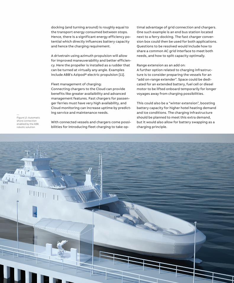
—Figure 12: Automatic shore connection enabled by the ABB robotic solution
docking (and turning around) is roughly equal to the transport energy consumed between stops. Hence, there is a significant energy efficiency po-tential which directly influences battery capacity and hence the charging requirement.
A drivetrain using azimuth propulsion will allow for improved maneuverability and better efficien-cy. Here the propeller is installed as a rudder that can be turned at virtually any angle. Examples include ABB’s Azipod® electric propulsion [11].
Fleet management of charging: Connecting chargers to the Cloud can provide benefits like greater availaibility and advanced management features. Fast chargers for passen-ger ferries must have very high availability, and Cloud monitoring can increase uptime by predict-ing service and maintenance needs.
With connected vessels and chargers come possi-bilities for introducing fleet charging to take op-