under an aquatic nuisance control permit - vermont.gov
TRANSCRIPT
Powered Mechanical Device March 2015
Application for use of a Powered Mechanical Device under an Aquatic Nuisance Control Permit
Per 10 VSA Chapter 50, § 1455
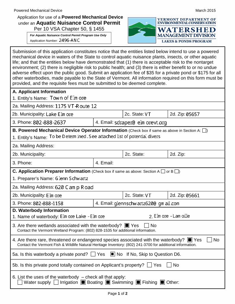
Submission of this application constitutes notice that the entities listed below intend to use a powered mechanical device in waters of the State to control aquatic nuisance plants, insects, or other aquatic life; and that the entities below have demonstrated that (1) there is acceptable risk to the nontarget environment; (2) there is negligible risk to public health; and (3) there is either benefit to or no undue adverse effect upon the public good. Submit an application fee of $35 for a private pond or $175 for all other waterbodies, made payable to the State of Vermont. All information required on this form must be provided, and the requisite fees must be submitted to be deemed complete.
A. Applicant Information 1. Entity’s Name:
2a. Mailing Address:
2b. Municipality: 2c. State: 2d. Zip:
3. Phone: 4. Email:
B. Powered Mechanical Device Operator Information (Check box if same as above in Section A: ) 1. Entity’s Name:
2a. Mailing Address:
2b. Municipality: 2c. State: 2d. Zip:
3. Phone: 4. Email:
C. Application Preparer Information (Check box if same as above: Section A or B ) 1. Preparer’s Name:
2a. Mailing Address:
2b. Municipality: 2c. State: 2d. Zip:
3. Phone: 4. Email: D. Waterbody Information 1. Name of waterbody: 2. Municipality:
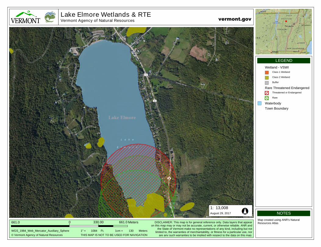
3. Are there wetlands associated with the waterbody? Yes No Contact the Vermont Wetland Program: (802) 828-1535 for additional information.
4. Are there rare, threatened or endangered species associated with the waterbody? Yes No Contact the Vermont Fish & Wildlife Natural Heritage Inventory: (802) 241-3700 for additional information.
5a. Is this waterbody a private pond? Yes No If No, Skip to Question D6.
5b. Is this private pond totally contained on Applicant’s property? Yes No
6. List the uses of the waterbody – check all that apply: Water supply Irrigation Boating Swimming Fishing Other:
For Aquatic Nuisance Control Permit Program Use Only
Application Number:
Page 1 of 2
_______
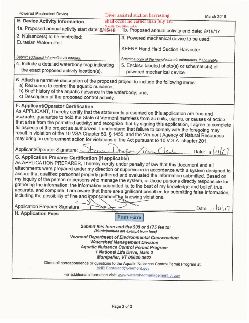
Diver assisted suction harvesting shall occur no earlier than July 1st.Specific Condition a.4.A.

Narrative Reasons to control the aquatic nuisance Lake Elmore is a small lake of 204 Acres. The Vermont Fish and Wildlife Department maintains a fishing access on the lake. In addition, the Vermont Department of Parks has campsites and a public beach on Lake Elmore. There are many camps and homes on the lake. The general public, who use the lake for recreational purposes (fishing, swimming, boating, etc.), need to be able to continue to do so. Continued growth of Eurasian Water Milfoil (EWM) without abatement could threaten further recreational use of the lake. The Lake Elmore Lake Association (LELA) project will have short and long term impacts upon the lake and the entire watershed. It is designed to reduce and control Eurasian Water Milfoil in Lake Elmore. By doing so it will reduce the potential of EWM flowing over or through the dam and infesting downstream bodies of water. Thus, the project will both assist in the restoration of Lake Elmore and help protect the entire watershed.
By restoring the lake, the project helps to ensure that boaters and fishermen will be able to continue to have access to the lake. Without action, in the very near future access to the lake via the state boat ramp will be impossible. Restoration of the lake also will ensure safe swimming at the state park site. Failure to act will soon lead to unsafe swimming conditions at the park.
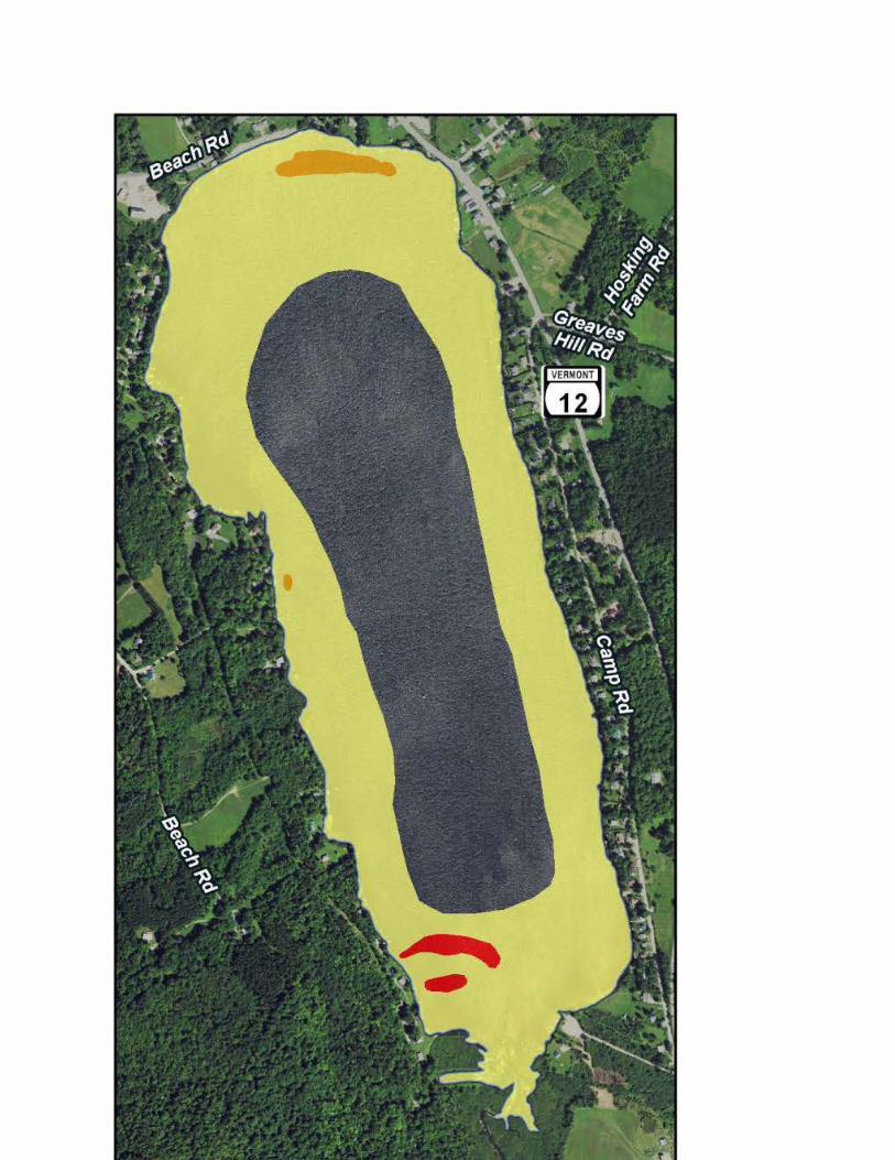
Protection of the downstream watershed is in the best interest of both residents of the area and the habitat. The watershed area is used for fishing, canoeing, kayaking, swimming, power boating and power generation. In addition to its use, it is important to protect the flora and fauna of the basin. If left unchecked, Milfoil will form dense mats, inhibit many recreational uses and choke out native vegetation. In the case of Lake Elmore, it is also threatening two rare and uncommon plant species. While EWM is currently widespread in the Lake, there are only a few areas where it has formed very dense infestations. While it may not be realistic to completely eradicate this species from the Lake, it should be possible to halt its spread and decrease the size of the dense infestations. Such control can ensure that recreational use of the Lake can continue and the ecological integrity of the Lake ecosystem remains intact. Brief history of the aquatic nuisance in the waterbody Control of EWM has been undertaken for many years in Lake Elmore. Continued control will be necessary to ensure that dense infestations do not occupy an increasing area of the Lake. There are many techniques that have been used for control of aquatic vegetation, including bottom barriers, manual harvesting, suction harvesting and mechanical harvesting. As evidenced by the dense infestations in the southern part of the Lake, EWM has the potential to become well established and choke out native aquatic vegetation. In these areas, it appears that EWM is having a significant detrimental impact on native vegetation. Outside of the Moderate and Dense infestations, the EWM is present only at low cover and does not appear to be posing a threat to native aquatic communities after this year’s harvesting.
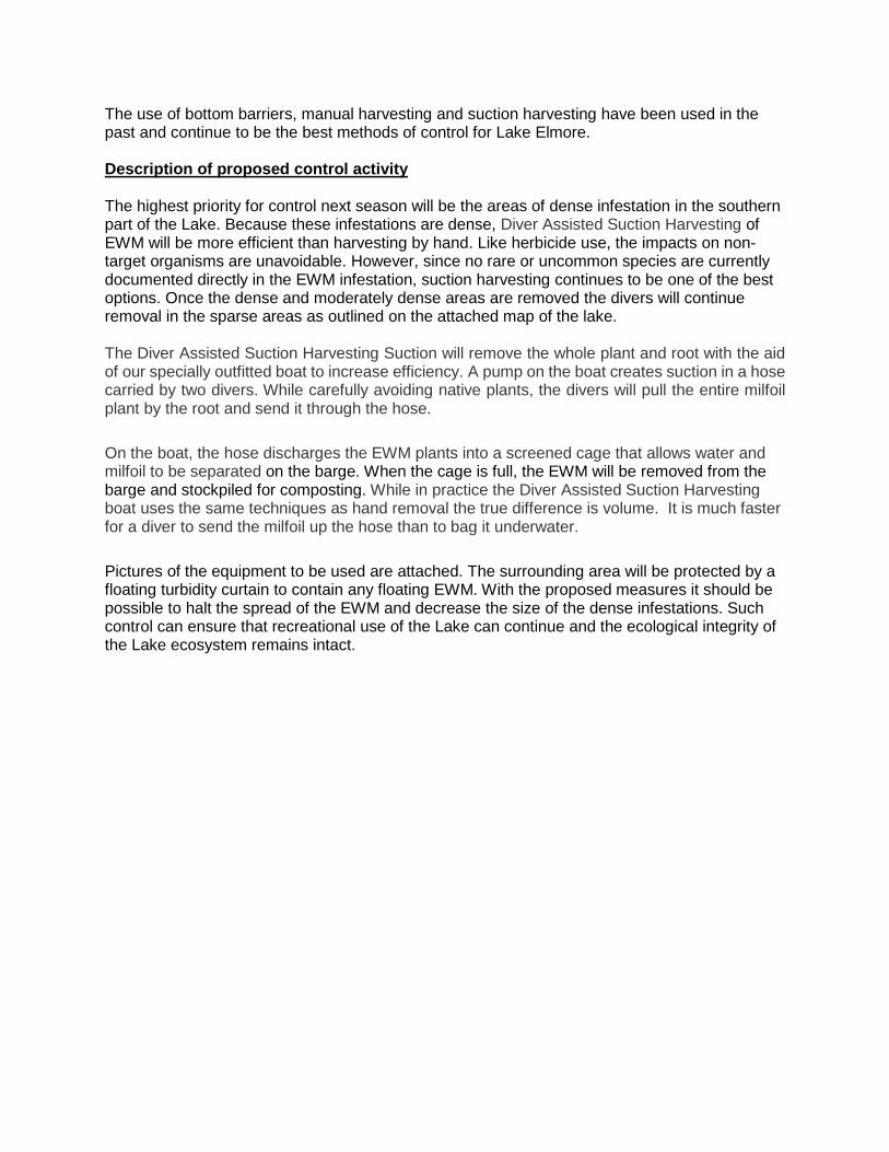
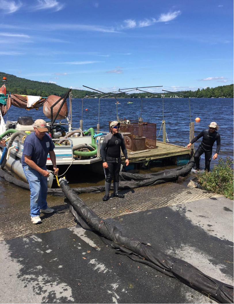
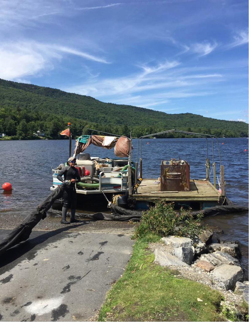
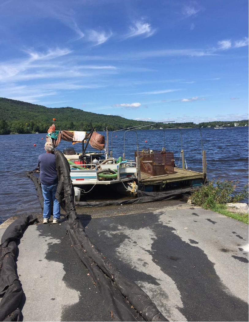
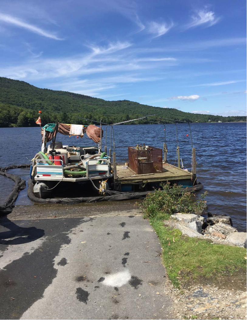
The use of bottom barriers, manual harvesting and suction harvesting have been used in the past and continue to be the best methods of control for Lake Elmore. Description of proposed control activity The highest priority for control next season will be the areas of dense infestation in the southern part of the Lake. Because these infestations are dense, Diver Assisted Suction Harvesting of EWM will be more efficient than harvesting by hand. Like herbicide use, the impacts on non-target organisms are unavoidable. However, since no rare or uncommon species are currently documented directly in the EWM infestation, suction harvesting continues to be one of the best options. Once the dense and moderately dense areas are removed the divers will continue removal in the sparse areas as outlined on the attached map of the lake. The Diver Assisted Suction Harvesting Suction will remove the whole plant and root with the aid of our specially outfitted boat to increase efficiency. A pump on the boat creates suction in a hose carried by two divers. While carefully avoiding native plants, the divers will pull the entire milfoil plant by the root and send it through the hose.
On the boat, the hose discharges the EWM plants into a screened cage that allows water and milfoil to be separated on the barge. When the cage is full, the EWM will be removed from the barge and stockpiled for composting. While in practice the Diver Assisted Suction Harvesting boat uses the same techniques as hand removal the true difference is volume. It is much faster for a diver to send the milfoil up the hose than to bag it underwater.
Pictures of the equipment to be used are attached. The surrounding area will be protected by a floating turbidity curtain to contain any floating EWM. With the proposed measures it should be possible to halt the spread of the EWM and decrease the size of the dense infestations. Such control can ensure that recreational use of the Lake can continue and the ecological integrity of the Lake ecosystem remains intact.
17,172
872.4
Lake Elmore Wetlands & RTEVermont Agency of Natural Resources
13,008
© Vermont Agency of Natural Resources
661.0
1:
WGS_1984_Web_Mercator_Auxiliary_Sphere
Meters661.00
NOTES
Map created using ANR's Natural Resources Atlas
LEGEND
330.00
vermont.gov
DISCLAIMER: This map is for general reference only. Data layers that appearon this map may or may not be accurate, current, or otherwise reliable. ANR and
the State of Vermont make no representations of any kind, including but notlimited to, the warranties of merchantability, or fitness for a particular use, nor
are any such warranties to be implied with respect to the data on this map.
August 29, 2017
THIS MAP IS NOT TO BE USED FOR NAVIGATION
1" = 1084 1cm = 130Ft. Meters
Wetland - VSWI
Class 1 Wetland
Class 2 Wetland
Buffer
Rare Threatened Endangered Species
Threatened or Endangered
Rare
Waterbody
Town Boundary
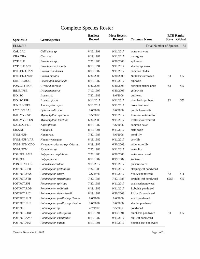
Complete Species Roster
SpeciesID Common Name
Earliest
Record
Most Recent
RecordGenus/species
RTE Ranks
State Global
Total Number of Species: 52ELMORE
CAL.CAL Callitriche sp. water-starwort8/13/1991 9/11/2017
CHA.CHA Chara sp. muskgrass8/19/1982 9/11/2017
CYP.ELE Eleocharis sp. spikerush7/27/1988 6/30/2003
CYP.ELE.ACI Eleocharis acicularis slender spikerush8/13/1991 9/11/2017
HYD.ELO.CAN Elodea canadensis common elodea8/19/1982 9/11/2017
HYD.ELO.NUT Elodea nuttallii Nuttall's waterweed6/30/2003 6/30/2003 S3 G5
ERI.ERI.AQU Eriocaulon aquaticum pipewort8/19/1982 9/11/2017
POA.GLY.BOR Glyceria borealis northern manna grass6/30/2003 6/30/2003 S3 G5
IRI.IRI.PSE Iris pseudacorus yellow iris7/10/1997 6/30/2003
ISO.ISO Isoetes sp. quillwort7/27/1988 9/6/2006
ISO.ISO.RIP Isoetes riparia river bank quillwort9/11/2017 9/11/2017 S2 G5?
JUN.JUN.PEL Juncus pelocarpus brownfruit rush9/11/2017 9/11/2017
LYT.LYT.SAL Lythrum salicaria purple loosestrife9/6/2006 9/6/2006
HAL.MYR.SPI Myriophyllum spicatum Eurasian watermilfoil9/5/2002 9/11/2017
HAL.MYR.TEN Myriophyllum tenellum leafless watermilfoil6/30/2003 9/11/2017
NAJ.NAJ.FLE Najas flexilis common naiad8/19/1982 9/6/2006
CHA.NIT Nitella sp. brittlewort8/13/1991 9/11/2017
NYM.NUP Nuphar sp. pond-lily7/27/1988 9/6/2006
NYM.NUP.VAR Nuphar variegata cow lily8/19/1982 9/11/2017
NYM.NYM.ODO Nymphaea odorata ssp. Odorata white waterlily8/19/1982 6/30/2003
NYM.NYM Nymphaea sp. water lily7/27/1988 9/11/2017
POL.POL.AMP Polygonum amphibium water smartweed7/27/1988 6/30/2003
POL.POL Polygonum sp. knotweed8/19/1982 8/19/1982
PON.PON.COR Pontederia cordata pickerel-weed9/11/2017 9/11/2017
POT.POT.PER Potamogeton perfoliatus claspingleaf pondweed7/27/1988 9/11/2017
POT.POT.VAS Potamogeton vaseyi Vasey's pondweed7/6/1978 9/11/2017 S2 G4
POT.POT.STR Potamogeton strictifolius straight-leaf pondweed7/27/1988 7/27/1988 S2S3 G5
POT.POT.SPI Potamogeton spirillus snailseed pondweed7/27/1988 9/11/2017
POT.POT.ROB Potamogeton robbinsii Robbin's pondweed8/19/1982 9/11/2017
POT.POT.RIC Potamogeton richardsonii Richard's pondweed8/19/1982 6/30/2003
POT.POT.PUT Potamogeton pusillus ssp. Tenuis small pondweed9/6/2006 9/6/2006
POT.POT.PUP Potamogeton pusillus ssp. Pusillu slender pondweed9/6/2006 9/6/2006
POT.POT Potamogeton sp. pondweed7/7/1997 9/5/2002
POT.POT.OBT Potamogeton obtusifolius blunt-leaf pondweed8/13/1991 8/13/1991 S3 G5
POT.POT.AMP Potamogeton amplifolius big-leaf pondweed8/19/1982 9/11/2017
POT.POT.NAT Potamogeton natans floating-leaf pondweed8/13/1991 9/11/2017
Tuesday, November 21, 2017 Page 1 of 2
SpeciesID Common Name
Earliest
Record
Most Recent
RecordGenus/species
RTE Ranks
State Global
Total Number of Species: 52ELMORE
POT.POT.ILL Potamogeton illinoensis Illinois pondweed8/19/1982 8/19/1982
POT.POT.GRA Potamogeton gramineus variable-leaf pondweed8/19/1982 9/11/2017
POT.POT.EPI Potamogeton epihydrus ribbonleaf pondweed8/19/1982 9/11/2017
POT.POT.PUS Potamogeton pusillus small pondweed8/13/1991 6/30/2003
RAN.RAN.AQD Ranunculus aquatilis L. var. diffu white water-crowfoot9/11/2017 9/11/2017 S3 G5
ALI.SAG.GRA Sagittaria graminea slender arrowhead9/11/2017 9/11/2017
ALI.SAG Sagittaria sp. arrowhead7/27/1988 9/6/2006
CYP.SCI Scirpus sp. bulrush8/19/1982 8/19/1982
SPA.SPA Sparganium sp. bur-reed7/27/1988 9/6/2006
SPA.SPA.ANG Sparganium angustifolium floating-leaf bur-reed7/7/1997 9/11/2017
SPA.SPA.FLU Sparganium fluctuans lesser bur-reed9/9/1989 6/30/2003 S3 G5
SPA.SPA.NAT Sparganium natans small bur-reed8/19/1982 8/19/1982 S2 G5
LEN.UTR Utricularia sp. bladderwort8/19/1982 8/19/1982
LEN.UTR.VUL Utricularia macrorhiza common bladderwort7/27/1988 9/11/2017
HYD.VAL.AME Vallisneria americana wild celery7/27/1988 9/11/2017
PON.ZOS.DUB Zosterella dubia water stargrass7/27/1988 8/13/1991
Tuesday, November 21, 2017 Page 2 of 2

POWERED MECHANICAL DEVICE REPORT FORM
Permittee Name: ______________________________________
Permittee Address: ____________________________________
_____________________________________
Permit Number: __________________ Date: ______________
If required, submit report to:
Lakes & Ponds Regulatory Program 1 National Life Drive, Main 2 Montpelier, VT 05620-3522
Or via email to: [email protected]
Date Operator’s Name Authorized Harvesting Location Harvesting Area Size Density of Growth
Volume of material removed
Non-target Mitigation
MM/DD/YYYY Example Entry Northern half of authorized area 900 feet² Abundant/at surface 10 yards³ 1 musk turtle found in
spoils. Returned to water.
“I certify under penalty of law that this document and all attachments were prepared under my direction or supervision in accordance with a system designed to assure that qualified personnel properly gathered and evaluated the information submitted. Based on my inquiry of the person or persons who manage the system, or those persons directly responsible for gathering the information, the information submitted is, to the best of my knowledge and belief, true, accurate, and complete. I am aware that there are significant penalties for submitting false information, including the possibility of fine and imprisonment for knowing violations.”
Operator’s Signature:
Record all harvesting activity throughout the authorized calendar year. Submit this form annually to the address above in accordance with the Aquatic Nuisance Control Permit. Add additional sheets as necessary.

Notice of Addition of Permittee under an Aquatic Nuisance Control Permit
per 10 V.S.A. § 1455
Submission of this complete form constitutes notice that the entity in Section C seeks to be added as a permittee to an existing individual Aquatic Nuisance Control Permit originally issued to the entity in Section B pursuant to 10 VSA § 1455.
A. Project Information 1. Permit Number: 2. Waterbody Name:
3. Control Activity Type: Pesticides Biological Control Structural Barrier Bottom Barrier
Powered Mechanical Device (mechanical harvester, DASH) Chemicals other than Pesticides
B. Current Permittee Information Check one or both: Decision-maker Operator*
1. Name:
2a. Mailing Address:
2b. City/Town: 2c. State: 2d. Zip:
3. Phone: 4. Email:
C. Additional Permittee Information Check one or both: Decision-maker Operator*
1. Name:
2a. Mailing Address:
2b. City/Town: 2c. State: 2d. Zip:
3. Phone: 4. Email:
D. Certification I hereby certify that the statements presented on this form are true and accurate; guarantee to hold the State of Vermont harmless from all suits, claims, or causes of action that arise from the permitted activity; and recognize that by signing this application, I agree to complete all aspects of the project as authorized. I understand that failure to comply with the foregoing may result in violation of the 10 VSA Chapter 50, § 1455, and the Vermont Agency of Natural Resources may bring an enforcement action for violations of the Act pursuant to 10 V.S.A. chapter 201.
Current (Section B) Permittee: Signature: Date: ________________________
Additional (Section C) Permittee: Signature: Date: ________________________
\Submit this form to:
Watershed Management Division Lake & Shoreland Permitting 1 National Life Drive, Main 2 Montpelier, VT 05620-3522
Direct all correspondence to: Lake & Shoreland Permitting: [email protected] or (802) 490-6199
*Decision-makers & Operators as Permittees. A Permittee is defined to mean any person associated with aquatic nuisance control activities (activity) (1) who performs the activity or who has day-to-day control of the activity; or, (2) any person with control over the decision to perform the activity including the ability to modify those decisions. Permittees identified as (1) are referred to in this permit as Operators while Permittees identified as (2) are referred to in this permit as Decision-makers. More than one Operator may be responsible for complying with this permit. Permittees are defined as a Decision-maker, as an Operator, or as both. When a Permittee is both a Decision-maker and an Operator, the Permittee must comply with all applicable requirements.
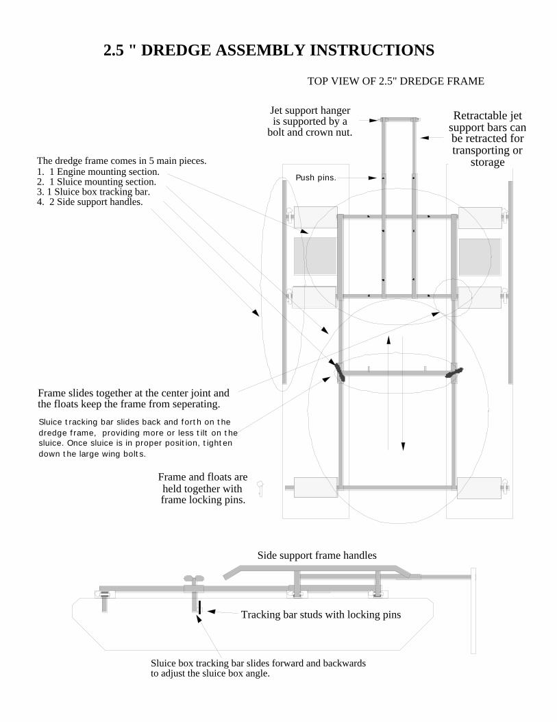
2.5 " DREDGE ASSEMBLY INSTRUCTIONS
TOP VIEW OF 2.5" DREDGE FRAME
The dredge frame comes in 5 main pieces.1. 1 Engine mounting section.2. 1 Sluice mounting section.3. 1 Sluice box tracking bar. 4. 2 Side support handles.
Sluice box tracking bar slides forward and backwards to adjust the sluice box angle.
Tracking bar studs with locking pins
Frame and floats areheld together withframe locking pins.
Side support frame handles
Jet support hangeris supported by a
bolt and crown nut.
Retractable jetsupport bars canbe retracted fortransporting or
storage
Frame slides together at the center joint and the floats keep the frame from seperating.
Sluice tracking bar slides back and forth on the dredge frame, providing more or less tilt on the sluice. Once sluice is in proper position, tighten down the large wing bolts.
Push pins.
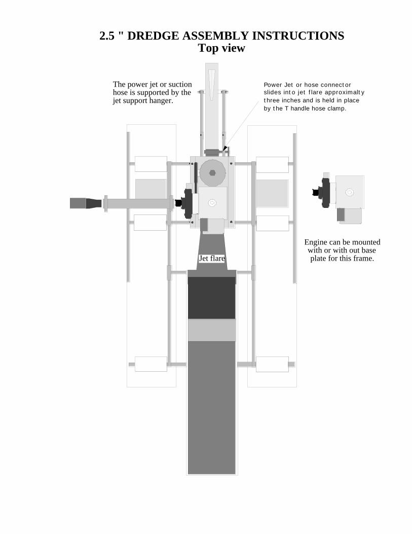
Jet flare
Engine can be mountedwith or with out baseplate for this frame.
The power jet or suctionhose is supported by thejet support hanger.
2.5 " DREDGE ASSEMBLY INSTRUCTIONSTop view
Power Jet or hose connector slides into jet flare approximaltythree inches and is held in placeby the T handle hose clamp.
2.5" suction nozzle uses long17' pressure hose.
2.5" suction tip
2.5" power jet
2.5" hose connector
Power Jet uses short 4' pressure hose
Sluice portion offrame is lower
Engine portion of the frame is higher
1 1/4" to 1 1/2" adaptor
1 1/4" to 1 1/2" adaptor
2.5" Dredge Side View
Power Jet Model
Suction Nozzle Model
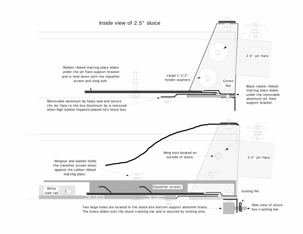
Inside view of 2.5" sluice
2.5" jet flare
Removable aluminum lip helps seal and secure the Jet flare to the box.Aluminum lip is removed when high banker hopperis placed into sluice box.
Black rubber ribbed matting plate slides under the removable aluminum jet flare support bracket.
Rubber ribbed matting plate slides under the jet flare support bracketand is held down with the classifier
screen and wing bolt.
2.5" jet flare
Riffleside rail
Classifier screen
Blue ribbed carpet Blue ribbed carpet
CrownNut
Large 1 1/2"fender washers
Wing nuts located onoutside of sluice.
Wingnut and washer holdsthe classifier screen downagainst the rubber ribbed
matting plate.
Two large holes are located in the sluice box bottom support aluminim brace. The brace slides over the sluice tracking bar and is secured by locking pins.
locking Pin
Side view of sluice box tracking bar.
End of Sluice BoxSlides
Under Metal Tabs.
Small aluminumadaptor plate bolts
onto the outsideof the sluice box.
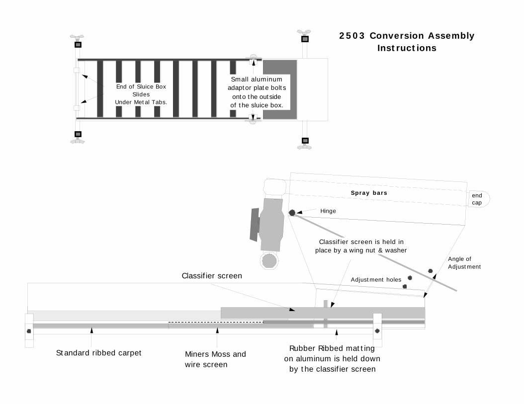
2503 Conversion AssemblyInstructions
Spray bars end cap
Angle of Adjustment
Adjustment holes
Hinge
Rubber Ribbed mattingon aluminum is held down
by the classifier screen
Standard ribbed carpet Miners Moss and wire screen
Classifier screen
Classifier screen is held inplace by a wing nut & washer
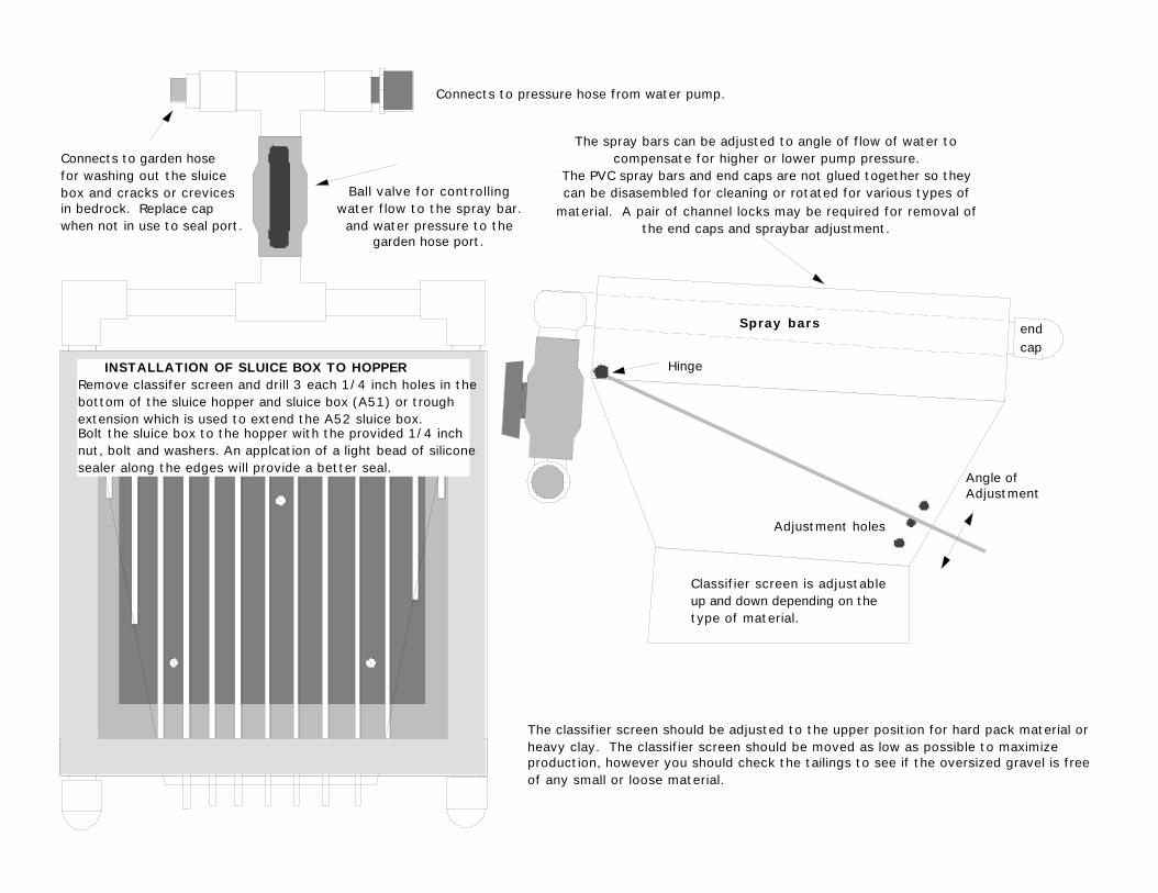
The classifier screen should be adjusted to the upper position for hard pack material or heavy clay. The classifier screen should be moved as low as possible to maximize production, however you should check the tailings to see if the oversized gravel is free of any small or loose material.
Classifier screen is adjustable up and down depending on the type of material.
The spray bars can be adjusted to angle of flow of water tocompensate for higher or lower pump pressure.
The PVC spray bars and end caps are not glued together so theycan be disasembled for cleaning or rotated for various types of
material. A pair of channel locks may be required for removal ofthe end caps and spraybar adjustment.
Spray bars end cap
INSTALLATION OF SLUICE BOX TO HOPPERRemove classifer screen and drill 3 each 1/4 inch holes in the bottom of the sluice hopper and sluice box (A51) or trough extension which is used to extend the A52 sluice box. Bolt the sluice box to the hopper with the provided 1/4 inch nut, bolt and washers. An applcation of a light bead of silicone sealer along the edges will provide a better seal.
Connects to pressure hose from water pump.
Connects to garden hose for washing out the sluicebox and cracks or crevices in bedrock. Replace cap when not in use to seal port.
Ball valve for controllingwater flow to the spray bar.
and water pressure to thegarden hose port.
Angle of Adjustment
Adjustment holes
Hinge
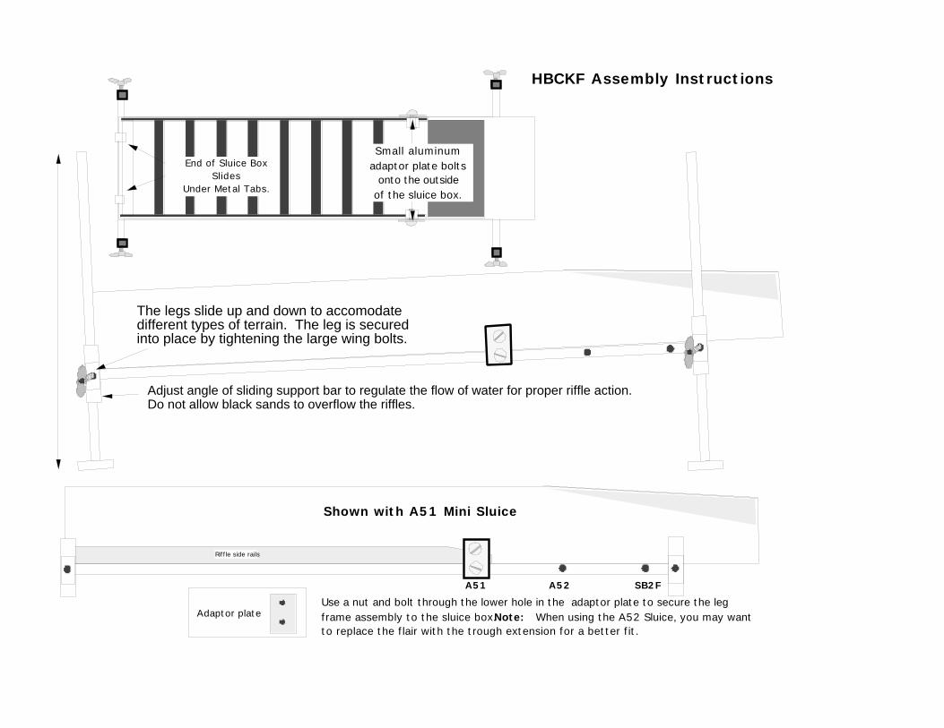
Use a nut and bolt through the lower hole in the adaptor plate to secure the leg frame assembly to the sluice box.Note: When using the A52 Sluice, you may want to replace the flair with the trough extension for a better fit.
A51 A52 SB2F
Shown with A51 Mini Sluice
Adaptor plate
Riffle side rails
The legs slide up and down to accomodate different types of terrain. The leg is secured into place by tightening the large wing bolts.
End of Sluice BoxSlides
Under Metal Tabs.
Small aluminumadaptor plate bolts
onto the outsideof the sluice box.
HBCKF Assembly Instructions
Adjust angle of sliding support bar to regulate the flow of water for proper riffle action.Do not allow black sands to overflow the riffles.
GENERAL OPERATING INSTRUCTIONS
THE FOLLOWING INFORMATION SHOULD ENABLE YOU TO UNDERSTAND THE BASIC THEORY OF OPERATION OF A PORTABLE DREDGE.
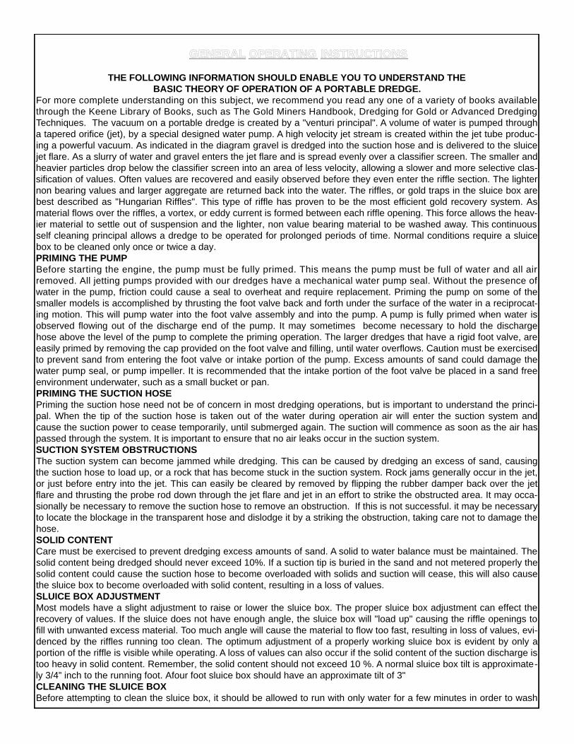
For more complete understanding on this subject, we recommend you read any one of a variety of books availablethrough the Keene Library of Books, such as The Gold Miners Handbook, Dredging for Gold or Advanced DredgingTechniques. The vacuum on a portable dredge is created by a "venturi principal". A volume of water is pumped througha tapered orifice (jet), by a special designed water pump. A high velocity jet stream is created within the jet tube produc-ing a powerful vacuum. As indicated in the diagram gravel is dredged into the suction hose and is delivered to the sluicejet flare. As a slurry of water and gravel enters the jet flare and is spread evenly over a classifier screen. The smaller andheavier particles drop below the classifier screen into an area of less velocity, allowing a slower and more selective clas-sification of values. Often values are recovered and easily observed before they even enter the riffle section. The lighternon bearing values and larger aggregate are returned back into the water. The riffles, or gold traps in the sluice box arebest described as "Hungarian Riffles". This type of riffle has proven to be the most efficient gold recovery system. Asmaterial flows over the riffles, a vortex, or eddy current is formed between each riffle opening. This force allows the heav-ier material to settle out of suspension and the lighter, non value bearing material to be washed away. This continuousself cleaning principal allows a dredge to be operated for prolonged periods of time. Normal conditions require a sluicebox to be cleaned only once or twice a day. PRIMING THE PUMPBefore starting the engine, the pump must be fully primed. This means the pump must be full of water and all airremoved. All jetting pumps provided with our dredges have a mechanical water pump seal. Without the presence ofwater in the pump, friction could cause a seal to overheat and require replacement. Priming the pump on some of thesmaller models is accomplished by thrusting the foot valve back and forth under the surface of the water in a reciprocat-ing motion. This will pump water into the foot valve assembly and into the pump. A pump is fully primed when water isobserved flowing out of the discharge end of the pump. It may sometimes become necessary to hold the dischargehose above the level of the pump to complete the priming operation. The larger dredges that have a rigid foot valve, areeasily primed by removing the cap provided on the foot valve and filling, until water overflows. Caution must be exercisedto prevent sand from entering the foot valve or intake portion of the pump. Excess amounts of sand could damage thewater pump seal, or pump impeller. It is recommended that the intake portion of the foot valve be placed in a sand freeenvironment underwater, such as a small bucket or pan. PRIMING THE SUCTION HOSEPriming the suction hose need not be of concern in most dredging operations, but is important to understand the princi-pal. When the tip of the suction hose is taken out of the water during operation air will enter the suction system andcause the suction power to cease temporarily, until submerged again. The suction will commence as soon as the air haspassed through the system. It is important to ensure that no air leaks occur in the suction system. SUCTION SYSTEM OBSTRUCTIONSThe suction system can become jammed while dredging. This can be caused by dredging an excess of sand, causingthe suction hose to load up, or a rock that has become stuck in the suction system. Rock jams generally occur in the jet,or just before entry into the jet. This can easily be cleared by removed by flipping the rubber damper back over the jetflare and thrusting the probe rod down through the jet flare and jet in an effort to strike the obstructed area. It may occa-sionally be necessary to remove the suction hose to remove an obstruction. If this is not successful. it may be necessaryto locate the blockage in the transparent hose and dislodge it by a striking the obstruction, taking care not to damage thehose. SOLID CONTENTCare must be exercised to prevent dredging excess amounts of sand. A solid to water balance must be maintained. Thesolid content being dredged should never exceed 10%. If a suction tip is buried in the sand and not metered properly thesolid content could cause the suction hose to become overloaded with solids and suction will cease, this will also causethe sluice box to become overloaded with solid content, resulting in a loss of values.SLUICE BOX ADJUSTMENTMost models have a slight adjustment to raise or lower the sluice box. The proper sluice box adjustment can effect therecovery of values. If the sluice does not have enough angle, the sluice box will "load up" causing the riffle openings tofill with unwanted excess material. Too much angle will cause the material to flow too fast, resulting in loss of values, evi-denced by the riffles running too clean. The optimum adjustment of a properly working sluice box is evident by only aportion of the riffle is visible while operating. A loss of values can also occur if the solid content of the suction discharge istoo heavy in solid content. Remember, the solid content should not exceed 10 %. A normal sluice box tilt is approximate-ly 3/4” inch to the running foot. Afour foot sluice box should have an approximate tilt of 3" CLEANING THE SLUICE BOXBefore attempting to clean the sluice box, it should be allowed to run with only water for a few minutes in order to wash
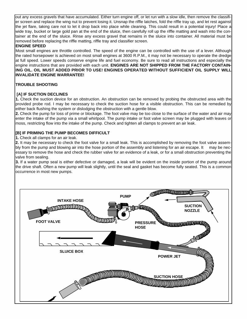
out any excess gravels that have accumulated. Either turn engine off, or let run with a slow idle, then remove the classifi-er screen and replace the wing nut to prevent losing it. Unsnap the riffle latches, fold the riffle tray up, and let rest againstthe jet flare, taking care not to let it drop back into place while cleaning. This could result in a potential injury! Place awide tray, bucket or large gold pan at the end of the sluice, then carefully roll up the riffle matting and wash into the con-tainer at the end of the sluice. Rinse any excess gravel that remains in the sluice into container. All material must beremoved before replacing the riffle matting, riffle tray and classifier screen. ENGINE SPEEDMost small engines are throttle controlled. The speed of the engine can be controlled with the use of a lever. Althoughthe rated horsepower is achieved on most small engines at 3600 R.P.M., it may not be necessary to operate the dredgeat full speed. Lower speeds conserve engine life and fuel economy. Be sure to read all instructions and especially theengine instructions that are provided with each unit. ENGINES ARE NOT SHIPPED FROM THE FACTORY CONTAIN-ING OIL. OIL MUST ADDED PRIOR TO USE! ENGINES OPERATED WITHOUT SUFFICIENT OIL S U P P LY W I L LINVALIDATE ENGINE WARRANTEE!
TROUBLE SHOOTING
[A] IF SUCTION DECLINES 1. Check the suction device for an obstruction. An obstruction can be removed by probing the obstructed area with theprovided probe rod. I may be necessary to check the suction hose for a visible obstruction. This can be remedied byeither back flushing the system or dislodging the obstruction with a gentle blow. 2. Check the pump for loss of prime or blockage. The foot valve may be too close to the surface of the water and air mayenter the intake of the pump via a small whirlpool. The pump intake or foot valve screen may be plugged with leaves ormoss, restricting flow into the intake of the pump. Check and tighten all clamps to prevent an air leak.
[B] IF PRIMING THE PUMP BECOMES DIFFICULT1. Check all clamps for an air leak. 2. It may be necessary to check the foot valve for a small leak. This is accomplished by removing the foot valve assem-bly from the pump and blowing air into the hose portion of the assembly and listening for an air escape. It may be nec-essary to remove the hose and check the rubber valve for an evidence of a leak, or for a small obstruction preventing thevalve from sealing. 3. If a water pump seal is either defective or damaged, a leak will be evident on the inside portion of the pump aroundthe drive shaft. Often a new pump will leak slightly, until the seal and gasket has become fully seated. This is a commonoccurrence in most new pumps.
PUMP
SUCTIONNOZZLE
SUCTION HOSE
POWER JET
RIFFLES
SLUICE BOX
FOOT VALVE
INTAKE HOSE
PRESSUREHOSE
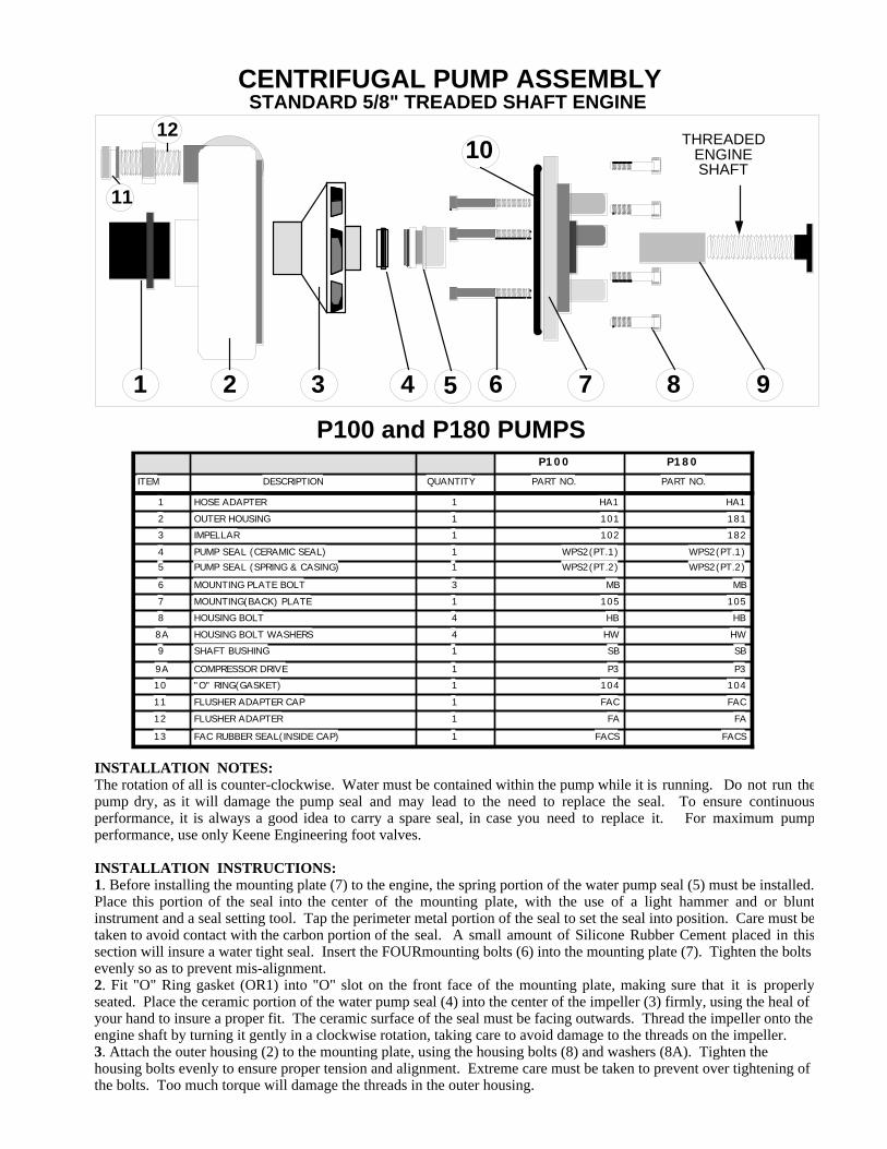
INSTALLATION NOTES:The rotation of all is counter-clockwise. Water must be contained within the pump while it is running. Do not run thepump dry, as it will damage the pump seal and may lead to the need to replace the seal. To ensure continuousperformance, it is always a good idea to carry a spare seal, in case you need to replace it. For maximum pumpperformance, use only Keene Engineering foot valves.
INSTALLATION INSTRUCTIONS:1. Before installing the mounting plate (7) to the engine, the spring portion of the water pump seal (5) must be installed.Place this portion of the seal into the center of the mounting plate, with the use of a light hammer and or bluntinstrument and a seal setting tool. Tap the perimeter metal portion of the seal to set the seal into position. Care must betaken to avoid contact with the carbon portion of the seal. A small amount of Silicone Rubber Cement placed in thissection will insure a water tight seal. Insert the FOURmounting bolts (6) into the mounting plate (7). Tighten the boltsevenly so as to prevent mis-alignment. 2. Fit "O" Ring gasket (OR1) into "O" slot on the front face of the mounting plate, making sure that it is properlyseated. Place the ceramic portion of the water pump seal (4) into the center of the impeller (3) firmly, using the heal ofyour hand to insure a proper fit. The ceramic surface of the seal must be facing outwards. Thread the impeller onto theengine shaft by turning it gently in a clockwise rotation, taking care to avoid damage to the threads on the impeller.3. Attach the outer housing (2) to the mounting plate, using the housing bolts (8) and washers (8A). Tighten thehousing bolts evenly to ensure proper tension and alignment. Extreme care must be taken to prevent over tightening ofthe bolts. Too much torque will damage the threads in the outer housing.
CENTRIFUGAL PUMP ASSEMBLYSTANDARD 5/8" TREADED SHAFT ENGINE
P100 P180
ITEM DESCRIPTION QUANTITY PART NO. PART NO.
1 HOSE ADAPTER 1 HA1 HA1
2 OUTER HOUSING 1 101 181
3 IMPELLAR 1 102 182
4 PUMP SEAL (CERAMIC SEAL) 1 WPS2(PT.1) WPS2(PT.1)
5 PUMP SEAL (SPRING & CASING) 1 WPS2(PT.2) WPS2(PT.2)
6 MOUNTING PLATE BOLT 3 MB MB
7 MOUNTING(BACK) PLATE 1 105 105
8 HOUSING BOLT 4 HB HB
8A HOUSING BOLT WASHERS 4 HW HW
9 SHAFT BUSHING 1 SB SB
9A COMPRESSOR DRIVE 1 P3 P3
10 "O" RING(GASKET) 1 104 104
11 FLUSHER ADAPTER CAP 1 FAC FAC
12 FLUSHER ADAPTER 1 FA FA
13 FAC RUBBER SEAL(INSIDE CAP) 1 FACS FACS
P100 and P180 PUMPS
1 2 3 4 6 8 97
1012 THREADED
ENGINESHAFT
5
11
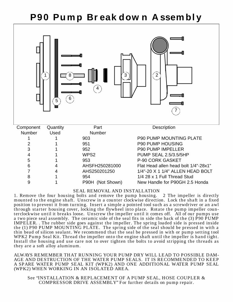
P90 Pump Breakdown Assembly
Component Quantity Part Description Number Used Number
1 1 903 P90 PUMP MOUNTING PLATE2 1 951 P90 PUMP HOUSING3 1 952 P90 PUMP IMPELLER4 1 WPS2 PUMP SEAL 2.5/3.5/5HP5 1 953 P-90 CORK GASKET6 4 AHSFH250281000 Flat Head allen head bolt 1/4"-28x1"7 4 AHS250201250 1/4"-20 X 1 1/4" ALLEN HEAD BOLT8 1 954 1/4 28 x 1 Full Thread Stud9 1 P90H (Not Shown) New Handle for P90GH 2.5 Honda
1 23
4
65
7
8
SEAL REMOVAL AND INSTALLATION1. Remove the four housing bolts and remove the pump housing. 2 The impeller is directlymounted to the engine shaft. Unscrew in a counter clockwise direction. Lock the shaft in a fixedposition to prevent it from turning. Insert a simple a pointed tool such as a screwdriver or an awlthrough starter housing cover, locking the flywheel into place. Rotate the pump impeller coun-terclockwise until it breaks loose. Unscrew the impeller until it comes off. All of our pumps usea two piece seal assembly. The ceramic side of the seal fits in side the back of the (3) P90 PUMPIMPELER. . The rubber side goes against the impeller. The spring loaded side is pressed insidethe (1) P90 PUMP MOUNTING PLATE. The spring side of the seal should be pressed in with athin bead of silicon sealant. We recommend that the seal be pressed in with or pump setting toolWPK2 Pump Seal Kit. Thread the impeller onto the engine shaft until the impeller is hand tight.Install the housing and use care not to over tighten the bolts to avoid stripping the threads asthey are a soft alloy aluminum.
ALWAYS REMEMBER THAT RUNNING YOUR PUMP DRY WILL LEAD TO POSSIBLE DAM-AGE AND DESTRUCTION OF THE WATER PUMP SEALS. IT IS RECOMMENDED TO KEEPA SPARE WATER PUMP SEAL KIT (WPK2) AND ONE ADDITIONAL WATER PUMP SEAL(WPK2) WHEN WORKING IN AN ISOLATED AREA.
See “INSTALLATION & REPLACEMENT OF A PUMP SEAL, HOSE COUPLER & COMPRESSOR DRIVE ASSEMBLY” For further details on pump repair.
KEENE ENGINEERINGKEENE ENGINEERING20201 Bahama Street Chatsworth California 91311
Tel. (818)-993-0411 Fax. (818)-993-0447E-mail: [email protected]
Web site www.keeneengineering.com
INSTALLATION & REPLACEMENT OF A PUMP SEAL, MARLEX PUMPCOUPLER & A COMPRESSOR DRIVE ASSEMBLY
The water pump seal must be replaced if water is observed leaking between the engine and pumpadapter or around the engine shaft,. To replace a seal or to install a compressor drive assembly (engineshaft pulley and drive belt), the pump must first be removed from the engine.
INSTRUCTIONS TO REMOVE THE PUMP FROM THE ENGINE:Note: If the pump has been in use for a year or more, we suggest that you apply a penetrant such as"WD-40" to the engine shaft threads and allow it to penetrate the threads of the engine shaft. Saturate for24 hours before attempting to remove the impeller from the engine shaft!1. Remove the four housing bolts and remove the pump housing. If the housing does not pull off easily,gently pry it off with a screwdriver. Inspect the housing gasket and replace if necessary.2. The impeller is directly mounted to the engine shaft and will unscrew in a counter clockwise direction.Before attempting to remove the impeller the engine shaft must be locked in a fixed position to preventit from turning. A simple way of locking the shaft is to insert a pointed tool such as a screwdriver or an awlthrough one of the many holes in the starter assembly and turning the engine over until the tool is firmlylocked in place by the starter housing cover.IMPORTANT: Always disconnect the spark plug wire before attempting any repairs or service on yourpump or engine. Once the engine shaft is locked into position, there are two methods that can be usedto remove the impeller.Method #1. Use a block of wood, such as a 2x4 and place one corner of it into one of the impeller vaneson the left side of the impeller and strike the block of wood sharply with a hammer. This should loosenthe impeller and enable it to be unscrewed in a counter clock-wise direction.Method #2. If the above is not successful, use a thin breaker bar or a heavy duty screw driver. Insert theblade into one of the impeller vanes towards the left side and try to unscrew the impeller by applying adownward pressure. If this still does not work carefully strike the end of the bar with a hammer until theimpeller loosens from the shaft. If this still does not work, strike gently with a hammer. This method maycause a chip in the vane of the impeller. Depending on the size break of the corner of the impeller, it mayor may not have adverse effects on the performance of the pump. So be careful!
SEAL REMOVAL AND INSTALLATION:1. All of our pumps use a two piece seal assembly, with the exception of some older models (P-50and P-60). One half of the seal located in the backside of the impeller is called the "seat", or ceramicportion. The other side of the seal is shrouded in a brass encasement, encasing a hardened material thatrests against the ceramic portion of the seal. Always replace both sides of the seal. Remove the ceramicportion with a sharp object similar to a screwdriver and press the new seat into place by hand. Alwaysinspect the seal to note that it is not cracked. Always place the smooth surface of the seal to the outside.
2. Remove the pump adapter from the engine and press the brass portion of the seal towards theoutside from the back of the adapter. If it cannot be pressed out easily, place a screwdriver handle onthe seal and gently tap it out. When replacing, it is suggested that a small amount of silicone sealant beplaced on the brass portion that fits into the adapter to ensure that it will not leak. Be careful not to get anysealant on the face of the seal. Position the seal in the center of the hole and press gently by hand intothe cavity as far as possible. Use a screwdriver or a blunt instrument and tap the seal gently around theedge of the seal in a circular motion until the seal is firmly fitted into place. Wipe off seal facing with a cleancloth before reassembling.3. After both sides of the seals is installed, replace the pump adapter onto the engine and carefullytighten. Thread the impeller onto the engine shaft until the impeller is hand tight. Install the housing anduse care not to over tighten the bolts to avoid stripping the threads as they are a soft alloy aluminum.
HOW TO INSTALL THE HOSE ADAPTOR PUMP INTAKE COUPLER: (For all models except theP-50 and P-300 Series).The tolerance of the Hose Adapter is critical for proper pump performance. The hose Adapter shouldbe installed as close as possible to the intake portion of the impeller. Center the adapter into the housingopening and press in by hand to locate it into place and place a wooden block against the outside of theadapter and gently tap until the adapter is firmly seated against the face of the impeller. Pull the starterrope until the engine turns. When the coupler is properly seated, the engine should be somewhatdifficult to turn over, making sure that the adapter is against the face of the impeller.
COMPRESSOR DRIVE INSTALLATION:To install the shaft pulley and belt for a compressor adaptation, the pump must be completely removedfrom the engine. For larger engines to include the 8 HP through 18 HP engines, slide the pulley to theback of the engine shaft and tighten the set screw. To install the engine pulley on smaller engines toinclude the 3HP to 5HP Engines, the furnished bushing should be pressed onto the pulley at the factoryto ensure proper alignment and spacing. If you choose to install it yourself, this can be accomplished byplacing the pulley on a flat surface, center the bushing in the hole of the pulley and gently drive it throughby tapping it with a hammer taking care not to damage the bushing. The bushing should be pressed ordriven through the pulley, in a flush position to the other side of the pulley. It should not extend thoughthe other side. Then install the V Belt before placing the pulley and bushing over the engine shaft. Afterthe pump is installed and secured, mount the compressor and compressor pulley. Install the V Belt tocompressor and make sure that the alignment is correct. You can compensate for some misalignment byadjusting the compressor pulley on the compressor shaft. Tighten firmly the set screw and all bolt andcheck for any misalignment before starting.

Diver Contact List A&E Diving Chris Sheldon PO Box 417 Manchester Ctr VT 05255 (802) 362-7234 home (802) 558-2985 cell [email protected] AB Aquatics Inc. Charlie Leocha 86 Maple Street Henniker, NH 03242 603) 475-1503 [email protected] Aqualogic Inc. John Jude 120 Hoyt Road Gilford, NH 03249 (603) 410-7413 [email protected] www.aqlogic.co Aquatic Concerns Shane Wheeler J 165 Sunrise Drive Fairlee VT 05045 (802) 461-3606 [email protected] Shawn L. Bickford PO Box 655 Derby VT 05829 802) 673-6128 [email protected] Aquatic Invasive Management, LLC Andrew Lewis 52 Burt Lane Au Sable Forks, NY 12912 (240)818-1070 Andrew (518)637-8350 Tommy [email protected]

David Burrows 12 Cottage Street Ashland, NH 03217 (603)707-6787 cell [email protected] Invasive Aquatics Kurt Aschenbach (802) 498-4183 cell [email protected] Bad email address Morin's Dive Centers Rich Morin 20 Warren Street Glens Falls NY 12801 (518)761-0533 No email address H2O Contractors Rusty Belevance 802-279-3504 802-472-6440 Home No email address Rob Patton (Shadow Lake) [email protected] Lighthouse Marine Casey Morey 802-558-5453 [email protected] Recommended by Dave Hathaway from M & K

Lake Elmore
Aquatic Plant Inventory
October 31, 2017
Lake Elmore Aquatic Plant Inventory
1
1. Introduction
Lake Elmore is a low-alkalinity, mesotrophic lake in the town of Elmore, Vermont. It sits at the
base of Elmore Mountain and is surrounded by private homes and cottages. Elmore State Park is
located on the northern end of the Lake and there is a Vermont fish and Wildlife public boat
access at the southern end of the Lake. Both private residents and visitors recreate on the Lake
throughout the year by fishing, boating, kayaking, and bird-watching. For many years, the Lake
Elmore Association has undertaken efforts to control Eurasian water-milfoil (EWM) in the Lake.
As part of the EWM control permitting process, periodic aquatic plant inventories are required.
In 2017, Arrowwood Environmental was retained by the Lake Elmore Association to conduct an
aquatic plant inventory of Lake Elmore. The purpose of the inventory was twofold: First, to
document and map the current status of Eurasian water-milfoil in the Lake and secondly, to
conduct an inventory for rare, threatened and endangered aquatic plant species in the Lake. This
report outlines the methodology and results of those inventories and presents management
recommendations based on those results.
2. Methods
The study area for the inventory consisted of the open water of Lake Elmore and based on the
boundaries of the Lake from the Vermont Hydrography Dataset. The inlet at the south end of the
Lake includes Elmore Brook and the extensive wetlands associated with the inlet. Only aquatic
species and emergent species that typically occur within aquatic plant communities were
included in this inventory. The Cattail Marshes and Deep Broadleaf Marshes in the Elmore
Brook wetlands, for example, were not inventoried as part of this study. Three days of field
work were conducted from September 11-26, 2017 by Michael Lew-Smith. Two different
survey methodologies were employed to document and map the aquatic species in the Lake, the
Grid-Point Survey and Transect Sampling. Each of these techniques is outlined below.
Lake Elmore Aquatic Plant Inventory
2
a. Grid-Point Survey
The purpose of the grid-point survey is to ensure
that all areas of the Lake receive a standardized
vegetation sample and to aid in the development
of vegetation community boundaries. A series of
points 200m apart were established over the study
area in an auto-generated grid pattern. To ensure
full representative coverage, the position of some
points established by the grid were adjusted. For
example, points that were established directly on
the shoreline or just into the upland were moved
into the open water of the Lake. This resulted in a
total of 26 sampling points established over the
study area. The study area and grid points are
shown in Figure 1.
The study area and the location of each point were
uploaded to a Trimble Juno 3B GPS unit, which
was used to navigate to each point on the Lake
using a motor boat. An aquatic survey rake was
used to take three vegetation samples at each
point location. In waters shallower than 12’, a
rake on a pole was used to sample vegetation. In
waters deeper than 12’, a survey rake attached to a
rope was used to sample vegetation. Rake
fullness was recorded for each sample to obtain information about vegetation density (Hauxwell
et al., 2010). In addition, each aquatic plant on the rake was identified to species (when
Figure 1. Study area and Grid Points
Lake Elmore Aquatic Plant Inventory
3
possible). Additional data collected at each point included water depth, substrate, and percent
cover of vegetation, when visible. A view-scope was used to view the vegetation when
necessary. Presence and abundance of aquatic invasive species (AIS) was also documented at
each point. All data was recorded using a digital data form on the GPS unit. Notes on
vegetation and AIS were also taken incidentally in between sampling points when appropriate.
b. Transect Sampling
Transect sampling was established during the field inventory in order to provide a more informal
sampling approach and to document species and trends that the grid-point survey may have
missed. This methodology is based on the Vermont Water Quality Division Field Methods
Manual (2006). Transects were conducted in one of three ways. First, by visible inspection of
the vegetation from the motor boat or from a kayak. Secondly, some transects were conducted
by snorkeling. This method is slower than the boat-based transects, but more in-depth data is
obtained and it enables the collection of plant specimens when necessary. Finally, some
transects were conducted using SCUBA gear in order to obtain data from the deeper areas and
allow for more time below the surface.
A continuous transect was conducted along the entire shoreline of the lake as well as across the
shallower northern and southern ends of the Lake. Notes on AIS and native vegetation presence
and abundance were taken along the transects. Narrative data not entered into the digital data
forms was recorded in a field notebook.
Once field work was completed, the data was analyzed on an ArcGIS platform. Data from the
grid-point survey and transects were used to create an aquatic natural community map and a map
of Eurasian water-milfoil (EWM).
Lake Elmore Aquatic Plant Inventory
4
3. Results
The results of the inventory are presented below.
Section 3a outlines the results relating to native
aquatic vegetation. Section 3b outlines the
findings related to Eurasian water-milfoil and
Section 3c includes species lists and a discussion
of rare species.
a. Native Aquatic Vegetation
Communities
A natural community is an interacting
assemblage of organisms, their physical
environment, and the natural processes that
affect them (Thompson and Sorenson, 2010).
Most studies done by scientists on vegetation
natural communities has been done in terrestrial
systems. Much work still needs to be done on
classifying groups of aquatic plants into natural
communities. There are a few groups, such as
the Water Lily Aquatic Community, that appear
to be well-understood, common components of
aquatic systems throughout the region. Other
groupings of plants are referred to as
“assemblages” because more studies need to be
done to determine if they are established
groupings that warrant the “natural community” designation.
Figure 2. Aquatic Natural Communities of
Lake Elmore
Lake Elmore Aquatic Plant Inventory
5
The native aquatic vegetation in Lake Elmore has been categorized into three different groups,
the Robbin’s Pondweed Assemblage, the Arrowhead-Mud Rush Assemblage and the Water Lily
Aquatic Community. Each of these is described below.
Robbin’s Pondweed Assemblage
As the name indicates, the Robbin’s Pondweed Assemblage is overwhelmingly dominated by
one species: Robbin’s pondweed. This species is known for forming dense, nearly monotypic
low-growing stands in lakes and ponds. The most common associate in Lake Elmore is the
broad-leaved pondweed. In contrast to the
low-growing form of Robbin’s pondweed,
this species can grow up to 9fttall and often
towers above the dense mat of Robbin’s
pondweed below. Other species present at
low abundance include water-weed (Elodea
canadensis), eel-grass (Vallisneria
americana), stonewort (Nitella spp.) and
clasping-leaved pondweed (Potamogeton
perfoliatus). Both water-weed and
stonewort can form small, dense colonies,
but these are typically occupy less than 100sq feet in area and are not widespread.
As can be seen from Figure 1, the Robbin’s PondweedAssemblage is the most common and
abundant plant assemblage in Lake Elmore. It occupies fairly shallow areas from 2-3 feet deep
as well as deeper sites up to 12 feet deep. On the deeper end, towards the middle of the Lake, the
vegetation in this community becomes sparser and grades into a silty un-vegetated lake
bottom.This mapped assemblage also includes un-vegetated patches in shallower water. These
include un-vegetated patches in areas of moderate depth (6 feet) as well as shallow areas along
the shoreline (1-2 feet deep). The swimming area at the north end of the Lake is one of the
largest, shallow un-vegetated areas included in this mapped assemblage.
Figure 3. Dense mat of Robbin’s Pondweed
Lake Elmore Aquatic Plant Inventory
6
Arrowhead-Mud Rush Assemblage
The Arrowhead-Mud Rush Assemblage is characterized by low-growing aquatic species which
all have a rosette of short leaves. Dominant species include grass-leaved arrowhead (Sagittaria
graminea), mud-rush (Juncus pelocarpus), leafless water-milfoil (Myriophyllum tenellum), and
quillwort (Isoetes riparia). Many of these
species look similar and will not flower
except in conditions of very shallow water.
This is a sparsely vegetated community, with
total plant cover in the 25%-40% range and
the remaining area an un-vegetated silty-sand
lake substrate. Other species such as
snailseed pondweed (Potamogeton spirillus)
and white water-crowfoot (Ranunculus
aquatilis var. diffusus) are also common in
this assemblage. There are two mapped
occurrences of this assemblage in Lake
Elmore (Figure 1). Both occur in shallow areas in a silty-sand substrate. It is likely that ice
scour and wave action play an important role in the development of this assemblage.
Water Lily Aquatic Community
The Water Lily Aquatic Community is a common and widespread community throughout the
region. It occupies shallow, sheltered bays of many water bodies and is dominated by floating-
leaved aquatics. The largest occurrence on Lake Elmore is in the southern part of the Lake
where it is part of the wetland at the Lake inlet. At this location, both floating-leaved and
submersed aquatic vegetation is abundant and comprises nearly 100% cover. Narrow-leaved
bur-reed (Sparganium angustifolium) is the most common floating-leaved aquatic and is
Figure 4. The sparsely vegetated Arrowhead-
Mud Rush Assemblage

Lake Elmore Aquatic Plant Inventory
7
interspersed with moderate amount of water lily (Nymphaea odorata) and yellow pond lily
(Nuphar variegata). Other species with floating leaves such as floating pondweed (P. natans)
and Vasey’s pondweed (P. vaseyi) are also
present but at lower percentage cover. The
submersed aquatics are quite diverse and
include common bladderwort, ribbon-leaved
pondweed, water starwort, and stonewort.
As the community grades into a palustrine
wetland community, emergent species such
as pickerel weed, American bur-reed and
cattails become dominant.
In addition to the large occurrence of this
community in the southern part of the Lake,
there are smaller, scattered occurrences along the western shoreline (Figure 1). While these
areas are dominated by narrow-leaved bur-reed and water lily, they typically lack the abundant
submersed vegetation that is present in the southern Lake.
b. Aquatic Invasive Species
Eurasian water-milfoil (EWM) was the only non-native aquatic invasive species documented in
the Lake. The Lake-wide distribution and abundance of this species is shown in Figure 6 and
includes areas of Sparse, Moderate and Dense cover. Sparse cover consists of areas where EWM
is present at less than 5% cover. The Moderate cover class consist of areas where EWM cover
ranges from 5-50% and Dense includes areas where cover generally exceeds 50%. As can be
seen from this figure, EWM is present throughout vegetated areas of the Lake at Sparse cover.
This species is fairly well-established in the Lake and scattered individuals can be found
Figure 5. Water Lily Aquatic Community
Lake Elmore Aquatic Plant Inventory
8
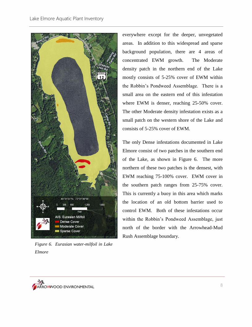
everywhere except for the deeper, unvegetated
areas. In addition to this widespread and sparse
background population, there are 4 areas of
concentrated EWM growth. The Moderate
density patch in the northern end of the Lake
mostly consists of 5-25% cover of EWM within
the Robbin’s Pondweed Assemblage. There is a
small area on the eastern end of this infestation
where EWM is denser, reaching 25-50% cover.
The other Moderate density infestation exists as a
small patch on the western shore of the Lake and
consists of 5-25% cover of EWM.
The only Dense infestations documented in Lake
Elmore consist of two patches in the southern end
of the Lake, as shown in Figure 6. The more
northern of these two patches is the densest, with
EWM reaching 75-100% cover. EWM cover in
the southern patch ranges from 25-75% cover.
This is currently a buoy in this area which marks
the location of an old bottom barrier used to
control EWM. Both of these infestations occur
within the Robbin’s Pondweed Assemblage, just
north of the border with the Arrowhead-Mud
Rush Assemblage boundary.
Figure 6. Eurasian water-milfoil in Lake
Elmore
Lake Elmore Aquatic Plant Inventory
9
c. Rare, Threatened and Endangered Species
One objective of this inventory was to document and map occurrences of uncommon, rare,
threatened or endangered species in the Lake. Appendix 1 includes a list of all plant species
documented during this inventory along with notes on distribution and abundance in the Lake.
Appendix 2 consists of this same list and includes scientific names, common names, plant family
and S-rank. The “S-Rank” is a state ranking of the rarity of uncommon and rare species. An S-
rank of S1 indicates that a species is “very rare” in the state. S2 indicates a “rare” species and S3
indicates an “uncommon” species in the state. The presence of one of these species could
potentially have an impact on the methods and implementation of control activities. A number
of S1-S3 species have been historically documented for Lake Elmore and are addressed below.
Vasey’s Pondweed (Potamogeton vaseyi)
This species is ranked as S2 “rare” in the state and was first documented in Lake Elmore in 1968.
Since that time, the population has been verified and monitored for a number of years. It has
previously been reported to be “common to abundant at the southern end of the lake” (Vermont
NHI EO-record 2063), though no actual count of plants present has been undertaken. The
current inventory documented this species in the Arrowhead-Mud Rush assemblage and in the
Water Lily Aquatic Community at the southern end of the Lake. This species is a submerged
aquatic, but can form small floating leaves in the early part of the summer. By the time of the
current inventory in September, the diagnostic floating leaves were no longer present. During
the current inventory this species was considered “frequent” but not abundant enough to be
considered common. It is unclear if this is an actual decline in the population or a mis-
interpretation of admittedly vague terms. Also, the fact that floating leaves were not present
during the current inventory (and the species therefore less visible) may have resulted in under-
reporting its abundance. Regardless of the terminology, this species appears to be stable at Lake
Elmore.
Lake Elmore Aquatic Plant Inventory
10
Blunt-leaved pondweed (Potamogeton obtusifolius)
Blunt-leaved pondweed is considered an “uncommon” (S3-ranked) species in the state. It was
documented in Lake Elmore in 1991 by the Vermont Lakes and Ponds Management and
Protection Program. This species was not documented during the current inventory.
Nutall’s waterweed (Elodea nutallii)
Nutall’s waterweed is considered an “uncommon” (S3-ranked) species in the state and is a close
relative of the common waterweed, which is common throughout Lake Elmore. It was
documented in Lake Elmore in 2003 by the Vermont Lakes and Ponds Management and
Protection Program. This species was not documented during the current inventory.
Blunt-leaved pondweed (Potamogeton strictifolius)
Blunt-leaved pondweed is a rare to uncommon species in the state (ranked S2S3). It was first
reported in the Lake in 1988. However, more recent surveys have not document this species
(Vermont NHI EO-record 1229). This species was not documented during the current inventory.
Bur-reeds (Sparganium spp.)
The bur-reeds are a genus of plants that occur with emergent leaves or, in some species, with
floating leaves. Three different species of the floating-leaved bur-reeds have been documented
in Lake Elmore in the past: least bur-reed (Sparganium natans), narrow-leaved bur-reed
(Sparganium angustifolium) and water bur-reed (Sparganium fluctuans) (Vermont NHI EO-
records 2872 and 5248). Least bur-reed is a rare-uncommon species (S2S3-ranked) which is also
a state listed Threatened species. Water bur-reed is an uncommon species (S3-ranked) and
narrow-leaved bur-reed is a common and widespread species. While there are some differences
in leaf-width between the species, in order to definitively distinguish these species, fruiting
specimens are required. To further complicate matters, these species are only rarely found in
flower or fruit. In all of the fruiting material examined during the current inventory, only
narrow-leaved bur-reed was documented. It is possible that previous identifications were made
based on vegetative material. It is also possible that identifications were made based on fruiting
Lake Elmore Aquatic Plant Inventory
11
material, but no specimens of either the least bur-reed or water bur-reed from Lake Elmore exist
and can be confirmed. Regardless of previous inventories, only the common species in this
group was documented during the current inventory.
White water-crowfoot (Ranunculus aqualitis var. diffusus)
White water-crowfoot is an aquatic plant in the buttercup family that is uncommon (S3-ranked)
in the state. A number of small but dense colonies of this species were documented in the
southern end of the Lake in the Arrowhead-Mud Rush Assemblage and the Water Lily Aquatic
community.
4. Management Recommendations
The following management recommendations are based on the distribution and abundance of
both EWM and the native plant communities and rare-uncommon species documented in the
Lake. As evidenced by the dense infestations in the southern part of the Lake, EWM has the
potential to become well established and choke out native aquatic vegetation. In these areas, it
appears that EWM is having a significant detrimental impact on native vegetation. Outside of
the Moderate and Dense infestations (Figure 6), however, EWM is present only at low cover and
does not appear to be posing a threat to native aquatic communities. Low levels of this species
in the Lake, therefore, may be tolerable. Complete eradication of this species from the Lake, in
addition to being extremely difficult, may not be necessary to protect native vegetation, rare-
uncommon species and recreational activities.
Control of EWM has been undertaken for many years in Lake Elmore. Continued control will be
necessary to ensure that dense infestations do not occupy an increasing area of the Lake. There
are many techniques that have been used for control of aquatic vegetation, including herbicides,
bottom barriers, manual harvesting and mechanical harvesting. Given the nature and extent of
the current infestation, herbicide use and mechanical harvesting are not the best options for
control in Lake Elmore. Herbicides are generally broad acting and have a significant detrimental
Lake Elmore Aquatic Plant Inventory
12
effect on native vegetation. Mechanical
harvesting works best on large and extensive
infestation. Since the areas of dense growth in
Lake Elmore are relatively small, these
techniques may not be cost-effective. In
addition, since rare and uncommon aquatic
plants have been found in the vicinity of the
EWM, methods that can have significant
impacts on these non-target species should be
avoided.
Both bottom barriers and manual harvesting
have been used in the past and continue to be
the best methods of control for Lake Elmore. Bottom barriers can be effective if small areas are
targeted for control and the barriers are properly installed and maintained. The dense
infestations in the southern part of the Lake are good candidates for this treatment. Like
herbicide use, the impacts on non-target organisms are unavoidable. However, since no rare or
uncommon species are currently documented directly in the EWM infestation bottom barrier
continues to be a viable option. Manual harvesting has the advantage of being a targeted control,
avoiding impacts on non-target species. In addition, it has the flexibility of addressing not just
the very dense infestations of EWM, but those with moderate cover as well.
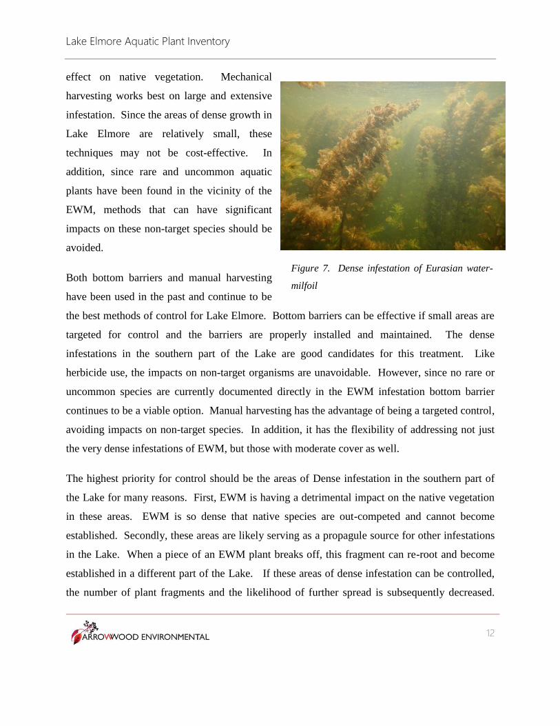
The highest priority for control should be the areas of Dense infestation in the southern part of
the Lake for many reasons. First, EWM is having a detrimental impact on the native vegetation
in these areas. EWM is so dense that native species are out-competed and cannot become
established. Secondly, these areas are likely serving as a propagule source for other infestations
in the Lake. When a piece of an EWM plant breaks off, this fragment can re-root and become
established in a different part of the Lake. If these areas of dense infestation can be controlled,
the number of plant fragments and the likelihood of further spread is subsequently decreased.
Figure 7. Dense infestation of Eurasian water-
milfoil
Lake Elmore Aquatic Plant Inventory
13
Thirdly, both of the rare-uncommon species documented in the Lake occur in the southern part
of the Lake near these infestations. This includes populations of Vaseyi’s pondweed and white
water-crowfoot. The spread of EWM into these areas would threaten these populations. Lastly,
because these infestations are dense, harvesting of EWM will be more efficient than harvesting
from the areas of sparse cover.
5. Conclusion
With a State Park on the northern end, a state boat launch on the southern end, and numerous
private homes along it shores, Lake Elmore receives a lot of use by humans. It has been well
documented that EWM, if left unchecked, can form dense mats, inhibit many recreational uses
and choke out native vegetation (Madsen et al. 1991). In the case of Lake Elmore, it is also
threatening two rare and uncommon plant species. While EWM is currently widespread in the
Lake, there are only a few areas where it has formed very dense infestations. While it may not
be realistic to completely eradicate this species from the Lake, it should be possible to halt its
spread and decrease the size of the dense infestations. Such control can ensure that recreational
use of the Lake can continue and the ecological integrity of the Lake ecosystem remains intact.
Lake Elmore Aquatic Plant Inventory
14
Literature Cited
Hauxwell, J., S. Knight, K. Wagner, A. Mikulyuk, M. Nault, M. Porzky and S. Chase. 2010.
Recommended baseline monitoring of aquatic plants in Wisconsin: sampling design, field
and laboratory procedures, data entry and analysis, and applications. Wisconsin
Department of Natural Resources Bureau of Science Services, PUB-SS-1068 2010.
Madison, Wisconsin, USA.
Madsen, J.D., J.W. Sutherland, J.A. Bloomfield, L.W. Eichler and C.W. Boylen. 1001. The
decline of native vegetation under dense Eurasian watermilfoil canopies. J. Aquatic Plant
Management, 29:94-99.
Thompson, E.H. and E.R. Sorenson. 2010. Wetland, Woodland and Wildland. A Guide to the
Natural Communities of Vermont. VT Department of Fish and Wildlife and The Nature
Conservancy of Vermont.
Vermont Natural Heritage Inventory (NHI) Element Occurrence Record 2063. Record of
Potamogeton vaseyi in Lake Elmore. Vermont Agency of Natural Resources.
Vermont Natural Heritage Inventory (NHI) Element Occurrence Record 2872. Record of
Sparganium natans in Lake Elmore. Vermont Agency of Natural Resources.
Vermont Natural Heritage Inventory (NHI) Element Occurrence Record 5248. Record of
Sparganium fluctuans in Lake Elmore. Vermont Agency of Natural Resources.
Vermont Natural Heritage Inventory (NHI) Element Occurrence Record 1229. Record of
Potagometon strictifolius in Lake Elmore. Vermont Agency of Natural Resources.
Vermont Lakes and Ponds Management and Protection Program. Complete species roster of
Lake Elmore. Accessed 9/29/2017.
Lake Elmore Aquatic Plant Inventory
15
Appendix 1.
Notes on distribution and abundance of each species documented in
Lake Elmore
Latin Name Notes
Callitriche sp. Common in southern Lake, especially in the Water Lily Community
Chara sp. Infrequent throughout Lake, most common in southern Lake
Eleocharis acicularis Infrequent in the Arrowhead-Mud Rush Assemblage
Elodea canadensis Common throughout the Lake
Eriocaulon aquaticum Frequent in the Arrowhead-Mud Rush Assemblage
Isoetes riparia Infrequent in the Arrowhead-Mud Rush Assemblage
Juncus pelocarpus Frequent in the Arrowhead-Mud Rush Assemblage
Myriophyllum spicatum Common throughout the Lake
Myriophyllum tenellum Frequent in the Arrowhead-Mud Rush Assemblage
Nitella sp. Common throughout the Lake
Nuphar variegata Frequent in the southern occurrence of the Water Lily Community
Nymphaea odorata Common throughout the Lake; most abundant in the southern Water Lily Community
Pontederia cordata Restricted to the southern occurrence of the Water Lily Community
Potamogeton amplifolius Second most common and abundant species in the Lake
Potamogeton epihydrus Common in southern Lake; sub-dominant in the Water Lily Community
Potamogeton gramineus Infrequent in the southern part of the Lake
Potamogeton natans Common in the southern part of the Lake
Potamogeton perfoliatus Common throughout the Lake
Potamogeton robbinsii Most common and abundant species in the Lake
Potamogeton spirillus Frequent in the Arrowhead-Mud Rush Assemblage
Potamogeton vaseyi Frequent in the southern part of the Lake
Ranunculus aquatilis var. diffusus Frequent in the Arrowhead-Mud Rush Assemblage and southern Water Lily Community
Sagittaria graminea Frequent in the Arrowhead-Mud Rush Assemblage
Sparganium angustifolium Common in all occurrence of the Water Lily Community
Utricularia macrorrhiza Common in the southern occurrence of the Water Lily Community
Vallisneria americana Common and widespread throughout the Lake
Lake Elmore Aquatic Plant Inventory
16
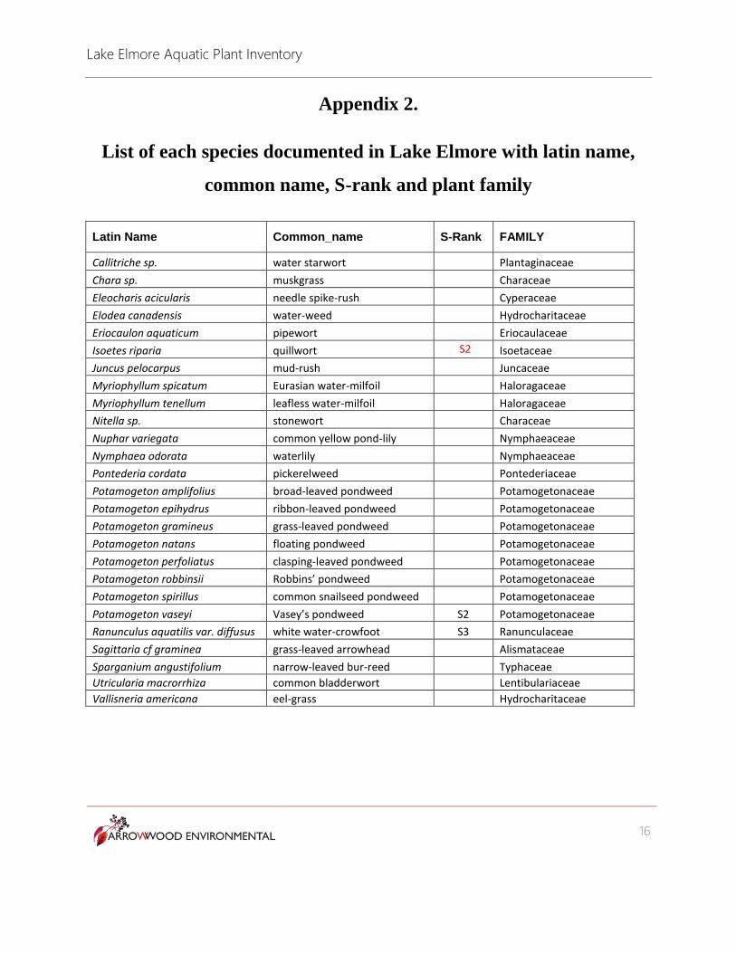
Appendix 2.
List of each species documented in Lake Elmore with latin name,
common name, S-rank and plant family
Latin Name Common_name S-Rank FAMILY
Callitriche sp. water starwort Plantaginaceae
Chara sp. muskgrass Characeae
Eleocharis acicularis needle spike-rush Cyperaceae
Elodea canadensis water-weed Hydrocharitaceae
Eriocaulon aquaticum pipewort Eriocaulaceae
Isoetes riparia quillwort Isoetaceae
Juncus pelocarpus mud-rush Juncaceae
Myriophyllum spicatum Eurasian water-milfoil Haloragaceae
Myriophyllum tenellum leafless water-milfoil Haloragaceae
Nitella sp. stonewort Characeae
Nuphar variegata common yellow pond-lily Nymphaeaceae
Nymphaea odorata waterlily Nymphaeaceae
Pontederia cordata pickerelweed Pontederiaceae
Potamogeton amplifolius broad-leaved pondweed Potamogetonaceae
Potamogeton epihydrus ribbon-leaved pondweed Potamogetonaceae
Potamogeton gramineus grass-leaved pondweed Potamogetonaceae
Potamogeton natans floating pondweed Potamogetonaceae
Potamogeton perfoliatus clasping-leaved pondweed Potamogetonaceae
Potamogeton robbinsii Robbins’ pondweed Potamogetonaceae
Potamogeton spirillus common snailseed pondweed Potamogetonaceae
Potamogeton vaseyi Vasey’s pondweed S2 Potamogetonaceae
Ranunculus aquatilis var. diffusus white water-crowfoot S3 Ranunculaceae
Sagittaria cf graminea grass-leaved arrowhead Alismataceae
Sparganium angustifolium narrow-leaved bur-reed Typhaceae
Utricularia macrorrhiza common bladderwort Lentibulariaceae
Vallisneria americana eel-grass Hydrocharitaceae
S2