environmental permit application - environment
TRANSCRIPT
70051165/LON5-8/001FEBRUARY 2020 PUBLIC
Virtus HoldCo Ltd
ENVIRONMENTAL PERMITAPPLICATIONStockley Park DCs LON5 to LON8
Virtus HoldCo Ltd
ENVIRONMENTAL PERMIT APPLICATIONStockley Park DCs LON5 to LON8
PUBLIC
TYPE OF DOCUMENT (VERSION) PUBLIC
PROJECT NO. 70051165
OUR REF. NO. 70051165/LON5-8/001
DATE: FEBRUARY 2020
WSP
110 Queen StreetGlasgowG1 3BX
Phone: +44 141 429 3555
Fax: +44 141 429 3666
WSP.com
ENVIRONMENTAL PERMIT APPLICATION PUBLIC | WSPProject No.: 70051165 | Our Ref No.: 70051165/Lon5-8/001 February 2020Virtus HoldCo Ltd
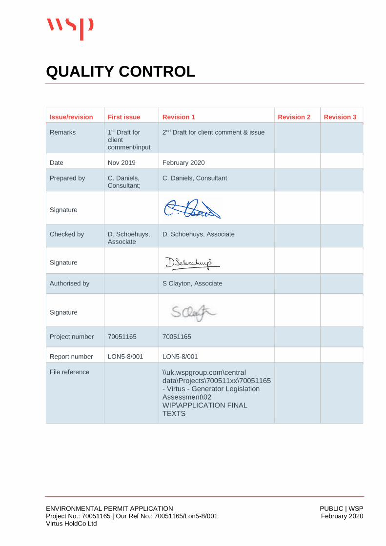
QUALITY CONTROL
Issue/revision First issue Revision 1 Revision 2 Revision 3
Remarks 1st Draft forclientcomment/input
2nd Draft for client comment & issue
Date Nov 2019 February 2020
Prepared by C. Daniels,Consultant;
C. Daniels, Consultant
Signature
Checked by D. Schoehuys,Associate
D. Schoehuys, Associate
Signature
Authorised by S Clayton, Associate
Signature
Project number 70051165 70051165
Report number LON5-8/001 LON5-8/001
File reference \\uk.wspgroup.com\centraldata\Projects\700511xx\70051165- Virtus - Generator LegislationAssessment\02WIP\APPLICATION FINALTEXTS
ENVIRONMENTAL PERMIT APPLICATION PUBLIC | WSPProject No.: 70051165 | Our Ref No.: 70051165/Lon5-8/001 February 2020Virtus HoldCo Ltd
CONTENTS
1 INTRODUCTION 1
2 FORM A SUPPORTING INFORMATION 3
3 FORM B2 SUPPORTING INFORMATION 4
3.1 PRE-APPLICATION DISCUSSIONS 4
3.2 ABOUT THE SITE 5
3.3 ABILITY AS AN OPERATOR 6
3.4 PLANS 6
3.5 SITE CONDITION REPORT 8
3.6 ENVIRONMENTAL RISK ASSESSMENT 8
4 FORM B3 SUPPORTING INFORMATION 9
4.1 LISTED ACTIVITIES 9
4.2 EMISSIONS TO AIR, WATER, LAND 10
5 OPERATING TECHNIQUES 16
5.1 GENERAL 16
5.2 STANDARDS 19
5.3 MANAGEMENT SYSTEMS 19
5.4 GRID RELIABILITY 27
5.5 ENGINE AND SET UP CHOICE 28
5.6 FUEL STORAGE AND DELIVERIES 31
TABLES
ENVIRONMENTAL PERMIT APPLICATION PUBLIC | WSPProject No.: 70051165 | Our Ref No.: 70051165/Lon5-8/001 February 2020Virtus HoldCo Ltd
Table 2-1 - Virtus HoldCo Directors 3
Table 4-1 – Types of Activities 9
Table 4-2 – Stockley Park Standby Generators 10
Table 4-3 – Standby Generator Emissions CAT 3516C 12
Table 4-4 – Operational Scenario Emissions 12
Table 5-1 – Routine Operational Scenario 16
Table 5-2 – Estimated Annual Fuel Consumption 17
Table 5-3 - Indicative BAT Requirements for Management Systems from GOV.UK Guidance23
Table 5-4 - BAT Summary for Data Centre Standby Generators 29
FIGURESFigure 5-1 – Standby Generation for Data Centres Schematic 18
APPENDICES
VIRTUS HOLDCO STRUCTURE
MAPS AND PLANS
AGENCY HABITATS REPORT
DRAINAGE PLANS
PLANNING STAGE AIR QUALITY HISTORY
GENERATOR ENGINE DATASHEET
ENVIRONMENTAL PERMIT APPLICATION PUBLIC | WSPProject No.: 70051165 | Our Ref No.: 70051165/Lon5-8/001 February 2020Virtus HoldCo Ltd Page 1 of 32
1 INTRODUCTION
WSP UK Ltd has been instructed by Virtus HoldCo Ltd, trading as Virtus Data Centres (theOperator, hereinafter called Virtus) to prepare an application for an Environmental Permit (EP) forthe site referred to as Stockley Park Campus, Prologis Park West London, off Horton Road, UB111HB.
The data centre at Stockley Park Campus is connected to the local electricity transmission networkvia multiple grid connections; however, given the nature of data centres and their requirement tohave an available energy supply at all times, the site (once complete) will incorporate up to 72diesel-fired standby generators across 4 separate buildings. These are referred to as London 5,London 6, London 7 and London 8 and will be operated independently but will all be groupedtogether in a single data centre campus under the same management system and managementstructure.
The generators will provide power to the site in the event of an emergency situation such as a failureof the electricity transmission network. During such events there is a potential for a delay betweenfault detection and initial operation of these back-up generators; hence the initial uninterruptiblepower supply is provided by on-site battery arrays in order to cover this ‘time gap’ and theconsequent loss or reduction in the power supply to the data servers.
The rated generation capacity of the proposed generators is 2.0, 2.2, or 2.4MWe each with athermal input of 5.71, 6.29, or 6.86MWth respectively (based on Agency calculation method). Thetotal rated thermal input (under standby power operating conditions) of all generators acrossStockley Park Campus will be 443.43MWth on completion (based on current design which may varythrough the tender process).
The Environmental Permitting (England and Wales) Regulations 2016 (as amended) (EPR) states:
“…where two or more appliances with an aggregate rated thermal input of 50 or moremegawatts are operated on the same site by the same operator, those appliances mustbe treated as a single appliance with a rated thermal input of 50 or more megawatts.”
The site is therefore considered to be an “installation” as defined in Paragraph 1, Part 1, Schedule 1of the EPR as: “a stationary technical unit where one or more activities are carried on”.
The “activities” that are proposed at the installation are defined in Chapter 1, Schedule 1 of the EPR,under Section 1.1, Combustion Activities.
This document is therefore submitted on behalf of the Operator to support the application for a newbespoke Environmental Permit for the site, as per the requirements of Section 2(1), Part 1, Schedule5 of the EPR. It describes the operating techniques that will be implemented at the facility withrespect to the diesel generators to ensure that environmental aspects are managed in compliancewith the conditions of the Environmental Permit and in line with Best Available Techniques (BAT)requirements.
For the purposes of this application, relevant technical standards in the following documents havebeen referenced:
ENVIRONMENTAL PERMIT APPLICATION PUBLIC | WSPProject No.: 70051165 | Our Ref No.: 70051165/Lon5-8/001 February 2020Virtus HoldCo Ltd Page 2 of 32
¡ GOV.UK Develop a management system: environmental permits guidance, 14 January 2019;¡ GOV.UK Risk assessments for your environmental permit guidance, 10 January 2019;¡ Data Centre FAQ Headline Approach, dated 01/06/18 and 11/01/2019;¡ Best Available Techniques (BAT) Reference Document for Large Combustion Plants, 2017 and
the associated BAT Conclusions (Establishing Best Available Techniques (BAT) Conclusions,under Directive 2010/75/EU of the European Parliament and of the Council, for LargeCombustion Plants, 31 July 2017);
¡ How To Comply With Your Environmental Permit Additional Guidance for Combustion Activities(EPR 1.01), 2014 (withdrawn).
ENVIRONMENTAL PERMIT APPLICATION PUBLIC | WSPProject No.: 70051165 | Our Ref No.: 70051165/Lon5-8/001 February 2020Virtus HoldCo Ltd Page 3 of 32
2 FORM A SUPPORTING INFORMATION
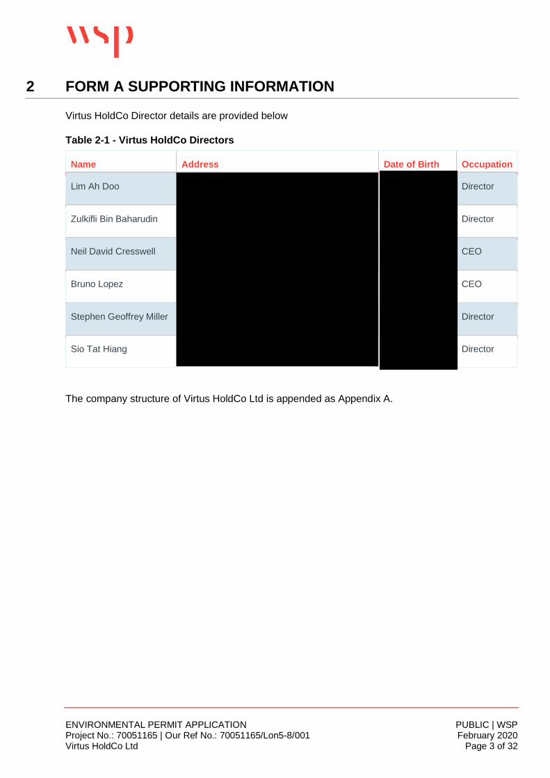
Virtus HoldCo Director details are provided below
Table 2-1 - Virtus HoldCo Directors
Name Address Date of Birth Occupation
Lim Ah Doo Director
Zulkifli Bin Baharudin Director
Neil David Cresswell CEO
Bruno Lopez CEO
Stephen Geoffrey Miller Director
Sio Tat Hiang Director
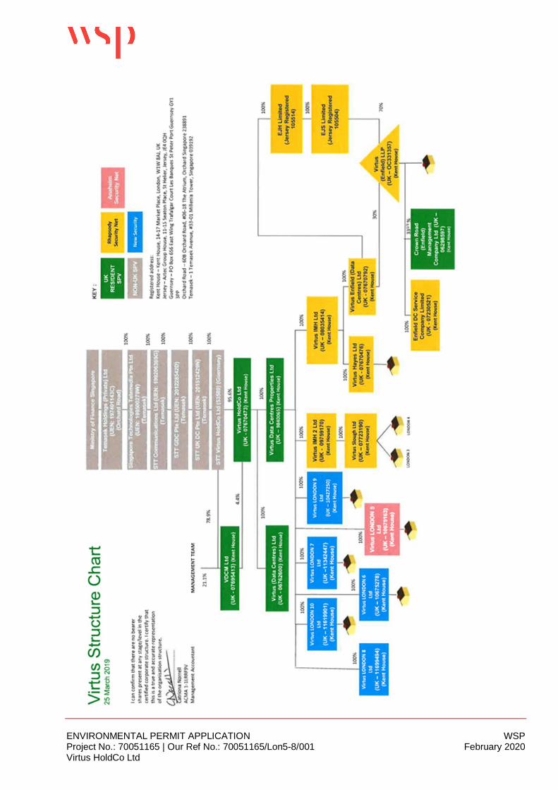
The company structure of Virtus HoldCo Ltd is appended as Appendix A.
ENVIRONMENTAL PERMIT APPLICATION PUBLIC | WSPProject No.: 70051165 | Our Ref No.: 70051165/Lon5-8/001 February 2020Virtus HoldCo Ltd Page 4 of 32
3 FORM B2 SUPPORTING INFORMATION
3.1 PRE-APPLICATION DISCUSSIONSDiscussions were held between the Operator and Howard Tee and Guy Elliot of the EnvironmentAgency (EA) on 11th July 2018 to outline the EA’s approach to permitting datacentres and tounderstand Virtus’ operations and obligations in relation to the EPR, followed up by e-mail on 12th
July.
A simple pre-application submission was made on-line using the Environment Agency web service,reference number EA/EPR/AP3903PD/A001 in January 2019.
A further telephone conversation was held between WSP and Guy Elliot in April 2019 to clarify thegeneral approach.
In summary the approach adopted is:
¡ The Environmental Permit application will focus on the standby generators and associatedroutine activities (engine testing) and not the operation of other datacentre-related activities;
¡ The permit is required for the routine generator testing regime and associated emissions,however the air emissions dispersion modelling assessment submitted with this application willalso include emergency operational periods;
¡ There may be a need for an air quality emergency action plan in conjunction with the LocalAuthority due to the location of the facility and the number of generators; and
¡ Noise impacts could also require a similar emergency action plan with the Local Authoritydepending on the outcome of the noise assessment.
¡ Best available techniques (BAT) for the generator engine planned maintenance and testingprotocol is to minimise emissions at the worst times (limits on the test periods are enforced viaplanning consent conditions to ensure they are planned outside rush hour peaks). The maximumhours per generator should be logged and reported to be less than 50 hours per year to stayexempt from the Medium Combustion Plant specified generator requirements;
¡ Fuel delivery and storage will be considered in the BAT assessment;¡ Details of reliability of the grid and connection philosophy etc. is required in the permit application
as justification of the unlikely need for the standby role and peak impacts;¡ A biodiversity pre-application screening assessment was included in the pre-app response; and¡ The charge for the application was included in the pre-application response.
The application comprises the following elements:
¡ Application forms (Parts A, B2, B3 and F1)¡ Non-technical Summary¡ Operating Techniques¡ Environmental Risk Assessment¡ Air Emissions Impact Assessment¡ Noise Impact Assessment¡ BAT discussions¡ Site Condition Report
ENVIRONMENTAL PERMIT APPLICATION PUBLIC | WSPProject No.: 70051165 | Our Ref No.: 70051165/Lon5-8/001 February 2020Virtus HoldCo Ltd Page 5 of 32
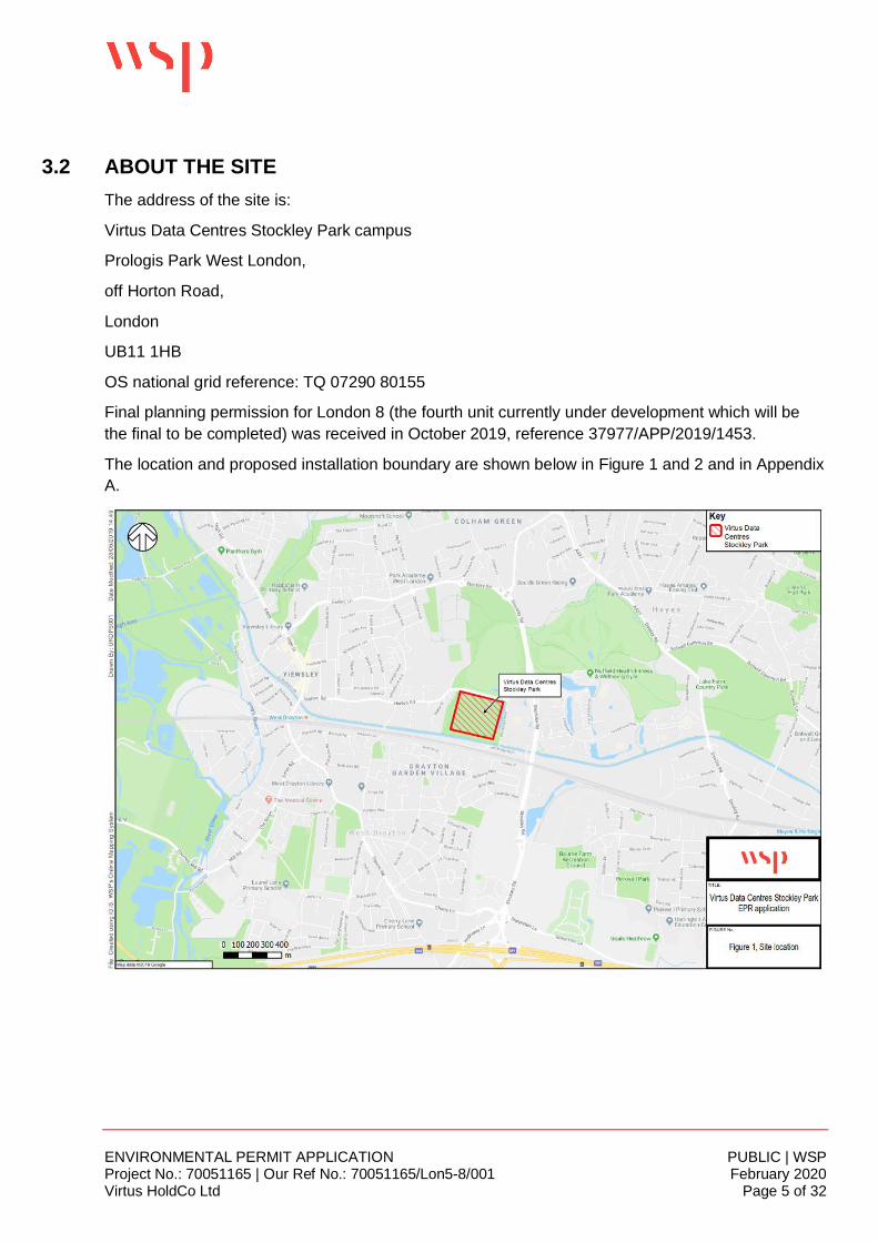
3.2 ABOUT THE SITEThe address of the site is:
Virtus Data Centres Stockley Park campus
Prologis Park West London,
off Horton Road,
London
UB11 1HB
OS national grid reference: TQ 07290 80155
Final planning permission for London 8 (the fourth unit currently under development which will bethe final to be completed) was received in October 2019, reference 37977/APP/2019/1453.
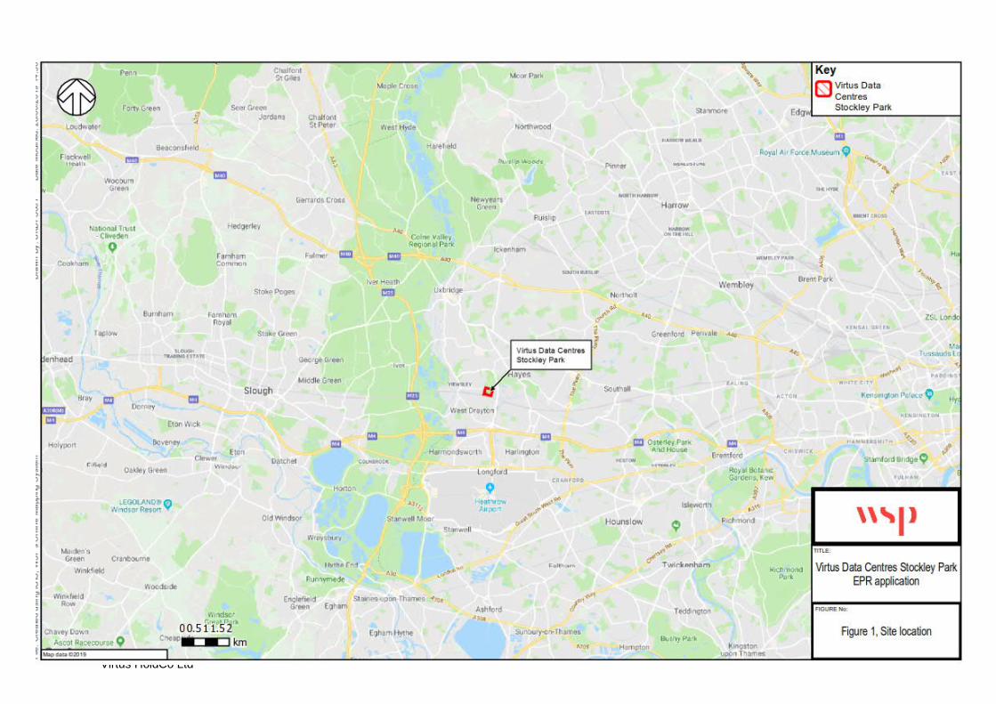
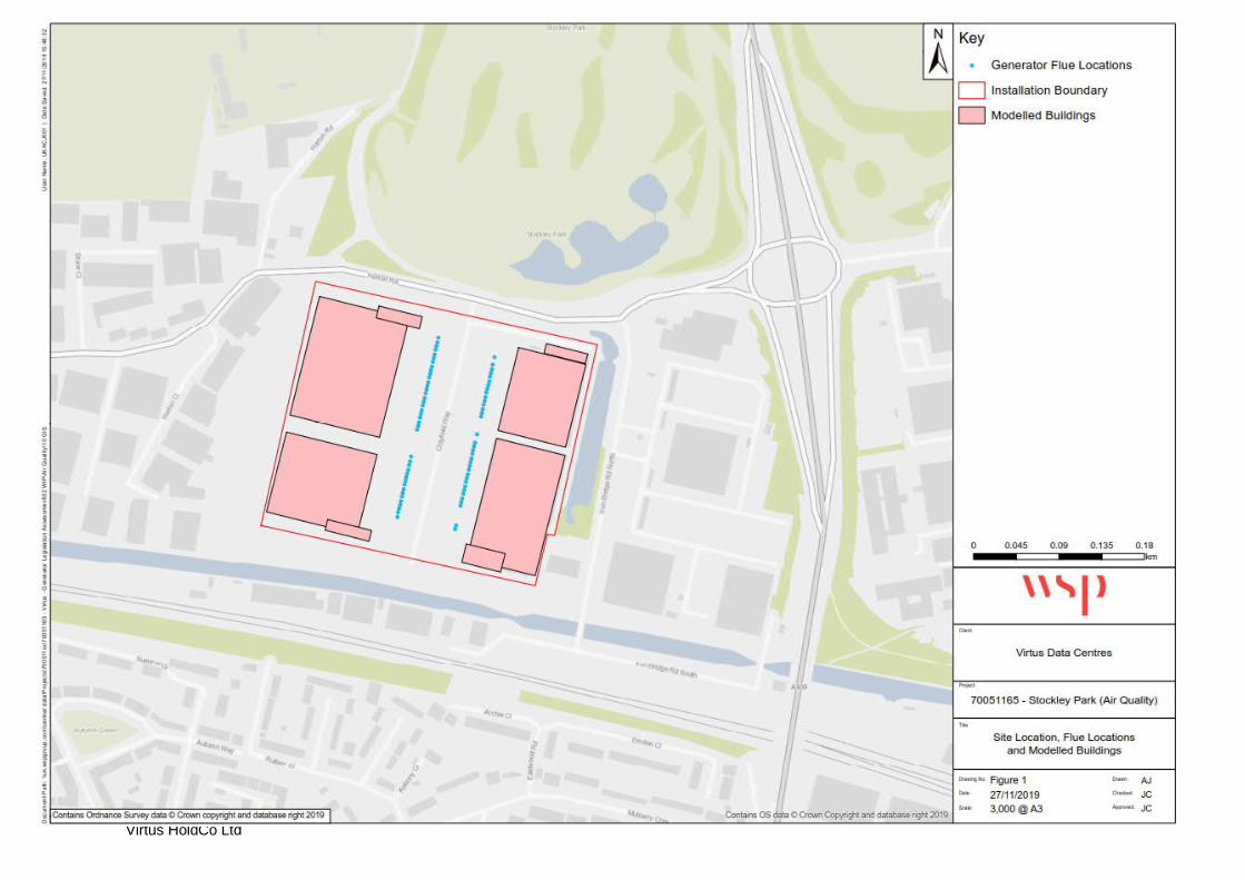
The location and proposed installation boundary are shown below in Figure 1 and 2 and in AppendixA.
ENVIRONMENTAL PERMIT APPLICATION PUBLIC | WSPProject No.: 70051165 | Our Ref No.: 70051165/Lon5-8/001 February 2020Virtus HoldCo Ltd Page 6 of 32
TYPE OF REGULATED ACTIVITY/FACILITYThe site incorporates a single installation comprising a single stationary technical unit (STU) madeup of the generator engines and fuel oil storage tanks, using the ‘Campus’ definition fromEnvironment Agency guidance.
More detailed discussion of the definition of the site (for the purposes of the EnvironmentalPermitting Regulations) is provided in Section 3.
The site is not a multi-operator installation.
3.3 ABILITY AS AN OPERATORVirtus has been designing, building and operating data centres since incorporation in 2008. Datacentres are mission critical facilities that are designed to supply uninterrupted power to tenantequipment 100% of the time. Virtus customers have global presence and hence provide globalservices which they must maintain. Virtus are required to deliver the highest levels of resilience andensure that new technologies are used which do not compromise reliability. Virtus data storageservices are managed in accordance with, and certified to, the standards detailed in this applicationvia an Integrated Management System (IMS) to ensure delivery of quality data centre services,energy and environmental performance, health and safety, and information security. The scope ofcertification is ‘the design, build and ongoing operation of mission critical data centre facilities.’ Seealso Section 5.3 Management Systems.
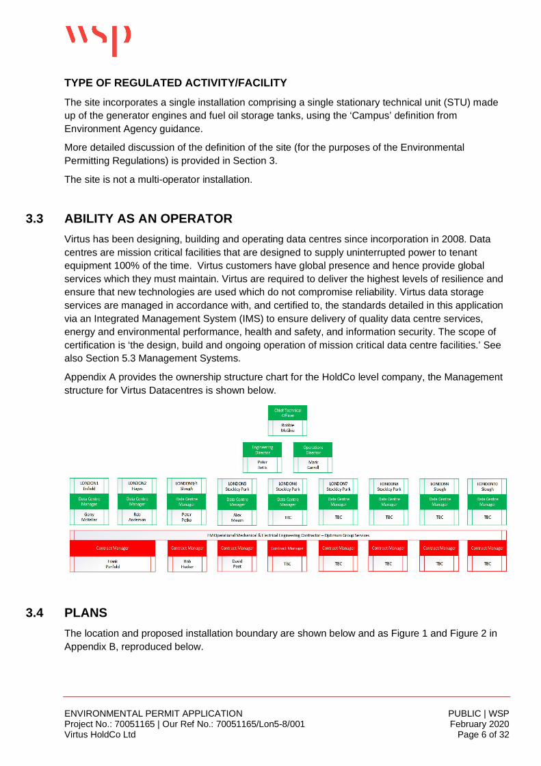
Appendix A provides the ownership structure chart for the HoldCo level company, the Managementstructure for Virtus Datacentres is shown below.
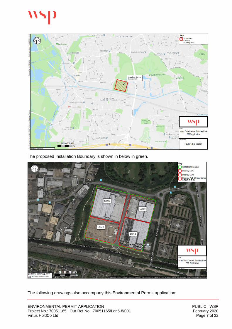
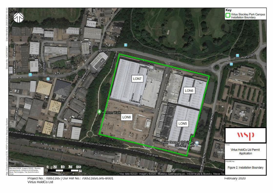
3.4 PLANSThe location and proposed installation boundary are shown below and as Figure 1 and Figure 2 inAppendix B, reproduced below.
ENVIRONMENTAL PERMIT APPLICATION PUBLIC | WSPProject No.: 70051165 | Our Ref No.: 70051165/Lon5-8/001 February 2020Virtus HoldCo Ltd Page 7 of 32
The proposed Installation Boundary is shown in below in green.
The following drawings also accompany this Environmental Permit application:
ENVIRONMENTAL PERMIT APPLICATION PUBLIC | WSPProject No.: 70051165 | Our Ref No.: 70051165/Lon5-8/001 February 2020Virtus HoldCo Ltd Page 8 of 32
1. Site Layout and Emission Points (AQ Report) Appendix B
2. Protected Areas (Habitats Assessment) in Appendix C
3. Drainage Plans (in Appendix D)
3.5 SITE CONDITION REPORTA site condition report has been developed and forms part of this application, reference70051165/LON5-8/SCR. The Site Condition Report (SCR) provides information on the current andprevious condition of the land and groundwater at the site. This will be a ‘live’ document and will beupdated during the lifetime of the installation and used to inform the surrender SCR at the time ofinstallation closure.
The report describes historical activities on the site as well as remediation works undertaken andreferences extensive geo-environmental assessments undertaken during 1997 and 2014, the latterof which contains the chemical analytical results of soil, leachate and groundwater sampling whichprovides the site baseline data.
3.6 ENVIRONMENTAL RISK ASSESSMENTAn environmental risk assessment has been undertaken, reference 70051165/LON5-8/ERA whichforms part of this application.
This has been undertaken in accordance with GOV.UK guidance Risk assessments for yourenvironmental permit and covers the following steps:
§ Step One – Identification of Risks
§ Step Two – Identification of Receptors
§ Step Three – Identification of Pathways between Sources and Receptors
§ Step Four – Assessment of Risks
§ Step Five – Controls for Risks
§ Step Six – Presentation of the Results
Odour, noise, fugitive emissions, visible emissions, discharges and accidental releases from theinstallation are all considered in the ERA. There are not considered to be any significant risks to theenvironment from the testing of the generators. There is a low risk of nuisance to nearby propertiesfrom noise emissions, and very low risk of land / water pollution in the event of any leaks or spills ofdiesel required for the generators. Appropriate mitigation and emergency response procedures willbe in place and are detailed in Section 5.3 and in the ERA.
ENVIRONMENTAL PERMIT APPLICATION PUBLIC | WSPProject No.: 70051165 | Our Ref No.: 70051165/Lon5-8/001 February 2020Virtus HoldCo Ltd Page 9 of 32
4 FORM B3 SUPPORTING INFORMATION
Virtus is applying to undertake the following EPR Schedule 1 listed activities.
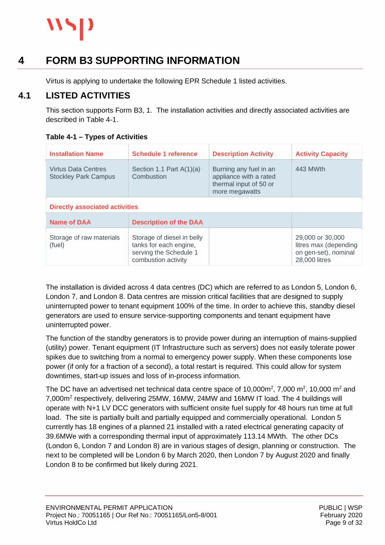
4.1 LISTED ACTIVITIESThis section supports Form B3, 1. The installation activities and directly associated activities aredescribed in Table 4-1.
Table 4-1 – Types of Activities
Installation Name Schedule 1 reference Description Activity Activity Capacity
Virtus Data CentresStockley Park Campus
Section 1.1 Part A(1)(a)Combustion
Burning any fuel in anappliance with a ratedthermal input of 50 ormore megawatts
443 MWth
Directly associated activities
Name of DAA Description of the DAA
Storage of raw materials(fuel)
Storage of diesel in bellytanks for each engine,serving the Schedule 1combustion activity
29,000 or 30,000litres max (dependingon gen-set), nominal28,000 litres
The installation is divided across 4 data centres (DC) which are referred to as London 5, London 6,London 7, and London 8. Data centres are mission critical facilities that are designed to supplyuninterrupted power to tenant equipment 100% of the time. In order to achieve this, standby dieselgenerators are used to ensure service-supporting components and tenant equipment haveuninterrupted power.
The function of the standby generators is to provide power during an interruption of mains-supplied(utility) power. Tenant equipment (IT Infrastructure such as servers) does not easily tolerate powerspikes due to switching from a normal to emergency power supply. When these components losepower (if only for a fraction of a second), a total restart is required. This could allow for systemdowntimes, start-up issues and loss of in-process information.
The DC have an advertised net technical data centre space of 10,000m2, 7,000 m2, 10,000 m2 and7,000m2 respectively, delivering 25MW, 16MW, 24MW and 16MW IT load. The 4 buildings willoperate with N+1 LV DCC generators with sufficient onsite fuel supply for 48 hours run time at fullload. The site is partially built and partially equipped and commercially operational. London 5currently has 18 engines of a planned 21 installed with a rated electrical generating capacity of39.6MWe with a corresponding thermal input of approximately 113.14 MWth. The other DCs(London 6, London 7 and London 8) are in various stages of design, planning or construction. Thenext to be completed will be London 6 by March 2020, then London 7 by August 2020 and finallyLondon 8 to be confirmed but likely during 2021.
ENVIRONMENTAL PERMIT APPLICATION PUBLIC | WSPProject No.: 70051165 | Our Ref No.: 70051165/Lon5-8/001 February 2020Virtus HoldCo Ltd Page 10 of 32
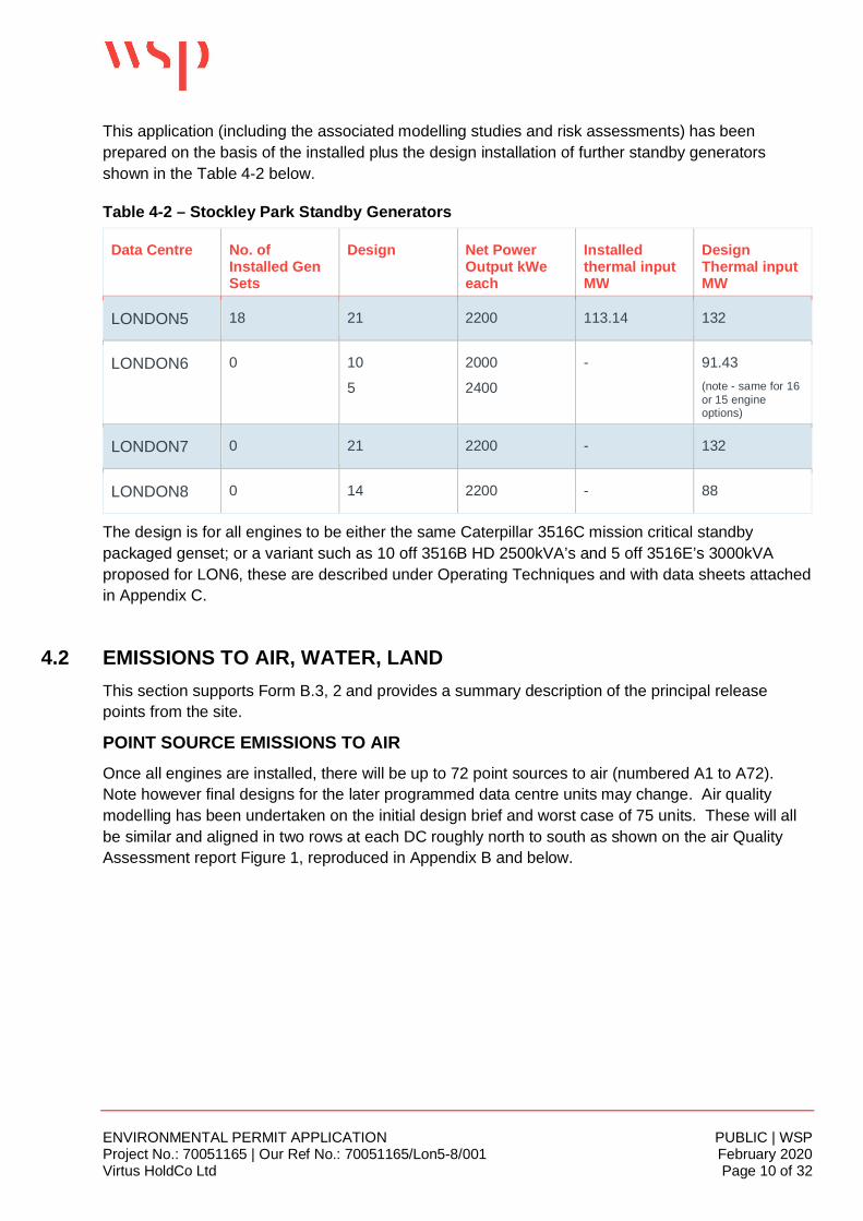
This application (including the associated modelling studies and risk assessments) has beenprepared on the basis of the installed plus the design installation of further standby generatorsshown in the Table 4-2 below.
Table 4-2 – Stockley Park Standby Generators
Data Centre No. ofInstalled GenSets
Design Net PowerOutput kWeeach
Installedthermal inputMW
DesignThermal inputMW
LONDON5 18 21 2200 113.14 132
LONDON6 0 10
5
2000
2400
- 91.43(note - same for 16or 15 engineoptions)
LONDON7 0 21 2200 - 132
LONDON8 0 14 2200 - 88
The design is for all engines to be either the same Caterpillar 3516C mission critical standbypackaged genset; or a variant such as 10 off 3516B HD 2500kVA’s and 5 off 3516E’s 3000kVAproposed for LON6, these are described under Operating Techniques and with data sheets attachedin Appendix C.
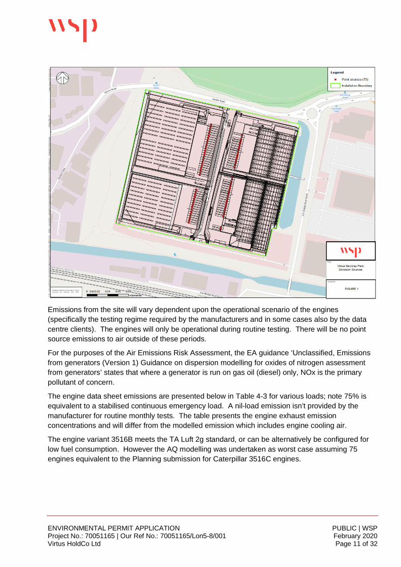
4.2 EMISSIONS TO AIR, WATER, LANDThis section supports Form B.3, 2 and provides a summary description of the principal releasepoints from the site.
POINT SOURCE EMISSIONS TO AIROnce all engines are installed, there will be up to 72 point sources to air (numbered A1 to A72).Note however final designs for the later programmed data centre units may change. Air qualitymodelling has been undertaken on the initial design brief and worst case of 75 units. These will allbe similar and aligned in two rows at each DC roughly north to south as shown on the air QualityAssessment report Figure 1, reproduced in Appendix B and below.
ENVIRONMENTAL PERMIT APPLICATION PUBLIC | WSPProject No.: 70051165 | Our Ref No.: 70051165/Lon5-8/001 February 2020Virtus HoldCo Ltd Page 11 of 32
Emissions from the site will vary dependent upon the operational scenario of the engines(specifically the testing regime required by the manufacturers and in some cases also by the datacentre clients). The engines will only be operational during routine testing. There will be no pointsource emissions to air outside of these periods.
For the purposes of the Air Emissions Risk Assessment, the EA guidance ‘Unclassified, Emissionsfrom generators (Version 1) Guidance on dispersion modelling for oxides of nitrogen assessmentfrom generators’ states that where a generator is run on gas oil (diesel) only, NOx is the primarypollutant of concern.
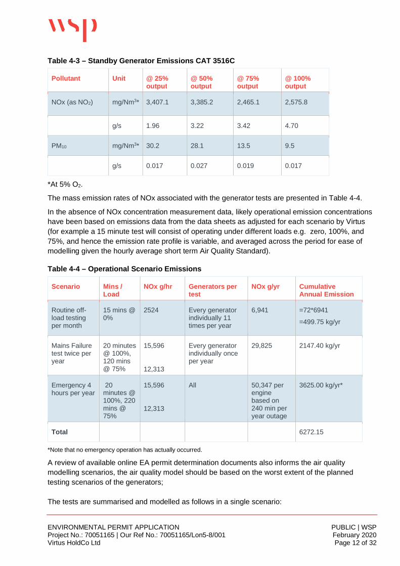
The engine data sheet emissions are presented below in Table 4-3 for various loads; note 75% isequivalent to a stabilised continuous emergency load. A nil-load emission isn’t provided by themanufacturer for routine monthly tests. The table presents the engine exhaust emissionconcentrations and will differ from the modelled emission which includes engine cooling air.
The engine variant 3516B meets the TA Luft 2g standard, or can be alternatively be configured forlow fuel consumption. However the AQ modelling was undertaken as worst case assuming 75engines equivalent to the Planning submission for Caterpillar 3516C engines.
ENVIRONMENTAL PERMIT APPLICATION PUBLIC | WSPProject No.: 70051165 | Our Ref No.: 70051165/Lon5-8/001 February 2020Virtus HoldCo Ltd Page 12 of 32
Table 4-3 – Standby Generator Emissions CAT 3516C
Pollutant Unit @ 25%output
@ 50%output
@ 75%output
@ 100%output
NOx (as NO2) mg/Nm3* 3,407.1 3,385.2 2,465.1 2,575.8
g/s 1.96 3.22 3.42 4.70
PM10 mg/Nm3* 30.2 28.1 13.5 9.5
g/s 0.017 0.027 0.019 0.017
*At 5% O2.
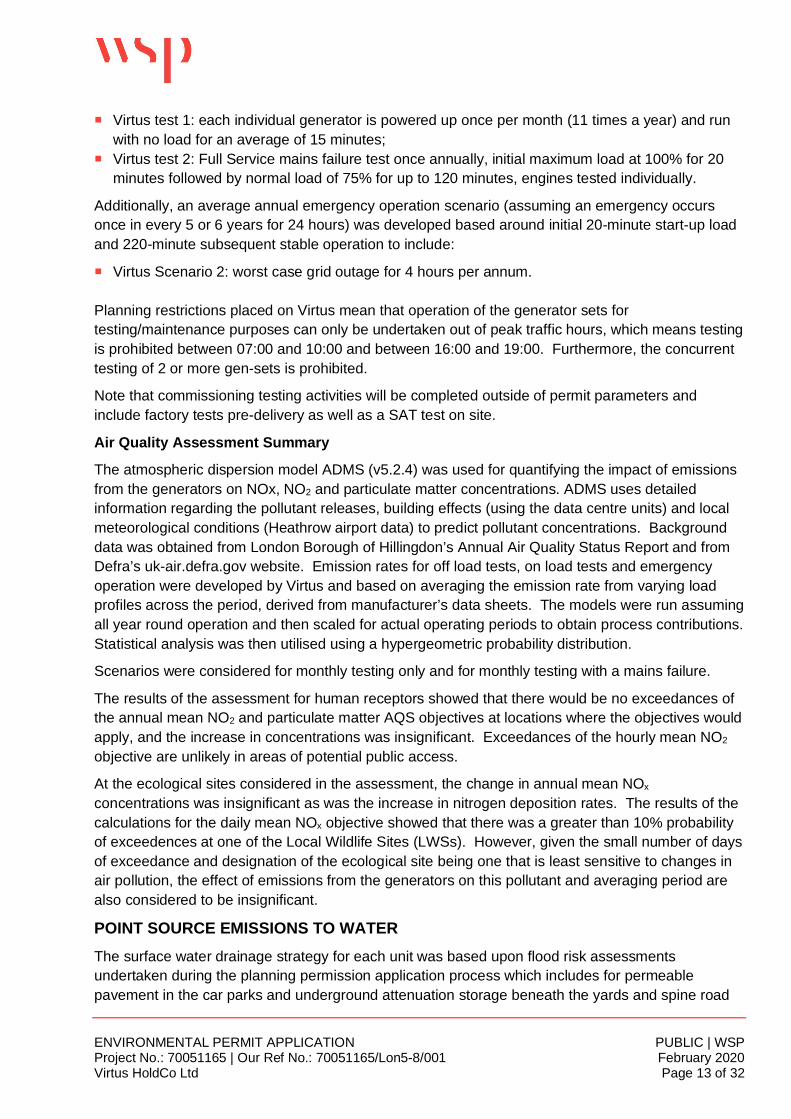
The mass emission rates of NOx associated with the generator tests are presented in Table 4-4.
In the absence of NOx concentration measurement data, likely operational emission concentrationshave been based on emissions data from the data sheets as adjusted for each scenario by Virtus(for example a 15 minute test will consist of operating under different loads e.g. zero, 100%, and75%, and hence the emission rate profile is variable, and averaged across the period for ease ofmodelling given the hourly average short term Air Quality Standard).
Table 4-4 – Operational Scenario Emissions
Scenario Mins /Load
NOx g/hr Generators pertest
NOx g/yr CumulativeAnnual Emission
Routine off-load testingper month
15 mins @0%
2524 Every generatorindividually 11times per year
6,941 =72*6941
=499.75 kg/yr
Mains Failuretest twice peryear
20 minutes@ 100%,120 mins@ 75%
15,596
12,313
Every generatorindividually onceper year
29,825 2147.40 kg/yr
Emergency 4hours per year
20minutes @100%, 220mins @75%
15,596
12,313
All 50,347 perenginebased on240 min peryear outage
3625.00 kg/yr*
Total 6272.15
*Note that no emergency operation has actually occurred.
A review of available online EA permit determination documents also informs the air qualitymodelling scenarios, the air quality model should be based on the worst extent of the plannedtesting scenarios of the generators;
The tests are summarised and modelled as follows in a single scenario:
ENVIRONMENTAL PERMIT APPLICATION PUBLIC | WSPProject No.: 70051165 | Our Ref No.: 70051165/Lon5-8/001 February 2020Virtus HoldCo Ltd Page 13 of 32
¡ Virtus test 1: each individual generator is powered up once per month (11 times a year) and runwith no load for an average of 15 minutes;
¡ Virtus test 2: Full Service mains failure test once annually, initial maximum load at 100% for 20minutes followed by normal load of 75% for up to 120 minutes, engines tested individually.
Additionally, an average annual emergency operation scenario (assuming an emergency occursonce in every 5 or 6 years for 24 hours) was developed based around initial 20-minute start-up loadand 220-minute subsequent stable operation to include:
¡ Virtus Scenario 2: worst case grid outage for 4 hours per annum.
Planning restrictions placed on Virtus mean that operation of the generator sets fortesting/maintenance purposes can only be undertaken out of peak traffic hours, which means testingis prohibited between 07:00 and 10:00 and between 16:00 and 19:00. Furthermore, the concurrenttesting of 2 or more gen-sets is prohibited.
Note that commissioning testing activities will be completed outside of permit parameters andinclude factory tests pre-delivery as well as a SAT test on site.
Air Quality Assessment Summary
The atmospheric dispersion model ADMS (v5.2.4) was used for quantifying the impact of emissionsfrom the generators on NOx, NO2 and particulate matter concentrations. ADMS uses detailedinformation regarding the pollutant releases, building effects (using the data centre units) and localmeteorological conditions (Heathrow airport data) to predict pollutant concentrations. Backgrounddata was obtained from London Borough of Hillingdon’s Annual Air Quality Status Report and fromDefra’s uk-air.defra.gov website. Emission rates for off load tests, on load tests and emergencyoperation were developed by Virtus and based on averaging the emission rate from varying loadprofiles across the period, derived from manufacturer’s data sheets. The models were run assumingall year round operation and then scaled for actual operating periods to obtain process contributions.Statistical analysis was then utilised using a hypergeometric probability distribution.
Scenarios were considered for monthly testing only and for monthly testing with a mains failure.
The results of the assessment for human receptors showed that there would be no exceedances ofthe annual mean NO2 and particulate matter AQS objectives at locations where the objectives wouldapply, and the increase in concentrations was insignificant. Exceedances of the hourly mean NO2
objective are unlikely in areas of potential public access.
At the ecological sites considered in the assessment, the change in annual mean NOx
concentrations was insignificant as was the increase in nitrogen deposition rates. The results of thecalculations for the daily mean NOx objective showed that there was a greater than 10% probabilityof exceedences at one of the Local Wildlife Sites (LWSs). However, given the small number of daysof exceedance and designation of the ecological site being one that is least sensitive to changes inair pollution, the effect of emissions from the generators on this pollutant and averaging period arealso considered to be insignificant.
POINT SOURCE EMISSIONS TO WATERThe surface water drainage strategy for each unit was based upon flood risk assessmentsundertaken during the planning permission application process which includes for permeablepavement in the car parks and underground attenuation storage beneath the yards and spine road
ENVIRONMENTAL PERMIT APPLICATION PUBLIC | WSPProject No.: 70051165 | Our Ref No.: 70051165/Lon5-8/001 February 2020Virtus HoldCo Ltd Page 14 of 32
with an outfall to the Grand Union Canal. The yards contain the generator arrays and gantriessupporting the cooling plant with an additional concrete pedestal/base laid on the surface withintegrated drainage channel to allow surface (rain) water to reach the underground drainage system.
Each of the 4 yards falls to a series of channel drains located at the low point of the yard. Thechannel drains within the service yard apron will convey the run-off to the receiving below grounddrainage system which is gravity-fed through a sediment sump/catch pit and class 1 full retentionalarmed interceptor before discharge via attenuation tanks. Each yard discharges to the centralspine road drain running approximately north to south towards the Canal to the outfall.
Each Data Centre’s drainage system is fitted with one or more penstock valve manholes eitherbefore or after the attenuation tank, prior to joining the combined central spine road allowing eachcentre to be isolated in the event of an incident.
Uncontaminated surface water from the roof areas of each building bypass the yard interceptors anddischarges via the attenuation tanks (and penstock valve manhole) to the central spine drain.
The surface water discharge to the canal is at approximately OS GR 507223 180008.
Domestic foul water is pumped via a rising main to the north and discharged separately to ThamesWater sewer at the North-West corner of the site.
The oil interceptors are listed as an asset under SFG20 and subject to routine annual inspection andcleaning.
POINT SOURCE EMISSIONS TO LANDThere are no proposed point source emissions to land from the installation activities.
NOISE EMISSIONSThe generators will only emit noise during operation (individual testing or emergency). The engineand generator enclosures are designed to meet 75dBA at 1 m free field condition, individually. Anoise impact assessment report (appended to this application) has been prepared which determinesthe impact of the proposed testing regime at nearby noise sensitive receptors (NSR) as well asproviding non-material comment on the impact of emergency operations.
The report provides baseline environmental noise (at the time of the survey which includesgenerators and cooling plant installed at LON5) to establish background and residual sound levels atthe NSRs, and a sound source survey to determine the sound levels of the generators.
The report presents the data and the outcome of CadnaA modelling covering the test scenario andthe emergency scenario.
The impact assessment indicates, based on numerical prediction and consideration of the context inwhich the sound sources are present, that a low impact is predicted at all identified receptors, for off-load start-up and on-load supply tests.
During a genuine emergency, all generators could potentially operate, in order to supply power tothe data centres. As this is a non-routine scenario with a low likelihood of occurrence, it has notbeen considered in detail. However, as a guide, it is predicted that the rating level would exceed thebackground level by 7 – 10 dB if this emergency scenario were to occur. As such, in the context ofthe extremely infrequent occurrence, this is considered to be a low impact.
ENVIRONMENTAL PERMIT APPLICATION PUBLIC | WSPProject No.: 70051165 | Our Ref No.: 70051165/Lon5-8/001 February 2020Virtus HoldCo Ltd Page 15 of 32
The quantitative noise impact indicates a low impact at noise-sensitive properties due to sound fromthe generators.
WASTE MANAGEMENTWaste management procedures and controls are outlined in Operations Manual Chapter 6. Auditsof service providers are audited regularly, including directly and indirectly contracted (via FMTeams).
Wastes which will be produced at the data centre will be recorded on a Waste Stream Duty of CareMatrix (QHS-37-06) which includes the following required information:
¡ Waste type and EWC code;¡ Whether it is hazardous or non-hazardous;¡ Activity waste has arisen from;¡ Broker number (if applicable);¡ Waste carrier and licence number;¡ Name and addresses of waste transfer station (waste destination);¡ Waste management licence number of destination facility; and¡ Disposal route (i.e. recycled, recovered, etc.)
The matrix for the data centre will be maintained and updated by sub-contractor Optimum. Wastedata will be recorded. Data will currently be available for LON5 only and can be submitted ifrequired.
ENVIRONMENTAL PERMIT APPLICATION PUBLIC | WSPProject No.: 70051165 | Our Ref No.: 70051165/Lon5-8/001 February 2020Virtus HoldCo Ltd Page 16 of 32
5 OPERATING TECHNIQUES
5.1 GENERALVirtus provide best in class Data Centre services. Due to their customers global presence and theglobal services that they provide, Virtus must maintain and demand a standardised solution from allproviders. The Power, Cooling and Security service levels that Virtus’s customers mandate, requireVirtus to deliver the highest levels of resilience and ensure that new technologies are used which donot compromise reliability. By providing these mission critical services VIRTUS continues to supportthe UK in making it one of the most attractive international locations for hyperscale customers.
Data centres are mission critical facilities that are designed to supply uninterrupted power to tenantequipment 100% of the time. In order to achieve this, standby diesel generators are used to ensureservice-supporting components and tenant equipment have uninterrupted power.
The function of the standby generators is to provide power during an interruption of mains-supplied(utility) power. Tenant equipment (IT Infrastructure such as servers) does not easily tolerate powerspikes due to switching from a normal to emergency power supply. When these components losepower (if only for a fraction of a second), a total restart is required. This could allow for systemdowntimes, start-up issues and loss of in-process information.
Virtus’ data centres operate in one of two modes:
Normal Operation – Operating from supplied utilities to power tenant equipment and service-supporting equipment such as chillers, computer room air conditioning, building managementsystems and power management systems. Normal operation includes the testing and maintenanceof the standby generators (hence the requirement for the permit).
Emergency Operation – Operating from standby generators in the event of a mains-supply failure.
Standby generators form part of the redundant design for both tenant equipment and service-supporting equipment.
The data centres are installed to Uptime Institute Tier III standard (see Section 5.5), which meansthat there is no interruption to the operation of the computer hardware located in the centre, forexample during routine maintenance of power and cooling systems. Virtus currently has a 100%uptime record. The generators are only utilised as back-up emergency provision and hence theroutine operation is for testing and maintenance only.
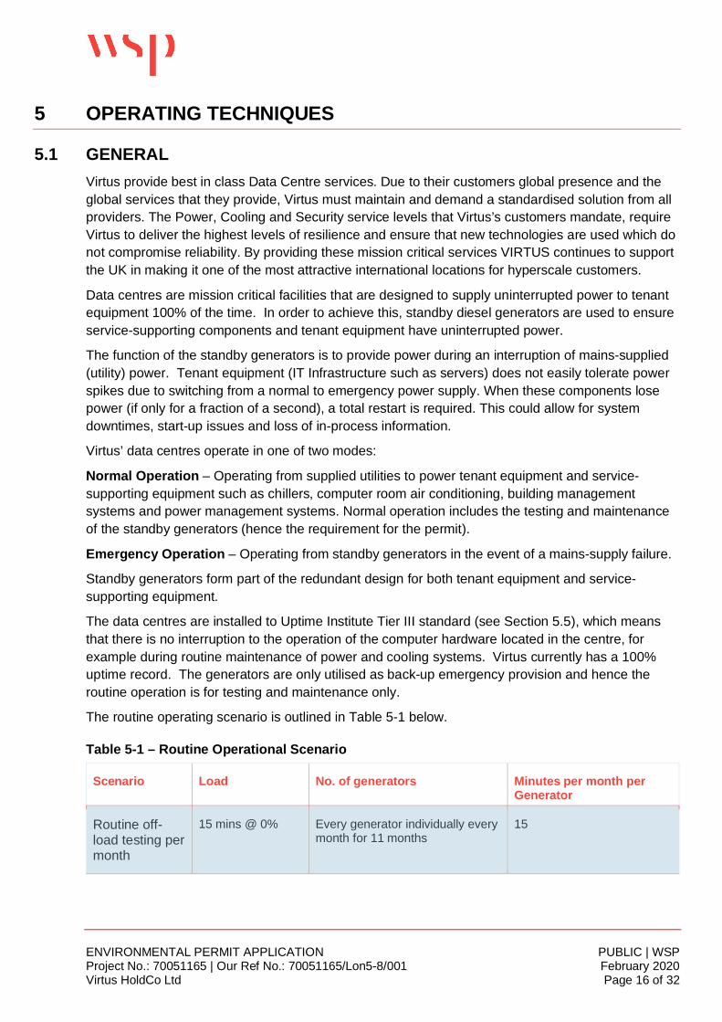
The routine operating scenario is outlined in Table 5-1 below.
Table 5-1 – Routine Operational Scenario
Scenario Load No. of generators Minutes per month perGenerator
Routine off-load testing permonth
15 mins @ 0% Every generator individually everymonth for 11 months
15
ENVIRONMENTAL PERMIT APPLICATION PUBLIC | WSPProject No.: 70051165 | Our Ref No.: 70051165/Lon5-8/001 February 2020Virtus HoldCo Ltd Page 17 of 32
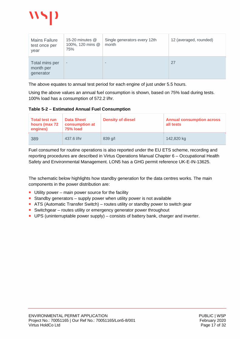
Mains Failuretest once peryear
15-20 minutes @100%, 120 mins @75%
Single generators every 12thmonth
12 (averaged, rounded)
Total mins permonth pergenerator
- - 27
The above equates to annual test period for each engine of just under 5.5 hours.
Using the above values an annual fuel consumption is shown, based on 75% load during tests.100% load has a consumption of 572.2 l/hr.
Table 5-2 – Estimated Annual Fuel Consumption
Total test runhours (max 72engines)
Data Sheetconsumption at75% load
Density of diesel Annual consumption acrossall tests
389 437.6 l/hr 839 g/l 142,820 kg
Fuel consumed for routine operations is also reported under the EU ETS scheme, recording andreporting procedures are described in Virtus Operations Manual Chapter 6 – Occupational HealthSafety and Environmental Management. LON5 has a GHG permit reference UK-E-IN-13625.
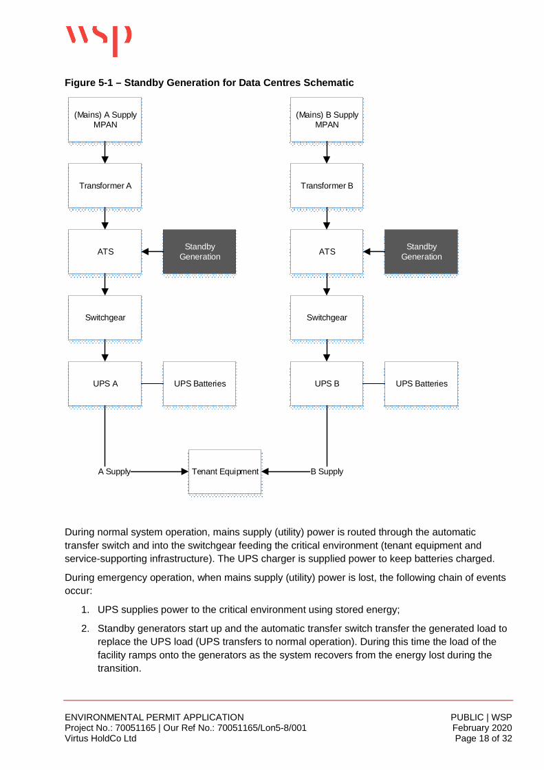
The schematic below highlights how standby generation for the data centres works. The maincomponents in the power distribution are:
¡ Utility power – main power source for the facility¡ Standby generators – supply power when utility power is not available¡ ATS (Automatic Transfer Switch) – routes utility or standby power to switch gear¡ Switchgear – routes utility or emergency generator power throughout¡ UPS (uninterruptable power supply) – consists of battery bank, charger and inverter.
ENVIRONMENTAL PERMIT APPLICATION PUBLIC | WSPProject No.: 70051165 | Our Ref No.: 70051165/Lon5-8/001 February 2020Virtus HoldCo Ltd Page 18 of 32
Figure 5-1 – Standby Generation for Data Centres Schematic
(Mains) A SupplyMPAN
(Mains) B SupplyMPAN
Transformer A
ATS StandbyGeneration
Transformer B
ATS StandbyGeneration
Switchgear Switchgear
UPS A UPS B
Tenant EquipmentA Supply B Supply
UPS Batteries UPS Batteries
During normal system operation, mains supply (utility) power is routed through the automatictransfer switch and into the switchgear feeding the critical environment (tenant equipment andservice-supporting infrastructure). The UPS charger is supplied power to keep batteries charged.
During emergency operation, when mains supply (utility) power is lost, the following chain of eventsoccur:
1. UPS supplies power to the critical environment using stored energy;
2. Standby generators start up and the automatic transfer switch transfer the generated load toreplace the UPS load (UPS transfers to normal operation). During this time the load of thefacility ramps onto the generators as the system recovers from the energy lost during thetransition.
ENVIRONMENTAL PERMIT APPLICATION PUBLIC | WSPProject No.: 70051165 | Our Ref No.: 70051165/Lon5-8/001 February 2020Virtus HoldCo Ltd Page 19 of 32
3. Then, when mains supply (utility) power is re-established, manual transfer of mains supply(utility) power occurs reversing the above steps.
Equipment Testing
The equipment (generators) to be installed are subject to a standard CAT Finning UK worksinspection and test which includes a full load test against a reactive load bank. This is carried out atthe acoustic enclosure supplier’s factory. Works tests as part of the Factory Acceptance Testinclude:
¡ Visual inspection;¡ 50% load step will be undertaken and recorded as the first load step applied, no performance
limits for this load are applied. The generator is cold (rested for 24 hours with engine blockheaters active).; and
¡ Transient load acceptance tests with engine block heaters active (engine static for 24 hours) toISO 8528 G3 with trace recordings of voltage, frequency and speed deviations.
Following installation of each generator on site, the individual generator systems would becommissioned in line with an agreed Functional Design Specification as per the manufacturersrecommendations. These include the above testing techniques, usually in the presence of the Client.Thereafter routine start up and mains failure tests are performed as outlined in Table 5-1.
5.2 STANDARDSVIRTUS subscribes to internationally-recognised data centre design standards such as the UptimeInstitute’s Tier III design certification. The basic requirements of this standard include:
¡ 99.982% uptime of power¡ No more than 1.6 hours of power downtime per year¡ N+1 fault tolerant providing at least 72-hour power outage protection
The generator sets are rated against the ISO8528 definition, and transient load acceptance testscompleted to ISO8528 G3. The generators will be ANSI/TIA-942 compliant for Rated-1 throughRated-4 data centres.
5.3 MANAGEMENT SYSTEMSThis section provides additional response to Form B2 3d Management Systems as part of the permitapplication.
Virtus has been designing, building and operating data centres since incorporation in 2008. Theirdata storage services are managed in accordance with, and certified to, the standards listed belowvia an Integrated Management System (IMS) to ensure delivery of quality data centre services,energy and environmental performance, health and safety, and information security. The scope ofcertification is ‘the design, build and ongoing operation of mission critical data centre facilities.’
¡ ISO/IEC 27001:2013 which specifies the requirements for establishing, implementing,maintaining and continually improving an information security management system (AlcumusISOQAR certificate 16390-ISN-001 expiry date 7th May 2021);
¡ ISO 14001:2015 which specifies the requirements for an environmental management system toenable an organisation to develop and implement a policy and objectives which take into account
ENVIRONMENTAL PERMIT APPLICATION PUBLIC | WSPProject No.: 70051165 | Our Ref No.: 70051165/Lon5-8/001 February 2020Virtus HoldCo Ltd Page 20 of 32
legal requirements and other requirements to which the organisation subscribes, and informationabout significant environmental aspects (Alcumus ISOQAR certificate 16390-MES-001 expirydate 7th May 2021);
¡ ISO 9001:2015 which specifies the requirements for establishing, implementing, monitoring,managing and improving quality throughout the organisation (Alcumus ISOQAR certificate 16390-QMS-001 expiry date 7th May 2021);
¡ ISO 50001:2011 which specifies requirements for establishing, implementing, maintaining andimproving an energy management system, whose purpose is to enable an organisation to followa systematic approach in achieving continual improvement of energy performance, includingenergy efficiency, energy use and consumption (Alcumus ISOQAR certificate 16390-NRG-001expiry date 7th May 2021).
All Virtus’ data centre operations at this site are managed in line with their Operations Manual whichincorporates the requirements of the IMS (Chapter 6 Occupational Health & Safety andEnvironmental (OHSE) Management System). The following paragraphs describe the managementsystems and processes which are in place / will be in place at the installation alongside assessmentof how the system will meet BAT requirements. Overall responsibility for the IMS lies with the SeniorManagement Team of Virtus HoldCo Ltd.
The environmental management system (EMS) includes an integrated policy (Compliance Policy),management principles, organisational structure, responsibilities, standards/ procedures, processcontrols and resources which are in place to manage environmental protection across all aspects ofthe business.
Environmental Policy
The ISO 14001 certified EMS is underpinned by an Environmental Policy which is included as partof an overall Compliance Policy. This defines Virtus’ commitment to continual improvement and todeveloping objectives and targets aimed at preventing pollution and improving environmentalperformance. The Policy is reviewed annually by the Senior Management Team of Virtus HoldCoLtd. Arrangements, such as inductions, tool box talks and noticeboards, are in place to ensure thatall employees are aware of the Policy and its contents and that the Policy is made available tocompany stakeholders, including contractors who undertake much of the onsite work around thegenerators (maintenance, deliveries, etc).
The Policy emphasises commitment to:
¡ Minimising (and where possible) preventing pollution;¡ Improving environmental and energy performance;¡ Ensuring robust maintenance regimes are in place;¡ Auditing and evaluation of operational policies, processes, staff and controls, communicating
findings to senior management; and¡ Communicating and promoting policies, processes and controls to all relevant parties.
Environmental Aspects & Risk Management
Virtus ensures that internal and external issues relevant to the provision of services, energy &environmental aspects, information security, strategic direction, and in maintaining compliance are
ENVIRONMENTAL PERMIT APPLICATION PUBLIC | WSPProject No.: 70051165 | Our Ref No.: 70051165/Lon5-8/001 February 2020Virtus HoldCo Ltd Page 21 of 32
captured, evaluated and mitigated through a Risk Management System compliant with therequirements of BS ISO31000:2009 Risk Management.
A Risk Evaluation Register controlled under the Risk Management Process (Chapter 4 of theOperations Manual) is implemented This register details environmental aspects and risks associatedwith the organisation’s activities, including a significance rating for each aspect. Environmental risksare evaluated in order to identify opportunities for continual improvement. This is undertakenalongside a regular energy performance review, a key aspect to identify opportunities to improveenvironmental performance. The energy review is used in particular to drive Power UsageEffectiveness figures which is the ratio of total amount of energy used by a computer data centerfacility to the energy delivered to computing equipment.
‘Significant’ aspects are managed by establishing operational controls, process, procedures, trainingand the monitoring of activities via an audit programme which covers both site-level andorganisation-level activities. All staff are responsible for working in accordance with proceduresrelating to environmental compliance.
Integrating environmental aspects in the Risk Management Process ensures that identifyingenvironmental risks together with the environmental aspect evaluation, allows routine managementsystem procedures to manage risks under normal circumstances, and emergency plans to mitigateimpacts under abnormal circumstances. Such assessments cover the implications of materialstorage, oil transfer, surface water drainage and site security.
All significant risks will be referenced in the Business Risk Register.
The process of managing and responding to environmental incidents is incorporated into an overallIncident Management Process (Chapter 2 of the Virtus Operations Manual) controlled via the VirtusService Management Centre. All incidents are reported to the Compliance Manager, who isresponsible for assessment of actions completed and updating of procedures and escalating to abusiness continuity plan if necessary.
The Operator has identified and documented a list of likely environmental incidents and developedcontrols around these.
A spill response procedure is in place with spill kits deployed strategically on site. Major diesel spillwould initiate a High P2 incident with implementation of the Virtus Incident Management Processand Pollution Incident Response Plans.
Virtus also has an Emergency Preparedness Response Process. The process identifies risks underthe headings of operational (environmental), third party (environmental), standards/statutory risk,and risks arising from natural disasters. This will be reviewed and updated as necessary once thesite is fully constructed and operational.
Training
Environmental training relates to both general awareness and job-specific training. The site ismanaged by a sufficient number of staff, who are competent to operate the site. In accordance withthe IMS:
¡ All staff have clearly defined roles and responsibilities;¡ Records are maintained of the knowledge and skills required for each post;
ENVIRONMENTAL PERMIT APPLICATION PUBLIC | WSPProject No.: 70051165 | Our Ref No.: 70051165/Lon5-8/001 February 2020Virtus HoldCo Ltd Page 22 of 32
¡ Records are maintained of the training and relevant qualifications undertaken by staff to meet thecompetence requirement of each post; and
¡ Operations are governed by standard operating instructions.
Each individual’s knowledge and skills are assessed and matched against the needs of the jobposition.
Additional experience and/or training requirements necessary to enable an individual to undertaketheir assigned role are identified, prioritised and planned.
Training records are maintained and training needs regularly reviewed.
All contractors and sub-contractors are given appropriate training prior to the commencement of anyworks or services.
Onsite training of personnel involved in the operation of the engines is undertaken by the suppliers.The training is both classroom and onsite practical and each trainee is issued with a training manual.
Review and Audit
Virtus recognises that continuous improvement requires the ongoing reappraisal of EMS and Policyin order to ensure that they remain effective, in line with developing best practice and relevant to thebusiness as a whole. An annual management review examines the EMS to ensure that it remainsappropriate and effective at controlling environmental performance and to identify any areas whereopportunities exist for improvement.
The EMS and site activities are internally audited at least annually. Internal audits are carried out bysite staff with suitable audit experience and / or training.
Where corrective action is identified as being required, through audit (or otherwise), which forexample involves modifications to plant and equipment, the implementation of such changes will bemanaged via the EMS change management process.
CRITICAL ASSET MANAGEMENTVirtus identify and manage critical assets comprising of physical, non-computing systems such aspower, cooling and life safety systems under a critical asset management process.
It identifies areas of criticality and ensures appropriate levels of planned preventative maintenance,Standard Operating Procedures, and Emergency Operating Procedures as well as an Operation andMaintenance Manual.
Contractor Management
Virtus’ approach to contractor management is detailed in their Operations Manual (Chapter 13).Large areas of operation and maintenance, including the data centre at Stockley, are contracted to aFacilities Management (FM) Team, Optimum Group Services; who are specialists in Data Centremaintenance. Other assets are maintained and tested by the vendors – including the engines andgenerator sets. Off load generator tests may be undertaken in-house.
All PPM scheduling is undertaken within the enterprise asset management system IBM Maximo.SFG20 is used as the standard to govern best practice in maintenance and parts replacementschedules.
ENVIRONMENTAL PERMIT APPLICATION PUBLIC | WSPProject No.: 70051165 | Our Ref No.: 70051165/Lon5-8/001 February 2020Virtus HoldCo Ltd Page 23 of 32
Using the information controlled and retained in Maximo, the FM Team deploy a scheduling systemthat provides regulation of Vendors for maintenance and repair works. The system utilised is theproprietary Optimis solution. This solution details the planned maintenance and the Vendor details.Upon completion of the activity, records (such as engineer site reports, maintenance reports,statutory assessment reports) are uploaded to Optimis against the activity for full reconciliation ofthe activity.
The FM Team schedule maintenance activities as governed by SFG20 and the PPM schedule(Maximo) once vendors are appointed. Vendors have to upload RAMS, competencies andqualifications of operatives and other relevant documentation to the Optimis system prior to arrivalon site. The FM Team are responsible for approving RAMS alongside VIRTUS site staff.
All maintenance works are to be completed through Maintenance Operating Procedures or MOPsthat intend to:
¡ Create a safe system of work for the Vendor operatives.¡ Ensure maintenance works are carried out in accordance with OEM specifications.¡ Associated or linked systems are not impacted in the course of maintenance activities.
Operating Procedures must be followed in order to maintain the quality control and qualityassurance processes and ensure continued service provision. The Operating Procedures arereviewed regularly by the FM Team senior contract staff. Current copies of the MOPs are readilyavailable at each site situated near or on equipment.
The FM team also maintain Emergency Operating Manuals and the Emergency OperatingProcedure (EOP) which explain emergency functionality, safety routines and procedures needed toestablish a status of safe working in equipment and infrastructure for emergency operation.
MANAGEMENT SYSTEM BAT ASSESSMENTTable 5-3 below identifies relevant BAT requirements for the installation and describes the current /proposed arrangements to meet these. The BAT requirements have been identified from relevantGOV.UK guidance and the BAT reference document.
Table 5-3 - Indicative BAT Requirements for Management Systems from GOV.UK Guidance
GOV.UK Requirements Current / Proposed Arrangements BAT?
As part of the Environmental ManagementSystem guidance available on the GOV.UKwebsite the following should be incorporated:
You must include a Site Infrastructure Planwhich highlights where the activities covered byan Environmental Permit are undertaken.
Your plan must also include:
¡ Buildings and other main constructions suchas treatment plants, incinerators, storage silosand security fencing;
As part of its EMS, Virtus maintains allnecessary documents for operationalplanning and control on a site-specificbasis. This includes relevant siteinfrastructure plans containing theinformation detailed in the relevantguidance.
As a result of this permit application beingmade, site plans including point sourceemission points, drainage system anddischarge points will be incorporated intothe EMS.
YES
ENVIRONMENTAL PERMIT APPLICATION PUBLIC | WSPProject No.: 70051165 | Our Ref No.: 70051165/Lon5-8/001 February 2020Virtus HoldCo Ltd Page 24 of 32
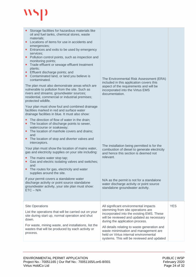
¡ Storage facilities for hazardous materials likeoil and fuel tanks, chemical stores, wastematerials;
¡ Locations of items for use in accidents andemergencies;
¡ Entrances and exits to be used by emergencyservices;
¡ Pollution control points, such as inspection andmonitoring points;
¡ Trade effluent or sewage effluent treatmentplants;
¡ Effluent discharge points; and¡ Contaminated land, or land you believe is
contaminated.
The plan must also demonstrate areas which arevulnerable to pollution from the site. Such asrivers and streams; groundwater sources;residential, commercial or industrial premises;protected wildlife.
Your plan must show foul and combined drainagefacilities marked in red and surface waterdrainage facilities in blue. It must also show:
¡ The direction of flow of water in the drain;¡ The location of discharge points to sewer,
watercourse or soakaway;¡ The location of manhole covers and drains;
and¡ The location of stop and diverter valves and
interceptors.
Your plan must show the location of mains water,gas and electricity supplies on your site including:
¡ The mains water stop tap;¡ Gas and electric isolating valves and switches;
and¡ The routes for gas, electricity and water
supplies around the site.
If your permit covers a standalone waterdischarge activity or point source standalonegroundwater activity, your site plan must show:ETC – N/A
The Environmental Risk Assessment (ERA)included in this application covers thisaspect of the requirements and will beincorporated into the Virtus EMSdocumentation.
The installation being permitted is for thecombustion of diesel to generate electricityand hence this section is deemed notrelevant.
N/A as the permit is not for a standalonewater discharge activity or point sourcestandalone groundwater activity.
Site Operations
List the operations that will be carried out on yoursite during start up, normal operation and shutdown.
For waste, mining waste, and installations, list thewastes that will be produced by each activity orprocess.
All significant environmental impactsstemming from site operations areincorporated into the existing EMS. Thesewill be reviewed and updated as necessaryduring the application process.
All details relating to waste generation andwaste minimisation and management areheld on Virtus internal environmentalsystems. This will be reviewed and updated
YES
ENVIRONMENTAL PERMIT APPLICATION PUBLIC | WSPProject No.: 70051165 | Our Ref No.: 70051165/Lon5-8/001 February 2020Virtus HoldCo Ltd Page 25 of 32
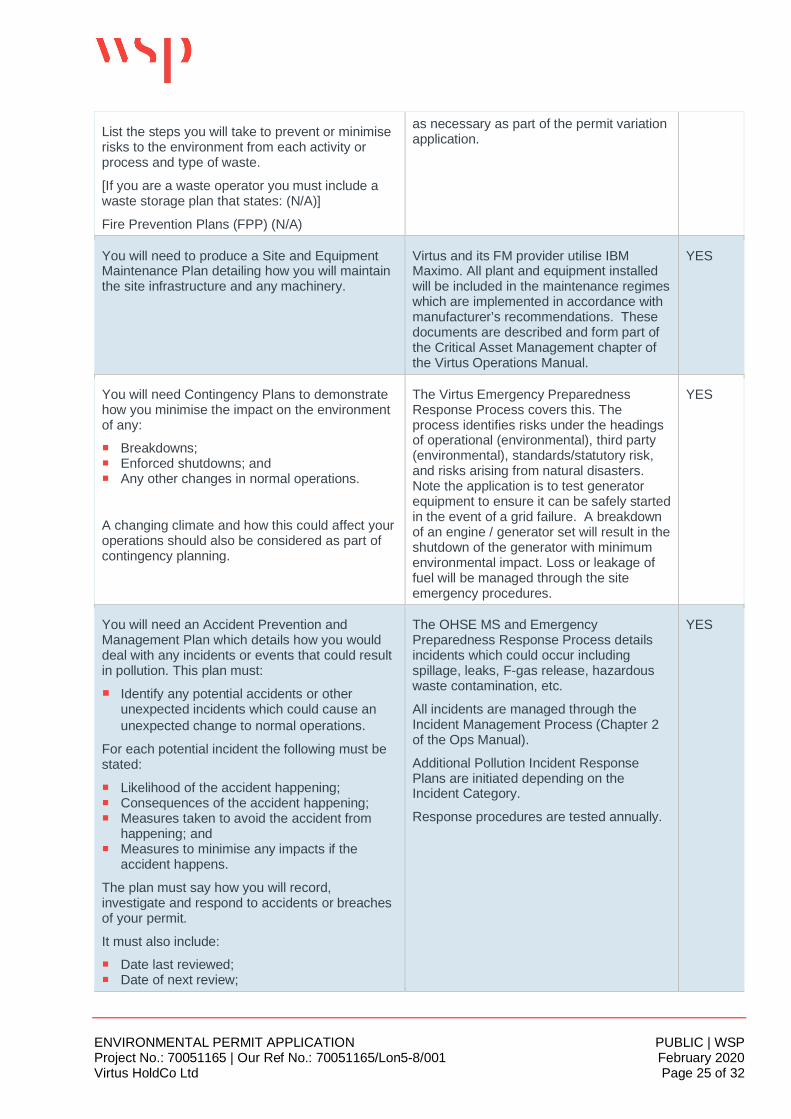
List the steps you will take to prevent or minimiserisks to the environment from each activity orprocess and type of waste.
[If you are a waste operator you must include awaste storage plan that states: (N/A)]
Fire Prevention Plans (FPP) (N/A)
as necessary as part of the permit variationapplication.
You will need to produce a Site and EquipmentMaintenance Plan detailing how you will maintainthe site infrastructure and any machinery.
Virtus and its FM provider utilise IBMMaximo. All plant and equipment installedwill be included in the maintenance regimeswhich are implemented in accordance withmanufacturer’s recommendations. Thesedocuments are described and form part ofthe Critical Asset Management chapter ofthe Virtus Operations Manual.
YES
You will need Contingency Plans to demonstratehow you minimise the impact on the environmentof any:
¡ Breakdowns;¡ Enforced shutdowns; and¡ Any other changes in normal operations.
A changing climate and how this could affect youroperations should also be considered as part ofcontingency planning.
The Virtus Emergency PreparednessResponse Process covers this. Theprocess identifies risks under the headingsof operational (environmental), third party(environmental), standards/statutory risk,and risks arising from natural disasters.Note the application is to test generatorequipment to ensure it can be safely startedin the event of a grid failure. A breakdownof an engine / generator set will result in theshutdown of the generator with minimumenvironmental impact. Loss or leakage offuel will be managed through the siteemergency procedures.
YES
You will need an Accident Prevention andManagement Plan which details how you woulddeal with any incidents or events that could resultin pollution. This plan must:
¡ Identify any potential accidents or otherunexpected incidents which could cause anunexpected change to normal operations.
For each potential incident the following must bestated:
¡ Likelihood of the accident happening;¡ Consequences of the accident happening;¡ Measures taken to avoid the accident from
happening; and¡ Measures to minimise any impacts if the
accident happens.
The plan must say how you will record,investigate and respond to accidents or breachesof your permit.
It must also include:
¡ Date last reviewed;¡ Date of next review;
The OHSE MS and EmergencyPreparedness Response Process detailsincidents which could occur includingspillage, leaks, F-gas release, hazardouswaste contamination, etc.
All incidents are managed through theIncident Management Process (Chapter 2of the Ops Manual).
Additional Pollution Incident ResponsePlans are initiated depending on theIncident Category.
Response procedures are tested annually.
YES
ENVIRONMENTAL PERMIT APPLICATION PUBLIC | WSPProject No.: 70051165 | Our Ref No.: 70051165/Lon5-8/001 February 2020Virtus HoldCo Ltd Page 26 of 32
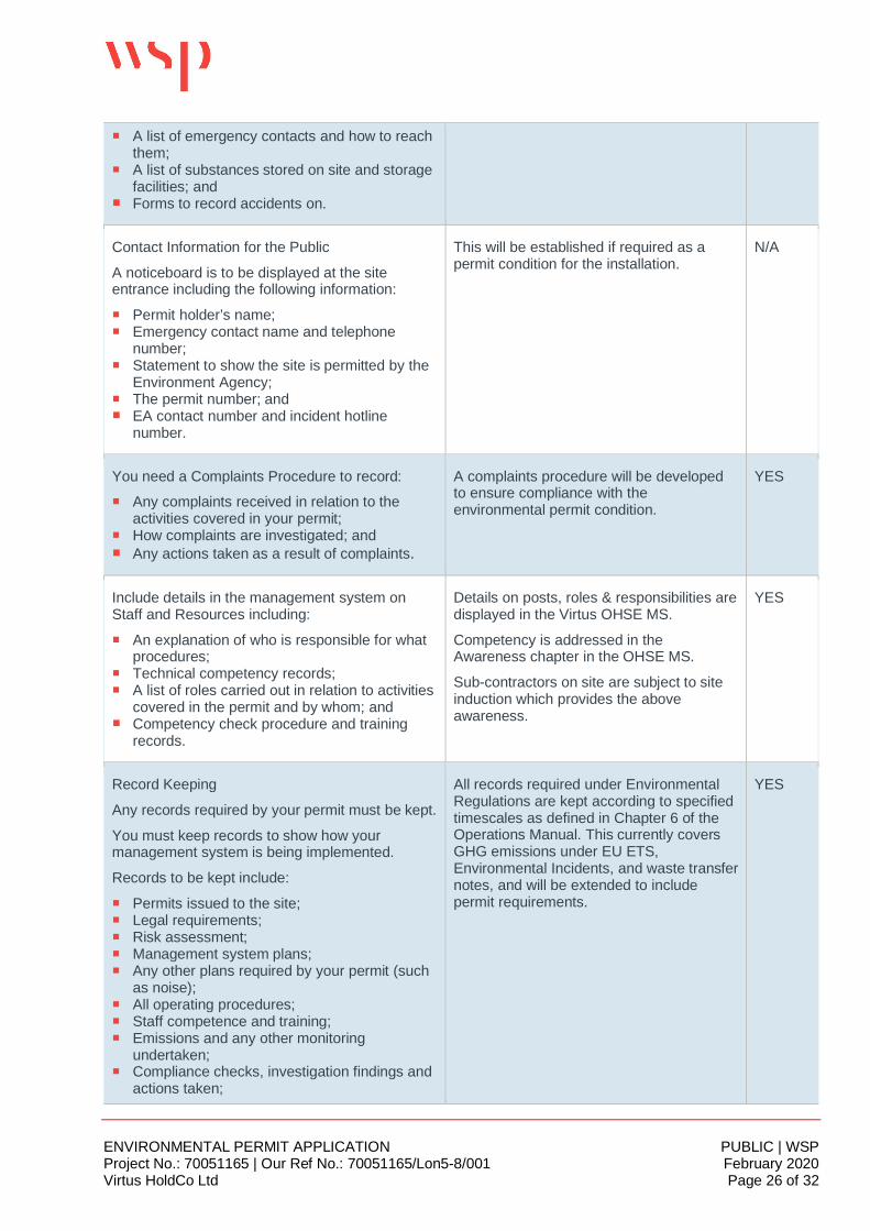
¡ A list of emergency contacts and how to reachthem;
¡ A list of substances stored on site and storagefacilities; and
¡ Forms to record accidents on.
Contact Information for the Public
A noticeboard is to be displayed at the siteentrance including the following information:
¡ Permit holder’s name;¡ Emergency contact name and telephone
number;¡ Statement to show the site is permitted by the
Environment Agency;¡ The permit number; and¡ EA contact number and incident hotline
number.
This will be established if required as apermit condition for the installation.
N/A
You need a Complaints Procedure to record:
¡ Any complaints received in relation to theactivities covered in your permit;
¡ How complaints are investigated; and¡ Any actions taken as a result of complaints.
A complaints procedure will be developedto ensure compliance with theenvironmental permit condition.
YES
Include details in the management system onStaff and Resources including:
¡ An explanation of who is responsible for whatprocedures;
¡ Technical competency records;¡ A list of roles carried out in relation to activities
covered in the permit and by whom; and¡ Competency check procedure and training
records.
Details on posts, roles & responsibilities aredisplayed in the Virtus OHSE MS.
Competency is addressed in theAwareness chapter in the OHSE MS.
Sub-contractors on site are subject to siteinduction which provides the aboveawareness.
YES
Record Keeping
Any records required by your permit must be kept.
You must keep records to show how yourmanagement system is being implemented.
Records to be kept include:
¡ Permits issued to the site;¡ Legal requirements;¡ Risk assessment;¡ Management system plans;¡ Any other plans required by your permit (such
as noise);¡ All operating procedures;¡ Staff competence and training;¡ Emissions and any other monitoring
undertaken;¡ Compliance checks, investigation findings and
actions taken;
All records required under EnvironmentalRegulations are kept according to specifiedtimescales as defined in Chapter 6 of theOperations Manual. This currently coversGHG emissions under EU ETS,Environmental Incidents, and waste transfernotes, and will be extended to includepermit requirements.
YES
ENVIRONMENTAL PERMIT APPLICATION PUBLIC | WSPProject No.: 70051165 | Our Ref No.: 70051165/Lon5-8/001 February 2020Virtus HoldCo Ltd Page 27 of 32
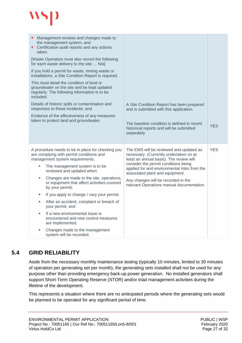
¡ Management reviews and changes made tothe management system; and
¡ Certification audit reports and any actionstaken.
[Waste Operators must also record the followingfor each waste delivery to the site:… N/a]
If you hold a permit for waste, mining waste orinstallations, a Site Condition Report is required.
This must detail the condition of land orgroundwater on the site and be kept updatedregularly. The following information is to beincluded:
Details of historic spills or contamination andresponses to these incidents; and
Evidence of the effectiveness of any measurestaken to protect land and groundwater.
A Site Condition Report has been preparedand is submitted with this application.
The baseline condition is defined in recenthistorical reports and will be submittedseparately
YES
A procedure needs to be in place for checking youare complying with permit conditions andmanagement system requirements.
§ The management system is to bereviewed and updated when:
§ Changes are made to the site, operations,or equipment that affect activities coveredby your permit;
§ If you apply to change / vary your permit;
§ After an accident, complaint or breach ofyour permit; and
§ If a new environmental issue isencountered and new control measuresare implemented.
§ Changes made to the managementsystem will be recorded.
The EMS will be reviewed and updated asnecessary. (Currently undertaken on atleast an annual basis). The review willconsider the permit conditions beingapplied for and environmental risks from theassociated plant and equipment.
Any changes will be recorded in therelevant Operations manual documentation.
YES
5.4 GRID RELIABILITYAside from the necessary monthly maintenance testing (typically 10 minutes, limited to 30 minutesof operation per generating set per month), the generating sets installed shall not be used for anypurpose other than providing emergency back-up power generation. No installed generators shallsupport Short-Term Operating Reserve (STOR) and/or triad management activities during thelifetime of the development.
This represents a situation where there are no anticipated periods where the generating sets wouldbe planned to be operated for any significant period of time.
ENVIRONMENTAL PERMIT APPLICATION PUBLIC | WSPProject No.: 70051165 | Our Ref No.: 70051165/Lon5-8/001 February 2020Virtus HoldCo Ltd Page 28 of 32
As the operation of the generating sets is considered undesirable, Virtus has designed an incomingpower system to the site to ensure that only the most major power interruption events would triggerthe need for the generators to be used to support the buildings outside of maintenance activities.
The incoming power system to the site will consist of three substations on-site, three separatecables from the Iver Heath sub-station in Buckinghamshire to the site, and three electrical feederbreakers at Iver. Each component in series would make up a power feed to the site, and the systemhas been designed such that in the event of any one of the three power feeds being accidently ormaliciously damaged, undergoing a fault or being shut down for maintenance, the on-site powersystem could be re-aligned without needing to engage the back-up generating sets.
The power for the Proposed Development originates from the Iver grid connection point, owned andrun by National Grid. The only circumstance envisaged by the project engineers where thegenerators would be used for a period of time would be a power outage directly from Iver or furtherupstream from this substation. This outage would be a major impact for the entire area, as it wouldaffect a large number of people and businesses over a wide area from Denham to Hayes to Slough.Given the scale of such an impact, it could be reasonably expected that such an outage would beaddressed as a matter of top priority by National Grid, and therefore the back-up generating setswould run for as little time as possible.
It should be noted that no outages have occurred at the Stockley or Virtus Slough campuses sincecommencement of operations, i.e. no outages in 5 years.
5.5 ENGINE AND SET UP CHOICEENGINE JUSTIFICATIONThe diesel-powered stand-by electrical generating sets envisaged for the data centre installation arefit-for-purpose vendor-supplied units, having the following (or similar/equivalent) characteristics:
§ Prime mover: V-16, four-stroke water-cooled diesel, low fuel consumption;§ Set arrangement: Containerised with close couple radiator;§ Standby rating: range from 2.0 – 2.4 MWe at 1,500 revolutions per minute, 400 volts, 50
Hertz.
The Uptime Institute regards electricity from utility service providers as an unreliable source ofpower. Therefore, Tier III data centre specifications require that the data centre must havealternative power generation as a backup for the utility power supply that is in the control of the datacentre owner. The Institute is currently formulating assessment considerations for alternativeredundant power outage protection, however standby diesel generators are still considered the triedand tested, reliable available technology with the following logic:
¡ Diesel generators are used for standby duty applications because they can accept significantload steps (transient capability) after a power outage, so they can be quickly brought online totake over from a UPS system;
· During the move from utility to back up generation the load applied will be in the region of 40-50% of the rated capacity of the generation, alternative base load applications such as Gasturbine systems have a poor load acceptance capacity requiring a relatively slow load walk in,this would mean greater quantities or over capacity to enable the required system response;
ENVIRONMENTAL PERMIT APPLICATION PUBLIC | WSPProject No.: 70051165 | Our Ref No.: 70051165/Lon5-8/001 February 2020Virtus HoldCo Ltd Page 29 of 32
¡ Shorter start up time compared to gas generator and gas turbine systems due to the exhaustpurge cycle and the supply of the air/fuel mixture to the cylinder;
¡ Fuel is stored on site ensuring local control is retained (48 hour supply to all generators);¡ The site retains full local control of power outage protection (exempt from utility supply failures);¡ The storage of diesel is considerably safer than the storage of alternative fuels, such as hydrogen
or natural gas for hydrogen fuel cell technology or gas-fired turbines respectively, whencomparing flash points under the Dangerous Substances and Explosive AtmospheresRegulations (DSEAR) 2002;
¡ The storage of enough alternative fuels to satisfy the Tier 3 24-hour power outage protectionrequirements requires significant space and considerable Health & Safety controls to comply withThe Control of Major Accident Hazards (COMAH) Regulations 2015;
¡ The Storage of the fuel is required to match the redundancy levels that the system is designed for(therefore a single storage will not be sufficient);
¡ The availability of diesel and diesel suppliers readily extends emergency operations to supporttenant equipment;
¡ The technology is mature;¡ The technology is the most cost-effective technique considering commissioning, availability of
spare parts, fuel, servicing and end of life decommissioning.
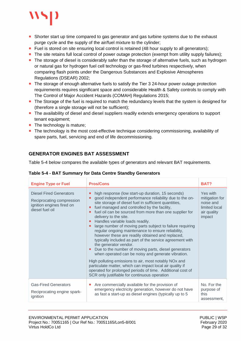
GENERATOR ENGINES BAT ASSESSMENTTable 5-4 below compares the available types of generators and relevant BAT requirements.
Table 5-4 - BAT Summary for Data Centre Standby Generators
Engine Type or Fuel Pros/Cons BAT?
Diesel Fired Generators
Reciprocating compressionignition engines fired ondiesel fuel oil
¡ high response (low start-up duration, 15 seconds)¡ good independent performance reliability due to the on-
site storage of diesel fuel in sufficient quantities,¡ fuel managed and controlled by the facility,¡ fuel oil can be sourced from more than one supplier for
delivery to the site.¡ Handles variable loads readily.¡ large number of moving parts subject to failure requiring
regular ongoing maintenance to ensure reliability,however these are readily obtained and replaced,typically included as part of the service agreement withthe generator vendor.
¡ Due to the number of moving parts, diesel generatorswhen operated can be noisy and generate vibration.
High polluting emissions to air, most notably NOx andparticulate matter, which can impact local air quality ifoperated for prolonged periods of time. Additional cost ofSCR only justifiable for continuous operation
Yes withmitigation fornoise andlimited localair qualityimpact
Gas-Fired Generators
Reciprocating engine spark-ignition
¡ Are commercially available for the provision ofemergency electricity generation, however do not haveas fast a start-up as diesel engines (typically up to 5
No. For thepurpose ofthisassessment,
ENVIRONMENTAL PERMIT APPLICATION PUBLIC | WSPProject No.: 70051165 | Our Ref No.: 70051165/Lon5-8/001 February 2020Virtus HoldCo Ltd Page 30 of 32
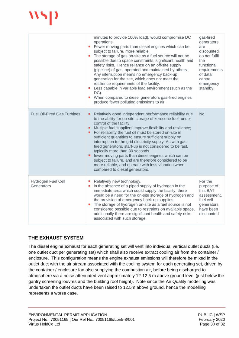
minutes to provide 100% load), would compromise DCoperations.
¡ Fewer moving parts than diesel engines which can besubject to failure, more reliable.
¡ The storage of gas on-site as a fuel source will not bepossible due to space constraints, significant health andsafety risks. Hence reliance on an off-site supply(pipeline) of gas, operated and maintained by others.Any interruption means no emergency back-upgeneration for the site, which does not meet theresilience requirements of the facility.
¡ Less capable in variable load environment (such as theDC).
¡ When compared to diesel generators gas-fired enginesproduce fewer polluting emissions to air.
gas-firedgeneratorsarediscounted,do not fulfilthefunctionalrequirementsof datacentreemergencystandby.
Fuel Oil-Fired Gas Turbines ¡ Relatively good independent performance reliability dueto the ability for on-site storage of kerosene fuel, undercontrol of the facility,
¡ Multiple fuel suppliers improve flexibility and resilience;¡ For reliability the fuel oil must be stored on-site in
sufficient quantities to ensure sufficient supply oninterruption to the grid electricity supply. As with gas-fired generators, start-up is not considered to be fast,typically more than 30 seconds.
¡ fewer moving parts than diesel engines which can besubject to failure, and are therefore considered to bemore reliable, and operate with less vibration whencompared to diesel generators.
No
Hydrogen Fuel CellGenerators
¡ Relatively new technology.¡ in the absence of a piped supply of hydrogen in the
immediate area which could supply the facility, therewould be a need for the on-site storage of hydrogen andthe provision of emergency back-up supplies.
¡ The storage of hydrogen on-site as a fuel source is notconsidered possible due to restraints on available space,additionally there are significant health and safety risksassociated with such storage.
For thepurpose ofthis BATassessment,fuel cellgeneratorshave beendiscounted
THE EXHAUST SYSTEMThe diesel engine exhaust for each generating set will vent into individual vertical outlet ducts (i.e.one outlet duct per generating set) which shall also receive extract cooling air from the container /enclosure. This configuration means the engine exhaust emissions will therefore be mixed in theoutlet duct with the air stream associated with the cooling system for each generating set, driven bythe container / enclosure fan also supplying the combustion air, before being discharged toatmosphere via a noise attenuated vent approximately 12-12.5 m above ground level (just below thegantry screening louvres and the building roof height). Note since the Air Quality modelling wasundertaken the outlet ducts have been raised to 12.5m above ground, hence the modellingrepresents a worse case.
ENVIRONMENTAL PERMIT APPLICATION PUBLIC | WSPProject No.: 70051165 | Our Ref No.: 70051165/Lon5-8/001 February 2020Virtus HoldCo Ltd Page 31 of 32
This system improves noise attenuation and provides a visual screening function satisfying planningpurposes however reduces the exhaust temperature at point of exit. The AQ modelling reporthowever demonstrates that the impact remains low for routine operations.
5.6 FUEL STORAGE AND DELIVERIESFUEL INFRASTRUCTUREThe fuel tanks installed are / will be double skinned steel tanks built to BS799: Part 5 Type J (2010)by Koronka (or similar from alternative suppliers). The tank plates are fully welded internally andexternally, and each tank is internally braced. Sets of tanks will have interconnecting pipework.Each will be fitted with a level probe and overfill valve (preventing overfill), and a High / Low alarm.More information on the size and quantity of each tank is included in Section 5.1 of the SiteCondition Report.
Fill points are within enclosure and with drip tray within enclosure.
OLE UK Ltd C2020 digital tank gauges are fitted on all tanks with low and high trigger points. Bundalarms are fitted.
Fuel polishing is undertaken to properly maintain fuel during long periods of storage and non-use.This is to ensure that the fuel supply is not wasted and managed sustainably. Fuel polishing isundertaken by a fuel polishing unit which is fixed to the tank, or wall mounted internally to theacoustic enclosure and piped to the tank. The unit contains a filter separator element which is usedto remove particulate contaminant and water from diesel fuels and hydrocarbon fuels. The unit ismanufactured from die cast aluminium head with a steel body; both of these components arepowder coated.
FUEL DELIVERIESProcedures for oil deliveries are included in Virtus management system and defined in theOperations Manual. A Standard Operating Procedure (SOP) is in place for fuel deliveries (SOP (G)021: Fuel Delivery Procedure). A COSHH Risk Assessment for Diesel is also held (AssessmentNumber DCV 001).
A fuel refill request is made by staff which initiates a controlled and safe system of work; a trainedmember of the FM Team takes a gauge reading and cross references this with a Monthly Log. Ifnecessary, cross reference is made to the secondary fuel gauges. Personnel are made aware ofthe maximum capacity of the generator fuel tanks at each location.
The tanks must not be filled more than an agreed amount usually 90 or 95% of their capacity. Thesupplier must be given an accurate reading. Any concerns over the accuracy of the readings mustbe reported to the FM Team Contract Manager or Supervisor and Virtus. The FM Team shall informboth Virtus and site security that fuel delivery is to take place. Where necessary the local area willbe appropriately cordoned off using barriers and cones. The tanker and its crew are supervised atall times, a permit to work process applies. Any ‘at risk’ drains must be covered to prevent potentialloss to the drains and spill kits must be positioned nearby. Any concerns over the quality of the spill
ENVIRONMENTAL PERMIT APPLICATION PUBLIC | WSPProject No.: 70051165 | Our Ref No.: 70051165/Lon5-8/001 February 2020Virtus HoldCo Ltd Page 32 of 32
kits or drain covers must be reported to FM Team Contract Manager and Virtus. Delivery of fuel willnot be carried out until any remedial actions are conducted.
The FM Team must ensure that all combustible materials, flammables and naked lights and mobilephones are removed or switched off within the fuel delivery area and immediate vicinity.
The FM Team are to obtain delivery receipts/reports indicating the exact amount of fuel delivered toindividual fuel storage tanks.
An Emergency Operating Procedure (EOP) exists in the event of a spillage or leakage of fuel (EOP(M) 013 – Diesel Fuel Spill), which triggers the Pollution Incident Response Plan if required. Virtusoperate a Nine Point Fuel / Chemical Spill Procedure which assesses the severity of the spill andassociated risks, and initiates the appropriate response in terms of alarms, actions, notifications andrecords.
Collected spilled oil and absorbent material is disposed of as hazardous waste.

Public
VIRTUS HOLDCO STRUCTURE
ENVIRONMENTAL PERMIT APPLICATION WSPProject No.: 70051165 | Our Ref No.: 70051165/Lon5-8/001 February 2020Virtus HoldCo Ltd

ENVIRONMENTAL PERMIT APPLICATION WSPProject No.: 70051165 | Our Ref No.: 70051165/Lon5-8/001 February 2020Virtus HoldCo Ltd

Public
MAPS AND PLANS

Public
ENVIRONMENTAL PERMIT APPLICATION WSPProject No.: 70051165 | Our Ref No.: 70051165/Lon5-8/001 February 2020Virtus HoldCo Ltd
ENVIRONMENTAL PERMIT APPLICATION WSPProject No.: 70051165 | Our Ref No.: 70051165/Lon5-8/001 February 2020Virtus HoldCo Ltd
ENVIRONMENTAL PERMIT APPLICATION WSPProject No.: 70051165 | Our Ref No.: 70051165/Lon5-8/001 February 2020Virtus HoldCo Ltd

Public
AGENCY HABITATS REPORT
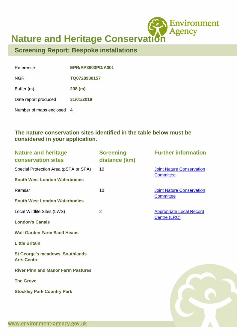
Nature and Heritage Conservation Screening Report: Bespoke installations
Reference EPR/AP3903PD/A001
NGR TQ0728980157
Buffer (m) 208 (m)
Date report produced 31/01/2019
Number of maps enclosed 4
The nature conservation sites identified in the table below must be considered in your application.
Nature and heritage conservation sites
Screening distance (km)
Further information
Special Protection Area (pSPA or SPA)
South West London Waterbodies
10 Joint Nature Conservation Committee
Ramsar
South West London Waterbodies
10 Joint Nature Conservation Committee
Local Wildlife Sites (LWS)
London's Canals
Wall Garden Farm Sand Heaps
Little Britain
St George's meadows, Southlands Arts Centre
River Pinn and Manor Farm Pastures
The Grove
Stockley Park Country Park
2 Appropriate Local Record Centre (LRC)

Stockley Rough Road
Iron Bridge Road Railsides (formerly the Piggeries)
Carp Ponds and Broads Dock
Stockley Business Park Lakes & Meadows
Bolingbroke Way Sunken Pasture
Lake Farm Country Park
Lower Colne
Protected Species
Screening distance (m)
Further Information
European Eel
up to 500m Environment Agency. Dial 03708 506 506 for your local Fisheries and Biodiversity team
Where protected species are present, a licence may be required from Natural England or the Welsh Government to handle the species or undertake the proposed works.
The relevant Local Records Centre must be contacted for information on the features within local wildlife sites. A small administration charge may also be incurred for this service.
Please note we have screened this application for protected and priority sites, habitats and species for which we have information. It is however your responsibility to comply with all environmental and planning legislation, this information does not imply that no other checks or permissions will be required.
Please note, the enclosed pre-application map(s) is valid for a period of 6 months. If you plan to submit your application more than 6 months after the map(s) was generated, you must request that the screen is re-run. This will ensure that you have used the most current information on heritage and nature conservation interests in your application.
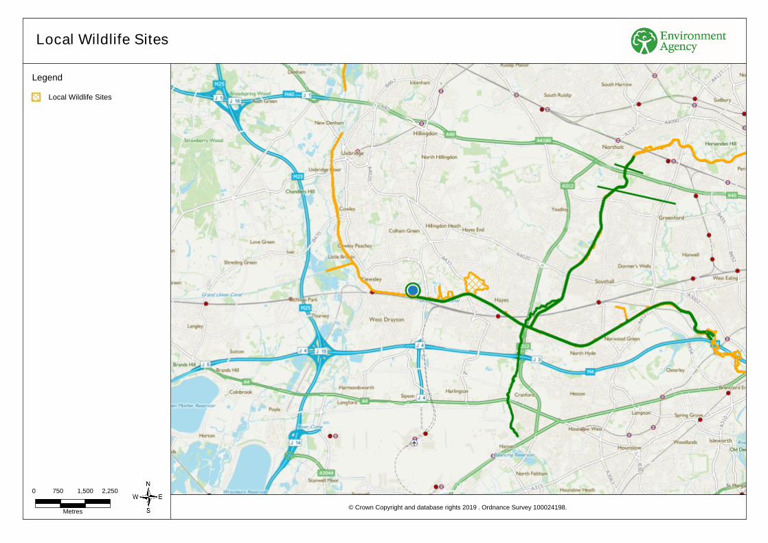
Metres
2,250
Local Wildlife Sites
© Crown Copyright and database rights . Ordnance Survey 100024198.2019
Legend
1,5000 750
Local Wildlife Sites
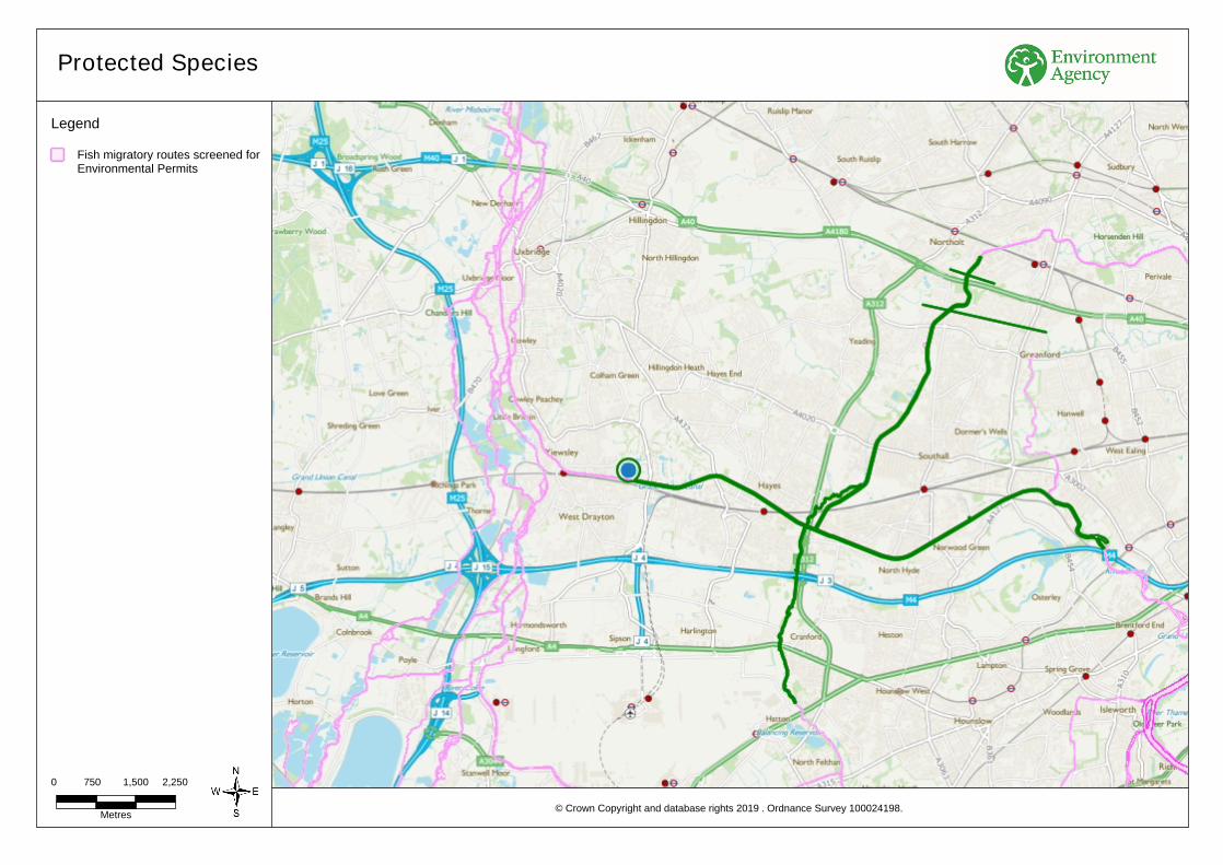
Metres
2,250
Protected Species
© Crown Copyright and database rights . Ordnance Survey 100024198.2019
Legend
1,5000 750
Fish migratory routes screened for Environmental Permits
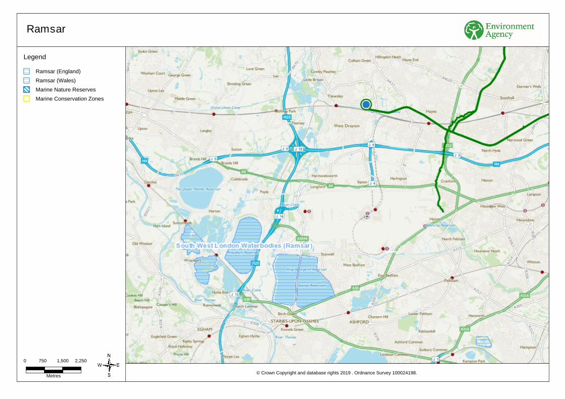
Metres
2,250
Ramsar
© Crown Copyright and database rights . Ordnance Survey 100024198.2019
Legend
1,5000 750
Ramsar (England)
Ramsar (Wales)
Marine Nature Reserves
Marine Conservation Zones
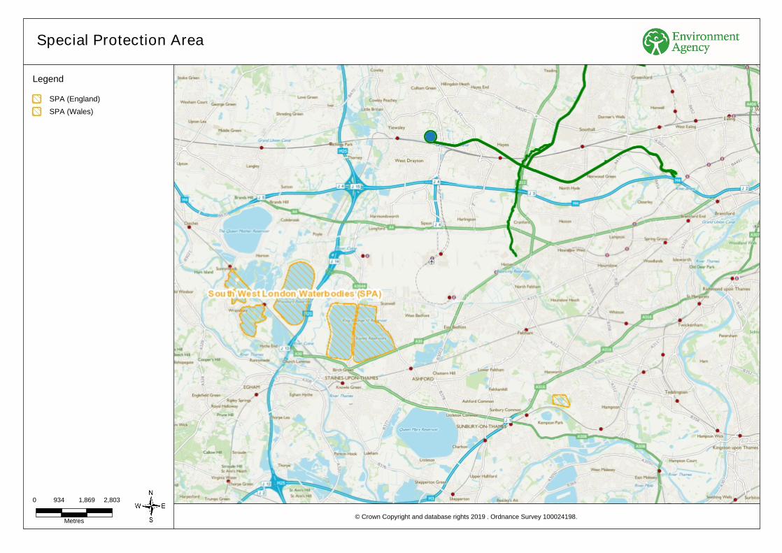
Metres
2,803
Special Protection Area
© Crown Copyright and database rights . Ordnance Survey 100024198.2019
Legend
1,8690 934
SPA (England)
SPA (Wales)

ENVIRONMENTAL PERMIT APPLICATION WSPProject No.: 70051165 | Our Ref No.: 70051165/Lon5-8/001 February 2020Virtus HoldCo Ltd
Public
DRAINAGE PLANS
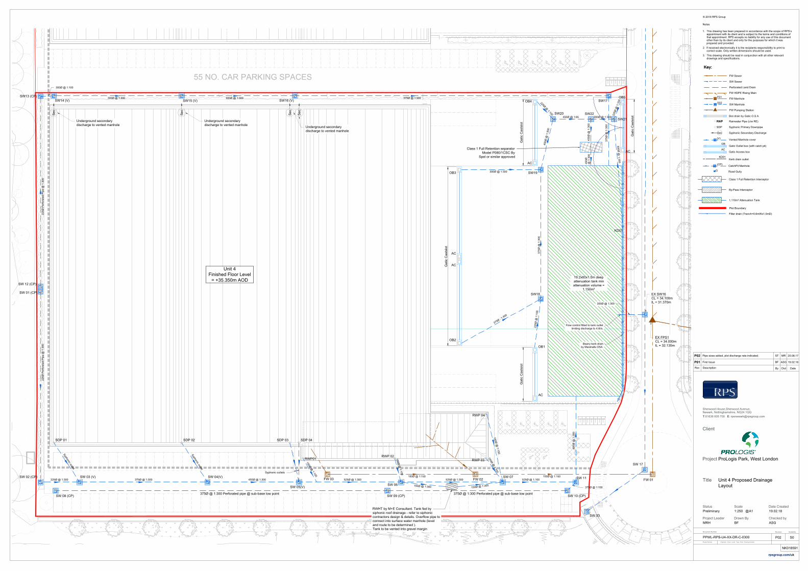
55 NO. CAR PARKING SPACES
MEZZANINE OFFICE
50000,07m
Unit 4
Finished Floor Level
= +35.350m AOD
375Ø @ 1:300 Perforated pipe @ sub-base low point
300Ø @ 1:300
300Ø @ 1:300
300Ø @ 1:43
300Ø @ 1:300
SDP 01 SDP 02 SDP 03 SDP 04
SW18
Sec
Sec
Sec
Sec
SW 02 (CP) SW 03 (V)
SW 08 (CP) SW 09 (CP) SW 10 (CP)
SW 04(V)
SW 05(V)
SW 07
SW 11
RWP 02
RWP01
RWP 03
SW19
SW22
SW17 SW14 (V)
SW15 (V)
OB2
AC
AC
OB3
OB5
AC
AC
OB4
OB1
AC
19.2x60x1.0m deep
attenuation tank min
attenuation volume =
1,150m³
SW13 (CP)
SW16 (V)
Underground secondary
discharge to vented manhole
Underground secondary
discharge to vented manhole
Underground secondary
discharge to vented manhole
SW20
375Ø @ 1:300 Perforated pipe @ sub-base low point
EX SW16
CL = 34.100m
IL = 31.370m
EX FPS1
CL = 34.000m
IL = 32.135m
FW 01
FW 02
FW 03
SW 33
SW 17
RWHT by M+E Consultant. Tank fed by
siphonic roof drainage - refer to siphonic
contractors design & details. Overflow pipe to
connect into surface water manhole (level
and route to be determined ).
Tank to be vented into gravel margin
SW 01 (CP)
SW 12 (CP)
SW 06
RWP 04
SW21
KD01
Class 1 Full Retention separator
Model P080/1CSC By
Spel or similar approved
S
y
p
h
o
n
i
c
o
u
t
l
e
t
1
5
0
Ø
@
1
:
1
0
0
1
5
0
Ø
@
1
:
1
0
0
1
5
0
Ø
@
1
:
1
0
0
1
5
0
Ø
@
1
:1
5
0
300Ø @ 1:100
450Ø @ 1:65 300Ø @ 1:300
22
5Ø
P
erfo
ra
te
d P
ip
e @
1
:3
00
22
5Ø
P
erfo
ra
te
d P
ip
e @
1
:3
00
225Ø @ 1:300 375Ø @ 1:300 450Ø @ 1:300
S
y
p
h
o
n
i
c
o
u
t
l
e
t
Syphonic outlets
525Ø @ 1:300 525Ø @ 1:300 525Ø @ 1:100
375Ø @ 1:100
60
0Ø
@
1
:3
00
3
7
5
Ø
:
1
:
3
0
0
300Ø @ 1:300 300Ø @ 1:300 375Ø @ 1:300
37
5Ø
@
1
:3
00
225Ø
@
1:100
37
5Ø
@
1:30
0
4
5
0
Ø
@
1
:3
0
0
45
0Ø
@
1
:30
0
2
2
5
Ø
@
1
:
1
0
0
2
2
5
Ø
@
1
:
1
0
0
@ 1
:3
00
300Ø
@
1:300
300Ø @ 1:300
45
0Ø
300Ø @ 1:300
Flow control fitted to tank outlet
limiting discharge to 4.6l/s.
Gatic C
astslot
Gatic C
astslot
Gatic C
astslot
Gatic C
astslot
Beany kerb drain
by Marshalls OSA.
150Ø @ 1:150 150Ø @ 1:150
150Ø
@ 1
:300
150Ø
@
1:300
Class 1 Full Retention Interceptor
Vented Manhole cover
Gatic Outlet box (with catch pit)
Gatic Access box
By-Pass Interceptor
F01
Key:
FW Sewer
SW Manhole
Syphonic Primary Downpipe
FW Manhole
FW HDPE Rising Main
SW Sewer
Rainwater Pipe (c/w RE)RWP
Sec Syphonic Secondary Discharge
Perforated Land Drain
FW Pumping Station
Slot drain by Gatic O.S.A.
Key:
SDP
RWP
Plot Boundary
CatchPit Manhole
Filter drain (Trench=0.6mWx1.0mD)
1,110m³ Attenuation Tank
S02
(V)
OB
AC
(CP)
G
Road Gully
Kerb drain outlet
KD01
Sherwood House,Sherwood Avenue,
Newark, Nottinghamshire, NG24 1QQ
T:01636 605 700 E: [email protected]
Client
Title
Status
Checked byDrawn By
Document NumberRevision
Project
Project Leader
DescriptionRev
By Ckd Date
-
Date CreatedScale
@
Suitability
Project Number Originator - Zone - Level - Type - Role - Drawing Number
rpsgroup.com/uk
S0
A11:250 19.02.18Preliminary
ASGBF
NK018591
P02
MRH
PPWL-RPS-U4-XX-DR-C-0300
ProLogis Park, West London
Unit 4 Proposed Drainage
Layout
© 2018 RPS Group
Notes
1. This drawing has been prepared in accordance with the scope of RPS’s
appointment with its client and is subject to the terms and conditions of
that appointment. RPS accepts no liability for any use of this document
other than by its client and only for the purposes for which it was
prepared and provided.
2. If received electronically it is the recipients responsibility to print to
correct scale. Only written dimensions should be used.
3. This drawing should be read in conjunction with all other relevant
drawings and specifications.
P01BF ASG 19.02.18First Issue
P02Pipe sizes added, plot discharge rate indicated. 20.08.17MRST
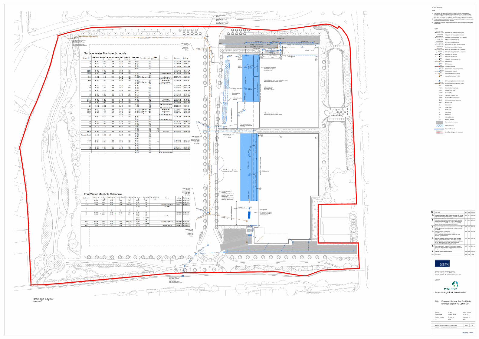
Plateau Level = To be advised by
VolkerFitzpatrick
R
:
E
:
3
8
.0
9
3
7
.6
2
Sec
SDP SDPSDP
Sec
S9
S10
RWP
RWP
Full retention interceptor
'P100/1CSC' by Spel or
similar approved.
S5(V)
S15
S16
S7
OB2
250m³ Attenuation
required
450Ø
@ 1:300
600Ø @ 1:300
225Ø @ 1:300 Perforated
pipe integral with sub-base
225Ø @ 1:300 Perforated pipe integral with sub-base
600Ø @ 1:40
300Ø @ 1:300
150Ø @ 1:100
450Ø
@ 1
:2
80
150Ø @ 1:100
300Ø @ 1:300
F7
F6
FW
H
DP
E R
isin
g M
ain
Existing foul water manhole
Invert Level = 32.280
taken from Thames water
asset location sewer map -
ALS Standard/2015_2970155
F10
FPS2
150Ø @ 1:150
2
2
5
Ø
@
1
:
1
5
0
2
2
5
Ø
@
1
:1
5
0
3
0
0
Ø
@
1
:1
0
0
1
5
0
Ø
@
1
:
1
5
0
3
0
0
Ø
@
1
:
1
0
0
150Ø
@
1:150
478m³ Flood zone @ dock
levellers max depth = 390mm
30
m G
atic U
ltra
slo
t 3
00
mm
52
m G
atic U
ltra
slo
t 3
00
mm
32
m G
atic U
ltra
slo
t 3
00
mm
33
m G
atic U
ltra
slo
t 3
00
mm
32
m G
atic U
ltra
slo
t 3
00
mm
27
m G
atic U
ltra
slo
t 3
00
mm
300Ø @
1:290
FPS1
FW
H
DP
E R
isin
g M
ain
RWP
150m³ Attenuation
required
300m³ Flood zone
@ dock levellers
max depth = 365mm
S13 (H)
3x450Ø pipes to
link tanks
Sec
Sec
Sec
Sec
Sec
FW HDPE Rising Main
675Ø @
1:300
300Ø @ 1:300
3
0
0
Ø
@
1
:
4
3
S32
3
0
0
Ø
Refer to drawing
NK018094_0350 for
outfall details
Max flow rate = 62l/s
Max flow velocity = 0.3m/s
Flow control manhole
restricted to a discharge
rate of 4l/s.
Peak flow to be
limited in
accordance with
WSP FRA dated
03.11.2015
(5.1l/s/Ha)
Peak flow to be
limited in
accordance with
Sewers for
Adoption 7th
Edition
Peak flow to be
limited in
accordance with
WSP FRA dated
03.11.2015
(5.1l/s/Ha)
Peak flow to be
limited in
accordance with
Sewers for
Adoption 7th
Edition
LD1
Rising Main for
groundwater
pump
94
.5
m L
an
d D
ra
in
1
50
mm
d
ia
me
te
r8
6.8
5m
L
an
d D
ra
in
1
50
mm
d
ia
me
te
r
300Ø @ 1:170
450Ø
@ 1:300
Foul pump station 1
Phase 1
average flow rate = 0.4l/s
peak flow rate = 3.0l/s
Phase 1 & 2
average flow rate = 0.8l/s
peak flow rate = 6.0l/s
Foul pump station 2
Phase 1
average flow rate = 0.8l/s
peak flow rate = 5.4l/s
Phase 1 & 2
average flow rate = 1.6l/s
peak flow rate = 10.8l/s
3
0
0
Ø
@
1
:
1
5
S33
1
5
0
Ø
@
1
:1
5
0
150Ø
RWHT1
IL in = 33.545
IL out = 33.495
Key:
FW Sewer (I/D & Gradient)
SW Manhole
Rodding Eye
Syphonic Primary Downpipe
G
Back Drop
Invert Level
Cover Level
IL
RE
CL
BD
PPIC4
FW Manhole
***mmØ 1/80
Trapped Gully
Polypropelyne Inspection Chamber
FW HDPE Rising Main (O/D & Gradient)
SW Sewer (I/D & Gradient)
Rainwater Pipe (c/w RE)RWP
SDG Sprinkler Discharge Gully
Fi4
Internal FW Manhole (>150ø)
Fi4
Internal FW Manhole (≤150ø)
FG Trapped Floor Gully
Sec Syphonic Secondary Discharge
Soil Vent Pipe SVP
Perforated Land Drain (O/D & Gradient)
***mm O/D
***mmØ 1/150
***mmØ 1/300
SW HDPE Rising Main (O/D & Gradient)
***mm O/D
Crown Level CRL
Soffit Level SL
Internal Diamater I/D
External DiameterE/D
Adoptable FW Manhole
Adoptable SW Manhole
Combined Sewer (I/D & Gradient)
Adoptable Combined Manhole
C3
F1
S2
***mmØ 1/150
Adoptable FW Sewer (I/D & Gradient)
***mmØ 1/80
Adoptable SW Sewer (I/D & Gradient)
***mmØ 1/300
Adoptable Combined Sewer (I/D & Gradient)
***mmØ 1/150
Combined Manhole
C3
F1
S2
(11.60)
SW Pumping Station with Inlet Invert
FW Pumping Station with Inlet Invert
SDP
PPCP2
Polypropelyne Catch Pit
Permeable block paviors
Attenuation tanks
Concrete Surround
Land Drain (integral with sub-base)
© 2015 RPS Group
Notes
1. This drawing has been prepared in accordance with the scope of RPS’s
appointment with its client and is subject to the terms and conditions of that
appointment. RPS accepts no liability for any use of this document other than
by its client and only for the purposes for which it was prepared and provided.
2. If received electronically it is the recipients responsibility to print to correct scale.
Only written dimensions should be used.
3. This drawing should be read in conjunction with all other relevant drawings and
specifications.
Drainage Layout
(Scale 1:500)
Surface Water Manhole Schedule
Foul Water Manhole Schedule
A
MCM MH 03.09.15Drainage design value engineered.
B
ST PS 24.11.15Discharge rates for flow control manholes indicated,
spine road attenuation tank size amended, volumes of
storage in service yards amended.
C
IC MH 27.01.16Manhole Schedule updated to reflect latest drainage
design and coordinates added. Attenuation volumes
amended, outfall drawing reference updated, land drain
added, development site notes added. Manholes
coordinated with hardstanding joint layout.
D
RB MH 16.03.16Status revised to Construction.
Unit 2 Tubosider attenuation tank added.
Unit 1 Tubosider attenuation tank added. Car Park
drainage layout amended.
Sherwood House,Sherwood Avenue,
Newark, Nottinghamshire, NG24 1QQ
T:01636 605 700 E: [email protected]
Client
Title
Status
Checked byDrawn By
Document NumberRevision
Project
Project Leader
DescriptionRev
By Ckd Date
-
Date CreatedScale
@
Suitability
Project Number Originator - Zone - Level - Type - Role - Drawing Number
rpsgroup.com/uk
S0
A0 1:500 28.08.15Final Issue
MRHACB
NK018094F01
PS
RPS-SI-XX-DR-D-0360
Prologis Park, West London
Proposed Surface And Foul Water
Drainage Layout VE Option 001
E
ST MH 15.04.16Foul pump station discharge rates added, manholes S17
& S28 repositioned to suit spine road drainge, manhole
S33 added.
F
BF MRH 22.04.16Attenuation tank updated in accordance with Tubosider
drawing TUB/14584 Sheet 2 of 2 Rev C. Manhole S28
repositioned to suit. FPS2 relocated outside of S278
works. Site layout revised to suit MSA details.
G
ST IC 23.05.16Rainwater harvesting tanks added, manholes F2, S5V &
S6V repositioned to avoid services, schedule updated to
suit, surface water flow rates added.
F01
BK AG 07/12/16Final Issue
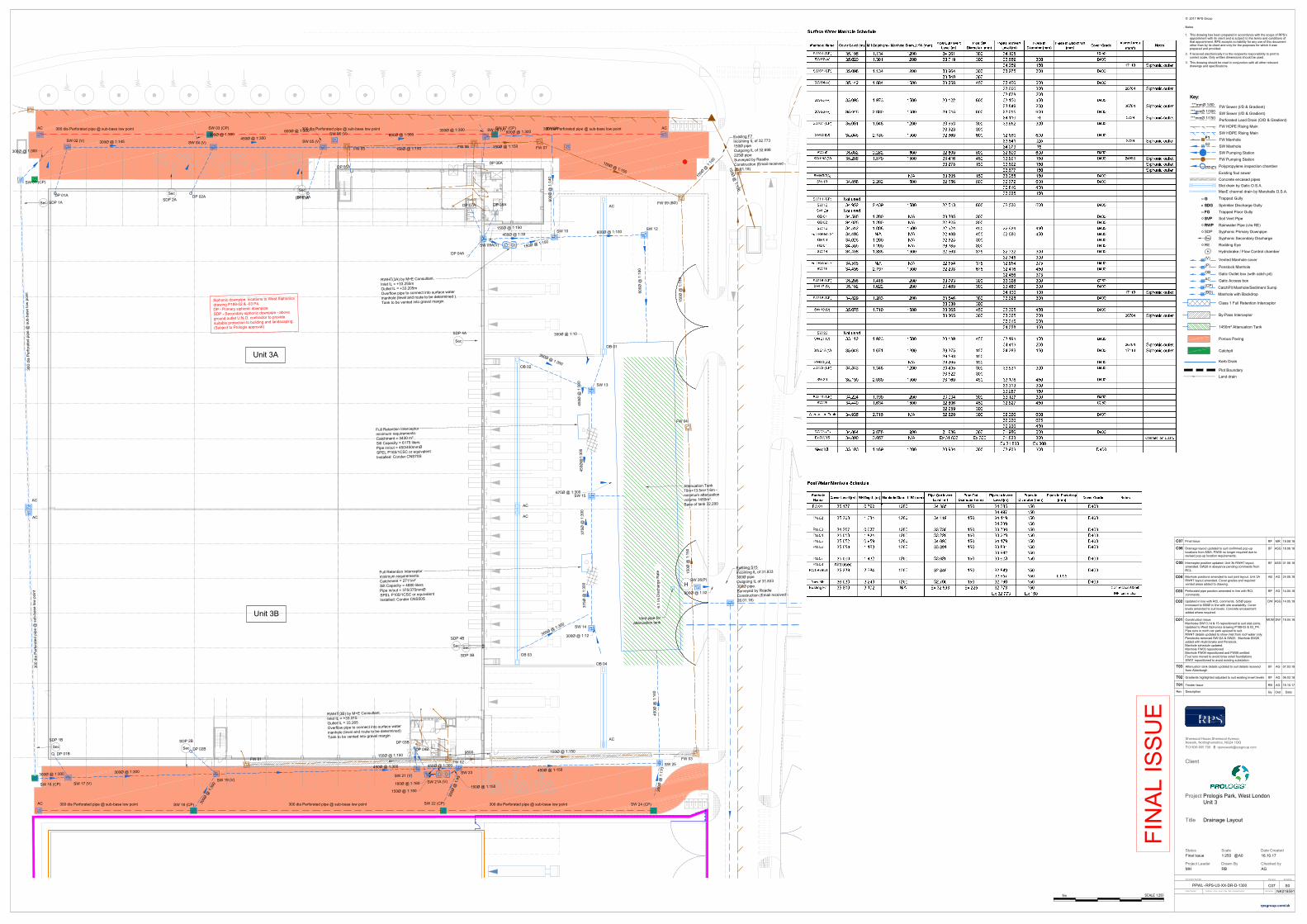
VVVV
V
V
V
V
V
V
V V V V
Unit 3A
Unit 3B
300 dia Perforated pipe @ sub-base low point
SW 03 (CP) SW 07 (CP)AC AC
300 dia Perforated pipe @ sub-base low point 300 dia Perforated pipe @ sub-base low point
OB 01
AC
OB 03
OB 02
AC
AC
OB 04
300 dia Perforated pipe @ sub-base low point
AC
SW 24 (CP)
SW 18 (CP)
SW 22 (CP)
300 dia Perforated pipe @ sub-base low point 300 dia Perforated pipe @ sub-base low point
Ex S15
300Ø @ 1:300
FW HDPE Rising Main
225Ø @ 1:150
FW HDPE Rising Main
F7
FPS2
DP 01A
SW 02 (V)
DP 02A
SW 04 (V)
DP 03A
AC
FW HDPE Rising Main
SW 05 (V)
SW 13
SW 15
SW 14
DP 01B
SDP 2B
DP 02B
DP 03B
SW 17 (V) SW 19 (V) SW 21 (V)
SW 25
DP 05A
SW 09
SW 10 SW 12
SW 23
AC
AC
SW 16 (CP)
SW 01 (CP)
300 d
ia
P
erforated
pipe @
sub-base low
point
300 dia
P
erfora
ted pipe @
sub
-base low
point
Full Retention Interceptor
minimum requirements:
Catchment = 2711m²
Silt Capacity = 4880 liters
Pipe in/out = 375/375mmØ
SPEL P100/1CSC or equivalent
Installed: Conder CNS50S
Full Retention Interceptor
minimum requirements:
Catchment = 3430 m²
Silt Capacity = 6175 liters
Pipe in/out = 450/450mmØ
SPEL P165/1CSC or equivalent
Installed: Conder CNS70S
6.1 l/s D
ischa
rge R
ate
H
Sec
300Ø @ 1:145
300Ø @ 1:300
300Ø @ 1:300
450Ø @ 1:300
600Ø @ 1:300
60
0Ø
@
1:140
600Ø @ 1:100
600Ø
@
1:1
00
3
0
0
Ø
@
1
:
3
0
0
300Ø @ 1:10
450Ø
@
1:300
450Ø
@1:300
375Ø
@
1:300
375Ø
@
1
:300
3
0
0
Ø
@
1
:
3
0
0
300Ø @ 1:12
675Ø @ 1:300
300Ø @ 1:300
300Ø @ 1:300
3
0
0
Ø
@
1
:
3
0
0
450Ø @ 1:300
3
0
0
Ø
@
1
:1
7
0
450Ø @ 1:150
45
0Ø
@
1:140
Attenuation Tank
70m×13.5m×1.6m -
minimum attenuation
volume 1450m³.
Base of tank 32.200
FW 01
FW 02
FW 03
FW 04
FW 05
FW 06
FW 07
FW 09 (BD)
Existing F7
Incoming IL of 32.773
150Ø pipe
Outgoing IL of 32.698
225Ø pipe
Surveyed by Readie
Construction (Email received -
26.01.18)
Existing S15
Incoming IL of 31.833
300Ø pipe
Outgoing IL of 31.833
300Ø pipe.
Surveyed by Readie
Construction (Email received -
26.01.18)
150Ø @ 1:150150Ø @ 1:150
1
5
0
Ø
@
1
:
1
5
0
150Ø @ 1:150
150Ø
@
1:150
15
0Ø
@
1
:150
RWHT(3B) by M+E Consultant.
Inlet IL = +33.315
Outlet IL = 33.265
Overflow pipe to connect into surface water
manhole (level and route to be determined)
Tank to be vented into gravel margin
RWHT(3A) by M+E Consultant.
Inlet IL = +33.255m
Outlet IL = +33.205m
Overflow pipe to connect into surface water
manhole (level and route to be determined ).
Tank to be vented into gravel margin
1
5
0
Ø
@
1
:
1
0
0
1
5
0
Ø
@
1
:
1
5
0
SW 09A(V)
Siphonic downpipe locations to West Siphonics
drawing P188-02 & -03 P4.
DP - Primary siphonic downpipe
SDP - Secondary siphonic downpipe - above
ground outlet U.N.O. contractor to provide
suitable protection to building and landscaping.
(Subject to Prologis approval)
Sec
Sec
DP 04A
DP 07ADP 08A
DP 06A
SDP 1ASec
Sec
SDP 2A
Sec
SDP 3A
SDP 4A
Sec
SDP 1B
Sec
SDP 3B
SDP 4B
DP 04B
SW 21A (V)
SW 06 (V)
SW 26(P)
600Ø @ 1:300600Ø @ 1:300
SW 08 (V)
150Ø @ 1:150
450Ø @ 1:300
450Ø @ 1:30
1
5
0
Ø
@
1
:1
5
0
300Ø @ 1:300
9500
300Ø @ 1:32
150Ø @ 1:150
Vent pipe for
attenuation tank
160Ø @ 1:160
150Ø @ 1:150
150Ø @ 1:150
3
0
0
Ø
@
1
:
4
5
***mmØ 1/150
***mmØ 1/300
Class 1 Full Retention Interceptor
Vented Manhole cover
Gatic Outlet box (with catch pit)
Gatic Access box
Penstock Manhole
By-Pass Interceptor
Kerb Drain
***mmØ 1/80
F1F1
Key:
FW Sewer (I/D & Gradient)
SW Manhole
Rodding Eye
Syphonic Primary Downpipe
G
FW Manhole
Trapped Gully
FW HDPE Rising Main
SW Sewer (I/D & Gradient)
Rainwater Pipe (c/w RE)RWP
SDG Sprinkler Discharge Gully
FG Trapped Floor Gully
Sec
Syphonic Secondary Discharge
Soil Vent Pipe SVP
Perforated Land Drain (O/D & Gradient)
SW HDPE Rising Main
SW Pumping Station
FW Pumping Station
Slot drain by Gatic O.S.A.
Concrete encased pipes
Existing foul sewer
Polypropylene inspection chamber
MaxE channel drain by Marshalls O.S.A.
Key:
G
SDP
RE
RWP
SDG
FG
SVP
Plot Boundary
CatchPit Manhole/Sediment Sump
Land drain
1450m³ Attenuation Tank
S2
PPIC1
(V)
OB
AC
(P)
(CP)
H
Hydrobrake / Flow Control chamber
Porous Paving
Catchpit
Manhole with Backdrop
(BD)
© 2017 RPS Group
Notes
1. This drawing has been prepared in accordance with the scope of RPS’s
appointment with its client and is subject to the terms and conditions of
that appointment. RPS accepts no liability for any use of this document
other than by its client and only for the purposes for which it was
prepared and provided.
2. If received electronically it is the recipients responsibility to print to
correct scale. Only written dimensions should be used.
3. This drawing should be read in conjunction with all other relevant
drawings and specifications.
Sherwood House,Sherwood Avenue,
Newark, Nottinghamshire, NG24 1QQ
T:01636 605 700 E: [email protected]
Client
Title
Status
Checked byDrawn By
Document NumberRevision
Project
Project Leader
DescriptionRev
By Ckd Date
-
Date CreatedScale
@
Suitability
Project Number Originator - Zone - Level - Type - Role - Drawing Number
rpsgroup.com/uk
Job Number
S0
A0 1:250 16.10.17Construction
AGRB
NK018591
C07
MH
RPS-U3-XX-DR-D-1300
Prologis Park, West London
Unit 3
Drainage Layout
5m SCALE 1:250
T01 RB AG 16.10.17Tender Issue
PPWL
Final Issue
T02 BF AG 06.03.18Gradients highlighted adjusted to suit existing invert levels
T03 BF AG 07.03.18Attenuation tank details updated to suit details received
from Alderburgh
C01MCM DW 19.04.18Construction Issue.
Manholes SW13,14 & 15 repositioned to suit slab joints.
Updated to West Siphonics drawing P188-02 & 03_P4.
Pipe runs in north car park upsized to suit.
RWHT details updated to show inlet from roof water only.
Penstocks removed SW12A & SW25. Manhole SW26
added with Hydrobrake and Penstock.
Manhole schedule updated.
Manhole FW03 repositioned
Manhole FW09 repositioned and FW08 omitted
Foul runs moved to avoid brise soleil foundations
SW01 repositioned to avoid existing substation
C02DW ASG 14.05.18Updated in line with RCL comments. 525Ø pipes
increased to 600Ø in line with site availability. Cover
levels amended to suit levels. Concrete encasement
added where required.
C03BF AG 14.05.18Perforated pipe position amended in line with RCL
comments.
C04AB AG 24.05.18Manhole positions amended to suit joint layout. Unit 3A
RWHT layout amended. Cover grades and required
vented areas added to drawing.
C05 BF ASG 01.06.18Interceptor position updated. Unit 3b RWHT layout
amended. SW26 in abeyance pending comments from
RCL.
C06 BF ASG 18.06.18Drainage layout updated to suit confirmed pop-up
locations from MSA. FW06 no longer required due to
revised pop-up location requirements.
C07 BF MR 19.09.18Final Issue
FIN
AL IS
SU
E

ENVIRONMENTAL PERMIT APPLICATION WSPProject No.: 70051165 | Our Ref No.: 70051165/Lon5-8/001 February 2020Virtus HoldCo Ltd
Public
PLANNING STAGE AIR QUALITYHISTORY
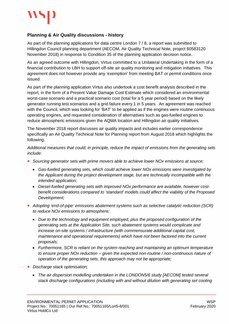
ENVIRONMENTAL PERMIT APPLICATION WSPProject No.: 70051165 | Our Ref No.: 70051165/Lon5-8/001 February 2020Virtus HoldCo Ltd
Planning & Air Quality discussions - historyAs part of the planning applications for data centre London 7 / 8, a report was submitted toHillingdon Council planning department (AECOM, Air Quality Technical Note, project 60583120November 2018) in response to Condition 35 of the planning application decision notice.
As an agreed outcome with Hillingdon, Virtus committed to a Unilateral Undertaking in the form of afinancial contribution to LBH to support off-site air quality monitoring and mitigation initiatives. Thisagreement does not however provide any ‘exemption’ from meeting BAT or permit conditions onceissued.
As part of the planning application Virtus also undertook a cost benefit analysis described in thereport, in the form of a Present Value Damage Cost Estimate which considered an environmentalworst-case scenario and a practical scenario cost (total for a 5 year period) based on the likelygenerator running test scenarios and a grid failure every 1 in 5 years. An agreement was reachedwith the Council, which was looking for ‘BAT’ to be applied as if the engines were routine continuousoperating engines, and requested consideration of alternatives such as gas-fuelled engines toreduce atmospheric emissions given the AQMA location and Hillingdon air quality initiatives.
The November 2018 report discusses air quality impacts and includes earlier correspondencespecifically an Air Quality Technical Note for Planning report from August 2018 which highlights thefollowing:
Additional measures that could, in principle, reduce the impact of emissions from the generating setsinclude:
¡ Sourcing generator sets with prime movers able to achieve lower NOx emissions at source;
· Gas-fuelled generating sets, which could achieve lower NOx emissions were investigated bythe Applicant during the project development stage, but are technically incompatible with theintended application;
· Diesel-fuelled generating sets with improved NOx performance are available, however cost-benefit considerations compared to ‘standard’ models could affect the viability of the ProposedDevelopment;
¡ Adopting ‘end-of-pipe’ emissions abatement systems such as selective catalytic reduction (SCR)to reduce NOx emissions to atmosphere;
· Due to the technology and equipment employed, plus the proposed configuration of thegenerating sets at the Application Site, such abatement systems would complicate andincrease on-site systems / infrastructure (with commensurate additional capital cost,maintenance and operational requirements) which have not been factored into the currentproposals;
· Furthermore, SCR is reliant on the system reaching and maintaining an optimum temperatureto ensure proper NOx reduction – given the expected non-routine / non-continuous nature ofoperation of the generating sets, this approach may not be appropriate;
¡ Discharge stack optimisation;
· The air dispersion modelling undertaken in the LONDON5/6 study [AECOM] tested severalstack discharge configurations (including with and without dilution with generating set cooling
ENVIRONMENTAL PERMIT APPLICATION WSPProject No.: 70051165 | Our Ref No.: 70051165/Lon5-8/001 February 2020Virtus HoldCo Ltd
air) and concluded that the stack discharge designs could likely be improved (from an airquality point of view) by:
- Increasing the stack discharge height above the surrounding buildings; and- Avoiding the dilution of engine exhaust with cooling air in the common duct (which
adversely affected the pollutant plume’s thermal buoyancy and exit velocity, in turnreducing the potential for dilution and dispersion in the atmosphere).
[Note however the current dispersion modelling presented with this application has been undertakenon the existing installation design.]
¡ Minimising and managing planned operating time;
· Monthly planned maintenance should allow for the absolute minimum time for the generatingsets to be operational;
· The maintenance schedule for the generating sets could arguably take consideration of thelikely patterns of occupation of nearby receptors. For example, the nursery school and officecomplexes to the east of the Application Site are unlikely to be occupied in the evenings orover weekends, hence the generating sets in the south-eastern portion of the site could bescheduled for maintenance during such periods. Similarly, maintenance testing should beavoided during peak traffic hours when pollutant contributions from (non-related) road vehicleswould be greatest;
· The concurrent maintenance testing of generators at the LONDON7/8 and LONDON5/6 sitescould be avoided through adoption of a strict “one generating set at a time” rule.
The council responded to the above points and a further letter (dated 20 September 2018) was sentdiscussing the option of gas-fired generating sets, and stated that three main considerations makethe use of gas-powered generating sets technically incompatible with the application, being:
¡ Load acceptance – Diesel engines are able to accept a load after approximately 15 seconds fromstarting, whereas gas engines would require approximately 5 minutes to reach the samecondition. In the proposed application, where the generating sets are relied upon to provideimmediate back-up power supply to the data centre in the event of a mains power failure, thesignificantly longer period to reach a point where load may be applied to the gas engines wouldcompromise the integrity of the data centres power supply to maintain essential operations.
¡ Load stability – Gas engines require a stable load to be applied to them. The proposeddevelopment includes several items of sizable mechanical equipment, potentially starting orstopping (i.e. a non-stable load profile). This variable load profile could not be feasiblyaccommodated by gas engines.
¡ Fuel supply – The nature of the proposed application of the generators means that they willrequire a secure supply of fuel for operation in the event of a main power failure. In order toachieve this for gas fuel, there would be a requirement for a large quantity of gas to be storedunder pressure on site in a large vessel/s. This would likely represent a potential major hazardinstallation, which would introduce both on-site and public health and safety risk considerations.Additionally, the level of potential risk posed by the on-site storage of such a large quantity ofpressurised gas, could undermine the fundamental integrity of the data centre operation itself.
ENVIRONMENTAL PERMIT APPLICATION WSPProject No.: 70051165 | Our Ref No.: 70051165/Lon5-8/001 February 2020Virtus HoldCo Ltd
Virtus holds regular technology enquiries with prospective vendors, including assessing the viabilityand appropriateness of exhaust gas recirculation technology as a potential emissions mitigationmeasure, and this approach was discounted as a viable solution considering the size, type andapplication of the generating sets required for the development.
The Council required Virtus to consider compliance with the Medium Combustion Plant Directive(MCPD) 190 mg/Nm3 emission limit under normal operating conditions, however installinggenerating sets at the site that are certified as able to comply could cost in the region of £8 million,and it is currently unclear whether the targeted emissions performance would be fully achieved (asthe measures employed to comply with the emission limit may not be fully compatible with theintended application of the generating sets at the site, i.e. short-term, infrequent periods ofoperation). There would also be an increase in running and maintenance costs of the generatorsystem in its entirety. In light of this, even considering a partial adoption of ‘low emission capable’generating sets (i.e. not all generating sets on would be of this type) may not deliver actual intendedbenefits, and would additionally complicate on-site systems by having two different types ofequipment (different spares requirements, operating/maintenance procedures etc.).
Public
GENERATOR ENGINE DATASHEET

1
IE FEATURES
Image shown may not reflect actual package
Mission Critical Standby 2200 ekW 2750 kVA 50 Hz 1500 rpm 11000 Volts
Caterpillar is leading the power generation Market place with Power Solutions engineered to deliver unmatched flexibility, expandability, reliability, and cost-effectiveness.
FUEL/EMISSIONS STRATEGY • Low fuel consumption DESIGN CRITERIA • The generator set accepts 100% rated load in one step per NFPA 110 and meets ISO 8528-5 transient response. FULL RANGE OF ATTACHMENTS • Wide range of bolt-on system expansion attachments, factory designed and tested • Flexible packaging options for easy and cost effective installation SINGLE-SOURCE SUPPLIER • Fully prototype tested with certified torsional vibration analysis available WORLDWIDE PRODUCT SUPPORT • Cat® dealers provide extensive post sale support including maintenance and repair agreements • Cat dealers have over 1,800 dealer branch
stores operating in 200 countries. • The Cat S•O•S SM program effectively
detects internal engine component condition, even the presence of unwanted fluids and combustion by-products.
CAT® 3516C-HD TA DIESEL ENGINE • Reliable, rugged, durable design • Four-stroke diesel engine combines consistent performance and excellent fuel economy with minimum weight CAT GENERATOR
• Matched to the performance and output characteristics of Cat engines • Industry leading mechanical and electrical design • High efficiency
CAT EMCP 4 CONTROL PANELS • Simple user friendly interface and navigation • Scalable system to meet a wide range of customer needs • Integrated Control System and Communications Gateway
DIESEL GENERATOR SET
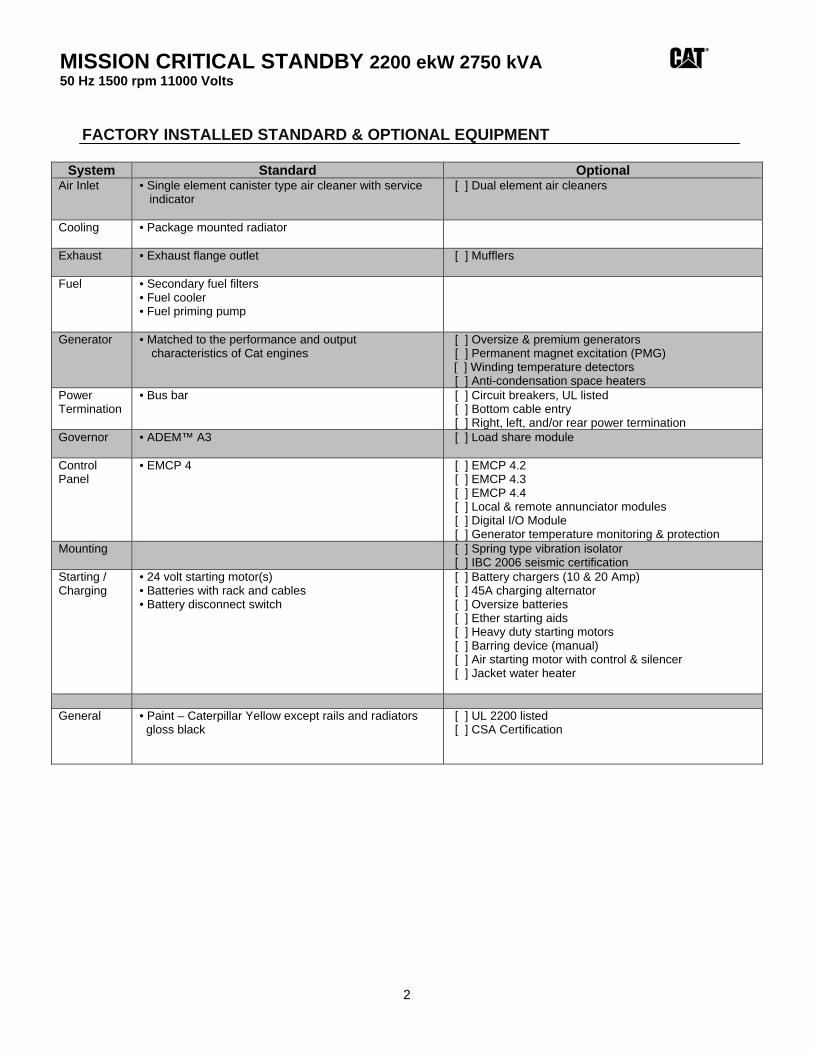
MISSION CRITICAL STANDBY 2200 ekW 2750 kVA 50 Hz 1500 rpm 11000 Volts
2
FACTORY INSTALLED STANDARD & OPTIONAL EQUIPMENT
System Standard Optional Air Inlet • Single element canister type air cleaner with service
indicator
[ ] Dual element air cleaners
Cooling • Package mounted radiator
Exhaust • Exhaust flange outlet
[ ] Mufflers
Fuel • Secondary fuel filters • Fuel cooler • Fuel priming pump
Generator
• Matched to the performance and output characteristics of Cat engines
[ ] Oversize & premium generators [ ] Permanent magnet excitation (PMG)
[ ] Winding temperature detectors [ ] Anti-condensation space heaters
Power Termination
• Bus bar
[ ] Circuit breakers, UL listed [ ] Bottom cable entry [ ] Right, left, and/or rear power termination
Governor • ADEM™ A3
[ ] Load share module
Control Panel
• EMCP 4 [ ] EMCP 4.2 [ ] EMCP 4.3 [ ] EMCP 4.4 [ ] Local & remote annunciator modules [ ] Digital I/O Module [ ] Generator temperature monitoring & protection
Mounting
[ ] Spring type vibration isolator [ ] IBC 2006 seismic certification
Starting / Charging
• 24 volt starting motor(s) • Batteries with rack and cables • Battery disconnect switch
[ ] Battery chargers (10 & 20 Amp) [ ] 45A charging alternator [ ] Oversize batteries [ ] Ether starting aids [ ] Heavy duty starting motors [ ] Barring device (manual) [ ] Air starting motor with control & silencer [ ] Jacket water heater
General • Paint – Caterpillar Yellow except rails and radiators
gloss black
[ ] UL 2200 listed [ ] CSA Certification
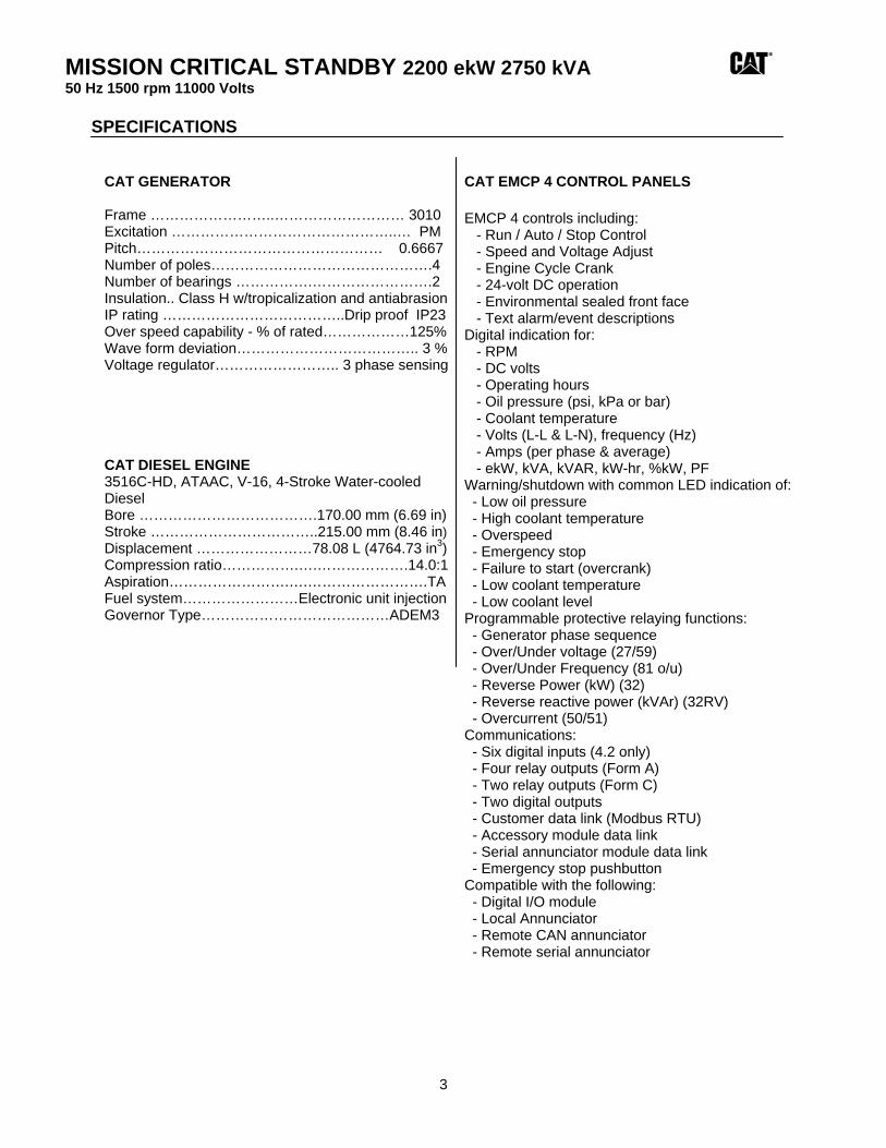
MISSION CRITICAL STANDBY 2200 ekW 2750 kVA 50 Hz 1500 rpm 11000 Volts
3
SPECIFICATIONS CAT GENERATOR Frame ……………………..……………………… 3010 Excitation ………………………………………..… PM Pitch…………………………………………… 0.6667 Number of poles……………………………………….4 Number of bearings …………….…………………….2 Insulation.. Class H w/tropicalization and antiabrasion IP rating ………………………………..Drip proof IP23 Over speed capability - % of rated………………125% Wave form deviation……………………………….. 3 % Voltage regulator…………………….. 3 phase sensing CAT DIESEL ENGINE 3516C-HD, ATAAC, V-16, 4-Stroke Water-cooled Diesel Bore ……………………………….170.00 mm (6.69 in) Stroke ……………………………..215.00 mm (8.46 in) Displacement ……………………78.08 L (4764.73 in3) Compression ratio…………….….……………….14.0:1 Aspiration…………………….….…………………….TA Fuel system……………………Electronic unit injection Governor Type…………………………………ADEM3
CAT EMCP 4 CONTROL PANELS EMCP 4 controls including: - Run / Auto / Stop Control - Speed and Voltage Adjust - Engine Cycle Crank - 24-volt DC operation - Environmental sealed front face - Text alarm/event descriptions Digital indication for: - RPM - DC volts - Operating hours - Oil pressure (psi, kPa or bar) - Coolant temperature - Volts (L-L & L-N), frequency (Hz) - Amps (per phase & average) - ekW, kVA, kVAR, kW-hr, %kW, PF Warning/shutdown with common LED indication of: - Low oil pressure - High coolant temperature - Overspeed - Emergency stop - Failure to start (overcrank) - Low coolant temperature - Low coolant level Programmable protective relaying functions: - Generator phase sequence - Over/Under voltage (27/59) - Over/Under Frequency (81 o/u) - Reverse Power (kW) (32) - Reverse reactive power (kVAr) (32RV) - Overcurrent (50/51) Communications: - Six digital inputs (4.2 only) - Four relay outputs (Form A) - Two relay outputs (Form C) - Two digital outputs - Customer data link (Modbus RTU) - Accessory module data link - Serial annunciator module data link - Emergency stop pushbutton Compatible with the following: - Digital I/O module - Local Annunciator - Remote CAN annunciator - Remote serial annunciator
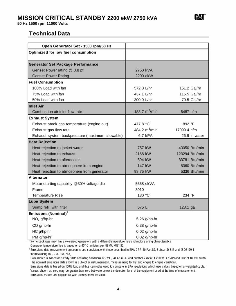
MISSION CRITICAL STANDBY 2200 ekW 2750 kVA 50 Hz 1500 rpm 11000 Volts
4
Technical Data
Open Generator Set - 1500 rpm/50 HzOptimized for low fuel consumption
Generator Set Package PerformanceGenset Power rating @ 0.8 pf 2750 kVAGenset Power Rating 2200 ekW
Fuel Consumption100% Load with fan 572.3 L/hr 151.2 Gal/hr75% Load with fan 437.1 L/hr 115.5 Gal/hr50% Load with fan 300.9 L/hr 79.5 Gal/hr
Inlet AirCombustion air inlet flow rate 183.7 m3/min 6487 cfm
Exhaust SystemExhaust stack gas temperature (engine out) 477.8 °C 892 °FExhaust gas flow rate 484.2 m3/min 17099.4 cfmExhaust system backpressure (maximum allowable) 6.7 kPA 26.9 in water
Heat RejectionHeat rejection to jacket water 757 kW 43050 Btu/minHeat rejection to exhaust 2168 kW 123294 Btu/minHeat rejection to aftercooler 594 kW 33781 Btu/minHeat rejection to atmosphere from engine 147 kW 8360 Btu/minHeat rejection to atmosphere from generator 93.75 kW 5336 Btu/min
AlternatorMotor starting capabiliy @30% voltage dip 5668 skVAFrame 3010Temperature Rise 130 °C 234 °F
Lube SystemSump refill with filter 675 L 123.1 gal
Emissions (Nominal)2
NOx g/hp-hr 5.26 g/hp-hrCO g/hp-hr 0.38 g/hp-hrHC g/hp-hr 0.02 g/hp-hrPM g/hp-hr 0.02 g/hp-hr
1 Some packages may hav e ov ersized generators w ith a different temperature rise and motor starting characteristics Generator temperature rise is based on a 40° C ambient per NEMA MG1-322 Emissions data measurement procedures are consistent w ith those described in EPA CFR 40 Part 89, Subpart D & E and ISO8179-1 for measuring HC, CO, PM, NO
x Data show n is based on steady state operating conditions of 77°F, 28.42 in HG and number 2 diesel fuel w ith 35° API and LHV of 18,390 btu/lb. The nominal emissions data show n is subject to instrumentation, measurement, facility and engine to engine v ariations. Emissions data is based on 100% load and thus cannot be used to compare to EPA regulations w hich use v alues based on a w eighted cy cle. Values show n as zero may be greater than zero but w ere below the detection lev el of the equipment used at the time of measurement. Emissions v alues are tailpipe out w ith aftertreatment installed.
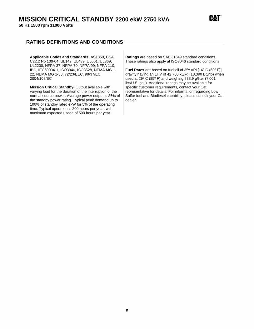
MISSION CRITICAL STANDBY 2200 ekW 2750 kVA 50 Hz 1500 rpm 11000 Volts
5
RATING DEFINITIONS AND CONDITIONS
Applicable Codes and Standards: AS1359, CSA C22.2 No 100-04, UL142, UL489, UL601, UL869, UL2200, NFPA 37, NFPA 70, NFPA 99, NFPA 110, IBC, IEC60034-1, ISO3046, ISO8528, NEMA MG 1-22, NEMA MG 1-33, 72/23/EEC, 98/37/EC, 2004/108/EC Mission Critical Standby- Output available with varying load for the duration of the interruption of the normal source power. Average power output is 85% of the standby power rating. Typical peak demand up to 100% of standby rated ekW for 5% of the operating time. Typical operation is 200 hours per year, with maximum expected usage of 500 hours per year.
Ratings are based on SAE J1349 standard conditions. These ratings also apply at ISO3046 standard conditions Fuel Rates are based on fuel oil of 35º API [16º C (60º F)] gravity having an LHV of 42 780 kJ/kg (18,390 Btu/lb) when used at 29º C (85º F) and weighing 838.9 g/liter (7.001 lbs/U.S. gal.). Additional ratings may be available for specific customer requirements, contact your Cat representative for details. For information regarding Low Sulfur fuel and Biodiesel capability, please consult your Cat dealer.
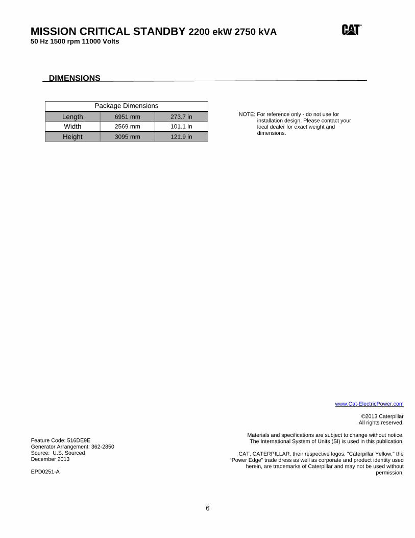
MISSION CRITICAL STANDBY 2200 ekW 2750 kVA 50 Hz 1500 rpm 11000 Volts
6
DIMENSIONS
Package Dimensions Length 6951 mm 273.7 in Width 2569 mm 101.1 in
Height 3095 mm 121.9 in
NOTE: For reference only - do not use for installation design. Please contact your local dealer for exact weight and dimensions.
www.Cat-ElectricPower.com
©2013 Caterpillar All rights reserved.
Materials and specifications are subject to change without notice. The International System of Units (SI) is used in this publication.
CAT, CATERPILLAR, their respective logos, "Caterpillar Yellow," the
“Power Edge” trade dress as well as corporate and product identity used herein, are trademarks of Caterpillar and may not be used without
permission.
Feature Code: 516DE9E Generator Arrangement: 362-2850 Source: U.S. Sourced December 2013 EPD0251-A
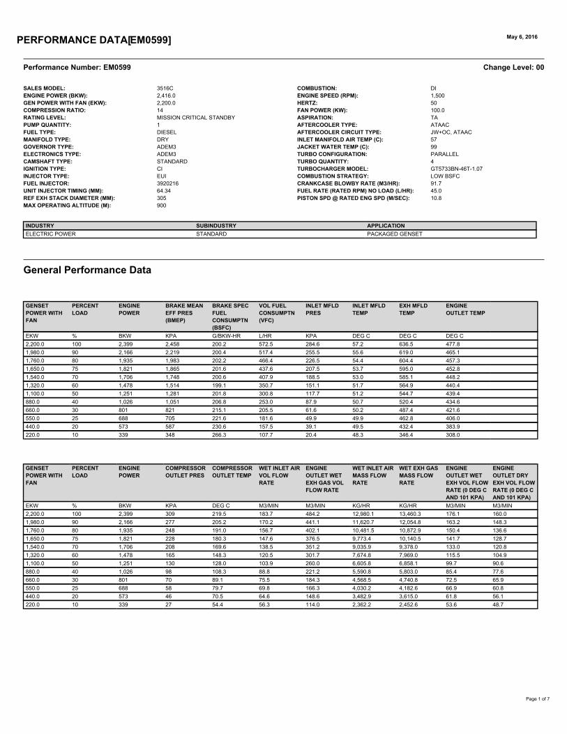
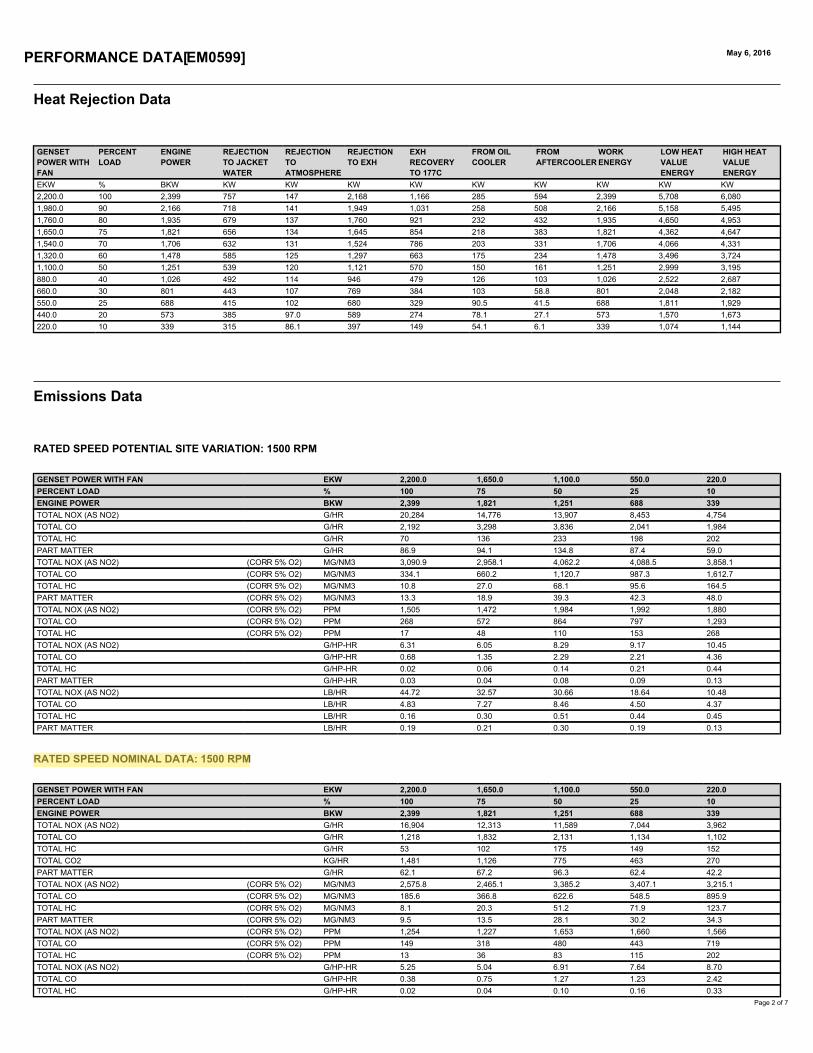

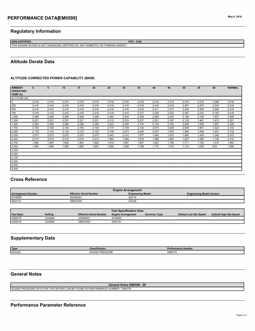
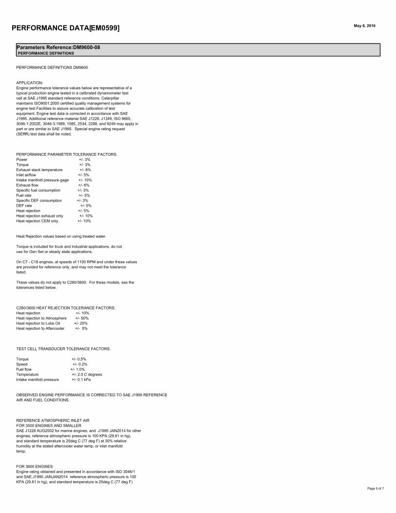


ENVIRONMENTAL PERMIT APPLICATION WSPProject No.: 70051165 | Our Ref No.: 70051165/Lon5-8/001 February 2020Virtus HoldCo Ltd

PUBLIC

PUBLIC
110 Queen StreetGlasgowG1 3BX
wsp.com