tongue-rudder: a glossokinetic-potential-based tongue–machine interface
TRANSCRIPT
290 IEEE TRANSACTIONS ON BIOMEDICAL ENGINEERING, VOL. 59, NO. 1, JANUARY 2012
Tongue-Rudder: A Glossokinetic-Potential-BasedTongue–Machine Interface
Yunjun Nam, Qibin Zhao, Andrzej Cichocki, Member, IEEE, and Seungjin Choi*, Member, IEEE
Abstract—Glossokinetic potentials (GKPs) are electric potentialresponses generated by tongue movement. In this study, we usethese GKPs to automatically detect and estimate tongue positions,and develop a tongue–machine interface. We show that a specificconfiguration of electrode placement yields discriminative GKPsthat vary depending on the direction of the tongue. We develop a lin-ear model to determine the direction of tongue from GKPs, wherewe seek linear features that are robust to a baseline drift prob-lem by maximizing the ratio of intertask covariance to intersessioncovariance. We apply our method to the task of wheelchair con-trol, developing a tongue–machine interface for wheelchair control,referred to as tongue-rudder. A teeth clenching detection system,using electromyography, was also implemented in the system inorder to assign teeth clenching as the stop command. Experimentson off-line cursor control and online wheelchair control confirmthe unique advantages of our method, such as: 1) noninvasiveness,2) fine controllability, and 3) ability to integrate with other EEG-based interface systems.
Index Terms—Electric wheelchair control, glossokinetic poten-tials (GKPs), tongue–machine interface.
I. INTRODUCTION
A SSISTIVE technologies have been developed for personswith limb motor disabilities and even for those with com-
plete quadriplegia, in order to provide an alternative communi-cation channel and help the persons in performing daily tasksby utilizing biosignals measured from various sensors placed onthe persons. For several reasons, highlighted in [1], the tongue
Manuscript received December 28, 2010; revised April 22, 2011 and August10, 2011; accepted October 4, 2011. Date of publication October 28, 2011; dateof current version December 21, 2011. This work was supported in part by theNational Research Foundation (NRF) of Korea under Grant 2011-0018283 andGrant 2011-0018284, by the NRF World Class University Program under GrantR31-10100, and by the TUBITAK under Project 110E232. A portion of thiswork was carried out while Y. Nam was visiting the Advanced Brain SignalProcessing Lab, Brain Science Institute, RIKEN, Wako-shi, Japan. Asterisk in-dicates corresponding author.
Y. Nam is with the School of Interdisciplinary Bioscience and Bioengineer-ing, Pohang University of Science and Technology, Pohang 790-784, Korea(e-mail: [email protected]).
Q. Zhao is with the Advance Brain Signal Processing Lab, BrainScience Institute, RIKEN, Wako-shi, Saitama 351-0198, Japan (e-mail:[email protected]).
A. Cichocki is with the Advance Brain Signal Processing Lab, Brain Sci-ence Institute, RIKEN, Saitama 351-0198, Japan, and also with the SystemsResearch Institute, Polish Academy of Science, 01-447 Warszawa, Poland(e-mail: [email protected]).
∗S. Choi is with the Department of Computer Science and Division ofIT Convergence Engineering, Pohang University of Science and Technology,Pohang 790-784, Korea (e-mail: [email protected]).
Color versions of one or more of the figures in this paper are available onlineat http://ieeexplore.ieee.org.
Digital Object Identifier 10.1109/TBME.2011.2174058
is regarded as a suitable organ for manipulating assistive de-vices involving motor control. These reasons are as follows:1) the tongue is directly connected to the brain by cranial nervesand the distance from the brain is relatively short; 2) the tonguegenerally escapes severe damage in spinal cord injuries, andin many cases, it is more slowly affected than limbs of per-sons suffering from most neuromuscular degenerative disorder;3) the tongue consists of special muscles suitable for complexvocalization and ingestion tasks so that it can move very quicklyand accurately with little fatigue; and 4) tongue movements canbe hidden by the mouth cavity, which is a cosmetic advantage.
Several tongue-operated assistive devices, which benefittedfrom the aforementioned advantages, have been developed. The“tongue drive” system uses a tongue-mounted permanent mag-net and magnetic-sensors-implanted dental retainer for trackingtongue movement [2]. The inductive tongue computer interface(ITCI) observes changes in the inductance from coils (attachedto the palatal plate), which are caused by the movement offerromagnetic material (attached to the tongue) [3]. The “think-a-move” system can recognize commands by analyzing acousticpatterns generated by specific tongue motions such as flickingof the tongue to the left/center/right gum line [4]. The “tongue-mouse” uses piezoelectric ceramic materials, which producesmall charges when pressed, to sense a push by the tongue [5].The “Tonguepoint” is a special mouthpiece, and it has a smallpressure-sensitive joystick on the hard palate region [6].
Most of the existing methods for tongue–machine interfacesrequire that sensors be placed on the tongue or inside the mouthin order to acquire signals involving tongue movement. Theyare limited to only a few commands so that fine control ofdevice is not possible. In this paper, we present a novel tongue–machine interface where we detect tongue positions solely by us-ing glossokinetic potentials (GKPs) that are EEG signals relatedto tongue movements. In contrast to existing tongue–computerinterface systems, our method does not require any extra sensorsplaced inside mouth, which might be more comfortable to ac-quire signals involving tongue movements. Moreover, as will beshown, our method enables fine-grained device control with anaccuracy (in terms of difference between the estimated directionand the true direction) of approximately 20◦.
In our preliminary results reported in [7], we showed that aspecific configuration of electrode placement yields discrimi-native GKPs that vary in accordance with the direction of thetongue. Thus, GKP is a direct continuous interpretation of thedirection of the tongue, leading to fine-grained device control.In this paper, we develop a linear model to associate GKP withthe direction of the tongue, where we seek linear features thatare robust to the baseline drift (the gradual and linear shift in
0018-9294/$26.00 © 2011 IEEE
NAM et al.: TONGUE-RUDDER: A GLOSSOKINETIC-POTENTIAL-BASED TONGUE–MACHINE INTERFACE 291
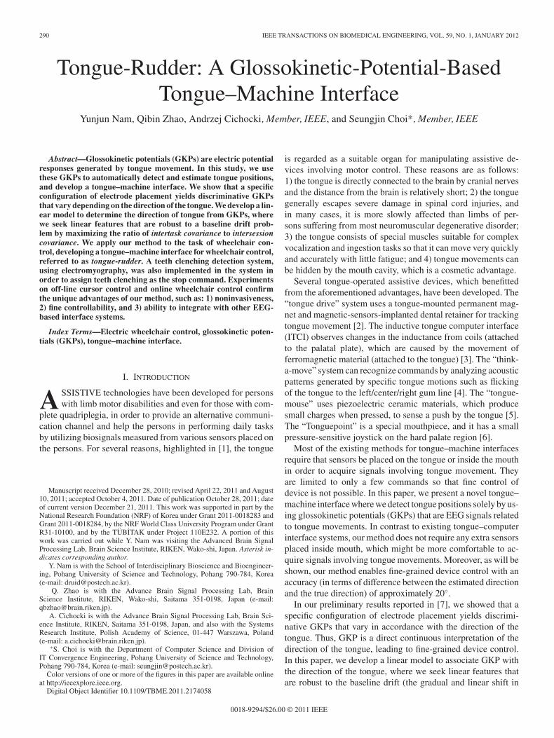
Fig. 1. Overview of the “tongue-rudder” system. GKP is analyzed to estimatethe direction of the tongue (in the range between − π
2 and π2 ) that facilitates
smooth control of the wheelchair. The electromyograph (EMG) signals thatarise when clenched are used for sending special commands such as “stop” or“turn ON/OFF.”
the baseline over a specified period of time), by maximizingthe ratio of intertask covariance to intersession covariance. Weapply our method to the task of wheelchair control, developinga tongue–machine interface for wheelchair control, referred toas tongue-rudder.
The rest of this paper is organized as follows. In Section II, wefirst briefly explain GKP that is a slow wave response caused bytongue movement. We then describe seesaw-like GKPs that varyin accordance with tongue positions that are observed under aspecific configuration of electrode placement. These seesaw-likeGKPs are one of the main topics discussed in this paper, becausethey enable us to develop an EEG-based tongue–machine inter-face. In Section III, we develop a method for interpreting GKPin terms of the direction of the tongue. We describe a linearfeature extraction method that is robust to the baseline drift.In Section IV, we describe the implementation details of ourtongue-rudder system, an overview of which is graphically de-picted in Fig. 1. The tongue-based interface is similar in functionto a steering wheel and allows the wheelchair to turn smoothly.The clenching-based interface is similar to a brake as it togglesbetween run and stop states. Section V presents experiments onoff-line cursor control and online wheelchair control. Finally,conclusions are drawn in Section VI.
II. GKPS
In this section, we briefly explain GKPs, and then, introduceseesaw-like GKPs that are used in our system.
A. Background: GKPs
GKPs are electric potential response generated by tonguemovement [8], [9]. The tip of the tongue has a negative electriccharge with respect to the root. As a result, if the tongue touchesthe palate or inside the mouth, a discharge is generated that
affects the potential levels on the scalp (see [8, pp. 114–117]).Vanhatalo et al. [10] also reported that GKP can be removedby insulating the surface of the tongue in order to block thedischarge. This GKP has been studied primarily within EEGanalysis. Since it originates from a noncerebral region, it caninterfere with the observation of brain activities. Thus, it hasbeen ignored or actively removed during the recording or thepreprocessing stages, likewise other artifacts such as EMG orelectrooculogram (EOG) [11].
GKP has attracted little attention, compared to EMG or EOG,since GKP is easily regulated than EMG or EOG. First, GKPcan be consciously suppressed by the subject. Unlike EOG ar-tifacts, which are caused by an involuntary eye–ball movementor blinking of the eye, GKP is caused by a voluntary tonguemovement. Thus, it can easily be regulated unless the subjecthas special symptoms such as Parkinson’s disease or tremordisorder. Second, GKP can easily be removed by simple high-pass filtering. EMG is also a consciously regulatable artifactlike GKP. However, once it is generated, it severely hampersEEG analysis because it contaminates all frequency bands inthe millivolt scale [12]. In contrast, GKP has influence onlyon low-frequency bands, so it induces less deterioration and caneasily be removed by simple high-pass filtering with a cutoff fre-quency at 4 Hz. Because of these reasons, GKP has been studiedless and considered only when the EEG analysis is related tovocalization or ingestion tasks [13], [14].
B. Seesaw-Like GKPs
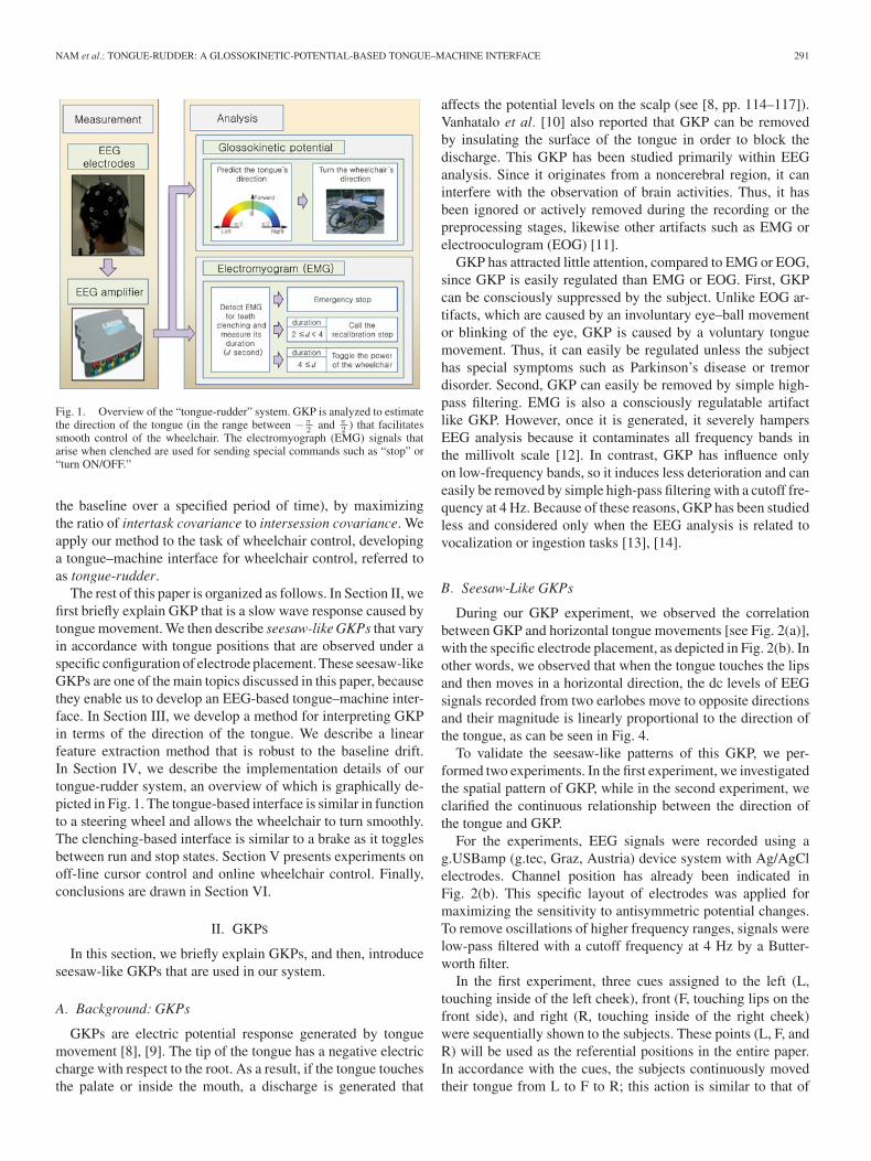
During our GKP experiment, we observed the correlationbetween GKP and horizontal tongue movements [see Fig. 2(a)],with the specific electrode placement, as depicted in Fig. 2(b). Inother words, we observed that when the tongue touches the lipsand then moves in a horizontal direction, the dc levels of EEGsignals recorded from two earlobes move to opposite directionsand their magnitude is linearly proportional to the direction ofthe tongue, as can be seen in Fig. 4.
To validate the seesaw-like patterns of this GKP, we per-formed two experiments. In the first experiment, we investigatedthe spatial pattern of GKP, while in the second experiment, weclarified the continuous relationship between the direction ofthe tongue and GKP.
For the experiments, EEG signals were recorded using ag.USBamp (g.tec, Graz, Austria) device system with Ag/AgClelectrodes. Channel position has already been indicated inFig. 2(b). This specific layout of electrodes was applied formaximizing the sensitivity to antisymmetric potential changes.To remove oscillations of higher frequency ranges, signals werelow-pass filtered with a cutoff frequency at 4 Hz by a Butter-worth filter.
In the first experiment, three cues assigned to the left (L,touching inside of the left cheek), front (F, touching lips on thefront side), and right (R, touching inside of the right cheek)were sequentially shown to the subjects. These points (L, F, andR) will be used as the referential positions in the entire paper.In accordance with the cues, the subjects continuously movedtheir tongue from L to F to R; this action is similar to that of
292 IEEE TRANSACTIONS ON BIOMEDICAL ENGINEERING, VOL. 59, NO. 1, JANUARY 2012
Fig. 2. (a) If the tongue touches the inside of the cheek (buccal wall) by passingin between the upper and the lower teeth, a potential alteration is generated. Weanalyzed this potential to detect the direction of the tongue within the range−π/2 (touching the inside of the left cheek) to π/2 (touching the inside of theright cheek). (b) Channel position for EEG recording during the implementationstep. The reference electrode was mounted on top of the head (Cz, dashed circle),and two ground electrodes were mounted on the forehead and at the back ofthe head (POz, AFz, black dashed circle). Then, signals were recorded fromtemporal regions (F7/8, T7/8, P7/8, and left/right earlobes (LE/RE), and blackcircle) for measuring antisymmetric GKP. (a) Tongue movements during theexperiments. (b) Channel location.
licking the lips. They were also instructed not to move their chinduring the tongue movements. This was done in order to preventshifting or tilting of the electrodes. The length of each cue was4 s and the single session consisting of three different cues wasrepeated eight times.
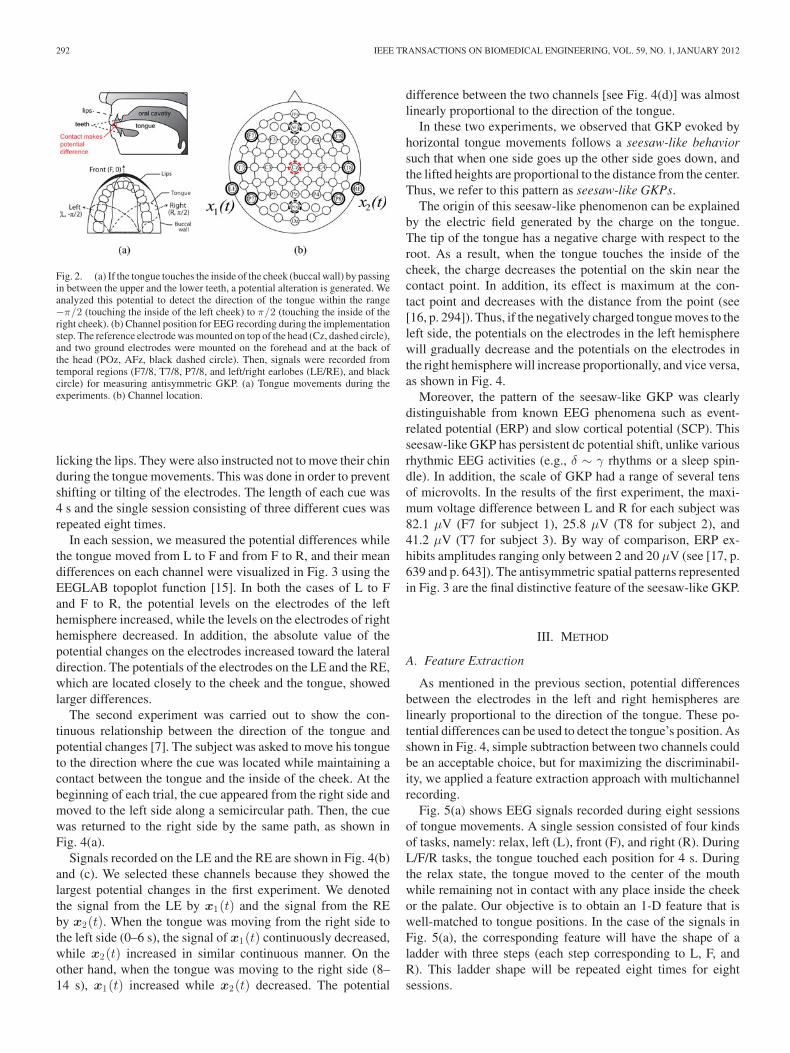
In each session, we measured the potential differences whilethe tongue moved from L to F and from F to R, and their meandifferences on each channel were visualized in Fig. 3 using theEEGLAB topoplot function [15]. In both the cases of L to Fand F to R, the potential levels on the electrodes of the lefthemisphere increased, while the levels on the electrodes of righthemisphere decreased. In addition, the absolute value of thepotential changes on the electrodes increased toward the lateraldirection. The potentials of the electrodes on the LE and the RE,which are located closely to the cheek and the tongue, showedlarger differences.
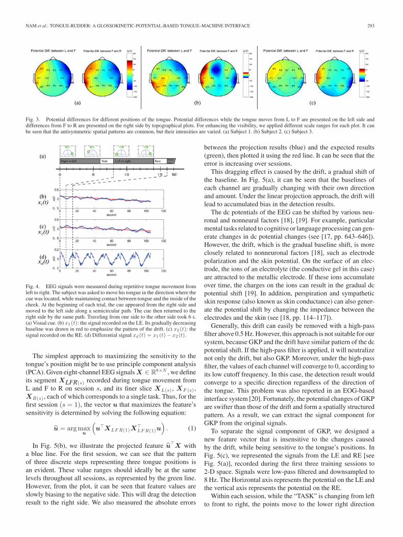
The second experiment was carried out to show the con-tinuous relationship between the direction of the tongue andpotential changes [7]. The subject was asked to move his tongueto the direction where the cue was located while maintaining acontact between the tongue and the inside of the cheek. At thebeginning of each trial, the cue appeared from the right side andmoved to the left side along a semicircular path. Then, the cuewas returned to the right side by the same path, as shown inFig. 4(a).
Signals recorded on the LE and the RE are shown in Fig. 4(b)and (c). We selected these channels because they showed thelargest potential changes in the first experiment. We denotedthe signal from the LE by x1(t) and the signal from the REby x2(t). When the tongue was moving from the right side tothe left side (0–6 s), the signal of x1(t) continuously decreased,while x2(t) increased in similar continuous manner. On theother hand, when the tongue was moving to the right side (8–14 s), x1(t) increased while x2(t) decreased. The potential
difference between the two channels [see Fig. 4(d)] was almostlinearly proportional to the direction of the tongue.
In these two experiments, we observed that GKP evoked byhorizontal tongue movements follows a seesaw-like behaviorsuch that when one side goes up the other side goes down, andthe lifted heights are proportional to the distance from the center.Thus, we refer to this pattern as seesaw-like GKPs.
The origin of this seesaw-like phenomenon can be explainedby the electric field generated by the charge on the tongue.The tip of the tongue has a negative charge with respect to theroot. As a result, when the tongue touches the inside of thecheek, the charge decreases the potential on the skin near thecontact point. In addition, its effect is maximum at the con-tact point and decreases with the distance from the point (see[16, p. 294]). Thus, if the negatively charged tongue moves to theleft side, the potentials on the electrodes in the left hemispherewill gradually decrease and the potentials on the electrodes inthe right hemisphere will increase proportionally, and vice versa,as shown in Fig. 4.
Moreover, the pattern of the seesaw-like GKP was clearlydistinguishable from known EEG phenomena such as event-related potential (ERP) and slow cortical potential (SCP). Thisseesaw-like GKP has persistent dc potential shift, unlike variousrhythmic EEG activities (e.g., δ ∼ γ rhythms or a sleep spin-dle). In addition, the scale of GKP had a range of several tensof microvolts. In the results of the first experiment, the maxi-mum voltage difference between L and R for each subject was82.1 μV (F7 for subject 1), 25.8 μV (T8 for subject 2), and41.2 μV (T7 for subject 3). By way of comparison, ERP ex-hibits amplitudes ranging only between 2 and 20 μV (see [17, p.639 and p. 643]). The antisymmetric spatial patterns representedin Fig. 3 are the final distinctive feature of the seesaw-like GKP.
III. METHOD
A. Feature Extraction
As mentioned in the previous section, potential differencesbetween the electrodes in the left and right hemispheres arelinearly proportional to the direction of the tongue. These po-tential differences can be used to detect the tongue’s position. Asshown in Fig. 4, simple subtraction between two channels couldbe an acceptable choice, but for maximizing the discriminabil-ity, we applied a feature extraction approach with multichannelrecording.
Fig. 5(a) shows EEG signals recorded during eight sessionsof tongue movements. A single session consisted of four kindsof tasks, namely: relax, left (L), front (F), and right (R). DuringL/F/R tasks, the tongue touched each position for 4 s. Duringthe relax state, the tongue moved to the center of the mouthwhile remaining not in contact with any place inside the cheekor the palate. Our objective is to obtain an 1-D feature that iswell-matched to tongue positions. In the case of the signals inFig. 5(a), the corresponding feature will have the shape of aladder with three steps (each step corresponding to L, F, andR). This ladder shape will be repeated eight times for eightsessions.
NAM et al.: TONGUE-RUDDER: A GLOSSOKINETIC-POTENTIAL-BASED TONGUE–MACHINE INTERFACE 293
Fig. 3. Potential differences for different positions of the tongue. Potential differences while the tongue moves from L to F are presented on the left side anddifferences from F to R are presented on the right side by topographical plots. For enhancing the visibility, we applied different scale ranges for each plot. It canbe seen that the antisymmetric spatial patterns are common, but their intensities are varied. (a) Subject 1. (b) Subject 2. (c) Subject 3.
Fig. 4. EEG signals were measured during repetitive tongue movement fromleft to right. The subject was asked to move his tongue in the direction where thecue was located, while maintaining contact between tongue and the inside of thecheek. At the beginning of each trial, the cue appeared from the right side andmoved to the left side along a semicircular path. The cue then returned to theright side by the same path. Traveling from one side to the other side took 6 s.(a) Visual cue. (b) x1 (t): the signal recorded on the LE. Its gradually decreasingbaseline was drawn in red to emphasize the pattern of the drift. (c) x2 (t): thesignal recorded on the RE. (d) Differential signal xd (t) = x1 (t) − x2 (t).
The simplest approach to maximizing the sensitivity to thetongue’s position might be to use principle component analysis(PCA). Given eight-channel EEG signals X ∈ R
8×N , we defineits segment XLFR(s) recorded during tongue movement fromL and F to R on session s, and its finer slice XL(s) , XF (s) ,XR(s) , each of which corresponds to a single task. Thus, for thefirst session (s = 1), the vector u that maximizes the feature’ssensitivity is determined by solving the following equation:
u = arg maxu
(
u�XLF R(1)X�LF R(1)u
)
. (1)
In Fig. 5(b), we illustrate the projected feature u�X witha blue line. For the first session, we can see that the patternof three discrete steps representing three tongue positions isan evident. These value ranges should ideally be at the samelevels throughout all sessions, as represented by the green line.However, from the plot, it can be seen that feature values areslowly biasing to the negative side. This will drag the detectionresult to the right side. We also measured the absolute errors
between the projection results (blue) and the expected results(green), then plotted it using the red line. It can be seen that theerror is increasing over sessions.
This dragging effect is caused by the drift, a gradual shift ofthe baseline. In Fig. 5(a), it can be seen that the baselines ofeach channel are gradually changing with their own directionand amount. Under the linear projection approach, the drift willlead to accumulated bias in the detection results.
The dc potentials of the EEG can be shifted by various neu-ronal and nonneural factors [18], [19]. For example, particularmental tasks related to cognitive or language processing can gen-erate changes in dc potential changes (see [17, pp. 643–646]).However, the drift, which is the gradual baseline shift, is moreclosely related to nonneuronal factors [18], such as electrodepolarization and the skin potential. On the surface of an elec-trode, the ions of an electrolyte (the conductive gel in this case)are attracted to the metallic electrode. If these ions accumulateover time, the charges on the ions can result in the gradual dcpotential shift [19]. In addition, perspiration and sympatheticskin response (also known as skin conductance) can also gener-ate the potential shift by changing the impedance between theelectrodes and the skin (see [18, pp. 114–117]).
Generally, this drift can easily be removed with a high-passfilter above 0.5 Hz. However, this approach is not suitable for oursystem, because GKP and the drift have similar pattern of the dcpotential shift. If the high-pass filter is applied, it will neutralizenot only the drift, but also GKP. Moreover, under the high-passfilter, the values of each channel will converge to 0, according toits low cutoff frequency. In this case, the detection result wouldconverge to a specific direction regardless of the direction ofthe tongue. This problem was also reported in an EOG-basedinterface system [20]. Fortunately, the potential changes of GKPare swifter than those of the drift and form a spatially structuredpattern. As a result, we can extract the signal component forGKP from the original signals.
To separate the signal component of GKP, we designed anew feature vector that is insensitive to the changes causedby the drift, while being sensitive to the tongue’s positions. InFig. 5(c), we represented the signals from the LE and RE [seeFig. 5(a)], recorded during the first three training sessions to2-D space. Signals were low-pass filtered and downsampled to8 Hz. The Horizontal axis represents the potential on the LE andthe vertical axis represents the potential on the RE.
Within each session, while the “TASK” is changing from leftto front to right, the points move to the lower right direction
294 IEEE TRANSACTIONS ON BIOMEDICAL ENGINEERING, VOL. 59, NO. 1, JANUARY 2012
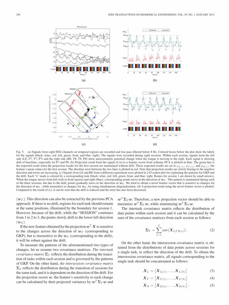
Fig. 5. (a) Signals from eight EEG channels on temporal regions are recorded and low-pass filtered below 8 Hz. Colored boxes below the plot show the labelsfor the signals (black: relax, red: left, green: front, and blue: right). The signals were recorded during eight sessions. Within each session, signals from the leftside (LE, F7, T7, P7) and the right side (RE, F8, T8, P8) show antisymmetric potential change when the tongue is moving to the right. Each signal is showingdrift of baselines, especially for P7 and P8. (b) Projection result from the signal of (a) to a feature vector from ordinary PCA is plotted in blue. The green line isthe expected result when the projection results for the first session are maintained without drift. These expected results are set to μL (1) , μF (1) , and μR (1) , thefeature’s mean values for the first session. The absolute error between the two lines is plotted in red. Note that projection results are slowly biasing to the negativedirection and errors are increasing. (c) Signals from LE and RE from a different experiment were plotted in 2-D scatter plot for explaining the patterns for GKP andthe drift. Each “x” mark is colored by a corresponding task (black: relax, red: left, green: front, and blue: right. Routes for session 1 are drawn by small arrows).When the tongue moves from left (red) to front (green) and right (blue), corresponding points move in the direction of wT . This pattern is maintained during eachof the three sessions, but due to the drift, points gradually move in the direction of wS . We tried to obtain a novel feature vector that is sensitive to changes forthe direction of wT , while insensitive to changes for wS , by using simultaneous diagonalization. (d) A projection result using the novel feature vector is plotted.Compared to the result of (c), it can be seen that the drift is reduced and the error has also been decreased.
(wT ). This direction can also be extracted by the previous PCAapproach. If there is no drift, regions for each task should remainat the same positions, illustrated by the boundary for session 1.However, because of the drift, while the “SESSION” continuesfrom 1 to 2 to 3, the points slowly drift to the lower left direction(wS ).
If the new feature obtained by the projection wT X is sensitiveto the changes across the direction of wT (corresponding toGKP), but is insensitive to the wS (corresponding to the drift),it will be robust against the drift.
To measure the patterns of the aforementioned two types ofchanges, let us assume two covariance matrices. The intertaskcovariance matrix ΣT reflects the distribution during the transi-tion of tasks within each session and is governed by the patternsof GKP. On the other hand, the intersession covariance matrixΣS reflects the distribution during the transition of sessions forthe same task, and it is dependent on the direction of the drift. Forthe projection vector w, the feature’s sensitivity to each changecan be calculated by their projected variances by wT ΣT w and
wT ΣS w. Therefore, a new projection vector should be able tomaximize wT ΣT w, while minimizing wT ΣS w.
The intertask covariance matrix reflects the distribution ofdata points within each session and it can be calculated by thesum of the covariance matrices from each session as follows:
ΣT =S
∑
s=1
cov(XLF R(s)). (2)
On the other hand, the intersession covariance matrix is ob-tained from the distributions of data points across sessions fora single task, to reflect the direction of the drift. To obtain theintersession covariance matrix, all signals corresponding to thesingle task should be concatenated as follows:
XL =[
XL(1) , . . . ,XL(S )]
(3)
XF =[
XF (1) , . . . ,XF (S )]
(4)
XR =[
XR(1) , . . . ,XR(S )]
. (5)
NAM et al.: TONGUE-RUDDER: A GLOSSOKINETIC-POTENTIAL-BASED TONGUE–MACHINE INTERFACE 295
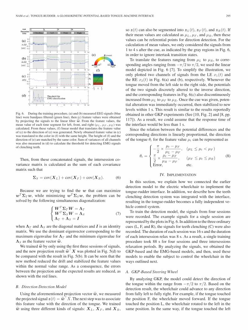
Fig. 6. During the training procedure, (a) and (b) measured EEG signals (blueline) were bandpass filtered (green line), then (c) feature values were obtainedby projecting the signals to the linear filter w. From the feature values, themean value of each time segment for left, front, and right (μL , μF , μR ) wascalculated. From these values, (f) linear model that translates the feature valueof (c) to the direction of (e) was generated. Newly obtained feature value in (c)was translated to the color in (f) with the same height. The height of (f) and thedirection of (e) are matched by the same color. Sum of variances of all channelswas also measured in (d) to calculate the threshold for detecting EMG signalsof clenching teeth.
Then, from these concatenated signals, the intersession co-variance matrix is calculated as the sum of each covariancematrix such that
ΣS = cov(XL ) + cov(XF ) + cov(XR ). (6)
Because we are trying to find the w that can maximizewT ΣT w, while minimizing wT ΣS w, the problem can besolved by the following simultaneous diagonalization:
⎧
⎨
⎩
W T ΣT W = ΛT
W T ΣS W = ΛS
ΛT + ΛS = I(7)
when ΛT and ΛS are the diagonal matrices and I is an identitymatrix. We use the dominant eigenvector corresponding to themaximum eigenvalue for ΛT and the minimum eigenvalue forΛS as the feature vector w.
We trained w by only using the first three sessions of signals,and the new projection result w�X was plotted in Fig. 5(d) tobe compared with the result in Fig. 5(b). It can be seen that thenew method reduced the drift and stabilized the feature valueswithin the normal value range. As a consequence, the errorsbetween the projection and the expected results are reduced, asshown with the red lines.
B. Direction Detection Model
Using the aforementioned projection vector w, we measuredthe projected signal z(t) = w�X . The next step was to associatethis feature value with the direction of the tongue. We trainedw using three different kinds of signals: XL , XF , and XR ,
so z(t) can also be segmented into zL (t), zF (t), and zR (t). Iftheir mean values are calculated as μL , μF , and μR , then thesevalues can be referential points for direction detection. For thecalculation of mean values, we only considered the signals from1 to 4 s after the cue, as indicated by the gray regions in Fig. 6,in order to ignore intertask transition states.
To translate the features ranging from μL to μR , to corre-sponding angles ranging from −π/2 to π/2, we used the linearmodel depicted in Fig. 6 [7]. To simplify the illustration, weonly plotted two channels of signals from the LE x1(t) andthe RE x2(t) in Fig. 6(a) and (b), respectively. Whenever thetongue moved from the left side to the right side, the potentialsof the two signals discretely altered to the inverse direction,and the corresponding features in Fig. 6(c) also discontinuouslyincreased from μL to μF to μR . Once the cue was given, poten-tial alteration was immediately occurred, then stabilized to newlevels within 1 s. This result is similar to the results reportedlyobtained in other GKP experiments (See [10, Fig. 2] and [8, pp.117]). As a result, we could assume that the response time ofthe interface would be less than 1 s.
Since the relation between the potential differences and thecorresponding directions is linearly proportional, the directionof the tongue θt for the feature value μt can be represented as
θt =
⎧
⎪
⎪
⎪
⎨
⎪
⎪
⎪
⎩
−π
2× μt − μF
μL − μF, (μL ≤ μt < μF )
π
2× μt − μF
μR − μF, (μF ≤ μt ≤ μR )
Error, etc.
(8)
IV. IMPLEMENTATION
In this section, we explain how we connected the earlierdetection model to the electric wheelchair to implement thetongue-rudder interface. In addition, we describe how the teethclenching detection system was integrated with the interface,resulting in the tongue-rudder becomes a fully independent ve-hicle control system.
To train the detection model, the signals from four sessionswere recorded. The example signals for a single session arerepresented by the plots in Fig. 6. In addition to the three ordinarycues (L, F, and R), the signals for teeth clenching (C) were alsorecorded. The duration of each session was 16 s and the durationof each intersession relax was 8 s. As a result, a single trainingprocedure took 88 s for four sessions and three intersessionsrelaxation periods. By analyzing the signals, we obtained theGKP-based and the EMG-based models, and then, used thesemodels to enable the subject to control the wheelchair in theways outlined next.
A. GKP-Based Steering Wheel
By analyzing GKP, the model could detect the direction ofthe tongue within the range from −π/2 to π/2. Based on thedetection result, the wheelchair could advance to any directionfrom fully left to fully right. For example, if the tongue touchedthe position F, the wheelchair moved forward. If the tonguetouched the position L, the wheelchair rotated to the left in thesame position. In the same way, if the tongue touched the left
296 IEEE TRANSACTIONS ON BIOMEDICAL ENGINEERING, VOL. 59, NO. 1, JANUARY 2012
corner of the mouth (where the upper lip meets the lower lip,the detection result may correspond to −π/4), the wheelchairsteered to the left, analogous to turning the steering wheel to theleft in a moving car. Due to this fine-grained controllability, thesubjects could drive the wheelchair smoothly, even on curvedpathways, as will be shown in Section V.
B. EMG-Based Brake and Recalibrator
The final goal of this research was to build a practical interfacethat can control the electric wheelchair. To fulfill this require-ment, the stop command, corresponding to the brake in a car, isessential not only for the user’s comfort, but also for safety rea-sons. To implement this stop command, we associated brakingwith the EMG for teeth clenching. During the teeth clenching,the subject cannot use the tongue-based interface because theteeth blocks contact between the tongue and the inside of thecheek. Therefore, we disabled the tongue-based interface whenthe clenching was detected.
In order to detect the EMG signals associated with teethclenching, we measured the sum of the variances of all chan-nels, during the clenching tasks in the training procedure. Sub-sequently, during the testing procedure, if the sum of variancesof the new signal exceeded this value by 20%, the system recog-nized it as the stop command, as shown in Fig. 6(d), and stoppedthe wheelchair immediately.
In addition, we assigned this clenching task to other com-mands essential for practical wheelchair control, such as callinga recalibration procedure and toggling wheelchair power. Thisprocedure is described by the flow chart in Fig. 7.
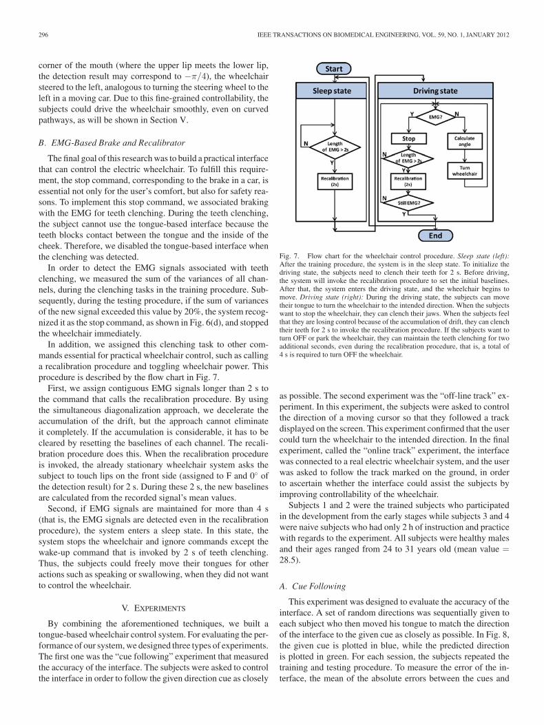
First, we assign contiguous EMG signals longer than 2 s tothe command that calls the recalibration procedure. By usingthe simultaneous diagonalization approach, we decelerate theaccumulation of the drift, but the approach cannot eliminateit completely. If the accumulation is considerable, it has to becleared by resetting the baselines of each channel. The recali-bration procedure does this. When the recalibration procedureis invoked, the already stationary wheelchair system asks thesubject to touch lips on the front side (assigned to F and 0◦ ofthe detection result) for 2 s. During these 2 s, the new baselinesare calculated from the recorded signal’s mean values.
Second, if EMG signals are maintained for more than 4 s(that is, the EMG signals are detected even in the recalibrationprocedure), the system enters a sleep state. In this state, thesystem stops the wheelchair and ignore commands except thewake-up command that is invoked by 2 s of teeth clenching.Thus, the subjects could freely move their tongues for otheractions such as speaking or swallowing, when they did not wantto control the wheelchair.
V. EXPERIMENTS
By combining the aforementioned techniques, we built atongue-based wheelchair control system. For evaluating the per-formance of our system, we designed three types of experiments.The first one was the “cue following” experiment that measuredthe accuracy of the interface. The subjects were asked to controlthe interface in order to follow the given direction cue as closely
Fig. 7. Flow chart for the wheelchair control procedure. Sleep state (left):After the training procedure, the system is in the sleep state. To initialize thedriving state, the subjects need to clench their teeth for 2 s. Before driving,the system will invoke the recalibration procedure to set the initial baselines.After that, the system enters the driving state, and the wheelchair begins tomove. Driving state (right): During the driving state, the subjects can movetheir tongue to turn the wheelchair to the intended direction. When the subjectswant to stop the wheelchair, they can clench their jaws. When the subjects feelthat they are losing control because of the accumulation of drift, they can clenchtheir teeth for 2 s to invoke the recalibration procedure. If the subjects want toturn OFF or park the wheelchair, they can maintain the teeth clenching for twoadditional seconds, even during the recalibration procedure, that is, a total of4 s is required to turn OFF the wheelchair.
as possible. The second experiment was the “off-line track” ex-periment. In this experiment, the subjects were asked to controlthe direction of a moving cursor so that they followed a trackdisplayed on the screen. This experiment confirmed that the usercould turn the wheelchair to the intended direction. In the finalexperiment, called the “online track” experiment, the interfacewas connected to a real electric wheelchair system, and the userwas asked to follow the track marked on the ground, in orderto ascertain whether the interface could assist the subjects byimproving controllability of the wheelchair.
Subjects 1 and 2 were the trained subjects who participatedin the development from the early stages while subjects 3 and 4were naive subjects who had only 2 h of instruction and practicewith regards to the experiment. All subjects were healthy malesand their ages ranged from 24 to 31 years old (mean value =28.5).
A. Cue Following
This experiment was designed to evaluate the accuracy of theinterface. A set of random directions was sequentially given toeach subject who then moved his tongue to match the directionof the interface to the given cue as closely as possible. In Fig. 8,the given cue is plotted in blue, while the predicted directionis plotted in green. For each session, the subjects repeated thetraining and testing procedure. To measure the error of the in-terface, the mean of the absolute errors between the cues and
NAM et al.: TONGUE-RUDDER: A GLOSSOKINETIC-POTENTIAL-BASED TONGUE–MACHINE INTERFACE 297
Fig. 8. Results for cue following experiments. (a) Subject 1, session 2.(b) Subject 1, session 6.
TABLE IPERFORMANCE RESULT FOR CUE FOLLOWING EXPERIMENT
the predicted results was measured for each session, as shownin Table I. The mean of all errors for 24 experiments was 18.9◦.
B. Off-Line Track
During this off-line track experiment, the subjects were askedto control the cursor to follow a track on the screen. As the cursorslowly moved forward, the subject could control its direction bymoving his tongue. We used the circuit map of the Toyota GrandPrix track located in Long Beach, California, as track’s image.
The image of the circuit map presented on the screen was12 cm × 8 cm in size. The cursor advanced at a speed of1.5 mm/s. The length of the course for a single lap was measuredto be 35 cm. When the detection result was pointing fully left orfully right, the cursor turned to the corresponding direction at aspeed of 10◦/s. The video clip for this experiment is available athttp://mlg.postech.ac.kr/research/tongue.html.
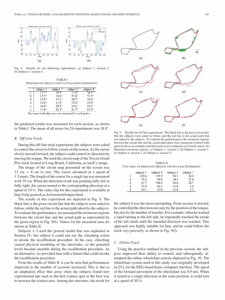
The results of this experiment are depicted in Fig. 9. Theblack line is the given circuit line that the subjects were asked tofollow, while the red line is the actual path taken by the subjects.To evaluate the performance, we measured the erroneous regionsbetween the circuit line and the actual path as represented bythe green region in Fig. 9(b). Values for the measured area areshown in Table II.
Subjects 1–3 used the general model that was explained inSection IV, but subject 4 could not use the clenching actionto invoke the recalibration procedure. In his case, clenchingcaused physical trembling of the electrodes, so the potentiallevels became unstable during the recalibration procedure. Asan alternative, we provided him with a button that could invokethe recalibration procedure.
From the results of Table II, it can be seen that performancesimproved as the number of sessions increased. This is due toan adaptation effect that arose when the subjects found newexperimental tips such as the best contact spot or the best wayto increase the contact area. Among the outcomes, the result for
Fig. 9. Results for off-line experiments. The black line is the given circuit linethat the subjects were asked to follow and the red line is the actual path thatwas taken by the subjects. To evaluate the performances, the erroneous regionsbetween the circuit line and the actual path taken were measured (colored withgreen in (b) as an example) and their areas were compared. (a) Circuit course. (b)Measured erroneous regions. (c) Subject 1, session 2. (d) Subject 1, session 5.(e) Subject 4, session 1. (f) Subject 4, session 5.
TABLE IIUNIT AREA OF ERRONEOUS REGION FOR OFF-LINE EXPERIMENT
the subject 4 was the most outstanding. From session 4 onward,he controlled the direction not only by the position of the tongue,but also by the number of touches. For example, when he wanteda rapid turning to the left side, he repeatedly touched the insideof his left cheek until the intended direction was reached. Thisapproach was highly suitable for him, and he could follow thetrack very precisely, as shown in Fig. 9(f).
C. Online Track
Using the practice outlined in the previous section, the sub-jects improved their ability to control, and subsequently, at-tempted the online wheelchair activity depicted in Fig. 10. Thewheelchair system used in this study was originally developedin [21], for the EEG-based brain–computer interface. The speedof the forward movement of the wheelchair was 0.9 m/s. Whenit turned to a single direction in the same position, it could turnat a speed of 30◦/s.
298 IEEE TRANSACTIONS ON BIOMEDICAL ENGINEERING, VOL. 59, NO. 1, JANUARY 2012
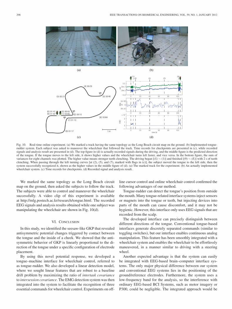
Fig. 10. Real-time online experiment. (a) We marked a track having the same topology as the Long Beach circuit map on the ground. (b) Implemented tongue-rudder system. Each subject was asked to maneuver the wheelchair that followed the track. Time records for checkpoints are presented in (c), while recordedsignals and analysis result are presented in (d). The top figure in (d) is actually recorded signals during the driving, and the middle figure is the predicted directionof the tongue. If the tongue moves to the left side, it shows higher values and the wheelchair turns left faster, and vice versa. In the bottom figure, the sum ofvariances for eight channels was plotted. The higher value means stronger teeth clenching. The driving began [(S) ∼ (1)] and finished [(9) ∼ (E)] with 2 s of teethclenching. When passing through the left turning curves [at (2), (5), and (7), marked with flags in (c)], the subject moved the tongue to the left side, then thesystem successfully recognized it, shown as the higher values in the middle figure of (d). (a) The marked track for the experiment. (b) An actually implementedwheelchair system. (c) Time records for checkpoints. (d) Recorded signal and analysis result.
We marked the same topology as the Long Beach circuitmap on the ground, then asked the subjects to follow the track.The subjects were able to control and maneuver the wheelchairsuccessfully. A video clip of this experiment is availableat http://mlg.postech.ac.kr/research/tongue.html. The recordedEEG signals and analysis results obtained while one subject wasmanipulating the wheelchair are shown in Fig. 10(d).
VI. CONCLUSION
In this study, we identified the seesaw-like GKP that revealedantisymmetric potential changes triggered by contact betweenthe tongue and the inside of a cheek. We showed that the anti-symmetric behavior of GKP is linearly proportional to the di-rection of the tongue under a specific configuration of electrodeplacement.
By using this novel potential response, we developed atongue–machine interface for wheelchair control, referred toas tongue-rudder. We also developed a linear detection model,where we sought linear features that are robust to a baselinedrift problem by maximizing the ratio of intertask covarianceto intersession covariance. The EMG detection system was thenintegrated into the system to facilitate the recognition of threeessential commands for wheelchair control. Experiments on off-
line cursor control and online wheelchair control confirmed thefollowing advantages of our method.
Tongue-rudder can detect the tongue’s position from outsidethe mouth. Many tongue-related interface systems inject sensorsor magnets into the tongue or teeth, but injecting devices intoparts of the mouth can cause discomfort, and it may not behygienic. However, this interface only uses EEG signals that arerecorded from the scalp.
The developed interface can precisely distinguish betweendifferent directions of the tongue. Conventional tongue-basedinterfaces generate discretely separated commands (similar totoggling switches), but our interface enables continuous analogmanipulation. This feature has been smoothly integrated with awheelchair system and enables the wheelchair to be effortlesslymaneuvered, in a manner similar to driving with a steeringwheel.
Another expected advantage is that the system can easilybe integrated with EEG-based brain–computer interface sys-tems. The only major physical difference between our systemand conventional EEG systems lies in the positioning of theground/reference electrodes. Furthermore, the system uses alow-frequency band for the analysis, so the interference withordinary EEG-based BCI Systems, such as motor imagery orP300, could be negligible. The integrated approach would be
NAM et al.: TONGUE-RUDDER: A GLOSSOKINETIC-POTENTIAL-BASED TONGUE–MACHINE INTERFACE 299
beneficial for extending the recognition capacity of the inter-face if the target subject still has motility of the tongue.
In spite of aforementioned advantages, there are a numberof challenges that remain to be overcome in order to realize apractical and reliable interface. First of all, the feature that wesuggested to reduce the accumulation of drift cannot achievecomplete elimination. The most promising approach is to sep-arate the signals into glossokinetic component and drift com-ponent, then use the drift component to update the baselines.Second, the combination of the tongue-based interface and theclenching-based interface is incomplete. Test subject 4 could notuse the combination method because his clenching task causesfluctuation of the baselines. This implies that individual anatom-ical differences can result in inability to operate the interface. Inthis section, we feel that further experiments with more subjects,including paralyzed patients, are required before this interfacecan be implemented for general use.
REFERENCES
[1] G. Krishnamurthy and M. Ghovanloo, “Tongue drive: A tongue operatedmagnetic sensor based wireless assistive technology for people with severedisabilities,” in Proc. IEEE Int. Symp. Circuits Syst. (ISCAS), Island ofKos, Greece, 2006, pp. 5551–5554.
[2] X. Huo and M. Ghovanloo, “Using unconstrained tongue motion as an al-ternative control mechanism for wheeled mobility,” IEEE Trans. Biomed.Eng., vol. 56, no. 6, pp. 1719–1726, Jun. 2009.
[3] L. N. S. A. Struijk, “An inductive tongue computer interface for controlof computers and assistive devices,” IEEE Trans. Biomed. Eng., vol. 53,no. 12, pp. 2594–2597, Dec. 2006.
[4] ThinkAMove. Introduction to think-a-move’s technology [On-line]. Available: http://www.think-a-move.com/pdfs/Intro_to_TAM_Technology.pdf.
[5] W. Nutt, C. Arlanch, S. Nigg, and G. Staufert, “Tongue-mouse forquadriplegics,” J. Micromech. Microeng., vol. 8, pp. 155–157, 1998.
[6] C. Salem and S. Zhai, “An isometric tongue pointing device,” in Proc.ACM Conf. Human Factors Comput. Syst. (CHI), 1997, pp. 538–359.
[7] Y. Nam, Q. Zhao, A. Cichocki, and S. Choi, “A tongue-machine interface:Detection of tongue positions by glossokinetic potentials,” in Proc. Int.Conf. Neural Inform. Process. (ICONIP), Sydney, Australia, 2010, pp. 34–41.
[8] B. J. Fisch, Fisch and Spehlmann’s EEG Primer, 3rd ed. New York:Elsevier, 1999.
[9] D. Klass and R. G. Bickford, “Glossokinetic potentials appearing in theelectroencephalogram,” EEG Clin. Neurophysilol., vol. 12, p. 239, 1960.
[10] S. Vanhatalo, A. Dewaraja, M. D. Holmes, and J. W. Miller, “Topographyand elimination of slow EEG responses related to tongue movements,”NeuroImage, vol. 20, pp. 1419–1423, 2003.
[11] J. R. Wolpaw, N. Birbaumer, D. J. McFarland, G. Pfurtscheller, and T.M. Vaughan, “Brain-computer interfaces for communication and control,”Clin. Neurophysiol., vol. 113, pp. 767–791, 2002.
[12] M. Fatourechi, A. Bashashati, R. K. Ward, and G. E. Birch, “EMG andEOG artifacts in brain computer interface systems: A survey,” Clin.Neurophysiol., vol. 118, pp. 480–494, 2007.
[13] A. Ikeda, H. O. Luders, R. C. Burgess, A. Sakamoto, G. H. Klem, I. H.H. Morris, and H. Shibasaki, “Generator locations of movement-relatedpotentials with tongue protrusions and vocalizations: Subdural recordingin human,” EEG Clin. Neurophysiol., vol. 96, pp. 310–328, 1995.
[14] R. C. Pratap, “The speech evoked potential in normal subjects and patientswith cerebral hemispheric lesions,” Clin. Neurol. Neurosurg., vol. 89,pp. 237–242, 1987.
[15] A. Delorme and S. Makeig, “EEGLAB: An open source toolbox for anal-ysis of single-trial EEG dynamics,” J. Neurosci. Methods, vol. 134, pp. 9–21, 2004.
[16] F. S. Tyner, J. R. Knott, and W. B. Mayer, Fundamentals of EEG Technol-ogy: Vol. 1: Basic Concepts and Methods. Baltimore, Maryland: Lippin-cott Williams & Wilkins, 1983.
[17] E. Niedermeyer and F. H. Lopes da Silva, Electroencephalography: BasicPrinciples, Clinical Applications, and Related Fields. Baltimore, Mary-land: Lippincott Williams & Wilkins, 1999.
[18] P. Tallgren, “Dc-EEG for routine clinical use: Methods and clinical im-pact,” Ph.D. dissertation, Helsinki Univ. of Technol., Helsinki, Finland,Dec. 2006.
[19] P. Tallgren, S. Vanhatalo, K. Kaila, and J. Voipio, “Evaluation of commer-cially available electrodes and gels for recording of slow EEG potentials,”Clin. Neurophysiol., vol. 116, no. 4, pp. 799–806, 2005.
[20] T. Yagi, Y. Kuno, K. Koga, and T. Mukai, “Drifting and blinking compen-sation in electro-oculography (EOG) eye-gaze interface,” in Proc. IEEEInt. Conf. Syst., Man, Cybern., Taipei, Taiwan, 2006, pp. 3222–3226.
[21] K. Choi and A. Cichocki, “Control of a wheelchair by motor imageryin real time,” in Proc. 9th Int. Conf. Intelligent Data Eng. AutomatedLearning (IDEAL), Daejeon, Korea, 2008, pp. 330–337.
Yunjun Nam received the B.Sc. degree in electricaland computer engineering from Hanyang University,Seoul, Korea, in 2008. He is currently working towardthe Ph.D. degree at the School of InterdisciplinaryBioscience and Bioengineering, Pohang Universityof Science and Technology, Pohang, Korea.
His current research interests include brain–computer interface and electroencephalographysignal processing.
Qibin Zhao was born in 1979. He received the Ph.D.degree in engineering from the Department of Com-puter Science and Engineering, Shanghai Jiao TongUniversity, Shanghai, China, in 2009.
He is currently a Research Scientist at the Labo-ratory for Advanced Brain Signal Processing, BrainScience Institute, RIKEN, Wako, Japan, where he isa Visiting Research Scientist at Non-invasive BMIUnit of BSI-TOYOTA Collaboration Center. His cur-rent research interests include multiway data analysis,brain–computer interface, and machine learning.
Andrzej Cichocki (M’95) received the Ph.D. andDr.Sc. (Habilitation) degrees in electrical engineer-ing from Warsaw University of Technology, Warsaw,Poland.
He is currently the Senior Team Leader and theHead of the Laboratory for Advanced Brain SignalProcessing, Brain Science Institute, RIKEN, Wako,Japan. He is the coauthor of more than 250 technicalpapers and four monographs (two of them translatedto Chinese). He has been invited to the Council ofCanadian Academies Survey of Science and Tech-
nology Strengths as an author and coauthor of one of the top 1% most highlycited papers in his field worldwide.
Seungjin Choi (M’93) received the B.S. and M.S. de-grees in electrical engineering from Seoul NationalUniversity, Seoul, Korea, in 1987 and 1989, respec-tively, and the Ph.D. degree in electrical engineer-ing from the University of Notre Dame, South Bend,Indiana, in 1996.
In 1997, he was with the Laboratory for ArtificialBrain Systems, RIKEN, Wako, Japan. From 1997 to2000, he was an Assistant Professor in the Schoolof Electrical and Electronics Engineering, ChungbukNational University. He is currently a Professor of
computer science at Pohang University of Science and Technology, Pohang,Korea. His current research interests include machine learning, Bayesian infer-ence, and probabilistic models.