tolerance management in construction: a conceptual ... - mdpi
TRANSCRIPT

sustainability
Article
Tolerance Management in Construction:A Conceptual Framework
Saeed Talebi *, Lauri Koskela , Patricia Tzortzopoulos and Michail Kagioglou
Innovative Design Lab, School of Art, Design and Architecture, University of Huddersfield, Huddersfield HD13DH, UK; [email protected] (L.K.); [email protected] (P.T.); [email protected] (M.K.)* Correspondence: [email protected]
Received: 12 December 2019; Accepted: 27 January 2020; Published: 1 February 2020�����������������
Abstract: Defects associated with dimensional and geometric tolerance variability (tolerance problems)are often dealt with during the construction phase of projects. Despite the potentially severeconsequences of those defects, tolerance management (TM) is a perennial challenge, and theconstruction industry lacks a systematic and practical process to provide insight into avoiding thereoccurrence of tolerance problems. The aim of this research is to present a conceptual framework toproactively reduce the reoccurrence of tolerance problems at stages preceding on site construction.The research uses an exploratory case study approach exploring TM in a civil engineering consultancy.Evidence was collated from semi-structured interviews and document analysis, and validated in agroup interview. The data was analysed using thematic analysis. The study contributes to knowledgein engineering management by providing new insights into drawbacks of existing TM guidelines.It also describes a good practice application of TM by a civil engineering consultancy, and proposes aconceptual framework to improve TM, which provides a basis to develop more effective practicalsolutions for TM.
Keywords: dimensional tolerance management; tolerance-related defects; variations; tolerance risk;tolerance requirement; communication of tolerance information; tolerance compliance control
1. Introduction
Defects associated with dimensional and geometric variability are amongst the most commonand recurring defects in conventional construction projects [1–4]. Those defects, called toleranceproblems hereafter, may adversely impact functional requirements, e.g., water tightness [5], safety [6],serviceability, durability, constructability, the fit between components [7,8], structural stability [5,9],aesthetics [5,9], energy performance [10], and compliance with regulations [11]. Tolerance problemscan considerably increase the cost of construction and maintenance [12], cause delays [4], and increasematerial wastage [13]. They influence customer satisfaction, which is integral to the success of anorganisation [14], and tolerance problems are often at the centre of disputes between the consumer,contractor, supply chain, and client [15].
The management of dimensional and geometric tolerances is a perennial challenge, which arisesfrom many interacting factors, design-related but also construction-related [16,17]. The most commonlyknown factor is that tolerances range from less than a millimetre for some factory-made components toseveral millimetres for many in situ components [18,19], while all components must still fit togetherand satisfy the functional requirements of the building [18]. This, along with other factors such aspoor workmanship [3,20], vulnerability of contemporary buildings to building movements and thesubsequent geometric changes [21], and poor tolerance compliance control [22] result in recurringtolerance problems. Several examples of tolerance problems encountered in typical constructionprojects (e.g., lack of fit, aesthetically unacceptable gaps, misalignments between components) have
Sustainability 2020, 12, 1039; doi:10.3390/su12031039 www.mdpi.com/journal/sustainability

Sustainability 2020, 12, 1039 2 of 24
been presented in the literature [20,23], demonstrating the challenges in the management of dimensionaland geometric variations.
Tolerance problems are traditionally dealt with at the time and place of the construction work, andthe way they are modified (e.g., shimming, grouting, reaming holes, applying forces) to a great extenthinges on the labourer’s experience and in situ capabilities rather than on a systematic process [20,22,24].Despite the importance of tolerances, the construction industry currently is argued to lack a systematicand practical process for tolerance management (TM) to provide designers and practitioners proactiveinsight into avoiding tolerance problems [12,25–27].
This paper explores TM good practices in a civil engineering consultancy. The process ofreviewing ‘good practices’ before attempting to improve existing practices is expected to (a) capturethe accumulated learning about a process [28], (b) allow others to build upon practice and continuouslyimprove it [29], and (c) ensure the relevance of management research to industrial practice [30–32].In this paper, the term ‘good practice’, also referred to as ‘one best way’ [33], does not mean that thereis only one path to success [28,33,34], but it is defined as “a process or method that, when executedeffectively, leads to enhanced project performance” [35]. As far as it is known, there is no literatureanalysing effective solutions used in practice for TM. Furthermore, some of the existing literatureprescribes solutions that lack empirical evidence to indicate whether these have been implementedwithin industry and how effective they have been.
The aim of the research reported in this paper is to introduce a conceptual framework to proactivelyreduce the reoccurrence of tolerance problems at stages preceding on site construction. The paper isstructured as follows. First, current approaches to TM and solutions to improve from the literatureare discussed. The research method and a background to the case studied are given. The TM processpracticed by a consultancy company is then presented. The findings and contributions to knowledgeare discussed and a framework to improve TM is proposed. Finally, conclusions drawn from theresearch are discussed.
2. Theoretical Background
2.1. Tolerances and Tolerance Management in Construction
Materials and components cannot be exactly dimensioned and positioned as they were designed.Tolerances are defined as the accepted amount of variations of materials and components from nominalvalues or design specifications [18]. There are two types of tolerances: (a) Dimensional tolerances,stating the permitted amount of deviation for a specific size, e.g., floor thickness, and (b) geometrictolerances, stating the allowed amount of deviation on a specific geometric property, e.g., flatness ofconcrete slabs [36,37].
TM in construction is about utilising various tools and methods [4] to: (a) Minimise toleranceproblems derived from dimensional and geometric variations by proactively identifying andmitigating risks related to the likelihood of an occurrence of tolerance problems, called tolerancerisks hereafter [27,38], (b) ensure constructability of design, operating capability, and structuralintegrity [39–41], and (c) reduce lead times by avoiding tolerance problems and the associatedmodification process [20]. The ultimate aim of TM is to minimise costs [42], increase quality [43],and continually improve the management of tolerances [16]. These can only be achieved if morejudicious decisions are made upstream in the process rather than downstream, once constructionhas commenced [20]. Moreover, a sustainable construction industry aims to obtain a high quality ofbuildings while optimising the utilisation of resources [44]. In particular, avoiding defects, such astolerance problems, is critical to maintaining building performance [45,46]. Hence, TM can make asignificant contribution to sustainability.
Sustainability 2020, 12, 1039 3 of 24
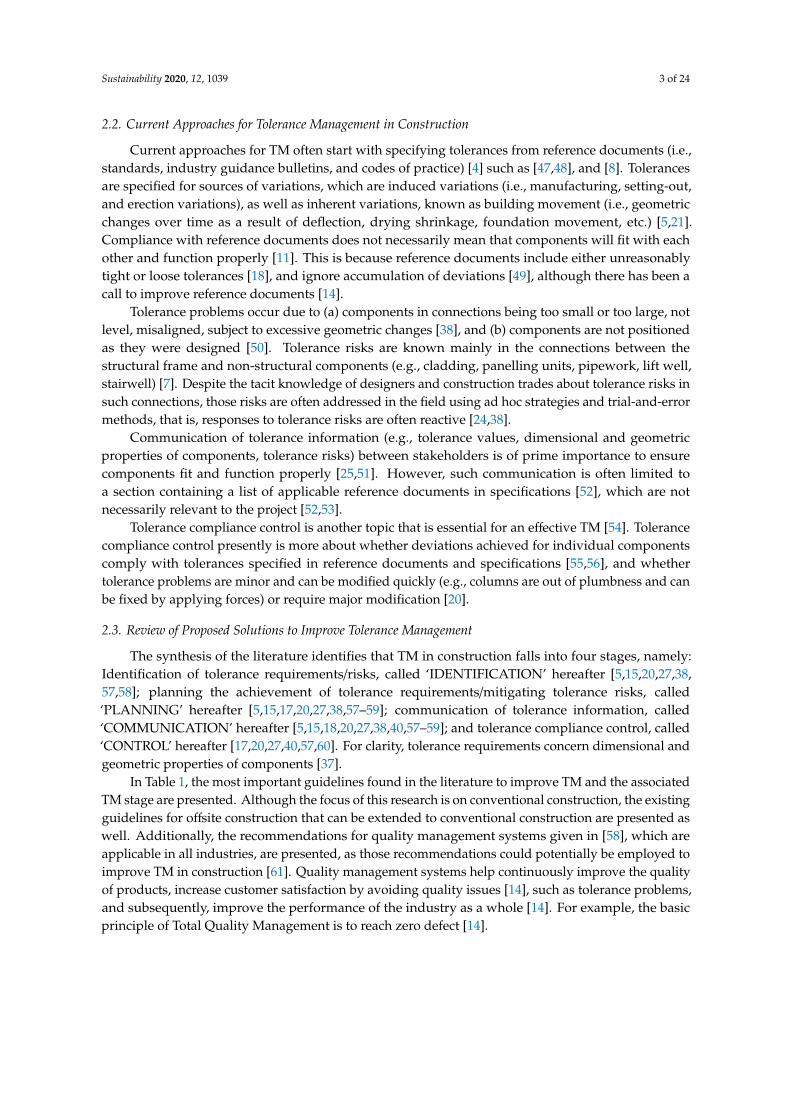
2.2. Current Approaches for Tolerance Management in Construction
Current approaches for TM often start with specifying tolerances from reference documents (i.e.,standards, industry guidance bulletins, and codes of practice) [4] such as [47,48], and [8]. Tolerancesare specified for sources of variations, which are induced variations (i.e., manufacturing, setting-out,and erection variations), as well as inherent variations, known as building movement (i.e., geometricchanges over time as a result of deflection, drying shrinkage, foundation movement, etc.) [5,21].Compliance with reference documents does not necessarily mean that components will fit with eachother and function properly [11]. This is because reference documents include either unreasonablytight or loose tolerances [18], and ignore accumulation of deviations [49], although there has been acall to improve reference documents [14].
Tolerance problems occur due to (a) components in connections being too small or too large, notlevel, misaligned, subject to excessive geometric changes [38], and (b) components are not positionedas they were designed [50]. Tolerance risks are known mainly in the connections between thestructural frame and non-structural components (e.g., cladding, panelling units, pipework, lift well,stairwell) [7]. Despite the tacit knowledge of designers and construction trades about tolerance risks insuch connections, those risks are often addressed in the field using ad hoc strategies and trial-and-errormethods, that is, responses to tolerance risks are often reactive [24,38].
Communication of tolerance information (e.g., tolerance values, dimensional and geometricproperties of components, tolerance risks) between stakeholders is of prime importance to ensurecomponents fit and function properly [25,51]. However, such communication is often limited toa section containing a list of applicable reference documents in specifications [52], which are notnecessarily relevant to the project [52,53].
Tolerance compliance control is another topic that is essential for an effective TM [54]. Tolerancecompliance control presently is more about whether deviations achieved for individual componentscomply with tolerances specified in reference documents and specifications [55,56], and whethertolerance problems are minor and can be modified quickly (e.g., columns are out of plumbness and canbe fixed by applying forces) or require major modification [20].
2.3. Review of Proposed Solutions to Improve Tolerance Management
The synthesis of the literature identifies that TM in construction falls into four stages, namely:Identification of tolerance requirements/risks, called ‘IDENTIFICATION’ hereafter [5,15,20,27,38,57,58]; planning the achievement of tolerance requirements/mitigating tolerance risks, called‘PLANNING’ hereafter [5,15,17,20,27,38,57–59]; communication of tolerance information, called‘COMMUNICATION’ hereafter [5,15,18,20,27,38,40,57–59]; and tolerance compliance control, called‘CONTROL’ hereafter [17,20,27,40,57,60]. For clarity, tolerance requirements concern dimensional andgeometric properties of components [37].
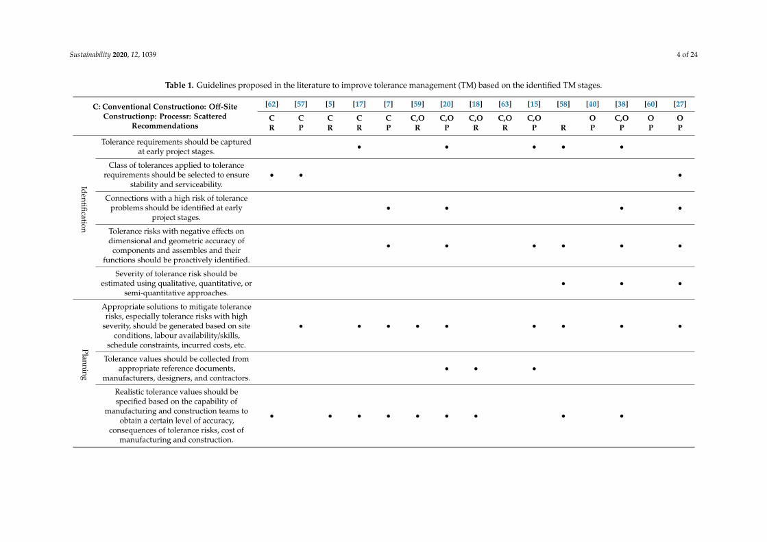
In Table 1, the most important guidelines found in the literature to improve TM and the associatedTM stage are presented. Although the focus of this research is on conventional construction, the existingguidelines for offsite construction that can be extended to conventional construction are presented aswell. Additionally, the recommendations for quality management systems given in [58], which areapplicable in all industries, are presented, as those recommendations could potentially be employed toimprove TM in construction [61]. Quality management systems help continuously improve the qualityof products, increase customer satisfaction by avoiding quality issues [14], such as tolerance problems,and subsequently, improve the performance of the industry as a whole [14]. For example, the basicprinciple of Total Quality Management is to reach zero defect [14].
Sustainability 2020, 12, 1039 4 of 24
Table 1. Guidelines proposed in the literature to improve tolerance management (TM) based on the identified TM stages.
C: Conventional Constructiono: Off-SiteConstructionp: Processr: Scattered
Recommendations
[62] [57] [5] [17] [7] [59] [20] [18] [63] [15] [58] [40] [38] [60] [27]
C C C C C C,O C,O C,O C,O C,O O C,O O OR P R R P R P R R P R P P P P
Identification
Tolerance requirements should be capturedat early project stages. • • • • •
Class of tolerances applied to tolerancerequirements should be selected to ensure
stability and serviceability.• • •
Connections with a high risk of toleranceproblems should be identified at early
project stages.• • • •
Tolerance risks with negative effects ondimensional and geometric accuracy of
components and assembles and theirfunctions should be proactively identified.
• • • • • •
Severity of tolerance risk should beestimated using qualitative, quantitative, or
semi-quantitative approaches.• • •
Planning
Appropriate solutions to mitigate tolerancerisks, especially tolerance risks with high
severity, should be generated based on siteconditions, labour availability/skills,
schedule constraints, incurred costs, etc.
• • • • • • • • •
Tolerance values should be collected fromappropriate reference documents,
manufacturers, designers, and contractors.• • •
Realistic tolerance values should bespecified based on the capability of
manufacturing and construction teams toobtain a certain level of accuracy,
consequences of tolerance risks, cost ofmanufacturing and construction.
• • • • • • • • •
Sustainability 2020, 12, 1039 5 of 24
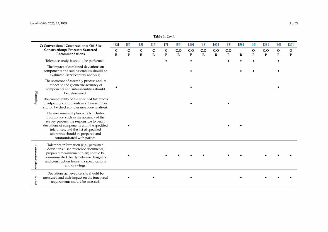
Table 1. Cont.
C: Conventional Constructiono: Off-SiteConstructionp: Processr: Scattered
Recommendations
[62] [57] [5] [17] [7] [59] [20] [18] [63] [15] [58] [40] [38] [60] [27]
C C C C C C,O C,O C,O C,O C,O O C,O O OR P R R P R P R R P R P P P P
Planning
Tolerance analysis should be performed. • • • • • •
The impact of combined deviations oncomponents and sub-assemblies should be
evaluated (serviceability analysis).• • • •
The sequence of assembly process and itsimpact on the geometric accuracy of
components and sub-assemblies shouldbe determined.
• • •
The compatibility of the specified tolerancesof adjoining components in sub-assembliesshould be checked (tolerance coordination).
• •
The measurement plan which includesinformation such as the accuracy of thesurvey process, the responsible to verify
deviations of components with the specifiedtolerances, and the list of specifiedtolerances should be prepared and
communicated with parties.
• • •
Com
munication
Tolerance information (e.g., permitteddeviations, used reference documents,
prepared measurement plan) should becommunicated clearly between designersand construction teams via specifications
and drawings.
• • • • • • • • • •
Control
Deviations achieved on site should bemeasured and their impact on the functional
requirements should be assessed.• • • • • • •

Sustainability 2020, 12, 1039 6 of 24
Like TM in manufacturing [64], the improvement of TM in construction requires a process thatmust involve all of the TM stages [4,15,17,20,24,25,38]. Nevertheless, the holistic view of TM hashardly been considered in the current construction management literature. It is evident from Table 1that only one process [20] for TM in construction could be found that covers all the identified stages(i.e., IDENTIFICATION, PLANNING, COMMUNICATION, CONTROL). In [20]’s effort to propose aprocess for TM, tolerance theories used in manufacturing are adopted to construction.
While the application of manufacturing tolerance theories in construction can be effective toestablish a systematic TM [60], it is challenging to incorporate complex approaches from manufacturinginto construction workflows [65]. This is because (a) the dominant approach for dimensional andgeometric variations is to use rule of thumb or trial and error strategies [4,24]; (b) existing software, e.g.,Building Information Models, do not support those approaches for most conventional constructionprojects [4]; and (c) a reluctance prevails in the industry to use manufacturing methodologies thatare not supported by organisations developing construction standards [18,24]. In fact, knowledgetransfer from manufacturing to construction must be treated with caution because the level of maturityof processes and practices is different [4], otherwise it is solely of interest to academics, without thepossibility of application in practice [30].
Some of the solutions proposed in the literature are potentially costly because they require selectingmore restrictive tolerances [2], changing existing measurement techniques, e.g., laser scanner [54],and using precise methods of production, e.g., robotic assembly [66]. Although such solutions canbring about improvements, dimensional and geometric variations can be still problematic due to theunderlying issue of discrepancies between precise factory-made components and large site tolerances,as well as geometric effects due to building movement [21,63]. Moreover, continuous improvement,which is at the heart of Lean [67], is essential to avoid recurring problems and improve TM [68].However, continuous improvement is not explicitly addressed in existing guidelines.
It should be noted that Table 1 only includes guidelines that do not require knowledge aboutcomplex manufacturing theories, and do not require costly production methods and measurementinstruments. Furthermore, it appears that some research propose systematic processes with a set ofsteps e.g., [15], while the remaining are limited to scattered recommendations e.g., [18]. A number ofthe existing guidelines are limited to generic recommendations (e.g., improving the communication oftolerance information) e.g., [18] and do not specify precisely how those recommendations should beeffectively carried out in practice. Last but not least, continuous improvement is essential to avoidrecurring problems and improve TM [14,68]. However, continuous improvement is not explicitlyaddressed in those guidelines.
3. Research Method
This research adopts an exploratory case study approach. According to [69], such an approachcan be chosen when describing, explaining, and exploring a contemporary phenomenon within areal-life context, and when the study attempts to answer “how” research questions. The exploratorycase study is suitable for this research because it aims to explore TM good practices as performedby a consultancy, and answer the following ‘how’ questions: How to identify and communicatetolerance requirements/risks?; how to mitigate tolerance risks?; and how to verify the compliance ofthe achieved deviations with the specified tolerances? This exploratory research identifies linkagesbetween theory from architecture, engineering, and construction project management and practice toinform researchers and practitioners.
The system view is adopted because this study intends to bring together principles and conceptsfrom different domains to conduct an interdisciplinary research [70]. In view of this, the study is builton existing literature alongside empirical evidence obtained from the case study and covers conceptsfrom three domains, namely: Architecture, engineering, and construction project management. Thepurpose of the literature review was to identify the underlying concepts and principles of TM; toidentify the current approaches of TM in practice; to identify the relevant state-of-the-art solutions to

Sustainability 2020, 12, 1039 7 of 24
improve TM; to categorise the existing solutions based on their focus; and to highlight the shortcomingsof existing solutions.
3.1. Rationale for Case Selection
The case study project (CSP) is an engineering consultancy in the UK. Regarding the strategies forcase selection, no universally accepted principles exists. The general advice is to select cases whichare ‘most likely’ to address the research aim [69,71]. The case study selected was identified as a firmwhich is most advanced in its TM practices in the UK. This was highlighted by some of its directcompetitors, who were involved in other research developed in collaboration with the authors of thispaper. As such, the selection has internal validation to the context of the research, in that the actors ofthe context self-select good practice worthy of observation and learning.
CSP is specialised in planning, design, and control for sixty years and provides services for civiland structural engineering, infrastructure, environmental engineering, and project management. Oneof the major foci of CSP is the proactive identification of tolerance risks, performance of toleranceanalysis, and communication of tolerance risks as part of the services offered to their clients. Thecompany was selected as it clearly supports the purpose of the research, which was exploring a TMgood practice.
3.2. Data Collection and Analysis
In this study, evidence was gathered from five semi-structured interviews, document analysis, anddata was validated and refined through a group interview. The multiple data collection methods resultin triangulation which contributes to the rigour of the research [72]. Interviews and document analysiswere carried out to explore the TM process practiced by CSP, providing detailed understanding ofpractice [73]. According to [74], semi-structured interviews allow the interviewer to focus on importantissues arising during the conversations, allow for clarification and expansion of questions and answers,and therefore, provide rich data collection. The interviewees were:
• One associate structural engineer (Interviewee A);• three senior structural engineers (Interviewee B, Interviewee C, Interviewee D); and,• one senior planner (Interviewee E).
Sampling is mainly associated with quantitative research; however, samples involving oneor more units of observations are always applied in qualitative research [75]. A non-probabilitysampling (non-random sampling), based on the authors’ subjective judgement, has been used in thisstudy. Among the non-probability sampling techniques (quota, purposive, snowball, self-selected,convenience) [76], purposive sampling has been selected. This form of sampling is used when workingwith a very small sample, such as in case study research, and when the researcher intends to selectcases that are particularly informative [76]. These two requirements apply to this case study, whichselected interviewees who are aware of the TM process practiced by the CSP.
The purposive sample of this study was suggested by the CSP managing director and includesthose who had developed the TM process practiced by the CSP over the last eighteen years andwere directly involved in its implementation. The interviews led to the satisfactory achievement oftheoretical saturation [77] because it led to a deep understanding of the practiced TM process. Whilefive interviews may seem a small sample, the sample size in qualitative research is directly linkedto the quality of data in supporting the aim of the study. In other words, the purposive sampling inthis study ensured that right participants were on board and theoretical saturation, which is moreimportant than the size of sample [78].
The interview protocol included questions exploring the process developed by CSP to managetolerances, especially because such process had not been documented previously. Interviews wereconducted and recorded face to face and they took between 60 and 110 min. The questions in theinterview protocol were:
Sustainability 2020, 12, 1039 8 of 24
• How do you identify tolerance requirements/ risks?• How do you plan to achieve tolerance requirements and mitigate tolerance risks?• How do you communicate tolerance information?• How do you verify the compliance of achieved deviations with the specified tolerances?
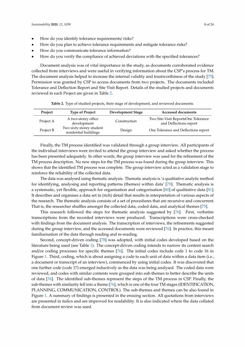
Document analysis was of vital importance in the study, as documents corroborated evidencecollected from interviews and were useful in verifying information about the CSP’s process for TM.The document analysis helped to increase the internal validity and trustworthiness of the study [75].Permission was granted by CSP to access documents from two projects. The documents includedTolerance and Deflection Report and Site Visit Report. Details of the studied projects and documentsreviewed in each Project are given in Table 2.
Table 2. Type of studied projects, their stage of development, and reviewed documents.
Project Type of Project Development Stage Accessed documents
Project A A two-storey officedevelopment Construction Two Site-Visit ReportsOne Tolerance
and Deflections report
Project B Two sixty-storey studentresidential buildings Design One Tolerance and Deflections report
Finally, the TM process identified was validated through a group interview. All participants ofthe individual interviews were invited to attend the group interview and asked whether the processhas been presented adequately. In other words, the group interview was used for the refinement of theTM process description. No new steps for the TM process was found during the group interview. Thisshows that the identified TM process was complete. The group interview acted as a validation stage toreinforce the reliability of the collected data.
The data was analysed using thematic analysis. Thematic analysis is ‘a qualitative analytic methodfor identifying, analysing and reporting patterns (themes) within data’ [79]. Thematic analysis isa systematic, yet flexible, approach for organisation and categorisation [80] of qualitative data [81].It describes and organises a data set in (rich) detail that results in interpretation of various aspects ofthe research. The thematic analysis consists of a set of procedures that are recursive and concurrent.That is, the researcher shuffles amongst the collected data, coded data, and analytical themes [75].
This research followed the steps for thematic analysis suggested by [76]. First, verbatimtranscriptions from the recorded interviews were produced. Transcriptions were cross-checkedwith findings from the document analysis. The transcription of interviews, the refinements suggestedduring the group interview, and the accessed documents were reviewed [76]. In practice, this meantfamiliarisation of the data through reading and re-reading.
Second, concept-driven coding [78] was adopted, with initial codes developed based on theliterature being used (see Table 1). The concept-driven coding intends to narrow its content searchand/or coding processes for specific themes [76]. The initial codes include code 1 to code 16 inFigure 1. Third, coding, which is about assigning a code to each unit of data within a data item (i.e.,a document or transcript of an interview), commenced by using initial codes. It was discovered thatone further code (code 17) emerged inductively as the data was being analysed. The coded data werereviewed, and codes with similar contents were grouped into sub-themes to better describe the unitsof data [76]. The identified sub-themes represent the steps of the TM process in CSP. Finally, thesub-themes with similarity fell into a theme [76], which is one of the four TM stages (IDENTIFICATION,PLANNING, COMMUNICATION, CONTROL). The sub-themes and themes can be also found inFigure 1. A summary of findings is presented in the ensuing section. All quotations from interviewsare presented in italics and are improved for readability. It is also indicated where the data collatedfrom document review was used.
Sustainability 2020, 12, 1039 9 of 24
Sustainability 2020, 12, x FOR PEER REVIEW 9 of 25
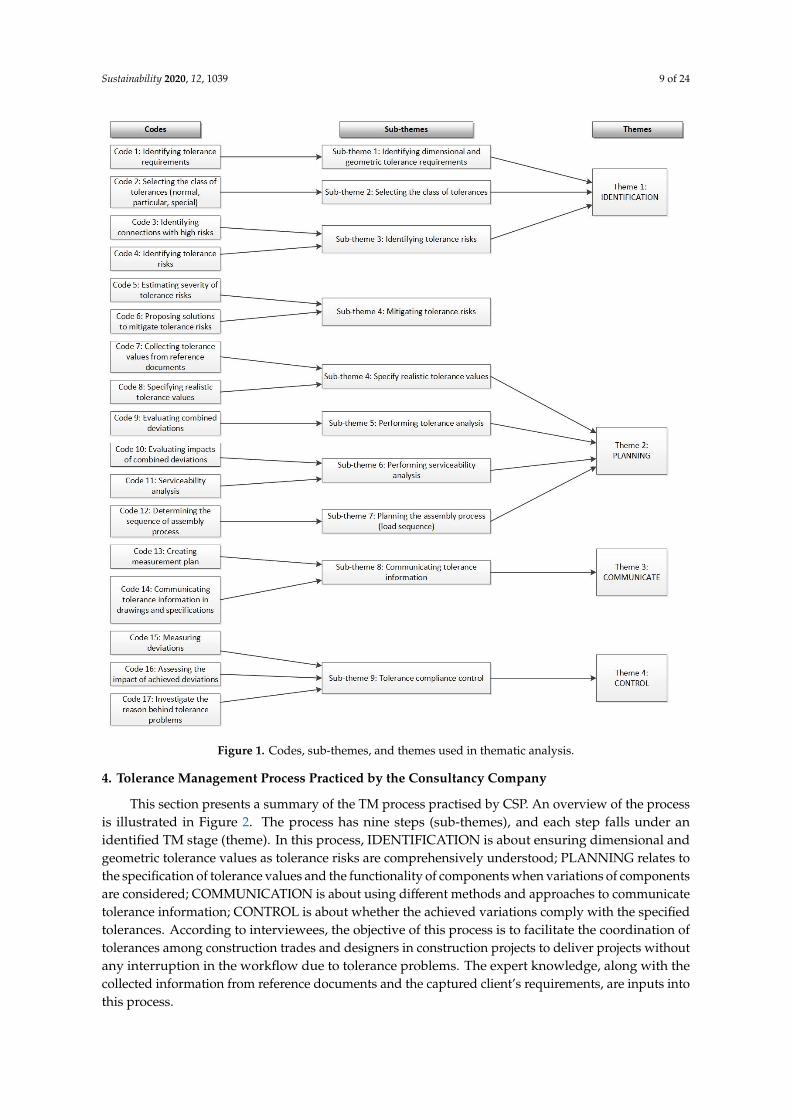
Figure 1. Codes, sub-themes, and themes used in thematic analysis.
4. Tolerance Management Process Practiced by the Consultancy Company
This section presents a summary of the TM process practised by CSP. An overview of the process is illustrated in Figure 2. The process has nine steps (sub-themes), and each step falls under an identified TM stage (theme). In this process, IDENTIFICATION is about ensuring dimensional and geometric tolerance values as tolerance risks are comprehensively understood; PLANNING relates to the specification of tolerance values and the functionality of components when variations of components are considered; COMMUNICATION is about using different methods and approaches to communicate tolerance information; CONTROL is about whether the achieved variations comply with the specified tolerances. According to interviewees, the objective of this process is to facilitate the coordination of tolerances among construction trades and designers in construction projects to deliver projects without any interruption in the workflow due to tolerance problems. The expert knowledge, along with the collected information from reference documents and the captured client’s requirements, are inputs into this process.
Identification of tolerance requirements/risks and selection of the class of tolerances fall under the IDENTIFICATION stage. The common tolerance requirements, tolerance risks, and classes of
Figure 1. Codes, sub-themes, and themes used in thematic analysis.
4. Tolerance Management Process Practiced by the Consultancy Company
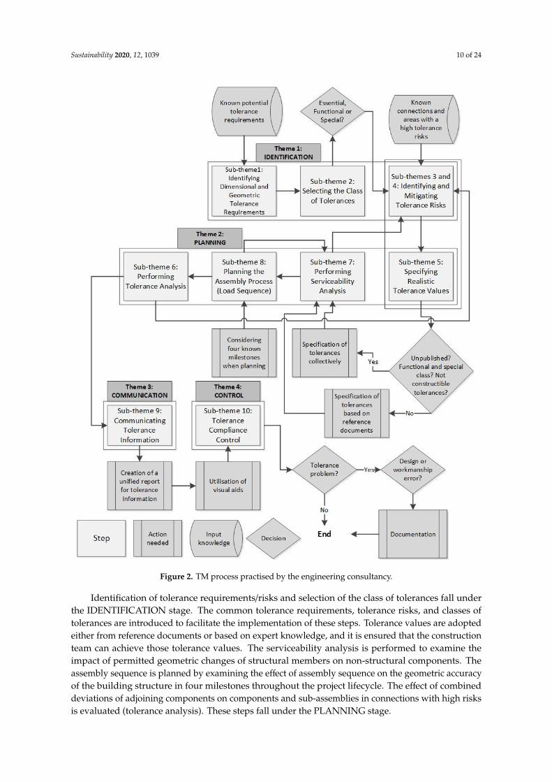
This section presents a summary of the TM process practised by CSP. An overview of the processis illustrated in Figure 2. The process has nine steps (sub-themes), and each step falls under anidentified TM stage (theme). In this process, IDENTIFICATION is about ensuring dimensional andgeometric tolerance values as tolerance risks are comprehensively understood; PLANNING relates tothe specification of tolerance values and the functionality of components when variations of componentsare considered; COMMUNICATION is about using different methods and approaches to communicatetolerance information; CONTROL is about whether the achieved variations comply with the specifiedtolerances. According to interviewees, the objective of this process is to facilitate the coordination oftolerances among construction trades and designers in construction projects to deliver projects withoutany interruption in the workflow due to tolerance problems. The expert knowledge, along with thecollected information from reference documents and the captured client’s requirements, are inputs intothis process.
Sustainability 2020, 12, 1039 10 of 24
Sustainability 2020, 12, x FOR PEER REVIEW 11 of 25
Figure 2. TM process practised by the engineering consultancy.
4.1. Sub-theme 1: Identifying Dimensional and Geometric Tolerance Requirements
CSP attempts to “identify dimensional and geometric tolerance requirements early at the design stage and to communicate them amongst designers and construction trades” (Quotation-1-A). “Even when we are at a concept design stage, we are thinking about how that building is going to be loaded, what the general deflection criteria are, and start identifying dimensional and geometric tolerance requirements otherwise difficulties at the design and construction stages will be encountered” (Quotation-2-C). For example, “it will be problematic to develop a cladding system that is compatible with geometric changes of the building structure” (Quotation-3-C). Tolerance requirements can be captured from the client’s brief, concept design, and early engagement with parties. The most common dimensional tolerance requirements, known as critical dimensions, are “floor thickness,
Figure 2. TM process practised by the engineering consultancy.
Identification of tolerance requirements/risks and selection of the class of tolerances fall underthe IDENTIFICATION stage. The common tolerance requirements, tolerance risks, and classes oftolerances are introduced to facilitate the implementation of these steps. Tolerance values are adoptedeither from reference documents or based on expert knowledge, and it is ensured that the constructionteam can achieve those tolerance values. The serviceability analysis is performed to examine theimpact of permitted geometric changes of structural members on non-structural components. Theassembly sequence is planned by examining the effect of assembly sequence on the geometric accuracyof the building structure in four milestones throughout the project lifecycle. The effect of combineddeviations of adjoining components on components and sub-assemblies in connections with high risksis evaluated (tolerance analysis). These steps fall under the PLANNING stage.
Sustainability 2020, 12, 1039 11 of 24
Collected tolerance information is communicated to the project participants (COMMUNICATIONstage) through a document called the ‘Tolerance and Deflection’ Report. Visual aids are used in thisreport to communicate the impact of variations on components, connections, and sub-assemblies tothe project participants with any level of understanding of tolerances in a simple language. Finally, thecompliance of deviations with the specified limits is verified and it is investigated whether occurredtolerance problems are due an error in design or construction work (CONTROL stage).
4.1. Sub-Theme 1: Identifying Dimensional and Geometric Tolerance Requirements
CSP attempts to “identify dimensional and geometric tolerance requirements early at the designstage and to communicate them amongst designers and construction trades” (Quotation-1-A). “Evenwhen we are at a concept design stage, we are thinking about how that building is going to beloaded, what the general deflection criteria are, and start identifying dimensional and geometrictolerance requirements otherwise difficulties at the design and construction stages will be encountered”(Quotation-2-C). For example, “it will be problematic to develop a cladding system that is compatiblewith geometric changes of the building structure” (Quotation-3-C). Tolerance requirements can becaptured from the client’s brief, concept design, and early engagement with parties. The most commondimensional tolerance requirements, known as critical dimensions, are “floor thickness, requiredclearances (spaces) between components” (Quotation-4-B), and “floor to floor height in tall buildings”(Quotation-5-A). The most common geometric tolerance requirements are “straightness of edgebeams, flatness of slabs” (Quotation-6-C), “parallelism of columns and stanchions” (Quotation-7-D),“plumbness of columns, position of base plates” (Quotation-8-A).
In Project A, considering the high value of office buildings, the client needs to ensure that thedimensions of the internal floor area would be as larger as possible in order to maximise the returnon investment. At the same time, “the office cannot be over area because issues such as the planningpermission and the extra cost will happen” (Quotation-9-B). In Project B, the envelope of the buildingcomprises precast cladding intermixed with glazed/curtain wall elements. At the gable ends, pre-castpanels are positioned edge to edge. The initial design developed by the cladding subcontractor was tomaintain a consistent 20 mm clearance between the panels to avoid physical clashes between them. Theinternal dimensions and 20 mm clearance are then recognised as critical dimension and subsequently,are tolerance requirements. The example of the tolerance requirement in project B was found in theTolerance and Deflection Report.
4.2. Sub-Theme 2: Selecting the Class of Tolerances
Three classes of tolerances (i.e., the required level of accuracy) can be considered for tolerancerequirements, namely essential (normal), functional, and special [47,82,83]. Essential tolerances canbe adopted from reference documents, while functional and special tolerances are more stringentthan essential tolerances [11]. Functional tolerances are applied to tolerance requirements of certaincomponents, whereas special tolerances are applied to an entire building or structure [47,82]. Theclass of tolerances and their definitions were given in the Tolerance and Deflection Report of bothProject A and Project B. “The class of tolerances should be selected at early design stages based on theclient’s brief” (Quotation-10-A). Choosing more stringent tolerances rather than normal type has costimplications and “it will be costly to apply the special class of tolerances . . . It seems sensible if particulartolerances are applied where essential tolerances may not be lenient enough” (Quotation-11-E).
The importance of the dimensions of the internal floor areas of Project A has already beenexplained. In Project B with tall buildings, the accumulation of deviations in floor-to-floor heightsmay require the client to deploy additional cladding, that is, producing extra costs. “The height can beinfluenced by the building structure due to the deflection and workmanship errors” (Quotation-12-B).In view of this, the dimensions of the floor area and the floor-to-floor heights were recognised as criticaldimensions, and the particular class of tolerances was applied only to those dimensions.
Sustainability 2020, 12, 1039 12 of 24
4.3. Sub-Themes 3 and 4: Identifying and Mitigating Tolerance Risks
Tolerance risks are different in each type of building. In general, there are three areas in buildingswith high tolerance risks (AHTRs), namely: “(a) internal components are fixed to the building structure,(b) the internal area of the building is critical and must be bound within stringent limits, (c) the buildingenvelope is attached to the structural frame” (Quotation-13-B). “A common method to mitigatetolerance risks is to ask contractors for more stringent tolerances” (Quotation-14-D). However, “TMis not about delivering unnecessary tight tolerances” (Quotation-15-A). The best strategy to identifyand deal with tolerance risks is “the early engagement with parties, especially cladding contractors,and collaboratively finding appropriate mitigation strategies” (Quotation-16-D). This is because thoseparties “work with their components day in/day out and have more knowledge about how to mitigaterisks” (Quotation-17-D), while holding a trade-off between the satisfied tolerance requirements and theincurred costs. Examples of AHTRs, tolerance risks, reasons behind the tolerance risks, and mitigationstrategies, which were found during interviews, are given in Table 3.
Table 3. Examples of the identified areas with high tolerance risks, tolerance risk, reasons behind thetolerance risks, and mitigation strategies.
Project AHTR Tolerance Risk Reason Mitigation Strategy
A 1st
Aestheticallyunacceptable gapsbetween internal
partitions and slabs
Excessive deflection(geometric changes) of slabswith large spans which may
make internal wallsmisaligned and not level
Changing theconfiguration of
columns
A 2nd Reduced internal areaof offices
Components such as wallsare not positioned as they
were designed
Setting out veryaccurately
B 3rdPhysical clash of
cladding panels due tothe reduced clearance
Excessive vertical deflectionof the structure which maymake panels not level and
misaligned
Increasing clearance
B 3rdReduced floor to floorheight and lack of fit of
curtain walls
Excessive deflection offloors
Embedding adjustableconnections in the
curtain walls
4.4. Sub-Theme 5: Specifying Realistic Tolerance Values
CSP discusses with the involved parties about what level of dimensional and geometric accuracycould be realistically achieved and whether limits in the reference documents are realistic. Under allcircumstances, reference documents are referred to first, as this is a common practice in industry and issupported by regulatory frameworks (Quotation-18-D). Early engagement with parties helps to specifyrealistic tolerances (Quotation-19-A). According to interviewees, in three particular situations, tolerancevalues are found only collectively rather than referring to reference documents: (a) When standardtolerances for a component are unpublished, (b) when the particular or special classes of tolerances areapplied, and (c) when the tolerance found in the reference documents is not constructible or does notguarantee that functional requirements are satisfied. The latter situation will be clarified further in thenext step. The specified tolerance values are presented in the Tolerance and Deflection Report.
4.5. Sub-Theme 6: Performing Serviceability Analysis
“When we are designing a structural member, two factors influence the design: the strength analysisand the serviceability analysis. First, we have to consider that whether geometric changes are withinan acceptable amount according to reference documents” (i.e., strength analysis) (Quotation-20-B).Afterwards, CSP performs the serviceability analysis, by which the impact of geometric changes of thestructural members on non-structural components is examined. Especially, “the serviceability analysis

Sustainability 2020, 12, 1039 13 of 24
for perimeter beams is important because its deflection may adversely impact the functions of thecladding system” (Quotation-21-C).
In Project A, the limit in the residual deflection of the soffit of the deck (after concreting) is givenas span/130 (but not more than 30 mm) [76] and accordingly, the tolerance of 28.5 mm for the deflectionwas initially allowed. After performing the serviceability analysis and considering the impact of thegeometric changes of the slabs on internal components, it was decided to allow for a tighter tolerance.In Project B’s building envelope, it was examined whether the panels, joints, and seals of the chosencladding system would be damaged due to the geometric changes of the beams after they are loaded.The details of the serviceability analysis for Project A and Project B can be found in the Tolerance andDeflection Reports.
4.6. Sub-Theme 7: Planning the Assembly Process (load sequences)
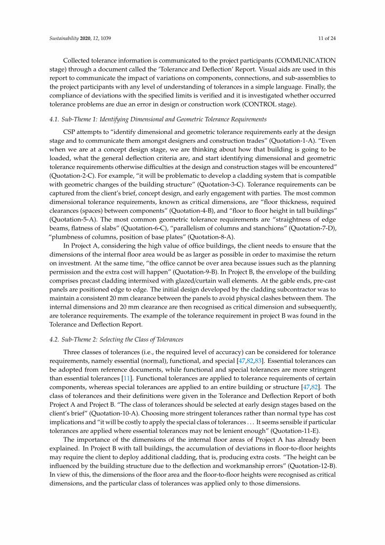
The effect of assembly sequence (i.e., load sequence) on the geometric accuracy of the buildingstructure is considered. There are four milestones when considering the load sequence, namely when“(a) the structure is erected, (b) the cladding is fixed to the structure, (c) finishes on floors and ceiling e.g.,services, suspended ceiling and raised floors, mechanical pipes are installed, and (d) when the buildingis occupied” (Quotation-22-A). CSP “determines the resultant deflection of floor slabs and beams aftereach milestone and performs the serviceability analysis” (Quotation-23-C). The load sequence andthe associated deflections for a typical concrete edge-beam are illustrated in Figure 3, which has beenadopted from the Tolerance and Deflection Report of Project B.
Sustainability 2020, 12, x FOR PEER REVIEW 14 of 27
4.6. Sub-theme 7: Planning the Assembly Process (load sequences)
The effect of assembly sequence (i.e. load sequence) on the geometric accuracy of the building structure is considered. There are four milestones when considering the load sequence, namely when “(a) the structure is erected, (b) the cladding is fixed to the structure, (c) finishes on floors and ceiling e.g. services, suspended ceiling and raised floors, mechanical pipes are installed, and (d) when the building is occupied” (Quotation-22-A). CSP “determines the resultant deflection of floor slabs and beams after each milestone and performs the serviceability analysis” (Quotation-23-C). The load sequence and the associated deflections for a typical concrete edge-beam are illustrated in Figure 3, which has been adopted from the Tolerance and Deflection Report of Project B.
Figure 3. Visual interpretation of the deflection criteria in an edge beam (adopted from Tolerance and Deflection Report of Project B).
The time point at which the cladding is installed in the construction programme is very important. This is because “deviations experienced after the cladding is installed must be incorporated within the cladding fixings” (Quotation-24-E). In other words, the cladding system should be capable of absorbing deviations due to its self-weight and any other load applied afterwards, otherwise tolerance requirements, e.g., the clearance between cladding panels, may not be satisfied. Hence, CSP coordinates with the construction planner whether the cladding is installed first or after the finishes.
In Project B, it was planned that the cladding system is fixed first on the edge beam and then the finishes are installed. Apparently, the cladding does not experience DL, which is 10 mm, because that has already occurred before the installation of the cladding, but it experiences SIDL-C, which is 5 mm,
SIDL-F, which is 15 mm, and IMP, which is 5 mm. Given that deflections should be arithmetically added together [84], the TOT of this edge beam is 35 mm, but the cladding has to be capable of absorbing a deflection of 25 mm ( SIDL-C + SIDL-F + IMP) only. If the assembly process was different in such a way that the finishes were installed first and then the cladding, only DL + IMP = 10 mm would need to be incorporated in the fixings of the cladding.
4.7. Sub-theme 8: Performing Tolerance Analysis
Dimensional and geometric variations of adjoining components are cumulative [36]. The evaluation of the combined variations is termed as the tolerance analysis and is performed using mathematical models [36]. The purpose of the tolerance analysis is to ensure that combined deviations of components are within the specified limits and the function of components and sub-assemblies will not be adversely influenced by the accumulation of deviations [85]. The tolerance analysis “is performed in areas where tolerance risks are identified… but not in all of them” (Quotation-25-D).
The calculations needed for tolerance analysis are fully explained in the Tolerance and Deflection Reports of both projects. In Project B, to maintain a 20 mm clearance between pre-cast panels of the cladding system, the impact of the sources of deviations are analysed. Among the
DL : Deflection due to self-weight of the structure SIDL-F: Deflection due to weight of the cladding and finishes
SIDL-C: Deflection due to weight of the cladding and finishes IMP: Deflection due to occupancy of the building
TOT: Total deflection of the edge beam.
IMP
δSIDL-C
DL
TOT
Figure 3. Visual interpretation of the deflection criteria in an edge beam (adopted from Tolerance andDeflection Report of Project B).
The time point at which the cladding is installed in the construction programme is very important.This is because “deviations experienced after the cladding is installed must be incorporated withinthe cladding fixings” (Quotation-24-E). In other words, the cladding system should be capable ofabsorbing deviations due to its self-weight and any other load applied afterwards, otherwise tolerancerequirements, e.g., the clearance between cladding panels, may not be satisfied. Hence, CSP coordinateswith the construction planner whether the cladding is installed first or after the finishes.
In Project B, it was planned that the cladding system is fixed first on the edge beam and then thefinishes are installed. Apparently, the cladding does not experience δDL, which is 10 mm, because thathas already occurred before the installation of the cladding, but it experiences δSIDL-C, which is 5 mm,δSIDL-F, which is 15 mm, and δIMP, which is 5 mm. Given that deflections should be arithmeticallyadded together [84], the δTOT of this edge beam is 35 mm, but the cladding has to be capable ofabsorbing a deflection of 25 mm (δSIDL-C + δSIDL-F + δIMP) only. If the assembly process was different insuch a way that the finishes were installed first and then the cladding, only δDL + δIMP = 10 mm wouldneed to be incorporated in the fixings of the cladding.

Sustainability 2020, 12, 1039 14 of 24
4.7. Sub-Theme 8: Performing Tolerance Analysis
Dimensional and geometric variations of adjoining components are cumulative [36]. Theevaluation of the combined variations is termed as the tolerance analysis and is performed usingmathematical models [36]. The purpose of the tolerance analysis is to ensure that combined deviationsof components are within the specified limits and the function of components and sub-assemblieswill not be adversely influenced by the accumulation of deviations [85]. The tolerance analysis “isperformed in areas where tolerance risks are identified . . . but not in all of them” (Quotation-25-D).
The calculations needed for tolerance analysis are fully explained in the Tolerance and DeflectionReports of both projects. In Project B, to maintain a 20 mm clearance between pre-cast panels of thecladding system, the impact of the sources of deviations are analysed. Among the existing methods fortolerance analysis, the worst case and root sum square methods, suggested by [84], are used by CSP.The worst-case method (Equation (1)) and root sum square method (Equation (2)) are calculated usingthe Equations (1) and (2), where Dwc is the worst-case method, DRSS is the root sum square method, Xiare tolerances for inherent sources of variations, Yi are tolerances for induced sources of variations,α = −1 shows the clearance closes due to the accumulated deviations, and α = +1 shows the clearanceopens. The total accumulated deviation (TTOT) applied to one of the pre-cast panels is calculated usingEquation (3).
TWC =∑
αXi (1)
TRSS = α√∑
Y2i (2)
TToT = TWC + TRSS (3)
The fabrication, erection, and setting-out tolerances for each panel are found to be 3 mm, 6 mm, 5 mm.The tolerances for horizontal movement due to vertical deflection at support and sway effects are12.5 mm and 2 mm. Tolerance analysis in the x-direction leads to the following results: TToT = −6.1 mm/
−22.9 mm. Even if the clearance is not closed as a result of the accumulated deviations of one panel,it can be closed if the position deviations of both adjacent panels would be towards each other. Hence,CSP suggested to increase the clearance at the gables to accommodate possible deviations of the panelsfrom their normal position.
4.8. Sub-Theme 9: Communicating Tolerance Information
The communication of tolerance information, including tolerance requirements/risks, is the mostimportant step in TM, as it was indicated in all interviews. CSP aims to “communicate the identifiedtolerance requirements and risks in a simple language to other parties including architects, contractorsand the supply chain who may not be fully familiar with the terms and concepts typically used”(Quotation-26-A). “Having that communication is important to make sure that everyone from designersto contractors have a full appreciation of how structural and non-structural components fit togetherdespite of their dimensional and geometric variations” (Quotation-27-B). “If structural designers,architects and construction teams work in isolation and only account for tolerances of their owncomponents, then tolerances of adjoining components will remain uncoordinated” (Quotation-28-D).“A lot of tolerance problems can be avoided if tolerance information is communicated at early stagesbefore construction commences” (Quotation-29-C).
One of the main means to communicate tolerance information is via the Tolerance and DeflectionReport produced by CSP. This document unifies all the tolerance information, and it is specificallyprepared for communication of tolerance information. Tolerance and Deflection Report is important toensure a common understanding has been established between parties about tolerance requirementsand risks. It minimises disputes as parties can develop appropriate designs once they are aware oftolerance requirements and risks. The contents of the report are summarised in Table 4.

Sustainability 2020, 12, 1039 15 of 24
Table 4. List of contents in a Tolerance and Deflection Report.
Content Description
Tolerance-related concepts Tolerance-related concepts (e.g., induced and inherent deviations, class oftolerances, tolerance analysis) are briefly explained.
Permitted deviations A list of tolerance values for sources of variations, applied to structuralcomponents, is provided.
Class of tolerances The selected class of tolerances for the listed tolerance requirements is delineated.
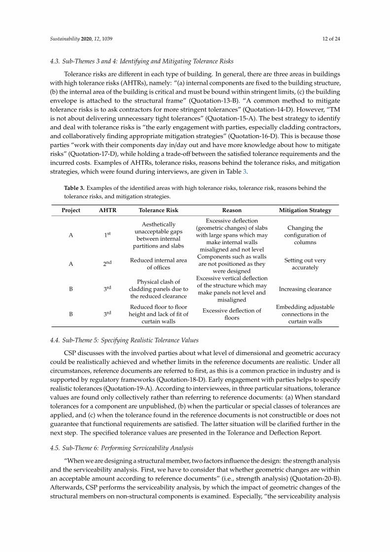
In the Tolerance and Deflection Report, a novel method of visualisation is used to communicatetolerance risks and their consequences during construction in a simple way. Regarding the riskidentified in the cladding system of Project B, 2-D interaction of panels when subjected to verticaldeflection are illustrated in Figure 4a, and sources of variations applying to the clearance betweenpanels are visualised in Figure 4b.
Sustainability 2020, 12, x FOR PEER REVIEW 16 of 25
identified in the cladding system of Project B, 2-D interaction of panels when subjected to vertical deflection are illustrated in Figure 4a, and sources of variations applying to the clearance between panels are visualised in Figure 4b.
(a) (b)
Figure 4. (a) Visualisation of the sources of deviations affecting a joint between pre-cast concrete panels; (b) arrangement of pre-cast panels before and after being subjected to sources of variations (adopted from Tolerance and Deflection Report of Project B).
4.9. Sub-theme 10: Tolerance Compliance Control
CSP documents the observed tolerance problems by the quality control team and investigates whether the occurred tolerance problem was due to an error in the design or construction work. All the investigations are documented in the ‘Site Visit Report’. In Project A, the cantilevered entrance canopy had deflected by up to 30 mm under its self-weight, whereas CSP, after the serviceability analysis, had assigned the deflection tolerance of 4.6 mm under the self-weight condition (Figure 5). According to the Site Visit Report of Project A, CSP ran the analysis again and demonstrated that the frame structure as designed was adequate and that the problem had been caused during the erection process of the frame.
Figure 5. Deflection of the cantilevered entrance canopy in Project A (adopted from the Site Visit Report of Project A).
5. Discussion
After presenting the empirical data, the first part of this section discusses the existing solution to improve TM and the explored good practice of TM by revisiting the key literature that has shaped the relevant arguments. The second part of the discussion then focuses on the proposed conceptual framework to improve TM.
Figure 4. (a) Visualisation of the sources of deviations affecting a joint between pre-cast concrete panels;(b) arrangement of pre-cast panels before and after being subjected to sources of variations (adoptedfrom Tolerance and Deflection Report of Project B).
4.9. Sub-Theme 10: Tolerance Compliance Control
CSP documents the observed tolerance problems by the quality control team and investigateswhether the occurred tolerance problem was due to an error in the design or construction work. All theinvestigations are documented in the ‘Site Visit Report’. In Project A, the cantilevered entrance canopyhad deflected by up to 30 mm under its self-weight, whereas CSP, after the serviceability analysis, hadassigned the deflection tolerance of 4.6 mm under the self-weight condition (Figure 5). According to theSite Visit Report of Project A, CSP ran the analysis again and demonstrated that the frame structure asdesigned was adequate and that the problem had been caused during the erection process of the frame.
Sustainability 2020, 12, x FOR PEER REVIEW 16 of 25
identified in the cladding system of Project B, 2-D interaction of panels when subjected to vertical deflection are illustrated in Figure 4a, and sources of variations applying to the clearance between panels are visualised in Figure 4b.
(a) (b)
Figure 4. (a) Visualisation of the sources of deviations affecting a joint between pre-cast concrete panels; (b) arrangement of pre-cast panels before and after being subjected to sources of variations (adopted from Tolerance and Deflection Report of Project B).
4.9. Sub-theme 10: Tolerance Compliance Control
CSP documents the observed tolerance problems by the quality control team and investigates whether the occurred tolerance problem was due to an error in the design or construction work. All the investigations are documented in the ‘Site Visit Report’. In Project A, the cantilevered entrance canopy had deflected by up to 30 mm under its self-weight, whereas CSP, after the serviceability analysis, had assigned the deflection tolerance of 4.6 mm under the self-weight condition (Figure 5). According to the Site Visit Report of Project A, CSP ran the analysis again and demonstrated that the frame structure as designed was adequate and that the problem had been caused during the erection process of the frame.
Figure 5. Deflection of the cantilevered entrance canopy in Project A (adopted from the Site Visit Report of Project A).
5. Discussion
After presenting the empirical data, the first part of this section discusses the existing solution to improve TM and the explored good practice of TM by revisiting the key literature that has shaped the relevant arguments. The second part of the discussion then focuses on the proposed conceptual framework to improve TM.
Figure 5. Deflection of the cantilevered entrance canopy in Project A (adopted from the Site Visit Reportof Project A).
Sustainability 2020, 12, 1039 16 of 24
5. Discussion
After presenting the empirical data, the first part of this section discusses the existing solution toimprove TM and the explored good practice of TM by revisiting the key literature that has shapedthe relevant arguments. The second part of the discussion then focuses on the proposed conceptualframework to improve TM.
5.1. Existing Solutions And Explored Good Practice For Tolerance Management
In this paper, the propositions to improve TM in construction [5,15,17,18,20,27,38,40,57–60,62] werecollated and categorised into four TM stages (IDENTIFICATION, PLANNING, COMMUNICATION,CONTROL), and are critically reviewed. Such categorisation is essential to help improve TM [86,87],however, the categorisation of TM stages in construction does not presently exist in the literature,and hence is a contribution from the research here presented. Furthermore, as argued in Section 3,the lack of a process that involves all the TM stages, application of complex manufacturing theories,and application of costly methods are the major drawbacks of the existing solutions presented in theliterature, when trying to implement them in practice.
This research presented a TM good practice (Section 5). The explored TM process was consideredas a good practice because its implementation does not require the application of costly methodsand understanding of theories adopted from manufacturing, as opposed to most of the existingsolutions in the literature [4,11]. In essence, such proactive process with the focus on tolerances indesign avoids reactive approaches (i.e., fixing tolerance problems on site) [13,27]. As it can be seenfrom Figure 2, the process includes all of the TM stages and is applicable from project inception toproject completion, unlike most of the existing solutions [4,20,88].This confirms the importance ofhaving a proactive process for TM that involves all the stages to reduce remedial actions duringconstruction [15,17,20,24,25,38,40]. Moreover, a significant amount of resources during design has beeninvested in CSP to proactively ensure that constructed components on site are compliant with tolerancerequirements. This restates the importance of focusing on tolerances at the design stage rather thanreactively fixing tolerance problems on site, which can be time-consuming [4,11,20], laborious, andcostly [4,20].
The process practiced by CSP starts from early design stages (Quotations 1-2-3) and consistsof verifiable and standardised steps (see Section 4). These two qualities are in accordance with theliterature [4,17,20,24,25,38] on when and how TM should be implemented. However, the exploredprocess shed additional light on how those guidelines can be used in practice (e.g., how to communicatetolerance information, how to perform the serviceability analysis for TM). More specifically, whilesome of the key guidelines in the literature are limited to generic recommendations e.g., [18], theprocess presented here can be considered as a guide allowing practitioners in industry to start dealingwith tolerances systematically (Section 3). This is because a set of practical steps of an effective processfor TM were clearly presented along with real examples for further demonstration. The review ofsuch good TM practice is currently missing in the literature, while the process of reviewing goodpractices before attempting to improve existing practices is essential [28–32]. The explored processcan be adapted by other companies and can be continuously improved to eventually develop astandard for TM rather than reinventing the wheel with each new project. The empirical data in thisstudy is essential to deviate from theoretical knowledge without practical relevance, towards effectivesolutions for real-world problems [32]. While the management research in general [30], and TM inparticular [24,40], have been criticised for practical irrelevance, this research contributes to supportbetter links between theory and practice in TM.
In this process, ‘identifying Dimensional and Geometric Tolerance Requirements’ is the first step.The most common dimensional and geometric tolerance requirements were presented to facilitate theidentification of such requirements in projects (Quotations 4-5-6-7-8). The most common dimensionaltolerance requirements were found to be floor thickness, required clearances between components(Quotation 4), and floor to floor height in tall buildings (Quotation 5); the most common geometric

Sustainability 2020, 12, 1039 17 of 24
tolerance requirements were found to be straightness of edge beams, flatness of slabs (Quotation 6),parallelism of columns and stanchions (Quotation 7), plumbness of columns, and position of baseplates (Quotation 8). This understanding of the most common tolerance requirements is missing in theliterature and is one of the findings emerged from this study.
The classes of tolerances, suggested by [47,82,83] and explained in the Tolerance and DeflectionReports, are selected at early design stages. It was discussed that it is more sensible to select theparticular class of tolerances where more lenient tolerances are needed (Quotation 10) because theselection of special tolerances has significant cost implications (Quotation 11). This is in in accordancewith previous studies [7], however, the empirical data shed additional light on how ‘particular’ classof tolerances can be applied in practice (see Section 4.2).
Unlike the current reactive practice of risk management for tolerances [24,38], the presentedprocess encourages to identify tolerance risks by early engagement of responsible parties and thenreflect them in the design proactively through the ‘identifying and mitigating tolerance risks’ step(Quotation 16). The research clearly indicates that the best strategy to deal with tolerance risksis the early engagement with parties and collaboratively finding appropriate mitigation strategies(Quotations 14-16-17). This is because those parties are often aware of potential tolerance risks andhave more knowledge about how to mitigate them (Quotation 17) while balancing the cost of satisfiedtolerance requirements and the incurred costs (Section 4.3). However, previous studies e.g., [4,15,38]imply that the knowledge of practitioners on tolerance risks is often disregarded by designers andproject managers, and this can result in costly tolerance problems. In order to achieve the proactiveidentification of tolerance risks, this study reveals three areas with high tolerance risks (AHTRs)(Quotation 13) based on real examples (see Table 3). Those AHTRs are (a) the connection betweeninternal components and the building structure, (b) the connection between the building envelope andthe building structure, and (c) where the internal area of the building must be bound within stringentlimits (Quotation 13). The categorisation of AHTRs is currently missing in the literature and is one ofthe most significant findings from this study.
Reference documents are considered first in the ‘specifying realistic tolerance values’ step of theexplored process (Quotation 18), similar to the current practice of TM [4]. It was suggested that thespecification of tolerances collectively is expected to tackle the problem with reference documents(Section 3.2), as previously found by [11,18]. However, the explored process goes beyond previousstudies by revealing three situations that tolerance values should be found only collectively (Section 4.4).These situations are (a) when tolerance values for a component cannot be found in reference documents,(b) when more stringent tolerances than normal tolerances are specified, and (c) when the tolerancevalue specified based on the reference documents is not constructible or does not guarantee thatfunctional requirements are satisfied (Section 4.4).
In the process practiced by CSP, the impact of geometric changes of the structural members onnon-structural members is examined through the ‘performing serviceability analysis’ step (Quotation20), especially for perimeter beams (Quotation 21). Four milestones, in which the serviceability shouldbe performed, were introduced based on the findings from interviews (Quotation 22) and documentanalysis (Tolerance and Deflection Reports). The milestones are when (a) the structure is erected,(b) the cladding is fixed to the structure, (c) finishes on floors and ceiling are installed, and (d) thebuilding is occupied (Quotation 22). Despite performing serviceability analysis for TM in general issuggested by [27,57,62], this is the first study that has found the milestones in which serviceabilityanalysis should be performed in the context of TM and has demonstrated performing the serviceabilityanalysis through a real case.
The worst case method and root sum square method are used in the ‘performing tolerance analysis’step because only these two methods are supported by reference documents [18]. Given toleranceanalysis is perceived to be difficult and time consuming [60,85], the review of the explored goodpractice suggests that tolerance analysis is particularly needed in AHTRs (Quotation 25). This finding

Sustainability 2020, 12, 1039 18 of 24
of this study is a contribution to knowledge, as it can facilitate TM for industry by prescribing toperform tolerance analysis only in particular areas.
Ineffective communication of tolerance information is a challenge in industry and insufficientattention has been devoted to it [18,89]. For that reason, it was indicated in all interviews that thecommunication of tolerance information in a simple language is the most important step in thisprocess (Section 4.8). Such communication is essential to ensure tolerances of adjoining componentsare coordinated (Quotations 26–27) [4], adjoining components function properly [25,51], and alsotolerance problems are avoided proactively (Quotations 28–29) [90]. Unlike the current practice ofhaving specifications with scattered tolerance information [52,53], the ‘Tolerance and Deflection Report’,produced by CSP as part of the ‘communicating tolerance information’ step, is a document that unifiesall the tolerance information (Quotation-30) and ensures all parties are aware of tolerance requirementsand risks (see Section 4.8). This study investigated the content of the ‘Tolerance and Deflection Report’and divided its content into (a) tolerance-related concepts, (b) permitted deviations, and (c) class oftolerances (Section 4.8). The proposition to have a unified document for communication of toleranceinformation and the content of such document contribute to the current literature.
A method is used in the ‘Tolerance and Deflection Report’ that uses visual aids to communicatethe impact of variations on components and connections in 2-D, especially to those who may not befully familiar with the tolerance and engineering-related concepts (Section 5). Visual aids have notyet been well deployed to improve TM [91], even though they are used in manufacturing to translatecomplex tolerance requirements and risks into an easily understandable language [92]. There aresources e.g., [11,20,24,93–95] that extol any improved communication of tolerance information for itsability to reduce tolerance problems, but do not offer any considerable actionable advice [90]. Thisstudy responds to the call from [3,49,90] that to propose methods whereby the communication oftolerance information can be improved by revealing two novel methods (i.e., creating a documentunifying tolerance information and using visual aids).
Finally, occurred tolerance problems are documented and analysed in the ‘Site Visit Reports’produced by CSP during the ‘performing tolerance compliance control’ step to investigate whetherthose problems were due to an error in the design or construction work (Quotation–32). This stepcan be a starting point to avoid reoccurrence of tolerance problems [20] and goes beyond the currentpractice of tolerance compliance control in practice (Section 3.2) and existing guidelines in the literaturee.g., [20,55,56]. However, a mechanism is still missing to enable the reuse of the knowledge gainedfrom such analysis and reflect it in design, which is the essence of continuous improvement in TM [68].
5.2. Proposed Conceptual Framework to Improve Tolerance Management in Construction
In view of the system approach, the guidelines in the literature and the good practice case exploredin this research are used to provide a solution to improve TM. The conceptual framework to improveTM in conventional construction projects is presented in Figure 6. The framework covers the four TMstages (themes in thematic analysis), and consists of findings from the literature and empirical study.Figure 6 also indicates whether the steps and input knowledge come from the literature and/or theempirical study.
In IDENTIFICATION, the steps were found from both the literature [7,15,17,20,27,38,57,58,62] andthe explored CSP. The knowledge of ‘known tolerance requirements’ as well as known ‘connections/areaswith high tolerance risks’ have been found from the empirical study.
In the second part of the framework, PLANNING, the step of ‘creating measurement plan’ comesfrom the literature [57], but the remaining steps were found from both the literature [5,7,15,17,18,20,38,40,57–60,62] and empirical study. Also, the knowledge of ‘four milestones when performingserviceability analysis’ was gained from the empirical study and was a contribution to the literature.
In COMMUNICATION, it is proposed to ‘create a unified report for tolerance information’ with aparticular content based on the CSP good practice. Based on the TM good practice, it is also suggestedto use visual aids in the report to facilitate the communication of tolerance information.

Sustainability 2020, 12, 1039 19 of 24
Sustainability 2020, 12, x FOR PEER REVIEW 20 of 25
Figure 6. A holistic process to improve TM in construction.
In IDENTIFICATION, the steps were found from both the literature [7,15,17,20,27,38,57,58,62] and the explored CSP. The knowledge of ‘known tolerance requirements’ as well as known ‘connections/areas with high tolerance risks’ have been found from the empirical study.
In the second part of the framework, PLANNING, the step of ‘creating measurement plan’ comes from the literature [57], but the remaining steps were found from both the literature [5,7,15,17,18,20,38,40,57–60,62] and empirical study. Also, the knowledge of ‘four milestones when performing serviceability analysis’ was gained from the empirical study and was a contribution to the literature.
In COMMUNICATION, it is proposed to ‘create a unified report for tolerance information’ with a particular content based on the CSP good practice. Based on the TM good practice, it is also suggested to use visual aids in the report to facilitate the communication of tolerance information.
In the fourth part, CONTROL, ‘investigating the reasons behind the occurrence of tolerance problems’ comes from the empirical study and the remaining steps were found from the literature [17,20,27,38,57,58,60]. The development of this conceptual framework is a contribution of this research because the framework integrates new concepts based on the empirical study with existing knowledge to introduce a better solution for an existing problem.
6. Conclusion
The aim of this research is to propose a conceptual framework as an effective practical solution to improve TM in construction. In this paper, the existing guidelines in literature are critically reviewed, and a good practice for TM in industry is explored. Empirical data and the literature were integrated to present a new framework as an effective practical solution to improve TM. Individual
Figure 6. A holistic process to improve TM in construction.
In the fourth part, CONTROL, ‘investigating the reasons behind the occurrence of toleranceproblems’ comes from the empirical study and the remaining steps were found from theliterature [17,20,27,38,57,58,60]. The development of this conceptual framework is a contributionof this research because the framework integrates new concepts based on the empirical study withexisting knowledge to introduce a better solution for an existing problem.
6. Conclusions
The aim of this research is to propose a conceptual framework as an effective practical solution toimprove TM in construction. In this paper, the existing guidelines in literature are critically reviewed,and a good practice for TM in industry is explored. Empirical data and the literature were integrated topresent a new framework as an effective practical solution to improve TM. Individual interviews anddocument analysis have been used to collate data in this research. The TM process identified throughinterviews and document analysis was then validated in a group interview.
The study presents key propositions to improve TM from the literature. The propositions weredivided into four TM stages, namely identification of tolerance requirements/risks (IDENTIFICATION),planning the achievement of tolerance requirements/ mitigating tolerance risks (PLANNING),communication of tolerance information (COMMUNICATION), and tolerance compliance control(CONTROL). The critical analysis of those propositions revealed that a practical process, which coversall TM stages, is still missing in the literature. Moreover, the propositions require either complexmanufacturing theories or costly methods. The proposed categorisation of TM stages and the presenteddrawbacks are currently missing in the literature and are novel contributions to theory.
Sustainability 2020, 12, 1039 20 of 24
This study moves the focus from viewing one or some TM stages to adopting a more holisticview for it, and from using complex or costly methods to adopting practical steps. The TM processpractised by CSP includes elements from all of the identified stages, and it has been successful toimprove the CSP’s performance in TM. This good practice of TM comprises a set of practical stepsaccompanied with examples to further demonstrate the point. It is essential to review good practicesbefore attempting to improve existing practices while there is no literature analysing effective solutionsused in practice for TM. Some of the methods in the explored process are new and do not exist in thecurrent literature (e.g., visualisation of variations). Therefore, this research contributes to both practiceand theory, as it presents a guide for practitioners and researchers seeking to improve TM.
A conceptual framework to improve TM in conventional construction projects is proposed. Theframework ensures that all the TM stages are covered, and guidelines from the literature and findingsfrom the empirical study are adopted. As far as it is known, there is no other solution in the literature asholistic as the framework proposed in this research. The framework pinpoints a basis for academics andpractitioners for further improvement and its development is a contribution of this research. ProactiveTM on the basis of this framework can reduce the number of defects associated with tolerances by theidentification of tolerance requirements and risks early in the design stage. This should help to reduceremedial actions needed to solve tolerance problems during construction.
Future research will include implementation of the proposed conceptual framework in practice.This will help to further develop and to validate the framework thoroughly. More work is needed toalign the steps in the framework to the Royal Institute of British Architectures (RIBA) plan of works [2].Even though the RIBA Plan of Work is recognised in the UK as a design and management frameworkfrom inception to completion [96], it does not explicitly address TM.
Finally, future work may attempt to adopt and refine concepts for TM from manufacturing toconstruction. For example, Geometric Dimensioning and Tolerancing (GD&T) is a symbolic languagewidely used to communicate both the true geometry and tolerances of components and assemblies [97].Further research is needed to investigate the application of GD&T in construction with the goal ofdeveloping a common language to facilitate communication of tolerance information throughout thedesign, construction, and inspection processes.
Author Contributions: Conceptualization, S.T., L.K., P.T. M.K.; formal analysis, S.T.; methodology, S.T., P.T., L.K.,M.K.; validation S.T., L.K., supervision, L.K. and P.T., writing—original draft preparation, S.T.; writing—reviewand editing, S.T., P.T., L.K., M.K. All authors have read and agreed to the published version of the manuscript.
Funding: This research is funded by the Innovative Design Lab, School of Art, Design and Architecture, Universityof Huddersfield.
Conflicts of Interest: The authors declare no conflict of interest.
References
1. Forcada, N.; Macarulla, M.; Gangolells, M.; Casals, M. Handover defects: Comparison of construction andpost-handover housing defects. Build. Res. Inf. 2016, 44, 279–288. [CrossRef]
2. Landin, A. Demands on the tolerances when industrialising the construction sector. In New Perspective inIndustrialisation in Construction: A State -Of-The-Art Report; Girmscheid, G., Scheublin, F., Eds.; InternationalCouncil for Research and Innovation in Building and Construction: Zurich, Switzerland, 2010; pp. 197–205.
3. Jingmond, M.; Ågren, R. Unravelling causes of defects in construction. Construct. Innovat. 2015, 15, 198–218.[CrossRef]
4. Talebi, S. Improvement of Dimensional Tolerance Management in Construction. Ph.D. Thesis, University ofHuddersfield, Huddersfield, UK, 2019. Available online: http://eprints.hud.ac.uk/id/eprint/35070/ (accessedon 30 January 2020).
5. British Standards Institution. Tolerances for Building - Part 1: Basic Principles for Evaluation and Specification;BSI: London, UK, 1988.
6. Berg, J.v.d.; Holicky, M. CIB W49 Tolerances and FIG Commission 6 Engineering Surveys; CIB publication:Amsterdam, The Netherlands, 1989; ISBN 2800525069.

Sustainability 2020, 12, 1039 21 of 24
7. British Standards Institution. Guide to Accuracy in Building; BSI: London, UK, 1990.8. American Concrete Institute. Specification for Tolerances for Concrete Construction and Materials; ACI: Farmington
Hills, MI, USA, 2010.9. CIM Steel. Design for Construction; The Steel Construction Institute: Berkshire, UK, 1997; ISBN 1859420486.10. Fischer, M.; Khanzode, A.; Reed, D.; Ashcraft, H.W. Integrating Project Delivery; John Wiley & Sons, Inc.:
Hoboken, NJ, USA, 2017; ISBN 0470587350.11. Davison, B.; Owens, G.W. Steel Designers’ Manual, 6th ed.; Blackwell Science, Ltd.: Chennai, India, 2012; ISBN
9781405189408.12. Milberg, C.; Tommelein, I. Role of tolerances and process capability data in product and process design
integration. In Proceedings of the Construction Research Congress, Honolulu, HI, USA, 19–21 March 2003.13. Gibb, A.G. Off-Site Fabrication: Prefabrication, Pre-Assembly and Modularisation; Whittles Publishing: Scotland,
UK, 1999; ISBN 0470378360.14. Popescu, C.-R. The Role of Total quality management in developing the concept of social Responsibility to
protect public interest in associations of liberal professions. Amfiteatru Economic 2017, 19, 1091–1106.15. American Concrete Institute. Guide for Tolerance Compatibility in Concrete Construction (ACI 117.1R-14); ACI:
Farmington Hills, MI, USA, 2014.16. Milberg, C.; Tommelein, I.D. Tolerance and constructability of soldier piles in slurry walls. J. Perform. Constr.
Fac. 2009, 24, 120–127. [CrossRef]17. Vorlícek, M.; Holický, M. Analysis of Dimensional Accuracy of Building Structures; Elsevier: Amsterdam,
The Netherlands, 1989; ISBN 0444988750.18. Ballast, D.K. Handbook of Construction Tolerances, 2nd ed.; John Wiley & Sons, Inc.: Hoboken, NJ, USA, 2007;
ISBN 9781118260227.19. Koskela, L. An Exploration towards a Production Theory and Its Application to Construction. Ph.D. Thesis,
Technical Research Centre of Finland, Espoo, Finland, 2000. Available online: http://lib.tkk.fi/Diss/2000/
isbn951385566X/ (accessed on 28 January 2020).20. Milberg, C. Application of Tolerance Management to Civil Systems. Ph.D. Thesis, 2006. Available
online: http://citeseerx.ist.psu.edu/viewdoc/download?doi=10.1.1.308.5119&rep=rep1&type=pdf (accessedon 30 January 2020).
21. Alexander, S. Design for Movement in Buildings, 2nd ed.; Construction Industry Research and InformationAssociation: London, UK, 2014; ISBN 9780128104330.
22. Bradford, C.W. The Impact of the Systematic Incorporation of Tolerances on Gypsum board Installation.Ph.D. Thesis, Indiana State University, Terre Haute, IN, USA, 2017. Available online: https://search.proquest.com/openview/8235437a5504cb84e4d1f5604d3f0f81/1?cbl=18750&diss=y&pq-origsite=gscholar (accessed on30 January 2020).
23. Valdes, F.J. Manufacturing Compliance Analysis for Architectural Design: A Knowledge-Aided Feature-BasedModeling Framework. Ph.D. Thesis, Georgia Tech, 2016. Available online: http://hdl.handle.net/1853/54973(accessed on 30 January 2020).
24. Talebi, S.; Koskela, L.; Shelbourn, M.; Tzortzopoulos, P. Critical review of tolerance management inconstruction. In Proceedings of the 24th Annual Conference of the International Group for Lean Construction,Boston, MA, USA, 20–22 July 2016.
25. Seymour, D.; Shammas-Toma, M.; Clark, L. Limitations of the use of tolerances for communicating designrequirements to site. Eng. Construct. Architect. Manag. 1997, 4, 3–22. [CrossRef]
26. McCarney, M.P. Interface Management of Offsite Bathroom Construction: Process-and People-Factors. Ph.D.Thesis, Loughborough University, Loughborough, UK, 2017. Available online: https://repository.lboro.ac.uk/
articles/Interface_management_of_offsite_bathroom_construction_process-_and_people-factors/9455024(accessed on 30 January 2020).
27. Enshassi, M.S.; Walbridge, S.; West, J.S.; Haas, C.T. Integrated risk management framework for tolerance-basedmitigation strategy decision support in modular construction projects. J. Manag. Eng. 2019, 35, 05019004.[CrossRef]
28. Liker, J.K. The Toyota Way: 14 Management Principles from the world’s Greatest Manufacturer; McGraw-Hill: NewYork, NY, USA, 2004; ISBN 9797813770.
29. Imai, M. Gemba Kaizen: A Common Sense Approach to a Continuous Improvement Strategy, 2nd ed.; McGraw Hill:New York, NY, USA, 2012; ISBN 0071790357.
Sustainability 2020, 12, 1039 22 of 24
30. Koskela, L. Why is management research irrelevant? Manag. Econ. 2017, 35, 4–23. [CrossRef]31. Arayici, Y.; Coates, P.; Koskela, L.; Kagioglou, M.; Usher, C.; O’reilly, K. Technology adoption in the BIM
implementation for lean architectural practice. Autom. Construct. 2011, 20, 189–195. [CrossRef]32. Checkland, P. OR and the systems movement: Mappings and conflicts. J. Oper. Res. Soc. 1983, 34, 661–675.
[CrossRef]33. Kanigel, R. The One Best Way: Frederick Winslow Taylor and the Enigma of Efficiency; Penguin Group: New York,
NY, USA, 2005; ISBN 9780262612067.34. Slowinski, G.; Sagal, M.W. Good practices in open innovation. Res. Tech. Manag. 2010, 53, 38–45. [CrossRef]35. Construction Industry Institute. CII Best Practices Guide: Improving Project Performance; CII: Austin, TX,
USA, 2012.36. Henzold, G. Geometrical Dimensioning and Tolerancing for Design, Manufacturing and Inspection: A Handbook for
Geometrical Product Specification Using ISO and ASME Standards, 2nd ed.; Butterworth-Heinemann: Oxford,UK, 2006; ISBN 0750667389.
37. Creveling, C.M. Tolerance Design: A Handbook for Developing Optimal Specifications; Prentice Hall: NeedhamHeights, MA, USA, 1997; ISBN 0201634732.
38. Shahtaheri, Y.; Rausch, C.; West, J.; Haas, C.; Nahangi, M. Managing risk in modular construction usingdimensional and geometric tolerance strategies. Autom. Construct. 2017, 83. [CrossRef]
39. Alshawi, M.; Underwood, J. Improving the constructability of design solutions through an integrated system.Eng. Construct. Architect. Manag. 1996, 3, 47–67. [CrossRef]
40. Rausch, C.; Nahangi, M.; Haas, C.; West, J. Kinematics chain based dimensional variation analysis ofconstruction assemblies using building information models and 3D point clouds. Autom. Construct. 2017, 75,33–44. [CrossRef]
41. Construction Industry Institute. Constructability Implementation Guide (Best Practice); University of Texas:Austin, TX, USA, 1993.
42. Landin, A.; Kämpe, P. Industrializing the construction sector through innovation–tolerance dilemma.In Proceedings of the CIB World Congress, Cape Town, South Africa, 14–17 May 2007.
43. Forsythe, P. Consumer-perceived appearance tolerances in construction quality management. Eng. Construct.Architect. Manag. 2006, 13, 307–318. [CrossRef]
44. Popescu, G.; Raluca, C.; Bant,a, V.C. Performance evaluation of the implementation of the 2013/34/EU directivein Romania on the basis of corporate social responsibility reports. Sustainability 2019, 11, 2531. [CrossRef]
45. Popescu, C.R.G.; Popescu, G.N. An exploratory study based on a questionnaire concerning green andsustainable finance, corporate social responsibility, and performance: Evidence from the Romanian businessenvironment. J. Risk Financ. Manag. 2019, 12, 162. [CrossRef]
46. Popescu, C.R.G. Corporate social responsibility, corporate governance and business performance: Limitsand challenges imposed by the implementation of directive 2013/34/EU in Romania. Sustainability 2019, 11,5146. [CrossRef]
47. British Standards Institution. Execution of Steel Structures and Aluminium Structures: Technical Requirements forSteel Structures; BSI: London, UK, 2011.
48. American Institute of Steel Construction. Code of Standard Practice for Steel Buildings and Bridges; AISC:Chicago, IL, USA, 2010.
49. Price, C.; Goodier, C.I.; Fouchal, F.; Fraser, N. The Role of Standards in Offsite Construction: A Review of ExistingPractice and Future Need; British Standards Institute: London, UK, 2019.
50. American Concrete Institute. Commentary on Standard Specifications for Tolerances for Concrete Construction andMaterials; ACI: Farmington Hills, MI, USA, 2002.
51. Krogstie, L. Closed Loop Tolerance Engineering: An Approach for Designing Robust Products and Processes.Ph.D. Thesis, Norwegian University of Science and Technology, Trondheim, Norway, 2015. Available online:https://ntnuopen.ntnu.no/ntnu-xmlui/handle/11250/282441 (accessed on 30 January 2020).
52. Frank, G.C. Construction Quality: Do It Right or Pay the Price; Pearson Higher Education, Inc.: Upper SaddleRiver, NJ, USA, 2012; ISBN 0133002837.
53. Smith, R.E. Prefab Architecture: A Guide to Modular Design and Construction; John Wiley & Sons, Inc.: Hoboken,NJ, USA, 2010; ISBN 0470275618.
Sustainability 2020, 12, 1039 23 of 24
54. Talebi, S.; Koskela, L.; Tzortzopoulos, P. Tolerance compliance measurement using laser scanner.In Proceedings of the 26th Annual Conference of the International Group for Lean Construction, Chennai,India, 18–20 July 2018.
55. Bosché, F.; Guenet, E. Automating surface flatness control using terrestrial laser scanning and buildinginformation models. Autom. Construct. 2014, 44, 212–226. [CrossRef]
56. Graham, J.R.; Lindholm, E.A. Concrete tolerances: Importance and achievement in Bureau of ReclamationConstruction. J. Am. Concr. Inst. 1978, 75, 49–54.
57. The Construction Industry Research and Information Association. A Suggested Design Procedure for Accuracyin Building; CIRIA: London, UK, 1983; ISBN 086017 199 X.
58. International Organisation for Standardization. Quality Management Systems: Requirements (BS EN ISO9001:2015); ISO: London, UK, 2015.
59. Prestressed Concrete Institute. PCI Design Handbook: Precast and Prestressed Concrete, 6th ed.; Martin, L.D.,Perry, C.J., Eds.; PCI: Chicago, IL, USA, 2004; ISBN 9780937040232.
60. Rausch, C.; Nahangi, M.; Haas, C.; Liang, W. Monte Carlo simulation for tolerance analysis in prefabricationand offsite construction. Autom. Construct. 2019, 103, 300–314. [CrossRef]
61. Abuhav, I. ISO 9001: 2015-A Complete Guide to Quality Management Systems; CRC Press: London, UK, 2017;ISBN 131536980X.
62. A checklist on tolerances. Build. Res. Inf. 1974, 2, 144–146. [CrossRef]63. Silva, P. Movement and tolerances. In ICE Manual of Structural Design: Buildings; Bull, J.W., Ed.; Thomas
Telford: London, UK, 2012; Volume 18, pp. 267–292.64. Curtis, M.A. Dimensional Management: A Comprehensive Introduction; Industrial Press, Inc.: New York, NY,
USA, 2002; ISBN 9780831130732.65. Kagioglou, M.; Cooper, R.; Aouad, G.; Sexton, M. Rethinking construction: The generic design and
construction process protocol. Eng. Construct. Architect. Manag. 2000, 7, 141–153. [CrossRef]66. Feng, C.; Xiao, Y.; Willette, A.; McGee, W.; Kamat, V.R. Vision guided autonomous robotic assembly and
as-built scanning on unstructured construction sites. Autom. Construct. 2015, 59, 128–138. [CrossRef]67. Womack, J.P.; Jones, D.T.; Roos, D. The Machine That Changed the World; Rawson Associates: New York, NY,
USA, 1990; ISBN 0892563508.68. Meiling, J.H.; Sandberg, M.; Johnsson, H. A study of a plan-do-check-act method used in less industrialized
activities: Two cases from industrialized housebuilding. Construct. Manag. Econ. 2014, 32, 109–125. [CrossRef]69. Yin, R.K. Case Study Research: Design and Methods, 4th ed.; SAGE Publications: Thousand Oaks, CA, USA,
2013; ISBN 978-1-4129-6099-1.70. Arbnor, I.; Bjerke, B. Methodology for Creating Business Knowledge, 3rd ed.; SAGE Publications: London, UK,
2008; ISBN 1446202526.71. Flyvbjerg, B. Five misunderstandings about case-study research. Qual. Inq. 2006, 12, 219–245. [CrossRef]72. Eisenhardt, K.M. Building theories from case study research. Acad. Manag. Rev. 1989, 14, 532–550. [CrossRef]73. Taylor, S.J.; Bogdan, R.; DeVault, M. Introduction to Qualitative Research Methods: A Guidebook and Resource;
John Wiley & Sons: Hoboken, NJ, USA, 2015; ISBN 1118767217.74. Blumberg, B.; Cooper, D.R.; Schindler, P.S. Business Research Methods; McGraw-Hill Higher Education:
London, UK, 2008; Volume 2, ISBN 9788776814212.75. Miles, M.B.; Huberman, A.M. Qualitative data analysis: An expanded sourcebook. Serv. Ind. J. 1995, 15, 366.76. Saunders, M.; Lewis, P.; Thornhill, A. Research Methods for Business Students, 7th ed.; Pearson Education:
Harlow, UK, 2016; ISBN 9780273716860.77. Boddy, C.R. Sample size for qualitative research. Qual. Mark. Res. Int. J. 2016, 19, 426–432. [CrossRef]78. Brinkmann, S. Qualitative Interviewing: Understanding Qualitative Research; Oxford University Press: New
York, NY, USA, 2013; ISBN 0199861390.79. Braun, V.; Clarke, V. Using thematic analysis in psychology. Qual. Res. Psychol. 2006, 3, 77–101. [CrossRef]80. Ghauri, P.N.; Grønhaug, K. Research Methods in Business Studies: A Practical Guide; Pearson Education: London,
UK, 2005; ISBN 0273681567.81. Bryman, A. Social Research Methods, 4th ed.; Oxford University Press: Oxford, UK, 2016; ISBN 0199689458.82. British Standards Institution. Execution of Concrete Structures; BSI: London, UK, 2009.83. Construct Structures Group. National structural concrete specification for building construction. In NSCS;
The Concrete Centre: Surrey, UK, 2010.
Sustainability 2020, 12, 1039 24 of 24
84. British Standards Institution. Tolerances for Building: Recommendations for Statistical Basis for Predicting Fitbetween Components Having a Normal Distribution of Sizes; BSI: London, UK, 1998.
85. Singh, P.; Jain, P.; Jain, S. Important issues in tolerance design of mechanical assemblies. Part 1: Toleranceanalysis. Proc. IME B J. Eng. Manufact. 2009, 223, 1225–1247. [CrossRef]
86. Krogstie, L.; Walter, M.S.; Wartzack, S.; Martinsen, K. Towards a more comprehensive understanding oftolerance engineering research importance. Procedia CIRP 2015, 27, 29–34. [CrossRef]
87. Hong, Y.; Chang, T. A comprehensive review of tolerancing research. J. Prod. Res. Manag. 2002, 40, 2425–2459.[CrossRef]
88. Milberg, C.T.; Tommelein, I.D. Methods for managing tolerance compatibility: Windows in cast-in-placeconcrete. J. Construct. Eng. Manag. 2019, 146, 04019105. [CrossRef]
89. Anderson, A.R. Construction tolerances for concrete in highway structures. J. Am. Concr. Inst.1965, 13–18. Available online: https://www.semanticscholar.org/paper/CONSTRUCTION-TOLERANCES-FOR-CONCRETE-IN-HIGHWAY-Anderson/483ce020cbb434a0c1247653fff7753557ec27dc (accessed on24 April 2019).
90. Savoini, J.-J.; Lafhaj, Z. Considering functional dimensioning in architectural design. Front. Architect. Res.2017, 6, 89–95. [CrossRef]
91. Da Rocha, C.; Tezel, A.; Talebi, S.; Koskela, L. Product modularity, tolerance management, and visualmanagement: Potential synergies. In Proceedings of the 26th Annual Conference of the International Groupfor Lean Construction, Chennai, India, 18–20 July 2018.
92. Costadoat, R.; Mathieu, L.; Falgarone, H.; Fricero, B. Geometric specification at the beginning of the productlifecycle. In Product Life-Cycle Management: Geometric Variations; Giordano, M., Mathieu, L., Villeneuve, F.,Eds.; John Wiley & Sons, Inc.: London, UK, 2012; pp. 433–454.
93. Sacks, R.; Eastman, C.; Lee, G.; Teicholz, P. BIM Handbook: A Guide to Building Information Modeling for Owners,Designers, Engineers, Contractors, and Facility Managers; John Wiley & Sons, Inc.: Hoboken, NJ, USA, 2018;ISBN 1119287545.
94. British Standards Institution. Design of Joints and Jointing in Building Construction: Guide; British StandardsInstitution: London, UK, 2013.
95. Ballast, D.K. Architect’s Handbook of Construction Detailing; John Wiley & Sons: Hoboken, NJ, USA, 2009; ISBN0470381914.
96. Royal Institute of British Architectures. RIBA Plan of Work Overview. Availableonline: https://www.architecture.com/-/media/gathercontent/riba-plan-of-work/additional-documents/ribaplanofwork2013overviewfinalpdf.pdf (accessed on 24 April 2019).
97. Krulikowski, A. Fundamentals of Geometric Dimensioning and Tolerancing, 3rd ed.; Cengage Learning: New York,NY, USA, 2012; ISBN 1285401972.
© 2020 by the authors. Licensee MDPI, Basel, Switzerland. This article is an open accessarticle distributed under the terms and conditions of the Creative Commons Attribution(CC BY) license (http://creativecommons.org/licenses/by/4.0/).