thesis template (double-sided) - cranfield university
TRANSCRIPT
CRANFIELD UNIVERSITY
ZAREEFA S MUSTAFA
ASSESSING THE EVIDENTIAL VALUE OF ARTEFACTS
RECOVERED FROM THE CLOUD
CRANFIELD DEFENCE AND SECURITY
Forensic Computing
PhD
Academic Year: 2016
Supervisor: Dr Annie Maddison Warren
Dr Sarah Morris
Dr Philip Nobles
June 2016

CRANFIELD UNIVERSITY
CRANFIELD DEFENCE AND SECURITY
Forensic Computing
PhD
Academic Year 2012 - 2016
ZAREEFA S MUSTAFA
Assessing the Evidential Value of Artefacts Recovered from the
Cloud
Supervisor: Dr Annie Maddison Warren
Dr Sarah Morris
Dr Philip Nobles
June 2016
© Cranfield University 2016. All rights reserved. No part of this
publication may be reproduced without the written permission of the
copyright owner.

i
ABSTRACT
Cloud computing offers users low-cost access to computing resources that are
scalable and flexible. However, it is not without its challenges, especially in
relation to security. Cloud resources can be leveraged for criminal activities and
the architecture of the ecosystem makes digital investigation difficult in terms of
evidence identification, acquisition and examination. However, these same
resources can be leveraged for the purposes of digital forensics, providing
facilities for evidence acquisition, analysis and storage. Alternatively, existing
forensic capabilities can be used in the Cloud as a step towards achieving
forensic readiness. Tools can be added to the Cloud which can recover artefacts
of evidential value.
This research investigates whether artefacts that have been recovered from the
Xen Cloud Platform (XCP) using existing tools have evidential value. To
determine this, it is broken into three distinct areas: adding existing tools to a
Cloud ecosystem, recovering artefacts from that system using those tools and
then determining the evidential value of the recovered artefacts. From these
experiments, three key steps for adding existing tools to the Cloud were
determined: the identification of the specific Cloud technology being used,
identification of existing tools and the building of a testbed. Stemming from this,
three key components of artefact recovery are identified: the user, the audit log
and the Virtual Machine (VM), along with two methodologies for artefact recovery
in XCP. In terms of evidential value, this research proposes a set of criteria for
the evaluation of digital evidence, stating that it should be authentic, accurate,
reliable and complete.
In conclusion, this research demonstrates the use of these criteria in the context
of digital investigations in the Cloud and how each is met. This research shows
that it is possible to recover artefacts of evidential value from XCP.
Keywords:
Cloud forensics, artefact recovery, evidential value, Cloud computing, Xen Cloud
Platform

iii
ACKNOWLEDGEMENTS
All thanks and praises be to the Almighty for making it possible to see this
research to completion.
I would like to thank my supervisors, Dr Annie Maddison Warren, Dr Sarah Morris
and Dr Philip Nobles, for their support and guidance. I would also like to thank
the members of my thesis committee, Professor Peter Zioupos and Mr Paul Scott,
for their time and support and Dr Chris Hargreaves for his additional guidance.
I would like to thank my family for their never ending love, patience and
encouragement, especially my mother without whom I would not have got to this
point. Finally, to my Eshgh, thank you for your love and support.

v
TABLE OF CONTENTS
ABSTRACT ......................................................................................................... i
ACKNOWLEDGEMENTS................................................................................... iii
LIST OF FIGURES ........................................................................................... viii
LIST OF TABLES ............................................................................................. xiv
LIST OF ABBREVIATIONS .............................................................................. xvi
1 Introduction ...................................................................................................... 1
1.1 Cloud Computing and Digital Forensics .................................................... 1
1.1.1 Computing and Security Risks ........................................................... 7
1.1.2 Digital Forensics ............................................................................... 11
1.1.3 Cloud Forensics ............................................................................... 14
1.2 Aim .......................................................................................................... 19
1.3 Research Hypothesis .............................................................................. 19
1.4 Methodology ........................................................................................... 20
1.5 Thesis Outline ......................................................................................... 22
1.6 Contributions to Knowledge .................................................................... 23
2 Literature Review .......................................................................................... 25
2.1 Introduction ............................................................................................. 25
2.2 Cloud Computing .................................................................................... 26
2.2.1 Characteristics ................................................................................. 30
2.2.2 Cloud Service Types ........................................................................ 33
2.2.3 Cloud Deployment Models ............................................................... 35
2.2.4 Cloud Computing and Crime ............................................................ 37
2.3 Digital Forensics ..................................................................................... 39
2.3.1 Digital Forensic Investigation Process.............................................. 39
2.3.2 Standards ......................................................................................... 41
2.4 Network Forensics .................................................................................. 44
2.5 Cloud Forensics ...................................................................................... 47
2.5.1 Cloud Forensics and Cloud Service Types ...................................... 56
2.6 Filesystems ............................................................................................. 59
2.7 Data Deletion in the Cloud ...................................................................... 65
2.8 Research Methodology and Evaluation in Digital Forensics ................... 66
2.8.1 Methodology ..................................................................................... 67
2.8.2 Evaluation ........................................................................................ 70
2.9 Conclusion .............................................................................................. 72
3 Methodology .................................................................................................. 73
3.1 Introduction ............................................................................................. 73
3.2 Research Objectives ............................................................................... 74
3.3 Experiments ............................................................................................ 78
3.4 Private Clouds ........................................................................................ 79
3.5 Xen Cloud Platform ................................................................................. 81
vi
3.5.1 Storage ............................................................................................. 83
3.5.2 Administration .................................................................................. 83
3.5.3 Basic Requirements and VM Installation .......................................... 85
3.6 Network ................................................................................................... 86
3.7 Tools ....................................................................................................... 87
3.8 Criteria for Evaluating Evidential Value ................................................... 91
3.8.1 Existing Requirements for Digital Evidence ...................................... 92
3.8.2 Proposed Requirements for Evaluating Digital Evidence in the
Cloud ......................................................................................................... 94
3.9 Methodology for the Use of Existing Tools in the Cloud.......................... 95
3.10 Constraints ............................................................................................ 96
3.11 Ethical Issues ........................................................................................ 97
3.12 Conclusion ............................................................................................ 99
4 LVM and XCP Structures ............................................................................ 101
4.1 Introduction ........................................................................................... 101
4.2 Logical Volume Manager (LVM) as a Storage Option ........................... 102
4.2.1 LVM Structure ................................................................................ 103
4.2.2 Logical Volume Acquisition ............................................................ 107
4.2.3 Analysis .......................................................................................... 109
4.2.4 Discussion ...................................................................................... 117
4.2.5 LVM Summary ............................................................................... 124
4.3 Xen Cloud Platform ............................................................................... 125
4.3.1 XCP Storage .................................................................................. 126
4.3.2 XCP Virtual Disk Formats ............................................................... 128
4.3.3 VM Acquisition ............................................................................... 129
4.3.4 Analysis .......................................................................................... 130
4.3.5 Discussion ...................................................................................... 133
4.3.6 XCP Summary ............................................................................... 137
4.4 Conclusion ............................................................................................ 138
5 Data Recovery in XCP ................................................................................ 141
5.1 Introduction ........................................................................................... 141
5.2 Deleted Files in XCP ............................................................................. 142
5.2.1 Analysis .......................................................................................... 143
5.2.2 Discussion ...................................................................................... 146
5.2.3 Summary ........................................................................................ 150
5.3 Deleted File Recovery with Forensic Tools in XCP ............................... 151
5.3.1 Analysis .......................................................................................... 152
5.3.2 Discussion ...................................................................................... 158
5.3.3 Summary ........................................................................................ 164
5.4 Attribution in XCP.................................................................................. 165
5.4.1 Analysis .......................................................................................... 168
5.4.2 Discussion ...................................................................................... 173

vii
5.4.3 Attribution Summary ....................................................................... 176
5.5 Recovery Methodology ......................................................................... 177
5.5.1 The User ........................................................................................ 178
5.5.2 The Audit Log ................................................................................. 179
5.5.3 The VM ........................................................................................... 180
5.5.4 Recovery Methodology ................................................................... 181
5.6 Methodology Discussion ....................................................................... 184
5.7 Generalisability of Recovery Methodology ............................................ 186
5.7.1 Setup .............................................................................................. 187
5.7.2 Analysis .......................................................................................... 190
5.7.3 Discussion ...................................................................................... 199
5.7.4 Generalisability Summary .............................................................. 203
5.8 Conclusion ............................................................................................ 203
6 Evaluation .................................................................................................... 205
6.1 Introduction ........................................................................................... 205
6.2 Methodology ......................................................................................... 205
6.2.1 Methodology for Adding Existing Tools to the Cloud ...................... 206
6.2.2 Methodology for Artefact Recovery in XCP .................................... 209
6.3 Criteria .................................................................................................. 215
6.3.1 Authenticity ..................................................................................... 216
6.3.2 Accuracy ........................................................................................ 217
6.3.3 Reliability ........................................................................................ 218
6.3.4 Completeness ................................................................................ 219
6.4 Conclusion ............................................................................................ 220
7 Conclusion ................................................................................................... 223
7.1 Research Summary .............................................................................. 223
7.2 Contributions to Knowledge .................................................................. 227
7.3 Future Work .......................................................................................... 228
REFERENCES ............................................................................................... 231
APPENDICES ................................................................................................ 250
Appendix A Published Work ....................................................................... 250
Appendix B DFIP Models ............................................................................ 254
Appendix C LVM Metadata Images ............................................................ 255
Appendix D XCP LVM Images .................................................................... 265
Appendix E Deleted Data in XCP with Local LVM ...................................... 271
Appendix F Deletion method effects on VHD files in XCP .......................... 276
Appendix G Data recovery: XCP with other SR .......................................... 282
Appendix H Attribution: Other XCP SR with AD .......................................... 294
Appendix I Methodology Images ................................................................. 302
Appendix J Generalisability logs ................................................................. 307
viii
LIST OF FIGURES
Figure 1-1: Cloud Computing Architecture ......................................................... 4
Figure 1-2: Cost of Cybercrime in 2015 .............................................................. 9
Figure 1-3: Cost of Cybercrime between 2013 to 2015 .................................... 10
Figure 1-4: Loss Due to Internet Crime between 2009 to 2015 ........................ 11
Figure 1-5: Proposed Methodology for this Research ...................................... 21
Figure 2-1: NIST Cloud Computing Framework .............................................. 31
Figure 2-2: ISO Standards on Digital Investigations ........................................ 43
Figure 2-3: An N round Delphi Process ........................................................... 68
Figure 3-1: Basic XCP Layout .......................................................................... 87
Figure 4-1: LVM Disk Layout .......................................................................... 105
Figure 4-2: Generic LVM Setup ...................................................................... 106
Figure 4-3: Extents Mapping .......................................................................... 107
Figure 4-4: Creation of Physical Volume ........................................................ 110
Figure 4-5: Volume Group Creation ............................................................... 111
Figure 4-6: ‘xen_cloud’ Directory in /dev/ ....................................................... 112
Figure 4-7: Logical Volume Creation .............................................................. 113
Figure 4-8: Logical Volume Files in /dev/xen_cloud Directory ........................ 113
Figure 4-9: LVM Experiment Layout ............................................................... 114
Figure 4-10: Extended Logical Volumes ......................................................... 115
Figure 4-11: Reduced Logical Volumes ......................................................... 115
Figure 4-12: List of Logical Volumes including the New One ......................... 116
Figure 4-13: Logical Volume Removal ........................................................... 116
Figure 4-14: List of Logical Volumes after ‘media’ was Removed .................. 116
Figure 4-15: Logical Volume View in EnCase ................................................ 120
Figure 4-16: Overview of Storage Objects .................................................... 127
Figure 4-17: XCP Setup ................................................................................. 130
Figure 4-18: WinHex XCP with Local ext Disk Image View ............................ 131
Figure 4-19: Mounted VHD File ...................................................................... 136
ix
Figure 5-1: Data Deletion in XCP Experimental Process ............................... 145
Figure 5-2: List Showing File Sizes in the Logical Volume ............................. 153
Figure 5-3: List of Files including Deleted Files with their Inode Numbers ..... 154
Figure 5-4: File Recovery by Inode Number ................................................... 154
Figure 5-5: List of Files Recovered by Inode Number .................................... 154
Figure 5-6: File Recovery by File Name ......................................................... 155
Figure 5-7: List of Files Recovered by File Name ........................................... 155
Figure 5-8: Recovered File Attached as VHD................................................. 156
Figure 5-9: VM Recovery Times for XCP with Local ext ................................. 161
Figure 5-10: RBAC Process ........................................................................... 165
Figure 5-11: XCP with AD Setup .................................................................... 170
Figure 5-12: UUID of the VM .......................................................................... 170
Figure 5-13: UUID of the VM’s VDI ................................................................ 171
Figure 5-14: Log Record Showing the UUID of the VM and the User Who Initiated the Action ................................................................................................. 171
Figure 5-15: Log Record Showing the UUID of both the VM and its VDI ....... 171
Figure 5-16: Log Record Showing the UUID of the VM, Action to be Performed and the User Who Initiated the Action ..................................................... 172
Figure 5-17: Log Record Showing the UUID of the VDI, Action to be Performed and User Who Initiated the Action ........................................................... 172
Figure 5-18: Warning ...................................................................................... 174
Figure 5-19: Sample of Audit Log with User Action ........................................ 177
Figure 5-20: User Related Information ........................................................... 178
Figure 5-21: Recovery Methodology Based on User Information ................... 182
Figure 5-22: Recovery Methodology Based on VM Information ..................... 183
Figure 5-23: XCP Cloud Network Layout ....................................................... 188
Figure 5-24: Initial XCP Cloud Setup .............................................................. 190
Figure 5-25: Recovery using VM Information ................................................. 191
Figure 5-26: Recovery using User information ............................................... 193
Figure 5-27: Restored VDIs ............................................................................ 194
Figure 5-28: Detached NFS SR Showing Deleted Files ................................. 194

x
Figure 5-29: VDI UUID in iSCSI SR ............................................................... 195
Figure 5-30: VDI UUID Changed after the VM was Moved to a Different SR . 195
Figure 5-31: UUID of Detached LVM SR ........................................................ 196
Figure 5-32: Detached SR Image Showing the Volume Group ...................... 196
Figure 5-33: UUID of Detached SR ................................................................ 197
Figure 5-34: Detached NFS SR Image Showing the SR Name...................... 197
Figure 5-35: Authorising an Action ................................................................. 198
Figure 7-1: Methodology used for this research ............................................. 224
Figure C-1: Hexdump after Partition was Created .......................................... 255
Figure C-2: Physical Volume Metadata on Disk ............................................. 255
Figure C-3: Volume Group ‘xen_cloud’ Metadata on Disk .............................. 256
Figure C-4: Hexdump Logical Volume ‘media’ Metadata on Disk ................... 257
Figure C-5: Logical Volume ‘backup’ Metadata on Disk ................................. 258
Figure C-6: Metadata Offset on Disk .............................................................. 261
Figure C-7: LVM Metadata File ...................................................................... 262
Figure D-1: GParted View of XCP Disk .......................................................... 265
Figure D-2: XCP Physical Volume Metadata .................................................. 265
Figure D-3: XCP Volume Group Metadata ..................................................... 265
Figure D-4: XCP Logical Volume Metadata .................................................... 266
Figure D-5: XCP LVM Label and Physical Volume Metadata on the Disk ...... 266
Figure D-6: XCP Volume Group Metadata on Disk ........................................ 267
Figure D-7: XCP Logical Volume Metadata on Disk ....................................... 268
Figure D-8: Metadata File Saved in \etc\lvm\backup Directory ....................... 269
Figure D-9: Metadata File Created by lvmdump ............................................. 270
Figure F-1: Comparison of VHD Header – VHD1 ........................................... 277
Figure F-2: Comparison of the Footer – VHD1 ............................................... 278
Figure F-3: Comparison of the Header – VHD2 ............................................. 279
Figure F-4: Comparison of the Footer – VHD2 ............................................... 279

xi
Figure F-5: Comparison of the Header – VHD3 ............................................. 280
Figure F-6: Comparison of the Footer – VHD3 ............................................... 280
Figure G-1: Creating local LVM SR ................................................................ 282
Figure G-2: View of Logical Volumes in the LVM SR showing the VM as a Logical Volume .................................................................................................... 283
Figure G-3: View of Logical Volumes after VM was Deleted .......................... 283
Figure G-4: Restoring VM using the Metadata File in the Archive Directory .. 284
Figure G-5: View of Logical Volumes after VM was Restored ........................ 284
Figure G-6: View of iSCSI SR with some of its Parameters ........................... 285
Figure G-7: View of Logical Volumes in the iSCSI SR showing the VM as a Logical Volume .................................................................................................... 286
Figure G-8: View of Logical Volumes after VM was Deleted .......................... 286
Figure G-9: Restoring VM using the Metadata File in the Archive Directory .. 286
Figure G-10: View of Logical Volumes after VM was Restored ...................... 287
Figure G-11: View of NFS SR with some of its Parameters ........................... 288
Figure G-12: The VM in the NFS Storage ...................................................... 289
Figure G-13: List of Files with their Inode Numbers ....................................... 289
Figure G-14: Deleted VM ............................................................................... 289
Figure G-15: VM Recovery using extundelete ................................................ 289
Figure G-16: Recovered VM by Inode Number .............................................. 290
Figure G-17: XCP LVM Configuration File showing Disabled Archiving ......... 290
Figure G-18: vgcfgrestore Help Page ....................................................... 291
Figure G-19: Exporting Restored VM to External Storage with dd ................. 291
Figure H-1: View of VM in LVM SR ................................................................ 295
Figure H-2: Part of VM Creation showing VM Name, VM UUID, User Name and ID ............................................................................................................. 295
Figure H-3: Part of VM Creation showing VM and VDI both with UUID .......... 296
Figure H-4: Action to Delete the VM showing the VM UUID and the User ID . 296
Figure H-5: Action to Delete the VDI showing the VDI UUID, User Name and ID ................................................................................................................ 296
Figure H-6: View of VM in iSCSI SR .............................................................. 297
xii
Figure H-7: Part of VM Creation showing VM Name, VM UUID, User Name and ID ............................................................................................................. 297
Figure H-8: Part of VM Creation showing VM and VDI both with UUID .......... 298
Figure H-9: Action to Delete the VM showing the VM UUID, User Name and ID ................................................................................................................ 298
Figure H-10: Action to Delete the VDI showing the VDI UUID, User Name and ID ................................................................................................................ 298
Figure H-11: View of VM in NFS SR .............................................................. 299
Figure H-12: Part of VM Creation showing VM name, VM UUID, User Name and ID ............................................................................................................. 299
Figure H-13: Part of VM Creation showing VM and VDI both with UUID ........ 300
Figure H-14: Action to Delete the VM showing the VM UUID, User Name and ID ................................................................................................................ 300
Figure H-15: Action to Delete the VDI showing the VDI UUID, User Name and ID ................................................................................................................ 300
Figure H-16: Generating Audit Log ................................................................. 301
Figure I-1: User ‘Fatima’ with No Role ............................................................ 302
Figure I-2: User ‘Fatima’ with VM Admin Role ................................................ 302
Figure I-3: User ‘Fatima’ with Role Changed from VM Admin to Read Only Role ................................................................................................................ 302
Figure I-4: User 'Fatima' on Different XCP Host with same Subject ID but Different UUID ........................................................................................................ 302
Figure I-5: Generic logrotate Configuration ............................................... 303
Figure I-6: Audit Log logrotate-hourly Configuration ............................. 303
Figure I-7: Audit Log logrotate Configuration in /etc/logrotate.d Directory . 304
Figure I-8: Syslog Configuration on Audit Log ................................................ 304
Figure I-9: Modified syslog.conf to save Audit Log on Syslog Server ............. 304
Figure I-10: Audit Log from Status Report ...................................................... 304
Figure I-11: Audit Log from CLI ...................................................................... 304
Figure I-12: Audit Log from XCP Root ............................................................ 305
Figure I-13: Audit Log from Syslog Server ..................................................... 305
Figure I-14: VM UUID and Name ................................................................... 306
xiii
Figure I-15: VM's VDI UUID ........................................................................... 306
Figure I-16: VHD in SR VDI UUID as File Name ............................................ 306

xiv
LIST OF TABLES
Table 2-1: Examples of the CSA Security Threats ........................................... 37
Table 2-2: Digital Investigation Process Models ............................................... 39
Table 2-3: Guidelines for Digital Evidence ....................................................... 41
Table 2-4: Comparison of Frameworks ............................................................ 50
Table 2-5: Guo et al (2012) Model Compared with Reordered Model .............. 51
Table 2-6: Comparison of Cloud Forensic Investigation Models to GCFIM ...... 52
Table 2-7: Disk Filesystems ............................................................................. 60
Table 2-8: Ext3 Block Group Layout ................................................................. 60
Table 2-9: Summary of NTFS System Files .................................................... 62
Table 2-10: HFS+ Structure ............................................................................. 63
Table 3-1: Adherence to Ethical Policy ............................................................. 98
Table 4-1: Layout of LVM on the Disk ............................................................ 119
Table 4-2: SR Category .................................................................................. 127
Table 4-3: XCP with Local ext Disk Layout .................................................... 133
Table 4-4: Metadata File Differences ............................................................. 135
Table 5-1: Text File Location .......................................................................... 146
Table 5-2: VHD File Location on Disk ............................................................ 147
Table 5-3: VM Recovery Times ...................................................................... 156
Table 5-4: XenServer RBAC Roles and Permissions ..................................... 166
Table 5-5: Information Recorded in the Audit and XenCenter Logs ............... 173
Table 5-6: XCP Cloud System Settings .......................................................... 187
Table 6-1: Acquisition Times for Amazon EC2 ............................................... 214
Table 6-2: Acquisition Times for 30GB VM on Amazon EC2 ......................... 214
Table 6-3: Proposed Criteria .......................................................................... 216
Table B-1: DFIP Mapping ............................................................................... 254
Table C-1: Comparison of Disk Layout after Logical Volumes Modifications . 259
Table C-2: Metadata Fields Description ......................................................... 263
xv
Table E-1: Text File Location on Disk ............................................................. 272
Table E-2: VHD File Location ......................................................................... 273
Table J-1: User Information and Actions ........................................................ 307
Table J-2: Users' Action Sequence ................................................................ 324
xvi
LIST OF ABBREVIATIONS
ACPO Association of Chief Police Officers
AD Active Directory
API Application Program Interface
AWS Amazon Web Service
BAT Block Allocation Table
BSI British Standards Institution
CCC Cloud Credential Council
CLI Command Line Interface
CoE Council of Europe
CSA Cloud Security Alliance
CSP Cloud Service Provider
DARPA Defense Advanced Research Projects Agency
DDoS Distributed Denial of Service
DFRWS Digital Forensics Research Workshop
DHCP Dynamic Host Configuration Protocol
DoS Denial of Service
EC2 Elastic Compute Cloud
FAT File Allocation Table
FORE Forensic Toolkit for Eucalyptus
FROST Forensic OpenStack Tools
FTK Forensic Toolkit
GCFIM Generic Computer Forensic Investigation Model
GFS Google File System
HBA Host Bus Adapter
HDD Hard Disk
IaaS Infrastructure as a Service
IC3 Internet Crime Complaint Center
IDS Intrusion Detection System
IOCE International Organisation on Computer Evidence
IPS Intrusion Prevention system
iSCSI Internet Small Computer System Interface
ISO International Organization for Standardization
xvii
ISP Internet Service Provider
LAN Local Area Network
LUN Logical Unit Number
LVM Logical Volume Manager
MAN Metropolitan Area Network
NAT Network Address Translation
NFS Network File System
NIC Network Interface Card
NIST National Institute of Standards and Technology
NTFS New Technology File System
OCF Open Cloud Forensics
ONS Office for National Statistics
OS Operating System
OSCAR Obtain information, Strategize, Collect Evidence, Analyse and Report
OVA Open Virtual Appliance
OVF Open Virtualization Format
PaaS Platform as a Service
PAN Personal Area Network
PBD Physical Block Device
RAM Random Access Memory
RBAC Role Based Access Control
SaaS Software as a Service
SLA Service Level Agreement
SR Storage Repository
SSD Solid State Drive
TSK The Sleuth Kit
USB Universal Serial Bus
UUID Universally Unique Identifier
VBD Virtual Block device
VDI Virtual Disk Image, virtual disk not file format
VHD Virtual Hard Disk
VM Virtual Machine
VMFS Virtual Machine File System
xviii
VPC Virtual Private Cloud
VPN Virtual Private Network
VSS Volume Shadow Copy Service
WAN Wide Area Network
XCP Xen Cloud Platform
XVA Xen Virtual Appliance

1
1 Introduction
1.1 Cloud Computing and Digital Forensics
The term ‘Cloud computing’ came into existence in 1996 (Regalado, 2011). It is
a technology that offers its users low cost, high power computing, along with large
amounts of storage space. It enables pay per use access to a range of resources,
such as computing infrastructure, application development environments,
software and storage, all of which are available real time over a network and can
be accessed using a wide range of devices. Whilst there are many advantages
to using the Cloud, there are also some disadvantages. Like most online
computing facilities, the Cloud provides opportunities for criminal activity such as
user account hijacking, Denial of Service (DoS) attacks and the storage of illegal
data. Known as e-crime or cybercrime, this is a general problem experienced in
a range of computing environments and much work has been undertaken in
recent years to counteract such crime. This includes action to secure systems but
also action to identify those who undertake criminal activity which involves digital
investigations. However, the architecture of the Cloud poses some specific
challenges in terms of carrying out investigations. For example, data might be
located in multiple national jurisdictions, while the identification of both evidence
and perpetrators, along with acquisition of artefacts can be problematic in a multi-
tenant environment (Taylor et al., 2011; Grispos et al., 2012; Marangos et al.,
2012; Almulla et al., 2014). These issues suggest that there is a requirement for
specific methods and techniques in digital forensics that can be applied in the
Cloud in order to obtain evidence in a way that will not affect the potential
admissibility of the gathered evidence (Ruan et al 2011b). That is, methods and
techniques that will enable the extraction of artefacts from the Cloud that can be
used as evidence in a court of law.
One way of achieving this is to add forensic capabilities to the Cloud, using
currently available forensic tools that are tried and tested in terms of aiding digital
forensic investigations. This may provide a solution to some of the challenges
posed by the Cloud, especially in terms of identification, preservation, collection
and examination of evidence. Therefore, the purpose of this research is to show
2
that it is possible to use existing digital forensic tools to recover artefacts from the
Cloud that are of evidential value. This chapter sets the scene for this thesis, by
expanding on this opening discussion, giving a general overview of Cloud
computing, along with the associated benefits and risks, and then charting the
rise and increasing cost of cybercrime. The focus then moves to digital forensics,
considering digital investigation processes and Cloud forensics in order to
determine the challenges and opportunities offered. This leads to the formulation
of an aim, hypothesis and methodology for this research. The structure of the
thesis is then outlined along with its contribution to knowledge.
The technology termed Cloud computing can be traced back to 1961 when Dr
John McCarthy was perhaps the first person to propose the idea of networked
computing as a utility, suggesting a system where subscribers have access to
resources such as programming languages, processing and storage, whilst
paying only for what they use (Mohamed, 2009). This notion was expanded by
Licklider’s concept of the “Intergalactic Computer Network”, where data and
programs are stored on networked computers that can be accessed by
connecting from any device anywhere in the world. This idea then led to the
creation of the Defense Advanced Research Projects Agency (DARPA) Network
in 1969, the precursor to the modern day Internet (Mohamed, 2009). Over time,
this idea of networked technology has continued to evolve into what is now known
as Cloud computing, which the National Institute of Standards and Technology
(NIST) defines as:
A model which enables convenient, on demand network access to a shared pool of configurable computing resources (e.g. networks, servers, storage, applications, and services) that can be rapidly provisioned and released with minimal interaction from management or the Cloud service provider (Mell and Grance, 2011).
The main characteristics of Cloud computing that differentiate it from traditional
computing are encompassed in this definition. The on-demand service gives
users the flexibility to choose and pay for the services they want on a pay per use
3
basis. Users can access networked resources via a range of computing devices,
while resource pooling enables computing resources to serve multiple users.
Such a configuration offers a range of benefits, including cost savings,
convenience, flexibility, resilience, centralisation of data storage, scalability and
reduced time to deployment (Krutz and Vines, 2010). The NIST framework has
three common service models: Infrastructure-as-a-Service (IaaS), which allows
users to provision computing resources, such as processing, networks and
storage; Platform-as-a-Service (PaaS), which enables users to deploy application
packages; and Software-as-a-Service (SaaS), which enables users to use the
applications offered by the Cloud Service Provider (CSP) (Mell and Grance,
2011). The deployment models that are identified in the NIST framework are the
‘Private Cloud’, where the infrastructure is provisioned for exclusive use by a
single organisation; the ‘Public Cloud’, which describes infrastructure that is for
use by the public; the ‘Community Cloud’ infrastructure is provisioned for use by
a group of organisations from a specific community with common interests; and
the ‘Hybrid Cloud’ is a combination of two or more of these deployment models
(Mell and Grance, 2011). Overall, these deployment and service models give
users or organisations the flexibility to choose a configuration that is best suited
to their needs.
In terms of its architecture and according to Marston et al (2011), the Cloud has
three components, the Cloud infrastructure, the network and the devices.
However, more recently, Morioka and Sharbaf (2015) have suggested that the
Cloud consists of two components connected via a network, which they describe
as the frontend and the backend. The frontend is the interface where users
connect to the Cloud and the backend includes servers, software and storage.
However, their view is not incompatible with that of Marston et al (2011). They
specifically differentiate the network from the infrastructure but the network is also
part of the Cloud architecture as is shown at Figure 1-1.

4
Figure 1-1: Cloud Computing Architecture
Each component of this architecture plays an important role in how the
technology works. The infrastructure is the fundamental part which encapsulates
all the hardware and software needed to provide the Cloud services to users. The
management of this infrastructure depends on the Cloud deployment model, as
this will determine whether it is hosted on or offsite of the CSA, and whether it is
managed in-house or outsourced. The network provides communication interface
between the infrastructure, where user data are stored and the users, in order to
access their data and/or the Cloud services. This could be via the Internet,
intranet or extranet. Again, this depends on how the infrastructure is managed.
The devices enable the users to connect to the Cloud, through an interface which
could be an application interface or a web browser. Without the devices, it might
not be possible for the users to access the Cloud services. Therefore, each
component of the architecture is essential to the technology as without one, it
might not work.
As the Cloud matures over time, it is likely that there will be further advancement
in facilities, such as data storage and application, and that this will change how
data is viewed, how programs are created and what defines a national border in
5
terms of where users are located and where their data are stored (Lillard et al.,
2010). Storage may move from traditional data centres to remote servers that are
managed by third parties, where applications can be developed, deployed and
accessed online without having to purchase and install them on computers; all of
these are likely to be spread across multiple jurisdictions (Zargari and Benford,
2012). Inevitably, this would make access to data complicated and the
investigator may have to trust and rely on the CSP to access data. In such
situations, the investigator may not be able to verify the integrity of the data which
may affect the admissibility of the evidence. A way to mitigate this is for countries
to have agreements on data access for both criminal and civil investigations.
In terms of the popularity of the Cloud, a recent survey by
PricewaterhouseCoopers (2015) shows a rise in the adoption of Cloud computing
and Cloud storage with one in five businesses making use of it in 2013, a figure
that rose to one in three by 2015. The report also shows that 81% of the
respondents use some form of Cloud service. This rise in use is further
demonstrated by the RightScale 2015 ‘State of Cloud’ report, which found that
93% of the 930 organisations surveyed were using the Cloud for business
purposes, a figure that rose to 95% of 1,060 organisations in 2016 (Weins, 2015a,
2016). In addition, a study by IDG Enterprise in 2015 shows that 72% of 962
organisations surveyed have either applications or infrastructure running in the
Cloud, as opposed to 69% in 2014 (Columbus, 2014; IDG Enterprise, 2015).
These studies demonstrate that more organisations are adopting the Cloud in
one form or another, which raises questions about how it is being managed in
terms of security and incidence response.
Despite the benefits of Cloud computing, there are a significant number of
associated challenges. Some of these are identified by Buyya et al (2010) and
include security, privacy and trust, data lock-in, availability of service, disaster
recovery, performance, resource management and scalability. The use of third
party servers and infrastructures to host or store data and applications means
that users have to trust the CSP to provide the desired level of security and
privacy. In addition, the lack of interoperability between CSPs makes it difficult
6
for users to move data and applications from one Cloud to another, thereby
running the risk of having their data locked-in by one CSP. It is argued that
Service Level Agreements (SLA) should be set up by the CSP for the benefit of
its users, acting as a warranty for the availability of service, performance levels,
and disaster recovery measures (Buyya et al., 2010). As discussed above, the
characteristics of the Cloud, its ease of access, high computing power and large
storage capacities, can be leveraged to commit crimes, such as infecting
computers with malware (Goodin, 2009), disrupting services (Martin, 2014) or
hijacking a Cloud user account (Rashid, 2014).
Specifically considering the security challenges, the Cloud Security Alliance
(2010) identified seven top threats to Cloud computing in 2010, which they then
revised to nine in 2013 (CSA, 2013) and to twelve in 2016 (CSA, 2016). This final
list includes data breaches, insufficient identity, credential and access
management, insecure interfaces and Application Program Interfaces (APIs),
system vulnerabilities, account hijacking, malicious insiders, advanced persistent
threats, data loss, insufficient due diligence, abuse and nefarious use of Cloud
services, Denial of service (DoS) and shared technology issues (CSA, 2016).
These can overlap. For example, an attacker could exploit a ‘backdoor’, a way of
bypassing normal security to access an application or a device as a result of a
flaw in an application in the Cloud or of insufficient identity management to access
user data, thereby causing a data breach. Data loss can occur due to insufficient
back-up policies, accidental deletion or a natural disaster, while the loss of user
credentials would also amount to data loss. A Cloud user account could be
hijacked if an attacker were to gain access to the user’s credentials. Insecure
software interfaces, insufficient due diligence and shared technology issues could
all be exploited, increasing the risk of an attack. One or more of these threats
could then lead to other threats. For example, an attacker could exploit insecure
software interfaces, insufficient due diligence and shared technology issues to
access the data of other Cloud users, which could result in a data breach. Also
malicious insiders or an attacker with a hijacked account could launch DoS
attacks, making computing resources unavailable to legitimate users (Southall,

7
2013). Legitimate account holders could also use the Cloud service as a means
of committing crimes, such as storage of illegal data, which is an abuse of Cloud
services. Given these potential threats, it is evident that there is a need for
techniques and tools to investigate crimes that are associated with Cloud
computing. Therefore, the discussion now considers some of the broader issues
relating to computing and security before focusing more specifically on digital
forensics both generally and then in relation to the Cloud.
1.1.1 Computing and Security Risks
Advances in technology are not without risk. In terms of computing, its prevalence
in everyday lives has brought about an increase in the level and sophistication of
crime (Wall, 2007). Computer crime is the use of a computer to commit an action
that constitutes an offence punishable by law; this is sometimes referred to as
‘cybercrime’. Computers can be used as instruments to commit a crime, can be
the target of a crime or can be used to store illegal data (Parker, 1989; Podgor,
2002; Wall, 2007). Crimes that involve using computers as the instruments
include DoS attacks, fraud, malware attacks, harassment, cyberbullying,
cyberstalking, and cyber terrorism (Wall, 2007).
From the other point of view, computers can also be targets of attack and such
crimes include malware, DoS attacks, hacking, and data breaches (Podgor,
2002; Wall, 2007). Malware describes the use of malicious software, such as
viruses and worms that are in most cases harmful to a computer, while hacking
is the term used to describe unauthorised access to a computer (Southall, 2013).
A data breach is unauthorised viewing, access or retrieval of data (Techopedia,
2016). Using computers for the storage of indecent and illegal images, along with
digital media piracy, most commonly relating to music and video, also constitutes
computer crime (Podgor, 2002). As detailed above, as well as being both an
instrument and a target for crime, computers can also be used as a source of
evidence in traditional crimes. For example, Google Earth has been used to view
a murder victim’s house before the attack in order to identify the target (Stokes,
2010). Sometimes the role of a computer in crime overlaps with it being used as
an instrument of crime, as storage or as a source of evidence. It is worth knowing
8
the difference when investigating a crime as each of these may be contravening
different laws.
The rise of computer crime is evidenced in a number of reports. Firstly, in the UK,
for example, the Office for National Statistics (ONS) (2015) estimated that there
were 2.5 million cybercrime incidences between 2014 and 2015 with malware
being reported as the most common type of cybercrime incidence. However, it
should be noted that, while the number of reported incidences is high, the actual
figure might well be even higher due to the number of unreported cases. This is
supported by a survey undertaken by PricewaterhouseCoopers (2015), which
shows that 90% of large organisations and 74% of small organisations suffered
a security breach in 2015, an increase from 81% and 60% respectively in 2014.
The report also shows that the cost of cybercrime nearly doubled in 2015 and
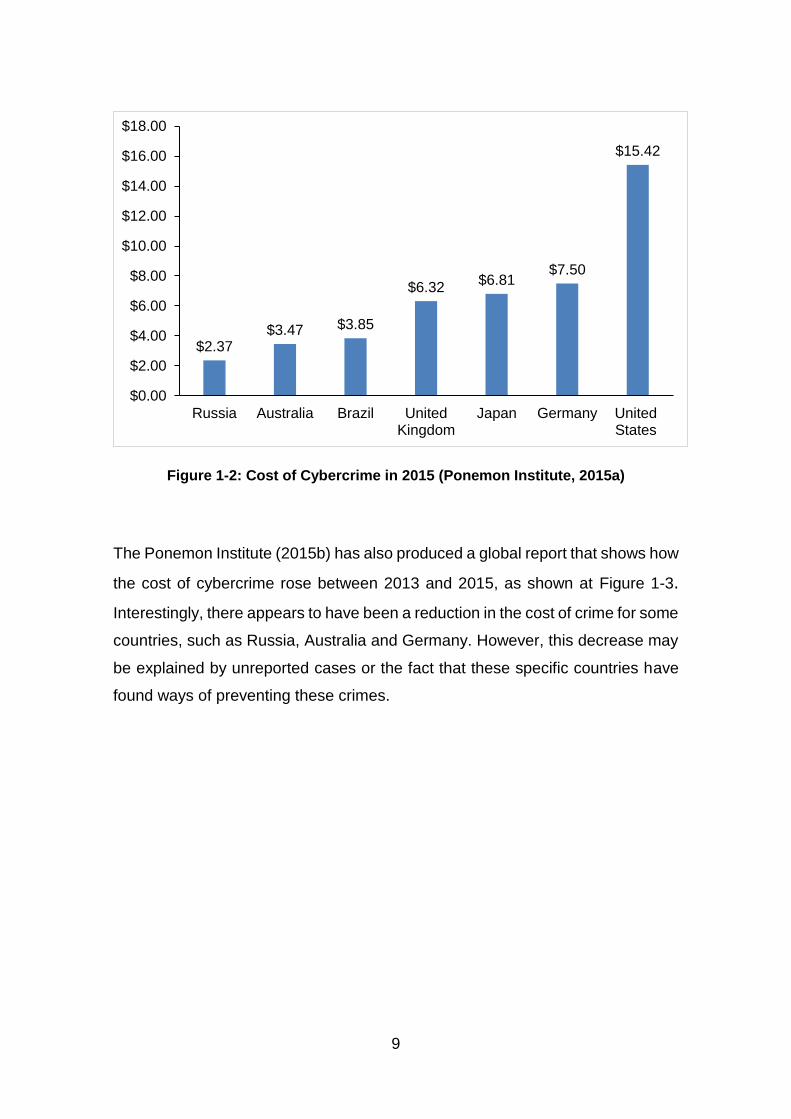
that the use of Cloud computing and storage is on the rise. In addition, an annual
study undertaken by the Ponemon Institute (2015a) highlights the cost of
cybercrime in millions of US Dollars across seven countries in 2015, as shown at
Figure 1-2.
9
Figure 1-2: Cost of Cybercrime in 2015 (Ponemon Institute, 2015a)
The Ponemon Institute (2015b) has also produced a global report that shows how
the cost of cybercrime rose between 2013 and 2015, as shown at Figure 1-3.
Interestingly, there appears to have been a reduction in the cost of crime for some
countries, such as Russia, Australia and Germany. However, this decrease may
be explained by unreported cases or the fact that these specific countries have
found ways of preventing these crimes.
$2.37$3.47 $3.85
$6.32$6.81
$7.50
$15.42
$0.00
$2.00
$4.00
$6.00
$8.00
$10.00
$12.00
$14.00
$16.00
$18.00
Russia Australia Brazil UnitedKingdom
Japan Germany UnitedStates

10
Figure 1-3: Cost of Cybercrime between 2013 to 2015 (Ponemon Institute, 2015b)
A report by Grant Thornton International estimated the cost of cybercrime in 2015
to be in the region of $315 billion, a finding based on a poll of 2500 businesses
in 35 countries (Muncaster, 2015). These findings are verified by the Internet
Crime Complaint Center (IC3), which publishes an annual report of statistical
information related to global Internet crimes. If these annual statistics are
assessed over time, they show an overall increase that amounts to millions of
dollars in terms of the reported loss that is categorised as being due to Internet
crime, rising from $559.70M in 2009 to $800.40M in 2014 (IC3, 2015). Figure 1-4
shows the loss based on the complaints received by IC3 from 2009 to 2014. Note
that the 2010 amount reflects the reported loss in the US only.
$2.37
$3.47
$3.85
$6.32
$6.81
$7.50
$15.42
$3.33
$3.99
$5.93
$6.91
$8.13
$12.69
$3.67
$4.72
$6.73
$7.56
$11.56
$0.00 $2.00 $4.00 $6.00 $8.00 $10.00 $12.00 $14.00 $16.00 $18.00
Russia
Australia
Brazil
UnitedKingdom
Japan
Germany
UnitedStates
2013 2014 2015

11
Figure 1-4: Loss Due to Internet Crime between 2009 to 2015 (IC3, 2015)
Even though the IC3 report focuses solely on Internet-related crimes, these are
categorised as being part of cybercrime and, therefore, contribute to the total cost
of cybercrime. Juniper Research Limited has predicted that the global cost of data
breaches will increase to $2.1 trillion by 2019, a figure that is almost four times
the estimated cost for 2015 (Maor, 2015). Overall, these statistics show that the
issue of cybercrime is a global problem and continuing to rise. This suggests that
either the methods used to curb cybercrime are not working or that the criminals
are finding increasingly ingenious ways of committing crime. Therefore, there is
a need to find equally clever ways of countering these crimes. Digital forensics
provides one such mechanism.
1.1.2 Digital Forensics
The goal of the investigator in any type of criminal investigation is to determine
the ‘who, what, when, where, why, and how’ of the crime. In terms of computer
crime, these questions may be answered through the use of digital forensics, the
$559.70
$364.26
$485.30
$581.40
$781.80 $800.49
$0.00
$200.00
$400.00
$600.00
$800.00
$1,000.00
2009 2010* 2011 2012 2013 2014
12
process of extracting data from a digital device to provide evidence that can be
used in a court of law. The Digital Forensics Research Workshop (DFRWS)
(2001) defines digital forensics as:
The use of scientifically derived and proven methods toward the preservation, collection, validation, identification, analysis, interpretation, documentation and presentation of digital evidence derived from digital sources for the purpose of facilitating or furthering the reconstruction of events found to be criminal, or helping to anticipate unauthorized actions shown to be disruptive to planned operations.
This definition shows the importance of using tested and validated methods in
digital investigation in order to provide evidence that is not compromised in any
way. For digital evidence to be presented in court, it must be clearly demonstrated
that it has been processed in a legally acceptable manner and that, as such, it
satisfies the rules of evidence (McKemmish, 1999). These generally state that
evidence should be relevant, authentic and credible, and competent (Graves,
2014).
The term ‘digital evidence’ refers specifically to data or information that can be
used to establish that a crime has been committed or that can be used to provide
a link between a crime and its victim or a crime and its perpetrator (Casey,
2004a). In line with any evidence that is being presented in a court of law, there
are procedures that should be followed in terms of its acquisition and processing,
known as the digital investigation process. This ensures that a digital forensic
investigation follows set procedures and techniques in order to ensure that the
results and findings are admissible in a court of law (Ruan, 2013). However, the
form that it takes varies between different countries and organisations. Pollitt
(1995a) provided one of the first documented processes of digital investigation,
which comprises four phases: acquisition, identification, evaluation and
admission. McKemmish (1999) then suggested a four-step process, covering the
identification, preservation, analysis and presentation of digital evidence. Over
time, other digital investigation process models have been developed and 15 of
these were synthesised by Yusoff et al (2011) to propose the Generic Computer
Forensic Investigation Model (GCFIM). This has five phases: pre-process,
13
acquisition and preservation, analysis, presentation and post-process. It should
be noted that the so-called ‘post-process’ is not generally identified as a distinct
phase in the digital investigation process even though some investigators may
consider it as part of the investigation. However, it is important as it provides
investigators with a chance to review the process and to identify gaps or lessons
learnt with a view to improving future investigations.
One of the most important aspects of the digital investigation process is the
preservation of evidence, which should not be changed in any way, shape or form
unless it becomes necessary to do so. This is emphasised in the first two of the
four Rules of Forensic Computing, which were defined by McKemmish (1999).
Rule 1 states that there should be minimal handling of the original evidence in
order to minimise alteration and Rule 2 states that the investigator should account
for any change in the collected evidence by documenting the nature, extent and
reason for that change. These rules are reiterated and reinforced by the first two
principles of the Association of Chief Police Officers’ (ACPO) (2012) Good
Practice Guide for Digital Evidence. The first states that “no action taken by law
enforcement agencies, persons employed within those agencies or their agents
should change data which may subsequently be relied upon in court” (ACPO,
2012). The second states that “in circumstances where a person finds it
necessary to access original data, that person must be competent to do so and
be able to give evidence explaining the relevance and the implications of their
actions” (ACPO, 2012). These principles emphasise the importance of evidence
preservation, particularly as digital evidence can easily be changed and, if it is
not properly justified and documented, this can affect the admissibility of that
evidence in court.
Principles 2 and 3 of the International Organisation on Computer Evidence
(IOCE) Guidelines for Best Practice in the Forensic Examination of Digital
Technology state that “upon seizing digital evidence, actions taken should not
change that evidence” and “when it is necessary for a person to access original
digital evidence, that person must be forensically competent” (Al-Zarouni, 2006;
Adams, 2013). These principles are designed to ensure that the evidence retains
its integrity, particularly if it has been accessed specifically to be presented in a
14
court. It should be noted that these rules, principles and guidelines regarding
preservation of evidence and the conduct of digital investigation as a whole tend
to be fairly similar and that the general thinking behind them does not appear to
have changed to any great extent over the years.
In terms of digital forensics, there are several classifications and these include
computer forensics, network forensics, mobile device forensics, internet
forensics, database forensics, software forensics (Yadav, 2011; Shrivastava et
al., 2012), optical media forensics (Irmler and Creutzburg, 2011) and Cloud
forensics (Ruan et al., 2011b). Regardless of the investigation type, the goal is to
ensure that the evidence is acquired, analysed and presented in a legally
acceptable manner. Also, as noted above, these principles of digital investigation
apply to forensics investigations that are undertaken in the Cloud, known as
Cloud forensics.
1.1.3 Cloud Forensics
As discussed above, the low-cost and high-power computing, along with the high
storage capacity of the Cloud are making it popular and resulting in increased
use. In addition to the anonymity that it offers its users, these are the very same
characteristics that are most likely to lead it to being used for criminal ends but
that can also be leveraged by forensic investigators in their work to identify,
acquire, process and store evidence. Forensic tools are required that provide a
means of adding ‘forensic readiness’ to the Cloud, thereby providing the ability to
maximise the potential of the system or environment for digital investigation and
the identification of digital evidence while minimising the associated cost of an
investigation (Rowlingson, 2004; Taylor et al., 2007). Given this, Cloud forensics
can be defined as the use of digital investigation processes in the Cloud to extract
evidence that is admissible in a court of law. This is confirmed by Ruan et al
(2011b), who define Cloud forensics as a subset of network forensics, whereby
digital forensics is applied in the Cloud environment to generate digital evidence,
while NIST (n.d.) defines it as,

15
…the application of scientific principles, technological practices and derived and proven methods to process past Cloud computing events through identification, collection, preservation, examination and reporting of digital data for the purpose of facilitating the reconstruction of these events.
As with traditional forensics, the main aim of Cloud forensics is to ensure that the
evidence is processed in a manner that is legally acceptable, meaning that it must
satisfy the rules of evidence as required by the courts.
Cloud forensics is still a relatively new area of digital forensics and, not
surprisingly, it comes with challenges that are unique to its particular ecosystem,
a term used to describe those interdependent components that work together for
the purpose of providing and consuming Cloud services (ITU, 2012). The
processes of traditional digital forensics investigation cannot be easily applied to
such an ecosystem. There are challenges in terms of identification, preservation,
collection and examination of evidence, for example. In terms of identification,
Taylor et al (2011) and Grispos et al (2012) note the difficulties of a ‘multi-tenant
environment’, a term used to describe multiple users sharing the same resources,
particularly as the investigator needs to begin by identifying the location of the
evidence and then proving that it belongs to the suspect. For example, a
malicious person can hijack a user account for malicious activity, making it difficult
to link the activity to the perpetrator. Also, the high storage capacity of the Cloud
means that the volume of potential evidence is another challenge to identification
as it may not be possible to access and process it all.
In terms of preservation of evidence, the Cloud also presents different challenges,
because physical machines cannot easily be unplugged and seized as this may
disrupt the Cloud services. In the Cloud, there may be a need to isolate the
suspect ‘Virtual Machine’ (VM), the term used to describe software that runs like
a physical computer system (Barrett and Kipper, 2010), or the suspect ‘VM
instance’, which describes a VM hosted on a Cloud infrastructure (Birk and
Wegener, 2011). This ensures that the integrity of the evidence is protected,
16
along with the other ‘tenants’ or users, from accidental or unavoidable access to
their VM instances (Delport et al., 2011; Damshenas et al., 2012).
Grispos et al (2012) and Almulla et al (2014) note that the collection process is
also a challenge, because seizure of physical machines is unlikely as this would
deny other users access to services and impact on the business continuity of the
CSP. In addition, the evidence may also be spread across several servers in
various locations. Therefore, due to location, the investigator may have to rely on
the CSP to provide the data or artefacts that are to be used as evidence. It might
then be difficult for the investigator to verify the integrity of the evidence. With the
Cloud spanning multiple jurisdictions, evidence may need to be collected from a
number of locations, adding another level of complexity to the collection of
evidence (Taylor et al., 2011; Marangos et al., 2012). Along similar lines, different
countries may have different laws relating to data and computer crime, while
treaties between countries can also affect access to evidence.
In terms of the final two processes, examination and analysis, Taylor et al (2011)
note that different CSPs use different technologies, which investigators might not
interpret correctly. In terms of the evidence itself, there may be challenges in
relation to its authenticity, integrity, reliability and completeness (Zargari and
Benford, 2012). All of these identified challenges in relation to the required digital
forensics processes demonstrate the need for a method that can be used in the
Cloud that will not affect the integrity of the evidence.
However, despite these challenges, there are also some identified benefits to
conducting digital forensics in the Cloud. IaaS, one of the three common service
models that is used in the Cloud, allows users to provision computing resources,
but also provides the required storage and processing power for forensic
investigation (Barrett and Kipper, 2010). In addition, dedicated forensic servers
in the Cloud could be on standby until they are needed as a method of providing
forensics as a service. This would make resources available, enabling them to be
pooled and used to access protected documents, thereby speeding up the
process of decryption (Barrett and Kipper, 2010; Reilly et al., 2010).
Compromised servers, including those in the Cloud, can easily be cloned and
17
made available for examination, thereby reducing the time taken to acquire
evidence (Barrett and Kipper, 2010).
As mentioned earlier, copies of the original data are made during an investigation
and then need to be stored. The nature of the storage devices in the Cloud means
that high volumes of data, including data that are being used as evidence, can
easily be stored (Reilly et al., 2010; Grispos et al., 2012; Almulla et al., 2013). In
addition, the high processing power of the Cloud enables access to faster and
more effective indexing as well as sorting and searching of evidence files (Almulla
et al., 2013). Cloud resources can also be used for extensive logging purposes,
enabling information which may be relevant to a digital investigation to be
recorded and stored without fear of service degradation or of the size of the logs
causing problems (Barrett and Kipper, 2010; Reilly et al., 2010). These logs can
be stored and made available for investigations when required.
In addition, some Cloud environments make use of verification techniques, such
as checksums or hashes, when saving data for integrity purposes (Barrett and
Kipper, 2010; Grispos et al., 2012). Investigators can use these techniques to
verify the integrity of acquired evidence by comparing it with data generated after
acquiring that evidence. It is obviously possible to conduct digital investigation in
the Cloud but, even with the benefits that this brings, there is still a need for more
precise forensic methods and techniques. One of the ways to achieve this is by
embedding these forensic capabilities within the Cloud, either by developing
forensic tools that are specifically for Cloud use (Dykstra and Sherman, 2013;
Srivastava et al., 2014; Raju et al., 2015) or by adding existing tools to the Cloud.
However, to date, there have been no studies that have considered the latter,
and it is this challenge that is the focus of this research.
Therefore, this research examines the use of existing tools in a Cloud platform
that supports the IaaS model. The research process began with a review of
various private Clouds, both open source and proprietary, from which two were
selected for further consideration. These were the Xen Cloud Platform (XCP) and
the VMware vCloud. Preliminary experiments revealed that VMWare uses a
propriety filesystem, the VMware Virtual Machine File System (VMFS). Given
18
this, it was considered an unsuitable platform for this research, as it would have
taken a considerable amount of time to understand its workings and then to install
existing tools on to it. In addition, attempts to analyse the files were not
successful. XCP, on the other hand, is Linux-based and uses the ext3 filesystem
or Linux Logical Volume Manager (LVM) to manage storage. As such, it was
considered suitable for this research, particularly as there is little research on the
use of XCP as a Cloud solution for digital forensic investigations and it could be
analysed using available resources. In addition, XCP is a free, open source
virtualization, as well as being a Cloud computing platform. It uses Xen
hypervisor, which enables the running of multiple instances of an OS on a single
host, as well as the running of multiple OS on a single host. XCP can be deployed
with local storage, with shared Network File System (NFS) storage or with shared
Internet Small Computer System Interface (iSCSI) storage (Xen.org, 2009a).
Given these advantages, XCP was, therefore, selected as the platform for this
research.
In summary, Cloud computing offers computing resources to users with benefits
like cost saving, convenience and scalability but its use is not without risk,
especially in terms of security as it can be leveraged for criminal activities, as
shown by the top threats identified by CSA. Coupled with the rising cost of
cybercrime and the adoption of Cloud by organisations, this shows that there is
a need for digital investigative techniques and processes that can be used in the
Cloud. While such processes and techniques already exist, the nature of the
Cloud ecosystem makes their use challenging. These challenges include
evidence identification, preservation, acquisition and examination, as evidence
needs to be collected and processed in a manner that will not affect its
admissibility. More positively, Cloud resources can be leveraged for digital
forensic purposes, such as evidence acquisition, analysis and storage. Another
way of leveraging Cloud resources is by adding forensic tools, either new or
existing, to the Cloud. This is also a step towards achieving forensic readiness in
the Cloud. To date, however, research has focused on developing tools for the
specific Cloud technologies with little research on the use of existing tools to
recover artefacts that can be used in a court of law. This then is the gap that this

19
research seeks to fill. To achieve this, various Cloud technologies were reviewed
and XCP was selected as a suitable platform for investigation, together with an
IaaS service type and a private Cloud deployment model. Having identified these
issues, an aim was formulated for this research, which is shown at Section 1.2,
and a research hypothesis derived, which is shown at Section 1.3 below.
1.2 Aim
The aim of this research is to evaluate the evidential value of artefacts recovered
from a private Cloud using existing digital forensic investigation tools.
Cloud computing enables users to access computing resources that are either
hosted in-house or in remote locations. Users can easily create and delete VM
instances, can use hosted applications, deploy their own applications and create
Cloud storage at a relatively low cost. In most cases, the user has no control over
the Cloud infrastructure especially where third party services are used or where
a public Cloud is used. However, this presents an opportunity for those users with
nefarious intentions to use Cloud services for a range of criminal activities,
including malware, DoS attacks and account hijacking. The ease with which
resources are allocated and released, the volatile nature of network traffic and
the anonymity offered by the Cloud makes it difficult but not impossible for
forensic investigators to access and recover artefacts. However, the stated
premise of this research is that new or existing tools can be added to the Cloud
to aid forensic investigations to acquire artefacts of evidential value. Therefore, it
is asserted that it is possible to recover artefacts from the Cloud and relate them
to specific users and to then use this as evidence that is admissible in a court of
law.
1.3 Research Hypothesis
Based on this stated aim, the research hypothesis formulated for this research
states that it is possible to recover artefacts of evidential value from the Xen Cloud
Platform, using existing tools.
As discussed above at Section 1.1.3, the architecture of the Cloud makes the use
of conventional forensic investigations difficult. Therefore, developing new tools

20
that can be added to the Cloud or adding existing tools to the Cloud can aid in
recovering artefacts that can then be used as evidence in a digital forensic
investigation.
1.4 Methodology
One of the main aims of forensic investigation is the presentation of digital
evidence in a court of law in order to prove or disprove a point (Pollitt, 1995a). To
achieve this, the digital evidence that is presented must satisfy the rules of any
form of evidence presented in court, as discussed above at Section 1.1.2. In
traditional forensics, requirements for assessing digital evidence and the criteria
for evaluating its evidential value have been proposed by Miller (1992), Sommer
(1998), Hargreaves (2009), Morris (2013) and Jones et al (2014). However, their
work raises two related questions. The first is whether these existing
requirements or criteria can be applied to Cloud forensics and the second is
whether the use of existing tools within the Cloud OS satisfies these
requirements. These questions, along with the aim that drives this research and
the research hypothesis that has been posed, led to the identification of a general
methodological framework for this research.
The first step in providing answers to these questions was to set up a Cloud
platform in a forensic computing laboratory and to design experiments that would
enable data to be collected. The NIST Cloud computing framework details four
Cloud deployment models. However, it was considered beyond the scope of this
research and beyond the capabilities of a sole researcher to investigate all four
of these. Therefore, a private Cloud model was chosen whereby the infrastructure
is provisioned exclusively for a single organisation, thus giving the organisation
control over its use (Mell and Grance, 2011). Such an infrastructure can either be
managed by the organisation or outsourced to a third party, and can be hosted
either on or off site. These characteristics made it the model of choice for the
experiments that were carried out for this research, enabling the creation of a
controlled Cloud environment for experiments. Out of the three service types,
IaaS was chosen as it provides the user with virtualized computing resources like
servers, storage and networking. IaaS gives the user control over operating

21
systems in guest VMs, over storage and over deployed applications. In addition,
IaaS provides direct access to VMs for data collection and analysis. Therefore, it
was deemed ideal for this research. The private Cloud technologies that were
reviewed were Microsoft Private Cloud, VMware vCloud, Citrix CloudPlatform,
Amazon Virtual Private Cloud and Xen Cloud Platform, XCP. XCP was selected
because it is a free open source Cloud platform with resource requirements that
are easy to meet in a laboratory environment. Having identified the Cloud
technology, deployment type and service model for this research, the next stage
was to consider the research design.
The literature review provided a means to identify and develop an appropriate
research methodology, which is shown at Figure 1-5. This served two purposes:
enabling the identification of the research gaps in this field and determining the
criteria for evaluating the evidential value of artefacts recovered from the Cloud.
The next stage was to study the structure of LVM, in order to provide insight into
how XCP uses LVM to manage storage, and the study of the structure of XCP
and how VMs are stored (Chapter 4).
Figure 1-5: Proposed Methodology for this Research
22
Having determined the structure of both LVM and XCP in terms of data storage,
and the formats used by XCP to store data, the next stage was to identify those
existing tools that could be added to the Cloud OS and used within XCP to
recover artefacts and then to develop a methodology for artefact recovery in XCP
Cloud (Chapter 5). Finally, the results were compared against the criteria for
evaluating the evidential value of recovered artefacts (Chapter 6). Conclusions
were then drawn, the contribution to knowledge revisited and recommendations
for future work identified (Chapter 7).
1.5 Thesis Outline
Given the methodological framework shown at Section 1.4 above, Chapter 2 of
this research critically reviews the literature in the areas of digital forensics and
Cloud computing, whilst identifying the challenges of digital forensics in the
Cloud. Its purpose is to identify the research gaps in terms of artefact recovery in
the Cloud, to define Cloud computing along with its benefits and risks before
describing digital forensics and some of the associated investigation models that
have been developed over time. The chapter then goes on to briefly describe the
common disk filesystems in use and Cloud filesystems. It also discusses data
deletion in relation to the Cloud.
Chapter 3 defines the objectives of this research by breaking down the aim into
a series of enabling objectives and outlines the experiments for each objective.
Various Clouds considered for this research are presented together with the tools
used in this research. A general methodology for adding tools to the Cloud is
presented. The criteria used to evaluate the evidential value of artefacts
recovered from a forensic investigation are identified. The research constraints
are described. Finally, the ethical issues are considered.
Chapter 4 describes LVM and XCP with specific reference to their structures
before examining how XCP uses LVM to store data along with a discussion of
the file format that it supports. The results of experiments on LVM and XCP are
presented and analysed.
23
Chapter 5 considers data deletion in XCP, the use of existing tools within XCP to
recover artefacts in the form of data and how the recovered artefacts can be
associated with a specific XCP user. Results of experiments to recover artefacts
using existing tools and to associate the recovered artefacts with specific users
are presented and analysed. It also describes the proposed methodology for
artefact recovery in XCP and evaluates the methodology against an XCP Cloud
ecosystem that could be found in the real world.
Chapter 6 then evaluates the methodologies developed for this research and the
evidential value of the artefacts that were recovered, using the criteria identified
in Chapter 3.
Chapter 7 summarises the research, presents the conclusions and
recommendations, and then makes recommendations for further study before
revisiting and confirming the contribution to knowledge.
1.6 Contributions to Knowledge
This research contributes to knowledge in six ways. Firstly, this research
elaborates on the leveraging of Cloud resources for forensic purposes by adding
forensic capabilities in the form of existing digital forensic tools in XCP as a
method for providing forensic readiness in the Cloud. This can be used to
alleviate some of the challenges of conducting forensic investigations in it.
Secondly, it confirms the use of XCP, a private Cloud technology, to recover
artefacts that can be used as evidence. As a result of this, a methodology was
developed for adding tools to a Cloud technology by following three key steps:
identification of Cloud technology; identification of appropriate tools; and building
a testbed to test the tools.
Thirdly, a general methodology for the recovery of artefacts in XCP using existing
tools in XCP is proposed, where three key components are identified: the user,
the audit log and the VM. This approach was evaluated and found to be effective
in an XCP Cloud of the type that can be found in the real world.
24
Fourthly, as part of this research, four requirements for evaluating the evidential
value of digital evidence are proposed. These were used to evaluate the
evidential value of artefacts recovered using existing tools from XCP.
Fifthly, this research investigated and documented the changes that occur when
VMs which are saved as Virtual Hard Disk (VHD) files in XCP are deleted using
XenCenter or the built in ‘xe’ commands. This can be used to prove the
authenticity of recovered VMs and can be compared with other Cloud
technologies that use VHD format for virtual disks in terms the effects of different
deletion methods.
Finally, during this research, the value of LVM metadata for digital investigation
was identified and verified. This included the use of the metadata to restore
deleted logical volumes that were used to restore deleted VMs in XCP with LVM-
based storage. LVM keeps copies of old metadata file that can be used to create
a timeline of events on a system that uses LVM; it can also be used to check for
previous configurations of LVM on the system.

25
2 Literature Review
2.1 Introduction
As discussed in Chapter 1, Cloud computing offers users access to low cost
computing resources, such as powerful processing, storage and networking.
While these resources obviously provide benefit to numerous users, there is also
evidence that they can be leveraged to commit crime (Goodin, 2009; Galante et
al., 2011; Noehr, 2011; Paganini, 2014; Rashid, 2014). Cybercrime or e-crime is
not a new problem and, over time, mechanisms have been put in place to enable
criminals to be detected and arrested, such as Intrusion Detection Systems (IDS).
However, the elasticity of Cloud resources, the location of Cloud servers (often
spanning multiple jurisdictions), the volatile nature of network traffic, the different
Cloud technologies and the anonymity that it offers, all contribute to making digital
forensics in the Cloud a challenge. This is especially true in terms of evidence
acquisition and analysis, both of which have a direct impact on the admissibility
of that evidence. Therefore, there is a need for investigative processes and
techniques that cannot easily be refuted for use in the Cloud.
After evidence is analysed in a digital investigation, it may be presented in court
where the investigator needs to clearly demonstrate that it conforms with the rules
of evidence as this will determine its evidential value (McKemmish, 1999). In
addition, the rate at which organisations and individuals are adopting the Cloud
and the concomitant rise in cybercrime, which was discussed in Chapter 1,
Section 1.1, suggests that there is a need to improve the methods of conducting
digital investigations in the Cloud, whilst also leveraging its resources for
forensics purposes, particularly in terms of its ability to store and process
evidence. This research sets out to examine whether existing forensic tools can
be used in the Cloud and whether the evidence that this produces would be
admissible in court. Therefore, the aim is to evaluate the evidential value of
artefacts recovered using existing tools in a private Cloud, based on the
hypothesis, which states that it is possible to recover artefacts of evidential value
from Xen Cloud Platform (XCP), using existing tools.
26
The purpose of this chapter is to critically review the literature on Cloud forensics
in order to confirm the research gap that this research sets out to fill and to identify
any other research gaps relating to the provision of forensic capabilities in the
Cloud. To this end, the first part of this chapter focuses on Cloud computing,
outlining the history and expanding on definitions that have been proffered by
different researchers and organisations that were highlighted in Chapter 1. It then
goes on to discuss the characteristics of Cloud computing, its service types and
deployment models. The discussion then turns to digital forensics, explaining the
various digital investigation models that have been proposed over time and the
existing guidelines for the provision of digital evidence. This is followed by an
examination of the challenges of network forensics, the sources of network
evidence and the types of network-based evidence. There is a variety of research
into frameworks for digital investigations in the Cloud, along with sources of
evidence, data ownership, evidence isolation, and how logs can be used in the
Cloud for forensics purposes. Some of the common filesystems in use are
examined and how these filesystems manage deleted data. The chapter ends
with a discussion of data deletion in the Cloud.
2.2 Cloud Computing
Cloud computing is a technology which enables users to access Cloud resources
over a network in real time. This access is usually independent of the device
being used or the location of the user. From 1961 when Dr John McCarthy first
proposed the idea of networked computing as a utility, Cloud computing
continued to develop over the next few decades until the 1990s when bandwidth
became affordable (Mohamed, 2009; NJVC, n.d.). However, it is the year 1999
that is considered to be the turning point for Cloud computing as this was when
Salesforce.com offered enterprise applications via a website, creating what is
now known as Software as a Service (SaaS) (Mohamed, 2009; NJVC, n.d.). The
next was step was the founding of Amazon Web Services (AWS) in 2002 which
offered Infrastructure as a Service (IaaS). Then, from 2009, other companies
started offering Cloud services to the public (Mohamed, 2009; NJVC, n.d.). Over
27
almost 20 years, the Cloud has become an established service and clarity has
begun to emerge about what it is and what it offers.
Cloud computing has many definitions but the first academic usage and definition
was in 1997 when it was described as a “computing paradigm where the
boundaries of computing will be determined by economic rationale rather than
technical limits alone” (Chellappa, 1997). Low cost is indeed one of the benefits
which makes it attractive to organisations and individuals (Kutz and Vines, 2010).
Vaquero et al (2008) define Clouds as:
A large pool of easily usable and accessible virtualized resources (such as hardware, development platforms and/or services). These resources can be dynamically re-configured to adjust to a variable load (scale), allowing also for an optimum resource utilization. This pool of resources is typically exploited by a pay-per-use model in which guarantees are offered by the Infrastructure Provider by means of customized Service Level Agreements (SLAs).
This definition was proposed following a review of various definitions and analysis
of the features of Cloud computing to ensure that it encompasses them all. The
key features are resource pooling, virtualization, scalability, pay-per-use and
SLAs.
The Cloud Security Alliance (CSA, 2009) then went on to define it as:
An evolving term that describes the development of many existing technologies and approaches to computing into something different. Cloud separates application and information resources from the underlying infrastructure, and the mechanisms used to deliver them. Cloud enhances collaboration, agility, scaling, and availability, and provides the potential for cost reduction through optimized and efficient computing.
This describes it as an evolution of existing technologies and approaches; it
identifies its features including scalability, efficiency and cost reduction.
Chellappa (1997) identified the latter as the driving force behind Cloud computing.
A year later, Buyya et al (2010) defined it as:
A parallel and distributed computing system consisting of a collection of inter-connected or more unified computing resources based on service level agreements (SLA) established through negotiation between the service provider and consumers.
28
They agree with CSA in terms of the Cloud using technology that is already in
existence, but focus on two specific technologies, parallel and distributed
computing. However, they also include resource pooling as a key feature along
with the agreements between service providers and users, both of which were
also identified by Vaquero et al (2008).
As detailed by Mell and Grance (2011), the National Institute of Standards and
Technology (NIST) then offered their definition of Cloud computing, which was,
A model which enables convenient, on demand network access to a shared pool of configurable computing resources (e.g., networks, servers, storage, applications, and services) that can be rapidly provisioned and released with minimal interaction from management or the Cloud service provider.
The definitions offered by Vaquero et al (2008), Buyya et al (2010) and the NIST
both include resource pooling as a critical component in Cloud computing.
However, the NIST goes further to include other critical components such as
being available on demand, and providing network access and elasticity, the latter
term meaning that resources are scaled based on user needs. Dykstra and
Sherman (2012) then define it more succinctly as “an evolution and combination
of decades of technology, resulting in a model of convenient, on-demand, elastic,
location-independent computing resources.” This combines both the CSA and
NIST definitions, clearly noting the evolution and combination of existing
technologies, but then adding specific characteristics that are unique to the
Cloud: on-demand, elastic, and location independent. Taking all of these
variations into account and noting the key points from each, a generic definition
of Cloud computing was derived for the purposes of this research. Therefore,
Cloud computing is taken to be:
A system where computing resources are delivered as a service to consumers over a network. The characteristics of Cloud computing include resource pooling, elastic capacity, scalability, pay-per-use, network access and multi-tenancy.
29
Given this definition, it is evident that Cloud computing offers benefits to the user
in terms of cost savings, convenience, flexibility, resilience, centralisation of data
storage, scalability and reduced time to deployment (Krutz and Vines, 2010). This
is not to say that it is without its risks and challenges. One key area of risk is
security. Zhou et al (2010) identified security and privacy as the main barriers of
Cloud adoption. They proposed five components: availability, confidentiality, data
integrity, control and audit to achieve adequate security. For privacy, they argued
that most privacy acts are out of date and do not make provision for Cloud
computing. They need to be modified, adapting to the needs of the Cloud,
including the relationship between providers and users. That is, they need to be
updated to include aspects of the Cloud. In terms of more specific Cloud
technologies, Tajadod et al (2012) compared Amazon Web Service (AWS) and
Microsoft Azure in terms of their security approaches, examining them according
to three components: data confidentiality, integrity and availability. They
concluded that Microsoft Azure offers better data security.
On the other hand, Sudha and Viswanatham (2013) identified the security
concerns in relation to four levels of the Cloud, network, host, application and
data levels. For the network level, they suggest that proper access control
mechanisms should be put in place, along with mechanisms that will ensure the
confidentiality and integrity of customer data as well as the availability of
resources. On the host level, the service type determines who is responsible for
the security. For IaaS, the CSP and the customer share the responsibility, while
for PaaS and SaaS, the CSP is solely responsible. For the application level, they
suggest that applications are designed with security in mind, while for the data
level, they suggest that sensitive and regulated data should not be stored in a
public Cloud in order to mitigate data security concerns.
Overall, it is evident that organisations and individuals that adopt the Cloud
should be aware of the associated security risks and employ measures to mitigate
them. To this end, NIST has published a document entitled ‘Cloud Computing
Security Reference Architecture’, which is aimed at providing a framework, giving
organisations a clear mechanism through which to choose a Cloud service that
30
will securely and effectively address their requirements. This includes a Risk
Management Framework to enable these organisations to create better security
plans based on their risk assessment and policies (NIST, 2013). This
demonstrates that there are methods available for mitigating or reducing the risks
associated with the Cloud. As the various definitions have shown, Cloud
computing has some characteristics which makes it different from other
technologies. Therefore, the next section discusses these characteristics.
2.2.1 Characteristics
It is evident from the derived definition stated in Section 2.2 above that Cloud
computing offers a variety of service models and deployment types which afford
users the flexibility to choose the services and resources that most suit their
requirements. According to the NIST definition, which is the most widely accepted
and used, there are five essential characteristics of the Cloud, along with three
service types and four deployment models. These are shown at Figure 2-1. These
five characteristics offer advantages to Cloud users but also bring challenges in
terms of digital investigations. Therefore, each of the five is discussed in turn in
relation to this issue, followed by an examination of the challenges of the service
types and deployment models.
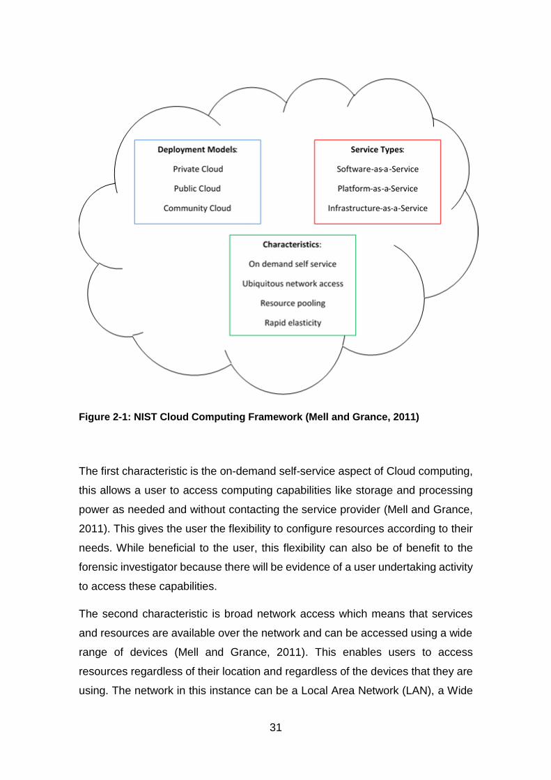
31
Figure 2-1: NIST Cloud Computing Framework (Mell and Grance, 2011)
The first characteristic is the on-demand self-service aspect of Cloud computing,
this allows a user to access computing capabilities like storage and processing
power as needed and without contacting the service provider (Mell and Grance,
2011). This gives the user the flexibility to configure resources according to their
needs. While beneficial to the user, this flexibility can also be of benefit to the
forensic investigator because there will be evidence of a user undertaking activity
to access these capabilities.
The second characteristic is broad network access which means that services
and resources are available over the network and can be accessed using a wide
range of devices (Mell and Grance, 2011). This enables users to access
resources regardless of their location and regardless of the devices that they are
using. The network in this instance can be a Local Area Network (LAN), a Wide
32
Area Network (WAN), an Intranet, Extranet or the Internet. However, it should be
noted that, in terms of forensics, the network type can affect the evidence type,
evidence sources and how evidence can be acquired or processed (ACPO, 2012;
Sibiya et al., 2012). Therefore, the network type should be taken into
consideration during an investigation.
Thirdly, resource pooling describes the fact that the service provider’s computing
resources are brought together in order to provide services to a wide range of
users according to their needs (Mell and Grance, 2011). These resources are
dynamically assigned to consumers based on their demands. In terms of forensic
investigation, this means that evidence may be spread across multiple servers
which may be difficult to access, making it difficult to acquire data in such a way
that the privacy of other tenants is not compromised (Ruan et al., 2011a).
The fourth characteristic is rapid elasticity, which allows capabilities to be scaled
according to consumer demands, creating an illusion that the resources are
infinite (Mell and Grance, 2011). While this is advantageous to the users, it poses
a challenge for digital investigators in terms of the recovery of evidence (Ruan et
al., 2011a). This is because resources can be reallocated to a different user within
a short period of time. However, this may be problematic if those resources
contain evidence as, once reallocated, new user data may overwrite old data.
The final characteristic that needs to be considered in relation to forensic
investigation in the Cloud is measured service, which allows users to pay for only
the resources they use by providing a metering capability (Mell and Grance,
2011). This enables the user to monitor and control their use of resources, while
providing a level of transparency for both the user and the service provider. In
terms of digital investigation, the log may provide corroborative evidence on user
activities (Ruan et al., 2011a). However, while it is possible to find logs on service
usage, this will depend on the types of logs kept by the service provider and the
length of time the logs are kept.
This demonstrates the advantages that these Cloud characteristics offer, but also
the issues that they raise for the forensic investigator. Given this, the discussion
now turns to an exploration of the three Cloud service types and four deployment
33
models, again discussing their advantages set against their impact on digital
investigations.
2.2.2 Cloud Service Types
Cloud service types are classified according to the services that are offered by
the Cloud Service Provider (CSP). The most common of these services are the
three that appear in the NIST framework, which was shown at Figure 2-1 above.
These are Software as a Service (SaaS), Platform as a Service (PaaS) and
Infrastructure as a Service (IaaS).
SaaS provides the consumer with the capability to use the service provider’s
applications, which are made available on the Cloud infrastructure. These
applications are usually accessed through a thin client interface such as a web
browser. In this service type, the user has no control over the underlying
infrastructure (Birk and Wegener, 2011; Mell and Grance, 2011). Those with valid
credentials can access software remotely via the Internet and, in a large
organisation, this can reduce the cost of software. In addition, in most cases,
software upgrades are part of the SaaS subscription. Examples of this type of
service are Microsoft Office 365 (Microsoft, 2016) and Google Apps (Google,
2016a). In terms of digital investigation, it may be possible to find evidence of
usage by analysing the web browser of a suspect’s computer (Birk and Wegener,
2011), the application logs from the CSP (Zawoad and Hasan, 2013) or the
contents of the RAM (Almulla et al., 2014).
In terms of the second service type, PaaS provides the consumer with the
capability to deploy application packages using the virtual environment that is
supported by the service provider (Mell and Grance, 2011). As with SaaS, the
user has no control over the underlying infrastructure but can control deployed
applications and how those applications interact with the infrastructure (Almulla
et al., 2014). This provides a platform where developers can collaborate on
designing, testing and deploying applications without worrying about the cost of
infrastructure. In PaaS, although the developed application is under the control
of the user, the interaction of the application with its dependencies may not be
secure and, therefore, the application can be compromised (Birk and Wegener,
34
2011). Examples of PaaS include Google App Engine (Google, 2016b), and
Amazon Web Services (AWS) Elastic Beanstalk (AWS, 2010).
In terms of the final service type listed by NIST, IaaS provides the consumer with
the capability to access computing resources, such as processing, storage, and
a network, as well as the capability to deploy applications in a virtual environment
(Mell and Grance, 2011). An example of IaaS is Amazon Elastic Compute Cloud
(EC2) (AWS, 2014). In terms of adoption, this service type has higher adoption
rate than the others (Weins, 2015b). In most cases, the user is provided with a
Virtual Machine (VM) that can be configured to their requirements. The user has
no control over the underlying infrastructures but is able to control operating
systems, storage, and deployed applications. In fact, IaaS gives more control to
users than the two other service models discussed above and offers access to
more resources. However, these very benefits can make it attractive to people
with nefarious intentions. In terms of forensic investigation, this service type gives
the investigator the most access to potential evidence in the form of virtual
instances which may contain further evidence (Birk and Wegener, 2011; Zawoad
and Hasan, 2013; Almulla et al., 2014).
Another service type that is not included on the NIST framework despite being in
common usage is Storage as a Service (StaaS). This provides block storage as
a service to consumers and is classified as an IaaS (Chung et al., 2012; Farina
et al., 2015). The service can be accessed via a web interface or a desktop client
using devices such as PCs, tablets and smartphones. Examples of this are
DropBox, Amazon S3 and iCloud.
Other service types include Desktop as a Service where virtual desktop images
are delivered to the user’s desktop (Barrett and Kipper, 2010), Forensic as a
Service where digital forensics is offered as a service (Ruan et al., 2011a),
Security as a Service where security solutions are delivered to users (Al-Aqrabi
et al., 2012; Yokoyama and Yoshioka, 2012), Network as a Service which
provides access to network infrastructure (Costa et al., 2012), and Recovery as
a Service, where applications and data are replicated in the Cloud to protect them
from natural or manmade disasters (James et al., 2013). Overall, this discussion
35
shows that different service types need different investigation approaches. This
is also true of the deployment models, which are discussed in the next section in
terms of the benefits that they offer to their users set against the problems that
they pose for the digital investigator.
2.2.3 Cloud Deployment Models
Cloud deployment represents how the Cloud infrastructure is managed and
classified according to who controls the infrastructure and how it can be
accessed. As depicted in the NIST framework, shown at Figure 2-1 above, there
are four deployment models: private, public, community and hybrid Clouds.
In a private Cloud, the infrastructure is provisioned for exclusive use by a single
organisation. It can either be managed by that organisation or outsourced to a
third party and it can be hosted either on or off site. In terms of adoption by
organisations, the ‘State of Cloud’ report by RightScale shows 63% of
organisations using a private Cloud in 2015 and 77% in 2016 (Weins, 2016).
Examples of technologies that can be used for a private Cloud include Microsoft
Private Cloud and Amazon Virtual Private Cloud. They offer the most in terms of
evidence identification (Taylor et al., 2011) and access to evidence by an
investigator (Zawoad and Hasan, 2013; Farina et al., 2015). This is because the
organisation which controls the Cloud can easily give access to the information
and data needed for an investigation. However, this model is not without its
limitations, and there may be challenges in terms of access to evidence in
situations where the management of the Cloud infrastructure is outsourced or
hosted offsite. Also, if the infrastructure is spread across multiple geographic
locations, there may be jurisdictional issues in terms of data access (Grispos et
al., 2012). Another challenge is the multi-tenancy of the Cloud. Care needs to be
taken to ensure that other users are not affected by digital investigations,
specifically in terms of confidentiality, the integrity of users and their data, along
with the availability of services (Grispos et al., 2012).
As the name suggests, a public Cloud is provisioned for public use and is usually
operated as a business with users paying for the services they use, although
there are instances where some free services are offered. In terms of adoption,
36
the RightScale report shows 88% of the respondents surveyed using a public
Cloud in 2015 and 89% in 2016 (Weins, 2016). Examples include AWS, IBM Blue
Cloud, Microsoft Azure, VMware vCloud and Google App Engine. Public Clouds
face the same challenges as private Clouds, along with the issues of physical
access to evidence (Zawoad and Hasan, 2013) and segregation of other tenants
in evidence collection (Ruan et al., 2011a).
The third model is the community Cloud, which is provisioned for use by a group
of organisations that belong to a specific community with shared concerns. It can
be managed by one or more of the organisations in the community or outsourced
to a third party and hosted on or off site. This model is similar to the private Cloud,
except that it is provisioned for use by more than one organisation. In addition, it
can be managed by more than one organisation, whereas a private Cloud, is
managed by a single organisation. In both models, the infrastructure
management can be outsourced and hosted on or off site and, in terms of digital
investigation, both models share the same challenges in terms of evidence
identification and access.
The last model, the hybrid Cloud, is a combination of two or more Cloud
infrastructures that are bound together whilst remaining as unique entities. This
is in order to offer the benefits of each deployment model. The State of Cloud
Survey showed that 58% of its respondents used a hybrid Cloud in 2015 and 71%
in 2016 (Weins, 2016). In terms of forensic investigation, this model has the
combined challenges of the models that are used in its deployment. Therefore, it
is evident from this discussion that the Cloud deployment models offer individuals
and organisations the option to choose the model that best suits their needs but
that they also have unique features which may impact digital investigation
(Grispos et al., 2012; Zawoad and Hasan, 2013). Therefore, having discussed
how the Cloud offers computing resources to users as services and the
challenges that this poses in terms of digital investigation, the discussion now
turns more specifically to how the Cloud can be used for criminal purposes.
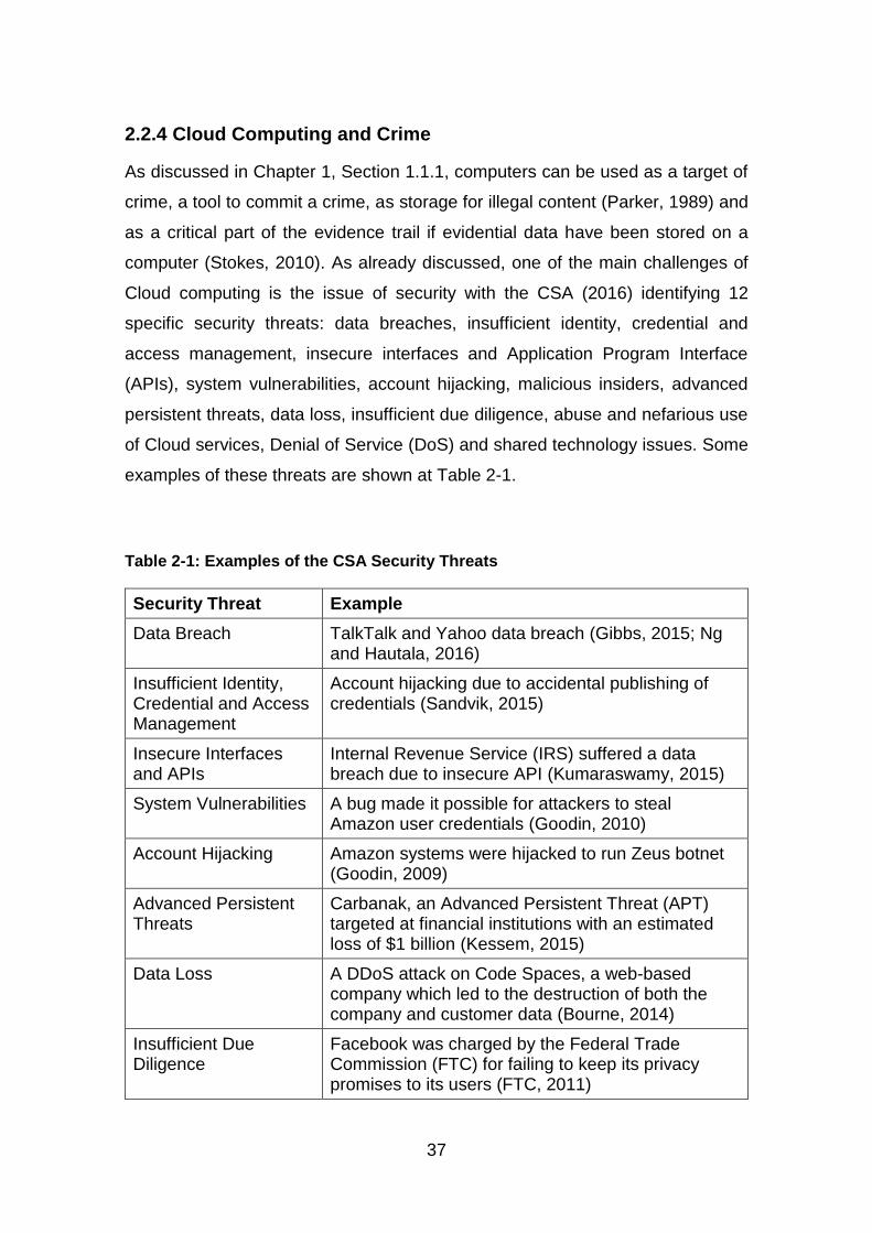
37
2.2.4 Cloud Computing and Crime
As discussed in Chapter 1, Section 1.1.1, computers can be used as a target of
crime, a tool to commit a crime, as storage for illegal content (Parker, 1989) and
as a critical part of the evidence trail if evidential data have been stored on a
computer (Stokes, 2010). As already discussed, one of the main challenges of
Cloud computing is the issue of security with the CSA (2016) identifying 12
specific security threats: data breaches, insufficient identity, credential and
access management, insecure interfaces and Application Program Interface
(APIs), system vulnerabilities, account hijacking, malicious insiders, advanced
persistent threats, data loss, insufficient due diligence, abuse and nefarious use
of Cloud services, Denial of Service (DoS) and shared technology issues. Some
examples of these threats are shown at Table 2-1.
Table 2-1: Examples of the CSA Security Threats
Security Threat Example
Data Breach TalkTalk and Yahoo data breach (Gibbs, 2015; Ng and Hautala, 2016)
Insufficient Identity, Credential and Access Management
Account hijacking due to accidental publishing of credentials (Sandvik, 2015)
Insecure Interfaces and APIs
Internal Revenue Service (IRS) suffered a data breach due to insecure API (Kumaraswamy, 2015)
System Vulnerabilities A bug made it possible for attackers to steal Amazon user credentials (Goodin, 2010)
Account Hijacking Amazon systems were hijacked to run Zeus botnet (Goodin, 2009)
Advanced Persistent Threats
Carbanak, an Advanced Persistent Threat (APT) targeted at financial institutions with an estimated loss of $1 billion (Kessem, 2015)
Data Loss A DDoS attack on Code Spaces, a web-based company which led to the destruction of both the company and customer data (Bourne, 2014)
Insufficient Due Diligence
Facebook was charged by the Federal Trade Commission (FTC) for failing to keep its privacy promises to its users (FTC, 2011)
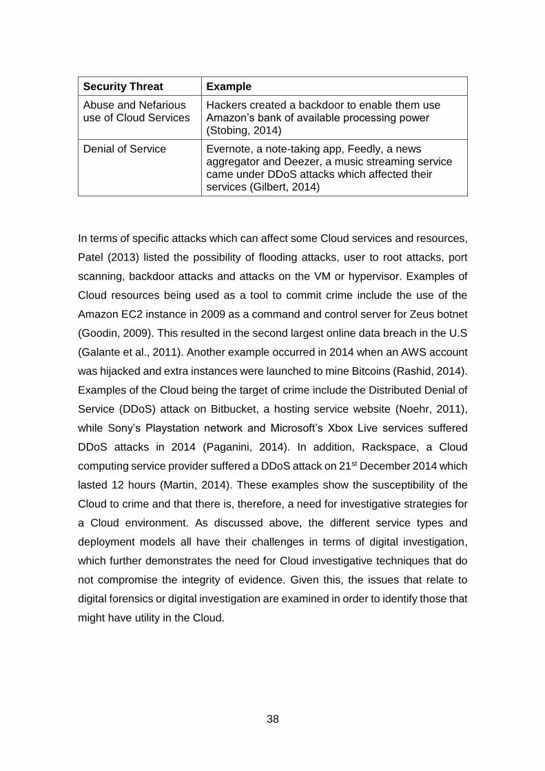
38
Security Threat Example
Abuse and Nefarious use of Cloud Services
Hackers created a backdoor to enable them use Amazon’s bank of available processing power (Stobing, 2014)
Denial of Service Evernote, a note-taking app, Feedly, a news aggregator and Deezer, a music streaming service came under DDoS attacks which affected their services (Gilbert, 2014)
In terms of specific attacks which can affect some Cloud services and resources,
Patel (2013) listed the possibility of flooding attacks, user to root attacks, port
scanning, backdoor attacks and attacks on the VM or hypervisor. Examples of
Cloud resources being used as a tool to commit crime include the use of the
Amazon EC2 instance in 2009 as a command and control server for Zeus botnet
(Goodin, 2009). This resulted in the second largest online data breach in the U.S
(Galante et al., 2011). Another example occurred in 2014 when an AWS account
was hijacked and extra instances were launched to mine Bitcoins (Rashid, 2014).
Examples of the Cloud being the target of crime include the Distributed Denial of
Service (DDoS) attack on Bitbucket, a hosting service website (Noehr, 2011),
while Sony’s Playstation network and Microsoft’s Xbox Live services suffered
DDoS attacks in 2014 (Paganini, 2014). In addition, Rackspace, a Cloud
computing service provider suffered a DDoS attack on 21st December 2014 which
lasted 12 hours (Martin, 2014). These examples show the susceptibility of the
Cloud to crime and that there is, therefore, a need for investigative strategies for
a Cloud environment. As discussed above, the different service types and
deployment models all have their challenges in terms of digital investigation,
which further demonstrates the need for Cloud investigative techniques that do
not compromise the integrity of evidence. Given this, the issues that relate to
digital forensics or digital investigation are examined in order to identify those that
might have utility in the Cloud.
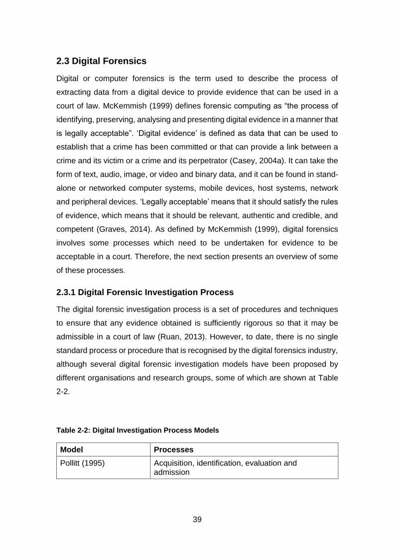
39
2.3 Digital Forensics
Digital or computer forensics is the term used to describe the process of
extracting data from a digital device to provide evidence that can be used in a
court of law. McKemmish (1999) defines forensic computing as “the process of
identifying, preserving, analysing and presenting digital evidence in a manner that
is legally acceptable”. ‘Digital evidence’ is defined as data that can be used to
establish that a crime has been committed or that can provide a link between a
crime and its victim or a crime and its perpetrator (Casey, 2004a). It can take the
form of text, audio, image, or video and binary data, and it can be found in stand-
alone or networked computer systems, mobile devices, host systems, network
and peripheral devices. ‘Legally acceptable’ means that it should satisfy the rules
of evidence, which means that it should be relevant, authentic and credible, and
competent (Graves, 2014). As defined by McKemmish (1999), digital forensics
involves some processes which need to be undertaken for evidence to be
acceptable in a court. Therefore, the next section presents an overview of some
of these processes.
2.3.1 Digital Forensic Investigation Process
The digital forensic investigation process is a set of procedures and techniques
to ensure that any evidence obtained is sufficiently rigorous so that it may be
admissible in a court of law (Ruan, 2013). However, to date, there is no single
standard process or procedure that is recognised by the digital forensics industry,
although several digital forensic investigation models have been proposed by
different organisations and research groups, some of which are shown at Table
2-2.
Table 2-2: Digital Investigation Process Models
Model Processes
Pollitt (1995) Acquisition, identification, evaluation and admission
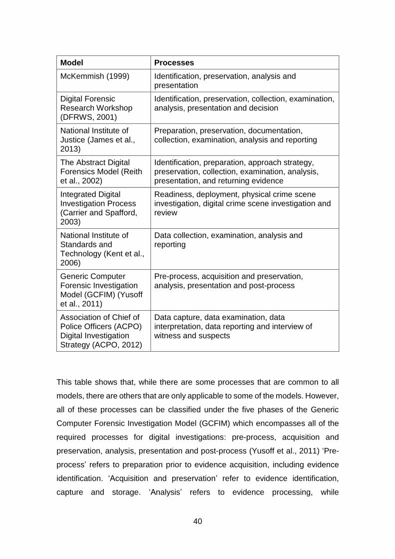
40
Model Processes
McKemmish (1999) Identification, preservation, analysis and presentation
Digital Forensic Research Workshop (DFRWS, 2001)
Identification, preservation, collection, examination, analysis, presentation and decision
National Institute of Justice (James et al., 2013)
Preparation, preservation, documentation, collection, examination, analysis and reporting
The Abstract Digital Forensics Model (Reith et al., 2002)
Identification, preparation, approach strategy, preservation, collection, examination, analysis, presentation, and returning evidence
Integrated Digital Investigation Process (Carrier and Spafford, 2003)
Readiness, deployment, physical crime scene investigation, digital crime scene investigation and review
National Institute of Standards and Technology (Kent et al., 2006)
Data collection, examination, analysis and reporting
Generic Computer Forensic Investigation Model (GCFIM) (Yusoff et al., 2011)
Pre-process, acquisition and preservation, analysis, presentation and post-process
Association of Chief of Police Officers (ACPO) Digital Investigation Strategy (ACPO, 2012)
Data capture, data examination, data interpretation, data reporting and interview of witness and suspects
This table shows that, while there are some processes that are common to all
models, there are others that are only applicable to some of the models. However,
all of these processes can be classified under the five phases of the Generic
Computer Forensic Investigation Model (GCFIM) which encompasses all of the
required processes for digital investigations: pre-process, acquisition and
preservation, analysis, presentation and post-process (Yusoff et al., 2011) ‘Pre-
process’ refers to preparation prior to evidence acquisition, including evidence
identification. ‘Acquisition and preservation’ refer to evidence identification,
capture and storage. ‘Analysis’ refers to evidence processing, while
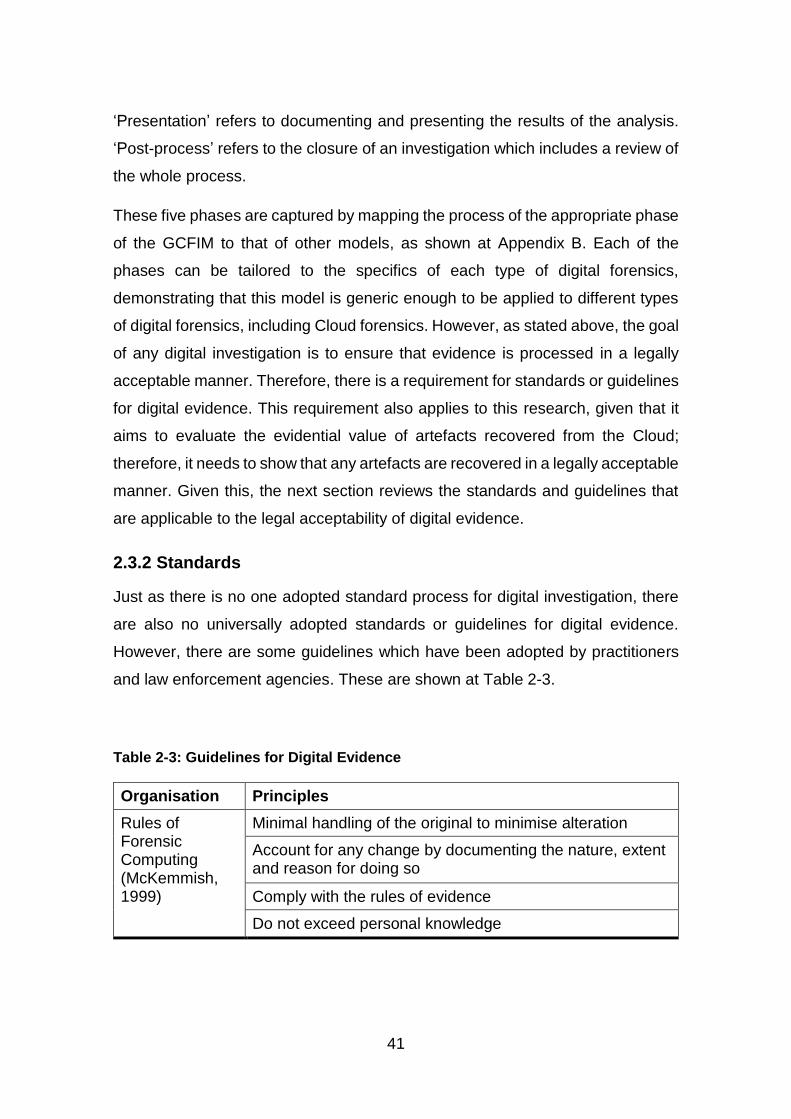
41
‘Presentation’ refers to documenting and presenting the results of the analysis.
‘Post-process’ refers to the closure of an investigation which includes a review of
the whole process.
These five phases are captured by mapping the process of the appropriate phase
of the GCFIM to that of other models, as shown at Appendix B. Each of the
phases can be tailored to the specifics of each type of digital forensics,
demonstrating that this model is generic enough to be applied to different types
of digital forensics, including Cloud forensics. However, as stated above, the goal
of any digital investigation is to ensure that evidence is processed in a legally
acceptable manner. Therefore, there is a requirement for standards or guidelines
for digital evidence. This requirement also applies to this research, given that it
aims to evaluate the evidential value of artefacts recovered from the Cloud;
therefore, it needs to show that any artefacts are recovered in a legally acceptable
manner. Given this, the next section reviews the standards and guidelines that
are applicable to the legal acceptability of digital evidence.
2.3.2 Standards
Just as there is no one adopted standard process for digital investigation, there
are also no universally adopted standards or guidelines for digital evidence.
However, there are some guidelines which have been adopted by practitioners
and law enforcement agencies. These are shown at Table 2-3.
Table 2-3: Guidelines for Digital Evidence
Organisation Principles
Rules of Forensic Computing (McKemmish, 1999)
Minimal handling of the original to minimise alteration
Account for any change by documenting the nature, extent and reason for doing so
Comply with the rules of evidence
Do not exceed personal knowledge
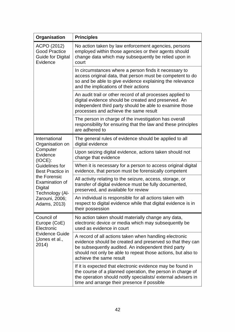
42
Organisation Principles
ACPO (2012) Good Practice Guide for Digital Evidence
No action taken by law enforcement agencies, persons employed within those agencies or their agents should change data which may subsequently be relied upon in court
In circumstances where a person finds it necessary to access original data, that person must be competent to do so and be able to give evidence explaining the relevance and the implications of their actions
An audit trail or other record of all processes applied to digital evidence should be created and preserved. An independent third party should be able to examine those processes and achieve the same result
The person in charge of the investigation has overall responsibility for ensuring that the law and these principles are adhered to
International Organisation on Computer Evidence (IOCE): Guidelines for Best Practice in the Forensic Examination of Digital Technology (Al-Zarouni, 2006; Adams, 2013)
The general rules of evidence should be applied to all digital evidence
Upon seizing digital evidence, actions taken should not change that evidence
When it is necessary for a person to access original digital evidence, that person must be forensically competent
All activity relating to the seizure, access, storage, or transfer of digital evidence must be fully documented, preserved, and available for review
An individual is responsible for all actions taken with respect to digital evidence while that digital evidence is in their possession
Council of Europe (CoE) Electronic Evidence Guide (Jones et al., 2014)
No action taken should materially change any data, electronic device or media which may subsequently be used as evidence in court
A record of all actions taken when handling electronic evidence should be created and preserved so that they can be subsequently audited. An independent third party should not only be able to repeat those actions, but also to achieve the same result
If it is expected that electronic evidence may be found in the course of a planned operation, the person in charge of the operation should notify specialists/ external advisers in time and arrange their presence if possible
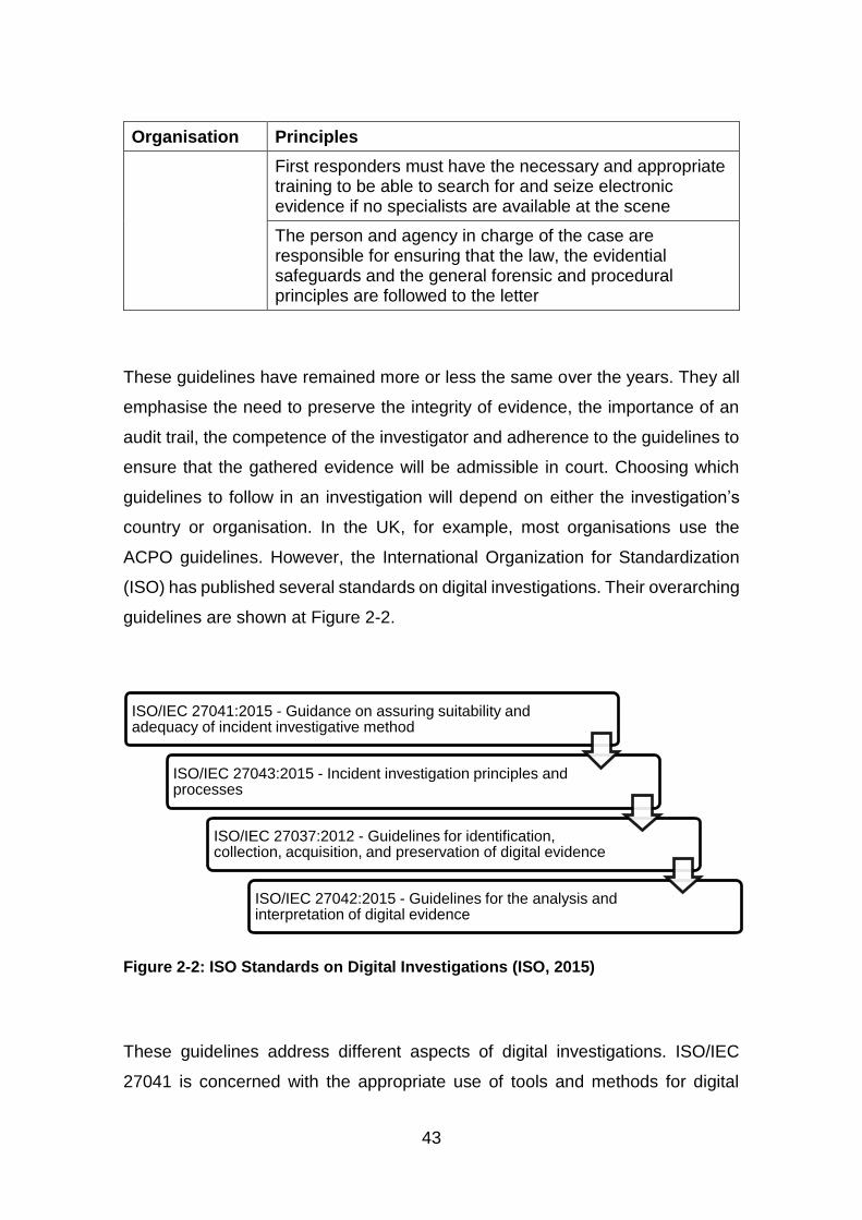
43
Organisation Principles
First responders must have the necessary and appropriate training to be able to search for and seize electronic evidence if no specialists are available at the scene
The person and agency in charge of the case are responsible for ensuring that the law, the evidential safeguards and the general forensic and procedural principles are followed to the letter
These guidelines have remained more or less the same over the years. They all
emphasise the need to preserve the integrity of evidence, the importance of an
audit trail, the competence of the investigator and adherence to the guidelines to
ensure that the gathered evidence will be admissible in court. Choosing which
guidelines to follow in an investigation will depend on either the investigation’s
country or organisation. In the UK, for example, most organisations use the
ACPO guidelines. However, the International Organization for Standardization
(ISO) has published several standards on digital investigations. Their overarching
guidelines are shown at Figure 2-2.
Figure 2-2: ISO Standards on Digital Investigations (ISO, 2015)
These guidelines address different aspects of digital investigations. ISO/IEC
27041 is concerned with the appropriate use of tools and methods for digital
ISO/IEC 27041:2015 - Guidance on assuring suitability and adequacy of incident investigative method
ISO/IEC 27043:2015 - Incident investigation principles and processes
ISO/IEC 27037:2012 - Guidelines for identification, collection, acquisition, and preservation of digital evidence
ISO/IEC 27042:2015 - Guidelines for the analysis and interpretation of digital evidence
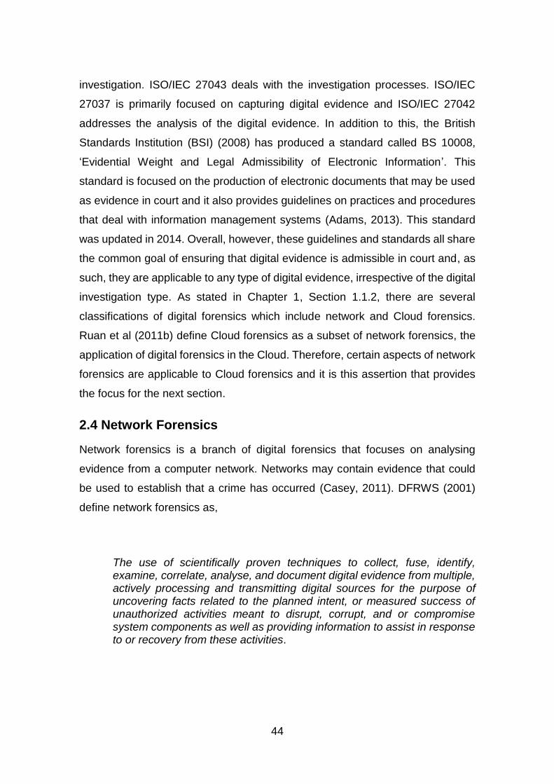
44
investigation. ISO/IEC 27043 deals with the investigation processes. ISO/IEC
27037 is primarily focused on capturing digital evidence and ISO/IEC 27042
addresses the analysis of the digital evidence. In addition to this, the British
Standards Institution (BSI) (2008) has produced a standard called BS 10008,
‘Evidential Weight and Legal Admissibility of Electronic Information’. This
standard is focused on the production of electronic documents that may be used
as evidence in court and it also provides guidelines on practices and procedures
that deal with information management systems (Adams, 2013). This standard
was updated in 2014. Overall, however, these guidelines and standards all share
the common goal of ensuring that digital evidence is admissible in court and, as
such, they are applicable to any type of digital evidence, irrespective of the digital
investigation type. As stated in Chapter 1, Section 1.1.2, there are several
classifications of digital forensics which include network and Cloud forensics.
Ruan et al (2011b) define Cloud forensics as a subset of network forensics, the
application of digital forensics in the Cloud. Therefore, certain aspects of network
forensics are applicable to Cloud forensics and it is this assertion that provides
the focus for the next section.
2.4 Network Forensics
Network forensics is a branch of digital forensics that focuses on analysing
evidence from a computer network. Networks may contain evidence that could
be used to establish that a crime has occurred (Casey, 2011). DFRWS (2001)
define network forensics as,
The use of scientifically proven techniques to collect, fuse, identify, examine, correlate, analyse, and document digital evidence from multiple, actively processing and transmitting digital sources for the purpose of uncovering facts related to the planned intent, or measured success of unauthorized activities meant to disrupt, corrupt, and or compromise system components as well as providing information to assist in response to or recovery from these activities.
45
Therefore, as the name implies, network forensics goes beyond focusing on a
standalone system. It encompasses all of the devices in a network and this
means that any evidence sought by a digital forensic investigator may be
distributed across any number of these devices. An additional problem for such
an investigation is the fact that network traffic is by its nature highly dynamic,
making it volatile and, therefore, easy to change and difficult to preserve. Some
of the sources of evidence in network forensics have been identified by Kent et
al (2006), Lillard et al (2010) and Davidoff and Ham (2012). They include firewalls,
logs like the Dynamic Host Configuration Protocol (DHCP), which assigns
network configurations to hosts on an Internet Protocol (IP) network, event logs,
application logs, anti-virus logs, proxy and Intrusion Detection System/Intrusion
Prevention system (IDS/IPS) logs, Internet Service Provider (ISP) notices
(network logs) and other devices where evidence can be found, such as
computers, routers, switches and servers.
Jones et al (2006) identified four types of network-based evidence, which they
describe as full content data, session data, alert data and statistical data. Full
content data refers to all of the user data and metadata contained in a packet,
which is a unit of data transmitted over the network. Session data consists of
summaries of communication between a source and destination. It contains
information like source and destination addresses, timestamp, port and protocol
used. Alert data is based on a set rules or signatures to detect anomalies and
alert the system administrator. It is usually created by an IDS. On the other hand,
statistical data involves looking at network traffic to detect certain patterns or
behaviours which might be related to an illegal activity. All of these types of
evidence are useful in their own ways and which of them is used depends on the
nature of the investigation. Lillard et al (2010) discuss some of the tools available
for capturing network traffic such as tcpdump, Wireshark and Fiddler, and the
limitations of these tools. As a result, they suggest the use of multiple tools in
order to overcome some of these limitations. However, where the limitations
cannot be overcome by use of multiple tools, other solutions should be sought
such as the use of either open source or commercial. Commercial tools, such as
NetDetector (NIKSUN, 2015), NetworkMiner (Netresec, 2015) and open source
46
tools include Xplico (Xplico, 2015) and Snort (Cisco, 2016); all of these can be
used for network forensics.
Davidoff and Ham (2012) discuss some of the challenges of network forensics in
the areas of acquisition, content, storage, privacy, seizure and admissibility of
evidence. They conclude that locating and acquiring evidence in a networked
environment may be difficult due to the number of possible sources of evidence.
The limited storage capacity and the non-persistent nature of network storage
devices can make it easy to lose evidence and make the overwriting of data
possible. In addition, non-persistent storage usually needs power in order to
preserve data. If the power is cut off, data may be deleted. In a traditional forensic
investigation, it is easy to seize a suspect’s devices but this may not be possible
in a network environment as it can disrupt the whole network and affect other
users who are connected to that network. As a solution to these challenges,
Davidoff and Ham (2012) developed the Network Forensics Investigative
Methodology. This is designed to help investigators acquire and analyse
evidence from a network in such a way that it can be used in a court. The
framework consists of five steps: Obtain information, Strategize, Collect
Evidence, Analyse and Report (OSCAR). Even though it was designed for
network forensics, it can be mapped to the phases of the GCFIM, which means
it can be applied to other types of digital forensics, such as Cloud forensics.
In terms of the McKemmish rules of computing and the ACPO, IOCE and CoE
guidelines discussed at Section 2.3.2, it may not be possible to adhere to some
of the sections/principles in a network forensic investigation. For example, it may
not be possible to follow Principle 1 of the ACPO guidelines where volatile data
are concerned because the original evidence may need to be accessed in order
to acquire the data and this will result in the original evidence being changed.
However, Principles 2, 3 and 4 can be followed by assigning a competent person
to acquire the data and stating the reason for accessing the original, whilst
keeping an audit trail and ensuring adherence to these principles. The guidelines
also cover network forensics in relation to both home and corporate networks
(ACPO, 2012). For home networks that use either wired or wireless connections,

47
all network devices and those devices that can connect to a network should be
considered, especially those with wireless capability. Network cabling should be
traced to the connected devices and the layout of the network should be noted.
In addition, the possibility of remote storage should be kept in mind when
analysing evidence from a network. In a corporate network environment, it is
common to find some software, like IDS, which can provide useful information,
while agents for remote acquisition can be used to image data across the network
to external storage.
In summary, network forensics is the branch of digital forensics which analyses
network traffic in addition to examining the host systems. There are various
sources of evidence that can be obtained, which range from computer systems
to network devices. However, network traffic is volatile and data should only be
acquired by competent investigators if its admissibility as evidence is to be
maintained. Traditional digital investigative processes can be used in network
forensics, although this may involve handling volatile, live data. Inevitably, all of
these challenges and guidelines for network forensics also apply to Cloud
forensics, given that it is considered to be a subset of network forensics.
Therefore, the next section discusses the literature that specifically relates to
digital investigations in the Cloud in order to identify potential research gaps.
2.5 Cloud Forensics
Cloud forensics is the application of digital investigation processes used in Cloud
computing for the purpose of extracting evidence that can be used in a court of
law. Ruan et al (2011b) define Cloud forensics as a subset of network forensics,
the application of digital forensics in the Cloud in order to generate digital
evidence. NIST (n.d.) defines Cloud forensics as,
Cloud computing forensic science is the application of scientific principles, technological practices and derived and proven methods to process past Cloud computing events through identification, collection, preservation, examination and reporting of digital data for the purpose of facilitating the reconstruction of these events.
48
This definition focuses on three main points: the use of scientific and proven
methods; the investigation of past events in the Cloud; and event reconstruction.
For any digital investigation, the goal is to maintain the admissibility of evidence,
and one of the methods of achieving this is the use of proven scientific methods.
The investigation of past activities is required, given that a crime precedes an
investigation and, in order to determine how that crime was committed, past
events need to be examined and evidence needs to be presented in order to
prove or disprove that a crime has occurred in the first place. The first two points
of this definition lead to the last one, which is the need for event reconstruction in
order to answer how, when, where and what, in relation to the crime and to show
the series of events that led to that crime. All of these steps are required in order
to obtain evidence that can be used in a court.
The processes of traditional digital forensics may not work in the Cloud and,
therefore, Cloud forensics are different (Lillard et al., 2010). This is because data
may be stored on servers that are hosted either on or offsite and that may span
multiple jurisdictions, therefore complicating access to evidence, including that
found on network devices. In addition, the Cloud is a multi-tenant ecosystem
where many users share the same resources. Therefore, the confidentiality and
integrity of other Cloud users needs to be protected, while the availability of the
service needs to be assured. Therefore, aspects of both traditional digital
forensics and network forensics need to be combined with other techniques that
are specific to Cloud computing in order to provide a model or guidelines for
carrying out investigations in the Cloud.
The Cloud Credential Council (CCC) and the NIST both have working groups on
Cloud forensics. The purpose of the CCC group is to collaborate with other
working groups from international Standardization Organisations (SDOs) to
develop best practice, to identify the training requirements and to disseminate
knowledge and expertise (Cloud Credential Council, n.d.). The goal of the NIST
Cloud Computing Forensic Science Working Group’ (NCC-FSWG) is to develop
standards and reference architectures for Cloud forensic science (NIST, n.d.).
49
These will go a long way towards providing legally acceptable methods and
techniques for digital investigation in the Cloud.
There are various published works on Cloud forensics ranging from its challenges
to the use of the Cloud for forensic purposes, to evidence seizure to how to
conduct digital forensics in the Cloud. As noted above, the NIST has formed a
working group to research the challenges of Cloud forensics and this produced a
draft report in 2014 called the NIST Cloud Computing Forensic Science
Challenges (NIST, 2014). It identified 65 challenges classified under nine
categories: analysis, anti-forensics, architecture, data collection, incidence first
responders, legal, role management, standards and training. Two of the
challenges that appear under the architecture category are associating deleted
data with a specific user, which can be linked to the attribution of a recovered
artefact, and recovery of deleted data, which falls under artefact recovery.
Attribution is a challenge in the Cloud because of its multi-tenancy nature, the
resulting number of users and the volume of data in the Cloud means that the
CSP may not be able to retain current and comprehensive back-ups, and may
not implement sufficient mechanisms for retrieving information of deleted data
(NIST, 2014). Recovery of deleted data is also a challenge because there may
not be a snapshot or a record that contains an image of that deleted data before
it is overwritten (NIST, 2014). These two challenges, attribution and recovery of
deleted data form the basis of this research as stated, in Chapter 1, Section 1.2.
While there are various challenges to conducting digital investigations in the
Cloud, its ecosystem can also prove beneficial to such investigations. Cloud
resources can be used to acquire, analyse and store evidence (Barrett and
Kipper, 2010; Reilly et al., 2010; Grispos et al., 2012; Almulla et al., 2013; van
Baar et al., 2014; Zeng, 2014; Farina et al., 2015). Barrett and Kipper (2010) and
Grispos et al (2012) note that some Cloud technologies make use of verification
techniques when saving data which can be used by forensic investigators to verify
the integrity of acquired evidence. Therefore, these show that the Cloud can be
leveraged for digital forensic investigation.
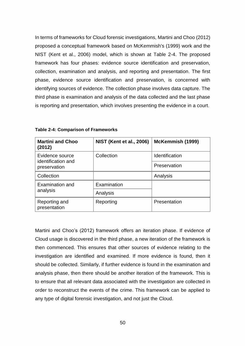
50
In terms of frameworks for Cloud forensic investigations, Martini and Choo (2012)
proposed a conceptual framework based on McKemmish's (1999) work and the
NIST (Kent et al., 2006) model, which is shown at Table 2-4. The proposed
framework has four phases: evidence source identification and preservation,
collection, examination and analysis, and reporting and presentation. The first
phase, evidence source identification and preservation, is concerned with
identifying sources of evidence. The collection phase involves data capture. The
third phase is examination and analysis of the data collected and the last phase
is reporting and presentation, which involves presenting the evidence in a court.
Table 2-4: Comparison of Frameworks
Martini and Choo (2012)
NIST (Kent et al., 2006) McKemmish (1999)
Evidence source identification and preservation
Collection Identification
Preservation
Collection Analysis
Examination and analysis
Examination
Analysis
Reporting and presentation
Reporting Presentation
Martini and Choo’s (2012) framework offers an iteration phase. If evidence of
Cloud usage is discovered in the third phase, a new iteration of the framework is
then commenced. This ensures that other sources of evidence relating to the
investigation are identified and examined. If more evidence is found, then it
should be collected. Similarly, if further evidence is found in the examination and
analysis phase, then there should be another iteration of the framework. This is
to ensure that all relevant data associated with the investigation are collected in
order to reconstruct the events of the crime. This framework can be applied to
any type of digital forensic investigation, and not just the Cloud.
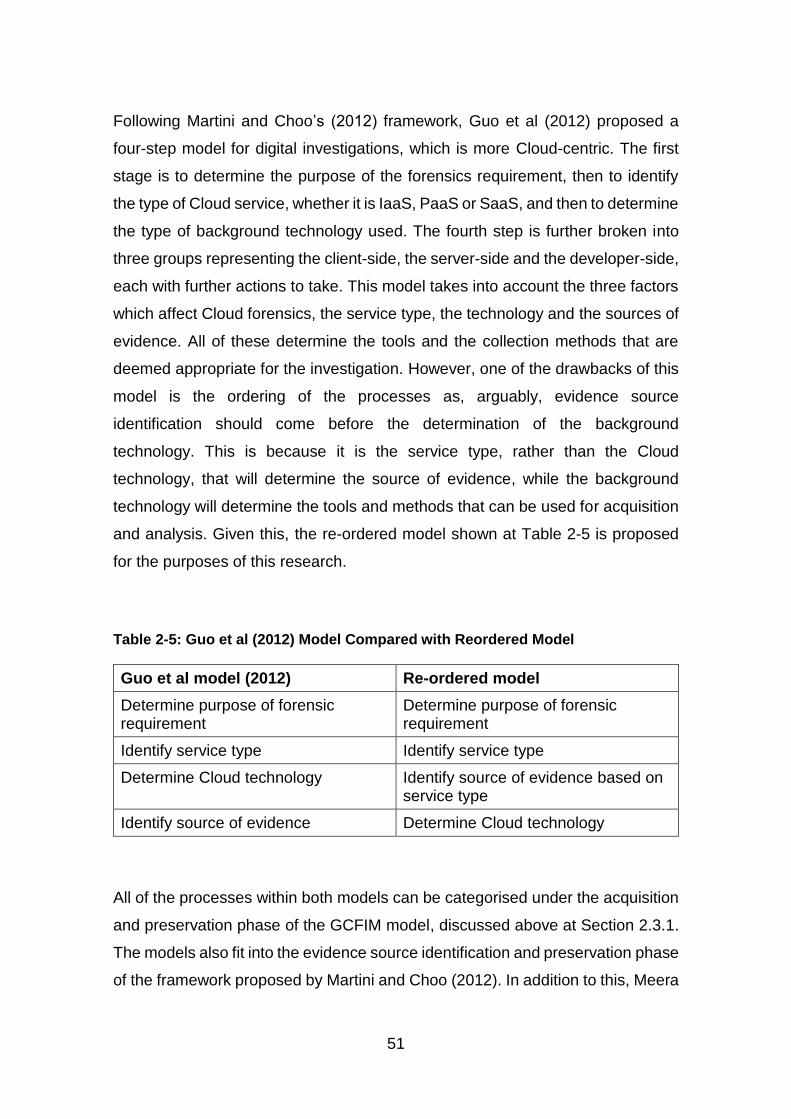
51
Following Martini and Choo’s (2012) framework, Guo et al (2012) proposed a
four-step model for digital investigations, which is more Cloud-centric. The first
stage is to determine the purpose of the forensics requirement, then to identify
the type of Cloud service, whether it is IaaS, PaaS or SaaS, and then to determine
the type of background technology used. The fourth step is further broken into
three groups representing the client-side, the server-side and the developer-side,
each with further actions to take. This model takes into account the three factors
which affect Cloud forensics, the service type, the technology and the sources of
evidence. All of these determine the tools and the collection methods that are
deemed appropriate for the investigation. However, one of the drawbacks of this
model is the ordering of the processes as, arguably, evidence source
identification should come before the determination of the background
technology. This is because it is the service type, rather than the Cloud
technology, that will determine the source of evidence, while the background
technology will determine the tools and methods that can be used for acquisition
and analysis. Given this, the re-ordered model shown at Table 2-5 is proposed
for the purposes of this research.
Table 2-5: Guo et al (2012) Model Compared with Reordered Model
Guo et al model (2012) Re-ordered model
Determine purpose of forensic requirement
Determine purpose of forensic requirement
Identify service type Identify service type
Determine Cloud technology Identify source of evidence based on service type
Identify source of evidence Determine Cloud technology
All of the processes within both models can be categorised under the acquisition
and preservation phase of the GCFIM model, discussed above at Section 2.3.1.
The models also fit into the evidence source identification and preservation phase
of the framework proposed by Martini and Choo (2012). In addition to this, Meera
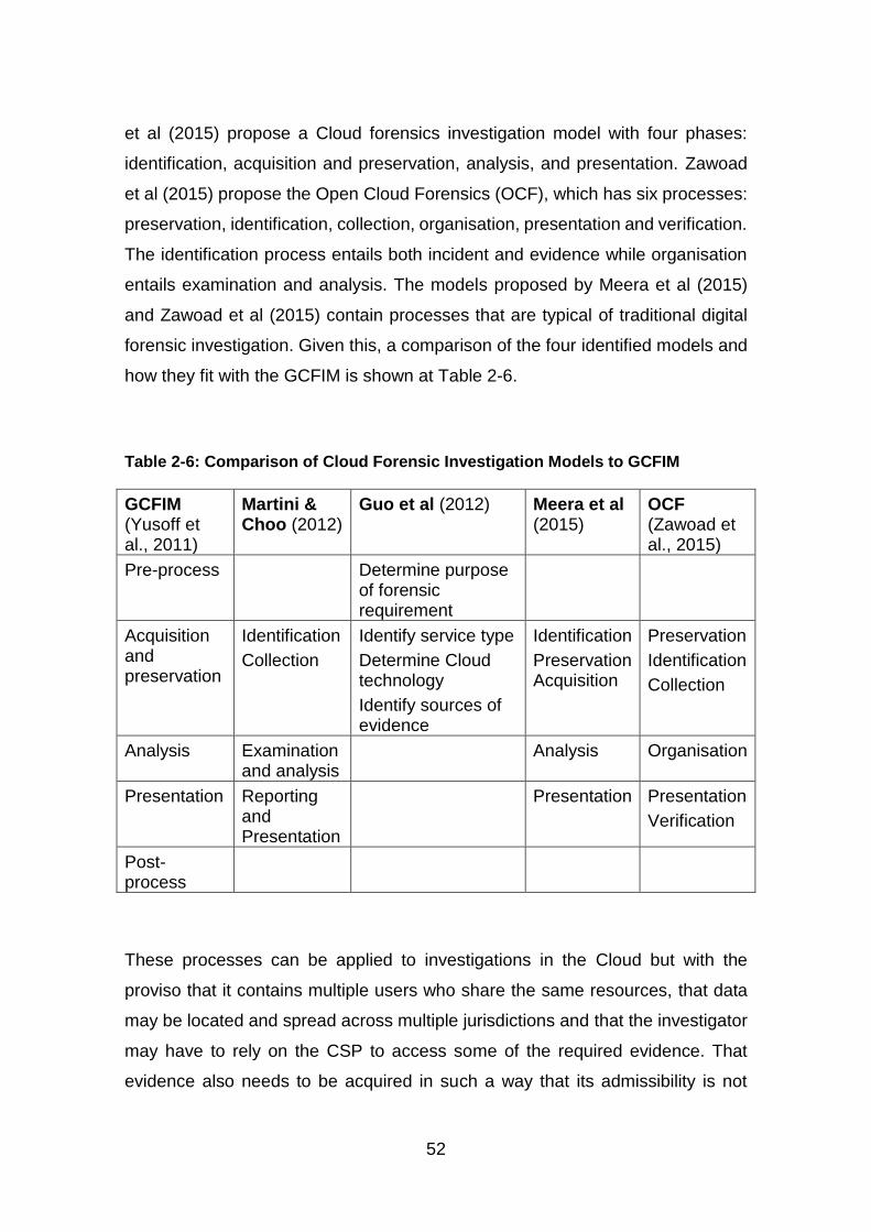
52
et al (2015) propose a Cloud forensics investigation model with four phases:
identification, acquisition and preservation, analysis, and presentation. Zawoad
et al (2015) propose the Open Cloud Forensics (OCF), which has six processes:
preservation, identification, collection, organisation, presentation and verification.
The identification process entails both incident and evidence while organisation
entails examination and analysis. The models proposed by Meera et al (2015)
and Zawoad et al (2015) contain processes that are typical of traditional digital
forensic investigation. Given this, a comparison of the four identified models and
how they fit with the GCFIM is shown at Table 2-6.
Table 2-6: Comparison of Cloud Forensic Investigation Models to GCFIM
GCFIM (Yusoff et al., 2011)
Martini & Choo (2012)
Guo et al (2012) Meera et al (2015)
OCF (Zawoad et al., 2015)
Pre-process Determine purpose of forensic requirement
Acquisition and preservation
Identification
Collection
Identify service type
Determine Cloud technology
Identify sources of evidence
Identification
Preservation Acquisition
Preservation
Identification
Collection
Analysis Examination and analysis
Analysis Organisation
Presentation Reporting and Presentation
Presentation Presentation
Verification
Post-process
These processes can be applied to investigations in the Cloud but with the
proviso that it contains multiple users who share the same resources, that data
may be located and spread across multiple jurisdictions and that the investigator
may have to rely on the CSP to access some of the required evidence. That
evidence also needs to be acquired in such a way that its admissibility is not

53
affected. To achieve this, guidelines for digital evidence, such as those offered
by ACPO, should be followed and, if there is a reason that precludes compliance
with some of the principles, that reason should be clearly stated.
In terms of sources of potential evidence, Birk and Wegener (2011) identified
three main components of the Cloud: the virtual Cloud instance, the network layer
and the Cloud client system. The virtual Cloud instance is a VM where user data
are stored and processed, providing a potential source of evidence. VMs can
easily be acquired either by the user or by the CSP. Sources of evidence in the
network layer include logs and data from the connected network devices. As
such, network forensic processes can be used to acquire evidence but, in terms
of the Cloud ecosystem, the investigator will need the help of the CSP. The client
system can also be a source of evidence and, in this case, traditional forensics
can be applied. Given that one of the processes of digital investigation is
identification, the client system can give investigators information on where
evidence can be found in a Cloud environment.
In terms of ownership of data, Lu et al (2010) propose a secure provenance
scheme to record ownership and keep track of data objects in the Cloud. This
scheme has been designed around two requirements, unforgeability and
conditional privacy preservation. The purpose of the former is to ensure that
ownership of data cannot be forged and the purpose of the latter is to ensure that
only an authorised party can reveal the identity of the owner of the data. The
conditional privacy preservation ensures confidentiality of information as well as
the anonymous authentication of users. Li et al (2014) later expanded on these
requirements to include traceability, which enables the identity of the user to be
traced using provenance records and access control, whilst enabling users to
specify access control over data stored in the Cloud.
In terms of application of the provenance mechanisms, Katilu et al (2015)
reviewed the current provenance approaches in relation to three layers of the
Cloud architecture: the system layer, the network layer and the application layer.
In the system layer, provenance records information on interactions between the
user and objects stored on the system, which can be used to track user activities.
54
In the network layer, provenance is achieved by tracking and capturing network
events, which can be used for network forensics. In the application layer,
provenance data is concerned with data accountability and assessing the
effectiveness of applications. Katilu et al (2015) note that there are gaps in the
research on confidentiality, provenance tracking outside a system and bridging
the gap between an existing system and provenance aware systems. They note
that, if secure provenance is implemented, then it can help forensic investigators
to associate data with a specific Cloud user account. This is because the design
requirements of secure provenance make it difficult for owners of data to dispute
ownership. In terms of this research, this means that recovered artefacts can be
associated with specific Cloud users. However, in terms of what it means for the
digital investigation process, it indicates that, once evidence has been identified,
the next step is to acquire that evidence. In the Cloud, this should be undertaken
without affecting other users and one way to achieve this is by isolating the
evidence.
Delport et al (2011) propose several methods to isolate a Cloud instance, which
they define as a VM, for the purposes of investigation, whilst aiming to preserve
the integrity of the evidence and to maintain the confidentiality, integrity of data
and availability of access for other Cloud users. This is comparable to roping off
a crime scene to protect the evidence from contamination, thereby protecting its
admissibility, and is necessary because several users are likely to be sharing the
same resources in the Cloud. Therefore, if an instance comes under suspicion,
isolating it before commencing investigations will prevent accidental or
unavoidable access to other instances. In addition, should the suspicious
instance have been infected (by malware, for example), then isolating it will
prevent the other instances from also becoming infected.
Apart from Cloud or VM instances, logs can be used as corroborative evidence
in investigations. They record transactional information between a user and a
system or application. Such information may be useful in an investigation, such
as corroborative evidence, for example. However, the availability of logs depends
on the service type. In order to overcome this issue, Marty (2011) proposes a

55
logging framework to generate and record all the required data for forensic
investigations. The guidelines that he proposes relate to what to log, when to log
and how to log. He suggests that logging should be enabled on all infrastructure
components, whilst an encrypted transport should be established to transfer the
logs to central log storage. Although his research was based on SaaS, the
processes that he defines can be applied to the other service types.
Birk and Wegener (2011) also address this issue, suggesting logging
mechanisms that can be implemented by the service providers for both SaaS and
PaaS. For PaaS, they suggest encrypting the log prior to transmission to the
central logging server to protect the integrity of the data. In SaaS, logs which
record customer activities like access, error and events should be implemented
in a way that the user can access. This can then be used to implicate or absolve
a user in a forensic investigation. To protect the integrity of such logs, Birk and
Wegener (2011) suggest that mechanisms for data integrity verification should
be implemented by the CSP. Sang (2013) also proposes a logging model for
SaaS and PaaS, which includes a local log module that synchronises with logs
on the CSP side, where incremental hash is employed for the purposes of data
integrity. This way, the logs from the CSP and the user can be compared to
ensure that they are authentic. Investigators can also either use the logs from the
CSP for analysis purposes or from the user or both, depending on which they
have access to. The logs can provide corroborative evidence in investigations. In
this research, logs were used to provide information that was used to map
recovered artefacts to specific XCP users.
Forensic tools can be added to the Cloud to aid investigations. An example of
this is the Sleuthkit Hadoop Framework, a project developed to use Sleuthkit on
Hadoop, an open source platform for distributed storage and processing, for
evidence extraction, analysis and reporting which can be deployed in a Cloud
(Carrier, 2012). This is based on an existing tool, or rather a collection of tools for
disk image analysis. Tools can also be developed for the Cloud, such as a web-
based tool for evidence collection based on Struts, a framework for building web
applications, and Hadoop OpenStack, an open source IaaS Cloud platform
56
(Saibharath and Geethakumari, 2015). Therefore, having reviewed the general
literature on Cloud forensics, the next section focuses on the available literature
on Cloud service types in relation to Cloud forensics.
2.5.1 Cloud Forensics and Cloud Service Types
As mentioned in Section 2.5 above, the potential sources of evidence depend on
the service type. Therefore, in a SaaS model, it is possible for an investigator to
find evidence of usage by analysing the web browser on the client machine. To
access other information, such as application logs, the investigator has to rely on
and trust the CSP. Birk and Wegener (2011) suggest that comprehensive logging
and provenance mechanisms could be implemented as a method of adding
forensic capabilities to the SaaS service model. This will give investigators access
to high level logs when needed, whilst the integrity and ownership of data can
easily be proven. On the other hand Freet et al (2015) suggest a strong
encryption mechanism to protect user data along with a synchronous logging
mechanism, where users keep a copy of the application logs. Therefore, in terms
of digital investigation, improved logging mechanisms can help in providing more
information.
In terms of forensic tools for SaaS, Srivastava et al (2014) designed and
implemented the Forensic Toolkit for Eucalyptus (FORE), which is a forensic
toolkit for the SaaS model of the Eucalyptus Cloud, an open source solution for
private and hybrid Clouds that is compatible with AWS (HP, 2015). The Cloud
platform is based on CentOS. FORE enables the user to access his or her logs,
usage history and to recover deleted files independent of the CSP. The purpose
of this is to improve transparency in SaaS. The toolkit is made up of three
modules: the admin, user and forensic modules. The admin module monitors and
secures the SaaS environment, providing an interface for communicating with the
user. The user module provides an interface between the user and the SaaS
application, access to the administrator and a forensic interface where a user can
audit his or her account. The forensic module gives an authorised third party
access to user accounts for investigation purposes. Therefore, FORE adds
forensic capabilities to SaaS through the forensic module, enabling access to
57
data that could be used as evidence in an investigation. Even though it was
designed specifically for SaaS, it is evidently a step towards forensic readiness
in the Cloud.
In terms of PaaS, evidence may be found on the developer’s (user) system as
well as the CSP servers. As mentioned earlier, to access data from the CSP, the
investigator has to both rely on and trust the CSP. Birk and Wegener (2011)
suggest that logging mechanisms can be implemented whereby application logs
are encrypted before the logs are transferred to a central logging server. This is
to prevent these logs from being changed, which might happen if the application
is compromised while running or while the logs are in transit. On the other hand,
Graves (2014) suggests that the logs should be stored either on third party
servers or on the user’s local server. The former is to protect the logs in the case
of the application being compromised, while the latter is to protect the logs in the
case of the CSP system being compromised. Therefore, this discussion shows
that logs can provide corroborative evidence in an investigation and that the
integrity of such logs should be protected.
For IaaS, Buchanan et al (2011) worked in collaboration with the Home Office to
design a Cloud-based Digital Forensics Evaluation Test (D-FET) platform for
evaluating the quality of digital forensic tools. The platform evaluates the tools
based on their performance and the forensic quality of the evaluation. The
platform in this instance was implemented using VMWare vSphere and VMWare
ESXi 4.1. This highlights the fact that the Cloud can be leveraged by forensic
investigators not only for evidence, log storage and evidence processing, but also
for other purposes, such as the evaluation of digital forensic tools. Dysktra and
Sherman (2012) discuss the various layers of trust in an IaaS Cloud environment
and propose solutions to data acquisition in such a system. They also evaluate
two of the most commonly used forensic tools, EnCase Enterprise 6.11, FTK 3.2
and FTK Imager Lite 2.9.0, in terms of remote acquisition using Amazon EC2, in
order to confirm that these tools can acquire both volatile and non-volatile data
from the Cloud. Dykstra and Sherman (2013) designed and implemented a
forensic tool for OpenStack, which they termed Forensic OpenStack Tools
58
(FROST). The Cloud platform was based on Ubuntu. FROST works at the
management plane of the Cloud platform but does not interact with the operating
system in the guest VM. It was evaluated by requesting API logs, firewall logs
and disk images, which were downloaded successfully while maintaining the
integrity, completeness and accuracy of the data. Mustafa and Nobles (2014)
then proposed a testbed for Cloud-based forensic investigation. This was based
on XCP in order to identify the sources of evidence both from the CSP and the
Cloud client, along with the artefacts that could be recovered from both. Thethi
and Keane (2014) evaluated five acquisition methods in terms of the time taken
to image the data, using Amazon EC2 as a test environment. They found that
acquisition using Cloud resources is significantly faster than using traditional
methods. Raju et al (2015) developed an acquisition tool for OpenStack Cloud.
The tool was developed to acquire three VM artefacts: the Cloud service logs,
virtual disk and virtual RAM. Therefore, this overview of the literature in this area
affirms that Cloud resources can be leveraged for digital forensic purpose
Another service type that is commonly used is Storage as a Service. Research
to date has shown clearly that it is possible to recover artefacts from a device that
has been used to access such a service. Chung et al (2012) discuss the artefacts
of Cloud storage services based on Windows and Mac, as well as Android and
Apple smartphones. Based on Amazon S3, Dropbox, Evernote and Google Docs,
their investigations showed that it is possible to find artefacts related to all of the
Cloud storage services, including user information, on all the devices used. Hale
(2013) focused solely on Amazon Cloud Drive, another Cloud storage service, to
find artefacts on a computer that was used to access the storage service via the
Web and via desktop interfaces. Quick et al (2014) focus on Cloud storage
forensics, identifying the evidence left on a Windows 7 machine and an Apple
iPhone 3G after they have been used to access Microsoft Skydrive, Dropbox,
Google Drive and ownCloud, an open source Cloud storage application. Federic
(2014) designed a Cloud Data Imager, a tool to collect remote data from Cloud
storage services. This currently supports Dropbox, Google Drive and Microsoft
Skydrive. Mehreen and Aslam (2015) identified the artefacts left by two Dropbox
interfaces on a Windows 8 machine. Overall, these research activities
59
demonstrate that it is possible to recover artefacts from various Cloud storage
services on a range of different devices and using a range of different operating
systems.
It should be noted that a digital forensics tool was developed for all of the different
service models discussed in this section with the exception of PaaS. While the
tools for IaaS and SaaS were developed for specific Cloud technologies, the tool
for StaaS supports various storage services. This shows that there is a need for
tools that can be used in relation to all service types. Ruan et al (2011b) suggest
developing tools for different deployment models. However, it is argued here that
a better solution is the addition of existing tools to the Cloud as these can then
be used with any service type and in relation to any deployment model. However,
while evidence from the Cloud may be dependent on deployment mode and
service type, there are other factors to consider. For example, Cloud technology
may play a role in the type of evidence and how it can be acquired. Different
filesystems, including those used within the Cloud manage, data in different ways
and this can affect both the acquisition of evidence and the evidence itself.
Therefore, this discussion turns to the available literature on filesystems in order
to determine how data storage is managed.
2.6 Filesystems
A filesystem is the way in which files are organised on a disk by an operating
system; different operating systems support different filesystems. Some of the
common filesystems are shown at Table 2-7.
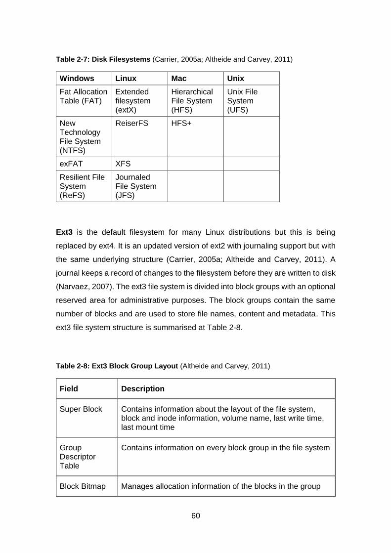
60
Table 2-7: Disk Filesystems (Carrier, 2005a; Altheide and Carvey, 2011)
Windows Linux Mac Unix
Fat Allocation Table (FAT)
Extended filesystem (extX)
Hierarchical File System (HFS)
Unix File System (UFS)
New Technology File System (NTFS)
ReiserFS HFS+
exFAT XFS
Resilient File System (ReFS)
Journaled File System (JFS)
Ext3 is the default filesystem for many Linux distributions but this is being
replaced by ext4. It is an updated version of ext2 with journaling support but with
the same underlying structure (Carrier, 2005a; Altheide and Carvey, 2011). A
journal keeps a record of changes to the filesystem before they are written to disk
(Narvaez, 2007). The ext3 file system is divided into block groups with an optional
reserved area for administrative purposes. The block groups contain the same
number of blocks and are used to store file names, content and metadata. This
ext3 file system structure is summarised at Table 2-8.
Table 2-8: Ext3 Block Group Layout (Altheide and Carvey, 2011)
Field Description
Super Block Contains information about the layout of the file system, block and inode information, volume name, last write time, last mount time
Group Descriptor Table
Contains information on every block group in the file system
Block Bitmap Manages allocation information of the blocks in the group
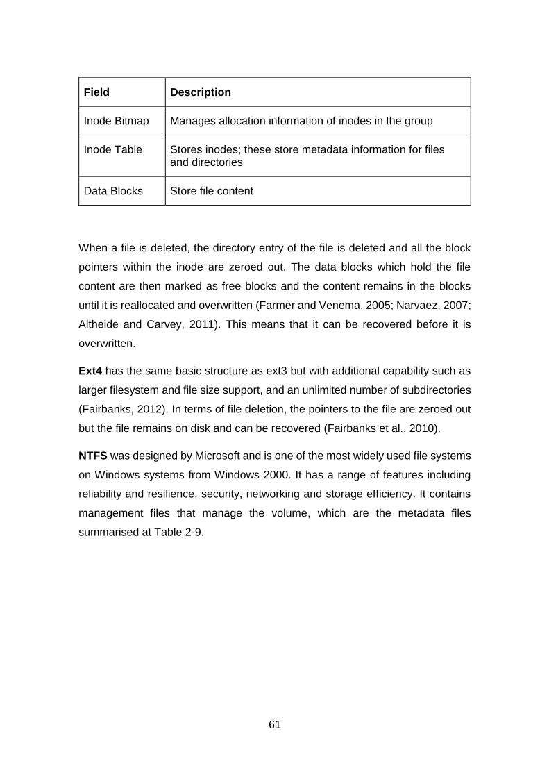
61
Field Description
Inode Bitmap Manages allocation information of inodes in the group
Inode Table Stores inodes; these store metadata information for files and directories
Data Blocks Store file content
When a file is deleted, the directory entry of the file is deleted and all the block
pointers within the inode are zeroed out. The data blocks which hold the file
content are then marked as free blocks and the content remains in the blocks
until it is reallocated and overwritten (Farmer and Venema, 2005; Narvaez, 2007;
Altheide and Carvey, 2011). This means that it can be recovered before it is
overwritten.
Ext4 has the same basic structure as ext3 but with additional capability such as
larger filesystem and file size support, and an unlimited number of subdirectories
(Fairbanks, 2012). In terms of file deletion, the pointers to the file are zeroed out
but the file remains on disk and can be recovered (Fairbanks et al., 2010).
NTFS was designed by Microsoft and is one of the most widely used file systems
on Windows systems from Windows 2000. It has a range of features including
reliability and resilience, security, networking and storage efficiency. It contains
management files that manage the volume, which are the metadata files
summarised at Table 2-9.
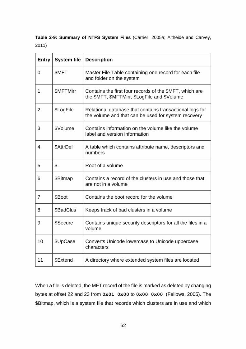
62
Table 2-9: Summary of NTFS System Files (Carrier, 2005a; Altheide and Carvey,
2011)
Entry System file Description
0 $MFT Master File Table containing one record for each file and folder on the system
1 $MFTMirr Contains the first four records of the $MFT, which are the $MFT, $MFTMirr, $LogFile and $Volume
2 $LogFile Relational database that contains transactional logs for the volume and that can be used for system recovery
3 $Volume Contains information on the volume like the volume label and version information
4 $AttrDef A table which contains attribute name, descriptors and numbers
5 $. Root of a volume
6 $Bitmap Contains a record of the clusters in use and those that are not in a volume
7 $Boot Contains the boot record for the volume
8 $BadClus Keeps track of bad clusters in a volume
9 $Secure Contains unique security descriptors for all the files in a volume
10 $UpCase Converts Unicode lowercase to Unicode uppercase characters
11 $Extend A directory where extended system files are located
When a file is deleted, the MFT record of the file is marked as deleted by changing
bytes at offset 22 and 23 from 0x01 0x00 to 0x00 0x00 (Fellows, 2005). The
$Bitmap, which is a system file that records which clusters are in use and which
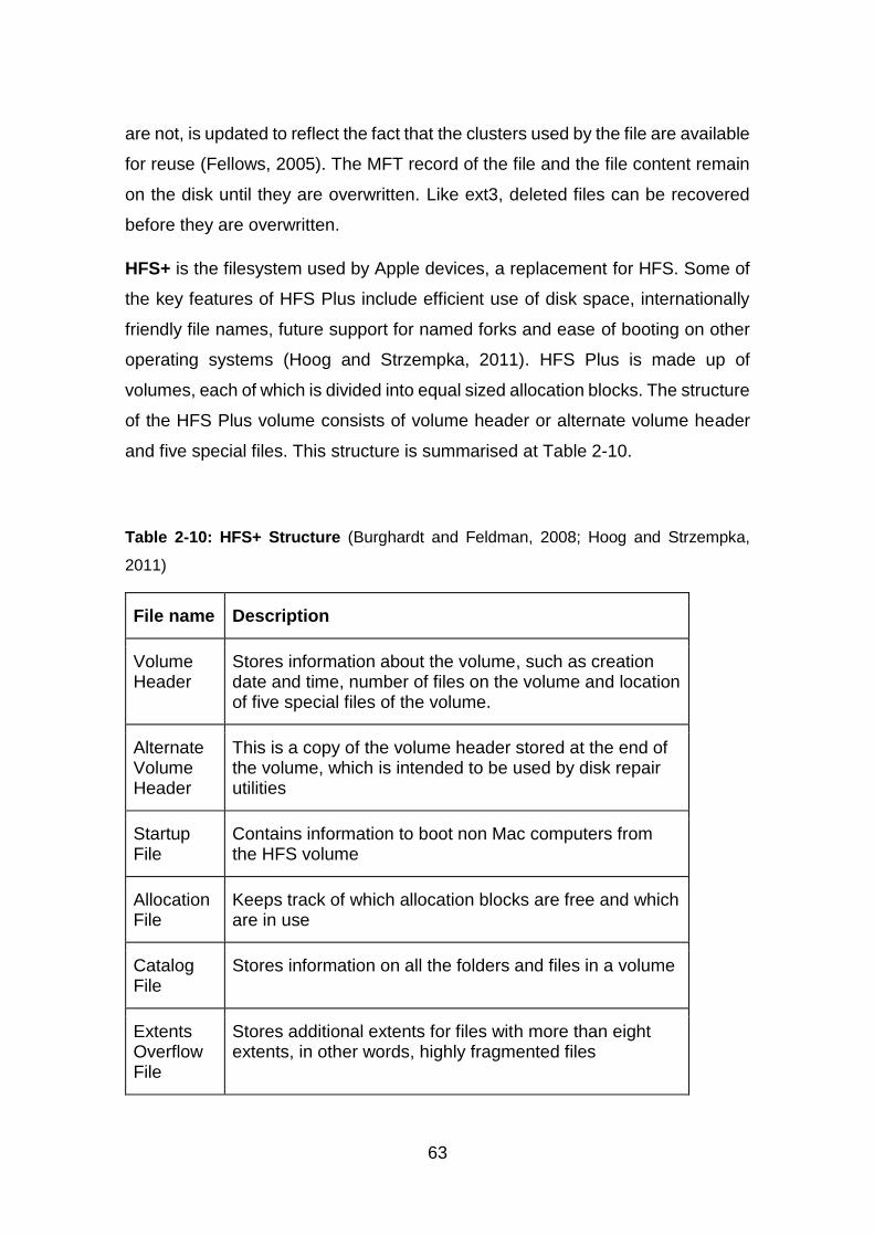
63
are not, is updated to reflect the fact that the clusters used by the file are available
for reuse (Fellows, 2005). The MFT record of the file and the file content remain
on the disk until they are overwritten. Like ext3, deleted files can be recovered
before they are overwritten.
HFS+ is the filesystem used by Apple devices, a replacement for HFS. Some of
the key features of HFS Plus include efficient use of disk space, internationally
friendly file names, future support for named forks and ease of booting on other
operating systems (Hoog and Strzempka, 2011). HFS Plus is made up of
volumes, each of which is divided into equal sized allocation blocks. The structure
of the HFS Plus volume consists of volume header or alternate volume header
and five special files. This structure is summarised at Table 2-10.
Table 2-10: HFS+ Structure (Burghardt and Feldman, 2008; Hoog and Strzempka,
2011)
File name Description
Volume Header
Stores information about the volume, such as creation date and time, number of files on the volume and location of five special files of the volume.
Alternate Volume Header
This is a copy of the volume header stored at the end of the volume, which is intended to be used by disk repair utilities
Startup File
Contains information to boot non Mac computers from the HFS volume
Allocation File
Keeps track of which allocation blocks are free and which are in use
Catalog File
Stores information on all the folders and files in a volume
Extents Overflow File
Stores additional extents for files with more than eight extents, in other words, highly fragmented files

64
File name Description
Attributes File
Stores additional data for a folder or file
HFS Plus uses B-trees for the catalog, extents overflow and attributes files. B-
tree is a data structure that stores data in a manner that allows efficient searches,
modifications and deletion. HFS Plus also uses journaling, which keeps a log of
related changes prior to implementing them on the filesystem. New logs are
appended to the journal file until the end of the file is reached, then it begins
overwriting old data at the beginning of the file. When data is deleted, the catalog
and allocation files are updated, but the deleted data remains on the disk until it
is overwritten. This means it can be recovered. It should be noted that there are
other filesystems, such as distributed or clustered filesystems which allow
multiple users to share and access files via the network (Burghardt and Feldman,
2008; Hoog and Strzempka, 2011).
Google File System (GFS) is a distributed filesystem designed and implemented
by Google. Consisting of a single master server and several chunkservers, it can
be accessed by multiple users (Ghemawat et al., 2003). Files are divided into
fixed sized chunks by the master and the chunks are then saved across the
chunkservers. For reliability, the chunks are replicated more than once on
different slaves with the default number of replications being three. The master
keeps a record of file metadata, which includes the mapping information from files
to chunks, the location of the chunks and the location of the replicas. It also keeps
an operation log which records metadata changes. The master manages system-
wide activities like chunk lease management, orphan chunks garbage collection
and chunk migration. When a file is deleted that deletion is recorded in the
operation log and the file is renamed to a hidden name. For recovery purposes,
the metadata of the file remains on the master for a number of days before it is
deleted. After deletion, the chunks become orphan chunks and are deleted during
garbage collection. The replicas of the chunks are also deleted from the
65
chunkservers and the space occupied by the chunks become free for reallocation
(Ghemawat et al., 2003). This shows that after a file is deleted, it can still be
recovered during the configurable interval before the metadata is deleted. Even
after the metadata is deleted, data stays on the disk until its chunks are
reallocated and overwritten, meaning that it can be recovered.
The final filesystem considered is the VMware Virtual Machine File System
(VMFS), which is a clustered filesystem designed by VMware to be used with
VMware ESX servers. It allows multiple ESX servers to access VM shared
storage concurrently (Vaghani, 2010). Each ESX server stores its VM file in a
specific subdirectory of the shared storage, which is called a datastore. When a
VM is in use, VMFS puts a lock on it to prevent other ESX servers from updating
it. VMFS also has a mechanism which ensures that a VM cannot be accessed by
more than one ESX server at a time. It utilises block storage and data, including
VMs, are stored in volumes or blocks. When a file is deleted, the blocks occupied
by the file are marked for deletion and the mappings between the file and the
physical storage are removed. However, that file then remains on disk until it is
overwritten (Vaghani, 2010). This shows that the file can be recovered.
As mentioned in Section 2.4, one of the challenges of Cloud forensics is recovery
of deleted data, this discussion shows that, in most filesystems, deleted files
remain on a disk until it is overwritten, and are, therefore recoverable. Given this,
the discussion in the next section focuses on data deletion in the Cloud.
2.7 Data Deletion in the Cloud
As discussed above, in many filesystems, including those used in the Cloud, a
deleted file remains on the disk until it is overwritten and may, in some cases,
then be recovered. This is certainly true for the filesystems discussed in Section
2.6 above. Deleted data thus remain an important source of evidence in digital
forensics. When data is deleted in a typical Cloud system, all of the mappings for
that data are removed almost immediately and the space formally occupied by
the deleted data is released for use. New data may then be written in that space,
thereby overwriting the deleted data (Ruan et al., 2011a). Ruan et al (2011b)
identified three challenges that relate to deleted data: its recovery, identifying and
66
confirming ownership, and event reconstruction using the deleted data.
Spyridopoulos and Katos (2011) then proposed an acquisition process based on
Google File System (GFS) for retrieving evidence from the Cloud for both live and
deleted data. They then expanded their initial work in 2013 to suggest a method
for recovering deleted data without violating the privacy of other Cloud users
(Spyridopoulos and Katos, 2013). In order to do this, they used two scenarios,
one where the deleted file had not been overwritten and one where the deleted
file had been overwritten. For both, they recommend that the CSP keeps a
permanent record of the data blocks where files are stored to enable investigators
to retrieve files which have not been overwritten. Therefore, in both this and the
preceding section, the possibility of recovering data after deletion has been
demonstrated, along with the fact that such data can be used in a forensic
investigation.
Up to this point, this chapter has concentrated on Cloud computing, digital and
Cloud forensics, filesystems and data deletion in the Cloud. None of these
touched on research methodology in digital forensics which is an important
aspect of digital forensics research. Therefore, the next section considers
research methodology and evaluation options in digital forensics.
2.8 Research Methodology and Evaluation in Digital Forensics
The term ‘research methodology’ can simply be described as methods by which
data is collected and analysed. However, Pearlson and Saunders (2004) define
it as “the theory of how research should be undertaken”. In most fields of forensic
science, research precedes its application while in digital forensics, application
precedes research. In other words, digital forensics emerged from the need for
investigators and tool developers to find solutions to the problems that they
encountered when dealing with computer crime (Beckett and Slay, 2007; Beebe,
2009). This called for a more rigorous and scientific approach to the field of digital
forensics and, over the years, efforts have been made to formalise and
standardise approaches and process of digital forensics (Beebe, 2009). The
purpose of this next section is, therefore, to focus on the potential approaches to
research methodology that are taken in digital forensics.

67
2.8.1 Methodology
Digital forensics is still relatively new in the field of forensic science. Whereas
methodologies have been developed for the other forms of forensic sciences that
are based on the scientific process, this is not the case with digital forensics
(Flandrin et al., 2014). A decade ago, based on the premise that traditional
forensic science is more developed, Pollitt (2008) suggested that digital forensics
should follow a similar approach to looking at evidence, adapting it to suit the
digital context. This led to the selection of four processes that form the basis of a
digital forensics research methodology: identification,
classification/individualisation, association and reconstruction. Identification is
used to describe digital evidence in terms of its context, either physically,
structurally, in terms of its location or content. Classification/individualisation
categorises evidence based on its characteristics. For example, filesystems,
partitions and individual files have characteristics which allow them to be easily
classified but, at the same time, each filesystem has features which distinguish it
from another filesystem. Association deals with linking data to a crime or to a
perpetrator, while reconstruction deals with recreating a series of events that to
led to a crime.
In order for these processes to be used effectively, Pollitt (2008) suggests that
the examiner/investigator should begin by defining the legal/investigative
question and then define the digital forensic (scientific) question. This process
provides a definite end to an investigation as the investigation ends when all of
the questions are answered. The incorporation of the development of forensic
questions in an investigation also ensures that scientific objectivity is achieved.
Therefore, while there is no unified methodology for research in digital forensics
in general, there are methodologies for testing and evaluating digital forensic
tools. These include those suggested by Beckett and Slay (2007) and Buchanan
et al (2011) and the available methodologies discussed by Flandrin et al (2014).
These researches show that is significant progress in terms of the application of
scientific process for testing, validating and evaluating digital forensic tools. Some
of these methodologies may be modified and adapted for general digital forensics
research and not only for tools.
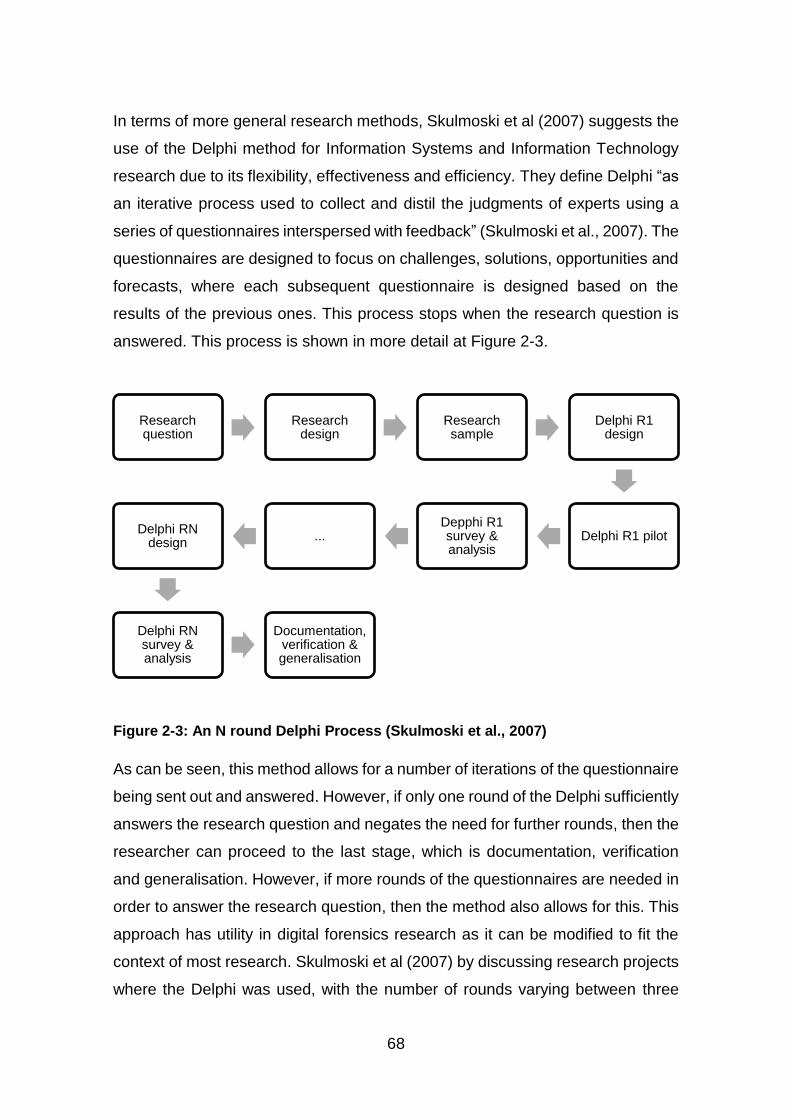
68
In terms of more general research methods, Skulmoski et al (2007) suggests the
use of the Delphi method for Information Systems and Information Technology
research due to its flexibility, effectiveness and efficiency. They define Delphi “as
an iterative process used to collect and distil the judgments of experts using a
series of questionnaires interspersed with feedback” (Skulmoski et al., 2007). The
questionnaires are designed to focus on challenges, solutions, opportunities and
forecasts, where each subsequent questionnaire is designed based on the
results of the previous ones. This process stops when the research question is
answered. This process is shown in more detail at Figure 2-3.
Figure 2-3: An N round Delphi Process (Skulmoski et al., 2007)
As can be seen, this method allows for a number of iterations of the questionnaire
being sent out and answered. However, if only one round of the Delphi sufficiently
answers the research question and negates the need for further rounds, then the
researcher can proceed to the last stage, which is documentation, verification
and generalisation. However, if more rounds of the questionnaires are needed in
order to answer the research question, then the method also allows for this. This
approach has utility in digital forensics research as it can be modified to fit the
context of most research. Skulmoski et al (2007) by discussing research projects
where the Delphi was used, with the number of rounds varying between three
Research question
Research design
Research sample
Delphi R1 design
Delphi R1 pilotDepphi R1 survey & analysis
...Delphi RN
design
Delphi RN survey & analysis
Documentation, verification & generalisation
69
and five. For these projects, the research questions were successfully answered,
demonstrating the validity of the approach. For research that does not involve
surveys such as this research, the principle of the Delphi method can still be used
to collect sufficient amount of data to answer research questions. This can be
done by substituting the survey and analysis stage with experiments for example,
where one or more iterations of the experiments can be used to achieve the
desired results.
In terms of data sets that can be used for digital forensics research, Garfinkel et
al (2009) identified four categories of digital corpora, a term used to describe
standardised sets of digital data. The four categories are disk images, memory
images, network packets and individual files. They went further to classify such
corpora based on the sensitivity of the data, which they classified as test data,
sampled data, realistic data, real and restricted data, and real but unrestricted
data. Test data are data which are constructed specifically for testing a tool or its
function or demonstrating a forensic issue. Sampled data contains a subset of a
large data source. Realistic data represent data that may be found in an
investigation. Real and restricted data are created during real activities and not
as a result of creating test data. This type of data is restricted due to privacy or
copyright concerns, whereas real and unrestricted data, also result from real
activities but are unrestricted as they are publicly available (Garfinkel et al., 2009).
Garfinkel et al (2009) describe the data sets that they have developed for digital
forensics research as real and unrestricted file corpus, test disk images, realistic
disk images and real data corpus.
This shows that there are different types of data corpora which are available for
digital forensic research and training. However, Yannikos et al (2014) identified
four problems with using data corpora for research and education. They argued
that the use of a data corpus provides solutions specific to that corpus (solution
specificity), that there may be legal issues with regards to the use of a corpus
either by the host country or the research country (legal issues), that the corpus
may lose its relevance over time (relevance) and that it may not be transferrable
to other contexts (transferability). As a solution to these problems, they suggest
70
the use of synthetic data corpus and then proposed a framework for it based on
scenario-based model. Such framework can be used in various fields of digital
forensics to generate data for research and education, and to test and evaluate
tools. The use of synthetic data corpora in conjunction with real world corpora will
provide a way of keeping abreast with the technological advances in digital
forensics research. These will provide data needed to test and evaluate tools,
methods of data collection and analysis for new areas of research and new
technologies. For this research, test data and realistic data will be used as the
problems identified by Yannikos et al (2014) is negated by the context of this
research.
In research, once methodologies are selected and data are collected, analysed
and results obtained, the research needs to be assessed in order to ensure that
it has met certain criteria in terms of standard or value of the research. Therefore,
the next section focuses on evaluation of research in digital forensics.
2.8.2 Evaluation
Evaluation is an important aspect of research as it provides a means of assessing
the quality of the research and enhancing its effectiveness. Stern (2005) define
evaluation as “a set of research methods and associated methodologies with a
distinctive purpose that provide a means to judge actions and activities in terms
of values, criteria and standards”. In terms of digital forensics, evaluation is based
on investigative context (Mocas, 2004). Mocas (2004) went further to identify a
set of five properties that can be used for the development and evaluation of
research. These are integrity, authentication, reproducibility, non-interference
and minimisation. Integrity refers the reliability of duplication and the need to
ensure that the process involved in duplicating data does not result in the data
being changed and that the duplicate is an exact bit copy of the original. The
process of authentication should ensure that the evidence is what it claims to be,
while reproducibility should ensure that the processes used to gather and/or
examine evidence are reproducible. Non-interference should provide assurance
that the method or tool used to gather and/or analyse the evidence does not
change the original and, if it does, that the changes are identifiable. Finally,
71
minimisation should provide assurance that the minimum amount of data required
was processed. These properties were proposed not just to evaluate digital
forensic research, but also to evaluate digital forensic tools and methods. In
addition, Mocas (2004) noted that the properties are not meant to be achievable
in all contexts but to provide a means for framing questions, model behaviour,
evaluate tools and procedures. This provides an encompassing method for
evaluating research which can be applied in the different aspects of digital
forensic research.
As with research methodologies, there is no unified approach for evaluating
digital forensic research. The approach proposed by Mocas (2004) provide a
starting point for a standardised method. However, there are other methods for
evaluating specific aspects of digital forensics such as tools by Beckett and Slay
(2007), Buchanan et al (2011) and Flandrin et al (2014), digital evidence by Miller
(1992), Sommer (1998), Hargreaves (2009), and Jones et al (2014) and
evidential value of digital evidence, which was proposed by Morris (2013). Some
of these may be adapted and/or modified for digital forensic research by making
them generalisable. For this research, the properties proposed by Mocas (2004)
will is used to evaluate data generated in the experimental part of the research
as it provides a general and encompassing method of evaluating research.
Overall, this chapter has shown that there are challenges with digital
investigations in the Cloud, particularly in relation to evidence acquisition. Deleted
data in most file systems are recoverable, but this process still remains
problematic in the context of the Cloud. While forensic tools have been developed
for IaaS and SaaS, they are designed for specific Cloud technologies, and there
is little research on the addition of forensic tools in the Cloud. Therefore, it is
evident that there is a need for techniques that can be used to recover artefacts
of evidential value from the Cloud and this is the gap that this research seeks to
fill, by adding existing tools to the Cloud for forensic purposes. This research tests
the hypothesis that it is possible to recover artefacts of evidential value from XCP,
using existing tools.
72
2.9 Conclusion
This chapter reviewed previous scholarly work that relates to this research. It
covered the characteristics of Cloud computing in terms of its service types and
deployment models as defined in the NIST framework and, for each, the
challenges in terms of digital investigation were highlighted. Digital forensics was
discussed, along with some of the models of digital investigation, as well as the
guidelines and standards for digital evidence. The discussion then turned to
networks, focusing on the sources of evidence, types of network-based evidence,
and challenges associated with network forensics, which include evidence
acquisition. This is problematic due to the volatile nature of network traffic and
the number of devices that are potentially connected to a network, due to the
privacy of users on a network, and to the admissibility of network evidence.
Cloud forensics was discussed in terms of its challenges and solutions proposed
by various researchers were discussed, including the development of digital
forensic tools for IaaS, SaaS and StaaS. Two of the challenges identified by NIST
were highlighted with specific regard to how they can be addressed by this
research, namely attribution and recovery of deleted data. Both disk and Cloud
filesystems were then discussed in relation to data deletion to demonstrate that
deleted data remain on disk until overwritten. They are, therefore, recoverable.
Finally, research methods and evaluation in digital forensics were discussed.
Given this, the next chapter proposes a methodology to gather data in order test
the research hypothesis which states that it is possible to recover artefacts of
evidential value from XCP using existing tools.

73
3 Methodology
3.1 Introduction
Cloud computing offers users access to affordable computing resources like
processing, networking and storage on a pay-per-use basis. These Cloud
services are available over a network using a wide range of devices and they can
be public, private, community-based or a combination of these and hosted either
on the premises of the Cloud Service Provider (CSP) or in remote locations.
Cloud computing offers its users benefits such as cost savings, convenience,
flexibility, resilience, centralisation of data storage, scalability and reduced time
to deployment (Krutz and Vines, 2010). The literature that was reviewed for
Chapter 2 showed the range of different deployment methods and service types
that the Cloud offers to its users. However, the Cloud is not without its challenges,
including security, privacy and trust, data lock-in, availability of service, disaster
recovery, performance, resource management and scalability, as described in
Chapter 1 (Buyya et al., 2010). Of these, security is a particular challenge as
demonstrated by the Cloud Security Alliance’s (CSA) (2016) identification of the
top 12 security threats that cover a spectrum of cybercrime: data breaches,
insufficient identity, credential and access management, insecure interfaces and
Application Program Interfaces (APIs), system vulnerabilities, account hijacking,
malicious insiders, advanced persistent threats, data loss, insufficient due
diligence, abuse and nefarious use of Cloud services, Denial of service (DoS)
and shared technology issues. These were described in Chapter 1, Section 1.1.
However, while the resources offered by the Cloud can be leveraged for the
purposes of criminal activity, this research argues that they can also be leveraged
for the purposes of digital forensics and used to both recover and investigate
artefacts found on digital devices.
The literature review showed that various studies consider the challenges of
digital forensics in the Cloud, highlighting evidence identification, acquisition and
segregation (Birk and Wegener, 2011; Delport et al., 2011; Dykstra and Sherman,
2012; Mustafa and Nobles, 2014; Thethi and Keane, 2014). However, others
focus on the types of artefacts that can be recovered from Cloud storage services
74
based on a variety of devices (Chung et al., 2012; Hale, 2013; Martini and Choo,
2013; Quick et al., 2014) or consider the development of forensic tools for specific
Cloud technologies (Dykstra and Sherman, 2013; Srivastava et al., 2014; Raju et
al., 2015). While the latter is concerned with adding forensic capabilities to the
Cloud, it is fair to say that the tools used were developed specifically for particular
Cloud technologies, namely Eucalyptus and OpenStack Cloud, which are based
on Centos and Ubuntu respectively, as discussed in Chapter 2, Section 2.5.1.
Given this, they may not be applicable to other Cloud technologies as the
underlying OS may have an impact on the tools and therefore may not work with
different OS. However, there is little research that considers the addition of
existing tools to the Cloud for digital forensic purposes, apart from the Sleuthkit
Hadoop Framework (Carrier, 2012). There is evidently a need for a more generic
method that uses existing tools to identify, acquire and analyse evidence in the
Cloud and which can be used for the various Cloud technologies. Therefore, the
aim of this research is to evaluate the evidential value of artefacts recovered from
the Cloud using existing tools. This tests the hypothesis that it is possible to
recover artefacts of evidential value from the Xen Cloud Platform using existing
tools.
The purpose of this chapter is to define the objectives of this research and then
to determine the range of tools and techniques that are appropriate for the
recovery of artefacts in the Cloud in order to determine the most appropriate
research design. The focus here is on the recovery of artefacts with evidential
value and, therefore, the existing requirements for assessing digital evidence are
discussed in order to create a set of criteria that will enable the evidential value
of any artefacts recovered from the Cloud to be evaluated. The chapter ends with
a discussion of the ethical issues associated with this form of research and how
they were mitigated through the research design.
3.2 Research Objectives
The first stage of the research was to consider the various Cloud deployment
models, service types and technologies, in order to determine which would
provide the best basis for this research. The service types that were considered
75
were based on the National Institute for Standards and Technology (NIST) Cloud
computing framework and were Software as a Service (SaaS), Platform as a
Service (PaaS) and Infrastructure as a Service (IaaS), while the deployment
models were private, public, community and hybrid Clouds, which were discussed
in Chapter 2, Section 2.2.3. In terms of Cloud technologies, Microsoft Private
Cloud, VMware vCloud, Amazon Virtual Private Cloud, Citrix CloudPlatform, and
Xen Cloud Platform (XCP) were considered. The first three are common private
Clouds while the last two are less common. In terms of service type, IaaS, which
offers Virtual Machines (VM) as well as other computing resources such as
storage and networking, was considered most appropriate for this research. This
is because it gives the investigator more access to potential evidence as more
artefacts can be recovered from this service type than from the others (Birk and
Wegener, 2011; Zawoad and Hasan, 2013; Almulla et al., 2014). Also, as
mentioned in Chapter 2, Section 2.2.2, IaaS has a higher adoption rate than the
other service types, which makes it more likely to be encountered in an
investigation. It should be noted that there are also likely to be more artefacts in
VMs that can be used as evidence, such as those that relate to user activities,
which may exist as live and deleted files. In addition, a private Cloud service
model was selected as this provides control over the Cloud infrastructure and,
therefore, enables more access to evidence (Zawoad and Hasan, 2013; Farina
et al., 2015). This allowed the investigation to be conducted both from the user
side and the service provider side. Also, and as mentioned in Chapter 2, Section
2.2.3, it has a high adoption rate.
There are various artefacts that can potentially be recovered in the Cloud,
including VMs, browser artefacts, network traffic, application logs etc. For this
research, the artefacts considered were VMs and the disks associated with them.
This is because they are the most common type of data that users are able to
create in XCP. Logs were also considered because they record information on
VM ownership and can, therefore, be used to identify the user who created them.
Finally, XCP, a Linux-based Cloud technology, was selected. This was because
the basic specification for an XCP host is easy to meet in a laboratory
environment, where it can be set up for experimental purposes.
76
Once these three elements were selected, the next stage was to investigate the
structure of XCP in relation to data storage. This was to provide insight into how
VMs are stored in XCP as they are the common type of data XCP users can
create and store. In addition, the use of existing forensic tools within XCP was
investigated in order to determine those that can be used to recover artefacts
and, more specifically, VMs. The final stage in this decision-making process was
to investigate how to associate recovered artefacts with specific XCP users. The
decision was taken that the most appropriate means of attributing users with VMs
was to the audit log, which records user operations in XCP. The design of this
staged process led to the identification of the first research objective:
1. To investigate the structure of the Logical Volume Manager (LVM) and how it
stores data.
XCP utilises filesystems and the LVM to manage storage. For forensic purposes,
the LVM structure needs to be broken down in order to examine each component,
as well as how the components interact with each other and how data are stored
in order to determine how data can be acquired and how this compares with
existing literature. The aim of the investigation of the structure of LVM that was
undertaken for this research was to provide insight into how XCP uses LVM to
manage storage. This led to the identification of the second research objective:
2. To investigate the structure of XCP and how it utilises LVM to store data.
Before determining which tools would be best suited to recovering artefacts, it
was necessary to examine the structure of XCP and to determine how it manages
storage. Given that it uses both filesystems and LVM for this purpose, it was
noted that the same tool might not work for both storage options. To solve this
issue, both the LVM and the filesystem storage were examined in order to
determine where data are stored, along with the format used to store data, and
how it can be accessed and acquired. This led to the identification of the third
research objective, which was:
3. To evaluate the use of existing tools within XCP to recover data from
unallocated space.
77
In some filesystems, including the one used by XCP, when a file is deleted, the
space occupied by that file is then marked as free. In other words, it becomes
unallocated even though the file may remain on the disk until the space is
reallocated and the file is overwritten. This makes it possible to recover artefacts
from unallocated space. How XCP manages deleted data both in the filesystem
and LVM storage needed to be examined in detail in order to determine how such
data might be recovered and what tools might be used for the recovery. In
addition, the selected methods and tools for the different types of XCP storage
needed to be tested in order to determine if they could be used to recover
artefacts of evidential value by evaluating the recovered artefacts against some
criteria for digital evidence.
As many users share computing resources in the Cloud, it is useful to be able to
associate recovered artefacts with specific Cloud users. XCP uses an audit log
which records user actions (Citrix Systems, 2014a). However, this log needed to
be examined in order to determine if it could be used to associate a user with a
recovered artefact. This led to the identification of the fourth research objective,
which was:
4. To investigate how recovered data can be associated with a specific Cloud
user in XCP.
In digital investigations, the information an investigator has may determine how
the investigation is conducted. Various CSPs may have different Cloud set-ups
which, in turn, can affect access to information. Therefore, a methodology for
artefact recovery and attribution in XCP was required. This led to the identification
of the fifth and final research objective, which was:
5. To propose a general methodology for artefact recovery in XCP Cloud.
The five objectives are grouped into Research Objectives 1 and 2, which form the
basis of Chapter 4, and Research Objectives 3, 4 and 5 which form Chapter 5.
The logic behind this grouping is that the first two objectives deal with data
storage structures, while the last three deal with data recovery and attribution.
Having identified these five objectives, the next stage of the research was to

78
design experiments to find answers to the questions raised about the process of
using existing tools to recover artefacts from the Cloud in order to meet these
objectives.
3.3 Experiments
The purpose of the experiments was to generate data in order to test the
hypothesis formulated in Chapter 1, Section 1.3, which stated that it is possible
to recover artefacts of evidential value from the Xen Cloud Platform, using
existing tools. To this end and as discussed above, five sets of experiments were
designed to mimic user activities in the Cloud. As XCP uses LVM to manage
storage, the first set of experiments was based on LVM, aimed at investigating
its structure and how it stores data in order to meet the first objective. The purpose
of the experiments was to document the structure of LVM in order to verify the
findings of the existing specification-based literature. The experiments also
provided a mechanism for identifying potential methods for acquiring LVM
components for forensic analysis, as well as determining some limitations of LVM
in terms of data storage. For this experiment, Ubuntu 14.04 LTS, a general Linux
distribution was used as LVM provides logical volume management for Linux
along with LVM2 tools. Ubuntu was used as it is easy to use, well known and
popular (DistroWatch, 2016; Hoffman, 2014)
The second set of experiments was based on XCP and the aim was to investigate
how it utilises LVM to store data, in order to meet the second objective of this
research. As XCP uses both filesystem and LVM storage, it was considered that
each might need a different set of tools or approach for recovery. Therefore, it
was necessary to determine which tools were best suited for this purpose. The
experiments documented the structure of XCP, and verified the VM formats and
VM storage options. They also identified some of the limitations of XCP in terms
of data storage. XCP with local storage was used for these experiments.
The third set of experiments focused on the recovery of artefacts from unallocated
space with the use of existing tools. The aim of these experiments was to
investigate how XCP manages deleted data and how existing tools can be used
in XCP to recover deleted data. The purpose of this was to achieve the third
79
objective. The focus was deleted VMs and the effect of various deletion methods
was documented. This was to ensure the authenticity of the recovered artefacts,
which was important in terms of demonstrating its evidential value. In addition,
the validity of the recovery methods used and their applicability in the real world
were considered.
The fourth set of experiments was concerned with attributing recovered data to
specific Cloud users by utilizing the Role Based Access Control (RBAC), which
XCP uses to manage Active Directory (AD) users and groups, and audit logs,
which keep a record of all activities carried out by a known XCP user (Citrix
Systems, 2014a; Xen.org, 2009b). This was to achieve the fourth objective of the
research. Being able to associate data with specific Cloud users is necessary
because multiple users share the same resources. The expected outcome of this
experiment was that it would be possible to use logs to associate artefacts with
specific Cloud users and that, as such, they would provide corroborative evidence
of recovered artefacts.
The fifth set of experiments was to determine whether the methodology proposed
is generalisable by using a larger data set. Therefore, having overviewed the five
sets of experiments, the next step is to describe the Cloud technology selected
for this research. However, firstly, the discussion turns to the Cloud technologies
that were considered for this research.
3.4 Private Clouds
As discussed in Chapter 2, Section 2.2.3, private Clouds offer more in terms of
evidence as the owner controls the infrastructure and therefore can provide
access to both client system and the Cloud server, as well as the high rate of
adoption. For these reasons, a private Cloud was considered the most suitable
for use in this research. Given this, this section reviews some of the technologies
available for the creation of a private Cloud to clarify and confirm which was
selected and why. The options considered were Microsoft Private Cloud, Amazon
Virtual Private Cloud, VMware vCloud, Citrix CloudPlatform, and Xen Cloud
Platform (XCP).
80
The Microsoft Private Cloud is built using Server 2012 with Hyper-V and System
Centre 2012. The System Center 2012 has many components which are
essential to the deployment of a Private Cloud (Finn et al., 2012). It offers the
IaaS service model and has benefits like cross-platform support, flexibility,
automation, whilst being customisable (Microsoft, 2012). However, set against
this, it was uncertain whether it would work with existing open source tools as
both components are propriety. For this reason, it was discounted.
The Amazon Virtual Private Cloud (VPC) enables users or organisations to create
their Private Cloud using Amazon Web Services (AWS). It is created as a virtual
network dedicated to an AWS account and isolated from other virtual networks in
AWS (Amazon, n.d.). Amazon VPC enables users to extend connection to their
private or corporate network using a Virtual Private Network (VPN), thereby
extending their data centre to include Amazon VPC and all the resources
attached to their AWS account (Zhang et al., 2010; Amazon, n.d.). However, it is
based on a public Cloud infrastructure and it was considered that this would limit
access to data as the Cloud infrastructure is in the control of Amazon. For this
reason, it was also discounted as an option.
VMware vCloud can be used to deploy public, private or hybrid Cloud platforms
to provide IaaS (Langenhan, 2013). It is one of the popular private Clouds
available (Weins, 2016). It was discounted as an option for this research because
it uses a propriety filesystem, VMware Virtual Machine Filesystem (VMFS), which
due to its limited use, is not widely supported by forensic tools.
The Citrix CloudPlatform is an open source Cloud platform which allows users to
provision the IaaS service model and which can be used to deploy a public,
private or hybrid Cloud (Citrix Systems, 2013). Some of the platform features for
this form of Cloud include multiple hypervisor support, high scalability and
availability and automation. It was discounted because it is not a standalone
Cloud solution as it needs to be used with other Cloud technologies such as
VMware and XenServer.
Finally, Xen Cloud Platform (XCP), an open source server virtualization and
Cloud computing platform was considered (“XCP Overview - Xen,” n.d.). This was
81
the system selected for this research, as it is Linux-based and therefore may work
with existing digital forensic tools. It delivers the Xen Hypervisor with support for
multiple operating systems, network and storage support, and management tools
(Xen.org, n.d.).
It should be noted that there are other open source IaaS Cloud technologies that
can be provisioned as a private Cloud. These include Eucalyptus (“HP Helion
Eucalyptus,” n.d.), OpenStack (Bist et al., 2013; OpenStack.org, n.d.), Apache
CloudStack (Apache, n.d.) and OpenNebula (OpenNebula.org, n.d.), but most
are not standalone Cloud solutions, but rather they need to be installed as an
application on an OS. There are also many Cloud technologies, both open source
and propriety, which can be provisioned as a private Cloud. For this research,
XCP was selected as the most appropriate Cloud. The identified objectives were
designed to provide a means of understanding the technology which would
enable the effective conduct of digital investigations in the Cloud. This is because
the technology might have impact on a range of issues, such as the evidence
type, how evidence can be accessed and acquired, or even the available tools to
process the evidence. Having overviewed the various Cloud technologies that
might be provisioned as a private Cloud, the next section focuses more
specifically on the Cloud technology that was used for this research.
3.5 Xen Cloud Platform
XCP is a free and open source server virtualization and Cloud computing
platform. There are two types of XCP, namely the XCP ISO and the XCP-XAPI
package. XCP ISO is based on CentOS 5 Dom0 kernel which can be installed to
operate as a standalone server while XCP-XAPI is a Linux package that can be
installed on Debian and Ubuntu (Xen.org, n.d.). In terms of this research, XCP
ISO was considered to be the more suitable of the two as it is a complete Cloud
server, whereas the underlying OS has to be taken into consideration with XCP-
XAPI as it may affect the experimental data. XCP uses Xen hypervisor (a VM
monitor), which is a Type-1 or native hypervisor that runs directly on the host’s
hardware, as opposed to a Type 2 hypervisor which runs on the host’s OS
(Barrett and Kipper, 2010). A Type-1 hypervisor does not interact directly with the
82
guest (VM) OS and, therefore, would have no effect on artefacts within a VM
(Barrett and Kipper, 2010). Xen hypervisor enables the running of multiple
instances of an OS on a single host as well as the multiple OS concurrently on a
single host, on the same hardware (Endo et al., 2010; “Xen Project Software
Overview - Xen,” n.d.).
For the purposes of these experiments, only VMs with the Windows OS installed
were created as Windows is the most widely used OS (Refsnes Data, 2016) and
therefore, most likely to be investigated. In terms of storage, XCP can be
deployed with either local or shared storage, where ‘shared’ refers to the storage
being shared in a pool of XCP hosts. However, both were used in this research
in order to understand their impact on artefact recovery. A ‘pool’ relates to one or
more XCP servers that are part of a Cloud system (Xen.org, 2009a). In addition,
there are also two options for local storage, ext3 or LVM. Local storage uses the
local disk on the XCP host and cannot be shared in a pool of XCP hosts. This
means that all VMs created will be stored on a local disk which will allow easier
access to them. VMs stored on local storage cannot be migrated between XCP
hosts in a pool (Xen.org, 2009a). Therefore, all artefacts related to a VM that is
stored on local storage can be accessed on a single XCP host. This makes it
easier to identify and recover artefacts.
Finally, there are two options for XCP with shared storage, shared Network File
System (NFS) storage or shared Internet Small Computer System Interface
(iSCSI) storage (Xen.org, 2009a). Shared storage uses storage servers which
can be shared in a pool of XCP hosts (Xen.org, 2009a). This means that evidence
may be spread across different geographical locations, making access to such
evidence a challenge. VMs stored on shared storage can be started on any of
the XCP hosts in the pool and can be migrated between them (Xen.org, 2009a).
Here also, evidence may be spread across multiple servers in different locations,
a fact that might complicate evidence acquisition. After reviewing the different
flavours of XCP and various deployment options, it was decided that XCP ISO
was the most appropriate for use in this research because it can be installed as
a complete server on a system and does not need an additional OS nor does it
83
need to be assembled in the same way as XCP-XAPI. It is also a subset of Citrix
XenServer and XCP 1.6 can be upgraded to XenServer. Therefore, any
implementation of XCP is likely to work on XenServer.
3.5.1 Storage
In order to manage storage, XCP utilises both filesystems and LVM (Shackleford,
2012; Xen.org, 2009b). For the purposes of this research, the decision was taken
to use both. LVM manages hard disks by creating logical volumes, which is where
data are stored. This offers the flexibility of being able to resize logical volumes,
of merging storage across multiple disks and of convenient naming (Red Hat,
2007). This means that artefacts can be spread across multiple disks. LVM is
discussed in more detail in Chapter 4. In addition, XCP stores Virtual Disk Images
(VDI) of VMs in Storage Repositories (SR) in the Virtual Hard Disk (VHD) format,
as discussed in Chapter 4, Section 4.3.2 (Xen.org, 2009b; Shackleford, 2012).
Other formats that are supported by XCP include Open Virtualization Format
(OVF) and Open Virtual Appliance (OVA) package. The OVF is a VM metadata
file and a single OVF can contain information on multiple VMs (Barrett and Kipper,
2010; Citrix Systems, 2012). The OVA package comprises the OVF and virtual
disk in tape archive format (Barrett and Kipper, 2010; Citrix Systems, 2012). For
this research, the decision was taken to use VHD. This was because OVF is a
metadata file that is used for exporting and importing VMs, and not for newly
created VMs. XCP storage is described in further detail in Chapter 4. For this
research, the artefact that was selected for recovery was deleted VMs because
live VMs can easily be exported. Both filesystem and LVM-based storage were
used in order to identify their differences in terms of artefact recovery and to
determine the tools that can potentially be used for each storage option. Given
this, decisions had to be taken about the administration of XCP for the purposes
of this research
3.5.2 Administration
In terms of administration, XCP can be managed with the Linux Command Line
Interface (CLI) using the xe or xl toolstack, a set of programs that manage the
Xen hypervisor. In XCP, some operations can only be performed via the CLI, for
84
example, creating local storage or changing local storage type. The xe toolstack
is the default toolstack for XCP (“Choice of Toolstacks - Xen,” n.d.). The syntax
for any of the xe commands is xe <command-name> <argument=value>
(XenServer, n.d.). The command xe help lists some of the common commands,
while xe help --all lists all xe commands. For a specific command, xe help
<command> gives the description of the command, along with required and
optional parameters. The xl toolstack is the default toolstack from Xen Project
4.1. It was designed as an upgrade to the xm toolstack which is a depreciated
toolstack that was removed from Xen 4.5 (“Choice of Toolstacks - Xen,” n.d.).
The syntax for xl is xl <subcommand>. Unlike the command xe help, xl
help lists the full xl subcommands. The command xl also lists all of the
subcommands. The xe toolstack has more commands than xl and can be used
to create, delete and modify VMs, to create storage repositories and pools, and
to change the parameters of the different components of the XCP host. On the
other hand, the xl toolstack is primarily focused on VM creation and
management. In this research, the xe toolstack was used to create SRs, to view
VM metadata and to access the audit log. The VM metadata provided the UUID
of its VDI, which was then used to identify the XCP user that had created or
deleted a VM, using the information in the audit log, as detailed in Chapter 5,
Section 5.4.
XCP can also be managed remotely with a graphical user desktop interface, such
as XenCenter, a Windows management interface, and OpenXenManager, an
open source multiplatform clone of XenCenter. Alternatively, web interfaces such
as XenWebManager, the web-based version of OpenXenManager, can be used
(Xen.org, n.d.). The CLI can be accessed on these interfaces, enabling remote
management of an XCP host. For the purposes of this research, XenCenter was
used as the management interface to create, export and delete VMs, to create
SRs and to access the audit log. The audit log provides information on XCP
users, including VM creation and deletion, which was used for attribution. This is
recorded in Chapter 5, Section 5.4. The next section presents the requirements
for XCP and the VM options.

85
3.5.3 Basic Requirements and VM Installation
The basic system requirements for the XCP host are 64-bit x86 CPU, 60GB disk
space, 2GB RAM and a 100 Mbits/s or faster Network Interface Card (NIC)
(Xen.org, 2009a). XCP supports both Windows and Linux VMs. These are
created using built-in templates, which are images that contain all of the operating
system configurations needed to create a VM. Templates provide a way of
creating a large number of VMs faster than the normal method, which involves
creating them from scratch. In terms of this research, templates were seen as a
means of creating VMs easily. These VMs could either be created by using a
complete pre-configured template, a CD or an ISO image used with a
corresponding template or by installing directly from the vendor via a network
onto a template (Xen.org, 2009c).
Complete pre-configured templates come with specific settings. Such templates
are usually VMs, which have been configured with specific settings like OS and
applications, and converted into templates. This is useful in situations where VMs
with the same settings need to be created. On the other hand, pre-configured
templates cannot easily be modified and can only be used to create specific types
of VMs. CD or ISO images can be used with generic templates that have been
configured with minimal settings. The ISO is needed for specific OS configuration
settings that are required for the VM. This method offers flexibility in terms of VM
settings and means that the VMs can be customised to suit user needs. However,
one of the disadvantages of this method is accessing the CD or ISO image
remotely by users. A way round this is to create an SR for ISO either on local or
shared storage for easy access.
To create VMs using network installation, access to a network server where the
installation media is located is needed. This method can be fast, depending on
the network access required, but it can make intensive use of network resources,
such as bandwidth. Other methods of creating VMs in XCP include Physical to
Virtual (P2V) conversion, where a physical system is converted into a VM and
started as a guest VM in XCP, importing an existing VM or converting an existing
VM into a template (Xen.org, 2009c). These options were not selected as users
86
create VMs with templates in the Cloud technologies that were considered for this
research. Therefore, for these experiments and for the purposes of easy access,
VMs were created using an ISO image stored in an SR with corresponding
templates.
Having reviewed the options for storage, management and VM creation within
XCP, along with its requirements, both local and shared storage were selected
for use in these experiments as this would enable the differences in terms of
artefact recovery to be determined. XenCenter was selected as a desktop
management interface because the other options are clones of it, while xe for
CLI was selected because it has more commands for the management of XCP
than xl. VM creation with ISO was selected because the ISO can be saved in a
storage repository in XCP, enabling easier access. Therefore, having determined
how to use XCP, the next issue was to consider the network interface, given that
it is a major enabler for Cloud computing. There are various types of networks
and these affect how users interact with the Cloud and the artefacts that can be
recovered, which are discussed in the next section.
3.6 Network
One of the characteristics of Cloud computing is that it offers broad network
access. That is to say, Cloud resources are available over a network that can be
either internal, external, local or the Internet. As a Cloud technology, XCP needs
a network interface before it can be installed, but it does not need the Internet to
work. While the basic network configuration for XCP is a Local Area Network
(LAN), a Personal Area Network (PAN) works as well (Chaudhary et al., 2013).
A PAN is considered a subset of a LAN and can also connect to other networks,
including the Internet (Baldauf and Stair, 2010). In terms of this research, a LAN
was used in order to provide a controlled environment where a management
system could be connected on the same network as the XCP host. This basic
layout is shown at Figure 3-1.

87
Figure 3-1: Basic XCP Layout
XCP can also be configured with larger networks like a Metropolitan Area
Network (MAN), Wide Area Network (WAN) or the Internet. Larger networks will
affect the network traffic and location of data across the geographical locations
covered by the network (Davidoff and Ham, 2012; Sibiya et al., 2012; Graves,
2014).
In terms of this research, the XCP platform was connected to the LAN but was
then isolated from the Internet in order to prevent changes to the XCP host and
the guest VMs due to external sources. It was considered that any changes might
affect the experimental data, and therefore, the results. These potential changes
include software updates and artefacts that could be created either on the XCP
host or the guest VMs. Data in the network traffic were not considered as part of
this research, because there are already established network forensics methods
and techniques that can be used to analyse them. While this could be considered
a limitation, it is argued that existing tools can be used in XCP to recover artefacts
of evidential value. Given this, the next section presents the tools that were
considered for this research.
3.7 Tools
This section reviews the process that was undertaken to identify those existing
tools that were considered appropriate for application in this research. It was
decided that both physical systems and VMs would be used, due to the limited
number of physical machines available for experimentation in the laboratory. Also
VMs provide a means of replicating experiments easily. VM snapshots can be
used to identify any changes that occur at stages in an experiment. In terms of
88
the physical machines, the hard drives were wiped before use by overwriting all
accessible bits with zeros. This ensured that no remnants of previous data were
left to contaminate the results. In addition, the XCP hosts were isolated from the
Internet to prevent any potential changes being caused by external sources, such
as software updates, as this might have affected the experimental data and,
therefore, the results. VMs were used where more than two systems were needed
for the experimental setup or where Internet access was needed to download
tools directly to the XCP host.
The VM software that was selected was VMware Workstation 10.0.3 (VMware,
2014). This supports both Windows and Linux OS guest operating systems and
has hardware virtualization support, which optimises the processor to manage
virtualization (Barrett and Kipper, 2010). This is needed to run Windows VMs in
XCP. Other VM software was considered for this purpose, including Oracle VM
VirtualBox (Oracle, 2015) and Windows Virtual PC (Microsoft, 2011). Oracle VM
VirtualBox was discounted for use in this research because its hardware
virtualization support is not compatible with XCP and, therefore, XCP could not
be installed properly. Windows Virtual PC was discounted because it does not
support the Windows Server guest operating system that is needed to configure
AD. AD is used by XCP to manage users, which was considered critical for these
experiments due to the need to associate recovered artefacts with specific users.
Industry standard digital forensic tools were required to examine physical and
virtual disk images and to analyse filesystems. The tools that were selected were
the Forensic Toolkit (FTK) 5.4, which is Windows-based, commercial digital
investigation software developed by AccessData (AccessData, 2015). It supports
various filesystems and can process data from different sources, including hard
drives, mobile devices, the network and VMs (AccessData, 2015). Therefore, it
can be used to analyse VMs created in XCP. EnCase 7.10 is also Windows-
based, commercial digital forensics software (Guidance Software, 2015). It
supports various filesystems and can acquire and process data from a wide range
of devices including virtualised resources (Guidance Software, 2015). Therefore,
it can be used to acquire a VM created in XCP.
89
Both FTK and EnCase support LVM, which makes them suitable for examining
XCP disk images. The Sleuth Kit (TSK) 4.2.0 is a library and collection of
command line tools for investigating disk images. It can be used as a standalone
tool, while other modules, such as a file analysis module written by other
developers, can be incorporated into it and, in turn, its library can be incorporated
into other forensic tools (Carrier, 2015a). TSK has a collection of tools that can
be used to examine different layers of a disk image. It can be added to XCP as a
forensic tool to view the contents of the XCP partitions, including the LVM partition
where data and VMs are stored, while the XCP host is powered on. It can also
be used to view both live and deleted data. Other tools available for Windows
include Forensic Explorer (GetData, 2015), Autopsy (Carrier, 2015b), and Digital
Forensics Framework (DFF) (ArxSys, n.d.), which can also be used with Linux
and Smart Linux (ASR Data, 2015) for Linux. However, they were not considered
suitable for use in these experiments because they do not support LVM.
Tools were required to view raw disk images and the two that were selected were
WinHex 18.0, a Windows-based hexadecimal editor which can be used for low-
level data processing (Fleischmann, 2013), and Bless 0.6.0, a Linux-based
hexadecimal editor that can be used to edit files as a sequence of bytes (Frantzis,
2008). They were also used to investigate the structure of LVM and to compare
the results of the structure in Windows and Linux systems. WinHex was used to
examine the structures of the XCP disk images and for keyword searches, due
to the fact that it is more than a hex editor, also providing capability as a forensic
tool which can be used for data recovery (Casey, 2004b). It can also be used for
file comparison, to compute the hash of a file, to wipe disks or files securely, to
clone a disk, to create a disk image and to make backup copies, amongst other
things. These features are not available in most hex editors. Bless was chosen
for its fast search operations. Hexdump, a built in Linux command line tool, which
can be used to display the contents of a file in hexadecimal format (Haas, n.d.),
was used to display and search disk images in hexadecimal format.
Other available hex editors include HxD (Horz, 2009) for Windows, Hexinator
(Sysnalysis, 2015) for both Windows and Linux, and dhex (Dettus, 2012) for
90
Linux. These were eliminated from the list of potential tools for this research
because they do not have forensic capabilities. Another hex editor, 010 editor
(SweetScape Software, 2016), which has some forensic capabilities was also
considered and rejected, because it does not interpret files as disk. This is
important as it was considered to be necessary to view partitions and their
contents on a disk and to view sector boundaries in order to determine the start
and end sectors of a file.
The tool that was selected to recover data from unallocated space in the ext3
filesystem used by XCP was extundelete version 0.2.4 (“extundelete,” 2013). This
can recover deleted files in ext3 and ext4 partitions by using the information in
the filesystem’s journal (“extundelete,” 2013) to locate a file and copy it to a
recovery directory. It can recover files by their file name and by their inode
number (“extundelete,” 2013). This feature meant that it was ideal for use in the
recovery of complete files and not for the recovery of fragments of a file. In
particular, it was used to recover VDI of VMs, which is where VM data are stored.
One limitation of extundelete is its dependence on the journal. If the information
it requires to recover a file is not in the journal, then it cannot be used to recover
the file. Other tools considered for recovery were ext3grep 0.10.2 (Ercolani, n.d.)
and ext4magic 0.3.2 (“Ext4magic,” 2014). Ext4magic was discounted because it
has dependencies that are not available in CentOS 5, the version used by XCP.
Ext3grep 0.10.2 was eliminated because it takes longer to recover deleted data
than extundelete, this was discovered during initial experiments and it can only
recover data from ext3 partitions. Another option was Debugfs, which is an in-
built Linux utility that can be used to recover deleted files. However, as the
process is not automated, it is time consuming to use. There are also commercial
tools available, such as Active@ UNDELETE (“Active@ UNDELETE,” 2014) and
Raise Data Recovery (LLC SysDev Laboratories, 2015), which can be used to
recover deleted data in ext3 partitions. However, they are mostly Windows-based
tools and, as such, were considered unsuitable for this research because they
cannot be added to XCP. As XCP is Linux-based, only open source tools were
considered because they are also Linux-based and so can be integrated into it.
91
These tools can also be modified to add more functions, such as additional data
recovery options.
Some experiments required the use of iSCSI storage. iStorage server 4.35, which
is network-based storage software (KernSafe, 2015), was selected for use in
these experiments. It was chosen because it supports Citrix XenServer, which is
both the commercial version and an upgrade of XCP. Not only does it work with
XCP, but it is easy to use. In addition, Microsoft iSCSI software target, which is
available from Server 2008 (Barreto, 2007), was considered. However, it was
discounted due to the fact that the iSCSI target, which is the storage resource,
could not be created. The reason for this is unknown.
In summary, the following tools were selected for use in the experiments. FTK
and EnCase were selected to examine both physical and virtual disk images
because they have LVM support. Sleuthkit was selected because it allows the
viewing of disk partitions with their contents, both live and deleted, while the
server is powered on. WinHex and Bless were used to view raw disk images and
for keyword searches. Extundelete was selected as the tool to recover deleted
files from ext3 filesystem, which XCP uses in filesystem-based storage, and also
because it can recover complete contiguous files. Having confirmed these tools,
the next consideration was the method to be used for evaluating the evidential
value of artefacts recovered from the Cloud.
3.8 Criteria for Evaluating Evidential Value
As with any other form of evidence, digital evidence may need to be presented in
a court of law. Given this, it must be shown that it has been acquired and
processed in a legally acceptable manner, that is to say, it must satisfy the rules
of evidence (McKemmish, 1999). The general rules of evidence state that it
should be relevant, authentic and credible, and competent (Graves, 2014).
However, by its very nature, digital evidence is volatile and can easily be
changed, whether intentionally or unintentionally. This means that there is a
requirement to evaluate digital evidence in order to determine if it can be used as
evidence in a court. Therefore, the purpose of this section is to review existing
requirements for digital evidence and to determine a general set of criteria that
92
can be used to evaluate its value, specifically in relation to artefacts recovered
from unallocated space in XCP.
3.8.1 Existing Requirements for Digital Evidence
As noted above, there are various requirements for assessing digital evidence.
In order to meet these requirements, Miller (1992) proposed a method for
assessing the reliability of machine-generated evidence. This defined its reliability
in terms of authenticity, accuracy and completeness. It should be possible to
assess the following: the authenticity of the input and output of the machine; the
accuracy of the information both supplied to and produced by the machine; and
the completeness of the information. Machines in this case are defined as devices
that process data and, as such, it is argued that these requirements can be
applied equally to digital evidence. Sommer (1998) then expanded the
requirements defined by Miller (1992) to propose three principles for the
evaluation of computer evidence. It should be authentic, accurate, and complete
(Sommer, 1998). These terms are clearly defined: authentic evidence should be
produced by a competent person who can clearly show how the evidence came
about and that it is linked to the suspect; accurate evidence should be acquired
and analysed in an irrefutable manner by an expert who can explain and justify
the actions taken to obtain that evidence which includes the accuracy of the
content; and complete evidence should show the events or circumstances that
led to a particular crime. Sommer (1998) expanded on Millers’ requirements to
include certain attributes that relate to the three principles. These state that a
clear chain of custody should be maintained and that the forensic method needs
to be transparent and repeatable.
Hargreaves (2009) further expanded Miller’s (1992) requirements to propose
more general requirements that can be used to assess the reliability of digital
evidence, authenticity, accuracy and completeness. These state that it should be
possible to prove the authenticity of evidence by demonstrating its origin in terms
of the physical machine and the processes that were used to produce the
evidence in a manner that cannot be easily be disputed. The accuracy of
evidence can be proved by evaluating the acceptable amount of error that might
93
be related to the methods used in acquiring and processing the digital evidence.
Finally, in confirming the completeness of evidence, the extent to which digital
evidence was both preserved and lost should be proven, along with the proof that
the maximum amount of evidence relevant to the investigation was preserved.
Other requirements summarised by Hargreaves (2009), which were shown to be
incorporated into the proposed requirements, include alteration, repeatability and
audit trail. Thus, forming part of the authenticity and completeness requirements,
it is stated that evidence should not be altered (Pollitt, 1995b; ACPO, 2012). In
terms of the accuracy requirement, the process should be repeatable (Pollitt,
1995b; Sommer, 1998; ACPO, 2012). Finally, and forming part of the authenticity
requirement, records of processes should be maintained (Sommer, 1998; ACPO,
2012).
Morris (2013) then proposed criteria for evaluating the evidential value of digital
evidence. The first of these criteria is the provenance of artefacts, which should
show that the results could be replicated using justifiable methods that the analyst
can explain. It should also be demonstrated that a scientific method was used to
obtain the results and that clear documentation was provided which can be used
to corroborate the results. The second criterion is the interpretation of the results,
which should show that the machine that created the artefacts was functioning
properly at the time of their creation and that the maximum amount of data was
retrieved to enable the recovery of all relevant artefacts. These criteria agree with
those proposed by Hargreaves (2009), but add the need to use scientific
methods.
Finally, Jones et al (2014) proposed five criteria for evaluating electronic evidence
in the Council of Europe Electronic evidence guide. These are authenticity,
completeness, reliability, believability and proportionality. Authenticity should
show that evidence has been preserved and that its integrity is unquestionable.
Completeness should show an unbiased analysis of the series of events that led
to the creation of the evidence. Reliability should show that evidence has been
collected and handled in an irrefutable manner, meaning in a manner that cannot
be disputed. Believability should show that the collected evidence represents the

94
true facts and, therefore, can be used as credible evidence in court.
Proportionality should show that the evidence has been acquired without
prejudice. These requirements are similar in that they can be used to create a set
of criteria for evaluating digital evidence. Therefore, the next section presents the
proposed criteria that will be used for this research.
3.8.2 Proposed Requirements for Evaluating Digital Evidence in the
Cloud
Once the requirements were reviewed, they were synthesised into a set of
general criteria for evaluating the evidential value of digital evidence, that is to
say, those artefacts collected in the course of a digital investigation. The
proposed criteria are authenticity, accuracy, reliability and completeness. In
terms of authenticity, it should be possible to show that the origin of the digital
evidence, as well as the processes and circumstances that produced that
evidence, cannot easily be disputed. In terms of accuracy, the machine that
created the digital evidence should be in proper working condition and the
techniques that were used to process the digital evidence should be acceptable
within the context of the investigation. Reliability requires justifiable methods to
obtain and process the digital evidence. Finally, completeness demonstrates that
the maximum amount of digital evidence required for the investigation has been
collected and analysed.
In summary, the purpose of this section was to review the current requirements
of digital evidence and to identify a set of general criteria which can be used to
evaluate the evidential value of artefacts and, specifically for this research,
artefacts recovered from the Cloud. Overall, it is asserted that the proposed
criteria are general, meaning that they can be applied to other forms of artefacts
collected during digital investigations. However, it is recognised that there may
be instances where they cannot be applied due to the wide range of sources of
digital evidence and to technological advancements. Therefore, some aspects of
the criteria may need to be modified according to the context of the investigation.
Up to this point, the methods used for adding existing tools to the Cloud have
focused on XCP and, therefore, may not be applicable to other technologies, as
95
some use propriety OS and filesystems. It is evident that there is a need for a
general methodology for the use of existing tools to recover artefacts in the Cloud.
Given this, the discussion turns to this issue.
3.9 Methodology for the Use of Existing Tools in the Cloud
In order to test the research hypothesis, which states that it is possible to recover
artefacts of evidential value from XCP using existing tools, it was necessary to
identify a methodology. First, the Cloud technology was selected and its storage
options identified in order to determine the tools best suited for recovery. This
was tested in terms of artefact recovery and then the evidential value of the
recovered artefacts was determined based on the proposed criteria. This
methodology consists of three key steps:
1. Identification of the Cloud technology. This includes identifying the
hypervisor type, the OS, the filesystem, the storage options and limitations,
the deployment models, the service type and the types of VM supported.
2. Identification of the tools that can be added to the Cloud, including both
open source and propriety tools. These tools should interact only with the
OS of the Cloud and not with the guest OS as the tools may change the
artefacts. If it is necessary to use tools that can interact with the guest OS,
the effect of their interaction should be identified and documented. Some
Cloud technologies are equipped with tools that can be used to recover
artefacts and such tools should be assessed to ensure that they do not
compromise the integrity of the artefacts. The limitations of the tools, both
built-in and added, should be identified and assessed against their
benefits.
3. Building of a testbed to test the tools and evaluate the results in
accordance with guidelines or requirements for evaluating digital
evidence, such as the criteria proposed in Section 3.8.2 above.
While this was designed to be a general methodology that could be applied in
relation to using existing tools to recover artefacts in the Cloud, it is recognised
that it is not without limitations. One such limitation is whether it could be applied
96
to Cloud technology that uses either a propriety OS or a filesystem that is not
compatible with existing tools. Given this, the purpose of the next section is to
identify the constraints that might affect this research.
3.10 Constraints
In any digital investigation, there are constraints with regards to how the
investigation is conducted and how evidence is handled (Morris, 2013). These
constraints relate to the issue of ensuring the admissibility of the evidence in court
and maintaining the evidential value of that evidence. Four key constraints were
identified in relation to the design of this research. These can be characterised
as evidential, experimental, technological and physical. Evidential constraints can
be defined in terms of access to and analyses of evidence. In terms of this
research, this relates to the artefacts recovered from the Cloud. To ensure the
admissibility of the evidence, tools which preserve the integrity of the evidence
were used, such as extundelete where the MD5 hash of a file created before
deletion was compared to the MD5 hash of a file after recovery to determine
whether the integrity of the file is preserved. For FTK, EnCase, Sleuthkit and
WinHex, the hashes of the disk images were created before and after
examination, and they remained the same.
In addition to this, there were experimental constraints in relation to the Cloud
setup. These were identified as network traffic artefacts, the service type, the
deployment model, the Cloud technology, the limited number of physical systems
applied and the use of existing tools. This is because the private Cloud that
provided the basis for these experiments was set up with local network access
and only those artefacts that existed on the Cloud server were considered.
However, it is recognised that this setup limited the investigation to the Cloud
server and that there was a possibility that other artefacts related to network traffic
might be in existence. There were also concerns that the way in which the
experiments were designed might limit the application of this research in the real
world. These concerns included the number of servers and users, the storage set
up and the network setting used. Overall, this design was limited in terms of not
depicting a typical Cloud that might exist in the real world, with multiple servers
97
and users, but rather of representing a subset of a Cloud. While this was noted
as a potential limitation, it is argued that the experiments still provide evidence of
the identification of a useful method of recovering artefacts from a Cloud server.
Another experimental constraint relates to the service type and the fact that this
research was focused on IaaS. However, it is argued that it could also be applied
to SaaS and PaaS as these two service types are based on IaaS. In addition, the
deployment model used could potentially limit the application of this research in
terms of other deployment models. However, private and community Clouds are
similar in terms of infrastructure control and access. Therefore, this research is
equally applicable to a community Cloud, whilst providing a baseline for the use
of existing tools in public and hybrid Clouds. There were also constraints with
regards to the Cloud technology used. However, the use of open source tools for
recovery provided a way of negating these concerns because some open source
tools can work with Linux-based Cloud systems with little or no modification.
Finally, there were constraints in terms of the number of physical systems
available for the experiments, which was limited. Where more than two systems
were needed, a viable alternative was the use of virtualisation in the form of VMs.
However, there was the potential that this might have an impact on the
experimental data obtained. Therefore, an experiment was conducted using both
a physical system and a VM so that they could be compared. This confirmed that
the results were the same, thus negating concerns about the effect of
virtualization on experimental data. Another constraint was the fact that these
experiments used existing tools rather than developing tools specifically for the
research. However, the reliability and validity of these tools had to be tested and
proven through integrity checks. As such, it is argued that they were sufficient for
this research. Therefore, having identified the constraints and considered how
best to mitigate them, the final step was to identify the ethical issues related to
this research design.
3.11 Ethical Issues
Ethics refers to acceptable behaviour while conducting research. The researcher
is expected to avoid harm to anyone and to resolve any potential conflicts with
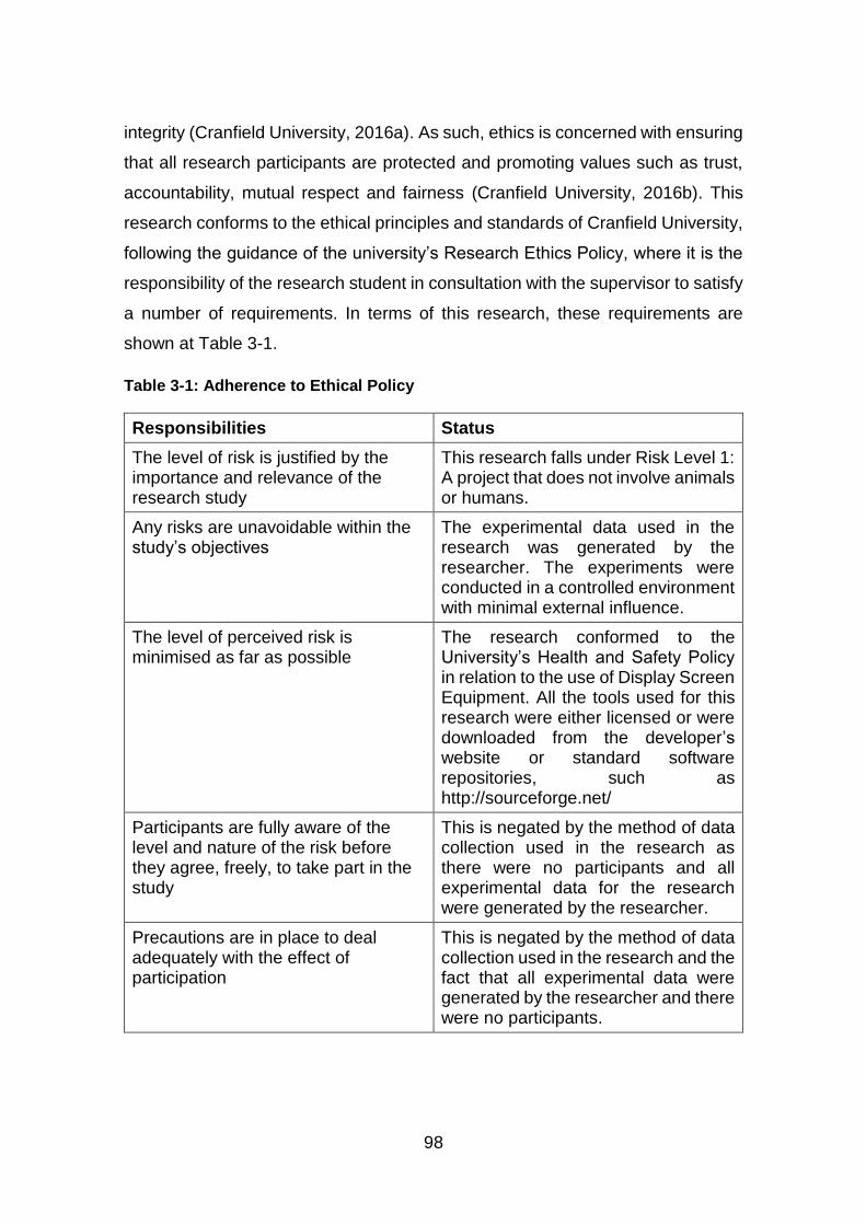
98
integrity (Cranfield University, 2016a). As such, ethics is concerned with ensuring
that all research participants are protected and promoting values such as trust,
accountability, mutual respect and fairness (Cranfield University, 2016b). This
research conforms to the ethical principles and standards of Cranfield University,
following the guidance of the university’s Research Ethics Policy, where it is the
responsibility of the research student in consultation with the supervisor to satisfy
a number of requirements. In terms of this research, these requirements are
shown at Table 3-1.
Table 3-1: Adherence to Ethical Policy
Responsibilities Status
The level of risk is justified by the importance and relevance of the research study
This research falls under Risk Level 1: A project that does not involve animals or humans.
Any risks are unavoidable within the study’s objectives
The experimental data used in the research was generated by the researcher. The experiments were conducted in a controlled environment with minimal external influence.
The level of perceived risk is minimised as far as possible
The research conformed to the University’s Health and Safety Policy in relation to the use of Display Screen Equipment. All the tools used for this research were either licensed or were downloaded from the developer’s website or standard software repositories, such as http://sourceforge.net/
Participants are fully aware of the level and nature of the risk before they agree, freely, to take part in the study
This is negated by the method of data collection used in the research as there were no participants and all experimental data for the research were generated by the researcher.
Precautions are in place to deal adequately with the effect of participation
This is negated by the method of data collection used in the research and the fact that all experimental data were generated by the researcher and there were no participants.
99
This research was approved by the Cranfield University Research Ethics System
(CURES).
3.12 Conclusion
The purpose of this chapter was to identify the objectives of this research based
on related research and the research hypothesis. It outlined the experimental
options in order to meet these objectives. The various private Cloud technologies
were reviewed before XCP, a Linux-based Cloud technology was selected. This
has requirements that are easy to meet in a laboratory environment for
experimental purposes. An overview of XCP, the Cloud technology used for this
research was presented, together with information about possible storage
options, management methods, requirements and how VMs can be created,
along with the decisions that were taken in relation to these. For storage, both
local and shared storage were selected in order to determine the differences in
terms of artefact recovery.
XenCenter was selected as the desktop management interface because the
other options are clones of it. In addition, xe for CLI was selected because it has
more commands for managing XCP than xl. VM creation with ISO was
considered to give easy access as it is saved in a storage repository in XCP. The
network impact of the research was discussed in terms of the network type. In
this instance, LAN was used as it is the basic network type supported by XCP,
with no Internet access to prevent potential changes to the system. Various tools
were reviewed to identify those that are most suited to this type of research. FTK
and EnCase were selected for the examination of both physical and virtual disk
images because they have LVM support, while Sleuthkit was selected because it
can be used to view the contents of a disk partition, both live and deleted, while
the server is powered on. WinHex and Bless were selected to view raw disk
images and for keyword searches, while extundelete was selected as the tool to
recover deleted files from ext3 filesystem, which XCP uses in filesystem-based
storage because it can recover complete contiguous files.

100
The existing requirements for evaluating digital evidence were reviewed in order
to propose a general criteria consisting of four requirements: authenticity,
accuracy, reliability and completeness. These criteria were used to evaluate the
evidential value of artefacts recovered as a result of the experiments. Also, a
general methodology for the use of existing tools in the Cloud was devised,
comprising three steps: identification of the Cloud technology, identification of the
tools that can be added and the building of a testbed to test the tools. The
constraints associated with this research were identified, including evidential
constraints in terms of artefact integrity, mitigated by the use of tools that preserve
integrity. Experimental constraints were recognised in terms of the setup, the
Cloud service type and the deployment model used. However, the setup was
considered to provide a method for artefact recovery which can be applied in a
larger set up. In terms of the service type, the research can be applied to SaaS
and PaaS as they are both based on IaaS. In terms of the deployment model, the
findings can be applied to a community Cloud as it is similar to a private Cloud,
providing a baseline for public and hybrid Clouds. In terms of the Cloud
technology, open source tools can be used in most Linux-based Clouds. Finally,
the ethical issues relating to this research were considered and the research
approach was approved.
The focus of the next chapter is the first and second of the defined research
objectives:
1. To investigate the structure of the Logical Volume Manager (LVM) and
how it stores data; and
2. To investigate the structure of XCP and how it utilizes LVM to store data.
These provide the first steps towards achieving the aim of this research, which is
to evaluate the evidential value of artefacts recovered from a private Cloud using
existing digital forensic investigation tools.
101
4 LVM and XCP Structures
4.1 Introduction
Whilst Cloud computing offers considerable benefits, its affordability and
anonymity makes it attractive for criminal use. However, the same resources that
can be leveraged for crime, such as high storage capacity, processing and
networking, can also be used to for the purposes of digital forensics, in terms of
acquiring, processing and storing evidence. The literature review undertaken for
Chapter 2 highlighted the challenges of Cloud forensics, including identifying,
acquiring and examining evidence as well as locating evidence which can span
multiple jurisdictions. However, there are methods of overcoming these
challenges and forensic tools have been developed for Infrastructure-as-a-
Service (IaaS), a Cloud service type where users can access virtualized
computing resources, such processing, networking and storage, and for
Software-as-a-Service (SaaS), where users can access applications offered by
the Cloud Service Provider (CSP). However, these were designed as general
purpose forensic tools and a key issue is that they have been designed for
specific types of Cloud and may not work with other Clouds. Therefore, there is
a need for a more generic method of digital forensics that could be used for
investigations of all Cloud technologies.
The most pragmatic approach to this would be to use existing tools, which have
already been tested and their limitations identified. For the purposes of this
research, Xen Cloud Platform (XCP) was selected as the Cloud technology to be
investigated. This was deployed as a private Cloud with an IaaS service type to
provide a basis for investigating how existing tools can be used to recover
artefacts of evidential value. XCP is Linux-based and open source and, therefore,
suitable for use with some of the existing open source tools. IaaS was selected
as the service type because it forms the basis of other Cloud service types. It also
gives the user control over Operating Systems (OS) in guest Virtual Machines
(VMs), in terms of their storage and deployed applications. Finally, a private
Cloud was selected for use because it enabled the creation of a controlled Cloud
environment.
102
The first step in the setting up of experiments for this research was the creation
of a Cloud environment to enable the structure of XCP to be studied in order to
investigate and verify how data are stored. This understanding then enabled the
identification of appropriate tools for the recovery of artefacts in XCP. This
preliminary research provided the basis for achieving the overarching aim of this
research, which was to evaluate the evidential value of artefacts recovered from
a private Cloud using existing digital forensic investigation tools. The purpose of
this chapter is, therefore, to fulfil the first and second of the Research Objectives
that drive this research, to investigate: 1) the structure of the Logical Volume
Manager (LVM) in order to examine how it stores data; and 2) to investigate the
structure of XCP in order to examine how it utilizes LVM for storage for the
reasons outlined above. Overall, the purpose of the experiments undertaken for
this research, was to provide information about how data is stored in XCP and, in
particular, how VMs are stored. The first part of the chapter focuses on the first
Research Objective, describing LVM and its structure, along with different data
acquisition methods. This is followed by a description of the structure of XCP and
how it uses LVM for storage, an examination of how XCP uses data storage
repositories, the various forms of VM that it supports and how it stores them,
along with how they can be acquired. The discussion begins with an overview of
LVM in order to determine its functions and features.
4.2 Logical Volume Manager (LVM) as a Storage Option
LVM is a device mapping technology that is available in many virtualised
environments and Linux distributions from kernel version 2.4 (Lewis, 2006). It
manages storage on hard disks, providing flexible storage management including
‘hot swapping’ of physical hard disks, that is, replacing the hard disk while the
system is running, the ‘dynamic resizing’ of filesystems, that is resizing while the
volume is mounted, and ‘thin provisioning’, allocating the minimum disk space
that is required for use. LVM manages hard disks by creating logical volumes
(Red Hat, 2007). It also offers the flexibility of being able to resize these logical
volumes, along with the merging of storage across multiple disks, and convenient
103
naming (Lewis, 2006; Red Hat, 2007). LVM is similar to Redundant Array of
Independent Disks (RAID) and dynamic disks (Carrier, 2005b).
There are two versions of LVM: LVM1 and LVM2. LVM2 is backward compatible
with LVM1, which means that it retains the original functionality of LVM1 except
in terms of ‘snapshot’, which is the state of a logical volume at a point in time, and
cluster support, which enables a group of systems working together to be viewed
as a single system (Red Hat, 2007). LVM1 supports read-only snapshots while
LVM2 snapshot is read/write (Lewis, 2006). The aim of the first set of experiments
was to investigate and verify the structure of Linux LVM, in order to aid the
investigation of the structure of XCP. This is because XCP uses LVM to manage
storage, which is discussed in the second part of this chapter. However, before
outlining the experiment, the structure of LVM and its acquisition methods are
examined in further detail at Sections 4.2.1 and 4.2.2 respectively.
4.2.1 LVM Structure
The underlying structure of the LVM is based on a physical device, which can be
either a whole disk or a partition of a disk. If a partition is used, the partition type
should be set to 0x8e; if the whole disk is used, there must be no partition table
on it (Red Hat, 2007). The absence of a partition table means that the disk or
partition can then be initialized as a block device to be used as a physical volume
(Lewis, 2006; Red Hat, 2007). When this physical volume is created, a label with
the prefix “LABELONE” is placed near the start of the disk in order to identify the
volume as lvm2. This label also contains the Universally Unique Identifier (UUID)
of the physical volume and the size of the block device in bytes (Carrier, 2005b).
By default, the label is placed in the second sector and, while this can be
changed, it must be placed within the first four sectors because the LVM tools
only check the first four sectors for the physical volume label (Red Hat, 2007).
The next stage is to combine the physical volumes into one or more volume
groups, in order to create a pool of disk space. A volume group collates all the
logical volumes and physical volumes of that volume group into one
administrative unit (Lewis, 2006). When such a volume group is created, the
metadata is added to the physical disk and stored in ASCII. This metadata

104
contains the name of the volume group, its unique identifier, version number, the
extent size, permissions or properties, and information on the physical volume(s)
that make up the volume group (Red Hat, 2007). It also retains the creation date
and time, along with information about the creation host. Also, a subdirectory is
created for the volume group in the /dev/ directory (Carrier, 2005b)
The volume group is divided into logical volumes and allocated disk space. The
logical volumes are similar to a disk partition in a non-LVM system (Lewis, 2006).
The aggregate of the logical volume(s) cannot exceed the size of the volume
group. Logical volumes can be linear, where they are mapped to physical
volumes sequentially; striped, where data in the logical volume is stored on the
physical volume in a predetermined round order; or mirrored, where stored data
is replicated exactly in another physical volume (Red Hat, 2007). For the
purposes this research, linear volumes were used, as they are the type of logical
volumes used in XCP, a point that was discovered during the initial experiments.
When a logical volume is created, its metadata is also added to the disk, including
the name of the logical volume, date and time of creation, extent count, logical
volume type, along with information on other logical volumes in the same volume
group. Also included are the metadata of the volume group to which it belongs
and the physical volumes that make up the volume group and, finally, information
on the creation host. The layout of LVM on a disk is shown at Figure 4-1

105
Figure 4-1: LVM Disk Layout
A copy of the metadata is stored in a file located in the /etc/lvm/backup directory,
which is updated every time the volume group or logical volume configuration
changes. The old metadata files are archived in the /etc/lvm/archive directory,
unless archiving is disabled in the lvm.conf file in /etc/lvm directory (Red Hat,
2007). Metadata files are useful to forensic investigations as they can be used to
reconstruct LVM volumes, to create a timeline of activities and to restore logical
volumes. Given this, they were used in these experiments to restore logical
volumes, as detailed in Chapter 5.
Figure 4-2 shows a generic setup of LVM. It has two physical disks, one with two
partitions and one with a single partition. Each disk partition was assigned a
physical volume, identified as pv1, pv2 and pv3. These were divided into two
volume groups, vg1 and vg2, and then multiple logical volumes were created in
each volume group. In vg1, the logical volumes are lv1 and lv2, while in vg2 they
are lv3, lv4 and lv5. Each volume group is a separate administrative unit and,
therefore, any changes made to one volume group or to a logical volume within
that volume group will not affect the other volume group.
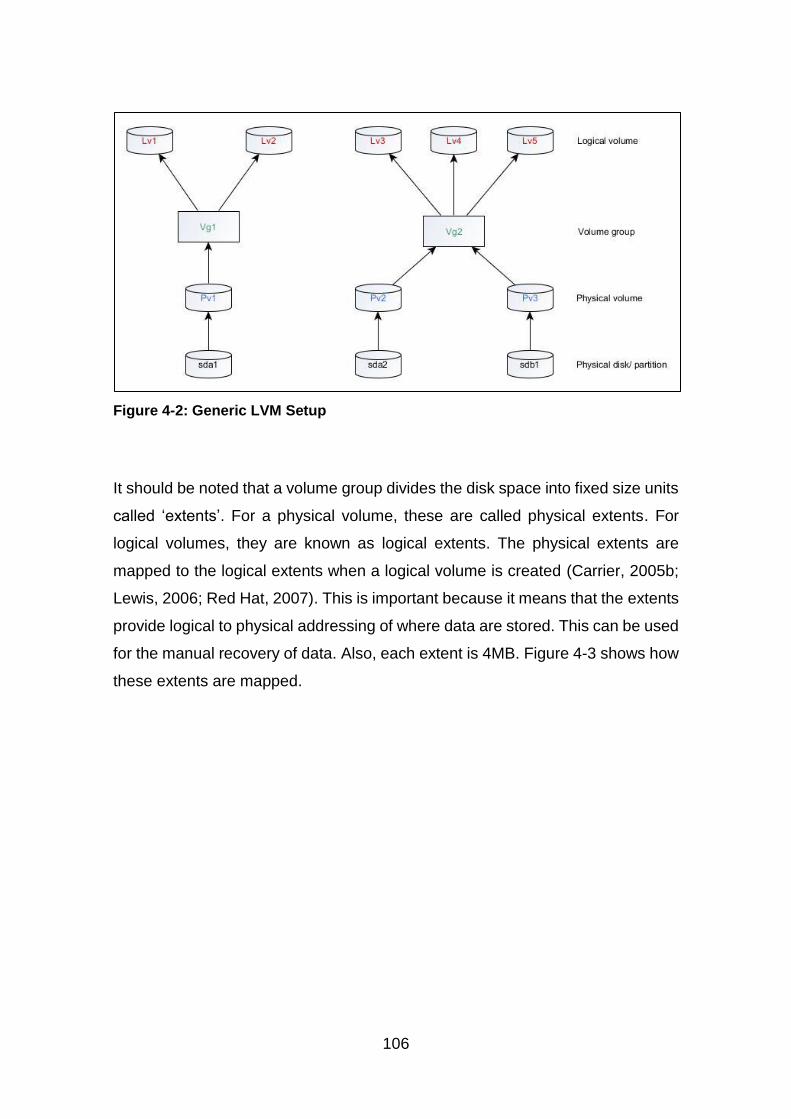
106
Figure 4-2: Generic LVM Setup
It should be noted that a volume group divides the disk space into fixed size units
called ‘extents’. For a physical volume, these are called physical extents. For
logical volumes, they are known as logical extents. The physical extents are
mapped to the logical extents when a logical volume is created (Carrier, 2005b;
Lewis, 2006; Red Hat, 2007). This is important because it means that the extents
provide logical to physical addressing of where data are stored. This can be used
for the manual recovery of data. Also, each extent is 4MB. Figure 4-3 shows how
these extents are mapped.
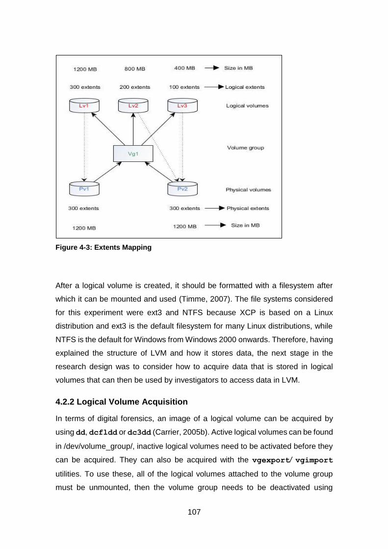
107
Figure 4-3: Extents Mapping
After a logical volume is created, it should be formatted with a filesystem after
which it can be mounted and used (Timme, 2007). The file systems considered
for this experiment were ext3 and NTFS because XCP is based on a Linux
distribution and ext3 is the default filesystem for many Linux distributions, while
NTFS is the default for Windows from Windows 2000 onwards. Therefore, having
explained the structure of LVM and how it stores data, the next stage in the
research design was to consider how to acquire data that is stored in logical
volumes that can then be used by investigators to access data in LVM.
4.2.2 Logical Volume Acquisition
In terms of digital forensics, an image of a logical volume can be acquired by
using dd, dcfldd or dc3dd (Carrier, 2005b). Active logical volumes can be found
in /dev/volume_group/, inactive logical volumes need to be activated before they
can be acquired. They can also be acquired with the vgexport/ vgimport
utilities. To use these, all of the logical volumes attached to the volume group
must be unmounted, then the volume group needs to be deactivated using
108
vgchange, which prevents there being any further changes to it. Next,
vgexport can be used to prevent the volume group from being accessed on the
host system and power off host system (Lewis, 2006; Red Hat, 2007). The disk
can then be removed and attached to an analysis machine. The command
pvscan needs to be used to view the physical volumes connected to the
machine. The next step is to import and activate the disk on the analysis machine.
Then dd or its variants can be used to make the image of the logical volumes
(Carrier, 2005b). Other variants of dd, dcfldd or dc3dd can also be used if they
are available on the analysis machine.
Carrier (2005b) suggests that vgimport/vgexport are not needed for
acquiring a disk. In his view, in order to create an image of a logical volume, the
disk can simply be removed and attached to a Linux analysis machine with
automount disabled. Alternatively, the suspect system can be booted with a live
Linux CD that supports LVM. For both approaches, the disk can be scanned for
volume groups, activating the volume group and imaging the logical volume of
interest using dd or its variants. The image can then be analysed with a forensic
tool. More recently, this approach has been supported by Altheide and Carvey
(2011).
If an examiner only has access to the disk image, an alternative method of
acquiring logical volumes is to use a Linux machine with LVM2 installed and to
map the disk image to a loopback device as read-only (“Linux Logical Volume
Manager (LVM),” n.d.). The first stage in this process is to view the partitions in
the image to identify the LVM partition with the partition type 0x8e (Carrier,
2005b). Then the partition should be mapped to a loopback device by using the
start offset of the partition in bytes. After mapping the partition to a loopback,
pvscan, vgscan and lvscan can be used to scan for physical volumes, volume
groups and logical volumes respectively. The logical volumes can be imaged
using dd or its variants. After imaging, the partition can be unmapped by first
deactivating the volume group then deleting the loopback device. The acquired
image can then be analysed. In addition to this, some forensic tools that have
LVM support can be used to both acquire logical volumes from a disk image and
109
to analyse them. Therefore, there are various ways to acquire logical volumes
and the selected method is dependent on what the investigator has access to
and whether that is a physical machine or a disk image.
As stated in Chapter 3, Section 3.4.1, XCP uses both filesystem-based and LVM-
based storage repository. The latter saves individual VMs as logical volumes,
thus there is a need to identify methods of acquiring logical volumes for analysis.
Therefore, having discussed the structure of LVM, how it stores data and the
different data acquisition methods that can be used in LVM, the discussion now
turns to the design and conduct of a set of experiments to verify the structure of
LVM for the purposes of this research.
4.2.3 Analysis
This section describes the set of experiments that was set up to verify the existing
literature on LVM structure and to document the structure of LVM. The results are
presented as each stage of the experiments is reported. The system that was set
up for this set of experiments was composed of Ubuntu 14.04 LTS, 150 GB HDD
and 16GB RAM, and an 80GB wiped hard disk. Gparted, a partition editor, was
then installed using the Ubuntu Software Centre. The zeroed 80GB hard disk was
viewed with GParted in order to identify all of the disks attached to the system.
Using the terminal, the lvm2 package was installed and the Command Line
Interface (CLI) was used to create and manage the LVMs. One Linux LVM
partition was created using fdisk 2.20.1, while hexdump was used to display
the contents of the disk. This revealed that only what appears to be the partition
table was on the disk, as shown at Appendix C.
A physical volume /dev/sdb1 was created on the partition with the following
command:
pvcreate /dev/sdb1
This is shown at Figure 4-4

110
Figure 4-4: Creation of Physical Volume
The pvscan command was then used to scan the whole system for any physical
volumes. The one that was found was /dev/sdb1. Next, the pvdisplay
command was used to display the metadata on any physical volume on the
system, as shown above at Figure 4-4. The metadata included the physical
volume name, size and UUID. Hexdump was used to view the contents of the
disk and a label ‘LABELONE’ was placed on the disk, along with the LVM version
and the UUID of the physical volume. This is shown at Appendix C.
The next LVM component, which is the volume group was created on the physical
volume /dev/sdb1 and named ‘xen_cloud’ using the following command:
vgcreate xen_cloud /dev/sdb1
This is shown at Figure 4-5.

111
Figure 4-5: Volume Group Creation
The vgscan command was used to scan all of the physical disks for any volume
group and, again, only one was found, which was ‘xen_cloud’. Then the
vgdisplay command was used to display the metadata on any volume group
on the system, including its size. The results were as expected, as shown at
Figure 4-5. Here also, hexdump was used to view the content of the disk, showing
the metadata of the volume group, as shown at Appendix C. The /dev/ directory
was viewed and a subdirectory for the volume group was listed, as shown at
Figure 4-6.
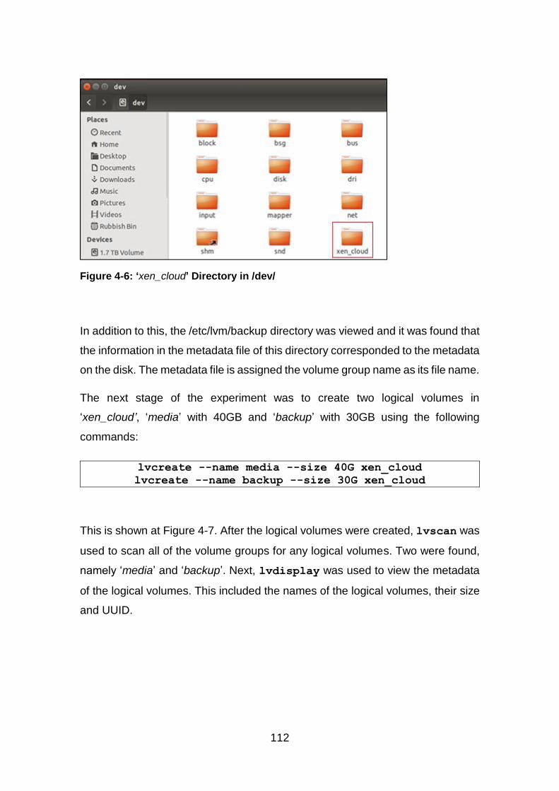
112
Figure 4-6: ‘xen_cloud’ Directory in /dev/
In addition to this, the /etc/lvm/backup directory was viewed and it was found that
the information in the metadata file of this directory corresponded to the metadata
on the disk. The metadata file is assigned the volume group name as its file name.
The next stage of the experiment was to create two logical volumes in
‘xen_cloud’, ‘media’ with 40GB and ‘backup’ with 30GB using the following
commands:
lvcreate --name media --size 40G xen_cloud
lvcreate --name backup --size 30G xen_cloud
This is shown at Figure 4-7. After the logical volumes were created, lvscan was
used to scan all of the volume groups for any logical volumes. Two were found,
namely ‘media’ and ‘backup’. Next, lvdisplay was used to view the metadata
of the logical volumes. This included the names of the logical volumes, their size
and UUID.
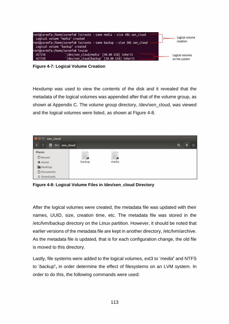
113
Figure 4-7: Logical Volume Creation
Hexdump was used to view the contents of the disk and it revealed that the
metadata of the logical volumes was appended after that of the volume group, as
shown at Appendix C. The volume group directory, /dev/xen_cloud, was viewed
and the logical volumes were listed, as shown at Figure 4-8.
Figure 4-8: Logical Volume Files in /dev/xen_cloud Directory
After the logical volumes were created, the metadata file was updated with their
names, UUID, size, creation time, etc. The metadata file was stored in the
/etc/lvm/backup directory on the Linux partition. However, it should be noted that
earlier versions of the metadata file are kept in another directory, /etc/lvm/archive.
As the metadata file is updated, that is for each configuration change, the old file
is moved to this directory.
Lastly, file systems were added to the logical volumes, ext3 to ‘media’ and NTFS
to ‘backup’, in order determine the effect of filesystems on an LVM system. In
order to do this, the following commands were used:
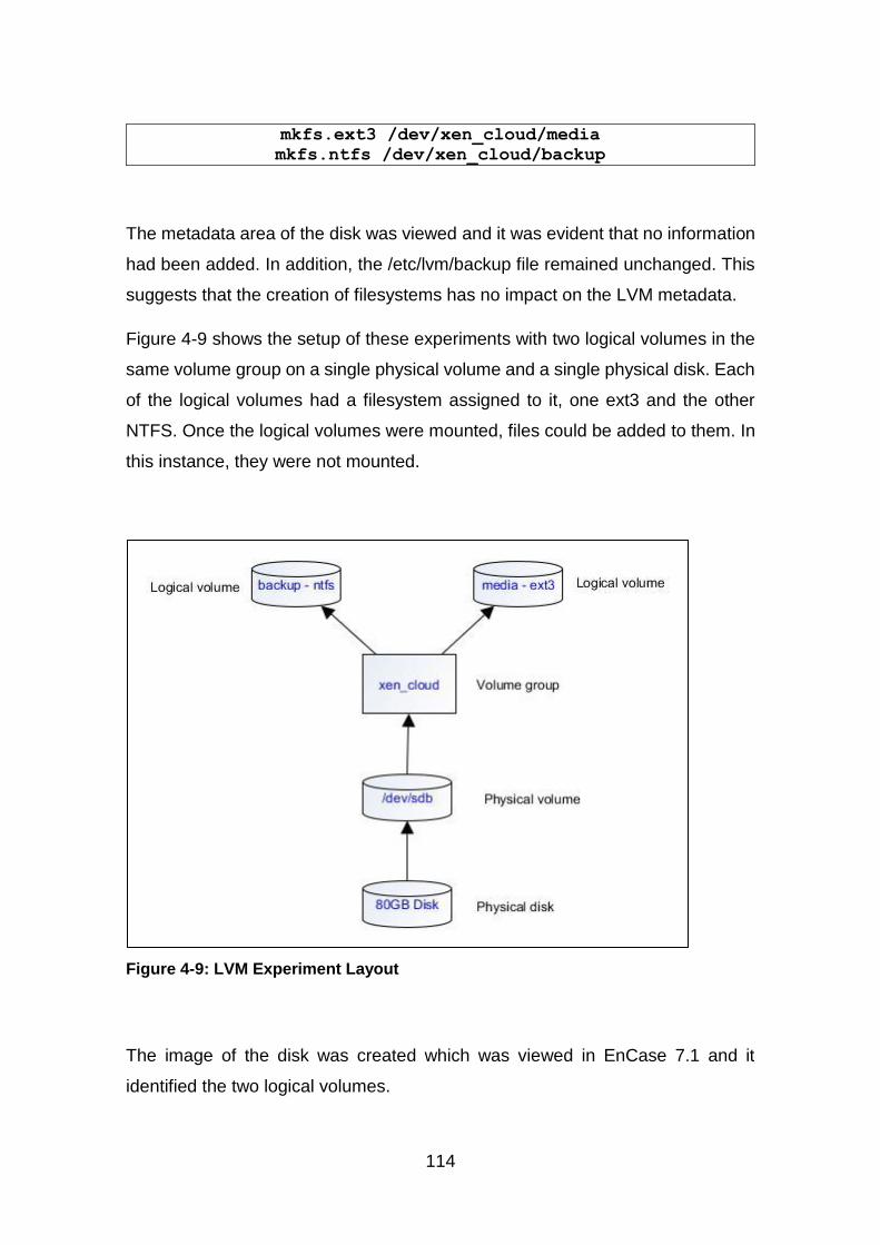
114
mkfs.ext3 /dev/xen_cloud/media
mkfs.ntfs /dev/xen_cloud/backup
The metadata area of the disk was viewed and it was evident that no information
had been added. In addition, the /etc/lvm/backup file remained unchanged. This
suggests that the creation of filesystems has no impact on the LVM metadata.
Figure 4-9 shows the setup of these experiments with two logical volumes in the
same volume group on a single physical volume and a single physical disk. Each
of the logical volumes had a filesystem assigned to it, one ext3 and the other
NTFS. Once the logical volumes were mounted, files could be added to them. In
this instance, they were not mounted.
Figure 4-9: LVM Experiment Layout
The image of the disk was created which was viewed in EnCase 7.1 and it
identified the two logical volumes.
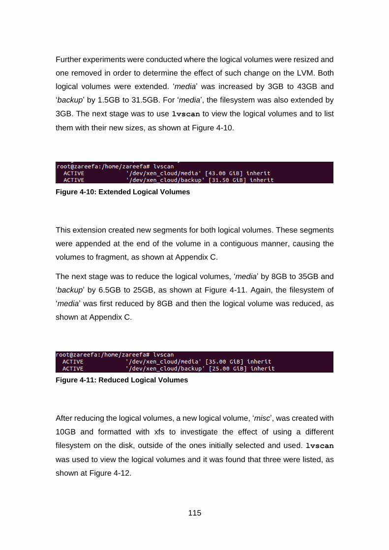
115
Further experiments were conducted where the logical volumes were resized and
one removed in order to determine the effect of such change on the LVM. Both
logical volumes were extended. ‘media’ was increased by 3GB to 43GB and
‘backup’ by 1.5GB to 31.5GB. For ‘media’, the filesystem was also extended by
3GB. The next stage was to use lvscan to view the logical volumes and to list
them with their new sizes, as shown at Figure 4-10.
Figure 4-10: Extended Logical Volumes
This extension created new segments for both logical volumes. These segments
were appended at the end of the volume in a contiguous manner, causing the
volumes to fragment, as shown at Appendix C.
The next stage was to reduce the logical volumes, ‘media’ by 8GB to 35GB and
‘backup’ by 6.5GB to 25GB, as shown at Figure 4-11. Again, the filesystem of
‘media’ was first reduced by 8GB and then the logical volume was reduced, as
shown at Appendix C.
Figure 4-11: Reduced Logical Volumes
After reducing the logical volumes, a new logical volume, ‘misc’, was created with
10GB and formatted with xfs to investigate the effect of using a different
filesystem on the disk, outside of the ones initially selected and used. lvscan
was used to view the logical volumes and it was found that three were listed, as
shown at Figure 4-12.

116
Figure 4-12: List of Logical Volumes including the New One
When the new logical volume was created, a file for it was added to
/dev/xen_cloud. Finally, the logical volume ‘media’ was removed, as shown at
Figure 4-13.
Figure 4-13: Logical Volume Removal
After the logical volume ‘media’ was removed, lvscan was used to view the
logical volumes and it was found that only two were listed, ‘backup’ and ‘misc’.
This is shown at Figure 4-14. The space previously occupied by ‘media’ became
unallocated.
Figure 4-14: List of Logical Volumes after ‘media’ was Removed
In addition to this, its file in the /dev/xen_cloud directory was removed. It should
be noted that inactive logical volumes are not listed in the /dev/ volume group
subdirectory, although they are listed as inactive volumes when lvscan is used.
As each modification was made, the metadata on the disk and in the /etc/lvm
directory were viewed and it was found that they were updated with the new
configuration. New metadata was appended to the disk when these changes took
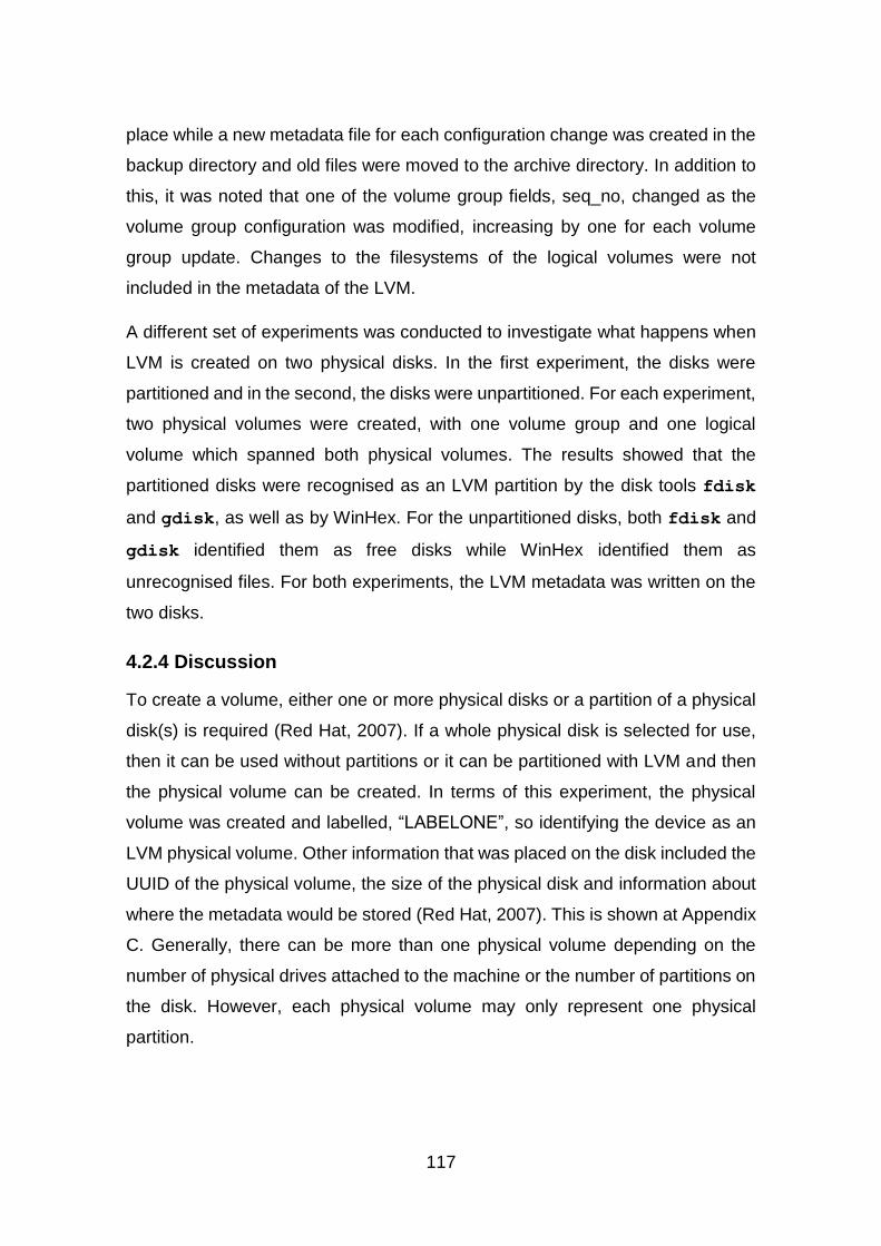
117
place while a new metadata file for each configuration change was created in the
backup directory and old files were moved to the archive directory. In addition to
this, it was noted that one of the volume group fields, seq_no, changed as the
volume group configuration was modified, increasing by one for each volume
group update. Changes to the filesystems of the logical volumes were not
included in the metadata of the LVM.
A different set of experiments was conducted to investigate what happens when
LVM is created on two physical disks. In the first experiment, the disks were
partitioned and in the second, the disks were unpartitioned. For each experiment,
two physical volumes were created, with one volume group and one logical
volume which spanned both physical volumes. The results showed that the
partitioned disks were recognised as an LVM partition by the disk tools fdisk
and gdisk, as well as by WinHex. For the unpartitioned disks, both fdisk and
gdisk identified them as free disks while WinHex identified them as
unrecognised files. For both experiments, the LVM metadata was written on the
two disks.
4.2.4 Discussion
To create a volume, either one or more physical disks or a partition of a physical
disk(s) is required (Red Hat, 2007). If a whole physical disk is selected for use,
then it can be used without partitions or it can be partitioned with LVM and then
the physical volume can be created. In terms of this experiment, the physical
volume was created and labelled, “LABELONE”, so identifying the device as an
LVM physical volume. Other information that was placed on the disk included the
UUID of the physical volume, the size of the physical disk and information about
where the metadata would be stored (Red Hat, 2007). This is shown at Appendix
C. Generally, there can be more than one physical volume depending on the
number of physical drives attached to the machine or the number of partitions on
the disk. However, each physical volume may only represent one physical
partition.

118
Having set up the physical volume for this experiment, a volume group was
created which resulted in more information being appended to the disk. This is
shown in full at Appendix C and includes the name of the volume group, the date
and time created, the status and extent size. Also, a subdirectory in the /dev/
directory was created for the volume group, as mentioned by Carrier (2005b).
This means that it is possible to find evidence of LVM usage on the system
outside of the /etc/lvm directory.
The next stage in the experiment was to create the logical volumes. The type of
logical volumes created for these purposes was linear and more information was
added to the disk when they were created, including the names of the logical
volumes, the type of logical volume, the date and time of creation and the name
of the volume group. These are also shown at Appendix C. A file for each logical
volume was also created in the /dev/xen_cloud directory on the device. This also
means that it is possible to find evidence of logical volumes that existed on the
system outside of the /etc/lvm directory
When the volume group and logical volumes were created, a new metadata file
was also created in the /etc/lvm/backup directory. This file contained the most up
to date configuration of the LVM. Old metadata files were moved to the
/etc/lvm/archive directory. By default, the minimum number of archive files is 10
and these are retained for a minimum of 30 days, as specified in the lvm.conf file
in /etc/lvm. This minimum retention time was not investigated. An LVM command,
lvmdump, can be used to save this information in a directory specified by the
user.
lvmdump -d <directory path>
The structure of the LVM on the disk that resulted from this experiment is shown
at Table 4-1, along with details about where each item of metadata information
was stored, the size of the file, as well as the filesystems and their sizes.

119
Table 4-1: Layout of LVM on the Disk
Field No. of sectors and size
Start sectors 0 – 2047: 1MB
LVM label including physical volume UUID 2048 -2056 = 4.5KB
Volume group ‘xen_cloud’ metadata 2057 – 2058 = 1KB
Logical volume ‘media’ metadata 2059 – 2061 = 1.5KB
Logical volume ‘backup’ metadata 2062 – 2064 = 1.5KB
Partition gap 2065 – 4095 = 1MB
Logical volume ‘media’ with ext3 filesystem 4096 – 83890175 = 40GB
Logical volume ‘backup’ with NTFS filesystem
83890176 – 146804735 = 30GB
Unallocated space 146804736 – 156301487 = 4.5GB
The next stage of the experiment was to add filesystems to the two logical
volumes, ext3 and NTFS. After the filesystems were added, there was no change
in the LVM metadata, either on the disk or in the files. However, filesystem
information was added to the disk, as shown at Table 4-1.
Forensic tools like EnCase and FTK, which have LVM support, can be used to
view an LVM disk image. However, this is dependent on the version being used,
as some do not have LVM support. In this instance, EnCase 7.1 was used and it
identified the two logical volumes, as shown at Figure 4-15. As stated in Section
4.2.2, some forensic tools with LVM support can be used to acquire and analyse
logical volumes. Therefore, the logical volume can be acquired with EnCase.
However, for the purposes this experiment, the logical volumes were not
acquired.
120
Figure 4-15: Logical Volume View in EnCase
A whole disk without any partition can be used for LVM but ideally, it needs to be
empty (Lewis, 2006). It can then be initialized through the creation of a physical
volume. Once this is done, nothing is written to it except the LVM label, which
appears on the second sector of the disk. If this option is used, some disk tools
may not recognise the LVM, showing it as unallocated but LVM tools can correctly
interpret the disk (Lewis, 2006). Where a partitioned disk is used, the LVM label
is also placed on the second sector of the LVM partition. However, there may be
data in the preceding sectors before the LVM partition, such as a partition table
on the disk. This depends on the tool used to create the partition. However, disk
tools, such as fdisk and gdisk, will recognise the LVM partition.
For the first set of experiments, an LVM partition was created using fdisk. It
started from sector 2048 which is the default start sector of the first partition from
fdisk 2.18 (Smith, 2014). In addition, when creating the LVM partition on a disk,
there is no requirement to use the whole disk. A partition size can be specified
for the LVM, which means that the remaining disk space can be used for other
purposes. Also if there is more than one physical volume in the volume group,
the logical volumes can span all of them as shown by the experiments. For
example, if there are three 40GB disks, three physical volumes can be created
and assigned to one volume group. With this volume group, one logical volume
of 120GB can be created or, alternatively, multiple logical volumes, provided that
their aggregated size does not exceed 120GB.
For the first set of experiments, only one physical disk of 80GB was used, with
an LVM partition. One physical volume was created on the partition, and the size

121
of two logical volumes was 70GB, which obviously is less than the available
80GB. For the last set of experiments, one logical volume that spanned the two
physical volumes was created. Also when WinHex, fdisk and gdisk were used
to view the LVM disks which had no partition, none of them recognised the disks
as LVM.
Large logical volumes of sizes up to 8EB can be created, although this depends
on the Linux kernel version and the CPU architecture of the host system (Lewis,
2006). For 2.4 based kernels, the maximum size of a single logical volume is 2TB,
for 32-bit systems on 2.6 kernels, the maximum is 16TB (Lewis, 2006). For a 64-
bit system of the same kernel, it is 8EB. Therefore, it is possible find a large logical
volume in an LVM that spans multiple disks.
As with physical partitions, logical volumes can be extended, reduced, renamed
or removed. When a logical volume is extended or reduced, the associated
filesystem may also need to be extended or reduced depending on the nature of
the filesystem. The command to extend a logical volume is lvextend (Lewis,
2006; Matthews et al., 2008; Red Hat, 2007; Timme, 2007). If the filesystem is
also required, then it needs to be extended to match the new size of the logical
volume. Again, how this is done depends on the filesystem. Some filesystem
resizing tools will increase the filesystem size to the size of the logical volume by
default (Lewis, 2006; Red Hat, 2007). In terms of the experiments that were
conducted for this research, the two logical volumes were extended in order to
document the changes that occurred as a result of this process.
For ‘media’, which was formatted with ext3, the logical volume was extended first
and then the filesystem was resized to the new size of the logical volume with the
resize2fs command. For the logical volume ‘backup’ formatted with NTFS,
only the logical volume was extended and NTFS was not resized. The extension
caused the logical volumes to fragment, with the added sizes allocated disk space
after the ‘backup’. The logical volume ‘media’ extension was added first, followed
by the ‘backup’ extension. This means that data added to these logical volumes
may be spread across the fragments. The space allocated for these extensions
122
was added in the metadata, both in the files and on the disk. The disk layout after
these changes were made is shown at Appendix C.
To reduce a logical volume, it should be unmounted and the filesystem should be
resized if required. However, the filesystem should be reduced before the logical
volume is reduced in order to avoid corrupting it and making it unusable. The two
logical volumes created for this experiment were also reduced in order to enable
the changes to be documented. For the logical volume ‘media’, the filesystem
was reduced first followed by the logical volume. For the logical volume ‘backup’,
only the logical volume was reduced. When the logical volumes were reduced,
more disk space became unallocated. This shows that there is a possibility of
finding data belonging to reduced logical volumes in the freed space as deleted
data in both NTFS and ext3 remain on disk until they are overwritten. The new
sizes and space occupied by the logical volumes were added to both metadata
in the files and on the disk. The disk layout after these changes were made is
also shown at Appendix C.
Logical volumes can be renamed using lvrename and removed using
lvremove (Lewis, 2006; Red Hat, 2007; Timme, 2007). To remove a mounted
logical volume, it should be unmounted first, and then deactivated with lvchange
-an, although this latter operation is optional (Red Hat, 2007; Timme, 2007). For
the purpose of these experiments, the logical volume ‘media’ was removed by
deactivating it and removing it using the command, lvremove. All the activities
on the logical volumes were recorded both in the metadata files and in the
metadata area of the disk in a contiguous manner with each metadata starting at
a new sector on the disk, as shown at Appendix C.
In terms of volume groups, they can be extended or reduced by adding or
removing physical volume. They can also be renamed, removed, split and
merged. As with logical volumes, the commands to carry out these actions are
respectively vgextend, vgreduce, vgrename, vgremove, vgsplit,
vgmerge (Lewis, 2006; Red Hat, 2007; Timme, 2007; Valle, 2010). Physical
volumes can also be removed or resized using the commands pvremove and
pvresize (Red Hat, 2007; Valle, 2010). If the physical volume is part of any

123
volume group, it must be removed from the volume group before it can be
removed in its entirety.
If required, any data on a physical volume can be moved to another physical
volume using the command, pvmove. It should be noted that any action taken in
relation to either the volume group or logical volumes that changes their
configuration appends the metadata on the disk and creates a new metadata file,
while the old metadata file is moved to the archive directory. However, actions
undertaken on the filesystem neither append the metadata nor create its file. This
means that any filesystem-related information may only be found in the logical
volumes and on the disk.
The volume group metadata can be restored using the command
vgcfgrestore (Valle, 2010). This uses the metadata files themselves to restore
the metadata and will be further discussed in Chapter 5. However, to restore
specific metadata, the -f option can be used, otherwise the most recent
metadata file is used. The vgcfgrestore command can be used to restore
deleted logical volumes using the archive metadata file created before the
deletion command is executed. This will also be discussed in Chapter 5.
The results of these sets of experiments verified the structure of LVM, where the
structure started with a physical device, and a physical volume, volume group
and logical volumes were created. However, they are not without their limitations.
The experiments only addressed the operation of a simple LVM structure.
Secondly, as stated in Section 4.2.1, there are three types of logical volumes,
linear, striped and mirrored, and only linear volumes were considered because
XCP uses linear volumes. These two limitations may mean that the results of this
research can only be applied to LVM with a simple structure, which is being used
with one or two physical disks. This highlights the fact that LVM with other types
of logical volumes could be investigated for future work.
The sets of experiments presented in the previous section were conducted on a
test data set, that is data constructed specifically for testing a tool or its function
or demonstrating a forensic issue (Garfinkel et al., 2009). These test data were
124
shown to satisfy the properties of evaluation of research in digital forensics
identified by Mocas (2004). These are integrity, authentication, reproducibility,
non-interference and minimisation. The test data used in these experiments can
be duplicated without changing it (integrity) as the processes followed were
outlined. The data continues to represent what it should represent
(authentication), the processes followed did not alter the data from what is
expected. The process used to create the test data is reproducible
(reproducibility), all of the experiments were outlined in a way that they can easily
be duplicated with the same results. The tools used to analyse the data did not
change it (non-interference), the results of the analyses showed that the tools did
not change the data. Finally, minimum amount of data was used to verify the
structure of LVM (minimisation), the experiments investigated a simple/basic
structure of LVM and how linear logical volumes can be modified. While there is
little research on LVM, Carrier (2005b) described the acquisition of LVM logical
volumes, which was supported by (Altheide and Carvey, 2011). These were
discussed in Section 4.2.2 along with other methods of acquisition. In terms of
analysis, the method and results may be dependent on the filesystem of logical
volumes.
4.2.5 LVM Summary
The above experiments showed that when an LVM was created, metadata was
written to the disk for each of its components. These metadata were consistent
with the most recent metadata file saved in the /etc/lvm/backup directory and the
old metadata files saved in the /etc/lvm/archive directory. As the LVM
configuration is modified, a field of the metadata (seq_no) increases by one, for
both the metadata on the disk and in the files. The metadata file can be generated
using the lvmdump command and the user can specify the directory to save the
file. Files are written to the disk in a contiguous form but this can change as the
LVM configuration is modified, which can cause files to fragment. New metadata
are appended on the disk as modifications take place and each starts at a new
sector. Whilst filesystem information was not reflected in the metadata, it could
be found on the logical volumes and on the disk itself. On the host system, LVM
125
created a directory for the volume group in the /dev/ directory and this was where
the active logical volume files were stored.
These experiments met the first objective of this research, which was to
investigate the structure of the LVM and how it stores data. It showed that
physical volumes, volume groups and logical volumes can be managed using a
variety of LVM commands. The filesystems on logical volumes may need to be
changed to reflect the changes made in the logical volumes, but this depends on
the filesystem. There are various logical volume acquisition methods available
and this gives the investigator the flexibility to choose the one best suited to his
or her needs depending on whether the investigator has access to the LVM disk
or to an image of the disk. The next section focuses on the second objective of
this research, which is to investigate the structure of XCP in relation to how it
utilizes LVM to store data.
4.3 Xen Cloud Platform
XCP is a free and open source Cloud solution, which can be provisioned as a
private Cloud in order to provide IaaS to individuals and organisations. It can be
deployed with local storage, with shared Network File System (NFS) storage or
with shared Internet Small Computer System Interface (iSCSI) storage (Xen.org,
2009a). There are two options for XCP with local storage, local LVM or local ext.
By default, local LVM is used when XCP is installed (Xen.org, 2009b), but this
can be changed to local ext by selecting the ‘thin provisioning’ option during the
installation. XCP can be managed with desktop or web user interfaces or via the
CLI using ‘xe’ commands, as discussed in Chapter 3, Section 3.5.2 (Xen.org,
n.d.). The syntax for the ’xe’ command is shown below (XenServer, n.d.).
xe <command-name> <argument=value>
In some of the desktop management interfaces, like XenCenter, the CLI of the
server can be accessed. This is useful as there are more management options
via the CLI than on the graphical management interface. XCP utilizes LVM to
126
manage storage for the Cloud, as discussed above at Section 4.1. When XCP is
installed, it creates a local Storage Repository (SR) where VM Virtual Disk
Images (VDIs) are stored. The local SR could either be LVM or ext3. Ext3 was
discussed in Chapter 2, Section 2.6, noting that deleted data in ext3 remains on
the disk until is overwritten. This is important, given that this research is focused
on the recovery of artefacts from XCP.
The aim of this second set of experiments was twofold. Firstly, investigation of
the structure of XCP was required in order to determine how it uses LVM to store
data, and to aid the conduct of a forensic examination of an XCP system.
Secondly, it provided insight into which tools are suitable for artefact recovery
and how to add these existing tools to XCP in order to recover artefacts. This
latter point is the third objective of this research and the subject of the next
chapter.
4.3.1 XCP Storage
XCP uses SRs to store VDI (Xen.org, 2009b). VDIs are the virtual disks of VMs,
which is where data is stored. VDIs are mapped to VMs with the help of Virtual
Block Devices (VBDs), which provide an interface for plugging a VDI into a VM
(Xen.org, 2009b). Another form of storage object is the Physical Block Device
(PBD). This is similar to the VBD in that it provides an interface between an SR
and a physical server. In other words, it serves as a connector that maps an SR
to an XCP server (Xen.org, 2009b). Figure 4-16 shows an overview of the storage
objects in XCP. The PDB connects the XCP server to an SR, which stores VDIs
that, in turn, are mapped to their corresponding VMs by VBDs.
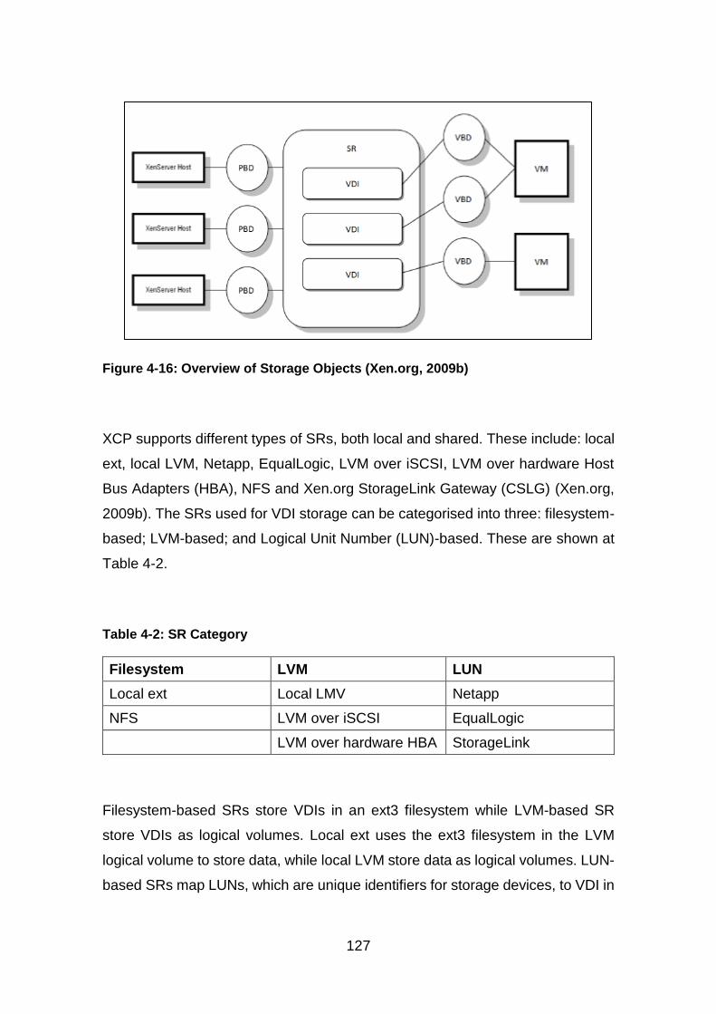
127
Figure 4-16: Overview of Storage Objects (Xen.org, 2009b)
XCP supports different types of SRs, both local and shared. These include: local
ext, local LVM, Netapp, EqualLogic, LVM over iSCSI, LVM over hardware Host
Bus Adapters (HBA), NFS and Xen.org StorageLink Gateway (CSLG) (Xen.org,
2009b). The SRs used for VDI storage can be categorised into three: filesystem-
based; LVM-based; and Logical Unit Number (LUN)-based. These are shown at
Table 4-2.
Table 4-2: SR Category
Filesystem LVM LUN
Local ext Local LMV Netapp
NFS LVM over iSCSI EqualLogic
LVM over hardware HBA StorageLink
Filesystem-based SRs store VDIs in an ext3 filesystem while LVM-based SR
store VDIs as logical volumes. Local ext uses the ext3 filesystem in the LVM
logical volume to store data, while local LVM store data as logical volumes. LUN-
based SRs map LUNs, which are unique identifiers for storage devices, to VDI in

128
a storage array, which consists of a collection of hard disks (Xen.org, 2009b).
However, investigation into LUN-based SRs is beyond the scope of this research.
The focus here is on the SRs that correspond to the XCP deployment models
used. For the deployment model based on XCP with local storage that was used
for these experiments, both local ext and LVM were used. For XCP with shared
NFS, NFS SR was used and for XCP with shared iSCSI, iSCSI over LVM SR was
used.
Other types of SRs that are supported by XCP are ISO and udev but these are
not used for VDI storage (Xen.org, 2009b). ISO stores CD images in ISO format
while udev is for removable storage, CD/DVD and USB. For the purposes of this
research, only VDI SRs were examined. Therefore, the next section discusses
the different types of VDI formats that XCP supports
4.3.2 XCP Virtual Disk Formats
XCP uses the VHD format either in LVM-based or filesystem-based SR in order
to store VDIs (Xen.org, 2009b). There are three different types of VHD: fixed,
dynamic and differencing (Microsoft, 2006). Fixed VHD is allocated the full size
that is specified by the user, which includes the data area and the footer. Dynamic
VHD starts with a minimum required size that includes the header and footer
information and increases as further data is added to it. The differencing disk
represents changes made to a VHD in comparison to its parent image. It can only
be used with a parent VHD, which can be fixed, dynamic or, alternatively, another
differencing VHD (Microsoft, 2006). Dynamic VHD is, therefore, as large as the
current data stored on it, including the file header and footer size. It grows as
more data is written to it to a limit of 2,040GB. The footer is repeated in the header
of the file for redundancy and, when a data block is added, the footer moves to
the end of the file (Barrett and Kipper, 2010).
By default, XCP default uses dynamic VHD for both filesystem-based SRs and
LVM-based SRs (Xen.org, 2009b). When a Windows VM is created in XCP with
local ext SR, dynamic VHD is used for the VDI. This is saved as a single file in
the logical volume of the XCP. Also, when a Windows VM is created in XCP with
local LVM, dynamic VHD is used but it is saved as a logical volume. Other virtual

129
disk formats supported by XCP include Open Virtualization Format (OVF) and
Open Virtual Appliance (OVA) packages. The OVF is a VM metadata file which
is not limited to one VM (Barrett and Kipper, 2010; Citrix Systems, 2012). The
OVA package comprises the OVF and virtual disk in tape archive format (Barrett
and Kipper, 2010; Citrix Systems, 2012).
VMs can be exported from XenCenter to a host system either in an OVF/OVA
package or as a Xen Virtual Appliance (XVA). XVA format is specific to Xen-
based hypervisors. The OVF/OVA package can be used when one or more VMs
need to be exported while XVA is for single VM (Citrix Systems, 2012). VMs can
also be imported in different formats, such as the OVF/OVA package, XVA and
as disk images. The supported disk image formats are dynamic VHD and flat
VMDK (Citrix Systems, 2012). VDIs have size limitations that depend on the SR
type. The maximum size for filesystem-based and LVM-based SRs is 2TB, while
LUN-based SRs support up to 15TB (Xen.org, 2009b). The size limitation of
filesystem-based and LVM-based SRs may be due to the size limitation of
dynamic VHD, which is 2TB.
For this research, VHD was selected as it is the default virtual disk format for XCP
with filesystem-based and LVM-based SRs, and XVA was selected as it is a
format that XenCenter supports for VM export. Both VMs and the data stored in
them could then be used as evidence in forensic investigations, but there is a
need to determine methods for the acquisition of VMs. Therefore, the next section
presents the potential methods that could be used to acquire VMs in XCP.
4.3.3 VM Acquisition
In terms of the forensic examination and analysis of VMs on an XCP host, there
are several methods that could be used. Firstly, a VM can be exported directly to
the host machine via XenCenter, in which case the VM needs to be powered off
or suspended as it cannot be done while the VM is running. Secondly, a snapshot
of the VM could be created while it is still on and then the snapshot could be
exported to the host machine using XenCenter. Finally, the disk image of the XCP
server where the VM resides can be created and: 1) the VM files can then be
exported with a forensic tool that has LVM support and 2) the image can be
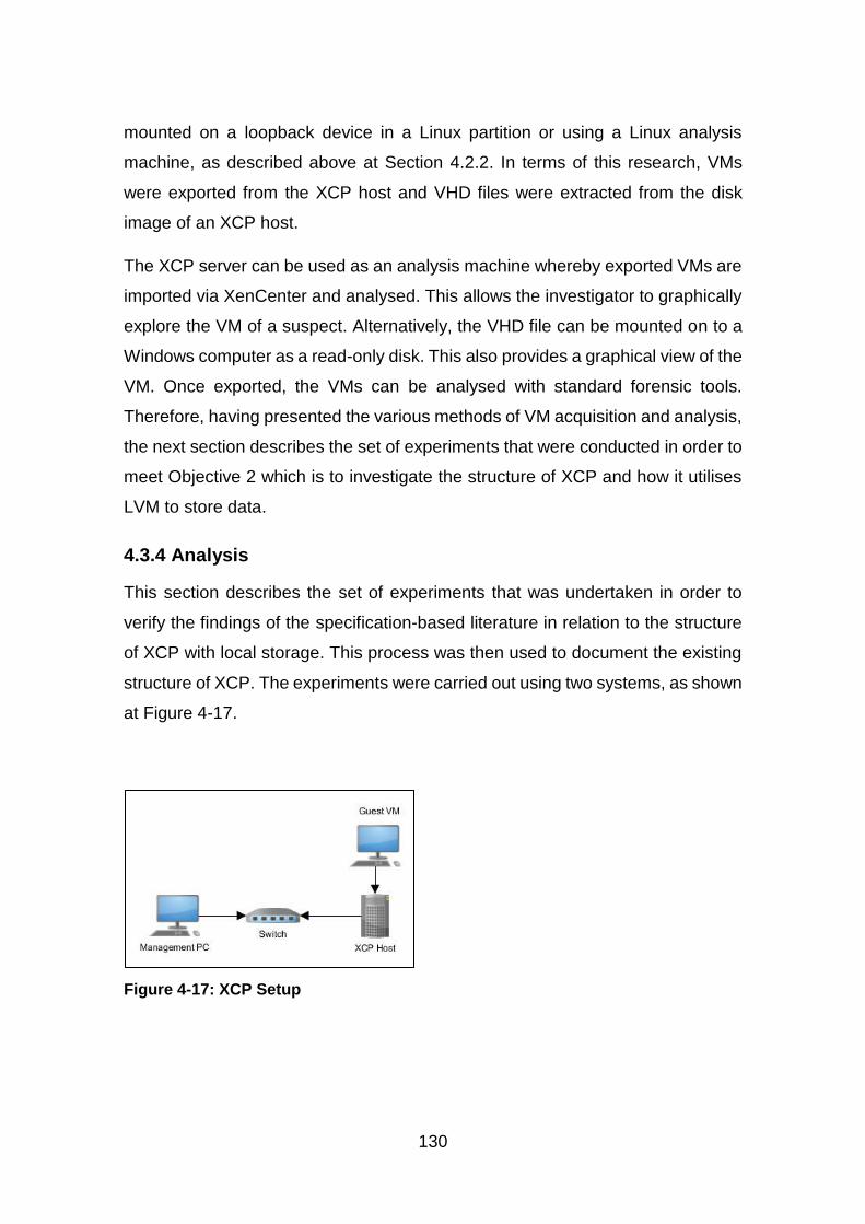
130
mounted on a loopback device in a Linux partition or using a Linux analysis
machine, as described above at Section 4.2.2. In terms of this research, VMs
were exported from the XCP host and VHD files were extracted from the disk
image of an XCP host.
The XCP server can be used as an analysis machine whereby exported VMs are
imported via XenCenter and analysed. This allows the investigator to graphically
explore the VM of a suspect. Alternatively, the VHD file can be mounted on to a
Windows computer as a read-only disk. This also provides a graphical view of the
VM. Once exported, the VMs can be analysed with standard forensic tools.
Therefore, having presented the various methods of VM acquisition and analysis,
the next section describes the set of experiments that were conducted in order to
meet Objective 2 which is to investigate the structure of XCP and how it utilises
LVM to store data.
4.3.4 Analysis
This section describes the set of experiments that was undertaken in order to
verify the findings of the specification-based literature in relation to the structure
of XCP with local storage. This process was then used to document the existing
structure of XCP. The experiments were carried out using two systems, as shown
at Figure 4-17.
Figure 4-17: XCP Setup
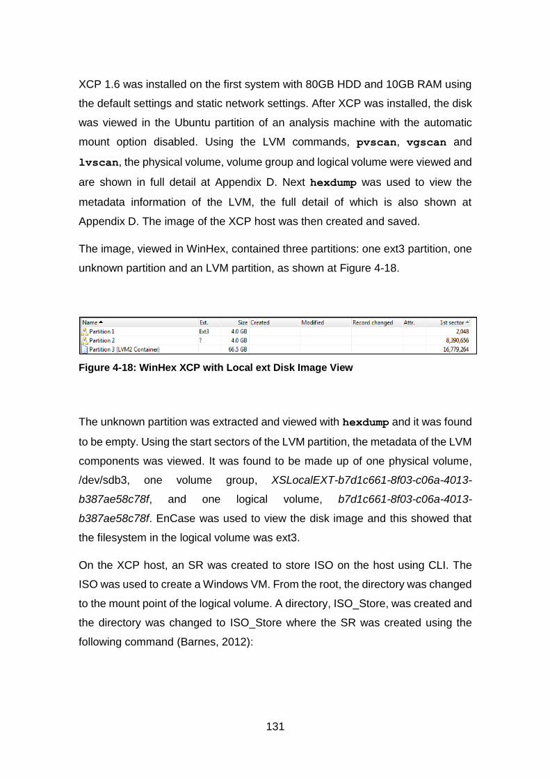
131
XCP 1.6 was installed on the first system with 80GB HDD and 10GB RAM using
the default settings and static network settings. After XCP was installed, the disk
was viewed in the Ubuntu partition of an analysis machine with the automatic
mount option disabled. Using the LVM commands, pvscan, vgscan and
lvscan, the physical volume, volume group and logical volume were viewed and
are shown in full detail at Appendix D. Next hexdump was used to view the
metadata information of the LVM, the full detail of which is also shown at
Appendix D. The image of the XCP host was then created and saved.
The image, viewed in WinHex, contained three partitions: one ext3 partition, one
unknown partition and an LVM partition, as shown at Figure 4-18.
Figure 4-18: WinHex XCP with Local ext Disk Image View
The unknown partition was extracted and viewed with hexdump and it was found
to be empty. Using the start sectors of the LVM partition, the metadata of the LVM
components was viewed. It was found to be made up of one physical volume,
/dev/sdb3, one volume group, XSLocalEXT-b7d1c661-8f03-c06a-4013-
b387ae58c78f, and one logical volume, b7d1c661-8f03-c06a-4013-
b387ae58c78f. EnCase was used to view the disk image and this showed that
the filesystem in the logical volume was ext3.
On the XCP host, an SR was created to store ISO on the host using CLI. The
ISO was used to create a Windows VM. From the root, the directory was changed
to the mount point of the logical volume. A directory, ISO_Store, was created and
the directory was changed to ISO_Store where the SR was created using the
following command (Barnes, 2012):
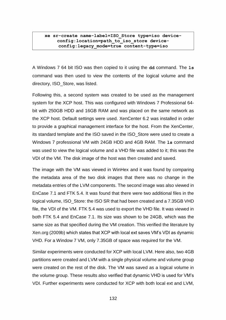
132
xe sr-create name-label=ISO_Store type=iso device-
config:location=path_to_iso_store device-
config:legacy_mode=true content-type=iso
A Windows 7 64 bit ISO was then copied to it using the dd command. The ls
command was then used to view the contents of the logical volume and the
directory, ISO_Store, was listed.
Following this, a second system was created to be used as the management
system for the XCP host. This was configured with Windows 7 Professional 64-
bit with 250GB HDD and 16GB RAM and was placed on the same network as
the XCP host. Default settings were used. XenCenter 6.2 was installed in order
to provide a graphical management interface for the host. From the XenCenter,
its standard template and the ISO saved in the ISO_Store were used to create a
Windows 7 professional VM with 24GB HDD and 4GB RAM. The ls command
was used to view the logical volume and a VHD file was added to it; this was the
VDI of the VM. The disk image of the host was then created and saved.
The image with the VM was viewed in WinHex and it was found by comparing
the metadata area of the two disk images that there was no change in the
metadata entries of the LVM components. The second image was also viewed in
EnCase 7.1 and FTK 5.4. It was found that there were two additional files in the
logical volume, ISO_Store: the ISO SR that had been created and a 7.35GB VHD
file, the VDI of the VM. FTK 5.4 was used to export the VHD file. It was viewed in
both FTK 5.4 and EnCase 7.1. Its size was shown to be 24GB, which was the
same size as that specified during the VM creation. This verified the literature by
Xen.org (2009b) which states that XCP with local ext saves VM’s VDI as dynamic
VHD. For a Window 7 VM, only 7.35GB of space was required for the VM.
Similar experiments were conducted for XCP with local LVM. Here also, two 4GB
partitions were created and LVM with a single physical volume and volume group
were created on the rest of the disk. The VM was saved as a logical volume in
the volume group. These results also verified that dynamic VHD is used for VM’s
VDI. Further experiments were conducted for XCP with both local ext and LVM,
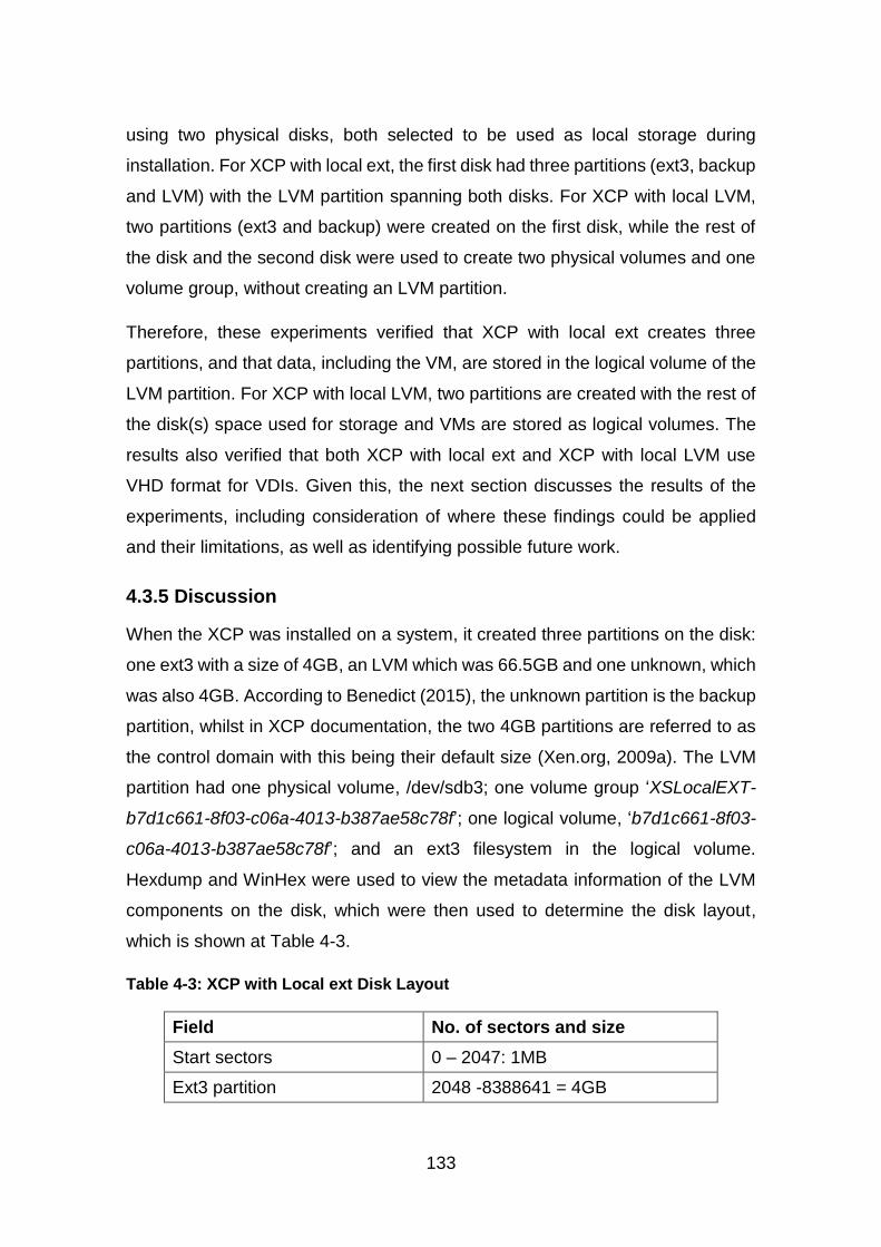
133
using two physical disks, both selected to be used as local storage during
installation. For XCP with local ext, the first disk had three partitions (ext3, backup
and LVM) with the LVM partition spanning both disks. For XCP with local LVM,
two partitions (ext3 and backup) were created on the first disk, while the rest of
the disk and the second disk were used to create two physical volumes and one
volume group, without creating an LVM partition.
Therefore, these experiments verified that XCP with local ext creates three
partitions, and that data, including the VM, are stored in the logical volume of the
LVM partition. For XCP with local LVM, two partitions are created with the rest of
the disk(s) space used for storage and VMs are stored as logical volumes. The
results also verified that both XCP with local ext and XCP with local LVM use
VHD format for VDIs. Given this, the next section discusses the results of the
experiments, including consideration of where these findings could be applied
and their limitations, as well as identifying possible future work.
4.3.5 Discussion
When the XCP was installed on a system, it created three partitions on the disk:
one ext3 with a size of 4GB, an LVM which was 66.5GB and one unknown, which
was also 4GB. According to Benedict (2015), the unknown partition is the backup
partition, whilst in XCP documentation, the two 4GB partitions are referred to as
the control domain with this being their default size (Xen.org, 2009a). The LVM
partition had one physical volume, /dev/sdb3; one volume group ‘XSLocalEXT-
b7d1c661-8f03-c06a-4013-b387ae58c78f’; one logical volume, ‘b7d1c661-8f03-
c06a-4013-b387ae58c78f’; and an ext3 filesystem in the logical volume.
Hexdump and WinHex were used to view the metadata information of the LVM
components on the disk, which were then used to determine the disk layout,
which is shown at Table 4-3.
Table 4-3: XCP with Local ext Disk Layout
Field No. of sectors and size
Start sectors 0 – 2047: 1MB
Ext3 partition 2048 -8388641 = 4GB
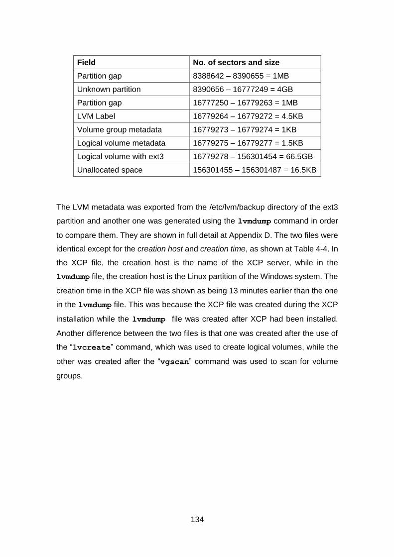
134
Field No. of sectors and size
Partition gap 8388642 – 8390655 = 1MB
Unknown partition 8390656 – 16777249 = 4GB
Partition gap 16777250 – 16779263 = 1MB
LVM Label 16779264 – 16779272 = 4.5KB
Volume group metadata 16779273 – 16779274 = 1KB
Logical volume metadata 16779275 – 16779277 = 1.5KB
Logical volume with ext3 16779278 – 156301454 = 66.5GB
Unallocated space 156301455 – 156301487 = 16.5KB
The LVM metadata was exported from the /etc/lvm/backup directory of the ext3
partition and another one was generated using the lvmdump command in order
to compare them. They are shown in full detail at Appendix D. The two files were
identical except for the creation host and creation time, as shown at Table 4-4. In
the XCP file, the creation host is the name of the XCP server, while in the
lvmdump file, the creation host is the Linux partition of the Windows system. The
creation time in the XCP file was shown as being 13 minutes earlier than the one
in the lvmdump file. This was because the XCP file was created during the XCP
installation while the lvmdump file was created after XCP had been installed.
Another difference between the two files is that one was created after the use of
the “lvcreate” command, which was used to create logical volumes, while the
other was created after the “vgscan” command was used to scan for volume
groups.
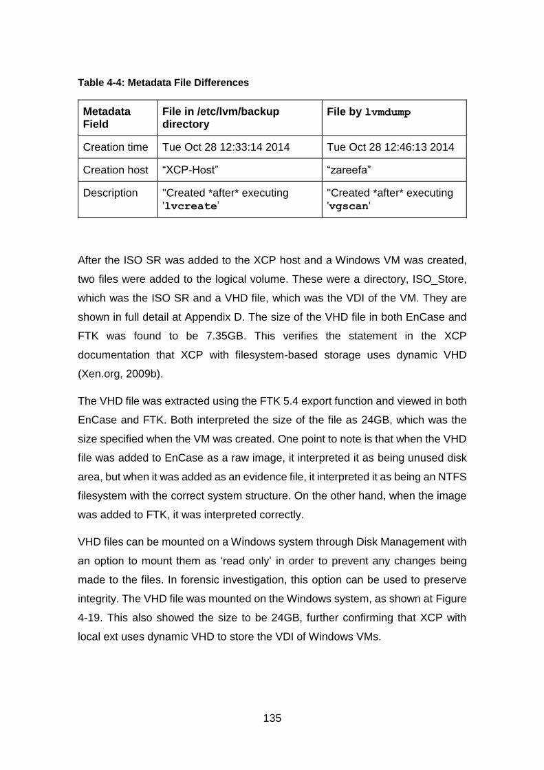
135
Table 4-4: Metadata File Differences
Metadata Field
File in /etc/lvm/backup directory
File by lvmdump
Creation time Tue Oct 28 12:33:14 2014 Tue Oct 28 12:46:13 2014
Creation host “XCP-Host” “zareefa”
Description "Created *after* executing 'lvcreate’
"Created *after* executing 'vgscan'
After the ISO SR was added to the XCP host and a Windows VM was created,
two files were added to the logical volume. These were a directory, ISO_Store,
which was the ISO SR and a VHD file, which was the VDI of the VM. They are
shown in full detail at Appendix D. The size of the VHD file in both EnCase and
FTK was found to be 7.35GB. This verifies the statement in the XCP
documentation that XCP with filesystem-based storage uses dynamic VHD
(Xen.org, 2009b).
The VHD file was extracted using the FTK 5.4 export function and viewed in both
EnCase and FTK. Both interpreted the size of the file as 24GB, which was the
size specified when the VM was created. One point to note is that when the VHD
file was added to EnCase as a raw image, it interpreted it as being unused disk
area, but when it was added as an evidence file, it interpreted it as being an NTFS
filesystem with the correct system structure. On the other hand, when the image
was added to FTK, it was interpreted correctly.
VHD files can be mounted on a Windows system through Disk Management with
an option to mount them as ‘read only’ in order to prevent any changes being
made to the files. In forensic investigation, this option can be used to preserve
integrity. The VHD file was mounted on the Windows system, as shown at Figure
4-19. This also showed the size to be 24GB, further confirming that XCP with
local ext uses dynamic VHD to store the VDI of Windows VMs.

136
Figure 4-19: Mounted VHD File
Efforts to modify the mounted VHD file by adding files to the disk or access the
user profile folder were not successful. This shows that this method may be used
in forensic investigation without compromising the integrity of the file. Also the
MD5 hash of the VHD file was generated both before and after mounting it, it
remained unchanged. For XCP with local LVM, the structure is similar except that
the LVM partition was not formatted with a filesystem and the VM was saved as
a logical volume in that partition.
The results show that XCP with both local ext and local LVM use dynamic VHD
for VDIs and VDIs in local ext are saved as VHD files in the SR, while they are
saved as logical volumes in local LVM. However, as with the LVM experiment
discussed above, these results have limitations, including the storage type used.
XCP with shared storage was not considered here but is considered in Chapter
5. Only XCP with filesystem-based and LVM-based SRs are examined here and
Chapter 5. LUN-based SRs were not considered for the reason mentioned at
Section 4.3.1 above, namely that only SRs that correspond to the XCP
deployment models used. Snapshots are another aspect of VMs that are not
considered here but are discussed in Chapter 5, Section 5.4. A final point is that
only Windows VM was used for these experiments. However, the results verifed
the structure of XCP with local ext and LVM, although these structures may only
be applied to XCP with local ext and LVM storage with Windows VMs. The
structure of Linux VMs in XCP with local and shared storage, and of Linux VM in
LUN-based SRs could be examined as future work.
As with the experiments on the LVM structure, the sets of experiments in the
preceding section were conducted on test data sets as defined by Garfinkel et al
(2009). These data sets were shown to satisfy the five properties of evaluation of

137
research in digital forensics, as proposed by Mocas (2004). That is, the test data
can be duplicated without changing it (integrity), all the processes undertaken
during the experiments were outline in a way that they can easily be duplicated.
This includes the versions of the tools, the sizes of the disks and OS versions.
The data represent what they should represent (authentication). For this property,
the data represented a basic structure of XCP and all the processes followed in
creating the data gave expected results. The process used to create the test data
is reproducible (reproducibility), here also, the steps outlined in the experiments
make them easy to replicate. The tools used to analyse the data did not change
it (non-interference) and a minimum amount of data was used to verify the
structure of XCP (minimisation).
4.3.6 XCP Summary
XCP divides a disk into three partitions: the root, which is an ext3 partition; the
backup root partition; and the LVM or storage partition. The results of the
experiments on XCP with local ext show that the LVM partition consists of one
physical volume, one volume group and one logical volume, and that the logical
volume is the same size as the physical volume. The logical volume has an ext3
filesystem and this serves as the local storage of the host. Any data added to the
XCP is added to this logical volume, including the VDI of the VM created on the
XCP host. For XCP with local LVM, the LVM partition was not formatted with a
filesystem and the VDI of the VM was saved as a logical volume.
For these experiments, the VDI was saved as a dynamic VHD on the disk and
nothing was saved on the VM. The size of this VDI was 7.35GB. If more data is
added to the VM, the size will increase until it reaches 24GB, the size specified
during its creation. Tools are available which can be used to examine the VM and
the LVM where the VM is saved. It should be noted that when a dynamic VHD is
viewed using forensic tools or mounted in Windows, the size shown is as
allocated during the VM creation and not as it actually is on the disk.
138
4.4 Conclusion
This chapter has described the structure of LVM and how data is stored on it. The
different components of LVM were identified to be the physical volume, the
volume group and the logical volume with the logical volume as the data storage
component. Various methods of acquiring logical volumes were identified. These
were the use of dd or its variants, the use of vgimport/vgexport, the use of
a Linux machine or live CD to image logical volumes, the use of a loopback device
on an image and use of tools with LVM support. Experiments to document the
structure of LVM were then carried out and this verified the findings of the
literature review, confirming that the LVM structure starts with a physical disk or
a partition, which was initialised as a physical volume from which a volume group
was created. This was then divided into two logical volumes, which were
formatted with a filesystem. Once logical volumes are formatted in this way, data
can be added. When changes were made to the logical volumes, the metadata
was updated to reflect the changes both on disk and in the files. The metadata
only contained information on the LVM components and filesystem information
was not captured.
The second part of the chapter related to the experiments on XCP. When
installed, it created three partitions on the disk, two for the control domain and
one for storage, using filesystem and LVM to manage the storage of VDIs. The
experiments examined the structure of XCP with local ext and LVM storage. The
two use different data storage structures. For XCP with local ext, VMs are stored
as dynamic VHDs in a logical volume with ext3 filesystem. The logical volume
can span multiple disks. On the other hand, XCP with local LVM stores VM as a
logical volume and uses dynamic VHD. Therefore, different recovery techniques
and tools are required for the two deployment models. For XCP with local ext,
ext3 tools are required while for XCP with local LVM, either LVM tools or tools
with LVM support are required.
The next stage of the research is to identify how artefacts can be recovered in
XCP with filesystem-based and LVM-based SRs and how the recovered artefacts
can be associated with a specific XCP user. Therefore, the next chapter
139
investigates how XCP manages deleted VMs and data. It describes how existing
tools can be added to XCP and how these tools can be used to recover artefacts,
thereby fulfilling the third objective of this research. It also identifies how
recovered data can be associated with Cloud users, which is the fourth objective
of this research. Finally, it proposes a general methodology for artefact recovery
in XCP, thereby fulfilling the fifth and final objective of this research.

141
5 Data Recovery in XCP
5.1 Introduction
The purpose of this research is to investigate the use of existing tools to recover
artefacts, which are complete, contiguous and have evidential value, from a Xen
Cloud Platform (XCP) and to investigate how the recovered artefacts can be
associated with XCP users. To this end, the previous chapter described the
structure of the Logical Volume Manager (LVM) in relation to data storage,
examining how XCP uses it to manage storage. The chapter described the
experiments that were undertaken to document the structures of both LVM and
XCP and to verify the findings of the literature review, which stated that LVM is
made up three components (physical volumes, volume groups and logical
volumes) with data stored in the logical volume. XCP creates three partitions on
the disk (the root, backup and storage partitions) and data is stored in the latter.
These experiments were precursors to investigating how existing tools can be
used within XCP to recover artefacts.
The purpose of this chapter is to fulfil the third, fourth and fifth Research
Objectives, which were to investigate how existing tools can be incorporated into
XCP to recover artefacts, to investigate how the recovered artefacts can be
associated with specific XCP users and to propose a general methodology for
artefact recovery in XCP. The results from these experiments are then evaluated
in Chapter 6 against the criteria for evidential value that were proposed in Chapter
3 in order to determine their evidential value. To this end, the first part of this
chapter focuses on how XCP manages deleted data, providing an insight into
how deleted data, in the form of Virtual Machines (VMs), can be recovered using
existing tools. This leads to the second part of this chapter, which examines the
use of existing tools to recover artefacts. Recovery of an artefact in itself may not
be sufficient to provide information on the owner and so there is a need to find a
method of associating that recovered artefact with the user. Therefore, how the
recovered artefact can be attributed to specific XCP users is explored, to form the
third part of this chapter. The fourth part of the chapter presents a general
methodology for recovering artefacts and associating the artefacts with XCP
142
users. The chapter concludes by evaluating the use of this methodology in a
larger XCP. The discussion begins by focusing on how XCP manages deleted
data.
5.2 Deleted Files in XCP
When used with local storage, XCP 1.6 uses either ext (ext3), which is a
filesystem based storage, or LVM-based storage to store Virtual Disk Images
(VDIs) of Virtual Machines (VMs) in a Virtual Hard Disk (VHD) format. When XCP
is installed, it uses LVM as the default local storage unless thin provisioning is
used, in which case it uses ext3.
For the experiments that are reported in this section, two filesystems were
considered: ext3 and NTFS. Ext3 is the standard used by XCP with local ext,
while NTFS is the filesystem for Windows VMs and is, therefore, the most
common filesystem for Windows systems. This includes Windows 7, which was
the operating system that was selected for use in these experiments. In ext3, the
filesystem is divided into block groups that, as the name implies, are made up of
blocks, which are units for data storage. The basic layout of a block group
consists of a group description table, block bitmap, inode bitmap, inode table and
data blocks. File contents are stored in blocks and the metadata for each file is
stored in an inode that is located in an inode table. File names are stored in a
directory entry with a pointer to the inode of the file (Carrier, 2005a; Altheide and
Carvey, 2011). When a file is deleted, the directory entry of the file is deleted and
all the block pointers within the inode are zeroed out. The data blocks which hold
the file content are then marked as free blocks and the content remains in the
blocks until they are reallocated and overwritten (Farmer and Venema, 2005;
Narvaez, 2007; Altheide and Carvey, 2011). Therefore, a deleted file in an ext3
partition of XCP can be recovered before it is overwritten.
In NTFS, every file and folder has a record in the Master File Table (MFT). When
a file is deleted, the MFT record of the file is marked as deleted by changing bytes
22 and 23 from 0x01 0x00 to 0x00 0x00 (Fellows, 2005). The $Bitmap, which
is a system file that keeps a record of which clusters are in use and which are
143
not, is updated to reflect the fact that the clusters used by the file are available
for reuse (Fellows, 2005). The MFT record of the file and the file content remain
on the disk until they are overwritten. For both filesystems, deleted files remain
on the disk until they are overwritten. This means that they can be fully or partially
recovered. Therefore, the aim of this experiment is to investigate how XCP
manages deleted files. The use of different filesystems by XCP along with the
VMs created in relation to deleted files need to be examined in order to find a
method of recovering data suited to XCP. This is the purpose of the second part
of this chapter. However, the first stage is to describe the experiments that were
setup in order to determine how XCP manages deleted VMs.
5.2.1 Analysis
A set of experiments was undertaken to investigate how XCP with local ext
storage manages deleted files. In order to do this, two systems were set up. On
the first system, the XCP host, XCP 1.6, was installed with 80GB HDD and 10GB
RAM with default settings and static network configuration. Next, an ISO Storage
Repository (SR) was created to store ISO on the host using the Command Line
Interface (CLI) with xe sr-create and a Windows 7 64 bit ISO was copied to
it using the dd command from the CD drive of the host. The second system, which
was to be used as a management system, was configured with Windows 7
Professional 64-bit with 250GB HDD and 16GB RAM. XenCenter was installed
to provide a graphical management interface for the XCP host, while XenConvert
2.3.1 was installed to convert Xen Virtual Appliance (XVA) files, the format used
to export VMs in XCP, to Open Virtualization Format (OVF). This was placed on
the same network as the XCP host. Using the XenCenter templates and the ISO
saved in the SR, a Windows VM was created with Windows 7 Professional, 24GB
HDD and 4GB RAM. A 1GB text file was added to the Documents directory of the
VM, by connecting a USB drive to the XCP host and attaching it as a disk to the
VM. The file was then copied from the USB to the Documents directory and the
USB was detached.
The VM was powered off and then exported as an XVA file. A disk image was
created and saved as Image 1. Using this image, the VHD file was extracted with
144
FTK and saved as VHD1. Both the image and the VHD file were viewed in
WinHex and the sectors that were occupied by the text file were identified and
noted. The sectors that were occupied by the VHD file, which is the VDI of the
VM on the image, were also noted.
Next, the 1GB text file was deleted and the VM exported. An image of the disk
was created and saved as Image 2, while the VHD file was extracted from this
image and saved as VHD2. The image and VHD file were viewed in order to find
the text file. This was found in the same sectors as in VHD1 and Image 1 and the
location was noted. This shows that the deleted text file remained on the disk. In
addition, the sectors occupied by the VHD were noted in order to compare with
the sectors it occupied in Image 1. These remained the same.
The two exported VMs were converted to the OVF package using XenConvert.
This package comprises VHD and VM metadata files. The VHD files were
extracted and the keyword search in WinHex was used to find the text file. It was
found in the same location in all of the VHDs and, in addition, it was found to
occupy the same number of sectors.
The VM itself was deleted; an image of the disk was created and this was saved
as Image 3. The image was viewed in WinHex and both the text and the VHD
files were found. This verifies that deleted files in both ext3 and NTFS filesystem
remain on a disk until they are overwritten.
Finally, a new VM was created and an image of the disk created. This was found
to have deleted part of the text file, but a large fragment of it was found, along
with a fragment of the VHD. This shows that, as more data are added to the disk,
both the text file and the VHD file may eventually be deleted. The steps
undertaken for this set of experiments are shown at Figure 5-1.
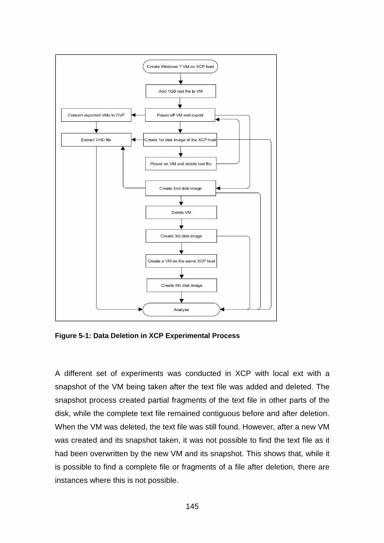
145
Figure 5-1: Data Deletion in XCP Experimental Process
A different set of experiments was conducted in XCP with local ext with a
snapshot of the VM being taken after the text file was added and deleted. The
snapshot process created partial fragments of the text file in other parts of the
disk, while the complete text file remained contiguous before and after deletion.
When the VM was deleted, the text file was still found. However, after a new VM
was created and its snapshot taken, it was not possible to find the text file as it
had been overwritten by the new VM and its snapshot. This shows that, while it
is possible to find a complete file or fragments of a file after deletion, there are
instances where this is not possible.
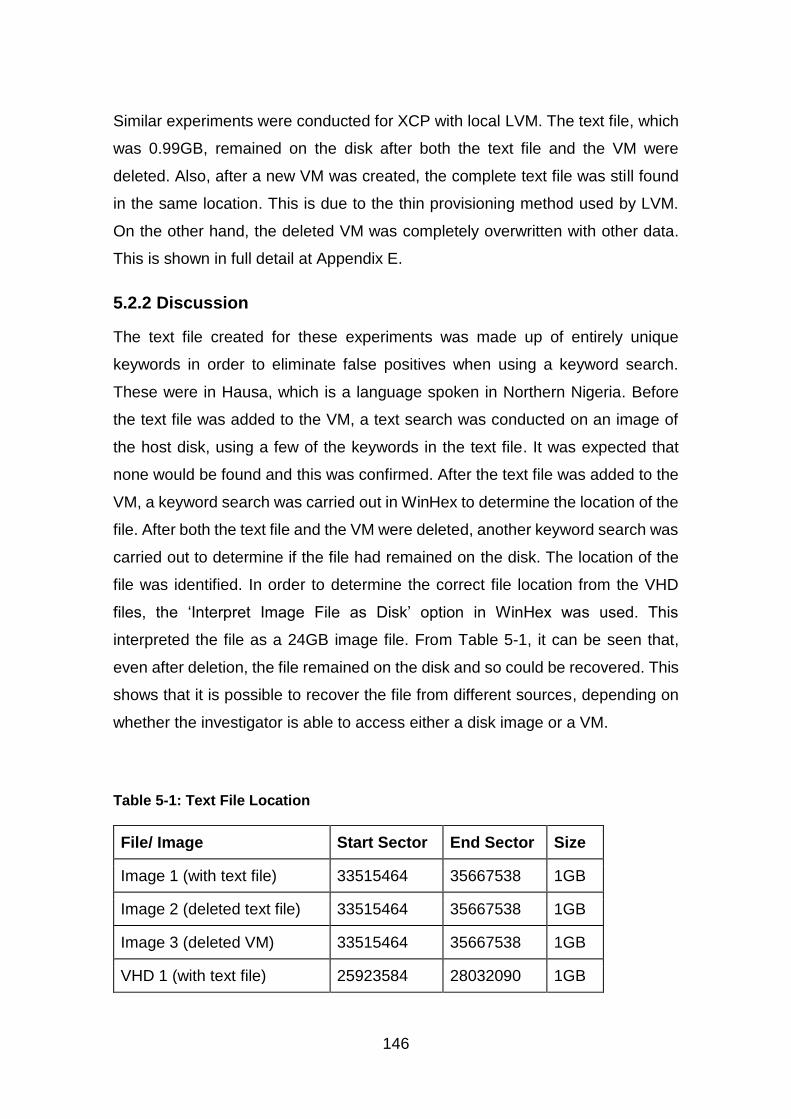
146
Similar experiments were conducted for XCP with local LVM. The text file, which
was 0.99GB, remained on the disk after both the text file and the VM were
deleted. Also, after a new VM was created, the complete text file was still found
in the same location. This is due to the thin provisioning method used by LVM.
On the other hand, the deleted VM was completely overwritten with other data.
This is shown in full detail at Appendix E.
5.2.2 Discussion
The text file created for these experiments was made up of entirely unique
keywords in order to eliminate false positives when using a keyword search.
These were in Hausa, which is a language spoken in Northern Nigeria. Before
the text file was added to the VM, a text search was conducted on an image of
the host disk, using a few of the keywords in the text file. It was expected that
none would be found and this was confirmed. After the text file was added to the
VM, a keyword search was carried out in WinHex to determine the location of the
file. After both the text file and the VM were deleted, another keyword search was
carried out to determine if the file had remained on the disk. The location of the
file was identified. In order to determine the correct file location from the VHD
files, the ‘Interpret Image File as Disk’ option in WinHex was used. This
interpreted the file as a 24GB image file. From Table 5-1, it can be seen that,
even after deletion, the file remained on the disk and so could be recovered. This
shows that it is possible to recover the file from different sources, depending on
whether the investigator is able to access either a disk image or a VM.
Table 5-1: Text File Location
File/ Image Start Sector End Sector Size
Image 1 (with text file) 33515464 35667538 1GB
Image 2 (deleted text file) 33515464 35667538 1GB
Image 3 (deleted VM) 33515464 35667538 1GB
VHD 1 (with text file) 25923584 28032090 1GB

147
File/ Image Start Sector End Sector Size
VHD 2 (deleted text file) 25923584 28032090 1GB
For the exported VMs, the text file was also found in the same location after
deletion. This shows that analysing VMs that are either exported or extracted
from a disk image gives similar results in terms of deleted files. It was also
possible to recover the deleted VM as it remained on the disk after deletion, as
shown at Table 5-2. The footer signature of the VHD file was used to determine
its location both before and after deletion as it is repeated in the header of a VHD
file (Barrett and Kipper, 2010). This was used to identify the beginning and end
of the VHD file.
Table 5-2: VHD File Location on Disk
Image Start Sector End Sector Size
Image 1 17766544 35697280 8.5GB
Image 2 17766544 35705552 8.5GB
Image 3 17766544 35705552 8.5GB
When a new VM was created, it was found to have overwritten part of the deleted
VM, and therefore, only a large fragment of the deleted file was found, rather than
the whole of the deleted file. This was identified in sectors 34518312 to
35667538, and its size was 561MB. The new VM that had been created was
located in sectors 17684624 to 34518304, roughly in the same location as the
deleted VM, which had occupied sectors 17766544 to 35705552. Between the
end of the new VM’s location and the beginning of the fragment, there were eight
sectors. This shows that not all of the sectors occupied by the deleted file were
overwritten when the new VM was created. It also shows that fragments of a
deleted file can be found. However, there is a possibility that, as the VHD file
grows, the deleted files will be overwritten.
148
A VM snapshot stores the state of the VM at a point in time. In XCP, the snapshots
can be created while the VM is still running. This means that they can be used to
create backups and templates. There are three different types of snapshot in
XCP: disk-only, quiesced, and disk and memory. Disk only stores the VM’s
metadata, while quiesced uses a Volume Shadow Copy Service (VSS) to create
application-consistent snapshots. This works with Microsoft VMs only, while disk
and memory store the VM’s metadata, disk and RAM (Citrix Systems, 2014b). As
is the case with VMs, snapshots can be exported to a file. However, unlike VMs,
they can only be exported as XVA files. This means that they would need to be
converted to OVF format before they can be analysed. In XCP, each VM created
has its associated VDI with a unique identifier, known as the Universally Unique
Identifier (UUID). When a snapshot is created, three things happen. First, the
parent VHD gets a new UUID and contains the data up to the point of the
snapshot. Second, a new child differencing VHD is created, which is assigned
the former UUID of the parent. This then becomes the active node and any data
added to the VM is saved there. Third, a second child VHD is created which is
empty except for header information. This is to provide storage support to the
snapshot (Citrix Systems, 2014b). When the snapshot is deleted, only the second
child disk is deleted. The first child VHD remains as the active node and continues
to grow as more data is added to it, while the parent VHD remains unchanged
(Citrix Systems, 2014b). Therefore, it is possible to find evidence in both files.
The creation of a snapshot in the second set of experiments caused the parent
VHD to fragment, thereby creating fragments of the text file elsewhere on the
disk. Despite this, the text file remained contiguous even after deletion and
fragments of the file were found within the sectors allocated to the VM.
Subsequent VMs that were created with a snapshot were then allocated the
sectors occupied by the deleted VM. In this way, the deleted VM was overwritten,
including the deleted file.
For XCP with local LVM, it was found that both the deleted file and deleted VM
remained on disk. After a new VM was created, the file remained on disk but the
VM was overwritten. This is due to the way data is written in LVM VHDs. When a
149
VM is created, the logical volume is assigned the full size of the VDI but only
minimum space is utilised. The free space is left for growth, snapshots or clones.
For this set of experiments, when the second VM was created, only the minimum
space required for the VM was used. This included the VHD header and footer
along with Windows 7 related data. The rest of the 24GB was left free which was
why the deleted text file was found. As more data is added to the VM or when
snapshots or clones are created, the text file may eventually be overwritten. The
details of the complete experiment are attached at Appendix E. It should be noted
that in XCP, when a VM is deleted, it becomes invisible and there is no option
within XCP for the recovery of deleted VMs.
While the results of these experiments show that it is possible to recover deleted
files before they are overwritten in both XCP with local ext and XCP with LVM
storage, this is dependent on the type of storage device used. In disks such as
Solid State Drive (SSD), unallocated blocks are erased before they are
reallocated (Chen et al., 2009; Bell and Boddington, 2010). This reduces the
chance of recovery. These results can be applied to other filesystem-based and
LVM-based SRs as they use the same structures. However, they may not be
applicable to LUN-based SRs, although this assertion requires further
investigation.
In terms of data deletion in XCP with local ext, two filesystems were considered,
ext3 for the logical volume which is the SR where the VM is stored and NTFS for
the VM. As discussed in Chapter 2, Section 2.6, both of these filesystems retain
deleted data until they are overwritten and, therefore, may be recoverable
(Farmer and Venema, 2005; Fellows, 2005; Narvaez, 2007; Altheide and Carvey,
2011). On the other hand, XCP with local LVM stores VMs directly in the volume
group as logical volumes. In this case, only one filesystem was considered, the
VM filesystem, which was NTFS. Also, with both filesystem and LVM storage in
XCP, when a VM is deleted, the space is marked for deletion but the actual
deletion of data is not immediate and depends on the SR (Xen.org, 2009b).
Therefore, it may be possible to find and recover such VMs. This is useful as
deleted data remain an important source of evidence both in traditional and Cloud
150
forensics (Ruan et al., 2011b). The experiments in this section focused on the
XCP host, which is the Cloud server where the user VM is stored. Birk and
Wegener (2011) identified three sources of evidence, the virtual Cloud instance,
the network layer and the Cloud client system. Here, only the virtual Cloud
instance was considered, that is, the VM, as this can contain both live and deleted
evidence.
As with the experiments that were discussed in Chapter 4, Sections 4.3.5 and
4.2.4 test data was used in this section. That is, a data set which is constructed
specifically for testing a tool or its function or demonstrating a forensic issue
(Garfinkel et al., 2009).They can be duplicated without changing the data
(integrity). The data represent XCP with two VMs one with a single text file as
expected and satisfying the requirement for authentication. The process used to
create the test data is reproducible and all of the processes undertaken to
produce the data are clearly documented in such a way that a third party could
follow the process and obtain the same results (reproducibility). It was confirmed
that the tools used to analyse the data did not change the data (non-interference)
as the analysis was conducted on disk images and not on the original data; and
a minimum amount of data, consisting of a single XCP host, a VM with a single
text file and a second VM, was used to show that deleted data in XCP can be
recovered before it is overwritten (minimisation). Therefore, test data satisfied the
five properties proposed by Mocas (2004).
5.2.3 Summary
The results of these sets of experiments show that it is possible to recover a
deleted file either from a disk or from a VM after deletion. Adding data to the XCP
SR can overwrite either part or the whole of a deleted file. If part of the deleted
file is overwritten, it is still possible to then find fragments of that file. In cases
where snapshots are used, it is also possible to recover a deleted file or
fragments of the file. However, using snapshots further complicates the recovery
of deleted files because it adds more data to the SR. As a result, this data may
be allocated the space that was previously occupied by the deleted files, thereby
resulting in the overwriting of those files. Therefore, having determined that
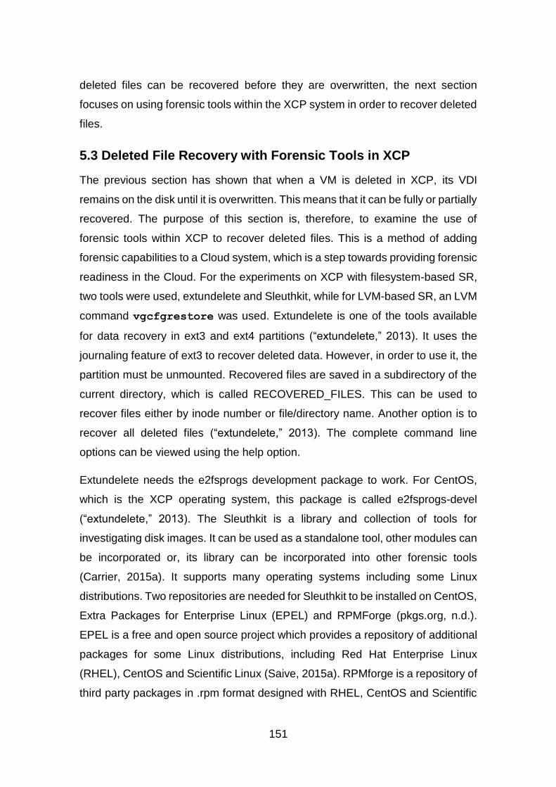
151
deleted files can be recovered before they are overwritten, the next section
focuses on using forensic tools within the XCP system in order to recover deleted
files.
5.3 Deleted File Recovery with Forensic Tools in XCP
The previous section has shown that when a VM is deleted in XCP, its VDI
remains on the disk until it is overwritten. This means that it can be fully or partially
recovered. The purpose of this section is, therefore, to examine the use of
forensic tools within XCP to recover deleted files. This is a method of adding
forensic capabilities to a Cloud system, which is a step towards providing forensic
readiness in the Cloud. For the experiments on XCP with filesystem-based SR,
two tools were used, extundelete and Sleuthkit, while for LVM-based SR, an LVM
command vgcfgrestore was used. Extundelete is one of the tools available
for data recovery in ext3 and ext4 partitions (“extundelete,” 2013). It uses the
journaling feature of ext3 to recover deleted data. However, in order to use it, the
partition must be unmounted. Recovered files are saved in a subdirectory of the
current directory, which is called RECOVERED_FILES. This can be used to
recover files either by inode number or file/directory name. Another option is to
recover all deleted files (“extundelete,” 2013). The complete command line
options can be viewed using the help option.
Extundelete needs the e2fsprogs development package to work. For CentOS,
which is the XCP operating system, this package is called e2fsprogs-devel
(“extundelete,” 2013). The Sleuthkit is a library and collection of tools for
investigating disk images. It can be used as a standalone tool, other modules can
be incorporated or, its library can be incorporated into other forensic tools
(Carrier, 2015a). It supports many operating systems including some Linux
distributions. Two repositories are needed for Sleuthkit to be installed on CentOS,
Extra Packages for Enterprise Linux (EPEL) and RPMForge (pkgs.org, n.d.).
EPEL is a free and open source project which provides a repository of additional
packages for some Linux distributions, including Red Hat Enterprise Linux
(RHEL), CentOS and Scientific Linux (Saive, 2015a). RPMforge is a repository of
third party packages in .rpm format designed with RHEL, CentOS and Scientific
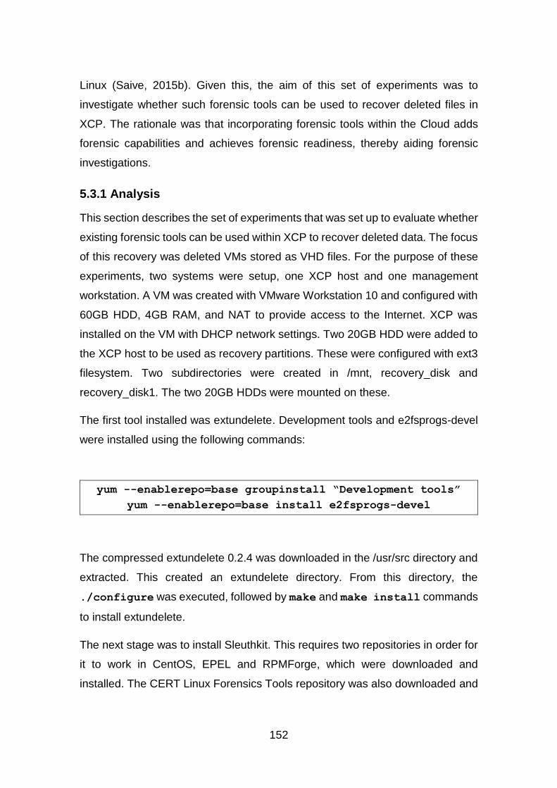
152
Linux (Saive, 2015b). Given this, the aim of this set of experiments was to
investigate whether such forensic tools can be used to recover deleted files in
XCP. The rationale was that incorporating forensic tools within the Cloud adds
forensic capabilities and achieves forensic readiness, thereby aiding forensic
investigations.
5.3.1 Analysis
This section describes the set of experiments that was set up to evaluate whether
existing forensic tools can be used within XCP to recover deleted data. The focus
of this recovery was deleted VMs stored as VHD files. For the purpose of these
experiments, two systems were setup, one XCP host and one management
workstation. A VM was created with VMware Workstation 10 and configured with
60GB HDD, 4GB RAM, and NAT to provide access to the Internet. XCP was
installed on the VM with DHCP network settings. Two 20GB HDD were added to
the XCP host to be used as recovery partitions. These were configured with ext3
filesystem. Two subdirectories were created in /mnt, recovery_disk and
recovery_disk1. The two 20GB HDDs were mounted on these.
The first tool installed was extundelete. Development tools and e2fsprogs-devel
were installed using the following commands:
yum --enablerepo=base groupinstall “Development tools”
yum --enablerepo=base install e2fsprogs-devel
The compressed extundelete 0.2.4 was downloaded in the /usr/src directory and
extracted. This created an extundelete directory. From this directory, the
./configure was executed, followed by make and make install commands
to install extundelete.
The next stage was to install Sleuthkit. This requires two repositories in order for
it to work in CentOS, EPEL and RPMForge, which were downloaded and
installed. The CERT Linux Forensics Tools repository was also downloaded and

153
installed in order to then install Sleuthkit. From this repository, Sleuthkit was
installed using the following command:
yum --enablerepo=forensics install sleuthkit
An SR was created for ISO and then Windows 7 Professional 32 bit ISO was
copied to it. A VM with Windows 7 32 bit professional, 1GB RAM and 24GB HDD
was created and a USB drive was then connected to the server and mounted.
Four text files with sizes between 135MB to 7.9GB were copied from the USB to
the LVM partition. These are shown along with the VM’s VDI at Figure 5-2.
Figure 5-2: List Showing File Sizes in the Logical Volume
The VM was deleted from XenCenter and the text file ‘Magana_Jari_1.txt’ was
deleted using the rm command. A Sleuthkit command, fls, was used to view
the files in the LVM partition. This command shows all the files, including deleted
files, with their inode numbers. The results of this are shown at Figure 5-3.

154
Figure 5-3: List of Files including Deleted Files with their Inode Numbers
The LVM partition was unmounted and the directory was changed to
/mnt/recovery_disk in order to save the recovered files in this directory. The
command extundelete was used to recover the two deleted files by their inode
numbers, as shown at Figure 5-4.
Figure 5-4: File Recovery by Inode Number
The ls command was used to review the contents of the RECOVERED_FILES
subdirectory. As a result of this, files were found with sizes that corresponded to
those of the two deleted files, as shown at Figure 5-5.
Figure 5-5: List of Files Recovered by Inode Number
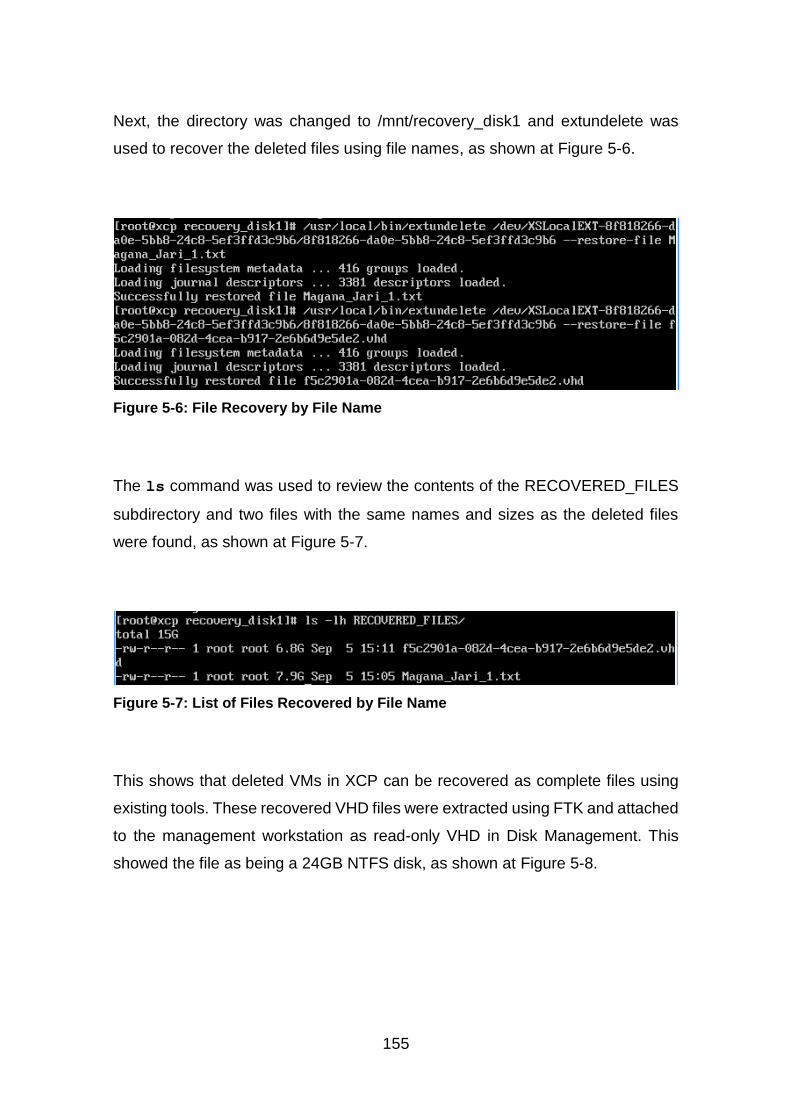
155
Next, the directory was changed to /mnt/recovery_disk1 and extundelete was
used to recover the deleted files using file names, as shown at Figure 5-6.
Figure 5-6: File Recovery by File Name
The ls command was used to review the contents of the RECOVERED_FILES
subdirectory and two files with the same names and sizes as the deleted files
were found, as shown at Figure 5-7.
Figure 5-7: List of Files Recovered by File Name
This shows that deleted VMs in XCP can be recovered as complete files using
existing tools. These recovered VHD files were extracted using FTK and attached
to the management workstation as read-only VHD in Disk Management. This
showed the file as being a 24GB NTFS disk, as shown at Figure 5-8.
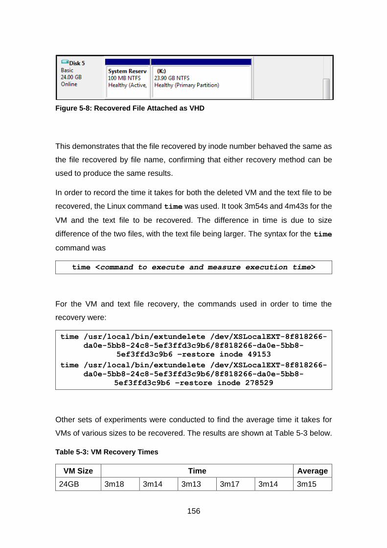
156
Figure 5-8: Recovered File Attached as VHD
This demonstrates that the file recovered by inode number behaved the same as
the file recovered by file name, confirming that either recovery method can be
used to produce the same results.
In order to record the time it takes for both the deleted VM and the text file to be
recovered, the Linux command time was used. It took 3m54s and 4m43s for the
VM and the text file to be recovered. The difference in time is due to size
difference of the two files, with the text file being larger. The syntax for the time
command was
time <command to execute and measure execution time>
For the VM and text file recovery, the commands used in order to time the
recovery were:
time /usr/local/bin/extundelete /dev/XSLocalEXT-8f818266-
da0e-5bb8-24c8-5ef3ffd3c9b6/8f818266-da0e-5bb8-
5ef3ffd3c9b6 –restore inode 49153
time /usr/local/bin/extundelete /dev/XSLocalEXT-8f818266-
da0e-5bb8-24c8-5ef3ffd3c9b6/8f818266-da0e-5bb8-
5ef3ffd3c9b6 –restore inode 278529
Other sets of experiments were conducted to find the average time it takes for
VMs of various sizes to be recovered. The results are shown at Table 5-3 below.
Table 5-3: VM Recovery Times
VM Size Time Average
24GB 3m18 3m14 3m13 3m17 3m14 3m15
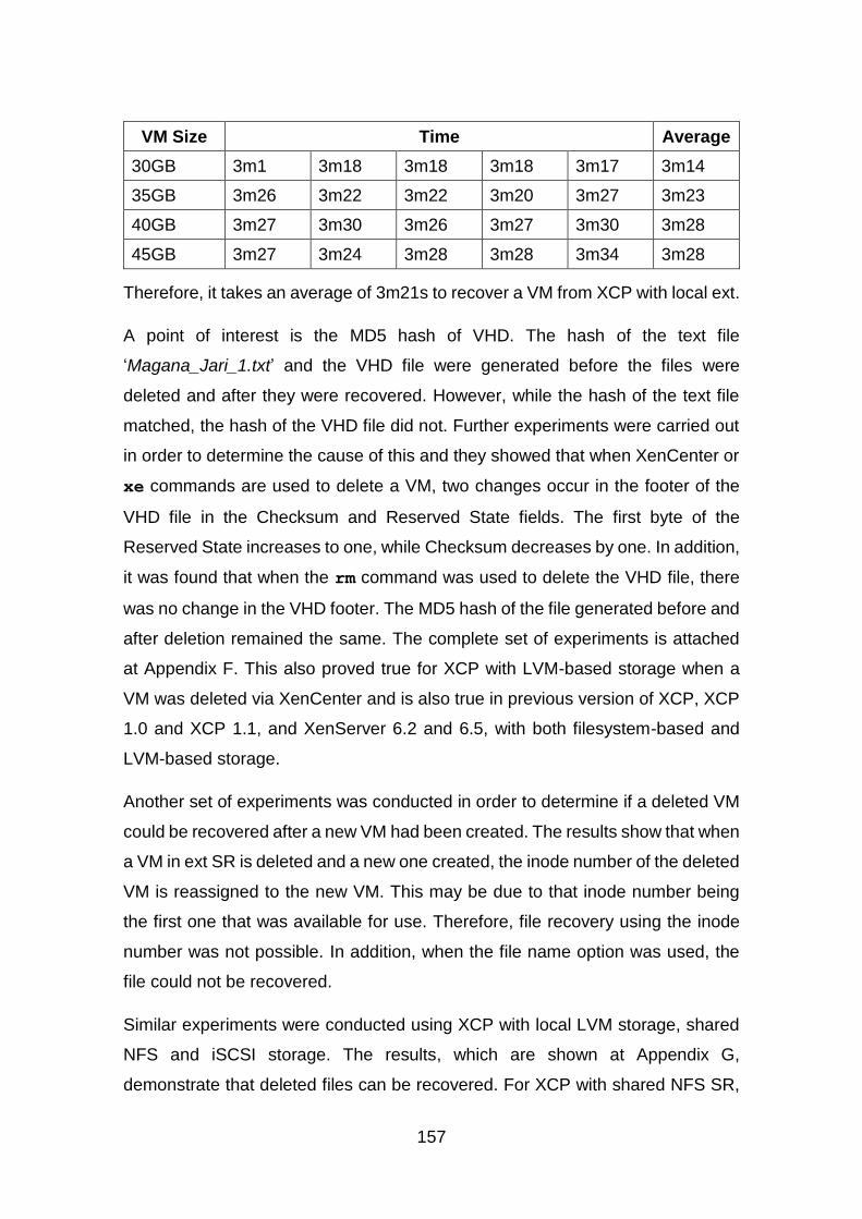
157
VM Size Time Average
30GB 3m1 3m18 3m18 3m18 3m17 3m14
35GB 3m26 3m22 3m22 3m20 3m27 3m23
40GB 3m27 3m30 3m26 3m27 3m30 3m28
45GB 3m27 3m24 3m28 3m28 3m34 3m28
Therefore, it takes an average of 3m21s to recover a VM from XCP with local ext.
A point of interest is the MD5 hash of VHD. The hash of the text file
‘Magana_Jari_1.txt’ and the VHD file were generated before the files were
deleted and after they were recovered. However, while the hash of the text file
matched, the hash of the VHD file did not. Further experiments were carried out
in order to determine the cause of this and they showed that when XenCenter or
xe commands are used to delete a VM, two changes occur in the footer of the
VHD file in the Checksum and Reserved State fields. The first byte of the
Reserved State increases to one, while Checksum decreases by one. In addition,
it was found that when the rm command was used to delete the VHD file, there
was no change in the VHD footer. The MD5 hash of the file generated before and
after deletion remained the same. The complete set of experiments is attached
at Appendix F. This also proved true for XCP with LVM-based storage when a
VM was deleted via XenCenter and is also true in previous version of XCP, XCP
1.0 and XCP 1.1, and XenServer 6.2 and 6.5, with both filesystem-based and
LVM-based storage.
Another set of experiments was conducted in order to determine if a deleted VM
could be recovered after a new VM had been created. The results show that when
a VM in ext SR is deleted and a new one created, the inode number of the deleted
VM is reassigned to the new VM. This may be due to that inode number being
the first one that was available for use. Therefore, file recovery using the inode
number was not possible. In addition, when the file name option was used, the
file could not be recovered.
Similar experiments were conducted using XCP with local LVM storage, shared
NFS and iSCSI storage. The results, which are shown at Appendix G,
demonstrate that deleted files can be recovered. For XCP with shared NFS SR,
158
which is a filesystem-based SR, the same method of recovery was employed as
that used for XCP with local ext. Local LVM and iSCSI, which are LVM-based
SRs, store the VDIs of VMs as logical volumes. Here, LVM archiving was enabled
on the XCP host as it is disabled by default in XCP (Xen.org, 2009b). This was
done by editing the lvm.conf in the /etc/lvm directory before the VMs were
created. An LVM command vgcfgrestore was then used to restore the deleted
VM, using the metadata file that was created before the VM was deleted, which
was located in the /etc/lvm/archive directory. The restored logical volumes were
activated and imaged to an external storage using dd.
In terms of recovery times, similar experiments were conducted on XCP with local
LVM, shared iSCSI and NFS SRs. For LVM SRs, it takes less than a second to
restore a deleted VM and an average of 4m20s to recover a VM in NFS SR. This
is shown at Appendix G.
A set of experiments was conducted on XCP with local LVM where a new VM
was created after the old VM was deleted. Before the VM was deleted a 228MB
text file was added to it, its image was then created and saved in external storage.
The VM was deleted and a new one created. A 295MB text file was added to the
new VM, while the deleted VM was then restored with vgcfgrestore and its
image created. The two images were compared in WinHex. This revealed that
when the deleted VM was restored, it overwrote some parts of the new VM, but
the filesystem information was retained along with its user profile and the 295MB
file. This shows that there are situations where the use of vgcfgrestore to
restore VMs is not ideal, and therefore, a different method for logical volume
recovery is needed.
5.3.2 Discussion
Before extundelete was installed, a set of tools named “Development tools” was
also installed. These are used to build and compile applications (Bowman, 2012).
To install standard Linux packages on XCP/ XenServer, the base repository
needs to be enabled. This is because it is disabled by default (Nanni, 2012).
Sleuthkit, on the other hand, needed the forensics repository to be enabled before
159
it could be installed. The “Development tools” and e2fsprogs-devel were installed,
followed by extundelete. It was determined that adding the extra repositories and
the development tool is unlikely to have negative effect on the recovered files.
Extundelete was used to recover the deleted files. When used in this way, it
creates a subdirectory, RECOVERD_FILES, in the current directory and then
saves any recovered files to this directory (“extundelete,” 2013).
The files recovered by inode number use the inode number as an extension. This
can cause difficulties in determining the file type unless the user is aware of this
fact beforehand. When the two recovered VHD files were attached as VHD in
Disk Management of a Windows machine, both were interpreted as 24GB NTFS
disks. Also when both files are compared in WinHex, they were found to be
identical except in two footer fields, as was shown in Section 5.3.1 above. This
shows that any recovery method used will suffice, provided the tools used for
analysis support the file type.
For XCP with filesystem-based SRs, the results are limited in terms of where they
can be applied. In a Cloud environment with multiple users, it may not be possible
to unmount the storage partition to recover deleted data, as it will make other
VMs stored in that storage partition unavailable to users. The experiments have
also shown that when a VM is deleted and a new one created in ext SR, the new
one may be assigned the deleted VM’s inode number. This makes it difficult to
recover the VM using both the inode number and the file name. This is because
extundelete uses the filesystem journal to recover files and once the information
in the journal is changed, it becomes difficult to recover the file. This happened
when the new VM was assigned the inode number of the deleted VM. This is not
to say that a deleted file whose inode has been reassigned cannot be recovered
using other methods, such as file carving, as long as the file is not overwritten.
However, it should be noted that file carving was beyond the scope of this
research because only complete and contiguous files and tools which are
dependent on the filesystem that created the files were used considered. Carving
may extract the data of other Cloud users, thereby violating their privacy. There

160
may be situations where carving can be used but it depends on the context of the
investigation.
For LVM-based SRs, VMs are stored as logical volumes. Deleted logical volumes
can be recovered using vgcfgrestore, an inbuilt LVM command that is used
to restore a volume group. In order for this to work, the metadata file created
before the logical volume was deleted is required. This file rolls back the volume
group configuration to the point in time before it was deleted. This file can be
found in the archive directory. By default, archiving old metadata files is disabled
in XCP but can be enabled in the lvm.conf file located in the /etc/lvm directory.
This was the process followed for the purposes of these experiments. Once
archiving has been enabled, deleted logical volumes can be restored using the
metadata files in the /etc/lvm/archive directory. If archiving is not enabled or the
archive file that could be used to restore a logical volume is not available, the
metadata on the disk could be used to restore logical volumes (Bros, 2009). File
carving is another option that could be used.
In XCP with LVM-based SR, the recovery can be undertaken while the partition
is mounted, but archiving needs to be enabled before deleted logical volumes
can be recovered. In situations where archiving is not enabled or the archive file
that can be used to recover a VM is not available, recovery may be difficult.
However as stated earlier, there are other methods that can be used to recover
the VM as long as it has not been overwritten. The use of vgcfgrestore to
recover deleted VMs is not without limitations, as these experiments have shown.
It is not always possible to recover a deleted VM as a newly created VM is
allocated the next available space, which, in this instance, is the space occupied
by the deleted VM.
When the deleted VM was restored, it was found to contain data from the new
VM. This is because vgcfgrestore used the configuration in the metadata file
to restore the VM. As mentioned in Chapter 4, Section 4.2, the LVM metadata
does not store filesystem information, only volume group configuration. As
discussed above at Section 5.2.2, when a VM is created in LVM SR, the header
and footer information are written to disk, along with the minimum OS data; the
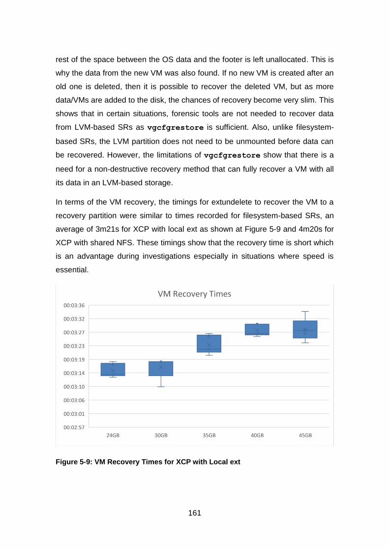
161
rest of the space between the OS data and the footer is left unallocated. This is
why the data from the new VM was also found. If no new VM is created after an
old one is deleted, then it is possible to recover the deleted VM, but as more
data/VMs are added to the disk, the chances of recovery become very slim. This
shows that in certain situations, forensic tools are not needed to recover data
from LVM-based SRs as vgcfgrestore is sufficient. Also, unlike filesystem-
based SRs, the LVM partition does not need to be unmounted before data can
be recovered. However, the limitations of vgcfgrestore show that there is a
need for a non-destructive recovery method that can fully recover a VM with all
its data in an LVM-based storage.
In terms of the VM recovery, the timings for extundelete to recover the VM to a
recovery partition were similar to times recorded for filesystem-based SRs, an
average of 3m21s for XCP with local ext as shown at Figure 5-9 and 4m20s for
XCP with shared NFS. These timings show that the recovery time is short which
is an advantage during investigations especially in situations where speed is
essential.
Figure 5-9: VM Recovery Times for XCP with Local ext
162
It is important to note that the filesystem-based SRs used thin provisioning when
creating VMs. This means only a minimal size is required for the VM to function
and that, therefore, the full size of the VM is not used. A series of experiments
were conducted to record the recovery times. These showed that the size of the
VMs was between 5.3GB to 5.4GB. This means that as data is added to the VMs,
their size will increase and that this may, in turn, affect the recovery time.
However, it was identified that, recovery in XCP with LVM-based SR is a bit
different. First, the logical volume metadata is restored and then the restored VM
can be copied to a recovery partition. Restoring the metadata takes less than a
second while copying the VM takes more time, 5m40s for XCP with local LVM
and 21m22s for XCP with shared iSCSI. This disparity may be due to the fact that
the iSCSI SR was connected via a network and the network speed, amongst
other things, might have affected the time. iSCSI SR is a remote SR unlike local
ext, local LVM and shared NFS which are SRs on the XCP host. Other factors
that might affect the timing include the size of the VM, the processor speed and
the number of processes running during the recovery. For these experiments, the
processing running on the XCP hosts were monitored and it was noted that they
used less than 6% of the CPU and less than 1% of memory. For filesystem-based
SRs, extundelete used between 7% - 20% of CPU and 0.5%-7% of memory; for
LVM-based SRs, vgcfgrestore does not take up any noticeable CPU or
memory. The processes running during the experiments were identified as OS
processes.
While these times are useful in an investigation, they only provide a baseline for
recovery times and this is likely to vary in different setups, especially in a real
world rather than experimental situation. However, the times serve as an
indication to investigators the time it is likely to take to recover VMs in the various
XCP SRs, both local and remote. These times can be used to provide an
indication of abnormalities in terms of recovery times during an investigation. It
should be noted that such abnormalities may affect the evidential value of the
recovered VM.

163
In terms of the deletion effect that xe commands and XenCenter have on VHD
files, it is not clear why the Reserved State changes but as the Checksum covers
the area of the Reserved State, this relationship directly affected the Checksum.
Further experiments need to be conducted in order to determine the cause of the
Reserved State change. For this research, it is sufficient to know that the change
occurs and where, given that it has been determined that these changes are
unlikely to have a negative impact on the results of the research. For the purposes
of this research, recoverable files are deleted files that can be recovered using
the methods described for filesystem-based and LVM-based storage. LUN-based
storage was not explored in these experiments and, therefore, it is noted that
these results may not apply in this instance. For future work, LUN-based storage
could be investigated in terms of file recovery using existing tools.
Section 5.2 has shown that deleted data in both ext3 and NTS can be recovered
before they are overwritten. This confirmed the literature that was reviewed in
Chapter 2, Section 2.6. This section focused on recovery in ext3 and LVM. As
mentioned earlier, deleted data remain an important source of evidence, not only
in Cloud forensics but also in traditional forensics (Ruan et al., 2011b). In addition,
recovery of deleted data is one of the challenges that was identified by the NIST
Cloud Computing Forensic Science Working Group (NIST, 2014). While this
section has shown that is possible to recover deleted data both in the form of VM
and a text file in XCP, additional techniques may need to be used in order to
preserve the integrity of the evidence, such as data segregation, for example.
Delport et al (2011) proposed several methods of isolating a Cloud instance
during an investigation, these may be modified to preserve evidence on a Cloud
server. Recovered VM, which is one of the sources of evidence in the Cloud
identified by Birk and Wegener (2011) can be analysed using tools and
techniques suitable to its filesystem. The experiments presented have shown that
is possible to add existing digital forensic tools to the Cloud. Other research is
focused on developing tools for specific Cloud technologies. For example, is the
Sleuthkit Hadoop Framework project by Carrier (2012) where Sleuthkit is used to
provide forensic capabilities. Dykstra and Sherman (2013) have designed a
forensic tool for OpenStack, called FROST, Srivastava et al (2014) have
164
designed FORE, a forensic toolkit for the SaaS model of the Eucalyptus Cloud.
Federic (2014) has designed a Cloud Data Imager, a tool to collect remote data
from Cloud storage services while Raju et al (2015) have developed an
acquisition tool also for OpenStack Cloud. Saibharath and Geethakumari (2015)
have designed a web-based evidence collection tool for Hadoop OpenStack. It is
evident that this is a range of research being undertaken that is focused on adding
forensic capabilities to the Cloud.
As with previous sections, the experiments in this section were also based on the
test data that was defined by Garfinkel et al (2009). The data sets used in these
experiments were evaluated against the five properties of evaluation of research
in digital forensics as proposed by Mocas (2004). It was shown that the data can
be duplicated as the steps undertaken to create the data are outlined (integrity);
the data represents XCP with both filesystem-based and LVM-based SRs, a VM
and text tiles of various sizes for XCP with local ext (authentication); the
processes used to create the data can be reproduced with the same results as
these processes have been documented (reproducibility); the tools used to
analyse the data did not change the data (non-interference); and the minimum
amount of data was used to show that deleted files in XCP can be recovered with
forensic tools, extundelete or built in tools, vgcfgrestore (minimisation).
Therefore, the data sets satisfied the properties of evaluation.
5.3.3 Summary
The results of this experiment show that extundelete can be used to recover
deleted files in XCP both by inode number and by file name in filesystem-based
SRs. They also confirmed that any extundelete method, inode or file name used
for recovery is sufficient for all types of digital forensic investigations. In addition,
different storage repository types have been shown to require the use of different
methods for the recovery of data. For filesystem-based SRs, the partition needs
to be unmounted before extundelete can be used for recovery, while for LVM-
based SRs, vgcfgrestore can be used while the partition is still mounted. For
filesystem-based SRs, the reassignment of the inode of a deleted file makes
recovery difficult using the tools selected for these experiments. However, there
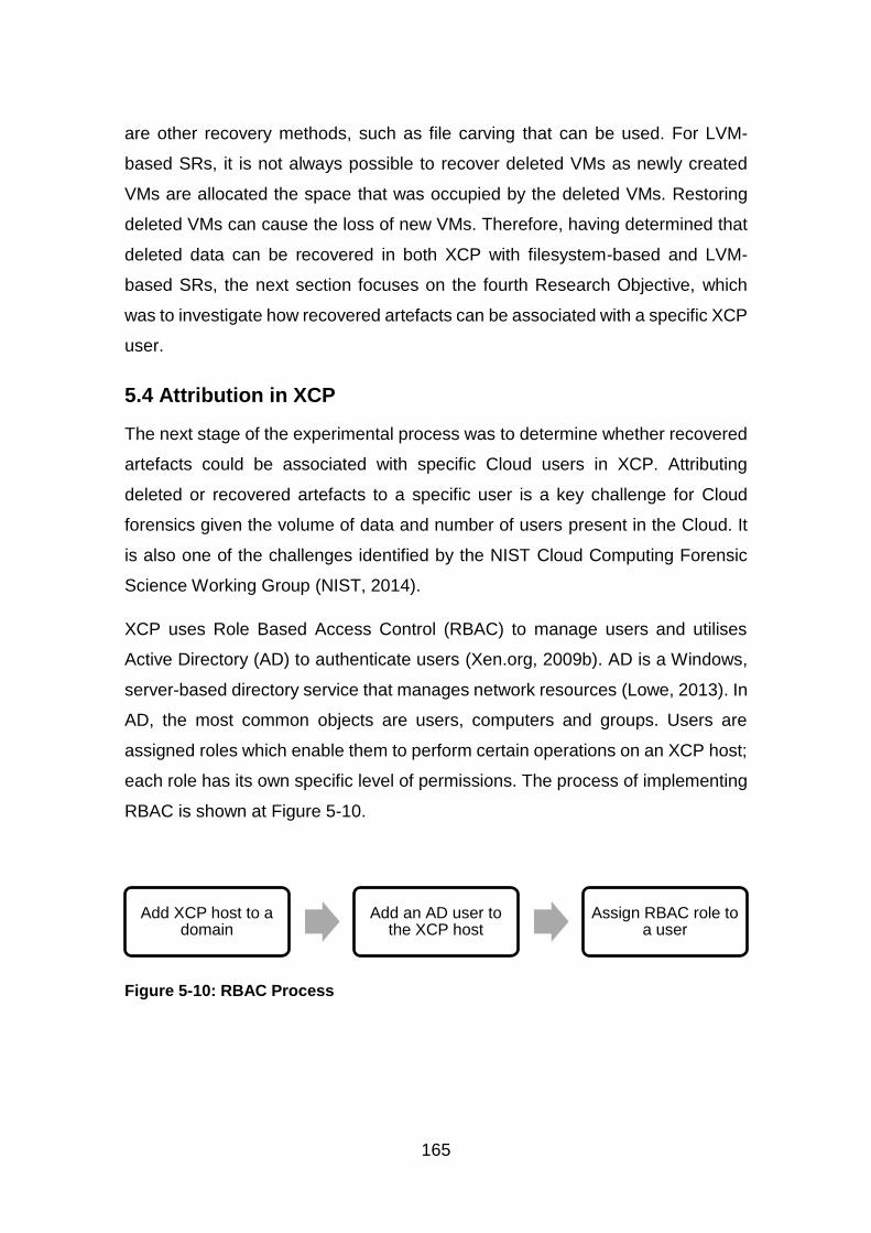
165
are other recovery methods, such as file carving that can be used. For LVM-
based SRs, it is not always possible to recover deleted VMs as newly created
VMs are allocated the space that was occupied by the deleted VMs. Restoring
deleted VMs can cause the loss of new VMs. Therefore, having determined that
deleted data can be recovered in both XCP with filesystem-based and LVM-
based SRs, the next section focuses on the fourth Research Objective, which
was to investigate how recovered artefacts can be associated with a specific XCP
user.
5.4 Attribution in XCP
The next stage of the experimental process was to determine whether recovered
artefacts could be associated with specific Cloud users in XCP. Attributing
deleted or recovered artefacts to a specific user is a key challenge for Cloud
forensics given the volume of data and number of users present in the Cloud. It
is also one of the challenges identified by the NIST Cloud Computing Forensic
Science Working Group (NIST, 2014).
XCP uses Role Based Access Control (RBAC) to manage users and utilises
Active Directory (AD) to authenticate users (Xen.org, 2009b). AD is a Windows,
server-based directory service that manages network resources (Lowe, 2013). In
AD, the most common objects are users, computers and groups. Users are
assigned roles which enable them to perform certain operations on an XCP host;
each role has its own specific level of permissions. The process of implementing
RBAC is shown at Figure 5-10.
Figure 5-10: RBAC Process
Add XCP host to a domain
Add an AD user to the XCP host
Assign RBAC role to a user
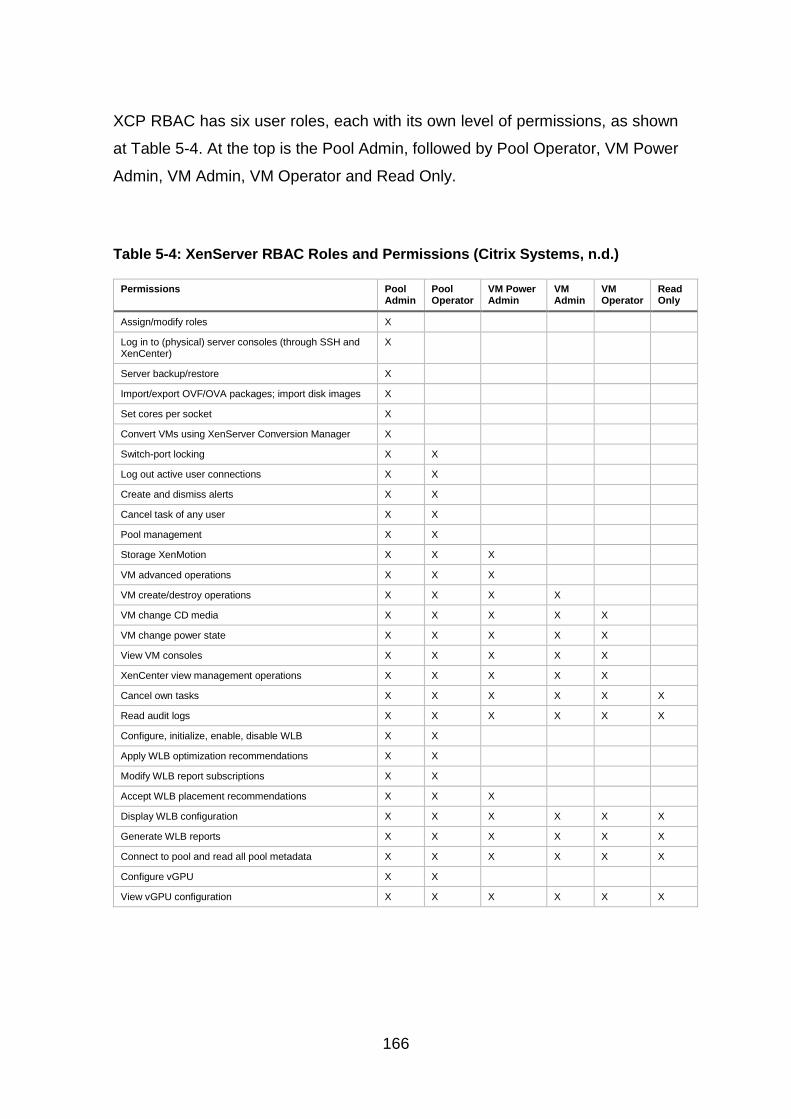
166
XCP RBAC has six user roles, each with its own level of permissions, as shown
at Table 5-4. At the top is the Pool Admin, followed by Pool Operator, VM Power
Admin, VM Admin, VM Operator and Read Only.
Table 5-4: XenServer RBAC Roles and Permissions (Citrix Systems, n.d.)
Permissions Pool Admin
Pool Operator
VM Power Admin
VM Admin
VM Operator
Read Only
Assign/modify roles X
Log in to (physical) server consoles (through SSH and XenCenter)
X
Server backup/restore X
Import/export OVF/OVA packages; import disk images X
Set cores per socket X
Convert VMs using XenServer Conversion Manager X
Switch-port locking X X
Log out active user connections X X
Create and dismiss alerts X X
Cancel task of any user X X
Pool management X X
Storage XenMotion X X X
VM advanced operations X X X
VM create/destroy operations X X X X
VM change CD media X X X X X
VM change power state X X X X X
View VM consoles X X X X X
XenCenter view management operations X X X X X
Cancel own tasks X X X X X X
Read audit logs X X X X X X
Configure, initialize, enable, disable WLB X X
Apply WLB optimization recommendations X X
Modify WLB report subscriptions X X
Accept WLB placement recommendations X X X
Display WLB configuration X X X X X X
Generate WLB reports X X X X X X
Connect to pool and read all pool metadata X X X X X X
Configure vGPU X X
View vGPU configuration X X X X X X
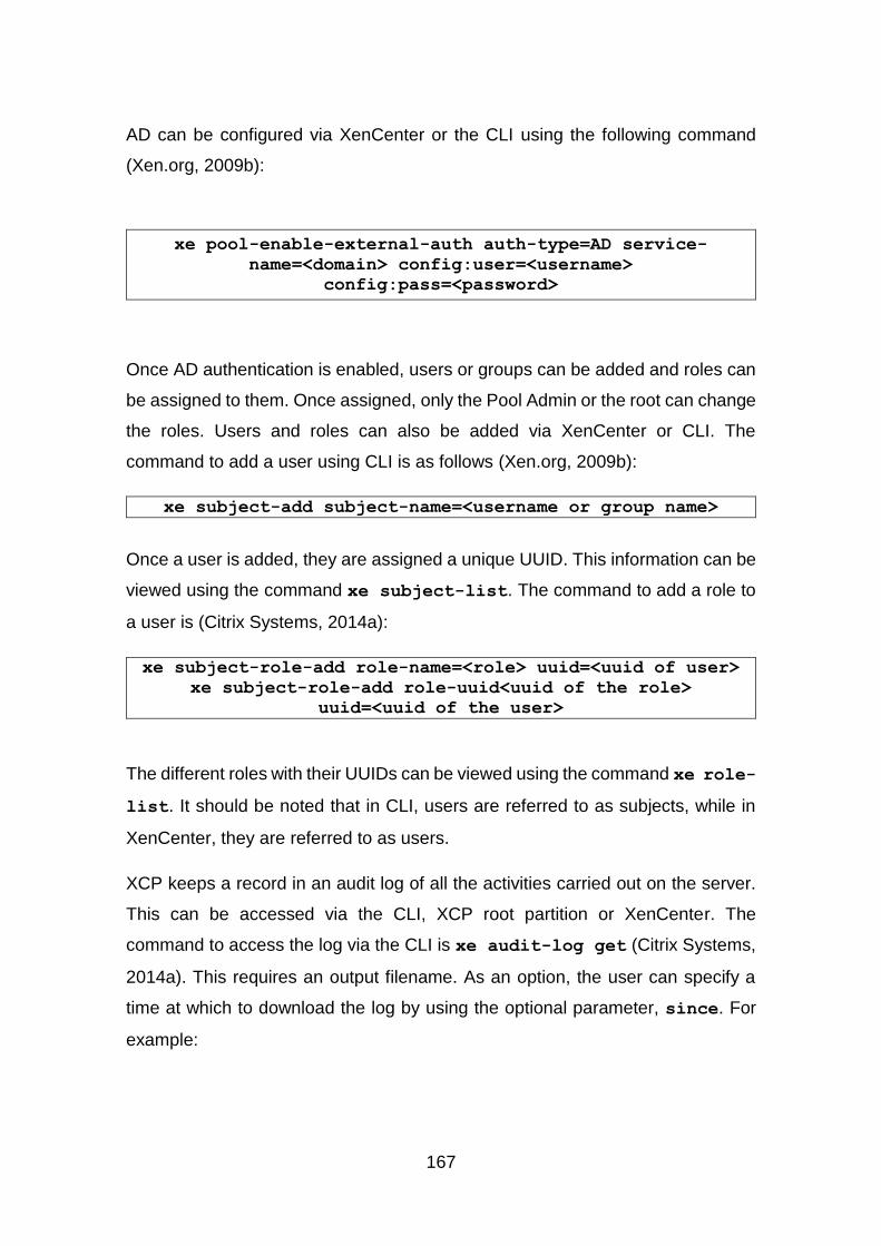
167
AD can be configured via XenCenter or the CLI using the following command
(Xen.org, 2009b):
xe pool-enable-external-auth auth-type=AD service-
name=<domain> config:user=<username>
config:pass=<password>
Once AD authentication is enabled, users or groups can be added and roles can
be assigned to them. Once assigned, only the Pool Admin or the root can change
the roles. Users and roles can also be added via XenCenter or CLI. The
command to add a user using CLI is as follows (Xen.org, 2009b):
xe subject-add subject-name=<username or group name>
Once a user is added, they are assigned a unique UUID. This information can be
viewed using the command xe subject-list. The command to add a role to
a user is (Citrix Systems, 2014a):
xe subject-role-add role-name=<role> uuid=<uuid of user>
xe subject-role-add role-uuid<uuid of the role>
uuid=<uuid of the user>
The different roles with their UUIDs can be viewed using the command xe role-
list. It should be noted that in CLI, users are referred to as subjects, while in
XenCenter, they are referred to as users.
XCP keeps a record in an audit log of all the activities carried out on the server.
This can be accessed via the CLI, XCP root partition or XenCenter. The
command to access the log via the CLI is xe audit-log get (Citrix Systems,
2014a). This requires an output filename. As an option, the user can specify a
time at which to download the log by using the optional parameter, since. For
example:
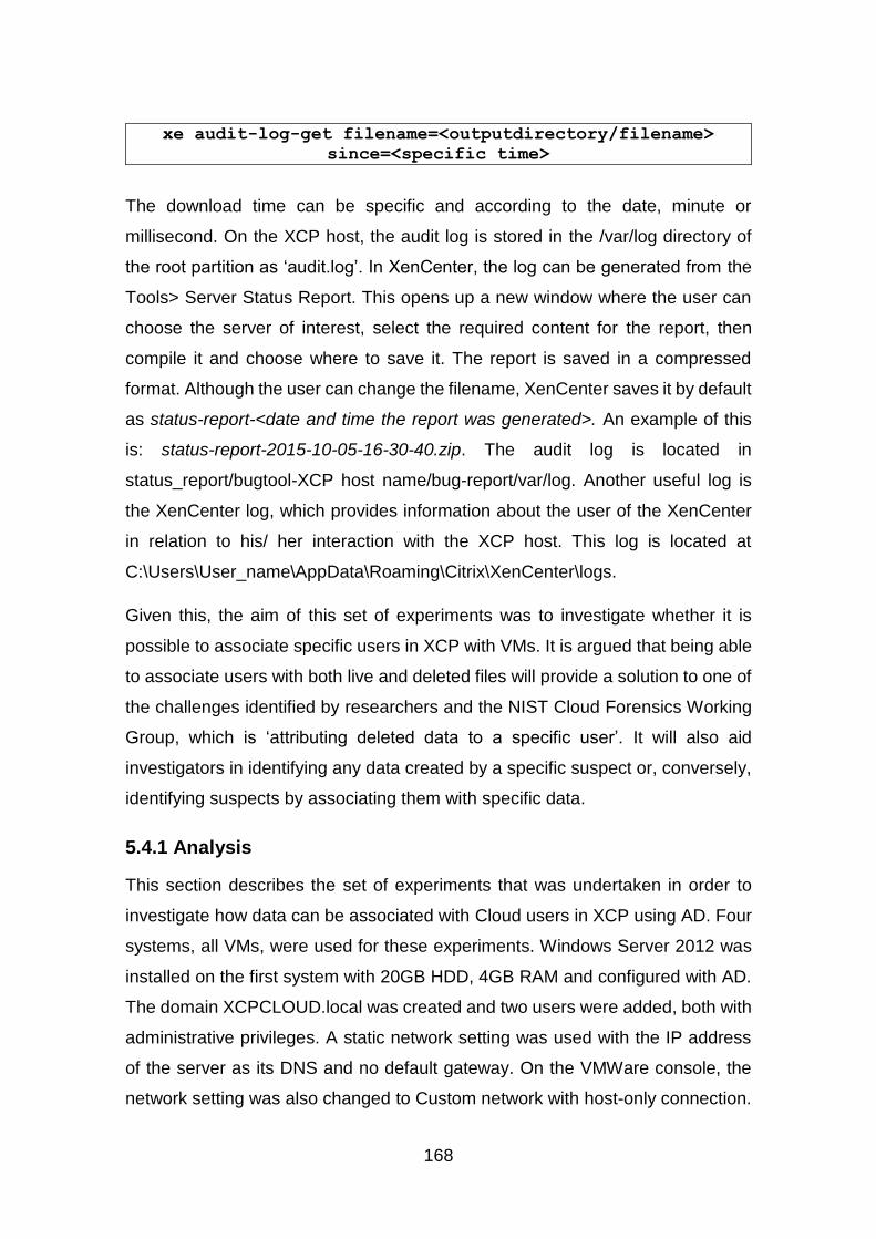
168
xe audit-log-get filename=<outputdirectory/filename>
since=<specific time>
The download time can be specific and according to the date, minute or
millisecond. On the XCP host, the audit log is stored in the /var/log directory of
the root partition as ‘audit.log’. In XenCenter, the log can be generated from the
Tools> Server Status Report. This opens up a new window where the user can
choose the server of interest, select the required content for the report, then
compile it and choose where to save it. The report is saved in a compressed
format. Although the user can change the filename, XenCenter saves it by default
as status-report-<date and time the report was generated>. An example of this
is: status-report-2015-10-05-16-30-40.zip. The audit log is located in
status_report/bugtool-XCP host name/bug-report/var/log. Another useful log is
the XenCenter log, which provides information about the user of the XenCenter
in relation to his/ her interaction with the XCP host. This log is located at
C:\Users\User_name\AppData\Roaming\Citrix\XenCenter\logs.
Given this, the aim of this set of experiments was to investigate whether it is
possible to associate specific users in XCP with VMs. It is argued that being able
to associate users with both live and deleted files will provide a solution to one of
the challenges identified by researchers and the NIST Cloud Forensics Working
Group, which is ‘attributing deleted data to a specific user’. It will also aid
investigators in identifying any data created by a specific suspect or, conversely,
identifying suspects by associating them with specific data.
5.4.1 Analysis
This section describes the set of experiments that was undertaken in order to
investigate how data can be associated with Cloud users in XCP using AD. Four
systems, all VMs, were used for these experiments. Windows Server 2012 was
installed on the first system with 20GB HDD, 4GB RAM and configured with AD.
The domain XCPCLOUD.local was created and two users were added, both with
administrative privileges. A static network setting was used with the IP address
of the server as its DNS and no default gateway. On the VMWare console, the
network setting was also changed to Custom network with host-only connection.
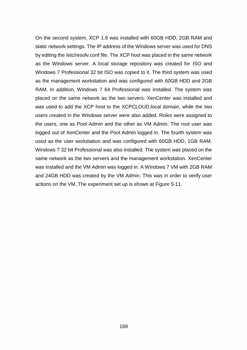
169
On the second system, XCP 1.6 was installed with 60GB HDD, 2GB RAM and
static network settings. The IP address of the Windows server was used for DNS
by editing the /etc/resolv.conf file. The XCP host was placed in the same network
as the Windows server. A local storage repository was created for ISO and
Windows 7 Professional 32 bit ISO was copied to it. The third system was used
as the management workstation and was configured with 60GB HDD and 2GB
RAM. In addition, Windows 7 64 Professional was installed. The system was
placed on the same network as the two servers. XenCenter was installed and
was used to add the XCP host to the XCPCLOUD.local domain, while the two
users created in the Windows server were also added. Roles were assigned to
the users, one as Pool Admin and the other as VM Admin. The root user was
logged out of XenCenter and the Pool Admin logged in. The fourth system was
used as the user workstation and was configured with 60GB HDD, 1GB RAM.
Windows 7 32 bit Professional was also installed. The system was placed on the
same network as the two servers and the management workstation. XenCenter
was installed and the VM Admin was logged in. A Windows 7 VM with 2GB RAM
and 24GB HDD was created by the VM Admin. This was in order to verify user
actions on the VM. The experiment set up is shown at Figure 5-11.
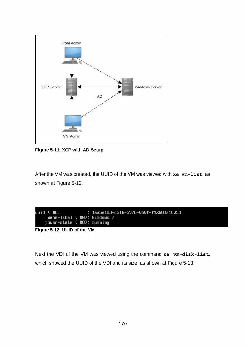
170
Figure 5-11: XCP with AD Setup
After the VM was created, the UUID of the VM was viewed with xe vm-list, as
shown at Figure 5-12.
Figure 5-12: UUID of the VM
Next the VDI of the VM was viewed using the command xe vm-disk-list,
which showed the UUID of the VDI and its size, as shown at Figure 5-13.
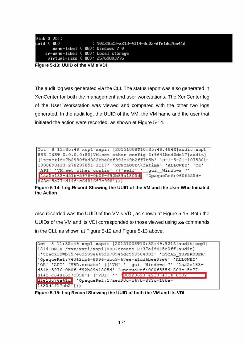
171
Figure 5-13: UUID of the VM’s VDI
The audit log was generated via the CLI. The status report was also generated in
XenCenter for both the management and user workstations. The XenCenter log
of the User Workstation was viewed and compared with the other two logs
generated. In the audit log, the UUID of the VM, the VM name and the user that
initiated the action were recorded, as shown at Figure 5-14.
Figure 5-14: Log Record Showing the UUID of the VM and the User Who Initiated the Action
Also recorded was the UUID of the VM’s VDI, as shown at Figure 5-15. Both the
UUIDs of the VM and its VDI corresponded to those viewed using xe commands
in the CLI, as shown at Figure 5-12 and Figure 5-13 above.
Figure 5-15: Log Record Showing the UUID of both the VM and its VDI
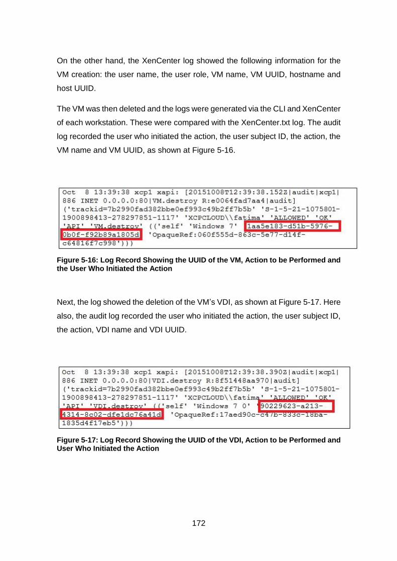
172
On the other hand, the XenCenter log showed the following information for the
VM creation: the user name, the user role, VM name, VM UUID, hostname and
host UUID.
The VM was then deleted and the logs were generated via the CLI and XenCenter
of each workstation. These were compared with the XenCenter.txt log. The audit
log recorded the user who initiated the action, the user subject ID, the action, the
VM name and VM UUID, as shown at Figure 5-16.
Figure 5-16: Log Record Showing the UUID of the VM, Action to be Performed and the User Who Initiated the Action
Next, the log showed the deletion of the VM’s VDI, as shown at Figure 5-17. Here
also, the audit log recorded the user who initiated the action, the user subject ID,
the action, VDI name and VDI UUID.
Figure 5-17: Log Record Showing the UUID of the VDI, Action to be Performed and User Who Initiated the Action
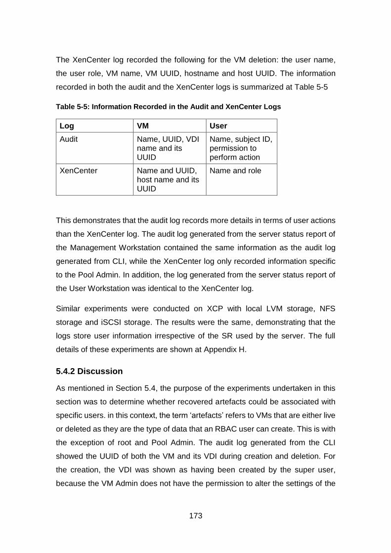
173
The XenCenter log recorded the following for the VM deletion: the user name,
the user role, VM name, VM UUID, hostname and host UUID. The information
recorded in both the audit and the XenCenter logs is summarized at Table 5-5
Table 5-5: Information Recorded in the Audit and XenCenter Logs
Log VM User
Audit Name, UUID, VDI name and its UUID
Name, subject ID, permission to perform action
XenCenter Name and UUID, host name and its UUID
Name and role
This demonstrates that the audit log records more details in terms of user actions
than the XenCenter log. The audit log generated from the server status report of
the Management Workstation contained the same information as the audit log
generated from CLI, while the XenCenter log only recorded information specific
to the Pool Admin. In addition, the log generated from the server status report of
the User Workstation was identical to the XenCenter log.
Similar experiments were conducted on XCP with local LVM storage, NFS
storage and iSCSI storage. The results were the same, demonstrating that the
logs store user information irrespective of the SR used by the server. The full
details of these experiments are shown at Appendix H.
5.4.2 Discussion
As mentioned in Section 5.4, the purpose of the experiments undertaken in this
section was to determine whether recovered artefacts could be associated with
specific users. in this context, the term ‘artefacts’ refers to VMs that are either live
or deleted as they are the type of data that an RBAC user can create. This is with
the exception of root and Pool Admin. The audit log generated from the CLI
showed the UUID of both the VM and its VDI during creation and deletion. For
the creation, the VDI was shown as having been created by the super user,
because the VM Admin does not have the permission to alter the settings of the

174
disk and memory of the VM. When the VM Admin tried to create the VM, a
warning appeared showing which actions the VM Admin is unable perform. This
is shown at Figure 5-18.
Figure 5-18: Warning
The UUID of the VM’s VDI is very important as it can be used to identify to which
VM it belongs and who created the VM after deletion. The VDI is saved as a VHD
file both in the filesystem and the LVM-based SRs of the XCP host. The UUID of
the VDI is used as the name of the file. This information can then be used to map
those users who created or deleted the VMs. As discussed in Section 5.2, when
a snapshot is created, this process creates two differencing child VHDs. The
parent VHD gets a new UUID and one of the child VHDs is assigned the UUID of
the parent. This can make it difficult to identify the parent VHD but it is likely that
the information on the snapshot, including the user that created it, is recorded in
the audit log.
In a server-status-report generated by the Pool Admin where the XenServer Logs
was selected, a log file was found in status_report/bugtool-xcpservername/bug-
report-date&time/var/log/audit.log. This keeps a record of all the operations that
have taken place within the XCP host. This is the same as the audit log generated
via CLI but is unlike the XenCenter log where only operations relating to the user
of that XenCenter are recorded. On the other hand, the permission level of the
VM Admin role is limited in terms of what such a user can add to the server status
report. In this instance, the user could not add XenServer logs. This shows that
the role of the user determines what that user can add to the server status report.
Therefore, if an investigator only has access to a suspect’s machine, it may not
be possible to access the audit. That said, the information in the XenCenter log
175
can be used to show user actions and to request more information from the Cloud
Service Provider (CSP).
While the results of these experiments are based on filesystem-based and LVM-
based SRs, it is possible that they may also apply to LUN-based SRs. This is
because the logs are created by the server and are not dependent on the SRs.
However, the use of the audit log is not without limitations as it can be deleted
directly from the root. Once deleted, all previous information on users is lost, and
at the server restart, a new audit log is created from that point in time. Even
though the log can be deleted, only users with root access can delete it and it can
be recovered, as shown above at Section 5.2.1 and Section 5.3.1. Therefore,
both the audit log and the XenCenter log should be used in an investigation, as
the XenCenter log can provide corroborative evidence on user actions.
Logs are a source of evidence which can be used on their own or as corroborative
evidence in digital forensics, as discussed by Birk and Wegener (2011), Marty
(2011), Sang (2013), Graves (2014) and Freet et al (2015). This section has
confirmed the importance of logs especially as corroborative evidence. As
mentioned, the logs generated by XCP are saved in text file and these can either
be modified or deleted. Therefore, they may be the need to protect such logs, as
without them, attribution may be difficult. To protect logs, Marty (2011) proposed
that they should be saved on a central log storage, using encrypted transport for
the transfer. In addition to this, Birk and Wegener (2011), Sang (2013), Graves
(2014) and Freet et al (2015) suggested encrypting the logs prior to transfer to
protect their integrity.
Sang (2013) further suggested the use of incremental hashing when
synchronising the logs between the CSP and the client system for the purposes
of data integrity. While this mechanism was proposed for PaaS and SaaS, it can
be argued that such mechanisms can also be implemented in IaaS, which is the
service type offered by XCP. As mentioned earlier, attribution in the Cloud is one
of the challenges of Cloud computing that has been identified by NIST Cloud
Computing Forensic Science Working Group (NIST, 2014). This research has
shown that it is possible. Storing logs on central log storage and the use of
176
encryption mechanisms can further ensure that such logs can be made available
if they are required during an investigation.
As with the sets of experiments described in the previous sections, test data were
also used for this set of experiments as they comply with the definition of test data
by Garfinkel et al (2009). As with the experiments described in Sections 5.2.2 and
5.3.2, these data sets satisfied the properties of evaluation of research in digital
forensics as proposed by Mocas (2004). The data for each set of experiments
can be duplicated as the processes involved in creating the data are clearly
documented (integrity). The data represents XCP with both filesystem-based and
LVM-based SRs and Windows server to enable RBAC (authentication). As with
the integrity property, the processes used to create the data is reproducible as
they are documented in such a way that a third party could use them with the
same results (reproducibility). The tools used to analyse the data did not change
it as the audit log used to associate a VM, live or deleted, was downloaded to an
external location (non-interference). The minimum amount of data (namely a
single XCP host connected to a domain with two users) was used to show that it
is possible to associate a deleted VM with a known XCP user (minimisation).
Therefore, they are valid to be used for research.
5.4.3 Attribution Summary
The results of this set of experiments show that it is possible to associate VM in
XCP with a user by using the audit log that was generated either via CLI or
XenCenter, the latter by selecting XenServer logs in the server status report. The
audit log records both the user information and the VM information, including the
UUID of VM’s VDI. As the UUID of the VDI is used as the name of the VHD file,
it can be used to search the audit log for the owner. Therefore, the unique nature
of the UUIDs makes it possible to associate users with live or deleted VMs unless
the audit log entry is deleted.
The experiments undertaken for this research and reported in this chapter have
identified how artefacts can be recovered and how they can be associated with a
user in XCP. While these findings are significant in terms of investigations in the
Cloud, it is acknowledged that they are specific to this research and may not be
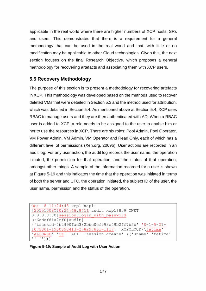
177
applicable in the real world where there are higher numbers of XCP hosts, SRs
and users. This demonstrates that there is a requirement for a general
methodology that can be used in the real world and that, with little or no
modification may be applicable to other Cloud technologies. Given this, the next
section focuses on the final Research Objective, which proposes a general
methodology for recovering artefacts and associating them with XCP users.
5.5 Recovery Methodology
The purpose of this section is to present a methodology for recovering artefacts
in XCP. This methodology was developed based on the methods used to recover
deleted VMs that were detailed in Section 5.3 and the method used for attribution,
which was detailed in Section 5.4. As mentioned above at Section 5.4, XCP uses
RBAC to manage users and they are then authenticated with AD. When a RBAC
user is added to XCP, a role needs to be assigned to the user to enable him or
her to use the resources in XCP. There are six roles: Pool Admin, Pool Operator,
VM Power Admin, VM Admin, VM Operator and Read Only, each of which has a
different level of permissions (Xen.org, 2009b). User actions are recorded in an
audit log. For any user action, the audit log records the user name, the operation
initiated, the permission for that operation, and the status of that operation,
amongst other things. A sample of the information recorded for a user is shown
at Figure 5-19 and this indicates the time that the operation was initiated in terms
of both the server and UTC, the operation initiated, the subject ID of the user, the
user name, permission and the status of the operation.
Oct 8 11:24:48 xcp1 xapi:
[20151008T10:24:48.841Z|audit|xcp1|859 INET
0.0.0.0:80|session.login_with_password
D:6adef81a7cf0|audit]
('trackid=7b2990fad382bbe0ef993c49b2ff7b5b' 'S-1-5-21-
1075801-1900898413-278297851-1117' 'XCPCLOUD\\fatima'
'ALLOWED' 'OK' 'API' 'session.create' (('uname' 'fatima'
'' '')))
Figure 5-19: Sample of Audit Log with User Action
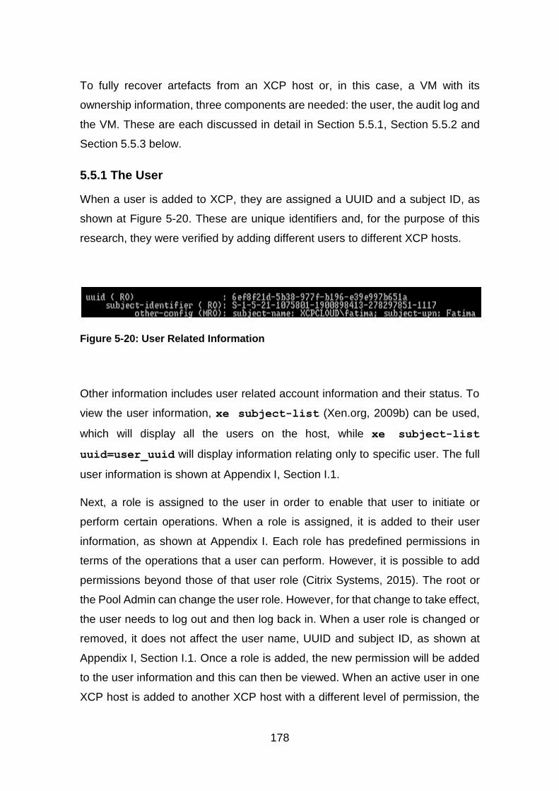
178
To fully recover artefacts from an XCP host or, in this case, a VM with its
ownership information, three components are needed: the user, the audit log and
the VM. These are each discussed in detail in Section 5.5.1, Section 5.5.2 and
Section 5.5.3 below.
5.5.1 The User
When a user is added to XCP, they are assigned a UUID and a subject ID, as
shown at Figure 5-20. These are unique identifiers and, for the purpose of this
research, they were verified by adding different users to different XCP hosts.
Figure 5-20: User Related Information
Other information includes user related account information and their status. To
view the user information, xe subject-list (Xen.org, 2009b) can be used,
which will display all the users on the host, while xe subject-list
uuid=user_uuid will display information relating only to specific user. The full
user information is shown at Appendix I, Section I.1.
Next, a role is assigned to the user in order to enable that user to initiate or
perform certain operations. When a role is assigned, it is added to their user
information, as shown at Appendix I. Each role has predefined permissions in
terms of the operations that a user can perform. However, it is possible to add
permissions beyond those of that user role (Citrix Systems, 2015). The root or
the Pool Admin can change the user role. However, for that change to take effect,
the user needs to log out and then log back in. When a user role is changed or
removed, it does not affect the user name, UUID and subject ID, as shown at
Appendix I, Section I.1. Once a role is added, the new permission will be added
to the user information and this can then be viewed. When an active user in one
XCP host is added to another XCP host with a different level of permission, the
179
user retains their name and subject ID but the UUID is changed, as shown at
Appendix I, Section I.1. This shows that the subject ID can be used to identify a
user on multiple XCP hosts, as long as they are in the same domain.
5.5.2 The Audit Log
The audit log records actions undertaken by all known users and it includes the
username and subject ID, the operation initiated, the permission for that
operation, and the status of the operation. This information can be used to map
the actions performed by a user, including VM creation and deletion, as shown at
Section 5.4.1 above. In an XCP pool, the pool master’s audit log records user
actions at pool level (Citrix Systems, n.d.). This means that all user actions on
any host in the pool are recorded in this log with each pool member keeping a
copy of their own audit log.
By default, the audit log is saved in the /var/log directory of the root partition. It
can be generated via the CLI with xe audit-log-get or via the XenCenter
Status Report. Logs are rotated based on the logrotate configuration file,
logrotate.conf, which is in the /etc/ directory; this contains the generic log
configurations. logrotate is a Linux utility which allows logs to be rotated,
compressed and mailed based on size or time interval (Troan and Brown, 2002).
Another file, logrotate-hourly.conf, sets the configuration for the audit log, as
shown at Appendix I, Figure I-6. The log files can be forced to rotate by using
either of the following commands:
logrotate –f /etc/logrotate.conf logrotate –f /etc/logrotate-hourly.conf
The audit log can be saved in a remote location by forwarding it to a syslog server.
The syslog information on the audit log is shown at Appendix I, Figure I-8. When
the audit log is forwarded to a remote syslog server, a copy is saved in the root
directory of the XCP host and this can still be generated via Status Report in
XenCenter and CLI. However, the saving of the audit log in the root directory can
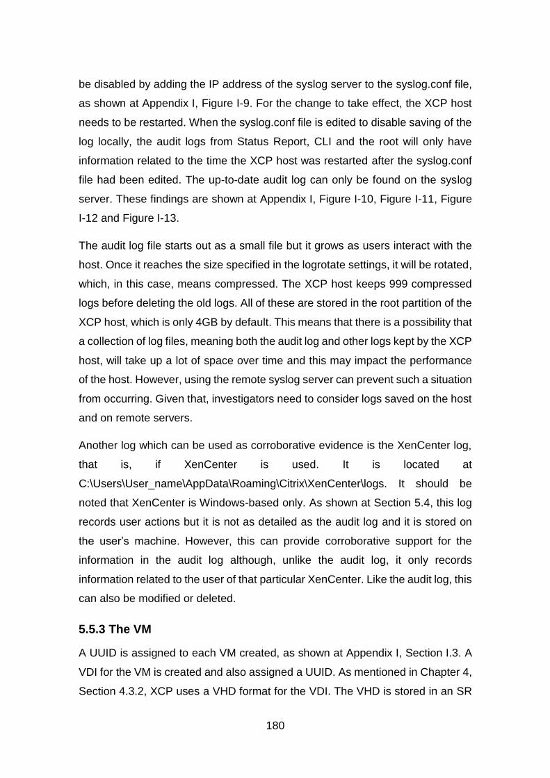
180
be disabled by adding the IP address of the syslog server to the syslog.conf file,
as shown at Appendix I, Figure I-9. For the change to take effect, the XCP host
needs to be restarted. When the syslog.conf file is edited to disable saving of the
log locally, the audit logs from Status Report, CLI and the root will only have
information related to the time the XCP host was restarted after the syslog.conf
file had been edited. The up-to-date audit log can only be found on the syslog
server. These findings are shown at Appendix I, Figure I-10, Figure I-11, Figure
I-12 and Figure I-13.
The audit log file starts out as a small file but it grows as users interact with the
host. Once it reaches the size specified in the logrotate settings, it will be rotated,
which, in this case, means compressed. The XCP host keeps 999 compressed
logs before deleting the old logs. All of these are stored in the root partition of the
XCP host, which is only 4GB by default. This means that there is a possibility that
a collection of log files, meaning both the audit log and other logs kept by the XCP
host, will take up a lot of space over time and this may impact the performance
of the host. However, using the remote syslog server can prevent such a situation
from occurring. Given that, investigators need to consider logs saved on the host
and on remote servers.
Another log which can be used as corroborative evidence is the XenCenter log,
that is, if XenCenter is used. It is located at
C:\Users\User_name\AppData\Roaming\Citrix\XenCenter\logs. It should be
noted that XenCenter is Windows-based only. As shown at Section 5.4, this log
records user actions but it is not as detailed as the audit log and it is stored on
the user’s machine. However, this can provide corroborative support for the
information in the audit log although, unlike the audit log, it only records
information related to the user of that particular XenCenter. Like the audit log, this
can also be modified or deleted.
5.5.3 The VM
A UUID is assigned to each VM created, as shown at Appendix I, Section I.3. A
VDI for the VM is created and also assigned a UUID. As mentioned in Chapter 4,
Section 4.3.2, XCP uses a VHD format for the VDI. The VHD is stored in an SR
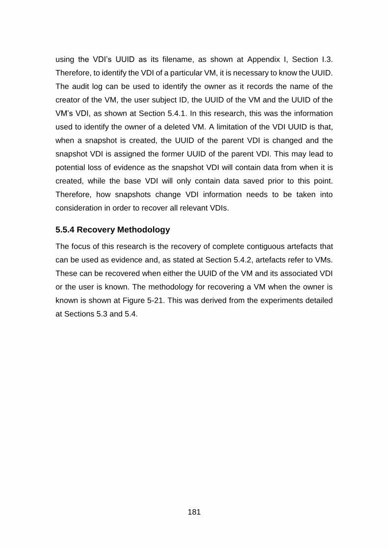
181
using the VDI’s UUID as its filename, as shown at Appendix I, Section I.3.
Therefore, to identify the VDI of a particular VM, it is necessary to know the UUID.
The audit log can be used to identify the owner as it records the name of the
creator of the VM, the user subject ID, the UUID of the VM and the UUID of the
VM’s VDI, as shown at Section 5.4.1. In this research, this was the information
used to identify the owner of a deleted VM. A limitation of the VDI UUID is that,
when a snapshot is created, the UUID of the parent VDI is changed and the
snapshot VDI is assigned the former UUID of the parent VDI. This may lead to
potential loss of evidence as the snapshot VDI will contain data from when it is
created, while the base VDI will only contain data saved prior to this point.
Therefore, how snapshots change VDI information needs to be taken into
consideration in order to recover all relevant VDIs.
5.5.4 Recovery Methodology
The focus of this research is the recovery of complete contiguous artefacts that
can be used as evidence and, as stated at Section 5.4.2, artefacts refer to VMs.
These can be recovered when either the UUID of the VM and its associated VDI
or the user is known. The methodology for recovering a VM when the owner is
known is shown at Figure 5-21. This was derived from the experiments detailed
at Sections 5.3 and 5.4.
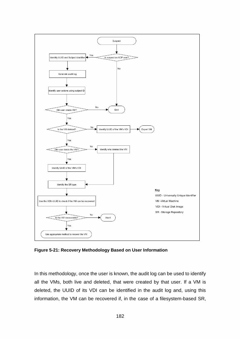
182
Figure 5-21: Recovery Methodology Based on User Information
In this methodology, once the user is known, the audit log can be used to identify
all the VMs, both live and deleted, that were created by that user. If a VM is
deleted, the UUID of its VDI can be identified in the audit log and, using this
information, the VM can be recovered if, in the case of a filesystem-based SR,
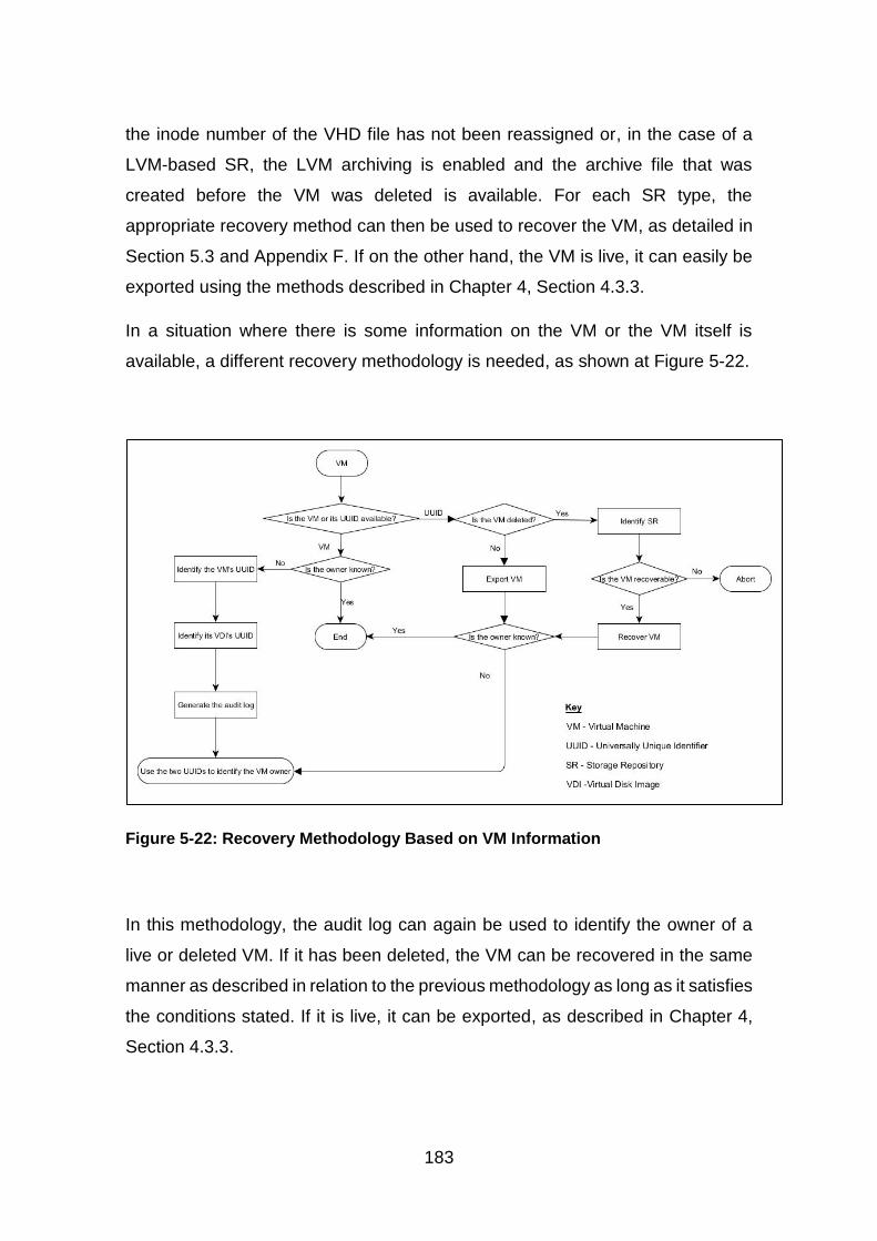
183
the inode number of the VHD file has not been reassigned or, in the case of a
LVM-based SR, the LVM archiving is enabled and the archive file that was
created before the VM was deleted is available. For each SR type, the
appropriate recovery method can then be used to recover the VM, as detailed in
Section 5.3 and Appendix F. If on the other hand, the VM is live, it can easily be
exported using the methods described in Chapter 4, Section 4.3.3.
In a situation where there is some information on the VM or the VM itself is
available, a different recovery methodology is needed, as shown at Figure 5-22.
Figure 5-22: Recovery Methodology Based on VM Information
In this methodology, the audit log can again be used to identify the owner of a
live or deleted VM. If it has been deleted, the VM can be recovered in the same
manner as described in relation to the previous methodology as long as it satisfies
the conditions stated. If it is live, it can be exported, as described in Chapter 4,
Section 4.3.3.

184
For both methodologies, the audit log is vital in relation to mapping the VM to its
owner. While the audit log can be deleted by the root, as was shown in Sections
5.2 and 5.3 above, deleted files can be recovered using either a manual or an
automated process. That being said, it will be difficult to associate a VM with a
user without the audit log, because it keeps a record of all user actions. However,
there are other logs that record user actions that could be used, including the
XenCenter log, as mentioned in Sections 5.4 and 5.5.2 above. Although this only
records actions specific to the XenCenter, regardless of the user permission level.
Information recorded for VM creation and deletion includes the action, the VM
name and UUID, the XCP host name and UUID, the status of the action, the user
name and role. However, when logged in as root, user name and role are not
recorded. The XenCenter log also records information on all the XCP hosts to
which it connects, which makes it possible to find records of any other XCP hosts
to which the user might have connected and the actions carried out by the user
on these hosts.
5.6 Methodology Discussion
The methodologies presented above at Section 5.5.3 can be used to recover
artefacts with ownership information in XCP, based on the available information.
For the experiments described in Section 5.3, the methodology shown at Figure
5-22 was used with the VM being recovered and then the owner of the VM being
identified based on the information in the audit log. For investigations in the real
world where a suspect is identified as an XCP user, the methodology shown at
Figure 5-21 above is considered to be more appropriate. This is because the user
information can be used to identify the VM that they created. For any of the
methodologies, two components are needed, the audit log and either the user or
the VM. If XenCenter is being used and the audit log is not available, then the
XenCenter log may provide some information that can be used to aid in the
recovery, although it does not record the same level of information as the audit
log. Therefore, this log is better for the provision of corroborative evidence. By
default, the audit log is stored in the /var/log directory of the XCP host but, as
discussed in Section 5.5.2 above, this can be changed to a remote syslog server.
185
This then makes it possible to store large audit log files without concerns about
their impact on the XCP host. As mentioned in Section 5.4.2 above, the audit log
can be deleted and, while it can be recovered, this may add another level of
complexity to an investigation. Also the audit log can be modified and, as with
deletion, this can only be done by root or a user with a Pool Admin role. This
shows that the audit log has some limitations. Like the audit log, the XenCenter
log can also be modified or deleted. However, unlike the audit log, regardless of
his or her permission level, the XenCenter user can delete or modify this log, as
it is stored on the user’s machine.
For investigations, both the audit and the XenCenter logs should be used as the
information in the XenCenter log can provide evidence to support the information
in the audit log. Also, in situations where an investigator only has access to the
suspect’s machine, the XenCenter log can provide information on the XCP host
or on the pool where the suspect’s VM is located and the VM UUID. This can then
be used to request more information from the CSP.
As the audit log is vital to the methodologies, additional steps should be
considered in order to preserve and protect such logs, as discussed in Section
5.4.2. The use of central log storage, encrypted transport channels and encrypted
logs are some of the solutions suggested by Birk and Wegener (2011), Marty
(2011), Sang (2013), Graves (2014) and Freet et al (2015). In terms of central log
storage, an option available in XCP is the use of a syslog server to store the audit
log. The syslog server can be used to store encrypted logs and the connection
between the Cloud server and the syslog server can be made secure either by
using encryption or other methods of securing a transport channel.
As discussed in Section 5.2.2, the VM is one of the sources of evidence that is
available in the Cloud (Birk and Wegener, 2011) and it can contain further
evidence which can be both live and deleted. Windows VM in XCP uses NTFS
as its filesystem while the VM itself is stored in either a filesystem-based SR which
uses ext3 or an LVM-based SR which uses LVM (Xen.org, 2009b). Deleted data
in NTFS and ext3 remain on disk until it is overwritten (Farmer and Venema,
2005; Fellows, 2005; Narvaez, 2007; Altheide and Carvey, 2011). In XCP with
186
filesystem-based and LVM-based SRs, deleted VMs remain on disk for some
time before it is removed. In both cases, such data can be recovered before it is
either overwritten or removed. However, this also depends on the storage device
being used, as disks such as Solid State Drive (SSD), utilise garbage collection
to erase unallocated blocks before they are reallocated (Chen et al., 2009; Bell
and Boddington, 2010). In such situations, it may be difficult to recover a deleted
VM and evidence may be lost. Therefore, there are various reasons why deleted
VMs may not be recoverable during an investigation. Evidence segregation
mechanisms, such as those proposed by Delport et al (2011), can be employed
in order to preserve and protect the integrity of evidence. Also, evidence
segregation ensures that the confidentiality of other users of a Cloud as well as
the admissibility of evidence (Ruan et al., 2011b).
As with previous sections, the two methodologies were developed using test data
and these test data were shown to have satisfied the five properties of evaluation
of research proposed by Mocas (2004). The methodologies presented at Section
5.5 were developed based on the experiments described in Sections 5.3 and 5.4.
These experiments used a limited data that is not representative of a real world
XCP Cloud. This raises questions about whether this methodology can be used
in the real world. To this end, it was necessary to test the findings of these
experiments in a larger Cloud in order to assess the generalisability of the
methodology. This is presented in the next section.
5.7 Generalisability of Recovery Methodology
The recovery methodology proposed in this research was created from a small
data set. The experimental set up that was described in Sections 5.2, 5.3 and 5.4
does not represent a real world XCP Cloud, but rather a subset of it and,
therefore, this may not provide an accurate measure for the generalisability of the
recovery methodology. Therefore, a larger Cloud with multiple servers, larger
storage capacity and multiple users was required. This was to provide a test
environment where users perform multiple tasks, similar to the situation found in
a real world Cloud. To achieve this, a combination of physical systems and VMs
was used.
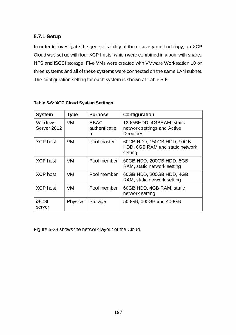
187
5.7.1 Setup
In order to investigate the generalisability of the recovery methodology, an XCP
Cloud was set up with four XCP hosts, which were combined in a pool with shared
NFS and iSCSI storage. Five VMs were created with VMware Workstation 10 on
three systems and all of these systems were connected on the same LAN subnet.
The configuration setting for each system is shown at Table 5-6.
Table 5-6: XCP Cloud System Settings
System Type Purpose Configuration
Windows Server 2012
VM RBAC authentication
120GBHDD, 4GBRAM, static network settings and Active Directory
XCP host VM Pool master 60GB HDD, 150GB HDD, 90GB HDD, 6GB RAM and static network setting
XCP host VM Pool member 60GB HDD, 200GB HDD, 8GB RAM, static network setting
XCP host VM Pool member 60GB HDD, 200GB HDD, 4GB RAM, static network setting
XCP host VM Pool member 60GB HDD, 4GB RAM, static network setting
iSCSI server
Physical Storage 500GB, 600GB and 400GB
Figure 5-23 shows the network layout of the Cloud.

188
Figure 5-23: XCP Cloud Network Layout
On the Windows server, AD was set up with one domain and 51 users with 11
created initially and 40 created later in order to give at least 50 users, the
minimum number of employees in a medium enterprise, according to Ward and
Rhodes (2014). On the pool master, NAT with DHCP settings was used to provide
access to the Internet. A 150GB HDD was added and a single partition was
created, formatted with ext3 which is used by XCP, this was configured as NFS
storage. Extundelete 0.2.4 and sleuthkit 3.2.3 were installed on the XCP host.
The network setting was changed to static and the IP address of the Windows
server was used as the DNS and network timeservers. The /etc/resolv.conf file
was edited to change the DNS server IP. A directory /sr was created in the root
and the ext3 filesystem was mounted on /sr. In order to ensure that the filesystem
was mounted on reboot, the /etc/fstab file was edited to add the following:
/dev/sdb1 /sr ext3 defaults 0 2
Two subdirectories, /sr/vm_sr and /sr/iso_sr were created in the /sr and the
/etc/exports file was edited to add the following:
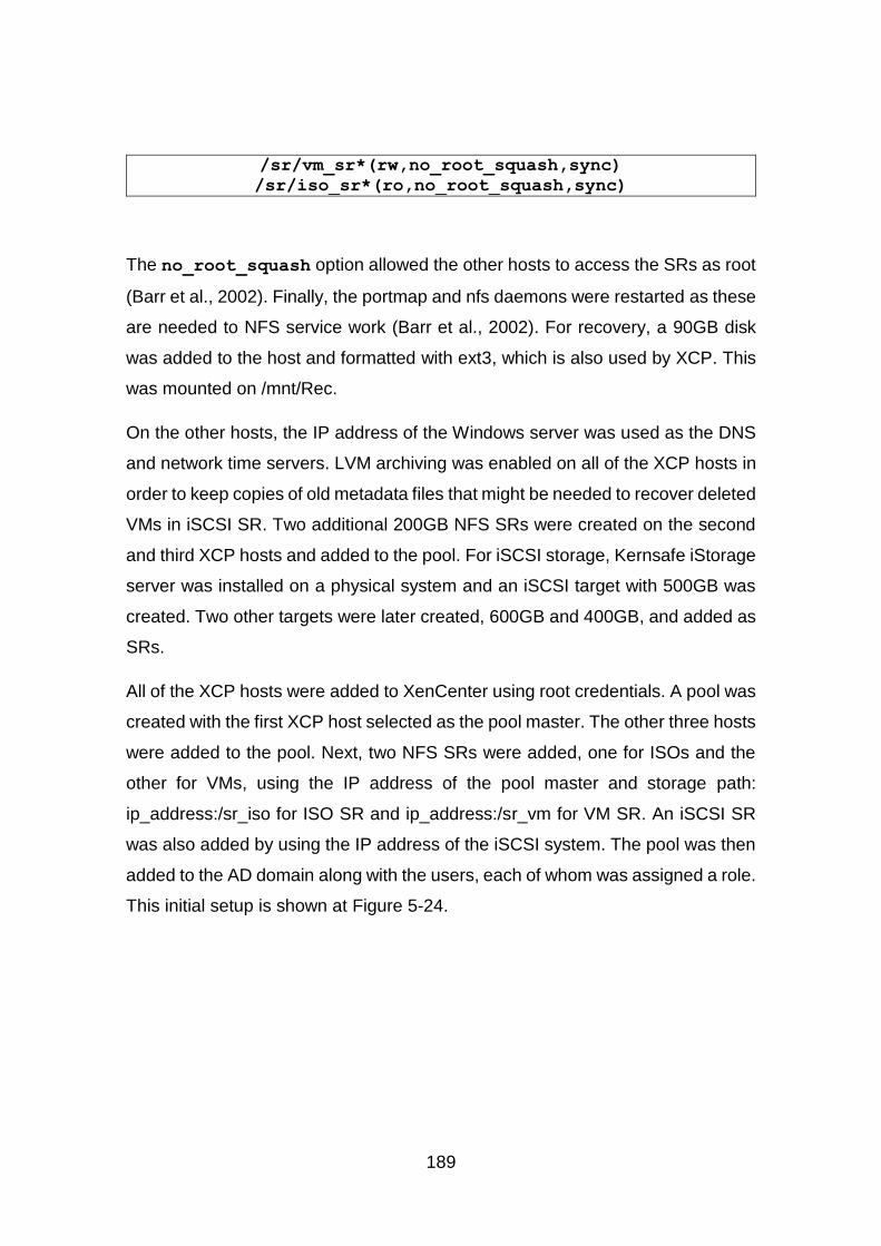
189
/sr/vm_sr*(rw,no_root_squash,sync)
/sr/iso_sr*(ro,no_root_squash,sync)
The no_root_squash option allowed the other hosts to access the SRs as root
(Barr et al., 2002). Finally, the portmap and nfs daemons were restarted as these
are needed to NFS service work (Barr et al., 2002). For recovery, a 90GB disk
was added to the host and formatted with ext3, which is also used by XCP. This
was mounted on /mnt/Rec.
On the other hosts, the IP address of the Windows server was used as the DNS
and network time servers. LVM archiving was enabled on all of the XCP hosts in
order to keep copies of old metadata files that might be needed to recover deleted
VMs in iSCSI SR. Two additional 200GB NFS SRs were created on the second
and third XCP hosts and added to the pool. For iSCSI storage, Kernsafe iStorage
server was installed on a physical system and an iSCSI target with 500GB was
created. Two other targets were later created, 600GB and 400GB, and added as
SRs.
All of the XCP hosts were added to XenCenter using root credentials. A pool was
created with the first XCP host selected as the pool master. The other three hosts
were added to the pool. Next, two NFS SRs were added, one for ISOs and the
other for VMs, using the IP address of the pool master and storage path:
ip_address:/sr_iso for ISO SR and ip_address:/sr_vm for VM SR. An iSCSI SR
was also added by using the IP address of the iSCSI system. The pool was then
added to the AD domain along with the users, each of whom was assigned a role.
This initial setup is shown at Figure 5-24.
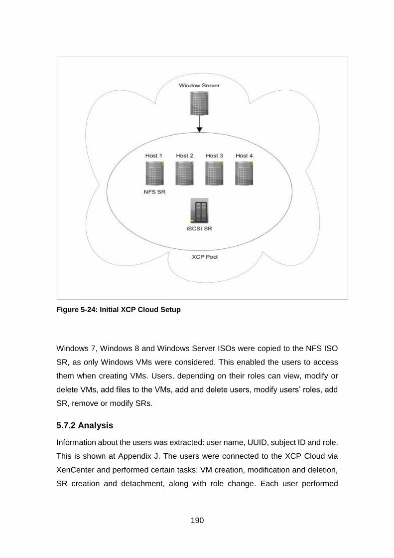
190
Figure 5-24: Initial XCP Cloud Setup
Windows 7, Windows 8 and Windows Server ISOs were copied to the NFS ISO
SR, as only Windows VMs were considered. This enabled the users to access
them when creating VMs. Users, depending on their roles can view, modify or
delete VMs, add files to the VMs, add and delete users, modify users’ roles, add
SR, remove or modify SRs.
5.7.2 Analysis
Information about the users was extracted: user name, UUID, subject ID and role.
This is shown at Appendix J. The users were connected to the XCP Cloud via
XenCenter and performed certain tasks: VM creation, modification and deletion,
SR creation and detachment, along with role change. Each user performed
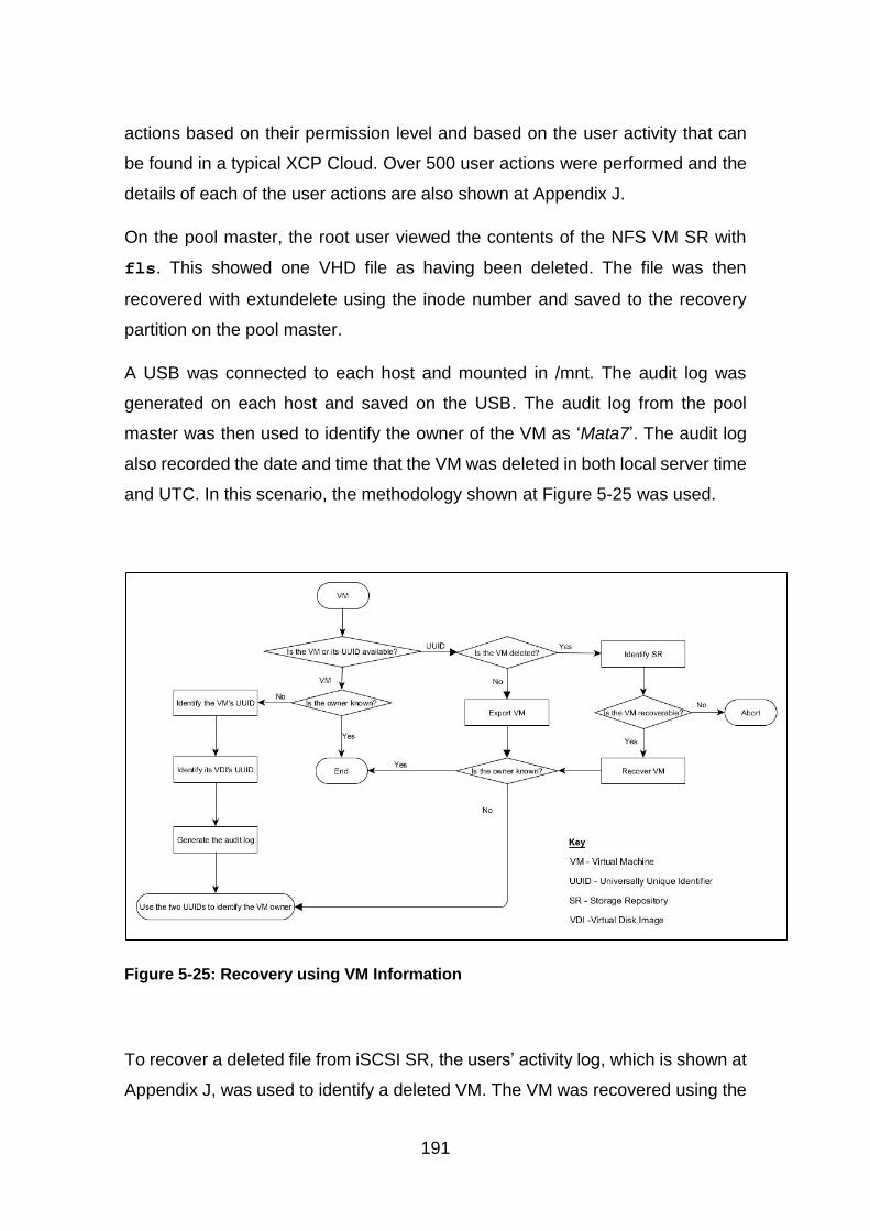
191
actions based on their permission level and based on the user activity that can
be found in a typical XCP Cloud. Over 500 user actions were performed and the
details of each of the user actions are also shown at Appendix J.
On the pool master, the root user viewed the contents of the NFS VM SR with
fls. This showed one VHD file as having been deleted. The file was then
recovered with extundelete using the inode number and saved to the recovery
partition on the pool master.
A USB was connected to each host and mounted in /mnt. The audit log was
generated on each host and saved on the USB. The audit log from the pool
master was then used to identify the owner of the VM as ‘Mata7’. The audit log
also recorded the date and time that the VM was deleted in both local server time
and UTC. In this scenario, the methodology shown at Figure 5-25 was used.
Figure 5-25: Recovery using VM Information
To recover a deleted file from iSCSI SR, the users’ activity log, which is shown at
Appendix J, was used to identify a deleted VM. The VM was recovered using the
192
vgcfgrestore command with the last archive file which was active prior to the
deletion of the VM. The audit logs were used to identify the owner of the VM as
the user ‘Mata2’. This methodology is shown at Figure 5-25 above.
A user with a deleted VM was selected and identified as ‘Test2’. As the user
information was available, the methodology shown at Figure 5-26 was used. The
subject ID of the user enabled the identification of the UUID of the VM’s VDI and
the SR that had been used, which was an NFS SR. This was examined in order
to determine whether the VDI was recoverable. However, the VDI was not listed.
Extundelete was used with both the filename and restore all options, but the VDI
could not be recovered.

193
Figure 5-26: Recovery using User information
Another user with a deleted VM was selected and identified as ‘Manager’. The
deleted VM had two disks, one 24GB and the other 70GB. The audit logs were
used to identify the UUID of the VM’s VDIs. The audit log also identified the SR
used as an iSCSI SR. Using the UUID of the VDIs, the LVM archive files of the
SR were viewed to identify the file that could be used to recover the VM. Once
the file was identified, the VM was recovered, as shown at Figure 5-27.
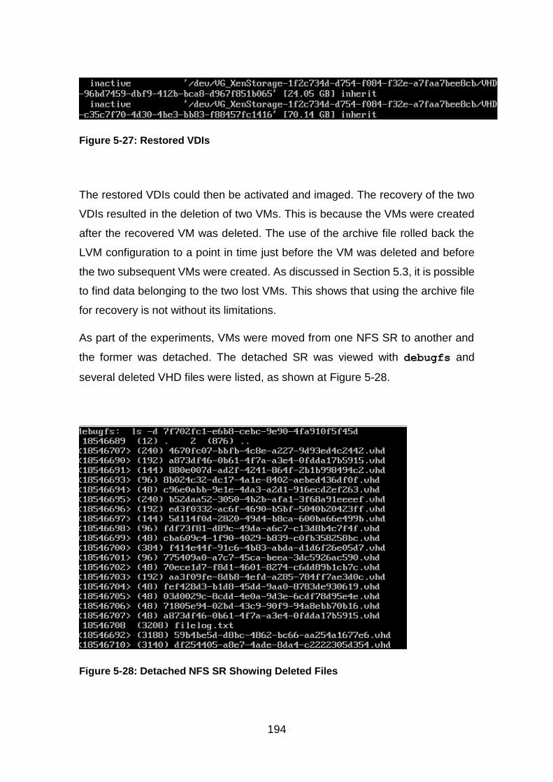
194
Figure 5-27: Restored VDIs
The restored VDIs could then be activated and imaged. The recovery of the two
VDIs resulted in the deletion of two VMs. This is because the VMs were created
after the recovered VM was deleted. The use of the archive file rolled back the
LVM configuration to a point in time just before the VM was deleted and before
the two subsequent VMs were created. As discussed in Section 5.3, it is possible
to find data belonging to the two lost VMs. This shows that using the archive file
for recovery is not without its limitations.
As part of the experiments, VMs were moved from one NFS SR to another and
the former was detached. The detached SR was viewed with debugfs and
several deleted VHD files were listed, as shown at Figure 5-28.
Figure 5-28: Detached NFS SR Showing Deleted Files
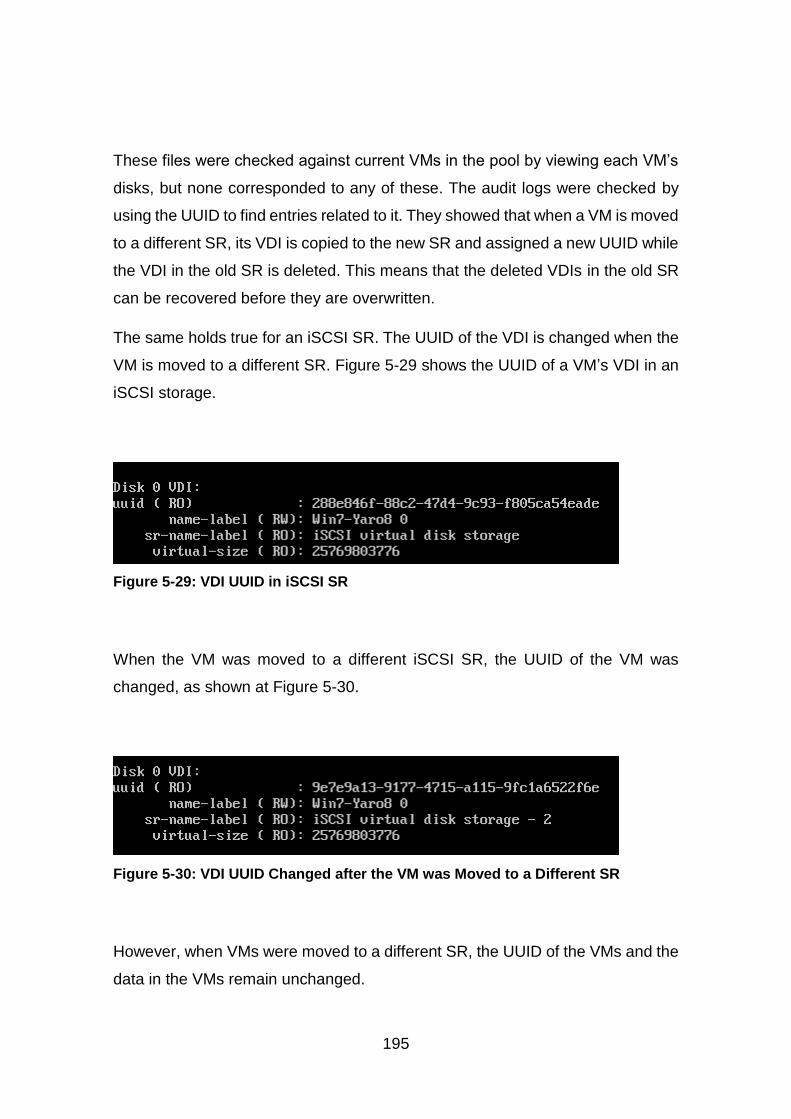
195
These files were checked against current VMs in the pool by viewing each VM’s
disks, but none corresponded to any of these. The audit logs were checked by
using the UUID to find entries related to it. They showed that when a VM is moved
to a different SR, its VDI is copied to the new SR and assigned a new UUID while
the VDI in the old SR is deleted. This means that the deleted VDIs in the old SR
can be recovered before they are overwritten.
The same holds true for an iSCSI SR. The UUID of the VDI is changed when the
VM is moved to a different SR. Figure 5-29 shows the UUID of a VM’s VDI in an
iSCSI storage.
Figure 5-29: VDI UUID in iSCSI SR
When the VM was moved to a different iSCSI SR, the UUID of the VM was
changed, as shown at Figure 5-30.
Figure 5-30: VDI UUID Changed after the VM was Moved to a Different SR
However, when VMs were moved to a different SR, the UUID of the VMs and the
data in the VMs remain unchanged.
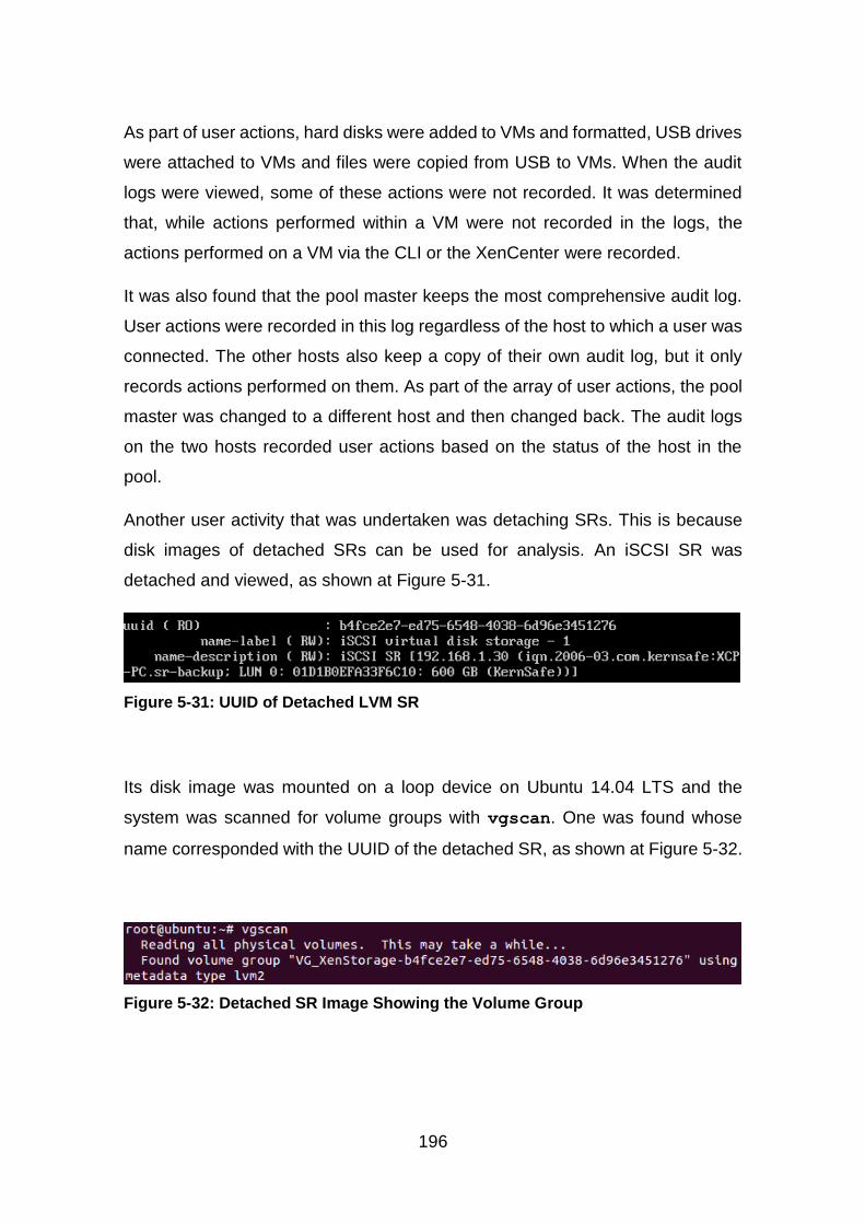
196
As part of user actions, hard disks were added to VMs and formatted, USB drives
were attached to VMs and files were copied from USB to VMs. When the audit
logs were viewed, some of these actions were not recorded. It was determined
that, while actions performed within a VM were not recorded in the logs, the
actions performed on a VM via the CLI or the XenCenter were recorded.
It was also found that the pool master keeps the most comprehensive audit log.
User actions were recorded in this log regardless of the host to which a user was
connected. The other hosts also keep a copy of their own audit log, but it only
records actions performed on them. As part of the array of user actions, the pool
master was changed to a different host and then changed back. The audit logs
on the two hosts recorded user actions based on the status of the host in the
pool.
Another user activity that was undertaken was detaching SRs. This is because
disk images of detached SRs can be used for analysis. An iSCSI SR was
detached and viewed, as shown at Figure 5-31.
Figure 5-31: UUID of Detached LVM SR
Its disk image was mounted on a loop device on Ubuntu 14.04 LTS and the
system was scanned for volume groups with vgscan. One was found whose
name corresponded with the UUID of the detached SR, as shown at Figure 5-32.
Figure 5-32: Detached SR Image Showing the Volume Group
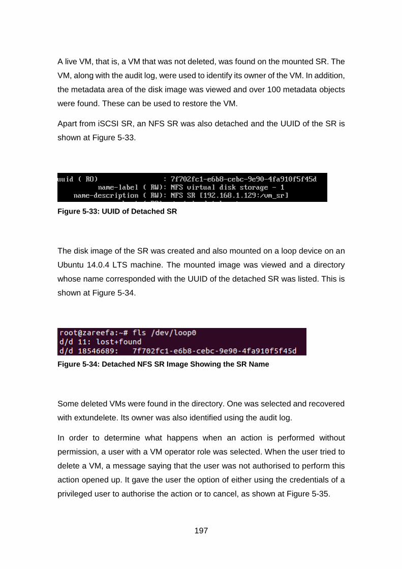
197
A live VM, that is, a VM that was not deleted, was found on the mounted SR. The
VM, along with the audit log, were used to identify its owner of the VM. In addition,
the metadata area of the disk image was viewed and over 100 metadata objects
were found. These can be used to restore the VM.
Apart from iSCSI SR, an NFS SR was also detached and the UUID of the SR is
shown at Figure 5-33.
Figure 5-33: UUID of Detached SR
The disk image of the SR was created and also mounted on a loop device on an
Ubuntu 14.0.4 LTS machine. The mounted image was viewed and a directory
whose name corresponded with the UUID of the detached SR was listed. This is
shown at Figure 5-34.
Figure 5-34: Detached NFS SR Image Showing the SR Name
Some deleted VMs were found in the directory. One was selected and recovered
with extundelete. Its owner was also identified using the audit log.
In order to determine what happens when an action is performed without
permission, a user with a VM operator role was selected. When the user tried to
delete a VM, a message saying that the user was not authorised to perform this
action opened up. It gave the user the option of either using the credentials of a
privileged user to authorise the action or to cancel, as shown at Figure 5-35.
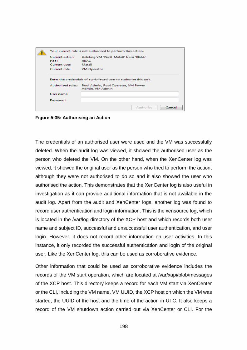
198
Figure 5-35: Authorising an Action
The credentials of an authorised user were used and the VM was successfully
deleted. When the audit log was viewed, it showed the authorised user as the
person who deleted the VM. On the other hand, when the XenCenter log was
viewed, it showed the original user as the person who tried to perform the action,
although they were not authorised to do so and it also showed the user who
authorised the action. This demonstrates that the XenCenter log is also useful in
investigation as it can provide additional information that is not available in the
audit log. Apart from the audit and XenCenter logs, another log was found to
record user authentication and login information. This is the xensource log, which
is located in the /var/log directory of the XCP host and which records both user
name and subject ID, successful and unsuccessful user authentication, and user
login. However, it does not record other information on user activities. In this
instance, it only recorded the successful authentication and login of the original
user. Like the XenCenter log, this can be used as corroborative evidence.
Other information that could be used as corroborative evidence includes the
records of the VM start operation, which are located at /var/xapi/blob/messages
of the XCP host. This directory keeps a record for each VM start via XenCenter
or the CLI, including the VM name, VM UUID, the XCP host on which the VM was
started, the UUID of the host and the time of the action in UTC. It also keeps a
record of the VM shutdown action carried out via XenCenter or CLI. For the
199
shutdown, it records the VM name, its UUID and the time of the action in UTC.
However, it does not record user information. XCP keeps a database of user, VM
and host information, which is stored in state.db located at /var/xapi/. Another
database, lsass-adcache.db, which is solely for AD user information was found.
This stores the name and the subject ID, and is located at /var/lib/likewise/db.
5.7.3 Discussion
The results show that while it is possible to recover VMs in the Cloud using the
two recovery methodologies identified above at Figure 5-25 and Figure 5-26, it
may not always be possible. With the tools used in this research, it is possible to
recover deleted VMs in NFS SR as long as the inode number of the VM’s VDI
has not been reassigned. If it has been reassigned, it makes recovery difficult but
not impossible, as long as the VDI is not overwritten. In Section 5.7.2 above, a
VDI could not be recovered because its inode number was reassigned, even
when the restore all option was used.
On the other hand, LVM archive files were used to recover VM saved in iSCSI
SR. The minimum number of archive files that can be stored is 10 and there were
380 in the pool master at the end of the experiments. These are retained for a
minimum of 30 days, which is the default setting in the lvm.conf file. Neither the
maximum number of files nor the maximum number of days that they are retained
are specified in the lvm.conf file. In addition, neither minimum nor maximum file
size is specified. It should be noted that recovery with archive files is not without
its challenges. Primarily that, the LVM configuration rolls back to the configuration
contained in the archive file. This means that any subsequent configuration
change after the file was created will be lost. A way round this is to move the VMs
to a different SR before attempting recovery. An alternative method is to use
manual recovery techniques. For these experiments, when a VM that was stored
in iSCSI SR was recovered, it resulted in the deletion of two VMs that were
created after the VM was deleted. This is because the LVM configuration rolled
back to a time before their creation.
As shown in Section 5.7.2 above, when a VM is moved from one SR to another,
its VDI is copied to the new SR while the one in the old SR is deleted. Also the
200
UUID of the VDI is changed. In both NFS and iSCSI SRs, these VDIs can be
recovered from the old SR before they are overwritten. Note that they will only
contain data up to the point of deletion.
These experiments showed that any action performed inside the VM is not
recorded in the audit log. Examples include restarting a VM, formatting a disk,
and copying a file. On the other hand, actions performed via XenCenter or CLI
are recorded. They also showed that each host keeps a copy of the audit log but
that the most comprehensive log is kept by the pool master. This suggests that,
when using the audit log for recovery in a pool, it is more prudent to use the logs
from all the hosts in the pool and not to rely only on the log from the pool master
for completeness. This is because the pool master can be changed, as in these
experiments, or removed from the pool. Another option is to forward the audit log
of all hosts in a pool to a remote server, as discussed in Section 5.5.2. This way,
the logs from all the hosts will be stored in the same location and they will be
easier to access.
For the most part, the focus of this research has been the recovery of VMs from
a live Cloud system and the recovery methodology developed reflected this. This
is not to say that it cannot be used for dead analysis. As shown in Section 5.7.2
above, there may be instances where images from SRs are available. These can
still provide evidence such as live or deleted VMs which can either be imaged or
recovered. The audit log can be used to identify their owners. For iSCSI SR, when
an image is created, it may not be possible to have all the LVM archive files as
they will be on the host system. However, it is still possible to find the metadata
in the metadata area of the disk image. These can be extracted and used to
restore logical volumes (Bros, 2009). While this was not undertaken for the
purposes of this research, the disk image of the iSCSI SR was viewed and it was
confirmed that the metadata was on the disk.
As discussed in Section 5.4, there are six different roles that users can be
assigned and each has its own level of permission. User actions are recorded in
an audit log; this log can be used to map user actions, as was also shown in
Section 5.4. When a user tried to perform an action for which he or she was not
201
authorised, that user was then given an option to either cancel or to use the
credentials of a user whose role had the relevant permission for that action. This
action was performed as part of the experimental process reported above in
Section 5.7.2. The audit log recorded that action as initiated by the user whose
credentials were used and no reference was made to the original user who
initiated the action. The XenCenter log provided more information in this instance.
It recorded both the user who initiated the action and the user who authorised the
action. This shows that there are situations where the XenCenter log provides
more information than the audit log and, therefore, both should be used in order
to ensure completeness of information. On the other hand, xensource log can be
used to show user authentication and login activities, which may be useful as
supporting evidence for both the audit and the XenCenter logs.
For investigations where an examiner only has access to a suspect’s machine, it
is possible to find some information on user activities in the XenCenter log, if
XenCenter is being used. Also, a server status report can be generated from
XenCenter, which may include the audit log. This depends on the permission
level of the user. However, even if the audit log is not available, the information
from the XenCenter log can be used to identify the username, role, actions
performed, and whether they were successful or not, VM name and UUID,
pool/host name and UUID. With this information, the examiner can request more
information from the CSP. However, if the examiner has access to the host, then
the XenCenter log can be used as corroborative evidence.
Another log that may be of use is the xensource log, as this can be used to show
the times a user was authenticated and logged in. Rather like the XenCenter log,
it can be used to corroborate the information in the audit log. The records found
in /var/xapi/blob/message are another source of information that can be used to
support the information in the audit log. These only record VM start and shutdown
initiated via XenCenter or CLI and do not record the user who initiated the action.
The UTC time in these records corresponds to the UTC time in the audit log. The
host uses local time but records both the UTC and local time in the audit log. The
records of both deleted and live VMs are stored. Finally, two database files were

202
found, state.db and lsass-adcache.db, which keep user related information. While
lsass-adcache.db only keeps user information, state.db also keeps VM and host
information in addition to user information. These can be used to corroborate the
information in the audit log. If the audit log is not available, they may still provide
useful information in an investigation. Therefore, all these logs and database files
need to be taken into consideration when investigating an XCP Cloud.
In Sections 5.4 and 5.6, logs were discussed and as they can be deleted, identify
ways in which to protect and preserve them based on the suggestions by Birk
and Wegener (2011), Marty (2011), Sang (2013), Graves (2014) and Freet et al
(2015). Particular attention was paid to the audit log and it was shown that it is
possible to store the audit log on a syslog server. This is comparable with storing
it within central log storage. Other logs, such as the xensource log which may be
useful in investigations, should also be stored within a central log storage. The
database files which may be provide useful information can be backed up on a
different server, in order to protect and preserve them.
The data used in this section was intended to be representative of realistic data,
the type of data which might be found in an investigation (Garfinkel et al., 2009).
This is unlike the data used in the experiments described in the previous sections
and in Chapter 4. As with the other experiments, the data corpus was evaluated
in relation to the five properties proposed by Mocas (2004). Of these five, four
were satisfied: integrity, authentication, reproducibility and non-interference. The
data can be duplicated as the steps used for the creation are well documented,
thereby satisfying the integrity requirement (integrity). The data represent an XCP
Cloud with four hosts, one Windows server to provide AD services, two NFS SRs,
two iSCSI SRs and 51 users (authentication). The documentation of the
processes involved in creating the data ensures that the reproducibility
requirement is fulfilled (reproducibility), while the tools used for analysis did not
change the data (non-interference). However, the property described as
minimisation not be satisfied as more than a minimum amount of data was used
in the context of this research.

203
5.7.4 Generalisability Summary
These sets of experiment demonstrate that the two methodologies presented in
Section 5.5 above can be used to recover VMs with their ownership information.
In addition, it has been shown that they are applicable in the real world. However,
the use of an archive file for recovery in an iSCSI can result in data loss and,
therefore, it is more prudent to carry out the recovery after moving VMs to a
different SR. While the audit log on the pool master is more comprehensive, the
use of logs from all hosts in a pool can provide more accurate information.
5.8 Conclusion
This chapter has described how XCP manages deleted files with a view to
addressing Research Objectives 3, 4 and 5. These were concerned with
investigating how existing tools can be used to recover artefacts in XCP, how the
recovered artefacts can be associated with XCP users and to propose an artefact
recovery methodology for XCP. To this end, experiments were carried out to
demonstrate that the VM is managed by the filesystem of the SRs, which is ext3
for XCP. For LVM-based SRs, this is managed by LVM. A range of forensic tools
was investigated and two tools, Sleuthkit and extundelete, were selected to
recover data in filesystem-based SRs. For LVM-based SRs, the LVM tools
themselves could be used to recover data. The way in which XCP manages users
with AD, and how it records all user actions in an audit log were described. This
showed that user information, such as user name, subject ID, actions performed
and status of actions, is recorded. This information can be used to associate
recovered artefacts with users.
Experiments were conducted to document the information about users that the
XCP host records. This showed that the information in the log can be used to
associate data with a specific user. Finally, a general methodology was proposed
for artefact recovery which identified three key components: user, audit log and
the VM. The audit log plays a key role in associating a user with a VM but it is
recognised that it is not without its limitations, primarily the fact that it can be
deleted. On the other hand, the audit log can be saved in a remote location, so
as to conserve space on the XCP host. The generalisability of the methodology
204
was assessed in a larger XCP Cloud which was made up of four XCP hosts in a
pool with both NFS and iSCSI SR and 51 users. This showed that the
methodology can be used in a large XCP Cloud to recover VM with their
ownership information. It also showed that there is other information apart from
the three main components that may be useful in an investigation.
Having determined that deleted files remain on a disk until it is overwritten, that
deleted data can be recovered with existing tools, and that recovered data can
be associated with specific users in XCP with filesystem-based and LVM-based
SRs, the purpose of the next chapter is to evaluate the methodology used and to
assess the evidential value of the recovered artefacts based on the criteria
outlined in Chapter 3.
205
6 Evaluation
6.1 Introduction
The aim of this research is to evaluate the evidential value of artefacts that are
recovered from a private Cloud using existing digital forensic investigation tools.
To achieve this aim, structural studies on the Logical Volume Manager (LVM) and
Xen Cloud Platform (XCP) were conducted to provide a baseline for evaluating
the evidential value of artefacts recovered from the XCP. Three key areas were
identified: the use of existing tools, the artefact recovery and the evaluation of
evidential value. To this end, a general methodology was developed in Chapter
3 for adding existing tools in the Cloud. A set of general criteria was proposed for
evaluating the evidential value of any digital evidence retrieved, following a review
of the current requirements for digital evidence, which were also discussed in
Chapter 3. Finally, a methodology was developed in Chapter 5 that is specifically
designed for the purpose of artefact recovery in XCP.
The purpose of this chapter is to evaluate the methodologies for adding existing
tools to the Cloud, for artefacts recovered from XCP and to evaluate the criteria
proposed for evaluating digital evidence that was proposed in Chapter 3. The
discussion begins by reviewing the methodologies that were developed for
adding existing tools to the Cloud and for the recovery of artefacts from XCP. This
is followed by an overview of the method that was used to identify a framework
for evaluating the value of digital evidence and the proposed criteria. The chapter
ends with an assessment of the artefacts that were recovered as a result of this
research, set against each of the criteria defined in the evaluation framework, in
order to establish their evidential value.
6.2 Methodology
The purpose of this research was to determine whether artefacts recovered from
the Cloud using existing tools have evidential value. The hypothesis stated that it
is possible to recover artefacts of evidential value from XCP, using existing tools.
In order to confirm this hypothesis, two methodologies were created, one for
adding existing tools in the Cloud and the second one specifically for the recovery
206
of artefacts in XCP. The first methodology identified three key steps: identification
of the Cloud technology, identification of existing tools, and construction of a
testbed to test the tools. Three key components were identified in relation to the
second methodology, namely the user, the audit log and the VM. The next section
evaluates the first methodology, which was designed to enable existing tools to
be added to the Cloud.
6.2.1 Methodology for Adding Existing Tools to the Cloud
As discussed in Chapters 1 and 2, the premise of this research is that Cloud
resources can be leveraged for digital forensic purposes. One way of achieving
this is to add forensic capabilities to the Cloud in order to achieve forensic
readiness. While it has been shown that it is possible to develop digital forensic
tools for specific Cloud technologies (Dykstra and Sherman, 2013; Srivastava et
al., 2014; Raju et al., 2015), there is little research on adding existing tools to the
Cloud. The use of existing tools, which have been tried and tested, gives a better
chance of artefact recovery and reduces the time it takes to develop and test new
tools. Also, most of these tools are maintained with a view to keeping up with
changes and upgrades of Operating Systems (OS) and filesystems. The
experiments conducted for this research demonstrated that it is possible to add
existing tools and to use them in the Cloud. However, the limitations of this
assertion are recognised. Primarily, the tools used for XCP may not work for other
Clouds due to the underlying technology, storage type and filesystem used. Given
this, a more generally applicable method was derived. This focuses on the Cloud
technology in general, rather than on a specific Cloud service type or deployment
model. The underlying rationale is that it is the technology that will determine the
feasibility of adding tools to it. Based on this assumption, three key steps that can
be used for this purpose were identified: identification of the Cloud technology,
identification of existing tools, and construction of a testbed to test the tools.
The identification of the type of Cloud technology under review requires the
scrutiny of the hypervisor, filesystem, storage, data type, service types and
deployment models it supports. Also, the limitations of these factors should be
identified and taken into consideration to enable the selection of appropriate tools.
207
The Cloud technology also needs to be taken into consideration when developing
tools for the Cloud, as shown by Dykstra and Sherman (2013), Srivastava et al
(2014) and Raju et al (2015), as well as when conducting forensic investigations
in the Cloud (Guo et al., 2012). For criminal investigations, Cloud technology can
provide a starting point for identifying where evidence could be found. Therefore,
the investigator needs to assess the technology to determine the OS, filesystem
and storage it uses. This process makes it easier to identify the potential types of
evidence and where they might be found. In terms of this research, XCP was
reviewed by identifying the hypervisor, Xen, the filesystem, ext3, storage,
filesystem-based and LVM-based storage and the type of data users can create,
which are Virtual Machines (VMs).
The next step is the identification of tools that can be added to the Cloud,
considering open source, propriety and built-in. These needed to be assessed to
ensure that they do not compromise the integrity of the evidence. On the other
hand, in order to develop digital forensic tools for the Cloud, requirements which
are specific to the Cloud environment need to be considered. Dykstra and
Sherman (2013) identified five requirements: the tool(s) should be compatible
with existing forensic formats; be easy to generate; be open and extensible; be
scalable; and follow existing practises and standards. For criminal investigations,
the tools should meet the criteria/requirements needed to ensure that evidence
is obtained in a way that does not compromise its integrity. There are
guidelines/standards, such the ACPO guidelines, which should be used to ensure
that the evidence is admissible, that is, the evidence satisfies legal requirements
(Reilly et al., 2010). The legal requirement for digital evidence is the same as for
conventional evidence stating that it must be authentic, reliable, complete and
believable (Reilly et al., 2010). Such guidelines and requirements for evidence
may vary between countries/regions but regardless of the location, one approach
should be adopted and used by the law enforcement agencies of any country. In
terms of this research, various tools were reviewed and extundelete was selected
because it can recover deleted data in ext3. This was critical as XCP with
filesystem-based SR uses ext3. The limitations of extundelete were identified,
and included the need for the partition to be unmounted before it could be used

208
and the difficulty of recovering a deleted file whose inode has been reallocated.
A built-in tool, vgcfgrestore, was also identified as it is able to recover logical
volumes in LVM, as XCP also uses LVM for storage. This is because LVM stores
VMs as logical volumes in XCP. Its limitations were also identified, and these
included the risk of data loss, access to other users’ data and incomplete
recovery.
The final step was to build a testbed to test the tools, thereby ensuring that they
would work within the Cloud, particularly in terms of providing results that could
be evaluated against the established requirements for digital evidence. This helps
in terms of identifying the limitations of using such tools for digital forensics in a
Cloud technology. This is also true in terms of tools developed for specific Cloud
technologies. The tools developed by Dykstra and Sherman (2013), Srivastava
et al (2014) and Raju et al (2015) were all tested, evaluated and their limitations
identified. For criminal investigations, the tools should be evaluated against the
standards for digital evidence used by the country investigating. The use of such
standards is to ensure that any evidence obtained conforms with legal
requirements. The testbed will provide law enforcement agencies with a platform
not only to evaluate tools but also to modify and improve the effectiveness and
efficiency of tools that have been developed in-house. In terms of the experiments
undertaken for this research, both extundelete and vgcfgrestore were tested,
and the recovered artefacts were evaluated to confirm that their integrity was
maintained.
These steps provide a generic methodology for application to other Cloud
technologies. They also provide, with a little modification, a methodology for
developing tools for the Cloud. Having said this, it is recognised that there may
be exceptions to this rule, such as Clouds that use propriety OS or that use a
filesystem which existing tools do not support. In such situations, it is
acknowledged that a different approach may be required. For law enforcement,
the methodology provides a baseline for adding not only existing forensic digital
tools to a Cloud, but to adding new tools as well. It also provides a platform for
evaluating tools for evidence recovery as well as evidence examination and
209
analysis. The methodology can also tested be to ensure that it complies with the
ISO/IEC 17025:2005 standard as it is a requirement forensics labs in the UK and
this includes digital forensics (Forensic Science Regulator, 2014). This standard
is on General requirements for the competence of testing and calibration
laboratories (ISO, 2005).
Therefore, having determined a framework, the discussion now moves to an
evaluation of the methodology that was used for the recovery of artefacts which
is another outcome of this research. It consists of identification of three
components: the user, the audit log and the VM.
6.2.2 Methodology for Artefact Recovery in XCP
XCP manages and authenticates users with Role Based Access Control (RBAC)
and Active Directory (AD) respectively (Xen.org, 2009b). There are six roles and
the operations that users can perform on an XCP host are dependent on the role
that they have been allocated, each of which has a different level of permissions.
These are: Pool Admin, Pool Operator, VM Power Admin, VM Admin, VM
Operator and Read Only (Xen.org, 2009b). When users are created and added
to XCP, two unique identifiers are assigned to them, a subject ID and a
Universally Unique Identifier (UUID). Then, when a role is assigned to the user,
this is added to the user information. For the purposes of this research, users
were created and assigned roles, some of which had permissions that would
enable them to create and delete VMs.
In XCP, it is the audit log that records user operations (Xen.org, 2009b). The
information recorded in this log includes the user name, subject ID, operation and
status. The audit log is saved in the /var/log directory of the root partition of XCP
and it can be accessed directly via the root, by the Command Line Interface (CLI)
with the xe command audit-log-get or by remote management interface,
such as XenCenter. The audit log can be used to identify those users who have
performed certain operations. In this research, the audit log was used to identify
those users who had created and deleted VMs using both user name and subject
ID. Another log that can provide supporting evidence is the XenCenter log. Unlike
the audit log, this is saved on a user’s machine on which XenCenter is installed.
210
It records actions specific to the user of the XenCenter on all the XCP hosts to
which it connects.
The information in this log is not as detailed as the information in the audit log but
there are instances where it records more information than the audit log, as was
shown in Chapter 5, Section 5.7. Other files which record user, VM and host
information were also found. These include xensource log, which records user
authentication and log in, and files in /var/xapi/blob/messages, which record VM
start and shutdown operations initiated via XenCenter or the CLI. Two database
files were found, state.db, which stores user, VM and host information, and lsass-
adcache.db, which stores AD user information. All of these can be used as
corroborative evidence on their own or to support the information in the audit log.
The last component is the VM, which is the type of data that users can create,
with the exception of the root and Pool Admin, which can access the CLI and can
add any type of data to the XCP host. When a VM is created, a Virtual Disk Image
(VDI) is attached to it and both the VM and VDI are assigned UUIDs. The VDI is
stored in a Virtual Hard Disk (VHD) format in XCP and its UUID is used as the file
name. This UUID can be used to identify the VDI in a Storage Repository (SR).
In this research, the UUID of the VDI was used both to identify a VM and to
recover a deleted VM. The audit log was then used to identify the user who had
deleted the VM through the use of both the UUID of the VDI and the user name
and subject ID of the user. It should be noted that snapshots change the UUID of
base VDIs, making it difficult to identify them, as shown in Chapter 5, Section
5.2.2. This can lead to loss of potential evidence. Therefore, the logs should be
checked for information on snapshots in order to ensure that the maximum
amount of evidence is identified and retrieved.
In order to recover a VM and associate it with a user, the audit log is needed
along with either the VM or the user. To accommodate this, two recovery
methodologies were created, one for situations where the audit log and the user
information are both available and the other where the audit log and some
information on the VM is available. For this research, both were used,
demonstrating that the methodologies can be applied for recovery in XCP. Whilst
211
these methodologies are useful because they may be applied in a larger XCP
Cloud, as shown in Chapter 5, Section 5.7, there are some limitations. For
example, the audit log could be deleted either by the root or the Pool Admin,
making attribution difficult. Also, when the log reaches a certain size, it is
compressed and a new log is started. However, as shown in Chapter 5, Sections
5.2 and 5.3, it is possible to recover a deleted file providing it has not been
overwritten. Sections 5.4.2 and 5.6 discussed the fact that there are methods
which can be used to protect and preserve the integrity logs, referring to not only
the audit log, but to other useful logs as well. These methods include central log
storage, encrypted log transport channel and log encryption (Birk and Wegener,
2011; Marty, 2011; Sang, 2013; Graves, 2014; Freet et al, 2015).
Deleted VMs can only be recovered with the tools used in this research if they
have not been overwritten, if their inode number has not been reassigned for
filesystem-based storage and if archiving is enabled for LVM-based storage,
given that it is disabled by default in XCP. LVM-based SRs have additional
limitations. For example, recovering a VM does not necessarily mean that the
data will be recovered as they can easily be overwritten when new VMs are
created. In addition, any subsequent VMs that are created may be lost or
damaged when a deleted VM is recovered. Therefore, it is possible to recover
VMs using existing tools and to associate them to specific users in XCP in certain
situations, providing that the above conditions are met.
That being said, the type of storage device used can have an impact on recovery.
As mentioned in Chapter 5, Section 5.2.2, Solid State Drives (SSDs) erase
unallocated blocks before they are reallocated (Chen et al., 2009; Bell and
Boddington, 2010). This means any data in the unallocated blocks are erased
and may not be recoverable. Therefore, the chances of recovery are not only
based on the filesystem or the SR, but also on the storage device type. As
discussed in Sections 5.2.2, 5.3.2 and 5.6, VMs are one of the sources of
evidence in the Cloud (Birk and Wegener, 2011) and they can contain both live
and deleted evidence. This remains true even after a VM is deleted, unless it is

212
overwritten. Therefore it remains useful as evidence as deleted data are
important sources of evidence (Ruan et al., 2011b).
The methodologies developed for use in this research can be used by law
enforcement agencies for conducting investigations that involve XCP and
XenServer or as a basis for the development of recovery methodologies for other
Cloud technologies. Use of the methodology can fast-track the recovery of
artefacts as it details the components and how each should be used, where the
artefacts can be found and if they can be recovered. This is important to the
conduct of examinations and to obtaining results in a timely manner as these are
required for law enforcement in an investigation (Beckett and Slay, 2007). In
situations where the VM is not recoverable, an investigator can use the
methodologies early in the investigation to check whether a VM is recoverable or
not, thereby saving time. Where the VM is not recoverable, other components of
the methodology may still provide useful information which can be used either as
stand-alone or corroborative evidence. As the methodologies were evaluated in
a real world XCP Cloud for the purposes of this research, this shows that they
are also transferable to real world investigations. As with the methodology for
adding existing tools to the Cloud, the recovery methodologies can be tested to
ensure that they comply with the ISO/IEC 17025:2005 standard.
While the methodologies were developed based on a test data set, it was shown
in Chapter 5, Section 5.7 that it can be applied in a real world environment using
a realistic data set. Yannikos et al (2014) raised some issues on the use of a data
corpus for research. These related to solution specificity, legal issues, relevance
and transferability. However, it is argued here that these issues did not pose a
problem for the methodologies that have been developed. In terms of solution
specificity, the methodologies were developed using test data sets and were
tested against a realistic data set with positive results. For this research, legal
issues were not a problem as the data sets were created specifically for this
research, as such, were not made publicly available. In terms of relevance, the
methodologies can be used in an XCP or XenServer Cloud system for research
or investigations in the real world. Also they may remain relevant for subsequent
213
versions of XenServer. However, this will depend on the structure, storage and
how it manages the users. It is noted that the developed methodologies may be
modified for other Cloud technologies, both now and in the near future. In terms
of transferability, they were tested against a realistic data set which means that
they can be used in various implementations of XCP or XenServer Cloud
systems.
In terms of the five properties of evaluation of research in digital forensics that
have been suggested by Mocas (2004), the integrity of the data used to develop
the methodologies was shown by using methods which did not change the data
in the experiments undertaken before the methodologies were developed. The
data from experiments were shown to have satisfied this property. Authentication
was shown by using data from the experiments, which have already satisfied this
property and documentation on XCP. The reproducibility was shown by outlining
the processes undertaken in the experiments, which can be replicated with the
same results. Non-interference was shown by using tools that did not affect the
integrity of the data and finally, minimisation was shown by using minimum data
in the context of this research to develop the methodology. That being said, the
methodology was tested against realistic data, that is a Cloud that depicts a real
world one, which did not satisfy the minimisation property as more than the
minimum data was used to create the realistic data.
In digital investigations, one of the requirements for law enforcement is the need
to both conduct examinations and obtain results in a timely manner (Beckett and
Slay, 2007). When dealing with volatile data and a dynamic environment such as
the Cloud, the need for speed cannot be overemphasised. Therefore, providing
guidelines for the time it takes for certain processes of digital investigation to
complete enables others to ensure that results are obtained in an acceptable
amount of time. In this research, evidence acquisition in terms of the recovery of
deleted data was investigated. In order to provide investigators with a reference
point for investigations that involve XCP, the time taken to recover the deleted
files, which were VM in the form of VHD was recorded in various XCP SRs. As
discussed in Chapter 5, Section 5.3.2, the recovery time for each file depends on

214
many factors, such as the storage type, processor speed, network speed, number
of processes running, and the size of the VM. That being said, it may also be
dependent on the filesystem and recovery tools. Only one tool, extundelete, was
used in this research and, therefore, it should be noted that this timing may not
be representative of the timings that could be achieved using other tools. Once
evidence is recovered, the next logical step is to acquire the evidence. Acquisition
times were tested by Dykstra and Sherman (2012) using three acquisition
methods, using popular forensic tools, injecting an agent and using AWS export
to extract data from Amazon EC2. The results are shown at Table 6-1.
Table 6-1: Acquisition Times for Amazon EC2 (Dykstra and Sherman, 2012)
Acquisition Method Time taken in hours
Tools: FTK, EnCase, Volume Block Copy 12, 12, 14
Agent Injection 1
AWS Export 120
This shows that there are various methods of acquiring data and the methods
chosen by an investigator will determined by the investigation type. Thethi and
Keane (2014) then tested both acquisition and verification times for VMs in
Amazon EC2 using various FTK tools and snapshot with dd. The results are
shown at Table 6-2.
Table 6-2: Acquisition Times for 30GB VM on Amazon EC2 (Thethi and Keane,
2014)
Tool Total Acquisition Time in Hours
FTK Remote Agent 9.23
FTK Remote Agent & FTK Imager 12.72
FTK Imager Lite 10.57
FTK Imager Lite (Transferred to VM) 6.76
Snapshot & dd command 5.42

215
This shows that the time it takes to recover a VM depends on the tool method
and tool. It should be noted that the length of times in these two examples are
due to the remote acquisition factors. The network speed may influence the
acquisition time. For local acquisition, the time should be less. However, in terms
of the research for this thesis, while it focuses on the recovery times, the
acquisition times are equally important as they provide an investigator with some
idea of the time that it will take for both recovery and acquisition of evidence not
only remotely, but locally as well. Also, the noted times could aid investigators in
spotting any abnormalities that may occur during recovery and acquisition that
might affect the value of the evidence. While these timings are important, they
may be limited in terms of where they can be used. They may not provide
accurate measures for recovery in other Cloud types and, as mentioned earlier,
when using other tools and filesystems. That being said, they still provide a
reference point for XCP Cloud with filesystem-based and LVM-based SRs.
Based on the aim of this research, once tools have been added to the Cloud and
artefacts recovered, the next logical step is to evaluate the evidential value of the
recovered artefacts. In order to do this, some measure is required, as discussed
in the next section.
6.3 Criteria
To test the hypothesis of this research, which states that it is possible to recover
artefacts of evidential value from XCP using existing tools, a measure for
evidential value was needed. This is because digital evidence, by its nature, is
volatile, meaning that it can easily be changed and, in order for it to be used in
court, it needs to satisfy the rules of evidence. To determine this measure, a
review was undertaken of the existing requirements, standards and guidelines
that are currently in use in relation to digital evidence. This was discussed in
Chapter 3, Section 3.8.1. It was deemed appropriate to use a set of criteria to
assess the evidential value of digital evidence. The requirements for digital
evidence that were proffered by Miller (1992), Sommer (1998), Hargreaves
(2009), and Jones et al (2014) and the criteria for evaluating the evidential value
of digital evidence set out by Morris (2013) were reviewed in order to identify a
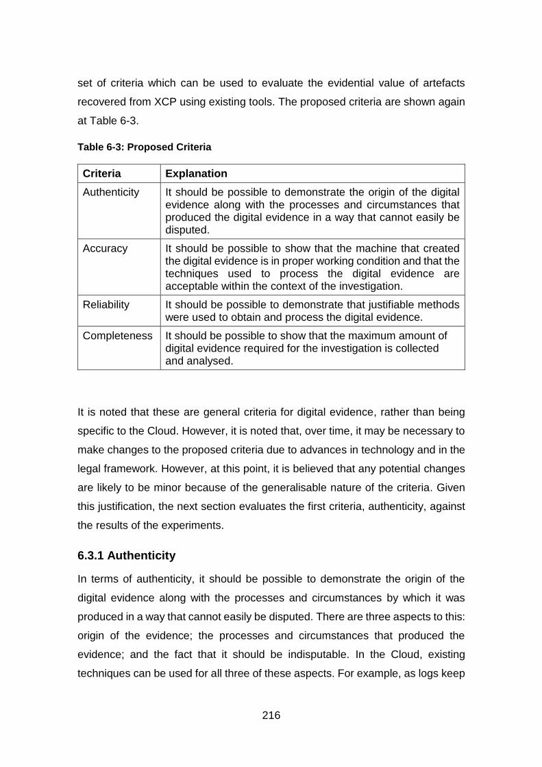
216
set of criteria which can be used to evaluate the evidential value of artefacts
recovered from XCP using existing tools. The proposed criteria are shown again
at Table 6-3.
Table 6-3: Proposed Criteria
Criteria Explanation
Authenticity It should be possible to demonstrate the origin of the digital evidence along with the processes and circumstances that produced the digital evidence in a way that cannot easily be disputed.
Accuracy It should be possible to show that the machine that created the digital evidence is in proper working condition and that the techniques used to process the digital evidence are acceptable within the context of the investigation.
Reliability It should be possible to demonstrate that justifiable methods were used to obtain and process the digital evidence.
Completeness It should be possible to show that the maximum amount of digital evidence required for the investigation is collected and analysed.
It is noted that these are general criteria for digital evidence, rather than being
specific to the Cloud. However, it is noted that, over time, it may be necessary to
make changes to the proposed criteria due to advances in technology and in the
legal framework. However, at this point, it is believed that any potential changes
are likely to be minor because of the generalisable nature of the criteria. Given
this justification, the next section evaluates the first criteria, authenticity, against
the results of the experiments.
6.3.1 Authenticity
In terms of authenticity, it should be possible to demonstrate the origin of the
digital evidence along with the processes and circumstances by which it was
produced in a way that cannot easily be disputed. There are three aspects to this:
origin of the evidence; the processes and circumstances that produced the
evidence; and the fact that it should be indisputable. In the Cloud, existing
techniques can be used for all three of these aspects. For example, as logs keep
217
a record of user activity, they can be used to identify the origin of the evidence
and to identify the processes that produced the evidence. Given that the XCP
host handles the logging, this evidence should be indisputable. One of the legal
requirements for evidence, as stated in Section 6.2.1, is that it should be authentic
(Reilly et al., 2010). For law enforcement, this authenticity criterion provides a
clear definition of the features, characteristics or properties of the evidence. Once
evidence satisfies this criterion, then the requirement has been met. This is
because the requirements are for general evidence while the criteria are specific
to digital evidence.
In the context of this research, the recovered artefact is the VM and the identity
of the owner of that VM was established, as discussed in Chapter 5, Section 5.3.
The experiments that were outlined in Chapter 4, Section 4.3 were used to
provide baseline data, demonstrating how a VM is created in XCP, together with
the processes used to create that VM. The experiments outlined in Chapter 5,
Sections 5.2 and 5.3 further demonstrated the VM deletion process and the fact
that this process could be used to produce the artefact that was recovered with
the existing forensic tool, extundelete. The effect of deletion on VMs was
determined through a comparison of both the live and recovered VM. The origin
of the VM was demonstrated by viewing the audit logs where the actions of each
user are recorded, including the XCP host name and the status of the action. The
audit log is controlled by the XCP host and only a local super user or a user with
the role of Pool Admin, the highest level of permission, can access the audit log.
Therefore, the authenticity of artefacts recovered from XCP using existing tools
can be demonstrated using the audit logs. The origin of the evidence and the
processes that produced the evidence can also be demonstrated in this way.
Finally, it can also be shown that the audit log cannot easily be changed as only
two types of users can access it, therefore the evidence is indisputable.
6.3.2 Accuracy
This criterion states that it should be possible to show that the machine that
created the digital evidence is in proper working condition and that the techniques
used to process that digital evidence are acceptable within the context of the

218
investigation. Proper working conditions mean that digital evidence was created
by fairly typical operation of the machine. Therefore, the techniques should be
repeatable and, if repeated, should produce the same result.
It was shown in Chapter 5, Sections 5.2 and 5.3, how typical operations of the
machine created the artefact. That is, the VM was deleted by a standard action
and by a user with the permission to do so. The artefact in the context of this
research is the deleted VM, which was then recovered using existing tools in the
XCP host. To verify the accuracy of the tool, three different deletion methods
were used and, for each method, the MD5 hash of the VM was calculated before
deletion and after recovery. This showed that when xe commands or XenCenter
are used to delete the VM, the hashes do not match. However, when the rm
command is used the hashes match. The files with hashes that did not match
were compared and this comparison revealed that there were two changes in the
recovered file. It is believed that these changes are unlikely to have affected the
accuracy of the recovered artefact. A different method of VM recovery was
undertaken, using the vgcfgrestore command for XCP with LVM storage, and
the same deletion effect was found. The artefacts from the two recovery methods
were analysed and the results were the same. Therefore, the accuracy of
artefacts recovered from XCP using existing tools can be shown by documenting
the effect that deletion has on VMs.
6.3.3 Reliability
The criterion of reliability states that it should be possible to demonstrate that
justifiable methods were used to obtain and process the digital evidence. In
addition, it states that existing methods, including existing digital forensic tools,
can be shown to be sufficient by acquiring and processing evidence in a manner
that does not compromise either the integrity or the admissibility of the recovered
artefact. As in the case of the authenticity criterion, this criterion provides a means
of conforming with the second requirement for evidence in criminal investigations.
In order for digital evidence to be considered reliable, it should meet the
conditions of this criterion, which effectively means that the evidence must be
reliable.
219
In terms of this research, it was demonstrated in Chapter 5, Section 5.2 that
existing tools have the capability to recover artefacts from the Cloud. Two
recovery methods were used: one for XCP with filesystem-based storage and the
other for XCP with LVM-based storage. Each method successfully recovered the
artefact and the analysis of the recovered artefacts produced predictable results.
Therefore, the reliability of artefacts recovered from XCP can be demonstrated
using existing tools. It can also be demonstrated that existing tools can be used
to analyse recovered artefacts with predictable results.
6.3.4 Completeness
The last criterion states that it should be possible to show that the maximum
amount of digital evidence required for the investigation has been collected and
analysed. Another legal requirement for evidence is that it should be complete
(Reilly et al., 2010). Once the digital evidence in a criminal investigation satisfies
this criterion, then the legal requirement has been met.
In this research, it was shown in Chapter 5, Sections 5.4 and 5.7 that the
maximum amount of digital evidence was collected. The recovered artefacts and
the audit log were used for analysis. The audit log contains corroborative
evidence pertaining to user identity and any actions on the recovered artefact.
Without the audit log, it would have been difficult to establish the ownership of
the recovered artefacts. In the absence of the audit log, other logs such as
XenCenter log and xensource log, and the two database files, state.db and lsass-
adcache.db may provide information which could be used to establish the
ownership of recovered artefacts. Therefore, the completeness of the artefact
recovered from XCP using existing tools can be shown by acquiring both the
artefact and artefact-related information in the audit log.
In terms of the final legal requirement which states that evidence should be
believable, there is no single criterion that is equivalent. However, a combination
of the authenticity, accuracy and reliability criteria would provide reassurance of
this requirement having been met. Believability is one of the criterion for
evaluating digital evidence proposed by Jones et al (2014). This states that the
collected evidence represents the true facts and, therefore, can be used as
220
credible evidence in court. Therefore, once evidence meets these three criteria
in a criminal investigation, then it can be argued that the requirement has been
met.
Overall, the discussion in this section has demonstrated the evidential value of
artefacts recovered from XCP and it has shown the artefacts to be authentic,
accurate, reliable and complete. It has also shown that the criteria proposed can
be used in criminal investigations and that they meet the legal requirements for
evidence.
6.4 Conclusion
The purpose of this chapter was to evaluate this research in three areas: adding
existing tools to the Cloud, the recovery of artefacts in XCP and the evidential
value of recovered artefacts. The general methodology developed for adding
existing tools to the Cloud was reviewed in relation to its three key steps:
identification of Cloud technology, identification of tools and the building of a
testbed. The limitations of this methodology were identified in terms of its
applicability to Cloud systems that use propriety OS or filesystems, as these may
not be supported by existing tools. Next, the methodology for artefact recovery
was reviewed with its three components of the user, the audit log and the VM.
The audit log and either the user or the VM are required to recover an artefact
and attribute it to a user, and a separate methodology was created for each. The
method adopted in order to find a measure for the evidential value of digital
evidence was highlighted followed by the proposed criteria. The research was
then assessed against each of the four criteria for the evaluation of evidence:
authenticity, accuracy, reliability and completeness. This showed that the
authenticity of artefacts recovered from XCP can be determined by using the
audit log, while any queries over the accuracy of artefacts recovered from XCP
can be satisfied by documenting and understanding the effect of deletion on the
VM. It was shown that the reliability of artefacts recovered from XCP can be
determined by using existing tools to recover and analyse the artefacts. Finally,
it has been shown that the completeness of artefacts recovered from XCP can
be determined by acquiring both the artefact and artefact-related information from

221
the audit log. Therefore, this research supports the hypothesis that it is possible
to recover artefacts of evidential value from XCP, using existing tools.
The next chapter and final chapter summarises this research and presents the
conclusion, highlighting the contributions to knowledge and making
recommendations for future work.

223
7 Conclusion
7.1 Research Summary
This chapter summarises this research before outlining its conclusions and
contributions to knowledge, and highlighting possible future work. The focus of
the research was Cloud computing, which offers users access to computing
resources that can be hosted at the premises of the Cloud Service Provider (CSP)
or in remote locations. It offers benefits like cost saving, convenience and
scalability but it is not without risk, especially in terms of security, as it can be
leveraged for criminal activities, as highlighted by the Cloud Security Alliance
(CSA). Together with the rising cost of cybercrime and the increasing adoption of
Cloud by organisations, this demonstrates that there is a need for digital
investigative techniques and processes that can be used in the Cloud ecosystem.
However, the architecture of the Cloud, where computing resources are pooled
together, along with its multi-tenancy and the ease with which resources are
released and reallocated, all contribute to making digital investigations a
challenge. This refers to processes such as evidence identification, preservation,
acquisition and examination, particularly as all evidence needs to be collected
and processed in a manner which will not affect its admissibility in a court of law.
More positively, the resources offered by the Cloud can be leveraged not only for
criminal purposes but also for digital forensic purposes, such as evidence
acquisition, analysis and storage.
Another way of leveraging Cloud resources for the purposes of digital forensics
is by adding forensic tools, either new or existing, to the Cloud. This is also a step
towards achieving forensic readiness in this environment. To date, research has
focused on developing tools for specific Cloud technologies with little work on
using existing tools. This research lacuna formed the basis of this research, which
aimed to evaluate the evidential value of artefacts recovered from a private Cloud
using existing digital forensic investigation tools, based on the hypothesis that it
is possible to recover artefacts of evidential value from the Xen Cloud Platform
(XCP) using existing tools.
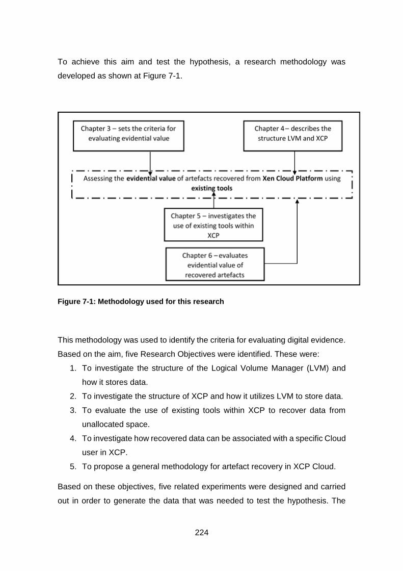
224
To achieve this aim and test the hypothesis, a research methodology was
developed as shown at Figure 7-1.
Figure 7-1: Methodology used for this research
This methodology was used to identify the criteria for evaluating digital evidence.
Based on the aim, five Research Objectives were identified. These were:
1. To investigate the structure of the Logical Volume Manager (LVM) and
how it stores data.
2. To investigate the structure of XCP and how it utilizes LVM to store data.
3. To evaluate the use of existing tools within XCP to recover data from
unallocated space.
4. To investigate how recovered data can be associated with a specific Cloud
user in XCP.
5. To propose a general methodology for artefact recovery in XCP Cloud.
Based on these objectives, five related experiments were designed and carried
out in order to generate the data that was needed to test the hypothesis. The
225
system that was selected as the basis for these experiments was XCP together
with an IaaS service type and a private Cloud deployment model.
To meet the first objective, a study of LVM structure in relation to data storage
was undertaken. The various components which make up LVM, physical volume,
volume group and logical volume, were discussed together with methods of
acquiring the logical volumes, which is where the data that needs to be retrieved
is stored. An experiment was conducted to document the LVM structure and this
verified the findings of the literature review in terms of the structure of LVM. This
structure was found to start with a physical device or partition, which can be
initialised as a physical volume. One or more physical volumes can then be
combined into a volume group, which is the administrative unit of LVM, and this
can then be divided into logical volumes, which are the components where data
is stored. In most cases, logical volumes need a filesystem before they can be
used.
For the second objective, the focus was on data storage in XCP. Therefore, it
was firstly reviewed in terms of its description, its deployment models and how it
manages storage using LVM-based and filesystem-based storage. XCP stores a
Virtual Disk Image (VDI) of Virtual Machines (VMs) in Storage Repositories
(SRs), which are then stored as a dynamic Virtual Hard Disk (VHD). The
experiments verified the structure of XCP, but went further than this to examine
it in relation to local ext and LVM storage. It was found that the two use different
data storage structures. For XCP with local ext, VMs are stored as dynamic VHDs
in a logical volume with an ext3 filesystem. XCP with local LVM stores VMs as
logical volumes, and uses dynamic VHD. Given this, it was evident that different
recovery techniques and tools were required for the two different storage types.
For XCP with local ext, ext3 tools were required while for XCP with local LVM
either LVM tools or tools with LVM support were required.
In terms of the third objective, experiments were carried out to investigate how
XCP manages deleted files. In the context of this discussion, deleted files refers
to VMs, as this is the type of data that users are able to create or delete in XCP.
The results showed that VM is either managed by the filesystem of the SRs,
226
which is ext3 for XCP with filesystem-based SR, or by LVM for XCP with LVM-
based SR. For both, the experiments showed that deleted data remains on the
disk until it is overwritten. For filesystem-based SRs, the existing tools Sleuthkit
and extundelete were selected to recover the deleted VMs. For LVM-based SRs,
the LVM tools themselves were used to recover data and the vgcfgrestore
command was used to recover deleted VMs.
The focus of the fourth objective was attribution. XCP manages users with Role
Based Access Control (RBAC) and these users are authenticated via the Active
Directory (AD). XCP keeps an audit log, which records all user actions. An
experiment was conducted to document the records of user activity, which
showed that the information in the log can be used to associate data with a
specific user.
For complete artefact recovery, all of the information that is associated with an
artefact is required, which means that the ownership information needs to be
retrieved as well. To this end, a general methodology was proposed for artefact
recovery and this met the final objective of the research by identifying three key
components: user, audit log and the VM. The audit log plays a key role in
associating a user with a VM but it is not without limitations. Principally, it could
be deleted. However, in order to guard against this, the audit log could be saved
in a remote location, thereby conserving space on the XCP host. Other files were
found which could corroborate the information in the audit log; these are
XenCenter log, xensource log, xapi records, state.db and lsass-adcache.db,
which may also provide useful information in the absence of the audit log.
A key component of this thesis is the argument that the data retrieved in this way
from the Cloud has evidential value. Therefore, the artefacts were tested against
the criteria that were derived from existing requirements for digital evidence and
the criteria for evaluating digital evidence. This research has demonstrated the
authenticity of the artefacts that were recovered from XCP using existing tools,
along with the origin of that evidence and the processes that produced the
evidence. This could all be confirmed by using the audit log, which cannot be
easily changed, as only the root or the Pool Admin can directly access it.

227
Therefore, the artefact that was retrieved was considered authentic. The
accuracy of the artefacts that were recovered from XCP using existing tools was
shown by documenting the effect that deletion has on VMs. Documenting the
changes caused by using xe commands or XenCenter to delete VMs shows how
the artefact was changed and what caused that change. It was determined that
these changes are unlikely to have a negative impact on the authenticity of the
artefact. The reliability of the artefacts that were recovered from XCP was
demonstrated using existing tools to analyse recovered artefacts with predictable
results. When the artefacts were analysed, the filesystem type and structure
corresponded to that of the VM, which showed that the use of existing tools did
not change the artefact. Finally, the completeness of the artefacts that were
recovered from XCP using existing tools was demonstrated by the acquisition of
the artefact and artefact-related information from the audit log. The audit log
provided corroborative evidence on the artefact, which included the creator, time
of creation and deletion, the UUID of both the VM and its VDI. Based on these
evaluations, it was determined that the artefacts recovered from XCP using
existing tools have evidential value.
This confirms the research hypothesis which states that it is possible to recover
artefacts of evidential value from the Xen Cloud Platform, using existing tools. It
also confirms that the aim of this research, which was to evaluate the evidential
value of artefacts recovered from a private Cloud using existing digital forensic
investigation tools, has been met.
7.2 Contributions to Knowledge
This research contributes to knowledge in six ways. Firstly, this research
expanded on leveraging Cloud resources as a means of achieving forensic
readiness in the Cloud by adding forensic capabilities in the form of existing digital
forensic tools in XCP. It is argued that adding forensic capabilities alleviates some
of the challenges of conducting forensic investigations in the Cloud, such as
identification, acquisition and analysis of evidence. In this research, existing
forensic tools were used to acquire artefacts.

228
Secondly, this research has established that existing digital forensic tools in XCP
can be used to recover artefacts with evidential value. This resulted in the
development of a methodology for adding existing tools to a Cloud technology,
which can be used for other Cloud technologies and not just XCP.
Thirdly, a methodology was developed for artefact recovery in XCP, which
encompasses both the artefact and its associated user information. This was
assessed in a large XCP Cloud set up and it was found to be effective.
Fourthly, a set of general criteria with four requirements for evaluating the
evidential value of digital evidence is proposed. This was based on existing
requirements for digital evidence that were synthesised to produce a general set
of criteria, which can be applied to all types of digital investigation. These
requirements are authenticity, accuracy, reliability and completeness. These
criteria were used to evaluate the evidential value of artefacts that were recovered
from XCP using existing digital forensics tools.
Fifthly, this research investigated and documented the changes that occur when
VMs that are saved as VHD files in XCP are deleted using XenCenter or the built
in ‘xe’ commands. This approach can be used to prove the authenticity of
recovered VMs, which is one of the requirements for evidential value. Also, it can
be compared with other Cloud technologies that use VHD format for virtual disks
to determine if this change is specific to XCP or if it is common.
During this research, LVM metadata was used to restore deleted VMs, which are
stored as logical volumes in XCP with LVM-based storage, thereby
demonstrating the value of LVM metadata in digital investigations. LVM keeps
copies of old metadata files, which could be used to create a timeline of events
to show user activities and to identify previous LVM configurations which may
contain information that can be used as evidence in an investigation.
7.3 Future Work
In terms of future work stemming from this research, six possible areas are noted.
According to the National Institute of Standards and Technology (NIST)
framework, research has shown that Cloud computing has four deployment
229
models: private, public, community and hybrid Clouds, and three service types:
Infrastructure as a Service (IaaS), Platform as a Service (PaaS) and Software as
a Service (SaaS). This research focused on adding existing forensic tools to a
private Cloud with an IaaS service type and on the recovery of artefacts based
on this. However, there may be limitations in terms of how this approach applies
to other service types and deployment models. Therefore, further work needs to
be undertaken to investigate the use of existing tools with the other deployment
models and service types, such as PaaS and SaaS.
Existing tools were used as a means of providing a generic method for adding
forensic capabilities to the Cloud in this research. Other researchers have
developed forensic tools for IaaS and SaaS, but not PaaS. However, there is a
requirement for the development of generic tools for use in the Cloud. Therefore,
work could be undertaken to develop generic tools for all service types and
deployment models.
This research focused on the recovery of complete and contiguous files.
However, it is noted that there are other methods of data recovery, such as data
carving, which could be used in the Cloud to recover artefacts. Carving could be
used in conjunction with evidence segregation techniques to recover artefacts,
without violating the confidentiality and integrity of other Cloud users and their
data. In addition, a method/tool for the recovery of complete and non-contiguous
files would provide an alternative to the recovery of complete and contiguous files
as used in this research.
The recovery tool that was used for XCP with filesystem-based storage required
the storage partition/server to be unmounted before use. This is not ideal, as it
could potentially make resources unavailable to other users. This provides an
opportunity for further investigation into the use of tools that do not need to be
unmounted. This will ensure that the Cloud services remain available to other
users during the recovery process.
The recovery tool used for LVM-based SRs is limited as it can cause data loss,
provide access to data belonging to other users and result in incomplete VM
recovery. As future work, there is a requirement for the development of a non-
230
destructive, non-invasive method or tool that can be used to recover VMs with
their data from LVM-based SRs.
Finally, this research focused on recovery in XCP with filesystem-based and
LVM-based Storage Repositories (SRs). As shown in Chapter 4, Section 4.3.1,
XCP also supports another SR type, Logical Unit Number (LUN) SR. Therefore,
it is suggested that future work could be conducted on XCP with LUN SR to
investigate its structure in order to determine how artefacts can be recovered.
This will aid in conducting investigations in Cloud systems that use LUN-based
storage.

231
REFERENCES
AccessData (2015) Forensic Toolkit (FTK). Available at: http://accessdata.com/ (Accessed: 15 January 2016).
ACPO. (2012) ACPO Good Practice Guide for Digital Evidence. Available at: http://www.digital-detective.net/digital-forensics-documents/ACPO_Good_Practice_Guide_for_Digital_Evidence_v5.pdf (Accessed: 19 January 2016).
Active@ UNDELETE. (2014). Available at: http://www.active-undelete.com/undelete.htm (Accessed: 2 March 2016).
Adams, R. (2013) 'The Emergence of Cloud Storage and the Need for a New Digital Forensic Process Model', in: Ruan, K. (Ed.), Cybercrime and Cloud Forensics: Applications for Investigation Processes: Applications for Investigation Processes. IGI Global, pp.79-104.
Al-Aqrabi, H., Liu, L., Xu, J., Hill, R., Antonopoulos, N., Zhan, Y. (2012) 'Investigation of IT Security and Compliance Challenges in Security-as-a-Service for Cloud Computing', 15th IEEE International Symposium on Object/Component/Service-Oriented Real-Time Distributed Computing Workshops (ISORCW), pp. 124–129, doi:10.1109/ISORCW.2012.31.
Almulla, S., Iraqi, Y., Jones, A. (2013) 'Cloud forensics: A research perspective', 9th International Conference on Innovations in Information Technology (IIT), pp. 66–71 doi:10.1109/Innovations.2013.6544395.
Almulla, S.A., Iraqi, Y., Jones, A. (2014) 'A State-of-the-Art Review of Cloud Forensics', Journal of Digital Forensics, Security and Law 9, 7–28.
Altheide, C., Carvey, H.A. (2011) Digital Forensics with Open Source Tools. Syngress Media Incorporated.
Al-Zarouni, M. (2006). Mobile handset forensic evidence: a challenge for law enforcement.
Amazon. (n.d.) AWS | Amazon Virtual Private Cloud (VPC) – Secure Private Cloud VPN. Amazon Web Services, Inc. Available at: //aws.amazon.com/vpc/ (Accessed: 22 April 2014).
Apache (n.d.) Apache Cloudstack. Available at: https://cloudstack.apache.org/ (Accessed: 16 November 2015).
ArxSys. (n.d.) Digital Forensics Framework. Available at: http://www.arxsys.fr/discover/ (Accessed: 24: February 2016).
ASR Data. (2015) SMART Linux. Available at: http://www.asrdata.com/forensic-software/smart-linux/ (Accessed: 24 February 2016).
232
AWS (2014) What Is Amazon EC2?. Available at: http://docs.aws.amazon.com/AWSEC2/latest/WindowsGuide/concepts.html (Accessed: 17 February 2016).
AWS. (2010) AWS Elastic Beanstalk. Available at: //aws.amazon.com/documentation/elastic-beanstalk/ (Accessed: 2.17.16).
Baldauf, K., Stair, R. (2010) Succeeding with Technology. Cengage Learning.
Barnes, S. (2012) XenServer - Creating a local ISO Library. Available at: http://www.riverlite.co.uk/blog/xenserver-creating-a-local-iso-library/ (Accessed: 20 January 2016).
Barr, T., Langfeldt, N., Vidal, S., McNeal, T. (2002) Linux NFS-HOWTO. Available at: http://www.tldp.org/HOWTO/NFS-HOWTO/index.html (Accessed: 11 June 2016).
Barreto, J. (2007) 'Configuring the Microsoft iSCSI Software Target', [Blog, Joe Barreto's Blog. 18 December. Available at: https://blogs.technet.microsoft.com/josebda/2007/12/18/configuring-the-microsoft-iscsi-software-target/.
Barrett, D., Kipper, G. (2010) Virtualization and Forensics: A Digital Forensic Investigator’s Guide to Virtual Environments. Syngress.
Beckett, J., Slay, J. (2007) 'Digital forensics: Validation and verification in a dynamic work environment', 40th Annual Hawaii International Conference on System Sciences, 2007, HICSS 2007, IEEE, pp. 266a–266a.
Beebe, N. (2009) 'Digital Forensic Research: The Good, the Bad and the Unaddressed', in: Peterson, G., Shenoi, S. (Eds.), Advances in Digital Forensics V, IFIP Advances in Information and Communication Technology. Springer Berlin Heidelberg, pp. 17–36. doi:10.1007/978-3-642-04155-6_2
Bell, G.B., Boddington, R. (2010) 'Solid State Drives: The Beginning of the End for Current Practice in Digital Forensic Recovery?', Journal of Digital Forensics, Security and Law 5, pp. 1–20.
Benedict, J. (2015) XenServer Root Disk Maintenance. XenServer Open Source Virtualization. Available at: http://xenserver.org/discuss-virtualization/virtualization-blog/entry/xenserver-root-disk-maintenance.html (Accessed: 8 March 2016).
Birk, D., Wegener, C. (2011) 'Technical Issues of Forensic Investigations in Cloud Computing Environments', 2011 IEEE Sixth International Workshop on Systematic Approaches to Digital Forensic Engineering (SADFE), pp. 1–10. doi:10.1109/SADFE.2011.17
Bist, M., Wariya, M., Agarwal, A. (2013) 'Comparing delta, open stack and Xen Cloud Platforms: A survey on open source IaaS', IEEE 3rd International
233
Advance Computing Conference (IACC), 2013, pp. 96–100. doi:10.1109/IAdCC.2013.6514201
Bourne, J. (2014) Code Spaces RIP: Code hosting provider ceases trading after “well-orchestrated” DDoS attack. Available at: http://www.cloudcomputing-news.net/news/2014/jun/19/code-spaces-rip-code-hosting-provider-ceases-trading-after-well-orchestrated-ddos-attack/ (Accessed: 13 October 2016).
Bowman, A. (2012) Installing the CentOS Development Tools (gcc, flex, etc). Available at: https://support.eapps.com/index.php?/Knowledgebase/Article/View/438/55/installing-the-centos-development-tools-gcc-flex-etc (Accessed: 10 September 2015).
Bros, A. (2009) 'Recover LVM Volume Groups and Logical Volumes WITHOUT Backups' [Blog] Adam Bros Blog. 30 May. Available at: http://blog.adamsbros.org/2009/05/30/recover-lvm-volume-groups-and-logical-volumes-without-backups/ (Accessed: 18 June 2016).
Buchanan, W.J., Macfarlane, R.J., Flandrin, F., Graves, J., Buchanan, B., Fan, L., Ekonomou, E., Bose, N., Ludwiniak, R. (2011) 'Cloud-based Digital Forensics Evaluation Test (D-FET) Platform', Cyberforensics 2011.
Burghardt, A., Feldman, A.J. (2008) 'Using the HFS+ journal for deleted file recovery', Digital Investigation 5, pp. S76–S82. doi:10.1016/j.diin.2008.05.013
Buyya, R., Brogerg, J., Goscinki, A., M. (Eds.). (2010) Cloud computing: Principles and Paradigms. John Wiley & Sons Inc.
Carrier, B. (2015a) The Sleuth Kit. Available at: http://www.sleuthkit.org/sleuthkit/ (Accessed: 28 May 2015).
Carrier, B. (2015b) Autopsy. Available at: http://www.sleuthkit.org/autopsy/ (Accessed: 24 February 2016).
Carrier, B. (2012) 'Sleuth Kit Hadoop Framework', Open Source Digital Forensics. Available at: http://www.sleuthkit.org/tsk_hadoop/ (Accessed: 10 February 2016).
Carrier, B. (2005a) File System Forensic Analysis. Addison-Wesley.
Carrier, B. (2005b) 'Volume analysis of disk spanning logical volumes', Digital Investigation 2, pp. 78–88. doi:10.1016/j.diin.2005.04.008
Carrier, B., Spafford, E.H. (2003) 'Getting physical with the digital investigation process', International Journal of Digital Evidence 2, pp. 1–20.
Casey, E. (2011) Digital Evidence and Computer Crime: Forensic Science, Computers and the Internet. Academic Press.
Casey, E. (2004a) Digital evidence and computer crime. Academic Press.
234
Casey, E. (2004b) 'Tool review—WinHex', Digital Investigation 1, pp. 114–128. doi:10.1016/j.diin.2004.04.001
Chaudhary, A., Bisht, N., Kumar, L., Choudary, S. (2013) 'Privacy Issues in Cloud Computing for Personal Area Network', International Journal of Advances in Computer Networks and its Security 3, pp. 134–138.
Chellappa, R. (1997) Intermediaries in Cloud-Computing. Available at: http://www.bus.emory.edu/ram/ (Accessed: 22 April 2016).
Chen, F., Koufaty, D.A., Zhang, X. (2009) 'Understanding intrinsic characteristics and system implications of flash memory based solid state drives', ACM SIGMETRICS Performance Evaluation Review, pp. 181–192.
Choice of Toolstacks - Xen (n.d.). Available at: http://wiki.xen.org/wiki/Choice_of_Toolstacks (Accessed: 27 April 2015).
Chung, H., Park, J., Lee, S., Kang, C. (2012) 'Digital forensic investigation of cloud storage services', Digital Investigation 9, pp. 81–95. doi:10.1016/j.diin.2012.05.015
Cisco. (2016) Snort . Available at: https://www.snort.org/ (Accessed: 22 March 2016).
Citrix Systems. (2015) Modifying Default Role Based Access Control Permissions for XenServer. Available at: http://support.citrix.com/article/CTX126442 (Accessed: 10 April 2016).
Citrix Systems (2014a) Citrix XenServer 6.2.0 Administrator’s Guide. Available at: http://docs.vmd.citrix.com/XenServer/6.2.0/1.0/en_gb/reference.html#dr_commands (Accessed: 26 May 2015).
Citrix Systems. (2014b) Citrix XenServer: Understanding Snapshots. Available at: http://support.citrix.com/servlet/KbServlet/download/21626-102-714437/XenServer_Understanding_Snapshots.pdf (Accessed: 7 February 2015).
Citrix Systems. (2013) Citrix CloudPlatform Installation Guide. Available at: http://support.citrix.com/servlet/KbServlet/download/36173-102-706977/CitrixCloudPlatform4.2.1InstallationGuide.pdf (Accessed: 22 May 2014).
Citrix Systems. (2012) Importing and Exporting VMs. Available at: http://support.citrix.com/proddocs/topic/xencenter-61/xs-xc-vms-exportimport.html (Accessed: 21 October 2014).
Citrix Systems. (n.d.) XenCenter 6.5 Help.
Cloud Credential Council. (n.d.) Cloud Forensics Working Group. Available at: http://www.cloudcredential.org/working-groups/cloud-forensics/ (Accessed: 13 June 2013).
235
Columbus, L. (2014) Cloud Computing Adoption Continues Accelerating In The Enterprise. Available at: http://www.forbes.com/sites/louiscolumbus/2014/11/22/cloud-computing-adoption-continues-accelerating-in-the-enterprise/ (Accessed: 9 February 2016).
Costa, P., Migliavacca, M., Pietzuch, P., Wolf, A.L. (2012) 'NaaS: Network-as-a-Service in the Cloud', The Hot-ICE 2012. Available at: https://www.usenix.org/system/files/conference/hot-ice12/hotice12-final29.pdf (Accessed: 11 December 2015)
Cranfield University. (2016a) Research Ethics Policy. Available at: https://intranet.cranfield.ac.uk/researchethics/Documents/CU-RIO-POL-2.0%20-%20V2%20-%20Research%20Ethics%20Policy.pdf (Accessed: 17 March 2016).
Cranfield University (2016b) Research ethics and integrity. Available at: https://cranfield.ac.uk/researchethics/Pages/,DanaInfo=intranet.cranfield.ac.uk,SSL+default.aspx (Accessed: 24 April 2016).
CSA. (2016) Treacherous 12: Cloud Computing Top Threats. Available at: https://downloads.cloudsecurityalliance.org/assets/research/top-threats/Treacherous-12_Cloud-Computing_Top-Threats.pdf (Accessed: 22 April 2016).
CSA. (2013) The notorious nine: cloud computing top threats in 2013. Available at: https://downloads.cloudsecurityalliance.org/initiatives/top_threats/The_Notorious_Nine_Cloud_Computing_Top_Threats_in_2013.pdf (Accessed: 9 February 2016).
CSA. (2010) Top Threats to Cloud Computing V1.0. Available at: https://cloudsecurityalliance.org/topthreats/csathreats.v1.0.pdf (Accessed: 20 March 2013)
CSA. (2009) Security guidance for critical areas of focus in cloud computing V2.1. Available at: https://cloudsecurityalliance.org/csaguide.pdf (Accessed: 18 February 2016).
Damshenas, M., Dehghantanha, A., Mahmoud, R., bin Shamsuddin, S. (2012) 'Forensics investigation challenges in cloud computing environments', International Conference on Cyber Security, Cyber Warfare and Digital Forensic (CyberSec), pp. 190–194. doi:10.1109/CyberSec.2012.6246092
Davidoff, S., Ham, J. (2012) Network Forensics: Tracking Hackers through Cyberspace. Prentice Hall.
Delport, W., Oliver, M.S., Kohn, M.D. (2011) 'Isolating a cloud instance for a digital forensic investigation', Conference on Information Security for South Africa (ISSA2011), pp. 145–153.
236
DFRWS. (2001) 'A Road Map for Digital Forensic Research', Digital Forensic Research Workshop.
Dettus. (2012) Dhex. Available at: http://www.dettus.net/dhex/ (Accessed: 24 February 2016).
Dykstra, J., Sherman, A.T. (2013) 'Design and implementation of FROST: Digital forensic tools for the OpenStack cloud computing platform', Digital Investigation 10, pp. S87–S95. doi:10.1016/j.diin.2013.06.010
Dykstra, J., Sherman, A.T. (2012) 'Acquiring forensic evidence from infrastructure-as-a-service cloud computing: Exploring and evaluating tools, trust, and techniques', Digital Investigation 9, pp. S90–S98. doi:10.1016/j.diin.2012.05.001
Endo, P.T., Gonçalves, G.E., Kelner, J., Sadok, D. (2010) 'A survey on open-source cloud computing solutions', Brazilian Symposium on Computer Networks and Distributed Systems, pp. 3-16.
Ercolani, R. (n.d) Ubuntu Manpage: ext3grep - ext3 file recovery tool. Available at: http://manpages.ubuntu.com/manpages/utopic/man8/ext3grep.8.html (Accessed: 4 July 2015).
Ext4magic. (2014) Ext4magic. Available at: http://ext4magic.sourceforge.net/ext4magic_en.html (Accessed: 25 August 2015).
extundelete. (2013) extundelete. Available at: http://extundelete.sourceforge.net/ (Accessed: 4 July 2015).
Fairbanks, K.D. (2012) 'An analysis of Ext4 for digital forensics', Digital Investigation, Proceedings of the Twelfth Annual DFRWS Conference 9, Supplement, pp. S118–S130. doi:10.1016/j.diin.2012.05.010
Fairbanks, K.D., Lee, C.P., Owen III, H.L. (2010) 'Forensic implications of ext4', Proceedings of the Sixth Annual Workshop on Cyber Security and Information Intelligence Research, pp. 4. ACM
Farina, J., Scanlon, M., Le-Khac, N.A., Kechadi, M.T. (2015) 'Overview of the Forensic Investigation of Cloud Services', 2015 10th International Conference on Availability, Reliability and Security (ARES), pp. 556–565. doi:10.1109/ARES.2015.81
Farmer, D., Venema, W. (2005) Forensic Discovery. Addison-Wesley Professional.
Federici, C. (2014) 'Cloud Data Imager: A unified answer to remote acquisition of cloud storage areas', Digital Investigation 11, 30–42. doi:10.1016/j.diin.2014.02.002
Fellows, G.H. (2005) 'The joys of complexity and the deleted file', Digital Investigation 2, 89–93. doi:10.1016/j.diin.2005.04.001

237
Finn, A., Vredevoort, H., Lownds, P., Flynn, D. (2012) Microsoft Private Cloud Computing. John Wiley & Sons.
Flandrin, F., Buchanan, W.J., Macfarlane, R., Ramsay, B., Smales, A. (2014) 'Evaluating Digital Forensic Tools (DFTs)', 7th International Conference: Cybercrime Forensics Education & Training.
Fleischmann, S. (2013) X-Ways Forensics & WinHex Manual. Available at: http://www.x-ways.net/winhex/manual.pdf (Accessed: 1 October 2013).
Forensic Science Regulator. (2014) Codes of Practice and Conduct. Available at: https://www.gov.uk/government/uploads/system/uploads/attachment_data/file/351197/The_FSR_Codes_of_Practice_and_Conduct_-_v2_August_2014.pdf (Accessed: 12 March 2017).
Frantzis, A. (2008) Bless 0.6.0 Manual. Available at: http://home.gna.org/bless/bless-manual/index.html (Accessed: 17 September 2014).
Freet, D., Agrawal, R., John, S., Walker, J.J. (2015) 'Cloud forensics challenges from a service model standpoint: IaaS, PaaS and SaaS', ACM Press, pp. 148–155. doi:10.1145/2857218.2857253
FTC. (2011) Facebook Settles FTC Charges That It Deceived Consumers By Failing To Keep Privacy Promises. Available at: https://www.ftc.gov/news-events/press-releases/2011/11/facebook-settles-ftc-charges-it-deceived-consumers-failing-keep (Accessed: 13 October 2016).
Galante, J., Kharif, O., Alpeyev, P. (2011) Sony Network Breach Shows Amazon Cloud’s Appeal for Hackers. Available at: http://www.bloomberg.com/news/2011-05-15/sony-attack-shows-amazon-s-cloud-service-lures-hackers-at-pennies-an-hour.html (Accessed: 27 March 2013).
Garfinkel, S., Farrell, P., Roussev, V., Dinolt, G. (2009) 'Bringing science to digital forensics with standardized forensic corpora', Digital Investigation, The Proceedings of the Ninth Annual DFRWS Conference 6, Supplement, pp. S2–S11. doi:10.1016/j.diin.2009.06.016
GetData. (2015) Forensic Explorer. Available at: http://www.forensicexplorer.com/ (Accessed: 24 February 2016).
Ghemawat, S., Gobioff, H., Leung, S.-T. (2003) 'The Google file system', ACM SIGOPS Operating Systems Review, pp. 29–43. ACM.
Gibbs, S. (2015) TalkTalk criticised for poor security and handling of hack attack. Available at: https://www.theguardian.com/technology/2015/oct/23/talktalk-criticised-for-poor-security-and-handling-of-hack-attack (Accessed: 27 September 2016).
238
Gilbert, D. (2014) Feedly Knocked Offline by DDoS Attack Following Evernote and Deezer Attacks. Available at: http://www.ibtimes.co.uk/feedly-knocked-offline-by-ddos-attack-following-evernote-deezer-attacks-1452237 (Accessed: 13 October 2016).
Goodin, D. (2010) Amazon purges account hijacking threat from site. Available at: http://www.theregister.co.uk/2010/04/20/amazon_website_treat/ (Accessed: 13 October 2016).
Goodin, D. (2009) Zeus bot found using Amazon’s EC2 as C&C server. Available at: http://www.theregister.co.uk/2009/12/09/amazon_ec2_bot_control_channel/ (Accessed: 16 February 2016).
Google. (2016a) Google Apps for Work. Available at: https://apps.google.co.uk/intl/en_uk/ (Accessed: 17 February 2016).
Google. (2016b) Google App Engine: Platform as a Service. Available at: https://cloud.google.com/appengine/docs (Accessed: 17 February 2016).
Graves, M.W. (2014) Digital archaeology: the art and science of digital forensics. 1st edn. Addison-Wesley, Upper Saddle River, N.J.
Grispos, G., Storer, T., Glisson, W.B. (2012) 'Calm Before the Storm: The Challenges of Cloud Computing', International Journal of Digital Crime and Forensics.
Guidance Software. (2015) EnCase Forensic Software. Available at: https://www.guidancesoftware.com/encase-forensic?cmpid=nav_r (Accessed: 15 January 2016).
Guo, H., Jin, B., Shang, T. (2012) 'Forensic investigations in Cloud environments', International Conference on Computer Science and Information Processing (CSIP), pp. 248–251. doi:10.1109/CSIP.2012.6308841
Haas, J. (n.d) hexdump - Linux Command - Unix Command. Available at: http://linux.about.com/library/cmd/blcmdl1_hexdump.htm (Accessed: 14 September 2014).
Hale, J.S. (2013) 'Amazon Cloud Drive forensic analysis', Digital Investigation 10, pp. 259–265. doi:10.1016/j.diin.2013.04.006
Hargreaves, C.J. (2009) Assessing the Reliability of Digital Evidence from Live Investigations Involving Encryption PhD Thesis. Cranfield University, Shrivenham.
Hoffman, C. (2014) 10 of the Most Popular Linux Distributions Compared. Available at: http://www.howtogeek.com/191207/10-of-the-most-popular-linux-distributions-compared/ (Accessed: 25 May 2016).
Hoog, A., Strzempka, K. (2011) iPhone and iOS Forensics: Investigation, Analysis and Mobile Security for Apple iPhone, iPad and iOS Devices. Syngress.
239
Horz, M. (2009) HxD - Freeware Hex Editor and Disk Editor | mh-nexus. Available at: https://mh-nexus.de/en/hxd/ (Accessed: 24 February 2016).
HP. (2015) HP Helion Eucalyptus. Available at: http://www8.hp.com/us/en/cloud/helion-eucalyptus.html (Accessed: 16 November 2015).
IC3. (2015) Internet Crime Complaint Center (IC3) | Annual Reports. Available at: https://www.ic3.gov/media/annualreports.aspx (Accessed: 8 February 2016).
IDG Enterprise (2015) 2015 IDG Enterprise Cloud Computing Study. Available at: http://www.idgenterprise.com/resource/research/2015-cloud-computing-study/ (Accessed: 9 February 2016).
Irmler, F., Creutzburg, R. (2011) 'Possibilities of forensic investigation of CD, DVD and Blu-ray disc', SPIE Defense, Security, and Sensing. International Society for Optics and Photonics, pp. 80631D–80631D.
ISO (2015) ISO/IEC JTC 1/SC 27 - IT Security techniques. Available at: http://www.iso.org/iso/home/store/catalogue_tc/catalogue_tc_browse.htm?commid=45306&published=on&includesc=true (Accessed: 21 March 2016).
ISO (2005) ISO/IEC 17025:2005 - General requirements for the competence of testing and calibration laboratories. Available at: https://www.iso.org/standard/39883.html (Accessed: 12 March 2017).
ITU. (2012) Part 1: Introduction to the cloud ecosystem: definitions, taxonomies, use cases and high-level requirements. Available at: http://wwwb.itu.int/dms_pub/itu-t/opb/fg/T-FG-CLOUD-2012-P1-PDF-E.pdf (Accessed: 20 February 2016).
James, J.I., Shoha, A.F., Gladyshev, P. (2013) 'Digital Forensic Investigation and Cloud Computing', in: Ruan, K. (Ed.), Cybercrime and Cloud Forensics: Applications for Investigation Processes. IGI Global, pp. 1-41.
Jones, K.J., Bejtlich, R., Rose, C.W. (2006) Real Digital Forensics: Computer Security and Incident Response. Addison-Wesley Professional.
Jones, N., George, E., Merida, F.I., Ramussen, U., Volzow, V. (2014) Electronic Evidence Guide - A Basic Guide for Police Officers, Prosecutors and Judges. Available at: https://rm.coe.int/CoERMPublicCommonSearchServices/DisplayDCTMContent?documentId=0900001680465f73#search=electronic%20evidence%20guide (Accessed: 25 February 2016).
Katilu, V.M., Franqueira, V.N.L., Angelopoulou, O. (2015) 'Challenges of Data Provenance for Cloud Forensic Investigations', 10th International Conference on Availability, Reliability and Security (ARES), pp. 312–317. doi:10.1109/ARES.2015.54
240
Kent, K., Chevalier, S., Grance, T., Dang, H. (2006) Guide to Integrating Forensic Techniques to Incident Response (Special Publication No. 800–86). National Institute of Standards and Technology.
KernSafe (2015) iSCSI SAN software. Available at: http://www.kernsafe.com/product/istorage-server.aspx (Accessed: 15 January 2016).
Kessem, L., 2015. Carbanak: How Would You Have Stopped a $1 Billion APT Attack?. Avaialable at: https://securityintelligence.com/carbanak-how-would-you-have-stopped-a-1-billion-apt-attack/ (Accessed: 13 October 2016).
Krutz, R.L., Vines, R.D. (2010) Cloud Security: A comprehensive Guide to Secure Cloud Computing. Wiley Publising Inc.
Kumaraswamy, S. (2015) The IRS Breach and the Importance of Adaptive API Security. Apigee.
Kutz, R.L., Vines, R.D. (2010) Cloud security. John Wiley & Sons Inc.
Langenhan, D. (2013) 'So, what is VMware vCloud?', in: Instant VMware vCloud Starter. Packt Publishing.
Lewis, A. (2006) LVM HOWTO, The Linux Documentation Project. Available at: http://tldp.org/HOWTO/LVM-HOWTO/ (Accessed: 14 September 2014).
Li, J., Chen, X., Huang, Q., Wong, D.S. (2014) 'Digital provenance: Enabling secure data forensics in cloud computing', Future Generation Computer Systems 37, pp. 259–266. doi:10.1016/j.future.2013.10.006
Lillard, T.V., Garrison, C.P., Schiller, C.A., Steele, J. (2010) Digital forensics for network, internet, and cloud computing. Syngress Media Incorporated.
Linux Logical Volume Manager (LVM). (n.d) Available at: http://www.forensicswiki.org/wiki/Linux_Logical_Volume_Manager_(LVM) (Accessed: 21 October 2014).
LLC SysDev Laboratories (2015) Raise Data Recovery for Ext2, Ext3 and Ext4 file system. Available at: http://www.ufsexplorer.com/rdr_ext23.php (Accessed: 2 March 2016).
Lowe, D., 2013. Networking For Dummies. 10th edn. John Wiley & Sons.
Lu, R., Lin, X., Liang, X., Shen, X.S. (2010) 'Secure provenance: the essential of bread and butter of data forensics in cloud computing', 5th ACM Symposium on Information, Computer and Communications Security, pp. 282–292. ACM.
Maor, J. (2015). Cybercrime and the Internet of Threats. Available at: http://106.186.118.91/201504/Cybercrime-and-the-Internet-of-Threats.pdf (Accessed: 10 February 2016).
241
Marangos, N., Rizomiliotis, P., Mitrou, L. (2012) 'Digital forensics in the Cloud Computing Era', IEEE Globecom Workshops (GC Wkshps), pp. 775–780. doi:10.1109/GLOCOMW.2012.6477673
Marston, S., Li, Z., Bandyopadhyay, S., Zhang, J., Ghalsasi, A. (2011) 'Cloud computing — The business perspective', Decision Support Systems 51, pp. 176–189. doi:10.1016/j.dss.2010.12.006
Martin, A. (2014) Rackspace knocked offline by huge DDoS attack. Available at: http://www.welivesecurity.com/2014/12/24/rackspace-knocked-offline-huge-ddos-attack/ (Accessed: 19 February 2016).
Martini, B., Choo, K.-K.R. (2013) 'Cloud storage forensics: ownCloud as a case study', Digital Investigation 10, pp. 287–299. doi:10.1016/j.diin.2013.08.005
Martini, B., Choo, K.-K.R. (2012) 'An integrated conceptual digital forensic framework for cloud computing', Digital Investigation, pp. 71-80. doi:10.1016/j.diin.2012.07.001
Marty, R. (2011) 'Cloud application logging for forensics', ACM Symposium on Applied Computing, SAC ’11. ACM, New York, NY, USA, pp. 178–184. doi:10.1145/1982185.1982226
Matthews, J.N., Dow, E.M., Deshane, T., Hu, W., Bongio, J., Wilbur, P.F., Johnson, B. (2008) Running Xen: A Hands-On Guide to the Art of Virtualization. Prentice Hill.
McKemmish, R., 1999. What is forensic computing?. Australian Institute of Criminology, Canberra. Available at: http://www.aic.gov.au/media_library/publications/tandi_pdf/tandi118.pdf (16: November 2015).
Meera, G., Kumar Raju Alluri, B.K.S.P., Powar, D., Geethakumari, G. (2015) 'A strategy for enabling forensic investigation in cloud IaaS', IEEE International Conference on Electrical, Computer and Communication Technologies (ICECCT), pp. 1–5. doi:10.1109/ICECCT.2015.7226103
Mehreen, S., Aslam, B. (2015) 'Windows 8 cloud storage analysis: Dropbox forensics', 12th International Bhurban Conference on Applied Sciences and Technology (IBCAST), pp. 312–317. doi:10.1109/IBCAST.2015.7058522
Mell, P., Grance, T., 2011. The NIST Definition of Cloud Computing. NIST Special Publication 500, 292.
Microsoft. (2016) Office 365. Available at: http://www.microsoftstore.com/store/msusa/en_US/cat/Office-365/categoryID.68021500 (Accessed: 17 February 2016).
Microsoft. (2012) Microsoft Private Cloud. Available at: http://download.microsoft.com/download/A/D/9/AD9E9446-D20C-42DE-
242
8FD7-2352C1D15518/Microsoft_Private_Cloud_Whitepaper.pdf (Accessed: 21 March 2013).
Microsoft. (2011) Windows Virtual PC. Available at: https://www.microsoft.com/en-gb/download/details.aspx?id=3702 (Accessed: 2 March 2016).
Microsoft. (2006) Virtual Hard Disk Image Format Specification. Available at: http://technet.microsoft.com/en-us/virtualization/bb676673.aspx (Accessed: 3 July 2014).
Miller, C. (1992) 'Electronic evidence-can you prove the transaction took place', Computer Lawyer 9, pp. 21–33.
Mocas, S. (2004) 'Building theoretical underpinnings for digital forensics research', Digital Investigation 1, pp. 61–68. doi:10.1016/j.diin.2003.12.004
Mohamed, A. (2009) A history of cloud computing. Available at: http://www.computerweekly.com/feature/A-history-of-cloud-computing (Accessed: 18 February 2016).
Morioka, E., Sharbaf, M.S. (2015) 'Cloud Computing: Digital Forensic Solutions', 12th International Conference on Information Technology - New Generations (ITNG), pp. 589–594. doi:10.1109/ITNG.2015.99
Morris, S.L.A. (2013) An Investigation into the identification, reconstruction, and evidential value of thumbnail cache file fragments in unallocated space PhD Thesis. Cranfield University, Shrivenham.
Muncaster, P. (2015) Global Cybercrime Costs $315bn. Available at: http://www.infosecurity-magazine.com/news/global-cybercrime-costs-315/ (Accessed: 8 February 2016).
Mustafa, Z., Nobles, P. (2014) 'A Testbed for Cloud based Forensic Investigation', 7th International Cybercrime Forensics Education and Training, Canterbury Christ Church University.
Nanni, D. (2012) How to install additional packages in XenServer. Available at: http://xmodulo.com/how-to-install-additional-packages-in.html (Accessed: 7 September 2015).
Narvaez, G. (2007) Taking advantage of Ext3 journaling file system in a forensic investigation. Available at: http://www.sans.org/reading-room/whitepapers/forensics/advantage-ext3-journaling-file-system-forensic-investigation-2011 (Accessed: 27 November 2014).
Netresec. (2015) NetworkMiner. Available at: http://www.netresec.com/?page=NetworkMiner (Accessed: 22 March 2016).

243
Ng, A., Hautala, L. (2016) Yahoo hit in worst hack ever, 500 million accounts swiped. CNET. Available at: https://www.cnet.com/news/yahoo-500-million-accounts-hacked-data-breach/ (27: September 2016)
NIKSUN. (2015) NetDetector. Available at: https://www.niksun.com/product.php?id=112 (Accessed: 22 March16).
NIST. (2014) NIST Cloud Computing Forensic Science Challenges. Available at: http://csrc.nist.gov/publications/drafts/nistir-8006/draft_nistir_8006.pdf (Accessed: 4 July 2014).
NIST. (2013) NIST Cloud Computing Security Reference Architecture. Available at: http://collaborate.nist.gov/twiki-cloud-computing/pub/CloudComputing/CloudSecurity/NIST_Security_Reference_Architecture_2013.05.15_v1.0.pdf (Accessed: 13 June 2013).
NIST. (n.d) Cloud Forensic Science. Available at: http://collaborate.nist.gov/twiki-cloud-computing/bin/view/CloudComputing/CloudForensics (Accessed: 13 June 13).
NJVC. (n.d) Thanking the Fathers of Cloud Computing. Available at: http://www.njvc.com/thanking-fathers-cloud-computing (Accessed: 10 March 2016).
Noehr, J. (2011) 'Denial of service attack'', [Blog] Bitbucket. 6 June. Available at: https://blog.bitbucket.org/2011/06/06/denial-of-service-attack/ (Accessed: 19 February 2016).
Office for National Statistics. (2015) Improving crime statistics in England and Wales. Available at: http://www.ons.gov.uk/ons/rel/crime-stats/crime-statistics/year-ending-june-2015/sty-fraud.html (Accessed: 8 February 2016).
OpenNebula.org. (n.d.) OpenNebula. Available at http://opennebula.org/ (Accessed: 16 November 2015).
OpenStack.org. (n.d.) OpenStack Open Source Cloud Computing Software. Available at: https://www.openstack.org/ (Accessed: 16 November 2015).
Oracle. (2015) Oracle VM VirtualBox. Available at: https://www.virtualbox.org/ (Accessed: 2 Marc 2016).
Paganini, P. (2014) Lizard Squad took down again Sony PSN and Xbox Live networks. Available at: http://securityaffairs.co/wordpress/31491/cyber-crime/lizard-squad-took-down-psn-xbox.html (Accessed: 19 February 2016).
Parker, D.B., 1989. Computer Crime: Crimminal Justice Resource Manual.
Patel, K. (2013) 'Security survey for cloud computing: threats & Existing IDS/IPS techniques', International Conference on Control, Communication and Computer Technology, pp. 5.
244
Pearlson, K., Saunders, C.S. (2004) Managing and Using Information Systems: A Strategic Approach. Wiley New York, NY.
pkgs.org (n.d.) sleuthkit-3.2.3-1.el5.i386.rpm CentOS 5 Download. Available at: http://pkgs.org/centos-5/forensics-i386/sleuthkit-3.2.3-1.el5.i386.rpm.html (Accessed: 28 May 2015).
Podgor, E.S. (2002) Computer Crime. Available at: http://www.encyclopedia.com/topic/Computer_Crime.aspx (Accessed: 8 February 2016).
Pollitt, M. (2008) 'Applying traditional forensic taxonomy to digital forensics', IFIP International Conference on Digital Forensics. Springer, Boston, pp. 17–26.
Pollitt, M. (1995a) 'Computer forensics: An approach to evidence in cyberspace', Proceedings of the National Information Systems Security Conference, pp. 487–491.
Pollitt, M. (1995b) 'Principles, practices, and procedures: an approach to standards in computer forensics', Second International Conference on Computer Evidence, pp. 10–15.
Ponemon Institute. (2015a) 2015 Cost of Cyber Crime Study: United Kingdom. Ponemon Institute.
Ponemon Institute. (2015b) Ponemon cost of cyber crime global report.
PricewaterhouseCoopers (2015) 2015 Information security breaches survey. Available at: http://www.pwc.co.uk/services/audit-assurance/insights/2015-information-security-breaches-survey.html (Accessed: 8 February 2016).
Quick, D., Martini, B., Choo, K.-K.R. (2014) Cloud Storage Forensics. Syngress, Waltham, MA.
Raju, B.K., G, M., Geethakumari, G. (2015) 'Cloud forensic investigation: A sneak-peek into acquisition', International Conference on Computing and Network Communications (CoCoNet), pp. 348–352. doi:10.1109/CoCoNet.2015.7411209
Rashid, F.Y. (2014) How Hackers Target Cloud Services for Bitcoin Profit. SecurityWeek. Available at: http://www.securityweek.com/how-hackers-target-cloud-services-bitcoin-profit (Accessed: 19 February 2016).
Red Hat. (2007) LVM Administrator’s Guide. Available at: https://www.centos.org/docs/5/html/Cluster_Logical_Volume_Manager/index.html (Accessed: 16 September 2014).
Refsnes Data. (2016) OS Platform Statistics. Available at: http://www.w3schools.com/browsers/browsers_os.asp (Accessed: 10 May 2016).
245
Regalado, A. (2011) Who Coined “Cloud Computing”?. Technology Review. Available at: http://www.technologyreview.com.br/printer_friendly_article.aspx?id=38987 (Accessed: 18 April 2016).
Reilly, D., Wren, C., Berry, T. (2010) 'Cloud computing: Forensic challenges for law enforcement', International Conference for Internet Technology and Secured Transactions (ICITST), pp. 1–7.
Reith, M., Carr, C., Gunsch, G. (2002) 'An examination of digital forensic models', International Journal of Digital Evidence 1, pp. 1–12.
Rowlingson, R. (2004) 'A ten step process for forensic readiness', International Journal of Digital Evidence 2, pp. 1–28.
Ruan, K. (Ed.) (2013) Cybercrime and Cloud Forensics: Applications for Investigation Processes. IGI Global.
Ruan, K., Carthy, J., Kechadi, T., Crosbie, M. (2011a) 'Cloud Forensics', Advances in Digital Forensics VII, IFIP Advances in Information and Communication Technology. Springer, pp. 35–46.
Ruan, K., Carthy, J., Kechadi, T., Crosbie, M. (2011b) 'Cloud forensics: An overview', IFIP Conference on Digital Forensics, pp. 69–74. ACM.
Saibharath, S., Geethakumari, G. (2015) 'Cloud forensics: Evidence collection and preliminary analysis', IEEE International Advance Computing Conference (IACC), pp. 464–467. doi:10.1109/IADCC.2015.7154751
Saive, R. (2015a) How to Enable EPEL Repository for RHEL/CentOS 7.x/6.x/5.x. Available at: http://www.tecmint.com/how-to-enable-epel-repository-for-rhel-centos-6-5/ (Accessed: 28 May 2015).
Saive, R. (2015b) How to Enable RPMForge Repository in RHEL/CentOS 7.x/6.x/5.x/4.x. Available at: http://www.tecmint.com/enable-rpmforge-repository/ (Accessed: 28 May 2015).
Sandvik, R.A. (2015) Attackers Scrape GitHub For Cloud Service Credentials, Hijack Account To Mine Virtual Currency. Forbes. Available at: http://www.forbes.com/sites/runasandvik/2014/01/14/attackers-scrape-github-for-cloud-service-credentials-hijack-account-to-mine-virtual-currency/ (Accessed: 13 October 2016).
Sang, T. (2013) 'A Log Based Approach to Make Digital Forensics Easier on Cloud Computing', Third International Conference on Intelligent System Design and Engineering Applications (ISDEA), pp. 91–94. doi:10.1109/ISDEA.2012.29
Shackleford, D. (2012) Virtualization Security: Protecting Virtualized Environments. Sybex.
Shrivastava, G., Sharma, K., Dwivedi, A. (2012) Forensic Computing Models: Technical Overview. Available at:
246
http://www.academia.edu/1629079/Forensic_Computing_Models_Technical_Overview (Accessed: 19 March 2013).
Sibiya, G., Venter, H.S., Ngobeni, S., Fogwill, T. (2012) 'Guidelines for procedures of a harmonised digital forensic process in network forensics', Information Security for South Africa (ISSA), pp. 1–7. doi:10.1109/ISSA.2012.6320451
Skulmoski, G.J., Hartman, F.T., Krahn, J. (2007) 'The Delphi method for graduate research', Journal of Information Technology Education 6, pp. 1.
Smith, R.W. (2014) Linux on 4 KB sector disks: Practical advice. IBM developerWorks. Available at: https://www.ibm.com/developerworks/linux/library/l-linux-on-4kb-sector-disks/ (Accessed: 1 April 2016).
Sommer, P. (1998) 'Digital footprints: Assessing computer evidence', Criminal Law Review 12, pp. 61–78.
Southall, J., 2013. BCS Glossary of Computing and ICT, 13th edn. British Computer Society.
Spyridopoulos, T., Katos, V. (2013) 'Data Recovery Strategies for Cloud Environments', in: Ruan, K. (Ed.), Cybercrime and Cloud Forensics: Applications for Investigation Processes. pp. 251–265.
Spyridopoulos, T., Katos, V. (2011) 'Requirements for a Forensically Ready Cloud Storage Service', IJDCF 3, pp. 19–36. doi:10.4018/jdcf.2011070102
Srivastava, A., Gupta, A.K., Goyal, T.K., Saxena, P. (2014) 'Design and Implementation of FORE Toolkit: Cyber Forensic Tool for the Eucalyptus Software as a Service Cloud Model', International Conference on Computational Intelligence and Communication Networks (CICN), pp. 546–550. doi:10.1109/CICN.2014.124
Stern, E. (2005) Evaluation Research Methods (Editor and introductory essay for a 4 volume collection in “Benchmark Series in Social Research Methods”). Sage.
Stobing, C. (2014) Hackers Sneak Back into AWS for DDoS Launch Hub. Available at: https://vpncreative.net/2014/07/29/hackers-sneak-back-aws-ddos-launch-hub/ (Accessed: 13 October 2016).
Stokes, P. (2010) Murderer used Google Earth before targeting victim’s home. Available at: http://www.telegraph.co.uk/news/uknews/crime/7737360/Murderer-used-Google-Earth-before-targeting-victims-home.html (Accessed: 18 February 2016).
Sudha, S., Viswanatham, V.M. (2013) Addressing Security and Privacy Issues in Cloud Computing. Available at:

247
http://www.jatit.org/volumes/Vol48No2/8Vol48No2.pdf (Accessed: 28 February 2013).
SweetScape Software. (2016) 010 Editor. Available at: http://www.sweetscape.com/010editor/ (Accessed: 29 March 2016).
Sysnalysis. (2015) Hexinator. Available at: https://hexinator.com/ (Accessed: 24 February 2016).
Tajadod, G., Batten, L., Govinda, K. (2012) 'Microsoft and Amazon: A comparison of approaches to cloud security', IEEE 4th International Conference on Cloud Computing Technology and Science (CloudCom), pp. 539–544. doi:10.1109/CloudCom.2012.6427581
Taylor, C., Endicott-Popovsky, B., Frincke, D.A. (2007) 'Specifying digital forensics: A forensics policy approach', Digital Investigation 4, pp. 101–104. doi:10.1016/j.diin.2007.06.006
Taylor, M., Haggerty, J., Gresty, D., Lamb, D. (2011) 'Forensic investigation of cloud computing systems', Network Security 2011, pp. 4–10.
Techopedia (2016) What is a Data Breach?. Available at: https://www.techopedia.com/definition/13601/data-breach (Accessed: 10: March 2016).
Thethi, N., Keane, A. (2014) 'Digital forensics investigations in the Cloud', IEEE International Advance Computing Conference (IACC), pp. 1475–1480. doi:10.1109/IAdCC.2014.6779543
Timme, F. (2007) A Beginner’s Guide To LVM. Available at: http://www.howtoforge.com/linux_lvm (Accessed: 10 September 2014).
Troan, E., Brown, P. (2002) logrotate. Available at: http://www.linuxcommand.org/man_pages/logrotate8.html (Accessed: 10 April 2016).
DistroWatch. (2016) Ubuntu. Available at: http://distrowatch.com/table.php?distribution=ubuntu (Accessed: 25 May 2016).
Vaghani, S.B. (2010) 'Virtual machine file system', ACM SIGOPS Operating Systems Review 44, pp. 57–70.
Valle, P. (2010) Logical Volume Manager - Cheat sheet. Available at: http://www.datadisk.co.uk/html_docs/redhat/rh_lvm.htm (Accessed: 12 October 2014).
van Baar, R.B., van Beek, H.M.A., van Eijk, E.J. (2014) 'Digital Forensics as a Service: A game changer', Digital Investigation, Proceedings of the First Annual DFRWS Europe 11, Supplement 1, pp. S54–S62. doi:10.1016/j.diin.2014.03.007

248
Vaquero, L.M., Rodero-Merino, L., Caceres, J., Lindner, M. (2008) 'A break in the clouds: towards a cloud definition', ACM SIGCOMM Computer Communication Review 39, pp. 50–55.
VMware (2014) VMware Workstation. Available at: http://www.vmware.com/uk/products/workstation (Accessed: 15 January 2016).
Wall, D. (2007) Cybercrime: The Transformation of Crime in the Information Age. Polity.
Ward, M., Rhodes, C. (2014) Small businesses and the UK economy. Standard Note: SN/EP/6078, House of Commons Library 13.
Weins, K. (2016) Cloud Computing Trends: 2016 State of the Cloud Survey. Available at: http://www.rightscale.com/blog/cloud-industry-insights/cloud-computing-trends-2016-state-cloud-survey (Accessed: 15 May 2016).
Weins, K. (2015a) Cloud Computing Trends: 2015 State of the Cloud Survey. Available at: http://www.rightscale.com/blog/cloud-industry-insights/cloud-computing-trends-2015-state-cloud-survey (Accessed: 9 February 2016).
Weins, K. (2015b) IaaS vs. PaaS: 2015 Cloud Trends from the State of the Cloud Survey. Available at http://www.rightscale.com/blog/cloud-industry-insights/iaas-vs-paas-2015-cloud-trends-state-cloud-survey (Accessed: 15 May 2016).
Xen Project Software Overview - Xen. (n.d.). Available at: http://wiki.xenproject.org/wiki/Xen_Overview (Accessed: 22 May 2014).
Xen.org. (2009a) Xen Cloud Platform Installation Guide. Available at: http://www-archive.xenproject.org/files/XenCloud/installation.pdf (Accessed: 23 April 2014).
Xen.org. (2009b) Xen Cloud Platform Administrator’s Guide. Available at: http://www-archive.xenproject.org/files/XenCloud/reference.pdf (Accessed: 1 October 2015).
Xen.org. (2009c) Xen Cloud Platform Virtual Machine Installation Guide. Available at: http://www-archive.xenproject.org/files/XenCloud/guest.pdf (Accessed: 23 April 2014).
Xen.org. (n.d.) XCP Overview - Xen. Available at: http://wiki.xen.org/wiki/XCP_Overview (Accessed: 19 May 2013).
XenServer. (n.d.) XCP Command Line Interface. Available at: https://wiki.xenserver.org/index.php?title=XCP_Command_Line_Interface (Accessed: 23: November 2014).
Xplico. (2015) Xplico. Available at: http://www.xplico.org/about (Accessed: 22 March 16).
249
Yadav, S. (2011) 'Analysis of Digital Forensic Investigation', VSRD International Journal of Computer Science & Information Technology 1, pp. 171–178.
Yannikos, Y., Graner, L., Steinebach, M., Winter, C. (2014) 'Data Corpora for Digital Forensics Education and Research', Advances in Digital Forensics X, IFIP International Conference on Digital Forensics. Springer, pp. 309–325.
Yokoyama, S., Yoshioka, N. (2012) 'Cluster as a Service for Self-Deployable Cloud Applications', 12th IEEE/ACM International Symposium on Cluster, Cloud and Grid Computing (CCGrid), pp. 703–704. doi:10.1109/CCGrid.2012.64
Yusoff, Y., Ismail, R., Hassan, Z. (2011) 'Common Phases of Computer Forensics Investigation Models', International Journal of Computer Science and Information Technology 3, 17–31. doi:10.5121/ijcsit.2011.3302
Zargari, S., Benford, D. (2012) 'Cloud Forensics: Concepts, Issues, and Challenges', Third International Conference on Emerging Intelligent Data and Web Technologies (EIDWT), pp. 236–243. doi:10.1109/EIDWT.2012.44
Zawoad, S., Hasan, R. (2013) 'Digital Forensics in the Cloud', CrossTalk, pp. 17–20.
Zawoad, S., Hasan, R., Skjellum, A. (2015) 'OCF: An Open Cloud Forensics Model for Reliable Digital Forensics', IEEE 8th International Conference on Cloud Computing (CLOUD), pp. 437–444. doi:10.1109/CLOUD.2015.65
Zeng, G. (2014) 'Research on Digital Forensics Based on Private Cloud Computing', IPASJ International Journal of Information Technology (IIJIT) 2, pp. 24–29.
Zhang, Q., Cheng, L., Boutaba, R. (2010) 'Cloud computing: state-of-the-art and research challenges', Journal of Internet Services and Applications 1, pp. 7–18. doi:10.1007/s13174-010-0007-6
Zhou, M., Zhang, R., Xie, W., Qian, W., Zhou, A. (2010) 'Security and Privacy in Cloud Computing: A Survey', Sixth International Conference on Semantics Knowledge and Grid (SKG), pp. 105–112. doi:10.1109/SKG.2010.19
250
APPENDICES
Appendix A Published Work
A.1 A Testbed for Cloud based Forensic Investigation
7th International Conference on Cybercrime Forensics Education and Training, 10th -
11th July, 2014, Canterbury Christ Church University, Canterbury, UK
A Testbed for Cloud based Forensic Investigation
Zareefa S Mustafa1, Philip Nobles2
Centre for Forensic Computing and Security
Cranfield University
Shrivenham
SN6 8LA
United Kingdom [email protected] [email protected]
Abstract
Cloud computing is a new technology which gives businesses and individuals on demand,
pay as you go access to a shared pool of computing resources via the internet to carry out
their transactions using a wide range of devices. It saves cost, space and it changes the
traditional look of business environment, but this technology is not without limitations
and risks.
Many researchers have reviewed the security and digital forensic investigation challenges
of the cloud. In cloud computing, data is stored in remote locations and users have limited
control over their data and the underlying physical infrastructure. In terms of digital
forensics, this new cloud security perimeter stemming from the trend with which data is
now accessed via the internet, housed and consumed on multiple systems and devices in
multiple jurisdictions, will pose some serious challenges (legally and technically). This
has the potential to complicate an investigation by making it difficult to determine: where
the data is, who owns the data, and how to acquire the data.
This paper identifies the requirements for setting up a testbed for digital forensic cloud
computing research. The testbed created during this research used Xen Cloud Platform,
XCP, which is an open source server virtualization and cloud computing platform and
Citrix XenCenter which is a windows graphical user interface management tool for
managing XCP hosts. A basic set up was used with two machines. On the first system
251
XCP 1.6 was installed and local storage configured. The second system had the
XenCenter installed on it to provide a graphical management interface for the XCP host.
This paper discusses cloud forensics and focuses on how to set up a private cloud within
a lab environment to carry out a forensic investigation. It identifies potential artefacts that
can be extracted from a computer that has been used to connect the cloud and the artefacts
that can be recovered from the Cloud Service Provider, CSP. It explains different methods
of data acquisition and the tools that can be used to analyse the data.
Keywords: cloud computing, digital forensics, cloud forensics
252
A.2 Investigating the Cloud: Amazon EC2 Client
The 5th International Conference on Cybercrime, Security and Digital Forensics,
14th – 15th September, 2016, Cranfield University, Shrivenham, UK.
Investigating the Cloud: Amazon EC2 Client
Zareefa Mustafa, Philip Nobles, Annie Maddison Warren, Sarah Morris
Cranfield University, Shrivenham,
Swindon, SN6 8LA,
United Kingdom.
[email protected], [email protected], [email protected], [email protected]
Abstract
‘Cloud forensics’ describes the application of digital investigation processes in the
Cloud with the aim of extracting evidence that can be used in a court of law. It
differs from traditional digital forensics on many levels but especially in terms of
access to evidence. In Cloud computing, data are stored remotely and users have
limited control, either over the Cloud infrastructure or where the data are stored.
This poses a problem for digital investigation. To access information about a
Cloud user, a forensic investigator may require the cooperation of the Cloud
Service Provider (CSP). This has potential challenges such as jurisdiction,
integrity of information from the CSP and privacy of other users of that CSP. Part
of the solution to this challenge is to investigate the user’s device in order to
establish a link between that user and the CSP. This may provide sufficient
evidence to enable the investigator to request further information on the user from
the CSP and provide admissible evidence.
This paper focuses on the potential sources of evidence that are likely to be left
behind on a computer by a Cloud user who has accessed the Amazon Elastic
Compute Cloud (EC2). It describes how a user can create a Windows instance
using an Amazon Web Services (AWS) account and how a connection can be
253
made to that instance using a Remote Desktop Protocol (RDP). The identified
artefacts and where they can be found can assist forensic investigators in
narrowing down their search area which, in turn, will reduce the time taken to
identify evidence. Based on this finding, potential areas for further research are
identified.
Keywords: Cloud forensics, Cloud computing, digital forensics, Amazon EC2

254
Appendix B DFIP Models
Table B-1: DFIP Mapping
Generic Computer Forensic
Investigation Model (GCFIM) (Yusoff et al.,
2011)
Pollitt (1995) McKemmish, (1999))
DFRWS, (2001) NIJ The Abstract Digital
Forensics Model (Reith et
al., 2002)
Integrated Digital Investigation
Process (Carrier and Spafford,
2003)
NIST (Kent et al., 2006)
ACPO Digital Investigation
Strategy (ACPO, 2012)
Pre-process Preparation Identification,
Preparation,
Approach Strategy
Readiness Phase,
Deployment Phase
Acquisition
and Preservation
Acquisition,
Identification
Identification, Preservation
Preservation,
Collection
Preservation,
Documentation,
Collection
Preservation,
Collection
Physical Crime Scene
Investigation,
*Preservation,
*Survey
Data Collection Data Capture
Analysis Evaluation Analysis Examination,
Analysis
Examination,
Analysis
Examination,
Analysis
*Documentation,
*Search and Collection,
*Reconstruction
Examination,
Analysis
Data Examination,
Data Interpretation
Presentation Admission Presentation Presentation,
Decision?
Reporting Presentation *Presentation Reporting Data reporting
Interview of Witness and
Suspects
Post-process Returning Evidence
Review
Note: * donates processes under digital crime scene investigation

255
Appendix C LVM Metadata Images
Figure C-1: Hexdump after Partition was Created
Figure C-2: Physical Volume Metadata on Disk
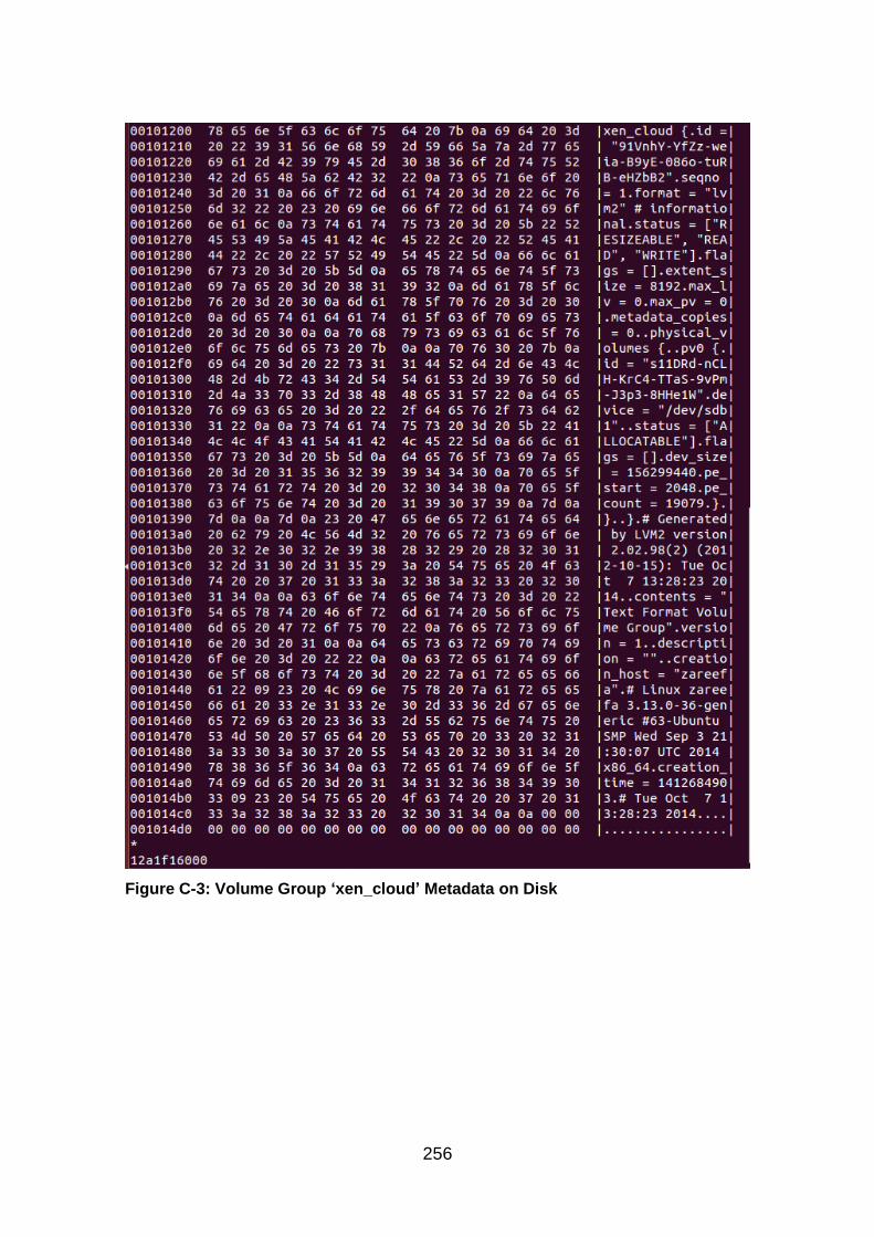
256
Figure C-3: Volume Group ‘xen_cloud’ Metadata on Disk

257
Figure C-4: Hexdump Logical Volume ‘media’ Metadata on Disk
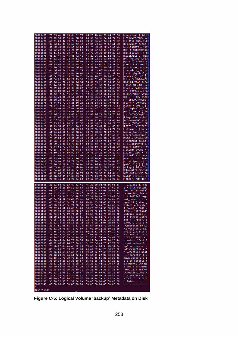
258
Figure C-5: Logical Volume ‘backup’ Metadata on Disk
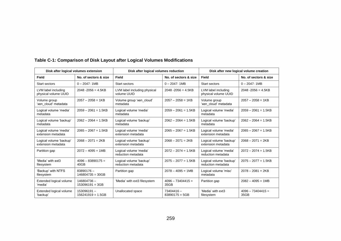
259
Table C-1: Comparison of Disk Layout after Logical Volumes Modifications
Disk after logical volumes extension Disk after logical volumes reduction Disk after new logical volume creation
Field No. of sectors & size Field No. of sectors & size Field No. of sectors & size
Start sectors 0 – 2047: 1MB Start sectors 0 – 2047: 1MB Start sectors 0 – 2047: 1MB
LVM label including physical volume UUID
2048 -2056 = 4.5KB LVM label including physical volume UUID
2048 -2056 = 4.5KB LVM label including physical volume UUID
2048 -2056 = 4.5KB
Volume group ‘xen_cloud’ metadata
2057 – 2058 = 1KB Volume group ‘xen_cloud’ metadata
2057 – 2058 = 1KB Volume group ‘xen_cloud’ metadata
2057 – 2058 = 1KB
Logical volume ‘media’ metadata
2059 – 2061 = 1.5KB Logical volume ‘media’ metadata
2059 – 2061 = 1.5KB Logical volume ‘media’ metadata
2059 – 2061 = 1.5KB
Logical volume ‘backup’ metadata
2062 – 2064 = 1.5KB Logical volume ‘backup’ metadata
2062 – 2064 = 1.5KB Logical volume ‘backup’ metadata
2062 – 2064 = 1.5KB
Logical volume ‘media’ extension metadata
2065 – 2067 = 1.5KB Logical volume ‘media’ extension metadata
2065 – 2067 = 1.5KB Logical volume ‘media’ extension metadata
2065 – 2067 = 1.5KB
Logical volume ‘backup’ extension metadata
2068 – 2071 = 2KB Logical volume ‘backup’ extension metadata
2068 – 2071 = 2KB Logical volume ‘backup’ extension metadata
2068 – 2071 = 2KB
Partition gap 2072 – 4095 = 1MB Logical volume ‘media’ reduction metadata
2072 – 2074 = 1.5KB Logical volume ‘media’ reduction metadata
2072 – 2074 = 1.5KB
‘Media’ with ext3 filesystem
4096 – 83890175 = 40GB
Logical volume ‘backup’ reduction metadata
2075 – 2077 = 1.5KB Logical volume ‘backup’ reduction metadata
2075 – 2077 = 1.5KB
‘Backup’ with NTFS filesystem
83890176 – 146804735 = 30GB
Partition gap 2078 – 4095 = 1MB Logical volume ‘misc’ metadata
2078 – 2081 = 2KB
Extended logical volume ‘media’
146804736 – 153096191 = 3GB
‘Media’ with ext3 filesystem 4096 – 73404415 = 35GB
Partition gap 2082 – 4095 = 1MB
Extended logical volume ‘backup’
153096191 – 156241919 = 1.5GB
Unallocated space 73404416 – 83890175 = 5GB
‘Media’ with ext3 filesystem
4096 – 73404415 = 35GB
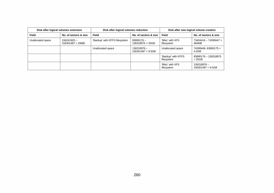
260
Disk after logical volumes extension Disk after logical volumes reduction Disk after new logical volume creation
Field No. of sectors & size Field No. of sectors & size Field No. of sectors & size
Unallocated space 156241920 – 156301487 = 29MB
‘Backup’ with NTFS filesystem 83890176 – 136318975 = 25GB
‘Misc’ with XFS filesystem
73404416 – 74395647 = 484MB
Unallocated space 136318976 – 156301487 = 9.5GB
Unallocated space 74395648- 83890175 = 4.5GB
‘Backup’ with NTFS filesystem
83890176 – 136318975 = 25GB
‘Misc’ with XFS filesystem
136318976 – 156301487 = 9.5GB

261
Figure C-6: Metadata Offset on Disk
# Generated by LVM2 version 2.02.98(2) (2012-10-15): Tue Oct 7 14:15:46 2014 contents = "Text Format Volume Group" version = 1 description = "Created *after* executing 'lvcreate --name backup --size 30G xen_cloud'" creation_host = "zareefa" # Linux zareefa 3.13.0-36-generic #63-Ubuntu SMP Wed Sep 3 21:30:07 UTC 2014 x86_64 creation_time = 1412687746 # Tue Oct 7 14:15:46 2014 xen_cloud { id = "91VnhY-YfZz-weia-B9yE-086o-tuRB-eHZbB2" seqno = 3 format = "lvm2" # informational status = ["RESIZEABLE", "READ", "WRITE"] flags = [] extent_size = 8192 # 4 Megabytes max_lv = 0 max_pv = 0 metadata_copies = 0 physical_volumes { pv0 { id = "s11DRd-nCLH-KrC4-TTaS-9vPm-J3p3-8HHe1W" device = "/dev/sdb1" # Hint only status = ["ALLOCATABLE"] flags = [] dev_size = 156299440 # 74.5294 Gigabytes pe_start = 2048 pe_count = 19079 # 74.5273 Gigabytes } }

262
logical_volumes { media { id = "cCORQC-qiYp-k2og-xRVk-Vveh-I6o3-neWmSD" status = ["READ", "WRITE", "VISIBLE"] flags = [] creation_host = "zareefa" creation_time = 1412687694 # 2014-10-07 14:14:54 +0100 segment_count = 1 segment1 { start_extent = 0 extent_count = 10240 # 40 Gigabytes type = "striped" stripe_count = 1 # linear stripes = [ "pv0", 0 ] } } backup { id = "8sZjmH-Nl2R-BFvI-UdBi-tmFx-zX5Q-JAox85" status = ["READ", "WRITE", "VISIBLE"] flags = [] creation_host = "zareefa" creation_time = 1412687746 # 2014-10-07 14:15:46 +0100 segment_count = 1 segment1 { start_extent = 0 extent_count = 7680 # 30 Gigabytes type = "striped" stripe_count = 1 # linear stripes = [ "pv0", 10240 ] } } } }
Figure C-7: LVM Metadata File
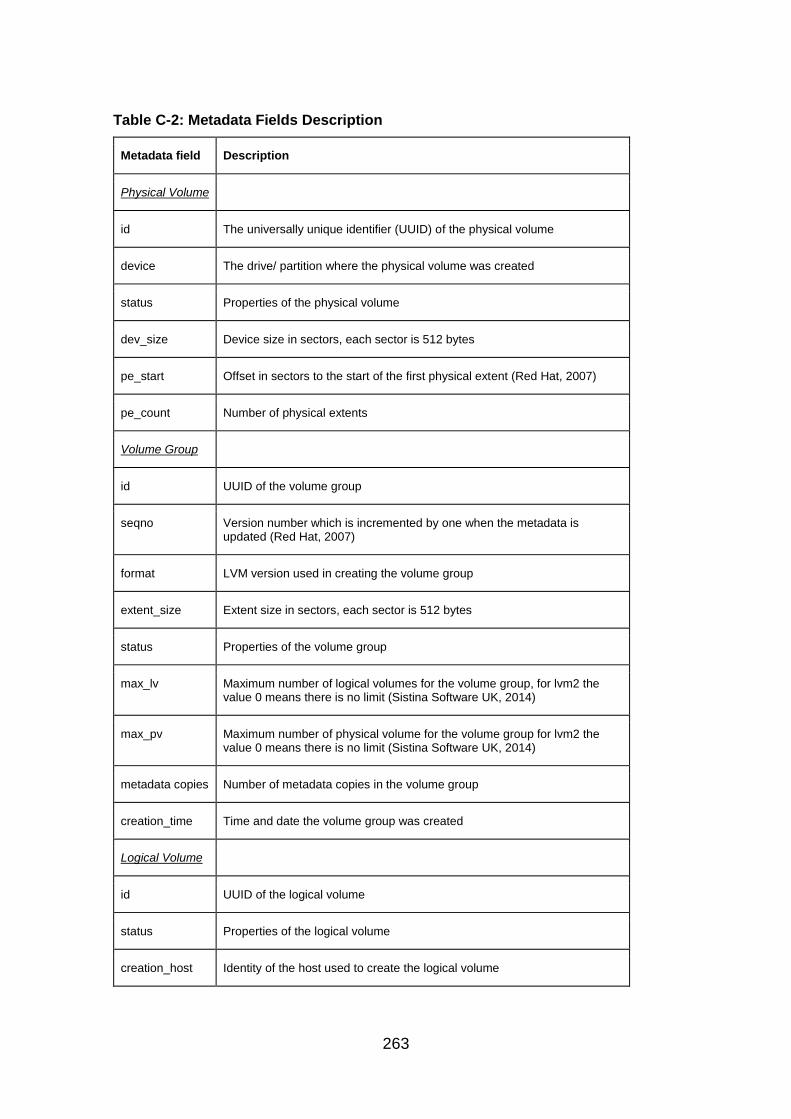
263
Table C-2: Metadata Fields Description
Metadata field Description
Physical Volume
id The universally unique identifier (UUID) of the physical volume
device The drive/ partition where the physical volume was created
status Properties of the physical volume
dev_size Device size in sectors, each sector is 512 bytes
pe_start Offset in sectors to the start of the first physical extent (Red Hat, 2007)
pe_count Number of physical extents
Volume Group
id UUID of the volume group
seqno Version number which is incremented by one when the metadata is updated (Red Hat, 2007)
format LVM version used in creating the volume group
extent_size Extent size in sectors, each sector is 512 bytes
status Properties of the volume group
max_lv Maximum number of logical volumes for the volume group, for lvm2 the value 0 means there is no limit (Sistina Software UK, 2014)
max_pv Maximum number of physical volume for the volume group for lvm2 the value 0 means there is no limit (Sistina Software UK, 2014)
metadata copies Number of metadata copies in the volume group
creation_time Time and date the volume group was created
Logical Volume
id UUID of the logical volume
status Properties of the logical volume
creation_host Identity of the host used to create the logical volume
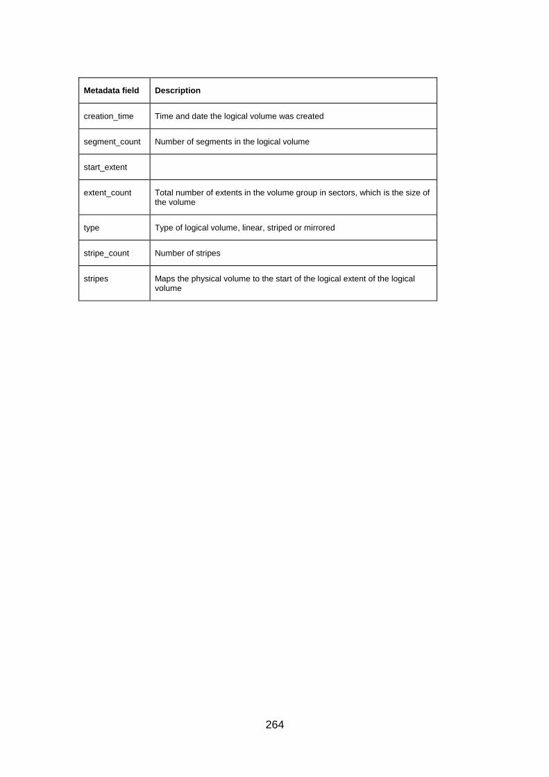
264
Metadata field Description
creation_time Time and date the logical volume was created
segment_count Number of segments in the logical volume
start_extent
extent_count Total number of extents in the volume group in sectors, which is the size of the volume
type Type of logical volume, linear, striped or mirrored
stripe_count Number of stripes
stripes Maps the physical volume to the start of the logical extent of the logical volume
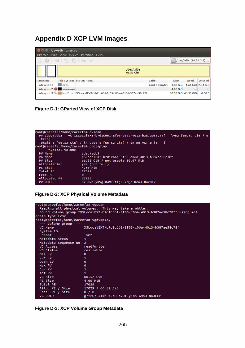
265
Appendix D XCP LVM Images
Figure D-1: GParted View of XCP Disk
Figure D-2: XCP Physical Volume Metadata
Figure D-3: XCP Volume Group Metadata

266
Figure D-4: XCP Logical Volume Metadata
Figure D-5: XCP LVM Label and Physical Volume Metadata on the Disk
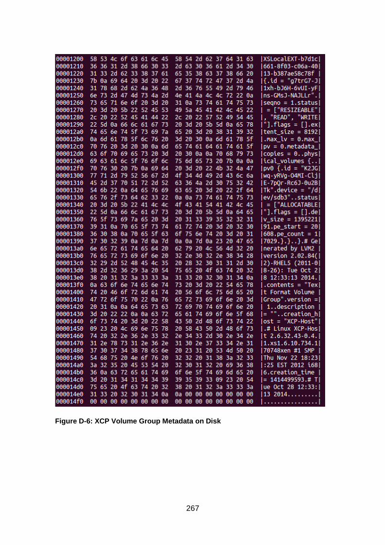
267
Figure D-6: XCP Volume Group Metadata on Disk
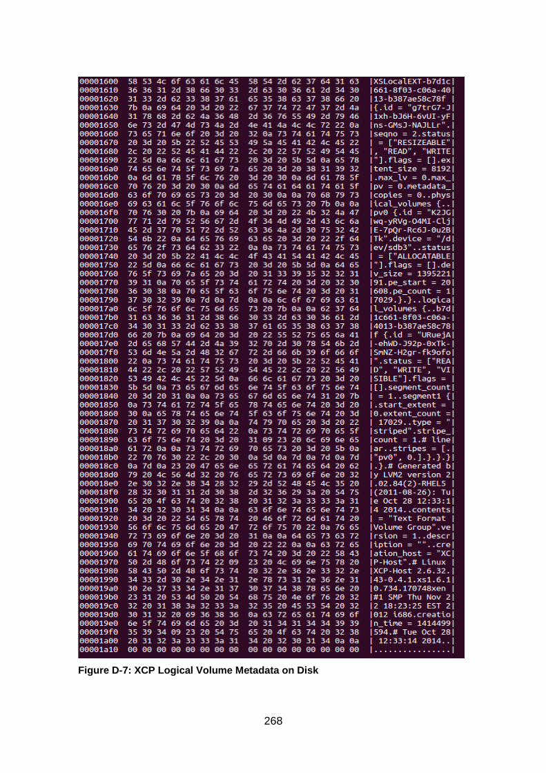
268
Figure D-7: XCP Logical Volume Metadata on Disk
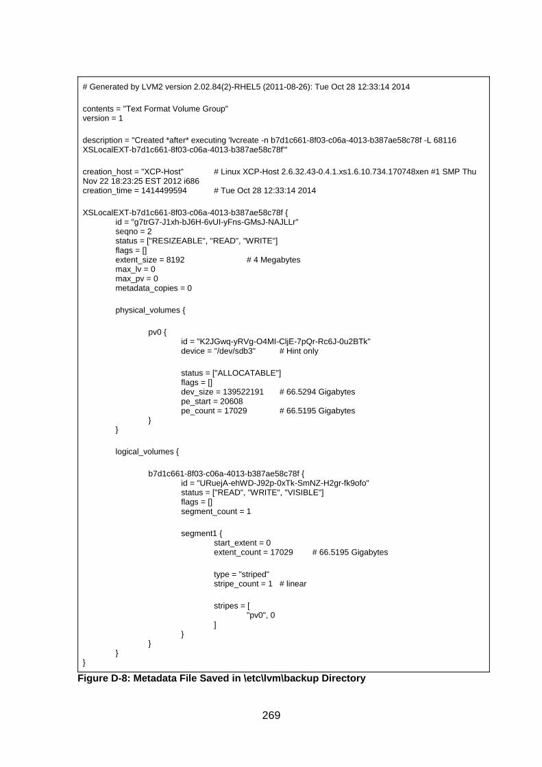
269
# Generated by LVM2 version 2.02.84(2)-RHEL5 (2011-08-26): Tue Oct 28 12:33:14 2014 contents = "Text Format Volume Group" version = 1 description = "Created *after* executing 'lvcreate -n b7d1c661-8f03-c06a-4013-b387ae58c78f -L 68116 XSLocalEXT-b7d1c661-8f03-c06a-4013-b387ae58c78f'" creation_host = "XCP-Host" # Linux XCP-Host 2.6.32.43-0.4.1.xs1.6.10.734.170748xen #1 SMP Thu Nov 22 18:23:25 EST 2012 i686 creation_time = 1414499594 # Tue Oct 28 12:33:14 2014 XSLocalEXT-b7d1c661-8f03-c06a-4013-b387ae58c78f { id = "g7trG7-J1xh-bJ6H-6vUI-yFns-GMsJ-NAJLLr" seqno = 2 status = ["RESIZEABLE", "READ", "WRITE"] flags = [] extent_size = 8192 # 4 Megabytes max_lv = 0 max_pv = 0 metadata_copies = 0 physical_volumes { pv0 { id = "K2JGwq-yRVg-O4MI-CljE-7pQr-Rc6J-0u2BTk" device = "/dev/sdb3" # Hint only status = ["ALLOCATABLE"] flags = [] dev_size = 139522191 # 66.5294 Gigabytes pe_start = 20608 pe_count = 17029 # 66.5195 Gigabytes } } logical_volumes { b7d1c661-8f03-c06a-4013-b387ae58c78f { id = "URuejA-ehWD-J92p-0xTk-SmNZ-H2gr-fk9ofo" status = ["READ", "WRITE", "VISIBLE"] flags = [] segment_count = 1 segment1 { start_extent = 0 extent_count = 17029 # 66.5195 Gigabytes type = "striped" stripe_count = 1 # linear stripes = [ "pv0", 0 ] } } } }
Figure D-8: Metadata File Saved in \etc\lvm\backup Directory
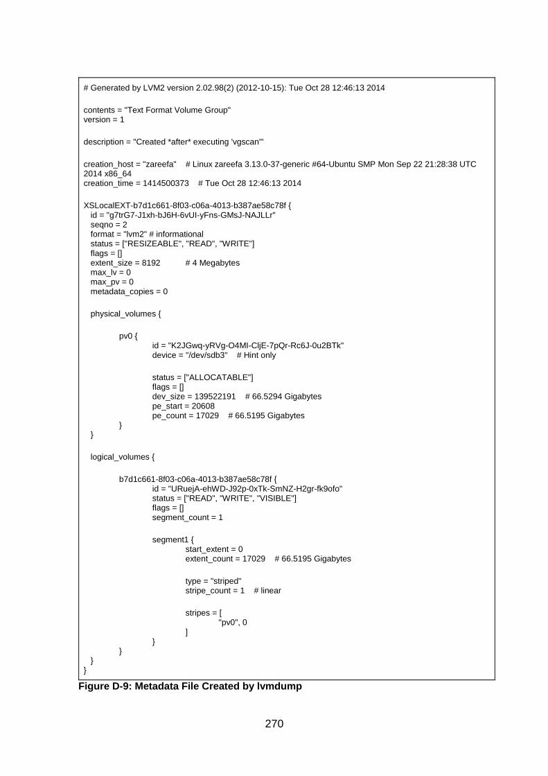
270
# Generated by LVM2 version 2.02.98(2) (2012-10-15): Tue Oct 28 12:46:13 2014 contents = "Text Format Volume Group" version = 1 description = "Created *after* executing 'vgscan'" creation_host = "zareefa" # Linux zareefa 3.13.0-37-generic #64-Ubuntu SMP Mon Sep 22 21:28:38 UTC 2014 x86_64 creation_time = 1414500373 # Tue Oct 28 12:46:13 2014 XSLocalEXT-b7d1c661-8f03-c06a-4013-b387ae58c78f { id = "g7trG7-J1xh-bJ6H-6vUI-yFns-GMsJ-NAJLLr" seqno = 2 format = "lvm2" # informational status = ["RESIZEABLE", "READ", "WRITE"] flags = [] extent_size = 8192 # 4 Megabytes max_lv = 0 max_pv = 0 metadata_copies = 0 physical_volumes { pv0 { id = "K2JGwq-yRVg-O4MI-CljE-7pQr-Rc6J-0u2BTk" device = "/dev/sdb3" # Hint only status = ["ALLOCATABLE"] flags = [] dev_size = 139522191 # 66.5294 Gigabytes pe_start = 20608 pe_count = 17029 # 66.5195 Gigabytes } } logical_volumes { b7d1c661-8f03-c06a-4013-b387ae58c78f { id = "URuejA-ehWD-J92p-0xTk-SmNZ-H2gr-fk9ofo" status = ["READ", "WRITE", "VISIBLE"] flags = [] segment_count = 1 segment1 { start_extent = 0 extent_count = 17029 # 66.5195 Gigabytes type = "striped" stripe_count = 1 # linear stripes = [ "pv0", 0 ] } } } }
Figure D-9: Metadata File Created by lvmdump

271
Appendix E Deleted Data in XCP with Local LVM
E.1 Introduction
XCP can be deployed with local storage, either ext or LVM, shared NFS or ISCSI
storage (Xen.org, 2009a). Storage repositories are used to store VDIs in XCP.
The aim of this experiment is to investigate how XCP manages deleted files in
LVM storage.
E.2 Analysis
This section describes the experiment that was set up to investigate how XCP
with local LVM storage manages deleted files. In order to do this, a setup was
used with two systems. On the first system, XCP 1.6 was installed on a system
with 80GB HDD and 4GB RAM with default setting and static network. The
second system, which was to be used as a management system, was configured
with Windows 7 Professional 64-bit with 250GB HDD and 16GB RAM. XenCenter
was installed to provide a graphical management interface for the XCP host and
XenConvert was installed to convert Xen Virtual Appliance (XVA) files, the format
used to export VMs in XCP to Open Virtualization Format (OVF). This was placed
on the same network as the XCP host.
Using the XenCenter templates and Windows 7 ISO, a Windows VM was created
with Windows 7 Professional, 24GB HDD and 1GB RAM. A 0.99GB text file,
which was created with a Python script, was added to the Documents directory
of the VM by connecting a USB drive to the XCP host and attaching it as a disk
to the VM. The file was then copied from the USB to the Documents directory and
the USB detached. The VM was powered off. The disk image was created and
saved as Image 1. Using this image, the VHD file was extracted with FTK and
saved as VHD1. Both the image and the VHD file were viewed in WinHex and
the sectors that were occupied by the text file were identified and noted. The
sectors that were occupied by the VHD file, which is the VDI of the VM on the
image, were also noted.
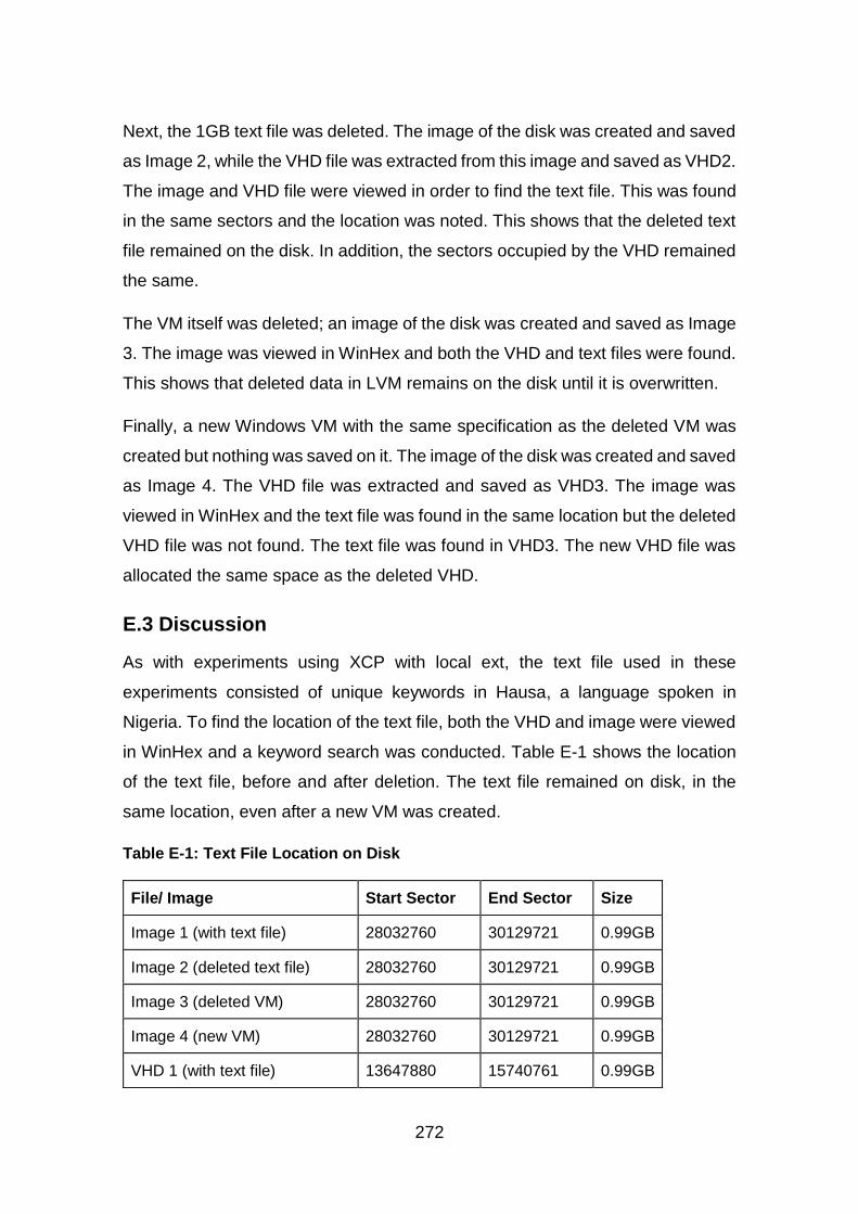
272
Next, the 1GB text file was deleted. The image of the disk was created and saved
as Image 2, while the VHD file was extracted from this image and saved as VHD2.
The image and VHD file were viewed in order to find the text file. This was found
in the same sectors and the location was noted. This shows that the deleted text
file remained on the disk. In addition, the sectors occupied by the VHD remained
the same.
The VM itself was deleted; an image of the disk was created and saved as Image
3. The image was viewed in WinHex and both the VHD and text files were found.
This shows that deleted data in LVM remains on the disk until it is overwritten.
Finally, a new Windows VM with the same specification as the deleted VM was
created but nothing was saved on it. The image of the disk was created and saved
as Image 4. The VHD file was extracted and saved as VHD3. The image was
viewed in WinHex and the text file was found in the same location but the deleted
VHD file was not found. The text file was found in VHD3. The new VHD file was
allocated the same space as the deleted VHD.
E.3 Discussion
As with experiments using XCP with local ext, the text file used in these
experiments consisted of unique keywords in Hausa, a language spoken in
Nigeria. To find the location of the text file, both the VHD and image were viewed
in WinHex and a keyword search was conducted. Table E-1 shows the location
of the text file, before and after deletion. The text file remained on disk, in the
same location, even after a new VM was created.
Table E-1: Text File Location on Disk
File/ Image Start Sector End Sector Size
Image 1 (with text file) 28032760 30129721 0.99GB
Image 2 (deleted text file) 28032760 30129721 0.99GB
Image 3 (deleted VM) 28032760 30129721 0.99GB
Image 4 (new VM) 28032760 30129721 0.99GB
VHD 1 (with text file) 13647880 15740761 0.99GB
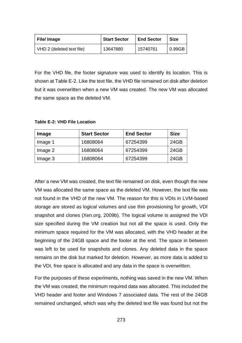
273
File/ Image Start Sector End Sector Size
VHD 2 (deleted text file) 13647880 15740761 0.99GB
For the VHD file, the footer signature was used to identify its location. This is
shown at Table E-2. Like the text file, the VHD file remained on disk after deletion
but it was overwritten when a new VM was created. The new VM was allocated
the same space as the deleted VM.
Table E-2: VHD File Location
Image Start Sector End Sector Size
Image 1 16808064 67254399 24GB
Image 2 16808064 67254399 24GB
Image 3 16808064 67254399 24GB
After a new VM was created, the text file remained on disk, even though the new
VM was allocated the same space as the deleted VM. However, the text file was
not found in the VHD of the new VM. The reason for this is VDIs in LVM-based
storage are stored as logical volumes and use thin provisioning for growth, VDI
snapshot and clones (Xen.org, 2009b). The logical volume is assigned the VDI
size specified during the VM creation but not all the space is used. Only the
minimum space required for the VM was allocated, with the VHD header at the
beginning of the 24GB space and the footer at the end. The space in between
was left to be used for snapshots and clones. Any deleted data in the space
remains on the disk but marked for deletion. However, as more data is added to
the VDI, free space is allocated and any data in the space is overwritten.
For the purposes of these experiments, nothing was saved in the new VM. When
the VM was created, the minimum required data was allocated. This included the
VHD header and footer and Windows 7 associated data. The rest of the 24GB
remained unchanged, which was why the deleted text file was found but not the

274
VHD file of the deleted VM. As stated earlier, if more data is added to the disk or
if snapshots and clones are created, the deleted text file will be overwritten.
When a snapshot was taken, two other logical volumes were created, one
6.36GB and the second 8MB.
[root@xcp-lvm-sr-del-vm ~]# lvscan
ACTIVE '/dev/VG_XenStorage-94e00181-00dd-266e-a6d4-
c64f6e73f966/MGT' [4.00 MB] inherit
ACTIVE '/dev/VG_XenStorage-94e00181-00dd-266e-a6d4-
c64f6e73f966/VHD-f5cac42a-e0ab-4789-a7af-37ceafc41585' [6.36 GB] inherit
ACTIVE '/dev/VG_XenStorage-94e00181-00dd-266e-a6d4-
c64f6e73f966/VHD-1b526e36-2a06-458a-b536-59cb8077e830' [24.05 GB]
inherit
inactive '/dev/VG_XenStorage-94e00181-00dd-266e-a6d4-
c64f6e73f966/VHD-f5e009b7-3d14-4e3e-828c-8cd064120b8d' [8.00 MB]
inherit
After snapshot was deleted----
[root@xcp-lvm-sr-del-vm ~]# lvscan
ACTIVE '/dev/VG_XenStorage-94e00181-00dd-266e-a6d4-
c64f6e73f966/MGT' [4.00 MB] inherit
ACTIVE '/dev/VG_XenStorage-94e00181-00dd-266e-a6d4-
c64f6e73f966/VHD-1b526e36-2a06-458a-b536-59cb8077e830' [24.05 GB]
inherit
[root@xcp-lvm-sr-del-vm ~]#
E.4 Conclusion
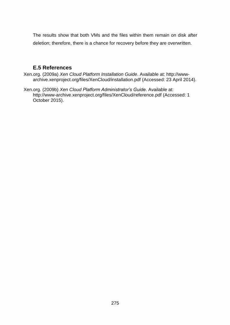
275
The results show that both VMs and the files within them remain on disk after
deletion; therefore, there is a chance for recovery before they are overwritten.
E.5 References Xen.org. (2009a) Xen Cloud Platform Installation Guide. Available at: http://www-
archive.xenproject.org/files/XenCloud/installation.pdf (Accessed: 23 April 2014).
Xen.org. (2009b) Xen Cloud Platform Administrator’s Guide. Available at: http://www-archive.xenproject.org/files/XenCloud/reference.pdf (Accessed: 1 October 2015).
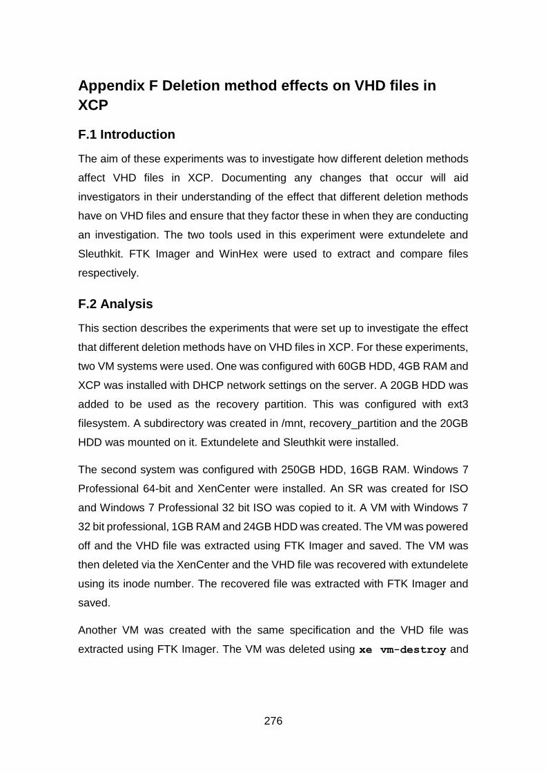
276
Appendix F Deletion method effects on VHD files in
XCP
F.1 Introduction
The aim of these experiments was to investigate how different deletion methods
affect VHD files in XCP. Documenting any changes that occur will aid
investigators in their understanding of the effect that different deletion methods
have on VHD files and ensure that they factor these in when they are conducting
an investigation. The two tools used in this experiment were extundelete and
Sleuthkit. FTK Imager and WinHex were used to extract and compare files
respectively.
F.2 Analysis
This section describes the experiments that were set up to investigate the effect
that different deletion methods have on VHD files in XCP. For these experiments,
two VM systems were used. One was configured with 60GB HDD, 4GB RAM and
XCP was installed with DHCP network settings on the server. A 20GB HDD was
added to be used as the recovery partition. This was configured with ext3
filesystem. A subdirectory was created in /mnt, recovery_partition and the 20GB
HDD was mounted on it. Extundelete and Sleuthkit were installed.
The second system was configured with 250GB HDD, 16GB RAM. Windows 7
Professional 64-bit and XenCenter were installed. An SR was created for ISO
and Windows 7 Professional 32 bit ISO was copied to it. A VM with Windows 7
32 bit professional, 1GB RAM and 24GB HDD was created. The VM was powered
off and the VHD file was extracted using FTK Imager and saved. The VM was
then deleted via the XenCenter and the VHD file was recovered with extundelete
using its inode number. The recovered file was extracted with FTK Imager and
saved.
Another VM was created with the same specification and the VHD file was
extracted using FTK Imager. The VM was deleted using xe vm-destroy and

277
vdi-destroy in the CLI of the XCP host. Extundelete was used to recover it by
its inode number. The recovered file was extracted and saved.
Lastly, a new VM with the same specification as the previous VMs was created.
The VHD file was extracted with FTK Imager and the VM deleted using rm Linux
command in the CLI of the XCP host. The VHD file was recovered with
extundelete using its inode number. The recovered file was extracted and saved.
Each set of VHD files, live and deleted/recovered were opened in WinHex. Under
the View tab, Synchronise & Compare was used to compare the two files.
In the first set of VHD files, the differences were in the header and footer of the
file. The values of the checksum field and the first byte of the reserved field
changed. The checksum value FF FF F0 E7 changed to FF FF F0 E6 and
the first value of the reserved field changed from 00 to 01. These changes are
shown at Figure F-1 and Figure F-2.
Figure F-1: Comparison of VHD Header – VHD1
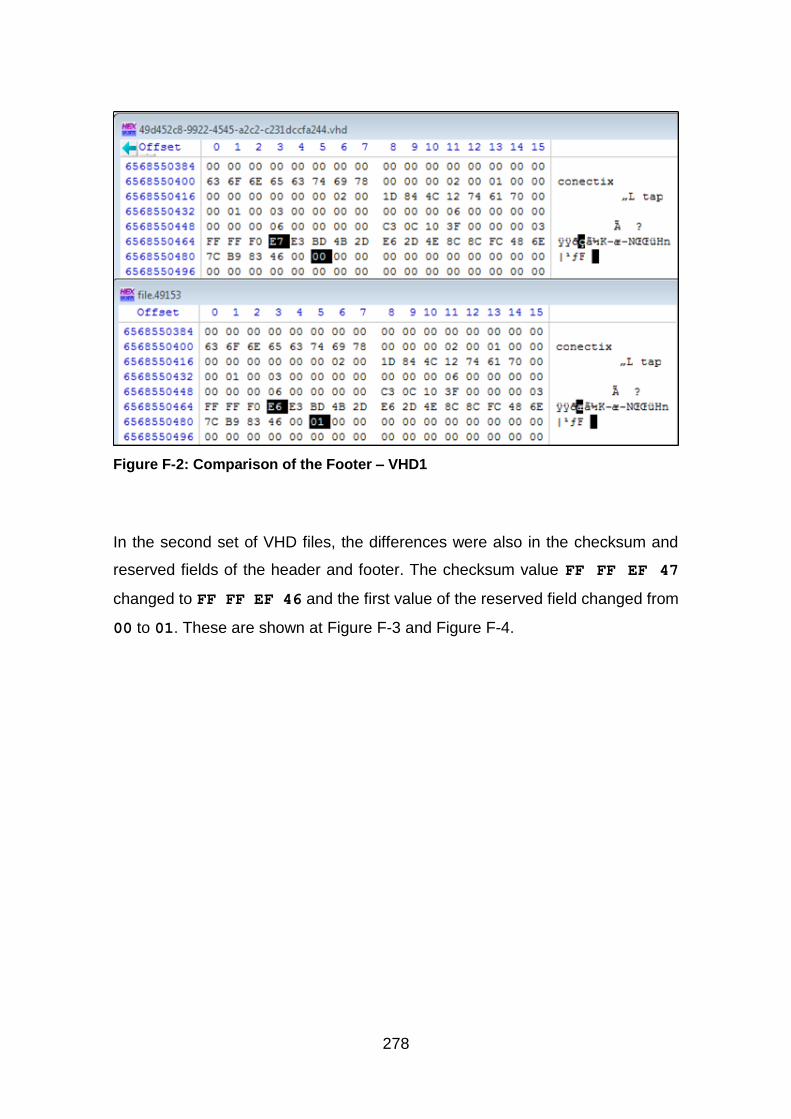
278
Figure F-2: Comparison of the Footer – VHD1
In the second set of VHD files, the differences were also in the checksum and
reserved fields of the header and footer. The checksum value FF FF EF 47
changed to FF FF EF 46 and the first value of the reserved field changed from
00 to 01. These are shown at Figure F-3 and Figure F-4.
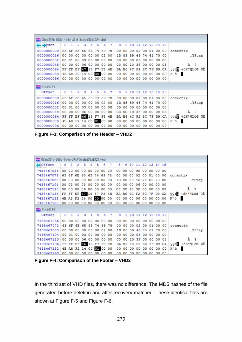
279
Figure F-3: Comparison of the Header – VHD2
Figure F-4: Comparison of the Footer – VHD2
In the third set of VHD files, there was no difference. The MD5 hashes of the file
generated before deletion and after recovery matched. These identical files are
shown at Figure F-5 and Figure F-6.
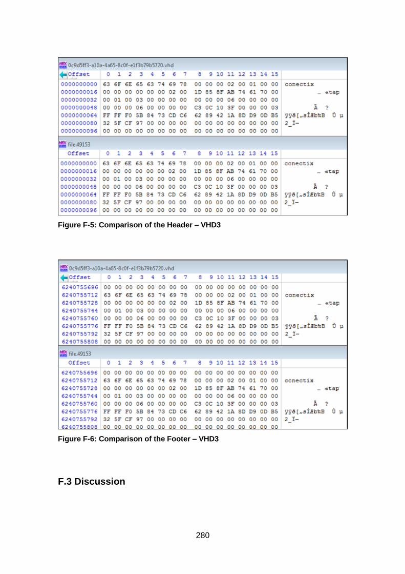
280
Figure F-5: Comparison of the Header – VHD3
Figure F-6: Comparison of the Footer – VHD3
F.3 Discussion
281
When the VHD files were deleted via the XenCenter and via the CLI using xe
command, two fields of the VHD header and footer changed. The Checksum
decreased by one and the first byte of the Reserved State increased by one. The
reason why the reserved field changed is not clear, but it is logical to conclude
that this is what causes the checksum to change. There is little documentation on
the reserved field, while the VHD specification by Microsoft only mentions that it
is 427 bytes in size and that it is all zeros (Microsoft, 2006). On the other hand,
the file deleted using Linux rm command did not change the file. The reason for
the difference between the different deletion methods is not clear. Further
research experiments need to be conducted to determine the reason.
F.4 Conclusion
The results show how different deletion methods affect the VHD file. Using either
the XenCenter or the xe commands to delete the VM results in a change in values
of the checksum and reserved fields of the VHD file, while a direct deletion using
Linux rm command does not change the file after deletion.
F.5 References
Microsoft, 2006. Virtual Hard Disk Image Format Specification. Available at: http://technet.microsoft.com/en-us/virtualization/bb676673.aspx (Accessed: 3 July 2014).
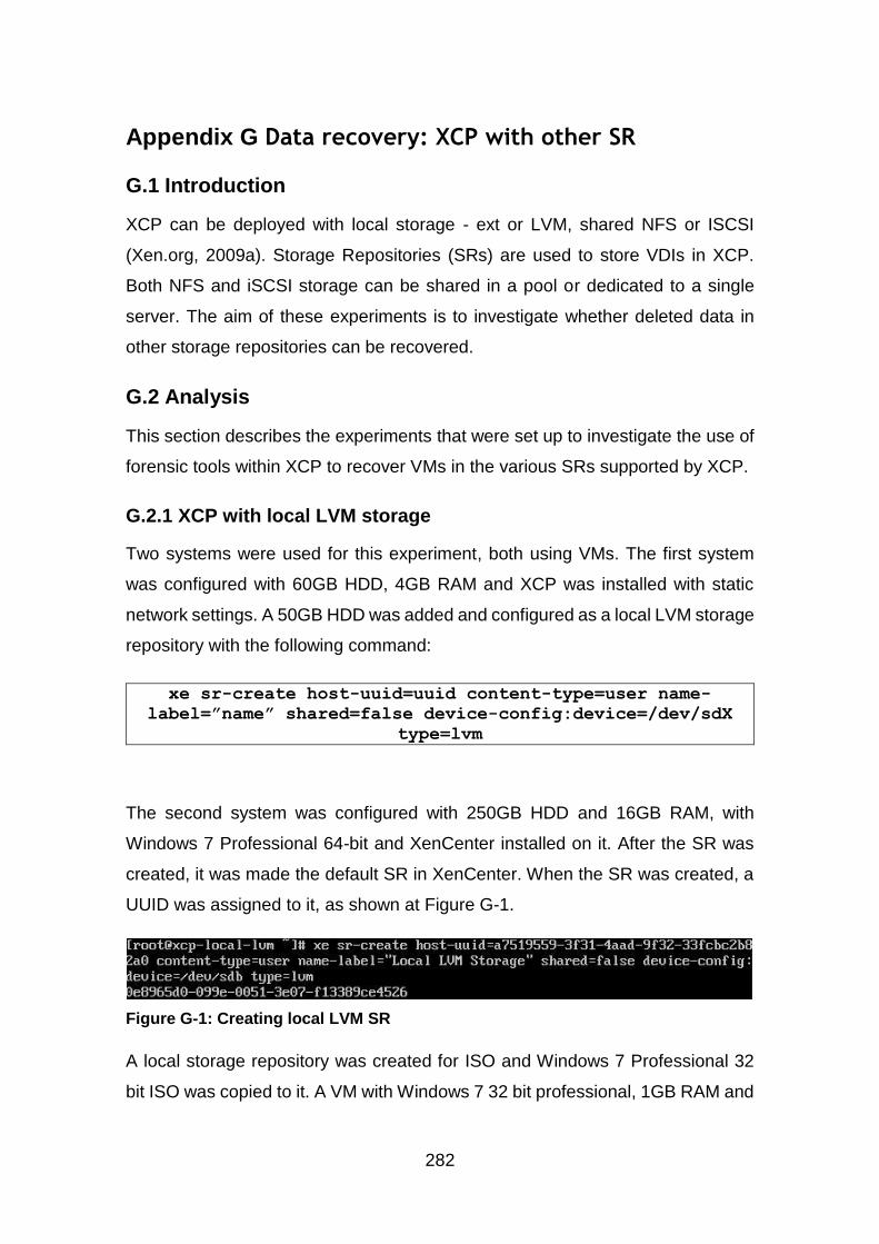
282
Appendix G Data recovery: XCP with other SR
G.1 Introduction
XCP can be deployed with local storage - ext or LVM, shared NFS or ISCSI
(Xen.org, 2009a). Storage Repositories (SRs) are used to store VDIs in XCP.
Both NFS and iSCSI storage can be shared in a pool or dedicated to a single
server. The aim of these experiments is to investigate whether deleted data in
other storage repositories can be recovered.
G.2 Analysis
This section describes the experiments that were set up to investigate the use of
forensic tools within XCP to recover VMs in the various SRs supported by XCP.
G.2.1 XCP with local LVM storage
Two systems were used for this experiment, both using VMs. The first system
was configured with 60GB HDD, 4GB RAM and XCP was installed with static
network settings. A 50GB HDD was added and configured as a local LVM storage
repository with the following command:
xe sr-create host-uuid=uuid content-type=user name-
label=”name” shared=false device-config:device=/dev/sdX
type=lvm
The second system was configured with 250GB HDD and 16GB RAM, with
Windows 7 Professional 64-bit and XenCenter installed on it. After the SR was
created, it was made the default SR in XenCenter. When the SR was created, a
UUID was assigned to it, as shown at Figure G-1.
Figure G-1: Creating local LVM SR
A local storage repository was created for ISO and Windows 7 Professional 32
bit ISO was copied to it. A VM with Windows 7 32 bit professional, 1GB RAM and
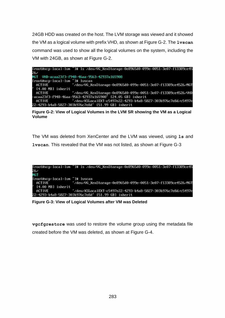
283
24GB HDD was created on the host. The LVM storage was viewed and it showed
the VM as a logical volume with prefix VHD, as shown at Figure G-2. The lvscan
command was used to show all the logical volumes on the system, including the
VM with 24GB, as shown at Figure G-2.
Figure G-2: View of Logical Volumes in the LVM SR showing the VM as a Logical Volume
The VM was deleted from XenCenter and the LVM was viewed, using ls and
lvscan. This revealed that the VM was not listed, as shown at Figure G-3
Figure G-3: View of Logical Volumes after VM was Deleted
vgcfgrestore was used to restore the volume group using the metadata file
created before the VM was deleted, as shown at Figure G-4.
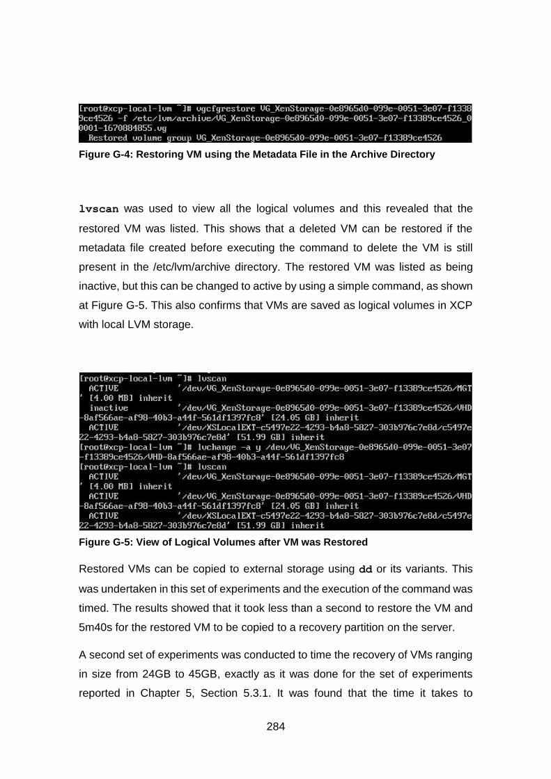
284
Figure G-4: Restoring VM using the Metadata File in the Archive Directory
lvscan was used to view all the logical volumes and this revealed that the
restored VM was listed. This shows that a deleted VM can be restored if the
metadata file created before executing the command to delete the VM is still
present in the /etc/lvm/archive directory. The restored VM was listed as being
inactive, but this can be changed to active by using a simple command, as shown
at Figure G-5. This also confirms that VMs are saved as logical volumes in XCP
with local LVM storage.
Figure G-5: View of Logical Volumes after VM was Restored
Restored VMs can be copied to external storage using dd or its variants. This
was undertaken in this set of experiments and the execution of the command was
timed. The results showed that it took less than a second to restore the VM and
5m40s for the restored VM to be copied to a recovery partition on the server.
A second set of experiments was conducted to time the recovery of VMs ranging
in size from 24GB to 45GB, exactly as it was done for the set of experiments
reported in Chapter 5, Section 5.3.1. It was found that the time it takes to
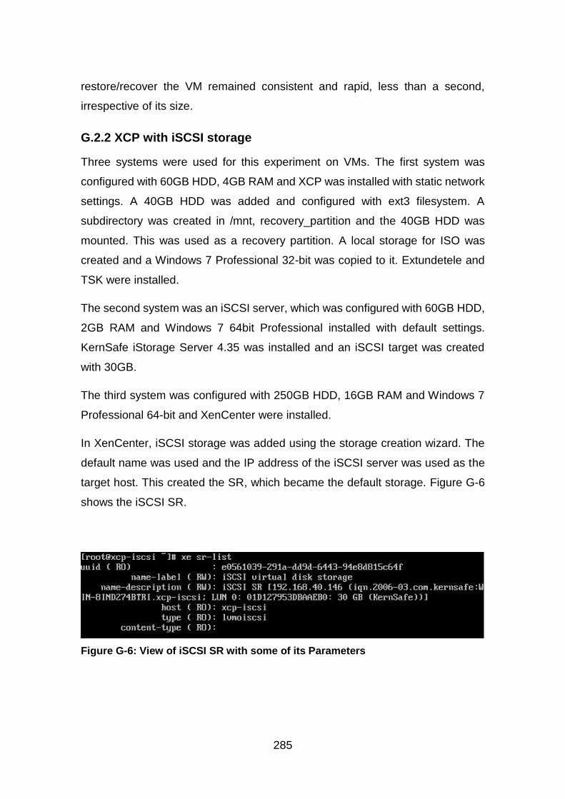
285
restore/recover the VM remained consistent and rapid, less than a second,
irrespective of its size.
G.2.2 XCP with iSCSI storage
Three systems were used for this experiment on VMs. The first system was
configured with 60GB HDD, 4GB RAM and XCP was installed with static network
settings. A 40GB HDD was added and configured with ext3 filesystem. A
subdirectory was created in /mnt, recovery_partition and the 40GB HDD was
mounted. This was used as a recovery partition. A local storage for ISO was
created and a Windows 7 Professional 32-bit was copied to it. Extundetele and
TSK were installed.
The second system was an iSCSI server, which was configured with 60GB HDD,
2GB RAM and Windows 7 64bit Professional installed with default settings.
KernSafe iStorage Server 4.35 was installed and an iSCSI target was created
with 30GB.
The third system was configured with 250GB HDD, 16GB RAM and Windows 7
Professional 64-bit and XenCenter were installed.
In XenCenter, iSCSI storage was added using the storage creation wizard. The
default name was used and the IP address of the iSCSI server was used as the
target host. This created the SR, which became the default storage. Figure G-6
shows the iSCSI SR.
Figure G-6: View of iSCSI SR with some of its Parameters
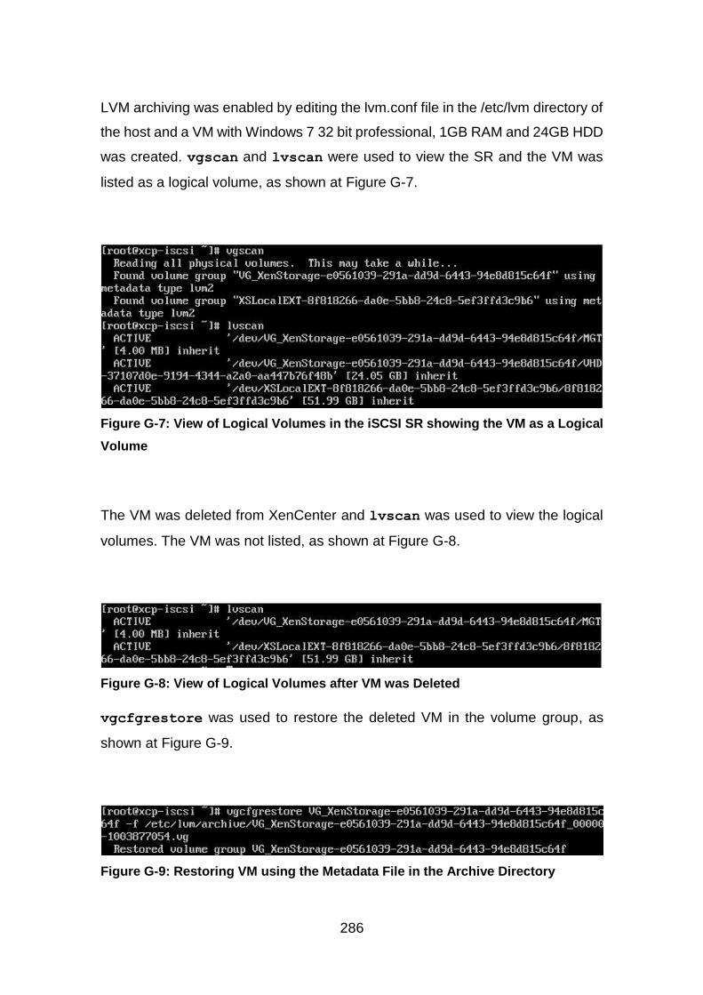
286
LVM archiving was enabled by editing the lvm.conf file in the /etc/lvm directory of
the host and a VM with Windows 7 32 bit professional, 1GB RAM and 24GB HDD
was created. vgscan and lvscan were used to view the SR and the VM was
listed as a logical volume, as shown at Figure G-7.
Figure G-7: View of Logical Volumes in the iSCSI SR showing the VM as a Logical
Volume
The VM was deleted from XenCenter and lvscan was used to view the logical
volumes. The VM was not listed, as shown at Figure G-8.
Figure G-8: View of Logical Volumes after VM was Deleted
vgcfgrestore was used to restore the deleted VM in the volume group, as
shown at Figure G-9.
Figure G-9: Restoring VM using the Metadata File in the Archive Directory
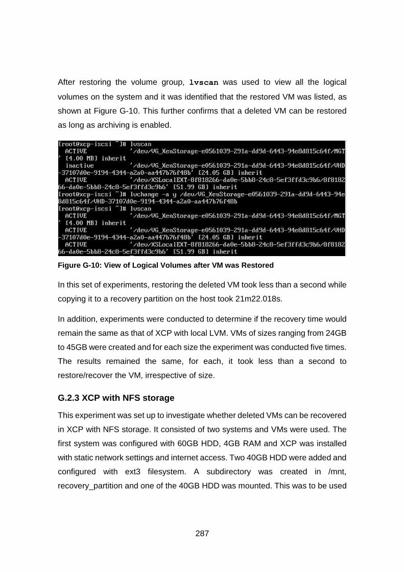
287
After restoring the volume group, lvscan was used to view all the logical
volumes on the system and it was identified that the restored VM was listed, as
shown at Figure G-10. This further confirms that a deleted VM can be restored
as long as archiving is enabled.
Figure G-10: View of Logical Volumes after VM was Restored
In this set of experiments, restoring the deleted VM took less than a second while
copying it to a recovery partition on the host took 21m22.018s.
In addition, experiments were conducted to determine if the recovery time would
remain the same as that of XCP with local LVM. VMs of sizes ranging from 24GB
to 45GB were created and for each size the experiment was conducted five times.
The results remained the same, for each, it took less than a second to
restore/recover the VM, irrespective of size.
G.2.3 XCP with NFS storage
This experiment was set up to investigate whether deleted VMs can be recovered
in XCP with NFS storage. It consisted of two systems and VMs were used. The
first system was configured with 60GB HDD, 4GB RAM and XCP was installed
with static network settings and internet access. Two 40GB HDD were added and
configured with ext3 filesystem. A subdirectory was created in /mnt,
recovery_partition and one of the 40GB HDD was mounted. This was to be used
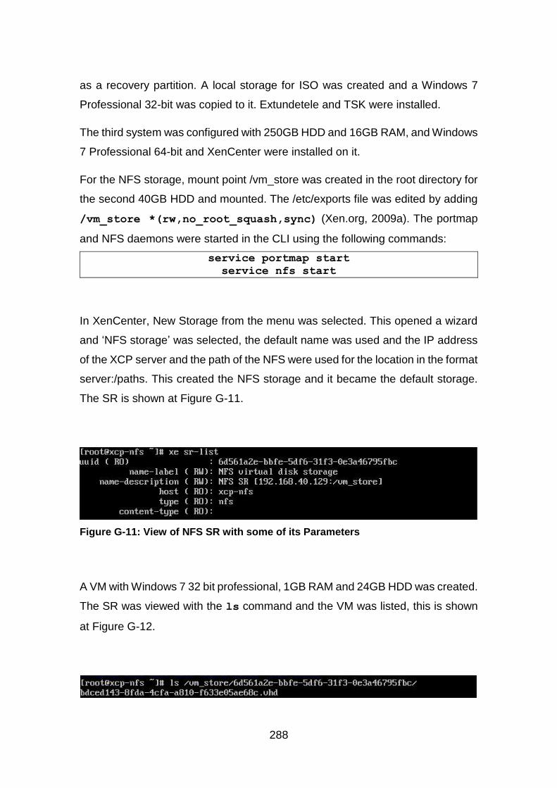
288
as a recovery partition. A local storage for ISO was created and a Windows 7
Professional 32-bit was copied to it. Extundetele and TSK were installed.
The third system was configured with 250GB HDD and 16GB RAM, and Windows
7 Professional 64-bit and XenCenter were installed on it.
For the NFS storage, mount point /vm_store was created in the root directory for
the second 40GB HDD and mounted. The /etc/exports file was edited by adding
/vm_store *(rw,no_root_squash,sync) (Xen.org, 2009a). The portmap
and NFS daemons were started in the CLI using the following commands:
service portmap start
service nfs start
In XenCenter, New Storage from the menu was selected. This opened a wizard
and ‘NFS storage’ was selected, the default name was used and the IP address
of the XCP server and the path of the NFS were used for the location in the format
server:/paths. This created the NFS storage and it became the default storage.
The SR is shown at Figure G-11.
Figure G-11: View of NFS SR with some of its Parameters
A VM with Windows 7 32 bit professional, 1GB RAM and 24GB HDD was created.
The SR was viewed with the ls command and the VM was listed, this is shown
at Figure G-12.
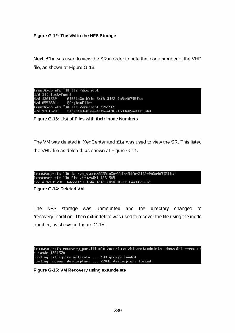
289
Figure G-12: The VM in the NFS Storage
Next, fls was used to view the SR in order to note the inode number of the VHD
file, as shown at Figure G-13.
Figure G-13: List of Files with their Inode Numbers
The VM was deleted in XenCenter and fls was used to view the SR. This listed
the VHD file as deleted, as shown at Figure G-14.
Figure G-14: Deleted VM
The NFS storage was unmounted and the directory changed to
/recovery_partition. Then extundelete was used to recover the file using the inode
number, as shown at Figure G-15.
Figure G-15: VM Recovery using extundelete
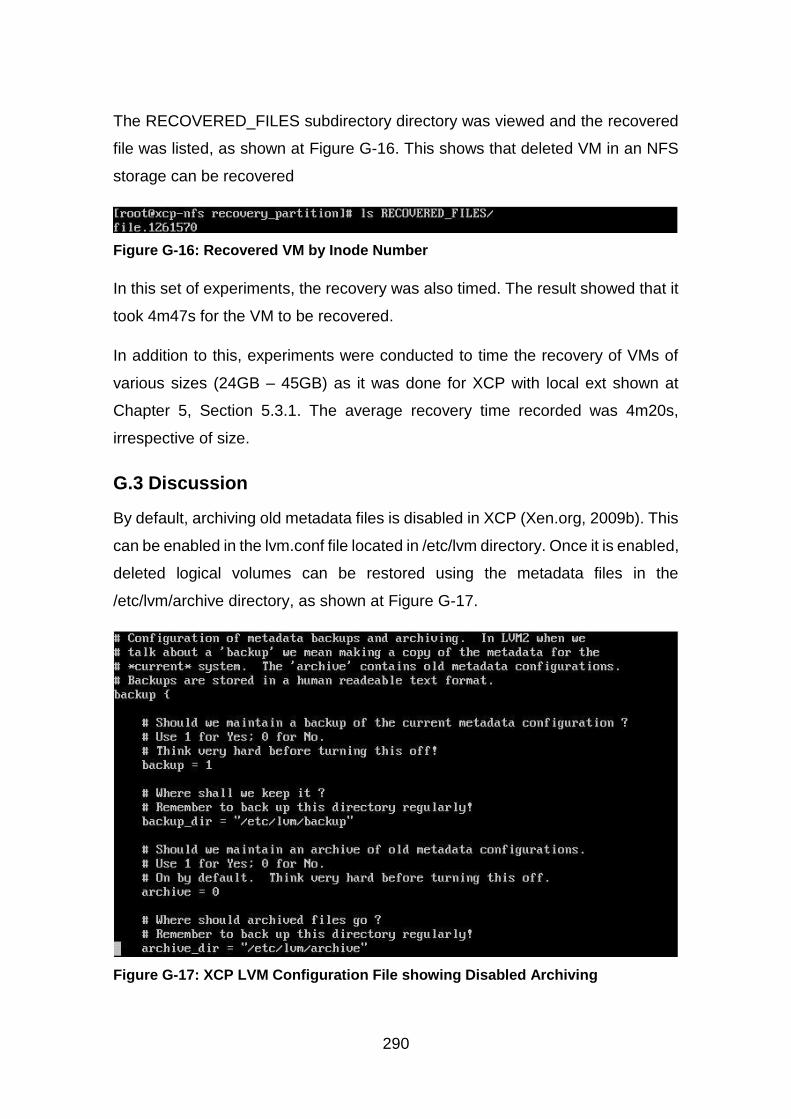
290
The RECOVERED_FILES subdirectory directory was viewed and the recovered
file was listed, as shown at Figure G-16. This shows that deleted VM in an NFS
storage can be recovered
Figure G-16: Recovered VM by Inode Number
In this set of experiments, the recovery was also timed. The result showed that it
took 4m47s for the VM to be recovered.
In addition to this, experiments were conducted to time the recovery of VMs of
various sizes (24GB – 45GB) as it was done for XCP with local ext shown at
Chapter 5, Section 5.3.1. The average recovery time recorded was 4m20s,
irrespective of size.
G.3 Discussion
By default, archiving old metadata files is disabled in XCP (Xen.org, 2009b). This
can be enabled in the lvm.conf file located in /etc/lvm directory. Once it is enabled,
deleted logical volumes can be restored using the metadata files in the
/etc/lvm/archive directory, as shown at Figure G-17.
Figure G-17: XCP LVM Configuration File showing Disabled Archiving
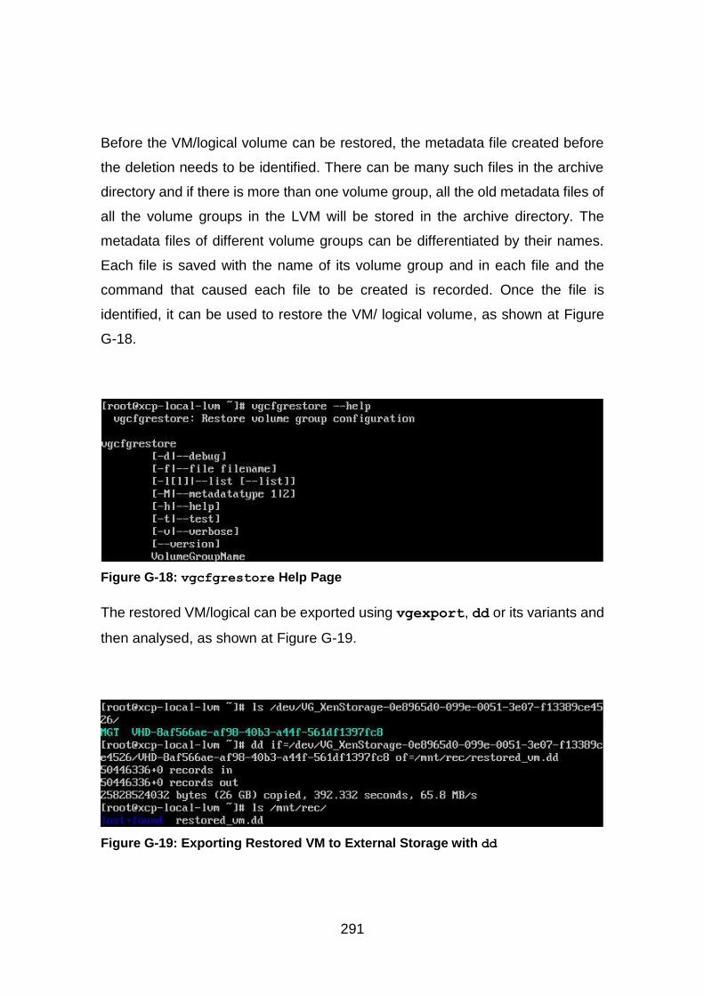
291
Before the VM/logical volume can be restored, the metadata file created before
the deletion needs to be identified. There can be many such files in the archive
directory and if there is more than one volume group, all the old metadata files of
all the volume groups in the LVM will be stored in the archive directory. The
metadata files of different volume groups can be differentiated by their names.
Each file is saved with the name of its volume group and in each file and the
command that caused each file to be created is recorded. Once the file is
identified, it can be used to restore the VM/ logical volume, as shown at Figure
G-18.
Figure G-18: vgcfgrestore Help Page
The restored VM/logical can be exported using vgexport, dd or its variants and
then analysed, as shown at Figure G-19.
Figure G-19: Exporting Restored VM to External Storage with dd
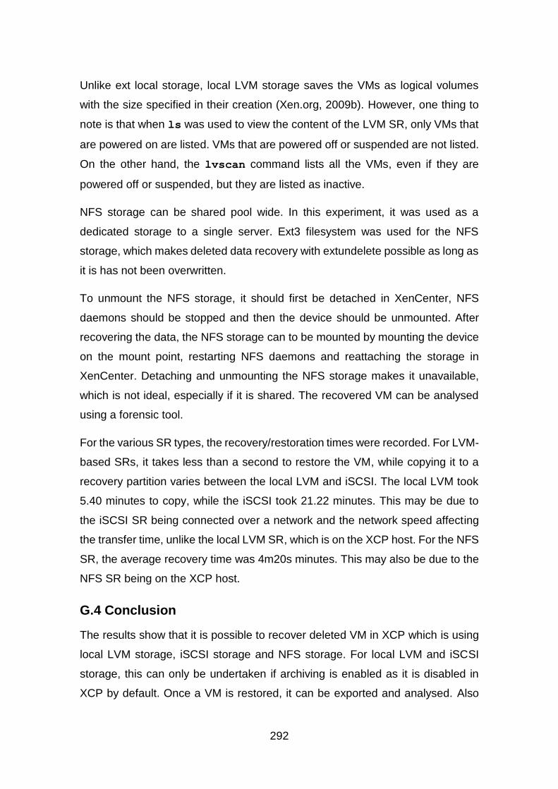
292
Unlike ext local storage, local LVM storage saves the VMs as logical volumes
with the size specified in their creation (Xen.org, 2009b). However, one thing to
note is that when ls was used to view the content of the LVM SR, only VMs that
are powered on are listed. VMs that are powered off or suspended are not listed.
On the other hand, the lvscan command lists all the VMs, even if they are
powered off or suspended, but they are listed as inactive.
NFS storage can be shared pool wide. In this experiment, it was used as a
dedicated storage to a single server. Ext3 filesystem was used for the NFS
storage, which makes deleted data recovery with extundelete possible as long as
it is has not been overwritten.
To unmount the NFS storage, it should first be detached in XenCenter, NFS
daemons should be stopped and then the device should be unmounted. After
recovering the data, the NFS storage can to be mounted by mounting the device
on the mount point, restarting NFS daemons and reattaching the storage in
XenCenter. Detaching and unmounting the NFS storage makes it unavailable,
which is not ideal, especially if it is shared. The recovered VM can be analysed
using a forensic tool.
For the various SR types, the recovery/restoration times were recorded. For LVM-
based SRs, it takes less than a second to restore the VM, while copying it to a
recovery partition varies between the local LVM and iSCSI. The local LVM took
5.40 minutes to copy, while the iSCSI took 21.22 minutes. This may be due to
the iSCSI SR being connected over a network and the network speed affecting
the transfer time, unlike the local LVM SR, which is on the XCP host. For the NFS
SR, the average recovery time was 4m20s minutes. This may also be due to the
NFS SR being on the XCP host.
G.4 Conclusion
The results show that it is possible to recover deleted VM in XCP which is using
local LVM storage, iSCSI storage and NFS storage. For local LVM and iSCSI
storage, this can only be undertaken if archiving is enabled as it is disabled in
XCP by default. Once a VM is restored, it can be exported and analysed. Also
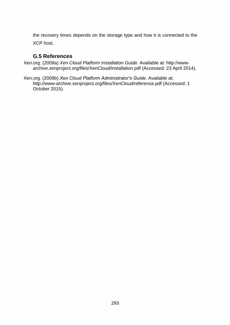
293
the recovery times depends on the storage type and how it is connected to the
XCP host.
G.5 References Xen.org. (2009a) Xen Cloud Platform Installation Guide. Available at: http://www-
archive.xenproject.org/files/XenCloud/installation.pdf (Accessed: 23 April 2014).
Xen.org. (2009b) Xen Cloud Platform Administrator’s Guide. Available at: http://www-archive.xenproject.org/files/XenCloud/reference.pdf (Accessed: 1 October 2015).

294
Appendix H Attribution: Other XCP SR with AD
H.1 Introduction
Storage Repositories (SRs) are used to store VDIs in XCP. Both NFS and iSCSI
storage can be shared in a pool or dedicated to a single server. The aim of these
experiments is to investigate whether deleted data in the different storage
repositories supported by XCP can be associated with users. XCP supports
different types of SRs including local ext, local LVM, NFS and iSCSI.
H.2 Analysis
This section describes the experiments set up to investigate how deleted data
can be associated with users in the various SRs supported by XCP.
H.2.1 Equipment/ Tools:
XCP Server: VMware Workstation 10, 60GB HDD, 4GB RAM, XCP 1.6 ISO
Windows Server: 120GB HDD, 4GB RAM, Windows Server 2012 ISO
iSCSI server: VMWare Workstation 10, 60GB HDD, 2GB RAM, Windows 7 64bit
Professional ISO, KernSafe iStorage Server 4.35
60GB HDD, 1GB RAM, XenCenter, Windows 7 32 Professional ISO
Analysis Machine: Windows 7 Professional 64-bit with 250GB HDD, 16GB RAM,
XenCenter 6.2
H.2.2 XCP with local LVM storage
XCP was installed with static network settings on the server. A 40GB HDD was
added and configured as a local LVM storage repository. This was made the
default SR in XenCenter. A local storage repository was created for ISO and
Windows 7 Professional 32 bit ISO was copied to it. The lvm.conf file was edited
to enable archiving.
A user with VM Admin role created a VM with Windows 7 32 bit professional, 2GB
RAM and 24GB HDD was created and installed Xen Server tools. The VM disk
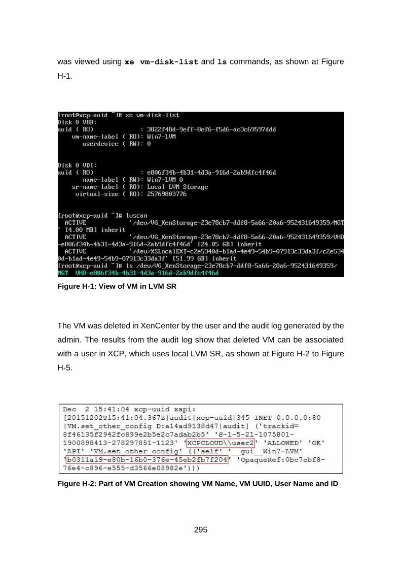
295
was viewed using xe vm-disk-list and ls commands, as shown at Figure
H-1.
Figure H-1: View of VM in LVM SR
The VM was deleted in XenCenter by the user and the audit log generated by the
admin. The results from the audit log show that deleted VM can be associated
with a user in XCP, which uses local LVM SR, as shown at Figure H-2 to Figure
H-5.
Figure H-2: Part of VM Creation showing VM Name, VM UUID, User Name and ID
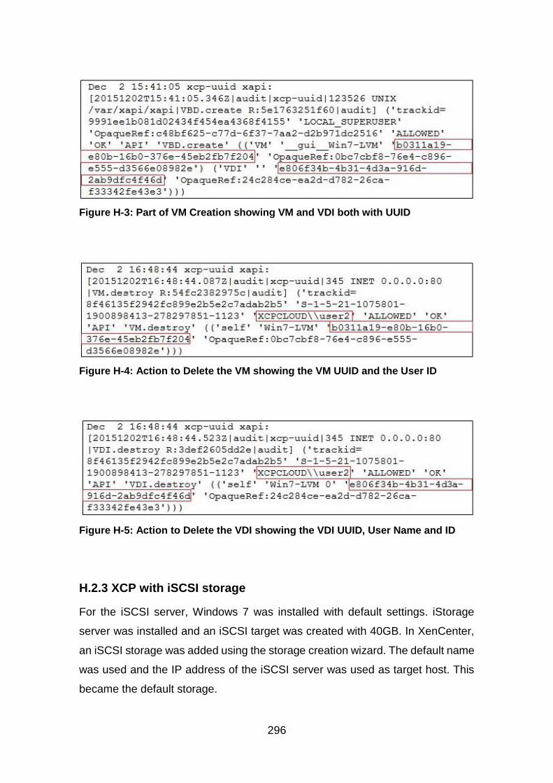
296
Figure H-3: Part of VM Creation showing VM and VDI both with UUID
Figure H-4: Action to Delete the VM showing the VM UUID and the User ID
Figure H-5: Action to Delete the VDI showing the VDI UUID, User Name and ID
H.2.3 XCP with iSCSI storage
For the iSCSI server, Windows 7 was installed with default settings. iStorage
server was installed and an iSCSI target was created with 40GB. In XenCenter,
an iSCSI storage was added using the storage creation wizard. The default name
was used and the IP address of the iSCSI server was used as target host. This
became the default storage.
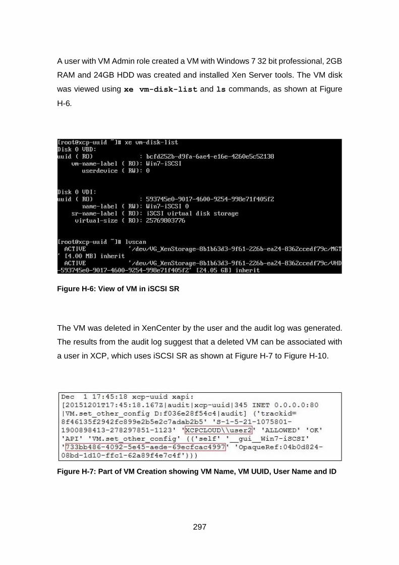
297
A user with VM Admin role created a VM with Windows 7 32 bit professional, 2GB
RAM and 24GB HDD was created and installed Xen Server tools. The VM disk
was viewed using xe vm-disk-list and ls commands, as shown at Figure
H-6.
Figure H-6: View of VM in iSCSI SR
The VM was deleted in XenCenter by the user and the audit log was generated.
The results from the audit log suggest that a deleted VM can be associated with
a user in XCP, which uses iSCSI SR as shown at Figure H-7 to Figure H-10.
Figure H-7: Part of VM Creation showing VM Name, VM UUID, User Name and ID
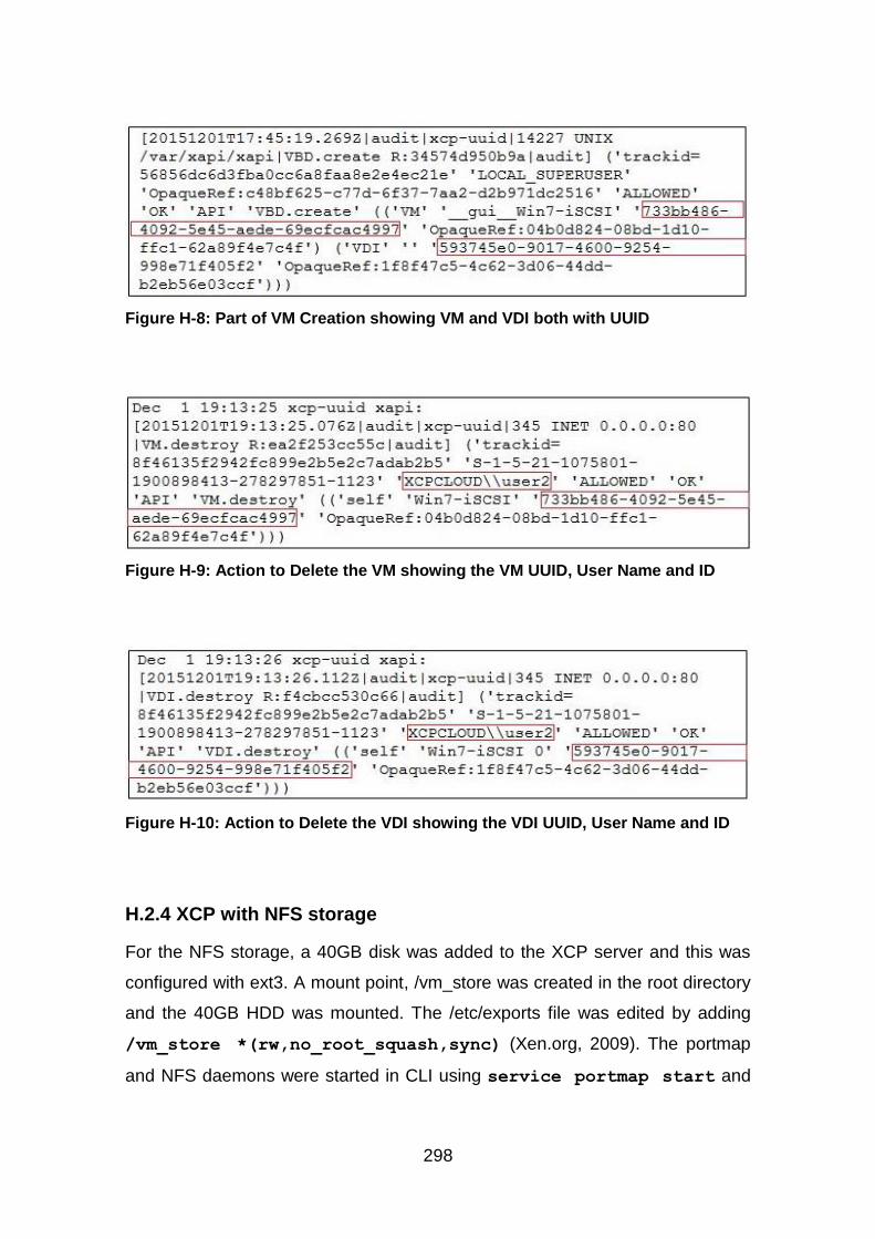
298
Figure H-8: Part of VM Creation showing VM and VDI both with UUID
Figure H-9: Action to Delete the VM showing the VM UUID, User Name and ID
Figure H-10: Action to Delete the VDI showing the VDI UUID, User Name and ID
H.2.4 XCP with NFS storage
For the NFS storage, a 40GB disk was added to the XCP server and this was
configured with ext3. A mount point, /vm_store was created in the root directory
and the 40GB HDD was mounted. The /etc/exports file was edited by adding
/vm_store *(rw,no_root_squash,sync) (Xen.org, 2009). The portmap
and NFS daemons were started in CLI using service portmap start and
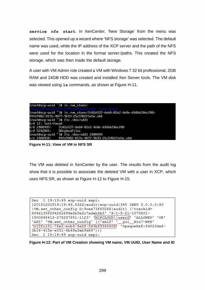
299
service nfs start. In XenCenter, 'New Storage' from the menu was
selected. This opened up a wizard where ‘NFS storage’ was selected. The default
name was used, while the IP address of the XCP server and the path of the NFS
were used for the location in the format server:/paths. This created the NFS
storage, which was then made the default storage.
A user with VM Admin role created a VM with Windows 7 32 bit professional, 2GB
RAM and 24GB HDD was created and installed Xen Server tools. The VM disk
was viewed using ls commands, as shown at Figure H-11.
Figure H-11: View of VM in NFS SR
The VM was deleted in XenCenter by the user. The results from the audit log
show that it is possible to associate the deleted VM with a user in XCP, which
uses NFS SR, as shown at Figure H-12 to Figure H-15.
Figure H-12: Part of VM Creation showing VM name, VM UUID, User Name and ID
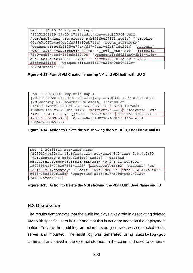
300
Figure H-13: Part of VM Creation showing VM and VDI both with UUID
Figure H-14: Action to Delete the VM showing the VM UUID, User Name and ID
Figure H-15: Action to Delete the VDI showing the VDI UUID, User Name and ID
H.3 Discussion
The results demonstrate that the audit log plays a key role in associating deleted
VMs with specific users in XCP and that this is not dependent on the deployment
option. To view the audit log, an external storage device was connected to the
server and mounted. The audit log was generated using audit-log-get
command and saved in the external storage. In the command used to generate
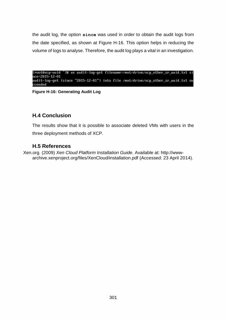
301
the audit log, the option since was used in order to obtain the audit logs from
the date specified, as shown at Figure H-16. This option helps in reducing the
volume of logs to analyse. Therefore, the audit log plays a vital in an investigation.
Figure H-16: Generating Audit Log
H.4 Conclusion
The results show that it is possible to associate deleted VMs with users in the
three deployment methods of XCP.
H.5 References Xen.org. (2009) Xen Cloud Platform Installation Guide. Available at: http://www-
archive.xenproject.org/files/XenCloud/installation.pdf (Accessed: 23 April 2014).
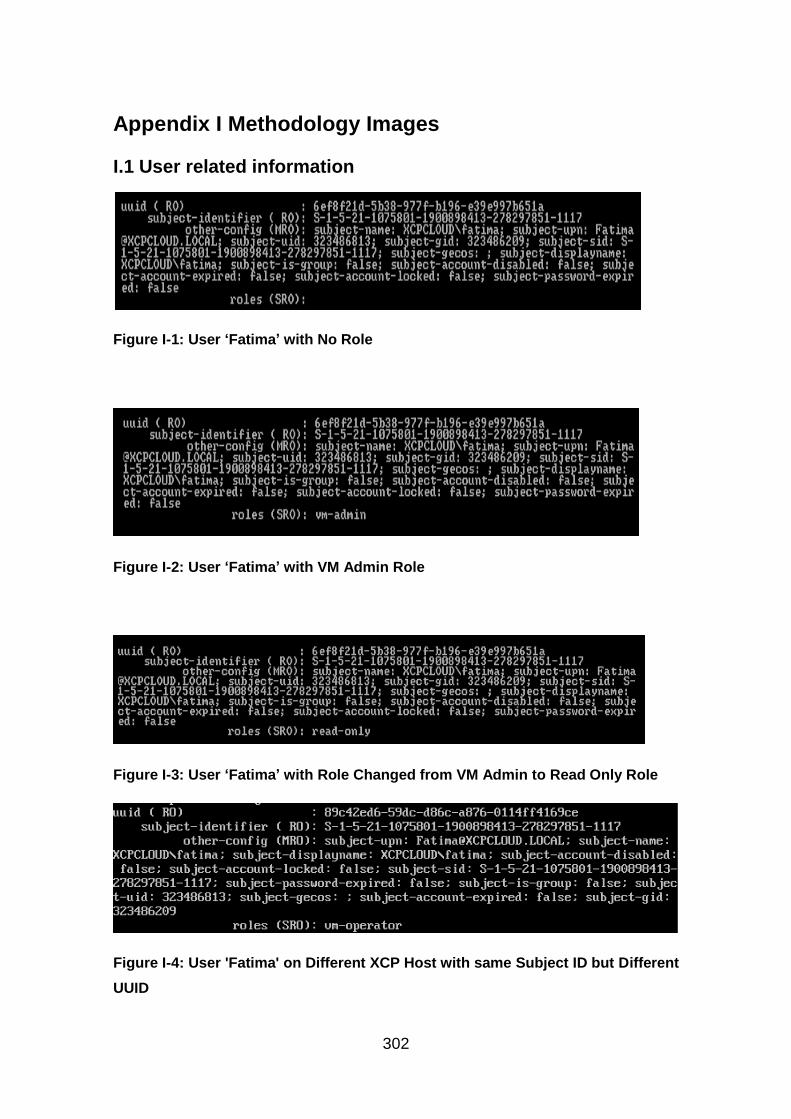
302
Appendix I Methodology Images
I.1 User related information
Figure I-1: User ‘Fatima’ with No Role
Figure I-2: User ‘Fatima’ with VM Admin Role
Figure I-3: User ‘Fatima’ with Role Changed from VM Admin to Read Only Role
Figure I-4: User 'Fatima' on Different XCP Host with same Subject ID but Different
UUID
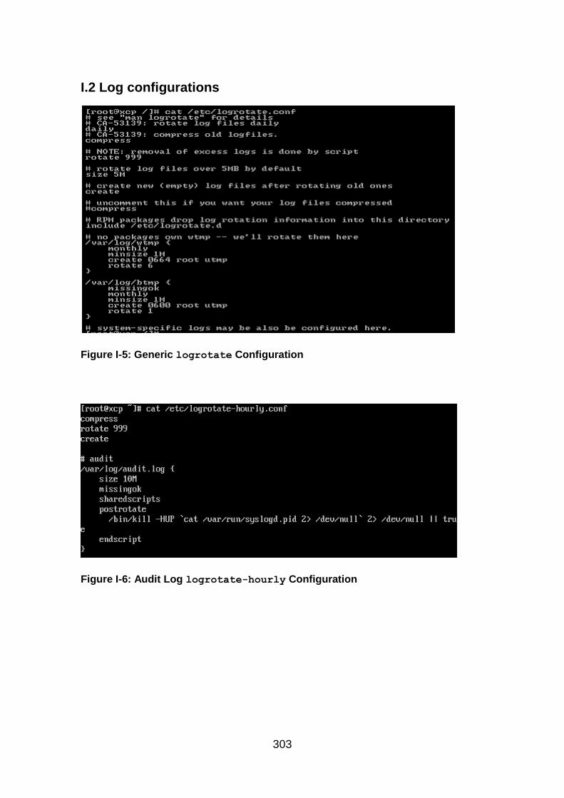
303
I.2 Log configurations
Figure I-5: Generic logrotate Configuration
Figure I-6: Audit Log logrotate-hourly Configuration
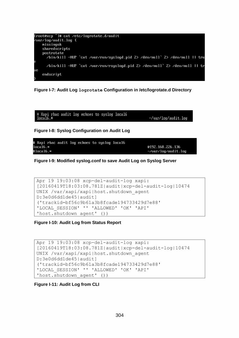
304
Figure I-7: Audit Log logrotate Configuration in /etc/logrotate.d Directory
Figure I-8: Syslog Configuration on Audit Log
Figure I-9: Modified syslog.conf to save Audit Log on Syslog Server
Apr 19 19:03:08 xcp-del-audit-log xapi:
[20160419T18:03:08.781Z|audit|xcp-del-audit-log|10474
UNIX /var/xapi/xapi|host.shutdown_agent
D:3e0d6dd1de45|audit]
('trackid=bf56c9b61a3b8fcade194733429d7e88'
'LOCAL_SESSION' '' 'ALLOWED' 'OK' 'API'
'host.shutdown_agent' ())
Figure I-10: Audit Log from Status Report
Apr 19 19:03:08 xcp-del-audit-log xapi:
[20160419T18:03:08.781Z|audit|xcp-del-audit-log|10474
UNIX /var/xapi/xapi|host.shutdown_agent
D:3e0d6dd1de45|audit]
('trackid=bf56c9b61a3b8fcade194733429d7e88'
'LOCAL_SESSION' '' 'ALLOWED' 'OK' 'API'
'host.shutdown_agent' ())
Figure I-11: Audit Log from CLI
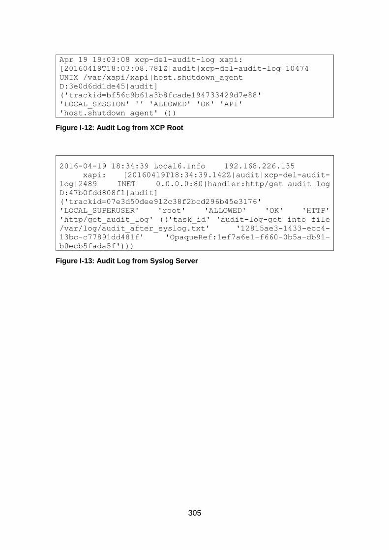
305
Apr 19 19:03:08 xcp-del-audit-log xapi:
[20160419T18:03:08.781Z|audit|xcp-del-audit-log|10474
UNIX /var/xapi/xapi|host.shutdown_agent
D:3e0d6dd1de45|audit]
('trackid=bf56c9b61a3b8fcade194733429d7e88'
'LOCAL_SESSION' '' 'ALLOWED' 'OK' 'API'
'host.shutdown_agent' ())
Figure I-12: Audit Log from XCP Root
2016-04-19 18:34:39 Local6.Info 192.168.226.135
xapi: [20160419T18:34:39.142Z|audit|xcp-del-audit-
log|2489 INET 0.0.0.0:80|handler:http/get_audit_log
D:47b0fdd808f1|audit]
('trackid=07e3d50dee912c38f2bcd296b45e3176'
'LOCAL_SUPERUSER' 'root' 'ALLOWED' 'OK' 'HTTP'
'http/get_audit_log' (('task_id' 'audit-log-get into file
/var/log/audit_after_syslog.txt' '12815ae3-1433-ecc4-
13bc-c77891dd481f' 'OpaqueRef:1ef7a6e1-f660-0b5a-db91-
b0ecb5fada5f')))
Figure I-13: Audit Log from Syslog Server
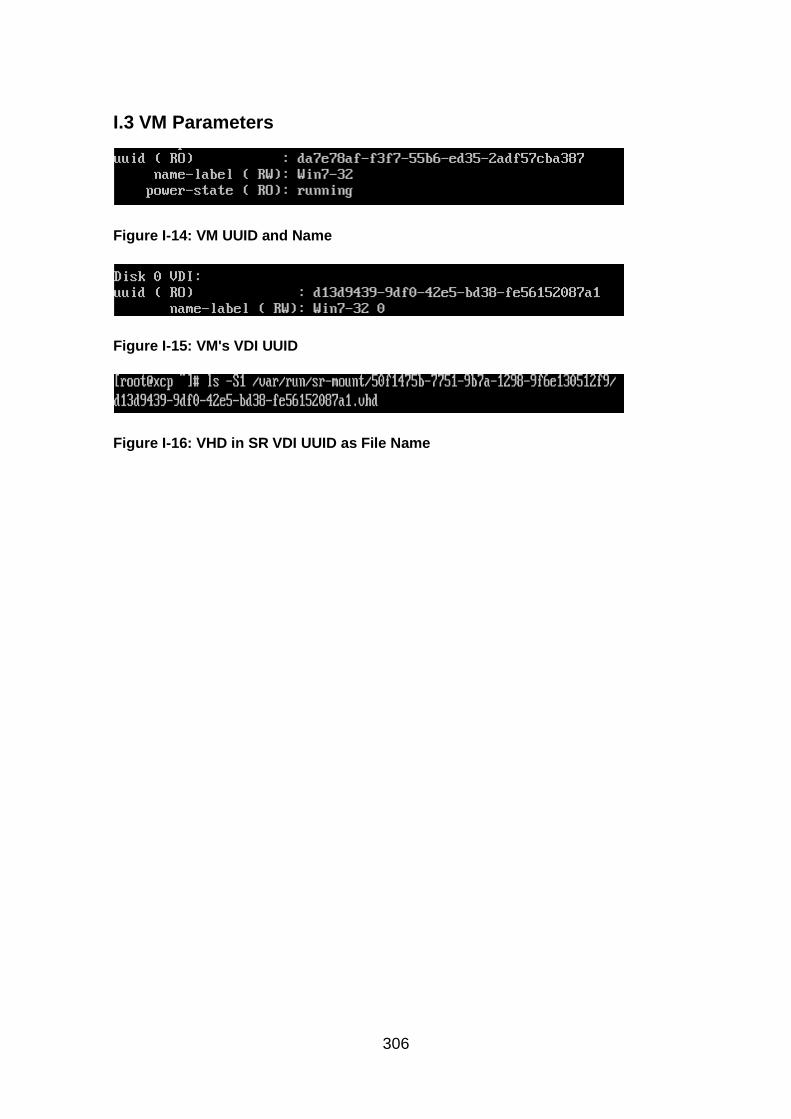
306
I.3 VM Parameters
Figure I-14: VM UUID and Name
Figure I-15: VM's VDI UUID
Figure I-16: VHD in SR VDI UUID as File Name
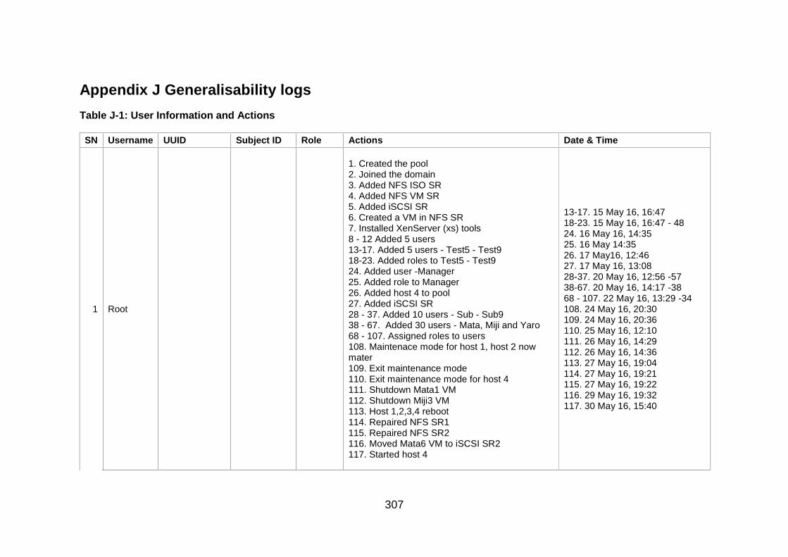
307
Appendix J Generalisability logs
Table J-1: User Information and Actions
SN Username UUID Subject ID Role Actions Date & Time
1 Root
1. Created the pool 2. Joined the domain 3. Added NFS ISO SR 4. Added NFS VM SR 5. Added iSCSI SR 6. Created a VM in NFS SR 7. Installed XenServer (xs) tools 8 - 12 Added 5 users 13-17. Added 5 users - Test5 - Test9 18-23. Added roles to Test5 - Test9 24. Added user -Manager 25. Added role to Manager 26. Added host 4 to pool 27. Added iSCSI SR 28 - 37. Added 10 users - Sub - Sub9 38 - 67. Added 30 users - Mata, Miji and Yaro 68 - 107. Assigned roles to users 108. Maintenace mode for host 1, host 2 now mater 109. Exit maintenance mode 110. Exit maintenance mode for host 4 111. Shutdown Mata1 VM 112. Shutdown Miji3 VM 113. Host 1,2,3,4 reboot 114. Repaired NFS SR1 115. Repaired NFS SR2 116. Moved Mata6 VM to iSCSI SR2 117. Started host 4
13-17. 15 May 16, 16:47 18-23. 15 May 16, 16:47 - 48 24. 16 May 16, 14:35 25. 16 May 14:35 26. 17 May16, 12:46 27. 17 May 16, 13:08 28-37. 20 May 16, 12:56 -57 38-67. 20 May 16, 14:17 -38 68 - 107. 22 May 16, 13:29 -34 108. 24 May 16, 20:30 109. 24 May 16, 20:36 110. 25 May 16, 12:10 111. 26 May 16, 14:29 112. 26 May 16, 14:36 113. 27 May 16, 19:04 114. 27 May 16, 19:21 115. 27 May 16, 19:22 116. 29 May 16, 19:32 117. 30 May 16, 15:40
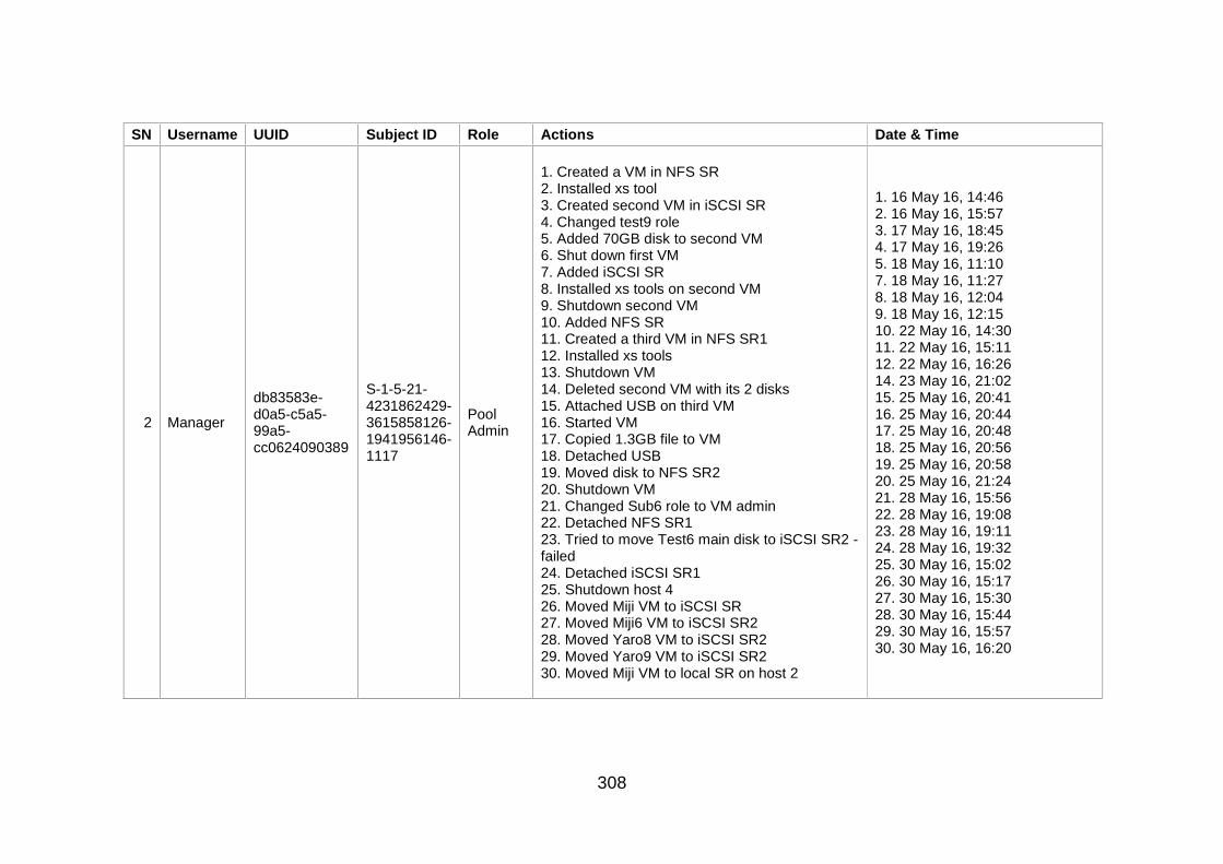
308
SN Username UUID Subject ID Role Actions Date & Time
2 Manager
db83583e-d0a5-c5a5-99a5-cc0624090389
S-1-5-21-4231862429-3615858126-1941956146-1117
Pool Admin
1. Created a VM in NFS SR 2. Installed xs tool 3. Created second VM in iSCSI SR 4. Changed test9 role 5. Added 70GB disk to second VM 6. Shut down first VM 7. Added iSCSI SR 8. Installed xs tools on second VM 9. Shutdown second VM 10. Added NFS SR 11. Created a third VM in NFS SR1 12. Installed xs tools 13. Shutdown VM 14. Deleted second VM with its 2 disks 15. Attached USB on third VM 16. Started VM 17. Copied 1.3GB file to VM 18. Detached USB 19. Moved disk to NFS SR2 20. Shutdown VM 21. Changed Sub6 role to VM admin 22. Detached NFS SR1 23. Tried to move Test6 main disk to iSCSI SR2 - failed 24. Detached iSCSI SR1 25. Shutdown host 4 26. Moved Miji VM to iSCSI SR 27. Moved Miji6 VM to iSCSI SR2 28. Moved Yaro8 VM to iSCSI SR2 29. Moved Yaro9 VM to iSCSI SR2 30. Moved Miji VM to local SR on host 2
1. 16 May 16, 14:46 2. 16 May 16, 15:57 3. 17 May 16, 18:45 4. 17 May 16, 19:26 5. 18 May 16, 11:10 7. 18 May 16, 11:27 8. 18 May 16, 12:04 9. 18 May 16, 12:15 10. 22 May 16, 14:30 11. 22 May 16, 15:11 12. 22 May 16, 16:26 14. 23 May 16, 21:02 15. 25 May 16, 20:41 16. 25 May 16, 20:44 17. 25 May 16, 20:48 18. 25 May 16, 20:56 19. 25 May 16, 20:58 20. 25 May 16, 21:24 21. 28 May 16, 15:56 22. 28 May 16, 19:08 23. 28 May 16, 19:11 24. 28 May 16, 19:32 25. 30 May 16, 15:02 26. 30 May 16, 15:17 27. 30 May 16, 15:30 28. 30 May 16, 15:44 29. 30 May 16, 15:57 30. 30 May 16, 16:20
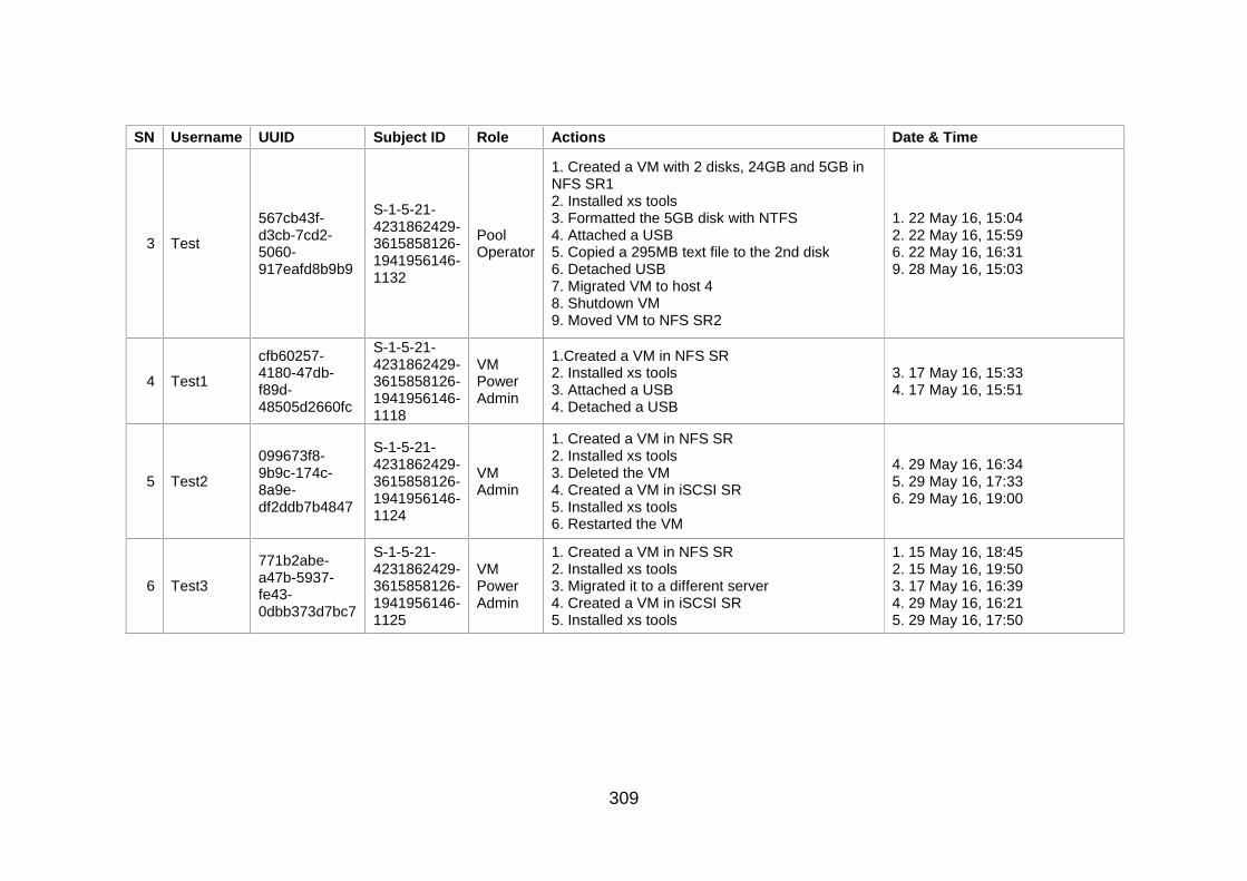
309
SN Username UUID Subject ID Role Actions Date & Time
3 Test
567cb43f-d3cb-7cd2-5060-917eafd8b9b9
S-1-5-21-4231862429-3615858126-1941956146-1132
Pool Operator
1. Created a VM with 2 disks, 24GB and 5GB in NFS SR1 2. Installed xs tools 3. Formatted the 5GB disk with NTFS 4. Attached a USB 5. Copied a 295MB text file to the 2nd disk 6. Detached USB 7. Migrated VM to host 4 8. Shutdown VM 9. Moved VM to NFS SR2
1. 22 May 16, 15:04 2. 22 May 16, 15:59 6. 22 May 16, 16:31 9. 28 May 16, 15:03
4 Test1
cfb60257-4180-47db-f89d-48505d2660fc
S-1-5-21-4231862429-3615858126-1941956146-1118
VM Power Admin
1.Created a VM in NFS SR 2. Installed xs tools 3. Attached a USB 4. Detached a USB
3. 17 May 16, 15:33 4. 17 May 16, 15:51
5 Test2
099673f8-9b9c-174c-8a9e-df2ddb7b4847
S-1-5-21-4231862429-3615858126-1941956146-1124
VM Admin
1. Created a VM in NFS SR 2. Installed xs tools 3. Deleted the VM 4. Created a VM in iSCSI SR 5. Installed xs tools 6. Restarted the VM
4. 29 May 16, 16:34 5. 29 May 16, 17:33 6. 29 May 16, 19:00
6 Test3
771b2abe-a47b-5937-fe43-0dbb373d7bc7
S-1-5-21-4231862429-3615858126-1941956146-1125
VM Power Admin
1. Created a VM in NFS SR 2. Installed xs tools 3. Migrated it to a different server 4. Created a VM in iSCSI SR 5. Installed xs tools
1. 15 May 16, 18:45 2. 15 May 16, 19:50 3. 17 May 16, 16:39 4. 29 May 16, 16:21 5. 29 May 16, 17:50
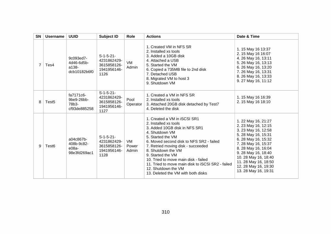
310
SN Username UUID Subject ID Role Actions Date & Time
7 Tes4
9c093ed7-4d46-6d5b-a138-dcb10182b6f0
S-1-5-21-4231862429-3615858126-1941956146-1126
VM Admin
1. Created VM in NFS SR 2. Installed xs tools 3. Added a 10GB disk 4. Attached a USB 5. Started the VM 6. Copied a 735MB file to 2nd disk 7. Detached USB 8. Migrated VM to host 3 9. Shutdown VM
1. 15 May 16 13:37 2. 15 May 16 16:07 4. 26 May 16, 13:11 5. 26 May 16, 13:13 6. 26 May 16, 13:20 7. 26 May 16, 13:31 8. 26 May 16, 13:33 9. 27 May 16, 11:12
8 Test5
fa7171c6-9be9-26bb-78b3-cf93de885258
S-1-5-21-4231862429-3615858126-1941956146-1127
Pool Operator
1. Created a VM in NFS SR 2. Installed xs tools 3. Attached 20GB disk detached by Test7 4. Deleted the disk
1. 15 May 16 16:39 2. 15 May 16 18:10
9 Test6
a04c867b-408b-9c82-e08a-98e3fd269ac1
S-1-5-21-4231862429-3615858126-1941956146-1128
VM Power Admin
1. Created a VM in iSCSI SR1 2. Installed xs tools 3. Added 10GB disk in NFS SR1 4. Shutdown VM 5. Started the VM 6. Moved second disk to NFS SR2 - failed 7. Retried moving disk - succeeded 8. Shutdown the VM 9. Started the VM 10. Tried to move main disk - failed 11. Tried to move main disk to iSCSI SR2 - failed 12. Shutdown the VM 13. Deleted the VM with both disks
1. 22 May 16, 21:27 2. 23 May 16, 12:15 3. 23 May 16, 12:58 5. 28 May 16, 15:31 6. 28 May 16, 15:32 7. 28 May 16, 15:37 8. 28 May 16, 16:04 9. 28 May 16, 18:40 10. 28 May 16, 18:40 11. 28 May 16, 18:50 12. 28 May 16, 19:30 13. 28 May 16, 19:31
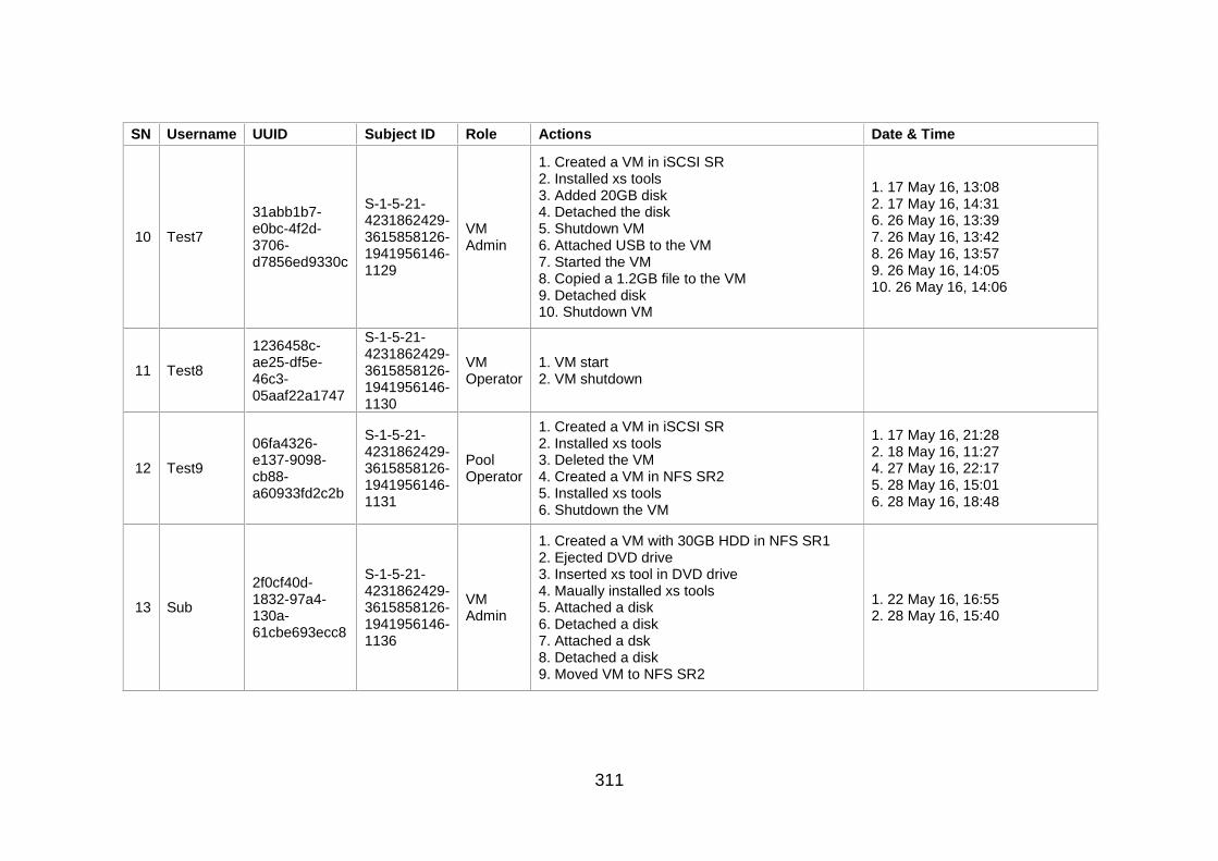
311
SN Username UUID Subject ID Role Actions Date & Time
10 Test7
31abb1b7-e0bc-4f2d-3706-d7856ed9330c
S-1-5-21-4231862429-3615858126-1941956146-1129
VM Admin
1. Created a VM in iSCSI SR 2. Installed xs tools 3. Added 20GB disk 4. Detached the disk 5. Shutdown VM 6. Attached USB to the VM 7. Started the VM 8. Copied a 1.2GB file to the VM 9. Detached disk 10. Shutdown VM
1. 17 May 16, 13:08 2. 17 May 16, 14:31 6. 26 May 16, 13:39 7. 26 May 16, 13:42 8. 26 May 16, 13:57 9. 26 May 16, 14:05 10. 26 May 16, 14:06
11 Test8
1236458c-ae25-df5e-46c3-05aaf22a1747
S-1-5-21-4231862429-3615858126-1941956146-1130
VM Operator
1. VM start 2. VM shutdown
12 Test9
06fa4326-e137-9098-cb88-a60933fd2c2b
S-1-5-21-4231862429-3615858126-1941956146-1131
Pool Operator
1. Created a VM in iSCSI SR 2. Installed xs tools 3. Deleted the VM 4. Created a VM in NFS SR2 5. Installed xs tools 6. Shutdown the VM
1. 17 May 16, 21:28 2. 18 May 16, 11:27 4. 27 May 16, 22:17 5. 28 May 16, 15:01 6. 28 May 16, 18:48
13 Sub
2f0cf40d-1832-97a4-130a-61cbe693ecc8
S-1-5-21-4231862429-3615858126-1941956146-1136
VM Admin
1. Created a VM with 30GB HDD in NFS SR1 2. Ejected DVD drive 3. Inserted xs tool in DVD drive 4. Maually installed xs tools 5. Attached a disk 6. Detached a disk 7. Attached a dsk 8. Detached a disk 9. Moved VM to NFS SR2
1. 22 May 16, 16:55 2. 28 May 16, 15:40

312
SN Username UUID Subject ID Role Actions Date & Time
14 Sub1
8639dc1b-6dbf-14bd-3576-246be29ab752
S-1-5-21-4231862429-3615858126-1941956146-1137
VM Operator
1. Installed xs tools on VM 2. Shutdown VM
1. 22 May 16, 20:20
15 Sub2
0e012a06-d996-c3f3-70c7-69f6fa6a234c
S-1-5-21-4231862429-3615858126-1941956146-1138
Pool Operator
1. Created a VM in NFS SR1 2. Installed xs tools 3. Created VM for Sub1 in NFS SR 4. Created VM for Sub5 in iSCSI SR1 5. Deleted Sub5 VM as Windows did not install properly 6. Created another VM for Sub5 in iSCSI SR 7. Created a VM for Sub9 with 30GB in iSCSI SR 8. Shutdown VM 9. Created a VM for Sub6 in iSCSI SR2 10. Moved VM to NFS SR2
1. 22 May 16, 15:18 3. 22 May 16, 18:46 4. 22 May 16, 20:30 5. 23 May 16, 12:17 6. 23 May 16, 12:18 7. 23 May 16, 14:11 -14 8. 24 May 16, 13:12 9. 28 May 16, 15:58 10. 28 May 16, 17:16
16 Sub3
d02c09dc-ac9b-2345-221e-47923d7de74b
S-1-5-21-4231862429-3615858126-1941956146-1139
VM Power Admin
1. Created a VM in NFS SR1 2. Installed xs tools 3. Shut down VM 4. Restarted VM 5. Shut down VM 6. Attached USB 7. Started VM 8. Copied a 0.99GB file to VM 9. Detached USB 10. Restarted VM 11. Shutdown VM 12. Moved VM to NFS SR2
1. 22 May 16, 17:07 2. 22 May 16, 18:15 7. 22 May 16, 19:34 9. 22 May 16, 19:54 12. 28 May 16, 17:29

313
SN Username UUID Subject ID Role Actions Date & Time
17 Sub4
bdaa09ec-0882-fb00-da79-abea23c3769c
S-1-5-21-4231862429-3615858126-1941956146-1140
VM Admin
1. Initiated VM creation with iSCSI SR 2. Moved VM to NFS SR1 3. Moved VM to NFS SR 4. Deleted VM 5. Created a new VM in NFS SR1 6. Installed xs tools 7. Shut down VM 8. Moved VM to NFS SR2
1. 22 May 16, 20:20 8. 28 May 16, 15:47
18 Sub5
0a4b4fd6-13cc-6fc5-0981-4bd781ff1f55
S-1-5-21-4231862429-3615858126-1941956146-1141
VM Operator
1. Installed xs tools on VM 2. Attached a USB - Sub2 credentials 3. Copied a 134MB file to VM 4. Detached USB 5. Shutdown VM
1. 23 May 16, 13:18 4. 23 May 16, 13:37
19 Sub6
11d51e93-1b07-f97f-f768-3134cb676f99
S-1-5-21-4231862429-3615858126-1941956146-1142
VM Admin
1. Configured VM 2. Installed xs tools 3. Started Miji4 VM 4. Shutdown the VM
1. 28 May 16, 16:00 2. 28 May 16, 17:25 3. 28 May 16, 17:48 4. 28 May 16, 18:10
20 Sub7
c3370b94-2c42-291b-af8c-b68403416952
S-1-5-21-4231862429-3615858126-1941956146-1143
VM Power Admin
1. Created a new VM with 50GB HDD in NFS SR1 2. Installed xs tools 3. Shut down VM 4. Started the VM 5. Suspended the VM 6. Attached a USB 7. Resumed the VM 8. Restarted the VM 9. Copied a 2.05GB file 10. Detached the USB 11. Shutdown the VM 12. Moved VM to NFS SR2
1. 23 May 16, 12:24 2. 23 May 16, 13:21 4. 27 May 16, 19:48 5. 27 May 16, 19:53 6. 27 May 16, 19:55 7. 27 May 16, 19:56 8. 27 May 16, 20:00 9. 27 May 16, 20:13 10. 27 May 16, 20:33 11. 27 May 16, 21:30 12. 28 May 16, 16:10

314
SN Username UUID Subject ID Role Actions Date & Time
21 Sub8
e63a178e-c641-9db3-8833-424f977eae2f
S-1-5-21-4231862429-3615858126-1941956146-1144
VM Admin
1. Created a VM in NFS SR 2. Restarted VM 3. Installed xs tools 4. Shutdown VM
1. 23 May 16, 14:21 3. 23 May 16, 16:04
22 Sub9
91e0dc5b-0a36-811d-f467-18ad5a3e083d
S-1-5-21-4231862429-3615858126-1941956146-1145
VM Operator
1. Set the VM 2. Installed xs tools on VM 3. Shut down VM
1-2. 23 May 16, 15:43
23 Mata
e361324b-d8e6-9197-91c5-b46d4a119384
S-1-5-21-4231862429-3615858126-1941956146-1146
Pool Admin
1. Created a VM in NFS SR1 2. Installed xs tools 3. Shutdown VM 4. Attached USB 5. Started the VM 6. Copied a 255MB file from USB to VM 7. Detached USB 8. Initiated maintenance mode for the pool master 9. VM moved to a different host 10. Changed default SR to iSCSI SR 11. Changed it back to NFS SR 12. Exit maintenance mode for host 1 13. VM moved back to host 1 14. Changed Mata5 role to VM Admin 15. Created a VM for Mata4 in NFS SR1 16. Created a VM for Mata8 in iSCSI SR 17. Shutdown VM 18. Moved VM to NFS SR2
1. 22 May 16, 17:02 12. 22 May 16, 20:14 14. 23 May, 13:09 15. 23 May 16, 13:11 16. 23 May 16, 14:41 17. 24 May 16 18. 28 May 16, 18:07
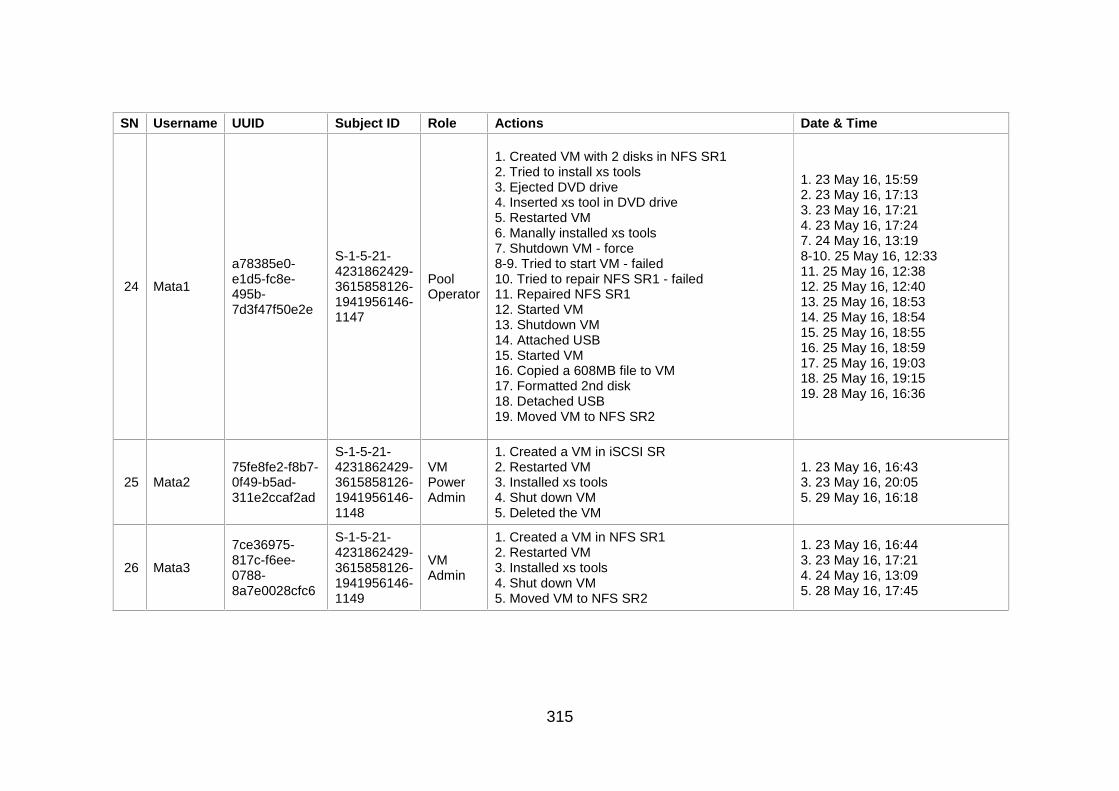
315
SN Username UUID Subject ID Role Actions Date & Time
24 Mata1
a78385e0-e1d5-fc8e-495b-7d3f47f50e2e
S-1-5-21-4231862429-3615858126-1941956146-1147
Pool Operator
1. Created VM with 2 disks in NFS SR1 2. Tried to install xs tools 3. Ejected DVD drive 4. Inserted xs tool in DVD drive 5. Restarted VM 6. Manally installed xs tools 7. Shutdown VM - force 8-9. Tried to start VM - failed 10. Tried to repair NFS SR1 - failed 11. Repaired NFS SR1 12. Started VM 13. Shutdown VM 14. Attached USB 15. Started VM 16. Copied a 608MB file to VM 17. Formatted 2nd disk 18. Detached USB 19. Moved VM to NFS SR2
1. 23 May 16, 15:59 2. 23 May 16, 17:13 3. 23 May 16, 17:21 4. 23 May 16, 17:24 7. 24 May 16, 13:19 8-10. 25 May 16, 12:33 11. 25 May 16, 12:38 12. 25 May 16, 12:40 13. 25 May 16, 18:53 14. 25 May 16, 18:54 15. 25 May 16, 18:55 16. 25 May 16, 18:59 17. 25 May 16, 19:03 18. 25 May 16, 19:15 19. 28 May 16, 16:36
25 Mata2 75fe8fe2-f8b7-0f49-b5ad-311e2ccaf2ad
S-1-5-21-4231862429-3615858126-1941956146-1148
VM Power Admin
1. Created a VM in iSCSI SR 2. Restarted VM 3. Installed xs tools 4. Shut down VM 5. Deleted the VM
1. 23 May 16, 16:43 3. 23 May 16, 20:05 5. 29 May 16, 16:18
26 Mata3
7ce36975-817c-f6ee-0788-8a7e0028cfc6
S-1-5-21-4231862429-3615858126-1941956146-1149
VM Admin
1. Created a VM in NFS SR1 2. Restarted VM 3. Installed xs tools 4. Shut down VM 5. Moved VM to NFS SR2
1. 23 May 16, 16:44 3. 23 May 16, 17:21 4. 24 May 16, 13:09 5. 28 May 16, 17:45
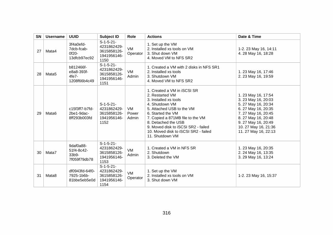
316
SN Username UUID Subject ID Role Actions Date & Time
27 Mata4
3f4a0efd-7dcb-fcab-0f20-13dfcb97ec92
S-1-5-21-4231862429-3615858126-1941956146-1150
VM Operator
1. Set up the VM 2. Installed xs tools on VM 3. Shut down VM 4. Moved VM to NFS SR2
1-2. 23 May 16, 14:11 4. 28 May 16, 18:28
28 Mata5
b812466f-e8a8-393f-4fe7-1208f66b4c49
S-1-5-21-4231862429-3615858126-1941956146-1151
VM Admin
1. Created a VM with 2 disks in NFS SR1 2. Installed xs tools 3. Shutdown VM 4. Moved VM to NFS SR2
1. 23 May 16, 17:46 2. 23 May 16, 19:59
29 Mata6 c15f3ff7-b7fd-2be1-9dac-8ff293b003fd
S-1-5-21-4231862429-3615858126-1941956146-1152
VM Power Admin
1. Created a VM in iSCSI SR 2. Restarted VM 3. Installed xs tools 4. Shutdown VM 5. Attached USB to the VM 6. Started the VM 7. Copied a 871MB file to the VM 8. Detached the USB 9. Moved disk to iSCSI SR2 - failed 10. Moved disk to iSCSI SR2 - failed 11. Shutdown VM
1. 23 May 16, 17:54 3. 23 May 16, 20:03 5. 27 May 16, 20:34 6. 27 May 16, 20:35 7. 27 May 16, 20:45 8. 27 May 16, 20:48 9. 27 May 16, 20:49 10. 27 May 16, 21:36 11. 27 May 16, 22:13
30 Mata7
9daf0a88-51f4-8c42-33b9-7f059f79db78
S-1-5-21-4231862429-3615858126-1941956146-1153
VM Admin
1. Created a VM in NFS SR 2. Shutdown 3. Deleted the VM
1. 23 May 16, 20:35 2. 24 May 16, 13:35 3. 29 May 16, 13:24
31 Mata8 df0943fd-64f0-7925-1b6b-81bbe5eb5e0d
S-1-5-21-4231862429-3615858126-1941956146-1154
VM Operator
1. Set up the VM 2. Installed xs tools on VM 3. Shut down VM
1-2. 23 May 16, 15:37

317
SN Username UUID Subject ID Role Actions Date & Time
32 Mata9
1a2b051a-7ab8-0ea8-768b-6f45b2065f63
S-1-5-21-4231862429-3615858126-1941956146-1155
VM Power Admin
1. Created a VM in NFS SR 2. Shutdown -force 3. Started VM 4. Installed xs tool 5. Shutdown VM
1. 23 May 16, 20:36 2. 24 May 16, 13:22 3. 25 May 16, 12:30 4. 25 May 16, 12:47 5. 25 May 16, 16:00
33 Miji
ce2f65c3-d0dc-fd91-ad0d-c87a7ce18694
S-1-5-21-4231862429-3615858126-1941956146-1156
VM Admin
1. Created VM with 30GB disk on iSCSI SR2 2. Installed xs tools 3. Restarted VM 4. Added a 20GB disk in iSCSI SR 5. Suspended VM 6. Resumed VM 7. Shutdown the VM
1. 25 May 16, 12:51 2. 25 May 16, 15:53 3. 25 May 16, 15:59 4. 25 May 16, 16:50 5. 25 May 16, 17:47 6. 27 May 16, 18:58 7. 27 May 16, 19:02
34 Miji1
74d013f8-b725-368b-64ce-f06d90fc8f76
S-1-5-21-4231862429-3615858126-1941956146-1157
VM Operator
1. Setup VM 2. Installed xs tools 3. Suspended VM 4. Attached USB 5. Resumed VM 6. Restarted VM 7 Shutdown VM 8. Detached USB 9. Attached USB 10. Started VM 11. Added a 462MB text fileto VM 12. Detached USB 13. Shutdown VM
1. 25 May 16, 17:39 2. 25 May 16, 17:42 3. 25 May 16, 18:16 4. 25 May 16, 18:25 5. 25 May 16, 18:25 6. 25 May 16, 18:28 7-9. 25 May 16, 18:40 10. 25 May 16, 18:41 11. 25 May 16, 18:46 12. 25 May 16, 18:49 13. 25 May 16, 18:51
35 Miji2
86d72cee-68ae-3075-f98d-e2cdfffacdd8
S-1-5-21-4231862429-3615858126-1941956146-1158
VM Admin
1. Created a VM in iSCSI SR2 2. Installed xs tools
1. 28 May 16, 18:24 2. 28 May 16, 18:42
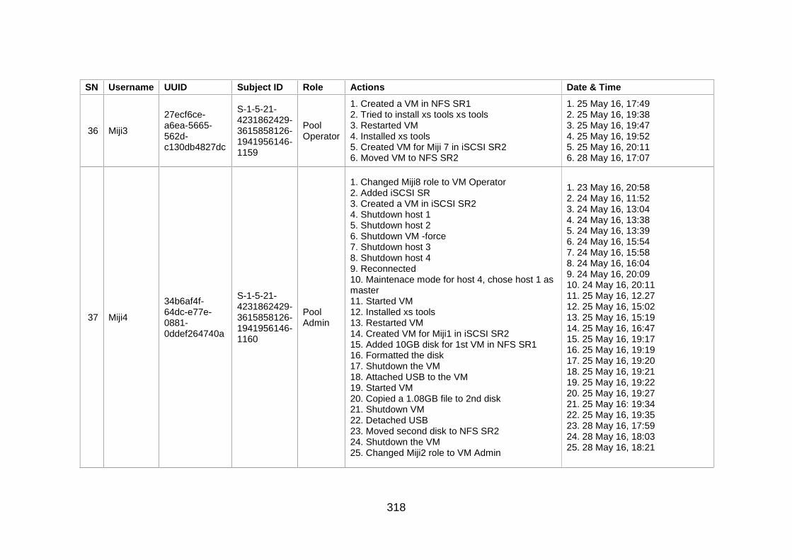
318
SN Username UUID Subject ID Role Actions Date & Time
36 Miji3
27ecf6ce-a6ea-5665-562d-c130db4827dc
S-1-5-21-4231862429-3615858126-1941956146-1159
Pool Operator
1. Created a VM in NFS SR1 2. Tried to install xs tools xs tools 3. Restarted VM 4. Installed xs tools 5. Created VM for Miji 7 in iSCSI SR2 6. Moved VM to NFS SR2
1. 25 May 16, 17:49 2. 25 May 16, 19:38 3. 25 May 16, 19:47 4. 25 May 16, 19:52 5. 25 May 16, 20:11 6. 28 May 16, 17:07
37 Miji4
34b6af4f-64dc-e77e-0881-0ddef264740a
S-1-5-21-4231862429-3615858126-1941956146-1160
Pool Admin
1. Changed Miji8 role to VM Operator 2. Added iSCSI SR 3. Created a VM in iSCSI SR2 4. Shutdown host 1 5. Shutdown host 2 6. Shutdown VM -force 7. Shutdown host 3 8. Shutdown host 4 9. Reconnected 10. Maintenace mode for host 4, chose host 1 as master 11. Started VM 12. Installed xs tools 13. Restarted VM 14. Created VM for Miji1 in iSCSI SR2 15. Added 10GB disk for 1st VM in NFS SR1 16. Formatted the disk 17. Shutdown the VM 18. Attached USB to the VM 19. Started VM 20. Copied a 1.08GB file to 2nd disk 21. Shutdown VM 22. Detached USB 23. Moved second disk to NFS SR2 24. Shutdown the VM 25. Changed Miji2 role to VM Admin
1. 23 May 16, 20:58 2. 24 May 16, 11:52 3. 24 May 16, 13:04 4. 24 May 16, 13:38 5. 24 May 16, 13:39 6. 24 May 16, 15:54 7. 24 May 16, 15:58 8. 24 May 16, 16:04 9. 24 May 16, 20:09 10. 24 May 16, 20:11 11. 25 May 16, 12.27 12. 25 May 16, 15:02 13. 25 May 16, 15:19 14. 25 May 16, 16:47 15. 25 May 16, 19:17 16. 25 May 16, 19:19 17. 25 May 16, 19:20 18. 25 May 16, 19:21 19. 25 May 16, 19:22 20. 25 May 16, 19:27 21. 25 May 16: 19:34 22. 25 May 16, 19:35 23. 28 May 16, 17:59 24. 28 May 16, 18:03 25. 28 May 16, 18:21

319
SN Username UUID Subject ID Role Actions Date & Time
38 Miji5
19a7173c-cb01-957d-4d68-6809398afbf9
S-1-5-21-4231862429-3615858126-1941956146-1161
VM Power Admin
1. Created a VM in NFS SR 2. Shutdown VM
1. 25 May 16, 13:38 2. 25 May 16, 16:43
39 Miji6
8d107ca1-ab72-197f-d686-64baeea765e0
S-1-5-21-4231862429-3615858126-1941956146-1162
VM Admin
1. Created a VM in iSCSI SR 2. Tried to install xs tools 3. Ejected xs tools from DVD drive 4. Loaed xs tools to DVD 5. Restarted VM 6. Installed xs tools 7. Shutdown VM
1. 25 May 16, 17:53 2. 25 May 16, 19:38 3-5. 25 May 16, 19:43 6. 25 May 16, 19:49 7. 25 May 16, 20:15
40 Miji7
5fa53aa6-0823-5d1b-613d-8f8cca4e0d9e
S-1-5-21-4231862429-3615858126-1941956146-1163
VM Operator
1. Setup VM 2. Installed xs tools 3. Shutdown VM 4. Attached a USB 5. Started the VM 6. Copied a 491MB file to VM 7. Detached USB 8. Shutdown VM
1. 25 May 16, 21:05 2. 25 May 16, 21:28 3. 26 May 16, 11:07 4. 26 May 16, 11:08 5. 26 May 16, 11:08 6. 26 May 16, 11:15 7. 26 May 16, 11:17 8. 26 May 16, 11:19
41 Miji8
1d245912-8419-1887-ac2d-99bd28c03f9b
S-1-5-21-4231862429-3615858126-1941956146-1164
Read Only
1. Started the VM created by root 2. Shutdown the VM
1. 28 May 16, 19:37 2. 28 May 16, 19:49
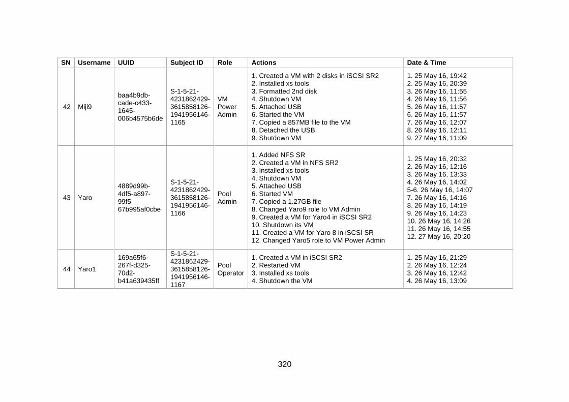
320
SN Username UUID Subject ID Role Actions Date & Time
42 Miji9
baa4b9db-cade-c433-1645-006b4575b6de
S-1-5-21-4231862429-3615858126-1941956146-1165
VM Power Admin
1. Created a VM with 2 disks in iSCSI SR2 2. Installed xs tools 3. Formatted 2nd disk 4. Shutdown VM 5. Attached USB 6. Started the VM 7. Copied a 857MB file to the VM 8. Detached the USB 9. Shutdown VM
1. 25 May 16, 19:42 2. 25 May 16, 20:39 3. 26 May 16, 11:55 4. 26 May 16, 11:56 5. 26 May 16, 11:57 6. 26 May 16, 11:57 7. 26 May 16, 12:07 8. 26 May 16, 12:11 9. 27 May 16, 11:09
43 Yaro
4889d99b-4df5-a897-99f5-67b995af0cbe
S-1-5-21-4231862429-3615858126-1941956146-1166
Pool Admin
1. Added NFS SR 2. Created a VM in NFS SR2 3. Installed xs tools 4. Shutdown VM 5. Attached USB 6. Started VM 7. Copied a 1.27GB file 8. Changed Yaro9 role to VM Admin 9. Created a VM for Yaro4 in iSCSI SR2 10. Shutdown its VM 11. Created a VM for Yaro 8 in iSCSI SR 12. Changed Yaro5 role to VM Power Admin
1. 25 May 16, 20:32 2. 26 May 16, 12:16 3. 26 May 16, 13:33 4. 26 May 16, 14:02 5-6. 26 May 16, 14:07 7. 26 May 16, 14:16 8. 26 May 16, 14:19 9. 26 May 16, 14:23 10. 26 May 16, 14:26 11. 26 May 16, 14:55 12. 27 May 16, 20:20
44 Yaro1
169a65f6-267f-d325-70d2-b41a639435ff
S-1-5-21-4231862429-3615858126-1941956146-1167
Pool Operator
1. Created a VM in iSCSI SR2 2. Restarted VM 3. Installed xs tools 4. Shutdown the VM
1. 25 May 16, 21:29 2. 26 May 16, 12:24 3. 26 May 16, 12:42 4. 26 May 16, 13:09
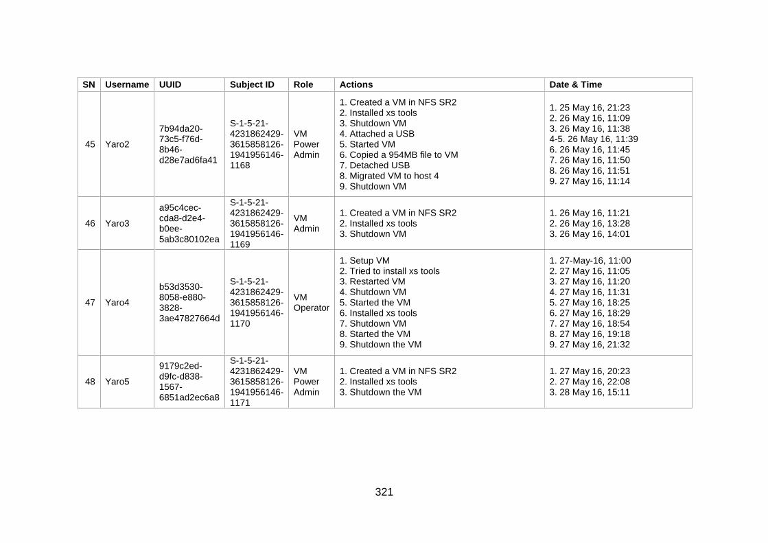
321
SN Username UUID Subject ID Role Actions Date & Time
45 Yaro2
7b94da20-73c5-f76d-8b46-d28e7ad6fa41
S-1-5-21-4231862429-3615858126-1941956146-1168
VM Power Admin
1. Created a VM in NFS SR2 2. Installed xs tools 3. Shutdown VM 4. Attached a USB 5. Started VM 6. Copied a 954MB file to VM 7. Detached USB 8. Migrated VM to host 4 9. Shutdown VM
1. 25 May 16, 21:23 2. 26 May 16, 11:09 3. 26 May 16, 11:38 4-5. 26 May 16, 11:39 6. 26 May 16, 11:45 7. 26 May 16, 11:50 8. 26 May 16, 11:51 9. 27 May 16, 11:14
46 Yaro3
a95c4cec-cda8-d2e4-b0ee-5ab3c80102ea
S-1-5-21-4231862429-3615858126-1941956146-1169
VM Admin
1. Created a VM in NFS SR2 2. Installed xs tools 3. Shutdown VM
1. 26 May 16, 11:21 2. 26 May 16, 13:28 3. 26 May 16, 14:01
47 Yaro4
b53d3530-8058-e880-3828-3ae47827664d
S-1-5-21-4231862429-3615858126-1941956146-1170
VM Operator
1. Setup VM 2. Tried to install xs tools 3. Restarted VM 4. Shutdown VM 5. Started the VM 6. Installed xs tools 7. Shutdown VM 8. Started the VM 9. Shutdown the VM
1. 27-May-16, 11:00 2. 27 May 16, 11:05 3. 27 May 16, 11:20 4. 27 May 16, 11:31 5. 27 May 16, 18:25 6. 27 May 16, 18:29 7. 27 May 16, 18:54 8. 27 May 16, 19:18 9. 27 May 16, 21:32
48 Yaro5
9179c2ed-d9fc-d838-1567-6851ad2ec6a8
S-1-5-21-4231862429-3615858126-1941956146-1171
VM Power Admin
1. Created a VM in NFS SR2 2. Installed xs tools 3. Shutdown the VM
1. 27 May 16, 20:23 2. 27 May 16, 22:08 3. 28 May 16, 15:11
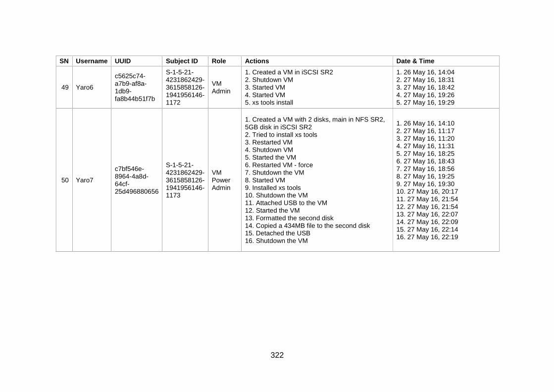
322
SN Username UUID Subject ID Role Actions Date & Time
49 Yaro6
c5625c74-a7b9-af8a-1db9-fa8b44b51f7b
S-1-5-21-4231862429-3615858126-1941956146-1172
VM Admin
1. Created a VM in iSCSI SR2 2. Shutdown VM 3. Started VM 4. Started VM 5. xs tools install
1. 26 May 16, 14:04 2. 27 May 16, 18:31 3. 27 May 16, 18:42 4. 27 May 16, 19:26 5. 27 May 16, 19:29
50 Yaro7
c7bf546e-8964-4a8d-64cf-25d496880656
S-1-5-21-4231862429-3615858126-1941956146-1173
VM Power Admin
1. Created a VM with 2 disks, main in NFS SR2, 5GB disk in iSCSI SR2 2. Tried to install xs tools 3. Restarted VM 4. Shutdown VM 5. Started the VM 6. Restarted VM - force 7. Shutdown the VM 8. Started VM 9. Installed xs tools 10. Shutdown the VM 11. Attached USB to the VM 12. Started the VM 13. Formatted the second disk 14. Copied a 434MB file to the second disk 15. Detached the USB 16. Shutdown the VM
1. 26 May 16, 14:10 2. 27 May 16, 11:17 3. 27 May 16, 11:20 4. 27 May 16, 11:31 5. 27 May 16, 18:25 6. 27 May 16, 18:43 7. 27 May 16, 18:56 8. 27 May 16, 19:25 9. 27 May 16, 19:30 10. 27 May 16, 20:17 11. 27 May 16, 21:54 12. 27 May 16, 21:54 13. 27 May 16, 22:07 14. 27 May 16, 22:09 15. 27 May 16, 22:14 16. 27 May 16, 22:19
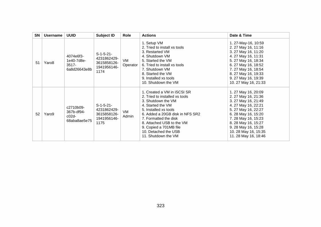
323
SN Username UUID Subject ID Role Actions Date & Time
51 Yaro8
4074e6f3-1e40-7d8e-3517-6a8d26643e8b
S-1-5-21-4231862429-3615858126-1941956146-1174
VM Operator
1. Setup VM 2. Tried to install xs tools 3. Restarted VM 4. Shutdown VM 5. Started the VM 6. Tried to install xs tools 7. Shutdown VM 8. Started the VM 9. Installed xs tools 10. Shutdown the VM
1. 27-May-16, 10:59 2. 27 May 16, 11:16 3. 27 May 16, 11:20 4. 27 May 16, 11:31 5. 27 May 16, 18:34 6. 27 May 16, 18:52 7. 27 May 16, 18:54 8. 27 May 16, 19:33 9. 27 May 16, 19:39 10. 27 May 16, 21:33
52 Yaro9
c2710b09-367b-df94-c02d-68aba8ae5e75
S-1-5-21-4231862429-3615858126-1941956146-1175
VM Admin
1. Created a VM in iSCSI SR 2. Tried to installed xs tools 3. Shutdown the VM 4. Started the VM 5. Installed xs tools 6. Added a 20GB disk in NFS SR2 7. Formatted the disk 8. Attached USB to the VM 9. Copied a 701MB file 10. Detached the USB 11. Shutdown the VM
1. 27 May 16, 20:09 2. 27 May 16, 21:36 3. 27 May 16, 21:49 4. 27 May 16, 22:21 5. 27 May 16, 22:27 6. 28 May 16, 15:20 7. 28 May 16, 15:23 8. 28 May 16, 15:27 9. 28 May 16, 15:28 10. 28 May 16, 15:35 11. 28 May 16, 18:46
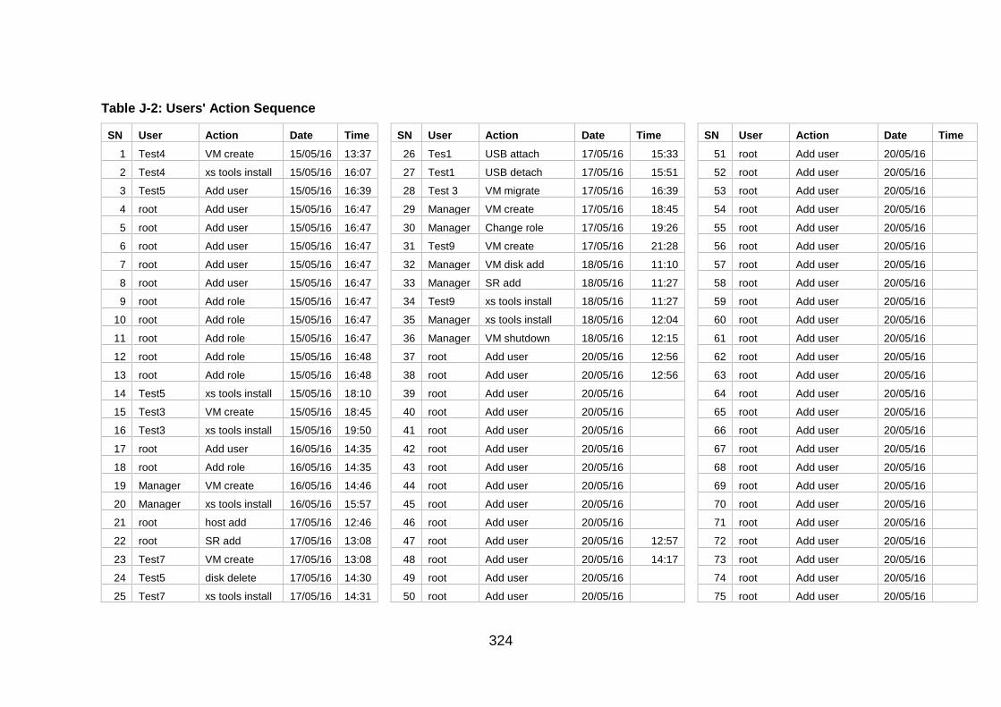
324
Table J-2: Users' Action Sequence
SN User Action Date Time SN User Action Date Time SN User Action Date Time
1 Test4 VM create 15/05/16 13:37 26 Tes1 USB attach 17/05/16 15:33 51 root Add user 20/05/16
2 Test4 xs tools install 15/05/16 16:07 27 Test1 USB detach 17/05/16 15:51 52 root Add user 20/05/16
3 Test5 Add user 15/05/16 16:39 28 Test 3 VM migrate 17/05/16 16:39 53 root Add user 20/05/16
4 root Add user 15/05/16 16:47 29 Manager VM create 17/05/16 18:45 54 root Add user 20/05/16
5 root Add user 15/05/16 16:47 30 Manager Change role 17/05/16 19:26 55 root Add user 20/05/16
6 root Add user 15/05/16 16:47 31 Test9 VM create 17/05/16 21:28 56 root Add user 20/05/16
7 root Add user 15/05/16 16:47 32 Manager VM disk add 18/05/16 11:10 57 root Add user 20/05/16
8 root Add user 15/05/16 16:47 33 Manager SR add 18/05/16 11:27 58 root Add user 20/05/16
9 root Add role 15/05/16 16:47 34 Test9 xs tools install 18/05/16 11:27 59 root Add user 20/05/16
10 root Add role 15/05/16 16:47 35 Manager xs tools install 18/05/16 12:04 60 root Add user 20/05/16
11 root Add role 15/05/16 16:47 36 Manager VM shutdown 18/05/16 12:15 61 root Add user 20/05/16
12 root Add role 15/05/16 16:48 37 root Add user 20/05/16 12:56 62 root Add user 20/05/16
13 root Add role 15/05/16 16:48 38 root Add user 20/05/16 12:56 63 root Add user 20/05/16
14 Test5 xs tools install 15/05/16 18:10 39 root Add user 20/05/16 64 root Add user 20/05/16
15 Test3 VM create 15/05/16 18:45 40 root Add user 20/05/16 65 root Add user 20/05/16
16 Test3 xs tools install 15/05/16 19:50 41 root Add user 20/05/16 66 root Add user 20/05/16
17 root Add user 16/05/16 14:35 42 root Add user 20/05/16 67 root Add user 20/05/16
18 root Add role 16/05/16 14:35 43 root Add user 20/05/16 68 root Add user 20/05/16
19 Manager VM create 16/05/16 14:46 44 root Add user 20/05/16 69 root Add user 20/05/16
20 Manager xs tools install 16/05/16 15:57 45 root Add user 20/05/16 70 root Add user 20/05/16
21 root host add 17/05/16 12:46 46 root Add user 20/05/16 71 root Add user 20/05/16
22 root SR add 17/05/16 13:08 47 root Add user 20/05/16 12:57 72 root Add user 20/05/16
23 Test7 VM create 17/05/16 13:08 48 root Add user 20/05/16 14:17 73 root Add user 20/05/16
24 Test5 disk delete 17/05/16 14:30 49 root Add user 20/05/16 74 root Add user 20/05/16
25 Test7 xs tools install 17/05/16 14:31 50 root Add user 20/05/16 75 root Add user 20/05/16
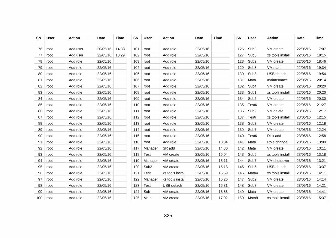
325
SN User Action Date Time SN User Action Date Time SN User Action Date Time
76 root Add user 20/05/16 14:38 101 root Add role 22/05/16 126 Sub3 VM create 22/05/16 17:07
77 root Add user 22/05/16 13:29 102 root Add role 22/05/16 127 Sub3 xs tools install 22/05/16 18:15
78 root Add role 22/05/16 103 root Add role 22/05/16 128 Sub2 VM create 22/05/16 18:46
79 root Add role 22/05/16 104 root Add role 22/05/16 129 Sub3 VM start 22/05/16 19:34
80 root Add role 22/05/16 105 root Add role 22/05/16 130 Sub3 USB detach 22/05/16 19:54
81 root Add role 22/05/16 106 root Add role 22/05/16 131 Mata maintenance 22/05/16 20:14
82 root Add role 22/05/16 107 root Add role 22/05/16 132 Sub4 VM create 22/05/16 20:20
83 root Add role 22/05/16 108 root Add role 22/05/16 133 Sub1 xs tools install 22/05/16 20:20
84 root Add role 22/05/16 109 root Add role 22/05/16 134 Sub2 VM create 22/05/16 20:30
85 root Add role 22/05/16 110 root Add role 22/05/16 135 Test6 VM create 22/05/16 21:27
86 root Add role 22/05/16 111 root Add role 22/05/16 136 Sub2 VM delete 23/05/16 12:17
87 root Add role 22/05/16 112 root Add role 22/05/16 137 Tes6 xs tools install 23/05/16 12:15
88 root Add role 22/05/16 113 root Add role 22/05/16 138 Sub2 VM create 23/05/16 12:18
89 root Add role 22/05/16 114 root Add role 22/05/16 139 Sub7 VM create 23/05/16 12:24
90 root Add role 22/05/16 115 root Add role 22/05/16 140 Test6 Disk add 23/05/16 12:58
91 root Add role 22/05/16 116 root Add role 22/05/16 13:34 141 Mata Role change 23/05/16 13:09
92 root Add role 22/05/16 117 Manager SR add 22/05/16 14:30 142 Mata VM create 23/05/16 13:11
93 root Add role 22/05/16 118 Test VM create 22/05/16 15:04 143 Sub5 xs tools install 23/05/16 13:18
94 root Add role 22/05/16 119 Manager VM create 22/05/16 15:11 144 Sub7 VM shutdown 23/05/16 13:21
95 root Add role 22/05/16 120 Sub2 VM create 22/05/16 15:18 145 Sub5 USB detach 23/05/16 13:37
96 root Add role 22/05/16 121 Test xs tools install 22/05/16 15:59 146 Mata4 xs tools install 23/05/16 14:11
97 root Add role 22/05/16 122 Manager xs tools install 22/05/16 16:26 147 Sub2 VM create 23/05/16 14:14
98 root Add role 22/05/16 123 Test USB detach 22/05/16 16:31 148 Sub8 VM create 23/05/16 14:21
99 root Add role 22/05/16 124 Sub VM create 22/05/16 16:55 149 Mata VM create 23/05/16 14:41
100 root Add role 22/05/16 125 Mata VM create 22/05/16 17:02 150 Mata8 xs tools install 23/05/16 15:37
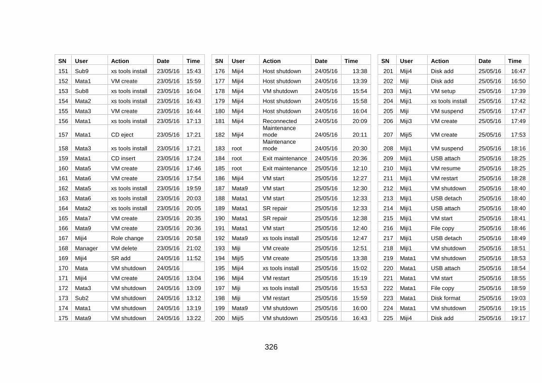
326
SN User Action Date Time SN User Action Date Time SN User Action Date Time
151 Sub9 xs tools install 23/05/16 15:43 176 Miji4 Host shutdown 24/05/16 13:38 201 Miji4 Disk add 25/05/16 16:47
152 Mata1 VM create 23/05/16 15:59 177 Miji4 Host shutdown 24/05/16 13:39 202 Miji Disk add 25/05/16 16:50
153 Sub8 xs tools install 23/05/16 16:04 178 Miji4 VM shutdown 24/05/16 15:54 203 Miji1 VM setup 25/05/16 17:39
154 Mata2 xs tools install 23/05/16 16:43 179 Miji4 Host shutdown 24/05/16 15:58 204 Miji1 xs tools install 25/05/16 17:42
155 Mata3 VM create 23/05/16 16:44 180 Miji4 Host shutdown 24/05/16 16:04 205 Miji VM suspend 25/05/16 17:47
156 Mata1 xs tools install 23/05/16 17:13 181 Miji4 Reconnected 24/05/16 20:09 206 Miji3 VM create 25/05/16 17:49
157 Mata1 CD eject 23/05/16 17:21 182 Miji4 Maintenance mode 24/05/16 20:11 207 Miji5 VM create 25/05/16 17:53
158 Mata3 xs tools install 23/05/16 17:21 183 root Maintenance mode 24/05/16 20:30 208 Miji1 VM suspend 25/05/16 18:16
159 Mata1 CD insert 23/05/16 17:24 184 root Exit maintenance 24/05/16 20:36 209 Miji1 USB attach 25/05/16 18:25
160 Mata5 VM create 23/05/16 17:46 185 root Exit maintenance 25/05/16 12:10 210 Miji1 VM resume 25/05/16 18:25
161 Mata6 VM create 23/05/16 17:54 186 Miji4 VM start 25/05/16 12:27 211 Miji1 VM restart 25/05/16 18:28
162 Mata5 xs tools install 23/05/16 19:59 187 Mata9 VM start 25/05/16 12:30 212 Miji1 VM shutdown 25/05/16 18:40
163 Mata6 xs tools install 23/05/16 20:03 188 Mata1 VM start 25/05/16 12:33 213 Miji1 USB detach 25/05/16 18:40
164 Mata2 xs tools install 23/05/16 20:05 189 Mata1 SR repair 25/05/16 12:33 214 Miji1 USB attach 25/05/16 18:40
165 Mata7 VM create 23/05/16 20:35 190 Mata1 SR repair 25/05/16 12:38 215 Miji1 VM start 25/05/16 18:41
166 Mata9 VM create 23/05/16 20:36 191 Mata1 VM start 25/05/16 12:40 216 Miji1 File copy 25/05/16 18:46
167 Miji4 Role change 23/05/16 20:58 192 Mata9 xs tools install 25/05/16 12:47 217 Miji1 USB detach 25/05/16 18:49
168 Manager VM delete 23/05/16 21:02 193 Miji VM create 25/05/16 12:51 218 Miji1 VM shutdown 25/05/16 18:51
169 Miji4 SR add 24/05/16 11:52 194 Miji5 VM create 25/05/16 13:38 219 Mata1 VM shutdown 25/05/16 18:53
170 Mata VM shutdown 24/05/16 195 Miji4 xs tools install 25/05/16 15:02 220 Mata1 USB attach 25/05/16 18:54
171 Miji4 VM create 24/05/16 13:04 196 Miji4 VM restart 25/05/16 15:19 221 Mata1 VM start 25/05/16 18:55
172 Mata3 VM shutdown 24/05/16 13:09 197 Miji xs tools install 25/05/16 15:53 222 Mata1 File copy 25/05/16 18:59
173 Sub2 VM shutdown 24/05/16 13:12 198 Miji VM restart 25/05/16 15:59 223 Mata1 Disk format 25/05/16 19:03
174 Mata1 VM shutdown 24/05/16 13:19 199 Mata9 VM shutdown 25/05/16 16:00 224 Mata1 VM shutdown 25/05/16 19:15
175 Mata9 VM shutdown 24/05/16 13:22 200 Miji5 VM shutdown 25/05/16 16:43 225 Miji4 Disk add 25/05/16 19:17
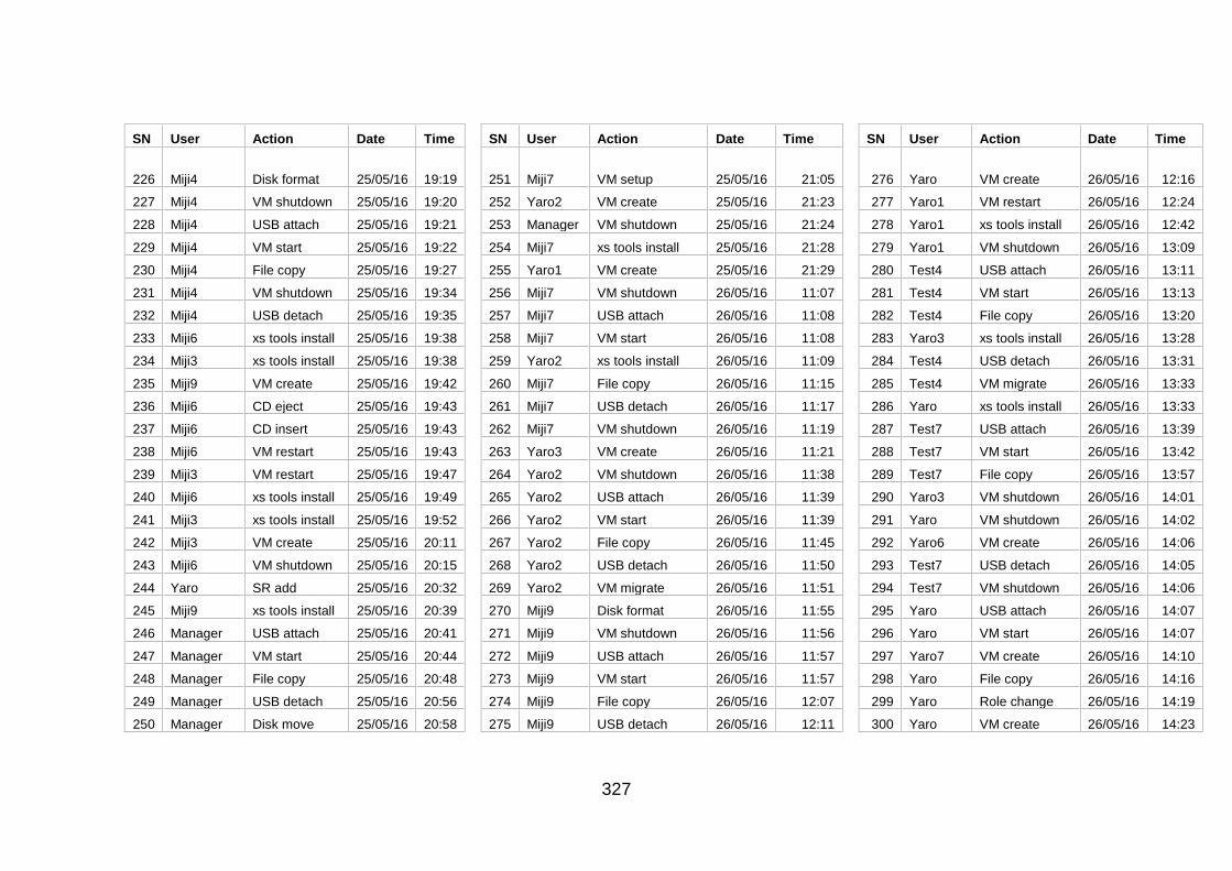
327
SN User Action Date Time SN User Action Date Time SN User Action Date Time
226 Miji4 Disk format 25/05/16 19:19 251 Miji7 VM setup 25/05/16 21:05 276 Yaro VM create 26/05/16 12:16
227 Miji4 VM shutdown 25/05/16 19:20 252 Yaro2 VM create 25/05/16 21:23 277 Yaro1 VM restart 26/05/16 12:24
228 Miji4 USB attach 25/05/16 19:21 253 Manager VM shutdown 25/05/16 21:24 278 Yaro1 xs tools install 26/05/16 12:42
229 Miji4 VM start 25/05/16 19:22 254 Miji7 xs tools install 25/05/16 21:28 279 Yaro1 VM shutdown 26/05/16 13:09
230 Miji4 File copy 25/05/16 19:27 255 Yaro1 VM create 25/05/16 21:29 280 Test4 USB attach 26/05/16 13:11
231 Miji4 VM shutdown 25/05/16 19:34 256 Miji7 VM shutdown 26/05/16 11:07 281 Test4 VM start 26/05/16 13:13
232 Miji4 USB detach 25/05/16 19:35 257 Miji7 USB attach 26/05/16 11:08 282 Test4 File copy 26/05/16 13:20
233 Miji6 xs tools install 25/05/16 19:38 258 Miji7 VM start 26/05/16 11:08 283 Yaro3 xs tools install 26/05/16 13:28
234 Miji3 xs tools install 25/05/16 19:38 259 Yaro2 xs tools install 26/05/16 11:09 284 Test4 USB detach 26/05/16 13:31
235 Miji9 VM create 25/05/16 19:42 260 Miji7 File copy 26/05/16 11:15 285 Test4 VM migrate 26/05/16 13:33
236 Miji6 CD eject 25/05/16 19:43 261 Miji7 USB detach 26/05/16 11:17 286 Yaro xs tools install 26/05/16 13:33
237 Miji6 CD insert 25/05/16 19:43 262 Miji7 VM shutdown 26/05/16 11:19 287 Test7 USB attach 26/05/16 13:39
238 Miji6 VM restart 25/05/16 19:43 263 Yaro3 VM create 26/05/16 11:21 288 Test7 VM start 26/05/16 13:42
239 Miji3 VM restart 25/05/16 19:47 264 Yaro2 VM shutdown 26/05/16 11:38 289 Test7 File copy 26/05/16 13:57
240 Miji6 xs tools install 25/05/16 19:49 265 Yaro2 USB attach 26/05/16 11:39 290 Yaro3 VM shutdown 26/05/16 14:01
241 Miji3 xs tools install 25/05/16 19:52 266 Yaro2 VM start 26/05/16 11:39 291 Yaro VM shutdown 26/05/16 14:02
242 Miji3 VM create 25/05/16 20:11 267 Yaro2 File copy 26/05/16 11:45 292 Yaro6 VM create 26/05/16 14:06
243 Miji6 VM shutdown 25/05/16 20:15 268 Yaro2 USB detach 26/05/16 11:50 293 Test7 USB detach 26/05/16 14:05
244 Yaro SR add 25/05/16 20:32 269 Yaro2 VM migrate 26/05/16 11:51 294 Test7 VM shutdown 26/05/16 14:06
245 Miji9 xs tools install 25/05/16 20:39 270 Miji9 Disk format 26/05/16 11:55 295 Yaro USB attach 26/05/16 14:07
246 Manager USB attach 25/05/16 20:41 271 Miji9 VM shutdown 26/05/16 11:56 296 Yaro VM start 26/05/16 14:07
247 Manager VM start 25/05/16 20:44 272 Miji9 USB attach 26/05/16 11:57 297 Yaro7 VM create 26/05/16 14:10
248 Manager File copy 25/05/16 20:48 273 Miji9 VM start 26/05/16 11:57 298 Yaro File copy 26/05/16 14:16
249 Manager USB detach 25/05/16 20:56 274 Miji9 File copy 26/05/16 12:07 299 Yaro Role change 26/05/16 14:19
250 Manager Disk move 25/05/16 20:58 275 Miji9 USB detach 26/05/16 12:11 300 Yaro VM create 26/05/16 14:23
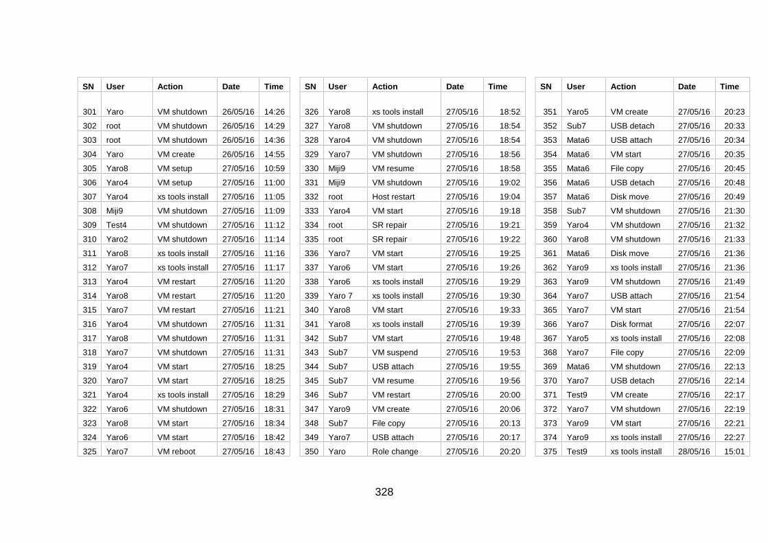
328
SN User Action Date Time SN User Action Date Time SN User Action Date Time
301 Yaro VM shutdown 26/05/16 14:26 326 Yaro8 xs tools install 27/05/16 18:52 351 Yaro5 VM create 27/05/16 20:23
302 root VM shutdown 26/05/16 14:29 327 Yaro8 VM shutdown 27/05/16 18:54 352 Sub7 USB detach 27/05/16 20:33
303 root VM shutdown 26/05/16 14:36 328 Yaro4 VM shutdown 27/05/16 18:54 353 Mata6 USB attach 27/05/16 20:34
304 Yaro VM create 26/05/16 14:55 329 Yaro7 VM shutdown 27/05/16 18:56 354 Mata6 VM start 27/05/16 20:35
305 Yaro8 VM setup 27/05/16 10:59 330 Miji9 VM resume 27/05/16 18:58 355 Mata6 File copy 27/05/16 20:45
306 Yaro4 VM setup 27/05/16 11:00 331 Miji9 VM shutdown 27/05/16 19:02 356 Mata6 USB detach 27/05/16 20:48
307 Yaro4 xs tools install 27/05/16 11:05 332 root Host restart 27/05/16 19:04 357 Mata6 Disk move 27/05/16 20:49
308 Miji9 VM shutdown 27/05/16 11:09 333 Yaro4 VM start 27/05/16 19:18 358 Sub7 VM shutdown 27/05/16 21:30
309 Test4 VM shutdown 27/05/16 11:12 334 root SR repair 27/05/16 19:21 359 Yaro4 VM shutdown 27/05/16 21:32
310 Yaro2 VM shutdown 27/05/16 11:14 335 root SR repair 27/05/16 19:22 360 Yaro8 VM shutdown 27/05/16 21:33
311 Yaro8 xs tools install 27/05/16 11:16 336 Yaro7 VM start 27/05/16 19:25 361 Mata6 Disk move 27/05/16 21:36
312 Yaro7 xs tools install 27/05/16 11:17 337 Yaro6 VM start 27/05/16 19:26 362 Yaro9 xs tools install 27/05/16 21:36
313 Yaro4 VM restart 27/05/16 11:20 338 Yaro6 xs tools install 27/05/16 19:29 363 Yaro9 VM shutdown 27/05/16 21:49
314 Yaro8 VM restart 27/05/16 11:20 339 Yaro 7 xs tools install 27/05/16 19:30 364 Yaro7 USB attach 27/05/16 21:54
315 Yaro7 VM restart 27/05/16 11:21 340 Yaro8 VM start 27/05/16 19:33 365 Yaro7 VM start 27/05/16 21:54
316 Yaro4 VM shutdown 27/05/16 11:31 341 Yaro8 xs tools install 27/05/16 19:39 366 Yaro7 Disk format 27/05/16 22:07
317 Yaro8 VM shutdown 27/05/16 11:31 342 Sub7 VM start 27/05/16 19:48 367 Yaro5 xs tools install 27/05/16 22:08
318 Yaro7 VM shutdown 27/05/16 11:31 343 Sub7 VM suspend 27/05/16 19:53 368 Yaro7 File copy 27/05/16 22:09
319 Yaro4 VM start 27/05/16 18:25 344 Sub7 USB attach 27/05/16 19:55 369 Mata6 VM shutdown 27/05/16 22:13
320 Yaro7 VM start 27/05/16 18:25 345 Sub7 VM resume 27/05/16 19:56 370 Yaro7 USB detach 27/05/16 22:14
321 Yaro4 xs tools install 27/05/16 18:29 346 Sub7 VM restart 27/05/16 20:00 371 Test9 VM create 27/05/16 22:17
322 Yaro6 VM shutdown 27/05/16 18:31 347 Yaro9 VM create 27/05/16 20:06 372 Yaro7 VM shutdown 27/05/16 22:19
323 Yaro8 VM start 27/05/16 18:34 348 Sub7 File copy 27/05/16 20:13 373 Yaro9 VM start 27/05/16 22:21
324 Yaro6 VM start 27/05/16 18:42 349 Yaro7 USB attach 27/05/16 20:17 374 Yaro9 xs tools install 27/05/16 22:27
325 Yaro7 VM reboot 27/05/16 18:43 350 Yaro Role change 27/05/16 20:20 375 Test9 xs tools install 28/05/16 15:01

329
SN User Action Date Time SN User Action Date Time SN User Action Date Time
376 Test VM move 28/05/16 15:03 401 Miji4 Disk move 28/05/16 17:59 426 Test3 xs tools install 29/05/16 17:50
377 Yaro5 VM shutdown 28/05/16 15:11 402 Miji4 VM shutdown 28/05/16 18:03 427 Test2 VM restart 29/05/16 19:00
378 Yaro9 Disk add 28/05/16 15:20 403 Mata VM move 28/05/16 18:07 428 Test3 VM restart 29/05/16 19:00
379 Yaro9 Disk move 28/05/16 15:23 404 Sub6 VM shutdown 28/05/16 18:10 429 root VM move 29/05/16 19:32
380 Yaro9 USB attach 28/05/16 15:27 405 Miji4 Role change 28/05/16 18:21 430 Manager Host shutdown 30/05/16 15:02
381 Yaro9 File copy 28/05/16 15:28 406 Miji2 VM create 28/05/16 18:24 431 Manager VM move 30/05/16 15:17
382 Test6 VM start 28/05/16 15:31 407 Mata4 VM move 28/05/16 18:28 432 Manager VM move 30/05/16 15:30
383 Test6 Disk move 28/05/16 15:32 408 Test6 VM start 28/05/16 18:40 433 root Host start 30/05/16 15:40
384 Yaro9 USB detach 28/05/16 15:35 409 Test6 Disk move 28/05/16 18:41 434 Manager VM move 30/05/16 15:44
385 Test6 Disk move 28/05/16 15:37 410 Yaro9 VM shutdown 28/05/16 18:46 435 Manager VM move 30/05/16 15:57
386 Sub VM move 28/05/16 15:40 411 Test9 VM shutdown 28/05/16 18:48 436 Manager VM move 30/05/16 16:20
387 Sub4 VM move 28/05/16 15:47 412 Test6 Disk move 28/05/16 18:50 437
388 Manager Role change 28/05/16 15:56 413 Manager SR detach 28/05/16 19:08
389 Sub2 VM create 28/05/16 15:58 414 Manager Disk move 28/05/16 19:11
390 Sub6 VM configure 28/05/16 16:00 415 Test6 VM shutdown 28/05/16 19:30
391 Test6 VM shutdown 28/05/16 16:04 416 Test6 VM delete 28/05/16 19:31
392 Sub7 VM move 28/05/16 16:10 417 Manager SR detach 28/05/16 19:32
393 Mata1 VM move 28/05/16 16:36 418 Miji8 VM start 28/05/16 19:38
394 Mata5 VM move 28/05/16 16:51 419 Miji2 xs tools install 28/05/16 19:42
395 Miji3 VM move 28/05/16 17:07 420 Miji8 VM shutdown 28/05/16 19:49
396 Sub2 VM move 28/05/16 17:16 421 Mata7 VM delete 29/05/16 13:24
397 Sub6 xs tools install 28/05/16 17:25 422 Mata2 VM delete 29/05/16 16:18
398 Sub3 VM move 28/05/16 17:29 423 Test3 VM create 29/05/16 16:21
399 Mata3 VM move 28/05/16 17:45 424 Test2 VM create 29/05/16 16:34
400 Sub6 VM start 28/05/16 17:48 425 Test2 xs tools install 29/05/16 17:33

330