thesis mari muthu
TRANSCRIPT

CHAPTER – 1
INTRODUCTION
Materials research has long been recognized as a fundamental activity that underpins
innovation in almost all areas of emerging technologies, including processes that improve and
extent existing technologies. This materials innovation process has been practiced by the human
race since its emergence on earth.
Because of low density, in ratio of strength to weight, fabric ability, durability and
damage tolerance aluminium products have been successfully utilized structural materials for
aircraft. Since duralumin was early 1900’s the success with aluminium and dried and true design
however bred reluctance to new materials. Advanced aluminium based product which are
produced using nontraditional process have been tried for a verity of application in area of
aerospace, automobile and structural engineering. The experience design as have developed the
level of comfort with the combination of properties exhibited by established aluminium product
because of the potential advantages.
Metals such as aluminium and its alloys are one of the most used material systems in the
automotive and aerospace industry due to their high strength to weight ratio as well as because of
their high thermal conductivity. It is mostly used in high temperature applications such as in
automobile engines and in other rotating and reciprocating parts such as piston, drive shafts,
brake rotors and in other structural parts which require light weight but high strength material
[Basavarajappan et al (2007); Ibrahim et al (1991)]. One of the main drawbacks of this material
system is that they exhibit poor tribological properties. Hence the desire in the engineering
community to develop a new material with greater wear resistance and better tribological
properties, without much compromising on the strength to weight ratio led to the development of
metal matrix composites [Sinclair et al (1997); Sannino et al (1995)].
1

A composite may be defined as a material system comprising of two or more constituent
materials that remain separate and distinct while forming a single component. The bulk material
forms the continuous phase that is the matrix (e.g. metals, polymers, etc) while the other acts as
the discontinuous phase that is the reinforcements (e.g. fibers, whiskers, particulates, etc). While
the reinforcing material usually carries the major amount of load, the matrix enable the load
transfer by holding them together [Pai et al (2004)].
The properties of ceramic reinforced metal matrix composites have been reported much
better to that of its unreinforced counterpart [Satyanarayana et al (2002), Gul Acilar (2004)]. The
addition of reinforcing phase significantly improves the tribological properties of aluminium and
its alloy system. The thinking behind the development of metal matrix composites is to combine
the desirable properties of metals and ceramics.
The combination of refractory particles with metallic matrix produces a material system
with properties intermediate to that of matrix alloy and ceramic reinforcements. Aluminium have
useful properties such as high strength , ductility, high thermal and electrical conductivity but
have low stiffness whereas ceramic reinforcements are stiffer and stronger and have excellent
high temperature resistance but they are brittle in nature [Balasivanandha prabu et al (2006)].
There are number of processing techniques which have been developed in recent years
for processing metal matrix composites. According to the type of reinforcements, the fabrication
techniques also vary considerably. The different techniques employed for metal matrix
composites are powder metallurgy, spray deposition, liquid metal infiltration, squeeze casting,
stir casting, etc [Nai et al (2002)]. All of them have their own advantages and disadvantages.
At the early stage of development of metal matrix composites, emphasis was on
preparation of fiber reinforced composites. But the high cost of reinforcement fibers, restricted
the commercial exploitation of this class except for some high technology applications. The
particulate reinforced metal matrix composites are gaining importance nowadays because of their
low cost with advantages like isotropic properties and the possibility of secondary processing.
2

Boron carbide (B4C) particulates are other promising candidates as reinforcement for
light weight metal matrix composites. B4C has a lower specific gravity than either Al or SiC
(2.52 g/cm 3 compared with 2.7 for Al and 3.2 for SiC). It has a similar thermal expansion
coefficient, higher specific stiffness and strength as compared to SiC. Increased application of
chills in Al alloy B4C composites and their mechanical properties have been studied.
One of the basic requirements associated with the development and operation of nuclear
reactors is control and containment of neutrons that sustain and are also produced during fission
reaction. Boron is one of the few elements to possess nuclear properties, with warrant its
consideration as neutron absorber material.
Among the various processing techniques available for particulate or discontinuous
reinforced metal matrix composites, stir casting is the technique which is in use for large quantity
commercial production. This technique is most suitable due to its simplicity, flexibility and ease
of production for large sized components. It is also the most economical among all the available
processing techniques.
In the present investigation, we have prepared B4C particulate-reinforced Al-Mg matrix
composites using stir casting technique. The purpose of this paper is to fabricate and characterize
the microstructure and mechanical properties of the resulting composites, and to identify the
failure mechanisms under various loading conditions.
3

CHAPTER –2
LITERATURE REVIEW
Araghi. A and Paydar. M.H [2010] investigated the effect of applying ternary Ni–P–B4C
composite coating from an electrolyses plating bath containing sulfate nickel, sodium
hypophosphate and suspended B4C particles, on the corrosion and wear resistance of an AZ91D,
high aluminum cast magnesium alloy, was investigated. Regarding low corrosion resistance of
magnesium alloys, chromium oxide plus HF (Hydro Fluoric Acid) pretreatment was applied to
prepare the substrate for coating treatment in electrolyses bath. The pH value and temperature of
the electrolyses bath were 9 and 82ºC, respectively. The coating was characterized for its micro
structure, morphology, microhardness, wear and corrosion resistance. SEM (Scanning Electron
Microscope) observation showed dense and coarse nodules in the ternary composite coating and
the cross section of Ni–P–B4C coating offered presence of well dispersed B4C particles in the
coating. The hardness of the Ni–P–B4C composite coatings was around 1200 MPa, more than
what can be obtained for Ni–P coatings (about 700 MPa). The wear test which was carried out by
using pin on disc method, showed that ternary Ni–P–B4C composite coating had a good wear
resistance and more superior than Ni-P coating. The polarization test results for ternary Ni–P–
B4C composite coating exhibited good corrosion resistance properties in protecting the AZ91D
magnesium alloy, but not better than Ni–P coating.
Kirity Bhusan Khan et al [2006] prepared Al–5% Mg matrix composites reinforced with
10 and 20% B4C by stir casting method. Microhardness of unreinforced alloy and composites
were measured using a Nikon hot hardness tester. It was observed that hardness values decrease
gradually with increase in temperature. Transition temperature increases marginally from 262 to
274 ºC due to addition of 20% B4C. Stress exponent for all the materials varies from 4.3 to 4.5 at
temperatures in the range 310 and 370 ºC. Apparent activation energy for creep increases with
increase in B4C content. At temperatures below transition temperature, deformation is attributed
to the increased interatomic spacing due to increase in temperature and the unpinning of
attractive junction between glide and forest dislocations. At temperatures above the transition
4

temperature, deformation is diffusion assisted phenomenon such as dislocation glide and
dislocation climb.
Ozkan Sarikaya et al [2007] prepared the Plasma-sprayed coatings of Al–Si/B4C on Al–Si
piston alloys for diesel engine motors. The Al–Si/B4C composite powders including 5–25 wt%
B4C were prepared by mixing and ball-milling processes. These powders were deposited on Al–
Si substrate using an atmospheric plasma spray technique. The coatings have been characterised
with respect to phase composition, microstructure, microhardness, bond strength and thermal
expansion. It was found that Al, Si, B4C and Al2O3 phases were determined in the coatings with
approximately 600 lm thick by using X-ray diffraction analysis. Scanning electron microscope
observation revealed that boron carbide particles were uniformly distributed in composite
coatings and B4C particles were fully wetted by Al–Si alloy. Also, no reaction products were
observed in Al–Si/B4C composite coatings. It was found that surface roughness, porosity, bond
strength and thermal expansion coefficient of composite coatings decreased with increasing
fraction of the boron carbide particle. It was demonstrated that the higher the B4C content, the
higher the hardness of coatings because the hardness of B4C is higher than that of Al–Si.
Jiangb. Q.C et al [2005] fabricated Magnesium metal matrix composites (MMCs)
reinforced with various fractions of 10, 15 and 20 vol.% B4C particulates by powder metallurgy
(P/M) technique were investigated. Microstructure characterization of the composites revealed
necklace distribution of B4C particulates in the matrix material and the presence of minimal
micro-porosity. The X-ray diffraction (XRD) showed the formation of MgO and MgB2 in
B4C/Mg composites. Moreover, the results revealed that the hardness and wear resistance of the
composites were higher than those of as-cast Mg ingot and increased with increasing amount of
B4C particulates from 10 to 20 vol. %.
2.1 COMPOSITES
Composites are combinations of two materials in which one of the materials, called the
reinforcing phase, is in the form of fibers, sheets, or particles, and are embedded in the other
material called the matrix phase. The reinforcing material and the matrix material can be metal,
5

ceramic, or polymer. Typically, reinforcing materials are strong with low densities while the
matrix is usually a ductile, or tough, material
2.2 TYPES OF COMPOSITES
On the basis of Matrix material, composites can be grouped mainly into following types:
(i) Polymer-Matrix Composites (PMC)
The most common matrix materials for composites are polymers. Polyester and vinyl esters
are the most widely used and least expensive polymer resins. These matrix materials are
basically used for fiber glass reinforced composites. The main disadvantages of PMCs are their
low maximum working temperature, high coefficient of thermal expansion and sensitivity to
radiation and moisture. The strength and stuffiness are low compared with metals and ceramics.
(ii) Metal-Matrix Composites (MMC)
The matrix in these composites is ductile metals .These composites can be used at higher
service temperature than their base metal counterparts. The reinforcements in these materials
may improve specific stuffiness, specific strength, abrasion resistance, creep resistance and
dimensional stability. The MMCs are light weight and resist wear and thermal distortion, so it
mainly used in automobile and aerospace industry. Metal matrix composites are much more
expensive than PMCs and, therefore, their use is somewhat restricted.
(iii) Ceramic-Matrix Composites (CMC)
One of the main objectives in producing CMCs is to increase the toughness. Ceramic
materials are resistant to oxidation and deterioration at elevated temperatures. Some of these
materials would be ideal candidates for use in high temperature applications, specifically for
components in automobile and air craft gas turbine engines .The developments of CMCs has
lagged behind mostly for the reason that most processing routes involve higher temperature and
only employed with high temperature reinforcements.
6

2.3 METAL MATRIX COMPOSITES
Due to combination of metallic properties (ductility and toughness) with ceramic properties
(high strength and high modulus), metal matrix composites show greater shear and compression
strength with capabilities to perform at high temperature. From the last decade, use of metal
matrix composites for automobile, aerospace and other high temperature structural and non
structural applications has increased a lot. This is due to the availability of relatively inexpensive
reinforcements and the development of various processing techniques resulting in reproducible
microstructures and properties [Ibrahim et al (1991)].
The matrix material generally used in metal matrix composites is aluminium and its alloys.
Besides aluminium, magnesium, copper, nickel, titanium, etc are also used as matrix material for
specific applications. Reinforcement materials include carbides (e.g. SiC, B4C), nitrides (e.g.
Si3N4, AlN), oxides (e.g. Al2O3, SiO2) as well as elemental materials (e.g. C, Si). The
reinforcements may be in the form of continuous fibers, chopped fibers, whiskers, platelets or
particulates. SiC for example, is being used in Aluminium matrix composites in all the above
mentioned forms.
2.4 TYPES OF METAL MATRIX COMPOSITES
MMCs come in several distinct classes, generally defined with reference to the shape of
their reinforcement:
(a) Particle-Reinforced metals (PRMs) :
Particle-Reinforced metals contain approximately equiaxed reinforcements, with an
aspect ratio less than about 5. These are generally ceramic (SiC, Al2O3, etc.). PRMs commonly
contain below 25vol. % ceramic reinforcement when used for structural applications, but can
have as much as 80vol% ceramic when used for electronic packaging[Surappa,(2003)]. In
general, PRMs are at least approximately isotropic. They are produced using both solid state
(powder metallurgy) and liquid metal techniques (stir casting, infiltration). Their mechanical
properties, while often inferior to those of fiber-reinforced metals, are more or less isotropic and
7

often represent, at moderate cost, significant improvements over those of corresponding
unreinforced metals.
(b) Short Fiber- and Whisker-Reinforced metals :
Short Fiber- and Whisker-Reinforced metals contain reinforcements with an aspect ratio
of greater than 5, but are not continuous. These composites are commonly produced by squeeze
infiltration. They often form part of a locally reinforced component, generally produced to net or
near-net shape. Their use in automotive engines is now well established.
(c) Continuous Fiber-Reinforced Metals :
Continuous Fiber-Reinforced Metals contain continuous fibers (of alumina, SiC, carbon,
etc.) with a diameter below about 20 μm. The fibers can either be parallel, or pre-woven before
production of the composite; this is generally achieved by squeeze infiltration.
(d)Monofilament-Reinforced metals :
Monofilament-Reinforced metals contain fibers that are relatively large in diameter
(typically around 100 μm), available as individual elements. Due to their thickness, the bending
flexibility of monofilaments is low, which limits the range of shapes that can be produced.
Monofilament reinforced metals can be produced by solid state processes requiring diffusion
bonding: they are commonly based on titanium alloy matrices, which are well-suited to such
techniques.
(e)Interpenetrating phase composites :
Interpenetrating phase composites are ones in which the metal is reinforced with a three-
dimensionally percolating phase, for example ceramic foam.
(f)Liquid phase sintered metallic materials :
Liquid phase sintered metallic materials include the cemented carbides, in which carbide
particles are bonded together by a metal such as cobalt, and the tungsten heavy alloys.
8
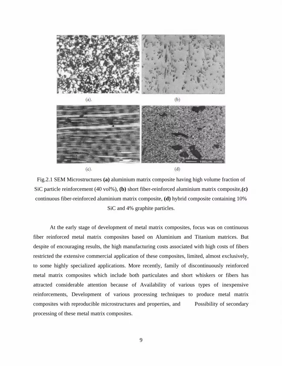
Fig.2.1 SEM Microstructures (a) aluminium matrix composite having high volume fraction of
SiC particle reinforcement (40 vol%), (b) short fiber-reinforced aluminium matrix composite,(c)
continuous fiber-reinforced aluminium matrix composite, (d) hybrid composite containing 10%
SiC and 4% graphite particles.
At the early stage of development of metal matrix composites, focus was on continuous
fiber reinforced metal matrix composites based on Aluminium and Titanium matrices. But
despite of encouraging results, the high manufacturing costs associated with high costs of fibers
restricted the extensive commercial application of these composites, limited, almost exclusively,
to some highly specialized applications. More recently, family of discontinuously reinforced
metal matrix composites which include both particulates and short whiskers or fibers has
attracted considerable attention because of Availability of various types of inexpensive
reinforcements, Development of various processing techniques to produce metal matrix
composites with reproducible microstructures and properties, and Possibility of secondary
processing of these metal matrix composites.
9

Moreover, the problem associated with fabrication of continuously reinforced metal
matrix composites such as fiber damage, microstructural non uniformity, fiber to fiber contact
and extensive interfacial reactions can be avoided with discontinuous reinforcements.
Discontinuously reinforced metal matrix composites with nearly isotropic properties have been
successfully utilized in applications such as in automotive components where extreme loading is
not required with improvement in strength and stiffness as compared to those available
unreinforced materials.
2.5 FABRICATION OF METAL MATRIX COMPOSITES
A variety of processing techniques have evolved over the last two decades in an effort to
optimize the structure and properties of MMCs. Accordingly, these can be classified into:
(a) Liquid state fabrication of Metal Matrix Composites, (b) Solid state fabrication of Metal
Matrix Composites, (c) Fabrication of Metal Matrix Composites by co-deposition.
1. Liquid state fabrication of Metal Matrix Composites:
This involves incorporation of dispersed phase into a molten matrix metal, followed by
its Solidification. In order to provide high level of mechanical properties of the composite, good
interfacial bonding (wetting) between the dispersed phase and the liquid matrix should be
obtained.
Wetting improvement may be achieved by coating the dispersed phase particles (fibers).
Proper coating not only reduces interfacial energy, but also prevents chemical interaction
between the dispersed phase and the matrix. The methods of liquid state fabrication of Metal
Matrix Composites are: Infiltration and Stir Casting.
Infiltration- This is a liquid state method of composite materials fabrication, in which a
preformed dispersed phase (ceramic particles, fibers, woven) is soaked in a molten matrix metal,
which fills the space between the dispersed phase inclusions.
10

The motive force of an infiltration process may be either capillary force of the dispersed
phase (spontaneous infiltration) or an external pressure (gaseous, mechanical, electromagnetic,
centrifugal or ultrasonic) applied to the liquid matrix phase (forced infiltration)
Stir Casting- This is a liquid state method of composite materials fabrication, in which a
dispersed phase (ceramic particles, short fibers) is mixed with a molten matrix metal by means of
mechanical stirring. The liquid composite material is then cast by conventional casting methods
and may also be processed by conventional Metal forming technologies. Stir Casting is the
simplest and the most cost effective method of liquid state fabrication.
Stir Casting is characterized by the following features:
Content of dispersed phase is limited (usually not more than 30 vol.%).
Distribution of dispersed phase throughout the matrix is not perfectly homogeneous:
o There are local clouds (clusters) of the dispersed particles;
o There may be gravity segregation of the dispersed phase due to a difference in
the densities of the dispersed and matrix phase.
The technology is relatively simple and low cost.
Distribution of dispersed phase may be improved if the matrix is in semi-solid condition.
The method using stirring metal composite materials in semi-solid state is called Rheocasting.
High viscosity of the semi-solid matrix material enables better mixing of the dispersed phase.
2. Solid state fabrication of Metal Matrix Composites:
This is the process, in which Metal Matrix Composites are formed as a result of bonding
matrix metal and dispersed phase due to mutual diffusion occurring between them in solid states
at elevated temperature and under pressure. Low temperature of solid state fabrication process
(as compared to Liquid state fabrication of Metal Matrix Composites) depresses undesirable
reactions on the boundary between the matrix and dispersed (reinforcing) phases.
11

Metal Matrix Composites may be deformed also after sintering operation by rolling,
forging, and pressing, Drawing or Extrusion. Deformation of sintered composite materials with
dispersed phase in form of short fibers results in a preferred orientation of the fibers and
anisotropy of the material properties (enhanced strength along the fibers orientation). There are
two principal groups of solid state fabrication of Metal Matrix Composites: Diffusion bonding
and Sintering.
Diffusion Bonding- This is a solid state fabrication method, in which a matrix in form of
foils and a dispersed phase in form of long fibers are stacked in a particular order and then
pressed at elevated temperature. The diffusion bonding process is shown in figure: 2.2.
Fig.2.2 diffusion bonding
The finished laminate composite material has a multilayer structure. Diffusion Bonding is
used for fabrication of simple shape parts (plates, tubes). Variants of diffusion bonding are roll
bonding and wire/fiber winding:
Roll Bonding is a process of combined rolling (hot or cold) strips of two different metals
(e.g. steel and aluminum alloy) resulted in formation of a laminated composite material with a
metallurgical bonding between the two layers. Wire/fiber Winding is a process of combined
12

winding continuous ceramic fibers and metallic wires followed by pressing at elevated
temperature.
Sintering- This is a process, in which a powder of a matrix metal is mixed with a powder
of dispersed phase in form of particles or short fibers for subsequent compacting and sintering in
solid state (sometimes with some presence of liquid).
Fig.2.3 Process of sintering
Sintering is the method involving consolidation of powder grains by heating the green
compact part to a high temperature below the melting point, when the material of the separate
particles diffuse to the neighboring powder particles. In contrast to the liquid state fabrication of
Metal Matrix Composites, sintering method allows obtaining materials containing up to 50% of
dispersed phase.The process of sintering is shown in figure: 2.3.
3. Fabrication of Metal Matrix Composites by co-deposition:
It is a process, in which matrix metal is deposited together with the dispersed phase by one
of the deposition techniques. The following co-deposition methods are used for manufacturing
13

2.6 Metal Matrix Composites:
Electrolytic co-deposition
Spray co-deposition
Vapor co-deposition
Electrolytic co-deposition:
This method (Electrolytic co-deposition) involves Electroplating technique, in which
electrolyte solution of matrix metal ions contains suspended particles of dispersed phase. When
the matrix metal is deposited on a substrate, the dispersed phase particles are entrapped by the
coating, reinforcing the matrix material.
Examples of electrolytic Co-deposition:
Nickel matrix composite materials with various dispersed phases are fabricated by
electrolytic co-deposition from Nickel Sulfamate and Watts electrolytes:
Ni-Al2O3 - oxidation resistant nickel matrix composite;
Ni-SiC – wear resistant nickel matrix composite;
Ni-PTFE, Ni-C, Ni-MoS2 – antifriction nickel matrix composites.
Anti-friction coating of Engine bearings consisting of lead-tin-copper alloy and
reinforced by alumina (Al2O3) is fabricated by electrolytic co-deposition from electrolyte
solution of lead, tin and copper with alumina particles.
Aluminum matrix material reinforced by silica (SiO2) is prepared from AlCl3-
dimethylsulfone electrolyte containing fine silica particles.
Spray Co-deposition:
14

This method implements thermal spraying technique for atomizing molten matrix
metal, droplets of which are delivered to a substrate in a high velocity gas stream together with
dispersed phase particles supplied to the stream from a separate container. The method allows
fabrication of near-net-shape forming of Metal Matrix Composites. Examples of spray co-
deposition are:
Aluminum matrix material reinforced by silicon carbide (SiC) is produced by
spray co-deposition followed by Rolling. High Velocity Oxyfuel Spraying (HVOS) method is
used for fabrication tungsten carbide-cobalt (WC-Co) composite material, which is
conventionally manufactured by more expensive technology of sintering fabrication of Metal
Matrix Composites
Vapor co-deposition:
This is a group of various methods, utilizing materials in vapor state: Physical Vapor
Deposition (PVD), Chemical Vapor Deposition (CVD), and Direct Vapor Deposition (DVD). In
these methods coating of solid material is formed as a result of vapor condensation or chemical
reaction on a substrate surface. Vapor co-deposition is used for coating fibers, creating
multilayer depositions, fabricating nanostructure composite materials.
2.7 STRENGTHENING MECHANISMS IN PARTICULATE REINFORCED MMCs
The strengthening mechanisms observed in particulate reinforced MMCs may be divided
into two categories, direct and indirect strengthening. Direct strengthening in particulate
reinforced metals is an extension of the classical composite strengthening mechanisms used to
describe the behavior of continuous fiber reinforced composites [Nikhilesh et al (2001);Chawla
et al (1997)]. Under an applied load, the load is transferred from the weaker matrix, across the
matrix/reinforcement interface, to the typically higher stiffness reinforcement. In this manner,
strengthening takes place by the reinforcement carrying much of the applied load. Due to the
lower aspect ratio of particulate materials, load transfer is not as efficient as in the case of
continuous fiber reinforcement, but is still significant in providing strengthening[Nardone et al
(1991).
15

In metal matrix composites, where a high stiffness ceramic reinforcement is embedded in
a metallic alloy, the thermal mismatch between the high expansion metallic matrix and the low
expansion ceramic is typically quite high. Thus, upon cooling, dislocations forms at the
reinforcement/matrix interface due to the thermal mismatch. In this manner, thermally induced
dislocation punching results in indirect strengthening of the matrix [Chawla et al (1972)].
In age-hardenable matrix materials, the thermally-induced dislocations (formed upon
quenching from the solution treatment) serve as heterogeneous nucleation sites for precipitate
formation during the aging treatment. Not only there is a preferential distribution of precipitates
in the particle/matrix interface region, but the higher density of dislocations also causes
acceleration in the time to peak-aging compared to the unreinforced alloy of a similar
composition. An increase in reinforcement volume fraction or a decrease in particle size
increases the amount of indirect strengthening, since a larger amount of interfacial area exists for
dislocation punching to take place.
2.8 MATERIAL SELECTION FOR MMCs
The structural efficiency of metal matrix composites is directly related to the density,
elastic modulus and tensile strength of the reinforcing phase. The chemical and thermal stability
of the reinforcements and compatibility with the matrix phase are important not only for the end
application but also during material fabrication. The thermal mismatch strain, €, is also an
important factor for composites used in high temperature applications. It is a function of the
difference between the coefficient of thermal expansion, Δα, of the reinforcement and matrix
according to the following expression
€=ΔαΔT (1)
Where, ΔT is the temperature change. It is important for Δα to be a minimum in order to
minimize strain accumulation.
16

The use of metal matrix composites for high temperature applications requires the
presence of thermodynamically stable dispersoids which can be achieved by using an alloy
dispersoid system in which elemental solubility, solid state diffusivity and interfacial energies
are minimized, thereby minimizing coarsening and interfacial reactions. For example, titanium
addition to aluminium promote the precipitation of Al3Ti phase which enhances the thermal
stability and structural efficiency of the matrix as a result of high m.p. (1330OC), low density
( 3.3g/cc ), and low diffusivity (1.69 x 10⁻¹⁴ cm2s-1) in aluminium.
2.9 WETTABILITY
The nature and characteristics of the interface region formed between the matrix and the
reinforcing phase determine load transfer and crack resistance of the metal matrix composites
during application. It is well known that by promoting wetting, controlling chemical reactions
and minimizing oxide formation, interfacial bond strength can be increased. The Contact angle
formed between solid, liquid and gas phases shown in figure: 2.4.
Fig.2.4 Contact angle formed between solid, liquid and gas phases
17

When the interfacial bond strength between a solid and a liquid exceeds the surface
tension of the liquid, wetting is said to be achieved. Wettability is measured in terms of contact
angle θ, formed between a solid and a liquid medium, as defined by Young’s equation,
Үsg=Үsl+Үlgcosθ (2)
Where, Үsl , Үsg and Үlg are the interfacial energies between solid and liquid, solid and gas, and
liquid and gas phases, respectively[10]. In terms of the energetics of wetting, the work of
adhesion, Wad, is defined as the energy required to separate a unit area of the solid-liquid
interface, according to
Wad=Үlg(1+cosθ) (3)
Hence, wetting is achieved when θ < 900 (i.e., when Үsg >Үsl or when the driving force
for wetting, Df, exceeds the liquid interfacial energy (i.e., Df > Үlg). The value of Df depends on
the surface tension of the liquid and the strength of the liquid-solid interface, which in turn are
influenced by surface characteristics, interfacial reactions, heat of formation, valence electron
concentration, temperature and time.
2.10 STIR CASTING TECHNIQUE
The high cost of production of even minimally complex shape components hinders the
widespread adoption of particulate metal matrix composites. Casting technology is the solution
to this problem. It is one of the cheapest methods for production of particulate matrix composites
at large scale. But there are several technical challenges as mentioned below that need
considerable attention before going for this technique [Hashim et al (2002)].
a) The difficulty of achieving a uniform distribution of particles.
b) Wettability between the matrix and the particles.
c) Porosity in the cast metal matrix composites.
18

d) Chemical reactions between the reinforcement material and the matrix alloy.
The attainment of uniform distribution of particles within the matrix is essential for
achievement of optimum mechanical properties. This is the most common problem which
remains with most of the processing techniques including stir casting. Porosity is another
common problem associated with casting technique.
In stir casting technique of production of metal matrix composites, a melt of the selected
matrix material is produced by heating the material in a furnace. In the molten matrix material,
the reinforcing particles are then added followed by stirring of the melt to make the
reinforcement particles homogenous to the melt. After stirring, solidification of the melt
containing suspended particles takes place to obtain the desired product. For a homogenous
distribution of reinforcing particles in the matrix material by stir casting route, the following
factors need to be understood:
1) Particle density, size, shape and volume fraction plays an important role in the
reinforcement settling rate.
2) Surface properties of particles determine the ease or difficulty of wetting.
3) The reaction of the reinforcing particles with each other and with matrix melt
influences the rheological behaviour of the slurry.
4) During particle addition or stirring, gas entrapment takes place leading to poor
distribution of particles due to attachment of particles to gas bubbles and also
increase in porosity in the composite.
5) Mixing parameters should be so adjusted that particle distribution in axial and
radial directions must be uniform
6) The settling time should be as minimum as possible during solidification of melt.
7) The reinforcement particles, in general, occupy interdendritic or between
19

secondary dendrite arm spacing, therefore the matrix grain size or the spacing
must be finer for better distribution of particles.
In stir casting method, the particle distribution depends on process parameters during the
melt and solidification stages. Flow and solidification characteristics are important factors
affecting distribution of particles in the matrix. Both factors depends on parameters like viscosity
of the melt, heat transfer rate, wettability of materials, stirring conditions, agglomeration of
particles before and after mixing , pattern or mould shape and temperature
The addition of reinforcing particles increases the viscosity of the melt and makes it non-
Newtonian and thus the casting fluidity of the melt decreases. There are two types of interaction
occurs by dispersion of solid particles in the melt, both of which causes an increase in the
apparent viscosity of the slurry [Girot et al (1987)]
1) A hydrodynamic interaction between liquid and the particle.
2) A non-hydrodynamic interaction between particles themselves.
The chemical interaction between the reinforcing particles and the matrix material which
causes a change in shape and volume fraction of the reinforcement is also responsible for the
change in apparent viscosity of the slurry. The suspended particles in the slurry also interact with
each other giving rise to particle agglomeration which is apparently responsible for the observed
shear rate dependent behavior of the slurries. The viscosity of the composite slurry decreases
with increasing temperature because of the decrease in solid volume fraction as in unreinforced
partially solidified matrix alloy melt [Moon et al (1991)].
An external driving force is required by the ceramic reinforcement particles for better
wettability in the metallic melt. The stirring action of the mechanical stirrer in the melt provides
this driving force to overcome the surface energy barriers and makes the ceramic particles more
wettable. The alloy chemistry, temperature of particle addition and rate of stirring are some other
parameters which control the wetting of the reinforcement particles by the melt [Asthana et al
(1993)].
20

The settling rate of reinforcement particles also plays an important role in casting
process. According to Gieger and Zaki, the settling rate is also a function of particle density with
particle shape and size playing a role. High volume fraction of particles hindered the settling rate
by particle interaction with each other.
Richardson and Zaki proposed a model for settling of spherical particles with the particle
velocity, Vc, is given by
Vc = Vo (1- f)n (4)
Where, Vo is the stokes velocity, f the volume fraction of particles and n is a factor which
depends on the Reynolds number, particle diameter and the diameter of the container. The value
of n increases with increasing particle diameter. The studies show that for lower settling rate, the
particle should be finer and their volume fraction is higher.
Thomas found that the particle shape and size are the most important parameters.
According to Ray, when the flow velocity is above a critical value for a given size of particle, the
suspension will remain homogenous during flow. If the flow velocity is reduced below critical
value, the suspension becomes inhomogenous. Further reduction in flow velocity causes the
particles to sediment at the bottom and move by tumbling over each other.
The stirring of slurry causes high shear rate which results in a fairly homogenous particle
distribution in radial direction and prevents particle settling. At the same time secondary flow in
axial direction causes lifting of particles by transfer of momentum from high to low momentum
regions. To correlate particle lifting with flow parameters, a particle dispersion number (PDN) is
given which is the ratio of the axial velocity of secondary flow to the terminal settling velocity. If
PDN is greater than 1, the settling velocity is smaller than the axial velocity of the secondary
flow and the particles will be carried to the upper portion of the melt. On the other hand, for
PDN smaller than 1, the particles will remain at the bottom. For homogenous dispersion, PDN
should be greater than [El-Kaddah et al (1991)].
21

During solidification, particle redistribution is generally affected by three mechanisms
namely agglomeration, sedimentation and particle engulfment or rejection (pushing) ahead of the
solidification front. Out of these which mechanism will be dominant, depends on the elements of
processing technique as well as the physical and chemical properties of the particle and the
matrix. In general, molten metal normally solidify dendritically. When the temperature drops
below the liquidus temperature solidification of the molten matrix start. Some very small
dendrites appear at this time which grows as the temperature decreases. Since, the ceramic
reinforcement particles have generally lower thermal conductivity than the metallic melt; it
causes the particles to be surrounded by the last freezing of the molten alloy during
solidification. During cooling the melt viscosity increases. There is also slight increase in
density. Both of these effects tend to reduce the particle settling rate compared to an isothermal
melt bath. The continuously precipitating crystals in the solidifying matrix also hinder the
settling rate.
Two mechanisms have been suggested for particle pushing from fluid flow [Han et al
(1995)]. The first mechanism says that the particle is in contact with the solid and moved over
the surface by the fluid flow as the solid grows. In the second mechanism, the particle which is
located near the solidification front are trapped because of the roughness of the solidification
front. The rejection of particles by the growing crystals and its pushing ahead of the advancing
interface results in generation of a viscous force which prevents the pushing of the particles.
Hence the balance of these counteracting forces decides whether the particles is rejected or
engulfed. The various parameters which affect the shape of the solidification front are relative
density difference, relative difference in thermal conductivity and heat diffusivity between the
particle and the metallic melt, and alloy composition. Pushing of particle suggests that the solid
metal has no affinity for the reinforcement and that the interfacial bonding is weak.
A low particle-solid interfacial energy is the requirement for both engulfment and
nucleation, just like low particle-liquid interfacial energy required for particle incorporation. This
lowering of interfacial energy can be achieved if the solid and the particle share the same crystal
22

structure and lattice parameter. Ceramic materials which act as grain refiner such as TiB2 and
TiC are likely to be engulfed within the metal grain rather than pushed to the boundary.
2.11 TENSILE STRENGTH
The reinforcing phase in the metal matrix composites bears a significant fraction of stress
as it is generally much stiffer than the matrix. Microplasticity in MMCs which takes place at
fairly low stress has been attributed to stress concentrations in the matrix at the poles of the
reinforcement and/or at sharp corners of the reinforcing particles. The increase in volume
fraction of reinforcing particles initially decreases the microyielding stress due to increase in
number of stress concentration points [Corbin et al (1994)].
The particle incorporation results in an increase in work hardening of the material. The
higher work hardening rate observed in the composites is due to geometric constraints imposed
by the presence of the reinforcement. The work hardened matrix is under great constraint. The
inability of the matrix for strain relaxation causes the onset of void nucleation and propagation,
which takes place at a much lower applied strain than that observed in the unreinforced material.
The increasing volume fraction (decreasing matrix volume) increases the work hardening
rate. The earlier onset of void nucleation with increasing volume of reinforcement results in
lower ductility of the composite. This lowering in ductility is further enhanced by the high stress
concentrations at the tips of the cracked particles.
The effect of particle size on tensile behavior indicates that with a decrease in particle
size, ductility increases. This is due to increase in particle strength with decrease in particle size,
since the probability of a strength-limiting flaw existing in the volume of the material decreases.
The decreasing particle size also results in higher work hardening rate due to formation of
dislocation tangles around the particles. This is due to plastic incompatibility between the
reinforcement and matrix, and the formation of a dislocation cell structure with a cell size
inversely proportional to the interparticle spacing [Chawla et al (2001)].
CHAPTER –3
23

EXPERIMENTAL WORK3.1 CHOICE OF MATERIALS
The matrix material used in the present investigation was commercially pure aluminium.
Boron carbide (B4C) is used as particulate and Mg were added to improve the wet ability.
3.2 MELTING AND CASTING Al–Mg alloy matrix–B4C particulate reinforced composites were fabricated by stir
casting method. In this method Al–Mg alloy was first melted and super heated to 800◦C in closed
type electrical resistance furnace. The melt was degassed with argon gas and then stirred at a rate
of 300–400 rpm by mechanical impeller type stirrer. The blades were made of stainless-steel
plate. Argon gas was purged in to the melting chamber to reduce the oxidation of the melt. B 4C
powder was preheated to 600◦C for 1 h, in a separate furnace and was added slowly to the Al-Mg
molten melt. Complete mixing of powder and melt, was done by uniform stirring. This enables to
disperse the B4C particles in to the melt.
Fig.3.1 Laboratory stir casting set up
The process was continued for 15min to obtain a uniform composite of metal and
particulate composite. During the entire process argon atmosphere was maintained. The
24

homogeneous mixture was then poured into the preheated graphite mold. The graphite molds
were preheated at 200◦ C. Cylindrical ingots of 10mm diameter and 100mm height were
machined and extruded in the form of rod. Composites with 3 and 7 wt % of B4C particles were
fabricated. The fabricated composite materials were characterized using various analytical
techniques such as XRD, and EDAX, and SEM. The mechanical behaviors of the composite
materials were assessed using an instron tensile testing machine on ASTM standard tensometer
specimens. The hardness of the composites was determined using an standard Micro hardness
test machine.
Fig: 3.2 Composites with 3 and 7 wt % of B4C particles specimens
3.3 PARTICLE SIZE ANALYSISParticle size of B4C was measured by Malvern particle size analyzer (Model Micro-P,
range 0.05-550 micron). First, the liquid dispersant containing 500 ml of distilled water was kept
in the sample holder. Then the instrument was run keeping ultrasonic displacement at 10.00
micron and pump speed 1800 rpm. The dispersant used was Sodium hexametaphosphate (15ml).
Malvern particle size analyzer shown in figure: 3.3.
25

Fig.3.3 Malvern particle size analyzer
3.4 EDAX- SPECTRAL ANALYSIS
The composites prepared were analyzed with the help of EDAX spectral analysis
technique to check the presence of different compounds in the composites.
3.5 MICROSTRUCTURAL CHARACTERIZATION
Scanning electron microscopy:
Microstructural characterization studies were conducted on unreinforced and reinforced samples.
This is accomplished by using scanning electron microscope. 3.4 Scanning Electron Microscope
The composite samples were metallographically polished prior to examination. Characterization
is done in etched conditions. Etching was accomplished using Keller’s reagent. The SEM
micrographs of composites were obtained using the scanning electron microscope. The images
were taken in both secondary electron (SE) and back scattered electron (BSE) mode according to
requirement. Microscopic studies to examine the micro structure were done by a JEOL JSM
3.5CF scanning electron microscope (SEM) equipped with an energy dispersive X-ray (EDX)
detector of Oxford data reference system. Micrographs are taken at suitable accelerating voltages
for the best possible resolution using the secondary electron imaging.
26

Fig.3.4 Scanning Electron Microscope
3.6 X-RAY POWDER DIFFRACTION (XRD)
X-ray powder diffraction (XRD) is a rapid analytical technique primarily used for phase
identification of a crystalline material and can provide information on unit cell dimensions. The
analyzed material is finely ground, homogenized, and average bulk composition is determined.
All diffraction methods are based on generation of X-rays in an X-ray tube. These X-rays
are directed at the sample, and the diffracted rays are collected. A key component of all
diffraction is the angle between the incident and diffracted rays. Powder and single crystal
diffraction vary in instrumentation beyond this.
X-ray powder diffraction is most widely used for the identification of unknown crystalline
materials (e.g. minerals, inorganic compounds). Determination of unknown solids is critical to
studies in geology, environmental science, material science, engineering and biology. The X-ray
powder diffraction shown in figure: 3.5.
27

Fig : 3.5 X-ray powder diffraction
3.7 MECHANICAL PROPERTIES OBSERVATION Hardness
Bulk hardness measurements were carried out on the base metal and composite samples
by using standard Micro hardness test machine. Hardness measurements were carried out in
order to investigate the influence of particulate weight fraction on the matrix hardness. Load
applied was 100 kg and indenter used was 1/16” ball indenter.
Fig: 3.6 Micro hardness testing machine
28

Tensile behavior
Tensile tests were performed using an instron tensile testing machine on ASTM standard
tensometer specimens. Each test result reported in this paper is the average obtained from at least
three test specimens taken from the same location in the mould and cast under identical
conditions. The Instron Tensile Testing Machine shown in figure: 3.7.
Fig : 3.7 Instron Tensile Testing Machine
29

CHAPTER – 4
RESULTS AND DISCUSSION
4.1 MICROSTRUCTURE OF CAST COMPOSITES
The microstructures of the composites were evaluated by scanning electron microscope
(SEM). The micrographs revealed a relatively uniform distribution of B4C particles and good
interfacial integrity between matrix and B4C particles. The microstructures of Al-Mg- B4C
composites containing 3 and 7 wt. % boron are shown in Figs. 4.1, 4.2 and 4.3 respectively.
These photo micro graphs show that the boron particles are of nearly uniform size and are
uniformly dispersed in the aluminum matrix. However, micro structural studies reveal that, Mg
migrated to the grain boundaries. This migration of alloying elements into the grain boundaries
leaving behind the dispersoids in the grains result in a higher concentration of boron within the
grains, which may be one of the main reasons for the increase in strength and soundness of the
composite developed, as will be described below.
Fig 4.1: Micro structure of unreinforced Al-Mg alloy
30
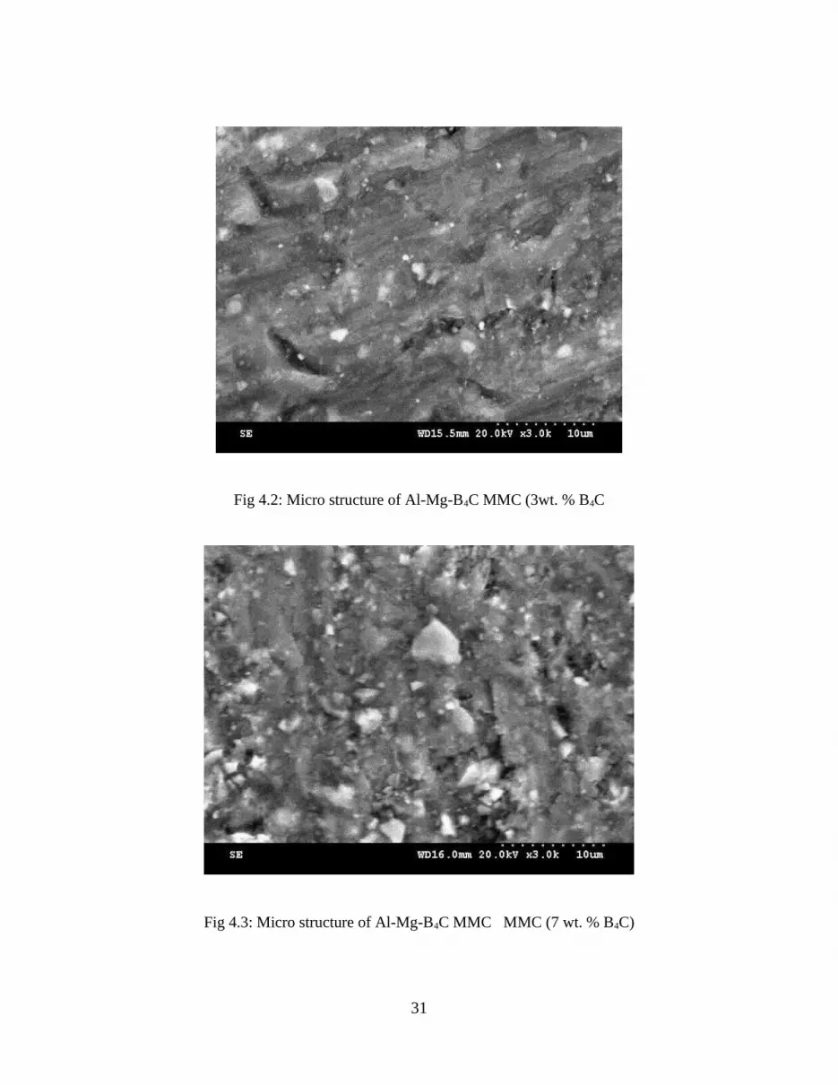
Fig 4.2: Micro structure of Al-Mg-B4C MMC (3wt. % B4C
Fig 4.3: Micro structure of Al-Mg-B4C MMC MMC (7 wt. % B4C)
31

4.2 EDAX
The element composition of Al-Mg alloy was assessed by EDAX spectral analysis. The EDAX
spectrum exhibits presents of Al and Mg in appropriate weight ratio. The EDAX values are
shown below figure 4.4, 4.5 and 4.6.
Fig 4.4: EDAX analysis of 92.5% Al –7.5% Mg
Table 4.1: Quantitative Results 92.5%Al-7.5%Mg
Fig 4.5: EDAX analysis of 92.5% Al – 7.5% Mg - 3% B4C
Table 4.2: Quantitative Results 92.5%Al-7.5%Mg-3%B4C
32
Element Net Counts
Weight % Atom %
Mg 25180 7.67 8.44 Al 243589 92.33 91.56Total 100.00 100.00

Element Net Counts
Weight % Atom %
Mg 15793 7.51 7.75 Al 213346 92.49 92.25Total 100.00 100.00
Fig 4.6: EDAX analysis of 92.5% Al – 7.5% Mg - 7% B4C
Table 4.3: Quantitative Results 92.5%Al-7.5%Mg-7%B4C
4.3 XRD
The synthesized Al-Mg alloys were analyzed by XRD spectral analysis. 100% peak shows that
the compound is in pure form.The XRD measurement shown in figure: 4.7,4.8 and 4.9.
33
Element Net Counts
Weight % Atom %
Mg 5833 7.42 7.32 Al 164862 92.58 92.68Total 100.00 100.00

Fig 4.7: XRD measurement –Al- Mg
Fig 4.8: XRD measurement –Al- Mg - 3% B4C
34

Fig 4.9: XRD measurement –Al- Mg- 7% B4C
4.4 MECHANICAL PROPERTIES Table 4.4: Tensile properties and Micro hardness test of composites
SPECIMAN UTS
(MPa)
%Elongation %Area
reduction
Hardness
(Rockwell)
92.5%Al-7.5%Mg 108.85 6.66 7.7 79
92.5%Al-7.5%Mg-
3%B4C113.39 6.25 6.8 82
92.5%Al-7.5%Mg-B4C 127.63 6.18 6.4 85
From the above table it is clear that addition of B4C leads to improvement in the ultimate
tensile strength of the aluminium alloy and increase in hardness value is more in case of
92.5%Al-7.5%Mg -7%B4C as compared with others. The addition of Magnesium improves the
strength of the composites significantly.
35

Fig 4.10 Ultimate Tensile Strength
Fig 4.11 % Elongation
36

Fig 4.12 % Area Reduction
Fig.4.13 Graph showing variation in hardness with composition of MMCs
37

CHAPTER- 5
CONCLUSION
In the Al-Mg-B4C composites both tensile and hardness properties of the composites
are found to increase as the content of B4C particulates is increased up to 6% by
weight.
From the micro structural studies, it has been concluded that the B4C dispersoids are
uniformly distributed in the alloy matrix, by influences the mechanical properties to
achieve better hardness.
There is a greater scope for the development of Al-Mg- B4C composites for the
application in the field of nuclear industries.
38

REFERENCES
Aikin.R.M, Jr. “The mechanical properties of in-situ composites”, JOM, 49 (8) (1997), 35-39.
Asthana.R and Tewari.S,N, “Interfacial and capillary phenomena in solidification processing of
metal-matrix composites”, Comp. manuf. 4 (1993), 3
Asthana.R, Tewari.S.N, “The engulfment of foreign particles by a freezing interface”, J. mater.
sci. 28 (1993) 5414.
Aniban.R, Pillai.R.M, B.C. Pai, “An analysis of impeller parameters for aluminium metal matrix
composites synthesis”, Materials and Design 23 (2002) 553–556.
Ahmad.S.N.A.S, Hashim.J; Ghazali.M.I, “Effect of porosity on tensile properties of cast
particle reinforced MMC, Journal of composite materials”, Vol. 41, No. 5(2007) 575-589
Aqida.S,N, Ghazali.M.I & Hashim.J, “Effects of porosity on mechanical properties of metal
matrix composite: an overview”, Jurnal Teknologi, 40(A) Jun. (2004): 17–32
Basavarajappa.S, Chandramohan.G, Arjun Mahadevan, Mukundan Thangavelu,
Subramanian.R, Gopalakrishnan.P, “Influence of sliding speed on the dry sliding wear behaviour
and the subsurface deformation on hybrid metal matrix composite”, Wear 262 (2007) 1007–
1012.
Balasivanandha Prabu.S , Karunamoorthy.L, Kathiresan.S , Mohan.B, “Influence of stirring
speed and stirring time on distribution of particles in cast metal matrix composite”. Journal of
Materials Processing Technology 171 (2006) 268–273
Chawla.K.K, “Composite materials - science and engineering, 2nd ed., Springer-verlag, New
York”, 1997, 102.
39

Chawla.N, Habel.U, Shen.Y.L, Andres.C, Jones.W.J, and Allison.J.E, “Effect of matrix
microstructure on the fatigue behavior of sic particle reinforced 2080 Al matrix composites” ,
Metall. mater. trans., (2000) 31a 531-540
Chawla.K.K, Metzger.M, “Initial dislocation distributions in tungsten fiber-copper composites”,
Journal mater. sci., (1972), 7, 34.
Corbin.S.F, Wilkinson.D.S, “The influence of particle distribution on the mechanical response of
a particulate metal matrix composite”, Acta metall. mater., 42 (1994) 1311-1318
Chawla.N, Andres.C, Jones.W.J, and Allison.W.E, “Cyclic stress-strain behavior of
discontinuously reinforced metal matrix composites”, Scripta mater. 38 (1998) 1596.
Chawla.N, Andres.C, Jones.J.W, and Allison.J.E, “Effect of reinforcement volume fraction and
particle size on the fatigue behavior of SiC particle reinforced al 2080 matrix composites”,
Metall. mater. trans., 29a (1998) 2843.
Chawla.N, and Yu-Lin Shen, “Mechanical behavior of particle reinforced metal matrix
composites”, Advanced engineering materials, 3, No. 6, (2001) 357-370.
El-Kaddah.N.E, Chang.K.E, “On the dispersion of SiC-A1 slurries in rotating flows”, Mater. sci.
eng. a144 (1991) 221.
Gul.F, Acilar.M, “Effect of the reinforcement volume fraction on the dry sliding wear behaviour
of al-10si/sicp composites produced by vacuum infiltration technique, Compos. sci. technol”. l64
(2004) 1959–1970.
Girot.F.A et al., “Discontinuously-reinforced aluminum matrix composites”, Composites science
and technology 30 (1987) 155-184 61
40

Ghosh P. K, and Ray.S. “Fabrication and properties of compocast aluminium-alumina
particulate composites”. Indian journal of technology. 26: (1988). 83-94.
Hashim.J, Looney.L, HashmiM.S.J, “Particle distribution in cast metal matrix composites, part
1, J. materials processing & technology”, 123 (2002) 251–257.
Hashim.J, Looney.L, HashmiM.S.J, “Particle distribution in cast metal matrix composites”, part
11, J. materials processing & technology. 123 (2002) 258–263.
Han.Q, Hunt.J.D, “Redistribution of particles during solidification”, ISIJ int. 35 (1995) 693–
699.
Hashim.J, “Microstructure and porosity studies of cast Al-SiCp metal matrix composite”. Jurnal
teknologi. 31(a): (1999), 1-12.
Hashim.J, Looney.L, and Hashmi..M.S.J. “Metal matrix composites: production by the stir
casting method”, Journal of materials processing technology. 92-93: (1999) 1-7.
Ibrahim.I.A, Mohamed.F.A, Lavernia.E.J, “Metal matrix composites—a review, Journal of
material science”, 26 (1991) 1137–1157.
Ibrahim.I.A, Mohamed.F.A, Lavernia.E.J, “Particulate reinforced metal matrix composites - a
review”, Journal of materials science 26 (1991) 1137- 1156.
Levi.C.G, Abaschian.C.J and Mehrabian.R, “Interface interactions during fabrication of
aluminum alloy-alumina fiber composite”s, Metall. trans. 9a (1978) 697.
Lloyd.D.J, “Particle reinforced aluminium and magnesium matrix composites, International
materials reviews”, volume 39, No. 1, (1994), 1-23
41

Moon.H.K et al.,” Rheological behavior of sic particulate-(al-6.5wt.%si) composite slurries at
temperatures above the liquidus and within the liquid + solid region of the matrix”, Mater. sci.
eng. 144a (1991) 253–265.
Moustafa, S. F. “Casting of particulate Al-base composites. zeitschrift fuer metallkunde”. 88:
(1997) 209-216.
Nai.S.M.L, Gupta.M, “Influence of stirring speed on the synthesis of al/sic based functionally
gradient materials”, Compos. struct. 57 (2002) 227–233.
Nikhilesh Chawla, and Yu-Lin Shen, “Mechanical behavior of particle reinforced metal matrix
composites”. Advanced engineering materials (2001), 3, No. 6, 357-370.
Nardone.V.C, Strife.J.R, Prewo.K.M, “Processing of particulate reinforced metals and
intermetallics for improved damage tolerance”, Materials science and engineering, (a) 144
(1991) 267-275
Ourdjini,A, Chew.K.C, Khoo.B.T, “Settling of silicon carbide particles in cast metal matrix
composite”, J. materials processing & technology. 116 (2001) 72–76.
Rohatgi.P.K, Asthana.R, Das.S, “Solidification, structures, and properties of cast metal-ceramic
particle composites”, Int. met. rev. 31 (1986) 115–139
Pai.P.C, Rajan.T.P.T, Pillai.R,M, Aluminium matrix composite castings for automotive
applications, Indian foundry journal, 50 (2004) 30–39.
Sinclair.I, Gregson.P.J, “Structural performance of discontinuous metal matrix composites,
Material science technology”, 3 (1997) 709–725.
Sannino.A.P, Rack.H.J, “Dry sliding wear of discontinuously reinforced aluminium composites:
review and discussion”, Wear 189 (1995) 1– 19.
42

Satyanarayana.K.G, Pillai.R.M, Pai.B.C, “Recent developments and prospects in cast aluminium
matrix composites”, Trans. Indian inst. metals 55 (3) (2002) 115–130.
Surappa.M.K, Aluminium matrix composites:” challenges and opportunities”, Sadhana Vol. 28,
Parts 1 & 2, (2003), 319–334
43

LIST OF PAPERS PRESENTED IN THE NATIONAL CONFERENCE
Third National Level Conference on “Focus on Lucid Advancement of Mechanical
Engineering-FLAME’12” held on March 05, 2012.
National Seminar on Advanced Materials:Processing and Application (NSAMPA-
2012) organized by the department of Physics,held on March 30,2012.
44