the atomic strain tensor
TRANSCRIPT
SEC'URITY CLASSF<ATN 0-40*-SPtG A D-A 237 287REPORT ~~~OCUMENTAT I ~111111 lii 1111111111111111 11ilifl
I& REPORT SEC*,RTY C.ASS1;,CATO4N 10 RESTR,;. iivc .rt
UNCLASSIFIED NONE2SjCLRY C6ASFICAr!ON AJTORITY 3 DISTR1UTION / AVAILABILITY OF REPORT
______________________________________ Approved for public release,,2b 0ECLASSiFIA'ON, D0VVNGRAD1NG SCI HEDULE Distribution unlimited.
4 PERFORMN.G ORGANiZATION REPORT NUMBER(S) S MONITORING ORGANIZATION REPORT OU 4
Technical Report No. 23
6a NAME OF PERFORMING ORGANIZATION 6b OFF CE SYMBOL ?a NAME OF MONITORING ORGANIZATION,Massachusetts Institute (if applicable) ONRof Technology 1_______ _______________________
6C. ADDRESS (City' State, and ZtP Code) 7b. ADDRESS(COty State, an ZIP Code) s.
77 Massachusetts Avenue, Room 1-306 800 North Quincy Street'Cambridge, MA 02139 Arlington, VA 22217
8a NAME OF FUNDiNG., SPONSORING 8b OFFiCE SYMBOL 9. PROCUREMENT INSTRUMENT IDENTIFICATION NOMtRORGANIZAT:ON (if aplicable)
DARPA N00014-86-K-07688(. ADDRESS (City, State, and ZIP Code) 10 SOURCE 0O FUNDING NUMBERS
1400 Wilson Boulevard PROGRAM PROJECT TASK WVORK, UNITAlntn VA229ELEMENT NO. NO NO IACESIIUtNO-
1 TITLE (include Secury Classification)R&TCoeIA405
The Atomic Strain Tensor
12 PERSONAL AU;THOR(S)Peter Mott; Ali S. Argon; and Ulrich W. Suter
13a TYPE OF REPORT 13b T-ME COVERED 114 DAT OF EPOR (Year, M.onth, Day) 1i5 PAGE COUNTinterim Technical -ROM 1990 ro. 1991 191 May 3 1' 23
16 SUPPLEMENTARY NOTATION
Paper to be published in J. Computational Physics
17 COSATI CODES 18 SUBECT TERMS (Continue on reverse if necessary and identify by block number)
F IL G UIt,-Ru Computer simulation, plastic shearing simulation
19 ABSTRACT (Continue on reverse if necessary "n identify by block number)
A definition of the local atomic strain increments in three dimensions and an algorithm for com-puting them is presented. An arbitrary arrangement of atoms is tessellated into Delauney tetrahe-dra, identifying interstices, and Voronol polyhedra, identifying atomic domains. The deformationgradient increment tensor for interstitial space is obtained from the displacement increments of thecorner atoms of Delaunay tetrahedra. The atomic site strain increment tensor is then obtainedby finding the intersectioin of the Delaunay tetrahedra with the Voronol polyhedra, accumulatingthe individual deformation gradient contributions of the intersected Delaunay tetrahedra into theVoronol polyhedra. An example application is discussed, showing how the atomic strain clarifies
the relative local atomic movement for a polymeric glass treated at the atomic level.
20 DISTRIBUTION,AVAILABILiTY OF~ ABSTRACT 21 ABSTRACT SECURITY CLASSIFICATIONCUNCLASSICIED/UNLIVITED 0 SAME AS RPT C r- USERS Uncl ass ified
22a NAME OF RFSPONSIPLE,).NDiIVDUAL 22b TELEPHONE (Include Area Code) 22c OFFICE SYMBOLD~r. Nenflfltk.L .7 /03/696-4166
DO FORM 1473, 84 MAR 83 APR edtion mYay Dq wied unitil qXlhaUltgd SECURITY CLASSIFICATION OF THIS PAGEAll other td'tions are obsolete
*Q GLwa *""s 0bwq OWU411Y
THE ATOMIC STRAIN TENSOR
Peter H. Mott*, All S. Argon*, and Ulrich W. Sutert*
* Massachusetts Institute of Technology, Cambridge, MA 02139, USA
t Institut fr Polymere, ETH-Zentrum, CH-8092, Z&rich, Switzerland
ABSTRACT
A definition of the local atomic strain increments in three dimensions and an algorithm
for computing them is presented. An arbitrary arrangement of atoms is tessellated into
Delaunay tetrahedra, identifying interstices, and Voronoi polyhedra, identifying atomic domains.
The deformation gradient increment tensor for interstitial space is obtained from the
displacement incremenis of the corner atoms of Delaunay tetrahedra. The atomic site strain
increment tensor is then obtained by finding the intersection of the Delaunay tetrahedra with
the Voronoi polyhedra, accumulating the individual deformation gradient contributions of the
intersected Delaunay tetrahedra into the Voronoi polyhedra. An example application is
discussed, showing how the atomic strain clarifies the relative local atomic movement for a
polymeric glass treated at the atomic level.
1. INTRODUCTION
Computer modelling provides coordinates of all atoms of model systems at any time.
One fundamental property of interest is how the local atomic structure changes in response
to a globally applied "driving force," for example, a stress or strain increment. Scrutinizing
atomic displacements has been the usual method to study how local structure changes, but
this method does not lend itself to structurally meaningful conclusions, especially in three-
dimensional systems. Atomic displacements show the distance and direction of movement for
each atom, but gives no information on the change in position of an atom with respect to its
neighbors. To study the motion of atoms in response to an applied driving force in a
meaningful way, we must define an "atomic strain tensor."
The algorithm presented below is best suited for the deformation of a dense, disordered
system with periodic boundaries, such as a glass. Deng et al. [1989] published a study on
a two-dimensional system and used the notion of atomic strain, but the method employed
cannot be extended to analyzing the topology of three-dimensional assemblies. Many other
1,, 91-03068
workers, such as Clarke and Brown [1989], Maeda and Takeuchi [1981], and Srolovitz et al.
[1983], have studied atomic displacements in three-dimensional glasses, without using atomic
strain as a means to isolate regions of high atom mobility. As far as we know, atomic strain
has not been defined for three-dimensional systems nor has an algorithm that calculates atomic
strain been developed for such systems.
In section 2, we briefly review two alternative and complementary ways of tessellating
space, as a means to define and clarify the terms used in later sections. We define the
"atomic strain" in section 3. Section 4 explores the topological details further in order to
implement atomic strain. In section 5, we outline the algorithm explicitly. Finally, section 6
sketches out an example application of the program to the deformation of a polymeric glass,
the details of which will be published elsewhere.
2. TESSELLATION OF SPACE
The atomic strain requires a precise way to divide the volume allotted to an atom and
an unambiguous way to identify the interstices in a system. The Voronoi and Delaunay
tessellation are methods that meet this requirement. Our development builds on the work of
Tanemura et al. [1983].
Let a set of distinct points ("atoms") be distributed in a parallelepiped ("box") of some
finite size. Assume that the entirety of three-dimensional space is covered by replicas of this
box. The region in space closest to a given atom defines the Voronoi polyhedron enclosing
the atom. These polyhedra are convex figures that are bounded by planar faces. A "face
plane" between two atoms is obtained by drawing a line segment connecting the two atoms,
and then constructing a plane that is the perpendicular bisector to the line segment. Any point
that lies on this face plane is equidistant to the two atoms. Where two face planes meet
defines an edge, and where three face planes meet forms a corner. Thus, the 'lace" is a
region of the face plane that is bounded by the edges formed by the intersections with other
face planes. The existence of a common face is the criterion used to determine "neighboring
atoms." The set of polyhedra constructed around all atoms fills space in the box without any
gaps or overlaps.
Joining all neighboring atoms by straight lines produces a space network. The set of
four atoms that are neighbors to each other forms a tetrahedron. The set of tetrahedra for
a given set of atoms also tessellates space, and is called the Delaunay tessellation. We term
the elementary tetrahedron in this tessellation the Delaunay tetrahedron and abbreviate it DT.
2

The strain increment defined in equation (1) is conservative and correct, but is
associated with interstitial space, not with atoms. An atom belongs typically to 20-30 DTs,
each with a differeit shape, volume, and displacement gradient; we are interested in the strain
increments associated with atoms, not with interstices. Thus, the information in equation (1)
needs to be re-allocated proportionally according to the volume belonging to the atoms.
Therefore, to find the deformation gradient of an atom, it is necessary to identify all the DTs
sampled by the Voronoi polyhedron constructed around the atom. Symbolically, we find the
deformation gradient D , for atom i, by the weighted sum over all DTs that the Voronoi
polyhedron intersects; i.e.:
DT's
_, = Z , (2)
where is the volume fraction of the Voronoi polyhedron that falls inside the jth DT. The
atomic strain increment tensor _ is then found from the deformation gradient D by subtracting
out the rigid-body rotations in the usual way. Of this strain tensor, two scalar invariants are
of special interest, the local dilatation e, and the local deviatoric normal distortion 6, which are
defined as:
= Tr _. (3)
62 = (2/3) Tr (L- j2 (4)
4. THE APPROACH TO THE PROBLEM
We address the problem using the original structure as the "ground state", and the
strained structure is compared to the original. The intersecting volume fraction .,., is found from
the ground state, so that the detailed Voronoi and Delaunay constructions for the original
structure are needed as input. The information required is the atom neighbor list for each
atom, the volume of the Voronoi polyhedra, and the set of Delaunay tetrahedra. The number
of atoms in the original structure must equal the number of atoms in the strained structure.
Throughout the proceedure, there are many places where conservation laws are used
to insure that an operation is done correctly. The most sensitive is that the volume weighted
sum of the local atomic level strains must exactly equal the imposed strain on the whole
system. It has been found that if a single DT is changed or omitted from the inputted DT set
(in the test data sets, there were about 3100 DTs), the summation of the atomic deformation
gradients deviates from the system gradient by about 1%. This is a large, obvious error,
4
compared to the computer working precision of about 10715; the strain program outlined here
is quite sensitive to any errors in tessellating the system.
There are two parts to find the atomic displacement gradient, calculating Q for each DT
and finding the intersections ,,.. Finding the deformation gradient for each DT is straightfor-
ward, and this is calculated at the beginning of the program. The major effort in the algorithm
is to find the intersections of all DTs with a single Voronoi polyhedron. We call the atom that
the Voronoi polyhedron is formed around the "central atom." This procedure is repeated for
all atoms in the system.
If a DT intersects a Voronoi polyhedron, it is apparent that the DT must enter the
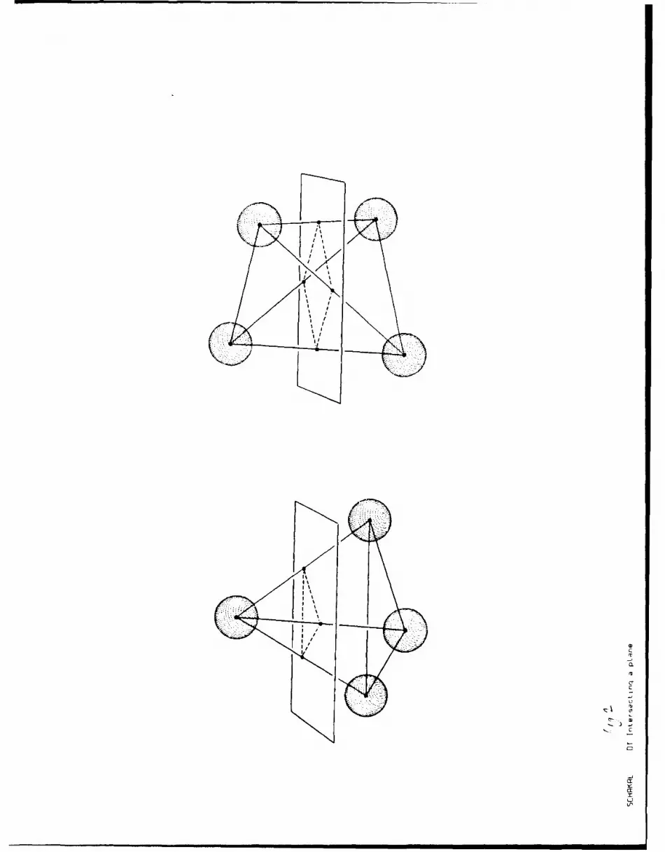
Voronoi polyhedron at one or more Voronoi face(s). Consider the intersection of a DT with
a plane, shown in Figure 2. A DT can intersect the plane only when the corners of the
tetrahedron lie on both sides of the plane. The two possibilities are: two atoms on each side,
or one atom on one side and three atoms on the other. The illustration shows that the
intersection must be either a three- or four-sided polygon. Because the set of DTs tessellates
space, the intersection of DTs with any plane must tessellate the plane. We do not consider
the degenerate case when an atom sits exactly on the plane; rather, if an atom does happen
to lie on the plane, we shall assume that it lies on the positive side, as defined by the direction
of the plane normal. The error introduced by this simplification is within the machine working
precision.
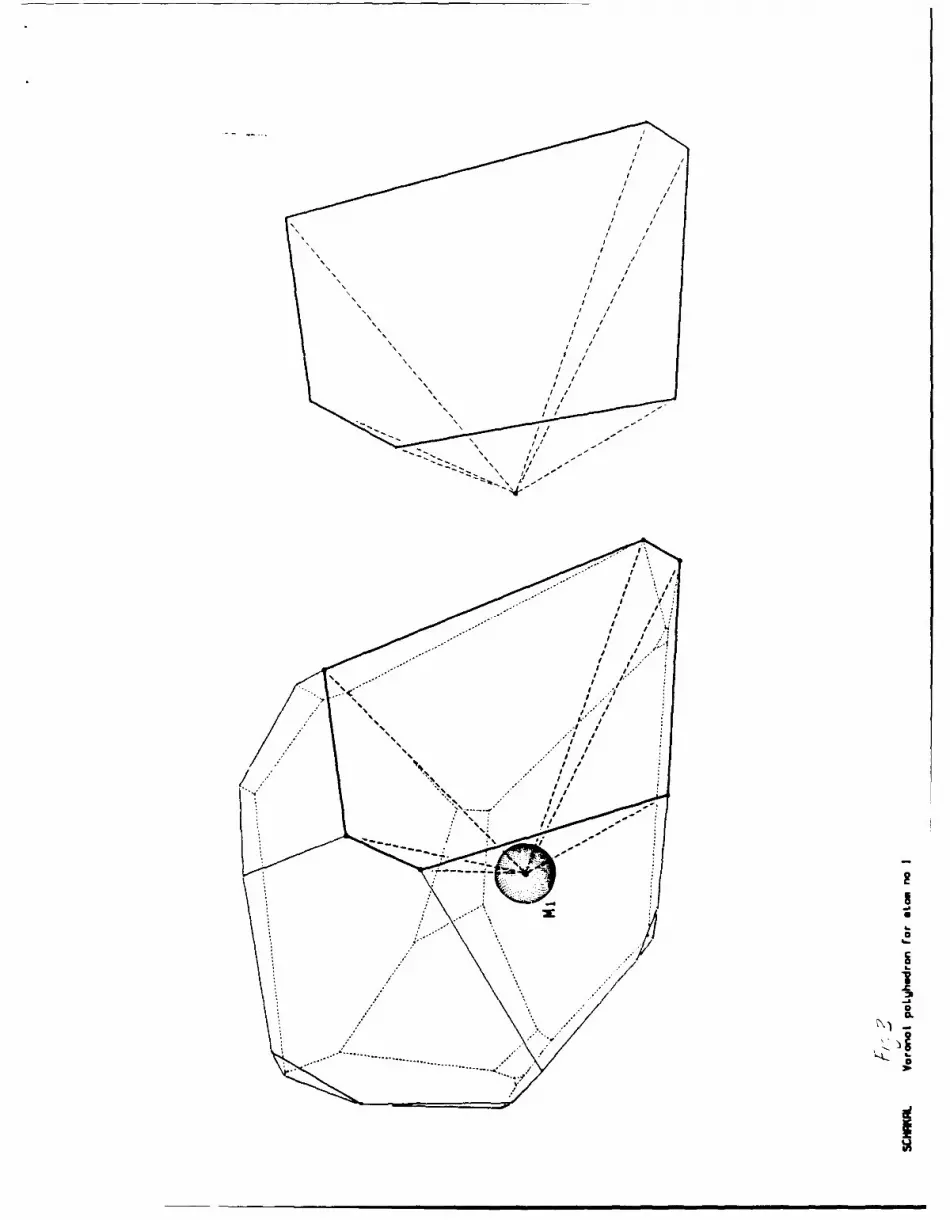
Since an intersecting DT must penetrate a Voronoi polyhedron at a face, it is natural
to further divide the polyhedron into composite pyramidal figures-one pyramid for each face
of the polyhedron. The base plane of the pyramid is then the Voronoi face, and the "peak"
of the pyramid is the position of the central atom. Figure 3 shows the Voronoi polyhedron
surrounding atom M1 with such a composite pyramid cut out for closer inspection. Triangular
side faces of the pyramid are formed by joining the edges of the face to the apex. Two such
pyramids inside a Voronoi polyhedron that have a common edge share a side face. It is
evident that the pyramids so constructed completely cover the volume without overlap inside
any given Voronoi polyhedron.
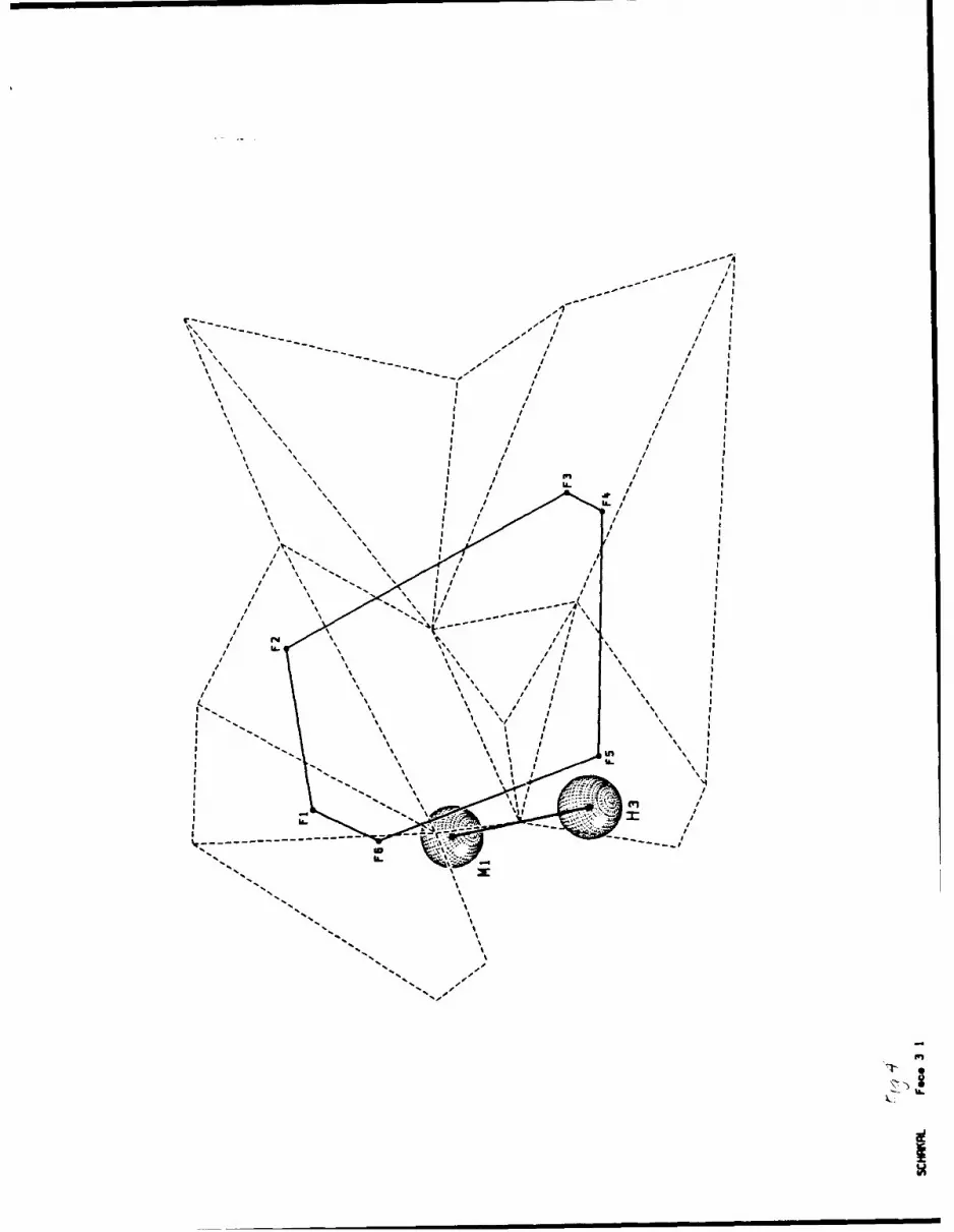
In Figure 4 the face that was cut out in Figure 3 is shown in greater detail. The two
atoms that share the face are shown, atom M1 is below, behind the face plane, and atom H3
is above the plane. Note that the face does not intersect the line segment connecting the two
atoms; this wz :ound to be a frequent occurrence. The corners of the face are labeled
Fi,...,.6 The tessellatinq three- and four-sidto figuies formed Dy the dashed lines all lie in th
face plane and are the Intersections of DTs that have some part falling inside the face, which
5

will make a contribution to the strain of atom Mi.
The composite pyramid that was formed from a Voronoi face may be further divided into
more elementary "sub-pyramids," using the are&4 of the dashed DT intersections that lie within
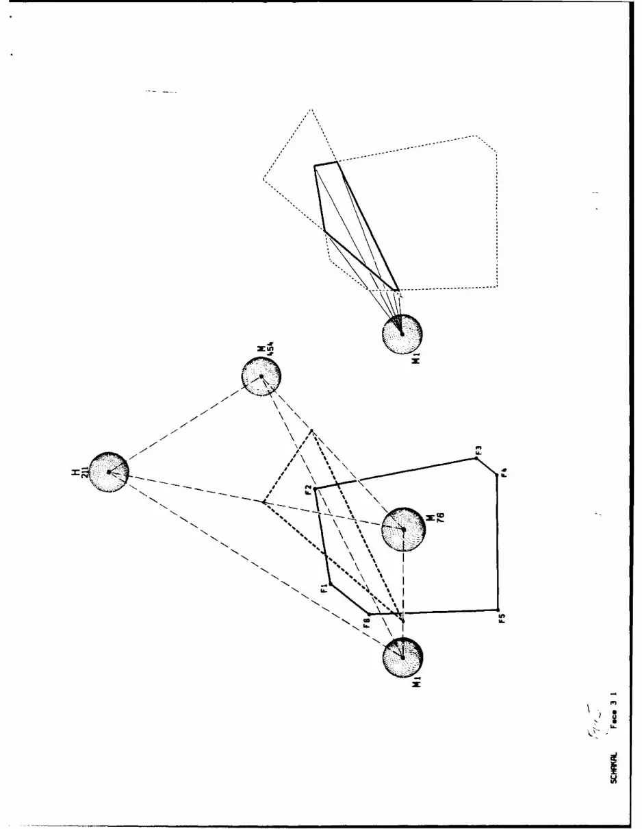
the face as the bases. For example, Figure 5a focuses on the DT intersecting the face that
contains the corner F2 of the same face seen in Figures 3 and 4. We take atom MI to be the
central atom; for clarity the neighboring atom H3 has been omitted. The DT that intersects
with the face is made up of atoms {M1 ,M76,H21 1,M454}, shown as light dashed lines. Atoms
M1, H21 1, and M454 lie below, behind the face plane, while atom M76 is above the plane.
The DT intersection with the face plane is shown as a heavy dashed line. The base of the
subpyramid formed by the intersection area is shown by the bold line in Figure 5b. The
subpyramid is precisely the intersection of the DT with the Voronoi face pyramid.
Supposing now that the central atom is not atom M1, as assumed in Figure 5, but the
other, neighboring atom H3 (see Figure 4). This situation is illustrated in Figure 6, focussing
now on the same face shown in Figures 3, 4, and 5, but with some enlargement and a slight
rotation. The pyramids formed on either side of the face are mirror images, so their volumes
must be equal. Atom MI is still below, behind the face plane, and atom H3 is above. The
same intersecting DT {M1 ,M76,H211 ,M454} is shown as in Figure 5a, where H21 1 and M454
are behind the plane, and M76 is above, in front of the plane. The central atom H3 is not a
member of this intersecting DT. The heavy dashed lines in Figure 6 form the subpyramid
base, like shown in Figure 5b; the two subpyramids in Figures 5b and 6 are mirror images, so
again, their volumes must be equal. Starting at the base of the subpyramid, and following it
to the peak at the central atom H3, the subpyramid emerges from the DT that contains the
base, into a neighboring DT: the DT face formed by the atoms {M1 ,M76,M454} is where the
subpyramid emerges. The edges of the subpyramid are drawn with medium dashed lines
behind this "exiting" face, inside the DT that contains the base; outside the DT, in front of the
exiting DT face, the subpyramid edges are drawn with solid lines. The intersection of the DT
face {M1 ,M76,M454} and the subpyramid is also shown with solid lines. The part of the
subpyramid inside the DT that contains the base (drawn with dashed lines) is the intersection
of the DT {M1 ,M76,H211 ,M454} with the Voronoi face pyramid. The remaining part of the
subpyramid forms a new, smaller sub-subpyramid, with its base on the exiting DT face plane.
The subpyramid illustrated in Figure 6 enters a new DT that does not contains the base.
This must be so for every DT that does not contain the central atom but does intersects the
Voron4A face, because the set of DTs that all contain a givei atom form a closed figure about
that atom. The intersection of a DT with a Voronoi face that does not contains the central
6

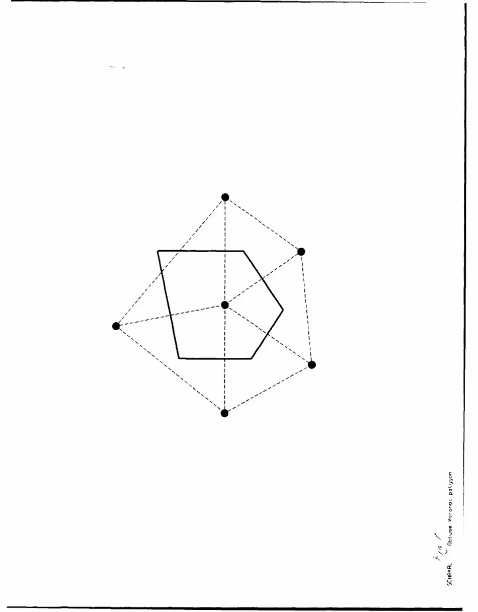
atom indicates an "obtuse" Voronoi polyhedron, a polyhedron that extends beyond the
enclosing figure formed from the DTs. A two-dimensional analogy is shown in Figure 7.
Obtuse Voronoi polyhedra were found to be much more common in three-dimensional systems
than in two-dimensional systems. Returning to the sub-subpyramid defined in Figure 6, starting
at the base, and following it to the central atom peak, it is necessary to identify the
reighboring DT that contains the new base. Supposing that this neighboring DT also does
not cu, ain the central atnm H3, the sub-subpyramid must emerge from this DT as well, and
another subpyramid piece like the one seen inside the DT in Figure 6 will be constructed. This
will spawn yet another sub-sub-subpyranid. This procedure is repeated until the subpyramid
finally enters a DT that contains the central atom. This DT will contain the apex, and thus there
will be no more "exits".
5. ALGORITHM
I. Initialization. Input {A}, the positions of the set of atoms; {N}, the neighbor list for each
atom; {P}, the volume fractions of the Voronoi polyhedra; and {T}, the set of DTs for the"original" structure. Input {B}, the positions of the atoms for the "strained" structure.
A. For each T, in {T}, find:
1. The position of the center of the sphere C, that passes through the atoms A,, AgTj,
which corresponds to a corner of a Voronoi polyhedron.
2. The volume fraction of the tetrahedron o,, and the displacement gradient D,. Finding
the displacement gradients is the only point in the program where the "strained"
atom positions {B} are used.
B. Check that E 01 = 1 and E ,j Q I
C. For each T, in {T}, find the DT that contains the circumcenter C, that belongs to Ti.
Denote this set {e(C)}.
II. Main part of algorithm. For each atom A4 in {A}:
A. Obtain the set of Voronoi face planes {F}, constructed from the neighbor list (NJ.
B. Define the set {p} to be the "master" list of DTs sampled by the Voronoi polyhedron
about atom A,. For each DT p, in {p), define the variable ,i., the volume fraction of
p, intersected by the Voronoi polyhedron about atom A,. Initially, the set {p} is empty
and {c,} is set to zero.
7
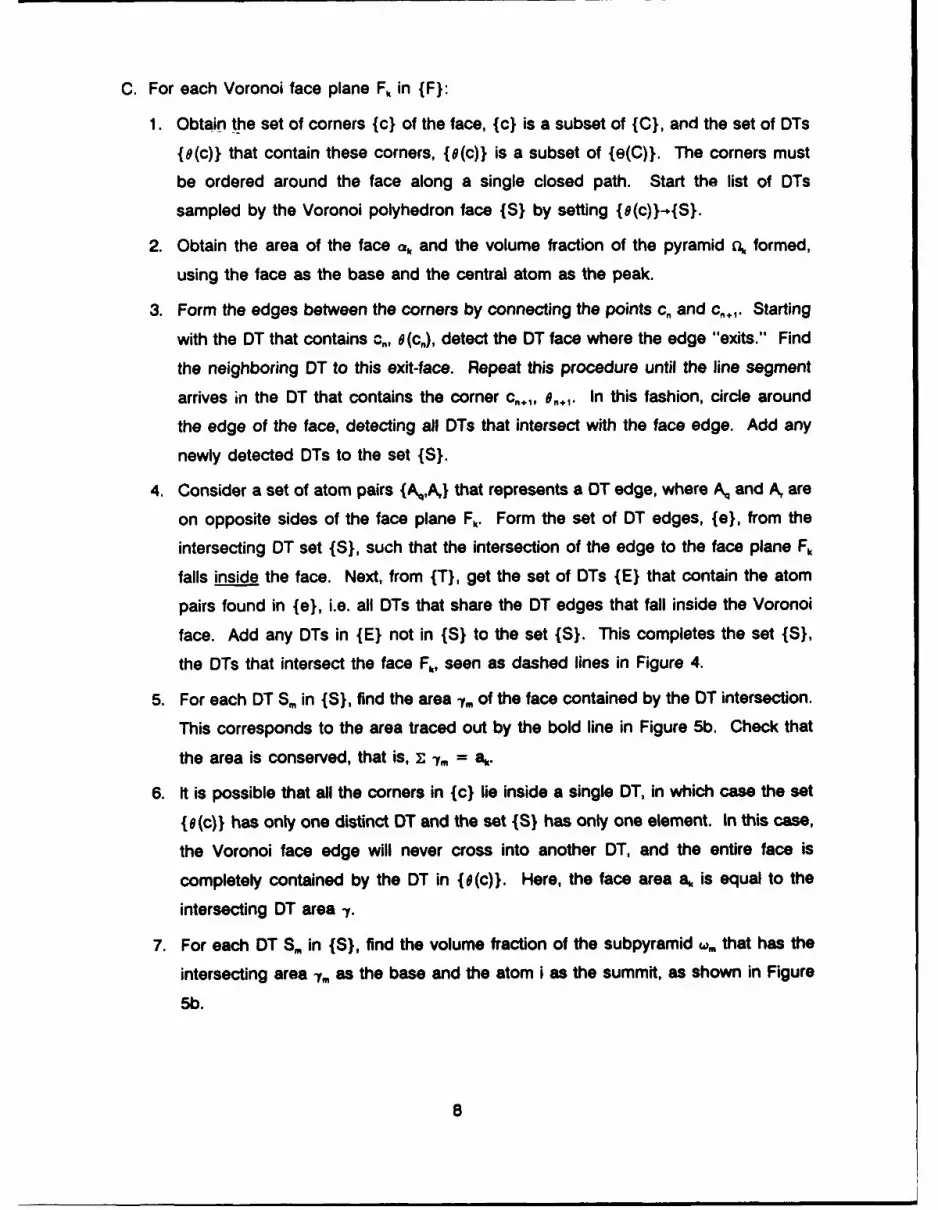
C. For each Voronoi face plane F, in {F}:
1. Obtain the set of corners {c} of the face, {c} is a subset of {C}, and the set of DTs
{e(c)} that contain these corners, {(c)} is a subset of {e(C)}. The corners must
be ordered around the face along a single closed path. Start the list of DTs
sampled by the Voronoi polyhedron face {S} by setting {e(c))-o{S}.
2. Obtain the area of the face ak and the volume fraction of the pyramid E formed,
using the face as the base and the central atom as the peak.
3. Form the edges between the corners by connecting the points c,, and c,+,. Starting
with the DT that contains c,, 0 (c,), detect the DT face where the edge "exits." Find
the neighboring DT to this exit-face. Repeat this procedure until the line segment
arrives in the DT that contains the corner c,. 1, e,. In this fashion, circle around
the edge of the face, detecting all DTs that intersect with the face edge. Add any
newly detected DTs to the set {S}.
4. Consider a set of atom pairs {Aq,A,} that represents a DT edge, where Aq and A, are
on opposite sides of the face plane Fk. Form the set of DT edges, {e}, from the
intersecting OT set {S}, such that the intersection of the edge to the face plane Fk
falls inside the face. Next, from {T}, get the set of DTs {E} that contain the atom
pairs found in {e}, i.e. all DTs that share the DT edges that fall inside the Voronoi
face. Add any DTs in {E} not in {S} to the set {S}. This completes the set {S},
the DTs that intersect the face Fk, seen as dashed lines in Figure 4.
5. For each DT Srm in {S}, find the area -y,, of the face contained by the DT intersection.
This corresponds to the area traced out by the bold line in Figure 5b. Check that
the area is conserved, that is, z -,, = ak.
6. It is possible that all the corners in {c} lie inside a single DT, in which case the set
{e(c)} has only one distinct DT and the set {S} has only one element. In this case,
the Voronoi face edge will never cross into another DT, and the entire face is
completely contained by the DT in {e(c)}. Here, the face area a, is equal to the
intersecting DT area -y.
7. For each DT S. in {S}, find the volume fraction of the subpyramid w, that has the
intersecting area -,f as the base and the atom i as the summit, as shown in Figure
5b.
8

8. Form a new set {w} by setting {S}-4{lr}. This will be the set of DTs that intersect
the pyramid formed from the face F. For each DT ir.m define the variable k,, the
volume fraction of the DT-pyramid intersection. Then, for each DT ir,. in {},
a. Check if the central atom AES.. If so, then add the volume fraction W,. to the
intersecting volume fraction k,,, and go on to (c). This is the case rendered in
Figure 5. If not, go on to (b).
b. Further subdivide the subpyramid into parts intersected by other DTs, starting
at the base, as outlined in the previous section and seen in Figure 6. Add the
pertinent volume fractions to k,. It is possible that new DTs will be detected
that are not found in {i}, i.e., DTs which intersect the pyramid, but do not
intersect the Voronoi face. These new DTs are then added to {ir}.
c. Check that z c, = ilk. Add the volume intersecting the pyramid k,. to f,,., the
volume fraction intersecting the Voronoi polyhedra.
9. Add the DTs in {r} to the "master" DT list {p} (if they are not already in {p}).
D. Check that F, x,, = P,, where P, is the volume fraction of the Voronoi polyhedron of
atom i. Calculate the atomic deformation gradient Q, = z,, 2,,.
Ill. Finally, check that the atomic displacement gradient is conserved for the system by
T, V, = ,, and that the volume for all DTs is conserved, for all T, in {T} that
7 r.j = IN.
6. AN APPLICATION
This algorithm was used to study the change in structure of a static, atomistic model
of polypropylene, developed by Theodorou and Suter [1985]. The polymer is modelled as a
single chain of atoms, with fixed bond lengths and bond angles, packed into a periodic
parallelepiped, initially an 18.15 A cube (total number of atoms = 455, degree of polymerization
= 76, density = 0.892 g/cm3). Molecular movement can occur only by rotation around the
skeletal C-C bonds. Van der Waals interaction between not directly bonded atoms is modelled
by the Lenard-Jones potential energy function; backbone skeletal rotation is associated by a
three-fold rotational potential energy barrier. The methyl groups are lumped together into a
single quasi-atom of appropriate size and potential parameters; the other hydrogen and carbon
atoms are treated explicitly. The initial guess structure is grown by a Monte Carlo generation
of a chain using the rotational isomeric state (RIS) theory, modified to account for long-range
9
atomic interactions; the total energy of the system as a function of the bond rotation angles
is then minimized using analytical derivatives. Figure 8 shows such an equilibrated structure;
the skeletal carbon-carbon bonds are striped to emphasize the chain backbone.
Starting with a structure that is at a minimum energy, a small strain step is imposed on
the periodic box continuation edges, which changes the position of the atoms in the parent
chain with respect to the positions of the atoms in the image chains. Re-minimizing the energy
of the system causes the polymer to seek a new conformation: repeatedly straining the box
and then minimizing the energy simulates large deformations, in small incremental steps. Since
time does not enter into the description of the system the strain rate is undefined.
Pure shear strain increments were imposed on the periodic box of the structure seen
in Figure 8, and the energy of the system re-minimized. The imposed incremental strain tensor
was
1.0 0.0 0.0 1= I 0.0 -1.0 0.0 I xlO-
L 0.0 0.0 0.0 J
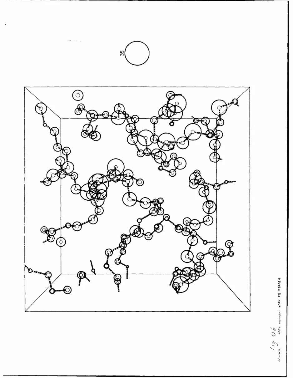
In Figure 9 the backbone movement resulting from the imposed shear strain increment is
demonstrated. The original backbone structure is shown with striped bonds (it is exactly the
same structure shown in Figure 8); the strained backbone is drawn unadorned. The "methyl"
and hydrogen atoms have been removed for clarity. It is apparent that the whole chain moves
in a complex way. Furthermore, it is impossible to distinguish a large movement of an atom
from a large change of local environment because it is difficult to compare the displacement
of a particular atom to the displacement of the neighbors of that atom.
To better understand the change in local structure, the atomic strain tensor for each
atom was calculated, using the procedure presented above. Because the pendant hydrogen
and "methyl" atoms were idealized as tied to the backbone wit, inextensible bonds at rigid
angles, there can be no relative movement between the backbone and the pendant groups.
Accordingly, we add the volume-weighted strains of the backbone carbon and pendant side
groups together. This is the "effective segment unit" strain tensor, from which the scalar
invariants in equations (3) and (4) were found. Figure 1 Oa illustrates the change in volume for
each segment, plotted as circles of radius proportional to dilatation centered on the backbone
carbon atoms (dashed circles indicate negative dilatation). In Figure 1Ob the deviatoric
distortion invariant is plotted. Three clusters of large distortion strains can be seen: in the
center of the box, in the lower left-hand corner, and the lower right-hand side. Other regions,
such the upper left-hand side, show relatively little distortion or dilatation, but can be seen to
have large displacement in Figure 9. The regions of large shear strains roughly coincide with
10

the regions of large circles of dilatation. Figure 10 clearly improves perception of how the local
environment has changed as a restllt of the imposed strain increment.
A detailed analysis of the change in the local atomic structure of this and other strain
simulations wi!l be published elsewhere as part of a comprehensive simulation of plastic
deformation of glassy pclymers at the molecular level.
ACKNOWLEDGMENT
We gratefully acknowledge support from the Defense Advance Research Projects
Agency, under ONR contract N0001 4-8S-K-0768. We thank Masaharu Tanemura for providing
the source code to their program that finds Voronoi polyhedra, and acknowledge useful
discussions with Professor David M. Parks.
REFERENCES
Deng, D., A. S. Argon, and S. Yip, Phil. Trans. R. Soc. London, A329, 613 (1989).
Clarke, J. H. R., and D. Brown, Molecular Simulation, 3, 27, (1989).
Maeda, K., and S. Takeuchi, Phil. Mag., A44, 643, (1981).
Srolovitz, D., V. Vitek, and T. Egami, Acta Metall., 31, 335, (1983).
Tanemura, M., T. Ogawa and N. Ogita, J. Comput. Phys., 51, 191, (1983).
Theodorou, D. N., and U. W. Suter, Macromolecules, 18, 1467 (1985).
11
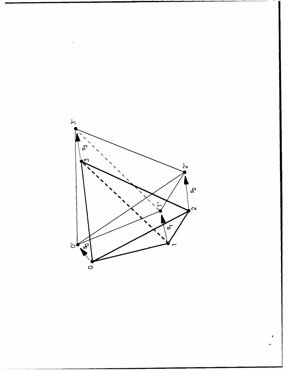
Figure 1: Displacement and distortion of a Delaunay tetrahedron.
Figure 2: The intersection of a tetrahedron with a plane.
Figure 3: Voronoi polyhedron around atom M1. A pyramidal figure formed by connecting aface (shown in bold) to the central atom has been cut out on the right.
Figure 4: Detail of the face cut out in figure 3. The points F1, ..., F6 are the corners of theface, and the bold lines bet% - n the corners are the edges. The face is shared by Voronoipolyhedra formed around atoms M1 and H3. The atom M1 is behind the plane, atom H3 is infront. The dashed lines all lie in the face plane, indicating where various contributing DTsintersect the Voronoi face.
Figure 5: (a) The intersection of a DT with the Voronoi face shown ;.7 figures 3 and 4. Theatoms M1, H21 1, M454 lie behind the plane, and atom M76 is in front of the plane. (b) The"sub-pyramid" formed by the intersecting face-DT area, shown in bold.
Figure 6: The subpyramid using the same intersection between the DT and the face seen infigure 4, but using the atom H3 as the central atom peak, instead of atom M1. The atonts M1,H21 1, and M454 lie behind the plane, and atoms H3 and M76 are in front. The face has beenrotated slightly from figure 4.
Figure 7: Two-dimensional example of an obtuse Voronoi polygon. The atoms A.-e the filledcircles, the dashed lines are the Delaunay triangle, and one enclosing Voronoi polygon is shownby the heavy solid ine.
Figure 8: Relaxed polypropylene structure. The backbone carbon-carbon bonds are s hownstriped. The large pendant atoms are "methyl" atoms, and the small pendant atoms arehydrogen atoms.
Figure 9: Displacement of backbone chain. The original backbone is striped- it is the samestructure as that drawn in figure 6. The backbone found after a strain increment was imposedon the system is shown with plain bonds.
Figure; 10: (a) Dilatation of the effective segment unit; plotted as circles centered on the
positions of the backbone carbon atoms. (b) Normal ., stortion of the effective segment.
12
C))
I
/I'K - /
; \
'I N*1__/ C)
I'I'I'I'Il
I *
* ~C
a
C
~-*~ w'-.- C
aa
N I~ --
................... 30.-
--- 4'I
'I- 'I
-- j
--- - - - -- - /
-- /-- -- I
' \ --' S -- - I /
S -- - p /--- I IS - -
"~ I ~/ I
S I / /S I
, S -
SS
4I -~I ~
-
-
Ia~ S~I'I
~~~.-../
S IL
S -. SS S
S S
S SS S
S S
* S
S -5~
m
Z m
7 In-- - - - - -

x I
7L
7. /o I
// I
/ I/ I
/ / ,/ / /1 ,// /~N N N -' N N
- I
I - -,
/ I -
7I -/I-
//
-- N/
-- I N
N N
I NNN
N N IN N N
NN N
N I NN N N
NN p
NN -
N -N -
N I - -N - -
NN I --
N I --N - -
N -
C0C,C,
Ca
C
0
C
UU,
C
N)*
LU

WT-
(L

SC
VA
- 0I~* r~a
pI
-Jcc
/U

04
0L
CrC
C
C: