temporary bond strength of partly cured epoxy adhesive for anchoring prestressed cfrp strips on...
TRANSCRIPT
Composite Structures 94 (2012) 2667–2676
Contents lists available at SciVerse ScienceDirect
Composite Structures
journal homepage: www.elsevier .com/locate /compstruct
Temporary bond strength of partly cured epoxy adhesive for anchoring prestressedCFRP strips on concrete
Julien Michels a,⇑, Christoph Czaderski a, Raafat El-Hacha b, Rolf Brönnimann c, Masoud Motavalli a,d
a Structural Engineering Research Laboratory, Swiss Federal Laboratories for Materials Science and Technology (Empa), Dübendorf, Switzerlandb Department of Civil Engineering, University of Calgary, Canadac Electronics and Metrology Laboratory, Swiss Federal Laboratories for Materials Science and Technology (Empa), Dübendorf, Switzerlandd Faculty of Engineering, University of Tehran, Iran
a r t i c l e i n f o
Article history:Available online 9 April 2012
Keywords:Carbon Fiber Reinforcement PolymerConcrete strengtheningPrestressingGradient anchorage methodAccelerated epoxy curingTemperature
0263-8223/$ - see front matter � 2012 Elsevier Ltd. Ahttp://dx.doi.org/10.1016/j.compstruct.2012.03.037
⇑ Corresponding author. Tel.: +41 58 765 4339.E-mail address: [email protected] (J. Michel
a b s t r a c t
Externally bonded Carbon Fiber Reinforced Polymer (CFRP) strips have been used for strengthening rein-forced concrete structures. This paper presents an experimental study on the debonding of externallybonded CFRP strips anchored to a concrete substrate by a commercial epoxy adhesive. The study repre-sents the basis for the characterization of an innovative ‘gradient method’, giving the possibility to anchorprestressed CFRP strips to concrete without the use any mechanical anchorage systems such as plates andbolts. Bond between the two components is achieved by an epoxy adhesive able to carry loads after anaccelerated curing process under elevated temperatures. The effect of heating configuration/duration,strip thickness and bond length on the temporary bond resistance have been investigated using pre-stressed and non-prestressed CFRP-strips. Besides the optimization of the heating elements necessaryfor the curing process, curing parameters for an optimal temporary bond strength could be determined.Twenty-five minutes of heating and curing at 90 �C was found to be an optimum heating configuration,resulting in better short-term mechanical performances than after conventional curing at room temper-ature for several days. The main reason is a temporarily softer adhesive which allows the use of the fullbond length by reducing shear force peaks.
� 2012 Elsevier Ltd. All rights reserved.
1. Introduction
Externally bonded (EB) Carbon Fiber Reinforced Polymer (CFRP)strips have been used extensively as an additional reinforcement forstrengthening reinforced concrete structures. Prestressing EB CFRPstrips generally increases the cracking load, delays yielding andimplicates a better exploitation of the mechanical performances,such as high tensile strength above 2000 MPa. The prestressed CFRPstrips can be used more efficiently and contribute to the loadcarrying capacity under both service and ultimate conditions [1].Combined with the delayed debonding failure [2] compared tonon-prestressed strips, the ultimate load capacity is generallyhigher, too.
The following research is part of the development of a novelanchorage system for prestressed CFRP strips. In contrast to the dif-ferent developed mechanical anchorage systems described in liter-ature [3–5], the idea of anchoring prestressed CFRP only with anepoxy adhesive was proposed by Professor Urs Meier at the SwissFederal Laboratories for Materials Science and Technology (Empa)(refer to [6–10]). In order to avoid a premature debonding of the
ll rights reserved.
s).
strip from the concrete substrate, the ‘gradient anchorage method’applies a repetitive local curing of the epoxy adhesive acceleratedby heat followed by a partial prestress release. The locally heatedepoxy is subsequently able to carry a portion of the prestress load.By repeating the curing-releasing steps, the initial prestress forcecan be gradually decreased to zero at the CFRP strip ends, thusensuring a proper force transfer from the concrete to the strip.
The aim of the experimental investigation was to determine thetemporary bond/anchorage resistance of CFRP–epoxy-concreteinterfaces established by heating and curing under elevated temper-atures for a limited time span (up to maximum 1 h) and compare toresults from reference specimens cured at room temperature forseveral days. The short-term anchorage resistance was investigatedshortly after the accelerated curing process, whereas the referencespecimens, which did not undergo any external heating, were testedafter 2–3 days of curing at room temperature.
The mechanical bond properties of CFRP strips connected to con-crete through an epoxy cured at room temperature was analyzedamong others by Mazzotti et al. [11], Lu et al. [12], Pellegrino et al.[13], De Lorenzis et al. [14], Leung et al. [15] and Toutanji et al.[16]. Temporary stiffness and strength of accelerated epoxy curinghas so far not found any large interest in structural strengthening.Preliminary axial tensile and pull-off tests and the related analysis
Nomenclature
bf strip widthft,u uniaxial tensile strength of CFRPfc,cube concrete compression strength on cubefct,s concrete splitting tensile strengthlb bond lengthlb,eff effective anchorage lengthuf, uc horizontal displacement in x-direction of the CFRP strip
and the concretesf relative displacement (slip) between CFRP strip and
concretesf,min, sf,max minimum and maximum slips in horizontal directiontf strip thicknesstcool cooling time prior to the test startx, y directions, axisthold overheating time during the curing process at elevated
temperature
Ef elastic modulus in fiber directionFl pulling forceF1, F2 prestress forces in the stripDF prestress force release in the stripFu ultimate debonding forceFinit force at initiation of debondingPO pull-offREL releasingRT room temperatureTa temperature in the adhesiveTavg average temperature over the testing durationsTfin final temperature in the heating elementTh temperature in the heating elementTpeak maximum temperature in the heating element
2668 J. Michels et al. / Composite Structures 94 (2012) 2667–2676
about the effect of high temperatures on the curing process of epoxyadhesive were presented in Czaderski et al. [17]. It was found that forthe used adhesive, the rule of thumb given by Mays and Hutchinson[18] and stating that the necessary curing duration is halved forevery increase of 10 �C in curing temperature, can be applied.
2. Research significance
In order to define a correct gradient configuration, it is neces-sary to determine the influence of a certain number of parameterson the bond/anchorage resistance. Beside varying the strip thick-ness and the bond length, it is necessary to optimize the heatingelements and durations to maximize the bond strength. The pre-sented number of tests with different geometrical characteristicsand heating conditions give precise information on the develop-ment of a temporary bond strength which can be exploited inthe production of the gradient anchorage force release.
3. Experimental characteristics
3.1. Materials
All CFRP strips used in the presented investigation had a width bf
of 100 mm, whereas three different strip thicknesses tf of 0.6, 0.9and 1.2 mm were used. Before each test, elastic moduli Ef of theused CFRP strips (in the fiber direction) were determined byprestressing the strip to several load stages and measuring the cor-responding tensile elongation (to derive the strain by dividing theelongation difference with the measuring length) by means of amechanical dial gauge (Table 1).
Direct tensile tests on coupon specimens according to EN ISO527-5 [19] with strips of 0.6 and 0.9 mm thickness revealed averageuniaxial tensile strengths ftu of 2236 and 2324 MPa, respectively.According to the quality analysis certificate of the producer, theuniaxial tensile strength of 1.2 mm strip thickness is 2975 MPa.
Throughout all experiments the epoxy-based S&P epoxy adhesive220 was used. According to the technical data sheet of the distributor[20] it offers a compression strength above 90 MPa and bending ten-sile strength higher than 30 MPa after curing at room temperature.Its glass transition temperature is higher than 56 �C. Further detailedinformation is available on the mentioned data sheet.
Concrete substrate, with a maximal aggregate size of 32 mm,had an average compressive strength fc,cube of 51.1 MPa (tested
according to EN 12390-3 [21]) and an average splitting tensilestrength fct,s of 3.3 MPa after 28 days.
3.2. Test setup
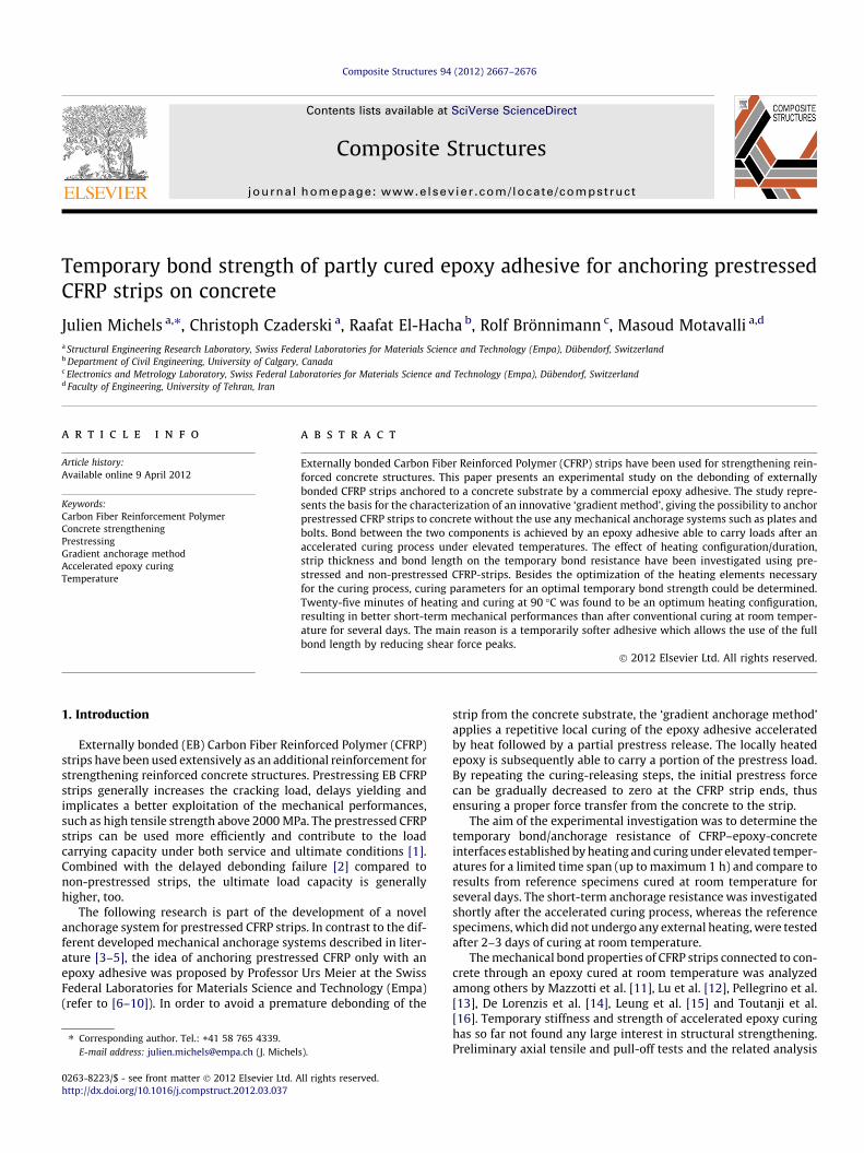
All experimental parameters are summarized in Table 1. Thedifferent tests are listed in chronological order as they were per-formed in the structural laboratory at Empa. A photo of the testsetup is presented in Fig. 1.
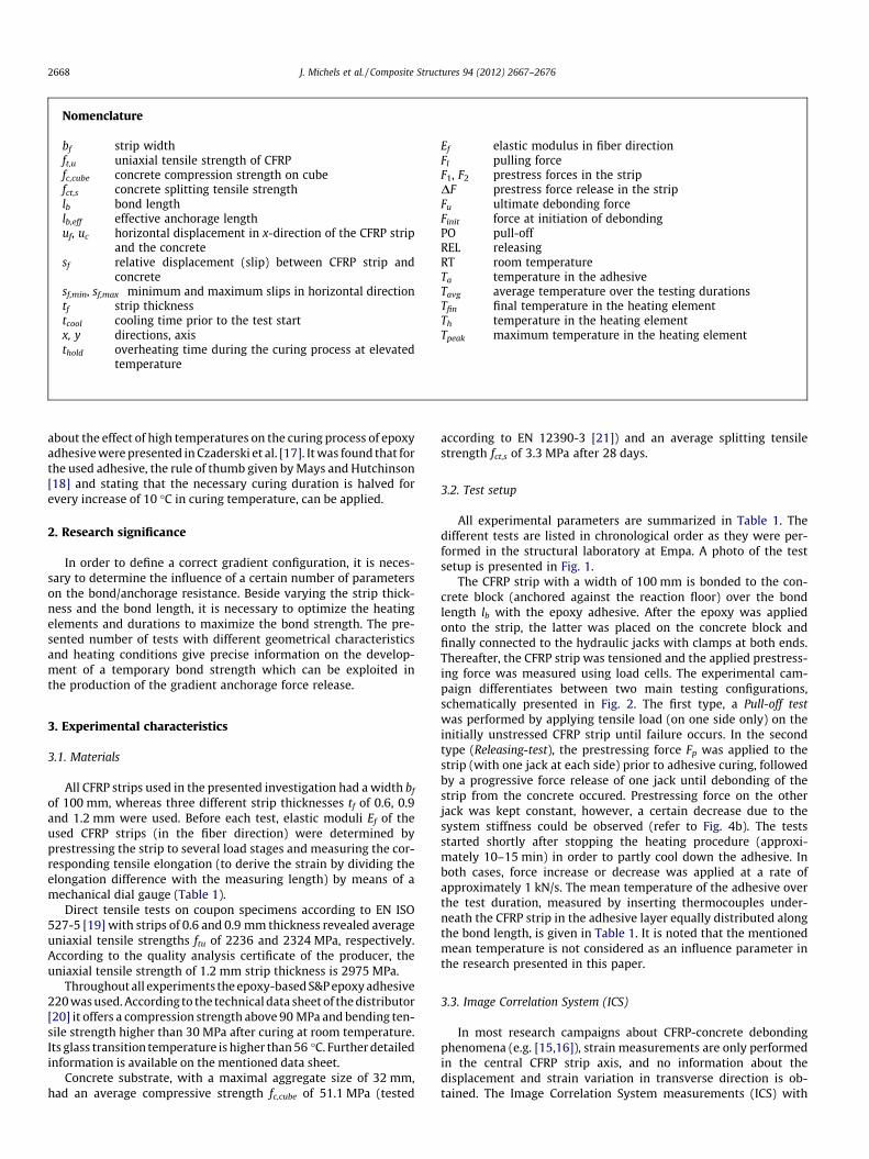
The CFRP strip with a width of 100 mm is bonded to the con-crete block (anchored against the reaction floor) over the bondlength lb with the epoxy adhesive. After the epoxy was appliedonto the strip, the latter was placed on the concrete block andfinally connected to the hydraulic jacks with clamps at both ends.Thereafter, the CFRP strip was tensioned and the applied prestress-ing force was measured using load cells. The experimental cam-paign differentiates between two main testing configurations,schematically presented in Fig. 2. The first type, a Pull-off testwas performed by applying tensile load (on one side only) on theinitially unstressed CFRP strip until failure occurs. In the secondtype (Releasing-test), the prestressing force Fp was applied to thestrip (with one jack at each side) prior to adhesive curing, followedby a progressive force release of one jack until debonding of thestrip from the concrete occured. Prestressing force on the otherjack was kept constant, however, a certain decrease due to thesystem stiffness could be observed (refer to Fig. 4b). The testsstarted shortly after stopping the heating procedure (approxi-mately 10–15 min) in order to partly cool down the adhesive. Inboth cases, force increase or decrease was applied at a rate ofapproximately 1 kN/s. The mean temperature of the adhesive overthe test duration, measured by inserting thermocouples under-neath the CFRP strip in the adhesive layer equally distributed alongthe bond length, is given in Table 1. It is noted that the mentionedmean temperature is not considered as an influence parameter inthe research presented in this paper.
3.3. Image Correlation System (ICS)
In most research campaigns about CFRP-concrete debondingphenomena (e.g. [15,16]), strain measurements are only performedin the central CFRP strip axis, and no information about thedisplacement and strain variation in transverse direction is ob-tained. The Image Correlation System measurements (ICS) with
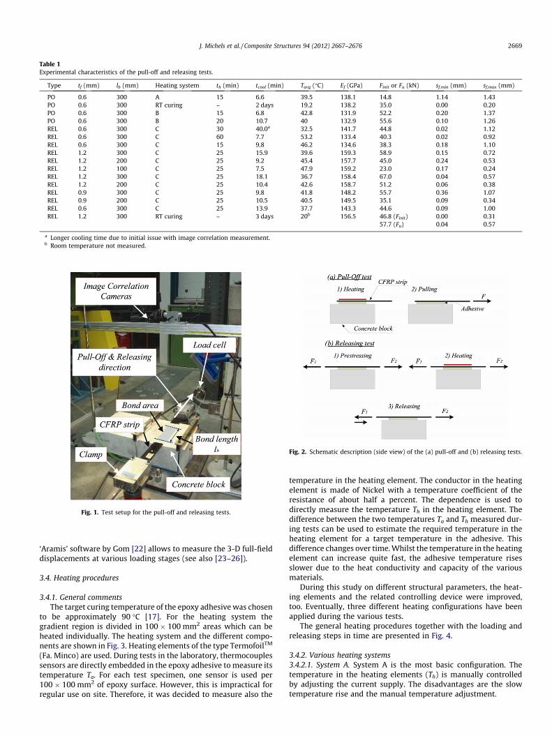
Table 1Experimental characteristics of the pull-off and releasing tests.
Type tf (mm) lb (mm) Heating system th (min) tcool (min) Tavg (�C) Ef (GPa) Finit or Fu (kN) sf,min (mm) sf,max (mm)
PO 0.6 300 A 15 6.6 39.5 138.1 14.8 1.14 1.43PO 0.6 300 RT curing – 2 days 19.2 138.2 35.0 0.00 0.20PO 0.6 300 B 15 6.8 42.8 131.9 52.2 0.20 1.37PO 0.6 300 B 20 10.7 40 132.9 55.6 0.10 1.26REL 0.6 300 C 30 40.0a 32.5 141.7 44.8 0.02 1.12REL 0.6 300 C 60 7.7 53.2 133.4 40.3 0.02 0.92REL 0.6 300 C 15 9.8 46.2 134.6 38.3 0.18 1.10REL 1.2 300 C 25 15.9 39.6 159.3 58.9 0.15 0.72REL 1.2 200 C 25 9.2 45.4 157.7 45.0 0.24 0.53REL 1.2 100 C 25 7.5 47.9 159.2 23.0 0.17 0.24REL 1.2 300 C 25 18.1 36.7 158.4 67.0 0.04 0.57REL 1.2 200 C 25 10.4 42.6 158.7 51.2 0.06 0.38REL 0.9 300 C 25 9.8 41.8 148.2 55.7 0.36 1.07REL 0.9 200 C 25 10.5 40.5 149.5 35.1 0.09 0.34REL 0.6 300 C 25 13.9 37.7 143.3 44.6 0.09 1.00REL 1.2 300 RT curing – 3 days 20b 156.5 46.8 (Finit) 0.00 0.31
57.7 (Fu) 0.04 0.57
a Longer cooling time due to initial issue with image correlation measurement.b Room temperature not measured.
Fig. 1. Test setup for the pull-off and releasing tests.
Fig. 2. Schematic description (side view) of the (a) pull-off and (b) releasing tests.
J. Michels et al. / Composite Structures 94 (2012) 2667–2676 2669
‘Aramis’ software by Gom [22] allows to measure the 3-D full-fielddisplacements at various loading stages (see also [23–26]).
3.4. Heating procedures
3.4.1. General commentsThe target curing temperature of the epoxy adhesive was chosen
to be approximately 90 �C [17]. For the heating system thegradient region is divided in 100 � 100 mm2 areas which can beheated individually. The heating system and the different compo-nents are shown in Fig. 3. Heating elements of the type TermofoilTM
(Fa. Minco) are used. During tests in the laboratory, thermocouplessensors are directly embedded in the epoxy adhesive to measure itstemperature Ta. For each test specimen, one sensor is used per100 � 100 mm2 of epoxy surface. However, this is impractical forregular use on site. Therefore, it was decided to measure also the
temperature in the heating element. The conductor in the heatingelement is made of Nickel with a temperature coefficient of theresistance of about half a percent. The dependence is used todirectly measure the temperature Th in the heating element. Thedifference between the two temperatures Ta and Th measured dur-ing tests can be used to estimate the required temperature in theheating element for a target temperature in the adhesive. Thisdifference changes over time. Whilst the temperature in the heatingelement can increase quite fast, the adhesive temperature risesslower due to the heat conductivity and capacity of the variousmaterials.
During this study on different structural parameters, the heat-ing elements and the related controlling device were improved,too. Eventually, three different heating configurations have beenapplied during the various tests.
The general heating procedures together with the loading andreleasing steps in time are presented in Fig. 4.
3.4.2. Various heating systems3.4.2.1. System A. System A is the most basic configuration. Thetemperature in the heating elements (Th) is manually controlledby adjusting the current supply. The disadvantages are the slowtemperature rise and the manual temperature adjustment.
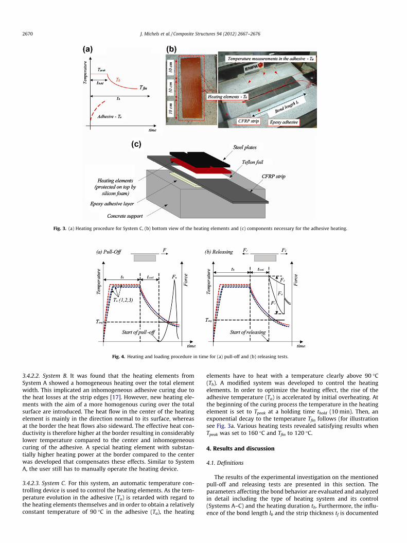
Fig. 3. (a) Heating procedure for System C, (b) bottom view of the heating elements and (c) components necessary for the adhesive heating.
Fig. 4. Heating and loading procedure in time for (a) pull-off and (b) releasing tests.
2670 J. Michels et al. / Composite Structures 94 (2012) 2667–2676
3.4.2.2. System B. It was found that the heating elements fromSystem A showed a homogeneous heating over the total elementwidth. This implicated an inhomogeneous adhesive curing due tothe heat losses at the strip edges [17]. However, new heating ele-ments with the aim of a more homogenous curing over the totalsurface are introduced. The heat flow in the center of the heatingelement is mainly in the direction normal to its surface, whereasat the border the heat flows also sideward. The effective heat con-ductivity is therefore higher at the border resulting in considerablylower temperature compared to the center and inhomogeneouscuring of the adhesive. A special heating element with substan-tially higher heating power at the border compared to the centerwas developed that compensates these effects. Similar to SystemA, the user still has to manually operate the heating device.
3.4.2.3. System C. For this system, an automatic temperature con-trolling device is used to control the heating elements. As the tem-perature evolution in the adhesive (Ta) is retarded with regard tothe heating elements themselves and in order to obtain a relativelyconstant temperature of 90 �C in the adhesive (Ta), the heating
elements have to heat with a temperature clearly above 90 �C(Th). A modified system was developed to control the heatingelements. In order to optimize the heating effect, the rise of theadhesive temperature (Ta) is accelerated by initial overheating. Atthe beginning of the curing process the temperature in the heatingelement is set to Tpeak at a holding time thold (10 min). Then, anexponential decay to the temperature Tfin follows (for illustrationsee Fig. 3a. Various heating tests revealed satisfying results whenTpeak was set to 160 �C and Tfin to 120 �C.
4. Results and discussion
4.1. Definitions
The results of the experimental investigation on the mentionedpull-off and releasing tests are presented in this section. Theparameters affecting the bond behavior are evaluated and analyzedin detail including the type of heating system and its control(Systems A–C) and the heating duration th. Furthermore, the influ-ence of the bond length lb and the strip thickness tf is documented
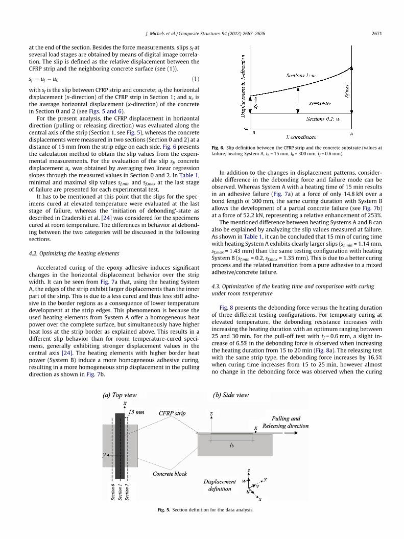
Fig. 6. Slip definition between the CFRP strip and the concrete substrate (values atfailure, heating System A, th = 15 min, lb = 300 mm, tf = 0.6 mm).
J. Michels et al. / Composite Structures 94 (2012) 2667–2676 2671
at the end of the section. Besides the force measurements, slips sf atseveral load stages are obtained by means of digital image correla-tion. The slip is defined as the relative displacement between theCFRP strip and the neighboring concrete surface (see (1)).
sf ¼ uf � uC ð1Þ
with sf is the slip between CFRP strip and concrete; uf the horizontaldisplacement (x-direction) of the CFRP strip in Section 1; and uc isthe average horizontal displacement (x-direction) of the concretein Section 0 and 2 (see Figs. 5 and 6).
For the present analysis, the CFRP displacement in horizontaldirection (pulling or releasing direction) was evaluated along thecentral axis of the strip (Section 1, see Fig. 5), whereas the concretedisplacements were measured in two sections (Section 0 and 2) at adistance of 15 mm from the strip edge on each side. Fig. 6 presentsthe calculation method to obtain the slip values from the experi-mental measurements. For the evaluation of the slip sf, concretedisplacement uc was obtained by averaging two linear regressionslopes through the measured values in Section 0 and 2. In Table 1,minimal and maximal slip values sf,min and sf,max at the last stageof failure are presented for each experimental test.
It has to be mentioned at this point that the slips for the spec-imens cured at elevated temperature were evaluated at the laststage of failure, whereas the ‘initiation of debonding’-state asdescribed in Czaderski et al. [24] was considered for the specimenscured at room temperature. The differences in behavior at debond-ing between the two categories will be discussed in the followingsections.
4.2. Optimizing the heating elements
Accelerated curing of the epoxy adhesive induces significantchanges in the horizontal displacement behavior over the stripwidth. It can be seen from Fig. 7a that, using the heating SystemA, the edges of the strip exhibit larger displacements than the innerpart of the strip. This is due to a less cured and thus less stiff adhe-sive in the border regions as a consequence of lower temperaturedevelopment at the strip edges. This phenomenon is because theused heating elements from System A offer a homogeneous heatpower over the complete surface, but simultaneously have higherheat loss at the strip border as explained above. This results in adifferent slip behavior than for room temperature-cured speci-mens, generally exhibiting stronger displacement values in thecentral axis [24]. The heating elements with higher border heatpower (System B) induce a more homogeneous adhesive curing,resulting in a more homogeneous strip displacement in the pullingdirection as shown in Fig. 7b.
Fig. 5. Section definition
In addition to the changes in displacement patterns, consider-able difference in the debonding force and failure mode can beobserved. Whereas System A with a heating time of 15 min resultsin an adhesive failure (Fig. 7a) at a force of only 14.8 kN over abond length of 300 mm, the same curing duration with System Ballows the development of a partial concrete failure (see Fig. 7b)at a force of 52.2 kN, representing a relative enhancement of 253%.
The mentioned difference between heating Systems A and B canalso be explained by analyzing the slip values measured at failure.As shown in Table 1, it can be concluded that 15 min of curing timewith heating System A exhibits clearly larger slips (sf,min = 1.14 mm,sf,max = 1.43 mm) than the same testing configuration with heatingSystem B (sf,min = 0.2, sf,max = 1.35 mm). This is due to a better curingprocess and the related transition from a pure adhesive to a mixedadhesive/concrete failure.
4.3. Optimization of the heating time and comparison with curingunder room temperature
Fig. 8 presents the debonding force versus the heating durationof three different testing configurations. For temporary curing atelevated temperature, the debonding resistance increases withincreasing the heating duration with an optimum ranging between25 and 30 min. For the pull-off test with tf = 0.6 mm, a slight in-crease of 6.5% in the debonding force is observed when increasingthe heating duration from 15 to 20 min (Fig. 8a). The releasing testwith the same strip type, the debonding force increases by 16.5%when curing time increases from 15 to 25 min, however almostno change in the debonding force was observed when the curing
for the data analysis.
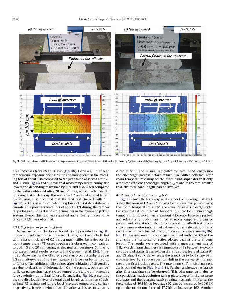
Fig. 7. Failure surface and ICS results for displacements in pull-off direction at failure for (a) heating Systems A and (b) heating System B, tf = 0.6 mm, lb = 300 mm, th = 15 min.
2672 J. Michels et al. / Composite Structures 94 (2012) 2667–2676
time increases from 25 to 30 min (Fig. 8b). However, 1 h of hightemperature exposure decreases the debonding force in the releas-ing test of about 10% compared to the peak force observed after 25and 30 min. Fig. 8a and c shows that room temperature curing alsolowers the debonding resistance by 63% and 86% when comparedto the values obtained after 20 and 25 min, respectively. For thereleasing test with a strip thickness tf = 1.2 mm and a bond lengthlb = 300 mm, it is specified that the first test (tagged with � inFig. 8c) with a maximum debonding force of 58.9 kN exhibited aconsiderable prestress force loss of about 5 kN during the tempo-rary adhesive curing due to a pressure loss in the hydraulic jackingsystem. Hence, this test was repeated and a clearly higher resis-tance (67 kN) was obtained.
4.3.1. Slip behavior for pull-off testsWhen analyzing the force-slip relations presented in Fig. 9a,
interesting information is obtained. Firstly, for the pull-off testwith a strip thickness of 0.6 mm, a much stiffer behavior for theroom temperature (RT) cured specimen is observed in comparisonto both 15 and 20 min curing at elevated temperatures. Similar tothe experimental results presented in Czaderski et al. [24], initia-tion of debonding for the RT cured specimen occurs at a slip of about0.2 mm, afterwards almost no increase in force can be noticed upto failure. The additional slip values after initiation of debondingare due to elastic strip deformation. On the contrary, both tempo-rarily cured specimen at elevated temperature show an increasingforce evolution up to final failure. By analyzing Fig. 10, presentingthe slip distribution over the total bond length at initiation of deb-onding (RT curing) and failure level (elevated temperature curing),respectively, it gets obvious that the softer adhesive, only partly
cured after 15 and 20 min, integrates the total bond length intothe anchorage process before failure. The stiffer adhesive afterroom temperature curing on the other hand implicates that onlya reduced efficient anchorage length lb,eff of about 125 mm, smallerthan the total bond length, can be involved.
4.3.2. Slip behavior for releasing testsFig. 9b shows the force-slip relations for the releasing tests with
a strip thickness of 1.2 mm. Similarly to the presented pull-off tests,the room temperature cured specimen reveals a clearly stifferbehavior than its counterpart, temporarily cured for 25 min at hightemperature. However, an important difference between pull-offand releasing for specimens cured at room temperature can bepointed out: whilst no further force increase in pull-off test is pos-sible anymore after initiation of debonding, a significant additionalresistance can be activated after first crack appearance (see Fig. 9b).Fig. 11 presents several load stages recorded with the ICS of theslips sf in the horizontal direction plotted against the total bondlength. The results were recorded with a measurement rate of1 Hz, which means that there is a time span of 1 s between two con-secutive load stages. It can be seen that slip curves for load stages 91and 92 almost coincide, whereas the transition to load stage 93 ischaracterized by a sudden vertical shift in the curves. At this mo-ment, the first crack appears. The maximum shift in displacementDs is pointed out in Figs. 9 and 11. Further anchorage resistanceafter first cracking can be observed. This phenomenon is due tothe particular crack evolution taking place deeper in the concretesubstrate and the resulting crack opening mechanisms. Hence, theforce value of 46.8 kN at loadstage 92 can be increased by10.9 kNup to the maximum force of 57.7 kN at loadstage 162. Another
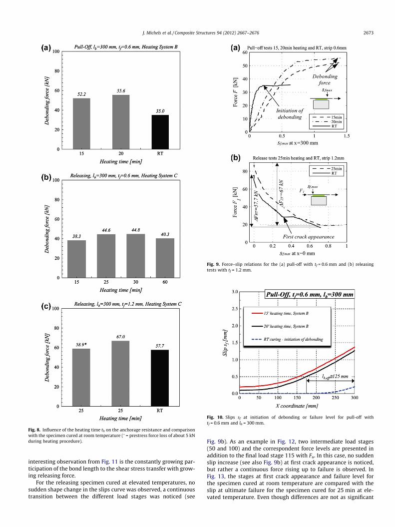
Fig. 8. Influence of the heating time th on the anchorage resistance and comparisonwith the specimen cured at room temperature (� = prestress force loss of about 5 kNduring heating procedure).
Fig. 9. Force–slip relations for the (a) pull-off with tf = 0.6 mm and (b) releasingtests with tf = 1.2 mm.
Fig. 10. Slips sf at initiation of debonding or failure level for pull-off withtf = 0.6 mm and lb = 300 mm.
J. Michels et al. / Composite Structures 94 (2012) 2667–2676 2673
interesting observation from Fig. 11 is the constantly growing par-ticipation of the bond length to the shear stress transfer with grow-ing releasing force.
For the releasing specimen cured at elevated temperatures, nosudden shape change in the slips curve was observed, a continuoustransition between the different load stages was noticed (see
Fig. 9b). As an example in Fig. 12, two intermediate load stages(50 and 100) and the correspondent force levels are presented inaddition to the final load stage 115 with Fu. In this case, no suddenslip increase (see also Fig. 9b) at first crack appearance is noticed,but rather a continuous force rising up to failure is observed. InFig. 13, the stages at first crack appearance and failure level forthe specimen cured at room temperature are compared with theslip at ultimate failure for the specimen cured for 25 min at ele-vated temperature. Even though differences are not as significant
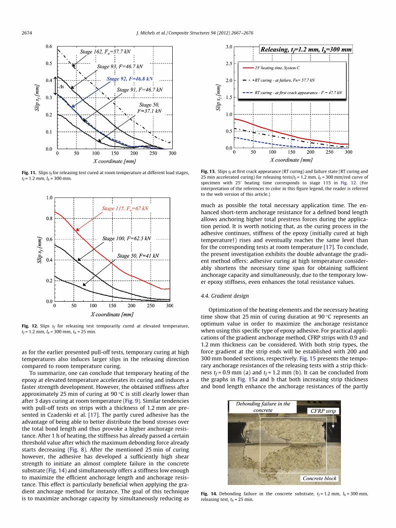
Fig. 11. Slips sf for releasing test cured at room temperature at different load stages,tf = 1.2 mm, lb = 300 mm.
Fig. 12. Slips sf for releasing test temporarily cured at elevated temperature,tf = 1.2 mm, lb = 300 mm, th = 25 min.
Fig. 13. Slips sf at first crack appearance (RT curing) and failure state (RT curing and25 min accelerated curing) for releasing tests/tf = 1.2 mm, lb = 300 mm/red curve ofspecimen with 25’ heating time corresponds to stage 115 in Fig. 12. (Forinterpretation of the references to color in this figure legend, the reader is referredto the web version of this article.)
Fig. 14. Debonding failure in the concrete substrate, tf = 1.2 mm, lb = 300 mm,releasing test, th = 25 min.
2674 J. Michels et al. / Composite Structures 94 (2012) 2667–2676
as for the earlier presented pull-off tests, temporary curing at hightemperatures also induces larger slips in the releasing directioncompared to room temperature curing.
To summarize, one can conclude that temporary heating of theepoxy at elevated temperature accelerates its curing and induces afaster strength development. However, the obtained stiffness afterapproximately 25 min of curing at 90 �C is still clearly lower thanafter 3 days curing at room temperature (Fig. 9). Similar tendencieswith pull-off tests on strips with a thickness of 1.2 mm are pre-sented in Czaderski et al. [17]. The partly cured adhesive has theadvantage of being able to better distribute the bond stresses overthe total bond length and thus provoke a higher anchorage resis-tance. After 1 h of heating, the stiffness has already passed a certainthreshold value after which the maximum debonding force alreadystarts decreasing (Fig. 8). After the mentioned 25 min of curinghowever, the adhesive has developed a sufficiently high shearstrength to initiate an almost complete failure in the concretesubstrate (Fig. 14) and simultaneously offers a stiffness low enoughto maximize the efficient anchorage length and anchorage resis-tance. This effect is particularly beneficial when applying the gra-dient anchorage method for instance. The goal of this techniqueis to maximize anchorage capacity by simultaneously reducing as
much as possible the total necessary application time. The en-hanced short-term anchorage resistance for a defined bond lengthallows anchoring higher total prestress forces during the applica-tion period. It is worth noticing that, as the curing process in theadhesive continues, stiffness of the epoxy (initially cured at hightemperature!) rises and eventually reaches the same level thanfor the corresponding tests at room temperature [17]. To conclude,the present investigation exhibits the double advantage the gradi-ent method offers: adhesive curing at high temperature consider-ably shortens the necessary time span for obtaining sufficientanchorage capacity and simultaneously, due to the temporary low-er epoxy stiffness, even enhances the total resistance values.
4.4. Gradient design
Optimization of the heating elements and the necessary heatingtime show that 25 min of curing duration at 90 �C represents anoptimum value in order to maximize the anchorage resistancewhen using this specific type of epoxy adhesive. For practical appli-cations of the gradient anchorage method, CFRP strips with 0.9 and1.2 mm thickness can be considered. With both strip types, theforce gradient at the strip ends will be established with 200 and300 mm bonded sections, respectively. Fig. 15 presents the tempo-rary anchorage resistances of the releasing tests with a strip thick-ness tf = 0.9 mm (a) and tf = 1.2 mm (b). It can be concluded fromthe graphs in Fig. 15a and b that both increasing strip thicknessand bond length enhance the anchorage resistances of the partly
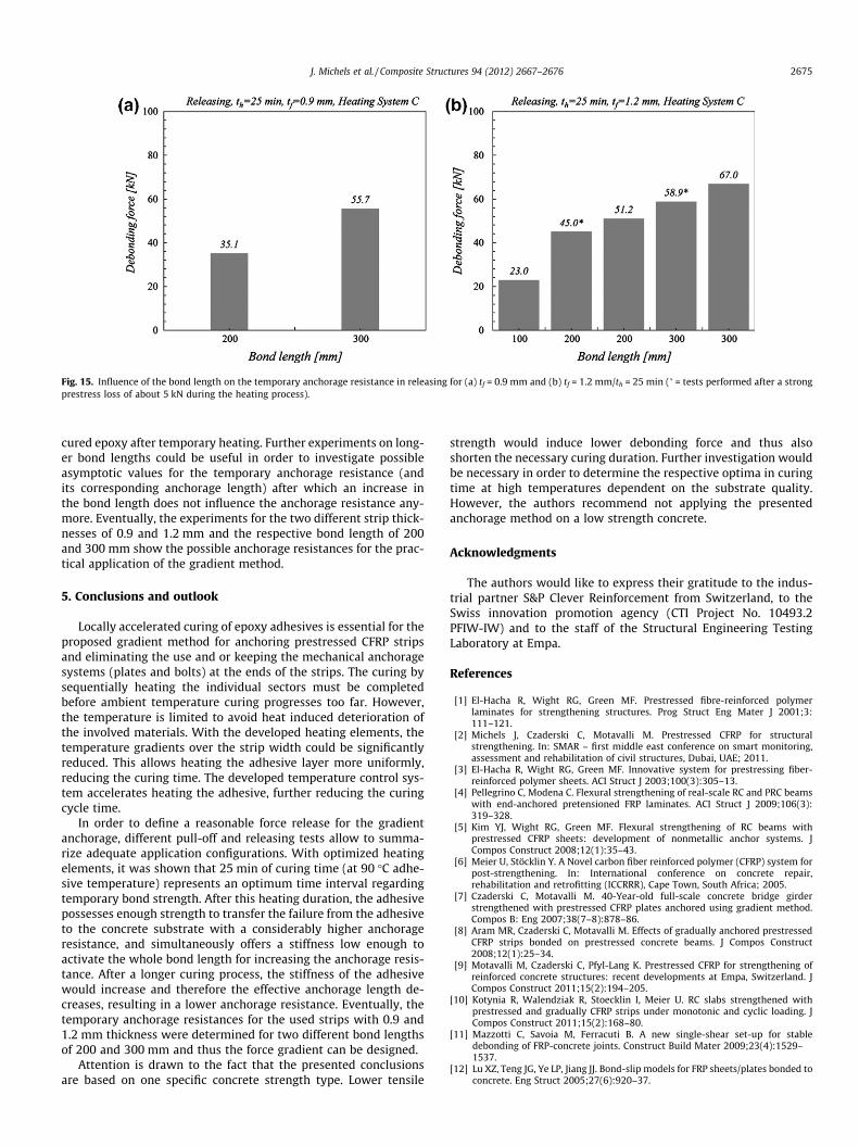
Fig. 15. Influence of the bond length on the temporary anchorage resistance in releasing for (a) tf = 0.9 mm and (b) tf = 1.2 mm/th = 25 min (� = tests performed after a strongprestress loss of about 5 kN during the heating process).
J. Michels et al. / Composite Structures 94 (2012) 2667–2676 2675
cured epoxy after temporary heating. Further experiments on long-er bond lengths could be useful in order to investigate possibleasymptotic values for the temporary anchorage resistance (andits corresponding anchorage length) after which an increase inthe bond length does not influence the anchorage resistance any-more. Eventually, the experiments for the two different strip thick-nesses of 0.9 and 1.2 mm and the respective bond length of 200and 300 mm show the possible anchorage resistances for the prac-tical application of the gradient method.
5. Conclusions and outlook
Locally accelerated curing of epoxy adhesives is essential for theproposed gradient method for anchoring prestressed CFRP stripsand eliminating the use and or keeping the mechanical anchoragesystems (plates and bolts) at the ends of the strips. The curing bysequentially heating the individual sectors must be completedbefore ambient temperature curing progresses too far. However,the temperature is limited to avoid heat induced deterioration ofthe involved materials. With the developed heating elements, thetemperature gradients over the strip width could be significantlyreduced. This allows heating the adhesive layer more uniformly,reducing the curing time. The developed temperature control sys-tem accelerates heating the adhesive, further reducing the curingcycle time.
In order to define a reasonable force release for the gradientanchorage, different pull-off and releasing tests allow to summa-rize adequate application configurations. With optimized heatingelements, it was shown that 25 min of curing time (at 90 �C adhe-sive temperature) represents an optimum time interval regardingtemporary bond strength. After this heating duration, the adhesivepossesses enough strength to transfer the failure from the adhesiveto the concrete substrate with a considerably higher anchorageresistance, and simultaneously offers a stiffness low enough toactivate the whole bond length for increasing the anchorage resis-tance. After a longer curing process, the stiffness of the adhesivewould increase and therefore the effective anchorage length de-creases, resulting in a lower anchorage resistance. Eventually, thetemporary anchorage resistances for the used strips with 0.9 and1.2 mm thickness were determined for two different bond lengthsof 200 and 300 mm and thus the force gradient can be designed.
Attention is drawn to the fact that the presented conclusionsare based on one specific concrete strength type. Lower tensile
strength would induce lower debonding force and thus alsoshorten the necessary curing duration. Further investigation wouldbe necessary in order to determine the respective optima in curingtime at high temperatures dependent on the substrate quality.However, the authors recommend not applying the presentedanchorage method on a low strength concrete.
Acknowledgments
The authors would like to express their gratitude to the indus-trial partner S&P Clever Reinforcement from Switzerland, to theSwiss innovation promotion agency (CTI Project No. 10493.2PFIW-IW) and to the staff of the Structural Engineering TestingLaboratory at Empa.
References
[1] El-Hacha R, Wight RG, Green MF. Prestressed fibre-reinforced polymerlaminates for strengthening structures. Prog Struct Eng Mater J 2001;3:111–121.
[2] Michels J, Czaderski C, Motavalli M. Prestressed CFRP for structuralstrengthening. In: SMAR – first middle east conference on smart monitoring,assessment and rehabilitation of civil structures, Dubai, UAE; 2011.
[3] El-Hacha R, Wight RG, Green MF. Innovative system for prestressing fiber-reinforced polymer sheets. ACI Struct J 2003;100(3):305–13.
[4] Pellegrino C, Modena C. Flexural strengthening of real-scale RC and PRC beamswith end-anchored pretensioned FRP laminates. ACI Struct J 2009;106(3):319–328.
[5] Kim YJ, Wight RG, Green MF. Flexural strengthening of RC beams withprestressed CFRP sheets: development of nonmetallic anchor systems. JCompos Construct 2008;12(1):35–43.
[6] Meier U, Stöcklin Y. A Novel carbon fiber reinforced polymer (CFRP) system forpost-strengthening. In: International conference on concrete repair,rehabilitation and retrofitting (ICCRRR), Cape Town, South Africa; 2005.
[7] Czaderski C, Motavalli M. 40-Year-old full-scale concrete bridge girderstrengthened with prestressed CFRP plates anchored using gradient method.Compos B: Eng 2007;38(7–8):878–86.
[8] Aram MR, Czaderski C, Motavalli M. Effects of gradually anchored prestressedCFRP strips bonded on prestressed concrete beams. J Compos Construct2008;12(1):25–34.
[9] Motavalli M, Czaderski C, Pfyl-Lang K. Prestressed CFRP for strengthening ofreinforced concrete structures: recent developments at Empa, Switzerland. JCompos Construct 2011;15(2):194–205.
[10] Kotynia R, Walendziak R, Stoecklin I, Meier U. RC slabs strengthened withprestressed and gradually CFRP strips under monotonic and cyclic loading. JCompos Construct 2011;15(2):168–80.
[11] Mazzotti C, Savoia M, Ferracuti B. A new single-shear set-up for stabledebonding of FRP-concrete joints. Construct Build Mater 2009;23(4):1529–1537.
[12] Lu XZ, Teng JG, Ye LP, Jiang JJ. Bond-slip models for FRP sheets/plates bonded toconcrete. Eng Struct 2005;27(6):920–37.
2676 J. Michels et al. / Composite Structures 94 (2012) 2667–2676
[13] Pellegrino C, Tinazzi D, Modena C. Experimental study on bond behaviorbetween concrete and FRP reinforcement. J Compos Construct 2008;12(2):180–189.
[14] De Lorenzis L, Miller B, Nanni A. Bond of fiber-reinforced polymer laminates toconcrete. ACI Mater J 2001;98(3):256–64.
[15] Leung CKY, Klenke M, Tung WK, Luk HCY. Determination of nonlinearsoftening behavior at FRP composite/concrete interface. J Eng Mech2006;132(5):498–508.
[16] Toutanji H, Saxena P, Zhao L, Ooi T. Prediction of interfacial bond failure of FRP-concrete surface. J Compos Construct 2007;11(4):427–36.
[17] Czaderski C, Martinelli E, Michels J, Motavalli M. Effect of curing conditions onstrength development in an epoxy resin for structural strengthening. ComposB: Eng 2011;43(2):398–410.
[18] Mays GC, Hutchinson AR. Adhesives in civil engineering. Cambridge UniversityPress; 1992.
[19] EN ISO 527-5/Kunststoffe – Bestimmung der Zugeinschaften – Teil 5:Prüfbedingungen für unidirektional faserverstärkte Kunststoffverbund-werkstoffe, Brussels; 1997.
[20] S&P Clever Reinforcement. <www.sp-reinforcement.ch>.[21] EN 12390-3 DE. Testing hardened concrete – Part 3: compressive strength of
test specimens. German version; 2011.[22] Gom. Software ARAMIS, version v. 6.2, Braunschweig, Germany: Gom GmbH;
2009.[23] Czaderski C, Rabinovitch O. Structural behavior and inter-layer displacements
in CFRP plated steel beams – optical measurements, analysis, and comparativeverification. Compos B: Eng 2010;41(4):276–86.
[24] Czaderski C, Soudki K, Motavalli M. Front and side view image correlationmeasurements on FRP to concrete pull-off bond tests. J Compos Construct2010;14(4):451–63.
[25] Subramaniam KV, Carloni C, Nobile L. Width effect in the interface fractureduring shear debonding of FRP sheets from concrete. Eng Fract Mech2007;74(4):578–94.
[26] Carloni C, Subramaniam KV. Direct determination of cohesive stress transferduring debonding of FRP from concrete. Compos Struct 2010;93(1):184–92.