table of content - dental expo
TRANSCRIPT
(SDS2.2 User manual) Issued 2019-03/ Rev. 01 Page 1 of 17
Table of Content
1. Product Description .............................................................................................................................................................. 2
2. SDS2.2 Implants Product Variants ............................................................................................................................. 4
3. SDS2.2 Indications for Use .............................................................................................................................................. 5
4. Surgery and Drilling Sequences .................................................................................................................................. 6
5. Insertion tool SDS2.2 single use ............................................................................................................................... 13
6. SDS2.2 Healing Caps-disc and SDS2.2 Standard Titanium Screw ................................................... 13
7. SDS2.2 Standard Implant Posts and SDS2.2 Standard Screws .......................................................... 14
8. Grinding of SDS2.2 Implants ....................................................................................................................................... 16
9. Taking Impression ............................................................................................................................................................... 17
10. Prosthetic Options .............................................................................................................................................................. 17
Caution: U.S Federal law restricts this device to sale by or on the order of a dental professional.
Caution: The SDS2.2 dental implant system has not been evaluated for safety and compatibility in the Magnetic Resonance (MR) environment. It has not been tested for heating or migration in the MR environment.
Combination with other products: The products are intended for exclusive use within the SDS system; combination with other implant systems is not indicated unless explicitly approved by SDS.
(SDS2.2 User manual) Issued 2019-03/ Rev. 01 Page 2 of 17
1. Product Description
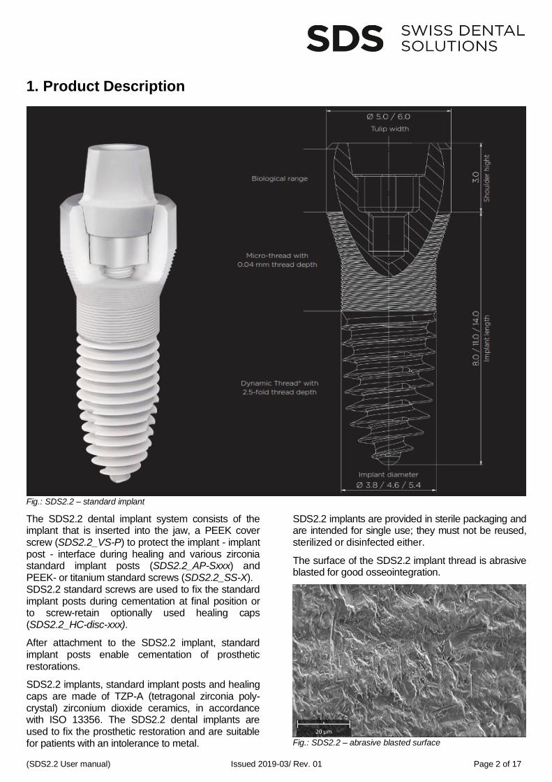
Fig.: SDS2.2 – standard implant
The SDS2.2 dental implant system consists of the implant that is inserted into the jaw, a PEEK cover screw (SDS2.2_VS-P) to protect the implant - implant post - interface during healing and various zirconia standard implant posts (SDS2.2_AP-Sxxx) and PEEK- or titanium standard screws (SDS2.2_SS-X). SDS2.2 standard screws are used to fix the standard implant posts during cementation at final position or to screw-retain optionally used healing caps (SDS2.2_HC-disc-xxx).
After attachment to the SDS2.2 implant, standard implant posts enable cementation of prosthetic restorations.
SDS2.2 implants, standard implant posts and healing caps are made of TZP-A (tetragonal zirconia poly-crystal) zirconium dioxide ceramics, in accordance with ISO 13356. The SDS2.2 dental implants are used to fix the prosthetic restoration and are suitable for patients with an intolerance to metal.
SDS2.2 implants are provided in sterile packaging and are intended for single use; they must not be reused, sterilized or disinfected either.
The surface of the SDS2.2 implant thread is abrasive blasted for good osseointegration.
Fig.: SDS2.2 – abrasive blasted surface
(SDS2.2 User manual) Issued 2019-03/ Rev. 01 Page 3 of 17
Fig.: SDS2.2 – enlarged core diameter by using a microthread
SDS2.2 implants have a self-tapping Dynamic Thread® in the lower section of the implant for good primary stability. Its bone-condensing section has a 2.5x thread depth. The upper section of the implant has a micro-thread.
The implant shoulder is machined.
Drill holes are prepared by using the accessory SDS instrument set implantology, following SDS drilling sequences (see chapter 4).
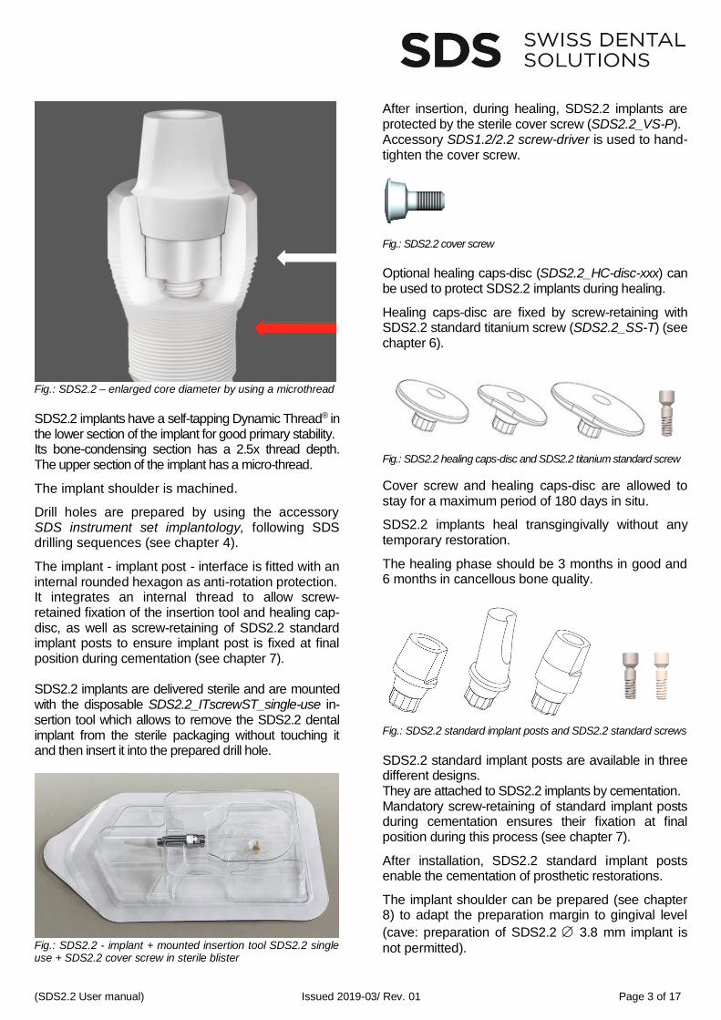
The implant - implant post - interface is fitted with an internal rounded hexagon as anti-rotation protection. It integrates an internal thread to allow screw-retained fixation of the insertion tool and healing cap-disc, as well as screw-retaining of SDS2.2 standard implant posts to ensure implant post is fixed at final position during cementation (see chapter 7). SDS2.2 implants are delivered sterile and are mounted with the disposable SDS2.2_ITscrewST_single-use in-sertion tool which allows to remove the SDS2.2 dental implant from the sterile packaging without touching it and then insert it into the prepared drill hole.
Fig.: SDS2.2 - implant + mounted insertion tool SDS2.2 single use + SDS2.2 cover screw in sterile blister
After insertion, during healing, SDS2.2 implants are protected by the sterile cover screw (SDS2.2_VS-P). Accessory SDS1.2/2.2 screw-driver is used to hand-tighten the cover screw.
Fig.: SDS2.2 cover screw
Optional healing caps-disc (SDS2.2_HC-disc-xxx) can be used to protect SDS2.2 implants during healing.
Healing caps-disc are fixed by screw-retaining with SDS2.2 standard titanium screw (SDS2.2_SS-T) (see chapter 6).
Fig.: SDS2.2 healing caps-disc and SDS2.2 titanium standard screw
Cover screw and healing caps-disc are allowed to stay for a maximum period of 180 days in situ.
SDS2.2 implants heal transgingivally without any temporary restoration.
The healing phase should be 3 months in good and 6 months in cancellous bone quality.
Fig.: SDS2.2 standard implant posts and SDS2.2 standard screws
SDS2.2 standard implant posts are available in three different designs. They are attached to SDS2.2 implants by cementation. Mandatory screw-retaining of standard implant posts during cementation ensures their fixation at final position during this process (see chapter 7).
After installation, SDS2.2 standard implant posts enable the cementation of prosthetic restorations.
The implant shoulder can be prepared (see chapter 8) to adapt the preparation margin to gingival level
(cave: preparation of SDS2.2 3.8 mm implant is
not permitted).
(SDS2.2 User manual) Issued 2019-03/ Rev. 01 Page 4 of 17
2. SDS2.2 Implants Product Variants
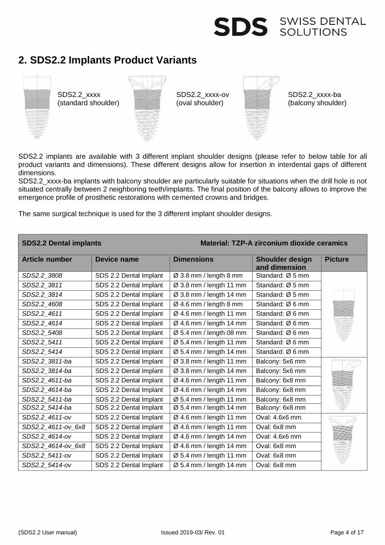
SDS2.2_xxxx (standard shoulder)
SDS2.2_xxxx-ov (oval shoulder)
SDS2.2_xxxx-ba (balcony shoulder)
SDS2.2 implants are available with 3 different implant shoulder designs (please refer to below table for all product variants and dimensions). These different designs allow for insertion in interdental gaps of different dimensions. SDS2.2_xxxx-ba implants with balcony shoulder are particularly suitable for situations when the drill hole is not situated centrally between 2 neighboring teeth/implants. The final position of the balcony allows to improve the emergence profile of prosthetic restorations with cemented crowns and bridges. The same surgical technique is used for the 3 different implant shoulder designs.
SDS2.2 Dental implants Material: TZP-A zirconium dioxide ceramics
Article number Device name Dimensions Shoulder design and dimension
Picture
SDS2.2_3808 SDS 2.2 Dental Implant Ø 3.8 mm / length 8 mm Standard: Ø 5 mm
SDS2.2_3811 SDS 2.2 Dental Implant Ø 3.8 mm / length 11 mm Standard: Ø 5 mm
SDS2.2_3814 SDS 2.2 Dental Implant Ø 3.8 mm / length 14 mm Standard: Ø 5 mm
SDS2.2_4608 SDS 2.2 Dental Implant Ø 4.6 mm / length 8 mm Standard: Ø 6 mm
SDS2.2_4611 SDS 2.2 Dental Implant Ø 4.6 mm / length 11 mm Standard: Ø 6 mm
SDS2.2_4614 SDS 2.2 Dental Implant Ø 4.6 mm / length 14 mm Standard: Ø 6 mm
SDS2.2_5408 SDS 2.2 Dental Implant Ø 5.4 mm / length 08 mm Standard: Ø 6 mm
SDS2.2_5411 SDS 2.2 Dental Implant Ø 5.4 mm / length 11 mm Standard: Ø 6 mm
SDS2.2_5414 SDS 2.2 Dental Implant Ø 5.4 mm / length 14 mm Standard: Ø 6 mm
SDS2.2_3811-ba SDS 2.2 Dental Implant Ø 3.8 mm / length 11 mm Balcony: 5x6 mm
SDS2.2_3814-ba SDS 2.2 Dental Implant Ø 3.8 mm / length 14 mm Balcony: 5x6 mm
SDS2.2_4611-ba SDS 2.2 Dental Implant Ø 4.6 mm / length 11 mm Balcony: 6x8 mm
SDS2.2_4614-ba SDS 2.2 Dental Implant Ø 4.6 mm / length 14 mm Balcony: 6x8 mm
SDS2.2_5411-ba SDS 2.2 Dental Implant Ø 5.4 mm / length 11 mm Balcony: 6x8 mm
SDS2.2_5414-ba SDS 2.2 Dental Implant Ø 5.4 mm / length 14 mm Balcony: 6x8 mm
SDS2.2_4611-ov SDS 2.2 Dental Implant Ø 4.6 mm / length 11 mm Oval: 4.6x6 mm
SDS2.2_4611-ov_6x8 SDS 2.2 Dental Implant Ø 4.6 mm / length 11 mm Oval: 6x8 mm
SDS2.2_4614-ov SDS 2.2 Dental Implant Ø 4.6 mm / length 14 mm Oval: 4.6x6 mm
SDS2.2_4614-ov_6x8 SDS 2.2 Dental Implant Ø 4.6 mm / length 14 mm Oval: 6x8 mm
SDS2.2_5411-ov SDS 2.2 Dental Implant Ø 5.4 mm / length 11 mm Oval: 6x8 mm
SDS2.2_5414-ov SDS 2.2 Dental Implant Ø 5.4 mm / length 14 mm Oval: 6x8 mm
(SDS2.2 User manual) Issued 2019-03/ Rev. 01 Page 5 of 17
3. SDS2.2 Indications for Use SDS2.2 dental implants are intended as artificial replacements to be placed in the human upper or lower jaw to provide anchor points for the prosthetic restoration. They are indicated for transgingival healing. SDS2.2 standard implant posts, SDS2.2 healing caps-disc, SDS2.2 cover screw and SDS2.2 standard screws are industrially manufactured prosthetic components. They are connected to the SDS2.2 dental implant and enable the fixation of prosthetic restorations. Additional information for the use of SDS2.2 dental implants: SDS2.2 dental implants are particularly suitable for patients with an intolerance to metal and associated chronic diseases. Indicated for situations where implants are
connected by interlocking or bridge restoration.
SDS2.2 4.6 / 5.4 mm implants are permitted as single-tooth implant for incisivi, cuspids, pre-molars and molars and as bridge post
SDS2.2 implants must be inserted at tissue-level
Contraindications SDS2.2 Existing medical conditions or poor general health can limit the possibility to insert dental implants surgically. Bruxism and insufficient bone quality/ quantity requires specific measures to ensure treatment success.
SDS implants are not suitable for applications in which the risk of excessive bending moments exists (e.g. extended crowns, extension bridges, bridges with more than one pontic unit). SDS2.2 implants may not be used in bone-level
position
SDS2.2 3.8 mm implant may not be used in
bridge restorations
Implant diameter smaller than 4.6 mm for upper central incisors, cuspids, molar region and/or bridge restoration
Distance to neighboring tooth/implant too small to allow insertion of rotationally asymmetrical SDS2.2 balcony- of oval implant
Bone not completely healed (residual ostitis/NICO)
Serious and systemic health problems in patient
Bruxism
Untreated periodontitis, poor oral hygiene, untreated abscess or bone infection
Crown-length greater than the osseointegrated threaded segment
Cantilever bridges/extension crowns (mesial or distal)
Pontic width between two bridge implant posts bigger than one pre-molar width
Connection of tooth with implant
The patient must be informed of risks, side-effects and complications, as well as of necessary precau-tions in connection with SDS2.2 dental implants (see instructions for the use of SDS2.2 dental implants). Anatomical and general health conditions can have a negative impact on dental implants.
(SDS2.2 User manual) Issued 2019-03/ Rev. 01 Page 6 of 17
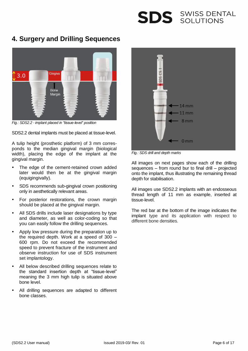
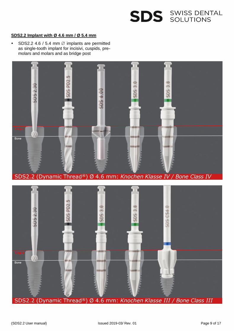
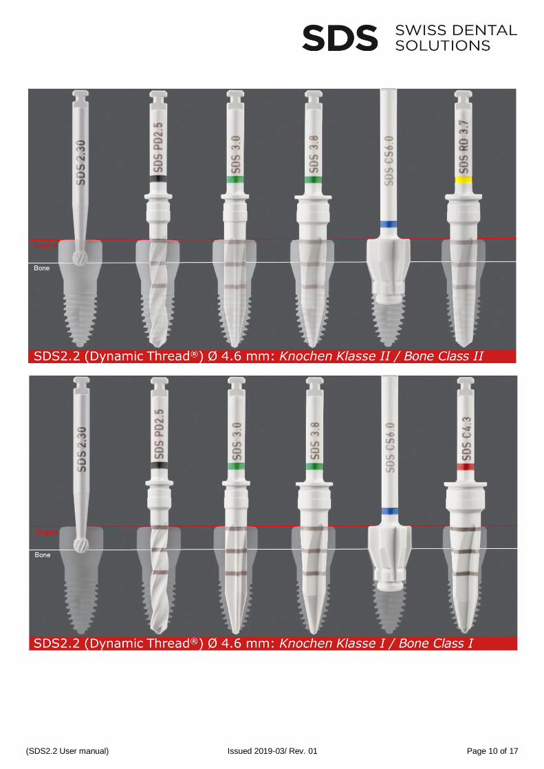
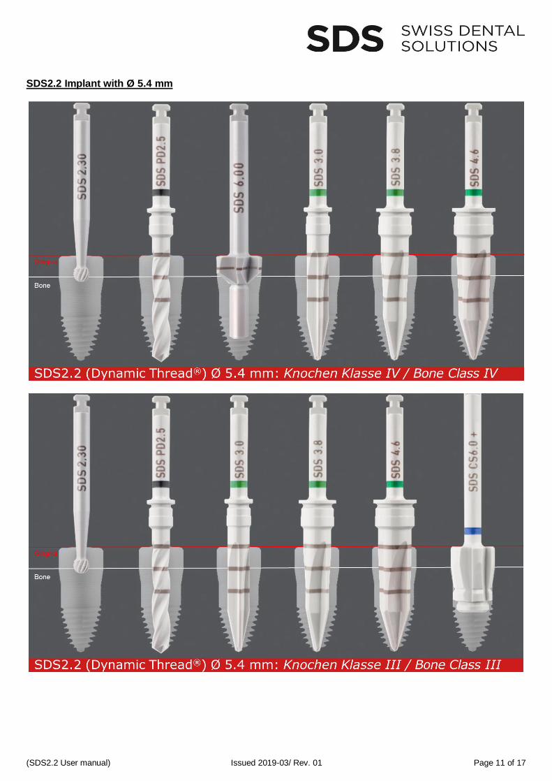
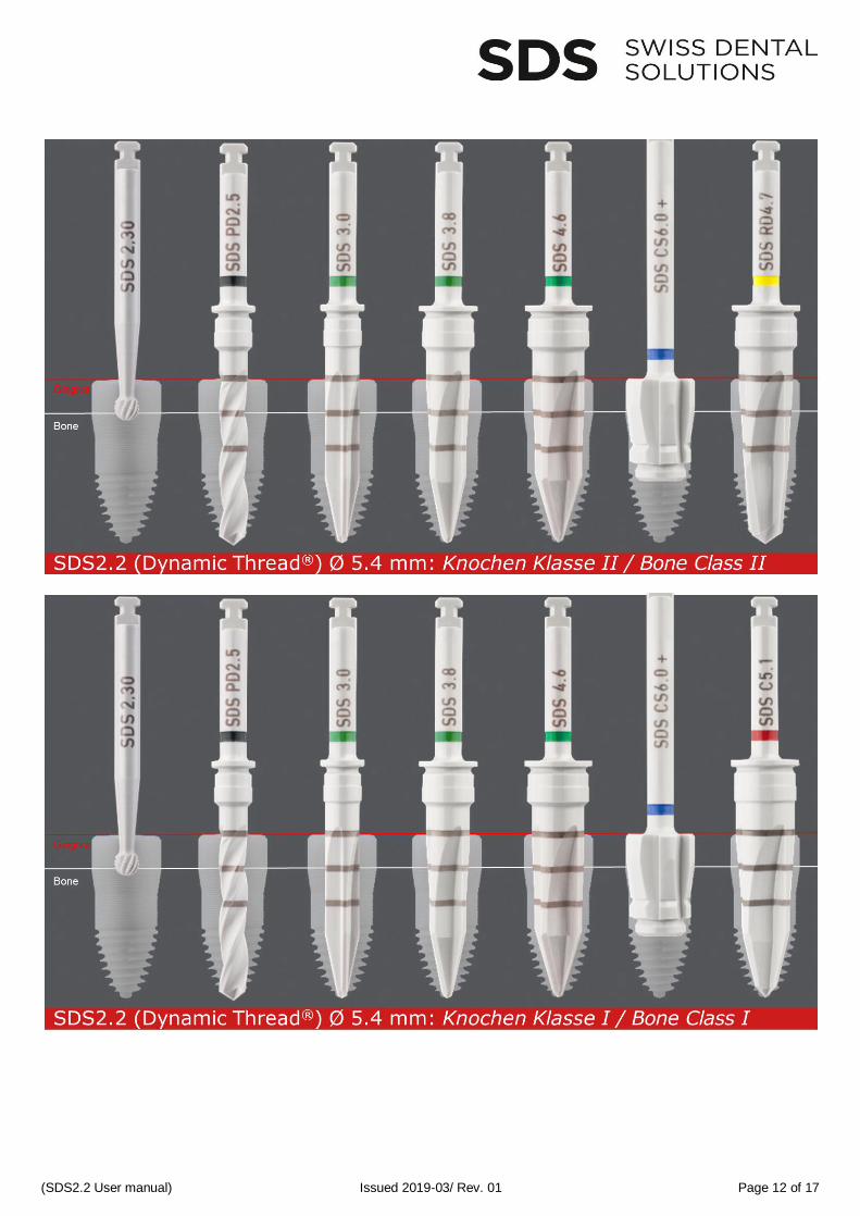
4. Surgery and Drilling Sequences
Fig.: SDS2.2 - implant placed in “tissue-level“ position
SDS2.2 dental implants must be placed at tissue-level. A tulip height (prosthetic platform) of 3 mm corres-ponds to the median gingival margin (biological width), placing the edge of the implant at the gingival margin.
The edge of the cement-retained crown added later would then be at the gingival margin (equigingivally).
SDS recommends sub-gingival crown positioning only in aesthetically relevant areas.
For posterior restorations, the crown margin should be placed at the gingival margin.
All SDS drills include laser designations by type and diameter, as well as color-coding so that you can easily follow the drilling sequences.
Apply low pressure during the preparation up to the required depth. Work at a speed of 300 – 600 rpm. Do not exceed the recommended speed to prevent fracture of the instrument and observe instruction for use of SDS instrument set implantology.
All below described drilling sequences relate to the standard insertion depth at “tissue-level” meaning the 3 mm high tulip is situated above bone level.
All drilling sequences are adapted to different bone classes.
Fig.: SDS drill and depth marks
All images on next pages show each of the drilling sequences – from round bur to final drill – projected onto the implant, thus illustrating the remaining thread depth for stabilisation. All images use SDS2.2 implants with an endosseous thread length of 11 mm as example, inserted at tissue-level. The red bar at the bottom of the image indicates the implant type and its application with respect to different bone densities.
(SDS2.2 User manual) Issued 2019-03/ Rev. 01 Page 7 of 17
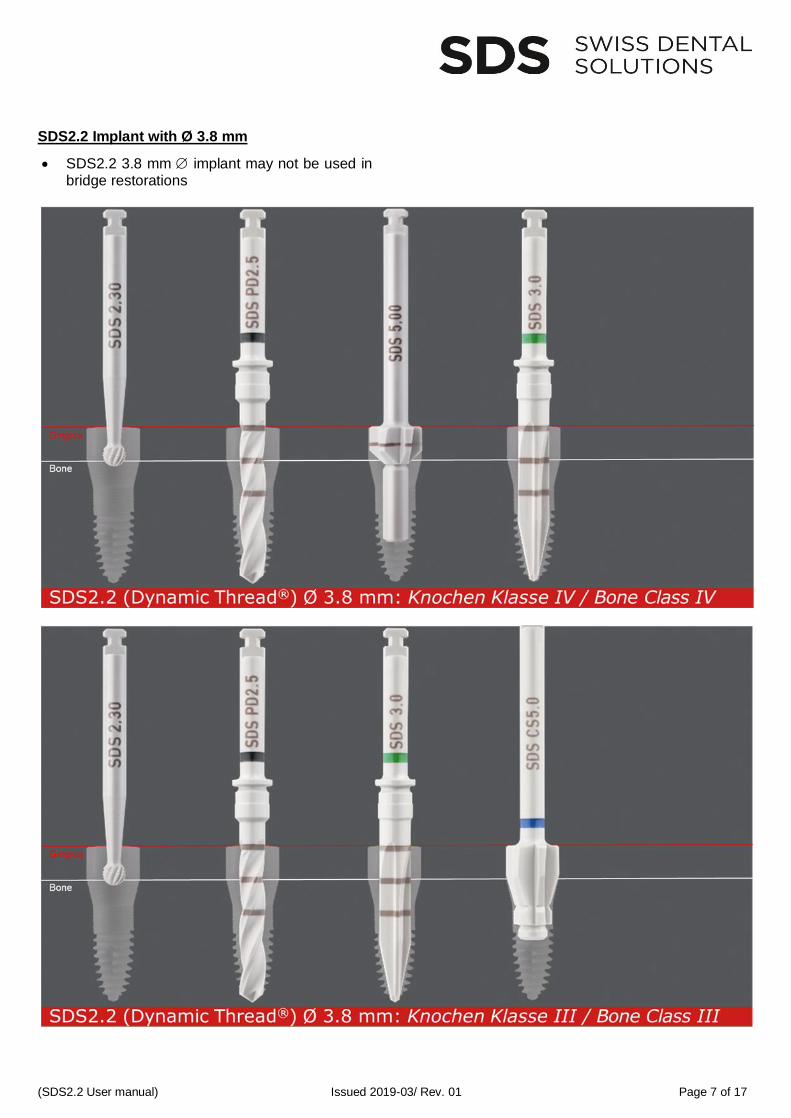
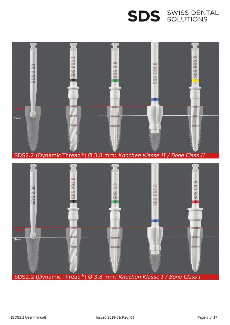
SDS2.2 Implant with Ø 3.8 mm
• SDS2.2 3.8 mm implant may not be used in bridge restorations
(SDS2.2 User manual) Issued 2019-03/ Rev. 01 Page 8 of 17
(SDS2.2 User manual) Issued 2019-03/ Rev. 01 Page 9 of 17
SDS2.2 Implant with Ø 4.6 mm / Ø 5.4 mm
SDS2.2 4.6 / 5.4 mm implants are permitted as single-tooth implant for incisivi, cuspids, pre-molars and molars and as bridge post
(SDS2.2 User manual) Issued 2019-03/ Rev. 01 Page 10 of 17
(SDS2.2 User manual) Issued 2019-03/ Rev. 01 Page 11 of 17
SDS2.2 Implant with Ø 5.4 mm
(SDS2.2 User manual) Issued 2019-03/ Rev. 01 Page 12 of 17
(SDS2.2 User manual) Issued 2019-03/ Rev. 01 Page 13 of 17
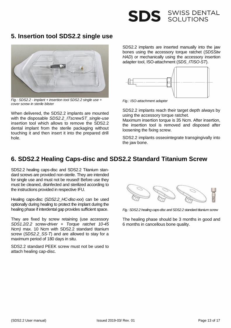
5. Insertion tool SDS2.2 single use
Fig.: SDS2.2 - implant + insertion tool SDS2.2 single use + cover screw in sterile blister
When delivered, the SDS2.2 implants are mounted with the disposable SDS2.2_ITscrewST_single-use insertion tool which allows to remove the SDS2.2 dental implant from the sterile packaging without touching it and then insert it into the prepared drill hole.
SDS2.2 implants are inserted manually into the jaw bones using the accessory torque ratchet (SDSStw HAD) or mechanically using the accessory insertion adapter tool, ISO-attachment (SDS_ITISO-ST).
Fig.: ISO-attachment adapter
SDS2.2 implants reach their target depth always by using the accessory torque ratchet. Maximum insertion torque is 35 Ncm. After insertion, the insertion tool is removed and disposed after loosening the fixing screw.
SDS2.2 implants osseointegrate transgingivally into the jaw bone.
6. SDS2.2 Healing Caps-disc and SDS2.2 Standard Titanium Screw SDS2.2 healing caps-disc and SDS2.2 Titanium stan-dard screws are provided non-sterile. They are intended for single use and must not be reused! Before use they must be cleaned, disinfected and sterilized according to the instructions provided in respective IFU. Healing caps-disc (SDS2.2_HC-disc-xxx) can be used optionally during healing to protect the implant during the healing phase if interdental gap provides sufficient space. They are fixed by screw retaining (use accessory SDS1.2/2.2 screw-driver + Torque ratchet 10-45 Ncm) max. 10 Ncm with SDS2.2 standard titanium screw (SDS2.2_SS-T) and are allowed to stay for a maximum period of 180 days in situ.
SDS2.2 standard PEEK screw must not be used to attach healing cap-disc.
Fig.: SDS2.2 healing caps-disc and SDS2.2 standard titanium screw
The healing phase should be 3 months in good and 6 months in cancellous bone quality.
(SDS2.2 User manual) Issued 2019-03/ Rev. 01 Page 14 of 17
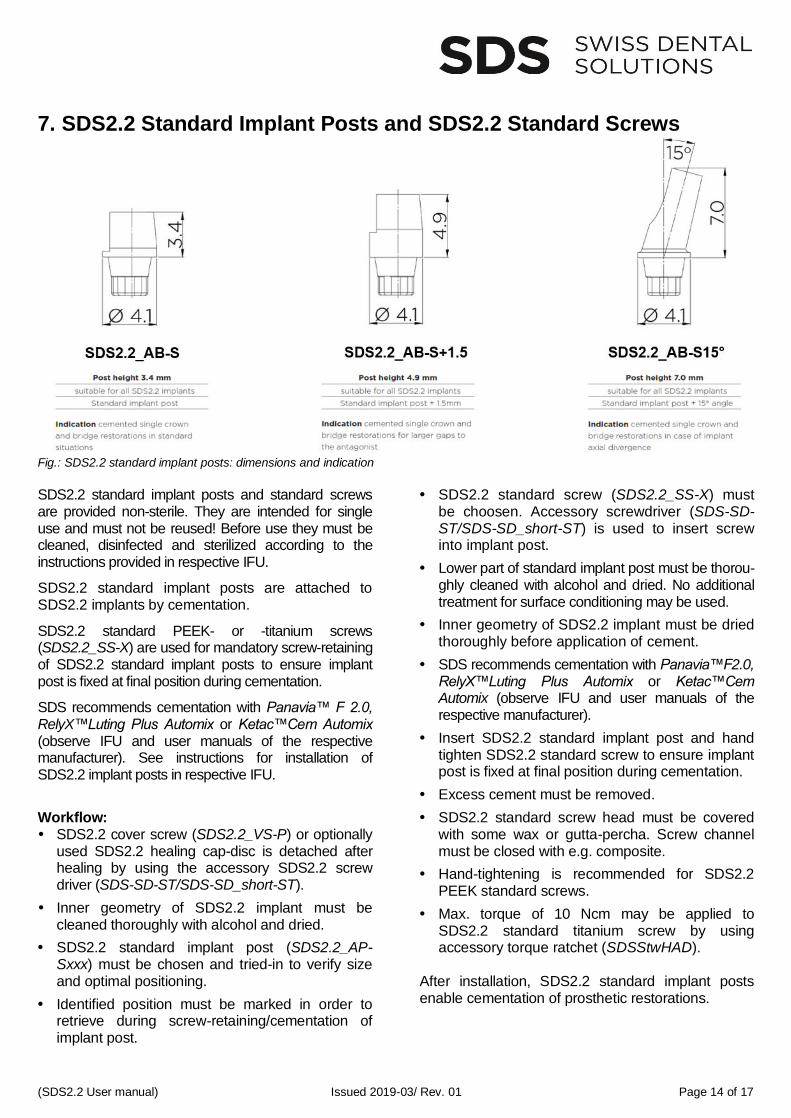
7. SDS2.2 Standard Implant Posts and SDS2.2 Standard Screws
Fig.: SDS2.2 standard implant posts: dimensions and indication SDS2.2 standard implant posts and standard screws are provided non-sterile. They are intended for single use and must not be reused! Before use they must be cleaned, disinfected and sterilized according to the instructions provided in respective IFU.
SDS2.2 standard implant posts are attached to SDS2.2 implants by cementation.
SDS2.2 standard PEEK- or -titanium screws (SDS2.2_SS-X) are used for mandatory screw-retaining of SDS2.2 standard implant posts to ensure implant post is fixed at final position during cementation.
SDS recommends cementation with Panavia™ F 2.0, RelyX™Luting Plus Automix or Ketac™Cem Automix (observe IFU and user manuals of the respective manufacturer). See instructions for installation of SDS2.2 implant posts in respective IFU.
Workflow: SDS2.2 cover screw (SDS2.2_VS-P) or optionally
used SDS2.2 healing cap-disc is detached after healing by using the accessory SDS2.2 screw driver (SDS-SD-ST/SDS-SD_short-ST).
Inner geometry of SDS2.2 implant must be cleaned thoroughly with alcohol and dried.
SDS2.2 standard implant post (SDS2.2_AP-Sxxx) must be chosen and tried-in to verify size and optimal positioning.
Identified position must be marked in order to retrieve during screw-retaining/cementation of implant post.
SDS2.2 standard screw (SDS2.2_SS-X) must
be choosen. Accessory screwdriver (SDS-SD-ST/SDS-SD_short-ST) is used to insert screw into implant post.
Lower part of standard implant post must be thorou-ghly cleaned with alcohol and dried. No additional treatment for surface conditioning may be used.
Inner geometry of SDS2.2 implant must be dried thoroughly before application of cement.
SDS recommends cementation with Panavia™F2.0, RelyX™Luting Plus Automix or Ketac™Cem Automix (observe IFU and user manuals of the respective manufacturer).
Insert SDS2.2 standard implant post and hand tighten SDS2.2 standard screw to ensure implant post is fixed at final position during cementation.
Excess cement must be removed.
SDS2.2 standard screw head must be covered with some wax or gutta-percha. Screw channel must be closed with e.g. composite.
Hand-tightening is recommended for SDS2.2 PEEK standard screws.
Max. torque of 10 Ncm may be applied to SDS2.2 standard titanium screw by using accessory torque ratchet (SDSStwHAD).
After installation, SDS2.2 standard implant posts enable cementation of prosthetic restorations.
(SDS2.2 User manual) Issued 2019-03/ Rev. 01 Page 15 of 17
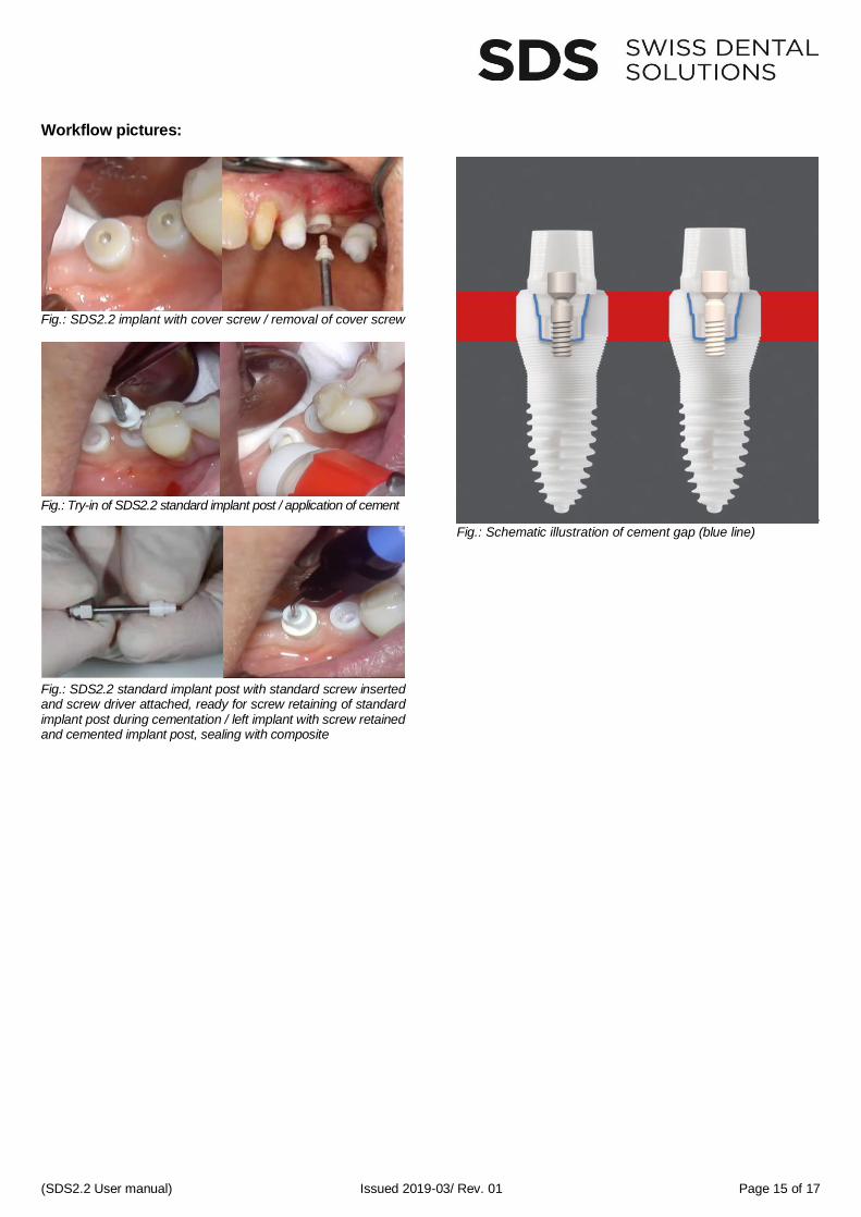
Workflow pictures:
Fig.: SDS2.2 implant with cover screw / removal of cover screw
Fig.: Try-in of SDS2.2 standard implant post / application of cement
Fig.: SDS2.2 standard implant post with standard screw inserted and screw driver attached, ready for screw retaining of standard implant post during cementation / left implant with screw retained and cemented implant post, sealing with composite
Fig.: Schematic illustration of cement gap (blue line)
(SDS2.2 User manual) Issued 2019-03/ Rev. 01 Page 16 of 17
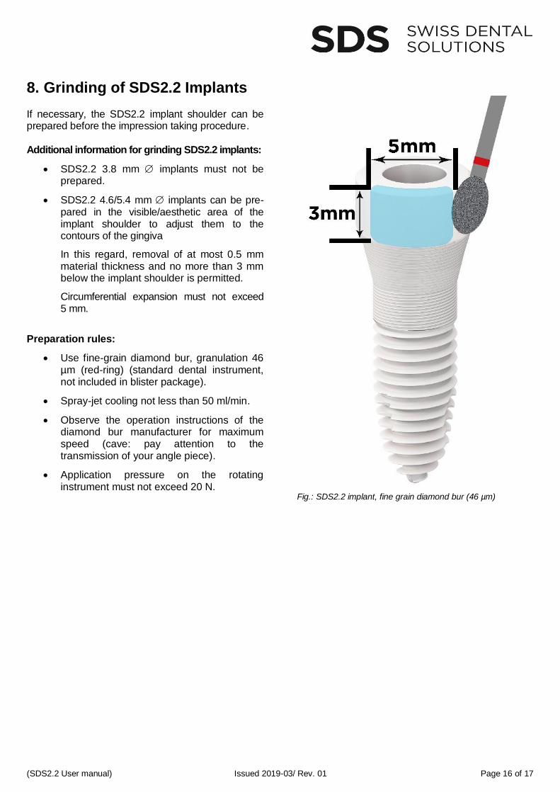
8. Grinding of SDS2.2 Implants If necessary, the SDS2.2 implant shoulder can be prepared before the impression taking procedure. Additional information for grinding SDS2.2 implants:
• SDS2.2 3.8 mm implants must not be prepared.
• SDS2.2 4.6/5.4 mm implants can be pre-pared in the visible/aesthetic area of the implant shoulder to adjust them to the contours of the gingiva
In this regard, removal of at most 0.5 mm material thickness and no more than 3 mm below the implant shoulder is permitted.
Circumferential expansion must not exceed 5 mm.
Preparation rules:
• Use fine-grain diamond bur, granulation 46 µm (red-ring) (standard dental instrument, not included in blister package).
• Spray-jet cooling not less than 50 ml/min.
• Observe the operation instructions of the diamond bur manufacturer for maximum speed (cave: pay attention to the transmission of your angle piece).
• Application pressure on the rotating instrument must not exceed 20 N.
Fig.: SDS2.2 implant, fine grain diamond bur (46 µm)
(SDS2.2 User manual) Issued 2019-03/ Rev. 01 Page 17 of 17
9. Taking Impression Impression is always taken after installation of SDS2.2 implant posts. In general, conventional direct impression is taken analogously to the prepared natural tooth (no retraction cord, ImpregumTM) by using irreversible elastic impression materials. Finally, the impression is casted with plaster to produce the master model.
10. Prosthetic Options General Considerations
SDS2.2 implants are suitable for fixed crown- and bridge restorations.
Always use the 4.6 mm / 5.4 mm implant for upper central incisivi, canini, molars and bridge restorations.
Zirconia should be used as standard material for fixed prosthetic restorations.
Prosthetic restoration must fit passively/without any tension and may not show any friction on the implant post.
Cementation with glass ionomer cement (KetacTM Cem) combines long-term stability with good biocompatibility.
Prosthetic restoration of patients who show bruxism or parafunctional habits is recom-mended with high-performance plastics like e.g. PEEK (polyetheretherketone).
In general, equigingival (“tissue-level“) implant positioning is recommended for SDS2.2 implants. This is considered being the best biological approach (soft tissue support and -formation, meeting the principles of biological width, etc.) and it allows optimal distribution of chewing forces.
Crown must always be cemented on implant shoulder/preparation margin.
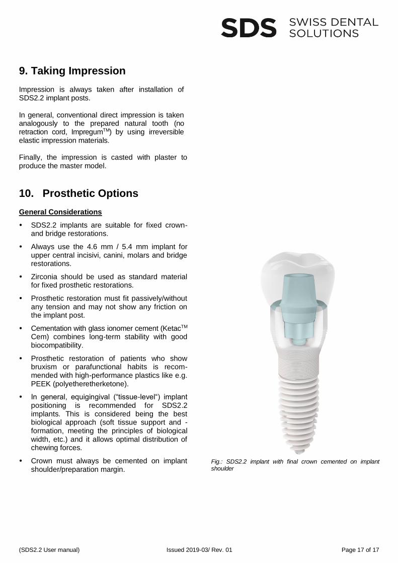
Fig.: SDS2.2 implant with final crown cemented on implant shoulder