study of basic design of a precast segmental box girder bridge
TRANSCRIPT

www.iaset.us edi [email protected]
STUDY OF BASIC DESIGN OF A PRECAST SEGMENTAL BOX GIRDER BRIDGE
CHIRAG GARG1 & M. V. N. S IVA KUMAR
2
1Department of Civil Engineering, BITS-Pilani Hyderabad Campus, India
2Department of Civil Engineering, National Institute of Technology, Warangal, India
ABSTRACT
Box girder bridges are being made into use at many places. Various studies have been performed so as to develop
a more stable structure design by varying the shape of the bridge structure. This study is also aims at understanding the
effect of changing the basic shape on the stability of the bridge. By varying the length of the over-hanging beam section
and increasing the thickness of the joints, the variation in the stability has been studied. SAP 2000 software has been used
to apply moving load and to study the deflections and stress contours .
KEYWORDS: Bridge, Box Girder Bridge, Design of Box Structure, Precast Bridge, SAP 2000
INTRODUCTION
Box g irder bridges are very commonly used. It is a bridge which has its main beams comprising of girders in the
shape of hollow boxes. The box girder normally comprises of pre-stressed concrete, structural steel or steel reinforced
concrete. As shown in Figure 1, a box-girder cross section may take the form of single cell (one box), multip le spine
(separate boxes), or mult i-cell with a common bottom flange (continuous cells) [1]. The box girder bridge achieves its
stability main ly because of two key features: shape and pre-stressed tendons [1].
Figure 1: Box Girder Cross Sections
Several research has been done till now on Box Girder Bridges [2]. The development of the curved beam theory
by Saint-Venant (1843) [3] and later the thin-walled beam theory by Vlasov (1965) [4] marked the birth of all research
efforts published to date on the analysis and design of straight and curved box-g irder bridges. Since then, numerous
technical papers, reports, and books have been published in the literature concerning various applications of, and even
modifications to, the two theories. A comprehensive review of analytical and experimental studies on box-g irder bridges
International Journal of Civil Engineering (IJCE)
ISSN(P): 2278-9987; ISSN(E): 2278-9995 Vol. 3, Issue 3, May 2014, 103-112 © IASET

104 Chirag Garg & M. V. N. Siva Kumar
Impact Factor (JCC): 2.6676 Index Copernicus Value (ICV): 3.0
was undertaken by Maisel (1970-85) [5-8] in England. This comprehensive review was extended by Swann (1972) [9],
Maisel et al. (1973), and Maisel (1985).
Over the developments in the past few years, several new modificat ions have been introduced so as to make the box girder
bridge more stable and increase its strength. These include, use of pre-stressed tendons [1], thicken ing of joints in the box
structure [10], modify ing the over-hanging beams [11-12], use of prestressed concrete [13] and multiple box type girder
bridges [13]. Th is study basically covers the study of analyzing the bridge structure with thickened joints and elongated
over-hanging beams together. Figure 2 shows the variation in the shape studied.
Figure 2: Positions of Prestressed Tendons
BRIDGE DESCRIPTION
The complete analysis of the bridge section and for the addition of prestressed tendons and loadings, SAP 2000
software has been used. The pre-defined Concrete Bridge AASHTO-PCI-ASBI has been considered for the study.
Figure 3 gives the basic structure and dimensions of the AASHTO-PCI-ASBI type bridge section as taken in SAP 2000
software. [1]
Figure 3: Basic Structure and Dimensions of AAS HTO-PCI-ASBI Type Bridge Section
The bridge structure was restricted to a two span and two lane section. Both the ends had fixed end supports.
Figure 4: Two S pan and Two Lane Bridge Section
Study of Basic Design of a Precast Segmental Box Girder Bridge 105
www.iaset.us edi [email protected]
Variation in Shape Analyzed
The variation in shape as shown in Figure 2 have been studied. The marked areas show the points where the joints
are thickened and the line marked in the image shows the elongated over-hanging beam. 7 different cases were studied by
varying the loads on the bridge structure for both, the basic shape as well as the modified shape of the box. Fig ure 5 shows
the difference of the two shapes.
Figure 5: Difference in Shape of the Basic and the Modified Bridge Section
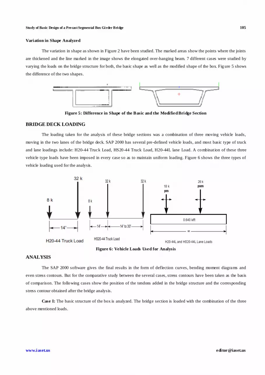
BRIDGE DECK LOADING
The loading taken for the analysis of these bridge sections was a combination of three moving vehicle loads,
moving in the two lanes of the bridge deck. SAP 2000 has several pre-defined vehicle loads, and most basic type of truck
and lane loadings include: H20-44 Truck Load, HS20-44 Truck Load, H20-44L lane Load. A combinat ion of these three
vehicle type loads have been imposed in every case so as to maintain uniform loading. Figure 6 shows the three types of
vehicle loading used for the analysis.
Figure 6: Vehicle Loads Used for Analysis
ANALYSIS
The SAP 2000 software gives the final results in the form of deflection curves, bending moment diagrams and
even stress contours. But for the comparative study between the several cases, stress contours have been taken as the basis
of comparison. The following cases show the position of the tendons added in the bridge structure and the corresponding
stress contour obtained after the bridge analysis.
Case I: The basic structure of the box is analyzed. The bridge section is loaded with the combination of the three
above mentioned loads.

106 Chirag Garg & M. V. N. Siva Kumar
Impact Factor (JCC): 2.6676 Index Copernicus Value (ICV): 3.0
Figure 7: Stress Contours and Longitudinal Stress for Case I
Case II: The same loading as in Case I for the modified shape.

Study of Basic Design of a Precast Segmental Box Girder Bridge 107
www.iaset.us edi [email protected]
Figure 8: Stress Contours and Longitudinal Stress for Case - II
Case III: Double the load in basic structure analysis case.
Figure 9: Stress Contours and Longitudinal Stress for Case III

108 Chirag Garg & M. V. N. Siva Kumar
Impact Factor (JCC): 2.6676 Index Copernicus Value (ICV): 3.0
Case IV: Same loading as in Case – III on the modified structure
Figure 10: Stress Contours and Longitudinal Stress for Case IV
Case V: Trip le loading for basic structure analysis case.

Study of Basic Design of a Precast Segmental Box Girder Bridge 109
www.iaset.us edi [email protected]
Figure 11: Stress Contours and Longitudinal Stress for Case V
Case VI: Same loading as in Case – V for the modified shape.
Figure 12: Stress Contours and Longitudinal Stress for Case VI

110 Chirag Garg & M. V. N. Siva Kumar
Impact Factor (JCC): 2.6676 Index Copernicus Value (ICV): 3.0
RESULTS AND DISCUSSIONS
The conclusion of entire analysis was obtained by comparing the stress contours of the different cases. After the
complete analysis of the basic structure of the box girder bridge by usin g different loadings and making some
modifications in the shape of the box, it was concluded that the mores table structure of the two cases for this box shape is
the modified one with elongated over-hanging beams and thickened joints.
This shape of the box of a modified box girder bridge has some peculiar features like: the increased thickness at
the fixed end of the cantilever beam, increased thickness at the bottom most portion of the box structure and sloping edges.
Longer the cantilever beam more is the thickness of the entire section from the free end to the fixed end. This provides us
more thickness at the fixed port ions and also helps us to reduce the stress acting on the entire span of the beam. The benefit
of this is that the bending moment acting at the fixed end is reduced and the beam becomes more stable.
The second peculiarity of this type of structure is the thickness at the bottom of the box. This thickness proves to
be useful because the stress transferred through the sloping edges from the bridge deck to the bottom of the box is easily
distributed. The join at the base between the horizontal edge and sloping edge is weak and hence making it thick increases
the efficiency.
Figure 13: Modified Positions in the Basic Shape of the Bridge Section
REFERENCES
1. Garg, Chirag and Siva Kumar, M V N (2014). “Prestressed Tendons System in a Box Girder Bridge”,
International Journal of Civ il Engineering (IJCE) Vol. 3-3, IASET.
2. Khaled M. Sennah, M.ASCE,and John B. Kennedy, F.ASCE (2002), “Literature Review in Analysis of Box-
Girder Bridges”, Journal Of Bridge Engineering, ASCE
3. Saint-Venant, B. (1843). ‘‘Memoire sur le calcul de la resistance et de la flexion des peicessolides a simple ou a
double courbure, en pregnant simultanement en consideration les divers efforts auxquelsellespeuvent entre
soumisesdans touts les sens.’’ Compts -Rendus, 27,l’Academic des sciences de Paris, Paris, 1020–1031
(in French).
4. Vlasov, V. Z. (1965). ‘‘Thin-walled elastic beams.’’ OTS61-11400, National Science Foundation,
Washington, D. C.
5. Maisel, B. I. (1970). ‘‘Review of literature related to the analysis and design of thin -walled beams.’’ Tech. Rep.
No. 42440, Cement and Concrete Association, London.
6. Maisel, B. I. (1985). ‘‘Analysis of concrete box beams using small computer capacity.’’ Can. J. Civ. Eng., 12(2),
265–278.
7. Maisel, B. I., and Roll, F. (1974). Methods of analysis and design of concrete bo x beam with side cantilevers,
Cement and Concrete Association, London.

Study of Basic Design of a Precast Segmental Box Girder Bridge 111
www.iaset.us edi [email protected]
8. Maisel, B. I., Rowe, R. E., and Swann, R. A. (1973). ‘‘Concrete box g irder bridges.’’ Struct. Eng., 51(10),
363–376.
9. Swann, R. A. (1972). ‘‘A feature survey of concrete box spine-beam bridges.’’ Technical Rep. 42.469, Cement
and Concrete Association, London.
10. Bakht, B., Jaegor, L. G., and Cheung, M. S. (1981). ‘‘State-of-the-art in analysis of cellular and voided slab
bridges.’’ Can. J. Civ. Eng., 8(3), 376–391.
11. Dezi, L. (1985). ‘‘Aspects of the deformation of the cross -section in curved single-cell box beams.’’
IndustriaItaliana Del Cemento, 55(7–8), 500–808.
12. Jeon, S. M., Cho, M. H., and Lee, I. (1995). ‘‘Static and dynamic analysis of composite box beams using large
deflection theory.’’ Comput. Struct., 57(4), 635–642.
13. Lounis, Z., and Cohn, M. Z. (1995). ‘‘Computer-aided design of prestressed concrete cellular bridge decks.’’ J.
Microcomput. Civ. Eng., 10(1), 1–11.
14. Cao Guo-Hui and Fang Zhi (2007). “Experimental Study on Behaviour of Concrete Box Girder Bridges
Prestressed with external tendons” Journal of Highway and Transportation Research and Development,
Vol.2 No.1 (34).
15. AASHTO (1980). Guide specifications for horizontally curved highway bridges, Washington, D.C.
16. AASHTO (1994). AASHTO LRFD Bridge Design Specificat ions, Washington, D.C.
17. AASHTO (1996). Standard specifications for highway bridges, Washington, D.C.
18. AASHTO (1993) Guide specifications for horizontally curved highway bridges, Washington, D.C.
19. AASHTO (1994). AASHTO LRFD Bridge Design Specificat ions, Washington, D.C.
20. AASHTO (1996). Standard specifications for highway bridges, Washington, D.C.
21. IS 1944: Part 5: 1981 Code of practice for lighting of public thoroughfare: Part 5 Lighting for grade sep arated
junctions, bridges and elevated roads (Group D).
22. IRC-78, Code of Pract ice for Road Bridges, Indian Road Congress, India.
23. IRC-SP13, Guidelines for the Design of Small Bridges and Culverts, Indian Road Congress, India.
24. Bridge Design Manual, Texas Department Of Transportation (August 2001).
