bellevue apartments, belfast 19-0101 precast design
TRANSCRIPT
Project
Bellevue Apartments, Belfast
Job Ref.
19-0101
Section
Precast Design Statement
Sheet no./rev.
1 of 4
Author
M Magill
Date
01/01/2019
Revision
B
Date
24/04/2019
Checked by
M Chidiac
Date
24/04/2019
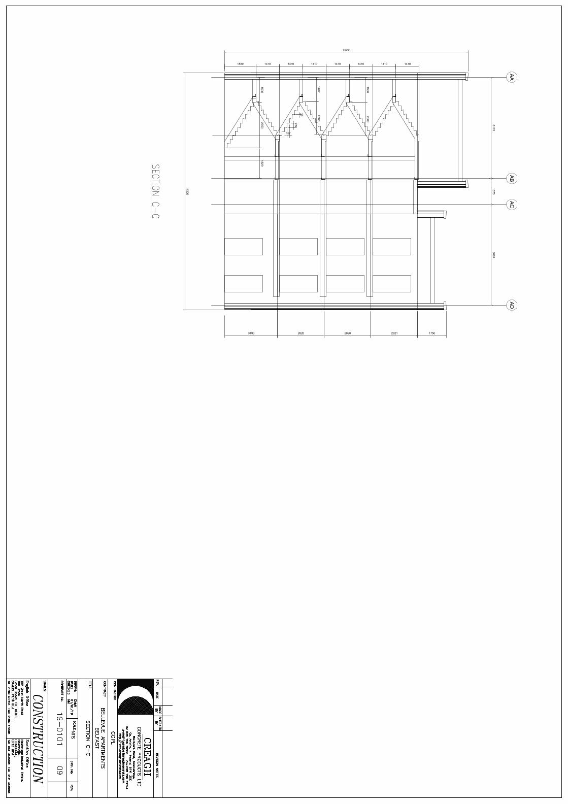
1.0 General
1.1 This design statement covers the precast concrete elements at the Bellevue Apartments project
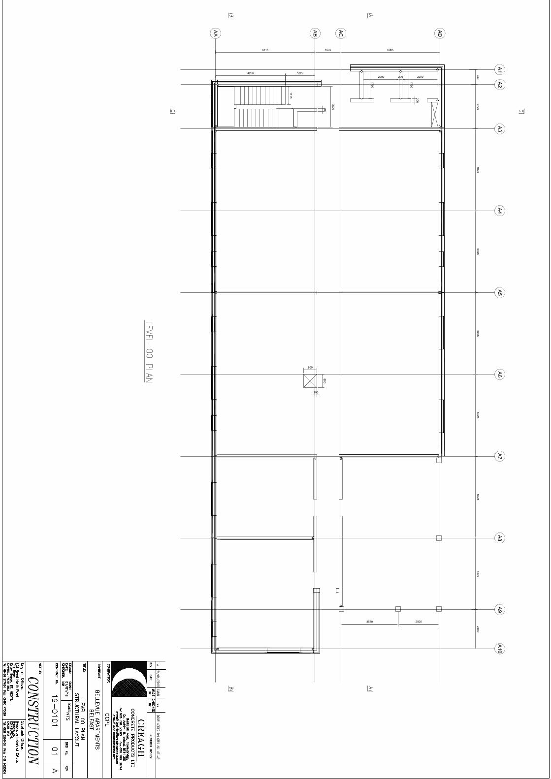
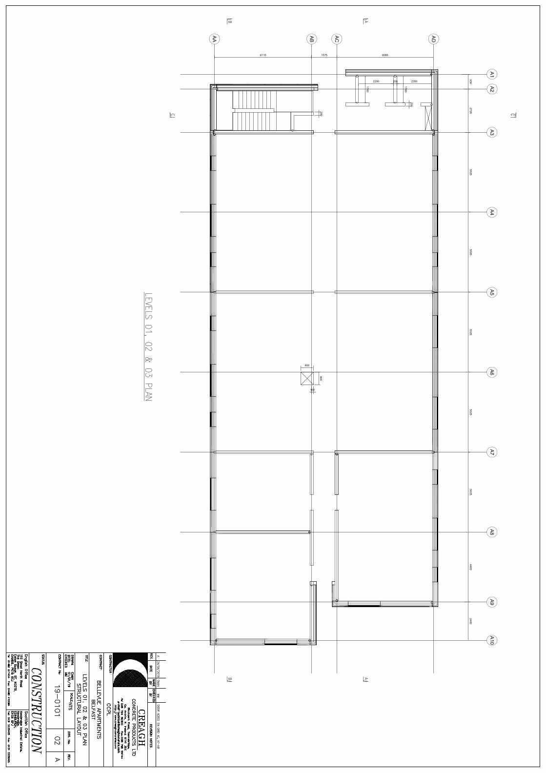
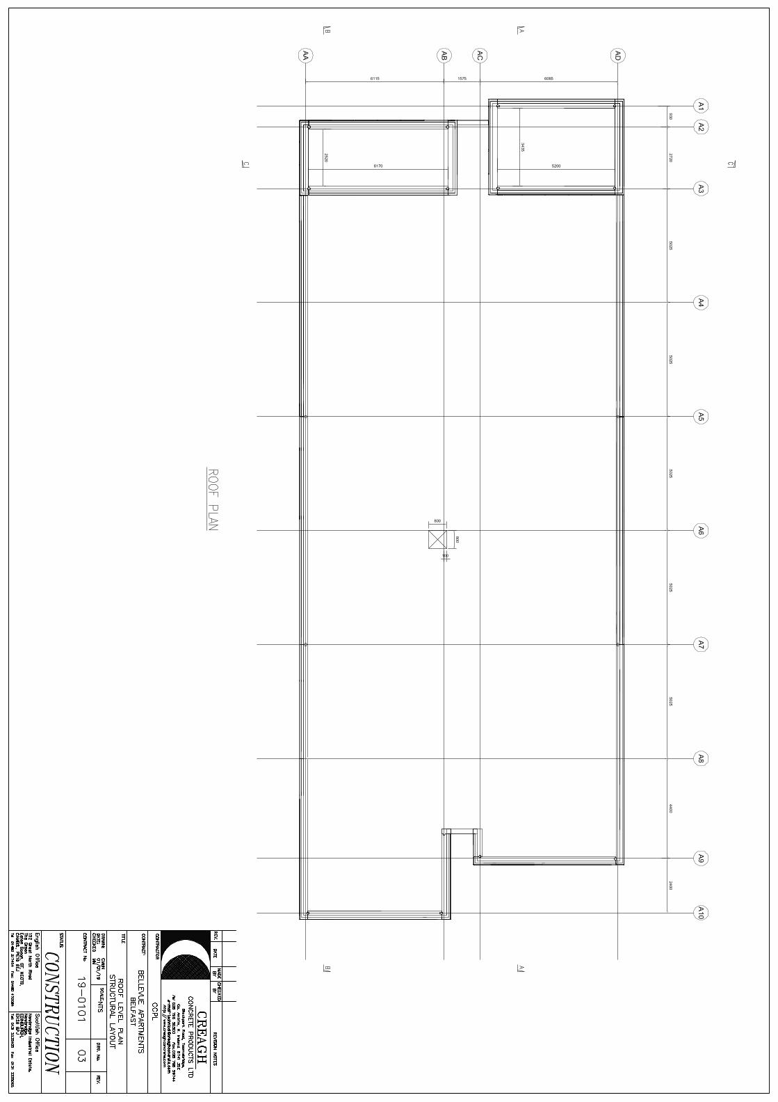
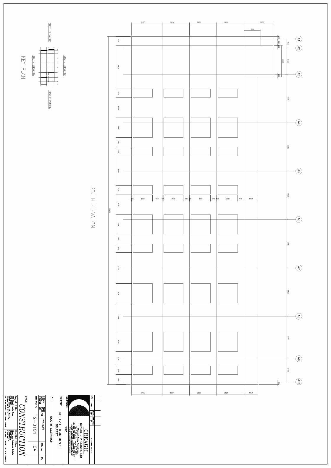
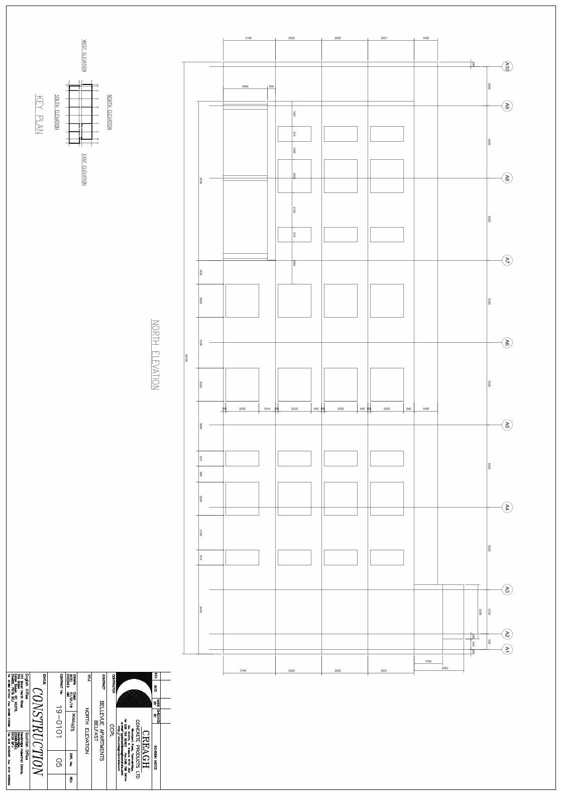
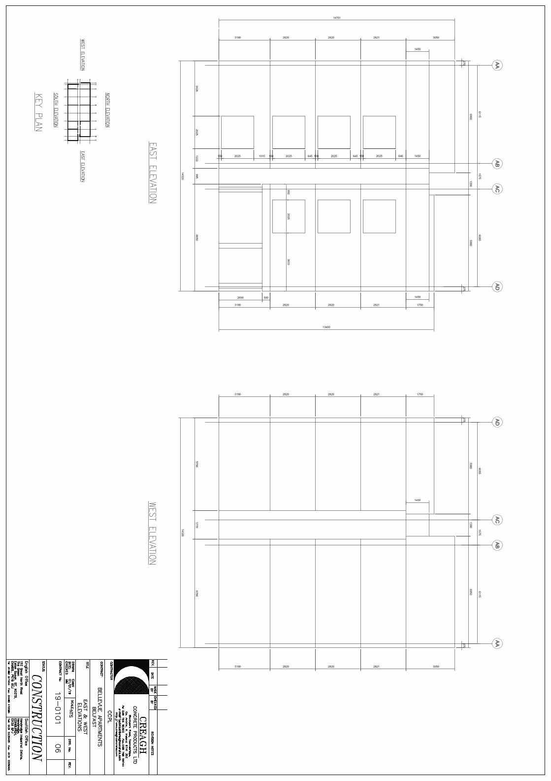
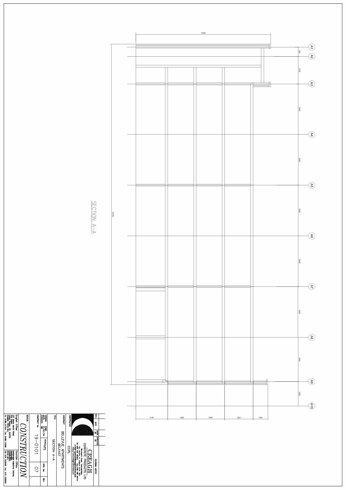
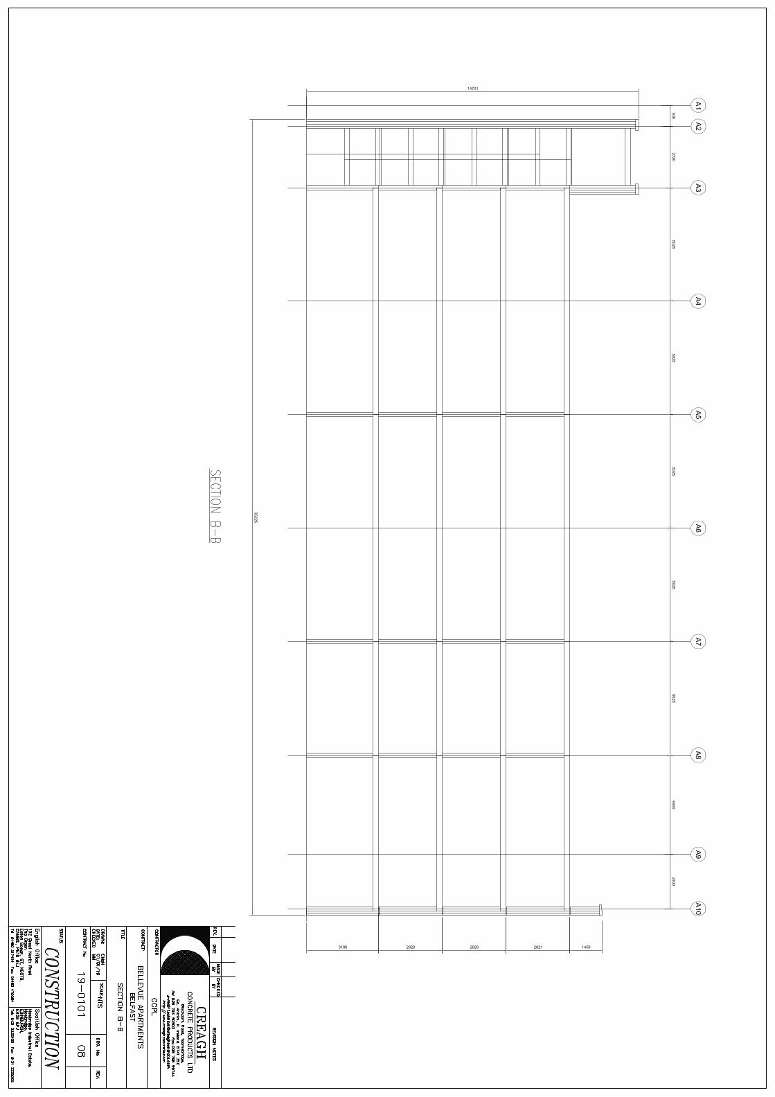
1.2 The project consists of one apartment block rising from insitu concrete foundations
1.3 The block is 14.7m tall (4 storeys + stair core overrun)
1.4 Footprint is 36.115m x 14.32m
1.5 All construction is new build
2.0 Reference Information
2.1 Clients Development Brief
2.2 Consulting Engineers Structural Design Statement
2.3 Consulting Engineers Precast Concrete Performance Specification
3.0 Basis of Design
3.1 BS EN 1990 (EC0) Basis of structural design
3.2 BS EN 1991 (EC1) Actions on structures
3.3 BS EN 1992 (EC2) Design of concrete structures
3.4 BS EN 1993 (EC3) Design of steel structures
3.5 National Annexes to relevant Eurocodes
3.6 PD6687 Background paper to the National Annexes to BS EN 1992-1 and BS EN 1992-3
3.7 BS EN 13369 Common rules for precast concrete products
3.8 BS EN 14992 Precast concrete products – Wall elements
3.9 BS EN 1168 Precast concrete products – Hollow core slabs
3.10 BS EN 14843 Precast concrete products – Stairs
3.11 BS EN 12354 Building acoustics
3.12 BS 8297 Design, manufacture and installation of architectural precast concrete
3.13 BS 8110 Structural use of concrete
3.14 BS 8500 Concrete – Complementary British Standard to BS EN 206
3.15 BS 5975 Code of practice for temporary works procedures and the permissible stress design of falsework
3.16 Non-contradictory published codes of practice and standards
4.0 Acoustic performance – calculated values BS EN 13369, clause 4.3.5 and BS EN 12354-1, Annex B and C
4.1 Weighted sound reduction index (dB) of 160mm wall Rw = 54
4.2 Weighted sound reduction index (dB) of 200mm wall Rw = 58
4.3 Weighted sound reduction index (dB) of 250mm wall Rw = 61
4.4 Weighted sound reduction index (dB) of 250mm hollowcore slab Rw = 52
5.0 Thermal performance
5.1 Sandwich wall panels and insulated cladding panels to provide a u-value of 0.19W/m2K
5.2 Any reduction in cavity and insulation thickness at door thresholds and window returns to be included within
the door & window u-value calculation
Project
Bellevue Apartments, Belfast
Job Ref.
19-0101
Section
Precast Design Statement
Sheet no./rev.
2 of 4
Author
M Magill
Date
01/01/2019
Revision
B
Date
24/04/2019
Checked by
M Chidiac
Date
24/04/2019
6.0 Structural Element Philosophies
6.1 Shear walls are designed as vertical cantilevers
6.2 All walls are designed as pinned and braced perpendicular to the minor axis
6.3 All floor slabs are designed as simply supported
6.4 Stair flights span simply supported between landings/supports
6.5 Landings span simply supported between supports perpendicular to stair flights
7.0 Lateral Stability
7.1 The precast floor slabs are designed to act as a rigid diaphragm at each level
7.2 The floor diaphragm is tied to and transfers horizontal loading to the shear walls at each level
7.3 All lateral loads are resisted by shear walls
7.4 Internal walls and external sandwich walls are used as shear walls to provide stability
8.0 Robustness
8.1 The building is considered as Class 2B
8.2 Disproportionate collapse mitigated by provision of vertical and horizontal ties
9.0 Loading
9.1 Permanent, Levels 01 - 03
9.1.1 Finishes 0.3kN/m2
9.1.2 100mm screed 2.4kN/m2
9.1.3 Ceiling and services 0.5kN/m2
9.2 Permanent, Roof
9.2.1 Ballast 1.6kN/m2
9.2.2 Single ply membrane 0.2kN/m2
9.2.3 Insulation 0.15kN/m2
9.2.4 100mm screed 2.4kN/m2
9.2.5 Ceiling and services 0.5kN/m2
9.3 Variable, Levels 01 - 03
9.3.1 Apartments (inc. partitions) 2.5kN/m2
9.3.2 Corridors 3kN/m2
9.3.3 Stairs 3kN/m2
9.4 Variable, Roof
9.4.1 Access 1.5kN/m2
9.4.2 Snow 0.7kN/m2
9.5 Wind
9.5.1 Basic wind speed 25.5m/s
9.5.2 Site altitude 60m
9.5.3 Nearest distance to the sea 2km
Project
Bellevue Apartments, Belfast
Job Ref.
19-0101
Section
Precast Design Statement
Sheet no./rev.
3 of 4
Author
M Magill
Date
01/01/2019
Revision
B
Date
24/04/2019
Checked by
M Chidiac
Date
24/04/2019
9.6 Geometric imperfections
9.6.1 Equivalent horizontal forces are applied to the structure due to geometric imperfections
10.0 Serviceability
10.1 Long term deflection of stairs, landings and floor slabs limited to span/250
10.2 Minimum natural frequency of floor slabs 4Hz
10.3 Internal exposure class for all elements is XC1
10.4 External exposure class for all elements is XC3
10.5 Cracking limited to 0.3mm
10.6 Durability in accordance with BS8500
10.7 Design life for all precast elements is 50 years
10.8 Fire resistance REI 90 for wall panels (wall exposed on one side only)
10.9 Fire resistance REI 90 for floor slabs
10.10 Fire resistance R 60 for stair flights and landings
10.11 Wind acceleration limited to threshold of perceptibility equal to 1.5% g = 0.14715m/s2
10.12 Building sway limited to height/750 for the entire precast structure and height/300 over any single storey
11.0 Material Characteristics
11.1 Typical precast concrete strength for load bearing walls C50/60, density 2450kg/m3
11.2 Typical precast concrete strength for hollowcore slabs C40/50, density 2400kg/m3
11.3 Typical precast concrete strength for solid slabs C32/40, density 2450kg/m3
11.4 Typical precast concrete strength for stairs and landings C32/40, density 2450kg/m3
11.5 Typical insitu concrete strength C32/40, density 2400kg/m3
11.6 Typical grout strength C40/50, density 2100kg/m3
11.7 Typical structural mortar strength C40/50, density 2095kg/m3
11.8 Typical reinforcement strength 500N/mm2 (B500B Type 2 deformed)
11.9 Tie reinforcement strength 500N/mm2 (B500C Type 2 deformed)
11.10 Prestressing strand strength 1860N/mm2
12.0 Surface Finish
12.1 Internal precast wall elements that are exposed to view are to have a surface finish that is suitable for direct
decoration, reference Type C description given in Clause 6.2.7.3 of BS8110-1:1997
12.2 External precast cladding and the external leaf of each type of sandwich panel is to have an approved
benchmark sample with colour, consistency and finish agreed by the client
12.3 Surface finish of precast slab soffits covered by a suspended ceiling is Type A, reference description given in
Clause 6.2.7.3 of BS8110-1:1997
12.4 Surface finish of precast stair and landing soffits is Type C, reference description given in Clause 6.2.7.3 of
BS8110-1:1997
Project
Bellevue Apartments, Belfast
Job Ref.
19-0101
Section
Precast Design Statement
Sheet no./rev.
4 of 4
Author
M Magill
Date
01/01/2019
Revision
B
Date
24/04/2019
Checked by
M Chidiac
Date
24/04/2019
13.0 Manufacturing Tolerance
13.1 BS EN 13369 Common rules for precast concrete products
13.2 BS EN 14992 Precast concrete products – Wall elements
13.3 BS EN 1168 Precast concrete products – Hollow core slabs
13.4 BS EN 14843 Precast concrete products – Stairs
13.5 BS 8297 Design, manufacture and installation of architectural precast concrete
13.6 National Structural Concrete Specification for Building Construction 4th Edition
14.0 Erection Tolerance
14.1 BS EN 13670 Execution of concrete structures
14.2 National Structural Concrete Specification for Building Construction 4th Edition
14.3 BS 5606 Accuracy in building
AA
AB
AC
AD
A1
A3
A4
A5
A6
A7
2720
5025
5025
5025
5025
A8
5025
A9
4400
A10
2400
A2
930
608515756115
2200
1700
2200
1700
200
200
200
800
800
100
4286 1829
1115
2520
3530 2500
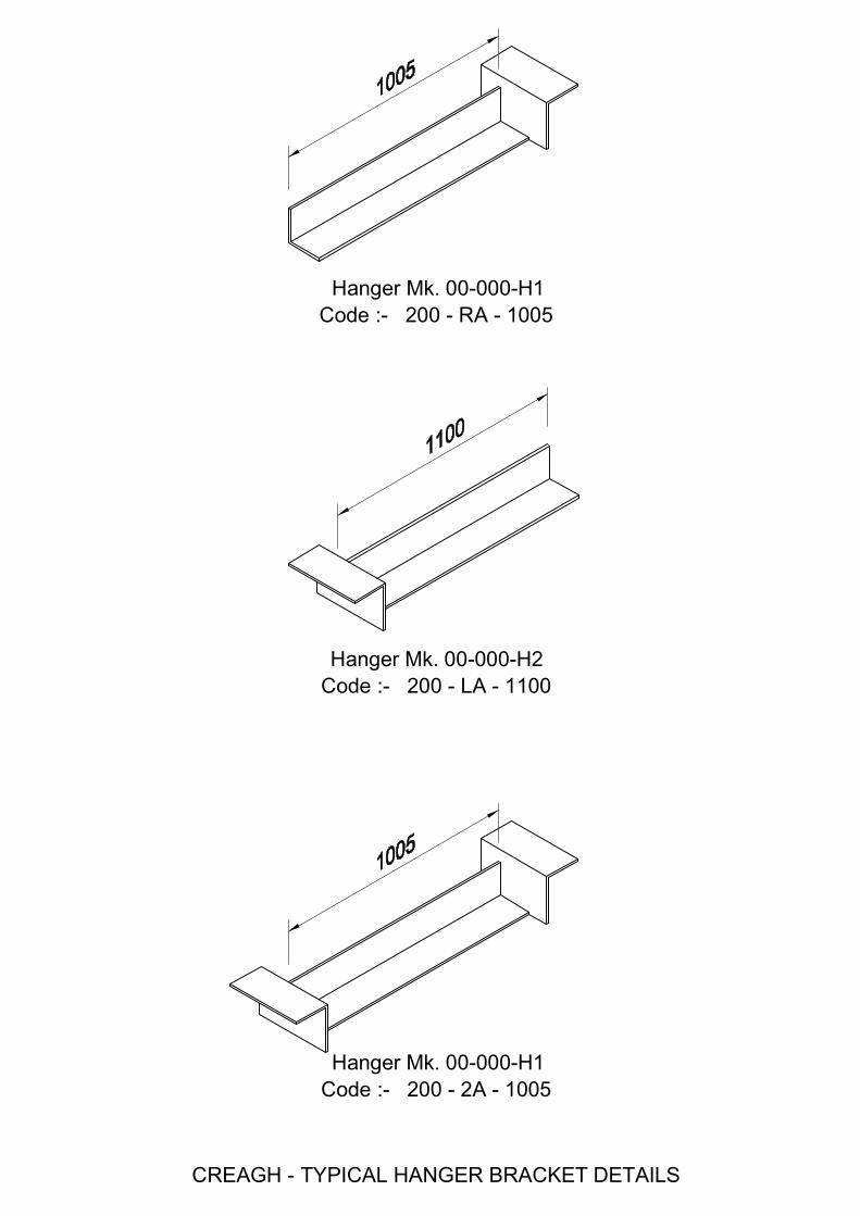
Code :- 200 - RA - 1005Hanger Mk. 00-000-H1
Hanger Mk. 00-000-H2Code :- 200 - LA - 1100
Hanger Mk. 00-000-H1Code :- 200 - 2A - 1005
CREAGH - TYPICAL HANGER BRACKET DETAILS
Creagh Concrete Products Ltd. Prestressed Flooring Technical Manual TECHNICAL INFORMATION
Page 11 of 65
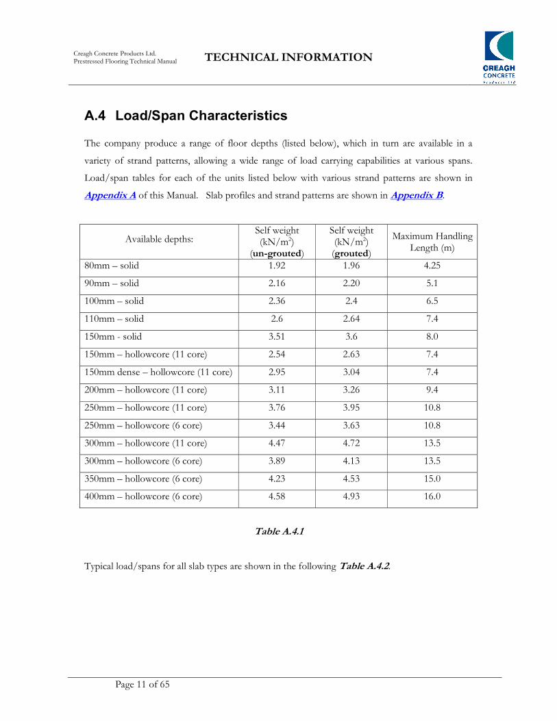
A.4 Load/Span Characteristics The company produce a range of floor depths (listed below), which in turn are available in a
variety of strand patterns, allowing a wide range of load carrying capabilities at various spans.
Load/span tables for each of the units listed below with various strand patterns are shown in
Appendix A of this Manual. Slab profiles and strand patterns are shown in Appendix B.
Available depths: Self weight (kN/m2)
(un-grouted)
Self weight (kN/m2)
(grouted)
Maximum Handling Length (m)
80mm – solid 1.92 1.96 4.25
90mm – solid 2.16 2.20 5.1
100mm – solid 2.36 2.4 6.5
110mm – solid 2.6 2.64 7.4
150mm - solid 3.51 3.6 8.0
150mm – hollowcore (11 core) 2.54 2.63 7.4
150mm dense – hollowcore (11 core) 2.95 3.04 7.4
200mm – hollowcore (11 core) 3.11 3.26 9.4
250mm – hollowcore (11 core) 3.76 3.95 10.8
250mm – hollowcore (6 core) 3.44 3.63 10.8
300mm – hollowcore (11 core) 4.47 4.72 13.5
300mm – hollowcore (6 core) 3.89 4.13 13.5
350mm – hollowcore (6 core) 4.23 4.53 15.0
400mm – hollowcore (6 core) 4.58 4.93 16.0
Table A.4.1
Typical load/spans for all slab types are shown in the following Table A.4.2.
Creagh Concrete Products Ltd. Prestressed Flooring Technical Manual TECHNICAL INFORMATION
Page 44 of 65
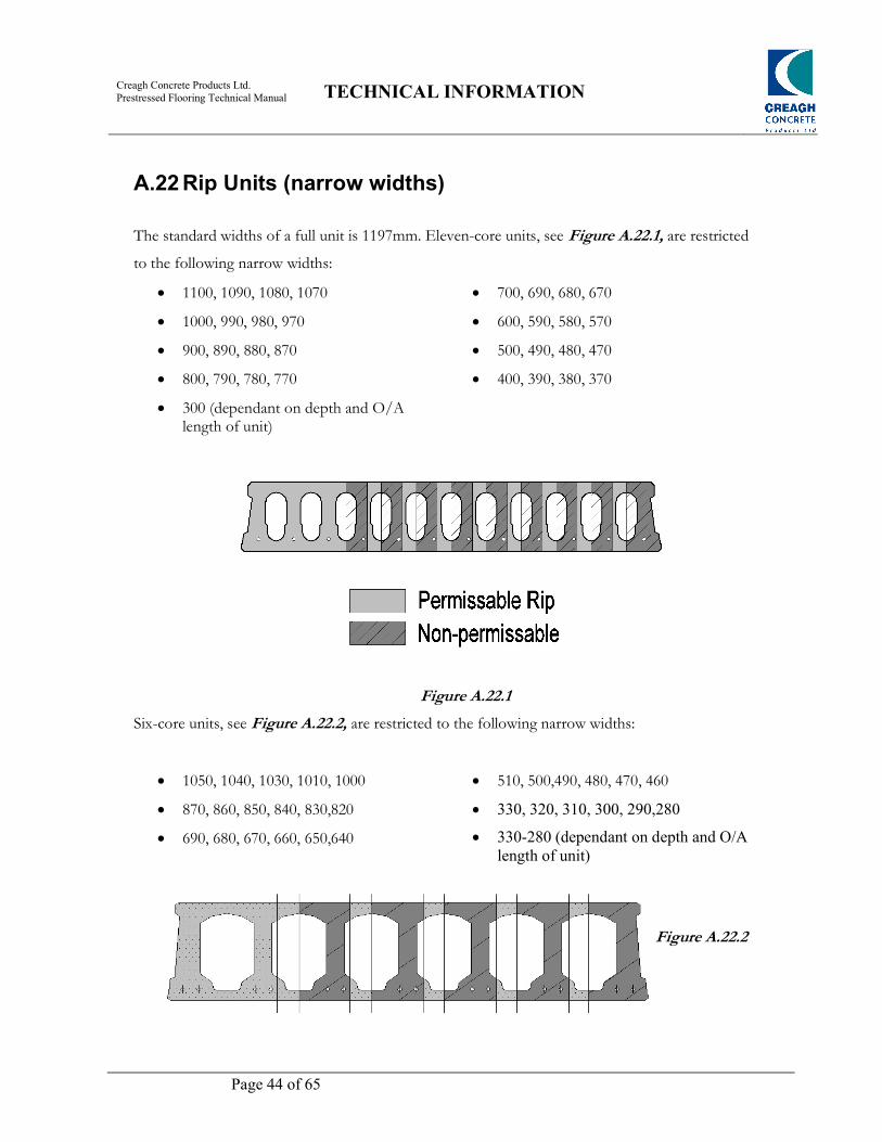
A.22 Rip Units (narrow widths)
The standard widths of a full unit is 1197mm. Eleven-core units, see Figure A.22.1, are restricted
to the following narrow widths:
1100, 1090, 1080, 1070
1000, 990, 980, 970
900, 890, 880, 870
800, 790, 780, 770
300 (dependant on depth and O/A length of unit)
700, 690, 680, 670
600, 590, 580, 570
500, 490, 480, 470
400, 390, 380, 370
Figure A.22.1
Six-core units, see Figure A.22.2, are restricted to the following narrow widths:
1050, 1040, 1030, 1010, 1000
870, 860, 850, 840, 830,820
690, 680, 670, 660, 650,640
510, 500,490, 480, 470, 460
330, 320, 310, 300, 290,280
330-280 (dependant on depth and O/A length of unit)
Figure A.22.2
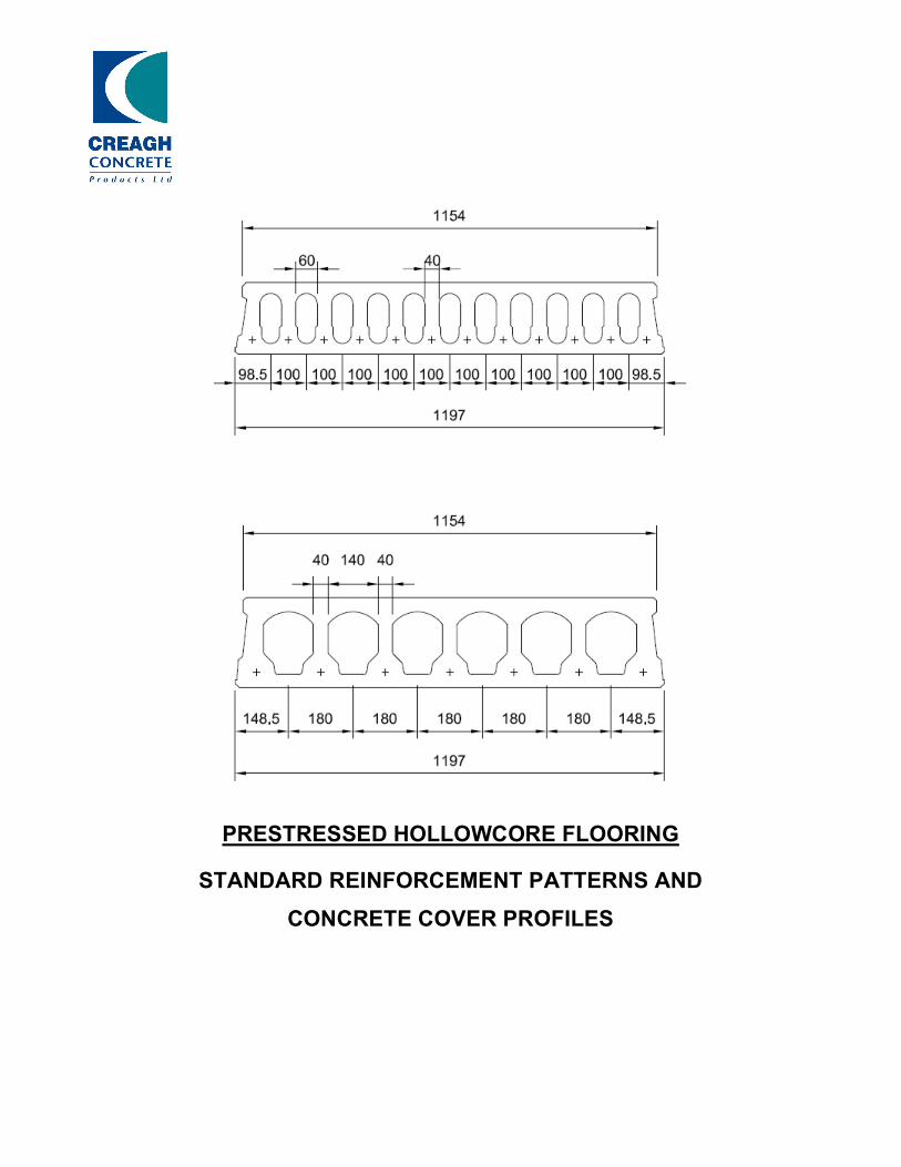
PRESTRESSED HOLLOWCORE FLOORING
STANDARD REINFORCEMENT PATTERNS AND
CONCRETE COVER PROFILES
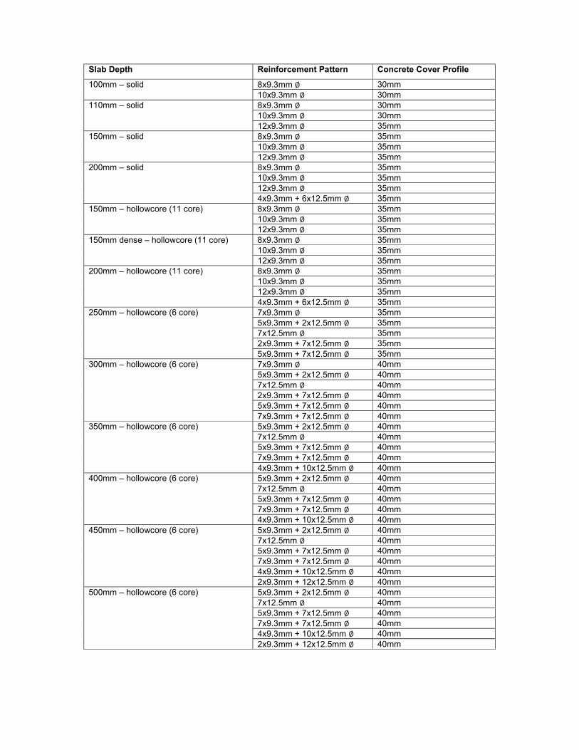
Slab Depth Reinforcement Pattern Concrete Cover Profile
100mm – solid 8x9.3mm ∅ 30mm 10x9.3mm ∅ 30mm
110mm – solid 8x9.3mm ∅ 30mm 10x9.3mm ∅ 30mm 12x9.3mm ∅ 35mm
150mm – solid 8x9.3mm ∅ 35mm 10x9.3mm ∅ 35mm 12x9.3mm ∅ 35mm
200mm – solid 8x9.3mm ∅ 35mm 10x9.3mm ∅ 35mm 12x9.3mm ∅ 35mm 4x9.3mm + 6x12.5mm ∅ 35mm
150mm – hollowcore (11 core) 8x9.3mm ∅ 35mm 10x9.3mm ∅ 35mm 12x9.3mm ∅ 35mm
150mm dense – hollowcore (11 core) 8x9.3mm ∅ 35mm 10x9.3mm ∅ 35mm 12x9.3mm ∅ 35mm
200mm – hollowcore (11 core) 8x9.3mm ∅ 35mm 10x9.3mm ∅ 35mm 12x9.3mm ∅ 35mm 4x9.3mm + 6x12.5mm ∅ 35mm
250mm – hollowcore (6 core) 7x9.3mm ∅ 35mm 5x9.3mm + 2x12.5mm ∅ 35mm 7x12.5mm ∅ 35mm 2x9.3mm + 7x12.5mm ∅ 35mm 5x9.3mm + 7x12.5mm ∅ 35mm
300mm – hollowcore (6 core) 7x9.3mm ∅ 40mm 5x9.3mm + 2x12.5mm ∅ 40mm 7x12.5mm ∅ 40mm 2x9.3mm + 7x12.5mm ∅ 40mm 5x9.3mm + 7x12.5mm ∅ 40mm 7x9.3mm + 7x12.5mm ∅ 40mm
350mm – hollowcore (6 core) 5x9.3mm + 2x12.5mm ∅ 40mm 7x12.5mm ∅ 40mm 5x9.3mm + 7x12.5mm ∅ 40mm 7x9.3mm + 7x12.5mm ∅ 40mm 4x9.3mm + 10x12.5mm ∅ 40mm
400mm – hollowcore (6 core) 5x9.3mm + 2x12.5mm ∅ 40mm 7x12.5mm ∅ 40mm 5x9.3mm + 7x12.5mm ∅ 40mm 7x9.3mm + 7x12.5mm ∅ 40mm 4x9.3mm + 10x12.5mm ∅ 40mm
450mm – hollowcore (6 core) 5x9.3mm + 2x12.5mm ∅ 40mm 7x12.5mm ∅ 40mm 5x9.3mm + 7x12.5mm ∅ 40mm 7x9.3mm + 7x12.5mm ∅ 40mm 4x9.3mm + 10x12.5mm ∅ 40mm 2x9.3mm + 12x12.5mm ∅ 40mm
500mm – hollowcore (6 core) 5x9.3mm + 2x12.5mm ∅ 40mm 7x12.5mm ∅ 40mm 5x9.3mm + 7x12.5mm ∅ 40mm 7x9.3mm + 7x12.5mm ∅ 40mm 4x9.3mm + 10x12.5mm ∅ 40mm 2x9.3mm + 12x12.5mm ∅ 40mm
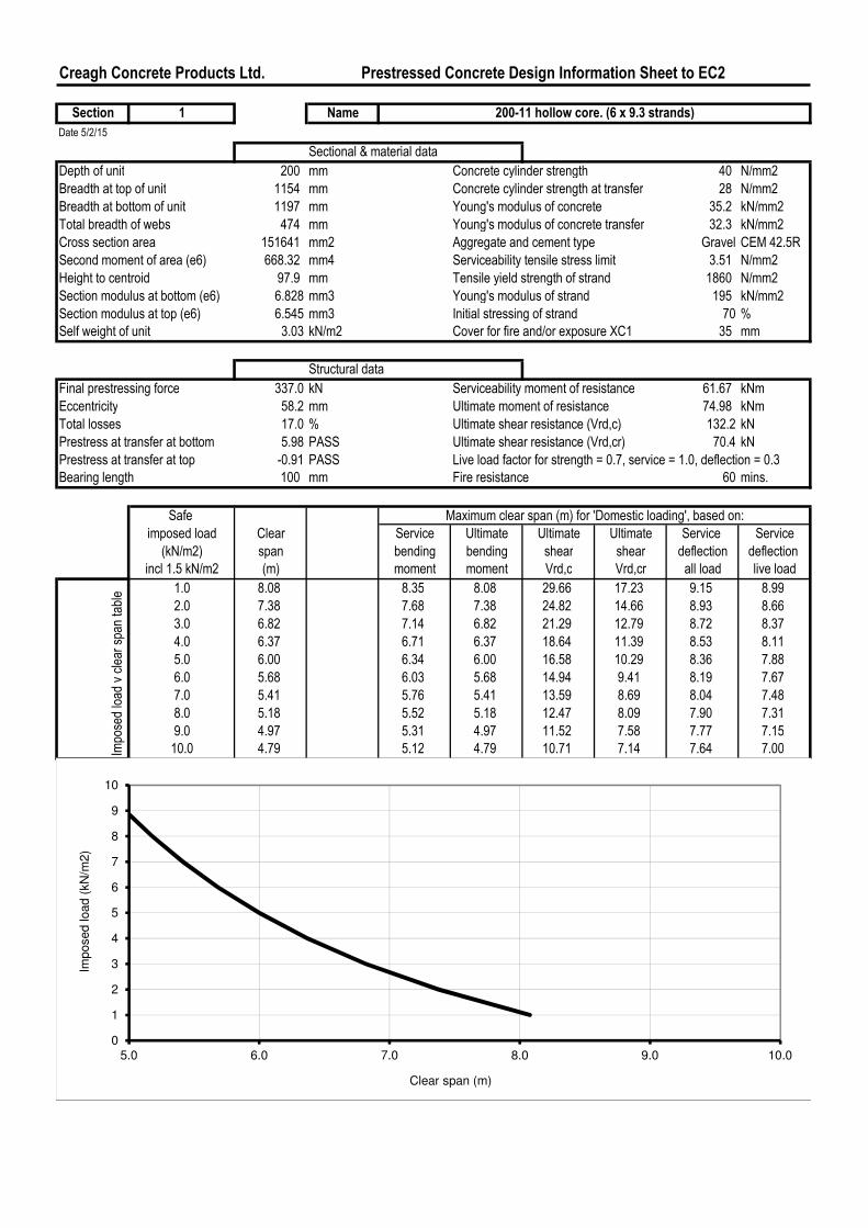
Creagh Concrete Products Ltd. Prestressed Concrete Design Information Sheet to EC2
Section 1 Name
Date 5/2/15
Sectional & material data
Depth of unit 200 mm Concrete cylinder strength 40 N/mm2
Breadth at top of unit 1154 mm Concrete cylinder strength at transfer 28 N/mm2
Breadth at bottom of unit 1197 mm Young's modulus of concrete 35.2 kN/mm2
Total breadth of webs 474 mm Young's modulus of concrete transfer 32.3 kN/mm2
Cross section area 151641 mm2 Aggregate and cement type Gravel CEM 42.5R
Second moment of area (e6) 668.32 mm4 Serviceability tensile stress limit 3.51 N/mm2
Height to centroid 97.9 mm Tensile yield strength of strand 1860 N/mm2
Section modulus at bottom (e6) 6.828 mm3 Young's modulus of strand 195 kN/mm2
Section modulus at top (e6) 6.545 mm3 Initial stressing of strand 70 %
Self weight of unit 3.03 kN/m2 Cover for fire and/or exposure XC1 35 mm
Structural data
Final prestressing force 337.0 kN Serviceability moment of resistance 61.67 kNm
Eccentricity 58.2 mm Ultimate moment of resistance 74.98 kNm
Total losses 17.0 % Ultimate shear resistance (Vrd,c) 132.2 kN
Prestress at transfer at bottom 5.98 PASS Ultimate shear resistance (Vrd,cr) 70.4 kN
Prestress at transfer at top -0.91 PASS Live load factor for strength = 0.7, service = 1.0, deflection = 0.3
Bearing length 100 mm Fire resistance 60 mins.
Safe
imposed load Clear Service Ultimate Ultimate Ultimate Service Service
(kN/m2) span bending bending shear shear deflection deflection
incl 1.5 kN/m2 (m) moment moment Vrd,c Vrd,cr all load live load
1.0 8.08 8.35 8.08 29.66 17.23 9.15 8.99
2.0 7.38 7.68 7.38 24.82 14.66 8.93 8.66
3.0 6.82 7.14 6.82 21.29 12.79 8.72 8.37
4.0 6.37 6.71 6.37 18.64 11.39 8.53 8.11
5.0 6.00 6.34 6.00 16.58 10.29 8.36 7.88
6.0 5.68 6.03 5.68 14.94 9.41 8.19 7.67
7.0 5.41 5.76 5.41 13.59 8.69 8.04 7.48
8.0 5.18 5.52 5.18 12.47 8.09 7.90 7.31
9.0 4.97 5.31 4.97 11.52 7.58 7.77 7.15
10.0 4.79 5.12 4.79 10.71 7.14 7.64 7.00
200-11 hollow core. (6 x 9.3 strands)
Maximum clear span (m) for 'Domestic loading', based on:
Impo
sed load
v clear spa
n table
0
1
2
3
4
5
6
7
8
9
10
5.0 6.0 7.0 8.0 9.0 10.0
Imposed load (
kN
/m2)
Clear span (m)
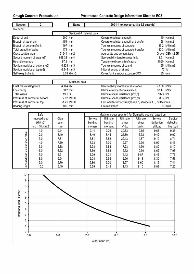
Creagh Concrete Products Ltd. Prestressed Concrete Design Information Sheet to EC2
Section 2 Name
Date 5/2/15
Sectional & material data
Depth of unit 200 mm Concrete cylinder strength 40 N/mm2
Breadth at top of unit 1154 mm Concrete cylinder strength at transfer 28 N/mm2
Breadth at bottom of unit 1197 mm Young's modulus of concrete 35.2 kN/mm2
Total breadth of webs 474 mm Young's modulus of concrete transfer 32.3 kN/mm2
Cross section area 151641 mm2 Aggregate and cement type Gravel CEM 42.5R
Second moment of area (e6) 668.32 mm4 Serviceability tensile stress limit 3.51 N/mm2
Height to centroid 97.9 mm Tensile yield strength of strand 1860 N/mm2
Section modulus at bottom (e6) 6.828 mm3 Young's modulus of strand 195 kN/mm2
Section modulus at top (e6) 6.545 mm3 Initial stressing of strand 70 %
Self weight of unit 3.03 kN/m2 Cover for fire and/or exposure XC1 35 mm
Structural data
Final prestressing force 438.4 kN Serviceability moment of resistance 73.80 kNm
Eccentricity 58.2 mm Ultimate moment of resistance 98.17 kNm
Total losses 19.1 % Ultimate shear resistance (Vrd,c) 137.4 kN
Prestress at transfer at bottom 7.92 PASS Ultimate shear resistance (Vrd,cr) 80.7 kN
Prestress at transfer at top -1.21 PASS Live load factor for strength = 0.7, service = 1.0, deflection = 0.3
Bearing length 100 mm Fire resistance 60 mins.
Safe
imposed load Clear Service Ultimate Ultimate Ultimate Service Service
(kN/m2) span bending bending shear shear deflection deflection
incl 1.5 kN/m2 (m) moment moment Vrd,c Vrd,cr all load live load
1.0 9.14 9.14 9.26 30.83 19.65 9.66 9.38
2.0 8.40 8.40 8.45 25.80 16.72 9.42 9.02
3.0 7.81 7.81 7.82 22.13 14.57 9.19 8.71
4.0 7.30 7.33 7.30 19.37 12.96 8.99 8.43
5.0 6.88 6.93 6.88 17.23 11.70 8.80 8.19
6.0 6.52 6.59 6.52 15.52 10.70 8.62 7.96
7.0 6.21 6.29 6.21 14.12 9.87 8.46 7.76
8.0 5.94 6.03 5.94 12.96 9.18 8.30 7.58
9.0 5.70 5.80 5.70 11.97 8.60 8.16 7.41
10.0 5.49 5.59 5.49 11.13 8.10 8.02 7.25
200-11 hollow core. (8 x 9.3 strands)
Maximum clear span (m) for 'Domestic loading', based on:
Impo
sed load
v clear spa
n table
0
1
2
3
4
5
6
7
8
9
10
5.0 6.0 7.0 8.0 9.0 10.0
Imposed load (
kN
/m2)
Clear span (m)
Creagh Concrete Products Ltd. Prestressed Concrete Design Information Sheet to EC2
Section 3 Name
Date 5/2/15
Sectional & material data
Depth of unit 200 mm Concrete cylinder strength 40 N/mm2
Breadth at top of unit 1154 mm Concrete cylinder strength at transfer 28 N/mm2
Breadth at bottom of unit 1197 mm Young's modulus of concrete 35.2 kN/mm2
Total breadth of webs 474 mm Young's modulus of concrete transfer 32.3 kN/mm2
Cross section area 151641 mm2 Aggregate and cement type Gravel CEM 42.5R
Second moment of area (e6) 668.32 mm4 Serviceability tensile stress limit 3.51 N/mm2
Height to centroid 97.9 mm Tensile yield strength of strand 1860 N/mm2
Section modulus at bottom (e6) 6.828 mm3 Young's modulus of strand 195 kN/mm2
Section modulus at top (e6) 6.545 mm3 Initial stressing of strand 70.00 %
Self weight of unit 3.03 kN/m2 Cover for fire and/or exposure XC1 35 mm
Structural data
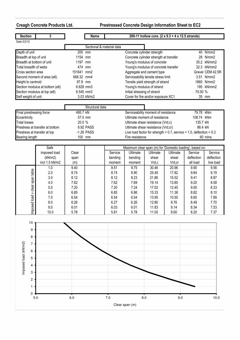
Final prestressing force 495.7 kN Serviceability moment of resistance 79.78 kNm
Eccentricity 57.0 mm Ultimate moment of resistance 108.74 kNm
Total losses 20.0 % Ultimate shear resistance (Vrd,c) 135.7 kN
Prestress at transfer at bottom 8.92 PASS Ultimate shear resistance (Vrd,cr) 86.4 kN
Prestress at transfer at top -1.26 PASS Live load factor for strength = 0.7, service = 1.0, deflection = 0.3
Bearing length 100 mm Fire resistance 60 mins.
Safe
imposed load Clear Service Ultimate Ultimate Ultimate Service Service
(kN/m2) span bending bending shear shear deflection deflection
incl 1.5 kN/m2 (m) moment moment Vrd,c Vrd,cr all load live load
1.0 9.40 9.51 9.75 30.46 20.96 9.90 9.56
2.0 8.74 8.74 8.90 25.49 17.82 9.64 9.19
3.0 8.12 8.12 8.23 21.86 15.52 9.41 8.87
4.0 7.62 7.62 7.69 19.14 13.80 9.20 8.58
5.0 7.20 7.20 7.24 17.02 12.45 9.00 8.33
6.0 6.85 6.85 6.86 15.33 11.38 8.82 8.10
7.0 6.54 6.54 6.54 13.95 10.50 8.65 7.89
8.0 6.26 6.27 6.26 12.80 9.76 8.49 7.70
9.0 6.01 6.03 6.01 11.83 9.14 8.34 7.53
10.0 5.78 5.81 5.78 11.00 8.60 8.20 7.37
200-11 hollow core. (2 x 9.3 + 4 x 12.5 strands)
Maximum clear span (m) for 'Domestic loading', based on:
Impo
sed load
v clear spa
n table
0
1
2
3
4
5
6
7
8
9
10
5.0 6.0 7.0 8.0 9.0 10.0
Imposed load (
kN
/m2)
Clear span (m)

Creagh Concrete Products Ltd. Prestressed Concrete Design Information Sheet to EC2
Section 4 Name
Date 5/2/15
Sectional & material data
Depth of unit 200 mm Concrete cylinder strength 40 N/mm2
Breadth at top of unit 1154 mm Concrete cylinder strength at transfer 28 N/mm2
Breadth at bottom of unit 1197 mm Young's modulus of concrete 35.2 kN/mm2
Total breadth of webs 474 mm Young's modulus of concrete transfer 32.3 kN/mm2
Cross section area 151641 mm2 Aggregate and cement type Gravel CEM 42.5R
Second moment of area (e6) 668.32 mm4 Serviceability tensile stress limit 3.51 N/mm2
Height to centroid 97.9 mm Tensile yield strength of strand 1860 N/mm2
Section modulus at bottom (e6) 6.828 mm3 Young's modulus of strand 195 kN/mm2
Section modulus at top (e6) 6.545 mm3 Initial stressing of strand 70.00 %
Self weight of unit 3.03 kN/m2 Cover for fire and/or exposure XC1 35 mm
Structural data
Final prestressing force 534.9 kN Serviceability moment of resistance 85.71 kNm
Eccentricity 58.2 mm Ultimate moment of resistance 117.88 kNm
Total losses 21.0 % Ultimate shear resistance (Vrd,c) 142.3 kN
Prestress at transfer at bottom 9.82 PASS Ultimate shear resistance (Vrd,cr) 91.2 kN
Prestress at transfer at top -1.50 PASS Live load factor for strength = 0.7, service = 1.0, deflection = 0.3
Bearing length 100 mm Fire resistance 60 mins.
Safe
imposed load Clear Service Ultimate Ultimate Ultimate Service Service
(kN/m2) span bending bending shear shear deflection deflection
incl 1.5 kN/m2 (m) moment moment Vrd,c Vrd,cr all load live load
1.0 9.40 9.86 10.15 31.92 22.07 10.15 9.74
2.0 9.05 9.05 9.27 26.72 18.75 9.88 9.36
3.0 8.41 8.41 8.57 22.91 16.33 9.64 9.03
4.0 7.89 7.89 8.01 20.05 14.51 9.42 8.74
5.0 7.46 7.46 7.55 17.84 13.09 9.22 8.48
6.0 7.09 7.09 7.15 16.07 11.96 9.03 8.24
7.0 6.76 6.76 6.81 14.62 11.03 8.85 8.03
8.0 6.48 6.48 6.52 13.41 10.25 8.68 7.83
9.0 6.23 6.23 6.26 12.39 9.59 8.53 7.66
10.0 6.01 6.01 6.03 11.52 9.02 8.38 7.49
200-11 hollow core. (10 x 9.3 strands)
Maximum clear span (m) for 'Domestic loading', based on:
Impo
sed load
v clear spa
n table
0
1
2
3
4
5
6
7
8
9
10
5.0 6.0 7.0 8.0 9.0 10.0
Imposed load (
kN
/m2)
Clear span (m)

Creagh Concrete Products Ltd. Prestressed Concrete Design Information Sheet to EC2
Section 5 Name
Date 5/2/15
Sectional & material data
Depth of unit 200 mm Concrete cylinder strength 40 N/mm2
Breadth at top of unit 1154 mm Concrete cylinder strength at transfer 28 N/mm2
Breadth at bottom of unit 1197 mm Young's modulus of concrete 35.2 kN/mm2
Total breadth of webs 474 mm Young's modulus of concrete transfer 32.3 kN/mm2
Cross section area 151641 mm2 Aggregate and cement type Gravel CEM 42.5R
Second moment of area (e6) 668.32 mm4 Serviceability tensile stress limit 3.51 N/mm2
Height to centroid 97.9 mm Tensile yield strength of strand 1860 N/mm2
Section modulus at bottom (e6) 6.828 mm3 Young's modulus of strand 195 kN/mm2
Section modulus at top (e6) 6.545 mm3 Initial stressing of strand 70.00 %
Self weight of unit 3.03 kN/m2 Cover for fire and/or exposure XC1 35 mm
Structural data
Final prestressing force 589.5 kN Serviceability moment of resistance 91.54 kNm
Eccentricity 57.2 mm Ultimate moment of resistance 126.74 kNm
Total losses 21.9 % Ultimate shear resistance (Vrd,c) 140.9 kN
Prestress at transfer at bottom 10.81 PASS Ultimate shear resistance (Vrd,cr) 96.4 kN
Prestress at transfer at top -1.55 PASS Live load factor for strength = 0.7, service = 1.0, deflection = 0.3
Bearing length 100 mm Fire resistance 60 mins.
Safe
imposed load Clear Service Ultimate Ultimate Ultimate Service Service
(kN/m2) span bending bending shear shear deflection deflection
incl 1.5 kN/m2 (m) moment moment Vrd,c Vrd,cr all load live load
1.0 9.40 10.19 10.53 31.60 23.28 10.37 9.91
2.0 9.36 9.36 9.62 26.45 19.77 10.10 9.52
3.0 8.70 8.70 8.89 22.67 17.20 9.85 9.18
4.0 8.16 8.16 8.31 19.85 15.28 9.62 8.88
5.0 7.71 7.71 7.83 17.66 13.78 9.41 8.61
6.0 7.32 7.32 7.42 15.91 12.58 9.21 8.37
7.0 6.99 6.99 7.07 14.47 11.60 9.03 8.15
8.0 6.70 6.70 6.76 13.28 10.78 8.86 7.95
9.0 6.44 6.44 6.49 12.27 10.08 8.70 7.77
10.0 6.21 6.21 6.25 11.41 9.48 8.55 7.60Impo
sed load
v clear spa
n table
200-11 hollow core. (4 x 9.3 + 4 x 12.5 strands)
Maximum clear span (m) for 'Domestic loading', based on:
0
1
2
3
4
5
6
7
8
9
10
5.0 6.0 7.0 8.0 9.0 10.0
Imposed load (
kN
/m2)
Clear span (m)

Creagh Concrete Products Ltd. Prestressed Concrete Design Information Sheet to EC2
Section 6 Name
Date 5/2/15
Sectional & material data
Depth of unit 200 mm Concrete cylinder strength 40 N/mm2
Breadth at top of unit 1154 mm Concrete cylinder strength at transfer 28 N/mm2
Breadth at bottom of unit 1197 mm Young's modulus of concrete 35.2 kN/mm2
Total breadth of webs 474 mm Young's modulus of concrete transfer 32.3 kN/mm2
Cross section area 151641 mm2 Aggregate and cement type Gravel CEM 42.5R
Second moment of area (e6) 668.32 mm4 Serviceability tensile stress limit 3.51 N/mm2
Height to centroid 97.9 mm Tensile yield strength of strand 1860 N/mm2
Section modulus at bottom (e6) 6.828 mm3 Young's modulus of strand 195 kN/mm2
Section modulus at top (e6) 6.545 mm3 Initial stressing of strand 70.00 %
Self weight of unit 3.03 kN/m2 Cover for fire and/or exposure XC1 35 mm
Structural data
Final prestressing force 626.5 kN Serviceability moment of resistance 97.41 kNm
Eccentricity 58.2 mm Ultimate moment of resistance 134.67 kNm
Total losses 22.9 % Ultimate shear resistance (Vrd,c) 146.9 kN
Prestress at transfer at bottom 11.70 PASS Ultimate shear resistance (Vrd,cr) 100.8 kN
Prestress at transfer at top -1.78 PASS Live load factor for strength = 0.7, service = 1.0, deflection = 0.3
Bearing length 100 mm Fire resistance 60 mins.
Safe
imposed load Clear Service Ultimate Ultimate Ultimate Service Service
(kN/m2) span bending bending shear shear deflection deflection
incl 1.5 kN/m2 (m) moment moment Vrd,c Vrd,cr all load live load
1.0 9.40 10.52 10.86 32.95 24.30 10.60 10.09
2.0 9.40 9.65 9.92 27.57 20.63 10.32 9.69
3.0 8.96 8.96 9.17 23.64 17.95 10.07 9.34
4.0 8.40 8.40 8.57 20.69 15.93 9.83 9.03
5.0 7.94 7.94 8.07 18.41 14.37 9.61 8.75
6.0 7.54 7.54 7.65 16.58 13.11 9.41 8.51
7.0 7.20 7.20 7.29 15.08 12.09 9.22 8.28
8.0 6.90 6.90 6.97 13.84 11.23 9.05 8.08
9.0 6.63 6.63 6.70 12.79 10.50 8.88 7.89
10.0 6.39 6.39 6.45 11.89 9.87 8.73 7.64
200-11 hollow core. (12 x 9.3 strands)
Maximum clear span (m) for 'Domestic loading', based on:
Impo
sed load
v clear spa
n table
0
1
2
3
4
5
6
7
8
9
10
5.0 6.0 7.0 8.0 9.0 10.0
Imposed load (
kN
/m2)
Clear span (m)

Creagh Concrete Products Ltd. Prestressed Concrete Design Information Sheet to EC2
Section 7 Name
Date 5/2/15
Sectional & material data
Depth of unit 200 mm Concrete cylinder strength 40 N/mm2
Breadth at top of unit 1154 mm Concrete cylinder strength at transfer 28 N/mm2
Breadth at bottom of unit 1197 mm Young's modulus of concrete 35.2 kN/mm2
Total breadth of webs 474 mm Young's modulus of concrete transfer 32.3 kN/mm2
Cross section area 151641 mm2 Aggregate and cement type Gravel CEM 42.5R
Second moment of area (e6) 668.32 mm4 Serviceability tensile stress limit 3.51 N/mm2
Height to centroid 97.9 mm Tensile yield strength of strand 1860 N/mm2
Section modulus at bottom (e6) 6.828 mm3 Young's modulus of strand 195 kN/mm2
Section modulus at top (e6) 6.545 mm3 Initial stressing of strand 70.00 %
Self weight of unit 3.03 kN/m2 Cover for fire and/or exposure XC1 35 mm
Structural data
Final prestressing force 746.7 kN Serviceability moment of resistance 111.55 kNm
Eccentricity 57.1 mm Ultimate moment of resistance 154.40 kNm
Total losses 25.1 % Ultimate shear resistance (Vrd,c) 146.8 kN
Prestress at transfer at bottom 14.07 PASS Ultimate shear resistance (Vrd,cr) 112.4 kN
Prestress at transfer at top -2.00 PASS Live load factor for strength = 0.7, service = 1.0, deflection = 0.3
Bearing length 100 mm Fire resistance 60 mins.
Safe
imposed load Clear Service Ultimate Ultimate Ultimate Service Service
(kN/m2) span bending bending shear shear deflection deflection
incl 1.5 kN/m2 (m) moment moment Vrd,c Vrd,cr all load live load
1.0 9.40 11.26 11.63 32.93 26.96 11.13 10.48
2.0 9.40 10.33 10.63 27.56 22.87 10.83 10.05
3.0 9.40 9.59 9.83 23.63 19.88 10.56 9.68
4.0 8.99 8.99 9.18 20.68 17.64 10.30 9.36
5.0 8.49 8.49 8.65 18.40 15.89 10.07 9.07
6.0 8.06 8.06 8.20 16.57 14.49 9.85 8.80
7.0 7.69 7.69 7.81 15.08 13.35 9.65 8.57
8.0 7.37 7.37 7.47 13.83 12.39 9.47 8.24
9.0 7.08 7.08 7.18 12.78 11.58 9.29 7.92
10.0 6.83 6.83 6.91 11.88 10.89 9.12 7.64Impo
sed load
v clear spa
n table
200-11 hollow core. (4 x 9.3 + 6 x 12.5 strands)
Maximum clear span (m) for 'Domestic loading', based on:
0
1
2
3
4
5
6
7
8
9
10
5.0 6.0 7.0 8.0 9.0 10.0
Imposed load (
kN
/m2)
Clear span (m)
Creagh Concrete Products Ltd. Prestressed Concrete Design Information Sheet to EC2
Section A-T Name
Date 5/2/15
Sectional & material data
Depth of unit 250 mm Concrete cylinder strength 40 N/mm2
Breadth at top of unit 1154 mm Concrete cylinder strength at transfer 28 N/mm2
Breadth at bottom of unit 1197 mm Young's modulus of concrete 35.2 kN/mm2
Total breadth of webs 300 mm Young's modulus of concrete transfer 32.3 kN/mm2
Cross section area 168011 mm2 Aggregate and cement type Gravel CEM 42.5R
Second moment of area (e6) 1270.55 mm4 Serviceability tensile stress limit 3.51 N/mm2
Height to centroid 123.0 mm Tensile yield strength of strand 1860 N/mm2
Section modulus at bottom (e6) 10.326 mm3 Young's modulus of strand 195 kN/mm2
Section modulus at top (e6) 10.008 mm3 Initial strand stressing 70 %
Self weight of unit 3.36 kN/m2 Cover for fire and/or exposure XC1 35 mm
Structural data
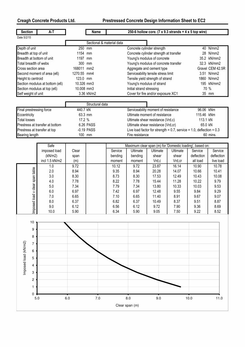
Final prestressing force 440.7 kN Serviceability moment of resistance 96.06 kNm
Eccentricity 63.3 mm Ultimate moment of resistance 115.46 kNm
Total losses 17.2 % Ultimate shear resistance (Vrd,c) 113.1 kN
Prestress at transfer at bottom 6.26 PASS Ultimate shear resistance (Vrd,cr) 65.0 kN
Prestress at transfer at top -0.19 PASS Live load factor for strength = 0.7, service = 1.0, deflection = 0.3
Bearing length 100 mm Fire resistance 60 mins.
Safe
imposed load Clear Service Ultimate Ultimate Ultimate Service Service
(kN/m2) span bending bending shear shear deflection deflection
incl 1.5 kN/m2 (m) moment moment Vrd,c Vrd,cr all load live load
1.0 9.72 10.12 9.72 23.87 16.14 10.90 10.78
2.0 8.94 9.35 8.94 20.28 14.07 10.66 10.41
3.0 8.30 8.73 8.30 17.53 12.49 10.43 10.08
4.0 7.78 8.22 7.78 15.44 11.28 10.22 9.79
5.0 7.34 7.79 7.34 13.80 10.33 10.03 9.53
6.0 6.97 7.42 6.97 12.48 9.55 9.84 9.29
7.0 6.65 7.10 6.65 11.40 8.91 9.67 9.07
8.0 6.37 6.82 6.37 10.49 8.37 9.51 8.87
9.0 6.12 6.56 6.12 9.72 7.90 9.36 8.69
10.0 5.90 6.34 5.90 9.05 7.50 9.22 8.52
250-6 hollow core. (7 x 9.3 strands + 4 x 5 top wire)
Maximum clear span (m) for 'Domestic loading', based on:
Impo
sed load
v clear spa
n table
0
1
2
3
4
5
6
7
8
9
10
5.0 6.0 7.0 8.0 9.0 10.0 11.0
Imposed load (
kN
/m2)
Clear span (m)
Creagh Concrete Products Ltd. Prestressed Concrete Design Information Sheet to EC2
Section B-T Name
Date 5/2/15
Sectional & material data
Depth of unit 250 mm Concrete cylinder strength 40 N/mm2
Breadth at top of unit 1154 mm Concrete cylinder strength at transfer 28 N/mm2
Breadth at bottom of unit 1197 mm Young's modulus of concrete 35.2 kN/mm2
Total breadth of webs 300 mm Young's modulus of concrete transfer 32.3 kN/mm2
Cross section area 168011 mm2 Aggregate and cement type Gravel CEM 42.5R
Second moment of area (e6) 1270.55 mm4 Serviceability tensile stress limit 3.51 N/mm2
Height to centroid 123.0 mm Tensile yield strength of strand 1860 N/mm2
Section modulus at bottom (e6) 10.326 mm3 Young's modulus of strand 195 kN/mm2
Section modulus at top (e6) 10.008 mm3 Initial strand stressing 70.00 %
Self weight of unit 3.36 kN/m2 Cover for fire and/or exposure XC1 35 mm
Structural data
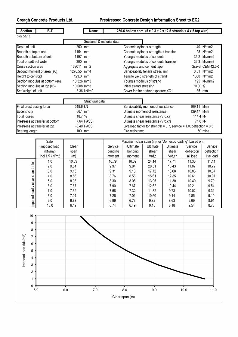
Final prestressing force 519.6 kN Serviceability moment of resistance 109.11 kNm
Eccentricity 66.1 mm Ultimate moment of resistance 139.47 kNm
Total losses 18.7 % Ultimate shear resistance (Vrd,c) 114.4 kN
Prestress at transfer at bottom 7.64 PASS Ultimate shear resistance (Vrd,cr) 71.8 kN
Prestress at transfer at top -0.40 PASS Live load factor for strength = 0.7, service = 1.0, deflection = 0.3
Bearing length 100 mm Fire resistance 60 mins.
Safe
imposed load Clear Service Ultimate Ultimate Ultimate Service Service
(kN/m2) span bending bending shear shear deflection deflection
incl 1.5 kN/m2 (m) moment moment Vrd,c Vrd,cr all load live load
1.0 10.69 10.79 10.69 24.14 17.71 11.33 11.11
2.0 9.84 9.97 9.84 20.51 15.43 11.07 10.72
3.0 9.13 9.31 9.13 17.72 13.68 10.83 10.37
4.0 8.56 8.76 8.56 15.61 12.35 10.61 10.07
5.0 8.08 8.30 8.08 13.95 11.30 10.40 9.79
6.0 7.67 7.90 7.67 12.62 10.44 10.21 9.54
7.0 7.32 7.56 7.32 11.52 9.73 10.02 9.31
8.0 7.01 7.26 7.01 10.60 9.14 9.85 9.10
9.0 6.73 6.99 6.73 9.82 8.63 9.69 8.91
10.0 6.49 6.74 6.49 9.15 8.18 9.54 8.73
250-6 hollow core. (5 x 9.3 + 2 x 12.5 strands + 4 x 5 top wire)
Maximum clear span (m) for 'Domestic loading', based on:
Impo
sed load
v clear spa
n table
0
1
2
3
4
5
6
7
8
9
10
5.0 6.0 7.0 8.0 9.0 10.0 11.0
Imposed load (
kN
/m2)
Clear span (m)

Creagh Concrete Products Ltd. Prestressed Concrete Design Information Sheet to EC2
Section C-T Name
Date 5/2/15
Sectional & material data
Depth of unit 250 mm Concrete cylinder strength 40 N/mm2
Breadth at top of unit 1154 mm Concrete cylinder strength at transfer 28 N/mm2
Breadth at bottom of unit 1197 mm Young's modulus of concrete 35.2 kN/mm2
Total breadth of webs 300 mm Young's modulus of concrete transfer 32.3 kN/mm2
Cross section area 168011 mm2 Aggregate and cement type Gravel CEM 42.5R
Second moment of area (e6) 1270.55 mm4 Serviceability tensile stress limit 3.51 N/mm2
Height to centroid 123.0 mm Tensile yield strength of strand 1860 N/mm2
Section modulus at bottom (e6) 10.326 mm3 Young's modulus of strand 195 kN/mm2
Section modulus at top (e6) 10.008 mm3 Initial strand stressing 70.00 %
Self weight of unit 3.36 kN/m2 Cover for fire and/or exposure XC1 35 mm
Structural data
Final prestressing force 632.5 kN Serviceability moment of resistance 128.32 kNm
Eccentricity 68.8 mm Ultimate moment of resistance 173.49 kNm
Total losses 20.9 % Ultimate shear resistance (Vrd,c) 115.8 kN
Prestress at transfer at bottom 9.68 PASS Ultimate shear resistance (Vrd,cr) 81.2 kN
Prestress at transfer at top -0.71 PASS Live load factor for strength = 0.7, service = 1.0, deflection = 0.3
Bearing length 100 mm Fire resistance 60 mins.
Safe
imposed load Clear Service Ultimate Ultimate Ultimate Service Service
(kN/m2) span bending bending shear shear deflection deflection
incl 1.5 kN/m2 (m) moment moment Vrd,c Vrd,cr all load live load
1.0 10.80 11.71 11.94 24.42 19.86 11.95 11.57
2.0 10.80 10.81 10.99 20.75 17.28 11.66 11.15
3.0 10.09 10.09 10.20 17.93 15.31 11.40 10.79
4.0 9.49 9.49 9.55 15.79 13.80 11.16 10.46
5.0 8.99 8.99 9.02 14.12 12.62 10.93 10.17
6.0 8.56 8.56 8.56 12.77 11.65 10.72 9.90
7.0 8.17 8.18 8.17 11.66 10.86 10.53 9.66
8.0 7.83 7.85 7.83 10.73 10.18 10.35 9.44
9.0 7.52 7.56 7.52 9.94 9.61 10.17 9.23
10.0 7.25 7.30 7.25 9.26 9.11 10.01 9.04
250-6 hollow core. (2 x 9.3 + 5 x 12.5 strands + 4 x 5 top wire)Im
posed load
v clear spa
n table
Maximum clear span (m) for 'Domestic loading', based on:
0
1
2
3
4
5
6
7
8
9
10
5.0 6.0 7.0 8.0 9.0 10.0 11.0
Imposed load (
kN
/m2)
Clear span (m)
Creagh Concrete Products Ltd. Prestressed Concrete Design Information Sheet to EC2
Section D-T Name
Date 5/2/15
Sectional & material data
Depth of unit 250 mm Concrete cylinder strength 40 N/mm2
Breadth at top of unit 1154 mm Concrete cylinder strength at transfer 28 N/mm2
Breadth at bottom of unit 1197 mm Young's modulus of concrete 35.2 kN/mm2
Total breadth of webs 300 mm Young's modulus of concrete transfer 32.3 kN/mm2
Cross section area 168011 mm2 Aggregate and cement type Gravel CEM 42.5R
Second moment of area (e6) 1270.55 mm4 Serviceability tensile stress limit 3.51 N/mm2
Height to centroid 123.0 mm Tensile yield strength of strand 1860 N/mm2
Section modulus at bottom (e6) 10.326 mm3 Young's modulus of strand 195 kN/mm2
Section modulus at top (e6) 10.008 mm3 Initial strand stressing 70.00 %
Self weight of unit 3.36 kN/m2 Cover for fire and/or exposure XC1 35 mm
Structural data
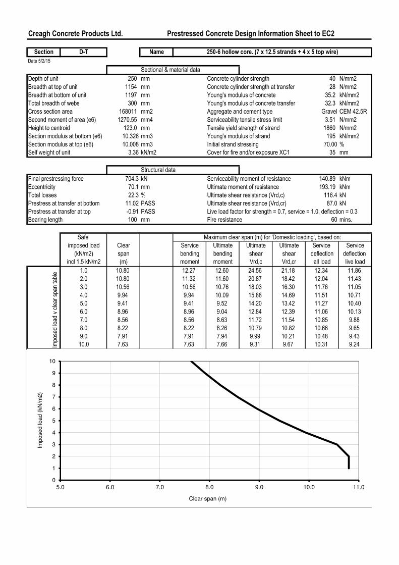
Final prestressing force 704.3 kN Serviceability moment of resistance 140.89 kNm
Eccentricity 70.1 mm Ultimate moment of resistance 193.19 kNm
Total losses 22.3 % Ultimate shear resistance (Vrd,c) 116.4 kN
Prestress at transfer at bottom 11.02 PASS Ultimate shear resistance (Vrd,cr) 87.0 kN
Prestress at transfer at top -0.91 PASS Live load factor for strength = 0.7, service = 1.0, deflection = 0.3
Bearing length 100 mm Fire resistance 60 mins.
Safe
imposed load Clear Service Ultimate Ultimate Ultimate Service Service
(kN/m2) span bending bending shear shear deflection deflection
incl 1.5 kN/m2 (m) moment moment Vrd,c Vrd,cr all load live load
1.0 10.80 12.27 12.60 24.56 21.18 12.34 11.86
2.0 10.80 11.32 11.60 20.87 18.42 12.04 11.43
3.0 10.56 10.56 10.76 18.03 16.30 11.76 11.05
4.0 9.94 9.94 10.09 15.88 14.69 11.51 10.71
5.0 9.41 9.41 9.52 14.20 13.42 11.27 10.40
6.0 8.96 8.96 9.04 12.84 12.39 11.06 10.13
7.0 8.56 8.56 8.63 11.72 11.54 10.85 9.88
8.0 8.22 8.22 8.26 10.79 10.82 10.66 9.65
9.0 7.91 7.91 7.94 9.99 10.21 10.48 9.43
10.0 7.63 7.63 7.66 9.31 9.67 10.31 9.24
250-6 hollow core. (7 x 12.5 strands + 4 x 5 top wire)Im
posed load
v clear spa
n table
Maximum clear span (m) for 'Domestic loading', based on:
0
1
2
3
4
5
6
7
8
9
10
5.0 6.0 7.0 8.0 9.0 10.0 11.0
Imposed load (
kN
/m2)
Clear span (m)

Creagh Concrete Products Ltd. Prestressed Concrete Design Information Sheet to EC2
Section E-T Name
Date 5/2/15
Sectional & material data
Depth of unit 250 mm Concrete cylinder strength 40 N/mm2
Breadth at top of unit 1154 mm Concrete cylinder strength at transfer 28 N/mm2
Breadth at bottom of unit 1197 mm Young's modulus of concrete 35.2 kN/mm2
Total breadth of webs 300 mm Young's modulus of concrete transfer 32.3 kN/mm2
Cross section area 168011 mm2 Aggregate and cement type Gravel CEM 42.5R
Second moment of area (e6) 1270.55 mm4 Serviceability tensile stress limit 3.51 N/mm2
Height to centroid 123.0 mm Tensile yield strength of strand 1860 N/mm2
Section modulus at bottom (e6) 10.326 mm3 Young's modulus of strand 195 kN/mm2
Section modulus at top (e6) 10.008 mm3 Initial strand stressing 70.00 %
Self weight of unit 3.36 kN/m2 Cover for fire and/or exposure XC1 35 mm
Structural data
Final prestressing force 791.0 kN Serviceability moment of resistance 157.25 kNm
Eccentricity 71.8 mm Ultimate moment of resistance 215.89 kNm
Total losses 24.0 % Ultimate shear resistance (Vrd,c) 120.6 kN
Prestress at transfer at bottom 12.73 PASS Ultimate shear resistance (Vrd,cr) 94.1 kN
Prestress at transfer at top -1.21 PASS Live load factor for strength = 0.7, service = 1.0, deflection = 0.3
Bearing length 100 mm Fire resistance 60 mins.
Safe
imposed load Clear Service Ultimate Ultimate Ultimate Service Service
(kN/m2) span bending bending shear shear deflection deflection
incl 1.5 kN/m2 (m) moment moment Vrd,c Vrd,cr all load live load
1.0 10.80 12.97 13.33 25.42 22.78 12.83 12.23
2.0 10.80 11.96 12.27 21.60 19.79 12.52 11.78
3.0 10.80 11.15 11.39 18.66 17.51 12.23 11.38
4.0 10.48 10.48 10.67 16.44 15.77 11.96 11.02
5.0 9.92 9.92 10.07 14.69 14.40 11.71 10.70
6.0 9.44 9.44 9.56 13.28 13.29 11.48 10.42
7.0 9.03 9.03 9.13 12.13 12.37 11.26 10.15
8.0 8.66 8.66 8.74 11.16 11.59 11.06 9.91
9.0 8.33 8.33 8.40 10.34 10.93 10.87 9.69
10.0 8.04 8.04 8.10 9.63 10.35 10.69 9.49Impo
sed load
v clear spa
n table
Maximum clear span (m) for 'Domestic loading', based on:
250-6 hollow core. (2 x 9.3 + 7 x 12.5 strands + 4 x 5 top wire)
0
1
2
3
4
5
6
7
8
9
10
5.0 6.0 7.0 8.0 9.0 10.0 11.0
Imposed load (
kN
/m2)
Clear span (m)
Creagh Concrete Products Ltd. Prestressed Concrete Design Information Sheet to EC2
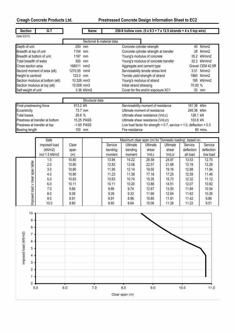
Section G-T Name
Date 5/2/15
Sectional & material data
Depth of unit 250 mm Concrete cylinder strength 40 N/mm2
Breadth at top of unit 1154 mm Concrete cylinder strength at transfer 28 N/mm2
Breadth at bottom of unit 1197 mm Young's modulus of concrete 35.2 kN/mm2
Total breadth of webs 300 mm Young's modulus of concrete transfer 32.3 kN/mm2
Cross section area 168011 mm2 Aggregate and cement type Gravel CEM 42.5R
Second moment of area (e6) 1270.55 mm4 Serviceability tensile stress limit 3.51 N/mm2
Height to centroid 123.0 mm Tensile yield strength of strand 1860 N/mm2
Section modulus at bottom (e6) 10.326 mm3 Young's modulus of strand 195 kN/mm2
Section modulus at top (e6) 10.008 mm3 Initial strand stressing 70.00 %
Self weight of unit 3.36 kN/m2 Cover for fire and/or exposure XC1 35 mm
Structural data
Final prestressing force 913.2 kN Serviceability moment of resistance 181.36 kNm
Eccentricity 73.7 mm Ultimate moment of resistance 245.38 kNm
Total losses 26.6 % Ultimate shear resistance (Vrd,c) 126.1 kN
Prestress at transfer at bottom 15.25 PASS Ultimate shear resistance (Vrd,cr) 103.8 kN
Prestress at transfer at top -1.65 PASS Live load factor for strength = 0.7, service = 1.0, deflection = 0.3
Bearing length 100 mm Fire resistance 60 mins.
Safe
imposed load Clear Service Ultimate Ultimate Ultimate Service Service
(kN/m2) span bending bending shear shear deflection deflection
incl 1.5 kN/m2 (m) moment moment Vrd,c Vrd,cr all load live load
1.0 10.80 13.94 14.22 26.58 24.97 13.53 12.75
2.0 10.80 12.83 13.08 22.57 21.68 13.19 12.26
3.0 10.80 11.95 12.14 19.50 19.16 12.88 11.84
4.0 10.80 11.23 11.38 17.18 17.25 12.59 11.46
5.0 10.63 10.63 10.74 15.35 15.73 12.32 11.12
6.0 10.11 10.11 10.20 13.88 14.51 12.07 10.82
7.0 9.66 9.66 9.74 12.67 13.50 11.84 10.54
8.0 9.26 9.26 9.33 11.66 12.64 11.62 10.26
9.0 8.91 8.91 8.96 10.80 11.91 11.42 9.86
10.0 8.60 8.60 8.64 10.06 11.28 11.22 9.51Impo
sed load
v clear spa
n table
Maximum clear span (m) for 'Domestic loading', based on:
250-6 hollow core. (5 x 9.3 + 7 x 12.5 strands + 4 x 5 top wire)
0
1
2
3
4
5
6
7
8
9
10
5.0 6.0 7.0 8.0 9.0 10.0 11.0
Imposed load (
kN
/m2)
Clear span (m)
Creagh Concrete Products Ltd. Prestressed Concrete Design Information Sheet to EC2
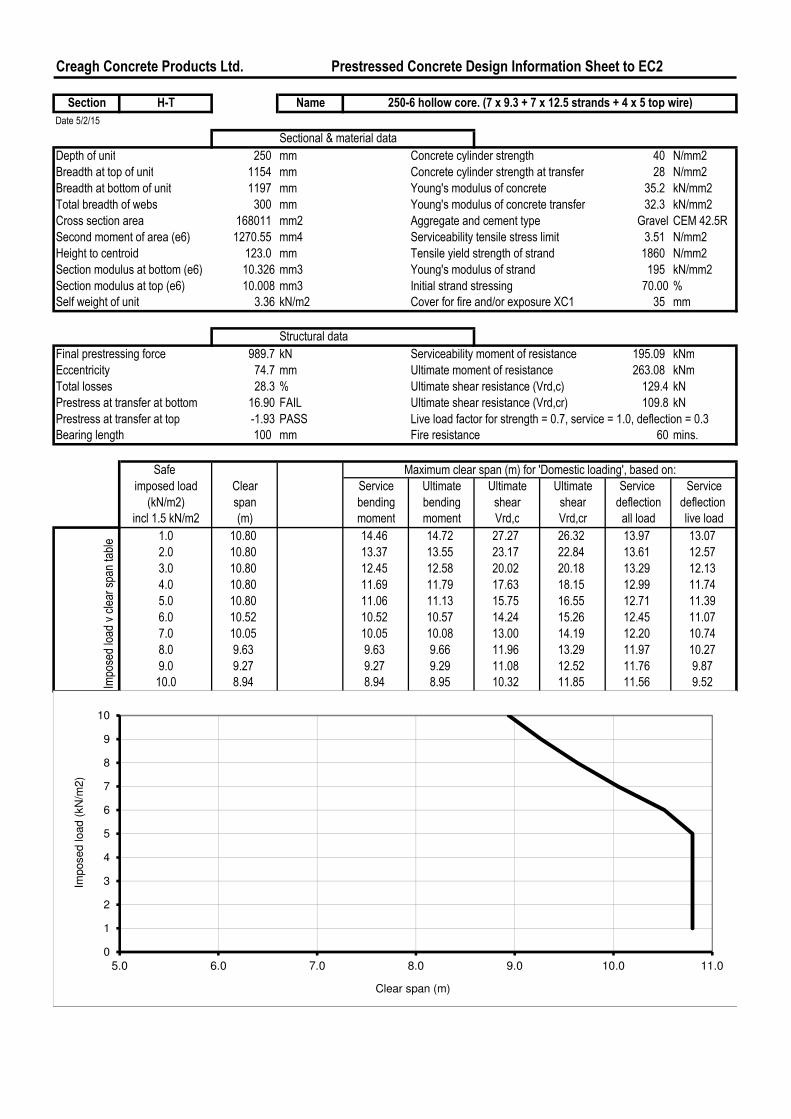
Section H-T Name
Date 5/2/15
Sectional & material data
Depth of unit 250 mm Concrete cylinder strength 40 N/mm2
Breadth at top of unit 1154 mm Concrete cylinder strength at transfer 28 N/mm2
Breadth at bottom of unit 1197 mm Young's modulus of concrete 35.2 kN/mm2
Total breadth of webs 300 mm Young's modulus of concrete transfer 32.3 kN/mm2
Cross section area 168011 mm2 Aggregate and cement type Gravel CEM 42.5R
Second moment of area (e6) 1270.55 mm4 Serviceability tensile stress limit 3.51 N/mm2
Height to centroid 123.0 mm Tensile yield strength of strand 1860 N/mm2
Section modulus at bottom (e6) 10.326 mm3 Young's modulus of strand 195 kN/mm2
Section modulus at top (e6) 10.008 mm3 Initial strand stressing 70.00 %
Self weight of unit 3.36 kN/m2 Cover for fire and/or exposure XC1 35 mm
Structural data
Final prestressing force 989.7 kN Serviceability moment of resistance 195.09 kNm
Eccentricity 74.7 mm Ultimate moment of resistance 263.08 kNm
Total losses 28.3 % Ultimate shear resistance (Vrd,c) 129.4 kN
Prestress at transfer at bottom 16.90 FAIL Ultimate shear resistance (Vrd,cr) 109.8 kN
Prestress at transfer at top -1.93 PASS Live load factor for strength = 0.7, service = 1.0, deflection = 0.3
Bearing length 100 mm Fire resistance 60 mins.
Safe
imposed load Clear Service Ultimate Ultimate Ultimate Service Service
(kN/m2) span bending bending shear shear deflection deflection
incl 1.5 kN/m2 (m) moment moment Vrd,c Vrd,cr all load live load
1.0 10.80 14.46 14.72 27.27 26.32 13.97 13.07
2.0 10.80 13.37 13.55 23.17 22.84 13.61 12.57
3.0 10.80 12.45 12.58 20.02 20.18 13.29 12.13
4.0 10.80 11.69 11.79 17.63 18.15 12.99 11.74
5.0 10.80 11.06 11.13 15.75 16.55 12.71 11.39
6.0 10.52 10.52 10.57 14.24 15.26 12.45 11.07
7.0 10.05 10.05 10.08 13.00 14.19 12.20 10.74
8.0 9.63 9.63 9.66 11.96 13.29 11.97 10.27
9.0 9.27 9.27 9.29 11.08 12.52 11.76 9.87
10.0 8.94 8.94 8.95 10.32 11.85 11.56 9.52Impo
sed load
v clear spa
n table
Maximum clear span (m) for 'Domestic loading', based on:
250-6 hollow core. (7 x 9.3 + 7 x 12.5 strands + 4 x 5 top wire)
0
1
2
3
4
5
6
7
8
9
10
5.0 6.0 7.0 8.0 9.0 10.0 11.0
Imposed load (
kN
/m2)
Clear span (m)
Creagh Concrete Products Ltd. Prestressed Concrete Design Information Sheet to EC2
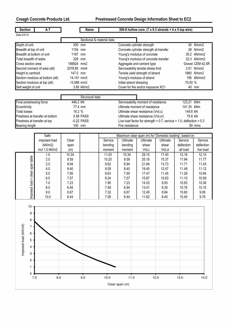
Section A-T Name
Date 5/2/15
Sectional & material data
Depth of unit 300 mm Concrete cylinder strength 40 N/mm2
Breadth at top of unit 1154 mm Concrete cylinder strength at transfer 28 N/mm2
Breadth at bottom of unit 1197 mm Young's modulus of concrete 35.2 kN/mm2
Total breadth of webs 329 mm Young's modulus of concrete transfer 32.3 kN/mm2
Cross section area 189924 mm2 Aggregate and cement type Gravel CEM 42.5R
Second moment of area (e6) 2078.85 mm4 Serviceability tensile stress limit 3.51 N/mm2
Height to centroid 147.0 mm Tensile yield strength of strand 1860 N/mm2
Section modulus at bottom (e6) 14.141 mm3 Young's modulus of strand 195 kN/mm2
Section modulus at top (e6) 13.588 mm3 Initial strand stressing 70.00 %
Self weight of unit 3.80 kN/m2 Cover for fire and/or exposure XC1 40 mm
Structural data
Final prestressing force 446.2 kN Serviceability moment of resistance 123.21 kNm
Eccentricity 77.4 mm Ultimate moment of resistance 141.35 kNm
Total losses 16.2 % Ultimate shear resistance (Vrd,c) 149.8 kN
Prestress at transfer at bottom 5.58 PASS Ultimate shear resistance (Vrd,cr) 75.8 kN
Prestress at transfer at top -0.22 PASS Live load factor for strength = 0.7, service = 1.0, deflection = 0.3
Bearing length 100 mm Fire resistance 90 mins.
Safe
imposed load Clear Service Ultimate Ultimate Ultimate Service Service
(kN/m2) span bending bending shear shear deflection deflection
incl 1.5 kN/m2 (m) moment moment Vrd,c Vrd,cr all load live load
1.0 10.34 11.03 10.34 29.15 17.40 12.18 12.15
2.0 9.59 10.25 9.59 25.18 15.37 11.94 11.77
3.0 8.94 9.62 8.94 21.94 13.73 11.71 11.43
4.0 8.40 9.09 8.40 19.45 12.47 11.49 11.12
5.0 7.95 8.63 7.95 17.47 11.45 11.29 10.84
6.0 7.57 8.24 7.57 15.87 10.63 11.10 10.59
7.0 7.23 7.90 7.23 14.53 9.93 10.93 10.36
8.0 6.94 7.59 6.94 13.41 9.35 10.76 10.15
9.0 6.67 7.32 6.67 12.45 8.84 10.60 9.95
10.0 6.44 7.08 6.44 11.62 8.40 10.45 9.76
300-6 hollow core. (7 x 9.3 strands + 4 x 5 top wire)Imposed load v clear span table
Maximum clear span (m) for 'Domestic loading', based on:
0
1
2
3
4
5
6
7
8
9
10
7.0 8.0 9.0 10.0 11.0 12.0 13.0 14.0
Imposed load (
kN
/m2)
Clear span (m)
Creagh Concrete Products Ltd. Prestressed Concrete Design Information Sheet to EC2
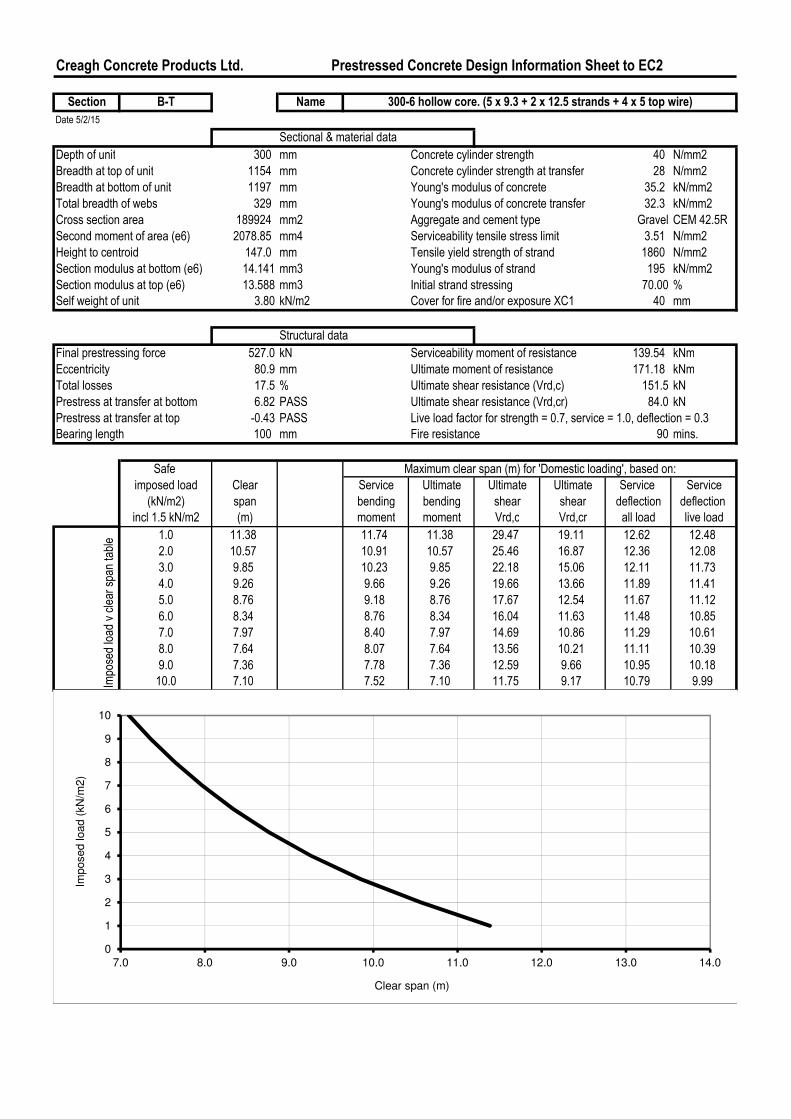
Section B-T Name
Date 5/2/15
Sectional & material data
Depth of unit 300 mm Concrete cylinder strength 40 N/mm2
Breadth at top of unit 1154 mm Concrete cylinder strength at transfer 28 N/mm2
Breadth at bottom of unit 1197 mm Young's modulus of concrete 35.2 kN/mm2
Total breadth of webs 329 mm Young's modulus of concrete transfer 32.3 kN/mm2
Cross section area 189924 mm2 Aggregate and cement type Gravel CEM 42.5R
Second moment of area (e6) 2078.85 mm4 Serviceability tensile stress limit 3.51 N/mm2
Height to centroid 147.0 mm Tensile yield strength of strand 1860 N/mm2
Section modulus at bottom (e6) 14.141 mm3 Young's modulus of strand 195 kN/mm2
Section modulus at top (e6) 13.588 mm3 Initial strand stressing 70.00 %
Self weight of unit 3.80 kN/m2 Cover for fire and/or exposure XC1 40 mm
Structural data
Final prestressing force 527.0 kN Serviceability moment of resistance 139.54 kNm
Eccentricity 80.9 mm Ultimate moment of resistance 171.18 kNm
Total losses 17.5 % Ultimate shear resistance (Vrd,c) 151.5 kN
Prestress at transfer at bottom 6.82 PASS Ultimate shear resistance (Vrd,cr) 84.0 kN
Prestress at transfer at top -0.43 PASS Live load factor for strength = 0.7, service = 1.0, deflection = 0.3
Bearing length 100 mm Fire resistance 90 mins.
Safe
imposed load Clear Service Ultimate Ultimate Ultimate Service Service
(kN/m2) span bending bending shear shear deflection deflection
incl 1.5 kN/m2 (m) moment moment Vrd,c Vrd,cr all load live load
1.0 11.38 11.74 11.38 29.47 19.11 12.62 12.48
2.0 10.57 10.91 10.57 25.46 16.87 12.36 12.08
3.0 9.85 10.23 9.85 22.18 15.06 12.11 11.73
4.0 9.26 9.66 9.26 19.66 13.66 11.89 11.41
5.0 8.76 9.18 8.76 17.67 12.54 11.67 11.12
6.0 8.34 8.76 8.34 16.04 11.63 11.48 10.85
7.0 7.97 8.40 7.97 14.69 10.86 11.29 10.61
8.0 7.64 8.07 7.64 13.56 10.21 11.11 10.39
9.0 7.36 7.78 7.36 12.59 9.66 10.95 10.18
10.0 7.10 7.52 7.10 11.75 9.17 10.79 9.99
Maximum clear span (m) for 'Domestic loading', based on:
300-6 hollow core. (5 x 9.3 + 2 x 12.5 strands + 4 x 5 top wire)Imposed load v clear span table
0
1
2
3
4
5
6
7
8
9
10
7.0 8.0 9.0 10.0 11.0 12.0 13.0 14.0
Imposed load (
kN
/m2)
Clear span (m)
0
1
2
3
4
5
6
7
8
9
10
7.0 8.0 9.0 10.0 11.0 12.0 13.0 14.0
Imposed load (
kN
/m2)
Clear span (m)
Creagh Concrete Products Ltd. Prestressed Concrete Design Information Sheet to EC2
Section D-T Name
Date 5/2/15
Sectional & material data
Depth of unit 300 mm Concrete cylinder strength 40 N/mm2
Breadth at top of unit 1154 mm Concrete cylinder strength at transfer 28 N/mm2
Breadth at bottom of unit 1197 mm Young's modulus of concrete 35.2 kN/mm2
Total breadth of webs 329 mm Young's modulus of concrete transfer 32.3 kN/mm2
Cross section area 189924 mm2 Aggregate and cement type Gravel CEM 42.5R
Second moment of area (e6) 2078.85 mm4 Serviceability tensile stress limit 3.51 N/mm2
Height to centroid 147.0 mm Tensile yield strength of strand 1860 N/mm2
Section modulus at bottom (e6) 14.141 mm3 Young's modulus of strand 195 kN/mm2
Section modulus at top (e6) 13.588 mm3 Initial strand stressing 70.00 %
Self weight of unit 3.80 kN/m2 Cover for fire and/or exposure XC1 40 mm
Structural data
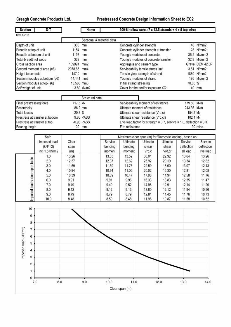
Final prestressing force 717.5 kN Serviceability moment of resistance 179.50 kNm
Eccentricity 86.2 mm Ultimate moment of resistance 243.36 kNm
Total losses 20.8 % Ultimate shear resistance (Vrd,c) 154.2 kN
Prestress at transfer at bottom 9.86 PASS Ultimate shear resistance (Vrd,cr) 102.1 kN
Prestress at transfer at top -0.93 PASS Live load factor for strength = 0.7, service = 1.0, deflection = 0.3
Bearing length 100 mm Fire resistance 90 mins.
Safe
imposed load Clear Service Ultimate Ultimate Ultimate Service Service
(kN/m2) span bending bending shear shear deflection deflection
incl 1.5 kN/m2 (m) moment moment Vrd,c Vrd,cr all load live load
1.0 13.26 13.33 13.59 30.01 22.92 13.64 13.26
2.0 12.37 12.37 12.62 25.92 20.19 13.34 12.82
3.0 11.59 11.59 11.76 22.59 18.00 13.07 12.43
4.0 10.94 10.94 11.06 20.02 16.30 12.81 12.08
5.0 10.39 10.39 10.47 17.98 14.94 12.58 11.76
6.0 9.91 9.91 9.96 16.33 13.83 12.35 11.47
7.0 9.49 9.49 9.52 14.96 12.91 12.14 11.20
8.0 9.12 9.12 9.13 13.80 12.12 11.94 10.96
9.0 8.79 8.79 8.79 12.81 11.45 11.76 10.73
10.0 8.48 8.50 8.48 11.96 10.87 11.58 10.52Imposed load v clear span table
300-6 hollow core. (7 x 12.5 strands + 4 x 5 top wire)
Maximum clear span (m) for 'Domestic loading', based on:
0
1
2
3
4
5
6
7
8
9
10
7.0 8.0 9.0 10.0 11.0 12.0 13.0 14.0
Imposed load (
kN
/m2)
Clear span (m)
Creagh Concrete Products Ltd. Prestressed Concrete Design Information Sheet to EC2
Section E-T Name
Date 5/2/15
Sectional & material data
Depth of unit 300 mm Concrete cylinder strength 40 N/mm2
Breadth at top of unit 1154 mm Concrete cylinder strength at transfer 28 N/mm2
Breadth at bottom of unit 1197 mm Young's modulus of concrete 35.2 kN/mm2
Total breadth of webs 329 mm Young's modulus of concrete transfer 32.3 kN/mm2
Cross section area 189924 mm2 Aggregate and cement type Gravel CEM 42.5R
Second moment of area (e6) 2078.85 mm4 Serviceability tensile stress limit 3.51 N/mm2
Height to centroid 147.0 mm Tensile yield strength of strand 1860 N/mm2
Section modulus at bottom (e6) 14.141 mm3 Young's modulus of strand 195 kN/mm2
Section modulus at top (e6) 13.588 mm3 Initial strand stressing 70.00 %
Self weight of unit 3.80 kN/m2 Cover for fire and/or exposure XC1 40 mm
Structural data
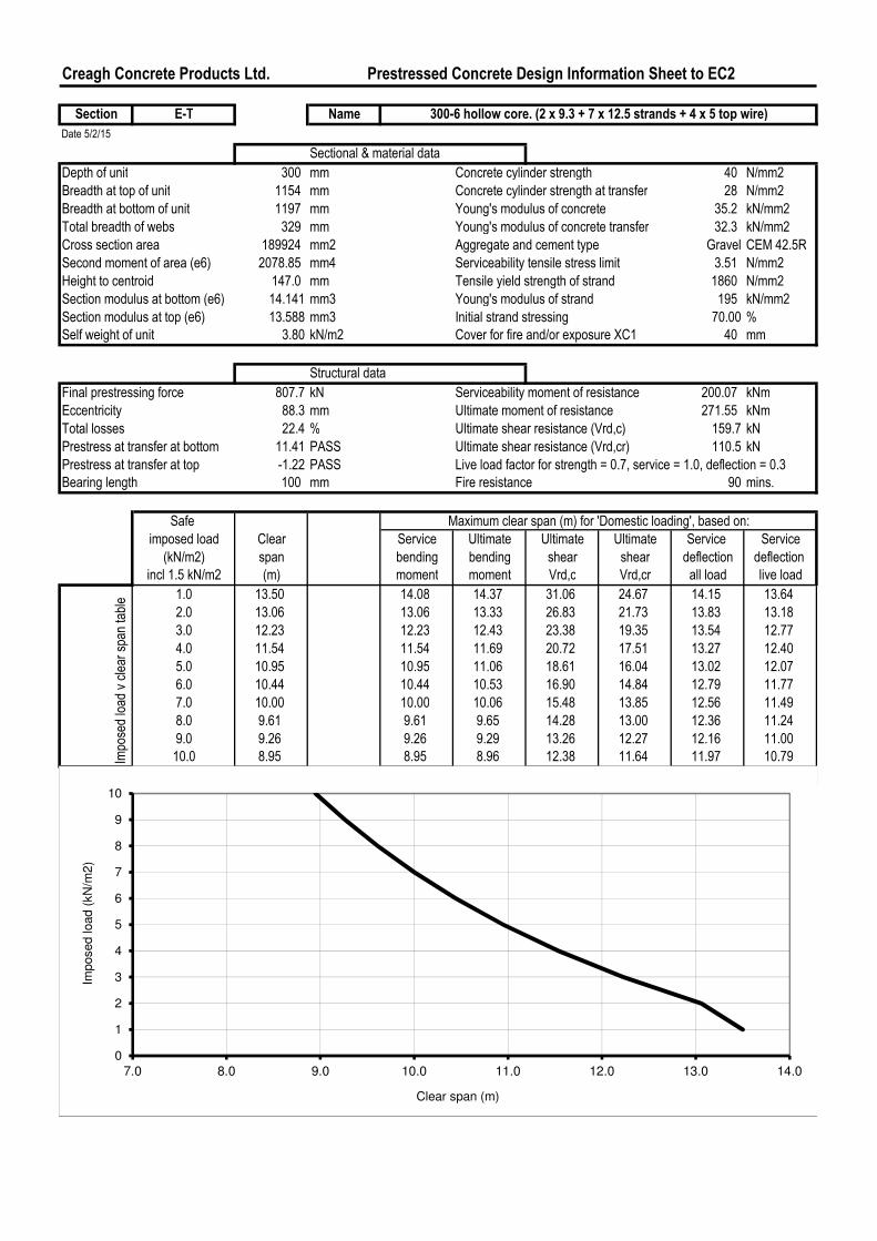
Final prestressing force 807.7 kN Serviceability moment of resistance 200.07 kNm
Eccentricity 88.3 mm Ultimate moment of resistance 271.55 kNm
Total losses 22.4 % Ultimate shear resistance (Vrd,c) 159.7 kN
Prestress at transfer at bottom 11.41 PASS Ultimate shear resistance (Vrd,cr) 110.5 kN
Prestress at transfer at top -1.22 PASS Live load factor for strength = 0.7, service = 1.0, deflection = 0.3
Bearing length 100 mm Fire resistance 90 mins.
Safe
imposed load Clear Service Ultimate Ultimate Ultimate Service Service
(kN/m2) span bending bending shear shear deflection deflection
incl 1.5 kN/m2 (m) moment moment Vrd,c Vrd,cr all load live load
1.0 13.50 14.08 14.37 31.06 24.67 14.15 13.64
2.0 13.06 13.06 13.33 26.83 21.73 13.83 13.18
3.0 12.23 12.23 12.43 23.38 19.35 13.54 12.77
4.0 11.54 11.54 11.69 20.72 17.51 13.27 12.40
5.0 10.95 10.95 11.06 18.61 16.04 13.02 12.07
6.0 10.44 10.44 10.53 16.90 14.84 12.79 11.77
7.0 10.00 10.00 10.06 15.48 13.85 12.56 11.49
8.0 9.61 9.61 9.65 14.28 13.00 12.36 11.24
9.0 9.26 9.26 9.29 13.26 12.27 12.16 11.00
10.0 8.95 8.95 8.96 12.38 11.64 11.97 10.79
300-6 hollow core. (2 x 9.3 + 7 x 12.5 strands + 4 x 5 top wire)
Maximum clear span (m) for 'Domestic loading', based on:
Imposed load v clear span table
0
1
2
3
4
5
6
7
8
9
10
7.0 8.0 9.0 10.0 11.0 12.0 13.0 14.0
Imposed load (
kN
/m2)
Clear span (m)
Creagh Concrete Products Ltd. Prestressed Concrete Design Information Sheet to EC2
Section F-T Name
Date 5/2/15
Sectional & material data
Depth of unit 300 mm Concrete cylinder strength 40 N/mm2
Breadth at top of unit 1154 mm Concrete cylinder strength at transfer 28 N/mm2
Breadth at bottom of unit 1197 mm Young's modulus of concrete 35.2 kN/mm2
Total breadth of webs 329 mm Young's modulus of concrete transfer 32.3 kN/mm2
Cross section area 189924 mm2 Aggregate and cement type Gravel CEM 42.5R
Second moment of area (e6) 2078.85 mm4 Serviceability tensile stress limit 3.51 N/mm2
Height to centroid 147.0 mm Tensile yield strength of strand 1860 N/mm2
Section modulus at bottom (e6) 14.141 mm3 Young's modulus of strand 195 kN/mm2
Section modulus at top (e6) 13.588 mm3 Initial strand stressing 70.00 %
Self weight of unit 3.80 kN/m2 Cover for fire and/or exposure XC1 40 mm
Structural data
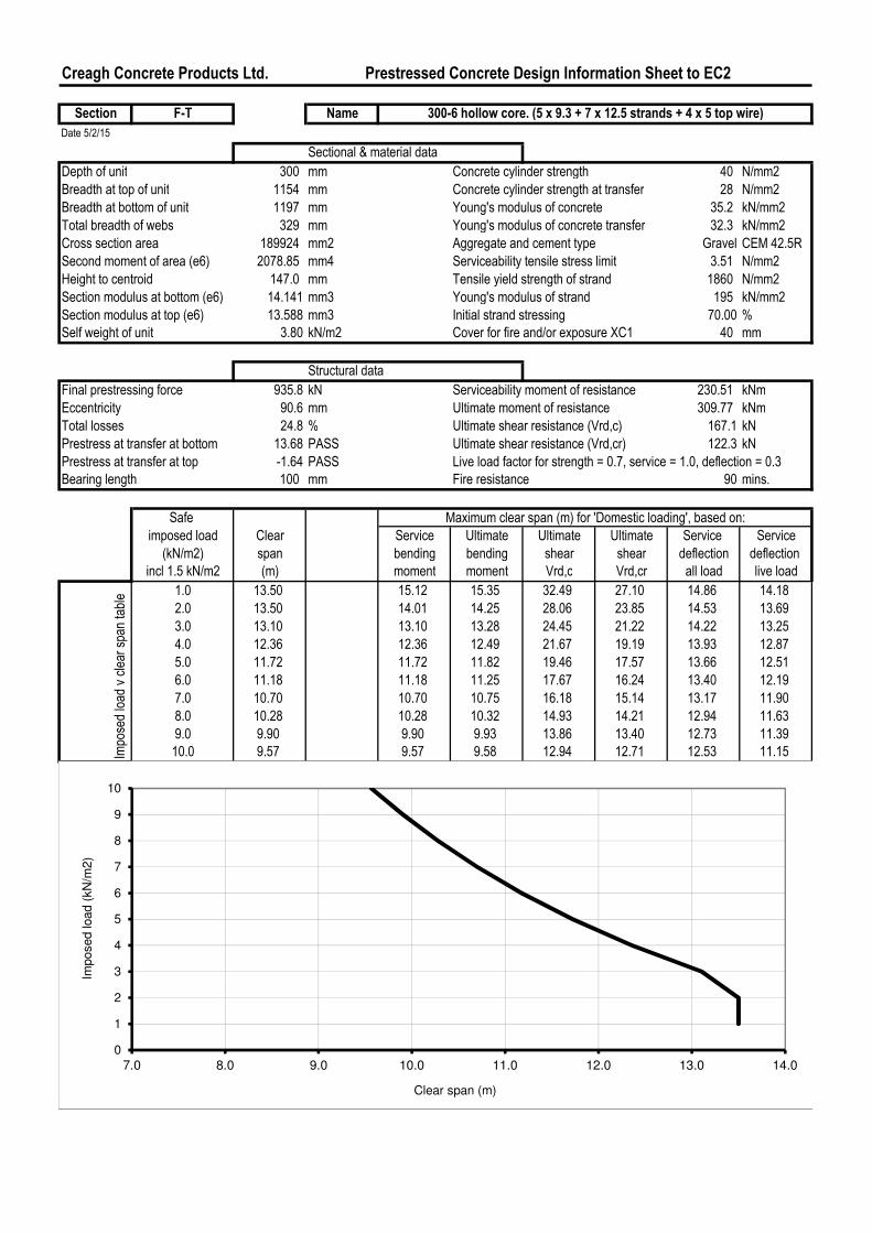
Final prestressing force 935.8 kN Serviceability moment of resistance 230.51 kNm
Eccentricity 90.6 mm Ultimate moment of resistance 309.77 kNm
Total losses 24.8 % Ultimate shear resistance (Vrd,c) 167.1 kN
Prestress at transfer at bottom 13.68 PASS Ultimate shear resistance (Vrd,cr) 122.3 kN
Prestress at transfer at top -1.64 PASS Live load factor for strength = 0.7, service = 1.0, deflection = 0.3
Bearing length 100 mm Fire resistance 90 mins.
Safe
imposed load Clear Service Ultimate Ultimate Ultimate Service Service
(kN/m2) span bending bending shear shear deflection deflection
incl 1.5 kN/m2 (m) moment moment Vrd,c Vrd,cr all load live load
1.0 13.50 15.12 15.35 32.49 27.10 14.86 14.18
2.0 13.50 14.01 14.25 28.06 23.85 14.53 13.69
3.0 13.10 13.10 13.28 24.45 21.22 14.22 13.25
4.0 12.36 12.36 12.49 21.67 19.19 13.93 12.87
5.0 11.72 11.72 11.82 19.46 17.57 13.66 12.51
6.0 11.18 11.18 11.25 17.67 16.24 13.40 12.19
7.0 10.70 10.70 10.75 16.18 15.14 13.17 11.90
8.0 10.28 10.28 10.32 14.93 14.21 12.94 11.63
9.0 9.90 9.90 9.93 13.86 13.40 12.73 11.39
10.0 9.57 9.57 9.58 12.94 12.71 12.53 11.15
300-6 hollow core. (5 x 9.3 + 7 x 12.5 strands + 4 x 5 top wire)
Maximum clear span (m) for 'Domestic loading', based on:
Imposed load v clear span table
0
1
2
3
4
5
6
7
8
9
10
7.0 8.0 9.0 10.0 11.0 12.0 13.0 14.0
Imposed load (
kN
/m2)
Clear span (m)
Creagh Concrete Products Ltd. Prestressed Concrete Design Information Sheet to EC2
Section G-T Name
Date 5/2/15
Sectional & material data
Depth of unit 300 mm Concrete cylinder strength 40 N/mm2
Breadth at top of unit 1154 mm Concrete cylinder strength at transfer 28 N/mm2
Breadth at bottom of unit 1197 mm Young's modulus of concrete 35.2 kN/mm2
Total breadth of webs 329 mm Young's modulus of concrete transfer 32.3 kN/mm2
Cross section area 189924 mm2 Aggregate and cement type Gravel CEM 42.5R
Second moment of area (e6) 2078.85 mm4 Serviceability tensile stress limit 3.51 N/mm2
Height to centroid 147.0 mm Tensile yield strength of strand 1860 N/mm2
Section modulus at bottom (e6) 14.141 mm3 Young's modulus of strand 195 kN/mm2
Section modulus at top (e6) 13.588 mm3 Initial strand stressing 70.00 %
Self weight of unit 3.80 kN/m2 Cover for fire and/or exposure XC1 40 mm
Structural data
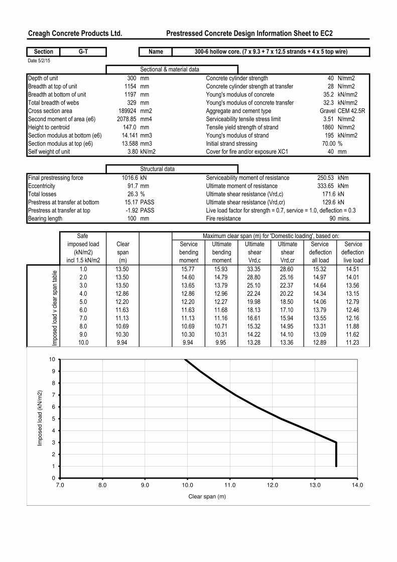
Final prestressing force 1016.6 kN Serviceability moment of resistance 250.53 kNm
Eccentricity 91.7 mm Ultimate moment of resistance 333.65 kNm
Total losses 26.3 % Ultimate shear resistance (Vrd,c) 171.6 kN
Prestress at transfer at bottom 15.17 PASS Ultimate shear resistance (Vrd,cr) 129.6 kN
Prestress at transfer at top -1.92 PASS Live load factor for strength = 0.7, service = 1.0, deflection = 0.3
Bearing length 100 mm Fire resistance 90 mins.
Safe
imposed load Clear Service Ultimate Ultimate Ultimate Service Service
(kN/m2) span bending bending shear shear deflection deflection
incl 1.5 kN/m2 (m) moment moment Vrd,c Vrd,cr all load live load
1.0 13.50 15.77 15.93 33.35 28.60 15.32 14.51
2.0 13.50 14.60 14.79 28.80 25.16 14.97 14.01
3.0 13.50 13.65 13.79 25.10 22.37 14.64 13.56
4.0 12.86 12.86 12.96 22.24 20.22 14.34 13.15
5.0 12.20 12.20 12.27 19.98 18.50 14.06 12.79
6.0 11.63 11.63 11.68 18.13 17.10 13.79 12.46
7.0 11.13 11.13 11.16 16.61 15.94 13.55 12.16
8.0 10.69 10.69 10.71 15.32 14.95 13.31 11.88
9.0 10.30 10.30 10.31 14.22 14.10 13.09 11.62
10.0 9.94 9.94 9.95 13.28 13.36 12.89 11.23Imposed load v clear span table
300-6 hollow core. (7 x 9.3 + 7 x 12.5 strands + 4 x 5 top wire)
Maximum clear span (m) for 'Domestic loading', based on:
0
1
2
3
4
5
6
7
8
9
10
7.0 8.0 9.0 10.0 11.0 12.0 13.0 14.0
Imposed load (
kN
/m2)
Clear span (m)
Bellevue Apartments
Span between grids A3 - A5
0.00 Date
HOLLOW
Frequent live load factor
Combination live load factor for ultimate load
First moment of area (10^6) mm3 Combination dead load factor
Bearing length mm Steel yield strength for strand
minutes Steel yield strength for 5 mm wire Load (kN) Distance* (m)
Relative humidity at transfer % Steel yield strength for 7 mm wire Point load 1 DEAD
Relative humidity to installation % Ratio initial prestress 12.5 strand Point load 2 DEAD
Detensioning age hours Ratio initial prestress 9.3 strand Point load 3 DEAD
Age at installation days Ratio initial prestress top tendon Point load 4 DEAD
Aggregate type Young's modulus of tendonCement type CEM 42.5R Tendon relaxtion class
Environmental exposure class 1000 hour relaxation % Load (kN/m) Start* (m) End* (m)STRAND PATTERN Line load 1 LIVE
Line load 2 DEAD
Line load 3 DEAD
Line load 4 DEAD
Area of tendons each row (mm2)
Stress in tendons (N/mm2) *Distances measured from left hand end to centre of support
Initial prestress force (kN)
Initial force x axis height (kNmm)
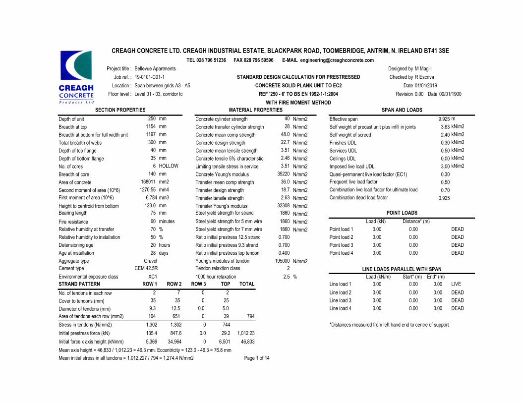
Mean axis height = 46,833 / 1,012.23 = 46.3 mm. Eccentricity = 123.0 - 46.3 = 76.8 mm
Mean initial stress in all tendons = 1,012,227 / 794 = 1,274.4 N/mm2 Page 1 of 14
XC1 2.5
N/mm2
1860
0.700
0.400
2Gravel
N/mm2
195000 N/mm2
20
0.00
Designed by
Checked by
Date
Revision
0.70
0.925
POINT LOADS
LINE LOADS PARALLEL WITH SPAN
0.00
0.00
0.00
0.00
0.00
0.00
0.00
0.00
0.00
0.00 0.00
0.000.00
0.50
104 794
CREAGH CONCRETE LTD. CREAGH INDUSTRIAL ESTATE, BLACKPARK ROAD, TOOMEBRIDGE, ANTRIM, N. IRELAND BT41 3SETEL 028 796 51236 FAX 028 796 59596 E-MAIL [email protected]
M MagillProject title :
SECTION PROPERTIES MATERIAL PROPERTIES SPAN AND LOADS
N/mm2 Effective span 9.925 Depth of unit 250 mm Concrete cylinder strength
Floor level : Level 01 - 03, corridor loading REF '250 - 6' TO BS EN 1992-1-1:2004
Job ref. : 19-0101-C01-1
Location :
00/01/1900
R Escriva
CONCRETE SOLID PLANK UNIT TO EC2 01/01/2019
STANDARD DESIGN CALCULATION FOR PRESTRESSED
40 m
WITH FIRE MOMENT METHOD
Breadth at top 1154 mm Concrete transfer cylinder strength kN/m2
kN/m2
28 N/mm2 Self weight of precast unit plus infill in joints 3.63 48.0 N/mm2 Self weight of screed 2.40 Breadth at bottom for full width unit 1197 mm Concrete mean comp strength
kN/m2
3.51 N/mm2 Services UDL 0.50 kN/m2
22.7 N/mm2 Finishes UDL 0.30
Depth of top flange 40 mm Concrete mean tensile strength
Total breadth of webs 300 mm Concrete design strength
Depth of bottom flange 35 mm Concrete tensile 5% characteristic 2.46 N/mm2 Ceilings UDL 0.00 kN/m2
0.30
No. of cores 6 Limiting tensile stress in service 3.51 3.00 kN/m2N/mm2 Imposed live load UDL
Breadth of core 140 mm Concrete Young's modulus 35220 N/mm2 Quasi-permanent live load factor (EC1)36.0 N/mm2
Second moment of area (10^6) 1270.55
mm2 Transfer mean comp strengthArea of concrete 168011
18.7 N/mm2mm4 Transfer design strength 6.784 Transfer tensile strength 2.63 N/mm2
Fire resistance 60
1860N/mm2Height to centroid from bottom 123.0 mm Transfer Young's modulus 32308
75
1860
70
0.00
28
0.00 0.00
0.0050
0.00 0.00
N/mm2
0 6,5015,369 34,964
No. of tendons in each row
Cover to tendons (mm)
Diameter of tendons (mm)
0.0 1,012.23
1,302
135.4
46,833
744
29.2
0
TOTALROW 2
5.0
TOP
25
ROW 1
0
0
0.0
2
35
9.3
ROW 3
0.700
1,302
847.6
2
0
7
35
12.5
651 39
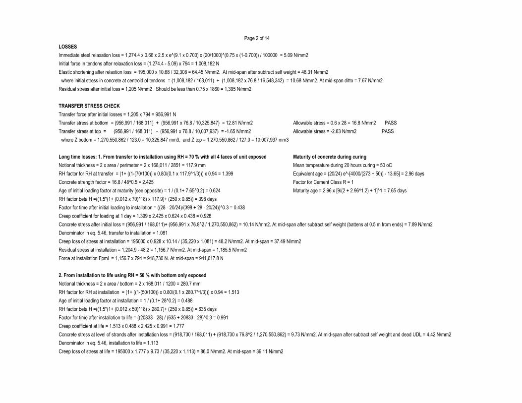
Page 2 of 14
LOSSES
Immediate steel relaxation loss = 1,274.4 x 0.66 x 2.5 x e^(9.1 x 0.700) x (20/1000)^(0.75 x (1-0.700)) / 100000 = 5.09 N/mm2
Initial force in tendons after relaxation loss = (1,274.4 - 5.09) x 794 = 1,008,182 N
Elastic shortening after relaxtion loss = 195,000 x 10.68 / 32,308 = 64.45 N/mm2. At mid-span after subtract self weight = 46.31 N/mm2
where initial stress in concrete at centroid of tendons = (1,008,182 / 168,011) + (1,008,182 x 76.8 / 16,548,342) = 10.68 N/mm2. At mid-span ditto = 7.67 N/mm2
Residual stress after initial loss = 1,205 N/mm2 Should be less than 0.75 x 1860 = 1,395 N/mm2
TRANSFER STRESS CHECK
Transfer force after initial losses = 1,205 x 794 = 956,991 N
Transfer stress at bottom = (956,991 / 168,011) + (956,991 x 76.8 / 10,325,847) = 12.81 N/mm2 Allowable stress = 0.6 x 28 = 16.8 N/mm2 PASS
Transfer stress at top = (956,991 / 168,011) - (956,991 x 76.8 / 10,007,937) = -1.65 N/mm2 Allowable stress = -2.63 N/mm2 PASS
where Z bottom = 1,270,550,862 / 123.0 = 10,325,847 mm3, and Z top = 1,270,550,862 / 127.0 = 10,007,937 mm3
Long time losses: 1. From transfer to installation using RH = 70 % with all 4 faces of unit exposed Maturity of concrete during curing
Notional thickness = 2 x area / perimeter = 2 x 168,011 / 2851 = 117.9 mm Mean temperature during 20 hours curing = 50 oC
RH factor for RH at transfer = (1+ ((1-(70/100)) x 0.80/(0.1 x 117.9^1/3))) x 0.94 = 1.399 Equivalent age = (20/24) e^-[4000/(273 + 50)) - 13.65] = 2.96 days
Concrete strength factor = 16.8 / 48^0.5 = 2.425 Factor for Cement Class R = 1
Age of initial loading factor at maturity (see opposite) = 1 / (0.1+ 7.65^0.2) = 0.624 Maturity age = 2.96 x [9/(2 + 2.96^1.2) + 1]^1 = 7.65 days
RH factor beta H =((1.5*(1+ (0.012 x 70)^18) x 117.9)+ (250 x 0.85)) = 398 days
Factor for time after initial loading to installation = ((28 - 20/24)/(398 + 28 - 20/24))^0.3 = 0.438
Creep coefficient for loading at 1 day = 1.399 x 2.425 x 0.624 x 0.438 = 0.928
Concrete stress after initial loss = (956,991 / 168,011)+ (956,991 x 76.8^2 / 1,270,550,862) = 10.14 N/mm2. At mid-span after subtract self weight (battens at 0.5 m from ends) = 7.89 N/mm2
Denominator in eq. 5.46, transfer to installation = 1.081
Creep loss of stress at installation = 195000 x 0.928 x 10.14 / (35,220 x 1.081) = 48.2 N/mm2. At mid-span = 37.49 N/mm2
Residual stress at installation = 1,204.9 - 48.2 = 1,156.7 N/mm2. At mid-span = 1,185.5 N/mm2
Force at installation Fpmi = 1,156.7 x 794 = 918,730 N. At mid-span = 941,617.8 N
2. From installation to life using RH = 50 % with bottom only exposed
Notional thickness = 2 x area / bottom = 2 x 168,011 / 1200 = 280.7 mm
RH factor for RH at installation = (1+ ((1-(50/100)) x 0.80/(0.1 x 280.7^1/3))) x 0.94 = 1.513
Age of initial loading factor at installation = 1 / (0.1+ 28^0.2) = 0.488
RH factor beta H =((1.5*(1+ (0.012 x 50)^18) x 280.7)+ (250 x 0.85)) = 635 days
Factor for time after installation to life = ((20833 - 28) / (635 + 20833 - 28)^0.3 = 0.991
Creep coefficient at life = 1.513 x 0.488 x 2.425 x 0.991 = 1.777
Concrete stress at level of strands after installation loss = (918,730 / 168,011) + (918,730 x 76.8^2 / 1,270,550,862) = 9.73 N/mm2. At mid-span after subtract self weight and dead UDL = 4.42 N/mm2
Denominator in eq. 5.46, installation to life = 1.113
Creep loss of stress at life = 195000 x 1.777 x 9.73 / (35,220 x 1.113) = 86.0 N/mm2. At mid-span = 39.11 N/mm2
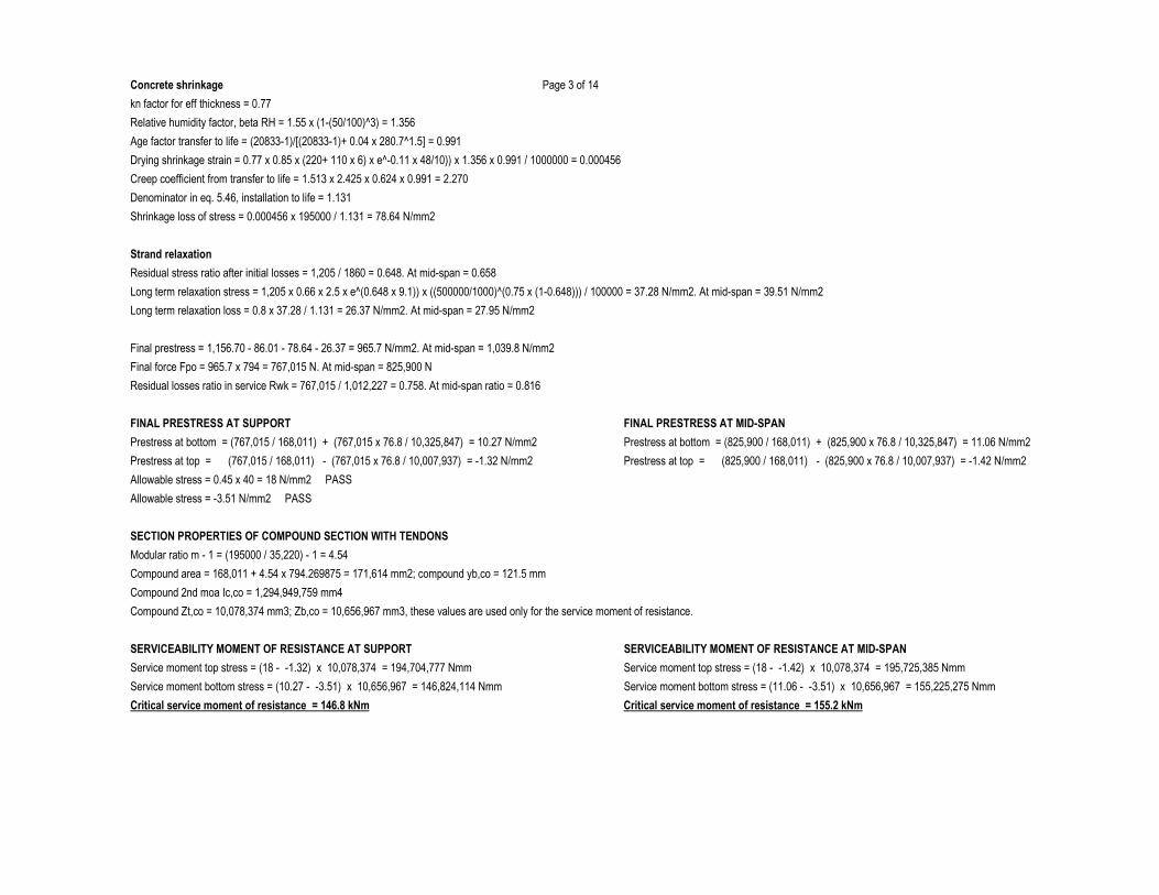
Concrete shrinkage Page 3 of 14
kn factor for eff thickness = 0.77
Relative humidity factor, beta RH = 1.55 x (1-(50/100)^3) = 1.356
Age factor transfer to life = (20833-1)/[(20833-1)+ 0.04 x 280.7^1.5] = 0.991
Drying shrinkage strain = 0.77 x 0.85 x (220+ 110 x 6) x e^-0.11 x 48/10)) x 1.356 x 0.991 / 1000000 = 0.000456
Creep coefficient from transfer to life = 1.513 x 2.425 x 0.624 x 0.991 = 2.270
Denominator in eq. 5.46, installation to life = 1.131
Shrinkage loss of stress = 0.000456 x 195000 / 1.131 = 78.64 N/mm2
Strand relaxation
Residual stress ratio after initial losses = 1,205 / 1860 = 0.648. At mid-span = 0.658
Long term relaxation stress = 1,205 x 0.66 x 2.5 x e^(0.648 x 9.1)) x ((500000/1000)^(0.75 x (1-0.648))) / 100000 = 37.28 N/mm2. At mid-span = 39.51 N/mm2
Long term relaxation loss = 0.8 x 37.28 / 1.131 = 26.37 N/mm2. At mid-span = 27.95 N/mm2
Final prestress = 1,156.70 - 86.01 - 78.64 - 26.37 = 965.7 N/mm2. At mid-span = 1,039.8 N/mm2
Final force Fpo = 965.7 x 794 = 767,015 N. At mid-span = 825,900 N
Residual losses ratio in service Rwk = 767,015 / 1,012,227 = 0.758. At mid-span ratio = 0.816
FINAL PRESTRESS AT SUPPORT FINAL PRESTRESS AT MID-SPAN
Prestress at bottom = (767,015 / 168,011) + (767,015 x 76.8 / 10,325,847) = 10.27 N/mm2 Prestress at bottom = (825,900 / 168,011) + (825,900 x 76.8 / 10,325,847) = 11.06 N/mm2
Prestress at top = (767,015 / 168,011) - (767,015 x 76.8 / 10,007,937) = -1.32 N/mm2 Prestress at top = (825,900 / 168,011) - (825,900 x 76.8 / 10,007,937) = -1.42 N/mm2
Allowable stress = 0.45 x 40 = 18 N/mm2 PASS
Allowable stress = -3.51 N/mm2 PASS
SECTION PROPERTIES OF COMPOUND SECTION WITH TENDONS
Modular ratio m - 1 = (195000 / 35,220) - 1 = 4.54
Compound area = 168,011 + 4.54 x 794.269875 = 171,614 mm2; compound yb,co = 121.5 mm
Compound 2nd moa Ic,co = 1,294,949,759 mm4
Compound Zt,co = 10,078,374 mm3; Zb,co = 10,656,967 mm3, these values are used only for the service moment of resistance.
SERVICEABILITY MOMENT OF RESISTANCE AT SUPPORT SERVICEABILITY MOMENT OF RESISTANCE AT MID-SPAN
Service moment top stress = (18 - -1.32) x 10,078,374 = 194,704,777 Nmm Service moment top stress = (18 - -1.42) x 10,078,374 = 195,725,385 Nmm
Service moment bottom stress = (10.27 - -3.51) x 10,656,967 = 146,824,114 Nmm Service moment bottom stress = (11.06 - -3.51) x 10,656,967 = 155,225,275 Nmm
Critical service moment of resistance = 146.8 kNm Critical service moment of resistance = 155.2 kNm
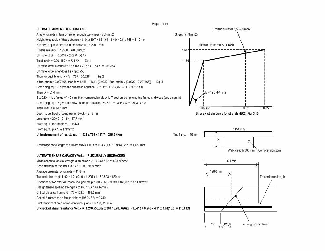
Page 4 of 14
ULTIMATE MOMENT OF RESISTANCE Limiting stress = 1,593 N/mm2
Area of strands in tension zone (exclude top wires) = 755 mm2 Stress fp (N/mm2)
Height to centroid of these strands = (104 x 39.7 + 651 x 41.3 + 0 x 0.0) / 755 = 41.0 mm
Effective depth to strands in tension zone = 209.0 mm Ultimate stress = 0.87 x 1860
Prestrain = 965.7 / 195000 = 0.004952 1,617
Ultimate strain = 0.0035 x (209.0 - X) / X
Total strain = 0.001452 + 0.731 / X Eq. 1 1,456
Ultimate force in concrete Fc = 0.8 x 22.67 x 1154 X = 20,926X
Ultimate force in tendons Fs = fp x 755
Then for equilibrium: X / fp = 755 / 20,926 Eq. 2
If final strain > 0.007465, then fp = 1,456 + [161 x (0.0222 - final strain) / (0.0222 - 0.007465)] Eq. 3
Combining eq. 1-3 gives the quadratic equation: 321 X^2 + -15,460 X + -89,313 = 0
Then X = 53.4 mm E = 195 kN/mm2
But 0.8X > top flange of 40 mm, then compression block is 'T section' comprising top flange and webs (see diagram)
Combining eq. 1-3 gives the new quadratic equation: 80 X^2 + -3,440 X + -89,313 = 0
Then final X = 61.1 mm
Depth to centroid of compression block = 21.3 mm
Lever arm = 209.0 - 21.3 = 187.7 mm
From eq. 1. final strain = 0.013424
From eq. 3. fp = 1,521 N/mm2
Ultimate moment of resistance = 1,521 x 755 x 187.7 = 215.5 kNm Top flange = 40 mm
Anchorage bond length to full Mrd = 824 + 0.25 x 11.8 x (1,521 - 966) / 2.29 = 1,457 mm
Web breadth 300 mm Compression zone
ULTIMATE SHEAR CAPACITY Vrd,c - FLEXURALLY UNCRACKED
Mean concrete tensile strength at transfer = 0.7 x 2.63 / 1.5 = 1.23 N/mm2 824 mm
Bond strength at transfer = 3.2 x 1.23 = 3.93 N/mm2
Average preimeter of strands = 11.8 mm 198.0 mm
Transmission length Lpt2 = 1.2 x 0.19 x 1,205 x 11.8 / 3.93 = 650 mm Transmission length
Prestress at NA after all losses, incl gamma,p = 0.9 x 965.7 x 794 / 168,011 = 4.11 N/mm2
Design tensile splitting strength = 2.46 / 1.5 = 1.64 N/mm2
Critical distance from end = 75 + 123.0 = 198.0 mm
Critical / transmission factor alpha = 198.0 / 824 = 0.240
First moment of area above centroidal plane = 6,783,626 mm3
Uncracked shear resistance Vcd,c = (1,270,550,862 x 300 / 6,783,626) x [(1.64^2 + 0.240 x 4.11 x 1.64)^0.5] = 116.6 kN
45 deg. shear plane
Stress v strain curve for strands (EC2: Fig. 3.10)
0.007465
X
0.02 0.0222
75 123.0
1154 mm
Page 5 of 14
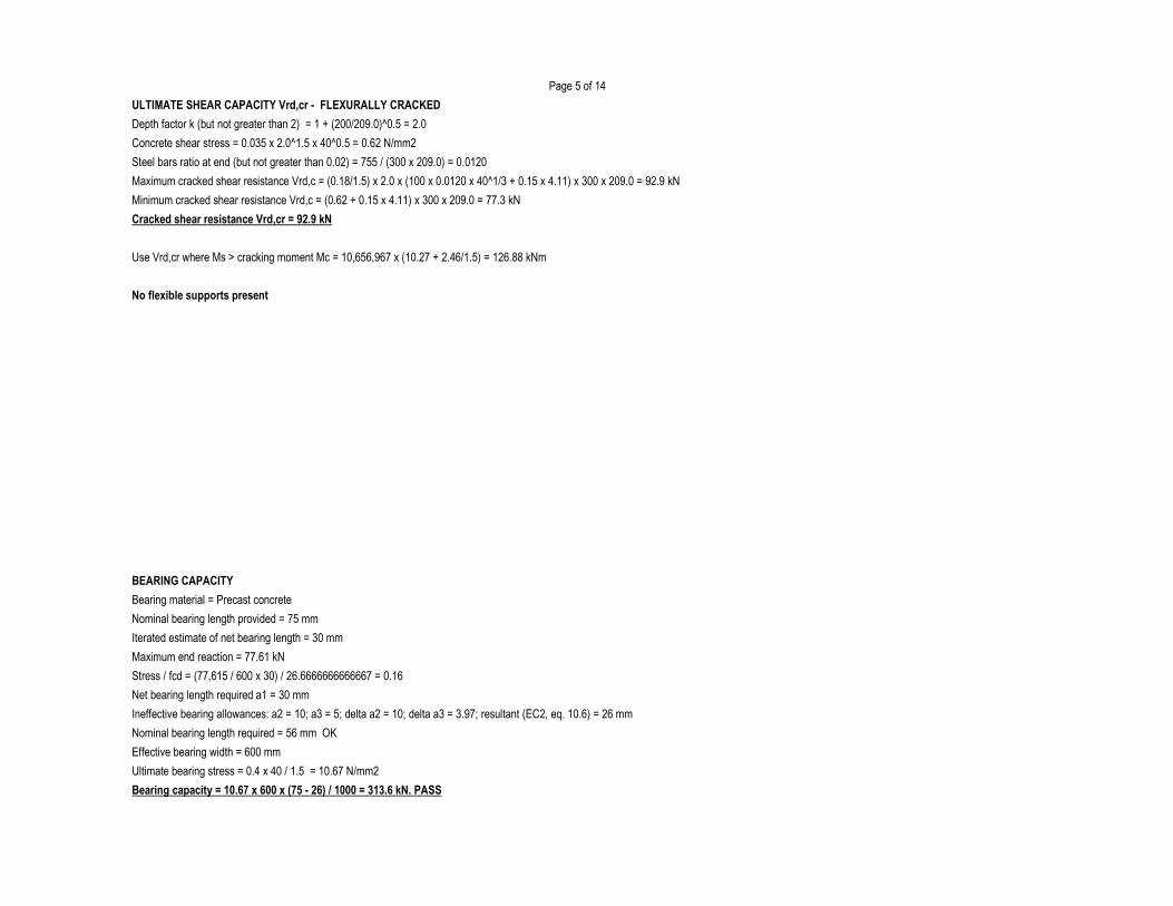
ULTIMATE SHEAR CAPACITY Vrd,cr - FLEXURALLY CRACKED
Depth factor k (but not greater than 2) = 1 + (200/209.0)^0.5 = 2.0
Concrete shear stress = 0.035 x 2.0^1.5 x 40^0.5 = 0.62 N/mm2
Steel bars ratio at end (but not greater than 0.02) = 755 / (300 x 209.0) = 0.0120
Maximum cracked shear resistance Vrd,c = (0.18/1.5) x 2.0 x (100 x 0.0120 x 40^1/3 + 0.15 x 4.11) x 300 x 209.0 = 92.9 kN
Minimum cracked shear resistance Vrd,c = (0.62 + 0.15 x 4.11) x 300 x 209.0 = 77.3 kN
Cracked shear resistance Vrd,cr = 92.9 kN
Use Vrd,cr where Ms > cracking moment Mc = 10,656,967 x (10.27 + 2.46/1.5) = 126.88 kNm
No flexible supports present
BEARING CAPACITY
Bearing material = Precast concrete
Nominal bearing length provided = 75 mm
Iterated estimate of net bearing length = 30 mm
Maximum end reaction = 77.61 kN
Stress / fcd = (77,615 / 600 x 30) / 26.6666666666667 = 0.16
Net bearing length required a1 = 30 mm
Ineffective bearing allowances: a2 = 10; a3 = 5; delta a2 = 10; delta a3 = 3.97; resultant (EC2, eq. 10.6) = 26 mm
Nominal bearing length required = 56 mm OK
Effective bearing width = 600 mm
Ultimate bearing stress = 0.4 x 40 / 1.5 = 10.67 N/mm2
Bearing capacity = 10.67 x 600 x (75 - 26) / 1000 = 313.6 kN. PASS
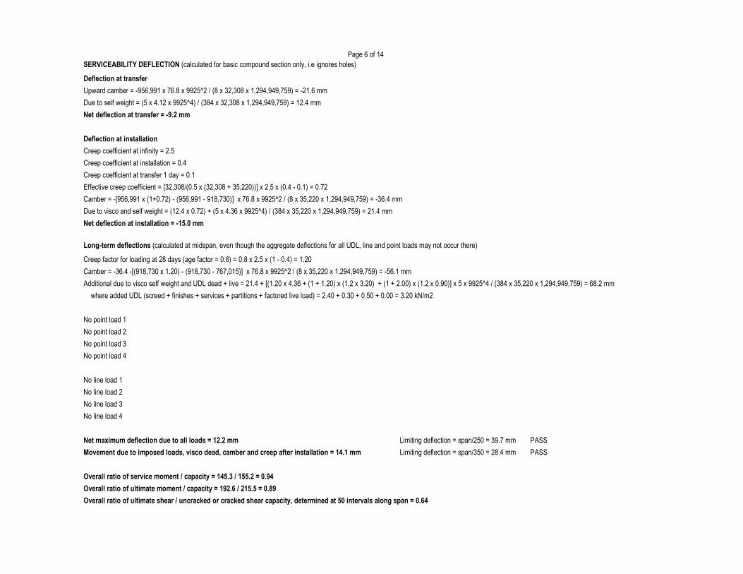
Page 6 of 14SERVICEABILITY DEFLECTION (calculated for basic compound section only, i.e ignores holes)
Deflection at transfer
Upward camber = -956,991 x 76.8 x 9925^2 / (8 x 32,308 x 1,294,949,759) = -21.6 mm
Due to self weight = (5 x 4.12 x 9925^4) / (384 x 32,308 x 1,294,949,759) = 12.4 mm
Net deflection at transfer = -9.2 mm
Deflection at installation
Creep coefficient at infinity = 2.5
Creep coefficient at installation = 0.4
Creep coefficient at transfer 1 day = 0.1
Effective creep coefficient = [32,308/(0.5 x (32,308 + 35,220))] x 2.5 x (0.4 - 0.1) = 0.72
Camber = -[956,991 x (1+0.72) - (956,991 - 918,730)] x 76.8 x 9925^2 / (8 x 35,220 x 1,294,949,759) = -36.4 mm
Due to visco and self weight = (12.4 x 0.72) + (5 x 4.36 x 9925^4) / (384 x 35,220 x 1,294,949,759) = 21.4 mm
Net deflection at installation = -15.0 mm
Long-term deflections (calculated at midspan, even though the aggregate deflections for all UDL, line and point loads may not occur there)
Creep factor for loading at 28 days (age factor = 0.8) = 0.8 x 2.5 x (1 - 0.4) = 1.20
Camber = -36.4 -[(918,730 x 1.20) - (918,730 - 767,015)] x 76.8 x 9925^2 / (8 x 35,220 x 1,294,949,759) = -56.1 mm
Additional due to visco self weight and UDL dead + live = 21.4 + [(1.20 x 4.36 + (1 + 1.20) x (1.2 x 3.20) + (1 + 2.00) x (1.2 x 0.90)] x 5 x 9925^4 / (384 x 35,220 x 1,294,949,759) = 68.2 mm
where added UDL (screed + finishes + services + partitions + factored live load) = 2.40 + 0.30 + 0.50 + 0.00 = 3.20 kN/m2
No point load 1
No point load 2
No point load 3
No point load 4
No line load 1
No line load 2
No line load 3
No line load 4
Net maximum deflection due to all loads = 12.2 mm Limiting deflection = span/250 = 39.7 mm PASS
Movement due to imposed loads, visco dead, camber and creep after installation = 14.1 mm Limiting deflection = span/350 = 28.4 mm PASS
Overall ratio of service moment / capacity = 145.3 / 155.2 = 0.94
Overall ratio of ultimate moment / capacity = 192.6 / 215.5 = 0.89
Overall ratio of ultimate shear / uncracked or cracked shear capacity, determined at 50 intervals along span = 0.64
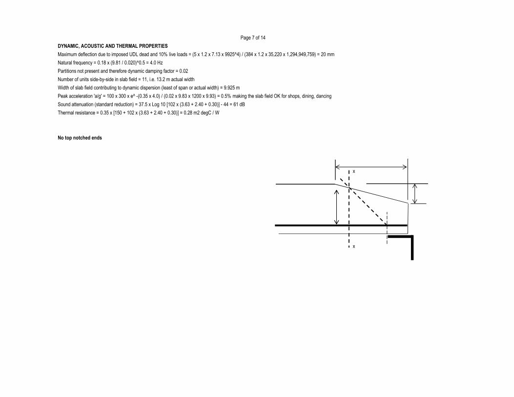
Page 7 of 14
DYNAMIC, ACOUSTIC AND THERMAL PROPERTIES
Maximum deflection due to imposed UDL dead and 10% live loads = (5 x 1.2 x 7.13 x 9925^4) / (384 x 1.2 x 35,220 x 1,294,949,759) = 20 mm
Natural frequency = 0.18 x (9.81 / 0.020)^0.5 = 4.0 Hz
Partitions not present and therefore dynamic damping factor = 0.02
Number of units side-by-side in slab field = 11, i.e. 13.2 m actual width
Width of slab field contributing to dynamic dispersion (least of span or actual width) = 9.925 m
Peak acceleration 'a/g' = 100 x 300 x e^ -(0.35 x 4.0) / (0.02 x 9.83 x 1200 x 9.93) = 0.5% making the slab field OK for shops, dining, dancing
Sound attenuation (standard reduction) = 37.5 x Log 10 [102 x (3.63 + 2.40 + 0.30)] - 44 = 61 dB
Thermal resistance = 0.35 x [150 + 102 x (3.63 + 2.40 + 0.30)] = 0.28 m2 degC / W
No top notched ends
x
x

Page 8 of 14
Section Properties and Resistances at Holes and Notches
No hole present
.

Page 9 of 14
No hole 2 present
.

Page 10 of 14
No notch at left end No notch at right end
. .
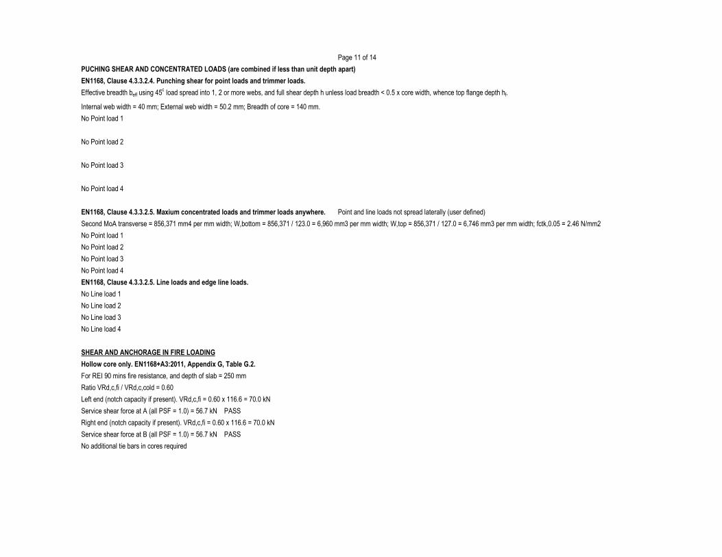
Page 11 of 14
PUCHING SHEAR AND CONCENTRATED LOADS (are combined if less than unit depth apart)
EN1168, Clause 4.3.3.2.4. Punching shear for point loads and trimmer loads.
Effective breadth beff using 45o load spread into 1, 2 or more webs, and full shear depth h unless load breadth < 0.5 x core width, whence top flange depth hf.
Internal web width = 40 mm; External web width = 50.2 mm; Breadth of core = 140 mm.
No Point load 1
No Point load 2
No Point load 3
No Point load 4
EN1168, Clause 4.3.3.2.5. Maxium concentrated loads and trimmer loads anywhere. Point and line loads not spread laterally (user defined)
Second MoA transverse = 856,371 mm4 per mm width; W,bottom = 856,371 / 123.0 = 6,960 mm3 per mm width; W,top = 856,371 / 127.0 = 6,746 mm3 per mm width; fctk,0.05 = 2.46 N/mm2
No Point load 1
No Point load 2
No Point load 3
No Point load 4
EN1168, Clause 4.3.3.2.5. Line loads and edge line loads.
No Line load 1
No Line load 2
No Line load 3
No Line load 4
SHEAR AND ANCHORAGE IN FIRE LOADING
Hollow core only. EN1168+A3:2011, Appendix G, Table G.2.
For REI 90 mins fire resistance, and depth of slab = 250 mm
Ratio VRd,c,fi / VRd,c,cold = 0.60
Left end (notch capacity if present). VRd,c,fi = 0.60 x 116.6 = 70.0 kN
Service shear force at A (all PSF = 1.0) = 56.7 kN PASS
Right end (notch capacity if present). VRd,c,fi = 0.60 x 116.6 = 70.0 kN
Service shear force at B (all PSF = 1.0) = 56.7 kN PASS
No additional tie bars in cores required
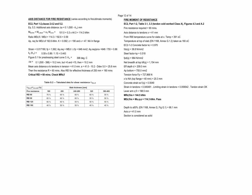
Page 12 of 14AXIS DISTANCE FOR FIRE RESISTANCE (varies according to fire/ultimate moments) FIRE MOMENT OF RESISTANCE
EC2, Part 1-2,clause 2.4.2 and 5.2. EC2, Part 1-2, Table 3.1, 3.3 (tendon cold worked Class A), Figures 4.3 and A.2Eq. 5.3. Additional axis distance Da = 0.1 (500 - qcr) mm Fire resistance required = 90 mins.
MEd,fire = Ms,dead + y2 Ms,live = 101.0 + 0.3 x 44.3 = 114.3 kNm Axis distance to tendons x = 41 mm
Ratio MEd,fi / MEd = 114.3 / 192.6 = 0.59 From R90 temperature curve for slabs at x. Temp = 391 oC
Ap, req for MEd of 192.6 kNm. K = 0.092; z = 190 and x = 47. NA In flange Temperature at top of slab (EN 1168, Annex G.1.2) taken as 160 oC
EC2-1-2 Concrete factor kc = 0.970
Strain = 0.017180; fp = 1,562; Ap,req = MEd / z fp = 648 mm2; Ap,req/prov =648 / 755 = 0.86 fck(q) = 38.8 N/mm2kp (qcr) = 0.59 x 0.86 / 1.15 = 0.443 Steel factor kp = 0.518
Figure 5.1 for prestressing steel curve 3. qcr = 398 deg. C fpd(q) = 964 N/mm2Da = 0.1 (500 - 398) = 10.2 mm, but >0 and <15, then = 10.2 mm Net breadth at top bfi(q) = 1,154 mm
Mean axis distance a to tendons in tension = 41.0 mm. a = 41.0 - 10.2 - Ddev 5.0 = 25.8 mm Eff depth d = 209.0 mm
Then fire resistance R = 60 mins. Also REI for effective thickness of 250 mm = 180 mins Ap bottom = 755.0 mm2
Critical REI = 60 mins. Check MRd,f Tension force Fp = 727,868 N
x to NA (top flange = 40 mm) = 20.3 mm
Concrete strain ec1(q) = 0.0049
Strain in tendons = 0.045491 . Limiting strain in tendons = 0.059542 . Tendon strain OK
Lever arm z,fi = 198.5 mm
MRd,fire = 144.5 kNm
MEd,fire = Ms,q-p = 114.3 kNm. Pass
Depth to a50% (EN 1168, Annex G, Fig G.1) = 66.1 mm
Axis a = 41.0 mm
Section is considered as solid
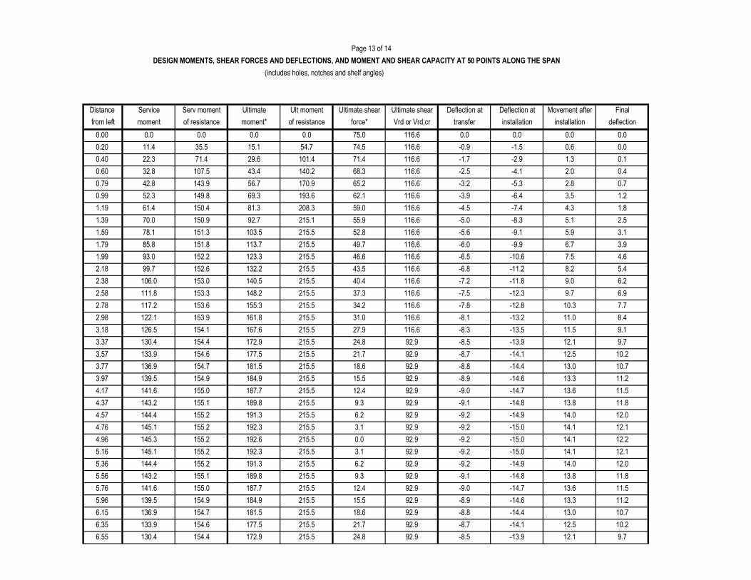
Page 13 of 14
(includes holes, notches and shelf angles)
Service Serv moment Ultimate Ult moment Ultimate shear Ultimate shear Deflection at Deflection at Movement after Final
moment of resistance moment* of resistance force* Vrd or Vrd,cr transfer installation installation deflection
4.6
92.9 -8.5 -13.9 12.1 9.76.55 130.4 154.4 172.9 215.5 24.8
21.7 92.9 -8.7 -14.1 12.5 10.2
92.9 -8.8 -14.4 13.0 10.7
215.5
6.15 136.9 154.7 181.5 215.5
6.35 133.9 154.6 177.5
18.6
15.5 92.9 -8.9 -14.6 13.3 11.2
92.9 -9.0 -14.7 13.6 11.5
215.5
5.76 141.6 155.0 187.7 215.5
5.96 139.5 154.9 184.9
12.4
9.3 92.9 -9.1 -14.8 13.8 11.8
92.9 -9.2 -14.9 14.0 12.0
215.5
5.36 144.4 155.2 191.3 215.5
5.56 143.2 155.1 189.8
6.2
3.1 92.9 -9.2 -15.0 14.1 12.1
92.9 -9.2 -15.0 14.1 12.2
215.5
4.96 145.3 155.2 192.6 215.5
5.16 145.1 155.2 192.3
0.0
3.1 92.9 -9.2 -15.0 14.1 12.1
92.9 -9.2 -14.9 14.0 12.0
215.5
4.57 144.4 155.2 191.3 215.5
4.76 145.1 155.2 192.3
6.2
9.3 92.9 -9.1 -14.8 13.8 11.8
92.9 -9.0 -14.7 13.6 11.5
215.5
4.17 141.6 155.0 187.7 215.5
4.37 143.2 155.1 189.8
12.4
15.5 92.9 -8.9 -14.6 13.3 11.2
92.9 -8.8 -14.4 13.0 10.7
215.5
3.77 136.9 154.7 181.5 215.5
3.97 139.5 154.9 184.9
18.6
21.7 92.9 -8.7 -14.1 12.5 10.2
92.9 -8.5 -13.9 12.1 9.7
215.5
3.37 130.4 154.4 172.9 215.5
3.57 133.9 154.6 177.5
24.8
27.9 116.6 -8.3 -13.5 11.5 9.1
116.6 -8.1 -13.2 11.0 8.4
215.5
2.98 122.1 153.9 161.8 215.5
3.18 126.5 154.1 167.6
31.0
34.2 116.6 -7.8 -12.8 10.3 7.7
116.6 -7.5 -12.3 9.7 6.9
215.5
2.58 111.8 153.3 148.2 215.5
2.78 117.2 153.6 155.3
37.3
40.4 116.6 -7.2 -11.8 9.0 6.2
116.6 -6.8 -11.2 8.2 5.4
2.38 106.0 153.0 140.5 215.5
2.18 99.7 152.6 132.2
7.5
0.0 0.0 75.0 116.6 0.0
116.6
116.6
215.5 43.5
Distance
0.00 0.0
DESIGN MOMENTS, SHEAR FORCES AND DEFLECTIONS, AND MOMENT AND SHEAR CAPACITY AT 50 POINTS ALONG THE SPAN
0.00.00.0
from left
0.0
0.20 11.4 35.5 15.1
101.4 71.4
54.7 74.5
0.40 22.3 71.4 29.6
116.6
-1.5 0.6 0.0-0.9
0.4
-2.9 1.3
0.60 32.8 107.5 43.4 140.2 2.0
0.1-1.7
68.3 -2.5 -4.1
-3.2
193.6 62.1 -3.9116.6
170.9 65.2 116.60.79 42.8 143.9 56.7
0.99 52.3 149.8 69.3 -6.4 3.5 1.2
-5.3 2.8 0.7
59.0 116.6 -4.51.19 61.4 150.4 81.3 -7.4 4.3 1.8
1.39 70.0 150.9 92.7 215.1 55.9 116.6
-9.1 5.9 3.1
-8.3 5.1 2.5-5.0
1.59 78.1 151.3 103.5 -5.6215.5 52.8 116.6
3.9-6.0 -9.9 6.749.7 116.6
-6.5 -10.6215.5 46.6 116.6
215.5
1.99 93.0 152.2 123.3
1.79 85.8 151.8 113.7
208.3
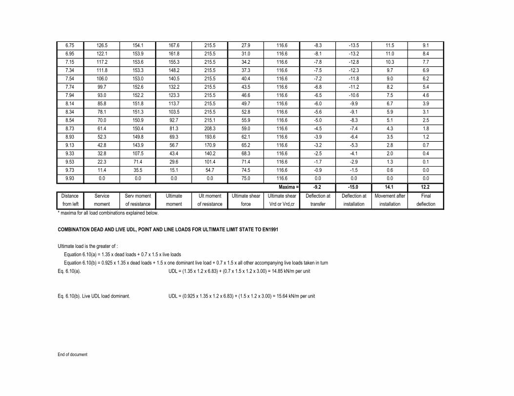
Service Serv moment Ultimate Ult moment Ultimate shear Ultimate shear Deflection at Deflection at Movement after Final
moment of resistance moment of resistance force Vrd or Vrd,cr transfer installation installation deflection
* maxima for all load combinations explained below.
COMBINATION DEAD AND LIVE UDL, POINT AND LINE LOADS FOR ULTIMATE LIMIT STATE TO EN1991
Ultimate load is the greater of :
Equation 6.10(a) = 1.35 x dead loads + 0.7 x 1.5 x live loads
Equation 6.10(b) = 0.925 x 1.35 x dead loads + 1.5 x one dominant live load + 0.7 x 1.5 x all other accompanying live loads taken in turn
Eq. 6.10(a). UDL = (1.35 x 1.2 x 6.83) + (0.7 x 1.5 x 1.2 x 3.00) = 14.85 kN/m per unit
Eq. 6.10(b). Live UDL load dominant. UDL = (0.925 x 1.35 x 1.2 x 6.83) + (1.5 x 1.2 x 3.00) = 15.64 kN/m per unit
End of document
0.1
0.4
-5.3
0.0 0.0
2.8 0.7
1.2
-1.5 0.6
-4.1 2.0
1.3
from left
-9.2 -15.0Maxima = 14.1 12.2
Distance
0.0 0.0
0.0
9.93 0.0 0.0 0.0 0.0 75.0 116.6
54.7 74.5 116.6 -0.99.73 11.4 35.5 15.1
71.4 116.6 -1.7 -2.9101.4
9.33 32.8 107.5 43.4 140.2
9.53 22.3 71.4
-6.4 3.5
29.6
65.2 116.6 -3.2
116.6 -2.5
170.9
68.3
193.6
9.13 42.8 143.9 56.7
8.93 52.3 149.8 69.3 62.1
59.0 116.6 -4.5
116.6 -3.9
208.3 -7.4 4.3 1.8
116.6 -5.0 -8.3 5.1 2.58.54 70.0 150.9 92.7 215.1
8.73 61.4 150.4 81.3
55.9
52.8 116.6 -5.6 -9.1 5.9 3.1
116.6 -6.0 -9.9 6.7 3.9
215.5
8.14 85.8 151.8 113.7 215.5
8.34 78.1 151.3 103.5
49.7
46.6 116.6 -6.5 -10.6 7.5 4.6
116.6 -6.8 -11.2 8.2 5.4
215.5
7.74 99.7 152.6 132.2 215.5
7.94 93.0 152.2 123.3
43.5
40.4 116.6 -7.2 -11.8 9.0 6.2
116.6 -7.5 -12.3 9.7 6.9
215.5
7.34 111.8 153.3 148.2 215.5
7.54 106.0 153.0 140.5
37.3
34.2 116.6 -7.8 -12.8 10.3 7.7
116.6 -8.1 -13.2 11.0 8.4
215.5
6.95 122.1 153.9 161.8 215.5
7.15 117.2 153.6 155.3
31.0
27.9 116.6 -8.3 -13.5 11.5 9.1215.56.75 126.5 154.1 167.6
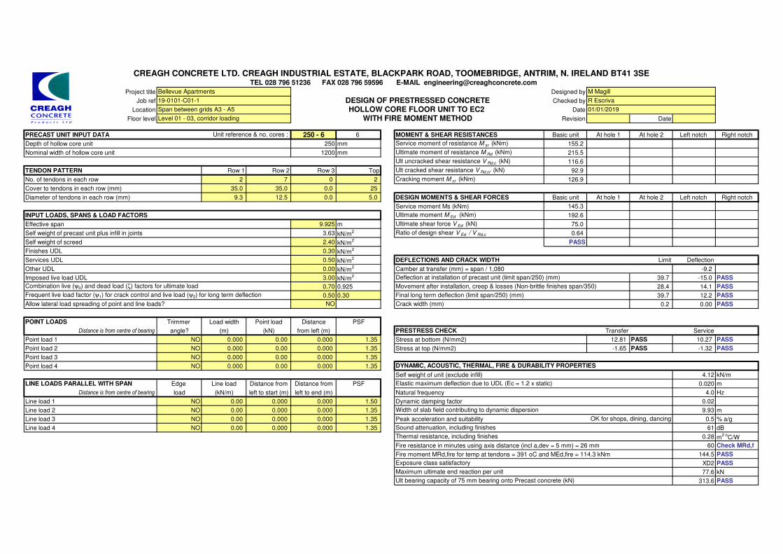
Project title Designed by
Job ref Checked by
Location Date
Floor level Revision Date
PRECAST UNIT INPUT DATA 250 - 6 6 MOMENT & SHEAR RESISTANCES Basic unit At hole 1 At hole 2 Left notch Right notch
Depth of hollow core unit 250 mm Service moment of resistance M sr (kNm) 155.2
Nominal width of hollow core unit 1200 mm Ultimate moment of resistance M Rd (kNm) 215.5
Ult uncracked shear resistance V Rd,c (kN) 116.6
TENDON PATTERN Row 1 Row 2 Row 3 Top Ult cracked shear resistance V Rd,cr (kN) 92.9
No. of tendons in each row 2 7 0 2 Cracking moment M cr (kNm) 126.9
Cover to tendons in each row (mm) 35.0 35.0 0.0 25
Diameter of tendons in each row (mm) 9.3 12.5 0.0 5.0 DESIGN MOMENTS & SHEAR FORCES Basic unit At hole 1 At hole 2 Left notch Right notch
Service moment Ms (kNm) 145.3
INPUT LOADS, SPANS & LOAD FACTORS Ultimate moment M Ed (kNm) 192.6
Effective span 9.925 m Ultimate shear force V Ed (kN) 75.0
Self weight of precast unit plus infill in joints 3.63 kN/m2 Ratio of design shear V Ed / V Rd,c 0.64
Self weight of screed 2.40 kN/m2 PASS
Finishes UDL 0.30 kN/m2
Services UDL 0.50 kN/m2 DEFLECTIONS AND CRACK WIDTH Limit Deflection
Other UDL 0.00 kN/m2 Camber at transfer (mm) = span / 1,080 -9.2
Imposed live load UDL 3.00 kN/m2 39.7 -15.0 PASS
0.70 0.925 28.4 14.1 PASS
0.50 0.30 39.7 12.2 PASS
NO 0.2 0.00 PASS
POINT LOADS Trimmer Load width Point load Distance PSF
Distance is from centre of bearing angle? (m) (kN) from left (m) PRESTRESS CHECK Transfer Service
Point load 1 NO 0.000 0.00 0.000 1.35 Stress at bottom (N/mm2) 12.81 PASS 10.27 PASS
Point load 2 NO 0.000 0.00 0.000 1.35 Stress at top (N/mm2) -1.65 PASS -1.32 PASS
Point load 3 NO 0.000 0.00 0.000 1.35
Point load 4 NO 0.000 0.00 0.000 1.35
Self weight of unit (exclude infill) 4.12 kN/m
LINE LOADS PARALLEL WITH SPAN Edge Line load Distance from Distance from PSF 0.020 m
Distance is from centre of bearing load (kN/m) left to start (m) left to end (m) Natural frequency 4.0 Hz
Line load 1 NO 0.00 0.000 0.000 1.50 Dynamic damping factor 0.02
Line load 2 NO 0.00 0.000 0.000 1.35 9.93 m
Line load 3 NO 0.00 0.000 0.000 1.35 Peak acceleration and suitability 0.5 % a/g
Line load 4 NO 0.00 0.000 0.000 1.35 61 dB
0.28 m2 o
C/W
Fire resistance in minutes using axis distance (incl a,dev = 5 mm) = 26 mm 60 Check MRd,f
Fire moment MRd,fire for temp at tendons = 391 oC and MEd,fire = 114.3 kNm 144.5 PASS
XD2 PASS
77.6 kN
313.6 PASS
Allow lateral load spreading of point and line loads?
Frequent live load factor (ψ1) for crack control and live load (ψ2) for long term deflection
Deflection at installation of precast unit (limit span/250) (mm)
DYNAMIC, ACOUSTIC, THERMAL, FIRE & DURABILITY PROPERTIES
OK for shops, dining, dancing
Thermal resistance, including finishes
Width of slab field contributing to dynamic dispersion
DESIGN OF PRESTRESSED CONCRETE
Unit reference & no. cores :
Level 01 - 03, corridor loading
HOLLOW CORE FLOOR UNIT TO EC2
R Escriva
TEL 028 796 51236 FAX 028 796 59596 E-MAIL [email protected]
Span between grids A3 - A5
Maximum ultimate end reaction per unit
Exposure class satisfactory
Ult bearing capacity of 75 mm bearing onto Precast concrete (kN)
Sound attenuation, including finishes
Elastic maximum deflection due to UDL (Ec = 1.2 x static)
Bellevue Apartments
WITH FIRE MOMENT METHOD
M Magill
Movement after installation, creep & losses (Non-brittle finishes span/350)
Final long term deflection (limit span/250) (mm)
Crack width (mm)
CREAGH CONCRETE LTD. CREAGH INDUSTRIAL ESTATE, BLACKPARK ROAD, TOOMEBRIDGE, ANTRIM, N. IRELAND BT41 3SE
Combination live (ψ0) and dead load (ζ) factors for ultimate load
01/01/2019
19-0101-C01-1
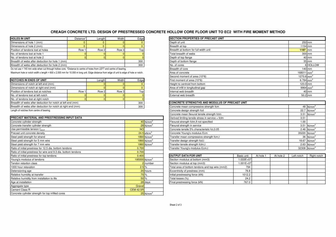
HOLES IN UNIT Distance* Length Width Edge
Dimensions of hole 1 (mm) 0 0 0 0 Depth of unit 250 mm
Dimensions of hole 2 (mm) 0 0 0 0 Breadth at top 1154 mm
Position of tendons lost at holes Row 1 Row 2 Row 3 Top 1197 mm
No. of tendons lost at hole 1 0 0 0 0 Total breadth of webs 300 mm
No. of tendons lost at hole 2 0 0 0 0 Depth of top flange 40 mm
Breadth of webs after deduction for hole 1 (mm) 300 Depth of bottom flange 35 mm
Breadth of webs after deduction for hole 2 (mm) 300 No. of cores 6 HOLLOW
Do not use < 140 mm wide when cut through hollow core. *Distance to centre of holes from LEFT end centre of bearing. Breadth of core 140 mm
Maximum hole or notch width x length = 600 x 2,000 mm for 10.000 m long unit. Edge distance from edge of unit to edge of hole or notch. Area of concrete 168011 mm2
Second moment of area (10^6) 1270.6 mm4
NOTCHES IN ENDS OF UNIT Length Width Edge First moment of area (10^6) 6.784 mm3
Dimensions of notch at left end (mm) 0 0 0 Height to centroid from bottom 123.0 mm
Dimensions of notch at right end (mm) 0 0 0 Area of infill in longitudinal gap 9964 mm2
Position of tendons lost at notches Row 1 Row 2 Row 3 Top Internal web breadth 40 mm
No. of tendons lost at left notch 0 0 0 0 External web breadth 50.2 mm
No. of tendons lost at right notch 0 0 0 0
300
300 Concrete mean compressive strength fcm 48 N/mm2
Length of notches from centre of bearing. Concrete design strength fcd 22.7 N/mm2
Concrete mean flexural tensile strength fctm 3.51 N/mm2
Derived limiting tensile stress in service = fctm 3.51
Concrete cylinder strength 40 N/mm2 Flexural strength fctm,fl not specified 1.00
Concrete transfer cylinder strength 28 N/mm2 Flexural strength in service 3.51 N/mm
2
Use permissible tension fctm,fl NO Concrete tensile 5% characteristic fct,0.05 2.46 N/mm2
Precast unit concrete density 24.5 kN/m3 Concrete Young's modulus Ecm 35220 N/mm
2
Steel yield strength for strand 1860 N/mm2 Transfer mean compressive strength fcm,t 36 N/mm
2
Steel yield strength for 5 mm wire 1860 N/mm2 Transfer design strength fcd,t 18.67 N/mm
2
Steel yield strength for 7 mm wire 1860 N/mm2 Transfer tensile strength fctm,t 2.63 N/mm
2
Ratio of initial prestress for 12.5 dia. bottom tendons 0.700 Transfer Young's modulus Ecm,t 32308 N/mm2
Ratio of initial prestress for wire and 9.3 dia. bottom tendons 0.700
Ratio of initial prestress for top tendons 0.400 OUTPUT DATA FOR UNIT Basic unit At hole 1 At hole 2 Left notch Right notch
Young's modulus of tendons 195000 N/mm2 Section modulus at bottom (mm3) 1.033E+07
Tendon relaxtion class 2 number Section modulus at top (mm3) 1.001E+07
1000 hour relaxation 2.5 % Total area of bottom tendons and top wire (mm2) 794
Detensioning age 20 hours Eccentricity of prestress (mm) 76.8
Relative humidity at transfer 70 % Initial prestressing force (kN) 1012.2
Relative humidity from installation to life 50 % Total losses (%) 24.2
Age at installation 28 days Final prestressing force (kN) 767.0
Aggregate type Gravel
Cement Class R CEM 42.5R
25 N/mm2
Sheet 2 of 3
Concrete cylinder strength for top infilled cores
Breadth at bottom for full width unit
CREAGH CONCRETE LTD. DESIGN OF PRESTRESSED CONCRETE HOLLOW CORE FLOOR UNIT TO EC2 WITH FIRE MOMENT METHOD
SECTION PROPERTIES OF PRECAST UNIT
Breadth of webs after deduction for notch at right end (mm)
PRECAST MATERIAL AND PRESTRESSING INPUT DATA
Breadth of webs after deduction for notch at left end (mm) CONCRETE STRENGTHS AND MODULUS OF PRECAST UNIT
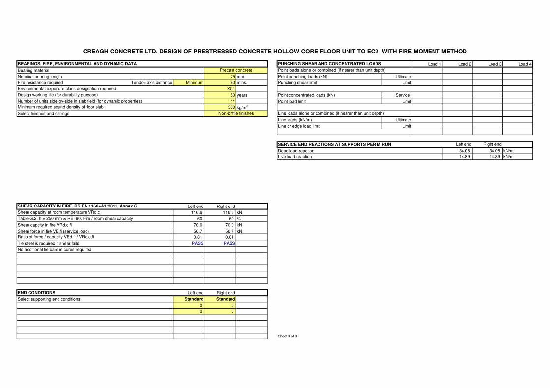
Load 1 Load 2 Load 3 Load 4
Bearing material
Nominal bearing length 75 mm Point punching loads (kN) Ultimate
Fire resistance required Tendon axis distance Minimum 90 mins. Punching shear limit Limit
XC1
50 years Point concentrated loads (kN) Service
11 Point load limit Limit
300 kg/m2
Select finishes and ceilings
Line loads (kN/m) Ultimate
RIGID OR FLEXIBLE SUPPORTS Line or edge load limit Limit
Precast unit on a flexible support ? NO NO
SERVICE END REACTIONS AT SUPPORTS PER M RUN Left end Right end
Dead load reaction 34.05 34.05 kN/m
Live load reaction 14.89 14.89 kN/m
Left end Right end
116.6 116.6 kN
60 60 %
Shear capcity in fire VRd,c,fi 70.0 70.0 kN
Shear force in fire VE,fi (service load) 56.7 56.7 kN
0.81 0.81
Tie steel is required if shear fails PASS PASS
END CONDITIONS Left end Right end
Select supporting end conditions Standard Standard
0 0
0 0
Sheet 3 of 3
Table G.2. h = 250 mm & REI 90. Fire / room shear capacity
Shear capacity at room temperature VRd,c
Minimum required sound density of floor slab
Number of units side-by-side in slab field (for dynamic properties)
Line loads alone or combined (if nearer than unit depth)
BEARINGS, FIRE, ENVIRONMENTAL AND DYNAMIC DATA
Precast concrete
PUNCHING SHEAR AND CONCENTRATED LOADS
Point loads alone or combined (if nearer than unit depth)
SHEAR CAPACITY IN FIRE. BS EN 1168+A3:2011, Annex G
CREAGH CONCRETE LTD. DESIGN OF PRESTRESSED CONCRETE HOLLOW CORE FLOOR UNIT TO EC2 WITH FIRE MOMENT METHOD
No additional tie bars in cores required
Design working life (for durability purpose)
Ratio of force / capacity VEd,fi / VRd,c,fi
Environmental exposure class designation required
Non-brittle finishes
Right endLeft end
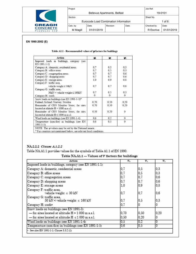
Project
Bellevue Apartments, Belfast Job Ref.
19-0101
Section
Eurocode Load Combination Information Sheet No.
1 of 6
Calc. by
M Magill
Date
01/01/2019
Revision
Date
Checked by
R Escriva
Date
01/01/2019
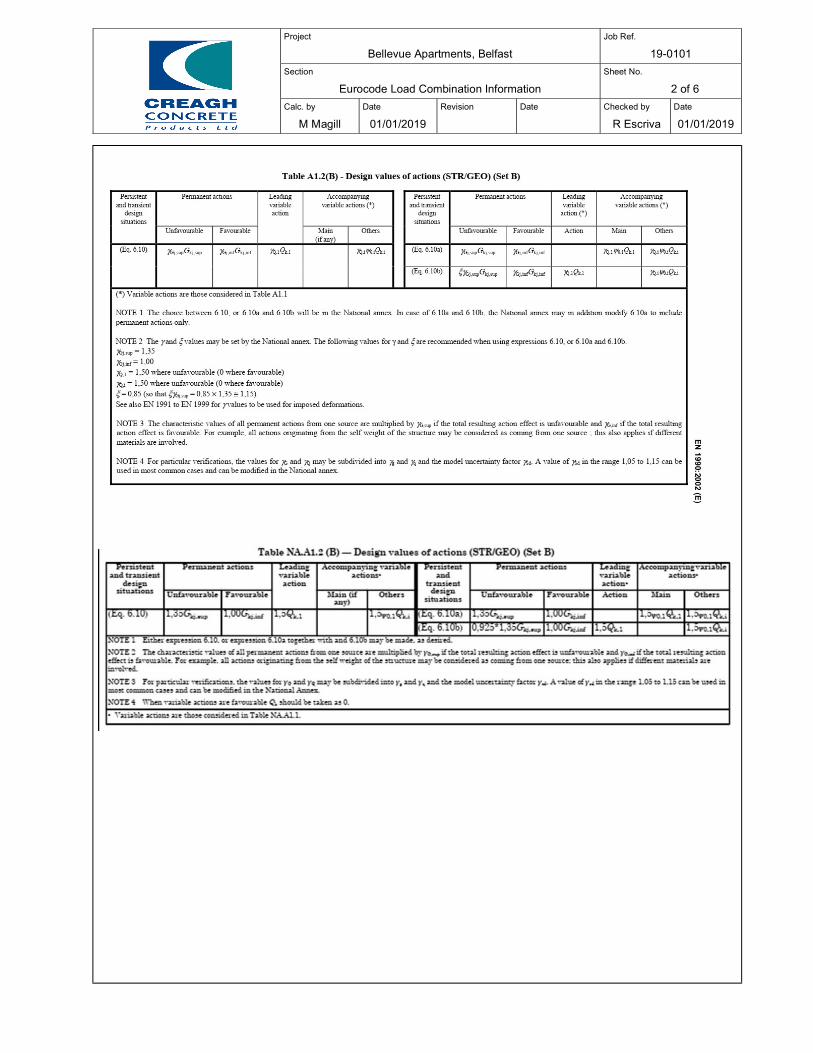
Project
Bellevue Apartments, Belfast Job Ref.
19-0101
Section
Eurocode Load Combination Information Sheet No.
2 of 6
Calc. by
M Magill
Date
01/01/2019
Revision
Date
Checked by
R Escriva
Date
01/01/2019
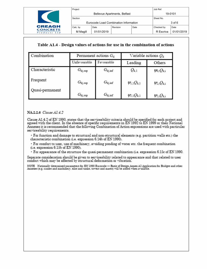
Project
Bellevue Apartments, Belfast Job Ref.
19-0101
Section
Eurocode Load Combination Information Sheet No.
3 of 6
Calc. by
M Magill
Date
01/01/2019
Revision
Date
Checked by
R Escriva
Date
01/01/2019
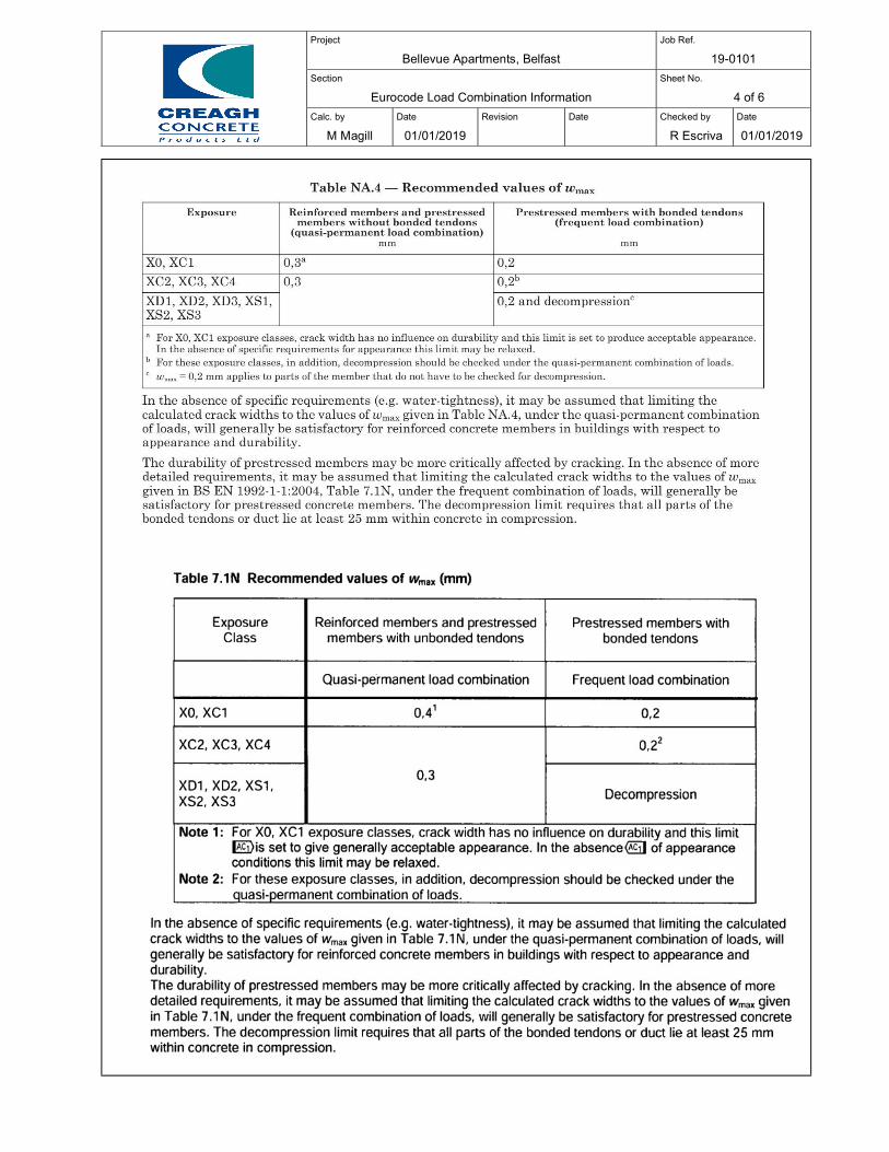
Project
Bellevue Apartments, Belfast Job Ref.
19-0101
Section
Eurocode Load Combination Information Sheet No.
4 of 6
Calc. by
M Magill
Date
01/01/2019
Revision
Date
Checked by
R Escriva
Date
01/01/2019
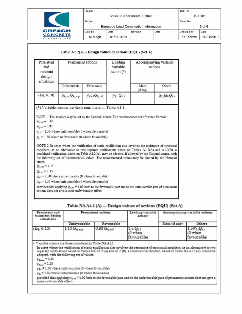
Project
Bellevue Apartments, Belfast Job Ref.
19-0101
Section
Eurocode Load Combination Information Sheet No.
5 of 6
Calc. by
M Magill
Date
01/01/2019
Revision
Date
Checked by
R Escriva
Date
01/01/2019
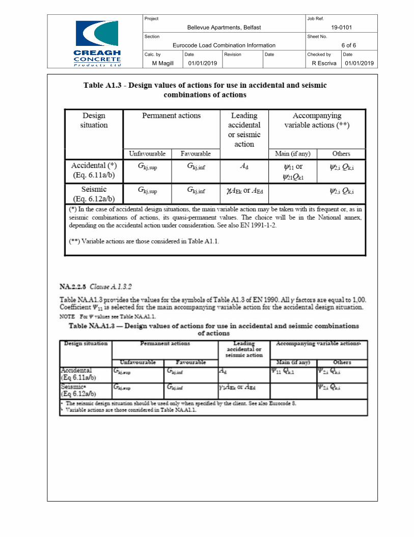
Project
Bellevue Apartments, Belfast Job Ref.
19-0101
Section
Eurocode Load Combination Information Sheet No.
6 of 6
Calc. by
M Magill
Date
01/01/2019
Revision
Date
Checked by
R Escriva
Date
01/01/2019
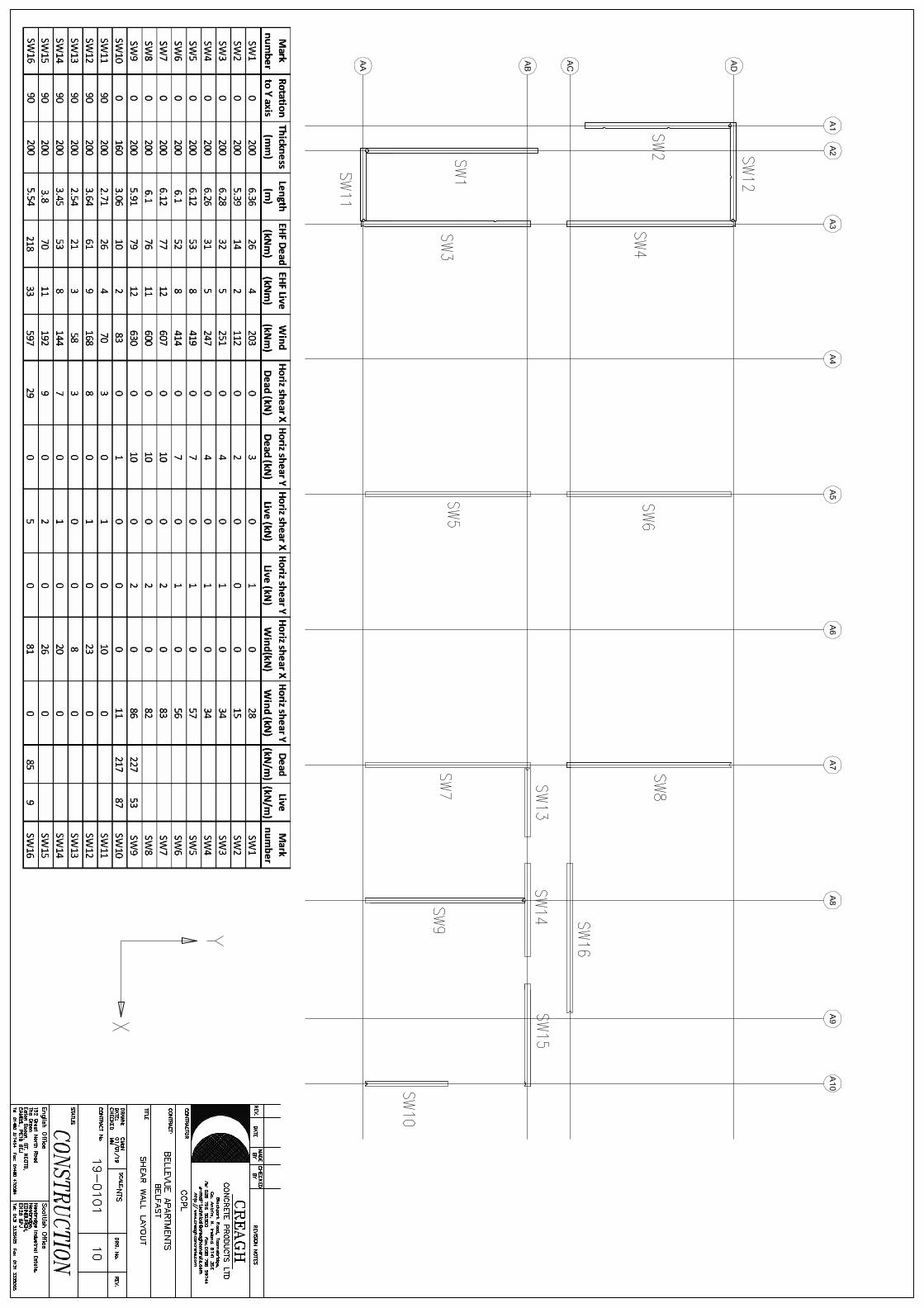
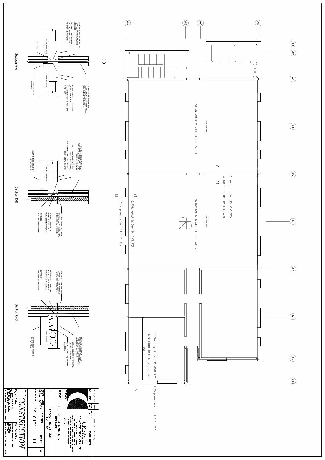
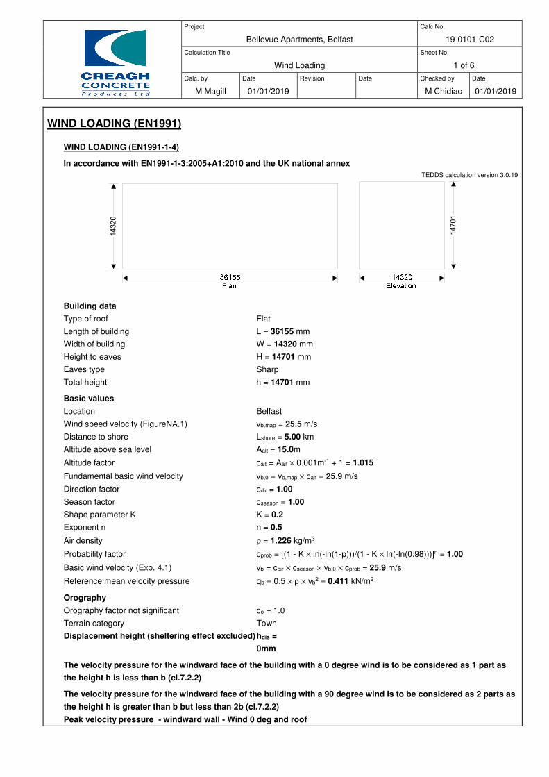
Project
Bellevue Apartments, Belfast
Calc No.
19-0101-C02
Calculation Title
Wind Loading
Sheet No.
1 of 6
Calc. by
M Magill
Date
01/01/2019
Revision
Date
Checked by
M Chidiac
Date
01/01/2019
WIND LOADING (EN1991)
WIND LOADING (EN1991-1-4)
In accordance with EN1991-1-3:2005+A1:2010 and the UK national annex
TEDDS calculation version 3.0.19
Building data
Type of roof Flat
Length of building L = 36155 mm
Width of building W = 14320 mm
Height to eaves H = 14701 mm
Eaves type Sharp
Total height h = 14701 mm
Basic values
Location Belfast
Wind speed velocity (FigureNA.1) vb,map = 25.5 m/s
Distance to shore Lshore = 5.00 km
Altitude above sea level Aalt = 15.0m
Altitude factor calt = Aalt × 0.001m-1 + 1 = 1.015
Fundamental basic wind velocity vb,0 = vb,map × calt = 25.9 m/s
Direction factor cdir = 1.00
Season factor cseason = 1.00
Shape parameter K K = 0.2
Exponent n n = 0.5
Air density ρ = 1.226 kg/m3
Probability factor cprob = [(1 - K × ln(-ln(1-p)))/(1 - K × ln(-ln(0.98)))]n = 1.00
Basic wind velocity (Exp. 4.1) vb = cdir × cseason × vb,0 × cprob = 25.9 m/s
Reference mean velocity pressure qb = 0.5 × ρ × vb2 = 0.411 kN/m2
Orography
Orography factor not significant co = 1.0
Terrain category Town
Displacement height (sheltering effect excluded) hdis =
0mm
The velocity pressure for the windward face of the building with a 0 degree wind is to be considered as 1 part as
the height h is less than b (cl.7.2.2)
The velocity pressure for the windward face of the building with a 90 degree wind is to be considered as 2 parts as
the height h is greater than b but less than 2b (cl.7.2.2)
Peak velocity pressure - windward wall - Wind 0 deg and roof
14320
14701
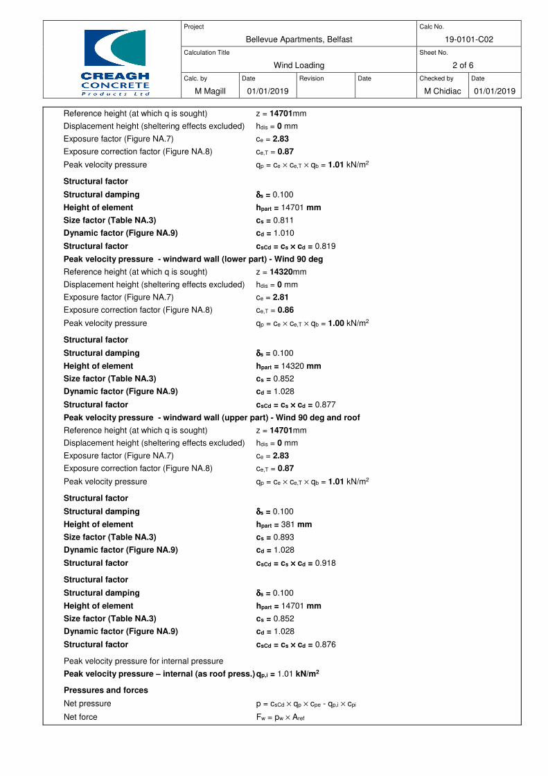
Project
Bellevue Apartments, Belfast
Calc No.
19-0101-C02
Calculation Title
Wind Loading
Sheet No.
2 of 6
Calc. by
M Magill
Date
01/01/2019
Revision
Date
Checked by
M Chidiac
Date
01/01/2019
Reference height (at which q is sought) z = 14701mm
Displacement height (sheltering effects excluded) hdis = 0 mm
Exposure factor (Figure NA.7) ce = 2.83
Exposure correction factor (Figure NA.8) ce,T = 0.87
Peak velocity pressure qp = ce × ce,T × qb = 1.01 kN/m2
Structural factor
Structural damping δδδδs = 0.100
Height of element hpart = 14701 mm
Size factor (Table NA.3) cs = 0.811
Dynamic factor (Figure NA.9) cd = 1.010
Structural factor csCd = cs ×××× cd = 0.819
Peak velocity pressure - windward wall (lower part) - Wind 90 deg
Reference height (at which q is sought) z = 14320mm
Displacement height (sheltering effects excluded) hdis = 0 mm
Exposure factor (Figure NA.7) ce = 2.81
Exposure correction factor (Figure NA.8) ce,T = 0.86
Peak velocity pressure qp = ce × ce,T × qb = 1.00 kN/m2
Structural factor
Structural damping δδδδs = 0.100
Height of element hpart = 14320 mm
Size factor (Table NA.3) cs = 0.852
Dynamic factor (Figure NA.9) cd = 1.028
Structural factor csCd = cs ×××× cd = 0.877
Peak velocity pressure - windward wall (upper part) - Wind 90 deg and roof
Reference height (at which q is sought) z = 14701mm
Displacement height (sheltering effects excluded) hdis = 0 mm
Exposure factor (Figure NA.7) ce = 2.83
Exposure correction factor (Figure NA.8) ce,T = 0.87
Peak velocity pressure qp = ce × ce,T × qb = 1.01 kN/m2
Structural factor
Structural damping δδδδs = 0.100
Height of element hpart = 381 mm
Size factor (Table NA.3) cs = 0.893
Dynamic factor (Figure NA.9) cd = 1.028
Structural factor csCd = cs ×××× cd = 0.918
Structural factor
Structural damping δδδδs = 0.100
Height of element hpart = 14701 mm
Size factor (Table NA.3) cs = 0.852
Dynamic factor (Figure NA.9) cd = 1.028
Structural factor csCd = cs ×××× cd = 0.876
Peak velocity pressure for internal pressure
Peak velocity pressure – internal (as roof press.) qp,i = 1.01 kN/m2
Pressures and forces
Net pressure p = csCd × qp × cpe - qp,i × cpi
Net force Fw = pw × Aref
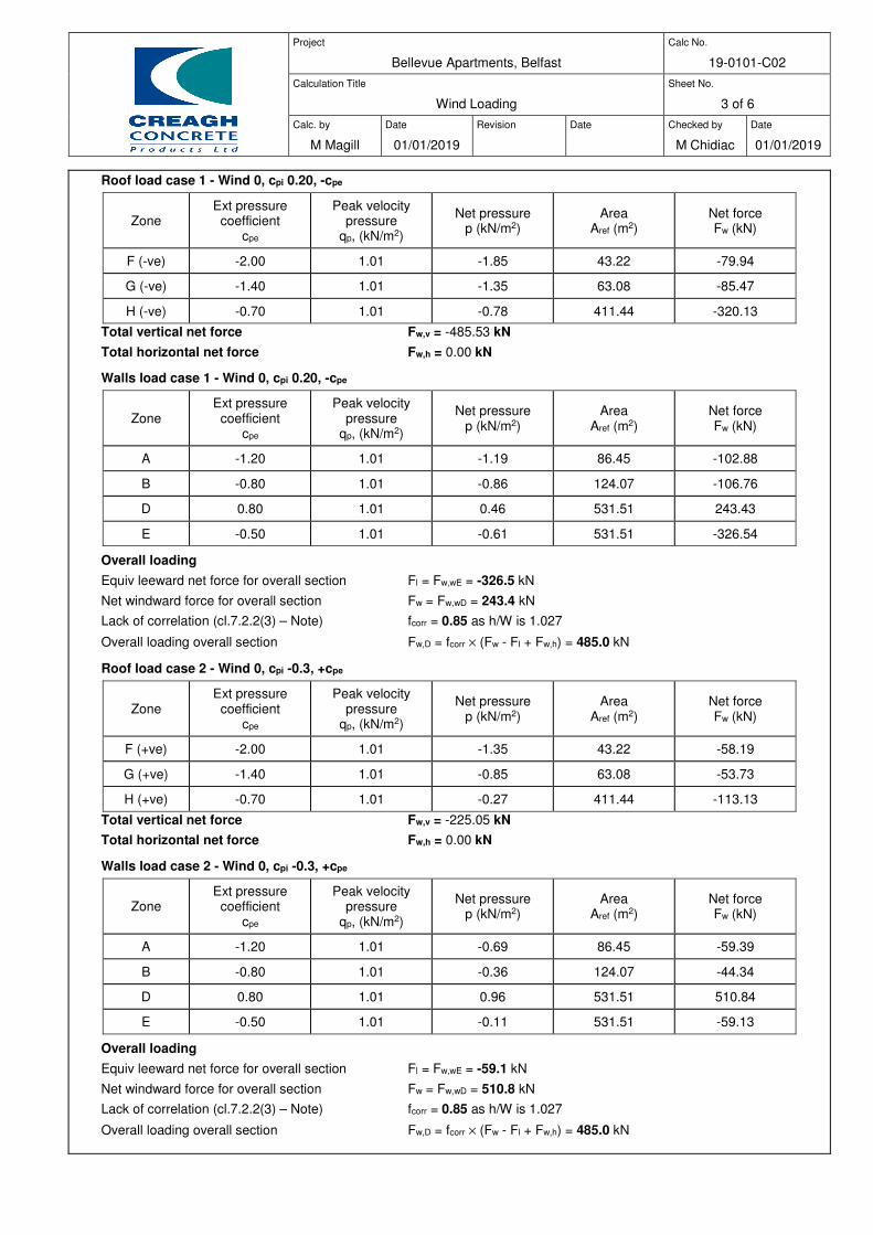
Project
Bellevue Apartments, Belfast
Calc No.
19-0101-C02
Calculation Title
Wind Loading
Sheet No.
3 of 6
Calc. by
M Magill
Date
01/01/2019
Revision
Date
Checked by
M Chidiac
Date
01/01/2019
Roof load case 1 - Wind 0, cpi 0.20, -cpe
Zone Ext pressure
coefficient cpe
Peak velocity pressure
qp, (kN/m2)
Net pressure p (kN/m2)
Area Aref (m2)
Net force Fw (kN)
F (-ve) -2.00 1.01 -1.85 43.22 -79.94
G (-ve) -1.40 1.01 -1.35 63.08 -85.47
H (-ve) -0.70 1.01 -0.78 411.44 -320.13
Total vertical net force Fw,v = -485.53 kN
Total horizontal net force Fw,h = 0.00 kN
Walls load case 1 - Wind 0, cpi 0.20, -cpe
Zone Ext pressure
coefficient cpe
Peak velocity pressure
qp, (kN/m2)
Net pressure p (kN/m2)
Area Aref (m2)
Net force Fw (kN)
A -1.20 1.01 -1.19 86.45 -102.88
B -0.80 1.01 -0.86 124.07 -106.76
D 0.80 1.01 0.46 531.51 243.43
E -0.50 1.01 -0.61 531.51 -326.54
Overall loading
Equiv leeward net force for overall section Fl = Fw,wE = -326.5 kN
Net windward force for overall section Fw = Fw,wD = 243.4 kN
Lack of correlation (cl.7.2.2(3) – Note) fcorr = 0.85 as h/W is 1.027
Overall loading overall section Fw,D = fcorr × (Fw - Fl + Fw,h) = 485.0 kN
Roof load case 2 - Wind 0, cpi -0.3, +cpe
Zone Ext pressure
coefficient cpe
Peak velocity pressure
qp, (kN/m2)
Net pressure p (kN/m2)
Area Aref (m2)
Net force Fw (kN)
F (+ve) -2.00 1.01 -1.35 43.22 -58.19
G (+ve) -1.40 1.01 -0.85 63.08 -53.73
H (+ve) -0.70 1.01 -0.27 411.44 -113.13
Total vertical net force Fw,v = -225.05 kN
Total horizontal net force Fw,h = 0.00 kN
Walls load case 2 - Wind 0, cpi -0.3, +cpe
Zone Ext pressure
coefficient cpe
Peak velocity pressure
qp, (kN/m2)
Net pressure p (kN/m2)
Area Aref (m2)
Net force Fw (kN)
A -1.20 1.01 -0.69 86.45 -59.39
B -0.80 1.01 -0.36 124.07 -44.34
D 0.80 1.01 0.96 531.51 510.84
E -0.50 1.01 -0.11 531.51 -59.13
Overall loading
Equiv leeward net force for overall section Fl = Fw,wE = -59.1 kN
Net windward force for overall section Fw = Fw,wD = 510.8 kN
Lack of correlation (cl.7.2.2(3) – Note) fcorr = 0.85 as h/W is 1.027
Overall loading overall section Fw,D = fcorr × (Fw - Fl + Fw,h) = 485.0 kN
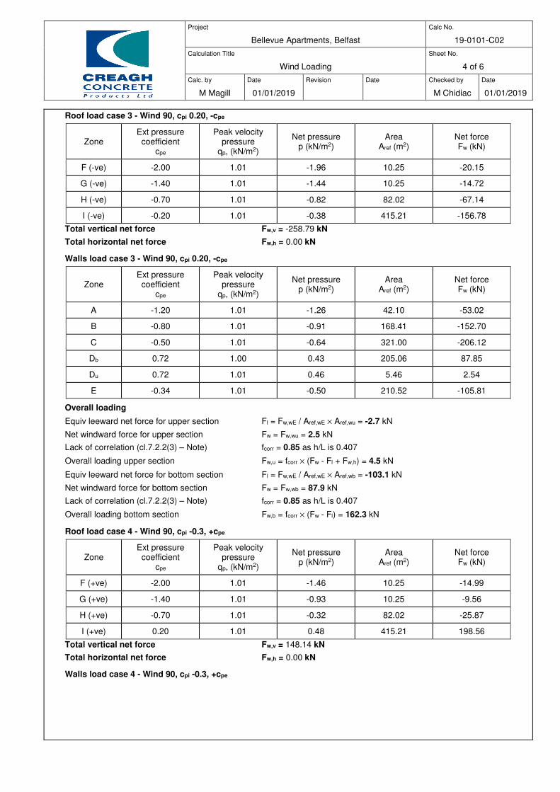
Project
Bellevue Apartments, Belfast
Calc No.
19-0101-C02
Calculation Title
Wind Loading
Sheet No.
4 of 6
Calc. by
M Magill
Date
01/01/2019
Revision
Date
Checked by
M Chidiac
Date
01/01/2019
Roof load case 3 - Wind 90, cpi 0.20, -cpe
Zone Ext pressure
coefficient cpe
Peak velocity pressure
qp, (kN/m2)
Net pressure p (kN/m2)
Area Aref (m2)
Net force Fw (kN)
F (-ve) -2.00 1.01 -1.96 10.25 -20.15
G (-ve) -1.40 1.01 -1.44 10.25 -14.72
H (-ve) -0.70 1.01 -0.82 82.02 -67.14
I (-ve) -0.20 1.01 -0.38 415.21 -156.78
Total vertical net force Fw,v = -258.79 kN
Total horizontal net force Fw,h = 0.00 kN
Walls load case 3 - Wind 90, cpi 0.20, -cpe
Zone Ext pressure
coefficient cpe
Peak velocity pressure
qp, (kN/m2)
Net pressure p (kN/m2)
Area Aref (m2)
Net force Fw (kN)
A -1.20 1.01 -1.26 42.10 -53.02
B -0.80 1.01 -0.91 168.41 -152.70
C -0.50 1.01 -0.64 321.00 -206.12
Db 0.72 1.00 0.43 205.06 87.85
Du 0.72 1.01 0.46 5.46 2.54
E -0.34 1.01 -0.50 210.52 -105.81
Overall loading
Equiv leeward net force for upper section Fl = Fw,wE / Aref,wE × Aref,wu = -2.7 kN
Net windward force for upper section Fw = Fw,wu = 2.5 kN
Lack of correlation (cl.7.2.2(3) – Note) fcorr = 0.85 as h/L is 0.407
Overall loading upper section Fw,u = fcorr × (Fw - Fl + Fw,h) = 4.5 kN
Equiv leeward net force for bottom section Fl = Fw,wE / Aref,wE × Aref,wb = -103.1 kN
Net windward force for bottom section Fw = Fw,wb = 87.9 kN
Lack of correlation (cl.7.2.2(3) – Note) fcorr = 0.85 as h/L is 0.407
Overall loading bottom section Fw,b = fcorr × (Fw - Fl) = 162.3 kN
Roof load case 4 - Wind 90, cpi -0.3, +cpe
Zone Ext pressure
coefficient cpe
Peak velocity pressure
qp, (kN/m2)
Net pressure p (kN/m2)
Area Aref (m2)
Net force Fw (kN)
F (+ve) -2.00 1.01 -1.46 10.25 -14.99
G (+ve) -1.40 1.01 -0.93 10.25 -9.56
H (+ve) -0.70 1.01 -0.32 82.02 -25.87
I (+ve) 0.20 1.01 0.48 415.21 198.56
Total vertical net force Fw,v = 148.14 kN
Total horizontal net force Fw,h = 0.00 kN
Walls load case 4 - Wind 90, cpi -0.3, +cpe
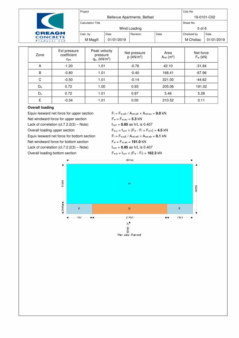
Project
Bellevue Apartments, Belfast
Calc No.
19-0101-C02
Calculation Title
Wind Loading
Sheet No.
5 of 6
Calc. by
M Magill
Date
01/01/2019
Revision
Date
Checked by
M Chidiac
Date
01/01/2019
Zone Ext pressure
coefficient cpe
Peak velocity pressure
qp, (kN/m2)
Net pressure p (kN/m2)
Area Aref (m2)
Net force Fw (kN)
A -1.20 1.01 -0.76 42.10 -31.84
B -0.80 1.01 -0.40 168.41 -67.96
C -0.50 1.01 -0.14 321.00 -44.62
Db 0.72 1.00 0.93 205.06 191.02
Du 0.72 1.01 0.97 5.46 5.28
E -0.34 1.01 0.00 210.52 0.11
Overall loading
Equiv leeward net force for upper section Fl = Fw,wE / Aref,wE × Aref,wu = 0.0 kN
Net windward force for upper section Fw = Fw,wu = 5.3 kN
Lack of correlation (cl.7.2.2(3) – Note) fcorr = 0.85 as h/L is 0.407
Overall loading upper section Fw,u = fcorr × (Fw - Fl + Fw,h) = 4.5 kN
Equiv leeward net force for bottom section Fl = Fw,wE / Aref,wE × Aref,wb = 0.1 kN
Net windward force for bottom section Fw = Fw,wb = 191.0 kN
Lack of correlation (cl.7.2.2(3) – Note) fcorr = 0.85 as h/L is 0.407
Overall loading bottom section Fw,b = fcorr × (Fw - Fl) = 162.3 kN
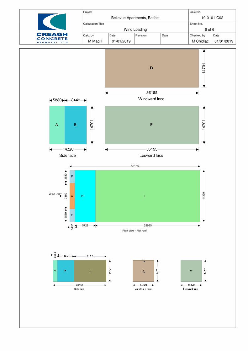
Project
Bellevue Apartments, Belfast
Calc No.
19-0101-C02
Calculation Title
Wind Loading
Sheet No.
6 of 6
Calc. by
M Magill
Date
01/01/2019
Revision
Date
Checked by
M Chidiac
Date
01/01/2019
14701
14701
14701
F
F
G H I
3580
7160
3580
1432 5728 28995
36155
14320
Wind - 90o
Plan view - Flat roof

Project
Bellevue Apartments, Belfast
Calc No.
19-0101-C03-1
Calculation Title
Shear wall load distribution - X direction %
Sheet No.
1 of 3
Calc. by
M Magill
Date
01/01/2019
Revision
Date
Checked by
M Chidiac
Date
01/01/2019
Notional 100kN load applied to provide % distribution of lateral loading.
RIGID DIAPHRAGM FORCE DISTRIBUTION
RIGID DIAPHRAGM FORCE DISTRIBUTION
Tedds calculation version 1.1.01
The location of elements are relative to the origin (0m, 0m).
Floor data
Building type Concrete
No of concrete columns Ncc = 0
No of shear walls NSW = 16
No of other elements Nele = 0
Floor height below Hf = 3.000 m
Modulus of elasticity for concrete E = Ec = 28000 N/mm2
Loads
Lateral load in X Fx = 100.000 kN
Location of Fx from origin Y = 7.160 m
Lateral load in Y Fy = 0.000 kN
Location of Fy from origin X = 0.000 m
Shear wall
No. Height Location
(relative to
origin)
Rotation
to
Y axis
Thickness Length k along X
axis
k along Y
axis
H (m) X (m) Y (m) θ (deg) tSW (mm) lSW (m) kx
(kN/mm)
ky
(kN/mm)
SW1 3 1.22 3.58 0 200 6.36 0 13307.943
SW2 3 0.29 11.22 0 200 5.39 0 8096.949
SW3 3 3.94 3.35 0 200 6.28 0 12842.312
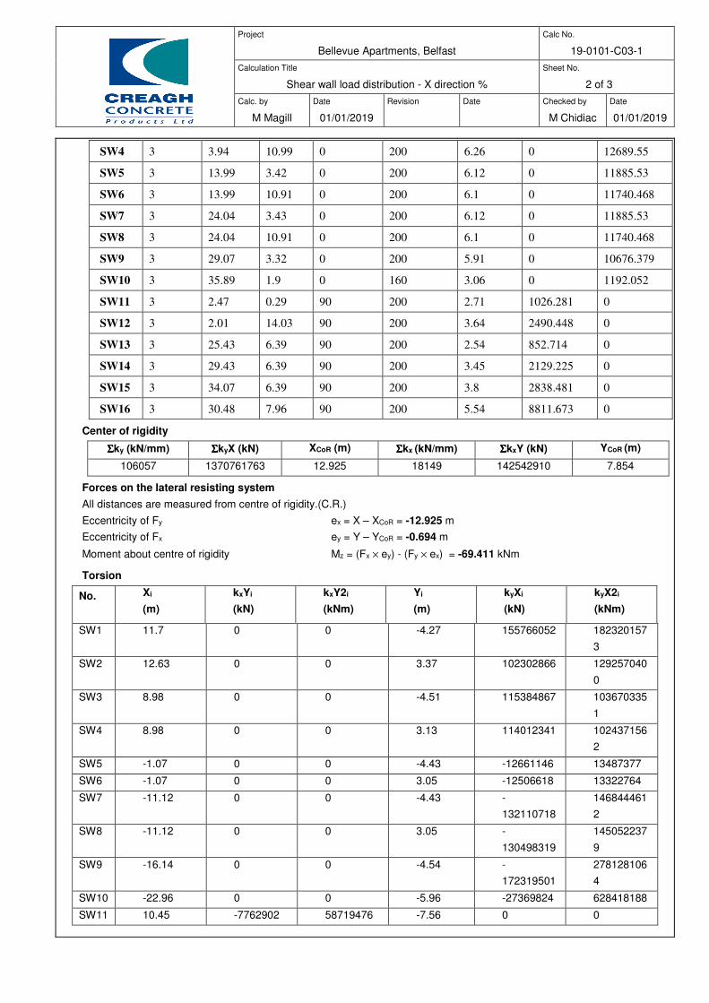
Project
Bellevue Apartments, Belfast
Calc No.
19-0101-C03-1
Calculation Title
Shear wall load distribution - X direction %
Sheet No.
2 of 3
Calc. by
M Magill
Date
01/01/2019
Revision
Date
Checked by
M Chidiac
Date
01/01/2019
SW4 3 3.94 10.99 0 200 6.26 0 12689.55
SW5 3 13.99 3.42 0 200 6.12 0 11885.53
SW6 3 13.99 10.91 0 200 6.1 0 11740.468
SW7 3 24.04 3.43 0 200 6.12 0 11885.53
SW8 3 24.04 10.91 0 200 6.1 0 11740.468
SW9 3 29.07 3.32 0 200 5.91 0 10676.379
SW10 3 35.89 1.9 0 160 3.06 0 1192.052
SW11 3 2.47 0.29 90 200 2.71 1026.281 0
SW12 3 2.01 14.03 90 200 3.64 2490.448 0
SW13 3 25.43 6.39 90 200 2.54 852.714 0
SW14 3 29.43 6.39 90 200 3.45 2129.225 0
SW15 3 34.07 6.39 90 200 3.8 2838.481 0
SW16 3 30.48 7.96 90 200 5.54 8811.673 0
Center of rigidity
ΣΣΣΣky (kN/mm) ΣΣΣΣkyX (kN) XCoR (m) ΣΣΣΣkx (kN/mm) ΣΣΣΣkxY (kN) YCoR (m)
106057 1370761763 12.925 18149 142542910 7.854
Forces on the lateral resisting system
All distances are measured from centre of rigidity.(C.R.)
Eccentricity of Fy ex = X – XCoR = -12.925 m
Eccentricity of Fx ey = Y – YCoR = -0.694 m
Moment about centre of rigidity Mz = (Fx × ey) - (Fy × ex) = -69.411 kNm
Torsion
No.
Xi
(m)
kxYi
(kN)
kxY2i
(kNm)
Yi
(m)
kyXi
(kN)
kyX2i
(kNm)
SW1 11.7 0 0 -4.27 155766052 182320157
3
SW2 12.63 0 0 3.37 102302866 129257040
0
SW3 8.98 0 0 -4.51 115384867 103670335
1
SW4 8.98 0 0 3.13 114012341 102437156
2
SW5 -1.07 0 0 -4.43 -12661146 13487377
SW6 -1.07 0 0 3.05 -12506618 13322764
SW7 -11.12 0 0 -4.43 -
132110718
146844461
2
SW8 -11.12 0 0 3.05 -
130498319
145052237
9
SW9 -16.14 0 0 -4.54 -
172319501
278128106
4
SW10 -22.96 0 0 -5.96 -27369824 628418188
SW11 10.45 -7762902 58719476 -7.56 0 0
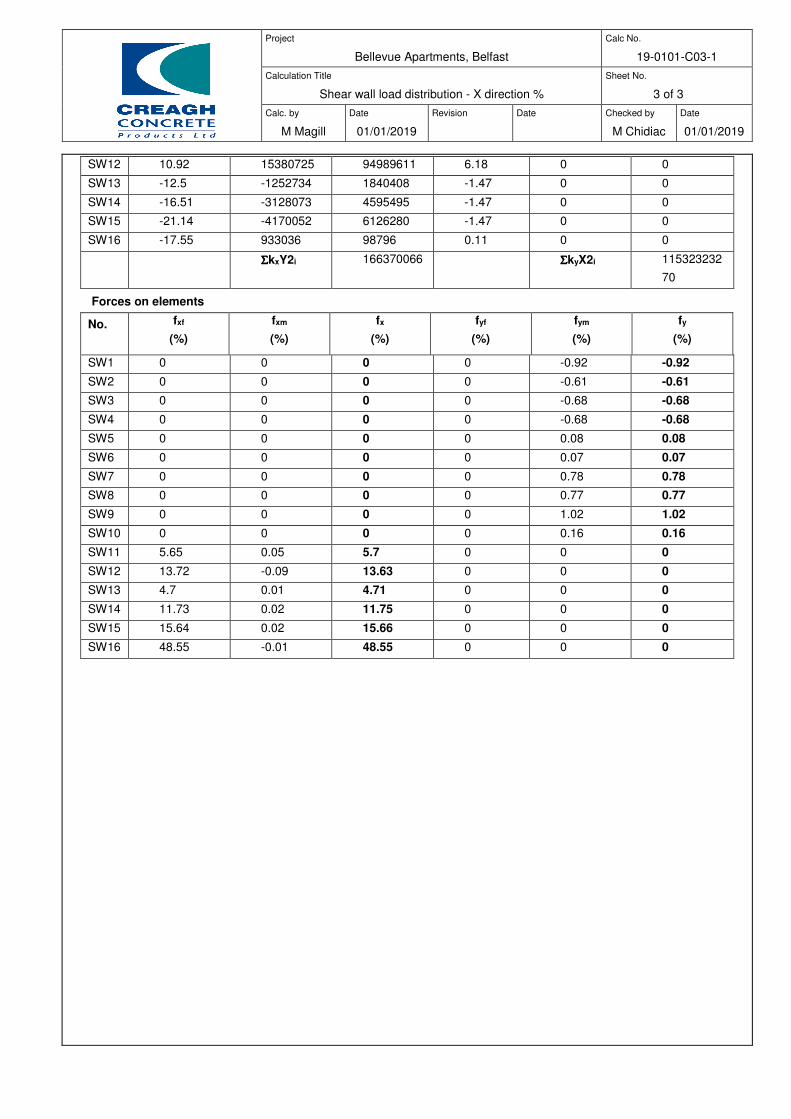
Project
Bellevue Apartments, Belfast
Calc No.
19-0101-C03-1
Calculation Title
Shear wall load distribution - X direction %
Sheet No.
3 of 3
Calc. by
M Magill
Date
01/01/2019
Revision
Date
Checked by
M Chidiac
Date
01/01/2019
SW12 10.92 15380725 94989611 6.18 0 0
SW13 -12.5 -1252734 1840408 -1.47 0 0
SW14 -16.51 -3128073 4595495 -1.47 0 0
SW15 -21.14 -4170052 6126280 -1.47 0 0
SW16 -17.55 933036 98796 0.11 0 0
ΣΣΣΣkxY2i 166370066 ΣΣΣΣkyX2i 115323232
70
Forces on elements
No.
fxf
(%)
fxm
(%)
fx
(%)
fyf
(%)
fym
(%)
fy
(%)
SW1 0 0 0 0 -0.92 -0.92
SW2 0 0 0 0 -0.61 -0.61
SW3 0 0 0 0 -0.68 -0.68
SW4 0 0 0 0 -0.68 -0.68
SW5 0 0 0 0 0.08 0.08
SW6 0 0 0 0 0.07 0.07
SW7 0 0 0 0 0.78 0.78
SW8 0 0 0 0 0.77 0.77
SW9 0 0 0 0 1.02 1.02
SW10 0 0 0 0 0.16 0.16
SW11 5.65 0.05 5.7 0 0 0
SW12 13.72 -0.09 13.63 0 0 0
SW13 4.7 0.01 4.71 0 0 0
SW14 11.73 0.02 11.75 0 0 0
SW15 15.64 0.02 15.66 0 0 0
SW16 48.55 -0.01 48.55 0 0 0
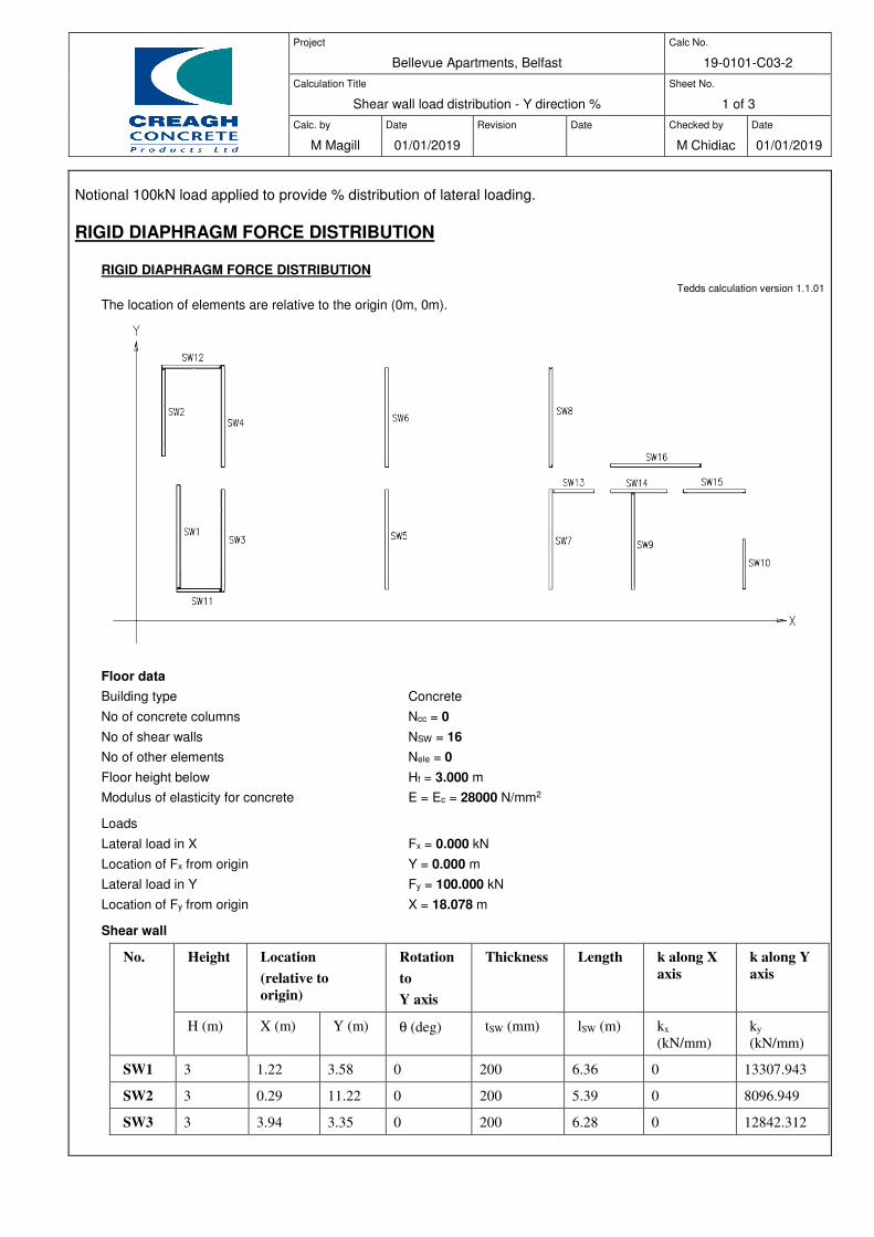
Project
Bellevue Apartments, Belfast
Calc No.
19-0101-C03-2
Calculation Title
Shear wall load distribution - Y direction %
Sheet No.
1 of 3
Calc. by
M Magill
Date
01/01/2019
Revision
Date
Checked by
M Chidiac
Date
01/01/2019
Notional 100kN load applied to provide % distribution of lateral loading.
RIGID DIAPHRAGM FORCE DISTRIBUTION
RIGID DIAPHRAGM FORCE DISTRIBUTION
Tedds calculation version 1.1.01
The location of elements are relative to the origin (0m, 0m).
Floor data
Building type Concrete
No of concrete columns Ncc = 0
No of shear walls NSW = 16
No of other elements Nele = 0
Floor height below Hf = 3.000 m
Modulus of elasticity for concrete E = Ec = 28000 N/mm2
Loads
Lateral load in X Fx = 0.000 kN
Location of Fx from origin Y = 0.000 m
Lateral load in Y Fy = 100.000 kN
Location of Fy from origin X = 18.078 m
Shear wall
No. Height Location
(relative to
origin)
Rotation
to
Y axis
Thickness Length k along X
axis
k along Y
axis
H (m) X (m) Y (m) θ (deg) tSW (mm) lSW (m) kx
(kN/mm)
ky
(kN/mm)
SW1 3 1.22 3.58 0 200 6.36 0 13307.943
SW2 3 0.29 11.22 0 200 5.39 0 8096.949
SW3 3 3.94 3.35 0 200 6.28 0 12842.312

Project
Bellevue Apartments, Belfast
Calc No.
19-0101-C03-2
Calculation Title
Shear wall load distribution - Y direction %
Sheet No.
2 of 3
Calc. by
M Magill
Date
01/01/2019
Revision
Date
Checked by
M Chidiac
Date
01/01/2019
SW4 3 3.94 10.99 0 200 6.26 0 12689.55
SW5 3 13.99 3.42 0 200 6.12 0 11885.53
SW6 3 13.99 10.91 0 200 6.1 0 11740.468
SW7 3 24.04 3.43 0 200 6.12 0 11885.53
SW8 3 24.04 10.91 0 200 6.1 0 11740.468
SW9 3 29.07 3.32 0 200 5.91 0 10676.379
SW10 3 35.89 1.9 0 160 3.06 0 1192.052
SW11 3 2.47 0.29 90 200 2.71 1026.281 0
SW12 3 2.01 14.03 90 200 3.64 2490.448 0
SW13 3 25.43 6.39 90 200 2.54 852.714 0
SW14 3 29.43 6.39 90 200 3.45 2129.225 0
SW15 3 34.07 6.39 90 200 3.8 2838.481 0
SW16 3 30.48 7.96 90 200 5.54 8811.673 0
Center of rigidity
ΣΣΣΣky (kN/mm) ΣΣΣΣkyX (kN) XCoR (m) ΣΣΣΣkx (kN/mm) ΣΣΣΣkxY (kN) YCoR (m)
106057 1370761763 12.925 18149 142542910 7.854
Forces on the lateral resisting system
All distances are measured from centre of rigidity.(C.R.)
Eccentricity of Fy ex = X – XCoR = 5.153 m
Eccentricity of Fx ey = Y – YCoR = -7.854 m
Moment about centre of rigidity Mz = (Fx × ey) - (Fy × ex) = -515.276 kNm
Torsion
No.
Xi
(m)
kxYi
(kN)
kxY2i
(kNm)
Yi
(m)
kyXi
(kN)
kyX2i
(kNm)
SW1 11.7 0 0 -4.27 155766052 182320157
3
SW2 12.63 0 0 3.37 102302866 129257040
0
SW3 8.98 0 0 -4.51 115384867 103670335
1
SW4 8.98 0 0 3.13 114012341 102437156
2
SW5 -1.07 0 0 -4.43 -12661146 13487377
SW6 -1.07 0 0 3.05 -12506618 13322764
SW7 -11.12 0 0 -4.43 -
132110718
146844461
2
SW8 -11.12 0 0 3.05 -
130498319
145052237
9
SW9 -16.14 0 0 -4.54 -
172319501
278128106
4
SW10 -22.96 0 0 -5.96 -27369824 628418188
SW11 10.45 -7762902 58719476 -7.56 0 0
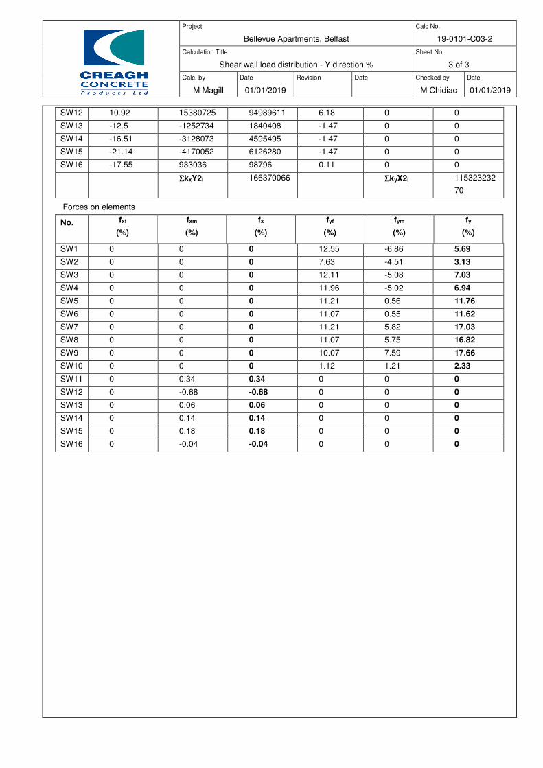
Project
Bellevue Apartments, Belfast
Calc No.
19-0101-C03-2
Calculation Title
Shear wall load distribution - Y direction %
Sheet No.
3 of 3
Calc. by
M Magill
Date
01/01/2019
Revision
Date
Checked by
M Chidiac
Date
01/01/2019
SW12 10.92 15380725 94989611 6.18 0 0
SW13 -12.5 -1252734 1840408 -1.47 0 0
SW14 -16.51 -3128073 4595495 -1.47 0 0
SW15 -21.14 -4170052 6126280 -1.47 0 0
SW16 -17.55 933036 98796 0.11 0 0
ΣΣΣΣkxY2i 166370066 ΣΣΣΣkyX2i 115323232
70
Forces on elements
No.
fxf
(%)
fxm
(%)
fx
(%)
fyf
(%)
fym
(%)
fy
(%)
SW1 0 0 0 12.55 -6.86 5.69
SW2 0 0 0 7.63 -4.51 3.13
SW3 0 0 0 12.11 -5.08 7.03
SW4 0 0 0 11.96 -5.02 6.94
SW5 0 0 0 11.21 0.56 11.76
SW6 0 0 0 11.07 0.55 11.62
SW7 0 0 0 11.21 5.82 17.03
SW8 0 0 0 11.07 5.75 16.82
SW9 0 0 0 10.07 7.59 17.66
SW10 0 0 0 1.12 1.21 2.33
SW11 0 0.34 0.34 0 0 0
SW12 0 -0.68 -0.68 0 0 0
SW13 0 0.06 0.06 0 0 0
SW14 0 0.14 0.14 0 0 0
SW15 0 0.18 0.18 0 0 0
SW16 0 -0.04 -0.04 0 0 0
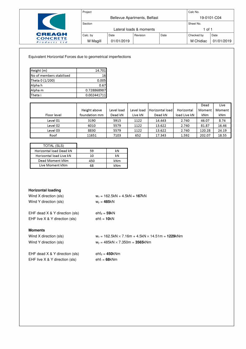
Project
Bellevue Apartments, Belfast
Calc No.
19-0101-C04
Section
Lateral loads & moments
Sheet No.
1 of 1
Calc. by
M Magill
Date
01/01/2019
Revision
Date
Checked by
M Chidiac
Date
01/01/2019
Equivalent Horizontal Forces due to geometrical imperfections
Horizontal loading
Wind X direction (sls) wx = 162.5kN + 4.5kN = 167kN
Wind Y direction (sls) wy = 485kN
EHF dead X & Y direction (sls) ehfd = 59kN
EHF live X & Y direction (sls) ehfl = 10kN
Moments
Wind X direction (sls) wx = 162.5kN × 7.16m + 4.5kN × 14.51m = 1229kNm
Wind Y direction (sls) wy = 485kN × 7.350m = 3565kNm
EHF dead X & Y direction (sls) ehfd = 450kNm
EHF live X & Y direction (sls) ehfl = 68kNm
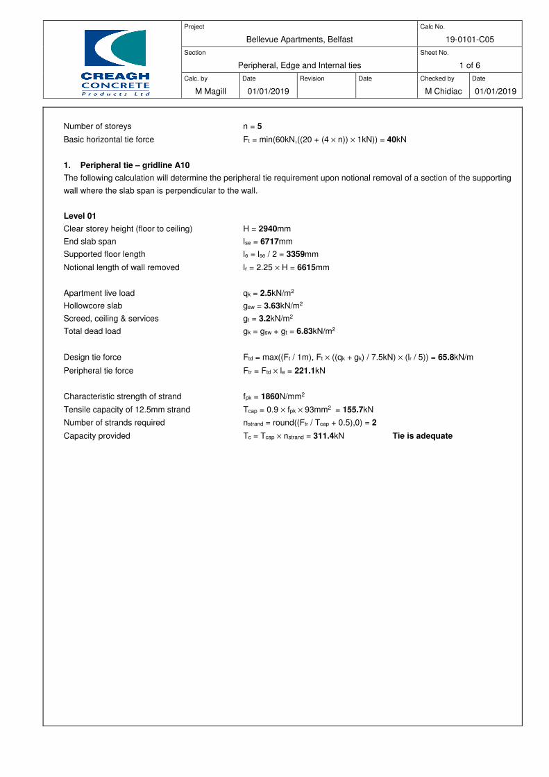
Project
Bellevue Apartments, Belfast
Calc No.
19-0101-C05
Section
Peripheral, Edge and Internal ties
Sheet No.
1 of 6
Calc. by
M Magill
Date
01/01/2019
Revision
Date
Checked by
M Chidiac
Date
01/01/2019
Number of storeys n = 5
Basic horizontal tie force Ft = min(60kN,((20 + (4 × n)) × 1kN)) = 40kN
1. Peripheral tie – gridline A10
The following calculation will determine the peripheral tie requirement upon notional removal of a section of the supporting
wall where the slab span is perpendicular to the wall.
Level 01
Clear storey height (floor to ceiling) H = 2940mm
End slab span lse = 6717mm
Supported floor length le = lse / 2 = 3359mm
Notional length of wall removed lr = 2.25 × H = 6615mm
Apartment live load qk = 2.5kN/m2
Hollowcore slab gsw = 3.63kN/m2
Screed, ceiling & services gt = 3.2kN/m2
Total dead load gk = gsw + gt = 6.83kN/m2
Design tie force Ftd = max((Ft / 1m), Ft × ((qk + gk) / 7.5kN) × (lr / 5)) = 65.8kN/m
Peripheral tie force Ftr = Ftd × le = 221.1kN
Characteristic strength of strand fpk = 1860N/mm2
Tensile capacity of 12.5mm strand Tcap = 0.9 × fpk × 93mm2 = 155.7kN
Number of strands required nstrand = round((Ftr / Tcap + 0.5),0) = 2
Capacity provided Tc = Tcap × nstrand = 311.4kN Tie is adequate
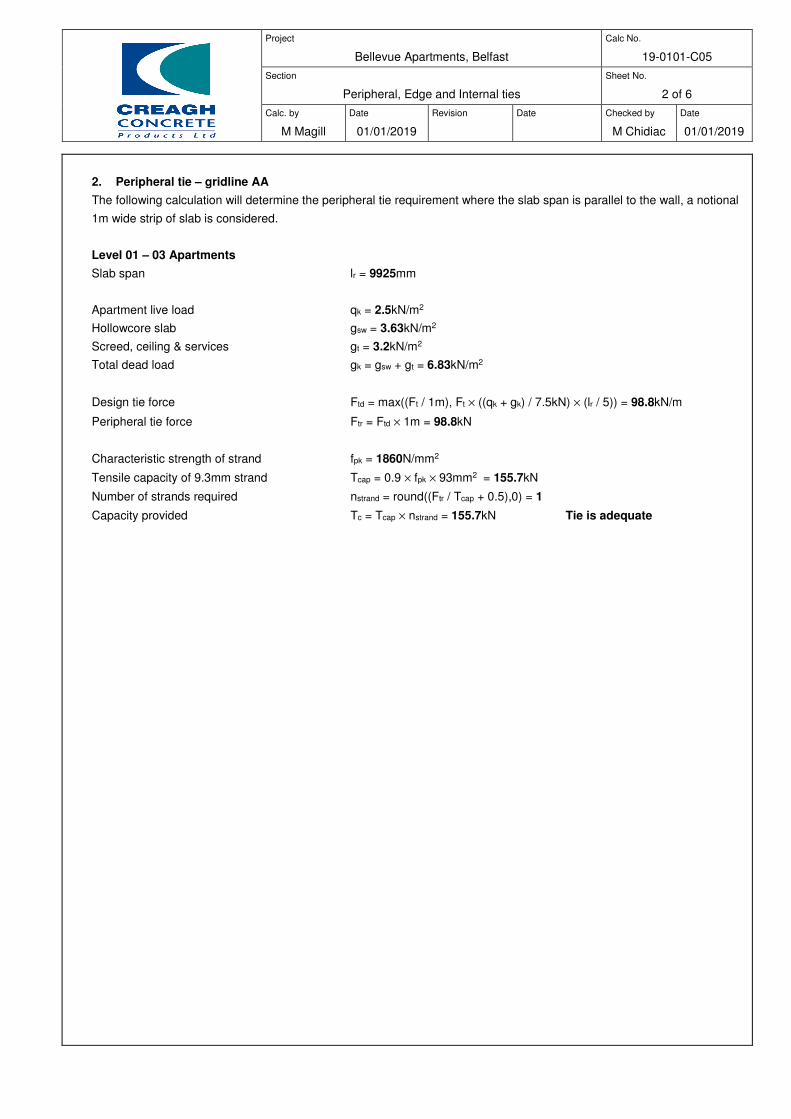
Project
Bellevue Apartments, Belfast
Calc No.
19-0101-C05
Section
Peripheral, Edge and Internal ties
Sheet No.
2 of 6
Calc. by
M Magill
Date
01/01/2019
Revision
Date
Checked by
M Chidiac
Date
01/01/2019
2. Peripheral tie – gridline AA
The following calculation will determine the peripheral tie requirement where the slab span is parallel to the wall, a notional
1m wide strip of slab is considered.
Level 01 – 03 Apartments
Slab span lr = 9925mm
Apartment live load qk = 2.5kN/m2
Hollowcore slab gsw = 3.63kN/m2
Screed, ceiling & services gt = 3.2kN/m2
Total dead load gk = gsw + gt = 6.83kN/m2
Design tie force Ftd = max((Ft / 1m), Ft × ((qk + gk) / 7.5kN) × (lr / 5)) = 98.8kN/m
Peripheral tie force Ftr = Ftd × 1m = 98.8kN
Characteristic strength of strand fpk = 1860N/mm2
Tensile capacity of 9.3mm strand Tcap = 0.9 × fpk × 93mm2 = 155.7kN
Number of strands required nstrand = round((Ftr / Tcap + 0.5),0) = 1
Capacity provided Tc = Tcap × nstrand = 155.7kN Tie is adequate
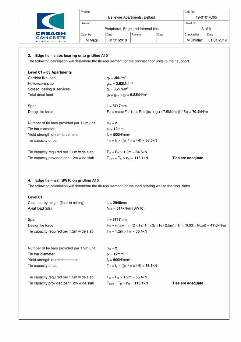
Project
Bellevue Apartments, Belfast
Calc No.
19-0101-C05
Section
Peripheral, Edge and Internal ties
Sheet No.
3 of 6
Calc. by
M Magill
Date
01/01/2019
Revision
Date
Checked by
M Chidiac
Date
01/01/2019
3. Edge tie – slabs bearing onto gridline A10
The following calculation will determine the tie requirement for the precast floor units to their support.
Level 01 – 03 Apartments
Corridor live load qk = 3kN/m2
Hollowcore slab gsw = 3.63kN/m2
Screed, ceiling & services gt = 3.2kN/m2
Total dead load gk = gsw + gt = 6.83kN/m2
Span lr = 6717mm
Design tie force Ftd = max((Ft / 1m), Ft × ((qk + gk) / 7.5kN) × (lr / 5)) = 70.4kN/m
Number of tie bars provided per 1.2m unit ntb = 2
Tie bar diameter φt = 12mm
Yield strength of reinforcement fy = 500N/mm2
Tie capacity of bar Ttb = fy × ((φt)2 × π / 4) = 56.5kN
Tie capacity required per 1.2m wide slab Fts = Ftd × 1.2m = 84.5kN
Tie capacity provided per 1.2m wide slab Tbars = Ttb × ntb = 113.1kN Ties are adequate
4. Edge tie – wall SW10 on gridline A10
The following calculation will determine the tie requirement for the load bearing wall to the floor slabs.
Level 01
Clear storey height (floor to ceiling) ls = 2940mm
Axial load (uls) NEd = 514kN/m (SW10)
Span lr = 6717mm
Design tie force Ftd = (max(min((2 × Ft / 1m),(ls × Ft / 2.5m) / 1m),(0.03 × NEd))) = 47.0kN/m
Tie capacity required per 1.2m wide slab Fts = 1.2m × Ftd = 56.4kN
Number of tie bars provided per 1.2m unit ntb = 2
Tie bar diameter φt = 12mm
Yield strength of reinforcement fy = 500N/mm2
Tie capacity of bar Ttb = fy × ((φt)2 × π / 4) = 56.5kN
Tie capacity required per 1.2m wide slab Fts = Ftd × 1.2m = 56.4kN
Tie capacity provided per 1.2m wide slab Tbars = Ttb × ntb = 113.1kN Ties are adequate
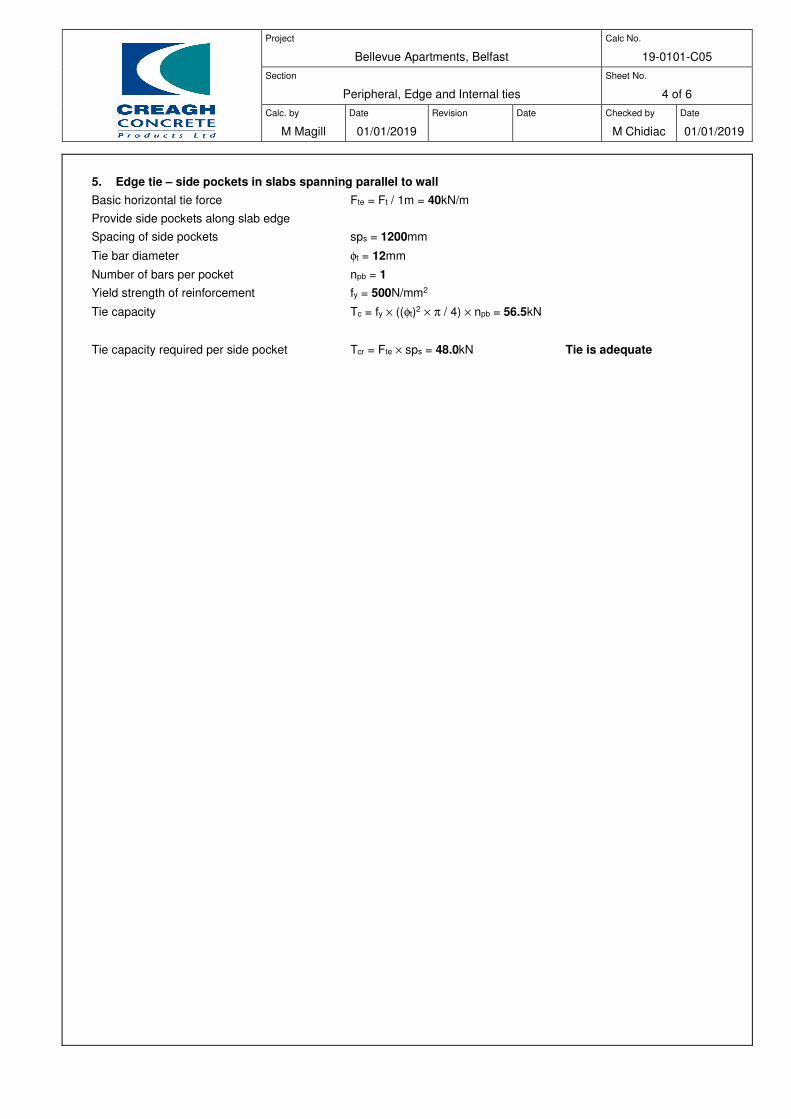
Project
Bellevue Apartments, Belfast
Calc No.
19-0101-C05
Section
Peripheral, Edge and Internal ties
Sheet No.
4 of 6
Calc. by
M Magill
Date
01/01/2019
Revision
Date
Checked by
M Chidiac
Date
01/01/2019
5. Edge tie – side pockets in slabs spanning parallel to wall
Basic horizontal tie force Fte = Ft / 1m = 40kN/m
Provide side pockets along slab edge
Spacing of side pockets sps = 1200mm
Tie bar diameter φt = 12mm
Number of bars per pocket npb = 1
Yield strength of reinforcement fy = 500N/mm2
Tie capacity Tc = fy × ((φt)2 × π / 4) × npb = 56.5kN
Tie capacity required per side pocket Tcr = Fte × sps = 48.0kN Tie is adequate
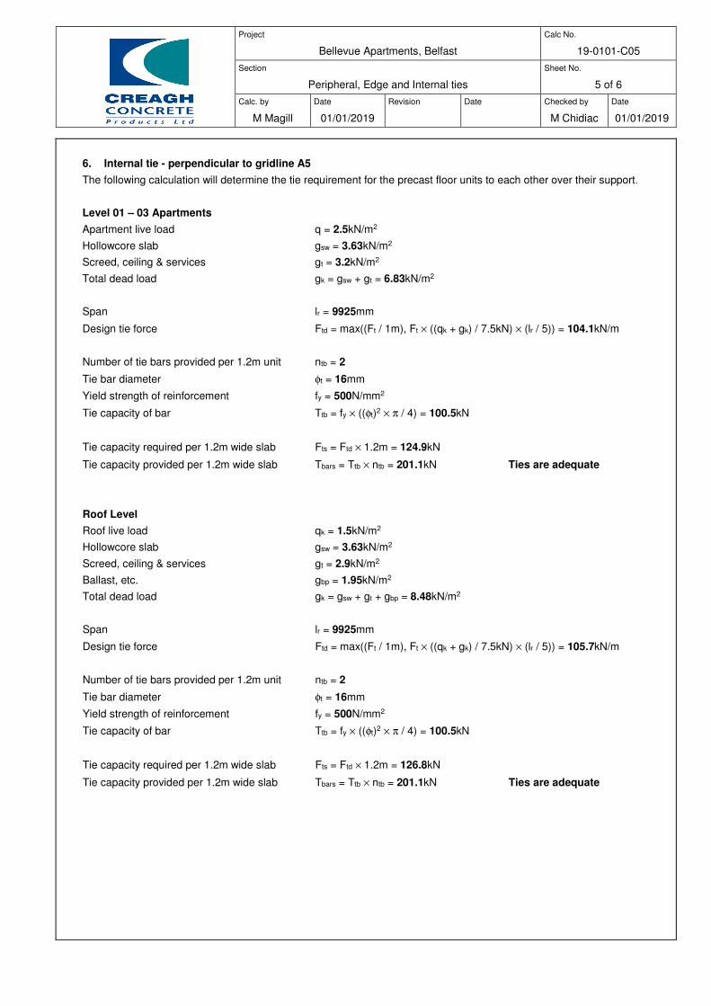
Project
Bellevue Apartments, Belfast
Calc No.
19-0101-C05
Section
Peripheral, Edge and Internal ties
Sheet No.
5 of 6
Calc. by
M Magill
Date
01/01/2019
Revision
Date
Checked by
M Chidiac
Date
01/01/2019
6. Internal tie - perpendicular to gridline A5
The following calculation will determine the tie requirement for the precast floor units to each other over their support.
Level 01 – 03 Apartments
Apartment live load q = 2.5kN/m2
Hollowcore slab gsw = 3.63kN/m2
Screed, ceiling & services gt = 3.2kN/m2
Total dead load gk = gsw + gt = 6.83kN/m2
Span lr = 9925mm
Design tie force Ftd = max((Ft / 1m), Ft × ((qk + gk) / 7.5kN) × (lr / 5)) = 104.1kN/m
Number of tie bars provided per 1.2m unit ntb = 2
Tie bar diameter φt = 16mm
Yield strength of reinforcement fy = 500N/mm2
Tie capacity of bar Ttb = fy × ((φt)2 × π / 4) = 100.5kN
Tie capacity required per 1.2m wide slab Fts = Ftd × 1.2m = 124.9kN
Tie capacity provided per 1.2m wide slab Tbars = Ttb × ntb = 201.1kN Ties are adequate
Roof Level
Roof live load qk = 1.5kN/m2
Hollowcore slab gsw = 3.63kN/m2
Screed, ceiling & services gt = 2.9kN/m2
Ballast, etc. gbp = 1.95kN/m2
Total dead load gk = gsw + gt + gbp = 8.48kN/m2
Span lr = 9925mm
Design tie force Ftd = max((Ft / 1m), Ft × ((qk + gk) / 7.5kN) × (lr / 5)) = 105.7kN/m
Number of tie bars provided per 1.2m unit ntb = 2
Tie bar diameter φt = 16mm
Yield strength of reinforcement fy = 500N/mm2
Tie capacity of bar Ttb = fy × ((φt)2 × π / 4) = 100.5kN
Tie capacity required per 1.2m wide slab Fts = Ftd × 1.2m = 126.8kN
Tie capacity provided per 1.2m wide slab Tbars = Ttb × ntb = 201.1kN Ties are adequate
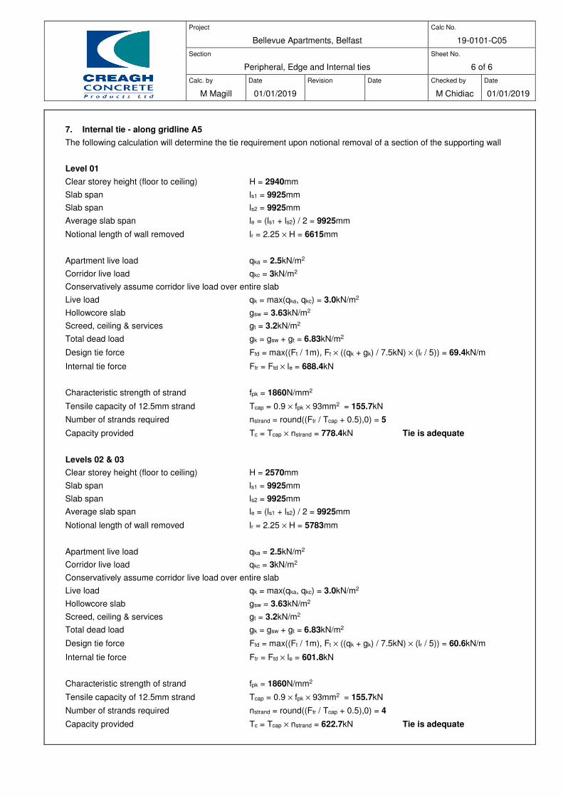
Project
Bellevue Apartments, Belfast
Calc No.
19-0101-C05
Section
Peripheral, Edge and Internal ties
Sheet No.
6 of 6
Calc. by
M Magill
Date
01/01/2019
Revision
Date
Checked by
M Chidiac
Date
01/01/2019
7. Internal tie - along gridline A5
The following calculation will determine the tie requirement upon notional removal of a section of the supporting wall
Level 01
Clear storey height (floor to ceiling) H = 2940mm
Slab span ls1 = 9925mm
Slab span ls2 = 9925mm
Average slab span le = (ls1 + ls2) / 2 = 9925mm
Notional length of wall removed lr = 2.25 × H = 6615mm
Apartment live load qka = 2.5kN/m2
Corridor live load qkc = 3kN/m2
Conservatively assume corridor live load over entire slab
Live load qk = max(qka, qkc) = 3.0kN/m2
Hollowcore slab gsw = 3.63kN/m2
Screed, ceiling & services gt = 3.2kN/m2
Total dead load gk = gsw + gt = 6.83kN/m2
Design tie force Ftd = max((Ft / 1m), Ft × ((qk + gk) / 7.5kN) × (lr / 5)) = 69.4kN/m
Internal tie force Ftr = Ftd × le = 688.4kN
Characteristic strength of strand fpk = 1860N/mm2
Tensile capacity of 12.5mm strand Tcap = 0.9 × fpk × 93mm2 = 155.7kN
Number of strands required nstrand = round((Ftr / Tcap + 0.5),0) = 5
Capacity provided Tc = Tcap × nstrand = 778.4kN Tie is adequate
Levels 02 & 03 Clear storey height (floor to ceiling) H = 2570mm
Slab span ls1 = 9925mm
Slab span ls2 = 9925mm
Average slab span le = (ls1 + ls2) / 2 = 9925mm
Notional length of wall removed lr = 2.25 × H = 5783mm
Apartment live load qka = 2.5kN/m2
Corridor live load qkc = 3kN/m2
Conservatively assume corridor live load over entire slab
Live load qk = max(qka, qkc) = 3.0kN/m2
Hollowcore slab gsw = 3.63kN/m2
Screed, ceiling & services gt = 3.2kN/m2
Total dead load gk = gsw + gt = 6.83kN/m2
Design tie force Ftd = max((Ft / 1m), Ft × ((qk + gk) / 7.5kN) × (lr / 5)) = 60.6kN/m
Internal tie force Ftr = Ftd × le = 601.8kN
Characteristic strength of strand fpk = 1860N/mm2
Tensile capacity of 12.5mm strand Tcap = 0.9 × fpk × 93mm2 = 155.7kN
Number of strands required nstrand = round((Ftr / Tcap + 0.5),0) = 4
Capacity provided Tc = Tcap × nstrand = 622.7kN Tie is adequate

Project
Bellevue Apartments, Belfast
Calc No.
19-0101-C06
Section
Shear wall SW9 starter bars, vertical tie & horiz. shear
Sheet No.
1 of 4
Calc. by
M Magill
Date
01/01/2019
Revision
Date
Checked by
M Chidiac
Date
01/01/2019
Wall data
Wall thickness tw = 200mm
Length of wall L = 5910mm
Wind moment (sls) Mw = 630kNm
EHF Dead moment (sls) Mhd = 79kNm
EHF Live moment (sls) Mhl = 12kNm
Dead load (sls) g = 227kN/m
Live load (sls) q = 53kN/m
Horizontal shear (uls) VEd = 145kN
Cylinder strength of precast concrete fck = 40N/mm2
Cylinder strength of bedding material fck,bed = 40N/mm2
Cylinder strength of insitu concrete fck,ins = 32N/mm2
Characteristic strength of reinf fy = 500N/mm2
Dead load factors G,sup = 1.35 G,supeq = 1.1 G,infeq = 0.9
Live load factors Q,sup = 1.5
Domestic, residential areas:
Comb, Freq, Quasi-perm values 0 = 0.7 1 = 0.5 2 = 0.3
Wind loads on buildings 0w = 0.5
Stability check
In plane overturning moment (uls) Meq = G,supeq Mhd + Q,sup Mw + Q,sup 0 Mhl = 1045kNm
Axial load (uls) Neq = (g G,infeq + q 0) L = 1207kN
Max stress under wall max = (Neq / (tw L)) + (6 Meq / (tw L2)) = 1.92N/mm2
Min stress under wall min = (Neq / (tw L)) - (6 Meq / (tw L2)) = 0.12N/mm2
Length of wall under compression lcpe = (max / (max + if(min < 0N/mm2,abs(min),0N/mm2))) L = 5910mm
Length of wall in tension lt = (L - lcpe) = 0mm
Uplift T = abs(min) tw lt = 0kN
Tension reinf required Asreq = (abs(min) tw lt) / (0.87 fy) = 0mm2
Try 1 No. 25 dia bar(s) As = 491mm2 bar = D = 25mm
Starter bars provided (each end) Asprov = As = 491mm2 Steel ok
Vertical tie check
Dead load per level gtie = 378kN
Live load per level qtie = 52kN
Tie force T = gtie + qtie 1 = 404kN
Tension reinforcement required As_ten = T / fy = 808mm2
Starter bars provided Asp = As 2 = 982mm2 Steel ok
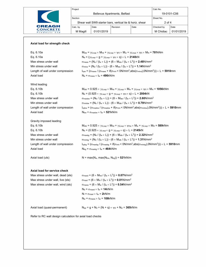
Project
Bellevue Apartments, Belfast
Calc No.
19-0101-C06
Section
Shear wall SW9 starter bars, vertical tie & horiz. shear
Sheet No.
2 of 4
Calc. by
M Magill
Date
01/01/2019
Revision
Date
Checked by
M Chidiac
Date
01/01/2019
Axial load for strength check
Eq. 6.10a Msta = G,sup Mhd + Q,sup 0 Mw + Q,sup 0 Mhl = 781kNm
Eq. 6.10a Na = (G,sup g + Q,sup 0 q) L = 2140kN
Max stress under wall maxa = (Na / (tw L)) + (6 Msta / (tw L2)) = 2.48N/mm2
Min stress under wall mina = (Na / (tw L)) - (6 Msta / (tw L2)) = 1.14N/mm2
Length of wall under compression lcpa = (maxa / (maxa + if(min < 0N/mm2,abs(mina),0N/mm2))) L = 5910mm
Axial load Na = maxa tw = 496kN/m
Wind leading
Eq. 6.10b Mstb = 0.925 G,sup Mhd + Q,sup Mw + Q,sup 0 Mhl = 1056kNm
Eq. 6.10b Nb = (0.925 G,sup g + Q,sup 0 q) L = 2004kN
Max stress under wall maxbw = (Nb / (tw L)) + (6 Mstb / (tw L2)) = 2.60N/mm2
Min stress under wall minbw = (Nb / (tw L)) - (6 Mstb / (tw L2)) = 0.79N/mm2
Length of wall under compression lcpbw = (maxbw / (maxbw + if(min < 0N/mm2,abs(minbw),0N/mm2))) L = 5910mm
Axial load Nbw = maxbw tw = 521kN/m
Gravity imposed leading
Eq. 6.10b Mstb = 0.925 G,sup Mhd + Q,sup 0w Mw + Q,sup Mhl = 589kNm
Eq. 6.10b Nb = (0.925 G,sup g + Q,sup q) L = 2145kN
Max stress under wall maxbg = (Nb / (tw L)) + (6 Mstb / (tw L2)) = 2.32N/mm2
Min stress under wall minbg = (Nb / (tw L)) - (6 Mstb / (tw L2)) = 1.31N/mm2
Length of wall under compression lcpbg = (maxbg / (maxbg + if(min < 0N/mm2,abs(minbg),0N/mm2))) L = 5910mm
Axial load Nbg = maxbg tw = 464kN/m
Axial load (uls) N = max(Na, max(Nbw, Nbg)) = 521kN/m
Axial load for service check
Max stress under wall, dead (sls) maxd = (6 Mhd / (tw L2)) = 0.07N/mm2
Max stress under wall, live (sls) maxl = (6 Mhl / (tw L2)) = 0.01N/mm2
Max stress under wall, wind (sls) maxw = (6 Mw / (tw L2)) = 0.54N/mm2
Nd = maxd tw = 14kN/m
Nl = maxl tw = 2kN/m
Nw = maxw tw = 108kN/m
Axial load (quasi-permanent) Nqp = g + Nd + (Nl + q) 2 + Nw = 365kN/m
Refer to RC wall design calculation for axial load checks

Project
Bellevue Apartments, Belfast
Calc No.
19-0101-C06
Section
Shear wall SW9 starter bars, vertical tie & horiz. shear
Sheet No.
3 of 4
Calc. by
M Magill
Date
01/01/2019
Revision
Date
Checked by
M Chidiac
Date
01/01/2019
Horizontal shear check
Shear coefficient c = 0.025 very smooth
Friction coefficient = 0.5 very smooth
Strength reduction value = 0.6 (1 – (max(fck, fck,bed, fck,ins) / 250N/mm2)) = 0.50
Reinforcement angle = 90
Partial factor for concrete c = 1.5
Factor for reinforced concrete cc = 0.85
Factor for reinforced concrete ct = 1
Mean comp. strength, wall fcm,w = fck + 8N/mm2 = 48N/mm2
Mean tens. Strength, wall fctm,w = 0.3N/mm2 (fck / 1N/mm2)2/3 = 3.5N/mm2
Tensile strength 5% fractile, wall fctk,0.05,w = 0.7 fctm,w = 2.456N/mm2
Design tensile strength, wall fctd,w = (ct fctk,0.05,w) c = 1.64N/mm2
Design compressive strength, wall fcd,w = cc fck / c = 22.67N/mm2
Mean comp. strength, bed fcm,b = fck,bed + 8N/mm2 = 48N/mm2
Mean tens. Strength, bed fctm,b = 0.3N/mm2 (fck,bed / 1N/mm2)2/3 = 3.5N/mm2
Tensile strength 5% fractile, bed fctk,0.05,b = 0.7 fctm,b = 2.456N/mm2
Design tensile strength, bed fctd,b = (ct fctk,0.05,b) c = 1.64N/mm2
Design compressive strength, bed fcd,b = cc fck,bed / c = 22.67N/mm2
Mean comp. strength, insitu fcm,i = fck,ins + 8N/mm2 = 40N/mm2
Mean tens. Strength, insitu fctm,i = 0.3N/mm2 (fck,ins / 1N/mm2)2/3 = 3.0N/mm2
Tensile strength 5% fractile, insitu fctk,0.05,i = 0.7 fctm,i = 2.117N/mm2
Design tensile strength, insitu fctd,i = (ct fctk,0.05,i) c = 1.41N/mm2
Design compressive strength, insitu fcd,i = cc fck,ins / c = 18.13N/mm2
Design tensile strength, joint fctd = min(fctd,w, fctd,b, fctd,i) = 1.41N/mm2
Design compressive strength, joint fcd = min(fcd,w, fcd,b, fcd,i) = 18.13N/mm2
Limiting shear resistance vRdi,lim = 0.5 fcd = 4.57N/mm2
Average stress normal to interface n = if(lcpe < L, max 0.5, (min + (max - min) 0.5)) = 1.02N/mm2
= Asprov / (tw lcpe) = 0.0004
Design shear resistance vRdid = c fctd + n + (0.87 fy) ( sin() + cos()) = 0.64N/mm2
Interface shear resistance vRdi = min(vRdi,lim, vRdid) = 0.64N/mm2
Minimum length of wall under comp. lcmin = min(lcpe, lcpa, lcpbw, lcpbg) = 5910mm
Horizontal shear stress at interface vEdi = VEd / (tw lcmin) = 0.12N/mm2 Horiz. shear ok
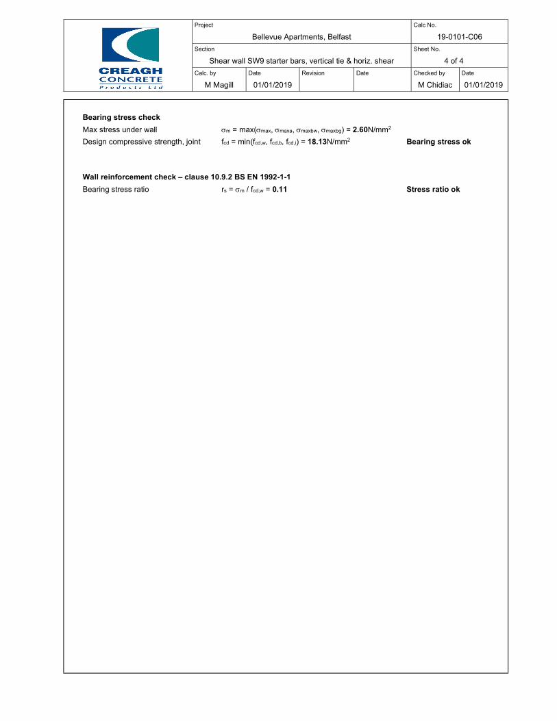
Project
Bellevue Apartments, Belfast
Calc No.
19-0101-C06
Section
Shear wall SW9 starter bars, vertical tie & horiz. shear
Sheet No.
4 of 4
Calc. by
M Magill
Date
01/01/2019
Revision
Date
Checked by
M Chidiac
Date
01/01/2019
Bearing stress check
Max stress under wall m = max(max, maxa,maxbw,maxbg) = 2.60N/mm2
Design compressive strength, joint fcd = min(fcd,w, fcd,b, fcd,i) = 18.13N/mm2 Bearing stress ok
Wall reinforcement check – clause 10.9.2 BS EN 1992-1-1
Bearing stress ratio rs = m / fcd,w = 0.11 Stress ratio ok
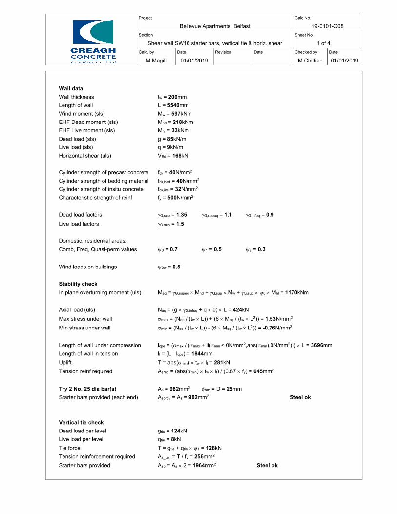
Project
Bellevue Apartments, Belfast
Calc No.
19-0101-C08
Section
Shear wall SW16 starter bars, vertical tie & horiz. shear
Sheet No.
1 of 4
Calc. by
M Magill
Date
01/01/2019
Revision
Date
Checked by
M Chidiac
Date
01/01/2019
Wall data
Wall thickness tw = 200mm
Length of wall L = 5540mm
Wind moment (sls) Mw = 597kNm
EHF Dead moment (sls) Mhd = 218kNm
EHF Live moment (sls) Mhl = 33kNm
Dead load (sls) g = 85kN/m
Live load (sls) q = 9kN/m
Horizontal shear (uls) VEd = 168kN
Cylinder strength of precast concrete fck = 40N/mm2
Cylinder strength of bedding material fck,bed = 40N/mm2
Cylinder strength of insitu concrete fck,ins = 32N/mm2
Characteristic strength of reinf fy = 500N/mm2
Dead load factors G,sup = 1.35 G,supeq = 1.1 G,infeq = 0.9
Live load factors Q,sup = 1.5
Domestic, residential areas:
Comb, Freq, Quasi-perm values 0 = 0.7 1 = 0.5 2 = 0.3
Wind loads on buildings 0w = 0.5
Stability check
In plane overturning moment (uls) Meq = G,supeq Mhd + Q,sup Mw + Q,sup 0 Mhl = 1170kNm
Axial load (uls) Neq = (g G,infeq + q 0) L = 424kN
Max stress under wall max = (Neq / (tw L)) + (6 Meq / (tw L2)) = 1.53N/mm2
Min stress under wall min = (Neq / (tw L)) - (6 Meq / (tw L2)) = -0.76N/mm2
Length of wall under compression lcpe = (max / (max + if(min < 0N/mm2,abs(min),0N/mm2))) L = 3696mm
Length of wall in tension lt = (L - lcpe) = 1844mm
Uplift T = abs(min) tw lt = 281kN
Tension reinf required Asreq = (abs(min) tw lt) / (0.87 fy) = 645mm2
Try 2 No. 25 dia bar(s) As = 982mm2 bar = D = 25mm
Starter bars provided (each end) Asprov = As = 982mm2 Steel ok
Vertical tie check
Dead load per level gtie = 124kN
Live load per level qtie = 8kN
Tie force T = gtie + qtie 1 = 128kN
Tension reinforcement required As_ten = T / fy = 256mm2
Starter bars provided Asp = As 2 = 1964mm2 Steel ok

Project
Bellevue Apartments, Belfast
Calc No.
19-0101-C08
Section
Shear wall SW16 starter bars, vertical tie & horiz. shear
Sheet No.
2 of 4
Calc. by
M Magill
Date
01/01/2019
Revision
Date
Checked by
M Chidiac
Date
01/01/2019
Axial load for strength check
Eq. 6.10a Msta = G,sup Mhd + Q,sup 0 Mw + Q,sup 0 Mhl = 956kNm
Eq. 6.10a Na = (G,sup g + Q,sup 0 q) L = 688kN
Max stress under wall maxa = (Na / (tw L)) + (6 Msta / (tw L2)) = 1.56N/mm2
Min stress under wall mina = (Na / (tw L)) - (6 Msta / (tw L2)) = -0.31N/mm2
Length of wall under compression lcpa = (maxa / (maxa + if(min < 0N/mm2,abs(mina),0N/mm2))) L = 4611mm
Axial load Na = maxa tw = 311kN/m
Wind leading
Eq. 6.10b Mstb = 0.925 G,sup Mhd + Q,sup Mw + Q,sup 0 Mhl = 1202kNm
Eq. 6.10b Nb = (0.925 G,sup g + Q,sup 0 q) L = 640kN
Max stress under wall maxbw = (Nb / (tw L)) + (6 Mstb / (tw L2)) = 1.75N/mm2
Min stress under wall minbw = (Nb / (tw L)) - (6 Mstb / (tw L2)) = -0.60N/mm2
Length of wall under compression lcpbw = (maxbw / (maxbw + if(min < 0N/mm2,abs(minbw),0N/mm2))) L = 4132mm
Axial load Nbw = maxbw tw = 351kN/m
Gravity imposed leading
Eq. 6.10b Mstb = 0.925 G,sup Mhd + Q,sup 0w Mw + Q,sup Mhl = 769kNm
Eq. 6.10b Nb = (0.925 G,sup g + Q,sup q) L = 663kN
Max stress under wall maxbg = (Nb / (tw L)) + (6 Mstb / (tw L2)) = 1.35N/mm2
Min stress under wall minbg = (Nb / (tw L)) - (6 Mstb / (tw L2)) = -0.15N/mm2
Length of wall under compression lcpbg = (maxbg / (maxbg + if(min < 0N/mm2,abs(minbg),0N/mm2))) L = 4973mm
Axial load Nbg = maxbg tw = 270kN/m
Axial load (uls) N = max(Na, max(Nbw, Nbg)) = 351kN/m
Axial load for service check
Max stress under wall, dead (sls) maxd = (6 Mhd / (tw L2)) = 0.21N/mm2
Max stress under wall, live (sls) maxl = (6 Mhl / (tw L2)) = 0.03N/mm2
Max stress under wall, wind (sls) maxw = (6 Mw / (tw L2)) = 0.58N/mm2
Nd = maxd tw = 43kN/m
Nl = maxl tw = 6kN/m
Nw = maxw tw = 117kN/m
Axial load (quasi-permanent) Nqp = g + Nd + (Nl + q) 2 + Nw = 249kN/m
Refer to RC wall design calculation for axial load checks
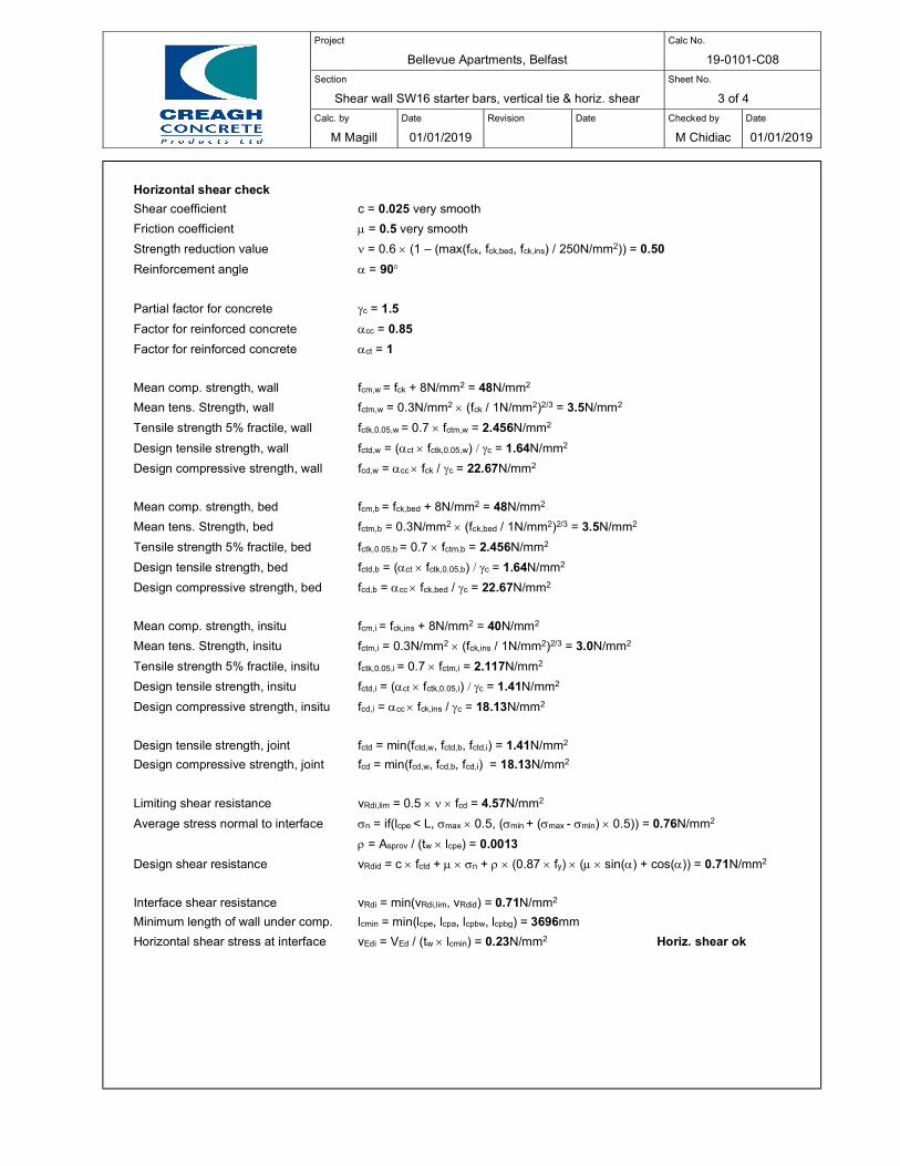
Project
Bellevue Apartments, Belfast
Calc No.
19-0101-C08
Section
Shear wall SW16 starter bars, vertical tie & horiz. shear
Sheet No.
3 of 4
Calc. by
M Magill
Date
01/01/2019
Revision
Date
Checked by
M Chidiac
Date
01/01/2019
Horizontal shear check
Shear coefficient c = 0.025 very smooth
Friction coefficient = 0.5 very smooth
Strength reduction value = 0.6 (1 – (max(fck, fck,bed, fck,ins) / 250N/mm2)) = 0.50
Reinforcement angle = 90
Partial factor for concrete c = 1.5
Factor for reinforced concrete cc = 0.85
Factor for reinforced concrete ct = 1
Mean comp. strength, wall fcm,w = fck + 8N/mm2 = 48N/mm2
Mean tens. Strength, wall fctm,w = 0.3N/mm2 (fck / 1N/mm2)2/3 = 3.5N/mm2
Tensile strength 5% fractile, wall fctk,0.05,w = 0.7 fctm,w = 2.456N/mm2
Design tensile strength, wall fctd,w = (ct fctk,0.05,w) c = 1.64N/mm2
Design compressive strength, wall fcd,w = cc fck / c = 22.67N/mm2
Mean comp. strength, bed fcm,b = fck,bed + 8N/mm2 = 48N/mm2
Mean tens. Strength, bed fctm,b = 0.3N/mm2 (fck,bed / 1N/mm2)2/3 = 3.5N/mm2
Tensile strength 5% fractile, bed fctk,0.05,b = 0.7 fctm,b = 2.456N/mm2
Design tensile strength, bed fctd,b = (ct fctk,0.05,b) c = 1.64N/mm2
Design compressive strength, bed fcd,b = cc fck,bed / c = 22.67N/mm2
Mean comp. strength, insitu fcm,i = fck,ins + 8N/mm2 = 40N/mm2
Mean tens. Strength, insitu fctm,i = 0.3N/mm2 (fck,ins / 1N/mm2)2/3 = 3.0N/mm2
Tensile strength 5% fractile, insitu fctk,0.05,i = 0.7 fctm,i = 2.117N/mm2
Design tensile strength, insitu fctd,i = (ct fctk,0.05,i) c = 1.41N/mm2
Design compressive strength, insitu fcd,i = cc fck,ins / c = 18.13N/mm2
Design tensile strength, joint fctd = min(fctd,w, fctd,b, fctd,i) = 1.41N/mm2
Design compressive strength, joint fcd = min(fcd,w, fcd,b, fcd,i) = 18.13N/mm2
Limiting shear resistance vRdi,lim = 0.5 fcd = 4.57N/mm2
Average stress normal to interface n = if(lcpe < L, max 0.5, (min + (max - min) 0.5)) = 0.76N/mm2
= Asprov / (tw lcpe) = 0.0013
Design shear resistance vRdid = c fctd + n + (0.87 fy) ( sin() + cos()) = 0.71N/mm2
Interface shear resistance vRdi = min(vRdi,lim, vRdid) = 0.71N/mm2
Minimum length of wall under comp. lcmin = min(lcpe, lcpa, lcpbw, lcpbg) = 3696mm
Horizontal shear stress at interface vEdi = VEd / (tw lcmin) = 0.23N/mm2 Horiz. shear ok

Project
Bellevue Apartments, Belfast
Calc No.
19-0101-C08
Section
Shear wall SW16 starter bars, vertical tie & horiz. shear
Sheet No.
4 of 4
Calc. by
M Magill
Date
01/01/2019
Revision
Date
Checked by
M Chidiac
Date
01/01/2019
Bearing stress check
Max stress under wall m = max(max, maxa,maxbw,maxbg) = 1.75N/mm2
Design compressive strength, joint fcd = min(fcd,w, fcd,b, fcd,i) = 18.13N/mm2 Bearing stress ok
Wall reinforcement check – clause 10.9.2 BS EN 1992-1-1
Bearing stress ratio rs = m / fcd,w = 0.08 Stress ratio ok
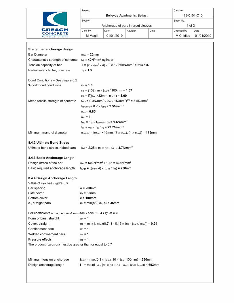
Project
Bellevue Apartments, Belfast
Calc No.
19-0101-C10
Section
Anchorage of bars in grout sleeves
Sheet No.
1 of 2
Calc. by
M Magill
Date
01/01/2019
Revision
Date
Checked by
M Chidiac
Date
01/01/2019
Starter bar anchorage design
Bar Diameter bar = 25mm
Characteristic strength of concrete fck 40N/mm2 cylinder
Tension capacity of bar T = ( bar2 / 4) 0.87 500N/mm2 = 213.5kN
Partial safety factor, concrete c = 1.5
Bond Conditions – See Figure 8.2
‘Good’ bond conditions n1 = 1.0
nb = (132mm - bar) / 100mm = 1.07
n2 = if(bar >32mm, nb, 1) = 1.00
Mean tensile strength of concrete fctm = 0.3N/mm2 (fck / 1N/mm2)2/3 = 3.5N/mm2
fctk,0.05 = 0.7 fctm = 2.5N/mm2
cc = 0.85
ct = 1
fctd = ct fctk,0.05 c = 1.6N/mm2
fcd = cc fck / c = 22.7N/mm2
Minimum mandrel diameter m,min = if(bar > 16mm, (7 bar), (4 bar)) = 175mm
8.4.2 Ultimate Bond Stress
Ultimate bond stress, ribbed bars fbd = 2.25 n1 n2 fctd 3.7N/mm2
8.4.3 Basic Anchorage Length
Design stress of the bar sd = 500N/mm2 / 1.15 = 435N/mm2
Basic required anchorage length Ib,rqd = (bar/ 4) (sd fbd) = 738mm
8.4.4 Design Anchorage Length
Value of cd – see Figure 8.3
Bar spacing a = 200mm
Side cover c1 = 35mm
Bottom cover c = 100mm
cd, straight bars cd = min(a/2, c1, c) = 35mm
For coefficients 1, 2, 3, 4&5 - see Table 8.2 & Figure 8.4
Form of bars, straight 1 = 1
Cover, straight 2 = min(1, max(0.7, 1 - 0.15 (cd -bar) / bar)) = 0.94
Confinement bars 3 = 1
Welded confinement bars 4 = 1
Pressure effects 5 = 1
The product (α2 α3 α5) must be greater than or equal to 0.7
Minimum tension anchorage lb,min = max(0.3 Ib,rqd, 10 bar,100mm) = 250mm
Design anchorage length lbd = max(lb,min, (1 2 3 4 5 Ib,rqd)) = 693mm
Project
Bellevue Apartments, Belfast
Calc No.
19-0101-C10
Section
Anchorage of bars in grout sleeves
Sheet No.
2 of 2
Calc. by
M Magill
Date
01/01/2019
Revision
Date
Checked by
M Chidiac
Date
01/01/2019
Vertical tie bar anchorage design – robustness connection
Bar Diameter bar = 25mm
Characteristic strength of concrete fck 40N/mm2 cylinder
Tension capacity of bar T = ( bar2 / 4) 0.87 500N/mm2 = 213.5kN
Partial safety factor, concrete c = 1.2 – accidental actions
Bond Conditions – See Figure 8.2
‘Good’ bond conditions n1 = 1.0
nb = (132mm - bar) / 100mm = 1.07
n2 = if(bar >32mm, nb, 1) = 1.00
Mean tensile strength of concrete fctm = 0.3N/mm2 (fck / 1N/mm2)2/3 = 3.5N/mm2
fctk,0.05 = 0.7 fctm = 2.5N/mm2
cc = 0.85
ct = 1
fctd = ct fctk,0.05 c = 2.0N/mm2
fcd = cc fck / c = 28.3N/mm2
Minimum mandrel diameter m,min = if(bar > 16mm, (7 bar), (4 bar)) = 175mm
8.4.2 Ultimate Bond Stress
Ultimate bond stress, ribbed bars fbd = 2.25 n1 n2 fctd 4.6N/mm2
8.4.3 Basic Anchorage Length
Design stress of the bar sd = 500N/mm2 – characteristic strength
Basic required anchorage length Ib,rqd = (bar/ 4) (sd fbd) = 679mm
8.4.4 Design Anchorage Length
Value of cd – see Figure 8.3
Bar spacing a = 200mm
Side cover c1 = 35mm
Bottom cover c = 100mm
cd, straight bars cd = min(a/2, c1, c) = 35mm
For coefficients 1, 2, 3, 4&5 - see Table 8.2 & Figure 8.4
Form of bars, straight 1 = 1
Cover, straight 2 = min(1, max(0.7, 1 - 0.15 (cd -bar) / bar)) = 0.94
Confinement bars 3 = 1
Welded confinement bars 4 = 1
Pressure effects 5 = 1
The product (α2 α3 α5) must be greater than or equal to 0.7
Minimum tension anchorage lb,min = max(0.3 Ib,rqd, 10 bar,100mm) = 250mm
Design anchorage length lbd = max(lb,min, (1 2 3 4 5 Ib,rqd)) = 638mm
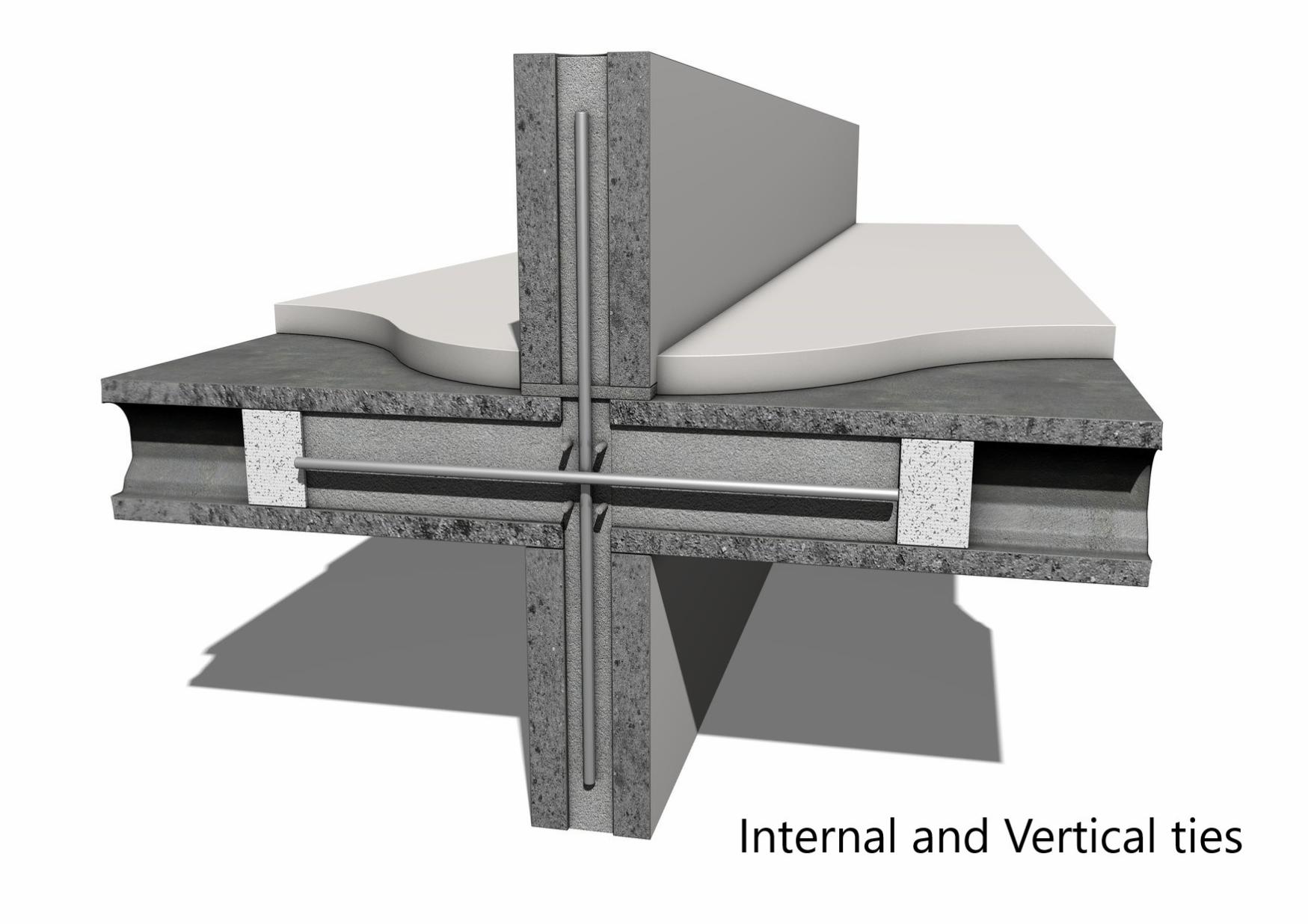
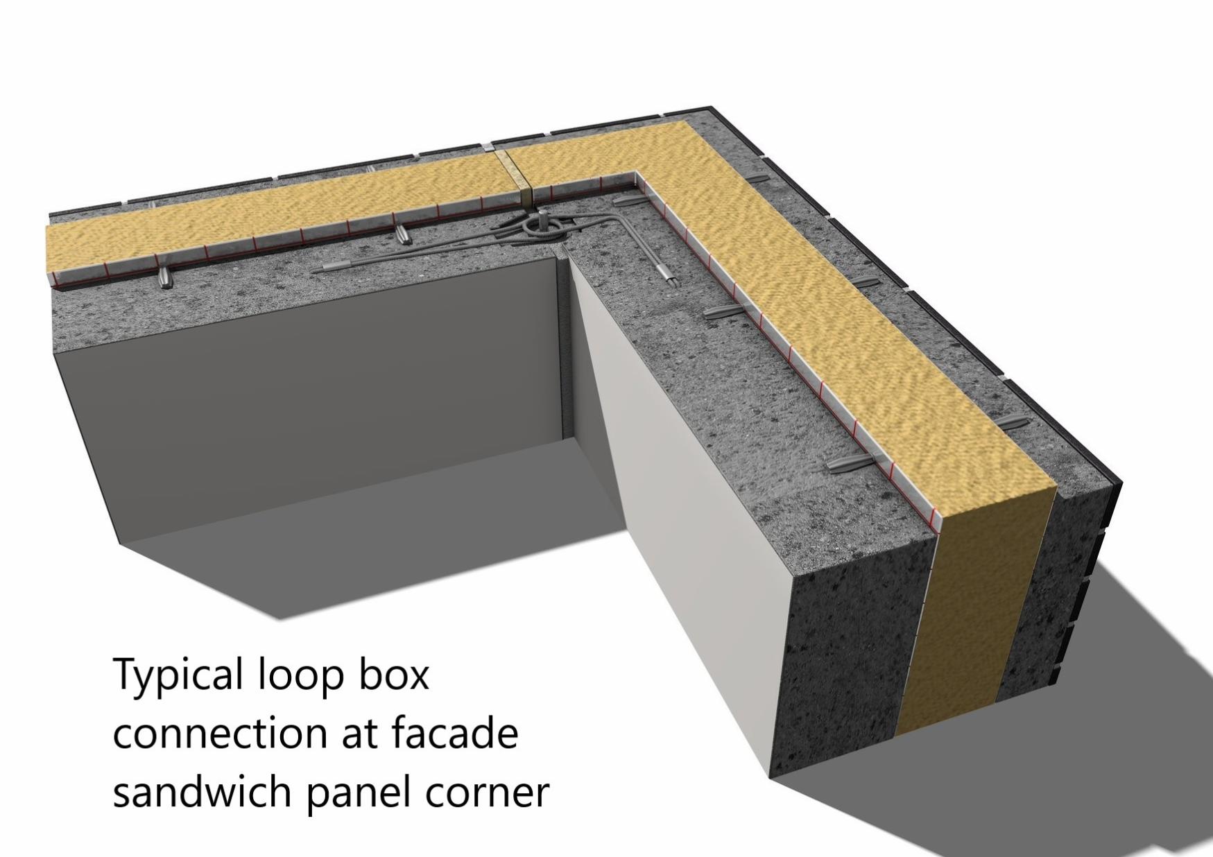
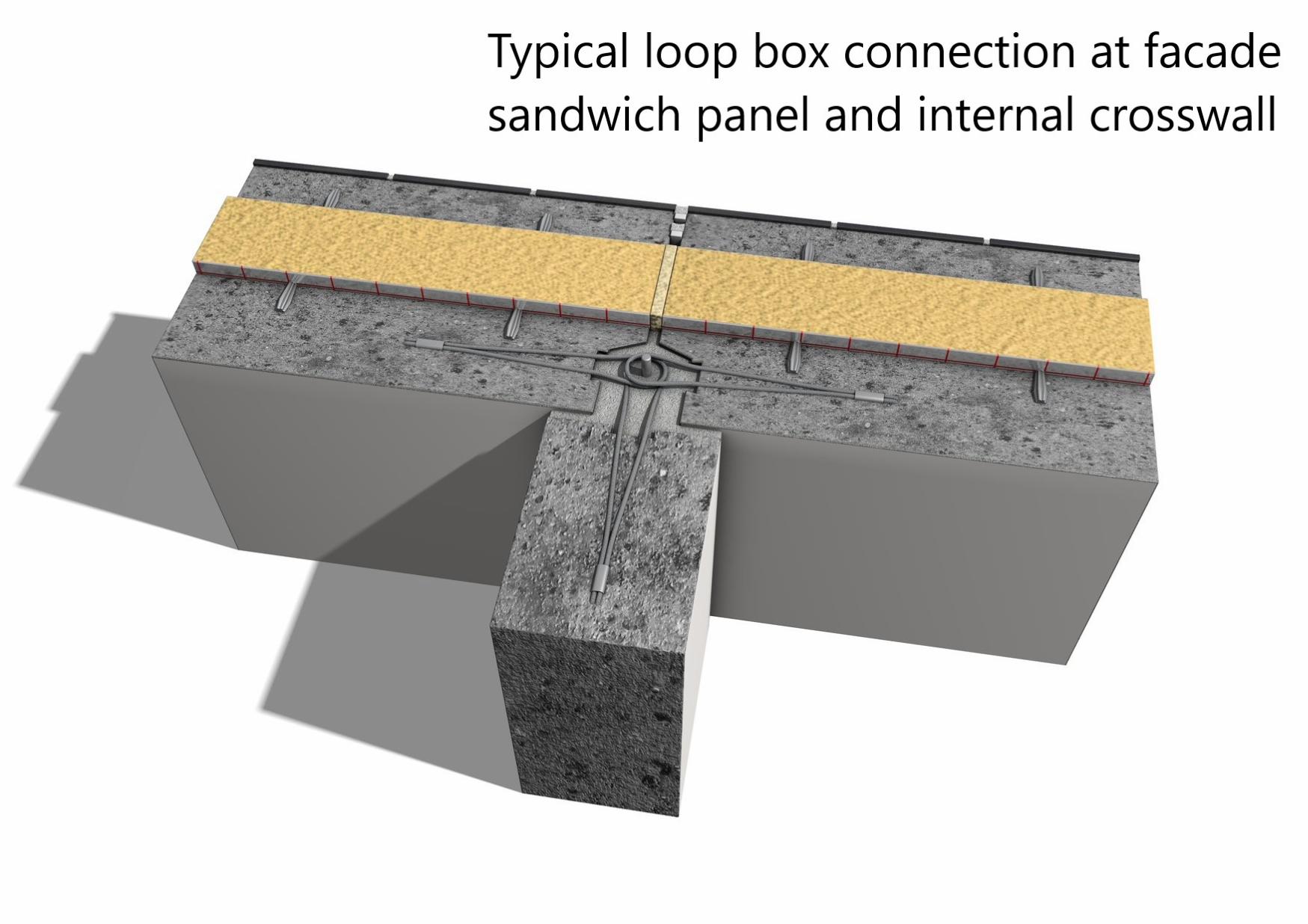
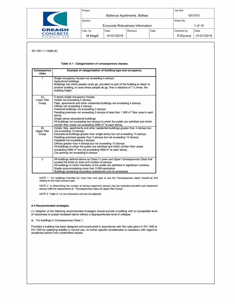
Project
Bellevue Apartments, Belfast Job Ref.
19-0101
Section
Eurocode Robustness Information Sheet No.
1 of 10
Calc. by
M Magill
Date
01/01/2019
Revision
Date
Checked by
R Escriva
Date
01/01/2019
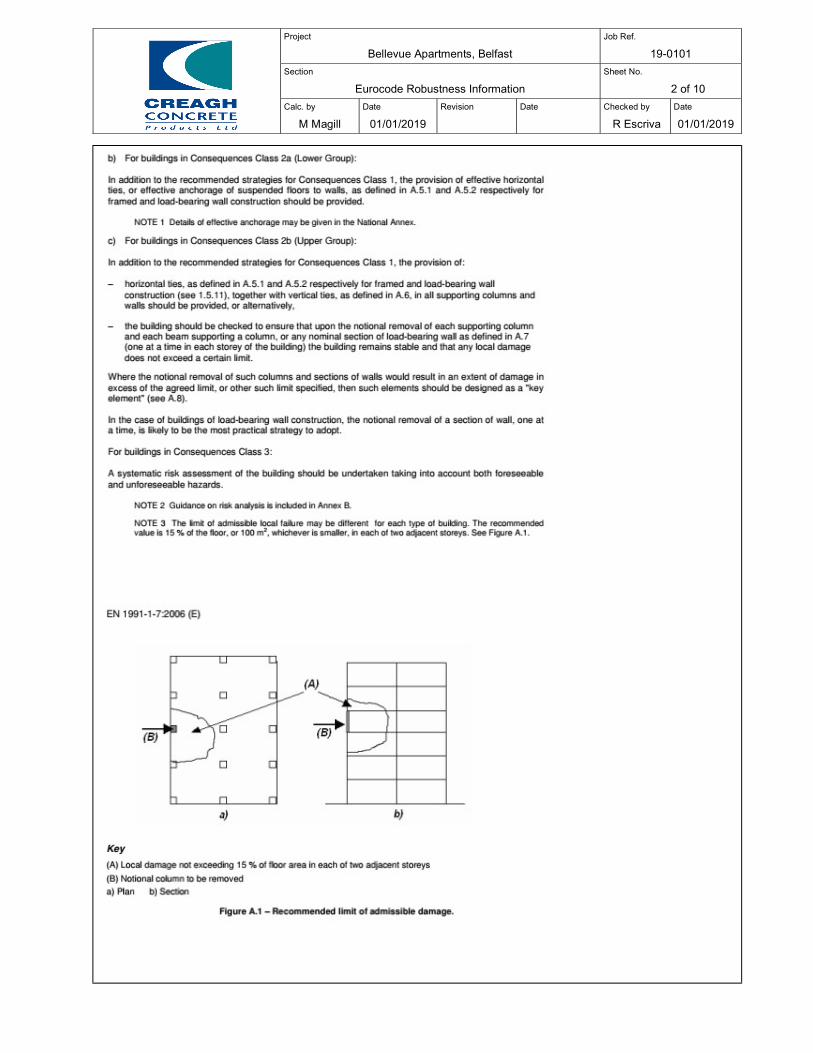
Project
Bellevue Apartments, Belfast Job Ref.
19-0101
Section
Eurocode Robustness Information Sheet No.
2 of 10
Calc. by
M Magill
Date
01/01/2019
Revision
Date
Checked by
R Escriva
Date
01/01/2019
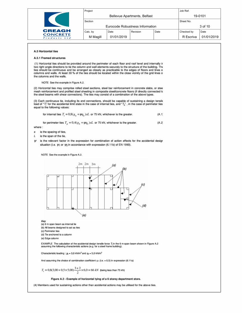
Project
Bellevue Apartments, Belfast Job Ref.
19-0101
Section
Eurocode Robustness Information Sheet No.
3 of 10
Calc. by
M Magill
Date
01/01/2019
Revision
Date
Checked by
R Escriva
Date
01/01/2019
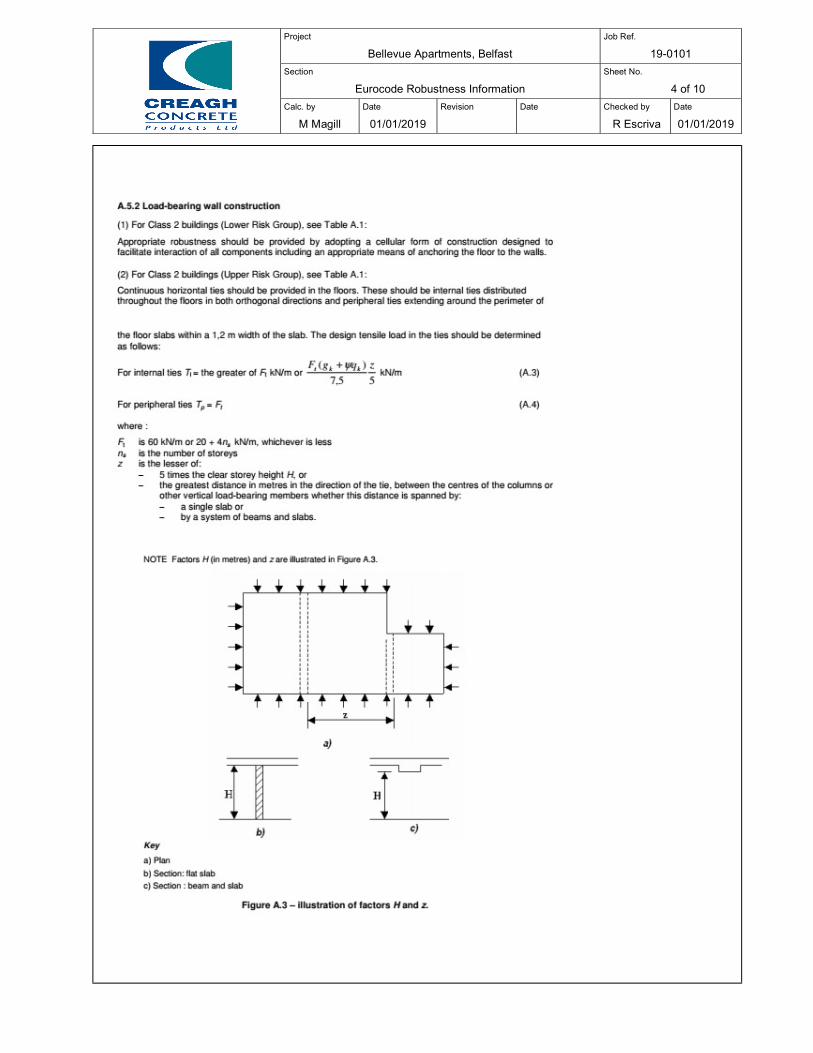
Project
Bellevue Apartments, Belfast Job Ref.
19-0101
Section
Eurocode Robustness Information Sheet No.
4 of 10
Calc. by
M Magill
Date
01/01/2019
Revision
Date
Checked by
R Escriva
Date
01/01/2019
Project
Bellevue Apartments, Belfast Job Ref.
19-0101
Section
Eurocode Robustness Information Sheet No.
5 of 10
Calc. by
M Magill
Date
01/01/2019
Revision
Date
Checked by
R Escriva
Date
01/01/2019
Project
Bellevue Apartments, Belfast Job Ref.
19-0101
Section
Eurocode Robustness Information Sheet No.
6 of 10
Calc. by
M Magill
Date
01/01/2019
Revision
Date
Checked by
R Escriva
Date
01/01/2019
Project
Bellevue Apartments, Belfast Job Ref.
19-0101
Section
Eurocode Robustness Information Sheet No.
7 of 10
Calc. by
M Magill
Date
01/01/2019
Revision
Date
Checked by
R Escriva
Date
01/01/2019
Project
Bellevue Apartments, Belfast Job Ref.
19-0101
Section
Eurocode Robustness Information Sheet No.
8 of 10
Calc. by
M Magill
Date
01/01/2019
Revision
Date
Checked by
R Escriva
Date
01/01/2019
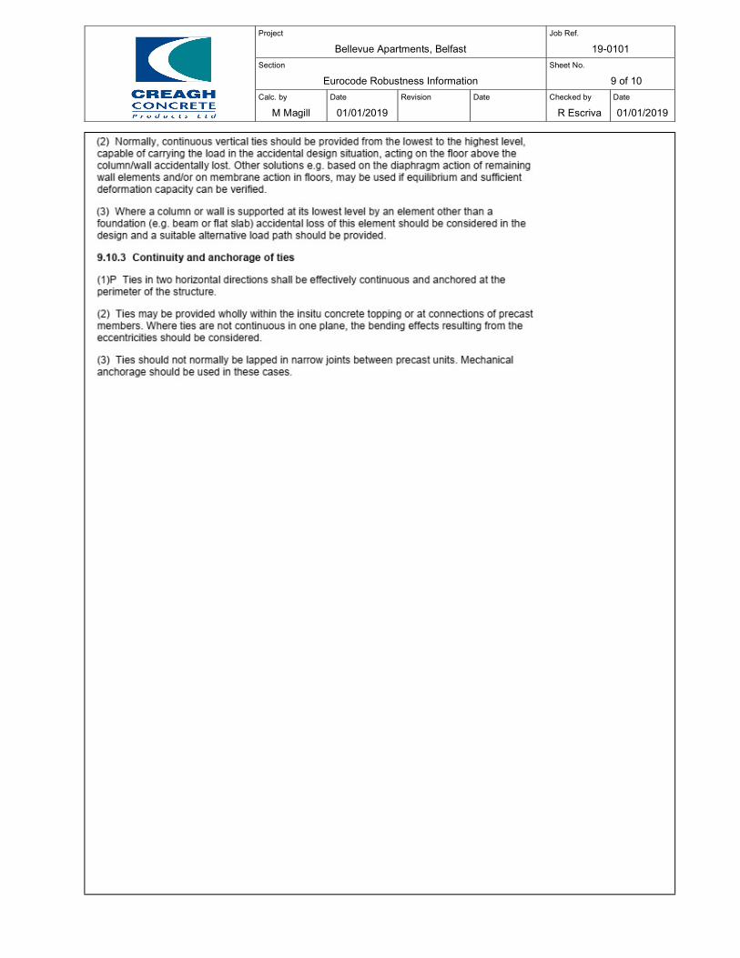
Project
Bellevue Apartments, Belfast Job Ref.
19-0101
Section
Eurocode Robustness Information Sheet No.
9 of 10
Calc. by
M Magill
Date
01/01/2019
Revision
Date
Checked by
R Escriva
Date
01/01/2019
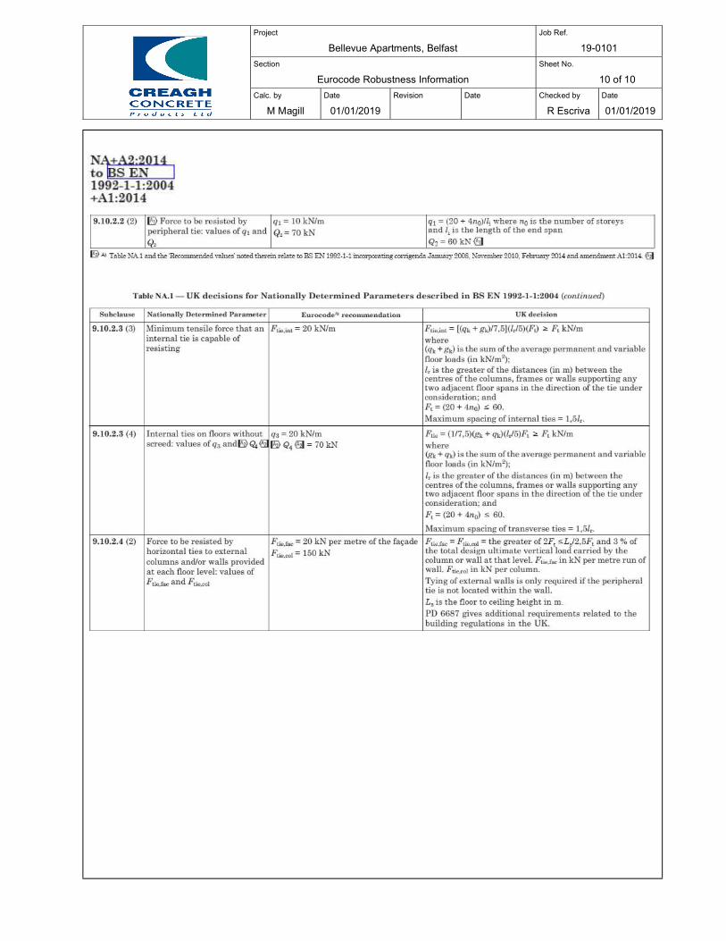
Project
Bellevue Apartments, Belfast Job Ref.
19-0101
Section
Eurocode Robustness Information Sheet No.
10 of 10
Calc. by
M Magill
Date
01/01/2019
Revision
Date
Checked by
R Escriva
Date
01/01/2019
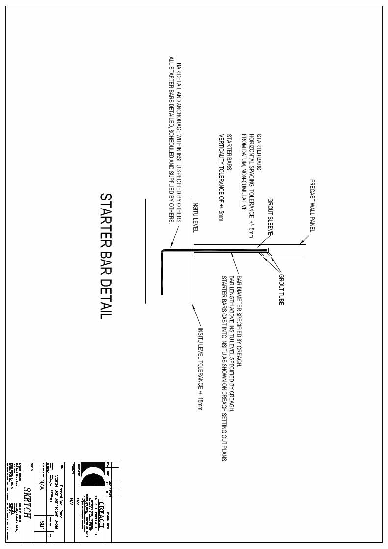
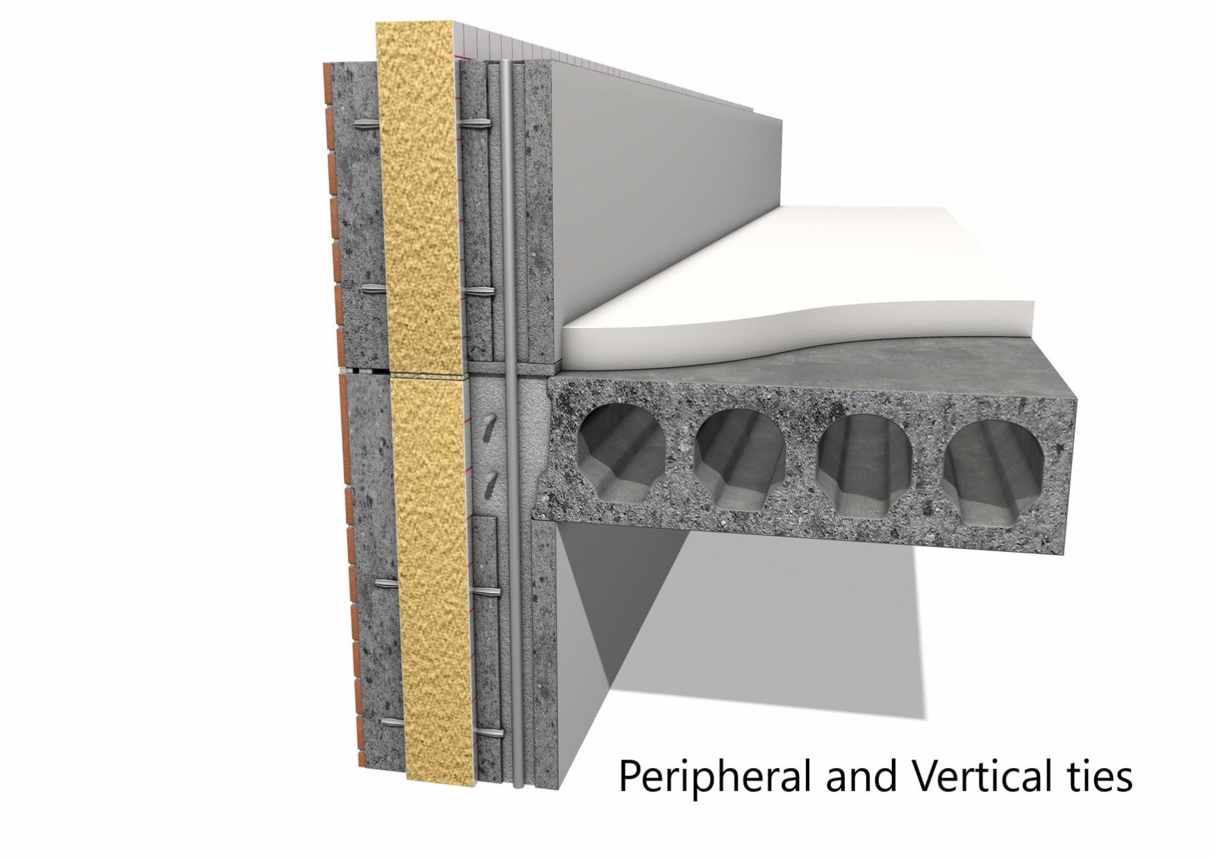
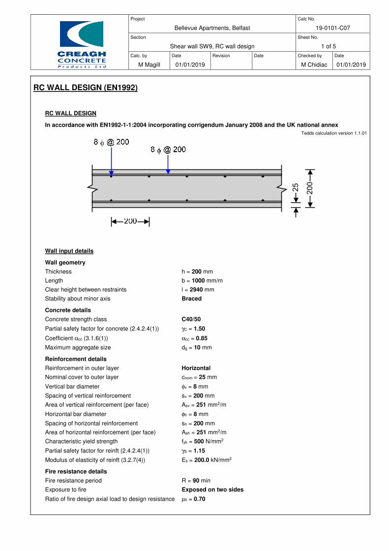
Project
Bellevue Apartments, Belfast
Calc No.
19-0101-C07
Section
Shear wall SW9, RC wall design
Sheet No.
1 of 5
Calc. by
M Magill
Date
01/01/2019
Revision
Date
Checked by
M Chidiac
Date
01/01/2019
RC WALL DESIGN (EN1992)
RC WALL DESIGN
In accordance with EN1992-1-1:2004 incorporating corrigendum January 2008 and the UK national annex
Tedds calculation version 1.1.01
Wall input details
Wall geometry
Thickness h = 200 mm
Length b = 1000 mm/m
Clear height between restraints l = 2940 mm
Stability about minor axis Braced
Concrete details
Concrete strength class C40/50
Partial safety factor for concrete (2.4.2.4(1)) γC = 1.50
Coefficient αcc (3.1.6(1)) αcc = 0.85
Maximum aggregate size dg = 10 mm
Reinforcement details
Reinforcement in outer layer Horizontal
Nominal cover to outer layer cnom = 25 mm
Vertical bar diameter φv = 8 mm
Spacing of vertical reinforcement sv = 200 mm
Area of vertical reinforcement (per face) Asv = 251 mm2/m
Horizontal bar diameter φh = 8 mm
Spacing of horizontal reinforcement sh = 200 mm
Area of horizontal reinforcement (per face) Ash = 251 mm2/m
Characteristic yield strength fyk = 500 N/mm2
Partial safety factor for reinft (2.4.2.4(1)) γS = 1.15
Modulus of elasticity of reinft (3.2.7(4)) Es = 200.0 kN/mm2
Fire resistance details
Fire resistance period R = 90 min
Exposure to fire Exposed on two sides
Ratio of fire design axial load to design resistance µfi = 0.70
25
200
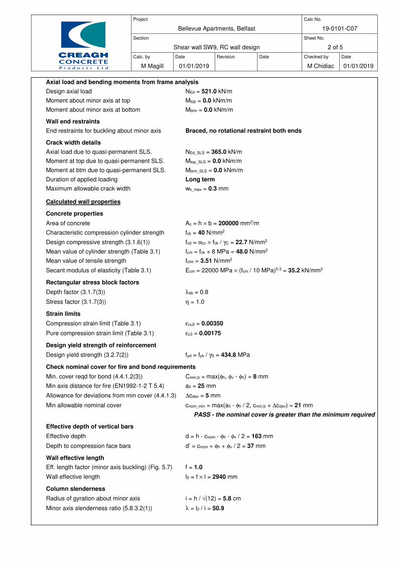
Project
Bellevue Apartments, Belfast
Calc No.
19-0101-C07
Section
Shear wall SW9, RC wall design
Sheet No.
2 of 5
Calc. by
M Magill
Date
01/01/2019
Revision
Date
Checked by
M Chidiac
Date
01/01/2019
Axial load and bending moments from frame analysis
Design axial load NEd = 521.0 kN/m
Moment about minor axis at top Mtop = 0.0 kNm/m
Moment about minor axis at bottom Mbtm = 0.0 kNm/m
Wall end restraints
End restraints for buckling about minor axis Braced, no rotational restraint both ends
Crack width details
Axial load due to quasi-permanent SLS. NEd_SLS = 365.0 kN/m
Moment at top due to quasi-permanent SLS. Mtop_SLS = 0.0 kNm/m
Moment at btm due to quasi-permanent SLS. Mbtm_SLS = 0.0 kNm/m
Duration of applied loading Long term
Maximum allowable crack width wk_max = 0.3 mm
Calculated wall properties
Concrete properties
Area of concrete Ac = h × b = 200000 mm2/m
Characteristic compression cylinder strength fck = 40 N/mm2
Design compressive strength (3.1.6(1)) fcd = αcc × fck / γC = 22.7 N/mm2
Mean value of cylinder strength (Table 3.1) fcm = fck + 8 MPa = 48.0 N/mm2
Mean value of tensile strength fctm = 3.51 N/mm2
Secant modulus of elasticity (Table 3.1) Ecm = 22000 MPa × (fcm / 10 MPa)0.3 = 35.2 kN/mm2
Rectangular stress block factors
Depth factor (3.1.7(3)) λsb = 0.8
Stress factor (3.1.7(3)) η = 1.0
Strain limits
Compression strain limit (Table 3.1) εcu3 = 0.00350
Pure compression strain limit (Table 3.1) εc3 = 0.00175
Design yield strength of reinforcement
Design yield strength (3.2.7(2)) fyd = fyk / γS = 434.8 MPa
Check nominal cover for fire and bond requirements
Min. cover reqd for bond (4.4.1.2(3)) Cmin,b = max(φh, φv - φh) = 8 mm
Min axis distance for fire (EN1992-1-2 T 5.4) afi = 25 mm
Allowance for deviations from min cover (4.4.1.3) ∆cdev = 5 mm
Min allowable nominal cover cnom_min = max(afi - φh / 2, cmin,b + ∆cdev) = 21 mm
PASS - the nominal cover is greater than the minimum required
Effective depth of vertical bars
Effective depth d = h - cnom - φh - φv / 2 = 163 mm
Depth to compression face bars d’ = cnom + φh + φv / 2 = 37 mm
Wall effective length
Eff. length factor (minor axis buckling) (Fig. 5.7) f = 1.0
Wall effective length l0 = f × l = 2940 mm
Column slenderness
Radius of gyration about minor axis i = h / √(12) = 5.8 cm
Minor axis slenderness ratio (5.8.3.2(1)) λ = l0 / i = 50.9

Project
Bellevue Apartments, Belfast
Calc No.
19-0101-C07
Section
Shear wall SW9, RC wall design
Sheet No.
3 of 5
Calc. by
M Magill
Date
01/01/2019
Revision
Date
Checked by
M Chidiac
Date
01/01/2019
Design bending moments
Frame analysis moments combined with moments due to imperfections (cl. 5.2 & 6.1(4))
Ecc. due to geometric imperfections ei = l0 /400 = 7.4 mm
Minimum end moment about minor axis M01 = min(abs(Mtop), abs(Mbtm)) + ei × NEd = 3.8 kNm/m
Maximum end moment about minor axis M02 = max(abs(Mtop), abs(Mbtm)) + ei × NEd = 3.8 kNm/m
Slenderness limit for buckling about minor axis (cl. 5.8.3.1)
Factor A A = 0.7
Mechanical reinforcement ratio ω = 2 × Asv × fyd / (Ac × fcd) = 0.048
Factor B B = √(1 + 2 × ω) = 1.047
Moment ratio rm = 1.000
Factor C C = 1.7 - rm = 0.700
Relative normal force n = NEd / (Ac × fcd) = 0.115
Slenderness limit λlim = 20 × A × B × C / √(n) = 30.3
λλλλ>=λλλλlim - Second order effects must be considered
Second order bending moment about minor axis (cl. 5.8.8.2 & 5.8.8.3)
Parameter nu nu = 1 + ω = 1.048
Approx value of n at max moment of resistance nbal = 0.4
Axial load correction factor Kr = min(1.0 , (nu - n) / (nu - nbal)) = 1.000
Reinforcement design strain εyd = fyd / Es = 0.00217
Basic curvature curvebasic = εyd / (0.45 × d) = 0.0000296 mm-1
Notional size of wall h0 = 2 × h ×b / (2 × b) = 200 mm
Factor α1 (Annex B.1(1)) α1 = (35 MPa / fcm)0.7 = 0.802
Factor α2 (Annex B.1(1)) α2 = (35 MPa / fcm)0.2 = 0.939
Relative humidity factor (Annex B.1(1)) φRH = [1 + ((1 - RH / 100%) / (0.1 mm-1/3 × (h0)1/3)) × α1] × α2 = 1.582
Concrete strength factor (Annex B.1(1)) βfcm = 16.8 × (1 MPa)1/2 / √(fcm) = 2.4
Concrete age factor (Annex B.1(1)) βt0 = 1 / (0.1 + (t0 / 1 day)0.2) = 0.488
Notional creep coefficient (Annex B.1(1)) φ0 = φRH × βfcm × βt0 = 1.874
Final creep development factor (at t = ¥) βc∞ = 1.0
Final creep coefficient (Annex B.1(1)) φ∞ = φ0 × βc∞ = 1.874
Effective creep ratio (5.8.4(2)) φef = φ∞ × rM = 1.312
Factor β β = 0.35 + fck / 200 MPa - λ / 150 = 0.211
Creep factor Kφ = max(1.0 , 1 + β × φef) = 1.276
Modified curvature curvemod = Kr × Kφ × curvebasic = 0.0000378 mm-1
Curvature distribution factor c = 10
Deflection e2 = curvemod × l02 / c = 32.7 mm
Nominal 2nd order moment M2 = NEd × e2 = 17.0 kNm/m
Design bending moment about minor axis (cl. 5.8.8.2)
Equivalent moment M0e = max(0.6 × M02 + 0.4 × M01, 0.4 × M02) = 3.8 kNm/m
Design moment MEd = max(M02, M0e + M2, M01 + 0.5 × M2, NEd × max(h/30, 20 mm))
MEd = 20.9 kNm/m
Moment capacity about minor axis with axial load NEd
Moment of resistance of concrete
By iteration:-
Position of neutral axis z = 35.2 mm
Concrete compression force (3.1.7(3)) Fc = η× fcd × min(max(λsb × z, 0 mm) , h) × b = 637.4 kN/m
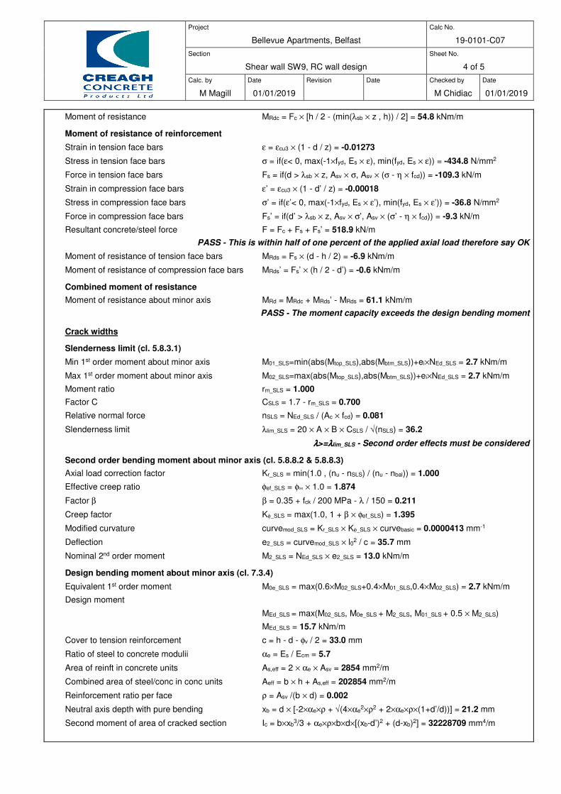
Project
Bellevue Apartments, Belfast
Calc No.
19-0101-C07
Section
Shear wall SW9, RC wall design
Sheet No.
4 of 5
Calc. by
M Magill
Date
01/01/2019
Revision
Date
Checked by
M Chidiac
Date
01/01/2019
Moment of resistance MRdc = Fc × [h / 2 - (min(λsb × z , h)) / 2] = 54.8 kNm/m
Moment of resistance of reinforcement
Strain in tension face bars ε = εcu3 × (1 - d / z) = -0.01273
Stress in tension face bars σ = if(ε< 0, max(-1×fyd, Es × ε), min(fyd, Es × ε)) = -434.8 N/mm2
Force in tension face bars Fs = if(d > λsb × z, Asv × σ, Asv × (σ - η × fcd)) = -109.3 kN/m
Strain in compression face bars ε’ = εcu3 × (1 - d’ / z) = -0.00018
Stress in compression face bars σ’ = if(ε’< 0, max(-1×fyd, Es × ε’), min(fyd, Es × ε’)) = -36.8 N/mm2
Force in compression face bars Fs’ = if(d’ > λsb × z, Asv × σ’, Asv × (σ’ - η × fcd)) = -9.3 kN/m
Resultant concrete/steel force F = Fc + Fs + Fs’ = 518.9 kN/m
PASS - This is within half of one percent of the applied axial load therefore say OK
Moment of resistance of tension face bars MRds = Fs × (d - h / 2) = -6.9 kNm/m
Moment of resistance of compression face bars MRds’ = Fs’ × (h / 2 - d’) = -0.6 kNm/m
Combined moment of resistance
Moment of resistance about minor axis MRd = MRdc + MRds’ - MRds = 61.1 kNm/m
PASS - The moment capacity exceeds the design bending moment
Crack widths
Slenderness limit (cl. 5.8.3.1)
Min 1st order moment about minor axis M01_SLS=min(abs(Mtop_SLS),abs(Mbtm_SLS))+ei×NEd_SLS = 2.7 kNm/m
Max 1st order moment about minor axis M02_SLS=max(abs(Mtop_SLS),abs(Mbtm_SLS))+ei×NEd_SLS = 2.7 kNm/m
Moment ratio rm_SLS = 1.000
Factor C CSLS = 1.7 - rm_SLS = 0.700
Relative normal force nSLS = NEd_SLS / (Ac × fcd) = 0.081
Slenderness limit λlim_SLS = 20 × A × B × CSLS / √(nSLS) = 36.2
λλλλ>=λλλλlim_SLS - Second order effects must be considered
Second order bending moment about minor axis (cl. 5.8.8.2 & 5.8.8.3)
Axial load correction factor Kr_SLS = min(1.0 , (nu - nSLS) / (nu - nbal)) = 1.000
Effective creep ratio φef_SLS = φ∞ × 1.0 = 1.874
Factor β β = 0.35 + fck / 200 MPa - λ / 150 = 0.211
Creep factor Kφ_SLS = max(1.0, 1 + β × φef_SLS) = 1.395
Modified curvature curvemod_SLS = Kr_SLS × Kφ_SLS × curvebasic = 0.0000413 mm-1
Deflection e2_SLS = curvemod_SLS × l02 / c = 35.7 mm
Nominal 2nd order moment M2_SLS = NEd_SLS × e2_SLS = 13.0 kNm/m
Design bending moment about minor axis (cl. 7.3.4)
Equivalent 1st order moment M0e_SLS = max(0.6×M02_SLS+0.4×M01_SLS,0.4×M02_SLS) = 2.7 kNm/m
Design moment
MEd_SLS = max(M02_SLS, M0e_SLS + M2_SLS, M01_SLS + 0.5 × M2_SLS)
MEd_SLS = 15.7 kNm/m
Cover to tension reinforcement c = h - d - φv / 2 = 33.0 mm
Ratio of steel to concrete modulii αe = Es / Ecm = 5.7
Area of reinft in concrete units As,eff = 2 × αe × Asv = 2854 mm2/m
Combined area of steel/conc in conc units Aeff = b × h + As,eff = 202854 mm2/m
Reinforcement ratio per face ρ = Asv /(b × d) = 0.002
Neutral axis depth with pure bending xb = d × [-2×αe×ρ + √(4×αe2×ρ2 + 2×αe×ρ×(1+d’/d))] = 21.2 mm
Second moment of area of cracked section Ic = b×xb3/3 + αe×ρ×b×d×[(xb-d’)2 + (d-xb)2] = 32228709 mm4/m
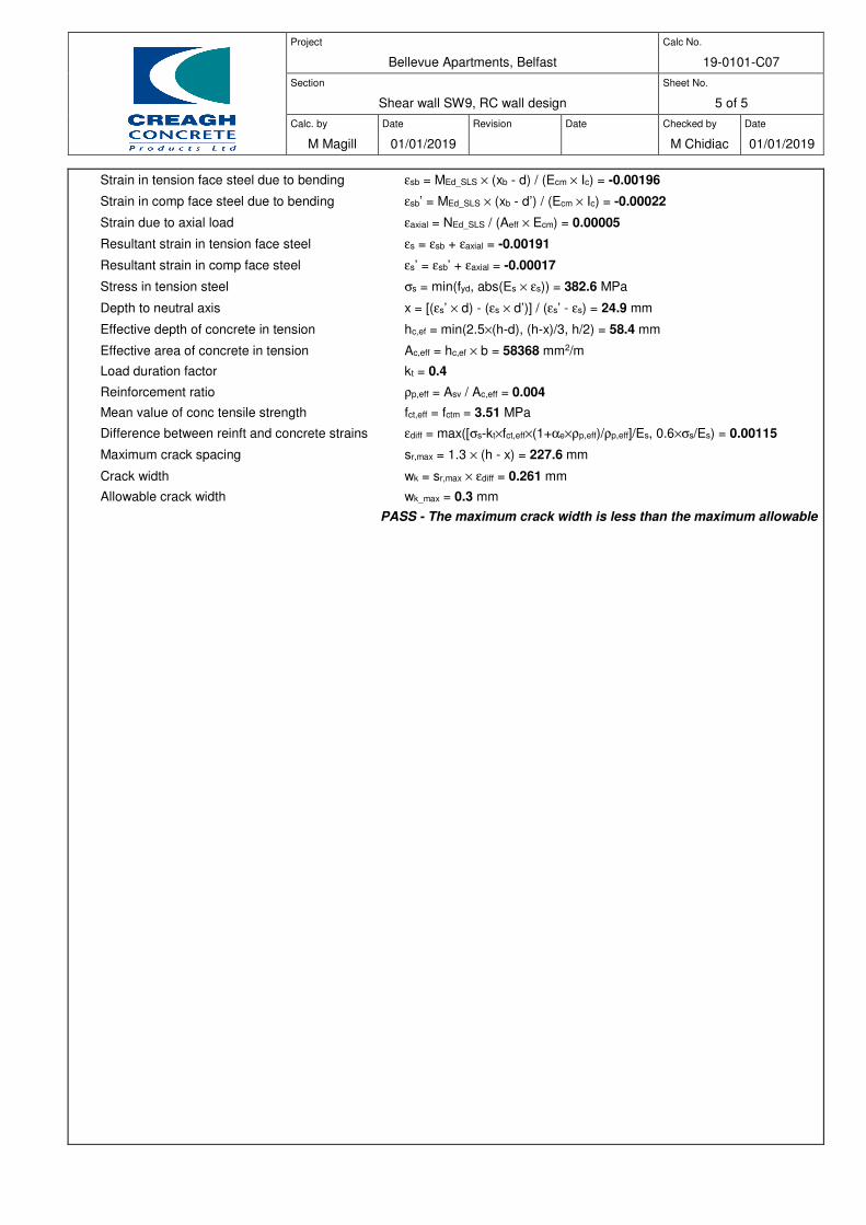
Project
Bellevue Apartments, Belfast
Calc No.
19-0101-C07
Section
Shear wall SW9, RC wall design
Sheet No.
5 of 5
Calc. by
M Magill
Date
01/01/2019
Revision
Date
Checked by
M Chidiac
Date
01/01/2019
Strain in tension face steel due to bending εsb = MEd_SLS × (xb - d) / (Ecm × Ic) = -0.00196
Strain in comp face steel due to bending εsb’ = MEd_SLS × (xb - d’) / (Ecm × Ic) = -0.00022
Strain due to axial load εaxial = NEd_SLS / (Aeff × Ecm) = 0.00005
Resultant strain in tension face steel εs = εsb + εaxial = -0.00191
Resultant strain in comp face steel εs’ = εsb’ + εaxial = -0.00017
Stress in tension steel σs = min(fyd, abs(Es × εs)) = 382.6 MPa
Depth to neutral axis x = [(εs’ × d) - (εs × d’)] / (εs’ - εs) = 24.9 mm
Effective depth of concrete in tension hc,ef = min(2.5×(h-d), (h-x)/3, h/2) = 58.4 mm
Effective area of concrete in tension Ac,eff = hc,ef × b = 58368 mm2/m
Load duration factor kt = 0.4
Reinforcement ratio ρp,eff = Asv / Ac,eff = 0.004
Mean value of conc tensile strength fct,eff = fctm = 3.51 MPa
Difference between reinft and concrete strains εdiff = max([σs-kt×fct,eff×(1+αe×ρp,eff)/ρp,eff]/Es, 0.6×σs/Es) = 0.00115
Maximum crack spacing sr,max = 1.3 × (h - x) = 227.6 mm
Crack width wk = sr,max × εdiff = 0.261 mm
Allowable crack width wk_max = 0.3 mm
PASS - The maximum crack width is less than the maximum allowable

Project
Bellevue Apartments, Belfast
Calc No.
19-0101-C09
Section
Shear wall SW16, RC wall design
Sheet No.
1 of 5
Calc. by
M Magill
Date
01/01/2019
Revision
Date
Checked by
M Chidiac
Date
01/01/2019
RC WALL DESIGN (EN1992)
RC WALL DESIGN
In accordance with EN1992-1-1:2004 incorporating corrigendum January 2008 and the UK national annex
Tedds calculation version 1.1.01
Wall input details
Wall geometry
Thickness h = 200 mm
Length b = 1000 mm/m
Clear height between restraints l = 2940 mm
Stability about minor axis Braced
Concrete details
Concrete strength class C40/50
Partial safety factor for concrete (2.4.2.4(1)) γC = 1.50
Coefficient αcc (3.1.6(1)) αcc = 0.85
Maximum aggregate size dg = 10 mm
Reinforcement details
Reinforcement in outer layer Horizontal
Nominal cover to outer layer cnom = 25 mm
Vertical bar diameter φv = 8 mm
Spacing of vertical reinforcement sv = 200 mm
Area of vertical reinforcement (per face) Asv = 251 mm2/m
Horizontal bar diameter φh = 8 mm
Spacing of horizontal reinforcement sh = 200 mm
Area of horizontal reinforcement (per face) Ash = 251 mm2/m
Characteristic yield strength fyk = 500 N/mm2
Partial safety factor for reinft (2.4.2.4(1)) γS = 1.15
Modulus of elasticity of reinft (3.2.7(4)) Es = 200.0 kN/mm2
Fire resistance details
Fire resistance period R = 90 min
Exposure to fire Exposed on two sides
Ratio of fire design axial load to design resistance µfi = 0.70
25
200

Project
Bellevue Apartments, Belfast
Calc No.
19-0101-C09
Section
Shear wall SW16, RC wall design
Sheet No.
2 of 5
Calc. by
M Magill
Date
01/01/2019
Revision
Date
Checked by
M Chidiac
Date
01/01/2019
Axial load and bending moments from frame analysis
Design axial load NEd = 351.0 kN/m
Moment about minor axis at top Mtop = 0.0 kNm/m
Moment about minor axis at bottom Mbtm = 0.0 kNm/m
Wall end restraints
End restraints for buckling about minor axis Braced, no rotational restraint both ends
Crack width details
Axial load due to quasi-permanent SLS. NEd_SLS = 249.0 kN/m
Moment at top due to quasi-permanent SLS. Mtop_SLS = 0.0 kNm/m
Moment at btm due to quasi-permanent SLS. Mbtm_SLS = 0.0 kNm/m
Duration of applied loading Long term
Maximum allowable crack width wk_max = 0.3 mm
Calculated wall properties
Concrete properties
Area of concrete Ac = h × b = 200000 mm2/m
Characteristic compression cylinder strength fck = 40 N/mm2
Design compressive strength (3.1.6(1)) fcd = αcc × fck / γC = 22.7 N/mm2
Mean value of cylinder strength (Table 3.1) fcm = fck + 8 MPa = 48.0 N/mm2
Mean value of tensile strength fctm = 3.51 N/mm2
Secant modulus of elasticity (Table 3.1) Ecm = 22000 MPa × (fcm / 10 MPa)0.3 = 35.2 kN/mm2
Rectangular stress block factors
Depth factor (3.1.7(3)) λsb = 0.8
Stress factor (3.1.7(3)) η = 1.0
Strain limits
Compression strain limit (Table 3.1) εcu3 = 0.00350
Pure compression strain limit (Table 3.1) εc3 = 0.00175
Design yield strength of reinforcement
Design yield strength (3.2.7(2)) fyd = fyk / γS = 434.8 MPa
Check nominal cover for fire and bond requirements
Min. cover reqd for bond (4.4.1.2(3)) Cmin,b = max(φh, φv - φh) = 8 mm
Min axis distance for fire (EN1992-1-2 T 5.4) afi = 25 mm
Allowance for deviations from min cover (4.4.1.3) ∆cdev = 5 mm
Min allowable nominal cover cnom_min = max(afi - φh / 2, cmin,b + ∆cdev) = 21 mm
PASS - the nominal cover is greater than the minimum required
Effective depth of vertical bars
Effective depth d = h - cnom - φh - φv / 2 = 163 mm
Depth to compression face bars d’ = cnom + φh + φv / 2 = 37 mm
Wall effective length
Eff. length factor (minor axis buckling) (Fig. 5.7) f = 1.0
Wall effective length l0 = f × l = 2940 mm
Column slenderness
Radius of gyration about minor axis i = h / √(12) = 5.8 cm
Minor axis slenderness ratio (5.8.3.2(1)) λ = l0 / i = 50.9
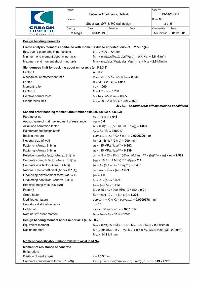
Project
Bellevue Apartments, Belfast
Calc No.
19-0101-C09
Section
Shear wall SW16, RC wall design
Sheet No.
3 of 5
Calc. by
M Magill
Date
01/01/2019
Revision
Date
Checked by
M Chidiac
Date
01/01/2019
Design bending moments
Frame analysis moments combined with moments due to imperfections (cl. 5.2 & 6.1(4))
Ecc. due to geometric imperfections ei = l0 /400 = 7.4 mm
Minimum end moment about minor axis M01 = min(abs(Mtop), abs(Mbtm)) + ei × NEd = 2.6 kNm/m
Maximum end moment about minor axis M02 = max(abs(Mtop), abs(Mbtm)) + ei × NEd = 2.6 kNm/m
Slenderness limit for buckling about minor axis (cl. 5.8.3.1)
Factor A A = 0.7
Mechanical reinforcement ratio ω = 2 × Asv × fyd / (Ac × fcd) = 0.048
Factor B B = √(1 + 2 × ω) = 1.047
Moment ratio rm = 1.000
Factor C C = 1.7 - rm = 0.700
Relative normal force n = NEd / (Ac × fcd) = 0.077
Slenderness limit λlim = 20 × A × B × C / √(n) = 36.9
λλλλ>=λλλλlim - Second order effects must be considered
Second order bending moment about minor axis (cl. 5.8.8.2 & 5.8.8.3)
Parameter nu nu = 1 + ω = 1.048
Approx value of n at max moment of resistance nbal = 0.4
Axial load correction factor Kr = min(1.0 , (nu - n) / (nu - nbal)) = 1.000
Reinforcement design strain εyd = fyd / Es = 0.00217
Basic curvature curvebasic = εyd / (0.45 × d) = 0.0000296 mm-1
Notional size of wall h0 = 2 × h ×b / (2 × b) = 200 mm
Factor α1 (Annex B.1(1)) α1 = (35 MPa / fcm)0.7 = 0.802
Factor α2 (Annex B.1(1)) α2 = (35 MPa / fcm)0.2 = 0.939
Relative humidity factor (Annex B.1(1)) φRH = [1 + ((1 - RH / 100%) / (0.1 mm-1/3 × (h0)1/3)) × α1] × α2 = 1.582
Concrete strength factor (Annex B.1(1)) βfcm = 16.8 × (1 MPa)1/2 / √(fcm) = 2.4
Concrete age factor (Annex B.1(1)) βt0 = 1 / (0.1 + (t0 / 1 day)0.2) = 0.488
Notional creep coefficient (Annex B.1(1)) φ0 = φRH × βfcm × βt0 = 1.874
Final creep development factor (at t = ¥) βc∞ = 1.0
Final creep coefficient (Annex B.1(1)) φ∞ = φ0 × βc∞ = 1.874
Effective creep ratio (5.8.4(2)) φef = φ∞ × rM = 1.312
Factor β β = 0.35 + fck / 200 MPa - λ / 150 = 0.211
Creep factor Kφ = max(1.0 , 1 + β × φef) = 1.276
Modified curvature curvemod = Kr × Kφ × curvebasic = 0.0000378 mm-1
Curvature distribution factor c = 10
Deflection e2 = curvemod × l02 / c = 32.7 mm
Nominal 2nd order moment M2 = NEd × e2 = 11.5 kNm/m
Design bending moment about minor axis (cl. 5.8.8.2)
Equivalent moment M0e = max(0.6 × M02 + 0.4 × M01, 0.4 × M02) = 2.6 kNm/m
Design moment MEd = max(M02, M0e + M2, M01 + 0.5 × M2, NEd × max(h/30, 20 mm))
MEd = 14.1 kNm/m
Moment capacity about minor axis with axial load NEd
Moment of resistance of concrete
By iteration:-
Position of neutral axis z = 28.3 mm
Concrete compression force (3.1.7(3)) Fc = η× fcd × min(max(λsb × z, 0 mm) , h) × b = 513.2 kN/m

Project
Bellevue Apartments, Belfast
Calc No.
19-0101-C09
Section
Shear wall SW16, RC wall design
Sheet No.
4 of 5
Calc. by
M Magill
Date
01/01/2019
Revision
Date
Checked by
M Chidiac
Date
01/01/2019
Moment of resistance MRdc = Fc × [h / 2 - (min(λsb × z , h)) / 2] = 45.5 kNm/m
Moment of resistance of reinforcement
Strain in tension face bars ε = εcu3 × (1 - d / z) = -0.01666
Stress in tension face bars σ = if(ε< 0, max(-1×fyd, Es × ε), min(fyd, Es × ε)) = -434.8 N/mm2
Force in tension face bars Fs = if(d > λsb × z, Asv × σ, Asv × (σ - η × fcd)) = -109.3 kN/m
Strain in compression face bars ε’ = εcu3 × (1 - d’ / z) = -0.00108
Stress in compression face bars σ’ = if(ε’< 0, max(-1×fyd, Es × ε’), min(fyd, Es × ε’)) = -215.2 N/mm2
Force in compression face bars Fs’ = if(d’ > λsb × z, Asv × σ’, Asv × (σ’ - η × fcd)) = -54.1 kN/m
Resultant concrete/steel force F = Fc + Fs + Fs’ = 349.8 kN/m
PASS - This is within half of one percent of the applied axial load therefore say OK
Moment of resistance of tension face bars MRds = Fs × (d - h / 2) = -6.9 kNm/m
Moment of resistance of compression face bars MRds’ = Fs’ × (h / 2 - d’) = -3.4 kNm/m
Combined moment of resistance
Moment of resistance about minor axis MRd = MRdc + MRds’ - MRds = 49.0 kNm/m
PASS - The moment capacity exceeds the design bending moment
Crack widths
Slenderness limit (cl. 5.8.3.1)
Min 1st order moment about minor axis M01_SLS=min(abs(Mtop_SLS),abs(Mbtm_SLS))+ei×NEd_SLS = 1.8 kNm/m
Max 1st order moment about minor axis M02_SLS=max(abs(Mtop_SLS),abs(Mbtm_SLS))+ei×NEd_SLS = 1.8 kNm/m
Moment ratio rm_SLS = 1.000
Factor C CSLS = 1.7 - rm_SLS = 0.700
Relative normal force nSLS = NEd_SLS / (Ac × fcd) = 0.055
Slenderness limit λlim_SLS = 20 × A × B × CSLS / √(nSLS) = 43.8
λλλλ>=λλλλlim_SLS - Second order effects must be considered
Second order bending moment about minor axis (cl. 5.8.8.2 & 5.8.8.3)
Axial load correction factor Kr_SLS = min(1.0 , (nu - nSLS) / (nu - nbal)) = 1.000
Effective creep ratio φef_SLS = φ∞ × 1.0 = 1.874
Factor β β = 0.35 + fck / 200 MPa - λ / 150 = 0.211
Creep factor Kφ_SLS = max(1.0, 1 + β × φef_SLS) = 1.395
Modified curvature curvemod_SLS = Kr_SLS × Kφ_SLS × curvebasic = 0.0000413 mm-1
Deflection e2_SLS = curvemod_SLS × l02 / c = 35.7 mm
Nominal 2nd order moment M2_SLS = NEd_SLS × e2_SLS = 8.9 kNm/m
Design bending moment about minor axis (cl. 7.3.4)
Equivalent 1st order moment M0e_SLS = max(0.6×M02_SLS+0.4×M01_SLS,0.4×M02_SLS) = 1.8 kNm/m
Design moment
MEd_SLS = max(M02_SLS, M0e_SLS + M2_SLS, M01_SLS + 0.5 × M2_SLS)
MEd_SLS = 10.7 kNm/m
Cover to tension reinforcement c = h - d - φv / 2 = 33.0 mm
Ratio of steel to concrete modulii αe = Es / Ecm = 5.7
Area of reinft in concrete units As,eff = 2 × αe × Asv = 2854 mm2/m
Combined area of steel/conc in conc units Aeff = b × h + As,eff = 202854 mm2/m
Reinforcement ratio per face ρ = Asv /(b × d) = 0.002
Neutral axis depth with pure bending xb = d × [-2×αe×ρ + √(4×αe2×ρ2 + 2×αe×ρ×(1+d’/d))] = 21.2 mm
Second moment of area of cracked section Ic = b×xb3/3 + αe×ρ×b×d×[(xb-d’)2 + (d-xb)2] = 32228709 mm4/m
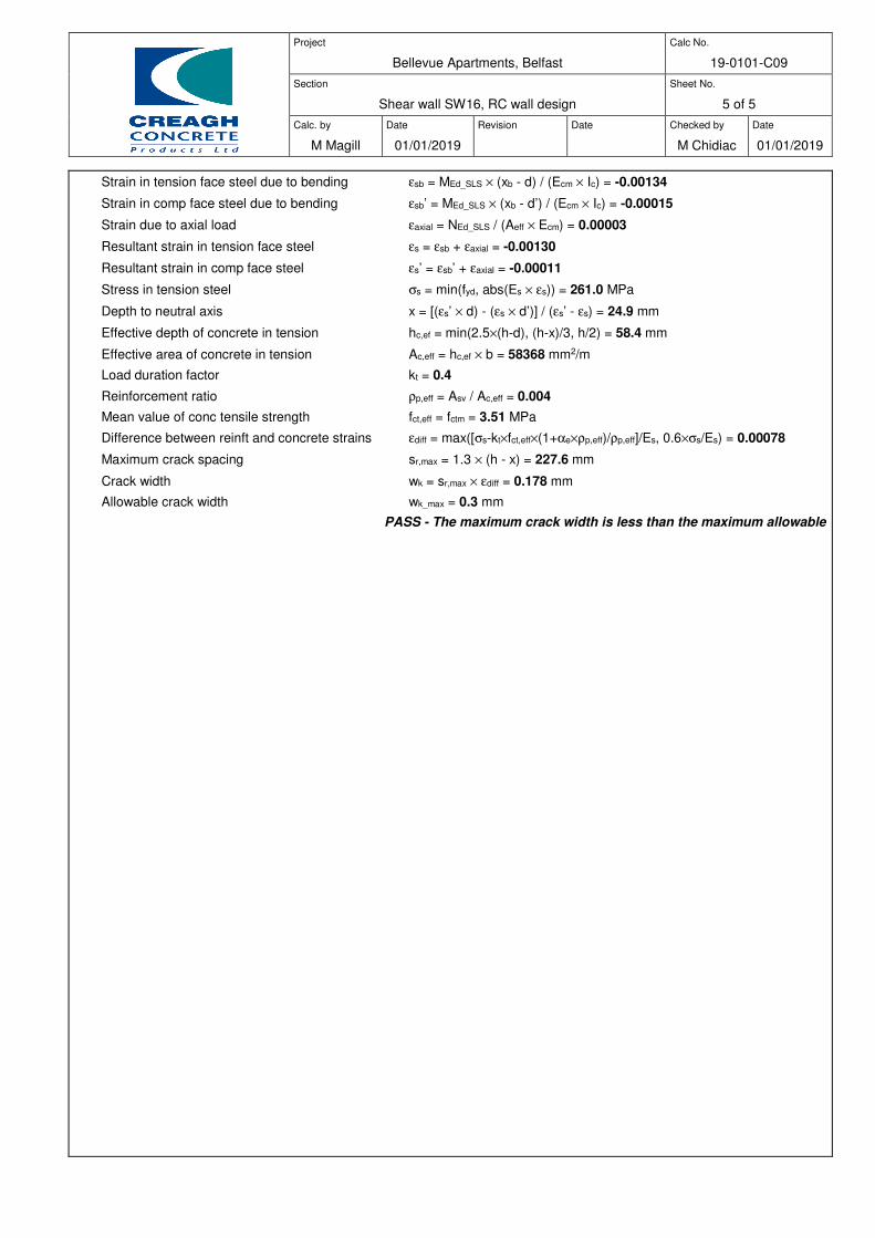
Project
Bellevue Apartments, Belfast
Calc No.
19-0101-C09
Section
Shear wall SW16, RC wall design
Sheet No.
5 of 5
Calc. by
M Magill
Date
01/01/2019
Revision
Date
Checked by
M Chidiac
Date
01/01/2019
Strain in tension face steel due to bending εsb = MEd_SLS × (xb - d) / (Ecm × Ic) = -0.00134
Strain in comp face steel due to bending εsb’ = MEd_SLS × (xb - d’) / (Ecm × Ic) = -0.00015
Strain due to axial load εaxial = NEd_SLS / (Aeff × Ecm) = 0.00003
Resultant strain in tension face steel εs = εsb + εaxial = -0.00130
Resultant strain in comp face steel εs’ = εsb’ + εaxial = -0.00011
Stress in tension steel σs = min(fyd, abs(Es × εs)) = 261.0 MPa
Depth to neutral axis x = [(εs’ × d) - (εs × d’)] / (εs’ - εs) = 24.9 mm
Effective depth of concrete in tension hc,ef = min(2.5×(h-d), (h-x)/3, h/2) = 58.4 mm
Effective area of concrete in tension Ac,eff = hc,ef × b = 58368 mm2/m
Load duration factor kt = 0.4
Reinforcement ratio ρp,eff = Asv / Ac,eff = 0.004
Mean value of conc tensile strength fct,eff = fctm = 3.51 MPa
Difference between reinft and concrete strains εdiff = max([σs-kt×fct,eff×(1+αe×ρp,eff)/ρp,eff]/Es, 0.6×σs/Es) = 0.00078
Maximum crack spacing sr,max = 1.3 × (h - x) = 227.6 mm
Crack width wk = sr,max × εdiff = 0.178 mm
Allowable crack width wk_max = 0.3 mm
PASS - The maximum crack width is less than the maximum allowable
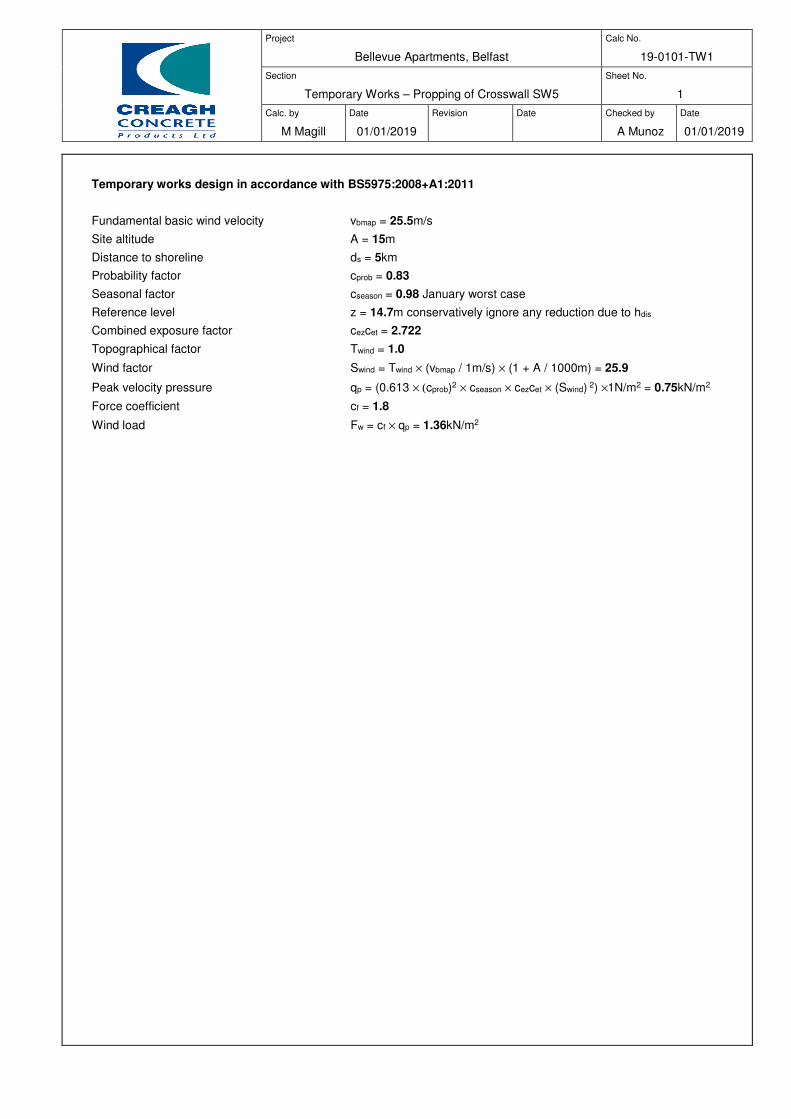
Project
Bellevue Apartments, Belfast
Calc No.
19-0101-TW1
Section
Temporary Works – Propping of Crosswall SW5
Sheet No.
1
Calc. by
M Magill
Date
01/01/2019
Revision
Date
Checked by
A Munoz
Date
01/01/2019
Temporary works design in accordance with BS5975:2008+A1:2011
Fundamental basic wind velocity vbmap = 25.5m/s
Site altitude A = 15m
Distance to shoreline ds = 5km
Probability factor cprob = 0.83
Seasonal factor cseason = 0.98 January worst case
Reference level z = 14.7m conservatively ignore any reduction due to hdis
Combined exposure factor cezcet = 2.722
Topographical factor Twind = 1.0
Wind factor Swind = Twind × (vbmap / 1m/s) × (1 + A / 1000m) = 25.9
Peak velocity pressure qp = (0.613 × (cprob)2 × cseason × cezcet × (Swind) 2) ×1N/m2 = 0.75kN/m2
Force coefficient cf = 1.8
Wind load Fw = cf × qp = 1.36kN/m2
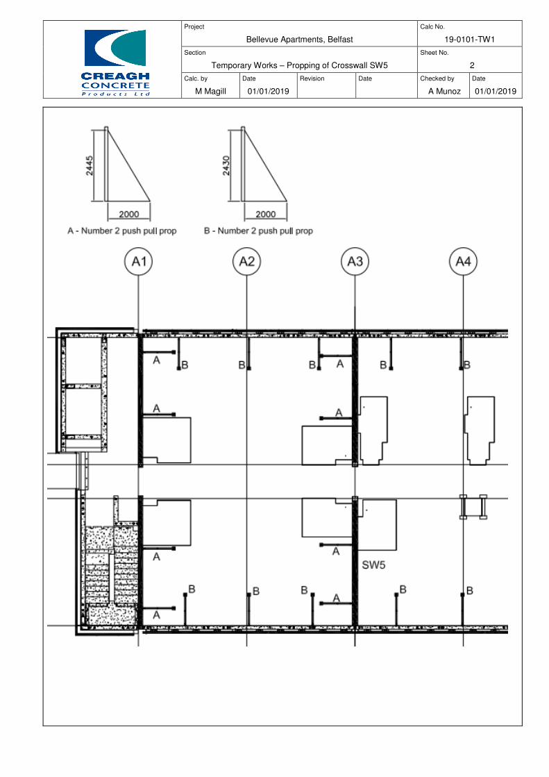
Project
Bellevue Apartments, Belfast
Calc No.
19-0101-TW1
Section
Temporary Works – Propping of Crosswall SW5
Sheet No.
2
Calc. by
M Magill
Date
01/01/2019
Revision
Date
Checked by
A Munoz
Date
01/01/2019
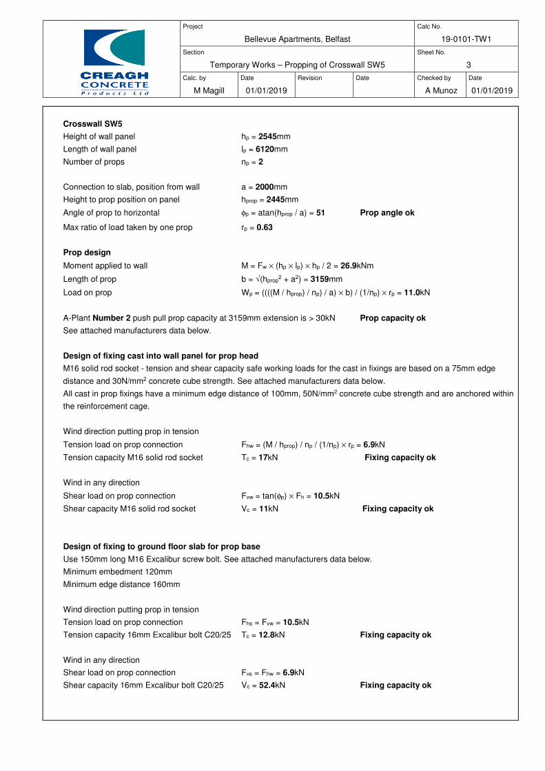
Project
Bellevue Apartments, Belfast
Calc No.
19-0101-TW1
Section
Temporary Works – Propping of Crosswall SW5
Sheet No.
3
Calc. by
M Magill
Date
01/01/2019
Revision
Date
Checked by
A Munoz
Date
01/01/2019
Crosswall SW5
Height of wall panel hp = 2545mm
Length of wall panel lp = 6120mm
Number of props np = 2
Connection to slab, position from wall a = 2000mm
Height to prop position on panel hprop = 2445mm
Angle of prop to horizontal φp = atan(hprop / a) = 51 Prop angle ok
Max ratio of load taken by one prop rp = 0.63
Prop design
Moment applied to wall M = Fw × (hp × lp) × hp / 2 = 26.9kNm
Length of prop b = √(hprop2 + a2) = 3159mm
Load on prop Wp = ((((M / hprop) / np) / a) × b) / (1/np) × rp = 11.0kN
A-Plant Number 2 push pull prop capacity at 3159mm extension is > 30kN Prop capacity ok
See attached manufacturers data below.
Design of fixing cast into wall panel for prop head
M16 solid rod socket - tension and shear capacity safe working loads for the cast in fixings are based on a 75mm edge
distance and 30N/mm2 concrete cube strength. See attached manufacturers data below.
All cast in prop fixings have a minimum edge distance of 100mm, 50N/mm2 concrete cube strength and are anchored within
the reinforcement cage.
Wind direction putting prop in tension
Tension load on prop connection Fhw = (M / hprop) / np / (1/np) × rp = 6.9kN
Tension capacity M16 solid rod socket Tc = 17kN Fixing capacity ok
Wind in any direction
Shear load on prop connection Fvw = tan(φp) × Fh = 10.5kN
Shear capacity M16 solid rod socket Vc = 11kN Fixing capacity ok
Design of fixing to ground floor slab for prop base
Use 150mm long M16 Excalibur screw bolt. See attached manufacturers data below.
Minimum embedment 120mm
Minimum edge distance 160mm
Wind direction putting prop in tension
Tension load on prop connection Fhs = Fvw = 10.5kN
Tension capacity 16mm Excalibur bolt C20/25 Tc = 12.8kN Fixing capacity ok
Wind in any direction
Shear load on prop connection Fvs = Fhw = 6.9kN
Shear capacity 16mm Excalibur bolt C20/25 Vc = 52.4kN Fixing capacity ok
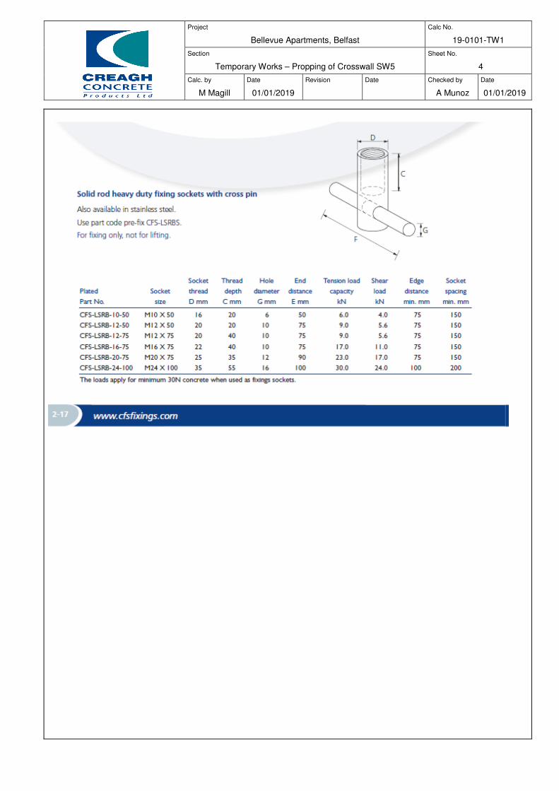
Project
Bellevue Apartments, Belfast
Calc No.
19-0101-TW1
Section
Temporary Works – Propping of Crosswall SW5
Sheet No.
4
Calc. by
M Magill
Date
01/01/2019
Revision
Date
Checked by
A Munoz
Date
01/01/2019
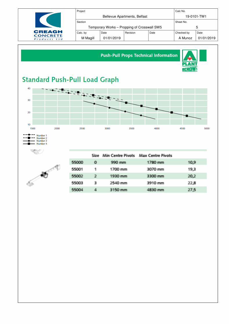
Project
Bellevue Apartments, Belfast
Calc No.
19-0101-TW1
Section
Temporary Works – Propping of Crosswall SW5
Sheet No.
5
Calc. by
M Magill
Date
01/01/2019
Revision
Date
Checked by
A Munoz
Date
01/01/2019
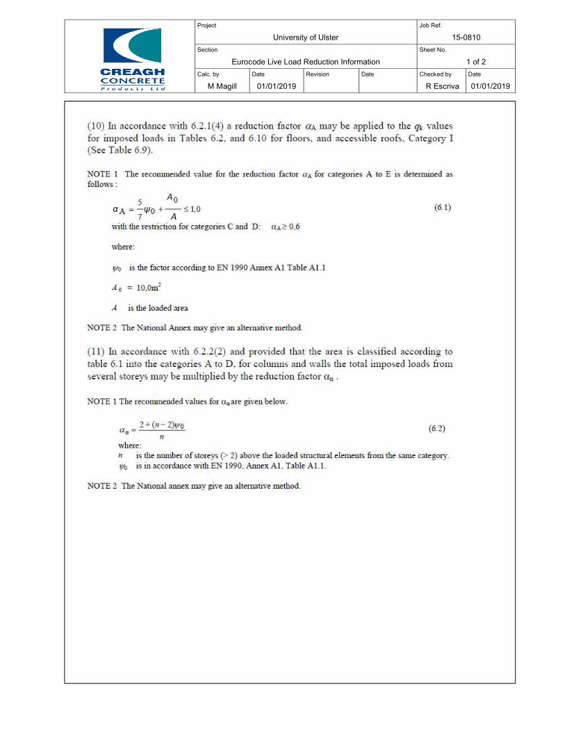
Project
University of Ulster Job Ref.
15-0810
Section
Eurocode Live Load Reduction Information Sheet No.
1 of 2
Calc. by
M Magill
Date
01/01/2019
Revision
Date
Checked by
R Escriva
Date
01/01/2019
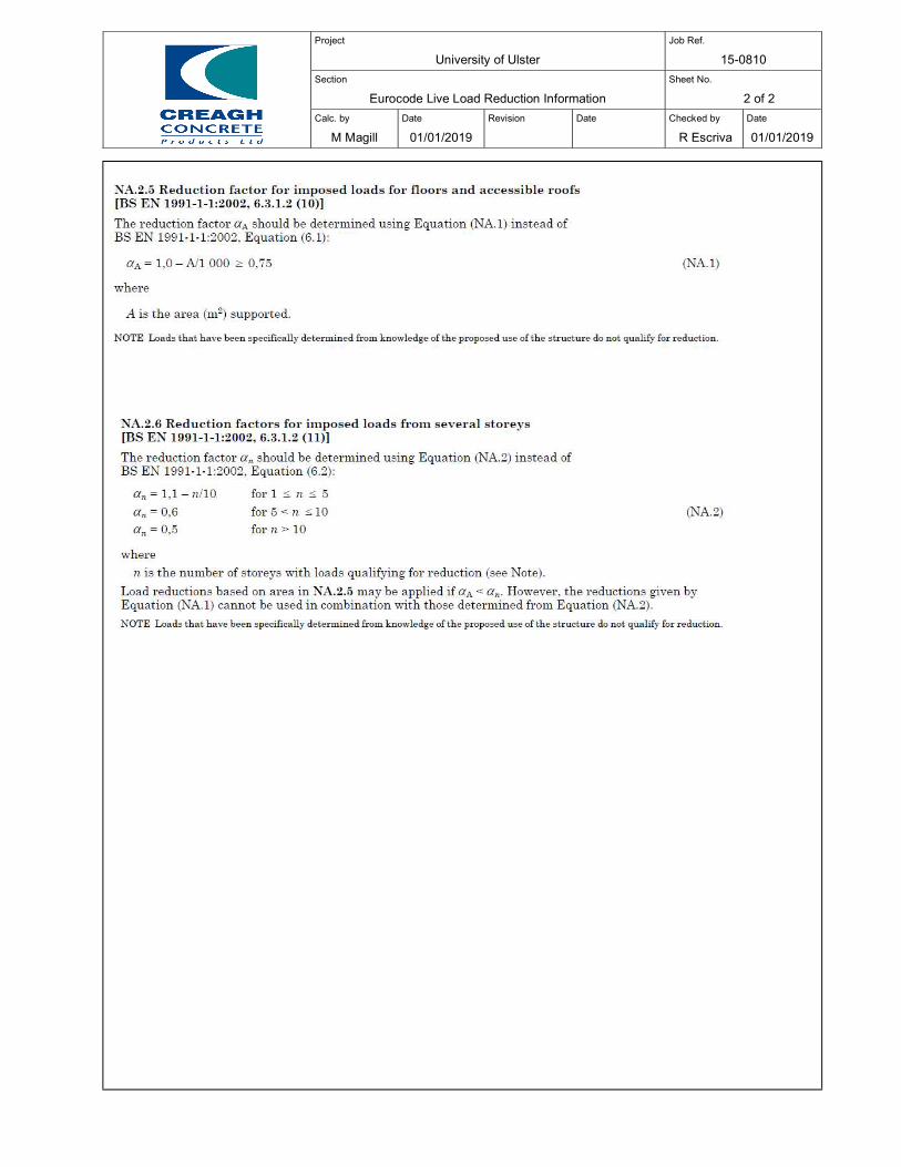
Project
University of Ulster Job Ref.
15-0810
Section
Eurocode Live Load Reduction Information Sheet No.
2 of 2
Calc. by
M Magill
Date
01/01/2019
Revision
Date
Checked by
R Escriva
Date
01/01/2019
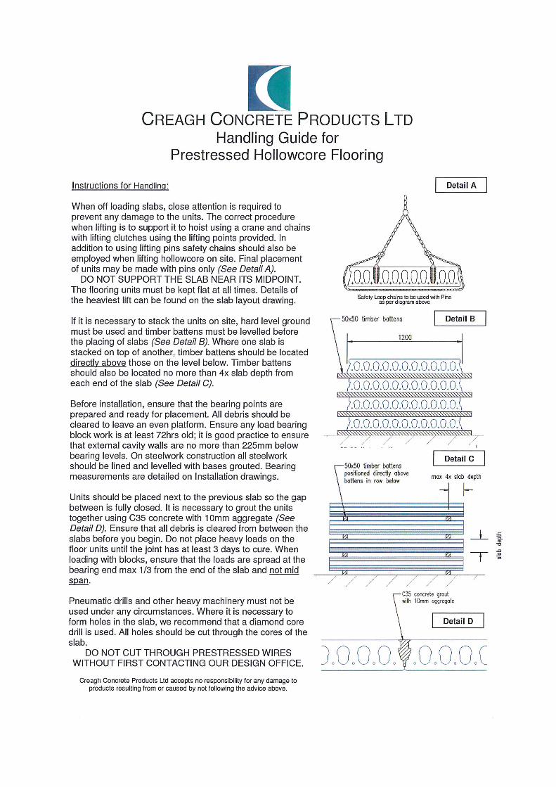
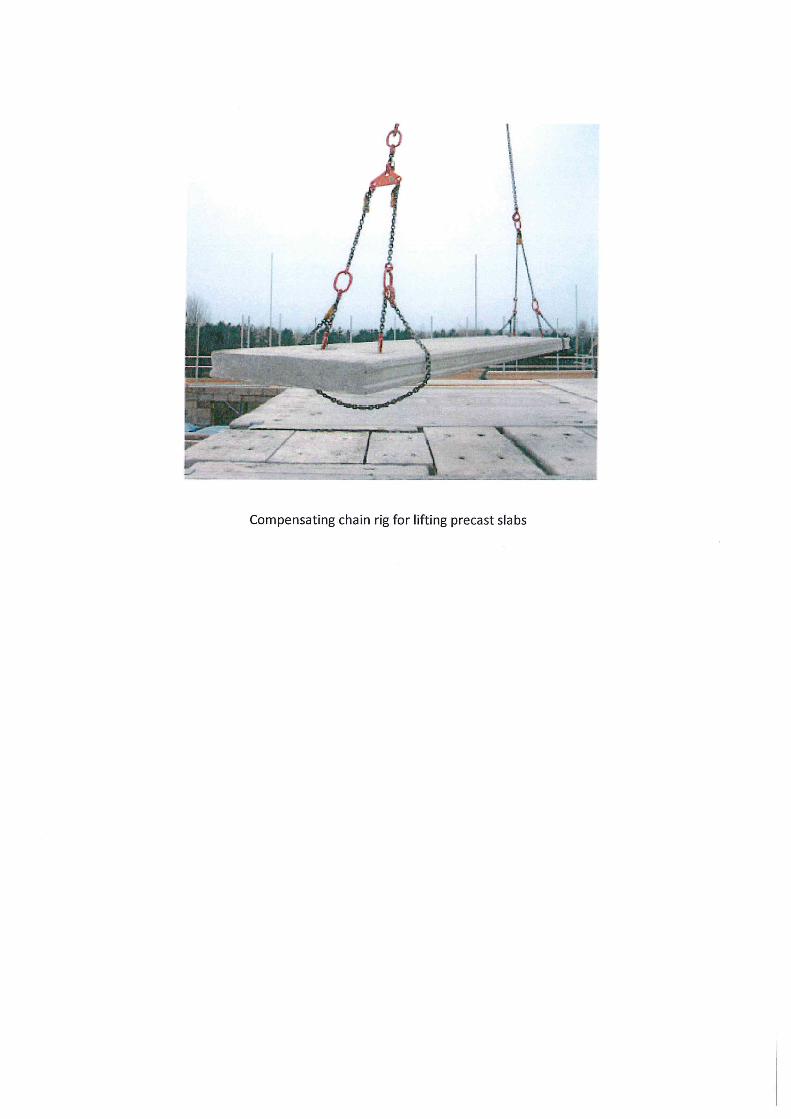
LIFTING SYSTEMS DESIGN CRITERIA 01

LIFTING SYSTEMS DESIGN CRITERIA
CONTENTS
Lifting Systems Design Criteria 1-3
Applied Load on Each Anchor 1-6

www.cfsfixings.com 0301
LIF
TIN
G S
YS
TE
MS
DE
SIG
N C
RIT
ER
IA
LIFTING SYSTEMS DESIGN CRITERIA
We have four main systems available for the lifting of precast concrete units. The reasons for selection may be technical, economic, or may be due to the lifting equipment already owned.
CFS can supply all the accessories you need including lifting loops, clutches and recess formers for each of these systems.
All the lifting sockets have Rd thread suitable for the building site environment.
Threaded Sockets
These are usually used for light to medium-weight units, they are easy to install in the concrete element and may be recessed if required.
Wavy Tail anchors are particularly easy to fix, High Load Wavy Tail type anchors may require no further reinforcement (for more information please contact CFS). Tube and flat plate sockets are also available, which depend on separate reinforcement.
Quick Lift System
This is an alternative quick lift option for lifting light to medium-weight precast concrete.
Spherical Head Anchors
These anchors may be used for the great concrete products such as staircase units, beams, slabs, walls, culverts and pipes. Spherical head anchors are recessed into the concrete and may require no additional reinforcement, depending on the application.
Cast-in Loops
These lifters require no further accessories as the loop is attached directly to the crane hook.
They are economic where smaller numbers are required, as you do not have to buy a lifting clutch.
They can be used for units where the area around the lifting point is not visible in their permanent condition, as the loop is cast into the top of the concrete.
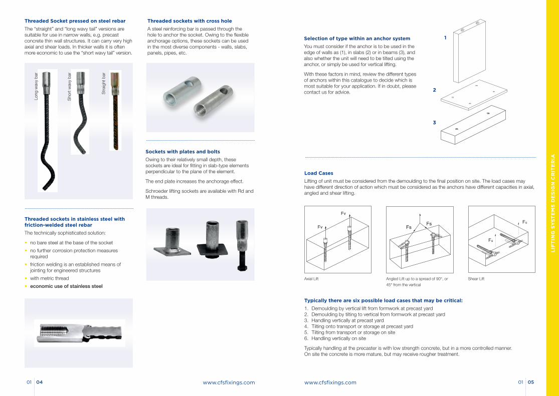
www.cfsfixings.com 0501
LIF
TIN
G S
YS
TE
MS
DE
SIG
N C
RIT
ER
IA
www.cfsfixings.com0401
Selection of type within an anchor system
You must consider if the anchor is to be used in the edge of walls as (1), in slabs (2) or in beams (3), and also whether the unit will need to be tilted using the anchor, or simply be used for vertical lifting.
With these factors in mind, review the different types of anchors within this catalogue to decide which is most suitable for your application. If in doubt, please contact us for advice.
Load Cases
Lifting of unit must be considered from the demoulding to the final position on site. The load cases may have different direction of action which must be considered as the anchors have different capacities in axial, angled and shear lifting.
1
2
3
Typically there are six possible load cases that may be critical:
1. Demoulding by vertical lift from formwork at precast yard 2. Demoulding by tilting to vertical from formwork at precast yard 3. Handling vertically at precast yard 4. Tilting onto transport or storage at precast yard 5. Tilting from transport or storage on site 6. Handling vertically on site
Typically handling at the precaster is with low strength concrete, but in a more controlled manner. On site the concrete is more mature, but may receive rougher treatment.
Axial Lift Angled Lift up to a spread of 90°, or
45° from the vertical
Shear Lift
Threaded Socket pressed on steel rebar
The “straight” and “long wavy tail” versions are suitable for use in narrow walls, e.g. precast concrete thin wall structures. It can carry very high axial and shear loads. In thicker walls it is often more economic to use the “short wavy tail” version.
Threaded sockets in stainless steel with friction-welded steel rebar
The technically sophisticated solution:
• no bare steel at the base of the socket
• no further corrosion protection measures required
• friction welding is an established means of jointing for engineered structures
• with metric thread
• economic use of stainless steel
Threaded sockets with cross hole
A steel reinforcing bar is passed through the hole to anchor the socket. Owing to the flexible anchorage options, these sockets can be used in the most diverse components - walls, slabs, panels, pipes, etc.
Sockets with plates and bolts
Owing to their relatively small depth, these sockets are ideal for fitting in slab-type elements perpendicular to the plane of the element.
The end plate increases the anchorage effect.
Schroeder lifting sockets are available with Rd and M threads.
Long
wav
y ba
r
Sho
rt w
avy
bar
Str
aigh
t bar
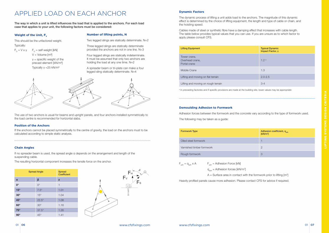
www.cfsfixings.com 0701
LIF
TIN
G S
YS
TE
MS
DE
SIG
N C
RIT
ER
IA
www.cfsfixings.com0601
Dynamic Factors
The dynamic process of lifting a unit adds load to the anchors. The magnitude of this dynamic effect is determined by the choice of lifting equipment, the length and type of cable or chain, and the hoisting speed.
Cables made of steel or synthetic fibre have a damping effect that increases with cable length. The table below provides typical values that you can use. If you are unsure as to which factor to apply please consult CFS.
Lifting Equipment Typical Dynamic Impact Factor, ψ
Tower crane, Overhead crane, Portal crane
1.2 a
Mobile Crane 1.3
Lifting and moving on flat terrain 2.0-2.5
Lifting and moving on rough terrain 3-4
Demoulding Adhesion to Formwork
Adhesion forces between the formwork and the concrete vary according to the type of formwork used.
The following may be taken as a guide:
Formwork Type Adhesion coefficient, qadh (kN/m2)
Oiled steel formwork 1
Varnished timber formwork 2
Rough formwork 3
Fadh = qadh x A Fadh = Adhesion Force [kN]
qadh = Adhesion forces [kN/m2]
A = Surface area in contact with the formwork prior to lifting [m2]
Heavily profiled panels cause more adhesion. Please contact CFS for advice if required.
a In precasting factories and if specific provisions are made at the building site, lower values may be appropriate
APPLIED LOAD ON EACH ANCHOR
The way in which a unit is lifted influences the load that is applied to the anchors. For each load case that applies to your unit, the following factors must be considered:
Weight of the Unit, Fv
This should be the unfactored weight.
Typically:
FG = V x γ FG = self weight [kN]
V = Volume [m³]
γ = specific weight of the precast element [kN/m³]
Typically γ =25 kN/m³
Number of lifting points, N
Two legged slings are statically determinate. N=2
Three legged slings are statically determinate provided the anchors are not in one line. N=3
Four legged slings are statically indeterminate. It must be assumed that only two anchors are holding the load at any one time. N=2
A spreader beam or tri-plate can make a four legged sling statically determinate. N=4
The use of two anchors is usual for beams and upright panels, and four anchors installed symmetrically to the load centre is recommended for horizontal slabs.
Position of the Anchors
If the anchors cannot be placed symmetrically to the centre of gravity, the load on the anchors must to be calculated according to simple static analysis.
Spread Angle Spread Coefficient
α β z
0° 0° 1
15° 7.5° 1.01
30° 15° 1.04
45° 22.5° 1.08
60° 30° 1.16
75° 37.5° 1.26
90° 45° 1.41
Chain Angles
If no spreader beam is used, the spread angle α depends on the arrangement and length of the suspending cable.
The resulting horizontal component increases the tensile force on the anchor.
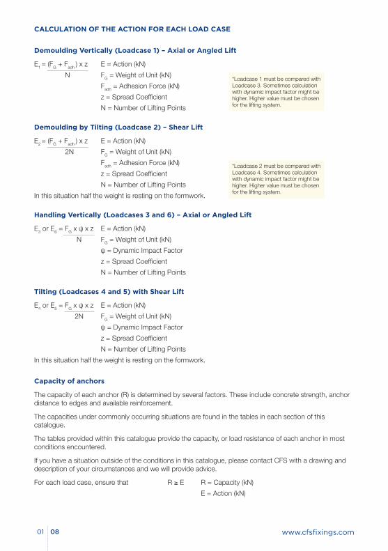
www.cfsfixings.com0801
Demoulding Vertically (Loadcase 1) – Axial or Angled Lift
E1 = (FG + Fadh ) x z E = Action (kN)
N FG = Weight of Unit (kN)
Fadh = Adhesion Force (kN)
z = Spread Coefficient
N = Number of Lifting Points
Demoulding by Tilting (Loadcase 2) – Shear Lift
E2 = (FG + Fadh ) x z E = Action (kN)
2N FG = Weight of Unit (kN)
Fadh = Adhesion Force (kN)
z = Spread Coefficient
N = Number of Lifting Points
In this situation half the weight is resting on the formwork.
Handling Vertically (Loadcases 3 and 6) – Axial or Angled Lift
E3 or E6 = FG x ψ x z E = Action (kN)
N FG = Weight of Unit (kN)
ψ = Dynamic Impact Factor
z = Spread Coefficient
N = Number of Lifting Points
Tilting (Loadcases 4 and 5) with Shear Lift
E4 or E5 = FG x ψ x z E = Action (kN)
2N FG = Weight of Unit (kN)
ψ = Dynamic Impact Factor
z = Spread Coefficient
N = Number of Lifting Points
In this situation half the weight is resting on the formwork.
CALCULATION OF THE ACTION FOR EACH LOAD CASE
Capacity of anchors
The capacity of each anchor (R) is determined by several factors. These include concrete strength, anchor distance to edges and available reinforcement.
The capacities under commonly occurring situations are found in the tables in each section of this catalogue.
The tables provided within this catalogue provide the capacity, or load resistance of each anchor in most conditions encountered.
If you have a situation outside of the conditions in this catalogue, please contact CFS with a drawing and description of your circumstances and we will provide advice.
For each load case, ensure that R ≥ E R = Capacity (kN)
E = Action (kN)
*Loadcase 1 must be compared with Loadcase 3. Sometimes calculation with dynamic impact factor might be higher. Higher value must be chosen for the lifting system.
*Loadcase 2 must be compared with Loadcase 4. Sometimes calculation with dynamic impact factor might be higher. Higher value must be chosen for the lifting system.
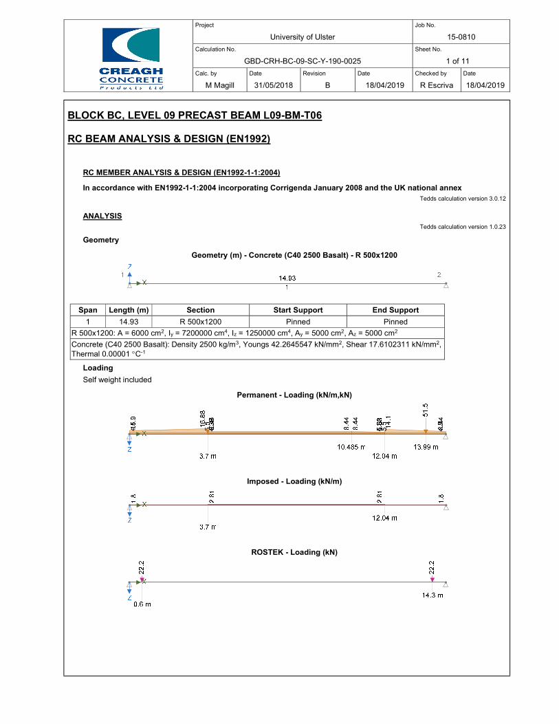
Project
University of Ulster
Job No.
15-0810
Calculation No.
GBD-CRH-BC-09-SC-Y-190-0025
Sheet No.
1 of 11
Calc. by
M Magill
Date
31/05/2018
Revision
B
Date
18/04/2019
Checked by
R Escriva
Date
18/04/2019
BLOCK BC, LEVEL 09 PRECAST BEAM L09-BM-T06
RC BEAM ANALYSIS & DESIGN (EN1992)
RC MEMBER ANALYSIS & DESIGN (EN1992-1-1:2004)
In accordance with EN1992-1-1:2004 incorporating Corrigenda January 2008 and the UK national annex Tedds calculation version 3.0.12
ANALYSIS Tedds calculation version 1.0.23
Geometry
Geometry (m) - Concrete (C40 2500 Basalt) - R 500x1200
Span Length (m) Section Start Support End Support
1 14.93 R 500x1200 Pinned Pinned
R 500x1200: A = 6000 cm2, Iy = 7200000 cm4, Iz = 1250000 cm4, Ay = 5000 cm2, Az = 5000 cm2
Concrete (C40 2500 Basalt): Density 2500 kg/m3, Youngs 42.2645547 kN/mm2, Shear 17.6102311 kN/mm2, Thermal 0.00001 C-1
Loading
Self weight included
Permanent - Loading (kN/m,kN)
Imposed - Loading (kN/m)
ROSTEK - Loading (kN)
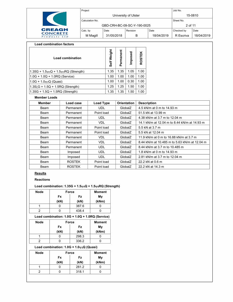
Project
University of Ulster
Job No.
15-0810
Calculation No.
GBD-CRH-BC-09-SC-Y-190-0025
Sheet No.
2 of 11
Calc. by
M Magill
Date
31/05/2018
Revision
B
Date
18/04/2019
Checked by
R Escriva
Date
18/04/2019
Load combination factors
Load combination
Se
lf W
eig
ht
Per
ma
ne
nt
Imp
os
ed
RO
ST
EK
1.35G + 1.50Q + 1.50RQ (Strength) 1.35 1.35 1.05 1.00
1.0G + 1.0Q + 1.0RQ (Service) 1.00 1.00 1.00 1.00
1.0G + 1.02Q (Quasi) 1.00 1.00 0.30 1.00
1.35G + 1.5Q + 1.5RQ (Strength) 1.25 1.25 1.50 1.00
1.35G + 1.5Q + 1.5RQ (Strength) 1.35 1.35 1.50 1.00
Member Loads
Member Load case Load Type Orientation Description
Beam Permanent UDL GlobalZ 4.5 kN/m at 0 m to 14.93 m
Beam Permanent Point load GlobalZ 51.5 kN at 13.99 m
Beam Permanent UDL GlobalZ 4.38 kN/m at 3.7 m to 12.04 m
Beam Permanent VDL GlobalZ 14.1 kN/m at 12.04 m to 8.44 kN/m at 14.93 m
Beam Permanent Point load GlobalZ 5.5 kN at 3.7 m
Beam Permanent Point load GlobalZ 5.5 kN at 12.04 m
Beam Permanent VDL GlobalZ 11.9 kN/m at 0 m to 16.88 kN/m at 3.7 m
Beam Permanent VDL GlobalZ 8.44 kN/m at 10.485 m to 5.63 kN/m at 12.04 m
Beam Permanent UDL GlobalZ 8.44 kN/m at 3.7 m to 10.485 m
Beam Imposed UDL GlobalZ 1.8 kN/m at 0 m to 14.93 m
Beam Imposed UDL GlobalZ 2.81 kN/m at 3.7 m to 12.04 m
Beam ROSTEK Point load GlobalZ 22.2 kN at 0.6 m
Beam ROSTEK Point load GlobalZ 22.2 kN at 14.3 m
Results
Reactions
Load combination: 1.35G + 1.50Q + 1.50RQ (Strength)
Node Force Moment
Fx Fz My
(kN) (kN) (kNm)
1 0 387.6 0
2 0 438.4 0
Load combination: 1.0G + 1.0Q + 1.0RQ (Service)
Node Force Moment
Fx Fz My
(kN) (kN) (kNm)
1 0 298.3 0
2 0 336.2 0
Load combination: 1.0G + 1.02Q (Quasi)
Node Force Moment
Fx Fz My
(kN) (kN) (kNm)
1 0 281.2 0
2 0 318.1 0
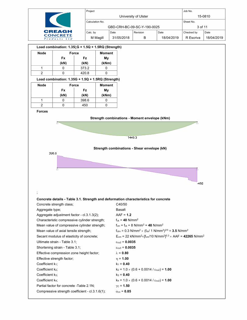
Project
University of Ulster
Job No.
15-0810
Calculation No.
GBD-CRH-BC-09-SC-Y-190-0025
Sheet No.
3 of 11
Calc. by
M Magill
Date
31/05/2018
Revision
B
Date
18/04/2019
Checked by
R Escriva
Date
18/04/2019
Load combination: 1.35G + 1.5Q + 1.5RQ (Strength)
Node Force Moment
Fx Fz My
(kN) (kN) (kNm)
1 0 373.2 0
2 0 420.8 0
Load combination: 1.35G + 1.5Q + 1.5RQ (Strength)
Node Force Moment
Fx Fz My
(kN) (kN) (kNm)
1 0 398.6 0
2 0 450 0
Forces
Strength combinations - Moment envelope (kNm)
Strength combinations - Shear envelope (kN)
;
Concrete details - Table 3.1. Strength and deformation characteristics for concrete
Concrete strength class; C40/50
Aggregate type; Basalt
Aggregate adjustment factor - cl.3.1.3(2); AAF = 1.2
Characteristic compressive cylinder strength; fck = 40 N/mm2
Mean value of compressive cylinder strength; fcm = fck + 8 N/mm2 = 48 N/mm2
Mean value of axial tensile strength; fctm = 0.3 N/mm2 (fck/ 1 N/mm2)2/3 = 3.5 N/mm2
Secant modulus of elasticity of concrete; Ecm = 22 kN/mm2[fcm/10 N/mm2]0.3 AAF = 42265 N/mm2
Ultimate strain - Table 3.1; cu2 = 0.0035
Shortening strain - Table 3.1; cu3 = 0.0035
Effective compression zone height factor; = 0.80
Effective strength factor; = 1.00
Coefficient k1; k1 = 0.40
Coefficient k2; k2 = 1.0 (0.6 + 0.0014 / cu2) = 1.00
Coefficient k3; k3 = 0.40
Coefficient k4; k4 = 1.0 (0.6 + 0.0014 / cu2) = 1.00
Partial factor for concrete -Table 2.1N; C = 1.50
Compressive strength coefficient - cl.3.1.6(1); cc = 0.85
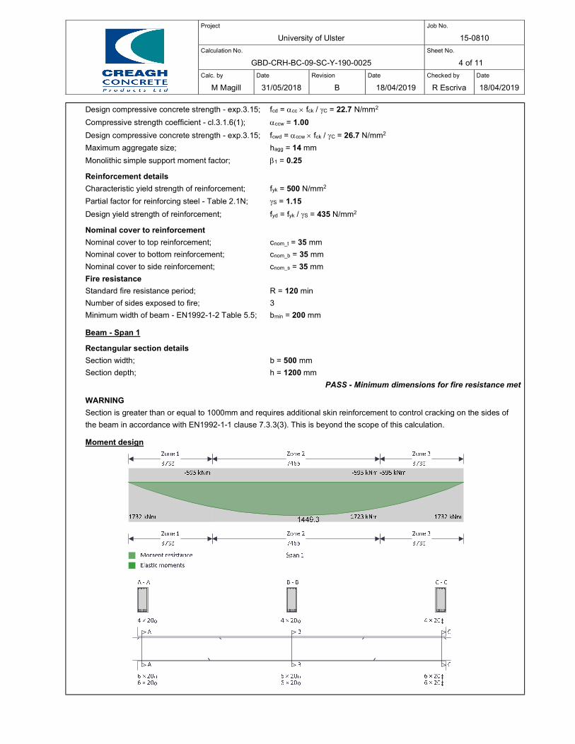
Project
University of Ulster
Job No.
15-0810
Calculation No.
GBD-CRH-BC-09-SC-Y-190-0025
Sheet No.
4 of 11
Calc. by
M Magill
Date
31/05/2018
Revision
B
Date
18/04/2019
Checked by
R Escriva
Date
18/04/2019
Design compressive concrete strength - exp.3.15; fcd = cc fck / C = 22.7 N/mm2
Compressive strength coefficient - cl.3.1.6(1); ccw = 1.00
Design compressive concrete strength - exp.3.15; fcwd = ccw fck / C = 26.7 N/mm2
Maximum aggregate size; hagg = 14 mm
Monolithic simple support moment factor; 1 = 0.25
Reinforcement details
Characteristic yield strength of reinforcement; fyk = 500 N/mm2
Partial factor for reinforcing steel - Table 2.1N; S = 1.15
Design yield strength of reinforcement; fyd = fyk / S = 435 N/mm2
Nominal cover to reinforcement
Nominal cover to top reinforcement; cnom_t = 35 mm
Nominal cover to bottom reinforcement; cnom_b = 35 mm
Nominal cover to side reinforcement; cnom_s = 35 mm
Fire resistance
Standard fire resistance period; R = 120 min
Number of sides exposed to fire; 3
Minimum width of beam - EN1992-1-2 Table 5.5; bmin = 200 mm
Beam - Span 1
Rectangular section details
Section width; b = 500 mm
Section depth; h = 1200 mm
PASS - Minimum dimensions for fire resistance met
WARNING
Section is greater than or equal to 1000mm and requires additional skin reinforcement to control cracking on the sides of
the beam in accordance with EN1992-1-1 clause 7.3.3(3). This is beyond the scope of this calculation.
Moment design
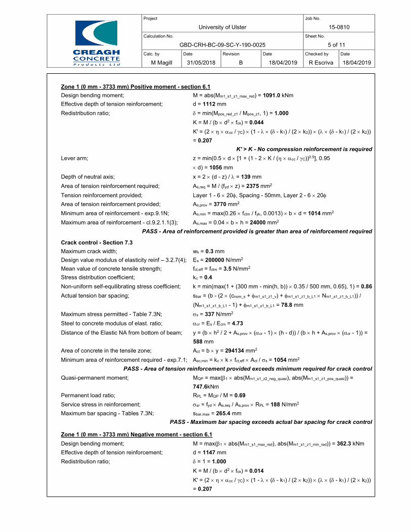
Project
University of Ulster
Job No.
15-0810
Calculation No.
GBD-CRH-BC-09-SC-Y-190-0025
Sheet No.
5 of 11
Calc. by
M Magill
Date
31/05/2018
Revision
B
Date
18/04/2019
Checked by
R Escriva
Date
18/04/2019
Zone 1 (0 mm - 3733 mm) Positive moment - section 6.1
Design bending moment; M = abs(Mm1_s1_z1_max_red) = 1091.0 kNm
Effective depth of tension reinforcement; d = 1112 mm
Redistribution ratio; = min(Mpos_red_z1 / Mpos_z1, 1) = 1.000
K = M / (b d2 fck) = 0.044
K' = (2 cc / C) (1 - ( - k1) / (2 k2)) ( ( - k1) / (2 k2))
= 0.207
K' > K - No compression reinforcement is required
Lever arm; z = min(0.5 d [1 + (1 - 2 K / ( cc / C))0.5], 0.95
d) = 1056 mm
Depth of neutral axis; x = 2 (d - z) / = 139 mm
Area of tension reinforcement required; As,req = M / (fyd z) = 2375 mm2
Tension reinforcement provided; Layer 1 - 6 20, Spacing - 50mm, Layer 2 - 6 20
Area of tension reinforcement provided; As,prov = 3770 mm2
Minimum area of reinforcement - exp.9.1N; As,min = max(0.26 fctm / fyk, 0.0013) b d = 1014 mm2
Maximum area of reinforcement - cl.9.2.1.1(3); As,max = 0.04 b h = 24000 mm2
PASS - Area of reinforcement provided is greater than area of reinforcement required
Crack control - Section 7.3
Maximum crack width; wk = 0.3 mm
Design value modulus of elasticity reinf – 3.2.7(4); Es = 200000 N/mm2
Mean value of concrete tensile strength; fct,eff = fctm = 3.5 N/mm2
Stress distribution coefficient; kc = 0.4
Non-uniform self-equilibrating stress coefficient; k = min(max(1 + (300 mm - min(h, b)) 0.35 / 500 mm, 0.65), 1) = 0.86
Actual tension bar spacing; sbar = (b - (2 (cnom_s + m1_s1_z1_v) + m1_s1_z1_b_L1 Nm1_s1_z1_b_L1)) /
(Nm1_s1_z1_b_L1 - 1) + m1_s1_z1_b_L1 = 78.8 mm
Maximum stress permitted - Table 7.3N; s = 337 N/mm2
Steel to concrete modulus of elast. ratio; cr = Es / Ecm = 4.73
Distance of the Elastic NA from bottom of beam; y = (b h2 / 2 + As,prov (cr - 1) (h - d)) / (b h + As,prov (cr - 1)) =
588 mm
Area of concrete in the tensile zone; Act = b y = 294134 mm2
Minimum area of reinforcement required - exp.7.1; Asc,min = kc k fct,eff Act / s = 1054 mm2
PASS - Area of tension reinforcement provided exceeds minimum required for crack control
Quasi-permanent moment; MQP = max(1 abs(Mm1_s1_z2_neg_quasi), abs(Mm1_s1_z1_pos_quasi)) =
747.6kNm
Permanent load ratio; RPL = MQP / M = 0.69
Service stress in reinforcement; sr = fyd As,req / As,prov RPL = 188 N/mm2
Maximum bar spacing - Tables 7.3N; sbar,max = 265.4 mm
PASS - Maximum bar spacing exceeds actual bar spacing for crack control
Zone 1 (0 mm - 3733 mm) Negative moment - section 6.1
Design bending moment; M = max(1 abs(Mm1_s1_max_red), abs(Mm1_s1_z1_min_red)) = 362.3 kNm
Effective depth of tension reinforcement; d = 1147 mm
Redistribution ratio; = 1 = 1.000
K = M / (b d2 fck) = 0.014
K' = (2 cc / C) (1 - ( - k1) / (2 k2)) ( ( - k1) / (2 k2))
= 0.207
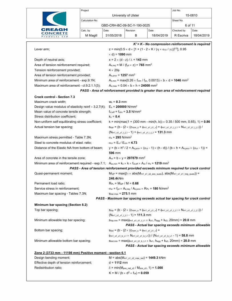
Project
University of Ulster
Job No.
15-0810
Calculation No.
GBD-CRH-BC-09-SC-Y-190-0025
Sheet No.
6 of 11
Calc. by
M Magill
Date
31/05/2018
Revision
B
Date
18/04/2019
Checked by
R Escriva
Date
18/04/2019
K' > K - No compression reinforcement is required
Lever arm; z = min(0.5 d [1 + (1 - 2 K / ( cc / C))0.5], 0.95
d) = 1090 mm
Depth of neutral axis; x = 2 (d - z) / = 143 mm
Area of tension reinforcement required; As,req = M / (fyd z) = 765 mm2
Tension reinforcement provided; 4 20
Area of tension reinforcement provided; As,prov = 1257 mm2
Minimum area of reinforcement - exp.9.1N; As,min = max(0.26 fctm / fyk, 0.0013) b d = 1046 mm2
Maximum area of reinforcement - cl.9.2.1.1(3); As,max = 0.04 b h = 24000 mm2
PASS - Area of reinforcement provided is greater than area of reinforcement required
Crack control - Section 7.3
Maximum crack width; wk = 0.3 mm
Design value modulus of elasticity reinf – 3.2.7(4); Es = 200000 N/mm2
Mean value of concrete tensile strength; fct,eff = fctm = 3.5 N/mm2
Stress distribution coefficient; kc = 0.4
Non-uniform self-equilibrating stress coefficient; k = min(max(1 + (300 mm - min(h, b)) 0.35 / 500 mm, 0.65), 1) = 0.86
Actual tension bar spacing; sbar = (b - (2 (cnom_s + m1_s1_z1_v) + m1_s1_z1_t_L1 Nm1_s1_z1_t_L1)) /
(Nm1_s1_z1_t_L1 - 1) + m1_s1_z1_t_L1 = 131.3 mm
Maximum stress permitted - Table 7.3N; s = 295 N/mm2
Steel to concrete modulus of elast. ratio; cr = Es / Ecm = 4.73
Distance of the Elastic NA from bottom of beam; y = (b h2 / 2 + As,prov (cr - 1) (h - d)) / (b h + As,prov (cr - 1)) =
596 mm
Area of concrete in the tensile zone; Act = b y = 297879 mm2
Minimum area of reinforcement required - exp.7.1; Asc,min = kc k fct,eff Act / s = 1219 mm2
PASS - Area of tension reinforcement provided exceeds minimum required for crack control
Quasi-permanent moment; MQP = max(1 abs(Mm1_s1_z2_pos_quasi), abs(Mm1_s1_z1_neg_quasi)) =
246.4kNm
Permanent load ratio; RPL = MQP / M = 0.68
Service stress in reinforcement; sr = fyd As,req / As,prov RPL = 180 N/mm2
Maximum bar spacing - Tables 7.3N; sbar,max = 275.1 mm
PASS - Maximum bar spacing exceeds actual bar spacing for crack control
Minimum bar spacing (Section 8.2)
Top bar spacing; stop = (b - (2 (cnom_s + m1_s1_z1_v) + m1_s1_z1_t_L1 Nm1_s1_z1_t_L1)) /
(Nm1_s1_z1_t_L1 - 1) = 111.3 mm
Minimum allowable top bar spacing; stop,min = max(m1_s1_z1_t_L1 ks1, hagg + ks2, 20mm) = 20.0 mm
PASS - Actual bar spacing exceeds minimum allowable
Bottom bar spacing; sbot = (b - (2 (cnom_s + m1_s1_z1_v) +
m1_s1_z1_b_L1 Nm1_s1_z1_b_L1)) / (Nm1_s1_z1_b_L1 - 1) = 58.8 mm
Minimum allowable bottom bar spacing; sbot,min = max(m1_s1_z1_b_L1 ks1, hagg + ks2, 20mm) = 20.0 mm
PASS - Actual bar spacing exceeds minimum allowable
Zone 2 (3733 mm - 11198 mm) Positive moment - section 6.1
Design bending moment; M = abs(Mm1_s1_z2_max_red) = 1449.3 kNm
Effective depth of tension reinforcement; d = 1112 mm
Redistribution ratio; = min(Mpos_red_z2 / Mpos_z2, 1) = 1.000
K = M / (b d2 fck) = 0.059
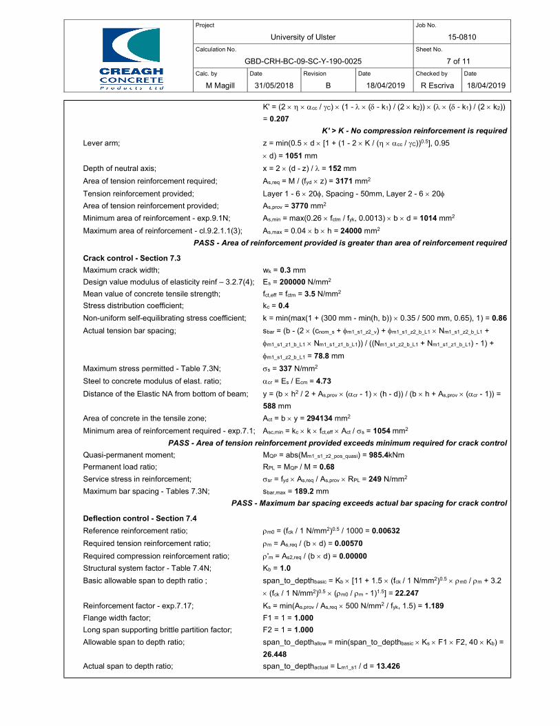
Project
University of Ulster
Job No.
15-0810
Calculation No.
GBD-CRH-BC-09-SC-Y-190-0025
Sheet No.
7 of 11
Calc. by
M Magill
Date
31/05/2018
Revision
B
Date
18/04/2019
Checked by
R Escriva
Date
18/04/2019
K' = (2 cc / C) (1 - ( - k1) / (2 k2)) ( ( - k1) / (2 k2))
= 0.207
K' > K - No compression reinforcement is required
Lever arm; z = min(0.5 d [1 + (1 - 2 K / ( cc / C))0.5], 0.95
d) = 1051 mm
Depth of neutral axis; x = 2 (d - z) / = 152 mm
Area of tension reinforcement required; As,req = M / (fyd z) = 3171 mm2
Tension reinforcement provided; Layer 1 - 6 20, Spacing - 50mm, Layer 2 - 6 20
Area of tension reinforcement provided; As,prov = 3770 mm2
Minimum area of reinforcement - exp.9.1N; As,min = max(0.26 fctm / fyk, 0.0013) b d = 1014 mm2
Maximum area of reinforcement - cl.9.2.1.1(3); As,max = 0.04 b h = 24000 mm2
PASS - Area of reinforcement provided is greater than area of reinforcement required
Crack control - Section 7.3
Maximum crack width; wk = 0.3 mm
Design value modulus of elasticity reinf – 3.2.7(4); Es = 200000 N/mm2
Mean value of concrete tensile strength; fct,eff = fctm = 3.5 N/mm2
Stress distribution coefficient; kc = 0.4
Non-uniform self-equilibrating stress coefficient; k = min(max(1 + (300 mm - min(h, b)) 0.35 / 500 mm, 0.65), 1) = 0.86
Actual tension bar spacing; sbar = (b - (2 (cnom_s + m1_s1_z2_v) + m1_s1_z2_b_L1 Nm1_s1_z2_b_L1 +
m1_s1_z1_b_L1 Nm1_s1_z1_b_L1)) / ((Nm1_s1_z2_b_L1 + Nm1_s1_z1_b_L1) - 1) +
m1_s1_z2_b_L1 = 78.8 mm
Maximum stress permitted - Table 7.3N; s = 337 N/mm2
Steel to concrete modulus of elast. ratio; cr = Es / Ecm = 4.73
Distance of the Elastic NA from bottom of beam; y = (b h2 / 2 + As,prov (cr - 1) (h - d)) / (b h + As,prov (cr - 1)) =
588 mm
Area of concrete in the tensile zone; Act = b y = 294134 mm2
Minimum area of reinforcement required - exp.7.1; Asc,min = kc k fct,eff Act / s = 1054 mm2
PASS - Area of tension reinforcement provided exceeds minimum required for crack control
Quasi-permanent moment; MQP = abs(Mm1_s1_z2_pos_quasi) = 985.4kNm
Permanent load ratio; RPL = MQP / M = 0.68
Service stress in reinforcement; sr = fyd As,req / As,prov RPL = 249 N/mm2
Maximum bar spacing - Tables 7.3N; sbar,max = 189.2 mm
PASS - Maximum bar spacing exceeds actual bar spacing for crack control
Deflection control - Section 7.4
Reference reinforcement ratio; m0 = (fck / 1 N/mm2)0.5 / 1000 = 0.00632
Required tension reinforcement ratio; m = As,req / (b d) = 0.00570
Required compression reinforcement ratio; 'm = As2,req / (b d) = 0.00000
Structural system factor - Table 7.4N; Kb = 1.0
Basic allowable span to depth ratio ; span_to_depthbasic = Kb [11 + 1.5 (fck / 1 N/mm2)0.5 m0 / m + 3.2
(fck / 1 N/mm2)0.5 (m0 / m - 1)1.5] = 22.247
Reinforcement factor - exp.7.17; Ks = min(As,prov / As,req 500 N/mm2 / fyk, 1.5) = 1.189
Flange width factor; F1 = 1 = 1.000
Long span supporting brittle partition factor; F2 = 1 = 1.000
Allowable span to depth ratio; span_to_depthallow = min(span_to_depthbasic Ks F1 F2, 40 Kb) =
26.448
Actual span to depth ratio; span_to_depthactual = Lm1_s1 / d = 13.426
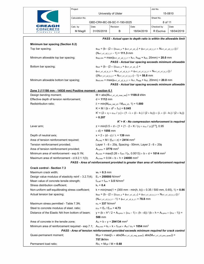
Project
University of Ulster
Job No.
15-0810
Calculation No.
GBD-CRH-BC-09-SC-Y-190-0025
Sheet No.
8 of 11
Calc. by
M Magill
Date
31/05/2018
Revision
B
Date
18/04/2019
Checked by
R Escriva
Date
18/04/2019
PASS - Actual span to depth ratio is within the allowable limit
Minimum bar spacing (Section 8.2)
Top bar spacing; stop = (b - (2 (cnom_s + m1_s1_z2_v) + m1_s1_z2_t_L1 Nm1_s1_z2_t_L1)) /
(Nm1_s1_z2_t_L1 - 1) = 111.3 mm
Minimum allowable top bar spacing; stop,min = max(m1_s1_z2_t_L1 ks1, hagg + ks2, 20mm) = 20.0 mm
PASS - Actual bar spacing exceeds minimum allowable
Bottom bar spacing; sbot = (b - (2 (cnom_s + m1_s1_z2_v) +
m1_s1_z2_b_L1 Nm1_s1_z2_b_L1 + m1_s1_z1_b_L1 Nm1_s1_z1_b_L1)) /
((Nm1_s1_z2_b_L1 + Nm1_s1_z1_b_L1) - 1) = 58.8 mm
Minimum allowable bottom bar spacing; sbot,min = max(m1_s1_z2_b_L1 ks1, hagg + ks2, 20mm) = 20.0 mm
PASS - Actual bar spacing exceeds minimum allowable
Zone 3 (11198 mm - 14930 mm) Positive moment - section 6.1
Design bending moment; M = abs(Mm1_s1_z3_max_red) = 1109.0 kNm
Effective depth of tension reinforcement; d = 1112 mm
Redistribution ratio; = min(Mpos_red_z3 / Mpos_z3, 1) = 1.000
K = M / (b d2 fck) = 0.045
K' = (2 cc / C) (1 - ( - k1) / (2 k2)) ( ( - k1) / (2 k2))
= 0.207
K' > K - No compression reinforcement is required
Lever arm; z = min(0.5 d [1 + (1 - 2 K / ( cc / C))0.5], 0.95
d) = 1056 mm
Depth of neutral axis; x = 2 (d - z) / = 139 mm
Area of tension reinforcement required; As,req = M / (fyd z) = 2414 mm2
Tension reinforcement provided; Layer 1 - 6 20, Spacing - 50mm, Layer 2 - 6 20
Area of tension reinforcement provided; As,prov = 3770 mm2
Minimum area of reinforcement - exp.9.1N; As,min = max(0.26 fctm / fyk, 0.0013) b d = 1014 mm2
Maximum area of reinforcement - cl.9.2.1.1(3); As,max = 0.04 b h = 24000 mm2
PASS - Area of reinforcement provided is greater than area of reinforcement required
Crack control - Section 7.3
Maximum crack width; wk = 0.3 mm
Design value modulus of elasticity reinf – 3.2.7(4); Es = 200000 N/mm2
Mean value of concrete tensile strength; fct,eff = fctm = 3.5 N/mm2
Stress distribution coefficient; kc = 0.4
Non-uniform self-equilibrating stress coefficient; k = min(max(1 + (300 mm - min(h, b)) 0.35 / 500 mm, 0.65), 1) = 0.86
Actual tension bar spacing; sbar = (b - (2 (cnom_s + m1_s1_z3_v) + m1_s1_z3_b_L1 Nm1_s1_z3_b_L1)) /
(Nm1_s1_z3_b_L1 - 1) + m1_s1_z3_b_L1 = 78.8 mm
Maximum stress permitted - Table 7.3N; s = 337 N/mm2
Steel to concrete modulus of elast. ratio; cr = Es / Ecm = 4.73
Distance of the Elastic NA from bottom of beam; y = (b h2 / 2 + As,prov (cr - 1) (h - d)) / (b h + As,prov (cr - 1)) =
588 mm
Area of concrete in the tensile zone; Act = b y = 294134 mm2
Minimum area of reinforcement required - exp.7.1; Asc,min = kc k fct,eff Act / s = 1054 mm2
PASS - Area of tension reinforcement provided exceeds minimum required for crack control
Quasi-permanent moment; MQP = max(1 abs(Mm1_s1_z2_neg_quasi), abs(Mm1_s1_z3_pos_quasi)) =
757.9kNm
Permanent load ratio; RPL = MQP / M = 0.68
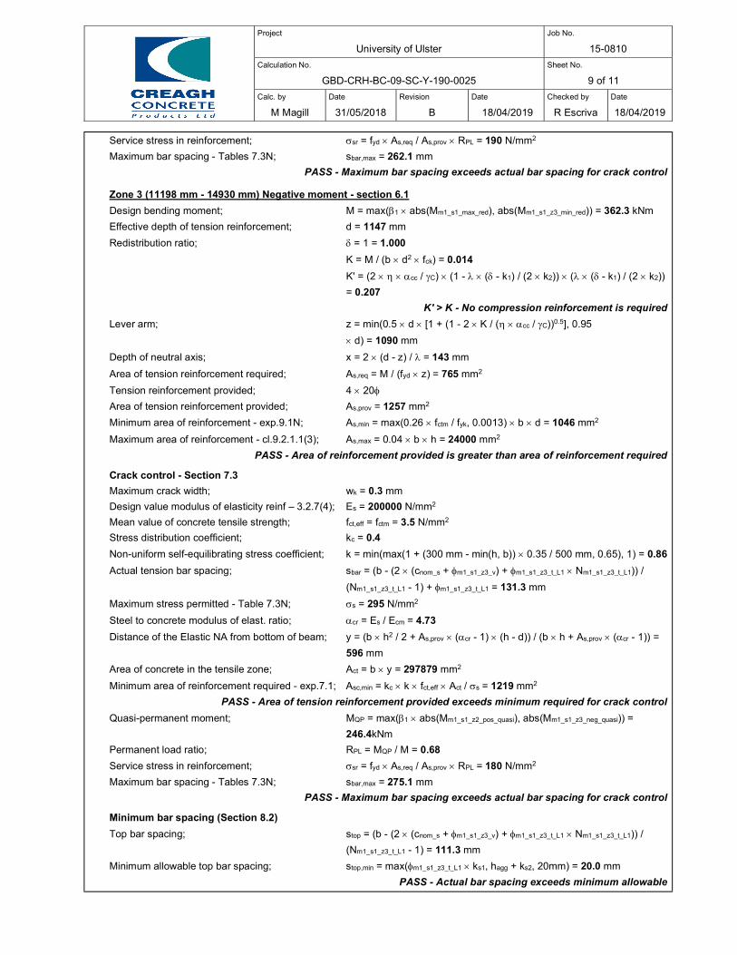
Project
University of Ulster
Job No.
15-0810
Calculation No.
GBD-CRH-BC-09-SC-Y-190-0025
Sheet No.
9 of 11
Calc. by
M Magill
Date
31/05/2018
Revision
B
Date
18/04/2019
Checked by
R Escriva
Date
18/04/2019
Service stress in reinforcement; sr = fyd As,req / As,prov RPL = 190 N/mm2
Maximum bar spacing - Tables 7.3N; sbar,max = 262.1 mm
PASS - Maximum bar spacing exceeds actual bar spacing for crack control
Zone 3 (11198 mm - 14930 mm) Negative moment - section 6.1
Design bending moment; M = max(1 abs(Mm1_s1_max_red), abs(Mm1_s1_z3_min_red)) = 362.3 kNm
Effective depth of tension reinforcement; d = 1147 mm
Redistribution ratio; = 1 = 1.000
K = M / (b d2 fck) = 0.014
K' = (2 cc / C) (1 - ( - k1) / (2 k2)) ( ( - k1) / (2 k2))
= 0.207
K' > K - No compression reinforcement is required
Lever arm; z = min(0.5 d [1 + (1 - 2 K / ( cc / C))0.5], 0.95
d) = 1090 mm
Depth of neutral axis; x = 2 (d - z) / = 143 mm
Area of tension reinforcement required; As,req = M / (fyd z) = 765 mm2
Tension reinforcement provided; 4 20
Area of tension reinforcement provided; As,prov = 1257 mm2
Minimum area of reinforcement - exp.9.1N; As,min = max(0.26 fctm / fyk, 0.0013) b d = 1046 mm2
Maximum area of reinforcement - cl.9.2.1.1(3); As,max = 0.04 b h = 24000 mm2
PASS - Area of reinforcement provided is greater than area of reinforcement required
Crack control - Section 7.3
Maximum crack width; wk = 0.3 mm
Design value modulus of elasticity reinf – 3.2.7(4); Es = 200000 N/mm2
Mean value of concrete tensile strength; fct,eff = fctm = 3.5 N/mm2
Stress distribution coefficient; kc = 0.4
Non-uniform self-equilibrating stress coefficient; k = min(max(1 + (300 mm - min(h, b)) 0.35 / 500 mm, 0.65), 1) = 0.86
Actual tension bar spacing; sbar = (b - (2 (cnom_s + m1_s1_z3_v) + m1_s1_z3_t_L1 Nm1_s1_z3_t_L1)) /
(Nm1_s1_z3_t_L1 - 1) + m1_s1_z3_t_L1 = 131.3 mm
Maximum stress permitted - Table 7.3N; s = 295 N/mm2
Steel to concrete modulus of elast. ratio; cr = Es / Ecm = 4.73
Distance of the Elastic NA from bottom of beam; y = (b h2 / 2 + As,prov (cr - 1) (h - d)) / (b h + As,prov (cr - 1)) =
596 mm
Area of concrete in the tensile zone; Act = b y = 297879 mm2
Minimum area of reinforcement required - exp.7.1; Asc,min = kc k fct,eff Act / s = 1219 mm2
PASS - Area of tension reinforcement provided exceeds minimum required for crack control
Quasi-permanent moment; MQP = max(1 abs(Mm1_s1_z2_pos_quasi), abs(Mm1_s1_z3_neg_quasi)) =
246.4kNm
Permanent load ratio; RPL = MQP / M = 0.68
Service stress in reinforcement; sr = fyd As,req / As,prov RPL = 180 N/mm2
Maximum bar spacing - Tables 7.3N; sbar,max = 275.1 mm
PASS - Maximum bar spacing exceeds actual bar spacing for crack control
Minimum bar spacing (Section 8.2)
Top bar spacing; stop = (b - (2 (cnom_s + m1_s1_z3_v) + m1_s1_z3_t_L1 Nm1_s1_z3_t_L1)) /
(Nm1_s1_z3_t_L1 - 1) = 111.3 mm
Minimum allowable top bar spacing; stop,min = max(m1_s1_z3_t_L1 ks1, hagg + ks2, 20mm) = 20.0 mm
PASS - Actual bar spacing exceeds minimum allowable
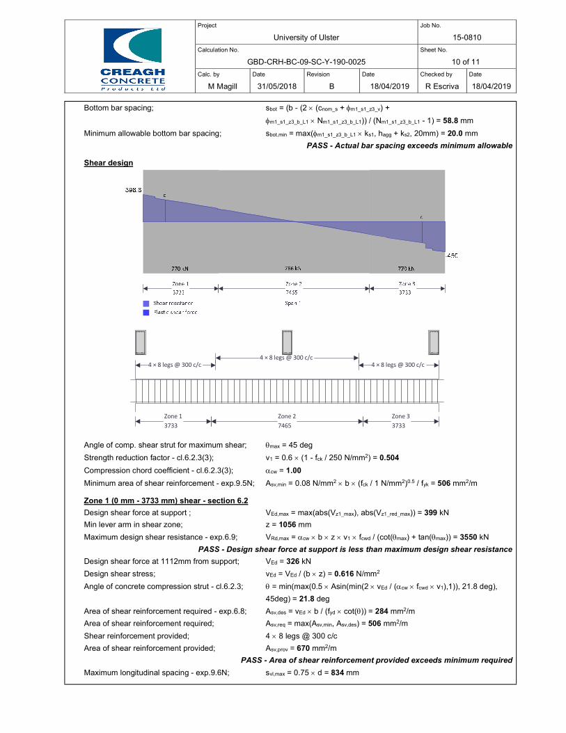
Project
University of Ulster
Job No.
15-0810
Calculation No.
GBD-CRH-BC-09-SC-Y-190-0025
Sheet No.
10 of 11
Calc. by
M Magill
Date
31/05/2018
Revision
B
Date
18/04/2019
Checked by
R Escriva
Date
18/04/2019
Bottom bar spacing; sbot = (b - (2 (cnom_s + m1_s1_z3_v) +
m1_s1_z3_b_L1 Nm1_s1_z3_b_L1)) / (Nm1_s1_z3_b_L1 - 1) = 58.8 mm
Minimum allowable bottom bar spacing; sbot,min = max(m1_s1_z3_b_L1 ks1, hagg + ks2, 20mm) = 20.0 mm
PASS - Actual bar spacing exceeds minimum allowable
Shear design
Angle of comp. shear strut for maximum shear; max = 45 deg
Strength reduction factor - cl.6.2.3(3); v1 = 0.6 (1 - fck / 250 N/mm2) = 0.504
Compression chord coefficient - cl.6.2.3(3); cw = 1.00
Minimum area of shear reinforcement - exp.9.5N; Asv,min = 0.08 N/mm2 b (fck / 1 N/mm2)0.5 / fyk = 506 mm2/m
Zone 1 (0 mm - 3733 mm) shear - section 6.2
Design shear force at support ; VEd,max = max(abs(Vz1_max), abs(Vz1_red_max)) = 399 kN
Min lever arm in shear zone; z = 1056 mm
Maximum design shear resistance - exp.6.9; VRd,max = cw b z v1 fcwd / (cot(max) + tan(max)) = 3550 kN
PASS - Design shear force at support is less than maximum design shear resistance
Design shear force at 1112mm from support; VEd = 326 kN
Design shear stress; vEd = VEd / (b z) = 0.616 N/mm2
Angle of concrete compression strut - cl.6.2.3; = min(max(0.5 Asin(min(2 vEd / (cw fcwd v1),1)), 21.8 deg),
45deg) = 21.8 deg
Area of shear reinforcement required - exp.6.8; Asv,des = vEd b / (fyd cot()) = 284 mm2/m
Area of shear reinforcement required; Asv,req = max(Asv,min, Asv,des) = 506 mm2/m
Shear reinforcement provided; 4 8 legs @ 300 c/c
Area of shear reinforcement provided; Asv,prov = 670 mm2/m
PASS - Area of shear reinforcement provided exceeds minimum required
Maximum longitudinal spacing - exp.9.6N; svl,max = 0.75 d = 834 mm
Zone 13733
4 × 8 legs @ 300 c/c
Zone 27465
4 × 8 legs @ 300 c/c
Zone 33733
4 × 8 legs @ 300 c/c
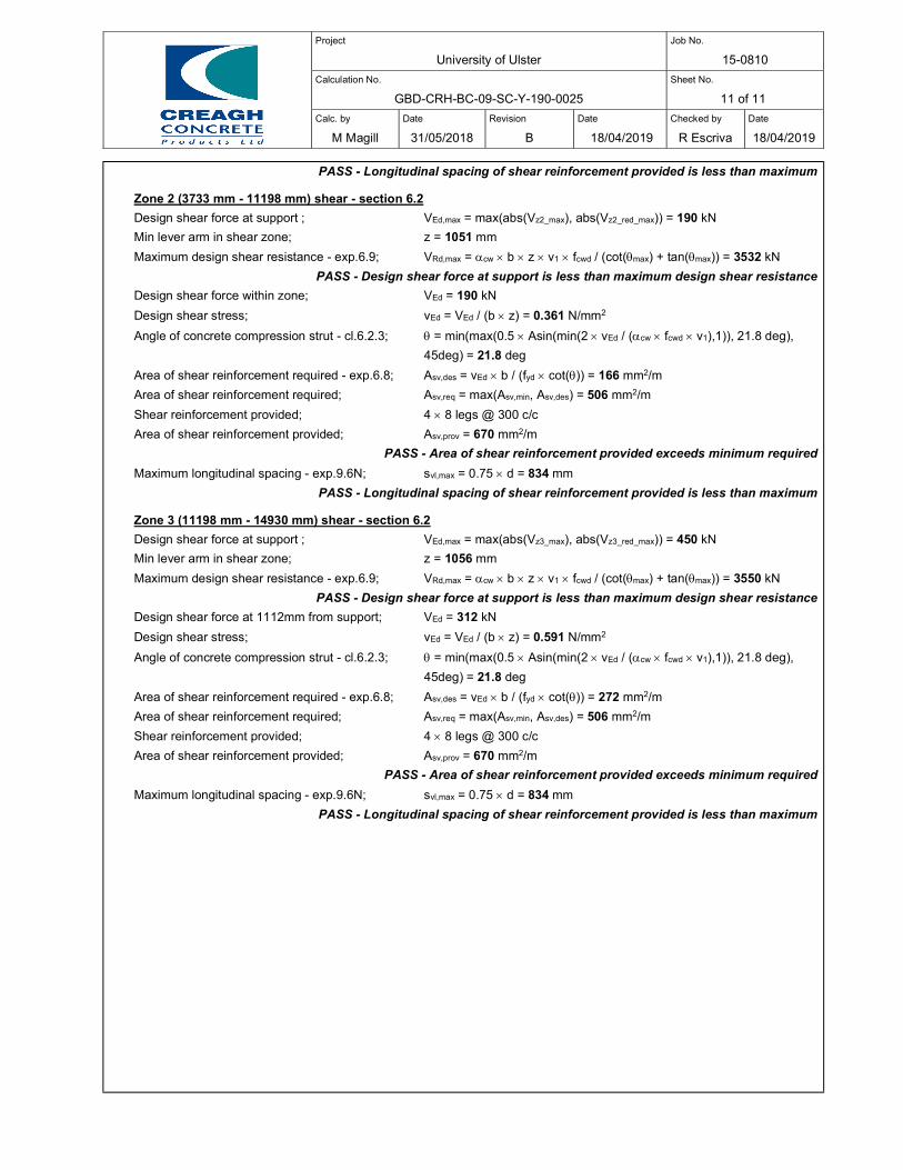
Project
University of Ulster
Job No.
15-0810
Calculation No.
GBD-CRH-BC-09-SC-Y-190-0025
Sheet No.
11 of 11
Calc. by
M Magill
Date
31/05/2018
Revision
B
Date
18/04/2019
Checked by
R Escriva
Date
18/04/2019
PASS - Longitudinal spacing of shear reinforcement provided is less than maximum
Zone 2 (3733 mm - 11198 mm) shear - section 6.2
Design shear force at support ; VEd,max = max(abs(Vz2_max), abs(Vz2_red_max)) = 190 kN
Min lever arm in shear zone; z = 1051 mm
Maximum design shear resistance - exp.6.9; VRd,max = cw b z v1 fcwd / (cot(max) + tan(max)) = 3532 kN
PASS - Design shear force at support is less than maximum design shear resistance
Design shear force within zone; VEd = 190 kN
Design shear stress; vEd = VEd / (b z) = 0.361 N/mm2
Angle of concrete compression strut - cl.6.2.3; = min(max(0.5 Asin(min(2 vEd / (cw fcwd v1),1)), 21.8 deg),
45deg) = 21.8 deg
Area of shear reinforcement required - exp.6.8; Asv,des = vEd b / (fyd cot()) = 166 mm2/m
Area of shear reinforcement required; Asv,req = max(Asv,min, Asv,des) = 506 mm2/m
Shear reinforcement provided; 4 8 legs @ 300 c/c
Area of shear reinforcement provided; Asv,prov = 670 mm2/m
PASS - Area of shear reinforcement provided exceeds minimum required
Maximum longitudinal spacing - exp.9.6N; svl,max = 0.75 d = 834 mm
PASS - Longitudinal spacing of shear reinforcement provided is less than maximum
Zone 3 (11198 mm - 14930 mm) shear - section 6.2
Design shear force at support ; VEd,max = max(abs(Vz3_max), abs(Vz3_red_max)) = 450 kN
Min lever arm in shear zone; z = 1056 mm
Maximum design shear resistance - exp.6.9; VRd,max = cw b z v1 fcwd / (cot(max) + tan(max)) = 3550 kN
PASS - Design shear force at support is less than maximum design shear resistance
Design shear force at 1112mm from support; VEd = 312 kN
Design shear stress; vEd = VEd / (b z) = 0.591 N/mm2
Angle of concrete compression strut - cl.6.2.3; = min(max(0.5 Asin(min(2 vEd / (cw fcwd v1),1)), 21.8 deg),
45deg) = 21.8 deg
Area of shear reinforcement required - exp.6.8; Asv,des = vEd b / (fyd cot()) = 272 mm2/m
Area of shear reinforcement required; Asv,req = max(Asv,min, Asv,des) = 506 mm2/m
Shear reinforcement provided; 4 8 legs @ 300 c/c
Area of shear reinforcement provided; Asv,prov = 670 mm2/m
PASS - Area of shear reinforcement provided exceeds minimum required
Maximum longitudinal spacing - exp.9.6N; svl,max = 0.75 d = 834 mm
PASS - Longitudinal spacing of shear reinforcement provided is less than maximum
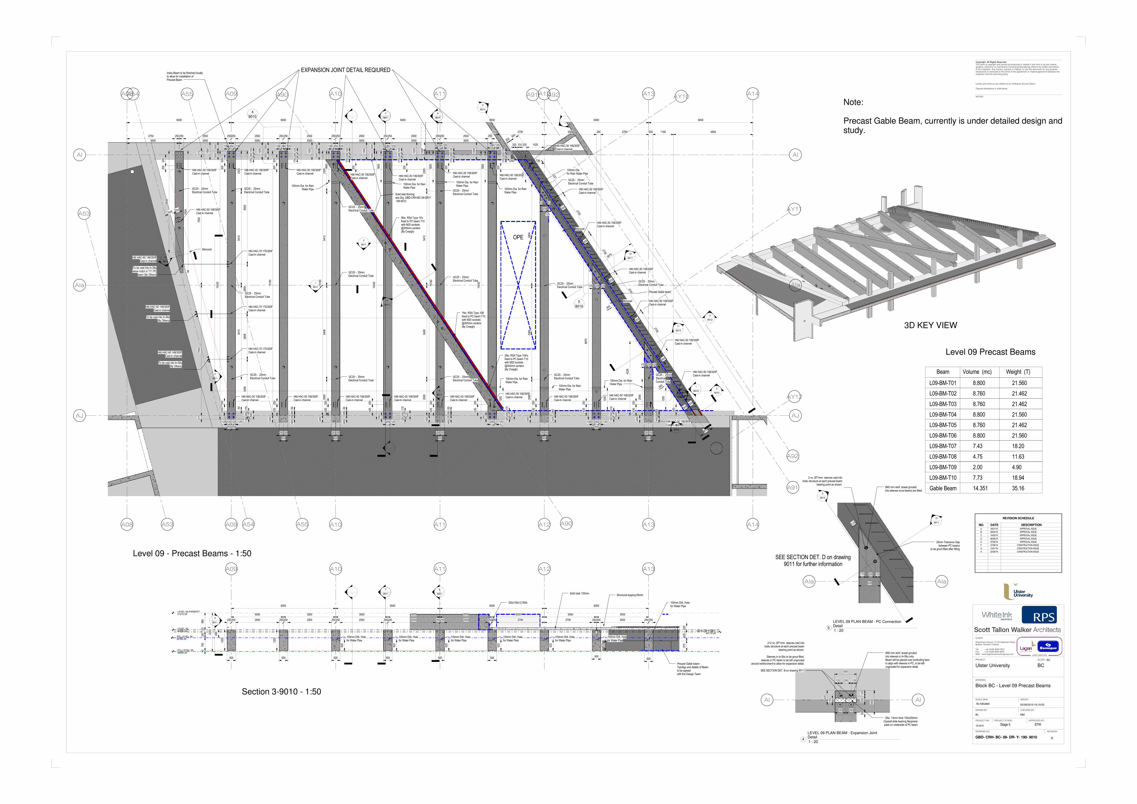
A92
A92
A91
A91
A90
A90
AJAJ
AIAI
AIaAIa
A08
A08
A09
A09
A10
A10
A11
A11
A12
A12
A13
A13
A14
A14
A53
A53
A54
A54
A55
A55AY10
AY12
AY12
AY11
-
---
-
---
-
---
1
9011
6000 6000 6000 6000 6000 6000
500
500
500
500
500
500
500
500
500
500
500
500
500
500
300
300
1000
1000
1000
1000
1000
1000
1000
1000
1543
0
1519
0
4226
8975
125 125 125 125
250250
125 250 125
500
250250
500
250250
500
250250
500
250250
500
250250
500
215
7500
7500
215
GC25 - 25mmElectrical Conduit Tube
GC25 - 25mmElectrical Conduit Tube
Insitu Beam to be Notched locallyto allow for installation ofPrecast Beam
OPE
Solid slab flooringsee Drg. GBD-CRH-BC-09-DR-Y-190-9012
250 2750 3000 250 2750 250 1185 4565
12
9011
3
9010
125 250 125 125 250 125 250125 125 250 125 250 125 250 125
175
200
125
500
175
200
125
500
175
200
125
500
175
200
125
500
175
200
125
175
200
125
175
200
125
175
200
125
175
200
125
175
200
125
5
9011
-
---
6
9011
7
9011
400
2526
050
400
285
50
400
2526
05050
100mm Dia. for RainWater Pipe
100mm Dia. for RainWater Pipe
100mm Dia. for RainWater Pipe
1800
250 125250 125
GC25 - 25mmElectrical Conduit Tube
GC25 - 25mmElectrical Conduit Tube GC25 - 25mm
Electrical Conduit TubeGC25 - 25mmElectrical Conduit Tube
GC25 - 25mmElectrical Conduit Tube
GC25 - 25mmElectrical Conduit Tube GC25 - 25mm
Electrical Conduit TubeGC25 - 25mmElectrical Conduit Tube
GC25 - 25mmElectrical Conduit Tube
-
---
5838
7004
Precast Gable beam
2750 250250 2500 250250 2500 250250 2500 250250 2500 250250 2500 250250 2500 250
3000 3000 3000 3000 3000 3000 3000
100mm Dia. for RainWater Pipe
1800
1800
1800
100mm Dia.for Rain Water Pipe
1585
1519
0
1543
0
240
1519
0
1543
0
240
400
400
400
400
400
260
2540
0
100mm Dia. for RainWater Pipe
100mm Dia. for RainWater Pipe
100mm Dia. for RainWater Pipe
1250
1250
1250
Hilti HAC-50 106/300FCast-in channel
Hilti HAC-50 106/300FCast-in channel
Hilti HAC-50 106/300FCast-in channel Hilti HAC-50 106/300F
Cast-in channelHilti HAC-50 106/300FCast-in channel
Hilti HAC-50 106/300FCast-in channel Hilti HAC-50 106/300F
Cast-in channel
Hilti HAC-50 106/300FCast-in channel
Hilti HAC-50 106/300FCast-in channel
Hilti HAC-50 106/300FCast-in channel
Hilti HAC-50 106/300FCast-in channel
Hilti HAC-50 106/300FCast-in channel
Hilti HAC-50 106/300FCast-in channel Hilti HAC-50 106/300F
Cast-in channel
Hilti HAC-50 106/300FCast-in channel
Hilti HAC-50 106/300FCast-in channel
2262 738
Hilti HAC-50 106/300FCast-in channel
Monorail
Monorail
Monorail
635
635
635
635
635
635
635
635
635
635
635
635
200
200
200
200
200
200
200
200
200
200
200
200
200
200
200
200
635 200
2875
3
9012
2
9011
Hilti HAC-50 106/300FCast-in channel
425
260
2305
5410
5410
2305
5412
5408
2065
2305
5412
5408
2065
5854
5365
2065
Hilti HAC-70 175/300FCast-in channel
Hilti HAC-70 175/300FCast-in channel
Hilti HAC-70 175/300FCast-in channel
Hilti HAC-60 148/300FCast-in channel
To be cast into In-Situbelow notch in T11 PC
beam (By Others)
Hilti HAC-60 148/300FCast-in channe
To be cast into In-Situ(By Others)
Hilti HAC-60 148/300FCast-in channel
To be cast into In-Situ(By Others)
3
9011
6505
2859
2608
3458
800
Hilti HAC-50 106/300FCast-in channel
Hilti HAC-50 106/300FCast-in channel
Hilti HAC-50 106/300FCast-in channel
Hilti HAC-50 106/300FCast-in channel
Hilti HAC-50 106/300FCast-in channel
Hilti HAC-50 106/300FCast-in channel
300500
170 205 125
170 205 125
GC25 - 25mmElectrical Conduit Tube
GC25 - 25mmElectrical Conduit Tube
300
300
300
300
300
300500
2700
2700
2700
2700
2327
1
9014
5
9014
-
---
600
205
125
EQ EQ
4
9014
9
9014
GC25 - 25mmElectricalConduit Tube
2065
5No. RSA Type 10'sfixed to PC beam T10with M20 sockets@300mm centers(By Creagh)
1No. RSA Type 10Bfixed to PC beam T10with M20 sockets@300mm centers(By Creagh)
2No. RSA Type 10A'sfixed to PC beam T10with M20 sockets@300mm centers(By Creagh)
4
9012
11
9014
12
9014
320 310 225 1025
GC25 - 25mmElectrical Conduit Tube
4
9010
EXPANSION JOINT DETAIL REQIURED
5
9010
A09 A10 A11 A12 A13
LEVEL 0940230.00 LEVEL 09 PLANT
40110.00
LEVEL 09 PARAPET41210.00
SSL LEVEL 0939780.00
FCL LEVEL 0838990.00
-
---
-
---
980
120
330
750
40
2220
1200
1200
6000 6000 6000 6000
450
3000 3000 3000 3000 3000 3000 3000 3000
Solid slab 135mm
6
9011
7
9011
100mm DIA. Holefor Water Pipe
625
100mm DIA. Holefor Water Pipe
625
100mm DIA. Holefor Water Pipe
625
100mm DIA. Holefor Water Pipe
625
100mm DIA. Holefor Water Pipe
625
100mm DIA. Holefor Water Pipe
625
100mm DIA. Holefor Water Pipe
Precast Gable beam -Typoligy and details of Beamto be agreedwith the Design Team
225
625
575
Structural topping 65mm
250250 2500 250250 2500 250250 2500 250250 2500 250250 2500 250250 2750 2750 250250 2500 250250
500 500 500 500 500 500 500500
200x150x12 RSA
3
9011
AIAI
500
125 250 125
5012
520
0
550
325
2+2 no. Ø71mm sleeves cast intoinsitu structure at each precast beam
bearing point as shown.
Sleeves in In-Situ to be grout filled,sleeves in PC beam to be left ungrouted
around reinforcment to allow for expansion detail.
SEE SECTION DET. B on drawing 9011
Ø40 mm reinf. dowel groutedinto sleeves in In-Situ only.Beam will be placed over protruding barsto align with sleeves in PC, to be leftungrouted for expansion detail
2No. 14mm thick 100x250mmCiparall slide bearing Neoprenepads on underside of PC beam
100
250 250
AIaAIa
12
9011
5
9014
2 no. Ø71mm sleeves cast intoinsitu structure at each precast beam
bearing point as shown.Ø40 mm reinf. dowel groutedinto sleeves once beams are fitted
25mm Tolerance Gapbetween PC beams
to be grout filled after fitting
170 205 125
500
125
SEE SECTION DET. D on drawing9011 for further information
NOTES:
Copyright. All Rights Reserved.This work is copyright and cannot be produced or copied in any form or by any means(graphic, electronic or mechanical including photocopying) without the written permissionof the originator. Any license, express or implied, to use this document for any purposewhatsoever is restricted to the terms of the agreement or implied agreement between theoriginator and the instructing party.
Levels and contours are relative to an Ordnance Survey Datum
Figured dimensions in millimetres.
DRAWING
PROJECT NO.
REVISION
SCALE @A0
DRAWING NO.
PROJECT
CLIENT
ISSUED:
DRAWN BY: CHECKED BY:
PROJECT STAGE: APPROVED BY:
Rosemount House, 21-23 Sydenam Road,Belfast, Northern Ireland
Tel: +44 (0)28 9045 5531Fax: +44 (0)28 9045 8940Web: www.laganconstructiongroup.com
BLOCK:
02/08/2019 16:19:53
Ulster University BC
Block BC - Level 09 Precast Beams
15-810
GBD- CRH- BC- 09- DR- Y- 190- 9010
BL MM
BC
Stage 5 STW
H
Level 09 Precast Beams
Level 09 - Precast Beams - 1:50
3D KEY VIEW
Section 3-9010 - 1:50
A 16/01/19 APPROVAL ISSUE
REVISION SCHEDULE
NO. DATE DESCRIPTION
As indicated
B 09/04/19 APPROVAL ISSUE
Note:
Precast Gable Beam, currently is under detailed design andstudy.
Beam
L09-BM-T01
Volume (mc) Weight (T)
L09-BM-T02
L09-BM-T03
L09-BM-T04
L09-BM-T05
L09-BM-T06
L09-BM-T07
L09-BM-T08
L09-BM-T09
8.800
8.760
21.560
21.462
7.43 18.20
4.75 11.63
2.00 4.90
8.760 21.462
8.800 21.560
8.760 21.462
8.800 21.560
L09-BM-T10 7.73 18.94
C 14/05/19 APPROVAL ISSUE
Gable Beam 14.351 35.16
D 06/06/19 APPROVAL ISSUE
E 07/06/19 APPROVAL ISSUE
F 27/06/19 CONSTRUCTION ISSUE
G 15/07/19 CONSTRUCTION ISSUE
1 : 204
LEVEL 09 PLAN BEAM - Expansion JointDetail
1 : 205
LEVEL 09 PLAN BEAM - PC ConnectionDetail
H 02/08/19 CONSTRUCTION ISSUE
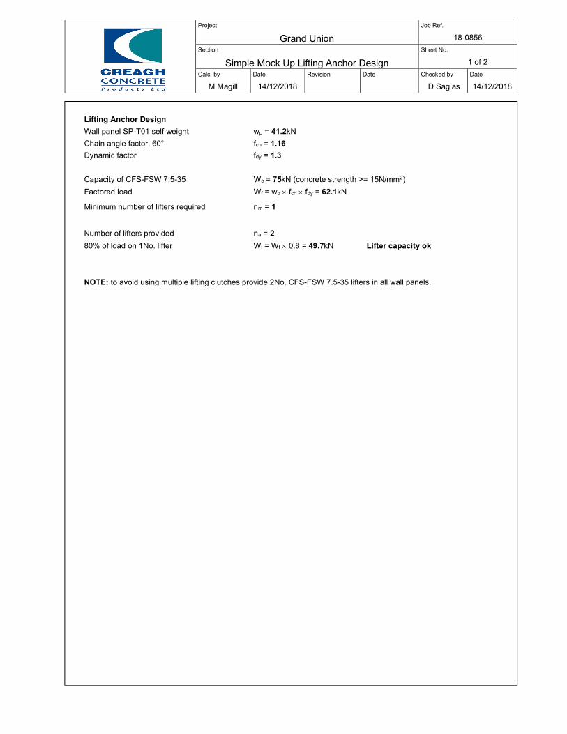
Project
Grand Union
Job Ref.
18-0856
Section
Simple Mock Up Lifting Anchor Design
Sheet No.
1 of 2
Calc. by
M Magill
Date
14/12/2018
Revision
Date
Checked by
D Sagias
Date
14/12/2018
Lifting Anchor Design
Wall panel SP-T01 self weight wp = 41.2kN
Chain angle factor, 60° fch = 1.16
Dynamic factor fdy = 1.3
Capacity of CFS-FSW 7.5-35 Wc = 75kN (concrete strength >= 15N/mm2)
Factored load Wf = wp fch fdy = 62.1kN
Minimum number of lifters required nm = 1
Number of lifters provided na = 2
80% of load on 1No. lifter Wl = Wf 0.8 = 49.7kN Lifter capacity ok
NOTE: to avoid using multiple lifting clutches provide 2No. CFS-FSW 7.5-35 lifters in all wall panels.
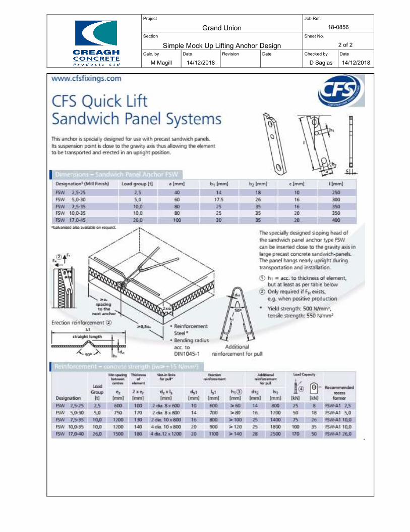
Project
Grand Union
Job Ref.
18-0856
Section
Simple Mock Up Lifting Anchor Design
Sheet No.
2 of 2
Calc. by
M Magill
Date
14/12/2018
Revision
Date
Checked by
D Sagias
Date
14/12/2018
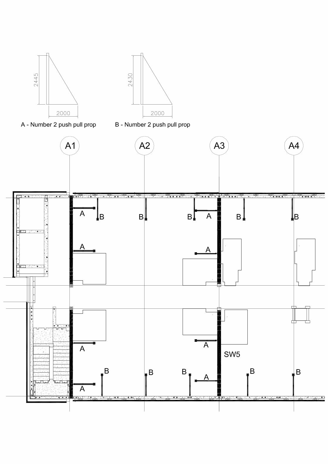
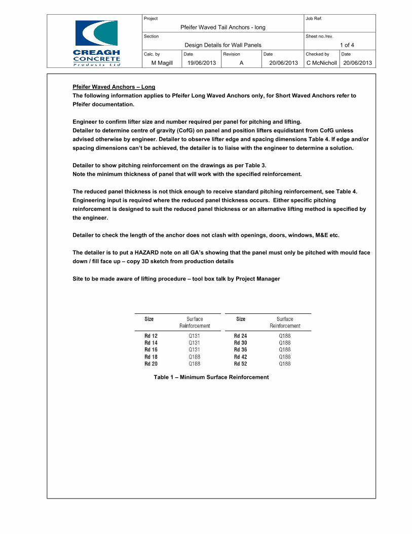
Project
Pfeifer Waved Tail Anchors - long
Job Ref.
Section
Design Details for Wall Panels
Sheet no./rev.
1 of 4
Calc. by
M Magill
Date
19/06/2013
Revision
A
Date
20/06/2013
Checked by
C McNicholl
Date
20/06/2013
Pfeifer Waved Anchors – Long
The following information applies to Pfeifer Long Waved Anchors only, for Short Waved Anchors refer to
Pfeifer documentation.
Engineer to confirm lifter size and number required per panel for pitching and lifting.
Detailer to determine centre of gravity (CofG) on panel and position lifters equidistant from CofG unless
advised otherwise by engineer. Detailer to observe lifter edge and spacing dimensions Table 4. If edge and/or
spacing dimensions can’t be achieved, the detailer is to liaise with the engineer to determine a solution.
Detailer to show pitching reinforcement on the drawings as per Table 3.
Note the minimum thickness of panel that will work with the specified reinforcement.
The reduced panel thickness is not thick enough to receive standard pitching reinforcement, see Table 4.
Engineering input is required where the reduced panel thickness occurs. Either specific pitching
reinforcement is designed to suit the reduced panel thickness or an alternative lifting method is specified by
the engineer.
Detailer to check the length of the anchor does not clash with openings, doors, windows, M&E etc.
The detailer is to put a HAZARD note on all GA’s showing that the panel must only be pitched with mould face
down / fill face up – copy 3D sketch from production details
Site to be made aware of lifting procedure – tool box talk by Project Manager
Table 1 – Minimum Surface Reinforcement
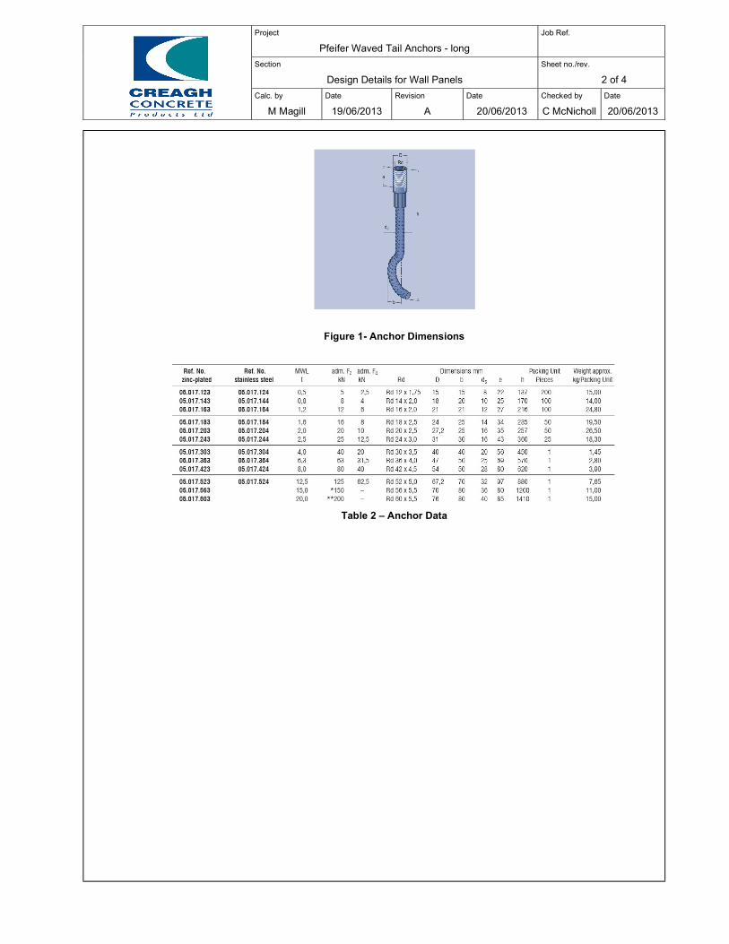
Project
Pfeifer Waved Tail Anchors - long
Job Ref.
Section
Design Details for Wall Panels
Sheet no./rev.
2 of 4
Calc. by
M Magill
Date
19/06/2013
Revision
A
Date
20/06/2013
Checked by
C McNicholl
Date
20/06/2013
Figure 1- Anchor Dimensions
Table 2 – Anchor Data
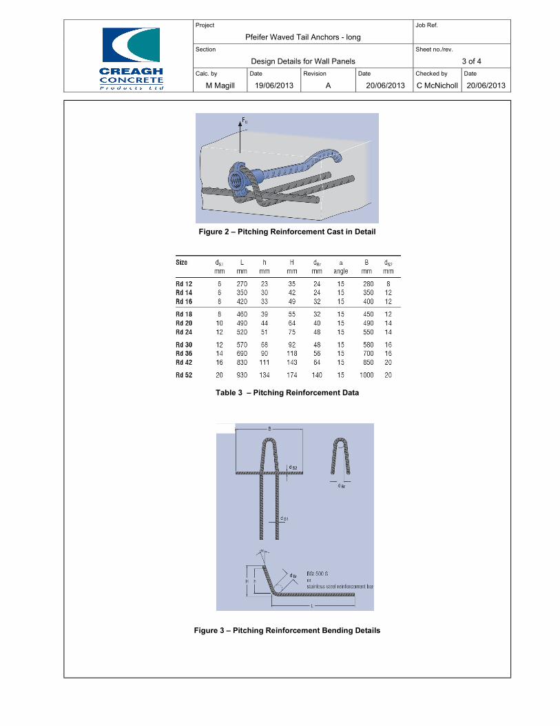
Project
Pfeifer Waved Tail Anchors - long
Job Ref.
Section
Design Details for Wall Panels
Sheet no./rev.
3 of 4
Calc. by
M Magill
Date
19/06/2013
Revision
A
Date
20/06/2013
Checked by
C McNicholl
Date
20/06/2013
Figure 2 – Pitching Reinforcement Cast in Detail
Table 3 – Pitching Reinforcement Data
Figure 3 – Pitching Reinforcement Bending Details
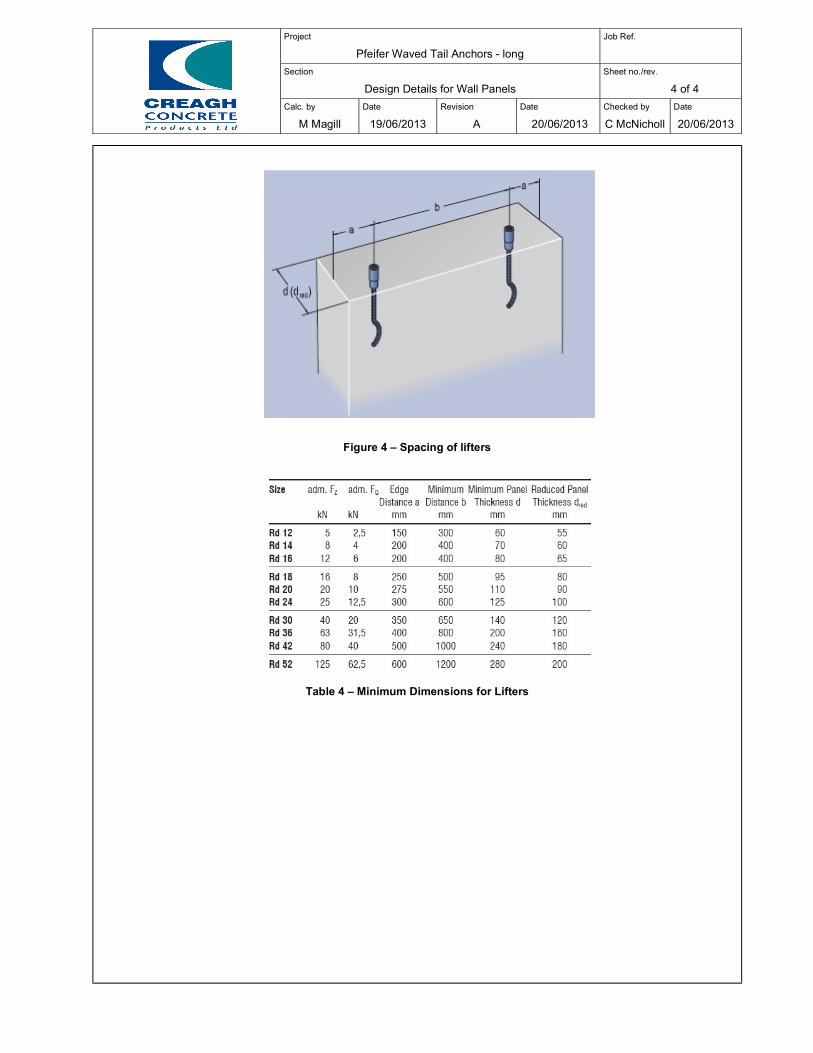
Project
Pfeifer Waved Tail Anchors - long
Job Ref.
Section
Design Details for Wall Panels
Sheet no./rev.
4 of 4
Calc. by
M Magill
Date
19/06/2013
Revision
A
Date
20/06/2013
Checked by
C McNicholl
Date
20/06/2013
Figure 4 – Spacing of lifters
Table 4 – Minimum Dimensions for Lifters