precast rrtdge girders
TRANSCRIPT
- 1
\
..
•
BEHAVIOR PRECAST RRTDGE GIRDERS.
T. Tschanz
,
(
, '
-_ ..... _----~~--~ - -
, " '1,
.,
,

l-
..
. -BEHAVIOR'OF OJ'EN WEB PRECAST BRIDGE GIRDERS
r -ANALYT!CAL_STUDY
-.
\ ",1 'oi
\ ,\
, by "-; .-'\ l'
Tony Tsehq.nz , -
..
1
• • A thesis submitted to the Faeulty of Graduate Studies
and Research in partial fulfillment of the requirements for the degree of
~ . Masters of Engineering
)
MeGi1! University" Montreal, Canada
Auqust 1974
(ê)' Tony Tschang 1975
/
"
o n
.'
.~
1
\
, , 'f
l -1 ' . -
il
'{
" ,
Ta
,4~i.1 fe Linda , " 4
c
•
"
' ..
..
\
-
.. 1
!
COMPORTEMENT D'UN PONT FAIT DE POUTRES PREFABRIQUEES' A
A AME OUVERTE--ETUDE ANALYTIQUE , .
• Tony Tschanz
Département de Gên2Ji'e "lvil et de M~canlque Appli uée
M.Eng. August 1974 - -
RESUME
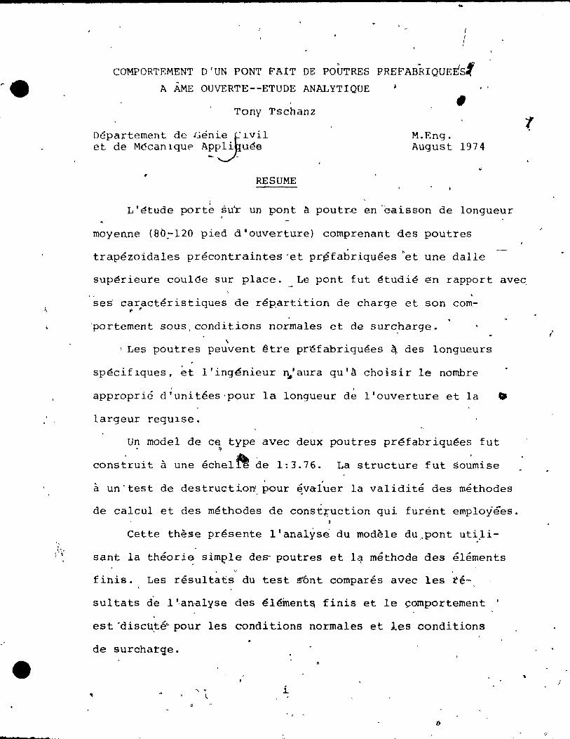
. L'étude porte su'r un pont à poutre en -c-aisson de longueur
moyenne (Bb~120 pied d'ouverture) comprenant des poutres
trapézoidales précontraintes "et pr~fabriquées 'et une dalle
supérieure coul~e sur place. Le pont fut étudié en rapport aveq
. ses car,actéristiques de répartition de charge et son com-t'
'portement sous,conditions normales et de surcharge. \
! Les poutres peuvent être préfabriquées ~ des longueurs
spéciflques, et l'ingénieur ~'aura qu'à choisir le nombre / .
approprié d'unitées'pour la longueur de l'ouverture et la •
largeur requ1se.
Un model de c~ type avec deux poutres préfabriquées fut ~)
construit à une échel~ de 1:3.76. La structure fut soumise
~ un'test de destructio~~our ~vaiuer la validit~ des méthodes
de calcul et des méthodes de construction qui furént employées.
Cette thèse présente l'analyse du modèle dU,opont utiJi
sant la théori~ sim~le de~ poutres et lq méthode des éléments
finis. Les résultats du test sônt comparés avec les té-
sul tats d'e l ',an-alyse des éléinent& finis et le çomportement .
est 'discu,té~ pour les conditions normales et les conditions
de surchat:'qe.
" . , , i
1 /
4
" ,
.' . ,
, . ,\ , \
~
BE~l\VIOR OF:' OPEN WÈB PRECAST BRIDGE GI~ERS--ANALYTICAL STUDY
.,; Tony Tschanz
Departm~t uf Clvi1 Engineering . '. . and Applled Mechanlcs
! ABS'TRACT
\,
M.Eng. August 1974
/ .
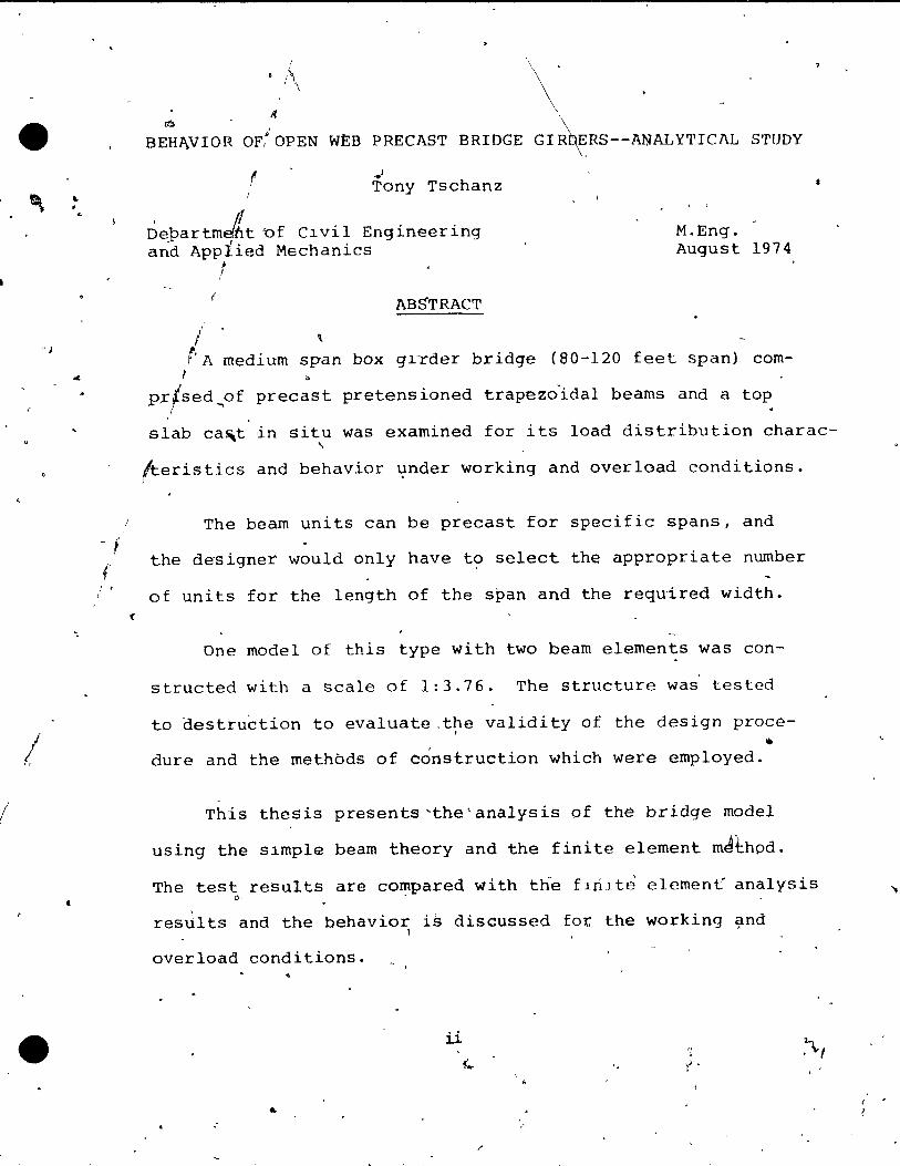
1 A medium sp~n box grrder bridge (80-120 feet span) comt b
p~/sed~of precast pretensioned trapezoida1 beams and a top r
slab ca!i\t in situ was examined for its load distribution char ac-, tteristics and behavior ~nder working and overload conditions.
The beam units can be precast for specifie spans, and
the designer would on1y have to select the appropriate number
of units for the 1ength of the span and the required width.
One model of this type with two beam e1ements was con-
structed with a sca1e of 1:3.76. The structure was tested
to destruction to eva1uate ,the va1idity of the design proce-. .. dure and the methbds of construction which were employed.
This thesis presents'the<analysis of the bridge model
using the slmpl~ beam theory and the finite element mJ~hpd.
The test results are co~pared with the flnlte element analysis 0-
resGlts and the behavior is discussed fot the working ~nd l
overload conditions.
il
.. /

" '
,1 , ,
r
~CKNOWL~DGEMENTS
The work presented in this thesis was carried out under
the direction of Prof~ S.M. Mirza, to whom the author wishes G
to express hiS deepest gratitude for the constant encourageL
ment and guidance during the course of thiS study.
1
~he finaneial assIstance came from'the Depar~enb of
Education of'- the GOvernment of Qu~beg, and the National
Research Couneil of Canada isTalso gratefully acknowlêdged. , The author wouid aiso Ii~e to thank Mr. Roque C6rdoba
. for his cooperation in this joint project, as weIl as the
technicians of the structures laboratory of McGill University,
who activel~ he~ped ta overcome the vast amount of manual
w6rk neeessar~ te complete 'this prej~et.·
Thanks are aiso due to Mr. Ronald Girardeau for the
assistance in the practical aspects of bu'ilding thlS model ( , "
as ,weIl as Dr. R. Tlnawi for use of ~is finite element com-
puter program.
Thanks are also due to Ms. Joanne Lemon for her patience
and excellent typlng of this tnesis. \
\ ,
The author would also like to thank Dr. A. Alam and ~he fellow qraduate students in the Civil Engineeri~g Depa~tme~t
at McGill University for providing excellent forum$, for dis-
cussion and valuable constru,tive eriticisrn. "-"-,
\ , iii \ p ,
J
••
~
"
., d
2
. , 1\
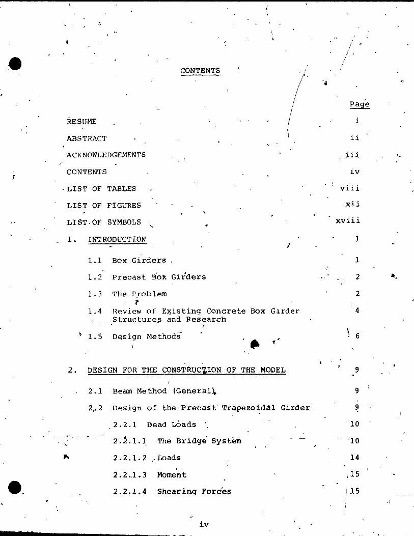
CONTENTS
RESUME
ABSTRACT
ACKNOWLEDGEMENTS
CONTENTS , )
. LIST OF TABLES
LIST OF FIGURES
LIST,OF SYMBOLS "- ..
1. INTRODUCTION
1.1 Bqx Girders
1.2 precast Box Girders
1.3 The PFoblem , :r
1.4 Review of E~isting Concrete Box G1rder Structure$ and Research
'1.5 D~sign Methodi
2. DESIGN FOR THE CONSTRUCtION OF THE MODEL
2.1 Bearn Method, (General\.
1
/
2 •• 2 Design of the Precast' Trapezoidâ1 Girder'
2 . 2 . 1 Dead Loads "
, 2'. ~ .-1.1 The Br ldge System
2.2.1. 2 " Loads ,
2 • 2 .,1 • 3 Momen t
2 • 2 .1 • 4 'Shear ing Forces
.. iv
ri (,
page
i
ii
iii . ~
iv 1 viii ,.
xii
xviii
1
1 -!
2 • . 2
4
\ 6
9
9
9
'10
,
, ,
t
"
,
" , .
\
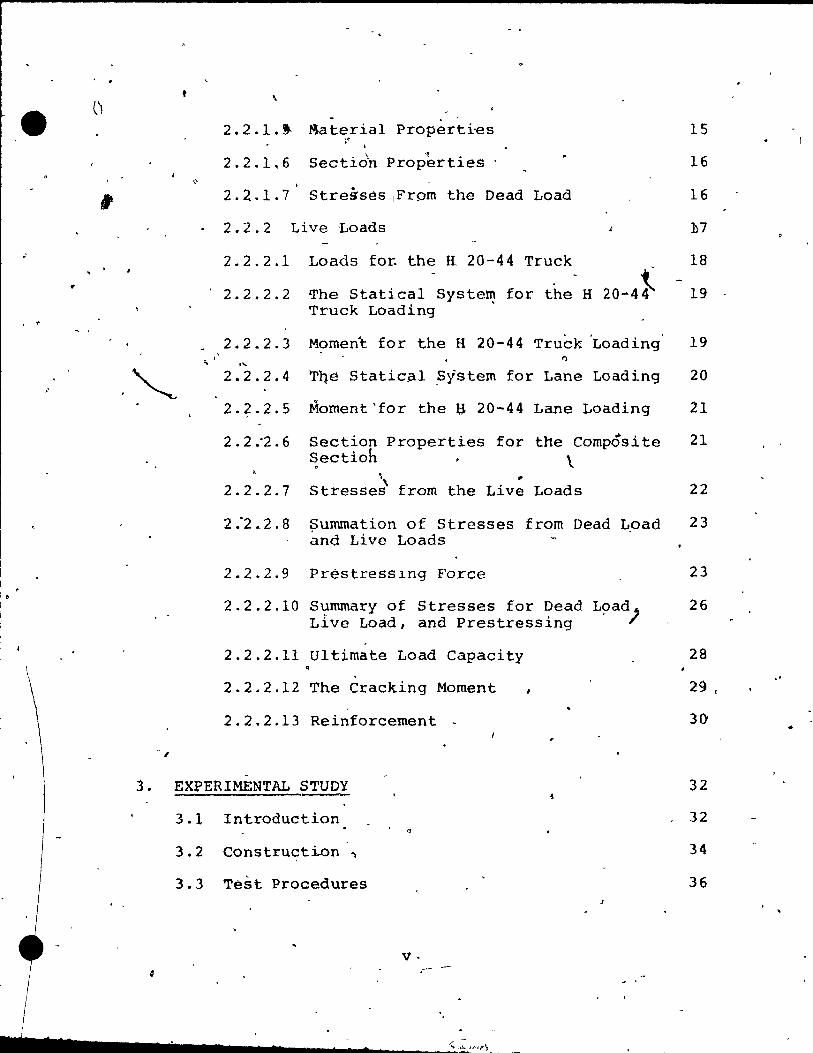
-2.2.1. J. Materia1 Properti'es
• 2.2.1.6
. \ ~. Sectlon Propertles .
2.Z.1.7 Stresses IFrom the Dead Load
2.2.2 Live Loads
Loads fot the K 20-44 Truck
The Statical System for the H 20-4~ Truck Loading .
2.2.2.1
2.2.2.2
2.2.2.3 Momen~ for the H 20-44 Truck 'Loading' .'-
2.2.2.4
2.2.2.5
2.2 :2.6
2.2.2.7
2.2.2.9
Q
Tqé Static~l ?ystem for Lane Loading
Mornent'for the U 20-44 Lane Loading
Section Properties for the Cornpôsite Sectioh . \
I>t, " Stresses from the Live Loads
Summation of Stresses from Dead 40ad ànd Live Loads
Préstresslng Force
2.2.2.10 Summary of Stresses for Dead L~ad) Live Load, and Prestressing
2.2.2.11 u1tirnate Load Capacity .
2.2.2.12 The Cracking Moment
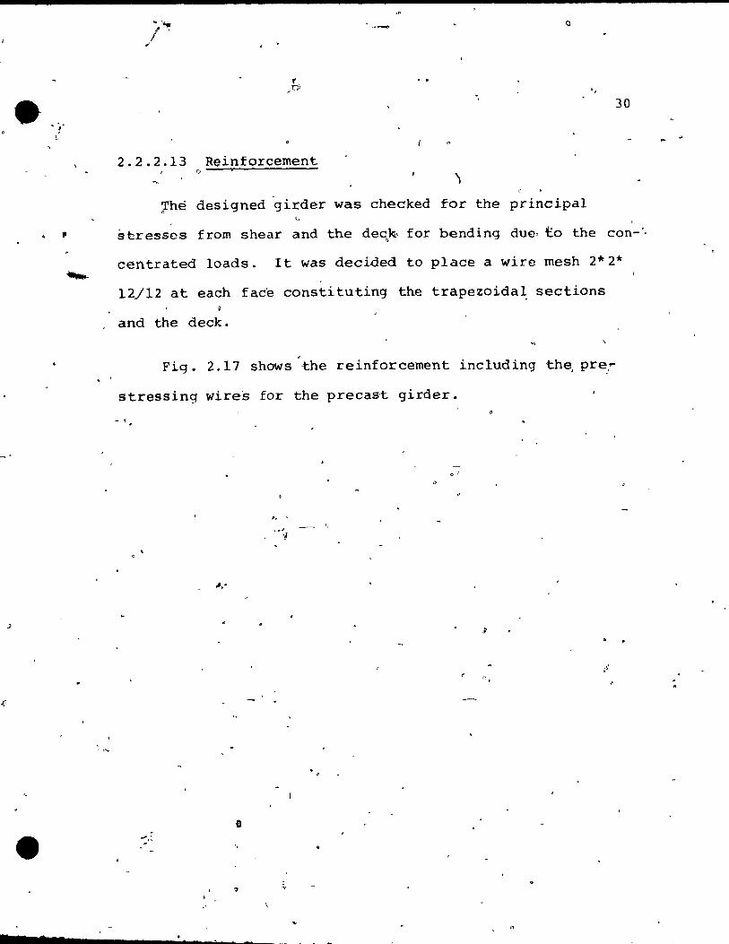
2.2.2.13 Reinforcernent .
-3. EXPERIMENTAL STUDY
3.1 Introduction "
3.2 Construction ~
3.3 Test Procedures
v·
15
16
16
17
18
19
19
20
21
21
22
23
23
26
28
29 , .'
30 ..
32
32
34
36
.-
\. ,
1
1 •
J
~ • "
1"
1
t 7 7
,,,.
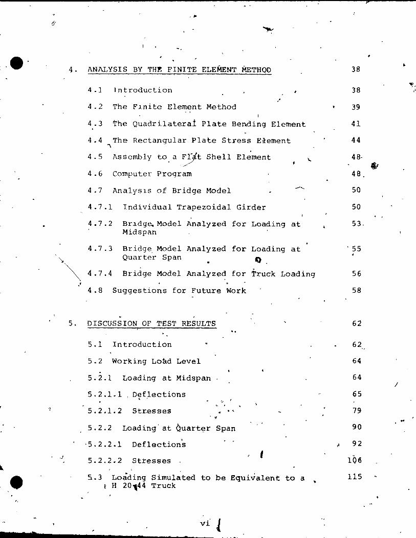
4 . ANALYSIS BY TH~ FINITE ELEMENT METHOD
4 .1 Introduction .. 1 ,
4 .2 The F1nite Element Method f
4 .3 The Quadrilatera1 Plate Bending Element ,
4.4 The Rectangular Plate Stress E~ement "\
4 . 5 Assembly to. a F~t Shell Element ..... o ___
4.6 Computer program
4 .7 Analysls of Bridge Model .........
4 .7 .1 Individual Trapezoidal Girder
4.7 .2 Br ~dge.. Model Analyzed for Loading at Midspan
4.7 .3 Br idge, Madel Analyzed for Loading at Quarter Span O. ..
~ 4 .7.4 Bridge Model Analyzed for Truck Loading t
4.8 Suggestions for Future Work
5. DISCUSSION OF TEST RESULTS "
5.1 Introduction
5.2 Working Load Level .
5.2.1 Loading at Midspan
5.2.1.1 Deflections ,
5.2.1.2 Str.esses ., ... . ..
5.2.2 Loading at èuart~r Span
'5.2.2.1
5.2.2.2
Deflection"s
Stresses t
5.3 Loâding Simulated to be Equivalent to a R H 20144 Truck
vi l Cl
38
38
39
41
44
48·
48.
50
50
53.
. 55
56
58
62
62
64
64
65
79
90
92
lQ6
115
?
..
'Ii, ,l~
.' ..
/

~
~
e \1
"
5 . .3 .1 Truck Loads for Working and Overload Level 116
5.3.1.1 Def1ections 116 ..
5.3.1.2 Stresses 12.1
5.3.2 U1tirnate Load Test 124
5.3.,2.1 Cracking Behavior 125
5.3.2.2 Failure -~ 126 ,
6. OTHER PRACTICAL CONSIDERATIONS 136
7. CONCLU~IONS 139 .,. 1"
REFERENCES 142
APPENDIX A' . " 144
- 1
..
'/
"
• 'Vii'
...... ------_?--~~.------
e
2
"
. .
~
S
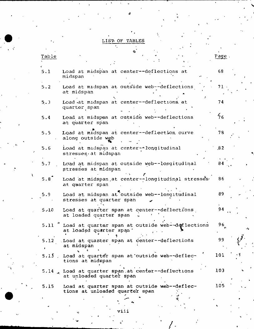
LIST~ OF TABLES
Table
5.1 Load at mids~~n at center--deflections at midspan
,
5.2 Load at m1dspan at outside web--defflections at midspan ...
, , ~.3 Load .at m~dspan at center--deflect1ona at
quarter,span
5.4 Load, at mids~en at outside web--deflections at quarter span
,lia • 5.5 Load at midspan at center--deflect~on curve
5.6
5.7
along .outslde w,b
Loao at m1dsp~n at center-~!ongitudinal stresse~,at rnidspqn
Laad at midspan at outside ~~b--longitudi~al ?tresses at midspan
, ,
-'
"
5.8 • F
Loa.d 'a t midspan. at center-:--long i tudinp.l stress~s' at q~arter span
.. • 0
5.9 Load at midspan at'outside web--long1tudinal
5.·Hl
stresses at quarter span ~ 0
Load at quarter span at center--deflections at loaded quarter span '"
5.11 r:- Load at quartar span at at l-oad~d qu.!rter spqn·
outside ~eb~-d~lections >' ,
~ ..., " '
5.12 .Load at qua~ter span at center--ùeflections at midspan .
~ -5.1.§' _ Load at quartér span at·outside web--deflec-
tions at rnidapan
5.14 Load at quarter spa;,at-c~nter--defl~c~1ons ". at unloaded qua.rtel- span .
5.15 Load at quarter span at outside w.eb- ... deflec-tions at unloaded quarter span "
~ , d ,."~
.. 'w, ~
0 ....
-jj viii
" 1 '4 (j ;. ,
Page.
68
'lI -
74
16
78 " .
,82 .. 84 -\ .
86
89
94 ...
96 0' '<\
99 'r
'- 1· f .
101 . ~
103 ...
105 " . .,

.
. .
",
t
5.16
5.17
~.18
5.19
5.20
5.21 ..
! , , 0
'.
Load at quartE!r Dsp~n at 'out~lde web of 'inside box-~def1edt~Gn curve atQng nutside web
" ~ " t ... l j;;.
Load at 'qudrter&span at outslde web~of outslde b.ox--defl cc-tion curvc â10ng outsidp· web , . i
Y ""f; e>
Load at quarter~span at outslde w~--stresseq at toaded quarter span
Q /;l ... l
Load at·quarter span at outslde web--stresses a t ruds pan ,
• Slml.llated truck load of 10 kips-"",de~l·ëctlons. at midspan
Simu1ated truck'1oad of ~5 kips--def1ections at ml.dspan
106
110
112
114
118
120
~. 22"., Slmu1ated truck load of 10 kips--stresses at,' 123
A-l
A-2.
A-J
A-4
A-5
A-6
A-7
A-8
A-9
'l,
A-IO
i~
mld~pan A
Load at mldspan at lnslèe web--deflections at mldspan
• Loan at m.ldspar\at O~cnter of 'box--deflectlons at midspan.
& ~ 10ad at mldspan at inside wep--deflections at'. , quarter span ~
Load at midspan at éenter of box--def1ectjons, at (,quarter span
Load at midspan at inrler web--deflections along outside web
Load at mid~Ran at tenier of bo~--defrections "~long outside web . ,
Load at midspan at outer web--deflections a}ong outslde web ..
" Load at midspan at inside web--st~esses at mids~an " /' c'
Load at midsppn at center of box--stre~ses at midspan
A, "'1
Load at mïdspa~ at insi~e ~eb--stresses at quarter span' ...
?'"' i.x ; "1
•• ~ 0 • ..... '"
146
14~
150
152 \
154
156
158
160
162
Q
164
.. .
1
( • 1
,
,.
'" .

..
"
Q ...... ' .
. A-Il Load' at midspan at cen'ter of box.--stresses
at quarter span •
A-12 LQad at quarter span at inside web--def1ectious at loaded quarter span'
A-13 'Load at quarter span at ce~ter of box--def1ec-
A-14
A-15
tions at loaded quarter span ~ ,
LOpd at quarter span at inslde web--def1ectlons at midspan
Load at quarter pan at center of box--deflectians 1 a t midsPi:
166
1'68
170
172
174'
A-16 Load at quarter span at inside web--def1ect~ons 176 at un10aded quarter span
, A-17. Load at quarter span at center of box--def1éc- 178
A-18
\.
A-19
A-20
A-21
A-22
A- 2:t
A-24
A-26
A-27 "
tions at unloaded quarter span .
Load at quarter ~pan at center of inside box-def1ections alohg outside web
Load at quarter span at inner web of inside box--def1ections.along outside web
Load dt qua~ter span at ce~ter--deflections along outside web
Load at quarter" span at inner web of outside bQx--deflections along outside web , "
Load at quarter span at center of outside box-def1ections along Qutside web
Load at quarter span at center--stresses at loaded quarter span
Load a~ g~arter span ,at inside web--stresses at loadea quavter span
Load at quaSfer span at center of bo~--stresses at loaded q4arter span
. ' Load at quartèr sp~n at center--stresses at midspan
Loàd at quarter ~pan-at inside web--stressés at rni,9span
x t
182
184
186
188 ,)
190
192
194
196 ...
198
•• __ c_ .. c _______ ~ __ ~
o ,~.
Ci

A-28
A-29
A-30
'A-31
A-32 .
A-33
A-34
A-35
A-37
• A-3e
•
\
Load at quarter span at center of .bax-stresse.s at midspan Q
Load at quarter. span at center--stresses at unloaded quarter spa~
, .
Load at quarter span at inside web-~stresses at unloaded quarter span
. Load at ~uarter span at center of box--stresses at unloaded quarter span
Load at quarter span at outside web--stresse~ at unloaded quarter span
À .... .
Simulated truck load of 5 kips--def1ections at midspan "
200
202
204
206
208
210
Simulated truck load of 5 kips--deflections a1ong' 212 outside web .
Simulated truck load of 10 k±ps--deflections along outside web
214
Simulated truck load of 15 k'ips--deflections along216 , outside web
simulated truck load of 5 kips--stresses at midspan
Simulated truck load of 15 kips--stresses at midspan
\
xi
21"8
220
......... ________ ~_c __ ~

•
"
• 7
, 1 . Fl.gure
1.1
t 1.3
'" 1 . 4
2.1
2.2
2.3
2 . 4,
2.5
2.6
2.7
2.8
'2.9
2.10
2.11
2.12
2.13
2.14
LIST OF FIGURES
Typical standardiz~d prefabrl.cated beam sectl.ons
Isometrl.c view of ,the box girder bridge model
Cross section of the Parkhausbrüke
A view of~construction of the Parkhausbrüke
Prototype cross section
Model cross section
-Girder cross section for the mode1.
The bridge system
The section properties'
Dead load stresses
o
- The loads of H 20-44"truck tor the mode1
The statica1 system for the H 20-44 truck loading
Section properties for the composite section ~ . Live load stresses
Summation of the stresses for dead and live load
1
Kern points for the trapezoidal section
Required prestressing forces and locations •
-Stresses résulting frqm the prestFessing force
xii
..
3
7'
7
11
12
13
14
16
17
18
19. \,
22
22
23
24
25
26
')
"
Fl.gure
LI
2.15 i,
2.1e' ,
"" 2.17
3.1
4 .1
4.2
4 • 3
4.4
4.5
4.6
4.7
4.8
• 1 4 • 9
5,.1
5.2
5.3
5.4
, -,
..., 5.5
•
, ,
Stresses at midspan 27 f'
Stresses at quarter span for the dead load 27 and prestressing'force
Reinforcement for the prec~st girder 31
A view ci the instrurnented model 37
The plate bending element 42
The triangular element 43
The plane stress rectangular element 46
PolynomL~als for the rectangular plane 47 s~ess element
.. ; B"èctangular shetl element Witt! 32 degrees 49 of freedom ( 1 ......., Finite e1ement tdealization of single 52 trapezoidal girder
Finite élement idealïzation of the model 54 for a load at midspan
-Finite element idealization for truck load 57
Proposed numbering system to reduce the 60 bandwidth
A representative stress-strain ~elation 63 for concret,r-
Typical representation of results from ~ests p~ and analysis
Load at midspan at center--deflections at 67 midspan
Load at.midspan at outside web--deflections 70 at midspan
Load at midspan at center--drfle~ions_at 73 quartér span
xiii
.......... ------~~.--~~

Flgure
5.6
5.7 • '1
5.8
5.9
5.10 (
5.11
5.12
5.13
5.14
5.15 Of'
5.16
5.17
5.18
5.19
5.20
7 7
Load at mldspan at outside we~-~def~ections a~.quarter span
Load at midspan at center--def1ection curve a10ng outs1de web
Load at midspan at center--longitudina1 stresses at midspan
Load at midspan at outside web--1opgitudina1 stresses at midspan
" Load at midspan, at center--1ongitudina1 stresses at quarter span
D c
Load at midspan at outside web--longitudinal stresses at quarter span
75
77
81
83
85
88'
Load at quarter span at center--deflec- 93 tlons at loaded quarter span
Load at quarter span at outside web-- 95 deflections at loaded quarter span
Load at quarter span at centerM-deflections 98 at midspan
L.oad 'at quarter span at outside web--de- 100 flections at midspan
Load at quarter span at ~ntér--deflec- 102 tions at,unloaded quarter span
Load at quarter span at outside web--de- 104 flections at unboaded quarter span
LoaP at quarter span at outside web of 107 ." inside box--def1ection curve along outside
web '
Load at quarter span at·outside web of outside box--def1ection curv~ along outside web '
Load at quarter span at outside web-stresses at loaded quarrer span
lCiv
109
111
Figure
5.21'
5.22
5.23
5.24
5.25
5.26
5.27
5.28
5.29
5.30
A-l
A-2
A-3
A-4 ~
'" A-5
A-6
; A-7-
/
1/0
. 1
Load at quarter span at outside web-I stresses at ~idspan
/ /
Slmulatcd truck load of la klps--deflectians' at midspan
1
o
113
()
117
Slmulated truck load of 15 klps--def1ec- 119 tlbns at midspan
(-
Slmulated truck load of 10 klps--stresses . at midspan
Load deflectü)J'l' curve f9r the ultimate, load test
Propagati0.n the cracks ;
Strai.ns at for- z{:!ro and 5 kips \ . "f
Strains at span for- .;K) and 15 kips
..
.. 122
1'26
• 128
130
. 132 ,
...
Strains at span for 20 and 25 kips 133 ~,
Str<üns at for 30 kips 135 .
Load at midspan at inside web--deflec~ tion$ at midspan
145 /' -- LI.
Load at midspan ~t cen~er of box--de~lec~ions at rnid~pan '
; ,
Load'at midspan at inside web--deflec. ~{ons at quarter span
147
<>-11" .
149
/-Load at midspan at center of box--de- 151 f1eçtions at quarter span
\ . Load at rnidspan at inner web--def1ections 153 a10ng outside wêb
Load at midspan at center of box--def1ections aLong outside 1\b
,Laa; at midspan at outer ~b--deflec-~ -tions a10pg outside web
xv
155
157
. ,

• Figur~
A-8
A-9
A-10
A-Il
A-12
A-13
A-14
A-15
A-16
A-17
A-19
A-20
A-21
A-22
• .
Load at rnidspan at inside web--stresses at rnidspan ' ........
Load at rnidspan at center of box-stresses at midspan
Load at midspan at inSlde web--stresses at quarter span
Loacl at rnidspan at center of box-stresses at quarter span
/ J
Load at quarter ,?,pan at inslde web--de-flections at loaded quarter span
Load at quarter span at center of box-def1ections at loaded quarter span
Load at quarter span at inside web-def1ections at midspan
Loao at quarter span at center uf bo~-deflections at midspan
Load at quarter span at i,ns-.t...dv~ web-def1ections at un10aded quarter s~
"" \.
Load at quarter span at cente~ of box-def1ections at un10aded quarter span
Load'at quarter span at center of inside 'box--deflections 'along outside web, ~
Load' at quarter span at inner web of inside box--deflections a10nq outside web
Load at quarter span at center--deflections along outside web
. Load at quarter sp'an at inner web of o~tside box--deflections along:9u~side web
Load at quarter span at center ct outside ~eflecti~n. along outside web
xV.i
,1
"
- 159
161
163
165
169
171
173
175
177
179
~
181
183
185

Figure
A-23
A-24
A-25
A-26 ',~
, A-27
,
A-30
A-3I
A-32
A-33
A-34 ~
/?
A-35
A-36
A-37
A-38
.1
\
, LO'ad at quarter span at: center--stresses p.~ 10aded quarter span
< ;
Lq,ad' ài~quarter span- at inside web-s,.tresa/s at loaded quarter span .
'Load at quarter span attcenter of box--stresses at 10aded quarter span
Load at quarter span at center--stresses at rnidspan
Load at quarter span at lnside web-stresses at midspan
Lôad at quarter span at center of box-stresses at midspan
Load at quarter span at center--stresses at unioaded quarter span
Load at quarter span at inside web-stresses at un10aded quarter span
Lcad at quarter span at center of box-stresses at un10aded quarter span
~ Load at quarter span at outslde web--stresses at un10adeq quarter span
,
Simulated truck load 0 f 5" kips--def Iections at mldspan
Sirnulated truck' load of 5 kips--def1ections a10ng ou ts ide web
Sirnulated truck load of 10 kips--def1ections a10ng outs ide web
Sirnulated truck load of 15 kips--def1ections along outside web
" Sirnu1ated truck load of 5 kips--stresses at midspan
Simu1ated ûruck load of 15 kips--stresses at midspan 1
xvii
189
191
193
195
197
199
201
203
205
207
209
211
213
215
217
"- .
..
...
e
)
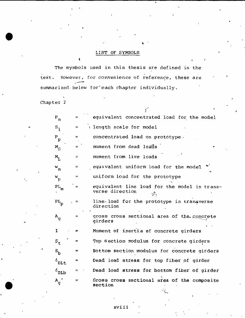
LIST OF SYMBOLS
• The symbols used in this thesis are defined in the
text. However, for convenience of referençe, these are -summarized. bel~w for~each chapter individually.
Chapter 2
P m
S1
P P
MG
~ w m w p
PLm
PLp
A 9
l
St .-
Sb
COLt
°OLb AI
9
( .. ::: equivalent concentrated load for, the model
::: (length scale for model
::: concentrated load on prototyp.e .
==
:::
:::
:::
:::
:::
:::
=
:::
=
=
=
moment from dead loads o
moment from live loads
equ1vaient uniform load for the model ~'
uniform load for the prototype
equivalent line load Jor the model in trans-verse direction "",
~fJ :
line.load for the prototype in transverse direction
gross cross sectional areâ of tb~~9~ete girders
Moment of inertia ef concrete girders
Top section rnodulus for concrete gird~rs
Bottom section modulus for concrete girders
Oead load stress for top fiber ,of girder
Dead 10ad stress for, bottom fiber of girder
Gross cross sectional aréa of the composite section
xviii

•
'0
• Z 2 r
l • ==
=
=
=
f = top
e y
==
==
=
=
= M u req'd=
p
fsu
f Y
Mu
f' v
==
::::
=
= ..
==
,"'""
, ,
1
1 , ' .
!
f
,
• Momênt of inertia of the composite section
. "
Top section madulus for the composite section (
Bottom section modulus for the composite section
Live load stress for the top fibe,r of the 'composite section
Live load stress for the ~bottom fiber of. the composite seçtion
Live load stress for the top fiber of the girder
Distance from resultant force to the top kern point
\
Distance from resultant,force to the bottom kern point ~
t
eccentricity for resultant prestress force from cen~er of gravit y
stress due to prestressing Qf top fibe~ of the girder
stress due té prestressing of bo~tom fiber . of the girder 1 •
initial prestressing force t
Required ultimate moment
Arèa of steel reinforcements'
Steel ration ,
Uni~ stress in steel at ultimate load
Yield stress of reinforcement
Ul tima te moment capaci ty.
Modulus of r~pture
Cracking moment
xix

•
1.1. BOX GIRDERS
CHhPTER 1
INTRODUCTION
,
, The most wide1y used cross section for bridges is the
l shape9 girder'type, because of its ~implicity tp con~truct.
However, it has the following disadvantages:
1} Thé span is limited to about 100 feet.
2) The aesthetic appearance is not ,p,s pleasing ..
3} It 1S structura/l"ly less efficient than the tors ...
ionally ,rig1d box girder.
The box ~irder bridge has become an ~stablished feature both
in North America and in-Europe. In Ca1ifornia about 60% of
the current. brïdge designs incorporate this structural form. 1)
prese~t'brid~es fa11 in the span range of 70 feet , .
to 130 feét, bQt spans in'excess of 80 feet will be used
~e frequently in t~e future. -One exampl~ of the new safet; •
standards for high speed highway ~truc~utes, is the recom
mendation 'for the _el~*ation' of shoulder piers on und~rpas~ structures.
1 :
li
(
.......... --------~~.~.----

. e
i
l "
7
• S
'0
7
/
1.2. PRECAST BOX GIRDERS " ,
, 2
For -reasons of .qua1ity control and .1ncreaslng labor ,
costs, the field labor shoula be minimized as ~ar as .poss~ble.
Precast "unshored" construction offers a praçtlcal solution. . " "
For many years, highway ~ngifieers have been developing stan-
dardized, prestressed concrete b~aros with a view to reduce î;'1!~'
bridge c9nstruct~on co~ts. Cl ~ ....
~ypical girder cro~s sectl0ns
are shown 1n Fig. 1.1 .
..
D J
: ( l
"
Fig: 1.1. ~ 0
Typical Staçdardized Prestr~ssed Bearn Sections
o
For btldges of medium span, a new section has been con-
osidered r~cently. It consists of a precast ope~ w~b girder , \ .
with a cast i~ place,deck ta forro a torsionally stiff SèC-
tian, as shown in Figure 1.2.
, "1
.1.3. THE PROBLEM f "
, S'tructures with the coroplexity of the 'box girder bridge-
)
nee~ rnuch research work for their economlcal a~d'repeated ..
, ,.
et
'. ,
, . J
...
/
/'
o

~
f
D
. ,
, .
• "L fi) ..,
•
-.
-i
. J
a
~ .
FIG. 1.2.
'>
'y (-~
,. 1.
, .
e
" .. ... fi:» .",0 '
"
.~ ~
,. ~
~
ISOMETRIC. VIEW 'OF
T ,
1
~.' -, - ,
38.'2e-
)
e
~-~~~ ~
~-
• rI' / DECI<, CAST IN PL 'AtE
• of _ TRAPEZOIOAI: GIRDER ~
- PR.EfAST ,. ,
"
\ .-.
~ ~ ,~~ 1-
1 if _ LOAD CEL:LS
1 1 a
-. "l> r~
.. BO)( GIRDER BRIDGE MODEl r
o'
A-<
.' 'G ..... ,: ~ ..
W
"
• •
1 •
a
" 4
o , ,
"1' a • , _';/;1
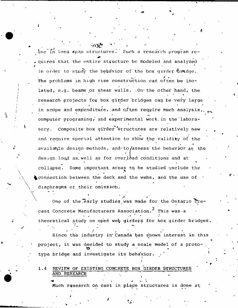
~se ln lonq ~pqn structures. Such a rese<:ù·ch proqram re-#1'
• qUlres' that the cntire structure be modeled ~nd analyz~d
in order to study the b~Qâvi.pr of the box glrder 'ùàdge. , ~
The prob1ems ln hlgh r1se construét10n cari often be ~so-
lated, e.g. beams or shear wa11s. :On' the o~her hand, the ! .0 \
research projects' fo," box gir,der bridges cal) be very large
in scope and exp'enditu~e, and o.ft.en req"'.lire much ana1ysis" ~ ",
'" computer programing Î and experimental work, in the -labora-
\ tory. Composi te box girder""structures are relatively new v
and r~qulre spectal attention to shbw ~h~ validity oi the .
.. availaQlè design methods l and'tO(aSsess the behav~dr at ~he
t •
design lo~d aS,well as for overl ad conditions and Qt . . -
collapse. Sorne important areas tq be studied -lnc1ude the ,"0 \
'\ \connectioh between the deck and the we~s: and the use of
dlaphragms or their omission.
\ \
/' ~
One of the jëar1y studié!?\ was made for the OntariO ~re-, --
cast Concrete Manufacturers Ass~ciation.2 This was~a . , "
theoretica1 ptudy on op'en weQ girder;; for box, g irder br .i:dges. "
' ... }, "
Since ih~ indust~y i~Canada ~as ~hown interest in thiS
project, it was de€ided to study a sca1e model of a proto- . ~
type bridge and investigate its behà~ior. " • ; r
~
of
1.4 REVIEW OF EXISTING CONCRETE BOX GIRDER S~RUCTURES AND RESEARCH 0
c
.."" J c., '.
Much research on cast in pl~~e structures is done a~ . ... ~ ..
1 ~ . ,~.
, ..,
'.
\
..
..
"

-../d' ,
\ . ,
, ,
•
5
~ , .
t~e University of California by A.C. Scordefis, et'al. Of
particular interest 'are the tests and analys~s of a t~G 5~an box giroer bridge model. 3 D
This mode1 which has the scale
of 1: 2 .,84,. was one of the, largest concrete model tests, con-
'" ducted. The entire structure was cast in si tu, and analyz'èd " d.,a., " .. -~
byl the finite element method and f~lded plate method, and • , t ,
was tested undeF highly controlled conditions at ser~ice J
load level and at overloads up:to failure.
~- Many full scale box'girder bridges have been built in
~orth'America and Europe, as weIl as in many other parts
of the world. An exarnple is the world' 5 lanjest ~span con-....
crete brIdge in SYdney "Au5;lalia, which has a span of 1000 • 1
althouqh jt 15 not strlctÎy of the box girdeD bridge fect,
t;ype, since it was des~gned in combination with an arch ...
Many,precast br~dges have been'built in segments of "~ " . ~
approxim,ately ~O feet in length. Examples of this are' the
• Manicunian Way' in Manchepter, England, and at the Western
kven~e Extension in London, ~ngland.
. , Model tests with precas~ open web girders and cast in
. . place decks have been made independent from this research
. . 1 d h' 'd .. 4,5) unlt, ln Eng an by t e Cement an Concrete ASSoclatlon ,
and at least-two u~eam structures aFe planned in England •
r
. .,
, , -
.\
, 1
,
• •
, 1
6
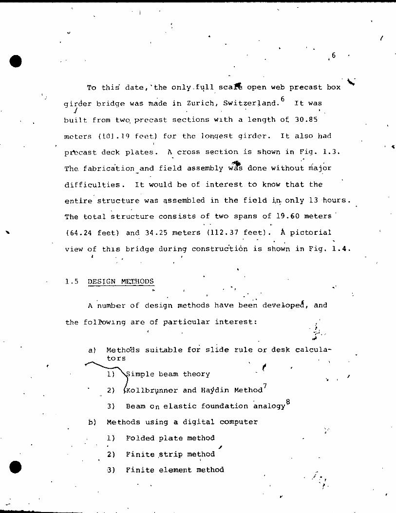
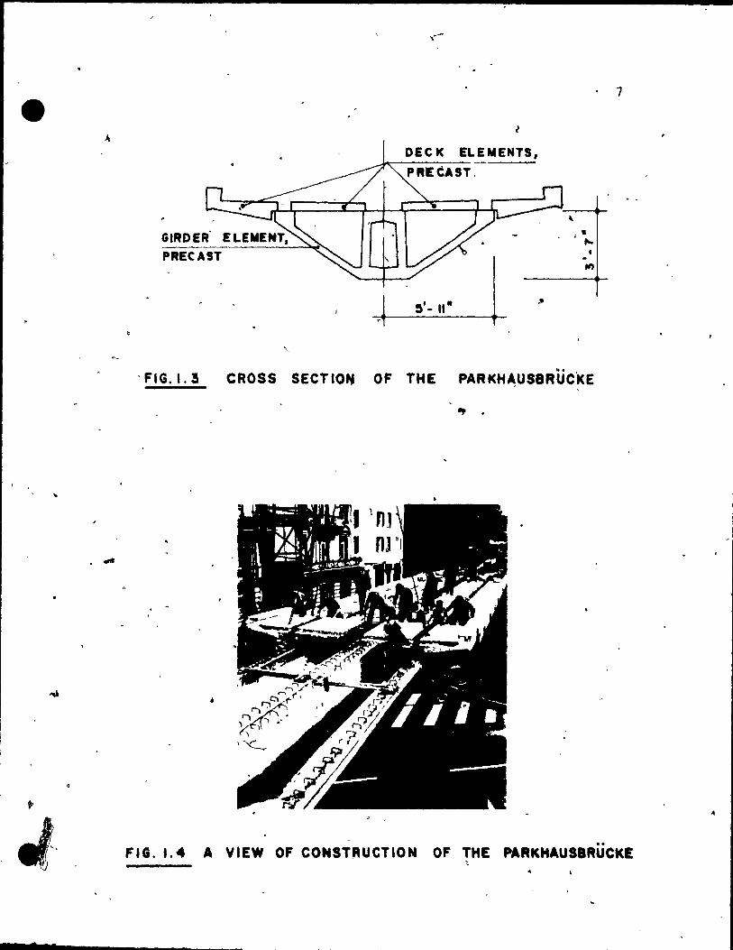
Tc this date, 'the only_f~ll sca!t open web precast box
'. d' 'h S' 1 6 girder bridge was ma e ln Zurlc, w1tzer, and. j
It was
built from tw~ precast sections wlth a length of 30.85
mcters (101.19 fcet) for the longest girder. It aiso had
p~cast deck plates. A cross section is shown in Fig. 1.3.
The fabrication~and field assembly w~ done without major
difficulties. It wou1d be of interest to know that the
,-
entire structure was assemb1ed in the field ~~ only 13 'hours. ,
The total structure consists of two spans of 19.60 meters
(64.24 feet) and 34.25 meters (112.37 feet). Â pictoria1 1
view of th1s bridge during construc"tion is shown in Fig. 1.4.
1.5 DESrGN M~T.HODS
, . A number of design methods have been develope~, and
the fol~w1ng are of particular interest:
,
a) Methoos suitable for slide rule or desk ca1cula-tors
~imPle beam
. 2) tOllbrvnner
theory
and Haydin Method7
3) Bearn On elastic foundation analogyS
b) Methods uSing a digital computer
1) Folded plate method
2) Finite ,strip method
~) Finite element method
'-'
1
1
s
GIRD ER' ELEMENT, PRECAST
OEC te ELEMENTS,
PREèAST.
~. - II-
, . .... ,
. FIG. 1.3 CROSS SECTIO" OF THE PARKH~USBRÜCi<E
.,. .
;
. 7
FIG. 1. 4 A VIEW OF CONSTRUCTION OF THE PARKHAUS8RÜCKE \;
,
/
• 7t •
(
8
From eàch group one method was chosen accdrd~n9 to the de
sired ~~curacy. For the preliminary !roportioning and de
sign of the.girders, the simple beam theor~ was used~ along
with the available empirical form~ae .
• The finite element analysis was used for the c?mpari--
son wlth the test results, and a detailed study of the bridge
behavior.
,.
"
,.
(
7
<
CHAPTER 2
"' DESI(;N FOR THE CON-STRUCTION OF THE MODEL
" 2.1 BEAM METHOD (GENERAL)
The simplest approach for determining the longitudinal
stresses in a box girder bridge is to consider the entire
cross section to act aS a beam ~n~ ~o calculate the longi~
tudinal stresses on the basis of the flexure formula from
the elementary beam theory with' its attendant assumptio~s.
Howevèr ';: the pressUre of transverse distod:lon in a
box qirder brldge 1 which is made up of thln plate:"ll.ke ele-
'ments vlolates the ba~assumptions of elementary beam
theory and can lead to incorrect results. Also, in many
cases, the resultant load dqes not p~ss througrr.the shear ,... . .
center, and the effect of torsion must be considered.
'. ..
2.2 DESIGN OF THE PRECAST TRAPEZOIDAL GIRDER
The,bridge structure, which is a composite of two pre-
cast open web girders and a cast in situ~deck slab has to
• be analyzed for two main loading cases:
(1) The dead load of the whole structure carried by 1
the girders alone, j
-(2) The live' loads applied to the structure cavried
by the composite section.
9 ft
... '
.'
10
In ~ simple span structure like the box girder bridge under \
study, the loading case (2) -'1 ' , if
~ ~ . is governing. '
-The brl,dge was
.. '",
designed according to the specifica-
tians af the Amerlcan Association of State Highway OfficiaIs \
(MSHO) •
1 •
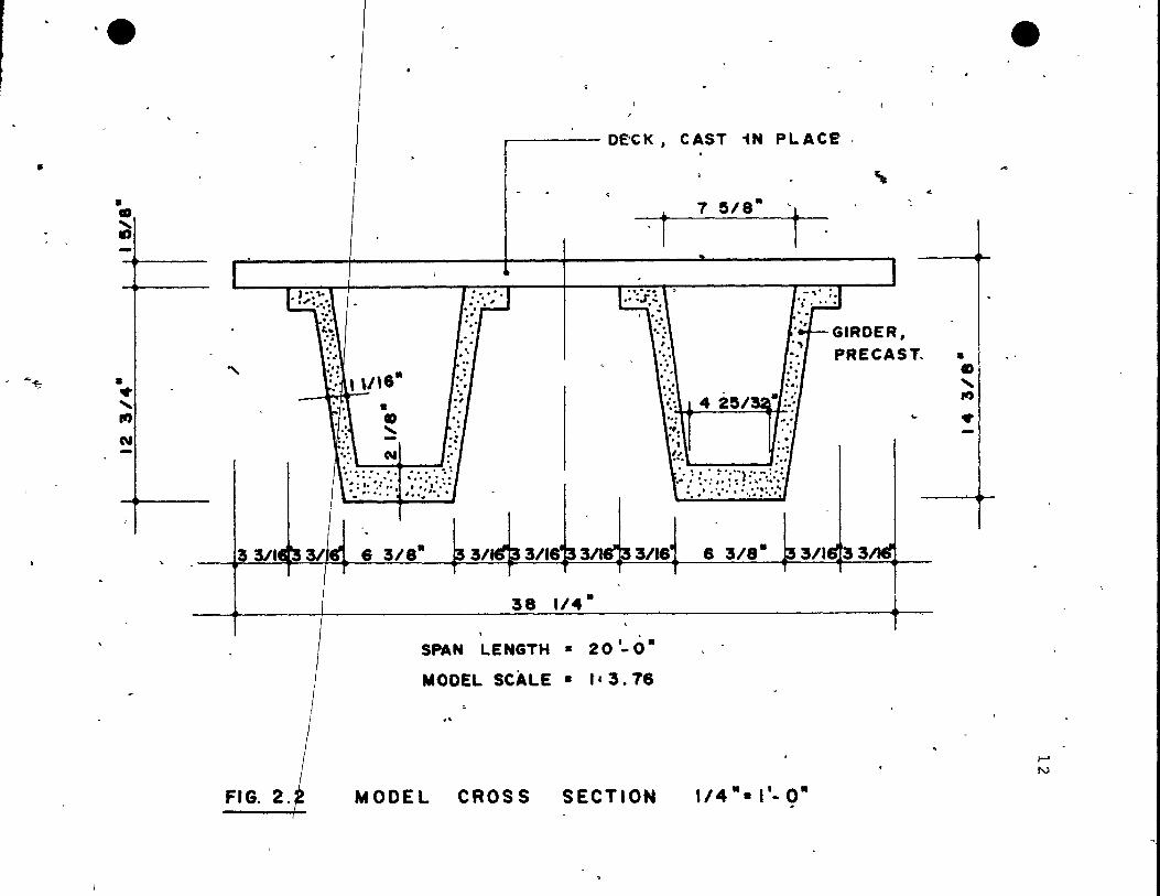
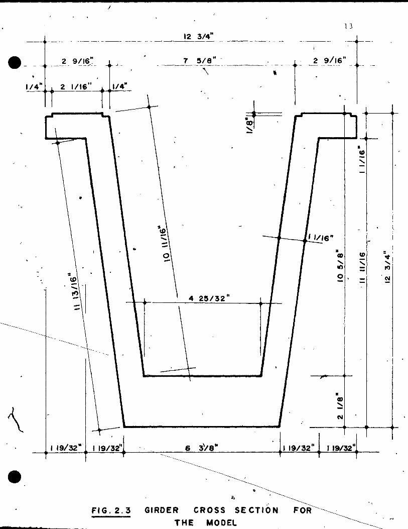
'Fig. 2.1 shows the dimensions of theicross section for , (
the ~ratotypes, while Fig. 2. ~ shows the details. for the 1 ' •
madel, which was designed using a length scale factor of~
" 1: 3.76'. The girder dimensions for the model are shown in
Fig. 2.3.
2.2.1 Bead Loads
~he dead load is to be carried by the girders at the time
of the casting a~~e deck. The load conststs of the self , t ~
welght of the qirders and the ~eight of the cast-in-place. " J
concrète deck. For the model, the t~tal of the dead load 'j,':i"'·'
cannat be scaied, s ince the same' tl~-~~~! mater ial is used 1.' 'I
for bath, the prototype and the rnodel structures. Compensa-
tian for dead weight can be achieved by concrete blocks sus-
pended from the bottam flang~ of the girder. "
2.2.1.1. Th~ Bridge sxstem
~ The system is similar ta a beam, which bas a span as
J
S 7

~
"
e
• •
• o • ..
d
~
!
II~ o· [ ,1. o·
FIG, 2.'
:'., .. . : :-.. . ': .. .. '\. ~).
"··'i 1-, .:.: \/ :. \. ..
-,'
~ .... ,.-. • :=-:::-·t:·. ':./; .~': .~ ::-, ~ ... : .........
r
.1
OECK '. CAST IN PLACE
\---
, . t 280 11/,8 1
, , , , . .::.
. , 1 8 t r1 G 1 ROE R S • '.(,\ t ~ PRE CAS T ,~ ",
.: ~~
" \ :~:l . .... '! ' , , '. . ,. " ' ".", .. , "l ;> ". . . ... -l' ............ .
2~O· l' .. o· 1.'· o· III. o· Il ~ o· 21 .. O· Il.O·lIl.0·
12'.0" , 1
SPAN LENGTH • 15' - 2 1/2-,
.., "
PROTOTYPE CROSS S'ECTION
..
e
-
1-' 1-'
•
..... ~
·e
• • ~
• • " .., N
"-
• GD
" -N
,------ oeCK 1 CAST iN PLACE
7 SIS" . ~ i
r 1
" . ~~:~\ ~ 4 2S/q·r:: .. , ,~: "
~ . .. .. .. " !!., ' .... ... " ~""}:' -.:;: . . : / ::.: :.:.: : : ,:,;:;:,~ ..
"
GIROER, PRECAST.
..
3 3/'.31lft 6 3/8" t' 3/tq 31t8'f3 311fi13 3/18' 8 3/8" , /
38 1/4·
SPAN LENGTH .. 20 '-0" MODEl SCAlE • l' 3.78
.-f
d t.fODEL CROSS SECTION 1/4".I'-Q"
..
• GD
" fi)
•
e
t-' N
J
e- -, 2 9/16" , _.-- . - - /:" -
1_/_4_"~~2 __ 1!16"~~I~/4~M_
•
1 19/32'" 1 19/32"
12 3/4"
1 !5/S"---- ~-- - .---.
\
..
4 2!5/32"
. -
l3
2 9/,6"
1 1/'6"
•
1& CI)
.....
CD U) ..... ...... Il')
0,
• CD .....
6 3\;8" J 19/32" J 19/32" ~-~
---------~~~~ ,
- 1 .
. '~
FIG.2.3 GIRDER CROSS 'SEC'T~~ .. "
THE MODEL . ~ ft
•
$
'\.
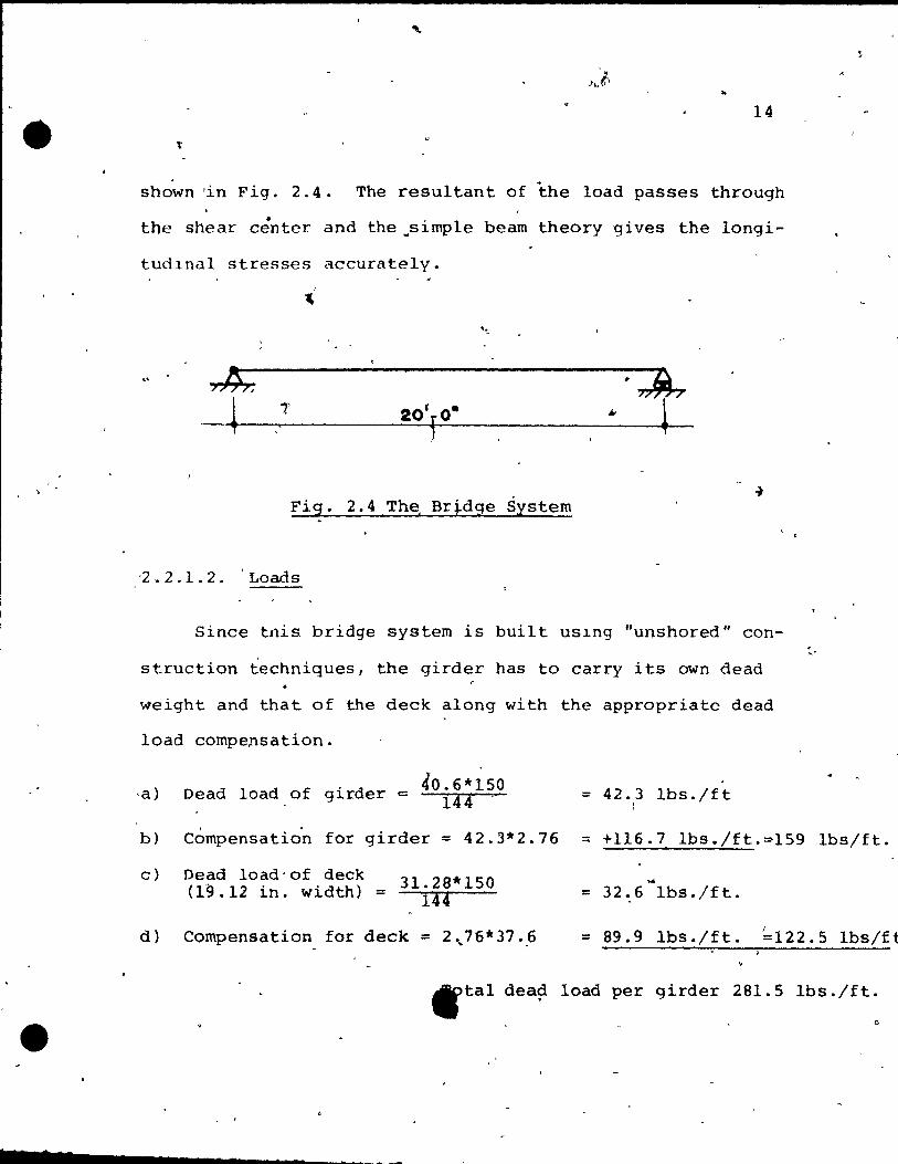
.. 14
shown 'in Fig. 2.4. The resu1tant of the 10ad passes through . • the shear center and the~simple bearn theory gives the 10ngi-
tud1nal stresses accurate1y.
• >7~7 ~
Fig. 2.4 Th~ Bridge System
·2 . 2 . 1 . 2. 'Loads
Since tnis bridge system is built uS1ng "unshored" con-
struction techniques, the girder has to carry its own dead <
weight and that of the deck along with the appropriate dead
10ad compensation.
40.6*150 Dead load of girder c 144-
" :: 42.3 lbs./ft
1
. ~.
b) Compensation for girder = 42.3*2.76 :: +116.7 Ibs./ft.~159 1bs/ft.
c)
d)
Dead load'of deck (19.12 in. width) = 31.28*150
144
Compensation for deck :: 2~76*37.~
.. :: 32.6 lbs./ft.
:: 89.9 lbs./ft. J
=122.5 1bslft
tlftal dea? load per girder 281.5 lbs./ft.
"
i
7
"
7
, c
15,
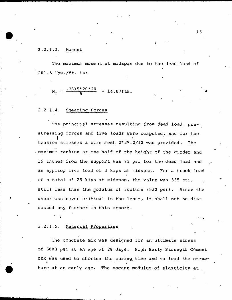
2.2.1.3. Moment
The maximum moment at midsp?n due to the dead load of
281.5 lbs./ft. ls:
.2815*20*20 8
= 14.07ftk.
2.2.1.4. Shearing Forces
The princip~l stresses resulting" from dèad 1oad, pre-
stressing forces and live 10ads were computed, and for the t '
tension stresses a wire mesh 2*2*12/12 was provided. The
,maxim~m tensIon at one half of the height of the girder and
15 inches from the support waS 75 psi for the dead load and
an applie~ live load of 3 kips at midspan. For a truck load
of a total of 25 kips ~t midspan, the value was 335 pSI,
still less than the ~du1us of rupture (530 psi). Since the
shear was never critica1 in the least, it shal1 not be dis-
cussed any further in this report.
- . 2.2.1.5. Material Properties
The concrete mix was designed for an ultimate stress
#II
/
of 5000 psi at an age of 28 days. High Early Strength Cément
XXX was used to shorten the curing. time and to load the struc-
ture at an early age. The secant modulus of elasticity at
(
.; -
't,

•
. ,
•
t 1
, ,
800 psi was rneasured·to be 5,000 ksi. lFig. 5.1) ~ ..
2.2.1.6. SectioIV Properties ....
Q
16
The section properties were derived using a computer
progr~rn·. . ' 'The cross section i8 idealized uS1ng t~iangles
and squares. The input conslst~ ot the dimensions, shapes ...
and distances fro~an assumed axis . ,
The output consists of
the'total area, ~he location of the -center of grav1ty, the , r
moments of inertia for the x and y-axes, the section mod~li,
the pt,incipal rnome~ts of inertia and the location of the , principal axes to the x,y-axes.
, The result~ for the trapezoidal girder are shown~in
Fig. 2.5.
3.24"
2.&4
• i \,
cr
c •
Fig. '2. ~ The section. propertits
Str~sses From thé Dead Load
14
, . 4 ,
.vA 40.6 in. 2 -
= ;.9 l =736.5 in. 4'
St ~t03. 0 in. 3
Sb =131.5 in. 3
<j!
The stresses are obtained by d~viding the moment by the
... ~ .... • t
.. 0,'
'" L ,~
o
, (
. , 17
)"
"
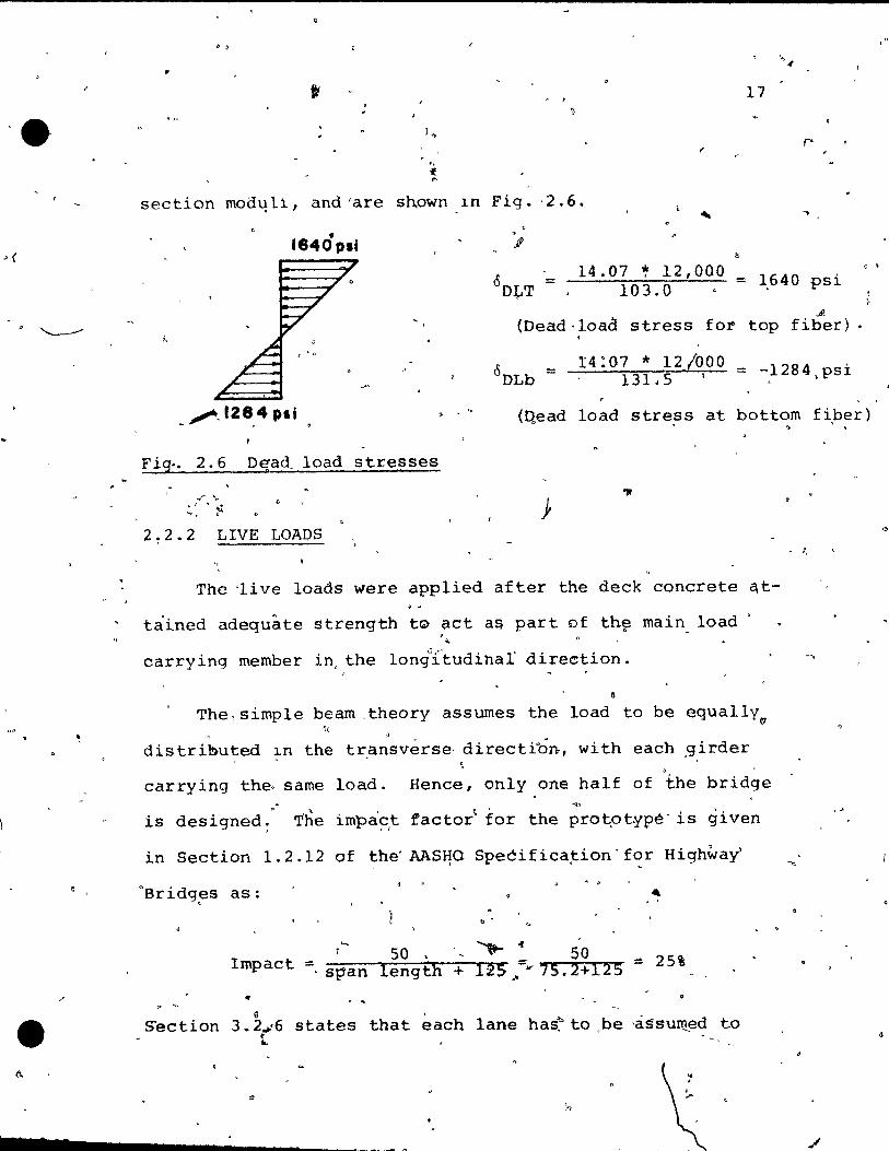
* .. section mo3L!li, and "are shown l.n Fig. -2.6. -.
• 1640 pli
i.
>
J!
14.07 ~ 12,000 = 103.0
1,640 psi
...9. (Dead·load stress for top fiber).
14 :07 * 12/000 131.5 . = -,1284 ,psi
c ,
(Qead 10ad stress at bottom f~ber)
Fi~. 2.6 D~ad load stresses
} 2.2.2 LIVE LOAPS
The 'live 10ads were applied after the deck concrete qt
tàined adequâte strength t0 act a~ part of th~ main load
carrying member in, the 1ongIJftudinal" direction.
G
The, simple beam ,theory assumes the load to be equa11y "
distributed ~n the tr.ansvérse, directibn, wi th each ,girder ,
carrying the" same load. Hence, only one half of the bridge [).. ~..i)
is designed; T'he impa'~,t factor~ for the protpt~pé' is given
in Section 1.2.12 of the' AAS~O Speèifica~ion'f~r Highway
n Br idg!3s as: -. '
b •
'-, -...- of 50 , 50 Impact :::
lengtli 12 $ .• =~ 7 5 • 2 + 12 5 == 25% , st'an + .. . . ~
Section 3.2 ..... 6 states that each lane has~ to ,be ·àssuIILed to t
~
"
, .
" .

l ,
e
18 1 _,
t occupy d wHHh of 10 fC'et.' l1f'ncc this,hr1(lqc structure has
~ .. '.
-to be dcs1.qnf'd for one traffic 1ane. • 0
-.' ,. ,
\ r 2.2.2.1. LoaQ.s for the He 20-44 Truck f'
.... 1
The br1.dge was analyzed for a H 20-44 trucRt~iv~n 'ih
Section 1.2 .,S of the 'AASftO Specifications. Thè truck has \ . • .
two front wheels" carrying' a load of 4:0 , . kips each and t~o
rear~ee1s with \"
a load of 1&.0 kips on each . -.. . ~
, wheel .. The
, .
distance between the front and 'rear ax1es 1.S 14. feet-. These. • e>
\":\ wheel loads can be simulated for the model as fol10ws: - •
• (p ) . ,m
\-vhere p m
SI
p p
=
=
=
'''' l' ,-..
equivalent loaçi for the.model
Iength scale for, mode,l
load on prototype
T~ distances for 'the model ar~ simp'ly the dist~nce of the
pto~otype divided by the.leng~h sc~le. . . Fig. 2.7 shows the ~~ck' 10a?ing for the bridge model:
f. 42 le .3& le 10:atl for the front wti~el with ~
·1 l G
impact:
4.0 * 1.25 , li 3'. 76 * :J.76 = .35 kips
,-l"oad for the rear wheel witl<l
~ ~ r . '.
44.6" 16 * 1. 25 3 .. ~6 * 3.76 = 1.42 kips
• •
impa,c;.t:
Th~ total load for one half of the Fig~ 2.7 The Loads of a
H 20':44 Truck ri _._ 1: C _ li _ ::::5 _ ,
bridge = 1.77 kips. l , ..

"
.~
~,
19
2 . ..2.2.2. <the Statical System for the Il 20-44 Truck LO,ading
The truck~has to be placed, to produce th~ maximum moment
i~ combination with the dead load. For the,span of 20 feet
o the re~'t wh~el' has to be placed 4,.6 inches to the lef t )nd
the ~ront wheels 40 inches to the right of the midspan. Fig.
2.8 shows the truckrPosition for ~aximum bending moment which .. occurs immediate'ly under the axle of the rear wheels.
1 "
L 2 k 3Sk
9 63' 3.72' 6.65'
'20'- 0" j ,
'0 •
Fig. 2.8 T~e Statical Sy~em for tpe H 20-44 Truck Loading, : .
2 1 2.2.3. Moment for the H 20-4~ Truck Loading
r'
The maximum moment occprs at" the point where the rear
wheel is placed:
. M '= 9~62 0* lO.la * 1.42 + 13.35 ~ 6.~5 * 0.35 * 9.63 =
L '20 20 <;;"' 13 .35
7.31 + 1.13 = 8.44 ftk.
, 1
t . 0'
. ,
-
)
20
Note that the same maximum moment is obtained for a single
concentrated,load of' 1.69 kips applied at the midspan.,
- '
2.2.2.4. !l'he Statlcal System for Lane Loading
il The AASHO Specifications for highway bridges (Section
1.2.5) require that the bridge structure be desitned for . the maximum moment produced' by the truck "loads directly or
by the specified lane loading, whichever. is larger.
The lane loading for the·H ~O-44 truck consists of a
uniform load of 640'pounds per linear foot on each lane plus
~~ine load in tran~verse direction of 18 kip~ placed at the
position to cause the worst bending moments or shearing
forces. Agaln the loads havé to be divided by 2 if only one
half of the brldge is analysed .. These loads can be simu
lated for the model" as follows:
Where:
w m
w. m
SI
w .p
is
:
=
* w p
the equivalent uniform 10ad for the model
length scale for the model
uniform load for the prototype
Uniform load with impact': ~ * 1.25,= 106.4 lbs./ft. 3.76
PL = (l )2". (PL) m SI' m
,
•
21
where: PL = equiva1ent li ne load for the model (tOransversé) m ---\ .
SI == length sca1e for model
PL .... m = line load for the prototype (transverse)
1 9 Line load with impact = 3.76 * 3~'6 * 1.25 = .796 kips
"
The maximum moment occurs if the line load is applied at the
midspan.
2.2.2.~. Moment for the H 20-44 Lan~ Loading
The maximum moment at the midspan from the uniform l~ad o
and the line load with the impact.~s:
.1064 * 20 * 20 , + 8
5.32 +
.796 * 201
4
3.98
=
4. 9.30 ftk.
This loading case gives the higher moment than the H 20-44 .
truck loading (8i44 ftk.). ... - .....
2.2.2.6. Section ?roperties for the Composite Section
- Fig. 2.9 shows the section ~roperties for the com~os±te
section. The material properties are the same \for' the deck ,
~s weIl as for the girders. The results were obtained using
a subroutine ta evaluate the section properties •
1 l,
... ~ f
t:>;.<
l ,
• l"
22 J
,........,_......-.,
Yt ll ,5.3&·
...
"-
A 1 = 71.16 l.n. 9
'. 4 l' = 1847 in.
;. <" • Yb- 9 .02 St 1 = 345.2 in.
':. . ~
. ......... t.O\. Sb
1 204.9 in. '- ...... " .,' = .......... '
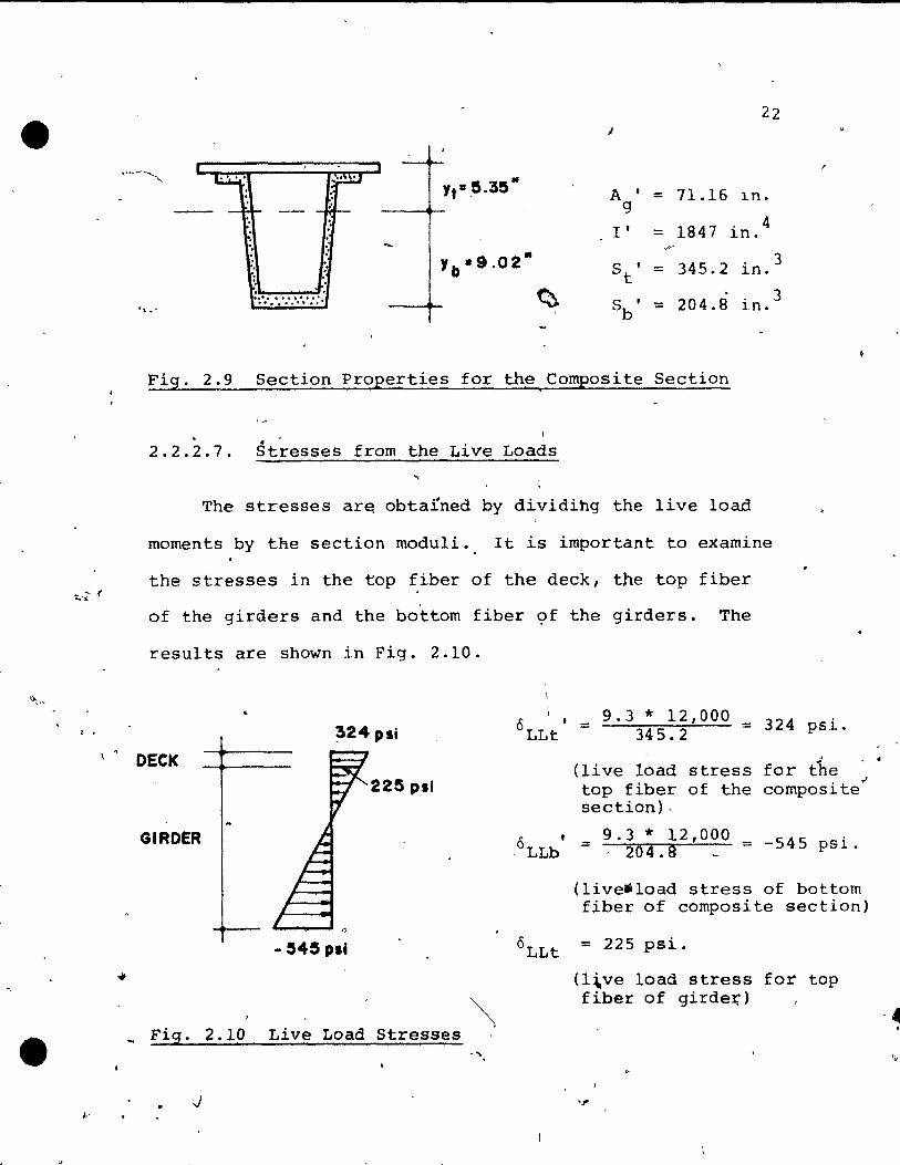
Fig. 2.9 Section Properties for the Composite Section
. 2.2.2.7. Stresses from the Live Loads
The stresses ar~ obtafned by dividihg the live load
moments by the section modu1i., It is important to examine
the stresses in the top fiber of the deck, the top fiber
of the girders and the bottom fiber of the girders. The
results are shown in Fig. 2.10.
"
*
3
3
9.3 12,000 °LLt
t 324 ~24 psi = 345.2 =
OECK (live load stress for
psi.
t'he 225 psi top fiber of the composite
section) ,
GIROER ,oLLb
, 9.3 * 12,000 -545 psi. = 204.8 == -
~
( live-load stress of bottom fiber of composite section)
- !S45 pli °LLt = 225 psi.
(l\ve load stress for top
'\ fiber of girde:ç)
Fig. 2.10 Live Load Stresses -,
J "
-4
'.)

•
23
2.2.2.8. Summation of Stresses From Dèad Load and Live Load
The stresses due to dead and live loads san be super-
imposed (Fig. 2.6 and 2.10) and the resulting ~tresses are
's,pown in Fig. 2.11.
324 pli
OECK
186S PI'
GIRDER
• 1284 pli
Flg. 2.11 'Summation of the Stresses for Dead and Live Load
2.2.2.9. Prestressing Force \ b
1.
--\
The conditions are as follows:
a) The permissible tensile stress during handling and
transportation is to be limited to a maximum of 150 psi
(~efore lossp.s of the prestress force occur ).
b) No tension is allowed at the center of the span
~fter aIl losses"in the prestressing force have occurred.
c' The lasses in t~e prestr~ssing force are ~ssuTed to
be 15%. For the rather short live t1me of the bridge
this value was judged to be the hest, and was confirmed
by th~ measurements from the strain gauges.
,
,., ..
24
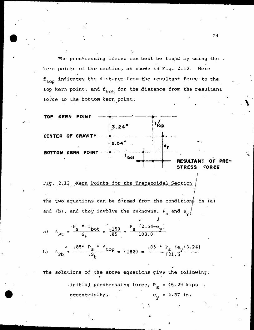
The prestressing forces can best be found by using the
kern points of the section, as shown in Fig. 2.12. Here
f tep indicates the distance from the resultant force te the
top kern point, and f bot for the distance from the resultartt
force te the bot tom kern.point.
TOP kERN POINT
CENTER OF GRAVITY-
BOTTOM KERN *'2.!54- .
1 •
POINT- ----
RESULTANT OF PRE" f bot ... ..-.-.-.... -
STRESS FORCE
Fl . 2.12 ~ern Points for the Tra ezoida1
The twe, equations can be formed from the in (a)
and (h) , and they involve the unknowns, P and ey s J
-p *, fbot -150
p (2.54-e ) 6pt
s s y = = :85 = St . 103.0 a}
b) ~ .85* P s * f
0pb = top = +1829 = -Sb 131.5
.85 * P (e +3.24) s y
The so1utions of the above equations give the following: t
,ini tia). prestressing force 1 P = 46.29 kips s
eccentricity, == 2.87 in.
• • _.,-----_ .... -. ...... -...... -~-~----
\

• .
25
-Note that the stress at the center of gravit y due ta the
prestressing force is 1140 psi, a rather high value which
cou1d be decreased by uS1ng posttensioning besides th~
prestress~ng force (or p·restressing. This can b'e' ach1eved
by b~nding the tendons, or by using the "shored" cons truc-
tien technique.
The fo1lowing strands were avai1ab1e te be used in the
box girder bridge mode1:
a) 5rnm wires with a yie1d strength' of 250 ksi
b) 3/8 inch strands wi~h a yie1d strength of 250 ksi
The yield strengths were defined by the supplier and w~~ . '
verified by tension tests.
Fig. 2.13 shows the required prestressing forces and 1; ,-, ip
their -locations.
• • .. __ -7.97 k
6.6S"1l
1
U5" ~ RESULTA"; PRESTRES S __ --.. __ .......... -38.~2 k FORCE • 46 ·29 k
~
5.60" • • • •
Fig. 2.13 Required Prestressing Forces and Locations
From the available strands the following cornbinat10ns were
/'
.,
. ,
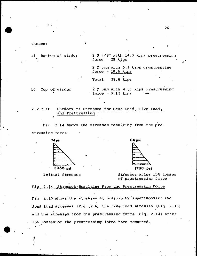
chosen:
a) Bottom of qirder
b) Top of girder
\
26
•
2 ~ 3/8" vith 14.0 kips prestressing force :::: 28 .k.ips
2 0 5mm wi th 5.3 kips prestressing force = 10.6 kips
Total 38.6 kips
:2 ~ 5nun vith 4.56 kips prestressing - force :::: 9.12 kips ---
2.2.2.10. Surnrnary of Stresses for Dead Load, Live Load, and prestressing ,
Fig. 2.14 shows the stresses resulting from the pre-
st ressi nq force:
74 psi
203' pli
Initial Stresses
64psÎ
",
1'7'30 PI' Stresses after 15% losses of prestressing force'
Fig. 2.14 StresseS-Resulting From the Prestressing Force
Fig. 2.15 shows the stresses at midspan by 'superirnposing the
dead load stresses (Fig. ,2.6) the live load stresses (Fig. 2.10) ,
and the stresses from the prestressing force (Fig. 2.14) after

. ,
• 7
1703 psf
446 p.1
324psi
22~psi
- 99 psi
1928 p~t
27
otCK
\ '-
GIRDER
Stresses from d~'ad load and prestre~sing force
Stresses from dead load, live load, and prestressing force
Fi'g. 2.15 Stresses at Midspan
Fig. 2.16 shows the stresses at quarter span after 15%
10ss of the pre,stressing force occurred (Fig. 2.14) super
imposed wi th the dead load stresses which are 75%, of the .
stresses in Fig. 2.6.
1293 p si , 1 1
- 1 1 1 1 1 1 1 -766 pli
-Fig. 2
7.16 Stresses at Quarter SEan for the Dead Load
and Prestressing Force ..
. ..
1
1
'1

7 7
.-
28
2.2.2~11 Ultlmate Load Capacity ,1 " . ~
The ana1ysis for eva1ua~ing the ultimate load capacity
of,the structure was performed accordin~ to the AASHO Spe-
èifications, Section 1.6.6.
The minimum capaclty required is 1.5 times th~dead
load plùs 2.5 times the- live load wi th·"impact. For this box
gïrder bridge, the required ultimate moment is given by:
A
M = 1.5 * 14.07 +-2.5 '" 9.3,. _ u req'd
i
= 21.11 + 23.25 = 44.36 ftk.
The u1timate flexura1- strength according to sectio!,\ 1.6-.10
is as, fo1laws:
a) Prestressing reinforcements
As = .211 in. 2
• 'ot b)
p = 0.000B4 (0.084%)
f = 245 ksi su Mu = .211 *' 245 11 13.625 (1-0.6 O.OOOS: * .245)
~ 713.4 = 59.45 ftk 12
Nonprestressed reinrorcements ,
As == 0.13 in. 2
P = 0.000505 ~0.05%)
..... •
• 2
f := 70 ksi y û.000505 * 70) M = 0.13 * 70 * 13.25 (1-0.6 ,
,u 5
120.1 := 10.0 ftk. = 12
MU total = 69.45 ftk-which is more than the required
capacity, which is 44.36 ftk.
2.2.2.12 The Crack'ing Moment
-The cracking moment is computed assuming that the ten-. , ~
sile stress in the bot tom f~ber reaches the modulus of rup-l~ }
ture.
The,modu1us of rupture (f~ J is assumed to be:
f; = 7.5/~ = 7.5~ ~'530 psi
The total tensile stress to be deve10ped by an applied \ ~ ",/,'
live 10ad is 446 psi (Fig. 2.15) plus 530 psi which is 97 6 psi~/ '
is:
The cracking moment, computed using the section modulus
M cr :::: 976 * 20.4.0 12,060 := 16.59 ftk.
.,
Note that a H 20-44 truck increased by the factor 1.96 placed
at the worst position also produces a maximum moment of 16.59
kips •
J
• • s
-'''"' /, Cl
,
" 30
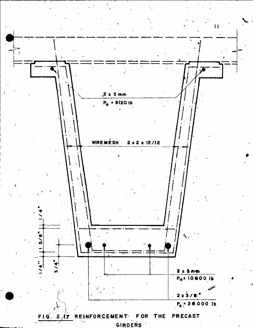
2.2.2.13 Reinforcement Q •
l hê designed girder was checked for the principal
, stresses from shear and the deq)<l\ for bending due, ta the con-'·
centrated loads. It was decided to place a wire mesh 2*2*
12/12 at each face constituting the trapezoida~ sections )
and the deck.
Fig. 2.17 shows the reinforcement including the, pre}'"
stressing wire~ for the precast girder.
- i r
Q ,
.. '
'<
-' ....
c ~,! - '"
G ;,
. .
, ,
31
,. .... - ........... - ------ ----. --- -- -...- --- - - ~ ,.......0#--..... ----rP"-------.-- .......... -----
li .. "--• CID "-en -· · .-......
, f'
• .. "-1ft
(' r
1·, ( .
o
1 . .2 • S Mm
Po • 9120 lb 1 1 II' . .
, 1 l, WIREMESH 212 li 12112
\ .,\ · 11. \, \ ' 1 \ ' 1 . " \ 1 1
. \ \ . , - _.
\' " " .. ,! · i '-f'.-:-'-·-·-'-'" '. \ ' , . 1 \.
.-----.~ .
P.o' 1 0 • 0 0 1 b .,-Po ,. 21 000 lb
FIG~ .. 2. 7 ,REt~FOR,CE<MENT· FOR THE PRECAST '·0 GIRDERS .. _
'(
.,
1 •• , . .
•
l
CHAPTER 3
EXPERIMENTAL STUDY
3.1 INTRODUCTION
\ ~~.~ A brief outline of the experimental study is pcesented
'~in this c~aPter, an~ a more detailed de~cript~on is given .. in Reference 1.
'Ir
Two models were buil t for the experimental study.1 Th: \
first model was made for preliminary studies on local be- ~~
haVlor, whilc the second model was built and used fdr~he ;'"
-behaVlor study of this type of bridge. ___ 1:
From the beginning, Construction without ~i~phragms was
favored, sirfçe' ±t simplif ies the construction .. Mrozek10
describes tests on â continuous' single cell box-bearn having 1 •
no diaphragms at interior supports or w.ithfn the span. The , {", ...
omission of,diaphragms resulted in an incrJas~~f 5% of~re-
lnforcement in the transverse direction. Hdwever, the in-
crease in oost for the reinforcement was much less than'the
savings made in the construction 'cost, due to the elimina
tion, of the ,d:i.,aphragms. To study the local behavior at the
-supports a preliminary model wa~. constructeq. It consisted
of a ~ingle girder: with the same dimensions as the full model, , .
32
'.!
)
, ...
fi

-'J
•
•
•
but :had a length of 40 f nches.
The be-am clement YI..,' precast, and the deck was)ast:
ln SltU ln a manner identical to 'the complete model. T c . reinfot"cement conslsted of wire mesh at e'ach face.
Oné end was provid~d with a diaphragme The spe~i-
men failed at~midspan 'at a concentrat~d load of 25.6 kips
in a bending finlure mode. The ,pupport reactions of 12.8 1
33
kips wer.~ of the same arder as the final m0de1 was expected
to support at ultimate load. The g~rder.ends at the support
show~n ~è slgns of'distress, the diaphragm did not show any . ,
irnprovements in the overal1 behavior. This led to· the de
cision to 'xcludC' diaph'ragms from the final design.
valuable~formation could be'obt?ined to m?ke modi-'
f ications in ,the 'farmwo'rk to ease the demold1ng prooedure. .
The çonnection between the g~rder and the deck did not " 1 -
show any fallure.
; . After the se preliminary studies, the constructiQn of
tHe 1/3.76 . .Bcale model consisting of two be~ elements "and . /
a cast ln place deck was bequn. The construètion is des-
-cribed in' the fo11o,}'ling section. . .
A self equilibrating testing ~rame was designed and
assembled in the laboratory·for the application of live
\.
,
~l'
..

e· ,
1
1 ~
\
-.
(
S 7
34
J' loads. This frame was also used during the construction
~hase of the pretensianing.
AlI work, including framework, pretensioning r castirlg
and placlng ln final position w~s done in the structures 1 , - . laboratory of McGill University.
, . \ \-....
3.2 CONSTRUCTION
To apply the large live loads, a self equilibvating
steel frame was designed. It consisted of two main girders
in longitudinal direction and two girders in transverse
direœtlon at locations where the supports were planned for
the bridqe model .. The pretensioning was performed using
the saffie loading frame. The tendons were prestressed by
hydraulic lacks. The force' was me~sured using load cells
and checked with strain gauges on the wires and by measur-w
ing the total elongation of the tendons. \
1 Addi tional reinforcement was p,rovided. in tlfe form of
, a wire mesh on each face. The two girders weré cast in~
dèpendently using the same set of forros. The dead load was
t~mporarily compensated for with steel billets. \
After both g'irders were placed in their correct posi- '
tion, the concrete blocks which simulated the additiopal
'-,

•
• -< dead load of' the -prot?t
~"" , to the qirders. Per
35
girders and the deck, were attached 1
press board- forms were place~ to
form the deck and the,protruding wire mesh was bent to pro.. vidè a shear connection between-.he beams and the deck, The
top slab was reinforced with a wire rnesh on the top and
bottom and was cast in a single operation; This was followed
by the compensation for the dead loads by transferring part 1
of the concrete blocks from the girders to the top of the
deck.
Several concrete specimens were tested to evaluate the
concrete properties ln~compression and tension, ~longt'th'
the stress-strain relationships. Extensive tests ~er a~:o
carried out to det~rmine the properties of the prest esslng
steel.
To measure the support reactions and to cheCk the -~quili-. - ----.--'
br,ium 0, the entire structure, four_ lJ:l.ad--CèIIs were con-
struct~d. Two load cell~~:~o~ a hollow structural
tube equipped wi th strain gaugès to meas'ure the compression
strains. The other two were made from high strength~~eel
, b~rs, equipped with strain gauges.
" , , ~ l
AlI load cells'a~lowed
for rotations due to the deflections bf the structure. De-
tailed figures are presented in Reference 1. AIl the load
cells were calibr~ed up to 20 kips load •
" ,1
\
/
•
\
•
36
, 3.3 TEST PROCEDURES
The Instrumentation of the model consisted of elec-
trlcal strain qauges for the measurement of strains in the 1
concrete and the steel reinforcemertt, and dial gauges for
the measurement of deflections . . The tests consisted of single concentrated loads applied
at different eccentricities at midspan and at quarte'r span. > f,
For the ultimate load'tests; a frame ~as assemb1ed to~e-
present a scaled down model of a truck. The frame was , statically determinqte and the load was applied from a jac~
'" and distributea by the frame ta the four wheels
propriate proportions. The scaled down truck model
p!aced sy~etrically wit~ respeat to the transverse
tion and was located as to produce the maximum moment
longi tudinAl -direction •
/ ,
, A. view of the instrumented bridge model prior te the
. ultimate test is shown in Fig. 3.1 .
.. "
\' \
• 7 _.1 .. ______ ..... ________ . .....:........._ .' > __

l
•
r
(
'" c:
<1> ..c
37
1 ••
»
- .
CHAPTER 4
ANALYSIS BY THE FINITE ELEMENT METHOD
4.1 INTRODUCTION
The behavior ~ the box girder'bridges is governed by
its geometry, material properties, and loading conditions.
Eor highway bri4ges the design has to be made for uniform
loads and a line load, or for specified truck wheel ~oad-
ings. When the deck is,loaded by concentrated loads, part
of the forces is tranSferred to adj acent boxes."" The tor!.
~Slonal rigidity plays a very important ro~e in this trans-
verse distr1bution of the loads.
• 'l'he deck lS called upon to per"form var ious functions:
.. in the ~ong1tudinal direction it is part of the main load ~~
~
carryinq system, in the transverse dîrection it acts as ~he
bridge f100r and transmits the loads to the weps.
Many inves·t~gators have attempted to simplify the
analysis of box girder bridges by using idealizations leading
to simplified solutions. ~ .
Sorne methods of particular in~
terest are listed in Section 1.5. ".
Most approa~hes are restricted to geometrically simple
38
J; ,
39
, . boundary conditions' and uniformi ties in shapê. W-i th the
development of high speed computet-s, it was possible to
use methods wnich involve solutIons of larqe syst~ms of
equatlons.
/- .,,1 The finite element method is perhaps the ~ost versa-
tile method of analysis presently available. It can be ,
used to analyze a bridge system for any arbitrary loa~ings
and boundary conditions. ~t can also han&le the varia-
tions of geometry and material properties within t~e struc-
ture as weIl a~ cu~outs tn the plates.
It has the disadvantaqe that it involves the solution
of a very larq0 system of cquatlons for ,structures of the
complexlty of the box girder bridge. The method,is approxi-
mate,·with its accuracy b~ing depèndent en the fi~eness of ~
the subdivision used in d'ividing the structure inta fil1ite
elements, and of the choice of the finite element type. The'
elements used to represent the structure can be the con-. f
forming or the nonconforming type and the final choice of
the type and number of degrees of freedom ln each eÏement
15 to be worked out by the in_vestigator.
4.2 TH~ FINITE ELEMENT METHOD
4It The structure is divided into elements which re~ognizably

•
40
. (
retaln properties of the entire system. Properties of re-
presentatlve elements are detcrmined, and flnally aIl
separatc elements are" assembled, joined only at the ends
o~ nodes to yleld the original structure. Loads on the ,
system are assumed ta açt at the nodes. D1splacement func-
tions are chosen in such a way as to make deformations of
an element typical of the deformations within the structure.
Next, the stiffness matrix for each e1ement is esta-
bli~hed by the we1l known virtual work method. The element
stiffness matr~ces are assembled to forro the global stiff
nPAS matrix foi the entire structure. The resulting equa-
tlons are solvcd to obtain the unknown nodal point dis-
placements and forces.
A box girder bridge can best be divided into thin
shell plate elements, where the inp~t data i~r rectangular
elements requires 1ess time than that needed for an ideali-
zation using triangular ele~ent5.
,1 r
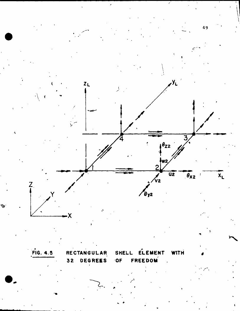
Tinawi9 investigated the beha~or of orthotropic bridge
decks and forrnulated an element with 32 degrees of freedom
as shown in Fig. 4.5. A brief outline of this element is
given in the fOllowing sections, 4.3, 4.4, and 4.5 .. Tinawi
also developed a computer ~rogram which was employed for
thi~ investigation. '{his finite element i5 conforming for
•
41
rectangu1ar shell elements and has shawn good accuracy ln
the analysis of problems wi th' known solutions,.~.
The program has an algorithm which automatically spe-
cifies the deqrees of freedom with respect to the midslde
nodes without reference to the data input.
Section 4.3 describes a ~onforming quadrilate~al ele
ment in bending as shown in'Fig. 4.1. Section 4.4 con tains
a rectangular plane stress element with in plane rotations
which act as generalized degrees of freedom at the corner
nodes of the element as shown in Fig. 4.3.
Section 4.5 describes the assembly of the global stiff-
ness corresponq1ng to"the combined structural elements.
4.3 ~ ....
THE QUADRILATERAL PLATE BENDING ELEMENT
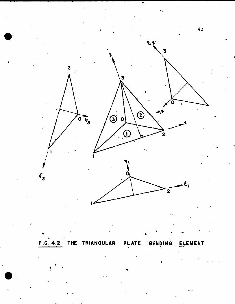
The quadrilateral plate bending ele~ent is basically
an assemblage of four triangular elements as shawn in Fig.
4.1. Each triangular element is again divided into three
subregions as shown i, Fig. 4.2. For quadratic vari8tl0ns,
-' J \
of normal slopè, a midside node is intrpduced at each side.-'---" . ~,
For each subregion a full cubic polynominal i? chosen which
gives ten constraints which c~n be evaluated in terms of
ten degrees of f reedom for each SUbr~ ion,. e. g. three degrees
"

•
...
• .
• f 1 .... Y ""M I~ 3 Q» CD, ,
\ . ~
lM
j H ~J._. l'à'M ,.., 1 CI) _ ,
-" ,
---=_1 .. ' - lM .,.., _ ,'ID_,
, c
J
.... Z
'" 2 &&l .J &&l
" Z Q Z 1&1 al
1&1 .... ~ ..J Q.
bJ X ....
42
•
..
•
43 •• 3
/1
•
FIG.4.2 THE TRIANGULAR P~ATE ·aEN~ING, ... ~~ME~T
1
•
•
•
, . , o
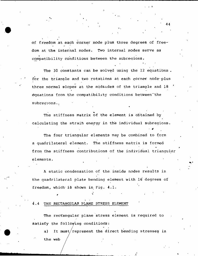
44
of freedom at each corner node plus three degrees of free-
dom at the internaI nodes. Two internal nodes serve as ~
compatibility conditions between the subregions.
(
The 30 constants can be solv~d using the 12 equations ~
for the triangle and two rotations at each corner nod~-plus -'
three normal slopes at the m~ds~des of thé triang1e and 18
~quations from the compatib~l~ty conditions between-the
subreg~ons·1
~
The stiffness rnatrix of the element is obtained by
ca1culating the straih energy in the individual subregions. , 4
The four triangular elements rnay be combined to ~orm
a quadrilateral element. The stitfness matrix is formed
fro~ the stiffness contributions of the indiv~dual triangu~àr
elements.
A static condensation of the, inside nodes results in
the quadrilateral plate bending element with 16 degrees of
freedom, which' i~ shown in Fig. 4.1.
r . . 4.4 THE RECTANGOLAR PLANE STR~SS ELEMENT
The rec~angular plane 'stress element is required to
satisfy the foll0o/ing conditions:
a) It must represent the direct bending stresse9 in
the web
~
"
e,
,
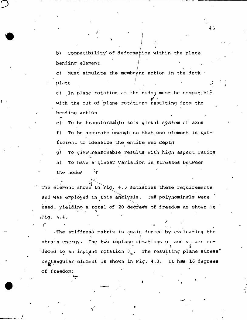
b) Compati~ility'-of
bending element
c) 'Must simulate the membr
plate
45
within the plate
action in the deck
d) In plane rotation at the nOd:;.'must be compatible
with the but of ~plane rotations resulting from the
bending action
e) Tb be transformab~e tO'a global ~pstern of axes ,
f) To be acéurate enough so that, one element is s,uf'"
ficient to ldea1ize the entire web depth
g)
h)
, To give\xeasonab1:e resul:.ts with high aspect ,ratios - .
" To have a"~inear variation in stresses between
" the nodes
-~ " o :J
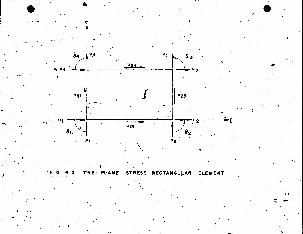
The é1eroent shown 1h '. 4.3 satisf ies these requirem€!nts
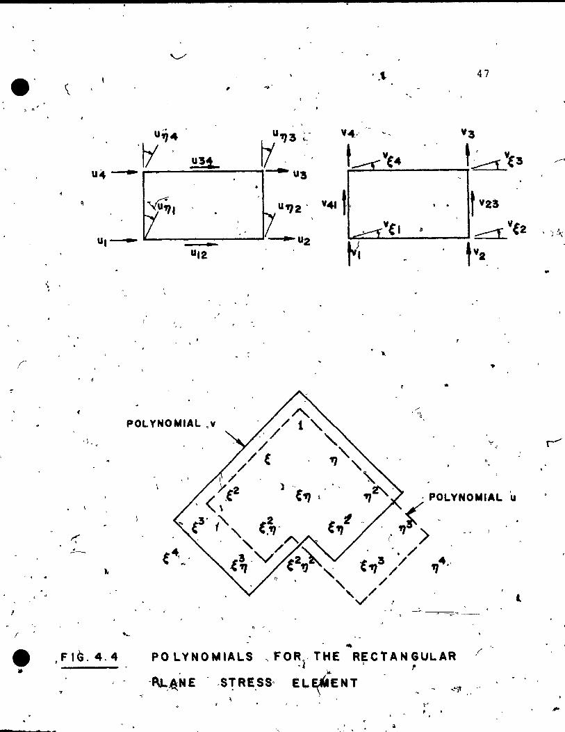
and ~as emplôyea in this an sis. Tw' polynomina~s were
ùsed, yielding a' total of 20 degrees of freedom as shown in ~
.;Fig. 4.4 • " / r ?
~The stiffnes~ matrix is a.gain formed by evaluating the ,
strain energy. The two inplane rçtations u and v ' are re-Tl §
'duced t9 an inpl~ne r9tation e~. The resu~ting plane stress~
rèit~ngular element is shown in Fig. 4.3. It h~s 16,degrees
of _freedOIrt~ . ""'" .
/
• -
..
.,
l 'e, .. , ------ . ., , ., -
----.; .. --
Il
~
..
•
~
Il
"
. ') -~.
\
...
J ,~
~
r . .... .. 1
,0
----------- --=--
11-'4 ~4 Y3't{ -- 3 - -----
: , u34 ., , , ; u3 , i ... U4
-;
"
l.
V~I. t 1 ~
) ,
f f vU
.,., .. ...
p;:,U,2 .Q.
~2 - 1
______ ' - Ut
Ul3 ;çi ~I- ~
. -Y2
.. .. JI,
,\ "- ,"
.. . "FIG. 4.3 TH'E- PL:ANE STRESS RECTANGUJ-AR ELEMENT
~\
" ,
~ , " /
1 • • • ~ ... '
..
" .... (
-~
• 1 ~
, e
1111#
~
.... 51'
'.
~
~
~
-. fi"'-.,...
"
)
, ,
-. " (~ • ~
• ~
/ , "
:;
POLYNOMIAL .y
, ~ v r-'
, '
. \
'14 ., " .
t , . '
/ .. ,FIG.4.4 PO LYNOMIALS ,FOR,< THE RECTANGULAR -~ . ,.
\0.
-F\L,.é:NE . ,STRESS· EL~ENT . '
v , . '. <0 •

, "
• •
. -
48
"'î(
l,
4.5 'ASSEMBLY TO A F~AT SHELL ELEMENT , i
, The degrees of freedoI'ior .of the p1a:te"l?-ending aI}d plane
stress é~€ments are combined into a sirtgle vector. ThlS \
v~ctor has si~ components (3 translations and 3 rotations)
at each node and two degrees of freedom (a translation and
a normal s lope) a t the mid·s ide node.
. \
The resulting element is shown in Fig. 4.5. The element
stiffness ~atrix of order 32x32 is obtained by summ,~g ùp
,the contributions from the plate bending element and the
rectangular ~iane stress élement in the global system.
~ ~ 4.6 COMPUTER PROGRAM
.'
/""'
The ~omputer program was coded to work on the IBM 360/~5
system at McGill Universi tir. in double ,precisi.on.· The pro-1 t'
gr~m consists of five overlays with a maximum of 1300 K bytes
each. FORTRAN H, which optim~zes the sequence of operations
was'used. The s~iffness matrices are sto~ed in dl~~ct access •
files. 'The sàlutio~ of the equation& is performed with a l ,
medified Cholesky approach, o/hich, decomposes the stiff~ess
matrix into a triple product of an upper, a lowe~ and a )
diagonal matrix. 1
, ,
The input consists of: , .
.. ' ,
:
49 ---. ,
--~ .... "',
\ ~
1
) .
.'\ f "$
/
f / 1 /. --If-/_" -' ~;-~--:;-11/ ... .. - -... . 3
, -, ·t8Z2;Y·
W2
~~~----=::::;~_~ __ .J:2=;11f---;;:.,_:"", ..... _. ~ U2 .8X2 r
~/V2
hvz ~ .. .. /'
z, / y
-
~' .'
X
. , . ... FIG. 4. S RECTANGULAR SHELL ELEMENT W1TH 1 . ,
32 DEGREES -OF FREEDOM .f;"' .
..,.
e .. ,~, /' ~
.. " .. r ••
•
. \
. (
Q
• , \
ft
)
50
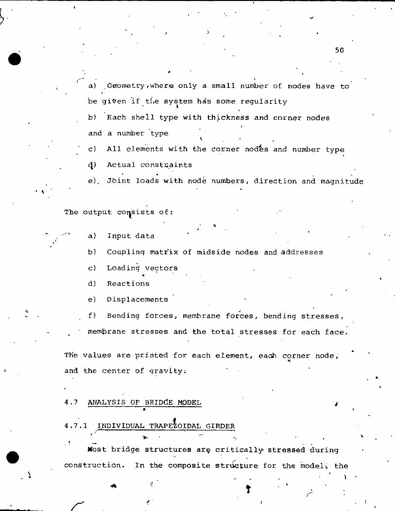
J ....
a) ,Geometry,whera only a small number of nodes have to
be given 'if die system hàs sorne regulari ty - t
b) Each shell type with th~ckness and corner nodes
and a number 'type
c) AlI elemënts with the èorner nod~s and number type
q) Actual const:c.aints
e), Jbint loads with nodé nurnbers, direction and magnitude
The output co~sists of:
a) Input data
b) Coupling matrix of midside nodes and addresses
c) Loading vectors , . •
d) Reactions
e) Displacements
.-f) Bending forces, membrane forces, bending stresses,
;
rnemprahe stresses and the total stresses for each face.
Tne values are printed for each elernent, eaah corner node; '"
and the center of gravity~
4.7 ANALYSIS OF BRIDdE MQDEL J •
4.7.1 Î
INDIVIDUAL TRAPEtOIDAL GIRDER ... . ~
Most bridge structures ar~ critically stressed during ,
construction. In the composi te stnkture for the model c; the
('
•
, .
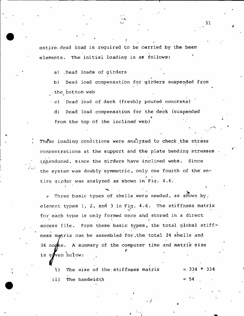
ent~re~dead load is required to be carried by the beam
elements. The initial loading is as follows:
a) ,Dead loads of girders
51
b) Dead load comp~nsatïon for girders suspe~ded from
. the hot tom web
c) Dead load of deck (freshly poured concrete)
d) Dead 16ad compensation for the deck (suspended <1
from the top of the inclined web) .........
. Thlse loading conditions were analyzed to check the stress
concentrations at the support and the plate bending stresses ' ..
~~troduced, Slnce the girders have inclined webs. Since
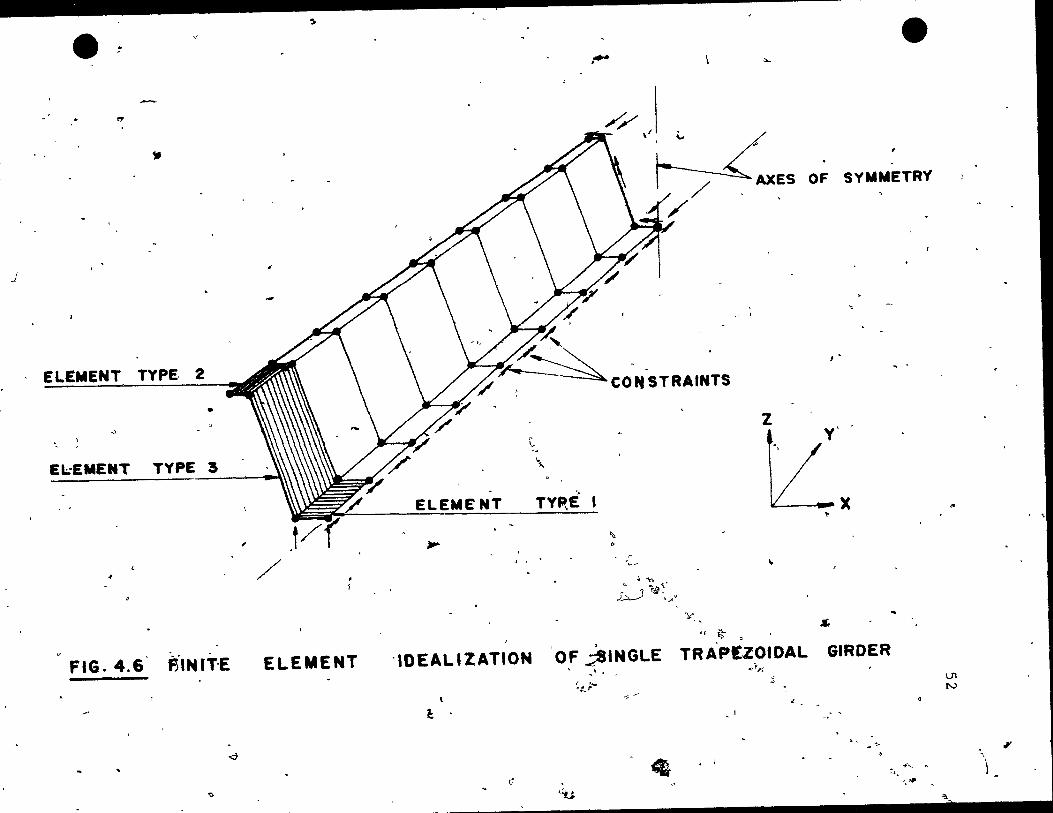
the system was doYbly' syrnrnetric, only one fourth of the' en-( ,
tire glrder was analyzed as shown-in Fig. 4.6.
"""- '
Three basic types of s~ells wer~ needed, as s~own bYI
element types l, 2, and 3 in .F~~g. 4.6. The stiffness matrix ""
for each type is only formed once and stored in a direct
access file. Frpm these basic types, the total global stiff-.
rix can be assembled for.the total 24 shells and
36 A summary of the computer t~me and matrix size . "
,. is below:
, ï) The size of the·stiffness matrix = 334 1t 334
ii) The bandwidth = 54
-.
................. ----------------------------.' •
(
J
- ~
~
111
ELEMENT TYPE, 2
• .;,
EI;;EMENT TYPE 3
.;
FtG. 4.6 f5INl'T'E
<;1
"
,
..
, 1
ELEMENT
".. ""-
// \' 1 ~
bL.xES / '.'
OF SYMMETRY'
~
J •
~
\.. -~
" ELEMENT TYIltÈ
tL'x "...
-IDEAL'ZATION
ê .
c
"
'" r ;,.--- ~ . "\-,
.G.-J ~:' .",.'
y .• s 'f i~ ~
OF ;SINGLE TRA'P!ZOIDAL GIRDER \ .. '. ,qr,.~
~t-;-'i/
'tl "
~ ~
J
.. .. ........ '" ~
'.*
U'1 IV
~)
,
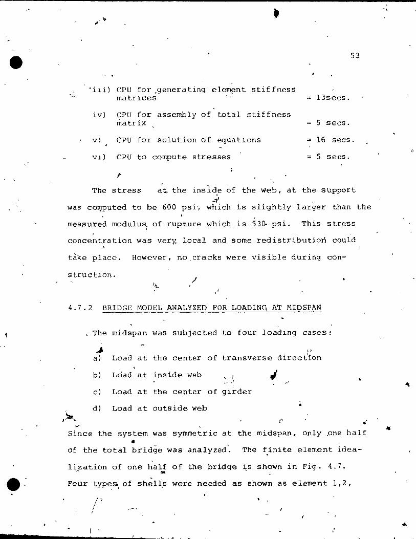
'i~i) CPU for ,generating elem~nt stiffness matr~ces :: l3secs.
iv) CPU for assembly of total stiffness matrix :: 5 secs.
53
v) CPU for solution of equatlons == 16 secs.
V~) CPU to compute stresses = 5 secs.
1-
The stress a~ the inslde bf the web, at the support l
-i' , was coroputed to be 600 psi', which is slightly larger th an the
,
measured modulu~ of rupture which is 53~ psi. This stress
concent,ration was ver}~ local and sorne redistribution could "
take place. However, no_cracks were visible during con-
struction. / •
.; -,
4.7.2 BRIDGE MODEL ANALYZED FOR LOADINC, AT MIDSPAN ,
f The midspan was subjected to four loadlng cases:
.., cl
a) Load at the center of transverse direction
b) Load at inside web " 1 J ~, , ~ ~I
c) Load at the center of girder
d) Load at outside web • ....
Since the system was symmetric at the midspan, only _one haif .. of the total bridge was analyzed. The finite element idea-
, lization of one half of the bridge ~s shown in Fig. 4.7.
- "'" FoUr types of shelis were needed as shown as element 1,2,
- "
• s __ s ...... ____ ....i. ____ !.......-_~ __ . •
o

f' ,.
~
•
'ELEMENT TYPE 2
ELEMENT TYPE 1
ELEMENT TYPE 3
ELEMENT TY~ 4
, >,
•
FIG. 4.7 FIN-ITE ELEMENT
t .,'
... • 1 -\
CONSTRAINTS ~
:;<;'\ / li ~.~T~-'::IIY-F--'"1F~-;T~r~~Y--~"':::=Y=~"'-=·1. / t
AXIS OF '
SYMMETRY
IDEAllZATION OF Tt1E MODEl
AT MiDSPAN
'"
FOR A lOAD ,. ,
.1
V1 A'
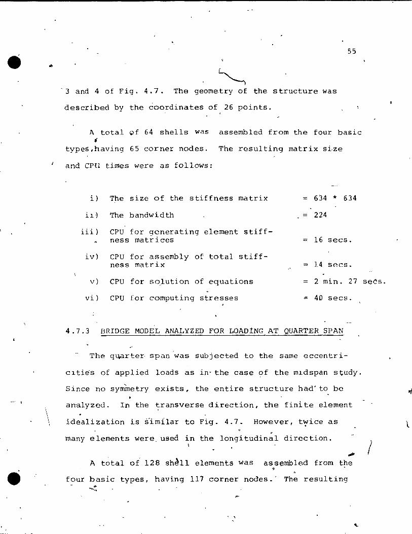
•
- t
\
55
- 3 and 4 of Fig. 4. 7 . The geornetry of the structure was
described by the èoordinates of 26 points.
A total 9f 64 shells was assernbled fram the four basic f
types,having 65 corner nodes. The resulting matrix sLze
and CPU times were as follows:
i) The size of the stiffness rnatrix
il~ The bandwidth
iii) CPU for generating elernent stiffness rnatr ices
iv) CPU for assembly of total stiffness matrix
= 634 * 634
= 224
= 16 secs.
=> 14 secs.
v) CPU for soJution of equations = 2 min. 27 seCs.
vi) CPU for cornputing stresses = 40 secs.
4.7.3 BRIDGE MaDEL ANALYZED FOR LOA01NG AT QUARTER SPAN
The qu,arter, span was subjeèted ta the same eccentri-
cltiés of applied loads as in'the case of the mldspan study.
Since no symmetry exists, the entire structure had' ta be
analyzed. In the transverse direction, the finite elément
ideali zation is s1m11ar ta Fig. 4.7. However, t,:,ice as .
many elements were used in the longitudinal direction.
A total or 128 sh~11 elements Was
.,. assembled from the
four basic types, having 117 corner nodes.' The resulting ~
. ,
1
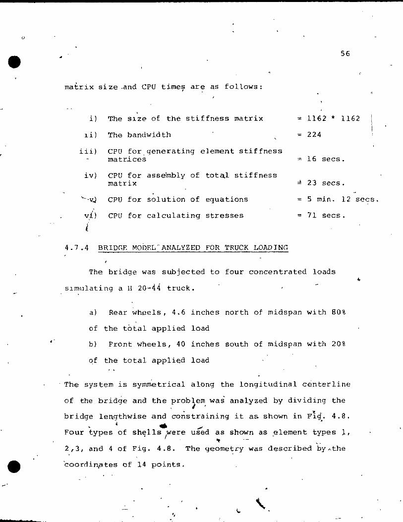
o
6
. «
56
matrix size .and CPU times are as fo11ows: ,
. i) T.he Slze of the stiffness matrix = 1162 * 1162
1 i) The bandwidth = 224
iii) CPU for.generating element stiffness ma tri. ces = 16 secs.
iv) CPU for asse"mbly of tota,l stiffness matrix :!: 23 secs.
"-'vJ CPU for solution of equations = 5 min. 12 (
v,A. ) CPU for calcu1ating stresses = 71 secs.
i
4.7.4 BRIDGE MO~EL0ANALYZED FOR TRUCK LOADING
The bridge was subjected to four concentrated loads
slmulating a li 20-44 truck.
a) Rear wheels, 4.6 inches north of midspan with 80%
of the total applied load
b) Front wheels, 40 inches south of midspan with 20%
qf the total applied load
The system is symmetrical along the longitudinal centerline
of the bridge and the problem was analyzed by dividing the - l'
bridge lengthwise and constraining it as shawn in Fi4. 4.8 . . " ... ,;
Four types of sh~11s rere used as shown aS .element types l, ~
2,3, and 4 of Fig. 4.8. The geometry was described bYAthe
coordinptes of 14 points.
secs.
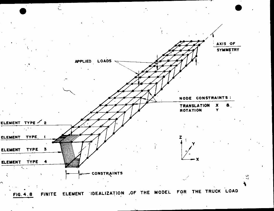
l,
or
ELEMENT TYPE./ 2
ELEMENT TYPE
ELEMENT TYPE 3
ELEMENT TYPE 4 ;, -
" .'\
rf_ -
e
/ A~ , , ,/ ~
.' AXIS -OF !
SY"M~TRY '"
APPLlED L OADS ~ If.,. J*' ;*~ ~
~ NODE CON~TRAINTS;
TRANSLATION X a ROTATION y
G
z
1i:x l.. '==-- CONSTR~INTS
/ '---'
• FIG. 4.8 FINITE ELEMENT ïDEALIZATION "OF THE MODEL FOR THE TRUCK LOAD
:
L1l ...J
"
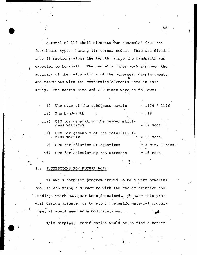
A!.. '.
...
,: /
/-58
A.tatal of 112 sbell elements ~~ assembled from the
four basic types, having 119 corner nodes. This was divided
into 16 sectlon~~a1ong the lenq~h, ~in~e the bandridth was
expected to be small. The use of a finer mesh ~mproved the
accuracy of the calculations of the stresses, displacement, . ,
and reactions with the conforming °elements used in this
sttldy. The matrix size and CPU tirnGs were as fo11ow~: o
. i) The size of the- st~fness matrix == 1176 * 1176 --
ii) The bandwidth == 118
11 i) CPU for gener-ating the mernber cBtif f-ness matrices = '17 secs.
i v') CPU for qssernbly of the tota1'stiff-ness matrix . == 15 secs . ./
v) CPU for solut:ion of equa.ti.ons =, 2 min. 7· s-ecs. ' .. / vi) CPU for calc~lating the stresses = 18 sées.
<.:
4.8 SUGGESTIONS FOE FUTURE WORK'
1
Tinawi's computer pro~rarn proved ~o be a very powerful
tool in analyzing a structure with'the èharacterlstics and
l,oadings which have .Just been' described.- ~ make this pro-~ .
grarn design orientedO or to study inelastlc rnaterial. proper-
ties 1 it would need sorne modificatioI}s.
T!ÜS sirnp1est modification would. be:to find a better
, ,

"
( ..
,J
..
59
numbering system, as -~shown i'Ï1 Fig, 4.9 which would \
reduce' the band~idth from 224 to 1~0, since the CPU time for
the solution of thé equations proved to be almost 1inear
wlth respeet to the matrix S13e or the bandwidth. In thlS o
way a1-most 30% of 'the computer tlme for the solution of
the equationscan possibly be saved.
Si~ya , ét al l1 have shown that for box qirder bridges
good_results are obtained bY'using nonconformlng elements ~
with a smallerenumb~r of degrees of freedom. The bandwidth
can thus be reduced, al though at the sam~ tirne , .... probably , Q
" more elements would have to" be used, and 50 there would b~
no savlngs in the size of the st1ffness matrlX. Further OU
wor,k would be needed to prove that another chè)lc.~ of she~J 1 «
clement ]s more ùdvantageous.
1
Good regults can be obtalned wîth, the present program . with a coars~ mesh, e.g. only 6 sections along tne length .
This Saves appro~irnare.ly 20~ of the compute! costs and a 'J
similar struètu,re can,be- analyzed for $100.00 comput1ng ~ts
for several l6ading cases. For the cODsultinq enqlneer this , . ' . ,
-cost'is f~as~ble fo~ the design of such.a ,sëructure~
\ . It 15 extremely ~mportant to check fo~ lnput errors
1"" • ,," :: before' co'nducting the -'f.~nite èlement analysis on the computer.
ok.) /' 6' ~. •
'The,author suggests ehat -a subroutine bë developed which, if l ' ,
, .

,. e: ".
'. ~-..r
.;,
~ .. "
., 0
-! -: .1Ir ~ ~~
.... ~ ,~, .. ":-J,>,', - .....
• '" "->~ ... "" :"
._'"!' •
:. ""---.~ .. - -<1
... ... /J~J
. .. c
3
.. . F'lG. 4.9 PRo.pOSED
... .. • ~
,. ô '
~ ~ ..
" '\
.. . ~\ i:
..~ .. Il-
19
\. ,
NUMBERING SYSTEM
-. "'\
,. 1 ,
D
v .
.. Il
TG 'REDUCE
.. •
10. ", d
e ,..)
~
"
LI
"
( .
..
...
i "0
Co: 0 ..
THE BAND WlDTH :
C\ ,0
•
\.,. ri ..
.~
•
, ,
~.
..
\ ,
•
a • run w:i,th ,the 'same input data as the finite e1ement pro-
" -gram, would'plot an isometric view of the structure~ In
thlS fTh:"1nner errOl~S can be det0cted and correeted with a ,. ) . --- ,
o
mlnimum amount of effort.
...
As shown in the next cha:@ter , the e,lastic analysts 1" .. .. }
proved to be good foro' th~ working load stage. The de-\ .. .
flections measured ln the tést were, in general, less.
than ~10%, and the stresses from +10% to +20%rin erro~ at
the working load ilevel. "
61
If lt'lS requrred to study the brid~~'beh~ior bey~nd( f
the workihg load level in the non-linear range, then ther \
existlng program ~an be modified for material nonlinearities.
The computer time require~ would obvious1y increa~e si~ni-\
ficantly and ',this would substantially ,i4ncrease ,th~ cast. ~. 1,1.
1 -1 .< •
. , "
/'
~ .
. -
1 j'
) .
, '.

/
• •
/
\ t
. ,
)
CHAPTERo5
DISCUSS10N OF TEST RESULTS
d 5.1 INTRODUCTION ., , ' ,
o
This chapter pre~~nts the experirnental results along , • 'wi th the, theoret.lcal values from the fini te elemènt anal~-
, f tII '
S1.S, with intetpre'tations of the data for the box 'g1.rder , ...
bridge'model.' The b~havior of the model at working load .. level is
uttirnate ~
presented in Section 5.2, w~1le the over16ad and
b~havlor i5 discussed .ln ;~~n 5.3. . ." l ' 1
Theodeflections, strains of the conc~ete and steel,
aS' weIl as thé react.i.ons were record-ed. The striüns were
cQnverted ta stregses by ~sing the"stress-strain curves . , . obtained from tests with concréte specimens. Several tests
on the concrete specimens (cylinders and beams) were con
ducted,' 'and' a rePJ'esentat~ve stress:'S
L. àil'l curve is shqwn.·
in ' F 1.g. ,5.1. 0 , A 6~line fit program was written te fit these values.
, , ~
It pcinted tablés where any 'strain values eouLd eas\~y be
converted into stresses .. This curve was used by the elec-~ -,'
.tronie st~ain gauge reader and ~~e requ~red multipliers (/
were directly eoded ,in. t~e pro~fam. This prQgram proved ! b ) ,
. \ ' , . \
62 ''\ . \
,.
r'
b
"" ,
' .
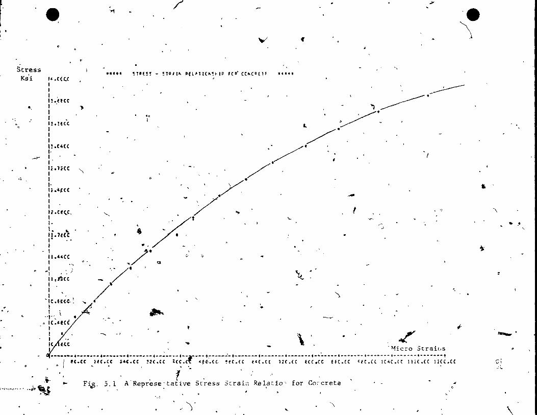
1 1 • ,
Stress Ks'i
• "
. Y1
." ..
/'
V'
!TPE!! - !TA/1~ AEl'Tr(~!~IP f(~ C(~(DE1F
JI'
'e '\
~ ,. ,\
" , ....
",
l' .cèc.c • 1 l , H.nee l ' 1
~ , '),~'~
- . /'~-10
~
Q
'.
..
,-""
"
J • H.!ttC 1 1 1 l!.C4CC l, 1 1 li.liCC 1 1 1· I,."t(( , 1 1 12.CEtC. 1 1-
l, ..' Il. lUe 1 y
t 1 Il.44(C ,
", 1
Il.tHc . -. 1
"
l ' ·IC,fH-'.~ '"
1 1 ~
··t"', Ic_'eté •
!
,-
,//~ - /,r
/, . ., . ' . ,
_ ,//' 0 -'
/- . •
, , -.
,Q
.,
--J
'--, ..,
... ...-
• .1
" '"
~ -..
'. ')
~ •
• 1 •. --., \ • _ /
1
• G
I~ :e tëé ... 1 _ ,'1vficro Straills
"
----i-;::;;--;;::;;--;~;:;;--;;;:;;--i;~:;t--:;i:;~--~;~:~;--;:;:~~--~;;:~;--;~;:;~--;;~:;~--:;~:~~-~;:~:;;-~~;;:~~-~;~~.cc ... l "'. , .. • •
••• ,.~.t ;V
... F~, 5.1 A- Represe: tative Stress Strain Re lat 10 -. for Co:-creta
.- )' '\
"
~
<,
fi
~
'"
'\
,. ~
::
,...,. .
,..... vI
.:: ..
..
\
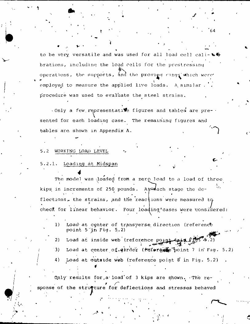
•
\ .1
, ,1
"
... ''FI, , :'."*" • .'
.
.. -
• . ..... .
ta be vùry versatile
~
. ~
.. , ~
éind
. ' ,
""
64
. ;l
• was used for aIl load cell cal i - "\a~
brations, Includlnq the load ~ells for the prestr~;slnq i
op.eratlons, the sUPI?orts, ,~ the: PJiîOVl~q r] ng\: Vlh lch w('r·~'· .. .. \ ..
emp.loye~ to measure the applied llve loads. A, s1ml1 ar
1
procequre was used to evaluate the. steel strains.
'·Only a few, r'E'fresentatl"e figures and tablE:;'d are pre
sented for each loadlng case. The remalnlng fIgures and
bables are showh ln Appendix A.
-5.2 WORKING LOAD LEVEL '" ..
~
5.2.l. Loadl!1g at Mic;1s}2an v 4
~
c.- o
The model was ~oade~ from a zero load to a load of three 1,
kips_ in incrernents of 250 pounds. A. ach stage the de- .... " ~ <
l' . '
flectlons~ the strains, ~nd t~e reac Ions were Il .
checl for linear behavlor. Four loa, in~~case5
measurea tl were tons ülered:
1)
2)
. j)
4)
,
~oad' at c~nter of tr?nsyerse, directIon (referendè point 5<Jn Fig. 5,.2) '.'-:':
.' ,ji'T"ll""~ Load at inside web' (refer~hce pOl.n~.+i.!-JJr-'" 2)
1 ... ..,...~""T =3, j,f'
Load at c;enter of •. cJirde'i;: (fo'~'f8r~.~'~~int 7 in' FIg .
~oad at outslde web (refere~èe poi~t ~ in Fig. 5.2)
1 1 -
O,nly' results for .a' load' of 3 kips are shown. "The re-J 1
1 r
5.2)
sp~~se of the ~~rUjture for deflections and stresses behaved
, " ,
, ,1
1
'"
"
t .
)

,
"
\
• ... ,
( , ~early Ilnear from zero load to the màXlmum Ioad of three ,
,~
65
'k~ applled at midspan. 'Por the load at cent~r the moment J
produced from a sIngle concentrated load i5 equlvalcnt to f '" ..... , .
moment pioduced by a H 20-44 truck wlth . , 89'9; 6 f the ma'x] mum 1
Impact ~t the most critical posltlon. To clc~rly sh0w the,. , "i • 1\
result,s .for defIec,tions stresses ln the"loncptudlnal , . .. direction -; the resul ts 1@tted"acr9ss the section in"
1
the diagram, where~~he deck ?
'the girders' ~shown se- , . l ,
,1
5'.2. Th?ell1erlC81 resul ts are
lmmediately follow th~ dl~grams. . \
~ . . pa'ra tely, as. seen ln Fig.
found on the tables which
5.2.1.1
1. \(
Det lectlons ,
f' i qure ) 5. 3 shows tt:e def lectJops for' the load a t center, 1
WhlCh 15 symmettlc ITthe traI\Svérse dir~ctl~n. ,?he test
values 'are symmetric, which proves that the quallty of the , 1
material and the geometrical properties ~f each girder were
reasonably uniform. In t~~ structura~tystem (which was
constructed in three parts and at 'thr~ dlfferent time~) . any geomettic or material non-symmetrf would have appeated
, /' '
deflections, in refèr~nce to the main longi-as unsymmetrical
.ltudinal a~ls .. ' For cornparison, the ~a;u~~om the slmple
, 1 ~ " '\ beam theory/ was ~c~ Pld:~eq,~ The numerical ~alues are give~
in Tab~e;5.l. The~~imum error of Jfe tes\ values, compared
te the finite element analysis is 7%~ on· si~e .•. 5
.. 1 1
- t Q •• __ .s_ ... ____________ ~q __ , . _ ~
. ,\
.'
"
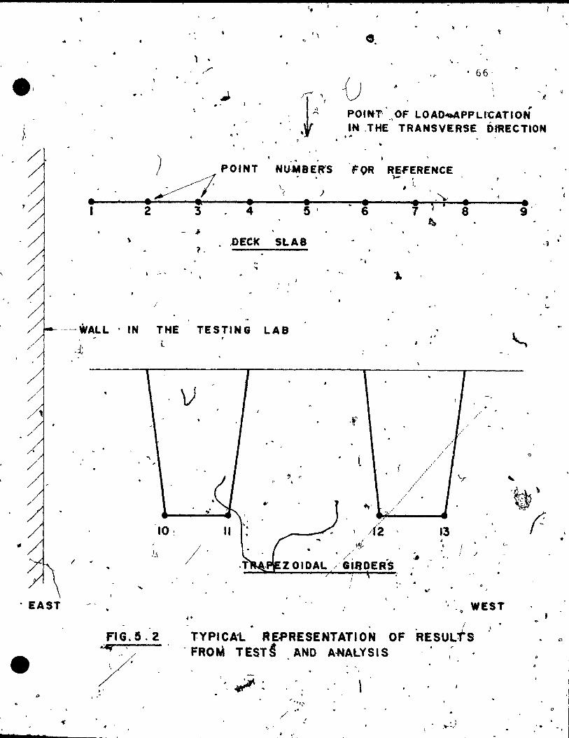
. EAST
, ' .. . , , e.
) . ' .. , ,"'- ". • 66·
1 • . , POUf", ., OF LOAO~PPLl:CATION IN ,THE TRANSVERSE ÔIftECTION . ' ,,,
) POINT . NU:.MBE{fS
·~l \() •• -------• .-~-----• .------4.~-----4.----~~16.~----~7.~'~'~~i--~.~----__e.I. 1 2 3 4 5' 1 8 9'
, OR REFERENCE 1- ,
1 : •
t::. - .J
~ ,oECI< SLAB 1. . . .. , - ,
,
i . ' '--WALL . IN THE TESTING LAS
.;t
1
l
10 :
FIG.5.2 .:Mf ' y " , .
v
l
.. '
.' 1 •
/
~' .... ,-,'---.. /1'2 '
" . .-
13 • • 1
1 .1
'.'.q WEST
lYPICA'L" RE.pRESENTATION OF 'RESULtS - FROM TEST§ AND A·NALYSIS
, ~-, . , , \
/ : , 1 .---- .. , -
l "
o
, •
,1
1
1
1
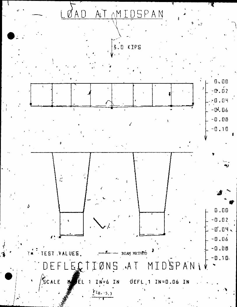
Q •
l' •
" .
1i . ' ...
. ••
,
, , .
el 7 -1->
- L , .
. . . ,--",,,-
, l ~ .: 0 K l'PS ,
b
. , ' • .1 1/
V
0
"- . ~
• . 0 . ~ , '
1
r . _.- r:. ~- J
\
, 0
,LI . "",
. \ ,
• -,. '. t :-
'( . . TEST .VALUES • . . DEFL -
" (s~AlE .1
•
-... '"" ...
1
-
r
.1
r
•
.1.
1
( . ..... ,
, • r-
• ( >
~/. - , \
, "----- -=01 .. ,
J . -.L... - 'BEAM MEnft'lD . .
..
,
1 .
0
.
. r, .
•
~
- ,
r l' 0 N 5 . ~A T MIO 's'P A' N \ ,
1 IN=6 IN l '
, !ig. '5.3 . i
'0 E F l 1 IN = 0 • 06 IN , ,
il
o .. L
. . "
0 ... 00 "
-[}.02
·.~O.OY . . ,
-[)( 06
-o.oô - 0 .10
0.00
-0.02
•
" - O· • 0 lj ." . -0.06
-D,OB - 0 • , O.
. .
. -., . . .
. ,

-.
\. ,
•
, . .
. .:
,"
J
7
. .
)
. " . ..
.-
.
, " '" ",.,
tl:? frnl.tÇelt-'mf'1~an~lY.S1S' wll1 be aVi1ddb·1(~ .•
69
" f rom ~
Therf' fal (' \ Cl •
~, . . the yalucs for the tU~lte pipmont analysls wcre assumod a~
i!o \, r. •
êhc bdSf~ and tho ~iverge~~e of the te~t value~ frbm ,the [nhte
.. element analysis results wasocallod 0n crror. /.
, '. Jo . " .r. \ . As the loa~1 15 p-l~cèlà a t di f feren t 'cccen tl"lCi tle~ , , the l
, " rli5agreements wlth the sImple b~am theoi~ and the test rp-
. sul t:, become larger, however r there 18 bet ter agr~ment·
. , , w~th the finlte clement analysls. Flgùre 5.4- shows the
, lOcldJng case wlth the most eccentr'lc applled i:O.t1centratecl - . ~ /
laad .. :l'hc InrCjPst dÎffcrence of the test Vc1\UÇS 'comp<.H"ed f "
6 \'~.lth t1)e fi'nlte clemen't a~alysls ils 2.5% on the lower'Sldc.
Th~ "'Va~~e at the ~en~erline is the.' sqme for the test and ~ '-. " ..... ----'" ~
~
the anal ys u~ . The numerical,values lor thl~ fIgure are qlven ,
ln., 'l'able 5.2. ~oad l~ases 1 •
a~e shown ln Appendix A.
The load d ftr ~b~tlon te the unload,.ed glrder was smaller ~
.1 than thaf ~omputed by the fInI te elemeI}t metho~. The loaded
~ 0 .' . .. . glt'der qeflect~d up to 20% more and the unlO'aded girder up
to 2"5% 1ess than thE: ana'1-yticê\l values (Fig. 5.4) . .
;
,~Thk measured deflections '.
, . ~ plotted in the same flgure to
fi
~t ~ôth~l~arter spans ·were
cll~Ck for ~ymm~try. Only de-'" . , flection~ atuthè bottom of ~he girder were measuréd, but
< •
. q
..
t
, ,
• d
..
,1
.' ,
"
1
"
'L , .
•

7
e· 1 •
(, , .' , .
2 7
. , t
'.
\
)
\1-~0~_Q ~A _T _M_I_D _5 P_A_N
- .
. " .
..
\
, ,
• ,- ---1.
. " "
1
"
.. r.
..
• •
~fJ'
..
1
'1
,\
• 'fi"
~
•
,
.. ' "
~
. f
.'
. . .
/
~'--
TE ST - V AL UE S - -. 'BEAM METFiQD ..
t~·~IPS --,
.,
1 --~---
"
o E F LEe T l '0' N 5 " ~ T~ M '1 0 5 p, A .N .. ..
t1 "0 E l -. 1 IN = 6 IN * stAlE DE'FL'1 lN=D.·06 IN,· , ,
.Fig, 5.4
. . . ,
70
f .. ~
~ D.DO
~ -0.0,2
-o.OY -0 ~06 ~
, 1 A. -·0 .05
'-.0 • , 0 , .
1 Q.ng -o.Di ,
-D'. DY -
-0.06 .. ':' 0 .1l fi
"
-0.10
'-
..
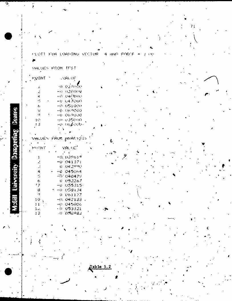

1 < '
1
., ,9
','. 1 •
l , !
. 2
-< •
(---72 \
analyticais values Wf)L'e plotted for the deck as wel.l-:-' For
the load at center,' the V'al.u(?'~'aro shown ln F..ig. 5.5. The
~a~lmum error 15 aqaln 7%, - , ~ whPlch l8 on thE' 1 'ow s ülc . 'J'he
~ \ ~ \. . , numer Ical val lice; ,uo 9 1 ven ln ''fable 5.3. FIgure 1).6 'show""
,- 1 I!i , theovalues fo~ th0 loading case with the most, eccentrjc , ,
~pp,~ co..n.centrated.-load, the largest d~tference belng , -..
25% on the hlgn slde. The-numerlcal results of the above
f Igu~e ar.e 9 l ven ln Table ~'" 4 'r
... l
1 t
. , 1
.
ThIS again confirms that the load d~strlbution to th~ ,\ 1
Q '\ l ' •
unloaded girdcli 15 less than that predicted Qy the"fInlte o . '
• olement analysis. _'r.he resnlts for the 'loadlng cases, ','Jlth
InteumeJlatA ,eccentrlcities are shown ip Appendix A. t { ,
1 (
• - '!,
The horIzontal displacemenbs / . " '- ~
were aiso measu~ed at the t 1
bottom.o~ the. glrdcr,' but for th~ Il
most eccentrlc ca~c the , . \
Lateral deflection was only .OÙ7 inches. ( . Since the hori-, ,
~ontal dlsp~acements are too s~all ,to be rneasured with . ....,. .,. , ... fonfid~ce, Ithey shail not be discussed ln thls_studY .
Cl
Il
\ r Foi the.outside w~b (point 13 in Fig. 5.2), ~he finite 1
.. e1e~ent analysis deflectio~ result~ 'a~4' the tèst ~esults 1 , '\" '
.. are plotted aIorrg the lOFlgitudinal axis of thê'" structure'. l . , ,
""- , .. , ~ , Figure 5:1 shows the values for the load at the ~en~er.
. --~ " '-,. Table 5.5 qives th~ numer1é~l results fox this loading ca~.·
- f q - J ..
Fig.res and ,tables for other ecbentricities are shown in
1 (
, ,
•
" ~ ....
. •

. ,
•
, 1
, ,A
.. ,
',.. ,
L0AD -~--
I?
\
.. r !
, l ' , " '
1
~. ( •
, J ~
~.\/). , ': \ l ..
• 1
"
0
l! -,
..
1 '-..1
O'
-- .
.f' • --l '. II • œ,f'
- - BF;AM. METHOD
, . ,
A,T
) ,
. f y
1 Q
• TEST ~ALUE~'NéRTH·. - cr J 1 E 5 T V A LUE 5,. ~ 0 U& TH,-
'---- , , '" 1 • • ff'
D E F--LI E C Tt -r" 0 .N 5 • ! "
,( ,
r
MI-D5PAN
~
-~ 3.0 KIPS
CI
- --, ..
6
, l • • ..
. "
o 'À"
. ,-
'--..
.~
0'
. . ,
•
..... t
. ' ._-
0'
"
, .
,
, , • 1.
,
• . . .
• 1
., '5 CAL E Me DE' L 1 IN = 6 l N .~.. 0 E F L .,. IN = 0 • 06. t'N . ,
n
l
. , .
. , '
. \.
,
..
~
,0 . : •
, r ,
, f, . ~I~'
"
•
If} -
, .
..
f
"' ~
0.00
-~. [] ;'( . -,0.04
'-0,,06
"- 0 • 0 Ô
-rI.10 \ .
, . -1<
'0 '
1 •
0.00 "
. , ,
-,0 .02 ' • . , \ ~ 0 . [f~
• . .. .<
,:-,0 • {) b <
. -:0 .i;JB ' . --o. , 0
•
," " .
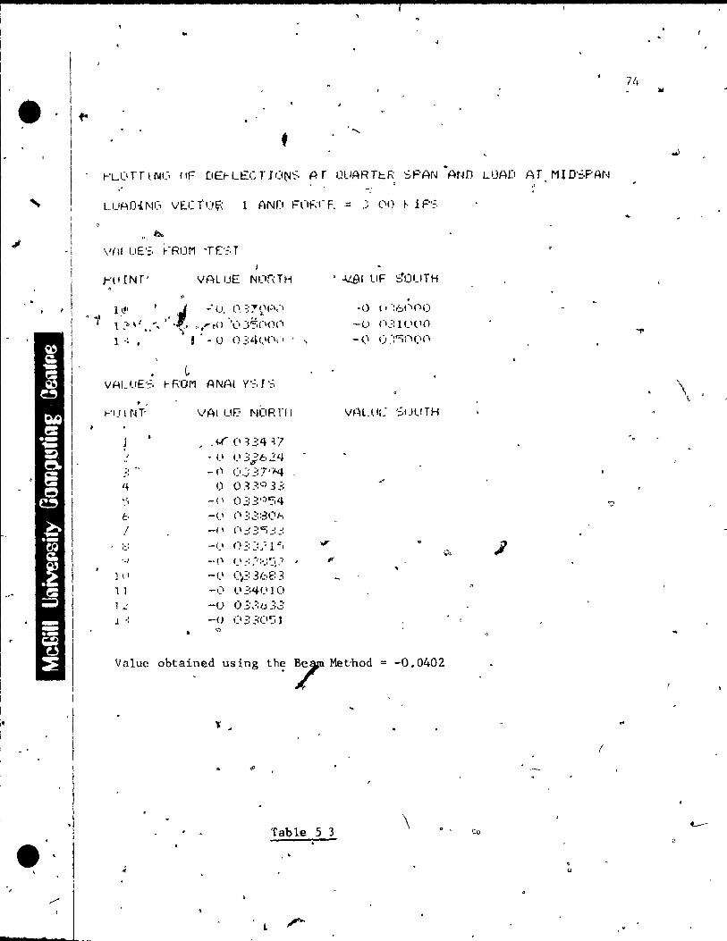
• "
• w
!f-1 1
1 -/
, ..
t
~LOrrlNG I~ DE~LECTIO~S AT Ql~RT~R SPAN AND LOAD ~T MIDSPAN "
l"~ ilI..
\I(\! uE'=, ~-R(IM -TE'~, T 1
;-'{I IN f' VAL !JE NlJnTH
, -0 (, -:6<"'<'0
-Cl (I~:: 1 '-,< ln - (\ (. ~:"'i("l(\(1
• L VAUJE '=. t- ROM A NAI Y '~, l ':=.
• ,
FU 1 rH' VAl uE' NORn!
1 , .if (lE:4 p / - (1 (1'::}624 -;, -'
" -(1 (1.::":; 7'J.4 ,+ 0 0330:,3':: ~i -(1 (1.::3·;'J'34 b -(} Cl ;:~::;3 C' 1--,
,1 -(1 (\ .3 .:: c; .:! ;:
:;:: -(1 ().:: ::.~ 1 c, .,.
'-1 -' 1) C \ _ .. : .. -/:"_:C:~.ï , Il'
] \ \ -Cl (~: 3/,;:,E: 3 1 1 _\~l 1,1341.1 ]0 l .: -1) 0,::,:;1.) 33 l -: -() (\;: 3():a J
'"
Value obtained using the 7 Met-hod = -0.0402
Table 5 3 \
1.
tu
• o
'?
(
\ \
-.
..

, .
Il
L 0 A. 0 -A T M 1 0 5 PAN
,.
Î ,
1 1 [ 1 J F
i
~ •
.. , .
, --r- --:----- --- ----':r-=- - - - J- .
, -'
BEAM METHOD . • TEST VALUES N~~THo
, o TEST VALUES 50UTH
L __ _ '. o ..
J.
--_ ..
7')
~·o ,00
~ -0.02 - 0 .-04
~ -0.06 . -O.Ofj
[ -0.10
t
-0.00
-0.02
. -0.04
-0.06-
-O.OB
- 0 .10
'e ( 0 E F LEe T 1·0 N- 5- A TOU ART ER, 5 PAN , - ,
SCALE MgOEL 1 IN~6 IN OEFl 1 IN=O.06 IN
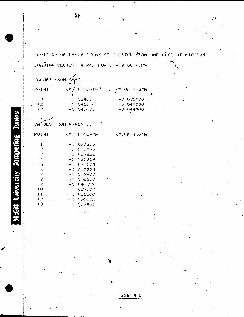
•
i l-,
ï
'\
V{-:I.t~E':,
t-'uJNT
J Cl
T :~
J ", ",
-: 4 'î
1:"
,1
11)
l l .] .' 1 E:
HWM ~~.r VAl II( N(IRrH \
.-(1 (1':41)/.10
-Cl 941 (Inn -0 0450(1(J
VAl I.lr NOR TH
-1) t)4"'7:: J .: -(J, r} :: t: C:;-MJ ....:
-<.' (",...!.'4:::..!6 -(\ (l,:r l ;;'1 :~ -(\ (i~:::174
--0 (l,yS.:? 14 --0 0:':6':'77 -0 () ~::3t,2 7 -0 n 4 ("l".' ""i:::: -Ci 02':1 l 77 -0 (y.:: 1 ::: CI Ci -0 n ;:60 7.? -0 q::';i4"':J
.~
>-
76
VAUlt" ';,nUTH
-1) c' ~~()OC) ._(.1 047000 -0 044nl)(i ,
,,'Al Uf" '3IJuTH
... .-:\
~
'\
Table 5.4

'1. 'J . • - .", ... ,. .. -'
r ·10AD AT CENTER' !
"
1
13.~ KIPS 1)
" 1 "2' ~ 4 S 6 1 Ô 9 '< b D:JJD,
JI!
-D.D2.
- 0 '.04.
• TEST VALUES ...
1 ;- ~O. 06 1 ! G t <- D. DB
..
o E F L E G~o T l 0 N C lJ R V E A L 0 N G '-1 U T 5 l 0 E LJ E 8 . .. - -.
.;.
"
~..;i''''' • (
S CAL E Me 0 E -L ,-,1' l N = Z 4 IN·' D ~rF l 1 l N = o. 0 6 l N Flg 5.7 # •
.. '-.l '-.l
'"

78 . ,
nEF- U:C TI ON':, AUJNI':; 'JUT'::, 1 DE WEi-: t=nn A t=flRI:-E Gi ;:.0 1< t P';. '. c
UIAD f\ 1 CfNTER
vnu '[':3 n~flM ANAL '( ':: I~, 1
~'l.ljNT VAI~lfF
Cl OOO()(\(\
.- -,0 017~'.:;o(1 -. U (1 ~30'31
tl :'
'-. (~ -0 044071 ~I -0 (\4:::2:-=:(1 ( ... -(1 044071 ' t,'
.f -1) (~3305l , , -u {l17'5;:10 .... '-/ (, ÔOO(H)(1
vALur~,::, FRuM rrST
t-'CII NT VALUF.
1 - () OO'::i(IO(1 1 -~{I o.?nOl\(l ~
"
.:' . _of} (1'::40(11)
4 -[) (.'4SU(I() ., i c- -<), (l4bO(H 1 "
(, .i) (14400(1 . ,
7 , ,~( 1 n350lH) ::.: r CI 02()OOO , .
000(1('0 './ , IJ . f " .. ~l r, ~
" p
.
.. Table 5.5
'.,
.' 79
AppendlX A.
'The' expcr imen ta! def lectlon rüsul ts s.hbw ~ that tl1e load
d)<:;trlbulH)D between the ~lnlers 18 less t.han th'?-t prcdlct-ed
by the fi n l te (lll~meI;lt metho-d. Further 5 tuches shoul cl be ,
m~le for the flXlty of the web-slab JOInts.
S.2.1.2 Stresses
~ Concretc strains are very dlfficult to measure accu~
rately. Parameters like 'temperature, humidi ty condlt 10'n5,
quallty and ~ge of the gauge, workmanshlp at the fa~riCa\IOn
and posslble micro-cracks ln the concrete, as weIl as the
rellablilty of the electro~lc meaguring equipment:consider-
ably Influence the results. It is also Important' to scan
tbe stralns at loast five tlmes at each loadlng stage,
average the valu~s and to study the discrepancI~s between
the lndlvldual readlngs. Th~s could not be done in' this . ,
project, Slnce thé use of a computer with speclalized hard
and software is necessary to deal with the vast collection
of da'ta. Values which show a large discrepancy from the ..
theoretlcal analysis are therefore to"be interpreted with
caution.
The measurement of the dead load stresses is almost .. -impossible to assess. in this. project the values for the.
\
"
t

"
,
7
80
l' dead load stresses were In1 t la Il zed ta the values of the -
fInlte c/lemC'nt analysls b/rorc cach test was carried out.
Typlcal stress values frQm prcstr0ss1ng z.md doad 10ad were
446 pSI (Flq. 2.15), for thf' compressIon at the hottom of
the gi rder a t mlCi span I( and 766 ps l f or th!" compn~ss l on a t t
the bottom of the gloder at quatter ~pan (FIg. 2.16), and
ncgllglhlo everywhete ln the deck as shown in' SectIon 2.2.2.
FIgure 5.8 s~ows the ]ongltudi~al stresses ~t ml~span "
for ~ Joad dt center ln the transverse dJrrctlnn élnd Table
5~6 qlVPS ~he pumerlcal rpsults, the larqrst crror of WhlCh
15 901, WhlC~ ]s on the hlgher slde whcn test values arc
cornpared wlth the ~lYSIS. FIgure 5.9 sh()ws the longltudinai
stresses at ffildspan for a load over the outslde web of the
... glrdcr, and Tabl('~ 5.7 glvP5 the numerlcal rcsll1Ls. The
/
err.or ln thlS case 15 35%, whlch IS on th(~ J.ow('r <; l,}e, when j
1
the v~lues are cornpared wIth the results of the analysls.
FIgure 5.10 shows the longItudInal stresses at quarlpr span - ,
for a load at center ln the transverse dlrectlon, and the
riurner ical values -.'1.re gl ve.n in Table 5.8. 'J'he larges t error ! ~
for \his is 40%, which is on the lower sJ.de when the test
results ar~ com~arRd wLth the an~]y~is. The test values
are again syrnmetrlcal, as required for a symmetrlcal loadlng
case.
•
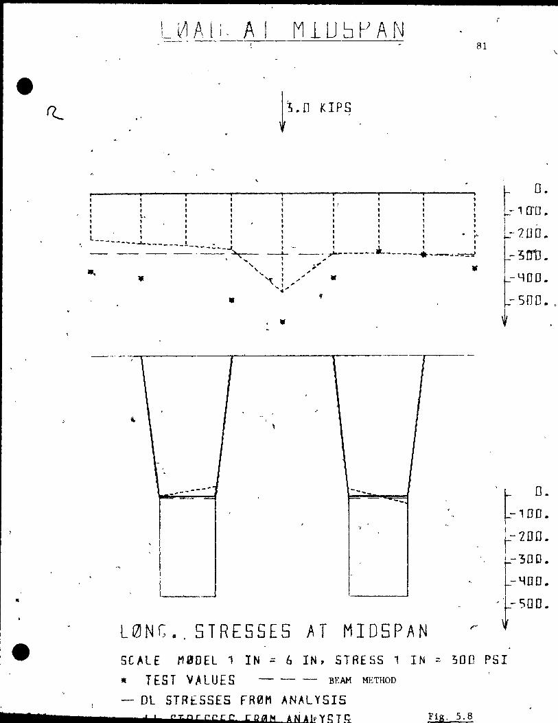
c
e
1 1
L~Al;, A [ 81
,. , , , , 1
j "
1 1 1 • l , l' 1 , ,
• '\-. 1 , , l' 1 , 1
l' 1 1 1 1 l , t ' 0 ,~ 1 l , l ,
, r' , L __ ~ __ ,_..:.. 1 :
..... ------- .. 1 - \ *- l , -t- - .... ~------ ------.. ,.-.-.. --:r::-:J -... ------1 --_._~
-. . ...
, \ 1
4
-
_ ... ------
1 ,
'\. 1 ,.;
" 1 .. ' " , -~, .. .... ~.,. ....
. ..
. .. . ~
,
,
,
"
•
T
--.... F= .... _-
"
. .
l0Nr:: •. STRESSES AT MID5PAN
SCALE M0DEl 1 IN ;:. 6 IN, STRESS 1 IN Il TEST VALUES --- BEAM METHOD
- DL STRESSES FR0M ANALYSIS 1 1 (i;;!ig,r;:r;:,~ (;:,l2m M A N A~ Y g T Ç-,
•
(
,
~
;: 500
Fia, 5.8
r O~
- 1 0'0 ~
~-1 il O.
- 3rrtJ ..
-400 •
\
- 500 .. ,
. 0
~-, 00: L--7DO.
1-300 •
-YOD. ,'-500.
PSI
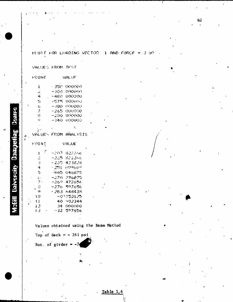
&,2
··e !-'L01 T !-tJR LI IADINC, VE"C TC\!1 1 AND FORCF = -3 1)(\
VALUE '~, r'RO/'l TF':,T
!-'O 1 NT VALUF 1
1 35(1 000(1(11)
...: -;:(:() (lOOOO(J i+ -480 uOOOOU '.:. -~~7C; (\Ol)(,'(j&)
1;;. -3~30 nO()ûOI.I
7 -265 OUOOC'O '::.. -.2:30 OCl(\(IOU '.' 0:/ -'::40 (,'00001)
\. • " ,~.
l'
fL, VALIJE'-, FT,O"" ANALYSIS , ~'('INT, VALUE
1 t --:·n) ::32,2)1)1;..
, -2":'5 ~; .. i :t.2'~,1... " "2"::~ 423:::2::; .;,
4 - 2':\1 ( ''Î';:)f...>(I·,J
'5 "4'+5 046875 1., -~7n }96f.~7:'
7' -26'~ 4726"5;", ,o. -271.:- &1)0:'/ 7656 '-' ',1 . .lE:·!: ~,4:;:4 3:;;
10 -() \ '75~: 1.?':. II 40 '-102344 12 34 O()O(>OO -, l 3 .... 32 '5o:;.76~,6
Values obtained using the Bearn Method
Top of deck = - 261 psi
-7f#' Bot. of girder =
. Table 5.6
n -
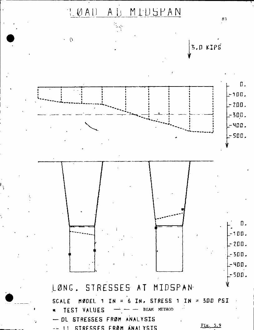
~' \
J J
1 .
•
i, ,
1 1 , • 1 • i , - t , f , ,
• • , , 1 -, 1 1 , , " ' , , , , , 1
, ... - ...... _. t , , • 1 i -~~ •• _. __ ~J __ • __ ~.~ , , , ,
i i , i ........ .. ' , ~ , ._~ t • 1 , f '.... , 1 1 1
,- - - - --- --.- ~ ----1- --.!L.. _ -'-- - '------ ---' .... , , , 1 ...... , . t , ,
~ ~-... f , , ..... ~,. , , -...
, , ~-- , ,
............ - .......... J
~
\ - 1 , -
.
-
• . . ....... --. .... -
... 1
Ir=- =
---.- .... _~.- .. 1
, '
, 1 . 4
1 1
. "
0 -"
,L 0 N G. ST RES 5 E 5- ATM l 0 5 P A N,
81
o . -100.
-ZOO. -300.
-~DD ..
-500 ..
0 ..
-100 •
-200 ..
-~oo.
-~oo.
r500•
SCAlE M0DEl, IN = 6 IN, STRESS 1 IN = ~DD PSI
111 TEST VALUES -' - - BEAM METHOD
- Dl STRESSES FRBH ANAL YSIS Fig, 5.9
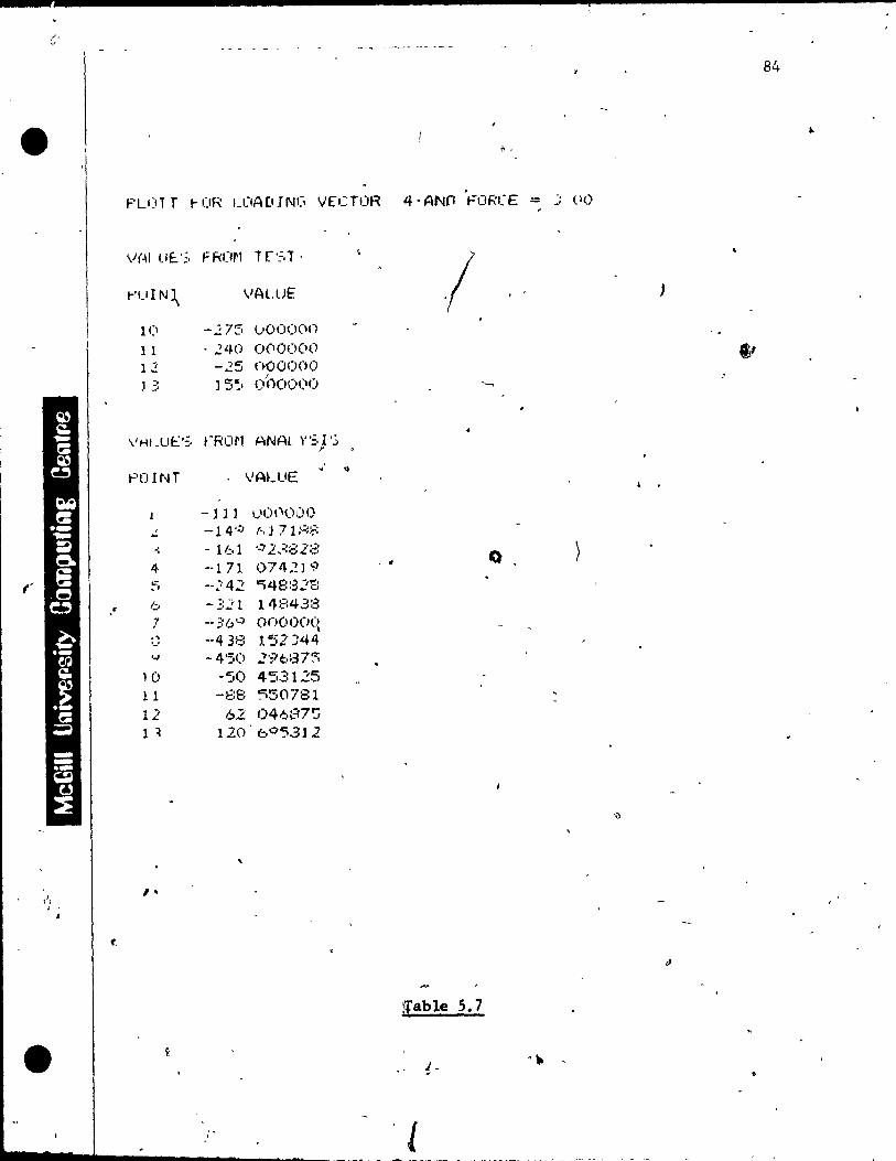
1 -
84
• .. ~ ,
. PU)T T t- CfH uJALUN(; V[CTOR 4· ANn t="ORt:E - j (II)
V(~I u!:.';, F R(I~l T [':::r .
/ 1-',-,1 N\ VALUE
1(\ -.275 \,,000(10
Il - 240 1)000(1()
12: -25 nooooo J .:: J 5~1 O'C,(lO(II) "-,
"Hf. Ut: '::, tORON ANAL y'::, l '.) l'
,j <b POINT VALUE
4 •
-111 1)(>1'\000 , -14':' {-, l 7 1 ;'::f: ~
-: . 161 '·-'2 .. ::81::: 4 ·-1 71 074.:)<:1 • 0
f' "" ,1 -.. :'42 ~48:32ë:
c 1.;. -321 14:::'1-3:;3 7 •• ;:6":' onoooq , , ··438 l ~i2" J44 '.' './ -4'50 ..?'?t,:37:::ï
10 -50 453125 l 1 -88 ~50781 12 6.2 04687~ 1 ~ 120 6°":5312
,
1 •
[able 5.7
• J-... _ ... '--..;..---~~-- --_. -
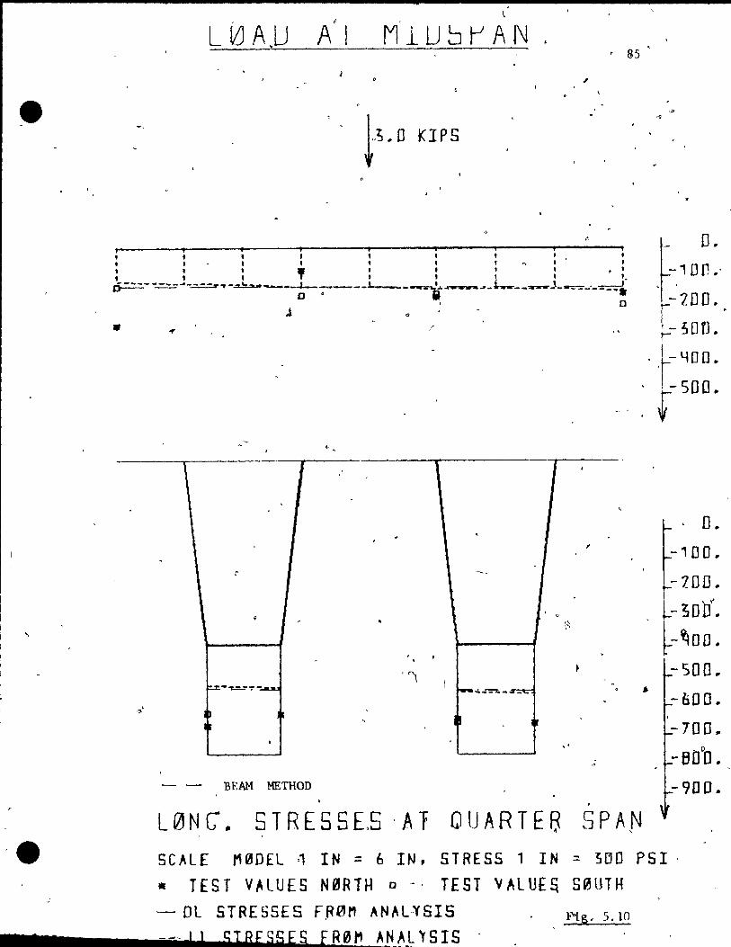
·e
7
J
L lLJ A.U AI M1U!:J~AI\J .
l"O KIPS
, , ,
,
, , , , t t 1 1 .'
, " "!' t. ---.---_ .... ___ __\0__' • , 1 \ • D----'- - ==.r ... ~----;;---;--------_w~.I- ..... --------=-.-~
o
•
. " , J , T ,
. . , JI
. 8 ~ .
, 0 • , . (~,
• , - ,
'Î • 1 " t=.z - ""-"" ':' ~ .......... _-::-:;.-~ ,
-,,' l~ ,
j '. Ir
, "
- - BEAM METHOD ,
L 0 Ne. S T RES 5 E,5 ,A T QUA RTE 8 SPA N
O. -1Dfl."
-200.
,- ;on .. . .r'100. r500
•
~. 0 -100~ ~700 ..
l- 300(.
~-~DD .. -500 ..
• -600.
-700 .. . 0
-BOO. -9DO ..
SCAlE M0DEL ~ IN = 6 IN, STRESS 1 IN = 350 PSI· .. TES TV" LUE S N ~ R THo -, TES TV" l Uf fi S 0 UT H
'- DL STRESSES F~0M ANAL~SIS Fig,5.10
-- 1 1 stRESSES fR~'" A~}_L 'T'SIS .
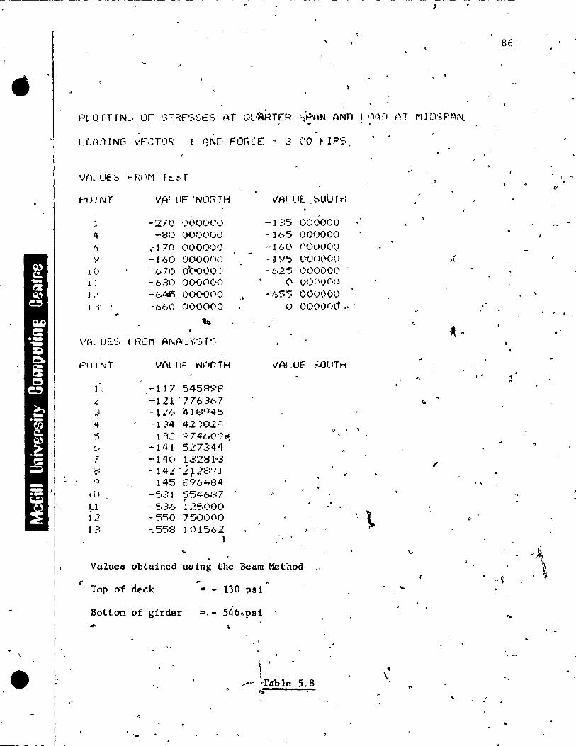
• '«/
< l '
\ -~ I~-
87
4
Figure 5.11 shows the stresses at the quarter span fQr>
a loa~ at the outside web of the girder. Most of the strain ..,
9auges did not give usable reading9; because of a t
temporary malfunction of the electronic straln gauge mea-o _
sur'ing dev{~0, but the values from the analysls are 'plotted
for the entlr.e çross section and the n~merlëal values are V~ '-
given in Table 5.9 . . . ..
Intermedlate loading cases for different eGcentricities It
are inc~udèd in Appendix A. 1
A study of aIl the longitud1nal stresses shows that:
• 1) The loa'd plac~d at thé most,:epcentric case produced d
the maxfmum stress of the entlre test (not considerlng 1
the local effects where the load lS applH~d) .
2) A load placed over a web of a 'girder pr"odu..c'es 'a . '
larger maximum stress than a'simllar load placed at the
midpoint between the web. This ù6 because the deck .
d~.stributes the' load .in the long i tudinal directlon,,.: as ,
weIl as in the transverse directlon. ,/ "
3) -The measured stresses in the deck are generally " ' 'o
uigher than the computed stresses., The shear connection
for" the web-deck joints aTe diff ieul t to" represent in a w • Ci. "
w"
r
model. The increase of thé stresses in the deck and sub-0, _ __ ~ ? ,/ • f
sequently the stress decréase at( the 'bottom fiber of the
girder pan be explqined by the redistribution of the .
stresses tha~ takes~place in the composite~ structure.
'.
\
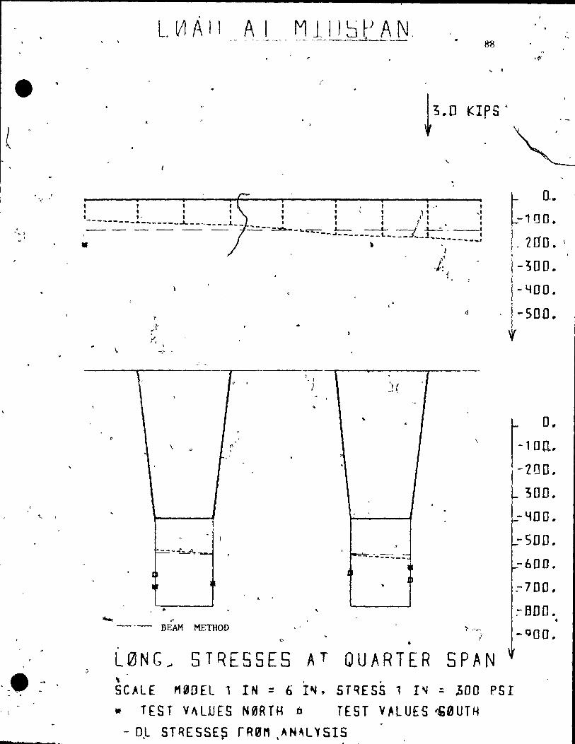
, " .
'-
'-. ~-,- ,
, (
"'t
Ll!1All A 1 • 0 • ,
!ffi c
,~-
...
KIPS G t3•0
~ " .
, , , " 1 .' ,
, t t t " , , j~ '1 ", ,---------" , , .. ------_-L. ________ J.__ • , , 1.. , ___ - -- _ ----.::.>o!o.._ ... _==_.L...- --.J..., -J ..l.-..!. __ , -~--~-- ___ ~ __ L_~ __ ~,_j~_~ ___ ~_~:
• ) i
,1
J' - , • J ,
t 0,.
-100.
I.lao.\ -;00.
-YOD.
~, . f500. , 1 ,
\.
L . '·1
1
.. '.
\ Q
J
, , ~_._~_::-
1 1
1 1 . '
.. ""' .-
- -- BEAM METHOD , o
,. •
L0NG~ 5TQE5SES AT QUARTER SPAN .. "
SCALE M00EL 1 IN = 6 I~, STQESS 1 I~ : ZOO PSI • TEST VI\LiJES N0RTH D TEST V~lUES "mUTH
- 0 ,L ST RES S E ~ r R 011 • A N ~ L V 5 15
D •
-1 0 o~"
-100 ..
300.
-~OD ..
-500 ..
-600.
:-700"
:-800 .
-QOO ..
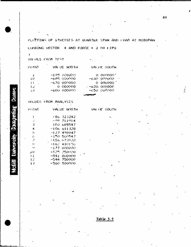
;
89 .,
•• LUi,DING VfCTOR 4 AND FonCE = .3 no 1< IPS
Ftl TN1 VAl UE NlJRl H vAl .llF.: SOUfH
.1 -195 ()1)OOIXI O . o()nooc) , 10 -é.~'::C) 0(1)1 .... ('0 -63(1 <)('1t"()()O
J l --670 001'1000 (J OOUOO() 0
Jo! 0 000C1OO , -6~O. 00000(\ .1 ,.: -b()O (IOO(H)(\ -I..~I() 0( • .11')(1(10
... .. ...,.".
W\'-UE:~, !--ROM ANAI_ Y';r '=,
l'-'IITNT VALUE NnRTH VAt /If '~,û,-,rH
- :36 .,,=:2. 2:242 '-1 -'-/0 711'':;'14 . 3 ]03 6E:'5~i4 7 4 --106 611328 -:-. -1.2 7 4';):::(147 (, -1~() 5(,(\~4 ,1 , -1.56 1.. ... 7' 3:=:1~3 :-: -] 6.~ 41'-1) ")'':' '-1 -177 OOO(I()(1
.lU ~- ")t .... '- ... 1 • '':,(H 'l'l(l
Q
) 1 -541 OuOO()O 12" -'j44 7'50000 1 ;. -' -'j60 5000(10
Table 5.9
7 S
D-
90
4) Rather than dlrec~ scaling of model results for
stresses to obtaun the,results of the prototype, .lt lS
preferable to use the results of the model to verity
a theory, and use the verified theory to design ëhe
11\. prototyp0.
5) At quarter span as shown in Fig. 5.11, the effects
of the ecc~ntriclties of the load are less than for the
case of the load at midspan, where the effects of the
loaq, are localized, while at quarter span a redistribu-
tion of the deflections and stresses took place to the
unloaded gl.rder.
Transverse stresses were checked from the analysis and
were of the or.der of 200 pst in the deck between the girders.
-5.2.2 LOADING AT QUARTER SPAN
The model was loaded with a concentrated load, ln dif-
feren.t' posi tians, 'whlch are explained bel?",! 1 from zero, load ,"
ta a load of four kips in increments of 500 pounds .. At each
stage, the deflections, the stralns, and the reactions were
measured to assess the behavior of the bridge model.' Seven .,
loading cases wete conslqer~d:
1) Load at center in transverse direction (referertce
point 5 ~n Flg. 5.2)·
2.) Load at lnside web of the girder west (reference
point 6 in Fig. 5.2) ,
" ,----,..."
91
{
3) Load at ins~de web of the girder east (reference
po~nt 4 ~n Flg. 5.2)
This loading case ~~,symmetric ~ loading case 2) w~th
pect to the main longit6dlnal ax~~ e.g. pOlnt 12 for
case 3) has'the same stresses and stTains as point )..1
load~ng case 1) . ' f
4) Load at center of the girder west (reference
point 7 in Flg. 5.2)
'5) L~d at center 'of t~e girder east (reference
point 3 in Flg. 5.2)
res-
loading
eor
(The analytical values a!"C' symmetr ic to loading'- case 4).
6) Load at outside web of girder w~~t (reference pOlnt 8
in Fig. 5.2)
7) Load at outslde web o~ girder east (reference point 2
(The analytical values are sYmm~- loading case 6) •
in Fig. 5.2)
.. Only the result~ for a load of four kips ar~ shown in
this case. The response of the structure for deflections
and stresses Was approximately linear for the load'range from
zero to four kips. For the load of four kips at the center,
the maximum bending moment is equivalent to 89% of the maxi-
mum moment produced by a H 20-44 truck with impact at the most • ~ critical position.
.,
t 7
\ -
92
Since the pairs of loading cases 2) and 3), 4) and 5)
6) and 7) are expected to produce symmetrical results, these
pairs are shawn on the same diagrams. For future reference,
values west of the reference point 5 in Fig. 5.2 are called
"west" or "outside box", and values east of J?o~nt 5 are
ca11ed "east" or "inside box".
5.2.2.1 Deflections (,
The measured and computed values for the deflectlons for
a load of four k~ps at the different eccentricities are shown • 1
~n Fig. 5.12 through 5.19, and the numerical results are shown
in Tables 5.10 through 5.17. The results obta~ned by uSlng
the simple beam theory, the finite element analysis, and the
test results [or the load at center agree closely. In Fig . .. 5.12 the maximum error of the test value compared with the
At dif-flnlte element analysis is 11% on the higter side.
• eccentricitles the disagreement between the test results ferent ~
and the val~es obtained using the simple beam theory enlarges,
however, there is a better agreement with the finite element
-analysas. Fig. 5.13 shows the results from the simpl~ beam /--'\
theorYfhê finite e1ement anal?sis, and the test values for
the mos eccentric loading case that was conducted (points
8 and 2 pect~vely in Fig. 5.2). The tèst values if com-
p~red with the finite element analysis are up to 20~ too low
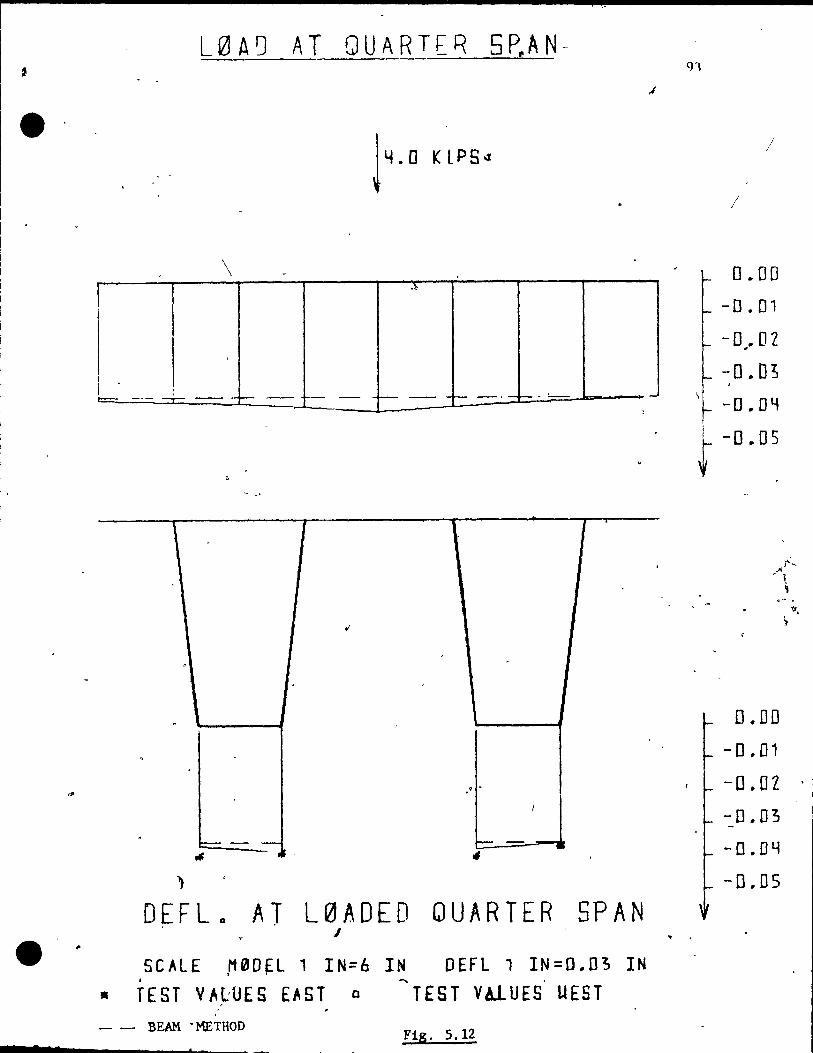
l, 1
1
1
1
7 •
L0AQ AT QUARTER 5~AN-
\ ."
"'=------
-~ 1-- 1-- Tf- .-f- . ,
1 1 1
~
. ,
,
. \
,
, -1
. ~ - -- - -,
..,
DEFLa AT L0ADED QUARTER SPAN J
SCALE M0DEL 1 IN=6 IN DEFl, IN=D.O~ IN . ' 1 ~
• TEST VALUES EAST a TEST VAlUES UEST - - BEAM -METBOD Fig. 5.12
.1
-
,
;' 1
/
0.00
-0.01
- D~. 01
-0.0; -D.DY r -O. 05
0.00
- 0.01
-0.02 '
-D.03
-0.04
-0.05
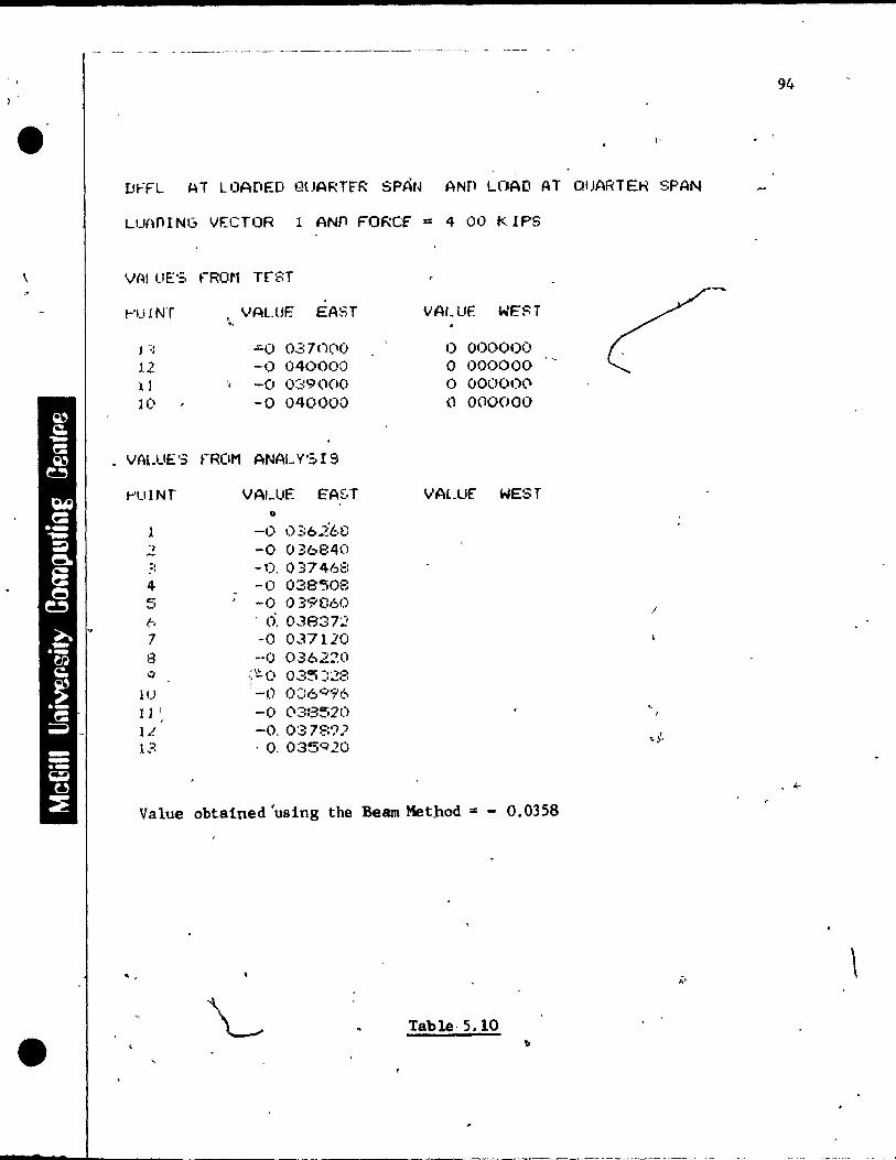
, ,
,
•
- - - - - -------- -- ------ ----~-------- - ---- - -
.' D .... FL 1-\ T lOADED l~lJART~R SPÀt4 ANP U1AD AT QIJARTEH SPAN
LU{\nING VECTOR 1 ANn FORCf = 4 00 K IPS
!-'UINT
12 il 10
, \" VAl.UE EAST
.:.0 037nçl O -0 040000 -0 089000 -0 040000
• VAl.LIE'5 fROM ANAL v'S 19
t-'IJINT VALUË E'A~·T
" 1 -1) 0'::6.2'68 ,2 -0 036840 ::: -0, 0 37 46ê: 4 -0 038"508 . 5
, -0 039860 b ci. 03837:.? 7 -0 0.37110 8 -0 O..362~O CI ,;'.!:.O 03~ :::.!8
1 0:::6 ';'-"7'6 lU -0
l 1 l, -0 03:3520 IL -0, 037::::'7"'" 1:-~. . O. 0350:)20
VALUE WEST
1) 000000 o OOOO()O '-o 000000 () 000000
VALUE" WEST
Value obtained 'using the Beam Met,hod .. - 0.0358
... ",
Table· 5.10
/
94
\

1
L0AD AT QUARTER 5PAN 95
"'~ 14.0 KIPS '
1 ~
, . , , ,
1
t,''''# .
\ , 1 f
,
.'
• "
1 -1.... -_.- f- --
- ~. D • DEFL Q AT L0AOED QUARTERc SPAN
e S CAL ~ M rio 'c L 1 . IN""; il 1: NOE F l 1 IN:: Q • 0 3 r ~
• TEST'VALUES EAST D TEST VALUFS WEST - . - BEAM METHOD
FiS.S.13
7
~'
0.00
_ - 0 .01
o .02
0.03
o . 0 t 1
-0.05
,1).[10
0 .. 01
0.02
-a .. 0 3,
1 !J.[l~
_} -!LCJS
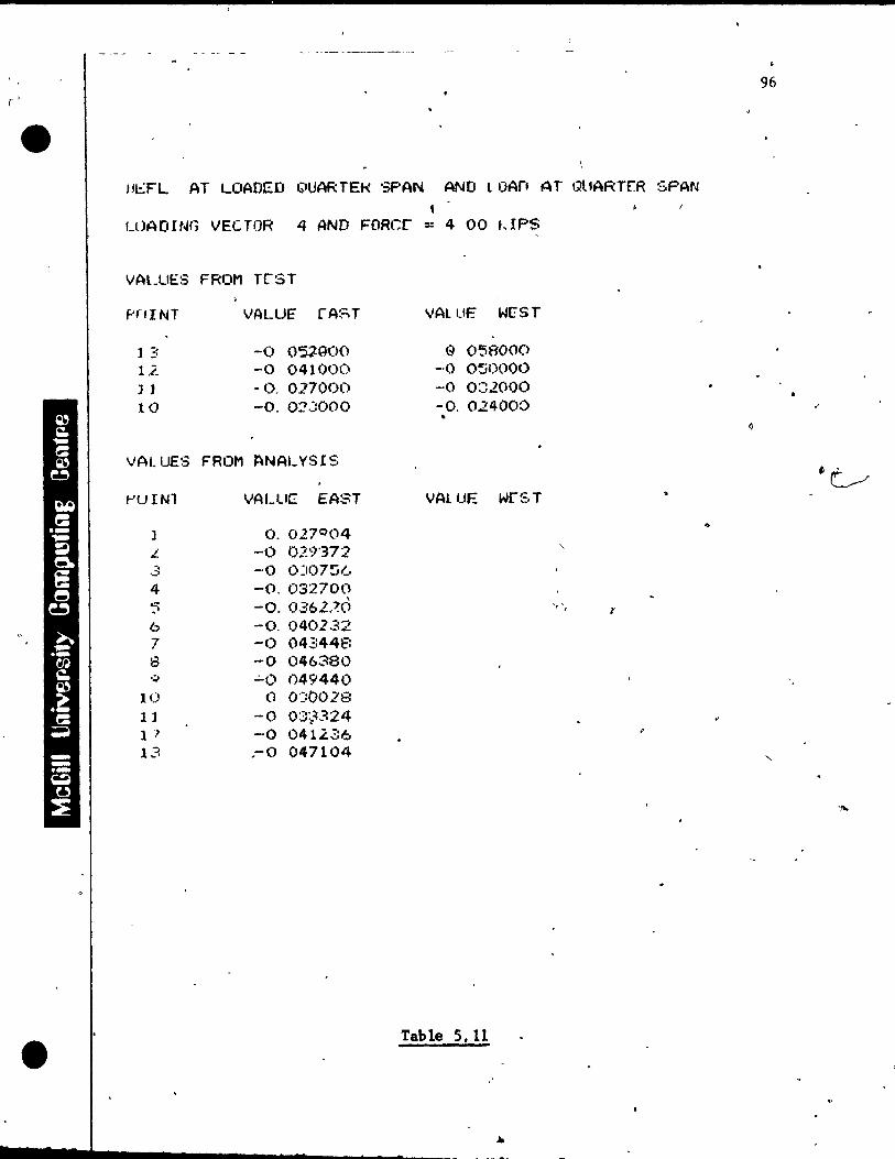
r 1
•
IJI.:TL AT LOADt::D QUARTEK SF'AN AND lOArt AT 1111ARTER SPAN , LOAOING VEC TOR 4 AND FORer == 4 00 t,IPS
VALUES FROM TrST
PflINT
] 3 12. l l 10
VALUE' rAST
-0 OSJ.QOO -0 041000 - O. 0.27000 -o. 02JOOO
VAL UES FROM J!'\NAL YS l S
~I.J 1 Nl
]
L
4
6 7 8
10 Il l ') 13
VALue EAST
O. 027004 -0 1)..?~')·372
-0 0::1)7~(.
-o. 032700 -o. 0362,~Ô -0.040232 -0 04.:::448 -0 046380 ~o 049440
<.1 0-::t1028 -0 08~=I.324 -0 0412.,::6 ,-0 047104
VAL LIE W[;ST
e O~800(> -0 050000 -0 0:::2000 -o. 024000
VALUE wrST
Table 5. 11
•
, , r
96
.'
..
1 .e
7
,
for the unloaded girder, and up tO\23% too high for the
loaded girder.
97
Flg. 5.14 shows the deflections at m~dspan for a con-
centrated load at quarter span at the center of the trans-
vèrse direct~on. The measured values ~ompare very wel1 with ,
the finite element analysis, only one value was 7% on the
hlgher slde.
For the most eccentric loading case as sho~n in Fig.
5.15, the load dlstribution to the unloaded girder is smaller
than that obtained by using the finite element analysls. The
maXlmum error when compared with "the finite element analysls . ,
is 31% on the lower side .. The disa?'reement can be explalned
by the fact that the web-;-deck joints! pre not J "\. .'
completely flxed
as analyzed by the finite element method. ,'" .
'.
For the unloaded guarter span the values obtained using
the simple beam methad, the finite elernent analysis, as weIl . .
as test values are shown in Flg. 5.16 and 5.17. Again the
test value~ for the loaded girder are up ta 40% tao large,
and up ta 40%. tao low for the un10aded glrder for the
eccentric loading case, as shown ~n Fig. 5.17. On the other
hand the test values at the same unloaded quarter span agree.
very favorably with the finite element rnethod, with the t .'
test values being ohly up ta 8% art the higher side for the
"
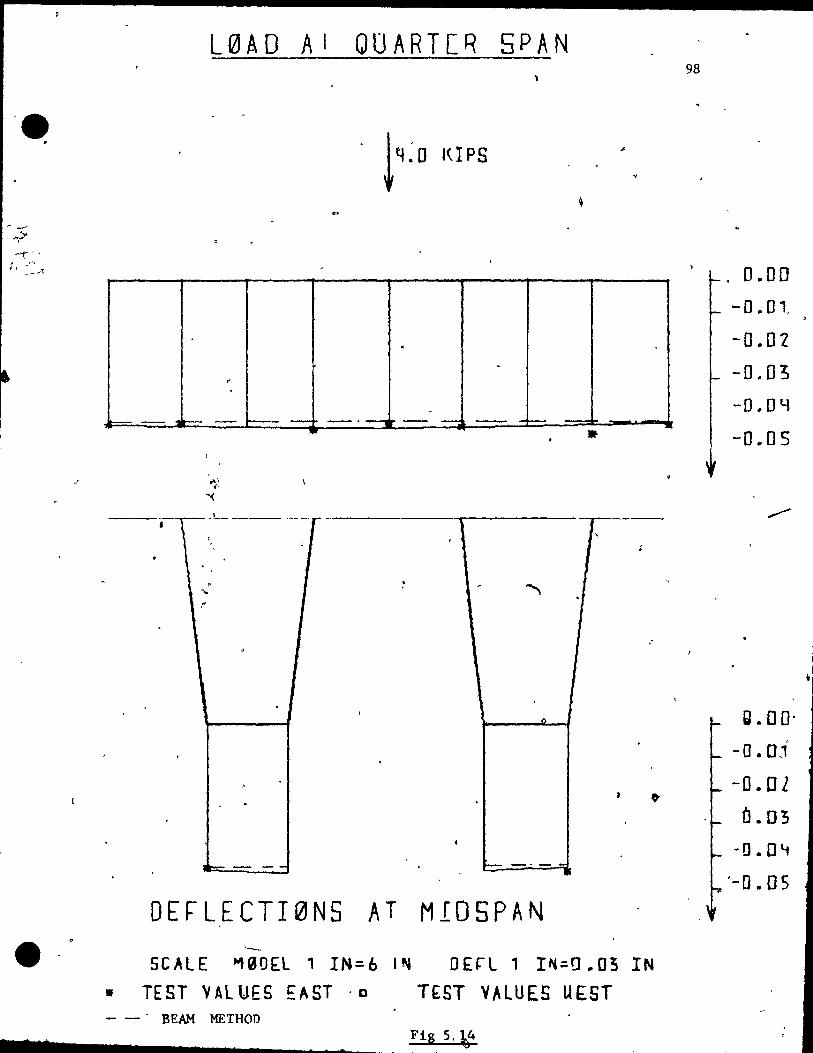
-e "
2 7 $
io--
•
LQ1,AD A 1 QUARTCR SPAN
. ~
.-. -
.. Ir-- t------ - ----, ---, - -1-- ---,...,,~- -
• , :L~----r-'------""'-I-----'I'--, ---,
.'
~
~..."...- -- ~ -" -..=
DErLECTI0NS AT MIOSPAN
SCAlE ~90~l 1 IN=b I~
TEST VALUES EAST "0
DErl 1 I~~a .. 03 IN
TlST VALUES U(ST - - - BEAM METHOD
•
98
_ 0.00
-o .. ol -0.02
-0.03
-0 .. 011
-0 .. 0 5
,.- 1
g .. 00-
-0.0.1'
-O .. Ol
Ô.03
-O.Olt
'-0.05
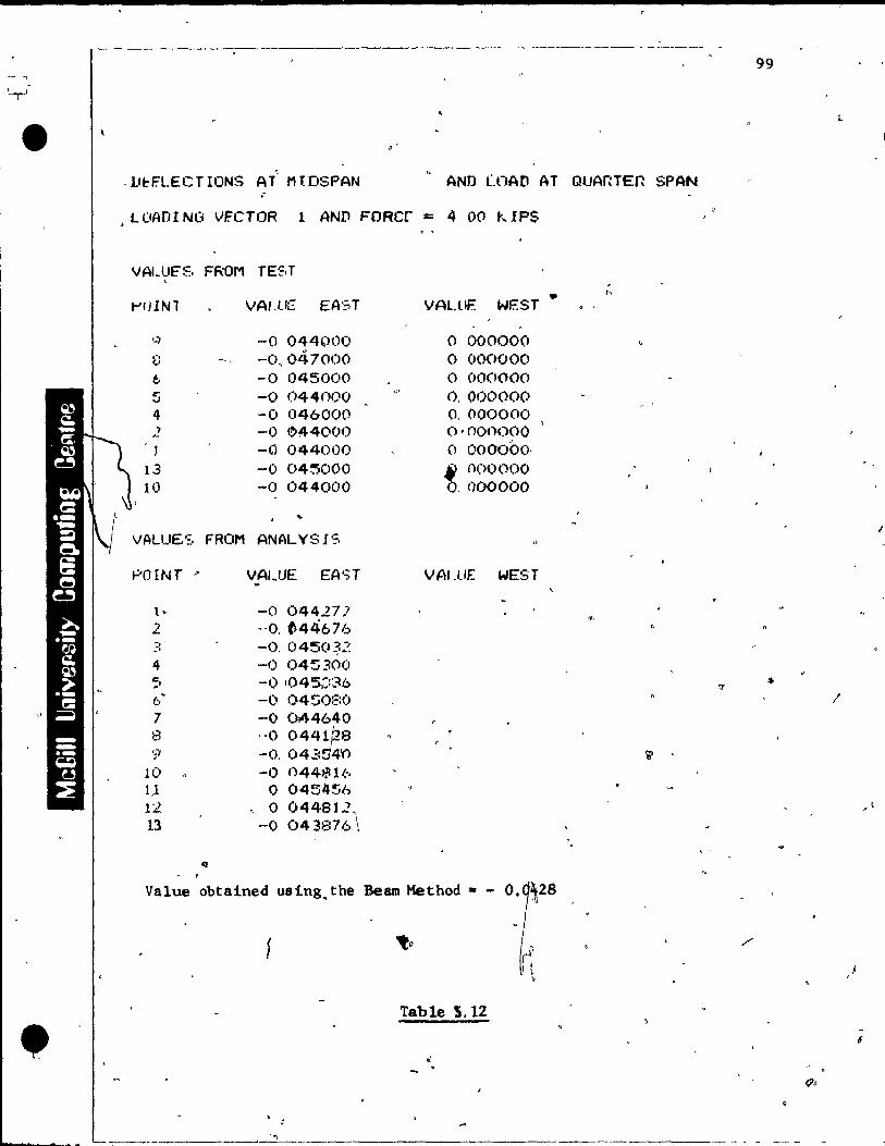
. ------- - --~-----
99
'~
l-e " . Lt~FLECT IONS AT MtDSPAN AND rOAD AT QUAnTEn SPAN
" > LOAOI NG VF.CTOR l AND FORer = 4 00 kIPS
VAUJF~, FROM TE~,T , .. /,
,...,JlNl VAl ,US EA-::,T VAU If:: WEST
..., -0 044(H)O 0 000000 ü -0 .. 047000 o 000000 6 -0 045000 0 000000 !i -0 044noo .. ' 0, 000000 4 -0 046000 0, 000000 2 -0 044000 o·nonooo
.'
-0 044000 0 000000-13 -0 04~OOO t nooooo ' .
10 -0 044000 .000000
.. VALUE':, FROM ANALYSIS
POINT " VAIJJE EA'=;T VAI.I./E WEST
1- -0 04427.' 2 ,,0. ~44676 :: -C). 04~O~:~
4 -0 045300 ';, -1) 104'5.:::86 .. 1:.," -0 04~()r::O /
" 7 -0 Ùl44640 8 ,,0 0441PS '? -o. 042:~4'() ~
10 -1) 044$16 1,1 0 0454~6 12 " o 04481.2'. 13 -0 043E:76 \
Q
- 1
Value obtained using.the Bearn Method .. - O. 28
'to
Table 5.12
• .. .
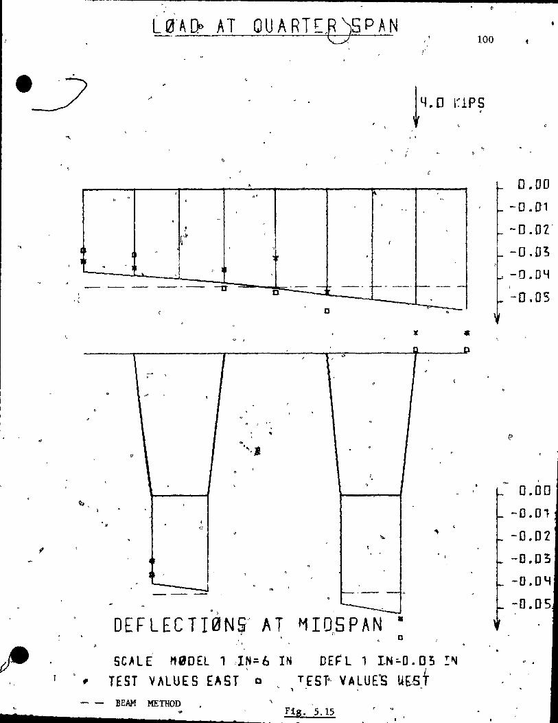
l, i
..
"
~ '-
7 2
-------------- -----~ ~----:---------------------
, , .
III
l'
~,
~
IJ
, l,
-
.
, ,
. , ·lt
1 ,
-
~ . ""
, '"
• J '--- - -=--
"
~ . t
c
-cr
o , ,
no" ...
. .. .. ' ... J
"
o "
• 0
100
t 4. 0 l~lPS 1 i
l' " , - . ,
J 1
,
-~ -' f-- - - -- -D ,
0 "
li[ • 1 D
,>
"
~
'"'
1--.- -0
-DE F LEe T l 0 N ~ .. AT ~I05PAN • n
0 , , - ,
SCALE MaDEL , ,IN=6 IN DEf' l 1 lN"O. 0 3 !~
fi TEST VALUES EAST 0 TES T"· V A LU E·S U~S,t , , - - BEAM METHOD
Fig. 5.15 r Q
1 1
0 .. 00
-O. n1 -0.02'
-0.0;
. -o. DY
-0.05
1
0.00
-0.01
-[).O2
-0.03
-0.0 lof
-O.US
. .

101
-r'
.' . AND LOAD ATdQUAnTER SPAN u~FLECTIONS AT MIOSPAN
~ d ,.
,
LOADING VECTOR 4 AND FORCE = 4 00 KJPS •
..... VALUES ,FROM TEST
" . 1
.. -~~)
VALUES FRO~l ANALYSIS
V~_~ " J-'OINT VAL:UF EAST' WEst ~
.'
1 --O. d36704 l' 2 -0 038372 ,"0
.. .3 ~ -0, 03·:)I;~b8. , --4 ·0 04ÎIIIJJO . .---;--
.". -0 04420'4 .......-1.--.----- 1 .. "- ... ' .-----' .
"-: 0 047020 ~ ....---.-----
6 7- -0 04f'264 ~ 8 -o. ~C:;l -J" CI ;.13200 -~ ?
10 .- .. l.~ -O. 04:3076 ~'
, 13 -0, 052452 l' " 1) • . 6'~_T
j )
.~ . • . ,
:- • Il'
. J
• '" , ..
,t
---~--- .. _-_.~----~. __ ._-------'."---~~-~_._~ ---- --
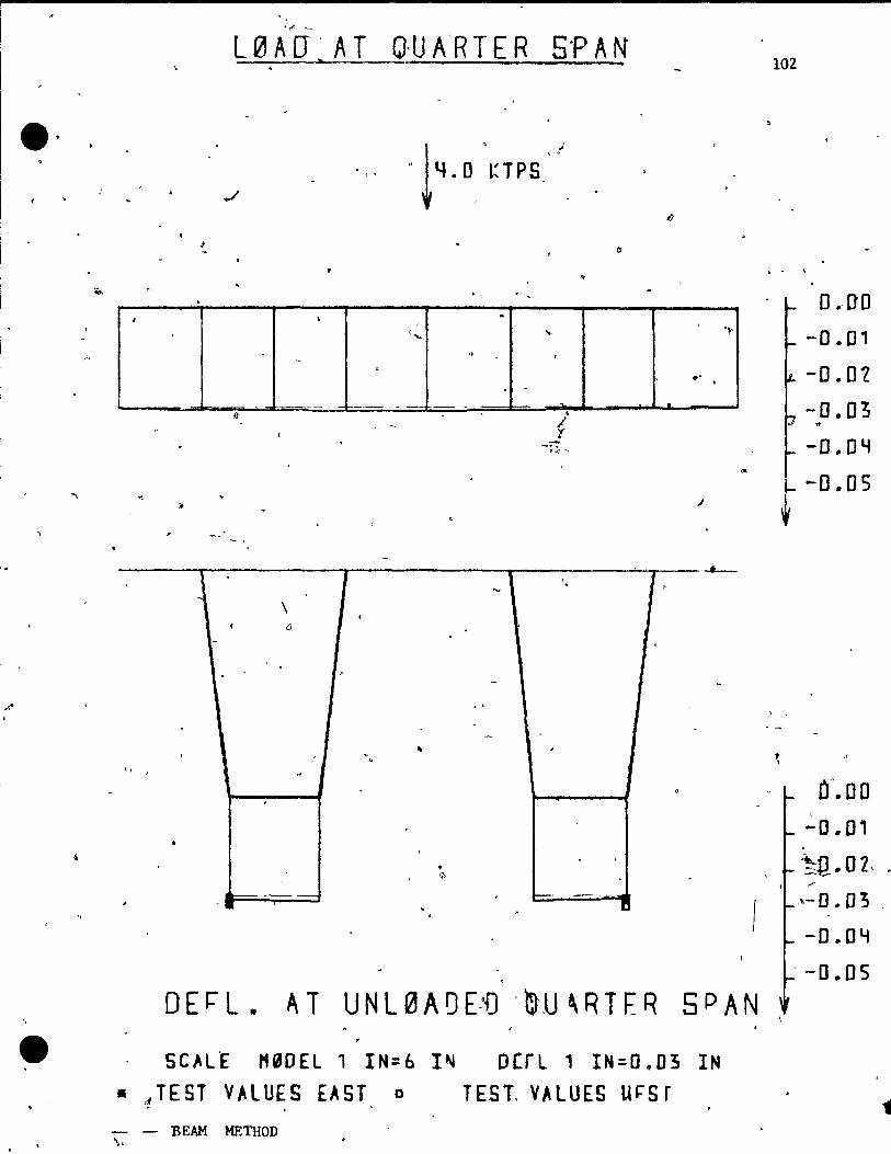
',f' -
L 0 A [J ~ A T O· UA' RTE R s·p A N
1·
1
1
\ <1
- --
1
1..,. .'
, Il
. --1
.
s'" v .
.. 0
1
'1<-
.' ..
.. .J
o E ~ L. A T U N L 0 A 0 E-'D . m'u 'R TER 5 PAN
SCALE M90EL 1 IN=6 I~ ocrL 1 IN:O.03 IN • ct TEST VALUES EAST 0 TEST. VALUES uÇS r
- - BEAM METHOD \,
102
. -
, \
. 0.-00
-0.01
-0.0,
-0.03 .. -D..Dli
-0.05
a". DO -0.01
~!l.02, . ;-
,\-0 .. D'3 .
-O.DY --0 .. 05
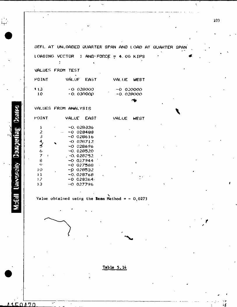
------------------------- -- ---- ----
DEFL AT IJNLOADED QUARrER SF'AN AND lOAD AT QUAHTÈR SPAN
lOADING VECTOR ANn·FOr.~ 7 4.00 KIPS
VALUES FROM TE~. T
POINT
• t3 10
VÀLUF EAST
·0 028000 • O. 03()OO,P
VAI.UES FROM ANAL YS IS
~'OINT VALut EAST
l -0.028,336 2 -- -0 02848:3 ...
.::> -0 028616
j , -0 02E:712 .. ' -0 0286'?6 6 '-0. 02E:5.?O 7 1 . -o. 02E::?52 8 -0 027'~44 ..:, -0 02'7588
JO -p 018532 ) 1 -o. 028768 J] -0 02:3::=:64· ]3 --0 O.'?77'~6
VALUE WEST
-0 0'::0000 -o. 028000
~
VALUE WE'ST
....
"-Value obtained using the Bearn Method a - 0,0273
, .
Table 5.14
,
L-_____________________________ .... ___ _
* D i.e: 0 t1 70
103
K
. t /
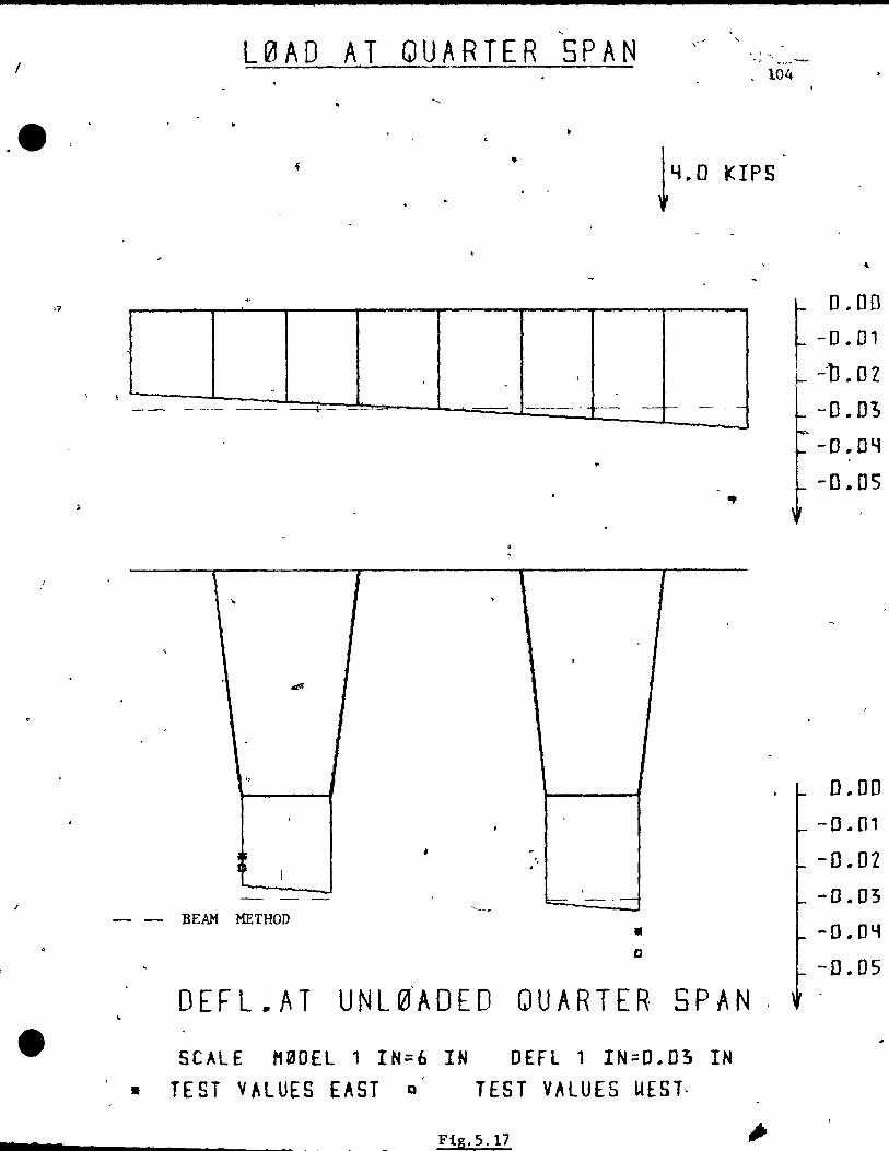
1
. e
/
2
..,
L0AD AT QUARTER SPAN . 104
..
• 1400 KIPS
.,
, 1 T ... ,
, ,
.ttfI
"
"
. ,
:t 1 . 1
J
-- - ~ ---'---~
- - BEAM METHOD • D
DEFL.AT UNL~ADED QUARTER SPAN
SCALE H00EL 1 IN=6 IN OEFl 1 IN=D.D3 IN • TEST VALUES EAST a TEST VALUES UEST,
Fig. 5.17
~ 0 .. 00
-0.01
--b .. OZ
-D.O!J
-D .. O~
-0 .. 05
0.00
-0 .. 01
-D .. OZ -0.03
-D.DY
-D .. 05
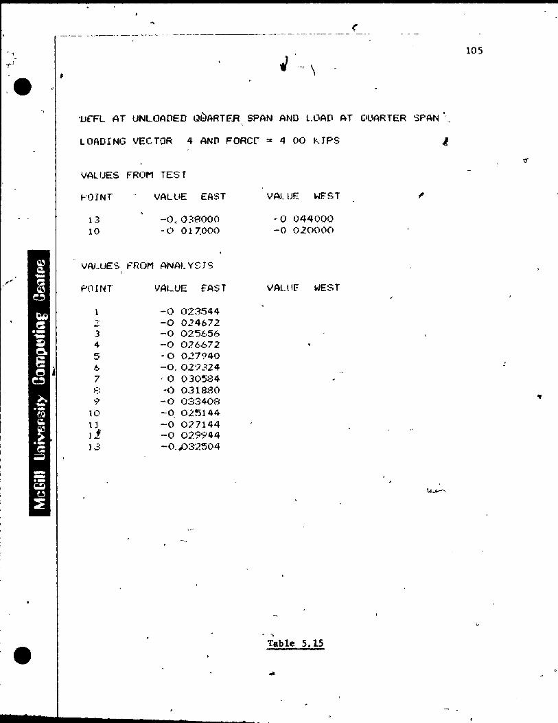
i
1
1
, , ,J
.e
l '
•
.\
( --- - - ---~. -. --------------~- ---.- --- - ._-
;. i "'-r \
'UfFL AT UNLOADeO t18ARTF..R SPAN AND L(\AD AT ClUARTER SPAN',
lOADING VECTOR 4 AND FORer = 4 00 KJPS
VAL UËS FROM TES T
.... 'OINT
13 10
VALUE EAST
-O.O?!8000 ~ 0 017.000
VALUES FROM ANALYSJS
P(l r NT VALUE fAST
1 -0 023544
" -0 024672 -3 -0 02'5656 4 -0 02(;,672 5 ~O 027940 6 -0.02'7324 7 ,0 0305:34 ,..:, .' -0 0.31880
9 -0 033408 10 -0 025144 II -0 077144 l1 -0 02'~944 1..3 -o. Jj32504
VAl. UF.: WF.'ST
-0 044000 -0 020000
VALllF WEST
, .. Table 5.15
105
..

-\
M «
106
load at center in the transverse direction.
Fig. 5.18 and 5.19 show the values for the deflections
from the firt1te element analysis and the test values along
the long1tudinal aX1S of the structure for the outside web
(point 13 in Fig. 5.2). F1gure 5.18 shows that thé test
vatluçs for the unloaded girder are maximal1y 16% tao small. ~J
Figure 5.19 shows that the test values for the loaded girder
are maxima11y 8% too large if compared with the finite '
element analysis.
The complete data for thé· toaded quarter span, the mid~
~pan and the unloaded q~arter span are inc1uded in Appendix
A. r-
5.2.2.2 Stresses
Figure 5.20 shows the values obtained using the simple
beam theory, the finite élement analysis and the measured test
values at the loaded quarter span. This loading,case is the
most eccentric case under consi~eration. The analysis pre
dicts the maximum longitudinal stress "'in the deck (-498 psi)
for th1s loading case~ This peak stress was confirmed by
the test, pS being even 29% higher than predicted by the'
finite element analysis.
Figure 5.21 shows the values at midspan for 'the above
--~.
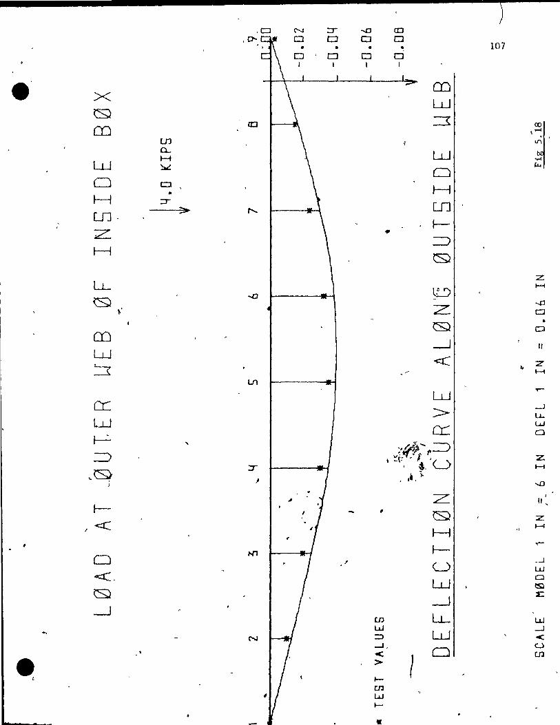
) .Cl N ::r ...0 a::J
.0- D CJ 0 0 . • • • • 107 0 , 0 0 D
1 1
e X CD w
cs;}
en ID ::3 UJ '~ Q...
W H W ~
.... 0
~
Cl CJ • H
H ::r-
UJ· > ,....... UJ
1--Z. • ::::> H
~
z l.L l:9
H
0 " Z
....0 0
en ~ •
CJ
-.--1 Il W ~
<C z t1
H
lJ)
W ..-
cr: w :> ---1
lJ...
r---:. CL: w
, a
=> ,.~'" =>
,,~. - l ."
J~ ,-t· 'u z.
, ~. H
, ft.). ....0
L Il l- ,
Q Z
1 <r: H " H
Cl Nl 1--
..... 1 .-1
<C. U w
W a tS)
\S;} --1
2::
~ en li- w W
N :::) W --.J
< --.J
e < 0 u
> 1
en
, ~
en w ~
•
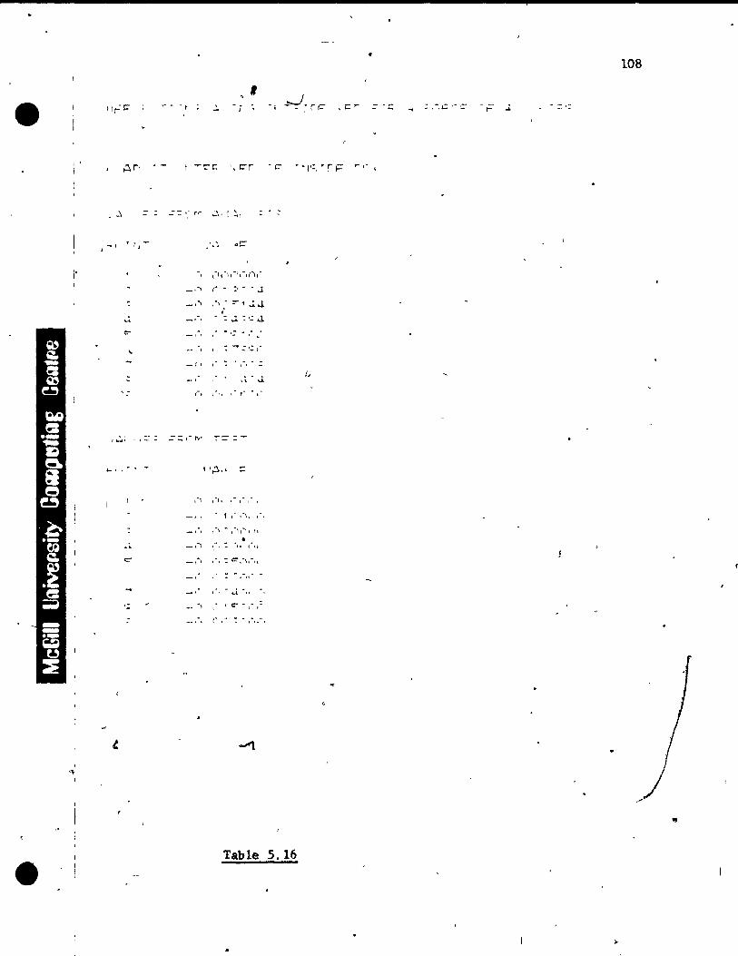
•
•
j'
'\ 1
,- ,
t , -
=
" ... "R , J
_il
1-'" =::: 1"""
, , -..
,
" CT
, ~I
.:: '.: 1 ~
ll~... ::
1· , .... , 1·'
,'"\ ... ,., ,-, l '1
\-, : "II· 1'" '.
,c: r
• "l':, • r ~ .. ,- ,
_!'"\ ,.,: '::,"\''"11
l' ... ~ .. ,.
t" ,- ..
Table 5.16
108
: ,-.~ ," ~ F J.
Of

Cl ::::r .....0 o:J
X 0'- 0 0 0
• • • • 109
~ 0 0
e m m ~
w w :3 0 H
en 0...
~ f UJ H W ~
~ Cl Cl H
~ :::r-
,~ >- en
" f-;-
:::> LL cs;} ~
z ~
...... CD Z
--.D Cl
W :::3 - & "!'
Cl
---1 Il
~ z. W 1-1
0 W ...--
H Ln
>-_.-1
? LL
cc: w 0
~ :=) -:=:)
~ T <IIU Z.
H
--0
J z: Il l--
<r: \SJ z H
......
t-..--
0 <t:
U ~
1 w
~ W
0 I.:S)
---1 ~
--1 \
en LL w LU
N ::::> W ~
-<:
• ...J \ <: Cl
u
>-en
1-
c.n W
-/ l-
i
r c .- If •
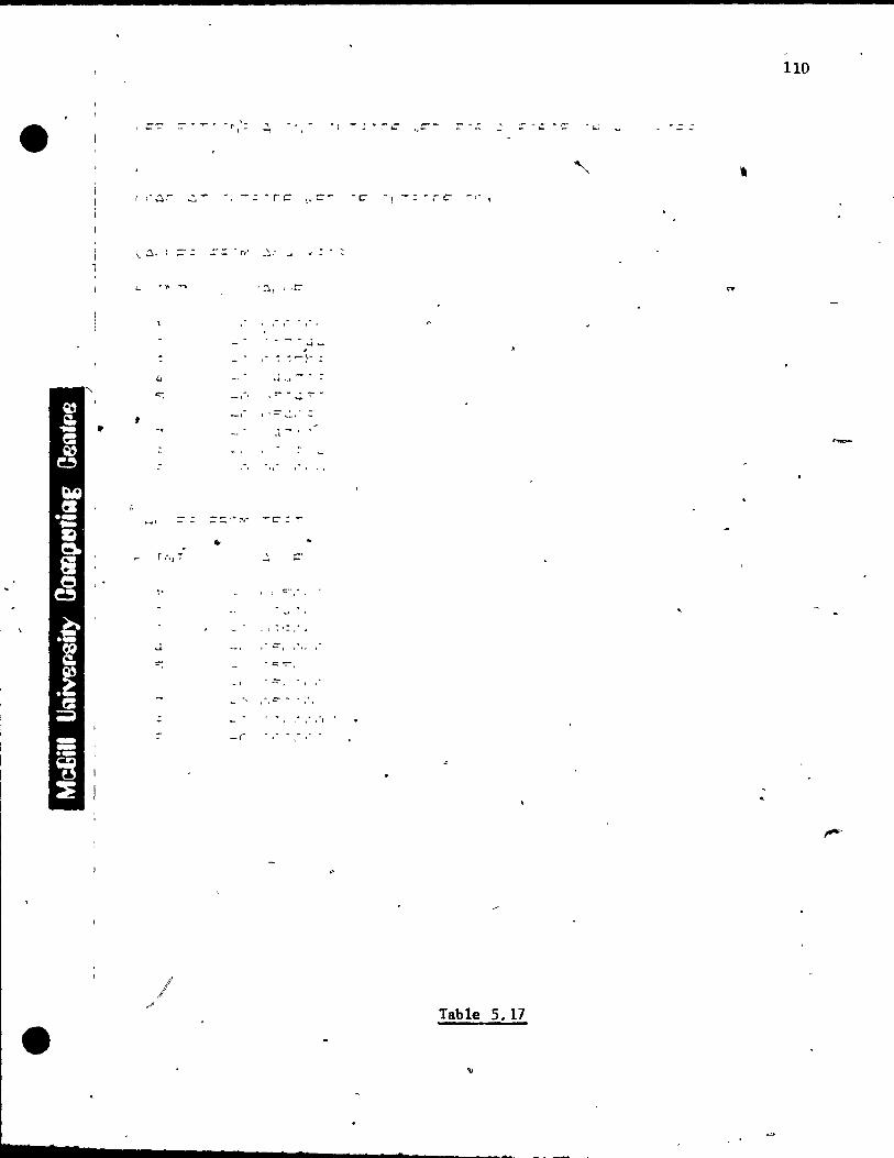
110
- ri: - f r .-C
- - r C' - ,. 1
1 \. ~,
l
-, '
t 'C" ... :,~ -
• ~1. ....
::-=:'''r,.· -c:- : ï
.. T :\1 T
, C' -
l' 1 c-.·.
, r.
"
, '
"
1 Table 5. 17

, '
-
T
. ,l, -,
' ....
L0AD AT QUARTER SPAN \. ,l'
" " " " " " -- 1 r " --•• -., 't " " ... ----.... -- ... -.1... t ,- 't ---------\,,"'- : :: . "'..... . "
c "'--..!_ • , : : 1 ___ ;-~ ___ t _~ __ -I __ ......... -~ ..
... "' ..... .,t : : ~ .,------... J ; .:
'",' t
•
..., , ....... t ,
..,., , t
. .... .. _--------,
o , 1 1
----------.-Il
- '-- -
-- .. .. ..._-- .. --.-
L~_ --- BEAM METHOD
STRESS AT L0ADED QUARTER SPAN
" 111
O. -100. . -ZOO . -~OO .
1
~-YOn:
L- 500 .. i
V
o . -100.
-200.
-100,.
-YOD.
- SO o. - 60 0-.
-700.
-Bon. -900.
s c'A LE'" M ~ 0 EL', l Ff == 6 IN, ST RES 5 1 IN:: ~ 0 0 PSI
• TEST VALUES EAST 0 TEST VALUES UEST - DL STRESSES FR~M ANALYSIS . 77 I! STRESSES FR0t1 ANALYSIS
Fig, 5.20

112
::' H~r'3'=, AT LtJADF-D ')UARTEf< ~,F'AN AND LOAD AT OUARTER ':'F'AN
LliAflINC, VEC fOR 4 AND FORer -- 4. 00 I,IF'S
vALUES FROM T["'3T
I-'U1NT WH 11[" EA~,T VAL Il::: W[':,T
t -175 ('0000(1 (1 000000 4 -200 ,1)00000 -~35. ooooon (-, -35~ (1(1 (If\(H) -335 000000
'-' (1 000000 645 nOO(lO(l ln -So:,.() 00001""0 -455 000000 1 l --6 ~5 OOOO(l(1 () (H)O(J(l(""
12 1), (H)('OOO -345 000000 .... l -: -21:.'5 ()OOOOO 0 000(1C'O
\{I~I UE':=, FHOI'1 ANAL Y'=, r ';
~'II.lNT VAL Uf EA':' T VAL ue WF.:~,T
t -7:: l':";:' ,-' l" ; -Il t: 7')f~::!l)5,
:: - 1 ::;'::; 7':-"::;:~ .. ""f! 4, --15el 0':''=/60':;' 5 .) -,,-,
--;. .. (1 (1(1(1 ()(1
I~ -:: .. ~'':;; ';"j':, 6,'\':/4
1 -37Cf 7'Yf:.:=:75 :-: -484 oooO(Jn '-1 -4'}:=: OOO<.\O,y
10 -4.20 60-1562 1 l 1 -466 6Ql'56.3 1': --207 2(131."'5 l -, :.' -1 ;:2. 0000(1(1
1 \. •
Values obtained using the Beam Method ) '--
Top or. deck = - 276 psi
Bottom of girder .. - 362 psi
. Table 5.18
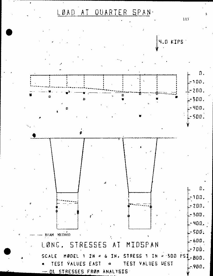
, e---~~~------~--------------------------------__________ _
• 1
•
, .
•
cr
,"
L0AD AT QUARTER SPANa 14
tI'
• , , Q
lu'
J'u KIPS·
l , ·f , ., 1
l , , , 1 1 1 • , .
D.
-, 00.
- -��_- - ---.~, 4- ----t ~ ~--D--- ... ---._t 0-200.
1-;00 . 0
" D
~
" 1 , ,
--....... ~ -- ,::'"-~
l ,
1
, t>
o
•
, ? l
~ - -'-lL .. ---~--- __
1
• •
T
--YOD. ",
-500 .
O.
-100.
-200. . -:son.
- 'iD O .•
o ~ ~ B'EAM MEiHOD -SOO~
L0NG. STRESSES AT MIDSPAN -600.
" ,
"'700. SC~LE M0DEL 1 IN : 6 IN, STRESS 1 IN ~ '300 PS -BOO. • TEST VALUES EAST ~ TEST v~LUES UEST -.9BO. - Dl ST RE SSES F.RI2!M À NA l Y SIS"
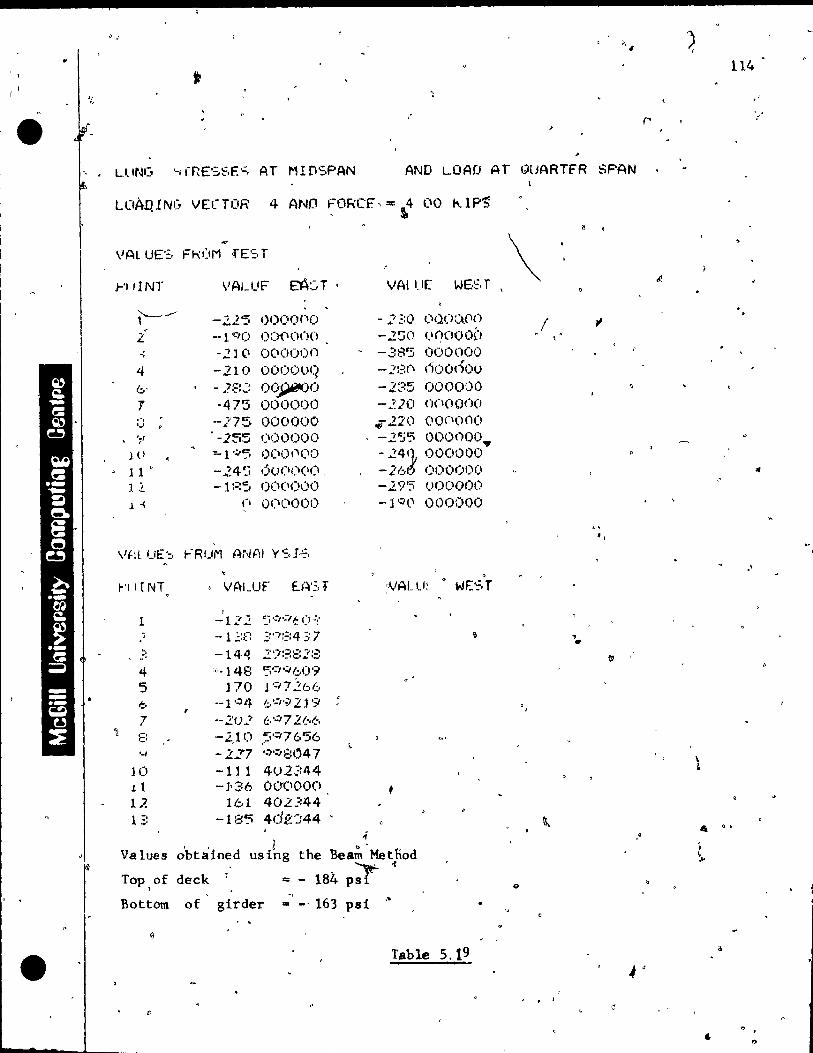

~
I~
-- .
-, /
'~,
115
)
mentloned loading case. -The mlnlmum stresseS ln the deck
for the unloaded glrder wer€ computed to be 50%.of tho , - ~ maXlmum va1ues of the dee~ for the loaded glrder. ThIS IS
mueh less than the 8~% ~ifferencc of the pOInt wIth th~ •
maXImum strass to the pOInt wI~h the mln!mum stress, for the
above loadlnq case, and shows that the load was better dlSl'
trIbuted t~ the unloaded girder w]"th Inerec:u:anq distaneè , .
ta the cross section ~~re the Ioad was applie~. l' ,
~ ~ ..
From the case where thc'Ioad IS appiled at quart0~ , , .
span, the sarne conclUSIons, l tp 5 ln Seetlon 5.2.1, can
be drawn. .F 19ure.s and t~ahles for the () thcl,l' tes ted eccen-\
5.3 LOADING SIMULATED Ta BE EQUIVALENT TO A H ,20-44'TRUÇK
A s~atlçally d~tcrmlnatc frame was constructed to SlffiU-
late a Il 20-44 ~ruck load, by dlstrlbutl.ng the loa~l applled
byone Jack ta two front wheels and ta two rear wheels. t:> ..
Each· front wheel was loaded with 10% of the total load, 1
whlle each rear wheel was loaded Wlth 40% of the rotaI • .
applled load. The rear wheels were placed where they would . . produce the maXImum bending mon;,ent, e. g. the rear wllee ls
~ .,
had ta be located 4:6 Inches to the north of,the midspa~
and the front wheels were located 4D inches to the south
•

"
" 116
of the midspan of the mode1.
The load was applied from zero kips up to the failure .
load of 32 klpS in increments of 500 pounds. One truck load
wou1d "be th'e equivalent of 3.54 kips applied bi the jack.
These wheel loads can be-simulated for the mode! as follows:
, . (--l) 2 (P ) = * (P )
m 51 p
where P = equivalent load for th~ model m ;'
SI = length scale for the IOOdel
p = lOfd on prototype p
The cracking load was computed as 6.95 kips or i.96 times
the truck load. However, th~ first crack was noted o~ly at
a jack load of 15 kips, Which is 4.24 times the truck load.
For load values of 10 and 15 kips the values for de-\.,-
flections from tHe flnite ~lement analysis and from the test
are shown in Fig. 5.22 afid Fig. 5.23, and the numerical l
values are given in Tables 5.20 -and 5.21.
" . 5/3.1 TRUCK LOADS FOR WORKING AND OVERLOAD LEVEL
5.3.1.1 Def1ections
The def1ections of th~ cross section for 10 and'15 kips
loàd pre shown in Fig. '·5.22 and 5.23. At a jack load of 5
~.
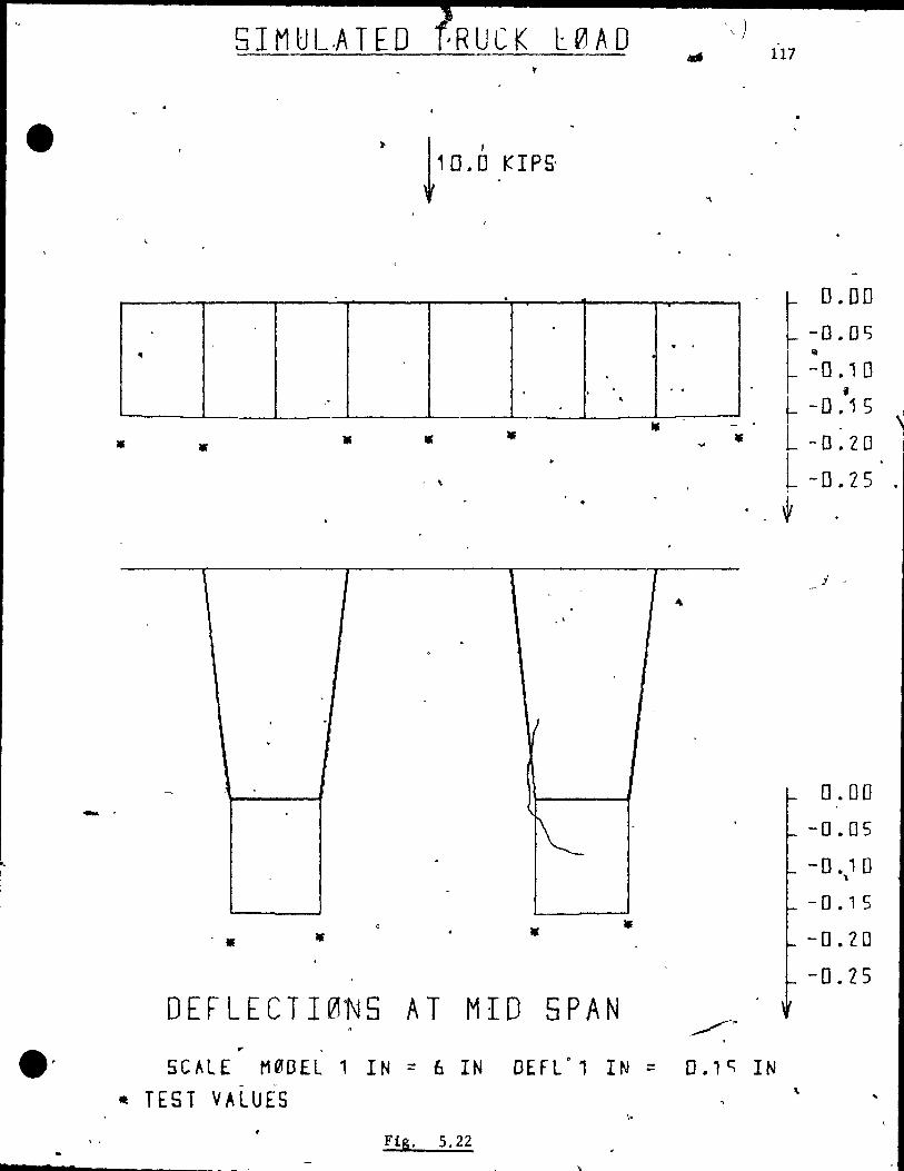
5 l M U L.A T E 0 ' Rue K l 0 A 0 . .. 117
~1D.6 nps
"
• •
1 1 1 ~ . . ,
, .
. .
-- .
~ . -
-. •
DEFLECTI0NS AT MID SPAN • ' " . 5CALE M0DEL 1 IN = 6 IN DEFLO, IN = O.l~ IN
Il TEST VALUES ,
Fig. 5.22 7 .
0.00
-0.05 'iII
-0.10 , -0 • 1 S
-0.20
-0.25 ,
j -
0.00
-0.05
-0.10 "\
- 0 • 1 S
-0.20
-0.25
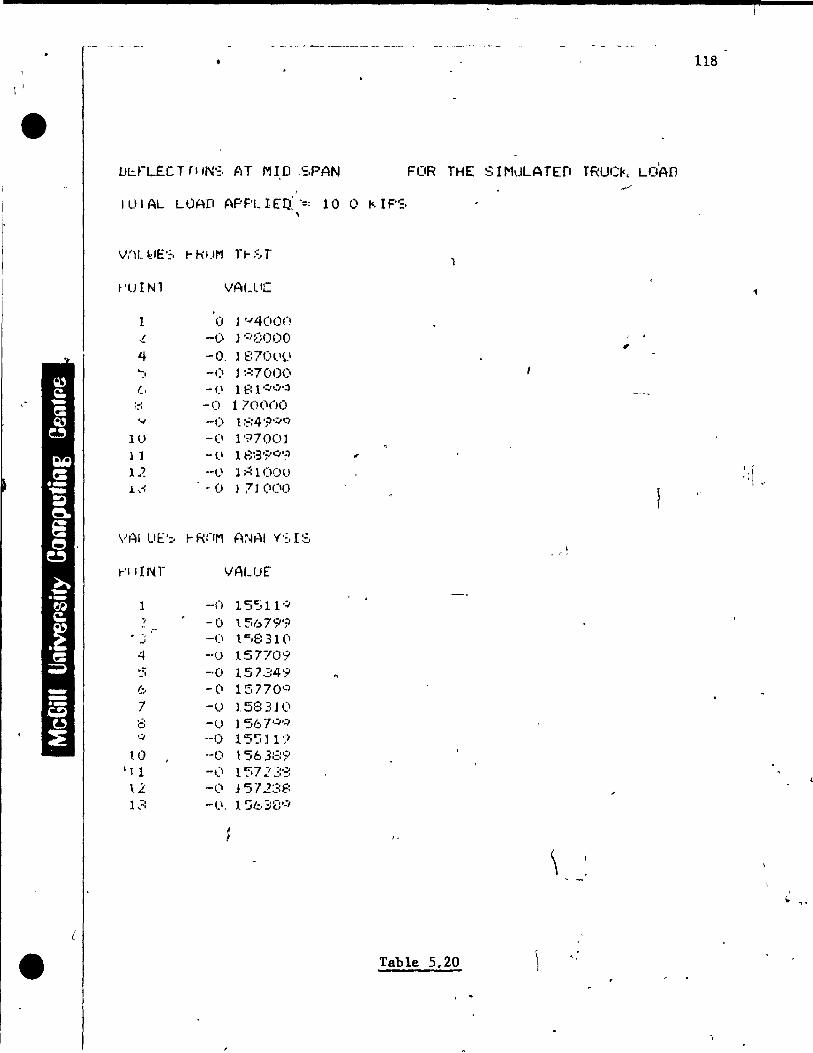
t 118
1 )
• LJl:.fLËC TrI IN':. ATM 1 D ,-:.PAN
1
FOR THE SIMLILATEfi TRUCft. LOAD 1
1 LI 1 AL LÛAfI APF'L 1 fIl -:: 10 0 .... 1 F'O:. ,
W\L feIE':, t- HUM n-::~T )
~'uINl VALue
1 0 l '~4(IO(J
-!. -0 J ':"8000 , . , 4 -0, l E:701.'t\
'":' -(1 1 :~7000 (, - (1 1 E: l ,::;...:),:)
. . .... -0 170(\()O '.'
',.J --0 t :::: 4 ';)o:/e'/
10 -CI 197001 l l -li 18:3';/..:)':-> ".
1.~ --0 ]~lOOll J. ,..: -0 l 71 (1(10
, \ -. "
VAl Ut':, r-RnM A~~HI Y':, I:=-\
, "
j-'IIIrH VALUE
1 _on 15'511':;--, -0 t 5679';> - .-. ' . -Ci t c,8 31 (1 .J
4 --u 157709 :.:; -0 157349 (;, -(1 15770':) 7 -v 15:::31(1 .-. c' -v J 56 r:":, .;, --1) 15:' 11 'Î
10 --1) t 'S6 3:;::9 '1 1 -,) 1'37:2 3!?' 12 -Ci j '57 2:3E: l -, ,-, -(.l, 1 ':;/.:,3(:'':'
~
\ - -'
• Table 5.20
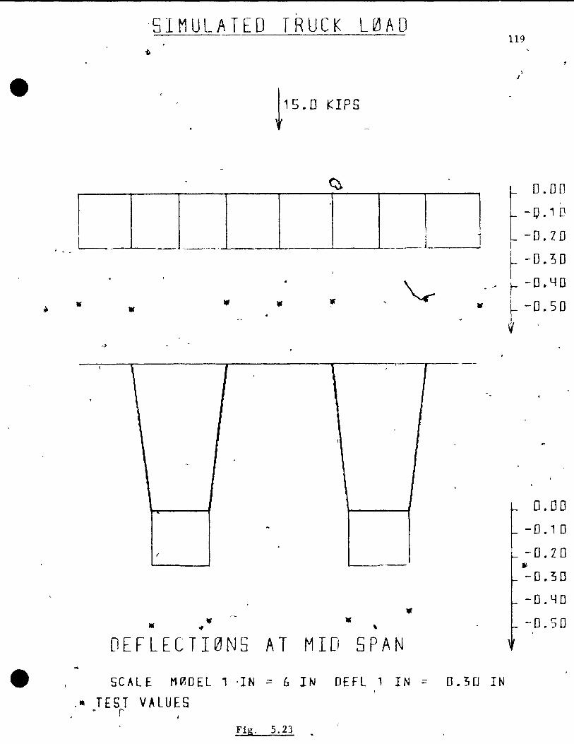
•
'5IMULATED TRUCK L0AD 119
ù
J
1 1 1 1 1 1_1 1
rD. 0 ~
t-O•1IJ
-D.ZD 1
• "
1 \ 1 ,
-
~
• • '* OEFLECTI0N5
.. SCAL E M~DEL 1 ·IN
• TEST VALUES 0 r
FiS·
-.,
1
~
-
• \
AT MID SPAN
= 6 IN OEfL 1 IN
5.23
[
=
,
~ -0:; 0 1 -- f -O~YO
• -0.50
1 o. 00
1 -D . , 0
- o. Z 0 ~
-O.!JO
-0.40
-0.50
0.30 IN

120
furAt. LOAJ) APPt JEff :' 15 0 I,IPS
\lAl UE '::, t- ROM TF f, T ,
t'IJINl' VAl !.I[ .~
l -(1 4710(11 ~
-() 41:"J':)'~C!
4 -l) 464001 ( :. ·0 470001
(, -('1 46:::001 8 -1) 453·:":") '.) --0 4 :=:(.'<'.'(} 0
1<..' -0 49':001 1 1 -0 47 .. :.'00(1
l.!. -0 4t.é,'.:)·':;·9 } 3 -() 42:::(j() 1
VHl UE':. t-R(IM ANAl. Y'::. 1';
I-'CI r N r VAI.ur
1 -0 ..:. 3:267':/ ", -0 23'5":(l] ~ -(1 ":;:746:' , 4 _.() _, 365t13 5 -0 .? :!1;., f)2 .::! " b -,0 .:'36:.60 3 7 -0 2 ;:741.:.5 f' -' --Cl ..2: 3'5.""(11 'il -(.1 13267'';}
10 ·0 .! ~45:~;~ 1 1 --1) .. !: .:::;::::5 ..... 1
l..! -0 .. ; 35:==S';.-' 13 - () 2~: 4 -=jE:5 ,
• ( Table 5.21

121
kips (1.41 tlmes the truck load), the test values were ·)ti1.1
ln close agreement with the finite element analysis. At a
load of 10 kips aIl the values were higher by 10 to 20 per
cent, indlcatLng a decrease in the bridge stiffness beyond
the elastic range.
For a Jafk load of 15 kips, as shown in Fig. 5.23, the
test values are about tWlce those predicted by the theore-
tical analysls. Slnce the entire cross sectlon underwent
the same deflection, this confirms that the load was equally
dlstrlbuted across the section. The deflectlons along the
outsidc web, e.g. reference pOlnt 13 in the cross sectlon of
Flg. 5.2, are shawn in Appendix A.
5.3.1.2 Stresses
V Flgure 5.24'and Table 5.22 show the stresses for the
cross sectlon at mldspan for a load of 10 klpS. The stresses
in the deck, compared with the results of the finite ele-
ment analysls, are a maximum of 30% too high. The experil'
mental values of the stresses ln the deck are aIl on the
highét side, ind"icating that a redistribution took place in
the composite structure from the glrder to the deck.
The stresses a~ the bottom fiber of the girder are
tensile, since the girders were pretensioned to have ~ompres-,
sion stresses across the entire' cross section, for the working
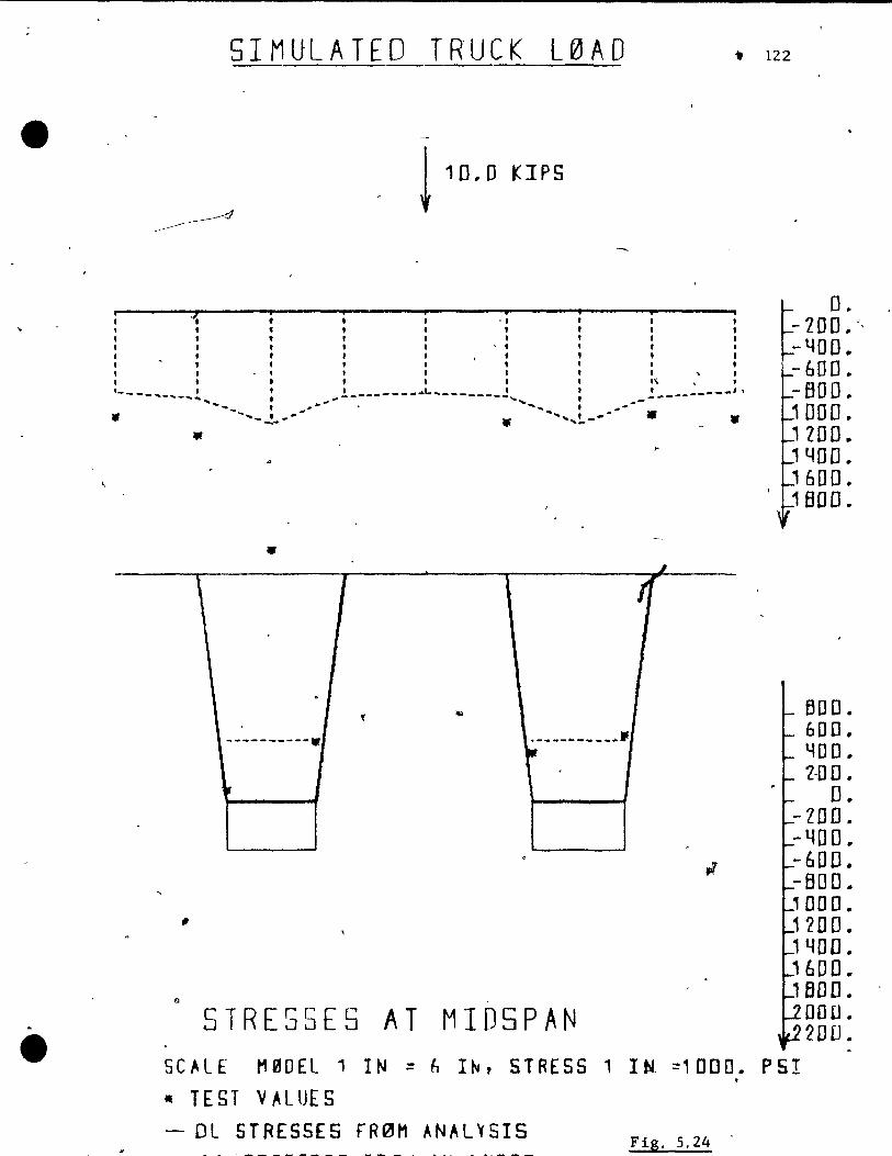
. •
SIMULATEO TRUCK L0AO .. 122
! 10.0 KIPS
:::: . i : " "
D. - 200. "
" " ,. . . ,. •• t t , -400. ,. t'., , • • "1 1 - 600 .. ,. 1 t 1\,' t---_ ... _ ... _ .. 1. t l_------- ....... ------_..! : ! __ --------.,
.... _-... : ,M,#Ji*-- • ..,...... , ~~ ... --BOO ..
• "' .... --! ..... -- • "' .... , .... !..---. •
• ~ , 1 "
. "
li>
----------w . _-------_ ... II' .
,
" STRESSES AT MID5PAN
1000 .. 1 ZOO .. '400 .. , 600 .. ',1 BOO ..
600. 600 • YOD .. 2-00 •
0 .. -ZDO .. -400. -600. -BOO. '000. 1200. , 40D. '600 .. 1 BOO ..
DO 0 .. 200 ..
SCALE t1PJOEl 1 IN ;: h I~, STRESS 1 Itt :::1000 .. PSI . • TEST VALUES - DL STRESSES FR~M ANAL~SIS
Fig. 5.24

,.
------------- --------------
':. TRE'S'-,(':; ATM l DSP,AN
PO INT VALUE
l --..:)8r:i 000000 ! - Il 5'5 . onnooo -, • 220(1 ooooon .:,
/;) -10:::0 OOOOO() :-3 --<.i6':' ()('\OOOO ~I - 1 ( )()':.~ (IOO!)OO
H' l 1 J":' -l -:
WH UE'::,
~'llrNr c
, )
-!
"+ ':' Q
1 . .:' '.'
10 11 12 1 -, ;,
103 (iOOOOn "',45 oonooO 440 OOCtoon hf)(\ nooooo
~RO"'l ANAL Y':' r '';;'
VAl ur-
-7'::,2 03'.:)063 ~'7' 31~':'OO
- 1 (Ill'::: 72.437'5 -793 41406:: - /5'") 3~/()6..!':.;
- lCI ::~ 4140(,,:: --1043 7:::437:::;
--7'=") 31~500
5/-,7_ 640625 ~62 04b87~
5b.-", 04&875 5/:.2 64062":i
'\
FOR nIF SJMULATED THuel<.. LOAr)
..
Table S.22
123

• 124
Ioad leve1. Strain gauge readings for concrete in tenslon
cannet be relied upon and therefore, no definite concluslons
can be drawn.
The measur~d stresses are syrnmetric which aiso conflrms
that the applied loads were distributed fqual~y about the
center 11ne, and "that the materialand geO~etrica1 proper
tics were consistent for the who1~ structure. The stresses
were caiculated using the finite element ana1ysis and the
test results for loads of 5 kips and 15 kips are shown ln
Appendix A.f
5.3.2 Ultimate Load Test ----------------~
For the final test the slmu1ated truck load was irlc~sed
ln stages of 500 pounds untii failure. The study of the
behaVlor Inciuded the observation of the concrete and steel
strains and deflectlOns at dlffërent loadlng Ievels, as well
as the marg ins of safety against the ini tlal cracklng and
the mode of failure.
The ultimate strength of the Ioad mQdel was computed
using the AAS HO Speèifications, and was noted te be 23.2 kips,
which is 6.56 times the live truck lead. The de~ign is des-. "
cribed ln detail in Section 2.2-.2.11. The theoretlcai mode
of fa~lure was calcu1ated to be the bending type, with the

• •• .
-e
7
125
prestressing Wires and the wire meSh yielding. The depth of tV
the compression zone at this stage was 0.67 inches. Thé
experimental failure load was 32.0 kips which is approxi-
mately n,ine tl)nes the truck loa~. The
deflection cu~ve is shown in Fig. 5.25
up ta 10 kipS applied load; the system
Ilnearly.
experimental load .r
Whic7 shows that at
behaved almost
For the total load values from 10 to 15 klpS, the deflec-
tiORS are approximately twice as much as computed by the
finite e1ement analysis based on linear elastlc materlal
properties. This is due to a decrease ln the bridge flexura1
stiffness, w~ich is due to cracking and a graduaI decreasing
modulus of elasticlty of the concrete ln compression at
hlCJhcr stresses.
5.3.2.1 Cracking Behavior
The first crack was observed at a load of 15 kips and
appeared as a tension crack near the mldspan. This crack
immediately propagated up to about half the depth of the
web.
With a slight increase in the '.load, many more ot'acks
appeared close to rnidspan in both girders, however, these
cracks remained closed up to a load of 25 kips . .t. This lndicated

• • LOAD IN KIPS ...
__ -6---6 ........ GIRDER WEST FAlLS IN TENSION ç __ 1:;- - \ ULTIMATE LOAD CAPACITY. 32.0 t<IPS
1:; ,.., -'1" 1 • 1 // 1
/6 1 ~ l ,
, '1:;/ CALCULATED ULTIMATE CARlCITY , -~-t- - - - ----- --'--r _._- ----- -.---
/
/ ,
CO~LAPSE LOAD· 14.0 KIPS
~ 1
1 1 ELAsrle OEFLECTION FROM THEORETlCAL II
/ ANALYSIS
, .~I:; FIRST CRACKS OBSERVED " ---GIRDER EAST FAlLS IN TENSION
" . , ---j REQU.RED ULTIMATE LOAD CAPACITY IY AASHO , "...---
---.----------;- ---,--- --- /~;7---ï
, ./ 1
l/'I , ~ 1
--- CALCULATE~ CRACKfN~OA9 -'- --- r _. /.? -,--- - --·l ____ .EQU-'VAL:ENT LOAD-.!..~ ~ 20-44 TRUCK ___ t-- L--- _ __ __ _ ~
WITH IMPACT 1 / 1
1 ;1 1
.li _______ __ _ J
MEASURED VALUES
.- )2- 3- 4--~--I---T - --T~'--- 10- ....
T 1- 8- 9 N
.----- 8- 7 DEFLECTION "" !5"
FIG. 5.25 LOAD- DEFLECTION CURVE FOR THE \ ULTIMATE LOAD TEST .'.

•
(}
. .... ft
127 "
o
that the f1exural bond was adequate to distribute the cracks
af unlform spaci~gs. ~ ~: ~
\
1 The an.cltorage bond did not become excessive anywhere
p ~
at the end of the girders. No cracking or any other form
of flexu~al bond distress was observed in the web regions
neart the supports .
.At an applied load of 25 kips, the cracks started wlden-
ing, espeçlally the crack at midspan. It must be noted from
the load deflec..t1on curve that thlS" curve f1attens out falrly
rapid1y at a load value of 26 klpS.
The propagatlon of the dracks at loads of 15, 15.5,
17, 19, 25 and 30 klpS, is shawn in Fig. 5.26 for the "Cuts ide
face of the west glrder. Near failure the crack propaga-
t~on could be clear1y seen, even at the bottam of the deck. . . The cracking pattern for the(east girder was almost ldentl-
cal ta that of the west girder.
5.3.2.2 Fai1ure
Fal1ure occurred exactly at the midspan where" the bending
moment was the 1argest. The bottom strands in the west gir-, . -
der were observed to fai1 'in tension. The dead load then had
'ta be q)arried by the other girder a1one. This immediate1y
.....
L
"
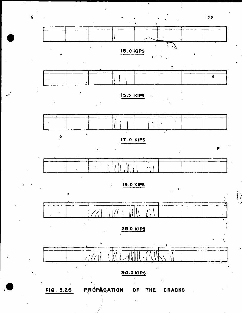
-
o -
128 _
[ l ' 1 1
! . 1 .1" Il! \ 1] 1 ~ 1
I~.~ KIPS 0
, f _
17.0 KtPS
.. .
o 19.0 KIPS
, ~ ~.~-
l '. " l' 1 a 1 \ 1 a 1 ~ lh L\ ~ l l ' ,1'"
1
FIG. 5.26
,
" 25.0 KIPS
3'0.0 KIPS , ,
P~RJPA~ATI ON OF THE ,CRACKS
) ,
- ~ r
l' . 1 . :
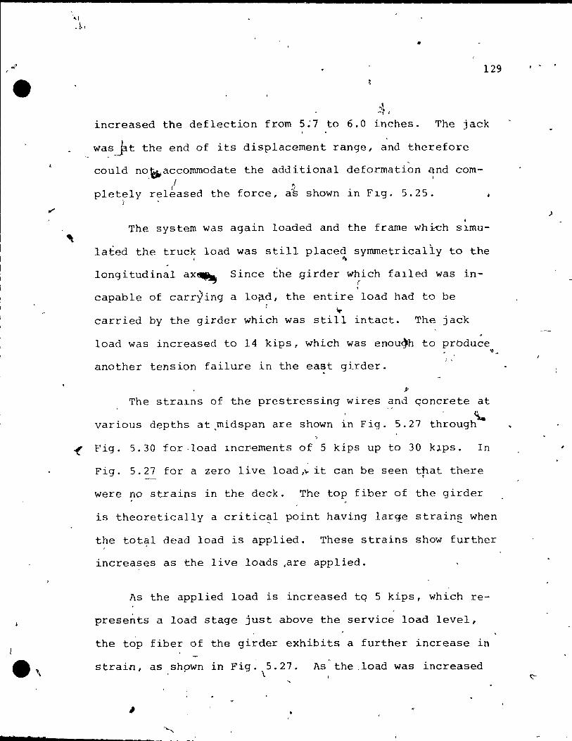
2 • •
'", .1 .•
,
•
129
~, increased the deflection from 5:7 to 6.0 inches. The jack
wa~.yt the end of its displacement range, and therefore
cou1d no.~accornrnodate the additional deformation qnd com-1 .
pletely released the force, a'~ shown in FIg. 5.25. r
Th~ system was again loaded and the frame which SlffiU
lated the truck load was still placed symmetrically to the , ~
longitudinal ax~ Since the girder which fa1led was inr ,
capable of carrying a lo~d, the entire load had ta be ....
carried by the girder which was still intact. The jadk
load was increased to 14 kips, which was enou~h to prbduce
another tension fai1ure in the east girder. J.
)1
The stra1ns of the prestressing wires and qoncrete at . ~
various depths at.rnidspan are shown in Fig. 5.27 through
"
~ Fig. 5.30 for·load Increments of 5 kips up to 30 klpS. In
Fig. 5.27 for a zero live load ,1.- it can be seen that there •
were no strains in the deck. The top fiber of the girder
is theoretically a critic~l point having large strainê when
the total dead load is applied. These strains show further
increases as the live loads ,are applied.
As the applied load is increased tq 5 kips, which re
presents a load stage just above the service load level,
the top fiber of the girder exhibits a further increase in ~
strain, as shpwn in Fig. 5.27. As the .1oad was increased l
\ '
)
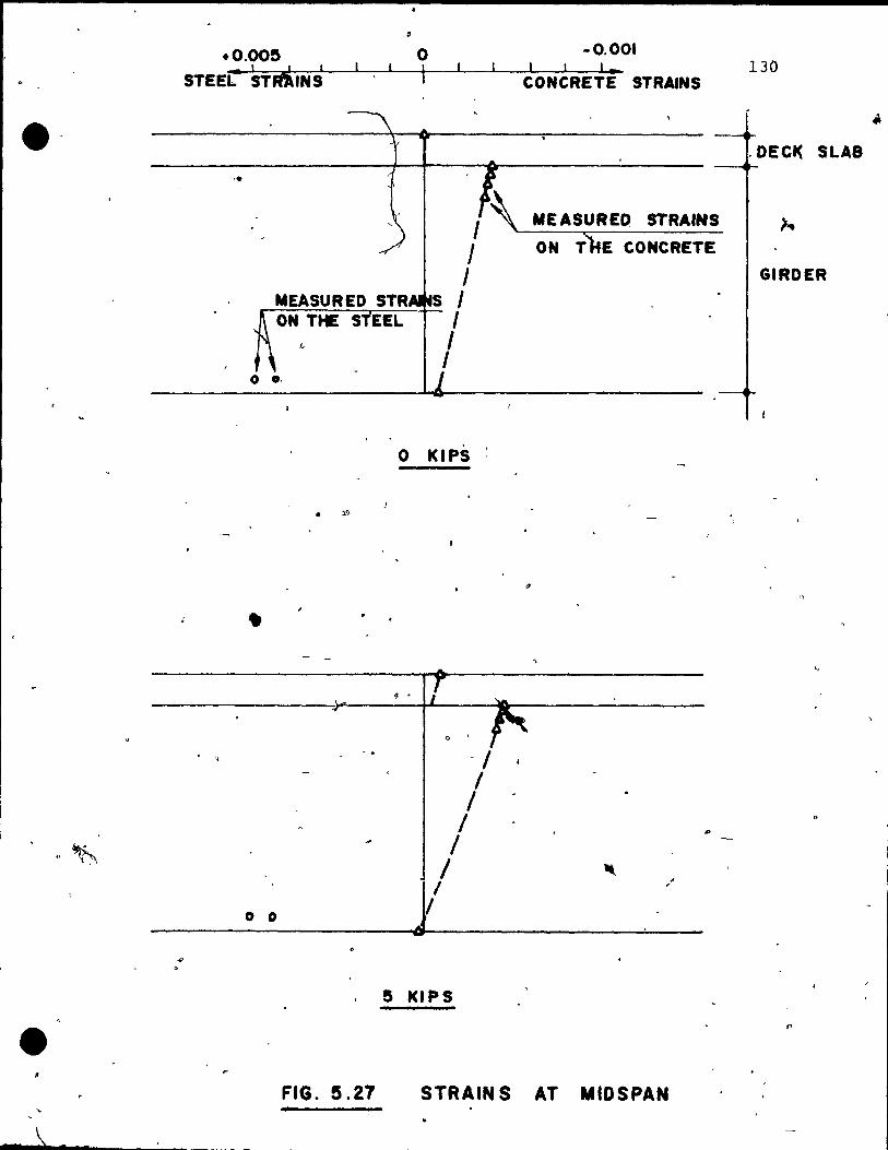
e-
.0.OO!5
STEEL 'TRi'NS
'.
o 1
1 1 J
S 1 __ ~~~~--4- 1
o o.
• ;,;\>
•
1 1
o KIPS
-0.001 1 l '_ 130
CONCRETE STRAINS
.DECI( SLA8
STRAINS
E CONCRETE
GIRDER
,.
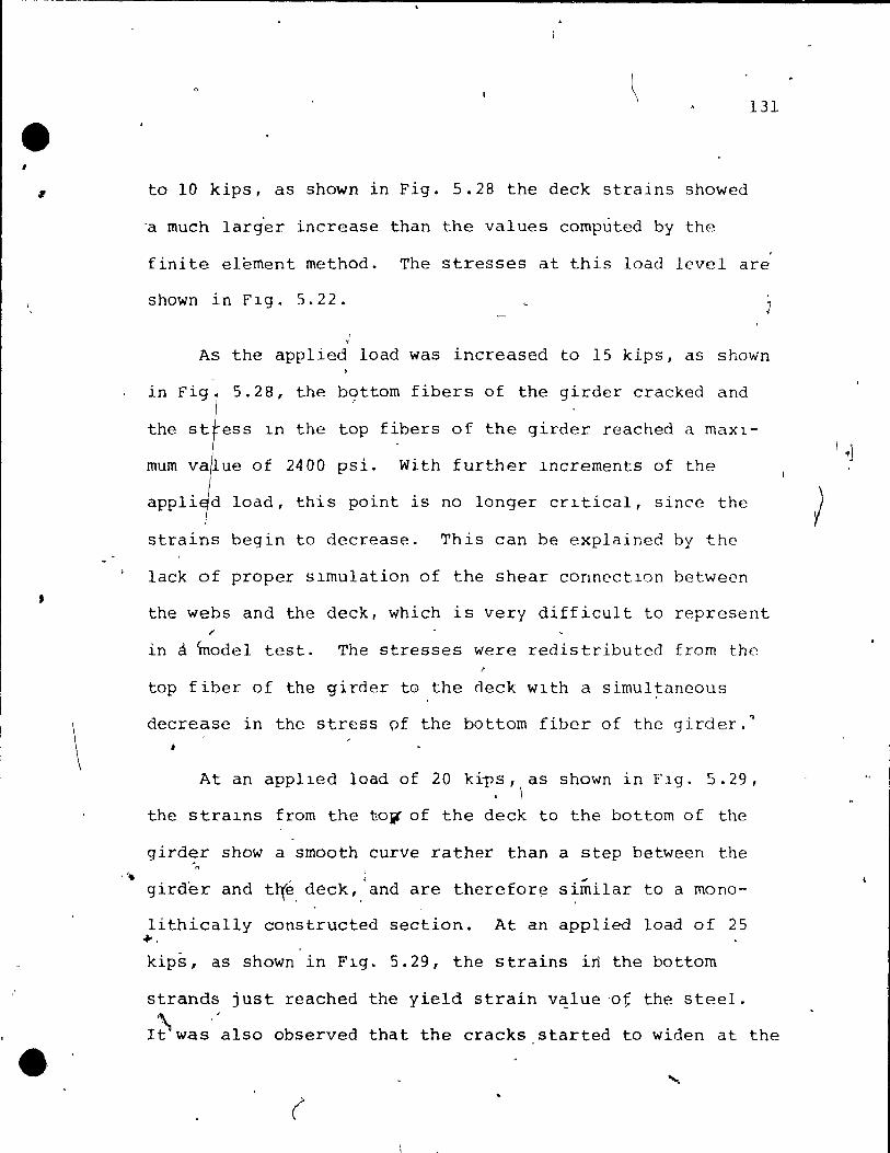
• , ,
,
\
,'.
•
131
ta 10 kips, as shawn in Fig. 5.28 the deck strains showed
-a much larg'er increase than the values computed by the
finite element method. The stresses at this load level are
shown in Fig. 5.22. J
, As the app1ied Ioad was increased to 15 kips, as shown
in Figl
5.28, the b9ttom fibers of the girder cracked and
the stress ln the top fibers of the girder reached a maXl
mum va~ue of 2400 psi. With further lncrements of the
apPli~d load, this point is no longer crltical, sincc the
strains begin to decrease. This can be explained by the
lack of proper simulation of the shear conncctlon between
the webs and the deck, which is very difficult to represent
in A model test. The stresses were redistributed from the
top fiber of the girder tG the deck wlth a simul~ancous
decrease in the stress pf the bottom fiber of the girder.~
At an applled laad of 20 kips, as shown in Flg. 5.29, . \
the stralns from the to~ of the deck to the bottom of the
girder show a smooth curve rather than a step between the - r~
girder and tl'(é, deck,.' and are therefor~ similar ta a mono-
Iithically constructed section. At an applied ioad of 25 ..... kips, as shown in Fig. 5.29, the strains irt the battom
strands just reached the yield strain v~lue 'at the steel.
r0was"also observed that the cracks started ta widen at the
(
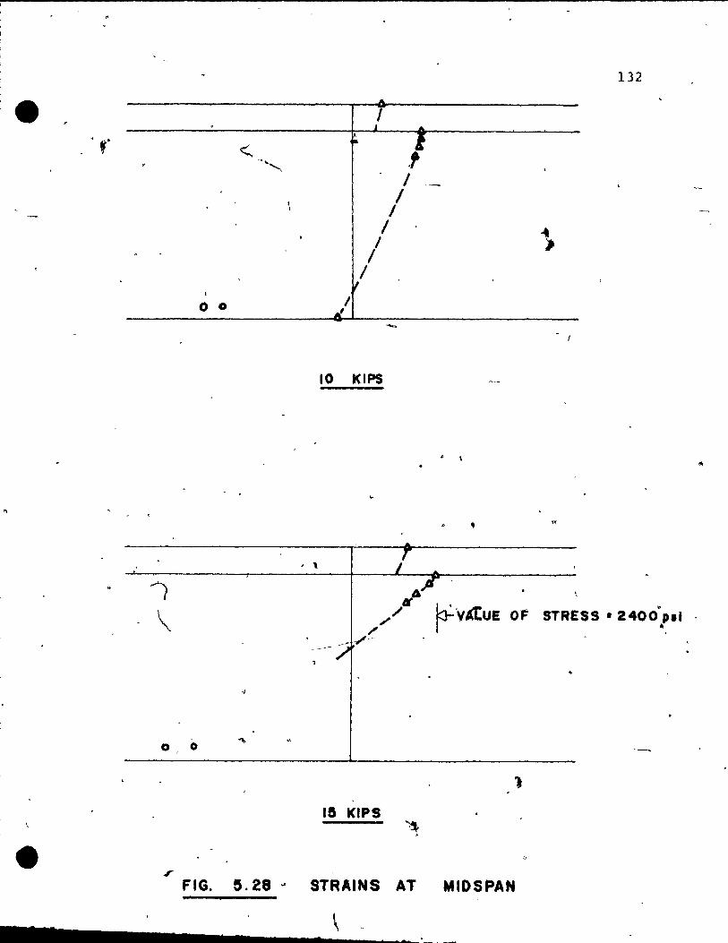
1
!.
, ~
1
1
i'
• -
/ \
0
.r
o 0
0 "l>
FIG. e.28 .-
132
.f 1 __
/ 1
1
/ /
10 KIPS
. \
..
, \
" ~ A" ~ ~,// 1'" V"L.ue OF STRESS· 2400.P.1
l
15 KIPS
" STRAINS AT MIOSPAN ,
s
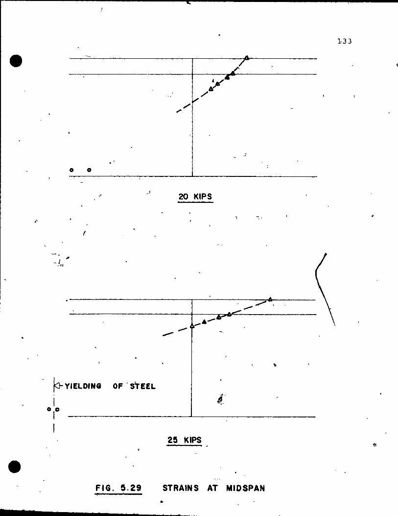
133
/
o 0
.' .0
20 KIPS
f
-.
- r- YIELDING OF 'STEEL
1 0,0
1
25 KIPS
FIG. 5.29 STRAINS AT MIDSPAN
• 7 7 7
(
l
134
midspan ..
At an applied load of 30 klpS, as shown in Fig. 5.30,
the compressIon zone 15 mostly conflned ta the dpck, wlth
the depth of the neutral axes bClng 2.5 Inches from the t'op
fiber of the deck. The maximum stress in. the deck at this
pOlnt was 3600 psi, and the strain in the steel was larger
than its yield strain.
At 30 klpS applied load, thè strains in the deck and
the strains ln the steel can still be increased, since they
are~not at th~ ultimate lev~l, and thus the ultimate re-
sfsttng mOMent 15 stlll not reached. However, 5train readj
Inqs werc not pos~lble, Slnce contlnuous yleld~ng occurred
above the applLcd load of 30 klpS.
, The model testing was superior to an analytical analy-
sis for the ultimate load level. . . For this composlte brldge
_structur~, the top fiber of the qirder was not a critlcal
point at the ultlmate load stagè as predicted by the analy-
sis. Further experimental studies would be needed to con
firm the slmilarlties of the shear connectIons between the
deck and the webs of the gir?ers for the concrete model and
the p"rototype', since this parameter is very difficult to·
represent in a small scale model test.
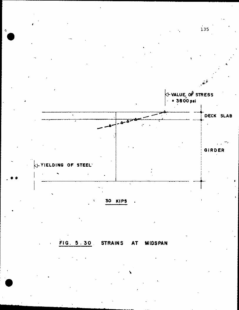
1) •
..
. . ..
l ' 1 •
135
rVALU~ rJ STRESS " • 3800 pli ,
-A ~ ...
-'" ___ ..- "";'. DECK SLAB --~-------------------+--~~~----~~------ ~ ... 1Jr6--
--- -.-' -.~
GIRDER
~ YIELOING OF STEEL:'
...
.. '! 30 KIPS
FI G. 5. 30, STRAINS AT MIDSPAN
\
........ ________ ~ ___ s ____ ._.
-
CHAPTER 6
OTHER PRACTICAL CONSIDERAT~ 1
The analysls as wel~ as the tests have clearly shawn
the potential of the precast box girder bridge for the
medium span range of 80 -toi 120 feet. A suitable system . 1
'could ~e developed to be c7mpetitive to any other alter-
native in this" span range-.i The basic pTototype des,lgn . ..... (
can effectively use a comblnatlon of pretensionlng and
posttensioning operations.
The cast of the material is less than for any other
" . alternative form of a bridge structure, on the other hand
,J
the amount of labor involved is rather high. Therefore,
the number of different types of standard elements should
be kept to a minimum in order to'make greater quantkties
of one type and thus rêduce the cost per element.
The length variations could easily be made, and any
width cou'ld be achieved by using a sui table number of pre-1
cast girders at a prescribed spacing. For normal loadlngs,
two qirders would usually be suggested per lane. Other
element types would be possible to construct with the sàme
136

137 (
; forrns, e.q. Increasing the hClqht while keepinq the slopc ~:
of the webs constane. This could be advantaqeous for
heavy loadings, where there is enough clearance ta have
deeper gir~ers.
Continuous bridges could be constructed by spllcing 1
the girders near the point of inflection. 2 The post-
tensioning could be spliced as weIl by couplinq the ducts .
• Temporary shoring would be required, but only at the spllce
pOints. The englneer would be free to use tempo~ary shor-
lng along the whô1c span and thus reducing the prestressi
lng force, if th1t proves to pe economical.
~
The casting o'f the girders requires great care. Rather
than cast the glrders upside down, as would seem desir -
able from practica1 considerations, it would be better if
they were cast like a trough, because the girders can be
overstressed If the y are cast upside ~own. It is suggested
to put small holes in the inside mold, ln order to let the
trapped air escape, during t~e casting procedure. ~ach
, glrder was moved twice berore they were in the f\njll posi
tion. Both ends were suspended from a crane which simulated
the handling of the prototype. The handllnq was not crlti-
cal. For a prototype, temporary cross bracings could be
used .
.... , ........ ----------.---

•
•
Further studies must be conducted for the use of the
precast girders ,in skew bridges. For skew bridges up to • 20 degrees, the elements could probably be used without
any major modifications.
(
138
Il 1
1
CHAPTER 7 .
CONCLUSIONS
The following conclus~ons can be drawn from this
study:
Il The precast box girder bridge provldes a com-
petiti~e alternative to other types of construction
in the 80-120 feet span range. It affers distinct
advantages like srnall construction depth, aesthetical
appearance, low field labor costs, and good distribu
tiGn of the concentrated wheei loads, WhlCh are usually
-present ~n the bridge structure.
2) The bridge behaved linearly at service load and ta
• a load ,up to approximate1y 2.8 times the service load. , ,
The midspan deflections were very small, and were of
the arder of spanj3000 at th~ service load stage.
3) The transverse distribution of the concentrated
load through the thin top slab was adeqtlate. The trans-
verse stresses eXIst in both the deck and the beam webs.
To make this redistribution possible, special care -
should be taken to make the web-slab joinfs stiff enough
to resist the rotations. ,
139
•.. as ........ ________________ __
- - - -
$
o
140
4) Diaphragms can be avoided without penalties to the
behavior under service loaas.
5) Two methods of analysis have been studied: ,
i) The simple beam method for the analysis of the
girders (Chapter 2).
ii) The finite element method for the analysls of
tQe whole structure and comparison with the test
results (Chapter 4). Both methods are compared in
Chapter 5.
For a prellminary design in terms of longitudinal mo-, .
rnents, the simple beam method is suggested along with
good engineering judgment. For a detailed analysls of
the brIdge the finite element method is recommended as
an accurate and economical method.
6) The behavior of the bridge under the overload and
collapse stages was satisfactory. Initial cracking ln
flexure in the girder was detected at a load of approxi-
mately 4.24 times the design load for a H 20-44 truck.
The ultimate load was approximately 9.04 times the de-
sign loa~.
7} The composite structure did not prove as critical
in shear or flexure at the joint between the webs ànd
1 the slab, although a better resistance can be acbieved
in a prototype.
•
• S

• o
..
•
141
o 0
At high 10ad levels the st.rains from'· the top' of the .
deck' to the.bottom of ihe girden show a smooth curve
rather than a step between thè' girder and the deck, and
are theref~re similar to a monolit~ically constructed
section. '
- .
"
. .
')
1 1
'0
..
•
• . "
/'
(
~ .. "~
•
, . 1. CORDOBA,' R.
2 • NAI RU, R. D •
3. SCORDELIS, A.C. , BOUWKAMP, J. G •
WAST!, S. T ••
.4 : CUSENS, A.R. ROUNDS, J.L.
5. CHAPLIN, E.C. GARRET, R.J. GORDON, S.A. SHARPE, D.J.
6. LfECHI, 0(. GLAN Z MAN '1' W. SCHNEIDER, J.
7. KOLLBRUNNER, C.F. HAYDIN, N.
8. HAflN, J.
7 __ 2 ... _...;;.... _____ ---'. _
142
'-'
REFERENCES
"Bahavior of Open Web Precast Bridge Girders--Experlmental Study" M.Eng. Thesis, MCGlll University, 1974.
"Techniques for Constructlon of Precast Long Spa'n Bridges" (unpublished)
"Structural Behavior of a Two Span Reinforced Concrete ~ox Girder Brldge Model" 'J Structural Engine'ering and Structural Mephanics ~eport No. 71-75 University of California, Berkeley, 1971. r--~ .
• ," l
"Tests of a U-Bearn Brldg~ Deck" The Structural Engineer, October 1973, vo 1. 5, no. l (J'. '
"The Development of a Design for a Precasticoncrete Bridge Bearn of U-Sectlans" The Structural Engineer, October 1973, vol. 5, no. 10.
"Die parkhél'Ùsbrücke über die Ramlstrasse in Zürich" Schweizerische Bauz,eltung,~ vol. 29 July 20, 1967.
) .
, >
'"Warping Torsion of Thin Walled Bearn$ and Closed S,ections fi (In German) Mitteilungen der Technischen Kommlssion, vol. 32, Schweizerische Stahlbauvereinigung 1966 (i ,
"Ourchlauftriger, Rahmen, Platten ~"'ûnd Balken auE elast:rscher, Bettung"
Werner-Verlag, 1970. Jo
, . 'r
• "1 Ji'
, .
,)

r ,
-"
, 10. MROTZEK, M.
Il. SISOn~YA, R.G.
•
)
- 14'3
"Behavior of Orthotropic Bridg~ Decks" Ph.D. Dissertation"McGi11 University, 1972. 'c -~
/
"Ana1ysis of Hollow BoX Girders With-D •
out Diaphragms" (In ~errnan) Beton und Stah1betonbau, December ,
- 1971.
't-Finite Element Analysis Ç>f Bridges", Ph.D. Dissertation, Dept. of -Civil Eng., University of calgàry, No~. 1971
•

) -
144 .• ,
APPENDIX A
SUPPLEMENTARY FIGURES AND TABLES.
A few hundred diagrams were plotted using the Calcomp ~
PIotter to analyze the vast arnount of eJxperirnental' q,nd analy-
tical data for the stu9Y Qf the behavior of the box gitder
bridge.
The behav~or of the ~ox girder bridge is discussed in
Chapter 5. Sinc€ more data would be needed for pararnetric,
studies at least one figure and a table w~th the nurnerical
values are presented for each loading case . . . •
The f~llow~ng figures are presented without cornrnents
to .... rnake the val uable test data available to interested re-'--,
searchers. )
'--- A typical r~presentation is shown' in Fig. 5.2, and aIl - .-
the'relevant.explanations ,are gîven ih Chapter 5.
, For the' deflect,ions alonq the outside web (referente
. , point 13 in Fig. 5.2) the points where the load was applied
in, transverse direction wer~ designated as follows:
1) "Inside box" m~ans girde.t' ~ast t ..
2) "Outside box" means girde+ west. ... ,
" ,-'" ' ! ,

L0AD AT MID5PAN
• !~.D KIPS
. • -
1 W .. .
\
• r
\ 1 1
'J
• 1 .. .....
. . ) ,
, ~ ,
. .
A
, 1
'r " ,
Il TEST VALUES
~ DEFLECTI0N5 AT MIDSPAN e SCALE et1~DEL 1 IN=6 IN 'OÉFL 1 IN=O.06 IN
l, Fig. A-l
• 7
,. 1 el
145
,
0.00
-0.02
-O.OY -0.06 . -O.OB
- 0 .10
0.00
-0.{1)
-D.DY -0.06
-0.08
-0 ~1 0
r P
-.;1'
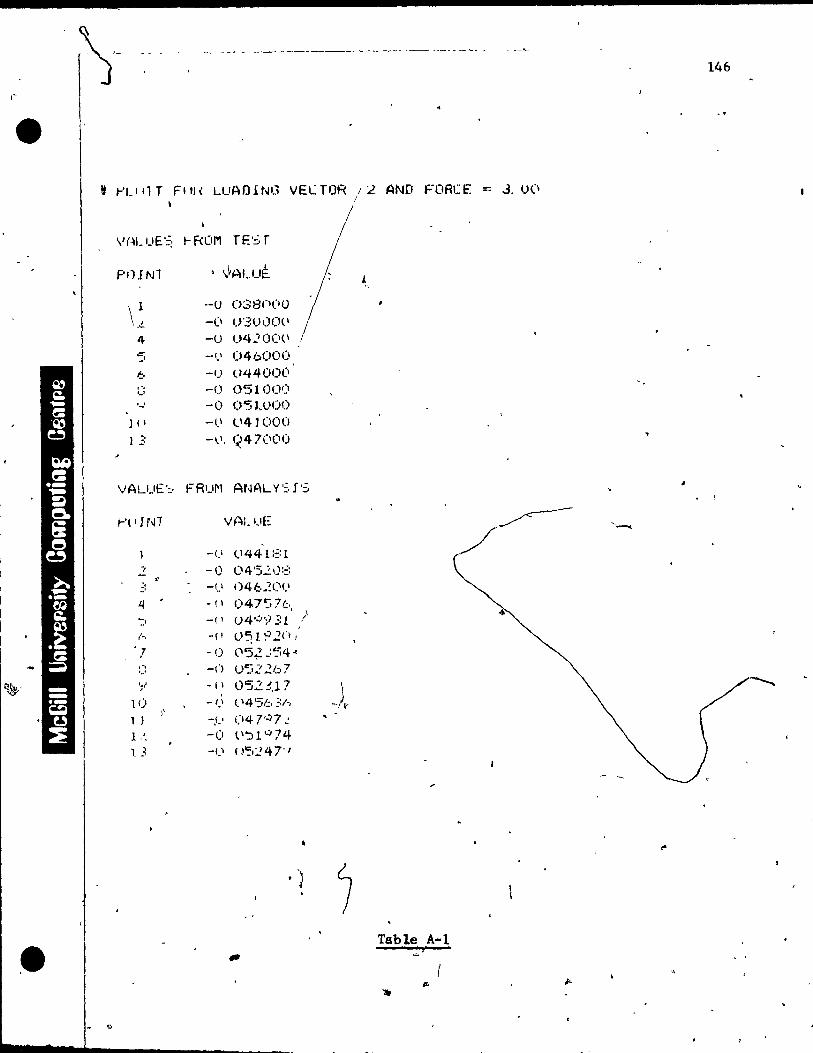
i'
~'
•
._-----_. __ .---~ ..
t f-'U'lT F"l( LUAOrNG vECTOR /2 AND FORCE::: J. U(' !
P'H "'1 , ')AUJE.
~ "
\~ ·-u ()38(l(IO _CI 0'3(1)0('
,,~
4 -() 04."'0('(1
'5 --(.' 046000 6 -t) 044(1)(.i
.' . -0 OSlO()!) ..... '-1 -0 051.000
}II --1.\ l\4] 1)00
1:;: -1.1, 1(47(1(10
VALUE':· FRu~l ANAL Y'=:, l';
/-'t , l NI VALUE
. _l.' <.1441:::: l
.., -1) 04'5.21):::: ., .:: -1) ()46;~(l<.1
i.j -(1 047:'76, ':' -(1 ()4 Q ';i31 Il
,-, -(1 (}~19.2n,
.7 -0 <"5~ .:'54" .... -Cl u52267 '-' ';" -(\ 0'52 :'.l! 1
, ),-10 -1.1 (14'5b ;:/-. )'
l l -,C, 047··)7.: ~
1.', -0 lI'J 1 '-/ 74 l 3 -Cl ()':.:'?47'1
Table A-l
. .,
4
'--~
146
1
• 1
1
1
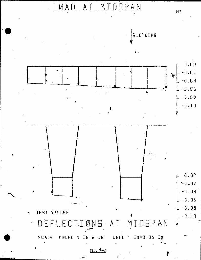
••
• ..
1
.
L0AO AT MIOSPAN 147 )
.
Ir .: 1 , . J
l
f '
, 1
;
0
"
.
• • TEST VALUES
-'1j-
5CALE M00El 1 IN=6 IN DEFL
Fig. -4t-2
r 1
.
!~.D' KIPS
, '
.
T
;).J . , .
.
-
f
1
"
0.00
" -0.02 , -0.04
-0.06
~ -D.oe ~ -0.10
~
r ,0. 00
~ "- 0 "\,02
~ -o.OY-
r .- 0 • 06
'1- - 0 .0 fi 1
MI05PAN t -o. 10,'
1 IN=O.06 IN (
t'
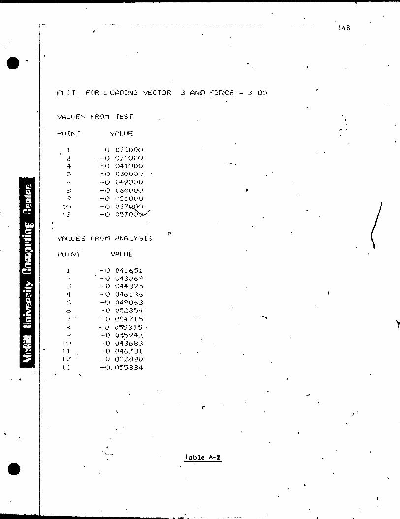
148
PLOTr FOR LUADING V~(TOR 3 AND fORC~ ~ ~ 00
VALUE'-, t- RIJM ft::.':, r
r'lI (l'l r ,h~UIE
0 u3200(\ .2 ,-1) U.:.10(ln
<+ -() 041(100 .:' ..) -0 ()'::OU(lf)
h -f) (14','}(1(11)
:' -0 06l~lICl(1
'.:,. --c''I ( ICi 1 (Ill (j lP -O-O37~ 13 -0 0570(1,
VALUE':' t="R(.fM ~'NALY';I S
t-'UINr VALuE
1 -1) 041é;'51 r l
-1) 1)4 ;:Ui!:,':' - -1) 044'::')'5 .:'
<t -CI 0461 ';:(:. -,~I n4';;'(l6~:
'.::. -1) L.'523 ':.,4 7 (p -lI (l'j4715
;-: - 1) ()C):.i::: 1'5 -, -<) t.\~';1'}4 ... ~
l rI -O. Uq:36::: _=:
1 1 -0 (146731 12 --0 OCi28S0 1 " , -' -O. t)5~:=:":!4
, .
Table A-2
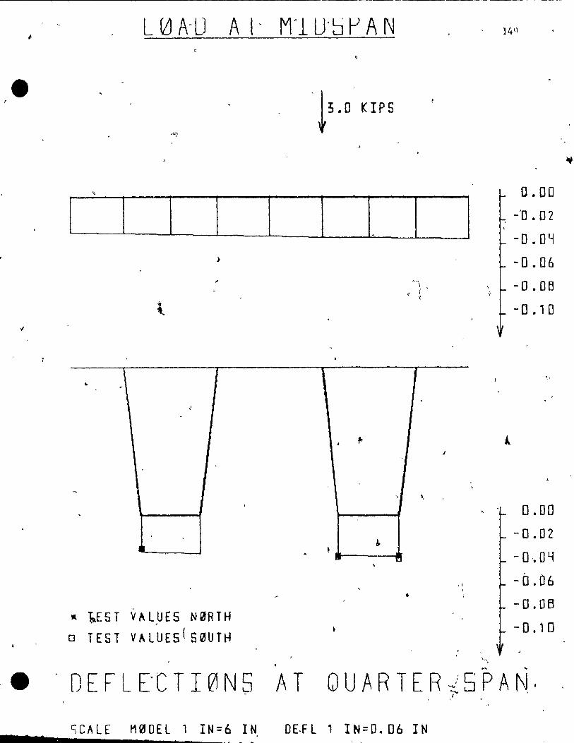
1
e
.,
. '
•
-"-ê
:>
~
l
\ 1 .. ~
J
-
.
1
" 1..E 5 TV" L ,U E 5 N 0 R T H
o TEST V"LUE5(S~UTH
,
. D E F L E' C T l 0 N 5 A T
~
t~·o KIPS
1
0.00
-'0 .02
-D.DY -0.06
c l- -O.OB \
1\
- 0 .10
1 '-'
1
,. 1
~
,
, \.
D.DO -D.DZ
~
-0,.04 • 1
'\ -0.06 • -D.DB
- 0.10
'> '"" ...
(JUARTER~5PAN,' 1
Cj CAL E Me 0 EL 1 IN = 6 IN 0 E·F t 1 IN = o. 06 IN
.,
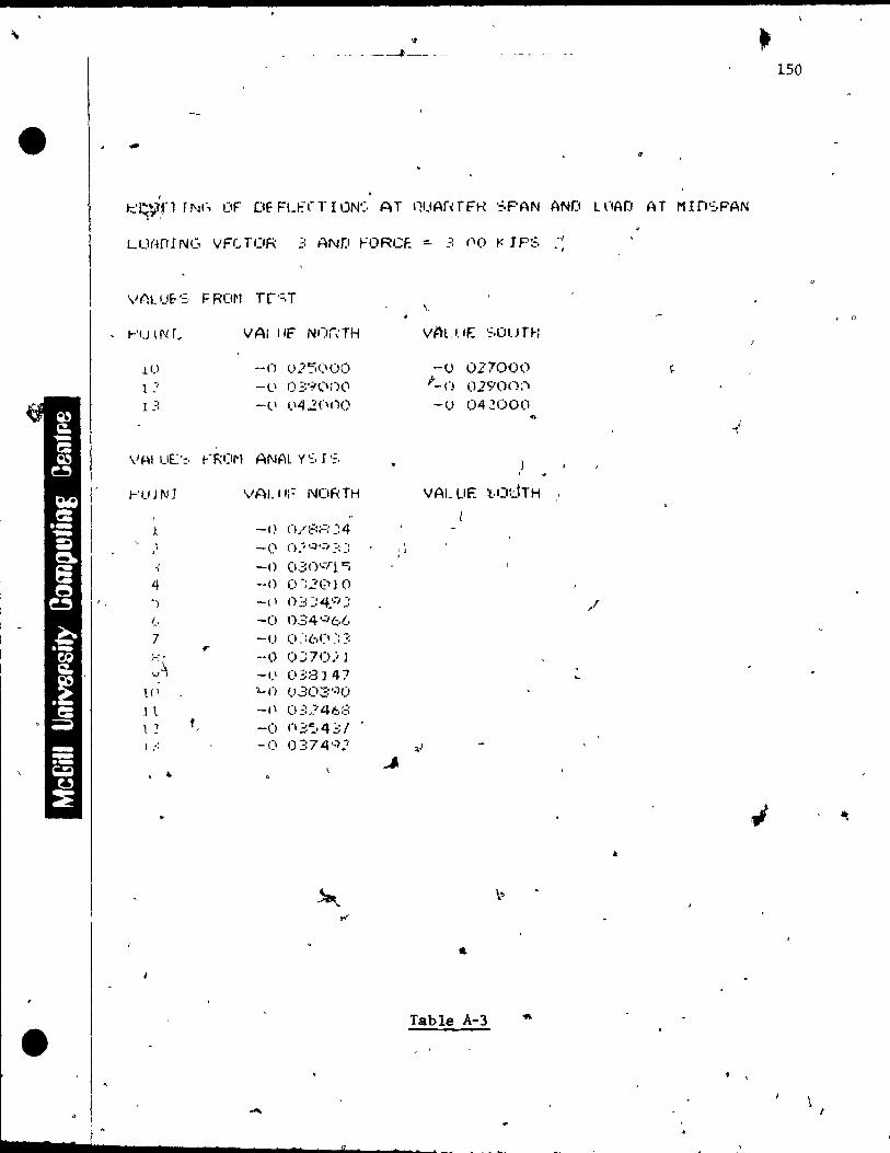
• \t
-- -- - --~--- ---
-,
t:=.'r;V,fl rl'~(, IJF Df-FLI:-CT l ON':, AT nUAraFR SPAN AND U'IAD AT Mln·~.PAN
LU(4(r! Ne. VFc.. H)R =: AND t-='ORCF.. ::. 3 no K J P:;, -, • l'
, r'U lN r~ VAl "F NOraH
-() 025(100 -li 1) ;::9(10(\
-( 1 lI'" .2C\t)O
V~IUE~ ~R(~ ANAtvSIS
r'l) 1 N J vALII;:- NORTH
-0 ()./:=::-=:: ~:4
• -(1 ().;·.:)';'I ,:::: . .; -0 030·:r i Cj
4 --0 0':2(1') 0 ') -(1 () ::: :: 4::1 ::
1., -(1 034'-">61..· 7 -1) Cl :: bel :: ::
:\ -<.) 0::70) l '-1 -1.1 038J 47
l (1 'l...() ()303'-iO
l t -t\ 03246::: l ) t -1) 1'1;::':,,43/ ,
l .' .' -(1 0374'·)1
. ~
....
.
,\ ,
VALUE ·~.OUTH
-u 027000 f_ n 0290n:"'I -u 042000
vAL UË l.O::JTH
Table A-3
1'/
/
. ,
150
. ()
1
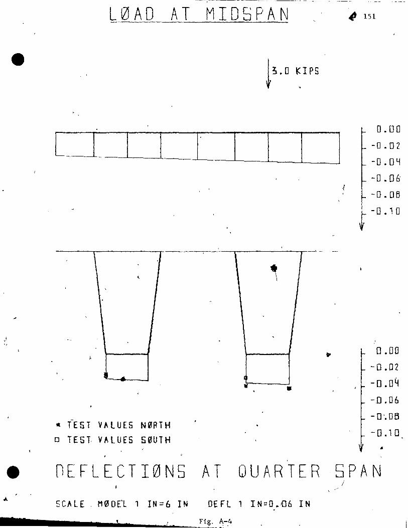
----------- - ---------------
L 0 A 0 ATM IDS PAN ~ 151
---r------r-~--~----_____r---_r_----"-
l , '
1( TEST VALUES N0RTH
o TEST VALUES S0UTH
• •
f ,
0.00
- 0 .02
-0 .0 y
-0.06'
-Q.OB
t -0 • 1 0
0.00
-0.02
-0.04
--0.06
- D'. OB
-0.10 ..
e nEFLECTI0N5 AT QUARTER ,5PAN ;'
5 CAL E , M ~ 0 El 1 l N = 6 l NOE F L 1 IN:: 0 ~ 06 l N
______ .... l ___ ~r_. _.!.F~ig. A-.4

1 'I
~
"
\
•
! 1
LIlnflIN(, \.'F:C10R .2 AN}) FORCE" - 3, on '" tPS
t-'IJINT
l CI
1 :-l -, :-
vnu JE'~- bROM
t-'uI NT
-; -:::
"-~ -
-' (:.
1 , -c.-
'-' ] (1
.t 1 , .2 l :> ,
-'
VALUE NnRTH
-0 02--7!.I(îO
-(\ o -::;;nn(", -(1 03"5000
(~NAL YS, 1 :.:, -,
VALUE· "NnRTH
-0 1) ~0703
-() (1;: 1458 --0 03:"134 1 Il O::}HI.A
-0 033776 -0 0::4'549 --lI 034,:,..:;07 -0 03'5:: 3é. -() ()':!'5 77 :: -h ..- 03171::- 3 -(1
0' 03317'5
-<) 0::4706 ·-0 (1::54'1 l
\
VALUE" :'::,OUTH
-1) 0.?'~O()O
(1 03600()
-0 03800()
VALur '=.OUTII
Table A-4
152
J
- 1

cl N ::r ....Q CD 153 Cl CJ Cl Cl
• • • Cl CJ Cl Cl
>< m~ 0
tS) w m ::::I
LLJ 0
W
~ 1 H Cl
UJ H UJ .-. r-
~ :::::; tsJ
~
z. l-L .. t5)
..a L.J ........
U1 :z ....0 Cl
a..
CO H tS;) •
~
Cl
~ " W 0
~ • <
t-f1 :z.
4, H
::. W
or-
CI:.. :::>--..J lJ...
w tz. 0::
~
0
~ z. H
:::r- U z. ........
~ , .
Z N u
t--r1" ?S) • z. <C H
'H
. Cl
,.rr ~ r-
I ~ -J
<C .. U ~~ tsJ 1
W t' tg
.--J s:
-.1 ,. 'LL en w
,/
• \ W ' -J
.1 N => W
-.J <
< 0 W c.t;J
>-
---- , t-U)
w
1 • '. t-(
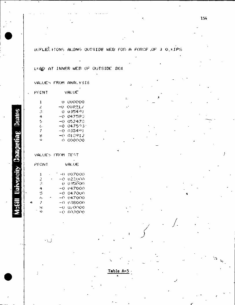
154
• V;;'FLEt t J ON'=:, ALONt-, OUTS l rtF. WEB Fon· A FORCF ,OF 3 ,,_ l'.r P!.'::'
LI'/U-' AT INNFR WEB OF üurSIDf f:OX
VALUE· ... FRCIM ANALY'3I=,
pnlNT VAlue 1. f'
1 () UO(l(IOO
L -li OU::~~lJ :' ~, 0 () 354'~ J 4 --Cl 04 7C:,.;r~:
':' -1) 0':,247::: --(, -0 04 7~,'-/3' 7 -0 () 354'.:) l '-' '-' -CI 01:::911 ,:, () OO!)(IOO
~
VALUL~. ~-Rnl'l n-·=·T J
pnINT VALUE
l -0 (J07000
- --1) O.L.!(lnn ;, li (l3'5(\on -. 4 -1) (147000 ... -' -,0 04700n , '-.. -Cl (.'47000
«J l -n (l.~800n
:-:: --() !) .. ,onoo .. ) -(1 nn30Cl(1
j j.
\
Table A-S· •

.--
C"-I :::r ~ (D
c:J Cl Cl Cl 155 • • •
0 Cl CJ CJ -1 1
en w
x ·ctl ::::I .'
~ ~
CD W 0 )
WO 1---1
0 " ln .--H :::::J
C}
UJ r- - r " ~
z => L.:)
H
~ Ul
.... Z. ...0 c:J
Cl..
LL H
ts.) ~
\ c:J
~ ""0 ~ Il
:<t:: z ,.." H
cr:: '> W
,.....
W > --' w
}-- . cr: w Cl
:z: )
,W L)
:r- U z H
"'Î N
Z Il
t--.'<c
~ z
H H
~
t--0 U
.J\ , LU
.,< . W a tS)
~ --1 E.
..--J 1
en LL uJ ~ YJ
N :::> W ....J
e ....J.
-<.
-<. 0 c...)
ln >
, 1
..,:.. Ul, " LU "4-f--
• . •
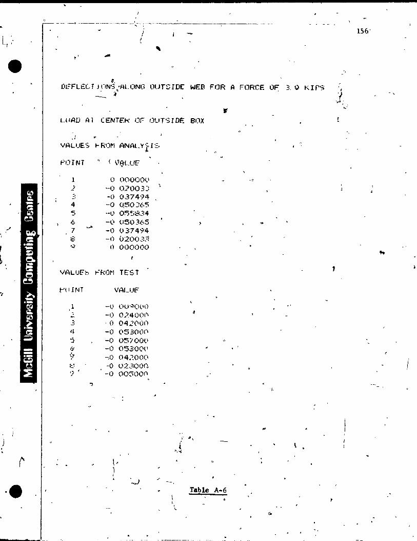
L1
",
, L
•• -
o _~ __ Cl __________ i_---.~ ____ _
" ,
1
~'
(J,
D1?FLE:C .. T JClN'3 -AL.ONG OUTSIDr WEB FOR A FORCE OF: 3. Q KIr'; • ~q
LlIAD Al CENTEk or tJUT':;IDË BOX
, ; . . ' VALUE'; ... ROl'" ANALYi'I~, ~
f'I)INT ( \?(\l.Uf?
l (1 00000<.' , r
1 -0 0.:>003:: .. :' -' -0 0374'14 4 -0 0.50::65 '5 _.1) O~':;834
6 -(1 050365 ~
7 .-Ao
-0 037494 E: -() 02003,:: q n 000000
VALUE'b r:RtJl"l TES.T
,..'IIINT VALUf'
1 1
·-u O~J';)(JlIO , -0 1).~40~W\ :' -' ,(1 04":('(ln
l.~ -(1 (1530(1(1 'j -0 05/00t.l I,t. -0 0'3.300(1 ~7 -,0 04:~O(l(l
::.: -0 u2300n 'l
1
-0 00300(\ .,
'~
-
\
Table A .. 6
, ,
156'
",
t
'1 ."..'
" ,
, , Lo'
,
,

,
' ..• -.. fII!II#
Co
- ~ D
- -<. ~ L 0 A 0 A T ~'0 'U TER, lJ E B " f1 F4(' 0 U T J5 l n ~ B 0 X '
-. "
!)
" ~ 3.0 KIPS 1
1 1 •
.'f --
•• "
..... , 2 .; 4 5 6 " ,= 7 B 9 0
f~ ~ -0.~2 .. ,----
"
• (r -0-.04
• ~
• TE?r VALUES ~ -~O. D6
" ."
~=- .. } -.. 0 • 0 B ç
OEFLEC.{I0N- (URVE: Al~RG 0UT5I.O(WEB:-J
" ••
~SCALE M0 DE L , tN = 24 IN , "
DEFL 1 IN = 0.06 IN f
.., ,Jo
Flg. A,7
'-" -...,J
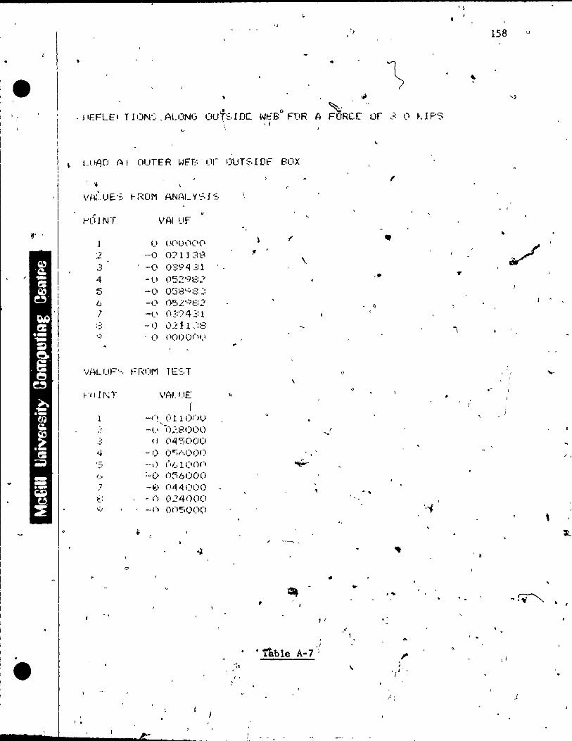
. \ • <,
ri 158 Il
" ..
~ e ~
.. ~
, J'EFLE' T ION': .. ALONG c'ut~·IDC. Wt:"Bo FOR A ~, FORCE Of -' ~, 0 ~,l F'S
\ . ,
...
" LUAD AI OUTER WH:: 'J,- OU T~. r Of' BCIX 1 1 l' 1
,1 ..
VA:·_UE·=. I-ROM ANA1_ y '~. l ':, 1 1 , v 1 ",,'1)1 NT VAl UF
\1' 1 • • l ') 0('0(1('(1
~
"2 --0 071138 ., / -, -0 0:::9431
\~ .:' 4 05298.; -. ...
-!.) ..,. -0 038'-;:=: :: <..' (;, -0 ()-;,L':'IE:2 1 -
li
7 -CI 02:'74'::: 1 :-:: -0 0.~ t 1,'::3 "\ '.) 0 nOO()(lI.1 ,.
Vf~LUF'-, Fr,(lM 1E'=.T 1 : , .... ,
/-'1111\;1" VAI.UE • (
l -(! OllonU " , "0:.8000 .-~ -lI r .... . : (J (\4'5000 . -
4 -1) f) "';/·.1) 00 , . " t
,= --1 ) ('(.1 (lOI" ~ -1
(~, :-0 n~60()O 7 -(!,) n44('OO
" . ~ t: -0 024000 q -Cl onsooo ',~
\ .. ~
.1 ---.. ,
~
0
• ~
... , ..
~ :T""-., , • (
11
,', \ < . ,
· 1\ble ,1
A-7 " <; . JI' ,1 • "~1i , ; < "l' ,
( , 1
/' : J
'.

.,
1 1
-
L~Ab AT
· ~-;.o KIPS
1
f " i • '1 1 , l ' 1
, '. ,
159
1 • -( r 0 .. ,
1 , l ' , " , " f "
1 , , • 1 f ~-1 DO ..
~2DD .. . ., , ..: ' " , ~-------.J _______ ' 1 l ,
---- ..... ~.._'"".J~_\.: : ........' ,
.... , t f .... , . '-'-.... ' .. , .... , -- ' ... ....!--_ ... --
• •
,
..
1. 1 ) 1 1 1
1 • 1
:_------ll----.. ---• --
\ ----r---------...--- '- - ,- ,
1
/
L, ,,.. .,.
J , ..
.. .. .... ..... ...... ... " \ - -"15--"-- , . ,
1 )
"" l~
l ~ .... "<>
't
, LQlNG" STRESSl:5 AT MIEJ5PAN -
.' ~~ .. S'CALE M~DEL 1 IN = 6 IN, S'TRESS 1 IN ;::. 300 'ri ,
• TEST VALUES ",\
-".,
- Dl STRESSES FRVlM :ANAL )'SIS FiS A-B _~ Il C'TOC C'(,CC' c: O~ M H.l11 Y~TC
i'
1
~- 30 0 ~I , , 1 .... ..- /
~YUO .. i f: 50(1 ..
~
OC .. I{/~
~ o • -100 ..
-'lOO ..
- '50,0 ..
-';J[JD. '
r f 500 ..
VI
PSI"

\
·e ,
1
/'
1
1-'1 011 r nR lliAD INlj VE"C T OR 2 ANf! 'FttncE -= 3 0(1 ,
V~LUE.':, FROM n"_,T
r'f) IN r VALUE
l '-.? 75 u(lOO(J(\ ) - :;..!l' ~ )(\(10,-,(1 -4 -:::50 nO(IO(I(1
1 - ::30_ (II) ()(I()0
(:. -'S?:4 !)1.IOI"l!.I( 1
:::: - ':::11 000(10(' . ... '/ -. ·1 ",
-~ ... ~-, ( lI),~·I)(I:i
1 (1& - 30:3 UOOOI.\(I 1 1 - 210 1"000(10 ] -' - 1':'6 OO(lljÜ1.1
\1 Al_UE.'::, I-"ROM ANAL V':-, l';
Pt 1 IN1 VAt liE' 1 -)
l -1 '55 '::':'/!=: Il'::8 <ll
l -184 1 '--'0 L l ,:)
" -' -1':1';; ..=:4 ':'t,(j':/ 4 -LCl"':' 1.4G4'::7 c:-~I "- .. "95_ 273437 (::.. -4ü::: (-.71:::75 l -rI:" -,
- ;'_, 1 OL ;:4 ~:l :3 - J}] 5'=176~,6 '.) - ~: 3:=: :'::476':.6
11.1. , - ~:(.., '~5.31~~
] 1 --5 ~ 8007:31 1 .., 118 ~445312 13 JO 750or)O .
.' Table A-B . .
160
, • •
••
f
(
"
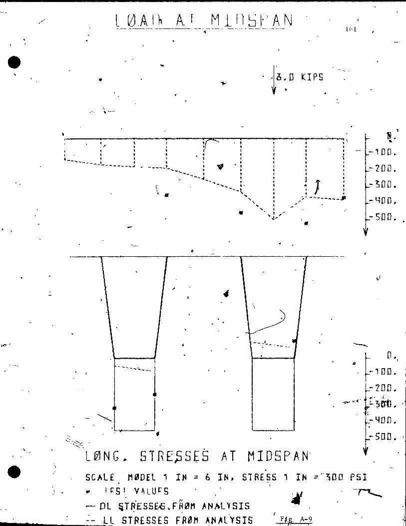
. , L ~~L A 1 h A. r M 1/1 ~ \0 l A N -- ------ ----- --~ ~- --- - --- .. ---- --- --~--~
" lb 1
•
"-~, , ---
· · r '> 1 1 I, ' i - -; , , ,.. l , , , , , , .-
" '0 l' • L_ 1 t" ,
---- ___ t t • t ' t ------ ... - ..... - -----,- ,..,,' , , .... _"'---~ :: ,:
~,., 1 J' ... _' ..... , :' J' -,~~ 1:
" :'" -.... ------J \ • '\ " ... ;'" ... ,
• • l " "'" .. ' -l '1
\
-
~ --- .... ~-_ .... . ,
AT MIDSPAN' .
"
N. "
-100.
-2DD .
-300.
-YOO~
}- SDD.
• .' 5CAlE M~DEL' IN ~ 6 IN, STRESS 1 IN :A300 PSI ., It:"S' V~LUcS
, (,
- DL ~TRE5SE-\S ... F IHH1 AN~L'" SI5 . . __ ....... s ___ ~~.Ll STRESSES FRal1 ANAl'YSIS Fi A-9 . R 1
"

'(
~
" •
-.
'/
•
~'u~lr T nJR
,
! ClAnI NI'";
VAl LIE i 1
VEC TlJr<
.~ --3'50 oooon(l 6 --460 (!(\(H)I..-'O
8
1(\
1 t
U
VI-\LUF.'3
FIJINl
:: 3
4 '" .' 1..,
,
:- ! ::~
,. ~
'.)
l (.'
.il Li l -,
J
--525 t)(I:)OCH) . . - ';:t.:=ï. ('O(I(.)nr' -311) (\(100(\('1
- 2.~~ ()(!(I()(,,"IO'
l W5 O(I()O('J
rJ'
fRI"IM ANAL Y'::,J ':,
VP.LLlt
-1 L:=: ::9:343::: -1 t.3 l ;>~(>()(I
- 174 .=: 7'50(1(1 .] ::-:3 .. .:<. .... 88.: 8
---2'32 2';/f;:=;,~ :.!
- .:~.;: l 3476'36 -4':'Q 72.265(, - ':~5':J '::,4~~:':: 7'5 - ~:;r (" '.:i4',Ï:~ 1 ~I ·-4:~ t::I)<"J78t _::;::.,7 101 :'(.2
':,'/ 2~O(\OI)
(-,6 -,s OO(l 1)
" ' ..
1
-, AND t- OR( E .:'
..
C> === - ~ (,:) - "7 "'+
Table A .. 9
c
~
= • 3. ll( -'
J .:,1
~. .
~. '~)
If
..JOB 1 ~~Al._ T
.' , ,
162
'"
(
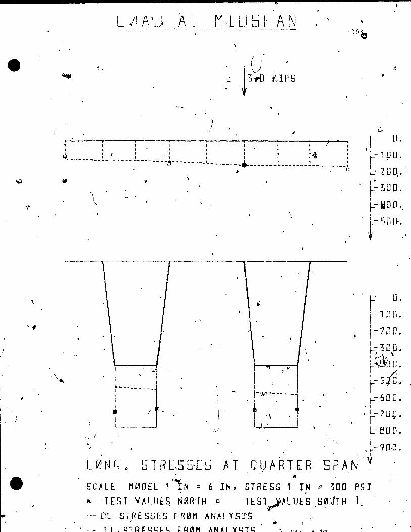
\i,) )
/ 1
•
..
, . ,
'"
, ,
L VI A 'L> A 1 M cL L) S /- AN t
- - -- - - --- - 1(, e ~ .
. . () ~ f. . .
~3.;.oKIP5 ~ , . ....
\- ~
) 1
:: :: ) , " 1 • 1
f- D. 1
~ : 1 : • , 1 : 1 :~ , --~---~------~--------,--- ... ~-- __ ... ___ ~ .. l , , r- 1 p il.
~ 10[\ ..
Î
'\ 1
"
1, / . , /
,
1 ~
u --~--___ _ ______ ~ _______ • _______ ._,
- ~ , 0
1 1
, ...
..... _~---
\ \
-~;:'--- .. _--Ip : '
,:\ l '
/.
~ ~OO. 1
t:WO[l., 1 . (500-..
r' D. ~-, no. , 1 t: 2DD • 1-300. r~ :>\' ~ r~~bD. fsiD . - 600 ..
-700. . - BOO.
- 90-D • . . .
L0N(:o S T REIS st S A T QUA R T [R -S PAN , Il
SCALf M0DfL ,·1N ::. 6 IN, STRESS' IN ::. 300 PSI
- TEST VALUE~ N0R"TH 0 TEST~ÂL UES ,S~liTH \ - DL STRESSES FR0M ANALYSrS
1 ..
• -- Il . C!TIH!C!cr~ COf'AH ANAl YCTC
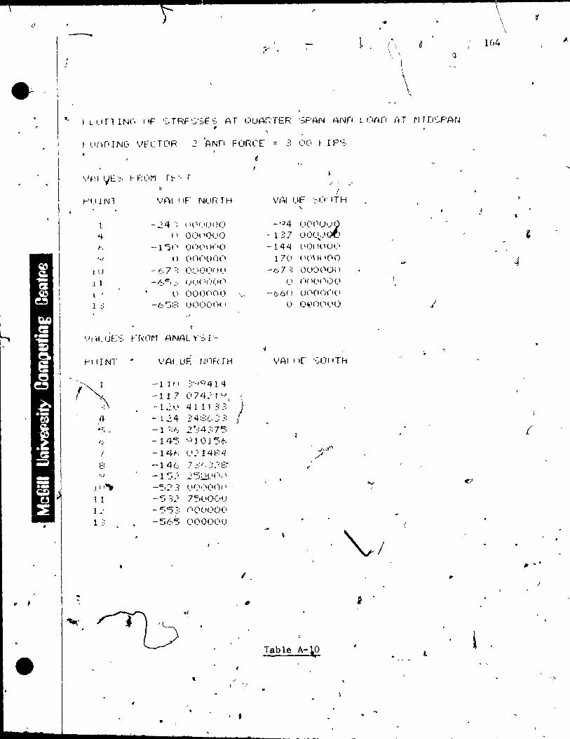
Lt ~r
--,
l , 1
1
f l'
... -;--- ~ (\ ~
\ ll.ITl INf .. IIF '::'TRF'.::;E::, AT I}UAi;TER ':PAN ANfI uv"n rH rJTD~,F'AN ,
Uf~[lINl' VfCTDR 2 'ANf! FORCE:::: -:: 0(1 ~ IP'':;,
"f~ 1 !.JE ':,
t-'U lN l
1 '+ /-,
'./
l ()
1 l l
,
l ~:
t-'llfNT
1
'-, 1!1~
t 1 1 .'
1 ~:
... F;(IM ft-'· r
VAl IIF Nufï:TH
-24 -; \ I(I<.,UOO ( 1 0<)1'0<..1e)
--1 "5(1 00(\\ 1(10
" (Ionone'
.• 1::.- 7:: (\;)O(\{ )(1
-6"' • ..:, U(l! 1(1(1(1
tl 000(100 \..
-(:, ':;:::! UOOO(H •
VAL LIE WiF< rH
-- 1 1 f \ ::,-,q 4 1 4 - 1 1 7 (17 L~.; 1 '-1 , , '
-12\.\ t.llil ~::: ) - L':' 4 ~: 4 ::::(, :: .=: J
-1 ::/, 2·~:4::7'5
- 1 45 ,..) J 01 5~, -lltt-, <.'2 t 4f:t.j --146 7 31, ~:.-,::::-
C' -, i -' ) ...
2·5~.\(" , 1.1 (I<'(I(), ,
7".::,(I!)c"(J
- 55~: ()(I(I(l()(1
-565 ('(\00(11)
•
"
• •
«
.. ..
! W-'I Uf" '~,IY ITH
" -q4 O(l(\()~
- l =, 7 ()()(~) 1 -' , -144 l \01 l( H)('
17(1 ('l"JlI(IO
-1,:..7:: O()~)('O( )
1.' ni 1(\("\J)(1
--b6( ) U(I(l()(1(1
() O\tlnc'('o
~/
Table A-\O 0(
l
,.
t
\ i 1
1
\ 1 ,
164 ,1.]
.'
(
" .' i

e-
,
G,
LtZJAO AT ~ID5FA·N --~-. -----~
, ..
!
\ . _1
1
. i'
KIP.S •
,b , .... ,: 4\ 'y, •• , , '.. "t" , " , . , , , , , ' " , - , , , , ,----. ____ t..._ l r t , , , ------ - ... ---------------..J____, , " 1
D ---- ..... --- .... -----------_L~- ..... -~-- .... -.-'
" • o , .
1
of
\
1 , 1 1 >t
1 - •
. ,
. . ~
"
A
,
1 ,-- .
~ ,~---- .. -.... _~ fi; ---------- , " . ,
"J , ~
1 ~
'< . . , , ~- • .
1(,',
Î
~J\ Cl.
-100.
~ZOO .. ,
-300" i ~- '10 fi) .. -
}-SOO. ,
D . -100"
-ZOO. -~OO .. -YOD ..
-500. , (...6DD.
\
-700.
-BOO .. '
f -900 ..
L0NG. STRESSES AT- QUARTER 5P,AN (' . ~ ~
SC~LE M0DEl' IN .,6 'IN, STRESS 1 IN = 300 PSI (' ..,
" T[5T VALUES N0R:TH 0 TEST VALU[~ S0(ITH--, " \
.- BL STRESSES FR0M AN~LYSIS ' l
117 _ ... 7 .... ____ ~~1 L CT.OC CCCC c: OtAM :JÜiAI Y'Cl'C

. e ·
,
,"
t.
~ J-1 •
. . "
, (e
• •• ,.1
.'" / .
~ ~
t-Ififi IN'-, l~tF '-,TRF' ';,F', AT OUARrÉhl 1~'i~N" f'~N;' ~ l'It~[1 f.IT"' l'Hn 'F'ç!r~
r'il fN 1
: JI
Jft l',
'~,'
1 Il j 1 l .'
1 .'
t 111 N T
".. \ <+ ::J , ", 7
:~
t l '
J J 1
I =:
J
..
( ..,
V,..'\I 1,It l'i\.H-;' TH
p-23,-' \ 1\ q \!"'(\ll
-,4 ft •• 11'11)1)( 1,'\ , -'161 ~ on(iClI \(1
( \ 1)' :1(\( )('\(1,
.. /.:;, 7·:; , " ,,'1( Itl;')
- t'/.:,. ' ( )(11 1(1(\("
li •. '(1(101)0
-(, ln (,H '1 I( H)('
, - '.J':: 7~,n(y)\)
--1 n'·1 'L~..:::-i....:t::
-1 L' -115 -12::1 -1'5(.' -14;': . 154-
"U-"
','.:~.:j '.'41.. 4
CS ~'..é, 1 ~, " :::',10'54 ? (,1351 'SI ... '::':::476,-,
(l( 1(\,)1.'(\
.?51Ictü(1
- ~J =:t::; 1, 7S()(\()() -5"J() 7~~(1(1()( 1
- 'St.,:,", f.·ont)()f) ,
/
•
•
0
VAi l,IF P' fTH
• \', ~'()U\.I()(1
- 1(;,'.:, (".,(1, \l. l n (
1 1 (ICI:I()()(I •
-.' :::1) ( H)Ol 'll()
- ("'::~' (IOCIt}(.I(I .
,', OO'lll('U
;",,_, ::c:, (.te '1)(\()1. \
1.. 1 i 1(1.(10 li ( ,
. '
.-.
" , \ ,.
• " Table À-ll
, ! Cl
l
.. 1
)
..
'"
- .j

..
'.
1 •
.".
, -7 n
\
14.0 .,
K IP s-
----- . b'
\
, . 1
J • n
,'}
~ , .
1
" 1
, ,1
j 1 1
, 1 \ i J
- --- __ , 1 l-
"
... ..
<-
..: .'
\ ,
j
...
, .
1 -. ..
\
1
.
• /
1
,
.... -
.1
.. . ~
, ,
f o
{-.
4 .
• \
/
oj
J , , " .
'1). •
nEF L., A T L 0 A 0 E. [l' CkU A R' TER SPA N \
~CALE M00~L 1 IN=6 IN TES T . V AL U E' 5 E A s.r 0
, .
OEFL 1 IN=O.D~·IN
TEST VALUES UEST
Fis. A-12
1 h7
. " ;'~ 0.00
1 -D .. 01 ~ , 1
1 -0.01 1-1
1 - -0 .. 03' , " 1 1
1 , -0.04 ... r-
I
1 -0.05 ...... J •
V
, 0,00
-O·.rJ1
-0.02
-0.03 . .. -)3 .DY .
~O .. D'5
'.
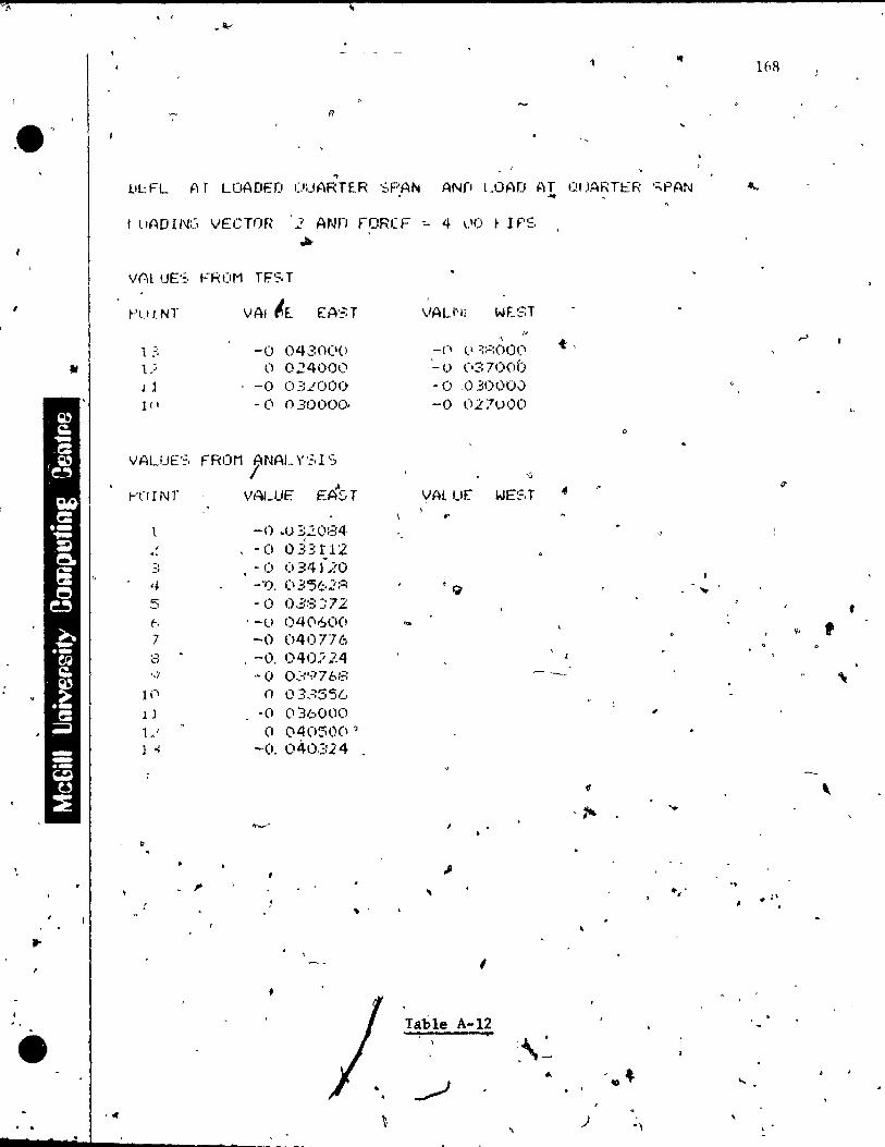
" . ,
i
.. l.Il:FL Ar LOADEO (JUARTER '::,PAN ANf! L.OAD AT l:!tJARTER ';PAN ...
fil
"
• ·ff . .
1 tlADIN::' VËCTnR 2 ANn rORCF -:.. 4 1..11) ~ Irs .. r'UINT VAl I,E. EA'=: T VAU'll WEST
, 1 ;: -0 0430(1(l -ri 1.' :::'=:(H)(I
1) (1 024000 -(.1 ('3700i) 11 . -0 03LOOl) -0 _0.30000 1(1 - () 03f)l)OQ. -0 027000
VALUE'::. FROM j'NAL Y'=.1 'S
" t-'CI r NT VALUE f:ÂST VAL ur WE~,T
.. l -0 .0320::::4
1 -(1 0.33 t12 . -~; . -0 Cl 34120 ,+ --,). Cl 3'5~,2;::; '9 t: -0 0.38 ::72 -' 1:-. '-li 040600 .. 7 -0 040776 8 , -O. 040.i24
<t.
..,
q ~O o~ .. :·-:., 7 é:f:~: ~--
1 ('1 n 0335'51..· l ] -(1 (1:36000 1 AI (1 (140::;0(1 ' l -: -O. 040324
1
,. .. .
1
Table A-l2
I.\~ -.
../ ~
" __ .... IIIIIi.""-..:-____ ~ ____ . _._
0
-... ) -,
,
- ...
'" . ,
16R
r'
f
•
,
-,
....
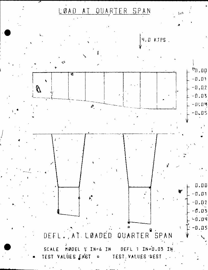
/ Il
!
l,
"
,
• •
Q
L0AD AT QUAR1ER SPAN
, >
L
"
f \ )
~~o ~ 00 ~
" -0.01
-O!O.2 o
-0.03
1 1 ,
1 t\ 1 l 1 (~ , -.._-~-.. - .~ , " - ---- ---------- ..
1 , i
, , ~---~ L _ . _ . _ -J, . _ 1 1 ~ 0 f 0 l1, - . -- . .. r ".r ---'-------.------- 1 f -0,:05
1
\ J '
1
/ \
J ------- • - Q
.. 1 .. --)
.>
~-- -. '
.... ~.
o iii •
DE F L ~ ~'A 1 - L 0 A 0 ÉD Q U A·R TER 5 PAN -. "
)
5 CAL E M CiJ 0 E L 1'; IN:: 6 l NOE F L 1 IN:: ~O • 0 3 l ~ .
• TES T V AL Û E S i A<S TeT ES L, V A l U ,f S . U EST "
..
•
-. 0.00
-0 .. 01
-O .. OL, \ '
-1 -rf.D3
1
:... cl;O 41
~ -D .. .o5
~ -" . ...
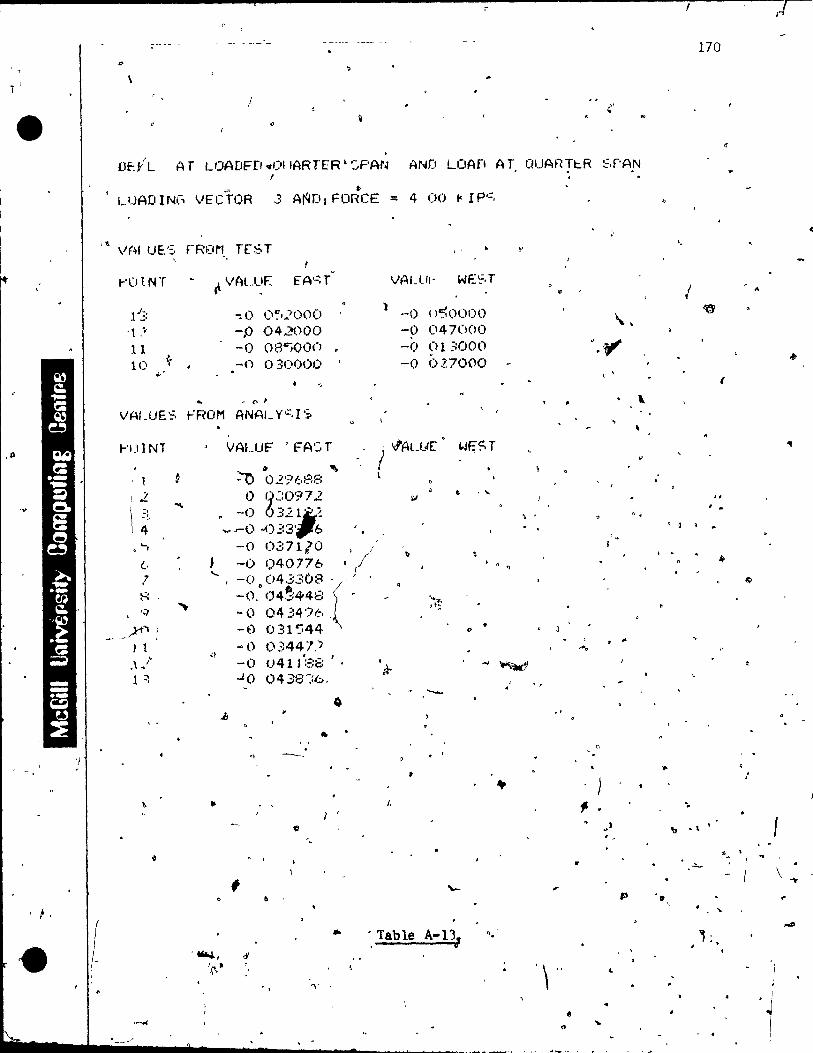
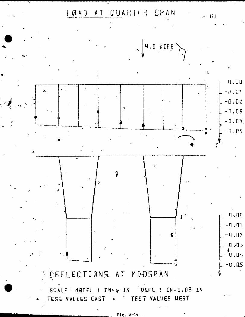
(
•
l, ~ .
1 r
, ...J
,.. " ... ' ~\ .. ....~' _ ,1'" r , ,r-
,
1 Ip
L0AD AT QUARlrR 5PA:N
. f
. I .
.,. .
, ,
.
.
.-' 171
..
,
-
0.00
-0.01
_ -0.01
-1),0;
1 . ~ ~
.-L -O.O~
D
Il ...-.--..J · J-O.OS" :~
• \ ... 1 l [ .
''')
1 . ~
Q, ,. , ,.. . ..
1 ,1
~ .. . "
~ ..
. , . r , ..
-\ ..
( - . h .. . .
0 '-.L .
...l
\ 0 E F LEe T l 0 N 5" ATM I~S PAN ,
SCALE ' M0D~L 1 I~~~ IN OEF'l 1 IN::.~.03 !~
> * TESt VALU~S EAST 0 0 TEST VALUES UI:ST
.... , _____ ..... ___________ ~fig. A-14 _
t
1] ',00
-0 , a 1
-!J,02
- Q )-0 j , -0.0'1
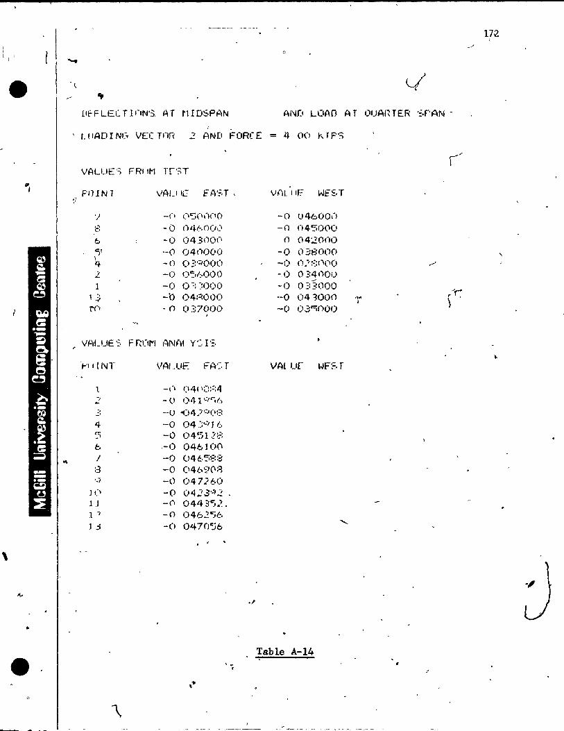
1 , 1 1
\
" ,
..
• o
. ~
AND LClAO- AT f)UAfnER ':.r'AN -r _
, L !lAD l Ne. VEC Tnn 2 AND FORe E = 4 00 r, T p~::;
~i
VALUES F~IM TrST
PIHN1
'/
8 ~
{;,
"),
4 1. 1
1 .;:
N")
Vf..)LUE .;:, F r~(l1"1
,..'1 j {/\Il'
l -, -.. .:'
4 ~:;
{;,
/ ::3 '."1
J Cl Il 1 -,
l j
VAU 1;7 EA':'=,T,
-(1 (l':;(\ ,')(1 0
-0 ()46r)ü ... ' -0 043()()(\
'-0 04C1000 -n 03<:1000 -0 ()":,{;.ooo -0 0:: ~:I)OO -b 04:=:000 ,n 037000 ,
f~NAI Y':, l':,
VAIJJE F"A':, T
-(\
-0 _ou -0 -0 ,-0 -0 -0 -c,)
-0 -('\
-0 -0
(\41 \;:::::4 041·:' ..... ,(:, ~)4)··::'(\:::
04 Y·"I16 0451.7::'=: 046100 04~,5~::::
(\46'i)08 047260 Oq.7 ,3';)2 0443Cj2, 0462Cj6 047n~6
. ,
, -,
VAL 1 IF. WE~,T
-0 046ÛO\')
-0 n45r)(IO n 04:;()(JO
-0 0.38000 -() n.':~:(\r\o
-0 034000 .J
-1) O~:3000 "'r -0 04"3000 "'" \ 1 1
-0 0.3 ""if)O 0
VAt ur WFST
.1'
Table A-14
172
,
"

L 0 A 0 A.T 0 U ART ERS PAN .'
. \ , - .-
1
---'\
. 1
L..,
\ , ... 1 1· '-~
. \
. • .
> , ~ ,-.
.' ,
-r-
I .
.
. - ,
. ~
- ,
OEFLEGTI0N5 AT MIDSPAN •
SCAlE M0gEl 1 I~=6 IN OEfL 1 IN=O_03 r~ y ~ TEST VAcU~S EAST 0 - ~fST V~LUfS UEST
-o x
r 0.00
~·-O.D1
~ -0 .02
.r -0 • 0 ~ ~ -0 .O~ f -'l.OS
. ,-:
( 1
•
r )
!l.on -0.01
-O~O2
-o.~03
-o.OY
-D.OS
,
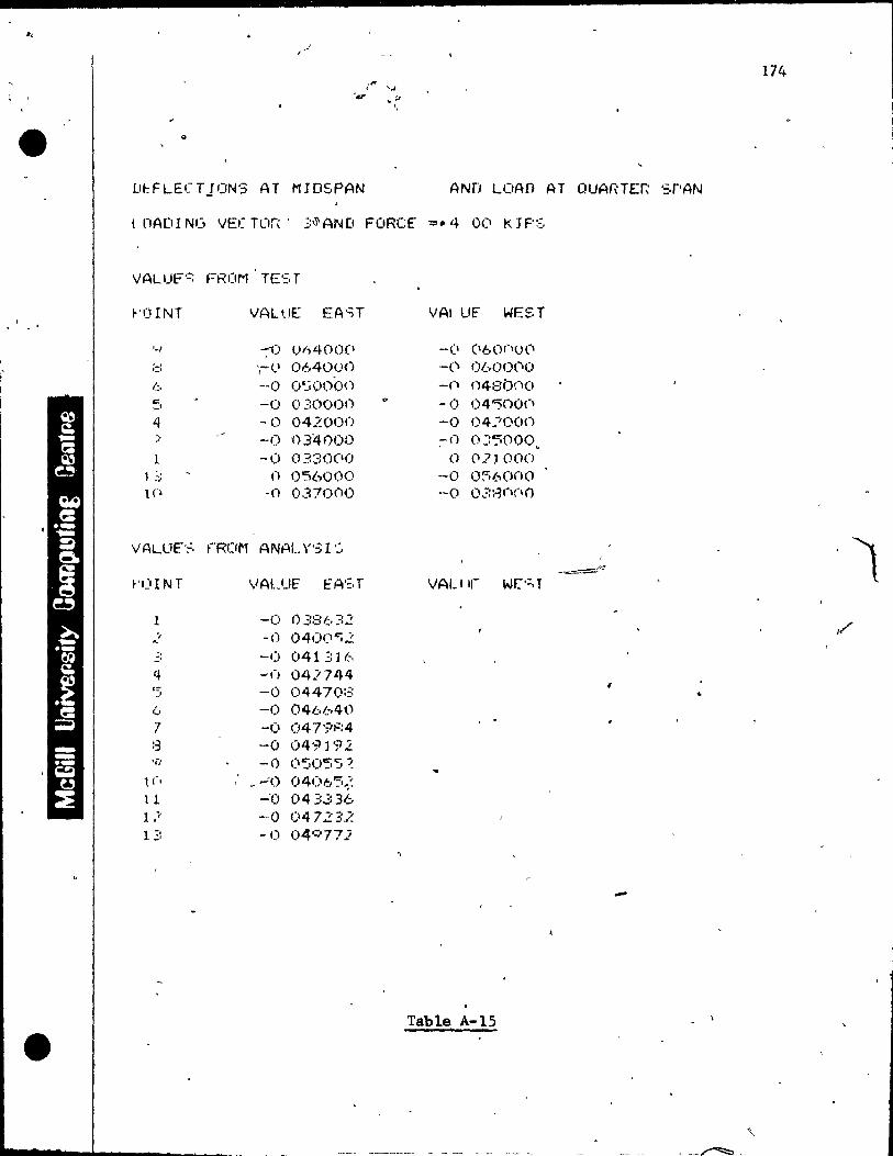
174
l ,
o
U~FLECT10NS AT MIDSPAN AND LOAD AT QUARTER SrAN
1 OADING VE(TO~' 3~AND FORCE ~.4 00 KJPS
VALUE"':-; FROM' TE':, T
!-'OINT VALi.IE EA'.:;r VAl ur WEST 1 •
'·1 -0 ()h400(1 -CI (160nUt"\ , '-' ..... ',-(,1 0640<.H) -() ObO()(,\O
l::,. -0 O~jooon -('\ 048bno '" -1) 0'::0000 -(l 04"'500n -' 4 -0 042000 -0 04~ÎOO() ::- -<) 034000 ;-0 0::5000. l -0 0330(10 0 02JOOO
1 .::: n 0'5600(> -0 0:=;6000 ln ·Cl O.370ClO -0 03:~(l(lO
VALL1t'~, ~-ROM ANAL '1"3 l'':'
t-'OINT VALUE fA':,T VAU l, W["; T
1 -0 ()381:.,;;2 .? -0 040('''i2 -, -0 041311.-, .,:,
4 -() 04J744 c;: -0 04470::: -1 .. (., -0 0461.;.40 7 -0 0479F;4
, . ::3 -0 049192 li) -0 (1":';055 ~
l C, _ "':0 0406'5.;: 11 -'0 043336 1 ..... -0 04723.< 1 -,
.:' -0 04'~772
-
Table A-15
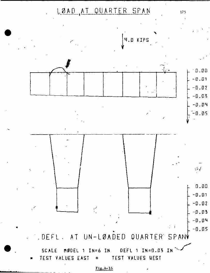
L 0 A 0 A T 0 -U ART ERS PAN 175 -~---e "---...;:------'----.;.....---
e t4•0
,-(,.,.r KIPS ,--
~
~I /-1
... ~ •• ' Q
~ ,
1
"
r
---,---- ---------r-----------r----- ---r----\ t 1
,f'
.. c '0 DEFL ~ AT UN-LeJADEO QUARTER' SPAN
sc ALE M ~ 0 E L 1 IN;: 6 IN 0 E 'F L 1 IN;: 0 • 0 3 l N ·, ... ~r' • tEST VALUES EAST D TEST VALUES UEST
Fig.A-16 p
• s.
.
- 0.00
-0.01
-0.02
-O.O~
-O.D~
-0.05
0.00
-0.01
-O.OZ -D.03
-0 .. 04
-0 .. 05
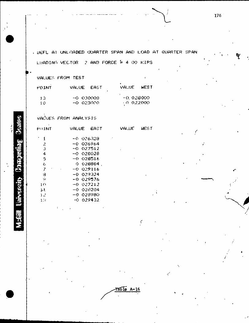
Il
(
" (
•
• UEFL Al UNLf1AOED Ol1ARTER SPAN AND LOAD AT G!lIARTE:R SPAN
LUAD l Nf, VECTOR 7 AND FORCE k 4 00 t( l PS
VALUE~=, FROM TES T .
1-'(1 LNT
]3 10
,
-0 03000,0 -0 023C1('I(>
VA'~IJE:'~, FR 0,..1 ANAL YS 1':'>
f'llINT VALUE E:AST
1 -0 O;?6328 2 -0 016964 :, ·-0 027512 ~.
4 -0 028028 '5 -0 028516 f.:., <) 028884 . 7 -0 Q29116 :3 -0 02'~"::24 ,;, -0 029576
ln -0 027212 ht -0 028284 12 -0 028980 1'" , ' -1) 02'9432
VALUE WEST
-0,028000 . n OJ~2000 ,
VAI~ur WEST
-' l
A-1G
(
\
176 -
l '
r
!
...
~ 1 /,
" /
1

l ' 1
1
e
r
/
• 7
, J
If
l' t
Il
L0AD AT
0
1 ,
1
QUARTER 5PAN
f.
t400
, ;
, [1
KIPS
1
OEFL.AT UNL0AOED QUARTER SPAN'
SCALE M9DEL 1 IN=6 IN DEFL 1 IN=O.03 IN ' • TEst VALUES EAST 0 TEST V~LUES UEST
Fig. A-17
177
Ù'
O.GD -0,,01
-0 .. 02
l-D.,O~
-D.OY 1
~ -[1.05
~ "
•
" ,
0.00
-0.01
-0.01
-0 .. 03 .
-'0 .. 0 ~ ,
: - 0'.01)

-,
• 1
,1 1
," ,
r
- ,
, , , !I~"'L AT UNIOAf,lED ('UAr:1ER ':;,r~N {~N[I LOAD AT OUAHTFH' ~.PAt.J
1 (lAD 1 NI, VEC Tf"ll~ .3 AND FORCE .;: 4 < 1(1 ~,r F"S
VALU["'-, FRGfM T [."'; T , >
" l-'lIINT VALUF t:A':' T ... VAl ur WEST
j ,;: -1) 0:: 7 (IUO o_() (136000 J 1 () -<) 024000 -;0 02300u
~ .~
VPtLUE:~, t-f<OM A~AL y '?-. 1 :.:, r,"\ 1"1] 1 NT VALUF FA':,T VAlllr WEf,T
.:J
l ( .-.i 02487(, -; (1 02"";78::: -.
) --CI O.~(.;:.5 76 " -.. 4 -0 O}.' 2:64
C; -0 ()~8.252
. ,
/:. - u V 2'-1 1 It. ! --(1 (l2')R4f~
t
;: ~ .1'1 0::0'3::;:4 '-Î • Cl U31452
li) -0 O~-'.6160 .. l l -(1 OJ7740 1 Î' --1) U::<'46::: } :' -0 1) '3 <J'? 40 -'
'Table A-17
•"~Ii·.''' .................... ____ ~ __ ~ ________ _ -
178
\
~ El
.- -
)
I~ ."
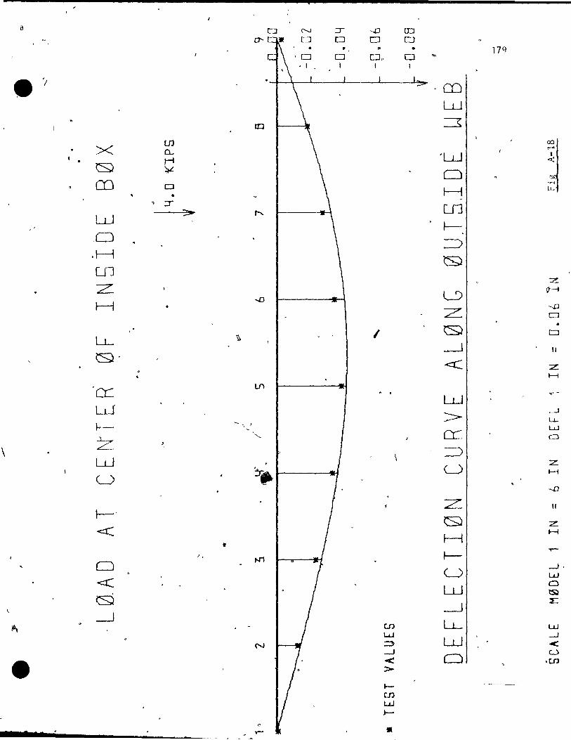
.,....r .- -
, '-' '
"
, 7
, . r
-~ -
,---.Il -,
, . . .. . e
, : c::;--
, , '- ' : ,-
ç
........ -~
" ,
',1'
. "
7 r
/
180
. . . ~ ~
, ,e .' ~ r . ::. - ·c . .:: '-1
~
<- IJ
1 : ~ . r,e r 1
/
/
1
Table A-l8
"
"
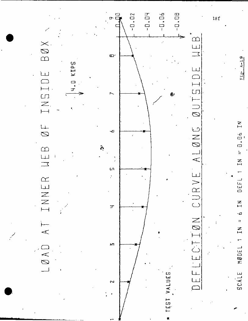
a N :::r --.0 ID 0-- 0 0 0 0 18f
• 0 0 t::::J 0
/' f 1
e ..
X-CO W
\S;J
fi a:::l' =r
ln
~ a...
'w t:=i W ~
0 a 0 'r-!
\J..l
• H H :r
en "> Ln ,~
z. ,/ l-
" ~ I--!
\SJ
z LL
~ -..0 l...')
H
z: --D al
CD ~ ~ 0
--.J i, W <C: z. ~ . ' H
Lf\
W ~
'" er:: .t.
> -.-1 l1-
W CL.
w CI
Z ===> :z: / U
Z H
H -....D
, Z Il
~ ~ z
,/ <t:: . ' • 1--1
H
;0 N'1
j-!.-..-
, ( 1. -.-1 U w
~ W a l:S)
~ ~
::E
~ [.JJ LL w t...J
N ::> W ---J ,<
.' ......J <: ,0
<:...,)
> t.IJ
....... en t...J ' ,. 1-
1 • •

, I,Ç-O:: • - r
"
.' ... -!::1" ,
--1 \
Il,1 -, \
c- --,
._,.., --
-, -
• • • ••
'.,..
. '
1 \ ,·1
J -,. ,l
,-,
-- -' .. i. :,
~,
J
F
-<"",-
-
, - . -, -, .. ,
, ;- -
1
...
\
Table A-l9 )
"
\ .
/ /
182.
• v
, . . '
..
o
\
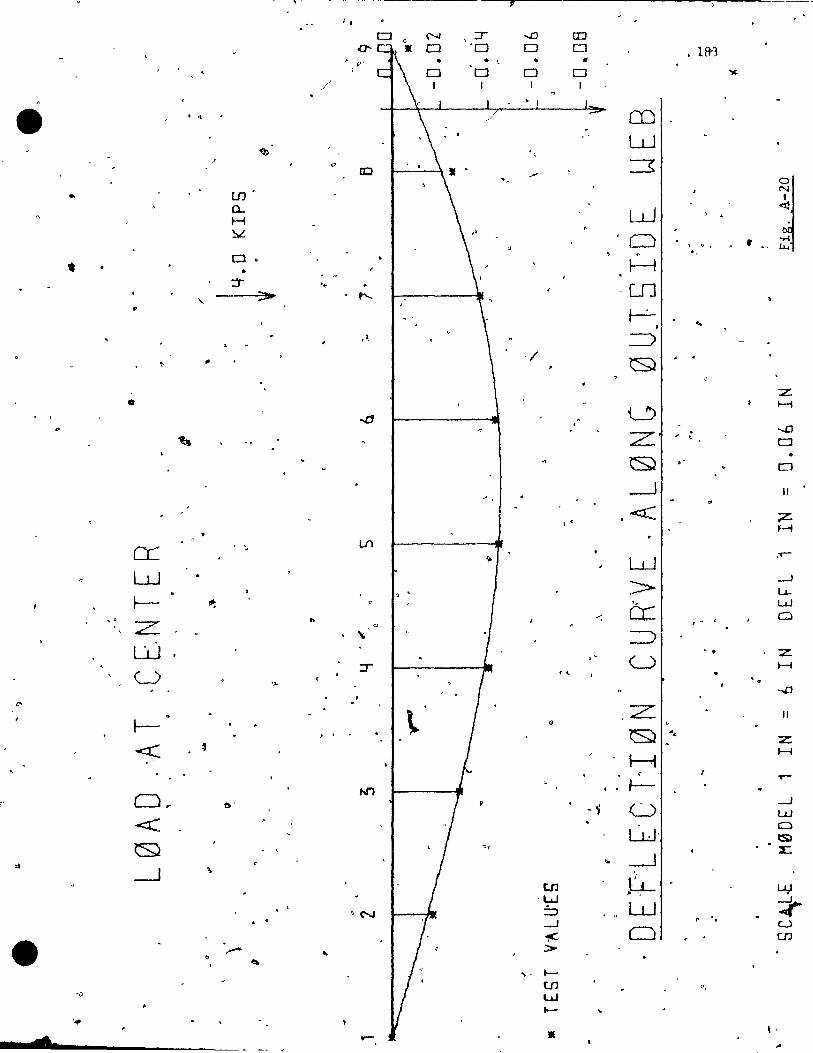
Jf , ,
N ,:r -.D CD 0 '0 0 0 • 1&3
". • • , . , 0 0 0 0 "1(.
/ 1 1
e . ~ CD
'<b W
" "
ID :=s .....
UJ'
~ a... H W ~
~
. 0
• Cl
, o , • . . -. • H
:J '. " >- ,..... UJ
" r--:-, .. , ~ =>
" '/ Q
z 0
....(j 0 H
... Z . --.D < CJ
~ . ' • 0
---1 Il ~
< \ < ;z:. H
CL ... LI)
r.. W ,...-
W >- --1 La..
~ III: , . " w
Z .. cr:: --: Q
,
" ' - "
W => ;:r " U
-. z
U ',. . , H
'" -D ,
t:> . z: Il
1-- Q
) ,
<Ç ~ ~ .... z H
H
o-
f' Or N'1 f-"-
,--
t). ~ ~ 0
--1 W
<C w· a lS)
~ ... --.J ~
---.J ,
tn ~ L.J.; ·W - , . '
"N :'::J W :t--.J
r .
• . 1'C 0 u
..-w
.. :> .-. ... t-
UJ ., '1) W
l-'. d ..- • \ '
,.
•
----..,.,-
•
1, .... --=
" ,~,
..
, -,
..:.
o J
;
o
..,. )
---- ......
- ,"'\
"
...... , .... \
,',
'_.(.
-, '
J,.
,~ . ,.....
....4=-
~ 1 : '.:,
TC;
o , '"
Il
,"Il-,,·,- 1'",
. .. 1,'1 -" , •
- =;, \( ,-
, ' . .,
•
184 .. " ... 1l.
...:. ::: 'F :- .. ;: P,
~-O a
r
"
•
.." , ..
" o
~ \ . ,. " Table A-20
, ,
o

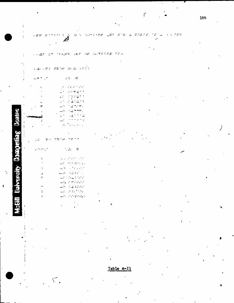
1 ,F==- .
1 .~r
.)" ..... ;
l- l''' .
!:
~ .... . .,
,- t:" ;
., '.
•
-r , . . ',r .
A
• r '~'j::--::; ,1):: r
- ~ -,r·- ..;.'- ...
~,
IJ.:!; I~
- - -1 , • ,
" . "'".:), --; -J. -.
. 'J. '
. ..;., -, -. \
-1·' -(-~
--1
,
"":'::' - r·'
1 --' ... ,~
-, , - ~~,
~ , -e
--c - -
, , ,
-
-, -. --,
..i.
1 .' 1 \
-, .. ,
_1'", .",,'", ':'r"""~I'"
'\' •
»
( 186
·'1 1 ~ rIt=" .•. ç::r -h ..:. :,"',ç, . - ~ ;; .: - .... .
0
,-,;: ,-" 'T'': ',F r ,"1 ,
, -
)
p
Table A-21
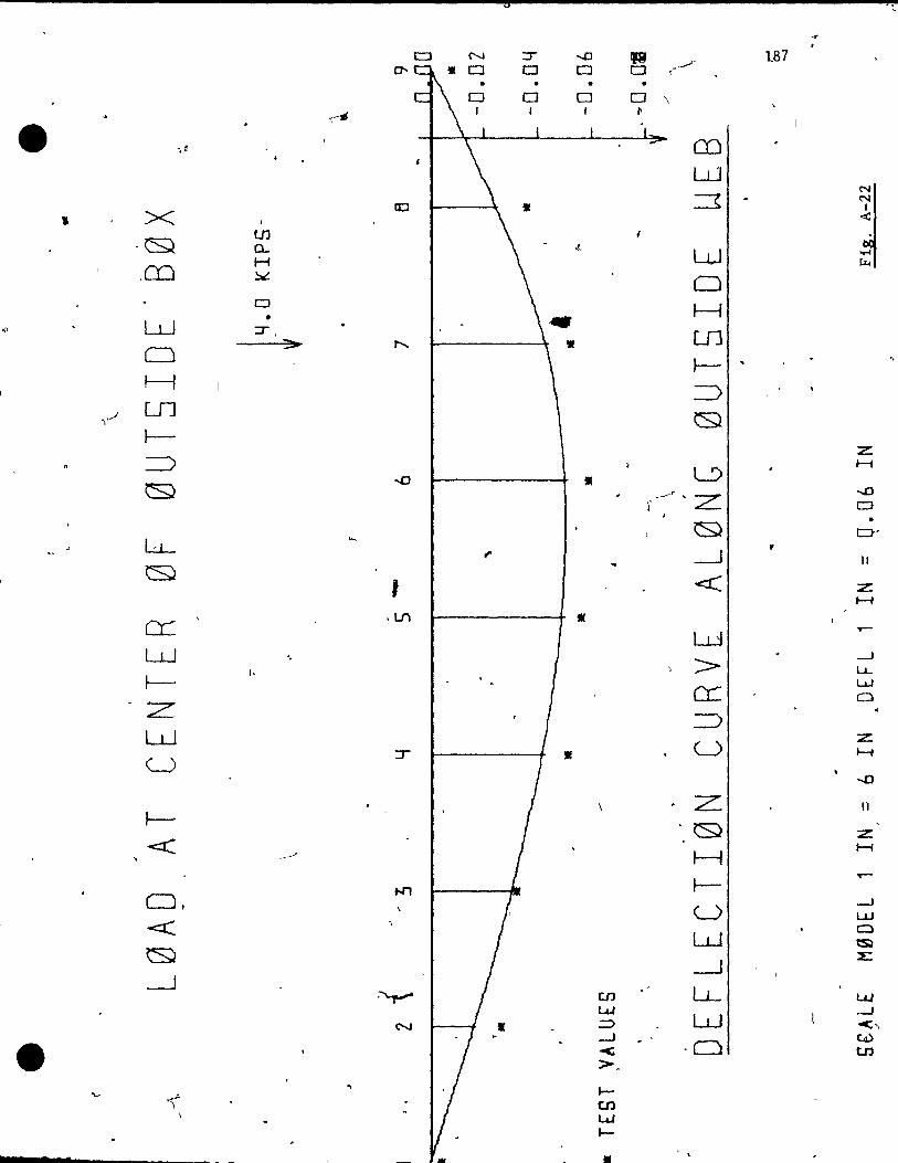
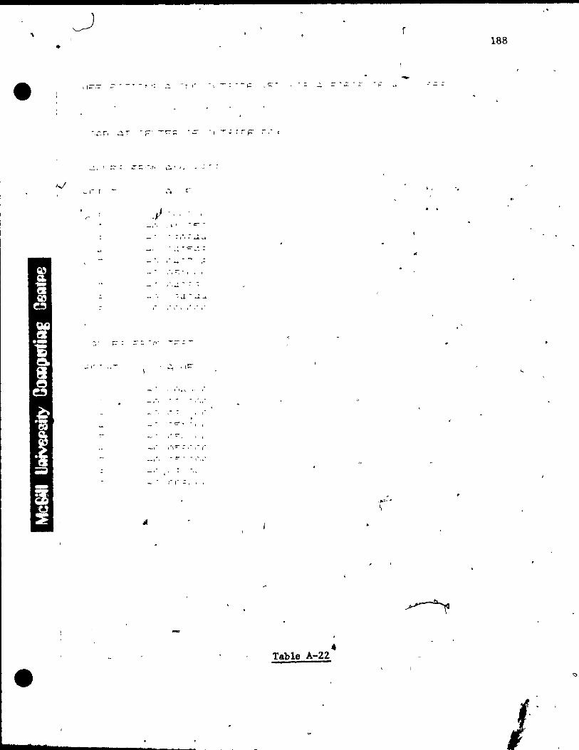
•
~ - .. - r
-,-
-, " ,r ,1 • -.,.. "
,~-c .. ~:
- l , .... .-
- r'" -;::-::.-
"Co
(( .:, 1 1
-
--ç
. -~ •. r ; ,'"
• Table A-22
f
-
"
188
, 1 '.
..
J
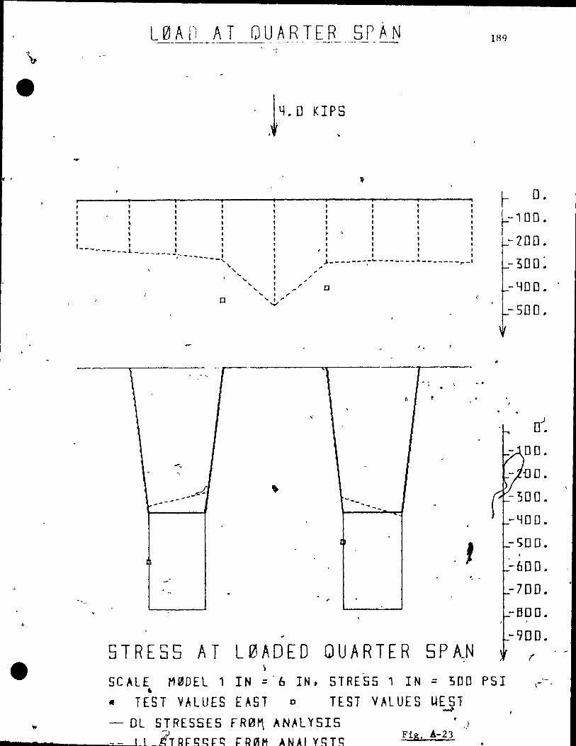
L0AD AT QUARTER SPAN
- .14. D KIP~
, , 1 t 1 1 , 1 \ 1 l , 1 ~ ,
1 1 1 l , t_______' • : ; . : --L- ______ 1~ l' . -------~ '. : ,;-------~~-------·-------r-I , 1 ,.
" t .,' " 1 /'
" l '" 0 ... 1 /'
c ...... !,/
J. , 1
--- A ---
1
1
'. -
STRESS AT L0AOED QUARTER 5PAN . \
189
D.
-100.
-200. -30D~
-YOD ..
- SDO ..
. .
-YOD ..
- 50 O. ,
:"600 ..
-700.
-BOO.
-900.
SCALE M0DEL 1 IN :.:"6 IN, STRESS 1 IN :.: '500 PSI Il
• TEST VALUES EAST 0 TEST VALUES UESl ~
- DL STRESSES FR0~ ANAL 'l'SIS ___ .... ___ ---=:..=--~I t _lTRr:r::qrc: rJH~M ANAl Y~T~ FiS, Â-23
,)
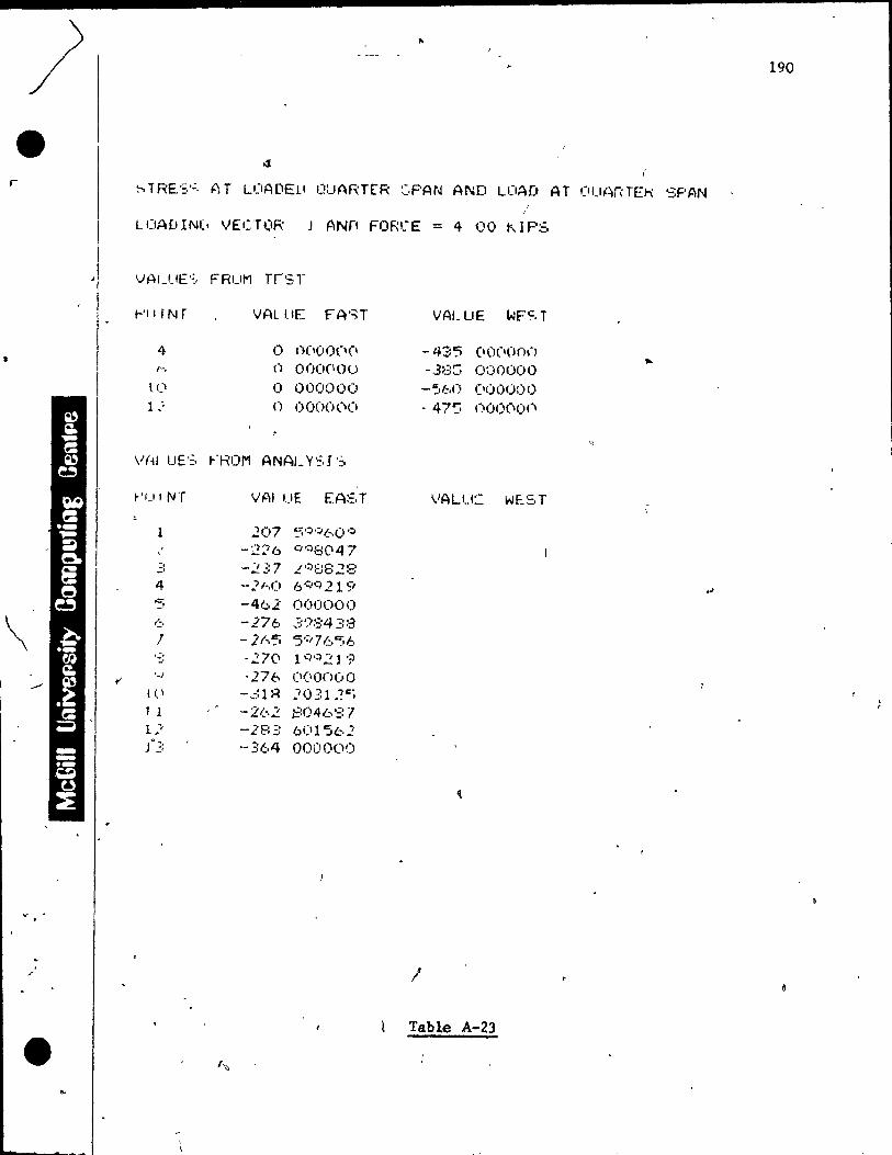
) r
\ 1,\
v ••
. .r
•
190
., ;-. TF~E::,';, ?) T L(lADElI 1.1UART[R :::,PAN AND uJAD AT (IUAn TEk SPAN
LOAVIN(, VECT(lR J ANf! FORI.-E = 4 00 KIPS
-- VALUE':, FRuM rrs r
1-'11 r N r VAL tlE f" A':;T VALUE wF'~, T
4 1) 1)(100(\(\ -43'5 (1 (I(\(J 0,-)
h () OOO(\Ou -..38S 0:)0000 li' 0 000000 -';:.60 (100000 1 ,; n 0000('1(1 - 47'; ()() 1)(\ (H'"\
\/(.H LIE':, ""ROM ANAL y,::,I ':.
~'U f NT VAl UE EA::,T VALU:: WF_ST
1 ::'07 5':;"~60'::;O
-'2"':'6 .:"/0:)::::(147 .:: -2:':7 L f:)::;E:.2 E: 4 -"11-,1) 6':)<:)219 .: -462 000000 -. (:. -276 '=:'/~::4 ;::::3 ,1 - .2 1 .. ':. '5'~ 7 /.:. c;6 ,., -27(1 10:)>:)21 '? ::'
tI '-1 "27b (\(lonüO
( ~ \ -,31R J031.?Cj 1 1 -2(-,2 1:::046'=:7 1 ~-, -28':! 6(11'562 Ji>3 -364 000000
)
Table A-23
'""
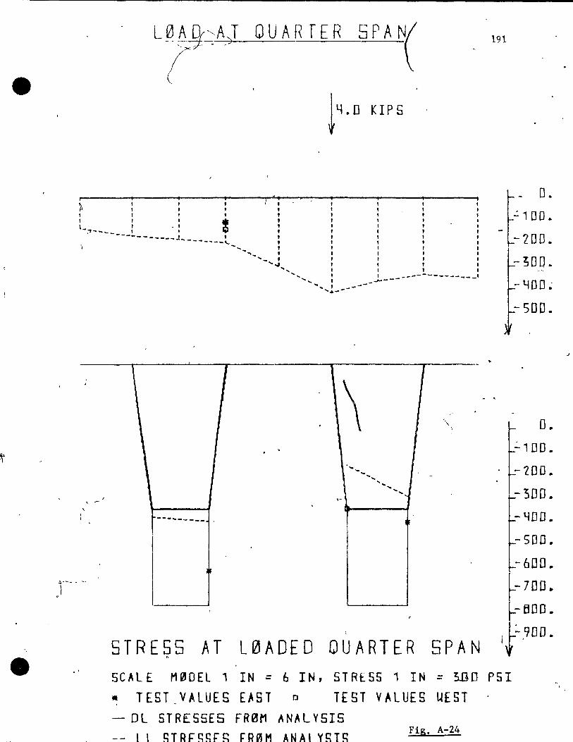
•
L-r-fY:A} QUA RTE R 5 P A N(
~4.D KIPS
, :: l ": : ; ~ " '" , " '" L;o~~~_: -l ! : l :
----------~J~ , , , , ----~--... , , ,
-..... t , 1 .... ~-, , ,
'- , , , '"<01 l ,
", : t '.........., ...!--------------- ... --' ........ , ----
......... --
, 1 1 .
\ .
. , "\
\
. . ... ...
'" ...... ~ .. .. ""- .......
, .... <. ~
\
1 ~--- ... _---- ,
-"
-
STRESS AT L0ADED QUARTER 5PAN
191
t - 0 ..
_ ":100.
-LOD. - ;00.
-YoO~
- 500.
D. ':'100 •
-200 •
-300 •
- LfD 0 •
-500.
- 600.
-700 ..
-BOO.
i :....90D.
SCALE M0DEL 1 IN = 6 IN, STRESS 1 IN = ~O PSI • TEST VALUES EAST 0 TEST VALUES UEST - DL STRESSES FR0M ANALV515 -- 1 1 ~TRÇ~~Ç"g rROIM ANAl ygTg
Fig. A-24
J
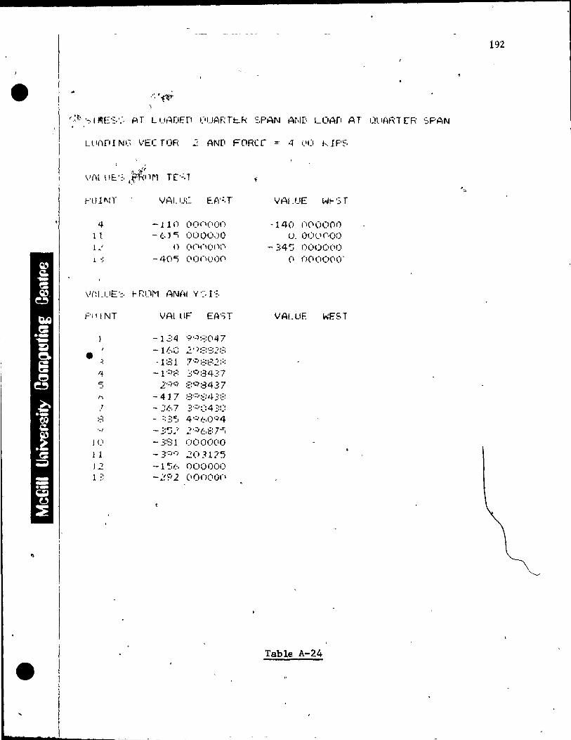
"'~ " ~'" ., .,,:t'I '-:,j Il'iE':;,':, AT l uADEP ("jAr; Tt:..R ':,PAN AND LOAfI AT l}li(U,T E"R SPAN , '
LlIl\PINI."\ VECTOR ::. ANf! FORcr =- 4 1.\(1 kIF'~,
1-' (HI\! r VAl.ue EA';,T
4 -lIn OOCl(\on l l - 1,;,) c; 00 !,)O.) 1)
l ~I () (\(I(1onn
! -; -40") 00(100(1
F'IIINT VAL llF EA';T
-134 9'''"):=::(\47 1 -16::: ::. 1 ):::;':::2::; • ~ -1:31 7';;':-;:82:'::
1+ -1':)f: ~:C,:3437 c 2-:,cl ::;:C,::3437 -' h -417 ;:3'~":::i.J. 3::: 1 - Y::,7 '::':,':::4;!:::
,-, ,:-t - :: 3~1 4';;"60';'4 '-1 - ~:~.,1 ':'.:)6t:7'::;
J (1 - 381 0000(\0 l 1 - 3'=,'j 203175 12 --1 :'(" 000000 1 -, ;, -:.!.~/2 (IOOOOCI
..... _-_...:.._--~~-~- - -
VAl -'-'E WI- ':; r
- 140 (\(lOO(l() 1), 0(.1(,.1('.00
- 34':. OO(){)(II) C\ ()(IOOCII.Y
VALUE WEST
Table A-24
192
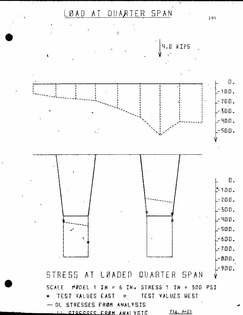
e
777
L0AD AT QU A~ T E'R 5PAN 191
[1
u , t 4 ,,0 KIPS
, ,., , -l "01 1
, "" • '" 1
''''--~~-~ :: :! :: --------.J , " t 1
o. -100.
.
~
\
-- ---- ... --........ " t, .,
1 .
~-------- .. /
, ~
........ _..... t. "1 1
-,' t " --4' " -......." , t
,
.. , '-... : :' -", 0\ ,
l
, , '" , ... _--------, , ,.
\, ,. '\ , " , , ,
'~,."
. _- .... -.... _- - ... _-
~ J
I~
.
1
- 20 0 ..
-;00 •
r. 40 O.
(500.
o. --100 ..
- 20 0 ..
-3D 0 ..
- YO 0 ..
-500.
-600 ..
-700 ..
-BOO ..
- 900 .. STRESS AT L0ADED QUARTER 5PAN i ,
SCALE M00EL 1 IN ;:: 6 IN, STRESS 1 IN :: 30D PSI
• 'T E S 1 V A LUE S E A S ToT EST V ~ LUE SUE S T
- Dl STRESSES FR0M ANALYSIS !! c: l Q 1: c; C; r: g f: R ~H1 _ A N AI Y ~ T ~ F:tg. A-25
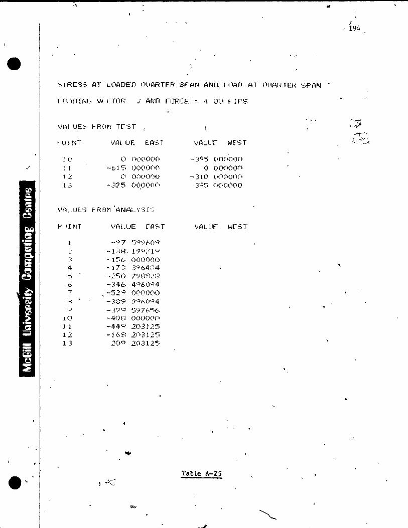
·"t,
-1
':,1 Res'::, AT L(IADED I}UARTfR SF'AN ANr,) UJMJ AT nUARTEK ':;,PAN ..
UI,~nINC. Vf- (TOR ,;.: Atm FORCE _. 4 OC' f IPS
YAI UE~ ~R(~ T~ST
~'UJ NT VAL UE E..A':, l
JO 0 (),~\(\OO(l
] 1 -615 000(1(1(\
12 CI OCH .. I!)f)O 1 ., ,:;. -375 0°.0°0 (1
WH .IJE.'; F Ror1 . ANAL \"3 l '~,
,"'lfINT
l
-., :' 4 0.=;
f.:.
'1 " !-:
'-' 10 1 1 12 1 3
-~)7 'J'~';If.n'"
-1 '-::8, 1 9';";t 1'-' - 1'5(.. 000000 - ] 7:: 3'::"64 C:4
--::46 4';;60"-'4 ,--52':' O(I(\OIXI
- :::f.:9 - ';/':1(-,0':'4 -: . .:'~I:' r:;';17bt:t(. .. , -40e 0000(1(1
-44-=' 20.31.~5 - ,1.-.:::: 2n;: 12":i
20C> 20312":.
- ,::0'5 (ionoon o O()(")000
-'::1(\ <..1(ll:-.unc· 3':'S ()(I(I(100
VALUF wrST
Table A-25
--~
. , ,
" - 194
,
..
l'
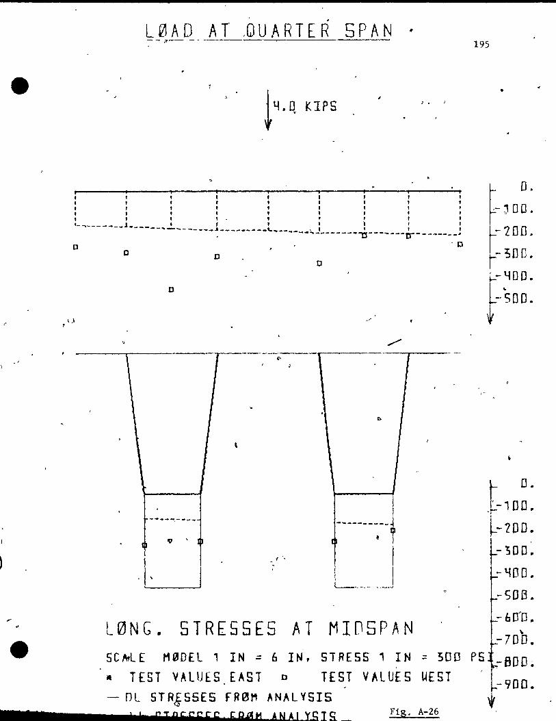
f
,.
.5
. L 0 A 0 A T ,Cl U ART ERS PAN " --- -- -----o
J. 1
, , , l , 1 l , 1 , l , , 1 1 1 l , ,
-~---- ___ l____ , 1 1 --~-""'--____ ..& _________ '- .. __ l' , , ,
o
\.1
0 0
D
\ 1 "
-.... _~----• 1
. \
----'-~------1O-------tr--------~
0
[
/
......-
-... _-------t
1
1 L--l~ ___ ..----I
'0
1
L0NG. STRESSES AT MIDSPAN
195
•
o . ,- ~ DO.
-700.
- 3D o. . -ttOD.
f-SOD.
"
l- D. L-, DO ..
~- 20 0 ..
- 300 ..
-~OO .. -SOB .. - bDPO ..
" -700. 5C~LE MaDEL 1 IN ~ 6 IN, STRESS 1 IN = 500 P5 :-BOD~
-900.
1
• TEST VALUES EAST 0 TEST VALUES UEST '- Dl STR&55ES FReJt1 ANAL YSI5
!! ç T R F S S ç S ! b BI! MAN A 1 YS l S. __ Fig. A-26
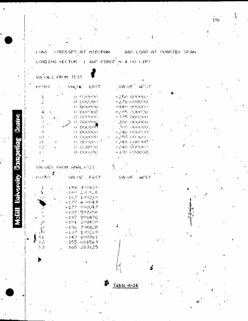
, ,
0
i ! 1
i 1
1
Î 1 1 !
1
~I l 1
s • l'
's, T RE"::, ':;p=, AT 1'1 f rI': PAN ANf! l GAn AT nlJARTEh' ':,PAN
r-'U rl'l"I '\'HU ~ "
EA':,T
1 CI n"I,li l '-'I', , ,) 1.\(II;j,.It), 1 -, , Il ()n(ln,"'()
4 Il (\(1(1:1<.\(\
(, , ,:1 I},'I""I Il ,(,
"- (1 (\ ,)(I(I( l( 1 ~,
C!(..)(I(I,I~ r" Il
',j 1) (1(.1('<11.'1-1
1'1 l'. (,(.,(,()(.(,
1 1 ( 1 ')1."',(.'( l, 1
1 .,
'-' '.' :'Ü(I:'I)
l <) (I(I( )\1('('
\'{~l UE'=, Ft--: (!I~l ~INAL y' :"I ':.
~
\ , ... -: ~~
-/-
l,
::.=:
l' : J 11 12 1 3
..
t
Il - J 1..-,7 1 :';':'2 l . .:, , - 1 7! 4 n=:("J"1 "J- 1 7:r "~":';:::i-':t 7 -, 1 :.:::' '50:, 7 6 o:~ /-.
-1"/ l '::1-1::::4 ~::.:'
,- 1 .;,/..., 7 ':'f;:3':: F:
-- l .:: 7 l :1') 21 '-/ - J 4.? .::;nn7:::! 1
1"-",. .. ',-' 165
(:,(1 1::;(:. 3 "'::03125
10
\lAuJF W,-'.> r
-"::,,,:,() O(l(·(1U, ,
- 2 ,7 a.:; , (1':'0«\0
-44(1 '.'1,1 (i 1.'(> \ '
_ ... , .... w/:' ,"I,_'!.ln:'I,1
- -, "'fiC" :. • 1 (Iün,:.( I( )
, ~(I(I ,'I( \()O(IU
.j l )~--; • I( Il J( 1(11) ,
-.'4« i 1'."(1("', ,("
è _:: C".'=; ,-,(', '(I( Il'
- .';i.j 0 l '1 )().')()('l
" - ~-, 4(1 1.")1"(\( 1:,
- l ':/(1 1 Ir)Oel::l/),
VAl !.IF
..
~; ~d
. t •
"
p Table .A-26
196
1
/
.r
"

• , , ... ;,"'L Jo.
<
, l'
; 0 ~ -: ~ :
l , ,1
" , 1 1 " 1 1 1 "- , , . • --- ....... _.,.. __ J. ___ .. ____ , ________ !_ _L__ : :
., III ,------- -----'---------0.:.. + ,.' . • r" C .... " .. '--'-0
lit ....... ' _ .. '-o o -- ....
III
o
..
-----,..------------ --._---'>-~-~_._. -------\ 1
(7
l' .... --:----- ...
'.J
. , L0NC.' STRESSES
1
r~-------,j
't l ' .
. , .
AT MIO~PAN .
t '17
'j' ~. ~_10[\.
~- Lon., L-30C.
_-YOD .. 1
~- 5f1 0 ~ t
(
o. -1.00.
-100.
- 300.
t-YD o .. -soo ..
- ~-60(,'. 1 -700 . • 5 CAL E M ~ Il El' IN;;:. (, IN, 5 T RES S , IN::., ~ 0 ù. P S ':'800.
-900 ..
. . • TES T .V A LUE 5 E" 5 T 0 "', T E 5· T V ·A L. U E 5 U EST , r . , - DL STRESSES F-R0,., ANAL YSIS c .,
~ , ....
• , _s .... __ ...... ;;;.;;;....J.! J..! -!i.S T1JRi.l:f~S.L..!:.iS±.E ~ uF IL011 A N A lYS l S ' 1 • Fi Il, A-1J
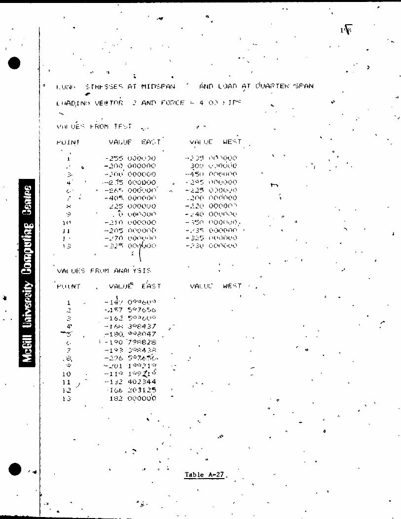
..
s
. ,
" '
.' P,t,Jfi l'JP,n Ar cIUAr,'TEt< "';PAN
r . L 1 lAD,! NI' \,lE I! rnr, 2 ANf! nJ;"\'( E !. 4 0,."' ~ J r",:,
. "HI UE'~, t-Rlil"l TF'=-,T
r-'ulNT
l
r;,
" ':'"
.... (, ' . " :-: 'il
}('I
1 l 1 1 .::
V,..'it UE':,
FI.ll NT
1 ,2 :' -' 4' -",.-,:,
(,
7 ,'.
, CI;:
,:,
10 Il ) 1.2 13
..
VAIJUF
- .2'5'5 uO!),_')<) - 2(H) OOOC)O(l
-;.n',1 (100(\(1<)
· .. -~#!5 0(10000 .- _~/:'jCt OOC\',IO'"
- 4(J"'), (lOf/(,O()
~25 O{YO(lUÜ ,. t·t)(I,)()(' II
-2ln (.IO(X)O(l
--lOS (J(I('I)(llI
-.'7n /.' 1),',( \0 'li '\
- ~:~Cj °t()<)(' F RJ.IM ANAl 1('5 r:,::,
-1 J,,! O'=I';)611""}
- .. 1 <f;7 ";876:,6 '-162 5':/;)(.1.1':'
.-] ~I-: Jr.'é:4 ;':7 .-180. ',')'·),::047 - l CIO '7'?:'::E:l:::: -1 '~? ::'·"1:=:4 ;:,.::: -2'71.:, ~':I7:tl~[" '-,.fI) 1 1 ';)':':' 1 ç,
-'1 1"'1 1 ':'9 t..1 ... ~; --1 =:2 402 :::44 , l 66 ~ C\ ..9 1 2"5 182 0(1000'0
,
~ ~
V {li ur WE'':,T
-.~ =;~'l 11/"\ )(11)(1
30:,1 \.' .lOC)1. i O -,/l'St) (l(I<:I( 1(\(1
. - .2,:,:- \ '(1/)\)0(1 M
.... -..?.2~ \:1 JOel,}!) . 2(1(1 (1(I(i(I(IO
r , - .~.2(, <)(1('0(\ '1
- .'4(' 0('1,'1'",<,' '" - :;".5(, (lO!)( 1,)0,. d
- .. ' 3-=, (\\)(\(,nn -- 3;': ':.; , \('l'ln!.'\) -,j-; ~:(..l ü(\(\('(\\:'
VAL U:.- WE'':,T
.'
'.
.;
Table A-27 .
l~ ..,
4
"\
.'
4
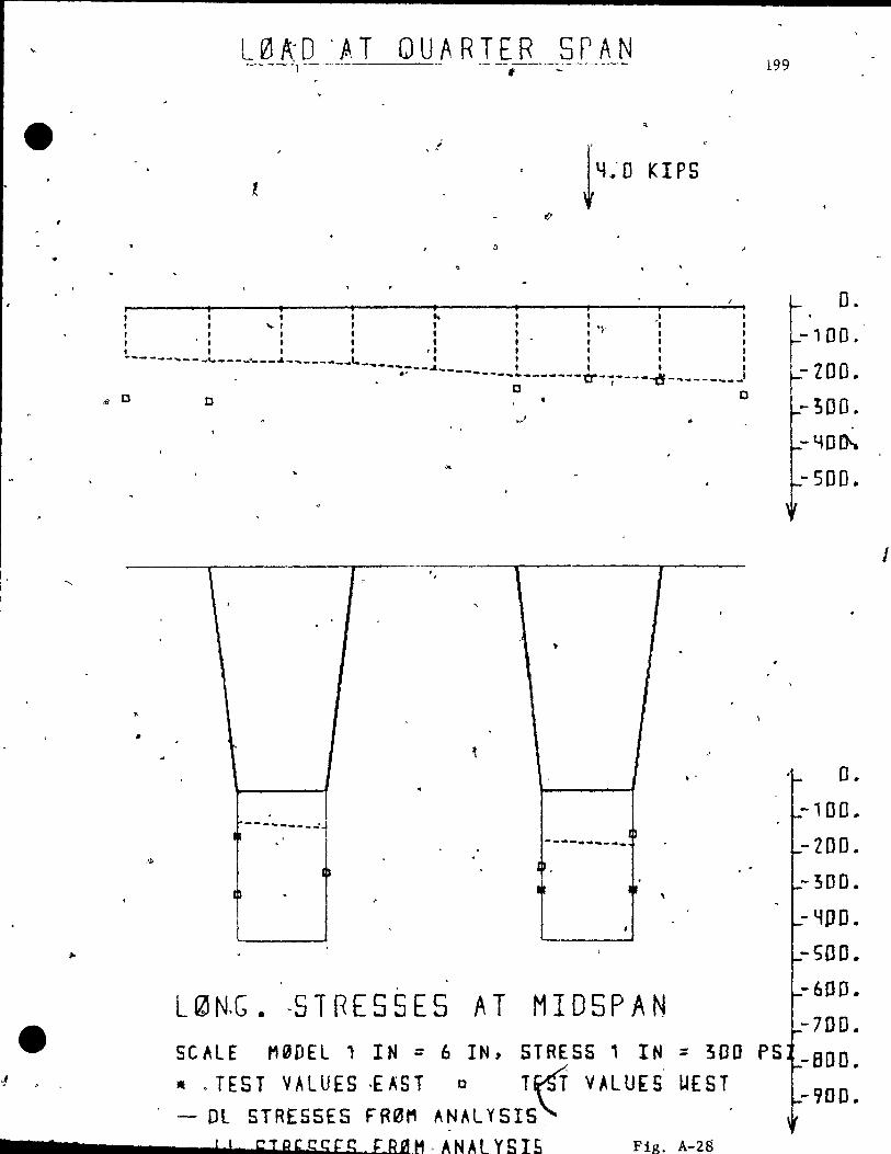
L0A~O 'ft,T QUARTER SPAN ---1----- - -f'-~-------
..
" "" " .. 1 l ,
: '" : ::: '?- ": , " ,t - , ,
, , , , ' , l , , ----_-... _________ 0 ___ ... _______ ...... , t , ,
-'--... ~--~----_ t , t • fi. - ... - ..... --------a--~----~- ....... ---..... -t
"i DOC • C
..
\ 1
•
• 0
---------"1 l "
lb ----....... -.... 1 _
1
L ~ N.G. -5 T RES 5 ES ATM l 05 PAN SCALE t10DEL 1 IN = 6 IN, STRESS' IN ;: 300
~ . , • . TEST VAlUES -EAST 0 T~ VALUfS IlEST - DL STRESSES FR3M ANAlYSIS,
7 7 !, ÇTRccgfS fsaH.ANALYSIS Fig, A-2B
199
PS
D. -100.
-ZOO .. -;00 ..
-YOth
-SDD.
o . -100.
-200.
-300.
- YOD .. -SOO. --600.
-700.
-BOO • -900.
1
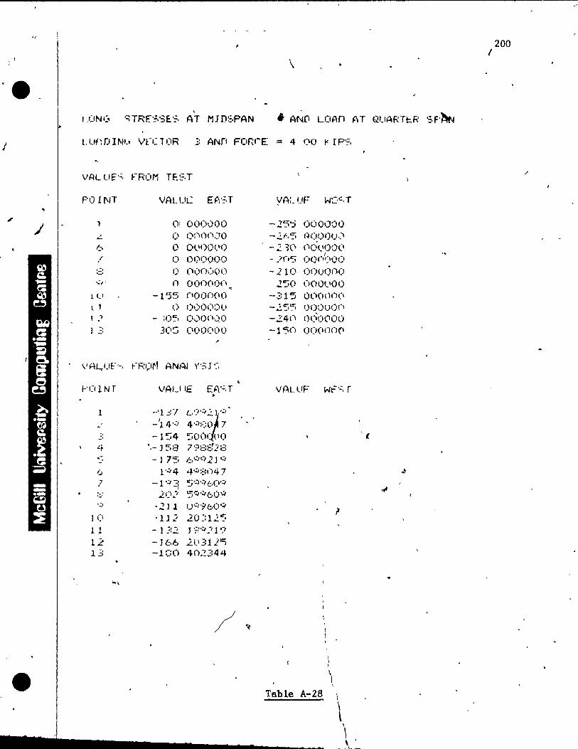
j
~
,-
~
•
, IDNG STR[SS~S AT ~JDSPAN
VALUES FROM TEST
PO 11\1T VALue E~'~,T
01 000,)00 L 1) 1);'00\"1,)0
6 0 0\.1<)0<.10 / 1) 01;-'0000
.'::;t 1) I;-'II)(X'(H) '-' .;, ' n OO()(If)n ~
1 c' -155 ClOOO(\(J
l 1 0 000(\01.' 1 ") - ;O~· 1),)0(1,)0
l .:: 3(IS (1 (H)(I 0 0 ..
VA/..,.UF·-. FRÇ1tl ANAl Y'3J .:.
1
..' 6 7
1-1
1 (1
1 1 12 13
.
vAU lE EA·':.T •
·-'1 :.:ï U;""T -114 '':1 4'·):-::0 7 -1':.4 500( tl() .-l58 198828 - ) 75 1,:.';;'0:,21 q
1'':'4 4':J::~1)4 7 --1 ':':1 '5':"i':'bIY.:'I
LC\ ... ""' 5·~·::t(:,O·,;,
-21 l u':;'i' (:,0 ,:,.
-Il .? 20~: 1.2 ') - l ::,2 J I;,tl~ .. ? 1';' -166 21.\ 311i:i -100 4().~344
\
,. AND LOAn AT QUARTI:.R SF'~
yA:_ UF WC'·;·T
-25':i 000000 -2f.S f~OO()(),~
-2 ~(\ (16<"100(1
- )'(''5 1
1)0(1'='00 -110 Oouon<)
250 000(-,00 -315 OOOOn(1 -2'55 ooou<)n -24(\ OÔOt'OO -l'50 OO(I(j()(l
VAL tiF Wt='·:, r
(
•
\ 1
\
\ Table A-2B \
\ \
\ \
L ~ .... '! .... --------~--~~
200 1
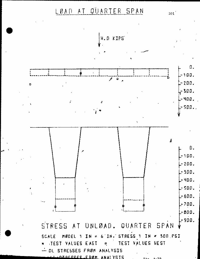
..
L0An AT OÙARTER SPAN 201
tlloO KIPS
. , , , ,. , , , ,
o
\
\
,
~~
1
.
, •
~_ .. ------. u
1
l'
,
~
,~
.. -. ., 1
r
,
, ,
.-... -- ..... ---0 .)
..,
. . STRESS AT UNL0AD. QUARTER SPAN
#
J '
t O.
r'OO" r 2DO • k- 300 ..
- "f00 .. "
- 500 ...
o. -100.
-200.
-300. -"100.
- SOO.
-600. ·700 ..
-BOO.
-900.
SC~lE M9DEL 1 IN ;:; (,. IN,' STRESS 1 IN :: 300.PSI
,. ITEST VALUES EAST D TEST VALUES UEST 1
- DL STRESSES FR0M AN.~l YSIS , , t STpesseE; of RAM. ANAL YSIS

(
202
• , ~, 1 h'F..':,'::: AT IJNlI.jAD rIUARTt:.f\ ·:.F'ANANrt LOAD AT ('UAr,TL-.R -:,PAN
l UA f1 [NI:' VEC T OR 1 AND FORCF t 4 00 ~ tPS
EA'~, r l'
t'II t NT VAl tlE W~LU( WE'-:, T .
'1 (1 (l()b.~·(I() - J ':'le' O('\I)(~01)
4 0 Ü(J(I{'\(l.) -5:' (IOI}no(\ (-, (1 (}O()(H)(I - 12~ (I(.'onoo '.) (1 OOnC)()O - l 1'.:'1 OO()()0v
10 1) \,0000(\\)0
H 0 oon(J(JO -71)5 P(I,JOU(I
/;)90 ,(1(1C/(1'(1(j
L , C, O(\(I(I( 1(.1 - l[)!) ooq:J!)Q
l -, 0 ()U(H)(JI-\ .-' -f..,C'/n, (I(I'}: H)O
V~H UE'::· FROM ANAL Y'~, 1'=,
t-'I l i N T VAl Ile fA'.:.r
! 1 -7'':/ 7 ,=, ;=: ::: ~, :::: • 1
.: -:~ 1 :3'·-":'14 14 ; --1::4 7 .;) ':i'f: 0 5
,~ -- !_: :f~ 5.:)863.:: 5 " - 'iCi ::'=:'':''':;'414
-':J 2 ::...·:.r';/~!C)5 . --Ci .? 7'4:·-:82:::: .. . ::; -'=14 49 Q O;' 3 .:, -'~b 1;"J':/f:,C'~ 3
J I() - (:,()';I ooonoo 1 1 -611 li) :!l.l'=; L~ 62::': 601'563 1 J '628 ::3f) 46;'::~:
1
\
Table A-29 •
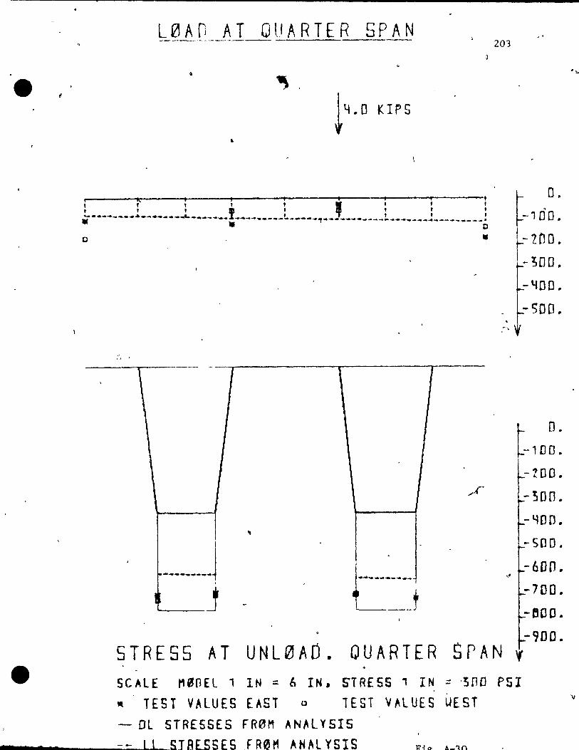
L0AfJ AT QUARTER SPAN
, ~-
..
, " , , , , l , ,
o •
" '
\ - 1 1
,
• '"
..('
1 .,
-------J . .
1
Lj h T '"
203
, ,~,
"
STRESS AT UNL0AO. QUARTER SPAN
"
o. -100.
-200 .
-;00.
-liDO.
-500.
o. -100.
-200 •
-300.
-YOD.
-500.
-6DO. -700.
-BOO. -'JOC.
'f
SCALE tH~OEL 1 IN = (, IN. STRESS' IN ;;: -3[10 PSI
" TEST VALUES EAST 0 lEST VALUES UEST
- DL STRESSES F'R0M AN,\L Y 515 __ • ___ -=-=~llL..SJR[SSfS FR0t1 ~NAL YSIS
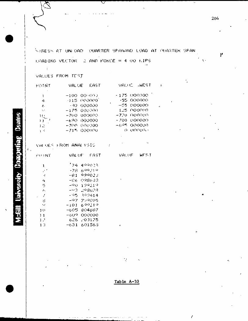
204
JI IfIA[IINC, VE.XHI~;: ~ ANf! t=üt-\(E = 4 (JO LIP'::,
• f
VALUE':; FRC'M TL'~r
r'C' T N r VALUE: EA':,T VP,LI li::' .. WE''; T t>
l -100 001 -on) - 175 ()ooi)00
4 ·115 (1(I(lO(lO ,
-S::ï 000000 f., . ~O OOOOüO -55 000000
-11'5 OOcI,:lnn 1.::5 (10 <)(l(lO
l. ( , -71.10 (JOO(lCl::I - 7.-1 l) n(ln()I.I(\ ....... 1 J --b'?(l 000000 - 700 llonooo ].2 -7(10 (\fi CI )00 -(:,qc:; O(IOOun
l .: -- 71 "". C)OCI< /(,1,,) () (lonujÎ. -
,.
f'1! INr VAL tiF' FA'3T VALIIF WF~,T
1 ?74 4':":/() ~ :: c -7::=: 6':/':'}' q
-: --81 C'/9o:)02.;:
'+ -::::6 (l'i';=:l:t;: :: ,::- -':'\) 1 ')>:J 21 '-Î .' (-, _1 .. , ?! ":'f:':3c.:~f:-1
! - 1:,,:, ::';;')iH 4
::: -0::'7 7'/':):::'(15
'., -101 1:;. '-"J'-' 21 '-' ] 0 --605 :::(l4~,87
] 1 -f.;.U'4 000000 L ) 626 .'031::-'5 1 :! -631 60156.:;
Table A-30
( F 7 ft

,
(,
L0AO AT QUARTER SPAN 20')
1
tll.D KIPS
,If ~ O. , f , , , , l , • 1 t , ·-------.......... ---____ J ______ ... _L ... ___ ...... J , f , , -, DO • ~- ------·--ë-~----·~-----·-4-_~;-4._~ · D'
•
\ J
,
-. \ . ,
.
t- .... - .... - ___ ~ 1 - .. --------
1 I~ , .
1
"
~
,. l.-- ZO o. ) L-;oo.
- . \ , 1
-"400 ..
"'SOO ..
D. -100.
- 200 ..
- 300 ..
-~n'o .. -SOO.
- 600 .. . -700.
-BOO .. '
~.-900. STRESS AT UNL0AD. QUARTER SPAN t SC~lE "'''DEL 1 IN_;: 6 IN, STRESS 1 IN ;: 300 PSI
" TEST V~LUES ~A5T D TEST v~LUES UEST - Dl STRESSES f~M AN~LY5IS
7 __ ..... _ ..... __ -1l-1I~C. T~" ~ r: "c! "rH~ M • NA' "t ~ T ~

1 206
,
'-, rRE':.'::, AT UNUJAfi I}UARTE"H SP{~NAN[t U)AD AT Ou{~RTEK '::,PAN ,
l , ,P1D 11\1(, VECT rtR 3 (~N[I FORCE .;: 4 00 ,.. IF"::,
,..'U j NT VfiLUF EH'~, r W't, UE WE'::, T
-lle:; (1 (\(1 \) (\() -1 7(\ (.'CII )(lnc. , , 4 --4(11 '. O(I(I()( '(1 1) l.l()(1( '1 Il.'
t-. (1 O()OI~I)() - j 2';:, <>I)O;-'OU ., -..:1(\ (10('( In(' -12~ Ol.l(l()(l()
11 , () (}oooon 7 fl-, _.:J ()( 1!)()I-'O
l J 7n-=; Cl, lI'I"' :'0 --705 (jCl:)I)(l\)
l ! -(.,50 (1(\01)01.' ~ -670 (\00 1) (1 \)
l '"\ -b..:)(1 ooonoo ( \ ()(j(\I)(\(\ '"\
V~ UES fRUM ANALYSIS
f-'I J lNT W~i IlE: EA'~,T VAl UE WEs, T
l "-(:I;~: c'O(l-}(I( )
-7 -, ':,':"-/( ) 1 -, .' :'
-' -7} 7 '-1'-) :~()c::; , '
4 - :::] ::::':,' 1414 ;:- - :~:~: n"/:::,~ : . ., .' ~,
1;:. -'.")4 i'-1t:4 ::7 7 -'/7 7':' '4~,':::(\r:, !-: -1(\] ::<:1'-')414
'-' - H I 7 5 t";.J I .. J!:., 0'-",
lU -,;:,.')q .. ~(\:: j 25 l1 -61\:\ (\(Hj(IOC'
1": -6,Er::, !.Ji) l '5(:,:~
1 ;: 6~:1 ..:.(1.:12'5
Table A-31 '
• ........... ___ --1. ___ ~ ___ ._ _
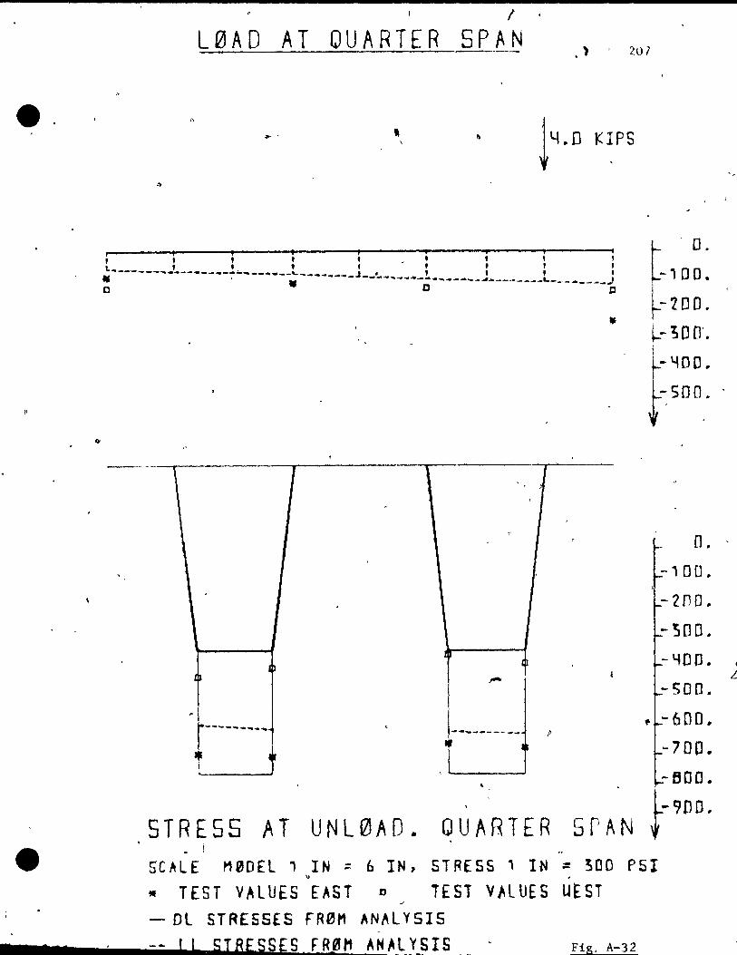
7 7
/
L0AO AT QUARTER SPAN .' , 207
a
r ,." i , , l '" _. t l , 1._ _, • , f , , l , • -- ----.~--·--~-~----~---~----~---J--~-__ ~~_l t , , • -------J------__ L _____ - __ J C D C
, 1 l T -
-,
0
.
Ih
~
p
f.-----_ ... _~ , -- .... ------- /' .~ 1 • i •
. D.
-100 ..
-200.
l-- ~ 0 D'.
~.lfDD .. (Son ..
O. ' 1
-100.
-zno . -300,
-YOD,
-500.
ft -600.
-700 .. ,
STRESS AT UNL0AD.
.. -BOO •
1:900, QUARTER 5PAN ~
- 1 "
SCALE M0DEl' IN = 6 IN, STRESS' IN ~ 300 PSI " ,
• TEST VALUES EAST 0 TEST VALUES UtST - Dl STRESSES rR0M AN~LYSIS
-- J L STRESSES, FRJH1 AH~l YSIS Fig. A-32
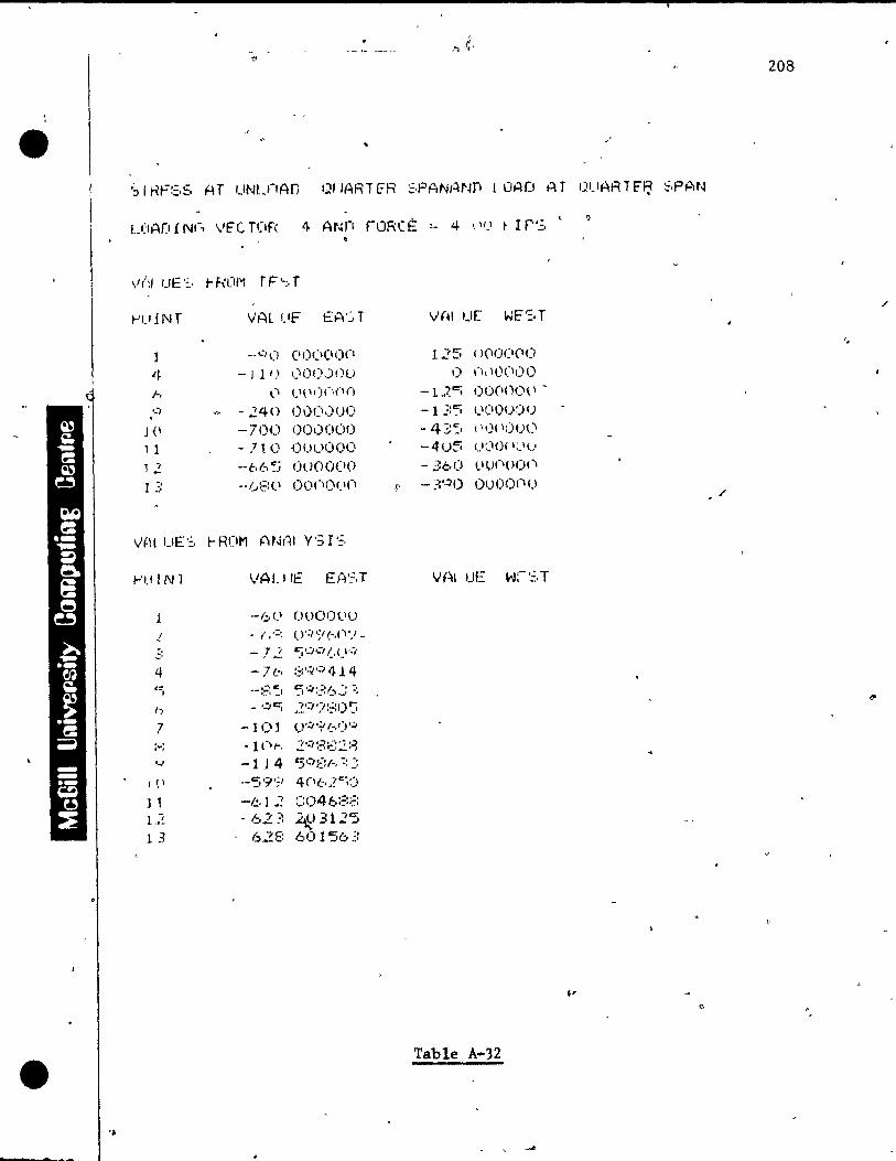
•
• '.
~'-'lNf
4 A
J(l
1 1 12 1 :::
1-'1.1 fNl
l
! :' ~,
4 '==ï
1)
7 ,-,
'../
J (1
] 1 L-!
1 3
W~l Uf" EA'::.r
--<'/1) (11)(1(10(1
- 111,1 I)oo.)nu l' !.'l'\)(\(I()
-240 !) 0(1.) o()
--700 (01)000 - 7t 0 ÜI)UOOO
--t.6'5 0000(10 .... /.J~=:'-\ oon{)(I(I
VALllE EA'~,T
--6<.\ 00001.\0 . ( ,:=: (J';' S' (-,('\ 'J -
-7 i Cj,-,,::, (,CI'../
-7 ~-, :;:9':;"11).14
.. -::: ~I 5'~::'=:6":: :: - ':IC; ~~I:, ')::=:()':J
-101 l)':' '.f (_,IY':"
·1 CI,.., .2f:/~3€~:2~~
-1 J 4 '5':1 ;:! /"l :~ :! "-S·"';J 4(1(-,}"'i:)
-f!,J oM! :::046:=:;:: . 62:: ~)312'5
628 601563
208
/
V(.I U[ ~E'-=. T
'. 1 7C" --' ( )(10(1(1(1
t) ,-I,IO(II)!)
-lJC; O!)(ln<)(1 -
-} ,.:::; !.'CIO!Y)()
- 43:, \ 1\)(II)Ol'\
-4u~ (}(IO( \;}C'
- 360 !,.II,)(\(H)('\
t;' -::'.10 Ou 0<) (")1)
"
Table A-32
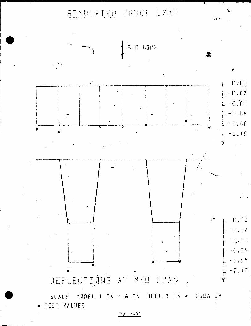
.'" t s.o UPS
1
\
1 1 1 -1 <.-
1 , . 1
l 1 - .. 1 1 1
L .
1 t ! ___ 1_ .-1
-. - r------ 1 ~---I
, -
. <
--
{
. . 1
~ • ,
"
• • - -
OEFLECTI~N5 AT MID 5PA~ , . , -
. 1 1 1
!
1 1 1
! " 1
1 , 1
- - -
, !
----~ /- .
"
/ / '
~ [l.'un
b- -D.r,-Z 1
~ -0.06 f
1-- -0 .OB
r -0.10
W
-. , ~
.. 't 0".00 -D.Dl
1 t- - Q. 0 y
~. - D .06 1
~ -D.Dô 1 1· r -n.ln
• SCALE M~DEL 1 IN ;:: 6 IN DEFL 1 IN;:: 0 .. 06 IN
Il TEST VALUES . Fig, A-33
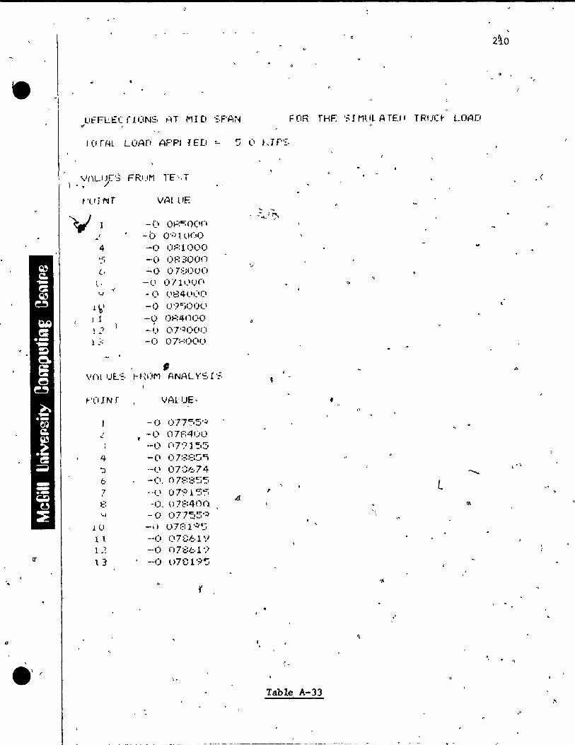
,
2\0
- ~ , c
LlfFL;.EC rI ON:=, ,..H MID ';PAN FOR THF. '3r MUl ArE./' T RI.IC~ LOAD .. "
f (f nu LOAn APPI JEt' "- ~ (1 t,J r";:.
\'/l\Uy:':5 FR1.lM rE'-.T , ( .. t'LI J NT WH llF.
... ~
y -1) O~:C;O(ln
...... ~~)? 1
1 -b OqlOC'O ~
4 -() 0:=:1000 ...:; -(1 083000
v' 1.., -0 07::;000
, -(..1 Oïl ,-,U(l t> ... " - CI 1.1841.1,~lr) '-'
l ~I -0 O,)c:;OOll
j 1 -q OI=:4()()O
!.2 -() or:)ooo lJ -(> 07:-:1)(1(J
, WH !JE.':, f- HO,..l ANAL ys. r '=,
r'OIN r VALUE? • .,
-0 07'7':.5':;-.! -0 07f:4ül)
--1) (17'"71 ":.5 4 -CI {)7~~:=t~,
':> --t' 07:::674 ' ., 1;,. -CI. 078:3"::)5 l 7 --(} r)7'~ 1 ~5 , . dJ, ~' -o. u 7:::400 -'
QI
'-1 -0 077~5o::) '1
lI) -1) u7::::1'~5
1 l --0 ()7ü/.:.l'/ L? --1) 07:::61')
cr t 3 --1) u7819"::i
" .,.,
r
o
Table A-33
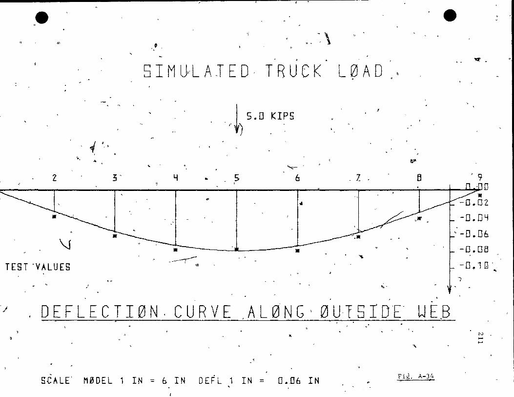
Qe " '"
1 a., . .... ....
Z 3 . .'
\j
TEST 'VALUES
.'
"~ ,
a, ~. \
. 5 l M U~L A. oT E 0, TRU C K L 0 A 0 ~
J ~
. ~ S.D KIPS r )
6?" ~ 0
~
Y • 5 6 ' 7, fi ~ 0
r '" 1
~, ..
. - '. --.------r- • ~
GJ
~.
, . ~ ..
e
'i'I,' •
> 9
9:>J2D
-D.DY '-0.06
-D.Da -0.1[\', ...
J
"/ 0 E F LEe T l 0 N . C U R V E ,A L k~f N G 1 0 U,15 l D'E' W E.B J A
~ ...
, ,
s.c ALE' M 0 0 E L 1 IN = & l NOE F L 1 l N = 0 • ,0 6 l N
....
Fig. A-34 3 ' ct?
N ..... t-'
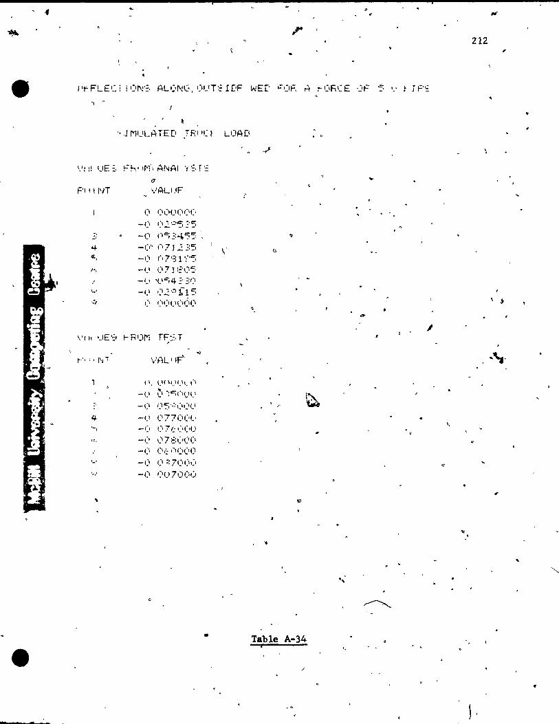
212 ,.
.., "
~
'-.1MUI.-ATED .TR110 UJAü
... F'I tINT
CI 1) l) (1(1 I~I('
-CI ,=, .2 '':'5 ~' 5 -(1 (.c-; .:; 4, '55 -(t', (17 J .2 35 \' ()
If., -CI ('7'31';-''5 -(1 (l7J ::'()s -( .. ' 'c'-=;4;' '::(1
'-' _(1 ,:\.,2':1 Ù '5 (, (I(I(}(IÔ<) \ ..
\'r II uE'';;, t- F'IJM TF~, T r
, ' 1
r', l, l'Ji \.!t-iL' IF' ...
(', CI' 11_11,11. 1"
-(} .. \} -:Ci(H)Ci
-(1 1_15,-/\:,,:1(1
4 -CI (177(1('1.'
-rI C' 7f.;':'('U 1.
r::, -(, \_) 7 ::::(,('(1 _(1 (Ir:: ,'1(1(1(1
-(1 (1 :~ 7C\()\~'
' .. ,' -(1 f~l() 71)(1(.0
'"
... 't
,
"
~
• Table A ... 34
• i "
A ,
/
•
l '
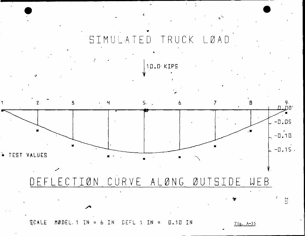
e e ..t
0'0
.. , 5 l M U L -lA T E 0 TRU C K L 0 A 0
•
~
~ 10.0· KI!,5
" 1 z- 3 LI 5. _ 6 7 B 9-
n r nOn 4C 2".U"
-o.os
-0 .. 10
• -0 .. 1 S . -. TEST VALUES
• • '\ •
/
DEFLECTI0N CURVE AL0NG 0UT5IDE WEB .~ ,l t-.J
...... W
""" S,CALE M0DEL.1 IN = 6 IN DEFL 1 IN = 0 ... 10 IN Fïp' A-35
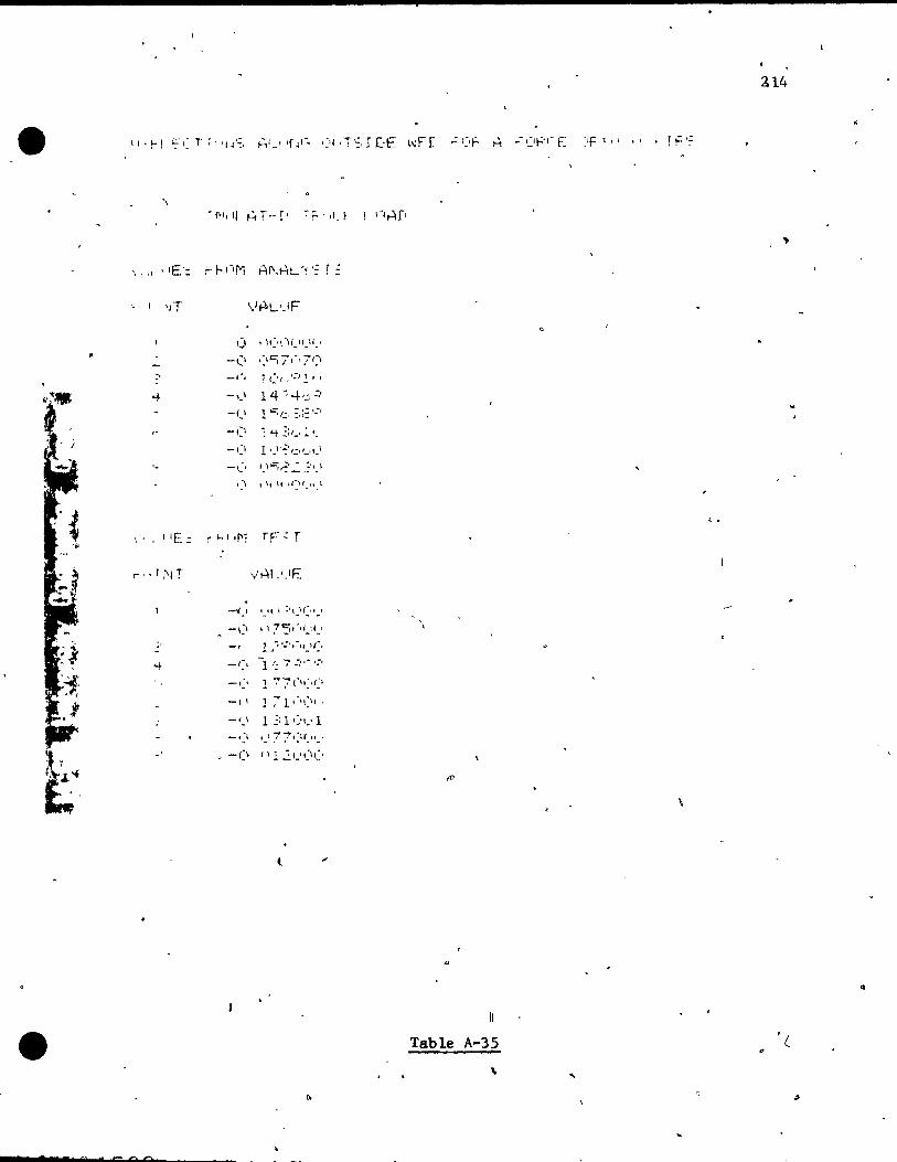
:114
\
'JT VHL'JF
\) ,If -'\ -H -" -li -0
-(, .:'C; /'-1 7i:' :' _/
W
, 1 ( Or 0 ':, 1 1 0
-+ - ...... \ 14 ~ -+,.:,:'
-f.' 10::::1:" :,:: ' .... ,
-(1 1 Li- ,::,_, : 1_
-(1 Il _, '~' ':" '_, ,_ \ '- -\ . _ .. )-=;.~'''':' :'1_\ -
, \ \ " "
Ij-,t " \ -
< . \ 1 lE .: r hl '1': TF': r
_~ ... I 1.1' 1 :1,_\(.,.,
-':\ ~'75t·lf .. li.1
\
l
Table A-35
..
. .! a- e= c.o
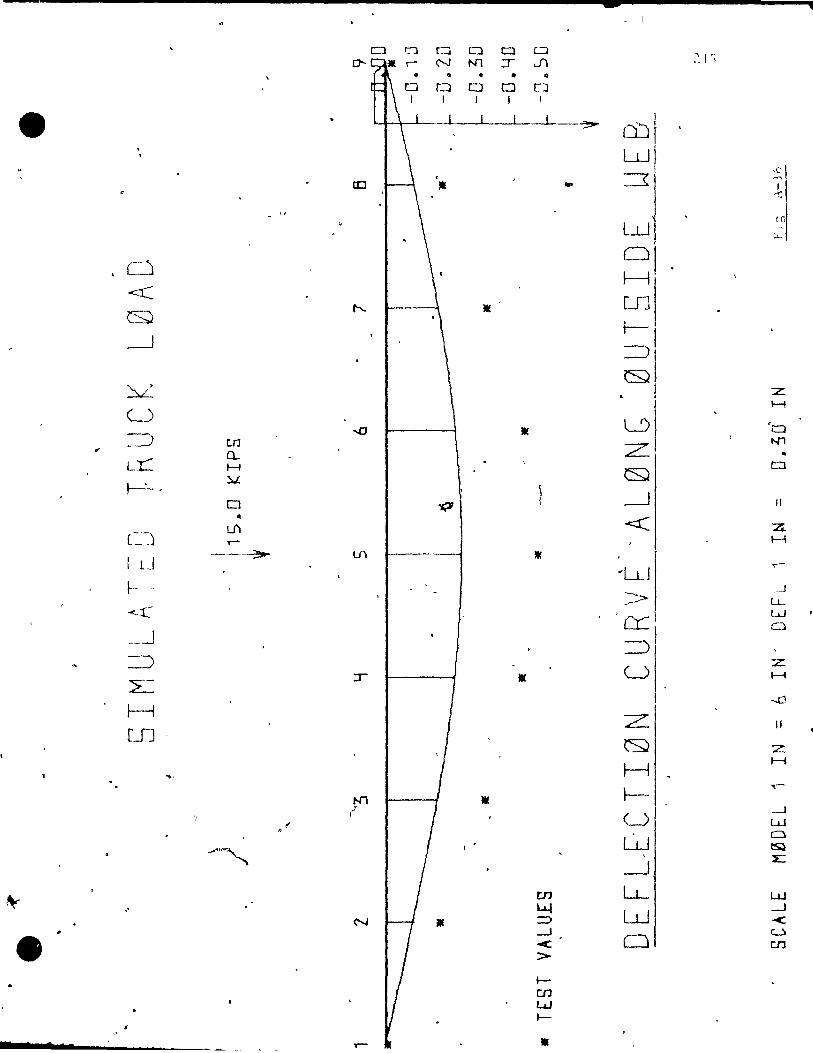
- "'i
CJ r::-:l Cl Cl Cl 0 0-- N N1 :r JI .~ ! ')
• • • • • 0 0 0 0
1 1 1 1
1 -~ ml , , w
cc Il =:r ,C .. "'" 1 ~
1
Lul te ~
i-L
, C) ~! ~
~ r--... 1( UJ
.---l t---~! 8
~ Z. H
(~
~-~ trJ ...0 Il L1) ,
".
t:::)
L:r: Cl.. Z 41
H •
~. "::.L. Q
0
0 "j,7 --' JI
• C~
Lf') <::C ,.-
z H
1 LI -_.~ v,
"llJ ...-
~ -
> _J
Ll..-. -<--r: . __ .J cr:: Lu
::)1 0
=:)
2: :r U
:z: Il H
..-r::J H LI1
Z Il
~ Z
~, H I-i
N1 Il ~I. ..-
1
" U .....J W
..... -" W 0
'" , ~
-J E
~ en LL-
"
W
N LY W
.-J III =:::> -<
e -.J < 0
CI
>-en
t--en W t--
- • III
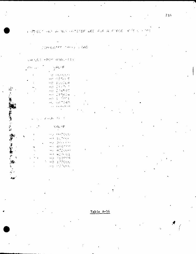
216
• 'r·, : , " rDF - ,-,~ '1-- ,'.::; .. :: t.:
r:" ,<'
. ~tf.? -'{if'
.' . ' ~ .\it 1 1,_
, ," l
~; 4:, 'II ,!t'".), '. \
~ . " . ,-
" .~
i , lf"
;,~ , \_ .. ltI
~.
-. --. 1
':1
t • !te,
li l'
~
-. l -, •
~'I \, 1 1 1
'f 1 :' '.- ç ,;:,
~ ~ ~ ~", -, .. ,
" ft - ,
.~~ ,"
" .~'
",
Table A-16
• .f (
_ c
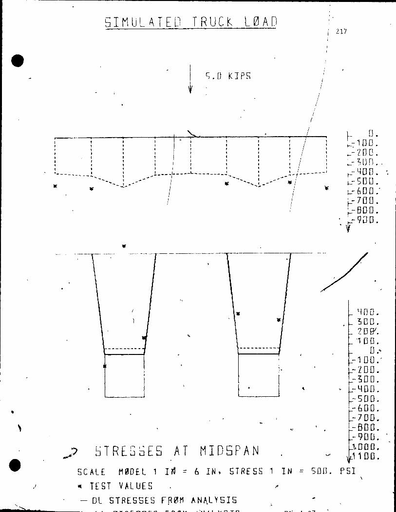
-----------------------------------
•
\
• '-
"">. •
5IMULATED TRUCK L0AD
t S.U KJPS
/ 1
(
1 1
/
~~---------~-+~~--~----~----~~ 1 .. , , 1
, l ,
'------ .... _-!
, , , 1 , 1 l , , 1 1
i L--I----L------L ! L -------' -----J------- 1 • -------L-- _o.
---- --- - - - ----------,-~-----~--y--- ---
•
----------., ,
i ,~
1 ,
~TREG5E5 AT MID5PAN
, l, 1
1
SCALE MeOE.L' I~ = 6 IN, STRESS 1 IN == SODa
~ TEST VALUES ~
- DL STRESSES FR0M AN~LY5IS • a __ .... __ _ _ _ _ _ _ _ .... • ~.I .. t ,~,..... .... ,.,
217
f- U. r--:- 1DO • ~- ZOO. ;...- ~ [J D • -~-YOD. '. ~SDO • ~600'' ~ 700. ~- BD o. '. r- 9Do •
l~ no . 300. 208". " 00.
o .~ -100.' -100. -300.
" -400. -SOO.
1"" 60 O. t-7 00. I-BOO.
f-90 [J. 1.000. 1100 .
PSI \

•
..
\
•
~ Il! N T ,,lAt ur
1
-, .:' r
',:,
, "
le l
1 1 1 .-~
f-'jII N 1
,.-'
11,1
l l ]}
13 ,
·-50'''; (lI,<l(l(I(Î
- '"'i ::5 (\(-)(}(.1 \)( \
,- J 1 :!I} !.lCI,} U! l'">
--4 ':"(1, ()(If)I)()\-\
-.:(<:::0 ~1(HX\(j(,
-:-C;L!t~ (_\\~IO~II~'(I -l.:V (IUt'!.\! lC'
..
1 71:' I,'U(IOUU
<t t t.=. 1 (IL\(II.\(\C\
;:'::;(\ 1.\(1 ',I( ''-1(1
::7/·, l \ }.'=, 'J .: 1
,- ::·.I;~ c,"';6.:5(\ . ':,21 ~:: (, 7 1 ~:.: :::; -- ~:·./I:I 1(\7(\.,1
- .; 7'·~' ,',,':'531 -. "
- _:':, (r 7(11,-\ : 1
-'5.i 1 :~:f,.7 J f:!~ . - _:'.1':' (,C5t, ,-; S'.' - \~: 7/J. (;1':"5 '; 1
..--... , -,,-, ::2(' .:: l.2 ~,E: ('I} 34 :u:.
-"."
':,E! 02 34~:::! c .... J.:, 32(\ 31.:'
<
c):~:-· i 1. . 7' 4-
Table A-37
218
. ,
'- "_. CI F: ~ E- N 1:'
,,-' C .... r: ~ f:--C .~ L . T

, 7
,.--
t. 1 1 1 1
5 l M LJ l. A T E 0 T -R U C k L ~ A 0
t 1 S. 0 KI PS
, , 1 1 l , 1 1 , , , , , , " l , , 1 1
t ___ ,, __ ...... _ ... :
'.. ~ r _!-.-------L~-------~,_ : _l--------~1 -...... f .,.-
........ , -"'" -- ......... .,.. , .,.'#" ........ ,!-- ...
" •
. ' -----.-. ------- r ------- ------- l 1
..
•
)
STRES5ES AT MID5PAN 5C~LE . t10DEL 1 IN = 6 IN, STRESS 1 IN =1 500~
• TEST V~LUES
- DL STRESSES FR0t1 ~N~LYSIS • • a T QS arc a r Q a id A LI ,r 'V c "r r 'Fia A-1R
219
~ 0 . L- 7 St \ • I_~UO.
c- 7S 0 . L1 OD 0 •
~Z50 •
1 SfHJ • 1 750.
DO o. ~
~2SD • 500. 750 •
1750 . , DO D.
7S D. 500 . 25 D.
D. - 2 50. - 50 D. -750. 1 DO D. 1250. 1500. 1750.
DO o. 250.' 500. ' 750. 000. Z 50.
GSDO. PSI
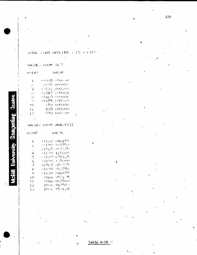
•
•
j 1.1 r~,l
1-'1 1 r i\! l
l --1 ,,;,.)5 ,.:-\(." " ,('\
.'""S l'41,II'C")
(, -- 1 hlO::: ""( Il.1(.'<)
::; - 1,':JI_,f) • l"f 1'_lt"_
,-, -.. 1:~7'5 ,.(~l()II\~~)
1 il ! 71.1 ()( I(},.II:""
1 l :3 "::'':; ,'001.'(")
1-'1.1 {NT Vf~lllf:
- 1 1 • ~ '::' ,-,'k,:;3 7'~ ..:.. - 1 1 ':,.:-: .... (., :~. 7 r:~, \
L~ -Il :/i' 1,,:,,",,-,<.,\-, '5 -- 1 J :;.:, '_' 7::' 1 • ..: c:;
6 r
-11':;'~ 1 ~"~('i-'('
-'1 ':;(.::; '-.1..\1,' - ... .r:-,
::: -·11 'i;':: '-i!:.'_:7'5(.'
'-1 --11_'Y 1 '4b:'::' 7:::; j (\ 1 ('b,::. ",'''; _:; l -e,
1 1 1 (\6/..:' ()f-,:":'I.'()
12 1(1,.1. 1'1/.: • .''',(1. 13 }(,,-,,_, ':/r:; -:l.'~_~
220
'.
•
1'-; ,\ f TF':
"
Table A-38
,