structural stability of large span free form shell ... - iaeme
TRANSCRIPT
http://iaeme.com/Home/journal/IJCIET 287 [email protected]
International Journal of Civil Engineering and Technology (IJCIET) Volume 9, Issue 6, June 2018, pp. 287 293, Article ID: IJCIET_09_06_033 –Available online at http://iaeme.com/Home/issue/IJCIET?Volume=9&Issue=6 ISSN Print: 0976-6308 and ISSN Online: 0976-6316
© IAEME Publication Indexed Scopus
STRUCTURAL STABILITY OF LARGE SPAN FREE FORM SHELL STRUCTURE BY FINITE
ELEMENT METHOD Vijayalaxmi Kedilaya B
Manipal Institute of Technology, Manipal Academy of Higher Education, Manipal, Karnataka, India
Shreelaxmi Prasanth Manipal Institute of Technology, Manipal Academy of Higher Education,
Manipal, Karnataka, India
Anil Hegde Structural Engineer, Vimal Anil Structural Consultants, Mangalore, India
ABSTRACT Freeform architecture is gaining importance in recent times because of its architectural importance as well as its structural advantages. Freeform shells
eliminate the need for column and its bulky foundations leading to column free space and aesthetically attractive structure. The shell being curved in geometry is strong because of the arch action, membrane action and beam action which resists the
applied loads. It can be spanned over a large lengths, eliminating the need for intermediate support. This leads to column free structure with large interior space. In the present study a freeform shell is modeled using AUTOCAD as per IS: 2210-1988 and the analysis has been carried out by finite element method using STAAD Pro in order to obtain the deflection of the freeform shell structure. Key words: freeform shell, arch action, displacement, column less space.
Cite this Article: Vijayalaxmi Kedilaya B, Shreelaxmi Prasanth and Anil Hegde, Structural Stability of Large Span Free form Shell Structure by Finite Element
Method, International Journal of Civil Engineering and Technology, 9(6), 2018, pp. 287 293. –
http://iaeme.com/Home/issue/IJCIET?Volume=9&Issue=6
1. INTRODUCTION Freeform shells are presently being called the new generation buildings. The development of shell structures originated initially in Rome about AD 125. The shell structures were used to cover large spans in the early 20th century. The development of shell simplified the structure by giving large space without any obstructions and reduced the number of columns in the
Structural Stability of Large Span Free form Shell Structure by Finite Element Method
http://iaeme.com/Home/journal/IJCIET 288 [email protected]
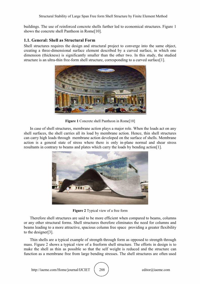
buildings. The use of reinforced concrete shells further led to economical structures. Figure 1 shows the concrete shell Pantheon in Rome[10].
1.1. General: Shell as Structural Form Shell structures requires the design and structural project to converge into the same object,
creating a three-dimensional surface element described by a curved surface, in which one dimension (thickness) is significantly smaller than the other two. In this study, the studied
structure is an ultra-thin free-form shell structure, corresponding to a curved surface[1].
Figure 1 Concrete shell Pantheon in Rome[10]
In case of shell structures, membrane action plays a major role. When the loads act on any shell surfaces, the shell carries all its load by membrane action. Hence, thin shell structures can carry high loads through membrane action developed on the surface of shells. Membrane
action is a general state of stress where there is only in-plane normal and shear stress resultants in contrary to beams and plates which carry the loads by bending action[1].
Figure 2 Typical view of a free form
Therefore shell structures are said to be more efficient when compared to beams, columns or any other structural forms. Shell structures therefore eliminates the need for columns and beams leading to a more attractive, spacious column free space providing a greater flexibility to the designer[3].
Thin shells are a typical example of strength through form as opposed to strength through mass. Figure 2 shows a typical view of a freeform shell structure. The efforts in design is to make the shell as thin as possible so that the self weight is reduced and the structure can function as a membrane free from large bending stresses. The shell structures are often used
Vijayalaxmi Kedilaya B, Shreelaxmi Prasanth and Anil Hegde
http://iaeme.com/Home/journal/IJCIET 289 [email protected]
for water tanks, large span roofs and silos since they are quite economical. Since concrete can be mouldable to any form or geometry, concrete shell offers a greater flexibility in
construction. By this means, a minimum of materials is used to the maximum structural advantage.
1.2. Merits of Shells as Structural Forms The main advantages of using shells are lightweight, flexibility, reversibility and aesthetics. But among all these shell being lightweight is the main advantage because when comparing
the shell structures with most commonly used portal frames, portal frames requires installation of heavy concrete foundations increasing the construction cost and making it the uneconomical option for the engineers. Also the danger caused due to damage during erection
or in case of collapse of the structure under extreme conditions is eliminated due to the lightweight nature of shell. The shell being curved in geometry makes it very strong similar
to arches and therefore it can be spanned over a wide length without using any support leading to the interior of the structure unobstructed and leading to column free structure with
large interior space. Also when concrete is used as a construction material for shell, free forming shell can be cast in any shape or geometry adding to the advantage. Structurally, shell being curved in nature, the arch action makes it a very strong structure[3].
1.3. Shortcomings of Shell structures Although the light weight nature of the shell has numerous benefits, when shells are casted in open sites where there is no obstruction to strong winds, they are very susceptible to uplift
due to wind loading. In order to eliminate this risk, the shell structure requires bulky foundations making the structure uneconomical. Moreover, as a result of the curved shape
imitating arch behaviour, the structure often transmits not only vertical loads into the foundations but also horizontal. These can lead to overturning or sliding phenomena. The
shell structure behaving as an arch would transmit both the vertical as well as horizontal loads. The horizontal loads may sometimes lead to overturning or sliding. Therefore all these aspects need to be taken care of when designing a shell[3].
2. METHODOLOGY Many researchers have been done on the regular shell structures [4-8].The present study deals with the analysis of the freeform shell structures. The study mainly involves modeling of the
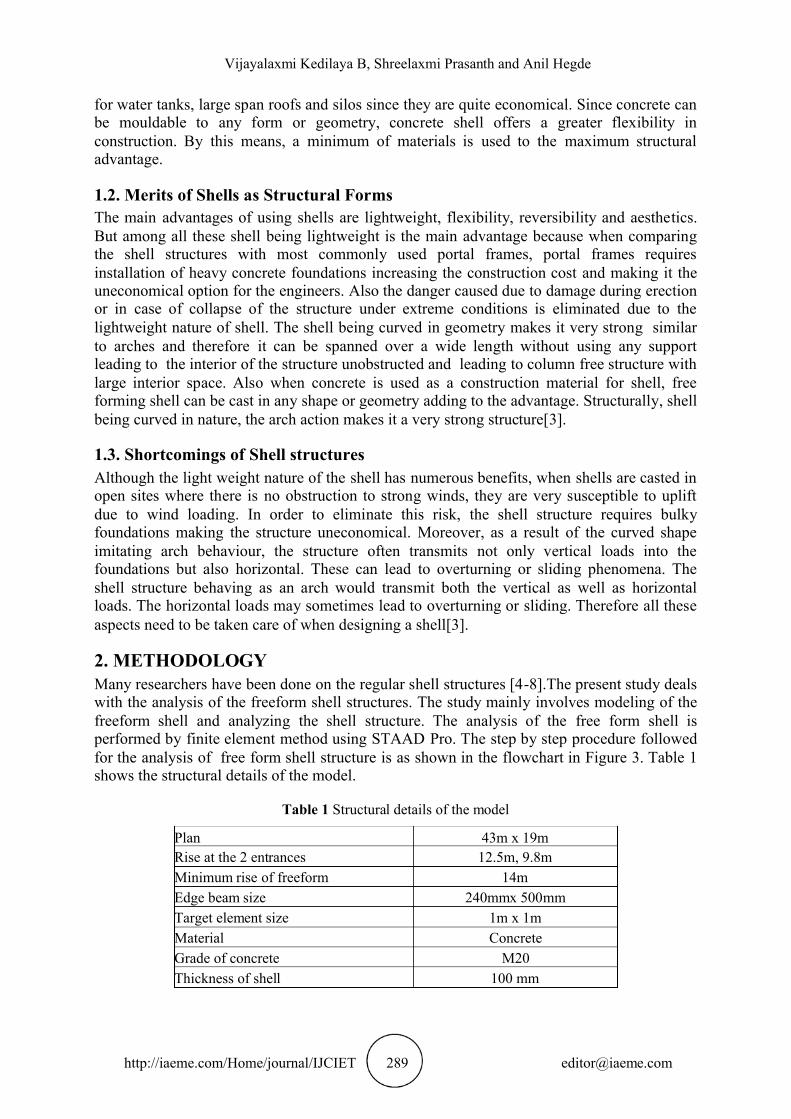
freeform shell and analyzing the shell structure. The analysis of the free form shell is performed by finite element method using STAAD Pro. The step by step procedure followed for the analysis of free form shell structure is as shown in the flowchart in Figure 3. Table 1 shows the structural details of the model.
Table 1 Structural details of the model
Plan 43m x 19m Rise at the 2 entrances 12.5m, 9.8m Minimum rise of freeform 14m Edge beam size 240mmx 500mm Target element size 1m x 1m Material Concrete Grade of concrete M20 Thickness of shell 100 mm
Structural Stability of Large Span Free form Shell Structure by Finite Element Method
http://iaeme.com/Home/journal/IJCIET 290 [email protected]
Figure 3 Methodology Chart
Modeling of freeform shell is done in AUTOCAD and exported to STAAD Pro. At the bottom of freeform shell, the edge beams are constructed. The dead loads are calculated by STAAD Pro itself by considering the thickness of the shell and dimensions of edge beams. After assigning the self weight, the live loads are assigned to the structure as per IS 875 (Part-
II)[9]. Finite element method, being the most popular method of analysis is used in the present study[2][4][5].The shell is modeled as thin shell whose thickness is comparatively
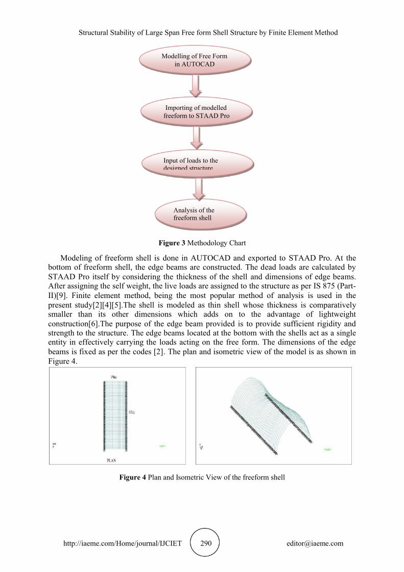
smaller than its other dimensions which adds on to the advantage of lightweight construction[6].The purpose of the edge beam provided is to provide sufficient rigidity and strength to the structure. The edge beams located at the bottom with the shells act as a single entity in effectively carrying the loads acting on the free form. The dimensions of the edge beams is fixed as per the codes [2]. The plan and isometric view of the model is as shown in Figure 4.
Figure 4 Plan and Isometric View of the freeform shell
Modelling of Free Form in AUTOCAD
Importing of modelled freeform to STAAD Pro
Input of loads to the designed structure
Analysis of the freeform shell

Vijayalaxmi Kedilaya B, Shreelaxmi Prasanth and Anil Hegde
http://iaeme.com/Home/journal/IJCIET 291 [email protected]
3. RESULTS 3.1. Displacement of free form shell
Free form shell has been analyzed for the displaced shape of the structure with the displacement details which have been reported in this section.
Similar to other structures or structural forms, free form shells undergo displacement on loading. The displacement of the freeform shell after loads are applied are tabulated in table 3. Unlike other regular structural forms shells are not oriented in any one particular direction.
Hence the displacement at each node is reported as displacement in each of X, Y and Z direction along with the resultant displacement.
Table 3 Displacement of the freeform model
DIRECTION X (mm) Y (mm) Z(mm) RESULTANT (mm) Maximum Dispacement (mm)
39.157
8.936
3.465
40.313
Max resultant displacement is found to be 40.313mm. Also the displacement in X direction is predominantly higher than in the other two directions. No significant
displacement under the action of loads is observed when compared to other dimensions. The structure is stable under the action of loads. This is due to the arch action of the structure. Compared to the the height of the shell structure being 14m, the displacement 40.313mm is
less significant. Also, in case of thin shell the deformations are less significant when compared to the thickness. The deformation 40.313mm is less significant compared to the
thickness of shell. In case of a conventional structure, for a span of 19m the allowable deflection is 76mm. Therefore it can be noted that the displacement is much lower than the displacement of the conventional structures (beam and column system). Figure 5 shows the deflected shape of the freeform structure under the action of loads.
Figure 5 Scaled Deflected shape
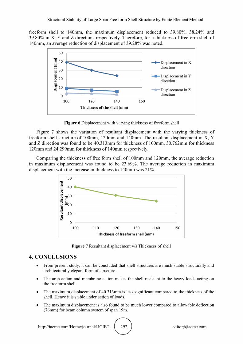
3.2. Effect of Increase in Thickness of Shell Figure 6 shows the maximum displacement exhibited by the node in shell in X, Y and Z
directions with varying thickness of 100mm, 120mm and 140mm. Initially, freeform shell with a thickness 100mm showed a maximum displacement of 40.313mm. It was found that with the increase in thickness of shell to 120mm, the maximum displacement in X direction
reduced to 21.04%, the maximum displacement in Y direction reduced to 20.37% and maximum displacement in Z direction reduced to 21.31%. Therefore it was observed that with the thickness of freeform shell of 120 mm, an average reduction of maximum displacement of
20.91% was achieved. Further it was observed that with the increase of the thickness of
Structural Stability of Large Span Free form Shell Structure by Finite Element Method
http://iaeme.com/Home/journal/IJCIET 292 [email protected]
freeform shell to 140mm, the maximum displacement reduced to 39.80%, 38.24% and 39.80% in X, Y and Z directions respectively. Therefore, for a thickness of freeform shell of 140mm, an average reduction of displacement of 39.28% was noted.
Figure 6 Displacement with varying thickness of freeform shell
Figure 7 shows the variation of resultant displacement with the varying thickness of freeform shell structure of 100mm, 120mm and 140mm. The resultant displacement in X, Y and Z direction was found to be 40.313mm for thickness of 100mm, 30.762mm for thickness 120mm and 24.299mm for thickness of 140mm respectively.
Comparing the thickness of free form shell of 100mm and 120mm, the average reduction in maximum displacement was found to be 23.69%. The average reduction in maximum
displacement with the increase in thickness to 140mm was 21% .
Figure 7 Resultant displacement v/s Thickness of shell
4. CONCLUSIONS From present study, it can be concluded that shell structures are much stable structurally and
architecturally elegant form of structure.
The arch action and membrane action makes the shell resistant to the heavy loads acting on the freeform shell.
The maximum displacement of 40.313mm is less significant compared to the thickness of the shell. Hence it is stable under action of loads.
The maximum displacement is also found to be much lower compared to allowable deflection (76mm) for beam column system of span 19m.
0
10
20
30
40
50
100 120 140 160
Dis
plac
emen
t (m
m)
Thickness of the shell (mm)
Displacement in Xdirection
Displacement in Ydirection
Displacement in Zdirection
0
10
20
30
40
50
100 110 120 130 140 150
Re
sult
an
t d
isp
lace
me
nt
(mm
)
Thickness of freeform shell (mm)

Vijayalaxmi Kedilaya B, Shreelaxmi Prasanth and Anil Hegde
http://iaeme.com/Home/journal/IJCIET 293 [email protected]
REFERENCES
[1] Ramaswamy, G. S., “Design and Construction of Concrete Shell Roofs”, C.B.S Publishers & Distributors, New Delhi, 1986
[2] IS: 2210- 1988, “Criteria for the Design of Reinforced Concrete Shell Structures and Folded Plates, Bureau of Indian Standards, New Delhi
[3] Ornella Iuorio, Eiki Enric Homma, Konstantinos Daniel Tsavdaridis , The application of free-form grid shells as protective shelters in archaeological sites Proceedings of the IASS
Annual Symposium 2016 “Spatial Structures in the 21st Century” 26–30 September, 2016, Tokyo, Japan
[4] T. Subramani, Athulya Sugathan, Finite Element Analysis of Thin Walled-Shell Structures by ANSYS and LS-DYNA,International Journal of Modern Engineering
Research (IJMER) ,Vol.2, Issue.4, July-Aug. 2012 pp-1576-1587 ISSN: 2249-6645
[5] Harish B. A, N. Venkata Ramana , K. Manjunatha, Finite Element Analysis of Doubly Curved Thin Concrete Shells, International Journal of Engineering Science and Innovative Technology (IJESIT) Volume 4, Issue 5, September 2015
[6] Dr. B. H. V. Pai, B. Durga Prasad Baliga International Journal of Civil Engineering and Technology (IJCIET) Volume 8, Issue 11, November 2017, pp. 212 218 –
[7] Peter Chacko, Dipu V S , Manju.P.M, Finite Element Analysis of Ribbed Dome, International Journal of Engineering Research and Applications (IJERA) ISSN: 2248-
9622,Trends and Recent Advances in Civil Engineering (TRACE- 24th-25th January 2014)
[8] Merilmol Eldhose , Rajesh A K , Ramadass, Finite Element Analysis and Parametric Study of Schwedler Dome using ABAQUS Software, International Journal of Engineering Trends and Technology (IJETT) Volume 28 Number 7 - October 2015 –
[9] IS 875 (Part-II), Code of practice for design loads for buildings and structures-Imposed loads. Bureau of Indian Standards, New Delhi, India, 1987
[10] https://en.wikipedia.org/wiki/Pantheon,_Rome