influence of facts devices on electrical ... - iaeme
TRANSCRIPT
http://iaeme.com/Home/journal/IJARET 1248 [email protected]
International Journal of Advanced Research in Engineering and Technology (IJARET) Volume 11, Issue 11, November 2020, pp. 1248-1270, Article ID: IJARET_11_11_113
Available online at http://iaeme.com/Home/issue/IJARET?Volume=11&Issue=11 ISSN Print: 0976-6480 and ISSN Online: 0976-6499
DOI: 10.34218/IJARET.11.11.2020.113
© IAEME Publication Indexed Scopus
INFLUENCE OF FACTS DEVICES ON
ELECTRICAL TRANSMISSION SYSTEM
Satyam Kumar Upadhyay, Piyush Kumar Yadav, Dr. Rajnish Bhasker and
Saurabh V Kumar
Electrical Engineering Department, VBS Purvanchal University, Jaunpur, India
ABSTRACT
This report contains the study of Flexible AC Transmission System (FACTS)
equipment operation in transmission systems. In the present scenario the demand for
electrical energy has increased manifold. This has led to the facing of power
transmission limitation crisis by energy transmission systems. The limitations occur
due to maintaining a balance between supplying the allowed level of voltage and
maintaining stability of the system. Due to the power crisis the FACTS devices play a
crucial role in the present scenario. In energy transmission systems FACTS are
effective equipments on power control. They help facilitating the improvement in
power transmission capability while minimising the transmission losses and impact on
the environment. They also aid in the improvement of power quality while maintaining
the stability of the system.The principal operating modes and applications of FACTS
equipment in transmission and distribution system such as Static Var Compensator
(SVC), Static Synchronous Compensator (STATCOM), Thyristor controlled series
capacitor (TCSC), Static Synchronous Series Compensator (SSSC) and Unified Power
Flow Controller (UPFC) is discussed in this report. The characteristics of FC-TCR
and UPFC were studied and their models were simulated in Matlab using simulink. In
Fixed capacitor Thyristor Controlled Reactor the regulation of power flow was done
by changing the firing angle of the thyristor. The compensation obtained was better
than that of a normal transmission line. In case of Unified Power Flow Controller the
injected voltage and the injected current were the control parameters. The power flow
can be regulated by changing the magnitude or phase of the injected voltage while for
the injected current the value of the injected current and the shunt resistance are
varied for regulating power flow
Keywords: SSS controller, Data acquisition system, Power computation circuit,
Firing pulse generator, pulse voltage source convertor.
Cite this Article: Satyam Kumar Upadhyay, Piyush Kumar Yadav, Rajnish Bhasker
and Saurabh V Kumar, Influence of Facts Devices on Electrical Transmission System, International Journal of Advanced Research in Engineering and Technology, 11(11),
2020, pp. 1248-1270.
http://iaeme.com/Home/issue/IJARET?Volume=11&Issue=11
Influence of Facts Devices on Electrical Transmission System
http://iaeme.com/Home/journal/IJARET 1249 [email protected]
1. INTRODUCTION
Electrical energy plays an important role in the present industrial society and has immense
importance to a nation s welfare and development. Hydro, thermal and nuclear power plants ‟
account for almost all of the energy generated. A lot of this energy is used for industrial,
commercial, home, space and military applications with the application of power
electronics[1]. Power electronics technology has advanced a lot over the last two decades and as a result of this the reach of power electronics applications has spread to all voltage levels,
starting from EHV transmission to low voltage circuits in the end user facilities[2]. HVDC terminals, Static Var Compensation (SVC) systems, load transfer switches, static phase
shifters, active line conditioning, energy storage, isolation switches and instantaneous backup power systems, renewable energy integration, and Various other applications are the
commonly observed power electronics applications[9].
In an interconnected transmission network, power flow control is a key problem in designing and operating. Requirement of interconnected networks, unforeseen increase of
load demands, limitations on installation of power plant in appropriate places and limitations on building new transmission lines are the factors that lead to such problems. The
employment of FACTS devices in transmission lines becomes necessary owing to reasons like over loaded transmission lines in special paths, power flow in unwanted paths, and non-
optimal operation of line capacity[9].
The major concern in world-wide distribution systems at present is power quality[6]. For instance consumers like industrial plants mainly deal with automated processes and if the line
voltage is not up to the levels of the expected quality due to voltage sags or flicker, they may economic losses. Therefore proper quality attached to the line voltage at the point of common
coupling is very necessary[2]. This quality cannot be achieved with conventional equipment in majority of the cases. In the last decade, improvement of power quality has been one of the
most vital subjects in the development of distribution and low voltage systems[5]. Development devices like IGBTs (Insulated Gate Bipolar Transistors) and IGCTs (Insulated
Gate Commutated Thyristors) has made it possible to build PWM converters. These converters are widely used for adjustable speed drives and are mass produced for power
ratings in the MVA range. The converters, along with conventional equipment and use of new
improved control algorithms, are used for mitigation of power quality problems. They are
also known as power conditioners[7].
1.2. Advantages of FACTS Devices
FACTS devices provide the following advantages:
• Improvement in power transmission capability.[2]
• Improvement of system stability and availability.[4]
• Improvement of power quality.[6]
• Minimising the environmental impact.[8]
• Minimising the transmission losses.[4]
Satyam Kumar Upadhyay, Piyush Kumar Yadav, Rajnish Bhasker and Saurabh V Kumar
http://iaeme.com/Home/journal/IJARET 1250 [email protected]
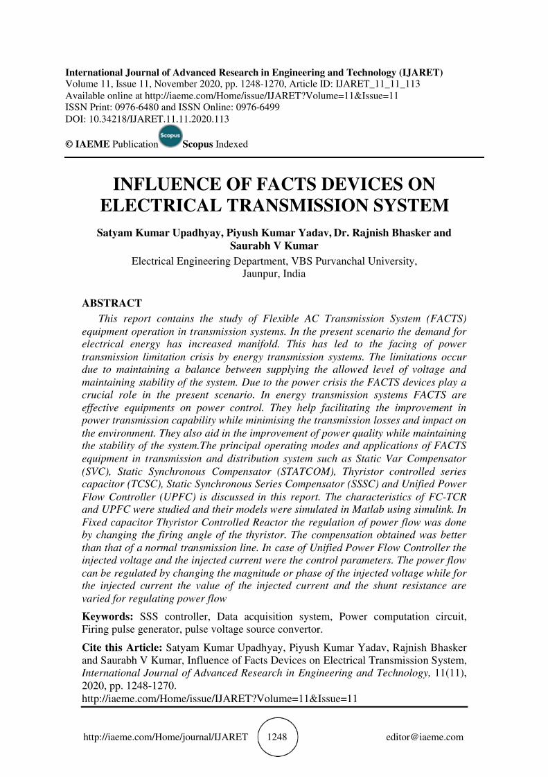
Figure 1 Practical Advantages of the main FACT devices
1.2. Flexible AC Transmission Systems (FACTS)
In the past few years the demand for electrical energy has increased significantly and as a
result energy transmission systems are facing power transmission limitation crisis[1-2]. The limitations occur due to keeping a balance between maintaining stability and supplying the
allowed level of voltage. As a result of this the practical operation capacity of the system is far less than the real capacity[9]. This results in non-optimal operation of the energy
transmission systems. One among the solutions to this problem of increasing power transmission capacity is construction of new transmission lines[5]. This is not feasible both
economically and practically. Due to the developing semiconductor industry and its applications in power systems, the concept of FACTS is offered, to enhance the real capacity
of transmission lines without having to construct any new transmission lines. The major drawback in using thyristor switches is that the control for turn-off capability is not
possible[7]. Hence in a cycle, switching more than once is not possible. After the invention of
IGBT and GTO which are semiconductor devices with controlled turn-off capability the transmission system was revolutionised[3]. This development resulted in the use of VSCs in
the field of energy transmission[4]. The advantage of this is the generation and absorption of reactive power without the use of devices like capacitor or reactor. All FACTS equipment
designed by Voltage Source Converters are known as FACTS new generation devices[8].The approach of engineers towards planning and operation of power systems will be changed by
the implementation of FACTS devices. The equipments can be applied in series, shunt or shunt-series in transmission lines, and the control of the operation parameters in transmission
systems in steady state and system dynamic behavior in transient state can be achieved[7-9].
• power flow control
• increase of transmission capability
• voltage control
• reactive power compensation
• stability improvement
• power quality improvement
Influence of Facts Devices on Electrical Transmission System
http://iaeme.com/Home/journal/IJARET 1251 [email protected]
• power conditioning
• flicker mitigation
• interconnection of renewable and distributed generation and storages
The use of FACTS-devices is achieved through switched or controlled shunt compensation, series compensation or phase shift control. The devices work electrically as
fast current, voltage or impedance controllers[8]. The reaction time allowed by power electronic is very short and goes down to far below one second. A structured overview on
FACTS-devices is given ahead. The devices are mapped to their different fields of applications[9].
1.3. Power System Constraints
The power system constraints are many (listed below) and they put a limit over power transfer
among areas or region. The typical constraints are:
1 Thermal
2 Dynamic Voltage and voltage stability
3 Power System Oscillation Damping
4 Steady-State Power Transfer
5 Short Circuit Current and Other limitations
1.4. Power system controllability
To improve the performance of a power system there are three key variables that must be controlled. The three main variables are:
1 Voltage
2 Angle
3 Impedance
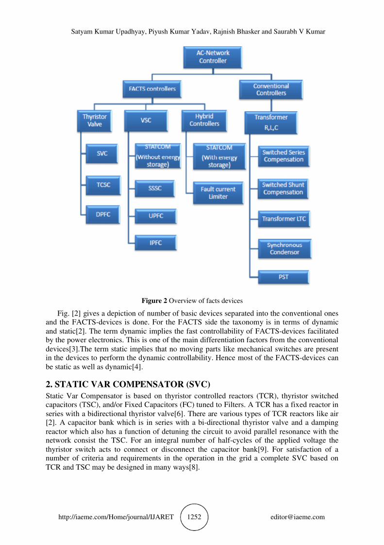
AC network controllers used to improve the performance of a power system can be classified in two categories, conventional network controller and FACTS controller. Overview of these
controllers is shown in ….
Satyam Kumar Upadhyay, Piyush Kumar Yadav, Rajnish Bhasker and Saurabh V Kumar
http://iaeme.com/Home/journal/IJARET 1252 [email protected]
Figure 2 Overview of facts devices
Fig. [2] gives a depiction of number of basic devices separated into the conventional ones and the FACTS-devices is done. For the FACTS side the taxonomy is in terms of dynamic
and static[2]. The term dynamic implies the fast controllability of FACTS-devices facilitated by the power electronics. This is one of the main differentiation factors from the conventional
devices[3].The term static implies that no moving parts like mechanical switches are present in the devices to perform the dynamic controllability. Hence most of the FACTS-devices can
be static as well as dynamic[4].
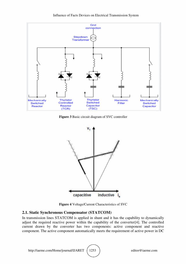
2. STATIC VAR COMPENSATOR (SVC)
Static Var Compensator is based on thyristor controlled reactors (TCR), thyristor switched capacitors (TSC), and/or Fixed Capacitors (FC) tuned to Filters. A TCR has a fixed reactor in
series with a bidirectional thyristor valve[6]. There are various types of TCR reactors like air [2]. A capacitor bank which is in series with a bi-directional thyristor valve and a damping
reactor which also has a function of detuning the circuit to avoid parallel resonance with the network consist the TSC. For an integral number of half-cycles of the applied voltage the
thyristor switch acts to connect or disconnect the capacitor bank[9]. For satisfaction of a number of criteria and requirements in the operation in the grid a complete SVC based on
TCR and TSC may be designed in many ways[8].
Influence of Facts Devices on Electrical Transmission System
http://iaeme.com/Home/journal/IJARET 1253 [email protected]
Figure 3 Basic circuit diagram of SVC controller
Figure 4 Voltage/Current Characteristics of SVC
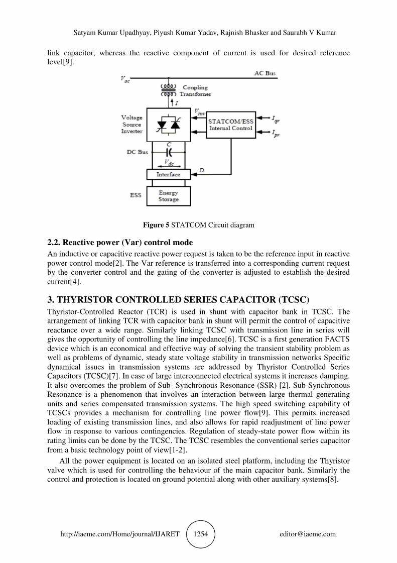
2.1. Static Synchronous Compensator (STATCOM)
In transmission lines STATCOM is applied in shunt and it has the capability to dynamically
adjust the required reactive power within the capability of the converter[4]. The controlled current drawn by the converter has two components: active component and reactive
component. The active component automatically meets the requirement of active power in DC
Satyam Kumar Upadhyay, Piyush Kumar Yadav, Rajnish Bhasker and Saurabh V Kumar
http://iaeme.com/Home/journal/IJARET 1254 [email protected]
link capacitor, whereas the reactive component of current is used for desired reference level[9].
Figure 5 STATCOM Circuit diagram
2.2. Reactive power (Var) control mode
An inductive or capacitive reactive power request is taken to be the reference input in reactive
power control mode[2]. The Var reference is transferred into a corresponding current request by the converter control and the gating of the converter is adjusted to establish the desired
current[4].
3. THYRISTOR CONTROLLED SERIES CAPACITOR (TCSC)
Thyristor-Controlled Reactor (TCR) is used in shunt with capacitor bank in TCSC. The arrangement of linking TCR with capacitor bank in shunt will permit the control of capacitive
reactance over a wide range. Similarly linking TCSC with transmission line in series will gives the opportunity of controlling the line impedance[6]. TCSC is a first generation FACTS
device which is an economical and effective way of solving the transient stability problem as well as problems of dynamic, steady state voltage stability in transmission networks Specific
dynamical issues in transmission systems are addressed by Thyristor Controlled Series Capacitors (TCSC)[7]. In case of large interconnected electrical systems it increases damping.
It also overcomes the problem of Sub- Synchronous Resonance (SSR) [2]. Sub-Synchronous Resonance is a phenomenon that involves an interaction between large thermal generating
units and series compensated transmission systems. The high speed switching capability of TCSCs provides a mechanism for controlling line power flow[9]. This permits increased
loading of existing transmission lines, and also allows for rapid readjustment of line power flow in response to various contingencies. Regulation of steady-state power flow within its
rating limits can be done by the TCSC. The TCSC resembles the conventional series capacitor
from a basic technology point of view[1-2].
All the power equipment is located on an isolated steel platform, including the Thyristor
valve which is used for controlling the behaviour of the main capacitor bank. Similarly the control and protection is located on ground potential along with other auxiliary systems[8].
Influence of Facts Devices on Electrical Transmission System
http://iaeme.com/Home/journal/IJARET 1255 [email protected]
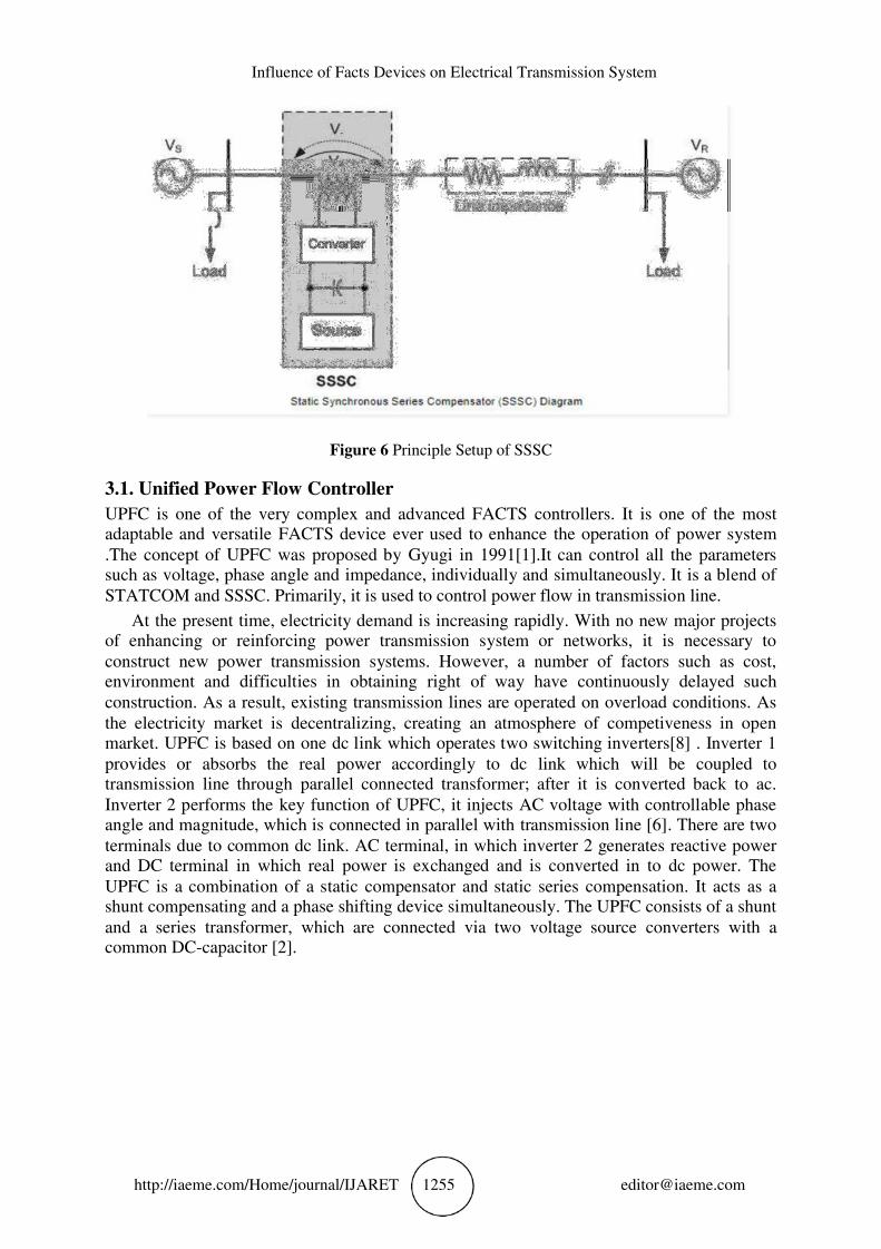
Figure 6 Principle Setup of SSSC
3.1. Unified Power Flow Controller
UPFC is one of the very complex and advanced FACTS controllers. It is one of the most adaptable and versatile FACTS device ever used to enhance the operation of power system
.The concept of UPFC was proposed by Gyugi in 1991[1].It can control all the parameters such as voltage, phase angle and impedance, individually and simultaneously. It is a blend of
STATCOM and SSSC. Primarily, it is used to control power flow in transmission line.
At the present time, electricity demand is increasing rapidly. With no new major projects of enhancing or reinforcing power transmission system or networks, it is necessary to
construct new power transmission systems. However, a number of factors such as cost, environment and difficulties in obtaining right of way have continuously delayed such
construction. As a result, existing transmission lines are operated on overload conditions. As
the electricity market is decentralizing, creating an atmosphere of competiveness in open market. UPFC is based on one dc link which operates two switching inverters[8] . Inverter 1
provides or absorbs the real power accordingly to dc link which will be coupled to transmission line through parallel connected transformer; after it is converted back to ac.
Inverter 2 performs the key function of UPFC, it injects AC voltage with controllable phase angle and magnitude, which is connected in parallel with transmission line [6]. There are two
terminals due to common dc link. AC terminal, in which inverter 2 generates reactive power and DC terminal in which real power is exchanged and is converted in to dc power. The
UPFC is a combination of a static compensator and static series compensation. It acts as a shunt compensating and a phase shifting device simultaneously. The UPFC consists of a shunt
and a series transformer, which are connected via two voltage source converters with a common DC-capacitor [2].
Satyam Kumar Upadhyay, Piyush Kumar Yadav, Rajnish Bhasker and Saurabh V Kumar
http://iaeme.com/Home/journal/IJARET 1256 [email protected]
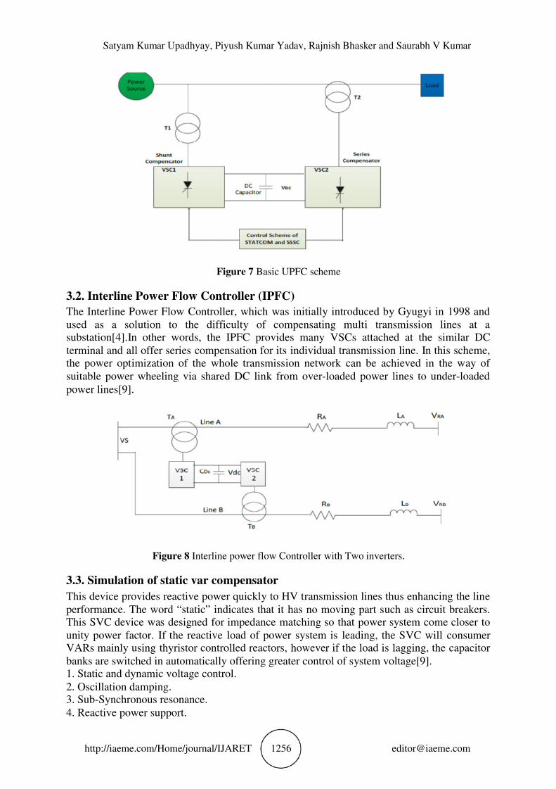
Figure 7 Basic UPFC scheme
3.2. Interline Power Flow Controller (IPFC)
The Interline Power Flow Controller, which was initially introduced by Gyugyi in 1998 and
used as a solution to the difficulty of compensating multi transmission lines at a substation[4].In other words, the IPFC provides many VSCs attached at the similar DC
terminal and all offer series compensation for its individual transmission line. In this scheme, the power optimization of the whole transmission network can be achieved in the way of
suitable power wheeling via shared DC link from over-loaded power lines to under-loaded
power lines[9].
Figure 8 Interline power flow Controller with Two inverters.
3.3. Simulation of static var compensator
This device provides reactive power quickly to HV transmission lines thus enhancing the line
performance. The word “static” indicates that it has no moving part such as circuit breakers. This SVC device was designed for impedance matching so that power system come closer to
unity power factor. If the reactive load of power system is leading, the SVC will consumer VARs mainly using thyristor controlled reactors, however if the load is lagging, the capacitor
banks are switched in automatically offering greater control of system voltage[9]. 1. Static and dynamic voltage control.
2. Oscillation damping. 3. Sub-Synchronous resonance.
4. Reactive power support.
Influence of Facts Devices on Electrical Transmission System
http://iaeme.com/Home/journal/IJARET 1257 [email protected]
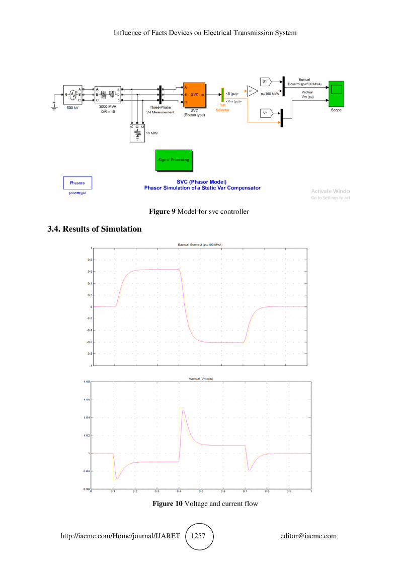
Figure 9 Model for svc controller
3.4. Results of Simulation
Figure 10 Voltage and current flow
Satyam Kumar Upadhyay, Piyush Kumar Yadav, Rajnish Bhasker and Saurabh V Kumar
http://iaeme.com/Home/journal/IJARET 1258 [email protected]
Dynamic Response of the SVC:- The Three-Phase Programmable Voltage Source is used to
vary the system voltage and observe the SVC performance. Initially the source is generating
nominal voltage. Then, voltage is successively decreased (0.97 pu at t = 0.1 s), increased (1.03 pu at t = 0.4 s) and finally returned to nominal voltage (1 pu at t = 0.7s). Start the
simulation and observe the SVC dynamic response to voltage steps on the Scope. Trace1 shows the actual positive sequences B1 and control signal output B of the voltage regulator.
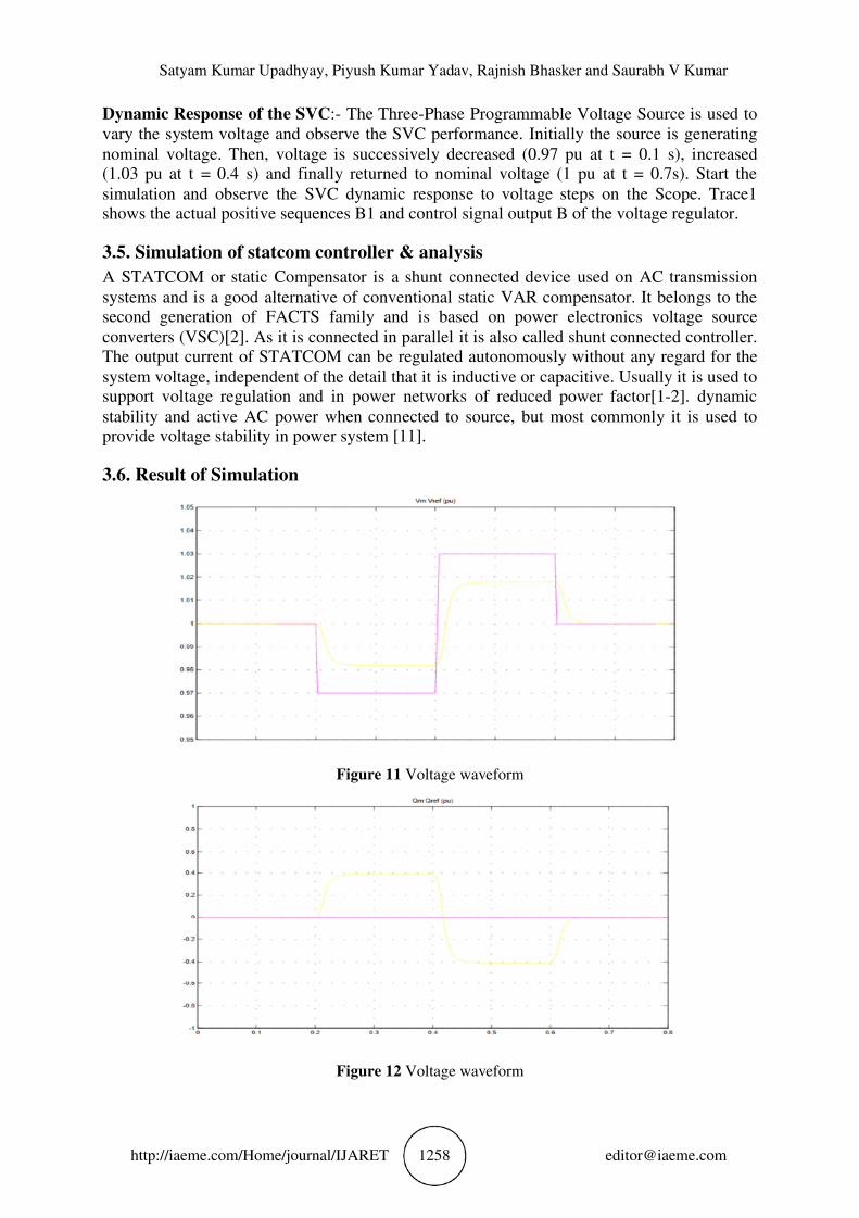
3.5. Simulation of statcom controller & analysis
A STATCOM or static Compensator is a shunt connected device used on AC transmission
systems and is a good alternative of conventional static VAR compensator. It belongs to the second generation of FACTS family and is based on power electronics voltage source
converters (VSC)[2]. As it is connected in parallel it is also called shunt connected controller. The output current of STATCOM can be regulated autonomously without any regard for the
system voltage, independent of the detail that it is inductive or capacitive. Usually it is used to support voltage regulation and in power networks of reduced power factor[1-2]. dynamic
stability and active AC power when connected to source, but most commonly it is used to provide voltage stability in power system [11].
3.6. Result of Simulation
Figure 11 Voltage waveform
Figure 12 Voltage waveform
Influence of Facts Devices on Electrical Transmission System
http://iaeme.com/Home/journal/IJARET 1259 [email protected]
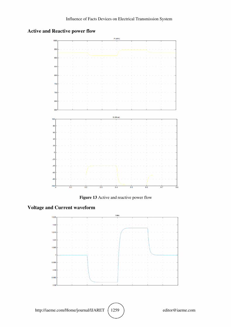
Active and Reactive power flow
Figure 13 Active and reactive power flow
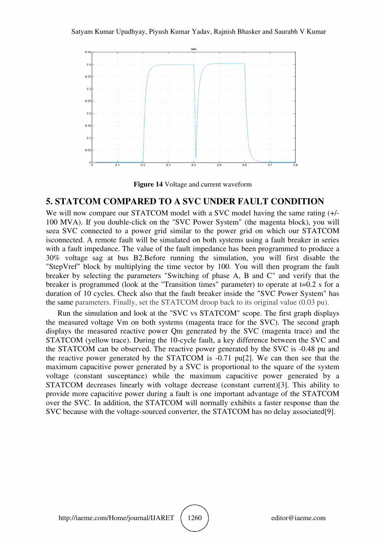
Voltage and Current waveform
Satyam Kumar Upadhyay, Piyush Kumar Yadav, Rajnish Bhasker and Saurabh V Kumar
http://iaeme.com/Home/journal/IJARET 1260 [email protected]
Figure 14 Voltage and current waveform
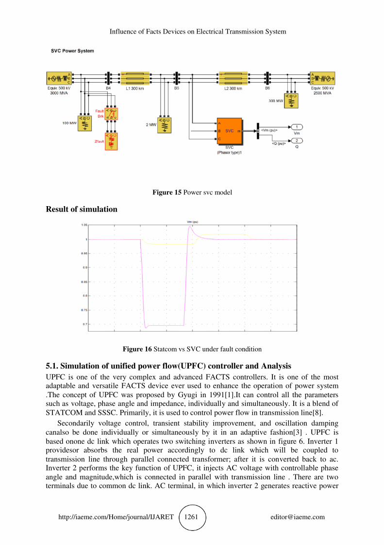
5. STATCOM COMPARED TO A SVC UNDER FAULT CONDITION
We will now compare our STATCOM model with a SVC model having the same rating (+/-
100 MVA). If you double-click on the "SVC Power System" (the magenta block), you will seea SVC connected to a power grid similar to the power grid on which our STATCOM
isconnected. A remote fault will be simulated on both systems using a fault breaker in series with a fault impedance. The value of the fault impedance has been programmed to produce a
30% voltage sag at bus B2.Before running the simulation, you will first disable the "StepVref" block by multiplying the time vector by 100. You will then program the fault
breaker by selecting the parameters "Switching of phase A, B and C" and verify that the breaker is programmed (look at the "Transition times" parameter) to operate at t=0.2 s for a
duration of 10 cycles. Check also that the fault breaker inside the "SVC Power System" has the same parameters. Finally, set the STATCOM droop back to its original value (0.03 pu).
Run the simulation and look at the "SVC vs STATCOM" scope. The first graph displays
the measured voltage Vm on both systems (magenta trace for the SVC). The second graph displays the measured reactive power Qm generated by the SVC (magenta trace) and the
STATCOM (yellow trace). During the 10-cycle fault, a key difference between the SVC and the STATCOM can be observed. The reactive power generated by the SVC is -0.48 pu and
the reactive power generated by the STATCOM is -0.71 pu[2]. We can then see that the maximum capacitive power generated by a SVC is proportional to the square of the system
voltage (constant susceptance) while the maximum capacitive power generated by a STATCOM decreases linearly with voltage decrease (constant current)[3]. This ability to
provide more capacitive power during a fault is one important advantage of the STATCOM
over the SVC. In addition, the STATCOM will normally exhibits a faster response than the SVC because with the voltage-sourced converter, the STATCOM has no delay associated[9].
Influence of Facts Devices on Electrical Transmission System
http://iaeme.com/Home/journal/IJARET 1261 [email protected]
Figure 15 Power svc model
Result of simulation
Figure 16 Statcom vs SVC under fault condition
5.1. Simulation of unified power flow(UPFC) controller and Analysis
UPFC is one of the very complex and advanced FACTS controllers. It is one of the most adaptable and versatile FACTS device ever used to enhance the operation of power system
.The concept of UPFC was proposed by Gyugi in 1991[1].It can control all the parameters such as voltage, phase angle and impedance, individually and simultaneously. It is a blend of
STATCOM and SSSC. Primarily, it is used to control power flow in transmission line[8].
Secondarily voltage control, transient stability improvement, and oscillation damping
canalso be done individually or simultaneously by it in an adaptive fashion[3] . UPFC is
based onone dc link which operates two switching inverters as shown in figure 6. Inverter 1 providesor absorbs the real power accordingly to dc link which will be coupled to
transmission line through parallel connected transformer; after it is converted back to ac. Inverter 2 performs the key function of UPFC, it injects AC voltage with controllable phase
angle and magnitude,which is connected in parallel with transmission line . There are two terminals due to common dc link. AC terminal, in which inverter 2 generates reactive power
Satyam Kumar Upadhyay, Piyush Kumar Yadav, Rajnish Bhasker and Saurabh V Kumar
http://iaeme.com/Home/journal/IJARET 1262 [email protected]
and DC terminal in which real power is exchanged and is converted in to dc power.It can be used for….
1. Static and dynamic voltage control.
2. Oscillation damping.
3. Sub-Synchronous resonance.
4. Reactive power support.
5. Voltage flicker control.
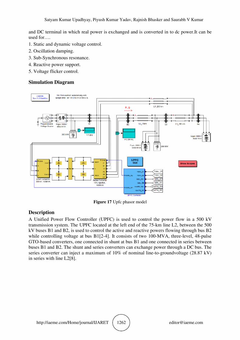
Simulation Diagram
Figure 17 Upfc phasor model
Description
A Unified Power Flow Controller (UPFC) is used to control the power flow in a 500 kV
transmission system. The UPFC located at the left end of the 75-km line L2, between the 500 kV buses B1 and B2, is used to control the active and reactive powers flowing through bus B2
while controlling voltage at bus B1[2-4]. It consists of two 100-MVA, three-level, 48-pulse
GTO-based converters, one connected in shunt at bus B1 and one connected in series between buses B1 and B2. The shunt and series converters can exchange power through a DC bus. The
series converter can inject a maximum of 10% of nominal line-to-groundvoltage (28.87 kV) in series with line L2[8].
Influence of Facts Devices on Electrical Transmission System
http://iaeme.com/Home/journal/IJARET 1263 [email protected]
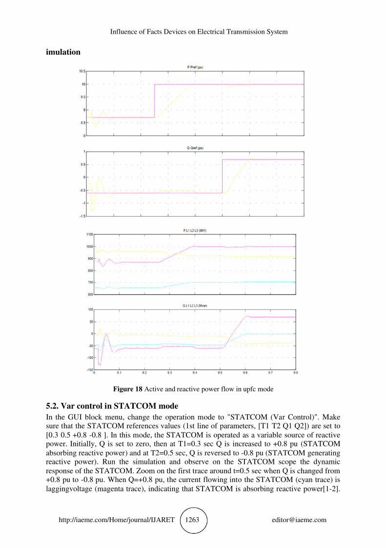
imulation
Figure 18 Active and reactive power flow in upfc mode
5.2. Var control in STATCOM mode
In the GUI block menu, change the operation mode to "STATCOM (Var Control)". Make sure that the STATCOM references values (1st line of parameters, [T1 T2 Q1 Q2]) are set to
[0.3 0.5 +0.8 -0.8 ]. In this mode, the STATCOM is operated as a variable source of reactive power. Initially, Q is set to zero, then at T1=0.3 sec Q is increased to +0.8 pu (STATCOM
absorbing reactive power) and at T2=0.5 sec, Q is reversed to -0.8 pu (STATCOM generating reactive power). Run the simulation and observe on the STATCOM scope the dynamic
response of the STATCOM. Zoom on the first trace around t=0.5 sec when Q is changed from +0.8 pu to -0.8 pu. When Q=+0.8 pu, the current flowing into the STATCOM (cyan trace) is
laggingvoltage (magenta trace), indicating that STATCOM is absorbing reactive power[1-2].
Satyam Kumar Upadhyay, Piyush Kumar Yadav, Rajnish Bhasker and Saurabh V Kumar
http://iaeme.com/Home/journal/IJARET 1264 [email protected]
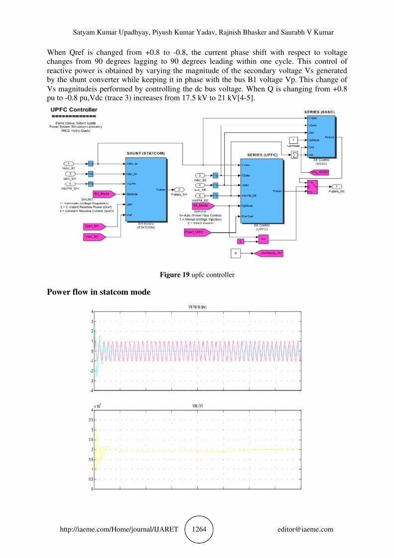
When Qref is changed from +0.8 to -0.8, the current phase shift with respect to voltage changes from 90 degrees lagging to 90 degrees leading within one cycle. This control of
reactive power is obtained by varying the magnitude of the secondary voltage Vs generated by the shunt converter while keeping it in phase with the bus B1 voltage Vp. This change of
Vs magnitudeis performed by controlling the dc bus voltage. When Q is changing from +0.8 pu to -0.8 pu,Vdc (trace 3) increases from 17.5 kV to 21 kV[4-5].
Figure 19 upfc controller
Power flow in statcom mode
Influence of Facts Devices on Electrical Transmission System
http://iaeme.com/Home/journal/IJARET 1265 [email protected]
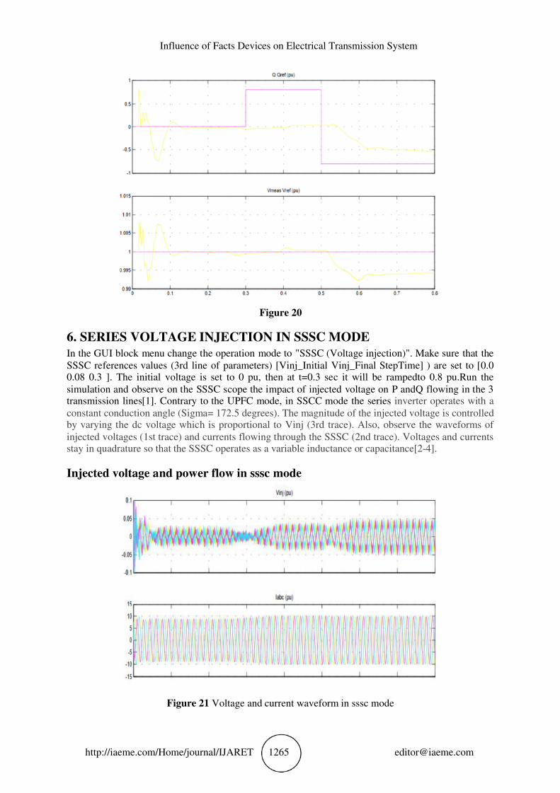
Figure 20
6. SERIES VOLTAGE INJECTION IN SSSC MODE
In the GUI block menu change the operation mode to "SSSC (Voltage injection)". Make sure that the
SSSC references values (3rd line of parameters) [Vinj_Initial Vinj_Final StepTime] ) are set to [0.0 0.08 0.3 ]. The initial voltage is set to 0 pu, then at t=0.3 sec it will be rampedto 0.8 pu.Run the
simulation and observe on the SSSC scope the impact of injected voltage on P andQ flowing in the 3 transmission lines[1]. Contrary to the UPFC mode, in SSCC mode the series inverter operates with a
constant conduction angle (Sigma= 172.5 degrees). The magnitude of the injected voltage is controlled by varying the dc voltage which is proportional to Vinj (3rd trace). Also, observe the waveforms of
injected voltages (1st trace) and currents flowing through the SSSC (2nd trace). Voltages and currents stay in quadrature so that the SSSC operates as a variable inductance or capacitance[2-4].
Injected voltage and power flow in sssc mode
Figure 21 Voltage and current waveform in sssc mode
Satyam Kumar Upadhyay, Piyush Kumar Yadav, Rajnish Bhasker and Saurabh V Kumar
http://iaeme.com/Home/journal/IJARET 1266 [email protected]
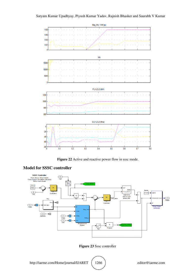
Figure 22 Active and reactive power flow in sssc mode.
Model for SSSC controller
Figure 23 Sssc controller
Influence of Facts Devices on Electrical Transmission System
http://iaeme.com/Home/journal/IJARET 1267 [email protected]
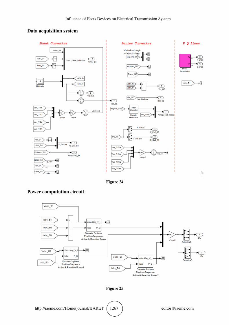
Data acquisition system
Figure 24
Power computation circuit
Figure 25

Satyam Kumar Upadhyay, Piyush Kumar Yadav, Rajnish Bhasker and Saurabh V Kumar
http://iaeme.com/Home/journal/IJARET 1268 [email protected]
48- pulse voltage source convertor
Figure 26
48- pulse voltage source convertor (switches) circuit
Figure 27
Influence of Facts Devices on Electrical Transmission System
http://iaeme.com/Home/journal/IJARET 1269 [email protected]
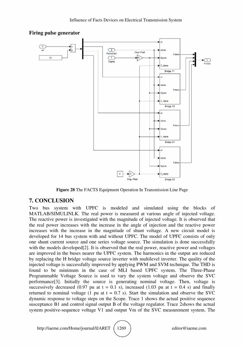
Firing pulse generator
Figure 28 The FACTS Equipment Operation In Transmission Line Page
7. CONCLUSION
Two bus system with UPFC is modeled and simulated using the blocks of
MATLAB/SIMULINLK. The real power is measured at various angle of injected voltage. The reactive power is investigated with the magnitude of injected voltage. It is observed that
the real power increases with the increase in the angle of injection and the reactive power increases with the increase in the magnitude of shunt voltage. A new circuit model is
developed for 14 bus system with and without UPFC. The model of UPFC consists of only one shunt current source and one series voltage source. The simulation is done successfully
with the models developed[2]. It is observed that the real power, reactive power and voltages are improved in the buses nearer the UPFC system. The harmonics in the output are reduced
by replacing the H bridge voltage source inverter with multilevel inverter. The quality of the injected voltage is successfully improved by applying PWM and SVM technique. The THD is
found to be minimum in the case of MLI based UPFC system. The Three-Phase Programmable Voltage Source is used to vary the system voltage and observe the SVC
performance[3]. Initially the source is generating nominal voltage. Then, voltage is successively decreased (0.97 pu at t = 0.1 s), increased (1.03 pu at t = 0.4 s) and finally
returned to nominal voltage (1 pu at t = 0.7 s). Start the simulation and observe the SVC
dynamic response to voltage steps on the Scope. Trace 1 shows the actual positive sequence susceptance B1 and control signal output B of the voltage regulator. Trace 2shows the actual
system positive-sequence voltage V1 and output Vm of the SVC measurement system. The
Satyam Kumar Upadhyay, Piyush Kumar Yadav, Rajnish Bhasker and Saurabh V Kumar
http://iaeme.com/Home/journal/IJARET 1270 [email protected]
SVC response speed depends on the voltage regulator integral gain Ki (Proportional gain Kp
is set to zero), system strength (reactance Xn) and droop(reactance Xs)[5]. If the voltage
measurement time constant and average time delay Td due to valve firing are neglected, the system can be approximated by a first order system having a closed loop time constant : Tc=
1/(Ki*(Xn+Xs)) With given system parameters (Ki = 300; Xn= 0.0667 pu/200 MVA; Xs = 0.03 pu/200 MVA), Tc = 0.0345 s. If you increase the regulator gain or decrease the system
strength, the measurement time constant and the valve firing delay Td will no longer be negligible and you will observe an oscillatory response and eventually unstability[8] .
18. FUTURE SCOPE AND LIMITATIONS OF THE RESEARCH This work deals with modelling and simulation of 30 bus system using MATLAB simulink.
• The simulation can also be done using PSCAD and PSIM [8].
• This work has covered power quality in 30 bus system using UPFC. The work may be
extended to sixty four bus system[6].
• Hardware implementation is beyond the scope of this work. Laborator hardware may be implemented using Digital Signal Processor (DSP)[4].
• Multibus system with multiple FACTS controllers may be studied to observe the power quality improvement[5].
• Closed loop system using Neural network or genetic algorithm can be studied in
future[1].
REFERENCES
[1] Xiao-Ping Zhang, Christian Rehtanz, Bikash Pal, “Flexible AC Transmission Systems: Modelling and Control”, Springer Publishers (2006)
[2] Narain G.Hingorani, Laszlo Gyugyi, 2000, Understanding FACTS: Concepts and Technology of Flexible AC Transmission Systems, IEEE Inc., New York, USA, 0-7803-3455-8.
[3] Math H. J. Bollen, 2000, Understanding Power Quality Problems: Voltage Sags & Interruption, IEEE Inc., New York, USA, 0-7803-4713-7.
[4] D. Povh, M. Weinhold, 2000, “Improvement of Power Quality by Power Electronic Equipment”, CIGRE Report No. 13/14/36-06
[5] Fugita and Watanaba. (2008) „Control and Analysis of UPFC , IEEE Transactions on Power ‟
Electronics Vol.14,No.6 pp. 1021-1027
[6] Gyugyi L, Schauder CD, Williams SL, Rietman TR, Torgerson DR, Edris DR. The unified power flow controller: a new approach to power transmission control. IEEE Trans on Power
Delivery 1995; 10(2):1085±1093.
[7] Gyugyi L. Unified power flow concept for Flexible AC transmission systems. IEE Proceedings -C 1992; 139:323±331.
[8] K.R. Padiyar, K. Uma Rao / Electrical Power and Energy Systems 21 (1999) 1±11
[9] S.Shankar.et.al./International Journal Of Engineering Science and Technology. Vol.2(4),2010,538-547