structural integrity monitoring of concrete structures via optical fiber sensors: sensor protection...
TRANSCRIPT

http://shm.sagepub.com
Structural Health Monitoring
DOI: 10.1177/1475921703002002004 2003; 2; 123 Structural Health Monitoring
G. F. Fernando, A. Hameed, D. Winter, J. Tetlow, J. Leng, R. Barnes, G. Mays and G. Kister Systems
Structural Integrity Monitoring of Concrete Structures via Optical Fiber Sensors: Sensor Protection
http://shm.sagepub.com/cgi/content/abstract/2/2/123 The online version of this article can be found at:
Published by:
http://www.sagepublications.com
can be found at:Structural Health Monitoring Additional services and information for
http://shm.sagepub.com/cgi/alerts Email Alerts:
http://shm.sagepub.com/subscriptions Subscriptions:
http://www.sagepub.com/journalsReprints.navReprints:
http://www.sagepub.co.uk/journalsPermissions.navPermissions:
http://shm.sagepub.com/cgi/content/refs/2/2/123 Citations
at Harbin Inst. of Technology on August 12, 2009 http://shm.sagepub.comDownloaded from

123
Structural Integrity Monitoring of Concrete
Structures via Optical Fiber Sensors: Sensor
Protection Systems
G. F. Fernando,* A. Hameed, D. Winter, J. Tetlow, J. Leng, R. Barnes,
G. Mays and G. Kister
Engineering Systems Department, Sensors and Composites Research Group,
Cranfield University, Shrivenham, Swindon SN6 8LA, UK
This paper reports on the design requirements and a range of specific concepts for optical fiber-based
sensor protection systems that can be used in concrete structures. The designs range from sensor
protection systems that are manufactured involving stainless steel, fiber reinforced composites and
concrete. The feasibility of manufacturing the sensor protection systems using these materials is also
demonstrated. A detailed finite element analysis was carried out to optimise the stainless steel-based
sensor protection system for concrete. Experimental results involving the sensor protection system will
be presented in Part 2 of this series of papers.
Keywords sensor protection � Fabry-Perot � Bragg grating � concrete � structural integrity
1 Introduction
There is considerable global interest in the condi-
tion assessment of civil structures such as bridges
and highways [1]. Apart from the obvious safety
implications and economic considerations, this
interest in structural integrity monitoring of civil
structures is generally dictated by the need to
monitor the structure due to one or more of the
following: (i) increased traffic or payload;
(ii) deterioration brought about by de-icing
agents, specified chemical agents, atmospheric and
traffic pollution; (iii) damage caused to the struc-
ture by land subsidence, earthquake and vehicle
impact; (iv) the development of strategies for
maintenance schedules, refurbishment and reno-
vation; (v) compliance with new codes of practice
and legislation; and (vi) availability of new non-
destructive techniques and sensor systems.
The established technologies for the structural
integrity assessment of civil structures include,
visual inspection, ground radar, X-ray radiogra-
phy, ultrasonic scanning, acoustic emission,
shearography, stimulated infrared thermography,
vibration testing, radar, conductivity, etc [2,3].
Whilst these techniques are adequate and reliable
for specified applications, they are not capable of
providing real-time and on-line information on
the measurands of interest. For example, local
and global strain, temperature, vibration charac-
teristics and concentration of specified chemicals
that may cause deterioration of the structure.
With reference to the above mentioned struc-
tural integrity issues, the availability of an on-line
*Author to whom correspondence should be addressed.
E-mail: [email protected]
Copyright � 2003 Sage Publications,
Vol 2(2): 123–135
[1475-9217 (200306) 2:2;123–135; 10.1177/147592103034253]
Copyright � 2003 Sage Publications,
Vol 2(2): 123–135
[1475-9217 (200306) 2:2;123–135; 10.1177/147592103034253]
at Harbin Inst. of Technology on August 12, 2009 http://shm.sagepub.comDownloaded from

monitoring system would be able to comply with
most of these needs. For example, significant
advances have been made in the last decade on
the utilisation of optical fiber-based sensor sys-
tems for health monitoring of engineering and
civil structures [4,5]. Fiber optic sensors (FOS)
are ideal candidates for remote and real-time
structural integrity monitoring as they offer the
following unique advantages over conventional
sensors and inspection techniques: (i) their rela-
tive small dimension and uniform cross-section
makes it easy for surface mounting or embedding
into materials such as polymers, fiber reinforced
composites and concrete; (ii) in general, when
embedded, they tend not to influence the quasi-
static tensile mechanical properties of materials;
(iii) they are immune to electro-magnetic inter-
ference and therefore can be deployed in areas
where electrical-based sensors would fail or require
expensive protection; (iv) FOS can be used to
infer the following measurements and in some
cases multiple properties may be accessed, for
example, strain, temperature, pressure, humidity,
vibration, specified chemicals, acoustic emission
and fracture [6–8]. Although a number of these
sensor systems have been demonstrated success-
fully in the laboratory under ideal conditions,
their exposure to on-site rigours is now being
given greater prominence and emphasis; (v) the
options of remote data telemetry and on-line data
acquisition are an extremely attractive feature of
FOS [9,10]; (vi) unlike conventional electrical-
based sensors, FOS can be multiplexed. In other
words, a number of similar or different sensors
can be attached along a single optical fiber. With
certain sensor design, distributed sensing can also
be achieved along the length of a fiber; (vii) the
cost of the fibers is relatively low and the overall
sensor systems costs can be modest if: (a) the
sensors are fabricated in-house; (b) telecommuni-
cation wavelengths are used (�1310 and
1550 nm); and (c) low-cost, off-the-shelf interro-
gation units can be used.
Fiber optic sensors have their limitations and
these need to be appreciated with specific refer-
ence to civil structures if they are to be exploited.
Examples of areas of concern in this industrial
sector are as follows. (i) The robustness and
survivability of the sensor system [11]: The low
attenuation characteristics of silica-based optical
fibers makes them ideal for data transmission
over long distances. However, these fibers and
sensors tend to be brittle and hence adequate
protection must be provided. In addition to this,
exposed silica fibers may be susceptible to hydro-
lytic degradation. With reference to optical fibers,
the protection generally takes the form of a
polymeric coating (acrylate, polyimide, fluoro-
hydrocarbon). Where additional protection is
required, reinforcing fibers are used in conjunc-
tion with a polymeric jacketing. Protecting the
sensing region is more problematic as it is
important to ensure that the sensing region is not
insulated or isolated from the measurand. This
first paper in this series will address the strategy
behind materials selection and design for surface-
mounted and embedded fiber optic sensors in
concrete. (ii) Transduction: This is a term that is
used sometimes to indicate the efficiency of the
transfer of the measurand in question to the
sensor. For example, for the structural integrity
strategies based on strain and/or stiffness method-
ology, it is essential for efficient strain transfer
from the substrate to the sensor. Factors that can
influence the strain transfer efficiency include the
relative moduli of the various components, the
type and degree of chemical bonding between
the sensor and the substrate, and the physical
protection rendered to the sensor system. The
homogeneity of the matrix can also have a sig-
nificant influence on the environment around the
sensor, for example, concrete. (iii) Interpretation
of the data from the sensor: The interpretation of
the data from the sensors may not be straight
forward because the output could be influenced
by a multitude of parameters such as axial, radial
and lateral strains, temperature, thermal expan-
sion of the structure, humidity, etc. With systems
consisting of multiple or multiplexed sensors,
some form of data reduction and fusion will be
needed. Data fusion in essence is the fusion of
multi-sensor data to increase the accuracy and
reliability of measurands which can be monitored
and characterised. This topic is of significant
relevance because of the complex and inter-
dependence of various parameters associated
with structural integrity monitoring and assess-
ment. The problem of identifying malfunctioning
124 Structural Health Monitoring 2 (2)
at Harbin Inst. of Technology on August 12, 2009 http://shm.sagepub.comDownloaded from

sensors needs to be addressed and may be
simplified by fusing the measurements with per-
formance and signal characteristics. By fusing
many measurands with a contextual database, it
may be possible to derive the following informa-
tion: (a) Material characterization. Identification
of material properties unobtainable through
single sensors. (b) Fault diagnosis. The data
fusion process may allow faults to be identified
and provide early warning of failures to reduce
maintenance costs. (iv) Influence of the embedded
sensor system on the long term integrity of the civil
structure: On the basis of the wealth of informa-
tion that is currently available on the use of
optical fiber-based sensor systems in concrete
structures, there is no evidence to suggest that the
embedded sensor has any detrimental effect on
the concrete structure. This is reasonable consid-
ering the relative volume fraction and dimension
of the optical fiber sensor system in relation to
the reinforced concrete. However, precautions
need to be taken to ensure that the entry and the
exit points do not provide a means for the
external environment to ingress into the concrete
structure. (v) Long-term stability and reliability of
the sensor and interrogation unit. As this is an
emerging technology, there is little information
available on the long-term performance of such a
sensor and interrogation unit. On the basis of the
information available thus far, the suggestion is
that this is not likely to be a cause for serious
concern. However, attention will need to be paid
to the relative magnitudes of the cross-talk
caused by the external environment (temperature,
humidity) and the signal generated by the mea-
surand of interest (strain, temperature, vibration,
humidity etc). (vi) Repair strategy for the
embedded sensor system. Given the constant
reference in the literature for the need to repair
and strengthen existing concrete structures such
as bridges, due consideration needs to be paid to
future renovation and repair strategies.
2 Sensor Protection System (SPS)
2.1 Requirements for the SPS
The primary requirements for the sensor protec-
tion system (SPS) are: (i) protection of the silica
fibers from the alkaline environment typical in
concrete; (ii) protection of the sensor system (a)
during the concrete pouring operation, (b) against
mechanical or abrasion damage caused by the
aggregates and against any aggressive chemical
environments; (iii) ability to secure the sensor
system in the required orientation during the
concrete pouring operation; (iv) protection of the
leading and trailing optical fiber into and out of
the structure; (v) appropriate protection to the
sensor system against physical damage and detri-
mental environmental effects when it is surface-
mounted; (vi) an appropriate repair strategy in
the event that the structure has to be repaired or
renovated. Due consideration must also be paid
to a redundancy strategy with regard to the total
number of sensors that will be installed. In other
words, as the technology is relatively new, an
extra numbers of sensors should be installed as a
precaution; (vii) the sensor system must ensure
good transduction for the measurand of interest;
and (viii) the sensor system must be relatively
low-cost, easy to fabricate and install.
In this current paper, the rationale for devel-
oping strategies for the embedded and surface-
mounted sensor protection system are developed
and discussed. The technology proposed in this
current publication is intuitive and is based on the
fulfilment of the criteria for the SPS set out in the
previous section. However, a selection of previous
publications that deal with sensor mounting and
protection systems can be found in previous
literature [12–19] and SPS designs proposed by
these authors/corporations are duly acknowl-
edged. An excellent coverage of the use of optical
fiber-based sensors and protection systems can be
found in the book authored by Measures [1].
2.2 Embedded Sensor Protection
Systems
With reference to the above mentioned criteria,
three classes of materials were selected: stainless
steel; carbon fiber prepreg-based composite and
concrete. Stainless steel is relatively inert in the
concrete environment except where chloride
attack is concerned. Here also, caution needs to
be exercised with designs that involve welding the
SPS on to metallic components on the reinforcing
Fernando et al. Structural Integrity Monitoring of Concrete Structures 125
at Harbin Inst. of Technology on August 12, 2009 http://shm.sagepub.comDownloaded from
bar (rebar) or structure as the use of dissimilar
metals can result in the formation of a corrosion
cell. Carbon fiber composites are used for reinfor-
cing concrete structures and are also used as pre-
tensioned tendons instead of steel in certain
applications. The carbon fiber composite is gen-
erally coated with a moisture-impermeable layer
that is alkali resistant. Concrete was evaluated as
a potential matrix for the SPS as it offers similar
mechanical, thermal and chemical properties.
2.2.1 Metal-Based Sensor Protection Systems
Stainless Steel: A preliminary series of experi-
ments were carried out to assess the suitability of
using a stainless steel tube to protect the FOS in
concrete. This was found to be unsuitable as no
anchorage points were provided. A finite ele-
ment study was undertaken to optimise the
shapes and dimensions of the anchorage points
or flanges. The details of this were reported in a
previous publication [20] and only a brief sum-
mary of the main findings are presented here.
A summary of the relevant material properties
used in the finite analysis is presented in Table 1.
The assumptions made in developing the FE
model were as follows: (i) the material was
homogenous and isotropic; (ii) the test specimen
was only subjected to elastic loading; (iii) prelimin-
ary analyses were performed with the following
type of contact between the concrete and the SPS
interface: (a) no separation – here the target and
contact surfaces are tied but they are allowed to
slide once the ultimate shear stress was achieved;
(b) rough – here perfect and rough frictional
contact was assumed; and (c) bonded – in this
case, the contact integration points were initially
inside the pinball region, the contact was attached
to the target surface along the normal and tangent
directions to the surface; this permitted sliding
when the ultimate shear stress was reached; (iv) in
the above-mentioned cases, debonding and slip-
page will occur when shear stress at the SPS–
concrete interface reaches the ultimate anchorage
stress of 2.2MPa, as calculated in accordance with
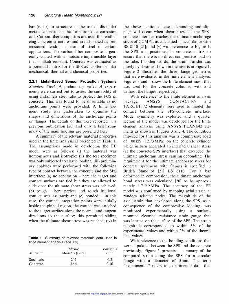
BS 8110 [21]; and (v) with reference to Figure 1,
the SPS was positioned in concrete matrix to
ensure that there is no direct compressive load on
the tube. In other words, the strain transfer was
purely by shear as shown in the inserts in Figure 1.
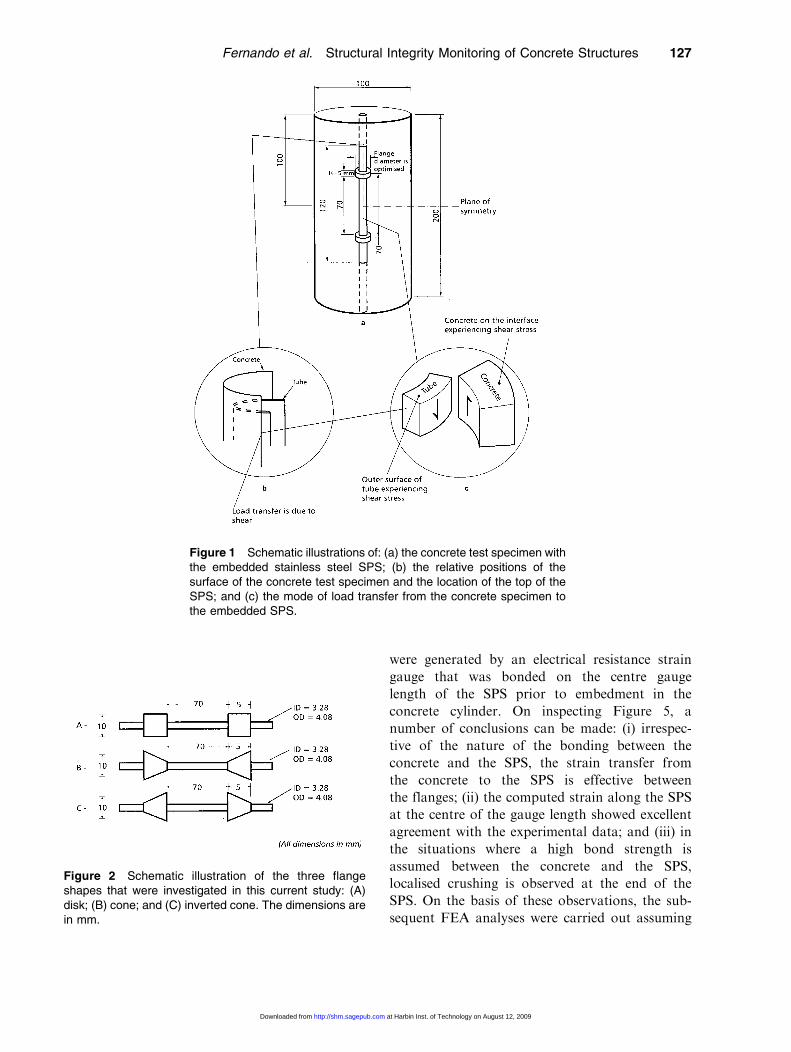
Figure 2 illustrates the three flange geometries
that were evaluated in the finite element analyses.
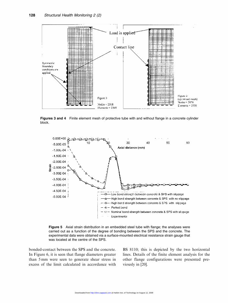
Figures 3 and 4 show the finite element mesh that
was used for the concrete columns, with and
without the flanges respectively.
With reference to the finite element analysis
package, ANSYS, CONTACT169 and
TARGET172 elements were used to model the
contact between the SPS–concrete interface.
Model symmetry was exploited and a quarter
section of the model was developed for the finite
element analysis using ANSYS PLANE42 ele-
ments as shown in Figures 3 and 4. The condition
imposed for this analysis was a compressive load
of 100 kN (12.73MPa) on the concrete cylinder
which in turn generated an interfacial shear stress
(at the concrete–SPS interface) that exceeded the
ultimate anchorage stress causing debonding. The
requirement for the ultimate anchorage stress for
concrete specimens with flanges is specified in
British Standard [21] BS 8110. For a bar
deformed in compression, the ultimate anchorage
bond stress was calculated [20] to be approxi-
mately 1.7–2.2 MPa. The accuracy of the FE
model was confirmed by mapping axial strain at
random selected nodes. The magnitude of the
axial strain that developed along the SPS, as a
consequence of the compressive loading, was
monitored experimentally using a surface-
mounted electrical resistance strain gauge that
was located on the surface of the SPS. The strain
magnitude corresponded to within 5% of the
experimental values and within 2% of the theore-
tical values.
With reference to the bonding conditions that
were stipulated between the SPS and the concrete
previously, Figure 5 presents a summary of the
computed strain along the SPS for a circular
flange with a diameter of 5 mm. The term
‘‘experimental’’ refers to experimental data that
Table 1 Summary of relevant materials data used infinite element analysis (ANSYS).
MaterialElastic
Modulus (GPa)Poisson’sratio
Steel tube 207 0.3Concrete 32.4 0.16
126 Structural Health Monitoring 2 (2)
at Harbin Inst. of Technology on August 12, 2009 http://shm.sagepub.comDownloaded from
were generated by an electrical resistance strain
gauge that was bonded on the centre gauge
length of the SPS prior to embedment in the
concrete cylinder. On inspecting Figure 5, a
number of conclusions can be made: (i) irrespec-
tive of the nature of the bonding between the
concrete and the SPS, the strain transfer from
the concrete to the SPS is effective between
the flanges; (ii) the computed strain along the SPS
at the centre of the gauge length showed excellent
agreement with the experimental data; and (iii) in
the situations where a high bond strength is
assumed between the concrete and the SPS,
localised crushing is observed at the end of the
SPS. On the basis of these observations, the sub-
sequent FEA analyses were carried out assuming
Figure 1 Schematic illustrations of: (a) the concrete test specimen withthe embedded stainless steel SPS; (b) the relative positions of thesurface of the concrete test specimen and the location of the top of theSPS; and (c) the mode of load transfer from the concrete specimen tothe embedded SPS.
Figure 2 Schematic illustration of the three flangeshapes that were investigated in this current study: (A)disk; (B) cone; and (C) inverted cone. The dimensions arein mm.
Fernando et al. Structural Integrity Monitoring of Concrete Structures 127
at Harbin Inst. of Technology on August 12, 2009 http://shm.sagepub.comDownloaded from
bonded-contact between the SPS and the concrete.
In Figure 6, it is seen that flange diameters greater
than 5 mm were seen to generate shear stress in
excess of the limit calculated in accordance with
BS 8110; this is depicted by the two horizontal
lines. Details of the finite element analysis for the
other flange configurations were presented pre-
viously in [20].
Figure 5 Axial strain distribution in an embedded steel tube with flange; the analyses werecarried out as a function of the degree of bonding between the SPS and the concrete. Theexperimental data were obtained via a surface-mounted electrical resistance strain gauge thatwas located at the centre of the SPS.
Figures 3 and 4 Finite element mesh of protective tube with and without flange in a concrete cylinderblock.
128 Structural Health Monitoring 2 (2)
at Harbin Inst. of Technology on August 12, 2009 http://shm.sagepub.comDownloaded from
With reference to the FE data presented
above, the following conclusions can be made. (i)
An SPS system based on flanges is capable of
providing good mechanical interlocking. (ii) High
shear stress develops in the vicinity of the flanges
for the three designs considered in this study. (iii)
For a specified flange diameter, the magnitude of
the shear stress at the concrete–SPS interface was
found to be independent of the shape of the
flange. (iv) The SPS was designed to accommo-
date an embedded optical fiber sensor approxi-
mately 35mm away from the flanges. The shear
stress and strain profiles in this vicinity were
within the specified limit and strain transfer
across the interface was good. (v) The shear
stress and the direct strain in the vicinity of
sensor are not affected significantly by the shape
and diameter of the flange.
On the basis of the FE analysis carried out in
this current study, a stainless steel based SPS was
designed for deployment in concrete structures
that are subjected to predominantly compressive
and tensile loading. A schematic illustration of
this SPS and photograph of it is presented in
Figures 7 and 8 respectively.
With reference to Figure 7, the items specified
in the schematic illustration correspond to the
following: (1) single mode optical fiber with a
Figure 6 FEA of the shear stress at the SPS–concrete interface for specified diskdiameters. The analyses were carried out as a function of the length along the SPS.The two horizontal lines represent the permissible band for the shear stressdistribution in accordance with BS 8110.
Figure 7 Schematic illustration of the embeddable stainless steel-based SPS. See textfor details.
Fernando et al. Structural Integrity Monitoring of Concrete Structures 129
at Harbin Inst. of Technology on August 12, 2009 http://shm.sagepub.comDownloaded from
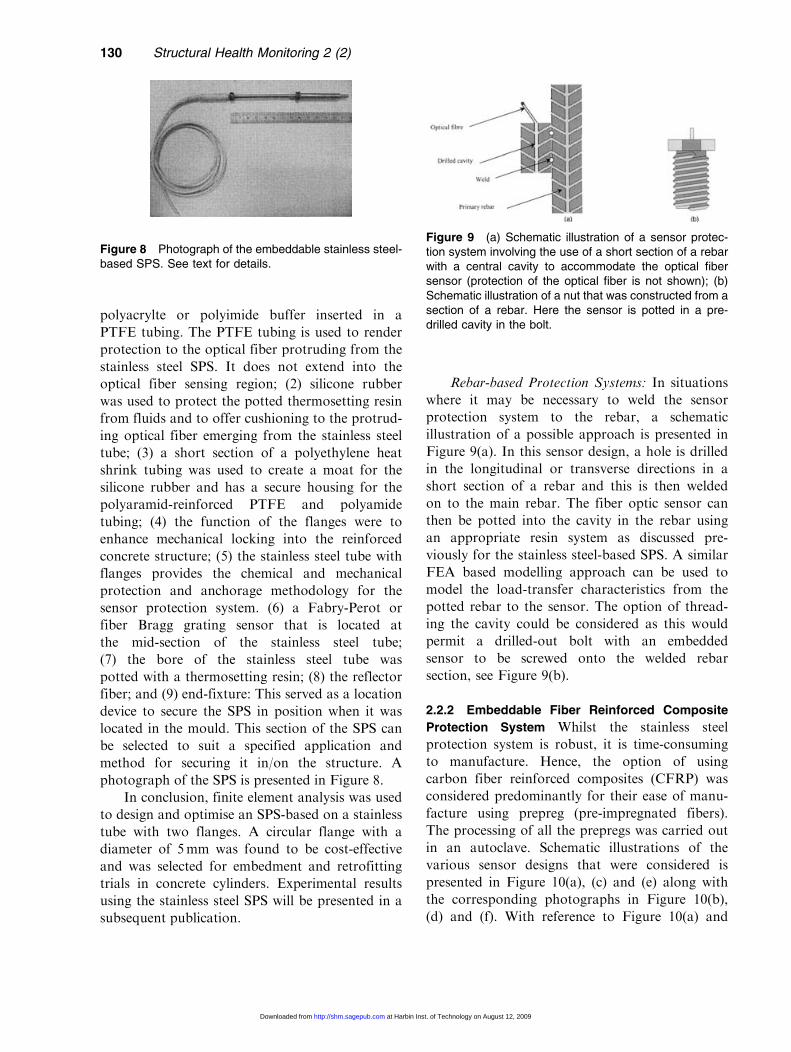
polyacrylte or polyimide buffer inserted in a
PTFE tubing. The PTFE tubing is used to render
protection to the optical fiber protruding from the
stainless steel SPS. It does not extend into the
optical fiber sensing region; (2) silicone rubber
was used to protect the potted thermosetting resin
from fluids and to offer cushioning to the protrud-
ing optical fiber emerging from the stainless steel
tube; (3) a short section of a polyethylene heat
shrink tubing was used to create a moat for the
silicone rubber and has a secure housing for the
polyaramid-reinforced PTFE and polyamide
tubing; (4) the function of the flanges were to
enhance mechanical locking into the reinforced
concrete structure; (5) the stainless steel tube with
flanges provides the chemical and mechanical
protection and anchorage methodology for the
sensor protection system. (6) a Fabry-Perot or
fiber Bragg grating sensor that is located at
the mid-section of the stainless steel tube;
(7) the bore of the stainless steel tube was
potted with a thermosetting resin; (8) the reflector
fiber; and (9) end-fixture: This served as a location
device to secure the SPS in position when it was
located in the mould. This section of the SPS can
be selected to suit a specified application and
method for securing it in/on the structure. A
photograph of the SPS is presented in Figure 8.
In conclusion, finite element analysis was used
to design and optimise an SPS-based on a stainless
tube with two flanges. A circular flange with a
diameter of 5 mm was found to be cost-effective
and was selected for embedment and retrofitting
trials in concrete cylinders. Experimental results
using the stainless steel SPS will be presented in a
subsequent publication.
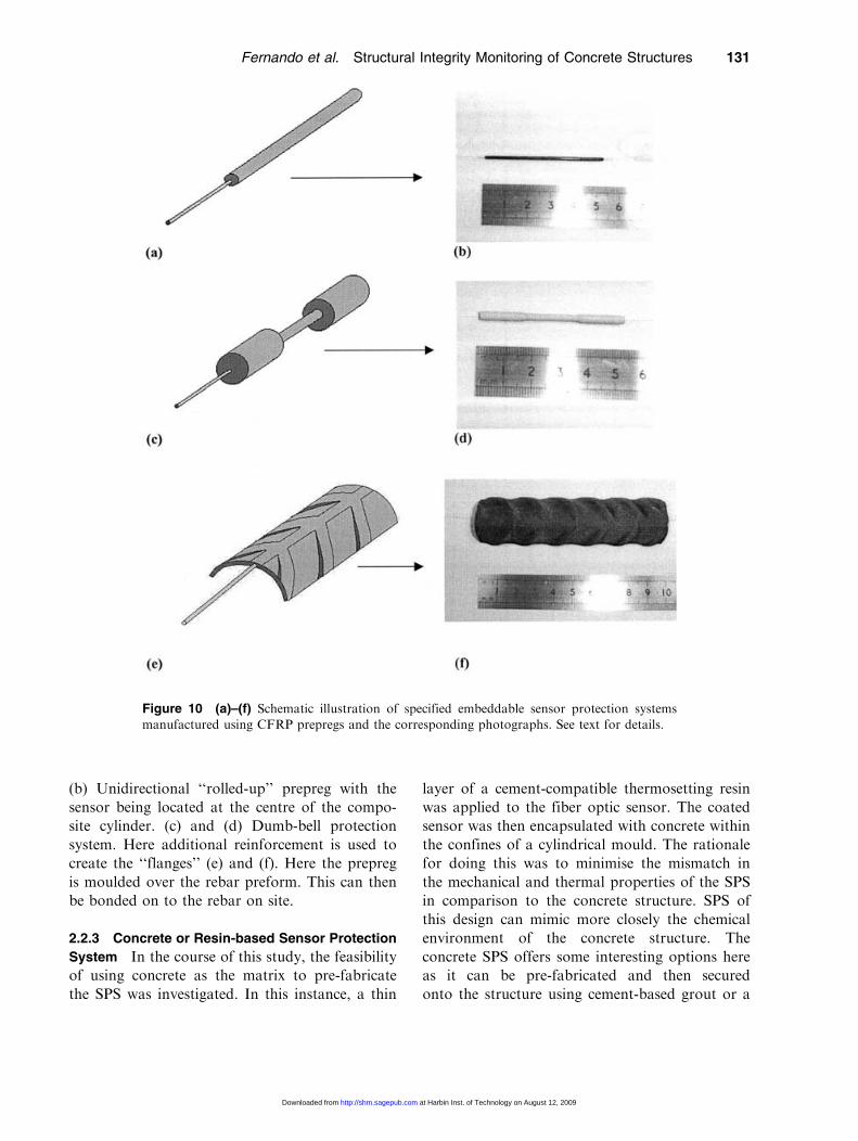
Rebar-based Protection Systems: In situations
where it may be necessary to weld the sensor
protection system to the rebar, a schematic
illustration of a possible approach is presented in
Figure 9(a). In this sensor design, a hole is drilled
in the longitudinal or transverse directions in a
short section of a rebar and this is then welded
on to the main rebar. The fiber optic sensor can
then be potted into the cavity in the rebar using
an appropriate resin system as discussed pre-
viously for the stainless steel-based SPS. A similar
FEA based modelling approach can be used to
model the load-transfer characteristics from the
potted rebar to the sensor. The option of thread-
ing the cavity could be considered as this would
permit a drilled-out bolt with an embedded
sensor to be screwed onto the welded rebar
section, see Figure 9(b).
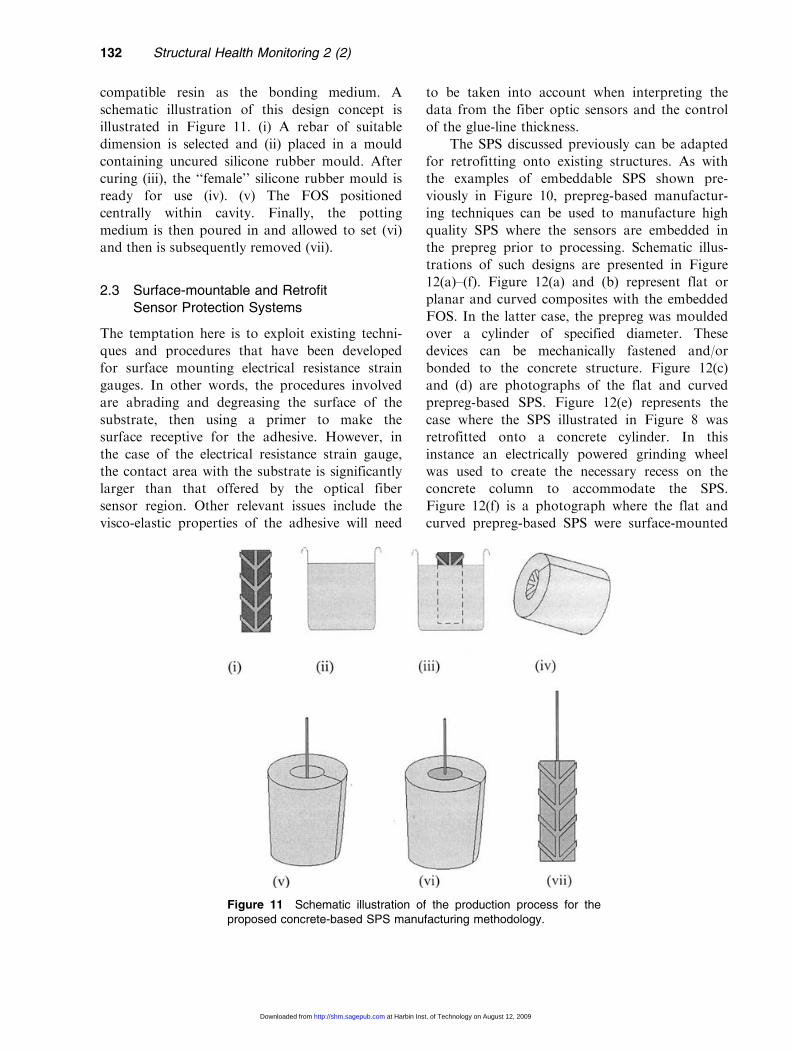
2.2.2 Embeddable Fiber Reinforced Composite
Protection System Whilst the stainless steel
protection system is robust, it is time-consuming
to manufacture. Hence, the option of using
carbon fiber reinforced composites (CFRP) was
considered predominantly for their ease of manu-
facture using prepreg (pre-impregnated fibers).
The processing of all the prepregs was carried out
in an autoclave. Schematic illustrations of the
various sensor designs that were considered is
presented in Figure 10(a), (c) and (e) along with
the corresponding photographs in Figure 10(b),
(d) and (f). With reference to Figure 10(a) and
Figure 9 (a) Schematic illustration of a sensor protec-tion system involving the use of a short section of a rebarwith a central cavity to accommodate the optical fibersensor (protection of the optical fiber is not shown); (b)Schematic illustration of a nut that was constructed from asection of a rebar. Here the sensor is potted in a pre-drilled cavity in the bolt.
Figure 8 Photograph of the embeddable stainless steel-based SPS. See text for details.
130 Structural Health Monitoring 2 (2)
at Harbin Inst. of Technology on August 12, 2009 http://shm.sagepub.comDownloaded from
(b) Unidirectional ‘‘rolled-up’’ prepreg with the
sensor being located at the centre of the compo-
site cylinder. (c) and (d) Dumb-bell protection
system. Here additional reinforcement is used to
create the ‘‘flanges’’ (e) and (f). Here the prepreg
is moulded over the rebar preform. This can then
be bonded on to the rebar on site.
2.2.3 Concrete or Resin-based Sensor Protection
System In the course of this study, the feasibility
of using concrete as the matrix to pre-fabricate
the SPS was investigated. In this instance, a thin
layer of a cement-compatible thermosetting resin
was applied to the fiber optic sensor. The coated
sensor was then encapsulated with concrete within
the confines of a cylindrical mould. The rationale
for doing this was to minimise the mismatch in
the mechanical and thermal properties of the SPS
in comparison to the concrete structure. SPS of
this design can mimic more closely the chemical
environment of the concrete structure. The
concrete SPS offers some interesting options here
as it can be pre-fabricated and then secured
onto the structure using cement-based grout or a
Figure 10 (a)–(f) Schematic illustration of specified embeddable sensor protection systems
manufactured using CFRP prepregs and the corresponding photographs. See text for details.
Fernando et al. Structural Integrity Monitoring of Concrete Structures 131
at Harbin Inst. of Technology on August 12, 2009 http://shm.sagepub.comDownloaded from
compatible resin as the bonding medium. A
schematic illustration of this design concept is
illustrated in Figure 11. (i) A rebar of suitable
dimension is selected and (ii) placed in a mould
containing uncured silicone rubber mould. After
curing (iii), the ‘‘female’’ silicone rubber mould is
ready for use (iv). (v) The FOS positioned
centrally within cavity. Finally, the potting
medium is then poured in and allowed to set (vi)
and then is subsequently removed (vii).
2.3 Surface-mountable and Retrofit
Sensor Protection Systems
The temptation here is to exploit existing techni-
ques and procedures that have been developed
for surface mounting electrical resistance strain
gauges. In other words, the procedures involved
are abrading and degreasing the surface of the
substrate, then using a primer to make the
surface receptive for the adhesive. However, in
the case of the electrical resistance strain gauge,
the contact area with the substrate is significantly
larger than that offered by the optical fiber
sensor region. Other relevant issues include the
visco-elastic properties of the adhesive will need
to be taken into account when interpreting the
data from the fiber optic sensors and the control
of the glue-line thickness.
The SPS discussed previously can be adapted
for retrofitting onto existing structures. As with
the examples of embeddable SPS shown pre-
viously in Figure 10, prepreg-based manufactur-
ing techniques can be used to manufacture high
quality SPS where the sensors are embedded in
the prepreg prior to processing. Schematic illus-
trations of such designs are presented in Figure
12(a)–(f). Figure 12(a) and (b) represent flat or
planar and curved composites with the embedded
FOS. In the latter case, the prepreg was moulded
over a cylinder of specified diameter. These
devices can be mechanically fastened and/or
bonded to the concrete structure. Figure 12(c)
and (d) are photographs of the flat and curved
prepreg-based SPS. Figure 12(e) represents the
case where the SPS illustrated in Figure 8 was
retrofitted onto a concrete cylinder. In this
instance an electrically powered grinding wheel
was used to create the necessary recess on the
concrete column to accommodate the SPS.
Figure 12(f) is a photograph where the flat and
curved prepreg-based SPS were surface-mounted
Figure 11 Schematic illustration of the production process for theproposed concrete-based SPS manufacturing methodology.
132 Structural Health Monitoring 2 (2)
at Harbin Inst. of Technology on August 12, 2009 http://shm.sagepub.comDownloaded from
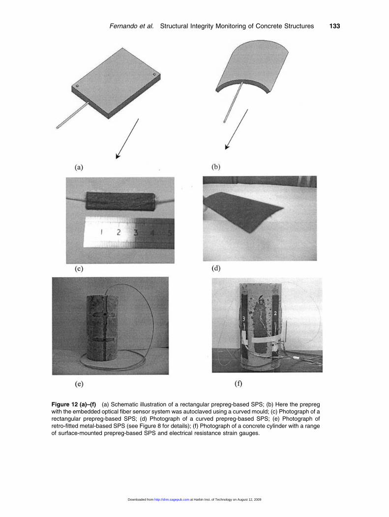
Figure 12 (a)–(f) (a) Schematic illustration of a rectangular prepreg-based SPS; (b) Here the prepregwith the embedded optical fiber sensor system was autoclaved using a curved mould; (c) Photograph of arectangular prepreg-based SPS; (d) Photograph of a curved prepreg-based SPS; (e) Photograph ofretro-fitted metal-based SPS (see Figure 8 for details); (f) Photograph of a concrete cylinder with a rangeof surface-mounted prepreg-based SPS and electrical resistance strain gauges.
Fernando et al. Structural Integrity Monitoring of Concrete Structures 133
at Harbin Inst. of Technology on August 12, 2009 http://shm.sagepub.comDownloaded from

on to a concrete test specimen. Surface-mounted
electrical resistance gauges were also used to
correlate the data obtained from fiber optic
sensors; the outcome from these investigations
will be reported in a subsequent publication.
4 Conclusions
This paper has outlined the major aspects asso-
ciated with the design and deployment of sensor
protection systems for concrete structures. A
number of designs were proposed for the SPS
and two of these were evaluated in detail: an
embedded stainless steel protection system and a
glass and carbon fiber-based protection for sur-
face mounting onto concrete structures. The
design for the metal-based SPS was based on
finite element analysis where the shape and
dimensions of the flanges were optimised.
Acknowledgements
The authors wish to acknowledge the funding provided by
EPSRC (GR/M56265 and GR M83605), the Institution of
Civil Engineers (Enabling Fund Ref: 9905) and the
Engineering Systems Department, Cranfield University.
The assistance and encouragement given by Professor Brian
Ralph, Mike Teagle, Jim Harber, Rodney Badcock,
Richard Rose, Julie Etches and Maggie Keats are duly
acknowledged. This project was carried out in collabora-
tion with colleagues from the Universities of Kent and City
under the remit of an EPSRC Structural Integrity research
grant.
References
1. Measures, R.M. (2001). Structural monitoring with fibre
optic technology. Academic Press, Oxford, UK.
2. McCann, D.M. and Forde, M.C. (2001). Review of
NDT methods in the assessment of concrete and
masonry structures. NDT&E International, 34, 71–84.
3. Blanc, M.L. and Measures, R.M. (1995). Fibre optic
damage assessment. In: Udd, E. (ed.), Fibre optic smart
structures, pp. 581–614, John Wiley & Sons, Inc.,
New York.
4. Merzbacher, C.I., Kersey, A.D. and Friebele, E.J.
(1996). Fibre optic sensors in concrete structures: a
review. Smart Materials and Structures, 5, 196–208.
5. Ansari (1997). State-of-the-art in the applications of
fibre-optic sensors to cementitious composites. Cement
& Concrete Composites (UK), 19, 3–19.
6. Grattan, K.T.V. and Meggitt, B.T. (1998). Optical fibre
sensor technology: devices and technology. Chapman &
Hall, London, UK.
7. Jones, J.D.C. (1997). Review of fibre sensor techniques
for temperature-strain discrimination, OSA Tech.
Digest. In: Proc. 12th Int. Optical Fibre Sensor Conf.,
Vol. 16, pp. 36–39, Williamburg, VA, USA.
8. Culshaw, B. and Daikin, J. (eds), (1989). Optical fibre
sensors principles and components, Vol. 1: Systems and
applications, Vol. 2. Artech House, London, UK.
9. Fuhr, P.L., Huston, D.R. and Ambrose, T.P. (1994).
Remote monitoring of instrumented structures using
the INTERNET information superhighway. In: Proc.
2nd Eur. Conf. on Smart, pp. 148–51, Structures and
Materials (Glasgow, 1994).
10. Fuhr, P.L., Huston, D.R., Ambrose, T.P. and Mowat,
E.F. (1995). An Internet observatory: remote monitor-
ing of instrumented civil structures using the informa-
tion superhighway. Smart Mater. Struct., 4, 14–9.
11. Volotinen, T., Griffioen, W., Gadonna, M. and
Limberger, H. (1999). Reliability of optical fibres and
components. Final Report of COST 246, Springer
Verlag, Berlin.
12. Inaudi, D., Vurpillot, S. and Casanova, N. (1996).
Bridge monitoring by interferometric deformation
sensors. SPIE Intl. Photonics China, Symposium on
Laser Optoelectronics and Microphotonics: Fiber Optic
Sensors, Beijing, China, 1–12.
13. DeWynter-Marty, V., Rougeault, S. and Ferdinand, P.
(1997). Concrete strain measurements and crack detec-
tion with surface-mounted and embedded Bragg grating
extensometers, OSA. 12th Int. Conf. on Optical Fibre
Sensors, pp. 600–603, Williamsburg.
14. Kronenberg, P., Casanova, N., Inaudi, D. and
Vurpillot, S. (1997). Dam monitoring with fibre optic
deformation sensors. SPIE 3043, 2–11.
15. Electro-Photonics Corporation, Ontario, Canada –
Trade literature.
16. Hillemeier, B., Habel, W.R. and Hofmann, D. (1997).
Deformation measurements of mortars at early ages
and of large concrete components on site by means of
embedded fibre-optic microstrain sensors. Cement &
Concrete Composites (UK), 19, 81–102.
17. De Vries, M., Arya, V., Meller, S., Masri, S.F. and
Claus, R.O. (1997). Implementation of EFPI-based
optical-fibre sensor instrumentation for the NDE of
concrete structures. Cement & Concrete Composites
(UK), 19, 59–68.
18. Choquet, P., Juneau, F. and Dadoun, F. (1999). New
generation of fibre-optic sensors for dam monitoring.
134 Structural Health Monitoring 2 (2)
at Harbin Inst. of Technology on August 12, 2009 http://shm.sagepub.comDownloaded from

‘99 International conference on dam safety and monitor-
ing, 19–22 Oct., Hubei, China.
19. Quirion, M. and Ballivy, G. (2000). Concrete strain
monitoring with Fabry-Perot fibre-optic sensor. Journal
of Materials in Civil Engineering, 12, 3.
20. Hameed, A., Fernando, G.F., Hetherington, J.G.,
Brown, R.D., Leng, J. and Barnes, R.A. (2002).
Investigation of strain transfer to a sensor protection
system embedded in concrete using finite element
analysis. Materials and Structures, 35, 557–563.
21. British Standards Institute (BSI) (1985). Structural use
of concrete, Part 1: Code of practice for design and
construction. BS 8110: Part 1: BSI, London.
Fernando et al. Structural Integrity Monitoring of Concrete Structures 135
at Harbin Inst. of Technology on August 12, 2009 http://shm.sagepub.comDownloaded from