stormwater management and road tunnel - ita-aites
TRANSCRIPT
ITA2009 BudapestGus Klados
BKV-DBR Metro ITA-AITES WTC 2009
MMC-GAMUDA JV 11
Construction of the SMART Project in MALAYSIA
Presentation for theITA-AITES WTC 2009 BUDAPEST
23d- 28th May 2009
SMARTStormwater Management
and Road Tunnel
ITA-AITES WTC2009BUDAPEST by Gus
BKV – DBR Metro ITA-AITES WTC 2009 Budapest Gus Klados
MMC-GAMUDA JV 22
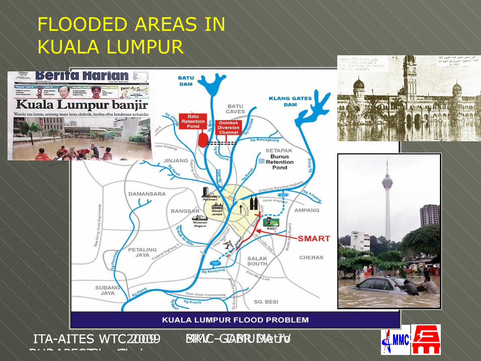
FLOODED AREAS IN KUALA LUMPUR
24th October 2007, GSM by Gus
MMC-GAMUDA JV ITA-AITES WTC 2009
MMC-GAMUDA JV 33
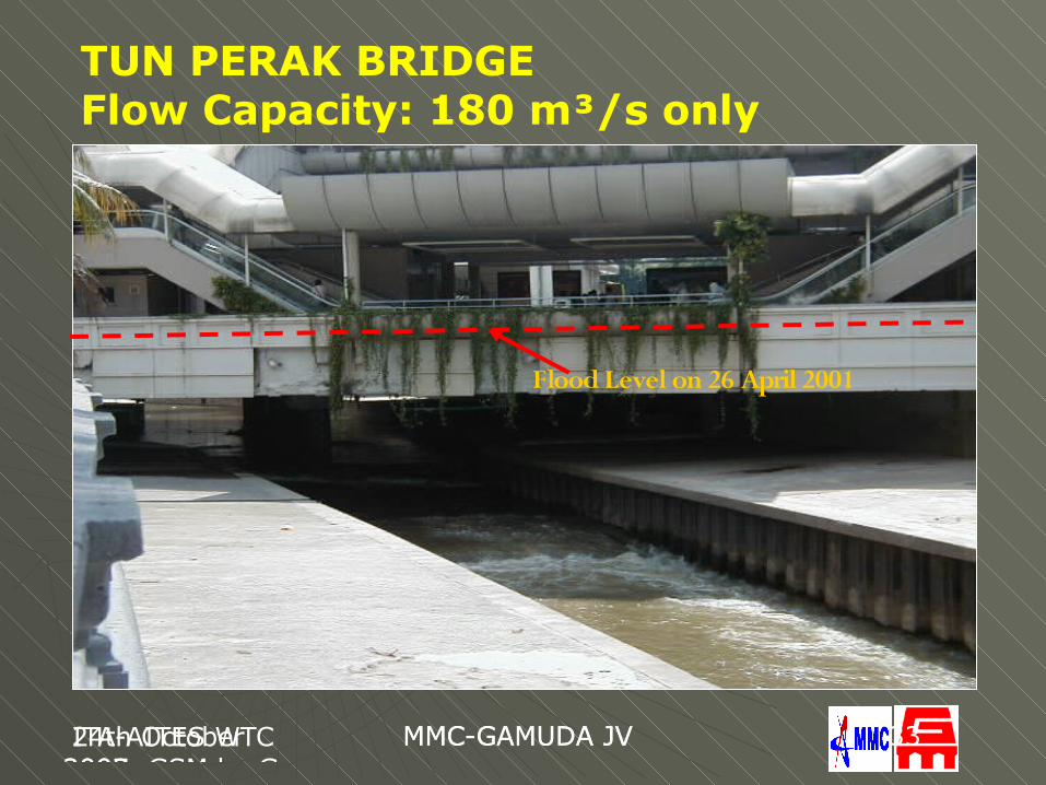
Flood Level on 26 April 2001
TUN PERAK BRIDGEFlow Capacity: 180 m³/s only
ITA2009 BudapestGus Klados
BKV-DBR Metro ITA-AITES WTC 2009
MMC-GAMUDA JV 44
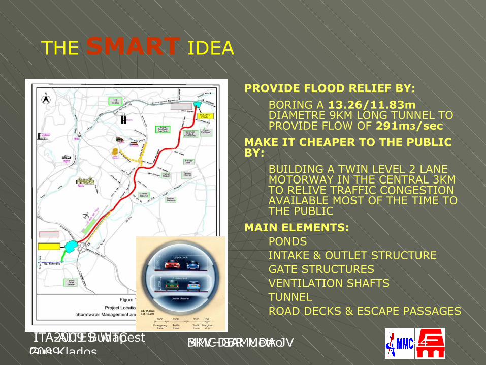
THE SMART IDEA
PROVIDE FLOOD RELIEF BY:BORING A 13.26/11.83m DIAMETRE 9KM LONG TUNNEL TO PROVIDE FLOW OF 291m3/sec
MAKE IT CHEAPER TO THE PUBLIC BY:
BUILDING A TWIN LEVEL 2 LANE MOTORWAY IN THE CENTRAL 3KM TO RELIVE TRAFFIC CONGESTION AVAILABLE MOST OF THE TIME TO THE PUBLIC
MAIN ELEMENTS:PONDSINTAKE & OUTLET STRUCTUREGATE STRUCTURESVENTILATION SHAFTSTUNNEL ROAD DECKS & ESCAPE PASSAGES
ITA2009 BudapestGus Klados
BKV-DBR Metro ITA-AITES WTC 2009
MMC-GAMUDA JV 55
RO
W
R OW
RO
W
OFFTAKE
RO
W
RO
W
RO
W
FLOATING
ROW
RL=38m Flood Level
RL=30.7m Standing Water Level
Bypass Tunnel
SG
. KLA
NG
SG
. A
MP
AN
G
SG
. KLA
NG
DIVERSION WEIR
BOOM
19.5024.50
Twin Box Culvert Kerayong
18.05
8.20
Storage Reservoir
28.00 Flood Level
OutfallIntake gated
-0.80
20.00 Standing Water Level
(TAMAN DESA POND) (2 nos. 5.1m H x 5.5m W)
25.70 Flood Level
18.55 Standing Water Level
0
5
10
15
20
25
30
35
4040
35
30
25
20
15
10
5
0
28.70
33.35
21.55
Sg Klang
Holding Pond
Bypass Tunnel(Diameter 11.8m)
38.50 Flood Level
31.3
38.00 Flood Level31.80 Standing Water Level structure
Offtake gatedstructure
STRUCTURE
BELL MOUTHSTRUCTURE AREA = 119028m
TAMAN DESA POND
RL 20mNEW POND SIZE
TO SEREMBAN
TO KL
2
TWIN BOX CULVERT(2 nos. 5.1m H x 5.5m W)
SG. BESI AIRFIELD
BY
PA
SS
TU
NN
EL
KL - SEREMBAN HIGHWAY
AREA = 216594m
ORIGINAL POND SIZERL 28m
2
RESTAURANTDESA
WATER PARK
THEME PARKDESA
WATER PARK
INTAKE GATEDSTRUCTURE
OUTFALLSTRUCTURE
OUTFALLSTRUCTURE
structureSg
RO
W
ROW
RO
W
OFFTAKE
RO
W
ROW
RO
W
FLOATING
ROW
RL=38m Flood Level
RL=30.7m Standing Water Level
Bypass Tunnel
SG
. KLA
NG
SG
. A
MP
AN
G
SG
. KL
AN
G
DIVERSION WEIR
BOOM
19.5024.50
Twin Box Culvert Kerayong
18.05
8.20
Storage Reservoir
28.00 Flood Level
OutfallIntake gated
-0.80
20.00 Standing Water Level
(TAMAN DESA POND) (2 nos. 5.1m H x 5.5m W)
25.70 Flood Level
18.55 Standing Water Level
0
5
10
15
20
25
30
35
4040
35
30
25
20
15
10
5
0
28.70
33.35
21.55
Sg Klang
Holding Pond
Bypass Tunnel(Diameter 11.8m)
38.50 Flood Level
31.3
38.00 Flood Level31.80 Standing Water Level structure
Offtake gatedstructure
STRUCTURE
BELL MOUTHSTRUCTURE AREA = 119028m
TAMAN DESA POND
RL 20mNEW POND SIZE
TO SEREMBAN
TO KL
2
TWIN BOX CULVERT(2 nos. 5.1m H x 5.5m W)
SG. BESI AIRFIELD
BY
PA
SS
TU
NN
EL
KL - SEREMBAN HIGHW
AY
AREA = 216594m
ORIGINAL POND SIZERL 28m
2
RESTAURANTDESA
WATER PARK
THEME PARKDESA
WATER PARK
INTAKE GATEDSTRUCTURE
OUTFALLSTRUCTURE
OUTFALLSTRUCTURE
structureSg
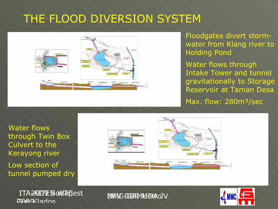
THE FLOOD DIVERSION SYSTEMFloodgates divert storm-water from Klang river to Holding Pond
Water flows through Intake Tower and tunnel gravitationally to Storage Reservoir at Taman Desa
Max. flow: 280m³/sec
Water flows through Twin Box Culvert to the Kerayong river
Low section of tunnel pumped dry
24th October 2007, GSM by Gus
MMC-GAMUDA JV ITA-AITES WTC 2009
MMC-GAMUDA JV 66
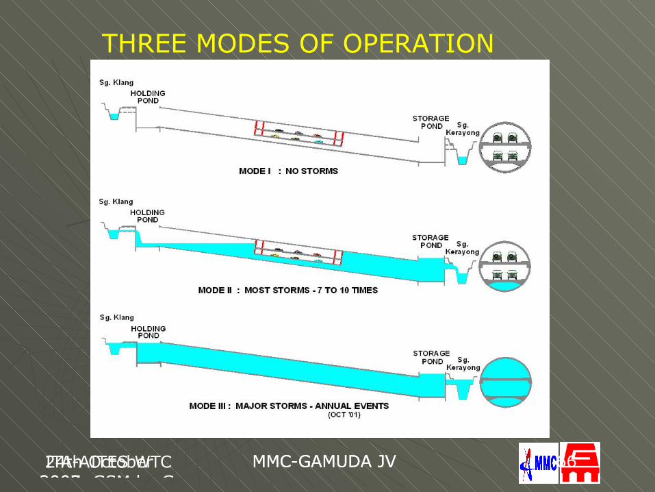
THREE MODES OF OPERATION
24th October 2007, GSM by Gus
MMC-GAMUDA JV ITA-AITES WTC 2009
MMC-GAMUDA JV 77
THE SMART PROJECT ORGANISATION
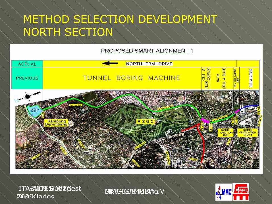
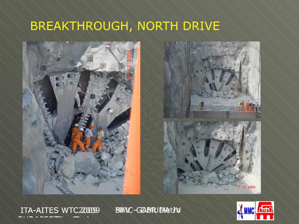
After 2,2km the North Drive contract was terminated, the remaining 2.8km was completed by MMC-GAMUDA JV in 11 months.
24th October 2007, GSM by Gus
MMC-GAMUDA JV 24th October 2007, GSM by Gus
MMC-GAMUDA JV 88
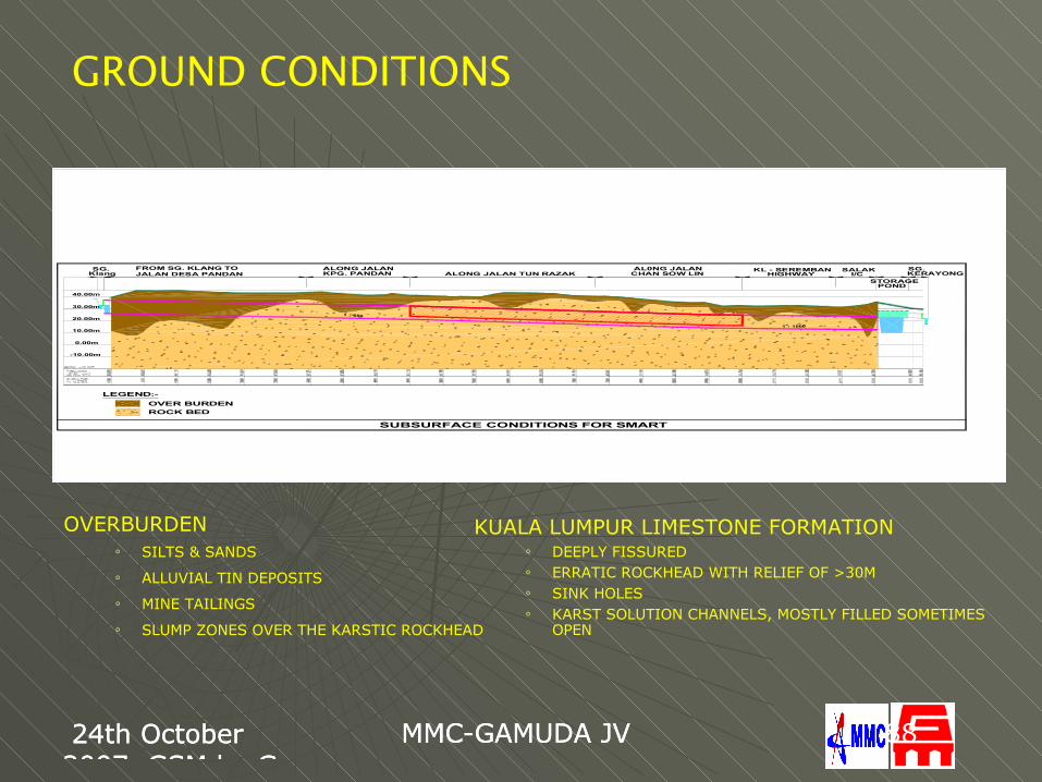
GROUND CONDITIONS
-10.00m
0.00m
KERAYONG
SUBSURFACE CONDITIONS FOR SMART
10.00m
20.00m
30.00m
40.00m
1 : 650
1 : 1000
LEGEND:-OVER BURDENROCK BED
STORAGEPOND
SG.SG.Klang JALAN DESA PANDAN
FROM SG. KLANG TOKPG. PANDANALONG JALAN
ALONG JALAN TUN RAZAK CHAN SOW LINAL0NG JALAN KL - SEREMBAN
HIGHWAYSALAK
I/C
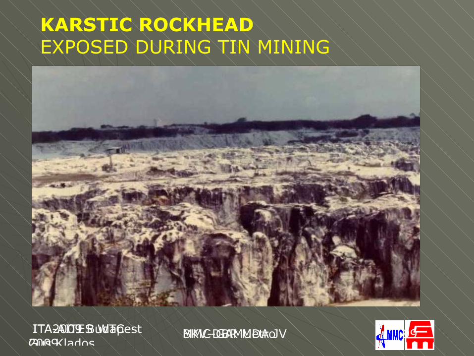
KUALA LUMPUR LIMESTONE FORMATION o DEEPLY FISSUREDo ERRATIC ROCKHEAD WITH RELIEF OF >30Mo SINK HOLESo KARST SOLUTION CHANNELS, MOSTLY FILLED SOMETIMES
OPEN
OVERBURDENo SILTS & SANDSo ALLUVIAL TIN DEPOSITSo MINE TAILINGSo SLUMP ZONES OVER THE KARSTIC ROCKHEAD
ITA2009 BudapestGus Klados
BKV-DBR Metro ITA-AITES WTC 2009
MMC-GAMUDA JV 99
KARSTIC ROCKHEAD EXPOSED DURING TIN MINING
24th October 2007, GSM by Gus
MMC-GAMUDA JV ITA-AITES WTC 2009
MMC-GAMUDA JV 1010
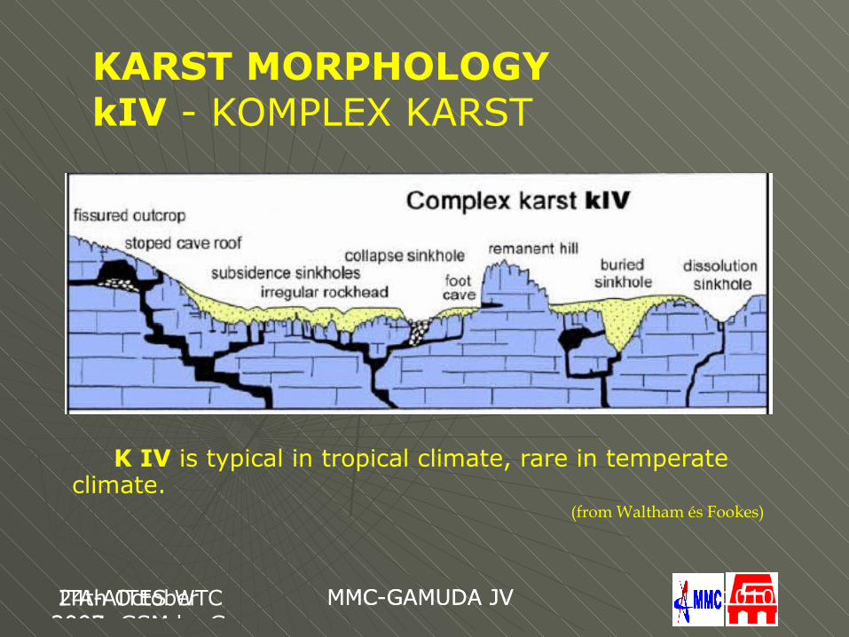
KARST MORPHOLOGYkIV - KOMPLEX KARST
K IV is typical in tropical climate, rare in temperate climate.
(from Waltham és Fookes)
24th October 2007, GSM by Gus
MMC-GAMUDA JV ITA-AITES WTC 2009
MMC-GAMUDA JV 1111
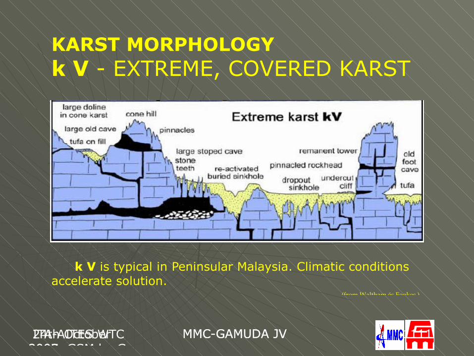
KARST MORPHOLOGYk V - EXTREME, COVERED KARST
k V is typical in Peninsular Malaysia. Climatic conditions accelerate solution.
(from Waltham és Fookes )
ITA2009 BudapestGus Klados
BKV-DBR Metro ITA-AITES WTC 2009
MMC-GAMUDA JV 1212
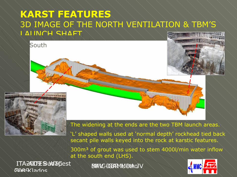
KARST FEATURES 3D IMAGE OF THE NORTH VENTILATION & TBM’S LAUNCH SHAFT
The widening at the ends are the two TBM launch areas.
‘L’ shaped walls used at ‘normal depth’ rockhead tied back secant pile walls keyed into the rock at karstic features.
300m³ of grout was used to stem 4000l/min water inflow at the south end (LHS).
South
North North
ITA2009 BudapestGus Klados
BKV-DBR Metro ITA-AITES WTC 2009
MMC-GAMUDA JV 1313
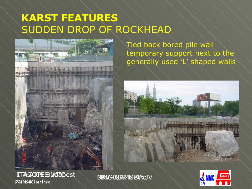
KARST FEATURESSUDDEN DROP OF ROCKHEAD
Tied back bored pile wall temporary support next to the generally used ‘L’ shaped walls
ITA2009 BudapestGus Klados
BKV-DBR Metro ITA-AITES WTC 2009
MMC-GAMUDA JV 1414
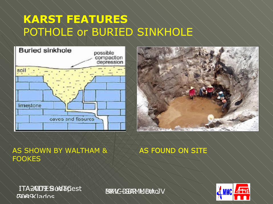
KARST FEATURES POTHOLE or BURIED SINKHOLE
AS SHOWN BY WALTHAM & FOOKES
AS FOUND ON SITEAS FOUND ON SITE
ITA2009 BudapestGus Klados
BKV-DBR Metro ITA-AITES WTC 2009
MMC-GAMUDA JV 1515
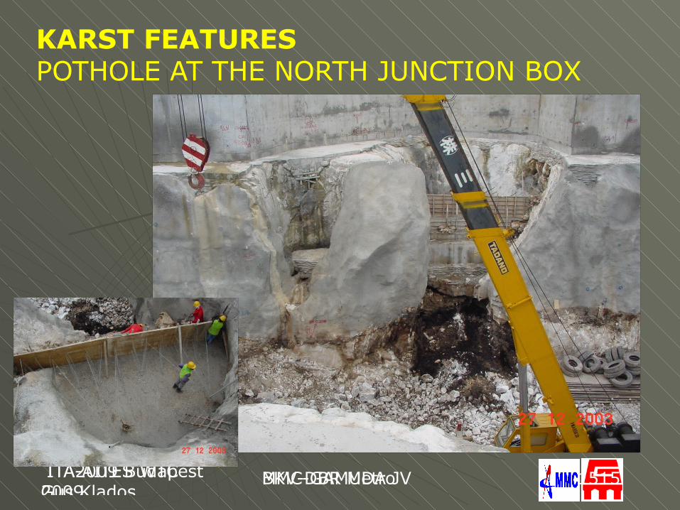
KARST FEATURES POTHOLE AT THE NORTH JUNCTION BOX
ITA2009 BudapestGus Klados
BKV-DBR Metro ITA-AITES WTC 2009
MMC-GAMUDA JV 1616
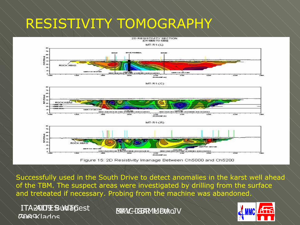
RESISTIVITY TOMOGRAPHY
Successfully used in the South Drive to detect anomalies in the karst well ahead of the TBM. The suspect areas were investigated by drilling from the surface and treteated if necessary. Probing from the machine was abandoned.
ITA2009 BudapestGus Klados
BKV-DBR Metro ITA-AITES WTC 2009
MMC-GAMUDA JV 1717
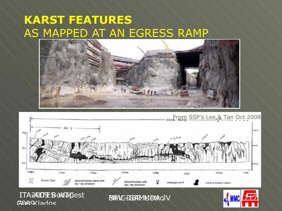
KARST FEATURESAS MAPPED AT AN EGRESS RAMP
From SSP’s Lee & Tan Oct 2008
24th October 2007, GSM by Gus
MMC-GAMUDA JV 24th October 2007, GSM by Gus
MMC-GAMUDA JV 1818
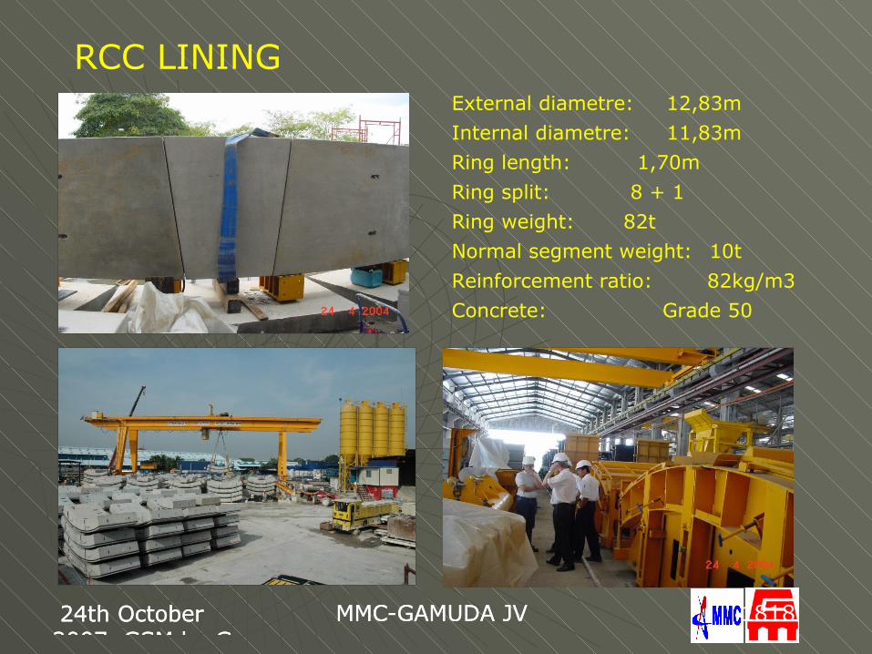
RCC LININGExternal diametre: 12,83mInternal diametre: 11,83mRing length: 1,70mRing split: 8 + 1Ring weight: 82tNormal segment weight: 10tReinforcement ratio: 82kg/m3Concrete: Grade 50
ITA2009 BudapestGus Klados
BKV-DBR Metro ITA-AITES WTC 2009
MMC-GAMUDA JV 1919
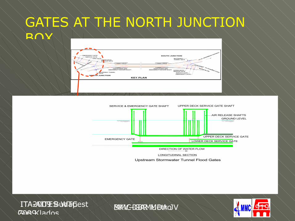
GATES AT THE NORTH JUNCTION BOX
TO JLN S
ULTAN ISM
AIL
WATER FLOW
TO KL-SEREMBAN HIGHWAY
TO STORAGE POND
NORTH JUNCTION
SOUTH JUNCTION
MOTORWAY TUNNELGATE
VENTILATION ANDEMERGENCY ESCAPE SHAFT
VENTILATION ANDEMERGENCY ESCAPE SHAFT
UPPER DECKSERVICE GATE
GRID GATESERVICE GATE
EMERGENCY GATE
UPPER DECKSERVICE GATE
MOTORWAY TUNNEL GATE
SERVICE GATEEMERGENCY GATE
GATE SHAFT
GATE SHAFT
KEY PLAN
EMERGENCY GATE
AIR RELEASE SHAFTS
DIRECTION OF WATER FLOW
GROUND LEVEL
UPPER DECK SERVICE GATE SHAFTSERVICE & EMERGENCY GATE SHAFT
Upstream Stormwater Tunnel Flood GatesLONGITUDINAL SECTION
UPPER DECK SERVICE GATE
LOWER DECK SERVICE GATE
24th October 2007, GSM by Gus
MMC-GAMUDA JV ITA-AITES WTC 2009
MMC-GAMUDA JV 2020
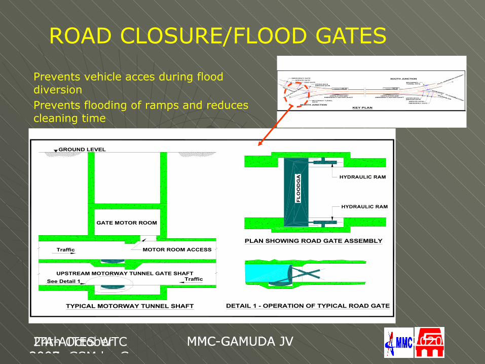
UPSTREAM MOTORWAY TUNNEL GATE SHAFT
MOTOR ROOM ACCESS
GROUND LEVEL
FL
OO
DG
AT
E
GATE MOTOR ROOM
HYDRAULIC RAM
HYDRAULIC RAM
TYPICAL MOTORWAY TUNNEL SHAFT DETAIL 1 - OPERATION OF TYPICAL ROAD GATE
PLAN SHOWING ROAD GATE ASSEMBLY
Traffic
Traffic
See Detail 1
ROAD CLOSURE/FLOOD GATES
Prevents vehicle acces during flood diversionPrevents flooding of ramps and reduces cleaning time
TO JLN SULTAN IS
WATER FLOW
TO KL-SEREMBAN HIGHWAY
TO STORAGE POND
NORTH JUNCTION
SOUTH JUNCTION
MOTORWAY TUNNELGATE
VENTILATION ANDEMERGENCY ESCAPE SHAFT
VENTILATION ANDEMERGENCY ESCAPE SHAFT
UPPER DECKSERVICE GATE
GRID GATE
SERVICE GATE
EMERGENCY GATE
UPPER DECKSERVICE GATE
MOTORWAY TUNNEL GATE
SERVICE GATEEMERGENCY GATE
GATE SHAFT
GATE SHAFT
KEY PLAN
24th October 2007, GSM by Gus
MMC-GAMUDA JV ITA-AITES WTC 2009
MMC-GAMUDA JV 2121
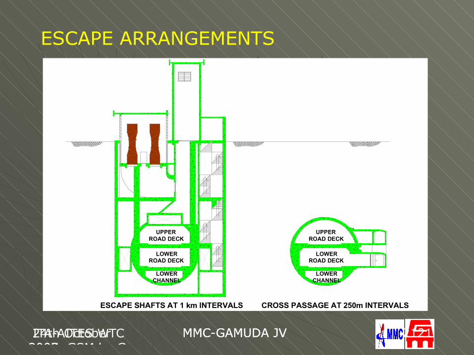
ESCAPE ARRANGEMENTS
ROAD DECK
CROSS PASSAGE AT 250m INTERVALSESCAPE SHAFTS AT 1 km INTERVALS
UPPER
ROAD DECKLOWER
CHANNELLOWER
ROAD DECKUPPER
ROAD DECKLOWER
CHANNELLOWER
24th October 2007, GSM by Gus
MMC-GAMUDA JV 24th October 2007, GSM by Gus
MMC-GAMUDA JV 2222
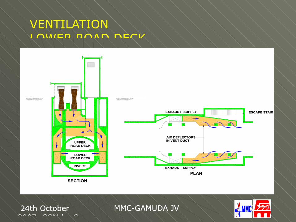
VENTILATION LOWER ROAD DECK
LOWER
INVERT
ROAD DECK
UPPERROAD DECK
EXHAUST SUPPLY
EXHAUST SUPPLY
ESCAPE STAIR
AIR DEFLECTORSIN VENT DUCT
PLAN
SECTION
24th October 2007, GSM by Gus
MMC-GAMUDA JV ITA-AITES WTC 2009
MMC-GAMUDA JV 2323
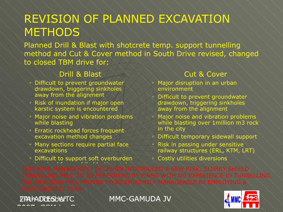
REVISION OF PLANNED EXCAVATION METHODS
Drill & Blasto Difficult to prevent groundwater
drawdown, triggering sinkholes away from the alignment
o Risk of inundation if major open karstic system is encountered
o Major noise and vibration problems while blasting
o Erratic rockhead forces frequent excavation method changes
o Many sections require partial face excavations
o Difficult to support soft overburden in mixed faces while blasting rock
Cut & Covero Major disruption in an urban
environmento Difficult to prevent groundwater
drawdown, triggering sinkholes away from the alignment
o Major noise and vibration problems while blasting over 1million m3 rock in the city
o Difficult temporary sidewall supporto Risk in passing under sensitive
railway structures (ERL, KTM, LRT)o Costly utilities diversions
Planned Drill & Blast with shotcrete temp. support tunnelling method and Cut & Cover method in South Drive revised, changed to closed TBM drive for:
THIS RISK MANAGEMENT DECISION INTRODUCED A NEW RISK; SLURRY SHIELD TUNNELLING WAS TO BE PERFORMED BY FIRMS WITH NO EXPERIENCE IN TUNNELLING. THE NEW RISK WAS PROVED TO BE EMINENTLY MANAGEABLE BY EMPLOYING A PROFESSIONAL TEAM.
ITA2009 BudapestGus Klados
BKV-DBR Metro ITA-AITES WTC 2009
MMC-GAMUDA JV 2424
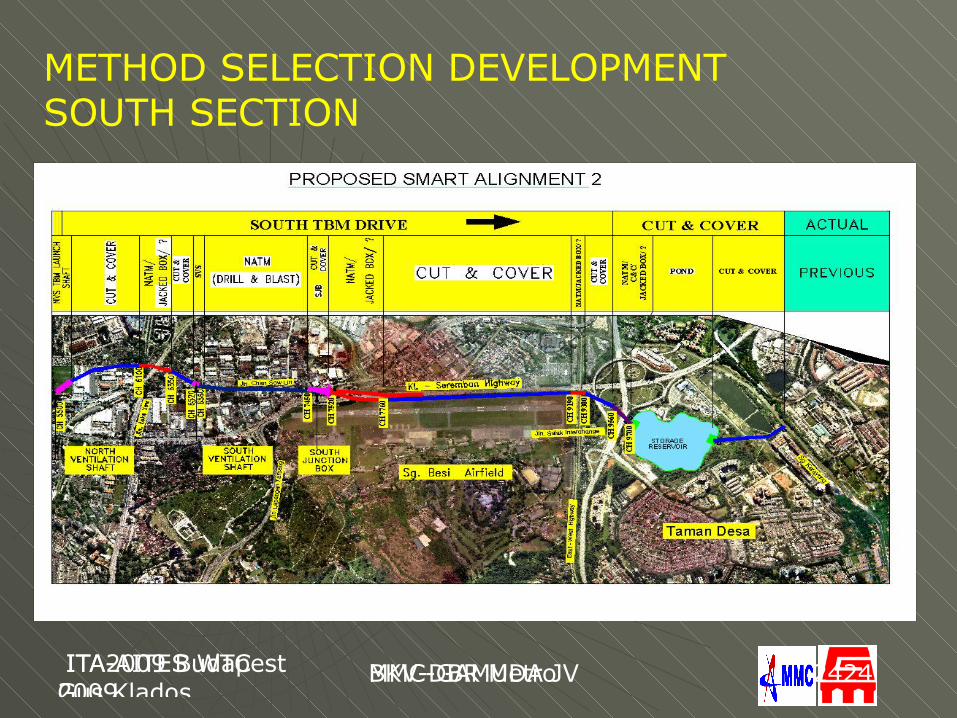
METHOD SELECTION DEVELOPMENTSOUTH SECTION
ITA2009 BudapestGus Klados
BKV-DBR Metro ITA-AITES WTC 2009
MMC-GAMUDA JV 2525
METHOD SELECTION DEVELOPMENT NORTH SECTION
24th October 2007, GSM by Gus
MMC-GAMUDA JV ITA-AITES WTC 2009
MMC-GAMUDA JV 2626
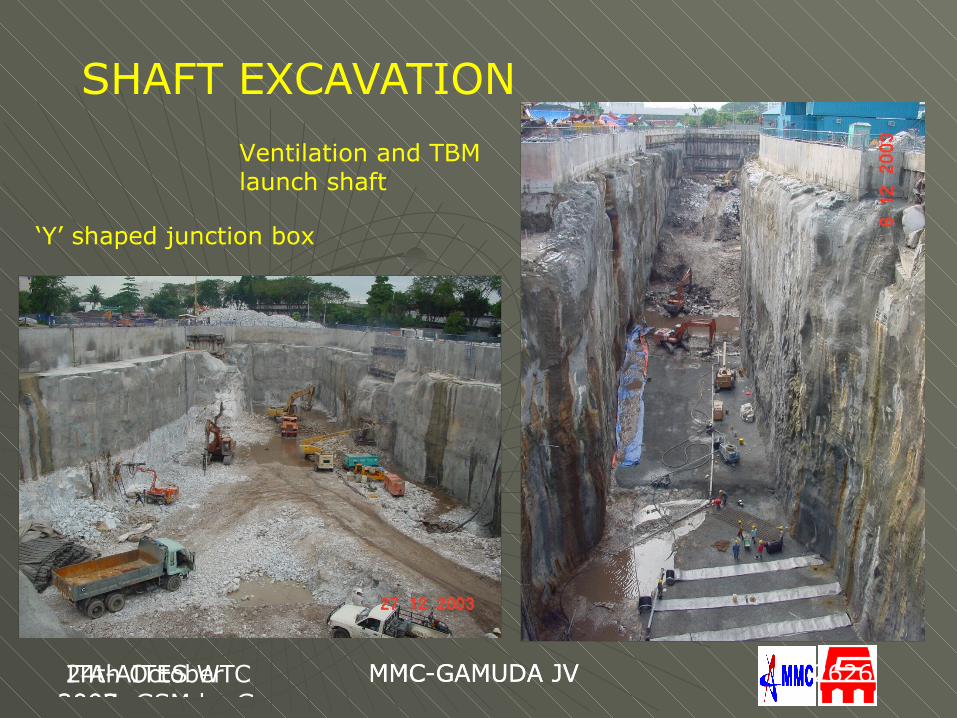
SHAFT EXCAVATIONVentilation and TBM launch shaft
‘Y’ shaped junction box
ITA2009 BudapestGus Klados
BKV-DBR Metro ITA-AITES WTC 2009
MMC-GAMUDA JV 2727
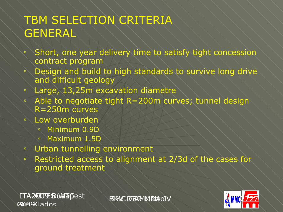
TBM SELECTION CRITERIAGENERALo Short, one year delivery time to satisfy tight concession
contract programo Design and build to high standards to survive long drive
and difficult geologyo Large, 13,25m excavation diametreo Able to negotiate tight R=200m curves; tunnel design
R=250m curveso Low overburden
o Minimum 0.9Do Maximum 1.5D
o Urban tunnelling environmento Restricted access to alignment at 2/3d of the cases for
ground treatment
ITA2009 BudapestGus Klados
BKV-DBR Metro ITA-AITES WTC 2009
MMC-GAMUDA JV 2828
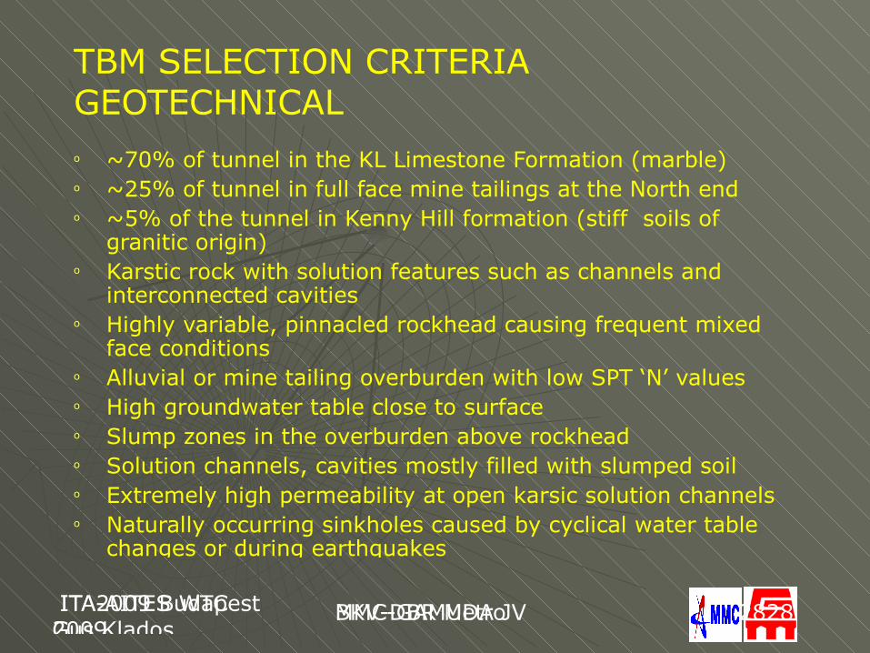
TBM SELECTION CRITERIAGEOTECHNICALo ~70% of tunnel in the KL Limestone Formation (marble)o ~25% of tunnel in full face mine tailings at the North endo ~5% of the tunnel in Kenny Hill formation (stiff soils of
granitic origin)o Karstic rock with solution features such as channels and
interconnected cavitieso Highly variable, pinnacled rockhead causing frequent mixed
face conditionso Alluvial or mine tailing overburden with low SPT ‘N’ valueso High groundwater table close to surface o Slump zones in the overburden above rockheado Solution channels, cavities mostly filled with slumped soilo Extremely high permeability at open karsic solution channelso Naturally occurring sinkholes caused by cyclical water table
changes or during earthquakes
ITA2009 BudapestGus Klados
BKV-DBR Metro ITA-AITES WTC 2009
MMC-GAMUDA JV 2929
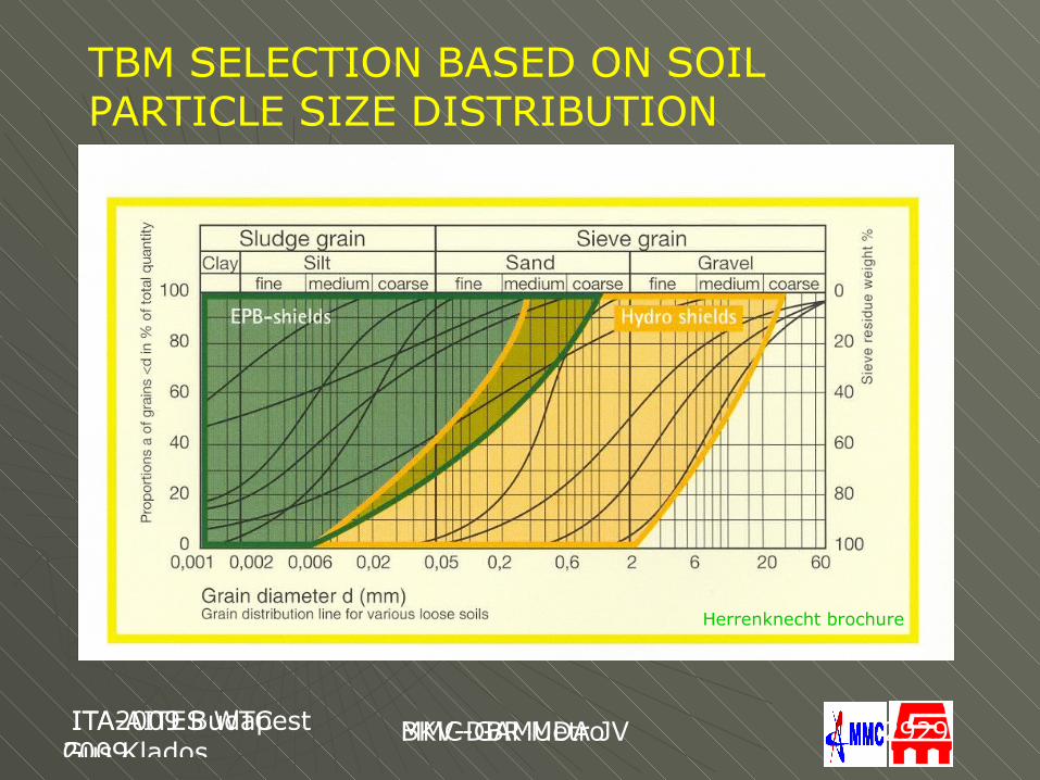
TBM SELECTION BASED ON SOIL PARTICLE SIZE DISTRIBUTION
Herrenknecht brochure
ITA2009 BudapestGus Klados
BKV-DBR Metro ITA-AITES WTC 2009
MMC-GAMUDA JV 3030
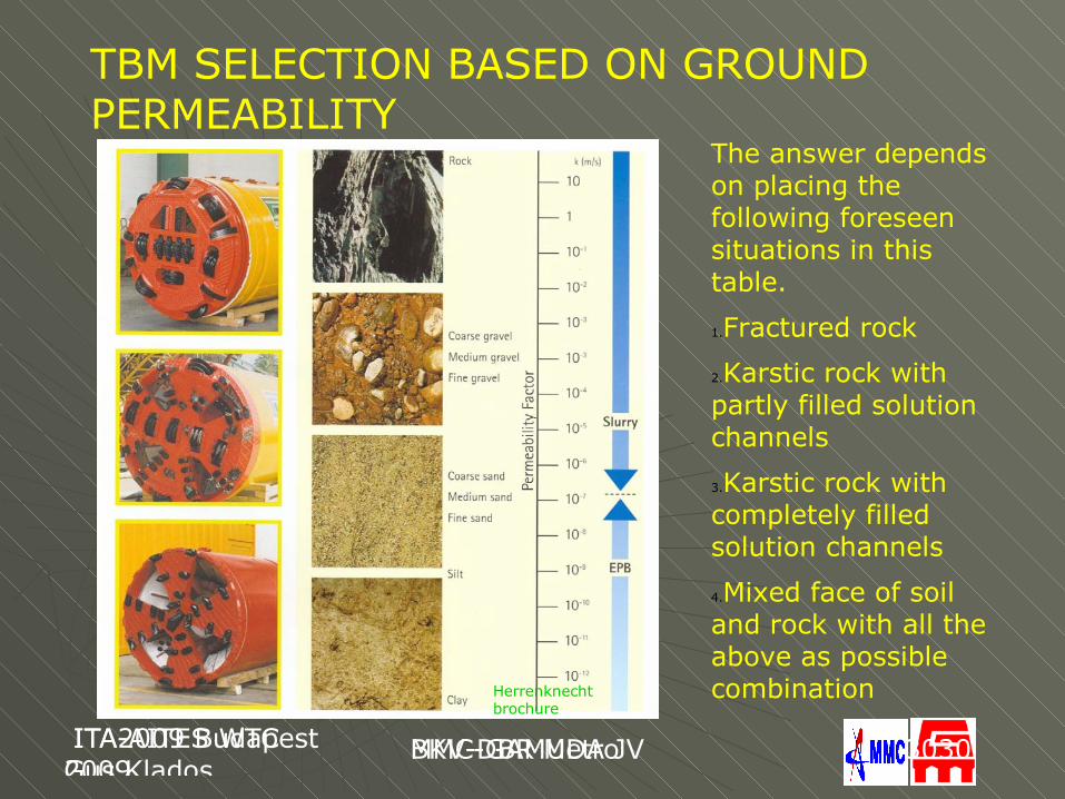
TBM SELECTION BASED ON GROUND PERMEABILITY
The answer depends on placing the following foreseen situations in this table.
1.Fractured rock
2.Karstic rock with partly filled solution channels
3.Karstic rock with completely filled solution channels
4.Mixed face of soil and rock with all the above as possible combinationHerrenknecht
brochure
ITA2009 BudapestGus Klados
BKV-DBR Metro ITA-AITES WTC 2009
MMC-GAMUDA JV 3131
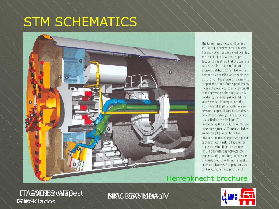
STM SCHEMATICS
Herrenknecht brochure
24th October 2007, GSM by Gus
MMC-GAMUDA JV ITA-AITES WTC 2009
MMC-GAMUDA JV 3232
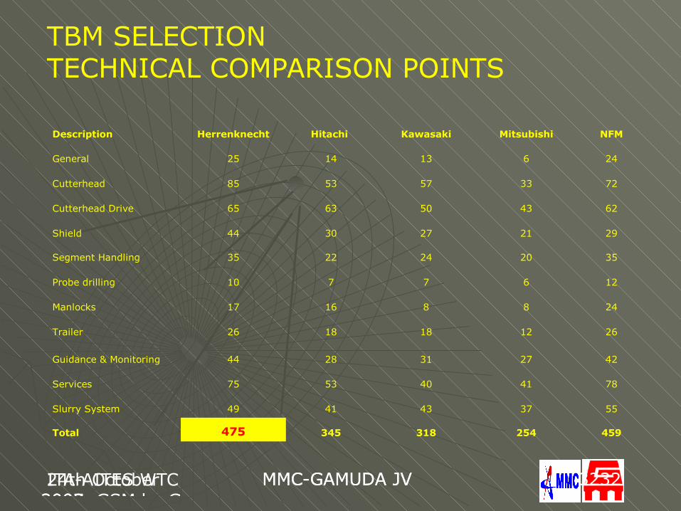
TBM SELECTIONTECHNICAL COMPARISON POINTS
Description Herrenknecht Hitachi Kawasaki Mitsubishi NFM
General 25 14 13 6 24
Cutterhead 85 53 57 33 72
Cutterhead Drive 65 63 50 43 62
Shield 44 30 27 21 29
Segment Handling 35 22 24 20 35
Probe drilling 10 7 7 6 12
Manlocks 17 16 8 8 24
Trailer 26 18 18 12 26
Guidance & Monitoring 44 28 31 27 42
Services 75 53 40 41 78
Slurry System 49 41 43 37 55
Total 475 345 318 254 459
24th October 2007, GSM by Gus
MMC-GAMUDA JV ITA-AITES WTC 2009
MMC-GAMUDA JV 3333
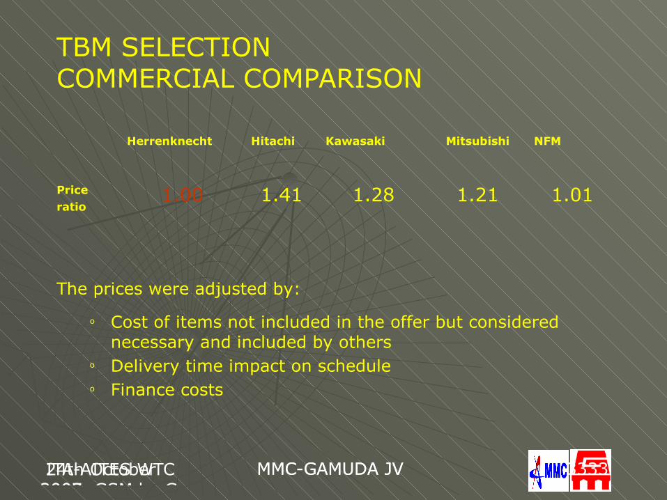
TBM SELECTIONCOMMERCIAL COMPARISON
The prices were adjusted by:
o Cost of items not included in the offer but considered necessary and included by others
o Delivery time impact on scheduleo Finance costs
Herrenknecht Hitachi Kawasaki Mitsubishi NFM
Price ratio
1.00 1.41 1.28 1.21 1.01
ITA2009 BudapestGus Klados
BKV-DBR Metro ITA-AITES WTC 2009
MMC-GAMUDA JV 3434
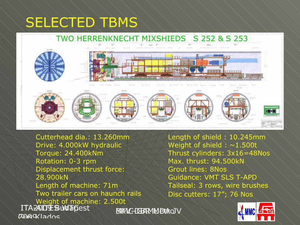
SELECTED TBMSS 252 & S 253
Cutterhead dia.: 13.260mmDrive: 4.000kW hydraulicTorque: 24.400kNmRotation: 0-3 rpmDisplacement thrust force: 28.900kNLength of machine: 71mTwo trailer cars on haunch railsWeight of machine: 2.500t
Length of shield : 10.245mmWeight of shield : ~1.500tThrust cylinders: 3x16=48NosMax. thrust: 94.500kNGrout lines: 8Nos Guidance: VMT SLS T-APDTailseal: 3 rows, wire brushesDisc cutters: 17”; 76 Nos
TWO HERRENKNECHT MIXSHIEDS
ITA2009 BudapestGus Klados
BKV-DBR Metro ITA-AITES WTC 2009
MMC-GAMUDA JV 3535
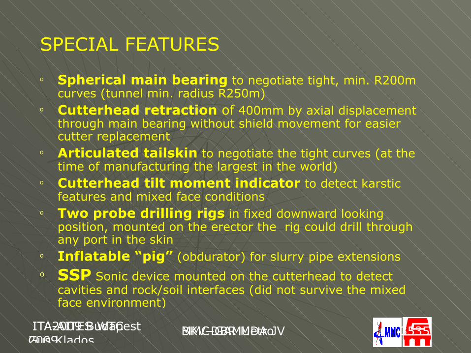
SPECIAL FEATURES
o Spherical main bearing to negotiate tight, min. R200m curves (tunnel min. radius R250m)
o Cutterhead retraction of 400mm by axial displacement through main bearing without shield movement for easier cutter replacement
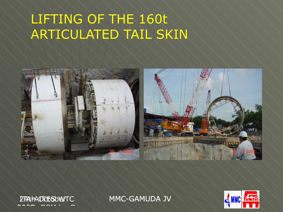
o Articulated tailskin to negotiate the tight curves (at the time of manufacturing the largest in the world)
o Cutterhead tilt moment indicator to detect karstic features and mixed face conditions
o Two probe drilling rigs in fixed downward looking position, mounted on the erector the rig could drill through any port in the skin
o Inflatable “pig” (obdurator) for slurry pipe extensionso SSP Sonic device mounted on the cutterhead to detect
cavities and rock/soil interfaces (did not survive the mixed face environment)
24th October 2007, GSM by Gus
MMC-GAMUDA JV ITA-AITES WTC 2009
MMC-GAMUDA JV 3636
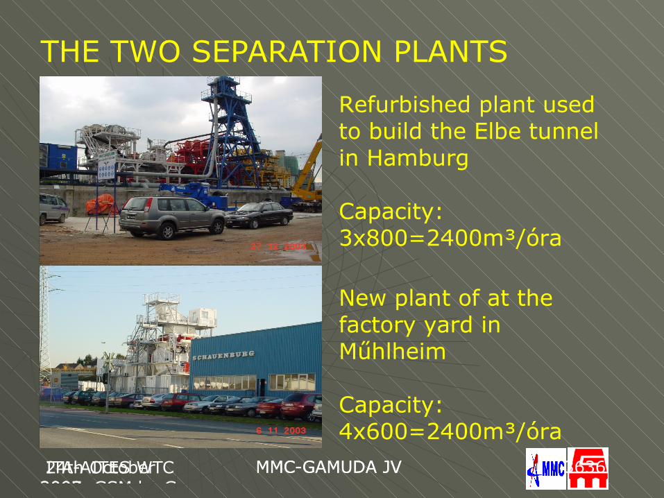
THE TWO SEPARATION PLANTS
New plant of at the factory yard in Műhlheim
Capacity:4x600=2400m³/óra
Refurbished plant used to build the Elbe tunnel in Hamburg
Capacity:3x800=2400m³/óra
24th October 2007, GSM by Gus
MMC-GAMUDA JV ITA-AITES WTC 2009
MMC-GAMUDA JV 3737
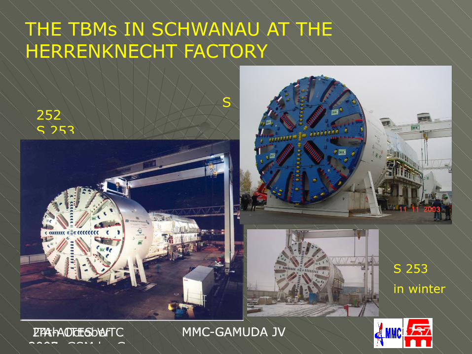
THE TBMs IN SCHWANAU AT THE HERRENKNECHT FACTORY
S 252S 253
S 253
in winter
24th October 2007, GSM by Gus
MMC-GAMUDA JV ITA-AITES WTC 2009
MMC-GAMUDA JV 3838
LIFTING OF THE 160t ARTICULATED TAIL SKIN
24th October 2007, GSM by Gus
MMC-GAMUDA JV ITA-AITES WTC 2009
MMC-GAMUDA JV 3939
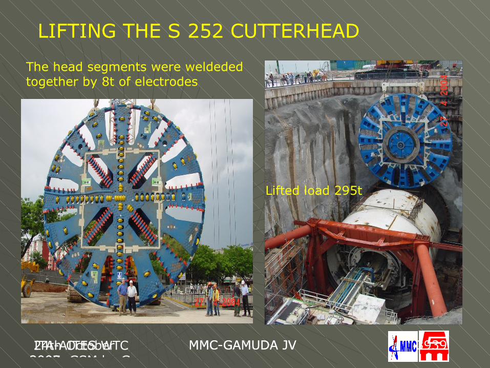
LIFTING THE S 252 CUTTERHEAD
The head segments were weldeded together by 8t of electrodes
Lifted load 295t
ITA-AITES WTC2009BUDAPEST by Gus
BKV – DBR Metro ITA-AITES WTC 2009 Budapest Gus Klados
MMC-GAMUDA JV 4040
BREAKTHROUGH, NORTH DRIVE
ITA-AITES WTC2009BUDAPEST by Gus
BKV – DBR Metro ITA-AITES WTC 2009 Budapest Gus Klados
MMC-GAMUDA JV 4141
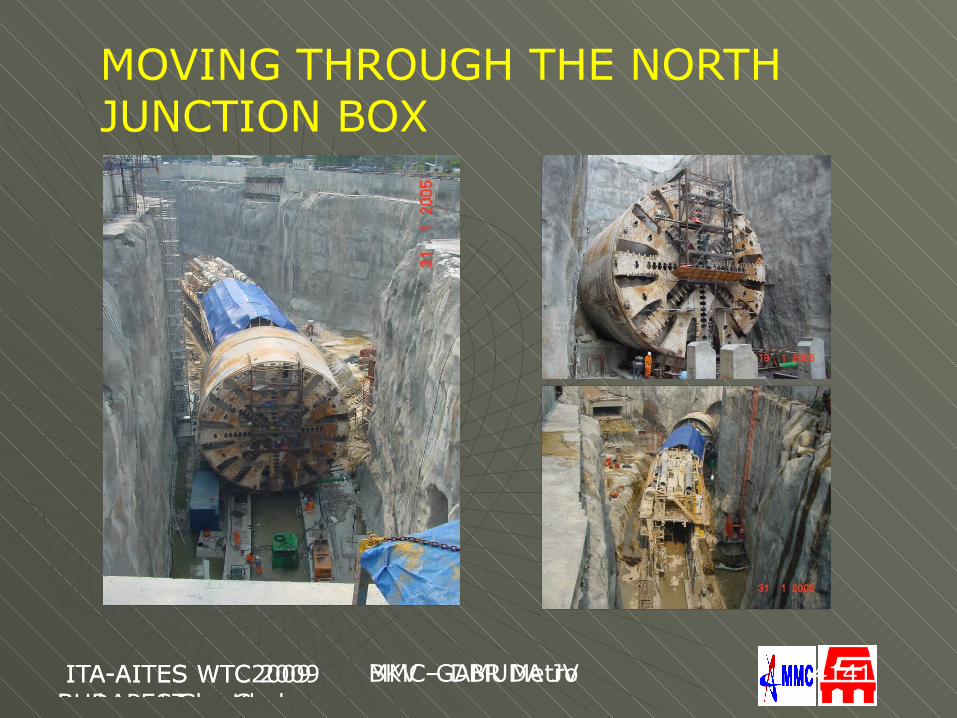
MOVING THROUGH THE NORTH JUNCTION BOX
ITA-AITES WTC2009BUDAPEST by Gus
BKV – DBR Metro ITA-AITES WTC 2009 Budapest Gus Klados
MMC-GAMUDA JV 4242
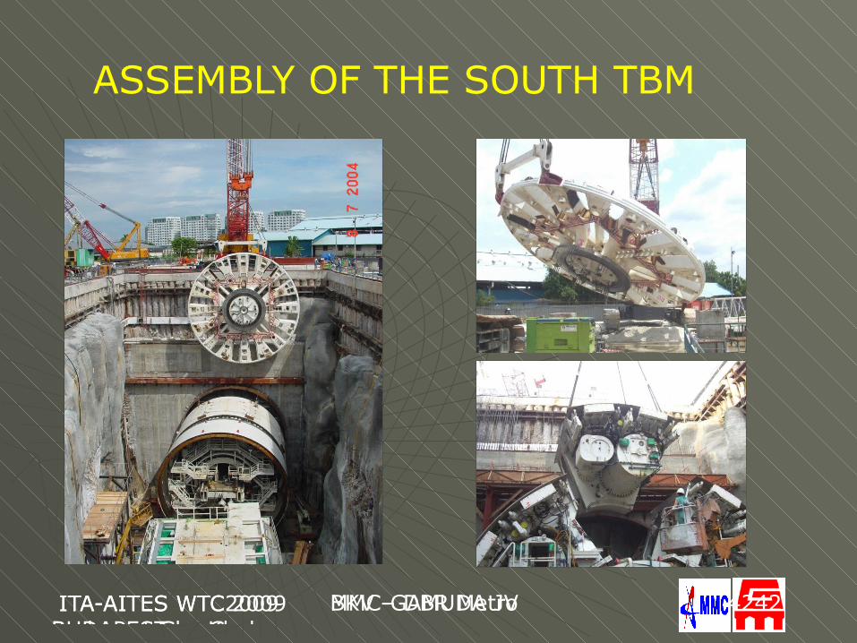
ASSEMBLY OF THE SOUTH TBM
ITA2009 BudapestGus Klados
BKV-DBR Metro ITA-AITES WTC 2009
MMC-GAMUDA JV 4343
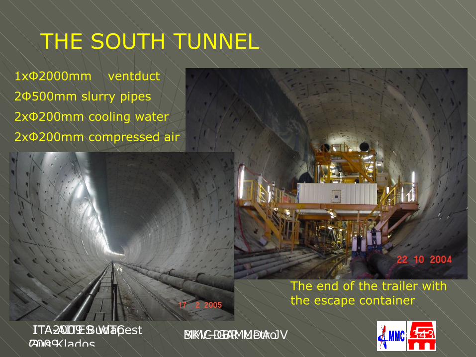
THE SOUTH TUNNEL
The end of the trailer with the escape container
1xΦ2000mm ventduct
2Φ500mm slurry pipes
2xΦ200mm cooling water
2xΦ200mm compressed air
ITA-AITES WTC2009BUDAPEST by Gus
BKV – DBR Metro ITA-AITES WTC 2009 Budapest Gus Klados
MMC-GAMUDA JV 4444
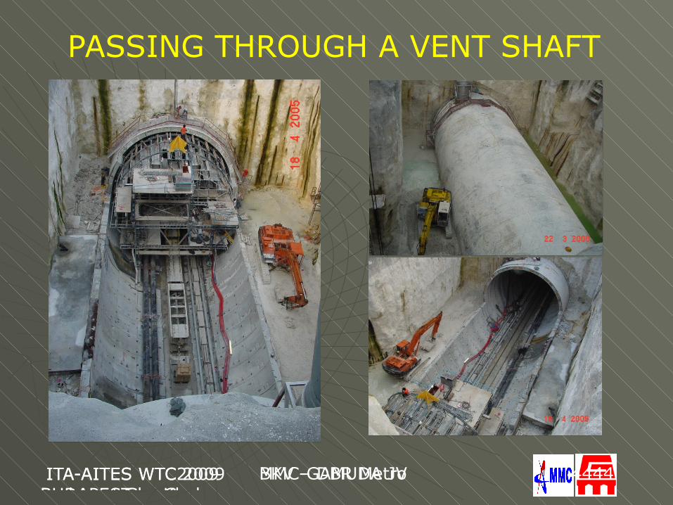
PASSING THROUGH A VENT SHAFT
24th October 2007, GSM by Gus
MMC-GAMUDA JV ITA-AITES WTC 2009
MMC-GAMUDA JV 4545
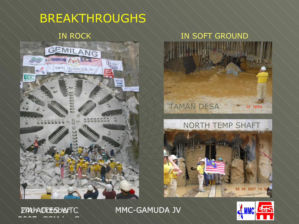
BREAKTHROUGHS IN ROCK IN SOFT GROUND
TAMAN DESA
NORTH TEMP SHAFT
24th October 2007, GSM by Gus
MMC-GAMUDA JV ITA-AITES WTC 2009
MMC-GAMUDA JV 4646
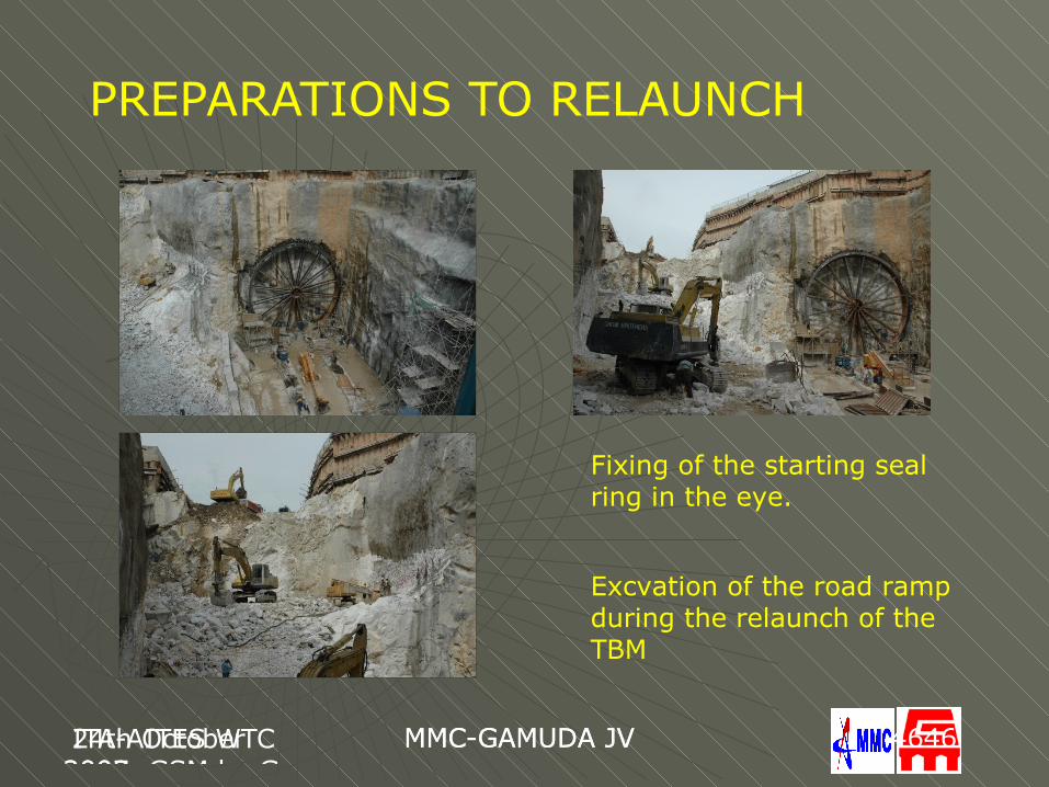
PREPARATIONS TO RELAUNCH
Fixing of the starting seal ring in the eye.
Excvation of the road ramp during the relaunch of the TBM
24th October 2007, GSM by Gus
MMC-GAMUDA JV 24th October 2007, GSM by Gus
MMC-GAMUDA JV 4747
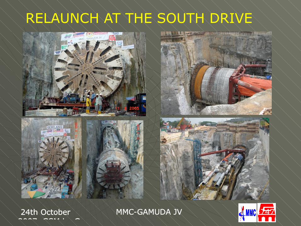
RELAUNCH AT THE SOUTH DRIVE
ITA2009 BudapestGus Klados
BKV-DBR Metro ITA-AITES WTC 2009
MMC-GAMUDA JV 4848
SOUTH DRIVE PRODUCTION SUMMARY
24th October 2007, GSM by Gus
MMC-GAMUDA JV ITA-AITES WTC 2009
MMC-GAMUDA JV 4949
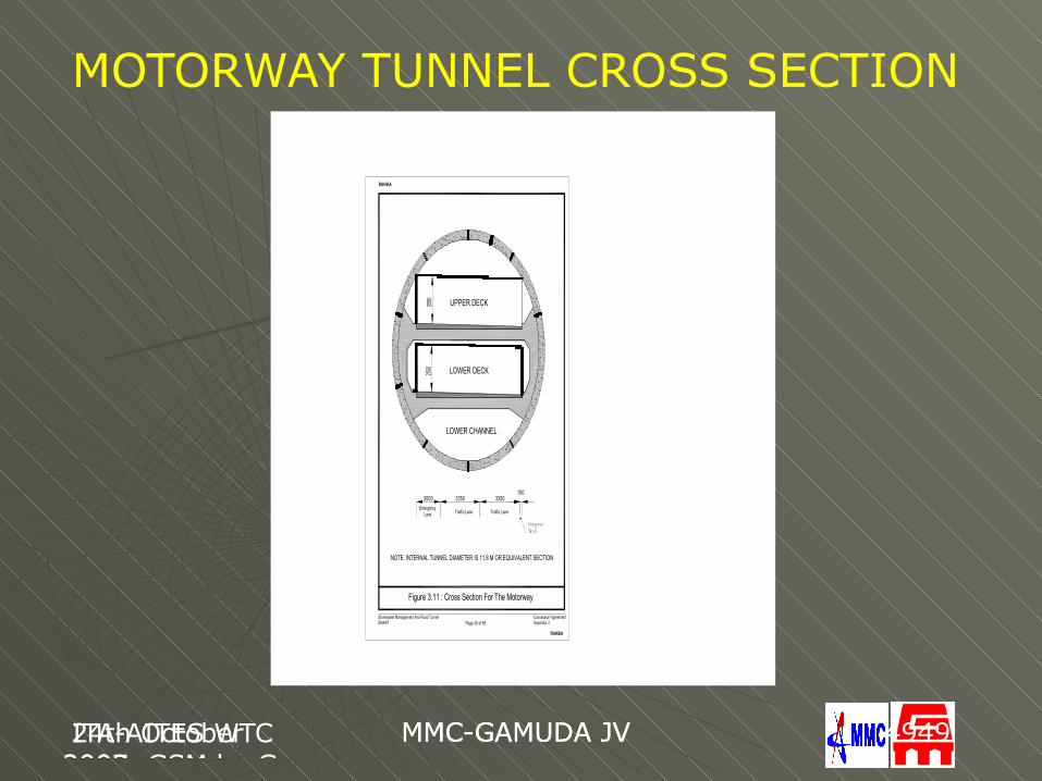
Figure 3.11 : Cross Section For The Motorway
NOTE: INTERNAL TUNNEL DIAMETER IS 11.8 M OR EQUIVALENT SECTION
Appendix 3Concession AgreementStormwater Management And Road Tunnel
SMART Page 30 of 56
2550
Traffic LaneTraffic LaneEmergency
Lane
2550
2000 3350 3350150
LOWER CHANNEL
LOWER DECK
UPPER DECK
RAHSIA
RAHSIA
MOTORWAY TUNNEL CROSS SECTION
24th October 2007, GSM by Gus
MMC-GAMUDA JV ITA-AITES WTC 2009
MMC-GAMUDA JV 5050
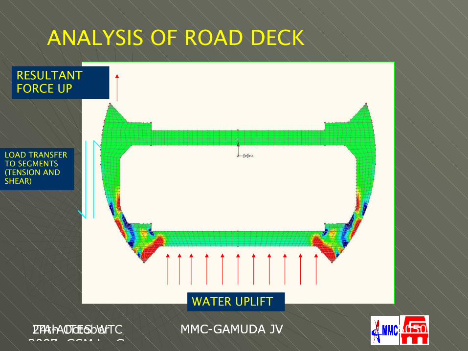
ANALYSIS OF ROAD DECK
LOAD TRANSFER TO SEGMENTS (TENSION AND SHEAR)
RESULTANT FORCE UP
WATER UPLIFT
ITA2009 BudapestGus Klados
BKV-DBR Metro ITA-AITES WTC 2009
MMC-GAMUDA JV 5151
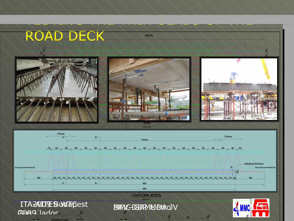
TESTING THE THIN SLABS OF THE ROAD DECK
350
175 175175
350
175175
350
175175
350
175175
350
175175
350
175175
350
175175
350
175175
350
175175
350
175175
350
175 175
350
175 175
350
175 175
350
175 175
350
175 175
350
175 175
350
175 175
350
175
350 175175
A
A
250 12
512
5
PLAN
LONGITUDINAL SECTIONSCALE 1:12.5
SCALE 1:12.5
G40N (Slump 150+/-25mm)
40
T12 Links
2T16 Links2T16 Links
B
B
100
1625
1625
125 125 1025
6550
6550
125
125
125
125
125
125
125
125
125
125
125
125
8600 (T25)
1025
8600
25mm Coupler (Lower Main Bars Only) 25mm Coupler (Lower Main Bars Only)
Ø25
SECTION A-ASCALE 1:5
Ø25
Ø32
Ø25
250 375 250 375 250
12Ø
40
12Ø
Ø25
12Ø12Ø
Ø32
12Ø12Ø
2T16 2T16 2T16
25
2525
25
TOP SURFACE TO HAVE ROUGHENED & EXPOSED AGGREGATES
441.5
125
625
100
1625
510
Ø25
SECTION B-BSCALE 1:5
Ø25
Ø25
250 375 250 375 250
Ø12 12Ø40
100
12Ø
2525
25
25
TOP SURFACE TO HAVE ROUGHENED & EXPOSED AGGREGATES
Ø32
Ø12 12Ø
12Ø
Ø32
Ø12 12Ø
12Ø
441.5
625
1625
510
FILIGRI SLAB UPPER DECK (STANDARD)GRIDER REINFORCEMENTKenny Lim Yeoh HK
25 August 2004 25 August 2004 SMART/MGJV/TUNNEL/FILIGRI SLAB /0002A
A23/8/04 1. Height of girder bars extended to 441.5mm c/c 2. Top middle main bar change from T32 to T25 3. Bottom main bar length 8.6m 4. Top main bars (T32 & T25) extended to 8.6m 5. Lower Main Bars Fitted 25mm Coupler A
ITA2009 BudapestGus Klados
BKV-DBR Metro ITA-AITES WTC 2009
MMC-GAMUDA JV 5252
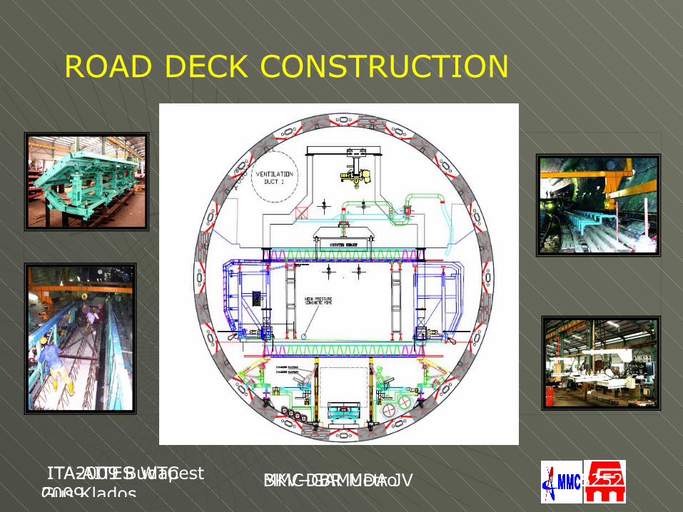
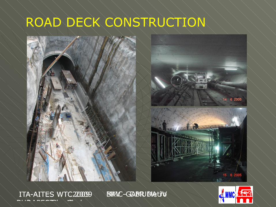
ROAD DECK CONSTRUCTION
ITA-AITES WTC2009BUDAPEST by Gus
BKV – DBR Metro ITA-AITES WTC 2009 Budapest Gus Klados
MMC-GAMUDA JV 5353
ROAD DECK CONSTRUCTION
ITA-AITES WTC2009BUDAPEST by Gus
BKV – DBR Metro ITA-AITES WTC 2009 Budapest Gus Klados
MMC-GAMUDA JV 5454
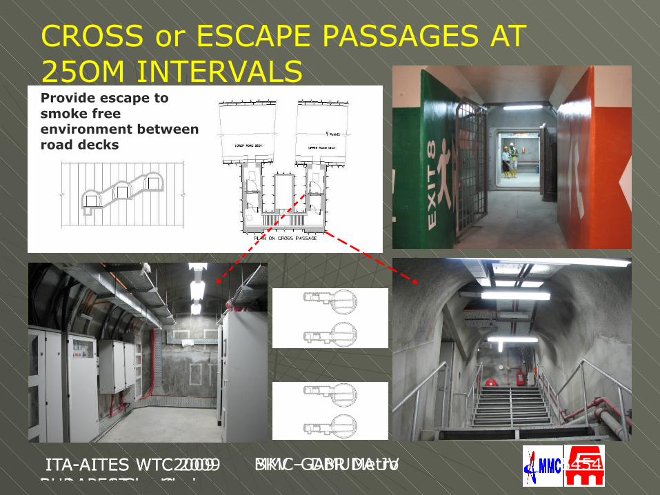
CROSS or ESCAPE PASSAGES AT 25OM INTERVALSProvide escape to smoke free environment between road decks
ITA-AITES WTC2009BUDAPEST by Gus
BKV – DBR Metro ITA-AITES WTC 2009 Budapest Gus Klados
MMC-GAMUDA JV 5555
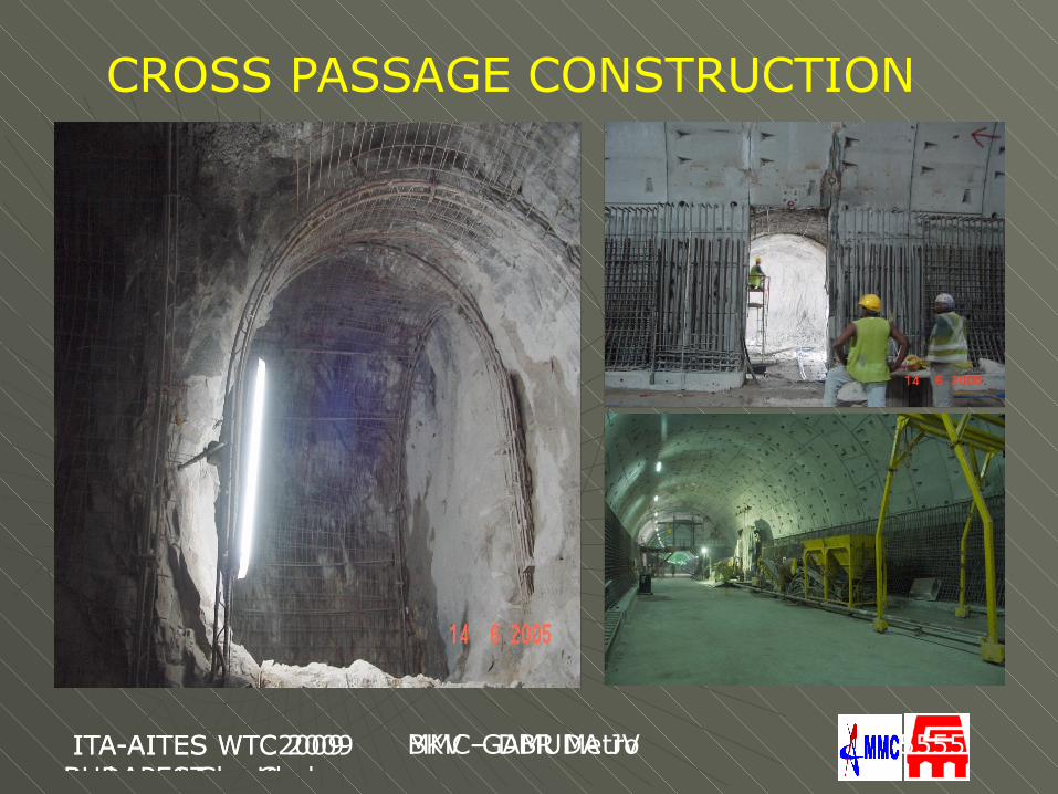
CROSS PASSAGE CONSTRUCTION
ITA2009 BudapestGus Klados
BKV-DBR Metro ITA-AITES WTC 2009
MMC-GAMUDA JV 5656
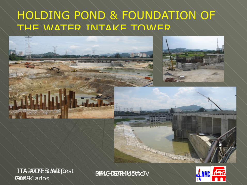
HOLDING POND & FOUNDATION OF THE WATER INTAKE TOWER
ITA2009 BudapestGus Klados
BKV-DBR Metro ITA-AITES WTC 2009
MMC-GAMUDA JV 5757
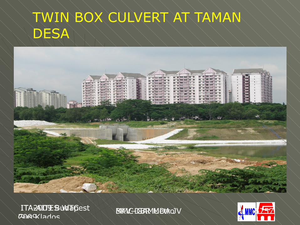
TWIN BOX CULVERT AT TAMAN DESA
24th October 2007, GSM by Gus
MMC-GAMUDA JV ITA-AITES WTC 2009
MMC-GAMUDA JV 5858
TIME-CHAINAGE DIAGRAM SOUTH TUNNEL
ITA2009 BudapestGus Klados
BKV-DBR Metro ITA-AITES WTC 2009
MMC-GAMUDA JV 5959
TIME CHAINAGE DIAGRAMNORTH TUNNEL
24th October 2007, GSM by Gus
MMC-GAMUDA JV ITA-AITES WTC 2009
MMC-GAMUDA JV 6060
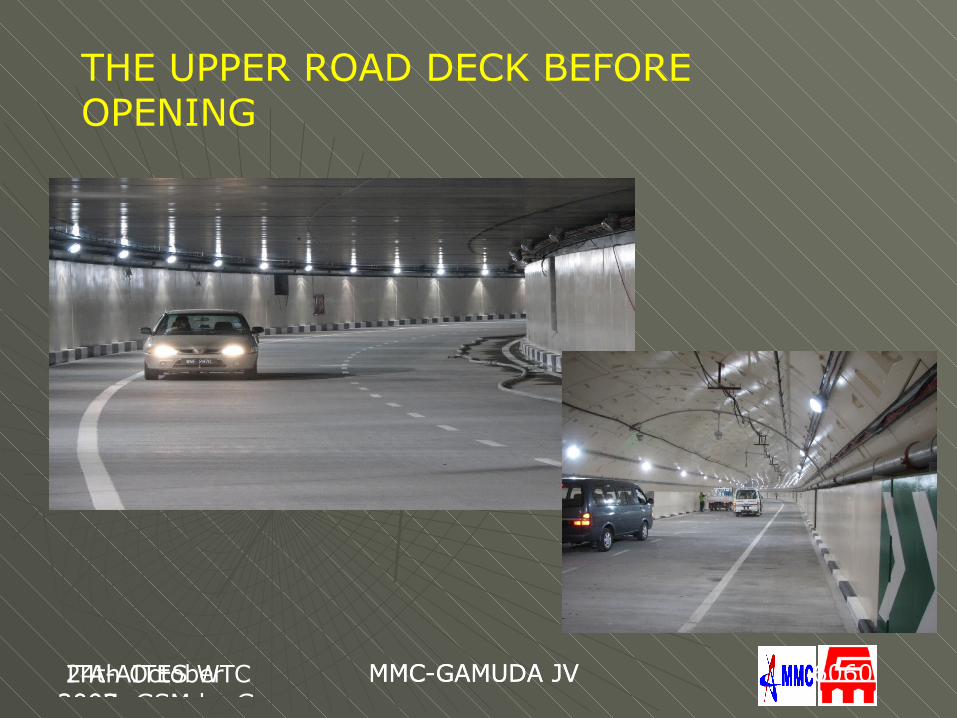
THE UPPER ROAD DECK BEFORE OPENING
ITA2009 BudapestGus Klados
BKV-DBR Metro ITA-AITES WTC 2009
ex. MMC-GAMUDA JV.BKV-DBR Metro
6161
THANK YOU
FOR YOUR PATIENCE