ssigl 13: irrigation pump facilities study and design
TRANSCRIPT

NATIONAL GUIDELINES
For Small Scale Irrigation Development in Ethiopia
November 2018
Irrigation Pump Facilities Study and Design
SSIGL 13
Addis Ababa

MINISTRY OF AGRICULTURE
National Guidelines for Small Scale Irrigation Development in Ethiopia
SSIGL 13: Irrigation Pump Facilities Study and Design
November 2018
Addis Ababa

National Guidelines for Small Scale Irrigation Development in Ethiopia
First Edition 2018
© MOA 2018
Ministry of Agriculture
Small-Scale Irrigation Development Directorate
P. O. Box 62347
Tel: +251-1-6462355
Fax: +251-1-6462355
Email: [email protected]
eDMS (intranet): MoA SSID DMS (http://172.28.1.188:8080/DMS/login.jsp)
Website: www.moa.gov.et
Financed by Agricultural Growth Program (AGP)
DISCLAIMER
Ministry of Agriculture through the Consultant and core reviewers from all relevant stakeholders included the
information to provide the contemporary approach about the subject matter. The information contained in the
guidelines is obtained from sources believed tested and reliable and are augmented based on practical
experiences. While it is believed that the guideline is enriched with professional advice, for it to be
successful, needs services of competent professionals from all respective disciplines. It is believed, the
guidelines presented herein are sound and to the expected standard. However, we hereby disclaim any
liability, loss or risk taken by individuals, groups, or organization who does not act on the information
contained herein as appropriate to the specific SSI site condition.
National Guidelines for Small Scale Irrigation Development MOA
SSIGL 13: Irrigation Pump Facilities Study and Design i
FORWARD
Ministry of Agriculture, based on the national strategic directions is striving to meet its commitments in which modernizing agriculture is on top of its highest priorities to sustain the rapid, broad-based and fair economic growth and development of the country. To date, major efforts have been made to remodel several important strategies and national guidelines by its major programs and projects. While efforts have been made to create access to irrigation water and promoting sustainable irrigation development, several barriers are still hindering the implementation process and the performance of the schemes. The major technical constrains starts from poor planning and identification, study, design, construction, operation, and maintenance. One of the main reasons behind this outstanding challenge, in addition to the capacity limitations, is that SSIPs have been studied and designed using many ad-hoc procedures and technical guidelines developed by various local and international institutions. Despite having several guidelines and manuals developed by different entities such as MoA (IDD)-1986, ESRDF-1997, MoWIE-2002 and JICA/OIDA-2014, still the irrigation professionals follow their own public sources and expertise to fill some important gaps. A number of disparities, constraints and outstanding issues in the study and design procedures, criteria and assumptions have been causing huge variations in all vital aspects of SSI study, design and implementation from region to region and among professionals within the same region and institutions due mainly to the lack of agreed standard technical guidelines. Hence, the SSI Directorate with AGP financial support, led by Generation consultant (GIRDC) and with active involvement of national and regional stakeholders and international development partners, these new and comprehensive national guidelines have been developed. The SSID guidelines have been developed by addressing all key features in a comprehensive and participatory manner at all levels. The guidelines are believed to be responsive to the prevalent study and design contentious issues; and efforts have been made to make the guidelines simple, flexible and adaptable to almost all regional contexts including concerned partner institution interests. The outlines of the guidelines cover all aspects of irrigation development including project initiation, planning, organizations, site identification and prioritization, feasibility studies and detail designs, contract administration and management, scheme operation, maintenance and management. Enforceability, standardization, social and environmental safeguard mechanisms are well mainstreamed in the guidelines, hence they shall be used as a guiding framework for engineers and other experts engaged in all SSI development phases. The views and actual procedures of all relevant diverse government bodies, research and higher learning institutions, private companies and development partners has been immensely and thoroughly considered to ensure that all stakeholders are aligned and can work together towards a common goal. Appropriately, the guidelines will be familiarized to the entire stakeholders working in the irrigation development. Besides, significant number of experts in the corresponding subject matter will be effectively trained nationwide; and the guidelines will be tested practically on actual new and developing projects for due consideration of possible improvement. Hence, hereinafter, all involved stakeholders including government & non-governmental organizations, development partners, enterprises, institutions, consultants and individuals in Ethiopia have to adhere to these comprehensive national guidelines in all cases and at all level whilst if any overlooked components are found, it should be documented and communicated to MOA to bring them up-to-date. Therefore, I congratulate all parties involved in the success of this effort, and urge partners and stakeholders to show a similar level of engagement in the implementation and stick to the guidelines over the coming years.
H.E. Dr. Kaba Urgessa State Minister, Ministry of Agriculture
National Guidelines for Small Scale Irrigation Development MOA
SSIGL 13: Irrigation Pump Facilities Study and Design ii
SMALL SCALE IRRIGATION DEVELOPMENT VISION
Transforming agricultural production from its dependence on rain-fed practices by creating reliable irrigation
system in which smallholder farmers have access to at least one option of water source to increase
production and productivity as well as enhance resilience to climate change and thereby ensure food
security, maintain increasing income and sustain economic growth.

National Guidelines for Small Scale Irrigation Development MOA
SSIGL 13: Irrigation Pump Facilities Study and Design iii
ACKNOWLEDGEMENTS
The preparation of SSIGLs required extensive inputs from all stakeholders and development partners.
Accordingly many professionals from government and development partners have contributed to the
realization of the guidelines. To this end MOA would like to extend sincere acknowledgement to all
institutions and individuals who have been involved in the review of these SSIGLs for their
comprehensive participation, invaluable inputs and encouragement to the completion of the guidelines.
There are just too many collaborators involved to name exhaustively and congratulate individually, as
many experts from Federal, regional states and development partners have been involved in one way
or another in the preparation of the guidelines. The contribution of all of them who actively involved in
the development of these SSIGLs is gratefully acknowledged. The Ministry believes that their
contributions will be truly appreciated by the users for many years to come.
The Ministry would like to extend its appreciation and gratitude to the following contributors:
Agriculture Growth Program (AGP) of the MoA for financing the development and publication of the guidelines.
The National Agriculture Water Management Platform (NAWMP) for overseeing, guidance and playing key supervisory and quality control roles in the overall preparation process and for the devotion of its members in reviewing and providing invaluable technical inputs to enrich the guidelines.
Federal Government and Regional States organizations and their staff for their untiring effort in reviewing the guidelines and providing constructive suggestions, recommendations and comments.
National and international development partners for their unreserved efforts in reviewing the guidelines and providing constructive comments which invaluably improved the quality of the guidelines.
Small-scale and Micro Irrigation Support Project (SMIS) and its team for making all efforts to have quality GLs developed as envisioned by the Ministry.
The MOA would also like to extend its high gratitude and sincere thanks to AGP‟s multi development
partners including the International Development Association (IDA)/World Bank, the Canada
Department of Foreign Affairs, Trade and Development (DFATD), the United States Agency for
International Development (USAID), the Netherlands, the European Commission (EC), the Spanish
Agency for International Development (AECID), the Global Agriculture and Food Security Program
(GAFSP), the Italy International Development Cooperation, the Food and Agriculture Organization
(FAO) and the United Nations Development Program (UNDP).
Moreover, the Ministry would like to express its gratitude to Generation Integrated Rural Development
Consultant (GIRDC) and its staff whose determined efforts to the development of these SSIGLs have
been invaluable. GIRDC and its team drafted and finalized all the contents of the SSIGLs as per
stakeholder suggestions, recommendations and concerns. The MoA recognizes the patience,
diligence, tireless, extensive and selfless dedication of the GIRDC and its staff who made this
assignment possible.
Finally, we owe courtesy to all national and International source materials cited and referred but
unintentionally not cited.
Ministry of Agriculture
National Guidelines for Small Scale Irrigation Development MOA
SSIGL 13: Irrigation Pump Facilities Study and Design iv
DEDICATIONS
The National Guidelines for Small Scale Irrigation Development are dedicated to Ethiopian smallholder
farmers, agro-pastoralists, pastoralists, to equip them with appropriate irrigation technology as we envision
them empowered and transformed.
National Guidelines for Small Scale Irrigation Development MOA
SSIGL 13: Irrigation Pump Facilities Study and Design v
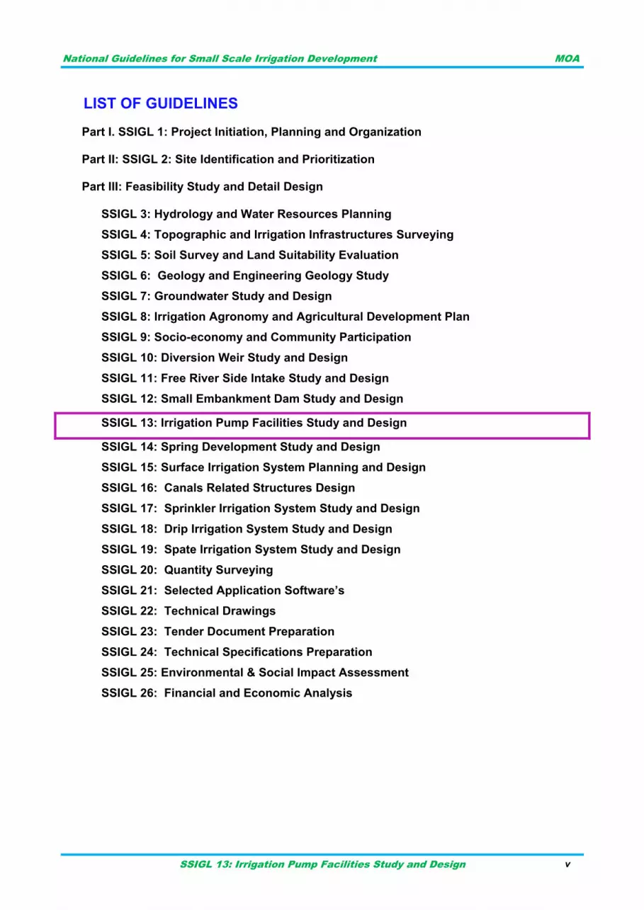
LIST OF GUIDELINES
Part I. SSIGL 1: Project Initiation, Planning and Organization
Part II: SSIGL 2: Site Identification and Prioritization
Part III: Feasibility Study and Detail Design
SSIGL 3: Hydrology and Water Resources Planning
SSIGL 4: Topographic and Irrigation Infrastructures Surveying
SSIGL 5: Soil Survey and Land Suitability Evaluation
SSIGL 6: Geology and Engineering Geology Study
SSIGL 7: Groundwater Study and Design
SSIGL 8: Irrigation Agronomy and Agricultural Development Plan
SSIGL 9: Socio-economy and Community Participation
SSIGL 10: Diversion Weir Study and Design
SSIGL 11: Free River Side Intake Study and Design
SSIGL 12: Small Embankment Dam Study and Design
SSIGL 13: Irrigation Pump Facilities Study and Design
SSIGL 14: Spring Development Study and Design
SSIGL 15: Surface Irrigation System Planning and Design
SSIGL 16: Canals Related Structures Design
SSIGL 17: Sprinkler Irrigation System Study and Design
SSIGL 18: Drip Irrigation System Study and Design
SSIGL 19: Spate Irrigation System Study and Design
SSIGL 20: Quantity Surveying
SSIGL 21: Selected Application Software’s
SSIGL 22: Technical Drawings
SSIGL 23: Tender Document Preparation
SSIGL 24: Technical Specifications Preparation
SSIGL 25: Environmental & Social Impact Assessment
SSIGL 26: Financial and Economic Analysis
National Guidelines for Small Scale Irrigation Development MOA
SSIGL 13: Irrigation Pump Facilities Study and Design vi
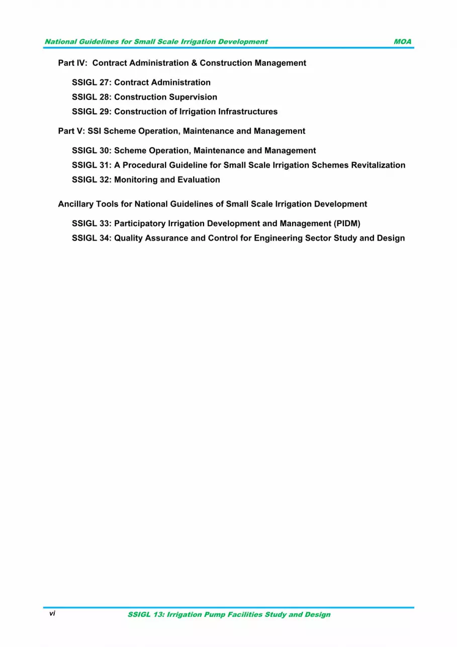
Part IV: Contract Administration & Construction Management
SSIGL 27: Contract Administration
SSIGL 28: Construction Supervision
SSIGL 29: Construction of Irrigation Infrastructures Part V: SSI Scheme Operation, Maintenance and Management
SSIGL 30: Scheme Operation, Maintenance and Management
SSIGL 31: A Procedural Guideline for Small Scale Irrigation Schemes Revitalization
SSIGL 32: Monitoring and Evaluation
Ancillary Tools for National Guidelines of Small Scale Irrigation Development
SSIGL 33: Participatory Irrigation Development and Management (PIDM)
SSIGL 34: Quality Assurance and Control for Engineering Sector Study and Design
National Guidelines for Small Scale Irrigation Development MOA
SSIGL 13: Irrigation Pump Facilities Study and Design vii
TABLE OF CONTENTS
FORWARD .......................................................................................................................... I
ACKNOWLEDGEMENTS ................................................................................................. III
LIST OF GUIDELINES ...................................................................................................... V
ACRONYMS .................................................................................................................... XII
SYMBOLS ...................................................................................................................... XIV
PREFACE ....................................................................................................................... XV
UPDATING AND REVISIONS OF GUIDELINES .......................................................... XVII
INTRODUCTION ......................................................................................................... 1 1
PURPOSE AND SCOPE OF THE GUIDELINE ........................................................... 3 2
PURPOSE ......................................................................................................................... 3 2.1
SCOPE .............................................................................................................................. 3 2.2
DEFINITIONS .............................................................................................................. 5 3
TYPES OF PUMPS AND AREAS OF APPLICATION ................................................ 9 4
TYPES OF PUMPS ........................................................................................................... 9 4.1
AREAS OF APPLICATION ............................................................................................. 12 4.2
SITE SELECTION CRITERIA FOR PUMPING FACILITY .............................................. 21 4.3
MAJOR COMPONENTS OF PUMPING FACILITY ........................................................ 21 4.4
PIPES, VALVES & FITTINGS ................................................................................... 23 5
PIPES .............................................................................................................................. 23 5.1
VALVES .......................................................................................................................... 23 5.2
Basic parts of a valves .............................................................................................. 24 5.2.1
Types of valves ......................................................................................................... 25 5.2.2
FITTINGS ........................................................................................................................ 32 5.3
HEAD IN PUMPING SYSTEM ................................................................................... 35 6
TOTAL DYNAMIC HEAD OR TOTAL PUMPING HEAD ................................................ 35 6.1
STATIC SUCTION HEAD OR STATIC SUCTION LIFT .................................................. 36 6.2
STATIC DISCHARGE HEAD .......................................................................................... 36 6.3
TOTAL STATIC HEAD .................................................................................................... 36 6.4
FRICTION HEAD ............................................................................................................ 36 6.5
PRESSURE HEAD .......................................................................................................... 36 6.6
VELOCITY HEAD ............................................................................................................ 36 6.7
DRAWDOWN .................................................................................................................. 37 6.8
LOSSES IN FLOW .................................................................................................... 39 7
DESIGN CONSIDERATIONS IN SUCTION AND DELIVERY LINES ....................... 49 8
PIPE SIZING FOR SUCTION AND DELIVERY LINE ..................................................... 49 8.1
CONDITIONS TO BE ACCOUNTED IN THE SUCTION LINE ....................................... 49 8.2
THE SUCTION SUMP ..................................................................................................... 55 8.3
CONDITIONS TO BE ACCOUNTED IN THE DELIVERY PIPE ..................................... 56 8.4
THE DELIVERY POOL OR BOX .................................................................................... 56 8.5
SITING AND INSTALLATION OF PUMPS ............................................................... 59 9
SITING OF THE PUMPING STATION ............................................................................ 59 9.1
INSTALLATION OF PUMP ............................................................................................. 60 9.2
COUPLING ...................................................................................................................... 60 9.3
GROUTING ..................................................................................................................... 61 9.4
PIPE LINES ..................................................................................................................... 61 9.5
National Guidelines for Small Scale Irrigation Development MOA
SSIGL 13: Irrigation Pump Facilities Study and Design viii
PUMP HYDRAULIC CHARACTERISTICS ............................................................... 65 10
CAPACITY ...................................................................................................................... 65 10.1
Determination of discharge rate in irrigation ............................................................. 66 10.1.1
Standby capacity ...................................................................................................... 66 10.1.2
TOTAL PUMP HEAD ...................................................................................................... 66 10.2
POWER AND EFFICIENCY ............................................................................................ 71 10.3
SPECIFIC SPEED ........................................................................................................... 73 10.4
Affinity law ................................................................................................................ 76 10.4.1
Pump characteristic curve ........................................................................................ 78 10.4.2
Pump arrangements ................................................................................................. 80 10.4.3
Pump combinations .................................................................................................. 82 10.4.4
Pump curve and system curve ................................................................................. 82 10.4.5
Best Efficiency Point (BEP) ...................................................................................... 84 10.4.6
PUMP SELECTION CRITERIA ....................................................................................... 85 10.5
DESIGN OF PUMPING FACILITY ............................................................................ 89 11
DATA REQUIREMENT ................................................................................................... 89 11.1
DESIGN PROCEDURE ................................................................................................... 90 11.2
DESIGN EXAMPLE ON SURFACE IRRIGATION SYSTEM .......................................... 91 11.3
DESIGN EXAMPLE ON GROUND WATER IRRIGATION SYSTEM ............................. 97 11.4
PUMP MOTOR POWER, STARTING METHODS AND CABLE SIZING ..................... 107 11.5
POWER UNITS ........................................................................................................ 111 12
ELECTRIC MOTORS .................................................................................................... 111 12.1
DIESEL ENGINES ........................................................................................................ 114 12.2
POWER TRANSMISSION ............................................................................................ 116 12.3
SOLAR POWER ............................................................................................................ 116 12.4
CONTROL PANELS AND OTHER UNITS .............................................................. 119 13
CONTROL PANELS ...................................................................................................... 119 13.1
TRANSFORMER AND STANDBY GENERATOR SIZING ........................................... 119 13.2
Transformer sizing .................................................................................................. 119 13.2.1
Standby generator sizing ........................................................................................ 120 13.2.2
ECONOMICS OF PUMP IRRIGATION SYSTEM .................................................... 121 14
GENERAL ..................................................................................................................... 121 14.1
Planning for pump irrigation system ....................................................................... 121 14.1.1
Alternatives in designing pump irrigation systems .................................................. 122 14.1.2
COST CONSIDERATIONS ........................................................................................... 122 14.2
Capital cost ............................................................................................................. 122 14.2.1
Economics of cost of pumping ................................................................................ 123 14.2.2
TECHNICAL SPECIFICATION FOR PUMPING FACILITIES ................................. 127 15
MECHANICAL ............................................................................................................... 127 15.1
ELECTRICAL POWER TECHNICAL SPECIFICATION ................................................ 127 15.2
IRRIGATION PUMP SETS ............................................................................................ 128 15.3
Irrigation pump motor sizing and de-rating ............................................................. 128 15.3.1
Irrigation pump materials ........................................................................................ 128 15.3.2
Supply of irrigation pump set technical information ................................................ 129 15.3.3
Factory performance tests of irrigation pump sets ................................................. 129 15.3.4
IRRIGATION PUMPING STATION STANDBY GENERATING PLANT ........................ 130 15.4
General ................................................................................................................... 130 15.4.1
Starting surges and sequence starting ................................................................... 131 15.4.2
National Guidelines for Small Scale Irrigation Development MOA
SSIGL 13: Irrigation Pump Facilities Study and Design ix
General description ................................................................................................ 131 15.4.3
Alternator power output .......................................................................................... 132 15.4.4
Control panel (generator) ....................................................................................... 133 15.4.5
Enclosures for electrical and control equipment ..................................................... 134 15.4.6
Finishes .................................................................................................................. 134 15.4.7
Drawings of pumping facilities ................................................................................ 134 15.4.8
PUMP MOTOR CONTROL PANEL SPECIFICATION .................................................. 134 15.5
General ................................................................................................................... 134 15.5.1
Construction ........................................................................................................... 135 15.5.2
Irrigation pump motor starter .................................................................................. 136 15.5.3
INSTALLATION, MAINTENANCE AND OPERATION OF E&M EQUPMENT ....... 137 16
SAFETY INSTRUCTIONS WHILE MAINTENANCE & SERVICING A PUMP .............. 137 16.1
INSTALLATION, MAINTENANCE AND OPERATION OF PUMP SET AND POWER 16.2SUPPLY ........................................................................................................................ 137
Submersible pump installation ................................................................................ 137 16.2.1
Power supply installation ........................................................................................ 138 16.2.2
Operation and maintenance of pumps ................................................................... 138 16.2.3
Maintenance of electric motor ................................................................................ 140 16.2.4
INSTALLATION, MAINTENANCE AND OPERATION OF DIESEL ENGINE ............... 141 16.3
INSTALLATION, MAINTENANCE AND OPERATION OF PIPES ................................ 141 16.4
MAINTENANCE OF IRRIGATION NETWORK ............................................................. 141 16.5
REFERENCES ............................................................................................................... 145
National Guidelines for Small Scale Irrigation Development MOA
SSIGL 13: Irrigation Pump Facilities Study and Design x
LIST OF TABLES Table 5-1: Types of Fittings ............................................................................................................ 33
Table 7-1: Dynamic and kinematic viscosity of water ..................................................................... 40
Table 7-2: Common friction factor values ....................................................................................... 43
Table 7-3: Loss coefficient due to bend .......................................................................................... 44
Table 7-4 Gate valve losses ........................................................................................................... 45
Table 7-5: Equivalent length of straight pipe for different pipe fittings ............................................ 45
Table 7-6 Values of Kc for contraction ............................................................................................ 46
Table 7-7: The values of Ke for sudden enlargement ..................................................................... 47
Table 8-1: Properties of water at various temperatures .................................................................. 51
Table 10-1: Typical values of modulus of elasticity (Larock et al., 2000) ....................................... 68
Table 10-2: Typical electric motor and pumping plant efficiencies by motor size ........................... 72
Table 10-3 Sample ambient temperature and altitude reduction factor for power requirement ...... 73
Table 11-1: Dynamic loss for BH1 ................................................................................................ 100
Table 11-2: Dynamic loss for BH2 ................................................................................................ 103
Table 11-3: Fitting losses .............................................................................................................. 106
Table 11-4: Pumps duty points ..................................................................................................... 107
Table 11-5: Selected motor power ................................................................................................ 108
Table 11-6: Standard cable sizes ................................................................................................. 109
Table 13-1: Transformer size ........................................................................................................ 119
Table 13-2: Total power demand .................................................................................................. 120
Table 14-1 Useful life of pumping equipment ............................................................................... 123
Table 14-2 Recommended specific fuel consumption of diesel engine ........................................ 124
Table 15-1: Material of construction for pump parts ..................................................................... 129
Table 16-1: Fault and solutions for electric driven pumps ............................................................ 140
Table 16-2: Diagnostic and trouble shooting of pumping system ................................................. 142
LIST OF FIGURES Figure 4-1: General Pump Classification-chart ............................................................................... 10
Figure 4-2 Classification of pumps by the Hydraulic Institute in 1983 ............................................ 11
Figure 4-3 Types of centrifugal pumps ........................................................................................... 14
Figure 4-4 Single Stage (left), double or two stage (middle) and multi stage (right) ....................... 14
Figure 4-5 Closed impeller (left), Semi closed impeller (middle) and Open impeller (right) ........... 15
Figure 4-6 Axial split case double suction (left) and radially split case double suction (right) ........ 15
Figure 4-7 Single stage end suction pump (left) and single stage double suction pump (right) ..... 15
Figure 4-8 Volute casing (left), vortex casing (middle) and diffuser casing (right) .......................... 16
Figure 4-9 Single volute pump (left) and double volute pump (right) .............................................. 16
Figure 4-10 Horizontal pump (left) and vertical pump (right) .......................................................... 17
Figure 4-11: End suction centrifugal pumps ................................................................................... 19
Figure 4-12: A Submersible Pump .................................................................................................. 20
Figure 4-13: Turbine pump ............................................................................................................. 20
Figure 5-1: Valve parts ................................................................................................................... 24
Figure 5-2: Gate valve .................................................................................................................... 26
Figure 5-3: Globe valve .................................................................................................................. 27
Figure 5-4: Ball valves .................................................................................................................... 27
Figure 5-5: Plug valves ................................................................................................................... 28
Figure 5-6: Straight through diaphragm valve ................................................................................ 28
Figure 5-7: Variable reducing valve ................................................................................................ 29
National Guidelines for Small Scale Irrigation Development MOA
SSIGL 13: Irrigation Pump Facilities Study and Design xi
Figure 5-8: Non-variable reducing valves ....................................................................................... 29
Figure 5-9: Butterfly valve ............................................................................................................... 30
Figure 5-10: Swing check valve ...................................................................................................... 30
Figure 5-11: Lift check valve ........................................................................................................... 31
Figure 5-12: Air/vacuum Valve ....................................................................................................... 32
Figure 6-1 General situation of irrigation pumping system ............................................................. 35
Figure 6-2 Components of total dynamic head ............................................................................... 35
Figure 7-1: Moody diagram ............................................................................................................. 42
Figure 8-1: Conditions to be avoided in suction side ...................................................................... 50
Figure 8-2: Schematic presentation of NPSHa ............................................................................... 51
Figure 8-3: Atmospheric pressure on liquid surface ....................................................................... 52
Figure 8-4: Typical suction sump arrangement .............................................................................. 55
Figure 8-5: Water jet profile ............................................................................................................ 57
Figure 9-1: Foundation of pumping unit and reinforcement details ................................................ 59
Figure 9-2: Foundation and pump arrangement ............................................................................. 60
Figure 9-3 Correct arrangement of suction piping and valves on delivery side .............................. 61
Figure 10-1: Water hammer due to sudden valve closure .............................................................. 67
Figure 10-2: Typical pressure wave caused by sudden valve closure ........................................... 70
Figure 10-3: Pump characteristic curves (variable speed) ............................................................. 74
Figure 10-4: Effect of speed change on centrifugal pump performance ......................................... 75
Figure 10-5: Changing wheel velocity ............................................................................................. 77
Figure 10-6” Pump characteristic curves ........................................................................................ 78
Figure 10-7: Pump operating area .................................................................................................. 79
Figure 10-8: TDH-Q curve for pumps operating in series ............................................................... 80
Figure 10-9: TDH-Q curve for two pumps operating in parallel ...................................................... 81
Figure 10-10: Typical pump curve .................................................................................................. 83
Figure 10-11: Interaction of pump curve and system curve ............................................................ 84
Figure 10-12: Best efficient points .................................................................................................. 84
Figure 10-13: Performance curve of pump (a) ................................................................................ 86
Figure 10-14: Performance curve of pump (b) ................................................................................ 87
Figure 11-1: Pump design procedure ............................................................................................. 91
Figure 11-2: Typical well pumping system ...................................................................................... 98
Figure 12-1: Rating curves for engine (Source: Irrigation Association, 1983) .............................. 116
National Guidelines for Small Scale Irrigation Development MOA
SSIGL 13: Irrigation Pump Facilities Study and Design xii
ACRONYMS
AGP Agricultural Growth Program
ANSI American National Standards Institute
API American Petroleum Institute
ASDs Adjustable speed rotational drives
BEP Best Efficiency Point
BH Brake horsepower
BOQ Bill of quantity
CTs Current Transformer
DCI Ductile cast iron
DN Nominal diameter
DOL Direct on Line
EEPCO Ethiopian electric power corporation
EQL Equivalent Length
GIRDC Generation Integrated Rural Development Consultant
GS Galvanized steel
HD Dynamic Head
HDL dynamic head loss
HS Static head
HSL static head loss
HT Total head
HT Total head
ISO International Organization for Standardization
KVA Kilo Volt Ampere
KW Kilowatt
LT Low Tension
MASL Meters above sea level
MCP Main canals pump
MOANR Ministry of Agriculture and Natural Resource
MOWIE Ministry of Water, Irrigation and Electricity
NEMA National Electrical Manufacturers Association
National Guidelines for Small Scale Irrigation Development MOA
SSIGL 13: Irrigation Pump Facilities Study and Design xiii
NPSH Net positive suction head
NPSHA Net positive suction head available
NPSHR Net positive suction head required
P&ID Piping and Instrumentation Diagram
PN Pipe Nominal pressure
PV Photovoltaic
PVC polyvinyl chloride
RISE Research Institute for Sustainable Energy
SSID Small Scale Irrigation Development
SSIGL Small Scale Irrigation Guideline
SSIP small scale irrigation project
SSIS Small Scale Irrigation Scheme
TDH Total Dynamic Head
VTs Voltage Transformer
WECS Wind Energy Conversion Systems
WHP water horsepower
XLPE Cross-linked polyethylene
National Guidelines for Small Scale Irrigation Development MOA
SSIGL 13: Irrigation Pump Facilities Study and Design xiv
SYMBOLS
Symbol description Unit
A Cross sectional area of flow m2
C Coefficient of discharge or creep coefficient unit less
D Internal diameter of pipe m
g Acceleration due to gravity m/s2
hf Head loss due to friction m
hl Head loss m
hav Velocity head m
L Length m
Q Discharge or Flow m3/s, l/s
q Discharge per unit length or intensity of flow m3/s/m
Qd Design discharge m3/s
v Velocity of flow m/s
v‟ Actual velocity m/s
VS velocity of suction m/s
Vd velocity discharge m/s
f Friction factor related to the roughness
inside the pipe unit less
L Length of the pipe suction or discharge m
d Diameter of the pipe m
∝ infinite resistance ohm
National Guidelines for Small Scale Irrigation Development MOA
SSIGL 13: Irrigation Pump Facilities Study and Design xv
PREFACE
While irrigation development is at the top of the government‟s priority agendas as it is key to boost
production and improve food security as well as to provide inputs for industrial development.
Accordingly, irrigated land in different scales has been aggressively expanding from time to time.
To this end, to enhance quality delivery of small-scale irrigation development planning,
implementation and management, it has been decided to develop standard SSI guidelines that
must be nationally applied. In September 2017 the Ministry of Agriculture (MoA) had entrusted
Generation Integrated Rural Development Consultant (GIRDC) to prepare the National Small-
scale Irrigation Development Guidelines (SSIGLs).
Preparation of the SSIGLs for enhancing development of irrigated agriculture is recognized as one
of the many core initiatives of the MoA to improve its delivery system and achieve the targets in
irrigated agriculture and fulfill its mission for improving agricultural productivity and production. The
core objective of developing SSIGLs is to summarize present thinking, knowledge and practices to
enable irrigation practitioners to properly plan, implement and manage community managed SSI
schemes to develop the full irrigation potential in a sustainable manner.
As the SSIGLs are prepared based on national and international knowledge, experiences and
practices, and describe current and recommended practice and set out the national standard
guides and procedures for SSI development, they serve as a source of information and provide
guidance. Hence, it is believed that the SSIGLs will contribute to ensuring the quality and timely
delivery, operation and maintenance of SSI schemes in the country. The SSIGLs attempt to
explain and illustrate the important concepts, considerations and procedures in SSI planning,
implementation and management; and shall be used as a guiding framework for professionals
engaged in SSI development. Illustrative examples from within the country have been added to
enable the users understand the contents, methodologies presented in the SSIGLs.
The intended audiences of the SSIGLs are government organizations, NGOs, CSOs and the
private sector involved in SSI development. Professionally, the SSIGLs will be beneficial for
experienced and junior planners, experts, contractors, consultants, suppliers, investors, operators
and managers of SSI schemes. The SSIGLs will also serve as a useful reference for academia
and researchers involved and interested in SSI development. The SSIGLs will guide to ensure
that; planning, implementation and management of SSI projects is formalized and set procedures
and processes to be followed. As the SSIGLs provide information and guides they must be always
fully considered and applied by adapting them to the local specific requirements.
In cognizance with the need for quality SSIGLs, the MoA has duly considered quality assurance
and control during preparation of the guidelines. Accordingly, the outlines, contents and scope of
the SSIGLs were thoroughly discussed, reviewed and modified by NAWMP members (senior
professionals from public, national and international stakeholder) with key stakeholders in many
consultative meetings and workshops. Moreover, at each milestone of SSIGL preparation,
resource persons from all stakeholders reviewed and confirmed that SSIGLs have met the
demands and expectations of users.
Moreover, the Ministry has mobilized resource persons from key Federal, National Regional States
level stakeholders and international development partners for review, validation and endorsement
of the SSIGLs.
National Guidelines for Small Scale Irrigation Development MOA
SSIGL 13: Irrigation Pump Facilities Study and Design xvi
Several hundreds of experienced professionals (who are very qualified experts in their respective
fields) from government institutions, relevant private sector and international development partners
have significantly contributed to the preparation of the SSIGLs. They have been involved in all
aspects of the development of SSIGLs throughout the preparation process. The preparation
process included a number of consultation meetings and workshops: (i) workshop to review
inception report, (ii) workshop on findings of review of existing guidelines/manuals and proposed
contents of the SSIGLs, (iii) meetings to review zero draft SSI GLs, (iv) review workshop on draft
SSI GLs, (v) small group review meetings on thematic areas, (vi) small group consultation
meetings on its final presentation of contents and layout, (vii) consultation mini-workshops in the
National States on semi-final versions of the SSIGLs, and (viii) final write-shop for the appraisal
and approval of the final versions of SSIGLs.
The deliberations, concerns, suggestions and comments received from professionals have been
duly considered and incorporated by the GIRD Consultant in the final SSIGLs.
There are 34 separate guidelines which are categorized into the following five parts concurrent to
SSI development phases:
Part-I. Project Initiation, Planning and Organization Guideline which deals with key considerations
and procedures on planning and organization of SSI development projects.
Part-II. Site Identification and Prioritization Guideline which treats physical potential identification
and prioritization of investment projects. It presents SSI site selection process and
prioritization criteria.
Part-III. Feasibility Study and Detail Design Guidelines for SSID dealing with feasibility study
and design concepts, approaches, considerations, requirements and procedures in the
study and design of SSI systems.
Part-IV. Contract Administration and Construction Management Guidelines for SSI development
presents the considerations, requirements, and procedures involved in construction of
works, construction supervision and contract administration.
Part-V. SSI Scheme Management, Operation and Maintenance Guidelines which covers SSI
Scheme management and operation.
Moreover, Tools for Small Scale Irrigation development are also prepared as part of SSIGLs.
It is strongly believed and expected that; the SSIGLs will be quickly applied by all stakeholders
involved in SSI development and others as appropriate following the dissemination and
familiarization process of the guidelines in order to ensure efficient, productive and sustainable
irrigation development.
The SSIGLs are envisioned to be updated by incorporating new technologies and experiences
including research findings. Therefore, any suggestions, concerns, recommendations and
comments on the SSIGLs are highly appreciated and welcome for future updates as per the
attached format below. Furthermore, despite efforts in making all types of editorial works, there
may still errors, which similarly shall be handled in future undated versions.
.
National Guidelines for Small Scale Irrigation Development MOA
SSIGL 13: Irrigation Pump Facilities Study and Design xvii
UPDATING AND REVISIONS OF GUIDELINES
The GLs are intended as an up-to-date or a live document enabling revisions, to be updated
periodically to incorporate improvements, when and where necessary; may be due to evolving
demands, technological changes and changing policies, and regulatory frameworks. Planning,
study and design of SSI development interventions is a dynamic process. Advancements in these
aspects are necessary to cope up with the changing environment and advancing techniques. Also,
based on observation feedbacks and experiences gained during application and implementation of
the guidelines, there might be a need to update the requirements, provisions and procedures, as
appropriate. Besides, day-by-day, water is becoming more and more valuable. Hence, for efficient
water development, utilization and management will have to be designed, planned and
constructed with a new set up of mind to keep pace with the changing needs of the time. It may,
therefore, be necessary to take up the work of further revision of these GLs.
This current version of the GLs has particular reference to the prevailing conditions in Ethiopia and
reflects the experience gained through activities within the sub-sector during subsequent years.
This is the first version of the SSI development GLs. This version shall be used as a starting point
for future update, revision and improvement. Future updating and revisions to the GLs are
anticipated as part of the process of strengthening the standards for planning, study, design,
construction, operation and management SSI development in the country.
Completion of the review and updating of the GLs shall be undertaken in close consultation with
the federal and regional irrigation institutions and other stakeholders in the irrigation sub-sector
including the contracting and consulting industry.
In summary, significant changes to criteria, procedures or any other relevant issues related to
technological changes, new policies or revised laws should be incorporated into the GLs from their
date of effectiveness. Other minor changes that will not significantly affect the whole nature of the
GLs may be accumulated and made periodically. When changes are made and approved, new
page(s) incorporating the revision, together with the revision date, will be issued and inserted into
the relevant GL section.
All suggestions to improve the GLs should be made in accordance with the following procedures:
I. Users of the GLs must register on the MOA website: Website: www.moa.gov.et
II. Proposed changes should be outlined on the GLs Change Form and forwarded with a
covering letter or email of its need and purpose to the Ministry.
III. Agreed changes will be approved by the Ministry on recommendation from the Small-scale
Irrigation Directorate and/or other responsible government body.
IV. The release date of the new version will be notified to all registered users and authorities.
Users are kindly requested to present their concerns, suggestions, recommendations and
comments for future updates including any omissions and/or obvious errors by completing the
following revisions form and submitting it to the Ministry. The Ministry shall appraise such requests
for revision and will determine if an update to the guide is justified and necessary; and when such
updates will be published. Revisions may take the form of replacement or additional pages. Upon
receipt, revision pages are to be incorporated in the GLs and all superseded pages removed.
National Guidelines for Small Scale Irrigation Development MOA
SSIGL 13: Irrigation Pump Facilities Study and Design xviii
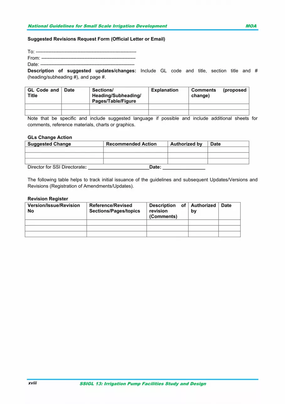
Suggested Revisions Request Form (Official Letter or Email)
To: ---------------------------------------------------------------
From: -----------------------------------------------------------
Date: -----------------------------------------------------------
Description of suggested updates/changes: Include GL code and title, section title and #
(heading/subheading #), and page #.
GL Code and Title
Date Sections/ Heading/Subheading/ Pages/Table/Figure
Explanation Comments (proposed change)
Note that be specific and include suggested language if possible and include additional sheets for
comments, reference materials, charts or graphics.
GLs Change Action
Suggested Change Recommended Action Authorized by Date
Director for SSI Directorate: _______________________Date: ________________
The following table helps to track initial issuance of the guidelines and subsequent Updates/Versions and
Revisions (Registration of Amendments/Updates).
Revision Register
Version/Issue/Revision No
Reference/Revised Sections/Pages/topics
Description of revision (Comments)
Authorized by
Date
National Guidelines for Small Scale Irrigation Development MOA
SSIGL 13: Irrigation Pump Facilities Study and Design 1
INTRODUCTION 1
Irrigation is considered as a means of renovating the agricultural economy and plays significant
role in improving income and livelihoods of the community through increased agricultural
production and productivity. Considering this significance of irrigated agriculture in the economy,
the Government has given top priority to the irrigation sub-sector in the overall development plans
of the country with the ultimate objective of enhancing agricultural production and productivity and
linking it with the industrial development.
Water is thus a fundamental input to agricultural production; indeed food security cannot be
achieved without supporting the rain fed agriculture with irrigated agriculture since climatic
variability is challenging the agricultural sector. On the other hand, the country did not yet utilized
the available surface and sub-surface water resources to the desired level.
Water can be conveyed to the available land resources either by gravity or lift/pump irrigation.
Particularly due to topographic constraints it may not be always possible to irrigate suitable
irrigable lands by gravity system and study and design of pumping facility must be considered for
such cases. Sometimes pumping is also necessitated to apply water by pressurized irrigation
systems.
Actual situations in the country indicate that pumping facilities implemented so far to benefit
smallholder farmers are not efficient enough due to various problems encountered during
planning, study, design, implementation and operation. As one of the limiting factors to sustain
pumped irrigation schemes, proper design and selection of appropriate pump for specific area is
very crucial. In this guideline study and design aspects of pumping facilities in small scale irrigation
schemes will be discussed.
The study and design incorporates proper site selection for pumping facility, setting design criteria
based on hydraulic and structural considerations and evaluation of different design alternatives
and selection of most viable one. Design considerations also depend on the water sources for
pumping like spring, stream, river, lake or underground water. The pumping facilities include the
pump and power unit, the control heads, the housing, suction and delivery outlet and the pipe
lines. Thus different categories of pumps for irrigation and pump driving energy sources are
discussed in this guideline.

National Guidelines for Small Scale Irrigation Development MOA
SSIGL 13: Irrigation Pump Facilities Study and Design 2
National Guidelines for Small Scale Irrigation Development MOA
SSIGL 13: Irrigation Pump Facilities Study and Design 3
PURPOSE AND SCOPE OF THE GUIDELINE 2
PURPOSE 2.1
The purpose of the guideline is to:
Guide engineering professionals in study and design of pumping facilities for irrigated agriculture and contribute to sustainable production and productivity.
Standardize study and design approaches of pumping facilities in irrigated agriculture.
Reinforce study and design skills of engineering professionals in making proper pump selection for particular site.
SCOPE 2.2
The guideline focuses on:
Study and design of pumping facilities in the irrigated agriculture particularly small scale schemes that serve smallholder farmers.
Addressing limiting factors related to study and design of pumping facilities in SSI schemes.
Study and design aspects of most common types of pumping facilities in small scale irrigation development.
Making the guideline easy to use with practical illustrations and examples in designing and selecting proper pump that suit to specific site conditions.

National Guidelines for Small Scale Irrigation Development MOA
SSIGL 13: Irrigation Pump Facilities Study and Design 4
National Guidelines for Small Scale Irrigation Development MOA
SSIGL 13: Irrigation Pump Facilities Study and Design 5
DEFINITIONS 3
Basic concepts in the study and design of pump Facilities:
Air/Vacuum Valve: An Air/Vacuum valve is used to allow air to escape the discharge piping when pumping begins, and to prevent vacuum damage to the discharge piping when pumping stops. If the pump discharge is open to the atmosphere, an air/vacuum release valve may not be necessary. Combination air release valves are frequently used at high points in force mains to evacuate trapped air.
Adjustable speed rotational drives (ASDs): Devices that allow control of a pump‟s speed; including mechanical devices such as hydraulic clutches and electronic devices such as eddy current clutches and variable frequency drives
Backpressure: The pressure on the discharge side of the pump
Bearing: A device that supports a rotating shaft, allowing it to spin, while keeping it from translating in the radial direction; a thrust bearing keeps a shaft from translating in the axial direction
Brake horsepower: The amount of power (measured in units of horsepower) delivered to the shaft of a motor driven piece of equipment
Baseline Consumption: Estimated pumping system annual energy consumption.
Best Efficiency Point (BEP): The best efficiency point (BEP) refers to the most efficient operating point (defined by a certain rate of flow and system head) for a centrifugal pump. This is the point at which each pump should operate at optimal system design.
Check Valve: A watertight fitting used in pipes to prevent back flow to the pumps and subsequent re-circulation. A check valve is sealed with a rubber seated ball type fitting.
Cavitation: A phenomenon in which the local liquid pressure drops below its vapor pressure, which results in the liquid flashing to vapor. As these vapor bubbles collapse, they create vibrations and noise which can be damaging to system components, especially pump impellers.
Capacity the rate of liquid flow that can be carried.
Centrifugal Pumps Centrifugal pumps operate by adding kinetic energy to a liquid via a spinning impeller, where dynamic pressure is created as a result of flow resistance in the discharge passage.
Coupling: Coupling refers to the connection or transmission of power between motor and pump. This includes types of coupling such as direct coupling or drive belts.
Coupling Efficiency: The coupling efficiency is defined as the ratio of the energy delivered by the motor to the coupling divided by the energy delivered to the pump shaft.
Current: the amount of electricity measured in amps which are flowing in a circuit.
Deadheading: A condition in which all the discharge from a pump is closed off
Design Point: The operating point as calculated for a pump during the system design. The actual operating point is often not at the design point.
Dynamic Head: The head associated with frictional losses within the pumping system pipe network.
Efficiency: In a pump, the efficiency with which the shaft power applied (not the power to the motor) is conver ted to flow and head; motor efficiency is the electrical equivalent of this parameter for the motor
Flow: The quantity of water passing an observation point; for pumped liquids the term mass flow is often used and refers to the mass of liquid passing per unit time (however, it is more common to use volume flow; that is, the volume passing per unit time.
Friction losses: Pressure losses caused purely by the resistance of the pipework and system, which must be added to the static head to obtain the total system resistance – note that friction losses vary with flow rate and that they occur in pump inlet pipework as well as outlet pipework
National Guidelines for Small Scale Irrigation Development MOA
SSIGL 13: Irrigation Pump Facilities Study and Design 6
Gate Valve: A gate valve is a simple shut-off device that is used to isolate pumps and facilitate removal. These valves should not be used to throttle flow. They should be either totally open or totally closed.
Head: A measure of pressure (expressed in meters or feet) indicating the height of a column of system fluid that has an equivalent amount of potential energy. It is the sum of Dynamic and Static heads
Heat exchanger: A device that transfers heat from one fluid to another
Impeller: a pump component that rotates on the pump shaft and increases the pressure on a fluid by adding kinetic energy. .
Hydraulic Power: The power imparted by the pump to the liquid.
Hydraulic horsepower (WHP): the pump output or the liquid horsepower delivered by the pump.
Impeller: The rotating component within a centrifugal pump used to increase the pressure and flow of a liquid.
(KVA): Common unit for apparent power, which is the total power that appears to be flowing from a source to a load. (Kilo Volt Ampere)
(KW): Common unit for real power, which is the actual net power that is flowing from a source to a load. (Kilowatt)
Liquid: In the context of this document, a solution or suspension following Newtonian or Non-Newtonian laws it is water.
Mechanical seal: A mechanical device for sealing the pump/shaft interface (as opposed to packing)
Motor: An electric machine that uses either alternating current (A.C.) or direct current (D.C.) electricity to spin a shaft that is typically coupled to a pump. Occasionally, however, mechanisms such as a slider/crank convert this rotation to axial movement to power piston pumps.
Motor controller: An electric switchbox that energizes and de-energizes an electric motor.
Motor input horsepower: (EHP) - the power input to the motor expressed in horsepower.
Multi-stage pumps : Pumps which contain several impellers, each feeding its output to the next stage in a serial fashion in order to generate pressures higher than a single-stage pump can achieve
Motor Power: The motor power is the power consumed by the pump motor to turn the pump shaft. The motor power is the sum of the shaft power and power loss due to inefficiencies in converting electric energy into kinetic energy. Motor power may be calculated as the shaft power divided by the motor efficiency
Motor Efficiency: The motor efficiency is defined as the ratio of the energy delivered to the motor divided by the energy delivered from the motor to the coupling.
Power: Output from a motor is equal to the input power multiplied by the motor efficiency – it is this output which is the power absorbed by a pump, that is, the power value which features on pump characteristics.
Preferred operating region: The region on a pump curve where flow remains well controlled within a range of capacities, within which hydraulic loads, vibration or flow separation will not significantly affect the service life of the pump.
Pressure: Force per unit area; commonly used as an indicator of fluid energy in a pumping system (expressed in kilograms per square centimeter or pounds per square inch).
Prime mover: A machine, usually an electric motor, that provides the motive force driving a pump.
Pump Control: A device that activates pumps successively in response to a rising water level in the source. The control regulates the pump activity until the inflow into the wet well has ceased.
Pump Driver: The device used to provide power to the pump. Alternating current electric motors are the most common type of driver.
National Guidelines for Small Scale Irrigation Development MOA
SSIGL 13: Irrigation Pump Facilities Study and Design 7
Peak Load: The peak power consumption of a site. This often determines the demand charges incurred by the site and should therefore be taken into account when considering the operating times of pumping systems.
Performance Curve: Graph plotting the head required as a function of flow rate for a given pump. Also often depicted on performance curves are the shaft power, pump efficiency and suction head required. The term “pump curve” often refers to the performance curve.
Piping and Instrumentation Diagram (P&ID): Schematic diagram of the pumping system including pipe layout, liquid users and associated instrumentation.
Positive Displacement Pumps: Positive displacement pumps move a set volume of liquid per revolution or stroke, with pressure developed as a result of this forced discharge. Positive displacement pumps are better suited to high-viscosity applications.
Power input: the electrical input to the motor expressed in kilowatts (kW). A measure of the rate at which work is done.
Power Factor: Ratio of real power to apparent power.
Pressure; head (NPSH): Net Positive Suction Head It usually has a subscript: NPSHR is the NPSH required by a pump at its inlet to prevent it from cavitation. NPSHA is the NPSH available from the inlet configuration in use. To avoid cavitation, NPSHA must be greater than NPSHR
Pump Efficiency: The ratio of the hydraulic power (power imparted to the liquid) divided by the pump shaft input power (power delivered to the pump via motor coupling).
Pumping System: A pump or group of pumps along with the other components relevant to the moving liquid. This includes the motors, coupling, piping and valves.
Rated duty: The flow and head that are specified on the pump nameplate – they should be close to the values corresponding to the peak efficiency of the pump.
Seals: Prevent water leaking outwards along the pump shaft – either packed glands or mechanical seals.
Specific gravity: The ratio of the density of a fluid to the density of water at standard conditions.
Static head: The head of water a pump must overcome before it will produce any flow; it is a result of the height difference between the suction water level and delivery water level
Shaft Input Power: The power delivered to the shaft of a pump.
Total head : A measure of the total energy imparted to the fluid by a pump, which includes static pressure increase and velocity head
Valve: A device used to control fluid flow in a piping system – there are many types of valves with different flow control characteristics, sealing effectiveness and reliability
Vapor pressure: The force per unit area that the fluid exerts in an effort to change the phase from a liquid to a vapor; it is a function of a fluid‟s chemical and physical properties, and its temperature
Viscosity: The resistance of a fluid to flow when subjected to shear stress

National Guidelines for Small Scale Irrigation Development MOA
SSIGL 13: Irrigation Pump Facilities Study and Design 8
National Guidelines for Small Scale Irrigation Development MOA
SSIGL 13: Irrigation Pump Facilities Study and Design 9
TYPES OF PUMPS AND AREAS OF APPLICATION 4
TYPES OF PUMPS 4.1
Pumps are hydraulic machines designed for transmitting fluids under pressure by transforming the
mechanical energy of the driving motor into the mechanical energy of the moving fluid; pumps lift
fluid up to a specified elevation, deliver it over the required distance at the horizontal plane or
make it circulating in a certain closed system.
Based on their method of operation, pumps can be classified into the following two major types
and common sub classifications are indicated under Figure 4-1 and Figure 4-2.
a) Dynamic Pumps Dynamic pumps include all types of pumps using fluid velocity and the resulting momentum to
pump and move the fluid through the piping system. Although dynamic pumps usually have lower
efficiencies than positive displacement pumps, they require lower maintenance. They are also
capable of operating at high speeds and high fluid flow rates.
b) Positive Displacement Pumps Positive displacement pumps operate by filling and displacing liquid from a cavity. Such pumps
deliver a constant flow and volume of liquid without discharge pressure or head. Positive
displacement pumps are ideal for a low flow–high pressure combination.
National Guidelines for Small Scale Irrigation Development MOA
SSIGL 13: Irrigation Pump Facilities Study and Design 10
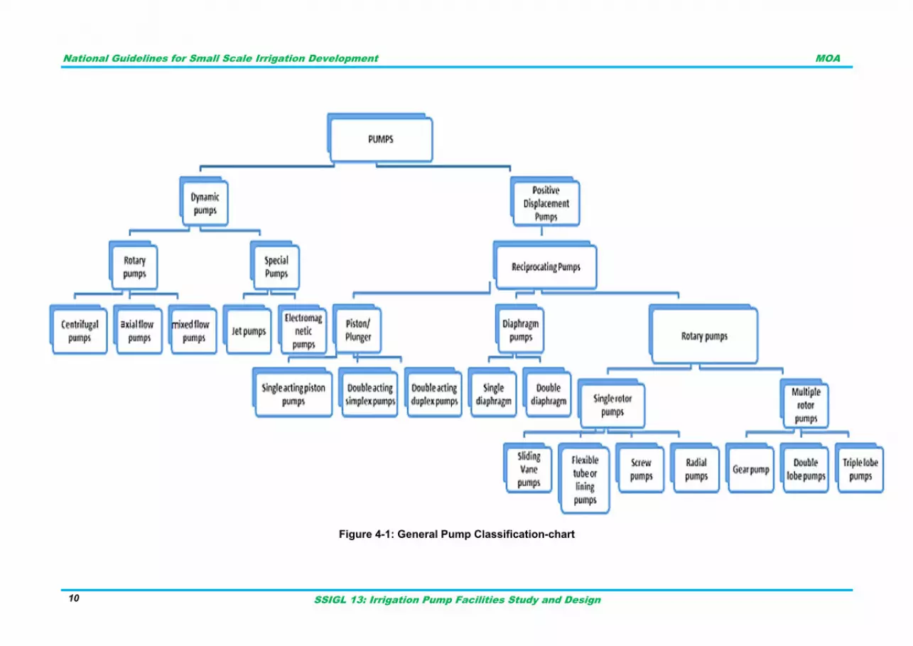
Figure 4-1: General Pump Classification-chart
National Guidelines for Small Scale Irrigation Development MOA
SSIGL 13: Irrigation Pump Facilities Study and Design 11
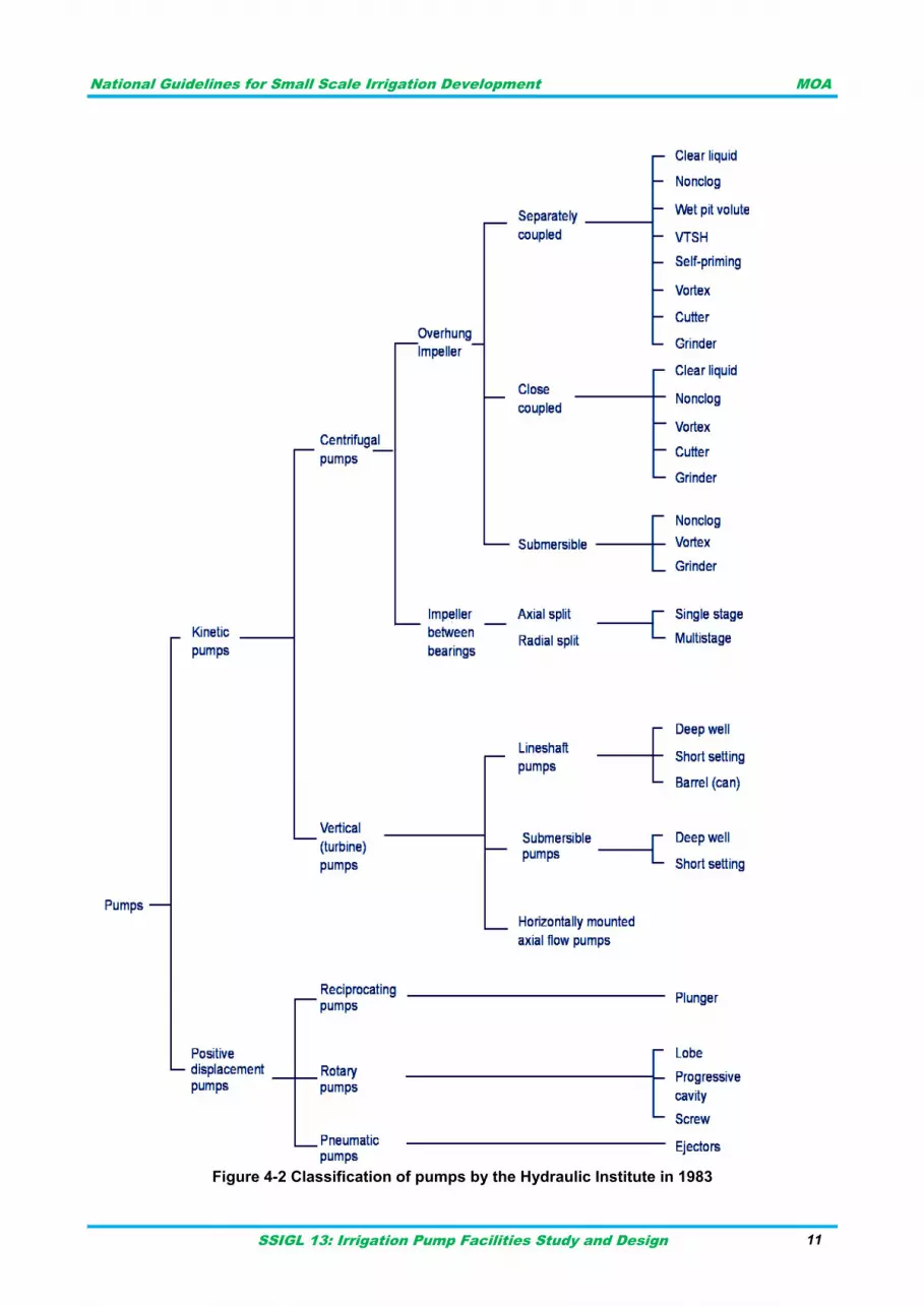
Figure 4-2 Classification of pumps by the Hydraulic Institute in 1983
National Guidelines for Small Scale Irrigation Development MOA
SSIGL 13: Irrigation Pump Facilities Study and Design 12
AREAS OF APPLICATION 4.2
The types of pumps are given in the pump classification chart Figure 4-1 above. There are
numerous ways of pump classification and the Hydraulic Institute classification is also given in
Figure 4-2.
The selection of proper type and its proper installation is very important to meet desired
specification and proper application. Knowledge of the variety of pumps is mandatory to propose
the right pump for the right application. Commonly used pumps for irrigation are addressed in
coming parts of the guideline.
a) Displacement Pumps
Displacement pumps force the water to move by displacement. Some of such pumps are piston
pumps, diaphragm pumps, roller-tubes, and rotary pumps. Displacement pumps are used not only
for water but for moving very thick liquids, creating very precise flow volumes, or creating very high
pressures. They are also used for fertilizer injectors, spray pumps, air compressors, and hydraulic
systems for machinery. With the exception of fertilizer injectors used for mixing fertilizer into
irrigation water, they are not widely used for irrigation.
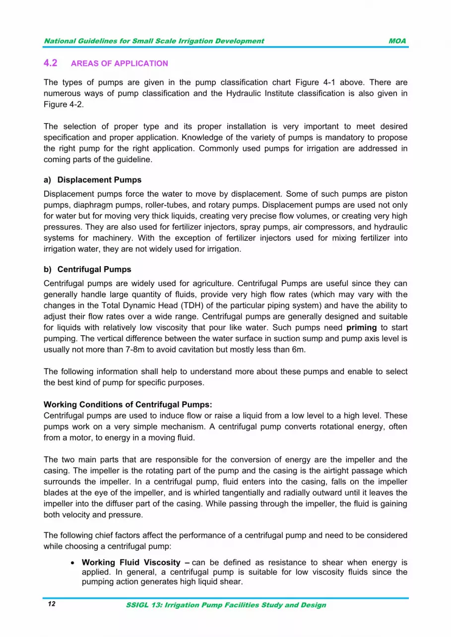
b) Centrifugal Pumps
Centrifugal pumps are widely used for agriculture. Centrifugal Pumps are useful since they can
generally handle large quantity of fluids, provide very high flow rates (which may vary with the
changes in the Total Dynamic Head (TDH) of the particular piping system) and have the ability to
adjust their flow rates over a wide range. Centrifugal pumps are generally designed and suitable
for liquids with relatively low viscosity that pour like water. Such pumps need priming to start
pumping. The vertical difference between the water surface in suction sump and pump axis level is
usually not more than 7-8m to avoid cavitation but mostly less than 6m.
The following information shall help to understand more about these pumps and enable to select
the best kind of pump for specific purposes.
Working Conditions of Centrifugal Pumps:
Centrifugal pumps are used to induce flow or raise a liquid from a low level to a high level. These
pumps work on a very simple mechanism. A centrifugal pump converts rotational energy, often
from a motor, to energy in a moving fluid.
The two main parts that are responsible for the conversion of energy are the impeller and the
casing. The impeller is the rotating part of the pump and the casing is the airtight passage which
surrounds the impeller. In a centrifugal pump, fluid enters into the casing, falls on the impeller
blades at the eye of the impeller, and is whirled tangentially and radially outward until it leaves the
impeller into the diffuser part of the casing. While passing through the impeller, the fluid is gaining
both velocity and pressure.
The following chief factors affect the performance of a centrifugal pump and need to be considered
while choosing a centrifugal pump:
Working Fluid Viscosity – can be defined as resistance to shear when energy is applied. In general, a centrifugal pump is suitable for low viscosity fluids since the pumping action generates high liquid shear.
National Guidelines for Small Scale Irrigation Development MOA
SSIGL 13: Irrigation Pump Facilities Study and Design 13
Specific density and gravity of working fluid – The density of a fluid is its mass per unit of volume. A fluid‟s mass per unit volume and gravity of a fluid is the ratio of a fluid‟s density to the density of water. It directly affects the input power required to pump a particular liquid. If you are working with a fluid other than water, it is important to consider the specific density and gravity since the weight will have a direct effect on the amount of work performed by the pump. In case of irrigation silt free water is usually assumed.
Operating temperature and pressure – Pumping conditions like temperature and pressures are an important consideration for any operation. For example - High temperature pumping may require special gaskets, seals and mounting designs. Similarly, an adequately designed pressure retaining casing may be required for high-pressure conditions.
Net Positive Suction Head (NPSH) and Cavitation – NPSH is a term that refers to the pressure of a fluid on the suction side of a pump to help determine if the pressure is high enough to avoid cavitation. Cavitation refers to the formation of bubbles or cavities in liquid, developed in areas of relatively low pressure around an impeller and can cause serious damage to the impeller and lead to decreased flow/pressure rates among other things. One must ensure that the system‟s net positive suction head available (NPSHA) is greater than the pump‟s net positive suction head required (NPSHR), with an appropriate safety margin.
Vapor pressure of the working fluid – The vapor pressure of a fluid is the pressure, at a given temperature, at which a fluid will change to a vapor. It must be determined in order to avoid cavitation as well as bearing damage caused by dry running when the fluid has evaporated.
Owing to the use in diverse range of applications, pumps come with different capacities and in
various sizes. One should also consider the pressure and volume requirements of the specific
operations for which you need the pump. The horsepower required is another important
consideration when it comes to volume and discharge pressure.
Applications of Centrifugal Pumps:
The fact that centrifugal pumps are the most popular choice for fluid movement makes them a
strong contender for many applications and as mentioned previously, they are used for agriculture,
industries, boosting pressure, pumping water for domestic requirements; assisting fire protection
systems, hot water circulation; sewage drainage and regulating boiler water are among the most
common applications. Here special attention is given to centrifugal pumps as they are used for
irrigation widely.
Types of centrifugal pumps:
Centrifugal pumps can be classified into several types depending on factors such as design,
construction, application, service, compliance with a national or industry standard, etc. Therefore,
one specific pump can belong to different groups and at times pump is known by its description
itself. Some of these groups have been highlighted below:
National Guidelines for Small Scale Irrigation Development MOA
SSIGL 13: Irrigation Pump Facilities Study and Design 14
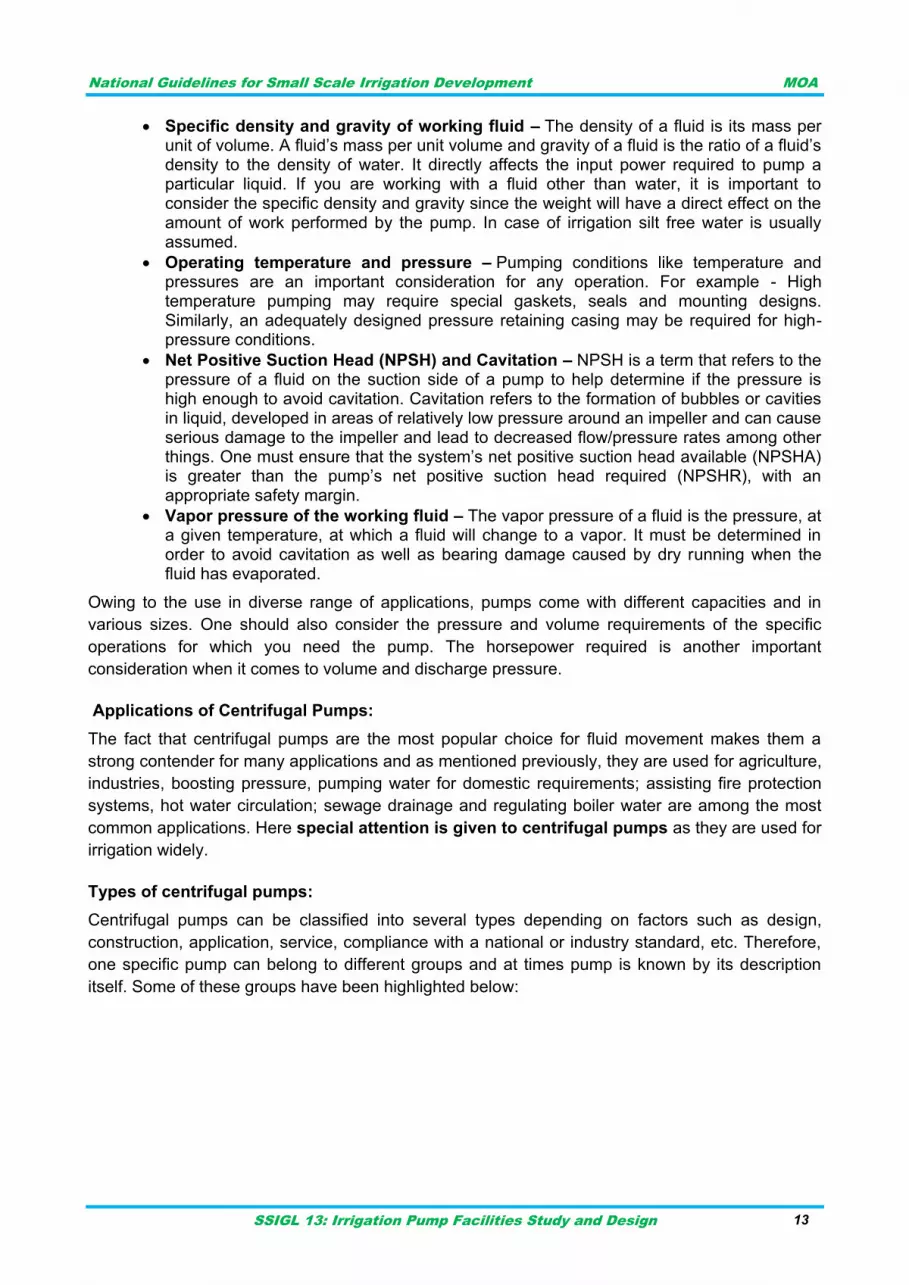
Figure 4-3 Types of centrifugal pumps
Centrifugal pumps as indicated on figure 4-2 above can be categorized based on different factors.
These categorizations are discussed below.
I. Depending on number of impeller(s) in the pump
Single stage – A one impeller pump, single stage pump has a simple design and easy
maintenance. They are ideal for large flow rates and low-pressure installations. They are
commonly used in pumping services of high flow and low to moderate TDH (Total Dynamic Head).
Two-stage – This type of pump has two impellers operating side by side which are used for
medium head applications.
Multi-stage – pump has three or more impellers in series; for high head service.
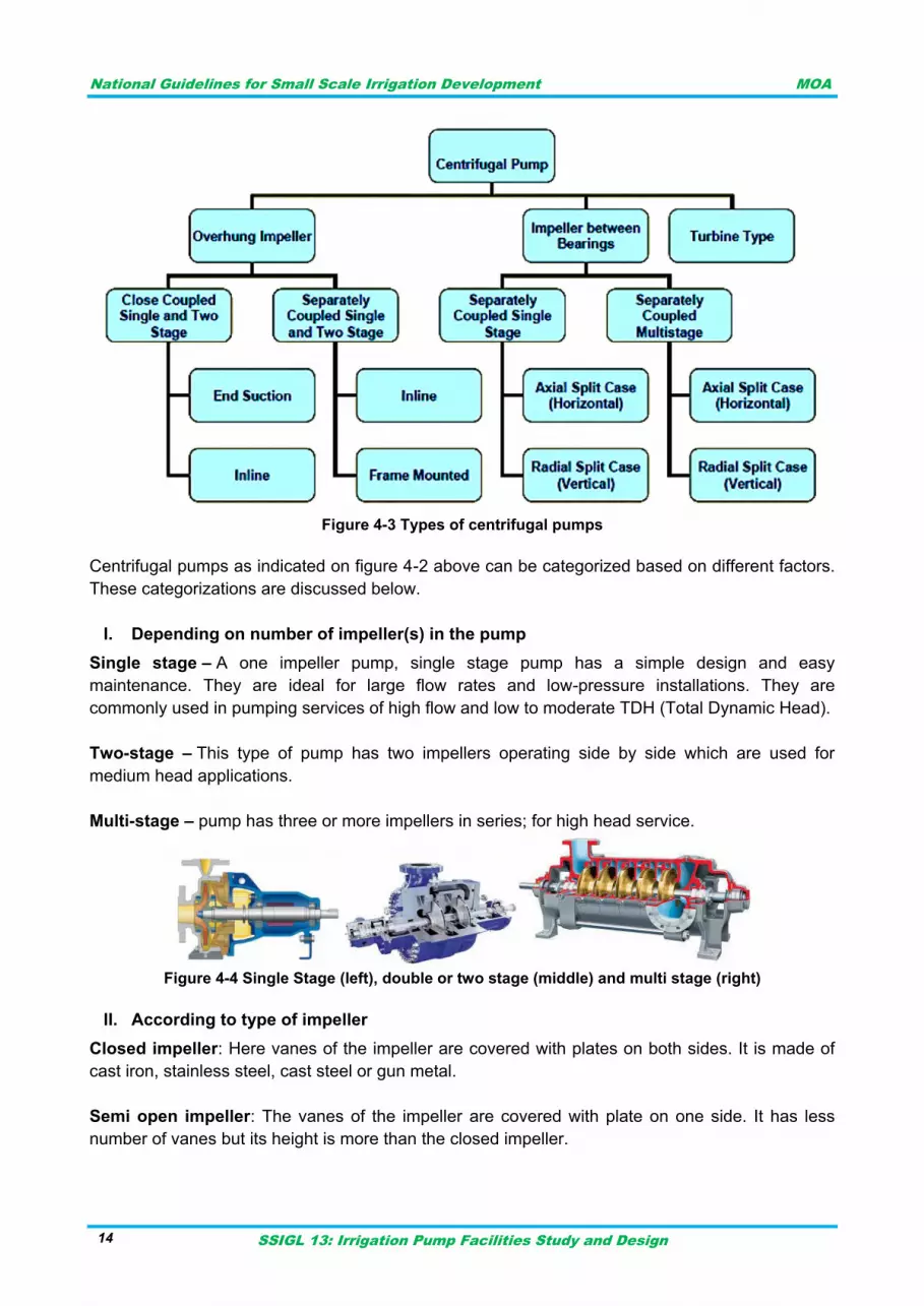
Figure 4-4 Single Stage (left), double or two stage (middle) and multi stage (right)
II. According to type of impeller
Closed impeller: Here vanes of the impeller are covered with plates on both sides. It is made of
cast iron, stainless steel, cast steel or gun metal.
Semi open impeller: The vanes of the impeller are covered with plate on one side. It has less
number of vanes but its height is more than the closed impeller.
National Guidelines for Small Scale Irrigation Development MOA
SSIGL 13: Irrigation Pump Facilities Study and Design 15
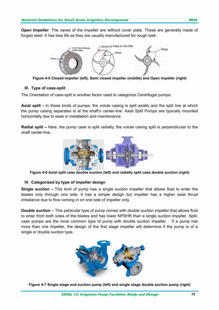
Open Impeller: The vanes of the impeller are without cover plate. These are generally made of
forged steel. It has less life as they are usually manufactured for rough task.
Figure 4-5 Closed impeller (left), Semi closed impeller (middle) and Open impeller (right)
III. Type of case-split
The Orientation of case-split is another factor used to categorize Centrifugal pumps:
Axial split – In these kinds of pumps, the volute casing is split axially and the split line at which
the pump casing separates is at the shaft‟s center-line. Axial Split Pumps are typically mounted
horizontally due to ease in installation and maintenance.
Radial split – Here, the pump case is split radially; the volute casing split is perpendicular to the
shaft center-line.
Figure 4-6 Axial split case double suction (left) and radially split case double suction (right)
IV. Categorized by type of impeller design
Single suction – This kind of pump has a single suction impeller that allows fluid to enter the
blades only through one side; It has a simple design but impeller has a higher axial thrust
imbalance due to flow coming in on one side of impeller only.
Double suction – This particular type of pump comes with double suction impeller that allows fluid
to enter from both sides of the blades and has lower NPSHR than a single suction impeller. Split-
case pumps are the most common type of pump with double suction impeller. If a pump has
more than one impeller, the design of the first stage impeller will determine if the pump is of a
single or double suction type.
Figure 4-7 Single stage end suction pump (left) and single stage double suction pump (right)
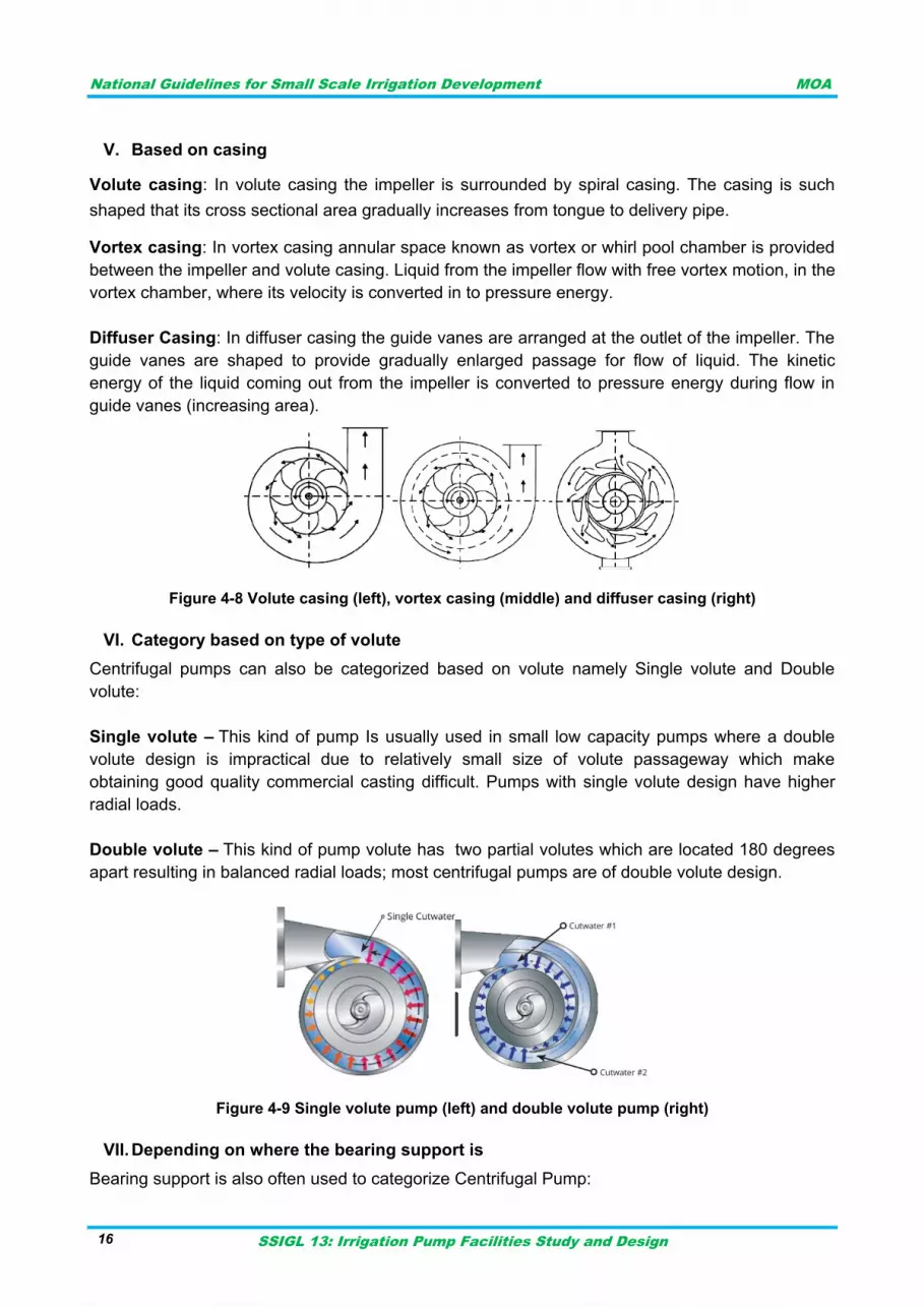
National Guidelines for Small Scale Irrigation Development MOA
SSIGL 13: Irrigation Pump Facilities Study and Design 16
V. Based on casing
Volute casing: In volute casing the impeller is surrounded by spiral casing. The casing is such
shaped that its cross sectional area gradually increases from tongue to delivery pipe.
Vortex casing: In vortex casing annular space known as vortex or whirl pool chamber is provided
between the impeller and volute casing. Liquid from the impeller flow with free vortex motion, in the
vortex chamber, where its velocity is converted in to pressure energy.
Diffuser Casing: In diffuser casing the guide vanes are arranged at the outlet of the impeller. The
guide vanes are shaped to provide gradually enlarged passage for flow of liquid. The kinetic
energy of the liquid coming out from the impeller is converted to pressure energy during flow in
guide vanes (increasing area).
Figure 4-8 Volute casing (left), vortex casing (middle) and diffuser casing (right)
VI. Category based on type of volute
Centrifugal pumps can also be categorized based on volute namely Single volute and Double
volute:
Single volute – This kind of pump Is usually used in small low capacity pumps where a double
volute design is impractical due to relatively small size of volute passageway which make
obtaining good quality commercial casting difficult. Pumps with single volute design have higher
radial loads.
Double volute – This kind of pump volute has two partial volutes which are located 180 degrees
apart resulting in balanced radial loads; most centrifugal pumps are of double volute design.
Figure 4-9 Single volute pump (left) and double volute pump (right)
VII. Depending on where the bearing support is
Bearing support is also often used to categorize Centrifugal Pump:
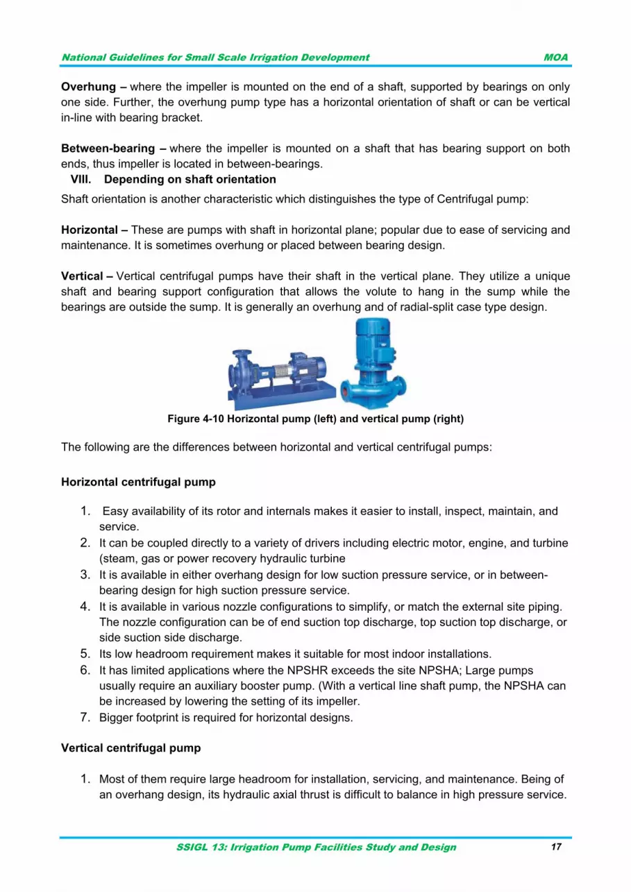
National Guidelines for Small Scale Irrigation Development MOA
SSIGL 13: Irrigation Pump Facilities Study and Design 17
Overhung – where the impeller is mounted on the end of a shaft, supported by bearings on only
one side. Further, the overhung pump type has a horizontal orientation of shaft or can be vertical
in-line with bearing bracket.
Between-bearing – where the impeller is mounted on a shaft that has bearing support on both
ends, thus impeller is located in between-bearings.
VIII. Depending on shaft orientation
Shaft orientation is another characteristic which distinguishes the type of Centrifugal pump:
Horizontal – These are pumps with shaft in horizontal plane; popular due to ease of servicing and
maintenance. It is sometimes overhung or placed between bearing design.
Vertical – Vertical centrifugal pumps have their shaft in the vertical plane. They utilize a unique
shaft and bearing support configuration that allows the volute to hang in the sump while the
bearings are outside the sump. It is generally an overhung and of radial-split case type design.
Figure 4-10 Horizontal pump (left) and vertical pump (right)
The following are the differences between horizontal and vertical centrifugal pumps:
Horizontal centrifugal pump
1. Easy availability of its rotor and internals makes it easier to install, inspect, maintain, and
service.
2. It can be coupled directly to a variety of drivers including electric motor, engine, and turbine
(steam, gas or power recovery hydraulic turbine
3. It is available in either overhang design for low suction pressure service, or in between-
bearing design for high suction pressure service.
4. It is available in various nozzle configurations to simplify, or match the external site piping.
The nozzle configuration can be of end suction top discharge, top suction top discharge, or
side suction side discharge.
5. Its low headroom requirement makes it suitable for most indoor installations.
6. It has limited applications where the NPSHR exceeds the site NPSHA; Large pumps
usually require an auxiliary booster pump. (With a vertical line shaft pump, the NPSHA can
be increased by lowering the setting of its impeller.
7. Bigger footprint is required for horizontal designs.
Vertical centrifugal pump
1. Most of them require large headroom for installation, servicing, and maintenance. Being of
an overhang design, its hydraulic axial thrust is difficult to balance in high pressure service.
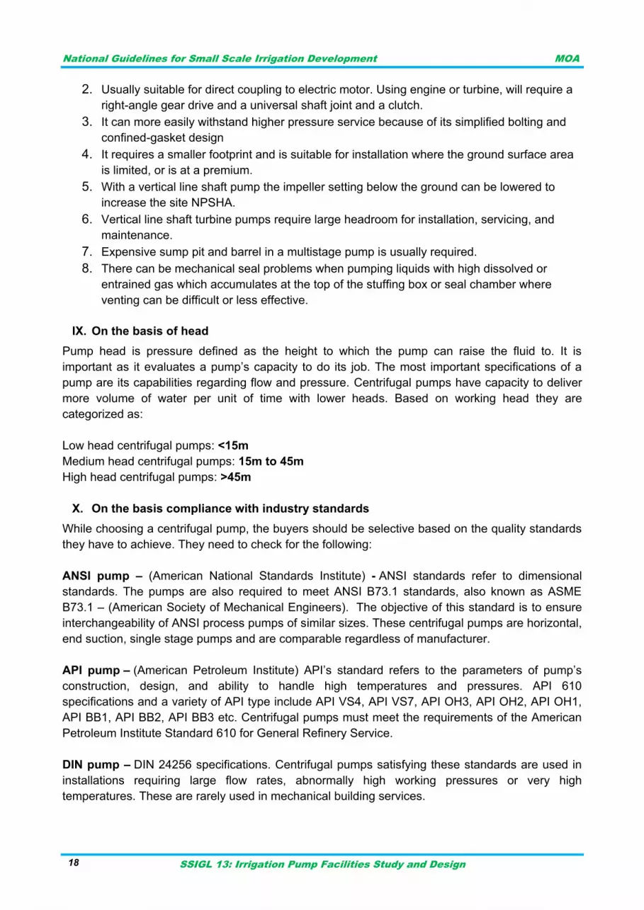
National Guidelines for Small Scale Irrigation Development MOA
SSIGL 13: Irrigation Pump Facilities Study and Design 18
2. Usually suitable for direct coupling to electric motor. Using engine or turbine, will require a
right-angle gear drive and a universal shaft joint and a clutch.
3. It can more easily withstand higher pressure service because of its simplified bolting and
confined-gasket design
4. It requires a smaller footprint and is suitable for installation where the ground surface area
is limited, or is at a premium.
5. With a vertical line shaft pump the impeller setting below the ground can be lowered to
increase the site NPSHA.
6. Vertical line shaft turbine pumps require large headroom for installation, servicing, and
maintenance.
7. Expensive sump pit and barrel in a multistage pump is usually required.
8. There can be mechanical seal problems when pumping liquids with high dissolved or
entrained gas which accumulates at the top of the stuffing box or seal chamber where
venting can be difficult or less effective.
IX. On the basis of head
Pump head is pressure defined as the height to which the pump can raise the fluid to. It is
important as it evaluates a pump‟s capacity to do its job. The most important specifications of a
pump are its capabilities regarding flow and pressure. Centrifugal pumps have capacity to deliver
more volume of water per unit of time with lower heads. Based on working head they are
categorized as:
Low head centrifugal pumps: <15m
Medium head centrifugal pumps: 15m to 45m
High head centrifugal pumps: >45m
X. On the basis compliance with industry standards
While choosing a centrifugal pump, the buyers should be selective based on the quality standards
they have to achieve. They need to check for the following:
ANSI pump – (American National Standards Institute) - ANSI standards refer to dimensional
standards. The pumps are also required to meet ANSI B73.1 standards, also known as ASME
B73.1 – (American Society of Mechanical Engineers). The objective of this standard is to ensure
interchangeability of ANSI process pumps of similar sizes. These centrifugal pumps are horizontal,
end suction, single stage pumps and are comparable regardless of manufacturer.
API pump – (American Petroleum Institute) API‟s standard refers to the parameters of pump‟s
construction, design, and ability to handle high temperatures and pressures. API 610
specifications and a variety of API type include API VS4, API VS7, API OH3, API OH2, API OH1,
API BB1, API BB2, API BB3 etc. Centrifugal pumps must meet the requirements of the American
Petroleum Institute Standard 610 for General Refinery Service.
DIN pump – DIN 24256 specifications. Centrifugal pumps satisfying these standards are used in
installations requiring large flow rates, abnormally high working pressures or very high
temperatures. These are rarely used in mechanical building services.
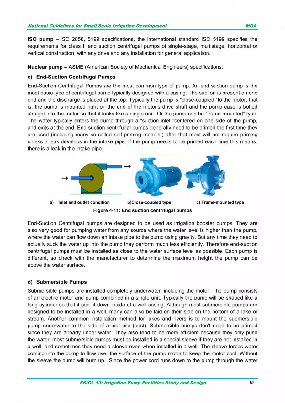
National Guidelines for Small Scale Irrigation Development MOA
SSIGL 13: Irrigation Pump Facilities Study and Design 19
ISO pump – ISO 2858, 5199 specifications, the international standard ISO 5199 specifies the
requirements for class II end suction centrifugal pumps of single-stage, multistage, horizontal or
vertical construction, with any drive and any installation for general application.
Nuclear pump – ASME (American Society of Mechanical Engineers) specifications.
c) End-Suction Centrifugal Pumps
End-Suction Centrifugal Pumps are the most common type of pump. An end suction pump is the
most basic type of centrifugal pump typically designed with a casing. The suction is present on one
end and the discharge is placed at the top. Typically the pump is "close-coupled "to the motor, that
is, the pump is mounted right on the end of the motor's drive shaft and the pump case is bolted
straight into the motor so that it looks like a single unit. Or the pump can be “frame-mounted” type.
The water typically enters the pump through a "suction inlet "centered on one side of the pump,
and exits at the end. End-suction centrifugal pumps generally need to be primed the first time they
are used (including many so-called self-priming models,) after that most will not require priming
unless a leak develops in the intake pipe. If the pump needs to be primed each time this means,
there is a leak in the intake pipe.
a) Inlet and outlet condition b)Close-coupled type c) Frame-mounted type
Figure 4-11: End suction centrifugal pumps
End-Suction Centrifugal pumps are designed to be used as irrigation booster pumps. They are
also very good for pumping water from any source where the water level is higher than the pump,
where the water can flow down an intake pipe to the pump using gravity. But any time they need to
actually suck the water up into the pump they perform much less efficiently. Therefore end-suction
centrifugal pumps must be installed as close to the water surface level as possible. Each pump is
different, so check with the manufacturer to determine the maximum height the pump can be
above the water surface.
d) Submersible Pumps
Submersible pumps are installed completely underwater, including the motor. The pump consists
of an electric motor and pump combined in a single unit. Typically the pump will be shaped like a
long cylinder so that it can fit down inside of a well casing. Although most submersible pumps are
designed to be installed in a well, many can also be laid on their side on the bottom of a lake or
stream. Another common installation method for lakes and rivers is to mount the submersible
pump underwater to the side of a pier pile (post). Submersible pumps don't need to be primed
since they are already under water. They also tend to be more efficient because they only push
the water, most submersible pumps must be installed in a special sleeve if they are not installed in
a well, and sometimes they need a sleeve even when installed in a well. The sleeve forces water
coming into the pump to flow over the surface of the pump motor to keep the motor cool. Without
the sleeve the pump will burn up. Since the power cord runs down to the pump through the water
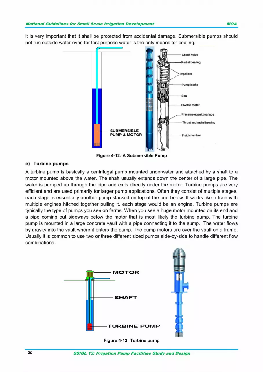
National Guidelines for Small Scale Irrigation Development MOA
SSIGL 13: Irrigation Pump Facilities Study and Design 20
it is very important that it shall be protected from accidental damage. Submersible pumps should
not run outside water even for test purpose water is the only means for cooling.
Figure 4-12: A Submersible Pump
e) Turbine pumps
A turbine pump is basically a centrifugal pump mounted underwater and attached by a shaft to a
motor mounted above the water. The shaft usually extends down the center of a large pipe. The
water is pumped up through the pipe and exits directly under the motor. Turbine pumps are very
efficient and are used primarily for larger pump applications. Often they consist of multiple stages,
each stage is essentially another pump stacked on top of the one below. It works like a train with
multiple engines hitched together pulling it, each stage would be an engine. Turbine pumps are
typically the type of pumps you see on farms. When you see a huge motor mounted on its end and
a pipe coming out sideways below the motor that is most likely the turbine pump. The turbine
pump is mounted in a large concrete vault with a pipe connecting it to the sump. The water flows
by gravity into the vault where it enters the pump. The pump motors are over the vault on a frame.
Usually it is common to use two or three different sized pumps side-by-side to handle different flow
combinations.
Figure 4-13: Turbine pump
National Guidelines for Small Scale Irrigation Development MOA
SSIGL 13: Irrigation Pump Facilities Study and Design 21
SITE SELECTION CRITERIA FOR PUMPING FACILITY 4.3
General site Selection criteria for the pumping facility are:
I. The location of the pumps should be above Highest Flood Level (H.F.L.) or well protected against high floods.
II. Required quantity of water should be available as the site. III. The pumping station should be at higher level above all the sources of contamination. IV. The location site should be such that future growth and expansion may be possible. V. The source of water should be permanent. In case of meandering rivers, the site should be
such that the water is available at the pumping station. VI. The site must be accessible and as close as possible to the delivery point
VII. Foundation and bank conditions must be suitable VIII. Power source must be accounted while making site selection
IX. Availability of construction material X. Ease of operation and maintenance is also one factor for site selection
MAJOR COMPONENTS OF PUMPING FACILITY 4.4
Major components of pumping facility are:
The building or pump house
The buildings are designed to accommodate the pump, motor and other couplings with door opening wide enough to allow good access and are designed for well ventilated circumstances. Ventilation mesh is usually provided. The Concrete pump seat is also provided with proper reinforcements. Usually the pump house also would have guard room and room for tools and accessories.
The hydraulic system: the suction sump, pump, pipes, fittings, delivery unit and anchor blocks are part of the hydraulic system.
Systematic arrangement of the hydraulic system (the pumps, pipes, fittings, suction and delivery) is very important for efficient pumping system.
The power supply unit: For example in electrical system the power line, transformer, the cables, motor and its related components.
The electrical and instrumentation components includes the following: a) electrical facilities configuration; b) emergency power design elements and sizing; c) fuel storage and transfer systems; d) pump station equipment selection and control system; e) pump station control room arrangement; and f) facility lighting, intrusion detection, and fire detection.
Lifting system: The lifting system can be manual, mechanical or electrical hoisting mechanism used during installation and maintenance. This may serve to lift and re-fix the pump, motor or engine, fittings and other accessories related to the pumping system.
The control system: pressure, flow rate, control board, control switches and fuses etc.
Ball valve and wide body globe valves are used to control flow and pressure from a pump as well as reduce water hammer during shutdown.

National Guidelines for Small Scale Irrigation Development MOA
SSIGL 13: Irrigation Pump Facilities Study and Design 22
National Guidelines for Small Scale Irrigation Development MOA
SSIGL 13: Irrigation Pump Facilities Study and Design 23
PIPES, VALVES & FITTINGS 5
PIPES 5.1
The type and size of pipe plays an important role in conveyance of fluid from one position to other.
The design of any pipe network involves various activities like the selection of pipe material,
specification with respect to nominal pressure, wall roughness, wall thickness, nominal diameter,
galvanization, etc. Different pipe materials are used for irrigation like steel, galvanized iron,
aluminum, asbestos, concrete, LDPE, HDPE, PVC and cast iron pipe. The pipes can be
connected with thread, flange, welds, socket and different seals or gaskets. The selection
preference depends on the pressure (including water hammer), the discharge and fluid property,
economy, availability in market, durability and any other issues on site like installation conditions,
corrosion etc. It is always important to understand class of the pipe as per ISO standards to use
for the intended purpose.
The following key factors apply to material selection:
Primary consideration shall be given to materials with good market availability and documented fabrication and service performance.
The number of different material types shall be minimized considering costs, interchangeability and availability of relevant spare parts.
Design life.
Operating conditions.
Experience with materials and corrosion protection methods from conditions with similar corrosivity.
System availability requirements.
Philosophy applied for maintenance and degree of system redundancy.
Weight reduction.
Inspection and corrosion monitoring possibilities.
Effect of external and internal environment, including compatibility of different materials.
Evaluation of failure probabilities, failure modes, criticalities and consequences.
Attention shall be paid to any adverse effects material selection may have on human health, environment, safety and material assets.
Environmental issues related to corrosion inhibition and other chemical treatments.
For main systems where materials/fabrication represent significant investments and/or operational costs.
VALVES 5.2
A valve is a mechanical device that controls the flow of fluid and pressure within a system or
process. A valve controls system or process fluid flow and pressure by performing any of the
following functions:
Stopping and starting fluid flow
Varying (throttling) the amount of fluid flow
Controlling the direction of fluid flow
Regulating downstream system or process pressure
Relieving component or piping over pressure
There are many valve designs and types that satisfy one or more of the functions identified above.
A multitude of valve types and designs safely accommodate a wide variety of industrial
applications.
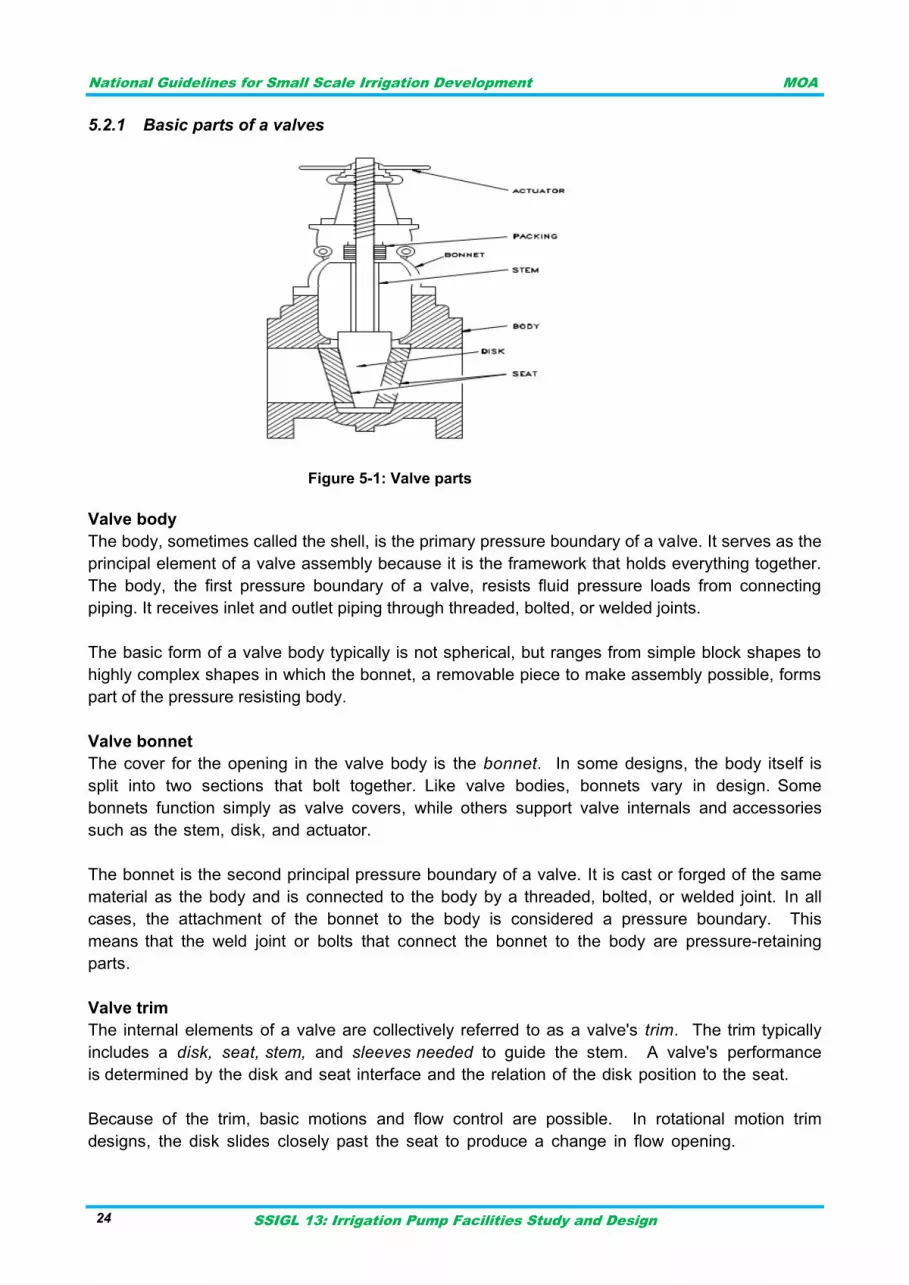
National Guidelines for Small Scale Irrigation Development MOA
SSIGL 13: Irrigation Pump Facilities Study and Design 24
Basic parts of a valves 5.2.1
Figure 5-1: Valve parts
Valve body
The body, sometimes called the shell, is the primary pressure boundary of a valve. It serves as the
principal element of a valve assembly because it is the framework that holds everything together.
The body, the first pressure boundary of a valve, resists fluid pressure loads from connecting
piping. It receives inlet and outlet piping through threaded, bolted, or welded joints.
The basic form of a valve body typically is not spherical, but ranges from simple block shapes to
highly complex shapes in which the bonnet, a removable piece to make assembly possible, forms
part of the pressure resisting body.
Valve bonnet
The cover for the opening in the valve body is the bonnet. In some designs, the body itself is
split into two sections that bolt together. Like valve bodies, bonnets vary in design. Some
bonnets function simply as valve covers, while others support valve internals and accessories
such as the stem, disk, and actuator.
The bonnet is the second principal pressure boundary of a valve. It is cast or forged of the same
material as the body and is connected to the body by a threaded, bolted, or welded joint. In all
cases, the attachment of the bonnet to the body is considered a pressure boundary. This
means that the weld joint or bolts that connect the bonnet to the body are pressure-retaining
parts.
Valve trim
The internal elements of a valve are collectively referred to as a valve's trim. The trim typically
includes a disk, seat, stem, and sleeves needed to guide the stem. A valve's performance
is determined by the disk and seat interface and the relation of the disk position to the seat.
Because of the trim, basic motions and flow control are possible. In rotational motion trim
designs, the disk slides closely past the seat to produce a change in flow opening.
National Guidelines for Small Scale Irrigation Development MOA
SSIGL 13: Irrigation Pump Facilities Study and Design 25
Disk and seat
For a valve having a bonnet, the disk is the third primary principal pressure boundary. The disk
provides the capability for permitting and prohibiting fluid flow. With the disk closed, full system
pressure is applied across the disk if the outlet side is depressurized. For this reason, the disk
is a pressure-retaining part. Disks are typically forged and, in some designs, hard-surfaced to
provide good wear characteristics. A fine surface finish of the seating area of a disk is necessary
for good sealing when the valve is closed. Most valves are named, in part, according to the
design of their disks.
Stem
The stem, which connects the actuator and disk, is responsible for positioning the disk. Stems
are typically forged and connected to the disk by threaded or welded joints. For valve designs
requiring stem packing or sealing to prevent leakage, a fine surface finish of the stem in the
area of the seal is necessary. Typically, a stem is not considered a pressure boundary part.
Connection of the disk to the stem can allow some rocking or rotation to ease the
positioning of the disk on the seat. Alternately, the stem may be flexible enough to let the disk
position itself against the seat.
Valve actuator
The actuator operates the stem and disk assembly. An actuator may be a manually
operated hand wheel, manual lever, motor operator, solenoid operator, pneumatic operator, or
hydraulic ram. In some designs, the actuator is supported by the bonnet. In other designs,
a yoke mounted to the bonnet supports the actuator.
Except for certain hydraulically controlled valves, actuators are outside of the pressure boundary.
Yokes, when used, are always outside of the pressure boundary.
Valve Packing
Most valves use some form of packing to prevent leakage from the space between the stem and
the bonnet. Packing is commonly a fibrous material (such as flax) or another compound (such
as Teflon) that forms a seal between the internal parts of a valve and the outside where the
stem extends through the body.
Valve packing must be properly compressed to prevent fluid loss and damage to the valve's
stem. If a valve's packing is too loose, the valve will leak, which is a safety hazard. If the
packing is too tight, it will impair the movement and possibly damage the stem.
Types of valves 5.2.2
Because of the diversity of the types of systems, fluids, and environments in which valves must
operate, a vast array of valve types have been developed. Examples of the common types are
the globe valve, gate valve, ball valve, plug valve, butterfly valve, diaphragm valve, check valve,
pinch valve, and safety valve. Each type of valve has been designed to meet specific needs.
Some valves are capable of throttling flow, other valve types can only stop flow, others work
well in corrosive systems, and others handle high pressure fluids. Each valve type has certain
inherent advantages and disadvantages. Understanding these differences and how they affect the
valve's application or operation is necessary for the successful operation of a facility.
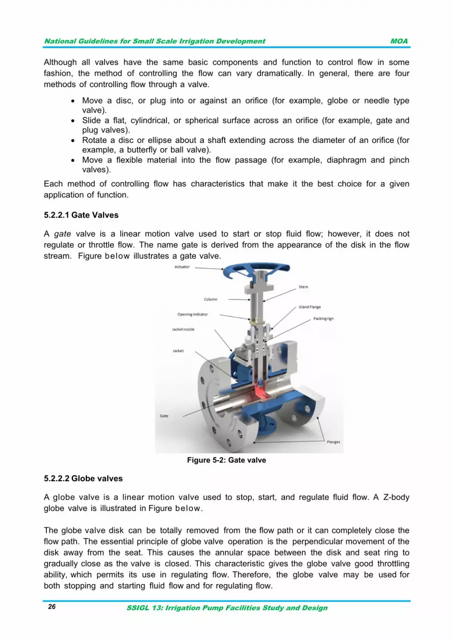
National Guidelines for Small Scale Irrigation Development MOA
SSIGL 13: Irrigation Pump Facilities Study and Design 26
Although all valves have the same basic components and function to control flow in some
fashion, the method of controlling the flow can vary dramatically. In general, there are four
methods of controlling flow through a valve.
Move a disc, or plug into or against an orifice (for example, globe or needle type valve).
Slide a flat, cylindrical, or spherical surface across an orifice (for example, gate and plug valves).
Rotate a disc or ellipse about a shaft extending across the diameter of an orifice (for example, a butterfly or ball valve).
Move a flexible material into the flow passage (for example, diaphragm and pinch valves).
Each method of controlling flow has characteristics that make it the best choice for a given
application of function.
Gate Valves 5.2.2.1
A gate valve is a linear motion valve used to start or stop fluid flow; however, it does not
regulate or throttle flow. The name gate is derived from the appearance of the disk in the flow
stream. Figure below illustrates a gate valve.
Figure 5-2: Gate valve
Globe valves 5.2.2.2
A globe valve is a linear motion valve used to stop, start, and regulate fluid flow. A Z-body
globe valve is illustrated in Figure below.
The globe valve disk can be totally removed from the flow path or it can completely close the
flow path. The essential principle of globe valve operation is the perpendicular movement of the
disk away from the seat. This causes the annular space between the disk and seat ring to
gradually close as the valve is closed. This characteristic gives the globe valve good throttling
ability, which permits its use in regulating flow. Therefore, the globe valve may be used for
both stopping and starting fluid flow and for regulating flow.
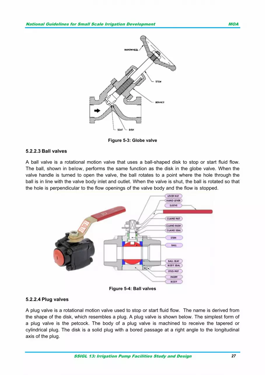
National Guidelines for Small Scale Irrigation Development MOA
SSIGL 13: Irrigation Pump Facilities Study and Design 27
Figure 5-3: Globe valve
Ball valves 5.2.2.3
A ball valve is a rotational motion valve that uses a ball-shaped disk to stop or start fluid flow.
The ball, shown in below, performs the same function as the disk in the globe valve. When the
valve handle is turned to open the valve, the ball rotates to a point where the hole through the
ball is in line with the valve body inlet and outlet. When the valve is shut, the ball is rotated so that
the hole is perpendicular to the flow openings of the valve body and the flow is stopped.
Figure 5-4: Ball valves
Plug valves 5.2.2.4
A plug valve is a rotational motion valve used to stop or start fluid flow. The name is derived from
the shape of the disk, which resembles a plug. A plug valve is shown below. The simplest form of
a plug valve is the petcock. The body of a plug valve is machined to receive the tapered or
cylindrical plug. The disk is a solid plug with a bored passage at a right angle to the longitudinal
axis of the plug.
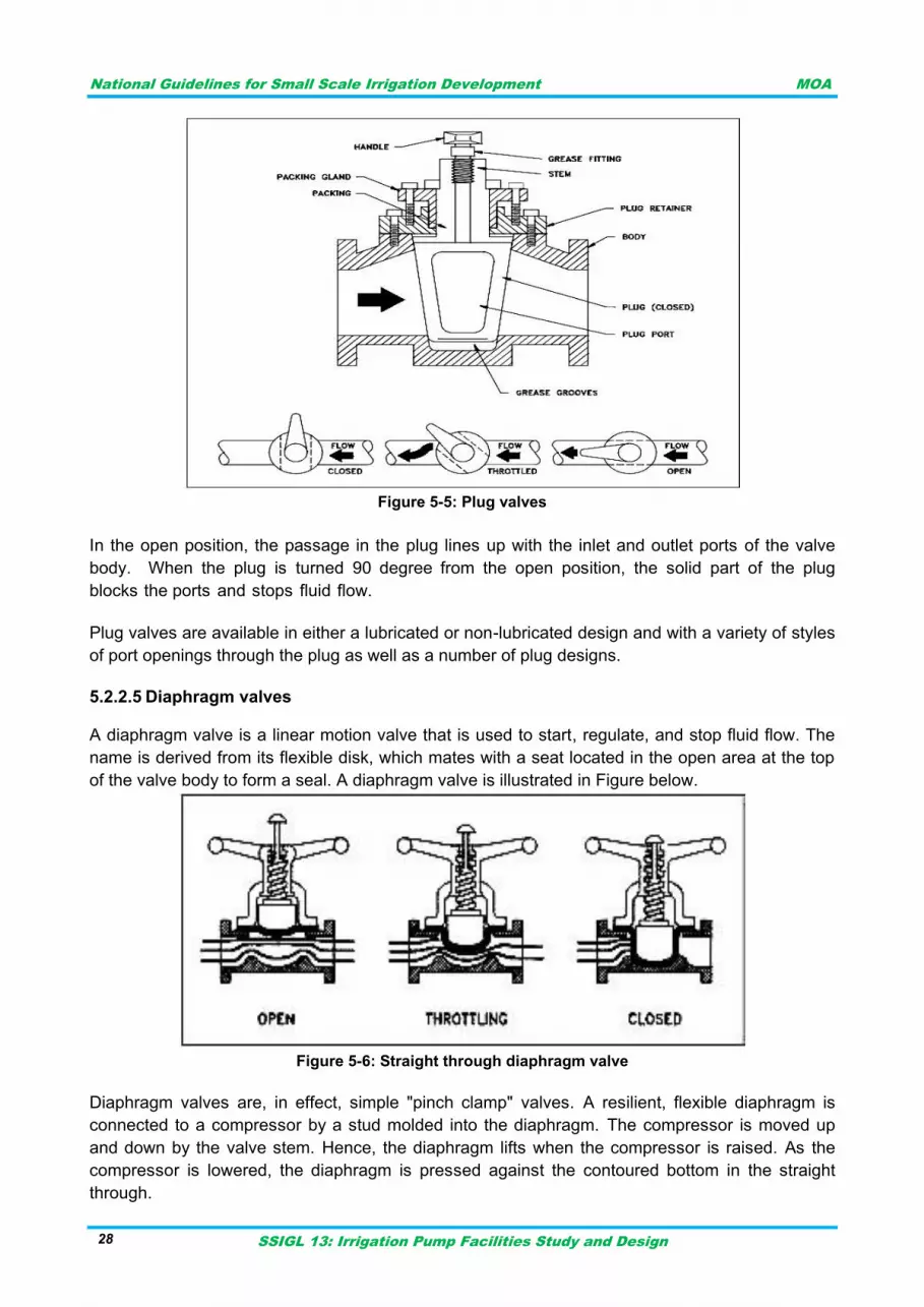
National Guidelines for Small Scale Irrigation Development MOA
SSIGL 13: Irrigation Pump Facilities Study and Design 28
Figure 5-5: Plug valves
In the open position, the passage in the plug lines up with the inlet and outlet ports of the valve
body. When the plug is turned 90 degree from the open position, the solid part of the plug
blocks the ports and stops fluid flow.
Plug valves are available in either a lubricated or non-lubricated design and with a variety of styles
of port openings through the plug as well as a number of plug designs.
Diaphragm valves 5.2.2.5
A diaphragm valve is a linear motion valve that is used to start, regulate, and stop fluid flow. The
name is derived from its flexible disk, which mates with a seat located in the open area at the top
of the valve body to form a seal. A diaphragm valve is illustrated in Figure below.
Figure 5-6: Straight through diaphragm valve
Diaphragm valves are, in effect, simple "pinch clamp" valves. A resilient, flexible diaphragm is
connected to a compressor by a stud molded into the diaphragm. The compressor is moved up
and down by the valve stem. Hence, the diaphragm lifts when the compressor is raised. As the
compressor is lowered, the diaphragm is pressed against the contoured bottom in the straight
through.
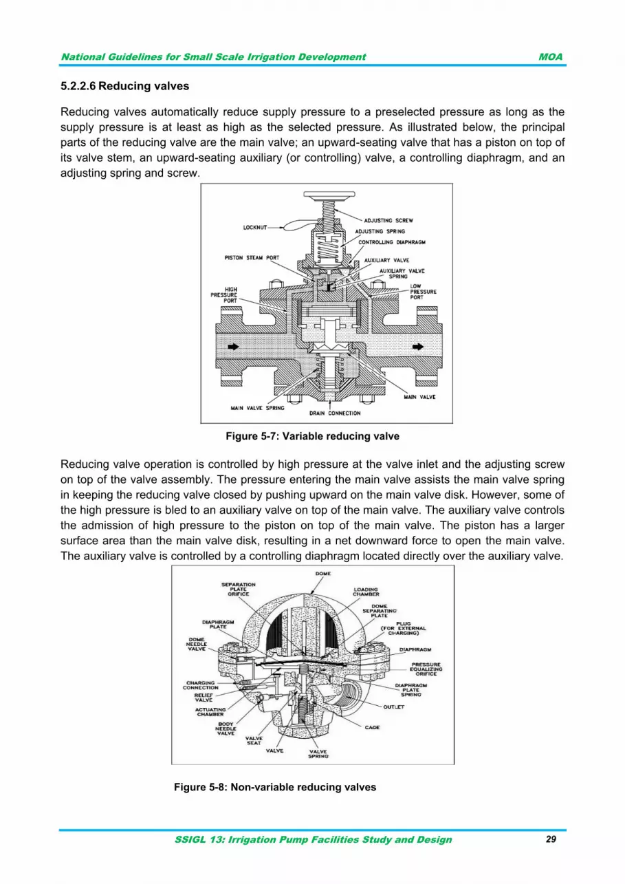
National Guidelines for Small Scale Irrigation Development MOA
SSIGL 13: Irrigation Pump Facilities Study and Design 29
Reducing valves 5.2.2.6
Reducing valves automatically reduce supply pressure to a preselected pressure as long as the
supply pressure is at least as high as the selected pressure. As illustrated below, the principal
parts of the reducing valve are the main valve; an upward-seating valve that has a piston on top of
its valve stem, an upward-seating auxiliary (or controlling) valve, a controlling diaphragm, and an
adjusting spring and screw.
Figure 5-7: Variable reducing valve
Reducing valve operation is controlled by high pressure at the valve inlet and the adjusting screw
on top of the valve assembly. The pressure entering the main valve assists the main valve spring
in keeping the reducing valve closed by pushing upward on the main valve disk. However, some of
the high pressure is bled to an auxiliary valve on top of the main valve. The auxiliary valve controls
the admission of high pressure to the piston on top of the main valve. The piston has a larger
surface area than the main valve disk, resulting in a net downward force to open the main valve.
The auxiliary valve is controlled by a controlling diaphragm located directly over the auxiliary valve.
Figure 5-8: Non-variable reducing valves
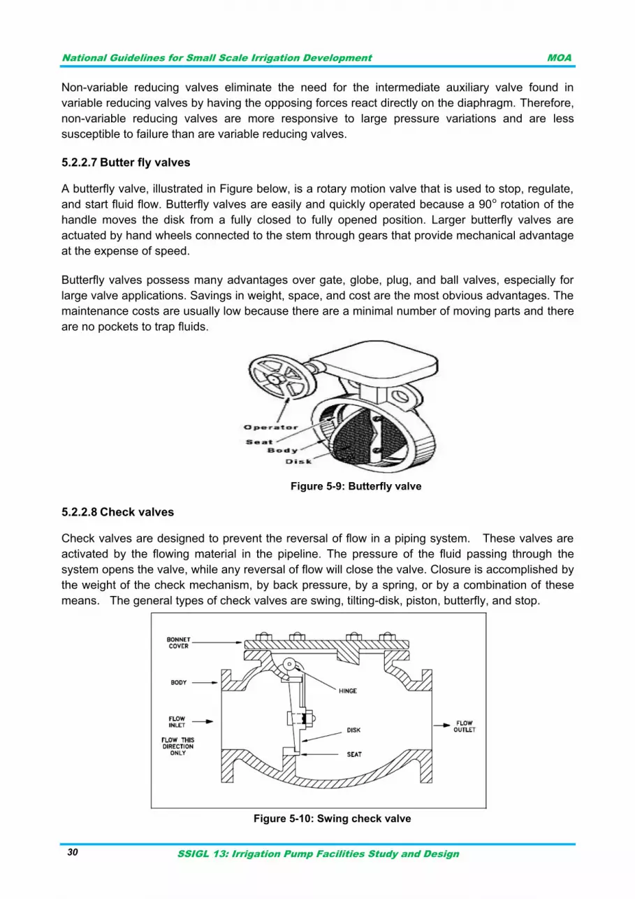
National Guidelines for Small Scale Irrigation Development MOA
SSIGL 13: Irrigation Pump Facilities Study and Design 30
Non-variable reducing valves eliminate the need for the intermediate auxiliary valve found in
variable reducing valves by having the opposing forces react directly on the diaphragm. Therefore,
non-variable reducing valves are more responsive to large pressure variations and are less
susceptible to failure than are variable reducing valves.
Butter fly valves 5.2.2.7
A butterfly valve, illustrated in Figure below, is a rotary motion valve that is used to stop, regulate,
and start fluid flow. Butterfly valves are easily and quickly operated because a 90o rotation of the
handle moves the disk from a fully closed to fully opened position. Larger butterfly valves are
actuated by hand wheels connected to the stem through gears that provide mechanical advantage
at the expense of speed.
Butterfly valves possess many advantages over gate, globe, plug, and ball valves, especially for
large valve applications. Savings in weight, space, and cost are the most obvious advantages. The
maintenance costs are usually low because there are a minimal number of moving parts and there
are no pockets to trap fluids.
Figure 5-9: Butterfly valve
Check valves 5.2.2.8
Check valves are designed to prevent the reversal of flow in a piping system. These valves are
activated by the flowing material in the pipeline. The pressure of the fluid passing through the
system opens the valve, while any reversal of flow will close the valve. Closure is accomplished by
the weight of the check mechanism, by back pressure, by a spring, or by a combination of these
means. The general types of check valves are swing, tilting-disk, piston, butterfly, and stop.
Figure 5-10: Swing check valve
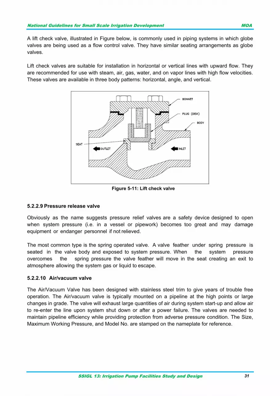
National Guidelines for Small Scale Irrigation Development MOA
SSIGL 13: Irrigation Pump Facilities Study and Design 31
A lift check valve, illustrated in Figure below, is commonly used in piping systems in which globe
valves are being used as a flow control valve. They have similar seating arrangements as globe
valves.
Lift check valves are suitable for installation in horizontal or vertical lines with upward flow. They
are recommended for use with steam, air, gas, water, and on vapor lines with high flow velocities.
These valves are available in three body patterns: horizontal, angle, and vertical.
Figure 5-11: Lift check valve
Pressure release valve 5.2.2.9
Obviously as the name suggests pressure relief valves are a safety device designed to open
when system pressure (i.e. in a vessel or pipework) becomes too great and may damage
equipment or endanger personnel if not relieved.
The most common type is the spring operated valve. A valve feather under spring pressure is
seated in the valve body and exposed to system pressure. When the system pressure
overcomes the spring pressure the valve feather will move in the seat creating an exit to
atmosphere allowing the system gas or liquid to escape.
Air/vacuum valve 5.2.2.10
The Air/Vacuum Valve has been designed with stainless steel trim to give years of trouble free
operation. The Air/vacuum valve is typically mounted on a pipeline at the high points or large
changes in grade. The valve will exhaust large quantities of air during system start-up and allow air
to re-enter the line upon system shut down or after a power failure. The valves are needed to
maintain pipeline efficiency while providing protection from adverse pressure condition. The Size,
Maximum Working Pressure, and Model No. are stamped on the nameplate for reference.
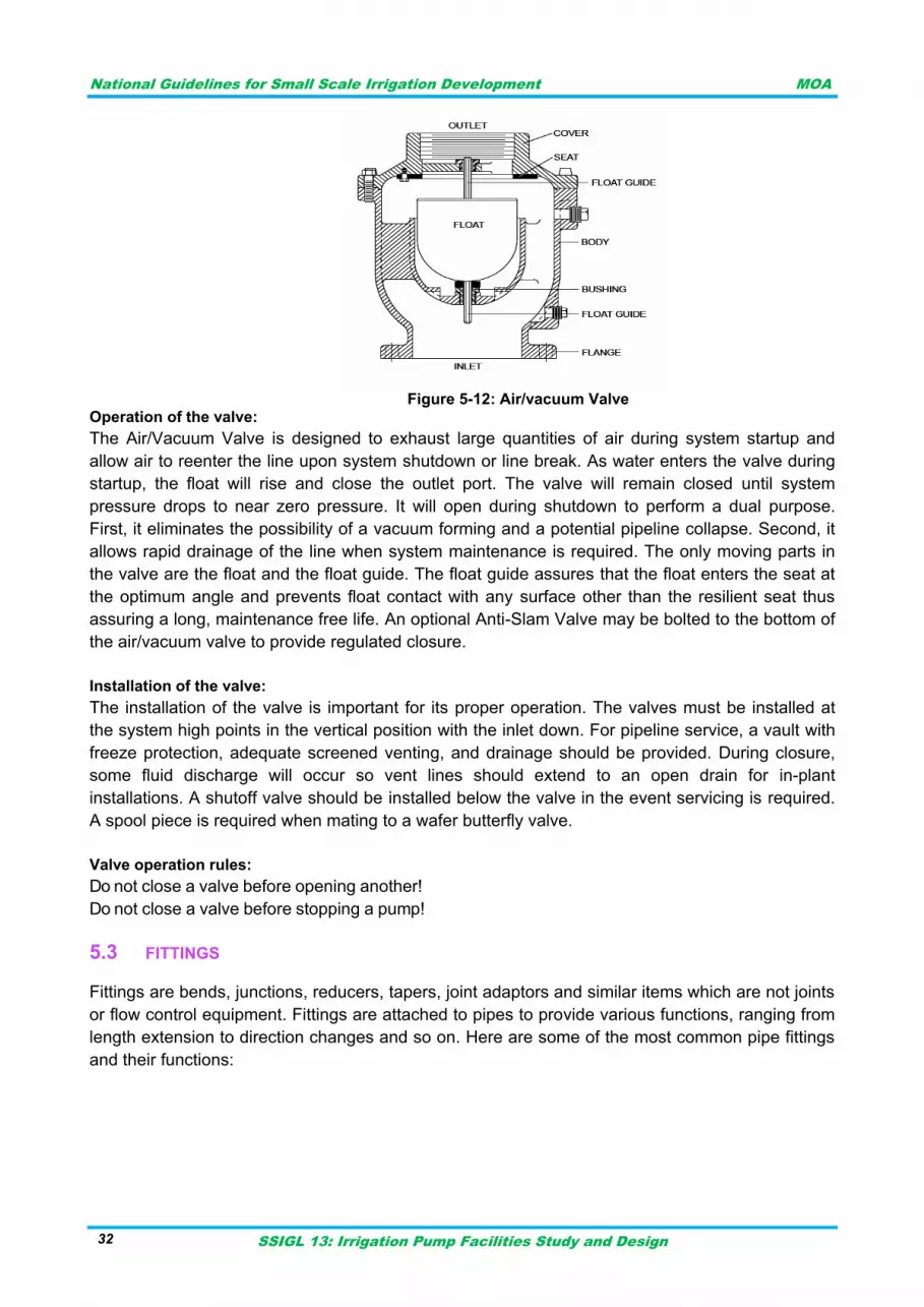
National Guidelines for Small Scale Irrigation Development MOA
SSIGL 13: Irrigation Pump Facilities Study and Design 32
Figure 5-12: Air/vacuum Valve
Operation of the valve:
The Air/Vacuum Valve is designed to exhaust large quantities of air during system startup and
allow air to reenter the line upon system shutdown or line break. As water enters the valve during
startup, the float will rise and close the outlet port. The valve will remain closed until system
pressure drops to near zero pressure. It will open during shutdown to perform a dual purpose.
First, it eliminates the possibility of a vacuum forming and a potential pipeline collapse. Second, it
allows rapid drainage of the line when system maintenance is required. The only moving parts in
the valve are the float and the float guide. The float guide assures that the float enters the seat at
the optimum angle and prevents float contact with any surface other than the resilient seat thus
assuring a long, maintenance free life. An optional Anti-Slam Valve may be bolted to the bottom of
the air/vacuum valve to provide regulated closure.
Installation of the valve:
The installation of the valve is important for its proper operation. The valves must be installed at
the system high points in the vertical position with the inlet down. For pipeline service, a vault with
freeze protection, adequate screened venting, and drainage should be provided. During closure,
some fluid discharge will occur so vent lines should extend to an open drain for in-plant
installations. A shutoff valve should be installed below the valve in the event servicing is required.
A spool piece is required when mating to a wafer butterfly valve.
Valve operation rules:
Do not close a valve before opening another!
Do not close a valve before stopping a pump!
FITTINGS 5.3
Fittings are bends, junctions, reducers, tapers, joint adaptors and similar items which are not joints
or flow control equipment. Fittings are attached to pipes to provide various functions, ranging from
length extension to direction changes and so on. Here are some of the most common pipe fittings
and their functions:
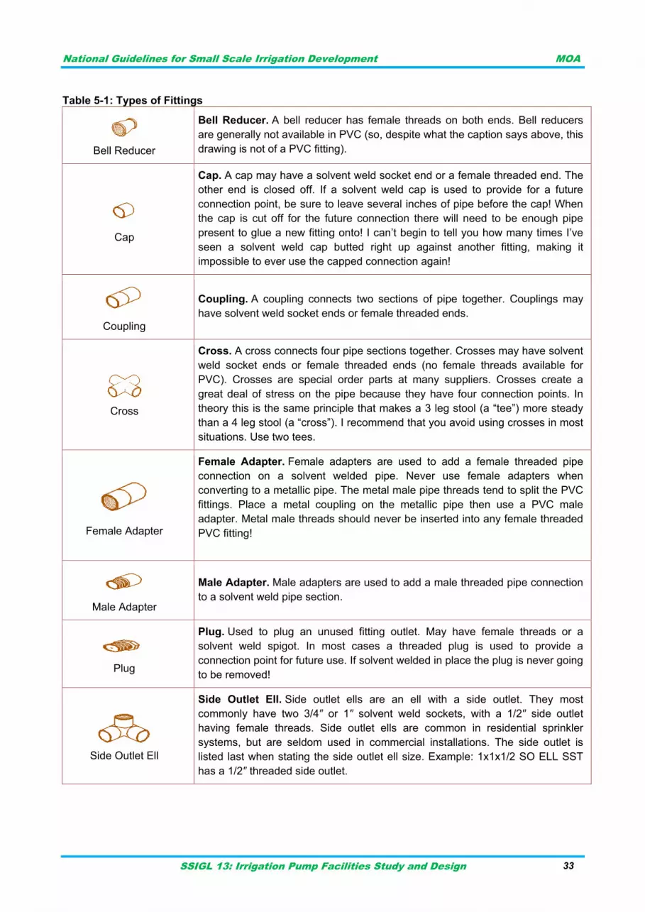
National Guidelines for Small Scale Irrigation Development MOA
SSIGL 13: Irrigation Pump Facilities Study and Design 33
Table 5-1: Types of Fittings
Bell Reducer
Bell Reducer. A bell reducer has female threads on both ends. Bell reducers
are generally not available in PVC (so, despite what the caption says above, this
drawing is not of a PVC fitting).
Cap
Cap. A cap may have a solvent weld socket end or a female threaded end. The
other end is closed off. If a solvent weld cap is used to provide for a future
connection point, be sure to leave several inches of pipe before the cap! When
the cap is cut off for the future connection there will need to be enough pipe
present to glue a new fitting onto! I can‟t begin to tell you how many times I‟ve
seen a solvent weld cap butted right up against another fitting, making it
impossible to ever use the capped connection again!
Coupling
Coupling. A coupling connects two sections of pipe together. Couplings may
have solvent weld socket ends or female threaded ends.
Cross
Cross. A cross connects four pipe sections together. Crosses may have solvent
weld socket ends or female threaded ends (no female threads available for
PVC). Crosses are special order parts at many suppliers. Crosses create a
great deal of stress on the pipe because they have four connection points. In
theory this is the same principle that makes a 3 leg stool (a “tee”) more steady
than a 4 leg stool (a “cross”). I recommend that you avoid using crosses in most
situations. Use two tees.
Female Adapter
Female Adapter. Female adapters are used to add a female threaded pipe
connection on a solvent welded pipe. Never use female adapters when
converting to a metallic pipe. The metal male pipe threads tend to split the PVC
fittings. Place a metal coupling on the metallic pipe then use a PVC male
adapter. Metal male threads should never be inserted into any female threaded
PVC fitting!
Male Adapter
Male Adapter. Male adapters are used to add a male threaded pipe connection
to a solvent weld pipe section.
Plug
Plug. Used to plug an unused fitting outlet. May have female threads or a
solvent weld spigot. In most cases a threaded plug is used to provide a
connection point for future use. If solvent welded in place the plug is never going
to be removed!
Side Outlet Ell
Side Outlet Ell. Side outlet ells are an ell with a side outlet. They most
commonly have two 3/4″ or 1″ solvent weld sockets, with a 1/2″ side outlet
having female threads. Side outlet ells are common in residential sprinkler
systems, but are seldom used in commercial installations. The side outlet is
listed last when stating the side outlet ell size. Example: 1x1x1/2 SO ELL SST
has a 1/2″ threaded side outlet.
National Guidelines for Small Scale Irrigation Development MOA
SSIGL 13: Irrigation Pump Facilities Study and Design 34
Tee
Tee. The most common fitting! Available with all female thread sockets, all
solvent weld sockets, or with opposed solvent weld sockets and a side outlet
with female threads. Many configurations of “reducer tees” are available,
meaning that one or more of the sockets is smaller than the others. Tees are
always labeled as TEE with the side outlet as the last size. The larger of the
other two sockets is always listed first.
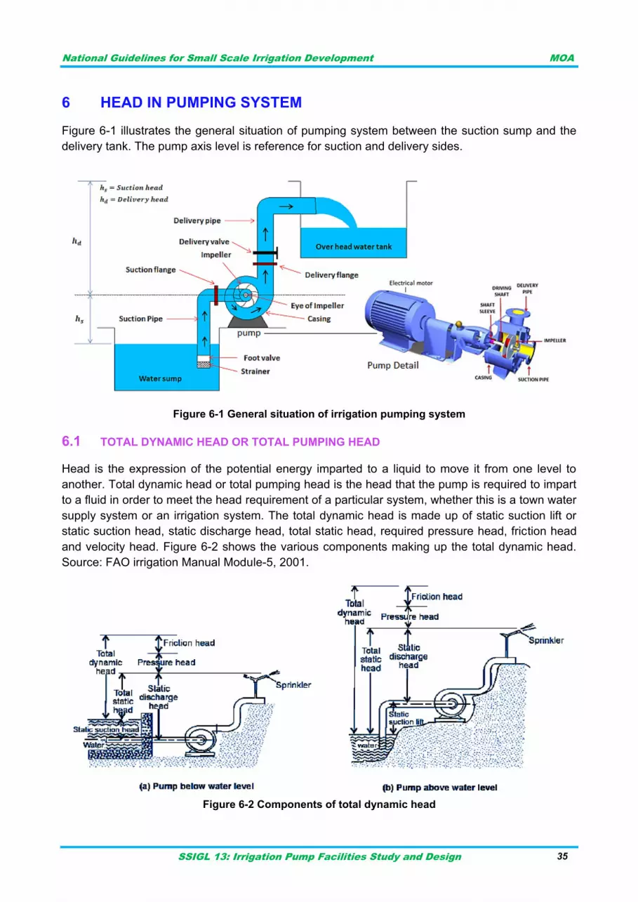
National Guidelines for Small Scale Irrigation Development MOA
SSIGL 13: Irrigation Pump Facilities Study and Design 35
HEAD IN PUMPING SYSTEM 6
Figure 6-1 illustrates the general situation of pumping system between the suction sump and the
delivery tank. The pump axis level is reference for suction and delivery sides.
Figure 6-1 General situation of irrigation pumping system
TOTAL DYNAMIC HEAD OR TOTAL PUMPING HEAD 6.1
Head is the expression of the potential energy imparted to a liquid to move it from one level to
another. Total dynamic head or total pumping head is the head that the pump is required to impart
to a fluid in order to meet the head requirement of a particular system, whether this is a town water
supply system or an irrigation system. The total dynamic head is made up of static suction lift or
static suction head, static discharge head, total static head, required pressure head, friction head
and velocity head. Figure 6-2 shows the various components making up the total dynamic head.
Source: FAO irrigation Manual Module-5, 2001.
Figure 6-2 Components of total dynamic head
National Guidelines for Small Scale Irrigation Development MOA
SSIGL 13: Irrigation Pump Facilities Study and Design 36
STATIC SUCTION HEAD OR STATIC SUCTION LIFT 6.2
When a pump is installed such that the level of the water source is above the eye of the impeller
(flooded suction), then the system is said to have a positive suction head at the eye of the impeller.
However, when the pump is installed above the water source, the vertical distance from the
surface of the water to the eye of the impeller is called the static suction lift.
STATIC DISCHARGE HEAD 6.3
This is the vertical distance or difference in elevation between the point at which water leaves the
impeller and the point at which water leaves the system, for example the outlet of the highest
sprinkler in an overhead irrigation system.
TOTAL STATIC HEAD 6.4
When no water is flowing (static conditions), the head required to move a drop of water from water
source to the highest sprinkler or outlet point is equal to the total static head. This is simply the
difference in elevation between where we want the water and where it is now. For systems with
the water level is above the pump, the total static head is the difference between the elevations of
the water and the sprinkler (Figure 6-2a).
Total Static Head = Static Discharge Head – Static Suction Head
For systems where the water level is below the pump, the total static head is the static discharge
head plus the static suction lift (Figure 6-2b).
Total Static Head = Static Discharge Head + Static Suction Lift
FRICTION HEAD 6.5
The pressure decreases in pipe flow because of the friction against the walls of the pipe over its
length. Therefore, the pump needs to provide the necessary energy to the water to overcome the
friction losses. The losses must be considered both for the suction part and the discharge part of
the pump. The magnitude of the friction head can be calculated using either hydraulic formulae or
tables and graphs.
PRESSURE HEAD 6.6
Except for the cases where water is discharged to a reservoir, or a canal, a certain head to
operate an irrigation system is required. For example, in order for a sprinkler system to operate, a
certain head is required.
VELOCITY HEAD 6.7
This energy component is not shown in Figure 6-2. It is very small and is normally not included in
practical pressure calculations. Most of the energy that a pump adds to flowing water is converted
to pressure in the water. Some of the energy is added to the water to give the velocity it requires to
move through the pipeline. The faster the water is moving the larger the velocity head. The amount
of energy that is needed to move water with a certain velocity is given by the formula:
National Guidelines for Small Scale Irrigation Development MOA
SSIGL 13: Irrigation Pump Facilities Study and Design 37
Velocity Head = V2/2g Equation 1 Where: V = the velocity of the water (m/s) g = the gravitational force which is equal to 9.81 (m/s2) Keller and Bliesner (1990) recommend that for centrifugal pumps the diameter of the suction pipe
should be selected such that the water velocity V< 3.3 m/s in order to assure good pump
performance. However, according to MoWR Design Manual on Pumping Facilities, 2001 the
suction velocity is taken about 1.5 m/s while for delivery line is about 2m/s.
DRAWDOWN 6.8
Usually, the level of the water in a well or even a reservoir behind a dam does not remain
constant. In the case of a well, after pumping starts with a certain discharge, the water level
lowers. This lowering of the water level is called drawdown. In the case of a dam or reservoir,
fluctuation of the water level is common and depends on water inflow, evaporation and water
withdrawal. The water level increases during the rainy season, followed by a decrease during the
dry season because of evaporation and withdrawal of the stored water. This variation in water
level will affect the static suction lift or the static suction head and, correspondingly, the total static
head.

National Guidelines for Small Scale Irrigation Development MOA
SSIGL 13: Irrigation Pump Facilities Study and Design 38
National Guidelines for Small Scale Irrigation Development MOA
SSIGL 13: Irrigation Pump Facilities Study and Design 39
LOSSES IN FLOW 7
A pipeline is a circular conduit used to convey fluid from one location in the system to another. A
pipeline consists of a circular pipe full of fluid, the valves and fittings used to direct the flow of fluid
through the pipe in the operation. Each of these items affects the head loss in the pipeline.
Flow of fluid through a pipe is resisted by viscous shear stresses within the fluid and the
turbulence that occurs along the internal pipe wall, which is dependent on the roughness of the
pipe material. This resistance is termed pipe friction and is usually measured in meters head of
the fluid, which is why it is also referred to as the head loss due to pipe friction.
I. Friction loss
When fluid flows inside a pipeline, friction occurs between the moving fluid and the stationary pipe
wall. This friction converts some of the fluid‟s hydraulic energy to thermal energy. This thermal
energy cannot be converted back to hydraulic energy, so the fluid experiences a drop in pressure.
This conversion and loss of energy is known as head loss. The head loss in a pipeline with
Newtonian fluids can be determined using the Darcy equation.
Pipe Friction Loss Calculations:
A large amount of research has been carried out over many years to establish various formulae
that can calculate head loss in a pipe. Most of this work has been developed based on
experimental data.
Overall head loss in a pipe is affected by a number of factors which include the viscosity of the
fluid, the size of the internal pipe diameter, the internal roughness of the inner surface of the pipe,
the change in elevation between the ends of the pipe and the length of the pipe along which the
fluid travels.
Valves and fittings on a pipe also contribute to the overall head loss that occurs, however these
must be calculated separately using fitting loss factors.
a. Darcy Weisbach Formula
The Darcy formula or the Darcy-Weisbach equation as it tends to be referred to, is now accepted
as the most accurate pipe friction loss formula, and although more difficult to calculate and use
than other friction loss formula, with the introduction of computers, it has now become the standard
equation for hydraulic engineers.
Darcy-Weisbach equation:
Equation 2
Where;
hf = the head loss due to friction (SI units: m); Note: This is also proportional to the piezometric
head along the pipe;
L = is the length of the pipe (m);
D = is the hydraulic diameter of the pipe (for a pipe of circular section, this equals the internal
diameter of the pipe) (m);
V = the average flow velocity, experimentally measured as the volumetric flow rate per unit cross-
sectional wetted area (m/s);
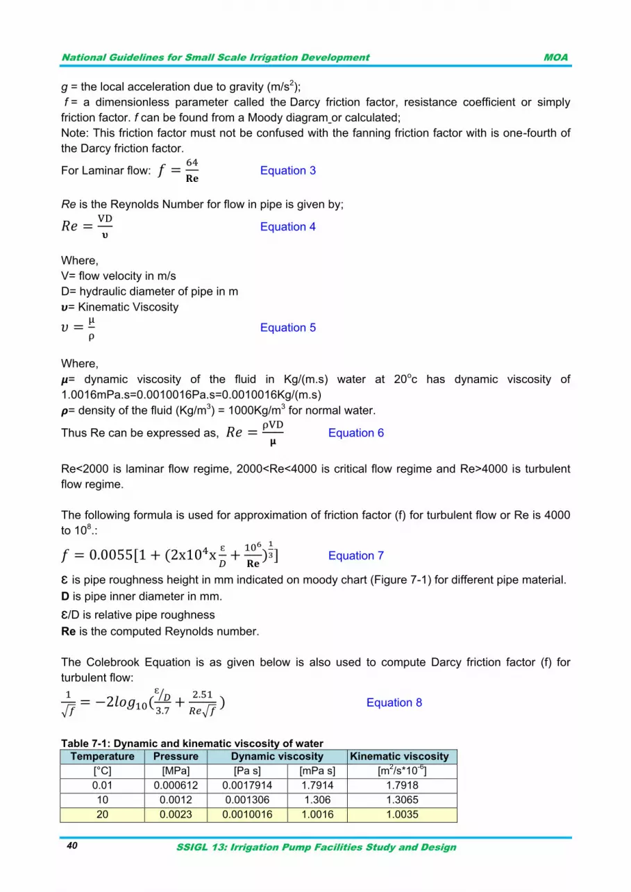
National Guidelines for Small Scale Irrigation Development MOA
SSIGL 13: Irrigation Pump Facilities Study and Design 40
g = the local acceleration due to gravity (m/s2);
f = a dimensionless parameter called the Darcy friction factor, resistance coefficient or simply
friction factor. f can be found from a Moody diagram or calculated;
Note: This friction factor must not be confused with the fanning friction factor with is one-fourth of
the Darcy friction factor.
For Laminar flow:
Equation 3
Re is the Reynolds Number for flow in pipe is given by;
Equation 4
Where,
V= flow velocity in m/s
D= hydraulic diameter of pipe in m
𝞾= Kinematic Viscosity
Equation 5
Where,
𝞵= dynamic viscosity of the fluid in Kg/(m.s) water at 20oc has dynamic viscosity of
1.0016mPa.s=0.0010016Pa.s=0.0010016Kg/(m.s)
𝞺= density of the fluid (Kg/m3) = 1000Kg/m3 for normal water.
Thus Re can be expressed as,
Equation 6
Re<2000 is laminar flow regime, 2000<Re<4000 is critical flow regime and Re>4000 is turbulent
flow regime.
The following formula is used for approximation of friction factor (f) for turbulent flow or Re is 4000
to 108.:
Equation 7
ɛ is pipe roughness height in mm indicated on moody chart (Figure 7-1) for different pipe material.
D is pipe inner diameter in mm.
ɛ/D is relative pipe roughness
Re is the computed Reynolds number.
The Colebrook Equation is as given below is also used to compute Darcy friction factor (f) for
turbulent flow:
√
⁄
√ Equation 8
Table 7-1: Dynamic and kinematic viscosity of water
Temperature Pressure Dynamic viscosity Kinematic viscosity
[°C] [MPa] [Pa s] [mPa s] [m2/s*10
-6]
0.01 0.000612 0.0017914 1.7914 1.7918
10 0.0012 0.001306 1.306 1.3065
20 0.0023 0.0010016 1.0016 1.0035
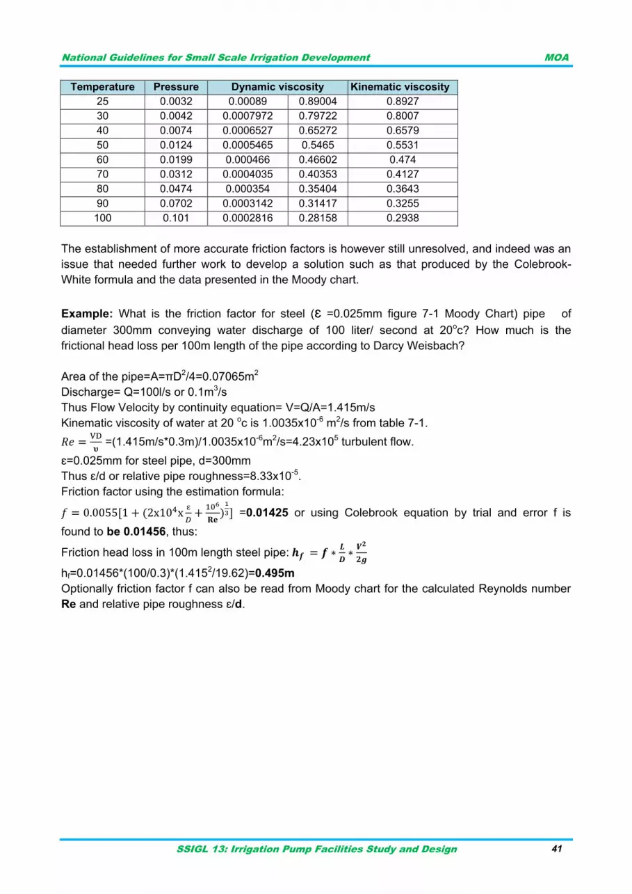
National Guidelines for Small Scale Irrigation Development MOA
SSIGL 13: Irrigation Pump Facilities Study and Design 41
Temperature Pressure Dynamic viscosity Kinematic viscosity
25 0.0032 0.00089 0.89004 0.8927
30 0.0042 0.0007972 0.79722 0.8007
40 0.0074 0.0006527 0.65272 0.6579
50 0.0124 0.0005465 0.5465 0.5531
60 0.0199 0.000466 0.46602 0.474
70 0.0312 0.0004035 0.40353 0.4127
80 0.0474 0.000354 0.35404 0.3643
90 0.0702 0.0003142 0.31417 0.3255
100 0.101 0.0002816 0.28158 0.2938
The establishment of more accurate friction factors is however still unresolved, and indeed was an
issue that needed further work to develop a solution such as that produced by the Colebrook-
White formula and the data presented in the Moody chart.
Example: What is the friction factor for steel (ɛ =0.025mm figure 7-1 Moody Chart) pipe of
diameter 300mm conveying water discharge of 100 liter/ second at 20oc? How much is the
frictional head loss per 100m length of the pipe according to Darcy Weisbach?
Area of the pipe=A=πD2/4=0.07065m2
Discharge= Q=100l/s or 0.1m3/s
Thus Flow Velocity by continuity equation= V=Q/A=1.415m/s
Kinematic viscosity of water at 20 oc is 1.0035x10⁻⁶ m2/s from table 7-1.
=(1.415m/s*0.3m)/1.0035x10-6m2/s=4.23x105 turbulent flow.
ɛ=0.025mm for steel pipe, d=300mm
Thus ɛ/d or relative pipe roughness=8.33x10⁻⁵.
Friction factor using the estimation formula:
=0.01425 or using Colebrook equation by trial and error f is
found to be 0.01456, thus:
Friction head loss in 100m length steel pipe:
hf=0.01456*(100/0.3)*(1.4152/19.62)=0.495m
Optionally friction factor f can also be read from Moody chart for the calculated Reynolds number
Re and relative pipe roughness ɛ/d.
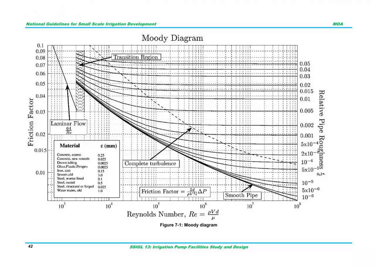
National Guidelines for Small Scale Irrigation Development MOA
SSIGL 13: Irrigation Pump Facilities Study and Design 42
Figure 7-1: Moody diagram
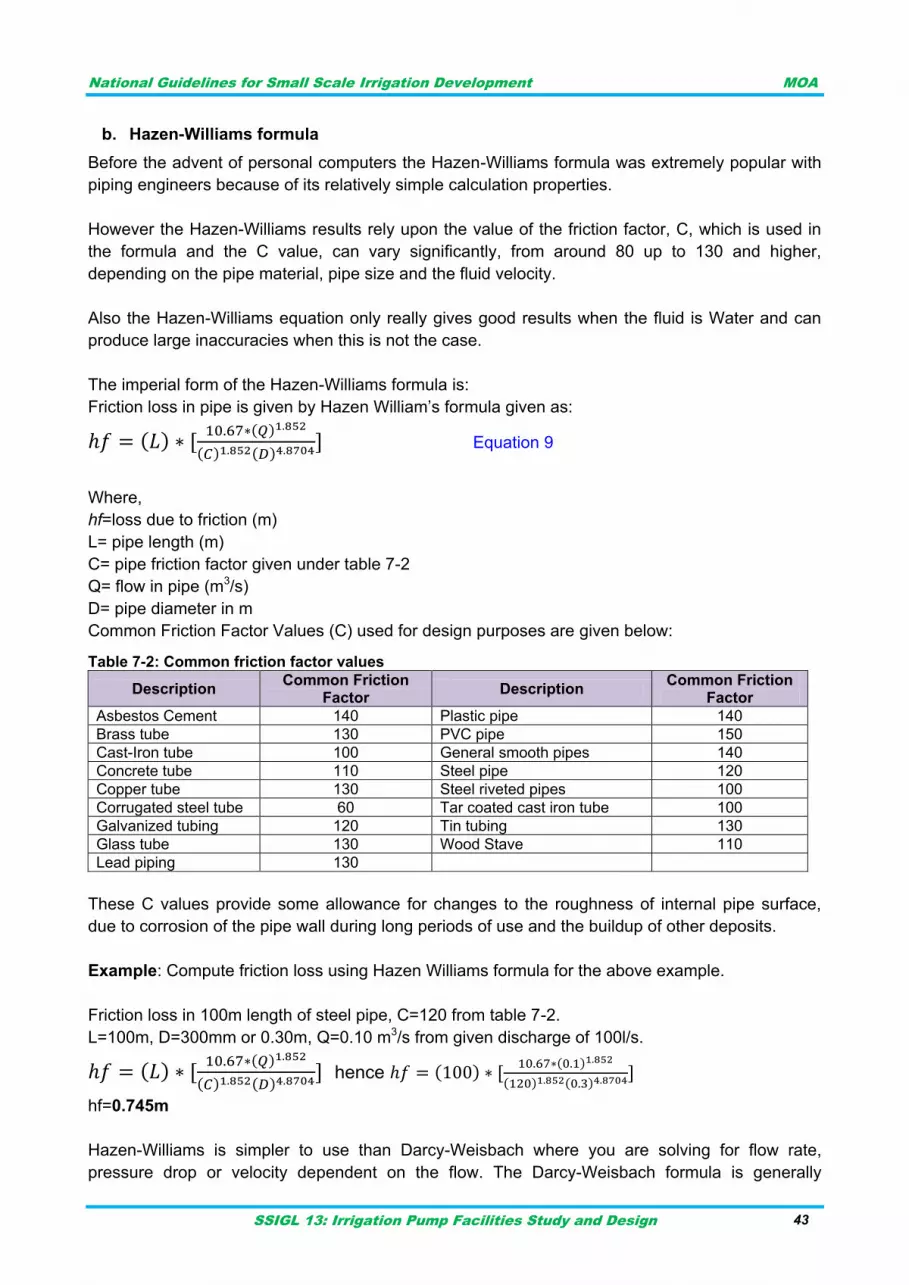
National Guidelines for Small Scale Irrigation Development MOA
SSIGL 13: Irrigation Pump Facilities Study and Design 43
b. Hazen-Williams formula
Before the advent of personal computers the Hazen-Williams formula was extremely popular with
piping engineers because of its relatively simple calculation properties.
However the Hazen-Williams results rely upon the value of the friction factor, C, which is used in
the formula and the C value, can vary significantly, from around 80 up to 130 and higher,
depending on the pipe material, pipe size and the fluid velocity.
Also the Hazen-Williams equation only really gives good results when the fluid is Water and can
produce large inaccuracies when this is not the case.
The imperial form of the Hazen-Williams formula is:
Friction loss in pipe is given by Hazen William‟s formula given as:
Equation 9
Where,
hf=loss due to friction (m)
L= pipe length (m)
C= pipe friction factor given under table 7-2
Q= flow in pipe (m3/s)
D= pipe diameter in m
Common Friction Factor Values (C) used for design purposes are given below: Table 7-2: Common friction factor values
Description Common Friction
Factor Description
Common Friction Factor
Asbestos Cement 140 Plastic pipe 140
Brass tube 130 PVC pipe 150
Cast-Iron tube 100 General smooth pipes 140
Concrete tube 110 Steel pipe 120
Copper tube 130 Steel riveted pipes 100
Corrugated steel tube 60 Tar coated cast iron tube 100
Galvanized tubing 120 Tin tubing 130
Glass tube 130 Wood Stave 110
Lead piping 130
These C values provide some allowance for changes to the roughness of internal pipe surface,
due to corrosion of the pipe wall during long periods of use and the buildup of other deposits.
Example: Compute friction loss using Hazen Williams formula for the above example.
Friction loss in 100m length of steel pipe, C=120 from table 7-2.
L=100m, D=300mm or 0.30m, Q=0.10 m3/s from given discharge of 100l/s.
hence
hf=0.745m
Hazen-Williams is simpler to use than Darcy-Weisbach where you are solving for flow rate,
pressure drop or velocity dependent on the flow. The Darcy-Weisbach formula is generally
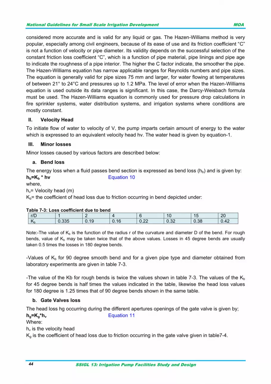
National Guidelines for Small Scale Irrigation Development MOA
SSIGL 13: Irrigation Pump Facilities Study and Design 44
considered more accurate and is valid for any liquid or gas. The Hazen-Williams method is very
popular, especially among civil engineers, because of its ease of use and its friction coefficient “C”
is not a function of velocity or pipe diameter. Its validity depends on the successful selection of the
constant friction loss coefficient “C”, which is a function of pipe material, pipe linings and pipe age
to indicate the roughness of a pipe interior. The higher the C factor indicate, the smoother the pipe.
The Hazen-Williams equation has narrow applicable ranges for Reynolds numbers and pipe sizes.
The equation is generally valid for pipe sizes 75 mm and larger, for water flowing at temperatures
of between 21° to 24°C and pressures up to 1.2 MPa. The level of error when the Hazen-Williams
equation is used outside its data ranges is significant. In this case, the Darcy-Weisbach formula
must be used. The Hazen-Williams equation is commonly used for pressure drop calculations in
fire sprinkler systems, water distribution systems, and irrigation systems where conditions are
mostly constant.
II. Velocity Head
To initiate flow of water to velocity of V, the pump imparts certain amount of energy to the water
which is expressed to an equivalent velocity head hv. The water head is given by equation-1.
III. Minor losses
Minor losses caused by various factors are described below:
a. Bend loss
The energy loss when a fluid passes bend section is expressed as bend loss (hb) and is given by:
hb=Kb * hv Equation 10
where,
hv= Velocity head (m)
Kb= the coefficient of head loss due to friction occurring in bend depicted under:
Table 7-3: Loss coefficient due to bend
r/D 1 2 4 6 10 15 20
Kb 0.335 0.19 0.16 0.22 0.32 0.38 0.42
Note:-The value of Kb is the function of the radius r of the curvature and diameter D of the bend. For rough
bends, value of Kb may be taken twice that of the above values. Losses in 45 degree bends are usually
taken 0.5 times the losses in 180 degree bends.
-Values of Kb for 90 degree smooth bend and for a given pipe type and diameter obtained from
laboratory experiments are given in table 7-3.
-The value of the Kb for rough bends is twice the values shown in table 7-3. The values of the Kb
for 45 degree bends is half times the values indicated in the table, likewise the head loss values
for 180 degree is 1.25 times that of 90 degree bends shown in the same table.
b. Gate Valves loss
The head loss hg occurring during the different apertures openings of the gate valve is given by;
hg=Kg*hv Equation 11
Where:
hv is the velocity head
Kg is the coefficient of head loss due to friction occurring in the gate valve given in table7-4.
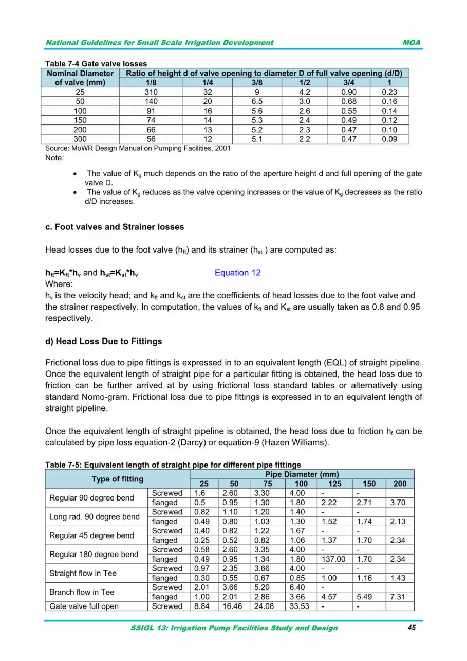
National Guidelines for Small Scale Irrigation Development MOA
SSIGL 13: Irrigation Pump Facilities Study and Design 45
Table 7-4 Gate valve losses
Nominal Diameter of valve (mm)
Ratio of height d of valve opening to diameter D of full valve opening (d/D)
1/8 1/4 3/8 1/2 3/4 1
25 310 32 9 4.2 0.90 0.23
50 140 20 6.5 3.0 0.68 0.16
100 91 16 5.6 2.6 0.55 0.14
150 74 14 5.3 2.4 0.49 0.12
200 66 13 5.2 2.3 0.47 0.10
300 56 12 5.1 2.2 0.47 0.09 Source: MoWR Design Manual on Pumping Facilities, 2001
Note:
The value of Kg much depends on the ratio of the aperture height d and full opening of the gate valve D.
The value of Kg reduces as the valve opening increases or the value of Kg decreases as the ratio d/D increases.
c. Foot valves and Strainer losses
Head losses due to the foot valve (hft) and its strainer (hst ) are computed as:
hft=Kft*hv and hst=Kst*hv Equation 12
Where:
hv is the velocity head; and kft and kst are the coefficients of head losses due to the foot valve and
the strainer respectively. In computation, the values of kft and Kst are usually taken as 0.8 and 0.95
respectively.
d) Head Loss Due to Fittings
Frictional loss due to pipe fittings is expressed in to an equivalent length (EQL) of straight pipeline.
Once the equivalent length of straight pipe for a particular fitting is obtained, the head loss due to
friction can be further arrived at by using frictional loss standard tables or alternatively using
standard Nomo-gram. Frictional loss due to pipe fittings is expressed in to an equivalent length of
straight pipeline.
Once the equivalent length of straight pipeline is obtained, the head loss due to friction hf can be
calculated by pipe loss equation-2 (Darcy) or equation-9 (Hazen Williams).
Table 7-5: Equivalent length of straight pipe for different pipe fittings
Type of fitting Pipe Diameter (mm)
25 50 75 100 125 150 200
Regular 90 degree bend Screwed 1.6 2.60 3.30 4.00 - -
flanged 0.5 0.95 1.30 1.80 2.22 2.71 3.70
Long rad. 90 degree bend Screwed 0.82 1.10 1.20 1.40 - -
flanged 0.49 0.80 1.03 1.30 1.52 1.74 2.13
Regular 45 degree bend Screwed 0.40 0.82 1.22 1.67 - -
flanged 0.25 0.52 0.82 1.06 1.37 1.70 2.34
Regular 180 degree bend Screwed 0.58 2.60 3.35 4.00 - -
flanged 0.49 0.95 1.34 1.80 137.00 1.70 2.34
Straight flow in Tee Screwed 0.97 2.35 3.66 4.00 - -
flanged 0.30 0.55 0.67 0.85 1.00 1.16 1.43
Branch flow in Tee Screwed 2.01 3.66 5.20 6.40 -
flanged 1.00 2.01 2.86 3.66 4.57 5.49 7.31
Gate valve full open Screwed 8.84 16.46 24.08 33.53 - -
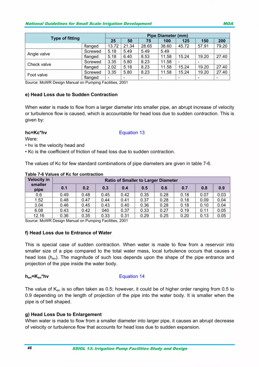
National Guidelines for Small Scale Irrigation Development MOA
SSIGL 13: Irrigation Pump Facilities Study and Design 46
Type of fitting Pipe Diameter (mm)
25 50 75 100 125 150 200
flanged 13.72 21.34 28.65 38.60 45.72 57.91 79.20
Angle valve Screwed 5.18 5.49 5.49 5.49
flanged 5.18 6.40 8.53 11.58 15.24 19.20 27.40
Check valve Screwed 3.35 5.80 8.23 11.58 - -
flanged 2.02 5.18 8.23 11.58 15.24 19.20 27.40
Foot valve Screwed 3.35 5.80 8.23 11.58 15.24 19.20 27.40
flanged - - - - - - - Source: MoWR Design Manual on Pumping Facilities, 2001
e) Head Loss due to Sudden Contraction
When water is made to flow from a larger diameter into smaller pipe, an abrupt increase of velocity
or turbulence flow is caused, which is accountable for head loss due to sudden contraction. This is
given by:
hc=Kc*hv Equation 13
Were:
• hv is the velocity head and
• Kc is the coefficient of friction of head loss due to sudden contraction.
The values of Kc for few standard combinations of pipe diameters are given in table 7-6. Table 7-6 Values of Kc for contraction
Velocity in smaller
pipe
Ratio of Smaller to Larger Diameter
0.1 0.2 0.3 0.4 0.5 0.6 0.7 0.8 0.9
0.6 0.49 0.48 0.45 0.42 0.35 0.28 0.18 0.07 0.03
1.52 0.48 0.47 0.44 0.41 0.37 0.28 0.18 0.09 0.04
3.04 0.46 0.45 0.43 0.40 0.36 0.28 0.18 0.10 0.04
6.08 0.43 0.42 040 0.37 0.33 0.27 0.19 0.11 0.05
12.16 0.36 0.35 0.33 0.31 0.29 0.25 0.20 0.13 0.05 Source: MoWR Design Manual on Pumping Facilities, 2001
f) Head Loss due to Entrance of Water
This is special case of sudden contraction. When water is made to flow from a reservoir into
smaller size of a pipe compared to the total water mass, local turbulence occurs that causes a
head loss (hen). The magnitude of such loss depends upon the shape of the pipe entrance and
projection of the pipe inside the water body.
hen=Ken*hv Equation 14
The value of Ken is so often taken as 0.5; however, it could be of higher order ranging from 0.5 to
0.9 depending on the length of projection of the pipe into the water body. It is smaller when the
pipe is of bell shaped.
g) Head Loss Due to Enlargement
When water is made to flow from a smaller diameter into larger pipe, it causes an abrupt decrease
of velocity or turbulence flow that accounts for head loss due to sudden expansion.
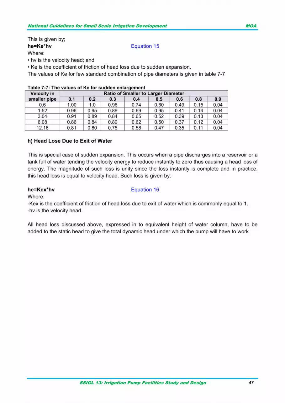
National Guidelines for Small Scale Irrigation Development MOA
SSIGL 13: Irrigation Pump Facilities Study and Design 47
This is given by;
he=Ke*hv Equation 15
Where:
• hv is the velocity head; and
• Ke is the coefficient of friction of head loss due to sudden expansion.
The values of Ke for few standard combination of pipe diameters is given in table 7-7
Table 7-7: The values of Ke for sudden enlargement
Velocity in smaller pipe
Ratio of Smaller to Larger Diameter
0.1 0.2 0.3 0.4 0.5 0.6 0.8 0.9
0.6 1.00 1.0 0.96 0.74 0.60 0.49 0.15 0.04
1.52 0.96 0.95 0.89 0.69 0.95 0.41 0.14 0.04
3.04 0.91 0.89 0.84 0.65 0.52 0.39 0.13 0.04
6.08 0.86 0.84 0.80 0.62 0.50 0.37 0.12 0.04
12.16 0.81 0.80 0.75 0.58 0.47 0.35 0.11 0.04
h) Head Lose Due to Exit of Water
This is special case of sudden expansion. This occurs when a pipe discharges into a reservoir or a
tank full of water tending the velocity energy to reduce instantly to zero thus causing a head loss of
energy. The magnitude of such loss is unity since the loss instantly is complete and in practice,
this head loss is equal to velocity head. Such loss is given by:
he=Kex*hv Equation 16
Where:
-Kex is the coefficient of friction of head loss due to exit of water which is commonly equal to 1.
-hv is the velocity head.
All head loss discussed above, expressed in to equivalent height of water column, have to be
added to the static head to give the total dynamic head under which the pump will have to work

National Guidelines for Small Scale Irrigation Development MOA
SSIGL 13: Irrigation Pump Facilities Study and Design 48
National Guidelines for Small Scale Irrigation Development MOA
SSIGL 13: Irrigation Pump Facilities Study and Design 49
DESIGN CONSIDERATIONS IN SUCTION AND DELIVERY LINES 8
PIPE SIZING FOR SUCTION AND DELIVERY LINE 8.1
Besides material type, pipe over or under sizing may even become a bottleneck for plant
operations. A larger size pipeline not only increases the plant cost but also creates operational
problems. One should bear in mind that the larger pipeline size than necessary increases plant
cost due to pipelines along with the connected valves, fittings, supporting structures, etc. Likewise,
the smaller pipe size may consume more energy for fluid movement.
Many factors should be kept in mind before sizing any pipeline. The basic principle of pipeline size
is based on the available pressure drop between its two ends. Normally to maintain certain fluid
velocity (may be from the available thumb rules), for clear water at pump discharge for the
maximum possible fluid flow rate through that pipeline, cross-sectional area (or diameter) of
pipeline is calculated. Based on this, the nearest commercially available pipeline size (of inside
diameter (DN) closely matching with the calculated value) is selected for application. With these
preliminary calculations of pipeline sizing and pipe routing, pressure drop between start and end
point, incorporating all fittings, is calculated. Decision of the selection of higher or lower pipeline
size is made according to the available pressure drop versus calculated pressure drop.
According to MoWR Design Manual on Pumping Facilities, 2001 velocity of flow is to be about
1.5m/s in suction and 2.0 m/sec in delivery pipe. This velocity limit depends on existing site
conditions and scheme type. The velocity both in suction and delivery pipe is usually not less than
1.5m/s and not more than 3.5m/s for the reasons indicated above. The design engineer shall fix
the flow velocity based on loss factors, material specification, cost and future operation and
maintenance considerations.
Flow velocity is expressed as:
Equation 17
Where:
V= flow velocity in m/s
Q= Volume of flow in m3/s
D= Pipe Diameter (m)
CONDITIONS TO BE ACCOUNTED IN THE SUCTION LINE 8.2
Some of the conditions to be avoided in the suction side are cavitation, sudden contractions, and
elbow too close to the pump, suspended loads and any air entry / leakage in to the suction pipe.
Some of these are illustrated by the following figures. Cavitation is mostly related to the NPSHa
which is critical element for smooth operation of the pump.
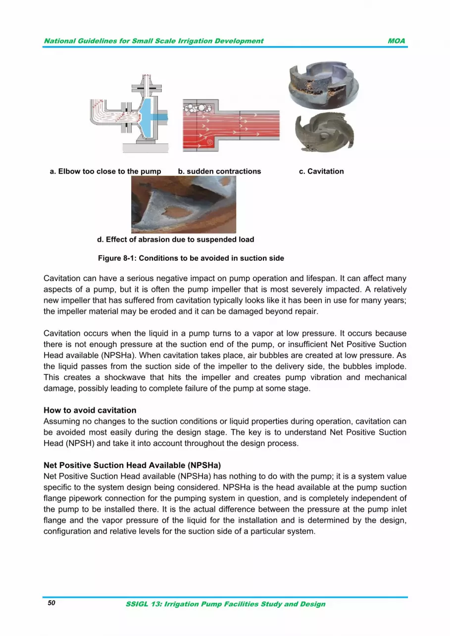
National Guidelines for Small Scale Irrigation Development MOA
SSIGL 13: Irrigation Pump Facilities Study and Design 50
a. Elbow too close to the pump b. sudden contractions c. Cavitation
d. Effect of abrasion due to suspended load
Figure 8-1: Conditions to be avoided in suction side
Cavitation can have a serious negative impact on pump operation and lifespan. It can affect many
aspects of a pump, but it is often the pump impeller that is most severely impacted. A relatively
new impeller that has suffered from cavitation typically looks like it has been in use for many years;
the impeller material may be eroded and it can be damaged beyond repair.
Cavitation occurs when the liquid in a pump turns to a vapor at low pressure. It occurs because
there is not enough pressure at the suction end of the pump, or insufficient Net Positive Suction
Head available (NPSHa). When cavitation takes place, air bubbles are created at low pressure. As
the liquid passes from the suction side of the impeller to the delivery side, the bubbles implode.
This creates a shockwave that hits the impeller and creates pump vibration and mechanical
damage, possibly leading to complete failure of the pump at some stage.
How to avoid cavitation
Assuming no changes to the suction conditions or liquid properties during operation, cavitation can
be avoided most easily during the design stage. The key is to understand Net Positive Suction
Head (NPSH) and take it into account throughout the design process.
Net Positive Suction Head Available (NPSHa)
Net Positive Suction Head available (NPSHa) has nothing to do with the pump; it is a system value
specific to the system design being considered. NPSHa is the head available at the pump suction
flange pipework connection for the pumping system in question, and is completely independent of
the pump to be installed there. It is the actual difference between the pressure at the pump inlet
flange and the vapor pressure of the liquid for the installation and is determined by the design,
configuration and relative levels for the suction side of a particular system.
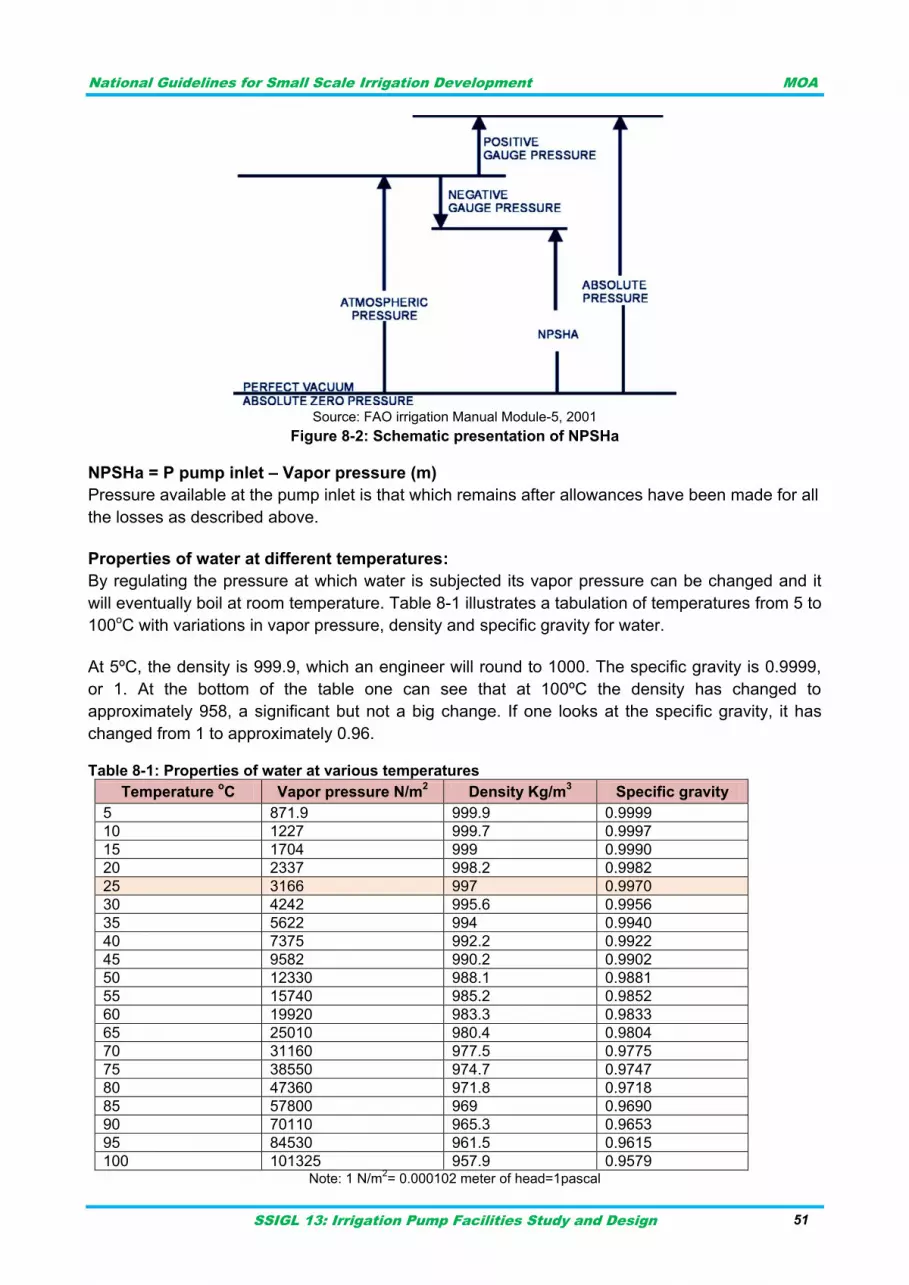
National Guidelines for Small Scale Irrigation Development MOA
SSIGL 13: Irrigation Pump Facilities Study and Design 51
Source: FAO irrigation Manual Module-5, 2001
Figure 8-2: Schematic presentation of NPSHa
NPSHa = P pump inlet – Vapor pressure (m)
Pressure available at the pump inlet is that which remains after allowances have been made for all
the losses as described above.
Properties of water at different temperatures:
By regulating the pressure at which water is subjected its vapor pressure can be changed and it
will eventually boil at room temperature. Table 8-1 illustrates a tabulation of temperatures from 5 to
100oC with variations in vapor pressure, density and specific gravity for water.
At 5ºC, the density is 999.9, which an engineer will round to 1000. The specific gravity is 0.9999,
or 1. At the bottom of the table one can see that at 100ºC the density has changed to
approximately 958, a significant but not a big change. If one looks at the specific gravity, it has
changed from 1 to approximately 0.96.
Table 8-1: Properties of water at various temperatures
Temperature oC Vapor pressure N/m
2 Density Kg/m
3 Specific gravity
5 871.9 999.9 0.9999
10 1227 999.7 0.9997
15 1704 999 0.9990
20 2337 998.2 0.9982
25 3166 997 0.9970
30 4242 995.6 0.9956
35 5622 994 0.9940
40 7375 992.2 0.9922
45 9582 990.2 0.9902
50 12330 988.1 0.9881
55 15740 985.2 0.9852
60 19920 983.3 0.9833
65 25010 980.4 0.9804
70 31160 977.5 0.9775
75 38550 974.7 0.9747
80 47360 971.8 0.9718
85 57800 969 0.9690
90 70110 965.3 0.9653
95 84530 961.5 0.9615
100 101325 957.9 0.9579 Note: 1 N/m
2= 0.000102 meter of head=1pascal
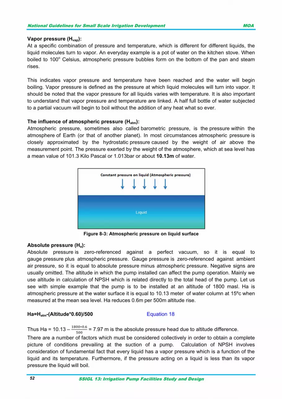
National Guidelines for Small Scale Irrigation Development MOA
SSIGL 13: Irrigation Pump Facilities Study and Design 52
Vapor pressure (Hvap):
At a specific combination of pressure and temperature, which is different for different liquids, the
liquid molecules turn to vapor. An everyday example is a pot of water on the kitchen stove. When
boiled to 100o Celsius, atmospheric pressure bubbles form on the bottom of the pan and steam
rises.
This indicates vapor pressure and temperature have been reached and the water will begin
boiling. Vapor pressure is defined as the pressure at which liquid molecules will turn into vapor. It
should be noted that the vapor pressure for all liquids varies with temperature. It is also important
to understand that vapor pressure and temperature are linked. A half full bottle of water subjected
to a partial vacuum will begin to boil without the addition of any heat what so ever.
The influence of atmospheric pressure (Hatm):
Atmospheric pressure, sometimes also called barometric pressure, is the pressure within the
atmosphere of Earth (or that of another planet). In most circumstances atmospheric pressure is
closely approximated by the hydrostatic pressure caused by the weight of air above the
measurement point. The pressure exerted by the weight of the atmosphere, which at sea level has
a mean value of 101.3 Kilo Pascal or 1.013bar or about 10.13m of water.
Figure 8-3: Atmospheric pressure on liquid surface
Absolute pressure (Ha):
Absolute pressure is zero-referenced against a perfect vacuum, so it is equal to
gauge pressure plus atmospheric pressure. Gauge pressure is zero-referenced against ambient
air pressure, so it is equal to absolute pressure minus atmospheric pressure. Negative signs are
usually omitted. The altitude in which the pump installed can affect the pump operation. Mainly we
use altitude in calculation of NPSH which is related directly to the total head of the pump. Let us
see with simple example that the pump is to be installed at an altitude of 1800 masl. Ha is
atmospheric pressure at the water surface it is equal to 10.13 meter of water column at 15ºc when
measured at the mean sea level. Ha reduces 0.6m per 500m altitude rise.
Ha=Hatm-(Altitude*0.60)/500 Equation 18
Thus Ha = 10.13 –
= 7.97 m is the absolute pressure head due to altitude difference.
There are a number of factors which must be considered collectively in order to obtain a complete
picture of conditions prevailing at the suction of a pump. Calculation of NPSH involves
consideration of fundamental fact that every liquid has a vapor pressure which is a function of the
liquid and its temperature. Furthermore, if the pressure acting on a liquid is less than its vapor
pressure the liquid will boil.
National Guidelines for Small Scale Irrigation Development MOA
SSIGL 13: Irrigation Pump Facilities Study and Design 53
In any pumping system, there is always an absolute pressure available at the suction source. This
pressure is reduced in the suction line due to such factors as static elevation, friction and
turbulence losses, and energy expended in accelerating the liquid. Finally, there is a pressure drop
within the pump itself caused by an increased velocity at the entrance to the impeller and shock
losses in the impeller eye.
In order to prevent the liquid boiling, the suction pressure at the pump suction branch must be at
least equal to the vapor pressure of the liquid at pumping temperature plus a margin to overcome
losses in the pump. This margin of head available above the vapor pressure of the liquid is the net
positive suction head, defined as follows.
Net positive suction head (NPSH): total head at the pump suction part over and above the vapor
pressure of the liquid being pumped.
NPSH required (NPSHR): is a function of the pump design and is the lowest value of NPSH at
which the pump can be guaranteed to operate without significant cavitation. There is no absolute
criterion for determining what this minimum allowable NPSH should be, but pump manufacturers
normally select an arbitrary drop in total dynamic head (differential head) of 3% as the normal
value for determining NPSHR.
NPSH available (NPSHA): is a function of the system in which the pump operates and is equal to
the absolute pressure head on the liquid surface (Ha) plus/ minus the static liquid level (Hs) is
below/ above the pump center line (positive if pump axis is below liquid surface or negative if
pump axis is above liquid surface) minus the absolute liquid vapor pressure head at pumping
temperature (Hvap) minus the suction friction head losses including entrance losses (Hf) minus
safety factor (Fs) taken about 0.60m. The velocity head (Hv) is usually ignored as it is too small.
Thus,
NPSHA = Ha + Hs - Hvap - Hf -Fs Equation 19
For successful operation NPSHA must be greater than NPSHR. Ensuring adequate available
NPSH Pump suppliers set the NPSH required (NPSHR) for a given pump. The NPSHR takes into
account any potential head losses that might occur between the pump‟s suction nozzle and
impeller, thus ensuring that the fluid does not drop below its vapor pressure. Thus NPSHA must
exceed the NPSHR set by the supplier.
There are a few options available to increase NPSHA, should it be at or below the NPSHR.
Increasing the source pressure or reducing the fluid vapor pressure (by cooling) is rarely feasible.
Therefore, there are two process variables remaining that can be adjusted that are the static head
and friction losses.
Static head can be adjusted by three methods:
i. Raise the elevation of the source point. This may prove impossible in some cases (e.g., a
tank that is set at grade).
ii. Lower the elevation of the pump inlet. This is a less appealing option because pumps are
typically located just above ground level, and lowering the inlet may require the suction
nozzle to be below grade. This usually results in a much more expensive pump.
iii. Raise the level of fluid in the suction vessel. The acceptability of this approach varies from
company to company and should not be used without first consulting company procedures.
National Guidelines for Small Scale Irrigation Development MOA
SSIGL 13: Irrigation Pump Facilities Study and Design 54
Friction losses can be reduced either by increasing the diameter of the pump suction-piping and/or
reducing the equivalent length of the suction line. In a grassroots plant, friction losses should
already be minimal, so raising static head is more viable. Reducing friction loss is usually more
appealing for suction lines in existing plants where throughput has been increased above the
original nameplate capacity.
There are also a few options to reduce the NPSHR of the pump, which include using a larger,
slower-speed pump, a double-suction impeller, a larger impeller inlet (eye) area, an oversized
pump and an inducer, which is a secondary impeller placed ahead of the primary impeller.
Example: Calculate the NPSH available for pump working at 25oC at an altitude of 2000m a.s.l.
Pump center line is 2.5m above water surface. The suction pipe is steel pipe of diameter 200mm
sucking sediment free water discharging 60l/s to elevated tanker. Suction pipe length is 6m and
loss coefficient for entrance, strainer and foot valve is 0.50, 0.95 and 0.80 respectively.
Here NPSHa= Ha - Hs - Hvap – Hf -Fs
Where Ha=absolute pressure head at liquid surface (m)
Ha is dependent on altitude: Ha=10.13- (2000*0.6)/500=7.73m
Hs= the static Liquid level is below pump center line (here it is minus)
Hs= -2.5m
Hvap= absolute vapor pressure at working temperature
Hvap=0.3166m at 25oC (from table 7-3)
Hf= Head loss due to friction including loss at entrance
Hv= velocity head (v2/2g)
Fs= Factor of Safety=0.60m
Friction loss in pipe is given by Hazen William‟s formula given as:
Where,
hf=loss due to friction (m)
L= pipe length (m)=6m
C= pipe friction factor given under table 7-2=120
Q= flow in pipe (m3/s)=60l/s=0.06m3/s
D= pipe diameter in m=200mm=0.20m
Thus hf=0.125m but entrance and fitting loss (minor loss) must be included
Minor loss= Kloss*v2/2g
V is flow velocity
V=Q/A
Where A= suction flow area =πD2/4=0.0314m2
Thus V=0.06m3/s/0.0314m2=1.91m/s
Minor loss= (0.50+0.95+0.80)*[1.912/(2*9.81)]=0.418m
Hf=0.125m+0.418m=0.543m
Hv=V2/2g=0.186m
Thus NPSHa=7.73m-2.5m-0.3166m-0.543m-0.60m=3.77m
NPSHa computed must be greater than NPSHr provided from manufacturer (supplier) usually
provided as pump performance curve.
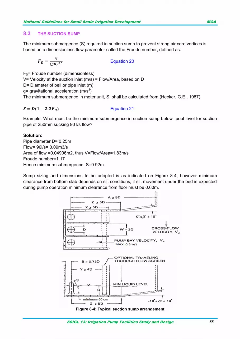
National Guidelines for Small Scale Irrigation Development MOA
SSIGL 13: Irrigation Pump Facilities Study and Design 55
THE SUCTION SUMP 8.3
The minimum submergence (S) required in suction sump to prevent strong air core vortices is
based on a dimensionless flow parameter called the Froude number, defined as:
Equation 20
FD= Froude number (dimensionless)
V= Velocity at the suction inlet (m/s) = Flow/Area, based on D
D= Diameter of bell or pipe inlet (m)
g= gravitational acceleration (m/s2)
The minimum submergence in meter unit, S, shall be calculated from (Hecker, G.E., 1987)
Equation 21
Example: What must be the minimum submergence in suction sump below pool level for suction
pipe of 250mm sucking 90 l/s flow?
Solution:
Pipe diameter D= 0.25m
Flow= 90l/s= 0.09m3/s
Area of flow =0.04906m2, thus V=Flow/Area=1.83m/s
Froude number=1.17
Hence minimum submergence, S=0.92m
Sump sizing and dimensions to be adopted is as indicated on Figure 8-4, however minimum
clearance from bottom slab depends on silt conditions, if silt movement under the bed is expected
during pump operation minimum clearance from floor must be 0.60m.
Figure 8-4: Typical suction sump arrangement
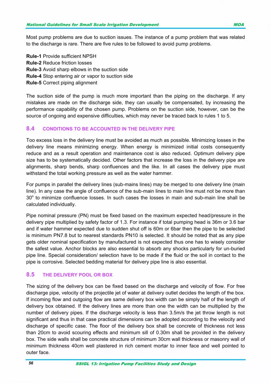
National Guidelines for Small Scale Irrigation Development MOA
SSIGL 13: Irrigation Pump Facilities Study and Design 56
Most pump problems are due to suction issues. The instance of a pump problem that was related
to the discharge is rare. There are five rules to be followed to avoid pump problems.
Rule-1 Provide sufficient NPSH
Rule-2 Reduce friction losses
Rule-3 Avoid sharp elbows in the suction side
Rule-4 Stop entering air or vapor to suction side
Rule-5 Correct piping alignment
The suction side of the pump is much more important than the piping on the discharge. If any
mistakes are made on the discharge side, they can usually be compensated, by increasing the
performance capability of the chosen pump. Problems on the suction side, however, can be the
source of ongoing and expensive difficulties, which may never be traced back to rules 1 to 5.
CONDITIONS TO BE ACCOUNTED IN THE DELIVERY PIPE 8.4
Too excess loss in the delivery line must be avoided as much as possible. Minimizing losses in the
delivery line means minimizing energy. When energy is minimized initial costs consequently
reduce and as a result operation and maintenance cost is also reduced. Optimum delivery pipe
size has to be systematically decided. Other factors that increase the loss in the delivery pipe are
alignments, sharp bends, sharp confluences and the like. In all cases the delivery pipe must
withstand the total working pressure as well as the water hammer.
For pumps in parallel the delivery lines (sub-mains lines) may be merged to one delivery line (main
line). In any case the angle of confluence of the sub-main lines to main line must not be more than
30o to minimize confluence losses. In such cases the losses in main and sub-main line shall be
calculated individually.
Pipe nominal pressure (PN) must be fixed based on the maximum expected head/pressure in the
delivery pipe multiplied by safety factor of 1.3. For instance if total pumping head is 36m or 3.6 bar
and if water hammer expected due to sudden shut off is 60m or 6bar then the pipe to be selected
is minimum PN7.8 but to nearest standards PN10 is selected. It should be noted that as any pipe
gets older nominal specification by manufactured is not expected thus one has to wisely consider
the safest value. Anchor blocks are also essential to absorb any shocks particularly for un-buried
pipe line. Special consideration/ selection have to be made if the fluid or the soil in contact to the
pipe is corrosive. Selected bedding material for delivery pipe line is also essential.
THE DELIVERY POOL OR BOX 8.5
The sizing of the delivery box can be fixed based on the discharge and velocity of flow. For free
discharge pipe, velocity of the projectile jet of water at delivery outlet decides the length of the box.
If incoming flow and outgoing flow are same delivery box width can be simply half of the length of
delivery box obtained. If the delivery lines are more than one the width can be multiplied by the
number of delivery pipes. If the discharge velocity is less than 3.5m/s the jet throw length is not
significant and thus in that case practical dimensions can be adopted according to the velocity and
discharge of specific case. The floor of the delivery box shall be concrete of thickness not less
than 20cm to avoid scouring effects and minimum sill of 0.30m shall be provided in the delivery
box. The side walls shall be concrete structure of minimum 30cm wall thickness or masonry wall of
minimum thickness 40cm well plastered in rich cement mortar to inner face and well pointed to
outer face.
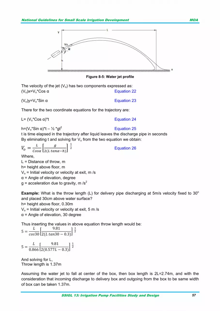
National Guidelines for Small Scale Irrigation Development MOA
SSIGL 13: Irrigation Pump Facilities Study and Design 57
Figure 8-5: Water jet profile
The velocity of the jet (Vo) has two components expressed as:
(Vo)x=Vo*Cos α Equation 22 (Vo)y=Vo*Sin α Equation 23 There for the two coordinate equations for the trajectory are: L= (Vo*Cos α)*t Equation 24 h=(Vo*Sin α)*t – ½ *gt2 Equation 25
t is time elapsed in the trajectory after liquid leaves the discharge pipe in seconds
By eliminating t and solving for Vo from the two equation we obtain:
*
+
Equation 26
Where,
L = Distance of throw, m
h= height above floor, m
Vo = Initial velocity or velocity at exit, m /s
α = Angle of elevation, degree
g = acceleration due to gravity, m /s2
Example: What is the throw length (L) for delivery pipe discharging at 5m/s velocity fixed to 30o
and placed 30cm above water surface?
h= height above floor, 0.30m
Vo = Initial velocity or velocity at exit, 5 m /s
α = Angle of elevation, 30 degree Thus inserting the values in above equation throw length would be:
[
]
[
]
And solving for L, Throw length is 1.37m Assuming the water jet to fall at center of the box, then box length is 2L=2.74m, and with the
consideration that incoming discharge to delivery box and outgoing from the box to be same width
of box can be taken 1.37m.

National Guidelines for Small Scale Irrigation Development MOA
SSIGL 13: Irrigation Pump Facilities Study and Design 58
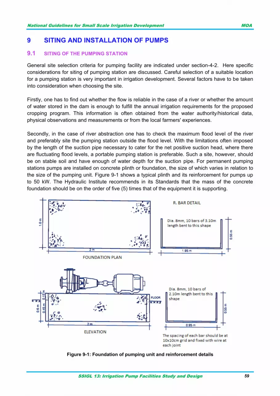
National Guidelines for Small Scale Irrigation Development MOA
SSIGL 13: Irrigation Pump Facilities Study and Design 59
SITING AND INSTALLATION OF PUMPS 9
SITING OF THE PUMPING STATION 9.1
General site selection criteria for pumping facility are indicated under section-4-2. Here specific
considerations for siting of pumping station are discussed. Careful selection of a suitable location
for a pumping station is very important in irrigation development. Several factors have to be taken
into consideration when choosing the site.
Firstly, one has to find out whether the flow is reliable in the case of a river or whether the amount
of water stored in the dam is enough to fulfill the annual irrigation requirements for the proposed
cropping program. This information is often obtained from the water authority/historical data,
physical observations and measurements or from the local farmers' experiences.
Secondly, in the case of river abstraction one has to check the maximum flood level of the river
and preferably site the pumping station outside the flood level. With the limitations often imposed
by the length of the suction pipe necessary to cater for the net positive suction head, where there
are fluctuating flood levels, a portable pumping station is preferable. Such a site, however, should
be on stable soil and have enough of water depth for the suction pipe. For permanent pumping
stations pumps are installed on concrete plinth or foundation, the size of which varies in relation to
the size of the pumping unit. Figure 9-1 shows a typical plinth and its reinforcement for pumps up
to 50 kW. The Hydraulic Institute recommends in its Standards that the mass of the concrete
foundation should be on the order of five (5) times that of the equipment it is supporting.
Figure 9-1: Foundation of pumping unit and reinforcement details
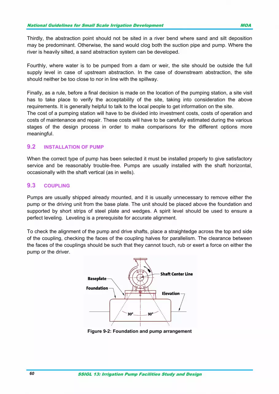
National Guidelines for Small Scale Irrigation Development MOA
SSIGL 13: Irrigation Pump Facilities Study and Design 60
Thirdly, the abstraction point should not be sited in a river bend where sand and silt deposition
may be predominant. Otherwise, the sand would clog both the suction pipe and pump. Where the
river is heavily silted, a sand abstraction system can be developed.
Fourthly, where water is to be pumped from a dam or weir, the site should be outside the full
supply level in case of upstream abstraction. In the case of downstream abstraction, the site
should neither be too close to nor in line with the spillway.
Finally, as a rule, before a final decision is made on the location of the pumping station, a site visit
has to take place to verify the acceptability of the site, taking into consideration the above
requirements. It is generally helpful to talk to the local people to get information on the site.
The cost of a pumping station will have to be divided into investment costs, costs of operation and
costs of maintenance and repair. These costs will have to be carefully estimated during the various
stages of the design process in order to make comparisons for the different options more
meaningful.
INSTALLATION OF PUMP 9.2
When the correct type of pump has been selected it must be installed properly to give satisfactory
service and be reasonably trouble-free. Pumps are usually installed with the shaft horizontal,
occasionally with the shaft vertical (as in wells).
COUPLING 9.3
Pumps are usually shipped already mounted, and it is usually unnecessary to remove either the
pump or the driving unit from the base plate. The unit should be placed above the foundation and
supported by short strips of steel plate and wedges. A spirit level should be used to ensure a
perfect leveling. Leveling is a prerequisite for accurate alignment.
To check the alignment of the pump and drive shafts, place a straightedge across the top and side
of the coupling, checking the faces of the coupling halves for parallelism. The clearance between
the faces of the couplings should be such that they cannot touch, rub or exert a force on either the
pump or the driver.
Figure 9-2: Foundation and pump arrangement
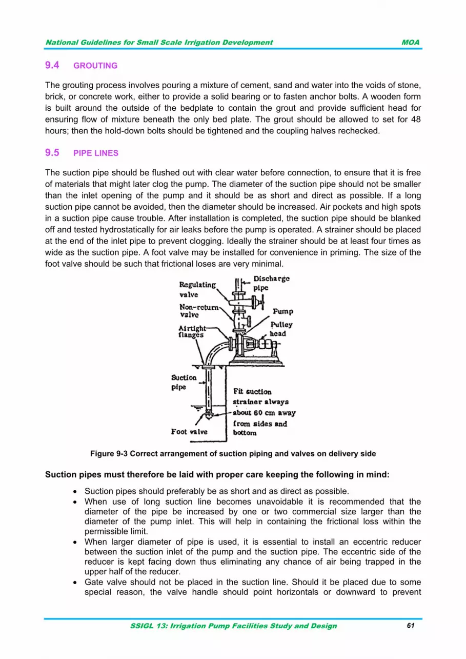
National Guidelines for Small Scale Irrigation Development MOA
SSIGL 13: Irrigation Pump Facilities Study and Design 61
GROUTING 9.4
The grouting process involves pouring a mixture of cement, sand and water into the voids of stone,
brick, or concrete work, either to provide a solid bearing or to fasten anchor bolts. A wooden form
is built around the outside of the bedplate to contain the grout and provide sufficient head for
ensuring flow of mixture beneath the only bed plate. The grout should be allowed to set for 48
hours; then the hold-down bolts should be tightened and the coupling halves rechecked.
PIPE LINES 9.5
The suction pipe should be flushed out with clear water before connection, to ensure that it is free
of materials that might later clog the pump. The diameter of the suction pipe should not be smaller
than the inlet opening of the pump and it should be as short and direct as possible. If a long
suction pipe cannot be avoided, then the diameter should be increased. Air pockets and high spots
in a suction pipe cause trouble. After installation is completed, the suction pipe should be blanked
off and tested hydrostatically for air leaks before the pump is operated. A strainer should be placed
at the end of the inlet pipe to prevent clogging. Ideally the strainer should be at least four times as
wide as the suction pipe. A foot valve may be installed for convenience in priming. The size of the
foot valve should be such that frictional loses are very minimal.
Figure 9-3 Correct arrangement of suction piping and valves on delivery side
Suction pipes must therefore be laid with proper care keeping the following in mind:
Suction pipes should preferably be as short and as direct as possible.
When use of long suction line becomes unavoidable it is recommended that the diameter of the pipe be increased by one or two commercial size larger than the diameter of the pump inlet. This will help in containing the frictional loss within the permissible limit.
When larger diameter of pipe is used, it is essential to install an eccentric reducer between the suction inlet of the pump and the suction pipe. The eccentric side of the reducer is kept facing down thus eliminating any chance of air being trapped in the upper half of the reducer.
Gate valve should not be placed in the suction line. Should it be placed due to some special reason, the valve handle should point horizontals or downward to prevent
National Guidelines for Small Scale Irrigation Development MOA
SSIGL 13: Irrigation Pump Facilities Study and Design 62
formation of air pocket at the upper half of the valve. Suction pipe should never be throttled when the pump is in operation.
All joints in the suction line have necessarily to be straight and leak proof and leak proof.
Foot valve should be of standard design. It should have two times entry area and four times screen area compared to the diameter of the suction pipe and shall be located at the bottom of the suction pipe with a minimum submergence of 60 cm below the pumping water level.
The end of the suction pipe should be submerged into water minimum by 4 times the pipe diameter.
Total suction lift without friction should normally be kept within 4.5-6.0 meters.
The suction pipe should be laid with a uniform rise towards the pump. There should not be any high spot where air pockets are likely to form.
When use of bends in the suction line become essential, only wide angle (long radius) bend should be used. Should any obstruction need to be crossed; bends in the suction line should cross from under such obstructions so as to prevent formation of air pocket in the line.
The size of the suction pipe shall be selected in such a way that the velocity of water on the suction side doesn't exceed 3.5 meters per second (as suction above this rate may produce cavitation).
There shall be ample opening on strainers (below the foot values). The combined area of strainers openings should be about three to four times the area of cross- section of the suction pipe. In order to prevent the strainer from being choked up by mud and other material accumulated at the bottom of the well, it shall be placed at least 0.6m above the bottom of the well.
Like the suction pipe, the discharge pipe should be as short and free of elbows as possible, in
order to reduce friction. A gate valve after a check valve should be placed at the pump outlet. The
non-return valve prevents backflow from damaging the pump when the pumping action is stopped.
The gate valve is used to gradually open the water supply from the pump after starting and to
avoid overloading the motor. The same valve is also used to shut off the water supply before
switching off the motor.
Delivery pipes must therefore be laid with proper care keeping the following in mind:
Delivery pipes should be laid as straight as possible.
A check valve and a gated valve should necessarily be used in the delivery line. The Check valve, which is placed between the pump and gets valve, prevents back flow of water into the pump in case pumping is stopped suddenly. Gate valve, which is placed after the chick valve, is used to control the flow in the delivery line.
In a long delivery line air release valves are placed at high points. Similarly scour valves are placed at appropriate locations. .Air pipes or Air vents provided in gravity mains.
A gate valve which should be placed in the lateral pipe, which takes off from the main delivery line. These gate valves control flow into the lateral lines.
In long and overgrown delivery line where expansion or contraction of pipe may occur due to the variation in ambient temperature, expansion joints, loops, bends flexible steel hose etc. should be used to compensate such expansion or contraction.
In addition to the pump which carries the normal discharge and use of bends, elbows tees and other fittings is kept to minimum to reduce head losses in the discharge line.
Necessary supports at suitable intervals should be provided to firmly anchor the pipe in place.
Provision of flow measuring devices viz. Pressure gauge, manometers, V-notch etc at the delivery end enable estimation of discharge readily. Calibrated pressure gauge may also be fitted in the delivery line to obtain working pressure.

National Guidelines for Small Scale Irrigation Development MOA
SSIGL 13: Irrigation Pump Facilities Study and Design 63
The use of reflux or non- return valve, fixed on the delivery side close to the pump, is necessary if distant pumping is required to avoid water hammering when pumping is stopped, sluice value can also be fitted immediately after the reflux value to regulate the discharge rate, for the purpose of maintaining controlled working conditions and also for easy disconnections of the pump for inspection and repairs without disturbing the delivery pipe line.

National Guidelines for Small Scale Irrigation Development MOA
SSIGL 13: Irrigation Pump Facilities Study and Design 64
National Guidelines for Small Scale Irrigation Development MOA
SSIGL 13: Irrigation Pump Facilities Study and Design 65
PUMP HYDRAULIC CHARACTERISTICS 10
When a hydraulic pump operates, it performs two functions. First, its mechanical action creates a
vacuum at the pump inlet which allows atmospheric pressure to force liquid from the source into
the inlet line to the pump. Second, its mechanical action delivers this liquid to the pump outlet and
forces it into the hydraulic system.
A pump produces liquid movement or flow: it does not generate pressure. It produces the flow
necessary for the development of pressure which is a function of resistance to fluid flow in the
system. For example, the pressure of the fluid at the pump outlet is zero for a pump not connected
to a system (load). Further, for a pump delivering into a system, the pressure will rise only to the
level necessary to overcome the resistance of the load. Here the main focus is on hydraulic
characteristics of pumps commonly used for irrigation.
Proper design of an irrigation system requires that the pumping system be precisely matched to
the irrigation distribution system. Then the pressure and flow rate required can be efficiently
provided by the pumping system.
When an irrigation system is designed or modified to use an existing pumping system, it is
necessary to measure the capacity of the existing pump. The irrigation system can be properly
designed only if the flow rate and pressure of the pump are accurately measured.
It is not adequate to visually estimate pump capacity or to use the manufacturer's specifications to
determine current pump capacity. Visual estimates are normally not accurate, and manufacturer's
specifications do not include the effects of site-specific factors such as well characteristics or
suction and discharge pipe sizes. Manufacturer's specifications also do not include the effects of
age and wear on pumping system performance.
Pump hydraulic characteristics to be considered in design of pumping facility are discussed below.
After determination of all the hydraulic characteristics the designer goes for most suitable pump
section for the specific irrigation system.
CAPACITY 10.1
Capacity means the flow rate with which liquid is moved or pushed by the pump to the desired
point in the process. It is commonly measured in either gallons per minute (gpm) or cubic meters
per hour (m3/hr). The capacity usually changes with the changes in operation of the process. The
capacity depends on a number of factors like operation conditions and liquid characteristics i.e.
density, viscosity, size of the pump and its inlet and outlet sections.
The capacity of a pump has two components, the pump discharge rate and the discharge
pressure. The discharge rate is normally measured in gallons per minute (gpm) in English units or
liters per second (lps) in metric units. Pressure is normally measured in pounds per square inch
(psi) in English units or kilo Pascal (kPa) in metric units. It is necessary to measure both discharge
rate and pressure under normal operating conditions in order to determine how the pumping
system will operate as a part of an irrigation system.
National Guidelines for Small Scale Irrigation Development MOA
SSIGL 13: Irrigation Pump Facilities Study and Design 66
Determination of discharge rate in irrigation 10.1.1
One of the basic parameters necessary to be determined in design of pumping facility for irrigation
is the discharge rate. The discharge rate for irrigated agriculture means the total demand or supply
for irrigation. This design discharge is influenced by the irrigation hours per day or indirectly the
pump operation hours per day. The pumping hours per day is usually not more than 8 to 10 hours
for engine driven systems. Thus for design purpose it must be referred to the maximum demand of
irrigation indicated under the irrigation agronomy report to fix maximum capacity of the pump and
stand-by capacity.
Standby capacity 10.1.2
Standby capacity is normally required as an insurance against pump failure as well as an
alternative during maintenance operations. This is necessary where the pumping station is the
sole source of supply to an area.
There will always be some standby capacity to take care for repairs, breakdowns etc. Generally
100% stand by capacity against average demand, and 33% to 50% standby capacity against the
peak demand is considered sufficient and may, therefore, be provided at the pumping stations.
TOTAL PUMP HEAD 10.2
Total Pump Head or Total Dynamic Head (TDH) is the total equivalent height that a fluid is to be
pumped, taking into account friction losses in the pipe.
TDH = Static suction lift+ Static delivery or discharge lift + Pipe friction Loss+ minor losses + any
extra head required at discharge point.
In irrigation fields, thus the designer has to have topographic data to properly decide the pump
location (position or axis), proper pipe line alignments, suction sump (in case of surface pumps)
and delivery point. Thus to properly fix pump axis besides the topographic data, geologic formation
of the pump site, minimum water level, maximum water level and sediment condition are so
important.
Besides the above parameters the pump head is influenced by the sediment condition. If water is
silt laden the operating head will definitely increase and this condition affects both the efficiency as
well as the life of the pump and the motor.
After computation of total pump head the other most critical factor not to be ignored is the water
hammer. The delivery line must withstand the total pump head and the water hammer.
Water Hammer:
Water hammer is the name given to the pressure surges caused by some relatively sudden
changes in flow velocity. This can be caused by valve opening or closing, pump starting or
stopping, cavitation or the collapse of air pockets in pipelines, filling empty pipelines or, of most
concern to irrigation applications, a power outage, which suddenly shuts down all the electric
pumps on the pipeline. When the velocity in the pipeline is suddenly reduced, the kinetic energy
(velocity head) of the moving column of water is converted into potential energy (pressure head),
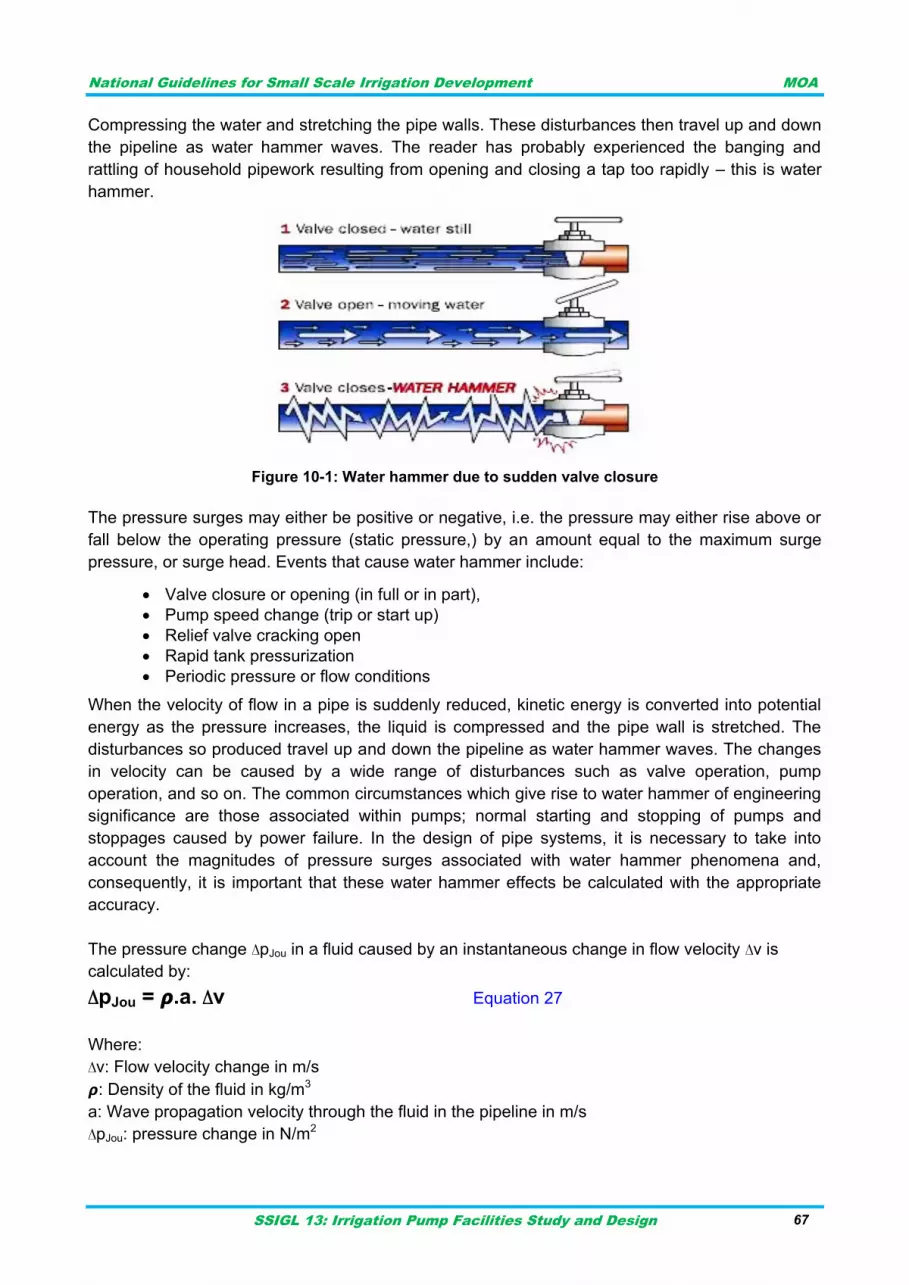
National Guidelines for Small Scale Irrigation Development MOA
SSIGL 13: Irrigation Pump Facilities Study and Design 67
Compressing the water and stretching the pipe walls. These disturbances then travel up and down
the pipeline as water hammer waves. The reader has probably experienced the banging and
rattling of household pipework resulting from opening and closing a tap too rapidly – this is water
hammer.
Figure 10-1: Water hammer due to sudden valve closure
The pressure surges may either be positive or negative, i.e. the pressure may either rise above or
fall below the operating pressure (static pressure,) by an amount equal to the maximum surge
pressure, or surge head. Events that cause water hammer include:
Valve closure or opening (in full or in part),
Pump speed change (trip or start up)
Relief valve cracking open
Rapid tank pressurization
Periodic pressure or flow conditions
When the velocity of flow in a pipe is suddenly reduced, kinetic energy is converted into potential
energy as the pressure increases, the liquid is compressed and the pipe wall is stretched. The
disturbances so produced travel up and down the pipeline as water hammer waves. The changes
in velocity can be caused by a wide range of disturbances such as valve operation, pump
operation, and so on. The common circumstances which give rise to water hammer of engineering
significance are those associated within pumps; normal starting and stopping of pumps and
stoppages caused by power failure. In the design of pipe systems, it is necessary to take into
account the magnitudes of pressure surges associated with water hammer phenomena and,
consequently, it is important that these water hammer effects be calculated with the appropriate
accuracy.
The pressure change ∆pJou in a fluid caused by an instantaneous change in flow velocity ∆v is
calculated by:
∆pJou = 𝞺.a. ∆v Equation 27
Where:
∆v: Flow velocity change in m/s
𝞺: Density of the fluid in kg/m3
a: Wave propagation velocity through the fluid in the pipeline in m/s
∆pJou: pressure change in N/m2
National Guidelines for Small Scale Irrigation Development MOA
SSIGL 13: Irrigation Pump Facilities Study and Design 68
The ∆pJou formula is referred to as the Joukowsky equation. The relationship only applies to the
period of time in which the velocity change ∆v is taking place. If ∆v runs in opposite direction to the
flow, the pressure will rise, otherwise it will fall. If the liquid pumped is water, i.e. 𝞺 = 1000 kg/m3,
equation 27 will look like this:
Equation 28
Where,
g: Acceleration due to gravity 9.81 m/s2
∆hJou: Pressure head change in m.
The wave propagation velocity (a) is one of the elements of the Joukowsky equation and,
therefore, a vital parameter for defining the intensity of a surge. It is calculated by solving equation
29.
√
Equation 29
Where,
𝞺: Density of the fluid in kg/m3
Ef: Modulus of elasticity of the fluid in N/m2
Ep: Modulus of elasticity of the pipe wall in N/m2
D: Inside pipe diameter in mm
t: Pipe wall thickness in mm
μ: Transverse contraction number or poison‟s ratio=0.40 for PVC, 0.30 for steel pipe
Equation 29 produces a range of values from approximately 1400 m/s for steel pipes to around
300 m/s for ductile plastic pipes. Characteristics of the pipe, such as temperature, pipe material
and the ratio of the diameter of the pipe to its wall thickness, affect the elastic properties of the
pipe and will ultimately have an impact on the speed at which the shock waves travel up and down
the pipe.
Table 10-1: Typical values of modulus of elasticity (Larock et al., 2000)
Material Modulus of Elasticity, E in pa or N/m2
steel 2.077 x 10¹¹
copper 1.10 x 10¹¹
bronze 1.00 x 10¹¹
Asbestos cement 2.30 x 10¹⁰
Fiber glass reinforced 9.00 x 10⁹
PVC 2.8 x 10⁹
Polyethylene 8.00 x 10⁸
Water (bulk) 2.2 x 10⁹
It may seem inconsistent that ∆pJou in the Joukowsky equation 28 seems to have nothing to do with
the mass of the flow inside the pipeline. For example, if the water hammer had been based on a
pipe diameter twice that of the diameter used, A = π D2/4 would have caused the fluid mass and
its kinetic energy to turn out four times as large. What seems to be a paradox is instantly resolved
if one considers the force exerted on the shut-off valve, i.e. force F = ∆p · A, the defining parameter
National Guidelines for Small Scale Irrigation Development MOA
SSIGL 13: Irrigation Pump Facilities Study and Design 69
for the surge load. Because of A, it is now in actual fact four times as large as before. This shows
that one must also consider the fluid mass to judge the risk of water hammer, although that does
not seem necessary after a superficial glance at Joukowsky‟s equation.
At the same time, this explains why the pressure surges occurring in domestic piping systems with
their small diameters and lengths are usually negligible. In these systems, the kinetic energy levels
and fluid masses are very small. In addition, it is practically impossible to close a valve within the
very short reflection time of a domestic water system.
Return time of wave
The time taken by the wave to go to peak and come back is given by the following equation:
Equation 30
Where:
Tr : Return time of the wave (seconds)
L : length of the pipe (m)
a : speed of pressure wave (m/s)
Example: what is the time of return of the wave for water under pumping at rate of 100l/s in 800m
long steel pipe of inner diameter 300mm and wall thickness 6mm if pump is suddenly stopped?
Calculate time of return for case of PVC pipe having 16mm wall thickness under same operation
conditions.
Solution:
L=800m
𝞺: Density of the fluid in kg/m3=1000kg/m3
Ef: Modulus of elasticity of the fluid in N/m2=2.2x109 N/m2 (table-----)
Ep: Modulus of elasticity of the pipe wall in N/m2=2.077x1011N/m2
D: Inside pipe diameter in mm=300mm
t: Pipe wall thickness in mm=6mm
μ: Transverse contraction number or poison‟s ratio=0.30 for steel pipe
Inserting the values in above formula: a=1219m/s
Thus Tr in steel pipe= (2*800)/1219=1.31 seconds
If the pipe material is PVC then μ=0.40, Ep=2.8x10⁹, t=16mm thus a=406m/s.
Tr in PVC pipe is equal to 3.94seconds.
Effect of the closure time:
The closure time (Tc) is the time during which the flow varies. For example, in the case of a power
cut, the pump will not stop instantaneously but will gradually reduce its flow depending on its
inertia and water pressure. Similarly, valves need some time to be closed. The way the flow is
reduced is usually not linear, for instance, gate valves have their flow reduced mainly during the
last 20% of the closure run.
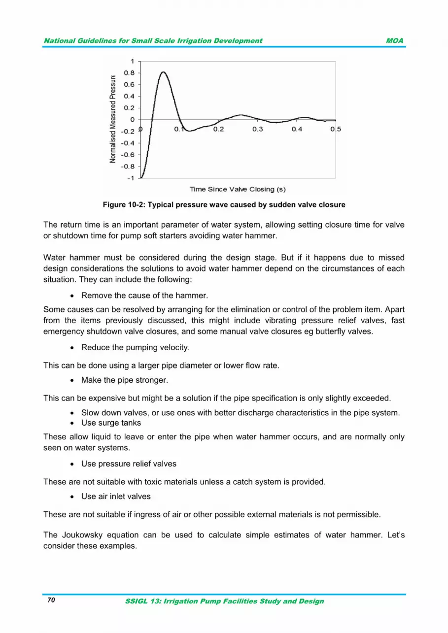
National Guidelines for Small Scale Irrigation Development MOA
SSIGL 13: Irrigation Pump Facilities Study and Design 70
Figure 10-2: Typical pressure wave caused by sudden valve closure
The return time is an important parameter of water system, allowing setting closure time for valve
or shutdown time for pump soft starters avoiding water hammer.
Water hammer must be considered during the design stage. But if it happens due to missed
design considerations the solutions to avoid water hammer depend on the circumstances of each
situation. They can include the following:
Remove the cause of the hammer.
Some causes can be resolved by arranging for the elimination or control of the problem item. Apart
from the items previously discussed, this might include vibrating pressure relief valves, fast
emergency shutdown valve closures, and some manual valve closures eg butterfly valves.
Reduce the pumping velocity.
This can be done using a larger pipe diameter or lower flow rate.
Make the pipe stronger.
This can be expensive but might be a solution if the pipe specification is only slightly exceeded.
Slow down valves, or use ones with better discharge characteristics in the pipe system.
Use surge tanks
These allow liquid to leave or enter the pipe when water hammer occurs, and are normally only
seen on water systems.
Use pressure relief valves
These are not suitable with toxic materials unless a catch system is provided.
Use air inlet valves
These are not suitable if ingress of air or other possible external materials is not permissible.
The Joukowsky equation can be used to calculate simple estimates of water hammer. Let‟s
consider these examples.
National Guidelines for Small Scale Irrigation Development MOA
SSIGL 13: Irrigation Pump Facilities Study and Design 71
Example-1:
In a DN 500 pipeline, L = 8000 m, a = 1000 m/s and v = 2 m/s, a gate valve is closed in 5 seconds.
Calculate the pressure surge. Calculate the force exerted on the gate.
Solution:
5 second < Tr =(2xL/a) or 16 second, i.e. Joukowsky‟s equation may be applied. If the flow velocity
is reduced from 2 m/s to zero as the valve is closed, ∆v = 2 m/s. This gives us a pressure increase
∆h = 100 · 2 = 200 m or approximately ∆p = 20 · 105 N/m2, which is 20 bar.
The valve cross-section measures A = D2 · 0.25 · π ≈ 0.2 m2. The force acting on the gate is p·A =
0.2 · 20 · 105 = 4·105 N= 400 kN.
Example-2:
A pump delivers water at Q = 300 l/s and a head ∆h = 40 m through a DN 400 discharge pipe
measuring L = 5000 m into an overhead tank; a = 1000 m/s. The inertia moments of pump and
motor are negligible. Is there a risk of liquid column separation, i.e. macro-cavitation, following
pump trip? If so, what is the anticipated pressure increase?
Solution:
Q = 300 l/s in a DN 400 pipeline roughly corresponds to a flow velocity v = 2.4 m/s. As a result of
pump trip and the loss of mass inertia moment, the pump comes to a sudden standstill, i.e. ∆v =
2.4 m/s. According to the Joukowsky equation, this causes a head drop of ∆h = -100 · 2.4 m = -
240 m. Since the steady-state head is just 40 m, vacuum is reached, the liquid column collapses
and macro-cavitation sets in. Following the liquid column separation near the pump outlet, the two
liquid columns will recombine with great impact after some time.
For reasons of energy conservation, the highest velocity of the backward flow cannot exceed the
original velocity of the steady-state flow of 2.4 m/s.
Under the most unfavorable conditions, the cavitation-induced pressure rise will, therefore, be ∆h
= 100 · 2.4 = 240 m, which is the equivalent to 24 bar.
POWER AND EFFICIENCY 10.3
Power in pumping system is the total energy needed to run the pump/s under given capacity and
total dynamic head. Horsepower is the unit of power to define hydraulic or water horsepower. In
International Systems (SI) it is expressed in kilowatts (KW). 1 horsepower = 746 watts or
0.746KW. The input power delivered by the motor to the pump is called brake horsepower (bHp).
The difference between the brake horsepower and hydraulic power is the pump efficiency.
Water Horse Power (Theoretical hp):
Pw=γQH Equation 31
Where,
Pw= power in Kw
H is the total lift head in m,
Q is the pump discharge in m3/s.
γ=unit weight of water which is approximately 10KN/m3.
Shaft horse power, for given pump efficiency of ηp:
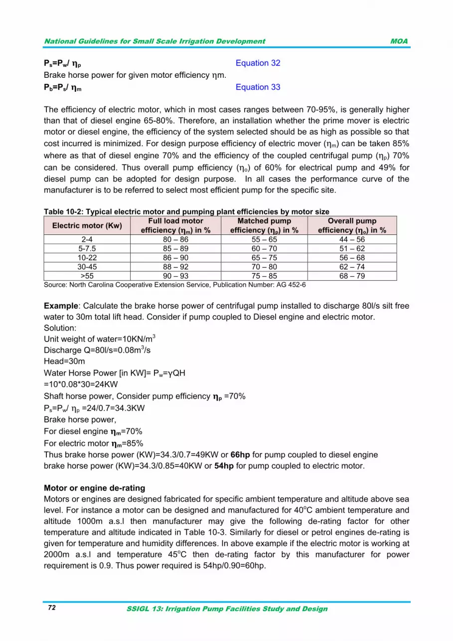
National Guidelines for Small Scale Irrigation Development MOA
SSIGL 13: Irrigation Pump Facilities Study and Design 72
Ps=Pw/ ηp Equation 32
Brake horse power for given motor efficiency ηm.
Pb=Ps/ ηm Equation 33
The efficiency of electric motor, which in most cases ranges between 70-95%, is generally higher
than that of diesel engine 65-80%. Therefore, an installation whether the prime mover is electric
motor or diesel engine, the efficiency of the system selected should be as high as possible so that
cost incurred is minimized. For design purpose efficiency of electric mover (ηm) can be taken 85%
where as that of diesel engine 70% and the efficiency of the coupled centrifugal pump (ηp) 70%
can be considered. Thus overall pump efficiency (ηo) of 60% for electrical pump and 49% for
diesel pump can be adopted for design purpose. In all cases the performance curve of the
manufacturer is to be referred to select most efficient pump for the specific site.
Table 10-2: Typical electric motor and pumping plant efficiencies by motor size
Electric motor (Kw) Full load motor
efficiency (ηm) in %
Matched pump
efficiency (ηp) in %
Overall pump
efficiency (ηo) in %
2-4 80 – 86 55 – 65 44 – 56
5-7.5 85 – 89 60 – 70 51 – 62
10-22 86 – 90 65 – 75 56 – 68
30-45 88 – 92 70 – 80 62 – 74
>55 90 – 93 75 – 85 68 – 79 Source: North Carolina Cooperative Extension Service, Publication Number: AG 452-6
Example: Calculate the brake horse power of centrifugal pump installed to discharge 80l/s silt free
water to 30m total lift head. Consider if pump coupled to Diesel engine and electric motor.
Solution:
Unit weight of water=10KN/m3
Discharge Q=80l/s=0.08m3/s
Head=30m
Water Horse Power [in KW]= Pw=γQH
=10*0.08*30=24KW
Shaft horse power, Consider pump efficiency ηp =70%
Ps=Pw/ ηp =24/0.7=34.3KW
Brake horse power,
For diesel engine ηm=70%
For electric motor ηm=85%
Thus brake horse power (KW)=34.3/0.7=49KW or 66hp for pump coupled to diesel engine
brake horse power (KW)=34.3/0.85=40KW or 54hp for pump coupled to electric motor.
Motor or engine de-rating
Motors or engines are designed fabricated for specific ambient temperature and altitude above sea
level. For instance a motor can be designed and manufactured for 40oC ambient temperature and
altitude 1000m a.s.l then manufacturer may give the following de-rating factor for other
temperature and altitude indicated in Table 10-3. Similarly for diesel or petrol engines de-rating is
given for temperature and humidity differences. In above example if the electric motor is working at
2000m a.s.l and temperature 45oC then de-rating factor by this manufacturer for power
requirement is 0.9. Thus power required is 54hp/0.90=60hp.
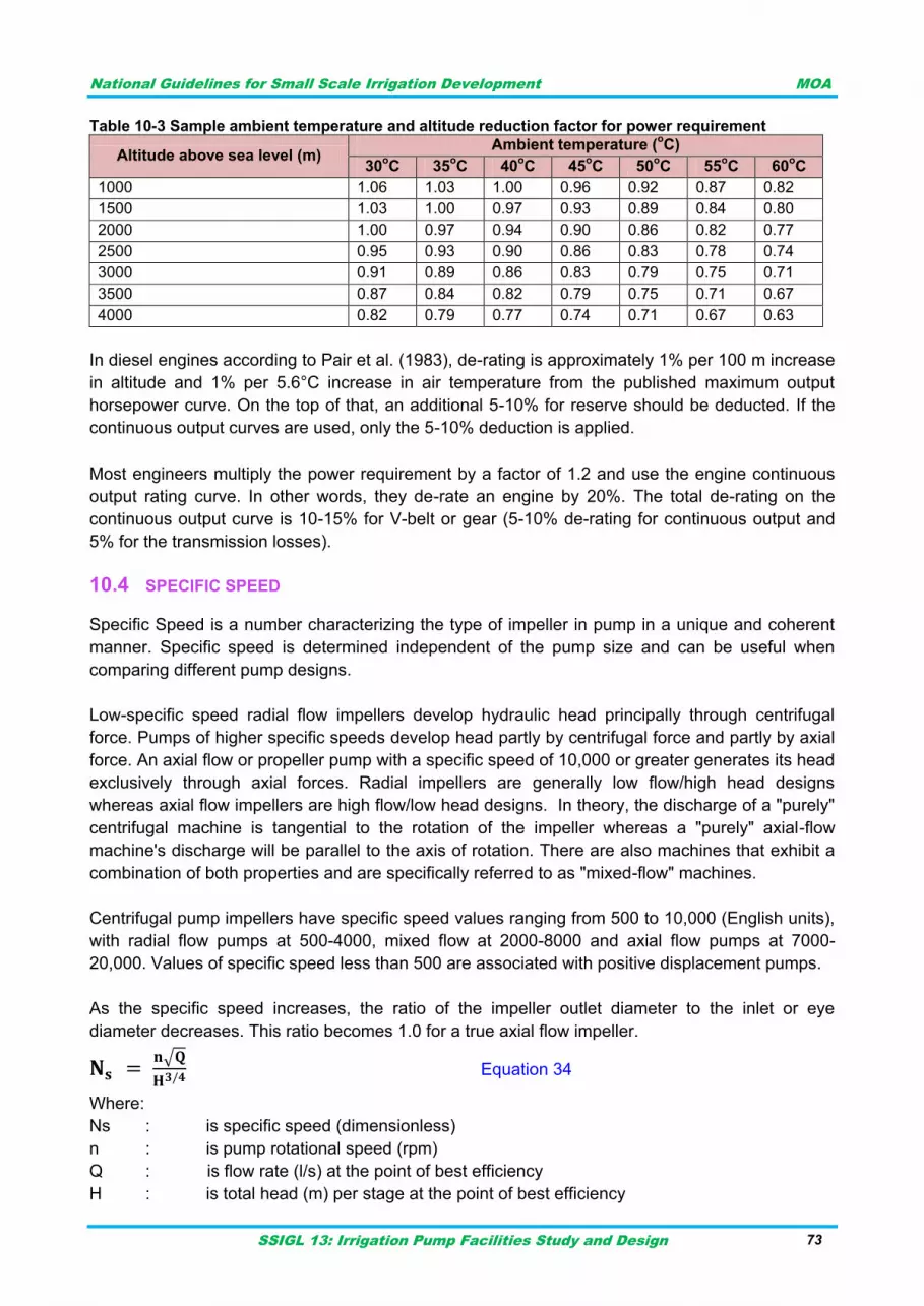
National Guidelines for Small Scale Irrigation Development MOA
SSIGL 13: Irrigation Pump Facilities Study and Design 73
Table 10-3 Sample ambient temperature and altitude reduction factor for power requirement
Altitude above sea level (m) Ambient temperature (
oC)
30oC 35
oC 40
oC 45
oC 50
oC 55
oC 60
oC
1000 1.06 1.03 1.00 0.96 0.92 0.87 0.82
1500 1.03 1.00 0.97 0.93 0.89 0.84 0.80
2000 1.00 0.97 0.94 0.90 0.86 0.82 0.77
2500 0.95 0.93 0.90 0.86 0.83 0.78 0.74
3000 0.91 0.89 0.86 0.83 0.79 0.75 0.71
3500 0.87 0.84 0.82 0.79 0.75 0.71 0.67
4000 0.82 0.79 0.77 0.74 0.71 0.67 0.63
In diesel engines according to Pair et al. (1983), de-rating is approximately 1% per 100 m increase
in altitude and 1% per 5.6°C increase in air temperature from the published maximum output
horsepower curve. On the top of that, an additional 5-10% for reserve should be deducted. If the
continuous output curves are used, only the 5-10% deduction is applied.
Most engineers multiply the power requirement by a factor of 1.2 and use the engine continuous
output rating curve. In other words, they de-rate an engine by 20%. The total de-rating on the
continuous output curve is 10-15% for V-belt or gear (5-10% de-rating for continuous output and
5% for the transmission losses).
SPECIFIC SPEED 10.4
Specific Speed is a number characterizing the type of impeller in pump in a unique and coherent
manner. Specific speed is determined independent of the pump size and can be useful when
comparing different pump designs.
Low-specific speed radial flow impellers develop hydraulic head principally through centrifugal
force. Pumps of higher specific speeds develop head partly by centrifugal force and partly by axial
force. An axial flow or propeller pump with a specific speed of 10,000 or greater generates its head
exclusively through axial forces. Radial impellers are generally low flow/high head designs
whereas axial flow impellers are high flow/low head designs. In theory, the discharge of a "purely"
centrifugal machine is tangential to the rotation of the impeller whereas a "purely" axial-flow
machine's discharge will be parallel to the axis of rotation. There are also machines that exhibit a
combination of both properties and are specifically referred to as "mixed-flow" machines.
Centrifugal pump impellers have specific speed values ranging from 500 to 10,000 (English units),
with radial flow pumps at 500-4000, mixed flow at 2000-8000 and axial flow pumps at 7000-
20,000. Values of specific speed less than 500 are associated with positive displacement pumps.
As the specific speed increases, the ratio of the impeller outlet diameter to the inlet or eye
diameter decreases. This ratio becomes 1.0 for a true axial flow impeller.
√
Equation 34
Where:
Ns : is specific speed (dimensionless)
n : is pump rotational speed (rpm)
Q : is flow rate (l/s) at the point of best efficiency
H : is total head (m) per stage at the point of best efficiency
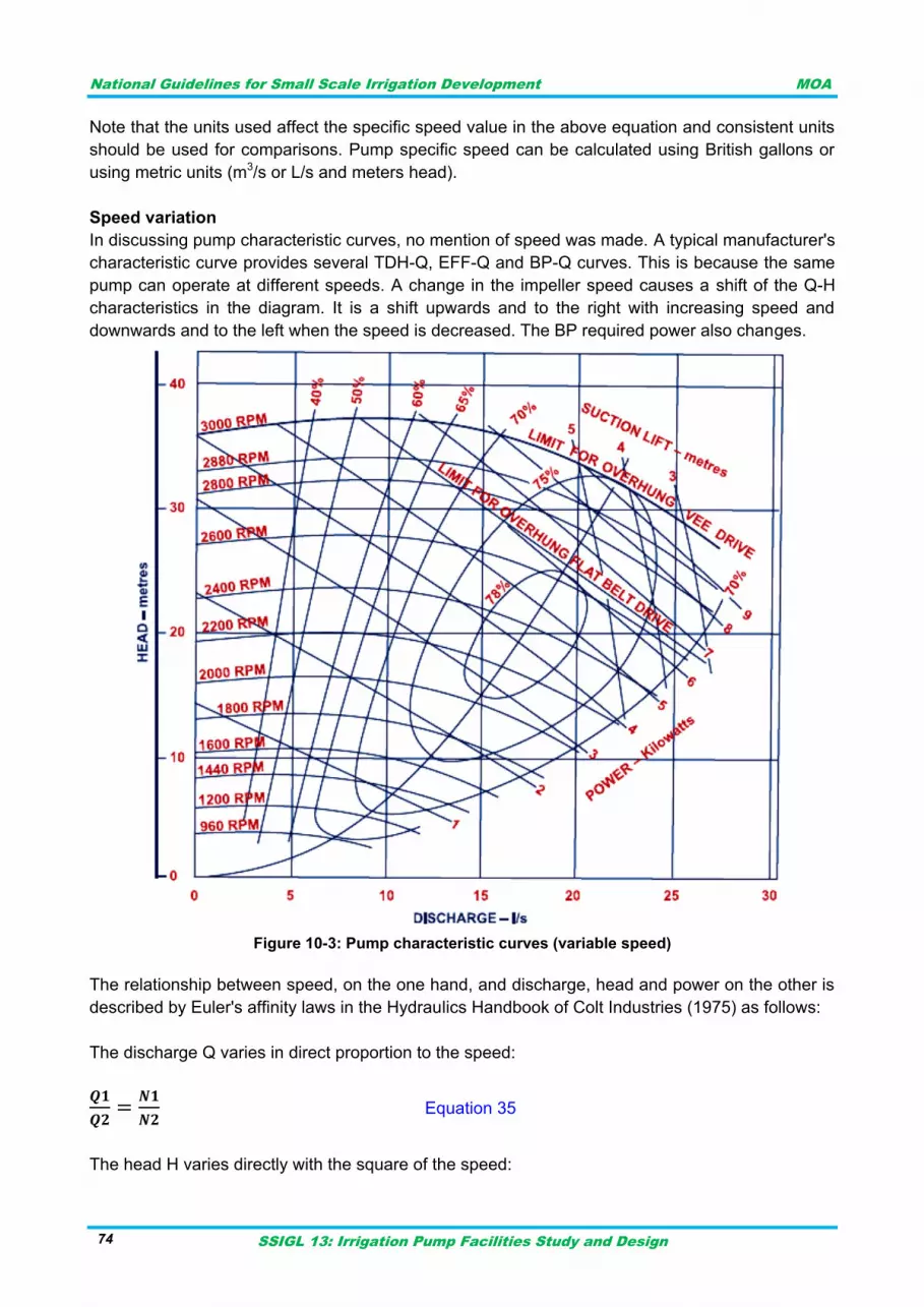
National Guidelines for Small Scale Irrigation Development MOA
SSIGL 13: Irrigation Pump Facilities Study and Design 74
Note that the units used affect the specific speed value in the above equation and consistent units
should be used for comparisons. Pump specific speed can be calculated using British gallons or
using metric units (m3/s or L/s and meters head).
Speed variation
In discussing pump characteristic curves, no mention of speed was made. A typical manufacturer's
characteristic curve provides several TDH-Q, EFF-Q and BP-Q curves. This is because the same
pump can operate at different speeds. A change in the impeller speed causes a shift of the Q-H
characteristics in the diagram. It is a shift upwards and to the right with increasing speed and
downwards and to the left when the speed is decreased. The BP required power also changes.
Figure 10-3: Pump characteristic curves (variable speed)
The relationship between speed, on the one hand, and discharge, head and power on the other is
described by Euler's affinity laws in the Hydraulics Handbook of Colt Industries (1975) as follows:
The discharge Q varies in direct proportion to the speed:
Equation 35
The head H varies directly with the square of the speed:
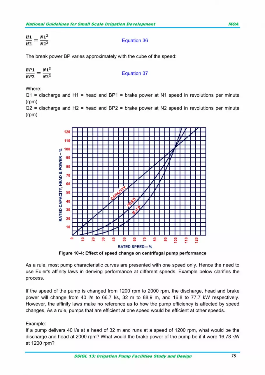
National Guidelines for Small Scale Irrigation Development MOA
SSIGL 13: Irrigation Pump Facilities Study and Design 75
Equation 36
The break power BP varies approximately with the cube of the speed:
Equation 37
Where:
Q1 = discharge and H1 = head and BP1 = brake power at N1 speed in revolutions per minute
(rpm)
Q2 = discharge and H2 = head and BP2 = brake power at N2 speed in revolutions per minute
(rpm)
Figure 10-4: Effect of speed change on centrifugal pump performance
As a rule, most pump characteristic curves are presented with one speed only. Hence the need to
use Euler's affinity laws in deriving performance at different speeds. Example below clarifies the
process.
If the speed of the pump is changed from 1200 rpm to 2000 rpm, the discharge, head and brake
power will change from 40 l/s to 66.7 l/s, 32 m to 88.9 m, and 16.8 to 77.7 kW respectively.
However, the affinity laws make no reference as to how the pump efficiency is affected by speed
changes. As a rule, pumps that are efficient at one speed would be efficient at other speeds.
Example:
If a pump delivers 40 l/s at a head of 32 m and runs at a speed of 1200 rpm, what would be the
discharge and head at 2000 rpm? What would the brake power of the pump be if it were 16.78 kW
at 1200 rpm?
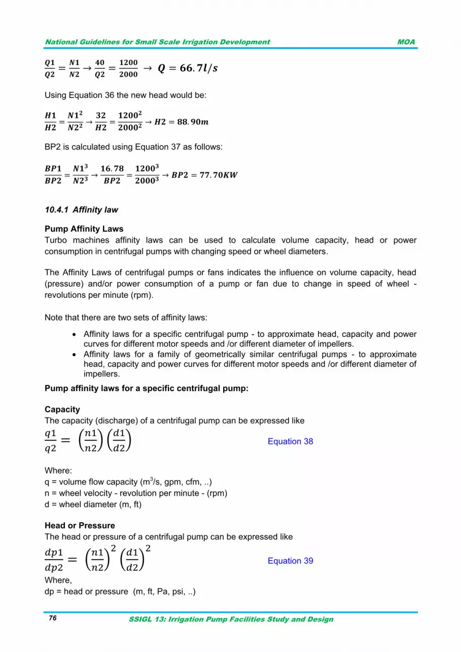
National Guidelines for Small Scale Irrigation Development MOA
SSIGL 13: Irrigation Pump Facilities Study and Design 76
Using Equation 36 the new head would be:
BP2 is calculated using Equation 37 as follows:
Affinity law 10.4.1
Pump Affinity Laws
Turbo machines affinity laws can be used to calculate volume capacity, head or power
consumption in centrifugal pumps with changing speed or wheel diameters.
The Affinity Laws of centrifugal pumps or fans indicates the influence on volume capacity, head
(pressure) and/or power consumption of a pump or fan due to change in speed of wheel -
revolutions per minute (rpm).
Note that there are two sets of affinity laws:
Affinity laws for a specific centrifugal pump - to approximate head, capacity and power curves for different motor speeds and /or different diameter of impellers.
Affinity laws for a family of geometrically similar centrifugal pumps - to approximate head, capacity and power curves for different motor speeds and /or different diameter of impellers.
Pump affinity laws for a specific centrifugal pump:
Capacity
The capacity (discharge) of a centrifugal pump can be expressed like
(
) (
) Equation 38
Where:
q = volume flow capacity (m3/s, gpm, cfm, ..)
n = wheel velocity - revolution per minute - (rpm)
d = wheel diameter (m, ft)
Head or Pressure
The head or pressure of a centrifugal pump can be expressed like
(
) (
) Equation 39
Where,
dp = head or pressure (m, ft, Pa, psi, ..)
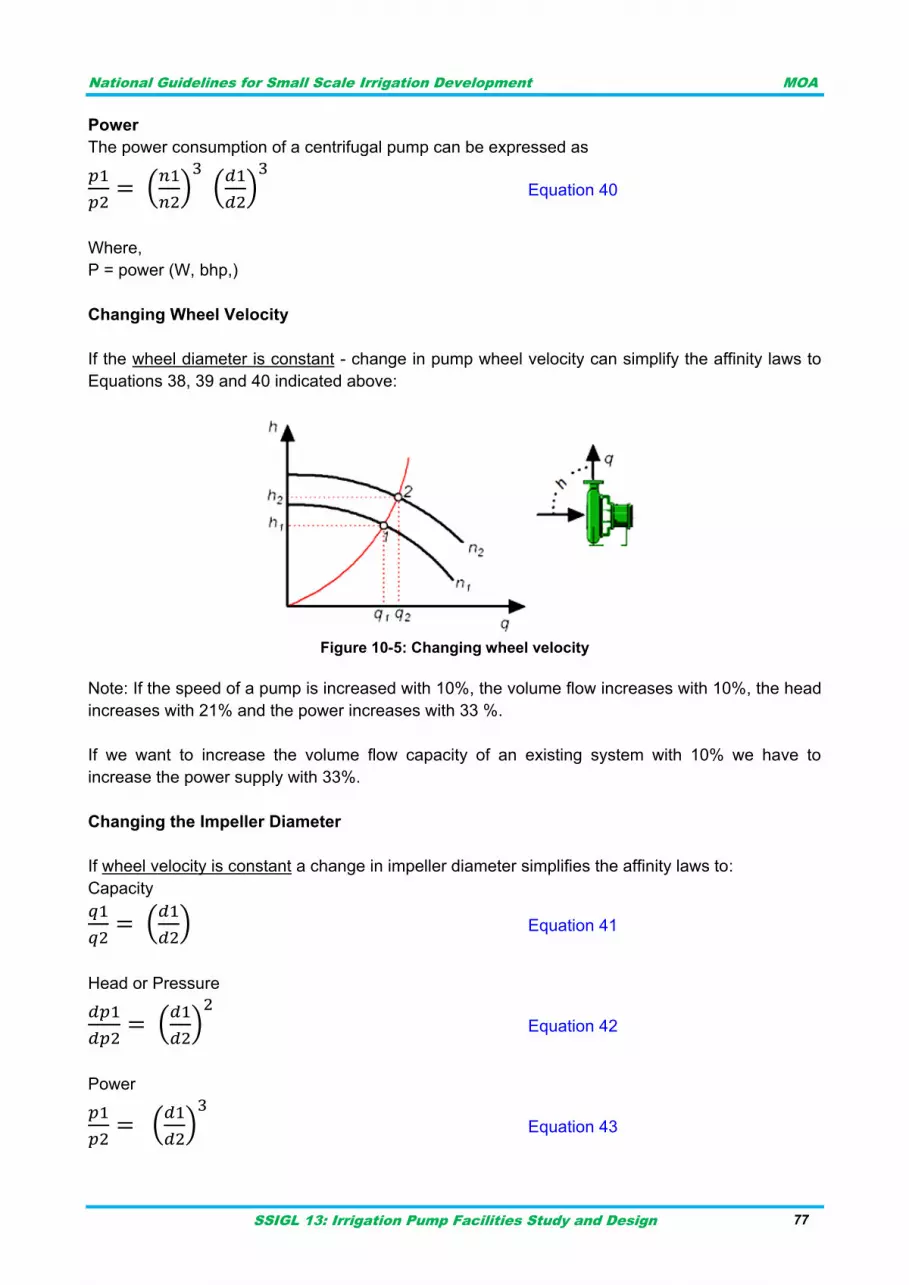
National Guidelines for Small Scale Irrigation Development MOA
SSIGL 13: Irrigation Pump Facilities Study and Design 77
Power
The power consumption of a centrifugal pump can be expressed as
(
) (
) Equation 40
Where,
P = power (W, bhp,)
Changing Wheel Velocity
If the wheel diameter is constant - change in pump wheel velocity can simplify the affinity laws to
Equations 38, 39 and 40 indicated above:
Figure 10-5: Changing wheel velocity
Note: If the speed of a pump is increased with 10%, the volume flow increases with 10%, the head
increases with 21% and the power increases with 33 %.
If we want to increase the volume flow capacity of an existing system with 10% we have to
increase the power supply with 33%.
Changing the Impeller Diameter
If wheel velocity is constant a change in impeller diameter simplifies the affinity laws to:
Capacity
(
) Equation 41
Head or Pressure
(
) Equation 42
Power
(
) Equation 43
National Guidelines for Small Scale Irrigation Development MOA
SSIGL 13: Irrigation Pump Facilities Study and Design 78
Pump characteristic curve 10.4.2
Most manufacturers provide four different characteristic curves for every pump: the Total Dynamic
Head versus Discharge or TDH-Q curve, the Efficiency versus Discharge or EFF-Q curve, the
Brake Power versus Discharge or BPQ curve and Net Positive Suction Head Required versus
Discharge or NPSHR-Q curve. All four curves are discharge related. Figure 10-6 presents the four
typical characteristic curves for a pump, with one stage or impeller.
Source: FAO irrigation Manual Module-5, 2001
Figure 10-6” Pump characteristic curves
Total dynamic head versus discharge (TDH-Q)
This is a curve that relates the head to the discharge of the pump. It shows that the same pump
can provide different combinations of discharge and head. It is also noticeable that as the head
increases the discharge decreases and vice versa.
The point at which the discharge is zero and the head at maximum is called shut off head. This
happens when a pump is operating with a closed valve outlet. As this may happen in the practice,
knowledge of the shut off head (or pressure) of a particular pump would allow the engineer to
provide for a pipe that can sustain the pressure at shut off point if necessary.
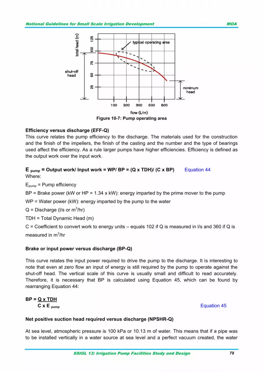
National Guidelines for Small Scale Irrigation Development MOA
SSIGL 13: Irrigation Pump Facilities Study and Design 79
Figure 10-7: Pump operating area
Efficiency versus discharge (EFF-Q)
This curve relates the pump efficiency to the discharge. The materials used for the construction
and the finish of the impellers, the finish of the casting and the number and the type of bearings
used affect the efficiency. As a rule larger pumps have higher efficiencies. Efficiency is defined as
the output work over the input work.
E pump = Output work/ Input work = WP/ BP = (Q x TDH)/ (C x BP) Equation 44
Where:
Epump = Pump efficiency
BP = Brake power (kW or HP = 1.34 x kW): energy imparted by the prime mover to the pump
WP = Water power (kW): energy imparted by the pump to the water
Q = Discharge (l/s or m3/hr)
TDH = Total Dynamic Head (m)
C = Coefficient to convert work to energy units – equals 102 if Q is measured in l/s and 360 if Q is
measured in m3/hr
Brake or input power versus discharge (BP-Q)
This curve relates the input power required to drive the pump to the discharge. It is interesting to
note that even at zero flow an input of energy is still required by the pump to operate against the
shut-off head. The vertical scale of this curve is usually small and difficult to read accurately.
Therefore, it is necessary that BP is calculated using Equation 45, which can be found by
rearranging Equation 44:
BP = Q x TDH
C x E pump Equation 45
Net positive suction head required versus discharge (NPSHR-Q)
At sea level, atmospheric pressure is 100 kPa or 10.13 m of water. This means that if a pipe was
to be installed vertically in a water source at sea level and a perfect vacuum created, the water
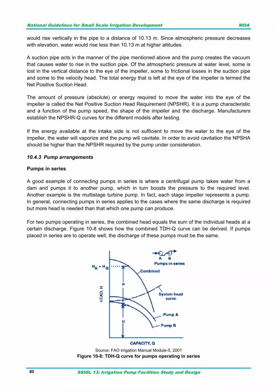
National Guidelines for Small Scale Irrigation Development MOA
SSIGL 13: Irrigation Pump Facilities Study and Design 80
would rise vertically in the pipe to a distance of 10.13 m. Since atmospheric pressure decreases
with elevation, water would rise less than 10.13 m at higher altitudes.
A suction pipe acts in the manner of the pipe mentioned above and the pump creates the vacuum
that causes water to rise in the suction pipe. Of the atmospheric pressure at water level, some is
lost in the vertical distance to the eye of the impeller, some to frictional losses in the suction pipe
and some to the velocity head. The total energy that is left at the eye of the impeller is termed the
Net Positive Suction Head.
The amount of pressure (absolute) or energy required to move the water into the eye of the
impeller is called the Net Positive Suction Head Requirement (NPSHR). It is a pump characteristic
and a function of the pump speed, the shape of the impeller and the discharge. Manufacturers
establish the NPSHR-Q curves for the different models after testing.
If the energy available at the intake side is not sufficient to move the water to the eye of the
impeller, the water will vaporize and the pump will cavitate. In order to avoid cavitation the NPSHA
should be higher than the NPSHR required by the pump under consideration.
Pump arrangements 10.4.3
Pumps in series
A good example of connecting pumps in series is where a centrifugal pump takes water from a
dam and pumps it to another pump, which in turn boosts the pressure to the required level.
Another example is the multistage turbine pump. In fact, each stage impeller represents a pump.
In general, connecting pumps in series applies to the cases where the same discharge is required
but more head is needed than that which one pump can produce.
For two pumps operating in series, the combined head equals the sum of the individual heads at a
certain discharge. Figure 10-8 shows how the combined TDH-Q curve can be derived. If pumps
placed in series are to operate well, the discharge of these pumps must be the same.
Source: FAO irrigation Manual Module-5, 2001
Figure 10-8: TDH-Q curve for pumps operating in series
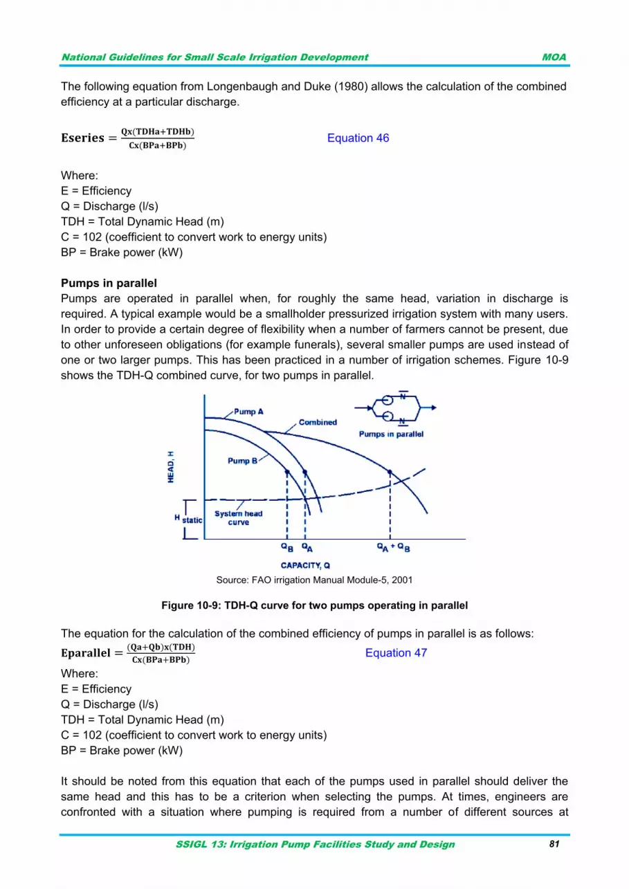
National Guidelines for Small Scale Irrigation Development MOA
SSIGL 13: Irrigation Pump Facilities Study and Design 81
The following equation from Longenbaugh and Duke (1980) allows the calculation of the combined
efficiency at a particular discharge.
Equation 46
Where:
E = Efficiency
Q = Discharge (l/s)
TDH = Total Dynamic Head (m)
C = 102 (coefficient to convert work to energy units)
BP = Brake power (kW)
Pumps in parallel
Pumps are operated in parallel when, for roughly the same head, variation in discharge is
required. A typical example would be a smallholder pressurized irrigation system with many users.
In order to provide a certain degree of flexibility when a number of farmers cannot be present, due
to other unforeseen obligations (for example funerals), several smaller pumps are used instead of
one or two larger pumps. This has been practiced in a number of irrigation schemes. Figure 10-9
shows the TDH-Q combined curve, for two pumps in parallel.
Source: FAO irrigation Manual Module-5, 2001
Figure 10-9: TDH-Q curve for two pumps operating in parallel
The equation for the calculation of the combined efficiency of pumps in parallel is as follows:
Equation 47
Where:
E = Efficiency
Q = Discharge (l/s)
TDH = Total Dynamic Head (m)
C = 102 (coefficient to convert work to energy units)
BP = Brake power (kW)
It should be noted from this equation that each of the pumps used in parallel should deliver the
same head and this has to be a criterion when selecting the pumps. At times, engineers are
confronted with a situation where pumping is required from a number of different sources at
National Guidelines for Small Scale Irrigation Development MOA
SSIGL 13: Irrigation Pump Facilities Study and Design 82
different elevations. In this case each pump should deliver its water to a common reservoir and not
a common pipe in order to avoid the flow of water from one pump to another.
Operators should be careful when operating pumps in parallel to ensure that the minimum flow
requirement is met for each pump. Using several pumps in parallel broadens the range of flow that
can be delivered to the system. It should also be noted that pumps used at the same time should
have identical performance characteristics. Pumps with differing performance curves operating in
parallel cannot both operate at their BEP and the likelihood of system failure is greatly increased.
Pump combinations 10.4.4
Using a number of smaller pumps rather than one larger unit may sometimes be an economical
alternative. This will allow a smaller pump operating at high efficiency to be used during low
demand periods which resultants saving in running costs. The change from single pumps to
multiple pump operation may affect individual pump efficiencies and maintenance costs. This
aspect must be satisfactorily resolved to ensure a multiple pump installation is feasible.
A single pump is unable to consistently operate close to its BEP with a wide variation in system
requirements. Multiple pumps consisting of several smaller pumps in combination can be used to
serve the pumping requirements of a system, particularly those with large differences between the
flow rate required during normal system operation and that required during maximum system flow
conditions.
The advantages in using combinations of smaller pumps rather than a single large one are:
Operation flexibility
Redundancy in case of a pump failure
Lower maintenance requirements due to pumps operating near their BEP
Higher efficiency
Generally the number of pumps to be installed for the specific purpose is decided based on the
capacity of pump/s and anticipated demands, the efficiency and cost consideration during initial
installation, operation and maintenance for the specific number of pumps considered. This needs
good engineering judgment to fix proper number of pumps to satisfy the same demand.
Pump curve and system curve 10.4.5
Pump curve
Performance curve or characteristic curve is discussed under section 10.4.2 above. The
parameters to be indicated in pump curve are also discussed under same section. A combined
typical pump curve is indicated under Figure 10-10.
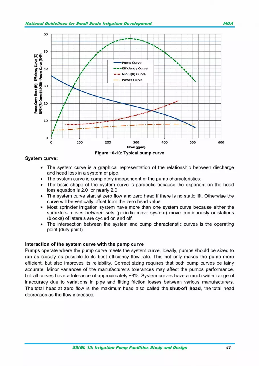
National Guidelines for Small Scale Irrigation Development MOA
SSIGL 13: Irrigation Pump Facilities Study and Design 83
Figure 10-10: Typical pump curve
System curve:
The system curve is a graphical representation of the relationship between discharge and head loss in a system of pipe.
The system curve is completely independent of the pump characteristics.
The basic shape of the system curve is parabolic because the exponent on the head loss equation is 2.0 or nearly 2.0
The system curve start at zero flow and zero head if there is no static lift. Otherwise the curve will be vertically offset from the zero head value.
Most sprinkler irrigation system have more than one system curve because either the sprinklers moves between sets (periodic move system) move continuously or stations (blocks) of laterals are cycled on and off.
The intersection between the system and pump characteristic curves is the operating point (duty point)
Interaction of the system curve with the pump curve
Pumps operate where the pump curve meets the system curve. Ideally, pumps should be sized to
run as closely as possible to its best efficiency flow rate. This not only makes the pump more
efficient, but also improves its reliability. Correct sizing requires that both pump curves be fairly
accurate. Minor variances of the manufacturer‟s tolerances may affect the pumps performance,
but all curves have a tolerance of approximately ±3%. System curves have a much wider range of
inaccuracy due to variations in pipe and fitting friction losses between various manufacturers.
The total head at zero flow is the maximum head also called the shut-off head, the total head
decreases as the flow increases.
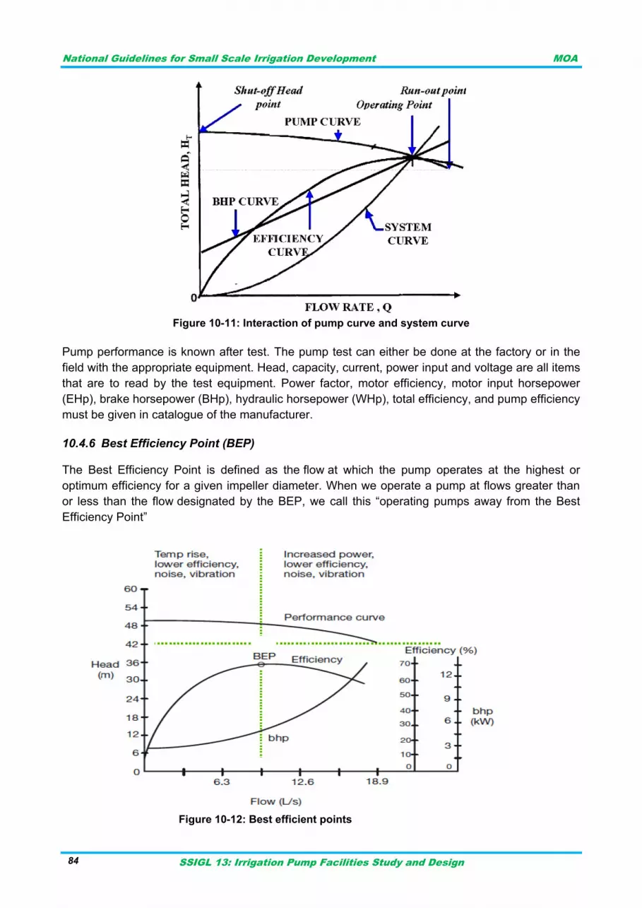
National Guidelines for Small Scale Irrigation Development MOA
SSIGL 13: Irrigation Pump Facilities Study and Design 84
Figure 10-11: Interaction of pump curve and system curve
Pump performance is known after test. The pump test can either be done at the factory or in the
field with the appropriate equipment. Head, capacity, current, power input and voltage are all items
that are to read by the test equipment. Power factor, motor efficiency, motor input horsepower
(EHp), brake horsepower (BHp), hydraulic horsepower (WHp), total efficiency, and pump efficiency
must be given in catalogue of the manufacturer.
Best Efficiency Point (BEP) 10.4.6
The Best Efficiency Point is defined as the flow at which the pump operates at the highest or
optimum efficiency for a given impeller diameter. When we operate a pump at flows greater than
or less than the flow designated by the BEP, we call this “operating pumps away from the Best
Efficiency Point”
Figure 10-12: Best efficient points
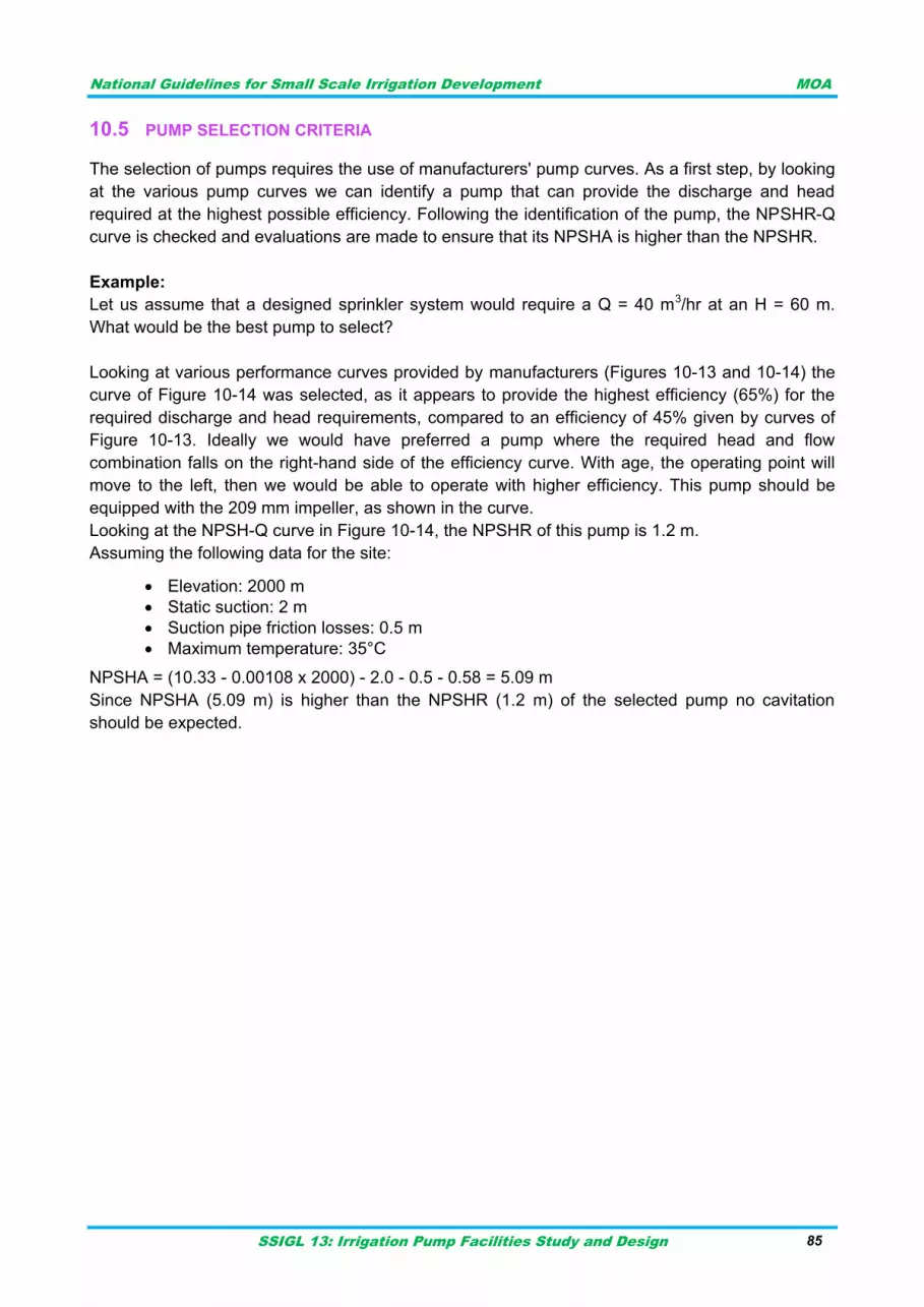
National Guidelines for Small Scale Irrigation Development MOA
SSIGL 13: Irrigation Pump Facilities Study and Design 85
PUMP SELECTION CRITERIA 10.5
The selection of pumps requires the use of manufacturers' pump curves. As a first step, by looking
at the various pump curves we can identify a pump that can provide the discharge and head
required at the highest possible efficiency. Following the identification of the pump, the NPSHR-Q
curve is checked and evaluations are made to ensure that its NPSHA is higher than the NPSHR.
Example:
Let us assume that a designed sprinkler system would require a Q = 40 m3/hr at an H = 60 m.
What would be the best pump to select?
Looking at various performance curves provided by manufacturers (Figures 10-13 and 10-14) the
curve of Figure 10-14 was selected, as it appears to provide the highest efficiency (65%) for the
required discharge and head requirements, compared to an efficiency of 45% given by curves of
Figure 10-13. Ideally we would have preferred a pump where the required head and flow
combination falls on the right-hand side of the efficiency curve. With age, the operating point will
move to the left, then we would be able to operate with higher efficiency. This pump should be
equipped with the 209 mm impeller, as shown in the curve.
Looking at the NPSH-Q curve in Figure 10-14, the NPSHR of this pump is 1.2 m.
Assuming the following data for the site:
Elevation: 2000 m
Static suction: 2 m
Suction pipe friction losses: 0.5 m
Maximum temperature: 35°C
NPSHA = (10.33 - 0.00108 x 2000) - 2.0 - 0.5 - 0.58 = 5.09 m
Since NPSHA (5.09 m) is higher than the NPSHR (1.2 m) of the selected pump no cavitation
should be expected.
National Guidelines for Small Scale Irrigation Development MOA
SSIGL 13: Irrigation Pump Facilities Study and Design 86
Figure 10-13: Performance curve of pump (a)
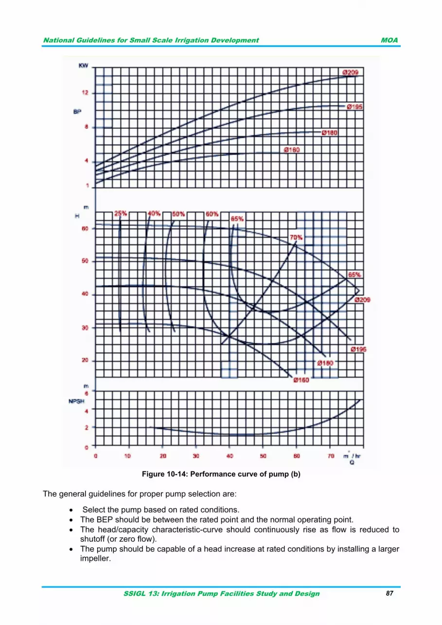
National Guidelines for Small Scale Irrigation Development MOA
SSIGL 13: Irrigation Pump Facilities Study and Design 87
Figure 10-14: Performance curve of pump (b)
The general guidelines for proper pump selection are:
Select the pump based on rated conditions.
The BEP should be between the rated point and the normal operating point.
The head/capacity characteristic-curve should continuously rise as flow is reduced to shutoff (or zero flow).
The pump should be capable of a head increase at rated conditions by installing a larger impeller.
National Guidelines for Small Scale Irrigation Development MOA
SSIGL 13: Irrigation Pump Facilities Study and Design 88
The pump should not be operated below the manufacturer‟s minimum continuous flow rate.
Critical Points for Selection of Pumps:
Fluid characteristics: A detailed study of the fluid characteristics is usually the most important factor for the proper selection of pumps. Right type of pump can only be selected based on the experience and knowledge of the selecting engineer and the environment.
The suction head and the available Net Positive Suction Head (NPSH) both decreases with an increase in liquid viscosity for the same pumping rate. At the same time, discharge and total head both increases with an increase in liquid viscosity for the same pumping rate. In other words, the power requirement also increases with liquid viscosity.
Specific Gravity: It affects the pump life along with performance of the pump.
Temperature: The operating temperature at the pump is an important factor affecting overall performance of the pump. While considering temperature, the combined ambient and liquid temperature along with the temperature rise due to evaluation of heart from the resistance in the system shall be taken into consideration. As per general experience, pumps can perform efficiently with trouble-free operation over an approximate temperature of up to 80°C.
Lubricating quality of liquid handled.
Space available for pump: It helps in selecting the pump, ie, horizontal or vertical. It also influences the model and size of the pump.
Ease in operation and maintenance
Lubricating system
Availability of spare parts
Cost factor
Reliability
Environmental-friendly
Efficiency of pump at duty point
Arrangement for minimising gland leakage, etc
Material of construction, etc
Drive system and reliability.
Selection of Pumps Based on Practical Experience.
National Guidelines for Small Scale Irrigation Development MOA
SSIGL 13: Irrigation Pump Facilities Study and Design 89
DESIGN OF PUMPING FACILITY 11
During preliminary design, the designer will confirm the suitability of the site for pump station
construction, evaluate facility alternatives, and confirm station features as a function of capacity
and risk. These activities will be accomplished through a geotechnical investigation, site survey,
environmental investigation, and preliminary design report. Each is described in other guidelines
for Topographic data, Hydro metrological data, Geological data and Agronomic data.
DATA REQUIREMENT 11.1
Type of data requirements shall be identified first to be used in the process of design activity in
order to have practical design report. Basic data required to the study and design of the proposed
scheme has to be properly collected, analyzed and simulated using proper and practicable
methodologies. The following major activities, but not limited are supposed to be considered to
meet the study and design needs of the project.
The complete information about the project site like location of source, farm area, roots of pipe
system etc. are needed. Detail survey works both at the head work site and irrigable area shall be
conducted and a topographic map of the scheme area has to be prepared at a specified scale.
Topographic map of the head work at a scale not more than 1:500 and at a contour interval of not
more than 0.5, showing all the features upstream and downstream, right and left of the proposed
site including observation pits shall be prepared. Cross-sections at a scale of both vertical and
horizontal shall be 1:100 indicating the pertinent features to head work shall be prepared.
Topographic map of the irrigable area at a scale of not more than 1:1000, at a contour interval of
not more than 1m for steeply area (25%) and not more than 0.5m for planning and undulating
areas shall be established. The topographic map should also show every major feature in the
irrigable area such as traditional canals, watering points/springs, settlements, foot path, cattle
crossings, gullies, trees, benchmarks, hills, graves, etc.
All the required benchmarks and stations shall be established using stable features and shall be
properly connected with the national grid stations and benchmarks of the proposed pump site.
The hydrological analysis is an essential engineering component that has to be investigated
thoroughly meeting the two basic elements safety and economy of the hydraulic structures. Thus,
proper estimation of extreme flows (high and low flows) is vital for the design of hydraulic
structures and planning and management of irrigation water. The two parameters crucial for
design purpose are the lean flow and the peak flood. These levels must be clearly indicated or
marked (as meter elevation a.s.l.) on site and on topographic map and sections.
The estimation is crucial for better planning and developing the given irrigable area and well-being
of the ecosystem in the downstream portion of the river reach. For the purpose of irrigation usually
80% flow exceedance should be adequately meet the crop water needed. The estimation of this
flow exceedance could only possible when direct measurements of flow are available in the case
of gauged river or it can be estimated using a regionalization approach or different techniques.
There are different methods or techniques available for the estimation of the lean flow in the river.
The automated base flow separation technique, graphical method, tracer methods using isotopes,
and rainfall runoff models are some of the methods applicable if the river is gauged.
National Guidelines for Small Scale Irrigation Development MOA
SSIGL 13: Irrigation Pump Facilities Study and Design 90
Variety of crops, crop plan, crop demand, type and characteristic of soil are some of the necessary
data. The main concern in this guideline is to obtain necessary data for pump design. Basically the
monthly demands after water balance consideration and the maximum duty of crops is
mandatory for design purpose. For details please refer Guideline for Irrigation Agronomy.
Desirable quantity and quality of geological and geotechnical investigations are required for safe
and economical design of the pumping facility. The detail about how geological date is to be
collected and used is given in Guideline for Geology and Engineering Geological Study.
DESIGN PROCEDURE 11.2
The design process starts with determination of discharge required for irrigation.
The next step in design is determination of the head or elevation difference and the lengths of suction and delivery lines.
Next select type of pipe materials and size the components.
Once the flow rate and pipe sizes are known, the friction head loss can be determined.
Additional energy losses are encountered as the fluid passes through bends, constrictions, valves, etc. These are referred to as minor losses.
Calculation of the system losses at several different flow rates will yield a system curve. System curves represent a loss of energy in systems with a variation in the flow rate. Or, stated differently, the amount of energy the pump must generate to operate at a given flow rates. Consider de-rating and other factors.
The total dynamic head (TDH) of a pumping system is calculated TDH is the head the pump must overcome to move the fluid to its destination. At the same time determine the NPSH and the water hammer expected.
By calculating multiple TDH values based on incrementing flow values, and plotting these on a graph of TDH vs flow rate, the system curve is determined.
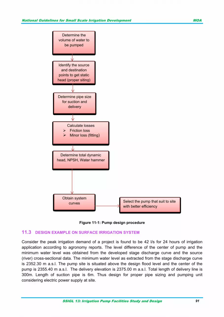
National Guidelines for Small Scale Irrigation Development MOA
SSIGL 13: Irrigation Pump Facilities Study and Design 91
Figure 11-1: Pump design procedure
DESIGN EXAMPLE ON SURFACE IRRIGATION SYSTEM 11.3
Consider the peak irrigation demand of a project is found to be 42 l/s for 24 hours of irrigation
application according to agronomy reports. The level difference of the center of pump and the
minimum water level was obtained from the developed stage discharge curve and the source
(river) cross-sectional data. The minimum water level as extracted from the stage discharge curve
is 2352.30 m a.s.l. The pump site is situated above the design flood level and the center of the
pump is 2355.40 m a.s.l. The delivery elevation is 2375.00 m a.s.l. Total length of delivery line is
300m. Length of suction pipe is 6m. Thus design for proper pipe sizing and pumping unit
considering electric power supply at site.
Obtain system
curves
Determine total dynamic
head, NPSH, Water hammer
Calculate losses
Friction loss
Minor loss (fitting)
Determine pipe size
for suction and
delivery
Identify the source
and destination
points to get static
head (proper siting)
Determine the
volume of water to
be pumped
Select the pump that suit to site
with better efficiency
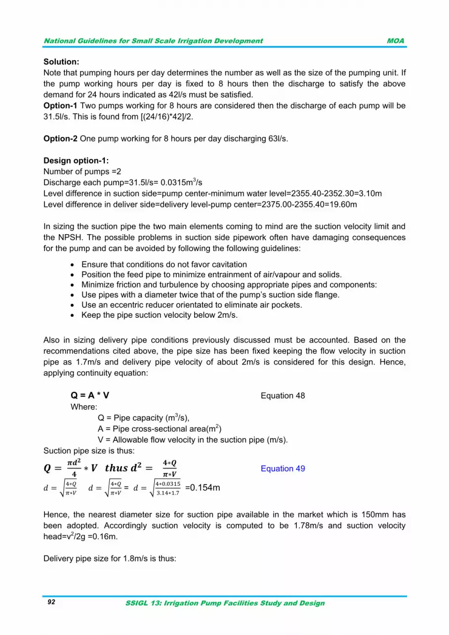
National Guidelines for Small Scale Irrigation Development MOA
SSIGL 13: Irrigation Pump Facilities Study and Design 92
Solution:
Note that pumping hours per day determines the number as well as the size of the pumping unit. If
the pump working hours per day is fixed to 8 hours then the discharge to satisfy the above
demand for 24 hours indicated as 42l/s must be satisfied.
Option-1 Two pumps working for 8 hours are considered then the discharge of each pump will be
31.5l/s. This is found from [(24/16)*42]/2.
Option-2 One pump working for 8 hours per day discharging 63l/s.
Design option-1:
Number of pumps =2
Discharge each pump=31.5l/s= 0.0315m3/s
Level difference in suction side=pump center-minimum water level=2355.40-2352.30=3.10m
Level difference in deliver side=delivery level-pump center=2375.00-2355.40=19.60m
In sizing the suction pipe the two main elements coming to mind are the suction velocity limit and
the NPSH. The possible problems in suction side pipework often have damaging consequences
for the pump and can be avoided by following the following guidelines:
Ensure that conditions do not favor cavitation
Position the feed pipe to minimize entrainment of air/vapour and solids.
Minimize friction and turbulence by choosing appropriate pipes and components:
Use pipes with a diameter twice that of the pump‟s suction side flange.
Use an eccentric reducer orientated to eliminate air pockets.
Keep the pipe suction velocity below 2m/s.
Also in sizing delivery pipe conditions previously discussed must be accounted. Based on the
recommendations cited above, the pipe size has been fixed keeping the flow velocity in suction
pipe as 1.7m/s and delivery pipe velocity of about 2m/s is considered for this design. Hence,
applying continuity equation:
Q = A * V Equation 48
Where:
Q = Pipe capacity (m3/s),
A = Pipe cross-sectional area(m2)
V = Allowable flow velocity in the suction pipe (m/s).
Suction pipe size is thus:
Equation 49
√
√
= √
=0.154m
Hence, the nearest diameter size for suction pipe available in the market which is 150mm has
been adopted. Accordingly suction velocity is computed to be 1.78m/s and suction velocity
head=v2/2g =0.16m.
Delivery pipe size for 1.8m/s is thus:
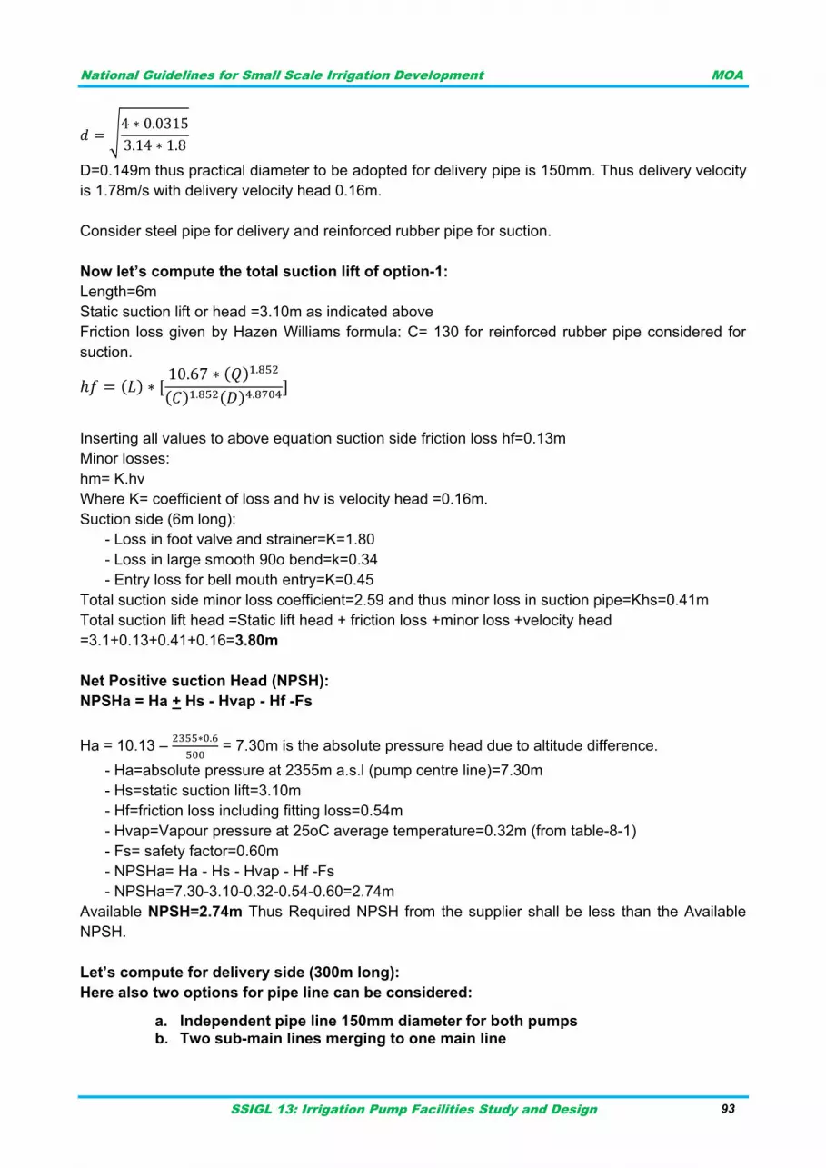
National Guidelines for Small Scale Irrigation Development MOA
SSIGL 13: Irrigation Pump Facilities Study and Design 93
√
D=0.149m thus practical diameter to be adopted for delivery pipe is 150mm. Thus delivery velocity
is 1.78m/s with delivery velocity head 0.16m.
Consider steel pipe for delivery and reinforced rubber pipe for suction.
Now let’s compute the total suction lift of option-1:
Length=6m
Static suction lift or head =3.10m as indicated above
Friction loss given by Hazen Williams formula: C= 130 for reinforced rubber pipe considered for
suction.
Inserting all values to above equation suction side friction loss hf=0.13m
Minor losses:
hm= K.hv
Where K= coefficient of loss and hv is velocity head =0.16m.
Suction side (6m long):
- Loss in foot valve and strainer=K=1.80
- Loss in large smooth 90o bend=k=0.34
- Entry loss for bell mouth entry=K=0.45
Total suction side minor loss coefficient=2.59 and thus minor loss in suction pipe=Khs=0.41m
Total suction lift head =Static lift head + friction loss +minor loss +velocity head
=3.1+0.13+0.41+0.16=3.80m
Net Positive suction Head (NPSH):
NPSHa = Ha + Hs - Hvap - Hf -Fs
Ha = 10.13 –
= 7.30m is the absolute pressure head due to altitude difference.
- Ha=absolute pressure at 2355m a.s.l (pump centre line)=7.30m
- Hs=static suction lift=3.10m
- Hf=friction loss including fitting loss=0.54m
- Hvap=Vapour pressure at 25oC average temperature=0.32m (from table-8-1)
- Fs= safety factor=0.60m
- NPSHa= Ha - Hs - Hvap - Hf -Fs
- NPSHa=7.30-3.10-0.32-0.54-0.60=2.74m
Available NPSH=2.74m Thus Required NPSH from the supplier shall be less than the Available
NPSH.
Let’s compute for delivery side (300m long):
Here also two options for pipe line can be considered:
a. Independent pipe line 150mm diameter for both pumps b. Two sub-main lines merging to one main line
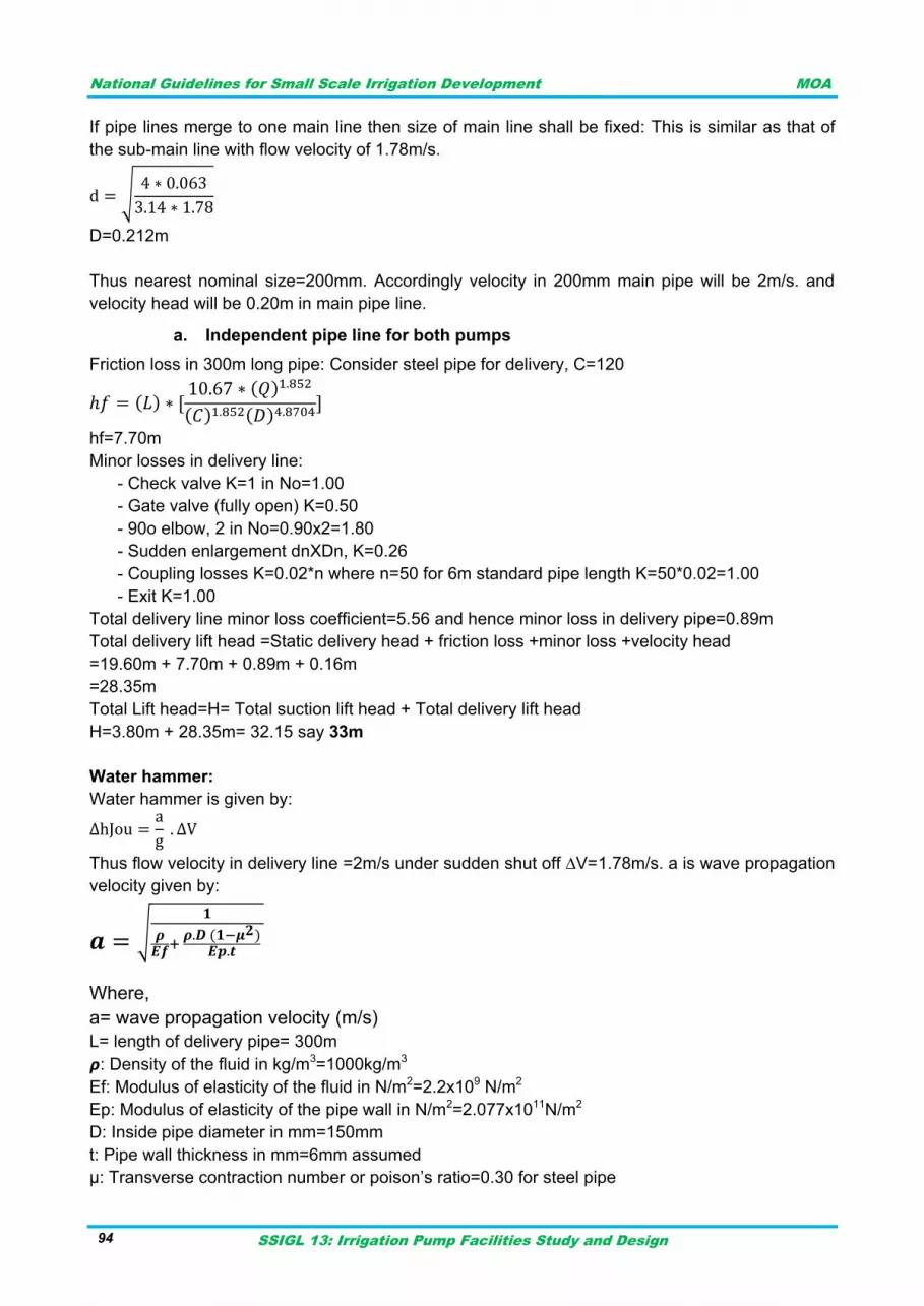
National Guidelines for Small Scale Irrigation Development MOA
SSIGL 13: Irrigation Pump Facilities Study and Design 94
If pipe lines merge to one main line then size of main line shall be fixed: This is similar as that of
the sub-main line with flow velocity of 1.78m/s.
√
D=0.212m
Thus nearest nominal size=200mm. Accordingly velocity in 200mm main pipe will be 2m/s. and
velocity head will be 0.20m in main pipe line.
a. Independent pipe line for both pumps
Friction loss in 300m long pipe: Consider steel pipe for delivery, C=120
hf=7.70m
Minor losses in delivery line:
- Check valve K=1 in No=1.00
- Gate valve (fully open) K=0.50
- 90o elbow, 2 in No=0.90x2=1.80
- Sudden enlargement dnXDn, K=0.26
- Coupling losses K=0.02*n where n=50 for 6m standard pipe length K=50*0.02=1.00
- Exit K=1.00
Total delivery line minor loss coefficient=5.56 and hence minor loss in delivery pipe=0.89m
Total delivery lift head =Static delivery head + friction loss +minor loss +velocity head
=19.60m + 7.70m + 0.89m + 0.16m
=28.35m
Total Lift head=H= Total suction lift head + Total delivery lift head
H=3.80m + 28.35m= 32.15 say 33m
Water hammer:
Water hammer is given by:
Thus flow velocity in delivery line =2m/s under sudden shut off ∆V=1.78m/s. a is wave propagation
velocity given by:
√
Where,
a= wave propagation velocity (m/s)
L= length of delivery pipe= 300m
𝞺: Density of the fluid in kg/m3=1000kg/m3
Ef: Modulus of elasticity of the fluid in N/m2=2.2x109 N/m2
Ep: Modulus of elasticity of the pipe wall in N/m2=2.077x1011N/m2
D: Inside pipe diameter in mm=150mm
t: Pipe wall thickness in mm=6mm assumed
μ: Transverse contraction number or poison‟s ratio=0.30 for steel pipe
National Guidelines for Small Scale Irrigation Development MOA
SSIGL 13: Irrigation Pump Facilities Study and Design 95
Inserting the values in above formula: a=1332m/s
Thus water hammer=(1332/9.81)*1.78=242m or 24bar. Thus the pipe must withstand this head
besides the working head.
Power Requirement: (For option-1 two pumps with independent delivery line)
Water Horse Power (Theoretical hp)=WHP=Pw =QH where H is the total lift head=33m, Q is
unit pump discharge=0.0315m3/s and =unit weight of water which is approximately 10KN/m3.
Thus PKw=10.40KW
Shaft horse power, assuming pump efficiency of 70% will be 14.86KW.
Brake horse power for motor efficiency of 85% will be 17.50KW.
b. Two sub-main lines merging to one main line
Out of 300m delivery line, let 18m is sub-main line (150mm) and the rest 282m is main line
(200mm Diameter).Thus using Hazen Williams formula friction los in sub-main line=0.46m and in
main line=6.43m thus total friction loss in delivery line=6.89m.
Minor loss in delivery (consider previously calculated loss in delivery + confluence loss) =0.89m +
0.95*22/19.62= 1.08m. Here confluence loss co-efficient is taken 0.95 for confluence angle not
more than 30o.
Velocity head in delivery=0.20m
Total delivery lift head =Static delivery head + friction loss +minor loss +velocity head
=19.60m + 6.89m + 1.08m + 0.20m
=27.77m
Total Lift head=H= Total suction lift head + Total delivery lift head
H=3.80m + 27.77m= 31.57 say 32m
Power Requirement: (For option-1 two pumps with merged delivery line)
Water Horse Power (Theoretical hp)=WHP=Pw =QH where H is the total lift head=32m, Q is
unit pump discharge=0.0315m3/s and =unit weight of water which is approximately 10KN/m3.
Thus PKw=10.08KW
Shaft horse power, assuming pump efficiency of 70% will be 14.40KW.
Brake horse power for motor efficiency of 85% will be 16.94KW.
Here pump power requirement is nearly the same for independent as well as merged delivery line
thus two in number 18KW pumps can be considered under option-1.
Design option-2:
Number of pump =1
Discharge each pump=63 l/s= 0.063m3/s
Level difference in suction side=pump center-minimum water level=2355.40-2352.30=3.10m
Level difference in deliver side=delivery level-pump center=2375.00-2355.40=19.60m
Suction and Delivery pipe size for 1.8m/s is:
√
d=0.211m thus practical diameter to be adopted for delivery pipe is 200mm. Thus delivery velocity
is 2.00m/s with delivery velocity head 0.20m.
National Guidelines for Small Scale Irrigation Development MOA
SSIGL 13: Irrigation Pump Facilities Study and Design 96
Consider steel pipe for delivery and reinforced rubber pipe for suction.
Now let’s compute the total suction lift of option-2:
Length=6m
Static suction lift or head =3.10m as indicated above
Friction loss given by Hazen Williams formula: C= 130 for reinforced rubber pipe considered for
suction.
Inserting all values to above equation suction side friction loss hf=0.14m
Minor losses:
hm= K.hv
Where K= coefficient of loss and hv is velocity head =0.20m.
Suction side (6m long):
- Loss in foot valve and strainer=K=1.80
- Loss in large smooth 90o bend=k=0.34
- Entry loss for bell mouth entry=K=0.45
Total suction side minor loss coefficient=2.59 and thus minor loss in suction pipe=Khs=0.52m
Total suction lift head =Static lift head + friction loss +minor loss +velocity head
=3.1+0.14+0.52+0.20=3.96m
Net Positive suction Head (NPSH):
NPSHa = Ha + Hs - Hvap - Hf -Fs
Ha = 10.13 –
= 7.30m is the absolute pressure head due to altitude difference.
- Ha=absolute pressure at 2355m a.s.l (pump centre line)=7.30m
- Hs=static suction lift=3.10m
- Hf=friction loss including fitting loss=0.66m
- Hvap=Vapour pressure at 25oC average temperature=0.32m (from table-8-1)
- Fs= safety factor=0.60m
- NPSHa= Ha - Hs - Hvap - Hf -Fs
- NPSHa=7.30-3.10-0.32-0.66-0.60=2.62m
Available NPSH=2.62m Thus Required NPSH from the supplier shall be less than the Available
NPSH.
Friction loss in 300m long pipe: Consider steel pipe for delivery, C=120
hf=6.84m
Minor losses in delivery line:
- Check valve K=1 in No=1.00
- Gate valve (fully open) K=0.50
- 90o elbow, 2 in No=0.90x2=1.80
- Sudden enlargement dnXDn, K=0.26
- Coupling losses K=0.02*n where n= number of couplings =50 for 6m standard pipe length
K=50*0.02=1.00
- Exit K=1.00
Total delivery line minor loss coefficient=5.56 and hence minor loss in delivery pipe=1.11m
National Guidelines for Small Scale Irrigation Development MOA
SSIGL 13: Irrigation Pump Facilities Study and Design 97
Total delivery lift head =Static delivery head + friction loss +minor loss +velocity head
=19.60m + 6.84m + 1.11m + 0.20m
=27.75m
Total Lift head=H= Total suction lift head + Total delivery lift head
H=3.96m + 27.75m= 31.71 say 32m
Power Requirement: (For option-2 one pump only)
Water Horse Power (Theoretical hp)=WHP=Pw =QH where H is the total lift head=32m, Q is
unit pump discharge=0.063m3/s and =unit weight of water which is approximately 10KN/m3.
Thus PKw=20.16KW
Shaft horse power, assuming pump efficiency of 70% will be 28.80KW.
Brake horse power for motor efficiency of 85% will be 34KW.
By assuming 20% for electric motor overload, the pump motor will be
Pm = Ph *(1+0.2), KW
Pm = 18* 1.2 = 21.6 KW (two pump case)
Pm = 34* 1.2 = 40.80 KW (one pump case)
Hence, the motors shall be selected from motor rating standards. Say 22KW for two pump case
and 41 KW for one pump case.
Additional power requirement for:
Illumination and others…………………………..5KW,
Allowance…………………………………….….. 5KW,
Thus actual total power requirement (KW) at site is 54KW for two pump case and 51KW for one
pump case.
The apparent power to be supplied (KVA) is computed by dividing the real power to power factor
(say 0.80).
Note:
The pump must be equipped with priming facility.
The designer shall fix number of pumps based on considerations cited in the guideline.
Stand-by capacity shall be considered by the designer as per the guideline.
Transformer size is fixed considering the power required at start of the largest motor.
DESIGN EXAMPLE ON GROUND WATER IRRIGATION SYSTEM 11.4
The ground water is extracted from two boreholes around the irrigable area. The two submersible
pumps will discharge to the collection chamber. Finally booster surface pumps are utilized to lift
water to canal system. Details are given below.
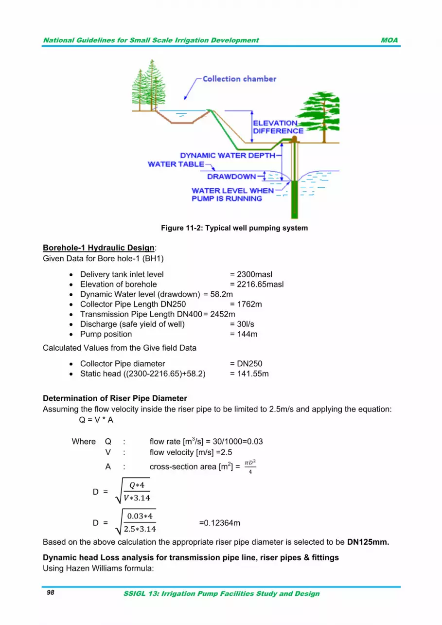
National Guidelines for Small Scale Irrigation Development MOA
SSIGL 13: Irrigation Pump Facilities Study and Design 98
Figure 11-2: Typical well pumping system
Borehole-1 Hydraulic Design:
Given Data for Bore hole-1 (BH1)
Delivery tank inlet level = 2300masl
Elevation of borehole = 2216.65masl
Dynamic Water level (drawdown) = 58.2m
Collector Pipe Length DN250 = 1762m
Transmission Pipe Length DN400 = 2452m
Discharge (safe yield of well) = 30l/s
Pump position = 144m
Calculated Values from the Give field Data
Collector Pipe diameter = DN250
Static head ((2300-2216.65)+58.2) = 141.55m
Determination of Riser Pipe Diameter
Assuming the flow velocity inside the riser pipe to be limited to 2.5m/s and applying the equation:
Q = V * A
Where Q : flow rate [m3/s] = 30/1000=0.03
V : flow velocity [m/s] =2.5
A : cross-section area [m2] =
D = √
D = √
=0.12364m
Based on the above calculation the appropriate riser pipe diameter is selected to be DN125mm. Dynamic head Loss analysis for transmission pipe line, riser pipes & fittings
Using Hazen Williams formula:

National Guidelines for Small Scale Irrigation Development MOA
SSIGL 13: Irrigation Pump Facilities Study and Design 99
hf = 10.7 (Q/C)1.85 x L / (D)4.87 for pipes and
hff= k*v2/2*g for valves and fittings
Where,
C - coefficient of Roughness for 120 for GS, 130 for DCI and 150 for PVC pipe
D - Pipe diameter (m )
Q - Flow Rate (m3/s)
hf - pipe friction loss (m)
L - pipe length (m)
hff - fitting loss
All the fittings in pipe line are listed below in the table to calculate the friction head loss or dynamic
loss Hf using the above formula. Let us calculate dynamic loss for the 3 elbows and check valve
90o bends
Hf = k*v2/2*g = 1.5*(0.95493047)2/(2*9.81) =0.068409 *3 =0.205227
Check valve
Hf = k*v2/2*g = 1.9*(0.95493047)2/(2*9.81) =0.086510
Likewise, substituting the known values in the above equation, the total calculated pipes and
fittings frictional loss is equal to 14.67m. See Table 11-1 below for the analysis:
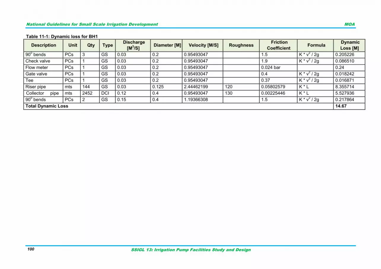
National Guidelines for Small Scale Irrigation Development MOA
SSIGL 13: Irrigation Pump Facilities Study and Design 100
Table 11-1: Dynamic loss for BH1
Description Unit Qty Type Discharge
[M3/S]
Diameter [M] Velocity [M/S] Roughness Friction
Coefficient Formula
Dynamic
Loss [M]
900 bends PCs 3 GS 0.03 0.2 0.95493047
1.5 K * v
2 / 2g 0.205226
Check valve PCs 1 GS 0.03 0.2 0.95493047
1.9 K * v2 / 2g 0.086510
Flow meter PCs 1 GS 0.03 0.2 0.95493047
0.024 bar
0.24
Gate valve PCs 1 GS 0.03 0.2 0.95493047
0.4 K * v2 / 2g 0.018242
Tee PCs 1 GS 0.03 0.2 0.95493047
0.37 K * v2 / 2g 0.016871
Riser pipe mts 144 GS 0.03 0.125 2.44462199 120 0.05802579 K * L 8.355714
Collector pipe mts 2452 DCI 0.12 0.4 0.95493047 130 0.00225446 K * L 5.527936
900 bends PCs 2 GS 0.15 0.4 1.19366308
1.5 K * v
2 / 2g 0.217864
Total Dynamic Loss 14.67
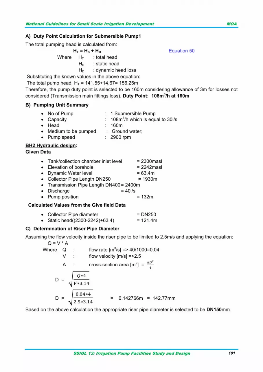
National Guidelines for Small Scale Irrigation Development MOA
SSIGL 13: Irrigation Pump Facilities Study and Design 101
A) Duty Point Calculation for Submersible Pump1
The total pumping head is calculated from:
HT = HS + HD Equation 50
Where HT : total head
HS : static head
HD : dynamic head loss
Substituting the known values in the above equation:
The total pump head, HT = 141.55+14.67= 156.25m
Therefore, the pump duty point is selected to be 160m considering allowance of 3m for losses not
considered (Transmission main fittings loss). Duty Point: 108m3/h at 160m
B) Pumping Unit Summary
No of Pump : 1 Submersible Pump
Capacity : 108m3/h which is equal to 30l/s
Head : 160m
Medium to be pumped : Ground water;
Pump speed : 2900 rpm
BH2 Hydraulic design:
Given Data
Tank/collection chamber inlet level = 2300masl
Elevation of borehole = 2242masl
Dynamic Water level = 63.4m
Collector Pipe Length DN250 = 1930m
Transmission Pipe Length DN400 = 2400m
Discharge = 40l/s
Pump position = 132m
Calculated Values from the Give field Data
Collector Pipe diameter = DN250
Static head((2300-2242)+63.4) = 121.4m
C) Determination of Riser Pipe Diameter
Assuming the flow velocity inside the riser pipe to be limited to 2.5m/s and applying the equation:
Q = V * A
Where Q : flow rate [m3/s] => 40/1000=0.04
V : flow velocity [m/s] =>2.5
A : cross-section area [m2] =
D = √
D = √
= 0.142766m = 142.77mm
Based on the above calculation the appropriate riser pipe diameter is selected to be DN150mm.

National Guidelines for Small Scale Irrigation Development MOA
SSIGL 13: Irrigation Pump Facilities Study and Design 102
D) Dynamic head Loss analysis for transmission pipe line, riser pipes & fittings
Using Hazen Williams‟s formula:
hf = 10.7 (Q/C)1.85 x L / (D)4.87 for pipes and
hff= k*v2/2*g for valves and fittings
All the fittings in pipe line are listed below in table 11-2 to calculate the friction head loss or
dynamic loss Hf using the above formula. Let us calculate dynamic loss for the riser pipe and Tee.
Rise pipe:
Hfr = k*L = 0.05802579*132 =7.6594
Tee:
Hft = k*v2/2*g = 0.37*(0.95493047)2/(2*9.81) =0.017196744
Similarly, substituting the known values in the above equation, the total calculated pipes and
fittings frictional loss is equal to 13.76. See Table 11-2 below for the analysis:
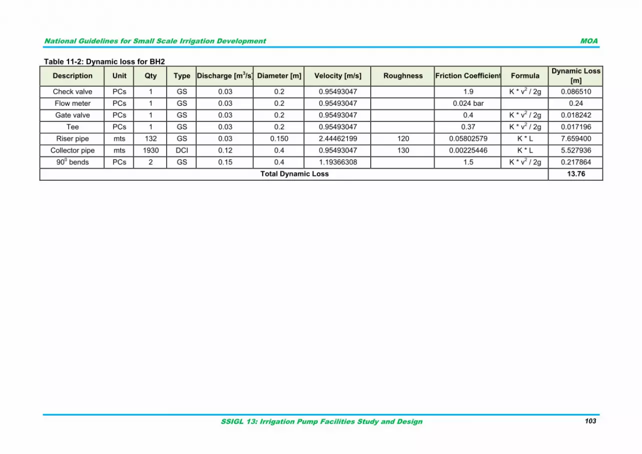
National Guidelines for Small Scale Irrigation Development MOA
SSIGL 13: Irrigation Pump Facilities Study and Design 103
Table 11-2: Dynamic loss for BH2
Description Unit Qty Type Discharge [m3/s] Diameter [m] Velocity [m/s] Roughness Friction Coefficient Formula
Dynamic Loss
[m]
Check valve PCs 1 GS 0.03 0.2 0.95493047
1.9 K * v2 / 2g 0.086510
Flow meter PCs 1 GS 0.03 0.2 0.95493047
0.024 bar
0.24
Gate valve PCs 1 GS 0.03 0.2 0.95493047
0.4 K * v2 / 2g 0.018242
Tee PCs 1 GS 0.03 0.2 0.95493047
0.37 K * v2 / 2g 0.017196
Riser pipe mts 132 GS 0.03 0.150 2.44462199 120 0.05802579 K * L 7.659400
Collector pipe mts 1930 DCI 0.12 0.4 0.95493047 130 0.00225446 K * L 5.527936
900 bends PCs 2 GS 0.15 0.4 1.19366308
1.5 K * v
2 / 2g 0.217864
Total Dynamic Loss 13.76
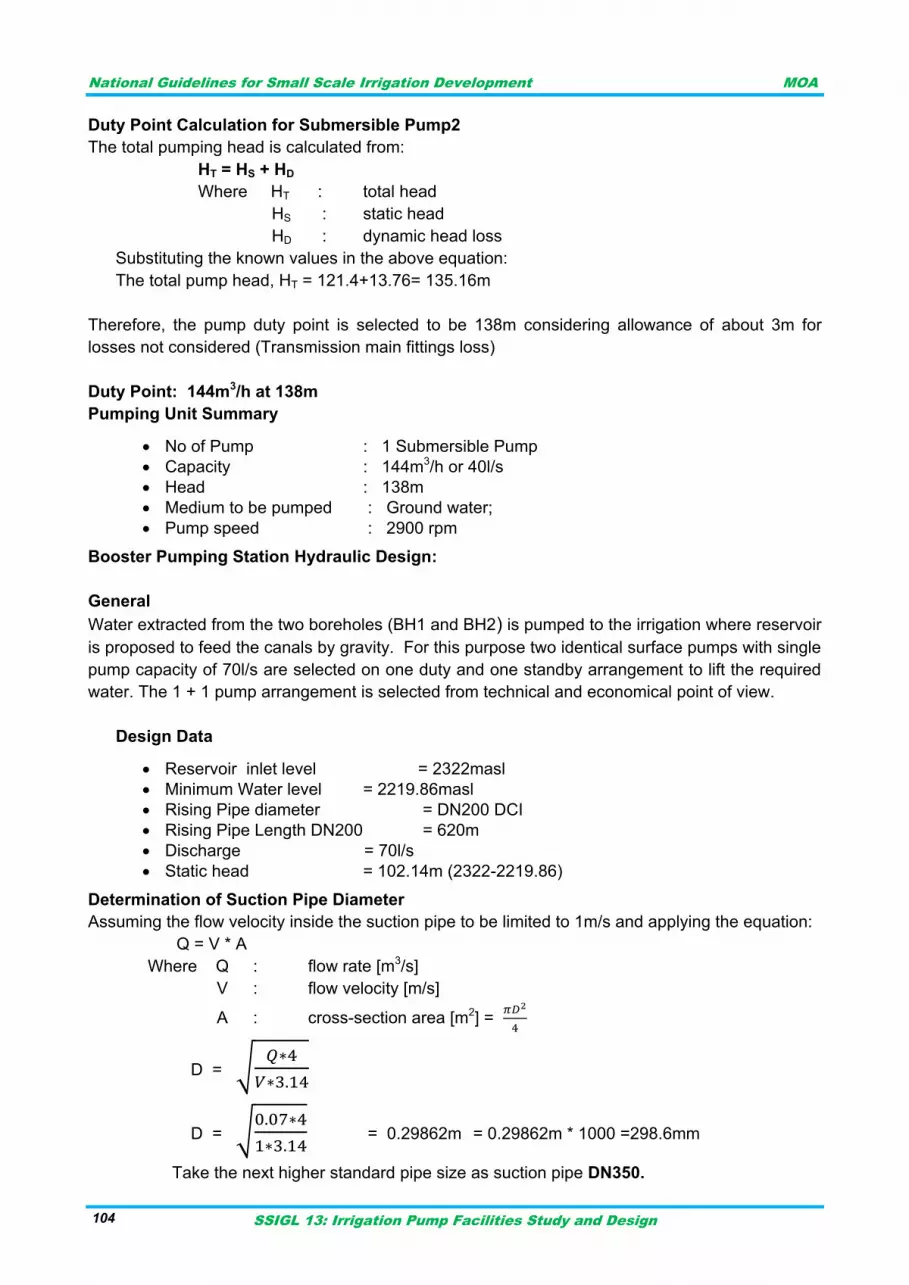
National Guidelines for Small Scale Irrigation Development MOA
SSIGL 13: Irrigation Pump Facilities Study and Design 104
Duty Point Calculation for Submersible Pump2
The total pumping head is calculated from:
HT = HS + HD
Where HT : total head
HS : static head
HD : dynamic head loss
Substituting the known values in the above equation:
The total pump head, HT = 121.4+13.76= 135.16m
Therefore, the pump duty point is selected to be 138m considering allowance of about 3m for
losses not considered (Transmission main fittings loss)
Duty Point: 144m3/h at 138m
Pumping Unit Summary
No of Pump : 1 Submersible Pump
Capacity : 144m3/h or 40l/s
Head : 138m
Medium to be pumped : Ground water;
Pump speed : 2900 rpm
Booster Pumping Station Hydraulic Design:
General
Water extracted from the two boreholes (BH1 and BH2) is pumped to the irrigation where reservoir
is proposed to feed the canals by gravity. For this purpose two identical surface pumps with single
pump capacity of 70l/s are selected on one duty and one standby arrangement to lift the required
water. The 1 + 1 pump arrangement is selected from technical and economical point of view.
Design Data
Reservoir inlet level = 2322masl
Minimum Water level = 2219.86masl
Rising Pipe diameter = DN200 DCI
Rising Pipe Length DN200 = 620m
Discharge = 70l/s
Static head = 102.14m (2322-2219.86)
Determination of Suction Pipe Diameter
Assuming the flow velocity inside the suction pipe to be limited to 1m/s and applying the equation:
Q = V * A
Where Q : flow rate [m3/s]
V : flow velocity [m/s]
A : cross-section area [m2] =
D = √
D = √
= 0.29862m = 0.29862m * 1000 =298.6mm
Take the next higher standard pipe size as suction pipe DN350.
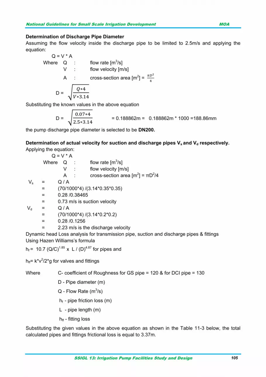
National Guidelines for Small Scale Irrigation Development MOA
SSIGL 13: Irrigation Pump Facilities Study and Design 105 105
Determination of Discharge Pipe Diameter
Assuming the flow velocity inside the discharge pipe to be limited to 2.5m/s and applying the
equation:
Q = V * A
Where Q : flow rate [m3/s]
V : flow velocity [m/s]
A : cross-section area [m2] =
D = √
Substituting the known values in the above equation
D = √
= 0.188862m = 0.188862m * 1000 =188.86mm
the pump discharge pipe diameter is selected to be DN200.
Determination of actual velocity for suction and discharge pipes Vs and Vd respectively.
Applying the equation:
Q = V * A
Where Q : flow rate [m3/s]
V : flow velocity [m/s]
A : cross-section area [m2] = πD2/4
Vs = Q / A
= (70/1000*4) /(3.14*0.35*0.35)
= 0.28 /0.38465
= 0.73 m/s is suction velocity
Vd = Q / A
= (70/1000*4) /(3.14*0.2*0.2)
= 0.28 /0.1256
= 2.23 m/s is the discharge velocity
Dynamic head Loss analysis for transmission pipe, suction and discharge pipes & fittings
Using Hazen Williams‟s formula
hf = 10.7 (Q/C)1.85 x L / (D)4.87 for pipes and
hff= k*v2/2*g for valves and fittings
Where C- coefficient of Roughness for GS pipe = 120 & for DCI pipe = 130
D - Pipe diameter (m)
Q - Flow Rate (m3/s)
hf - pipe friction loss (m)
L - pipe length (m)
hff - fitting loss
Substituting the given values in the above equation as shown in the Table 11-3 below, the total
calculated pipes and fittings frictional loss is equal to 3.37m.
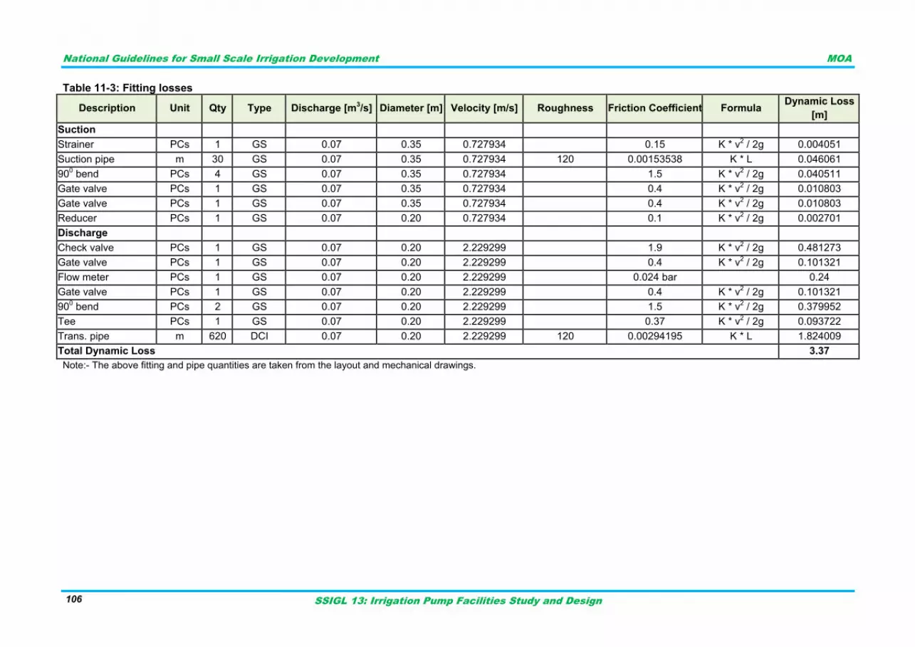
National Guidelines for Small Scale Irrigation Development MOA
SSIGL 13: Irrigation Pump Facilities Study and Design 106
Table 11-3: Fitting losses
Description Unit Qty Type Discharge [m3/s] Diameter [m] Velocity [m/s] Roughness Friction Coefficient Formula
Dynamic Loss
[m]
Suction
Strainer PCs 1 GS 0.07 0.35 0.727934
0.15 K * v2 / 2g 0.004051
Suction pipe m 30 GS 0.07 0.35 0.727934 120 0.00153538 K * L 0.046061
900 bend PCs 4 GS 0.07 0.35 0.727934
1.5 K * v
2 / 2g 0.040511
Gate valve PCs 1 GS 0.07 0.35 0.727934
0.4 K * v2 / 2g 0.010803
Gate valve PCs 1 GS 0.07 0.35 0.727934
0.4 K * v2 / 2g 0.010803
Reducer PCs 1 GS 0.07 0.20 0.727934
0.1 K * v2 / 2g 0.002701
Discharge
Check valve PCs 1 GS 0.07 0.20 2.229299
1.9 K * v2 / 2g 0.481273
Gate valve PCs 1 GS 0.07 0.20 2.229299
0.4 K * v2 / 2g 0.101321
Flow meter PCs 1 GS 0.07 0.20 2.229299
0.024 bar
0.24
Gate valve PCs 1 GS 0.07 0.20 2.229299
0.4 K * v2 / 2g 0.101321
900 bend PCs 2 GS 0.07 0.20 2.229299
1.5 K * v
2 / 2g 0.379952
Tee PCs 1 GS 0.07 0.20 2.229299
0.37 K * v2 / 2g 0.093722
Trans. pipe m 620 DCI 0.07 0.20 2.229299 120 0.00294195 K * L 1.824009
Total Dynamic Loss 3.37
Note:- The above fitting and pipe quantities are taken from the layout and mechanical drawings.
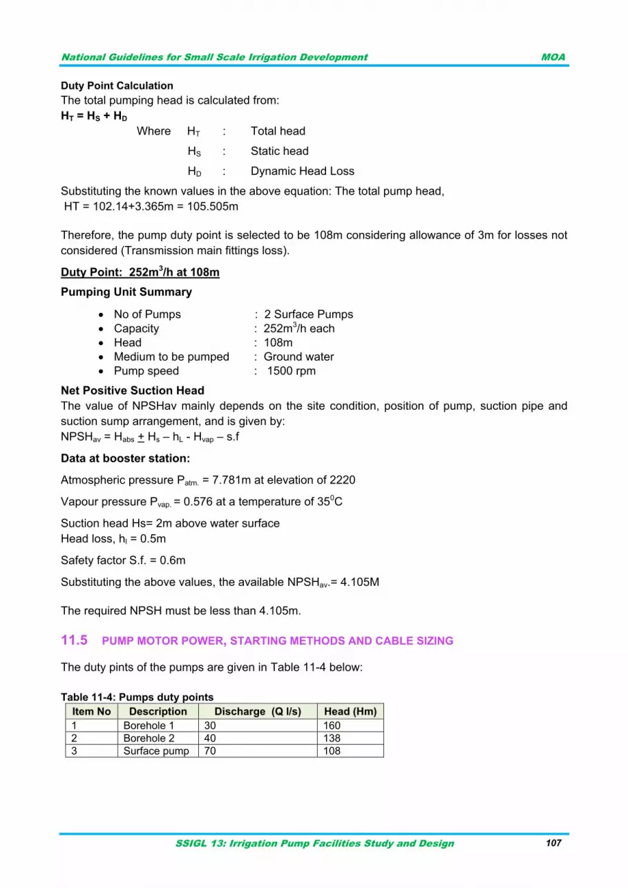
National Guidelines for Small Scale Irrigation Development MOA
SSIGL 13: Irrigation Pump Facilities Study and Design 107
Duty Point Calculation
The total pumping head is calculated from:
HT = HS + HD
Where HT : Total head
HS : Static head
HD : Dynamic Head Loss
Substituting the known values in the above equation: The total pump head,
HT = 102.14+3.365m = 105.505m
Therefore, the pump duty point is selected to be 108m considering allowance of 3m for losses not
considered (Transmission main fittings loss).
Duty Point: 252m3/h at 108m
Pumping Unit Summary
No of Pumps : 2 Surface Pumps
Capacity : 252m3/h each
Head : 108m
Medium to be pumped : Ground water
Pump speed : 1500 rpm
Net Positive Suction Head
The value of NPSHav mainly depends on the site condition, position of pump, suction pipe and
suction sump arrangement, and is given by:
NPSHav = Habs + Hs – hL - Hvap – s.f
Data at booster station:
Atmospheric pressure Patm. = 7.781m at elevation of 2220
Vapour pressure Pvap. = 0.576 at a temperature of 350C
Suction head Hs= 2m above water surface
Head loss, hl = 0.5m
Safety factor S.f. = 0.6m
Substituting the above values, the available NPSHav.= 4.105M
The required NPSH must be less than 4.105m.
PUMP MOTOR POWER, STARTING METHODS AND CABLE SIZING 11.5
The duty pints of the pumps are given in Table 11-4 below:
Table 11-4: Pumps duty points
Item No Description Discharge (Q l/s) Head (Hm)
1 Borehole 1 30 160
2 Borehole 2 40 138
3 Surface pump 70 108
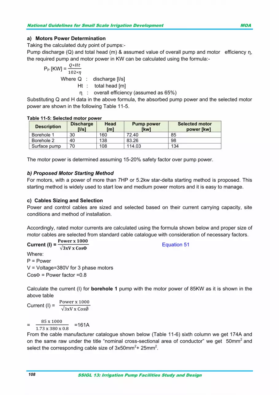
National Guidelines for Small Scale Irrigation Development MOA
SSIGL 13: Irrigation Pump Facilities Study and Design 108
a) Motors Power Determination
Taking the calculated duty point of pumps:-
Pump discharge (Q) and total head (m) & assumed value of overall pump and motor efficiency η,
the required pump and motor power in KW can be calculated using the formula:-
PP [KW] =
Where Q : discharge [l/s]
Ht : total head [m]
η. : overall efficiency (assumed as 65%)
Substituting Q and H data in the above formula, the absorbed pump power and the selected motor
power are shown in the following Table 11-5.
Table 11-5: Selected motor power
Description Discharge
[l/s] Head [m]
Pump power [kw]
Selected motor power [kw]
Borehole 1 30 160 72.40 85
Borehole 2 40 138 83.26 98
Surface pump 70 108 114.03 134
The motor power is determined assuming 15-20% safety factor over pump power.
b) Proposed Motor Starting Method
For motors, with a power of more than 7HP or 5.2kw star-delta starting method is proposed. This
starting method is widely used to start low and medium power motors and it is easy to manage.
c) Cables Sizing and Selection
Power and control cables are sized and selected based on their current carrying capacity, site
conditions and method of installation.
Accordingly, rated motor currents are calculated using the formula shown below and proper size of
motor cables are selected from standard cable catalogue with consideration of necessary factors.
Current (I) =
Equation 51
Where:
P = Power
V = Voltage=380V for 3 phase motors
Cos = Power factor =0.8
Calculate the current (I) for borehole 1 pump with the motor power of 85KW as it is shown in the
above table
Current (I) =
=
=161A
From the cable manufacturer catalogue shown below (Table 11-6) sixth column we get 174A and
on the same raw under the title “nominal cross-sectional area of conductor” we get 50mm2 and
select the corresponding cable size of 3x50mm2+ 25mm2.
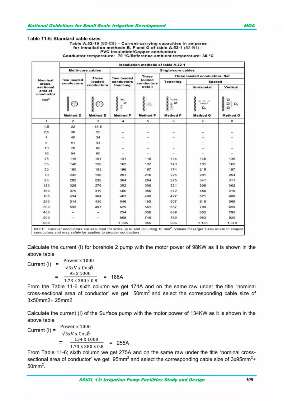
National Guidelines for Small Scale Irrigation Development MOA
SSIGL 13: Irrigation Pump Facilities Study and Design 109
Table 11-6: Standard cable sizes
Calculate the current (I) for borehole 2 pump with the motor power of 98KW as it is shown in the
above table
Current (I) =
=
= 186A
From the Table 11-6 sixth column we get 174A and on the same raw under the title “nominal
cross-sectional area of conductor” we get 50mm2 and select the corresponding cable size of
3x50mm2+ 25mm2
Calculate the current (I) of the Surface pump with the motor power of 134KW as it is shown in the
above table
Current (I) =
=
= 255A
From Table 11-6; sixth column we get 275A and on the same raw under the title “nominal cross-
sectional area of conductor” we get 95mm2 and select the corresponding cable size of 3x95mm2+
50mm2.

National Guidelines for Small Scale Irrigation Development MOA
SSIGL 13: Irrigation Pump Facilities Study and Design 110
National Guidelines for Small Scale Irrigation Development MOA
SSIGL 13: Irrigation Pump Facilities Study and Design 111
POWER UNITS 12
Most irrigation pumps are powered either with electric motors or diesel engines. In some countries,
natural gas, propane, butane and gasoline engines are also used to drive pumps. Wind and solar
driven pumps are also used for pumping water, but mostly for human and animal purposes.
Manual pumps like treadle pump, rope and washer pump, hand pump etc. are also used as lifting
mechanism for small discharge rates and low heads.
In earlier parts of the guide line it is described how to compute the size of the power unit. For
centrifugal pumps and turbine pumps up to 20 m deep it is not necessary to compute the energy
required to overcome bearing losses in the pump. For turbine pumps that are more than 20 m
deep, the manufacturer's literature should be consulted on line shaft bearing losses.
ELECTRIC MOTORS 12.1
For most centrifugal pumps the motors are directly coupled to the pump. This results in the
elimination of belt drives and energy loss due to belt slippage, and safety hazards.
Most centrifugal pumps used in Eastern and Southern Africa are coupled to the motor shaft
through a flexible coupling.
In the past it was common practice to overload motors by 10-15% above the rated output without
encountering problems. However, because of the materials currently used, motors can no longer
stand this overloading. Therefore, they should be sized to the needed and projected future output.
For sustained use of a motor at more than 1100 m altitude or at temperatures above 37°C de-
rating may be necessary. Manufacturer's literature should be consulted for the necessary de-
rating. An example of the de-rating of diesel engines is shown in the following section.
Electric motor
If the brake horsepower of a centrifugal pump exceeds the safe operating load of the motor, the
motor may be damaged or burned out. The shape of the power characteristics curve and the
system head characteristics will determine if pump operation may exceed the safe loading of its
electric motor. Attention must also be paid to the shape of the speed -torque curve of the motor
and the voltage supply of the power system. Any supply voltage lower than the rated voltage
would be unable to take the load. The motor should be able to take the loads over the entire range
of operating conditions.
Power factor
In AC circuits, the power factor is the ratio of the real power that is used to do work and
the apparent power that is supplied to the circuit. The power factor can get values in the range
from 0 to 1. When all the power is reactive power with no real power (usually inductive load), the
power factor is 0. When all the power is real power with no reactive power (resistive load), the
power factor is 1.
a) Direct current motor
Direct current (dc) motors are available in three types viz. shunt sound, series wound and
compound wound. But dc motors are not very suitable for centrifugal pumps as the full load speed
of DC, motors may vary by 5 to 7.5% from the rated speed. A dc motor to be used for a centrifugal
pump has therefore to be specially ordered to match the pump speed. Such use is possible only
National Guidelines for Small Scale Irrigation Development MOA
SSIGL 13: Irrigation Pump Facilities Study and Design 112
for special requirements. A DC motor is useful in situation where duty of the pump changes
periodically.
b) Alternating current motor
Single-phase motors are normally used as directly coupled with small centrifugal pumps. Uses of
single phased motors are restricted up to 7.5 HP applications. Motors above 7.5Hp are 380 volts,
3 phase 50 cycles/sec. 2) Three Phase Motors Squirrel cage motors are simplest type of poly-
phase motors and are most widely used for irrigation pumps. These motors have a primary
winding (stator) and a secondary squirrel cage winding (rotor) which takes power from the primary
winding by transformer action. Centrifugal pumps do not require motors with high starting torque.
Hence normal torque, normal starting current (National Electrical Manufacturers Association
(NEMA) class A) or normal torque low-starting current (NEMA class B) motors are adequate. Ac
motors run at a constant speed. The Standard rpm ranges from 1450 to 1500. Other motors are
wound rotor motors and synchronous motors.
Motors can also classified into horizontal or vertical depending upon their housing design, slow
speed or high speed, constant speed or Multi speed motors depending upon their speed
characteristics. Motors can be run in either direction by simply changing any two leads of a 3
phase motor.
C) Feature of electric motors
Long life
Low operating and maintenance cost
Dependable service
Easy operation
Practically automatic
Ineffective when power supply is not dependable
Extension of power lines and installation of transformers etc for a new scheme cost extra and cause inordinate delay
Standard motor sizes are 3, 5, 7.5, 10, 15,20,25,30,40,50,60KW
Closed motors have advantage over open motors in the sense that they are protected from dust, drip and rodents.
Motors have a built in service factor of 10 to 15% at air temperature 40 degree centigrade or less. Present bay motors can withstand up to 70 degree centigrade without much damage.
Present day motors are smaller in size than earlier models due to the use of high quality insulation.
Sometimes voltages in all the three phase may not be equal. A 3.5 % imbalance may cause about 25% increase in temperature.
Similarly a reduction of 10% voltage in each line will cause temperature increase of about 16%.
Motors are air cooled by the surrounding air and are designed to operate safe up to an altitude of 1000 m above sea level, for altitudes above 1000 m de-rating curves are used. It should be observed that, for higher altitude operations, special motor is therefore, necessary.
Standard motors are designed to operate satisfactorily at 5% reduction of rated frequency.
The normal efficiency of an electric motor ranges from 70% to 95 %
National Guidelines for Small Scale Irrigation Development MOA
SSIGL 13: Irrigation Pump Facilities Study and Design 113
d) Starting methods of Motors
Motors require two to three times more current to start than when it is running of full load.
Motor starters are classified in various ways depending on their method of:
Control (automatic or non- automatic);
Operation (manual, electromagnetic, motor operated, pneumatic, and electro pneumatic;
Interruption Mode (air-break, oil-break);
Degree of protection provided by the enclosure), etc (see all parts of IS 8544 or equivalent standards for details)
The most usual way and simplest method of starting a squirrel cage motor is means of direct on
line starting. A push button starters or stroke switches are normally applied for direct on line
starting. If the conditions are such that the starting current must be limited, the star-delta starting
method should be employed. The starting current, and also the starting torque, are then limited to
about one third of the values obtained with direct on line starting. This lower starting torque is quite
adequate in many cases, since the driven machine during the start is often unloaded or running
under a relatively low load. The use of an auto-transformer starter has the advantage that the
starting torque can be more closely matched with the actual requirements through a suitable
choice of the turn ration.
Starter of electric motors also contain built in circuit breaker as a protective device. Good quality
starter therefore ensures motor safety. Motor may also get damaged if there is no current in one of
the three phases due to faulty connection. To overcome this single phasing, the control of motors
is used to prevent the motor from over loading and power fluctuation. Controls like time delay
fuses are available to start pump automatically after power supply is resumed after a power failure.
Suitable alarms, light indicators etc. are available to indicate whether a motor is running.
NOTE:
The choice of starling method depends on the actual rating of the motor, the specific work
requirements or application or the duty of the motor, etc. In some countries, for instance in India
the following requirement is enforced:
Motors up to 7.5 HP are normally started by Direct on Line (DOL) starter. Motors ranging from 7.5-
50 HP are started on "Star-Delta" starter. As the motor picks up speed the star connection is
changed over to delta shaped circuit either automatically or manually. Star and delta means the
shape in which the leads gets arranged within the starter by different shifting contacts and the
circuit reassemble either a triangular star or a delta. Motors of 50 HP and above are started by
using an auto transformer in line. Therefore, users are advised to observe the electrical wiring
regulations issued by pertinent national organizations.
e) Installation
In situation where it is difficult to calculate the exact mead correctly and in order to avoid
continuous overloading of electric motor, a safely margin over the calculated HP is recommended
at the following rate:
Add 50% for pumps requiring up to 2 HP
Add 30% for pumps requiring 2-5 HP
Add 20% for pumps requiring 5-10 HP
Add 15% for pumps requiring 10- 20 HP
Add 10% for pumps requiring over 20 HP
National Guidelines for Small Scale Irrigation Development MOA
SSIGL 13: Irrigation Pump Facilities Study and Design 114
In large schemes, instead of having a single motor or having provision for standby motors,
parallels operation is more advantageous. The recommended break lip of motors is as below.
Up to 200 HP: 2 numbers
200 -300 HP: 3 numbers
Above 300 HP: 4 numbers
Decision on the number of motors, however, is guided more by the required capacity of each
pump, the capacity of power supply and availability of motors.
f) Electric connection
Load up to 100 kW can be handled by Low Tension (LT) lines of 380 V. For higher load, High-
Tension (HT) line is required.
Selection of electric motor to the rated power of pumps, proper installations and use of suitable controls for the operation and protection of the motor are the core factors that could affect proper installations.
Wiring of motors shall follow the technical regulations issued by the
Ethiopian electric agency, Ethiopian Electric Power Corporation, or Ministry of Works & Urban Development; or the Ethiopian Standards issued by the Quality and Standards Authority of Ethiopia. Except the standards, the wiring regulations issued by the Ethiopian Electric Agency shall have precedence and prevalence over those of the remaining regulations.
The wires to be used shall have sufficient current carrying capacity selected on the maximum allowable voltage drop set ill the wiring regulation.
Alternating current supply of 380 V 50 Hz four wire, three phase system or 220 V 50 Hz single-
phase system may be used for lighting of pump station All three phase loads need to be equally
divided between all three phases system. The service entrance of the installation shall be
grounded. Alternating current supply of 380 V 50 Hz four wire, three phase system or 220 V 50 Hz
single-phase system may be used for lighting of pump station All three phase loads need to be
equally divided between all three phases system. The service entrance of the installation shall be
grounded.
g) Accessories
The following accessories are used in electrical installation
Energy meters,
Volt meters and ammeters,
Indicator lamps,
Main switch fuses,
Starters,
For single-phase motor a hard operated switch is used for controlling the starting of the motor, and
Starters are usually designed and provided with overload (magnetic and thermal) adjustable or fixed releases.
DIESEL ENGINES 12.2
As a rule, petrol engines drive very small pumps. For most irrigation conditions, the diesel engine
has gained popularity. It is more robust, requires less maintenance and has lower overall operation
and maintenance costs.
National Guidelines for Small Scale Irrigation Development MOA
SSIGL 13: Irrigation Pump Facilities Study and Design 115
The common types of diesel engines are:
Horizontal engines: These are less in use in the present days.
Lister type: These are slow speed vertical engines.
High-speed vertical engine: These are most commonly used these days.
Diesel engines for agriculture purpose are available, for instance, in 5, 6, 7, 8, 9, 10, 12, 14 HP
range. Diesel engines may be either air-cooled or water-cooled. Air-cooled engines are available
normally up to 25 HP. They are improved over water-cooled engines. They are less messy than
the water-cooled engines where the coolant (water) is to be properly disposed off to prevent the
site turning muddy. Water-cooled engines however are made in all sizes. The user or purchaser
shall specify the standard reference operating or testing conditions for internal combustion engines
indicated below. For such proposes one can refer to ISO or equivalent standards.
Mean barometric pressure
Atmospheric temperature (air temperature)
Relative humidity
Charge air coolant temperature
Intake air depression and exhaust back pressure
Auxiliaries
Fuel
Air inlet temperature
Fuel supply system
Fuel inspection equipment
Governor
Lubrication system
Most literature on engines uses English units of measurement. To convert kilowatts to horsepower
a conversion factor of 1.34 can be applied. Horsepower versus speed curves (Figure 12-1)
illustrate how output power increases with engine speed. However, there is a particular speed at
which the engine efficiency is highest.
This is the point at which the selected engine should operate. The continuous rated curve
indicates the safest continuous duty at which the engine can be operated. Care should be taken to
use the continuous rated output curve and not the intermittent output curve.
Manufacturer's curves are calculated for operating conditions at sea level and below 30°C. It is
therefore necessary to de-rate the engines for different altitudes and temperatures where the
operating conditions are different. According to Pair et al. (1983), de-rating is approximately 1%
per 100 m increase in altitude and 1% per 5.6°C increase in air temperature from the published
maximum output horsepower curve. On the top of that, an additional 5-10% for reserve should be
deducted. If the continuous output curves are used, only the 5-10% deduction is applied.
Example: What will be the output of a diesel engine with a speed of 2600 rpm at 2000 m altitude
and a temperature of 35°C?
Referring to Figure 12-1, the maximum output at 2600 rpm, by interpolation, would be around 114
hp, which falls outside the limits of this curve. By applying the above rule for 2000 m altitude and
35°C, a deduction of 20% should be applied for elevation and 1% for temperature. An additional
10% should be applied for reserve. Therefore, the total deduction should be 114 x 0.31 = 35.3 HP,
resulting in an output of 78.7 HP (= 114 - 35.3).
If we apply the 10% deduction on the continuous rating curve then the output will be 80 - 8 = 72
HP. This is a more conservative approach.
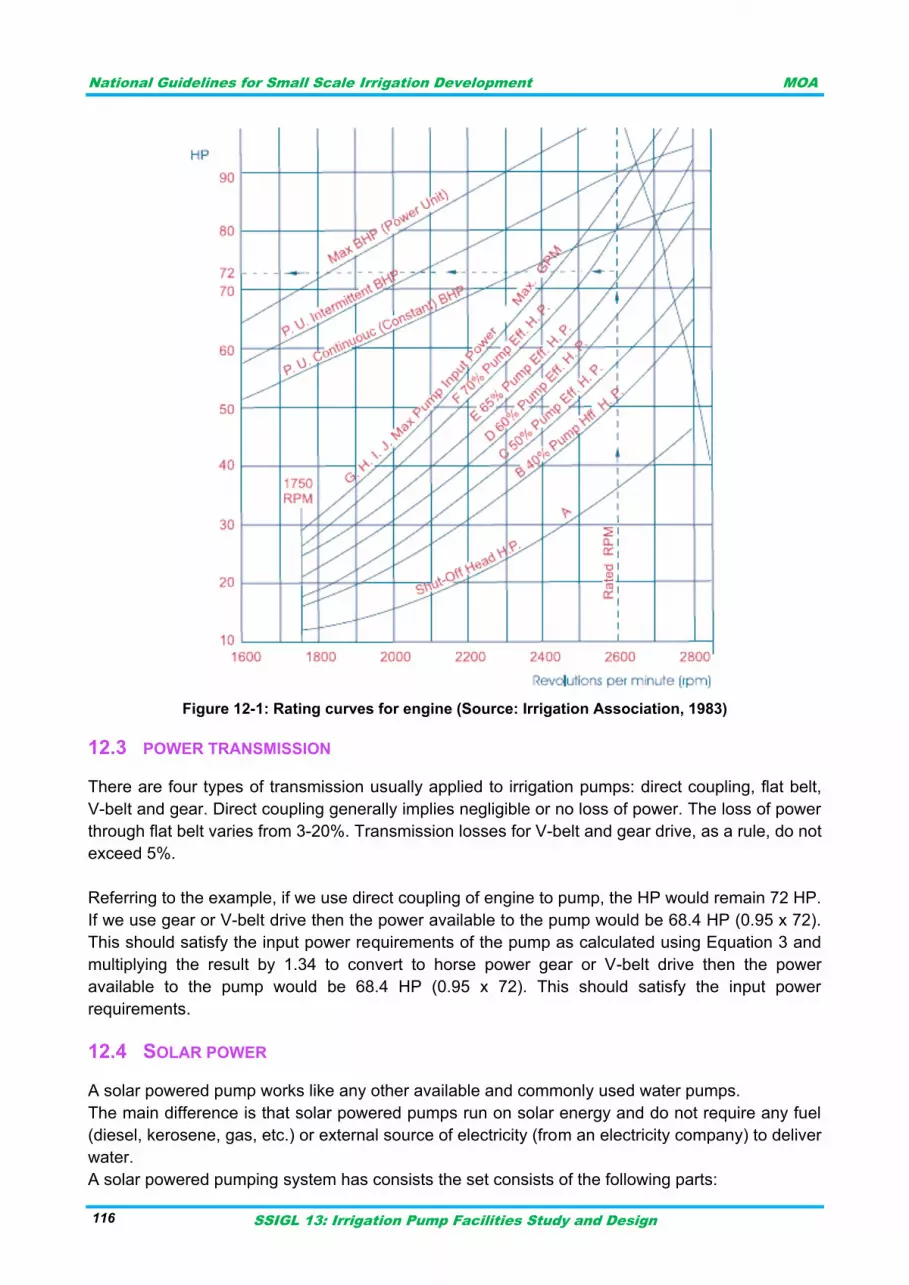
National Guidelines for Small Scale Irrigation Development MOA
SSIGL 13: Irrigation Pump Facilities Study and Design 116
Figure 12-1: Rating curves for engine (Source: Irrigation Association, 1983)
POWER TRANSMISSION 12.3
There are four types of transmission usually applied to irrigation pumps: direct coupling, flat belt,
V-belt and gear. Direct coupling generally implies negligible or no loss of power. The loss of power
through flat belt varies from 3-20%. Transmission losses for V-belt and gear drive, as a rule, do not
exceed 5%.
Referring to the example, if we use direct coupling of engine to pump, the HP would remain 72 HP.
If we use gear or V-belt drive then the power available to the pump would be 68.4 HP (0.95 x 72).
This should satisfy the input power requirements of the pump as calculated using Equation 3 and
multiplying the result by 1.34 to convert to horse power gear or V-belt drive then the power
available to the pump would be 68.4 HP (0.95 x 72). This should satisfy the input power
requirements.
SOLAR POWER 12.4
A solar powered pump works like any other available and commonly used water pumps.
The main difference is that solar powered pumps run on solar energy and do not require any fuel
(diesel, kerosene, gas, etc.) or external source of electricity (from an electricity company) to deliver
water.
A solar powered pumping system has consists the set consists of the following parts:
National Guidelines for Small Scale Irrigation Development MOA
SSIGL 13: Irrigation Pump Facilities Study and Design 117
Solar array: The solar array is a set of solar modules which are to be connected in series and
possibly strings of modules connected in parallel to get the required power to operate the pump.
Controller: The controller is an electronic device that matches the power output from the solar
array to the pump motor and regulates the operation of the pump according to the input from the
solar array.
Pump: The pump comprises of the motor which drives the movement (prime mover) and the pump
impeller which moves the water under pressure. Additionally, the solar powered pump set might
include accessories like cabling and fittings, a battery, and an inverter.
Solar pumps are used for both surface pumps and submersible pumps. The most important criteria
for choosing between a surface and a submersible pump are the groundwater level and the type of
water source. If the well is a bore well and total head (suction + delivery) is greater than 10-15
meters, a submersible pump should be used. If the water source is an open well, pond, canal, etc.
then a surface pump is more feasible. As a thumb rule, a surface pump can be used if the water
level is less than 10 meters; for levels more than 10 meters, the installation of a submersible pump
is required. Currently the solar pumps are widely applied to areas that require small energy to run
the system.
Typical Technology options and accessories: Thanks to technology now a days invented smart
solution-PSk2 Smart Solution introduces hybrid power solutions to the PSk2 system. Using a
combination of the SmartPSUk2 and Smart Start the PSk2 system can be powered by solar, by AC
power from a generator or grid supply or with a mix of solar and AC power. Thus;
I. The PSk2 controls the Smart Solution components to deliver water depending on power available, time or specific water requirements.
II. To connect PSk2 to an AC 3-phase grid power supply then a SmartPSUk2 is used
Solar-diesel system sizing considerations: The SmartPSUk2 is able to switch between solar and
diesel as well as blend both power sources, e.g. to obtain a desired flow rate or pressure irrespective
of sunshine. It can operate on diesel generators with a constant power rating higher, equal or smaller
than the power rating of the pump motor. The constant power rating of the diesel generator should be
selected considering the desired flow or pressure.
SmartSolution supports the following diesel generator specifications:
380/ 400/ 415 V
50/ 60 Hz
Remote start function (if use of SmartStart is desired)
To connect PSk2 to an AC 3-phase generator then a SmartPSUk2 and SmartStart is used.
Sample calculation for solar energy
1. GF 270
The GF is a polycrystalline solar module. The module is equipped with MC plugs for easy connection
and comes as pieces per pallet without individual packing. It must be mounted on a support structure
tilted at an angle ensuring optimum utilization of the solar energy.it can be installed at Range of
ambient temperature 233-358K which is suitable for our country
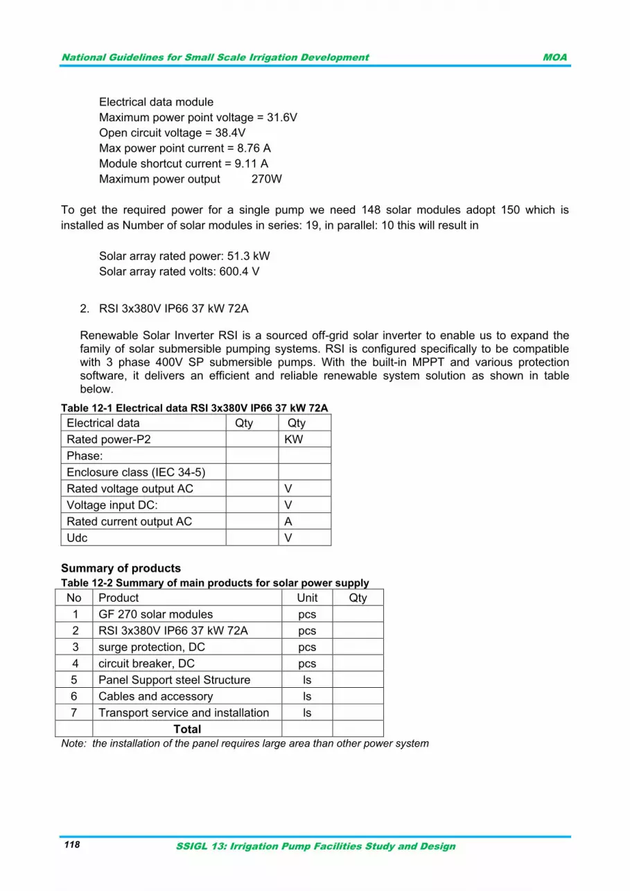
National Guidelines for Small Scale Irrigation Development MOA
SSIGL 13: Irrigation Pump Facilities Study and Design 118
Electrical data module
Maximum power point voltage = 31.6V
Open circuit voltage = 38.4V
Max power point current = 8.76 A
Module shortcut current = 9.11 A
Maximum power output 270W
To get the required power for a single pump we need 148 solar modules adopt 150 which is
installed as Number of solar modules in series: 19, in parallel: 10 this will result in
Solar array rated power: 51.3 kW
Solar array rated volts: 600.4 V
2. RSI 3x380V IP66 37 kW 72A Renewable Solar Inverter RSI is a sourced off-grid solar inverter to enable us to expand the family of solar submersible pumping systems. RSI is configured specifically to be compatible with 3 phase 400V SP submersible pumps. With the built-in MPPT and various protection software, it delivers an efficient and reliable renewable system solution as shown in table below.
Table 12-1 Electrical data RSI 3x380V IP66 37 kW 72A
Electrical data Qty Qty
Rated power-P2 KW
Phase:
Enclosure class (IEC 34-5)
Rated voltage output AC V
Voltage input DC: V
Rated current output AC A
Udc V
Summary of products
Table 12-2 Summary of main products for solar power supply
No Product Unit Qty
1 GF 270 solar modules pcs
2 RSI 3x380V IP66 37 kW 72A pcs
3 surge protection, DC pcs
4 circuit breaker, DC pcs
5 Panel Support steel Structure ls
6 Cables and accessory ls
7 Transport service and installation ls
Total
Note: the installation of the panel requires large area than other power system
National Guidelines for Small Scale Irrigation Development MOA
SSIGL 13: Irrigation Pump Facilities Study and Design 119
CONTROL PANELS AND OTHER UNITS 13
CONTROL PANELS 13.1
Indoor or outdoor control panels will have provision for energy meter, main switch, starter, single
phase preventer, capacitor, etc. some of the components embedded in a control panel are as
follows:- a) Switches: A main switch of adequate capacity to disconnect power supply shall be provided
after the meter. This will enable to disconnect the service immediately in case of any
emergency or for maintenance purpose.
b) Starter: Starter with over load relay is provided to start and stop the motor and to protect it
against any over load. Over load may be either electrical or mechanical.
c) Capacitor:- Installation of capacitor of suitable rating in the motor circuit will improve the power
factor and reduce energy consumption. The running cost of the motor will also be reduced.
The recommended capacitor ratings can be given by control panel manufacturer.
d) Single phase preventer: - In three phase circuit, three fuses are provided (1 for each phase). If
in any one phase fuses were to blow or any one phase is disconnected form service during
running of the motor, the motor keeps running drawing excess current from the two lines and
hence causing damage to the motor. If a single phase preventer is provided in the circuit, it will
sense the operating coil and trips the starter and protects the motor from burning.
e) Voltmeter and three phase ammeters: - These meters will indicate whether system voltage is
within permissible range for the motor or to know whether motor is drawing current equally on
all three phases. The functioning of Voltmeter is very important, voltage being low in villages
damaging the motors.
TRANSFORMER AND STANDBY GENERATOR SIZING 13.2
Transformer sizing 13.2.1
Transformers for the station are sized taking in to consideration motor starting currents and other
station loads. Generally transformers have high impact withstanding capability against induction
load starting/ motor loads. To determine transformer capacity:-
Add up all site electrical loads
Multiply the total power by 1.25 (for big plant)
Consider starting of the biggest motor (if motors are two or less)
Example: In a borehole site there is a power demand of 85KW for motor; 3KW lighting purpose
and other loads about 1.5KW determine the site Transformer capacity? Table 13-1: Transformer size
Name Motor
capacity[kw] Motor capacity
at start[kw] Other station
loads[kw] Total station
loads[kw] Selected transformer
capacity[KVA]
Pump station 85 147 3+1.5 151 190
Example: Electrical surface pumps are installed to pump in different farm lands. 3 pumps 20KW
each; 4 pumps 35KW each and 2 pumps 50KW each and 1 dewatering pump of 10KW. Calculate
the transformer capacity assuming 4KW of site utility loads?
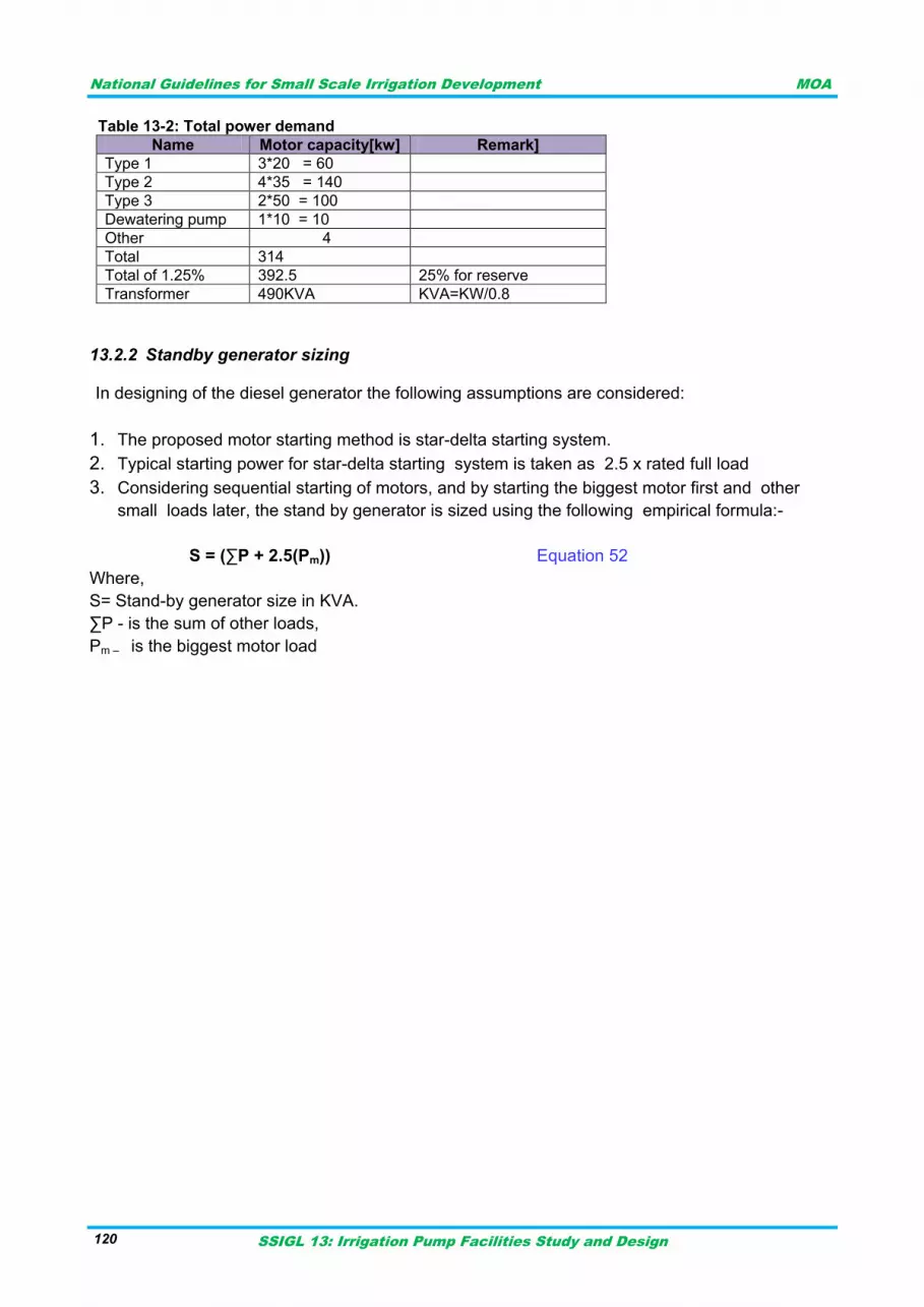
National Guidelines for Small Scale Irrigation Development MOA
SSIGL 13: Irrigation Pump Facilities Study and Design 120
Table 13-2: Total power demand
Standby generator sizing 13.2.2
In designing of the diesel generator the following assumptions are considered:
1. The proposed motor starting method is star-delta starting system.
2. Typical starting power for star-delta starting system is taken as 2.5 x rated full load
3. Considering sequential starting of motors, and by starting the biggest motor first and other
small loads later, the stand by generator is sized using the following empirical formula:-
S = (∑P + 2.5(Pm)) Equation 52
Where,
S= Stand-by generator size in KVA.
∑P - is the sum of other loads,
Pm – is the biggest motor load
Name Motor capacity[kw] Remark]
Type 1 3*20 = 60
Type 2 4*35 = 140
Type 3 2*50 = 100
Dewatering pump 1*10 = 10
Other 4
Total 314
Total of 1.25% 392.5 25% for reserve
Transformer 490KVA KVA=KW/0.8
National Guidelines for Small Scale Irrigation Development MOA
SSIGL 13: Irrigation Pump Facilities Study and Design 121
ECONOMICS OF PUMP IRRIGATION SYSTEM 14
GENERAL 14.1
Basic laws of economics are as much applicable to pump irrigation system as in any other
activities. Production of a particular crop depends upon a number of factors, the most important of
which are:
Soil condition;
Meteorological condition; and
Application of inputs in which water comprises single most important input for crop production.
Economics of Pump irrigation system therefore centers on studying the crop yield in relation to the
application of water at a fairly reasonable cost that should bring a direct benefit in the form of
revenue. Cost is that expenses incurred directly and indirectly in applying water to the crop, which
is of two types - one is the initial or capital cost and the other is operating cost that comprises of
both the fixed and variable cost.
Planning for pump irrigation system 14.1.1
Planning for feasibility:
Pump irrigation system planning involves socio economic consideration as to the feasible course
of investment and other aspects of social developments.
When planning factors that deserve consideration are discussed below:-
a) Dependability
Dependability of sources and Source types, period of availability (with a minimum quantity of
supply)
Quality of water (whether these is an adverse effect on crops, salinity in upstream course, whether
these is an adverse effect if there are industrial effluents, etc)
b) Location of Command Area
Location of command area and distance of delivery point from the source decides the cost of the
pump irrigation system. Initial capital costs with too high lifting cost and long pipelines may be
considered' acceptable but the high operating cost due to the use of higher horsepower may
completely upset the economic viability of LIS scheme.
c) Viability of pump irrigation system
Viability of pump irrigation system shall be decided either on the basis of unit cost or socio-
economic consideration (as applicable, to that specific scheme.)
d) Shape of command area
Emphasis should be given to the design and distribution layout (whether gravity flow or other type)
depends on the topography of the irrigable area.
e) Social conditions
Factors such as: soil thickness, texture and water holding capacity fertility, shall be supported by
chemical analysis.
National Guidelines for Small Scale Irrigation Development MOA
SSIGL 13: Irrigation Pump Facilities Study and Design 122
f) Agro- climatologically condition
Data on rainfall reliability, extent of precipitation, runoff, etc is of utmost importance. Further
analysis to determine: effective rainfall and potential evapotranspiration are required.
g) Copping pattern
Study of existing and proposed cropping pattern needs to be considered with respect to the cost
benefit analysis (Agronomy GL)
h) Source Sharing
Number and type of schemes operating in the up and down stream sides of the sources (river,
canal, stream, etc) shall be considered so as not to disturb the existing water sharing practice.
i) Source of energy
The choice of prime movers and the source of energy for the prime movers (diesel and electric
maintenance practice) ought to be studied for economic viability.
j) Land use
The ownership of the land and use pattern to be affected (grazing area, etc) should be Studied.
k) Availability of infrastructure or material
Availability of standard construction material pumping machineries, maintenance facilities, source
of energy, agricultural input, etc must be looked into.
I) Social demands
Pump irrigation system that does not meet technical or economic viability maybe acceptable from
the point of view of social desirability, in such cases, subsidy under appreciable policy or financing
scheme ought to be assessed.
Alternatives in designing pump irrigation systems 14.1.2
Designing pump irrigation system involves selection of possible alternatives and preparation of
specific details concerning the details of; Development of water source; Assessment on pumping
equipment; Decision on pumping equipment and distribution layout; and Preparation of cost
estimates.
What is sought from a good designed lift irrigation system is not only least unit cost of construction
but also it must ensure smooth and trouble free operation over the designed project life. Thus, the
design engineer be adequately familiar with the aspects of; Development of water sources; Water
requirement of crops Selection of pumps and pipes Installation, operation and maintenance, and
Cost and benefit analysis of techniques of such schemes; Intake structures; Pump house; etc.
COST CONSIDERATIONS 14.2
Capital cost 14.2.1
All costs involved during the implementation of the scheme. Capital cost is ascertained easily after
the scheme is implemented. Once the technical design of the scheme is finalized, a rough
estimate of the capital cost could be made by following standard methods of cost estimates. Cost
in a pump irrigation system is generally incurred in the following items:
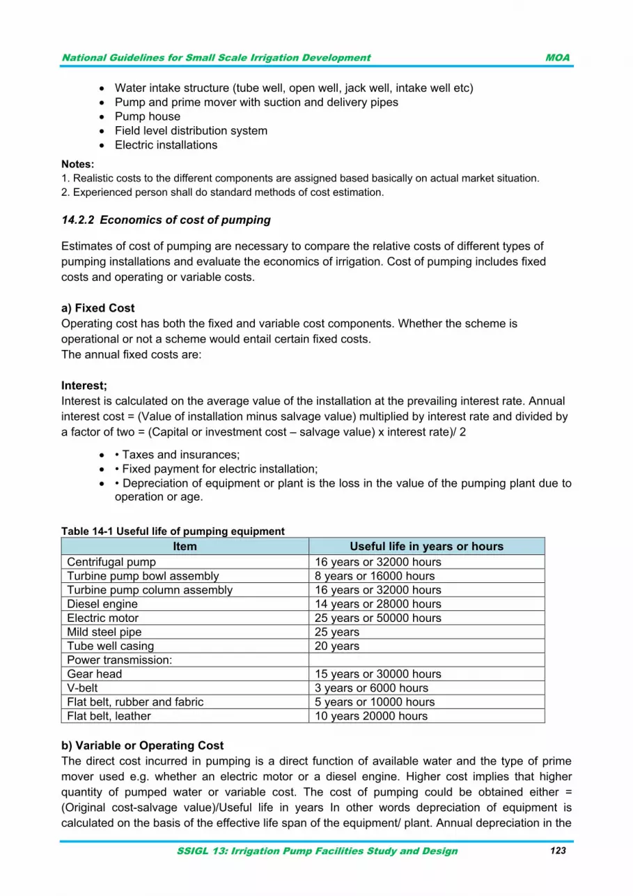
National Guidelines for Small Scale Irrigation Development MOA
SSIGL 13: Irrigation Pump Facilities Study and Design 123
Water intake structure (tube well, open well, jack well, intake well etc)
Pump and prime mover with suction and delivery pipes
Pump house
Field level distribution system
Electric installations
Notes:
1. Realistic costs to the different components are assigned based basically on actual market situation.
2. Experienced person shall do standard methods of cost estimation.
Economics of cost of pumping 14.2.2
Estimates of cost of pumping are necessary to compare the relative costs of different types of
pumping installations and evaluate the economics of irrigation. Cost of pumping includes fixed
costs and operating or variable costs.
a) Fixed Cost
Operating cost has both the fixed and variable cost components. Whether the scheme is
operational or not a scheme would entail certain fixed costs.
The annual fixed costs are:
Interest;
Interest is calculated on the average value of the installation at the prevailing interest rate. Annual
interest cost = (Value of installation minus salvage value) multiplied by interest rate and divided by
a factor of two = (Capital or investment cost – salvage value) x interest rate)/ 2
• Taxes and insurances;
• Fixed payment for electric installation;
• Depreciation of equipment or plant is the loss in the value of the pumping plant due to operation or age.
Table 14-1 Useful life of pumping equipment
Item Useful life in years or hours
Centrifugal pump 16 years or 32000 hours
Turbine pump bowl assembly 8 years or 16000 hours
Turbine pump column assembly 16 years or 32000 hours
Diesel engine 14 years or 28000 hours
Electric motor 25 years or 50000 hours
Mild steel pipe 25 years
Tube well casing 20 years
Power transmission:
Gear head 15 years or 30000 hours
V-belt 3 years or 6000 hours
Flat belt, rubber and fabric 5 years or 10000 hours
Flat belt, leather 10 years 20000 hours
b) Variable or Operating Cost
The direct cost incurred in pumping is a direct function of available water and the type of prime
mover used e.g. whether an electric motor or a diesel engine. Higher cost implies that higher
quantity of pumped water or variable cost. The cost of pumping could be obtained either =
(Original cost-salvage value)/Useful life in years In other words depreciation of equipment is
calculated on the basis of the effective life span of the equipment/ plant. Annual depreciation in the
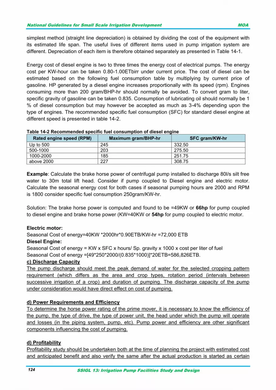
National Guidelines for Small Scale Irrigation Development MOA
SSIGL 13: Irrigation Pump Facilities Study and Design 124
simplest method (straight line depreciation) is obtained by dividing the cost of the equipment with
its estimated life span. The useful lives of different items used in pump irrigation system are
different. Depreciation of each item is therefore obtained separately as presented in Table 14-1.
Energy cost of diesel engine is two to three times the energy cost of electrical pumps. The energy
cost per KW-hour can be taken 0.80-1.00ETbirr under current price. The cost of diesel can be
estimated based on the following fuel consumption table by multiplying by current price of
gasoline. HP generated by a diesel engine increases proportionally with its speed (rpm). Engines
consuming more than 200 gram/BHP-hr should normally be avoided. To convert gram to liter,
specific gravity of gasoline can be taken 0.835. Consumption of lubricating oil should normally be 1
% of diesel consumption but may however be accepted as much as 3-4% depending upon the
type of engines. The recommended specific fuel consumption (SFC) for standard diesel engine at
different speed is presented in table 14-2.
Table 14-2 Recommended specific fuel consumption of diesel engine
Rated engine speed (RPM) Maximum gram/BHP-hr SFC gram/KW-hr
Up to 500 245 332.50
500-1000 203 275.50
1000-2000 185 251.75
above 2000 227 308.75
Example: Calculate the brake horse power of centrifugal pump installed to discharge 80l/s silt free
water to 30m total lift head. Consider if pump coupled to Diesel engine and electric motor.
Calculate the seasonal energy cost for both cases if seasonal pumping hours are 2000 and RPM
is 1800 consider specific fuel consumption 250gram/KW-hr.
Solution: The brake horse power is computed and found to be =49KW or 66hp for pump coupled
to diesel engine and brake horse power (KW=40KW or 54hp for pump coupled to electric motor.
Electric motor:
Seasonal Cost of energy=40KW *2000hr*0.90ETB/KW-hr =72,000 ETB
Diesel Engine:
Seasonal Cost of energy = KW x SFC x hours/ Sp. gravity x 1000 x cost per liter of fuel
Seasonal Cost of energy =[49*250*2000/(0.835*1000)]*20ETB=586,826ETB.
c) Discharge Capacity
The pump discharge should meet the peak demand of water for the selected cropping pattern
requirement (which differs as the area and crop types, rotation period (intervals between
successive irrigation of a crop) and duration of pumping. The discharge capacity of the pump
under consideration would have direct effect on cost of pumping.
d) Power Requirements and Efficiency
To determine the horse power rating of the prime mover, it is necessary to know the efficiency of
the pump, the type of drive, the type of power unit, the head under which the pump will operate
and losses (in the piping system, pump, etc). Pump power and efficiency are other significant
components influencing the cost of pumping.
d) Profitability
Profitability study should be undertaken both at the time of planning the project with estimated cost
and anticipated benefit and also verify the same after the actual production is started as certain

National Guidelines for Small Scale Irrigation Development MOA
SSIGL 13: Irrigation Pump Facilities Study and Design 125
amount of capital is invested in a pump irrigation system as a means of production. If the rate of
return received from a Pump irrigation system is found to be less than the existing interest rate
then naturally a thorough economic review of the entire activity would be

National Guidelines for Small Scale Irrigation Development MOA
SSIGL 13: Irrigation Pump Facilities Study and Design 126
National Guidelines for Small Scale Irrigation Development MOA
SSIGL 13: Irrigation Pump Facilities Study and Design 127
TECHNICAL SPECIFICATION FOR PUMPING FACILITIES 15
The technical specification shall be descriptive and having full detail of the equipment that we
desire to buy. Let us see below typical sample technical specification.
MECHANICAL 15.1
The following details relating to the Mechanical Plant are to be provided.
General arrangement drawings showing equipment positions and pipe work routings
Equipment, valve and pipe work schedules. These should include the overall size and weight of individual items as broken down for delivery and installation
Schedule of painting and protection systems for all plant
Process and Instrumentation diagrams, detailing in full pipeline diameters, instrument functions, I/O requirements, control panel interfaces etc.
General arrangements of individual items of plant. These drawings must be suitably detailed to enable the Engineer to satisfy himself that the Plant is well designed, complies with the Specification and is suitable for the intended purpose.
Sectional drawings showing component parts, associated materials and sufficient details to determine that each item of plant can be operated, maintained, dismantled, assembled, and adjusted in a safe and efficient manner
Detailed manufacturing drawings (workshop drawings) for each item of plant
Hydraulic calculations
Plant sizing calculations
Pump and motor performance curves for main pump sets
A list of the special tools that are to be provided for the operation of the Permanent Works
ELECTRICAL POWER TECHNICAL SPECIFICATION 15.2
The following details relating to the Power Supply are to be provided
Equipment location plan;
Single line diagrams for the site electrical distribution;
A load schedule calculating the maximum demand for each transformer and bus bar section.
Drive schedule;
Switchgear/MCC/control panel general arrangement drawings (internal and external), including fixing and mounting details in plan and section;
Cable routing diagrams;
Circuit schematics providing full details of the proposed individual power and control circuits. Full rating details of all fuses, overloads, CTs, VTs, contactors, relays etc. to be shown. All relay contacts used shall be fully cross referenced within each schematic using an approved grid and table reference system;
Cable schedules;
Power system study comprising:
Cable calculations for power cables (cable calculations generated by proprietary computer software must be fully substantiated manually i.e a sample of the manual calculations shall also be submitted).
Full system calculations detailing worst case voltage drops at motor terminals and transformer secondary terminals when operating on the mains supply and the standby generator supply.
National Guidelines for Small Scale Irrigation Development MOA
SSIGL 13: Irrigation Pump Facilities Study and Design 128
Co-ordinated protection study, incorporating full details of all fault levels, graded protection curves and calculations.
Protection relay setting schedule
Emergency shutdown schedule, detailing location of all emergency stop pushbuttons and their interfaces with proprietary shutdown relays and associated plant.
IRRIGATION PUMP SETS 15.3
Pumps shall be multistage centrifugal ring section type and shall be long coupled with its electric
motor and mounted horizontally on a fabricated steel base plate.
The pump shall have both suction and delivery radial nozzles with rolling element bearings on both
the drive and suction side. The orientation of both the suction and delivery nozzles shall suit the
layout as shown on the Tender Drawings.
The first stage shall have a special suction impeller designed to minimise the required NPSH.
Shaft seals shall be provided with un-cooled gland packing or mechanical shaft seal and shaft
protection sleeves made of stainless steel.
Casing wear rings shall be provided that is easily replaceable. Pumps shall be fitted with pressure
gauges, complete with valves, pipe and fittings, on both discharge and suction flanges.
Irrigation pump motor sizing and de-rating 15.3.1
The motor sizing shall take account of maximum possible run out operation, de-rating due to both
the high ambient temperatures in the pumping station and the high altitude of the pumping
stations.
The maximum „specified run out‟ absorbed power shall be the absorbed power when only one
pump is running under the system curve condition of minimum static head.
The sizing shall be calculated as follows:
Maximum „specified run out‟ absorbed power P kW
Add a 10% margin (P+10%) kW
Factor up by 12% for altitude de-rating (P+10%) x 1.12 kW
Factor up by 4% for temperature de-rating (P+10%) x 1.04 kW
Hence the selected motor size must equal or be greater than 1.26P kW
Irrigation pump materials 15.3.2
Materials of construction shall be selected with due regard to the water being pumped and the risk
of corrosion, cavitation, and metal-to-metal galling that can occur within a pump in all its modes of
operation. The following table outlines the general material construction of the pump.
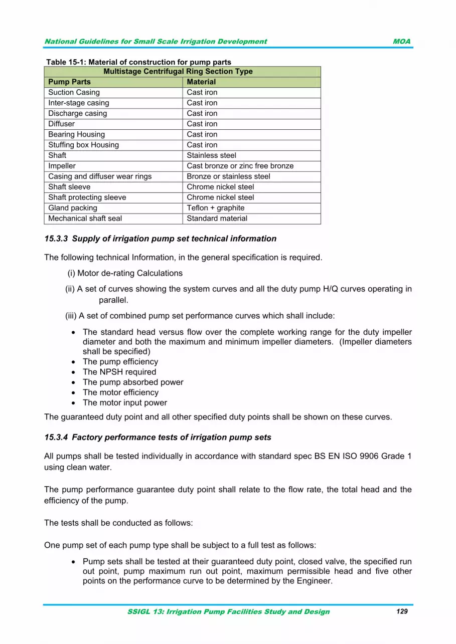
National Guidelines for Small Scale Irrigation Development MOA
SSIGL 13: Irrigation Pump Facilities Study and Design 129
Table 15-1: Material of construction for pump parts
Multistage Centrifugal Ring Section Type
Pump Parts Material
Suction Casing Cast iron
Inter-stage casing Cast iron
Discharge casing Cast iron
Diffuser Cast iron
Bearing Housing Cast iron
Stuffing box Housing Cast iron
Shaft Stainless steel
Impeller Cast bronze or zinc free bronze
Casing and diffuser wear rings Bronze or stainless steel
Shaft sleeve Chrome nickel steel
Shaft protecting sleeve Chrome nickel steel
Gland packing Teflon + graphite
Mechanical shaft seal Standard material
Supply of irrigation pump set technical information 15.3.3
The following technical Information, in the general specification is required.
(i) Motor de-rating Calculations
(ii) A set of curves showing the system curves and all the duty pump H/Q curves operating in
parallel.
(iii) A set of combined pump set performance curves which shall include:
The standard head versus flow over the complete working range for the duty impeller diameter and both the maximum and minimum impeller diameters. (Impeller diameters shall be specified)
The pump efficiency
The NPSH required
The pump absorbed power
The motor efficiency
The motor input power
The guaranteed duty point and all other specified duty points shall be shown on these curves.
Factory performance tests of irrigation pump sets 15.3.4
All pumps shall be tested individually in accordance with standard spec BS EN ISO 9906 Grade 1
using clean water.
The pump performance guarantee duty point shall relate to the flow rate, the total head and the
efficiency of the pump.
The tests shall be conducted as follows:
One pump set of each pump type shall be subject to a full test as follows:
Pump sets shall be tested at their guaranteed duty point, closed valve, the specified run out point, pump maximum run out point, maximum permissible head and five other points on the performance curve to be determined by the Engineer.
National Guidelines for Small Scale Irrigation Development MOA
SSIGL 13: Irrigation Pump Facilities Study and Design 130
Temperature sensors shall be connected to all bearings and motor windings and the temperatures recorded throughout the test
Vibration of the pump sets shall be tested in accordance with the American Hydraulic Institute Standards (in range of 10 – 1000 Hz).
The pump sets shall be subjected to a noise test and the maximum „A‟ noise level shall be not more than 90 dB at 1 metre from the surface of the pump set.
All remaining pump sets shall be subject to an abbreviated test as follows:
Pump sets shall be tested at their duty point, closed valve, specified run out point, maximum permissible head and five other points on the performance curve to be determined by the Engineer
A full NPSH test shall be conducted on one pump set of each type at each pumping station.
All the above pump tests shall be carried out with their electric motors and assembled on their
base plate.
Tests shall provide information for performance curves to be drawn for: head/quantity,
efficiency/quantity, power absorbed/quantity and net positive suction head/quantity. All the
specified duty points in the Technical Schedules shall be shown on the performance curves.
All pump sets shall operate at their guaranteed design points within the „acceptance‟ tolerances for
flow rate and total head laid down in BS EN ISO 9906. The pump sets will not be accepted if they
are outside the accepted tolerances.
Vibration of the pump sets or any point inside or outside the bearings shall be no more than 0.71
mm/s and the vibration amplitude (crest value) shall be no more than 0.05 mm when the pump
sets run normally.
Pump casings shall be subject to a pressure test at 1.5 times the pressure obtained with the
delivery valve closed. The positive suction head shall be taken into account in determining this
pressure.
Pump tests in sub paragraphs (a) and (c) shall be witnessed by the Engineer or his nominated
inspection agent.
IRRIGATION PUMPING STATION STANDBY GENERATING PLANT 15.4
General 15.4.1
The supply and installation of the standby power diesel generating plant, must be included
together with all other services, switchgear, cabinets, cables etc., as specified below. The
requirements shall include for the manufacture, supply and complete installation of all materials,
equipment, plant and components necessary for the provision of fully operational and functioning
standby power diesel plant, associated switchgear and services, as specified. The diesel plant
and equipment shall include:
Diesel generating plant
Fuel tanks and pipe work
Switchgear
Cables
Earthing
All accessories and other necessary items
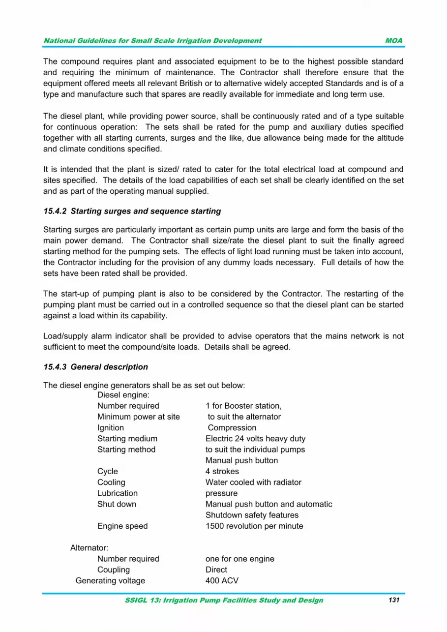
National Guidelines for Small Scale Irrigation Development MOA
SSIGL 13: Irrigation Pump Facilities Study and Design 131
The compound requires plant and associated equipment to be to the highest possible standard
and requiring the minimum of maintenance. The Contractor shall therefore ensure that the
equipment offered meets all relevant British or to alternative widely accepted Standards and is of a
type and manufacture such that spares are readily available for immediate and long term use.
The diesel plant, while providing power source, shall be continuously rated and of a type suitable
for continuous operation: The sets shall be rated for the pump and auxiliary duties specified
together with all starting currents, surges and the like, due allowance being made for the altitude
and climate conditions specified.
It is intended that the plant is sized/ rated to cater for the total electrical load at compound and
sites specified. The details of the load capabilities of each set shall be clearly identified on the set
and as part of the operating manual supplied.
Starting surges and sequence starting 15.4.2
Starting surges are particularly important as certain pump units are large and form the basis of the
main power demand. The Contractor shall size/rate the diesel plant to suit the finally agreed
starting method for the pumping sets. The effects of light load running must be taken into account,
the Contractor including for the provision of any dummy loads necessary. Full details of how the
sets have been rated shall be provided.
The start-up of pumping plant is also to be considered by the Contractor. The restarting of the
pumping plant must be carried out in a controlled sequence so that the diesel plant can be started
against a load within its capability.
Load/supply alarm indicator shall be provided to advise operators that the mains network is not
sufficient to meet the compound/site loads. Details shall be agreed.
General description 15.4.3
The diesel engine generators shall be as set out below: Diesel engine:
Number required 1 for Booster station,
Minimum power at site to suit the alternator
Ignition Compression
Starting medium Electric 24 volts heavy duty
Starting method to suit the individual pumps
Manual push button
Cycle 4 strokes
Cooling Water cooled with radiator
Lubrication pressure
Shut down Manual push button and automatic
Shutdown safety features
Engine speed 1500 revolution per minute
Alternator:
Number required one for one engine
Coupling Direct
Generating voltage 400 ACV
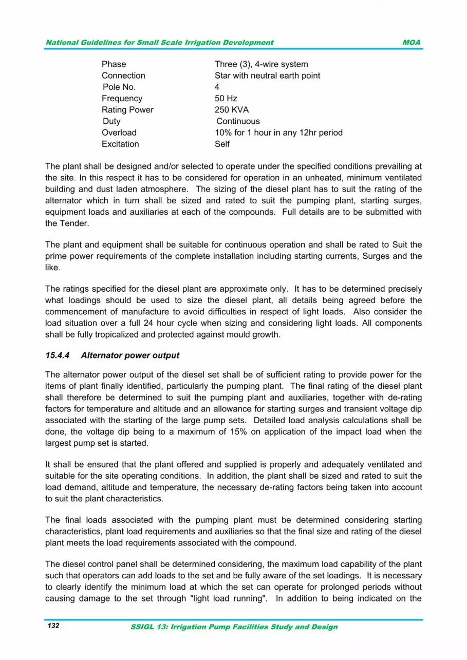
National Guidelines for Small Scale Irrigation Development MOA
SSIGL 13: Irrigation Pump Facilities Study and Design 132
Phase Three (3), 4-wire system
Connection Star with neutral earth point
Pole No. 4
Frequency 50 Hz
Rating Power 250 KVA
Duty Continuous
Overload 10% for 1 hour in any 12hr period
Excitation Self
The plant shall be designed and/or selected to operate under the specified conditions prevailing at
the site. In this respect it has to be considered for operation in an unheated, minimum ventilated
building and dust laden atmosphere. The sizing of the diesel plant has to suit the rating of the
alternator which in turn shall be sized and rated to suit the pumping plant, starting surges,
equipment loads and auxiliaries at each of the compounds. Full details are to be submitted with
the Tender.
The plant and equipment shall be suitable for continuous operation and shall be rated to Suit the
prime power requirements of the complete installation including starting currents, Surges and the
like.
The ratings specified for the diesel plant are approximate only. It has to be determined precisely
what loadings should be used to size the diesel plant, all details being agreed before the
commencement of manufacture to avoid difficulties in respect of light loads. Also consider the
load situation over a full 24 hour cycle when sizing and considering light loads. All components
shall be fully tropicalized and protected against mould growth.
Alternator power output 15.4.4
The alternator power output of the diesel set shall be of sufficient rating to provide power for the
items of plant finally identified, particularly the pumping plant. The final rating of the diesel plant
shall therefore be determined to suit the pumping plant and auxiliaries, together with de-rating
factors for temperature and altitude and an allowance for starting surges and transient voltage dip
associated with the starting of the large pump sets. Detailed load analysis calculations shall be
done, the voltage dip being to a maximum of 15% on application of the impact load when the
largest pump set is started.
It shall be ensured that the plant offered and supplied is properly and adequately ventilated and
suitable for the site operating conditions. In addition, the plant shall be sized and rated to suit the
load demand, altitude and temperature, the necessary de-rating factors being taken into account
to suit the plant characteristics.
The final loads associated with the pumping plant must be determined considering starting
characteristics, plant load requirements and auxiliaries so that the final size and rating of the diesel
plant meets the load requirements associated with the compound.
The diesel control panel shall be determined considering, the maximum load capability of the plant
such that operators can add loads to the set and be fully aware of the set loadings. It is necessary
to clearly identify the minimum load at which the set can operate for prolonged periods without
causing damage to the set through "light load running". In addition to being indicated on the
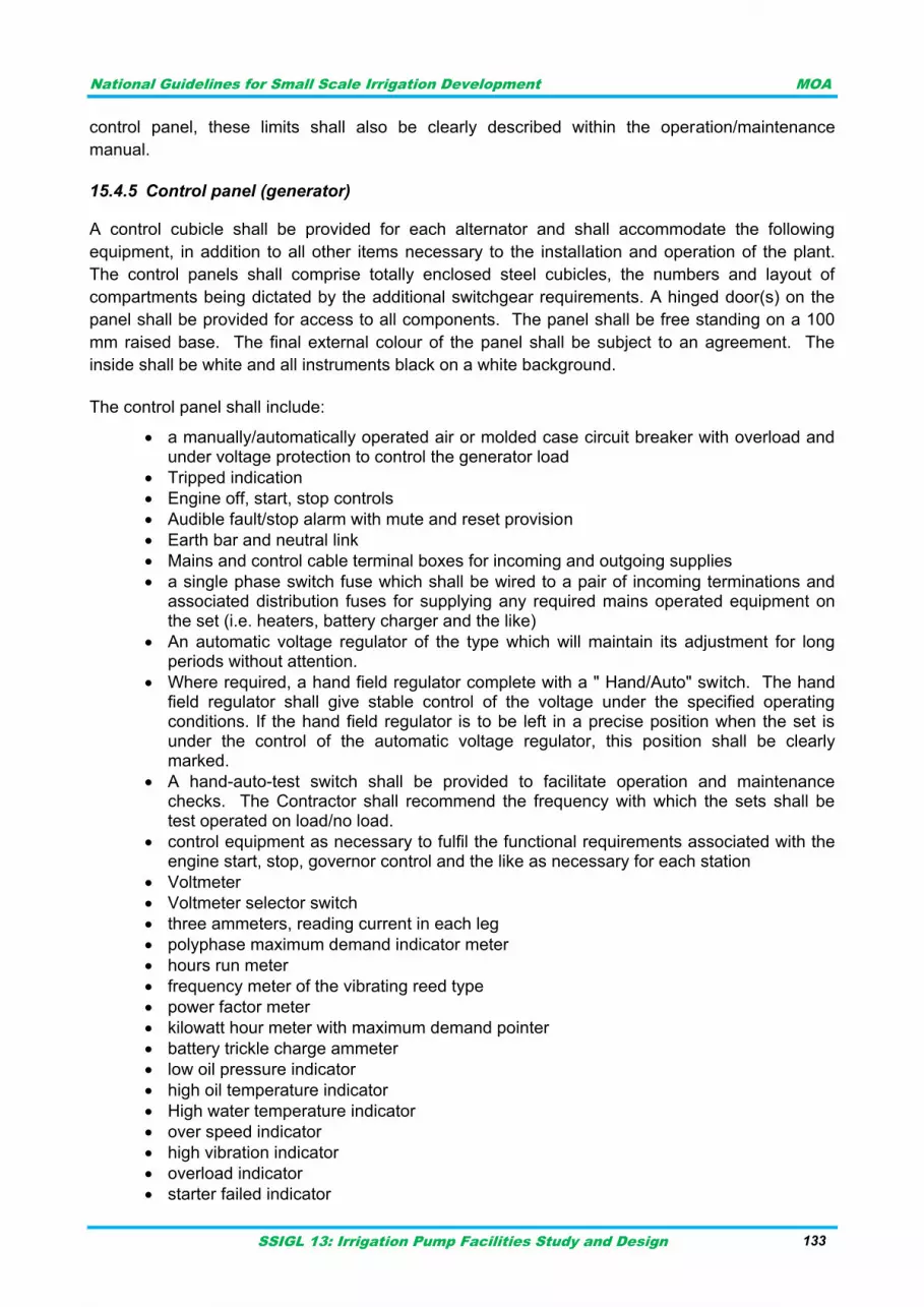
National Guidelines for Small Scale Irrigation Development MOA
SSIGL 13: Irrigation Pump Facilities Study and Design 133
control panel, these limits shall also be clearly described within the operation/maintenance
manual.
Control panel (generator) 15.4.5
A control cubicle shall be provided for each alternator and shall accommodate the following
equipment, in addition to all other items necessary to the installation and operation of the plant.
The control panels shall comprise totally enclosed steel cubicles, the numbers and layout of
compartments being dictated by the additional switchgear requirements. A hinged door(s) on the
panel shall be provided for access to all components. The panel shall be free standing on a 100
mm raised base. The final external colour of the panel shall be subject to an agreement. The
inside shall be white and all instruments black on a white background.
The control panel shall include:
a manually/automatically operated air or molded case circuit breaker with overload and under voltage protection to control the generator load
Tripped indication
Engine off, start, stop controls
Audible fault/stop alarm with mute and reset provision
Earth bar and neutral link
Mains and control cable terminal boxes for incoming and outgoing supplies
a single phase switch fuse which shall be wired to a pair of incoming terminations and associated distribution fuses for supplying any required mains operated equipment on the set (i.e. heaters, battery charger and the like)
An automatic voltage regulator of the type which will maintain its adjustment for long periods without attention.
Where required, a hand field regulator complete with a " Hand/Auto" switch. The hand field regulator shall give stable control of the voltage under the specified operating conditions. If the hand field regulator is to be left in a precise position when the set is under the control of the automatic voltage regulator, this position shall be clearly marked.
A hand-auto-test switch shall be provided to facilitate operation and maintenance checks. The Contractor shall recommend the frequency with which the sets shall be test operated on load/no load.
control equipment as necessary to fulfil the functional requirements associated with the engine start, stop, governor control and the like as necessary for each station
Voltmeter
Voltmeter selector switch
three ammeters, reading current in each leg
polyphase maximum demand indicator meter
hours run meter
frequency meter of the vibrating reed type
power factor meter
kilowatt hour meter with maximum demand pointer
battery trickle charge ammeter
low oil pressure indicator
high oil temperature indicator
High water temperature indicator
over speed indicator
high vibration indicator
overload indicator
starter failed indicator
National Guidelines for Small Scale Irrigation Development MOA
SSIGL 13: Irrigation Pump Facilities Study and Design 134
set failed indicator
The panel shall also include other lamps as required for the correct operation of the generating set
together with alarms and switches. Automatic shutdown shall occur with the operation of any of
the first five alarm, protection and indicating circuits together with overload after reaching an
agreed predetermined load value, and the operation of the thermistor protection relay.
Enclosures for electrical and control equipment 15.4.6
Enclosures for electrical and control equipment shall be drip proof and dust protecting with
adequate front access as necessary for maintenance and repair and to IP51 classification. Special
attention shall be given to the method of construction and to the mounting of the components to
minimize the effect of vibration. Diagrams of connections in durable form shall be mounted inside
the enclosures.
Full consideration shall be given to the fixing/supports and the running/connection of all cables.
Full details shall be submitted for approval, the Contractor taking into consideration all details
including cable terminations, access to these terminations, cable bending radii etc.
Finishes 15.4.7
All ferrous metalwork shall be either painted or processed to give a rustproof coating. Ferrous
metalwork to be painted shall first be either shot blasted or thoroughly wire brushed to remove all
scale and oxide and immediately given one brushed coat or two sprayed coats of primer. After not
less than four hours, one brushed or two sprayed undercoats followed by one brushed or two
sprayed finishing coats of heat and oil resisting quality paint shall be applied.
Successive coats of paint shall be slightly differing shades. The interior service of electrical
equipment enclosures shall be finished white and all external surfaces shall be finished to the BS
4800 to suit the manufacturer's standard colour. The engine crank case shall not be painted
internally unless the plant is resistant to the lubricating oil.
Drawings of pumping facilities 15.4.8
The following drawings are essential:
Building drawings showing details of cable entries, pipe entries and ducts required.
General arrangement of the diesel engines.
Details, supports and general requirements associated with the exhaust system.
General arrangement of the alternator and exciter showing terminal markings, polarity and phase rotation.
General arrangement of the electrical control panel
Schematic and wiring diagram of the electrical control panel
PUMP MOTOR CONTROL PANEL SPECIFICATION 15.5
General 15.5.1
A. The motor control panel shall be assembled and tested by a controls system manufacturer
meeting the Standards of UL 508A for industrial controls and be UL labeled and serialized
accordingly. The motor control panel shall be assembled and tested by the manufacturer so
as to insure suitability in matching controls to motors and to insure single source
National Guidelines for Small Scale Irrigation Development MOA
SSIGL 13: Irrigation Pump Facilities Study and Design 135
responsibility for the equipment.
B. The panel shall contain all components required by the pump manufacturer for starting and
protecting the motor as well as features required by the pump manufacturer for warranty of
the pumps. Items such as thermal overload detection or seal failure detection shall be
included when required.
C. Incoming pump power shall be single/three -phase, 50 Hz, 230/380 volts AC.
D. Incoming control/alarm power shall be single-phase50 Hz, 230 volts AC.
E. The control panel shall incorporate three (3) normally open; mercury or mechanically-
activated control switches with pipe clamps. Floats shall be labeled in the panel as stop,
start, and alarm. Floats shall be SJE-Rhombus control switches or approved equal.
Construction 15.5.2
A. The controls for the pump shall be housed in an engineered thermoplastic enclosure
meeting NEMA 4X requirements with a hinged door and neoprene gasket. The enclosure
shall have provisions for a padlock.
B. A nameplate shall be permanently affixed to the panel. A ratings label shall include the
model number, voltage, phase, frequency, ampere rating and horsepower rating and shall
be affixed to the inside of the enclosure. A warning label against electric shock shall be
permanently affixed to the outer door. The interior of the enclosure shall have a clear
envelope with "as built" schematics located within.
C. A removable aluminum back plate shall be provided for mounting all circuit breakers, motor
starters, etc. All components mounted to the back plate shall be secured by type 25, self-
tapping screws in extruded holes. Rivets shall not be acceptable for securing any
component to the back plate.
D. A simplex pump controller shall be provided for control logic. The controller shall utilize a
printed circuit board to avoid conventional wiring. The printed circuit board of the pump
controller shall be manufactured using UL listed materials. There shall be separately fused
control and alarm circuit protection. A run light and hand-off-auto switch shall be provided
for the pump circuit. The run light and hand-off-auto switch shall be mounted on the printed
circuit board. The run light shall be green.
E. A circuit breaker shall be used as branch circuit protection for the pump. The circuit breaker
shall be thermal magnetic and sized to meet NEC requirements for interrupt capacity and
amp rating.
F. The magnetic motor starter shall be general purpose type rated for the pump horsepower
and include a contactor with a minimum mechanical life of 500,000 operations and a
minimum contact life of 100,000 operations. Pump overloads, if not included in the pump,
shall provide overload protection for the pump circuit and shall be sized to meet NEC
requirements for the pump full load ampere rating specified.
G. A high-level alarm condition shall activate the main alarm light (red, mounted on the top of
the panel) and alarm horn. The alarm light shall remain illuminated until the problem is
National Guidelines for Small Scale Irrigation Development MOA
SSIGL 13: Irrigation Pump Facilities Study and Design 136
corrected. The alarm horn shall be rated 83-85 dB minimum. A Test-Normal-Silence toggle
switch labeled and placed adjacent to the horn, shall be included.
H. H. Wire ties shall be used to maintain panel wiring in neat bundles for maintenance and to
prevent interference with operating devices. All grounding conductors shall be securely
connected to assure a proper ground.
Irrigation pump motor starter 15.5.3
Starter sections shall be provided for the irrigation pumping station. Each starter shall be complete
with the following features:
Incoming door interlocked fuse-switch disconnect
Control circuit bypass “test” switch
Set of three contactors for star/delta starting
Star/delta changeover timer relay
Motor protection relay incorporating instantaneous overcurrent, earth-fault, thermal overload, delayed start, current unbalance, loss of phase and under voltage
Integral 380/110 V transformer for AC control supply
Power factor correction to 0.96 when the load is at rated value
110 V AC operated “external trip” relay (de-energise to trip/energise to permit running)
110 V AC operated “start/stop” command relay (energise to start)
Thermistor relay
Front of panel mounted start, stop and reset pushbuttons
Front of panel mounted hand/off/auto selector switch (auto selects control from the C&I section)
Front of panel mounted indicator lamps for running, stopped, motor protection relay fault, motor winding over temperature alarm, motor winding over temperature trip, and “external trip operated”
“Power-up” auto-reset timer relay
Anti-condensation heater complete with fuse protection and thermostat
Cable termination features for multiple outgoing multicore power cables
Volt-free changeover contacts for remote indication of running status, internal trip conditions, external trip relay operated, control selection and “available”
Auxiliary terminals and contacts as necessary
The external trip relay shall be powered from circuitry in the Control & Instrumentation section and
will be energised when external hydraulic conditions permit operation of the pump set. If the
external trip relay is de-energised it shall latch out and power to the pump shall immediately be
cut-off. The pump shall remain unavailable for service until the trip condition has been cancelled
and the relay has been manually reset, or reset by a power-up auto reset function following power
failure.
The “available” signal shall be generated when no internally detected trip conditions exist and the
“external trip” relay is energised.
National Guidelines for Small Scale Irrigation Development MOA
SSIGL 13: Irrigation Pump Facilities Study and Design 137
INSTALLATION, MAINTENANCE AND OPERATION OF E&M 16EQUPMENT
Generally, Electro-mechanical equipment experiences the most serious problems with operation
and maintenance and lags in cost recovery aspects. Hundreds of project built infrastructure
deteriorates after the project‟s termination. Therefore, it is imperative to plan for operation and
maintenance, with a planned withdrawal of external support as local ownership builds. This
document is intended for managers and planners who are concerned with the challenging problem
of how to implement effective operation and maintenance plan in irrigation projects.
SAFETY INSTRUCTIONS WHILE MAINTENANCE & SERVICING A PUMP 16.1
Before attempting any maintenance on a pump particularly if it has been handling any form of
liquid, it should be ensured that the unit is safe to work on. The pump must be flushed thoroughly
with suitable cleaner to purge away any of the product left in the pump components. This should
be carried out by the plant operator and assurance of cleanliness obtained before starting work. To
avoid any risk to health it is also advisable to wear protective clothing as recommended by the site
safety officer especially when removing old packing which may be contaminated.
Check and ensure that the pump operates at below the maximum working pressure specified in
the manual or on the pump nameplate and before maintenance, ensure that the pump is drained
down. Wear a suitable mask or respirator when working with packing and gasket components
which contain fibrous material, as these can be hazardous when the fibrous dust is inhaled. Be
cautious, if other supplier‟s components have been substituted for genuine parts, these may then
contain hazardous materials.
INSTALLATION, MAINTENANCE AND OPERATION OF PUMP SET AND POWER SUPPLY 16.2
Submersible pump installation 16.2.1
Before installation, must check whether the cable is damaged, scratched, broken, etc. If they are faulty, must consult the supplier.
The pumps are normally supplied with motor and pump disconnected; connect the coupling and pump-motor suction lantern.
Clean the surface to be coupled.
Put the suction lantern of the pump in correspondence of the motor studs.
Couple the grooved joint of the pump to the motor shaft.
Screw in the nuts to the suction lantern, and then fix the crosswise starting from the one opposed to the cable.
The torque recommended is 10 Nm for 4‟ motor.
Connect the cable to the pump with the cable guard and place the filter on the suction lantern.
When threaded connections are used, delivery pipes must be tightened to avoid any risks of the pump falling into the well.
A safety rope or chain on non-perishable material should always be used to secure the pump.
Attach the power cables to the delivery pipe with cable clamps placed at intervals of approximate 3 meter.
Lower the pump into the well, making sure the feed cables are not damaged in any way during the operation.
National Guidelines for Small Scale Irrigation Development MOA
SSIGL 13: Irrigation Pump Facilities Study and Design 138
Install the pump with its axis placed at least 0.5 meter above the bottom of the well.
Power supply installation 16.2.2
From safety point of view all work of an electrical system must be carefully carried out by skilled
person only. Thus note that:
Make sure the frequency and mains voltage correspond with the name plate data.
Check whether the power supply is conformed to the stipulation of name plate before installation.
Power supply connected with the pump must be assembled with electric cable, and the voltage fluctuation must be controlled within ± 10% of rated.
For connection of cables in the well, use thermo-shrinking insulation sheathes or other system used for submerged cables.
The operating temperature limiting the drop in voltage to at most 3%.
The live wire should made dead before making the connection. The connection between the pump and the other part must be made using suitable material for submersed cables and in compliance with the current regulation from local electricity authority.
All checking of connection should be checked by appropriate instruments.
Important While installing the motor pump, avoid impact, rubbing or anything else that can damage the power cable or puncture the cable leading to short-circuit.
Operation and maintenance of pumps 16.2.3
Daily checks
Pressure gauge reading.
Voltage and current.
Pump and motor bearing temperature.
Vibration and noise.
Periodical checks
Replenishing of the grease to the pump antifriction bearing and motor bearing after proper intervals.
Check the vibrations.
Check the liquid level controller for its functioning.
Calibration of measuring instruments.
Check the level of motor stool as described in assembly procedure after taking out motor at regular intervals of 6 months.
Clean the tank, if there are chances of deposition of the contents of the liquid handled.
Overhauling
With continuous daily operations spell, the pump will be due for overhaul after 10000 working hours. This work should be carried out by specialised and experienced fitters.
While ordering spare parts, the details of the nameplate must be quoted in full. Particularly the name of the pump, order number, name of the part and quantity required.
Keep the sufficient stock of spare parts in order to meet the emergency requirement.
Follow the following procedure while dismantling the pump.
Disconnect the delivery pipe connections above support plate. Unscrew the fasteners holding support plate on the flange of tank.
Disconnect the motor power connections. Unscrew the nuts of motor stool and take out motor stool along with motor.
National Guidelines for Small Scale Irrigation Development MOA
SSIGL 13: Irrigation Pump Facilities Study and Design 139
Remove coupling star and take out pump half coupling after loosening the set screw. Use suitable puller. Remove coupling key.
Unscrew the two bearing nuts
Remove the bearing cover along with oil seal Use release bolts if necessary.
Remove spacer for thrust bearing adapter and split key for unit pumps).
Unscrew nuts holding bearing holder on stuffing box housing and remove bearing holder.
Lift entire pump unit vertically upwards with the help of crane having slings
Supported on eye bolts screwed on support plate.
Fit clamp to the top column pipe and keep two girders or strong wooden logs across the opening of the tank.
Rest the clamps on these two girders of wooden log.
Unscrew flange and pipe nut.
Unscrew bolts holding bearing carrier support plate and top column pipe together.
Remove key for thrust bearing carrier Take out bearing holder along with oil seal, angular contact ball bearing and thrust bearing carrier Use release bolts.
Push thrust bearing carrier so that it will come out of bearing holder along with angular contact ball bearing. Remove angular contact ball bearing from thrust bearing carrier only if found to be damaged.
Lift the unit vertically up after engaging the shelling on the arms of the pump.
Fit another pair of clamps on column pipe next below the top column pipe.
Allow the unit to lower down so as to rest the clamps of the girders or wooden logs.
Unscrew the bolts holding top column pipe, bearing spider and column pipe together.
Take out top column pipe connect the head shaft using suitable spanner.
Disconnect the lubricating pipe for bearing spider by unscrewing nut.
Take out the bearing spider.
Unscrew grub screw at the junction of intermediate bearing bush and bearing spider. Remove the bearing bush out of bearing spider only if it is found damaged.
Unscrew the screwed coupling from intermediate shaft or impeller shaft
Follow the procedure given till you remove last intermediate shaft last bearing spider and last screwed coupling.
Disconnect the rising pipe at support plate while dismantling the column
Preventive maintenance usually consists in checking pump functionality and cleaning the pump
and site daily, greasing weekly, checking all parts of the pump stand monthly, and taking the whole
pump apart for a check, cleaning the parts with clean water and painting the pump stand annually.
Pump rods that show bad corrosion must be replaced. Under normal conditions, a galvanized steel
pump rod needs replacement every five to six years. Rising mains consisting of galvanized iron
have to be removed and checked and pipes with badly corroded threads must be replaced. Small
repairs are the replacement of bearings, cup seals and washers, straightening bent pumping rods,
etc. Major repairs may involve the replacement of the plunger, foot valve, and cylinder, pump rods,
rising main; pump handle, fulcrum, etc. With open-top cylinder pumps, all preventive maintenance
activities can normally be executed by a village pump caretaker. For major repairs and problems,
external support may be needed. Closed-top cylinder pumps often need special lifting equipment
to pull up the rising main and cylinder for maintenance of parts down in the hole.
In addition to the above the following checks, on-site modifications, re-arrangements and
preventive maintenance are necessary:
Check and repair any leakage in piping or through valves.
Flush for time of 2-3min for each line to prevent sedimentation on the inner pipes walls.
Clean the canals of the system thoroughly before every irrigation.
Check the air and check valves periodically for proper functioning.
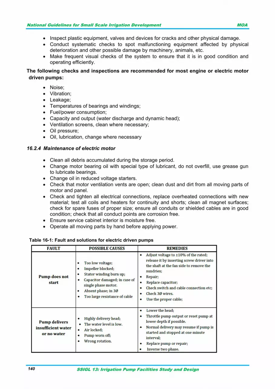
National Guidelines for Small Scale Irrigation Development MOA
SSIGL 13: Irrigation Pump Facilities Study and Design 140
Inspect plastic equipment, valves and devices for cracks and other physical damage.
Conduct systematic checks to spot malfunctioning equipment affected by physical deterioration and other possible damage by machinery, animals, etc.
Make frequent visual checks of the system to ensure that it is in good condition and operating efficiently.
The following checks and inspections are recommended for most engine or electric motor
driven pumps:
Noise;
Vibration;
Leakage;
Temperatures of bearings and windings;
Fuel/power consumption;
Capacity and output (water discharge and dynamic head);
Ventilation screens, clean where necessary;
Oil pressure;
Oil, lubrication, change where necessary
Maintenance of electric motor 16.2.4
Clean all debris accumulated during the storage period.
Change motor bearing oil with special type of lubricant, do not overfill, use grease gun to lubricate bearings.
Change oil in reduced voltage starters.
Check that motor ventilation vents are open; clean dust and dirt from all moving parts of motor and panel.
Check and tighten all electrical connections, replace overheated connections with new material; test all coils and heaters for continuity and shorts; clean all magnet surfaces; check for spare fuses of proper size; ensure all conduits or shielded cables are in good condition; check that all conduct points are corrosion free.
Ensure service cabinet interior is moisture free.
Operate all moving parts by hand before applying power.
Table 16-1: Fault and solutions for electric driven pumps
National Guidelines for Small Scale Irrigation Development MOA
SSIGL 13: Irrigation Pump Facilities Study and Design 141
INSTALLATION, MAINTENANCE AND OPERATION OF DIESEL ENGINE 16.3
Installation
Diesel engines are to be installed by qualified technician following the manufacturer procedure.
Operation
The engine must be operated by a trained caretaker. Every engine has its own typical operating
instructions. Before starting it, the levels of fuel, oil and cooling water (if not air-cooled) are
checked. If these levels are low, extra fuel, oil or water has to be added. During operation, the fuel
level, oil pressure, and engine speed are checked and also the functioning of the pump or
generator. Some moving parts may need manual lubrication. When the engine is operated at very
low speeds, its efficiency is low and carbon builds up rapidly in the engine, increasing the need for
servicing. All data on liquid levels and running hours are written down in a log book.
Maintenance
Every day the outside of the engine must be cleaned, and in dusty conditions the air filter must be
checked and cleaned. Some parts may need manual lubrication. In moderately dusty conditions,
oil-bath air filters are cleaned once a week, dry-paper air filters a little less frequently. The engine
is serviced for preventive maintenance according to the number of hours it has run. Every 50
hours, the clutch (if present) must be greased. Every 250 hours, clean all filters (replace if
necessary), change oil, check nuts and bolts and exhaust pipe. Every 1500 hours, major service
overhaul with decarbonizing, adjusting valve clearance, etc. If the engine is connected to a pump
or generator with a V-belt, this will regularly need replacement. Once a year the engine house
must be painted and occasionally repaired. If a generator is present it will have its own
maintenance needs. The Table below shows only the most important O&M activities.
INSTALLATION, MAINTENANCE AND OPERATION OF PIPES 16.4
The maintenance of distribution pipes consists in checking for leaks, corrosion, and scale. Each
time a line is opened, the interior of the piping can be observed. The life of more than one system
has been greatly extended by workmen who have reported pipe damage when making a house
connation.
Due to differential thermal expansion rates between metal and plastic, transmittal of pipe vibration,
and pipe loading forces DIRECT INSTALLATION OF METAL PIPE INTO PLASTIC
CONNECTIONS IS NOT RECOMMENDED. Wherever installation of a plastic duplex strainer into
a metal piping systems is necessary, it is recommended that at least 10 pipe diameter in length of
plastic pipe be installed upstream and downstream of the plastic duplex strainer to compensate for
the factors mentioned above
MAINTENANCE OF IRRIGATION NETWORK 16.5
The procedure for the irrigation network checkup is as follows:
Inspect for possible damage to the network and repair it.
Open fully and drain completely all valves.
Remove dirt, corrosion and other foreign material from the component parts.
Check E&M equipment for possible, damage, wear and signs of deterioration, and replace where necessary.
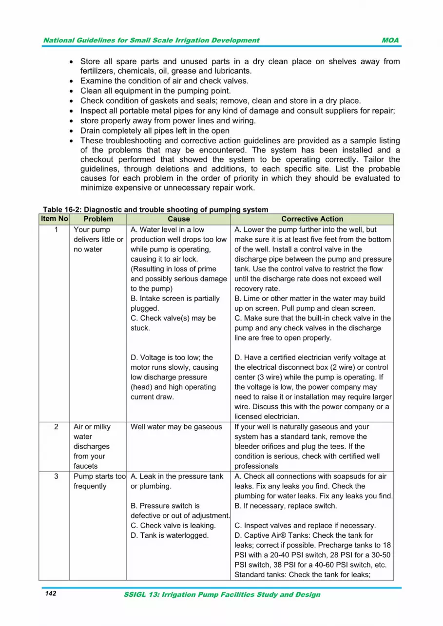
National Guidelines for Small Scale Irrigation Development MOA
SSIGL 13: Irrigation Pump Facilities Study and Design 142
Store all spare parts and unused parts in a dry clean place on shelves away from fertilizers, chemicals, oil, grease and lubricants.
Examine the condition of air and check valves.
Clean all equipment in the pumping point.
Check condition of gaskets and seals; remove, clean and store in a dry place.
Inspect all portable metal pipes for any kind of damage and consult suppliers for repair;
store properly away from power lines and wiring.
Drain completely all pipes left in the open
These troubleshooting and corrective action guidelines are provided as a sample listing of the problems that may be encountered. The system has been installed and a checkout performed that showed the system to be operating correctly. Tailor the guidelines, through deletions and additions, to each specific site. List the probable causes for each problem in the order of priority in which they should be evaluated to minimize expensive or unnecessary repair work.
Table 16-2: Diagnostic and trouble shooting of pumping system
Item No Problem Cause Corrective Action
1 Your pump
delivers little or
no water
A. Water level in a low
production well drops too low
while pump is operating,
causing it to air lock.
(Resulting in loss of prime
and possibly serious damage
to the pump)
B. Intake screen is partially
plugged.
C. Check valve(s) may be
stuck.
D. Voltage is too low; the
motor runs slowly, causing
low discharge pressure
(head) and high operating
current draw.
A. Lower the pump further into the well, but
make sure it is at least five feet from the bottom
of the well. Install a control valve in the
discharge pipe between the pump and pressure
tank. Use the control valve to restrict the flow
until the discharge rate does not exceed well
recovery rate.
B. Lime or other matter in the water may build
up on screen. Pull pump and clean screen.
C. Make sure that the built-in check valve in the
pump and any check valves in the discharge
line are free to open properly.
D. Have a certified electrician verify voltage at
the electrical disconnect box (2 wire) or control
center (3 wire) while the pump is operating. If
the voltage is low, the power company may
need to raise it or installation may require larger
wire. Discuss this with the power company or a
licensed electrician.
2 Air or milky
water
discharges
from your
faucets
Well water may be gaseous If your well is naturally gaseous and your
system has a standard tank, remove the
bleeder orifices and plug the tees. If the
condition is serious, check with certified well
professionals
3 Pump starts too
frequently
A. Leak in the pressure tank
or plumbing.
B. Pressure switch is
defective or out of adjustment.
C. Check valve is leaking.
D. Tank is waterlogged.
A. Check all connections with soapsuds for air
leaks. Fix any leaks you find. Check the
plumbing for water leaks. Fix any leaks you find.
B. If necessary, replace switch.
C. Inspect valves and replace if necessary.
D. Captive Air® Tanks: Check the tank for
leaks; correct if possible. Precharge tanks to 18
PSI with a 20-40 PSI switch, 28 PSI for a 30-50
PSI switch, 38 PSI for a 40-60 PSI switch, etc.
Standard tanks: Check the tank for leaks;
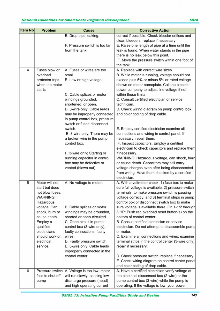
National Guidelines for Small Scale Irrigation Development MOA
SSIGL 13: Irrigation Pump Facilities Study and Design 143
Item No Problem Cause Corrective Action
E. Drop pipe leaking.
F. Pressure switch is too far
from the tank.
correct if possible. Check bleeder orifices and
clean bleeders; replace if necessary.
E. Raise one length of pipe at a time until the
leak is found. When water stands in the pipe
there is no leak below this point.
F. Move the pressure switch within one foot of
the tank.
4 Fuses blow or
overload
protector trips
when the motor
starts
A. Fuses or wires are too
small.
B. Low or high voltage.
C. Cable splices or motor
windings grounded,
shortened, or open.
D. 3-wire only; Cable leads
may be improperly connected
in pump control box, pressure
switch or fused disconnect
switch.
E. 3-wire only; There may be
a broken wire in the pump
control box.
F. 3-wire only; Starting or
running capacitor in control
box may be defective or
vented (blown out).
A. Replace with correct wire sizes.
B. While motor is running, voltage should not
exceed plus 5% or minus 5% or rated voltage
shown on motor nameplate. Call the electric
power company to adjust line voltage if not
within these limits.
C. Consult certified electrician or service
technician.
D. Check wiring diagram on pump control box
and color coding of drop cable.
E. Employ certified electrician examine all
connections and wiring in control panel. If
necessary, repair them.
F. Inspect capacitors. Employ a certified
electrician to check capacitors and replace them
if necessary.
WARNING! Hazardous voltage, can shock, burn
or cause death. Capacitors may still carry
voltage charges even after being disconnected
from wiring. Have them checked by a certified
electrician.
5 Motor will not
start but does
not blow fuses.
WARNING!
Hazardous
voltage. Can
shock, burn or
cause death.
Employ a
qualified
electricians
should work on
electrical
service.
A. No voltage to motor.
B. Cable splices or motor
windings may be grounded,
shorted or open-circuited.
C. Open circuit in pump
control box (3-wire only);
faulty connections; faulty
wires.
D. Faulty pressure switch.
E. 3-wire only; Cable leads
improperly connected in the
control center.
A. With a voltmeter check; 1) fuse box to make
sure full voltage is available; 2) pressure switch
terminals, to make pressure switch is passing
voltage correctly; and 3) terminal strips in pump
control box or disconnect switch box to make
sure voltage is available there. On 1-1/2 through
3 HP: Push red overload reset button(s) on the
bottom of control center.
B. Consult certified electrician or service
electrician. Do not attempt to disassemble pump
or motor.
C. Examine all connections and wires; examine
terminal strips in the control center (3-wire only);
repair if necessary.
D. Check pressure switch; replace if necessary.
E. Check wiring diagram on control center panel
and color coding of drop cable.
6 Pressure switch
fails to shut off
pump
A. Voltage is too low; motor
will run slowly, causing low
discharge pressure (head)
and high operating current
A. Have a certified electrician verify voltage at
the electrical disconnect box (2-wire) or the
pump control box (3-wire) while the pump is
operating. If the voltage is low, your power

National Guidelines for Small Scale Irrigation Development MOA
SSIGL 13: Irrigation Pump Facilities Study and Design 144
Item No Problem Cause Corrective Action
draw.
B. Faulty pressure switch. C.
Drop pipe is leaking.
D. Water level in the well may
become too low when pump
is running
company may require larger wire. Discuss with
the power company or a certified electrician.
Check voltage with a recording meter if trouble
recurs.
B. Replace switch.
C. Raise one length at a time until the leak is
found. When water stands in the pipe, there is
no leak below this point.
D. Lower pump further into well, make sure it is
between five and ten feet from the bottom of the
well. Install a valve into the discharge pipe
between the pump and the pressure tank. Use
the valve to restrict flow until discharge rate
does not exceed the well recovery rate.
WARNING! To prevent the possibility of
dangerous high pressure, install a relief valve in
the discharge pipe between the pump and flow
restriction valve. The relief valve must be
capable of passing full pump flow at 75 PSI
7 Fuses blow or
overload
protector trips
when motor is
running
A. Low or high voltage.
B. 3-Wire only: High ambient
(atmospheric) temperature.
C. 3-Wire only: Pump control
box is wrong horsepower or
voltage for installation.
D. Wire size is too small.
Improperly connected in the
pump control box.
E. Cable splices or motor
windings may be grounded,
shorted or open-circuited
A. While the motor is running, voltage should
not exceed plus 5% or minus 5% of rated
voltage shown on motor nameplate. Call your
power company to adjust line voltage if it is not
within these limits.
B. Make sure the pump control box is installed
out of direct sunlight.
C. Compare horsepower and voltage rating of
motor (from motor nameplate) with those of the
pump control box (from pump control box
nameplate). These numbers must match.
Make sure the wire sizes match specifications in
the Table.
E. Consult certified electrician or a service
technician to determine if this is the cause of the
problem or not. Do not attempt to disassemble
pump or motor.

National Guidelines for Small Scale Irrigation Development MOA
SSIGL 13: Irrigation Pump Facilities Study and Design 145
REFERENCES
FAO irrigation Manual Module-5, 2001
FAO. 1986. Water Lifting Devices. FAO Irrigation and Drainage Paper 43. Prepared by: Fraenkel, P.L. Rome, Italy
Irrigation Association. 1983. Irrigation. 5th Edition.
Jensen Engineered Systems, Pump station design guideline, 2nd edition.
Keller, J. and Bliesner, R.D. 1990. Sprinkler and trickle irrigation. Chapman and Hall, New York.
Longenbaugh and Duke. 1980. Farm Pumps Chapter of Design and Operation of Farm
Irrigation Systems. ASAE Monograph.
MoWR Design Manual on Pumping Facilities, 2001
Renewable Energy Water Pumping Systems Handbook
Seipt, W.R. 1974. Water hammer considerations for PVC pipeline in irrigation systems.
Solar/ Diesel Mini Grid handbook