software requirements for the a-7e aircraft
TRANSCRIPT
* Naval Research Laboratory AD-A255 -746Washington. DC 20375-5000 I IIlH IN HI111111!ll_111111__1111____ _1i
NRLJFR15530-92-9194
* Software Requirements forthe A-7E Aircraft
THOMAS A. ALSPAUGH, STUART R. FAULK, KATHRYN HENINGER BRn-rON,R. ALAN PARKER, DAVID L. PARNAS, AND JOHN E. SHORE
Human Computer Interaction Laboratory BranchInformation Technology Division
August 31, 1992
_DTICELECTE
S SEP2 3 1992
* A
I Q 92-2571
Approved for public release; distribution unlimited.
'I

Public reportri buirdmn for this collection of ejformstion is simted to averag 1 hour per remporne. kicludwil; the tWe for reviekwin euctimwt. serwg extet data saurs.gathering wid m omrgil the date needed, end coipns'if-g id reviewingl the collection of inotion. Send communit regrdil; de birden aetimaste or wn otte epec of te
colctioin of'iformato, icludingl ouggeetwu for reduing thie buaden, to Washngton lHeadquoitsre Services. Directorate for Information Opertorm and Flopo-rte. 1216 .JeffersonDavie Highwmay. Sute 1204, Arlington. VA 22202-4302. and to the Office of Management mid Budget. Paperwork Reoduction Proiect 10704-199). Wsolwten. DC 20603.
1. AGENCY USE ONLY ILeeve Mebnki 2. REPORT DATE j3. RPORT TYPE AND DATES COVERED
I August 31. 1992Fia34. TITLE AND SUBTITLE 6. FUNDING NUMBERS
SoftareRequremntsfor he -7E ircaftPE 0602234N
7.PERFORMING ORGANIZATION NAMEISI AND ADDRESSIES) B. PERFORMING ORGANIZATION
Naval Research LaboratoryWashington, DC 20375-5320 NRLIFR/5530-92-9194
9. SPONSORINGIMONITORING AGENCY NAME11S) AND ADDRESS(ES) 10. SPONSORINGIMONITORINGAGENCY REPORT NUMBER
311. SUPPLEMENTARY NOTES
Revision of NRL Memorandum Report 3876
31 2s. DISTRIBUTION/AVAILABILITY STATEMENT 1 2b. DISTRIBUTION CODE
Approved for public release; distribution unlimited.
13. ABSTRACT (Maeximuim 200 words)
The Software Cost Reduction (SCR) research project introduced a new approach to specifying requirements for real-timeembedded systems. The principles were applied in the development of the Software Requirements of 1he A-7E Aircraft, as an example
3 The system software requirements specification document comprises the first product in a series of products which the SCRmethodology produces. The methodology is intended to be adaptable for various types of systems.
Specification properties which it supports include: (1) conciseness, (2) preciseness, (3) aids to completeness, (4) avoidance ofredundancy, (5) descriptions of all externally visible behavior, (6) ease of change, (7) good reference tool, (8) record of fundamentalassumptions which might otherwise be only implicit, (9) record of responses to error conditions, (10) specification of constraints on
the system, and (11) separation of concerns; that is, a division of the information into distinct, independent parts.
14 SUBJECT TERMS 15. NUMBER OF PAGES
Software Cost Reduction (SCR) project Methodology 473___________ISoftware engineering A-7E aircraft 16 PRICE CODE
Software requirement specification Software development lifecycle
17. SECURITY CLASSIFICATION 18. SECU91TY CLASSIFICATION 19. SECURITY CLASSIFICATION 20. LIMITATION OF ABSTRACT
UNCLASSIFIED UNCLASSIFIED UNCLASSIFIED A
NSN 7640-01-280-5500 Steriderd Form 236 Mev. 2-691
Precrbe by ANSI Std 239-18
i 18-102
*Acknowledgments
IWe would like to thank all the people at the Naval Weapons Center at China Lake, California.£ ~ who helped us. but especially the following people who answered questions patiently and reviewed the
document carefully.~Bob Westbrook
I Lee ThomsonMark JacobsonIvan Harnage
Dan AllenJim Hall
Terry MooreCharles Hill
Jack Willbur
We would like to thank Stan Wilson for his integral support of the A7 project.u We would like to thank P. Clements who coptributed more than any other non-author to the
contents of this document, both in his time spent updating the document, and in his invaluable discus-sions of the relevant issues.
We would like to thank John Kallander. who contributed to the original version of this docu-ment.
We would like to thank Georgine Spisak. Louise Alekna and Katherine Tyer for their assistancein the preparation of the original version of this document.
We would like to thank Bruce Labaw. who has worked yery hard to uncover and correct factualerrors and ambiguities in this document.
We would like to thank Jean Tschohl for her work in maintaining this document underconfiguration control.
In addition, we would like to thank all other members of the A7 team, who over the course of10 or more years have contributed to the refinement of this document.
... .. .. , .. ., ... . . .
I•I MI
0:;
DTIC QUALrrY rNSPETD 3
iA.. .
III
Preface 1This document is the second published release of the Software Requirements of the A-7E Air-
craft [ref NRL Memorandum Report 38761. The first release. published in November 1978, introduceda new approach to specifying requirements for real-time embedded systems in the form of an engineer-ing model. That document has been perhaps the most successful of the publications of NRL'sSoftware Cost Reduction project in terms of the interest generated and the number of copies Irequested since its introduction.
In spite of its success (in a sense, because of it) the specification has changed in many detailsover the years. This is not the result of flaws in its design, but the fulfillment of its creators' vision Ithat the requirements should be a "living document;" i.e.. that it would serve as the primary reference
document for system designers. as well as the authoritative "test to" document for program valida-tion, and be useful throughout the system development process. Because the document has served Uthese purposes as well. it has changed over the years as requirements became better understood.Further. since the document is intended to serve as a model document, we have felt free to change itas better specifications techniques have been developed. This release represents the accumulation ofthose changes from the original publication in November 1978 to the end of the SCR project inDecember 1988.
In spite of many changes in its particulars. the reader will find the document remarkablyunchanged in its overall structure and approach. One of the principles guiding the original design wasthat because requirements change, the requirements specification should be easy to change. As a
result, incremental changes and improvements have been easy to accommodate over the years withoutdisrupting the essential document structure.[Chmu82]
This remainder of this preface gives a brief overview of the software requirements specificationmethodology developed as part of the Software Cost Reduction (SCR) project at the Naval ResearchLaboratory. A good description of the role of requirements specification in the development process isgiven in 1Heni80 and [Hest81i.
PROCESS
In the SCR methodology., the first product of the software development process is the the systemsoftware requirements specification document. Initially, the requirements document provides a skele-ton framework of sections and templates. Filling in the framework requires answering increasinglydetailed questions regarding system requirements. At any point in the process, gaps in information Iindicate unresolved issues.
Since different types of systems have different characteristics, no single rigid framework or set oftechniques will yield the best specification for all aspects of all systems. Rather than attempting to fit Iall specifications to a single mold, the SCR approach defines (1) a set of objectives that thespecification must meet and (2) a set of principles to guide choices among possible specification tech-
SPECIFICATION PROPERTIES
The primary objective is to provide a complete specification of required system behavior. In itsfinal form the specification, and any documents to which it refers, should contain all of the informa-tion necessary to build an acceptable software system. All significant externally visible behavior of thesoftware should be constraiiied to acceptable alternativeb iW ,he requirements document. Other
iv I
UI
objectives for the requirements documentation are:
(1) Specify external behavior only: The purpose of the document is to state only what behavior thesystem must have; it should not imply a particular implementation or constrain the set of imple-mentations unnecessarily.
(2) Be easy to change: Software requirements can be expected to change both during developmentand as the system evolves into subsequent versions. The requirements document should be easyto change.
(3) Serve as a reference tool: The primary purpose of the document is to answer specific questionsquickly and easily. It should be obvious where to put or find a given piece of information. Itshould be obvious where information is missing or incomplete.
(4) Record forethought about the system life cycle: We assume that system software should bedesigned for ease of subsetting and ease of change. Design for either requires forethought. Therequirements should record (1) fundamental assumptions, characteristics of the system that are
not expected to change, (2) changes anticipated or planned for subsequent releases, and (3)required subsets, subsets of the system functions that are expected to be useful for development,early release, or subsequent versions.
(5) Specify responses to undesired events: The systems response to undesired events such ashardware failure or user errors should be specified as part of the requirements and not left to thepossibly arbitrary discretion of system implementors.
(6) Specify constraints on implementation: The requirements must specify any constraints on theset of possible implementations. For instance, the design may be constrained by the need tointerface with specific hardware, meet certain timing and accuracy requirements, or even to usea particular algorithm or language.
In summary, the objective for producing the software requirements document is to produce ayardstick by which the acceptability of the delivered system may be judged. If the software meets allthe constraints (behavioral and otherwise) imposed by the document, then it shall be consideredacceptable by definition. Conversely, constraints not included in the requirements document shall notbe considered to apply to the builders.
DOCUMENT DESIGN PRINCIPLES
Guiding principles allow one to make rational choices between alternative design possibilities.The primary guiding principles for the SCR requirements specification are:
(1) Separation of concerns: The ability to maintain intellectual control over a system depends onthe number of details that must be considered at any one time[M11ll80]. The principle of separa-tion of concerns dictates that information be divided into clearly distinct and relatively indepen-dent parts. The division into distinct, identifiable parts make it easy to determine where a givenpiece of information belongs. If the parts are relatively independent they can be studied orchanged independently.
(2) Be as formal as possible: Where possible. prose is avoided in favor of formal methods. Formalmethods are more likely to be precise. concise, consistent, and complete. Examples includemathematical expressions, state transition tables, or other graphical representations with rigidlydefined semantics.
(3) Avoid redundancy: Requirements should be stated only once. Where there is redundant infor-mation. the document is more difficult to change since the document must be changed in morethan one place; failure to find all instances of redundant information leads to ambigvities.'Explanatory" material that repeats information included elsewhere in the specification belongsn a separate section or should be clearly labeled as not specifying a requirement.
These principles have been applied to the specification of the Navy A-7E avionics system. Theg following section gives a brief overview of the techniques used in that specification.
v

II
SUMMARY DESCRIPTION OF THE METHODIn the NRL method, the externally visible behavior of the software is described in the form of "a
set of functions associated with output data items." A data item is associated with each input or out-put of the software that can change value independently of the others. For instance, an input dataitem might be the barometric altitude or the setting of a cockpit switch: an output data item mightdenote a signal that turns a light on or off in the cockpit, or positions a symbol on a display. For eachdata item, a template gives the information necessary to write software that can read the inputs andwrite the outputs. For example, template entries for input data items include a description of thephysical quantity or state that it represents, its range, resolution, how fast it can change, its accuracy, Iand its hardware representation. The set of templates for all the data items taken as a collection con-stitute a definition of the interface to the embedding hardware with which the software interacts.
Associated with each output data item is a function. Each function determines the possiblevalues for one or more output data items. The possible values for a given output data item are deter-mined by exactly one function.
Rather than describing output values as mathematical functions of the input values, the valuesare specified as functions of the external environment. For instance, in the specifications for the A-7Eavionics system. conditions describe aircraft operating conditions such as the aircraft being at an alti-tude of 30,000 feet or having an airspeed of 500 knots. To describe the outputs in terms of externalvalues, a language of conditions and events is created. A condition is defined to be a predicate that Icharacterizes some aspect of the system for a measurable period of time. For instance, "barometricaltitude > 5,000 feet" might be a condition. An event refers to a moment in time and is said to occurwhen the value of a condition changes from true to false or vice versa. Output functions are then Iwritten in terms of conditions and events. A consistent notation for expressing predicates concerningexternal conditions is developed as well.
By separating concerns, this approach simplifies the specification and avoids overspecifying the Isystem. Concern for the output value produced is separated from concern for which inputs will beused by the code to produce that value. Inputs are considered only a means for obtaining the neces-sary values. This avoids overspecifying software because one need not dictate the choice betweenalternative sources of a value where more than one is available and because no particular sequence oftransformations from input to an output need be specified.
The output functions are simplified by writing them in terms of system modes. Often a func-tion describing an output data item will be affected by several external conditions. Describing the out-put value for all possible cases will require lengthy and complicated Boolean expressions of the condi-tion values to adequately characterize the relevant system states. To keep the output value functiondescriptions simple the notion of a mode is introduced. A mode corresponds to a subset of the possible Isystem states. Instead of giving the output value functions solely in terms of conditions, they are
defined in terms of modes as well.
Since a mode describes the states of many conditions, the function descriptions are simpler interms of modes than in terms of conditions alone. A separate section of the document describes therelationship between the modes and the condition values. This section describes the system modes byspecifying the events that cause transition between system modes. A mode class is described as a setof modes between which transitions may occur. The set of modes in a mode class completely anduniquely partitions the system state space. The abstract model for a mode class is a finite statemachine for which events are "input" and modes are machine states.
The technique of writing system output functions in terms of modes simplifies the specification Iand makes state information manageable by separating concerns. Concern for the details of exactlywhich conditions determine a particular system state is separated from concern for the systembehavior in that state. Details of the relationship between conditions and system states are encapsu- Ilated in the specifications of the system modes.
I

The "heart" of the document consists of the data item templates, the output functions, and themode definitions. Other information called for by the SCR methodology includes timing and accuracyrequirements for each output function, a description of likely changes that should be anticipated in thedesign, and a specification of the computer or computing environment to be used.
CONCLUSIONS
Requirements specification is the process of answering the question "what should the softwaredo?" Two kinds of information essential to answering that question are (1) what (specific) questionsremain to be answered about the software and (2) how complete is the specification, i.e., how do weknow when the job is done?
The SCR requirements method provides a framework for a requirements tpecification documentand a set of document design principles. The document framework, from the table of contents to theformats of specific tables, guides the requirements analyst in determining what questions concerningsystem requirements remain to be answered. The document structure makes it evident where infor-mation is missing or inadequately specified. The design principles provide guidance for extending orotherwise modifying the structures used for the A-7E example.
The document structure and accompanying formalisms also provide a variety of checks for com-pleteness. The completeness of the specification is often obvious from the degree to which thechapters, sections, tables, etc. are filled out. In addition, underlying formalisms provide checks for log-ical completeness and consistency of many parts of the specification. Often the consistency checksproceed downward in a hierarchical fashion. For example, there is exactly one function for each out-put data item; since the number of output data items may be easily determined, we immediately knowat most how many functions are necessary. Within a function, the list of mode classes and modeswithin each class may be used as a checklist to assure that behavioral changes within each mode areaccounted for. Recall that a mode class partitions the system state space completely; therefore, speci-fying the behavior of an output in each mode fully specifies it for all system states.
REFERENCES
[Chmu82lL.J. Chmura and D.M. Weiss. "The A-7E Software Requirements Document: Three Years ofChange Data." NRL Memorandum Report 4938. Nov., 1982.
3Faul871S. Faulk and P. Clements. "The NRL Software Cost Reduction (SCR) RequirementsSpecification Methodology," Workshop Notes. Fourth International Workshop on SoftwareSpecification and Design. April 3-4, 1987.VHeni801K.B. Heninger, "Specifying Software Requirements for Complex Systems: New Techniques andTheir Application," IEEE Trans. Software Eng. SE-8(1), 2-13. 1980.
'Hest811
S. Hester. D. Parnas, and D. Utter. "Using Documentation as a Software Design Medium," BellSys. Tech. J. 00(8), 1941-1977, 1981.
I Mill80j
H.D. Mills. "How to Make Exceptional Performance Dependable and Manageable in SoftwareEngineering," Proceedings of the COM1PSAC Conference. Oct. 1980. pp. 19-23.
vii
III
CONTENTS I1
Chapter 0: Introduction
Chapter 1: The TC-2 Computer IChapter 2: Input and Output Data Items
Chapter 3: Modes of Operation
Chapter 4: Time-independent Descriptions of A-7 Software Functions gChapter 5: Timing Requirements
Chapter 6: Accuracy Constraints on Software Functions IChapter 7: Undesired Event (UE) Responses
Chapter 8: Required Subsets 3Chapter 9; Expected Types of Change IChapter 10: Glossary of Abbreviations. Acronyms, and Technical Terms
Chapter 11: References and Sources of Further Information 3Dictionary of Terms
Data Item Index
Mode Index
Index of Output Items Affected by Functions I
Detailed contents follow for Chapters 0 through 11. 1vIS
viii1 I
Detailed Contents
3 01: OVERVIEW.....................................................................................0.1.1: Document Purpos6e............................................................................. 10.1.2: Document Design Decisions ................................................................... I30.1.3: Document Structure ........................................................................... 2
0.2: NOTATION................................4£0.2.1: Bracketing Symbols............................................................................ 40.2.2: Operators........................................................................................ 50.2.3: Conditions and Events ........................................................................ 5
0.3: TABLE FORMATS ................................................................................ 60.3.1: Selector Tables ............................................................................... 630.3.2: Condition Tables........................................................................... 70.3.3: Event Tables ................................................................................ 80.3.4: Mode Tables................................................................................. 9B0.3.4.0: Initial Modes Table....................................................................... 9
0.3.4.1: Mode Transition tables .................................................................. 9
Ii

II
Detailed Contents 1
1.0: INTR O DU CT IO N .............................................................................................................. 11
1.1: M EM O RY ........................................................................................................................... 11
1.2: A CCU M U LA TO R .............................................................................................................. 12
1.3: IND IRECT AD DRESSIN G ............................................................................................... 12
1.4: DATA MOVEMENT, ARITHMETIC, AND LOGICAL INSTRUCTIONS .................... 12
1.5: SH IFT INSTR U CTIO N S .................................................................................................. . 12
1.6: BR AN CH INSTR U CTIO N S ............................................................................................ 12 11.7: O PERA TIO N S O N REG ISTER S ..................................................................................... 13
1.8: OPERATIONS ON THE ACCUMULATOR .................................................................... 13 11.9: M ISCELLA N EO US INSTRU CTIO N S ............................................................................... 13 51.10: THE CPU STA TU S W O RD ........................................................................................... 13
1.11: INTERR U PTS .................................................................................................................. 13
1.12: BUILT-IN TEST EQUIPMENT AND THE DIAGNOSE INSTRUCTION ................... 14 31.13: PO W ER-O N A N D RESET ............................................................................................. 14
1.14: A SYN CHR O N O US I/O .................................................................................................. . 14 51.15: SYN CHR O N O US I/O ...................................................................................................... 14
1.15.1: C hannelO ................................................................................................................ 15
1.15.2: C hannel I ................................................................................................................ 15
1.15.3: Channel 2 ................................................................................................................ 16
1.15.4: C hannel 3 ................................................................................................................ 161.15.5: Channel 4 ................................................................................................................ 16
1.15.6: Channel 5 ................................................................................................................ 16
1.15.7: Channel6 ................................................................................................................ 16
1.15.8: Channel 7 ................................................................................................................ 17
2.0: INTR O D UC TIO N .............................................................................................................. 18 I2.0.1: A ccum ulator as D efault Data Item Location ........................................................... 18
2.0.2: V alue Representations .............................................................................................. 18
x

2.0.3: Coordinate Systems ................................................................................................. 19.0.4: Definition of Data Item Classes ................................................................................. 19
2.0.5: Data Items for More than One Device ..................................................................... -02.0.6: Data Items That Affect Signal Converter Tests ....................................................... .20
2.1: DEVICES W ITH TW O-WAY COMMUNICATION PATHS ......................................... .21
2.1.1: Inertial Measurement Set (IMS) .............................................................................. .212.1.1.1: Diminishing wait count .................................................................................. . 22
2.1.1.2: Gyro torque counters (residual inputs) ............................................................ .232.1.1.3: IMS AUTO/CAL mode ..................................................................................... 24
2.1.1.4: IMS mode switch .............................................................................................. 25
2.1.1.5: IMS system ready .............................................................................................. 262.1.1.6: IMS system reliable ............................................................................................ 27
2.1.1.7: IMS incremental velocities ................................................................................. 282.1.1.8: IMS attitudes .................................................................................................... .292.1.1.9: AUTO/CAL light .............................................................................................. 312.1.1.10: Computer control .......................................................................................... 322.1.1.11: Computer system fail ...................................................................................... 332.1.1.12: Gyro-torquing commands ................................................................................ 34
2.1.1.13: [M S scale factor change .................................................................................. 362 .1.1.14 : IM S slew s ......................................................................................................... 372.1.1.15: IMS slew directions ........................................................................................ . 38
2.1.1.16: Latitude > 70 .................................................................................................. 392.1.2: Air Data Computer (ADC) ....................................................................................... 40
2.1.2.1: ADC failure ...................................................................................................... 40I2.1.2.2: ADC barometric altitude .................................................................................. . 412.1.2.3: ADC Mach number ....................................................................................... 422.1.2.4: ADC true airspeed ............................................................................................ 43
2.1.2.5: Test select ADC/FLR ....................................................................................... 442.1.3: Forward Looking Radar (FLR) ................................................................................. 45
2.1.3.1: F L R locked-on .................................................................................................. 46
2.1.3.2: Slant range to target ......................................................................................... 472.1.3.3: Antenna slave command ........................................... 48
2.1.3.4: Computer system fail .......................... ................. 49
2.1.3.5: C ursor azim uth ........................................................................................... ..... .. 502.1.3.6: FLR cursor enable ............................................................................................ 51
2.1.3.7: FLR cursor position ................................................ 522 .1.3 .8 : F ligh t p ath an g le ................................................................................................ 53
2.1.3.9: FLR ground track velocity ...................................... AI2.1.3.10: Steering commands .......................................................................................... 55
2.1.3.11: Test select ADC/FLR ....................... 57
2.1.4: Head-Up Display (HUD) ........................................................................................... 58
2 .1.4 .1: H U D reliab le ................................................................................ ............ ...... 6 1
2.1.4.2: HUD AS, ASL, FPM. LSC. PUAC. and USC ................................. 62
xi

II
2.1.4.3: Azim uth steering line angle and roll angle ....................................................... 63
2.1.4.4: HUD barom etric :'itude ................................................................................... 64
2.1.4.5: HUD Flight director ......................................................................................... 65 U2.1.4.6: HUD sym bol controls ....................................................................................... 66
2.1.4.7: HUD m agnetic heading ..................................................................................... 67 12.1.4.8: HUD pitch angle ................................................................................................ 68
2.1.4.9: HUD vertical velocity/acceleration .................................................................... 69
2.1.5: Arm am ent Station Control Unit (ASCU) ................................................................. 70 52.1.5-1: Bom b drag ....................................................................................................... 71
2.1.5.2: Guns selected .................................................................................................... 72
2.1.5.3: M aster arm switch ........................................................................................... 73 52.1.5.4: M ultiple rack switch ......................................................................................... 74
2.1.5.5: Stations ready .................................................................................................... 75
2.1.5.6: W eapon type ..................................................................................................... . 76 I2.1.5.7: Bom b release ..................................................................................................... 77
2.1.5.8: Fire ready ........................................................................................................ . 78
2.1.6: Projected M ap Display Set (PM DS) ......................................................................... 79 U2.1.6.1: PM DS decenter switch ...................................................................................... 81
2.1.6.2: PM DS hold switch ............................................................................................ 82
2.1.6.3: PM DS north-up switch ..................................................................................... 83 I2.1.6.4: PM D S scale switch ....................................................................................... 84
2.1.6.5: PM D S landing switch ....................................................................................... 85
2.1.6.6: Azim uth ring angle ............................................................................................ 862.1.6.7: Destination pointer angle ................................................................................... 87
2.1.6.8: M ap orientation angle ....................................................................................... 88
2.1.6.9: Range digits ...................................................................................................... 892.1.6.10: Hor..ontal m ap position com m ands ................................................................ 90
2.1.6.11: Vertical m ap position com m and ...................................................................... 91.
2.1.7: _-2 P nel ............................................................................................................... 92
2.!.7.1: Enter button ...................................................................................................... 93
2.1.7.2: Fly-to thum bwheel ............................................................................................ 94
2.1.7.3: Fly-to toggle ................................................................................................ 95
2.1.7.4: K eyboard enable s- tch ..................................................................................... 96
2.1.7.5: N -vboard integer buttons ................................................................................. 97 I2.1.7.6: M ark button ....................................................................................................... 98
2.1.7.7: M ode rotary switch ................................................ 99
2.1.7.8: Panel self-test ................. ................................... 100 I2.1.7.9: Present position toggle ...................................................................................... 101
2.1.7.10: Update thum bwheel ...................................................................................... 102
2.1.7.11: Lower window digits ....................................................................................... 103 I2.1.7.12: Nfark window .................................................................................................. 105
2.1.7.13: O ther panel lights ............................................................................................ 106
2.1.7.14: Upper window digits ....................................................................................... 108
2.1.8: Built-In Test Equipm ent (BITE) .............................................................................. 109
Ixii I
2.1.8.1: Introduction ....................................................................................................... 1092.1.8.2: BITE functions .................................................................................................. 109
2.1.8.3: GO/NO-GO counter ......................................................................................... 1092.1.8.4: Storage protect violation detection .................................................................... 109
2.1.8.5: Signal converter hardware-generated values ...................................................... 109
2.1.8.6: AC self-test ........................................................................................................ 110
2.1.8.7: DC self-test ........................................................................................................ 112
2.1.8.8: Discrete input words 1-3 .................................................................................... 113
2.1.8.9: Serial wrap I ...................................................................................................... 114
2.1.8.10: Serial wrap 2 ................................................................................................... 115
2.1.8.11: Accelerometer tests .......................................................................................... 1162.1.8.12: Discrete output words 1-3 ................................................................................ 117
2.1.8.13: BITE register function 1 .................................................................................. 118
2.1.8.14: BITE register function 2 .................................................................................. 119
2.1.8.15: Cycle steal channel A ....................................................................................... 120
2.1.8.16: Cycle steal channel B ....................................................................................... 121
2.1.8.17: Spare synchro outputs ...................................................................................... 1222.1.8.18: Gyro torque tests ............................................................................................ 123
2.2: DEVICES WITH INPUT COMMUNICATION PATHS .................................................. 124
2.2.1: Radar Altimeter (RADALT) ..................................................................................... 124
2.2.1.1: Radar altitude .................................................................................................... 124
2.2.2: Slew Control .............................................................................................................. 1252.2.2.1: Slew com mands .................................................................................................. 125
2.2.3: M aster Function Selectors (M FS) .............................................................................. 127
2.2.3.1: M aster function switches .................................................................................... 1282.2.4: Armament Release Panel (ARP) ............................................................................... 129
2.2.4.1: ARP interval ................... ............................................................................. 130
2.2.4.2: ARP pairs switch ............................................................................................... 1312.2.4.3: ARP quantity .................................................................................................... 132
2.2.5: Doppler Radar Set (DRS) .......................................................................................... 133
2.2.5.1: Doppler drift angle ............................................................................................. 1342.2.5.2: Doppler groundspeed ........................................................................................ 135
2.2.5.3: Dcppler function switch ..................................................................................... 136
2.2.5.4: Doppler memory mode ...................................................................................... 137
2.2.5.5: Doppler reliable .................................................................................................. 138
2.2.5.6: Doppler self-test ................................................................................................. 139
2.2.6: Tactical Air Navigation (U'ACAN ) ................. ................................................. 140
2.2.6.1: Bearing from station .......................................................................................... 140
2.2.6.2: Range from station ............................................................................................ 141
2.2.7: Angle of Attack (AOA ) Transducer .......................................................................... 142
2.2.7.1: Angle of attack 1................................................................................................. 142
2.2.8: Shipboard Inertial Navigation System (SINS) ........................................................... 143
2.2.9: W eight-On-Gear (W OG ) sensor ................................................................................ 144
xiii

2.2.9.1: Aircraft airborne......................................................................... 144
2.2.10: Pilot Grip Stick (PGS) ...................................................................... 14512.2.10.1: Release enable button.................................................................. 1462.2.10.2: Target designate button ............................................................ 147
2.2.11: Waypoint Data System...................................................................... 148
2.3: DEVICES WITH OUTPUT COMMUNICATION PATHS ................................... 1492.3.1: Horizontal Situation Indicator (HSI) ........................................................ 1493
2.3.1.1: Bearing to destination................................................................... 1502.3.1.2: Ground track pointer.................................................................... 151
2.3.1.3: Left digit flag............................................................................. 152I2.3.1.4: Range digits .............................................................................. 153
2.3.2: Attitude Director Indicator (ADI)........................................................... 154
2.3.2.1: Computer fail ............................................................................ 155I2.3.2.2: Flight path angle......................................................................... 1562.3.2.3: Steering error............................................................................. 157
2.3.3: Flight Recorder (FLTREC) .................................................................. 158I2.3.3.1: Flight recorder data ..................................................................... 158
2.3.4: Bomb Tone (BMBTON) ..................................................................... 159
2.3.4.1: Bomb tune.............................................................................. 15912.3.5: Caution and Advisory Panel (CAPANL)................................................... 160
2.3.5.1: Computer fail ............................................................................ 161
2.3.5.2: Non-aligned light ........................................................................ 162
2.4: WEAPON CHARACTERISTICS.................................................................. 1635
2.5: DATA ITEM CLASSES............................................................................. 168
2.6: UNUSED INPUTS AND OUTPUTS.............................................................. 1711
3.0: INTRODUCTION ................................................................................. 175
3.0.1: Overview....................................................................................... 175I3.0.2: Organization ................................................................................. 177
3.1: LEGAL MODE COMBINATIONS ................................................................ 1771
3.2: ALIGNMENT MODES ............................................................ ................ 179
3.2.0: Introduction................................................................................. 1793.2.1. Land Autocalibration (*Lautocal*).......................................................... 1813.2. SINS Autocalibration (*Sautocal*) .......................................................... 182
3.2.3. 01 Parameter Update (*OlUpdate*)......................................................... 1833.2.4: Land Alignment (*Landaln*) ................................................................ 1843.2.5: SINS alignment (*SLNSaln*)................................................................. 185
3.2.6: iMS-HUD Alignment (*HUDaln*)........................................................... 186
3.2.7: Airborne Alignment (*Airaln*) .............................................................. 187
xiv

3.3: NAVIGATION MODES............................................................................. 1883.3.0: Introduction................................................................................. 188I3.3.1: Doppler Inertial Gyrocompassing ('DIG*) ................................................. 1893.3.2: Doppler Inertial (*DI') ....................................................................... 1903.3.3: Inertial (*I*)................................................................................. 191I3.3.4: Magnetic Slave (*Mag sI').................................................................... 1923.3.5: Grid (*Grid*) ....... ....................................... I................................ 1933.3.6: Unaligned Doppler Inertial (*'UDI*)......................................................... 194
3.3.7: Open Loop ('OLB') ........................................................................ 1953.3.8: IMS failure (*IMS fail').................................................................... 1963.3.9: Polar Doppler Inertial ('PolarDI') .......................................................... 197
3.3.10: Polar Wander Azimuth. Inertial (*PolarI') ............................................... 19833.4: TRANSITIONS BETWEEN ALIGNMENT/NAVIGATION /TEST MODES ............. 199
3.5: NAVIGATION UPDATE MODES................................................................ 2143.5.0: Introduction................................................................................. 214
3.5.1: HUD or Visual Update ('HUJDUpd') ....................................................... 2143.5.2: Flyover Urdate ('FlyUpd').................................................................. 2153.5.3: Automatic Flyover Update ('AkfiyUpd')...I................................................. 215
3.5.4: Radar Update ('RadarUpd') ................................................................ 2153.5.5: Map Update (*MapUpd*) .................................................................... 2153.5.6: TACAN Update ('TacUpd')................................................................ 2153.5.7: Transitions Between Update Modes......................................................... 216
3.6: WEAPON DELIVERY MODES................................................................... 2203.6.0: Introduction................................................................................. 2203.6.1: Normal Attack ('Nattack') ................................................................. 2203.6.2: Normal Offiset ('Noffset') .................................................................... 2213.6.3: Bomb on Coordinates ('BOC').............................................................. 2213.6.4: Bomb on Coordinates. Fly-to 0 ('BOCFlytoO') ........................................... 222I3.6.5: Bomb on Coordinates Offset ('BOCoffset')................................................ 2223.6.6: Continuously Computed Impact Point (*CCII") ......................................... 2233.6.7: Air to Ground Guns/Rockets ('A/G Guns') .............................................. 223I3.6.8: Air to Air Guns ('A,/A Guns').............................................................. 2233.6.9: Mlanual Ripple ('Mlanrip')................................................................... 2233.6.10: Normal Attack. HIUD unreliable ('HUTDdawnl') ........................................ 223I3.6.11: Backup HUD Mode for Normal Offset ('HUJDdown2') ................................ 2243.6.12: Walleye ('Walleye')........................................................................ 2243.6,13: Special mode overviews ..................................................................... 225
3.6-14: Backup HUD) mode for Special Normal Attack ('SHUDdowni') ..................... 2253.6.15: Backup HUD Mode for Special Normal Offset ('SHULDdown2')...................... 2263.6.16: Extended Weapon Delivery Modes......................................................... 226
3.6.17: Transitions Between WVeapon Delivery Modes............................................ 226
UI
3.7: TEST M O DE ...................................................................................................................... 238
3.7.0: Introduction ............................................................................................................... 238
3.7.1: G round Test (*G rtest*) overview ............................................................................. 239
4.0: IN TR O D U C TIO N .............................................................................................................. 241
4.0.1: O verview ................................................................................................................... 241
4.0.2: O rganization .............................................................................................................. 241
4.1: INERTIAL MEASUREMENT SET FUNCTIONS ........................................................... 243
4.1.1: Switch A U TO CAL Light O n/O ff ............................................................................. 243
4.1.2: Switch Com puter Control of IM S O n/O ff ................................................................ 244 54.1.3: Issue Com puter Failure ............................................................................................. 245
4.1.4: Torque Platform X , Y , and Z Axes ........................................................................... 246
4.1.5: Change IM S Scale Factor .......................................................................................... 248 I4.1.6: Sw itch X ,Y ,Z Slew ing O n/O ff .................................................................................. 249
4.1.7: Change Latitude-greater-than -70-degrees .................................................................. 251
4.1.8: IM S N on-A ligned Light Functions ............................................................................ 252 I4.1.8.1: Sw itch IM S N on-Aligned Light O n/O ff ............................................................. 252
4.1.8.2: Flash the IM S N on-aligned Light ....................................................................... 253
4.2: FORWARD-LOOKING RADAR FUNCTIONS ............................................................... 254
4.2.1: Enable R adar C ursors ............................................................................................... 254
4.2.2: Placem ent of R adar C ursors .................................................................................... . 255 I4.2.2.0: R eference points indicated by radar cursors ...................................................... 255
4.2.2.1: U pdate A zim uth-C ursor Position ...................................................................... 256
4.2.2.2: U pdate R ange-C ursor Position .......................................................................... 257
4.2.3: Slave or R elease the FLR A ntenna ........................................................................... 2584.2.4: U pdate Antenna Elevation ........................................................................................ 259
4.2.5: U pdate A ntenna A zim uth/D rift Angle ..................................................................... 260
4.2.6: Update G round Track V elocity ................................................................................ 262
4.2.7: U pdate Flight Path Angle (AD I and FLR ) ............................................................... 263 54.3: HEAD UP D ISPLAY FU N CT IO N S ................................................................................. 265
4.3.1: U pdate A im ing Sym bol Coordinates ......................................................................... 265
4.3.2: A zim uth Steering Line Functions .............................................................................. 2694.3.2.1: U pdate A zim uth Ste ering Line Coordinates ...................................................... 269
4.3.2.2: U pdate A zim uth Steering Line Angle ................................................................ 273
4.3.3: Update H UI D Barom etric Altitude ............................................................................ 274
4.3.4: U pdate Flight D irector Coordinates .......................................................................... 275
4.3.5: Flight Path M arker Functions ................................................................................... 276 34.3.5.1: U pdate Flight Path M arker Coordinates ........................................................... 276
4.3.5.2: Start FPM Flashing ........................................................................................... 278
4.3.6: Update HUD M agnetic H eading ................................................................................ 279 i
4.3.7: U pdate HUD Pitch Angle .......................................................................................... 280
4.3.8: Pullup A nticipation C ue Functions ........................................................................... 281 5xvi
II
4.3.8.1: Update Pullup Anticipation Cue Coordinates ................................................... 2814.3.8.2: Flash PUA C ...................................................................................................... 284
4.3.9: Flash Pullup Cue ....................................................................................................... 2854.3.10: Update HUD Roll Angle .......................................................................................... 286
4.3.11: Solution Cue Functions ........................................................................................... 2874.3.11.1: Display Solution Cues ...................................................................................... 287
4.3.11.2: Update Lower Solution Cue Coordinates ......................................................... 288
4.3.11.3: Update Upper Solution Cue Coordinates ......................................................... 290
4.3.11.4: Flash Solution Cues ......................................................................................... 2914.3.12: Vertical Velocity and Acceleration Indicators ......................................................... 292
4.3.12.0: When the Velocity Indicators are Updated............................. 292
4.3.12.1: Update HUD Vertical Velocity ........................................................................ 293
4.3.12.2: Update HUD Vertical Derivative ..................................................................... 293
4.4: BOM B RELEASE FUNCTIONS ...................................................................................... 295
4.4.1: Switch Bom b Release On/Off ................................................................................... 295
4.4.2: Switch Fire Ready On/Off ........................................................................................ 2964.4.3: Switch Bom b Tone O n/Off ....................................................................................... 298
4.4.4: Beep Bom b Tone ....................................................................................................... 299
4.5: PROJECTED MAP DISPLAY SET FUNCTIONS .......................................................... 300
4.5.1: Update M ap A zim uth Ring Angle ............................................................................. 300
4.5.2: Update M ap Orientation Angle ................................................................................ . 3014.5.3: Update Filmstrip Position ........................................................................................ . 302.
4.6: PANEL SERVICE FUN CTIONS ...................................................................................... 304
4.6.0: Description Approach ................................................................................................ 304
4.6.1: Rules for Changing the Panel Display ...................................................................... 306
4.6.2: Rules for Entering Data ............................................................................................ 3084.6.3: Change Panel M ARK Display ................................................................................... 310
4.6.4: Switch Panel EN TER Light On/O ff ......................................................................... 311
4.6.5: Update Present Position Coordinates Display ........................................................... 312
4.6.6: Update W ind Display ................................................................................................ 314
4.6.7: Update SINS X and Y O ffsets Display ...................................................................... 315
4.6.8: Update SIN S Z Offset and Delta Heading ................................................................. 316
4.6.9: Update M agnetic Variation Display .......................................................................... 317
4.6.10: Update Platform Heading and Reference Heading Display ..................................... 318
4.6.11: Update Destination Coordinates Display ................................................................. 319
4.6.12: Update Destination Altitude and M SLP Display .................................................... 320
4.6.13: Update Offset Range and Bearing Display .............................................................. 321
4.6.14: Update Offset Delta Height and Burst Height ......................................................... 322
4.6.15: Update M ark Coordinates Display .......................................................................... 323
4.6.16: Update M ap Coordinates Display ............................................................................ 324
4.6.17: Update Position Error Display ................................................................................ 325
4.6.18: Update DATA 00 .................................................................................................... 327
xviiI

I
I4.6.19: U pdate DA TA 01 ................................................................................................... . 3284.6.20: U pdate DA TA 02 ................................................................................................... . 3294.6.22: Update DATA 04306 .................................................................................... 331i4.6.21: Update DATA 03-0 .(North, East, Vertical) .......................................................... 3324.6.22: Update DATA 04-06 (north, east, vertical) .......................................................... 331
4.6.23: Update DATA 10-1 (north, east) .......................................................................... 3324.6.24: Update DATA 10-11 (north, east ) ................................................................. 333
4.6.28: Update DATA 12-14 (north, east) ..................................................................... 3344.6.26:UpaeDT 151(nrheat...................35I4.6.27: Update DATA 17-18 (area A, area B) ................................................................... 336
4.6.28: Update DATA 19-20 (area A, area B).................................. ................................... 337
4.6.29: Update DATA 21-22 (area A, area B).................................................................... 338 I4.6.30: Update DA TA 23 ................................................................................................... . 3394.6.31: U pdate DA TA 24 ................................................................................................... . 340
4.6.32: U pdate DA TA 25 ................................................................................................... . 341 4.6.33: U pdate DA TA 26 ................................................................................................... . 3424.6.34: U pdate DA TA 70 ................................................................................................... . 343
4.6.35: U pdate DA TA 71 ................................................................................................... . 344 4.6.36: U pdate DA TA 72 ................................................................................................... . 3454.6.37: U pdate DA TA 73 ................................................................................................... . 3464.6.38: Update DATA 80 ................................................................................................... . 347 l4.6.39: Update DA TA 81 ................................................................................................... . 3504.6.40: U pdate DA TA 82 ................................................................................................... . 3524.6.41: Update DATA 83 ................................................................................................... . 354 i4.6.42: Update DA TA 84 ................................................................................................... . 3554.6.43: Update DA TA 85 ................................................................................................... . 356
4.6.44: Update DATA 88 ................................................................................................... . 3574.6.45: Update DA TA 89 ................................................................................................... . 3584.6.46: Update DATA 90 .................................................................. 359 4.6.47: U pdate DA TA 91 ................................................................................................... . 3604.6.48: Update DATA 92 (north) and 93 (east).................................................................. 361
4.6.49: U pdate DA TA 94 ................................................................................................... . 362 i4.6.50: U pdate DA TA 95 ................................................................................................... . 3634.6.51: U pdate D A TA 96 ................................................................................................... . 364
4.6.52: U pdate DA TA 97 ................................................................................................... . 365 4.6.53: Update DATA 98............................................................................ 3664.6.54: Update DATA 99............................................................................ 367 i
4.7: HORIZONTAL SITUATION INDICATOR FUNCTIONS .............................................. 3684.7.0: Reference Points for HSI Functions .......................................................................... 368
4.7.1: Update HSI Bearing Indicator ................................................................................... 369 I4.7.2: Update HSI G round Track ........................................................................................ 3704.7.3: Update Range Indicator (Map and HSI) .................................................................... 371 3
4.8: ATTITUDE DIRECTION INDICATOR FUNCTIONS ................................................... 3734.8.1: Update ADI Azimuth Steering Needle Position .............................. 373 3
xviii I

4.9: GO/NO-GO COUNTER FUNCTIONS ............................................................................ 374
4.9.1: Resetting the GO/NO-GO Counter .......................................................................... 374
5: TIM ING REQUIREMENTS .................................................................................................. 375
5.1: TIMING REQUIREMENTS FOR PERIODIC FUNCTIONS .......................................... 375
5.2: TIMING REQUIREMENTS FOR DEMAND FUNCTIONS ............................................ 376
6: ACCURACY CONSTRAINTS ON SOFTWARE FUNCTIONS ........................................ 378
7: UNDESIRED EVENT (UE) RESPONSES ............................................................................ 379
7.0: INTRODUCTION .................................................. 379
8: REQUIRED SUBSETS ........................................................................................................... 384
8.0: INTRODUCTION .............................................................................................................. 384
8.1: POTENTIAL SUBSETS ................................................... 3848.1.1: Output Subsets .......................................................................................................... 384
8.1.2: Input Subsets ............................................................................................................. 3858.1.3: Hardware Test Subsets................................................ 3858.1.4: Scheduling Subset ...................................................................................................... 385
8.1.5: Real-time Input Data Base ........................................................................................ 3858.1.6: Periodic Output Data Base ..................................................................................... 3858.1.7: Navigation Subsets .................................................................................................... 3858.1.8: W eapons Delivery Subsets ......................................................................................... 3868.1.9: Pilot Display Subsets ................................................................................................. 3868.1.10: Alignment and Calibration Subsets ......................................................................... 386
82: REQUIRED SUBSETS ....................................................................................................... 3868,2.1: The Useful Subset ................................................................................................... 386
8.2.1.1: Data items .......................................................................................................... 3868 .2 .1.2 : M od es ................................................................................................................. 387
8 .2 .1.3 : F u n ctio ns ........................................................................................................... 387
i .9 EXPECTED TYPES OF CHANGES .............................. ............. 388
9.0: LNTRODUCTION .............................................................................................................. 388
91 FUNDA ENTAL ASSUMPTIONS .............................................................................. 388
D.2: COM PUTER CHANGES ................................................................................................... 388
9.. INTERFACE CHANGES .................................................................................................. 388S9.3.1: General ...................................................................................................................... 388
xix

II
9.3.2: FLR ........................................................................................................................... 3899.3.3: H UD .......................................................................................................................... 3899.3.4: O ther Uses of Flight R ecorder .................................................................................. 3899.3.5: A .SCU ........................................................................................................................ 389
9.3.6: PM D S ........................................................................................................................ 389
9.3.7: TC-2 Panel ................................................................................................................ 3899.3.8: Slew Control .............................................................................................................. 3899.3.9: D oppler R adar Set ..................................................................................................... 389 59.3.10: Weapon Characteristic Parameters Are Subject to Change (Frequently) ............... 389
9.4: FUN CTIO N CHAN G ES .................................................................................................... 389 59.4.1: G eneral ...................................................................................................................... 389
9.4.2: HUD .......................................................................................................................... 390
9.4.3: Panel .......................................................................................................................... 3909.4.4: N ew W eapons Functions ........................................................................................... 390
9.4.5: RECO N Functions .................................................................................................... 390
9.4.6: In-flight A /C M onitoring Functions .......................................................................... 390 I9.4.7: SYSG EN Capability Shipboard ................................................................................ 390
9.4.8: Suspension of Low Priority Activities to Allow Special Functions ........................... 390
9.4.9: Internal A /C Com m unications Functions ................................................................. 391 I9.4.10: Accept Information Over Data Link While Airborne ............................................. 3919.4.11: Lateral Control of Aircraft ...................................................................................... 391
9.4.12: Parallel Processing of Release/Impact Points. Etc. for Several Weapons ............... 391 I9.4.13: Calculations for Two Destinations (One a Target) (Already Planned) ................... 391
9.4.14: M ore Support for M oving T argets ........................................................................... 391
9.4.15: M ulti-step Flight Path N avigation .......................................................................... 3919.4.16: Electronic W arfare Counter M easures .................................................................... 3919.4.17: Com puter Self-test D uring Flight ............................................................................ 391 3
10: GLOSSARY OF ABBREVIATIONS, ACRONYIS, AND TECHNICAL TERMS ........... 392
11: REFERENCES AND SOURCES OF FURTHER INFORMATION .................................. 408 311.1: D O CUM EN TA TIO N ..................................................................................................... 408 111.2: PEOPLE TO CONTACT FOR MORE INFORMATION ............................................. 416 I
3II

SOFTWARE REQUIREMENTS FOR THE A-7E AIRCRAFT
CHAPTER 0
Introduction
0.1. OVERVIEW
0.1.1. Document PurposeThis document will be maintained as a complete and up-to-date reference for the A-7 Opera-
tional Flight Program (OFP). Together with items referenced within the document, it should providea complete picture of the functions that the OFP must perform and the constraints imposed by thehardware environment. The document describes what the software will do, not how it will do it. Forexample, it states that the software must display a symbol on a screen to indicate the direction of theaircraft velocity vector, but not how the display coordinates are computed from the input data. Thedocument, and references where indicated, describes the aspects of the computer, sensors and displaydevices that must be known to verify that the software meets its requirements.
Chapters I through 6 of this document describe the current OFP, specifying the product that iscurrently required. Chapters 7 through 9 characterize the kinds of changes that are likely to be madeduring the life of the software. In a sense, these three sections provide additional constraints for theimplementation, since they determine the types of flexibility that should be built into the program. Aprogram that meets the constraints in the first six sections would be initially useful; a program basedon the assumptions expressed in Chapters 7 through 9 would change easily to meet anticipatedchanges in requirements.
0.1.2. Document Design DecisionsThe organization of the document is based on a distinction between the interfaces to other dev-
ices and the software functions. In the data item section, we describe all forms of communicationbetween the software and the outside world without making any assumptions about the purpose of thecomputer system. In theory, the section could stay unchanged if the hardware configuration stayedunchanged, even if there were a drastic change in mission. In fact, the hardware is so specialized thatour nomenclature often implies mission characteristics. In the software function sections. we describethe purpose of the program without referring to the details of data representation and the mechanicsof data communication, which we assume are described in the data item section. The function sectionwould stay the same if we were to replace a device with another that provided the same informationbut in a different format or through a different channel.
To present the information in a compact, precise form that is easily referenced, the followingadditional decisions were made:
(1) Much of the information is presented in tables which make it easy to find specific facts and todetect missing information and inconsistencies. The table formats are discussed later in this
I chapter.(2) To fit the information into tables, we introduced many standard definitions in the form of short
phrases delineated by exclamation marks. Usually these terms refer to conditions that are com-plex or appear very frequently. The !terms! are defined in the dictionary section at the end ofthe document.
Manuscript approved May 1, 1992.

IChapter 0 ALSPAUGH. FAULK. BRITTON. PARKER. PARNAS. AND SHORE g(3) To provide compact descriptions of conditions, much notation is introduced, including standard
acronyms for all inputs and outputs and standard mnemonic values for all switch settings and
other input and output values. These are denoted by "/input/," ".'/output//," and "$mnemon-icsS." We have also introduced a terminology for describing events using the "@" symbol. Thenotation is discussed later in this chapter. 3
0.1.3. Document Structure
This section contains a brief abstract for each of the chapters of the document. In addition,some important terms are defined that will be used throughout the document.
Chapter 1: The TC-2 Computer
This section describes the distinguishing characteristics of the TC-2 computer. As an introduc-tion for experienced programmers, it highlights the differences between the TC-2 and commercialcomputers. A complete description of the computer is provided in references 18 and 20. i
Chapter 2: Input and Output Data Items
This section describes the interfaces between the TC-2 and the other devices in the aircraft.Information is transmitted in the form of data items. Data items are transmitted through one of the ITC-2 channels (see Chapter 1). Each channel is used to transmit many data items. We refer to dataitems that are transmitted to the TC-2 from other devices as input data items. We refer to data items
that are transmitted from the TC-2 to other devices as output data items. This section is the only Iplace in the requirements document that contains information about the physical representation ofdata items and the details of transmission over channels. Other sections refer to data items and theirvalues in terms of symbolic names defined in this section.
Provided for each data item are (a) a standard acronym to be used through- out the document Iand during system development- (b) a verbal description of its significance or meaning in terms of dev-ice with which it is associated; (c) characteristics of each numerical data item, such as range and accu-
racy, or mnemonic names for the possible value of each non-numerical data item; (d) the format of thedata representation; and (e) the TC-2 instruction sequence that must be executed in order to read theitem in or transmit it to the external device. Where surh information is available and meaningful, thedocument describes any timing restrictions that must be observed.
Chapter 3: Modes of Operation
We have grouped the possible states of the OFP into modes that correspond to A/C operatingconditions. Because the functions performed by the OFP differ greatly in different modes, a descrip- Ition of the OFP requirements on a mode-by-mode basis is simpler than a general description.
There are five classes of modes described in this section: alignment, navigation. navigationupdate. weapon delivery and test. Each mode class is a partition of the possible states of the system Iinto a set of modes. That is. the system can be in only owc mode of a given mode class at a given
time. The system may be in more than one mode where the modes belong to different mode classes.There may also be exclusion relations among the modes in different classes. For each of these mode Iclasses, we indicate the mode that the system will be in when started up. \Ve then indicate the events
that will cause the system to change from one mode to another. This fully specifies the mode of the
system, provided that we know the history of events. IChapter 3 includes introductory overviews of each mode, and the mode transition tables. The
functions are described in Section 4.
2I I

NRL REPORT 9194 Introduction
Chapter 4: Time Independent Descriptions of A-7 Software Functions
This chapter describes the functions that the OFP must perform. Each one of these functions isthe computation of values for one or more output data items. For each one, we specify the relationthat the output value must have to the current state of the inputs and A/C operating conditions. Tosimplify the function descriptions, we use the modes described in Chapter 3 as a shorthand notation.
Each function is classified as either demand or periodic. A demand function is performed whenrequested by the occurrence of some external event (e.g., a pilot action). A periodic function is per-formed at regular intervals without being requested each time.
Chapter 5: Timing Requirements
In Chapter 4, each of the functions is described without reference to clock time. Chapter 5states the known timing requirements for the functions. This section is not complete. Ideally oneshould state the maximum delay between request and completion of response for each of the demandfunctions, and the minimum and possibly maximum frequency for the periodic functions. Unfor-tunately, many of the data that should be in this section are not known. The present delay and thepresent rate of performance are listed, but no experiments have been done to record the minimum andmaximum acceptable values of these figures.
Chapter 6: Accuracy Constraints on Software Functions
Chapter 6 reports the known constraints on accuracy. As yet. we have not been able to find theinformation that we wanted. We will take the behavior of the present system as a statement ofrequirements until more information becomes available.
Chapter 7: Undesired Event (UE) ResponsesThis chapter is a systematic description of the desired behavior of the system when undesired
events occur. We list the behavior that system engineers and pilots consider the best response. giventhat full functioning is not possible. This chapter describes behavior that does not always correspondto the behavior of the present system. The information in this chapter is present to assist in designingfor future changes.
Chapter 8: Required SubsetsThis chapter describes the subsets that should be obtainable by omitting parts of the code. We
identify those services that would be useful if all remaining services were not performed. These
requirements greatly restrict the software design. They are motivated by a desire to extend the areaof applicability of the software.
Chapter 9: Expected Types of Change
This chapter characterizes the family of programs that includes the present OFP and possiblefuture modifications. We have identified those aspects of the present OFP behavior that appear not tobe so fundamental that they could not change during the life of the aircraft. Included in this sectionare characterizations of changes that have been requested by the Fleet as well as improvements thatsystem engineers and others thought might be desirable if they could be made at reasonable cost.These changes are not necessarily planned: we included any change we could imagine, if no one could
find a good reason to rule it out.
Chapter 10: Glossary of Abbreviations, Acronyms, and Technical Terms
This chapter is a glossary of acronyms and technical terms that are in use in the A-7 commun-ity.
I
I
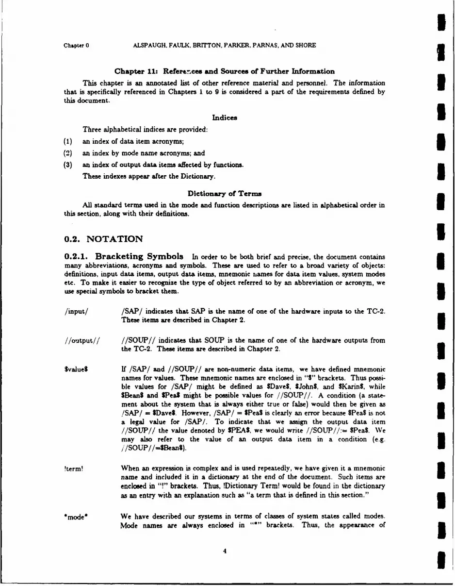
IChapter 0 ALSPAUGH. FAULK. BRITTON. PARKER, PARNAS, AND SHORE g
Chapter 11: References and Sources of Further Information
This chapter is an annotated list of other reference material and personnel. The information 3that is specifically referenced in Chapters 1 to 9 is considered a part of the requirements defined bythis document.
Indices 3Three alphabetical indices are provided:
(1) an index of data item acronyms; m
(2) an index by mode name acronyms; and
(3) an index of output data items affected by functions.
These indexes appear after the Dictionary.
Dictionary of Terms
this section, along with their definitions.
0.2. NOTATION I0.2.1. Bracketing Symbols In order to be both brief and precise, the document containsmany abbreviations, acronyms and symbols. These are used to refer to a broad variety of objects:definitions, input data item, output data items, mnemonic itames for data item values, system modesetc. To make it easier to recognize the type of object referred to by an abbreviation or acronym, weuse special symbols to bracket them.
/input/ /SAP/ indicates that SAP is the name of one of the hardware inputs to the TC-2.These items are described in Chapter 2.
//output// //SOUP// indicates that SOUP is the name of one of the hardware outputs fromthe TC-2. These items are described in Chapter 2. 1
Svalue$ If /SAP/ and //SOUP// are non-numeric data items, we have defined mnemonicnames for values. These mnemonic names are enclosed in "S" brackets. Thus possi-ble values for /SAP/ might be defined as SDaveS, $John$, and SKarin$, while ISBean$ and SPea$ might be possible values for //SOUP//. A condition (a state-ment about the system that is always either true or false) would then be given as/SAP/ff SDave$. However, /SAP/ = SPea$ is clearly an error because SPea$ is not Ia legal value for /SAP/. To indicate that we assign the output data item//SOUP// the value denoted by SPEAS, we would write //SOUP//:- SPea$. Wemay also refer to the value of an output data item in a condition (e.g.//SOUP//--SBean$).
!term! When an expression is complex and is used repeatedly, we have given it a mnemonicname and included it in a dictionary at the end of the document. Such items areenclosed in "!" brackets. Thus, !Dictionary Term! would be found in the dictionaryas an entry with an explanation such as "a term that is defined in this section." 3
*mode* We have described our systems in terms of classes of system states called modes.
Mode names are always enclosed in "" brackets. Thus, the appearance of 341
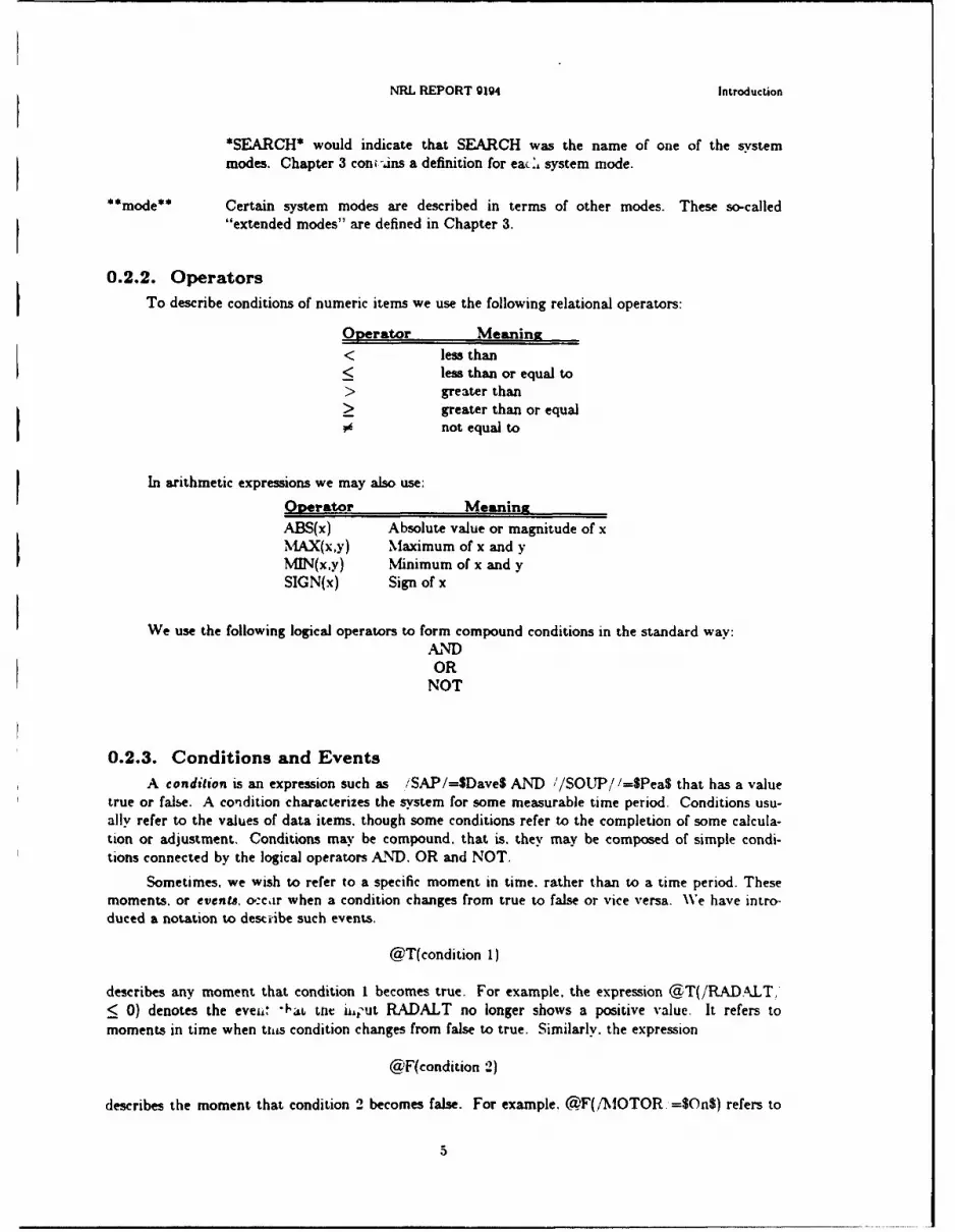
NRL REPORT 9194 Introduction
*SEARCH* would indicate that SEARCH was the name of one of the system
modes. Chapter 3 con -,ins a definition for eacz, system mode.
**mode** Certain system modes are described in terms of other modes. These so-called"extended modes" are defined in Chapter 3.
0.2.2. OperatorsTo describe conditions of numeric items we use the following relational operators:
Operator Meaning< less than< less than or equal to> greater than> greater than or equal0 not equal to
In arithmetic expressions we may also use:
Operator MeaningABS(x) Absolute value or magnitude of xMAX(x,y) Maximum of x and yMJN(x,y) Minimum of x and ySIGN(x) Sign of x
We use the following logical operators to form compound conditions in the standard way:ANDOR
NOT
0.2.3. Conditions and EventsA condition is an expression such as iSAP/=$Dave$ AND '/SOUP/ /=SPea$ that has a value
true or false. A condition characterizes the system for some measurable time period. Conditions usu-ally refer to the values of data items, though some conditions refer to the completion of some calcula-tion or adjustment. Conditions may be compound. that is. they may be composed of simple condi-tions connected by the logical operators AND. OR and NOT.
Sometimes, we wish to refer to a specific moment in time. rather than to a time period. Thesemoments, or events, o:cir when a condition changes from true to false or vice versa. We have intro-duced a notation to destiibe such events.
@T(condition 1)
describes any moment that condition I becomes true. For example, the expression @T(/RADALT,< 0) denotes the eveii" "'ab the ii, ut RADALT no longer shows a positive value. It refers tomoments in time when this condition changes from false to true. Similarly, the expression
@F(condition 2)
describes the moment that condition 2 becomes false. For example. (F(/MOTOR =$On$) refers to
.. ... ..

|I
Chapter 0 ALSPAUGH, FAULK, BRITTON, PARKER, PARNAS, AND SHORE 3the event of the condition /MOTOR/=$On$ changing :rom true to false. To describe an event inwhich one condition changes at a time when another is true we write m
@T(Condition 1) WHEN (Condition 2).
For example, @T(!Wheels Retracted!) WHEN (/RADALT/ = 0) refers to the event that the pilot 3retracted the wheels while at zero altitude. This event only occurs if he condition !Wheels Retracted!changes. For contrast consider @T(/RADALT/=O) WHEN (!Wheels Retracted!). The latter wouldrefer to events in which the value of /RADALT/ changes and the wheels are already retracted.* 3
Note the difference between
@T(Conditionl OR Condition2)and
@T(Conditionl) OR @T(Condition2)
The former event occurs when the disjunction of the two conditions becomes true. Note that the 3event does NOT occur when one condition becomes true if the other condition is already true. The
latter specifies a disjunction that is true whenever either event occurs.
0.3. TABLE FORMATSMuch of the information in Section 4 is presented in tables to make it easy to answer specific
questions. The table formats have been chosen to promote completeness and to achieve concisenessnot possible with straight text.
Each table defines some aspect of a function that varies depending on the current mode and con-ditions. Some tables specify when a function should be performed. For example, a table might showthat a light should be turned on in one mode when it is entered, and in another mode when a switchsetting changes. Some tables characterize the actual values that should be assigned to output dataitems. For example, . table might show that an output should be barometric altitude in some modes, Iand radar altitude in others. Finally, some tables define terms or conditions that are meaningful incharacterizations of output values. For example, an output value might be characterized as the dis-tance to some reference point. A table would then be given to define "reference point," which might
be the designated target in some modes under some conditions, and the offset aimpoint in others.
There are three types of tables used in this document: Selector tables, Condition tables andEvent tables. 30.3.1. Selector Tables
These tables are useful if the information is determined completely by an active mode. Selectortables have a row for each mode, or for each group of modes that give the same information. Therows must be mutually exclusive. The columns give the information appropriate f~r each mode. 3
* This notation theoretically calls for the evaluation of a condition simultaneously with the detection of an event. Sincethis is not possible in any real implementsuoa, we define the meaning of an expression such as @T(X) WHEN(Y) thus: Let tbe the time at which @T(X) is detected by the software. Then there is a time interval c such that if Y is true (raise) for all of It:- C, 1J, or for all of I, 1, + (I, or for all of it, - e, 1, + el, then the expression is (is not) considered to be satisfied. The
behavior of the system when Y is true for only a part of the interval is not defined: it may or may not behave as though the ex-pression were satisfied. Which interval we use as the requirement, as well as the value of ' is defined in the Accuracy chapter Ufor each such event.
6 I

INRL REPORT 9194 Introduction
Format:
Selector Table x: Description of ACT and BE
MODE //ACT / / //BE/V
*MODISH* $Vogue$ $Cool$
*LASTLNG* X SWarm$
Thus, in mode *MODISH*, i/ACT//:=SVogueS and //BE//:=$Coo$; in mode *LASTING*,//BE//:SWarmS. If an X appears as an entry in a selector table, it indicates that no statement isbeing made about the value of that variable in that mode.
1 0.3.2. Condition TablesCondition tables are used when the information is determined by the active mode and a set of
mutually exclusive conditions that occur in the mode. Condition tables are especially useful indescribing periodic functions. Each row in a condition table corresponds to a mode or group of modes.
In each row of the table, a set of conditions exists: one and only one condition should be true ata time. At the bottom of the column for each condition is the information appropriate for thatmode/condition pair. Thus to find the value for a given mode and given condition, first find the rowcorresponding to the mode, then within that row find the column corresponding to the condition, thenfollow the column to the bottom of the table to find the information. An "X" entry in a row of a con-
dition table means that the information at the bottom of the column is never appropriate for thatmode.
The conditions are the entries in the body of the table rather than the column headings becausethere are usually many more conditions than there are different values for the information presentedby the table, and because different conditions are applicable in different modes. To draw attention tothis inverted way of organizing a table, we put the values at the bottom, rather than at the top of the* table.
A benefit of this organization is that a row in a table completely describes the intervals within amode that are meaningful for that particular value. The conditions must be mutually exclusive andtogether they must describe the entire time that the program is within the mode. In addition, therows must also be mutually exclusive: the current mode must be unambiguously defined. Conditiontables therefore define precisely the time intervals when each value holds.
I7

UChapter 0 ALSPAUGH. FAULK, BRITTON, PARKER, PARNAS. AND SHORE 3
Format:
Condition Table x: Definition of !Point!
MODE CONDITIONS
*Mi* A B
*M2* C D 3*M3*
*M4* E F
!Point! Vi V2
In *M3*, when condition C holds, !Point! is VI. i
!Point! is also V1 in *MI* when condition A is satisfied, or in *M2* when condition C is satisfied, or in*M4* when condition E is satisfied. i
Whenever the system is in mode *Mi*, (A OR B) must be true and (A AND B) must be false. Ifthose conditions are met, we are guaranteed that the table defines !Point! completely in mode *M1*.Similar conditions apply to the other rows. 30.3.3. Event Tables
These tables are useful to characterize demand functions or to specify when periodic functions Ishould be performed. Each row in an event table corresponds to a mode or a group of modes. In eachrow, there is a set of events that causes the function to be performed in the mode(s). Usually, anevent table also specifies some action to be carried out, depending on the mode/event pair. Theevents are arranged so that each column in the table corresponds to a common action. Thus, to findthe action to be taken for a given mode and given event, first find the row corresponding to the mode.then within that row find the column corresponding to the event, then follow the column to the bot-tom of the table to find the action. An "X" entry means that action is never taken in the mode(s)listed on that row.
Two events appear so frequently that they are worth mentioning here: 3@T(n mode) \VHEN(condition A)
- the event that condition A is true when the mode is entered.
@F(In mode)
- occurrence of one of the events that causes exit from the mode. These exit events are listed inChapter 3.
If either of these events occurs on a row corresponding to more than one mode. they refer to theevent of entering or leaving the modes taken as a group. Thus, if *Mi* and *M2* occur on the samerow of an event table, and @T(In mode) appears as one of the events on that row, then leaving *MI*and entering *M2* does not count as an occurrence of that event (assuming no other mode transitions Itook place in the interim). I
I

NRL REPORT 9194 Introduction
Format:
Event Table x: When Zip is Turned On/Off
MODES EVENTS
*Mode2l* X @T(Condition B)
*Mode22* @F(Condition C) @T(In mode AND Condition D)*Mode23*
*Mode24* (&_F(In mode) ObTIln mode) WHEN (Condition E)
ACTION: Turn Zip On Turn Zip Off
In *Mode24*, the function is requested at mode entry if condition E is true, and the Zip is turned off.
It is also requested at mode exit, when Zip is turned on. Zip is never turned on in *Mode21*.
0.3.4. Mode TablesInformation about the mode transitions within a mode class is given via two types of tables; one
shows which mode the system will start in when initialized and one shows the possible mode transi-tions and the events associated with each possible transition.
0.3.4.0. Initial Modes Table
These tables show which mode of a class the system will be in when it is initialized, providedthere is more than one possibility. Subsequent behavior is determined by the transition events. InitialModes tables have a row for each candidate mode, with a set of defining conditions. If the conditionsare true at system initialization, the system will start in the corresponding mode. The rows must bemutually exclusive, and there may only be one mode per row.
Format:
MODES DEFINING CONDITIONS
*Model* A
*Mode2* BI0.3.4.1. Mode Transition tables
The Mode Transition tables describe the possible transitions between system modes. Each rowof the table describes an event that will cause a mode transition. To find the event(s) causing a transi-tion from a mode *A* to a mode *B*. first find the entry for *A* under the left column labeled"Current Mode." Then, in the *A* section of the table, find the row(s) with *B* in the righthandcolumn labeled "New Mode." Each row in that section describes an event causing a transition from.A* to *B*.
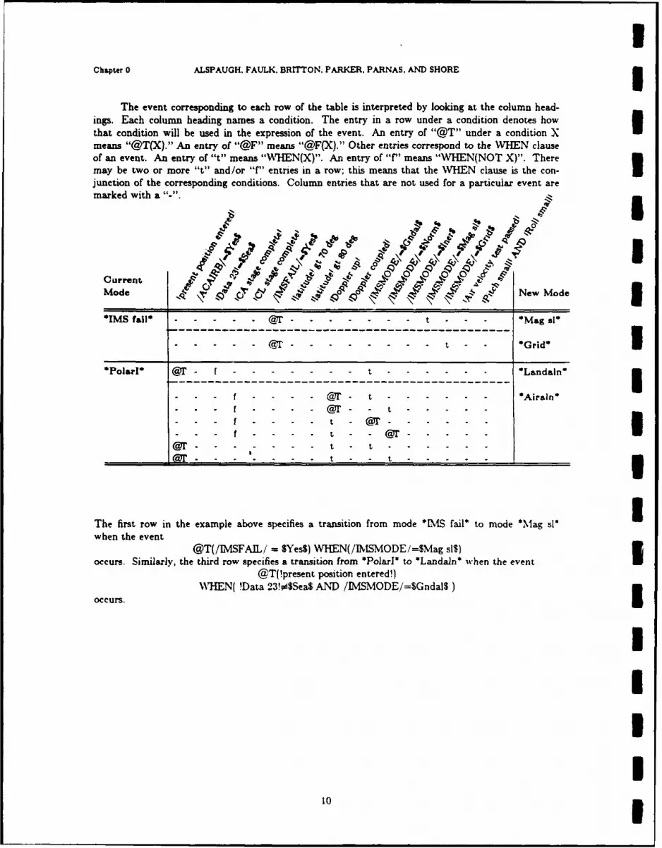
Chapter 0 ALSPAUGH. FAULK, BRITTON, PARKER, PARNAS, AND SHOREI
The event corresponding to each row of the table is interpreted by looking at the column head-ings. Each column heading names a condition. The entry in a row under a condition denotes how
that condition will be used in the expression of the event. An entry of "@T" under a condition Xmeans "@T(X)." An entry of "@F" means "@F(X)." Other entries correspond to the WHEN clauseof an event. An entry of "t" means "WHEN(X)". An entry of "f" means "WHEN(NOT X)". Theremay be two or more "t" and/or 'f" entries in a row; this means that the WHEN clause is the con-Ujunction of the corresponding conditions. Column entries that are not used for a particular event are
marked with a ..
oV 4 0
Current p.~~9 4OOMode ~ '4 '~~New Mode
OIMS fail*.......................................t - - - 'Kiag sl*
'PolaI' --- -f---------------------t---------------------------Lnan
-- ---- -- - -------------------------------- Ara'
f -- -- t - 3a= . . .. . t - - ____ ____I__I
The first row in the example above specifies a transition from mode *MAS fail* to mode 'Mlag si'when the event
@T(/IMSFAIL/ = $Yes$) WHEN(/IMlSMODE/=SMag AI)
occurs. Similarly, the third row specifies a transition from 'IPo[ar*' to *Landaln' when the event@T(!present position entered!)
WHTEN( !Data 23!0SSea$ AND /IM4SMODE/=$GndalS)
occurs.
10I

II
CHAPTER 1
I The TC-2 Computer
1.0. INTRODUCTIONThe A-7 software is required to run on the IBM 4PI TC-2 computer. This section provides an
introduction for those unfamiliar with the TC-2. A more complete description is given in references(18,20).
II.I. MEMORYThe organization of the TC-2 memory is given in the diagram below: all addresses there are
hexadecimal. Each memory location is 16 bits long. Three-quarters of the locations are protected, orread-only. Certain areas of memory may be used for special purposes. All of memory may beaddressed using base registers; the first one-sixteenth may also be addressed directly. Only the firstone-sixty-fourth, whose addresses may be expressed using just 8 bits, may be used by certain instruc-tions.
I Link registers 0-3Base registers 4-7
Short addressed O-FF Interrupt level 0 10-11
Interrupt level 1 12-13
Unprotected 0-FFF Direct addressed 0-3FF Registerstorage 100-IFFI Unprotected 0-FFF
Register addressed 0-3FFF First instruction 400
Cycle steal chains 600-7FF
IProtected 1000-3FFF
TC-2 MemoryI(All addresses given in hexadecimal notation)
11

Chapter I ALSPAUGH, FAULK, BRITTON. PARKER, PARNAS, AND SHORE
1.2. ACCUMULATORThe accumulator is in two parts, called the Areg and Qreg. The Areg is the accumulator for
single-precision instructions, and the Aeg and Qreg together are the accumulator for double-precision Uinstructions, with the Qreg acting as the low-order half of the accumulator. Most instructions takeone operand in memory and the other in the accumulator, and leave the result of the instruction in
the accumulator.
1.3. INDIRECT ADDRESSING 3Most instructions may address their memory operand either directly, if it is in the direct
addressed part of memory, or indirectly through a base register. An instruction using indirect address-ing names a base register containing a pointer and gives an offset in the range [0,255], the register andoffset together determining what location is addressed; if the pointer has value A and the offset is I.the location with address (A+I) is addressed. Note from the diagram that the base registers are them-selves memory locations, with addresses 4 through 7.
The accumulator load and store instructions, the arithmetic and logical instructions, and the C
(compare) and T (tally) instructions may address their data directly or indirectly. I1.4. DATA MOVEMENT, ARITHMETIC, AND LOGICAL INSTRUC-TIONS
The accumulator is loaded from and stored into memory by the LA, LD, STA. and STDinstructions. LD and STD are double precision. For double precision instructions, the memoryoperand is two consecutive locations, the first of which must have an even address. U
The arithmetic instructions provided are A, AD, S, SD, M, and D, for addition, subtraction,multiplication, and division. AD and SD are double precision. The minuend of subtraction instruc-tions is the accumulator operand. M takes single precision operands and leaves a double precisionresult in the accumulator; D takes a singlt precision divisor in memory and a double precision divi-
dend in the accumulator, and leaves a single precision result in the accumulator. All these instructionsuse two's complement representation. M and D assume the most significant bit represents 1/2.
The logical instructions are N (and), 0 (or), and X (exclusive or). 31.5. SHIFT INSTRUCTIONS
The shift instructions shift the Areg and Qreg as a unit. SLD (shift left double) shifts left, withO's shifted in at the right end of the Qreg. SRDA (shift right double arithmetic) and SRDL (shift rightdouble logical) shift right; SRDL shifts O's in at the left end of the Aeg, and SRDA shifts in whatevervalue the sign bit had before the instruction, the sign bit being the leftmost bit in the Areg. The 1number of bits shifted may be specified in two ways: (1) directly, by a number in the range [0,31 ; (2)indirectly, as the sum modulo 32 of such a number and the contents of a base register.
1.6. BRANCH INSTRUCTIONSBF and BB are unconditional branches forward and backward, respectively, up to 255 locations.
BFC and BBC are analogous conditional branches: possible conditions are that the Areg is positive.negative, or zero, or the negation of any of those three, or that the carry bit is set (see "The CPUStatus Word", below). BIA (branch indirect address) is an indirect branch, and B is an indirectbranch to a location 0 to 255 locations beyond the address given by a pointer. B requires a pointer in Ia base or link register, and BIA a pointer in short addressed memory.
I12 i

INRL REPORT 9194 The TC-2 Computer
Subroutine linkage may be done using BIAL (branch indirect and link). It is like BIA but addi-tionally places the current address in a base or link register, so that a return from the subroutine maybe done with a BIA or B using that pointer.
C (compare) is a three-way conditional branch; if the Areg is greater than. less than. or equal tothe contents of a location in memory, it branches to the next instruction, the second instruction fol-lowing, or the third instruction following, respectively.
T (tally) is an instruction for indexed loops. It increments the contents of a location in memory;if the result is zero, it branches to the second succeeding instruction, otherwise it continues to the nextinstruction.
1.7. OPERATIONS ON REGISTERSLR and STR load or store the contents of a register from or to the register storage area of
memory. MDR increments a register by a fixed offset in the range [1.2.551.
1.8. OPERATIONS ON THE ACCUMULATORZQ sets the to all exchanges the contents of the Meg and Qreg. SAZ storesZ s e s t e Q e t o a l z e r o e s . c o teX 7rg Q e .s o e
the contents of the Areg in the Qreg and sets the Areg to all zeroes. CA takes the two's or arithmeticcomplement of the Areg, and CL the one's or logical complement.I1.9. MISCELLANEOUS INSTRUCTIONS
NOP has no effect. STIC stores the current value of the instruction counter in a base or linkregister.
1.10. THE CPU STATUS WORDThe CPU status word is 16 bits long. Bits 2. 3, and 6 through 15 have no function. LSW and
STSW load or store the CPU status word from or to short address memory..
Bit 0 of the CPU status word is the carry bit of the TC-2. Its value is the carry from the signbit of the accumulator in an addition. raction. or an arithmetic complement (CA) instruction, orthe last bit shifted out of the sign bit by SLD. Synchronous I/O instructions set the carry bit to 1if an error is detected.
When bit 1 is changed to '1'. the TC-2 is put into a wait state, in which no instructions are exe-cuted until an unmasked interrupt occurs.
Bits 4 and 5 mask level 0 and 1 interrupts. respectively.
1.11. INTERRUPTSThe TC-2 has two levels of interrupts, level 0 and level 1: if two interrupts are simultaneous, the
level 0 is accepted first. When an interrupt occurs, a number of things occur if it is not masked:
(1) A bit that identifies the cause of the interrupt is set: these bits may be read with an I/0 com-mand (see "Synchronous L"O", below).
(2) The wait state bit in the CPU status word is cleared to 0.
(3) The current value of the instruction counter is saved at location 10 (level 0) or 12 (level 1) hexa-decimal.
13

UChaptcr 1 ALSPAUGH, FAULK. BRITTON. PARKER. PARNAS. AND SHORE
(4) The next instruction executed is the one whose address is given at location 11 (level 0) or 13(level 1) hexadecimal.
Masked interrupts remain pending until they are unmasked using the CPU status word.
1.12. BUILT-IN TEST EQUIPMENT AND THE DIAGNOSE IINSTRUCTION
Certain functions of the TC-2's built-in test equipment are controlled by the DIAGNOSE 3instruction:
(1) Output channels may be wrapped to input channels, to test that both are working.
(2) Interrupts and parity errors may be generated. 3(3) Output channels may be placed in or out of a fail-safe state. In this state all critical outputs are
forced to zeroes, and whatever data would otherwise be written to those channels is wrappedback to input channels.
The TC-2 is initially in this fail-safe state when powered up, and must be removed from it using
DIAGNOSE before any output on those channels can occur.
(4) Certain failure indicators can be set. 3The built-in test equipment also has functions that are independent of the DIAGNOSE instruc-
tion, including hardware that detects attempts to store into protected memory, and a hardware"GO/NO-GO" timer that, if not reset frequently (see "Synchronous I/0", below), generates an inter-rupt and sets failure indicators.
1.13. POWER-ON AND RESET IWhen the computer is turned on or manually reset, the first instruction executed is the one at
location 400 hexadecimal. 31.14. ASYNCHRONOUS I/O
The TC-2 has three cycle steal channels over which data is transmitted asynchronously; the 3three channels are identified as A, B, and C. Data sent over each channel is obtained from a linkedlist of locations called a cycle steal chain. These chains reside in the cycle steal area of memory; eachchain consists of a list of pairs of adjacent locations, the first of which identifies the pair's datum (bygiving its "word identity code") and points to the next pair in the chain, and the second of which con-tains the datum. For normal operation, the chains are circular, with a dummy head pair and the lastpair in the chain pointing back to the second pair. Each of the three channels has its own chain, st? t-ing at a fixed location.
Once the chains are set up, data is transmitted essentially continuously while the TC-2 is not ina wait state. Transmission over a particular channel may be stopped by linking the last pair in itschain to the dummy head pair. I1.15. SYNCHRONOUS I/O
The TC-2 has eight synchronous I/O channels (0 through 7), each of which may have several
devices attached. A particular device is indicated by a numeric code combining a channel code and adevice code. The READ and WRITE instructions transfer data from a device to the Areg and vice
versa. READM (modified read) sends control commands to a device to prepare it for a READ; it is
only used for I/O channel 3.
I14 I
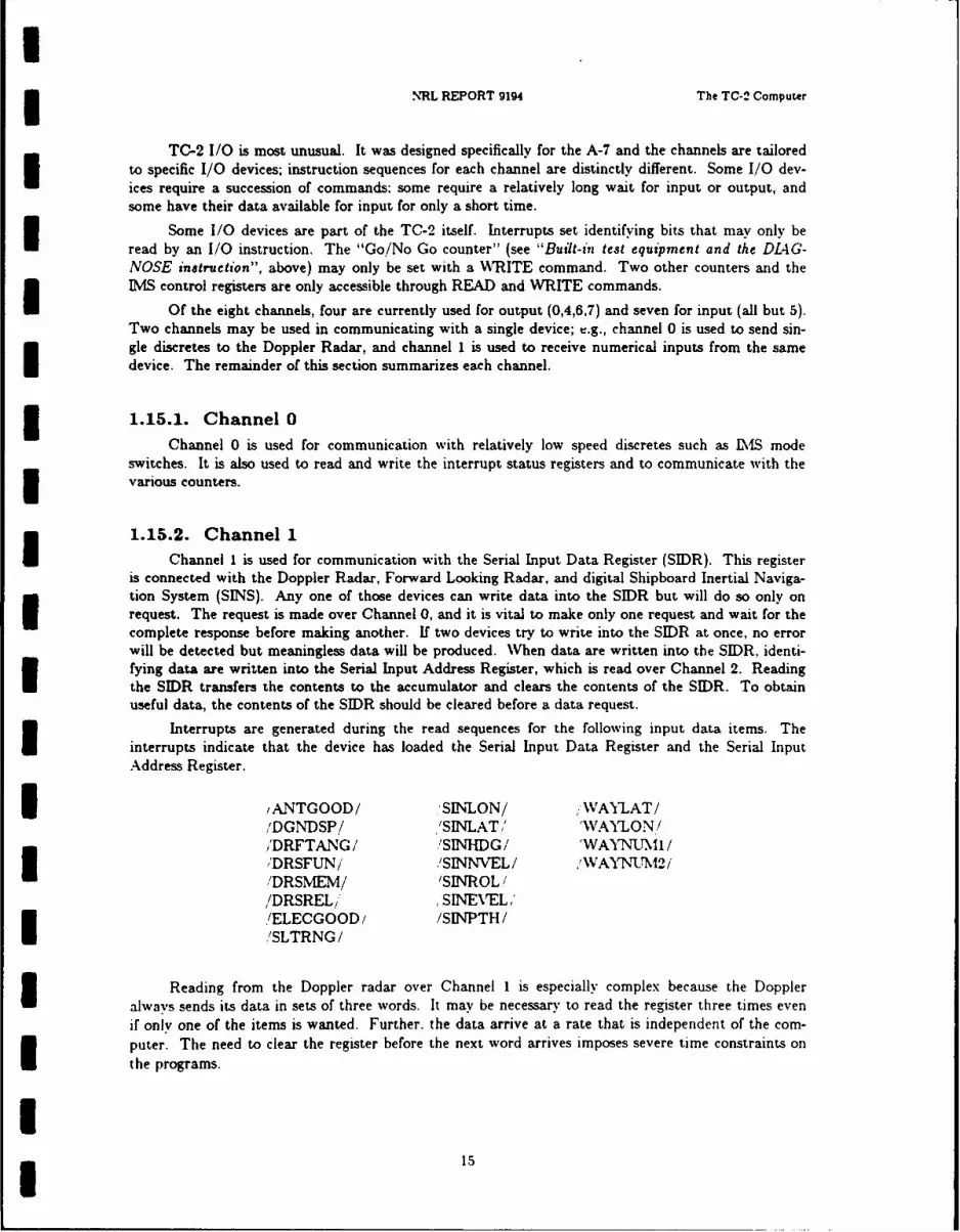
INRL REPORT 9194 The TC-2 Computer
TC-2 I/O is most unusual. It was designed specifically for the A-7 and the channels are tailoredto specific I/O devices; instruction sequences for each channel are distinctly different. Some I/O dev-ices require a succession of commands; some require a relatively long wait for input or output, andsome have their data available for input for only a short time.
Some I/O devices are part of the TC-2 itself. Interrupts set identifying bits that may only beread by an I/O instruction. The "Go/No Go counter" (see "Built-in test equipment and the DL4G-NOSE instruction", above) may only be set with a WRITE command. Two other counters and theIMS control registers are only accessible through READ and WRITE commands.
Of the eight channels, four are currently used for output (0,4,6,7) and seven for input (all but 5).Two channels may be used in communicating with a single device; e.g., channel 0 is used to send sin-gle discretes to the Doppler Radar, and channel 1 is used to receive numerical inputs from the samedevice. The remainder of this section summarizes each channel.
1 1.15.1. Channel 0Channel 0 is used for communication with relatively low speed discretes such as LMS mode
switches. It is also used to read and write the interrupt status registers and to communicate with the* various counters.
1.15.2. Channel 1
Channel 1 is used for communication with the Serial Input Data Register (SIDR). This registeris connected with the Doppler Radar, Forward Looking Radar, and digital Shipboard Inertial Naviga-tion System (SINS). Any one of those devices can write data into the SIDR but will do so only onrequest. The request is made over Channel 0, and it is vital to make only one request and wait for thecomplete response before making another. If two devices try to write into the SIDR at once, no error
will be detected but meaningless data will be produced. When data are written into the SIDR, identi-fying data are written into the Serial Input Address Register, which is read over Channel 2. Readingthe SIDR transfers the contents to the accumulator and clears the contents of the SIDR. To obtainuseful data, the contents of the SIDR should be cleared before a data request.
Interrupts are generated during the read sequences for the following input data items. Theinterrupts indicate that the device has loaded the Serial Input Data Register and the Serial InputAddress Register.
I /ANTGOOD/ SINLON/ WAYLAT/,'DGNDSP/ 'SINLAT,' 'WAYLON!/'DRFTANG/ 'SINHDG/ 'WAYNUMI/
/DRSFUN/ /SINNVEL,'DRSMEM/ 'SINROL//DRSRELi SINEVEL,''/ELECGOOD / /SINPTH /'SLTRNG/
Reading from the Doppler radar over Channel 1 is especially complex because the Doppleralways sends its data in sets of three words. It may be necessary to read the register three times evenif only one of the items is wanted. Further. the data arrive at a rate that is independent of the com-puter. The need to clear the register before the next word arrives imposes severe time constraints onthe programs.
I

IChapter I ALSPAUGH, FAULK, BRITTON, PARKER, PARNAS, AND SHORE
1.15.3. Channel 2Channel 2 is used for communication with the Serial Input Address Register (SIAR). The SIAR
contains bits that identify the source of the data in the Serial Input Data Register. Unfortunately, theaddress bits do not unambiguously identify the data source; to determine the source, one must also useinformation about the most recent request made over Channel 0. 3
Bit 0: Data Valid Set to 1 when SIDR contains a valid data word.Bit 1: Data Parity Set to 1 hen the Data Word in the SIDR has passed
the hardN, re parity test. IBit 2: Address Parity Set to 1 when the address word in the SIAR has
passed the hardware parity test.Bit 7: Serial Input Set to 1 after a serial input has been requested
in Progress and data transmission not yet complete.Bits 10-14: Identity This field contains the address code for identifying
the source of the SIDR word. 31.15.4. Channel 3
Channel 3 is used for communication with the TACAN receiver. It requires a READM and aREAD command.
1.15.5. Channel 4 i
Channel 4 is used for the IMS torque and accelerometer registers.
Dealing with the torque registers is difficult for two reasons. First, there is never a zero torque $on the IMS. One must alternate between positive and negative torques to maintain the IMS in itspresent state. Second, one must be aware of the values in the torque counters before setting newvalues. These values change periodically. If the count is about to change, it is necessary to wait Ubefore sending data to the counters. A Channel 0 input bit /DIMWC/ warns of this possibility andmust be checked before changing the torque counters.
Each READ of an accelerometer register clears it. 31.15.6. Channel 5
Channel 5 is intended for Loran communication. Channel 5 is not used presently.
1.15.7. Channel 6 3Channel 6 is devoted to communication with the TC-2 panel. Pushing a digit, I-YBD,
MARK, or ENTER button generates an interrupt signal and sets a bit to indicate which button hasbeen pushed. A bit will be I for each button that has been pushed since the last time the bits were Iread. The bits are cleared when read. Response is time critical although the time periods involvedare relatively long. Delays in reading can result in missing a Panel Interrupt. There can be ambiguityabout the sequence in which buttons were pushed if two buttons have been pushed since the last timethat the interrupt was serviced.
1I16 I
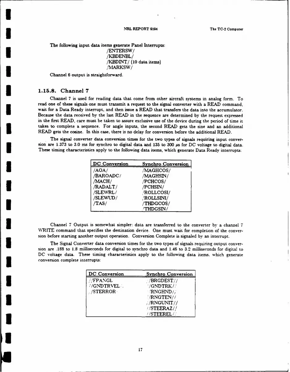
INRL REPORT 9194 The TC-2 Computer
The following input data items generate Panel Interrupts:/ENTERSW//KBDENBL//KBDINT/ (10 data items)/A RKSW/
Channel 6 output is straightforward.
1.15.8. Channel 7Channel 7 is used for reading data that come from other aircraft systems in analog form. To
read one of these signals one must transmit a request to the signal converter with a READ command,wait for a Data Ready interrupt, and then issue a READ that transfers the data into the accumulator.Because the data received by the last READ in the sequence are determined by the request expressedin the first READ, care must be taken to assure exclusive use of the device during the period of time ittakes to complete a sequence. For angle inputs, the second READ gets the sine and an additionalREAD gets the cosine. In this case, there is no delay for conversion before the additional READ.
The signal converter data conversion times for the two types of signals requiring input conver-sion are 1.373 to 3.0 ms for synchro to digital data and 135 to 300 ps for DC voltage to digital data.These timing characteristics apply to the following data items, which generate Data Ready interrupts:
DC Conversion S3nchro Conversion
/AOA/ /MAGHCOS//BAROADC/ /MAGHSIN//MACH/ /PCHCOS//RADALT/ /PCHSIN//SLEVRL / /ROLLCOSI//SLE WUD/ 'ROLLSINI//TAS/ /THDGCOS/
'THDGSIN/
3 Channel 7 Output is somewhat simpler: data are transferred to the converter by a channel 7W\RITE command that specifies the destination device. One must wait for completion of the conver-sion before starting another output operation. Conversion Complete is signaled by an interrupt.5 The Signal Converter data conversion times for the two types of signals requiring output conver-sion are .188 to 1.8 milliseconds for digital to synchro data and 1.46 to 3.2 milliseconds for digital toDC voltage data. These timing characteristics apply to the following data items. which generate3 conversion complete interrupts:
DC Conversion Synchro Conversion,I'/FPANGL /BRGDEST///GNDTRVEL, '/GNDTRK/,.'/STERROR 'RNGHND' 1
'/RNGTEN//'/RNGUNIT////STEERAZ///STEEREL /
17
II
CHAPTER 2 IInput and Output Data Items
II
2.0. INTRODUCTION 3This chapter describes the individual data items communicated between the TC-2 and other
devices in the aircraft. There is a separate subsection for each hardware device. Within each subsec-tion, input items precede output items. The data items are alphabetized within each category. 3
Provided for each data item are (a) a standard acronym enclosed in brackets (/input/ and//output//) to be used throughout the document and during system development; (b) a verbaldescription of its significance or meaning in terms of the device with which it is associated; (c) charac-teristics of each numerical data item, such as range, accuracy or mnemonic names enclosed in brackets($value$) for the possible values of each non-numerical data item; (d) the format of the data represen-tation; and (e) the TC-2 instruction sequence that must be executed in order to read the item in ortransmit it to the external device. For numerical data items, the range gives the maximum and Iminimum values encountered in actual use. This may be smaller than the range of values that can berepresented. Where such information is available and meaningful, the document describes any timingrestrictions that must be observed. 32.0.1. Accumulator as Default Data Item Location
An input data item is always located in the accumulator after an input instruction sequence.Except for cycle-steal outputs, an output instruction starts with the output value in the accumulator.
2.0.2. Value RepresentationsBoth the verbal description and the list of value characteristics refer to the data items using
"standard" units, such as degrees. knots, or Mach number. Ve shall refer to the units in the I/O representation as "indicated" units. For most numerical data items. values in standard and indicatedunits are related by a multiplicative scale factor and an additive offset factor as follows:
indicated = scale X (standard + offset) (output conversion) Istandard = (indicated / scale) - offset (input conversion) 3
where "indicated" is the value in indicated units. "standard" is the value in standard units, "scale" isthe scale factor, and "offset" is the offset factor in standard units. The scale factor is to be interpretedas a quantity in "indicated/standard" units, and the offset in standard units. In each case, we will Idefine the data representation by stating the bit field covered by the indicated value, stating whetherthese fields are to be interpreted as positive, two's complement, or signed-magnitude quantities, and
18
NRL REPORT gg4 Introduction
stating values for scale and offset. In all cases, the least significant bit of a numerical bit field is thehighest-numbered (rightmost) bit, and that bit represents one indicated unit.
In some cases, the exact scale factor for an input data item is not known, but an approximatevalue of 1/scale is available. In these cases, we will give the approximate value for 1/scale using thesymbol :-: to mean "approximately equals."
For example, the indicated representation of the Doppler Drift Angle input data item./DRFTANG/, is a 14 bit positive count with scale - 175 and offset = 9375/175. The standard unitsof /DRFTANG/ are degrees. Thus, an indicated value of 9375 corresponds to 0", and a value of 9200corresponds to -1 *.
Many of the data items are described in terms of particular units of measurement, such asdegrees, feet/second, or knots. It should be clear that by altering the scale (and offset) the data itemscould be described in different units. The units used here were chosen for convenience in writing thisdocument. The implementor of programs using these data items should alter the scale to produce thevalues in the appropriate units.
2.0.3. Coordinate SystemsThe description of the input and output data items will often refer to three coordinate systems:
(1) the airframe coordinate system,(2) the IMS platform coordinate system, and(3) the SINS coordinate system.
All three coordinate systems are right-handed systems.
The airframe coordinate system has axes Xa, Ya, and Za. The Ya axis lies along the A/Cboresight line with the positive direction being forward (toward nose, from tail). The A/C boresightline is 3 below A/C waterline - see Ref. 15a, p. 1-4-4. The Xa axis points out in the direction of theright wing and is defined so that the Xa - Ya plane is horizontal and the Za axis point upward whenthe A/C wings are level and the A/C is not inverted.
The Inertial Measurement Set (EMS) platform coordinate system has axes Xp, Yp, and Zp.These are often referred to as East, North, and Up (away from the center of the earth), respectively,because in normal operation the OFP attempts to align them in these directions. Note that when theA/C is flying north and level and the platform is aligned, Ya aligns with Yp, Xa aligns with Xp, andZa aligns with Zp.
The Shipboard Inertial Navigation System (SINS) coordinate system has axes Xs. Ys, and Zs.
The Ys axis is toward the forward end of the ship, the Xs axis is to the starboard side of the ship, andthe Zs axis is vertical anid points upward.
2.0.4. Definition of Data Item ClassesSome instruction sequences, particularly those that read and write single-bit discretes. affect
more than one data item. For example. .'/BMBTON//, 'FIRRDY//, / /BMBREL/,./CURENABL//, and //ANTSLAVE// are all written by the same TC-2 instruction. This intro-
duces dependencies between data items: when writing one data item. it is important to know whichother data items will also be affected.
To provide this information. we have defined classes of data items. one class for each instructionsequence that affects more than one data item. The names of the classes, along with their acronyms.and the class members are listed in Section 2.5. each class name followed by the acronyms for the dataitems it affects. The class acronym, if any, is given in the data item description. A data item ma'belong to more than one class if it is affected by more than one instruction sequence.
19

Chapter 2 ALSPAUGH. FAULK, BRITTON, PARKER, PARNAS, AND SHORE
2.0.5. Data Items for More than One DeviceIf a sinle output data item is sent to more than one device, there will be a descriptions of the
data item included for each device to which it is sent. The main description, including data represen-tation, instruction sequence, etc. appears in only one place. The other descriptions explain how thedata item affects that particular device, and refers to the section that contains the main description.
2.0.6. Data Items That Affect Signal Converter Tests
The following data items affect the values read in for /DCTEST/. After the WRITE instruc- Ition for these data items, if the conversion complete interrupt does not occur within 280 psec, ahardware error is indicated.
//STERROR//,//FPANGL//
//GNDTRVEL//
The following data items affect the values read in for /ACTESTCOS/ and /ACTESTSIN/. IAfter the WRITE instruction for these data items, if the conversion -omplete interrupt does not occurwithin 3.2 msec, a hardware error is indicated.
//RNGUNIT// /'/RNGTEN////RNGHND// //ANTSLAVE//,/STEERAZ// //GNDTRK////STEEREL// !/BRGDEST//
//SPAREI// //SPARE2// 3
IIIIIIII
20 I
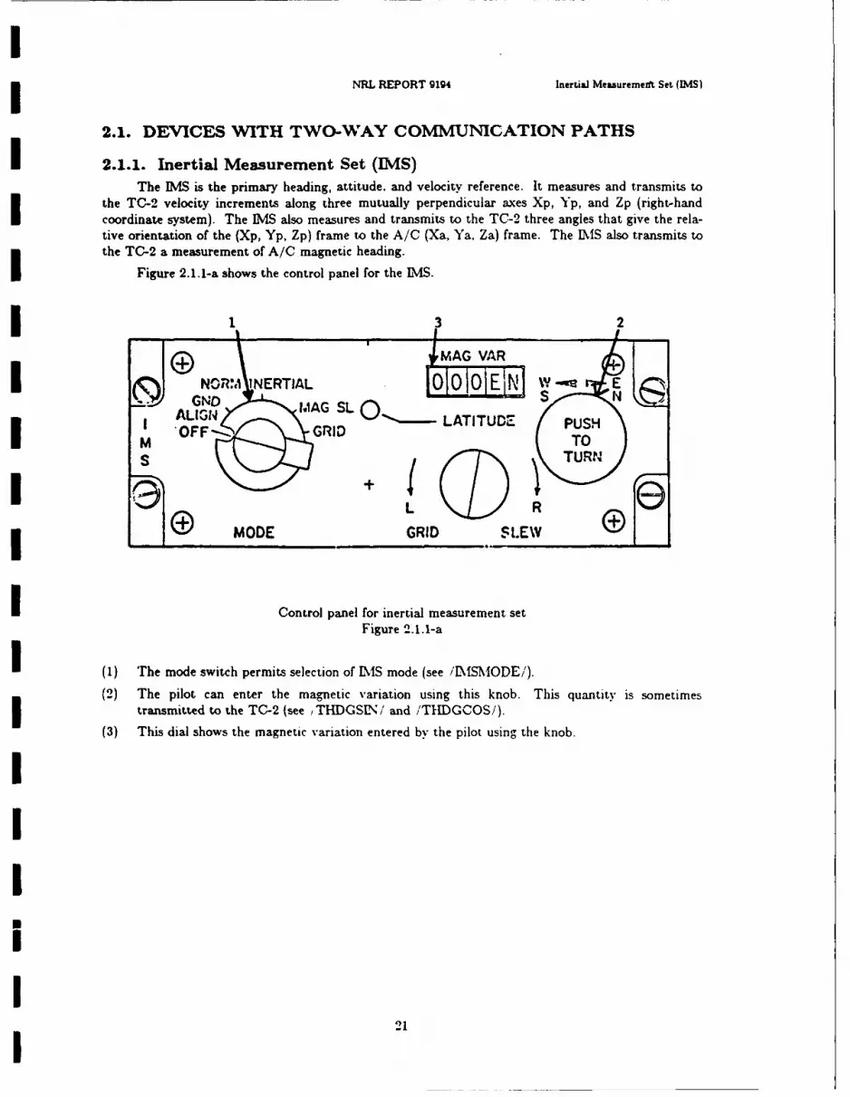
NRL REPORT 914 Inertial Measuremeift Set (MS)
2.1. DEVICES WITH TWO-WAY COMMUNICATION PATHS
2.1.1. Inertial Measurement Set (IMS)The IMS is the primary heading, attitude, and velocity reference. It measures and transmits to
the TC-2 velocity increments along three mutually perpendicular axes Xp, Yp, and Zp (right-handcoordinate system). The IMS also measures and transmits to the TC-2 three angles that give the rela-tive orientation of the (Xp, Yp, Zp) frame to the A/C (Xa, Ya, Za) frame. The IWS also transmits tothe TC-2 a measurement of A/C magnetic heading.
Figure 2.1.1-a shows the control panel for the LMS.
1 3 2
G WMA G VA RN071. INERTIAL OQO10EN I W- E
G.~ GNO MAG SLS-ALIGN 0 LATITUDZ PUSHOFF--- GRID T
I ( N\ TURN"4
IMODE GRID SLEW
I Control panel for inertial measurement setFigure 2.1.1-a
I (i) The mode switch permits selection of IS mode (see i'IMSMODE/).(2) The pilot can enter the magnetic variation using this knob. This quantity is sometimesI transmitted to the TC-2 (see ,THDGSIN/ and 'THDGCOS/).
(3) This dial shows the magnetic variation entered by the pilot using the knob.
2I
21

1Chapter 2 ALSPAUGH. FAULK. BRITTON, PARKER, PARNAS. AND SHORE
2.1.1.1. Diminishing wait count
Input data item(s): Diminishing Wait Count IClass: DIW5
Acronym: /DIMWC/
Hardware: Inertial Measurement Set (Physically in the TC-2 but associated with IMS)
Description: /DIMWC/ indicates whether or not a change in the torque counters is imminent. See//XGYCOM//, //YGYCOM//, //ZGYCOMI/ for more information.
Characteristics of values:
Value encoding: $Ready$ (0); $Changing$ (1)
Instruction sequence: READ 24 (Channel 0)
Data representation: Discrete input word 5, bit 14
Timing characteristics:
@T(/DIMWC/ = $Changing$) occurs once every 5 ms. approximately 200-300 microsecondsbefore changes of the IMS torque counters.
@T(/DIMWC/ = SReady$) occurs several nanoseconds after changes of the IMS torquecounters.
IIIIII
IUII
INRL REPORT 9194 Inertial Measurement Set (IMSJ
2.1.1.2. Gyro torque counters (residual inputs)Input data item(s): X, Y, and Z Axis Gyro Torque CountersAcronym: /XGYCNT/ /YGYCNT/ /ZGYCNT/I Hardware: Inertial Measurement Set (Physically in the TC-2, but associated exclusively with the
Description: /XGYCNT/, /YGYCNT/, and /ZGYCNT/ indicate the current value of the two leastI significant two bits of the corresponding torque counters. See ,/XGYCOM//, ,',YGYCOMI//, and/ZGYCQM// for more information.
Characteristics of values:I Value encoding:Value Bit reresentation Toraue counter bits
WM 10 00I BS 11 01SOS 00 10SDS 01 11
Instruction sequence: READ # (Channel 4) (valid only if /DIMWC/ = $Ready$)
# = 144 for XAxis#= 136 for YAxis
#= 152 for Z AxisData representation: Bits 13-14
Timing characteristics: See /DIWC/ and //XGYCOM//, //YGYCOM//, ///ZGYCOM.k//
Comments: When the torque counter is toggling (see //XGYCONI//, etc.), the values SASk and $D$will be read when the torque counter values are 0 and -1 respectively.
I2

Chapter 2 ALSPAUGH, FAULK, BRITTON, PARKER, PARNAS. AND SHORE
2.1.1.9. IMS AUTO/CAL mode
input data item(s): IMS AUTO /CAL ModeI
Class: DIW5
Acronym: /IMSAUTOC/
Hardware: Inertial Measurement Set
Description: /IMSAUTOC/ indicates the position of a momentary pushbutton on Adaptor/Power
Supply in Avionics Bay)ICharacteristics of values:
Value encoding: $Off$ (0); W0n (1)
Instruction sequence: READ 24 (Channel 0)Data representation: Discrete input word 5, bit 9
Timing characteristics: When the button is pushed, (/IMSAUTOC/ $ On$) is known to be truefor at least 40 mns.
24I

3NRL REPORT 9194 Inertial Measurement Set IS)
2.1.1.4. IMS mode swidtch
Input data item(s): IMS Mode Switch
Claws: DIW5I Acronym: /IMSMODE/Hardware: Inertial Measurement Set
Description: /ISMODE/ indicates the position of a six-position rotary switch on the IM1S controlpanel. This switch determines the IMS's mode of operations. as described in Ref. 33a. §3.4.1.5.Switch nomenclature: OFF; GND ALIGN; NORM; INERTIAL; MAG SL; GRID
Characteristics of values:
Value encoding:
SOffnone$ (00000) Occurs when the switch is off or between two positions.SGndal$ (10000)$Norm$ (01000)$InerS (00100)$Grid$ (00010)
SMagslS (00001)
Instruction sequence: READ 24 (Channel 0)
Data representation: Discrete input word 5, bits 3-7
I2

IChapter 2 ALSPAUGH, FAULK. BRITTON, PARKER, PARNAS. AND SHORE
2.1.1.5. IMS system ready
Input data item(s): IMS System Ready IClas: DIW5
Acronym: /IMSREDY/
Hardware: Inertial Measurement Set
Description: /IMSREDY/ indicates whether or not the IMS has completed its self-controlled align-ment sequence and is ready for operation under TC-2 control.
Characteristics of values:
Value encoding: SYes$ (0); $No$ (1)
Instruction sequence: READ 24 (channel 0)
Data representation: Discrete input word 5, bit 8
II
IUUIIIII
26 I
II NRL REPORT 9194 Inertial Measurement Set (DIS)
2.1.1.6. IMS system reliable
Input data item(s): IMS System Reliable
Clas: DIW5
Acronym: /IMSREL/
Hardware: Inertial Measurement Set
Description: /IMSREL/ indicates whether or not the IMS is reliable based on a hardware self-checkinternal to the IMS. /IMSREL/ cannot be $Yes$ if /IMSREDY/ is not SYes$.
Characteristics of values:
j Value encoding: No (0); $Yes$ (1)
Instruction sequence: READ 24 (Channel 0)
Data representation: Discrete input word 5. bit 0
IIIII
I
I 27

IChapter 2 ALSPAUGH, FAULK. BRITTON, PARKER, PARNAS, AND SHORE
2.1.1.7. MS incremental velocities
Input data item(s): Incremental Velocities (Accelerometer Pulses) IAcronym: /XVEL/ /YVEL/ /ZVEL/
Hardware: Inertial Measurement Set
Description: /XVEL/, /YVEL/, /ZVEL/ are incremental velocities along the Xp, Yp, and Zp axes.The values are sums of the positi, e and negative pulses received from the corresponding accelerometersince the last completed read of the corresponding counter. Each count must be multiplied by thescale factor corresponding to the value of //IMSSCAL// to obtain the corresponding incremental velo-city.
/XVEL/ is positive in the positive Xp direction;/YVEL/ is positive in the positive Yp direction;/ZVEL/ is positive in the negative Zp direction.
After @T(//COMPCTR// = SOffS), these data items are not updated by the IMS. Hence. /XVEL/./YVEL/, and /ZVEL/ remain 0 after they are read.
Characteristics of values:
Units: fps IRange: varies based on particular IMS and scale.
Max for coarse: -19.456 to 19.418.Max for fine: -. 19456 to .19418.
Maximum derivative: varies per IMS
Max for coarse: 380 fps2 3Max for fine: 3.8 fps 2
Instruction sequence: READ * (Channel 4) valid only if //COMPCTR//ff SOnS• 129 for Xp Axis
• = 130 for Yp Axis
• 132 for Zp Axis 3Data representation: 10-bit two's complement number, bits 6-15; scale = !inc vel scale!: offset -!acc bias!. (See //IMSSCAL// for scale factors to calculate incremental velocities.)
2IIII
28 I

NRL REPORT 9194 Inertial Measurement Set ILMS)
2.1.1.8. IMS attitudes
Input data item(s):
Input data items: Acronyms:Magnetic Heading - Cosine "MAGHCOS/Magnetic Heading - Sine 'MAGHSIN!Pitch Angle - Cosine !PCHCOS/Pitch Angle - Sine /PCHSEIN/Roll Angle - IMS - Cosine /ROLLCOSI/Roll Angle - WMS - Sine /ROLLSINI/True Heading - Cosine /THDGCOS/True Heading - Sine /'THDGSIN/
Hardware: Inertial Measurement Set
Description:
/THDGCOS/, /THDGSIN/: When (/IMSREL/ = $Yes$ AND /[MSREDY/= $'Yes$). theangle determined by /THDGCOSi and iTHDGSIN/ is the angle measured clockwise in theXp-Yp plane (looking in the -Zp direction: i.e., down) from the Yp axis to the projection into theXp-Yp plane of the Ya axis. When iIMSREL/ = $No$), the angle determined by /THDGCOS/and /THDGSIN/ is the magnetic variation input by pilot to the IMS panel (see Fig. 2.1.1-a).
/ROLLCOSI/, /ROLLSINI/: The angle determined by these data items is thus: Let Yapbe the projection of the Ya axis into the Xp-Yp plane. Let Xap be a ray in the Xp-Yp planethat is perpendicular to Yap and that extends to the right (when viewed looking at the Xp-Ypplane in the Yap direction) of Yap. Then the angle is measured from the Xap ray to the Xaaxis. The angle is positive when the positive Xa axis is below the Xp-Yp plane (negative Zpcomponent) and negative otherwise.
/PCHCOS/, /PCHSIN/: The angle determined by these data items is the angle betweenthe Ya axis and its projection into the Xp-Yp plane. The angle is negative when the positive Yaaxis is below the Xp-Yp plane (negative Zp component) and positive otherwise.
/MAGHCOS/, /MAGHSIN/: The angle determined by these data items is the magneticheading of the aircraft. The magnetic heading is the angle measured C\V from magnetic north(looking down) to the horizontal component of the Ya axis.
Pitch: The pitch angle output is limited to a range of -90 to +90" If the A C pitches upthrough 90" then its pitch will start back down toward 0'. but its roll will shift by 180' whenthe pitch crosses 90'.
Characteristics of values:
Units: None
Range: -1 to +1
Resolution: 1 '4096
Angular Accuracy:
Magnetic Heading: ±0.25Pitch Angle: ±0.1"Roll Angle: ±0.1True Heading: ±0.1
Maximum derivative:
Roll: 300 degis;
29

UChapter 2 ALSPAUGH, FAULK. BRITTON, PARKER, PARNAS, AND SHORE
Pitch: 60 deg/s;Heading 200 deg/s 3
Maximum second derivative:
Roll: 1500 deg/s 2;Pitch: 200 deg/s 2; IHeading: 200 deg/s 2
Instruction sequence:
READ 255 (Channel 7) (Reset Signal Converter if not already done)READ * (Channel 7) (Request Signal Converter to start conversion)Test Carry Indicator for 0 - Request acknowledged. 3If not, try againWhen DATA READY interrupt occurs, conversion completeREAD 225 (Channel 7) (SIN)Save Accumulator value IREAD 255 (Channel 7) (COS) (Also resets Signal Converter)
where * is replaced by
228 for Magnetic Heading225 for Pitch Angle226 for Roll Angle227 for True Heading I
Data representation: K X SIN(A) and K x COS(A) (relative SIN and COS), where K depends ontemperature and other conditions (see comments), and A is the angle for Pitch, Roll and True H-ead-ing, and the angle minus 180' for Magnetic Heading.
13 bit two's complement number, bits 0-12; bits 13-15 - 0. Scale - 4096; offset - 0.
Timing characteristies: Sychro (analog) to digital conversion (see §1.15.8). IComments: If the Xp axis and Yp axis are aligned with (true) East, and North respectively, then/THDGCOS/ and /THDGSIN/ determine true A/C heading. If the Zp axis is aligned with vertical(Z positive in the Up direction), then /ROLLCOSI/ and /ROLLSINI/ determine A/C roll angle and I/PCHCOS/ and /PCHSIN/ determine A/C pitch. Roll is positive when the right wing is down andpitch is positive when the nose is up.
The factor K, which is close to 1, is introduced by the synchro converter. Techniques to recover A Ifrom K x SIN(A) and K x COS(A) for small angles A are discussed in Ref. 6, §2.
The scale is given assuming K - 1. 1IIII
30 I

NRL REPORT g194 Inertial Measurement Set (MItS)
2.1.1.9. AUTO/CAL light
Output data item(s): AUTO/CAL Light
Class: DOW23 Acronym: //AUTOCAL//Hardware: Inertial Measurement Set
Description: //AUTOCAL // = $On$ turns on the AUTO /CAL light on the IMS Adapter/PowerU Supply in the left hand avionics bay.Characteristics of values:
Value encoding: $On$ (0); $00f (1)
Instruction sequence: WRITE 4 (Channel 0)
Data representation: Discrete output word 2. bit 03 Comments: The light is in the pushbutton (see /IMlSAUTOC/)
I3

IChapter 2 ALSPAUGH. FAULK. BRITTON. PARKER. PARNAS. AND SHCRE
2.1.1.10. Computer control
Output data item(s): Computer Control i
Clas: DOW2Acronym: //COMPCTR// 3Hardware: Inertial Measurement SetDescription: //COMPCTR// = SOnS commands the IMS to accept TC-2 control (see//XGYCOM//, //XSLEW//, etc.) and to update accelerometer pulses (see /XVEL/, /YVEL/,/ZVEL/).
Characteristics of values:
Value encoding: SOfS (0); SOnS (1)Instruction sequence: WRITE 4 (Channel 0)Data representation: Discrete output word 2, bit 13 1
IIIIIIIIIII
32
NRL REPORT 9194 Inertial Meaaurement Set (IMS)
2.1.1.11. Computer system fail
Output data item(s): Computer System Fail
Clas: DOW2
Acronym: //COMPFAIL//
Hardware: Inertial Measurement SetDescription: //COMPFAIL// = $Yes$ commands the LMS to revert to either Magnetic Slave orGrid mode depending on the most recent value of i/LATGT70/ i. See Ref. 33a. §3.4.1.5 for kIMS modedefinitions. //COMPFAIL// is output also to the FLR. the ADI. and the Caution and AdvisoryPanel; see those sections for the effects on those devices. Turned on by hardware whenever @T(!In-time test failed!) occurs, or when certain other hardware or BITE tests fail. See Ref. 19, §3.17. Set-ting //COMPFAIL//=$No$ reverses the effects of setting it to $Yes$. unless one of the hardware-detected anomalies still exists. In that case. the assignment has no effect.
Characteristics of values:
Value encoding: $No$ (0): $Yes$ (1)
Instruction sequence: WRITE 4 (Channel 0)Data representation: Discrete output word 2, bit 10
33
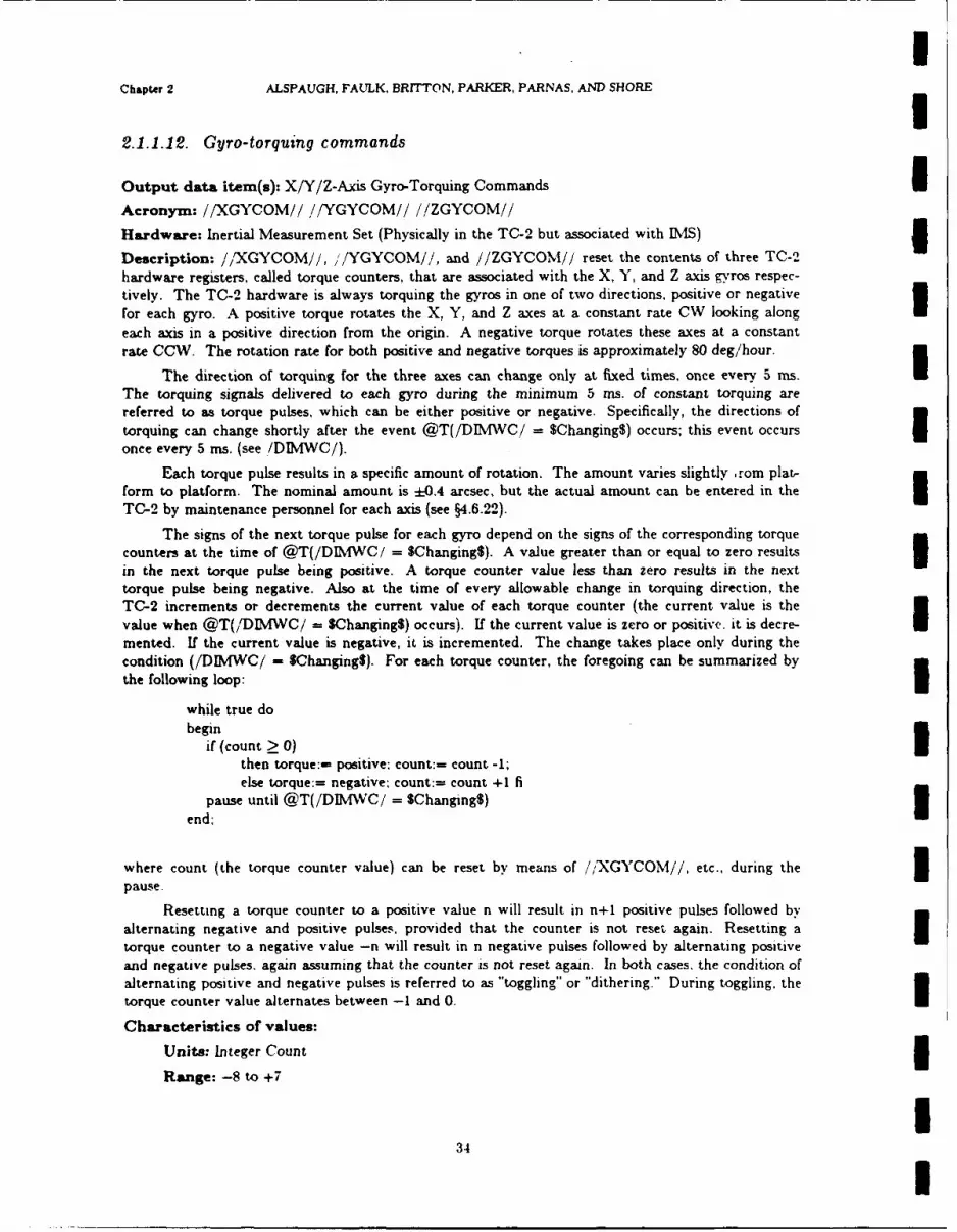
IChapter 2 ALSPAUGH, FAULK, BRrrTON, PARKER, PARNAS. AND SHORE I2.1.1.12. Gyro-torquing commands
Output data item(s): X/Y/Z-Axis Gyro-Torquing Commands iAcronym: //XGYCOM// //YGYCOM// //ZGYCOM//
Hardware: Inertial Measurement Set (Physically in the TC-2 but associated with IMS) 3Description: //XGYCOM//, ,/YGYCOM//, and //ZGYCOM// reset the contents of three TC-2hardware registers, called torque counters, that are associated with the X, Y, and Z axis gyros respec-tively. The TC-2 hardware is always torquing the gyros in one of two directions, positive or negative
for each gyro. A positive torque rotates the X, Y, and Z axes at a constant rate CW looking alongeach axis in a positive direction from the origin. A negative torque rotates these axes at a constant
rate CCW. The rotation rate for both positive and negative torques is approximately 80 deg/hour.
The direction of torquing for the three axes can change only at fixed times, once every 5 ms.
The torquing signals delivered to each gyro during the minimum 5 ms. of constant torquing arereferred to as torque pulses, which can be either positive or negative. Specifically, the directions of
torquing can change shortly after the event @T(/DIMWC/ = $Changing$) occurs; this event occurs Ionce every 5 ms. (see IDIMWC/).
Each torque pulse results in a specific amount of rotation. The amount varies slightly rom plat-form to platform. The nominal amount is :0.4 arcsec, but the actual amount can be entered in the ITC-2 by maintenance personnel for each axis (see §4.6.22).
The signs of the next torque pulse for each gyro depend on the signs of the corresponding torquecounters at the time of @T(/DIMWC/ = $Changing$). A value greater than or equal to zero results Iin the next torque pulse being positive. A torque counter value less than zero results in the nexttorque pulse being negative. Also at the time of every allowable change in torquing direction, theTC-2 increments or decrements the current value of each torque counter (the current value is thevalue when @T(/DIMWC/ = $Changing$) occurs). If the current value is zero or positive, it is decre-mented. If the current value is negative, it is incremented. The change takes place only during thecondition (/DIMWC/ - $Changing$). For each torque counter, the foregoing can be summarized by
the following loop:
while true dobegin
if (count > 0)then torque:- positive: count:- count -1;
else torque:= negative: count:= count +1 fi
pause until @T(/DIMVC/ = $Changing$)end;
where count (the torque counter value) can be reset by means of /XGYCOM//, etc., during the 3pause.
Resetting a torque counter to a positive value n will result in n+1 positive pulses followed byalternating negative and positive pulses, provided that the counter is not reset again. Resetting a ltorque counter to a negative value -n will result in n negative pulses followed by alternating positive
and negative pulses, again assuming that the counter is not reset again. In both cases, the condition ofalternating positive and negative pulses is referred to as "toggling" or "dithering." During toggling, the
torque counter value alternates between -1 and 0.
Characteristics of values:
Units: Integer Count 3Range: -8 to +7
I34 I

NRL REPORT gg4 Inertial Measurement Set (IS)
Resolution: I
Instruction sequence: WRITE * (Channel 4) (valid only when iDIVC/ = $Ready$) (where * -129 for X Axis, 130 for Y Axis, 132 for Z Axis)
Data representation: 4 bit two's complement number. bits 11-14; bits 0-10 and bit 15 are not used.Scale = 1, offset = 0.
Timing characteristics: See /DIMWC/. See also Description and Comments.
Comments: Because //XGYCOM//, !/YGYCOM//, and //ZGYCOM// reset the current values ofthe torque counters, and since only two bits of information are available about the current values ofthe four bit counters, pulses can be "lost" if care is not taken. (See /XGYCNT/, /YGYCNT/. and/ZGYCNT/ for more information.) In general, it is easiest to wait until a counter is toggling beforeresetting it.
An additional problem is the need to make sure that an equal number of positive and negativetorquing pulses are output during toggling so as not to introduce an unintentional bias. This can beaccomplished by determining the current value of the torque counter (-1 or 0) and resetting thecounter so that the desired number of positive or negative pulses is output prior to the counter return-ing to the value it had at the time it was reset. The action to be taken in each case is given in the fol-lowing table:
Current (toggling) Number of Reset value forvalue of counter desired pulses counter
0 n n0 -n -n
-1 n n-1
-1 -(n+l)
This table can be understood by referring back to the pseudo-code and diagram given in the Descrip-tion. In each case, the time required to return to the starting value (left most column) is 5n ms.From the table, it can be seen that the appropriate reset value is equal to the sum of the desirednumber of pulses and the current (toggling) value of the counter. During toggling, the current valueof a torque counter (-1 or 0) can be determined through use of /XGYCNT/, /YGYCNT/, or/ZGYCNT/. For example. if the X axis torque counter is toggling, !,.GYCNT/ = $A$ will holdwhen the counter value is zero, and /XGYCNT/ = $D$ will hold when the counter value is -1. Notethat when the counter is not toggling. ,'XGYCNT/ does not contain sufficient information to deter-mine the reset value.
Note: In the current OFP. the IMS equations assume an opposite rotation sense for X and Y thandefined undpr Description. The results of the calculation are negated (thus converting into the presentstandard reference frame) before being output to the device.
35

IChapter 2 ALSPAUGH, FAULK, BRITTON, PARKER, PARNAS. AND SHORE
2.1.113. IMS scale factor change
Output data item(s): IMS Scale Factor Change 1Class: DOW2
Acronym: //IMSSCAL//
Hardware: Inertial Measurement Set
Description: //IMSSCAL// tells the IDvIS which of two scale factors to use for calculating incremen-tal velocities from /XVEL/ and /YVEL/. The /ZVEL/ scale factor always remains set at $Coarse$.
Characteristics of values:
Value encoding:
$Coarse$ (0): incremental #-velocity = low gain scale X /#VEL/ pulses$Coarse$ (0): incremental Z-velocity = low gain scale X /ZVEL/ pulses$Fine$ (1): incremental #-velocity = high gain scale X /#VEL/ pulses
where # E {X Y)
Instruction sequence: WRITE 4 (Channel 0)
Data representation: Discrete output word 2, bit 14 1Comments: The amount of incremental velocity indicated by each /XVEL/, /YVEL/ or /ZVEL/count varies from platform to platform. The nominal values for the scale factors are .032 for the lowgain scale and .000327 for the high gain scale. The actual value for each scale factor for each axis canbe entered by maintenance personnel (see §4.6.23 for low gain scale and §4.6.24 for high gain scale.)
Note: The above example of velocity calculation does not show the adjustment required for accelerom-
Ieter bias.
3UUIIII
36 I

RLREPORT 9194 Inertial Measurement Set (IMS)
2.1.1.14. IMS slews
Output data item(s): IMS X,Y,Z Slews
Acronym: //XSLEW// //YSLEW /! ,'/ZSLEW //
Claws: DOW2
Hardware: Inertial Measurement Set
Description: //XSLEW//, //YSLEW//, //ZSLEW// command the IMS to slew the IMS platformcluster about its X Y, and Z Axes, respectively. The directions of the slews are determined by//XSLSEN//, //YSLSEN 1/, //ZSLSEN//, respectively.
Characteristics of values:
Value encoding: $Off$ (0); $On$ (1)
Instruction sequence: WRITE 4 (Channel 0)
Data representation: Discrete output word 2;
//XSLEWV//: bit 6.//YSLEW//: bit 2,//ZSLEW//: bit 4
Timing characteristics: X slewing and Y slewing occur at the rate 30 */min; Z slewing occurs atthe rate 90 deg/min.
37
Chapter 2 ALSPAUGH, FAULK, BRITTON, PARKER, PARNAS, AND SHORE
2.1.1.15. IMS slew directions
Output data item(s): XY,Z Slew Sense1
Acronym: //XSLSEN// //YSLSEN// //ZSLSEN//
Claws: DOW25
Hardware: Inertial Measurement Set
Description: //XSLSEN//, //YSLSEN//, //ZSLSEN// advise the IMS of the directions of the slews
for X slewing, Y slewing, and Z slewing, respectively. The values designate the directions of the slewIwhen looking in the positive direction from the origin along the X, Y, and Z axes, respectively.//XSLSEN//, //YSLSEN//, //ZSLSEN// are meaningful only when the corresponding //XSLEW//,//YSLEW//, //ZSLEW// = $OnSA
Characteristics of values:
VleecdnSOWS (1); $COWS (0): /XSLSEN// and //YSLSEN//
SOWS (0); SCOWS (1): //ZSLSEN//
Instruction sequence: WRITE 4 (Channel 0)3
Data represntation: Discrete output word 2;
//XSLSEN//: bit 7,//YSLSEN//: bit 3,
//ZSLSEN//: bit 5
38I

NRL REPORT g194 Inertial Measurement Set (IMS)
2.1.1.16. Latitude > 70
Output data Item(s): Latitude > 70'
Acronym: //LATGT70//
Clas: DOW2
Hardware: Inertial Measurement Set
Description: //LATGT70// - $No$ directs the IMS to revert to Magnetic Slave Mode when@T(//COMPFAIL// = SYes$) occurs. //LATGT70// = $Yes$ directs the IMS to revert to GridMode when @T(//COMPFAIL// = SYes$) occurs.
Characteristics of values:
Value encoding: $No$ (0), $Yes$ (1)
Instruction sequence: WRITE 4 (Channel 0)
Data representation: Discrete output word 2, bit 8
Comments: See Ref. 33a, §3.4.1.5 for IMS mode definitions.
39

IChapter 2 ALSPAUGH, FAULK, BRITTON, PARKER, PARNAS, AND SHORE
2.1.2. Air Data Computer (ADC)The Air Data Computer (ADC) processes inputs from the A/C pitot-static system and from a
temperature probe to provide outputs that represent barometric altitude, Mach number, and trueairspeed. I2.1.2.1. ADC failure
Input data item(s): ADC Failure
Acronym: /ADCFAIL/
Class: DIW5
Hardware: Air Data Computer
Description: /ADCFAIL/ = $YES$ indicates either 3(a) The ADC detects errors during its own continuous self-monitoring.
(b) The ADC is in the middle of a special self-test initiated by the self-test switch on the ADC com-
puter.
Note that @T(/ADCFAIL/ = SNo$) may occur after @T(/ADCFAEL/ = SYes$).
Characteristics of values: 3Value encoding: $No$ (0); W/es$ (1)
Instruction sequence: READ 24 (Channel 0)
Data representation: Discrete input word 5, bit 12
Timing characteristics: For a catastrophic failure, the ADC input data may be bad for 400 msbefore @T(/ADCFAIL/ = Wes$). A gradual degradation, e.g., icing of the probes, may result in baddata for a long period (5-10 minutes or more) before @T(/ADCFAIL/ - $Yes$).
IIIIIII
40 I

NRL REPORT g2g4 Air Dus Computer (ADC)
2.1.2.2. ADC barometric altitude
Input data item(s): Barometric Altitude - ADC
Acronym: /BAROADC/
Hardware: Air Data Computer
Description: /BAROADC/ provides the altitude above or below sea level. /BAROADC/ is basedon air pressure. The ADC calculation is based on the assumption that the sea level pressure is 29.92inches of mercury.
Characteristics of values:
Units: Feet
Range: -1024 to 50,000
Accuracy: Ranges from + NAX (40 ft, .3% /BAROADC/) at -54' C to ± MAX (25 ft, .25%/BAROADC/) at 10' C to 50" C.
Resolution: 14.90 ft
Maximum derivative: ±1000 ft/s
Instruction sequence:
READ 255 (Channel 7) (Reset Signal Converter if not already reset)READ 235 (Channel 7) (Request Signal Converter to start conversion)Test Carry Indicator for 0 - request acknowledgedIf not, start again.When DATA READY interrupt occurs, conversion completeREAD 255 (Channel 7) (Resets Signal Converter also).
Data representation: 12-bit positive number, bits 1-12. Bit 0, bits 13-15 = 0. Scale = 4096/61020:=: 0.0671255; ofset - 0
Timing characteristics: Analog (DC voltage) to digital conversion. See §1.15.8.
41
IChapter 2 ALSPAUGH. FAULK. BRITTON. PARKER, PARNAS, AND SHORE
2.1.2.S. ADC Mach number
Input data item(s): Mach number IAcronym: /MACH/
Hardware: Air Data Computer
Description: /MACH/ provides the ratio of the speed of the A/C to the speed of sound in the sur-rounding atmosphere.
Characteristics of values:
Units: Mach
Range: .2 to 1.2 (accuracy above .96 may be degraded)
Accuracy: ±0.010 (at 30,000 ft and 10. C to 50" C)
Resolution: .00061Maximum derivative: *05 mach/s
Instruction sequence:
READ 255 (Channel 7) (Reset Signal Converter if not already reset)READ 236 (Channel 7) (Request Signal Converter to start conversion) ITest Carry Indicator for 0 - request acknowledgedIf not, start againWhen DATA READY interrupt occurs, conversion completeREAD 255 (Channel 7) (Also resets Signal Converter).
Data representation: 12-bit positive number, bits 1-12; bit 0, bits 13-15 = 0. Scale = 2048/1.25 =
1638.4; offset - 0
Timing characteristics: Analog (DC voltage) to digital conversion. See §1.15.8.
IUIUIIII
42 I

NRL REPORT 9194 Air Daa Computer (ADC)
2.1.2.4. ADC true airspeed
Input data item(s): True Airspeed (TAS)
Acronym: /TAS/
Hardware: Air Data Computer
Description: /TAS/ provides the true airspeed which is the indicated airspeed corrected by the ADCfor air density (altitude), temperature, and pressure.
Characteristics of values:
Units: Feet/Second
Range: 200 to 1013
Accuracy: :k8 (at 20.000 ft and 10 C to 50" C)
Resolution: .4883
Maximum derivative: ±34 ft/s.
Instruction sequence:
READ 255 (Channel 7) (Reset Signal Converter if not already reset)READ 234 (Channel 7) (Request Signal Converter to start conversion)Test Carry Indicator for 0 - request acknowledgedIf not, start againWhen DATA READY interrupt occurs, conversion completeREAD 255 (Channel 7). (Also resets Signal Converter).
Data representation: 12-bit positive number, bits 1-12; bit 0, bits 13-15 = 0. Scale - 2048/1000 -2.048. If .Data 26! - !L-probe! then offset = 0; else offset = -12.
Timing characteristics Analog (DC voltage) to digital conversion. See §1.15.8.
II
IIIIII
! 43

IChapter 2 ALSPAUGH, FAULK, BRITTON. PARKER, PARNAS, AND SHORE
2.1.2.5. Test select ADC/FLR
Output data item(s): Test Select ADC/FLR i
Claws: DOW2
Acronym: //TSTADCFLR//
Hardware: Air Data Computer
Description: @T(//TSTADCFLR// = SONS) causes the ADC to execute a self-test yielding the fol-
lowing values:I/TAS/: 400 ± 20 knots/BAROADC/ = 10,000 ft ± 1000 ft./MACH/ - .63 :0.04 Mach
Characteristics of values:
Value encoding: SOffS (0); SOnS (1)
Instruction sequence: WRITE 4 (Channel 0)
Data representation: Discrete output word 2, bit 1
Comments: //TSTADCFLR// is also output to the FLR.
IIIIiIIIII
44I
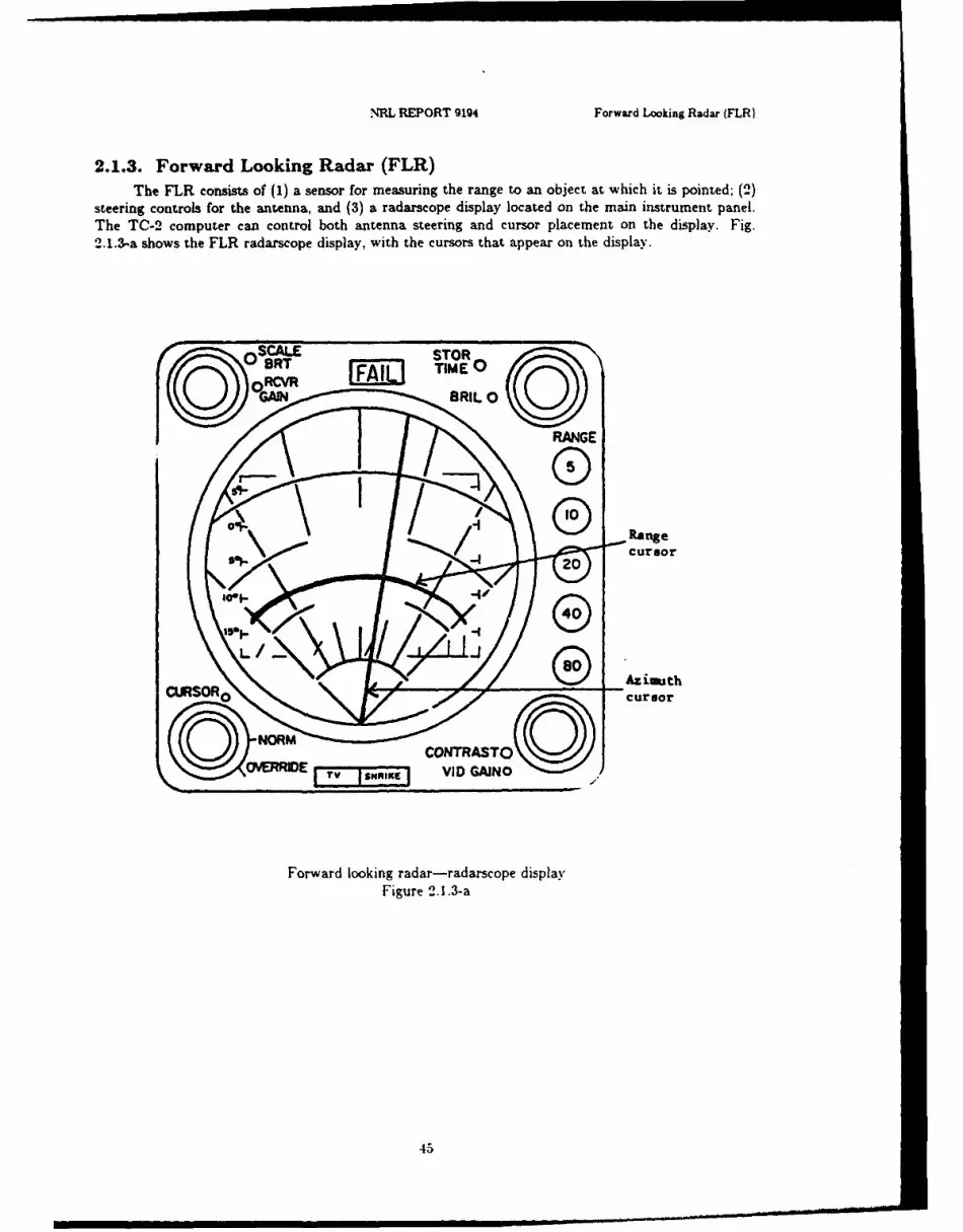
NRL REPORT 9194 Forward Looking Radar (FLR)
2.1.3. Forward Looking Radar (FLR)The FLR consists of (1) a sensor for measuring the range to an object at which it is pointed; (2)
steering controls for the antenna, and (3) a radarscope display located on the main instrument panel.The TC-2 computer can control bath antenna steering and cursor placement on the display. Fig.2.1.3-a shows the FLR radarscope display, with the cursors that appear on the display.
ERIEVDGAIN BI 0
Figure c.1.3-a
420

Chapter 2 ALSPAUGH. FAULK, BRITTON, PARKER, PARNAS, AND SHORE
2.1.3.1. FLR locked-on
Input data item(s): Locked-On IClam: SFLR-DOW3
Acronym: /LOCKEDON/
Hardware: Forward Looking Radar
Description: /LOCKEDON/ indicates whether or not the FLR antenna is locked on to an object onthe ground. /LOCKEDON/ = $Yes$ may be obtained by the hardware pointing the antenna at thepoint on the ground when the FLR is in the AGR mode.
Characteristics of values:
Value encoding: $No$ (0); $Yes$ (1) IInstruction sequence: Available after READ 64 in /SLTRNG/ instruction sequence
Data representation: Serial Input Address word, bit 0.
Comments: /LOCKEDON/ is a hardware function of the FLR. See Ref. 33e, §3.4.3.7.4.
IIII$Il
I46 I

NRL REPORT 9194 Forward Looking Radar (FLR)
2.1.9.2. Slant range to target
Input data item(s): Slant Range to Target
Class: SFLR-DOW3
Acronym: /SLTRNG/
Hardware: Forward Looking Radar
Description: /SLTRNG/ is the distance from the A/C to the selected point on the ground. Datavalid only if /LOCKEDON/ = $Yes8.
Characteristics of values:
Unit.: Feet
Range: 1,000 to 60,000
Accuracy: ±25 below 10,000; ±0.25% of /SLTRNG/ above 10,000
Resolution: 20
Maximum derivative: 10,000 ft/s
Instruction sequence:
LA '4000' Hex (Discrete Output Word 3)WRITE 2 (Channel 0) (Enable FLR)Wait for External Control InterruptREAD 64 (Channel 2) (Read Serial Input Address)Save address data to verify identity code - 00001*Check if !Serial Input OK!
READ 32 (Channel 1) (Read Serial Input Data)
Data representation: 13-bit positive number, bits 0-12; bits 13-15 = 0. Scale = 1/20 = .05; offset-=0.
Comments: Note that the FLR Slant Range and the DRS status have the same device address(00001).
47

IChapter 2 ALSPAUGH, FAULK, BRITTON. PARKER, PARNAS. AND SHORE
2.1.3.3. Antenna slave command
Output data item(s): Antenna Slave Command IClas: DOWI
Acronym: //ANTSLAVE//
Hardware: Forward Looking Radar
Description: //ANTSLAVE// = SOnS directs the FLR to slave the antenna in azimuth and eleva-tion to //STEERAZ// and //STEEREL//. See Ref. 13e, §3.4.3.7.1.
Characteristics of values:
Value encoding: SOftS (0); SOnS (1)
Instruction sequence: WRITE 8 (Channel 0)Data representation: Discrete output word 1, bit 13
Comments: See //STEERAZ//, //STEEREL//
IIUIIIIIIII
48
i

NRL REPORT 9194 Forward Looking Radar (FLR)
2.1.3.4. Computer system fail
Output data item(s): Computer System Fail
Claws: DOW2
Acronym: //COMPFAIL//
Hardwaze: Forward Looking Radar
Description: When //COMIPFAIL// = $Yes$, the FLR does not perform functions that require TO-2 input.
Comments: //COMIPFAEL// is defined in the IM section. //COMPFAIL// is also output to theADI and the Caution and Advisory Panel.
49
IChapter 2 ALSPAUGH. FAULK. BRITTON, PARKER. PARNAS. AND SHORE 12.1.3.5. Cursor azimuth
Output data item(s): Cursor Azimuth Sine and Cosine IAcronym: //CURAZSIN// //CURAZCOS/.'
Hardware: Forward Looking Radar
Description: These outputs control the placement of the azimuth cursor on the radarscope; theydetermine the angle measured from the vertical center line of the display to the cursor line drawnfrom the bottom of the vertical center line. Positive angles are measured clockwise looking at thedisplay; negative angles counterclockwise. Figure 2.1.3-a shows the azimuth cursor.
The display range is only -45 to +45 *. The azimuth cursor is removed from the display when//CURAZCOS// is set to -1. Has no effect unless //CURENABL// = SOnS.
Characteristics of values: 3Units: None
Range: -1 to +1
Resolution: 1/4096 IData representation: 13-bit two's complement number, bits 0-12; bits 13-15 not used. Scale =
4096: offset = 0.
Instruction sequence: Cycle Steal Channel B. Word Identity Code: i
//CURAZCOS//: OC//CURAZSIN//: 08 3
IIIII
II
50i|I

I3 NRL REPORT 9194 Forward Looking Radar (FLR)
2.1.9.6. FLR cursor enable
Output data item(s): Cursor Enable
Clss: DOWI
Acronym: //CURENABL//
Hardware: Forward Looking Radar
Description: //CURENABL// directs the FLR to display Range and Azimuth Cursors as specifiedby //CURPOS//, //CURAZCOS//, //CURAZSIN//.Characteristics of values:
Value encoding: SOf (0); SOnS (1)
Instruction sequence: WRITE 8 (Channel 0)
Data representation: Discrete output word 1, bit 12
Comments: See Ref. 33e.
IIiIIIIII1I
I 51

IChapter 2 ALSPAUGH, FAULK. BRITTON. PARKER. PARNAS. AND SHORE I
2.1.S.7. FLR cursor position
Output data item(s): Cursor Position i
Acronym: //CURPOS//
Hardware: Forward Looking Radar
Description: The value of //CTRPOS// determines the position of the range cursor on the FLRdisplay. Figure 2.1.3-a shows the range cursor. The FLR calculation is based on the assumption thatthe value of //CURPOS// is slant range and converts the number to ground range itself in order toposition the cursor. Has no effect unless /CURENABL!' = $On$.
Characteristics of values:
Units: Feet 3Range: 0 to 120,000
Accuracy: -0.2% of //CURPOS//
Resolution: 40
Instruction sequence: Cycle Steal Channel B. Word Identity Code 04.
Data representation: 12-bit positive number, bits 1-12; bit 0 = Scale = 140 .025: offset 0. 3
52I
IIII!UUII
52 I

NRL REPORT 9194 Forward Looking Radar (FLR)
2.1.S.8. Flight path angle
Output data item(s): Flight Path Angle
Acronym: //FPANGL//
Hardware: Forward Looking Radar
Description: Flight Path Angle is the angle between the A/C velocity vector and its projection ontothe horizontal plane. The positive direction is above the horizontal plane. The FLR calculation isbased on the assumption that //FPANGL// is this angle in determining the climb or dive angle thatshould be used in terrain following.
Characteristics of values:
Units: Degrees
Range: -30 to +30
Accuracy: ±0.2
Resolution: .029
Instruction sequence:
WRITE 228 (Channel 7)Test Carry Bit = 0 for request acknowledgedIf not, restart.
Data representation: 11-bit two's complement number, bit 0 and bits 3-12; bits 1-2 not used, bits13-15 = 0. Scale = 512/15 :=: 34.13333; offset = 0.
Timing characteristics: Digital to DC voltage conversion. See §1.15.8.
Comment@: //FPANGL// is only used by the FLR when in TF mode (see /IMFSW/).//FPANGL// is also output to the ADI.
53

i
Chapter 2 ALSPAUGH. FAULK, BRITTON. PARKER. PARNAS. AND SHORE
2.1.3.9. FLR ground track velocity
Output data item(s): Ground Track Velocity (Ground Speed) IAcronym: //GNDTRVEL//
Hardware: Forward Looking Radar iDescription: The FLR calculation is based on the assumption that //GNDTRVEL/ is the A/Cground speed in determining the climb or dive angle that should be used for terrain following.
Characteristics of values:
Units: Knots
Range: 0 to 900
Accuracy: MAX (2.5, 1% of //GNDTRVEL//) UResolution: .879
Maximum derivative: 250 knots/s 2 5Instruction sequence:
WRITE 227 (Channel 7)Test Carry Bit - 0 for request acknowledged IIf not, restart.
Data representation: 10-bit positive number, bits 3-12; bits 0, 13-15 - 0. Scale - 512/450 :=:1.14; offset - 0.
Timing characteristics: Digital to DC voltage conversion. See §1.15.8.
Comments: //GNDTRVEL// is only used by the FLR when it is in TF mode (see /MFSW/).
IU
IU
I

NRL REPORT 9194 Forward Looking Radar (FLR)
2.1.3.10. Steering commands
Output data item(s): Steering Commands - Azimuth and Elevation
Acronym: //STEERAZ// //STEEREL//
Hardware: Forward Looking Radar
Description: When //ANTSLAVE// = $On$. //STEERAZ// and //STEEREL// determine thedirection in which the FLR antenna is pointed. Let the "antenna pointing vector" be any vector thatpoints away from the A/C in the antenna pointing direction. Then the angle determined byJ/STEEREL// is the angle between the antenna pointing vector and its projection into the platformXp-Yp plane. This angle is positive when the Zp component of the antenna pointing vector is posi-tive, i.e., pointing up is positive when the platform is aligned.
The angle determined by //STEERAZ// is the angle between the projection of the A/C Y. axisand the FLR antenna pointing vector into the platform Xp-Yp plane.
When //ANTSLAVE// = $OI$, the FLR calculation is based on the assumption that//STEERAZ// is the A/C drift angle and uses it in certain modes to position the center of the scanaround the A/C ground track. Drift angle is the angle between the projection of the A/C Ya-axisonto the horizontal plane and the projection of the A/C velocity vector onto the horizontal plane.The angle is positive when measured CW from the projection of the A/C Y.-axis (looking down) andnegative when measured CCW.
The FLR antenna is restrained by hardware stops if out-of-range angles are output.
Characteristics of values:
Units: degrees
R. .;e:
Azimuth: -40 to +40Elevation: -20" to +20.
Accuracy: ±0.1
Maximum derivative: TBD
Instruction sequence:
WRITE * (Channel 7)Test Carry Bit = 0 for request acknowledgedIf not, restart.
= 235 for Azimuth• = 234 for Elevation
Data representation: These two data items and i/BRGDEST!i and '/GNDTRK/,' arerepresented with two fields, an Octant and a Magnitude. To calculate the indicated value of
'STEERAZ//, use the translation table below. To calculate the indicated value of //STEERELi ','BRGDEST/i and i,'GNDTRK/,, add 180" to the standard value, and then use the translation
table below.
55

IChapter 2 ALSPAUGH. FAULK. BRITTON. PARKER. PARNAS. AND SHORE
Angle-to-Octant /Magnitude Translation Table
Angle a. in degrees Octant Magnitude in Indicated Units I0 0 10230 <a < 45 0 L ABS( tan a ) X 1024J I
45 1 102345 < a < 90 1 [ABS( cotan a ) X 1024 ]90 2 102390 < a < 135 2 L (21' - [ABS(cotan a)] X 2'3)23 J
135 3 1023135 < a < 180 3 [ABS( tan a ) X 1024 J180 4 1023180 < a < 225 4 L (2' 3
- LABS(tan a)j X 2'3)/2 3 J225 5 1023225 < a < 270 5 1 (213 - LABS(cotan a)] X 213)/2I3270 6 1023270 < a < 315 6 LABS( cotan ) X 1024J315 7 1023 I315 < a < 360 7 [ (213 - LABS(tan a)] X 2'3)/23 J I
Octant: 3-bit positive number, bits 0-2:Magnitude: 10-bit positive number, bits 3-12.Bits 13-15 not used.
Timing characteristics: Digital to synchro conversion. See §1.15.8.
IIII!III
.56 1

INRL REPORT 9194 Forward Looking Radar (FLR)
2.1 .9.11. Test select ADC/FLR
Output data item(s): Test Select ADC/FLR
Clas: DOW2
Acronym: //TSTADCFLR//
Hardwar~e: Forward Looking Radar
Description: The event @T(//TSTADCFLR//=-$OnS) causes the FLR to execute a self-test yielding/LOCKEDON/=SYes$ and /SLTRNG/= 10,000 ± 1000 ft
Comments: This data item is defined in the ADO section.
57
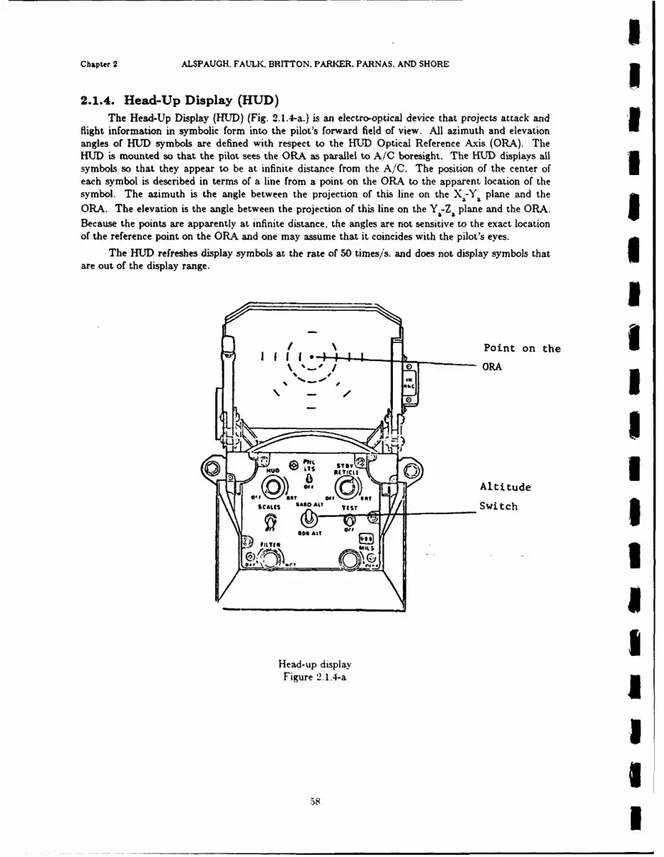
IChapter 2 ALSPAUGH. FAULK, BRITTON, PARKER, PARNAS, AND SHORE I
2.1.4. Head-Up Display (HUD)The Head-Up Display (HUD) (Fig. 2.1.4-a.) is an electro-optical device that projects attack and
flight information in symbolic form into the pilot's forward field of view. All azimuth and elevationangles of HIUD symbols are defined with respect to the HUD Optical Reference Axis (ORA). TheHUJD is mounted so that the pilot sees the ORA as parallel to A/C boresight. The HUD displays allsymbols so that they appear to be at infinite distance from the A/C. The position of the center ofeach symbol is described in terms of a line from a point on the ORA to the apparent location of thesymbol. The azimuth is the angle between the projection of this line on the X.-Y. plane and theORA. The elevation is the angle between the projection of this line on the Y Z. plane and the ORA.Because the points are apparently at infinite distance, the angles are not sensitive to the exact location
of the reference point on the ORA and one may assume that it coincides with the pilot's eyes.The HUD refreshes display symbols at the rate of 50 times/s. and does not display symbols that I
are out of the display range.
Point on the IORA
Off Altitude
SCAM S At? TIST Switch 3
~I iiLi
Head-up displayFigure 2.1.4-a j
II
58!

NRL REPORT g194 Head-Up Display (HUD)
4- -. Flight Path- -eMarker
Aiming Symbol Flight- ' Director
HUD aiming symbol, flight director, and flight path markerFigure 2.1.4-b
IiE1-Upper Solution Cue
+----Z4er Soluti0 , Cue
light Path Marker
0 4 -- Aimtng Symbol
- - P Anticipa tion Cue
----- AImth Steering Line
HUfD cuesFigure 2 1.4-c

iChapter 2 ALSPAUGH. FAULK. BRITTON. PARKER, PARNAS. AND SHORE
E xFlashing Pullup Cue
HUD pullup cue tFigure 2.1.4-d
S IWarningSymbol o Barometric Altitude Indicator
ai (3750 feet)
4 Vertical Velocity Indicator
L- (-4000 fps) 33
HUD barometric altitude indicator and vertical velocity indicator
Figure 2.1.4-e g
117 Pitch Lines U(00 pitch)
Magnetic _HeadingIndicator I(1100)
I-RD magnetic heading indicator and pitch
Figure 2.1.4-f
60

NRL REPORT 9194 Head-Up Display (HUD)
2.1.-4.1. HUD reliable
Input data item(s): HUD Reliable
Class: DIW4
Acronym: /HUDREL/
Hardware: Head Up Display
Description: /HUDREL/ indicates whether or not the HUD is reliable. The HUT continuously runsits own self-tests when turned on. /HUDREL/ = $-No$ when the HUD is off.
Characteristics of values:
Value encoding: $No$ (0); SYes$ (1)
Instruction sequence: READ I (Channel 0)
Data representation: Discrete input word 4, bit 15
.. .. ... .
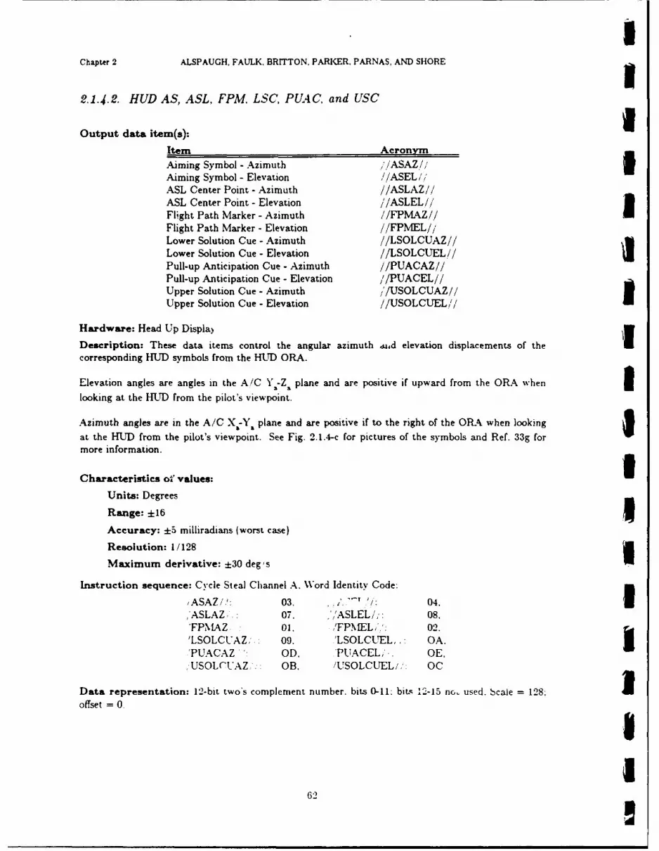
IChapter 2 ALSPAUGH. FAULK. BRITTON. PARKER. PARNAS, AND SHORE
2.1.4.2. HUD AS, ASL, FPM. LSC, PUAC, and USC
Output data item(s): iItem AcronymAiming Symbol - Azimuth /iASAZ/Aiming Symbol - Elevation //ASEL/ASL Center Point - Azimuth //ASLAZ//ASL Center Point - Elevation //ASLEL//'Flight Path Marker - Azimuth //FPMAZ//Flight Path Marker - Elevation //FPMEL//Lower Solution Cue - Azimuth //LSOLCUAZ//Lower Solution Cue - Elevation //LSOLCUEL//Pull-up Anticipation Cue - Azimuth //PUACAZ//Pull-up Anticipation Cue - Elevation ,/PUACEL//Upper Solution Cue - Azimuth '/USOLCUAZ//Upper Solution Cue - Elevation //USOLCUEL//
Hardware: Head Up Displa)Description: These data items control the angular azimuth U.,d elevation displacements of thecorresponding HUD symbols from the HtD ORA.
Elevation angles are angles in the A/C Y1-Z a plane and are positive if upward from the ORA when Ilooking at the HUD from the pilot's viewpoint.
Azimuth angles are in the A/C X8-Y, plane and are positive if to the right of the ORA when lookingat the HUD from the pilot's viewpoint. See Fig. 2.1.4-c for pictures of the symbols and Ref. 33g formore information.
Characteristics oa values:
Units: Degrees
Range: ±16
Accuracy: ±5 milliradians (worst case)
Resolution: 1/128
Maximum derivative: ±30 deg's
Instruction sequence: Cycle Steal Channel A. Word Identity Code:
/ASAZ//: 03. ,,,.' /: 04. I,'ASLAZ, 07. ,'ASLEL/': 08.'FPMAZ 01. /FP.fELi,': 02.'LSOLCUAZ,'," 09. 'LSOLCUEL,, OA. I'PUACAZ ' OD, 'PUACEL,' . OE.,USOLC'UAZ,',: OB /USOLCUEL/,. OC
Data representation: 12-bit two's complement number, bits 0-11: bits 12-15 nc. used. bcale = 128; 1offset = 0.
62
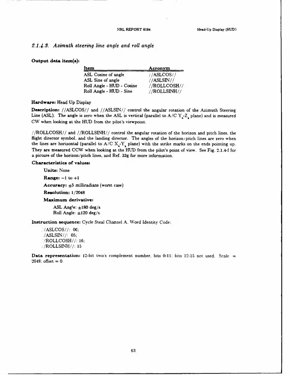
NRL REPORT g194 Head-Up Display (HUD)
2.1.4.3. Azimuth steering line angle and roll angle
Output dat item(s):
Item AcronymASL Cosine of angle /iASLCOS/I/ASL Sine of angle //ASLSIN//Roll Angle - HUD - Cosine //ROLLCOSH//Roll Angle - HUD - Sine /ROLLSINH//
Hardware: Head Up Display
Description: //ASLCOS// and //ASLSIN// control the angular rotation of the Azimuth SteeringLine (ASL). The angle is zero when the ASL is vertical (parallel to A/C Ya-Z. plane) and is measuredCW when looking at the HUD from the pilot's viewpoint.
//ROLLCOSH// and //ROLLSINH// control the angular rotation of the horizon and pitch lines, theflight director symbol, and the landing director. The angles of the horizon/pitch lines are zero whenthe lines are horizontal (parallel to A/C X.-Y1 plane) with the strike marks on the ends pointing up.
They are measured CCW when looking at the HUD from the pilot's point of view. See Fig. 2.1.4-f fora picture of the horizon/pitch lines, and Ref. 33g for more information.
Characteristics of values:
Units: None
Range: -1 to +1
Accuracy: ±5 milliradians (worst case)
Resolution: 1/2048
Maximum derivative:
ASL Angle: ±180 deg/sRoll Angle: ±120 deg/s.
Instruction sequence: Cycle Steal Channel A. Word Identity Code:
,'/ASLCOS//: 06;/ASLSIN//: 05;/ROLLCOSH//: 16;
,,/ROLLSINH/: 15
Data representation: 12-bit twos complement number, bits 0-I1: bits 12-15 not used. Scale =
2048: offset = 0.
63
IChapter 2 ALSPAUGH, FAULK. BRITTON. PARKER. PARNAS. AND SHORE
2.1-.-4. HUD barometric altitude
Output data item(s): Barometric Altitude - HUE) IAcronym: //BAROHUTD//
Hardware: Head Up Display IDescription: When the HUD Altitude switch is set to BARO ALT. ,/BAROHUD /, determines thetwo digits and a bar position for the altitude display on the HUD. (The TC-2 can not sense the alti-tude switch). The switch is shown in Fig. 2.1.4-a. and the display symbology is shown in Fig. 2.1.4-e.
The digits displayed are //BAROHUD,, - (,/BAROHUD// MOD 1000).
The bar height indicates (//BAROHUD// MOD 1000) on a scale from 0 to 1000. 1Characteristics of values:
Units: None 3Range: -1.000 to +50.000
Resolution: 12.207
Maximum derivative: :10.000/min. IInstruction sequence: Cycle Steal Channel A. Word Identity Code 18
Data representation: 13-bit two's complement number, bits 0-12; bits 13-15 not used. Scale =
I4096/50000 ::0.08192: offset =0.
645
UIIIIII
(34 I
NRL REPORT 9194 Head-Up Display (HUD)
2.1.4.5. HUD Flight director
Output data item(s): Flight Director - Azimuth (Heading Error Cue Azimuth)
Acronym: //FLTDIRAZ//
Hardware: Head Up Display
Description: //FLTDIRAZ// controls the azimuthal placement of the Flight Director symbol. Theazimuthal angle is measured in the X -Y plane and is positive if the Flight Director symbol is to the
right of the ORA when looking at the HUD from the pilot's viewpoint. The Flight Director Symbol isshown in Fig. 2.1.4-b.
Because of hardware constraints, the flight director is not displayed if a master function switch isselected.
Characteristics of values:
Units: Degrees
Range: -8 to +8
Accuracy: ±5 milliradians (worst case)
Resolution: 1/256
Maximum derivative: ±30 deg/s
Instruction sequence: Cycle Steal Channel A, Word Identity Code: OF
Data representation: 12-bit two's complement number, bits 0-11: bits 12-15 not used. Scale = 256:offset - 0.
65
IChapter 2 ALSPAUGH, FAULK, BRITTON. PARKER, PARNAS, AND SHORE
2.1. 4.6. HUD symbol controls
Output data item(s): HUD Symbol Controls (7 Data Items) IAcronym: //HUDWARN// /HUDPUC// /HUDVEL// //HUDFPM// / ,'HUDAS!/!/ /HUDSCUE// //HUDASL//
Class: HUDCTL
Hardware: Head Up Display
Description: I//HUDWARN//: tells the HUD whether or not to display the warning symbol
//HUDPUC//: tells the HUD whether or not to display a blinking pull up cue
//HlDVEL//: tells the HUD whether or not to display the vertical velocity and altitude Iscale, the vertical velocity marker, and the altitude marker. The vertical velo-city indicator is used in all flight modes, the HUD also interprets
//HUDVEL// as an indication of TC-2 operating condition. When S//HUDVEL// = SOfft. the HUD uses non-computer inputs to position the
Flight Path Marker.
//HUDFPM//: the HUD will blink the flight path marker on and off for two seconds following@T(//HUDFPM/i = $Blink$). At other times the HUD displays the FPMconstantly
//HUDAS//: tells the HUD whether or not to display the aiming symbol n
//HUDSCUE//: tells the HUD whether or not to display the solution cues; because of ahardware constraint, not displayed if no master function switch is selected.
//HUDASL//: tells the HUD whether or not to display the azimuth steering line; because of a .mhardware constraint, not displayed if no master function switch is selected.
Characteristics of values:
Value encoding:
//HUDWARN// SOnS (1); SOS (0) bit 0//HUDPUC// SBlink$ (1); SOffS (0) bit 1
//HUDVEL/,i SOffS (1); $On$ (0) bit 2 I//HUDFPM// $Blink$ (1); $ConstantS (0) bit 3/"/HUDAS/i $Of$ (1); SOnS (0) bit 4//HUDSCUE/, SOffS (1); $On$ (0) bit 5/ /HUDASL/ SOfS (1): SOnS (0) bit 6
Note: Bits 7-15 must be set to0. IInstruction sequence: Cycle Steal Channel A. Word Identity Code 17
Timing characteristics: To blink the FPM for two seconds. ( 1,,'HU)DFPMI// = $Blink$) must hold
for at least 100 ms. and not more than two seconds.
III
66 I
NRL REPORT 9194 Head-Up Display (HUD)
2.1.4.7. HUD magnetic heading
Output data item(s): Magnetic Heading - HUD
Acronym: //MAGHDGH//
Hardware: Head Up Display
Description: The HUD displays the two most significant digits of up to three integers that are multi-ples of 10. A fixed pointer indicates the position of //MAGHDGH// within the displayed range. Thepointer is called the lubber line. The display simulates a horizontal tape moving past a fixed pointer.See Fig. 2.1.4-f for a picture of the Magnetic HeaJing display.
Characteristics of values:
Units: Degrees
Range: 0 to 360
Resolution: .17578
Maximum derivative: ±30 deg/s
Instruction sequence: Cycle Steal Channel A, Word Identity Code: 12
Data representation: 11-bit positive number, bits 1-11; bit 0 = 0, bits 12-15 not used. Scale -
2048/360 :=: 5.6888; offset = 0.
67
IChapter 2 ALSPAUGH. FAULK. BRITTON, PARKER, PARNAS. AND SHORE
2.1.4.8. HUD pitch angle
Output data item(s): Pitch Angle IAcronym: //PTCHANG//'
Hardware: Head Up Display IDescription: //PTCHANG// controls the spacing between and numerical labeling of thepitch/horizon lines as well as their horizontal positions with respect to the Flight Path Marker. Thepitch/horizon lines simulate a vertical tape moving past the FPM. The "tape" can be rotated bymeans of //ROLLCOSH// and /ROLLSINH//. Figure 2.1.4-f shows a picture of the pitch/horizon
lines, and Ref. 33g provides more information.
Characteristics of values: 3Units: Degrees
Range: ±90
Resolution: .02197
Maximum derivative: ±30 degis
Instruction sequence: Cycle Steal Channel A. Word Identity Code: 14 1Data representation: 12-bit two's complement number, bits 0-11; bits 12-15 not used. Scale -4096/90 :=: 45.511; offset = 0.
Comments: The HUD hardware changes scaling (6 possibilities) as //PTCHANGi/ increases IRegardless of the scale, the pitch lines are 5' apart on the HUD.
IIIIIIIII
68

NRL REPORT 9194 Head-Up Display (HUD)
2.1.4.9. HUD vertical velocity/acceleration
Output data item(s): Vertical Velocity/Acceleration
Acronym: //VERTVEL//,//VTVELAC//
Hardware: Head Up Display
Description: The HUD uses either //VERTVEL// or /,/VTVELAC// to place the vertical velocity
pointer on the vertical velocity scale. Which one is used is not under TC-2 control.
The pointer displacement from the bottom of the vertical velocity scale is a linear function of the out-put values. The value -1000 results in zero displacement, and the value +1000 results in maximum
displacement. The value that may be output has a range of ±10,000. but only ±1000 is displayed.That is, the pointer on the HUD moves off the - ale if the value is greater than 1000, but is limited to
the field of view.
The vertical velocity indicator is shown in Fig. 2.1.4-e.
Characteristics of values:
Units: None
Range: ±10,000
Resolution: 4.882
Maximum derivative: ±10.000/min
Instruction sequence: Cycle Steal Channel A, Word Identity Code:
10 for //VTVELAC//11 for //VERTVEL//
Data representation: 12-bit two's complement number, bits 0-11; bits 12-15 not used. Scale =
2048/10000 = .2048; offset = 0.
Comments: //VERTVEL/i is displayed when the HUD detects landing mode (not a software condi-
tion). //VTVELAC// is displayed at all other times.
69
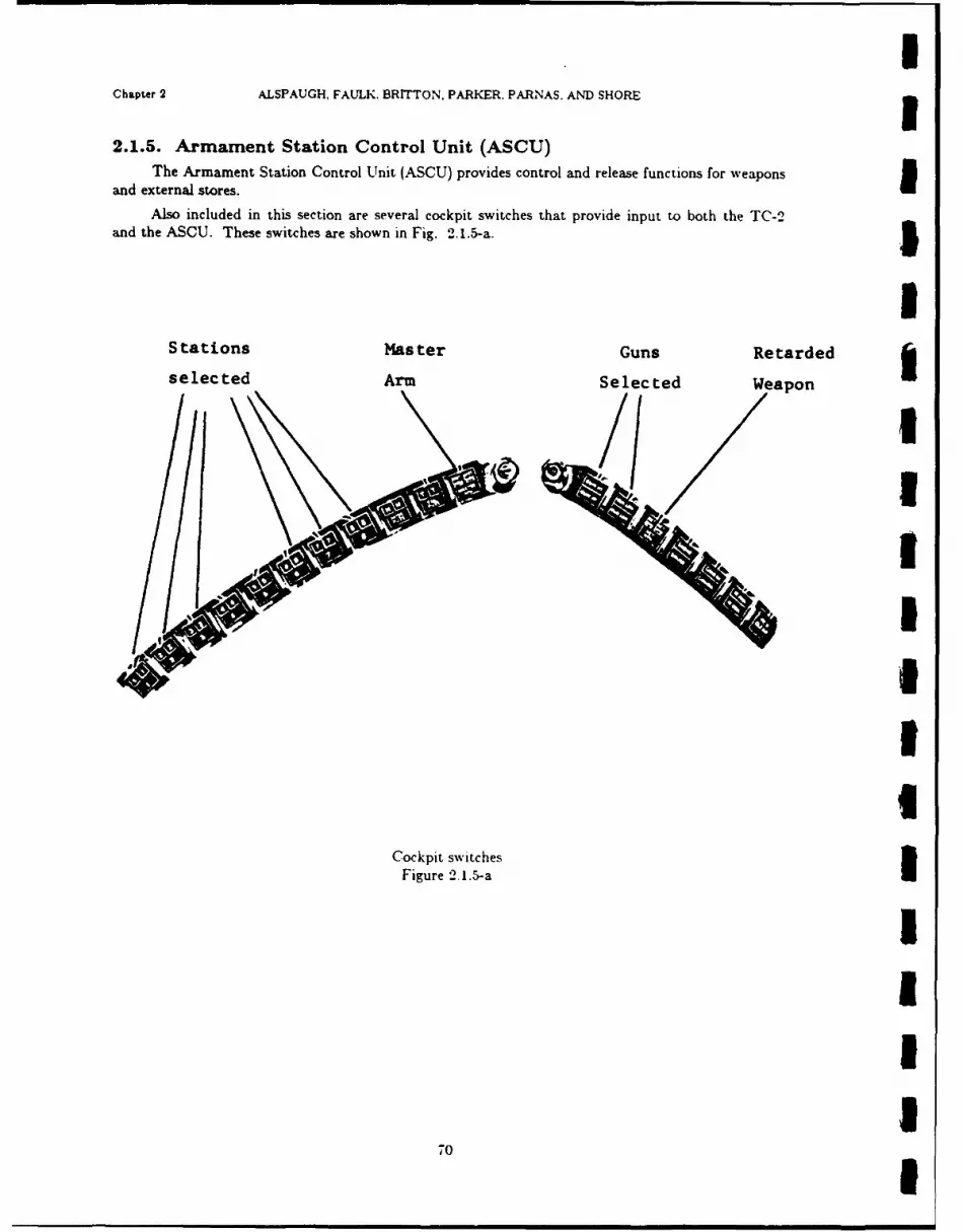
IChapter 2 ALSPAUGH, FAULK. BRITTON, PARKER. PARNAS, AND SHORE 32.1.5. Armament Station Control Unit (ASCU)
The Armament Station Control Unit (ASCU) provides control and release functions for weaponsand external stores.
Also included in this section are several cockpit switches that provide input to both the TC-2and the ASCU. These switches are shown in Fig. 2.1.5-a. 5
IStations Master Guns Retarded
selected Arm Selected Weapon
1I
II
Cockpit switchesFigure 2.1.5-a
1III
70 I
NRL REPORT 9194 Armament Station Control Unit
2.1.5.1. Bomb drag
Input data item(s): Bomb Drag (also called Retarded Weapon)
Clas: DIW4
Acronym: /BMBDRAG/
Hardware: None
Description: /BMBDRAG/ indicates the position of the cockpit switch labeled RET WPN. See Ref.
14a, Fig. 8-7.
Characteristics of values:
Value encoding: SLowS (0); $High$ (1)
Instruction sequence: READ 1 (Channel 0)
Data representation: Discrete input word 4, bit 0
71

IChapter 2 ALSPAUGH. FAULK. BRITTON, PARKER, PARNAS. AND SHORE
2.1.5.-2. Guns selected
Input data item(s): Guns Selected IClas: DIW3
Acronym: /GUNSSEL / 3Hardware: Armament Station Control Unit
Description: /GUNSSEL/ indicates whether or not the pilot has selected guns by means of the GUNHI and/or GUN LO armament selector pushbuttons.
Characteristics of values:
Value encoding: $Yes$ (0); $No$ (1)
Instruction sequence: READ 2 (Channel 0)
Data representation: Discrete input word 3. bit 7 £
IIIIIIIIIIII

NRL REPORT 9194 Armament Station Control Unit
2.1.5.3. M1aster arm switch
Input data item(s): Master Arm
Class: DIW5
Acronym: /MA/
Hardware: Cockpit Switch connected to Armament Station Control Unit
Description: /MA/ indicates the position of the Master Arm switch. See Ref. 14a, Fig. 8-8. Thevalue is also input directly to the ASCU, which will not release weapons unless /MA/= SOnS.
Characteristics of values:
Value encoding: SOftS (0); SOnS (1)
Instruction sequence: READ 24 (Channel 0)
Data representation: Discrete input word 5, bit 15
73

IChapter 2 ALSPAUGH, FAULK. BRITTON. PARKER. PARNAS. AND SHORE
2.1.5.4. Multiple rack switch
Input data item(s): Multiple Rack IClas: DIW3
Acronym: /MULTRACK/ 5Hardware: Armament Station Control Unit
Description: /MULTRACK/ indicates whether or not the highest priority selected station has amultiple ejector rack (either Multiple Ejector Rack (MER) with 6 stores or Triple Ejector Rack (TER)with 3 stores).
Characteristics of values:
Value encoding: $No$ (0); SYes$ (1)Instruction sequence: READ 2 (Channel 0)
Data representation: Discrete input word 3. bit 9 £Comments: See /STA1RDY/, 'STA2RDY/,. etc.
IIII
I
IIII
Ii-I
NRL REPORT 9194 Armament Station Control Unit
2.1.5.5. Stations ready
Input data item(s): Station Ready (6 data items)
Clas: DIW3Acronym: /STA1RDY/ /STA2RDY/ /STA3RDY/ /STA6RDY/ /STA7RDY/ /STASRDY/
Hardware: Armament Station Control UnitDescription: An item will be $Yes$ if and only if the pilot has selected the corresponding stationusing the pushbutton station selectors. See Ref. 14a. Fig. 8-7.
Characteristics of values:
Value encoding: $No$ (0); SYes$ (1)
Instruction sequence: READ 2 (Channel 0)Data representation: Discrete input word 3
/STAIRDY/: bit 1/STA2RDY/: bit 2/STA3RDY/: bit 3/STA6RDY/: bit 4/STA7RDY/: bit 5/STA8RDY/: bit 6
Comments: See /VEAPTYP/.
75
IChapter 2 ALSPAUGH. FAU'LK, BRITTON. PARKER. PARNAS. AND SHORE
2.1.5.6. WVeapon type
Input data item(s): Weapon Type IClass: DIWl
Acronym: /EAPTYP/ 5Hardware: Armament Station Control Unit
Description: When no weapons station is selected, the value of /\VEAPTYPE/ is 00. \'hen one ormore weapons stations are selected. NVEAPTYPE/ is a two digit code specifying the type of weaponin the highest priority weapons station. (The priority is determined by the ASCU and is not underTC-2 control.) The ASCU code table is given in Section 2.4. This table also gives mnemonic namesfor the ASCU codes.
Characteristics of values:
Range: 0 to 99
Instruction sequence: READ 8 (Channel 0)
Data representation: Discrete input word 1. BCD encoded in bits 0-7. Bits 0-3 hold the tens digit.bits 4-7 hold the units digit. 5Comments: See /STAIRDY, .STA2RDY,, etc.
III
IIIII1
76 I

1NRL REPORT 9194 Armament Station Control Unit
2.1.5.7. Bomb release
IOutput data item(s): Bomb Release
Class: DOWI
Acronym: //BMBREL//
Hardware: Armament Station Control Unit
Description: When @T(//BMBREL//ff SOnS) occurs, the ASCU issues the start of a release pulseto the highest priority ready station. If /ARPPAIRS/ = SYes$, the pulse is also issued to the stationsymmetrically placed about the Ya axis, if it is also ready. See /ARPPAIRS/ and /STAIRDY/, etc.
Symmetrically placed station pairs are (1,8), (2,7) and (3,6).
Station priority (from highest to lowest) is 1. 8, 2, 7, 3, 6.
When @T(//BMBREL//-- SOftS) occurs, the ASCU ends the release pulse.
If the A/C is on the ground (/ACAIRB/ = $No$), the ASCU will not issue release pulses. If theA/C is airborne with wheels down, the ASCU will not issue release pulses to stations 3 or 6.
Characteristics of values:
Value encoding: $Ofl$ (0); SOnS (1)
Instruction sequence: WRITE 8 (Channel 0)
Data representation: Discrete output word 1, bit 10
Timing characteristics: //BMBREL// = SOfY$ must hold for at least I ms before@T(//MBREL// = SOnS).
Required //BMBREL// pulse width varies with weapon. The pulse width range is about 21 to134 ms. Pulse widths are given in §2.4.
iIIII
III 7

IChapter 2 ALSPAUGH, FAULK. BRITTON, PARKER. PARNAS, AND SHORE
2.1.5.8. Fire ready
Output data item(s): Fire Ready IClass: DOWI
Acronym: /; .RRDY// 5Hardware: Armament Station Control Unit
Description: //FIRRDY// = SOn readies the ASCU for weapon release. The ASCU will not issuerelease pulses unless /FIRRDY I = $On$.
Characteristics of values:
Value encoding: SMt (0); $On$ (1)
Instruction sequence: WRITE 8 (Channel 0)
Data representation: Discrete output word 1, bit 9
Timing characteristics: / iFIRRDY/' = $OnS can be issued simultaneously with J/BMBRELii = ISOnS for all weapons except SHRIKE. For SHRIKE. @T(//FIRRDY/; = SOnS) must occur approxi-mately I to 2.5 seconds before @T(,'/BMBREL// -SOnS) in order to turn on thermal batteries.
8II1IIUII1I
78
I NRL REPORT g194 Projected Map Display Set
2.1.6. Projected Map Display Set (PMDS)The Projected Map Display Set (PMDS) is driven by the TC-2 to give a continuous indication of
the A/C geographical position on filmed maps projected upon a screen in the cockpit. Control of thePMDS requires an understanding of the film-strip formats. These are described in detail in Ref. 33h.This section provides an introduction. The film-strips are prepared by dividing maps into rows andthen placing images of the rows along the film-strip.
The maps known as "A", cover approximately 800 nautical miles (nmi) by 1000 nmi: the mapsknown as "1", cover approximately 1500 nmi by 2500 nmi. The long axis may be either east-west ornorth-south. "A" maps are photographed in two scales. The photographs of the large scale mapsalternate with those of the low scale maps, the latter being much longer and using more of the film.
Cassettes within this specification are characterized by six parameters giving for Area A andArea B the following information: longitude of the center of the map area, the latitude of the south-ernmost part, and the map orientation (whether long axis is north-south or east-west).
Fig. 2.1.6-a shows the PMDS display unit in the cockpit.
I!iIIIIIIIII 7

Chapter 2 ALSPAUGH. FAULK. BRITTON, PARKER. PARNAS. AND SHORE
Mode Destination Azimuth Range
Switch Pointer Ring Counter
N UP IMOLES
VAN NORM %3 .
C4F DAT MANSLETES FAILI
SCALE80 LOG
'a 000, I20 C4
LAKIP DI
Center Reference Center Vertical
Circle Line5
Projected map display setFigure 2.1.6-aI
801
NRL REPORT 9194 Projected Map Display Set
2.1.6.1. PMDS decenter switch
Input data item(s): PMDS Decenter
Clas: DIW6
Acronym: /PMDCTR/
Hardware: Projected Map Display Set
Description: /PMDCTR/ indicates the setting of the DECTR Switch on the PMDS panel (Fig.2.1.6-a). This switch has no hardware effect on the PMDS.
Characteristics of values:
Value encoding: $No$ (0); $Yes$ (1)
Instruction sequence: READ 16 (Channel 0)
Data representation: Discrete input word 6, bit 2
81

Ch&pter 2 ALSPAUGH. FAULK, BRrrTON, PARKER. PARNAS, AND SHORE
2.1.6.2. PMDS hold suitch
Input data item(s): PMDS Hold iClass: DIW6
Acronym: /PMHOLD/ 5Hardware: Projected Map Display Set
Description: /PMHOLD/ indicates the setting of the HOLD Switch on the PMDS panel (Fig. 2.1.6-
a). This switch has no hardware effect on the PM**DS.ICharacteristics of values:
Value encoding: $No$ (0); $Yes$ (1)
Instruction sequence: READ 16 (Channel 0)
Data representation: Discrete input word 6, bit 1 1
8IIII0III1
I

NRL REPORT 9194 Projected Map Display Set
2.1.6.9. PMDS north-up switch
Input data item(s): PMDS North Up
Clas: DW6
Acronym: /PMNORUP/
Hardware: Projected Map Display Set
Description: /PMNORUP/ indicates whether or not the six-position PMDS mode rotary switch isset to N UP (Fig. 2.1.6-a). Computer commands are only accepted by the PMDS when this switch isin the position MAN or N UP. However, the TC-2 is not able to distinguish between the other 4switch settings.
Switch nomenclature: OFF, MAN, N UP, NORM, DATA, TEST
Characteristics of values:
Value encoding: $No$ (0); $Yes$ (1)
Instruction sequence: READ 16 (Channel 0)
Data representation: Discrete input word 6, bit 3
83

Chapter 2 ALSPAUGH. FAULK. BRITTON, PARKER. PARNAS. AND SHORE
2.1.6.4. PMDS scale switch
Input data item(s): PMDS Scale IClas: DIW6
Acronym: /PMSCAL / iHardware: Projected Map Display Set
Description: /PMSCAL/ indicates the position of a two-position toggle switch marked "SCALE" onthe PMDS Panel (Fig. 2.1.6-a). This switch has no hardware effect on the PMIS. Switch nomencla-ture: 80, 20
Characteristics of values:
Value encoding: $20$ (0); $80S (1) 3Instruction sequence: READ 16 (Channel 0)
Data representation: Discrete input word 6. bit 0. i
8I
III
IIIII
84
ii

NRL REPORT 9194 Projected Map Display Set
2.1.6.5. PMDS landing switch
Input data item(s): PMDS Landing
Clam: DIW6
Acronym: /PNSLAND/
Hardware: Projected Map Display Set
Description: /PMSLAND/ indicates the position of the two-position switch marked 'LDG" on thePMDS Panel (Fig. 2.1.6-a). The switch has no hardware effect on the PMDS.
Characteristics of values:
Value encoding: $No$ (0), SYes$ (1)
Instruction sequence: READ 16 (Channel 0)
Data representation: Discrete input word 6, bit 4
85
Chapter 2 ALSPAUGH. FAULK. BRITTON, PARKER. PARNAS. AND SHORE
2.1.6.6. Azimuth ring angle
Output data item(s): Azimuth Ring Angle UAcronym: //AZRING//
Hardware: Projected Map Display Set 3Description: //AZRING// positions the azimuth ring, a scale ring with direction markers thatrotates around the PMDS display. When looking at the PMDS display, //AZRING// is the anglemeasured CW from the N marker on the azimuth ring to the central vertical line on the display face. 3For example, the //AZRING/i value for the azimuth ring position in Fig. 2.1.6-a is 340".
Characteristics of values: 3Units: degrees
Range: 0 - 360
Accuracy: ±1.0"
Resolution: .087912'
Instruction sequence: Cycle Steal Channel A, Word Identity Code: 22 3Data representation: 12-bit positive number, bits 1-12. Bit 0 = 0, bits 13-15 not used. Scale =
4096/360 :=: 11.377; offset = 0.
Timing characteristics: Position change occurs at approximately 18 deg/s 3III
IU
IIU
86 I
NRL REPORT 9194 Projected Map Display Set
2.1.6.7. Destination pointer angle
Output data item(s): Destination Pointer Angle
Acronym: //DESTPNT//
Hardware: Projected Map Display Set
Description: //DESTPNT// positions the destination pointer, an arrow on the face of the PMDS.//DESTPNT// determines the angle between the central vertical line on the display face and thearrow. The angle is measured CW when looking at display. For example, the //DESTPNT// valueto position the destination pointer in Fig. 2.1.6-a is 290'.
Characteristics of values:
Units: degrees
Range: 0 - 360
Accuracy: *1.0"
Resolution: .087912'
Instruction sequence: Cycle Steal Channel A, Word Identity Code: 23
Data representation: 12-bit positive number, bits 1-12; bit 0 - 0, bits 13-15 not used. Scale =
4096/360 :=: 11.377; offset = 0.
Timing characteristics: Position change occurs at approximately 18 deg/s
87
Chapter 2 ALSPAUGH. FAULK. BRITTON. PARKER. PARNAS. AND SHORE
2.1.6.8. Map orientation angle
Output data item(s): Map Orientation Angle IAcronym: //MAPOR//
Hardware: Projected Map Display Set 3Description: //MAPOR// determines the rotation angle of the map itself. It gives the angle, meas-ured CCW looking at the display, from the center vertical line to a line drawn from the center refer-ence circle in the north direction of the projected map.
Characteristics of values:
Uni*: degrees
Range: 0- 360"
Accuracy: *1"
Resolution: .087912 -
Instruction sequence: Cycle Steal Channel A, Word Identity Code: 21
Data representation: 12-bit positive number, bits 1-12; bit 0 = 0, bits 13-15 not used. Scale4096/360 :-: 11.377; offset =0.
Timing characteristics: Position change occurs at approximately 18 deg/s
8II!IIUIUU
88
• • m | iI

II NRL REPORT 9194 Projected Map Displ, - -t
2.1.6.9. Range digits
Output data item(s): Range Digits
Acronym: //RNGUNIT// //RNGTEN// //RNGHND//Hardware: Projected Map Display Sct
Description: These three data items control the units-digit (//RNGUNIT//), tens-digit(//RNGTEN//), and hundreds-digit (//RNGHND//) of a 3-digit range counter on the PMDS.
Characteristics of values:
Value encoding: bits 0 to 7 of associated words
0So (01010101);$15 (0110010);$2$ (01001001);US (00011100);$4$ (10101110);
$5$ (11011101);$63 (11101010);
$78 (11000001);S8$ (10010100);
Instruction sequence: 898(00100110)
WRITE * (Channel 7)Test Carry BIT = 0 for request acknowledgedIf not, restart.
= 224 for //RNGUNIT//= 225 for //RNGTEN//
• = 226 for //RNGHND//
ITiming characteristics: Digital to synchro torque receiver conversion. See §1.15.8.
Comments: //RNGUNIT//, //RNGTEN//, and //RNGHND// are also output to the HSI.
IIIIIII
I 89
Chapter 2 ALSPAUGH, FAULK, BRITTON, PARKER, PARNAS, AND SHORE
2.1.6.10. Horizontal map position commands
Output data item(s): X-Command - Coarse and Fine 5Acronym: //XCOMMC// //XCONMF//
Hardware: Projected Map Display Set 3Description: Together, //XCOMMC// and //XCONvSv[F// determine the PIDS film-strip horizon-tal position
Characteristics of values: IUnits: Inch
Range: 0 - 523.09
Resolution: .00049886
Instruction sequence: Cycle Steal Channel A, Word Identity Code:
//XCOMMC//: iDIFXCOMNll: IE
Data representation: 20-bit positive number. The 20-bit indicated value is composed of 8 bits from,/XCOMMC// (bits 1-8; bit 0 = 0. bits 9-15 not used) followed by 12 bits from //XCOMMF// (bits1-12; bit 0 - 0, bits 13-15 not used).
1/scale :=: .00049886; offset = 0. 3Timing characteristics: When the value is changed, the map moves to the new position at the rateof 3.5 inches per second.
Comments: The film-strip formats are described in detail in Ref. 33h.
I3IIIIUU
gO I

I,NRL REPORT 9194 Projected Map Display Set
2.1.6.11. Vertical map position command
Output data item(s): Y-Command
Acronym: //YCOMM//
Hardware: Projected Map Display SetDescription: //YCOMM// determines the vertical position of the PMDS film-strip.
Characteristics of values:
Units: Inch
Range: 0 - 1.020928
Resolution: .00049854
Instruction sequence: Cycle Steal Channel A Word Identity Code: IF
Data representation: 11-bit positive number, bits 1-11; bit 0 = 0. bits 12-15 not used. 1/scale.00049854; offset = 0.Timing characteristics: When the register's value is changed, the film is moved to the new positionat a rate of 1.25 inches per second.
Comments: The film-strip formats are describcd in detail in Ref. 33h. Using the film formatdescribed in Ref. 33h. 0.510464 inches is the vertical center of the filmstrip.I
1IIIIIIII
• • •mm ll 91
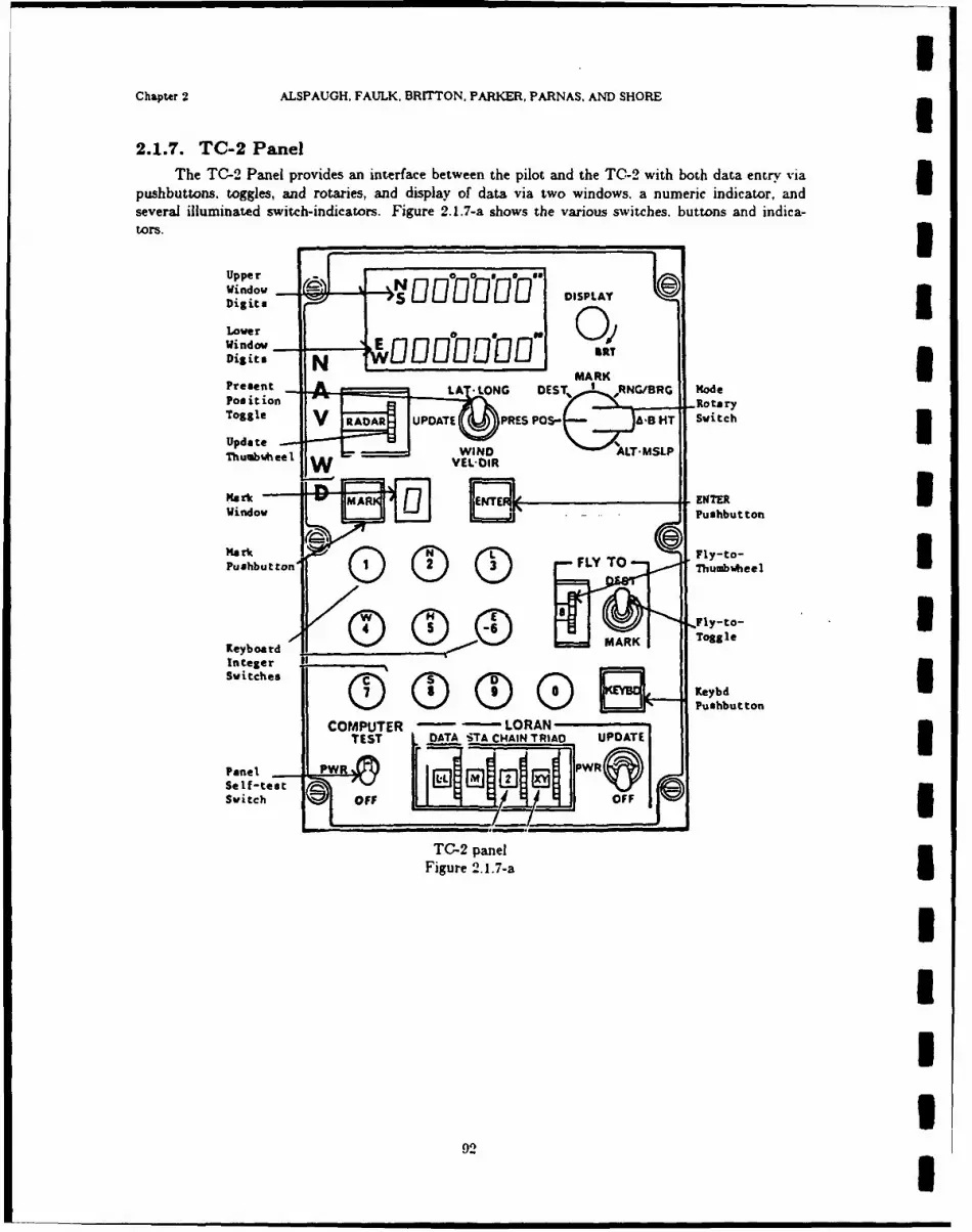
Chapter 2 ALSPAUGH. FAULK, BRITTON, PARKER, PARNAS, AND SHORE
2.1.7. TC-2 PanelThe TC-2 Panel provides an interface between the pilot and the TW-2 with both data entry via
pushbuttons. toggles, and rotaries, and display of data via two windows, a numeric indicator, andIseveral illuminated switch-indicators. Figure 2.1.-a shows the various switches. buttons and indica-tors. _ _ _ _ _ _ _ _ _ _ _
Digits N MARKIJ~rDPeet ALAT *LONG DEST, I RNG/BRG Mode
Update V RAARUPDATE PRES POS- ABlTSwitch
Windw ElPushbutton
Mark Fl-oPushbut ton '- ~ , ~ FLY TO ThIute
Keyoar (ii 0"ri-~ Pusbutto
InlftestrSw itche
KeOFF
Panel~TO- panI el JPR
Figure 2.1.7-aI
92

NRL REPORT 9194 TC-2 Panel
2.1.7.1. Enter button
Input data item(s): Enter Pushbutton Switch
Claw: PIWI
Acronym: /ENTERSW/
Hardware: TC-2 Panel
Description: The ENTER button is a momentary contact pushbutton switch on the TC-2 panel./ENTERSW/ indicates whether or not the ENTER button was pushed since the last time PanelInput Word I was checked. The event @T(!ENTERSW/ = SOnS), i.e.. pushing the button, gen-erates a Panel Interrupt.
Characteristics of values:Value encoding: SOffS (0); SOnS (1)
j Data representation: TC-2 Panel Input Word 1, bit 10
Instruction sequence: READ 208 (Channel 6)
Timing characteristics: The thirteen buttons that generate Panel Interrupts are not interlocked. Ifone is pressed before the previous panel interrupt is serviced, both bits will be set. The software can-not resolve such ambiguities. The other input data items that cause panel interrupts are/KBDENBL/, /KBDINT/, and /MARKSW/.
Comments: READ 208 resets all bits of TC-2 Panel Word 1 to 0. Spurious interrupts occasionallyoccur: when they do, there is no change to TC-2 Panel Word 1.
IIIIIIIII

IChapter 2 ALSPAUGH, FAULK, BRITTON, PARKER, PARNAS, AND SHORE
2.1.7.2. Fly-to thumbwheel
Input data item(s): Fly-to Thumbwheel IClass: PIW2
Acronym: /FLYTOTW/ 3Hardware: TC-2 Panel
Description: /FLYTOTW/ indicates the setting of a ten-position BCD thumbwheel switch. The tenpositions are labeled with decimal digits. UCharacteristics of values:
Value encoding:
$O$ (1111);$18 (1110);
$4 (1011);
$55 (1010);$6$ (1001); 175 (1000);
$85 (0111);$95 (0110)
Instruction sequence: READ 200 (Channel 6) I
Data representation: TC-2 Panel Input Word 2, bits 2-5
Timing characteristics: When the thumbwheel is moved, the previous setting is retained until the
next position is reached. There is no momentary "0" value.
IIIIllU
94 I

NRL REPORT 9194 TC-2 Panel
2.1.7.9. Fly-to toggle
Input data item(n): Fly-to Toggle
Class: PIW 2
Acronym: /FLYTO TOG /Hardware: TC-2 Panel
Description: /FLYTOTOG / indicates the current setting of a two-position toggle switch on thepanel. Switch Nomenclature: DEST. NAARK
Characteristics of values:
Value encoding: SDEST (10); SIMARKS (01)Instruction sequence: READ 200 (Channel 6)Data representation: TC-2 Panel Input Word 2, bits 0-1
95

IChapter 2 ALSPAUGH, FAULK, BRITTON. PARKER, PARNAS. AND SHORE
2.1.7.-4. Keyboard enable switch
Input data item(s): Keybd Enable Switch IClaw: PIWI
Acronym: /KBDENBL/ 3Hardware: TC-2 Panel
Description: The IKYD button is a momentary contact pushbutton switch on the TC-2 Panel./KBDENBL/ indicates whether or not the KEYBD button was pushed since the last time Panel InputWord I was checked. The event @T(/KBDENBL/ =f $On$), i.e., pushing the button, generates a
Panel Interrupt.
Characteristics of values: IValue encoding: SOftS (0); SOnS (1)
Instruction sequence: READ 208 (Channel 6)
Data representation: TC-2 Panel Input Word 1, bit 11Timing characteristics: See /ENTERSW/.
Comments: See /ENTERSW/. 3IIUII-I
IIU
96
aa I II I II
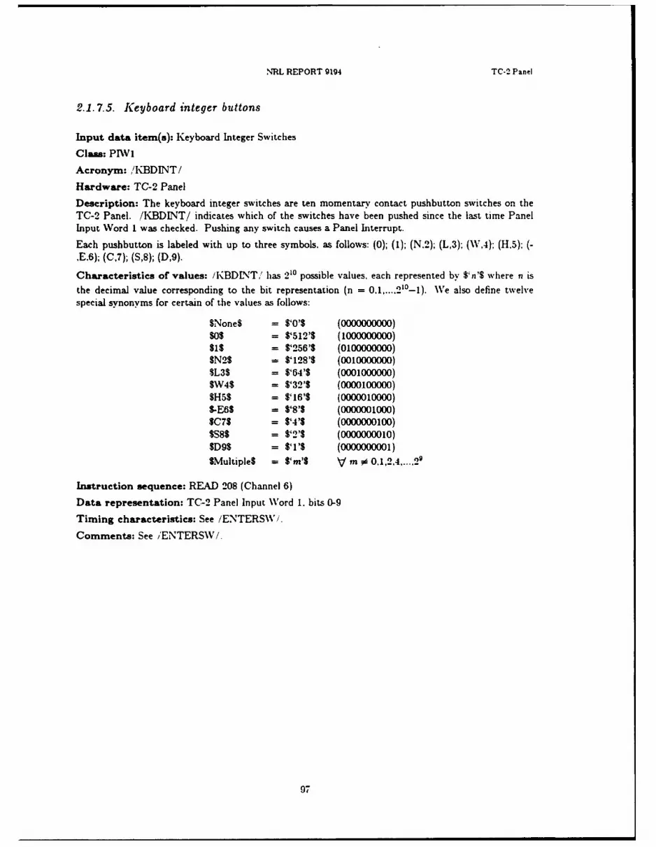
NRL REPORT 9194 TC-2 Panel
2.1.7.5. Keyboard integer buttons
Input data item(s): Keyboard Integer Switches
Class: PIWI
Acronym: /KBDINT/
Hardware: TC-2 Panel
Description: The keyboard integer switches are ten momentary contact pushbutton switches on theTC-2 Panel. /KBDINT/ indicates which of the switches have been pushed since the last time PanelInput Word 1 was checked. Pushing any switch causes a Panel Interrupt.
Each pushbutton is labeled with up to three symbols, as follows: (0); (1); (N.2); (L,3); (\V,4); (H,5); (-,E.6); (C,7); (S,8); (D,9).
Characteristics of values: /KBDINT/ has 210 possible values, each represented by $'n'S where n is
the decimal value corresponding to the bit representation (n = 0,1,....21Io). Ve also define twelvespecial synonyms for certain of the values as follows:
$None$ = $'0'$ (0000000000)$0S = $'512'3 (1000000000)$s = $'256'$ (0100000000)
$N2$ = $'128'$ (0010000000)$L3$ = $'64'$ (0001000000)SW45 = $'32'$ (0000100000)SH55 = $'16'$ (0000010000)S-E6S = $'8'$ (0000001000)$c7$ = $'41 (0000000100)$S85 - $'2'$ (0000000010)$D9$ = $'1'$ (0000000001)
SMultiple$ = $'m'$ V m # 0.1,2.4,...,29
Instruction sequence: READ 208 (Channel 6)
Data representation: TC-2 Panel Input Word 1. bits 0-9
Timing characteristics: See /ENTERSW\'/.
Comments: See /ENTERSW/.
97

Chapter 2 ALSPAUIGH, FAULK, BRITTON, PARKER, PARNAS, AND SHORE
2.1.7.6. Mark button
Input data item(s): Mark Pushbutton SwitchI
Class: PIWi
Acronym: /MAkRKSW /
Hardware: TC-2 Panel
Description: The MARK button is a momentary contact pushbutton switch on the TC-2 panel (seeFig. 2.1.7-a). /MAkRKSW/ indicates whether or not the MARK button was pushed since the last timeIPanel Input Word 1 was checked. The event @T(/fMARKSW/ =$On$), i.e., pushing the button.generates a Panel Interrupt.
Characteristics of values;Value encoding: $Of0 (0); $On$ (1)
Instruction sequence: READ 208 (Channel 6)
Data representation: TC-2 Panel Input Word 1. bit 12Timing characteristics: See /ENTERSW I.
Comments: See /ENTERSW I.
98I
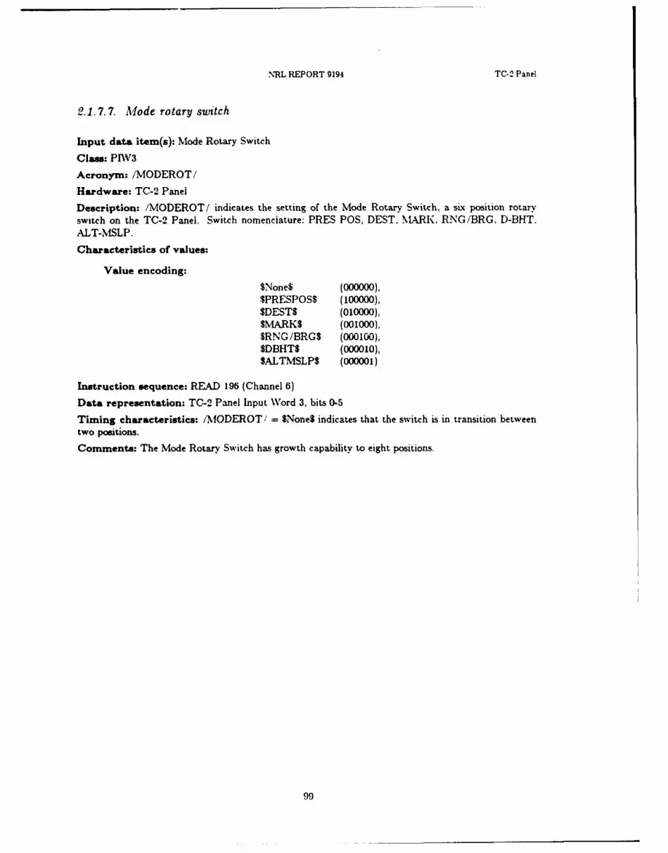
N'RL REPORT 9194 TC-2 Panel
2.1.7.7. Mode rotary switch
Input data item(s): Mode Rotary Switch
Class: PIWV3
Acronym: /MODEROT/
Hardware: TC-2 Panel
Description: /MODEROT/ indicates the setting of the Mode Rotary Switch, a six position rotaryswitch on the TC-2 Panel. Switch nomenclature: PRES POS, DEST, MARK. RNG/BRG. D-BHT.ALT-MSLP.
Characteristics of values:
Value encoding:
$None$ (000000),
SPRESPOSS (100000),$DEST$ (010000),
MARKS (001000),SRNG/BRG$ (000100),SDBHTS (000010),gALTMSLP$ (000001)
Instruction sequence: READ 196 (Channel 6)
Data representation: TC-2 Panel Input Word 3, bits 0-5
Timing characteristics: /MODEROT/ = gNoneS indicates that the switch is in transition betweentwo positions.
Comments: The Mode Rotary Switch has growth capability to eight positions.
99

IChapter 2 ALSPAUGH, FAULK, BRITTON. PARKER, PARNAS, AND SHORE
2.1.7.8. Panel self-test
Input data item(s): Panel Self Test Switch IClam: DIW5
Acronym: /PNLTEST/ 3Hardware: TC-2 Panel
Description: /PNLTEST/ indicates the setting of a three-position toggle switch on the TC-2 Panel.The switch will not stay in the COMPUTER TEST position unless the pilot holds it there. SwitchNomenclature: OFF, PWR, COMPUTER TEST
If the TC-2 is on, the switch must be either in PWR or COMPUTER TEST position.
Characteristics of values:IValue encoding: $PWR$ (0); STESTS (1)
Instruction sequence: READ 24 (Channel 0)
Data representation: Discrete input word 5, bit 10
1IIIIIIIIII
100
- = .=, . ilmnml A n n iN lin I I II l

NRL REPORT 9194 TC-" Panel
2.1.7.9. Present position toggle
Input data item(s): Present Position Toggle Switch
Class: PIW3
Acronym: /PRESPOS/
Hardware: TC-2 Panel
Description: /PRESPOS/ indicates the position of a three-position toggle switch on the TC-2 Panel.Switch Nomenclature: LAT.LONG. UPDATE, WIND VEL.DIR Sometimes when the switch positionis changed, the software can momentarily detect a fourth value for this switch, corresponding to aposition in between the others. We refer to this value as $None$.
Characteristics of values:
Value encoding:
Panel label Enumerated value Binary ValueLAT.LONG $LATLONGS 100UPDATE SUPDATE$ 010WINDVEL.DIR SWINDS 001
SNone$ 000
Instruction sequence: READ 196 (Channel 6)
Data representation: TC-2 Panel Input Word 3, bits 8-10
101

IChapter 2 ALSPAUGH, FAULK, BRITTON, PARKER, PARNAS, AND SHORE
2.1.7.10. Update thumbwheel
Input data item(s): Update Thumbwheel Switch IClas: PIW2
Acronym: /UPDATTW/ 3Hardware: TC-2 Panel
Description: /UPDATTW/ gives the current setting of the Update Thumbwheel Switch. a ten posi-tion thumbwheel switch on the panel. Switch Nomenclature: See below under Value Encoding.
Characteristics of values:
Value encoding: ;$DATA$ (1111);
$1HDS (1110);$RADARS (1101);SFLYOVER$ (1100);$LORAN$ (1011);STACL-L$ (1010);$TACMV$ (1001);$SMS-HUDS (1000);SSINSX-Y$ (0111);$Z-DHDGS (0110)
Instruction sequence: READ 200 (Channel 6)
Data representation: TC-2 Panel Input Word 2, bits 6-9 3Timing characteristics: When the thumbwheel is moved, the previous setting is retained until the
next position is reached. There is no intervening "0. 1IIIIIIU
102 I
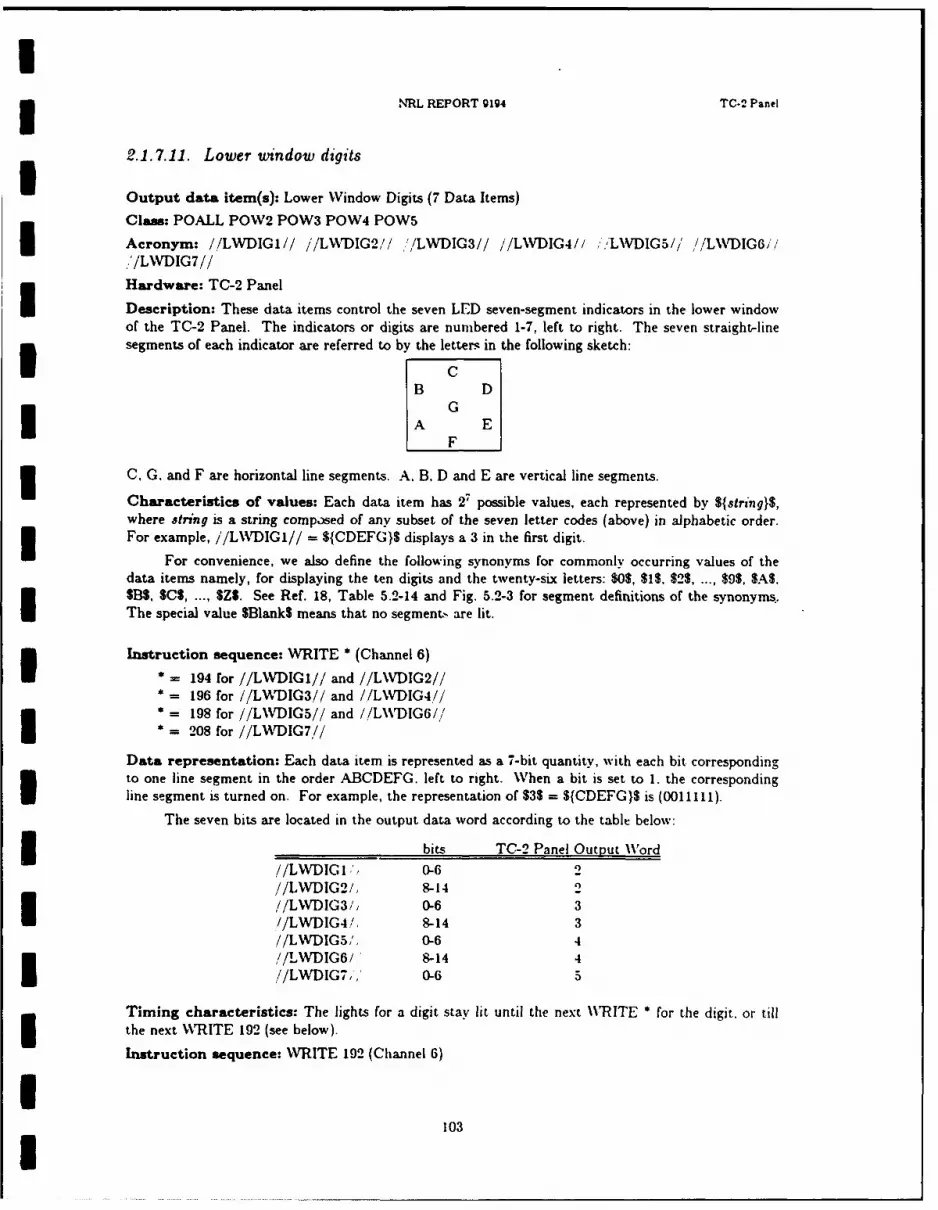
INRL REPORT 9194 TC-2 Panel
2.1.7.11. Lower window digits
Output data item(s): Lower Window Digits (7 Data Items)
Clas: POALL POW2 POW3 POW4 POW5
Acronym: //LWDIGI// /'/LN\DIG2,// "ILWDIG3// //LWDIG4// ,'LNVDIG5// //LWDIG6//*.'/LWDIG7//
Hardware: TC-2 Panel
Description: These data items control the seven LED seven-segment indicators in the lower windowof the TC-2 Panel. The indicators or digits are numbered 1-7, left to right. The seven straight-linesegments of each indicator are referred to by the letters in the following sketch:
CB D
GA E
C, G. and F are horizontal line segments. A. B. D and E are vertical line segments.
Characteristics of values: Each data item has 27 possible values, each represented by ${string}$,where string is a string composed of any subset of the seven letter codes (above) in alphabetic order.For example, //LWVDIGI// = ${CDEFG}$ displays a 3 in the first digit.
For convenience, we also define the following synonyms for commonly occurring values of thedata items namely, for displaying the ten digits and the twenty-six letters: $05, 15. $ ... $95, $A$,$13$, S$ ... Z. See Ref. 18, Table 5.2-14 and Fig. 5.2-3 for segment definitions of the synonyms.The special value SBank$ means that no segment. are lit.
Instruction sequence: WRITE * (Channel 6)
• = 194 for //LWDIGI// and //LWDIG2//• 196 for //LWNDIG3// and //LWDIG4//
* - 198 for //LWDIG5// and //L\\WDIG6//
2 - 208 for //LWDIG7//
Data representation: Each data item is represented as a 7-bit quantity, with each bit correspondingto one line segment in the order ABCDEFG. left to right. When a bit is set to 1. the correspondingline segment is turned on. For example, the representation of 53 = ${CDEFG}$ is (0011111).
The seven bits are located in the output data word according to the table below:
bits TC-2 Panel Output Word
//LWDIG1,'I 0-6 2//LWDIG2/, 8-14//LWDIG3/, 0-6 3//LWDIG4/, 8-14 3//LWDIG5,', 0-6 4
//LWDIG6/ 8-14 4//LWDIG7,,' 0-6 5
Timing characteristics: The lights for a digit stay lit until the next WRITE a for the digit. or tillthe next WRITE 192 (see below).
Instruction sequence: WRITE 192 (Channel 6)
103U

Chapter 2 ALSPAUGH, FAULK, BRITTON, PARKER. PARNAS. AND SHORE
The instruction above causes the value in the accumulator to be written out to all Channel 6outputs simultaneously. Thus, it acts as a simultaneous execution of WRITE *, where * is 194, 196.198 200, 202, 204, 206, 208, 210. 212, and 214. Other output data items affected by this instructionare //UWDIGn//, //MARKWIN//, the other panel lights.
IIIUIIIUIiUIIUI
104
• m m | |I

NRL REPORT 9194 TC-2 Panel
2.1.7.12. Mark window
Output data item(s): Mark Window
Clam: POALL
Acronym: //MARKWIN//
Hardware: TC-2 Panel
Description: //IvIARKWIN// controls the seven segment LED indicator in the LkRK window ofthe TC-2 Panel. For a description of the indicator, characteristics of values, data representation, andtiming characteristics, see the lower window digits (//L\%DIG1//, etc.).
Instruction sequence: WRITE 214 (Channel 6)I Data representation: TC-2 Panel Output Word 9, bits 0-6
Timing characteristics: The specified lights stay on until the next \VRITE 214 or WRITE 192.
Comments: See //LWDIGI//, etc.
IIIII1IIIII
i 105
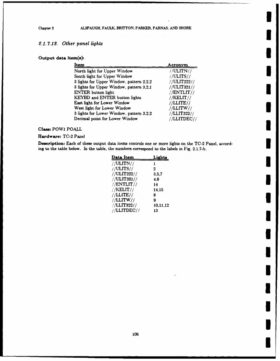
Chapter 2 ALSPAUGH. FAULK, BRITTON, PARKER, PARNAS. AND SHORE
2.1.7.13. Other panel lights
Output data item(s).
Item Acronym
North light for Upper Window //ULITN// ISouth light for Upper Window //ULITS//3 lights for Upper Window, pattern 2.2.2 //UL1T222//3 lights for Upper Window, pattern 3,2,1 //ULIT321//ENTER button light / /ENTLIT//IKEYED and ENTER button lights //K,-ELIT//East light for Lower Window //LLITE//
West light for Lower Window //LLITW//3 lights for Lower Window, pattern 3,2.2 .//LLIT322//Decimal point for Lower Window //LLITDEC//
Claws: POWI POALLU
Hardware: TC-2 Panel
Dencription: Each of these output data items controls one or more lights on the TC-2 Panel, accord-3ing to the table below. In the table, the numbers correspond to the labels in Fig. 2.1.7-b.
Data Itemn Lirghts/'/ULITN// 1I//ULITS//2//UL1T222// 3,5,7,/ULIT32I/,/ 4.6//ENTLIT// 141//KELIT// 14,15
//LLITE// 8//LLITW// 9II//LLIT322// 10,11,12
//LLITDEC/,/ 131
10I

INRL REPORT g914 TC-2 Panel
I 3 'i5£r.7
I '3 73
ILights on TC-2 panel
* Figure 2.1.7-b
I Characteristics of values:
Value encoding: SOnS (1), SOftS (0)
i Instruction sequence: WRITE 200 (Channel 6)
I Data representation: TC-2 Panel Output Word 1/!ULITN// bit 0
o //ULITS// bit 1
/!UL rT222e/ bit 2;/-ULIT321// bit 3I /ENTLIT // bit 6
/KELIT/ bit 7
'LLITE/i bi 8/'LLIT\W / / bit 3
'LLIT322 ,'/' bit 10,'LLITDEC/' bit 11
Timing characteristics: The specified lights stay on until the next WRITE 200 or WRITE 192.
Comments: Light 14 is tuined on if either 'ENTLIT/ 1 f SOnS or .'/KELIT = .On$See L\\rDIGI//, etc.
IIII
i 107

Chaptar 2 ALSPAUGH, FAULK, BRITTON, PARKER, PARNAS, AND SHORE
2.1.7.14. Upper wtindow digits
Output data item(s): Upper Window Digits (6 Data Items)I
Acronym: //UWDIGI// //UWDIG2// //UW~DIG3/,/ //UWDIG4// //UWDIG5// //UWDIG6//
Class: POALL POW6 POW7 POW8
Hardware: TC-2 Panel
Description: These dr.ta items control the six LED seven segment indicators in the upper window of
the TC-2 Panel. The digits are numbered 1-6, left to right. For a description of the indicators.Icharacteristics of values, data representation, and timing characteristics. see the lower window digits(//LWDIGi//, etc.).
Instruction sequence: WRITE * (Channel 6)2 '02 for //UWDIGI// and IIUWDIG2//204 for //UW~DIG3// and //UWDIG4//I
*=206 for //UWDIG5// and //UWDIG6//
Data representation: The seven bits are located in the output data word according to thetable below:I
bits TC-2 Panel Output WVord//UWDIGI// 0-6 6///UWDIG2// 8-14 6I//UWDIG3// 0-6 7//UWDIG4// 8-14 7//UWDIG5// 0-6 8//UWtDIG6// 8-14 81
Timing characteristics: The lights for a digit stay lit until the next WRITE Sfor the digit, or untilthe next WRITE 192.IComments: See I/LWDIG 1//, etc.
108
NIRL REPORT 9194 Built-In Test Equipment (BITE)
2.1.8. Built-In Test Equipment (BITE)
2.1.8.1. Introduction
The Built-In Test Equipment hardware provides features that allow programs to test for and
identify TC-2 computer and hardware interface malfunctions. The BITE hardware also has functionsthat operate automatically and independently of any written program code: they will not be describedhere. Further information about BITE hardware can be found in Refs. 18. 19, and 20.
The BITE interface to the software consists of the following:
* A set of commands to cause the BITE to wrap IO data. to turn on computer fail displays. to sendcomputer fail indicators to other hardware, and to set certain output data items to failsafe values.
e A GO/NO-GO counter that signals situations where program control may be lost.
* A circuit that signals when the program attempts to write into the protected area of storage.
i Check values generated by the hardware from sets of outputs.
2.1.8.2. BITE functions
The Input/Output Wrap causes an output data path to be connected or "wrapped" to an inputdata path. This allows both paths to be tested by writing out a value on the output path and check-ing to see that the same value can be read on the input path.
In case of computer malfunction, the failsafe feature prevents dangerous output signals frombeing sent inadvertently by setting critical output data items to a predetermined state. The critical
output data items are !/FIRRDY/,. ,/BMBREL/i, 'CURENABL/i, . 'ANTSLAVE//,.'//IMSNA//, and //COMPCTR,'./.
2.1.8.3. GO/NO-GO counter
A GO/NO-GO Counter is a real-time readable and resettable timing counter that incrementsindr idently of any program action. This counter can be used both as a system clock and as atime- detector. The counter will overflow after 1.3 seconds if it is not reset. This overflow condi-tion au matically generates a level-one interrupt and has the same hardware effect as BITEL :=$FORCEFAILS and //BITE2// - SDETECTNMkL$, except that the LRU malfunction flag is nottripped. This counter is used to detect improper OFP execution sequences. infinite iterative loops, and
program execution stoppages.
2.1.8.4- Storage protect niolation detection
A storage protect N iolation detection circuit senses if the program attempts to store into the pro-tected area of storage. A violation generates a level-one interrupt and has the same hardware effect as
BITEl, := $FORCEFAIL$ and /BITE2 := $DETECT.L,$.
2. 1.8.5. Signal converter hardware-generated values
The Signal Converter hardware generates check values used to verify results in the AC and DCself-tests.
109I
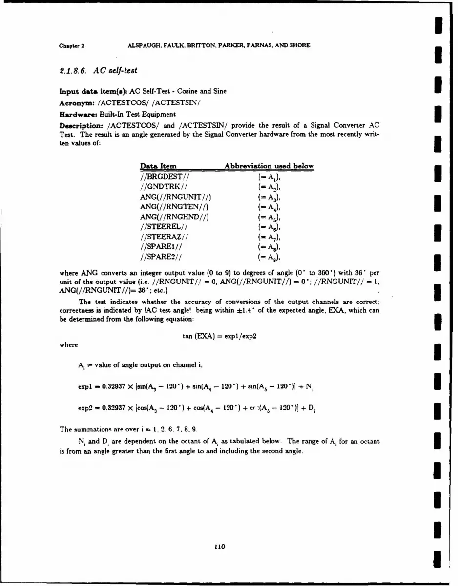
Chapter 2 ALSPAUGH, FAULK, BRITTON, PARKER, PARNAS. AND SHORE
2.1.8.6. AC self-test
Input data item(s): AC Self-Test - Cosine and Sine IAcronym: /ACTESTCOS/ /ACTESTSIN/
Hardware: Built-In Test Equipment 3Description: /ACTESTCOS/ and /ACTESTSIN/ provide the result of a Signal Converter ACTest. The result is an angle generated by the Signal Converter hardware from the most recently writ-ten values of:
Data Item Abbreviation used below//BRGDEST// (i Al), I//GNDTRK// k),
ANG(//RNGUNIT//) (= A3),ANG(//RNGTEN//) (= A), IANG(//RNGHND//) (= A-),//STEEREL// (= AO),//STEERAZ// (= A7)//SPAREI// N),//SPARE2// (fA,), 3
where ANG converts an integer output value (0 to 9) to degrees of angle (0" to 360") with 36' perunit of the output value (i.e. //RNGUNIT// = 0, ANG(//RNGUNIT//) = 0 ; //RNGUNIT// = 1,ANG(//RNGUNIT//)= 36"; etc.)
The test indicates whether the accuracy of conversions of the output channels are correct;correctness is indicated by !AC test angle! being within ±1.4 of the expected angle, EXA, which canbe determined from the following equation: 3
tan (EXA) = expl/exp2where
A. value of angle output on channel i,
expl - 0.32937 X Isin(A 3 - 120" + sin(A 4 - 120" ) + sin(A5 - 120 )1 + Ni Iexp2 = 0.32937 X jcos(A. - 120" + cos(A 4 - 120") + cr (A3 - 120")] + Di
The summations are over i - 1. 2. 6. 7. 8, 9.
N. and Di are dependent on the octant of A as tabulated below. The range of Ai for an octant
is from an angle greater than the first angle to and including the second angle.
1I3
110 I

INrRL REPORT 9194 Built-In Test Equipment (BITE)
A, Octant N. D.
0' - 45" 1 tan A, 1
45' - 90" 2 1 cot A.
90" - 135" 3 1 -cotA,135' - 180' 4 tan A. -1180" - 225" 5 -tanA -1
225' - 270" 6 -1 -cot A.
270 - 315 7 -1 cotA.315 - 360" 8 -tan A 1
Characteristics of values:
Units: None
Range: -1 to +1
Resolution: 1/4096
Instruction sequence:
READ 255 (Channel 7) (Reset Signal Converter if not already done)READ 224 (Channel 7) (Request Signal Converter to start conversion)Test Carry Indicator for 0 - Request acknowledged.If not, read sequence not successfully initiatedWhen DATA READY interrupt occurs, conversion completeREAD 225 (Channel 7) (SIN)Save Accumulator valueREAD 255 (Channel 7) (COS) (Also resets Signal Converter)
Data representation: 13-bit two's complement number, bits 0-12; bits 13-15 Scale - 4096, offset =
0.Timing characteristics: Synchro (analog) to digital conversion, see §1.15.8.
Comments: A delay of 4 seconds should be allowed between writing out //RNGUNIT//,/RNGTEN//, and //RNGHND// and reading in /ACTESTCOS/ and /ACTESTSIN/. to allow the
servos to settle down. If they haven't settled. !AC test angle! will not reflect the expected value.
A hardware error is indicated if the DATA READY interrupt does not occur in 3.2 msec after READ224 or if the request is not acknowledged after READ 224.
IIIIII 111
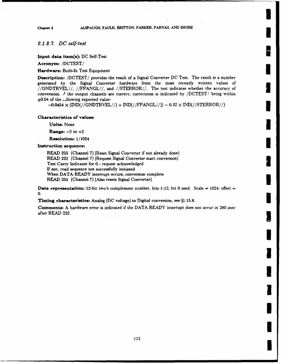
IChapter 2 ALSPAUGH. FAULK, BRITTON, PARKER, PARNAS. AND SHORE
2.1.8.7. DC self-test
Input data item(s): DC Self-Test
Acronym: /DCTEST/
Hardware: Built-In Test Equipment
Description: /DCTEST/ provides the result of a Signal Converter DC Test. The result is a numbergenerated by the Signal Converter hardware from the most recently written values of//GNDTRVEL//, //FPANGL//, and //STERROR//. The test indicates whether the accuracy of Iconversions XV the output channels are correct; correctness is indicated by /DCTEST/ being within
:-0.04 of the ,)llowing expected value:-0.0454 x (IND(//GNDTRVEL//) + IND(//FPANGL//)) - 0.32 X IND(//STERROR//)
Characteristics of values:
Units: None 3Range: -2 to +2
Resolution: 1/1024
Instruction sequence:
READ 255 (Channel 7) (Reset Signal Converter if not already done)READ 232 (Channel 7) (Request Signal Converter start conversion)Test Carry Indicator for 0 - request acknowledged IIf not, read sequence not successfully initiatedWhen DATA READY interrupt occurs, conversion completeREAD 255 (Channel 7) (Also resets Signal Converter)
Data representation: 12-bit two's complement number, bits 1-12; bit 0 used. Scale - 1024: offset -0.|Timing characteristics: Analog (DC voltage) to Digital conversion, see §1.15.8.
Comments: A hardware error is indicated if the DATA READY interrupt does not occur in 280 Psecafter READ 232. 3
1NINII
112!
t | • ' 'I
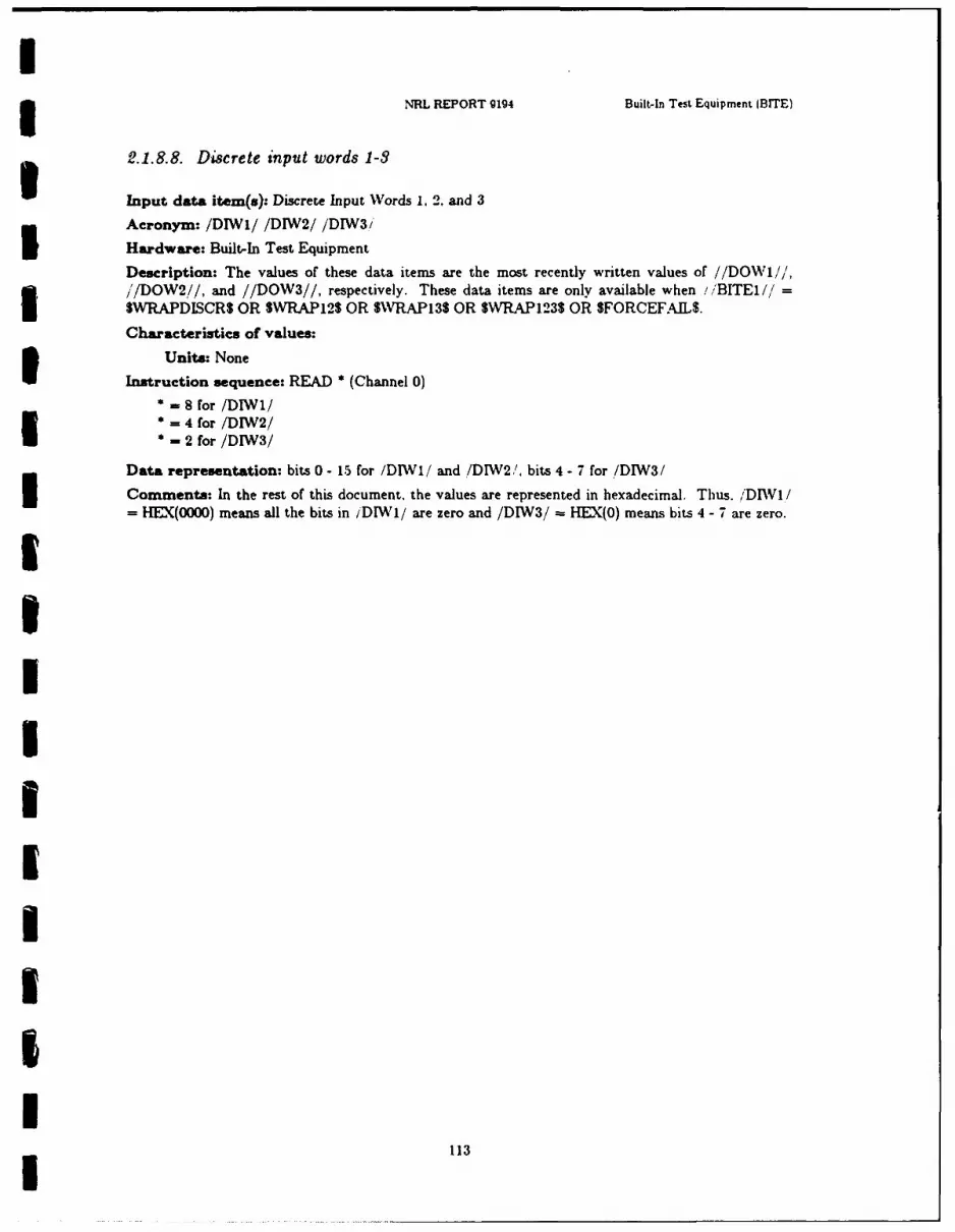
I3 NRL REPORT g194 Built-In Test Equipment (BITE)
2.1.8.8. Discrete input words 1-3
Input data item(s): Discrete Input Words 1. 2. and 3
Acronym: /DIWI/ /DIW2/ /DIW3/
Hardware: Built-In Test Equipment
Description: The values of these data items are the most recently written values of //DOW1//',//DOW2//, and //DOW3//, respectively. These data items are only available when !/'BITE1//
SWRAPDISCR$ OR SWRAP125 OR SWRAP13S OR $WRAP123$ OR $FORCEF.AL$.
Characteristics of values:
Units: None
Instruction sequence: READ * (Channel 0)
8 for /D1W1/= 4 for /DIW2/
- 2 for /DIW3/
Data representation: bits 0 - 15 for /DIWI/ and /DIW2/, bits 4 - 7 for /DIW3/
Comments: In the rest of this document, the values are represented in hexadecimal. Thus. /'DIW1/- HEX(O000) means all the bits in iDIWI/ are zero and /DIW3/= HEX(0) means bits 4 - 7 are zero.
1!I!iIUIII
i 113
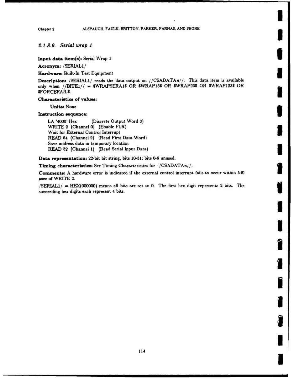
IChapir 2 ALSPAUGH, FAULK. BRITTON, PARKER. PARNAS. AND SHORE
2.1.8.9. Serial wrap 1
Input data item(s): Serial Wrap I UAcronym: /SERIAL1/
Hardware: Built-In Test Equipment IDescription: /SERIALI/ reads the data output on //CSADATAn//. This data item is availableonly when //BITEI// = $WRAPSERAI$ OR SWRAP135 OR $WRAP23S OR SWRAP123$ ORgFORCEFAILS. 1Characteristics of values:
Units: None
Instruction sequence:
LA '4000' Hex (Discrete Output Word 3)WRITE 2 (Channel 0) (Enable FLR)Wait for External Control Interrupt IREAD 64 (Channel 2) (Read First Data Word)Save address data in temporary locationREAD 32 (Channel 1) (Read Serial Input Data)
Data representation: 22-bit bit string, bits 10-31; bits 0-9 unused.
Timing characteristics: See Timing Characteristics for /CSADATAn//.
Comments: A hardware error is indicated if the external control interrupt fails to occur within 540 Ipsec of WRITE 2.
/SERIALI/ = HEX(000000) means all bits are set to 0. The first hex digit represents 2 bits. Thesucceeding hex digits each represent 4 bits.
I!
IIIaU
114 I
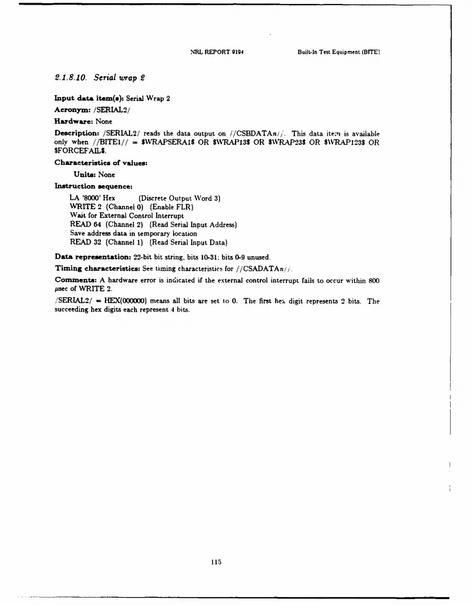
NRL REPORT 0194 Built-In Test Equipment (BITE)
2.1.8.10. Serial wrap 2
Input data item(s): Serial Wrap 2
Acronym: /SERIAL2/
Hardware: None
Description: /SERIAL2/ reads the data output on //CSBDATAn/i. This data item is availableonly when //BITEI// f SWRAPSERAIS OR $\WAP135 OR $WAP23$ OR $WVRAPl235 ORSFORCEFAILS.
Characteristics of values:
Units: None
Instruction sequence:
LA '8000' Hex (Discrete Output Word 3)WRITE 2 (Channel 0) (Enable FLR)Wait for External Control InterruptREAD 64 (Channel 2) (Read Serial Input Address)Save address data in temporary locationREAD 32 (Channel 1) (Read Serial Input Data)
Data representation: 22-bit bit string, bits 10-31; bits 0-9 unused.
Timing characteristics: See timing characteristics for //CSADATAn!/.
Comments: A hardware error is indicated if the external control interrupt fails to occur within 800psec of WRITE 2.
/SERIAL2/ - HEX(000000) means all bits are set to 0. The first he;, digit represents 2 bits. Thesucceeding hex digits each represent 4 bits.
115

Chapter 2 ALSPAUGH, FAULK. BRITTON, PARKER. PARNAS. AND SHOREg
2.1.8.11. Accelerometer tests
Input data item(s): Accelerometer Tests
Acronym: /XVELTEST/ /YVELTEST/ /ZVELTEST ~Hardware: Built-In Test EquipmentI
Description: The values of these data items are the most recently written values of //X.TOR-TEST//, //YTORTEST//, and //ZTORTEST//, respectively. These data items are only availablewhen //BITE2// - SWRAPGYACCS.Characteristics of values:
Units: None
Instruction sequence: READ * (Channel 4) (valid only if /DalIWCI'* 130 for /XVELTEST/*=129 for /YVELTEST/
132 for /ZVELTEST/I
Data representation: 16-bit string
111
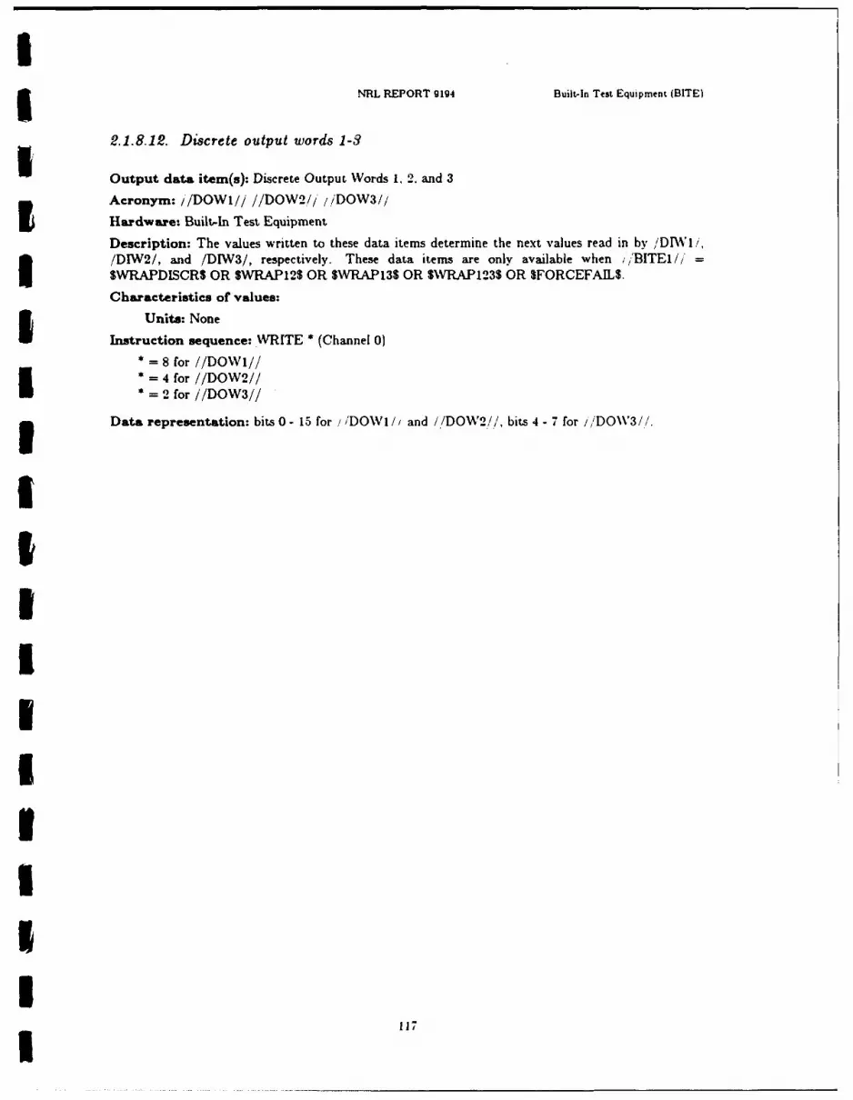
INRL REPORT 9194 Built-In Test Equipment (BITE)
2.1.8.12. Discrete output words 1-3
Output data item(s): Discrete Output Words 1, 2. and 3
Acronym: //DOWI/ //DOW2/i /DOW3//
Hardware- Built-In Test Equipment
Description: The values written to these data items determine the next values read in by /DIW1I,/DIW2/, and /DIW3/, respectively. These data items are only available when //'BITEI//' =
SWRAPDISCRS OR SWRAP12$ OR $WRAPI3$ OR SVRAPI235 OR SFORCEFAIL$.
Characteristics of values:
Units: None
Instruction sequence: WRITE * (Channel 0)8 for //DOWI!/
= 4 for //DOW2//2 - 2 for //DOW3//
Data representation: bits 0 - 15 for //DOWi //and /,/DOW2/!/, bits 4 - 7 for I/DOV3//.
£
IiIIIiII
I 117
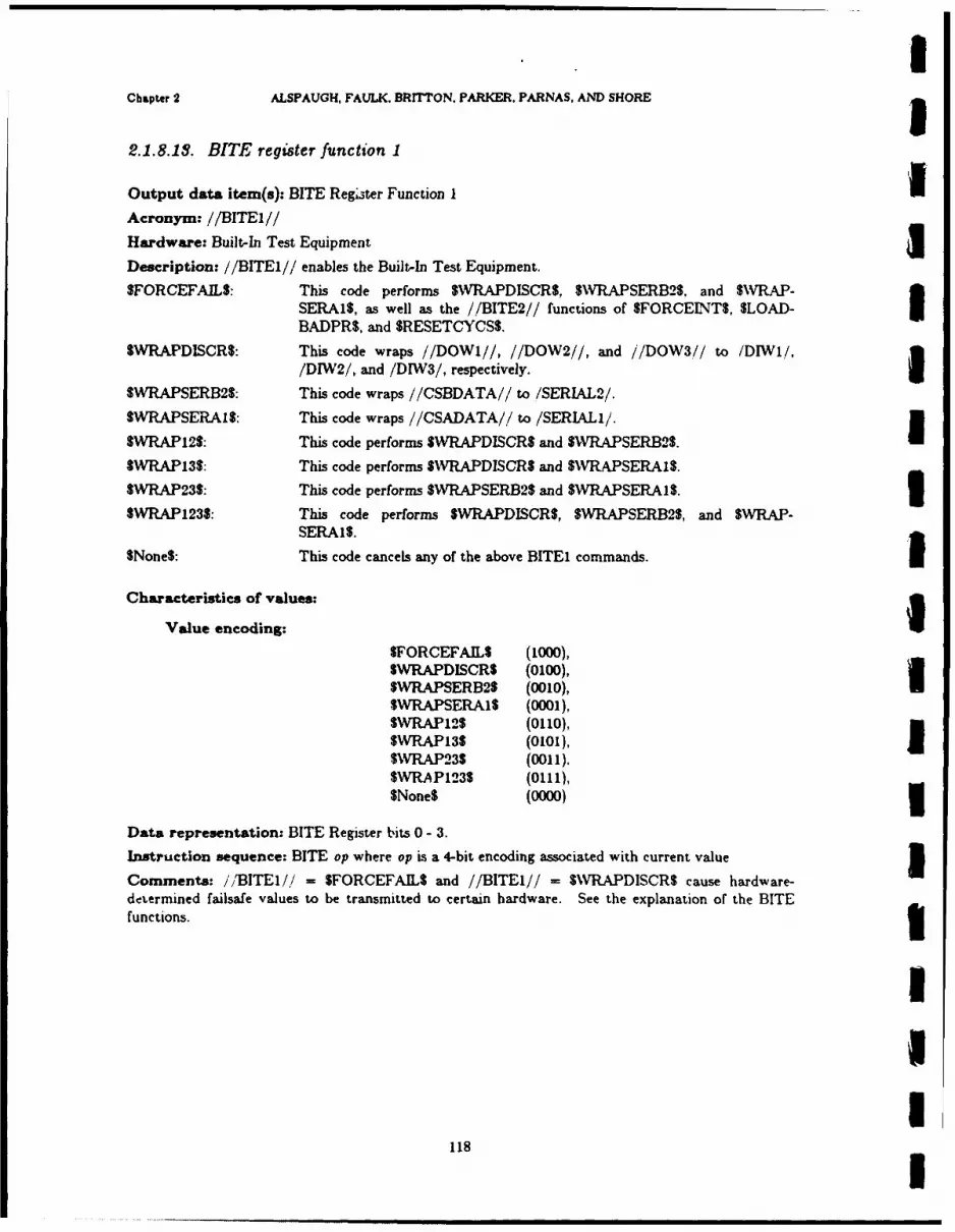
Chapter 2 ALSPAUGH, FAULK. BRITTON, PARKER, PARNAS, AND SHOREg
2.1.8.18. BITE register function 1
Output data item(s): BITE Register Function II
Acronym: //BITEI//
Hardware: Built-In Test Equipment
Description: //BITEI// enables the Built-In Test Equipment.
$FORCEFAILS: This code performs SNWRAPDISCRS, SNVRAPSERB2$. and $WVRAP-
SERAIS, as well as the //BITE2// functions of SFORCEIT$, $LOAD-BADPR$, and SRESETCYCSS.
SWRAPDISCR$: This code wraps //DOWI//, //DOW2//, and //DOW3,// to /DIW1l/,
/DIW2/, and /DIW3/, respectively.ISWR7APSERB2$: This code wraps //CSBDATA// to /SERIAL2/.
SWRAPSERAIS: This code wraps //CSADATA// to /SERL1/.SWRP12: hiscod prfomsSWRPDICR an UVAPER12I$WRAP13$: This code performs SWVRAPDISCRS and SWRAPSERB2S.
SWVRAP23$: This code performs $WRAPSERB2$ and $WRAPSERAI$.3
SWRAP 123: This code performs $WRAPDISCR$, $WRAPSERB2$, and $WRAP-SERA 1$.
$None$: This code cancels any of the above BITEI commands. 'Characteristics of values:
Value encoding:ISFORCEFAILS (1000),SWRAPDISCRS (0100),$WRAPSERB2$ (0010),ISWRAPSERA1S (0001),SWRLAP12S (0110),
SWRAP13S (0101),I$WRAP=3 (0011).SWRAP123S (0111),$None$ (0000)1
Data representation: BITE Register bits 0 - 3.
Instruction sequence: BITE op where op is a 4-bit encoding associated with current value
Comments: // BITE1// = SFQRCEFALLS and //BITE1// = SWVRAPDISCRS cause hardware-determined failsafe values to be transmitted to certain hardware. See the explanation of the BITEfunctions.
118

I
NRL REPORT 9194 Built-In Test Equipment (BITE)
2.1.8.14. BITE register function 2
Output data item(s): BITE Register Function 2
Acronym: //BITE2//
Hardware: Built-In Test Equipment
Description: //BITE2// enables the Built-In Test Equipment (see §2.1.8).
$WRAPGYACC$: This code wraps i/XTORTEST//, ,'/YTORTEST/'/. and //ZTOR-TESTI' to /XVELTEST/, ,YVELTEST/, and /ZVELTEST/, respec-tively. This code is only available when /DaIMVC/:= $Changing$.
$DETECTMAL$: This code sets a mechanical malfunction latch, trips the computer LRUmalfunction flag, and causes //COMPFAIL//:= SOnS. The computermust be reset manually before the program can resume running.
SFORCEINT$: This code sets all bits in the Interrupt Registers.
$LOADBADPRS: This code generates bad parity for the cycle steal channel A.
SRESETCYCS$: This code resets all Cycle Steal channels to the initialized state andcauses cycle steal to stop.
$None$: This code cancels any of the above BITE2 commands.
Characteristics of values:
£Value encoding:
$WRAPGYACCS (1110),SDETECTMALS (1100),'FORCEINT$ (0110),SLOADBADPR$ (0101),SRESETCYCS$ (0100),$None$ (0000)
Data representation: BITE Register bits 4 - 7.
Instruction sequence: BITE op. where op is a 4-bit encoding associated with current value.
iIIaiI
i 119
Chaptr 2 ALSPAUGH, FAULK, BRITTON, PARKER, PARNAS. AND SHORE 92.1.8.15. Cycle steal channel A
Output data item(s): Cycle Steal Channel A
Acronym: //CSADATAn//
Hardware: Built-In Test Equipment IDescription: //CSADATAn// refers to the data items in the channel A cycle steal list, //CSA-DATAI// ... //CSADATAn// for any integer 1<n<128. See §1.14 for information about the cyclesteal list. When //CSADATAn// is enabled, these data items are transmitted one at a time, in Isequence. Depending on how the list is constructed, //CSADATAn// can be followed by any //CSA-DATA//, 25j<n. The data item that was most recently transmitted determines the next value readin for /SERIALl/. //CSADATAn// is enabled when //BITE1// = $WRAPSERAI$ OR SWRAP13$OR SWRAP23S OR SWRAP1235 OR SFORCEFAIL$
Characteristics of values:
Units: None 1Instruction sequence: See §1.14.
Data representation: 22 bits (bits 9-14 and 16-31) in a 32-bit word; bits 0-8 and 15 not used.
Timing characteristics: At least 360 psec elapse between the transmission of two //CSADATAni/ Idata items.
IIi1IIUIiI
120
. . . . .m m m | |I
f, NRL REPORT 9194 Built-In Test Equipment (BITE)
2.1.8.16. Cycle steal channel B
Output data item(s): Cycle Steal Channel BAcronym: //CSBDATAn//
Hardware: Built-In Test Equipment
Description: //CSBDATAn// refers to the data items in the channel B cycle steal list.//CSBDATAI// . . //CSBDATAn// for any integer 1 n_128. See 1.14 for information about thecycle steal list. When //CSBDATAn// is enabled, these data items are transmitted one at a time, insequence. Depending on how the list is constructed, //CSBDATAn// can be followed by any
,//CSBDATAj//, 2_ n. The data item that was most recently transmitted determines the nextvalue read in for /SERIALI/. //CSBDATAn// is enabled when //BITE1//= SWRAPSERAlS ORSWRAP135 OR SWRAP23$ OR SWRAPI235 OR SFORCEFAIL$
Characteristics of values:
5Units: None
Instruction sequence: See §1.14.
Data representation: Same as / /CSADATAn/.
Timing characteristics: At least 360,psec elapse between the transmission of two /i/CSBDATAn//data items.
It3
II£iI
II 121
IChapter 2 ALSPAUGH. FAULK, BRITTON, PARKER. PARNAS, AND SHORE5
2.1.8.17. Spare synchro outputs
Output data item(s): Spare Synchro Outputs KAcronym: //SPAREI// //SPARE2//
Hardware: None
Description: //SPARE1// and //SPARE2// affect the value of /ACTESTCOS/ and /ACTEST-SIN/. They have no other observable effects.
Characteristics of values: 3Units: Degrees
Range: 0 to 360 *
Accuracy: -0.1 *
Instruction sequence:WRITE * (Channel 7) ITest Carry Bit - 0 for request acknowledgedIf not, restart
* = 236 for //SPAREI//, 237 for //SPARE2// IData representation: Each angle is represented by two fields, an octant and a magnitude. See//STEERAZ//.
Timing characteristics: Digital to Synchro conversion. See §1.15.8.
1gUI
IiIa
122 !

INRL REPORT 9194 Built-In Test Equipment (BITE)
2.1 .8.18. Gyro torque tests
I Output data item(s): Gyro Torque TestsAcronym: //XTQRTEST// /JYTORTEST// //ZTORTEST//
Hardware: Built-in Test Equipment
Description: The values written to these data items determine the next values read by /'XV\EL-TEST/, /YVELTEST/. aad ,'ZVELTEST,'. respectively. These data items can only be output when,"/BITE2/// = $WRZAPGYACCS.
Characteristics of values:
Unt:NoneI Instruction sequence:WVRITE * (Channel 4) (valid only if /DIMW\C / $Ready$)
I - j129 for //XTORTEST//=130 for //YTORTEST//
*-132~ for //ZTORTEST//
I Data representation: 16-bit string
12
IChapter 2 ALSPAUGH, FAULK, BRITTON, PARKER, PARNAS. AND SHORE
2.2. DEVICES WITH INPUT COMMUNICATION PATHS
2.2.1. Radar Altimeter (RADALT)The Radar Altimeter (RADALT) provides a continuous, accurate indication of absolute altitude
above terrain or water to the TC-2, FLR, and HUD.
2.2.1.1. Radar altitude
Input data item(s): Radar Altitude
Acronym: /RADALT/
Hardware: Radar Altimeter
Description: /RADALT/ provides the distance above terrain as determined by the Radar Altimeter.
Characteristics of values:
Units: Feet
Range: 0 to 5000
Accuracy: E5 ft IResolution: 1.2207031
Maximum derivative: 1000 ft/s
Instruction sequence:
READ 255 (Channel 7) (Reset Signal Converter if not already reset)READ 233 (Channel 7) (Request Signal Converter start conversion)Test Carry Indicator for 0 - request acknowledgedIf not, start againWhen DATA READY interrupt occurs, conversion completeREAD 255 (Channel 7) (Also resets Signal Converter)
Data representation: 12-bit positive number, bits 1-12; bit 0 = 0, bits 13-15 not used. Scale -.048/2500 :=: 0.8192; offset = 0.
Comments: Analog (DC voltage) to digital conversion. See §1.15.8.If the data is not valid, e.g., A/C upside down. a value of 0 is transmitted.
IIIII
124I
m mu nnninn nmlln nlnulllNI

I,\71, REPORT 9194 Slew Control
2.2.2. Slew ControlThe Slew Control is used as a direction-of-motion control. It is a "joystick" with 2 degrees of
freedom. See figure 2.2.2-a.
SlwCoto
I Slew control
Inu dat itm3:Se ih-Lf.Se pDw
1125
Chapter 2 ALSPAUGH. FAULK. BRITTON, PARKER. PARNAS. AND SHORE
Description: The Slew Control is a cube shaped control located forward on the cockpit left console.The input value is proportional to the displacement from center. Positive values of /SLEWRL/ and/SLEWUD/ indicate displacements to the right and up respectively. ICharacteristics of values:
Units: None
Range: -4 to +4
Resolution: 1/1024
Instruction sequence: IREAD 255 (Channel 7) (Reset Signal Converter if not already reset)
READ * (Channel 7) (Request Signal Converter to start conversion)Test Carry Indicator for 0 - request acknowledgedIf not, start againWhen DATA READY interrupt occurs, conversion completeREAD 255 (Channel 7) (Also resets Signal Converter) I• = 240 for Slew Right-Left* 239 for Slew Up-Down
Data representation: 13-bit two's complement number, bits 0-12; bits 13-15 = 0. Scale - 2048/2= 1024; offset = 0.
Timing characteristics: Analog (DC voltage) to digital conversion. See §1.15.8. 1Comments: The Slew control "snaps back" to central position. The values of /SLENVRL/ and/SLEWUD/ are not always 0 in this position. Slew values less than .148 are known to be a reliableindication that the control is in the central position. 9
1II
IIII
128
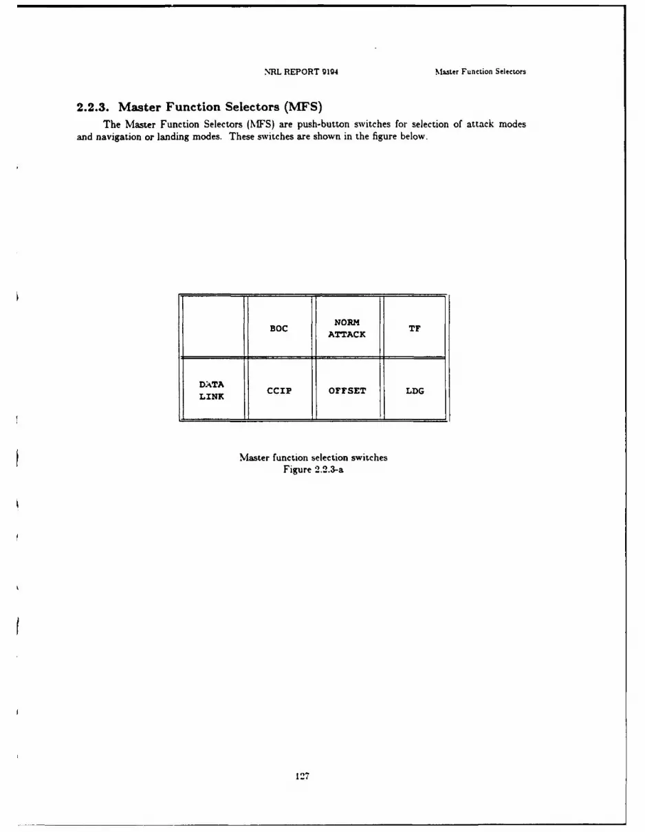
NRL REPORT 9194 Master Function Selectors
2.2.3. Master Function Selectors (MFS)
The Master Function Selectors (MFS) are push-button switches for selection of attack modesand navigation or landing modes. These switches are shown in the figure below.
NORMBOC TF
ATTACK
DATALINK CCIP OFFSET LDG
Master function selection switchesFigure 2.2.3-a
127

I
Chapter 2 ALSPAUGH, FAULK, BRITTON, PARKER. PARNAS, AND SHORE 52.2.3.1. Master function switches
Input data item(s): Master Function Switches /
Clas: DIW4
Acronym: / MFSW/ iHardware: Master Function Switch
Description: /MFSW/ indicates the settings of a series of pilot selectable pushbuttons.
Characteristics of values:I
Value encoding:
$NATTS (10000) - only NORM ATT pushed I$BOC$ (00100) - only BOC pushed$C0PS (00010) - only CCIP pushedSTF$ (00001) - only TF pushedSNATTOFFS (11000) - NORM ATT and OFFSET pushed$BOCOFFS (01100) - BOC and OFFSET pushed$NONE$ (00000) - none of the above pushed g
Instruction sequence: READ I (Channel 0)
Data representation: Discrete Input Word 4, bits 1-5 3Comments: Hardware constrains NORM ATT, BOC, CCIP, and TF to be mutually exclusive.OFFSET can only be pushed in conjunction with NORM ATT or BOC.
1III1IIa
1o.8 ii promif 128

NRL REPORT 9194 Master Function Selectors
2.2.4. Armament Release Panel (ARP)The Armament Release Panel (ARP) contains switches for weapons controls. They are located
in the cockpit and communicate with both TO-2 and ASCU.
Single-Pairs -Simuxltaneous.p.ocketsSwitch
ARP _____
Thumbwheel AR
Armament release panelFigure 2.2.4-a
129

Chapter 2 ALSPAUGH, FAULK. BRITTON, PARKER, PARNAS, AND SHORE
2.2 .4.1. ARP interval
Input data item(s): ARP Interval 3Clas: DIW2
Acronym: /ARPINT/ 3Hardware: Armament Release Panel
Description: /ARPINT/ indicates the position of a dual thunibwheel switch. See Ref. 14a. Fig. 8-12. Switch Nomenclature: The left wheel (hundreds) runs from 0 to 9 by units; the right wheel (tens)runs from 00 to 90 by tens.
Characteristics of values: 3Range: 0 to 990
Resolution: 10
Instruction sequence: Read 4 (Channel 0) aData representation: Discrete input word 2, 2 digits BCD encoded in bits 8-15 (hundreds digit inbits 8-11, tens digit in bits 12-15).
Standard value (HUNDREDS DIGIT) x 100) + (TENS DIGIT) x 10) 1
I-
I
IIII!
130i
l I I II

ISNRL REPORT g194 Master Function Selectors
2.2-.4.2. ARP pairs switch
Input data item(s): ARP Pairs
Claw: DIW5
. Acronym: /ARPPAIRS/
Hardware: Armament Release Panel
Description: The Single-Pair-Simultaneous-Rockets switch is a three-position toggle switch in thecockpit. (See Ref. 14a, Fig. 8-12). /ARPPAIRS/ indirates whether the switch is in PAIR position orin one of the other two positions. The TC-2 is not able -uish between the other two values.The switch is also input to the ASCU (see //BMBREL/. -h nomenclature: PAIR; SINGLE;SIMULT RKTS.
Characteristics of values:
Value encoding: $Yes$ (1); $No$ (0)
Instruction sequence: READ 24 (Channel 0)Data representation: Discrete input word 5, bit 13.
II!IIIIIII
I 131

IChapter 2 ALSPAUGH. FAULK, BRITTON, PARKER, PARNAS, AND SHORE a2.2.4.8. ARP quantity
Input data item(s): ARP Quantity iClas: DIW2
Acronym: /ARPQUANT/ 5Hardware: Armament Release Panel
Description: /ARPQUANT/ indicates the position of a dual thumbwheel switch. Both wheels have
10 positions, labeled from 0 to 9.ICharacteristics of values:
Range: 0 to 99
Instruction sequence: READ 4 (Channel 0)Data representation: Discrete input word 2, BCD encoded in bits 0-7 (tens digit in bits 0-3, unitsdigit in bits 4-7).
Comments: The /ARPQUANT/ is also input to the ASCU - the ASCU can sense when/ARPQUANT/ 1. When iARPQUANT/ i and /MFSW/ SNone$, the ASCU will permit amanual release.5
1aI
IIai
II
132
--- m~mam nnnnn nn imiiiB •I

NRL REPORT g194 Doppler Radar Set (DRS)
2.2.5. Doppler Radar Set (DRS)
The Doppler Radar Set (DRS) continuously measures the A/C ground speed and drift angle
during flight and transmits this information to the TC-2.
The DRS sends three data words (DRS Status, Ground Speed, and Drift Angle) continuously in
sequence. One word arrives every 400 microseconds. Since a request for one of these must be made
before the word arrives, and since only one request can be made at a time, the fastest program can
only read every second word of the DRS three word sequence. Obtaining a particular word can there-
fore require two requests and as long as 2.4 milliseconds. Obtaining all three words requires three
requests and 2.4 milliseconds.
Figure 2.2.5-a shows the Doppler Control Panel. This panel has no direct connection to the
TC-2, since the displays are driven directly by the DRS. But the setting of the Doppler Selector Knob
affects the inputs received by the TC-2.
l DopplerSe lector
I Knob ON TEST
:o L R S D
II
5 Doppler control panelFigure 2.2.5-a
II$I$I
I 133
I
UChapter 2 ALSPAUGH, FAULK, BRITTON, PARKER, PARNAS, AND SHORE g2.2.5.1. Doppler drift angle
Input data item(s): Doppler Drift Angle IClass: SDOP-DOW3
Acronym: /DRFTANG/ 5Hardware: Doppler Radar Set
Description: /DRFTANG/ provides the DRS estimate of the angle from the projection of the A/CYa axis onto the horizontal plane to the projection of the A/C velocity vector onto the horizontalplane. The angle is positive when measured CW from the projection of the A/C Ya axis (lookingdown). Thus, drift is positive when ground track is to the right of the A/C heading.
Characteristics of values:Units: Degrees
Range: -53.5714 to 40.045714
Range: ±45
Accuracy: -0.06
Resolution: .0057
Maximum derivative: ±50 deg/s
Maximum second derivative: 100 deg/s "
Instruction sequence: ILA '8000' Hex (Discrete Output Word 3)WRITE 2 (Channel 0) (Enable DRS)Wait for External Control Interrupt aREAD 64 (Channel 2) (Read Serial Input Address)Save address data to verify identity code = 00011Check if !Serial Input OK! 1If not, try again in 20 to 400 microsecondsREAD 32 (Channel 1) (Read Serial Input Data)
Data representation: 14-bit positive number, bits 1-14: bits 0 and 15 = 0. Scale = 175: offset 19375/175.
Timing characteristics: See §2.2.5.
Comments: iDRFTANG/ is a current estimate only if /DRSMEM/ $No$. It is a valid estimate Ionly if /DRSREL/ = $Yes$.
1aIaI
134!
3 NRL REPORT 9194 Doppler Radar Set (DRS)
2.2.5.2. Doppler groundspeed
I Input data item(s): Doppler Ground SpeedClass: SDOP-DOW33 Acronym: /DGNDSP/Hardware: Doppler Radar Set
Description: /DGNDSP/ provides the DRS estimate of the magnitude of the projection of the A/Cvelocity vector onto the horizontal plane.Characteristics of values:
Units: KnotsRange: 100 to 999
Accuracy: -(.11% GS + .081) to +(.i% GS + .081)
Resolution: .129
Maximum derivative: 999 knots/s
Maximum second derivative: ± 250 ft/s 2.Instruction sequence:
LA '8000' Hex (Discrete Output Word 3)WRITE 2 (Channel 0) (Enable DRS)
Wait for External Control InterruptREAD 64 (Channel 2) (Read Serial Input Address)Save address data to verify identity code = 00010Check if !Serial Input OK!If not, try again in 20 to 400 microseconds
READ 32 (Channel 1) (Read Serial Input Data)
Data representation: 14-bit positive number, bits 1-14; bits 0 and 15 - 0. 1/scale :-: .129032:offset - 0;
Timing characteristics: See §2.2.5.
Comments: /DGNDSP/ is a current estimate only if /DRSMEM/ = $No$. It is valid only if/DRSREL/ = SYes$. /DGNDSP/ is not true doppler ground speed, which is given by !DGNDSP!.
1IIIII
! 135

Chapter 2 ALSPAUGH, FAULK, BRITTON, PARKER. PARNAS. AND SHORE
2.2.5.3. Doppler function switch
Input data item(s): DRS Function Switch IClass: SDOP-DOW3
Acronym: /DRSFUN/ 5Hardware: Doppler Radar Set
Description: /DRSFUN/ indicates the current setting of the rotary switch on the DRS control panel(OFF; STBY; ON; TEST). The setting of the switch affects the values of /ANTGOOD/ and/ELECGOOD/.
Characteristics of values:
Value encoding: $Stby$ (010); SOnS (001); $Test$ (100); SOftS (000)
Instruction sequence:
LA '8000' HEX (Discrete Output Word 3)WRITE 2 (Channel 0) (Enable DRS)Wait for external control interruptREAD 64 (Channel 2) (Read Serial Input Address)Save address data to verify identity code - 00001Check if !Serial Input OK!If not, try again in 20 to 400 microsecondsREAD 32 (Channel 1) (Read Serial Input Data)
Data representation: DRS Status Word, bits 4-6
Comments: A hardware interlock currently prevents iDRSFUN/= $Test$ when A/C airborne. 5Note that the DRS Status Word and the FLR Slant Range both have the same identity code (00001).
I
IIIII
1316 I
INRL REPORT 9194 Doppler Radar Set (DRS)
2.2.5.4. Doppler memory mode
Input data item(s): Doppler Memory Mode
Claw: SDOP-DOW3
Acronym: /DRSMEM/
Hardware: Doppler Radar Set
Description: /DRSMEM/ indicates whether or not the DRS signal-to-noise ratio is below some thres-hold. If so, /DRSMEM/ = $Yes$ indicating that the DRS is assumed to be in memory mode. Whenthe DRS is in memory mode, both /DRFTANG/ and /DGNDSP/ provide stale values.
Characteristics of values:
Value encoding: $Yes$ (1); $No$ (0)Instruction sequence:
LA'8000' HEX (Discrete Output Word 3)WRITE 2 (Channel 0) (Enable DRS)Wait for external control interruptREAD 64 (Channel 2) (Read Serial Input Address)Save address data to verify identity code = 00001Check if !Serial Input OK!If not, try again in 20 to 400 microseconds
READ 32 (Channel 1) (Read Serial Input Data)
Data representation: DRS Status Word, bit 75 Timing characteristics: See §2.2.5.
Comments: Note that the DRS Status Word and the FLR Slant Range have the same identity code(00001).
I
1 3

Chapter 2 ALSPAUGH, FAULK. BRITTON, PARKER, PARNAS. AND SHORE 32.2-.5.5. Doppler reliable
Input data item(s): Doppler Reliable iClam: SDOP-DOW3
Acronym: /DRSREL/ 5Hardware: Doppler Radar Set
Description: /DRSREL/ indicates the result of a continuously running DRS hardware self test.
Characteristics of values:IValue encoding: $Yes$ (1); $No$ (0)
Instruction sequence: 5LA '8000' Hex (Discrete Output Word 3)WRITE 2 (Channel 0) (Enable DRS)Wait for external control interrupt
READ 64 (Channel 2) (Read Serial Input Address)Save address data to verify identity code - 00001Check if !Serial Input OWICIf not. try again in 20 to 400 microsecondsREAD 32 (Channel 1) (Read Serial Input Data)
Data representation: DRS Status Word, bit I 3Comments: /DRSREL/ = $No$ can result both from DRS hardware problems and from A/Cexceeding certai attitude limitations.
Note that the DRS Status Word and the FLR Slant Range have the same identity code (00001). '1
IIIII
I138
..... ... .... ............ . . . .mu ars m m n al a3
Ij NRL REPORT 9194 Doppler Radar Set (DRS)
2.2.5.6. Doppler self-test
Input data item(s): Doppler Test Results (2 Data Items)
Class: SDOP-DOW3
Acronym: /ANTGOOD/ /ELECGOOD/
Hardware: Doppler Radar Set
Description: /ANTGOOD/ and /ELECGOOD/ indicate the results of the test initiated by@T(/DRSFUN/ = $Test$), which occurs when the pilot sets the knob on the DRS control panel to"TEST" (See Fig. 2.2.5-a).
Characteristics of values:
Value encoding:
/ANTGOOD/ (antenna good): $Yes$ (1); $No$ (0)/ELECGOOD/ (electronics good): SYes$ (1); $No$ (0)
Instruction sequence:
LA '8000' HEX (Discrete output word 3)WRITE 2 (Channel 0) (Enable DRS)Wait for external control interrupt
READ 64 (Channel 2) (Read serial input address)Save address data to verify identity code = 00001Check if !Serial Input OK!If not, try again in '20 to 400 microsecondsREAD 32 (Channel 1) (Read Serial Input Data)
Data representation:
/ANTGOOD/: DRS Status Word, bit 2/ELECGOOD/: DRS Status Word, bit 3
Timing characteristics: See §2.2.5.
Comments: Note that the DRS Status Word and the FLR Slant Range both have the same identity
code (00001).
iIII
1139
Chptar 2 ALSPAUGH, FAULK, BRITTON, PARKER, PARNAS, AND SHORE 32.2.6. Tactical Air Navigation (TACAN)
The Tactical Air Navigation (TACAN) system provides bearing and range from a selected !TACAN station.
I2.2.6.1. Bearing from station
Input data item(s): Bearing from Station UAcronym: /BRGSTA/
Hardware: TACAN iDescription: /BRGSTA/ gives the angle measured CW (+) from magnetic north to the line from thecurrently selected TACAN station to the A/C.
Characteristics of values: 5Units: Degrees
Range: 0 to 360
Resolution: .25
Maximum derivative: 30 deg/s
Instruction sequence:READM 96 (Channel 3)READ 96 (Channel 3)
Data representation: 11-bit positive number, bits 4-14; bit 0 = 0, bits 1-3 not used, bit 15 vali-dity bit. Scale - 1/.25 = 4; offset - 0.
Timing characteristics: READM. READ sequence delays the required 5 microseconds for TACANto place the requested data into the output shift register.
Comments: Bit 15 equals I when data is valid.
IIIi
1
I140
NR' REPORT 914 TACAN
1 2.2.6. 2. Range from station
Input data item(s): Range from station
Acronym: /RNGSTA/
Hardware: TACANDescription: /RNGSTA/ provides the TACAN-measured slant range between the A/C and thecurrently selected TACAN station.
Characteristics of values:
Units: Nautical miles
Range: 0 to 400
Resolution: .025
Maximum derivative: 800 nmi/s.
Instruction sequence:
READM 97 (Channel 3)READ 97 (Channel 3)
Data representation: 14-bit positive number, bits 1-14; bit 0 = 0, bit 15 - validity bit. Scale =
1/.025 - 40; offset = 0.
Timing characteristics: READM. READ sequence delays the required 5 microseconds for TACANto place the requested data into the output shift register.
Comments: bit 15 equals I when the data is valid
II
IIIII
i 141
IChapter 2 ALSPAUGH. FAULK. BRnTTON, PARKER, PARNAS, AND SHORE
2.2.7. Angle of Attack (AOA) TransducerThe Angle of Attack (AOA) transducer provides information about the aircraft attitude relative
to the air flowing by the aircraft as a result of the aircraft motion. True angle of attack is the anglebetween the aircraft Ya axis and the projection into the A/C Ya-Za plane of the A/C velocity vector.True angle of attack is positive when the Za component of the A/C velocity vector projection is nega-tive (below the wings). I2.2.7.1. Angle of attack 3Input data item(s): Angle of Attack
Acronym: /AOA/ iHardware: AOA Transducer
Description: The Angle of Attack (AOA) Transducer transmits the angle of the angle of attack vanewith respect to a reference position 8' below waterline. /AOA/ is not true angle of attack, which is Igiven by:
true = .76 x /AOA/ - 8.68
Angle of attack measured with respect to waterline rather than boresight (Ya), is given by: .76 X 1/AOA/ - 5.68 (see Ref. 6, p. 3-3)
If the corrected value is less than -5.6 *, then the AOA vane has stopped sending values to the 1TC-2 in order to send them to the Automatic Power control.
Characteristics of values: 1Units: Degrees
Range: I to 31
Accuracy: -0.18 (at speeds above 115 knots) 1
Resolution: .0073
Instruction sequence:
READ 255 (Channel 7) (Reset Signal Converter if not already reset)READ 237 (Channel 7) (Request Signal Converter start conversion)Test Carry Indicator for 0 - request acknowledgedIf not, start againWhen DATA READY interrupt occurs. conversion complete
READ 255 (Channel 7) (Also resets Signal Converter)
Data representation: 12-bit positive number, bits 1-12; bits 0 and 13-15 0. Scale = 4096/31 I132.12903; offset = 0.
Timing characteristics: DC voltage to digital conversion, see §1.15.8.
II142 I
NRL REPORT 9194 SINS
2.2.8. Shipboard Inertial Navigation System (SINS)The Ship's Inertial Navigation System (SINS) may be connected to the TG-2 through the peri-
pheral IN/OUT lines to permit the ship's navigation system data to be used during the on-deck align-ment process. In addition, the TC-2 receives waypoint data over these lines.
These data items are defined in §2.2.8 of the classified addendum. For additional information.see Ref. 39.
/SINLAT//SINLON//SINHDG//SINPTH//SINROL//SINEVEL//SINNVEL/
143

i
Chapter 2 ALSPAUGH, FAULK, BRITTON, PARKER, PARNAS, AND SHORE
2.2.9. Weight-On-Gear (WOG) sensorThe Weight-On-Gear (WOG) detects whether or not the A/C is airborne. 5
2.2.9.1. Aircraft airborne 5Input data item(s): A/C Airborne
Class: DIW5
Acronym: /ACAIRB/
Hardware: Weight on Gear
Description: /ACAIRB/ is a switch in the landing gear. /ACAIRB/ = $Yes$ indicates that there isno weight on the wheels, i.e., that the aircraft is airborne.
Characteristics of values:
Value encoding: SYes$ (0); $No$ (1)
Instruction sequence: READ 24 (Channel 0)
Data representation: Discrete input word 5. bit 1 5Comments: There is a separate switch that directly prevents bomb release when the aircraft is onthe ground. Its value is normally equivalent to /ACAIRB/. As a result, bomb release is normally notpossible when /ACAIRB/ $No. 3
IIIII£I3I
1144I
.J m~n unun u m I n n l • ,-

3NRL REPORT 9194 Pilot Grip Stick (PGS)
2.2.10. Pilot Grip Stick (POS)3 Two pushbutton switches used for weapons delivery are on the pilot's grip stick. These switchesare shown in Fig. 2.2.10-a.
*:. Target
ReleaseEnable
- Switch
IlI1
Pilot grip stickI Figure 2.2.10-a
145

Chapter 2 ALSPAUGH. FAULK. BRITTON, PARKER. PARNAS, AND SHORE
2.2.10.1. Release enable button
Input data item(s): Release Enable IClas: DIW3
Acronym: /RE/ 5Hardware: Pilot Grip Stick
Description: iRE/ indicates the position of a momentary contact pushbutton switch on the PGS.
Characteristics of values:I
Value encoding: $Off$ (0); SOnS (1)
Instruction sequence: READ 2 (Channel 0)
Data representation: Discrete input word 3, bit 8
Timing characteristics: /RE/ = SOnS which is true only as long as the button is depressed, is
Iknown to be true for at least 40 milliseconds after @T(/RE/ $ On$).
III
IIII
I
I146i
romane ~alal I l iIf tral aid liI

U3 NRL REPORT 9194 Pilot Grip Stick (PGS)
2.2.10.-2. Target designate button
Input data item(s): Target Designate
Clas: DIW3
Acronym: /TD/Hardware: Pilot Grip Stick
Description: /TD/ indicates the position of a momentary contact pushbutton switch on the PGS.
Characteristics of values:
Value encoding: SOfS (0); $On$ (1)
Instruction sequence: READ 2 (Channel 0)Data representation: Discrete input word 3, bit 15
Timing characteristics: /TD/ = SOnS, which is true only as long as the button is pushed, is knownto be true for at least 40 milliseconcLs following @T(/TD/ff SOnS).
1U
IIU
I
II
Ii 147

IChapter 2 ALSPAUGH. FAULK. BRITTON, PARKER, PARNAS, AND SHORE
2.2.11. Waypoint Data SystemThe TC-2 receives position data over a set of data items defined in the classified addendum.
/WAYLON/
/VAYLAT//WAYNUMI/ 5/WAYNLTM2/
1II
IIiI3Ii
I,
148 I
.... • • • • • •m | II I i II I | II -- a
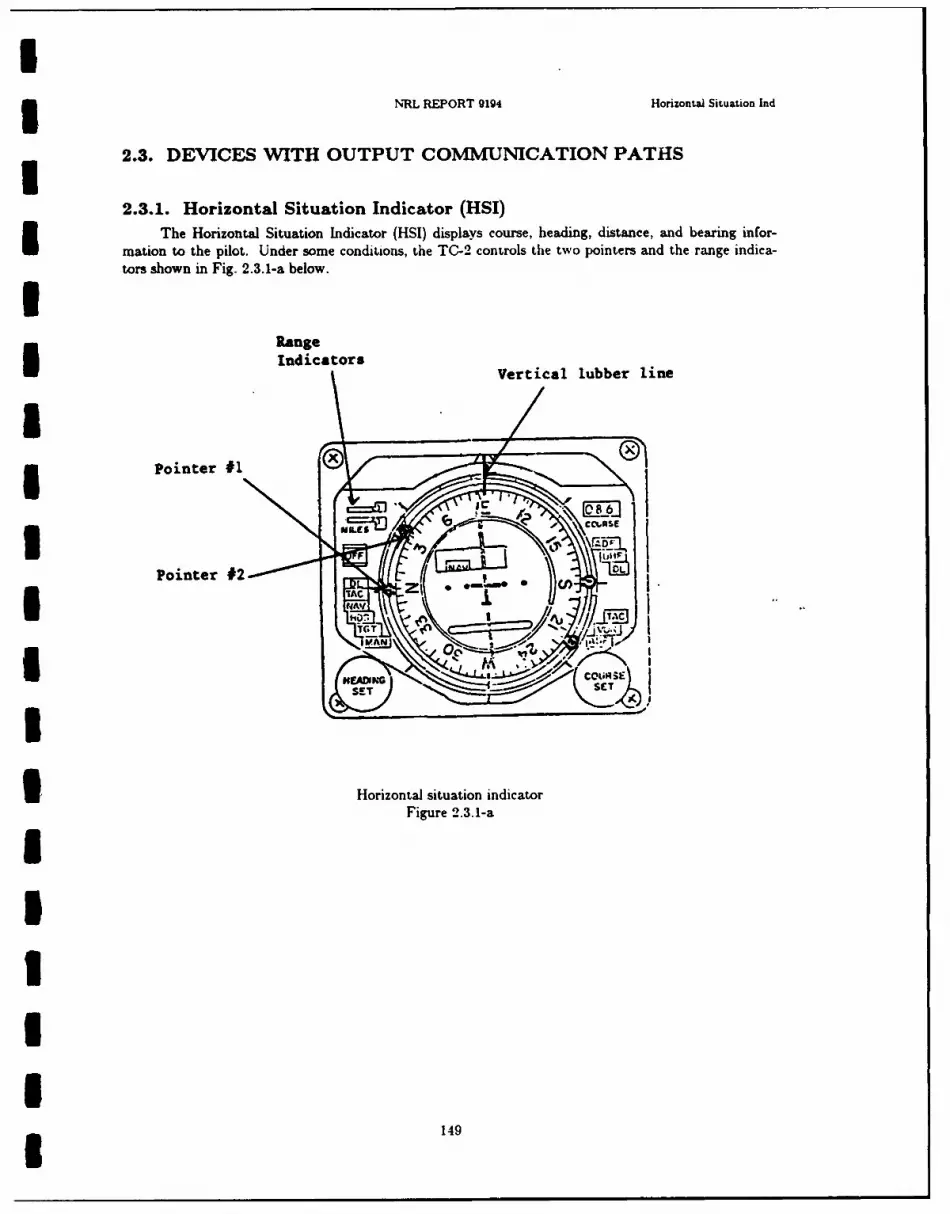
I3 NRL REPORT 9194 Horizontai Situation Ind
2.3. DEVICES WITH OUTPUT COMMUNICATION PATHS
2.3.1. Horizontal Situation Indicator (HSI)The Horizontal Situation Indicator (HSI) displays course, heading, distance, and bearing infor-
mation to the pilot. Under some condiLions, the TC-2 controls the two pointers and the range indica-tors shown in Fig. 2.3.1-a below.U
RangeI Indicators Vertical lubber line
3 Pointer #1
Pointer #2IA _IC/
3' Horizontal situation indicator
Figure 2.3.1-a
IIIII£ 149
IChapter 2 ALSPAUGH, FAULK, BRITTON, PARKER, PARNAS. AND SHORE
2.8.1.1. Bearing to destination
Output data item(s): Bearing to Destination iAcronym: //BRGDEST//
Hardware: Horizontal Situation i.. :icator 5Description: //BRGDEST// controls the pointing angle of the HSI #1 pointer The angle is mea-sured CW from the vertical lubber line.
Characteristics of values:
Units: Degrees
Range: 0 to 360
Accuracy: ±0.1Instruction sequence:
WRITE 232 (Channel 7) 5Test Carry Bit = 0 for request acknowledgedIf not, restart.
Data representation: The angle is represented by two fields, an octant and a magnitude. It is offset 5by 180". See //STEERAZ//.
Timing characteristics: Digital to Synchro conversion. See §1.15.8. 3
1IIIIIUU
150

U
3 NRL REPORT 9194 Horizontal Situation Ind
2.3.1.2. Ground track pointer
Output data item(s): Ground Track
Acronym: //GNDTRK//I Hardware: Horizontal Situation Indicator
Description: //GNDTRK// controls the pointing angle of the HSI #2 pointer. The angle is mea-sured CW from the vertical lubber line.
Characteristics of values:
Units: Degrees
Range: 0 to 360
Accuracy: ±0.1
Instruction sequence:
WRITE 233 (Channel 7)Test Carry Bit = 0 for request acknowledgedIf not, restart.
Data representation: The angle is represented by two fields, an octant and a magnitude. It is offsetby 180". See //STEERAZ//.3 Timing characteristics: Digital to Synchro conversion. See §1.15.8.
1IUUII
II3 151
IChapter 2 ALSPAUGH, FAULK, BRITTON, PARKER, PARNAS, AND SHORE
2.9.1.9. Left digit flag
Output data item(s): Left Digit Flag iClams: DOW2
Acronym: //LFTDIG// 5Hardware: Horizontal Situation Indicator
Description: //LFTDIG// controls a flag with a 1 on it that can drop down in place to the left ofthe three digits of the HSI distance indicator, which are controlled by //RNGUNIT//,//RNGTEN//, and //RNGHND//.
Characteristics of values:
Value encoding: $Blank$ (0); $One$ (1)
Instruction sequence: WRITE 4 (Channel 0)
Data representation: Discrete output word 2, bit 12 5
IIIIUIIIII'I
152 I

NRL REPORT 9194 Horizontal Situation Ind
2.3.1.-4. Range digits
Output data item(s): Range Digits
Acronym: //RNGUNIT// //RNGTEN// //RNGHND//
Hardware: Horizontal Situation Indicator
Description: These data items control the setting of a mileage indicator on the HSI. (See Fig. 2.3.1-a).
Comments: The data items are defined as outputs to the PMDS.
15
1
I
I
II
I
| 153
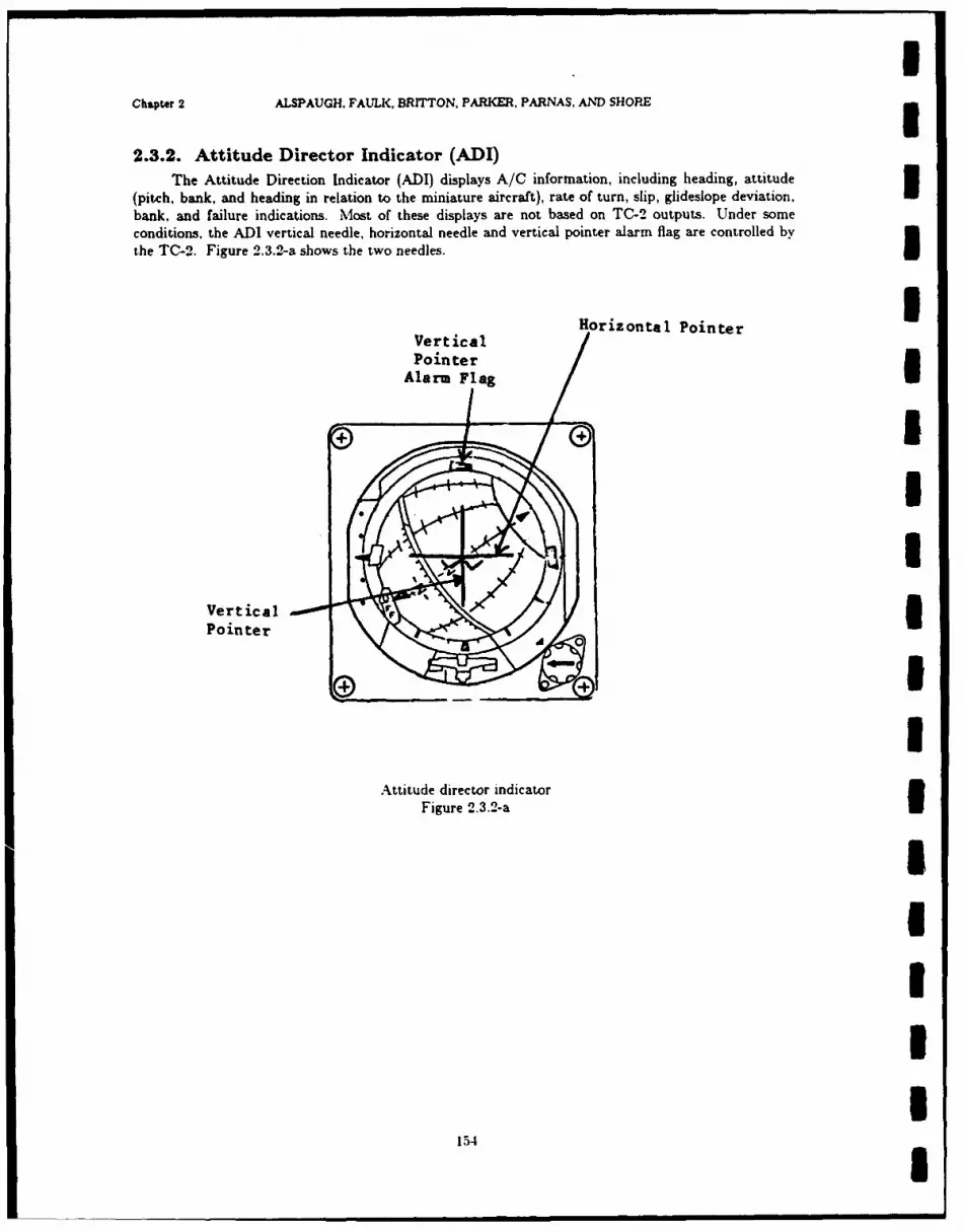
Chapter 2 ALSPAUGH, FAULK, BRITTON, PARKER, PARNAS, AND SHORE
2.3.2. Attitude Director Indicator (ADI)The Attitude Direction Indicator (ADI) displays A/C information, including heading, attitude
(pitch, bank, and heading in relation to the miniature aircraft), rate of turn, slip, glideslope deviation,
bank, and failure indications. Most of these displays are not based on TC-2 outputs. Under someconditions, the ADI vertical needle, horizontal needle and vertical pointer alarm flag are controlled by
Ithe TC-2. Figure 2.3.2-a shows the two needles.
Horizontal Pointer
PointerAlarm Fag
II
VerticalPointer
1
Attitude director indicatorFigure 2.3.2-a
154III
154... , , I

NRL REPORT g1g4 Attitude Director (nd (ADI)
2.3.2.1. Computer fail
Output data itezn(a): Computer System Fail
Clan: DOW2
Acronym: //CONTFAIL,//
Hardware: Attitude Direction Indicator
Description: When //COMPFAIL// = $Yes$, the vertical pointer alarm flag is in view.1Comments: //'COMPFAIL// is defined in the IMIS section. ,'CONMPFAEL// is also output to theFLR and the Caution and Advisory Panel.
15

Chapter 2 ALSPAUGH. FAULK. BRITTON, PARKER. PARNAS, AND SHORE
2.9.2.2. Flight path angle
Output data item(s): Flight Path Angle UAcronym: //FPANGL//
Hardware: Attitude Direction Indicator 3Description: //FPANGL// positions the horizontal needle of the ADI. Positive direction is up whenlooking at the ADI. A value of zero centers the needle. The value -20 puts the needle out of view.
Comments: //FPANGL// is defined in the FLR section.
//FPANGL// is not assumed to be Flight Path Angle by the ADI. Other quantities can be displayedprovided the FLR is not in Terrain Following mode.
IIi!IU
III
156

NRL REPORT 9194 Attitude Director Ind (ADI)
2.3.2.3. Steering error
Output data item(s): Steering Error
Acronym: //STERROR//
Hardware: Attitude Direction Indicator
Description: //STERROR// controls the position of the v(rtical needle on the ADI. A positivevalue moves the pointer to the right when looking at the ADI. A value of zero centers the needle.
Characteristics of values:
Units: Degrees
Range: -2.5 to +2.5
Accuracy: :0.1
Resolution: .00244
Instruction sequence:
WRITE 229 (Channel 7)Test Carry Bit - 0 for request acknowledgedIf not, restart
Data representation: 11-bit two's complement number, bit 0 and bits 3-12: bits 1-2 not used, bits13-15 = 0. Scale = 512/1.25 = 409.6; offset = 0.
Timing characteristics: Digital to DC voltage conversion. See §1.13.8.
Comments: The pointer hits a mechanical stop at 1:2.5".
I
I
III
I
i 157
Chapter 2 ALSPAUGH, FAULK. BRITTON. PARKER. PARNAS. AND SHORE 32.3.3. Flight Recorder (FLTREC)
The Flight Recorder (FLTREC) is a magnetic tape recording device. It was intended for flighttesting of the A/C system units in its early versions and is available in some production models. It
records blocks of 100 words periodically. I2.3.8.1. Flight recorder data
Output data item(s): : Flight Recorder Data Items
Acronym: //FLTREC// iHardware: Flight RecorderDescription: //FLTREC// consists of 100 16-bit data words. There is no requirement for which
words are used to make up //FLTREC//.
Instruction sequence: Cycle Steal Channel C
Timing characteristics: 100 16-bit words are output every 40 milliseconds.
Comments: It is not necessary to output 100 different words to i/FLTREC!/. Any smaller number(greater than zero) may be output simply by building the cycle-steal chain with a loop in it.
1II
II
II
I158 1
I3 NRL REPORT g194 Bomb Tone (BMBTON)
2.3.4. Bomb Tone (BMBTON)The Bomb Tone (BMBTON) is an audio cockpit signal.
I2.S.4.1. Bomb tone
Output data item(s): Bomb ToneClass: DOWI
Acronym: //BMBTON//
Hardware: Bomb Tone
Description: There is an audible tone in the cockpit when //BMBTON// SONS.Characteristics of values:
Value encoding: SOffS (0); SOnS (1)Instruction sequence: WRITE 8 (Channel 0)3Data representation: Discrete output word 1, bit 8
1II11II
I
I1I59
I
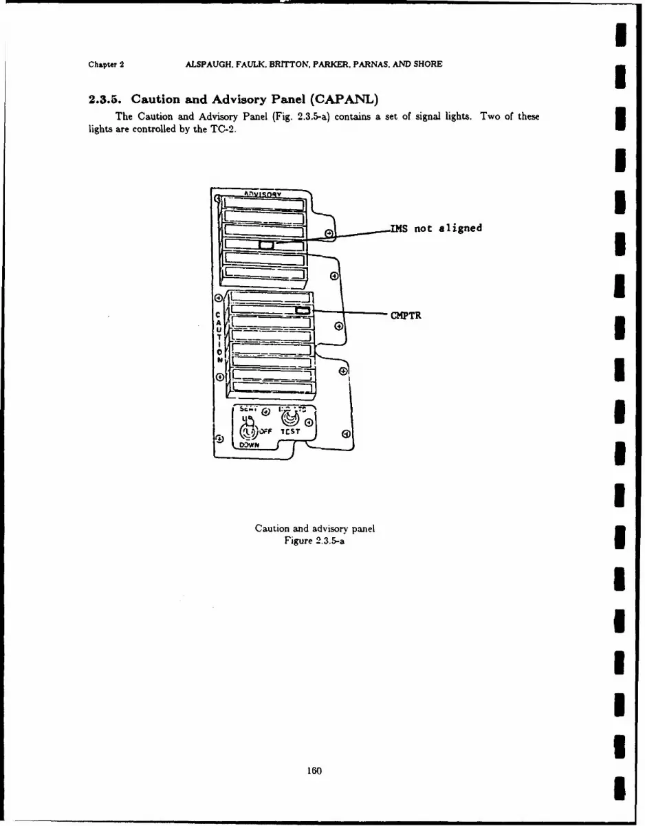
Chapter 2 ALSPAUGH. FAULK, BRITTON, PARKER, PARNAS. AND SHORE
2.3.5. Caution and Advisory Panel (CAPAINL)The Caution and Advisory Panel (Fig. 2.3.5-a) contains a set of signal lights. Two of these
lights are controlled by the TC-2.I
IMS not aligned
UU0I
Caution and advisory panel
Figure 2.3.5-aI
160

I3 NRL REPORT 9194 Caution Advisory PnI
2.3.5.1. Computer fail
Output data item(s): Computer System Fail
Claw: DOW2
Acronym: //COMPFAIL//
Hardware: Caution and Advisory Panel
Description: The light labeled CMPTR on the caution and advisory panel is turned on whenSl/COMPFAlL// = SYes$.Comments: //COMPFAIL// is defined in the INIS section. i/COMPFAIL// is also output to the3 FLR and the ADI.
1UIiIiiIIUlI
! 161

Chaper 2 ALSPAUGH, FAULK, BRITTON, PARKER, PARNAS. AND SHORE
2.8.5.2. Non-aligned light
Output data item(s): IMS Non-Align Light UClass: DOW2
Acronym: //IMSNA//
Hardware: Caution and Advisory Panel
Description: //IMSNA// turns on and off the IMS NOT ALIGNED light on the Caution andAdvisory Panel.
Characteristics of values:
Value encoding: $Off$ (0), SOnS (1)
Instruction sequence: WRITE 4 (Channel 0)
Data representation: Discrete output word 2, bit 9
IIIIIIIIIII
162 I

13.NML REPORT g194 Weapon Characteristics
2.4. WEAPON CHARACTERISTICS3Table 2 .4-a gives characteristics of the different weapons that are used with the A-7 aircraft.The first three columns give parameters identifying the type of delivery, i.e.. the weapon. the
drag characteristics, and the rack mounting. These parameters are communicated to the computer bythe input data items /\\APTYPi'. /BNBDRAG/. and ,7I_-LTRACK/. NOTE: For safety rea-sons. in the case of $OD$ and $SL weapons. the OFP will ignore the setting of the i TULTRACKiswitch and assume it is $Yes$ if the number of weapons selected exceeds the number of stationsselected (i.e.. if the OFP deduces that a multiple or triple ejector rack is loaded on one of the selectedstations). The number of weapons is taken to be the value of /ARPQUANT/, doubled if'A-%RPP.MRS /=$Y'es$.
The last four columns provide characteristics associated with the identified type of delivery.
Column 4 gives the two-letter code and the common name associated with the weapon.Column 5 (Fire Pulse Width) gives the time in milliseconds that (i/BvBREL $ SOn$) must
be true to eject the weapon.
Column 6 (!Weapon Class!) specifies to which of the following classes each weapon belongs.
Guns SGN$ Shrike $SK$High Dual SHDS Simple High $SH$Medium Dual SMD$ Simple Low $SL$Mines/Flares $MF$ Simple Medium SSM$Optional Drag $ODS Special Optional Drag $SOD$Optional Rockeye $OR$ Special Simple High SSSH$Rockets $RKS Uncataloged SUNSIWalleye $WLS
Column 7 (MIRI Class) assigns each weapon, where applicable, a number referring to one of thethree Minimum-release-interval curves in Fig. 2.4-a. These curves give the mirimum safe time inter-val between release of two weapons of that type. See alo Ref. 24. part 1. §5.6.
IIUU
III
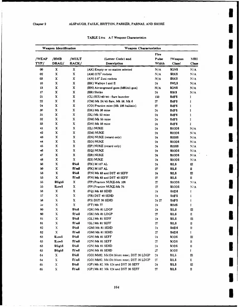
Chapter 2 ALSPAUGH, FAULK, BRITTON, PARKER, PARNAS, AND SHORE
TABLE 2.4-a: A-7 Weapons Characteristics
Weapon Identification Weapon Characteristics 3Fire
/VEAP /BMB /MULT (Letter Code) and Pulse !Weapon MRI
TYP/ DRAG/ RACK/ Description Width Cla!s Class
00 X X (AK) Empty or no station selected N/A SGNS N/A02 X X (AM) 2.75" rockets N/A SRKS N/A03 X X (AN) 5.0" Zuni rockets N/A SRKS N/A10 X X (BK) Walleye I and 11 24 SWL$ N/A13 X X (BN) Air-to-ground guns (MO1Al gun) N/A SONS N/A
17 X X (BR) Shrike 24 SSKS N/A I21 X X (CL) SUU-40/44- flare launcher 150 SMFS 122 X X (CM) Mk 24/46 flare, Mk 58. Mk 6 27 SMFS 124 X X (CO) Practice mine (Mk 106 ballistic) 27 SMFS 330 X X (DK) Mk 36 mine 24 SMF$ I31 X X (DL) Mk 52 mine 24 SMFS32 X X (DM) Mk 55 mine 24 SMFS 1
33 X X (DN) Mk 56 mine 24 $MFS I41 X X (EL) NUKE 24 $SODS N/A
42 X X (EM) NUKE 24 $SODS N/A43 X X (EN) NUKE (retard only) 24 $SSiHS N/A
44 X X (EO) NUKE 24 $SOD$ N/A45 X X (EP) NUKE (retard only) 24 $SSHS N/A46 X X (EQ) NUKE 24 $SODS N/A47 X X (ER) NUKE 24 $SOD$ N/A48 X X (ES) NUKE 24 $SODS N/A
50 X $No$ (FK) M 117 AL 24 SSLS IIIso X Ses$ (FK) M 117 AL 27 SSLS II I53 X $No$ (FN) Mk 83 and DST 40 SEFF 24 SSLS Ill53 X SYes$ (FN) Mk 83 and DST 40 SEFF 27 SSLS II55 SHigh$ X (FP) Practice NUKE-Mk 106 27 $SODS N/A55 SLows X (FP} Practice NUKE-Mk 76 .-7 $SODS N/A I56 X X (FQ) Mk 83 SEHD 24 SMDS 1
57 X X (FR) DST 40 SEHD 24 $MF$ 1
58 X X (FS) DST 36 SEHD 24 27 SMFS I-5 X X (FT) Mk 77 24 ISMS I60 X $No$ (GK) Mk 8l LDGP 24 SSL$ IlI60 X IVes$ (GK)Mk81LDGP 27 $SLS f
61 X SNo$ (GL) Mk 81 SEFF 24 SSLS mI61 x $Yes$ GL) Mk 81 SEFF 27 SSLS II62 X $No$ (GM) Mk 81 SEHD 24 SMDS Ii
62 X $Yes$ (GM) Mk 81 SEID 27 SMD$ I63 SLowS SNo$ (GN) Mk 81 SEFF 24 SODS III63 SLowS SYesS (GN) Mk 81 SEFF 27 SODS II63 SHigh$ SNoS (GN) Mk 81 SEHD 24 SODS II
63 SHigh$ SYes$ (GN) Mk 81 SEHD 27 SODS IE4 X $No$ (GO) Mk82, Mk124 (blunt nose). DST 36 LDGP 24 SSLS Ii64 X $'es$ (GO) Mk82. Mk124 (blunt nose). DST 36 LDGP 27 SSLS 11
65 X $NoS (GP) Mk 82. Mk 124 and DST 36 SEFF 24 SSL$ MI65 X $Yes$ (GP) Mk 82. Mk 124 and DST 36 SEFF 27 SSLS II
I
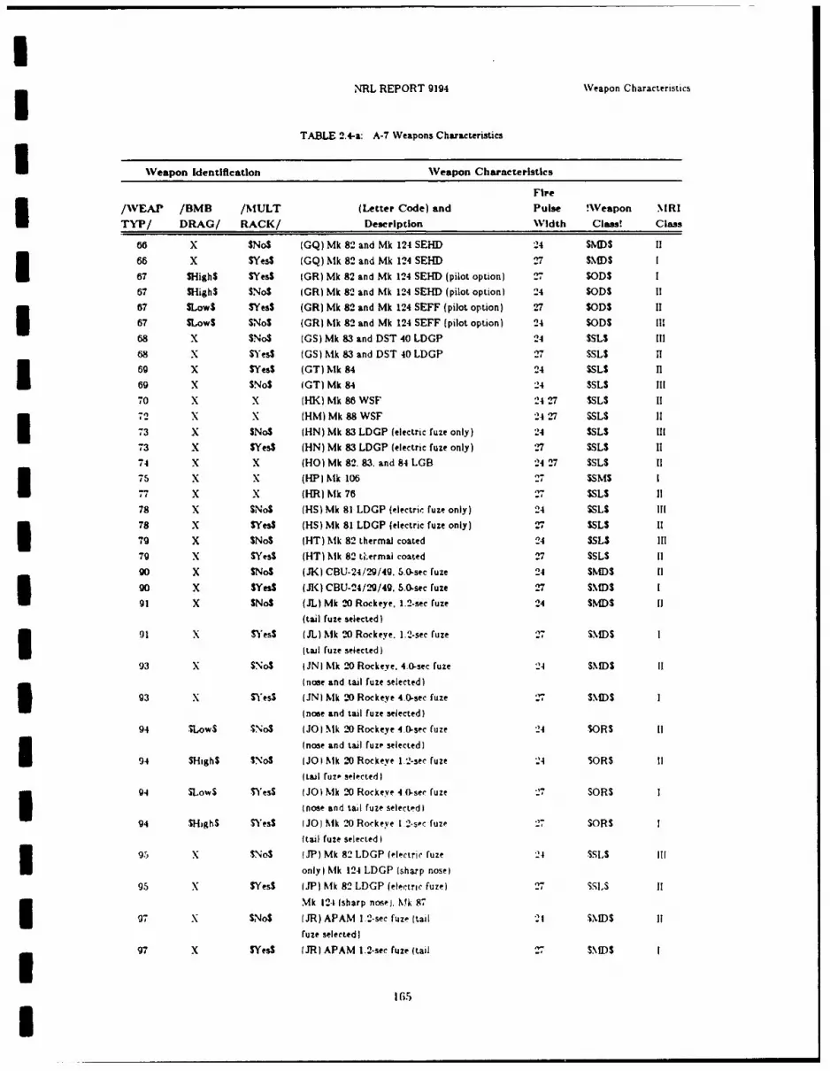
INRL REPORT 9194 WVeapon Characteristics
TABLE 2.4-&: A-7 Weapons Characteristics
WVeapon Identification WVeapon Characteristics
Fire
VWEAP /BMB /NIULT (Letter Code) and Pulse !WVeapon NIRI
TYP/ DRAG/ RACK/ Description Width Class! Class
66 x $No$ (GQ) Mk 82 and Mk 124 SEl-D 24 SMWS 11
66 x $Yes$ (GQ) NIk 82 and Mk 124 SEFH 2 SIMWSII67 SHigh$ SVesS (OR) Mk 82 and Mk 124 SEHD (pilot option) 27 SOD$S67 $High$ $No$ (OR) Mk 82 and Mkl 124 SEHD (pilot option) 24 SODS If
87 SLowS $Yes$ (OR) Mk 82 and Mk 124 SEFF (pilot option) 27 SODS 11I67 SLowS SNoS (OR) k~k 82 and Mk 124 SEFF (pilot option) 24 SODS IlI68 x $No$S (OS) Mk 83 and DST 40 LDOP 24 SSLS I68 x $)'es$ (OS) hMk 83 and DST 40 LDOP 27 SSLS H-69 x $Yes$ (OT) NIk 84 24 SSLS HlI69 x $No$ (OT) Mk 84 24 SSLS III70 x x (H-K) Mk 86 WSF 24 27 SSLS 11
72 x x (HM) Mk 88WSF 24 27 SSLS ifI73 x $No$ (HN) Mk 83 LDOP (electric fuze only) 24 SSLS I73 x $Yes$ (HN) Mk 83 LDOP (electric fuze only) 27 SSL$ 1174 x X (HO) Mk 82. 83. and 84 LOB3 24 27 SSLS 1175 X x (HP) Nik 106 27 SSM$77 x x (HR) hk 76 27 SSL$ 1178 x $No$ (HS) Mk 81 LDOP (electric fuze only) 24 SSLS III78 X $Yes$ (HS) Mk 81 LDOP (electric fuze only) 27 SSLS 11I79 X $No$ IHT) Mk 82 thermal coated 24 SSLS Ill79 X SYesS (HT) hMk 82 ta.ermai coated 27 SSLS 11
90 X $No$ PJK) CBU-24/N9/49. 5.0-sec fuze 24 SMDS 11
90 x SVes$ 0JK0 CBU-24/2-9149. 5.0-sec fuze 27 $MDSI
91 X $No$ (JL) Mk 2-0 Rockeye, 1.2-sec fuze 24 SNIDS I(taI fuze selected)I
01 x SYesS IJL) Nik 2.0 Rockeve. 1.2-sec fuze 27 SII)SI (tail ruze selected)93 x $No$ (iN) Mk 20 Rockeve, 4.0-sec fuze 24 $ISNSI
(nose and tail fuse selected)
93 X SYesS OJN) 161k 2.0 Rockeyc 4.0-sec fuze 2 ND
(nose and tai fuse selected)
94 TLowS $No$ (JO) NIk 20 Rockeye 4.0-sec fuze 24 SORS I
(nose and tail ruse selected)
94 $High$ SNoS (JO) IMk 20 Rockeye 1.2-sec fuze '24 $OR$ I
94 SLowS SWess (JO) M6k 2-0 Rockeve 4 0-see fuze 27 SORSI (nose and tall ruse selected)94 $High$ S) esS (JO) hik 20 Rorkeye 12-sec fuse 27 MOR$
ftail fuze selected)I
95 x No$ )JP( Mkh 82 LDOP )(ectric fuse 21 SSLSIlI only) Nik 124 LDOP (sharp nose)95 x $Yes$ )JP) Kik 82 LDOP (electric fuse) 27 SSL'S
Mk 124i (sharp nose). Mkh 87I07 x $No$ (JR) APAM 1.2-sec fuze (tail 2 NSIffuze selected)
97 x $Yes$ UJRI APAM 1.2-sec fuze (tail 7S.N 1)S
165
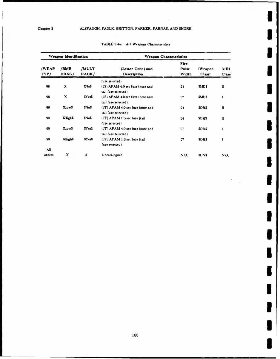
Chapter 2 ALSPAUGH, FAULK. BRITTON, PARKER, PARNAS. AND SHORE
TABLE 2.4-a: A-7 Weapons Characteristics
Weapon Identification Veapon Characteristics IFire
/WEAP /BMB /MULT (Letter Code) and Pulse !Veapon NIRITYP/ DRAG/ RACK/ Description Width Class! Class
fuze selected)98 X $No$ PiS) APAM 4.0-sec fuze (nose and 24 St)S 1I
tail fuze selected)98 X SYes$ (JS) APAM 4.0-sec fuze (nose and .-7 $MDS I
tail ruze selected)
99 SLowS SNoS (JT) APAM 4.0-sec fuze (nose and 24 $OR$ fl IItail, uze selected)
99 SHigh$ SNoS (JT) APAM 1.2-sec fuze (tail 24 SORS 11fuze selected)
99 SLowS SYes$ (JT) APAM 4.0-sec fuze (nose and 27 $OR$ Itail fuze selected)
99 SHigh$ SYesS (JT) APAM 1.2-sec fuze (tail 27 $OR$ I
All fuze selected) I
others X X Uncataiogued N/A SUNS N/A
IIIIIIII
I166 I

I5 NRL REPORT 9194 Weapon Characteristics
500
I
354 ms SUU-40/44 FLARE LAUNCHERSJ (SEE NOTE 4)
. 300
I z
Lr
200Z101S34m CLASSI (SEE NOTE 11
100
i ." 65 ms CLASS n1 (SEE NOTE 2)
i 25 m s CLASS = (SEE NOTE 3)
0I I I0 +1.0 +2.0 +3.0 +4.0 +5.0
AIRPLANE NORMAL ACCELERATION, g
INOTEI1. CLASS L BELOW +1.98g; MRI - 470m%-170ms/g
ABOVE +1.98g; MRI - 134ms
2. CLASS U: BELOW +1.95g; MRI = 246.8 ms-93.4 m/gABOVE +1.95g; MRI - 65ms
3. CLASS IM. MRI - 25ms (9-INDEPENDENT)
4. SUU-40/44 FLARE LAUNCHER: BELOW +0.68g; MRI - 470ms-70ms/gABOVE +0.68g; MRI - 354 ms
Figure 2.4-a MRI Curve Chart
Minimum Release Interval Curve
i
167
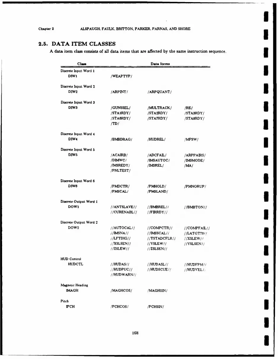
Chapter 2 ALSPAUGH, FAULK, BRITTON, PARKER. PARNAS, AND SHORE
2.5. DATA ITEM CLASSESA data item class consists of all data items that are affected by the same instruction sequence.3
Class DataL Items
Discrete Input Word 1IDIWI /WEAPTYP/
Discrete Input Word 2
DIW2 /ARPINTI /ARPQUANT/I
Discrete Input Word 3
DIW3 /GUNSSEL/ /MULTRACK/ /RE//STAIRDY/ /STA2RDY/ /STA3RDY/
ISTA6RDY/ /STA7RDY/ /STA8RDY/
/TD/
Discrete Input Word 4
DIW4 /BMBDRAG/ /HUDREL/ /MFSW/
Discrete Input Word 5DIWS /ACAIRB/ /ADCFAIL/ /ARPPAIRS/
/DIMWC/ /IMSAUTOC/ /IMSMODE//IMSREDY/ /IMSREL/ /MA//PNLTEST/
Discrete Input Word 6IDIWO /PMDCTR/ /PMHOLD/ /PMNORUP/
Discrete Output Word I /MCL PSAD
DOW1 /IANTSLAVE// //BMvBREL/f //BMBTON////CURENABL// //FIRRDY/ 3
Discrete Output Word 2DOW2 I/AUTOCAL 1/ //COMPCTR/ / //COIPrAIL/ /
j/MSNAI/ //lMSSCAL// //LATGT7o/,/Ij/LFTDIG// //TSTADCFLRI1/ / /XSLEW / // /XSLSENI/ //YSLEW // //YSLSEN ////ZSLEW// //ZSLSEN//5
HUD ControlHUDCTL //HUDASI/ //HUDASL// //HUDFPM//
,,/HUDPUC// //HUDSCUE/,! j/HUDNVELI//HUDWARN//
Magnetic Heading
IM.AGH /MAGI-COS/ /MAGHSIN/I
Pitch
IPCH /PCHCOS/ /PCHSIN/I
168

NRL REPORT g194 Dats, Item Clase
clan Data, Items
Roll
TROLL /ROLLCOSI/ /ROLLSINI/
True HeadingI I)G /THDGCOSI /THDGSIN/
Panel Input Word 1
PIWi /ENTERSW/ /KBDENBL/ /KBDINT/IMRKWPanel Input Word 2IPTW2 /FLYTOTOG/ /FLYTOTW/ /UPDATTW/
Panel Input Word 3IPIW3 /MODEROT/ /PRESPOS/
Panel Output-Al
POALL //ENTLrr// //KELrT// //LLITDEC//
//LLlTE/f //LLITW// //LLrr322////LWDIGI// //LWDIG2// //LWDIG3//
(//LWDIG4// //LWDIG6// //LWDIG6//
//ULITS// //UL1T222'I' /JULIT321////UWDIG1/f //UWDIG2f/ /JUWDIG3//
//UWDIG4// //UTWDIG5,'/ //UWDIG8//
Panel Output Word 1
POWI /IENTLrr// //K(ELIT// //LLlTDEC////LUTrE// //LLITW// //LLrr322//'//ULrrN// //ULITS// //ULrr2?-2//
IPanel utput Word 2 /r32/
POW2 /ILWDIG1// //LWDIG2//'
1 Panel Output Word 3POW3 //LWDIG3// //LWDIG4//
5 Panel Output Word 4POW4 //LWDIGS// //LYVDlG6//
3 Panel Output Word 5POWs //LWDIG7//
Panel Output Word 6IPOW6 //UWD[Gl// //UNNDIG2//
Panel Output Word 73POW7 //UWDIG3// //UWDIG4//
Panel Output Word 83POWs //UWDIG5// //UWDIG6//
169

Chapter 2 ALSPAUGH. FAULK(, BRITTON. PARKER. PARNAS. AND SHORE
Class Data Items
Serial Input Register -1Discrete Output Word 3
SDOP-DOW3 MDRS) .'ANTGOOD/ /DGNDSP/ /DRFTANG/
/DRSFUN/ /DRSNEM/ /'DRSREL/IIELEC GOOD /
SFLR-DOW3 (FLR) 'LOCKEDON/ /SLTRNG/
SSIN-DOW3 (SINS) 'Se*HDG/ /WAYLAT/
/SINLAT/ /WAYLON/
/SINLON/ /WAYNUMI/I/SIN4EVEL/ /WAYNUM2'1
/SINROLI
170

INRL REPORT 9194 Unused Inputs and Output-s
2.6. UNUSED INPUTS AND OUTPUTSThe following table contains those words and bits which are not used by the Input/Output
operations of the Navy version of the OFP. The unused bits of the Cycle Steal outputs are notincluded since the OFP does not directly control their output.
The first column (Instruction) gives the basic I/O command of the instruction sequence.
The second column (I/O Item) gives an identification of the input or output item. The letter inparentheses designates the category of the I/O item; e.g., data item class, data item, etc. Thedefinitions of the letters follows:
(a) The reference is to the data item class defined in §2.0.4.
(b) The reference is to the register or counter defined in Ref. 18, pp. 5-6 and 5-10.
(c) The reference is the to the thumbwheel encoder counter defined in Ref. 18, pp. 5-6.
(d) The reference is to the Doppler Radar Status word as defined in Ref. 18, pp. 5-16.
(e) The reference is to the data item word defined in §2.1-2.3.(f) The reference is to the LASER word defined in Ref. 18, pp. 5-21.(g) The reference is to the Serial Input Address word defined in Ref. 18, pp. 5-20.
(h) The reference is to the LORAN words or bits defined in Ref. 18, §5.
(i) The reference is to the Lower Window 7 word defined in Ref. 18, pp. 5-56.
(j) The reference is to the Mark Window word defined in Ref. 18, pp. 5-56.
(k) The reference is to the self-test signals defined in Ref. 18, pp. 5-60 and 5-62.(1) The reference is to the SINS analog data defined in Ref. 18, pp. 5-59 and 5-60.
(m) The reference is to the spare signals defined in Ref. 18, pp. 5-59, 5-62, 5-71, 5-73, and 5-74.
(n) The reference is to the signal converter defined in Ref. 18, pp. 5-60.
The third column (Bit(s)) gives the bit(s) of the I/O Item that are unused.
The last column (Descripticn) gives a description of the I/O Item. The number in parenthesesdescribes why the bits of the I/O Item are unused. The definition of the numbers follows:
(1) Used by the USAF version of the OFP.
(2) Not used by the Navy version of the OFP.(3) Bit always set to 1. Not used by the Navy version of the OFP.
(4) Not physically implemented.
Instruction I/0 ITEM Bit(s) Description
READ 8 DIWI(a) 8-13READ 8 DIWI(a) 14 ASCU SSU-20 (1,2)READ 8 DIWI(a) 15 BITE FAIL SAFE (2)READ 2 DIW3(a) 0 TACAN PARITY VALID (3)READ 2 DIW3(a) 10-14 AGE TEST EQUIPMENT (2)READ 1 DIW4(a) 6-14 LORAN (2)READ 24 DIW5(a) 2READ 24 DIW5(a) 11 SIGNAL CONTV OVER TEMP (2)READ 16 DIW6(a) 4-7
READ 16 DIW6(a) 8-15 ZERO (4)READ/WRITE 20 Interrupt 4 SPARE MEMORY PARITY
Level 1(b)
171

PIChapter 2 ALSPAUGH, FAULK, BRITTON. PARKER, PARNAS, AND SHORE
Instruction I/O ITEM Bit(s) DescriptionREAD/WRITE 20 Interrupt 5-14 ZERO (4)
Level 1(b). _- IREAD/WRITE 18 Interrupt 4 SPARE LORAN (2)Level 0(b)
READ/WRITE 18 Interrupt 5
Level 0(b)READ/WRITE 18 Interrupt 6-15 ZERO (4)
Level 0(b)READ 22 TW Encoder(c) 0-7, 11-15 THUMBWHEEL ENCODER (2)READ 22 TW Encoder(€) 8-10 ZERO (4)WRITE 8 DOWI(a) 0-7, 11, 15WRITE 8 DOWl(a) 14 NAV/WD PANEL MAL.IND. (2) IWRITE 4 DOW2(a) 11, 15WRITE 2 SIR-DOW3(a) 2 ENAB. LASER (2)WRITE 2 SIR-DOW3(a) 4-6 AGE TEST EQUIPMENT (2)WRITE 2 SIR-DOW3(a) 7 LIFT STO. PRO (2)WRITE 2 SIR-DOW3(a) 8-15WRITE 24 10-bit Counter(b) 10-15READ 32 DRS STATUS(d) 0, 8-15READ 32 /DGNDSP/te) 0 SIGN ALWAYS SET TO 1READ 32 /DGNDSP/(e) 15 ZERO (4)READ 32 /DRFTANG/(e) 0 SIGN ALWAYS SET TO IREAD 32 /DRFTANG/(e) 15 ZERO (4)READ 32 /SLTRNGie) 13-15 ZERO (4)
READ 32 LASER(f) - 0-15READ 64 SIA Word(g) 5 LASER ENABLE (2)READM 97 ?? ?? /RNGSTA/ADDRESS
READM 96 ?? ?? /BRGSTA/ADDRESSREAD 129 /XVEL/(e) 0-5READ 130 /YVEL/(e) "0-5READ 132 /ZVEL/(e) 0-5READ 144 /XGYCNT/(e) 0-12,15READ 136 /GYCNT/(e) 0-12, 15READ 152 /ZGYCNT/(e) 0-12, 15WRITE 129 //XGYCOM//(e) 0-10. 15WRITE 130 //YGYCOM//(e) 0-10, 15
WRITE 132 //ZGYCOM//(e) 0-10, 15READ 161 LORAN(h) 0-13 LORAN (4)READ 161 LORAN(h) . . 14-15 ZERO (4)READ 162 LORAN(h) 0-13 LORAN (4)READ 162 LORAN(h) 14-15 ZERO (4)WRITE 161 LORAN(h) 0-13 LORAN (4)WRITE 161 LORAN(h) 14-15 ZERO (4)READ 208 PIWI(a) 13-15 ZERO (4)READ 200 PIW2(a) 10-15 ZERO (4)READ 196 PIW3(a) 6-7 /MODEROT/ SPARE (2)READ 196 PIW3(a) 11-13 /PRESPOS/ SPARE (2)READ 196 PIW3(a) 14 NOT KBD (2)READ 196 PIW3(a) 15 ZERO (4)READ 194 LORAN(h) 0-13 LORAN (4)READ 194 LORAN(h) 14-15 ZERO (4)WRITE 200 POWl(a) 12-15
172 I
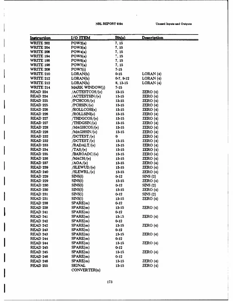
NRL REPORT 9194 Unused Inputs and Outputs
Instruction I/O ITEM Bit(s) DescriptionWRITE 202 POW2(a) 7, 15WRITE 204 POW3(a) 7, 15WRITE 206 POW4(a) 7,15WRITE 194 POW5(a) 7, 15WRITE 196 POW6(a) 7, 15WRITE 198 POW7(a) 7, 15WRITE 208 POW7(i) 7-15WRITE 210 LORAN(h) 0-15 LORAN (4)WRITE 212 LORAN(h) 0-7, 9-12 LORAN (4)
WRITE 212 LORAN(h) 8, 13-15 LORAN (4)WRITE 214 MARK WINDOW(j) 7-15READ 224 /ACTESTCOS/(e) 13-15 ZERO (4)READ 224 /ACTESTSIN/(e) 13-15 ZERO (4)READ 225 /PCHCOS/(e) 13-15 ZERO (4)READ 225 /PCHSIN/(e) 13-15 ZERO (4)READ 226 /ROLLCOSI(e) 13-15 ZERO (4)
READ 226 /ROLLSINI(e) 13-15 ZERO (4)READ 227 /THDGCOS/(e) 13-15 ZERO (4)READ 227 /THDGSIN/(e) 13-15 ZERO (4)READ 228 /MAGHCOS/(e) 13-15 ZERO (4)READ 228 /MAGHSIN/(e) 13-15 ZERO (4)READ 232 /DCTEST/(e) 0 ZERO (4)READ 232 /DCTEST/(e) 13-15 ZERO (4)READ 233 /RADALT/(e) 13-15 ZERO (4)READ 234 /TAS/(e) 13-15 ZERO (4)READ 235 /BAROADC/(e) 13-15 ZERO (4)READ 236 /MACH/(e) 13-15 ZERO (4)READ 237 /AOA/(e) 13-15 ZERO (4)READ 239 /SLEWUD/(e) 13-15 ZERO (4)READ 240 /SLEWRL/(e) 13-15 ZERO (4)READ 229 SINS(J) 0-12 SINS (2)READ 229 SINS(I) 13-15 ZERO (4)READ 230 SINS(1) 0-12 SINS (2)READ 230 SINS(1) 13-15 ZERO (4)READ 231 SINS(1) 0-12 SINS (2)READ 231 SINS(I) 13-15 ZERO (4)READ 238 SPARE(m) 0-12READ 238 SPARE(m) 13-15 ZERO (4)READ 241 SPARE(m) 0-12READ 241 SPARE(m) 13-.5 ZERO (4)READ 242 SPARE(m) 0-12READ 242 SPARE(m) 13-15 ZERO (4)READ 243 SPARE(m) 0-12READ 243 SPARE(m) 13-15 ZERO (4)READ 244 SPARE(m) 0-12READ 244 SPARE(m) 13-15 ZERO (4)READ 245 SPARE(m) 0-12READ 245 SPARE(m) 13-15 ZERO (4)READ 246 SPARE(m) 0-12READ 246 SPARE(m) 13-15 ZERO (4)READ 255 SIGNAL 13-15 ZERO (4)
CONVERTER(n)
173
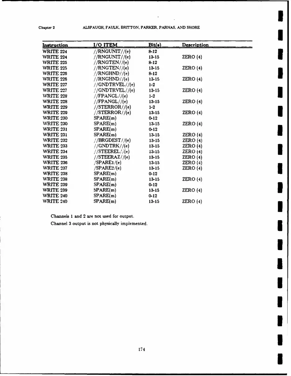
IChapter 2 ALSPAUGH, FAULK, BRrrTON, PARKER. PARNAS, AND SHORE I
Instruction I/O ITEM Bit(s) DescriptionWRITE 224 //RNGUNIT//(e) 8-12WRITE 224 //RNGUNIT//(e) 13-15 ZERO (4)WRITE 225 //RNGTEN//(e) 8-12WRITE 225 //RNGTEN//(e) 13-15 ZERO (4)WRITE 226 //RNGHND//(e) 8-12 IWRITE 226 //RNGHND//(e) 13-15 ZERO (4)WRITE 227 //GNDTRVEL//(e) 1-2WRITE 227 //GNDTRVEL//(e) 13-15 ZERO (4)WRITE 228 //FPANGL//(e) 1-2WRITE 228 //FPANGL//(e) 13-15 ZERO (4)WRITE 229 //STERROR//(e) 1-2WRITE 229 //STERROR//(e) 13-15 ZERO (4) iWRITE 230 SPARE(m) 0-12WRITE 230 SPARE(m) 13-15 ZERO (4)WRITE 231 SPARE(m) 0-12WRITE 231 SPARE(m) 13-15 ZERO (4)WRITE 232 '/BRGDEST//(e) 13-15 ZERO (4)WRITE 233 //GNDTRK//(e) 13-15 ZERO (4)WRITE 234 //STEEREL/i'(e) 13-15 ZERO (4) IWRITE 235 //STEERAZ//(e) 13-15 ZERO (4)WRITE 236 /SPAREI/(e) 13-15 ZERO (4)WRITE 237 /SPARE2/(e) 13-15 ZERO (4)WRITE 238 SPARE(m) 0-12WRITE 238 SPARE(m) 13-15 ZERO (4)WRITE 239 SPARE(m) 0-12WRITE 239 SPARE(m) 13-15 ZERO (4)WRITE 240 SPARE(m) 0-12WRITE 240 SPARE(m) 13-15 ZERO (4)
Channels 1 and 2 are not used for output.
Channel 3 output is not physically implemented.
1III1I
1"74 I
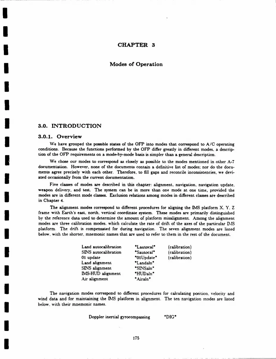
CHAPTER 3
Modes of Operation
II
I 3.0. INTRODUCTION
3.0.1. OverviewWe have grouped the possible states of the OFP into modes that correspond to A/C operating
conditions. Because the functions performed by the OFP differ greatly in different modes, a descrip-tion of the OFP requirements on a mode-by-mode basis is simpler than a general description.
We chose our modes to correspond as closely as possible to the modes mentioned in other A-7documentation. However, none of the documents contain a definitive list of modes; nor do the docu-ments agree precisely with each other. Therefore, to fill gaps and reconcile inconsistencies, we devi-ated occasionally from the current documentation.
Five classes of modes are described in this chapter: alignment, navigation, navigation update.weapon delivery, and test. The system can be in more than one mode at one time, provided themodes are in different mode classes. Exclusion relations among modes in different classes are describedin Chapter 4.
The alignment modes correspond to different procedures for aligning the IMS platform X, Y. Zframe with Earth's east, north, vertical coordinate system. These modes are primarily distinguished
by the reference data used to determine the amount of platform misalignment. Among the alignmentmodes are three calibration modes, which calculate the rate of drift of the axes of the particular IMSplatform. The drift is compensated for during navigation. The seven alignment modes are listedbelow, with the shorter, mnemonic names that are used to refer to them in the rest of the document.
Land autocalibration *Lautocal* (calibration)SINS autocalibration *Sautocal* (calibration)01 update *01Update* (calibration)Land alignment *Landaln*SINS alignment *SLNSaln*IMS-HUD alignment *WUDaln*Air alignment *Airaln*
I The navigation modes correspond to different procedures for calculating position. velocity andwind data and for maintaining the IMS platform in alignment. The ten navigation modes are listedbelow, with their mnemonic names.
Doppler inertial gyrocompassing *DIG*
175
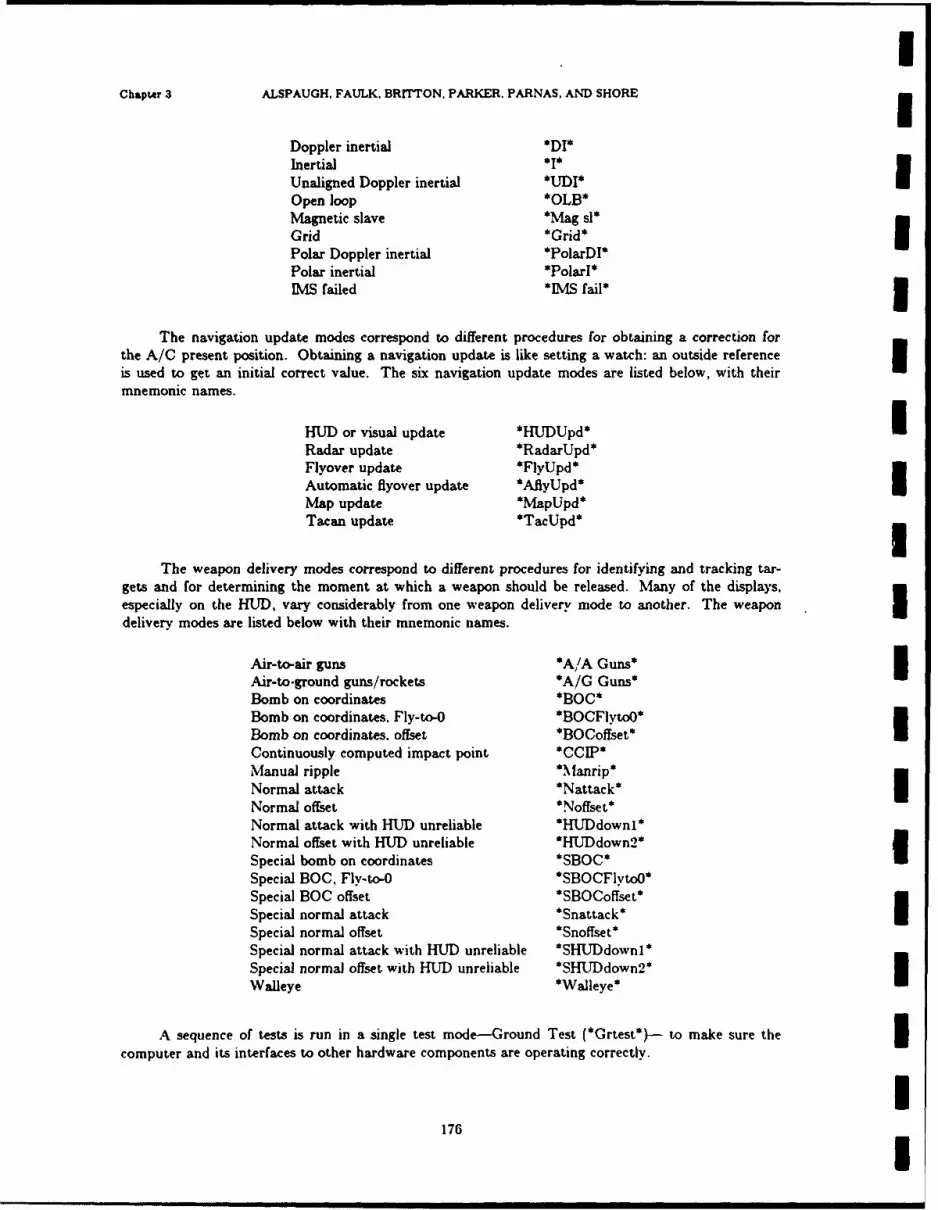
IChpter 3 ALSPAUGH, FAULK. BRITTON. PARKER. PARNAS. AND SHORE 3
Doppler inertial *DI*Inertial *I*
Unaligned Doppler inertial *UDI*
Open loop *OLB*Magnetic slave *Mag sl*Grid *Grid* [Polar Doppler inertial *PolarDI*Polar inertial *PolarI*IMS failed *IMS fail* 3
The navigation update modes correspond to different procedures for obtaining a correction forthe A/C present position. Obtaining a navigation update is like setting a watch: an outside referenceis used to get an initial correct value. The six navigation update modes are listed below, with theirmnemonic names.
HUD or visual update *HJDUpd* IRadar update *RadarUpd*Flyover update *FlyUpd*Automatic flyover update *AflyUpd*Map update *MapUpd*Tacan update *TacUpd*
The weapon delivery modes correspond to different procedures for identifying and tracking tar-gets and for determining the moment at which a weapon should be released. Many of the displays,especially on the HUD, vary considerably from one weapon delivery mode to another. The weapon Idelivery modes are listed below with their mnemonic names.
Air-to-air guns *A,/A Guns*Air-to-ground guns/rockets *A/G Guns*Bomb on coordinates *BOC*Bomb on coordinates, Fly-to-O *BOCFlytoO*Bomb on coordinates, offset *BOCoffset*Continuously computed impact point *CCIP*Manual ripple *\anrip*Normal attack *Nattack* INormal offset *Noffset*Normal attack with HUD unreliable *HUDdownl*Normal offset with HUD unreliable *HUDdown2*Special bomb on coordinates *SBOC*Special BOC, Fly-to-O *SBOCFytoO*Special BOC offset *SBOCoffset*Special normal attack *Snattack*Special normal offset *Snoffset*Special normal attack with HUD unreliable *SHUDdownl*Special normal offset with HUD unreliable *SHUDdown2*Walleye *Walleye*
A sequence of tests is run in a single test mode-Ground Test (*Grtest*)- to make sure thecomputer and its interfaces to other hardware components are operating correctly.
I17/6 I
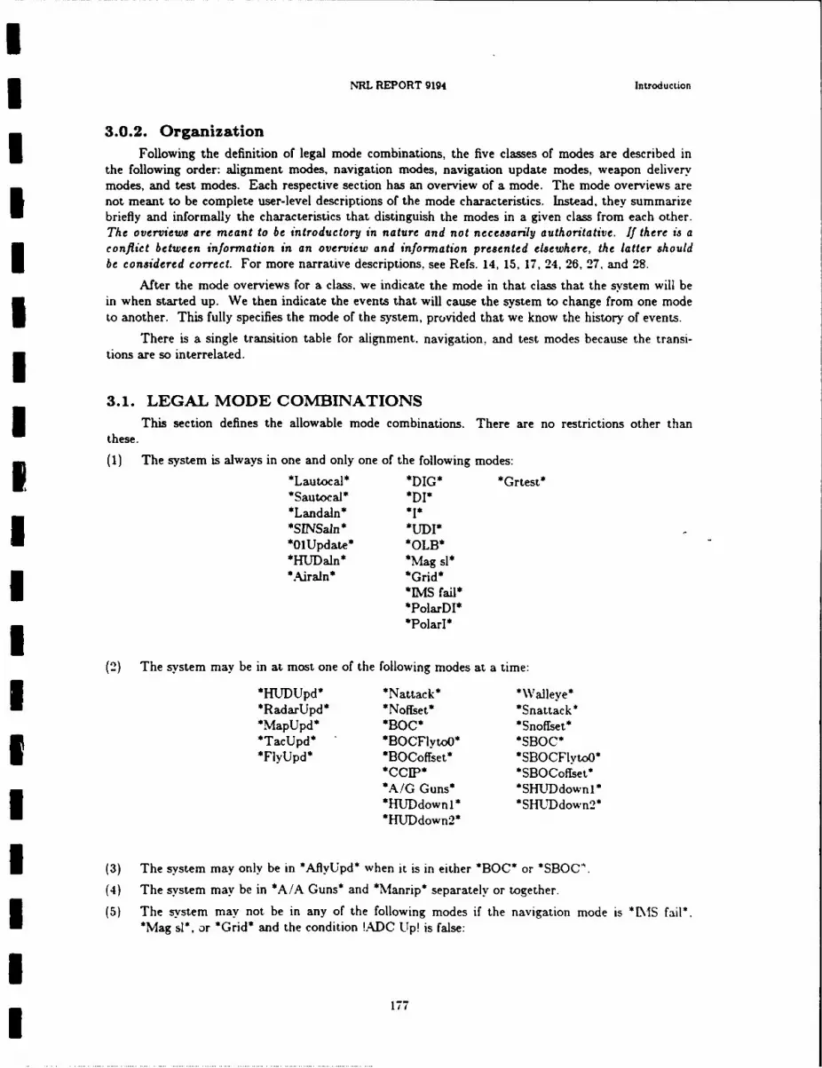
NRL REPORT g194 Introduction
3.0.2. OrganizationFollowing the definition of legal mode combinations, the five classes of modes are described in
the following order: alignment modes, navigation modes, navigation update modes, weapon deliverymodes, and test modes. Each respective section has an overview of a mode. The mode overviews arenot meant to be complete user-level descriptions of the mode characteristics. Instead, they summarizebriefly and informally the characteristics that distinguish the modes in a given class from each other.The overviews are meant to be introductory in nature and not necessarily authoritative. If there is aconflict between information in an overview and information presented elsewhere, the latter shouldbe considered correct. For more narrative descriptions, see Refs. 14, 15, 17, 24, 26, 27, and 28.
After the mode overviews for a class, we indicate the mode in that class that the system will bein when started up. We then indicate the events that will cause the system to change from one modeto another. This fully specifies the mode of the system, provided that we know the history of events.
There is a single transition table for alignment, navigation, and test modes because the transi-tions are so interrelated.
3.1. LEGAL MODE COMBINATIONSs This section defines the allowable mode combinations. There are no restrictions other than
these.
(1) The system is always in one and only one of the following modes:*Lautocal* *DIG* *Grtest**Sautocal* *Dl**Landaln* *1**SINSain* *UDI**01Update* *OLB**HUDaln* *Mag sl*
*Airaln* *Grid**RAS fail**PolarDI**Polarl*
(2) The system may be in at most one of the following modes at a time:
*HUDUpd* *Nattack* *Walleye**RadarUpd* *Noffset* *Snattack**MapUpd* *BOC* *Snoffset**TacUpd* *BOCFiyto0* *SBOC*
*FlyUpd* *BOCoffset* *SBOCFlytoO**CCIP* *SBOCoffset**A/G Guns* *SHUDdownl**HLUDdownl* *SHUDdown2*
*HUDdown2*
(3) The system may only be in *AflyUpd* when it is in either *BOC* or *SBOC' .
(4) The system may be in *A/A Guns* and *Manrip* separately or together.
(5) The system may not be in any of the following modes if the navigation mode is *NS fail*.*Mag sl*, Dr *Grid* and the condition !ADC Up! is false:
177

Chapter 3 ALSPAUGH, FAULK, BRITTON, PARKER, PARNAS, AND SHORE
*Natwk* *Noffset* *BOC*
*BOOFlytoO* *BOCofTset* *coIP*3*HUDdownl* *HUlDdown2* *Walleye*
*Snatak* *Snoffset* *BC*SBOCFyo* *SBO~offset* *SHUDdownl*
*SHTJDdown2*
1781
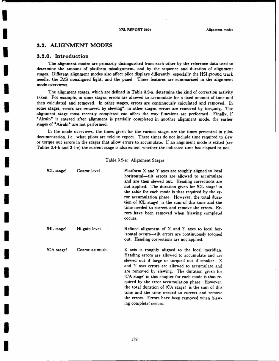
NRL REPORT 9194 Alignment modes
3.2. ALIGNMENT MODES
3.2.0. IntroductionThe alignment modes are primarily distinguished from each other by the reference data used to
determine the amount of platform misalignment, and by the sequence and duration of alignmentstages. Different alignment modes also affect pilot displays differently, especially the HSI ground trackneedle, the IMS nonaligned light, and the panel. These features are summarized in the alignmentmode overviews.
The alignment stages, which are defined in Table 3.2-a. determine the kind of correction activitytaken. For example, in some stages, errors are allowed to accumulate for a fixed amount of time andthen calculated and removed. In other stages, errors are continuously calculated and removed. Insome stages, errors are removed by slewing*; in other stages, errors are removed by torquing. Thealignment stage most recently completed can affect the way functions are performed. Finally, if*Airaln* is entered after alignment is partially completed in another alignment mode, the earlier
stages of *Airaln* are not performed.
In the mode overviews, the times given for the various stages are the times presented in pilotdocumentation, i.e.. what pilots are told to expect. These times do not include time required to slewor torque out errors in the stages that allow errors to accumulate. If an alignment mode is exited (seeTables 3.4-b and 3.4-c) the current stage is also exited, whether the indicated time has elapsed or not.
i Table 3.2-a: Alignment Stages
!CL stage! Coarse level Platform X and Y axes are roughly aligned to localhorizontal-tilt errors are allowed to accumulateand are then slewed out. Heading corrections arenot applied. The duration given for !CL stage! inthe table for each mode is that required by the er-ror accumulation phase. However, the total dura-tion of !CL stage! is the sum of this time and thetime needed to correct and remove the errors. Er-
rors have been removed when !slewing complete!
occurs.
!IHL stage! Hi-gain level Refined alignment of X and Y axes to local hor-izontal occurs-tilt errors are continuously torqued
out. Heading corrections are not applied.
!CA stage! Coarse azimuth Z axis is roughly aligned to the local meridian.aoHeading errors are allowed to accumulate and are
-- slewed out if large or torqued out if smaller. X
and Y axis errors are allowed to accumulate andare removed by slewing. The duration given forI- !CA stage! in this chapter for each mode is that re-quired by the error accumulation phase. However.the total duration of !CA stage! is the sum of this
time and the time needed to correct and removethe errors. Errors have been removed when !slew-
ing complete! occurs.
179
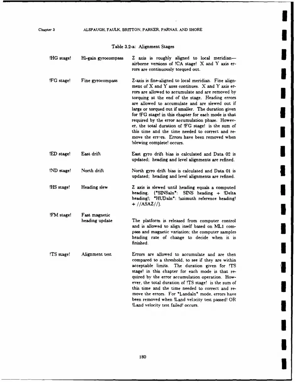
Chapter 3 ALSPAUGH, FAULK. BRITTON. PARKER. PARNAS, AND SHORE
Table 3.2-a: Alignment Stages
!HG stage! Hi-gain gyrocompass Z axis is roughly aligned to local meridian- Iairborne versions of !CA stage! X and Y axis er-rors are continuously torqued out.
!FG stage! Fine gyrocompass Z-axis is fine-aligned to local meridian. Fine align-ment of X and Y axes continues. X and Y axis er-rors are allowed to accumulate and are removed bytorquing at the end of the stage. Heading errors Iare allowed to accumulate and are slewed out iflarge or torqued out if smaller. The duration givenfor FG stage! in this chapter for each mode is that Irequired by the error accumulation phase. Howev-er, the total duration of !FG stage! is the sum ofthis time and the time needed to correct and re-move the errors. Errors have been removed when!slewing complete! occurs.
!ED stage! East drift East gyro drift bias is calculated and Data 02 is Iupdated; heading and level alignments are refined.
!ND stage! North drift North gyro drift bias is calculated and Data 01 is 3updated; heading and level alignments are refined.
!HS stage! Heading slew Z axis is slewed until heading equals a computedheading. (*SINSaln*: SINS heading + !Deltaheading!; *HUDaln*: !azimuth reference heading!
+ //ASAZ//).
!'FM stage! Fast magnetic
heading update The platform is released from computer controland is allowed to align itself based on MNIL1 com-pass and magnetic variation; the computer samplesheading rate of change to decide when it isfinished.
!TS stage! Alignment test Errors are allowed to accumulate and are thencompared to a threshold, to see if they are withinacceptable limits. The duration given for !TSstage! in this chapter for each mode is that re-quired by the error accumulation operation. How-ever, the total duration of !TS stage! is the sum ofthis time and the time needed to correct and re- Imove the errors. For *Landaln* mode. errors havebeen removed when !Land velocity test passed! OR!Land velocity test failed! occurs.
II
180I

NRL REPORT 9194 Alignment modes
3.2.1. Land Autocalibration (*Lautocal*)This mode is used to calculate and update the drift rates associated with the X and Y axes of
the platform, when the aircraft is on the ground. Since the A/C is not moving, the reference veloci-ties are zero: any nonzero /XVEL/ or /YVEL/ values are interpreted as signs of platform misalign-ment.
Refe-ence data:
Horizontal velocities: 0 corrected by Earth's rateLatitude and longitude: values most recently entered by pilot
I Stages:
S Coarse level 50 seconds !CL stage!Coarse azimuth 100 seconds !CA stage!Fine gyrocompassing 150 seconds !FG stage!Coarse azimuth 2 200 seconds !CA stage!East drift - 02 update 260 seconds !ED stage!Coarse azimuth 3 50 seconds !CA stage!North drift - 01 update 200 seconds !ND stage!
Comments:
The first three stages allow the platform enough time to become thermally stabilized.
181
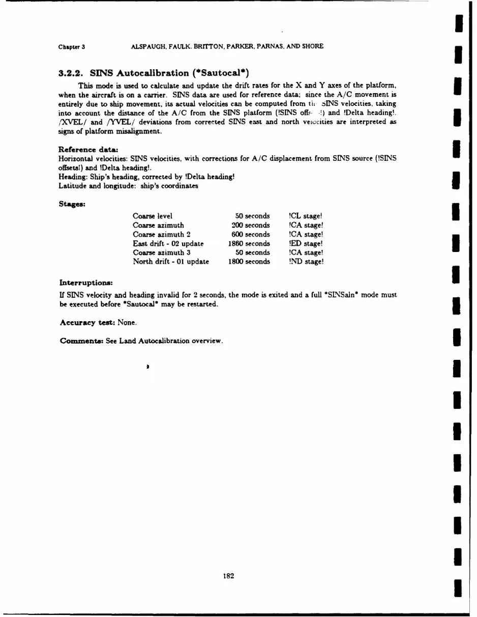
IChapter 3 ALSPAUGH, FAULK. BRrrTON, PARKER, PARNAS. AND SHORE
3.2.2. SINS Autocalibration (*Sautocal*)
This mode is used to calculate and update the drift rates for the X and Y axes of the platform,when the aircraft is on a carrier. SINS data are used for reference data; since the A/C movement is
entirely due to ship movement, its actual velocities can be computed from th SINS velocities, takinginto account the distance of the A/C from the SINS platform (!SINS offi:. !) and !Delta heading!.
/OXVEL/ and /YVEL/ deviations from corrected SINS east and north veiccities are interpreted as
signs of platform misalignment.
Reference data: IHorizontal velocities: SINS velocities, with corrections for A/C displacement from SINS source (!SINSoffsets!) and !Delta heading!.Heading: Ship's heading, corrected by !Delta heading!Latitude and longitude: ship's coordinates
Stages.:
Coarse level 50 seconds !CL stage!Coarse azimuth 200 seconds !CA stage!Coarse azimuth 2 600 seconds !CA stage!East drift - 02 update 1860 seconds !ED stage!Coarse azimuth 3 50 seconds !CA stage!North drift - 01 update 1800 seconds !ND stage!
Interruptions:I
If SINS velocity and heading invalid for 2 seconds, the mode is exited and a full *SNSaln* mode must
be executed before *Sautocal* may be restarted. 5Accuracy test: None.
Comments: See Land Autocalibration overview. I
IIIIIII
182 I

NRL REPORT 9194 Alignment modes
3.2.3. 01 Parameter Update (*OlUpdate*)This mode is used to update the drift rate of the Y axis. when the aircraft is on the ground and
a full *Landaln* mode has been executed. The new drift rate value is not used unless the accuracytests are passed.
Reference data:
Horizontal velocities: 0, corrected by Earth's rate
U Stages:
Fine gyrocompassing 200 seconds !FG stage!Alignment test 30 seconds !TS stage!
The above sequence is repeated until the mode is exited.
Accuracy test:
Velocity test: north and east velocities < 1/8 fps for 30 secondsDeltaOi test: difference between old and new Y axis drift rate values <0.049.
183

IChapter 3 ALSPAUGH. FAULK. BRITTON, PARKER, PARNAS, AND SHORE
3.2.4. Land Alignment (*Landaln*)This mode is used to align the axes of the platform to north, east, and vertical when the aircraft
is on the ground. Since the A/C is not moving, the reference velocities are zero: any nonzero
:XVEL/ or /YVEL/ values ar- interpreted as signs of platform misalignment.
Reference data: IHorizontal velocities: 0 corrected by Earth's rate
Stages:I
Coarse level 50 seconds !CL stage!Coarse azimuth 100 seconds !CA stage!
Fine gyrocompasbing 150 seconds FG stage!Fine gyrocompassing 200 seconds !FG stage!Alignment test 30 seconds !TS stage!
The last two stages are repeated until the mode is exited. The duration of the error accumulationphase of the !FG stage! that follows a !TS stage! depends upon the outcome of the Land velocity testat the end of the preceding !TS stage!. If !Land velocity test passed!, the duration is 200 seconds. IfNOT !Land velocity test p,-ssed!, the duration is 170 seconds.
Accuracy test: North and east velocities: less than 1/8 fps after 30 seconds.
1IIIIIIII,
184

NRL REPORT 9194 Alignment modes
3.2.5. SINS alignment (*SINSaln*)
This mode is used to align the axes of the platform to east, north, and vertical when the aircraftis on a carrier. SINS data are used for reference data: since the A/C movement is entirely due toship movement, its actual velocities can be computed from the SINS velocities, taking into account thedistance of the A/C from the SINS platform and the !Delta heading!. ,,XVEL/ and /YVEL/' devia-tions from corrected SINS east and north velocities are interpreted as signs of platform misalignment.
Reference data:
Not all the reference data are required: alignment may proceed even if the optional databecome not available.
Horizontal velocities: SINS velocities, with corrections for A/C displacement from SINS source(!SINS offsets!) (required) and !Delta heading!
Heading: Ship's heading, corrected by !Delta heading! (required)
Latitude and longitude: ship's coordinates (optional)
SINS heading, pitch and roll (required)
*Stages:
Heading slew varies !HS stage!Coarse level 50 seconds !CL stage!Coarse azimuth 200 seconds !CA stage!Fine gyrocompassing 600 seconds !FG stage!Alignment test 30 seconds !TS stage!
I The last two stages repeat until mode exited.
Interruptions: SINS data interrupt greater than 5 seconds--current stage restarted powerI interrupt less than 30 seconds-continues where left off otherwise stage restarted.
Accuracy teat: difference between [MS and corrected SINS north and east velocities: < I fpsafter 30 seconds.
1
I
185

I1Chapter 3 ALSPAUGH. FAULK. BRITTON, PARKER, PARNAS. AND SHORE
3.2.6. IMS-HUD Alignment (*HUDaln*)This mode is primarily used to correct the platform heading quickly, when the aircraft is on the
ground and the angle between the Ya axis and the line from the A/C nose to a visual reference pointis known. Once the heading correction has been made, the mode will continue with a regular *Lan-daln* sequence, if /MSMODE/=$Gnda$; otherwise the mode will be exited.
Reference data:Azimuth of known reference pointHUD coordinates of known reference point(For other reference data, see *Landaln* overview.)
Stages: Heading slew: !HS stage!
If /IMSMODE/ = Siner$ OR SNorm$, the mode is exited at this point. Otherwise alignment contin-ues with the sequence of stages given in *Landaln* overview.
Interruptions: If power interrursed: continues where left off.
Aceracy test: If /IMSMODE/=$Iner$ OR $Norm$: None. If /IMSMODE/=$GndalS: north andeast felocities: less than 1/8 fps after 30 seconds.
IIIIIIIIII
186
! I i i I !I
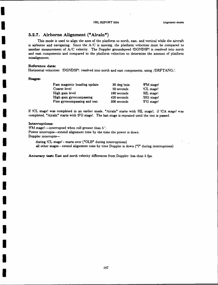
NRL REPORT 9194 Alignment modes
3.2.7. Airborne Alignment (*Airaln*)This mode is used to align the axes of the platform to north, east. and vertical while the aircraft
is airborne and navigating. Since the A/C is moving, the platform velocities must be compared toanother measurement of A/C velocity. The Doppler groundspeed !DGNDSP! is resolved into northand east components and compared to the platform velocities to determine the amount of platformmisalignment.
Reference data:Horizontal velocities: !DGNDSP!. resolved into north and east components, using /DRFTANG/.
Stages:S Fast magnetic heading update 30 deg/min !FM stage!
Coarse level 50 seconds !CL stage!High gain level 180 seconds !HL stage!High gain gyrocompassing 420 seconds !HG stage!Fine gyrocompassing and test 300 seconds !FG stage!
If !CL stage! was completed in an earlier mode. *Airaln* starts with !HL stage!; if !CA stage! wascompleted, *Airaln* starts with !FG stage!. The last stage is repeated until the test is passed.
Interruptions:!T'M stage!:-interrupted when roll greater than 5.Power interrupts-extend alignment time by the time the power is down.Doppler interrupts-
during !CL stage! - starts over (*OLB* during interruptions)
all other stages - extend alignment time by time Doppler is down (*I* during interruptions)
Accuracy test: East and north velocity differences from Doppler: less than 5 fps.
187

IChapter 3 ALSPAUGH, F'AULK. BRITTON, PARKER, PARNAS. AND SHORE
3.3. NAVIGATION MODES
3.3.0. IntroductionIThe two major aspects that distinguish navigation modes are (1) the data sources used in the
velocity, heading, and attitude calculations, and (2) whether any adjustments are applied to the plat-form axes, and if so, how they are calculated. These two main areas are covered in the navigationmode overviews.
The modes are also grouped into two classes: Primary and backup. The primary purpose of theclassification is continuity with existing documentation. Also the Data 98 display distinguishes Ibetween modes in this way.
In the overviews, vertical velocity is frequently calculated from AOA. IMS attitudes, and eitherhorizontal velocity or true airspeed (total velocity). In these cases, the following steps are followed to Icalculate vertical velocity:
(1) The angle of the A/C velocity vector relative to horizontal is calculated from AOA, pitch, androll. I
(2) Side v of the triangle below is solved, given that angle f (see step I) is known and eitherside h (horizontal velocity) or side t (total velocity) is known. 3
h angle f
We distinguish between "IMS corrections" and "VIS adjustments." Both involve torquing theplatform axes. However, the angle to be torqued is calculated differently in the two cases:
(1) Correction angles are calculated by comparing platform velocities to Doppler velocities to deter-mine the magnitude of platform misalignment. For the Z axis, this is called Doppler gyrocorn-panning, since the IMS heading is corrected. For the X and Y axes, this is called Doppler level-ing, since platform tilt errors are removed.
(2) Adjustment angles are calculated by applying fixed corrections: a reference velocity is notneeded. Adjustment maintains the platform in alignment with Earth axes, accounting for Earthcurvature and for the ongoing drift occurring in each axis.
IIIII
188 I
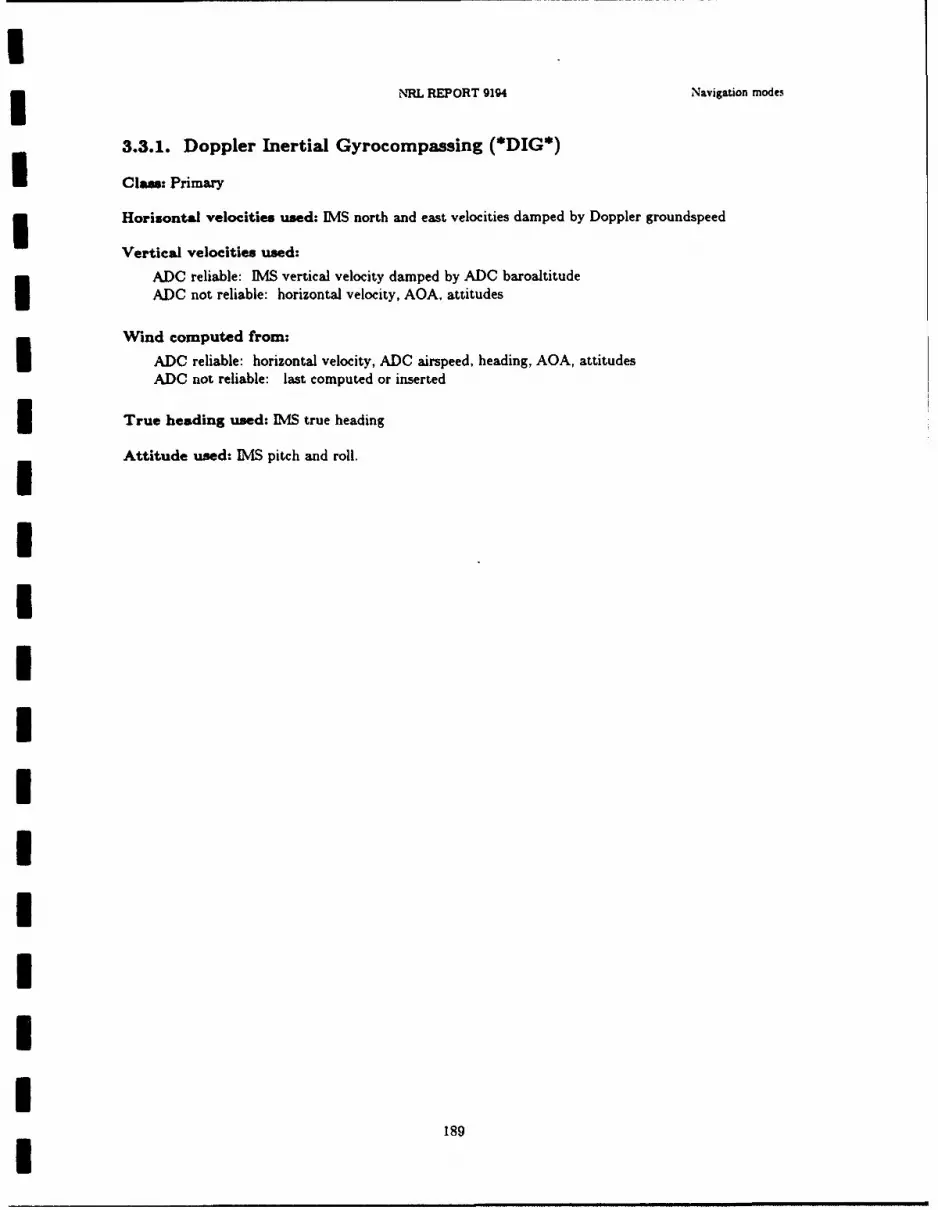
NRL REPORT 9194 Navigation modes
3.3.1. Doppler Inertial Gyrocompassing (*DIG*)
Clae: Primary
Horisontal velocities used: IMS north and east velocities damped by Doppler groundspeed
Vertical velocities used:
ADC reliable: IMS vertical velocity damped by ADC baroaltitude
I ADO not reliable: horizontal velocity, AQA. attitudes
Wind computed from:ADC reliable: horizontal velocity, ADC airspeed, heading, AOA, attitudesADC not reliable: last computed or inserted
True heading used: IMS true heading
Attitude used: IMS pitch and roll.
I1
I
IIIII
II
189I
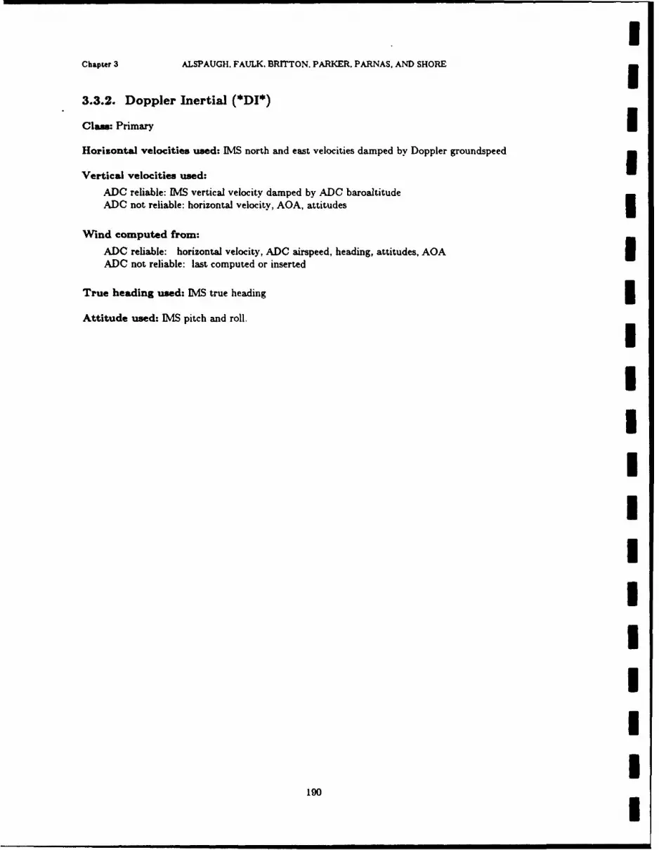
IChapter 3 ALSPAUGH, FAULK. BRrrTON, PARKER, PARNAS, AND SHORE
3.3.2. Doppler Inertial (*DI*)
Clas: Primary IHorizontal velocities used: IMS north and east velocities damped by Doppler groundspeed
Vertical velocities used:
ADC reliable: [MS vertical velocity damped by ADC baroaltitudeADC not reliable: horizontal velocity, AOA, attitudes
Wind computed from:
ADC reliable: horizontal velocity, ADC airspeed, heading, attitudes, AOAADC not reliable: last computed or inserted
True heading used: IMS true heading
Attitude used: [MS pitch and roll.
IIIIIIIIIII
190I
mm mm~mmmm m ¢ W===ii= I
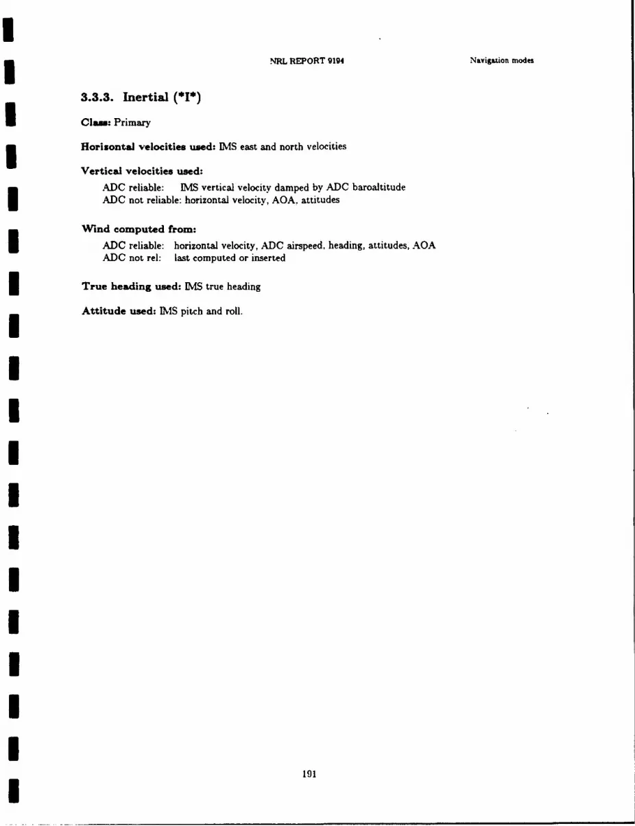
NRL REPORT 9194 Navigazion modes
3.3.3. Inertial (*I*)
Clam: Primary
Horizontal velocities used: IMS east and north velocities
Vertical velocities used:
ADC reliable: IMS vertical velocity damped by ADC baroaltitudeADC not reliable: horizontal velocity, AOA. attitudes
Wind computed from:
ADC reliable: horizontal velocity, ADC airspeed, heading, attitudes, AOAADC not rel: last computed or inserted
True heading used: IMS true heading
Attitude used: IS pitch and roll.
IIIIIII
191
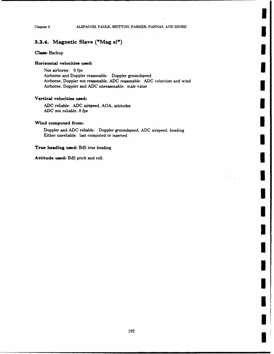
UChapter 3 ALSPAUGH. FAULK. BRITTON, PARKER, PARNAS, AND SHORE
3.3.4. Magnetic Slave (*Mag sl*)
Clas: Backup iHorizontal velocities used:
Not airborne: 0 fpsAirborne and Doppler reasonable: Doppler groundspeedAirborne, Doppler not reasonable, ADC reasonable: ADC velocities and windAirborne, Doppler and ADC unreasonable: stale value
Vertical velocities used:
ADC reliable: ADC airspeed, AOA, attitudes IADC not reliable: 0 fps
Wind computed from:
Doppler and ADC reliable: Doppler groundspeed, ADC airspeed. headingEither unreliable: last computed or inserted
True heading used: IMS true heading
Attitude used: IMS pitch and roll.
IIIIIIIII
192
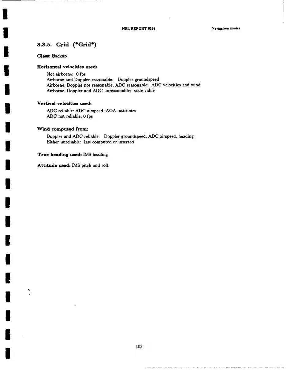
NRL REPORT 9194 Navigtion modes
3.3.5. Grid (*Grid*)
Class: Backup
Horizontal velocities used:
Not airborne: 0 fpsAirborne and Doppler reasonable: Doppler groundspeedAirborne, Doppler not reasonable. ADC reasonable: ADC velocities and windAirborne, Doppler and ADC unreasonable: stale value
Vertical velocities used:
ADC reliable: ADC airspeed, AOA. attitudesADC not reliable: 0 fps
Wind computed from:
Doppler and ADC reliable: Doppler groundspeed, ADC airspeed, headingEither unreliable: last computed or inserted
True heading used: IMS heading
Attitude used: IMS pitch and roll.
1
I
I9
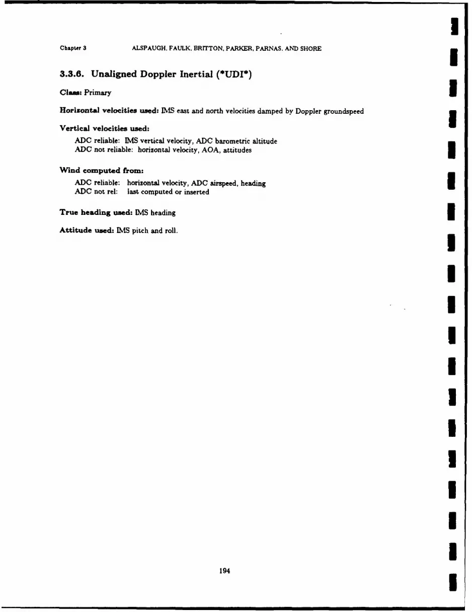
Chapter 3 ALSPAUGH. FAULK, BRITTON, PARKER, PARNAS. AND SHORE
3.3.6. Unaligned Doppler Inertial (*UDI*)
Cluas: Primary IHorizontal velocities used: IMS east and north velocities damped by Doppler groundspeed gVertical velocities used:
ADC reliable: IMS vertical velocity, ADC barometric altitudeADC not reliable: horizontal velocity, AOA, attitudes
Wind computed from:ADC reliable: horizontal velocity, ADC airspeed, heading iADC not rel: last computed or inserted
True heading used: IMS heading
Attitude used: IMS pitch and roll.
IIIIII1IIII
194
! ! I I Ii !I
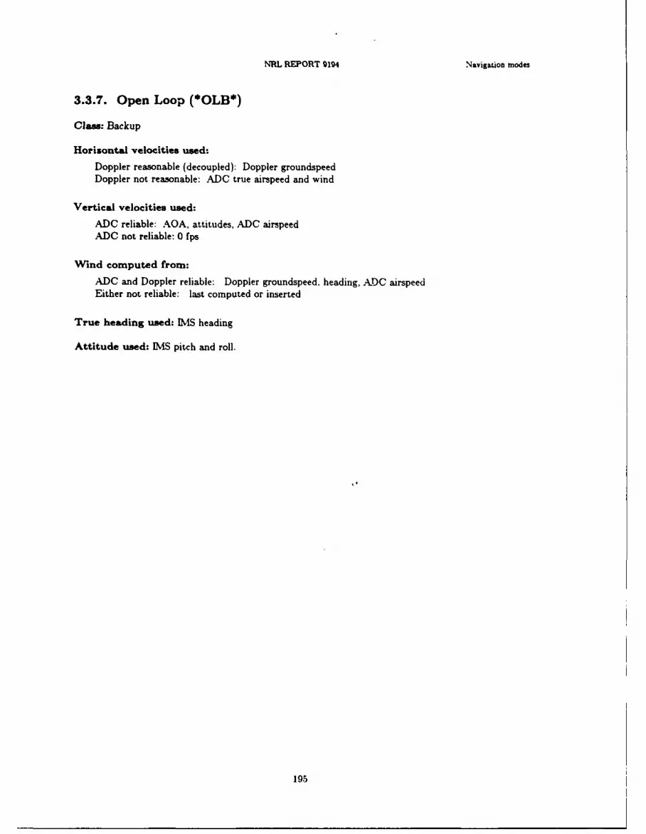
NRL REPORT 194 Navigation modes
3.3.7. Open Loop (*OLB*)
Clas: Backup
Horisontal velocities used:
Doppler reasonable (decoupled): Doppler groundspeedDoppler not reasonable: ADC true airspeed and wind
Vertical velocities used:
ADC reliable: AOA, attitudes, ADC airspeedADC not reliable: 0 fps
Wind computed from:
ADC and Doppler reliable: Doppler groundspeed, heading, ADC airspeedEither not reliable: last computed or inserted
True heading used: [MS heading
Attitude used: IMS pitch and roll.
195

IChapter 3 ALSPAUGH. FAULK, BRrTTON. PARKER. PARNAS. AND SHORE
3.3.8. IMS failure (*IMS fail*)
Claw: Backup IHorizontal velocities used:
Not airborne: 0 fpsAirborne and Doppler reasonable: Doppler groundspeedAirborne, Doppler not reasonable, ADC reasonable: ADC velocities and windAirborne, Doppler and ADC unreasonable: stale value
Vertical velocities used: 0 fps
Wind computed from:
ADC and Doppler reliable: Doppler groundspeed, heading, ADC airspeedEither not reliable: last computed or inserted
True heading used:
Partial IMS failure: magnetic heading + magnetic variationComplete IMS failure: north
Attitude used: Pitch = !True AOA!, roll = 0. 3
IIIIIIIII
196!
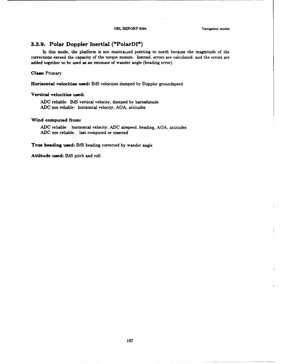
NRL REPORT g194 Navigation modes
3.3.9. Polar Doppler Inertial (*PolarDI*)In this mode, the platform is not maintawed pointing to north because the magnitude of the
corrections exceed the capacity of the torque motors. Instead, errors are calculated, and the errors areadded together to be used as an estimate of wander angle (heading error).
Clas: Primary
Horizontal velocities used: [MS velocities damped by Doppler groundspeed
Vertical velocities used:
ADC reliable: IMS vertical velocity, damped by baroaltitudeADC not reliable: horizontal velocity, AOA, attitudes
Wind computed from:
ADC reliable: horizontal velocity. ADC airspeed. heading, AOA, attitudesADC not reliable: last computed or inserted
True heading used: IMS heading corrected by wander angle
Attitude used: [MS pitch and roll.
197

IChapter 3 ALSPAUGH. FAULK, BRITTON. PARKER. PARNAS. AND SHORE
3.3.10. Polar Wander Azimuth, Inertial (*PolarI*)In this mode, the platform is not maintained pointing to north because the magnitude of the
corrections exceed the capacity of the torque motors. Instead, errors are calculated, and the errors are
added together to be used as an estimate of wander angle (heading error).
Class: Primary
Horizontal velocities used: INIS north and east velocities
Vertical velocities used:
ADC reliable: IMS vertical velocity, damped by baroaltitudeADC not reliable: horizontal velocity, AOA, attitudes
Wind computed from:
ADC reliable: horizontal velocity, ADC airspeed, heading, AOA, attitudes 5ADC not rel: last computed or inserted
True heading used: IMS heading corrected by wander angle
Attitude used: ]MS pitch and roll.
1UII
III
II
198!
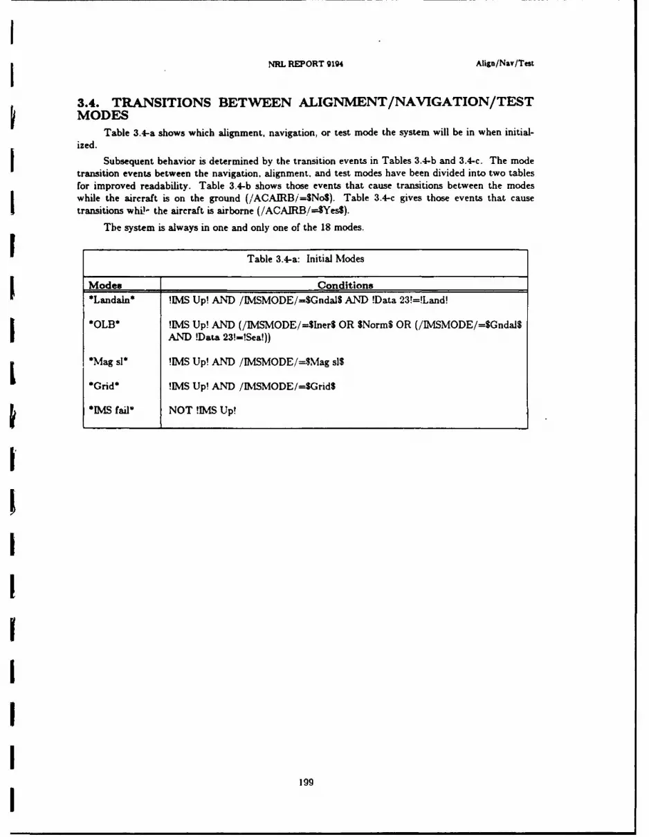
II NRL REPORT 9194 Align/Nay/Test
3.4. TRANSITIONS BETWEEN ALIGNMENT/NAVIGATION/TESTMODES
Table 3.4-a shows which alignment, navigation, or test mode the system will be in when initial-ized.
Subsequent behavior is determined by the transition events in Tables 3.4-b and 3.4-c. The modetransition events between the navigation, alignment, and test modes have been divided into two tablesfor improved readability. Table 3.4-b shows those events that cause transitions between the modeswhile the aircraft is on the ground (/ACAIRB/=$No$). Table 3.4-c gives those events that causetransitions whil the aircraft is airborne (/ACAIRB/--$Yes$).
The system is always in one and only one of the 18 modes.
Table 3.4-a: Initial Modes
Modes Conditions*Landaln* !IMS Up! AND /IMSMODE/=$Gndal$ AND !Data 23!-!Land!
*OLB* !IMS Up! AND (/IMSMODE/=$Iner$ OR SNorm$ OR (/IMSMODE/=$Gnda$AND !Data 23!-!Sea!))
*Mag sl* !MS Up! AND /IMSMODE/=$Mag sis
*Grid* !IMS Up! AND /IMSMODE/=$GridS
*IMS failm NOT !IMS Up!
I9

Chapter 3 ALSPAUGH, FAULK, BRITTON. PARKER. PARNAS. AND SHORE
Table 3.4-bTransitions Between Alignment. Navigation, and Test Modes
While the Aircraft Is Not Airborne (/ACAIRB/=$No$)
%U% %
CA '- -
Current0Mode NewMod
Lautoca@1....................%o----------------------------------_"Il
N.........@r 0 r---------------I
-1--- -----------------------------------------------
----------------------------------------------------- asri
-------- -- - -- - - - - --- ---- ---- --- ---- --- ---- ---- ------------
--------------------------------------------------------- NanI
-------- ---- -------- - r--------------------------j
-~~~~~~~OB -I - -CT- - - - - *rd
@1--------------------------------------------------------. .. . . . . . . r (9 - - --- --- --- --- --- --- - - - - om al
------------ r:-----------------------------------------------*~Srt
- - - -- - - t - t-- ---- --- --- Pola,1 I----------------- @1------------------------------------------Gtt------Ca .. . .... .. * rt qI
0sautocaI@ r -- - - - - - - - - - - - - *200dn----------------------------------------
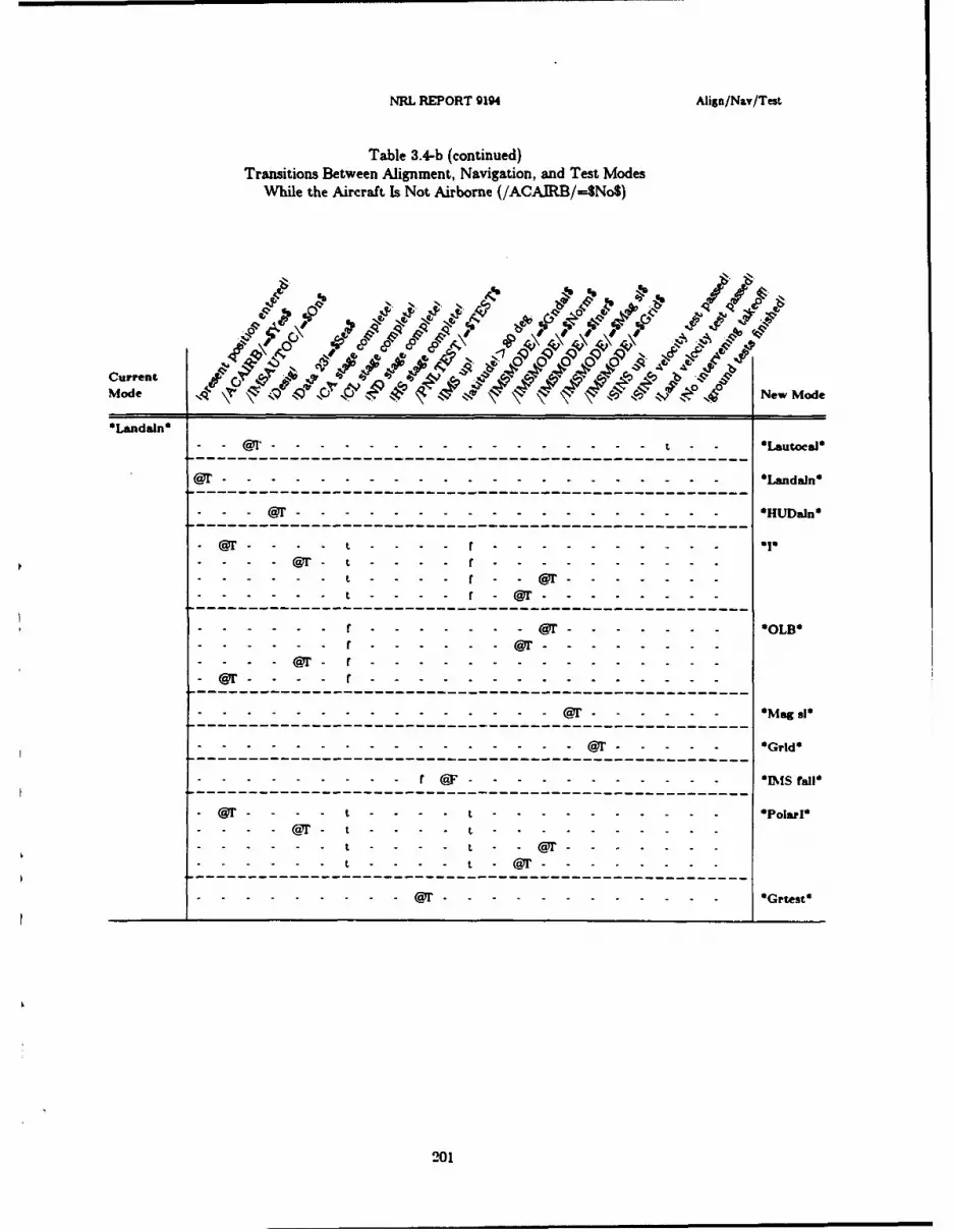
NEL REPORT 9194 Align/N,.v/Test
Table 3.4-b (continued)Transitions Between Alignment, Navigation, and Test Modes
While the Aircraft Is Not Airborne (/ACAJRB/=SNoS)
e5.~~4 .04 '3 -% 0/0 3 ~ ~ 4~~%
Current A j 'j -j-i _V-Y
Mode NeNo,
*Landaln*
- ---.-.-.-.-.. . .-.-.-. . . . . . . . t e Lautoesis
*----------------------------------------------------Han
@r @- - - - - - - - - - -r
---------------------------------.r- @ .............
-----------------------------------r........r........*-- @r -...............................
- @r- - t - - - - .................................- o -
........ t -- - [email protected] - --- . - --- ---- ---- ---- ---- ----
- - - - -r - - - - - CT - G-r--e-t
. .. - - - -@ r - - - - -20-1
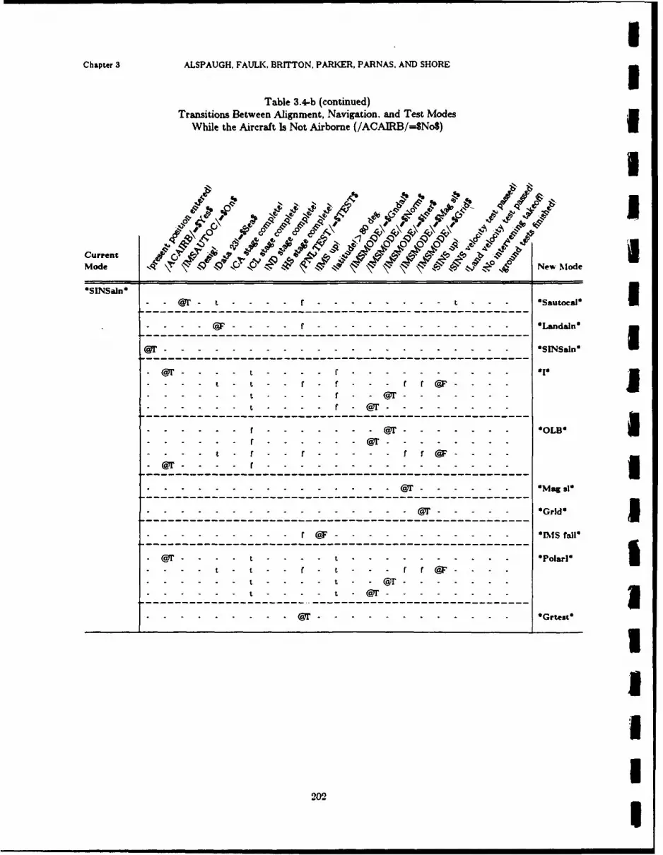
Chapter 3 ALSPAUGH, FAULK, BRITTON, PARKER, PARNAS. AND SHORE3
Table 3.4-b (continued)Transitions Between Alignment, Navigation. and Test Modes
While the Aircraft Is Not Airborne (/ACAIRB/=SNoS)
4 01 4g 4.4q, ACurrent5rArMode 4 4VC e Mode
*SINSaln* 9 - - - -r---- ------ - - - Sautocal I- -------- ------------------------------------ Ladl
---- - ------------------------------- 1
- - - - t - - f r - - r - - - -* I
----------------------------------------------------
t .- t - r - - ----- r r (9F- - - -
-------------------- @1-----------------------Ma 1
--- - --- ------ r---------------------------------------r~rl
- - - - - - - - r 9F- - - - - - - - - - 010 i
. . . . . . @1-----------------------------------------------Gret
CaT ------ ---- -- - * olrUt - .r t - r (9 .
202

NRL REPORT 9194 Align/Nay/Test
Table 3.4-b (continued)Transitions Between Alignment, Navigation, and Test Modes
While the Aircraft Is Not Airborne (/ACAIRB/=-$No$)
Vm .04
4 P0 P
'0CurrentMode I$ ' NewMode
Ol1Update*
---- --- ---- --- --- ------- LautocaiO
@-------------------------------------------------------------------Ldan
- - --- ------------------------------ *HDh
-----------------------------------------
- - - - - - - - - - - - - - - - - - - - - - - - - - -r - - ------- ------- -------- - -- - - - --- --- - -- ---------------------
--------------------------......--- -- ---------------- -
- - -- - - - - - f @F - - - ..... -.-.-.-.-...........
- - - - - -- - -- -- - - - -- - -- - - -- - - - - -- - -- - -- -
203

Chapter 3 ALSPAUGH. FAULK, BRITTON, PARKER, PARNAS. AND SHORE
Table 3.4-b (continued)Transitions Between Alignment, Navigation. and Test Modes
WVhile the Aircraft Is Not Airborne (/ACAIRB/=$No$)
bI4 % ' 1
Current 9P0 t'4"4-4, 4 2b
1 1 0 :7 'j 4 e-, A4New M ode
OHUDain*C - - - - - - - - - - - - - - - - t - - * a oc l*-1------------------------------------------------------- - - Luoa
@T @- - - - t-- - - r.......................*-t - -*-- r-- @r I
- - - - - - t - - r - -T - - - - - - - -- -
-@r--------r------------------------------------
W.-.-.-. -. -. -. -@ - - - - t - - - - - - - -
r ~ ~ ~ ~ ~ ~ M t taI--@ ----
-- - - t -- t---------------------------------------------------Par
--- ---- - - -@----------------------
--------------------- -t. -------------------
. . . .. . CaT - - - - - - - - - Grtest*
204
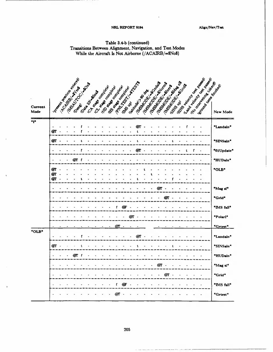
NRL REPORT 9194 Align/Nsv/Test
Table 3.4-b (continued)Transitions Between Alignment, Navigation, and Test Modes
While the Aircraft Is Not Airborne (/ACAIRB/=$No$)
b' N'8b--, %%6 b1%b
a'A'-~~~~~~~~ 0 0 - A,---------r........ adl
- ~ ~~~~~~~~ A................K % 4 b I~
- - -.-.-.-.-. Or.- - - - - - r *-n an
........................................... @-------------------Gd
.................................- -.. ... ... ... 'Gr e
W- - - t -....-.............................. LD*l
@ - - - .- - .- .- - .- . .- .- . .t .- - - - - - -S! ai
-91 - - -r t.........................................- -
-------------- ---- --- ---- --- ---- --- ---- ---
- - - -- - (T - - - - *Mg 91d-~~ - --.-.-.--.-.---.-.----------------------------
.................. @- '.................................Grid*t
- ---- - -- -- --- -- -- --- -- --- -- -- --- -- --

Chapter 3 ALSPAUGH. FAULK, BRITTON. PARKER, PARNAS, AND SHORE3
Table 3.4-b (continued)Transitions Between Alignment, Navigation, and Test Modes
While the Aircraft Is Not Airborne (/ACAIRB/=$No$)
4 .; 9 4'',
II&CurrentIMode New Mode
'%lag .1* 1 Lnan- -..............-------------------------------------- Ladin
--------------------- @1----------------------'rd------ -- ----MT - - - *G id------------------------------------------------------- -- M taI
- - -....... F-- -- - ---------------------- Wd*
----------------------------------------------- @..............LD3
W - -t
---------------------------------------------------- 'Pt al
- ----- 1 -------------------------------------------------- 'Lnan
-- ---------- - t----------------------------------OD
@ F - - - - - --- - - - OP I t
Or" - - - ---- -- - - - -::
------------------------------------------------------- Gret
.......C T ---t - - -- O LI----- -aT - - - - -U
.0 .1 a

NRL REPORT 9194 Afign/Na/Test
Table 3.4-b (continued)Transitions Between Alignment, Navigation, and Test Modes
While the Aircraft Is Not Airborne (/ACAIRB/=$No$)
t_ -&- t~
~c NN %
CurretMad~ _
*Poar5_110 --------- @'-------------- adl
X3-- r--------------------t------------------------- - - - t - SI~aP
ff @.--------------------- - -- 'INI tLnal
- ------------------- ---------------------------------- Lnan
-------------- - -- -- - t - - - -- t- --- -@ 'SLn--------------------------------------- *---------
- - - ------ ---- -- -- - t---- -- - -- - t r- *71'd
-- - - - - - - - ---------------------------------- .. . .
- - -- f---- - --- - - - - t- - - - - - -1 *la
------------------------------------------------------
@r - t - -- - - - 1 Gr-d-
------------------------------------------------------ Tral
-------------------------------------------------
- - -- - - - - - f 2 07 - - - - - - - - - - -* [ I fa l

mChapter 3 ALSPAUGH, FAULK. BRITTON, PARKER, PARNAS, AND SHORE
Table 3.4-cTransitions Between Alignment, Navigation, and Test Modes
While the Aircraft Is Airborne (/ACAIRB/=$Yes$)
mI51,
Abb
Current ) '7 IMode S: . \ \ \ New Mod
* A i r l n * C a - f t - - - - - - - -* A i r a l n *C~iaie 1----------- -------------------------------------------- Aian
f f -" t - - - f - - @I,'- *DIG*
t---------- ---------------------------- D- - - - f- - t t - - *DI*
t - f t @ "- - -
S - t f - - - - - - - - -
-~ ~ f (9FI - - t - - -71- - - -
t f - f - - @
- ~- --------------------------------- ------- OLf - - - - t - r - - -U I t
-- - -- ------------------------------ I@ Ff - - - - - - - - - -- *O L B O
f - -- ---- @- - -
ff - - -Magsl I
@1' - Grid"
( F- IMS rail* If t-tt - - - - - -PoarDI*
- F t t --------------------------------------------- PorI
I, - -t t t *P -~l
t ~ ~ ~ t @fCO - - - -
I
IIU
208m
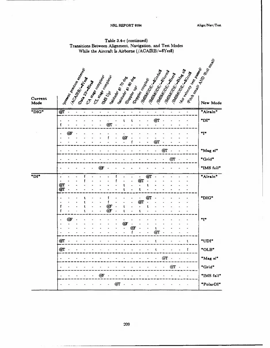
NRL REPORT 9194 Afign/Nay/Test
Table 3.4-c (continued)Transitions Between Alignment, Navigation. and Test Modes
While the Aircraft Is Airborne (/ACAIRB/=$YesS)
:N,
4.p
Current
Mode Neod
D1 1'------------------------------------------------------irn
t t -r - - - *DI
f--------- ------------------
@F - - - - - - -r- - - - *1
f@1'-- - - - - M g s
- - -- - - - @1'r - - -Gr d
D1- -------- - - f - -@---------- ------------ Arl
--- --- -- - --- ---- -- - -- -------------- -- - - - - - - - - - CT - - * rd
- - - --- - - -- --- ---------------------- I@F - - - - - - -------- Mfal
I f - - Or - - -- - -
W - - - - - t t - -
-------------------------------------- *1
f t @ - t F - t - - - - -
- - - - - - - - - -- t - t- - - - - -
---'---------------------------------------- --- u~@71----------------- - - -- -- - - - - *I*
@F -Ma - - - -
-- ---- --- ---- --- --- ---- ----------------- ---- --- - -
@F-------------------------------------------*ISri
--------------------------------------------- PoaD
209

Chapter 3 ALSPAUGH, FAULK. BRITTON, PARKER, PARNAS. AND SHORE3
Table 3.4-c (continued)Transitions Between Alignment, Navigation, and Test Modes
While the Aircraft Is Airborne (/ACAIRB/=$Yes$)
% 4'
CurrentIMode 17 '7VNew Mode
S f ---- --- --- --- --- ----- t----- --- --- ---- --------- Landaln*
- - - I - - - - @12 - t--------- - - - - ------ A
-- - - - -- @ t12- - -
- - -- - t-- --- [email protected] Gf - tf a - t - - - -@1- - *DG
f - t f - f - t -@1------- --
- t - @ -- - - - -
--- --- t- --------- -------------------------- Dt t - - - -- - ODr
tt f t12 @1' - - - -t f O r t- - - - - - -
f---- --- --- -------- f Ct@1- t- - - - -
O0LB N-~~~1 - a MagI 31
------- @------------------------------------Par
lJD---I-------------------------------------- Y2..........ian
-- -- - - - - - - -- --- -------------------
-- -- -- -- -- -- -- -- - -------------------- 0L
@F -- - - -@ - - - - -M gI
- - -- - - - @ - - - @- - -
-- ~ ~ ~ ~ ~ ~~ M -- -- -- - - - -- - - -- - -
2101
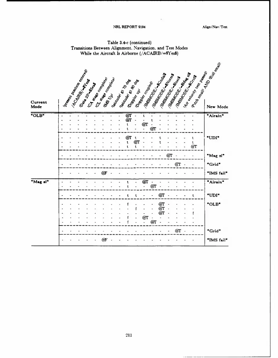
NRL REPORT 9194 Aign/Nav!Test
Table 3.4-c (continued)Transitions Between Alignment. Navigation, and Test Modes
While the Aircraft Is Airborne (/ACAIRB/=$Y'ies$)
~% Cl6
Current % e~dMode
CI CIO -V t -Y
A 0
4 1' -T 4 -4Zags
*OL * -- - - - - - - CT t - - - - - GArald*
Ma a---------------------------- @I--------------------------Arn- -- -- -- -CTtt @--------- M
t @r t - ~ - - - t UD
- -- - - - - - - - 0L1
- -- - - - - - - - s - a - - - * a l
-- - -- - - - - - - - 1a - - *G rid *
- -& - - - - - - - - IM S fail*
*Magsl* - - - - - - - Ca - - - - - *A211n
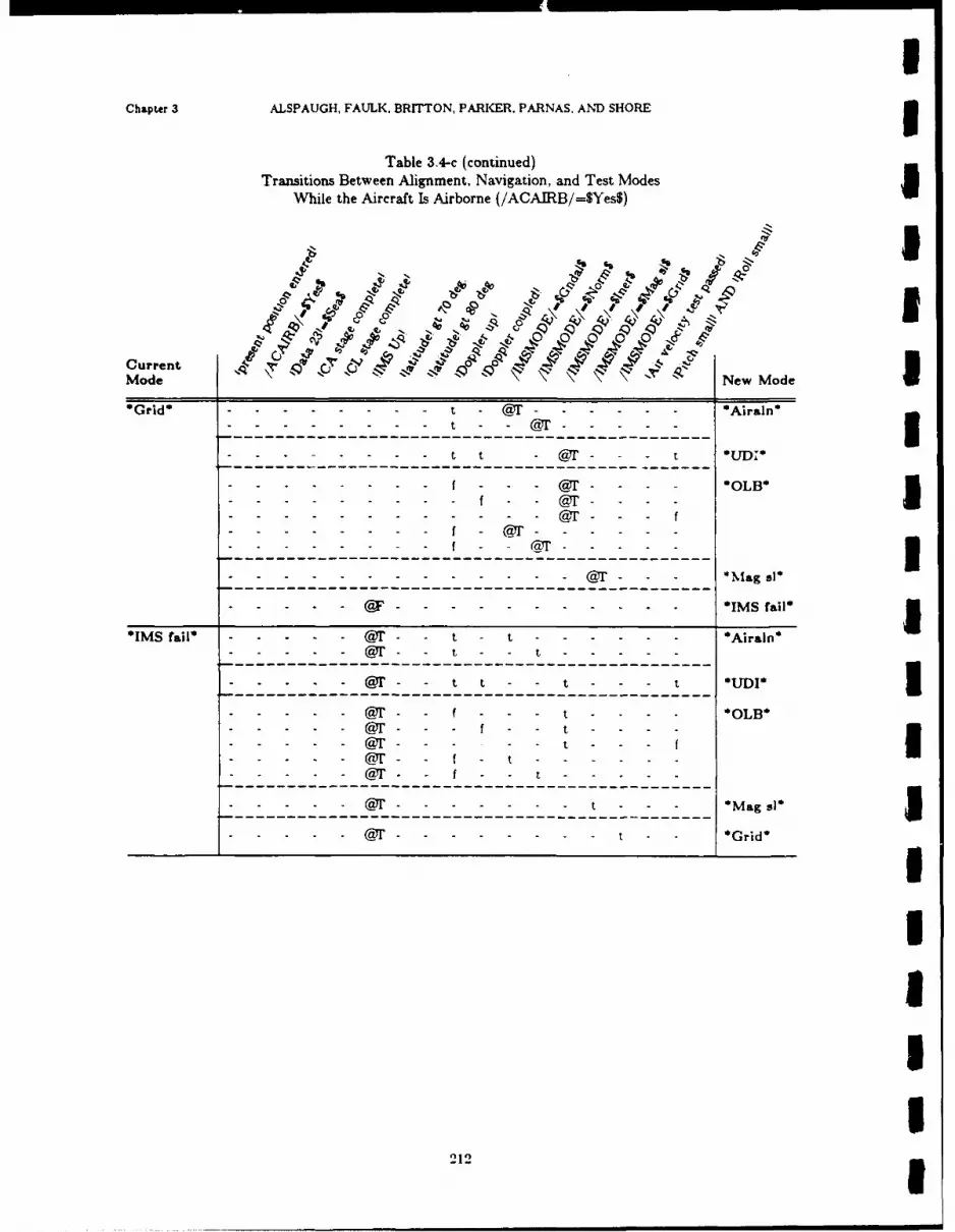
Chapter 3 ALSPAUGH, FAULK. BRITTON, PARKER. PARNAS. AND SHORE3
Table 3.4-c (continued)Transitions Between Alignment, Navigation, and Test Modes
While the Aircraft Is Airborne (/ACAIRB/=$YesS)
J.4$
CurrentMode New Mode
'Grd'----------------------------- 1----------------------Aiin
- -- - - - t t - Ca 1'- - - t
-- - - - - f - - - Or1'- - - - *OLB'
- - -- - - - - f C- -@ 1- - - -- - -- - - f - ra @ - - - - -
- - -- - - @- Ca - - - Mag 9l'
'IM fil-----------------7'---t------------------------------Arin
*I S f i* - - -- @ Y- - - - - - - - - - - * I S fa l
-@1 -- a - - t - - - - - - *AO rLB'- --7 - a ' - t - - t - - - - -
---- --- --- --- ---------------------------
-71------------- t - - t---- - - t M gs--------------------------------------- -- 'rd
----CaT - - - -t ---- OLICaT ---t ---U
- - - -CaT --t - -I- - - CaT -ft - - -
2121
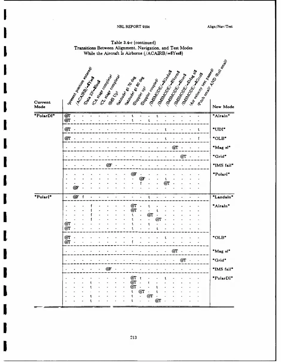
INRL REPORT 9194 Align/Nay/Test
Table 3.4-c (continued)Transitions Between Alignment, Navigation, and Test Modes
While the Aircraft Is Airborne (/AOAIRB/=SYes$)
NN10
A 'x
Mode " New Mode
*PolarDI* Ca @'--- -- ------ - - t t------------------*Airaln*
-- -- - -- - --- ---------------------------
Or t t 0M-
-71-------------------------------- --- f L
- - - -- - - - - - CT, Grid*
-------- ---- ---------------------- ISri
- - - -- - - (9 - - - - - - - PolarI*(WF t - - - -
PolarI* @F f - - - - - - - t-- ---- --- ---- ---------- Landaln*
-------- ------- t--------------------------------Arl
f -- - - CR @ 1- t - - - - - - * ianf - - ------- t -- -- --f- - --- t - T------
f -- - - t - - CT - -'
1~a ------------------------- t - - - - L1-- -- - -- - -- - --------------------------
CaT - - -- - - f - - - - ' - -
----------------------------------------------- IM- -- - - - - - - -t - - - CT - - -* a .
I - - - - - CT - t - - -
213

Chapter 3 ALSPAUGH, FAULK, BRITTON, PARKER, PARNAS, AND SHORE
3.5. NAVIGATION UPDATE MODES
3.5.0. IntroductionIn a navigation update mode. data about a reference point near the aircraft are used to obtain
an estimate of A/C position. The update is obtained by comparing the coordinates of two points: theOFP's estimate of the reference point (0) and the pilot's estimate (P). If 0 and P coincide, no correc-tion is necessary; if they do not coincide, the pilot's claim is assumed to be valid and the OFP data areupdated accordingly.
The navigation update modes differ in the reference point that is used (present position or desti-nation) and in the way that the pilot and the OFP exchange information about the location of thereference point. The pilot communicates by (1) designating when the A/C is above the referencepoint; (2) slewing the aiming symbol on the HUD or the cursors on the radarscope; or (3) slewing themap. The OFP communicates by (1) placing the aiming symbol on the HUD or the cursors on theradarscope; (2) moving the map; or (3) displaying information on the panel. The OFP usuallydisplays the error computed by comparing the two estimates, so that the pilot can decide whether ornot to accept the new value.
In several update modes, the horizontal distance from the A/C to the reference point must becomputed. This computation is called ranging. Assuming the OFP knows the angle "d" in Fig. 3.5a,the distance "h" may be computed if either the slant range "s" is known or the altitude "a" is known.Which one of these is known depends on the mode, !Data 24!, and the availability of the sensors.
A/C
angle d
a
5:hI
Reference point
Figure 3.5-a: Ranging calculations
The mode vzriations are summarized in the overviews that follow. 33.5.1. HUD or Visual Update (*HUDUpd*) IReference point: Called up destination (1-9)OFP estimate shown: Position of aiming symbol. before slewingOFP estimate derived: OFP compares destination coordinates to present position coordinates tocompute aiming symbol positionPilot estimate shown: Position of aiming symbol, at designation.Pilot estimate derived: Pilot slews aiming symbol to overlay the observed location.Ranging: Slant range if !Slant range reasonable! is between mode entry and first slew. Otherwise.the sensor is defined by !Data 24! (/RADALT/ or !Baro altitude above target!).
214

NRL REPORT g194 Navig&Uon update modes
3.5.2. Flyover Update (*FlyUpd*)Reference point: Called up destination (1-9)OFP estimate derived: Present position coordinates at designationPilot estimate derived: Destination coordinates (pilot designates when the A/C is directly over thedestination).
3.5.3. Aittomatic Flyover Update (*AflyUpd*)Reference p int: Called up destination (1-9)OFP estimate derived: Present position coordinates at designationPilot estimate derived: Destination coordinates (pilot designates when the A/C is directly over thedestination).
3.5.4. Radar Update (*RadarUpd*)Reference point: Called up destination (1-9)OFP estimate shown: Position of radar cursors, before slewingOFP estimate derived: OFP compares destination coordinates to present position coordinates tocompute position of radar cursorsPilot estimate shown: Position of radar cursors, at designationPilot estimate derived: Pilot slews radar cursors to overlay the location seen on the radarscopeRanging: from sensor defined by !Data 24! (/RADALT/ or !Baro altitude above target!).
3.5.5. Map Update (*MapUpd*)Reference point: Present positionOFP estimate shown: Map location under position marker before designationOFP estimate derived: Present position coordinates before designationPilot estimate shown: Map location after designationPilot estimate derived: Pilot slews map to move position seen on the filmstrip under the positionmarker.
3.5.6. TACAN Update (*TacUpd*)Reference point: Called up destination (1-9)
OFP estimate: present position coordinates at designation
TACAN estimate: position calculated from TACAN station coordinates. /RNGSTA/ and'BRGSTA/, as Fig. 3.5-b indicates. h is the horizontal distance from the a/c to the TACAIN station.
calculated from /RNGSTA/ and the angle d.
215
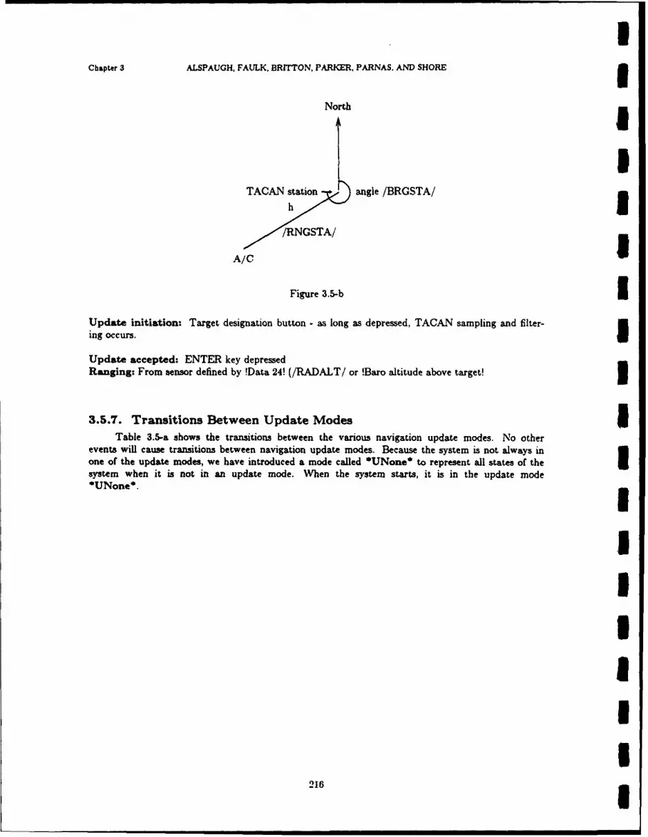
IChapter 3 ALSPAUGH, FAULK, BRITTON, PARKER, PARNAS. AND SHORE
North I
I
TACAN station angle /BRGSTA/
/RNGSTA/
A/C
Figure 3.5-b 5Update initiation: Target designation button - as long as depressed, TACAN sampling and filter-
ing occurs.I
Update accepted: ENTER key depressedRanging: From sensor defined by !Data 24! (/RADALT/ or !Baro altitude above target!
3.5.7. Transitions Between Update Modes ITable 3.5-a shows the transitions between the various navigation update modes. No other
events will cause transitions between navigation update modes. Because the system is not always inone of the update modes, we have introduced a mode called *UNone* to represent all states of thesystem when it is not in an update mode. When the system starts, it is in the update mode*UNone*.
IIU
I216 3
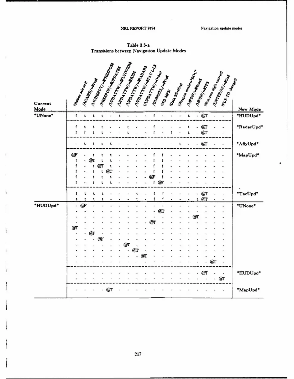
NEL REPORT 9194 Navigation update modes
Table 3.5-aTransitions between Navigation Update Modes
C'
0
CurrentMode New Mode*UNone* f t t t - - - f - - t -@r1 - HUDUpd*
f t t t - - t f - - - t -iT - - RadarUpd*
f it t t - f - t -@1 -
--- -- --- -- --------------------------------- @' - --- fy~d
-t---t ----------- ------------------------------ ~Mpp@F - 1t t t - - - - f f - - - - - - - * ~ ~ d
f - @ t 1 t - -
f t t t - - - - F If - t t Or - - - - f f - - - - - - -
t t t - - - - IF f - - - -@- - - Tcpf__ _ __ t t t - - - - I I - - - -@Y- - -
------ ------------------------------------ U~n
* ~ ~ ~ ~ ~ ~ ~ ~ ~-HUDUpd* Uoe
___________j- - - -@1-------------------- - - - - - ----
@ 217 - - -

Chapter 3 ALSPAUGH, FAULK, BRITTON, PARKER, PARNAS, AND SHORE
Table 3.5-a (continued)Transitions between Navigation Update Modes .
Modren New Mode 3*RadarUpd*------ ------ ------ ------ ------ ------ t-------- ----------- UNone*
r- -- -- ------- - -@- - - Rdrp
~~~~- - - -1--------------- - - - - ----- M3
F~y~pd-------- ------------------------ - -------------- Uoe
--- - - -- -- - -- - - - - ---
--- -- -- -- -- - -@- - - *MapUpd 3*Fy~* - - - - - - - - - - - - - - -@--- - --Ca - - - -3
-- ---- - ---- -I-@ F ---- - ---- -U--@ F --- ------ -I
218

NRL REPORT g1g4 Navigation update modes
Table 3.5-a (continued)Transitions between Navigation Update Modes
N,
0
CurrentI 0
Mode 0 T INew Mode
*AflyUpd* -- F---- -------- ------ --------- UNone*
- -- - -- --- --- T-------- -----
- - -- - - - - - - - - ~ ~ p
TacUpd----------------------------------------UNone*
- - - ---------------------------------------------- Mpd
- -- - - - - - - - @T -219pd
IChapter 3 ALSPAUGH, FAULK, BRITTON, PARKER. PARNAS. AND SHORE I
3.6. WEAPON DELIVERY MODES
3.6.0. Introduction IThe weapon delivery modes differ primarily in the way the target location is identified to the
OFI. In normal modes (*Nattack* *Noffset*, *BOCFIytoO*, *HUDdownl*. and *HUDdown2*), the
pilot sees the target or a landmark near the target and identifies the point to the OFP by designatingwhen the aiming symbol or standby reticle overlays the point.
In bomb-on-coordinates modes (*BOC*, *BGCoffset*). the OFP computes the location of the Itarget or landmark by comparing Fly-to coordinates to present position coordinates.
In *CCIP* mode, the pilot may release a weapon at any time. The OFP displays HUD symbolsto show the pilot the location that would be hit if a weapon were released now. U
The offset modes (*Noffset*, *HUDdown2*, and *BOCoffset*) identify a target by its posi-tion relative to a landmark, as the following figure shows.
North
3Landmark (OAP) Offset bearing to target
Offset range to target
Target m
In *Manrip* and *Walleye*. the pilot may release the weapon at any time. In *Manrip*, the
OFP calculates release time to space a stik correctly.
The weapon modes also differ in the pilot displays, especially HUD symbols, and the type of Iranging used to calculate horizontal and vertical components of the distance to target. Ranging is dis-cussed in the navigation update mode overview.
The special weapon modes operate essentially the same as the parent mode (e.g.., *BOC* is the Uparent mode of *SBOC*).
These points are summarized in the overviews that follow. 33.6.1. Normal Attack (*Nattack*) gHow target location identified: Visually by the pilot. The TC-2 is notified by the position of theaiming symbol at designation or after each slew.
Additional target information: Burst height. If baroaltimeter highest priority available sensor: Ialtitude, MSLP.
l220m

NRL REPORT 91g4 Weapon delivery modes
Additional target information source: DEST 1-9, OR IF MARK 0-9 OR DEST 0: Altitudedefault (0 ft), burst height default (0 ft) and MSLP default (29.92)
Designation signaled by: Target designate button or release button or first slew or retained from*BOC*, *BOCFlytoO*, or *BOCoffset* modes
Undesignation by: Target designate button if already designated
Air to ground ranging used: Ranging is started on mode entry. There is no sampling until thefirst slew or until designation. Thereafter, the sampling is done when a target is designated and at theend of each slew.
Sources for Target ranging: Upon designation and after each slew, the priority sensor is used asthe source. At other times, the target is dead reckoned.
3.6.2. Normal Offset (*Noffset*)
How target location identified: Offset from a landmark (offset aimpoint) that is identified visuallyby the pilot. The landmark is identified to TC-2 by the position of the aiming symbol at designation.
Additional target information: Burst height, delta height (difference in altitude between landmarkand target), range (distance from offset aimpoint to target), bearing (direction from offset aimpoint totarget); if baroaltimeter highest priority sensor: altitude, MSLP
Additional target information source: DEST 1-9
Designation signaled by: Target designate button or release button
Undesignation by: Target designate button if already designated
Air to ground ranging used: Started on mode entry no sampling until first slew sampling at desig-nation and after each slew
Sources for Target ranging: Upon designation and after each slew. the priority sensor is used asthe source. At other times, the target is dead reckoned.
3.6.3. Bomb on Coordinates (*BOC*)
How target location identified: Coordinates of DEST OR MARK (1-9)
Additional target information: Burst height if baroaltimeter highest priority available sensor: alti-tude, MSLP
Additional target information source: DEST 1-9. or IF MARK 1-9: Altitude default (0 ft), burstheight default (0 ft) and MSLP default (29.92)
Designation signaled by: Mode entry (autodesignation): None
221
IChapter 3 ALSPAUGH. FAULK. BRITTON, PARKER, PARNAS, AND SHORE I
Air to ground ranging used: None
Sources for Target ranging: IHorizontal range: coming within 30 nautical miles (nmi) and after each slew: measurementsof priority sensor other times: dead reckoned 3Vertical range: continuous measurements of priority sensor.
I3.6.4. Bomb on Coordinates, Fly-to 0 (*BOCFlytoo*)
How target location identified: Visually by pilot-location identified by TC-2 by location of HUD 3AS and radar cursors at designation and after each slew
Additional target information: Altitude default (0 ft), burst height default (0 ft) and MSLPdefault (29.92)
Designation signaled by: Target designate button or release button or first slew 5Undesignation by: Target designate button if already designated
Sources for Target ranging: 3Horizontal range: coming within range and after each slew: measurements of priority sensorother times: dead reckoned
Vertical range: continuous measurements of priority sensor. I
3.6.5. Bomb on Coordinates Offset (*BOCoffset*) 3How target location identified: Offset from coordinates stored for DEST (1-9) (the offset aimpointis originally the DEST point: after slewing, it is the point displaced from the DEST by the slewcorrections)
Additional target information: Burst height, delta height (difference in altitude between offsetaimpoint and target), range (distance from offset aimpoint-to target), bearing (direction from offsetaimpoint to target), if baroaltimeter highest priority sensor: altitude. MSLP
Additional target information source: DEST 1-9 3Designation signaled by: Target designate button or release button
Undesignation by: Target designate button if already designated
Sources for Target ranging: After each slew, the priority sensor is used as the source. At othertimes, the target is dead reckoned.
I222 I
NRL REPORT 9194 WeLpon delivery modes
3.6.6. Continuously Computed Impact Point (*CCIP*)
How target location identified: Impact point at the moment the release enable pressed; release isallowed any time in mode; HUD shows where bomb would hit if released now.
Additional target information: If baroaltimeter highest priority available sensor: altitude, MSLP;burst height always 0
Additional target information source: DEST 1-9, OR IF MARK 1-9 OR DEST 0: Altitudedefault (0 ft), MSLP default (29.92)
Designation signaled by: None.
Undesignation by: None.
Air to ground ranging used: On mode entry, antenna slaved to intersection of ASL and solutioncue.
Sources for Target ranging: Continuous measurements of priority sensor
3.6.7. Air to Ground Guns/Rockets (*A/G Guns*)
How target location identified: Visually by pilot.
3.6.8. Air to Air Guns (*A/A Guns*)
How target location identified: Visually by pilot.
3.6.9. Manual Ripple (*Manrip*)
How target location identified: First weapon released when release enable pressed-TC-2 com-putes spacing of remaining weapons in the stik.
3.6.10. Normal Attack, HUD unreliable (*HUDdownl*)
How target location identified: Visually by the the pilot-TC-2 notified by the position of thestandby reticle at designation. which it assumes at HUD ORA.
Additional target information: Burst height; if baroaltimeter highest priority available sensor:altitude. MSLP.
Additional target information source: DEST 1-9, OR IF MARK 1-9 OR DEST 0: Altitude
223
IChapter 3 ALSPAUGH. FAULK. BRITTON, PARKER. PARNAS. AND SHORE 3default (0 ft), burst height default (0 ft), and MSLP default (29.92)
Designation signaled by: Target designate button or release enable button IUndesignation by: Target designate button, when designated i
Air to ground ranging used: Started on mode entry; no sampling until designated; sampling atdesignation
Sources for Target ranging: IDesignation: measurements of priority sensorOther times: dead reckoned. 3
3.6.11. Backup HUD Mode for Normal Offset (*HUDdown2*) IHow target location identified: Offset from a landmark that is identified visually by the pilot--landmark identified to TC-2 by the position of the standby reticle at designation, which it assumes is Iat HUD ORA.
Additional target information: Burst height, delta height (difference in altitude between landmarkand target), range (distance from landmark--offset aimpoint-to target), bearing (direction from offset Iaimpoint to target), if baroaltimeter highest priority sensor: altitude, MSLP
Additional target information source: DEST 1-9 1Designation signaled by: Target designate button or release button
Undesignation by: Target designate button, if already designated IAir to ground ranging used: Antenna slaved on mode entry sampling at designation
Sources for Target ranging:
Designation: measurements of priority sensorOther times: dead reckoned.
3.6.12. Walleye (*Walleye*)
How target location identified: The A/C is flown to place the aiming reticle over the target, Iwhich should place the target within the Walleye seeker field of view, causing the target to appear onthe radar scope television display. The A/C is then flown to place the target at the center of thetelevision display. IAdditional target information: Altitude. MSLP
Designation signaled by: Target designation button iUndesignation by: Target designation button, if already designated 3
224
NRL REPORT 9194 Weapon delivery modes
Sources for Target ranging:
Horizontal range: computed from altitude and depression angle
Vertical range: baro or radar altimeter
3.6.13. Special mode overviewsNormal Attack (*Snattack*)
Special Normal Offset (*Snoffset*)Special Bomb on Coordinates (-SBOC*)Special BOC Fly-to 0 (*SBOCFlytoO*)
Special BOC Offset (*SBOCoffset*)
How target location identified: Same as parent mode
Additional target information:
!low-drag!: Same as parent mode!high-drag!: Burst height entry has no effect, all others same as parent mode
Additional target information source: Same as parent mode
Designation signaled by: Same as parent mode, except release enable button will not designate
Undesignation by: Mode deselection
Air to ground ranging used: Same as parent mode
Sources for Target ranging: Same as parent mode
3.6.14. Backup HUD mode for Special Normal Attack (*SHUDdownl*)
How target location identified: Visually by the pilot-TC-2 notified by the position of standbyreticle at designation, which it assumes at HUD ORA
Additional target information: Burst height; if baroaltimeter highest priority available sensor:altitude, MSLP
Additional target information source: DEST 1-9, OR IF MARK 1-9 OR DEST 0: Altitudedefault (0 ft), burst height default (0 ft), and MSLP default (29.92)
Designation signaled by: I arget designate button
Undesignation by: Mode deselection
Air to ground ranging used: Same as *Snattack*
Sources for Target ranging: Same as *Snattack*
225

Chapter 3 ALSPAUGH. FAULK, BRITTON. PARisER, PARNAS. AND SHORE
3.6.15. Backup HUD Mode for Special Normal Offset (*SHUDdown2*)a
How target location identified- Offset from a landmark that is identified visually by the pilot -
landmark identified to TC-2 by position of the standby reticle at designation, wvhich it assumes is atH-U'D ORA3
Additional target iritormation: burst height, delta height (difference in altitude between landmark
and target), range (distance from landmark-offset aimpoint-target), bearing (direction from offset
aimpoint to target), if baroaltimeter highest priority sensor: altitude. NISLP
Additional target information source: DEST 1-9
Designation signaled by: Target designate buttonI
Undesignation by: Mode deselection3
Air to ground ranging used: Same as *Snoffset* ST Same as *Snoffset*
3.6.16. Extended Weapon Delivery ModesA group of weapon delivery modes exist that are not the primitive modes listed in this section.
These nioies are indicated by one of the primitive modes and some other conditions. Table 3.6-adefines the extended modes.I
Table 3.6-a: Extended Weapon Delivery Modes
Extended Mode ConditionsI**NBShrike** (*Nattack* OR *Noffset* OR *BOC* OR *BOCoffset*
_______________OR*BOCFlvtoo* OR *HUDdownI* OR *HUrDdo'wn 2 )AND !Shrike!
**NBnotShrike** (*Nattack* OR *Noffset* OR *BOC* OR *BOCoffset* OR_______________*BOCFIvt~oO*_OR *HiUDdownl*_OR*IUDdow~n2*)_AN DNOT_!Shrikel
**Lo',uke** (*Snattack* OR *Snoffset* OR *SBOC* OR *SBOCoffset* OR_______________*SBOCFlvtoO* OR *SHUTDdownl* OR *SHUDdown2*).-XND !lo%%-drag!I
*HiNuke** (*Snattack* OR *Snoffset* OR *SBOC* OR *SBOCoffset* OR________________*SBOCFivtoO* OR *SIHUDdownl* OR *SHUj~down2l*).AND_!ligh dras!
3.6.17. Transitions Between Weapon Delivery Modes3Table 3.6-b shows the transitions between the various wveapon delivery modes, that are described
in this section. No other events will cause transitions between weapon modes. Because the system isnot always in a weapon delivery mode. we have introduced a mode called *WNone* to represent all
states of the -ystem when it is not in a weapon delivery mode. When thle system starts, it is in the
weapon mode *WNone*.
226

NRL REPORT 9194 Weapon delivery modes
Table 3.6-bI Transitions Between Weapon Delivery Modes
Current S c
'WNone- .
I~~~ --- - - - - - -------------------- ------------------ F---------------
T-------------------------
I~ -- - - - - ------------------
------------- f-----------------------------
~~ -------------- T - WD-.MFS..........................................- -------------.......... ...................... T-------------.I T -- -- ----------------- ---------------------- T---------.--.--.--.--.--.--.--.--.--.------------------------- T- -------F----- --- -- ----- t------- -------
* T----- ------ t------- ---- -----
T ------- t----------------T - -- - t--------------
OFF-MFS- - - ------ r -- -- --- ----------- T - 'VNone*
t--------------------------------------------------------------
I t~~ - -- ---------------------------------------------- Mnl
- -- - t-- ------------------------------------------------ A~tni
I Note: In this table, "T" and "F" are used to represent "@T" and "@F", respectiveljy.
227

Chapter 3 ALSPAUGH. FAULK. BRITTON, PARKER. PARNAS. AND SHORE
Table 3.6-b (continued)
Transitions Between Weapon Delivery ModesI
Current <IkMode ;9 o \ V. "-P \ \ ' New Mode
WD...MFS
----- -- - - - - -- -- -- -- -- -- T OWVZone U- - - - - -t -- -t ---- ------ --------- T
------------------------------------------------t .. . . . . . . . . . t ---- - - - - - ------ T N tak
-------------------------------------------------
-- t ---------------------------------------------------------- atc
t -------.........------- t------------------------------- ofe
-------------- -------------------------------------------- IOFyO
t ft ~t - -t.-t-----O 8coffseto
---------------------------------------------------- T-C-
-- t ---------------------------------------------------------- I~on
t f r-- --------- --------------------------- T IIUDdownl*
--------------------------------------------------------
t - - ----------------------- - - - t - t - - - - - t - -- -- --- ---- T *IIUattackst ------------- t----------------------------------
t --------- -- -- - t---- -- -- --- - - - t-----------T SnoffGse
--- ------- c------t-------------------------------
t - - t----- -- -- ---- - - -- -- t---- -- --- T *SBOttCkI
---------------------------- ---------------
----- -- -I---I---------------------t-------------------BCFvo
t - -t--- -- - --- t-- -- -- -- t-- -- -- T ISOCt- - t ---------- - - - -------------t------------T -S-O- . .eT
---------- -- -- t-------------------------------------
---------------------------------- I----------------------------------- VIe'
228

NRL REPORT 9194 Weapon delivery modes
Table 3.6-b (continued)Transitions Between Weapon Delivery Modes
Current It b%,\~\Mode 0NwMd
*Nattack*--------------------- t--------------- - *WNone'
------------------------------------------------------
-------------- F------------------OFF-.MFs
------------- ------ ---------------------------
- - ------------------------------F - - ------------------------- ---
-------------------------------------------------------
-------------- T-------------- -- - Nattawk*
-------------------------------------- T----------------
- F---------------------------------UDdownl*
Noffset*---------------------------- F - -WNone*
---------------------------------------------------
-------------------------- F----------------------------------------------------------------------------------------------
------------------------ F-------------------- - - --- - - - - ----- FS
------------------------------ T------------ -- - - - ----
- - ---------------------------------------------------- T--------------------------- ---- ---------------------
----------------------- T-----------------------------------------Noffset*
--------------------------------------- T----------------
F F------------------r - - IIUDdown2*
229
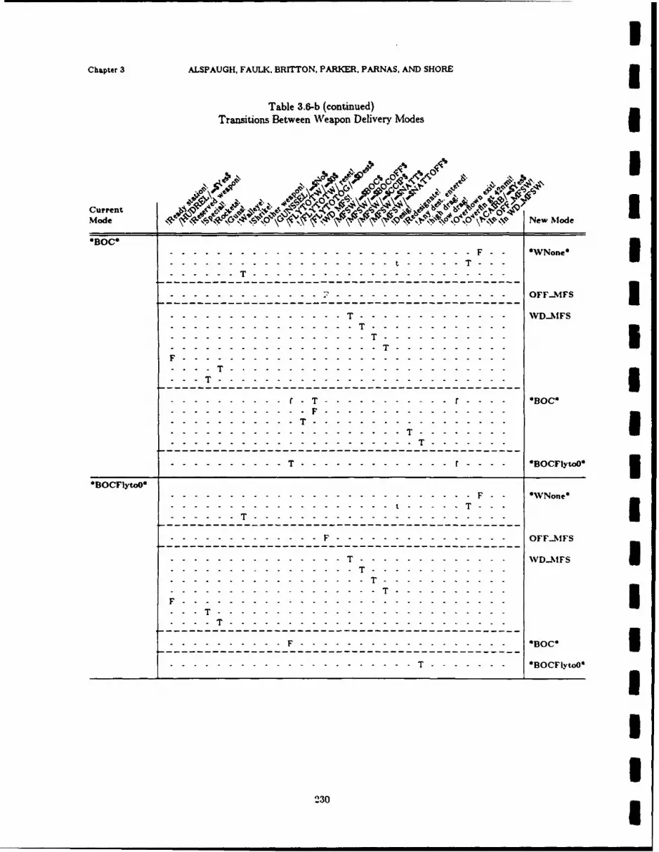
Chapter 3 ALSPAUGH, FAULK, BRITTON, PARKER, PARNAS, AND SHORE
Table 3.6-b (continued)Transitions Between Weapon Delivery Modes
Current 4Mode I ,\ NIO\$N New Mfode
OBOCS------------------------------ F - - WNone 3------- - --- -- -- --t - -.-- T---
. . .--------------------------------------------------
- - - - - -- - - - - - - - - - - - - - OFFJVIFSI
- ---------- T--------------------------I
-- -------------------------------- -- --- - ---------------------------------
T- -- ----- --- -- -- -- ------- - - 0
------------ -- T----------------------------------------
...................--- T-------------- - - - - OBOCF~O
------------------------------------ t----------------
- - T-------------------------------------------------.--.-.-.-.-.-.--.-.-.-.-.--- F- ------------ -- -- -- ---- OFF--NFS
-- -- ----- --- T-------------------------
F - - -T---------------------------
F------ ----------------------------------------- B0
--------------------------------- BCytO
230
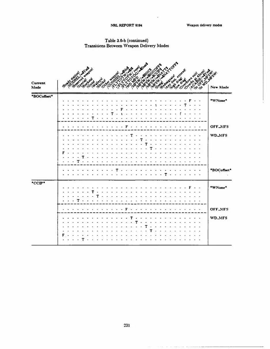
NRL REPORT 9194 Weapon delivery modes
Table 3.6-b (continued)Transitions Between Weapon Delivery Modes
Current - ", vx
Mode \\\ N -, %ps New Node
*BOCoffset*--------------------------- F - WNone*
............--------------------------------------------
............................. F------------------OFF-N1FS
--------------------------------- T-----------------------F---------------------------- - - ---- - --------------------------- -- --- - -----------------------------
T........................................................... - - Won------ T----------------------------------------------
- - ---------------------------- -- -
F----------------------------------------------------
- -T----------------------------------------------------
- --- - - - - - T - - - - - - -23--1
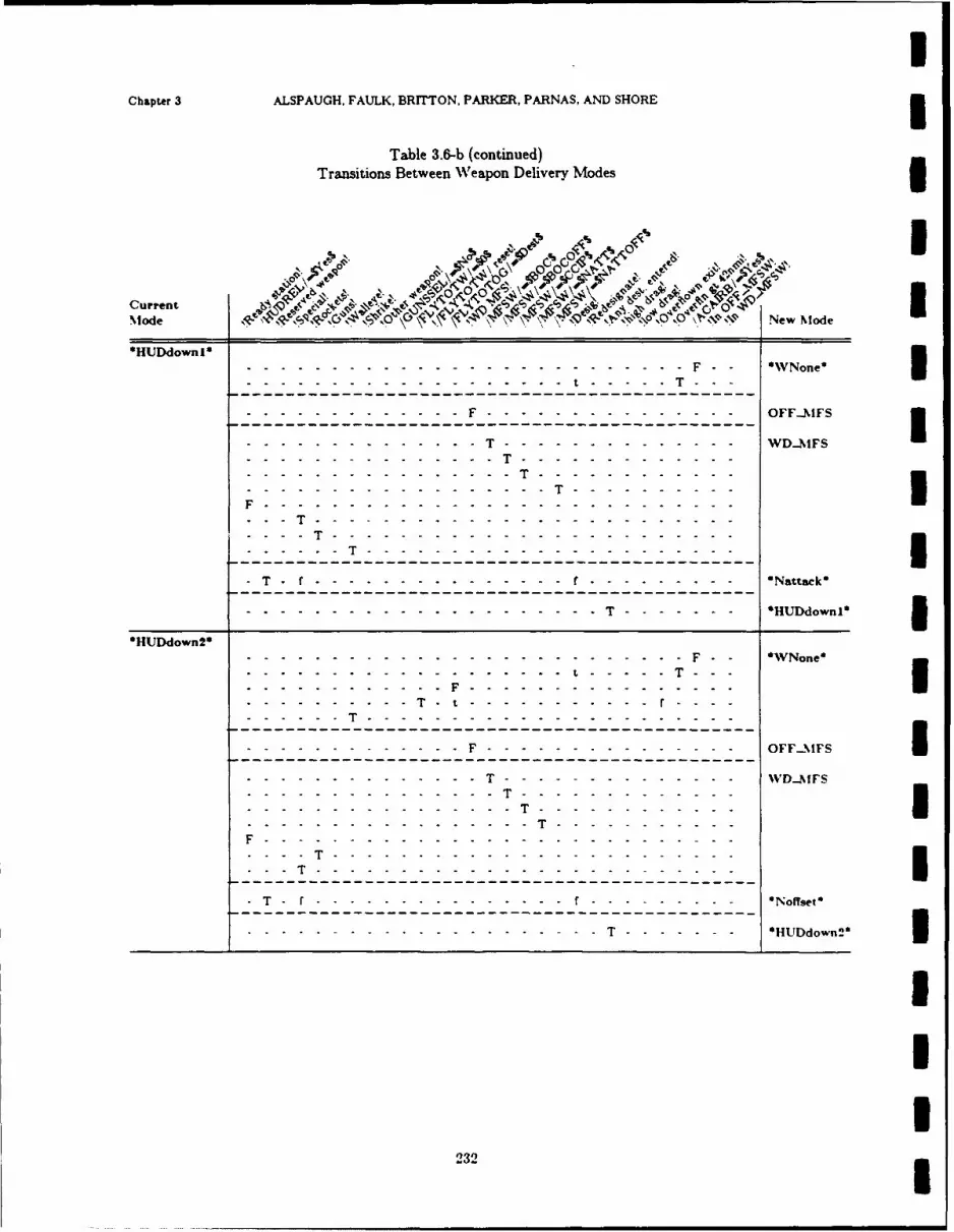
Chapter 3 ALSPAUGH, FAULK, BRITTON, PARKER, PARNAS, AND SHORE5
Table 3.6-b (continued)Transitions Between Weapon Delivery Modes
ff IQI\ 4 ap O
C~q0
Current ' kP
Mode N4 ,~ : \, * \$\iNONON New Mode
*HUDdownl*
---------- - - -- -- -- -- F - - VNone*
------------------- F-----------------------------------------OF S. . . . . . .T- -- - - -- -- - ---------------- - IFSI------------------------ -T-------------------------------
- - ----------------------------- -- ---
- - ------------------------ -- - - - --- -- -- ---
------ T--------------------------------------------------
- ----------------------------- f---------------------------Ntak
-..-.-.-..-.-.-..-.-.-..-.-.-..-.-.-.......- -- -- ---------- HUDdownl*
*HUDdown2*......................................................... F * WNone*
---------------------------------------------------------- T----------------------------- -- - -- -- - - - ---
F--------------------------------------------OF2F
--- - - - ------------T - -- -- -------------- WD-AfFS
T - - ----------------------- - - -- -- -- -- -- ---
T - ---------------------------- -
-T --------------------- f----------------------------No~e
. . . .. . . . . . . . .T - HUDdown2 3
232
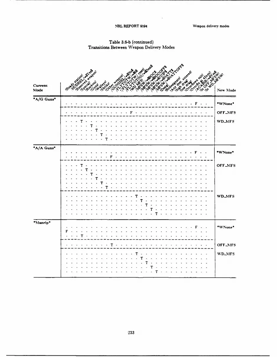
NRL REPORT 9194 Weapon delivery modes
Table 3.6-b (continued)Transitions Between Weapon Delivery Modes
Current 40e.j Pt'Tj
Mode New Mode
'A/G Guns*.--.-.-.-.-.--.-.-.-.-.--.-.-.-.-.--.-.-.-.-.--.--------- F *WNone*
------------------- F-----------------------------------------OF2F
- - -T---------------------------- F - - ----- - ---- - - - - ----- FS----------------------------------------------------------
'A/A Guns*------------------------- -- - - -- -- -- -- ----- - - 'WNone*
---------- F---------------------------------------------
- - -------------------------------------- OFF24FS- -T- ------- ------- ------- ------- ---------------------
........---------------------------------------------------------------------------------------------
--------------------- T---------- -- - - - - -----
*\anrlp*
F------------------------------------ - - Voe
-- ------------------------------------------------------
-------------------- T------------------------------OFF2%!FS
------------------------- T-------------------------------
-------------------------.----- T------------ - - - - - - - - -- '
233

Chapter 3 ALSPAUGH, FAULK,. BRITTON, PARKER, PARNAS, AND SHORE
Table 3.6-b (continued)Transitions Between Weapon Delivery Modes
Current R i>0Mode %-C \\, O $ NwMode
*A/A Mazirip*
- -- -------------------- - OWNone IF.............................................................OFF2-fFS
------ F----------------------------------------
..........................-- -- -- ------------- WD...MFS
*Snattack* Woe
F-------- -- -- -- - - - -- - - ~~nF------------------------------------------------------ ------------------------------- IDMF- -- ------------ F---------- -- -- ---
-~~~~ - - -T---------------- ---- -- -- -- -- ---------- T-------------------- - ---- -- -- -- -- ---- T----------------------------------------------I
- - - ------------T - -- -- -- -- ------------ Snattack I- -- ----------- T---------- -- -- -- ----
II
234
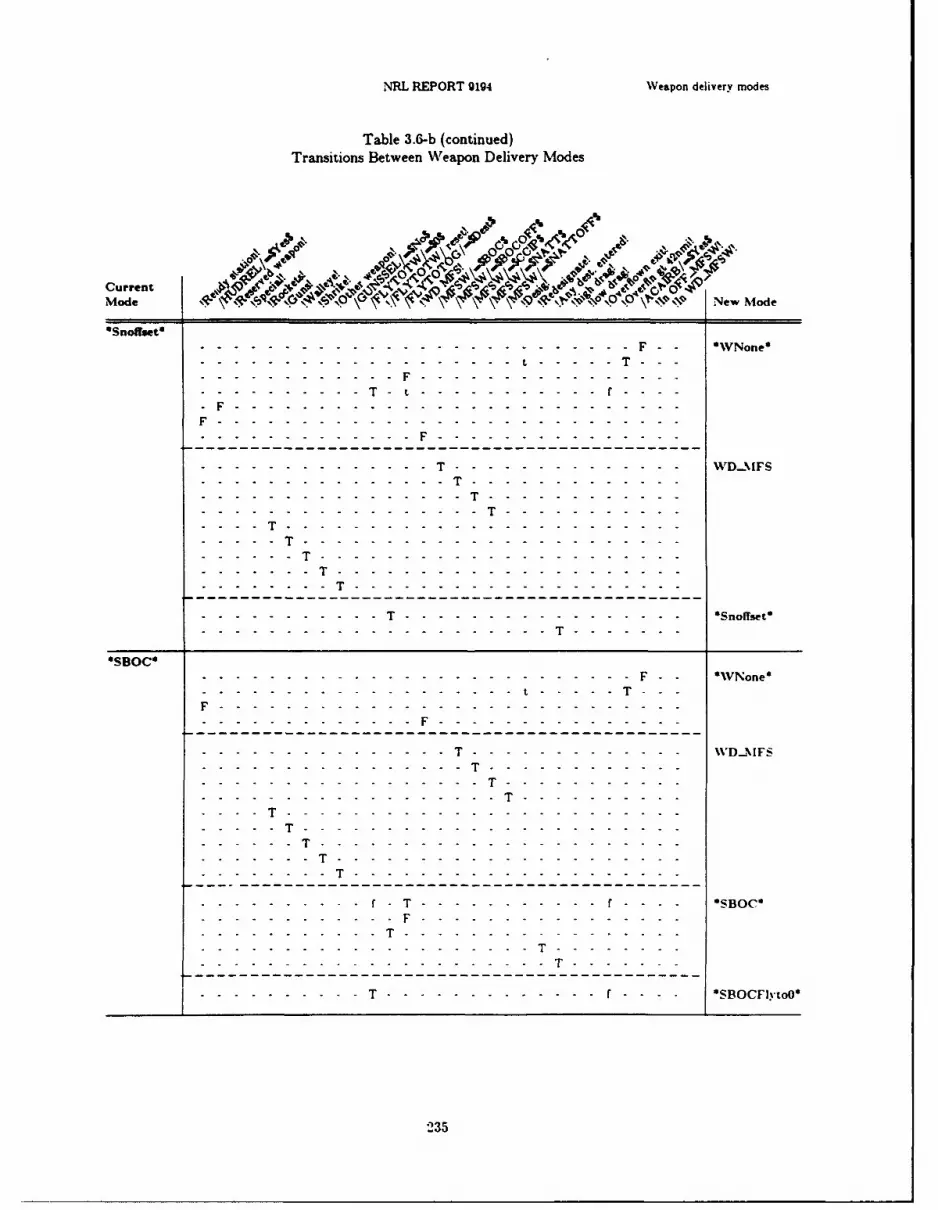
,NRL REPORT 9194 WVeapon delivery modes
Table 3.6-b (continued)Transitions Between Weapon Delivery Modes
.YfIAc 4o AV4 4t0' 0~ 0 t '5 A
Mode NwMd
*Snoffset'--------------------------- F - WNone*
--------------------------------- - -- ----- - ------
--------------------------------------------------------------------------- - - - ------------------------------------------------- - - - -- -- --...............................
-~~~~ - - -T--------------------------- - - -- -- -- ------------------------------------- -- - - ---- -- --
------- T--------------------------------------------------
------------- T---------------------Snoffset*
OSBOCO-------------------------------------------------------- F. F - WNone*
-------------------------- T------------------------------ -- -------------------------------------------------------------- T----------- -- -- -
T - ---------------------------------------------------
------------------------------- - - - SOC
-------------- T-----------------------------------------
._____ .[-.-- ..-- .-- .T--------------- - -- -- --- - - - -
235

Chapter 3 ALSPAUGH, FAULK. BRITTON, PARKER, PARNAS. AND SHORE
Table 3.6-b (continued)Transitions Between Weapon Delivery Modes3
Current Ne ModA'A~Mode *\4,'oc 41cO Nwde
*SBOCFlytoO* ---------- - -- -- -- -- - - None I---------------------- F------------------------------------
-- -- -- -T----------- -- -- -- - -------- MFS
-~~~ - ------------------------ - - -- -- -- -- -- ---
-- ----------------------------------------------------------------- -T----- ------------------------
*SBOCoffset I---------- - -- -- -- -- - - VtNone'-------------------------------- -- - - -T
----------- F------------------ - -- -- -- -- ---
-------------------- F------------------------------------
- - - - -- - - - - - - - - - - - - - - - - W D...MFS
*~~~ - ------------------------- - - -- -- -- -- -- ---
- - T-----------------------------------------------I
.--.-.-.-.-.--.-.-.-.--- T---- -- --- -- -- --- -------- SBOCoffsetO
236

NRL REPORT 9194 Weapon delivery modes
Table 3.6-b (continued)Transitions Between Weapon Delivery Modes
Current COCMode sp NewMode
*Waiieye I------- - - --- -- -- -- -- -- - - None*
------------------------ T------------------------------------------------------------ - - - - ---
------------------------------- T--------------------------------------------------- - - ----
- - -------------------------------- - ----------------------------- -- ------------------------------ ------
F.........T------------------------ - - - ----- - --- -- --
------------------- -T-------------------------------..-.-.-..-.-.-.- ..-.- ...- -- - - - -- ---- -- ----- ---
237
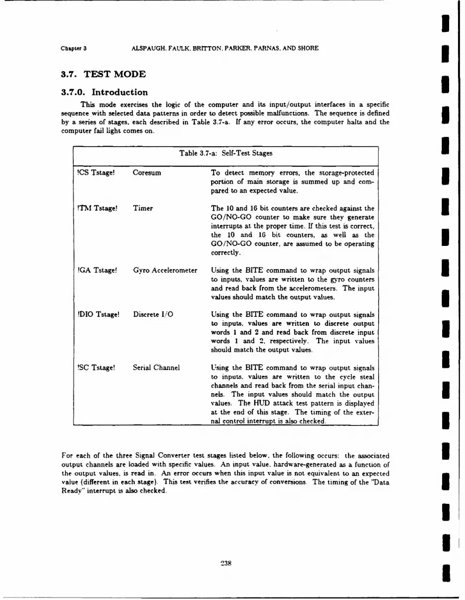
IChapter 3 ALSPAUGH. FAULK. BRITTON, PARKER. PARNAS. AND SHORE
3.7. TEST MODE
3.7.0. Introduction i
This mode exercises the logic of the computer and its input/output interfaces in a specificsequence with selected data patterns in order to detect possible malfunctions. The sequence is definedby a series of stages, each described in Table 3.7-a. If any error occurs, the computer halts and thecomputer fail light comes on.
Table 3.7-a: Self-Test Stages I!CS Tstage! Coresum To detect memory errors, the storage-protected
portion of main storage is summed up and com- apared to an expected value.
!TM Tstage! Timer The 10 and 16 bit counters are checked against the 3GO/NO-GO counter to make sure they generateinterrupts at the proper time. If this test is correct,the 10 and 16 bit counters, as well as theGO/NO-GO counter, are assumed to be operatingcorrectly.
!GA Tstage! Gyro Accelerometer Using the BITE command to wrap output signals 3to inputs, values are written to the gyro countersand read back from the accelerometers. The inputvalues should match the output values. i
DIO Tstage! Discrete I/O Using the BITE command to wrap output signalsto inputs, values are written to discrete outputwords 1 and 2 and read back from discrete input Iwords 1 and 2, respectively. The input values
should match the output values.
!SC Tstage! Serial Channel Using the BITE command to wrap output signals Ito inputs, values are written to the cycle stealchannels and read back from the serial input chan-nels. The input values should match the outputvalues. The HUD attack test pattern is displayed
at the end of this stage. The timing of the exter-nal control interrupt is also checked.
For each of the three Signal Converter test stages listed below, the following occurs: the associated ioutput channels are loaded with specific values. An input value, hardware-generated as a function ofthe output values, is read in. An error occurs when this input value is not equivalent to an expectedvalue (different in each stage). This test verifies the accuracy of conversions. The timing of the 'Data IReady" interrupt is also checked.
II
238

NRL REPORT g194 Test mode
!DC Tstage! DC Signal Converter
S! AC1 Tstage! AC Signal Converter 1
-AC2 Tstage! AC Signal Converter 2
!PD Tstage! Panel Display If no errors have occurred in previous stages,all NAV/WD panel lights come on and the upperand lower windows display all 8's. If an errorI_ has been detected, the Computer Fail light onthe Caution and Advisory panel will come on, thepanel display will not change from what it wasat mode entry, and this stage will not be entered.This stage lasts for 8 seconds.I
3.7.1. Ground Test (*Grtest*) overview
UStage sequence:
Coresum !CS Tstage!Timer !TM Tstage!Gyro Accelerometer !GA Tstage!Discrete I/0 !DIO Tstage!Serial Channel !SC Tstage!DC Signal Converter !DC Tstage!AC Signal Converter I !AC1 Tstage!
AC Signal Converter 2 !AC2 Tstage!Panel Display !PD Tstage!
HUD: attack test pattern displayed at the end of !SC Tstage!. The pattern displayed depends on thevalue of the master function switch (see Figure 3.7.1-a). The left pattern is displayed when no func-tion is selected. The right pattern is displayed when any function is selected.
IIII
I Figure 3.7.1-a: HUD test patterns
I239

Chapter 3 ALSPAUGH, FALLK, BRiTTON, PARKER, PARNAS, AND SHOREI
Special built-in test output 1:
set to 45 *in 1ACI Tstage! and !A02 Tstage!
Special built-in test output 2:
set to 225 in 'ACI Tstage! and !A02 Tstage!I
240

II
CHAPTER 4
Time-Independent Descriptk -is of A-7E Software Functions
I
I4.0. INTRODUCTION
4.0.1. OverviewThis section gives the values of the output d-.ta items as a function of A/C situation. In mostI- cases, we do not .- ,ecify how the output values are related to the input values; the requirements state
that output values must bear a certain relationship to the actual flight conditions, and the input valuesare considered only a means for acquiring the correct values. However, in some situations, the pilotmust have the ability to choose from alternative sources of similar information (e.g., a barometricaltimeter or a radar altimeter) or the system must choose from alternative data sources on the basis ofexternal conditions. In these cases, the requirements must be expressed by naming the sources ofinput data appropriate for different conditions. In short, where the system implementor is free tochoose his input data sources, we do not name them. Where requirements dictate the input datasources, output values are expressed as functions of input values.
The services required of the OFP are described in terms of a set of functions. Each functiondetermines the value for one or more output data items. For example, the values of //FPMAZ// and,//FPNEL//are both determined by the function called "Update Flight Path Marker Coordinates."
The display windows on the TC-2 panel are used to display so many different values that wehave described the computation of each value as a separate function. In effect, we have described eachfunction as if it had its own continuously available display window and its own set of output dataitems. Ve are then able to describe separately the rules that determine which information is actuallydisplayed aPd the rules that determine the various values.
4.0.2. OrganizationEach function is described in a section that (a) lists the modes in which the function must be
performed. (b) names the output data items affected. (c) describes the conditions under which thefunction must be performed, and (d) includes one or more tables giving a detailed description of theoutput values in terms of aircraft situations or input values. The functions are described without thetiming requirements, which are given in Chapter 5.
Every function is classified as either periodic or demand. A periodic function will be per-formed repeatedly at regular intervals. If it is not required all the time. the section lists the eventsthat initiate and terminate performance. A demand function is initiated by a specific event, such as abutton being pushed. For a demand function, we describe the events that cause it to be executed andthe action required after each event.
Each function is also classified by the hardware device associated with its output data items.For example, there are IMS functions to provide values '" IMS output data items. Chapter 4 is
241

IChapter 4 ALSPAUGH. FAULK. BRITTON, PARKER. PARNAS, AND SHORE
organized by hardware devices, with all the functions for one device in the same subsection. The sub-sections are given in the order that the devices are described in chapter 2. Within each subsection, thefunctions are given in the same order as in Chaptei 2. However, even if an output data item istransmitted to more than one hardware device, the function associated with it is only described in oneplace in Chapter 4.
IIIIIIIUI'IIII
242
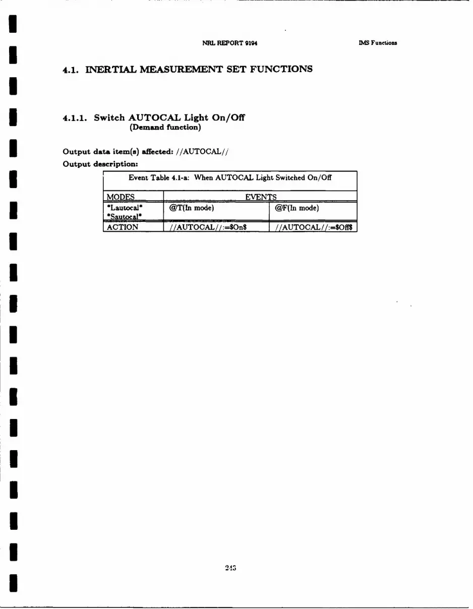
NML RPORT 9194 RAfS Functions
4.1. IN1ERTIAL MEASUREMENT SET FUNCTIONS
4.1.1. Switch AUTOCAL Light On/Off(Demand function)
I Output data item(s) affected: //AUTOCAL//
Output description:
Event Table 4.1-a: When AUTOCAL Light Switched On/Off
MODES EVENTS*Luoa* @T(nmoe @F(In mode)
*Sauoal*ACTION /AUTOCAL//:=$OnS /.AUTOCAL! :=$Of1S
2-I

Chapter 4 ALSPAUGH, FAULK, BRITTON, PARKER, PARNAS, AND SHORE
4.1.2. Switch Computer Control of IMS On/Off(Demand function)1
Output data item(s) affected: //COMPCTR//
Output description:
Event Table 4.1-b: When IM Controlled by the Computer
MODES EVENTS3@T(!roll large!) @F(!roll large!)WHEan* VV N (!FM stage!) 'WHEN (!FM stage! AND
OR //COMPCTR//-$On$)@T(!FM stage complete!) ORI
OR @T(!FM stage!)@T(In mode) WHIEN(NOT !FM stage! WHEN (NOT !roll large!AND //COMPCTR//=$OflS) AND //COMPCTR//=On$)I
@T(!CL stage complete! AND!IMS total velocity! > 1440 fps)
WHEN(/ACAIRB/=S3YesS AND//COMPCTR//=$OnS)
All @T(!CL stage complete! ANDalignment @T(In mode) !IM4S total velocity! > 1440 fps)Uexcept WHEN (//COMPCTR//-$OffS) WHEN(/ACAIRB/ = $Yes$ AND*Airaln* //CONPCTR/ /=$On$)
*DI**I* @T(In mode) X*TDI* WHEN(//COMPCTR//=$Off$)*OLB**PolarDI**PolarI*3*Mag Sl**Grid* X @T(ln mode)*IMJS fail* WHEN (I CONPCTR / /=$OnS)-
ACTION Computer controlled Not computer controlled_______/ /COM1PCTR / /:=SOnS //COM1PCTR //:=$Off$
244

INRL REPORT 9194 IMS Functions
4.1.3. Issue Computer Failure(Demand function)
Output data item(s) affected: //COMPFAIL//3Output description:
Event Table 4.1-c: When Computer System Fails
MODES EVENTSAll modes except X @T(!power up!)*Grtest*
*Grtest* @T(!Checksum test failed! X
I OR !Interface test failed!)
ACTION //COMPFAIL./ /:=$Yes$ //COMPFAIL //:=$No$
IIIIIIIIIII
245I
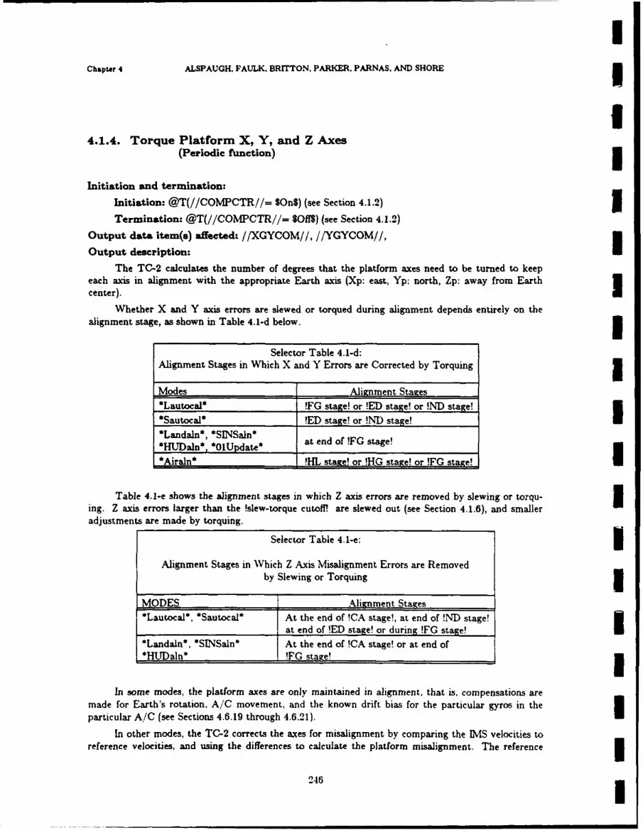
IChapter 4 ALSPAUGH, FAULK, BRITTON, PARKER, PARNAS, AND SHORE
I4.1.4. Torque Platform X, Y, and Z Axes
(Periodic function)
Initiation and termination:Initiation: @T(//COMPCTR//= SOnS) (see Section 4.1.2) 3Termination: @T(//COMPCTR//= SOffS) (see Section 4.1.2)
Output data item(s) affected: //XGYCOM//, //YGYCOM//,
Output description: IThe TC-2 calculates the number of degrees that the platform axes need to be turned to keep
each axis in alignment with the appropriate Earth axis (Xp: east, Yp: north, Zp: away from Earthcenter). I
Whether X and Y axis errors are slewed or torqued during alignment depends entirely on thealignment stage, as shown in Table 4.1-d below.
Selector Table 4.1-d:Alignment Stages in Which X and Y Errors are Corrected by Torquing 3Modes Alignment Stages*Lautocal* !FG stage! or !ED stage! or !ND stage!
*Sautocal* !ED stage! or !ND stage!*Landaln*, *SINSaln*
*HUDaln*, *01Update* at end of !FG stage!
*Airaln* !HL stage! or !HG stage! or !FG stage!
Table 4.1-e shows the alignment stages in which Z axis errors are removed by slewing or torqu- 3ing. Z axis errors larger than the !slew-torque cutoff! are slewed out (see Section 4.1.6), and smalleradjustments are made by torquing.
Selector Table 4.1-e:
Alignment Stages in Which Z Axis Misalignment Errors are Removedby Slewing or Torquing
MODES Alignment Stages
"Lautocal*, *Sautocal* At the end of !CA stage!, at end of !ND stage!at end of !ED stage! or during !FG stage!
*Landaln*, *SINSaln* At the end of !CA stage! or at end of
*HUDain* 'FG stage!
In some modes, the platform axes are only maintained in alignment, that is, compensations aremade for Earth's rotation, A/C movement, and the known drift bias for the particular gyros in the
particular A/C (see Sections 4.6.19 through 4.6.21).
In other modes, the TC-2 corrects the axes for misalignment by comparing the MS velocities toreference velocities, and using the differences to calculate the platform misalignment. The reference
246

NRL REPORT gi94 IS Functions
velocities used in different modes are shown in Table 4.1-g. Table 4.1-f shows when the axes are onlymaintained and when they are also corrected.
Selector Table 4.1-f: Platform Torquing
IMODES X AXIS ACTION Y AXIS ACTION Z.AXIS ACTION*Lautocal**Landaln* Maintained and Maintained and Maintained andI*Sauoal* Corrected Corrected Corrected*SINSaln**OlUpdate**HUDaln**Aran*DIG* Maintained and Maintained and Maintained and
__ __ __ Corrected Corrected Corrected
*DI* Maintained and Maintained and Maintained_______________Corrected Corrected __________
!latitude! < 80**Maintained Maintained Maintained
*UTDI* OLB* !ltitude! > 80:.
*PolarD* Maintained and Maintained and Nn
______________Corrected Corrected None
*-PolarI* Maintained Maintained = None
Slcctor Table 4.1-g: Reference Velocities for Platform Corrections
UMODES SOURCES OF REFERENCE VELOCITIES*Lautocal*, *Landaln*Cnttvau(0*OlUpdate*, *HTJDaln* Cntn au 0
*SINSaln*. *Sautocal* SINS X. Y. Z offsets and SINS data*Airaln*. *DIG*, IDGNDSP!. /DRFTA-NG/'*D!*._PolarDIs _____________________
247

Chapter 4 ALSPAUGH, FAULK, BRITTON. PARKER, PARNAS, AND SHORE3
4.1.5. Change IMS Scale Factor(Demand function)
Output data item(s) affected: //IMSSCAL//
Output description:I
Event Table 4.1-h: WVhen the Scale Factor Is Changed
MODES EVENTS*Lautocal**Landaln* @T(In mode) WHEN x*OlUpdate* (//UMSSCAL //=$Coarse$)a*HUjlJ)nf* @T(In mode) WH1EN @T(In mode) WHEN
(/lMSMODE/ = SGndal$ (/IMSMODE/ = ($Norm$ OR SInerS)
___________________n AND / /M SSCAL //= $Coarse$) AND //IMlSSCAL// - $Fine$)
*Airaln*, *DIG*, *1*, X @T(In mode) WHEN*DI*, *TJDI*, *OLB*, (//IMSCAL//=Fine$)*PolarDI _ *PolarI* I______________
ACTION //LMSSCAL //:-$Fine$ //IMSSCAL/ /:=$Coarse$
248

INRL REPORT 9194 IMS Functions
i4.1.6. Switch X,Y,Z Slewing On/Off
(Demand function)
Output data item(s) affected: ,'XSLEW// ,/XSLSEN// //YSLSEN// ',/ZSLEW,////ZSLSEN//
m Output description: The commands/XSLEW//:=$On$
//YSLEW//:i$On$'/ZSLEW//:--SOn$
start the corresponding axis slewing in the direction given by the value of the associated //*SLSEN//output ($CWS or $CCW$). Slewing is stopped by setting the //*SLEW// outputs to SOfiS when theslewing has been on the time required to move the * axis the desired amount at the rates given in Sec-tion 2.1.1.14.
Table 4.1-i shows the alignment modes and stages when platform tilt errors are removed byslewing the X and Y axes. These errors are removed by slewing whether they are small or large.
Selector Table 4.1-i:Alignment Stages in Which X and Y Errors are Corrected by S. !ng
MODES Alignment Stages•Lautocal*, *Sautocal* At the end of the !CL stage! OR*Landaln*, *SINSaln* At the end of the !CA stage!
HUDaln*•Airaln* At the end of the !CL stage!
Note: Platform slewing can only occur when //COMPCTR// = SOnS; (Section 4.1.2).
I Z axis slewing occurs (a) when Z axis errors are to be removed during the alignment stagesshown in Table 4.1-e if the velocity error calculations show that the Z axis is out of alignment by morethan the !slew-torque cutofP (b) in *Lautocal* and *Sautocal*, to rotate the north-pointing axis sothat it points east, and later to move it back. and (c) to remove heading errors in *SINSaln* and*HUDaln* modes. The second two kinds of slewing are summarized in Table 4.1.j.
II
II
249I

IChapter 4 ALSP4UGH. FAULK. BRITTON. PARKER, PARNAS, AND SHORE 3
Event Table 4.1-j: Z Axis Slews iMODES EVENTS*Lautocal* @T(!ED stage!) @F(!ED stage!) X x
*Sautocal*_______*SINSaln* X X @T(In mode) X
@T(/TD/--$On$) WHEN*HUDaln* X X X (NOT !during
platform slewing!)
AMOUNT OF 90" CCW 90' CW + error !SINS- !Az-reference
SLEWING in !ED stage! error!' error!2 3PERFORMED (see Table 4.1-e)
"SINS error! is the error calculated by comparing !IMS heading! to !SINS heading! corrected by !Delta Iheading!
2!Az-reference error! is the error calculated by comparing the !IMS heading! to the heading calculatedfrom the !azimuth reference heading! corrected by the Aiming Symbol azimuth displacement at desig-
nation.
IIIIiIIIII
25C i
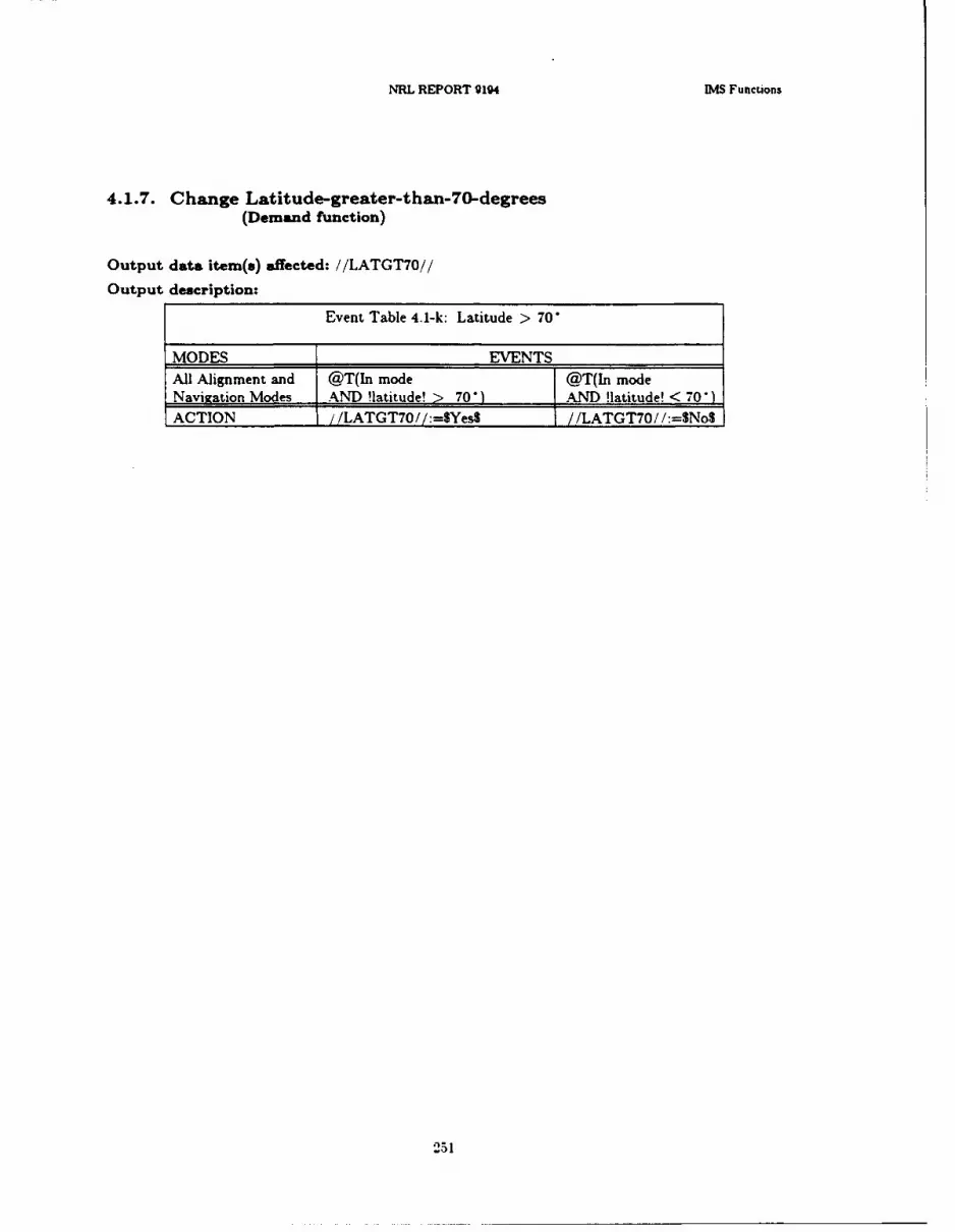
NRL REPORT 9194 IM Funcuions
4.1.7. Change Latitude-greater-than-70-degrees(Demand function)
Output data item(s) affected: //LATGT7O//
Output description:
Event Table 4.1I-k: Latitude > 70
MODES EVENTSAll Alignment and @T(In mode @T(In modeNavigation Modes AND !latitude! > 70 1AND flatitude! <0ACTION /LATGT7O //:=$Yes$ //LATGT7O / / :-No$
25 1

Chapter 4 ALSPAUGH, FAULK. BRITTON. PARKER. PARNAS. AND SHORE3
4.1.8. IMS Non-Aligned Light Functions
.1.8.1. Swi'tch IMS Non-Aligned Light On/OffI(Demand function)
Output data item(s) affected: //IM NA//I
Output description:
Event Table 4.1-1: When WMS Non-Aligned Light Switched On and Off3__________MODES
*Lauoal @T(ln mode) _________
*Landaln* @T(In modej @T(!Land velocity test passed!)
*SINSaln* @T(In mode) @T0!SINS velocity test passed!)____________________ OR @F(In mode)I
*Airaln* @T(!OL stage complete!) @T(In mode) WHEN (NOT !CLOR @T(In mode) WHEN stage complete!) OR
____________(!CL stage complete!) @T(!Ar velocity test passed!)5*OlUpdate* @F(!Land velocity test passed!) @T(!Land velocity test passed!
___________OR @F(!New 01 test passed!) AND !New 01 test passed!)*HUDaln* @T(!HS stage complete!) @T(ln mode) OR
WHEN (/IMSMODE/=$GndalS) @F(In mode) OR____________@T(!CL stage complete!)
*DIG', 'DI @T(!Nav velocity test faied!) x*PolarDI*
*Mag s1*,*Grid* x @T(In mode)*EMS fail*ACTION /l]VSNA//:=$OnS /IMSNA//:=$Off$
Note: Blinking takes precedence (see Table 4.1-rn). At the termination of blinking, the light *goes to the state for which the condition has most recently been met. (The state may have changedseveral times while the light was blinking.)I
252
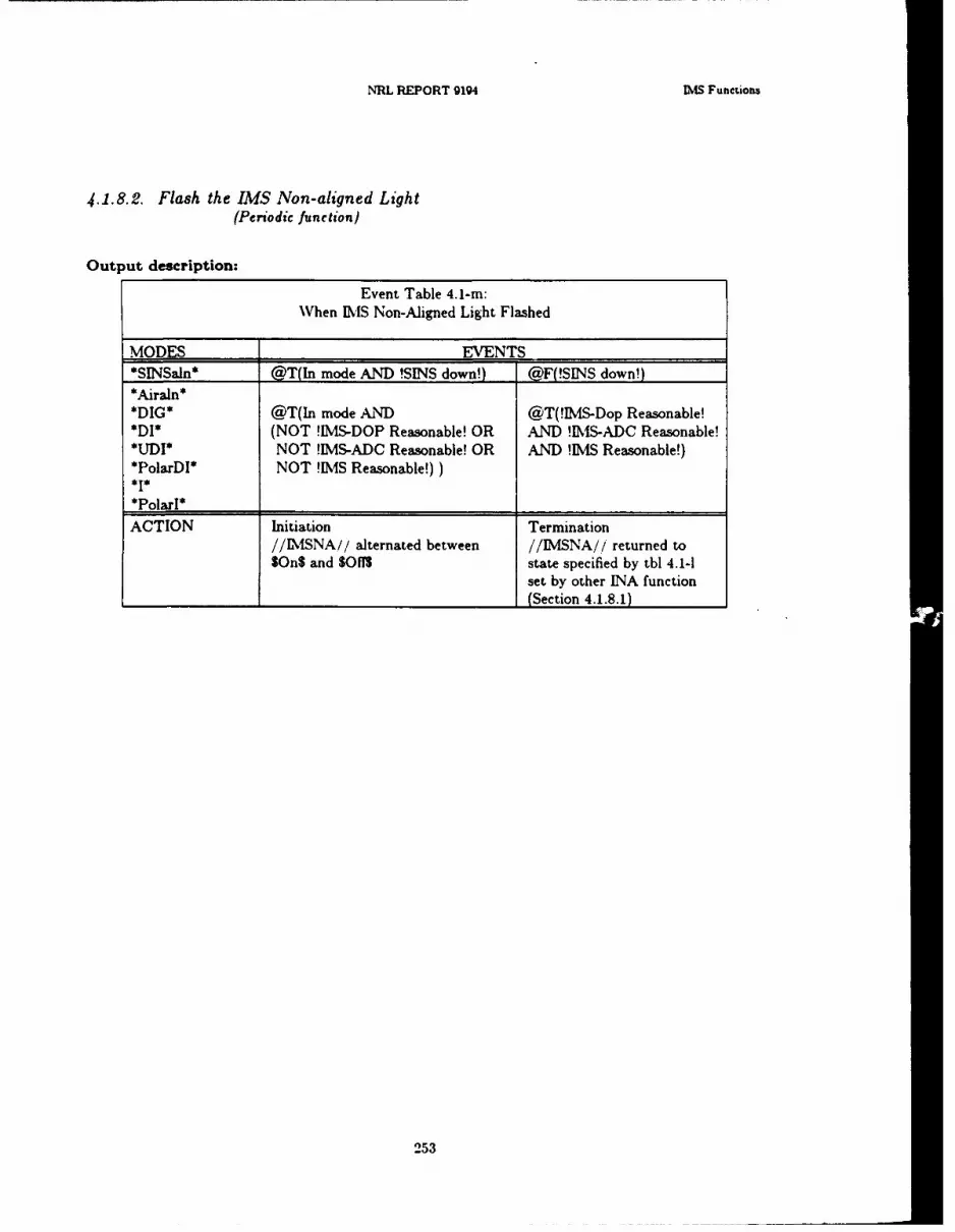
NRL REPORT 9194 MI4S Funenions
.4.1.8.2. Flash the IMS Non-aligned Light(Periodic function I
Output description:
Event Table 4.1-rn:When [MIS Non-Aligned Light Flashed
MODES EVENT.S
*SINSaln* @T(In mode AND !SINS down!) @F(!SINS down!)*Airaln**DIG* @T(In mode AND @T(!IMLS-Dop Reasonable!*DI* (NOT !IS-DOP Reasonable! OR AND !IS-ADC Reasonable!
UDMI* NOT !IS-ADC Reasonable! OR AND !TMS Reasonable!)*PolarDl* NOT !IS Reasonable!))*1**Polarl*ACTION Initiation Termination
//ISNA,// alternated between //IM NA// returned to$On$ and SOfYS state specified by tbl 4.1-1
set by other INA function______________ ___________________________ (Section 4.1.8.1)
253
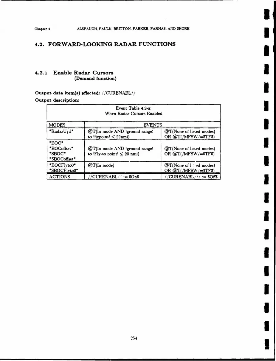
Chapter 4 ALSPAUGH. FAUJLK. BRITTON. PARKER. PARNAS, AND SHORE
4.2. FORWARD-LOOKING RADAR FUNCTIONS
4-2-1 Enable Radar CursorsI(Demand function)
Output data item(s) affected: '/CURENABL//
Output description:
Event Table 4.2-a:IWhen Radar Cursors Enabled
MODES EVENTS3*RadarUT d* @T(In mode AND !ground range' @T(None of listed modes)
__________to !fixpoint! <22nmi) OR @T(/MFSW/=STFS)
*BOCoffset* @T(In mode AND !ground range! @T(None of listed modes)*SBOC* to !Fly-to point! < 20 nmi) OR @T(/M4FSW/=STFS)
*O lyo* @T(In mode) @T(None of F~ d modes)U
*SBOCFlvtoO* _____________OR @aT( /MFSW I.STFSACTIONS //CURENABL" $On$ //CURENABL,//: SOMl
254
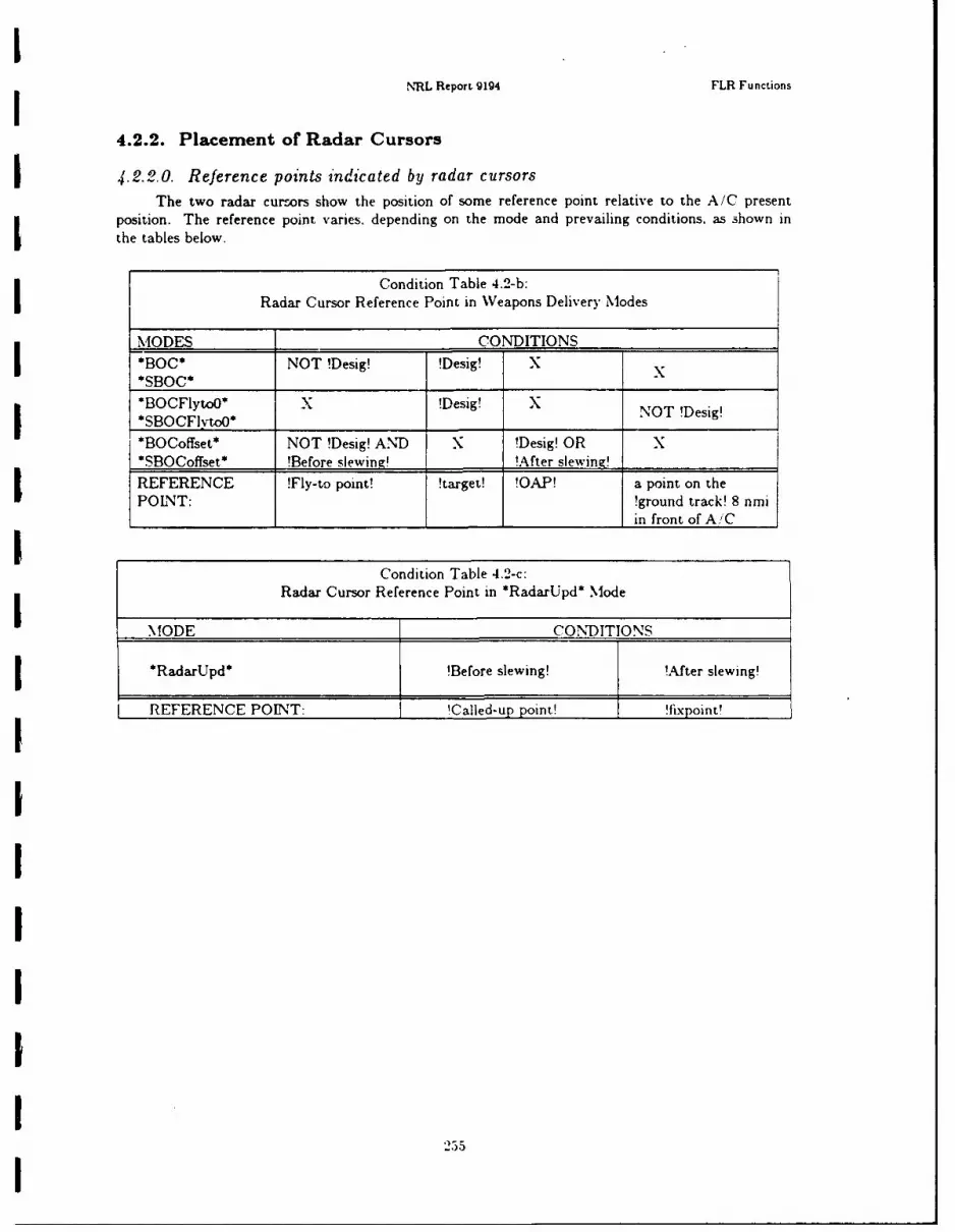
NRL Report 9194 FLR Functions
4.2.2. Placement of Radar Cursors
4.2.2.0. Reference points indicated by radar cursorsThe two radar curcors show the position of some reference point relative to the A/C present
position. The reference point varies. depending on the mode and prevailing conditions, as shown inI the tables below.
Condition Table 4.2-b:Radar Cursor Reference Point in Weapons Delivery Modes
MODES _______- CONDITIONS _______
*BOC* NOT !Desig! !Desig! x
*BOCFlytoO* x!D5g NO !Desig!*BOCFlvtoO*NO Dsg
*BOCoffset* NOT !Desig! AND X !Desig! OR X*SBOCoffset* !Before slewing! ______!After slewing!____________
REFERENCE !Fly-to point! !target! !OAP! a point on theIPOINT: !ground track! 8 nmi_____________ _____________ __________in front ofA/C
Condition Table 4.2-c:
Radar Cursor Reference Point in *RadarUpd* Mode
MODE CONDITIONS
I*RadarUpd* !Before slewing! !After slewing!
REFERENCE POINT: lCalled-u p point! !fixpoint!
25
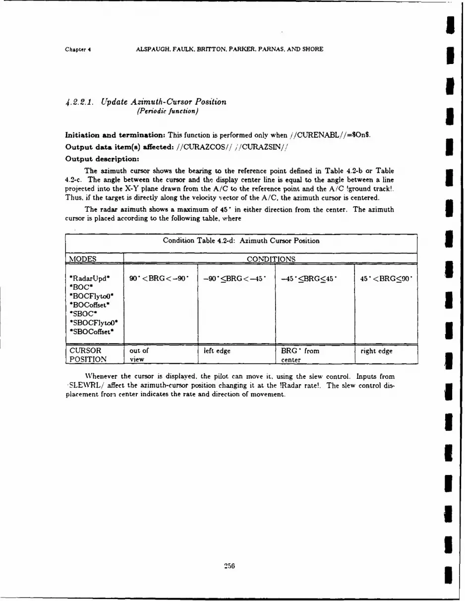
IChapter 4 ALSPAUGH. FAULK, BRITTON. PARKER. PARNAS. AND SHORE
U4.2.2.1. Update Azimuth-Cursor Position
(Periodic function)
Initiation and termination: This function is performed only when //CURENABL//=$On$.
Output data item(s) affected: //CURAZCOS/./ //CURAZSIN// 3Output description:
The azimuth cursor shows the bearing to the reference point defined in Table 4.2-b or Table4.2-c. The angle between the cursor and the display center line is equal to the angle between a lineprojected into the X-Y plane drawn from the A/C to the reference point and the A/C !ground track!.Thus, if the target is directly along the velocity ,ector of the A/C, the azimuth cursor is centered.
The radar azimuth shows a maximum of 45 in either direction from the center. The azimuth 3cursor is placed according to the following table, where
Condition Table 4.2-d: Azimuth Cursor Position IMODES CONDITIONS
*RadarUpd* 90 < BRG<-90 -90 <BRG <-45' -45"<BRG<45" 45" <BRG<90"*BOC**BOCFlytoO**BOCoffset*
*SBOC**SBOCFlyto0*
* S B O C o ff s e t * __ _ _ e d g3
CURSOR out of left edge BRG" from right edgePOSITION view center 3
Whenever the cursor is displayed, the pilot can move it. using the slew control. Inputs from'SLE\\rRL/ affect the azimuth-cursor position changing it at the !Radar rate!. The slew control dis-placement from center indicates the rate and direction of movement.
2UIII
256
NRL Report 9194 FLR Functions
4.2.2.2. Update Range-Cursor Position(Periodic function)
Initiation and termination: This function is performed when and only when'/CURENABL//=$On$.
Output data item(s) affected: //CLRPOS//
Output description:
The output is required in the following modes: *RadarUpd*, *BOC*, *BOCFlytoO*,*BOCoffset*, *SBOC*, *SBOCFytoO* and *SBOCoffset*
The value output for //CURPOS/! is the !slant range! from the A/C to the reference pointdefined in Tables 4.2-b and 4.2-c. The !i1 CURPOS// output value is limited in the following way:
//CURPOS//:=MIN(!slant range!, 20 nmi)
If the azimuth cursor is out of view (see Section 4.2.2.1), i/CURPOS/,i:- 0.
Whenever the cursor is displayed, the pilot can move it, using the slew control. Inputs from/SLEWUD/ affect the //CURPOSi'i value, changing it at the !Radar rate!. The slew control dis-placement from center indicates the rate and direction of movement.
Note: The value output by this function is !slant range! even though the cursor actually shows!ground range!. The conversion from !slant range! to !ground range! is performed by the FLR (seeSection 2.1.3.7).
257

IChapter 4 ALSPAUGH, FAULK. BRITTON, PARKER, PARNAS, AND SHORE 3
I4.2.3. Slave or Release the FLR Antenna
(Demand function) 5Output data item(s) affected: //ANTSLAVE//
Output description:
Event Table 4.2-e: When FLR Antenna Slaved or Released
MODES EVENTS I*HUDUpd* @T(In mode) @F(In mode)
OR @T(/MFSW/=STFS)*Nattack*'I
*Noffset**CCIP**HUDdownl* @T(In mode) @F(In mode)
*H-UDdown2* OR @T(/MFSW/-$TFS)*Snattack**Snoffset**SHUDdownl**SHUDdown2*
@T(/GUNSSEL/= SYes$)
*A/G Guns* OR @F(hu made)"A/_______@T(In mode AND !Rockets!) OR @T(MFSW/=STFS)*Grtest* @T(ACI Tstage!) @F(!AC2 Tstage!)
OR @T(!AC2 Tstage!) OR -T(/MFSW/--$TF)
ACTION //ANTSLAVE//:=$OnS //ANTSLAVE//:-$Off$
Note: In the software, (//ANTSLAVE// = SOnS AND //CURENABL//'= SOnS) does not occur. 3
I
IIIU
258I
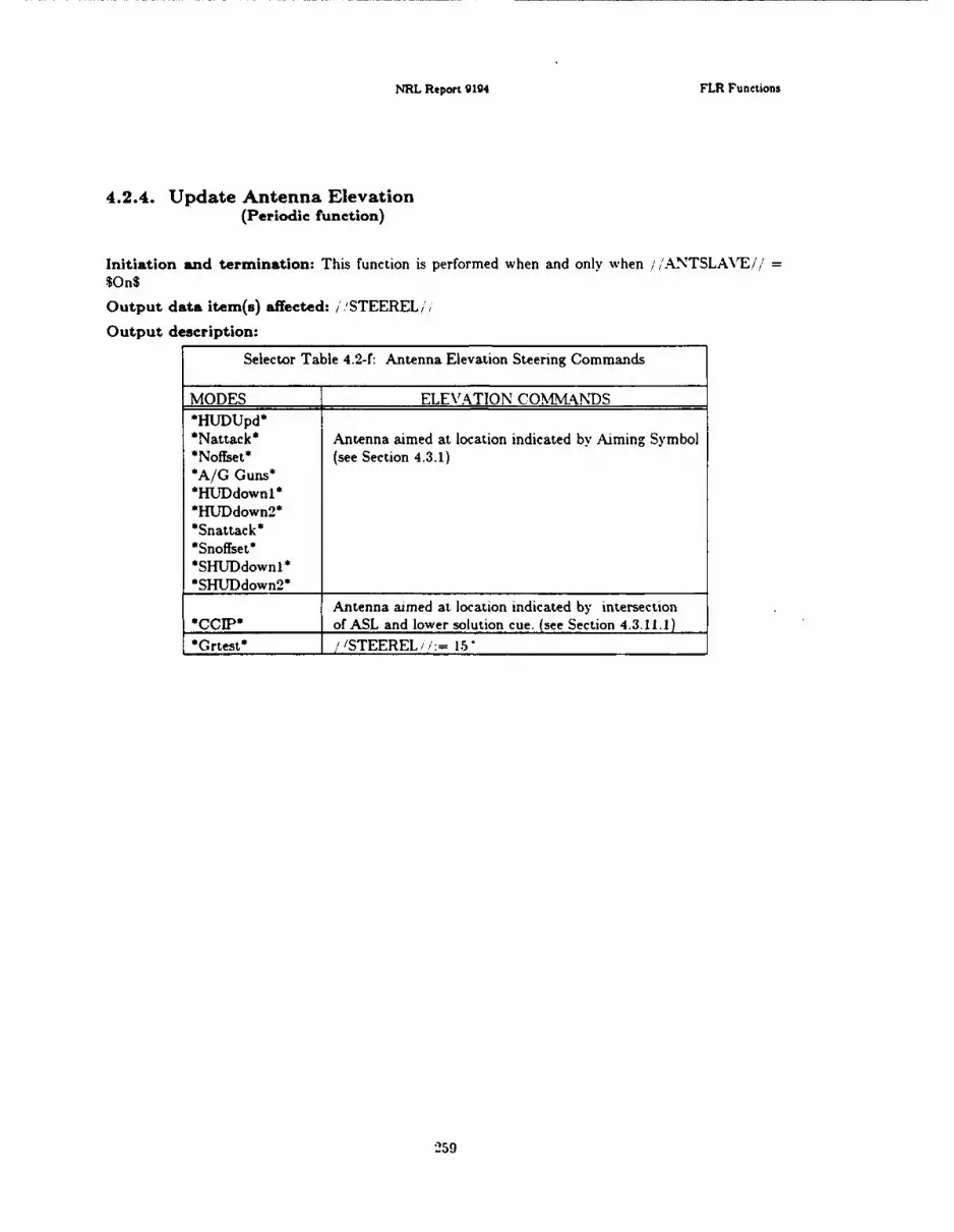
NRL Report 91g4 FLR Functions
4.2.4. Update Antenna Elevation(Periodic function)
Initiation and termination: This function is performed when and only when /' /ANTSLAVE/''
Output data item(s) affected: / 'STEEREL 6'
Output description:
Selector Table 4.2-f: Antenna Elevation Steering Commands
MODES ELEVATION COMMAkNDS*HUDUpd* I*Nattack* Antenna aimed at location indicated by Aiming Symbol*Noffset* (see Section 4.3.1)
*A/G Guns**HUDdownl**H*UDdown 2 **Snattack**Snoffset*51-fUDdownl*
*SHUJDdown 2 *Antenna aimed at location indicated by intersection
*CCIP* of ASL and lower solution cue. (see Section 4.3.11.1)Grtest* /STEEREL /: = 15
259

Chapter 4 ALSPAUGH, FAULK. BRITTON. PARKER. PARNAS, AND SHORE3
4.2.5. Update Antenna Azimuth/Drift Angle(Periodic function)I
Initiation and termination:
Event Table 4.2-g: WVhen Azimuth Steering Must be Output3
MODES EVENTSAll Alignment @T(In mode) @T(No listed mode)3and Navigation*HUTDUpd**RadarUpd* *NattaI*Noffset**CCIP**Snattack*U
*A/G Guns**HUJDdownl**HlJDdown 2*I*SHUDdown I**SHUDdown2* ______________
*Grtest* @F(In mode) OR @T(In mode) OR___________ _ /A.NTSLAVE//= $On$) (,@T( /IANTSLAkrE/I= Sg011$)
ACTION Initiation Termination
Must be output______________
Output data item(s) affected: //STEERAZ//
Output description:
This function has two different purposes: when //ANTSLAVE// = $On$, /STEERAZ// isused to steer the antenna in azimuth. At other times. the value is the !drift angle!, which the FLRIuses to calculate !ground track! so that the c.nter of the FLR display represents !ground track!
260
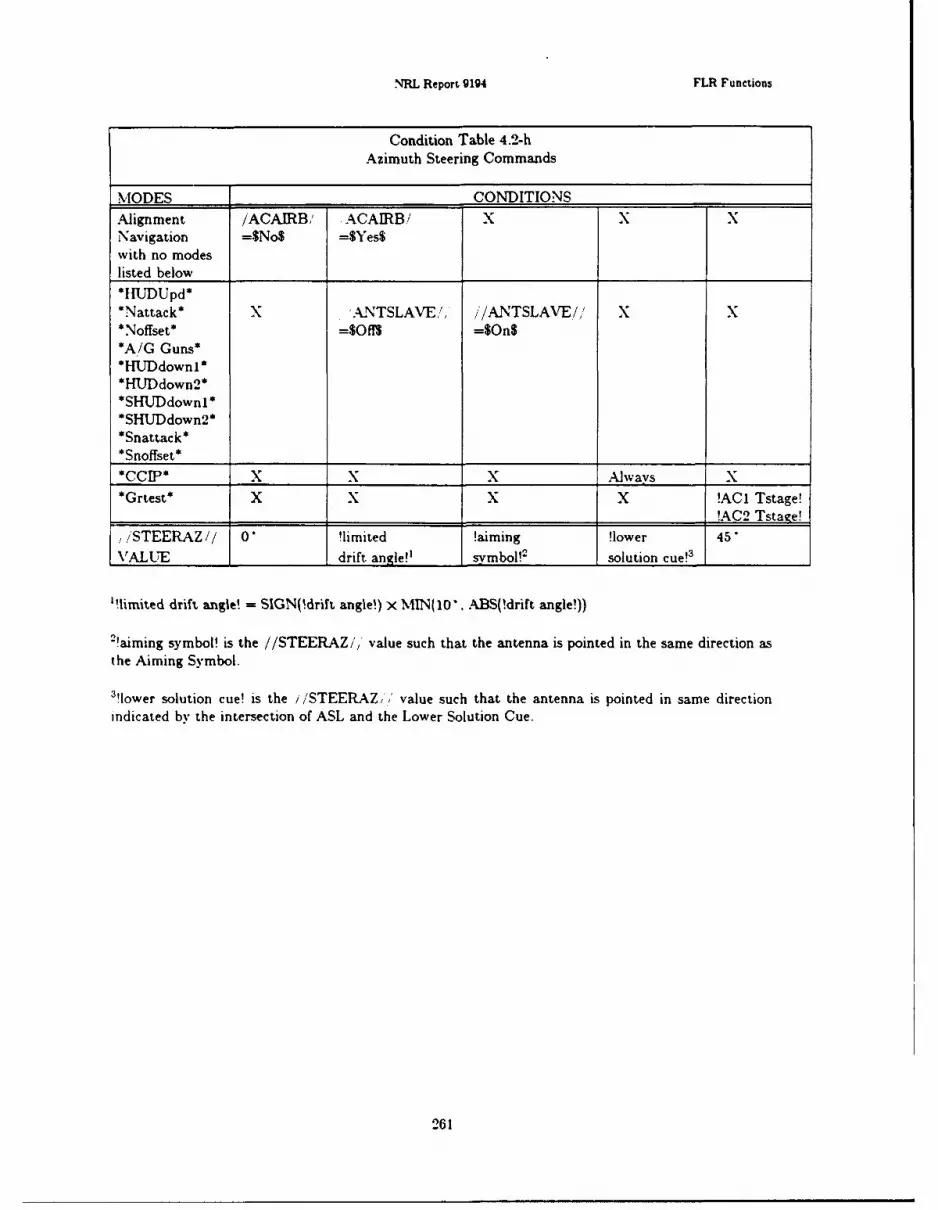
NRL Report 9194 FLR Functions
Condition Table 4.2-hAzimuth Steering Commands
MODES CONDITIONSAlignment /ACAIRB/ ACAIRB/ X X XNavigation =$No$ =$Yes$with no modes
listed below*tIUDUpd**Nattack* X '.ANTSLAVE/, //ANTSLAVE/ X X*Noffset* =$Of1s =$On$*A/G Guns**HUDdownl**HUDdown2**SHUDdownl**SHUTDdown2**Snattack**Snoffset*
*CCIP* X X X Always X*Grtest* X X X X !AC1 Tstage!
!AC2 Tstage!
IiSTEERAZ/ 0 !limited !aiming !lower 45"VALUE drift angle!' symbol!2 solution cue!3
!limited drift angle! = SIGN(Idrift angle!) x MIN(10> ABS(drift angle!))
2 1aiming symbol! is the //STEERAZ/i value such that the antenna is pointed in the same direction asthe Aiming Symbol.
3!lower solution cue! is the / /STEERAZ;i value such that the antenna is pointed in same directionindicated by the intersection of ASL and the Lower Solution Cue.
261
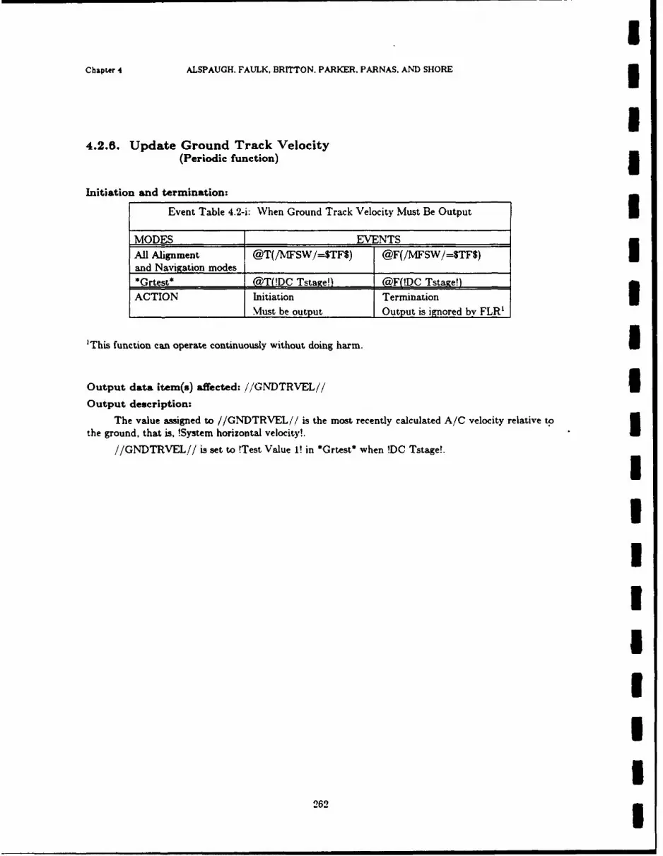
IChapter 4 ALSPAUGH. FAULK, BRITTON. PARKER. PARNAS. AND SHORE 3
I4.2.8. Update Ground Track Velocity
(Periodic function) 3Initiation and termination:
Event Table 4.2-i: When Ground Track Velocity Must Be Output IMODES EVENTS
All Alignment @T(/MFSW/=$TFS) @F(/MFSW/=$TF$)and Navigation modes*Grtest* @T(!DC Tstaxe!) @F(!DC Tstage!)
ACTION Initiation TerminationMust be output Output is ignored by FLR'
'This function can operate continuously without doing harm. I
Output data item(s) affected: //GNDTRVEL// IOutput description:
The value assigned to //GNDTRVEL// is the most recently calculated A/C velocity relative to0the ground, that is, !System horizontal velocity!.
//GNDTRVEL// is set to !Test Value 1! in *Grtest* when !DC Tstage!.
IIII$IIIU
262 3

NRL Report 9194 FLR Functions
4.2.7. Update Flight Path Angle (ADI and FLR)(Periodic function)
Initiation and termination:
Event Table 4. 2-j: When //FPANGL/ Must Be Output
MODES EVENTSAll Alignment andNavigation modesNattack*, *Noffset*
*BOC*, *BOCFlytoO* @T(In mode) X*BOCoffset*, *Snattack**Snoffset*, *SBOC**SBOCFlyto0**SBOCoftset*
*HUDdownl*. *HUDdown2**SHUDdownl**SHUDdown2*
*Grtest* @T(!DC Tstage!) @T(In mode) OR_@FEL!DC Tstage!)
ACTION Initiation TerminationMust be output
Output data item(s) affected: //FPANGL//
Output description:
When required by the FLR (see note below), the i/FPANGL// value is the A/C flight pathangle; that is, the angle between the A/C velocity vector and its projection into the horizontal plane.However, when the FLR does not require the value, it is sometimes used to give a special display tothe pilot via the ADI horizontal needle. The different values assumed by / /FPANGL ',' are shown inTables 4.2-k and 4.2-1.
Note: This output data item goes to both the ADI horizontal needle and the FLR. The FLRonly requires it when /MIFSWi = $TF$: at other times, the value has no effect on the FLR. See Sec-tions 2.1.3.8 and 2.3.2.2.
263

Chapter 4 ALSPAUGH. FAULK. BRITTON, PARKER, PARNAS. AND SHORE3
Condition Table 4.2-k: / /FPANGL// Value in
Navigation. Alignment, and Test ModesI
'MODES CONDITIONS*Ajraln*, *DIG', *DI* /IWSW /=STFS (NOT /AMFSW/=$TF$) X*'I' UDI*' AND ORI'PolarDI' 'PolarI' /ACAIRB/=$Yes$ /AGAIRB/=$No$
No applicable weapon
modes' ____________
'Mag si', *Grid* /WFSW /=$TF$ (NOT /NfFSW./=$TF$) X*OLB*, AND !ADC Up! OR NOT !ADC Up!No applicable weapon AND !Doppler Up! OR NOT !Doppler Up!modes' AND /ACAIRB/=S'tes$ OR /ACAIRB/=$No$*RAS fail*
All alignment modes X Always XUexcept *Airaln*No listed weaponsmodes5*Grtest* X X !DC Tstage!
VALUE !limited flight ADI needle out !Test Value 2!_______________path angle!2 of view5
'The applicable weapons modes are: 'Nattack'. *Noffset*' 'BOG', *BOCFlytoO*, *BOCoffset*,
'Snattack'. *Snoffset*, 'SBOC*, *SBOCFlvtoO*, *SBOCoffset*, 'HUDdownl', *HUDdown2*,*SHUDdownl', *SHUDdown2*.2 ! limited flight path angle! = SIGN (Mfight path angle!) X MIN(ABS(!flight path angle!), 21.6')
Condition Table 4.2-1//FPANGL// in Weapon Delivery Modes3
MODES ______CONDITIONS______
ABS ABS( //PLIACEL//) ABS(//'PUACEL'//) X"*LoNuke"* (//PUACEL//) 4 *AND NOT <4 *AIND
_____________> 4 *!A/C inverted! !A/C inverted!
"*HiNuke** ABS(//LSOL- X X ABS(//LSOL-"NBnotShrike** CUEL,//) > 4 C 'E//:'Walieve' E***NBShrike"* Always I X X XACTION ADI needle /PUACEL,'- /PUACEL// //LSOLCTEL
______________out of view__________
264

INRL REPORT 9194 HUD Functions
4.3. HEAD UP DISPLAY FUNCTIONS
4.3.1. Update Aiming Symbol CoordinatesI (Periodic function)
Initiation and termination: In Table 4.3.1-a. !Range! refers to the ground range from the A/CI present position to the reference point defined in Tables 4.3.1-b and 4.3.1-c.
3 Event Table 4.3.1-a: When Aiming Symbol Switched On/Off
MODES EVENTS*A/A Guns*U *A/G Guns**BOCFlyto3**H1TDdowni* @T(In mode) X*HUDdown2*
3 *SHTJDdown1**SHUTDdown2**Snattack*
*Snoffset*
*Grtest**BOC* @T(In mode AND !Range! < @T(In mode AND !Range!*BOCoffset* 30 nmi) > 30 nmi)*SBOC* @T(In mode AND !Range! < @T(In modeA-ND !Range!*SBOCoffset* 30 nmi) > 42 nmi)
*RadarUpd* @T(In mode AND !Range! < @T(Jn mode AND !Range!_______________ 20 nmi) > 20 nmi)
*HUDUpd* @T(ln mode AND !Range! < @T(Ln mode AN!)D !Range!_______________ 22 nmi) > 22 nmi)
*Walleve* CaT(ln mode) @T( 'RE/=$On$)U _dln
*OlUpdate* (?iT(!aiming switches set!) x*1* *OLB**PolarP ______________
!*~None*! X (MT(In mode)ACTION I HLDAS,:=$On$ , /HUTDAS,'/:=SOflS
___________________j ______________________or AS moved out of view
Output data item(s) affected: .'.ASAZ. ASELIOutput description:
The Aiming Symbol is usually placed on the HUTD to overlay a reference point. The type ofreference point varies according to the prevailing mode and conditions, as shown in Tables 4.3.1-b and
265
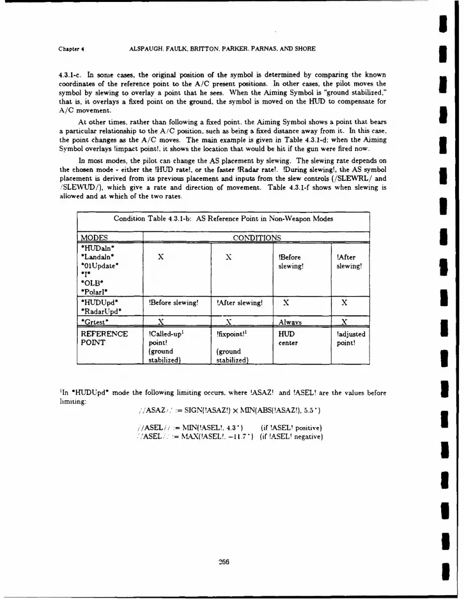
Chapter 4 ALSPAUGH, FAULK. BRITTON. PARKER. PARNAS. AND SHORE3
4.3.1-c. In sonme cases, the original position of the symbol is determined by comparing the knowncoordinates of the reference point to the A/C present positions. In other cases, the pilot moves thesymbol by slewing to overlay a point that he sees. When the Aiming Symbol is "ground stabilized,"that is, it overlays a fixed point on the ground, the symbol is moved on the HUD to compensate forA/C movement.
At other times, rather than following a fixed point, the Aiming Symbol shows a point that bearsIa particular relationship to the A/C position. such as being a fixed distance away from it. In this case,the point changes as the A/C moves. The main example is given in Table 4.3.1-d; when the AimingSymbol overlays !imnpact point!, it shows the location that would be hit if the gun were fired now.I
In most modes, the pilot can change the AS placement by slewing. The slewing rate depends onthe chosen mode - either the !HUD rate!, or the faster !Radar rate!. !During slewing!, the AS symbol
placement is derived from its previous placement and inputs from the slew controls (/SLEW~RL/ and/SLEW!JD/), which give a rate and direction of movement. Table 4.3.1-f shows wvhen slewing isallowed and at which of the two rates.
Condition Table 4.3.1-b: AS Reference Point in Non-Weapon Modes
MODES _______ CONDITIONS ___
*HfJDaln**Landaln* X X !Before !AfterOl1Update* slewing! slewing!3
*1*1*OLB*
*h-LTJDUpd* !Before slewing! !.After slewing! X X*RadarUpd* _________ ______________
*Grtest* X X Always; X
REFERENCE !Called-upi !fixpoint!1 HUD !adjustedIPOINT point! center point!
(ground (ground
_______________stabilized) stabilized) _______________U
'In *HUDUpd* mode the following limiting occurs, where !ASAZ! and !ASEL! are the values before3limiting:
','ASAZi': SIGN(!ASAZ!) x NIIN(ABS(!ASAZ!), 5.5)
//ASEL// 'vMIN(!ASEL!. 4.3') (if !ASEL! positive)',/ASEL." MAX(!ASEL!. -11.7*) (if !ASEL! negative)
266
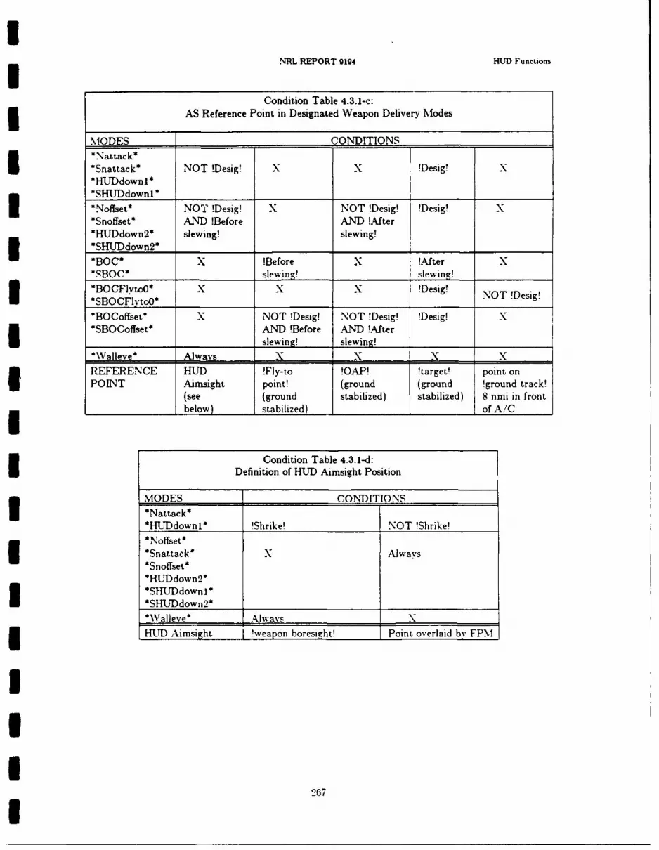
NRL REPORT 9194 HUD Functions
Condition Table 4.3.1-c:AS Reference Point in Designated Weapon Delivery Modes
MODES _____ ____ CONDITIONS -___ ____
*Nattack*I*Snattack* NOT !Desig! x X !Desig! X*LWDdownl **SHUDdownl*______ ______
*Noffset* NOT !Desig! X NOT !Desig! !Desig! X*Snoffset* AND !Before AND !After*HlJDdown2* slewing! slewing!*SHUrDdown2* _____________________ _____________I*BOC* X !Before X !After X*SBOC* ________slewing' _______ slewing! _______
*BOCFlytoO* X X X !Desig! NOT !Desigl*SBOCFlvtoO* _____ ______ _____
*BOCoffset* X NOT !Desig! NOT !Desig' 'Desig! N*SBOCoffset* AND !Before AND) !After
_____________ ___________ slewing' slewing!*WValleve* Always x x x N
REFERENCE HUD !fly-to !OAP! !target! point onIPOINT Airnsight point! (ground (ground !ground track!(see (ground stabilized) stabilized) 8 nmi in front
_elow) stabilized) of A/C
Condition Table 4.3.1-d:Definition of HUD Aimsight Position
MODES CONDITIONS*Nattack*
*H T5 dwnl* 'Shrike! NOT !hie
*Snattack* x Always*Snoffset*
HIJDdown2**SHUTDdownl*
*SHUrDdown 2 * ____________
*Walleve* Awy
HUD Aimnsight ! weapon boresight! Point overlaid bv FPM
267
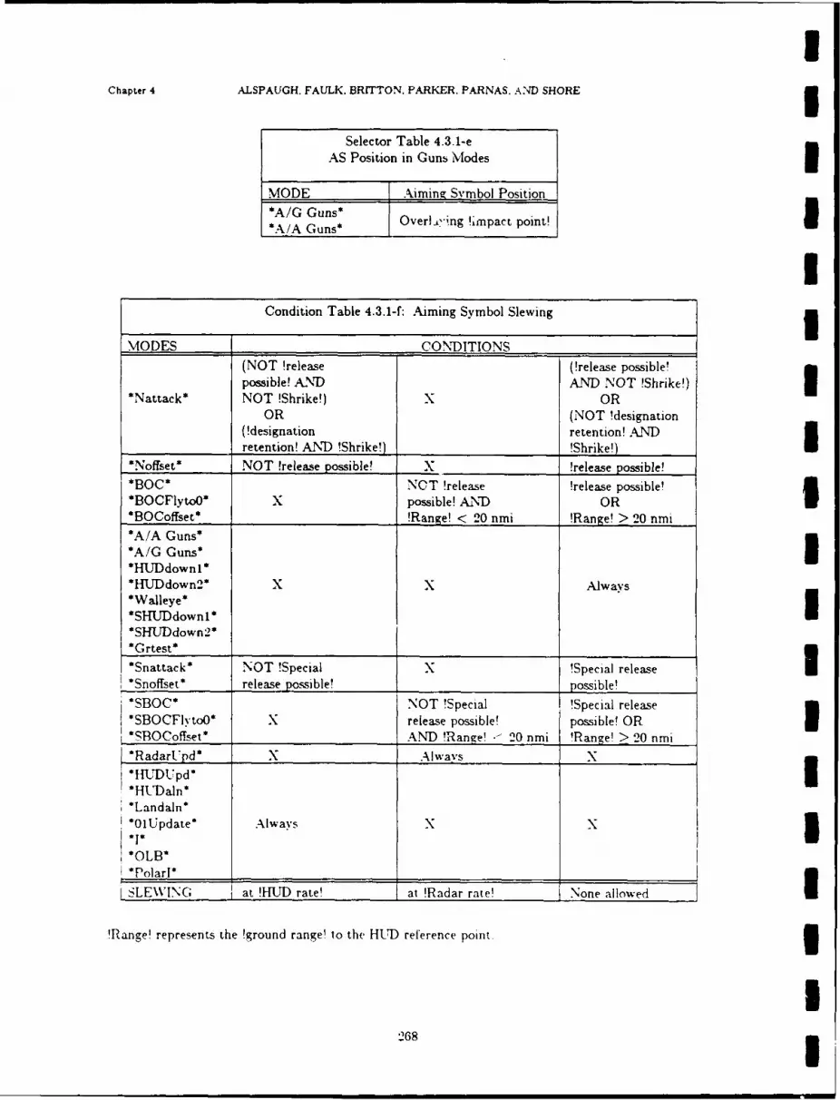
Chapter 4 ALSPAUGH. FAUJLK, BRITTON. PARKER. PARNAS. AN"D SHORE3
CODtoE ale431f Aiming Smbol Pseiting
MODES CONDITIONS(NOT !release (!release possible!possible! AND A.ND NOT !Shrike!)I
*Nattack* NOT !Shrike!) X OROR (NOT !designation
(!designation retention! ANDretention! AND !Shrike!) ______________!Shrike!)
*Noffset* NOT !release possible! x __________ !release possible!
*BOC* NOT !releas5e !release possible!*BOCFlytoO* x possible! AND OR*BOCoffset* !Range! < 20 nmi !Range! > 20 nmi*A/A Guns*
*A/G Guns*I
*HFJDdown2* x x Always*Walleye**SHUDdownl*
*Grtest*
*Snattack* NOT !Special X !Special releaseI*Snoffset* release possible! _______________possible!
*SBOC NOT !Special !Special release*SBOCFIvtoO* x release possible! possible! OR*SfOCoffset' ___________ AND !Range! .~20 nmi 'Range! > 20 nmi
*RadarL'pd* X Always N
*Landaln**0IUpdate* Always XN5
*OLB*
PolarI* I___________
SLEWING at !IIUD rate! at !Radar rate!- None allowed
!R~ange! represents the !ground range! to the H-UD reference point.3
2683

INRL REPORT 9194 HUD Functions
4.3.2. Azimuth Steering Line FunctionsI4.3.2.1. Update Azimuth Steering Line Coordinates
(Periodic function)
3 Initiation and termination:
Event Table 4.3.2-a: When ASL Switched On/Off
3 MODES EVENTS*Nattack*, *Noffset**BOC*, *BOCFyto0*
*BOCoffset*, *CCIP**HUDdownl*, *RI-UDdown2* @T(In mode) @F(In mode)*Snattack*, *Snoffset**SBOC**SBOCFytoO**SBOCoffset**SHUDdown 1*
*SHUDdown2**Grtest* @T(!WVD MFS! AND @T(In mode) OR @F(!\WD MFS!)
end of !SC Tstae!) OR @F1In mode)
ACTIONS !//HUDASL//:=$OnS //HUTDASL// :=$OffSOR placed out of view
3 Output data item(s) affected: / iASLAZ// //ASLEL//
Output description:
The ASL usually shows the pilot the direction and sometimes the amount of steering error to histarget or release point. Steering error is the angle between (1) the projection into the horizontal planeof the A/C !ground track! and (2) the projection into the horizontal plane of the line from the A/C tothe target or release point. In all modes except *CCIP*, the ASL center is placed on the line that isparallel to the pitch lines, and that passes through the FPM, as shown in Fig. 4.3-a. In some cases, wedescribe the ASL position as a displacement from the FPM along this line. This displacement affectsthe values of both //ASLAZ// and ' ASLEL,'i. In other cazes. we describe the ASL position by stat-ing thit it intersects another HUD symbol. such as the aiming symbol. This does not mean that theASL center point is placed within the other symbol. Instead, it means that the ASL center point isplaced on the line going through the FPM. such that. given the angle of the ASL (see Section 4.3.2.2),the line will intersect the symbol.
III
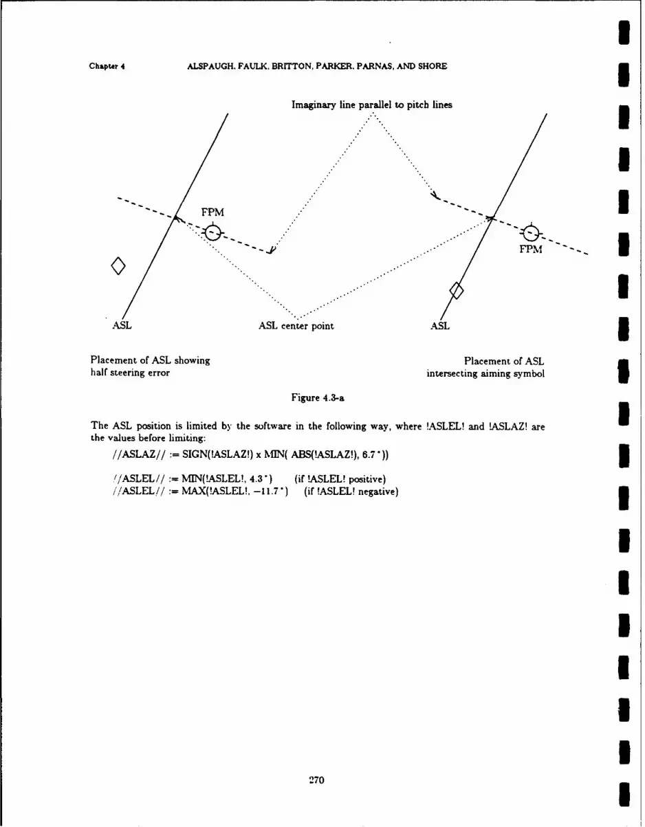
IChapter 4 ALSPAUGH. FAULK. BRITTON, PARKER. PARNAS, AND SHORE 5
Imaginary line parallel to pitcb lines
I
" FPM I
ASL ASL center point ASL 5Placement of ASL showing Placement of ASLhalf steering error intersecting aiming symbol
Figure 4.3-a
The ASL position is limited by the software in the following way, where !ASLEL! and !ASLAZ! arethe values before limiting:
//ASLAZ// := SIGN(tASLAZ!) x JffN( ABS(!ASLAZ!), 6.7")) I
r//ASLEL//:= MIN(!ASLEL!, 4.3) (if !ASLEL! positive)//ASLEL//:= MAX(!ASLEL!, -11.7 ) (if !ASLEL! negative) I
IIIUII
270I

NRL REPORT 9194 HUD Functions
Condition Table 4.3.2-b:3 ASL Placement in Designated Weapons Delivery Mvodes
MODES ______-CONDITIONS -
*Nattack*
Jdon*SnaLLack*
*HUDdown2* X NOT !Desig! !steering !OTS! !GAS!*Noffset* to target!I *BOCFlytoO**Snoffset**SBOCFlytoO*
*SHUDdownI _ __ _ __ _ _
*SHUDdown 2 * ________
k.ange! <I 30 nmi AND*BOC* !Range!' X !steering !OTS! !GAS!*SBOC* > 30 nmi to target!3NOT !Desig! !Range! <
AND 30 nmi AND*BOCoffset* !Range! !Range! < !steering !OTS! !GAS!
SBOCoffset* > 30 nmi 30 nmi to target! _______IASL !steering ASL Line !alternate -(half of edge ofPLACEMENT error! Intersects steering! !steering HUD to
from FPM AS2 display' error!) closest(same as from FPM return
___________ //FLTDIRAZ,/ _____ ____ __
"!Range! means ground distance from A/C present position to the aiming symbol reference point.
Iln *Nattack* and *Snattack*, the AS is centered in the FPM, so the ASL center would also be cen-Itered in the FPM: in *BOCFlyo*, *SBOCFlvtoo*. *Noffset*. and *Snoffset*. the AS may be dis-placed from the FPM. causing the ASL center also to be moved.3 'Ajternate steering! has two substages. When the horizontal range to the target is > 48.000 feet. theI steering error is calculated to cause the A/C to fly over the target. WVithin 48.000 feet. the steeringerror is calculated to take the A/C to the proper place to release the weapon. which may not bedirectly over the target.
When the A/C pitch gets large. the steering error is multiplied by the weighting factor showvnbelow, because otherwise the error growvs too large to display.
271
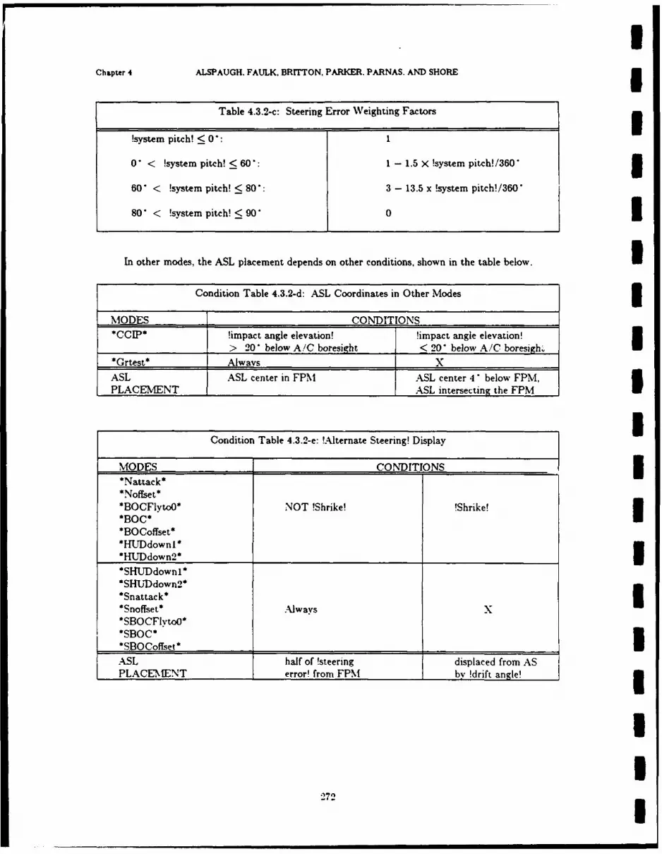
Chapter 4 ALSPAUGH. FAULK, BRITTON. PARKER. PARNAS. AND SHORE5
Table 4.3.2-c: Steering Error Weighting Factors
!system pitch! < 0*: 1
0 *< !system pitch! < 60: 1 - 1.5 X !system pitch! /3605
60' < !system pitch!< 80: 3 - 13.5 x !system pitch!/360'
80' < !system pitch! < 90 01
In other modes, the ASL placement depends on other conditions, shown in the table below.U
Condition Table 4.3.2-d: ASL Coordinates in Other Modes
MODES CONDITIONS!CIP impact angle elevation! !impact angle elevation!> 20 *below A/C boresight < 20 *below A/C boresigh.
*Grtest* Always X
ASL ASL center in FPM ASL center 4' below FPM,PLACEMENT _______________ ASL intersecting the FPM
Condition Table 4.3.2-e: !Alternate Steering! Display
MODES CONDITIONS*Nattack*
*O lyo*NOT !Shrike! !Shrike!
*BOCoffset**HLTrDdowni*
*H1JDdown2 _____________
*SHUTDdownl**SHLUDdown2**Snattack**Snoffset* Always
*SBOCit*
ASL half of ~Steering displaced from ASPLACEM\ENT error! from FPM by !drift angle!3
272
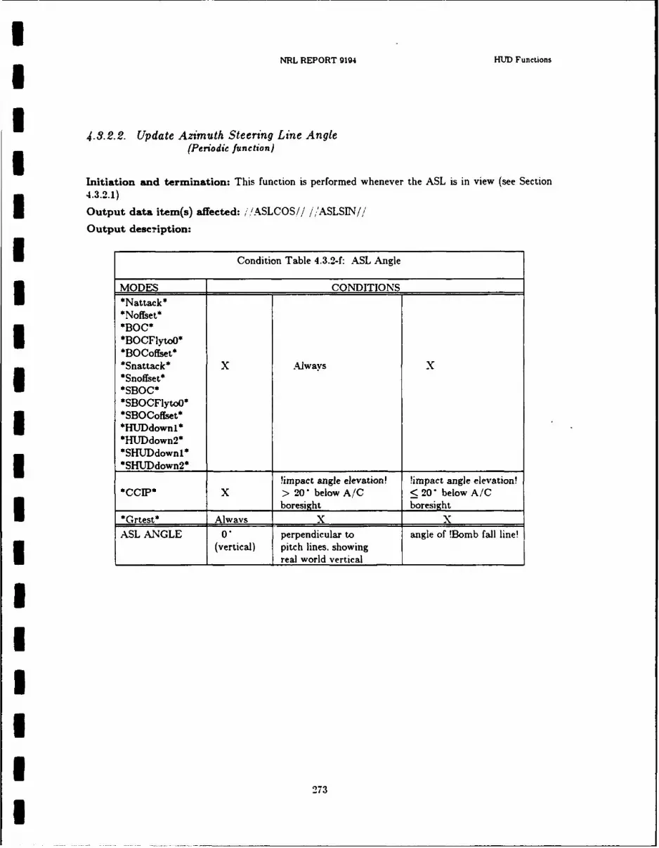
NRL REPORT 9194 HUD Functions
U4.3.2.2. Update Azimuth Steering Line Angle
(Periodic function)
Initiation and termination: This function is performed whenever the ASL is in view (see Section4.3.2.1)
Output data item(s) affected: ,',ASLCOS// i'ASLSIN//
Output description:
I Condition Table 4.3.2-f: ASL Angle
3 MODES CONDITIONS*Nattack**Noffset**BOC**BOCFlytoO**BOCoffset**Snattack* X Always X*Snoffset*
*SBOC*
*SBOCFiytoO**SBOCoffset**HUDdownl**HUDdown2*
*SHUDdownl**SHUDdown2* _________________U !impact angle elevation !impact angle elevation!
*CCIP* X > 20 below A/C < 20 below A/C_ _ _ boresixht boresight
*Grtest* Always X X
ASL ANGLE 0 perpendicular to angle of !Bomb fall line!(vertical) pitch lines, showing
real world vertical _
2IIIU
'273I

IChapter 4 ALSPAUGH. FAULK, BRITTON, PARKER. PARNAS, AND SHORE 5
I4.3.3. Update HUD Barometric Altitude
(Periodic function) 5Initiation and termination: None: always done
Output data item(s) affected: //BAROHUD// 3Output description:
Condition Table 4.3.3-a: Barometric Altitude Display Values 3MODES CONDITIONSAll modes LADC Up! AND LADC Up! AND NOT !AL)C Up'except !Dest 1-9! (.Mark!*Grtest*l OR !Dest 0!)
BAROMETRIC /BAROADC/ /BAROADC/ 4500ALTITUDE corrected for corrected for
!FLY-TO mslp! 29.92 MSLP I'In *Grtest* mode, the HUD displays a fixed value, the value of /iBAROHUD// at mode entry time.
2IIIIIUII
274 5

NRL REPORT 9194 HUD Functions
4.3.4. Update Flight Director Coordinates(Periodic function)
Initiation and termination:
Event Table 4.3.4-a: When Flight Director Coordinates Updated
MODES EVENTS
All modes @T(!power up!) OR @T(!WD MFS!)______________ F(!WD MFS!)
ACTION Initiation TerminationI FD moved in view FD out of view
Output data item(s) affected: //FLTDIRAZ//
Output description:
The Flight Director output is an azimuth displacement from the HUD ORA showing theazimuth steering error, that is. the angle between the projections into the horizontal plane of theA/C Ya axis (A/C heading) and the line drawn from the A/C to the !Fly-to point!. (As a result, thedistance between the FPM and the Flight Director shows the angular difference between the A/C!ground track angle! and the bearing to the !Fly-to point!).
Condition Table 4.3.4-b: Flight Director Azimuth Value
MODES CONDITIONS
NOT *Grtest* /FLYTOTW/'0 /FLYTOTW/=O*Grtest* X Alwavs
/FLTDIRAZ// SIGN(azimuth steering error) X 0MIN(ABS(azimuth steering error).5 )
275
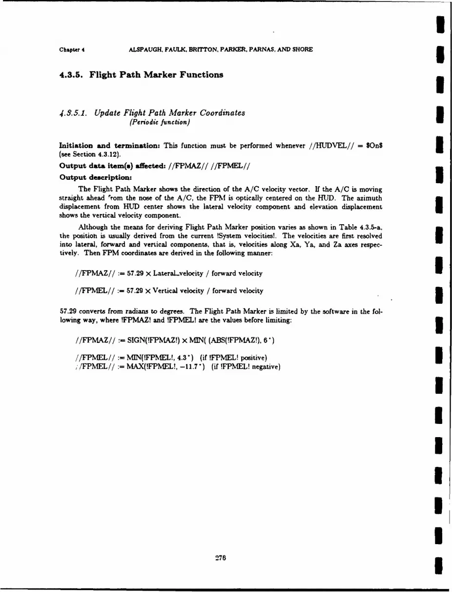
IChapter 4 ALSPAUGH, FAULK, BRITTON, PARKER, PARNAS, AND SHORE 34.3.5. Flight Path Marker Functions
4.3.5.1. Update Flight Path Marker Coordinates(Periodic function)
Initiation and termination: This function must be performed whenever //HUDVEL// = SOn$ 3(see Section 4.3.12).
Output data item(s) affected: //FPMAZ// //FPMEL//
Output description:
The Flight Path Marker shows the direction of the A/C velocity vector. If the A/C is movingstraight ahead lrom the nose of the A/C, the FPM is optically centered on the HUD. The azimuthdisplacement from HUD center shows the lateral velocity component and elevation displacementshows the vertical velocity component.
Although the means for deriving Flight Path Marker position varies as shown in Table 4.3.5-a,the positioh is usually derived from the current !System velocities!. The velocities are first resolvedinto lateral, forward and vertical components, that is, velocities along Xa, Ya, and Za axes respec-tively. Then FPM coordinates are derived in the following manner:
//FPMAZ// 57.29 X LateraLvelocity / forward velocity I//FPMEL// 57.29 X Vertical velocity / forward velocity 3
57.29 converts from radians to degrees. The Flight Path Marker is limited by the software in the fol-lowing way, where !FPMAZ! and !FPMEL! are the values before limiting: 3
//FPMAZ// := SIGN(!FPMAZ!) x MIN( (ABS(!FPMAZ!), 6)
//FPMEL//:= MIN(!FPMEL!, 4.3") (if !FPMEL! positive),/FPMEL//: MAX(!FPMEL!, -11.7") (if !FPMEL! negative)
IIUUII
275 5
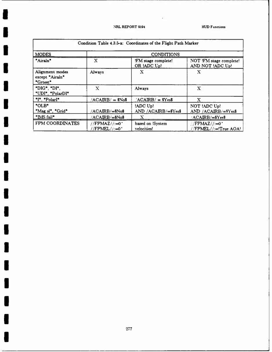
NRL REPORT 9194 HUD Functions
Condition Table 4.3.5-a: Coordinates of the Flight Path Marker
I MODES CONDITIONS -
*Airaln* X !FM stage complete! NOT !FM stage complete!OR !ADC Up! AND NOT !ADC Up!IAlignment modes Always X X
except *Airaln**Grtest* ____________
*DIG*, *DI*, X Always*UDI*, PolarDI* _________ ___________
*, *Poar* ,'ACAIRB/ $ No$ 'ACAIRB/ = .$Yes$ X
*OLB* !ADC Up! NOT !ADC Up!*Mag sis, *Grid* /ACAIRB/=$No$ AND /ACAIRB/=SYesS AND /ACAIRB,'=$'es$*IMS fail* /ACAIRB /=$No$ X ,ACAIRB/=$Yes$
FPM COORDINATES / /FPMAZ//:=0* based on !System /FPMlAZ//:=Y
U/PE/:-* vlcte! /PE/:1r- O
27
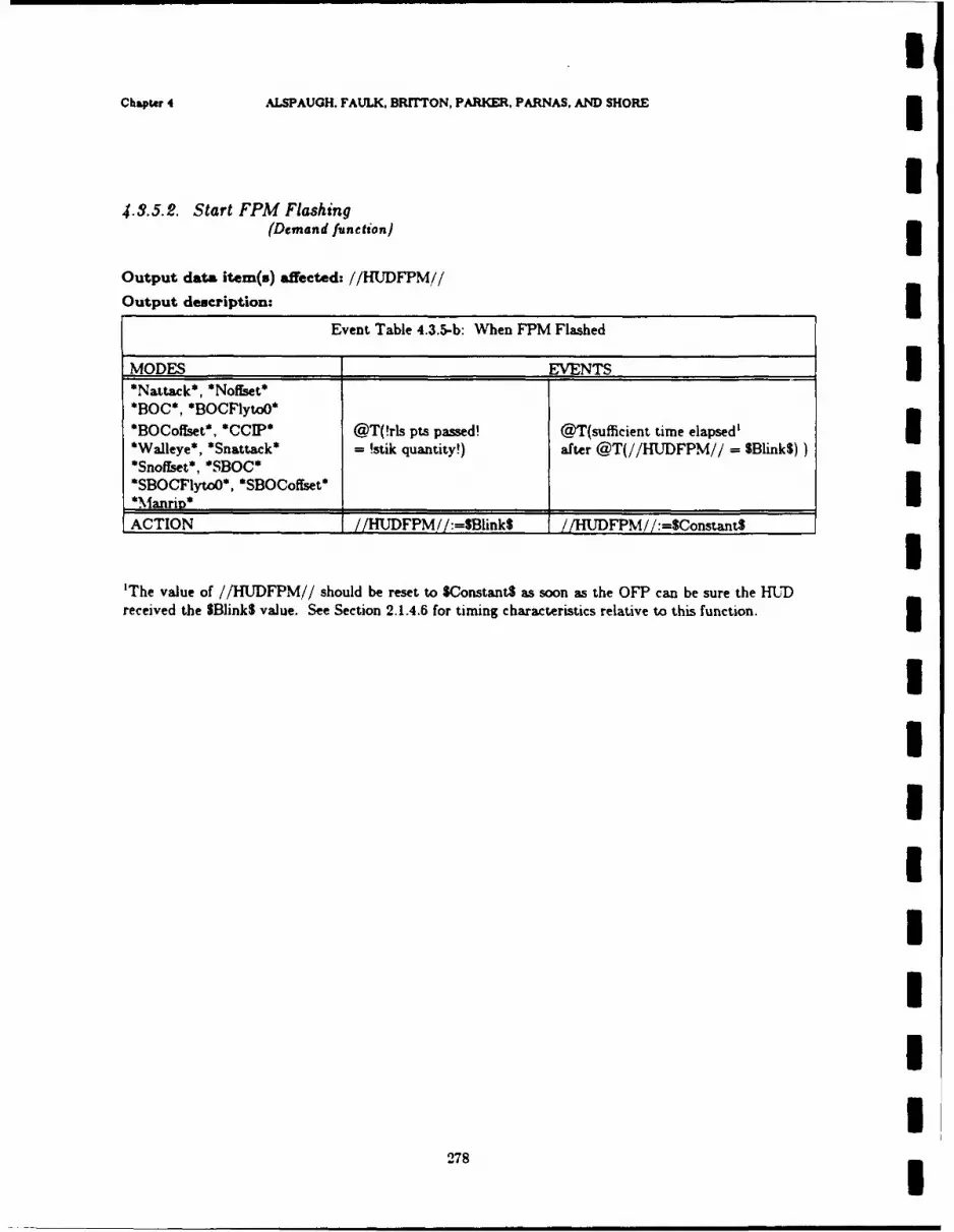
UChapter 4 ALSPAUGH. FAULK, BRrrTON, PARKER, PARNAS, AND SHORE
U4.3.5.2. Start FPM Flashing
(Demand function) 3Output data item(s) affected: //HUDFPM//
Output description: 3Event Table 4.3.5-b: When FPM Flashed
MODES EVENTS 3*Nattack*, *Nofset**BOC*, *BOCFytoO*
*BOCoflset*, *CCIP* @T(!rls pts passed! @T(sufficient time elapsed'*Walleye*, *Snattack* - !stik quantity!) after @T(//HUDFPM// = $Blink$))
*SnofIset*, *SBOC**SBOCFytoO*, *SBOCoffset*
*Manri_*
ACTION //HUDFPM //:=SBIink$ //HUDFPM // :=$Constant$ I'The value of //HUDFPM// should be reset to $Constant$ as soon as the OFP can be sure the HU)received the SBlink$ value. See Section 2.1.4.6 for timing characteristics relative to this function. 3
IIII
III
278

NRL REPORT 9194 HUD Functions
4.3.6. Update HUD Magnetic Heading(Periodic function)
Initiation and termination: None; always performed
Output data item(s) affected: //MAGHDGH//'
Output description:
Condition Table 4.3.6-a: Magnetic Heading
MODES CONDITIONS
All alignment andnavigation modes Always X,except *IMS fail**IMS Fail'IMSMODE/ SOffnone$ /MSMODE/=$Offnone$
*Grtest* X Always
i/MAGH.DGH// !magnetic heading! 0' (North)
279

Chaptr 4 ALSPAUGH, FAULK, BRITTON, PARKER, PARNAS, AND SHORE
U4.3.7. Update HUD Pitch Angle
(Periodic function) I
Initiation and termination: None; always performed
Output data item(s) affected: //PTCHANG//
Output description: In all modes but *Grtest*, the HUD displays !system pitch!. In *Grtest*mode, the HUD displays a fixed value, the current value of !IMS pitch! at mode entry time.
IIIIII'UIIIII
280

NRL REPORT 9194 HMD Functions
4.3.8. Pullup Anticipation Cue Functions
4.3.8.1. Update Pullup Anticipation Cue Coordinates
(Periodic function)
Initiation and termination:
In the following table, !Range! refers to ground range to the !Fly-to point!.
I Event Table 4.3.8-a: WVhen PUAC Updated
MODES EVENTS
*Nattack*, *Noffset*, @T(In mode) X*BOCFlytoO*, *CIP*,*A/C Guns*. *WVa1eve* _____________
*Snattack* @T(!Rmin+6000! AND*Snoffset* @T(!Rmax+6000!) !rls pts passed! = 0) OR*SBOC* @T(!Range! >10 nmi AND*SBOCFlytoO* !rls pts passed! = !stik
*SBOCoffset* quantity!) OR@T(!LMS pitch! < -3G* AND
Hrs pts passed! = !stik
quantity!) OR___________________ _________________@T(!ighi drag!)
*BOC*, @T(In mode AND @T(!Range! > 30 nmi)*BOCoffset* !Range! < 30 nmi)*Grtest* (aT(!WD MFS!) @F(!VWD MFS!)
None of the modeslisted above X aF(!W~D NMFS!)
ACTION Initiation Termination______________PUAC in view PUAG out of view
O utput data item(s) affected: /PACZ/'PUACEL//
Output description:I In most modes, the PUAC shows the pilot how far he is from the "pullup point": the pointwhere he must execute a 4g pullup to avoid either the ground or the blast radius of a released weapon.In *Grtest*. the PUAC is centered on the display.I in Table 4.3.8-b, (*A,/G Guns* ANT) !Rockets!) and (*A/G Guns* ANT) !Gumi,!) are treated as ifthey were two separate modes.
281

Chapter 4 ALSPAUGH, FAULK, BRITTON, PARKER, PARNAS, AND SHORE
Condition Table 4.3.8-b: PUAC Elevation
MODES CONDITIONS*Nattack* !slant range! to !slant range! to*Noffset* !ground pullup point! !ground pullup point!
*BOC* > 5000 ft AND < 5000 ft OR*BOCFytoO* !slant range! to !slant range! to*BOCoffset* !blast pullup point! !blast pullup point!
*CCIP* > 5000 ft < 5000 ft*A/G Guns* (!Rockets!)
*Walleye**A/G Guns* (!Guns!) !slant range! to !slant range! to
!ground pullup point! !ground pullup point!> 5000 ft < 5000 ft
*SBOC* Always X*SBOCFlytoO**SBOCoffset**Snattack*
*Snoffset**SHUDdownl**SHUDdown2*
PUAC ELEVATION 3.5' below FPM 0.7 below FPMper 1000 ft toclosest pullup point I
Selector Table 4.3.8-c: PUAC Azimuth
MODES PUAC AZIMUTH i*Nattack*, *Noffset*
*BOC*, *BOCFlyto0* Centered in azimuth on the ASL*BOCoffset* I*Snattack*, *Snoffset*,*SBOC*, *SBOCFlyto0*,
*SBOCoffset**CCIP**A/G Guns* //FPMAZ//*Walleve*
Note: The ground avoidance calculations are based on the assumption that terrain around a target isfiat.i
The purpose of the ground avoidance calculations is to keep the A/C above the target altitudeby at least a safety margin of 98 feet. It is assumed to be unnecessary to calculate ground avoidanceunless the A/C is moving down with a vertical velocity of at least 3 fps.
The purpose of the blast avoidance calculations is to keep the A/C outside of a blast sphere ofradius 1500 feet around each bomb burst point in a stik. It is unnecessary to calculate the blastavoidance if any of the following conditions holds: 3(1) slant range to designated target greater than 16,400 ft
I282I

NRL REPORT 9194 HMJ Functions
(2) NOT !Desig!, in one of the following modes: *Nattak*, *NofEset*, *BOCFlytoJ*, *BOCoffset*(3) *A/G Guns* AND NOT !Rockets!
(4) Wrs pts passed! = !stik quantity!
(5) !overfln!
(6) *Snattack*, *Snoffset*, *SBOC*, *SBOCFlytoo*, and *SBOCoffset*
(7) A/C greater than 1500 feet past impact paint at time of impact
I The target altitude used in these calculations is given in Table 4.3.8-d below.
Condition Table 4.3.8-d: Target Altitude
MODES _______ __CONDITIONS
*Nattack* !Mark!
*BOC* !Dest 1-9! X OR*CCIP* !Dest, 0!*A/G Guns*
*Walleve*I*BOCoffset* X Always*Noffset*_________________ ____
*BOCFYto* _________ X AlwavsITarget !Destaltitude! !Destaltitude! + 0altitude: ______________ !Delta Height!________
28

IChapter 4 ALSPAUGH. FAULK, BRITTON, PARKER. PARNAS, AND SHORE
I4.3.8.2. Flash PUAC
(Periodic function)
Output description:
Event Table 4.3.8-e: When PUAC Flashed 5MODES EVENTS*BOCoffset*, *CCIP*,*Nattack*, *Noffset* @T(In mode @T(/MA/ = $On$) OR*BOC*, *BOCFlytoO*. AND /MA/ SOftS) @F(In mode)*Walleve* _
*Snattack* @T(in mode AND @T(/MA/=$On$ OR !high*Snoffset* /MA/=$Off$) drag!) OR @F(In mode)*SBOC* WHEN(!Iow drag!)
*SBOCoffset**SBOCFIvtoO*
@T(In mode @T(/MA/ = SOnS)*A/G Guns* AND /MAi = SOffS) OR I
WHEN (!Guns! @T(!Guns! OR !Rockets!)OR !Rockets!)
None of above modes X @T(None of above modes)ACTIONS Initiation: Termination:
PUAC moved in and PUAC positionedout of view. by Update PUAC functionWhen in view. PUAC (see §4.3.8.1)positioned byUpdate PUAC function(see §4.3.8.1)
IIIIII
284
INRL REPORT 9194 HUD Functions
I4.3.0. Flash Pullup Cue
I (Demand function)
Initiation and termination:
Initiation: The Pullup Cue is flashed (i.e.. i/HUDPUC//:=$On$) when the A/C reaches a!puUup point!, i.e., a point where the pilot must immediately execute a 4 g pullup to escape theground or the blast radius of a weapon. In the weapons delivery modes *Nattack*, *Noffset*.*BOC*, *BOCFlytoO*, *BOCoffset*, *CCIP*. *A/G Guns*, *Walleye*, *Snattack*, *Snoffset*,*SBOC*, *SBOCFlyto0*. and *SBOCoffset* this point occurs when the PUAC reaches theFPM. In other modes, only ground avoidance is calculated.
For low-drag special weapons the Pullup Cue indicates a 4 g pullup is required for weaponrelease. Ground and blast avoidance is not calculated. The Pullup Cue appears for two seconds whenused for this purpose.
Termination: The Pullup Cue stops flashing (i.e., //HUDPUC//:=$Off$) when the pilot pullsup sufficiently to remove the A/C from danger, or has been flashed for two seconds when !lowdrag! AND !Special!.
IIII
I
III
285I

Chapter 4 ALSPAUGH, FAULK. BRrTTON, PARKER. PARNAS. AND SHORE
4.3.10. Update HIUD Roll Angle(Periodic function)
Initiation and termination: None - always performed
Output data item(s) affected:.//ROLLCOSH// //ROLLSINII//
Output description: In all modes except * Grtest*, the roll angle transmitted to the HIM is !sys-tem roll!. In *Grtest* mode, the HUD displays a fixed value, the current value of !system roll! at
mode entry time.
286

5 NRL REPORT 9194 HMD Functions
4.3.11. Solution Cue Functions
I 4.3.11.1. Display Solution Cues(Demand function)
5 sp 5Ou>0 When".
Event Table 4.3.11-a: When Both Solution Cues Switched On/Off
MODES EVENTS@T(!target in range! @F(!target in range!)
**NBnotShrike** AND !Desig! OR @F(!Desig!)I AND NOT !GAS! OR @T(!GAS!)ADNOT !During slewing!) OR @T(!During slewing!)
OR
@T(!target in range! occursin 1 second) WHEN
_______________ (ISpitch!-_421 *)_____________
*Snatak* @T(!Special in range! @F(!Special in range!)*Snoffset* AND !Desig! OR @F(ln mode)
*SBOC* AND NOT !GAS! OR @T(!GAS!)
*SBOCFlytoo* AND NOT !During slewing!) OR @ .T(!During slewing!)
*SHlJDdown1**SHUDdown2* ______________________________
**NBShrike** @T(!target in range! @F(!target in range!)*Walleve* AND !Desig!) OR @F(!Desig!)
@T(ABS( !impact angle @T(ABS( !impact angle*CCIP* elevation!) < 16 elevation!) > 16
AND ORABS(!impact angle azimuth!) ABS(!impact angle azimuth!)
______ _ <_ <12*) > 12 *)__ _ __ _
*A/G Guns* @T(!target in range!) @Fftarget in range!)*Grtest* _ @T(!WD MFS!) @F(! WVD VFS!)
______Non of_ _ _ _ _ _ _ _ _ _ _ _ _
above modes X @T In mode)ACTIONS //HUDSCUE/ 1 := SWnS //HUDSCUTE//:= SOMl or cues
_____________ ________________________placed out of view
Note: If the pitch of the A/C is near 42 *when the target is designated. the Solution Cue is displayedI 1 second before the target comes within !maximum range! to give the pilot warning that a release
point is imminent.
287

Chapter 4 ALSPAUGH, FAULK. BRITTON, PARKER, PARNAS. AND SHORE3
4.3.11.2. Update Lower Solution Cue Coordinates(Periodic function) f
Initiation and termination: Performed whenever //HUDSCUE//=SOn3
Output data item(s) affected: //LSOLCUAZ// //LSOLCUEL//1
Output description:
The Lower Solution Cue has three different uses: (1) as a warning that a release point isapproaching; (2) as an impact point indicator; (3) as an in-range cue. In the first case, it is centeredin azimuth on the ASL, moving toward or away from the ASL center point in elevation, as indicatedin Table 4.3.11-b, c, & d. The other two cases are shown in Table 4.3.11-e.
Condition Table 4.3.11-b: Placement of Lower Solution CueI
MODES CONDITIONSI*Nattack**Noffset* !OTS! !low drag! NOT !low drag!*BOC* AND NOT OTS! AN!) NOT !OTS!*BOCFlytoO**BOCoffset**HUDdownl**HU~down2*____________LOWER 4- SIGN(!dive pullup!) x SIGN(!distance-to-release!)SOLUTION CUE 'NUN (4', 1 *x 1/8 X MIN(4, 'JXI100DISTANCE FROM X ABS(!dive pullup!)) X ABS(!distance-to-release!))
ASL CENTERPOINT________________ __
'distance-to-release! < 0 when the release point has been overflown.I
Condition Table 4.3.1 1-c: Placement of Lower Solution Cue
~ ODES for !low drag! Special Weapons
**Lo.Nuke** !OTS! OR !range to Rrnax! < 0 !Range! to !target! < 10 nmi
OR AND
___________________NOT !A IC facing target! !A/C facing tar et!ILSC DISPLACEM\ENT out of view MIN(4 '.1 * X 1/ 1000 XFROM FPN1 ABS(!range to Rmax!))
288

NRL REPORT 9194 HUD Functions
Condition Table 4.3.11-d: Placement of Lower Solution Cuefor !high drag! Special Weapons
MODES CONDITIONS
**HiNuke** !TOS! NOT !TOS! AND NOT !TOS! AND
!distance to release! > 0 AND !distance to release! < 0
LSC 4 SIGN(!distance-to-release!) -(MIN(3.5" ,1 "Xl/1000xDISPLACEMENT xMIN(4 1" X1/1000 ABS(!distance-to-release!)))FROM FPM xABS(!distance-to-release!))
Selector Table 4.3.11-e: Other Positions for the Lower Solution Cue
MODES SOLUTION CUE PLACEMENT*A/G Guns* Superimposed on the Aiming Symbol
*Walleve* (which pilot interprets as !target in range! cue)*CCIP_ Intersecting ASL showing the !impact point!
*Grtest* Along the bottom of the Flight Path Marker
2I
II
IU
II
289I
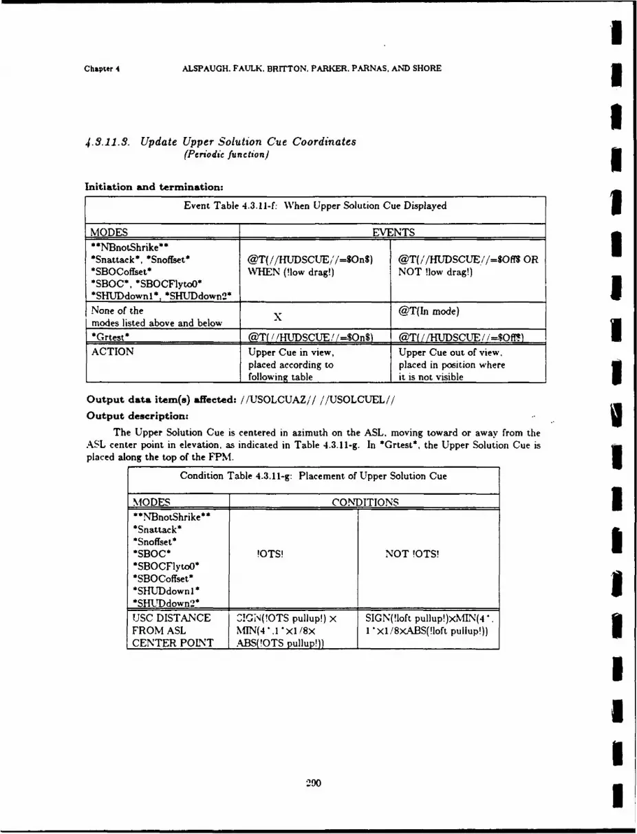
Chapter 4 ALSPAUGH. FAULK. BRITTON. PARKER. PARNAS. AND SHORE3
4.3.11.. Update Upper Solution Cue Coordinates(Periodic function)3
Initiation and termination:
Event Table 4.3.11-f: When Upper Solution Cue Displayed1
MODES EVENTS3
*Snattack*, *Snoffset* @T(//HUTDSCUE/'/=$On$) @T(/'/HUDSCUE//=$Offt OR*SBOCoffset* WHEN (!low drag!) NOT !low drag!)*SBOC*, *SBOCFlytoO*
*SHUDdownl*, *SHlJDdown2* _____________
None of the Tnmoemodes listed above and below @Tlmoe
*Grtest* @!T(' /HTDSCUTE! /=$On') @:T( //HUDSCTJE /=$Off*.)ACTION Upper Cue in view, Upper Cue out of view.
placed according to placed in position where
______________________following table it is not visible
Output data item(s) affected: //USOLCUAZ// //USOLCUEL//
Output description:
The Upper Solution Cue is centered in azimuth on the ASL. moving toward or away from theASL center point in elevation, as indicated in Table 4.3.11-g. In *Grtest*, the Upper Solution Cue isplaced along the top of the FPM.
Condition Table 4.3.11-g: Placement of Upper Solution Cue
MODES CONDITIONS3**NBnotShrike***Snattack*
*SBOC* !OTS! NOT !OTS!*SBOCFlytoO**SBOCoffset*
*SHU'Ddown2 _________________________
UJSC DISTANCE S!CN-1-(!OTS pullup!) X SIGN(!loft pullup!)XMI]N(4>FROM ASL MIfN(4' I.1 X1 /8x I1 X1 /8XABS(!loft pullup!))CENTER POINT ABS(!OTS pullup!)) __________
290
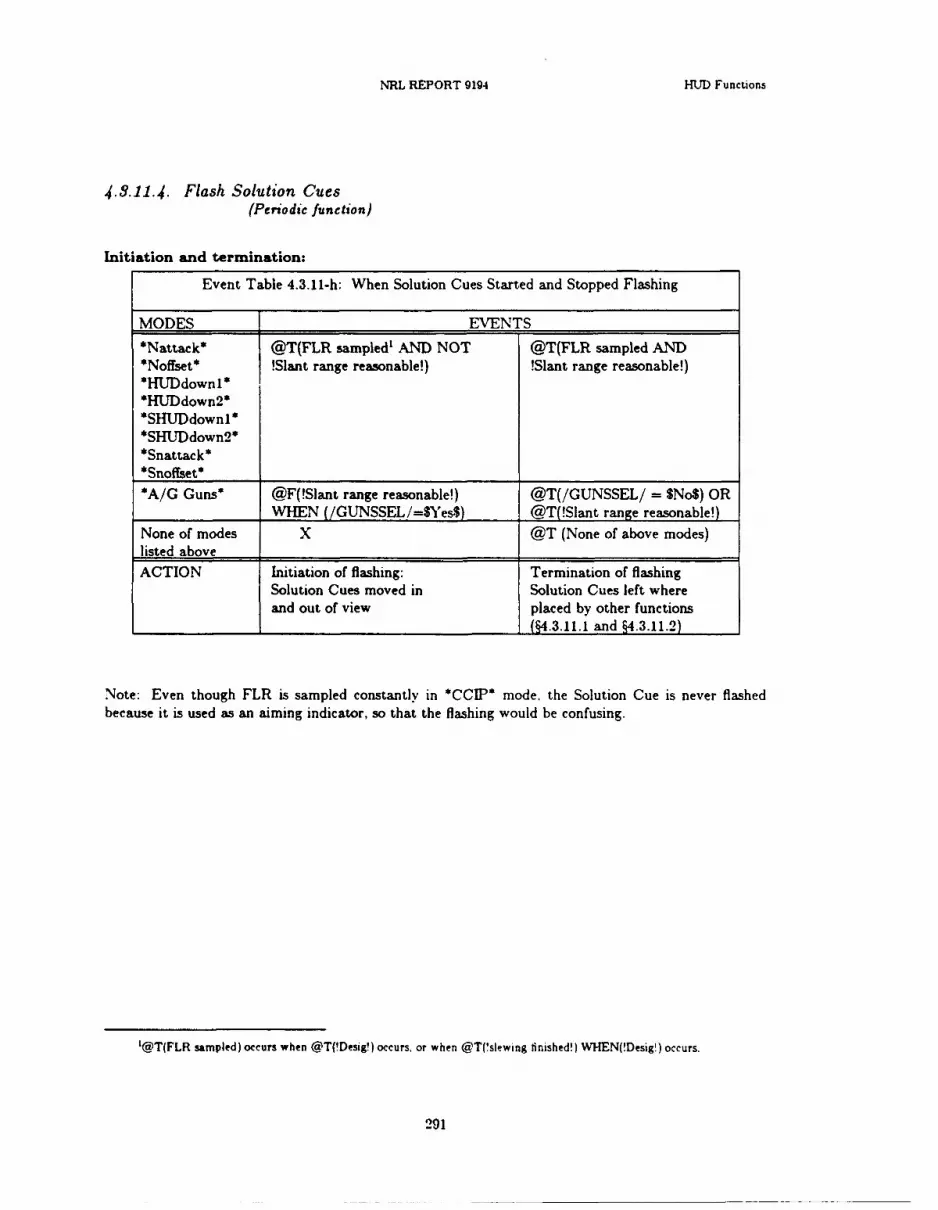
NRL REPORT 0194 HUD Functions
4..11.4. Flash Solution Cues(Periodic function)
Initiation and termination:
Event Table 4.3.11-h: When Solution Cues Started and Stopped Flashing
MODES EVENTS
*Nattack* @T(FLR sampled' AND NOT @T(FLR sampled AND*Noffset* !Slant range reasonable!) !Slant range reasonable!)*HUDdownlI**HUDdown2**SHyJDdown1**SHUD down2 **Snattack*
*A/G Guns* @F(!Slant range reasonable!) @T(/GUNSSEL/ = $No$) OR____________WHEN (/GUNSSEL /=$Yes$) @T(!Slant range reasonable!)
None of modes X @T (None of above modes)listed above ________________
ACTION Initiation of flashing: Termination of flashingSolution Cues moved in Solution Cues left whereand out of view placed by other functions
_________________________________________ (§4.3.11.1 and §4.3.11.2)
Note: Even though FLR is sampled constantly in *CCTP* mode, the Solution Cue is never flashedbecause it is used as an aiming indicator, so that the flashing would be confusing.
'@T(FLR sampled) occurs when @T(!Desig!) occurs, or when @TC'slewing finished!) WHEN(!Desig') occurs.
291
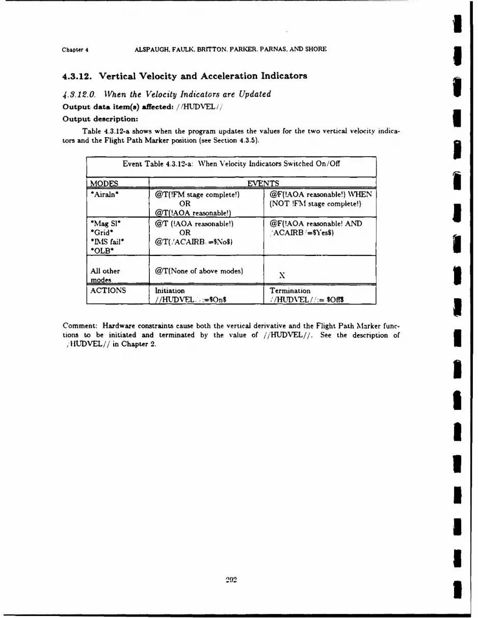
IChapter 4 ALSPAUGH, FAULK. BRITTON. PARKER. PARNAS, AND SHORE I
4.3.12. Vertical Velocity and Acceleration Indicators g4.3.12.0. When the Velocity Indicators are Updated
Output data item(s) affected: / /HUDVEL/,
Output description:
Table 4.3.12-a shows when the program updates the values for the two vertical velocity indica-tors and the Flight Path Marker position (see Section 4.3.5).
Event Table 4.3.12-a: When Velocity Indicators Switched On/Off
MODES EVENTS 3*Airaln* @T(!FM stage complete!) @F(!AOA reasonable!) WHEN
OR (NOT !FM stage complete!)@T(!AOA reasonable!)
*Mag Sl* @T (!AOA reasonable!) @F(!AOA reasonable! AND*Grid* OR 'ACAIRB '=$Yes$)*IMS fail* @T(/ACAIRB, =$No$) 3*OLB* _
All other @T(None of above modes) xmodes __
ACTIONS Initiation TerminationI // HUDVEL., :=$On$ '/HUDXEL/:= $Off$3
Comment: Hardware constraints cause both the vertical derivative and the Flight Path Marker func-tions to be initiated and terminated by the value of //HUDVEL//. See the description of
I/ IIUDVEL// in Chapter 2.
2IUII
.9. I

NRL REPORT 9194 HUD Functions
4..12-.1. Update HUD Vertical Velocity(Periodic function)
Initiation and termination:
Termination: This function is performed whenever //HUDVEL//=$On$
Output data item(s) affected: //VERTVEL//
Output description:
The HUD Vertical Velocity Indicator usually shows !System vertical velocity!, i.e., the verticalvelocity calculated from the highest priority, reliable sensors (see Table D-c in the Dictionary.)
Condition Table 4.3.12-b: Vertical Velocity Value
MODES CONDITIONSNOT*Grtest* Always X
*Grtest* X Always
OUTPUT !System vertical velocity! 01 in feet per second
4.3.12.2. Update HUD Vertical Derivative(Periodic function)
Initiation and termination:
Termination: This function is performed whenever //HUDVEL//=SOns
Output data item(s) affected: / /VTVELAC//
Output description:
The HUD Vertical Derivative Indicator shows either vertical velocity or vertical acceleration,depending on the active modes. If it shows vertical velocity, the same value is output that goes to
/,VERTVEL//.
293

UChapter 4 ALSPAUGH. FAULK. BRITTON, PARKER. PARNAS. AND SHORE 3
Condition Table 4.3.12-c: Vertical Derivative Value uMODES CONDITIONSAll modes except Always Xthose below _*Snattack* *Snoffset* *SBOC**SBOCFlytoO* *SBOCoffset* NOT !low drag! !low drag!*SHUJDdownl* *SHUDdown2*
OUTPUT id2/VERTNEL// value !normal acceleration!.
(see Table 4.3.12-b) from 0 to 6 g'
''1 ,VERTVEL// and /,VTVELAC / govern the position of a pointer on a scale (see Chapter 2).When reading an acceleration, the pilot interprets the bottom of the scale as 0 g's and the top of thescale as +8 g's. Thus, the actual value to be sent to the data item is -1000 + 250 x the accelerationin g's.
IUIUIUIU
II
294 1
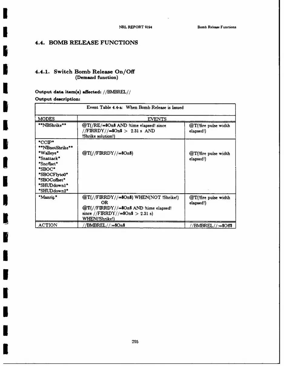
MRL RPORT g1g4 Bomb Release Functions
4.4. BOMB3 RELEASE FUNCTIONS
I 4.4.1. Switch Bomb Release On/Off(Demand function)
I Output data item(s) affected: //BMBREL//
O u p t d s rp i n Event Table 4.4-a: W hen Bomb Release is Issued
MODES EVENTS _______
**NI3~hrike** @T(/RE/=$On$ AND !timne elapsed! since @T(!fire pulse width//FIRRDY//=$OnS > 2.31 s AND elapsed!)
______________ !Shrike solution!)
**NBot~hrike**Walleye* @T(//FIRRDY//=$On$) @T(!fire pulse width*Snattack* elapsed!)*Snoffset*
*SHTJDdown2*___________
,Manrip* @T(//FIRRDY//=-$OnS) WHEN(NOT !Shrike!) @T(!fire pulse width
OR elapsed!)@T(//FIRRDY//=SOn$ AND !time elapsed!since //FIRRDY//=$OnS > 2.31 s)
_______________ HEN(!Shrike!)ACTION //BMvffREL / /:=$On$ /BMBREL :, $Ofi3
29
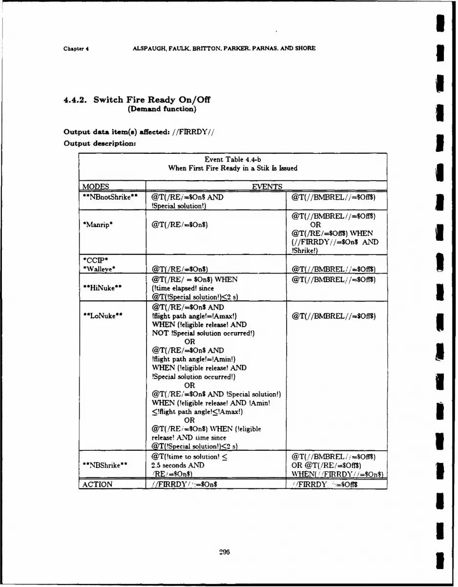
Chapter 4 ALSPAUGH, FAULK, BRITTON. PARKER. PARNAS. AND SHORE3
4.4.2. Switch Fire Ready On/Off(Demand function)
Output data item(s) affected: //FIRRDY//
Output description:3
Event Table 4.4-bWhen First Fire Ready in a Stik Is Issued
MODES EVENTS -________
**SN4notShrike** @T(/RE/=$On$ AND @T(//BMREL //=.$Ofl)
______________!Special soution!) _____________
@T(//BM1BREL //=$Ofl3)*Manrip* @T(/RE/-SOnS) OR
@T(/RE/=$OfYS) WHENI(//FIRRDY//=$On$ AND
______________ _______________________________ !Shrike!)
__________ @Tf/RE/=SOnS) @T(/ /BMBREL / /=$OflS)
@T(/RE/ = $On$) WHEN @T(//BM1BREL'/=$Off$)**HiNuke** (!timne elapsed! since
@T(!Special solution!)<2 s)_____________
@T(/RE/=$On$ AND**LoNuke** Mfight path angle!=Amax!) @T(//BMREL//=$Off$)
MWHEN (!eligible release! ANDUNOT !Special solution occurred!)
OR@T(/RE/-$On$ AND!fiight path angle!=!Amin!)WHEN (!eligible release! AND!Special solution occurred!)
ORI@T(,!RE/'=SOn$ AND !Special solution!)WHEN (Meigible release! AND !Amin!
<!flight path angle!<!Arnax!)I
@T(/RE'=$On$) WHTEN (!eligiblerelease! A.ND time since
______________@T(!Special solution!)<2 s) _____________
@T(!time to solution! < @T(//BM1BREL//=$Ofl3)**NT'BShrike** 2.5 seconds AND OR @T(/RE/=$Ofl$)
/RE/=$On$) 'WHEN(/ 'FIRRD' /=$On$)ACTION //FIRRDY/ ':=-1On$ / FIRRDY :=$OffS
296

NRL REPORT g1g4 Bomb Release Funetions
Event Table 4.4-c:I When Subsequent Fire Ready Pulses in a Stik Are Issued
MODES EVENTS*Nattack* @T(!ground range! from @T(//BMBREL//=SOff3)
!iffet mpact point! of last release OR*BOC* to impact point! of present @T(/RE/=$OflS)
*BOCFlytoO* = !bomb spacing!) WHEN W;HEN(!Shrike! AND*BOCoffset* (!rls pts passed! //FIRRDY,//=$On$)
*CCIPAN!stik quantity!*Mannip* AD/E=O$
ACTION / /FIRRDY//I:=$On$ / /FIRRDY/ /:=$OfI3
29
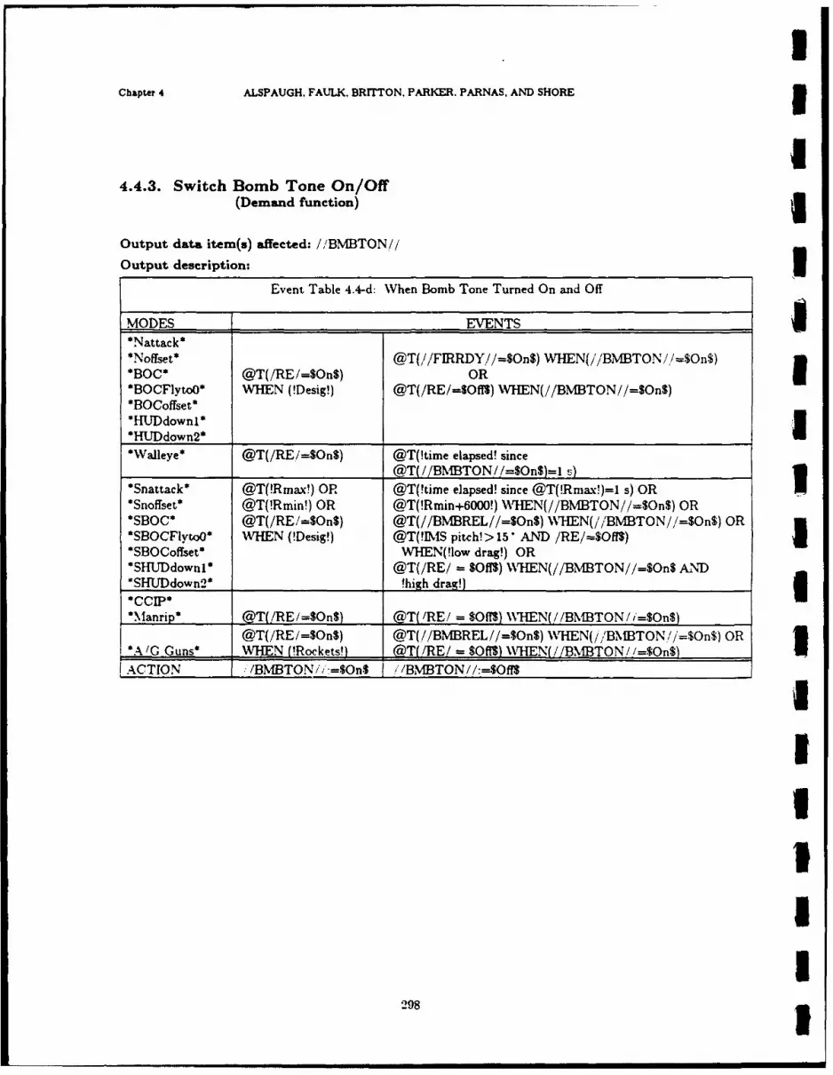
Chapter 4 ALSPAUGH. FAULK, BRITTON. PARKER, PARNAS, AND SHORE3
4.4.3. Switch Bomb Tone On/Off(Demand function)
Output data item(s) affected: //BMIBTON,//
Output description:IEvent Table 4.4-d: WVhen Bomb Tone Turned On and Off
MODES EVENTS*Nattack**Noffset* @T(//FIRRDY,'//=4On$) WVHEN(//'BMBTON //=$On$)
*BOC* @T(/RE/=$On$) OR3*BOCFlvtoO* WHEN (!Desig!) @T(/RE/=Of1$) WHEN(//BMBTON//=On$)*BOCoffset**HUDdownl*I*HUTDdown2*____________________________
*WaIleye* @T(/RE/=SOn$) @T(!time elapsed! since
@T( /BMTON //=$OnS)=l -z)*Snattack* @T(!Rmax!) OR @T(!time elapsed! since @T(!Rmax!)=I s) OR1*Snoffset* @T( !Rmin!) OR @T(!Rmin+6000!) WH7EN(//BNMTON//=$On$) OR
*SBOC* @T(/RE /=SOnS) @T(//BMBREL//=OnS) WHTEN(//BMBTON/,/-SOn$) OR*SBOCFlytoO* WHEN (!Desig!) @T(!IS pitch!> 15 *AND /RE/=$Off%)I*SBOCoffset* WHEN(!low drag!) OR*SHlJDdownl* @T(/RE/ =$00l) WHTEN(//BMBTON//=$On$ AND*SHTJDdown2* Nhigh drag!)
*:\anrp* @T(/RE/=Son$) @T( RE! = $OffS) X\HEN(//l3NBTON/i=$On$)
@T(/RE /=$OnS) @T( //BM1BREL //=$On$) WHTEN(/ ,'BMBTON //=$On$) OR*A'/G Guns* WHEN M!ockets!) (diTU RE! = $ffS) N~rHEN(/ /BMBTON //=$On/$)
ACTION /BMBTON/; =$%OnS "/BMTON//:-5Off$
298
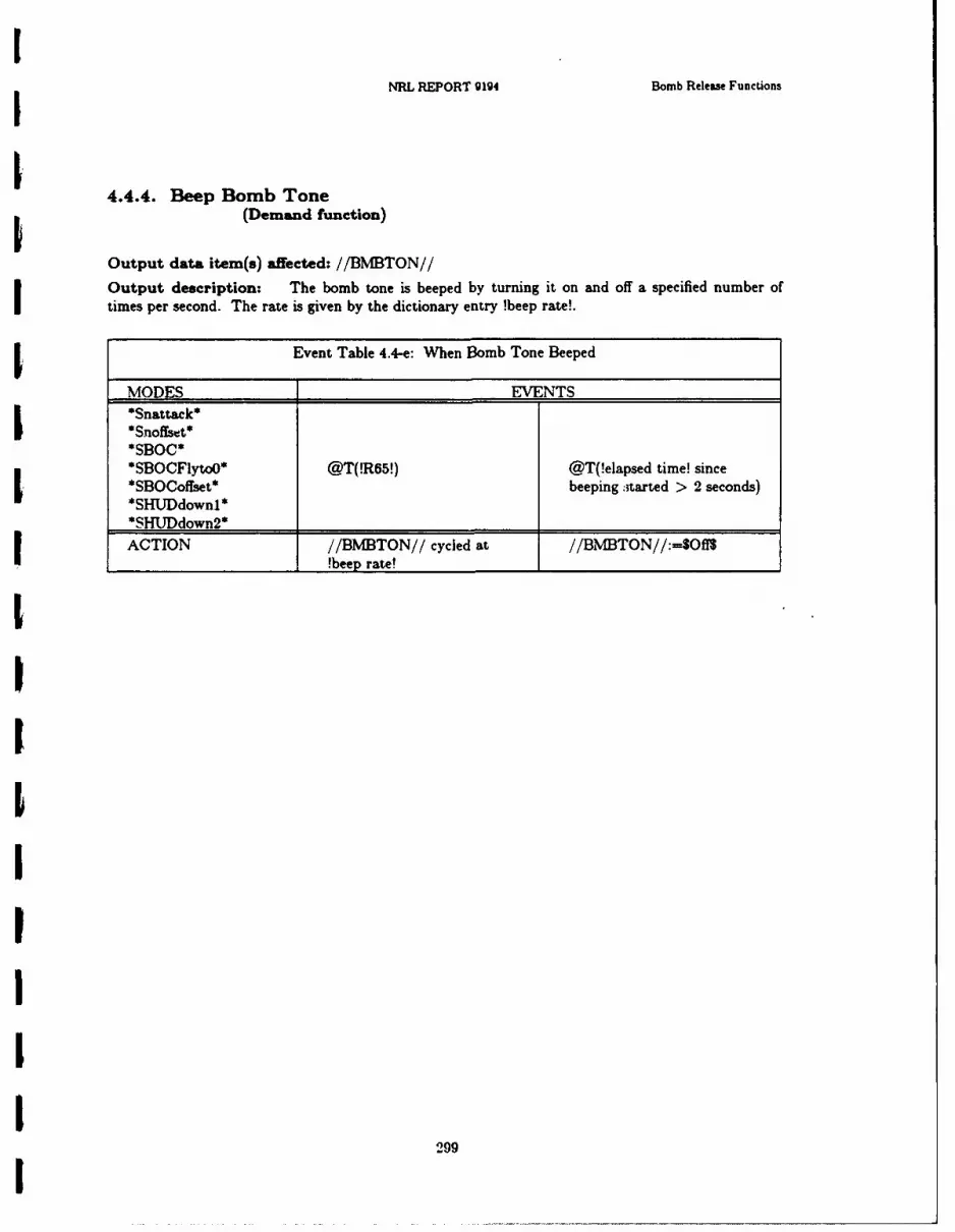
INRL REPORT 9194 Bomb Release Functions
4.4.4. Beep Bomb Tone
(Demand function)
Output data item(s) affected: //BMBTON//
Output description: The bomb tone is beeped by turning it on and off a specified number of
times per second. The rate is given by the dictionary entry !beep rate!.
I Event Table 4.4-e: When Bomb Tone Beeped
MODES EVENTS*Snatak*
II *Snoffset**SBOC**SBOCFlytoO* @T(!R65!) @T(!elapsed time! since
*SBOCoffset* beeping :tarted > 2 seconds)*SHUJDdownl*_______________________________
ACTION //BM[BTON// cycled at //BM[BTON//:=S~ffS
______________________ !beep rae_________________
29
Ch pter 4 ALSPAUGH, FAULK. BRITTON, PARKER. PARNAS, AND SHORE 34.5. PROJECTED MAP DISPLAY SET FUNCTIONS
4.5.1. Update Map Azimuth Ring Angle(Periodic function)
Initiation and termination: Ncae: always done 3Output data item(s) affected: //AZRING//
Output description: This function positions the azimuth ring so that the N marker shows thedirection of north on the filmstrip. Thus, if the map is oriented with !ground track! up (see Section4.5.3), the marker at the top of the display shows the horizontal direction of the A/C velocity vector.//AZRING// is not affected by the value of /PMHOLD/.
//AZRING// := !magnetic heading! + !ground track angle! - true heading IThis function is not performed in *Grtest*.
Initiation and termination: None: always done
Output data item(s) affected: //DESTPNT// 3Output description: The destination pointer shows the bearing to the !Fly-to point! from theA/C present position. The //DESTPNT// value is the angle measured clockwise from the A/C!ground track! to the line drawn from the the A/C present position to the !Fly-to point!. If/FLYTOTW/=O then //DESTPNT//:--O
This function is not performed in *Grtest*.
IIiIIII
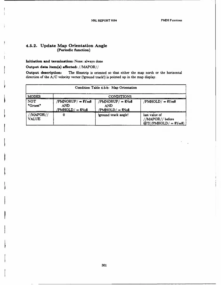
NRL REPORT 9194 PMDS Functions
4.5.2. Update Map Orientation Angle(Periodic function)
Initiation and termination: None: always done
Output data item(s) affected: //MAPOR//
Output description: The filmstrip is oriented so that either the map north or the horizontaldirection of the A/C velocity vector (!ground track!) is pointed up in the map display.
Condition Table 4.5-b: Map Orientation
MODES CONDITIONSNOT /PMNORUP/ - $Yes$ /PMNORUP/ = $No$ /PMHOLD/ - $Yes$*Grtest* AND AND
_______/PMHOLD/= $No$ !PMHOLD/= $NO$//MAPOR// 0 !ground track angle! last value ofVALUE //MAPOR// before_@T(/PMHOLD/ = $Yes$)
301
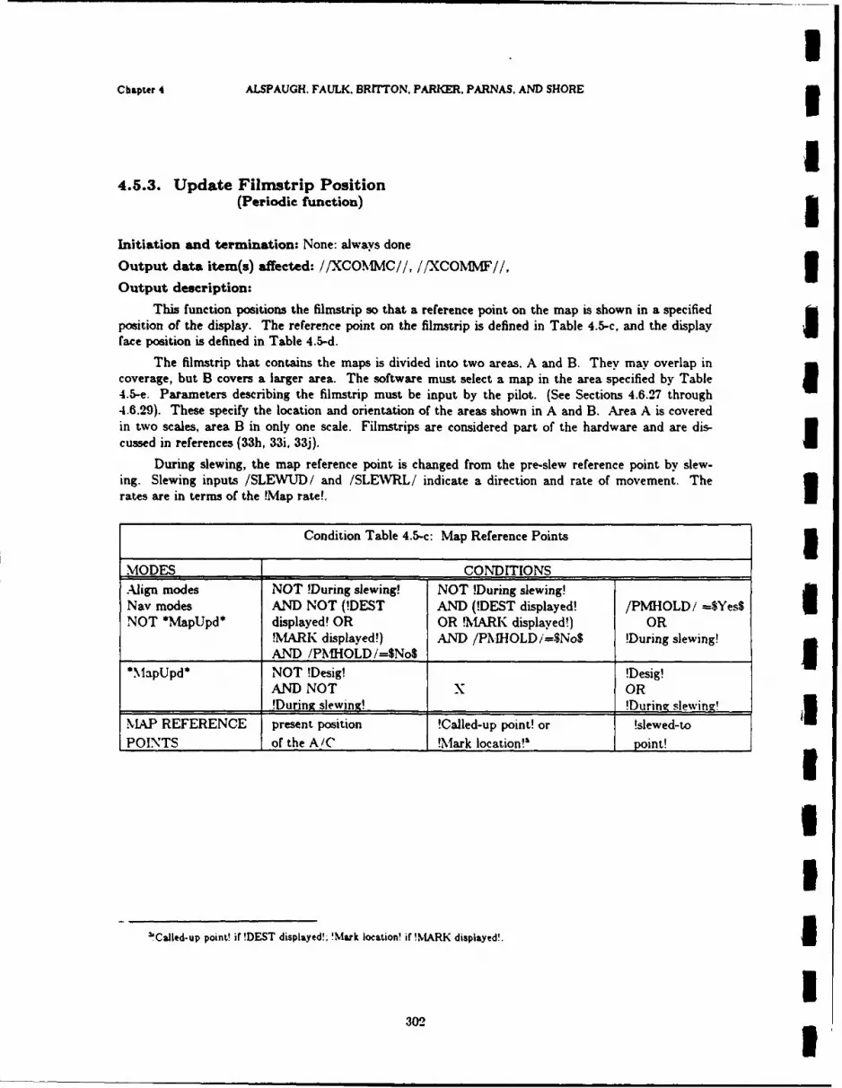
IChapter 4 ALSPAUGH. FAULK, BRiTTON. PARKER, PARNAS, AND SHORE 3
4.5.3. Update Filmstrip Position(Periodic function) a
Initiation and termination: None: always done
Output data item(s) affected: //XCOTMMC//, //XCO1NfF//, 3Output description:
This function positions the filmstrip so that a reference point on the map is shown in a specifiedposition of the display. The reference point on the filmstrip is defined in Table 4.5-c, and the display a
face position is defined in Table 4.5-d.
The filmstrip that contains the maps is divided into two areas. A and B. They may overlap incoverage, but B covers a larger area. The software must select a map in the area specified by Table I4.5-e. Parameters describing the filmstrip must be input by the pilot. (See Sections 4.6.27 through4.6.29). These specify the location and orientation of the areas shown in A and B. Area A is coveredin two scales, area B in only one scale. Filmstrips are considered part of the hardware and are dis-cussed in references (33h, 33i, 33j).
During slewing, the map reference point is changed from the pre-slew reference point by slew-ing. Slewing inputs /SLEWUD/ and /SLEWRL/ indicate a direction and rate of movement. Therates are in terms of the !Map rate!.
Condition Table 4.5-c: Map Reference Points 5MODES CONDITIONSAlign modes NOT !During slewing! NOT !During slewing!Nay modes AND NOT (!DEST AND (!DEST displayed! /PMHOLD/ -$Yes$ INOT *MapUpd* displayed! OR OR !MARK displayed!) OR
'MARK displayed!) AND /PMHOLDi=$No$ !During slewing!AND /PNIHOLD/=No$ _
*MapUpd* NOT !Desig! !Desig!
AND NOT X OR!DurinA slewing! !During slewing!
.LAP REFERENCE present position !Called-up point! or !slewed-toPOINTS of the A!C !Mark location!'aI point!
UI
'Called-up point! if !DEST displayed!: 'Mark location! if !MARK displayed!. I
1

NRL REPORT 9194 PMDS Functons
Condition Table 4.5-d: Map Display Position
MODES CONDITIONSAll Navigation /PMNORUP/ = $Yes$ /PMNORUP/ = $No$and Alignment OR AND*MaDUDd* /PMDCTR/ = $No$ /PMDCTR/ = $Yes$DISPLAYPOSITION: center reference circle bottom center of display
Table 4.5-e: Map Area Selected
Area Now /PMSCAL/ !IN A! !IN B! Note Next AreaDisplayed IA or undefined $20$ No No Error - Undefined
No Yes 2 Error - UndefinedYes No 1 AYes Yes 2 A
$805 No No Error - UndefinedNo Yes BYes No 1 AYes Yes A
B 8S208 No No Error - UndefinedNo Yes 2 Error - UndefinedYes No 1 AYes Yes 2 A
$808 No No Error - UndefinedNo Yes BYes No 1 Error - Undefined
I Yes Yes I _ I B
Legend
!IN A!: reference position within Area A of the map!IN B!: reference position within Area BFrror - Undefined: indicates an error (Undesired Event), but a display from area B at scale 8808would be a useful response.
Notes
(1) With current maps, this cannot happen since the A area is included in the B area. However,this is not required by the NAVAIR filmstrip specification.
(2) With current maps, this cannot happen, since area B is only in scale $80$. However, this is notrequired by the NAVAIR filmstrip specification.
303
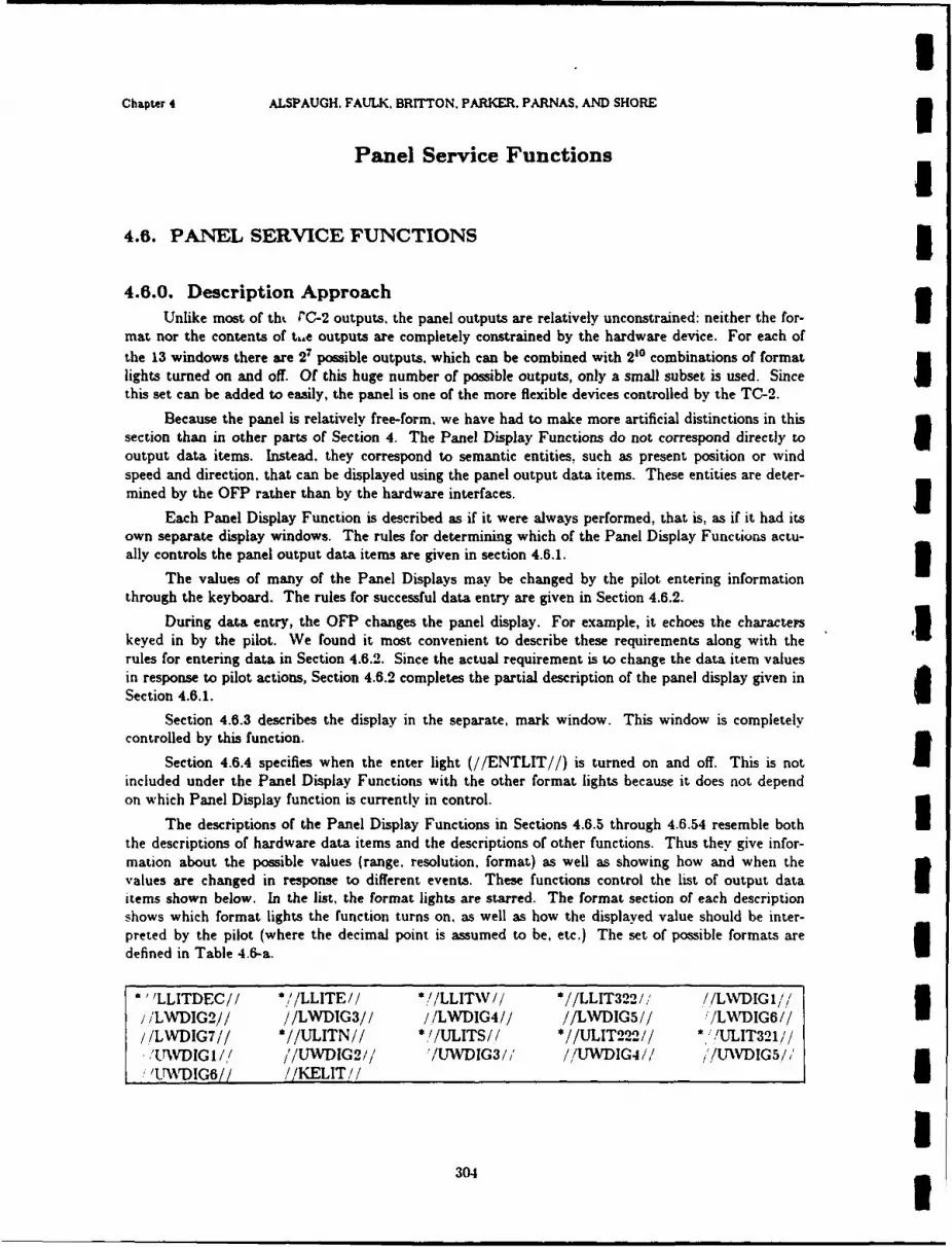
UChapter 4 ALSPAUGH. FAULK. BRITTON. PARKER, PARNAS, AND SHORE 3
Panel Service Functions I
4.6. PANEL SERVICE FUNCTIONS I
4.6.0. Description ApproachUnlike most of tht PC-2 outputs. the panel outputs are relatively unconstrained: neither the for-
mat nor the contents of tk.e outputs are completely constrained by the hardware device. For each ofthe 13 windows there are 2 possible outputs. which can be combined with 210 combinations of format
lights turned on and off. Of this huge number of possible outputs, only a small subset is used. Since Ithis set can be added to easily, the panel is one of the more flexible devices controlled by the TC-2.
Because the panel is relatively free-form, we have had to make more artificial distinctions in thissection than in other parts of Section 4. The Panel Display Functions do not correspond directly to Ioutput data items. Instead, they correspond to semantic entities, such as present position or windspeed and direction, that can be displayed using the panel output data items. These entities are deter-mined by the OFP rather than by the hardware interfaces. I
Each Panel Display Function is described as if it were always performed, that is, as if it had itsown separate display windows. The rules for determining which of the Panel Display Functions actu-ally controls the panel output data items are given in section 4.6.1. 1
The values of many of the Panel Displays may be changed by the pilot entering informationthrough the keyboard. The rules for successful data entry are given in Section 4.6.2.
During data entry, the OFP changes the panel display. For example, it echoes the charactem 1keyed in by the pilot. We found it most convenient to describe these requirements along with therules for entering data in Section 4.6.2. Since the actual requirement is to change the data item valuesin response to pilot actions, Section 4.6.2 completes the partial description of the panel display given inSection 4.6.1. I
Section 4.6.3 describes the display in the separate, mark window. This window is completelycontrolled by this function.
Section 4.6.4 specifies when the enter light (//ENTLIT//) is turned on and off. This is notincluded under the Panel Display Functions with the other format lights because it does not dependon which Panel Display function is currently in control.
The descriptions of the Panel Display Functions in Sections 4.6.5 through 4.6.54 resemble boththe descriptions of hardware data items and the descriptions of other functions. Thus they give infor-mation about the possible values (range. resolution, format) as well as showing how and when thevalues are changed in response to different events. These functions control the list of output data Iitems shown below. In the list, the format lights are starred. The format section of each descriptionshows which format lights the function turns on. as well as how the displayed value should be inter-preted by the pilot (where the decimal point is assumed to be, etc.) The set of possible formats aredefined in Table 4.6-a.
J'LLITDEC// *//LLITE// *!/LLITW// *//LLIT322/, //LWDIGI//iiLWDIG2// //LWDIG3// /ILWDIG4// //LWDIG5// !LW)DIG6// I//LWDIG7// *//ULITN// *,!/ULITS// *//ULIT222// I/'/ULIT321//
TTWDIG I// i'/UWDIG2// '/LVDIG3/' //UWDIG4// , /UWDIG5//, ,Nw% IG6// //KELIT//
304

NRL REPORT 9194 Panel Functions
The panel data that can be entered by the pilot also play the role of input data items. Both thepanel data name and the mnemonic names for the possible values can be !items! appearing in the dic-tionary, if they are referred to in other parts of the document. For example, !Data 23! = !Sea! refersto the condition that the most recent value entered for the Update Data 23 function was -000000,which signifies that the A/C is based on a ship.
Table 4.6-a: Panel Formats
Format Name Format Description Example!angle - Lwindow! //LLIT322//--$On$; seconds digits are blank 360'59'
!angle - Uwindow! //ULIT321//-OnS; seconds digits are blank 360 59'
!blank! No format lights on and all windows blank
!decimal point! //LLITDEC//=$On$; zero fill to left 00056.01
!label! No format lights on; blank fill to left 23
!lat! Either //ULITN//--$On$ OR //ULITS//=$On$ 565 45'23"//ULIT222//-$On$
!long! Either //LLITE//=$On$ OR //LLITW//--$On$ E125 23'45"//LL1T322//--$OnS
!no lights! No format lights on
!north light! //ULITN//--$OnS and //ULIT222//=SOn$;and all windows - $Blank$ N .
!sign! No format lights ontwo values: !positive! 0000000
!negative! -000000
!signed fraction! No format lights on; zero fill to right -123000Leftmost window indicates sign: either 0 or -Assumed decimal point after sign
!signed integer! No format lights on; zero fill to left -02456Assumed decimal point after right digit -034567Leftmost window indicates sign: either 0 or -
!signed 2-digit! No format lights on: zero fill to right -350000Leftmost window indicates sign: either 0 or -Decimal point assumed after 3rd window from left
!unsigned fraction! No format lights on: zero fill to right 012300Assumed decimal point before left digit
!unsigned integer! No format lights on; zero fill to left 000021Assumed decimal point after right digit
305
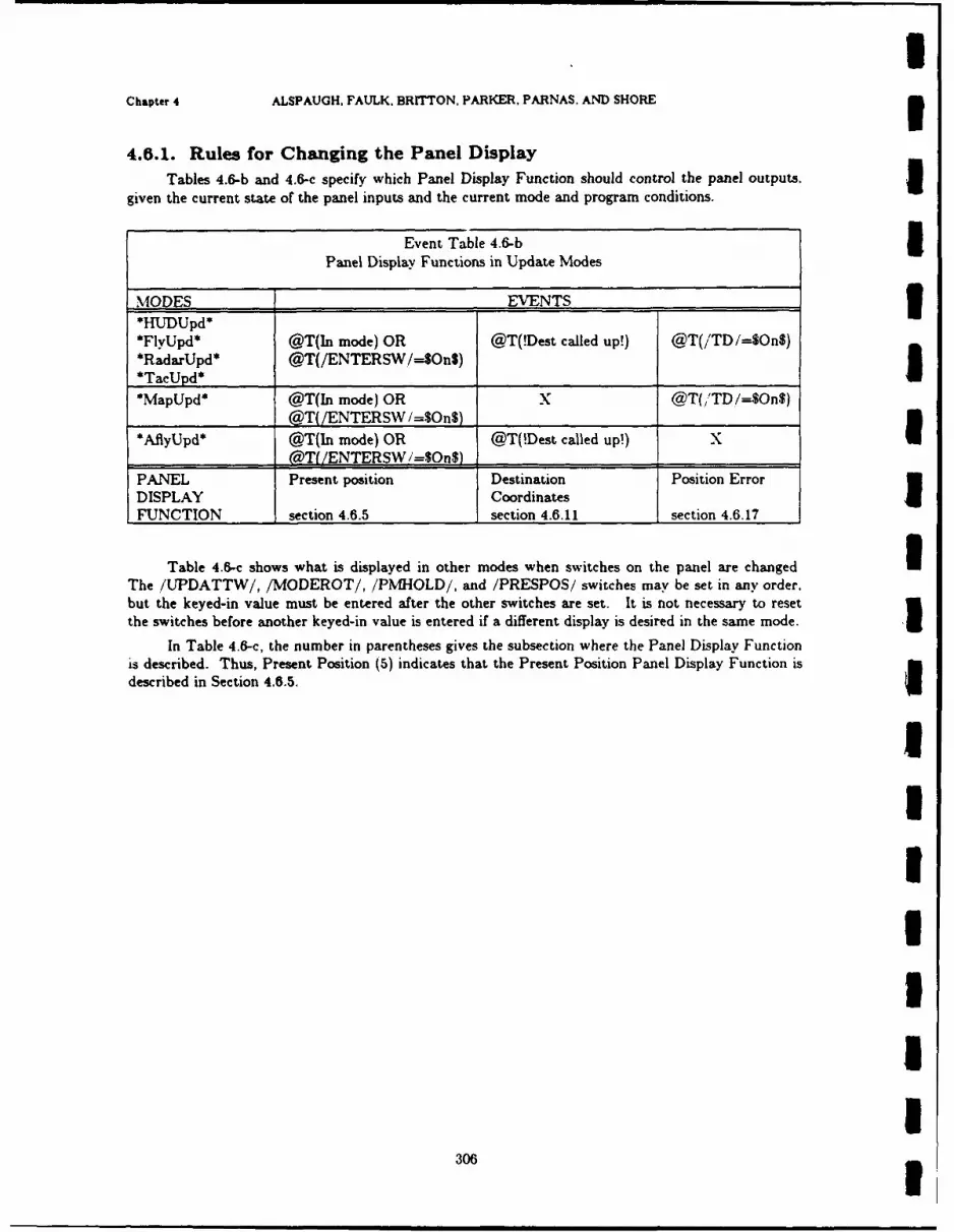
Chapter 4 ALSPAUGH, FAULK. BRITTON. PARKER, PARNAS. AND SHORE3
4.6.1. Rules for Changing the Panel DisplayTables 4.&-b and 4.6-c specify which Panel Display Function should control the panel outputs.3
given the current state of the panel inputs and the current mode and program conditions.
Event Table 4.6-b5Panel Display Functions in Update Modes
MODES EVENTS3*HUDUpd**FlvUpd* @T(In mode) OR @T(!Dest called up!) @T(/'TD/=$On$)
*RadarUpd* @T(/ENTERSW,/-S$On$)*Ta___________ _________
*MapUpd* @T(In mode) OR X @T(,'TD/=$On$)
@T( /ENTERSW I=$OnS) ______
*AflyUpd* @T(In mode) OR @T(!Dest called up!) X__________ (@T( /ENTERSW i=1OnS) _________ ______
PANEL Present position Destination Position ErrorDISPLAY CoordinatesFUNCTION section 4.6.5 section 4.6.11 section 4.6.17
Table 4.6-c shows what is displayed in other modes when switches on the panel are changedThe /UPDATTW/, /MODEROT/, /PMHOLD/, and /PRESPOS/ switches may be set in any order,but the keyed-in value must be entered after the other switches are set. It is not necessary to reset
the switches before another keyed-in value is entered if a different display is desired in the same mode.In Table 4.6-c, the number in parentheses gives the subsection where the Panel Display Function
is described. Thus, Present Position (5) indicates that the Present Position Panel Display Function is
described in Section 4.6.5.
306
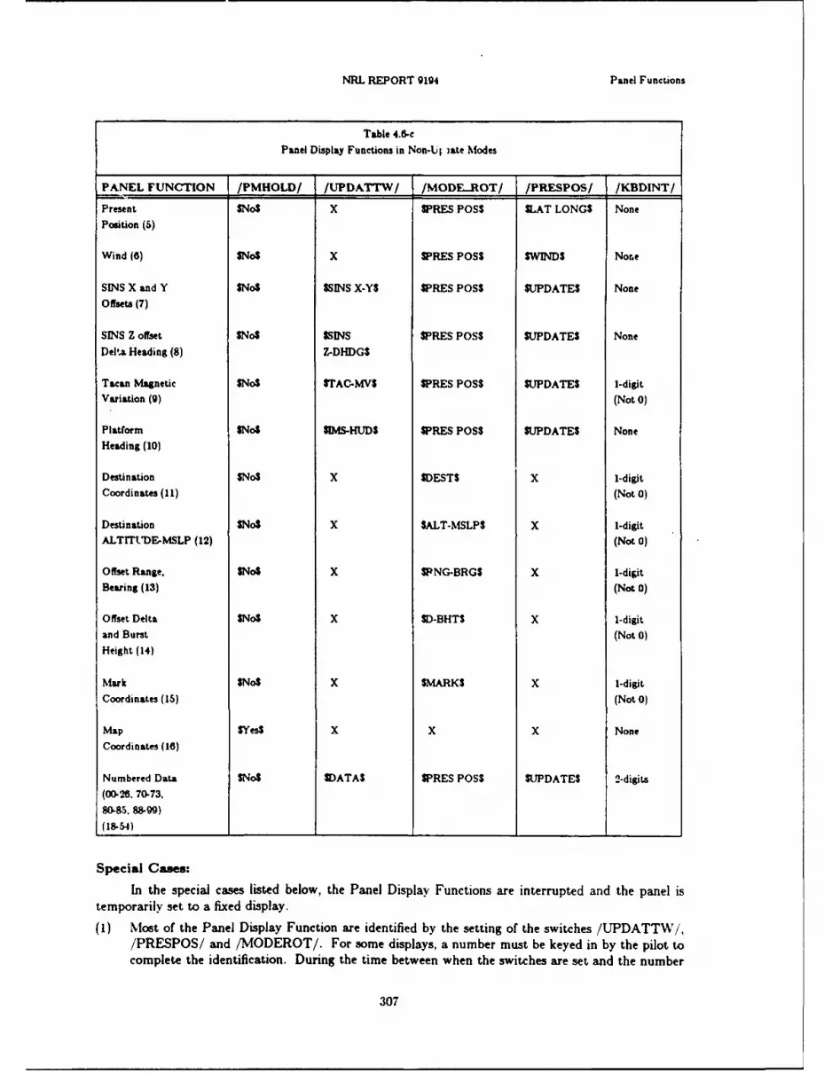
NRL REPORT 9194 Panel Functions
Table 4.6-cPanel Display Functions in Non-Ul iate Modes
PANEL FUNCTION /PMHOLD/ /UPDATT'V/ /MODE..ROT/ /PRESPOS/ /KBDINT/
Present $No$ X WPRES P055 SLAT LONGS NonePosition (5)
Wind (6) $No$ x WPRES P055 SWINDS Nore
SINS X and Y $No$ $SINS X-YS SPRES P055 SUPDATES None
Offsets (7)
SINS Z offset $No$ $SINS SPRES P055 $UPDATE$ None
Delta Heading (8) Z-DHDGS
Tacan Magnetic $No$ STAC-MVS SPRES POSS SUPDATES 1-digitVariation (9) (Not 0)
Platform $No$ SIMS-MUDS SPRES POSS SUPDATES None
Heading (10)
Destination $No$ x SDESTS X 1-digitCoordinates (11) (Not 0)
Destination $No$ x $ALT-MSLPS x 1-digitALTITLME-MSLP (12) (Not 0)
Offset Range, $No$ x SPNG-BRGS X 1-digit
Bearing (13) (Not 0)
Offset Delta $No$ X SD-BHTS X 1-digit
and Burst (Not 0)Height (14)
Mark $No$ x $MARKS x 1-digit
Coordinates (15) (Not 0)
Map $Yes$ X x X None
Coordinates (16)
Numbered Data $No$ SI)ATAS SPRES P055 "UDATE$ 2-digits
(00-26. 70-73,
W085. 88&99)
(18-54) _____ _____ ___________
Special Cames:
In the special cases listed below, the Panel Display Functions are interrupted and the panel istemporarily set to a fixed display.
(1) Most of the Panel Display Function are identified by the setting of the switches /UPDATT W/,/PRESPOS/ and /MODEROT/. For some displays, a number must be keyed in by the pilot tocomplete the identification. During the time between when the switches are set and the number
307

UChapter 4 ALSPAUGH. FAULK, BRITTON. PARKER. PARNAS. AND SHORE 3
is entered, the panel is blank.
(2) In *Grtest* mode, no Panel Display Functions control the panel. Instead, the panel displays the 1data it was showing at mode entry. When !PD Tstage! is entered (indicating that all tests havepassed), all lights are turned on - the windows display $8S and !format lights on!. When themode is exited the Panel Display Function defined by the switch settings resumes.
(3) @T(//COMPFAIL//=SYesS), all panel lights are turned on.(4) If the pilot makes an error during data entry, an error display (described in Section 4.6.2) is
shown momentarily before the Panel Display Function defined by the switch settings resumes.
(5) If an update mode is exited without the update being accepted (i.e., the exit is caused by Ichanges in one of the following inputs: /UPDATTW/, /PRESPOS/, /MODEROT/,/FLYTOTW/ or /FLYTOTOG/), the panel is blank momentarily before the panel displayfunction defined by the switch settings resumes.
(6) @T(/PN HOLD/=$Off$) the panel is blank momentarily before the Panel Display Functiondefined by the switch settings resumes. 3
(7) During the stages of data entry, the panel display is described in Section 4.6.2.
(8) All 9's are displayed if any of the following conditions occurs during *TacUpd*: NOT !TAC.ANvalid! OR /RNGSTA/ < /BAROADC/ OR /ISMODE/ = $Grid$
(9) In an update mode, all 9's are displayed if the number keyed in for !Dest called up! is 0.
4.6.2. Rules for Entering Data IThe data entry process includes the following five steps:
(I) !Alterable data displayed! must be true. Only the value controlled by that function may be Ichanged.
(2) /KBDENBL/ = SOnS
//KELIT// := $On$ UPanel Display: blank
(3) Data keyed in using /KPDINTi inputs
Panel Display: !echo! I(H1) IF error in format or range, GO TO 1. See associated Panel Display Function for restrictions
on the values.
Panel Display: All 9's. south, west. and all format lights flashed. Then display of step Iresumed.
(5) IF /KBDENBL/ = SOnS GOTO 1 3(6) ENTERSV/ = SOnS
IKELIT'/ := SOff$ UPanel Display: blank
Special case: To enter Present Position or SINS Z Offset/Delta heading, steps 3 and 4 may be omit-ted. Then the stale value is reentered. This is only important in alignment mode entry (see Table3.6-a).
Entry or display errors: I(1) KBDENBL/ depressed twice with no intervening IlKBDINT/ or /ENTERS\V U
308I

NRL REPORT 9194 Panel Functions
(2) /ENTERSW/ depressed when NOT //ENTLIT//--$On$ (See Section 4.6.4).
(3) Update modes, /KBDENBL/ depressed.
(4) In Update modes, any /KBDINT/ input after @T(!Dest called up!).
(5) In other modes, after panel switches are changed, if more /KBDINT/ buttons are pressed thanspecified in the /KBDINT/ column of Table 4.6-c.
(6) Attempt to display non-existent data (27-69, 74-79, 86-87)
(7) Error in data format or range (see Sections 4.6.5 through 4.6.54)
(8) When trying to enter Present Position, /ACAIRB/$SYes$
(9) When trying to enter Wind, /ACAIRB/f$No$ OR !ADC Up!
3
I0

Chapter 4 ALSPAUGH. FAULK, BRITTON, PARKER, PARNAS, AND SHORE3
4.6.3. Change Panel MARK Display(Demand function)5
Output data item(s) affected: /!fMARKWIN//
O utp t de crip ion:Event Table 4.6-d: M ark W indow Display
MODES _____________VNTS ______
All @T(!Power @T(/MARKSW/=$On$) @T(!Data 98 @T(!Data 98modes Up!) WH1EN displayed!) WIHEN displayed!) WHMEN
(NOT !Data 98 (NOT !ADC reasonable!) (!ADC reasonable!)
distnlavedfl I____________ _________
MARK $Blank$ !Mark number! $1$ $0$WINDOW3
310

I NRL REPORT 9194 Panel Functions
I 4.6.4. Switch Panel ENTER Light On/OffI (Demand function)
Output data item(s) anffected: //ENTLIT//Output description:
Event Table 4.6-e: When Panel ENTER light switched on and off
MOE @T(/KBDENBL/4On$) TS@T(!Panel switch changed!Any mode WHEN (!Aterable OR !Panel error!)except those data displayed! WHEN (//ENTLIT//=SOn$)Imodes listed AND OR @T(!power up!)below //ENTLIT// = $Mfl)*HUDUpd**RadarUpd* @T(/TD/ = $On$) @T(!Panel switch changed!*TacUpd* WHEN OR !Keyboard input!*FlyUpd* (//ENTLIT//=$Off$) OR !FLY-TO changed!)*MavUvd* ________________ WHEN (//ENTLIT//=On'IACTION Switched on Switched off
_____________ //ENTLIT//:= $On$ //ENTLIT//:= $0fl
31

IChapter 4 ALSPAUGH. FAULK. BRITTON. PARKER. PARNAS. AND SHORE 3
I4.6.5. Update Present Position Coordinates Display
(Periodic function) 5UPPER WINDOW: Present position latitude
When value initialized: OFP loaded 3Initial value: 0'
Units: degrees, minutes, seconds
Range: N 89 59' 59" to S89 59' 59"
Display resolution: I second
Characterization of value: latitude of A/C position 3Display format: !lat!
LOWER WINDOW: Present position longitude 3When value initialized: OFP loaded
Initial value: 0
Units: degrees, minutes, seconds
Range: E 180 to W 180
Display resolution: I second 3Characterization of value: longitude of A/C position
Display format: flong!
BOTH WINDOWS:
When value changed: 3
3IIIII
312 3
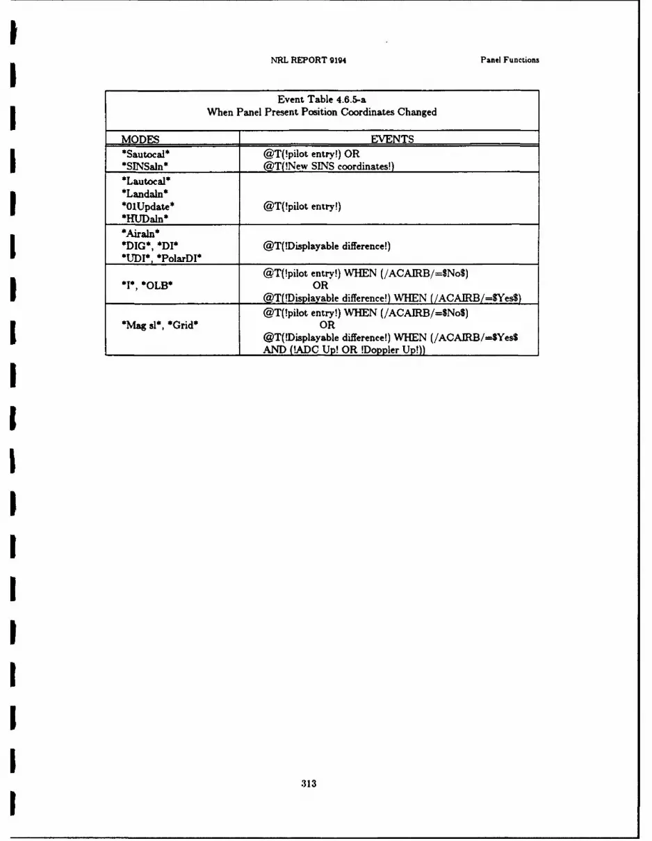
INRL REPORT 9194 Panel Functions
Event Table 4.6.5-aI When Panel Present Position Coordinates Changed
MODES EVENTS*Sautocal* @T(!pilot entry!) OR
*SINSaln* @T(!New SINS coordinates!)*Lauoa*
*O1Update* @T(!pilot entry!)
*DIG*, *DI* @T(!Displayable difference!)*UDI* *PolarDI*
@T(!pilot entry!) WHEN (/ACAIRB/=$No$)*I*, *OLB* OR
__________________ @T(!Displayable difference!) WHEN (/ACAIRB/---Yes$)
@T(!pilot entry!) WHEN (/ACAIRB/=$No$)*NWa sl*, *Grid* OR
@T(!Displayable difference!) WHEN (/ACAIRB/=-$Yes$___________________ AND (!ADC Up! OR !Doppler Up!))
31

Chapter 4 ALSPAUGH, FAULK, BRITTON. PARKER. PA4RNAS, AND SHORE
4.6.6. Update Wind Display(Periodic function)
UPPER WINDOW: Wind velocity
When value initialized: OFP loaded3Initial value: 0
Units: knots
Range: 0 to 255 (If value > 255 entered, output undefined)Display resolution: I knot
Display format: !unsigned integer!3
LOWER WINDOW: Wind direction
When value initialized: OFP loaded1Initial value: 0
Unit.: degrees, minutes, seconds
Range: 0 to 3603Display resolution: I second
Display format: !angle - Lwindow!5
BOTH WINDOWS:
When value changed:I
Event Table 4.6.6-a: When Panel Wind Display Changed
MODES EVENTSAll alignment @T(!Displayable difference!) WHEN (!ADC Up!)except_*Airaln*____________________________
*.kiraln* @T(!Displayable difference!) WVHEN (!ADC Up!)*DIG*, *DI* OR
*UJD)*, *PolarDI* @T(!pilot entry!) WHEN (NOT !ADC Up!)@T(!Displayable difference!) WHEN (!ADC Up!)I
*1*. *PolajrJ* OR@T(!pilot entry!) WHEN (/ACAIRB /=$Yes$
_________________ AND NOT !ADC Up!)@T(!Displayable difference!) WHENU
*Mag sl*. *Grid* (!Doppler Up! AND !ADC Up!)
OR*OLB*, *JI45 fail* @T(!pilot entry!) WHEN (/AGAIRB/=$Yes$
_________________ AND (NOT !ADC Up! OR NOT !Doppler Up!))
3141

i NRL REPORT 9194 Panel Functions
4.6.7. Update SINS X and Y Offsets DisplayI (Periodic function)
UPPER WINDOW: SINS X offset
LOWER WINDOW: SINS Y offset
BOTH WINDOWS:
When value initialised: OFP loadedI Initial value: 0Units: feet
Range: -2047 to +2047
Display resolution: 1 ft
Display format: igned integer!
Characterisation of value: X offset and Y ofiset are the X and Y coordinates of the A/C inthe SINS coordinate system. See Addendum for discussion of the SINS coordinate system. Thepilot enters these values and they are never calculated by the OFP.
When value changed: @T(!pilot entry!)
I!III
315

IChapter 4 ALSPAUGH, FAULK. BRITTON, PARKER. PARNAS. AND SHORE 3
I4.6.8. Update SINS Z Offset and Delta Heading
(Periodic function) 5UPPER WINDOW: SINS Z offset
When value initialized: OFP loaded 3Initial value: 0Units: feet
Range: -2047 to +2047Display resolution: 1 ftCharacterisation of value: Z offset is the A/C Z coordinate in the SINS coordinate system. ISee Addendum for discussion of the SINS coordinate system. The pilot enters the value, and itis never calculated by the OFP.
Display format: 'signed integer! 1When value changed: @T(!pilot entry!)
LOWER WINDOW: SINS delta heading 3When value initialized: OFP loaded
Initial value: 0
Units: degrees, minutes
Range: 0 to 360
Display resolution: I minute ICharacterization of value: Angle between the Ys axis of the SINS coordinate system and theYa axis projected into the Xs-Ys plane. The angle is measured clockwise, looking down, fromthe Ya axis. The pilot enters the value, and it is never calculated by the OFP.
Display format: !angle - Lwindow!
When value changed: @T(!pilot entry!) 1
I
UIIU
316
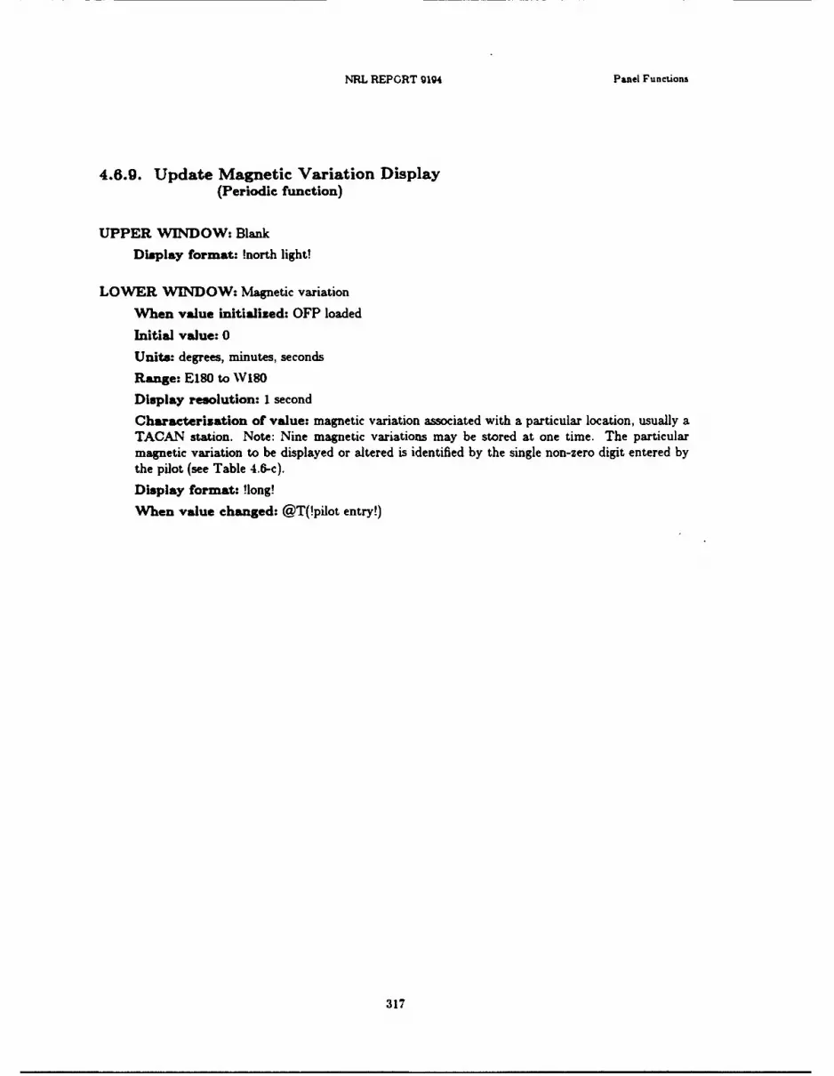
NRL REPORT 9194 Panel Functions
4.6.9. Update Magnetic Variation Display(Periodic function)
UPPER WINDOW: Blank
Display format: !north light!
LOWER WINDOW: Magnetic variation
When value initialized: OFP loaded
Initial value: 0
Units: degrees, minutes, seconds
Range: E180 to W180
Display resolution: I second
Characterization of value: magnetic variation associated with a particular location, usually aTACAN station. Note: Nine magnetic variations may be stored at one time. The particularmagnetic variation to be displayed or altered is identified by the single non-zero digit entered bythe pilot (see Table 4.6-c).
Display format: !long!
When value changed: @T(!pilot entry!)
317
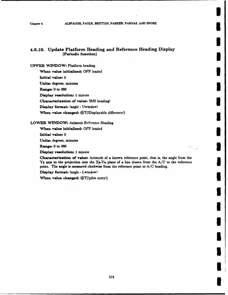
IChapter 4 ALSPAUGH, FAULK. BRITTON, PARKER. PARNAS, AND SHORE 3
I4.6.10. Update Platform Heading and Reference Heading Display
(Periodic function) 5UPPER WINDOW: Platform heading
When value initialised: OFP loaded I
Initial value: 0
Units: degrees, minutes
Range: 0 to 360
Display resolution: 1 minute
Characterisation of value: !IMS heading! I
Display format: !angle - Uwindow!
When value changed: @T(!Displayable difference!)
LOWER WINDOW: Azimuth Reference Heading
When value initialised: OFP loaded
Initial value: 0IUnits: degrees, minutes
Range: 0 to 360
Display resolution: I minute
Characterisation of value: Azimuth of a known reference point, that is, the angle from theYa axis to the projection into the Xa-Ya plane of a line drawn from the A/C to the referencepoint. The angle is measured clockwise from the reference point to A/C heading.
Display format: !angle -Lwindow!
When value changed: @T(!pilot entry!)
I
I
I
I
318I

NRL REPORT 094 Panel Functions
4.6.11. Update Destination Coordinates Display(Periodic function)
UPPER WINDOW: Destination Latitude
When value initialized: OFP loaded
Initial value: 0
Units: degrees, minutes, seconds
Range: N89 59 59 to S89 59 59
Display resolution: I second
Display format: !lat!
LOWER WINDOW: Destination Longitude
When value initialized: OFP loaded
Initial value: 0
Units: degrees, minutes. seconds
Range: E 180 to W 180
Display resolution: I second
Display format: !long!
BOTH WINDOWS:
Characterization of value: Coordinates of a location that the pilot wants eit:,er to flytoward, to use as a navigation update reference point, to use as a target or to use as an offsetaimpoint to locate a target.
When value changed: @T(!pilot entry!) OR (@aT(!map destination entry!) OR @T(!data linkwaypoint coordinates! received) (see also Addendum).
Rules for !map destination entry!
1. ;MODEROT/ = $DEST$2. /PNMHOLD = $Yes$3. Slewing may occur (/SLEWUDi and /SLE\RL, inputs)4. Destination number keyed in (/KBDINT/ = $1$. $2$... OR $9$)5. /KBDENBL/ = SOnS6. IENTERSW/ = $On$
After the last step. the coordinates of the filmstrip location under the reference point becomesthe coordinates of the destination identified in step 4.
Note: Nine sets of coordinates can be stored as destinations at one time. The particular set tobe displayed or altered is identified by the single non-zero digit keyed in by the pilot (see Table4.6-c).
319
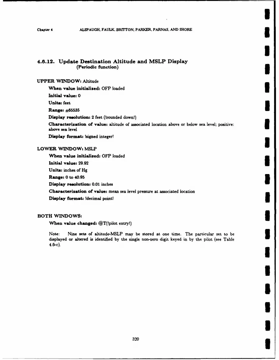
IChapter 4 ALSPAUGH, FAULK. BRITTON, PARKER, PARNAS, AND SHORE 3
I4.6.12. Update Destination Altitude and MSLP Display
(Periodic function) 3UPPER WINDOW: Altitude
When value initialised: OFP loaded 3Initial value: 0
Units: feet
Range: * 5535
Display resolution: 2 feet (!rounded down!)
Characterization of value: altitude of associated location above or below sea level; positive: 3above sea level
Display format: !signed integer!
LOWER WINDOW: MSLP
When value initialized: OFP loaded
Initial value: 29.92
Units: inches of Hg
Range: 0 to 40.95
Display resolution: 0.01 inches
Characterization of value: mean sea level pressure at associated location
Display format: !decimal point!
BOTH WINDOWS:
When value changed: @T(!pilot entry!)
Note: Nine sets of altitude-MSLP may be stored at one time. The particular set to be 3displayed or altered is identified by the single non-zero digit keyed in by the pilot (see Table4.6-c).
II
I32

NRL REPORT 9194 Panel Functions
4.6.13. Update Offset Range and Bearing Display(Periodic function)
UPPER WINDOW: Range
When value initialized: OFP loaded
Initial value: 0
Units: feet
Range: 0 to 131.070
Display resolution: 4 feet (!rounded down!)
Characterization of value: distance from Offset Aimpoint (!OAP!) to actual target
Display format: !unsigned integer!
LOWER WINDOW: Bearing
When value initialized: OFP loaded
Initial value: 0
Units: degrees, minutes. seconds
Range: 0 to 360
Display resolution: I second
Characterization of value: angle between line from Offset Aimpoint (!OAP!) to north andline from Offset Aimpoint to target, measured clockwise from the north line looking down
Display format: !angle - Lwindow!
BOTH WINDOWS:
When value changed: @T(!pilot entry!)
Note: Nine offset range-bearing sets may be stored at one time. The particular set to bedisplayed or altered is identified by the single non-zero digit keyed in by the pilot (see Table4.6-c).
321

IChapter 4 ALSPAUGH. FAULK, BRrrTON, PARKER. PARNAS, AND SHORE 3
I4.6.14. Update Offset Delta Height and Burst Height
(Periodic function) 3UPPER WINDOW: Delta height
When value initialized: OFP loaded 3Initial value: 0
Units: feet
Range: ±65535
Display resolution: 2 feet (!rounded down!)
Characterization of value: difference in altitude between Offset aimpoint (!OAP!) and !tar-get!; positive value means !OAP! below !target!, negative value means !OAP! above !target!.
Display format: !signed integer!
When value changed: @T(!pilot entry!) 3LOWER WINDOW: Burst height
When value initialized: OFP loaded
Initial value: 0
Units: feet
Range: 0 - 65535
Display resolution: 2 feet (!rounded down!)
Characterization of value: height above ground where bomb to burst for that destination 3Display format: !unsigned integer!
When value changed: @T(!pilot entry!) 3Note: Nine delta-height/burst-height sets may be stored at one time. The particular set to bedisplayed or altered is identified by the single non-zero digit keyed in by the pilot (see Table 34.6-c).
IIIUI
322
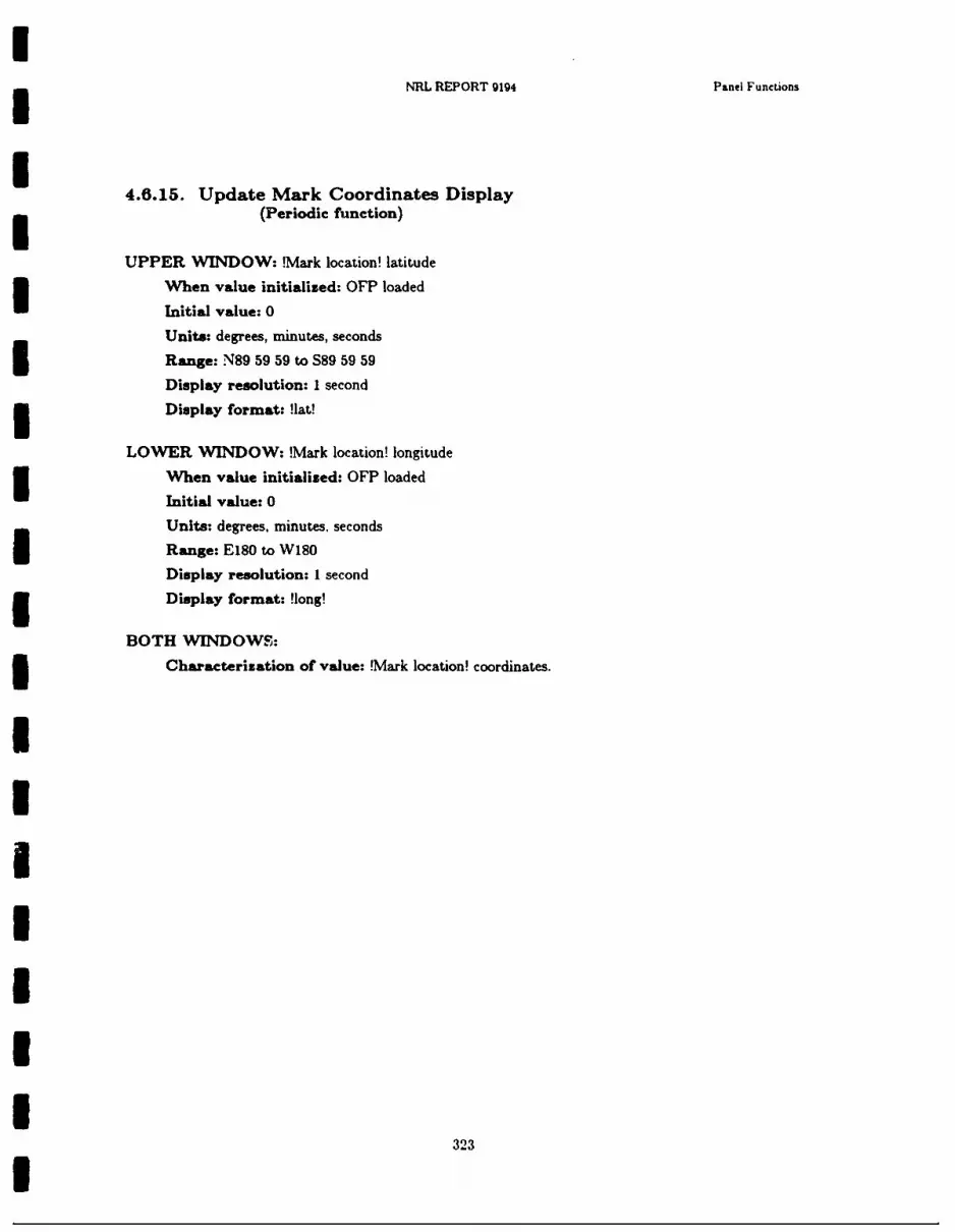
NRL REPORT 9194 Panel Functions
4.6.15. Update Mark Coordinates Display(Periodic function)
UPPER WINDOW: !Mark location! latitude
When value initialized: OFP loaded
Initial value: 0
Units: degrees, minutes, seconds
Range: N89 59 59 to S89 59 59
Display resolution: 1 second
Display format: !lat!
LOWER NVINDOW: !Mark location! longitude
When value initialized: OFP loaded
Initial value: 0
Units: degrees, minutes, seconds
Range: E180 to W180
Display resolution: 1 second
Display format: !long!
BOTH WINDOWS:
Characterization of value: !Mark location! coordinates.
323
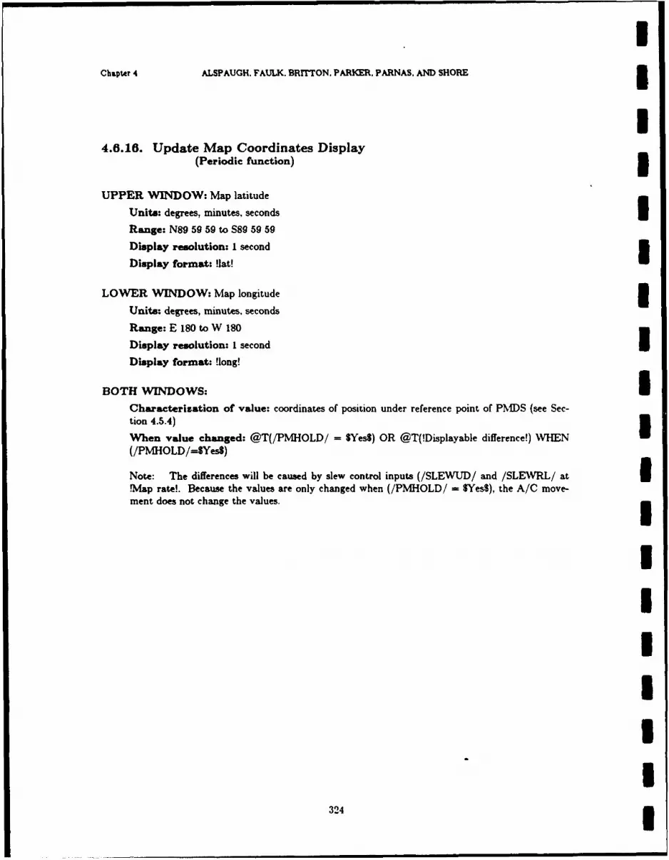
Chapter 4 ALSPAUGH. FAULK. ERrrTON, PARKER. PARNAS, AND SHORE3
4.6.16. Update Map Coordinates Display(Periodic function) 3
UPPER WINDOW: Map latitude
Units: degrees, minutes, seconds
Range: N89 59 59 to S89 59 59
Display resolution: I second
Display format: !lat!
LOWER WINDOW: Map longitude IUnits: degrees, minutes, seconds
Range: E 180 to W 180
Display resolution: I second
Display format: !long!
BOTH WINDOWS: ICharacterization of value: coordinates of position under reference point of PMDS (see Sec-tion 4.5.4)
When value changed: @T(/PMHOLD/ = SYes$) OR @T(!Displayable difference!) WHEN
(/PMHOLD/=SYes$)
Note: The differences will be caused by slew control inputs (/SLEWUD/ and /SLEWRL/ at I.Map rate!. Because the values are only changed when (/PMHOLD/ VYes$), the A/C move-ment does not change the values.
IIUIIU
324 3

NRL REPORT 9194 Panel Functions
4.6.17. Update Position Error Display(Periodic function)
UPPER 'WINDOW: error in latitude
When value initialised: OFP loaded
Initial value: 0Units: degrees, minutes, seconds
Range: N90 to S90Display resolution: I second
Display format: !lat!
LOWER WINDOW: Error in longitude
When value initialized: OFP loaded
Initial value: 0Units: degrees, minutes, seconds
Range: E180 to W180
Display resolution: 1 second
Display format: !long!
BOTH WINDOWS:Characterization of value: The position error is the difference between the coordinates of thetwo reference points given in Table 4.6.17-a. The position error is measured from the first refer-ence point to the second. The direction of the error is shown by the format lights. For exam-ple, //ULITN// = $On$ and //LLITE// = SOnS means the error is north east, that is, theU -cond point is northeast of the first.
Selector Table 4.6.17-a: Update Mode Reference Points
MODES FIRST REFERENCE POINT*HUDUpd* !Called-up point! !fixpoint! (indicated by AS)*RadarUpd* !Called-up point! !fixpoint!
(indicated by Radar cursors)
*FlyUpd* !Called-up point! A/C present position*TacUpd* A 'C present position position calculated from
!Called-up point! coordinates,___/RNGSTA, and !BRGSTAI*MapUpd* A/C present position !fixpoint!
(indicated by map displayposition)
325
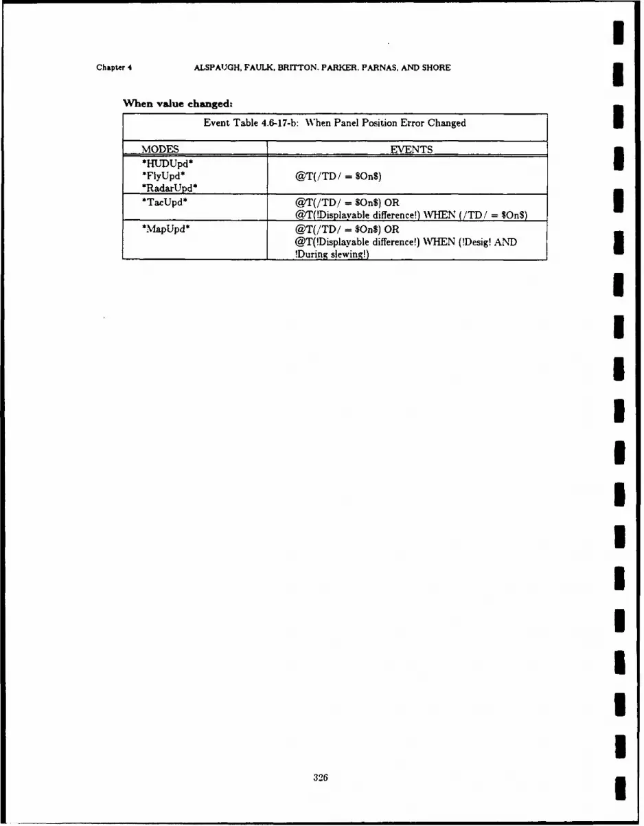
Chapter 4 ALSPAUGH, FAULK, BRITTON. PARKER. PARNAS. AND SHORE3
When value changed:
Event Table 4.6-17-b: When Panel Position Error Changed
MODES EVENTS3
SFlyUpd* @T(/TD/ = $On$)
*RadarUpd*
*TacUpd* @T(/TD/ = $On$) ORI@T(!Displavable difference!) WHEN (/TD/ = n$)
*M~apUpd* @T(/TD/ = $On$) OR
@T(!Displavable difference!) WHEN (!Desig! AND!During slewing!)I
326
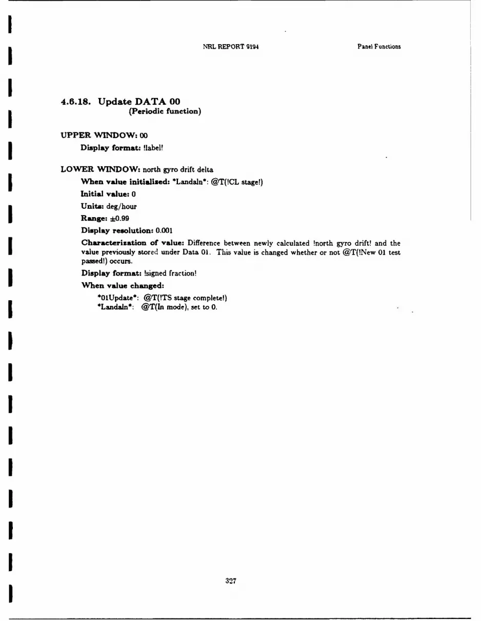
IIIRL REPORT 9194 Panel Functions
I4.6.18. Update DATA 00
(Periodic function)
UPPER WINDOW: 00
Display format: !label!
LONVER WINDOW: north gyro drift delta
When value initialised: *Landaln*: @T(!CL stage!)
Initial value: 0
Units: deg/hour
Range: -0.99Display resolution: 0.001
Characterization of value: Difference between newly calculated !north gyro drift! and thevalue previously stored under Data 01. This value is changed whether or not @T(!New 01 testpassed!) occurs.
Display format: !signed fraction!
When value changed:*01Update*: @T(!TS stage complete!)*Landaln*: @T(In mode), set to 0.
IIIII
327
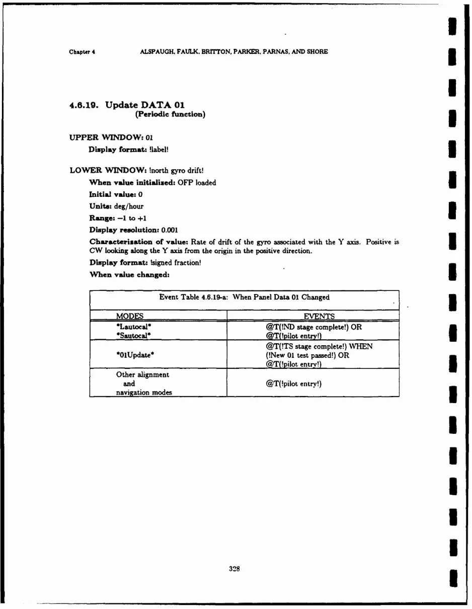
UChapter 4 ALSPAUGH, FAULK, BRITTON, PARKER, PARNAS, AND SHORE 3
U4.8.1g. Update DATA 01
(Periodic function) 3UPPER WINDOW: 01
Display format: !label! 3LOWER WINDOW: !north gyro drift!
When value initialized: OFP loaded
Initial value: 0Units: deg/hour
Range: -1 to +I
Display resolution: 0.001
Characterization of value: Rate of drift of the gyro associated with the Y axis. Positive is 3CW looking along the Y axis from the origin in the positive direction.
Display format: !signed fraction!
When value changed: I
Event Table 4.6.19-a: When Panel Data 01 Changed 3MODES EVENTS*Lautocal* @T(!ND stage complete!) OR
*Sautocal* @T(!pilot entry!)@T(!TS stage complete!) WHEN
*OUpdate* (!New 01 test passed!) OR_______________________@T(!pilot entry')
Other alignment
and @T(!pilot entry!)navigation modes 3
IIIII
328I

NRL REPORT 9194 Panel Functions
4.6.20. Update DATA 02(Periodic function)
UPPER WINOW: 02
Display format: !label!
LOWER WIN*DOW: east gyro drift
When value initialized: OFP loaded
Initial value: 0
Units: deg/hourI Range: -1 to +1Display resolution: .001
Characterization of value: Rate of drift of the gyro associated with the X axis. Positive isOW looking along the X axis from the origin in the positive, lirection.
Display format: !signed fraction!
j When value changed:
Event Table 4.6.20-a: WNhen Panel Data 02 Changed
IMODES EVENTS*Lautoal* @T(!ED stage complete!) OR*Sautocal* @TPilot entry!)I Other navigationor @T(!pilot entry!)alignment modes_______ _______
32

IChapter 4 ALSPAUGH, FAULK, BRITTON. PARKER, PARNAS. AND SHORE 3
I4.6.21. Update DATA 03
(Periodic function) 3UPPER WINDOW: 03
Display format: !label!
LOWER WINDOW: vertical gyro drift
When value initialized: OFP loaded
Initial value: 0
Units: deg/hour
Range: -1 to +1Display resolution: .001
Characterization of value: Rate of drift of gyro associated with Z axis. Positive is C\V, 3looking along the Z axis from the origin in the positive direction. This value is specific to anindividual IMU and is never calculated by the OFP.
Display format: !signed fraction! 3When value changed: @T(!pilot entry!)
IIIUIIIII
330I
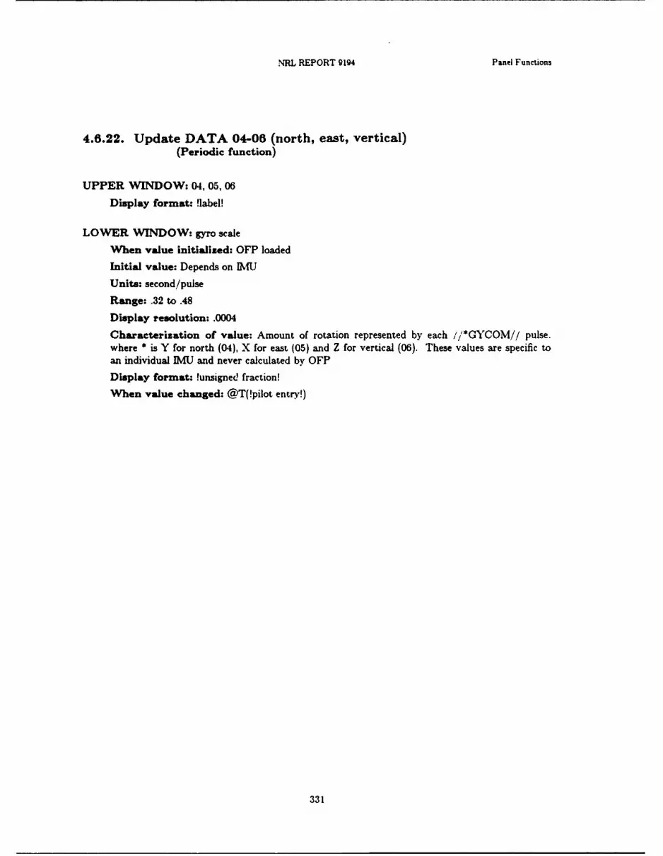
NRL REPORT 9194 Panel Functions
4.6.22. Update DATA 04-06 (north, east, vertical)(Periodic function)
UPPER WINDOW: 04,05,06
Display format: 'label!
LOWER WINDOW: gyro scale
When value initialized: OFP loaded
Initial value: Depends on BMU
Units: second/pulse
Range: .32 to .48
Display resolution: .0004
Characterization of value: Amount of rotation represented by each // t*GYCOM// pulse.where * is Y for north (04), X for east (05) and Z for vertical (06). These values are specific toan individual IMU and never calculated by OFP
Display format: !unsigned fraction!
When value changed: @T(!pilot entry!)
331
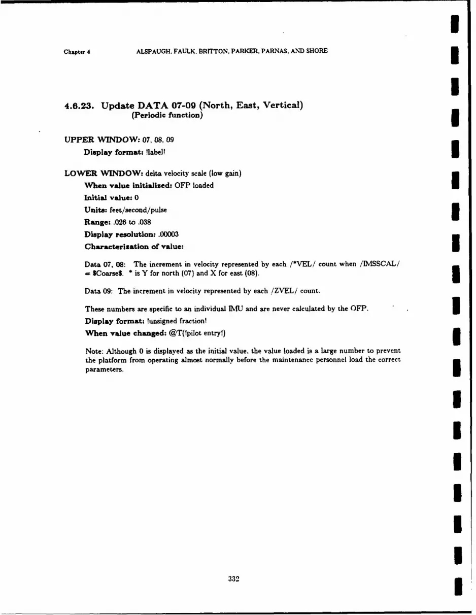
! I
Chapter 4 ALSPAUGH. FAULK. BRrrTON. PARKER. PARNAS, AND SHORE
I4.6.23. Update DATA 07-09 (North, East, Vertical)
(Periodic function)
UPPER WINDOW: 07,08, 09
Display format: !label! ILOWER WINDOW: delta velocity scale (low gain)
When value initialized: OFP loaded
Initial value: 0
Units: feet/second/pulse 3Range: .026 to .038
Display resolution: .00003
Characterization of value:
Data 07, 08: The increment in velocity represented by each /*VEL/ count when /IMSSCAL/= $Coarse. * is Y for north (07) and X for east (08). 3Data 09: The increment in velocity represented by each /ZVEL/ count.
These numbers are specific to an individual IMU and are never calculated by the OFP. 3Display format: !unsigned fraction!
When value changed: @T(!pilot entry!)
Note: Although 0 is displayed as the initial value, the value loaded is a large number to preventthe platform from operating almost normally before the maintenance personnel load the correct
parameters.I
3IIIII
332 3

NRL REPORT g1, Panel Functions
4.6.24. Update DATA 10-11 (north, east)(Periodic function)
UPPER WINDOW: 10, 11
Display format: !label!
LOWER WINDOW: delta velocity scale (high gain)
When value initialized: OFP 1. aded
Initial value: 0
Units: feet/second/pulse
Range: .000-6 to .00038
Display resolution: .000001
Characterization of value: The increment in velocity represented by each /*VELi countwhen /IMSSCAL/ = $Fine$. * is Y for north (10) and X for east (11). This value is specific toan individual IMU and is never calculated by the OFP.
Display format: !unsigned fraction!
When value changed: @T(!pilot entry!)
Note: Although 0 is displayed as the initial value, the value loaded is a large number to preventthe platform from operating almost normally before the maintenance personnel load the correctparameters.
333
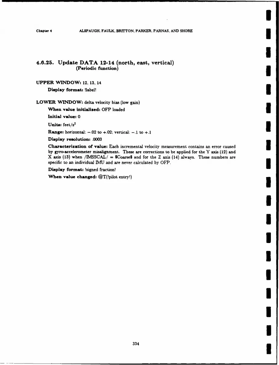
Chapter 4 ALSPAUGH. FAULK. BRITTON, PARKER. PARNAS, AND SHORE
I4.6.25. Update DATA 12-14 (north, east, vertical)
(Periodic function)
UPPER WINDOW: 12,13,14
Display format: !label!
LOWER WINDOW: delta velocity bias (low gain)
When value initialised: OFP loaded IInitial value: 0
Units: feet/s2 3Range: horizontal: -. 02 to +.02; vertical: -. 1 to +.J
Display resolution: .0003Characterization of value: Each incremental velocity measurement contains an error caused Iby gyro-accelerometer misalignment. These are corrections to be applied for the Y axis (12) andX axis (13) when /IMSSCAL/ = Coarse$ and for the Z axis (14) always. These numbers arespecific to an individual IMU and are never calculated by OFP.
Display format: !signed fraction!
When value changed: @T(!pilot entry!)
IIIIIIII
334 U

Nn REPORT 9194 Panel Functions
4.6.26. Update DATA 15-16 (north, east)(Periodic function)
UPPER WINDOW: 15,16
Display format: !label!
LOWER WINDOW: delta velocity bias (high gain)
When value initialized: OFP loaded
Initial value: 0
Units: feet/s 2
Range: -. 01 to +.01
Display resolution: .0003
Characterization of value: Each incremental velocity measurement contains an error causedby gyro-accelerometer misalignment. These are corrections to be applied for the Y axis (15) andX axis (16) when /IMSSCAL! f SFine$. These numbers are specific to an individual IMU andnever calculated by the OFP.
Display format: !signed fraction!
When value changed: @T(!pilot entry!)
335

3Chapter 4 ALSPAUGH, FAULK. BRTON. PARKER. PARNAS, AND SHORE
I4.6.27. Update DATA 17-18 (area A, area B)
(Periodic function) 3UPPER WINDOW: 17,18
Display format: !Iabel!
LOWER WINDOW: map control longitude
When value initialised: OFP loadedInitial value: 0
Units: deg/min/s
Range: +180
Display resolution: I second
Characterization of value: Longitude of center line on map, area A (17) and area B (18).These numbers are specific to an individual filmstrip and are never calculated by the OFP.
Display format: !long!
When value changed: @T(!pilot entry!)
IIIII
III
336

NRL REPORT 9194 Panel Functions
4.6.28. Update DATA 19-20 (area A, area B)(Periodic function)
UPPER WINDOW: 19, 20
Display format: !label!
LOWER 'WINDOW: map control latitude
When value initialized; OFP loaded
Initial value: 0
Units: integer counts
Range: -90 to +90 (NS0 to S80 degrees)
Display resolution: 10 seconds
Characterization of value: Latitude of southernmost part of map in area A (19) and area B
(20). The indicated valve entered is in integer counts. To get a standard value in degrees,minutes and seconds, use the following equation:
standard value = indicated value X (53' 20")
These values are specific to an individual filmstrip and are never calculated by the OFP.
Display format: !signed integer!
When value changed: @T(!pilot entry!)
3IIIIIII
3.37I

I
Chapter 4 ALSPAUGH, FAULK, BRITTON. PARKER, PARNAS, AND SHORE
I4.6.29. Update DATA 21-22 (area A, area B)
(Periodic function)
UPPER WINDOW: 21,22
Display format: !label!
LOWER WINDOW: orientation
When value initialized: OFP loaded IInitial value: !positive!
Characterization of value: Orientation of the long axis of filmstrip of area A (21) and area B(22).
!positive!: !NS!: map oriented north-south!negative!: !EW!: map oriented east-west
Display format: !sign!
When value changed: @T(!pilot entry!)
IUI
IIUIII
338

INRL REPORT 9194 Panel Functions
i4.6.30. Update DATA 23
(Periodic function)
UPPER WINDOW: 23
Display format: !label!
LOWER WINDOW: land or sea based
When value initialised: OFP loaded
Initial value: !positive!Characterization of value: Whether the A/C is operating on land or at sea on a carrier. Adisplay or !pilot entry! of !positive! (!negative!) indicates !Land! (!Sea!).
Display format: !sign!
When value changed- @T(!pilot entry!)
339

IChapter 4 ALSPAUGH, FAULK, BRITTON, PARKER, PARNAS. AND SHORE 3
i4.6.31. Update DATA 24
(Periodic function)
UPPER WINDOW: 24
Display format: !label!
LOWER WINDOW: vertical ranging priority
When value initialised: @T(!power up!) WHEN (/IMSREDY/= $No$ AND /ACAIRB/ = I$No$) OR @T(!present position entered!)
Initial value: !negative!
Display format: !sign!
Characterization of value: Which sensor is used for ranging when the FLR not available. Adisplay or !pilot entry! of !positive! (!negative!) indicates radar (baro) altimeter has priority over
baro (radar) altimeter.IWhen value changed: @T(!pilot entry!)
IIIUI
IIIII
340I
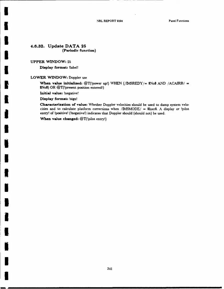
NRL REPORT 9194 Panel Functions
4.6.32. Update DATA 25(Periodic function)
UPPER WINDOW: 25
Display format: !label!
LOWER WINDOW: Doppler use
When value initialised: @T(!power up!) \VHEN (/IMSREDY,/= $No$ AND /ACAIRB/ fSNo$) OR @T(!present position entered!)
Initial value: !negative!
Display format: !sign!
Characterization of value: Whether Doppler velocities should be used to damp system velo-cities and to calculate platform corrections when /INIvSMODE/ = $InerS. A display or !pilot*entry! of !positive! (!negative!) indicates that Doppler should (should not) be used.
When value changed: @T(!pilot entry!)
3UII
IIII
I341I

Chapter 4 ALSPAUGH. FAULK, BRrTTON. PARKER, PARNAS, AND SHORE3
4.6.33. Update DATA 26(Periodic function)3
UPPER WINDOW: 26
Display format: !label!I
LOWVER WINDOW: ADC equation
When value initialized: OFP loadedIInitial value: !negative!
Display format: !sign!3Characterization of value: Which equations should be used for true airspeed calculations.
!positive!: !L-probe! - L-probe equations used.!negative!: !Non L-probe! - non L-probe equations used
When value changed: @T(!pilot entry!)
342

INRL REPORT g194 Panel Functions
i4.6.34. Update DATA 70a (Periodic function)
Characterization of value: Data 70 shows the state of the following input discretes. in thepattern shown below the list. Given after each input data item is the value that causes thecorresponding panel window to show a 1$: the other value causes the window to show a SO$. A'-'in a diagram means the window is always $Blank$.
I i'STAIRDY/ $Yes$2 'STA2RDY/ SYes$3 ,STA3RDY/ SYes$4 /STA6RDY/ SYes$5 /STA7RDY/ SYes$6 !STA8RDY/ SYes$7 'GUNSSEL/ SYes$8 /RE/ SOnS9 /MULTRACK/ SYes$£ 10 ,TD/ SOnS
1 2 3 4 5 6 UPPER WINDOW1 7 8 9 10 - - LOWER WINDOW
Display format: !no lights!
When value changed: Whenever one of the represented conditions changes value
3I
I343I

IChapter 4 ALSPAUGH. FAULK, BRITTON, PARKER, PARNAS. AND SHORE 3
I4.6.35. Update DATA 71
(Periodic function)
Characterisation of value: Data 71 shows the state of the following input discretes, in thepattern shown below the list. Given after the input data item is the value that causes thecorresponding panel window to show a $I$; the other value causes the window to show a $0S. A I'-' in a diagram means the window is always $Blank$.
I /BMBDRAG / SHigh$ I2 /NFfSW/ SNATTS OR SNATTOFFS3 /MFSW/ SNATTOFF$ OR $BOCOFF$4 /MFSW/ $BOC$ OR SBOCOFF$ I5 I'MFSW/ $CCIP$
6 /MFSW / $TF$7 /PMSCAL/ $80$ I8 ./PMHOLD./ $Yes$9 /PMDCTR/ $Yes$
10 /PMNORUP/ SYes$11 /PMSLAND/ SYes$ I12 /HUDREL/ $Yes$
1 2 3 4 5 6 UPPER WLNDOW I7 8 9 10 11 12 - LOWER WINTDOW
Display format: !no lights! IWhen value changed: Whenever one of the represented conditions changes value
II
III
3-44 1

NRL REPORT 9194 Panel Functions
4.6.38. Update DATA 72(Periodic function)
Characterization of value: Data 72 shows the state of the following input discretes, in thepattern shown below the list. Given after each input data item is the value that causes thecorresponding panel window to show $1$; other values cause the window to show a SMS. A ina diagram means the window is always $Blank$.
I /IMSREL / $Yes$2 ,'ACAIRB/ $Yes$3 MvA/ $On$4 /'MSMODE/ $Gndal$5 'IMSMODE/ $Norm$6 'IMSMODE/ $Iner$
7 /IMSMODE/ $Grid$8 !IMSMODE/ $MagslS9 /IMSREDY/ $No$
10 *'ISAUTOC/ SMnS1 I ADCFAIL / $Yes$12 ARPPAIRS/ $Yes$
1 2 3 4 5 6 UPPER WINDOW7 8 9 10 11 12 - LOWER WINDOW
Display format: !no lights!
When value changed: Whenever one of the represented conditions changes value
345
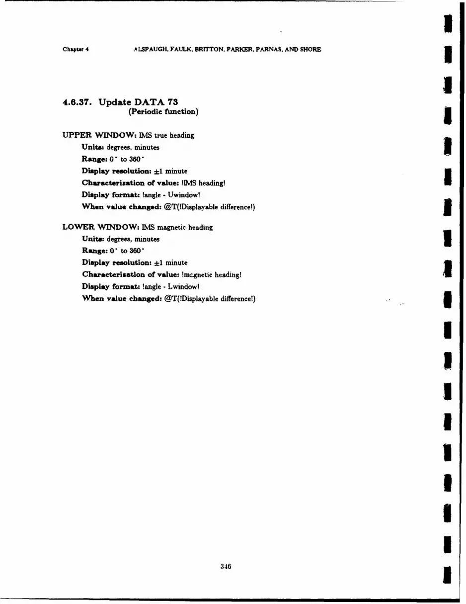
Chapter 4 ALSPAUGH, FAULK. BRrrTON. PARKER. PARNAS. AND SHORE1
4.6.37. Update DATA 73(Periodic function)g
UPPER WINDOW: PAS true heading
Units: degrees, minutes3
Range: 0 *to360*
Display resolution: ±1 minute
Characterization of value: IM& heading!I
Display format: !angle - Uwindow!
When value changed: @T(!Displayable difference!)3
LOWER WINDOW: IMS magnetic heading
Units: degrees, minutesIRange: 0 *to360*
Display resolution: ±1 minute
Characterization of value: !mr~gnetic heading!I
Display format: !angle - Lwindow!
When value changed: @T(!Displayable difference!)
346
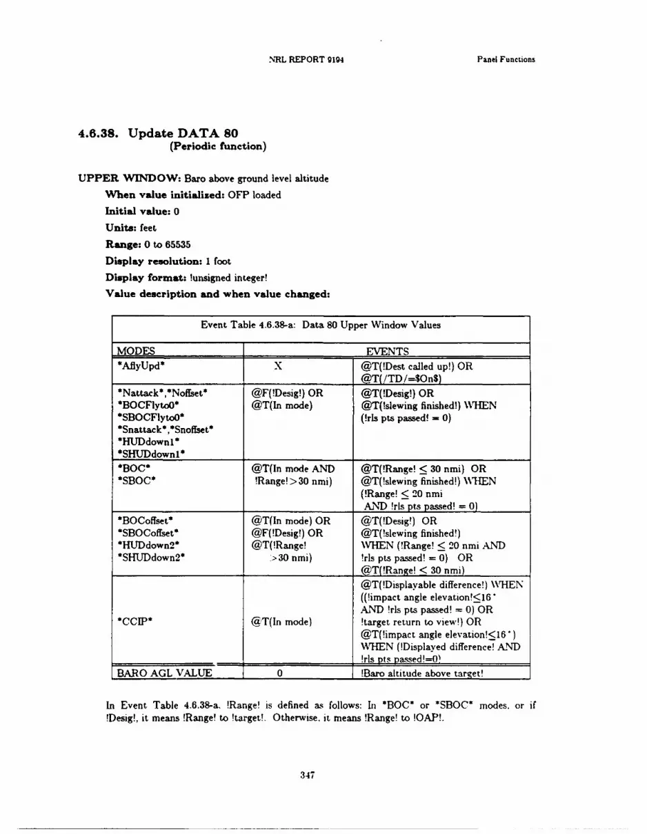
NRL REPORT 9194 Panel Functions
4.6.38. Update DATA 80(Periodic function)
UPPER WIDOW: Baro above ground level altitude
When value initialized: OFP loaded
Initial value: 0
Units: feet
Range: 0 to 65535
Display resolution: 1 foot
Display format: !unsigned integer!
Value description and when value changed:
Event Table 4.6.38-a: Data 80 Upper Window Values
MODES _____ __ EVENTS*AfiyUpd* x @T(!Dest called up!) OR
______________ ___________ @T( /TD /=$On$)*Nattak**Noffset* @F(!Desig!) OR @T(!Desig!) OR*BOCFlyto()* @T(In mode) @T(!slewing finished!) WHTEN*SBOCFlytoO* (!rls pts passed! = 0)*Snattack* ,Snoffset**HmDdownI**SHTJDdownI* _________
*BC*@T(In mode AND @T(!Range! 30 nmi) OR*SBOC* !Range!> >30 nmi) @T(!slewing finished!) N\11EN
(!Range! < 20 nmi__________________ _______________ AND_!rls pts passed!_=_0)
*BOCoffset* @T(In mode) OR @T(!Desig!) OR*SBOCoffset* @F(!Desig!) OR @T(!slewing finished!)*HUDdown2* @T(!Range! WVHEN (!Range! < 20 nmi AND* .HLJDdown2* >30 nmi) !rls pts passed! = 0) OR
__________________ _______________@T(!Range! < 30 nmi)
@T(!Displayable difference!) WHEN((!impact angle elevation!<16AND !rls pts passed! = 0) OR
*CC1JP* @dT(In mode) !target return to view!) OR@T(!impact angle elevation!<IV')WHEN (!Displayed difference! AIND
_________________ __________________!rls rpts yassed!=OW
BARO AGL VALUE 0 !Baro altitude above target! :
In Event Table 4.6.38-a. !Range! is defined a- follows: In *130G* or *SBOC* modes, or if!Desig!, it means !Range! to !target!. Otherwise. it means !Range! to !OA.P!.
347
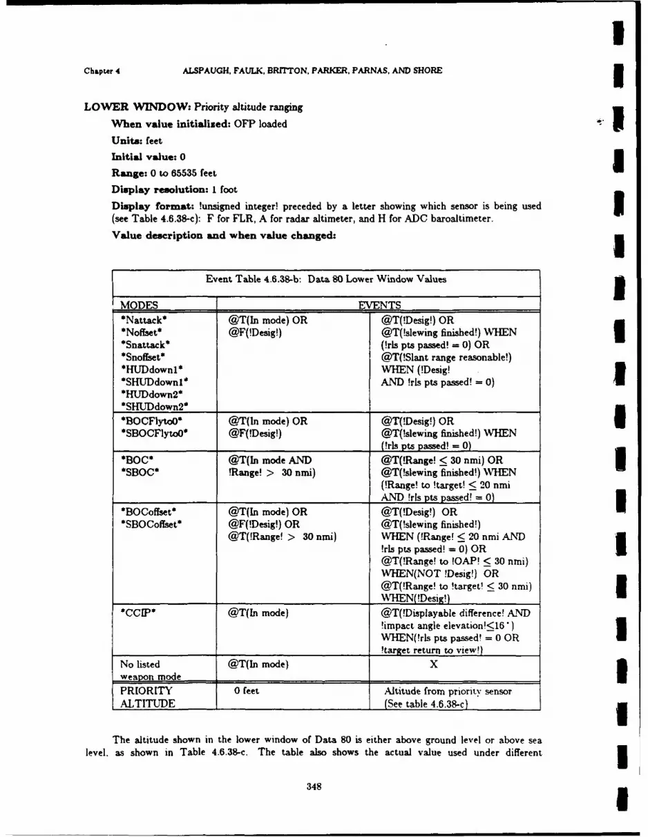
Chapta 4 ALSPAUGH, FAULK, BRITTON, PARKER, PARNAS, AND SHORE
LOWER WIN4DOW: Priority altitude ranging
When value initialized: OFP loadedUnits: feetInitial value: 0
Range: 0 to 65535 feetDisplay resolution: I foot
Display format: !unsigned integer! preceded by a letter showing which sensor is being used(see Table 4.6.38-c): F for FLR, A for radar altimeter, and H for ADC baroaltimeter.
Value description and when value changed:
Event Table 4.6.38-b: Data 80 Lower Window Values3
MODES EVENTS*Nattack* @T(In mode) OR @T(!Desig!) OR
*Snaf~tt* @F(!Desig!) @T(!slewing finished!) WHENI*Snatack*(!rls pts passd! = 0) OR
*Snoffset* @T(!Slant range reasonable!)*HUDdownl* WHEN (!Desig!*SHUTDdown1* AND !rls pts passed! 0)I
SHUDdown2* _____________ ______________
*BOCFlytoO' @T(In mode) OR @T(!Desig!) OR*SBOOFlytoO* @F(!Desig!) @T(!slewing finished!) WHEN
____________________ (!rls pts passed! = 0)
*O*@T(In mode AND @T(!Range! < 30 nmi) ORU*SBOC* !Range! > 30 nmi) @T(!slewing finished!) WHEN
(!Range! to !target! < 20 nmi______________AND !rls pts passed! = 0)
*BOCoffset* @T(In mode) OR @T(!Desig!) ORI*SBOCoffset* @F(!Desig!) OR @T(!slewing finished!)
@T(!Range! > 30 nmi) WHEN (!Range! < 20 nmi AND!rls pts passed! = 0) OR@T(!Range! to !OAP! < 30 nmi)WIHEN(NOT !Desig!) OR@T(!Range! to !target! < 30 nmi)
__________________ WHN( !Desig!)
*CI*@T(In mode) @T(!Displayable difference! AND!impact angle elevation!<16*)WHEN(!rls pts passed! = 0 OR
________________ ________________________ !target return to view!)
No listed @T(In mode) Xweap~on mode ______________ _______________
PRIORITY 0 feet Altitude from priority sensorALTITUDE ______ ____ (See table 4.6.38-c)I
The altitude shown in the lower window of Data 80 is either above ground level or above sealevel, as shown in Table 4.6.38-c. The table also shows the actual value used under different
348
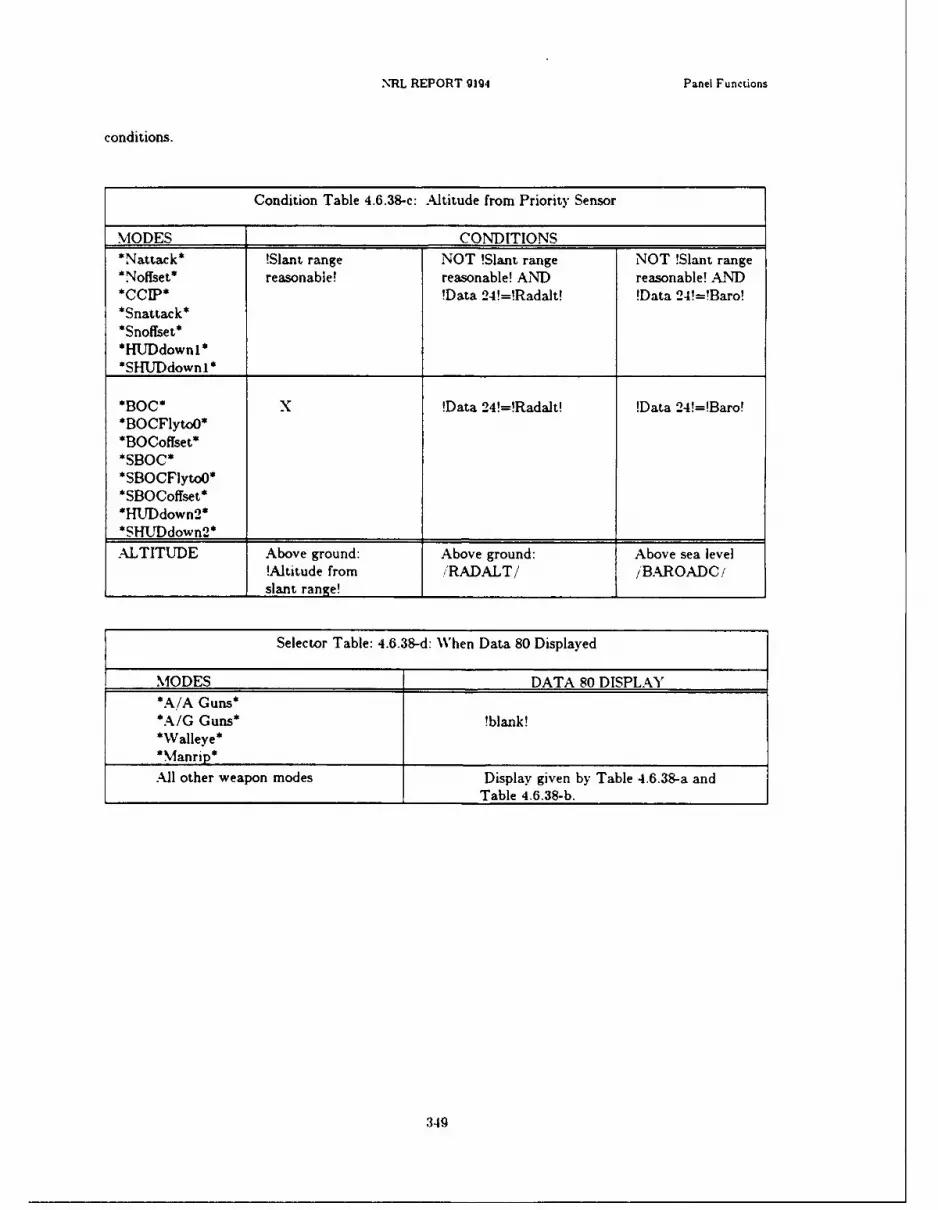
NRL REPORT 9194 Panel Functions
conditions.
Condition Table 4.6.38-c: Altitude from Prioritv Sensor
MODES CONDITIONS*Nattack* !Slant range NOT !Slant range NOT !Slant range*Noffset* reasonable! reasonable! AND reasonable! AND
*CI*!Data 24!=!Radalt! !Data 24!=!Baro!*Snattack** Snoffset**HUTDdownl**SL1* TDdownl* ___________
*BOC* x !Data 24W=Radalt! !Data 24!=Baro!*BOCFlytoO*
*BOCoffset**SBOC**SBOCFlytoO**SBOCoffset**HlJDdown 2 **SHUTDdown2* ___________
ALTITUDE Above ground: Above ground: Above sea level!Altitude from 'RADALT// ,BARIOADC!
_________________ slant range! ___________
Selector Table: 4.6.38-d: W~hen Data 80 Displayed
MODES DATA 80 DISPLAY*A /A Guns**A/G Guns* Mbank!'Walleye'*Man rip' ________________________
All other weapon modes Display given by Table 4.6.38-a and_______________________________Table 4.6.38-b.
349
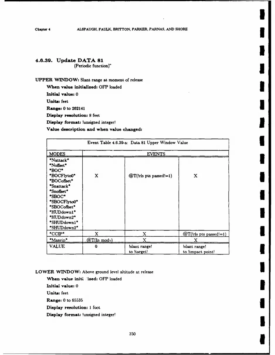
Chapter 4 ALSPAUGH, FAULK, BRITTON, PARKER, PARNAS, AND SHORE5
4.6.30. Update DATA 81(Periodic function)"I
UPPER WVINDOW: Slant range at moment of release
When value initialized: OFP loaded3
Initial value: 0
Unit.: feet
Range: 0 to 262141Display resolution: 8 feetDisplay format: !unsigned integer!
Value description and when value changed:
Event Table 4.6.39-a: Data 81 Upper Window Value3
MODES EVENTS _______
*Nattack*j*Noffset**BOC**BOCFlytoO* X @T(!rls pts passd!=1) X3*BOCoffset**Snattack*
SBOCFlytoO**SBOCoffset**HUDdown1*U*HUrDdown2**SHlJDdownl **SHUDdown2* ____________________ __________
*CCIP* X x @T(!rls pts passed!=1)*Manrip* @T(In mod'1 X X
VALUE 0 !slant range! !slant range!
__________________I to !target! to !imnpact point!
LOWER WINOW: Above ground level altitude at releaseI
When value nit! 'ized: OFP loaded
Initial value: 03
Units: feet
Range: 0 to 65535
Display resolution: I footDisplay format: !unsigned integer!
350

INRL REPORT 9194 Panel Functions
Chaaterization of value: Above ground level altitude, from highest priority available sen-sor:
Condition Table 4.6.39-b: Data 81 Lower WVindow Value
IMODES CONDITIONS*Nattak**Noffiet* !Slant range (NOT !Slant range (NOT !Slant rangeI*CCff)* reasonable! reasonable!) AND reasonable!) AXND*Snattack* !Data 24!=!Radalt! !Data 24!=!Baro!*Snoffset**HUDdownI **SHUDdownl _ _ __ __ __ _ _
* BOC **BOCFlyto3*I *BOCoffset**Manrip* x !Data 24!=!Radalt! !Data 24!=!Baro!*SBOC**SBOCFlytoJ**SBOCoffset**HUDdown2*3 SHU~~~down2* _________ ___________
ALTITUDE !Altitude from /RADALT/ !Baro altitude______________ slant range! I__________F____ above target!
U When value changed: @T(!rls pis passed! = 1) WHEN(*Nattack*, *Noffset*, *BOC*,*BOCFytoo*l *BOCoffset*. *CCIP*, *Manrip*, *Snattack*, *Snoffset*, *SBOC*.*SBOCFlytoO*, *SBOCoffset* *HUTDdownl*, *HUTDdown2*, *SHUDdownl*, OR *SHUD-
down2*)
35
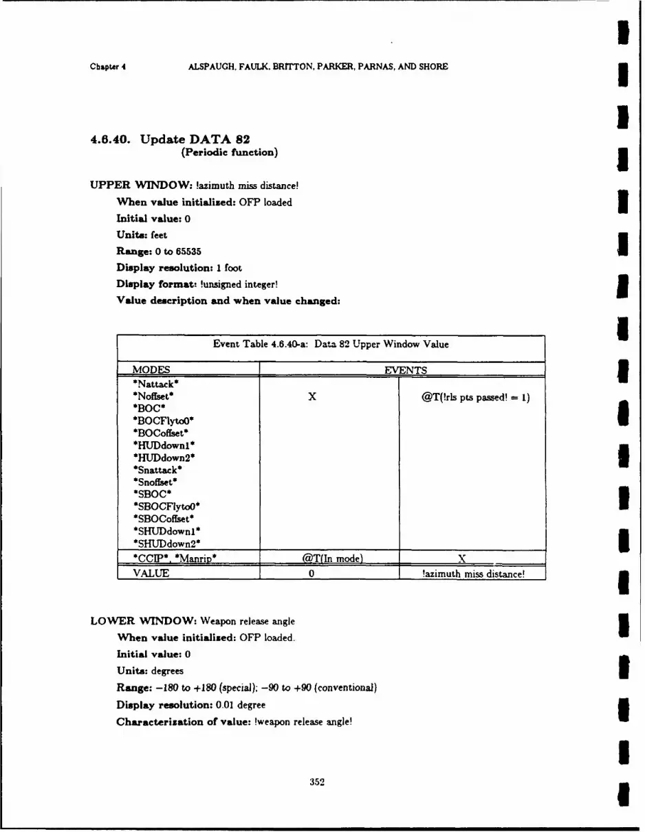
IChapter 4 ALSPAUGH, FAULK. BRITTON, PARKER, PARNAS, AND SHORE
I4.6.40. Update DATA 82
(Periodic function) jUPPER WINDOW: !azimuth miss distance!
When value initialized: OFP loaded IInitial value: 0
Units: feet
Range: 0 to 65535Display resolution: I foot
Display format. !unsigned integer!
Value description and when value changed:
Event Table 4.6.40-a: Data 82 Upper Window Value l
MODES EVENTS 1*Nattack*
*Noffset* x @T(!rls pts passed! =1)*BOC**BOCFlytoO*
*BOCoffset**HUDdownl* 3*HUDdown2*
*Snattack**Snoffset**SBOC*
*SBOCFIytoO**SBOCoffset**SHUDdownl**SHUDdown 2 **CCIP* *Manrip* qT(In mode) X
VALUE 0 !azimuth miss distance!
LOWER WINDOW: Weapon release angle 3When value initialised: OFP loaded.
Initial value: 0
Units: degrees 3Range: -180 to +180 (special); -90 to +90 (conventional)
Display resolution: 0.01 degree
Characterization of value: !weapon release angle!
352 1

.NRL REPORT 9194 Panel Functions
Display format: !decimal paint!
When value changed:*Nattack*
j *BOC* @T(!rls pts passed! =1
*BOCFlyto)*SBOCoffset**CoIP**Manrip*
*HUDdown2*3 *Snattack**Snoff*set** SBO C*SBOCFlyt,4J**SBOCoflset**SHWJDdownI**SHUDdown2*
35
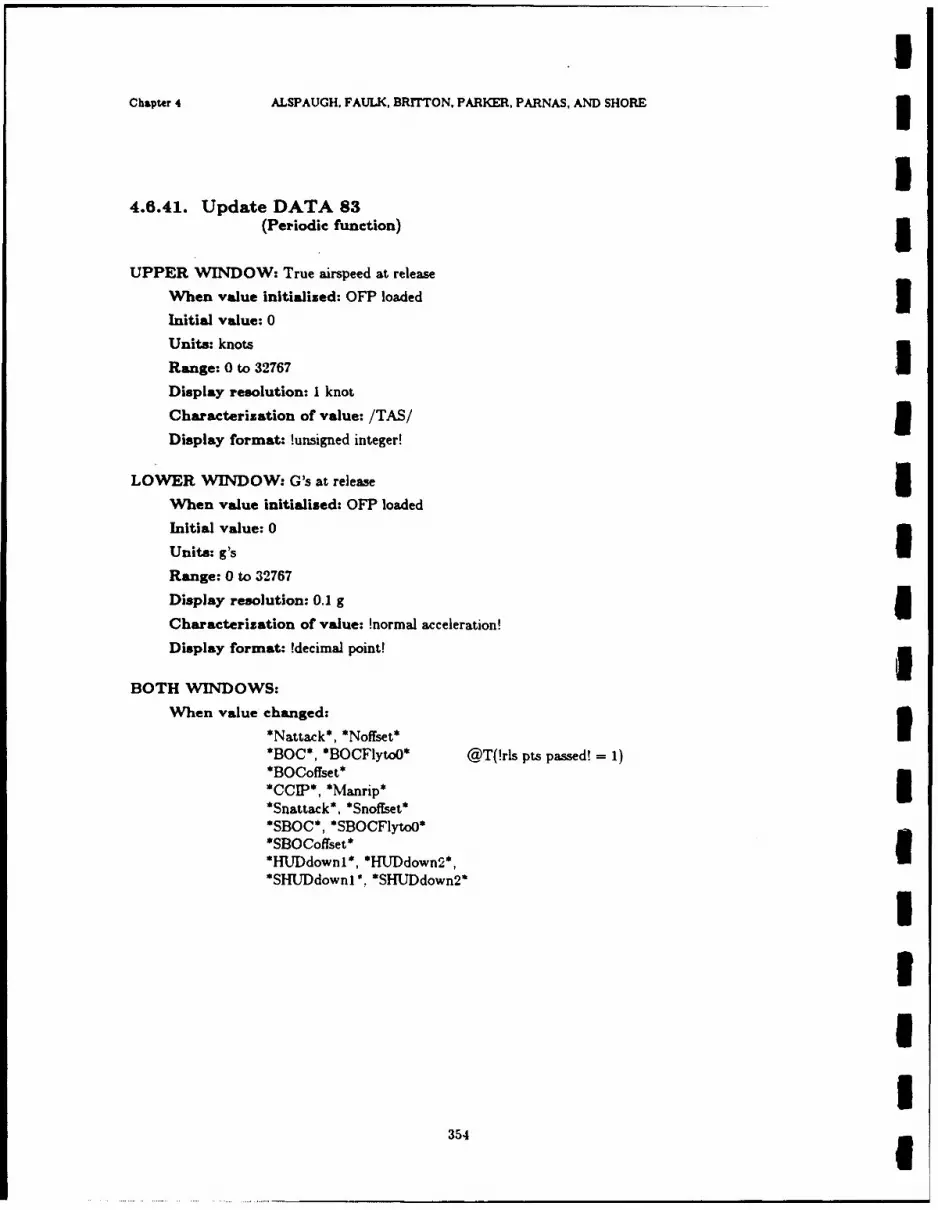
Chapter 4 ALSPAUGH, FAULK, BRfTTON, PARKER, PARNAS, AND SHORE3
4.6.41. Update DATA 83(Periodic function)5
UPPER WINDOW: True airspeed at release
When value initialized: OFP loaded3
Initial value: 0
Units: knots
Range: 0 to 32767IDisplay resolution: I knot
Characterization of value: /TAS/1Display format: !unsigned integer!
LOWER WINDOW: G's at release5When value initialised: OF? loaded
Initial value: 0
Unite: g'sIRange: 0 to 32767
Display resolution: 0.1 g
Characterization of value: !normal acceleration!
Display format: !decimal point!
BOTH WINqDOWS:
When value changed:*Nattack*, *Nofiset*
BOC, BOCFlytoO* @T(!rls pts passed! =1
*BOCoffset**CCIP*, *Manrip**Sflattack*, *Snoffset*I*SBOC*, *SBOCFlytoo**SBOCoffset**HUDdownI*, *HLDdown2*,
*SHU~downi* . SHU~down2*
3541

II NRL REPORT 9194 Panel Functions
I4.6.42. Update DATA 84I (Periodic function)
UPPER WINDOW: Weapon quantity
Range: 0 to 99
Display r :solution: 1
Characterization of value: /ARPQUANT/
Display format: !unsigned integer!
When value changed: @T(/ARPQUANT/ changed) WHEN(!rls pts passed!=O)
LOWER WINDOW: Weapon interval
Units: feet
Range: 10 to 990
Display resolution: 10 feet
Characterization of value: /ARPINT/
Display format: !unsigned integer!
When value changed: @T(/ARPINT/ changed) WHEN (!rls pts passed!--O)
I
35
I

IChapter 4 ALSPAUGH. FAULK, BRTTON. PARKER,. PARNAS. AND SHORE
I4.6.43. Update DATA 85
(Periodic function) IUPPER WINDOW: Blank
LOWER WINDOW: ASCU code
Range: 00-99 IDisplay resolution: 1
Characterization of value: ,\EAPTY,'
Display format: !unsigned integer!
When value changed: @T(/WEAPTT/ changed)
IIIIIIIIIII
356I

I NRL REPORT 9194 Panel Functions
I4.6.44. Update DATA 88I(Periodic function)
UPPER WINDOW: Alignment stage
When value initialised: power up
Initial value: blank
Characterization of value: two-letter code identifying the current alignment stage:
CL !CL stage!A !CA stage!
AL !'HL stage!FG !FG stage!HG !HG stage!ND !ND stage!ED !ED stage!FG !TS stage!
!FM stage!I!HS stage!
Display format: - - L L - -, where the -'s indicate blanks
When value changed: @T(!New stage!)
LOWER 'WINDOW: Elapsed time in alignment or navigation
When value initialized:
@T(!power up!) OR@T(!CL stage!) OR@T(//IMSNA//=$Ofl$) WHEN(In an alignment mode) OR@T(!FG stage!) WHEN (//LMSNA//=$Off$) OR@T(*OlUpdate*) OR@F(/IMSMODE/= $Gndal$) OR@T(!time elapsed! - 6 hr 45 min)
Initial value: 0
Units: hours, minutes, seconds
Range: 0 to 6 hr 45 min
Display resolution: I second
1Characterization of value: !time elapsed!
Display format: !angle - Lwindow!
When value changed: @T(!Displayable difference!)
I
357

Chapter 4 ALSPAUGH, FAULK BRITTON, PARKER, PARNAS. AND SHORE
4.6.45. Update DATA 80(Periodic function)3
UPPER WINDOW: Blank
LOWER WINDOW: time-to-go to reach destination1
Units: hours, minutes, seconds
Range: 0 to 6 hr 45 minIDisplay resolution: I second
Characterization of value: time-to-go before !Fly-to point! reached, assuming direct flight:
(!Range! to !Fly-to point!)/(!System horizontal velocity!)
If (time-to-go > 6 hr 45 min), zero is displayedU
Display format: !angle - Lwindow!
'When value changed: @T(!Displayable difference!)
358

NRL REPORT 9194 Panel Functions
4.6.46. Update DATA 90(Periodic function)
UPPER WINDOW: SINS latitude
When value initialized: OFP loaded
Initial value: 0
Units: degrees, minutes, seconds
Range: N 90 to S 90
Display resolution; I second
Display format: !lat!
LOWER WINDOW: SINS longitude
When value initialized: OFP loaded
Initial value: 0
Units: degrees, minutes, seconds
Range: E 180 to W 180
Display resolution: I second
Display format: !long!
BOTH WINDOWS:
Characterization of value: ship's coordinates received over SINS data link
When value changed: *Sautocal*, *SINSaln*: @T(!New SINS coordinates!)
359
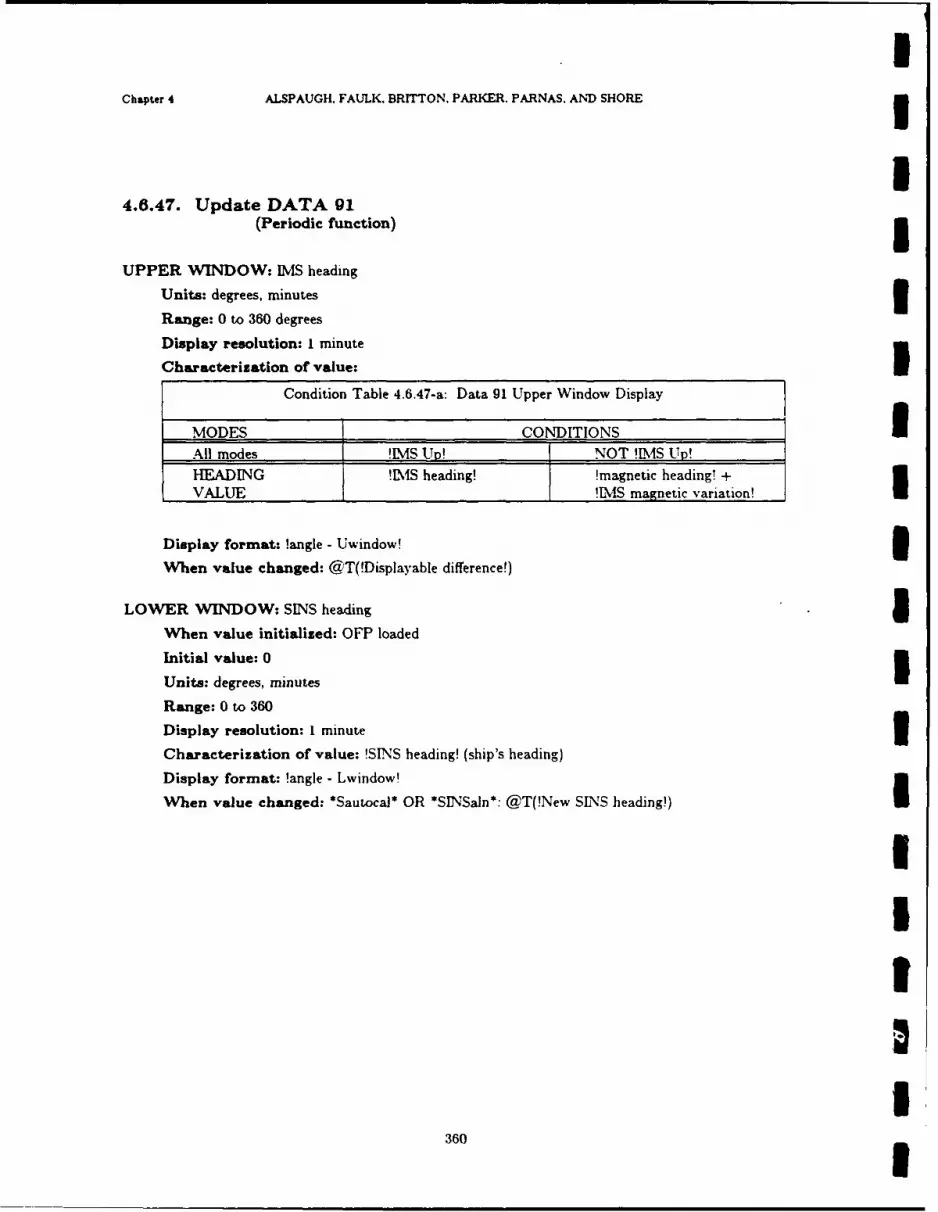
IChapter 4 ALSPAUGH. FAULK. BRITTON. PARKER. PARNAS. AND SHORE 3
I4.6.47. Update DATA 91
(Periodic function) 5UPPER WINDOW: IMS heading
Units: degrees, minutes 3Range: 0 to 360 degrees
Display resolution: 1 minute
Characterization of value:
Condition Table 4.6.47-a: Data 91 Upper Window Display
MODES CONDITIONS IAll modes !IMS U! NOT !MMvS Up!
HEADING !IMS heading! !magnetic heading! +VALUE IS magnetic variation!
Display format: !angle - Uwindow!
When value changed: @T(!Displayable difference!)
LOWER WINDOW: SINS heading 5When value initialized: OFP loaded
Initial value: 0
Units: degrees, minutes
Range: 0 to 360
Display resolution: I minute 3Characterization of value: !SINS heading! (ship's heading)
Display format: !angle - Lwindow!
When value changed: *Sautocal* OR *SINSaln*: @T(!New SINS heading!)
3II
I360
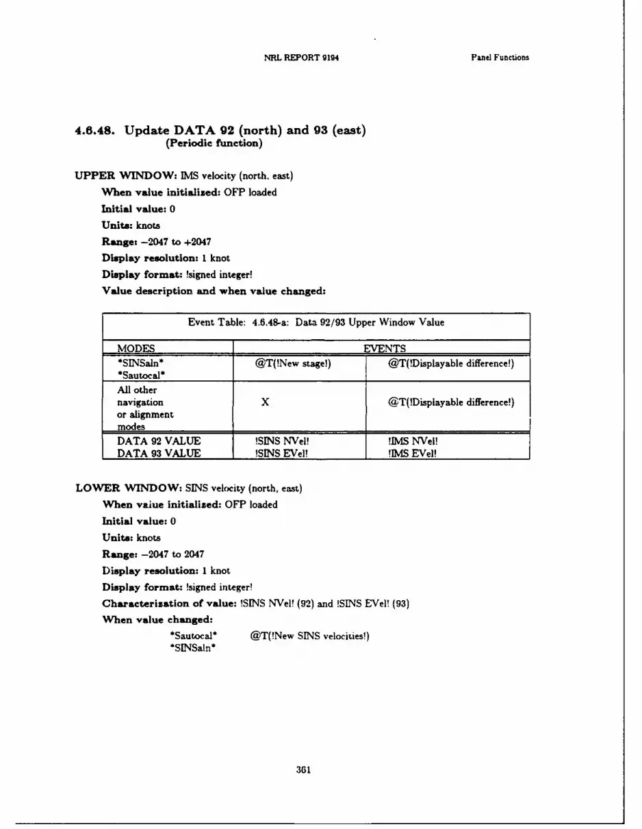
NRL REPORT 9194 Panel Functions
4.6.48. Update DATA 92 (north) and 93 (east)(Periodic function)
UPPER WINDOW: IMS velocity (north, east)
When value initialized: OFP loaded
Initial value: 0
Units: knots
Range: -2047 to +2047
Display resolution: 1 knot
Display format: !signed integer!
Value description and when value changed:
Event Table: 4.6.48-a: Data 92/93 Upper Window Value
MODES EVENTS*SINSan* @T(!New stage!) @T(!Displayable difference!)
*Sautocal*
All othernavigation X @T(!Displayable difference!)or alignmentmodes
DATA 92 VALUE !SINS NVeI! !IMS NVeI!DATA 93 VALUE !SINS EVeI! !IMS EVeI!
LOWER W;INDOW: SINS velocity (north, east)
When value initialized: OFP loaded
Initial value: 0
Units: knots
Range: -2047 to 2047
Display resolution: I knot
Display format: !signed integer!
Characterization of value: !SINS NVeI! (92) and !SINS EVeI! (93)
When value changed:*Sautocal* @T(!New SINS velocities!)
*SINSaln*
361

IChapter 4 ALSPAUGH, FAULK. BRITTON, PARKER. PARNAS. AND SHORE
I4.6.4g. Update DATA 94
(Periodic function) 5BOTH WINDOWS: SINS status
When value initialized: OFP loaded 3Initial value: all zeros
Units: discrete ICharacterization of value: During *Sautocal* and *SLNSaIn*. Data 94 shows the validity ofthe various data received over the SINS data link. The classified addendum explains how thevalidity of each datum is determined. The display is arranged in the pattern shown below; a$1 in the window indicates the datum is invalid while a $0$ indicates that it is valid. A '-' indi-cates that the window is always blank.
I !SINS heading!2 !SINS NVel!3 !SINS roll!4 !SINS EVeI!5 !SINS pitch!6 !SINS latitude!7 !SINS longitude!
2 - 3 - UPPER WINDOW4- 5 - 6 - 7 LOWER WINDOW
During all other modes, the non-blank windows above are all set to $1$. 3Display format: !no lights!
'When value changed: *Sautocal*. *SINSaln*: @T(one of the conditions changes) OR @F(In
Imode)
IIII
362
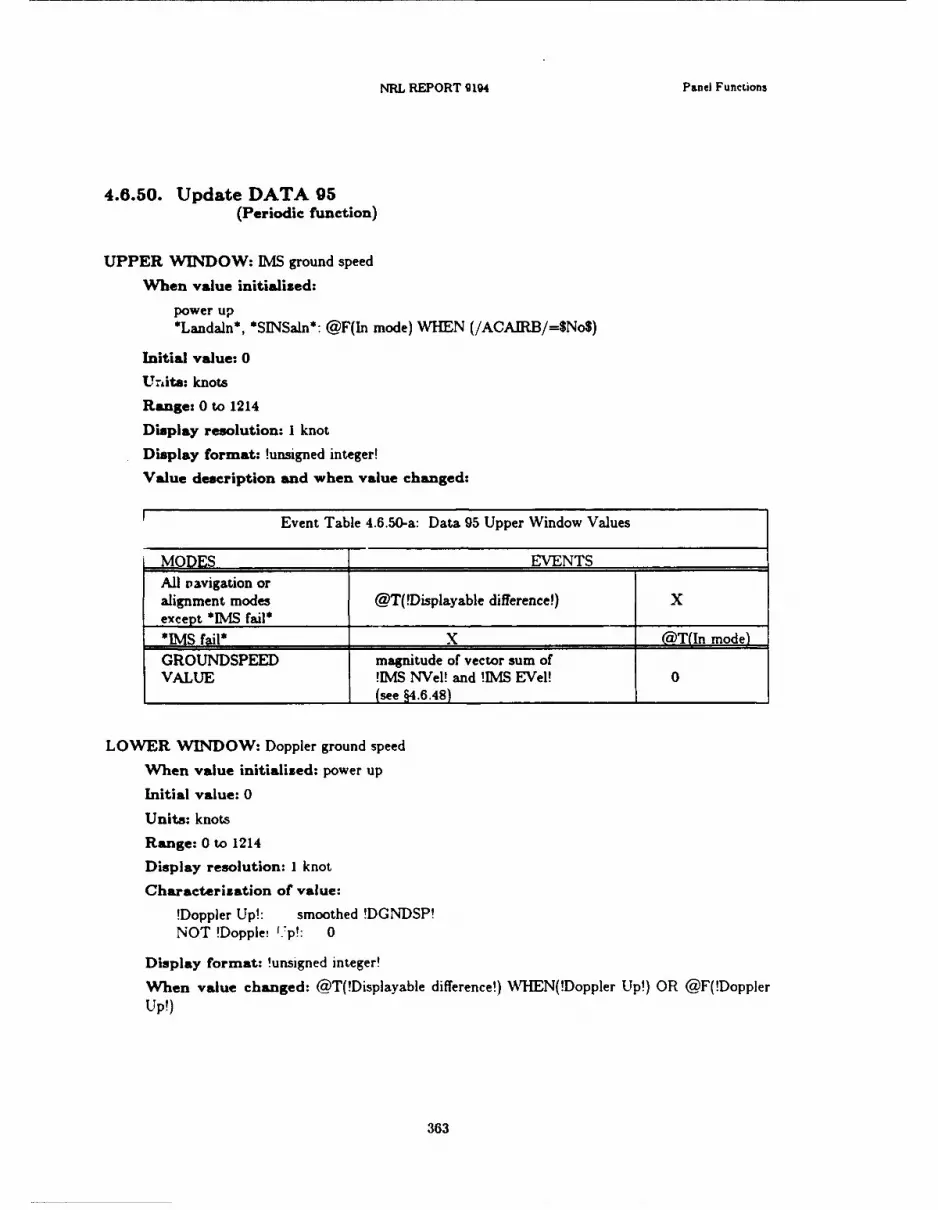
NRL REPORT 9194 Panel Function
4.6.50. Update DATA 95(Periodic function)
UPPER WINDOW: IMS ground speed
When value initialized:
power up*Landaln*, *SINSaln*: @F(In mode) WHEN (/ACAIRB/=$No$)
Initial value: 0
Unite: knots
Range: 0 to 1214
Display resolution: I knot
Display format: !unsigned integer!
Value description and when value changed:
Event Table 4.6.50-a: Data 95 Upper Window Values
MODES EVENTSAll Davigation oralignment modes @T(!Displayable difference!) Xexcept *EMS fail*
*RM4 fail* X @T(In mode)GROUNDSPEED magnitude of vector sum ofVALUE !IMS NVel! and !IMS EVel! 0
_______________________ (see §4.6.48)
LOWER 'WINDOW: Doppler ground speed
When value initialised: power up
Initial value: 0
Units: knots,
Range: 0 to 1214
Display resolution: I knot
Characterization of value:
!Doppler Up!: smoothed !DGNDSP!NOT !Dopple! f-p!: 0
Display format: !unsigned integer!
When value changed: @T(!Displayable difference!) WHI-EN(!Doppler Up!) OR @F(!DopplerUp!)
363

IChapter 4 ALSPAUGH. FAULK. BRITTON, PARKER, PARNAS. AND SHORE 3
I4.6.51. Undate DATA 96
(Periodic function) 5UPPER WINDOW: IMS drift angle
Value description and when value changed: 3Event Table 4.6.51-a: Data 96 Upper Window Values
MODES EVENTSAll navigation or @T(!Displayable difference!) X
alignment modesexcept [MS fail**IMS fail* X (ThT(In mode)
DRIFT ANGLE VALUE !IMS drift angle! 0 3LOWER WINDOW: Doppler drift angle 3
Characterization of value:
!Doppler Up! : /DRFTANG / averaged over 3 secondsNOT !Doppler Up!: 0
When value changed: @F(!Doppler Up!) OR @T(!Displayable difference!) \\rHEN(!DopplerUp!) 3
BOTH WINDOWS:
Units: degrees 3Range: +180 degrees
Display resolution: I degree
Display format: !signed integer!
3I
364
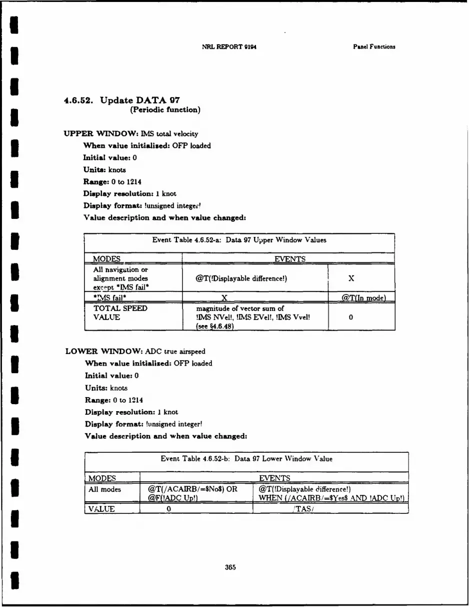
3NRL REPORT 9194 Panel Functions
4.6.52. Update DATA 973 (Periodic function)
UPPER WINDOW: IMS total velocity
When value initialized: OFP loaded
Initial value: 0Unite: knots3 Range: 0 to 1214
Display resolution: I knot
Display format: !unsigned intege0'
Value description and when value changed:
3Event Table 4.6.52-a: Data 97 Uper Window Values
-MODES EVENTS ______
All navigation or
alignment modes @T(!Displayable difference!) Xexce-pt *lMS fail*_____________________ __ _______
"NAS fail* X aT(In mode)ITOTAL SPEED magnitude of vector sum ofVALUE !D&S NVel!, !MS EVel!, !IMS Vvel! 03 ~ ~~~~(see §4.6.48)_________
LOWER WINDOW: ADC true airspeed3 When value initialized: OFP loaded
Initial value: 0
Units: knotsI Range: 0 to 1214Display resolution: I knot3 Display format: !unsigned integer!
Value description and when value changed:
EvnIal ..2b at 7LwrWno auU~OE EVENTS___ __
365
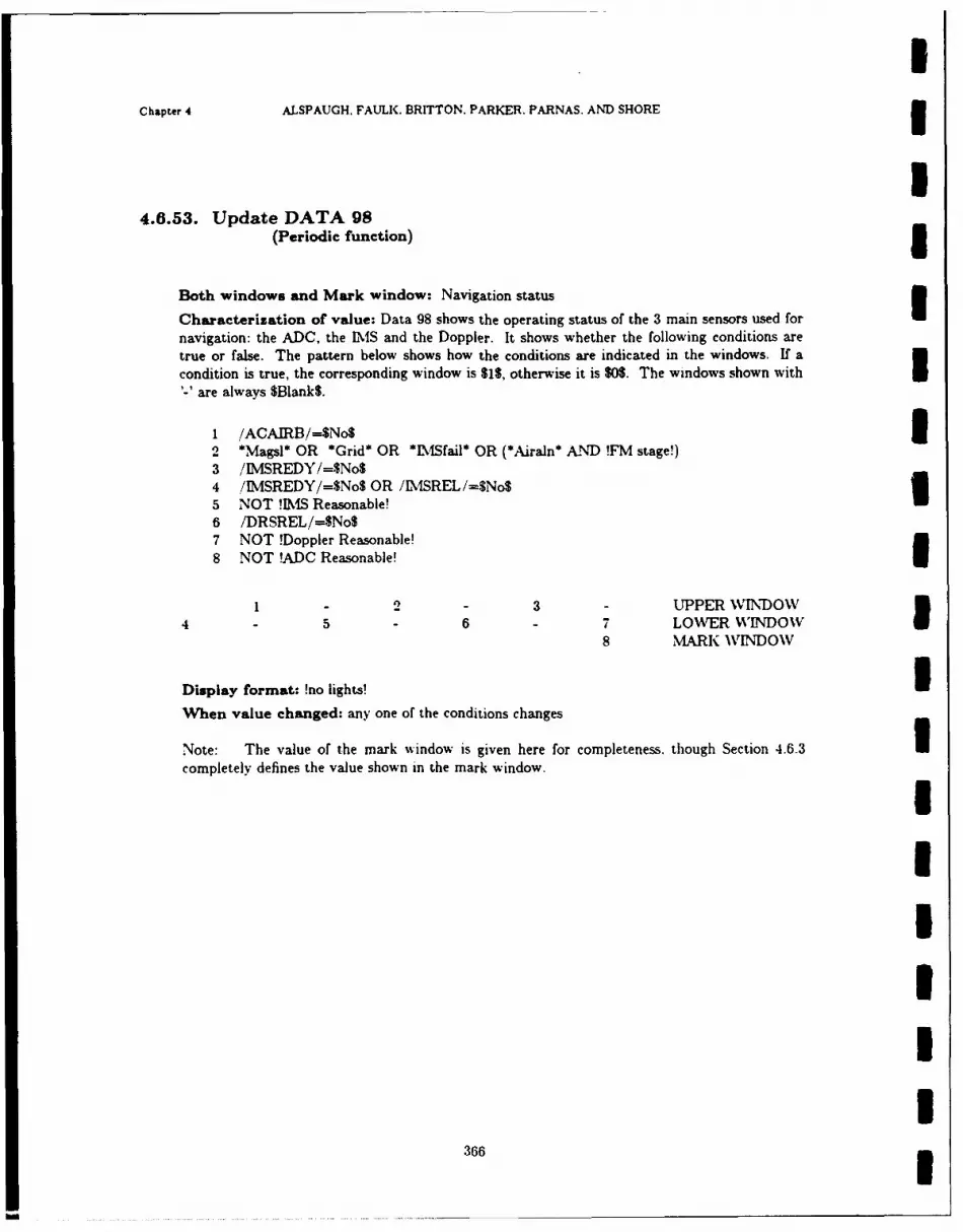
IChapter 4 ALSPAUGH, FAULK. BRITTON. PARKER. PARNAS. AND SHORE
I4.6.53. Update DATA 98
(Periodic function) 3Both windows and Mark window: Navigation status
Characterization of value: Data 98 shows the operating status of the 3 main sensors used for
navigation: the ADC, the 1IS and the Doppler. It shows whether the following conditions aretrue or false. The pattern below shows how the conditions are indicated in the windows. If acondition is true, the corresponding window is $15, otherwise it is $05. The windows shown with
''are always $Blank$.
1 /ACAIRB/--$No$2 *Magsl* OR *Grid* OR *LISfail* OR (*Airaln* AND !FM stage!)3 /IMSREDY/=$No$4 /IMSREDY/=$No$ OR /IMSREL/=SNo$5 NOT !IMlS Reasonable!6 /DRSREL/=$No$7 NOT !Doppler Reasonable!8 NOT !ADC Reasonable!
- - 3 - UPPER WINDOW7 LOWER WINDOW8 MARK WINDOW
Display format: !no lights! IWhen value changed: any one of the conditions changes
Note: The value of the mark window is given here for completeness. though Section 4.6.3 Icompletely defines the value shown in the mark window.
3III
I
366

INRL REPORT 914 Panel Functions
I4.6.54. Update DATA 99
(Periodic function)
BOTH WINDOWS: OFP Identification
When value initialized: OFP loaded
Characterization of value: character string identifying version of program: current string:Upper Window: OFP-A7Lower Window: NWC-2
Display format: !no lights!
IUIIIIIIIUII
367I
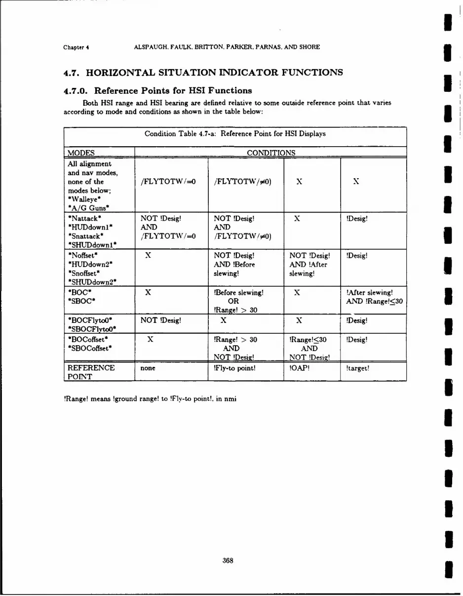
Chapter 4 ALSPAUGH, FAULK, BRITTON, PARKER. PARNAS. AND SHORE
4.7. HORIZONTAL SITUATION INDICATOR FUNCTIONS
4.7.0. Reference Points for HSI FunctionsIBoth HSI range and HSI bearing are defined relative to some outside reference point that varies
according to mode and conditions as shown in the table below:3
Condition Table 4.7-a: Reference Point for HSI Displays
MODES CONDITIONS
All alignmentand nay modes,
none of the /FLYTOTW/=O /FLYTOTW/00) X Xmodes below;*WValleye*
*A/G Guns* _______ ______
*Nattack* NOT !Desig! NOT !Desig! x !Desig!*HUDdownl* AND AND
*Snattack* /FLYTOTW /=O ./FLYTOTWV/00)*SHITDdown1* ________________
*Noffset* X NOT !Desig! NOT !Desig! !Desig!*HUDdown2* AND !Before AND !After*Snoffset* slewing! slewing!I*SHTJDdown2* _________________
*O*X !Before slewing! x !After slewing'
*SBOC* OR AND !Range!<30______________ ____ ___ ____ ___ !Range! > 30 _ _____ _______
*O lyo* NOT !Desig! x X !Desig!3
*BOCoffset* x !Range! > 30 !Range!<30 !Desig!*SBOCoffset* AND AND
NOT IDesi-! NOT !Desig!IREFERENCE none !fly-to point! !OAP! !target!POINT I______ I______
I____ I_____
!Range! means !ground range! to !Fly-to point!, in nmi
368

NRL REPORT 9194 HSI Functions
4.7.1. Update HSI Bearing Indicator(Periodic function)
Initiation and termination:3 Event Table 4.7-b: When //BRGDEST// Must Be Output
MODES EVENTS __ _____
NOT *Grtest* @T(In mode) X@F(In mode) OR @T(In mode) OR
*Grtest* @T(!AC1 Tstage!) OR @F(!AC2 Tstage!)
___________________ I (&T(!AC2 Tstajefl___________
ACTION Intation Termination__________________T Must be output __________
U Output data item(s) affected: //BRGDEST//
Oup td srpi n Condition Table 4.7-c: Update HSI Bearing Indicator
MODES CONDITIONS3No reference X Reference pointNOT *Grtest* point defined defined*Grtest* !AC1 Tsta e! !AC2 Tstaze! X3VALUE 0*225' !bearng angle!
3 Table 4.7-a shows when a reference point is defined.
36
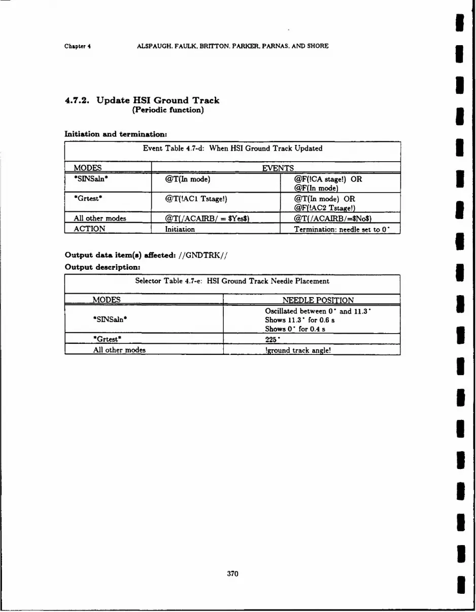
IChapter 4 ALSPAUGH. FAULK, BRITTON. PARKER. PARNAS. AND SHORE
I4.7.2. Update HSI Ground Track
(Periodic function) 3Initiation and termination:
Event Table 4.7-d: When HSI Ground Track Updated
MODES EVENTS*SINSaln* @T(In mode) @F(!CA stage!) OR 3
@F(In mode)
*Grtest* @T(!ACI Tstage!) @T(In mode) OR@F!AC2 Tstawe!) 3
All other modes @T(/ACAIRB/ = $Yes$) @T(/ACAIRB/=SNo$)ACTION Initiation Termination: needle set to 0
Output data item(s) affected: //GNDTRK//
Output description:
Selector Table 4.7-e: HSI Ground Track Needle Placement
MODES NEEDLE POSITIONOscillated between 0 and 11.3'
*SINSaln* Shows 11.3 for 0.6 s
Shows 0 for 0.4 s*Grtest* 225"All other modes !ground track angle!
3IiIIIU
370I

INRL REPORT 9194 HSI Functions
I4.7.3. Update Range Indicator (Map and HSI)
(Periodic function)
Initiation and termination: None. Always performed.
Output data item(s) affected: //RNGUNIT//, //RNGTEN//, ,//LFTDIG//
Output description:
The range indicator value is the geographical distance (ground range) from the A/C presenti position to the outside reference point defined in Table 4.7-a.
If no reference point is defined, the range value is 0.The range is calculated either by great circle or rhumb line (fiat earth) methods, depending on
the great circle ground range to the reference point:!Range! > 32 nmi - great circle
!Range! < 32 nmi - rhumb line
The values displayed are given either in nmi or in thousands of feet according to the tablebelow. The table also shows the setting of the //LFTDIG// indicator.
3Condition Table 4.7-f: HSI Range Units
MODES CONDITIONSAll modes except !Range! > !Range! < Xwhen overridden 1000 nmi 1000 nmiby modes belowi*NBShrike****NBnotShrike***Snattack**Snoffset* NOT !Desig! OR !Desig! AND
*SBOC* X ('Desig! AND !Range! < 10 nmi*SBOCFlyto0* !Range! > 10 nmi)*SBOCoffset*
*SHUDdownl **SHUDdown2**Grtest* X Always X
RANGE UNITS: nmi nmi 1000 ftACTION: //LFTDIG/./:fi$One$ 1/!LFTDIG / /:=$Blank$ //LFTDIG / / :=$One$
III
371U

Chapter 4 ALSPAUGH, FAULK, BRITTON. PARKER. PARNAS. AND SHORE
CondiLion Table 4.7-g: Range Indicator Value
MODES CONDITIONS
All modesexcept *Grtest* X X Always
*Grtest* !AC1 Tstage! !AC2 Tstage! xVALUE 555 553 !limited range!
Note: The range indicator value must be set to 555 actually in !DC Tstage! to allow the servosto settle in time for 'AC1 Tstage!. 3
IIIIIIIII1II
I372
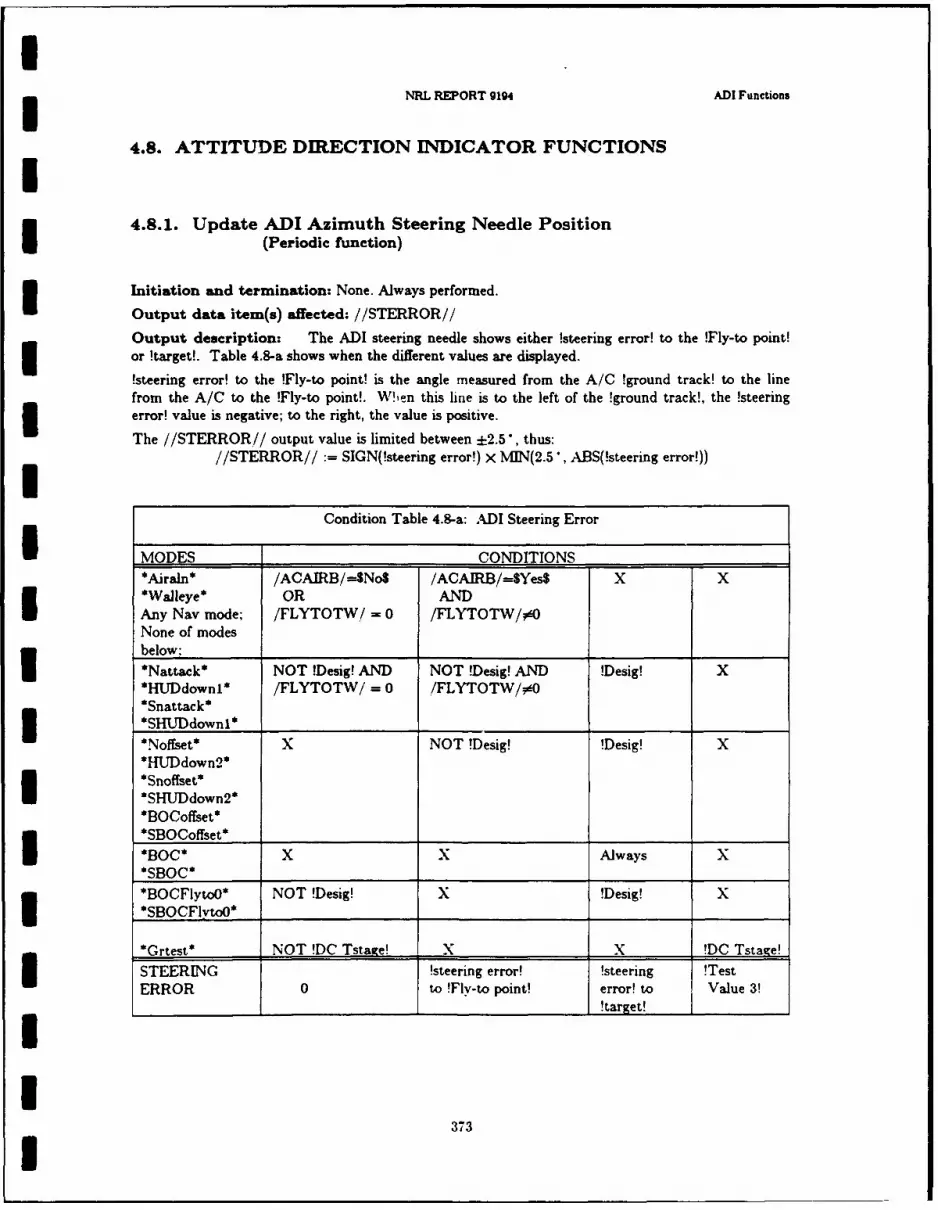
NRL REPORT 9194 ADI Functons
4.8. ATTITUDE DIRECTION INDICATOR FUNCTIONS
4.8.1. Update ADI Azimuth Steering Needle PositionI (Periodic function)
Initiation ad termination: None. Always performed.I Output data item(s) affected: //STERROR//
Output description: The ADI steering needle shows either !steering error! to the !Fly-to point!or !target!. Table 4.8-a shows when the different values are displayed.
!steering error! to the !Fly-to point! is the angle measured from the A/C !ground track! to the linefrom the A/C to the !Fly-to point!. Wlen this line is to the left of the !ground track!, the !steeringerror! value is negative; to the right, the value is positive.
The //STERROR// output value is limited between ±2.5*, thus://STERROR// :- SIGN(!steering error!) x MIN(2.5*, ABS(!steering error!))
Condition Table 4.8-a: ADI Steering Error
I MODES ____ ___CONDITIONS _____
*Airaln* /ACAIRB/-=SNoS /AOAIRB/=SYes$ X X*Waleye* OR ANDIAny Nay mode; /FLYTOTW/ = 0 /FLYTOTW/0O
None of modesbelow: _ _ _ _ _ _ _ _ _ _ _ _ _ _ _ _ _ _ _ ______
*Nattack* NOT !Desig! AND NOT !Desig! AND !Desig! X*HUDdownil /FLYTOTW/ =0 ./FLYTOTW/0*Snattack*3SL~dwi*Noffset* X NOT !Desig! !Desig! X*HU~down2 *I :Snoffset**SHUJDdown2*
*BOCoffset**SBOCoffset* __________SB0C* X x Always x*SBOC* ________ ____
*BOCFlytoJ* NOT !Desig! x !Desig! x
*SBOCFlvtoOt
_______ ______________
*Grtest* NOT !DC Tstkge! x x 'DC Tstage!USTEERING !steering error! !steering !TestERROR 0 to !Fly-to point! error! to Value 3!
__________________________________________________________ !target! _______
373

IChapter 4 ALSPAUGH. FAULK. BRITTON. PARKER. PARNAS. AND SHORE
4.9. GO/NO-GO COUNTER FUNCTIONS
4.9.1. Resetting the GO/NO-GO Counter(Periodic function)
Initiation and termination: None. Always performed. 3Output description: The GO/NO-GO counter must not be allowed to overflow. It must period-ically be assigned a new value. How often this must occur depends on the value assigned; the max-imum period of 1.3 seconds is obtained by setting the counter to zero. U
3
IIIIIII
IUI
374 1
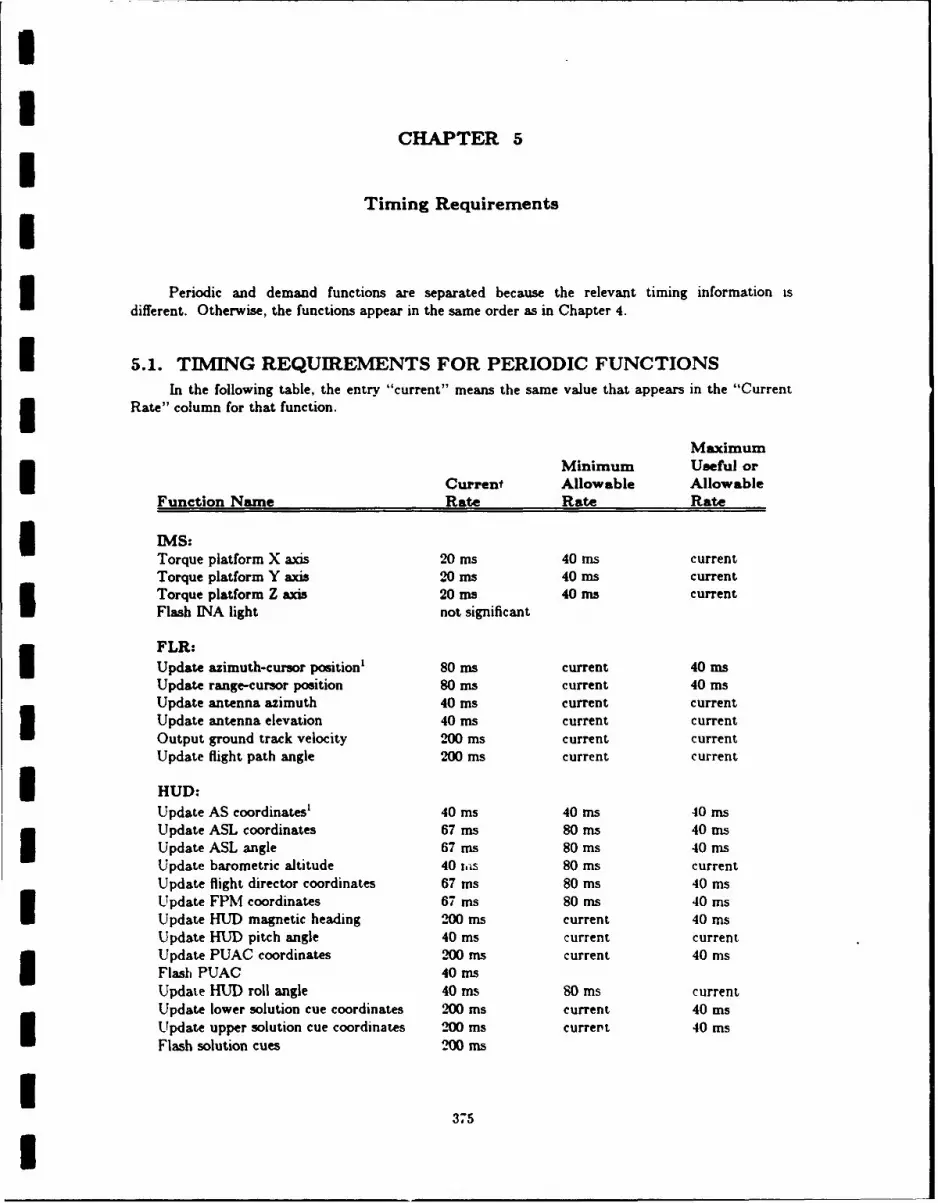
UU
CHAPTER 5ITiming RequirementsI
Periodic and demand functions are separated because the relevant timing information is
different. Otherwise, the functions appear in the same order as in Chapter 4.
I 5.1. TIMING REQUIREMENTS FOR PERIODIC FUNCTIONSIn the following table, the entry "current" means the same value that appears in the "Current
Rate" column for that function.
MaximumMinimum Useful or
Current Allowable AllowableFunction Name Rate Rate Rate
3 IMS:Torque platform X axis 20 ms 40 ins currentTorque platform Y axis 20 ms 40 ms currentTorque platform Z axis 20 ms 40 ms currentFlash INA light not significant
FLR:Update azimuth-cursor position' 80 ms current 40 msUpdate range-cursor position 80 ms current 40 msUpdate antenna azimuth 40 ms current currentUpdate antenna elevation 40 ms current currentOutput ground track velocity 200 ms current currentUpdate flight path angle 200 ms current current
i HUD:Update AS coordinates' 40 ins 40 ms 40 insUpdate ASL coordinates 67 ms 80 ms 40 msUpdate ASL angle 67 ms 80 ms 40 msUpdate barometric altitude 40 ias 80 ins currentUpdate flight director coordinates 67 ms 80 ms 40 insUpdate FPM coordinates 67 ins 80 ms 40 msUpdate HUD magnetic heading 200 ms current 40 msUpdate HUD pitch angle 40 ms current currentUpdate PUAC coordinates 200 ms current 40 insFlash PUAC 40 msUpdate HUD roll angle 40 ms 80 ins currentUpdate lower solution cue coordinates 200 ms current 40 msUpdate upper solution cue coordinates 200 ins currert 40 msFlash solution cues 200 Ins
I375I
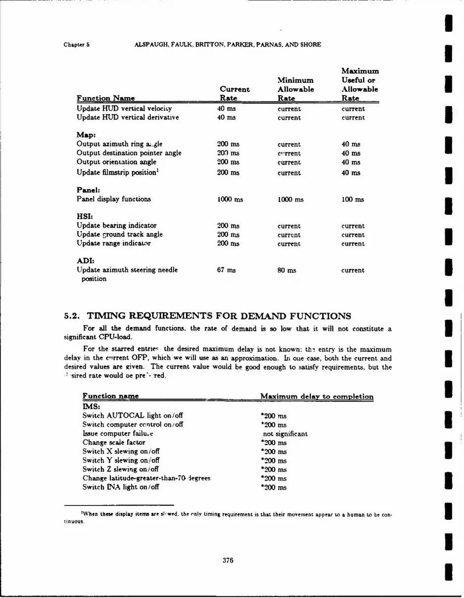
1Chapter 5 ALSPAUGH, FAULK, BRITTON, PARKER, PARNAS, AND SHORE
MaximumMinimum Useful or
Current Allowable Allowable
Function Name Rate Rate Rate
Update HUD vertical velociry 40 ms current currentUpdate HUD vertical derivative 40 ms current current
Map:Output azimuth ring ai.gle 200 ms current 40 msOutput destination pointer angle 200 ms clrrent 40 msOutput orientation angle 200 ms current 40 ms
Update filmstrip position' 200 ms current 40 ms
Panel:Panel display functions 1000 ins 1000 ms 100 ins
HSI:Update bearing indicator 200 ms current currentUpdate ground track angle 200 nis current currentUpdate range indicator 200 ms current current
ADI-Update azimuth steering needle 67 s 80 ms current
position
I5.2. TIMING REQUIREMENTS FOR DEMAND FUNCTIONS
For all the demand functions, the rate of demand is so low that it will not constitute a 3significant CPU-load.
For the starred entrie the desired maximum delay is not known; thb entry is the maximumdelay in the c, rrent OFP, which we will use as an approximation. In oue case, both the current anddesired values are given. The current value would be good enough to satisfy requirements, but the
"sired rate would oe pre'-"-red.
Function name Maximum delay to completion IIMS:Switch AUTOCAL light on/off *200 TnsSwitch computer ccntrol on/off *200 msIssue computer failu. e not significantChange scale factor *200 insSwitch X slewing on/off *200 msSwitch Y slewing on/off *200 msSwitch Z slewing on/off *200 insChange latitude-greater-than-70 legrees *200 msSwitch UNA light on/off *200 ms
'When these display items are skwed, the rnly timing requirement is that their movement appear to a human to be con- 3tinuous.
3376 I
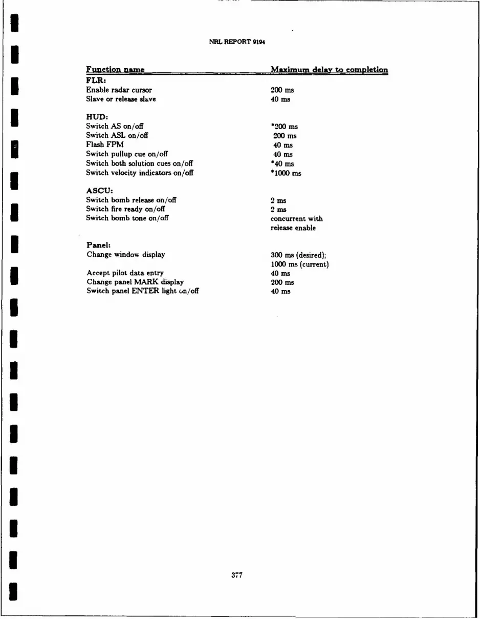
INRL REPORT 9194I
Function name Maximum delay to conletionFLR:Enable radar cursor 200 msSlave or release slave 40 ms
HUD:Switch AS on/off *200 msSwitch ASL on/off 200 msFlash FPM 40 msSwitch pullup cue on/off 40 msSwitch both solution cues on/off *40 msSwitch velocity indicators on/off *1000 ms
ASCU:Switch bomb release on/off 2 msSwitch fire ready on/off 2 msSwitch bomb tone on/off concurrent with
release enable
Panel:Change window display 300 ms (desired);
1000 ms (current)Accept pilot data entry 40 msChange panel MARK display 200 msSwitch panel ENTER light on/off 40 ms
IIIIIIUII
377
I

II
CHAPTER 6
Accuracy Constraints on Software Functions
[The purpose of Chapter 6 is to state the acceptable errors or tolerances for each of the functions
described in Chapter 4. Accuracy requirements vary with A/C situation, weapon type, mode ofoperation and other factors.
Our original intention was to have Chapter 6 contain tables defining the tolerances in a wayanalogous to the tables defining the output values in Chapter 4. Unfortunately, the data necessary tocomplete such tables are not available to us. In a development of a totally new weapon system, themission analysis necessary to determine these requirements would have been justified. Knowledge ofthe tolerances would be necessary to make rational choices of computation methods, data representa-tion and resource allocation. In the present system. we have available a model with acceptable perfor-mance, and we know that the methods and representations used in that model are adequate to thetask. For that reason, we have omitted Chapter 6 from this document and take as our requirementthat we must meet or exceed the accuracy of the present system.
[IIIIIIII
378

II
CHAPTER 7
Undesired Event (UE) Responses
7.0. INTRODUCTIONThis chapter describes system responses to undesired events, such as hardware malfunctioning.I It includes both responses made by the current OFP and hypothetical responses considered reasonable
by system engineers. If our only purpose were to duplicate the current OFP, this chapter would beredundant, since the current responses are described in Chapter 4. However, we are also concernedwith making the system easy to change. One very common change to a system is an improvedresponse to an undesired event. To anticipate these changes, we have sketched the kinds of responsesthat might be considered useful.
For each response, we have indicated in the two columns to the right a) whether it is performedin the current OFP, and b) the system engineers' judgment of its usefulness. Responses are classified"'Y1' (Yes), "'N"' (no) and "'M'. (maybe). We included some responses judged not useful in order tokeep a record of their consideration.I Although the responses are organized by means of detection, we do not describe how each of theUEs is detected. We organized them in this way because it gave us a systematic approach, so that wecould be reasonably sure of completeness. We continue to use it because we believe gaps will show upmore clearly.
I Current Desired
UFA detected by periodic self checks
3 a. IMS not functioning
I) Inform pilot (currently !DATA 98! display). Y Y2) Go to backup NAV mode (SIMS fail*). Y Y
b. Doppler not functioning
3 1) Inform pilot (currently !Data 98! display). Y Y2) Switch navigation modes. Y Y(From *DIG* or *DI* to *I*; from *UDI* to *OLB*).
I 3) If it starts functioning again. Y Ywait five seconds before using data.
c. ADC not functioning
1) Set barometric altitude to nominal value: 4500 ft. Y YI2) Inform pilot (Mark window when !Data 98! displayed). Y Y
379
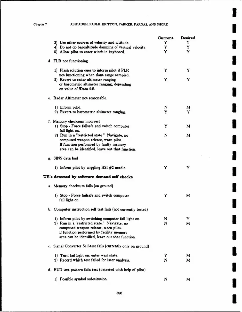
IChapter 7 ALSPAUGH, FAULK, BRITTON, PARKER. PARNAS. AND SHORE
Current Desired3) Use other sources of velocity and altitude. Y Y4) Do not do baroaltitude damping of vertical velocity. Y Y5) Allow pilot to enter winds in keyboard. Y Y
d. FLR not functioning
1) Flash solution cues to inform pilot if FLR Y Ynot functioning when slant range sampled.
2) Revert to radar altimeter ranging Y Yor barometric altimeter ranging, dependingon value of .Data 24!. 3
e. Radar Altimeter not reasonable.
1) Inform pilot. N M2) Revert to barometric altimeter ranging. Y Y U
f. Memory checksum incorrect1) Stop - Force failsafe and switch computer Y M
fail light on.2) Run in a "restricted state." Navigate, no N M
computed weapon release, warn pilot. IIf function performed by faulty memoryarea can be identified, leave out that function.
g. SINS data bad I1) Inform pilot by wiggling HSI #2 needle. Y Y
UE's detected by software demand self checks
a. Memory checksum fails (on ground)
1) Stop - Force failsafe and switch computer Y Mfail light on.
b. Computer instruction self test fails (not currently tested)
1) Inform pilot by switching computer fail light on. N Y2) Run in a "restricted state." Navigate, no N M I
computed weapon release, warn pilot.If function performed by facility memoryarea can be identified, leave out that function.
c. Signal Converter Self-test fails (currently only on ground)
1) Turn fail light on: enter wait state. Y M I2) Record which test failed for later analysis. N M
d. HUD test pattern fails test (detected with help of pilot) II) Possible symbol substitution. N M
380
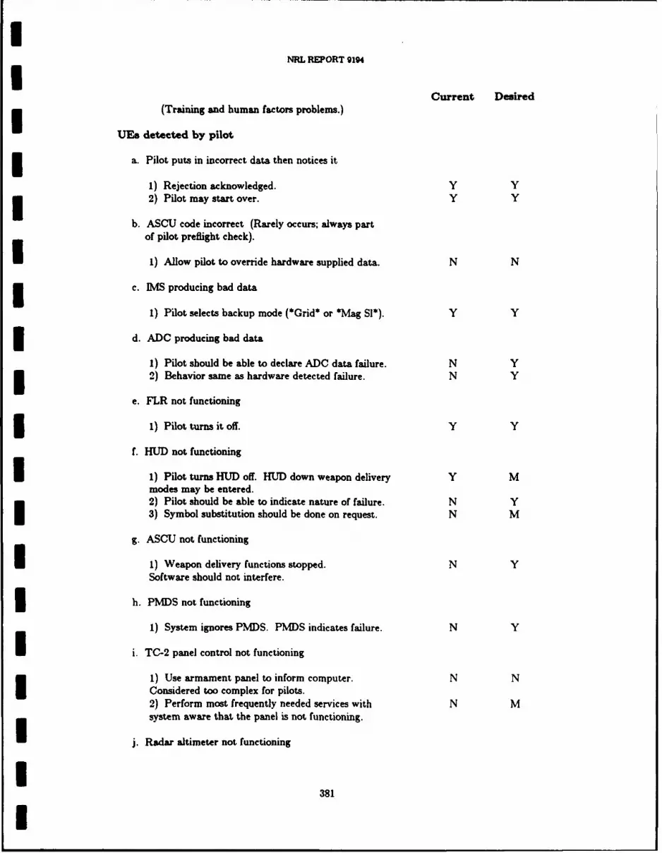
INRL REPORT 9194I
Current Desired(Training and human factors problems.)
UEa detected by pilot
a. Pilot puts in incorrect data then notices it
1) Rejection acknowledged. Y Y3 2) Pilot may start over. Y Y
b. ASCU code incorrect (Rarely occurs; always partof pilot preflight check).
1) Allow pilot to override hardware supplied data. N N
3 c. IMS producing bad data
1) Pilot selects backup mode (*Grid* or *Mag S1*). Y Y
d. ADC producing bad data
1) Pilot should be able to declare ADC data failure. N Y3 2) Behavior same as hardware detected failure. N Y
e. FLR not functioning
1 1) Pilot turns it Off. Y Y
f. HUD not functioning
I 1) Pilot turns HUD off. HUD down weapon delivery Y Mmodes may be entered.2) Pilot should be able to indicate nature of failure. N Y3) Symbol substitution should be done on request. N M
g. ASCU not functioning
1 1) Weapon delivery functions stopped. N YSoftware should not interfere.
3 h. PMDS not functioning
1) System ignores PMDS. PMDS indicates failure. N Y
I i. TC-2 panel control not functioning
1) Use armament panel to inform computer. N NConsidered too complex for pilots.2) Perform most frequently needed services with N Msystem aware that the panel is not functioning.
j. Radar altimeter not functioning
I381
I

IChapter 7 ALSPAUGH, FAULK. BRITTON. PARKER, PARNAS, AND SHORE
Current Desired1) Pilot turns it off. Y Y2) Revert to baroaltimeter ranging. Y Y
k. Slew Control not functioning
1) Pilot can inform computer. N Y2) OFP ignores slew control. N Y3) Alternate input source used to indicate slew. N N 3
I. Doppler not functioning
1) Pilot switches it off. Y Y2) Behaves as if the computer detected the failure. Y Y
m. TACAN not functioning 31) Pilot won't use it. Y Y2) System should ignore it. Y Y
n. AOA data bad
1) Pilot can inform computer. N Y I2) Computer ignores input and uses a constant. N N3) Pilot can change the constant. N N
o. SINS communication not functioning (ground only) I1) No action. Y Y
p. Weight on whcel switch not functioning
1) Possible Action: Override (might not be permitted). N N
q. Release enable switch not functioning
1) Pilot informs computer to ignore setting of switch. N Y 32) Alternate input designated. N M
r. Designate switch not functioning
1) Pilot informs computer. N M2) Pilot can use release enable switch as alternate input. Y M I
s. HSI not functioning
1) Pilot informs computer. N Y2) Display "distance to target" on HUD at pilot option. N M I3) Make other items available on panel. N M
t. ADI not functioning I1) No action. Y M
382 I

INRL REPORT 9194I
Current Desired
u. Flight recorder not functioning
1) Pilot informs computer. N Y2) Don't ship data to flight recorder. N Y
v. Bomb tone not functioning
1) Computer need not perform bomb tone functions. N Y2) Possible use of light or HUD display symbol. Y Y
LJEs detected by timeouts
a. GO/NO-GO counter hits zero
1 1) Save data. N Y2) Pilot informed by 8's in window. Y Y
UIs detected by computer hardware
a. DIAGNOSE instruction (not used in flight)
3 1) None. Y M
b. Power interruption
1) Perform a restart if airborne and IMS ready. Y MOtherwise, perform a complete reinitialization.
IIIIIIII
383
I
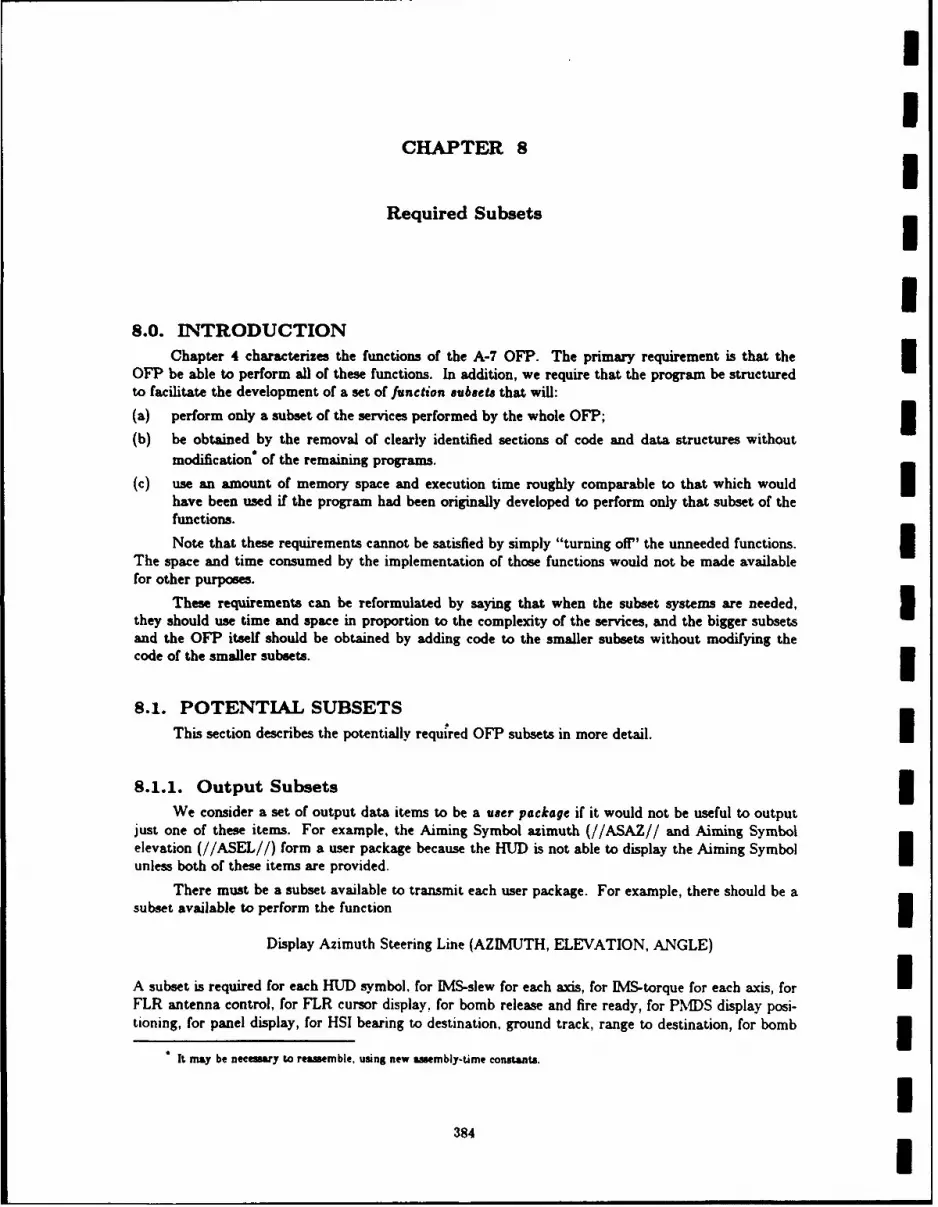
II
CHAPTER 8
Required Subsets
U8.0. INTRODUCTION
Chapter 4 characterizes the functions of the A-7 OFP. The primary requirement is that theOFP be able to perform all of these functions. In addition, we require that the program be structuredto facilitate the development of a set of function subsets that will:
(a) perform only a subset of the services performed by the whole OFP;
(b) be obtained by the removal of clearly identified sections of code and data structures withoutmodification* of the remaining programs.
(c) use an amount of memory space and execution time roughly comparable to that which wouldhave been used if the program had been originally developed to perform only that subset of thefunctions.
Note that these requirements cannot be satisfied by simply "turning off" the unneeded functions.The space and time consumed by the implementation of those functions would not be made availablefor other purposes.
These requirements can be reformulated by saying that when the subset systems are needed, 3they should use time and space in proportion to the complexity of the services, and the bigger subsetsand the OFP itself should be obtained by adding code to the smaller subsets without modifying thecode of the smaller subsets.
8.1. POTENTIAL SUBSETSThis section describes the potentially required OFP subsets in more detail. I
8.1.1. Output Subsets
We consider a set of output data items to be a user package if it would not be useful to outputjust one of these items. For example, the Aiming Symbol azimuth (//ASAZ// and Aiming Symbolelevation (//ASEL//) form a user package because the HUD is not able to display the Aiming Symbolunless both of these items are provided.
There must be a subset available to transmit each user package. For example, there should be asubset available to perform the function 3
Display Azimuth Steering Line (AZIMUTH, ELEVATION, ANGLE)
A subset is required for each HUD symbol. for IMS-slew for each axis, for IMS-torque for each axis, for IFLR antenna control, for FLR cursor display, for bomb release and fire ready, for PM])S display posi-tioning, for panel display, for HSI bearing to destination, ground track, range to destination, for bomb 3
It may be neesary to reassemble, using new assembly-time constants.
I384 I

INRL REPORT 9194
tone, for ADI and for the miscellaneous discrete items.
8.1.2. Input SubsetsWe consider input data items to form a user package if one must know the value of one to make
use of the value of the others. For example, we consider True Heading Cosine and True Heading Sinea user package because one must know both cosine and sine to determine the quadrant. There mustbe a subset capable of reading in any of these input user packages. These will include magnetic head-ing, pitch, role, true heading, X, Y, and Z accelerations, barometric altitude, mach number, trueairspeed, FLR lockon and slant range to target, ASCU status. PDS status, each of the panelswitches and thumbwheels. radar altitude, slew control position and movement, the various MFS andARP input switches, Doppler drift angle, Doppler ground speed. TACAN range and bearing to desti-nation, AOA, and SINS inputs. The SINS subset is not needed when airborne. The memory allo-cated to it may be used for other purposes while airborne provided that it can be regenerated when aSINS input is available.
8.1.3. Hardware Test SubsetsThere should be a subset capable of executing the hardware test sequences for any of the
hardware units. Since these tests are not conducted when airborne, the remarks made about the SINSinput subset apply here as well.
8.1.4. Scheduling SubsetThere will be a subset of the system that provides for the synchronization and scheduling of a
fixed number of concurrent activities with real-time deadlines. By means of reassembly it will be p6s-sible to adjust the space to take advantage of a decrease in the number of such activities or to allowfor an increase in the number of such activities.I8.1.5. Real-time Input Data Base
The system will include a subset that makes current values of the input data items available tothe rest of the OFP. This subset will use the input subsets and the scheduling subset. The data basesubset will be so constructed that if certain data items are not needed, the memory space and cputime devoted to maintaining those items can be saved at the cost of a reassembly operation.
8.1.6. Periodic Output Data BaseFor those data items that must be output periodically, there will be a subset that maintains a
record of the most recent values and sends them to the appropriate devices at the necessary intervals.This subset will use the output subsets and scheduling subset. It, will be so constructed that if certainitems are not being transmitted, the memory space and CPU time devoted to maintaining those itemscan be saved by means of a reassembly operation. This subset makes pseudo-output commands avail-able to the rest of the OFP which then acts as if there was continuous output of the items in the database.
8.1.7. Navigation SubsetsThe system shall be capable of performing navigation functions without the presence of any of
the weapons delivery software. In particular, the software required to maintain an estimate of currentposition and heading shall function without the presence of any weapons delivery software. It shall be
385I

IChapter 8 ALSPAUGH, FAULK, BRITTON, PARKER, PARNAS, AND SHORE
possible to provide navigation information to the pilot through either the HUD, the HSI, the PMDS,or the panel even if the software used to display information on the other three devices is not avail-able. Similarly, there shall be subsets available to perform navigation services using only a subset ofthe normal input devices wherever alternate means of obtaining the necessary input are available.
8.1.8. Weapons Delivery Subsets
There shall be functional subsets available for each of the possible subsets of the weapons carriedon the aircraft. In the event that a weapon is not available or used, it shall be possible to generate a Isubset of the system in which the table space and code used for that weapon is made available forother uses. I8.1.9. Pilot Display Subsets
It shall be possible to produce a subset that eliminates some of the information displayed to thepilot. For example, a subset that does not include PMDS display functions should be available.
8.1.10. Alignment and Calibration Subsets 3Subsets shall be available that can only perform land-based alignment or only perform ship-
based alignment. Subsets without air alignment capabilities shall be available. All systems should beable to perform functions without the presence of the land or ship alignment code when airborne.
8.2. REQUIRED SUBSETSThis section describes all subsets that shall actually be delivered. Each is specified by describing
the differences between it and the full OFP specified elsewhere in this document. I8.2.1. The Useful Subset
8.2.1.1. Data items UData items belonging to the following devices shall not be included:
Bomb Tone (see Section 2.3.4) 3Projected Map Display Set (see Section 2.1.6)Shipboard Inertial Navigation System (see Section 2.2.8)TACAN (see Section 2.2.6)Waypoint Information System (see Section 2.2.11)
The following additional data items shall not be included: 3//AUTOCAL////CURAZCOS//
//CURAZSIN//Ii/CURPOS/// /IMSNA///PNLTEST /
I386

INRL REPORT 9194
Only the following !Weapon Class! members shall be included: SGN$, $HDS, SMDS, SSLS. $SHS, $SMS,5 SUNS. All others shall be returned as SUNS.
8.2.1.2. Modes
Only the following modes shall be included. Actions which would cause an entry into one of thedeleted modes shall cause no transition:
Alignment: *Landaln*Navigation: *1*, *DIG*Nay Update: *HUDUpd*, *UNone*Weapon: *Nattack*, *Noffset*, *Manrip*, **NBnotShrike**, *\VNone*5 Test: none
8.2.1.3. FunctionsThe following functions are not included:
A function to drive a deleted output item:Update SINS X and Y Offsets Display;Update SINS Z Offset and Delta Heading Display;Update Map Coordinates Display;Update DATA 03 through Update DATA 22:Update DATA 26; !Land! shall always be true;Update DATA 71 (lower window);Update DATA 90;Update DATA 91 (lower window);Update DATA 92/93 (lower window);Update DATA 94.
III
II
II
387
I

II
CHAPTER 9 IExpected Types of Changes
I9.0. INTRODUCTION
This chapter characterizes the requirement changes that can be expected in the future. It isimpossible to give specific details of any particular change, but we wish to point out the aspects of thisdocument that cannot be considered fundamental when designing the system. However. there are afew fundamental assumptions about the system that are not expected to change whatever enhance-ments are made. These are listed in Section 9.1.
9.1. FUNDAMENTAL ASSUMPTIONS 39.1.1 The flight characteristics and weapon characteristics are adequately characterized by the
mathematical models documented in Refs. 6,7,10,11,12, 13,25. The flight conditions andmission conditions are such that the approximations made in deriving the equations willremain sufficiently accurate. All parameters that can vary from aircraft to aircraft, locationto location, or weapon to weapon, are adequately identified in the referenced documents.
9.1.2 Point of impact (weapon delivery) calculation can not be accurately performed if alignmentor location data are not accurate.
9.1.3 The computer will not be assigned "background" functions with non-real-time computationsuch as map-making, digital picture processing, etc.
9.1.4 When writing the programs, realistic (worst-case) upper bounds on memory requirementsand cpu cycle requirements for each function can be predicted and will be independent offlight conditions. I
9.2. COMPUTER CHANGES9.2.1 The computer might be replaced by a TC-2A. I9.2.2 Additional channel hardware might be added to the TC-2.
9.2.3 Additional interlocks or improvements might be added to the present TC-2 channels.
9.2.4 A completely different computer might be substituted (very unlikely).9.2.5 A register other than the A register might be used as an I/0 buffer.
9.2.6 TC-2 Panel may be used for other parameters or pilot selectable switches.
9.3. INTERFACE CHANGES 39.3.1. General(a) Assignment or devices to channels may be changed.
(b) Assignment of bits to discrete words may be changed.
I388 I

NRL REPORT 9194
(c) All data representations may be changed.
9.3.2. FLR(a) Display symbology may be changed.
(b) Range characteristics could be improved.
3 9.3.3. HUD(a) Data Item Identity codes could be changed.
(b) Symbols could be added.
(c) Computer controlled intensity or color could be added with a new HUD.
3 9.3.4. Other Uses of Flight Recorder(a) Flight recorder might be used as a serial output channel.
9.3.5. ASCU(a) ASCU might be replaced by computer controllable unit.
9.3.6. PMDS3 (a) Map might be replaced by a unit that can be positioned more quickly (unlikely).
(b) Other film-strip formats and scaling might be used.
I 9.3.7. TC-2 Panel(a) Additional switches or positions may be added (very likely)
9.3.8. Slew Control3 (a) An extension dimension might be added (in A-6, but not likely for A-7).
9.3.9. Doppler Radar Set(a) Precision might be increased (very unlikely).
3 9.3.10. Weapon Characteristic Parameters Are Subject to Change (Fre-quently)
I 9.4. FUNCTION CHANGES
9.4.1. General(a) Improved processing algorithms might be added (e.g., Kalman filters).
3389I
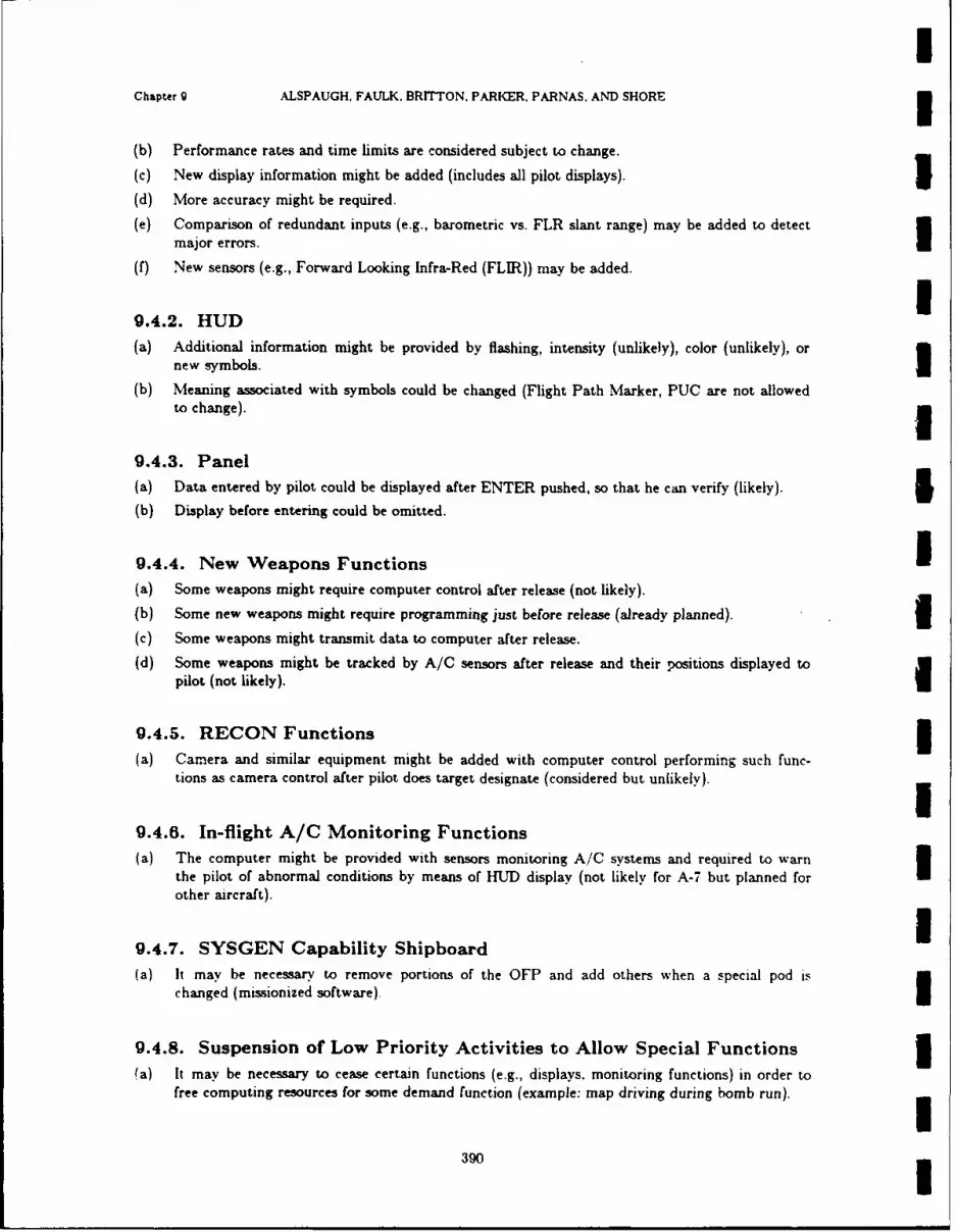
iChapter 9 ALSPAUGH, FAULK, BRITTON. PARKER, PARNAS, AND SHORE 3(b) Performance rates and time limits are considered subject to change.
(c) New display information might be added (includes all pilot displays). 5(d) More accuracy might be required.
(e) Comparison of redundant inputs (e.g., barometric vs. FLR slant range) may be added to detectmajor errors. I
(f) New sensors (e.g., Forward Looking Infra-Red (FLIR)) may be added.
9.4.2. HUD(a) Additional information might be provided by flashing, intensity (unlikely), color (unlikely), or
new symbols. U(b) Meaning associated with symbols could be changed (Flight Path Marker, PUC are not allowed
to change).
9.4.3. Panel(a) Data entered by pilot could be displayed after ENTER pushed, so that he can verify (likely). £(b) Display before entering could be omitted.
9.4.4. New Weapons Functions I(a) Some weapons might require computer control after release (not likely).
(b) Some new weapons might require programming just before release (already planned). i(c) Some weapons might transmit data to computer after release.
(d) Some weapons might be tracked by A/C sensors after release and their positions displayed topilot (not likely).
9.4.5. RECON Functions
(a) Camera and similar equipment might be added with computer control performing such func-tions as camera control after pilot does target designate (considered but unlikely).
9.4.6. In-flight A/C Monitoring Functions(a) The computer might be provided with sensors monitoring A/C systems and required to warn
the pilot of abnormal conditions by means of HUD display (not likely for A-7 but planned forother aircraft).
I9.4.7. SYSGEN Capability Shipboard(a) It may be necessary to remove portions of the OFP and add others when a special pod is
changed (missionized software).
9.4.8. Suspension of Low Priority Activities to Allow Special Functions 1(a) It may be necessary to cease certain functions (e.g., displays, monitoring functions) in order to
free computing resources for some demand function (example: map driving during bomb run).
390
INRL REPORT 9194
9.4.9. Internal A/C Communications Functions(a) Software might have to serve as data link between other devices by getting data from one device
and sending data to some other (not likely).
19.4.10. Accept Information Over Data Link While Airborne
(a) Updates in the air with the aid of ground stations might be required.
(b) Airborne A/C may accept destination data over data link.
9.4.11. Lateral Control of Aircraft
9.4.12. Parallel Processing of Release/Impact Points, Etc. for Several3 Weapons
19.4.13. Calculations for Two Destinations (One a Target) (AlreadyPlanned)
9.4.14. More Support for Moving Targets
3 9.4.15. Multi-step Flight Path Navigation
I* 9.4.16. Electronic Warfare Counter Measures(a) Example: checks on reasonableness.
1 9.4.17. Computer Self-test During Flight
I[IIII
391[

II
CHAPTER 10!
Glossary of Abbreviations, Acronyms, and Technical Terms
These acronyms and terms are used in the A-7 community to describe various aspects of the INavigation Weapon Delivery System (NWDS), that is, the complete system including the computer.software and all the hardware displays and sensors used for navigation and weapon delivery.
-A-
AAM Air-to-air missile IABH Above burst height
above ground level Vertical distance of A/C above target or ground 5AC Alternating current
a/c Aircraft IA/C Aircraft 3ACL Automatic carrier landing
ACLS Automatic carrier landing system (not connected to the TC-2) 5ADC Air data computer - hardware component of the NWDS
A/D CONV Analog-to-digital converter n
ADI Attitude direction indicator - hardware component of the NWDS
ADL Aircraft datum line; the longitudinal center reference line of the a/cweapons system (3 degrees down from water line 100)
AFCS Automatic flight control system (not connected to the TC-2) n
AGE Aerospace ground equipment IAGL See above ground level
AGM Air-to-ground missile 3AGR Air-to-ground ranging - radar mode providing target slant range to the
TC-2 3aiming symbol Diamond-shaped HIMJD symbol
3392

INRL REPORT 9194
alignment Causing the IMS platform axes to point toward the Earth's local east, theprojection in the local horizontal plane of the north vector, and the perpen-dicular to the local horizontal plane away from the Earth's center.
ALT Altitude (also altimeter)
angle of attack Angle of wing (or other reference horizontal) to air flow
ANT Antenna
AN/ASN91 Another name for the TC-2 computer
AQA See angle of attack
AOA transducer Angle of attack transducer - a hardware component of the NVDS
I AR Aiming reticle - see aiming symbol
ARDA Aiming reticle depression angle
ARL Aiming reticle location
ARL Armament reference line
ARP Armament release panel - a hardware component of the NWDS
ARS Armament release switch - also called Release Enable
AS See Aiming symbol
ASCU Armament station control unit - a hardware component of the NWDS
ASL See aimuth steering line
AUTO Automatic
3 AUTOCAL Automatic calibration - calculation of IMS-axis drift biases
AZ See azimuth
3 azimuth Horizontal direction; for example, angle between a/c heading and the lineprojected into the horizontal plane from the a/c to a destination
3 azimuth steering error Angular difference between actual ground track and desired ground track
azimuth steering line Straight-line HUD symbol; also called bomb fall line (BFL)
* -B-
Backup reticle Also called standby reticle - symbol displayed by the HUD when the HUDnot reliable
BARO Barometric (altimeter/altitude)
I393I
UChapter 10 ALSPAUGH, FAULK, BRITTON, PARKER, PARNAS, AND SHORE 5BCN Beacon integration - radar mode
Bearing Angle between projection of Y axis onto the horizontal plane and projec- Ition onto the horizontal plane of the line from the A/C to a destination ortarget 3
BDU Bomb dummy unit
BFL Bombfall line - see azimuth steering line 5BHT See burst height
BIT Built-in test IBITE Built-in test equipment 5BOC Bomb on coordinates - an OFP weapon delivery mode
Bottom Latitude below which PMDS map does not extend 5BPC Bullpup control set (see slew control)
BRG See bearing 5BRIL Brilliance
BRL Boresight reference line
Bullpup control See slew control IBUR See backup reticle
Burst height distance above ground that a bomb is set to explode 3BO, B15, etc. Scale indicators. BO means the binary point follows bit 0 of a 16-bit
number, i.e.. that the entire number is a fraction. B15 means the binarypoint follows bit 15, i.e., that the number is an integer
-C-
CA Coarse azimuth - an OFP alignment stage; same as coarse gyrocompass
CADU Control and display unit: used to debug programs on the TC-2 1CAL Calibration
callup Selection of a numbered destination 5CBU Cluster bomb unit
CCIP Continuously computed impact point - an OFP weapon delivery mode ICCW Counterclockwise 5
394 1

NRL REPORT 0194
CDCE Computer-driven cursor enable; when the OFP enables the cursors on theI radarscope
CEP Circular error probable - radius of circle in which 5075 of bombs fall; meas-
ured in feet
CG Center of gravity
5 CHAN Channel
CIP Computed impact point
CIR Circular
CL Coarse level - an OF? alignment stage
I coarse Platform self-contained alignment to true north
crab Difference between ground track angle and the heading as measured byI IMS; see also drift angle
CRT Cathode-ray tube
I CSGMP Cross scan ground map, pencil - a radar mode
CSTA Cros scan terrain avoidance - a radar mode
I CW Clockwise
3DA See drift angle
3 D/A CONV Digital-to-analog converter
DC Direct current
I DDC Digital data converter
3 delta heading Angular difference between a/c heading and ship heading
DEOB Deck edge outlet box - used to connect A/C to source of SINS data: eachDEOB is marked with its offsets from the SINS source on the ship
designate A pilot action that ground stablizes the HUD aiming symbol or radar cur-sors on the selected aiming point and records the aiming point location inthe Tactical Computer. Used in update modes and weapons deliverymodes
DEST See destination
destination A location whose coordinates are entered in the Tactical Computer by thepilot
395U

IChapter 10 ALSPAUGH. FAULK. BRITTON. PARKER. PARNAS, AND SHORE
DF Direction-finding
DI Doppler inertial - an OFP navigation mode
DIG Doppler inertial gyrocompassing - an OFP Navigation mode 3DIR Direction
DIW Discrete input word 3DL Data link
DLV Delivery IDME Distance measuring equipment
DOP Doppler
DOW Discrete output word IDR Dead reckoning
drift angle Angle between the projections into the horizontal plane of the Y. axis and 3the A/C velocity vector. The angle is usually measured from the Y. axis.
dpositive in the CW direction, looking down, and negative in the CCWdirection
DRS Doppler radar set
DU Display unit I
E East
EAS Electronic altitude sensor iEAS Equivalent airspeed
ECM Electronic countermeasures 3ELA Effective launch angle
ELEC Electric iEnter Inserting information (pilot selected or update) into the TC-2 via the Enter
pushbutton
ET Elapsed time
EULERANG Geometry-related reference angles
-F- 3
396
INRL REPORT 9194
FG Fine gyro compassing - an OFP alignment stage
flight path angle Angle between aircraft velocity vector and its projection into the horizontalplane: pitch corrected for angle of attack. The angle is usually measuredfrom the horizontal line, positive in the up direction, negative in the downdirection
flight path marker HUD symbol showing direction of A/C velocity vector
SFLIR Forward-looking infrared
FLR Forward-looking radar - a hardware component of NWDS
flux valve ML1 magnetic compass - part of the IMS
3 FOV Field of view
FPA See flight path angle
FPM See flight path marker
fps Feet per second
I FREEFALL Low drag weapon
FREQ Frequency
FRL Fuselage Reference Line
3 FWD Forward
-G-
g Force of gravity or load factor
GAS Go-around steering
I GM Ground mapping - radar m,
3 GMP Ground map, pencil - radar mode
GMPB Ground mapping, pencil (beam) - radar mode
3 GMS Ground map, spoiled - radar mode
GMSB Ground mapping, shaped (beam) - radar mode
I GND Ground
GND ALIGN Ground alignment - an MS mode
grazing angle Angle between the line defined by the direction that the FLR antennapoints and its projection into the horizontal plane
3397

IChapter 10 ALSPAUGH, FAULK. BRrrTON, PARKER, PARNAS, AND SHORE 3Grid Grid mode - an IMS mode; also an OFP navigatior mode
ground track Line defined by projection of the A/C velocity vector onto the ground 3ground track angle Angle between ground track and the line from the A/C to true north (true
heading + drift angle). The angle is usually measured CW from north look-ing down
GS Ground speed
GTA See ground track angle
GYPTO Gyro pulse torque 1
Gyrocompassing Method used to align the IMS platform to true north
-H-
HDG See heading 1
HDGP High drag general purpose
HD/LD High drag/low drag - weapon types 1
heading Line defined by the projection of the Y. axis into the horizontal plane; orthe angle between this line and the line from the A/C to north. See alsotrue heading and magnetic heading
Hg Mercury
HG High-gain gyro compassing - an OFP airborne alignment stage
HL High-gain level - an OFP airborne alignment stage 3HSI Horizontal situation indicator - a hardware component of NWDS
HUD Head-up display - a hardware component of NDS 1
HW Head wind
Hz Hertz (cycle per second)
I Inertial - IMS mode; also OFP navigation mode
IAS Indicated air speed: not corrected for temperature and air pressure 1
EBFL Instantaneous bombfall
LBS Interbomb spacing iIMN Indicated Mach number: not corrected for temperature and air pressure 3
398
INRL REPORT 9194
IMS Inertial measurement set - hardware component of NWDS
IMU Inertial measurement unit - platform component of IMS
impact angles Angles measured from the a/c Y, axis to the line from the A/C to theimpact point projected into the X.-Y3 plane (azimuth) or into the Y a-Z a~plane (elevation)
3 impact point Point where bomb would hit the ground if released now
INA IS non-align light
I incremental velocity Change in velocity or Delta velocity. The IMS measures acceleration and
by applying the variable of time provides incremental velocity to the TC-2for aircraft speed and distance solutions
I N PANEL Tactical Computer Control Panel (TCCP). Also called NWDS Panel
IP Identification point (also initial point; also impact point). See offset aim-U point
IR Infrared
IWS Integrated weapons system
3 -K-
KCAS Knots calibrated airspeed - same as KMAS
KEAS Knots equivalent airspeed
K YBD Keyboard
I KIAS Knots indicated airspeed; not corrected for temperature and air pressure
KN Knots (nautical miles per hour)
-Kt Knots
KTAS Knots true airspeed: corrected for temperature and air pressure
3 LAT Latitude
Lateral steering error See azimuth steerin, error
LB Pounds
LBA Limits of basic aircraft
LD Low drag
399
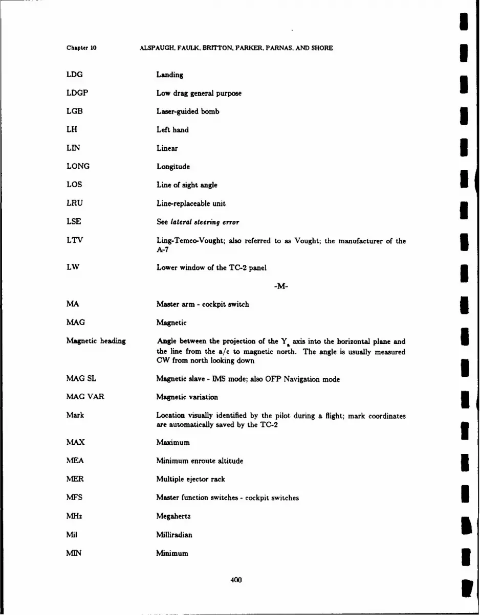
iChapter 10 ALSPAUGH, FAULK, BRITTON. PARKER. PARNAS, AND SHORE
LDG Landing
LDGP Low drag general purpose ULGB Laser-guided bomb 5LH Left hand
LIN Linear i
LONG Longitude
LOS Line of sight angle iLRU Line-replaceable unit
LSE See lateral steering error
LTV Ling-Temco-Vought; also referred to as Vought; the manufacturer of theA-7 I
LW Lower window of the TC-2 panel 5
MA Master arm - cockpit switch iMAG Magnetic
Magnetic heading Angle between the projection of the Y axis into the horizontal plane and ithe line from the a/c to magnetic north. The angle is usually measuredCW from north looking down 5
MAG SL Magnetic slave - IMS mode; also OFP Navigation mode
MAO VAR Magnetic variation 5Mark Location visually identified by the pilot during a flight; mark coordinates
are automatically saved by the TC-2 3MAX Maximum
MEA Minimum enroute altitude 5MER Multiple ejector rack
MFS Master function switches - cockpit switches IMHz Megahertz
Mil Milliradian
MIN Minimum 5400

NRL REPORT g194
Mk Mark, Navy designation for model
MLV Memory loader verifier
MN Mach number
Mod Navy designation for modification
Mode Particular working status of the system
MIZE Mean radial error
MRI Minimum release interval
MRT Military rated thrust
MPI Mean point of impact
ms Milliseconds
MSL Mean sea level
MSL ALT Height of A/C above sea level: AGL + target altitude
MSLP Mean sea level pressure
MV Magnetic variation
-N-
N North
NAL Non align light (also called INA)
NATOPS Naval Air Training and Operating Procedures Standardization - pilotmanual
NAV Navigation
NAV/WD Navigation/ weapon delivery
nm Nautical miles
nmi Nautical miles
NORM Normal - [MS mode; also used as another name for DIG
NRL Naval Research Laboratory, Washington, DC 20375-5000
NWC Naval Weapons Center, China Lake, CA 93555
NWDC Navigation weapon delivery computer (see TC-2)
401

IChapter 10 ALSPAUGH, FAULK. BRITTON. PARKER, PARNAS, AND SHORE
NWDS Navigation/weapon-delivery system
NWDS/NAVWD Navigation weapons delivery system 1-O- U
OAP See offset aimpoint
offset aimpoint Landmark used to identify a target in an offset weapon delivery mode
offset bombing Delivery of weapons to an obscured target identified in relation to a prom-inent landmark 3
OFP Operational flight program
ORA Optical Reference Axis: see introduction to the HUD data items (see Sec- Ition 2.1.4)
OTP Operational test program 3OTS Over-the-shoulder steering
-P-IPGS Pilot's grip stick
pitch angle Flight path angle above local horizontal IPMDS Projected map display set 3PNL Panel
POS Position 3POT Potentiometer
PPI Plan position indicator; another name for the radarscope cursors UPRC Program reloadable counter
PRES Present
PRES POS Present position 3PSEUDO Pseudo-ground-stabilized
PUAC See pullup anticipation cue
PUC See pullup cue
pullup anticipation cue A HUD symbol Ipullup cue X-shaped HIJD symbol 3
402
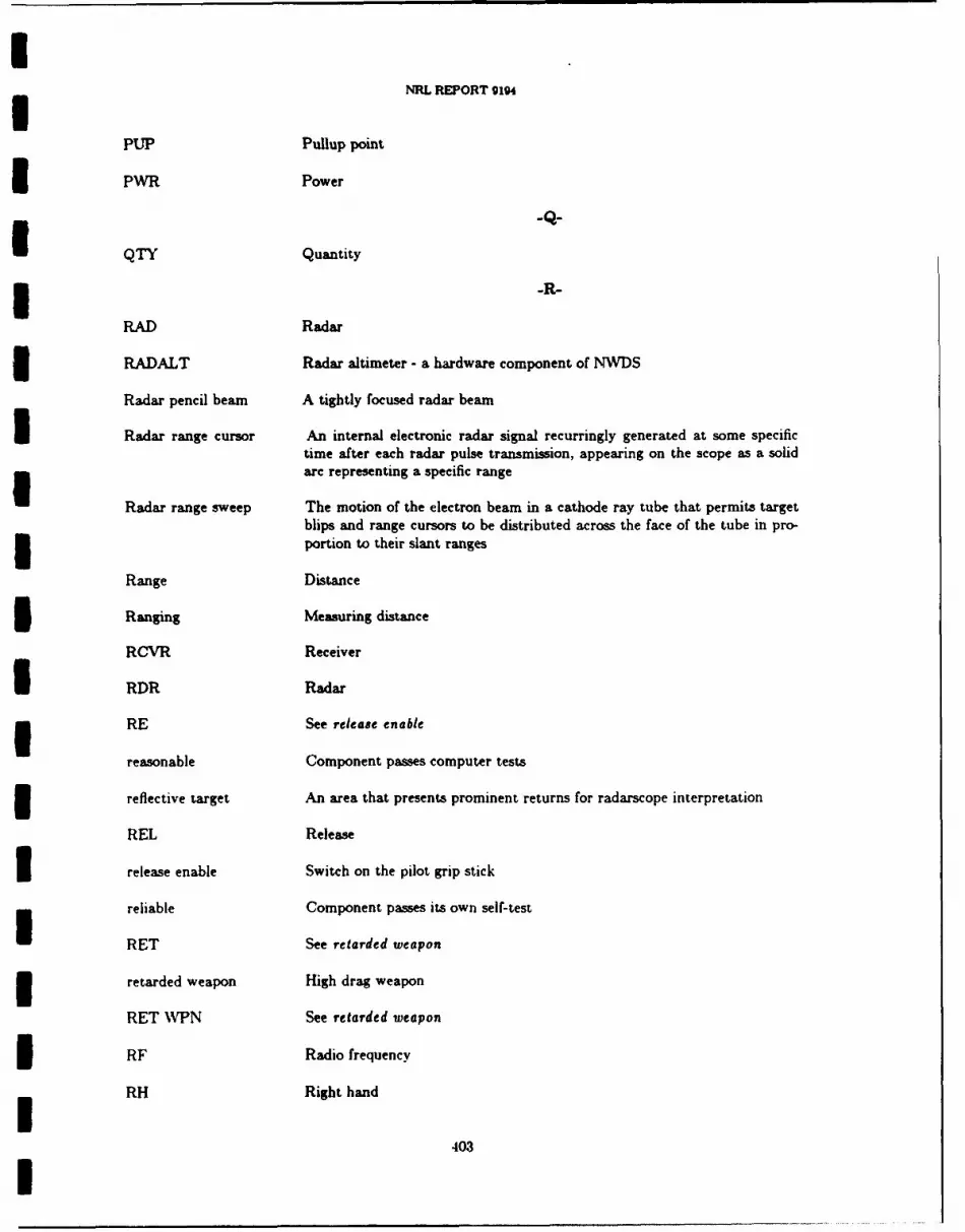
NRL REPORT 9194
PUP Pullup point
PWR Power
QTY Quantity
-R-
RAD Radar
RADALT Radar altimeter - a hardware component of NWDS
Radar pencil beam A tightly focused radar beam
Radar range cursor An internal electronic radar signal recurringly generated at some specifictime after each radar pulse transmission, appearing on the scope as a solidarc representing a specific range
Radar range sweep The motion of the electron beam in a cathode ray tube that permits targetblips and range cursors to be distributed across the face of the tube in pro-3 portion to their slant ranges
Range Distance
Ranging Measuring distance
RCVR Receiver
I RDR Radar
3 RE See release enable
reasonable Component passes computer tests
reflective target An area that presents prominent returns for radarscope interpretation
REL Release
3 release enable Switch on the pilot grip stick
reliable Component passes its own self-test
RET See retarded weapon
3 retarded weapon High drag weapon
RET VPN See retarded weapon
RF Radio frequency
RH Right hand
403

IChapter 10 ALSPAUGH, FAULK, BRITTON, PARKER, PARNAS, AND SHORE
RKTS Rockets
RMAX Maximum range IRMIN Minimum range 3RNG Range
rpm Revolutions per minute 3
s Seconds IS South 3SAM Surface-to-air missile
SAR Storage address register 3SBR Storage buffer register
Schuler tuned A stable platform maintained in an orientation that is perpendicular to the 3earth's gravity
SDC CV-2622/ASN-99 signal data converter
SDP Signal data processor
SIAR Serial Input Address Register 3SIDS Shrike Improved Display System
SIDR Serial Input Data Register ISINS Shipboard Inertial Navigation System 3SF Scale factor
SIMtJLT Simultaneous 3SING Single
SL Sea level Islant range Line-of-sight distance from the aircraft to the target 3slew control Pilot joystick, used to control up-down and right-left movement of a
display symbol. Also called Bullpup control
solution cue HUD symbol providing pilot with release anticipation and appearing on Iscreen when a/c within range of a target. WVeapons delivery can oc..urwhen either cue crosses the flight path marker. 3
404
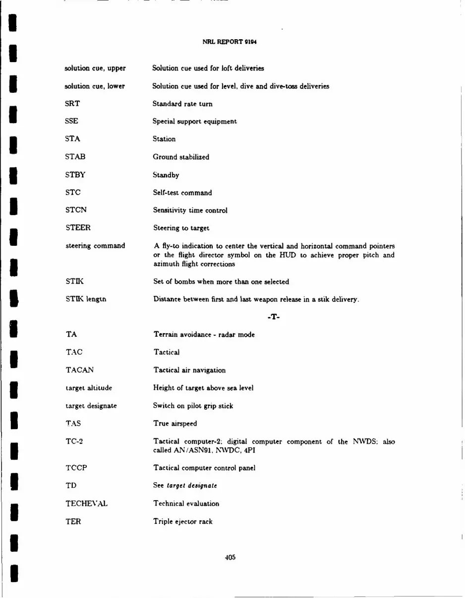
UNRL REPORT 9194
solution cue, upper Solution cue used for loft deliveries
3 solution cue, lower Solution cue used for level, dive and dive-toss deliveries
SRT Standard rate turn
SSE Special support equipment
3 STA Station
STAB Ground stabilized
3 STBY Standby
STC Self-test command
3 STCN Sensitivity time control
STEER Steering to target
steering command A fly-to indication to center the vertical and horizontal command pointersor the flight director symbol on the HUD to achieve proper pitch and3 azimuth flight corrections
STIK Set of bombs when more than one selected
5 STI. lengtn Distance between first and last weapon release in a stik delivery.
U TA Terrain avoidance - radar mode
3 TAC Tactical
TACAN Tactical air navigation
3 target altitude Height of target above sea level
target designate Switch on pilot grip stick
3 TAS True airspeed
TC-2 Tactical computer-2; digital computer component of the NWIDS: alsocalled AN/ASN91, NVDC, 4PI
TCCP Tactical computer control panel
3 TD See target designate
TECHEVAL Technical evaluation
TER Triple ejector rack
4405
U
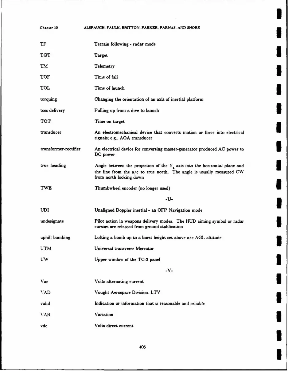
3Chapter 10 ALSPAUGH, FAULK, BRITTON. PARKER, PARNAS, AND SHORE n
TF Terrain following - radar mode
TGT Target ITM Telemetry 3TOF Time of fall
TOL Time of launch 3torquing Changing the orientation of an axis of inertial platform
toss delivery Pulling up from a dive to launch ITOT Time on target
transducer An electromechanical device that converts motion or force into electrical Isignals; e.g., AOA transducer
transformer-rectifier An electrical device for converting master-generator produced AC power to IDC power
true heading Angle between the projection of the Y. axis into the horizontal plane andthe line from the a/c to true north. The angle is usually measured CWfrom north looking down
TWE Thumbwheel encoder (no longer used) I-U- I
UDI Unaligned Doppler inertial - an OFP Navigation mode
undesignate Pilot action in weapons delivery modes. The HUD aiming symbol or radarcursors are released from ground stablization I
uphill bombing Lofting a bomb up to a burst height set above a/c AGL altitude 3UTM Universal transverse Mercator
U V Upper window of the TC-2 panel 3-V-
Vac Volts alternating current IVAD Vought Aerospace Division. LTV 3valid Indication or information that is reasonable and reliable
VAR Variation 3vdc Volts direct current
I406 I
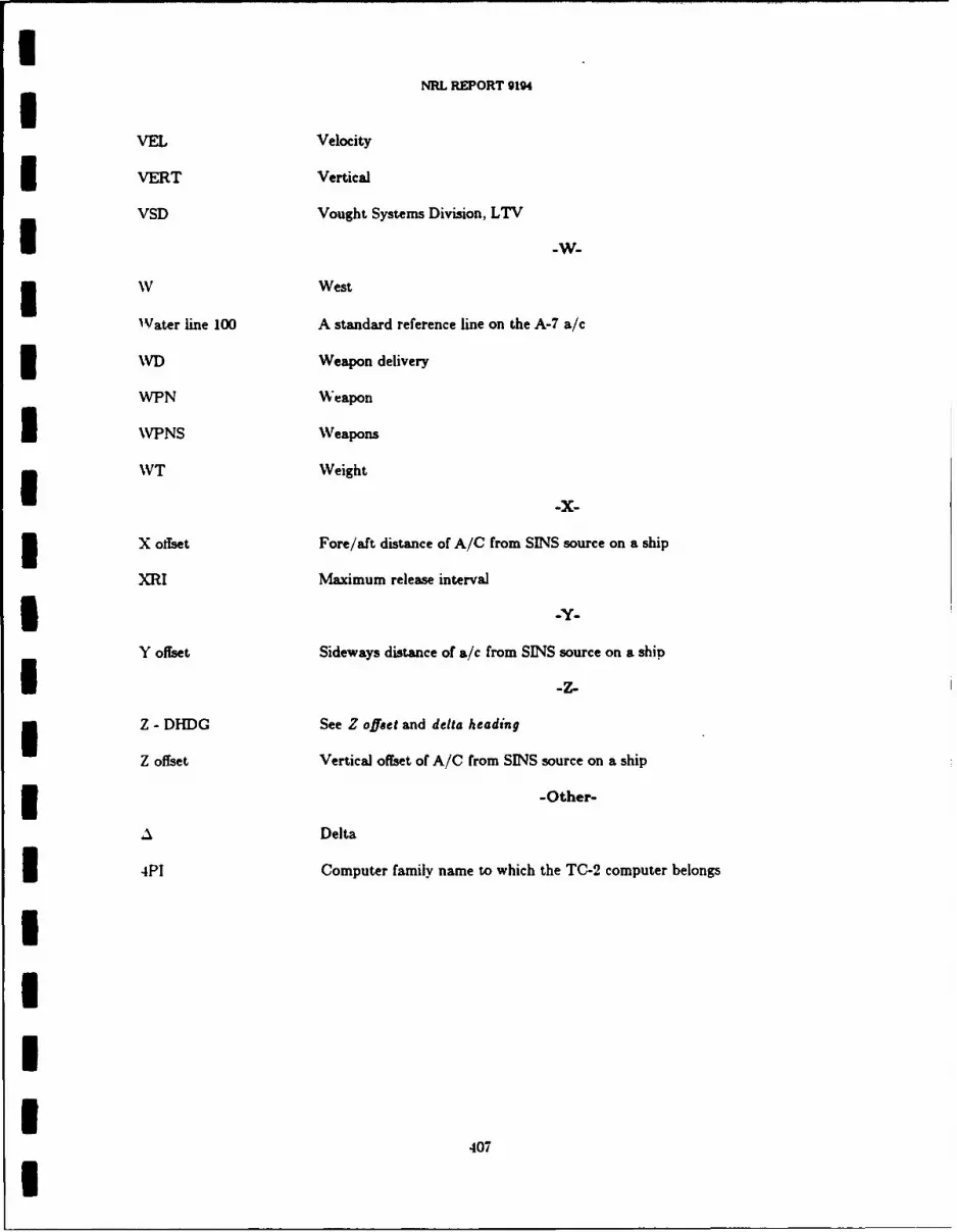
INRL REPORT 9194
VEL Velocity
VERT Vertical
VSD Vought Systems Division, LTV
NV West
Water line 100 A standard reference line on the A-7 a/c
3 WD Weapon delivery
WPN Weapon
I WPNS Weapons
VT Weight
X offset Fore/aft distance of A/C from SINS source on a ship
XRI Maximum release interval
* Y.
Y offset Sideways distance of a/c from SINS source on a ship
I-z.Z - DHDG See Z offset and delta heading
Z offset Vertical offset of A/C from SINS source on a ship
3 -Other-
A Delta
3 4PI Computer family name to which the TC-2 computer belongs
4III
407
I
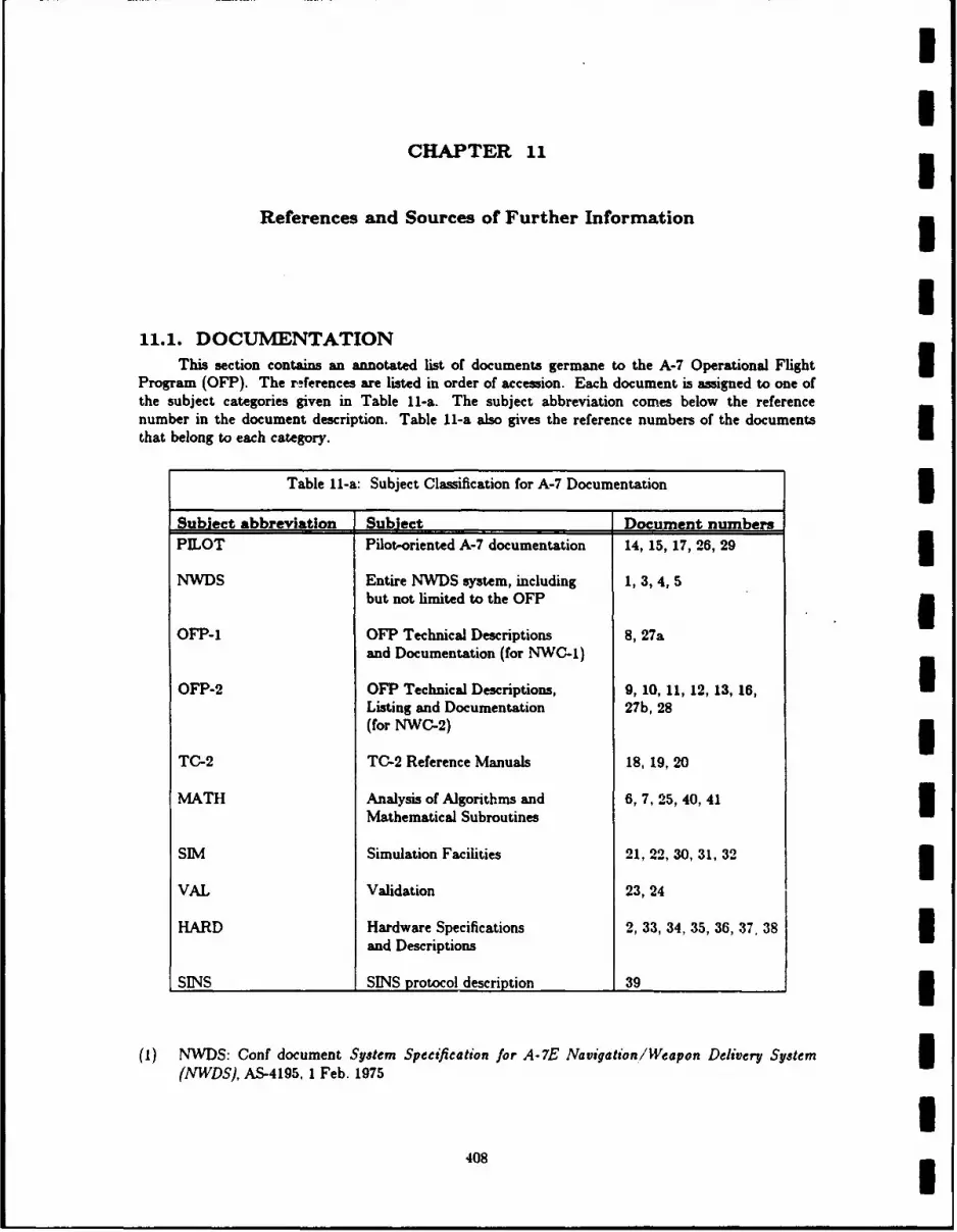
II
CHAPTER 11
References and Sources of Further Information
I11.1. DOCUMENTATION
This section contains an annotated list of documents germane to the A-7 Operational Flight 3Program (OFP). The r4erences are listed in order of accession. Each document is assigned to one ofthe subject categories given in Table 11-a. The subject abbreviation comes below the referencenumber in the document description. Table 11-a also gives the reference numbers of the documentsthat belong to each category.
Table 11-a: Subject Classification for A-7 Documentation 3Subiect abbreviation Subject Document numbers
PILOT Pilot-oriented A-7 documentation 14, 15, 17, 26, 29 3NWDS Entire NWDS system, including 1, 3, 4, 5
but not limited to the OFP 3OFP-1 OFP Technical Descriptions 8, 27a
and Documentation (for NWC-1)
OFP-2 OFP Technical Descriptions, 9, 10, 11, 12, 13, 16, IListing and Documentation 27b, 28(for NWC-2) 3
TC-2 TC-2 Reference Manuals 18, 19, 20
MATH Analysis of Algorithms and 6, 7, 25, 40, 41Mathematical Subroutines
SIM Simulation Facilities 21, 22, 30, 31, 32 3VAL Validation 23, 24
HARD Hardware Specifications 2, 33, 34, 35, 36, 37, 38and Descriptions
SINS SINS protocol description 39 I
(1) NWDS: Conf document System Specification for A-7E Navigation/Weapon Delivery System 3(NWDS), AS-4195, I Feb. 1975
408

INRL REPORT 9194
Functional requirements of the entire NWDS system (not just the software requirements).
Requirements for each of the following components: Digital Computer and panel, ASCU, HUD,PMDS, Doppler, ADI, IMS, HSI. ADC, and FLR
Description of NWC-1 modes and functions, including the following information for each of theattack modes: how initiated, aiming, designation, delivery, backup operation, and pictures ofHUD symbology
Over 100 pages of tables and figures, including the following: Equipment used in different modes.signals between components broken down by navigation and attack modes, pictures and expla-nations of cockpit controls (over 90 pages)A very brief performance requirements section.
1 (2) HARD: Conf document Procurement Specification for Navigation/Weapon Delivery DigitalComputer System for A-7D/E Airplane, 204-16-29g, Nov. 1968
Primarily covers the computer and panel. Many hardware details. Function description mostly
superseded by Refs. 1 and 4 Computer interface descriptions superseded by Ref. 3 except thefollowing charts:
Computer-weapons management interface (p. 57)Miscellaneous controls (p. 59)Wing Station Stores Capability (p. 63) - probably out-of-date
Computer-TACAN interface (p. 67)Computer-AR panel interface (p. 71)Computer-SINS interface (p. 72)
3 (3) NWDS: Conf document A-7 Navigation and Weapon Delivery System and Subsystem Charac-teristics: Accuracies and Tolerances, VSD #2-54150/5R-5790, 8 May 1975
Computer-device tables, with the following information: signal names, types, ranges, accuracies,
scales, modes, etc. for each of the following devices: Doppler, FLR, HSI, ADI, HUD, ADC.PMDS, AOA, IMS.
Subsystem Characteristics and vital statistics
IMS (especially operational limits)FLR (especially mode descriptions, range rates)HUDADC (especially resolution and rate of response)Doppler (especially operational limits, probable error rates)PMDSRadar Altimeter (especially tracking rates)
(4) NWDS: Conf document A-7 Navigation and Weapon Delivery System. VSD #2-14000/5R-5 IMay 1975Narrative presentation of system specified in Ref. 1. Table summarizing tactical computercharacteristics. Table showing memory space allocation of OFP to 5 major modules. Radarmode descriptions with pictures of associated displays. HUD displays with explanatory captionsfor navigation and weapon delivery.
(5) NWDS: Performance Specifications for the Weapon Delivery Function of the OFP (U), IBM #68-L68-012, 3 Dec. 1968
409I
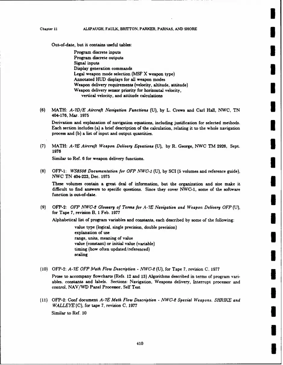
NChapter 11 ALSPAUGH, FAULK, BRITTON. PARKER, PARNAS, AND SHORE
Out-of-date, but it contains useful tables:
Program discrete inputs3Program discrete outputsSignal inputsDisplay generation commandsLegal weapon mode selection (MSF X weapon type)Annotated HUD displays for all weapon modesWeapon delivery requirements (velocity, altitude, attitude)Weapon delivery sensor priority for horizontal velocity,
vertical velocity, and attitude calculations
(6) MATH: A-7D/E Aircraft Navigation Functions (U), by L. Crews and Carl Hall, NWC, TN I404-176, Mar. 1975Derivation and explanation of navigation equations, including justification for selected methods.Each section includes (a) a brief description of the calculation, relating it to the whole navigationprocess and (b) a list of input and output quantities.
(7) MATH: A-7E Aircraft Weapon Delivery Equations (U), by R. George, NWC TM 2926, Sept. 31976Similar to Ref. 6 for weapon delivery functions. 3
(8) OFP-1: WS8506 Documentation for OFP NWC-1 (U), by SCI (5 volumes and reference guide),NWC TN 404-223, Dec. 1975 IThese volumes contain a great deal of information, but the organization and size make itdifficult to find answers to specific questions. Since they cover NWC-1, some of the softwarefunction is out-of-date.
(9) OFP-2: OFP NWC-2 Glossary of Terms for A-7E Navigation and Weapon Delivery OFP (U),for Tape 7, revision B, I Feb. 1977
Alphabetical list of program variables and constants, each described by some of the following: 3value type (logical, single precision, double precision)explanation of userange, units, meaning of value Uvalue (constant) or initial value (variable)timing (how often updated/referenced)scaling
(10) OFP-2: A-7E OFP Math Flow Description - NWC-2 (U), for Tape 7, revision C. 1977
Prose to accompany flowcharts (Refs. 12 and 13) Algorithms described in terms of program vari-ables, constants and labels. Sections: Navigation, Weapons delivery, Interrupt processor andcontrol, NAV/WD Panel Processor, Self Test
(11) OFP-2: Conf document A-7E Math Flow Description - NWC-2 Special Weapons. SIIKE andWALLEYE (C), for tape 7, revision C, 1977
Similar to Ref. 10 3
I410 3
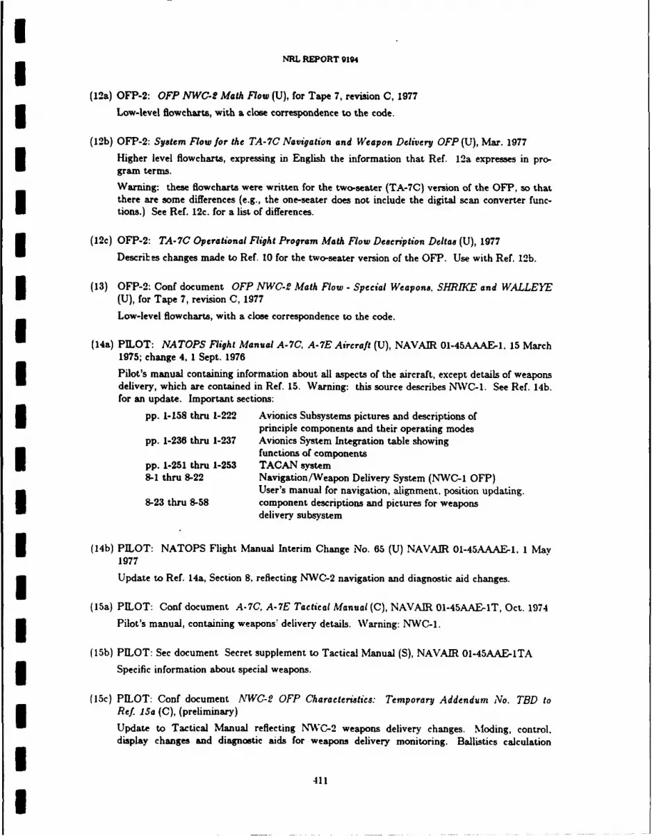
INRL REPORT gg4
(12a) OFP-2: OFP NWC-2 Math Flow (U), for Tape 7, revision C, 19775 Low-level flowcharts, with a close correspondence to the code.
(12b) OFP-2: System Flow for the TA-7C Navigation and Weapon Delivery OFP (U), Mar. 1977
fHigher level flowcharts, expressing in English the information that Ref. 12a expresses in pro-gram terms.
Warning: these flowcharts were written for the two-seater (TA-7C) version of the OFP, so thatthere are some differences (e.g., the one-seater does not include the digital scan converter func-tions.) See Ref. 12c. for a list of differences.
(12c) OFP-2: TA-7C Operational Flight Program Math Flow Description Deltas (U), 1977
Describes changes made to Ref. 10 for the two-seater version of the OFP. Use with Ref. 12b.
(13) OFP-2: Conf document OFP NWC-2 Math Flow - Special Weapons, SHRIKE and WALLEYE(U), for Tape 7, revision C, 1977
Low-level flowcharts, with a close correspondence to the code.
(14a) PILOT: NATOPS Flight Manual A-7C, A-7E Aircraft (U), NAVAIR 01-45AAAE-1. 15 March1975; change 4, 1 Sept. 1976Pilot's manual containing information about all aspects of the aircraft, except details of weaponsdelivery, which are contained in Ref. 15. Warning: this source describes NWC-1. See Ref. 14b.for an update. Important sections:
pp. 1-158 thru 1-222 Avionics Subsystems pictures and descriptions ofprinciple components and their operating modes
pp. 1-236 thru 1-237 Avionics System Integration table showingfunctions of components
pp. 1-251 thru 1-253 TACAN system8-1 thru 8-22 Navigation/Weapon Delivery System (NWC-1 OFP)
User's manual for navigation, alignment, position updating.8-23 thru 8-58 component descriptions and pictures for weapons
delivery subsystem
(14b) PILOT: NATOPS Flight Manual Interim Change No. 65 (U) NAVAIR 01-45AAAE-1, 1 May19773 Update to Ref. 14a, Section 8, reflecting NWC-2 navigation and diagnostic aid changes.
(15a) PILOT: Conf document A-7C, A-7E Tactical Manual (C), NAVAIR 01-45AAE-1T, Oct. 19745 Pilot's manual, containing weapons' delivery details. Warning: NWC-1.
(15b) PILOT: Sec document Secret supplement to Tactical Manual (S), NAVAIR 01-45AAE-ITA5 Specific information about special weapons.
(15c) PILOT: Conf document NWC-2 OFP Characteristics: Temporary Addendum No. TBD toRef. 15a (C), (preliminary)Update to Tactical Manual reflecting N WC-2 weapons delivery changes. Moding, control,display changes and diagnostic aids for weapons delivery monitoring. Ballistics calculation
I4113

IChapter 11 ALSPAUGH. FAULK. BRITTON, PARKER. PARNAS, AND SHORE 3
changes for special weapons.
(16) OFP-2: OFP NWC-2 Program Listing and Cross References (U), NWC-2 Tape 7 Revision C, 3
Oct. 1977
Secret parts encoded. 3(17) PILOT: OFP A7 NWC-2 Viewgraph Presentation (U), 22 April 1977
Presentation prepared for pilots, showing the differences between NWC-1 and NWC-2, particu-
larly weapon's delivery: moding, display, diagnostics
(18) TC-2: Introduction to TC- Assembly Language Programming for A-7D/E Programmers (U), 3SCI, by G. Abels, Feb. 1976
Compilation of Refs. 19, 20. and Assembler Language manuals, written by a tech writer. (NOT
RELIABLE). Confuses TC-2 and TC-2A in places.
(19) TC-2: A.7D/E Programmers Guide to Input/Output for the TC-2 (U), IBM #6870158-3, 25
May 1970
For each input and output channel, it gives: information items, associated devices, data format.
Explanation of cycle-stealing I/O and the BITE instruction. Some corrections have been made
in our copy based on Lee Thomson's marginal notes. I(20) TC-2: A-7 D/E Programmer's Reference Manual (U), IBM #67-506-001, 14 Sept. 1967
Data and instruction formats, registers, interrupt processing, addressing. For each instruction:
opcode and mnemonic, operands, timing, formats, affected indicators
(21) SIM: A-7C/E Simulation Computer Program Documentation (U), Parts 1-6, NWC TM 3105,Feb. 1977
Documentation for the V & V simulation laboratory (Sigma 5, VG, etc.). Pts. I and 2 provide
an indirect description of the OFP, since they contain models of most of the interfaces - they Ishow what assumptions had to be made about the OFP and other components to simulate the
Avionics system.
(22) SIM: A-7E Simulator Software Capabilities (U), NWVC TN 404-186, May 1974 1Simulator description superseded by Ref. 21. Brief description of other software support on the
SIGMA 5 and PDP 11, including the assembler and Tape merge, punch and verify program 3(23) VAL: A-7 Simulation Facility - Cursory Validation Plan for OFP NWC-2 (U), NWC TM 3159,
Jan. 1977
Description of the short, 40-hour version of formal validation. Mostly derived from Ref. 24.
(24) VAL: .4-7 OFP Validation Plan and Procedures for Simulation Facilities (U), OFP NWC-2. IParts 1 and 2, NWC TM 3204, Mar. 1977
Part I gives background and justification for the test approach. Part I appendix: user's manual
for entering and displaying data on the NWDC panel, including units, accuracy and meaning of Ivarious panel quantities. Part 2 shows how the OFP should behave in a large number of testcases.
I412
INRL REPORT 9194
(25) MATH: A.7D/E Mathematical Subroutine Description (U), IBM #6870156-3, 25 May 1970
For each of the 16 subroutines:flowchart
interfaces (in parameters, calling routines, called routines, etc.)data organizationlimitations (e.g. register contents destroyed, max size of input)storage requiredexecution time
The descriptions should be checked against the code, but they should still be substantiallycorrect.
1 (26) PILOT: A Pilot's Guide to the Use and Understanding of the A-7E Avionics System (U), VA-122, 29 Jan. 1973 Update
This manual should not be trusted for facts - it covers an earlier version of the OFP, and it wasnever formally released. However, it does provide background information and explanationwhich may aid understanding.
I (27a) OFP-I: Technical Description of NWC First A7E Operational Flight Program (OFP) (U) by R.R. Bruckman, NWC Reg Memo 40408, 31 Aug. 1973, Rev. A
Describes changes to be made to an earlier version of the OFP. Mostly focuses on weaponsdelivery changes.
(27b) OFP-2: Technical Description of NWC-2 Operation Flight Program (U), Preliminary, rev. F, 21Apr. 1976
Describes changes between NWC-l and NWC-2. Mostly focuses on weapons delivery changes.
I (28) OFP-2: Advanced Organizational Maintenance Data to be incorporated into NAVAIR 01-45AAE-2-17.2 (U). 15 Aug. 1977Update to maintenance manual, reflecting NWC-2 changes. More complete description of diag-nostic panel displays than Ref. 29. Discussions of alignment, updating, and weapons delivery.
(29) PILOT: In Panel Display Card (U)
Reference card showing NWDC panel displays for data locations 00-99, used for navigation,weapons delivery and maintenance diagnostics. Page 8 summarizes the pilot procedures for3 navigation updates. Page 9 explains when the INA should be steady or flashing.
(30) SIM: CADU Reference Card (U)
Informal list of instructions for the Control and Display Unit (CADU) used to load and debugOFPs in the laboratory TC-2 computers. The CADU allows limited tracing and breakpoint set-ting.
(31) SIM: Weapons Station Simulator (U), by Jack Williams, NWC 2706, Sept. 1976
Physical characteristics, components and operation of the Weapons Station Simulator laboratory3 (downstairs in hangar 3). Includes wiring diagrams and detailed signal descriptions.
(32) SIM: Weapons Management Simulation and Control (U), by Jack Williams, NWC 3029, Dec.3 1976
413I
IChapter 11 ALSPAUGH, FAULK, BRITTON, PARKER, PARNAS. AND SHORE
Description of the weapons simulation laboratory focusing on the weapons delivery controls andcomponents (ASCU, ARP, etc.). Wiring diagrams, decoder logic, and signal descriptions. Someprose which explains the use of the controls.
(33a-h)HARD: Procurement Specifications for NWDS components.
a. Inertial Measurement Set AN/ASN-90(V) (U)
b. Navigation Set, Radar AN/APN-190(V (U) (Doppler) Includes:
One paragraph description of operationOperational limitsElectrical outputs: range, probable error formData transmission and word formatResolution and timing
c. Air Data Computer (U)
d. Transducer, Angle of Attack (U)
e. Forward Looking Radar System (AN/APQ-126) (U)
f. Projected Map Display Set (U)g. Head Up Display (U) Includes:
3.3.29 Discussion of symbology functionsParagraphs per symbol, showing meaning, scale, limits, etc.
3.3.40 Digital Data Channel DescriptionList of data with identity codes
3.4.1 Symbol positioning accuracies
h. Projected Map Display Set for A-7E Airplane, Film-strip for (U) Ii. Specification for Multicolor 85MM Film-strips for the Projected Map Display System (U) draft,
18 Nov. 1968j. DoD Procurement Specifications for Projected Map Display Set for the A-7 Aircraft (U), June
1974
(34) HARD: A/7D/E Head Up Display (U), by W. N. Carroll, IBM 68-L88-099, 8 Apr. 1968 I(35) HARD: General Description of the Head Up Display (An/A VQ-7) for the A-7D/E Airplane (U),
by I. S. Glickstein, IBM 69-M93-001, 14 Feb. 1969
(36) HARD: General Description of the Projected Afap Display Set for the A-7E Airplane (U), byIra S. Glickstein, IBM 69-M93-003, 10 June 1969
(37) HARD: Addendum No. 6, Projected-Map Display Set Functional and Performance Require-mento for A-7E Airplane Navigation/Weapon Delivery System (NWDS) (U), IBM 209-18-67b, 9July 1968
(38) HARD: NAVAIR Maintenance Manuals Ia. Inertial Measurement Set AN/ASN-90 (V): NAVAIR 05-35EAB-I, 15 Nov. 1971, Change 8 - 1
Nov. 1977 I
414
INRL REPORT 9194
b. Head-Up Display Set AN/AVQ-7 (V): NAVAIR 05-35FAB-I, 15 Apr. 1972, Change 7 - 15 Oct.1977
c. Projected Map Display Set AN/ASN-99 (V): NAVAIR 05-35FAC-1, 15 Aug. 1971, Change 4 -15 Jan. 1977
I (39) SINS: Conf document Shipboard Data Link System Requirements for Aircraft Inertial Naviga-tion System Alignment and Waypoint Insertion Naval Air Systems Command, AR-57A, 3 May1971
(49) MATH: A Ballistic Trajectory Algorithm for Digital Airborne Fire Control (U) by Duke,Brown, Burke, and Seeley, NWC TP 5416, 17 Aug. 1972
(41) MATH: Coordinate Systems Analyst Manual (BLSIM5) (U) by Kobaly (Systems Consultants,Inc.), Renta and Breisch (NWC A-7D Project Office), July 1979.
IIII
III
415I

IChapter 11 ALSPAUGH, FAULK, BRITTON, PARKER, PARNAS, AND SHORE
11.2. PEOPLE TO CONTACT FOR MORE INFORMATIONThis section used to contain an annotated list of the people who could answer questions about I
various aspects of the A-7E, as well as the people who worked on the A-7E software engineering pro-ject. This information is very outdated, and those individuals have long since moved to various otherprojects, so it has been deleted.
The information which used to be here gave the name of each individual, the naval facility andaddress where he/she worked, phone numbers, and how the individual contributed to the project (e.g.,"A-7 project member", "weapons delivery equations", etc.).
IIII
IIIIIIII
416
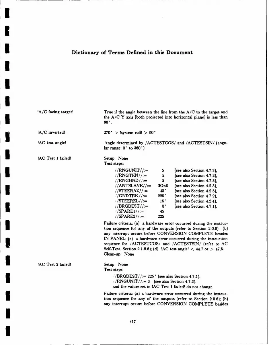
I
I
-- Dictionary of Terms Defined in this Document
!A/C facing target! True if the angle between the line from the A/C to the target andthe A/C Y axis (both projected into horizontal plane) is less than90*.
u !A/C inverted! 270 > !system roll! > 90
!AC test angle! Angle determined by /ACTESTCOS/ and /ACTESTSIN/ (angu-lar range: 0 to 360").
!AC Test I failed! Setup: None
Test steps:
//RNGUNIT//:= 5 (see also Section 4.7.3),!//RNGTEN//:= 5 (see also Section 4.7.3),//RNGHND//:= 5 (see also Section 4.7.3),//ANTSLAVE//:- SOnS (see also Section 4.2.3),//STEERAZ//:- 45' (see also Section 4.2.5),'/GNDTRK//:= 225 (see also Section 4.7.2),,/STEEREL//:= 15" (see also Section 4.2.4),//BRGDEST//:= 0 (see also Section 4.7.1),'/SPARE1//:= 45//SPARE2//:= 225
Failure criteria: (a) a hardware error occurred during the instruc-
tion sequence for any of the outputs (refer to Section 2.0.6). (b)any interrupt occurs before CONVERSION COMPLETE besidesIN PANEL; (c) a hardware error occurred during the instructionsequence for iACTESTCOS/ and /ACTESTSIN/ (refer to ACSelf-Test. Section 2.1.8.6); (d) !AC test angle! < 44.7 or > 47.5.Clean-up: None
!AC Test 2 failed! Setup: None
Test steps:
J /BRGDEST!/:= 225 (see also Section 4.7.1),I/RNGUNIT//:= 3 (see also Section 4.7.3),and the values set in LAC Test 1 failed! do not change.
Failure criteria: (a) a hardware error occurred during the instruc-tion sequence for any of the outputs (refer to Section 2.0.6); (b)any interrupt occurs before CONVERSION COMPLETE besides
I417I

IDictionary ALSPAUGH, FAULK. BRITTON, PARKER, PARNAS, AND SHORE 3
IN PANEL; (c) a hardware error occurred during the instructionsequence for /ACTESTCOS/ and /ACTESTSIN/ (refer to ACSelf-Test, Section 2.1.8.6); (d) 1AC test angle! < 49.14 or >52.0 *.Clean-up: None
!ACI Tstage! Stage of *Grtest*. See Section 3.7.0.
!AC2 Tstage! Stage of *Grtest*. See Section 3.7.0.
!acc bias! Part of each incremental velocity measurement is an error causedby the misalignment of an accelerometer with its associated gyro.The biases caused by gyro-accelerometer misalignment are mea- Isured for each axis and can be entered in the TC-2 by the mainte-nance personnel (see Sections 4.6.25 and 4.6.26).
ADO Reasonable! 150 fps < /TAS/ < 1024 fps
!ADC Up! /ADCFAIL/--$No$ AND tADC Reasonable! 5!adjusted point! The position of the aiming symbol after the pilot moves it with the
slew control.
!After slewing! @T(ABS(/SLEWUD/) < 0.148 AND ABS(/SLEWRL/) < 0.148)
!Aiming switches set! /MODEROT/--$PRESPOSS AND /PRESPOS/--3UPDATESAND /UPDATTW/--IMS-HUD$ I
!Air velocity test passed! Difference between !IMS NVel! and !Doppler NVe!, and between!IMS EVel! and !Doppler EVel! < 5 fps I
lterable data displayed! One of the following Panel Display Functions is controlling thepanel output data items:
Update Present Position Coordinates DisplayUpdate Wind DisplayUpdate SINS X and Y Offsets DisplayUpdate SINS Z Offset and Delta Heading DisplayUpdate Magnetic Variation Display (1-9)Update Platform Heading and Reference Hdg DisplayUpdate Destination Coordinates Display (1-9) IUpdate Destination Altitude and MSLP Display (1-9)ldpdate Offset Range and Bearing Display (1-9)Update Offset Delta Ht. and Burst Ht. Display (1-9)Update Data 01 Through Data 26 Display
The rules for determining which function controls the panel aregiven in Section 4.6.1.
!alternate steering! See Section 4.3.2
!Altitude from slant range! Above ground altitude can be calculated from /SLTRNG/ and thedepression angle from horizontal to the point on the ground thatthe FLR is aimed at since they provide the length of a side and an
I
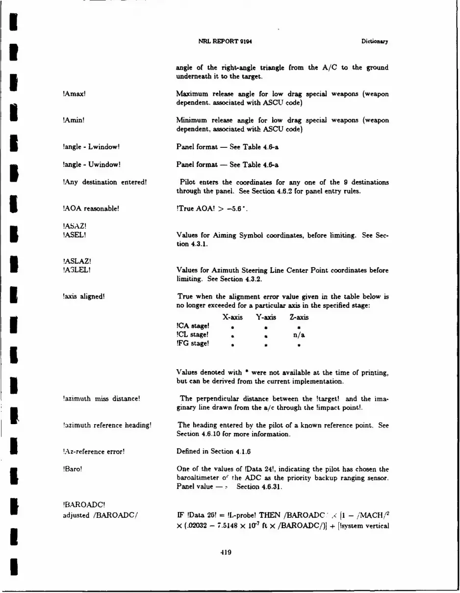
INRL REPORT 9194 Dictionary
angle of the right-angle triangle from the A/C to the ground3 underneath it to the target.
!Amax! Maximum release angle for low drag special weapons (weapondependent. associated with ASCU code)
!Amin! Minimum release angle for low drag special weapons (weapondependent, associated with ASCU code)
3 !angle - Lwindow! Panel format - See Table 4.6-a
!angle - Uwindow! Panel format - See Table 4.6-a
!Any destination entered! Pilot enters the coordinates for any one of the 9 destinationsthrough the panel. See Section 4.6.2 for panel entry rules.
I !AOA reasonable! !True AOA! > -5.6".
!ASAZ!!ASEL! Values for Aiming Symbol coordinates, before limiting. See Sec-
tion 4.3.1.
!ASLAZ!!A3LEL! Values for Azimuth Steering Line Center Point coordinates before
limiting. See Section 4.3.2.
5 !axis aligned! True when the alignment error value given in the table below isno longer exceeded for a particular axis in the specified stage:
X-axis Y-axis Z-axis!CA stage!!CL stage! , , n/a!FG stage! , *
Values denoted with * were not available at the time of printing,3 but can be derived from the current implementation.
!azimuth miss distance! The perpendicular distance between the !target! and the ima-I ginary line drawn from the a/c through the !impact point!.
!azimuth reference heading! The heading entered by the pilot of a known reference point. See
Section 4.6.10 for more information.
I !Az-reference error! Defined in Section 4.1.6
!Baro! One of the values of !Data 24!, indicating the pilot has chosen thebaroaltimeter o the ADC as the priority backup ranging sensor.Panel value - .- Section 4.6.31.
!BAROADC!adjusted /BAROADC/ IF !Data 26! = !L-probe! THEN /BAROADC' z 1 - /MACH!'
X (.02032 - 7.5148 X 10⁻⁷ ft X /BAROADC/)] + [!system vertical
419I
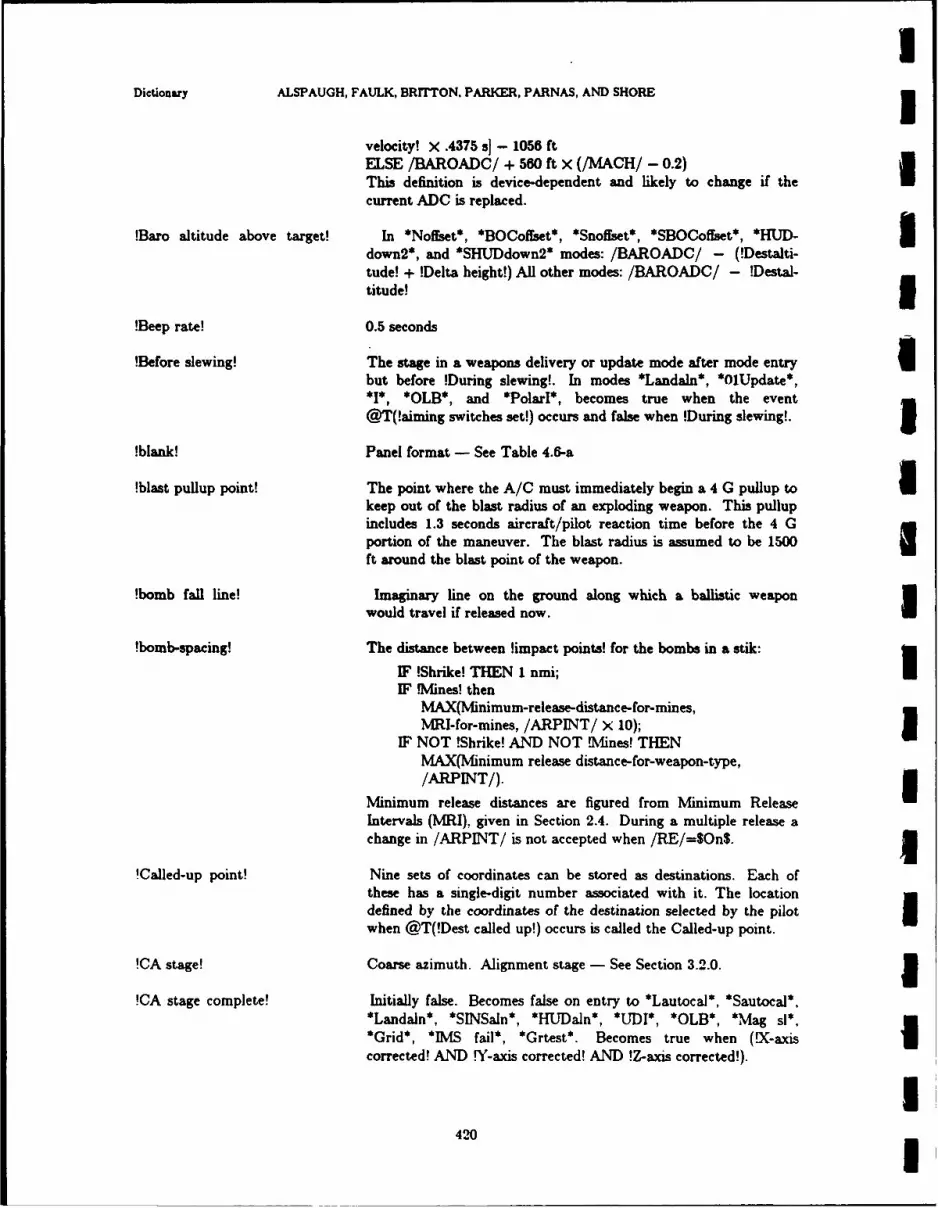
IDictiony ALSPAUGH, FAULK, BRITTON. PARKER, PARNAS, AND SHORE 3
velocity! X .4375 s] - 1056 ftELSE /BAROADC/ + 560 ft x (/MACH/ - 0.2)This definition is device-dependent and likely to change if thecurrent ADC is replaced.
!Baro altitude above target! In *Noffset*, *BOCoffset*, *Snoffset*, *SBOCoffset*, *HUD- Idown2*, and *SHUDdown2* modes: /BAROADC/ - (!Destalti-tude! + !Delta height!) All other modes: /BAROADC/ - !Destal-titude! 5
!Beep rate! 0.5 seconds
!Before slewing! The stage in a weapons delivery or update mode after mode entry Ubut before !During slewing!. In modes *Landaln*, *01Update*,*1*, *OLB*, and *PolarI*, becomes true when the event
@T(!aiming switches set!) occurs and false when !During slewing!. I!blank! Panel format - See Table 4.6-a
!blast pullup point! The point where the A/C must immediately begin a 4 G pullup to Ikeep out of the blast radius of an exploding weapon. This pullupincludes 1.3 seconds aircraft/pilot reaction time before the 4 Gportion of the maneuver. The blast radius is assumed to be 1500ft around the blast point of the weapon.
!bomb fall line! Imaginary line on the ground along which a ballistic weaponwould travel if released now. I
!bomb-spacing! The distance between !impact points! for the bombs in a stik:
IF !Shrike! THEN 1 nmi; UIF .Mines! then
MAX(Minimum-release-distance-for-mines,MRI-for-mines, /ARPINT/ X 10);
IF NOT !Shrike! AND NOT Mines! THENMAX(Minimum release distance-for-weapon-type,/ARPINT/). 5
Minimum release distances are figured from Minimum ReleaseIntervals (MRI), given in Section 2.4. During a multiple release achange in /ARPINT/ is not accepted when /RE/=$On$.
!Called-up point! Nine sets of coordinates can be stored as destinations. Each ofthese has a single-digit number associated with it. The locationdefined by the coordinates of the destination selected by the pilot Iwhen @T(!Dest called up!) occurs is called the Called-up point.
!CA stage! Coarse azimuth. Alignment stage - See Section 3.2.0. 1!CA stage complete! Initially false. Becomes false on entry to *Lautocal*, *Sautocal*,
*Landaln*, *SINSaln*, *HUJDaln*, *ULDI*, *OLB*, *Mag sl*,
*Grid*, *IMS fail*, *Grtest*. Becomes true when (!X-axis Icorrected! AND !Y-axis corrected! AND !Z-axis corrected!).
I
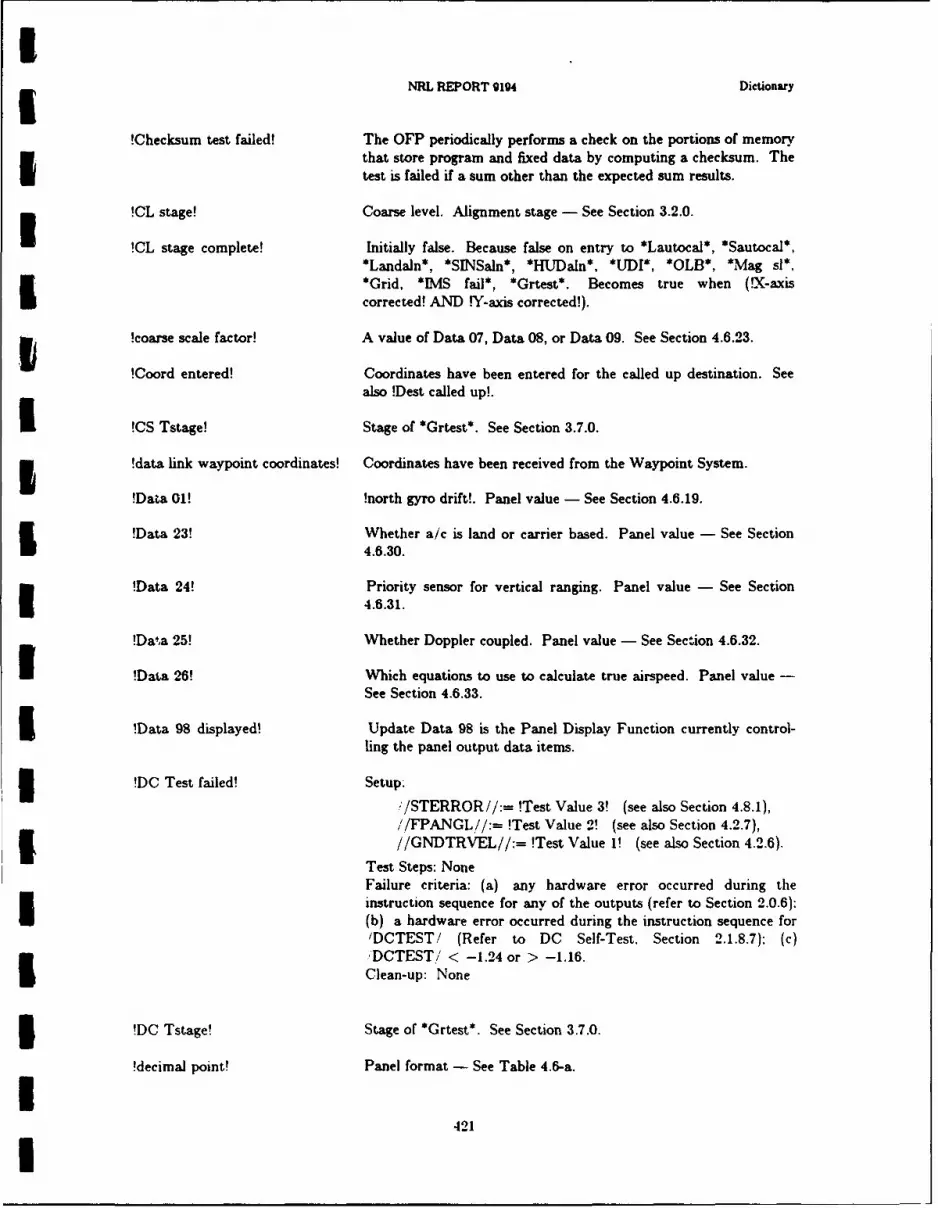
SNRL REPORT 9194 Dictionary
!Checksum test failed! The OFP periodically performs a check on the portions of memoryI that store program and fixed data by computing a checksum. The
test is failed if a sum other than the expected sum results.
!CL stage! Coarse level. Alignment stage - See Section 3.2.0.
!CL stage complete! Initially false. Because false on entry to *Lautocal*, *Sautocal*,*Landaln*, *SINSaln*, *HUDaln*, *UJDI*, *OLB*, *Mag sl*,*Grid, *IMS fail*, *Grtest*. Becomes true when (lX-axis
corrected! AND IY-axis corrected!).
!coarse scale factor! A value of Data 07, Data 08, or Data 09. See Section 4.6.23.
!Coord entered! Coordinates have been entered for the called up destination. Seealso !Dest called up!.
I !CS Tstage! Stage of *Grtest*. See Section 3.7.0.
5 !data link waypoint coordinates! Coordinates have been received from the Waypoint System.
!Data 01! !north gyro drift!. Panel value - See Section 4.6.19.
!Data 23! Whether a/c is land or carrier based. Panel value - See Section4.6.30.
!Data 24! Priority sensor for vertical ranging. Panel value - See Section4.6.31.
!Daa 25! Whether Doppler coupled. Panel value - See Section 4.6.32.
!Data 26! Which equations to use to calculate true airspeed. Panel value -See Section 4.6.33.
!Data 98 displayed! Update Data 98 is the Panel Display Function currently control-ling the panel output data items.3 !DC Test failed! Setup.
!/STERROR//:= !Test Value 3! (see also Section 4.8.1),//FPANGL//:= !Test Value 2! (see also Section 4.2.7),//GNDTRVEL//:= !Test Value 1! (see also Section 4.2.6).
Test Steps: NoneFailure criteria: (a) any hardware error occurred during theinstruction sequence for any of the outputs (refer to Section 2.0.6);(b) a hardware error occurred during the instruction sequence for'DCTEST/ (Refer to DC Self-Test, Section 2.1.8.7): (c),DCTEST/ < -1.24 or > -1.16.Clean-up: None
3 !DC Tstage! Stage of *Grtest*. See Section 3.7.0.
!decimal point! Panel format - See Table 4.6-a.
I421I

IDictionary ALSPAUGH, FAULK, BRITTON, PARKER, PARNAS, AND SHORE 1!Delta heading! Angle entered by pilot indicating difference between A/C heading
and ship heading. Panel value - See Section 4.6.8.
!Delta height! Difference in altitude between the OAP and the target. Panelvalue - See Section 4.6.14. 1
!Desig! The pilot has identified a target to the computer. Initial value:false. Table D-d shows when !Desig! changes value. a
!Designation-retention! !Desig! AND !Desig! last became true in *BOC*, *BOCFytoO* or*BOCoffset*.
!Destaltitude! An altitude entered by the pilot asociated with a particular desti-nation. Panel value - See Section 4.6.12.
!Dest called up! During update modes, the pilot keys in the single non-zero digit Ithat identiies the destination to be used as the update referencepoint. !Dest called up! becomes true when @T(!Non-zero digitentered!) occurs while in an update mode. It becomes false uponexit from the current update mode.
!DEST displayed! Update Destination Coordinates Display (see Section 4.6.11) is thePanel Display Function currently controlling the panel output data Iitems.
!Dest 0! /FLYTOTOG/ = $Dest$ AND /FLYTOTW/= 0
!Dest 1-9! /FLYTOTOG/ff= gDest$ AND /FLYTOTW/# 0
!DGNDSP! if !BAROADC! is available /DGNDSP/ [/DGNDSP/ x 1!BAROADC! / 4000000 feet] otherwise /DGNDSP/ - [/DGNDSP/x 9 / 8000]This definition is device-dependent and likely to change if thecurrent Doppler is replaced.
!DIO Tstage! Stage of *Grtest*. See Section 3.7.0. 5!Discrete I/O Test failed! Setup: //BITEI//:= SWRAPDISCRS, //BITE2//:= $None$.
Subtest 1 - Step: //DOWI//:= 00A41 . Failure criteria:/DIVI/ # 00A410. 3Subtest 2 - Step: //DOW2//:= A5A4 10, Failure criteria:
/DIW2/ )!- A5A40 ISubtest 3 - Step: //DOW2//:= 5A5A,,. Failure criteria:
/DIW2/ o 5A5A 16.
Clean-up:
//DOW1//:= 00001, I//DOW2//:= 000016,i/BITEI//:= $None$,
422

IiNRL REPORT 9194 Dictionary
//BITE2//:- SNone.I!Displayable difference! Some of the Update Panel Functions are concerned with values
that change continuously, such as the A/C position when it is air-borne. The functions update the values to be displayed on thepanel at discrete intervals. !Displayable difference! occurs whenthe difference between the most recent update value and thecurrent value is greater than the resolution for that function.
!distance to release! With !high drag! weapons, the !ground range! the A/C must travelto reach the point where it should release the first weapon in thestik. Measured in feet.
!dive pullup! If the A/C is close enough to the target, there exist two pitchangles (one greater than the pitch for maximum range, one lessthan this pitch) from which the aircraft, at present position andairspeed, would release a !low drag! weapon, and the weaponwould reach burst height at the target. If the aircraft is closeenough for these two angles to be calculated, !dive pullup! is thelower of the two pitch angles minus the !system pitch!. Otherwise,
!dive pullup! is 42' minus !system pitch!.
!Doppler coupled! One of the values of !Data 25!, used by the pilot to select ordeselect the use of the Doppler radar when in an inertial naviga-tion mode. This value indicates Doppler should be used. Panelvalue - See Section 4.6.32.
!Doppler EVel! East component of !DGNDSP!
!Doppler NVel! North component of !DGNDSP!
!Doppler Reasonable! True iff/DRSREL/ = $Yes$ for last 5 seconds AND256 fps < !DGNDSP! < 1456 fps AND!DGNDSP! change from .2 s ago < 79 fps AND/DRFTANG /< 29.5" AND/DRFTANG / change from .2 s ago _< 4' ANDat least I bit change in either /DGNDSP/ or /DRFTANG/in last 2 seconds
!Doppler Up! /DRSREL/ = SYes$ AND /DRSMEM/ = SNo$ AND !DopplerReasonable!
'drift angle! IF !Doppler Up! THEN /DRFTANGi ELSE !IMS drift angle!
I !during platform slewing! ,XSLEW//= SOnS OR //YSLEW//= SOnS OR //ZSLEW//= SOnS.
5 !During slewing! At least one of /SLEWUD/ or /SLEWRL/ indicates slew controldisplayed from center. If the slew control were a perfect device.the meaning of this term would be (NOT /SLEWUD/ = 0 OR
423U

IDictionary ALSPAUGH, FAULK, BRITTON, PARKER. PARNAS, AND SHORE 3
NOT /SLEWRL/ - 0). Since the slew control is not perfect, seeSection 2.2.2 for reliable indications of displacement.
!echo! The characters typed in by the pilot are echoed in the panel win-dow. Exactly what is displayed depends on the format of thedisplay that he is entering. For example, when a display of format U!lat! is displayed, the first /KBDINT/ must be either $S or $N$,or else an error has been made. If the first input is correct, either/ /ULITN//=--$On$ or //ULITS//:--$On$. Subsequent/KBDINT/ values are shown in panel windows.
!ED stage! East drift. Alignment stage - See Section 3.2.0. j!ED stage complete! Initially false. Becomes false on entry to *Lautocal*, *Sautocal*.
*HUDaln*, *UDI*, *OLB*, *Mag sl*, *Grid*, *IMS fail*,*Grtest*. Becomes true when !Data 02! has been calculated and
(!X-axis corrected! AND !Y-axis corrected! AND !Z-axiscorrected!).
!eligible release! !Desig! AND PUAC in view I!EW! One of two values of Data 19 and Data 20. indicating that the
associated map area is oriented East-West. See Section 4.6.28. I!FG stage! Fine gyrocompass. Alignment stage - See Section 3.2.0
!fine scale factor! A value of Data 10 or Data 11. See Section 4.6.24. 3!fire pulse width! Length of time that //BMBREL//=$On$ should be true to cause
the ASCU to release a particular weapon. The fire pulse widths Uvary from weapon to weapon and are given in Table 2.4-a.
!fixpoint! In Update modes after @T(!Dest called up!) occurs, the referencepoint is one of the nine destinations, until the pilot slews the aim- Iing symbol or radar cursors to show his idea of the reference pointlocation. After he slews, the aiming symbol or cursors track thepoint the pilot left them over when he finished slewing. Thisrefined point is the fixpoint.
!flight path angle! !system pitch! - [!True AOA! X Cosine(!system roll!)] 3!FLY-TO changed! Value of either /FLYTOTOG/ or /FLYTOTW/ changed.
!FLY-TO MSLP! See Section 4.3.3 The MSLP associated with the location indi- Icated by /FLYTOTOG/ and /FLYTOTW/.
!Fly-to point! Destination or Mark indicated by settings of /FLYTOTOG/ and m
/FLYTOTW/.
!/FLYTOTW/ reset! /FLYTOTW changes value from x to y, where x o y $05$. 3!FM stage! Fast magnetic heading update. Alignment stage - See Section
3.2.0. 1
424
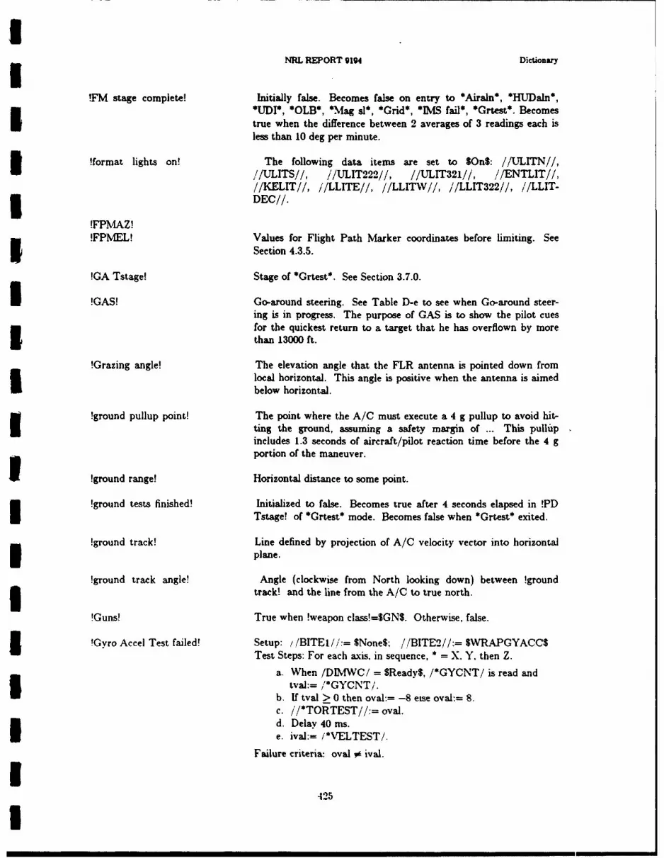
NRL REPORT 3194 Dictionary
!FM stage complete! Initially false. Becomes false on entry to *Airaln*, *HUDaln*,---- *1UDI*, *OLB*, *Mag sl*, *Grid*, *IMS fail*, *Grtest*. Becomestrue when the difference between 2 averages of 3 readings each isless than 10 deg per minute.
!format lights on! The following data items are set to SOnS: //ULITN//,S//ULITS//, //ULIT222//, //ULIT321//, //ENTLIT//,//KELIT//, //LLITE//, //LLITW//, //LLIT322//, //LLIT-
-- DEC//.
!FPMAZ!!FPMEL! Values for Flight Path Marker coordinates before limiting. See
Section 4.3.5.
!GA Tstage! Stage of *Grtest*. See Section 3.7.0.
!GAS! Go-around steering. See Table D-e to see when Go-around steer-ing is in progress. The purpose of GAS is to show the pilot cuesfor the quickest return to a target that he has overflown by moreI, than 13000 ft.
!Grazing angle! The elevation angle that the FLR antenna is pointed down fromlocal horizontal. This angle is positive when the antenna is aimedbelow horizontal.
!ground pullup point! The point where the A/C must execute a 4 g pullup to avoid hit-ting the ground, assuming a safety margin of ... This pullupincludes 1.3 seconds of aircraft/pilot reaction time before the 4 gportion of the maneuver.
!ground range! Horizontal distance to some point.
!ground tests finished! Initialized to false. Becomes true after 4 seconds elapsed in !PDTstage! of *Grtest* mode. Becomes false when *Grtest* exited.
!ground track! Line defined by projection of A/C velocity vector into horizontalplane.
!ground track angle! Angle (clockwise from North looking down) between !groundtrack! and the line from the A/C to true north.
!Guns! True when !weapon class!=$GNS. Otherwise, false.
!Gyro Accel Test failed! Setup: //BITEI,/':= $None$, //BITE2//:= SWRAPGYACCS
Test Steps: For each axis, in sequence, * = X. Y, then Z.
a. When /DIMWC/ = SReady$, /*GYCNT/ is read andtval:= !*GYCNT/.
b. If tval > 0 then oval:= -8 eLse oval:= 8.c. //*TORTEST//:= oval.d. Delay 40 ms.e. ival:= /*VELTEST/.
Failure criteria: oval 0 ival.
425

IDictionary ALSPAUGH, FAULK, BRITTON, PARKER. PARNAS, AND SHORE 1
Clean-up: //BITE2//:= SNoneS.
!HG stage! Hi-gain gyrocompass. Alignment stage - See Section 3.2.0.
!high drag! True iff:!weapon class! - SSHS OR!weapon class! = SSHS OR
!weapon class! = SHDS OR(!weapon class! = SODS AND/BMBDRAG! = $H-igh$) OR(!weapon class! SOR$ AND /BMBDRAG/ = $High$) OR(!weapon class! = $SODS AND /BMBDRAG/= SHighS) OR
!L stage! Hi-gain level. Alignment stage - / See Section 3.2.0.!HS stage! Heading slew. Alignment stage - See Section 3.2.0.
!HS stage complete! Initially false. Becomes false on entry to *SINSaln*, *HUDaln*,*UDI*, *OLB*, *Mag sl*, *Grid*, *IMS fail*, *Grtest*. Becomes
true when !Z-axis corrected!. I!HUD rate! Azimuth displacement, in degrees per second:
(25/256) X /SLEWRL/ X (/SLEWRL/ 2 -.1482 + 9) Ielevation displacement, in degrees per second:
(25/256) X /SLEWUD/ x (/SLEW0UD/ 2 -. 1482 + 9)
!impact angle azimuth! The angle between the A/C Ya axis and the line projected intothe Xa-Ya plane from the a/c nose to the !impact point!. Lookingin the -Za direction, it is positive clockwise from Ya.
!impact angle elevation! The angle between the A/C Ya axis and the line projected intothe Ya-Za plane from the A/C nose to the !impact point!. Mea- Isured from the Ya axis in the positive Za direction (up).
!impact point! The point on the ground that would be hit by a weapon releasednow or a gun fired now, in any weapon delivery mode. Atdifferent times, different compensations are made in impact pointcaicul.ions. (a) *A/G Guns* with !Guns!: wind, parallax, gravitydrop, and AOA. (b) *A/G Guns* with !Rockets!: wind and grav- Iity. (c) *A/A Guns*: A/C acceleration and platform angles.
'IMS-ADC Reasonable! ABS(!IMS total velocity! - /TAS/) :_ 191 kt OR !ADC down!. 5IMS-Dop Reasonable! ABS(!IMS groundspeed! - !DGNDSP!) < 62 kt OR !Doppler
down!. I!MS drift angle! Drift angle calculated by subtracting !IMS heading! from the
ground track angle derived from !IMS NVe!! and !IMS EVeI!.
!IMS EVeI! Velocity calculated from /XVEL/ history - speed of A/C in theeast direction (assuming platform aligned). It is set to 0 when@T(in mode) for *IMS fail* and when @F(in mode) for
426 g

NRL REPORT 9194 Dictionary
*SINSaln*, *Sautocal*, *Landaln*, and *Lautoeal*.
!IMS ground speed! Magnitude of the horizontal component of the velocity vector, cal-culated from !IMS NVeI! and !IMS EVel! - length of vector g infigure D-a.
IMS heading! Angle determined by /THDGCOS/ and /THDGSIN/ (angularrange: 0' to 360"); above 80" latitude corrected by addition of!wander angle!.
!IMS magnetic variation! Magnetic variation received through the IMS true heading inputs,/THDGCOS/ and /THDGSIN/ (angular range: 0 to 360),when !IMS down! See Section 2.1.1.8.
!IMS NVeI! Velocity calculated from /YVEL/ history - speed of the A/C inthe north direction (assuming platform aligned). It is set to 0when @T(in mode) for *IMS fail* and when @F(in mode) for*SINSaln*, *Sautocal*, *Landaln*, and *Lautocal*.
!IMS pitch! Angle determined by /PCHCOS/ and /PCHSIN/ (angular range:
±180"). (see !system pitch!)
!IMS Reasonable! Magnitude of !IMS total velocity! < 1440 fpsAND !IMS total velocity! 0.2 s ago <__ .5O fps.
!IMS roll! Angle determined by /ROLLCOSI/ and /ROLLSINI/ (angularrange: :180"). (see !system roll!)
!IMS total velocity! 3-dimensional vector sum of !IMS NVel!, !IMS EVel! and !IMSWei!
!IMS Up! /IMSREDY/ - $Yes$ AND /IMSREL/ = $Yes$
!IMS VVe! Velocity calculated from /ZVEL/ history - speed of the A/C mov-ing towards or away from the ground (assuming IMS aligned).
!IN A!!IN B! See Section 4.5.3.
!In-time test failed! The OFP is required to reset the TC-2 GO/NO GO counter every1.3 seconds. This test is failed if the OFP fails to do this.
!In OFFMEFSW! True iff current weapons mode is OFF__MFSW.
!In WD_%MFSW! True iff current weapons mode is WDvfFSW.
!inc vel scale! X and Y axes: IF //IMSSCAL// = $Coarse$ THEN !coarse scalefactor! ELSE !fine scale factor!Z axis: !coarse scale factor!
!Interface test failed! !Timer Test failed! OR !Gyro Accel Test failed! OR !DiscreteI/O Test failed! OR !DC Test failed! OR !Serial Channel Testfailed! OR 'AC Test I failed! OR !AC Test 2 failed!
427
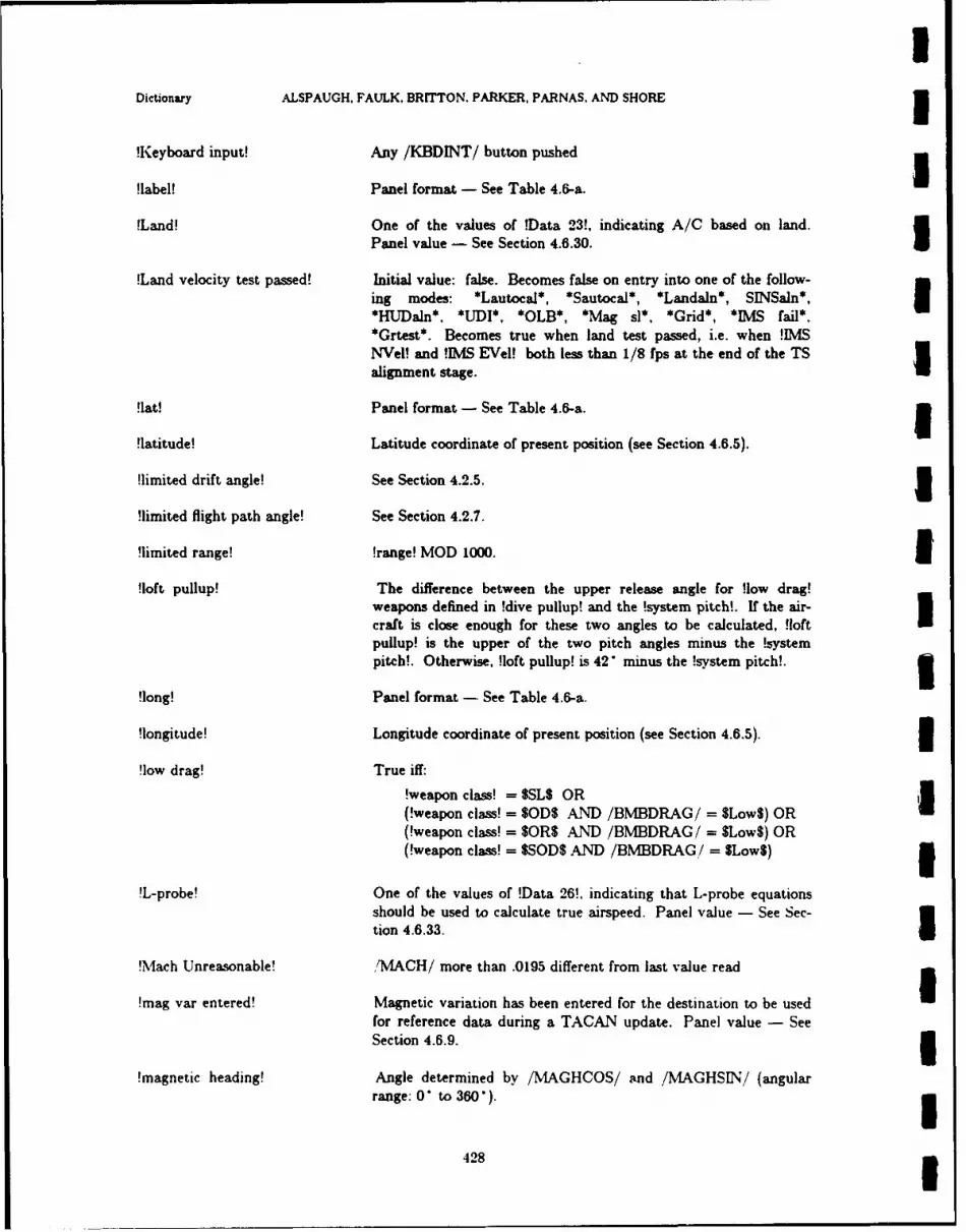
IDictionary ALSPAUGH, FAULK. BRITTON. PARKER, PARNAS, AND SHORE I
!Keyboard input! Any /KBDINT/ button pushed
!label! Panel format - See Table 4.6-a.
!Land! One of the values of !Data 23!, indicating A/C based on land.Panel value - See Section 4.6.30. I
!Land velocity test passed! Initial value: false. Becomes false on entry into one of the follow-ing modes: *Lautocal*, *Sautocal*, *Landaln*, SINSan*, I*HUDaln*. *UDI*, *OLB*, *Mag sl*, *Grid*, *IMS fail*,*Grtest*. Becomes true when land test passed, i.e. when !IMS
NVel! and !IMS EVel! both less than 1/8 fps at the end of the TSalignment stage.
!lat! Panel format - See Table 4.6-a. 5!latitude! Latitude coordinate of present position (see Section 4.6.5).
!limited drift angle! See Section 4.2.5. 1!limited flight path angle! See Section 4.2.7.
!limited range! !range! MOD 1000. 3!loft pullup! The difference between the upper release angle for !low drag!
weapons defined in !dive pullup! and the !system pitch!. If the air-craft is close enough for these two angles to be calculated, !loftpullup! is the upper of the two pitch angles minus the !systempitch!. Otherwise, !loft pullup! is 42 minus the !system pitch!. 3
!long! Panel format - See Table 4.6-a.
!longitude! Longitude coordinate of present position (see Section 4.6.5). 3!low drag! True iff:
!weapon class! = $SLS OR(!weapon class! = SODS AND /BMBDRAG/ = SLowS) OR i(!weapon class! = SOR$ AND /BMBDRAG/ = SLowS) OR(!weapon class! = $SOD$ AND /BMBDRAG/ = SLowS) 3
!L-probe! One of the values of !Data 26!. indicating that L-probe equationsshould be used to calculate true airspeed. Panel value - See Sec-tion 4.6.33.
!Mach Unreasonable! fMACH/ more than .0195 different from last value read
!mag var entered! Magnetic variation has been entered for the destination to be used
for reference data during a TACAN update. Panel value - SeeSection 4.6.9. 3
!magnetic heading! Angle determined by /MAGHCOS/ and /MAGHSIN/ (angularrange: 0 to 360'). 3
428 g
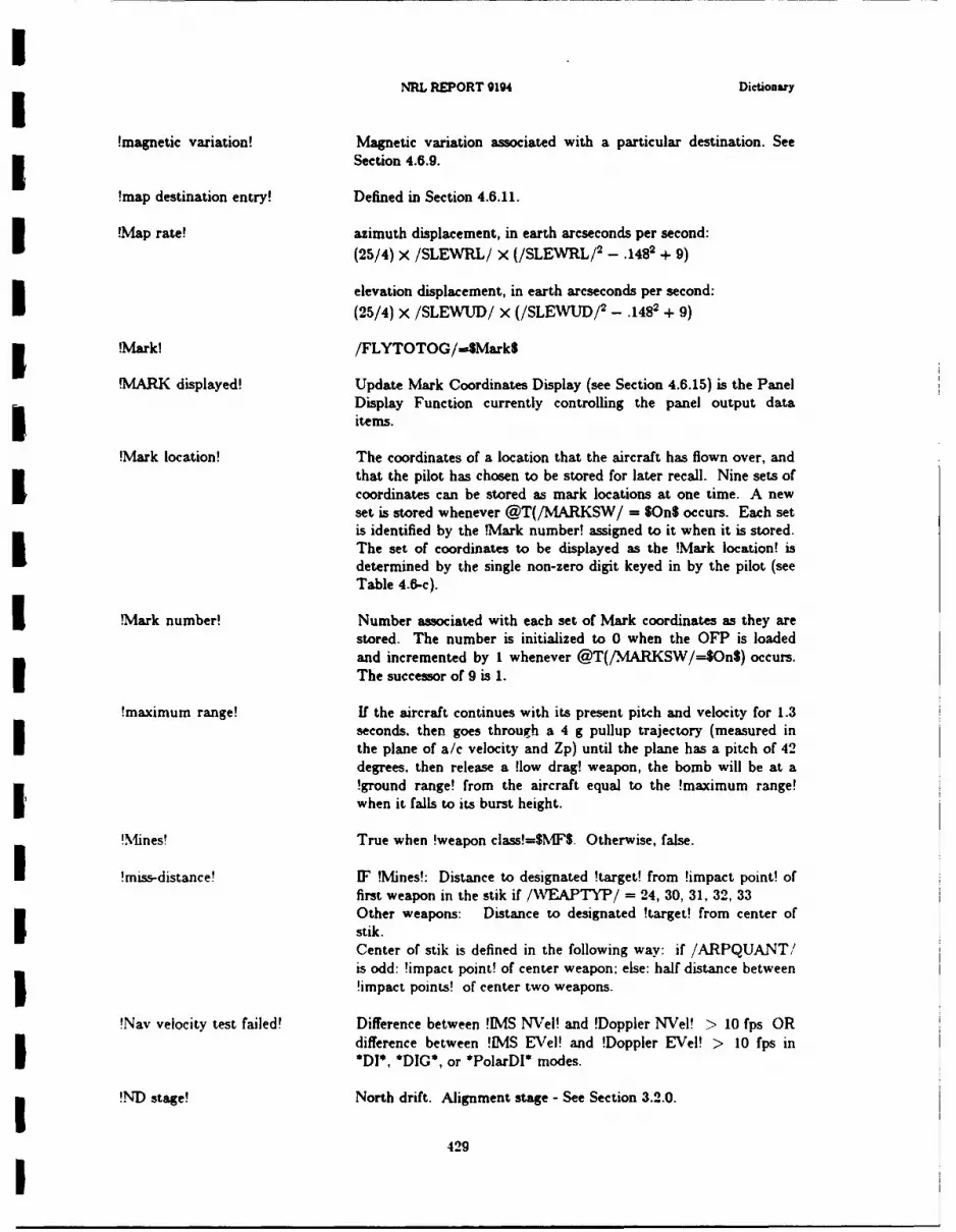
NRL REPORT 9194 Dictionary
!magnetic variation! Magnetic variation associated with a particular destination. SeeSection 4.6.9.
!map destination entry! Defined in Section 4.6.11.
!Map rate! azimuth displacement, in earth arcseconds per second:
(25/4) X/SLEWRL/ X (/SLEWRL/ 2 - .1482 + 9)
elevation displacement, in earth arcseconds per second:
(25/4) X /SLEWUD/ x (/SLEWUD/ 2 - .1482 + 9)
!Mark! /FLYTOTOG/-4MarkS
.rMARK displayed! Update Mark Coordinates Display (see Section 4.6.15) is the PanelDisplay Function currently controlling the panel output dataitems.
!Mark location! The coordinates of a location that the aircraft has flown over, andthat the pilot has chosen to be stored for later recall. Nine sets ofcoordinates can be stored as mark locations at one time. A newset is stored whenever @T(/MARKSW/ = $On$ occurs. Each setis identified by the !Mark number! assigned to it when it is stored.The set of coordinates to be displayed as the !Mark location! isdetermined by the single non-zero digit keyed in by the pilot (seeTable 4.6-c).
!Mark number! Number associated with each set of Mark coordinates as they arestored. The number is initialized to 0 when the OFP is loadedand incremented by I whenever @T(/MARKSW/--$On$) occurs.The successor of 9 is 1.
!maximum range! If the aircraft continues with its present pitch and velocity for 1.3seconds, then goes through a 4 g pullup trajectory (measured inthe plane of a/c velocity and Zp) until the plane has a pitch of 42degrees, then release a !low drag! weapon, the bomb will be at a!ground range! from the aircraft equal to the !maximum range!Iwhen it falls to its burst height.
!Mines! True when !weapon class!=gMF$. Otherwise, false.
I !miss-distance! IF .Mines!: Distance to designated !target! from !impact point! offirst weapon in the stik if /VEAPTYP/ = 24, 30, 31, 32, 33Other weapons: Distance to designated !target! from center ofstik.Center of stik is defined in the following way: if /ARPQUANT/is odd: !impact point! of center weapon; else: half distance between!impact points! of center two weapons.
!Nav velocity test failed! Difference between !IMS NVei! and !Doppler NVeI! > 10 fps ORdifference between !IMS EVel! and !Doppler EVe!! > 10 fps in*DI*, *DIG*, or *PolarDI* modes.
!ND stage! North drift. Alignment stage - See Section 3.2.0.
429I
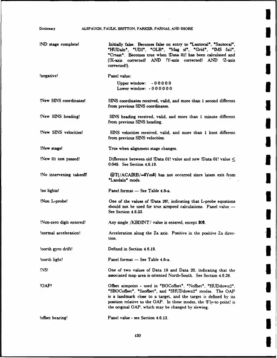
1Dictionary ALSPAUGH, FAULK. BRITTON, PARKER. PARNAS, AND SHORE 3!ND stage complete! Initially false. Becomes false on entry to *Lautocal*, *Sautocal*,
*HUJDaln*, *UDI*, *OLB*, *Mag sl*, *Grid*, *MS fail*,*Crtest*. Becomes true when !Data 01! has been calculated and
(X-axis corrected! AND .Y-axis corrected! AND !Z-axiscorrected!). 3
!negative! Panel value:
Upper window: - 0 0 0 0 0Lower window: - 0 0 0 0 0 0
!New SINS coordinates! SINS coordinates received, valid, and more than 1 second differentfrom previous SINS coordinates. n
!New SINS heading! SINS heading received, valid, and more than 1 minute differentfrom previous SINS heading. 3
!New SINS velocities! SINS velocities received, valid, and more than I knot differentfrom previous SINS velocities. n
!New stage! True when alignment stage changes.
!New 01 test passed! Difference between old !Data 01! value and new !Data 01! value <0.049. See Section 4.6.19. I
!No intervening takeoff! @T(/ACAIRB/--$YesS) has not occurred since latest exit from*Landaln* mode. I
!no lights! Panel format - See Table 4.6-a.
Non L-probe! One of the values of !Data 26!, indicating that L-probe equations Ishould not be used for true airspeed calculations. Panel value -See Section 4.6.33. 3
'Non-zero digit entered! Any single /KBDINT/ value is entered, except SO$.
!normal acceleration! Acceleration along the Za axis. Positive in the positive Za direc- '3tion.
!north gyro drift! Defined in Section 4.6.19. 1!north light! Panel format - See Table 4.6-a.
!NS! One of two values of Data 19 and Data 20. indicating that the 5associated map area is oriented North-South. See Section 4.6.28.
!OAP! Offset aimpoint - used in *BOCoffset*, *Noffset*, *HUJDdown2*.*SBOCofEset*, *Snoffset*, and *SHUDdown2* modes. The OAPis a landmark close to a target, and the target is defined by itsposition relative to the OAP. In these modes, the !Fly-to point! isthe original OAP. which may be changed by slewing. I
!offset bearing! Panel value - see Section 4.6.13.
430

I SNRL REPORT 9194 Dictionary
!offset range! Panel value - see Section 4.6.13.
!OF-range! !ground range! past last !impact point!.
!Other weapon! !Ready station! AND NOT (!Reserved weapon! OR !Shrike!).
!OTS! Over the shoulder steering, used for loft and over-the-shouldermaneuvers. See Table D-e to see when Over the shoulder steeringIis in progress.
!OTS pullup! With !low drag! weapons and !OTS!, the angle the A/C mustpullup to reach the correct release angle in an OTS maneuver. Inthe first portion of the pullup 'A/C facing target! is not true. Dur-
ing this time interval the !loft pullup! is calculated for a !low drag!weapon to an imaginary target that is the same !ground range! asthe !target! from the aircraft, but at a bearing from the aircraftthat is 180" from the bearing of the !target!. The !OTS pullup! is180" minus this !loft pullup! minus ( 2 X !system pitch!). When!A/C facing target! and !OTS!, !OTS pullup! is equal to !loftpullup!.
!overflown exit! True if last weapon mode was exited because the target wasIoverflown without a release.
!Overfln! The A/C has passed the last release point in a stik. If the !stikquantity! is 1, the last release point is the target. If the !stikquantity! is 2, the last release point is one-half the stik intervalpast the target. If the !stik quantity! is 3, the last release point isone stik interval past the target, and so forth.
I !Overfln gt 42 nmi! !Overfln! by more than 42 nmi.
!Panel error! See Section 4.6.2 for a list.
!Panel switch changed! /MODEROT/, /UPDATTW/, or /PRESPOS/ change value. OR'KBDENBL/ = SONS OR /ENTERSW/ = SONS
!PD Tstage! Stage of *Grtest*. See Section 3.7.0.
!pilot entry! The pilot goes through the procedure outlined in Section 4.6.2 toenter data. The only data that can be affected by this procedureare the ones associated with the Update Panel Display function
currently controlling the panel output data items.
'pitch small! ABS(!system pitch!)<20". (Only relevant for determining whethersystem in *OLB* or *UDI* modes).
!positive! Panel value:
Upper window: 000000Lower window: 0 0 0 0 0 0 0
!power up! OFP started and initialized.
431
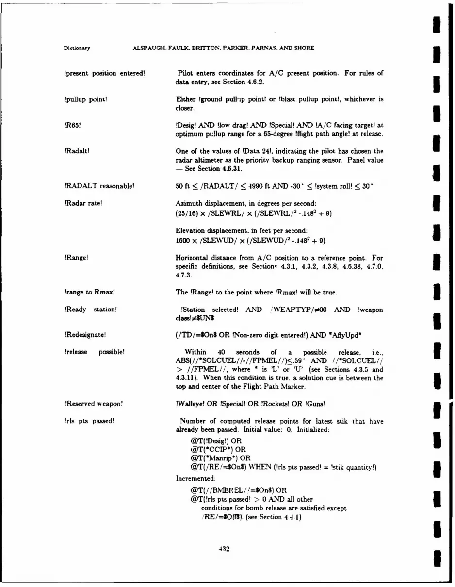
UDictionary ALSPAUGH, FAULK. BRITTON. PARKER, PARNAS, AND SHORE 1!present position entered! Pilot enters coordinates for A/C present position. For rules of
data entry, see Section 4.6.2. 3!pullup point! Either !ground pulbip point! or !blast pullup point!, whichever is
closer. 3!R65! Desig! AND low drag! AND !Special! AND !A/C facing target! at
optimum pullup range for a 65-degree !flight path angle! at release.
!Radalt! One of the values of !Data 24!, indicating the pilot has chosen the Iradar altimeter as the priority backup ranging sensor. Panel value- See Section 4.6.31. 1
!RADALT reasonable! 50 ft < /RADALT/ < 4990 ft AND -30" <!system roll! < 30
!Radar rate! Azimuth displacement, in degrees per second: n(25/16) X /SLEWRL/ x (/SLE\\WRL/ 2 -. 1482 + 9)
Elevation displacement. in feet per second:1600 x /SLE\WJD/ x (/SLEWLUD/ 2 -. 1482 + 9)
!Range! Horizontal distance from A/C position to a reference point. Forspecific definitions, see Section- 4.3.1, 4.3.2, 4.3.8, 4.6.38, 4.7.0,4.7.3.
!range to Rmax! The !Range! to the point where !Rmax! will be true. 3!Ready station! !Station selected! AND /WEAPTYP/#00 AND !weapon
class!#$UNS 3!Redesignate! (/TD/=$On$ OR !Non-zero digit entered!) AND *AflyUpd*
!release possible! Within 40 seconds of a possible release, i.e., 3ABS(//*SOLCUEL//-//FPMEL/ /) _.59" AND //*SOLCUEL//> //FPMEL//, where * is 'L' or 'U' (see Sections 4.3.5 and4.3.11). When this condition is true. a solution cue is between thetop and center of the Flight Path Marker.
!Reserved weapon! !Walleye! OR !Special! OR !Rockets! OR !Guns! 3!rls pts passed! Number of computed release points for latest stik that have
already been passed. Initial value: 0. Initialized:
@T(!Desig!) OR 5@T(*CCIP*) OR@T(*Manrip*) OR@T(/RE/=$On$) WHEN (!rls pts passed! = !stik quantity!)
Incremented:
@T(//BMBREL /!=$On$) OR@T(!rls pts passed! > 0 AND all other I
conditions for bomb release are satisfied except/RE/--,SOfl). (see Section 4.4.1)
432 1
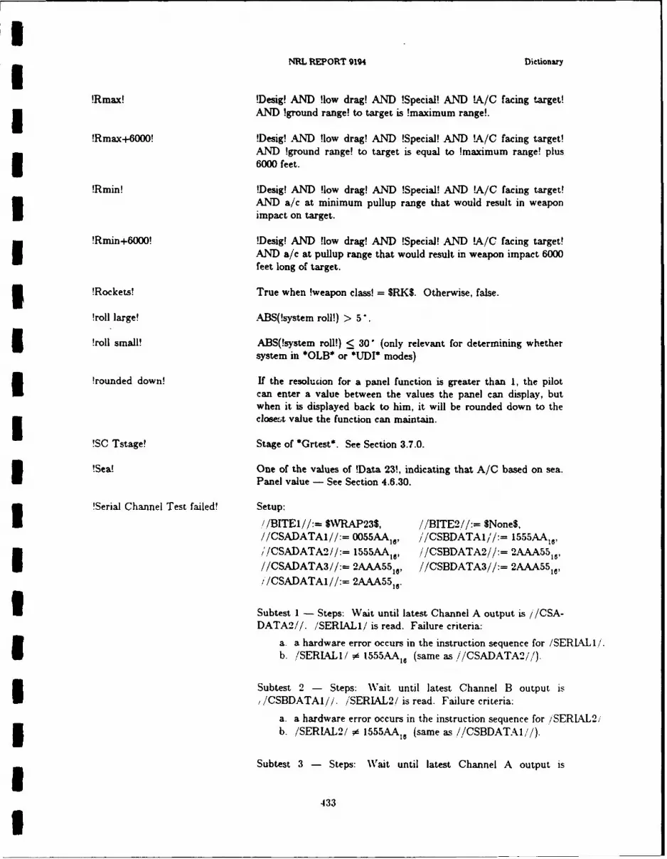
NRL REPORT 9194 Dictionary
!Rmax! !Desig! AND flow drag! AND !Special! AND !A/C facing target!
ANIgon ag!t agti mxmmrne!Rmax6000!!Desig! AND Hlow drag! AND !Special! AND !A/C facing target!
AND !ground range! to target is equal to !maximumn range! plus* 6000 feet.
!Rmin! !Desig! AND flow drag! AND !Special! AND !A/C facing target!AND a/c at minimum pullup range that would result in weapon
impact on target.
!Rmin+6000! !Desig! AND flow drag! AND !Special! AND !A/C facing target!AND a/c at pullup range that would result in weapon impact 6000feet long of target.
3!Rockets! True when !weapon class! = SRKS. Otherwise, false.
!roll large! ABS(!system roll!) > 5.
!roll small! ABS(!system roll!) <! 30' (only relevant for determining whether
system in *OLB* or *UDI* modes)
!rounded down! If the resolucion for a panel function is greater than 1, the pilotI can enter a value between the values the panel can display, butwhen it is displayed back to him, it will be rounded down to theclose-,t value the function can maintain.
!SC Tstage! Stage of *Grtest*. See Section 3.7.0.
!Sea! One of the values of !Data 23%, indicating that A/C based on sea.I Panel value - See Section 4.6.30.
!Serial Channel Test failed! Setup:U //BITEI//:= $XVRAP23$, //BITE2//:= SMone$,//CSADATA1//:= 0055AA1 6, /'/CSBDATAI/'/:= 1555AAIO//CSADATA2//:= 1555AAIO, //CSBDATA2//:= 2AAA55 1 ,I//CSADATA3//:= 2AAA55 1., //CSBDATA3//:= A 55,/ /CSADATAI//:= 2AAA55,,
I Subtest 1 - Steps: Wait until latest Channel A output is / /CSA-DATA2//. /SERIAL1/ is read. Failure criteria:
a. a hardware error occurs in the instruction sequence for /SERIAL1I/.
b. /SERIALI1/ 6 1555AA, 6 (same as //CSADATA2//).
Subtest 2 - Steps: Wait until latest Channel B output is
/CSBDATAI//. /SERIAL2,/ is read. Failure criteria:a. a hardware error occurs in the instruction sequence for /'SERIALL2/3 b. /SERL4AL2/ * 1555AA, 6 (same as //CSBDATAl,'/).
Subtest 3 - Steps: Wait until latest Channel A output is
.433
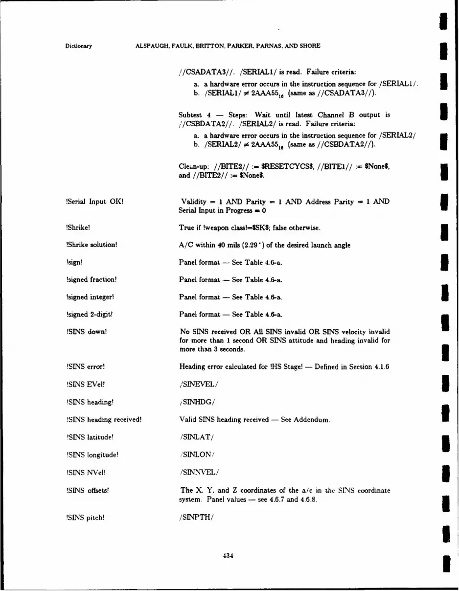
aDictionary ALSPAUGH, FAULK, BRITTON, PARKER, PARNAS, AND SHORE 3
//CSADATA3//. /SERIALI/ is read. Failure criteria:
a. a hardware error occurs in the instruction sequence for /SERIAL1I. Ib. /SERIALI/ # 2AAA55,, (same as //CSADATA3//).
Subtest 4 - Steps: Wait until latest Channel B output is 3,'/CSBDATA2//. /SERIAL2/ is read. Failure criteria:
a. a hardware error occurs in the instruction sequence for /SERIAL2/b. /SERIAL2/ # 2AAA55,, (same as //CSBDATA2//).
CleL.n-up: //BITE2// := SRESETCYCSS, //BITE1// $None$,
and //BITE2// := $None$.I
!Serial Input OK! Validity = 1 AND Parity = 1 AND Address Parity = 1 AND 3Serial Input in Progress = 0
!Shrike! True if !weapon class!=SSKS; false otherwise. 5!Shrike solution! A/C within 40 mils (2.29 ) of the desired launch angle
!sign! Panel format - See Table 4.6-a. I!signed fraction! Panel format - See Table 4.6-a.
!signed integer! Panel format - See Table 4.6-a. I!signed 2-digit! Panel format - See Table 4.6-a.
!SINS down! No SINS received OR All SINS invalid OR SINS velocity invalidfor more than I second OR SINS attitude and heading invalid formore than 3 seconds. 3
!SINS error! Heading error calculated for !HS Stage! - Defined in Section 4.1.6
!SINS EVeI! /SINEVEL/ 3!SNS heading! iSINHDG/
!SINS heading received! Valid SINS heading received - See Addendum. I!SINS latitude! /SINLAT/
!SINS longitude! iSINLON/
!SINS NVeI! /SINNVEL/ 3!SINS offsets! The X. Y. and Z coordinates of the a/c in the SINS coordinate
system. Panel values - see 4.6.7 and 4.6.8. 3!SINS pitch! /SINPTH/
4434 1

NRL REPORT 9194 Dictionary
!SINS roll! /SINROL/
!SINS velocity test passed! Initial value: false. Becomes false on entry into one of the follow-ing modes: *Lautocal*, *Sautocal*, *Landaln*, SINSaln*,*HUDaln*, *UDI*, *OLB*, *Mag sl*, *Grid*, *IMS fail*,*Grtest*. Becomes true when SINS test passed, i.e. whendifference between !IMS NVeI! and !SINS NVe! _< 1 fps after 30 sAND difference between !IMS EVel! and !SINS EVeI ! < 1 fps at
the end of the TS alignment stage.
!slant range! Total line-of-sight distance to some point.
!Slant range reasonable! !Grazing angle! > 4 AND -40 *< !system roll! < 40 AND FLRAntenna Azimuth and Elevation within 16 of Ya axis AND 1700ft < /SLTRNG/< 54000 ft
!slewed-to point! If /PMHOLD/ = $Yes$, this is the filmstrip point under thedisplay marker of the map when @T(!slewing finished!) occurs.The display marker varies, as shown in Section 4.5.4.
!slewing complete! No further change in //X.SLEW//, //YSLEW//, and/or//ZSLEW// will occur in the current stage.
!slewing finished! @T(/SLEWUD/:=:0 AND /SLEWRL*/:=:O) (this indicates thatthe slew inputs fall below the minimum that indicates that thecontrol has returned to center. See Section 2.2.2).
!slew-torque cutoffl 20 arcminutes, which is the minimum platform Z axis error worthslewing out - Z axis errors smaller than this are torqued out.
!Special! True when (!weapon class!=SSODS OR !weapon class!--SSSH$;false otherwise.
!Special in range! IF !low drag! THEN !Range to target! < 10 nmi; IF !high drag!THEN !target in range!.
!Special release possible! ABS(//LSOLCUEL// - //FPMEL//) _< .59- AND //LSOL-CUEL// > //FPMEL// (see Sections 4.3.5 and 4.3.11). Whenthis condition is true, the Lower Solution Cue is between the topand center of the Flight Path Marker.
!Special solution! !miss-distance! < 10 ft AND ABS(!steering error!) < 20
!Special solution occurred! @T(!Special solution!) since last target designation
!Station selected! /STAnRDY/ = SYes$ for any n E {1 2 3 6 7 8}.
'steering error! Angle measured from !ground track! to the line from the A/C tothe destination; positive value show destination line to left of!ground track!, looking down.
!steering to target! See Table D-e.
435
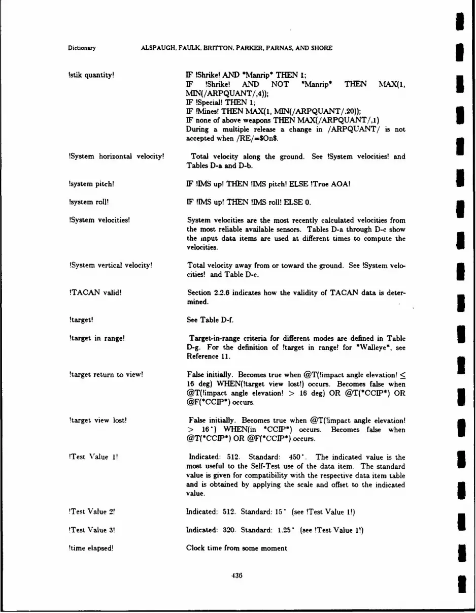
IDictionary ALSPAUGH, FAULK, BRITTON. PARKER, PARNAS, AND SHORE 3!stik quantity! IF !Shrike! AND *Manrip* THEN 1;
IF !Shrike! AND NOT *Manrip* THEN MIAX(I, IMIN(/ARPQUANT/,4));IF !Special! THEN 1;IF Mines! THEN MAX(1, MIN(/ARPQUANT/,20));IF none of above weapons THEN MAX(/ARPQUANT/,j) UDuring a multiple release a change in /ARPQUANT/ is notaccepted when /RE/=$On$. 3
!System horizontal velocity! Total velocity along the ground. See !System velocities! andTables D-a and D-b.
!system pitch! IF !IMS up! THEN !IMS pitch! ELSE !True AOA! I!system roll! IF !IMS up! THEN !IMS roll! ELSE 0. 3!System velocities! System velocities are the most recently calculated velocities from
the most reliable available sensors. Tables D-a through D-c showthe input data items are used at different times to compute thevelocities.
!System vertical velocity! Total velocity away from or toward the ground. See !System velo-cities! and Table D-c.
!TACAN valid! Section 2.2.6 indicates how the validity of TACAN data is deter-mined.
!target! See Table D-f.
!target in range! Target-in-range criteria for different modes are defined in Table ID-g. For the definition of !target in range! for *Waleye*, seeReference 11.
!target return to view! False initially. Becomes true when @T(!impact angle elevation! <16 deg) WHEN(!target view lost!) occurs. Becomes false when@T(!impact angle elevation! > 16 deg) OR @T(*CCIP*) OR@F(*CCIP*) occurs.
!target view lost! False initially. Becomes true when @T(!impact angle elevation!> 16") WHEN(in *CCIP*) occurs. Becomes false when 3@T(*CCIP*) OR @F(*CCIP*) occurs.
!Test Value I! Indicated: 512. Standard: 450". The indicated value is themost useful to the Self-Test use of the data item. The standardvalue is given for compatibility with the respective data item tableand is obtained by applying the scale and offset to the indicatedvalue.
!Test Value 2! Indicated: 512. Standard: 15 (see !Test Value 1!)
!Test Value 3! Indicated: 320. Standard: 1.25 (see !Test Value 1!)
!time elapsed! Clock time from some moment 5436 3

NRL REPORT 9194 Dictionary
time to solution! Estimated time remaining to solution
3 !Timer test failed! Setup: NoneSubtest 1 - Step: the 10 bit counter is loaded with 10.24 ms.Failure criteria: an interrupt occurs before 10.22 ms or after 10.26is, as timed by the GO/NO-GO counter
Subtest 2 - Step: the 16 bit counter is loaded with 0.65 s.Failure criteria: an interrupt occurs before 0.65536 s or after0.65540 s, as timed by the GO/NO-GO counter.Clean-up: None
!TM Tstage! Stage of *Grtest*. See Section 3.7.0.
I !TOS! Tail on steering, used to steer the A/C away from a weapon blastwith the tail of the A/C pointing at the blast.
!TS stage! Alignment test. Alignment stage - See Section 3.2.0.
!TS stage complete! Initially false. Becomes false on entry to *HUDaln*. *Landaln*,*SINSaln*, *UDI*. *OLB*, *Mag sl*, *Grid*, *M fail*,*Grtest*. Becomes true when (TBD).
!True AOA! The smoothed value of .76 X /AOA/ - 8.68. The smoothing is asimple lag filter with time constant 3.125 seconds. The device isread every 0.025 seconds.This definition is device-dependent and likely to change if thecurrent AOA sensor is replaced.
!unsigned fraction! Panel format - See Table 4.6-a.
!/UJPDATTW/=Other! /UPDATTW/$FLYOVER$ AND /UPDATTW/$HUDS AND/UPDATTW/$RADARS AND /UPDATTW/;$TAC L-L$
3!Walleye! True when !weapon class!=SWL$. Otherwise, false.
!wander angle! Accumulated corrections to alignment of the IMS Zp axis whichare not actually applied when the A/C is above 80" latitude. Theangle is measured from between the line from the A/C to northand the Yp axis.
3 !WD MFS! -'rue iff:/MFSW/= $Natt$ OR/vFSW/ = $BOC$ OR/MFSW/ = $CCIPS OR/MFSW/ = SNATTOFF OR/MFSW/ = $BOCOFFS
!weapon boresight! IF !Shrike! OR !Valleve! THEN 0 mils on HUD vertical axis;
!weapon class! Weapons are classified by drag and other characteristics in Table2.4-a.
437I

Dictionary ALSPAUGH, FALK, BR=NON. PARKER, PARNAS, AND SHORE3
!weapons released! Number of weapons in the latest stik that have actually beenreleased. Angle of weapon velocity vector to earth horizontal.
down negative.
!weapon release angle! Angle between weapon velocity vector and earth horizontal, down
negative.
!within grace period! Less than 1.6 seconds elapsed since one of the following modesexited: *BOC*, *BOCFlytoO*, *BOCoffset*3
!X--axis corrected! Initially false. Becomes false on entry to !CL stage!, !CA stage!,!HL stage!, !HC stage!, WFC stage!, WND stage! or !HS stage!.Becomes true when the IMS X axis has been torqued or slewedI(see Tables 4.1-d and 4.1-i) such that the condition !axis aligned!
!Yai orce!holds.3'Y-ais crreced!Initially false. Becomes false on entry to !CL stage!, !CA stage!,
!HL stage!, !HC stage!, !FC stage!, !ND) stage! or !HS stage!.Becomes true when the IS Y axis has been torqued or slewed(see Tables 4.1-d and 4.1-i) such that the condition !axis aligned!I
!Z-axis corrected! Initially false. Becomes false on entry to !CA stage!, !HC stage!,3!FC stage!, !ED stage!, !ND stage!, and !HS stage!. Becomes truewhen the IMVS-Z axis has been torqued or slewed (see Tables 4.1-eand 4.1-j) such that the condition !axis aligned! holds.3
Condition Table D-a: System Horizontal Velocities in Navigation Modes
MODES _____ ____ CONDITIONS ____3
*Dl**DIG* Always X X X
*PolarDI' ________
*Polarl' X Alwavs X X X3*Magsl**Grid* X X !Doppler !Doppler !Doppler
*OLB* Up! Down! AND Down! AND*_____ _______ fail*__ !ADC Up! !.ADC Down!
VELOCITY !IMS NVeI! WIS NVeI! !DGNDSP! /TAS/ stale /TAS/SOURCES !IMS EVeI! WIS EVeI! drift angle !True AOA! !True AOA!
damped by heading !system pitch! stale windI_________ !DGNDSP! _______ _______wind !svstem pitch!
438

NRL REPORT 9194 Dictionary
Selector Table D-b: System Horizontal Velocities in Alignment Modes
3 *Lautocal**Landaln**OlUpdate* Constant (0)
*HUDalD* ________________
*Sautocal* SINS velocities, adjusted by*SINSaln* by !SINS offsets!U _____________ !IMS NVeI!. !IMS EVeI! damped by !DGNDSP!
I Condition Table D-c: System Vertical Velocity
3 MODES ____ ___CONDITIONS
Alignment*DIG*, *DI*
*1*, *UDIP /ADCFAEL/=-$No$ /ADCFAIL/=$Yes$ X x
*PolarI*__________ ___________ ______ ___
I Mag s**Grid*, 0LB* X X !ADC Up! NOT !ADC Up!
*IMS fail* __ __ _ X Always
3 IMS VVeI! !System horizontal /TAS/, 0damped by velocities! !flight path angle!
____________ BAROADC/ !fight path angle! ______ _____
43
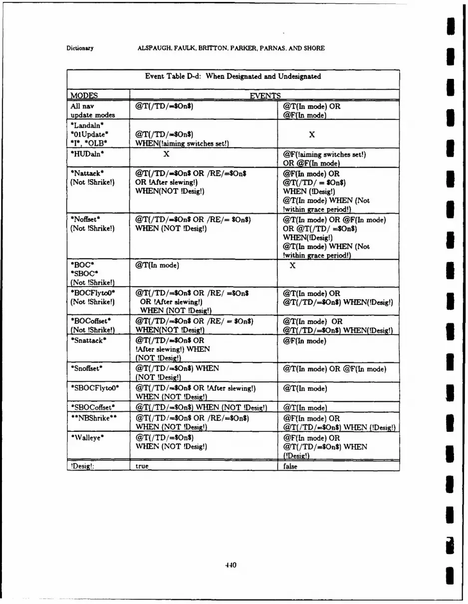
Dictionary ALSPAUGH, FAULK, BRITTON, PARKER, PARNAS, AND SHORE3
Event Table D-d: When Designated and Undesignated
MODES EVE-Q NTS1All nay @T(/TD/=40On$) @T(In mode) ORupdate modes @F(In mode)*Landaln**OlUpdate* @T(/TD/=S$On$) X*I*, *()LB* WHEN~aiming switches set!)
*HlJDaln* X @F(!aiming switches set!)________ ____________________OR @F(Tn mode)
*Nattack* @T(/TD/=SOnS OR /RE/=$On$ @F(In mode) OR(Not !Shrike!) OR !After slewing!) @T(/TD/ = $On$)I
WHEN(NOT !Desig!) WHEN (!Desig!)@T(In mode) WHEN (Not
____________ ____________________________!within grace period!)*Noffset* @T(/TD/=40n$ OR /RE/= $On$) @T(Jn mode) OR @F(In mode)I(Not !Shrike!) WIHEN (NOT !Desig!) OR @T(/TD/ --$On$)
WHEN(!Desig!)@T(ln mode) WHEN (Not
_____________________________!within grace period!)
*BOC* @T(In mode) X*SBOC*(Not !Shrike!)_______________*BOCFlyto)* @T(/TD/=$On$ OR /RE/ =$On$ @T(In mode) OR
(Not !Shrike!) OR !After slewing!) @T(/TD/-$OnS) WHEN(!Desig!)
*BOCofrset* @T(/TD/-=40n$ OR /RE/ = $On$) @T(In mode) OR(Not !Shrike!) WHEN(NOT !Desig!) @T(/TD/=S$OnS) WHEN(!Desigl)*Snattack* @T(/TD/=SOn$ OR @F(ln mode)U
!After slewing!) WHEN(NOT !Desig!)
*Snoffset* @T(/TD/--$On$) WHEN @T(Tn mode) OR @F(In mode)(NOT !Desig!)
*SBOCFlytoO* @T(/TD /-$On$ OR tAfter slewing!) @T(In mode)
__________ IHEN (NOT !Desig!)*SBOCoffset* @TITD /-$On$) WHEN (NOT !Desiq! @T(In mode)**1N4BShrike** @T(/TD/=SOnS OR /RE/=SOn$) @F(In mode) OR
WHEN (NOT !Desig!) @T(/TD /=$On$) WHEN M!esig!)*WValleye* @T(/TD/=SOn$) @F(In mode) OR
WHEN (NOT !Desig!) @T(/TD/=OnS) WHEN_ _ _ _ _ _ _ _ _ _ _ _ _ _ _ _ _ _ _ _ _ _ _ _ _ _ _ _ _ _ _ _
!Desig!: true false
4410
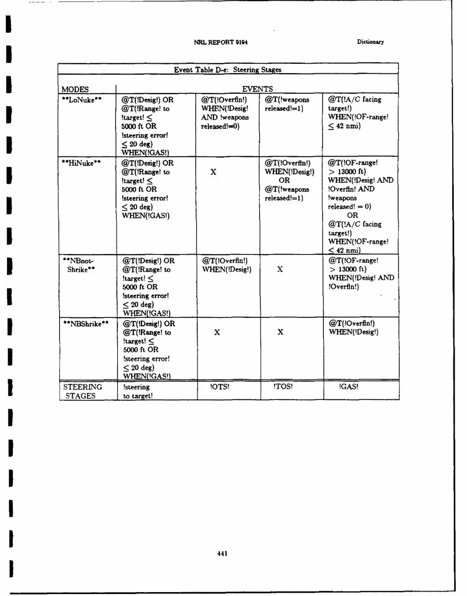
INRL REPORT 9194 Dictionary
Event Table D-e: Steering Stages
I MODES ____ ___EVENTS ______
**LoNuke** @T(!Desig!) OR @T(!Overfln!) @T(!weapons @T(!A/C facing
@T(!Range! to WHEFN(!Desig! released!=1) target!)!target! < AND Iweapons WVHEN(!OF-range!500 ft OR released!uO) 42 nmi)
!steering error!< 20 deg)
_________ WHEEN !GAS!)_____**iue* @T(!Desig!) OR @T(!Overfln!) @T(!OF-range!
@T(!Range! to X WHMEN(!Desig!) > 13000 ft)!target! < OR WHEN(!Desig! AND5000 ft OR @T(!weapons, !Overfln! AND!steering error! released!=1) !weapons< 20 deg) released! = 0)WHEMN(!GAS!) OR
@T(!A/C facingtarget!)I W'HEN(!OF-range!
______________~~ _______<42 nmi)
*N]Bnot- @T( !Desig!) OR @T(!Overfln!) @T(!OF-range!Ihik* @T(!Range! to WVHEN(!Desig!) x > 13000 ft)!target! < WHEMN(!Desig! AND5000 ft OR !Overfln!)!steering error!I~ <20 deg)
_________ WHN(!GAS!)___ __________
**NDBhrike** @T(!Desig!) OR @T(!Overfin!)
@T(!Range! to X X WHEN(!Desig!)!target! <5000 ft ORI !steering error!< 20 deg)
__________ N WH !GAS!)_______jSTEERIN G !steering !OTS! !TOS! !GAS!STAGES Ito target!________________________
441

Dictionary ALSPAUGH, FAULK, BRrTTON, PARKER, PARNAS, AND SHORE
Table D-f: Target in Weapon Delivery Modes
MODES - !tarmet!*Nattack* location on ground overlaid by AS at designation and after
*BOCFlytoO* each slewU*Snattack*
*SBOCFlytoO**HUDdownl* location on ground intersecting the HUD ORA at designation*SHUDdownl* __________________________
*HUDdown2* OAP is the point on the ground intersecting the HUD ORA at*SHUDdown2* designation; target is a point on the line drawn from the
OAF in the direction defined by !Offset bearing!; thetarget is !Offset range! nmi from the OAF.
*Noffset* OAP is the point on the ground overlaid by AS at*Snoffset* designation and after each slew; target is a point on theI
line drawn from the OAP in the direction defined by!Offset bearing!; the target is !Offset range! nrni fromthe OAF.
*BOC* Before slewing, the target is the 'Fly-to point!; afterI*SBOC* slewing, it is the point defined by the radar cursors when
@T(!slewing finished!) occurs.*BO~offset* OAF is defined in the same way the target is defined inI*SBOCoffst* *BOC* (*SBOC*); target position relative to OP.P is
defined in *Noffret* (*Snoffset*)
*Walleve* location on ground overlaid by AS at designation
- Condition Table D-g: Target-in-range criteria
MODES ______CONDITIONS ____
*Nattak**Noffset* !high drag! !low drag! X x
*BOCoffset* ___________
*A/G Guns* X X !Guns! !Rockets!
!target in !distance-to Wdive pullup! !slant range! to Wsant range!range! release! < < 42 deg !impact point! to ipact
6000 ft < 8192 ft point! <
____ ___ ___ __ _ ___ ___ ___ ____ ___ ___ ___ ____ ___ ___ ___ 14366 ft
4421

NRL REPORT 9194
Data Item Index
/ACAIRB/ ........................................................................................... 144I/ACTESTCOS/ ...................................................................................... 110/ACTESTSIN/ ....................................................................................... 110/ADCFAIL/ .......................................................................................... 40I/ANTGOOD/ ........................................................................................ 139//ANTSLAVE//......................................................................................... 48/AOA/ .............................................................................................. 142/ARPINT/ ........................................................................................... 130/ARPPAIRS/ ........................................................................................ 131/ARPQUANT/ ....................................................................................... 132I '/ASAZ//................................................................................................ 62//ASEL// ................................................................................................ 62//ASLAZ// ................................................................................. ........... 62
//ASLCOS// ......................................................................................... 63,//ASLEL//........................................................................................... 62//ASLSIN// .......................................................................................... 63
//AUTOCAL// ...................................................................................... 31//A.ZRING//......................................................................................... 86/BAROADC/ ......................................................................................... 41//BAROHUD// ...................................................................................... 64//BITE1// ........................................................................................... 118//BITE2// ........................................................................................... 119/BNMDRAG/ ........................................................................................ 71//7BMREL//................................................................ ........................ 77I ,/BNMTON// ........................................................................................ 159,/BRGDEST// ....................................................................................... 150/BRGSTA/ .......................................................................................... 140I//COMPCTR// ...................................................................................... 32J'/CO PFAEL// ...................................................................................... 155/,/COMPFAIL//...................................................................................... 161I'/COMPFAIL// ...................................................................................... 33//COMPFAIL//...................................................................................... 49
/CSADATAn// ...................................................................................... 120
/CSBDATAn// ...................................................................................... 121/CURAZCOS// ..................................................................................... 50
//CLTRAZSIN//..................................................... ................................. 50'/CLMENABL//.................I.......I............................................................. 51
/CU~POS// ......................................................................................... 52"DCTEST/ .......................................................................................... 112
/ /DESTPNT//...................................................................... ................. 87
/DGNDSP/ .......................................................................................... 135
443
.I ... .

IIndexes ALSPAUGH, FAULK. BRrrTON. PARKER, PARNAS, AND SHORE 5
"9I
/DIM W C/ ................................................................................................................................... 22
/DIW .l/ ....................................................................................................................................... 113
/DIW 2/ ....................................................................................................................................... 113/DIW 3/ ....................................................................................................................................... 113
//DOW I// .................................................................................................................................. 117//DOW 2// .................................................................................................................................. 117//DOW 3// .................................................................................................................................. 117/DRFTANG/ .............................................................................................................................. 134
/DRSFUN/ ................................................................................................................................. 136
/DRSM EM / ................................................................................................................................ 137
/DRSREL/ .................................................................................................................................. 138/ELECGOOD/ ........................................................................................................................... 139
/ENTERSW / ............................................................................................................................. 93
/i/FIRRDY// ............................................................................................................................... 78,//FLTDIRAZ// .......................................................................................................................... 65
/.'/FLTREC// .............................................................................................................................. 158/FLYTOTOG / ........................................................................................................................... 95 I/FLYTOTW / ............................................................................................................................. 94
//FPAN GL/i/ ............................................................................................................................. 156
//FPANGL// ............................................................................................................................. 53
i//FPM AZ// ................................................................................................................................ 62
/l/FPM EL//. ................................................................................................................................ 62
//GNDTRK // ............................................................................................................................ 151//GNDTRVEL// ........................................................................................................................ 54
/GUNSSEL/ ............................................................................................................................... 72
//HUDAS// ................................................................................................................................ I
,,/HUDASL// .............................................................................................................................. 66'/HUDFPM // ............................................................................................................................. 66
',/HU CDPUC,// ............................................................................................................................. 66
'HUDREL/ ................................................................................................................................. 61
iHUDSCUE,'i . .......................................................................................................................... 66
'HUDVEL//' ..-......................................................................................................................... 66
/H'UDW ,RN / ............................ ............................................................................................. 66
'M SAUTOC / ............................................................................................................................ 24I S M O D E .. ................................................................................................................................ 2 5
'IM S N A // ................................................................................................................................ 16 2
DS R E D Y / ................................................................................................................................ 26M S R E L / ................................................................................................................................... 2 7
'IM S S C A L /. ............................................................................................................................. 36
'KBDENBL/ .............................................................................................................................. 96
I1 D IN T / .................................................................................................................................. 9 7
/K E L IT // .................................................................................................................................. 10 6
/LATGTT70// .......................................................................................................................... 39iL F T D IG i i ............................................................................................................................... 152
I444 I

NRL REPORT 9194
//LLIT322// ............................................................................................................................... 106
//LLr DEC// ............................................................................................................................. 106//LLITE// .................................................................................................................................. 106//LLITW // ................................................................................................................................. 106
/LOCKEDON/ ........................................................................................................................... 46//LSOLCUAZ// ......................................................................................................................... 62
//LSOLCUEL// ......................................................................................................................... 62//LW DIG I// .............................................................................................................................. 103
IILW DIG2// ............................................................................................................................. 103//L IG 3//. .............................................................................................................................. 103//LW D IG4// .............................................................................................................................. 103//LW DIG5// .............................................................................................................................. 103//LW DIG6// .............................................................................................................................. 103//LW DIG 7// ............................................................................................................................. 103
/M A/ ........................................................................................................................................... 73/M ACH/ ..................................................................................................................................... 42
/M AGHCOS/ ............................................................................................................................. 29
//M AGHDGH// ......................................................................................................................... 67
/M AGHSIN/ ............................................................................................................................... 29
//M APOR// ............................................................................................................................... 88/M ARKSW / ............................................................................................................................... 98
I/M ARKW IN // .......................................................................................................................... 105/M FSW / ..................................................................................................................................... 128/M ODEROT/ ............................................................................................................................. 99
/M ULTRACK/ ........................................................................................................................... 74/PCHCOS/ ................................................................................................................................. 29/PCHSIN/ ................................................................................................................................... 29/PM DCTR/ ................................................................................................................................ 81
/PM HOLD/ ................................................................................................................................ 82/PM NOR TP/ ............................................................................................................................. 83
/PM SCAL/ ................................................................................................................................. 84
/PM SLAND/ .............................................................................................................................. 85/PNLTEST/ ............................................................................................................................... 100
/PRESPOS/ ................................................................................................................................ 101//PTCHANG// .......................................................................................................................... 68
i/PUACAZ// ............................................................................................................................. 62//PUACEL/./ .............................................................................................................................. 62/RADALT/ ................................................................................................................................. 124
! /R E / ............................................................................................................................................ 146
//RNGHND// ............................................................................................................................ 153
//RNGHND// ............................................................................................................................ 89
/RNGSTA / ................................................................................................................................. 141//RNGTEN // ............................................................................................................................ 153
//RNGTEN// ........................................................................................................................... 89
445

IIndexes ALSPAUGH. FAULK, BRITTON, PARKER, PARNAS. AND SHORE 5//RNGUN IT// ........................................................................................................................... 153
//RNGUNIT // .......................................................................................................................... 89//ROLLCOSH// ......................................................................................................................... 63/ROLLCOSI/ .............................................................................................................................. 29//RO SINH // .......................................................................................................................... 63/ROLL I ............................................................................................................................... 29/SERIALI/ .................................................................................................................................. 114/SERIAL2/ .................................................................................................................................. 11I/SINEVEL/ ................................................................................................................................. 143
/SINHDG / .................................................................................................................................. 143
/SINLAT/ ................................................................................................................................... 143/SINLONG / ................................................................................................................................ 143/S NVEL/ ................................................................................................................................ 143
/SINPTH / ................................................................................................................................... 143/SINROL/ ................................................................................................................................... 143/SLEW RL/ ........................................ ...................................................................................... 125
/SLEW UD/ ................................................................................................................................. 125
/SLTRNG/ ............................................................................................................ ................... 47//SPA REI// ............................................................................................................................... 122
//SPARE2// ............................................................................................................................... 122/STA IRDY/ .......................................................................................................................... 75/STA2RDY/ ............................................................................................................................... 75/STA3RDY / .............................................................................................................................. 75/STA6RDY/ ............................................................................................................................... 75/STA7RDY/ ............................................................................................................................... 75
/STA8RDY/....................................75
//ST EERA Z// .......................................................................................................................... 5//ISTEER EL// ......................................................................................................................... 55//STERRO R //. . .......................................................................................................................... 157i'TAS/ ....... ...................................................... .................................................................. 43
/TD / ...................................................................................................................................... 147 I/THD GCOS/ ............................................................................................................................. 29/THDGSIN / .............................................................................................................................. 29
//TSTADCFLR// ......................................... .............................. .. . ..................... 44 I/'TSTAD CFLR// ........................................................................ ...................................... . 57
/UL T222//.. ...................................................................................................................... 106
/ULIT 32 .// ............................................................................................................................... 1I/UrLIT32/ i/ ..................................................................................... .......................................... 106/ULITN// .............................................................................................................................. 106!UJLITSII.................................................................................................. 106
/UPDATTW ............................................................................................................................. 102,//USOLCUAZ// .................................................................................................................... . 62
//USOLCUEL// ........................................................................................................................ 62//U DIG I// .............................................................................................................................. 108/ U W D IG2// .............................................................................................................................. 108
446

NRL REPORT 9194
//U D IG3// .............................................................................................................................. 108// W D IG 4// .............................................................................................................................. 108
i t I G5ll .............................................................................................................................. 108//I W DIG 6// .............................................................................................................................. 108//VERTVEL// ........................................................................................................................... 69
S//VTVELAC // .......................................................................................................................... 69/W AYLAT/ ................................................................................................................................ 148
/W AYLON / ............................................................................................................................... 148
/W AYNUMM I/ ............................................................................................................................. 148
/W AYN UM 2/ ............................................................................................................................. 148/EAPTYP/ ................................................................ 76
//X COMMC . .// ........................................................................................................................... 90
//XCO F . ..// ............................................................................................................................ 90
S, XGYCNT/ ............................................................................................................................... 23
/ XGYCOM // ............................................................................................................................ 34
,,'/XSLEW // ................................................................................................................................ 37
S//X SLSEN // .............................................................................................................................. 38/ /X TORTEST// ........................................................................................................................ 123
/XVEL/ ....................................................................................................................................... 28
S/XVELTEST/ ............................................................................................................................. 116
/Y COM M // .............................................................................................................................. 91/YGYCNT/ ................................................................................................................................ 23
S/ YGYCOM // ............................................................................................................................ 34//YSLEW // ................................................................................................................................ 37, /YSLSEN// ............................................................................................................................... 38
//YTORTEST// ........................................................................................................................ 123/ .YVEL/ ....................................................................................................................................... 28,Y..VELTEST/ ............................................................................................................................. 116
ZGYCNT .............................................................................................................................. 23
,'ZGYCOM // ........................................................................................................................... 34
'ZSLEW !/ ............................................................................................................................... 37''ZSLSEN // ............................................................................................................................... 38
/ZTORTEST// ......................................................................................................................... 123
SZ V E L / ....................................................................................................................................... 2 8
ZVELTEST/ ............................................................................................................................. 116
IIIU
447
I

IIndexes ALSPAUGH, FAULK, BRrnON, PARKER, PARNAS, AND SHORE
Mode Index
I*0 U pdate * ................................................................................................................................ 183
*A/A G un* ................................................................................................................................ 223*AfM yUpd s* ................................................................................................................................ 215
*A /G G un.* ................................................................................................................................ . 223
*A raln* ....................................................................................................................................... 187
*BOC*..... ............................................................................................................................... . 221*BOC Fy ..* .............................................................................................................................. 222
*BOCofI t** ................................................................................................................................ . 222 I*C I * ........................................................................................................................................ 223
*DI* ....................................................................... . . . .
* D .................. ................................................................................................................... 19
*GI d* ......................................................................................................................................... 19
*Griy d * ..................................................................................................................................... 23
Grt~ est ................................................................................................... 239
*Hrdan* .................................................................................................................................... 186
*HUDdownl* . .............................................................................................................................. . 23
*H UDdown.* .............................................................................................................................. 224
*HUDUpd* .................................................................................................................................. 214* * .......... .............................................................................................................................. .. 191
W S fail* .................................................................................................................................. 196*L* ....... .................................................................................................................................... . 184
*Lau i . . .l* ................................................................................................................................... 181
*L oN ukeda * ................................................................................................................................ 226
* atog s1 * ................................................................................................................................... 192
*M anripk * ................................................................................................................................ 223
*M paUpd* ................................................................................................................................... 2. ) 15
*N attack* .................................................................................................................................... 220*M pa dno .hrike. . ......................................................................................................................... 226
* NBShrike .* .............................................................................................................................. 226
*Noffset h * ........................................................................................................................ 221*OLB....* ................................................................................................................................. 195*PolarDI* .................................................................................................................................... 197
*PoLarI* ....................................................................................................................................... 198
*RadarUpd*............................................................................................ 215Sautocal ................................................................................................................................... 182
*SBOC* ....................................................................................................................................... 2I
*SBOCF ytoO.* ............................................................................................................................ 225
*SBOCoffset*. . . . . ............................................................................................................................... 225*SHUDdownl* ............................................................................................................................ 225*SHUDdown2* ........................................................................................................................... 226
448

NRL REPORT g194
*SINSaln* .................................................................................................................................... 185*Snattack* ................................................................................................................................... 225
_*Snof~set* ......................................................... ........................................................................... 005
*TacUpd* 215*UDI* ............................................... ...................................................................................... 194
*W alleye* .................................................................................................................................... 224
449
U

IIndexes ALSPAUGH, FAULK, BRITTON, PARKER, PARNAS, AND SHORE
Index of Output Items Affected by Functions
//AN TSLAVE// ......................................................................................................................... 258
//ASA Z// ................................................................................................................................... 265//ASEL// .................................................................................................................................... 265//ASLA Z// ................................................................................................................................. 269
//ASLCOS// .............................................................................................................................. 273//ASLEL/ / ................................................................................................................................. 26
//ASLSIN// ................................................................................................................................ 273//AUTOCA L// .......................................................................................................................... 243//A ZRING // ................................................................................................................... 300
//BAR OHUD // .......................................................................................................................... 274//BM BREL// ............................................................................................................................. 295//BM NBTON // ............................................................................................................................ 298//BM NBTON // ............................................................................................................................ 299
//BRGDEST// ........................................................................................................................... 369//COM PCTR// .......................................................................................................................... 244//COM PFA IL// ......................................................................................................................... 245 I//CURA ZCO S// ........................................................................................................................ 256//CURA,.ZSIN // .......................................................................................................................... 256//CURENABL// ........................................................................................................................ 254
//CU RPOS// .............................................................................................................................. 257
//DESTPNT// ........................................................................................................................... 300//ENTLIT// "31......................................................1 I/.FIRRDY //.......................................................... 296//FLTDIR AZ// .......................................................................................................................... 275
//FPA N G L // .......................................................................................................................... 263/ /FPAN GLZ / / .............................................................................................................................. 263
/FPM A Z// ................................................................................................................................ 27
,//FPM EL // ............................................................................................................................ 276
/'/G ND TR K // ........................................................................................................................ 2370,/G ND TRV EL// ........................................................................................................................ 262'/HUDAS// .............................................................................................................................. 265/H D PMASL// ............................................................................................................................. 269;/H U DL FPM // ............................................................................................................................. 278
/ UDVEL/// ............................................................................................................................. 292/IM SN A // ............................................................................................................................. 252/ ESSCAL.// ............................................................................................................................. 248jKELIT// ............ ............................................................................... 304/LA TGT7O// ............................................................................................................................ 251
,/LFTDIG // ............................................................................................................................... 371
//LLIT322// ............................................................................................................................... 304/LLITDEC // ............................................................................................................................. 304
/LLITE // ................................................................................................................................. 304 I
450

iNRL REPORT 9194I
//LLITW // ................................................................................................................................. 304
//LSOLCUA Z// ......................................................................................................................... 288
S//LSOLCUEL// ......................................................................................................................... 288
//LW DIG 1// .............................................................................................................................. 304
//LW DIG2// .............................................................................................................................. 304
//LW DIG3// .............................................................................................................................. 304
//LW DIDIG4// .............................................................................................................................. 304
//LW DIG 5// .............................................................................................................................. 304
//LW D .IG6// .............................................................................................................................. 304
//LW DIG7// .............................................................................................................................. 304
//MAAGHDGH// ......................................................................................................................... 279
//M APOR // ............................................................................................................................... 301
/ iMARKW IN // .......................................................................................................................... 310
S//PTCHAN G // .......................................................................................................................... 280
//PUACAZ// ............................................................................................................................. 281
/./PUACEL// .............................................................................................................................. 281
//RNGHND //, ........................................................................................................................... 371//RNGTEN //, ........................................................................................................................... 371//RNGUNIT// ........................................................................................................................... 371
//ROLLCOSH// ......................................................................................................................... 286
//ROLLSINH // .......................................................................................................................... 286
//STEERAZ// ............................................................................................................................ 260
//STEEREL// ............................................................................................................................ 259//STERROR// ........................................................................................................................... 373
//ULIT222// ............................................................................................................................... 304
//ULTLIT321// ............................................................................................................................... 304
//ULITN // ................................................................................................................................. 304
'/.ULITS// .................................................................................................................................. 304
/USOLCUAZ// ......................................................................................................................... 290
/USOLCUEL// ......................................................................................................................... 290
/UWDIG1// ............................................................... 304
U W DIG2// .............................................................................................................................. 304
/UW DIG3// .............................................................................................................................. 304
'L rDIG4,// ............................................................................................................................. 304
'UW DIG5// .............................................................................................................................. 304
,'UW DIG6// .............................................................................................................................. 304
rVERTVEL// ........................................................................................................................... 293
,'rTVELAC / / ........................................................................................................................... 293
XCON14M C .......... ................................................................................................................. 302I'XCOMM F!/ ............................................................................................................................ 302
XGYCOM // ............................................................................................................................ 246
XSLE\V / ............................ ................................................................................................. 249
'XSLSEN // ............................................................................................................................... 249
CO // ............................................................................................................................. 302.
I451I

Indexes ALSPAUGH, FAULK, BRITTON, PARKER, PARNAS, AND SHORE
//YGYCOM// ........................................................................................ 246//YSLEW// .......................................................................................... 249//YSLSEN// ......................................................................................... 249//ZGYCOM// ....................................................................................... 246
//ZSLEW// .......................................................................................... 249I//ZSLSEN// ......................................................................................... 249
45I