shoretel / nortel legacy pbx integration:
TRANSCRIPT
Application Note AN-00124 July 2009
ShoreTel IP Phone System – PBX Interoperability: Nortel Meridian 1 Option 11C
Table of Contents 1. Overview 2 2. Nortel to ShoreTel Integrations 2 3. T1 Crossover 3 4. ShoreTel Applications and Features Available to Nortel Users 3 5. Nortel TIE-Line Configuration 4 6. ShoreTel TIE Configuration 5 6.1 Configure Trunk Group 5 6.2 Configure ShoreGear-T1 6 7. SMDI Overview 8 8. SMDI Voicemail Integration 8 8.1 SMDI Features Supported 9 8.2 Configuring SMDI for an External Voicemail 10 8.3 Configuring ShoreTel Voicemail Integration Using SMDI 16 8.4 SMDI Integration: Programming the Nortel PBX and the PBXLink Interface 22 9. Technical and Troubleshooting Tips 30 10. Known Issues 32
1
1. Overview The purpose of this document is to update AN-0124 in accordance with ShoreTel 9 software. This includes additional applications and features that were not available when this testing was performed, and also provides a step-by-step guide on configuring a ShoreTel system to integrate with a Nortel Meridian 1 PBX. This document provides an example of how to configure the Nortel PBX to function in this environment; however this information is targeted to individuals who already have knowledge on configuring the Nortel Meridian 1 PBX. Please be aware that the scope of this document is not to give step-by-step instructions on configuring third-party PBX systems, and the environment can very depending on the customer’s PBX hardware, software and operating environment. The examples provided offer a guide which can be used to configure and test the two systems’ interoperability. 2. Nortel to ShoreTel Integrations ShoreTel has five different configuration options to integrate with a Nortel Meridian 1 PBX.
1. Inter-system dialing: Configuration requires a TIE trunk between ShoreTel and Nortel. This is over T1 CAS with a crossover RJ-48C cable (see below). The trunk-group will require adding the Off-System extension (OSE’s) to match the extensions on the Nortel side.
2. Inter-system dialing with Caller ID: Configuration requires a TIE trunk between
ShoreTel and Nortel. This is over ISDN PRI QSIG with a crossover RJ-48C cable. (see below) The trunk-group will require adding the Off-System extension (OSE’s) to match the extensions on the Nortel side.
3. AMIS (Audio Message Interchange System): Ability to forward voicemail messages from
one VM system to another. AMIS will transmit the voicemail messages to the other user's voicemail box by calling the other voicemail system.
4. SMDI (Simple Message Desk Interface): ShoreTel acts as the voicemail system.
5. SMDI (Simple Message Desk Interface): ShoreTel acts as the PBX system.
Important:
• Make sure that one side of the T1 is configured as the “network”, the other is the “user,” one side is the “Master clock,” and the other “Slave.” If “Calling Name” is required, you need to configure the ISDN protocol for QSIG on both sides and enable sending “Calling Name” on the switches page.
• ShoreTel supports three different types of digital voice T1 circuits: Digital Loop Start,
Digital Wink Start (also called digital E&M) and ISDN (with support for both the PRI and QSIG protocols). When used for TIE-line integration, Digital Loop Start trunks support the
2
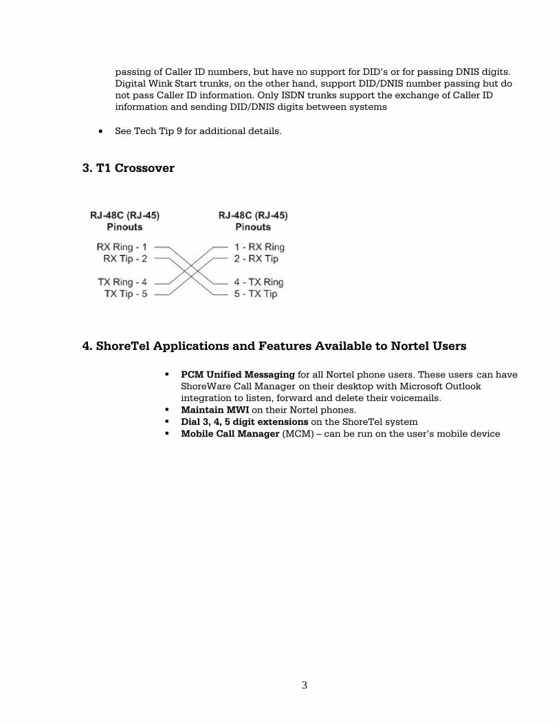
passing of Caller ID numbers, but have no support for DID’s or for passing DNIS digits. Digital Wink Start trunks, on the other hand, support DID/DNIS number passing but do not pass Caller ID information. Only ISDN trunks support the exchange of Caller ID information and sending DID/DNIS digits between systems
• See Tech Tip 9 for additional details.
3. T1 Crossover
4. ShoreTel Applications and Features Available to Nortel Users
PCM Unified Messaging for all Nortel phone users. These users can have ShoreWare Call Manager on their desktop with Microsoft Outlook integration to listen, forward and delete their voicemails.
Maintain MWI on their Nortel phones. Dial 3, 4, 5 digit extensions on the ShoreTel system Mobile Call Manager (MCM) – can be run on the user’s mobile device
3
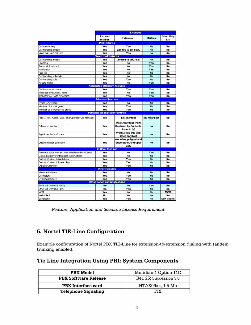
Feature, Application and Scenario License Requirement
5. Nortel TIE-Line Configuration Example configuration of Nortel PBX TIE-Line for extension-to-extension dialing with tandem trunking enabled: Tie Line Integration Using PRI: System Components
PBX Model Meridian 1 Option 11C PBX Software Release Rel. 25; Succession 3.0
PBX Interface card NTAK09xx, 1.5 Mb Telephone Signaling PRI
4
ShoreTel Software Release ShoreTel 9 ShoreTel Hardware SG-T1, SG-220, SG-T1K
Interconnect RJ-48c crossover cable
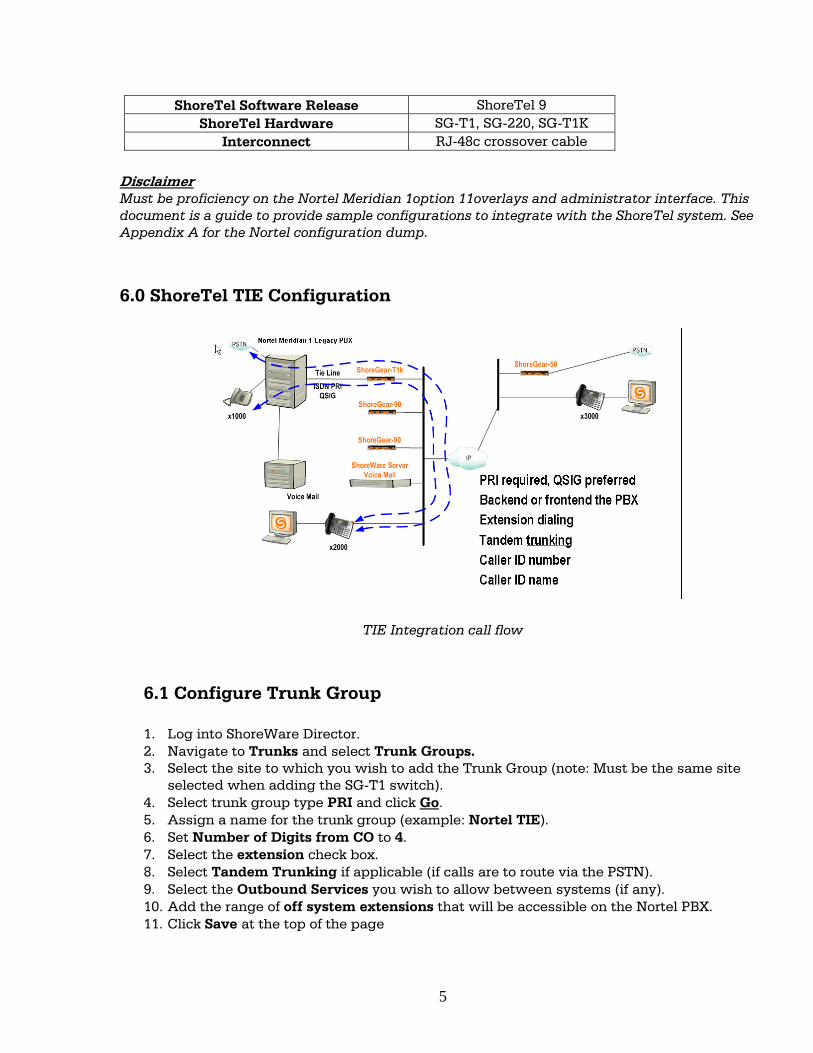
Disclaimer Must be proficiency on the Nortel Meridian 1option 11overlays and administrator interface. This document is a guide to provide sample configurations to integrate with the ShoreTel system. See Appendix A for the Nortel configuration dump. 6.0 ShoreTel TIE Configuration
TIE Integration call flow
6.1 Configure Trunk Group 1. Log into ShoreWare Director. 2. Navigate to Trunks and select Trunk Groups. 3. Select the site to which you wish to add the Trunk Group (note: Must be the same site
selected when adding the SG-T1 switch). 4. Select trunk group type PRI and click Go. 5. Assign a name for the trunk group (example: Nortel TIE). 6. Set Number of Digits from CO to 4. 7. Select the extension check box. 8. Select Tandem Trunking if applicable (if calls are to route via the PSTN). 9. Select the Outbound Services you wish to allow between systems (if any). 10. Add the range of off system extensions that will be accessible on the Nortel PBX. 11. Click Save at the top of the page
5
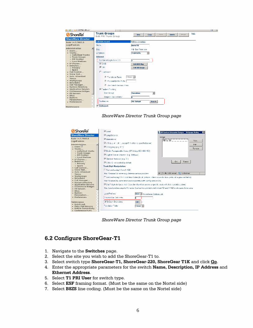
ShoreWare Director Trunk Group page
ShoreWare Director Trunk Group page 6.2 Configure ShoreGear-T1 1. Navigate to the Switches page. 2. Select the site you wish to add the ShoreGear-T1 to. 3. Select switch type ShoreGear-T1, ShoreGear-220, ShoreGear T1K and click Go. 4. Enter the appropriate parameters for the switch Name, Description, IP Address and
Ethernet Address. 5. Select T1 PRI User for switch type. 6. Select ESF framing format. (Must be the same on the Nortel side) 7. Select B8ZS line coding. (Must be the same on the Nortel side)
6
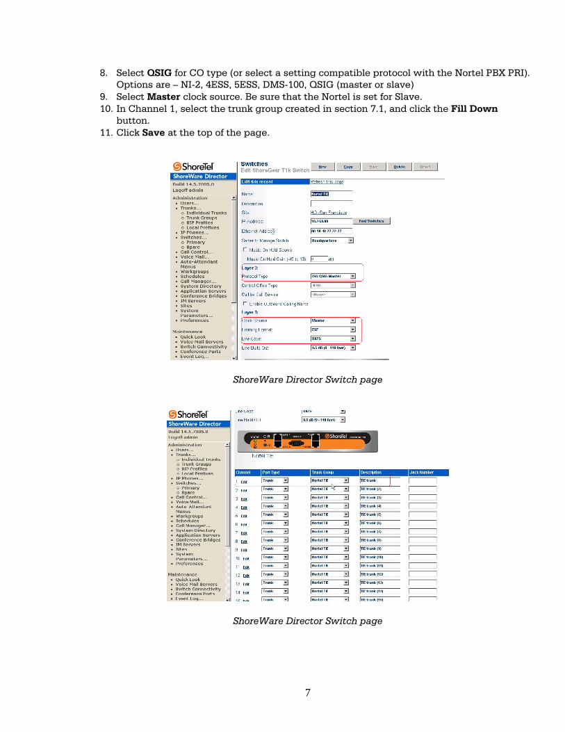
8. Select QSIG for CO type (or select a setting compatible protocol with the Nortel PBX PRI). Options are – NI-2, 4ESS, 5ESS, DMS-100, QSIG (master or slave)
9. Select Master clock source. Be sure that the Nortel is set for Slave. 10. In Channel 1, select the trunk group created in section 7.1, and click the Fill Down
button. 11. Click Save at the top of the page.
ShoreWare Director Switch page
ShoreWare Director Switch page
7
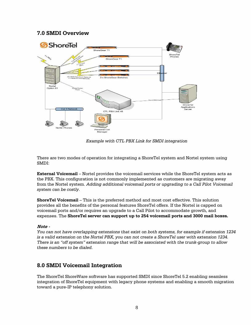
7.0 SMDI Overview
Example with CTL PBX Link for SMDI integration There are two modes of operation for integrating a ShoreTel system and Nortel system using SMDI: External Voicemail – Nortel provides the voicemail services while the ShoreTel system acts as the PBX. This configuration is not commonly implemented as customers are migrating away from the Nortel system. Adding additional voicemail ports or upgrading to a Call Pilot Voicemail system can be costly. ShoreTel Voicemail – This is the preferred method and most cost effective. This solution provides all the benefits of the personal features ShoreTel offers. If the Nortel is capped on voicemail ports and/or requires an upgrade to a Call Pilot to accommodate growth, and expenses. The ShoreTel server can support up to 254 voicemail ports and 3000 mail boxes. Note - You can not have overlapping extensions that exist on both systems, for example if extension 1234 is a valid extension on the Nortel PBX, you can not create a ShoreTel user with extension 1234. There is an “off system” extension range that will be associated with the trunk-group to allow these numbers to be dialed. 8.0 SMDI Voicemail Integration The ShoreTel ShoreWare software has supported SMDI since ShoreTel 5.2 enabling seamless integration of ShoreTel equipment with legacy phone systems and enabling a smooth migration toward a pure-IP telephony solution.
8
How it works ShoreTel use the SMDI protocol that allows dissimilar voicemail services and PBXs to share information over an out-of-band serial cable connection related to the Called and Calling Party. The PBX shares information with the voicemail system about incoming calls. The following information is passed to the voicemail system: 8.1 SMDI Features Supported The SMDI protocol transmits the following call information from the ShoreTel system to the legacy system:
• Message desk number: 1-999 • Logical Terminal number (terminal identifier): 1-9999 • Call type (All, Busy, Direct, No Answer, and Unknown) • Called party • Calling party • The SMDI MWI protocol transmits the following information from the legacy voicemail
system to the ShoreTel system: • Message waiting indication control • Extension • On/Off indication
When using SMDI for ShoreTel voicemail, the following features will not be supported: • SMDI protocol is not supported on the ShoreGear-90V, ShoreGear-50V switches • Setting call handling mode • Setting agent state • Agents cannot be extensions in the legacy PBX. The following features are supported: • • Recording greeting and name • Setting TUI password • Enable/disable envelope information • Email voice message options • Find Me • Message functions including call back • Message sending functions • Workgroup • "ShoreTel voicemail" • System configuration • Configuration parameters
9
8.2 Configuring SMDI for External Voicemail As mentioned above, there are two modes of operation with respect to integrating a ShoreTel system and a legacy system: • External Voicemail Configuration: In this configuration, the legacy system provides voicemail services while the ShoreTel system acts as PBX for users. • ShoreTel Voicemail Configuration: In this configuration, the ShoreTel system provides voicemail services while the legacy system acts as a PBX for users. The former of these two operational modes (external voicemail) is discussed below, while the procedure for the latter configuration (ShoreTel voicemail) follows in “Configuring ShoreTel Voicemail Integration Using SMDI” on page 63 4.3 of the ShoreTel Administration Guide. To integrate a Nortel voicemail system with ShoreTel 9, you need to perform the following basic tasks:
• Com Port Configuration on the ShoreTel Server • Trunk Group Configuration
– Off-System Extensions (OSEs) used to select digit translation table – Select the trunk group to be used by the Nortel PBX for voicemail.
• Application Server Configuration – Identifies “SMDI: ShoreTel as VM” or “SMDI: ShoreTel as PBX”
• User Group Configuration – Drop down to select whether the user is a normal “ShoreTel user”, a user with an
“external voicemail” or a user with an “external extension” • User Configuration
– Considered an “Off System User” when a member of a User Group listing “SMDI with external extension”
– Select the appropriate license type (i.e. mailbox only, ext. only) • Digit Translation Tables
– For digit translation and mapping of digits between system with different extension length (e.g. 3-digit ShoreTel dial plan with 5-digit PBX dial plan)
– Configured under System Parameters Configuring the COM Port To establish the SMDI link between the ShoreTel server and the legacy voicemail system, connect one end of a DB-9 serial cable to the COM port on the ShoreTel server and the other end of the cable to a COM port on the legacy voicemail server. The COM port settings on the ShoreTel server must match the settings of the COM port on the legacy voicemail server. Obtain the legacy voicemail COM port settings from the legacy voicemail server’s administration guide or from your system integration manager. You need the following information:
10
• Baud rate • Data bits • Parity • Stop bits • Flow control To configure COM port communication:
• Step 1 From the Start menu on the Windows server connected to the legacy voicemail server, select Settings, and then Control Panel.
• Step 2 In the Control Panel, open the Computer Management folder. • Step 3 Open the Device Manager. • Step 4 from the right pane in the window, expand the item Ports (COM & LTP). • Step 5 Right-click the COM port used to connect the ShoreTel server and legacy voicemail
system, and select Properties from the menu. • Ask your server administrator if you need help in determining the correct COM port. • Step 6 In the Properties window; enter the settings for the legacy voicemail server COM
port. • Step 7 Click OK to save the settings. • Step 8 In ShoreWare Director, open the Server edit page. • Step 9 Enter the COM port the server will use for SMDI communications in the COM Port
(1-10) text box. • Step 10 Click Save.
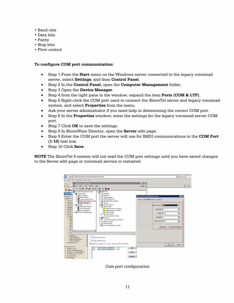
NOTE The ShoreTel 9 system will not read the COM port settings until you have saved changes to the Server edit page or voicemail service or restarted.
Com port configuration
11
Configuring Analog Trunk Ports for PBXLink The ShoreTel system sends calls to the legacy voicemail server over analog trunks connecting the two systems. The extensions are on the ShoreTel side, and the legacy voicemail system is the trunk side. The ShoreTel system sends calls made to these extensions to the legacy voicemail system when voicemail is needed. Before the call is sent, the SMDI protocol sends information about the call to the legacy voicemail system via the SMDI serial link. This allows the legacy voicemail system to handle the call correctly. To configure the extensions, you need to do the following:
• Create a list of the extensions and include the Logical Terminal Number for each extension.
• Configure the extensions with a new dial number (DN) type and marked as private users with no mail box.
• Assign a physical port to each extension in Director. Configure the extensions to forward to the Backup Auto Attendant on “no answer” or “busy.”
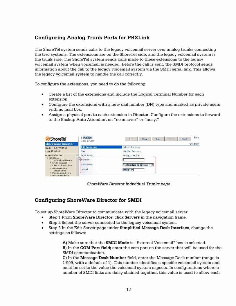
ShoreWare Director Individual Trunks page Configuring ShoreWare Director for SMDI To set up ShoreWare Director to communicate with the legacy voicemail server:
• Step 1 From ShoreWare Director; click Servers in the navigation frame. • Step 2 Select the server connected to the legacy voicemail system. • Step 3 In the Edit Server page under Simplified Message Desk Interface, change the
settings as follows:
A) Make sure that the SMDI Mode is “External Voicemail” box is selected. B) In the COM Port field; enter the com port on the server that will be used for the SMDI communication. C) In the Message Desk Number field, enter the Message Desk number (range is 1-999, with a default of 1). This number identifies a specific voicemail system and must be set to the value the voicemail system expects. In configurations where a number of SMDI links are daisy chained together, this value is used to allow each
12
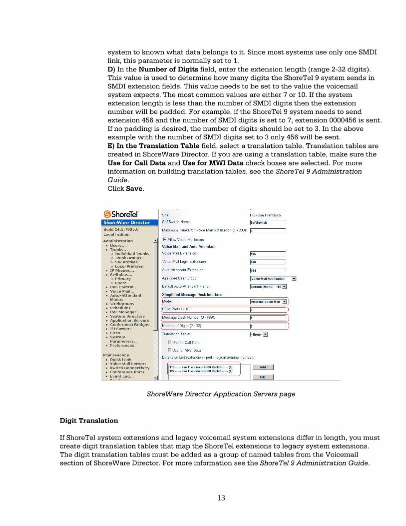
system to known what data belongs to it. Since most systems use only one SMDI link, this parameter is normally set to 1. D) In the Number of Digits field, enter the extension length (range 2-32 digits). This value is used to determine how many digits the ShoreTel 9 system sends in SMDI extension fields. This value needs to be set to the value the voicemail system expects. The most common values are either 7 or 10. If the system extension length is less than the number of SMDI digits then the extension number will be padded. For example, if the ShoreTel 9 system needs to send extension 456 and the number of SMDI digits is set to 7, extension 0000456 is sent. If no padding is desired, the number of digits should be set to 3. In the above example with the number of SMDI digits set to 3 only 456 will be sent. E) In the Translation Table field, select a translation table. Translation tables are created in ShoreWare Director. If you are using a translation table, make sure the Use for Call Data and Use for MWI Data check boxes are selected. For more information on building translation tables, see the ShoreTel 9 Administration Guide. Click Save.
ShoreWare Director Application Servers page Digit Translation If ShoreTel system extensions and legacy voicemail system extensions differ in length, you must create digit translation tables that map the ShoreTel extensions to legacy system extensions. The digit translation tables must be added as a group of named tables from the Voicemail section of ShoreWare Director. For more information see the ShoreTel 9 Administration Guide.
13
To create a digit translation table, follow the procedure below: Step 1 Launch ShoreWare Director and enter the user ID and password. Step 2 Click on the Administration link to expand the list (if it has not already been expanded). Step 3 Click on the System Parameters link to expand the list. Step 4 Click on the Digit Translation Tables link. Step 5 Click the New button. Step 6 Enter a name in the Name field and click the Save button to store your digit translation table. Step 7 Click the New button again to display the Digit Translation window (below). Next, you must select the digit translation mapping that you just created at the server. Step 8 Click on the Application Servers link and click on the name of the ShoreTel server that will be handling the digit translation. Step 9 In the Simplified Message Desk Interface section of the Application Servers window, select ShoreTel Voicemail from the Mode drop-down menu. Step 10 The Translation Table drop-down menu appears. Click on the arrow button and select the name of the digit translation table that you just created. Step 11 Select the Use for Call Data check box and Use for MWI Data check box by placing a check mark in each one (as shown below). Doing so allows for the digit translation to occur when:
• Data about a call is transferred between the legacy and ShoreTel systems. • Message Waiting Indicator information is transferred between the two systems to notify
the legacy PBX that a message was left on the ShoreTel voicemail. Step 12 By default, the "Use Flash to Route Calls" check box is enabled. Leave this as is. Note that this check box only appears when "ShoreTel Voicemail" is selected in the Mode drop-down menu in the Simplified Message Desk Interface section of the window. If selected, calls sent to the ShoreTel Auto Attendant from the SMDI trunk group are automatically transferred to the dialed extension using flash. If not selected, calls will be routed using other lines. NOTE - The flash call routing function is supported on the following switches: ShoreGear -30/30BRI, ShoreGear -50/50BRI/50V, ShoreGear -90/90BRI/90V, ShoreGear-40/8, ShoreGear-60/12, and ShoreGear-120/24. NOTE - The extension length must be the same on each of the systems for the “Transfer Using Flash” feature to work as no translation is applied. Setting Up the User Group in ShoreWare Director Follow these steps to set up a user group for those users who will have their voicemail re-directed to the legacy voicemail system.
14
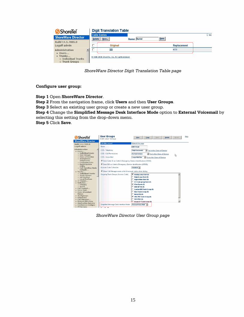
ShoreWare Director Digit Translation Table page
Configure user group: Step 1 Open ShoreWare Director. Step 2 From the navigation frame, click Users and then User Groups. Step 3 Select an existing user group or create a new user group. Step 4 Change the Simplified Message Desk Interface Mode option to External Voicemail by selecting this setting from the drop-down menu. Step 5 Click Save.
ShoreWare Director User Group page
15
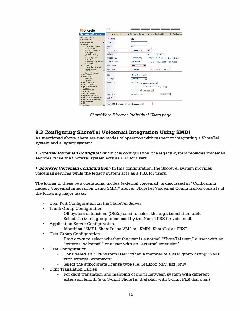
ShoreWare Director Individual Users page 8.3 Configuring ShoreTel Voicemail Integration Using SMDI As mentioned above, there are two modes of operation with respect to integrating a ShoreTel system and a legacy system: • External Voicemail Configuration: In this configuration, the legacy system provides voicemail services while the ShoreTel system acts as PBX for users. • ShoreTel Voicemail Configuration:- In this configuration, the ShoreTel system provides voicemail services while the legacy system acts as a PBX for users. The former of these two operational modes (external voicemail) is discussed in “Configuring Legacy Voicemail Integration Using SMDI” above. ShoreTel Voicemail Configuration consists of the following major tasks:
• Com Port Configuration on the ShoreTel Server • Trunk Group Configuration
– Off-system extensions (OSEs) used to select the digit translation table – Select the trunk group to be used by the Nortel PBX for voicemail.
• Application Server Configuration – Identifies “SMDI: ShoreTel as VM” or “SMDI: ShoreTel as PBX”
• User Group Configuration – Drop down to select whether the user is a normal “ShoreTel user,” a user with an
“external voicemail” or a user with an “external extension” • User Configuration
– Considered an “Off-System User” when a member of a user group listing “SMDI with external extension”
– Select the appropriate license type (i.e. Mailbox only, Ext. only) • Digit Translation Tables
– For digit translation and mapping of digits between system with different extension length (e.g. 3-digit ShoreTel dial plan with 5-digit PBX dial plan)
16
– Configured under System Parameters • PBX link
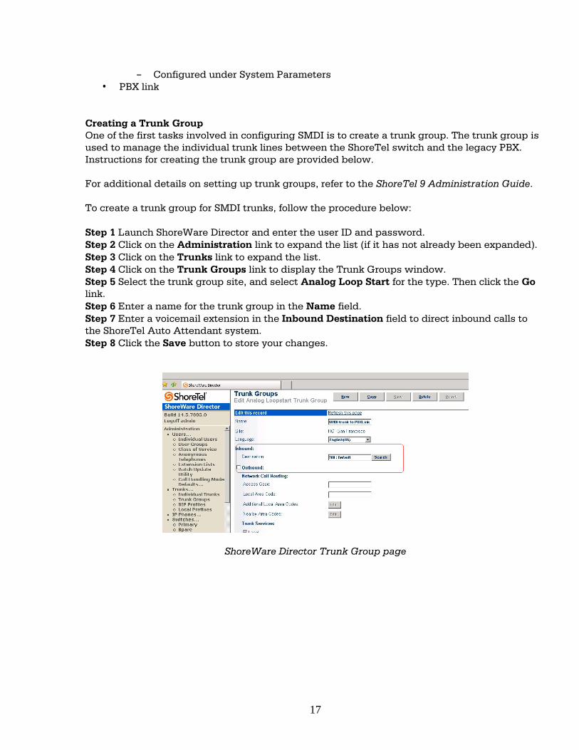
Creating a Trunk Group One of the first tasks involved in configuring SMDI is to create a trunk group. The trunk group is used to manage the individual trunk lines between the ShoreTel switch and the legacy PBX. Instructions for creating the trunk group are provided below. For additional details on setting up trunk groups, refer to the ShoreTel 9 Administration Guide. To create a trunk group for SMDI trunks, follow the procedure below: Step 1 Launch ShoreWare Director and enter the user ID and password. Step 2 Click on the Administration link to expand the list (if it has not already been expanded). Step 3 Click on the Trunks link to expand the list. Step 4 Click on the Trunk Groups link to display the Trunk Groups window. Step 5 Select the trunk group site, and select Analog Loop Start for the type. Then click the Go link. Step 6 Enter a name for the trunk group in the Name field. Step 7 Enter a voicemail extension in the Inbound Destination field to direct inbound calls to the ShoreTel Auto Attendant system. Step 8 Click the Save button to store your changes.
ShoreWare Director Trunk Group page
17
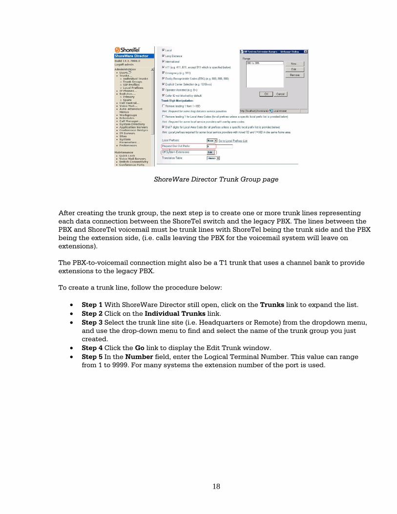
ShoreWare Director Trunk Group page After creating the trunk group, the next step is to create one or more trunk lines representing each data connection between the ShoreTel switch and the legacy PBX. The lines between the PBX and ShoreTel voicemail must be trunk lines with ShoreTel being the trunk side and the PBX being the extension side, (i.e. calls leaving the PBX for the voicemail system will leave on extensions). The PBX-to-voicemail connection might also be a T1 trunk that uses a channel bank to provide extensions to the legacy PBX. To create a trunk line, follow the procedure below:
• Step 1 With ShoreWare Director still open, click on the Trunks link to expand the list. • Step 2 Click on the Individual Trunks link. • Step 3 Select the trunk line site (i.e. Headquarters or Remote) from the dropdown menu,
and use the drop-down menu to find and select the name of the trunk group you just created.
• Step 4 Click the Go link to display the Edit Trunk window. • Step 5 In the Number field, enter the Logical Terminal Number. This value can range
from 1 to 9999. For many systems the extension number of the port is used.
18
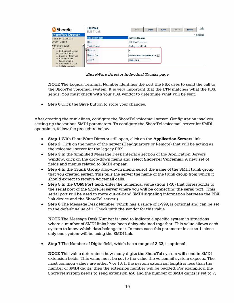
ShoreWare Director Individual Trunks page
NOTE The Logical Terminal Number identifies the port the PBX uses to send the call to the ShoreTel voicemail system. It is very important that the LTN matches what the PBX sends. You must check with your PBX vendor to determine what will be sent.
• Step 6 Click the Save button to store your changes.
After creating the trunk lines, configure the ShoreTel voicemail server. Configuration involves setting up the various SMDI parameters. To configure the ShoreTel voicemail server for SMDI operations, follow the procedure below:
• Step 1 With ShoreWare Director still open, click on the Application Servers link. • Step 2 Click on the name of the server (Headquarters or Remote) that will be acting as
the voicemail server for the legacy PBX. • Step 3 In the Simplified Message Desk Interface section of the Application Servers
window, click on the drop-down menu and select ShoreTel Voicemail. A new set of fields and menus related to SMDI appear.
• Step 4 In the Trunk Group drop-down menu; select the name of the SMDI trunk group that you created earlier. This tells the server the name of the trunk group from which it should expect to receive voicemail calls.
• Step 5 In the COM Port field, enter the numerical value (from 1-10) that corresponds to the serial port of the ShoreTel server where you will be connecting the serial port. (This serial port will be used to route out-of-band SMDI signaling information between the PBX link device and the ShoreTel server.)
• Step 6 The Message Desk Number, which has a range of 1-999, is optional and can be set to the default value of 1. Check with the vendor for this value.
NOTE The Message Desk Number is used to indicate a specific system in situations where a number of SMDI links have been daisy-chained together. This value allows each system to know which data belongs to it. In most case this parameter is set to 1, since only one system will be using the SMDI link.
• Step 7 The Number of Digits field, which has a range of 2-32, is optional.
NOTE This value determines how many digits the ShoreTel system will send in SMDI extension fields. This value must be set to the value the voicemail system expects. The most common values are either 7 or 10. If the system extension length is less than the number of SMDI digits, then the extension number will be padded. For example, if the ShoreTel system needs to send extension 456 and the number of SMDI digits is set to 7,
19
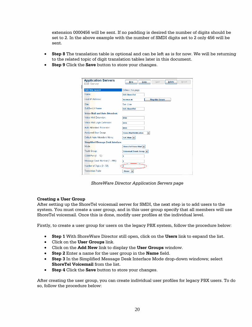
extension 0000456 will be sent. If no padding is desired the number of digits should be set to 2. In the above example with the number of SMDI digits set to 2 only 456 will be sent.
• Step 8 The translation table is optional and can be left as is for now. We will be returning to the related topic of digit translation tables later in this document.
• Step 9 Click the Save button to store your changes.
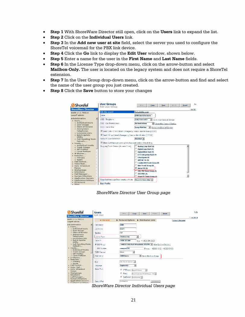
ShoreWare Director Application Servers page Creating a User Group After setting up the ShoreTel voicemail server for SMDI, the next step is to add users to the system. You must create a user group, and in this user group specify that all members will use ShoreTel voicemail. Once this is done, modify user profiles at the individual level. Firstly, to create a user group for users on the legacy PBX system, follow the procedure below:
• Step 1 With ShoreWare Director still open, click on the Users link to expand the list. • Click on the User Groups link. • Click on the Add New link to display the User Groups window. • Step 2 Enter a name for the user group in the Name field. • Step 3 In the Simplified Message Desk Interface Mode drop-down windows; select
ShoreTel Voicemail from the list. • Step 4 Click the Save button to store your changes.
After creating the user group, you can create individual user profiles for legacy PBX users. To do so, follow the procedure below:
20
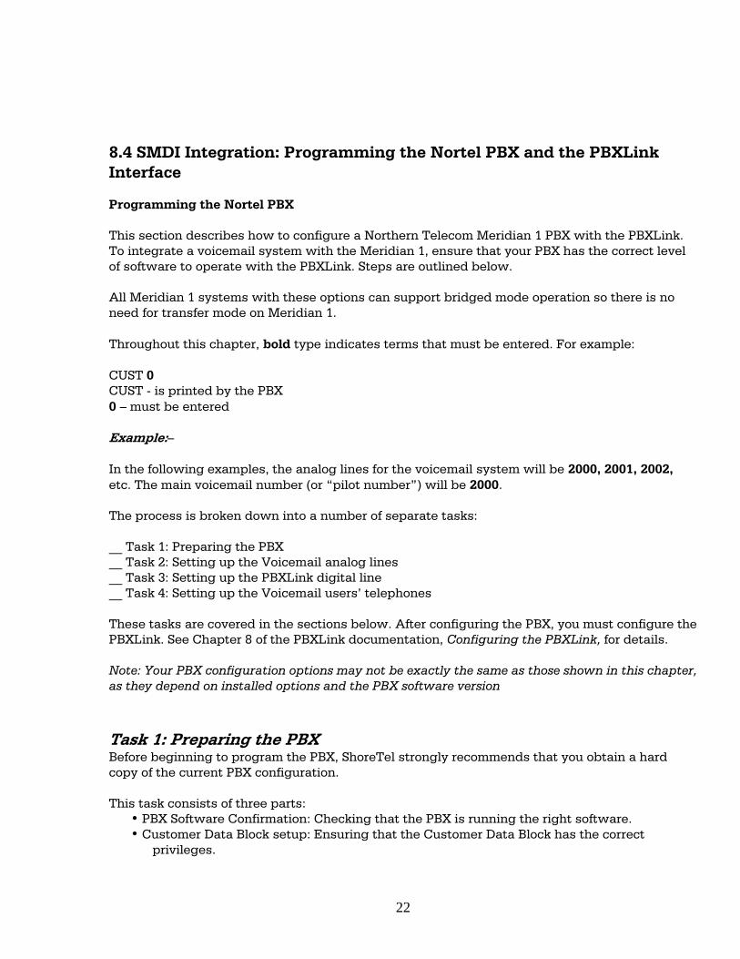
• Step 1 With ShoreWare Director still open, click on the Users link to expand the list. • Step 2 Click on the Individual Users link. • Step 3 In the Add new user at site field, select the server you used to configure the
ShoreTel voicemail for the PBX link device. • Step 4 Click the Go link to display the Edit User window, shown below. • Step 5 Enter a name for the user in the First Name and Last Name fields. • Step 6 In the License Type drop-down menu, click on the arrow-button and select
Mailbox-Only. The user is located on the legacy system and does not require a ShoreTel extension.
• Step 7 In the User Group drop-down menu, click on the arrow-button and find and select the name of the user group you just created.
• Step 8 Click the Save button to store your changes
ShoreWare Director User Group page
ShoreWare Director Individual Users page
21
8.4 SMDI Integration: Programming the Nortel PBX and the PBXLink Interface Programming the Nortel PBX This section describes how to configure a Northern Telecom Meridian 1 PBX with the PBXLink. To integrate a voicemail system with the Meridian 1, ensure that your PBX has the correct level of software to operate with the PBXLink. Steps are outlined below. All Meridian 1 systems with these options can support bridged mode operation so there is no need for transfer mode on Meridian 1. Throughout this chapter, bold type indicates terms that must be entered. For example: CUST 0 CUST - is printed by the PBX 0 – must be entered Example:– In the following examples, the analog lines for the voicemail system will be 2000, 2001, 2002, etc. The main voicemail number (or “pilot number”) will be 2000. The process is broken down into a number of separate tasks: __ Task 1: Preparing the PBX __ Task 2: Setting up the Voicemail analog lines __ Task 3: Setting up the PBXLink digital line __ Task 4: Setting up the Voicemail users’ telephones These tasks are covered in the sections below. After configuring the PBX, you must configure the PBXLink. See Chapter 8 of the PBXLink documentation, Configuring the PBXLink, for details. Note: Your PBX configuration options may not be exactly the same as those shown in this chapter, as they depend on installed options and the PBX software version Task 1: Preparing the PBX Before beginning to program the PBX, ShoreTel strongly recommends that you obtain a hard copy of the current PBX configuration. This task consists of three parts:
• PBX Software Confirmation: Checking that the PBX is running the right software. • Customer Data Block setup: Ensuring that the Customer Data Block has the correct
privileges.
22
• Programming Calling Party Name Display: Ensuring that the reason for a call being forwarded is sent to the PBXLink.
PBX Software Confirmation You must ensure that the correct software packages have been installed, for the PBXLink to operate correctly. To ensure this use overlay 22 as follows: >LD 22 REQ PRT TYPE PKG OPTF 1 CUST 2 CTY 5 DNDI 9 EES 10 MSB 17 DDSP 19 MWC 46 DSET 88 CPND 95 ARIE 170 Customer Data Block Setup You must enable certain options in the Customer Data Block to ensure correct operation of the digital line used by the PBXLink. >LD 15 REQ CHG TYPE CDB CUST 0 [Example only] LDN0 DGRP NITE 2000 [The pilot number if night calls go to Voicemail] TSTL SPRE ATDN NCOS OPT CFO [Call forwarding Originating Party COS] MCI [Message Centre Included] IDP [Include Digit Display] INTR RTIM CDR ICI FLSH CHLN FCAF
SPWD FNAD FDN [Call Forward No Answer DID] FNAN FDN [Call Forward No Answer NONDID] FNAT FDN [Call Forward No Answer Trunk] FNAL FDN [Call Forward No Answer Local] CFNA 6 [Rings for Call Forward No Answer NONDID] DFNA 6 [Rings for Call Forward No Answer DID] PHDT AQTT AODN 2000 [Attendant overflow sent to Voicemail] SRCD ATAC CWCL CWTM CWBZ
23
DNDT Chapter 7 Programming Your Nortel PBX CCRS 32 MDID YES [No Answer DID to
Voicemail] DIDT LDTT 6 [Line Disconnect Tone Timer for 500/255 phones]
NDID YES [No Answer NONDID to Voicemail]
BOTO MWFB YES [Busy DID to Voicemail] NFCR MATT EEST NO [Enable End-to-End signaling for digital phones]
CONG LLT
DLT DIND Programming Call Party Name Display When the PBX forwards a call, it displays a four-letter string on the display which explains why the call was forwarded. These four-letter strings can be changed by the PBX administrator -- this is done in LD 95. The relevant strings and their reasons for being displayed are: __ CFWD -- call forwarded because all calls have been forwarded to voicemail __ CFNA -- call forwarded because there was no answer __ HUNT -- call forwarded because the extension was busy This LD95 session sets up the default strings: >LD 95 REQ CHG TYPE CPND CUST 0 [Example only] CNFG MXLN STAL DFLN DES RESN YES CFWD CFWD CFNA CFNA HUNT HUNT PKUP XFER T AAA A If your system does not use the default strings, then you must configure your PBXLink with the strings that you use. This is done in: Configuration... PBX Options... Call Forward Display... Task 2: Setting up the Voicemail analog lines
24
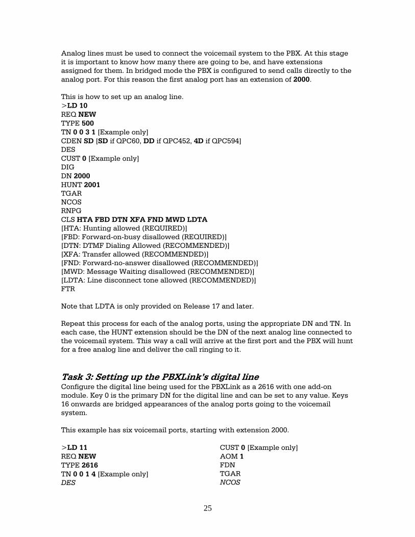
Analog lines must be used to connect the voicemail system to the PBX. At this stage it is important to know how many there are going to be, and have extensions assigned for them. In bridged mode the PBX is configured to send calls directly to the analog port. For this reason the first analog port has an extension of 2000. This is how to set up an analog line. >LD 10 REQ NEW TYPE 500 TN 0 0 3 1 [Example only] CDEN SD [SD if QPC60, DD if QPC452, 4D if QPC594] DES CUST 0 [Example only] DIG DN 2000 HUNT 2001 TGAR NCOS RNPG CLS HTA FBD DTN XFA FND MWD LDTA [HTA: Hunting allowed (REQUIRED)] [FBD: Forward-on-busy disallowed (REQUIRED)] [DTN: DTMF Dialing Allowed (RECOMMENDED)] [XFA: Transfer allowed (RECOMMENDED)] [FND: Forward-no-answer disallowed (RECOMMENDED)] [MWD: Message Waiting disallowed (RECOMMENDED)] [LDTA: Line disconnect tone allowed (RECOMMENDED)] FTR Note that LDTA is only provided on Release 17 and later. Repeat this process for each of the analog ports, using the appropriate DN and TN. In each case, the HUNT extension should be the DN of the next analog line connected to the voicemail system. This way a call will arrive at the first port and the PBX will hunt for a free analog line and deliver the call ringing to it. Task 3: Setting up the PBXLink’s digital line Configure the digital line being used for the PBXLink as a 2616 with one add-on module. Key 0 is the primary DN for the digital line and can be set to any value. Keys 16 onwards are bridged appearances of the analog ports going to the voicemail system. This example has six voicemail ports, starting with extension 2000. >LD 11 REQ NEW TYPE 2616 TN 0 0 1 4 [Example only] DES
CUST 0 [Example only] AOM 1 FDN TGAR NCOS
25
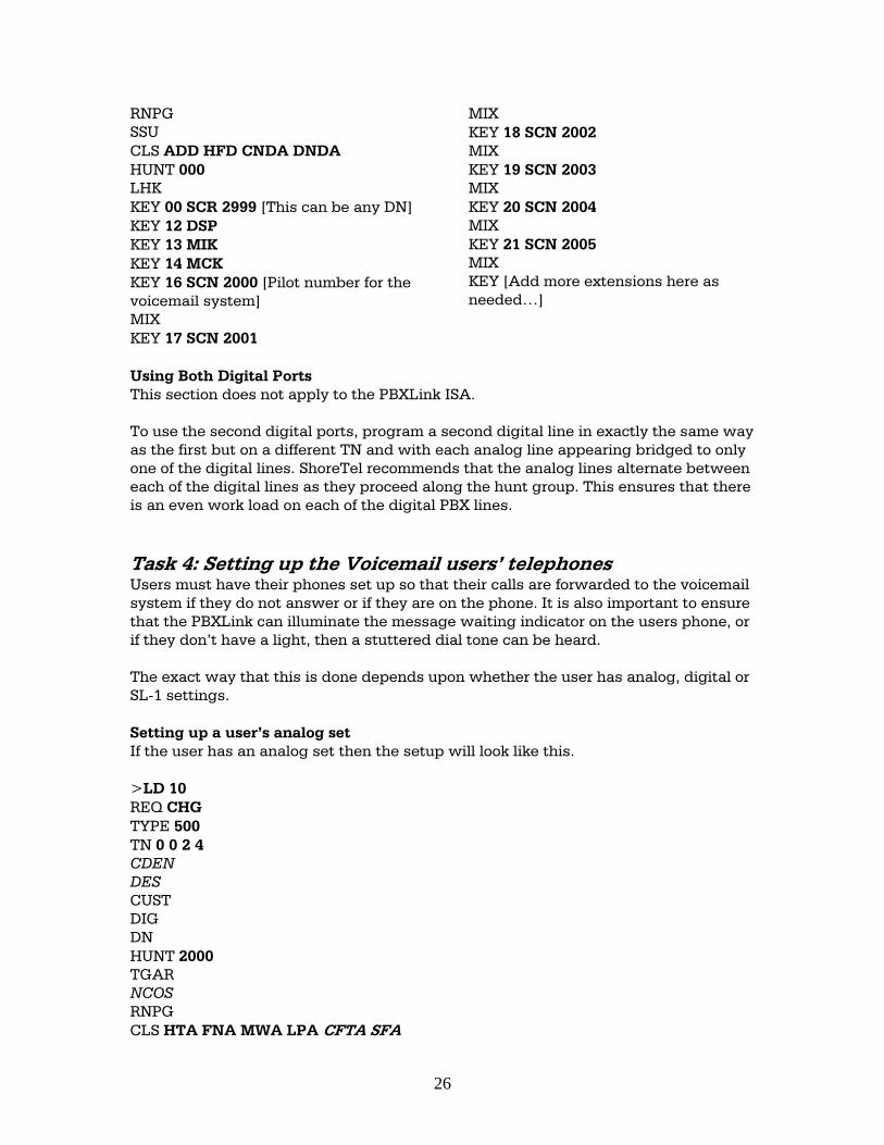
RNPG MIX SSU KEY 18 SCN 2002 CLS ADD HFD CNDA DNDA MIX HUNT 000 KEY 19 SCN 2003 LHK MIX KEY 00 SCR 2999 [This can be any DN] KEY 20 SCN 2004
MIX KEY 12 DSP KEY 21 SCN 2005 KEY 13 MIK MIX KEY 14 MCK KEY [Add more extensions here as needed…]
KEY 16 SCN 2000 [Pilot number for the voicemail system] MIX KEY 17 SCN 2001 Using Both Digital Ports This section does not apply to the PBXLink ISA. To use the second digital ports, program a second digital line in exactly the same way as the first but on a different TN and with each analog line appearing bridged to only one of the digital lines. ShoreTel recommends that the analog lines alternate between each of the digital lines as they proceed along the hunt group. This ensures that there is an even work load on each of the digital PBX lines. Task 4: Setting up the Voicemail users’ telephones Users must have their phones set up so that their calls are forwarded to the voicemail system if they do not answer or if they are on the phone. It is also important to ensure that the PBXLink can illuminate the message waiting indicator on the users phone, or if they don’t have a light, then a stuttered dial tone can be heard. The exact way that this is done depends upon whether the user has analog, digital or SL-1 settings. Setting up a user’s analog set If the user has an analog set then the setup will look like this. >LD 10 REQ CHG TYPE 500 TN 0 0 2 4 CDEN DES CUST DIG DN HUNT 2000 TGAR NCOS RNPG CLS HTA FNA MWA LPA CFTA SFA
26
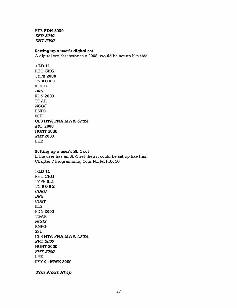
FTR FDN 2000 EFD 2000 EHT 2000 Setting up a user’s digital set A digital set, for instance a 2008, would be set up like this: >LD 11 REQ CHG TYPE 2008 TN 0 0 4 3 ECHG DES FDN 2000 TGAR NCOS RNPG SSU CLS HTA FNA MWA CFTA EFD 2000 HUNT 2000 EHT 2000 LHK Setting up a user’s SL-1 set If the user has an SL-1 set then it could be set up like this. Chapter 7 Programming Your Nortel PBX 36 >LD 11 REQ CHG TYPE SL1 TN 0 0 6 2 CDEN DES CUST KLS FDN 2000 TGAR NCOS RNPG SSU CLS HTA FNA MWA CFTA EFD 2000 HUNT 2000 EHT 2000 LHK KEY 04 MWK 2000 The Next Step
27
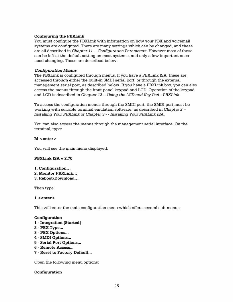
Configuring the PBXLink You must configure the PBXLink with information on how your PBX and voicemail systems are configured. There are many settings which can be changed, and these are all described in Chapter 11 -- Configuration Parameters. However most of these can be left at the default setting on most systems, and only a few important ones need changing. These are described below. Configuration Menus The PBXLink is configured through menus. If you have a PBXLink ISA, these are accessed through either the built-in SMDI serial port, or through the external management serial port, as described below. If you have a PBXLink box, you can also access the menus through the front panel keypad and LCD. Operation of the keypad and LCD is described in Chapter 12 -- Using the LCD and Key Pad - PBXLink. To access the configuration menus through the SMDI port, the SMDI port must be working with suitable terminal emulation software, as described in Chapter 2 -- Installing Your PBXLink or Chapter 3 - - Installing Your PBXLink ISA. You can also access the menus through the management serial interface. On the terminal, type: M <enter> You will see the main menu displayed. PBXLink ISA v 2.70 1. Configuration… 2. Monitor PBXLink… 3. Reboot/Download… Then type 1 <enter> This will enter the main configuration menu which offers several sub-menus Configuration 1 - Integration [Started] 2 - PBX Type... 3 - PBX Options... 4 - SMDI Options... 5 - Serial Port Options... 6 - Remote Access... 7 - Reset to Factory Default... Open the following menu options: Configuration
28
PBX Type This must be set to your type of PBX. When this set correctly, the port LED will stop flashing (this is the LED on the bracket of the PBXLink ISA, and the LED labeled PBX A on the PBXLink box). If you have a Nortel Meridian 1 or SL-100 PBX, choose the Nortel M1 option. Note that when you change the PBX type, the PBXLink will restart. That means you will be back at the initial boot up screen, after allowing it a few seconds and will have to type M <enter> again to get back into the configuration menus. Configuration…/Integration This should be set to Started. Configuration…/PBX Options…/Analog Ports on A This should be set according to the number of analog lines connected to your voicemail system. Configuration…/PBX Options…/Configure Port A This should be set to Calls + MWI, the default. Configuration…/PBX Options…/Prime number (Nortel and Lucent bridged mode only) This should be set to the extension number that voicemail users call to pick up their voicemail.. Configuration…/PBX Options…/Message Waiting Ind…(Lucent only) These settings must match those in the Feature Access Codes pages of the PBX programming, and are the prefixes that are dialed before an extension number to turn on or off a Message Waiting Indicator. The defaults are *4 and #4, which are the defaults for most PBXs. Configuration PBX Options…/Call Forward display…(Nortel only) These settings must match those in LD 95 of PBX programming (see Chapter 7 -- Programming Your Nortel PBX), and indicate what the PBX should expect on the display of the digital phone it is emulating. There are three settings: one for all calls forwarded, one for forward on no answer, and one for forward on busy. 9. Technical and Troubleshooting Tips Call History messages to the message desk (data link) start with a carriage return and a line-feed sequence. These must be followed by the elements/fields listed below, in the given order: 1. The alphabetic characters MD.
29
2. Three digits that represent the message desk number to which the incoming call is routed. Valid numbers for this field range from 000 to 999.
3. Four digits that designate the position number to which the incoming call was delivered. Valid numbers for this field range from 0000 to 9999.
4. A single character specifies the Type of Call Indicator. A All calls to the subscriber’s line are forwarded to the Message Storage and
Retrieval (MSR) System. B Call has been forwarded to the MSR System because the subscriber’s line is
in a busy condition. D Direct dialed call to the MSR System (e.g., for message retrieval). N Call has been forwarded to the MSR System upon no answer at the
subscriber’s line. U Call forwarded, but the reason for forwarding is not available.
5. Up to ten digits that specify the Forwarding subscriber’s Directory Number (DN), if available.
6. An ASCII space character. 7. Up to ten digits that specify the Calling DN, if available. 8. Optional: An ASCII space character. 9. Optional: A single character that shall specify the presentation status of the DN.
a. If the DN is available. A Allowed P Restricted
b. If unavailable This field must consist of all zeros or be omitted.
10. Optional: An ASCII space character. 11. Optional: One to fifteen characters that shall specify the calling name or a
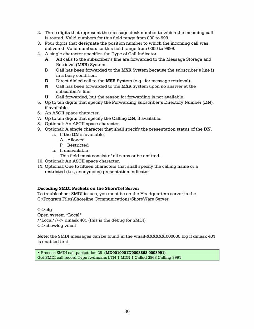
restricted (i.e., anonymous) presentation indicator Decoding SMDI Packets on the ShoreTel Server To troubleshoot SMDI issues, you must be on the Headquarters server in the C:\Program Files\Shoreline Communications\ShoreWare Server. C:>cfg Open system *Local* /*Local*//-> dmask 401 (this is the debug for SMDI) C:>showlog vmail Note: the SMDI messages can be found in the vmail-XXXXXX.000000.log if dmask 401 is enabled first. • Process SMDI call packet, len 28 (MD0010001N0003868 0003991) Got SMDI call record Type fwdnoans LTN 1 MDN 1 Called 3868 Calling 3991
30
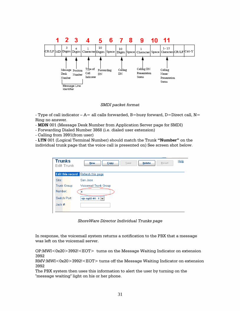
SMDI packet format - Type of call indicator – A= all calls forwarded, B=busy forward, D=Direct call, N= Ring no answer. - MDN 001 (Message Desk Number from Application Server page for SMDI) - Forwarding Dialed Number 3868 (i.e. dialed user extension) - Calling from 3991(from user) - LTN 001 (Logical Terminal Number) should match the Trunk “Number” on the individual trunk page that the voice call is presented on) See screen shot below.
ShoreWare Director Individual Trunks page In response, the voicemail system returns a notification to the PBX that a message was left on the voicemail server. OP:MWI<0x20>3992!<EOT> turns on the Message Waiting Indicator on extension 3992 RMV:MWI<0x20>3992!<EOT> turns off the Message Waiting Indicator on extension 3992 The PBX system then uses this information to alert the user by turning on the "message waiting" light on his or her phone.
31
The group of analog trunks from the ShoreTel system that is used to access the legacy voicemail system (the ShoreTel system is on the extension side of the trunks) is considered the LTN. The ShoreTel voicemail application manages the group of outgoing extensions. The ShoreTel server provides digit translations if the legacy voicemail and ShoreTel system have different extension lengths. 10. Known Issues - See AN-124s Integrating ShoreTel to Nortel using NI-2 PRI Tie Lines. - Calling Name not displayed on the ShoreTel or Nortel phones. ShoreTel recommends you use the ISDN QSIG protocol to successfully pass Calling Name between the two systems. Using NI-2 ISDN Protocol with a Nortel Meridian 1 does not correctly pass the Calling Name in many cases. The options OVLR and OVLS (overlap Receiving/Sending) should always be set to “NO” with ShoreTel. If this option is selected, you may experience calls dropping during call progress tones or not completely at all. OVLR NO OVLS NO - MWI/SMDI pacing – SMDI MWI packets are transmitted rapidly to the Nortel PBX digital port causing the port to lockup. The instructions below will allow you to set a time between MWI SMDI packets to control the flow and prevent a lockup .
1. Back up their current MailServ.exe 2. Stop "ShoreWare Voicemail Message Server" service and click Yes to stop other
two dependent services 3. Replace with attached binary. 4. Change HKEY_LOCAL_MACHINE\SOFTWARE\Shoreline
Teleworks\Voicemail\MWIDelay to a desirable value. A value of 1000 (decimal) is for one second in between each MWI command.
5. Start "ShoreWare Voicemail Application" service Three seconds delay with disconnect supervision - ShoreTel was the voicemail system for a Nortel Meridian 1 Option 61 using a PBXLink 48. Three seconds of dial tone was played at the end of each voicemail left on the ShoreTel. To resolve this problem you must replace the station cards with the NT1R20AB station card for proper disconnect supervision. Record of Change This application note is subject to change as third party hardware and software changes. Updates and corrections are always welcome. Please submit any updates or corrections to [email protected].
32

Issue Author Reason for Change Date 1.0 S. Graham Initial Release November 11, 2005 2.0 B. Lynch Revision July 6, 2009
33
Appendix A: Nortel Configuration for TIE Integration
Disclaimer The configuration described in this document requires proficiency on the Nortel Meridian 1 overlays and the administrator interface. This document is a guide to provide sample configurations to integrate with the ShoreTel .Inc (see AN 124a) for reference
34