shoretel connect planning and installation guide - amazon s3
TRANSCRIPT

ShoreTel ConnectPlanning and Installation
Guide
May 20, 2016

Legal Notices
Document and Software CopyrightsCopyright © 1998-2016 by ShoreTel Inc., Sunnyvale, California, USA. All rights reserved.
Printed in the United States of America. Contents of this publication may not be reproduced or transmitted in any form or by any means, electronic or mechanical, for any purpose, without prior written authorization of ShoreTel, Inc. ShoreTel, Inc. reserves the right to make changes without notice to the specifications and materials contained herein and shall not be responsible for any damage (including consequential) caused by reliance on the materials presented, including, but not limited to typographical, arithmetic or listing errors.
TrademarksShoreTel, ShoreTel (and logo), Brilliantly Simple, Brilliantly Simple Communication, ShoreTel Connect, ShoreTel Connect ONSITE, ShoreTel Connect HYBRID, ShoreTel Connect CLOUD, ShoreGear, and ShoreWare are registered trademarks of ShoreTel, Inc. in the United States and/or other countries. The ShoreTel logo is a trademark of ShoreTel, Inc. in the United States and/or other countries.
All other copyrights and trademarks herein are the property of their respective owners.
PatentsShoreTel products are covered by patents as listed at http://www.shoretel.com/about/patents.html.
Version InformationShoreTel ConnectPlanning and Installation GuideDate: May 20, 2016
Company InformationShoreTel, Inc.960 Stewart DriveSunnyvale, California 94085 USA+1.408.331.3300+1.408.331.3333 (fax)www.shoretel.com
2 Planning and Installation Guide ShoreTel Connect

Table of Contents
Preface . . . . . . . . . . . . . . . . . . . . . . . . . . . . . . . . . . . . . . . . . . . . . . . . . . . . . . . . . . . . . . . . . .14
Audience . . . . . . . . . . . . . . . . . . . . . . . . . . . . . . . . . . . . . . . . . . . . . . . . . . . . . . . . . . . . . . . . . 14Organization . . . . . . . . . . . . . . . . . . . . . . . . . . . . . . . . . . . . . . . . . . . . . . . . . . . . . . . . . . . . . . . 14Documentation Overview . . . . . . . . . . . . . . . . . . . . . . . . . . . . . . . . . . . . . . . . . . . . . . . . . . . . . 14
System Documentation . . . . . . . . . . . . . . . . . . . . . . . . . . . . . . . . . . . . . . . . . . . . . . . . . . . 14Software Documentation . . . . . . . . . . . . . . . . . . . . . . . . . . . . . . . . . . . . . . . . . . . . . . . . . . 14Hardware Documentation . . . . . . . . . . . . . . . . . . . . . . . . . . . . . . . . . . . . . . . . . . . . . . . . . 15Release Notes . . . . . . . . . . . . . . . . . . . . . . . . . . . . . . . . . . . . . . . . . . . . . . . . . . . . . . . . . . 15Online Knowledge Base . . . . . . . . . . . . . . . . . . . . . . . . . . . . . . . . . . . . . . . . . . . . . . . . . . 15Document Conventions . . . . . . . . . . . . . . . . . . . . . . . . . . . . . . . . . . . . . . . . . . . . . . . . . . . 15
Chapter 1 Getting Started . . . . . . . . . . . . . . . . . . . . . . . . . . . . . . . . . . . . . . . . . . . . . . . .16
Overview . . . . . . . . . . . . . . . . . . . . . . . . . . . . . . . . . . . . . . . . . . . . . . . . . . . . . . . . . . . . . . . . . 17Assembling the Team . . . . . . . . . . . . . . . . . . . . . . . . . . . . . . . . . . . . . . . . . . . . . . . . . . . . . . . 17
Phase 1: Voice Communication System Analysis and Ordering . . . . . . . . . . . . . . . . . . . . 17Phase 2: Environmental and Infrastructure Analysis and Upgrade . . . . . . . . . . . . . . . . . . 18Phase 3: Resource Scheduling and Tracking . . . . . . . . . . . . . . . . . . . . . . . . . . . . . . . . . . 19Phase 4: System Load and Configuration . . . . . . . . . . . . . . . . . . . . . . . . . . . . . . . . . . . . . 20Phase 5: Installation Readiness Review . . . . . . . . . . . . . . . . . . . . . . . . . . . . . . . . . . . . . . 20Phase 6: Cut-Over . . . . . . . . . . . . . . . . . . . . . . . . . . . . . . . . . . . . . . . . . . . . . . . . . . . . . . . 21
Chapter 2 Planning and System Design. . . . . . . . . . . . . . . . . . . . . . . . . . . . . . . . . . . . .22
Overview . . . . . . . . . . . . . . . . . . . . . . . . . . . . . . . . . . . . . . . . . . . . . . . . . . . . . . . . . . . . . . . . . 23Recommendations . . . . . . . . . . . . . . . . . . . . . . . . . . . . . . . . . . . . . . . . . . . . . . . . . . . . . . . . . . 23Network Assessment . . . . . . . . . . . . . . . . . . . . . . . . . . . . . . . . . . . . . . . . . . . . . . . . . . . . . . . . 23Determine System Topology . . . . . . . . . . . . . . . . . . . . . . . . . . . . . . . . . . . . . . . . . . . . . . . . . . 23
Sites and Users . . . . . . . . . . . . . . . . . . . . . . . . . . . . . . . . . . . . . . . . . . . . . . . . . . . . . . . . . 24Headquarters and Distributed ShoreTel Servers . . . . . . . . . . . . . . . . . . . . . . . . . . . . . . . 24Citrix and Windows Terminal Server . . . . . . . . . . . . . . . . . . . . . . . . . . . . . . . . . . . . . . . . . 25Teleworker Sites . . . . . . . . . . . . . . . . . . . . . . . . . . . . . . . . . . . . . . . . . . . . . . . . . . . . . . . . 25Telephone Requirements . . . . . . . . . . . . . . . . . . . . . . . . . . . . . . . . . . . . . . . . . . . . . . . . . 25Trunk Requirements . . . . . . . . . . . . . . . . . . . . . . . . . . . . . . . . . . . . . . . . . . . . . . . . . . . . . 26
Determine Number of ShoreTel Voice Switches . . . . . . . . . . . . . . . . . . . . . . . . . . . . . . . . . . . 27WAN Connections . . . . . . . . . . . . . . . . . . . . . . . . . . . . . . . . . . . . . . . . . . . . . . . . . . . . . . . . . . 28Failover . . . . . . . . . . . . . . . . . . . . . . . . . . . . . . . . . . . . . . . . . . . . . . . . . . . . . . . . . . . . . . . . . . 28System Capacity . . . . . . . . . . . . . . . . . . . . . . . . . . . . . . . . . . . . . . . . . . . . . . . . . . . . . . . . . . . 28
ShoreTel Connect Planning and Installation Guide 3
Table of Contents
Virtual Phone and Virtual Trunk Switches . . . . . . . . . . . . . . . . . . . . . . . . . . . . . . . . . . . . . 34BHCC Call Volume . . . . . . . . . . . . . . . . . . . . . . . . . . . . . . . . . . . . . . . . . . . . . . . . . . . . . . 34BHCA Call Volume . . . . . . . . . . . . . . . . . . . . . . . . . . . . . . . . . . . . . . . . . . . . . . . . . . . . . . 35Call Load Capacity for Switches . . . . . . . . . . . . . . . . . . . . . . . . . . . . . . . . . . . . . . . . . . . . 35Extension Monitoring Limitations . . . . . . . . . . . . . . . . . . . . . . . . . . . . . . . . . . . . . . . . . . . . 35ShoreTel Voice Switch Feature Capacity . . . . . . . . . . . . . . . . . . . . . . . . . . . . . . . . . . . . . 35
Chapter 3 Network Requirements and Preparation . . . . . . . . . . . . . . . . . . . . . . . . . . .40
Overview . . . . . . . . . . . . . . . . . . . . . . . . . . . . . . . . . . . . . . . . . . . . . . . . . . . . . . . . . . . . . . . . . 42Understanding the Network Requirements for Toll-Quality Voice . . . . . . . . . . . . . . . . . . . . . . 42
General Network Requirements . . . . . . . . . . . . . . . . . . . . . . . . . . . . . . . . . . . . . . . . . . . . 42Bandwidth Requirements . . . . . . . . . . . . . . . . . . . . . . . . . . . . . . . . . . . . . . . . . . . . . . . . . 46Latency . . . . . . . . . . . . . . . . . . . . . . . . . . . . . . . . . . . . . . . . . . . . . . . . . . . . . . . . . . . . . . . 47Jitter for Voice Switches . . . . . . . . . . . . . . . . . . . . . . . . . . . . . . . . . . . . . . . . . . . . . . . . . . 47Packet Loss . . . . . . . . . . . . . . . . . . . . . . . . . . . . . . . . . . . . . . . . . . . . . . . . . . . . . . . . . . . . 48Bandwidth Management . . . . . . . . . . . . . . . . . . . . . . . . . . . . . . . . . . . . . . . . . . . . . . . . . . 48Virtual LANs . . . . . . . . . . . . . . . . . . . . . . . . . . . . . . . . . . . . . . . . . . . . . . . . . . . . . . . . . . . 49Wide Area Network . . . . . . . . . . . . . . . . . . . . . . . . . . . . . . . . . . . . . . . . . . . . . . . . . . . . . . 50Client Bandwidth . . . . . . . . . . . . . . . . . . . . . . . . . . . . . . . . . . . . . . . . . . . . . . . . . . . . . . . . 50Admission Control in the Wide Area Network . . . . . . . . . . . . . . . . . . . . . . . . . . . . . . . . . . 51Spanning Tree Protocol . . . . . . . . . . . . . . . . . . . . . . . . . . . . . . . . . . . . . . . . . . . . . . . . . . . 51Traffic Shaping to Reduce Bottlenecks . . . . . . . . . . . . . . . . . . . . . . . . . . . . . . . . . . . . . . . 52Echo Cancellation . . . . . . . . . . . . . . . . . . . . . . . . . . . . . . . . . . . . . . . . . . . . . . . . . . . . . . . 52
WAN Technology Choices . . . . . . . . . . . . . . . . . . . . . . . . . . . . . . . . . . . . . . . . . . . . . . . . . . . . 53Minimum Bandwidth Requirements . . . . . . . . . . . . . . . . . . . . . . . . . . . . . . . . . . . . . . . . . . 53Leased T1 . . . . . . . . . . . . . . . . . . . . . . . . . . . . . . . . . . . . . . . . . . . . . . . . . . . . . . . . . . . . . 53MPLS . . . . . . . . . . . . . . . . . . . . . . . . . . . . . . . . . . . . . . . . . . . . . . . . . . . . . . . . . . . . . . . . . 54SDSL . . . . . . . . . . . . . . . . . . . . . . . . . . . . . . . . . . . . . . . . . . . . . . . . . . . . . . . . . . . . . . . . . 54IDSL . . . . . . . . . . . . . . . . . . . . . . . . . . . . . . . . . . . . . . . . . . . . . . . . . . . . . . . . . . . . . . . . . 54ADSL . . . . . . . . . . . . . . . . . . . . . . . . . . . . . . . . . . . . . . . . . . . . . . . . . . . . . . . . . . . . . . . . . 54Cable Modems . . . . . . . . . . . . . . . . . . . . . . . . . . . . . . . . . . . . . . . . . . . . . . . . . . . . . . . . . 54ISDN BRI . . . . . . . . . . . . . . . . . . . . . . . . . . . . . . . . . . . . . . . . . . . . . . . . . . . . . . . . . . . . . . 54Dial-Up Modems . . . . . . . . . . . . . . . . . . . . . . . . . . . . . . . . . . . . . . . . . . . . . . . . . . . . . . . . 54
IP Address Assignment . . . . . . . . . . . . . . . . . . . . . . . . . . . . . . . . . . . . . . . . . . . . . . . . . . . . . . 55Configuring DHCP for ShoreTel IP Phones . . . . . . . . . . . . . . . . . . . . . . . . . . . . . . . . . . . . . . . 56Configuring Automatic VLAN Assignment Using DHCP . . . . . . . . . . . . . . . . . . . . . . . . . . . . . 60
Configuring Automatic VLAN Assignment on a DHCP Server . . . . . . . . . . . . . . . . . . . . . 60Configuring Automatic VLAN Assignment Using DHCP During ShoreTel IP Phone Standard Boot Process . . . . . . . . . . . . . . . . . . . . . . . . . . . . . . . . . . . . . . . . . . . . . . . . . . . . . . . . . . . 60
Configuring Automatic VLAN Assignment Using LLDP . . . . . . . . . . . . . . . . . . . . . . . . . . . . . . 61Configuring Automatic VLAN Assignment Using LLDP-MED During the ShoreTel IP Phone Standard Boot Process . . . . . . . . . . . . . . . . . . . . . . . . . . . . . . . . . . . . . . . . . . . . . . . . . . . 61
Time Services . . . . . . . . . . . . . . . . . . . . . . . . . . . . . . . . . . . . . . . . . . . . . . . . . . . . . . . . . . . . . 62Virtual Private Network (VPN) . . . . . . . . . . . . . . . . . . . . . . . . . . . . . . . . . . . . . . . . . . . . . . . . . 62
Tunneling . . . . . . . . . . . . . . . . . . . . . . . . . . . . . . . . . . . . . . . . . . . . . . . . . . . . . . . . . . . . . . 63Performance . . . . . . . . . . . . . . . . . . . . . . . . . . . . . . . . . . . . . . . . . . . . . . . . . . . . . . . . . . . 64Integrated Security Appliances . . . . . . . . . . . . . . . . . . . . . . . . . . . . . . . . . . . . . . . . . . . . . 64
Firewalls . . . . . . . . . . . . . . . . . . . . . . . . . . . . . . . . . . . . . . . . . . . . . . . . . . . . . . . . . . . . . . . . . . 65Media Encryption . . . . . . . . . . . . . . . . . . . . . . . . . . . . . . . . . . . . . . . . . . . . . . . . . . . . . . . . . . . 66Security for ShoreTel 400-Series IP Phones . . . . . . . . . . . . . . . . . . . . . . . . . . . . . . . . . . . . . . 66Session Initiation Protocol (SIP) . . . . . . . . . . . . . . . . . . . . . . . . . . . . . . . . . . . . . . . . . . . . . . . 67
ShoreTel Connect Planning and Installation Guide 4

Table of Contents
Example Network Topologies . . . . . . . . . . . . . . . . . . . . . . . . . . . . . . . . . . . . . . . . . . . . . . . . . 68Single-Site Implementation . . . . . . . . . . . . . . . . . . . . . . . . . . . . . . . . . . . . . . . . . . . . . . . . 68Multisite Implementation . . . . . . . . . . . . . . . . . . . . . . . . . . . . . . . . . . . . . . . . . . . . . . . . . . 68
Computing Admission Control Bandwidth . . . . . . . . . . . . . . . . . . . . . . . . . . . . . . . . . . . . . . . . 69WAN Bandwidth per Call (Full Duplex) without cRTP . . . . . . . . . . . . . . . . . . . . . . . . . . . . 70WAN Bandwidth per Call (Full Duplex) with cRTP . . . . . . . . . . . . . . . . . . . . . . . . . . . . . . 71Setting Admission Control . . . . . . . . . . . . . . . . . . . . . . . . . . . . . . . . . . . . . . . . . . . . . . . . . 73
Chapter 4 Routing Calls. . . . . . . . . . . . . . . . . . . . . . . . . . . . . . . . . . . . . . . . . . . . . . . . . .74
Overview . . . . . . . . . . . . . . . . . . . . . . . . . . . . . . . . . . . . . . . . . . . . . . . . . . . . . . . . . . . . . . . . . 75Recommendations . . . . . . . . . . . . . . . . . . . . . . . . . . . . . . . . . . . . . . . . . . . . . . . . . . . . . . . . . . 75Hunt Groups . . . . . . . . . . . . . . . . . . . . . . . . . . . . . . . . . . . . . . . . . . . . . . . . . . . . . . . . . . . . . . . 76
Direct All Calls to an Auto Attendant . . . . . . . . . . . . . . . . . . . . . . . . . . . . . . . . . . . . . . . . . 76After-Hours Call Routing . . . . . . . . . . . . . . . . . . . . . . . . . . . . . . . . . . . . . . . . . . . . . . . . . . 78Direct All Calls to a Live Operator . . . . . . . . . . . . . . . . . . . . . . . . . . . . . . . . . . . . . . . . . . . 78Direct All Calls to Extensions . . . . . . . . . . . . . . . . . . . . . . . . . . . . . . . . . . . . . . . . . . . . . . 82
Blended Call Routing . . . . . . . . . . . . . . . . . . . . . . . . . . . . . . . . . . . . . . . . . . . . . . . . . . . . . . . . 83Trunk Considerations . . . . . . . . . . . . . . . . . . . . . . . . . . . . . . . . . . . . . . . . . . . . . . . . . . . . 84Analyze Outbound Call Routing . . . . . . . . . . . . . . . . . . . . . . . . . . . . . . . . . . . . . . . . . . . . 86
Chapter 5 Trunk Planning and Ordering . . . . . . . . . . . . . . . . . . . . . . . . . . . . . . . . . . . .88
Recommendations . . . . . . . . . . . . . . . . . . . . . . . . . . . . . . . . . . . . . . . . . . . . . . . . . . . . . . . . . . 90Reviewing and Selecting Trunk Types . . . . . . . . . . . . . . . . . . . . . . . . . . . . . . . . . . . . . . . . . . . 90
Analog Loop-Start Trunks (North America) . . . . . . . . . . . . . . . . . . . . . . . . . . . . . . . . . . . . 91Analog Loop-Start Trunks (EMEA) . . . . . . . . . . . . . . . . . . . . . . . . . . . . . . . . . . . . . . . . . . 92Digital Loop-Start Trunks . . . . . . . . . . . . . . . . . . . . . . . . . . . . . . . . . . . . . . . . . . . . . . . . . . 92Analog Wink-Start Trunks (Analog DID) . . . . . . . . . . . . . . . . . . . . . . . . . . . . . . . . . . . . . . 93Digital Wink-Start Trunks . . . . . . . . . . . . . . . . . . . . . . . . . . . . . . . . . . . . . . . . . . . . . . . . . . 93BRI Trunks . . . . . . . . . . . . . . . . . . . . . . . . . . . . . . . . . . . . . . . . . . . . . . . . . . . . . . . . . . . . 94T1 PRI Trunks . . . . . . . . . . . . . . . . . . . . . . . . . . . . . . . . . . . . . . . . . . . . . . . . . . . . . . . . . . 94E1 PRI Trunks . . . . . . . . . . . . . . . . . . . . . . . . . . . . . . . . . . . . . . . . . . . . . . . . . . . . . . . . . . 95SIP Trunks . . . . . . . . . . . . . . . . . . . . . . . . . . . . . . . . . . . . . . . . . . . . . . . . . . . . . . . . . . . . . 95
Understanding Trunk Features . . . . . . . . . . . . . . . . . . . . . . . . . . . . . . . . . . . . . . . . . . . . . . . . 96Caller ID Number . . . . . . . . . . . . . . . . . . . . . . . . . . . . . . . . . . . . . . . . . . . . . . . . . . . . . . . . 97Caller ID Name . . . . . . . . . . . . . . . . . . . . . . . . . . . . . . . . . . . . . . . . . . . . . . . . . . . . . . . . . 97Automatic Number Identification (ANI) . . . . . . . . . . . . . . . . . . . . . . . . . . . . . . . . . . . . . . . 97Direct Inward Dial (DID) . . . . . . . . . . . . . . . . . . . . . . . . . . . . . . . . . . . . . . . . . . . . . . . . . . 98Dialed Number Identification Service (DNIS) . . . . . . . . . . . . . . . . . . . . . . . . . . . . . . . . . . 98Outbound Caller ID . . . . . . . . . . . . . . . . . . . . . . . . . . . . . . . . . . . . . . . . . . . . . . . . . . . . . . 99Tandem Trunking . . . . . . . . . . . . . . . . . . . . . . . . . . . . . . . . . . . . . . . . . . . . . . . . . . . . . . . 99Tie Trunks . . . . . . . . . . . . . . . . . . . . . . . . . . . . . . . . . . . . . . . . . . . . . . . . . . . . . . . . . . . . . 99
Performing Traffic Calculations . . . . . . . . . . . . . . . . . . . . . . . . . . . . . . . . . . . . . . . . . . . . . . . 100Ordering Telephone Service . . . . . . . . . . . . . . . . . . . . . . . . . . . . . . . . . . . . . . . . . . . . . . . . . 100
Analog Service . . . . . . . . . . . . . . . . . . . . . . . . . . . . . . . . . . . . . . . . . . . . . . . . . . . . . . . . 101T1 Service . . . . . . . . . . . . . . . . . . . . . . . . . . . . . . . . . . . . . . . . . . . . . . . . . . . . . . . . . . . . 101T1 PRI Service . . . . . . . . . . . . . . . . . . . . . . . . . . . . . . . . . . . . . . . . . . . . . . . . . . . . . . . . 102Ordering Service . . . . . . . . . . . . . . . . . . . . . . . . . . . . . . . . . . . . . . . . . . . . . . . . . . . . . . . 103E1 PRI Service . . . . . . . . . . . . . . . . . . . . . . . . . . . . . . . . . . . . . . . . . . . . . . . . . . . . . . . . 103
ShoreTel Connect Planning and Installation Guide 5

Table of Contents
Chapter 6 Dialing Plan . . . . . . . . . . . . . . . . . . . . . . . . . . . . . . . . . . . . . . . . . . . . . . . . . .104
Overview . . . . . . . . . . . . . . . . . . . . . . . . . . . . . . . . . . . . . . . . . . . . . . . . . . . . . . . . . . . . . . . . 105Dialing . . . . . . . . . . . . . . . . . . . . . . . . . . . . . . . . . . . . . . . . . . . . . . . . . . . . . . . . . . . . . . . . . . 105
Define Digit Collection . . . . . . . . . . . . . . . . . . . . . . . . . . . . . . . . . . . . . . . . . . . . . . . . . . . 105Configuring Internal Numbers . . . . . . . . . . . . . . . . . . . . . . . . . . . . . . . . . . . . . . . . . . . . . 105Configuring External Numbers . . . . . . . . . . . . . . . . . . . . . . . . . . . . . . . . . . . . . . . . . . . . 107Define Digit Manipulation . . . . . . . . . . . . . . . . . . . . . . . . . . . . . . . . . . . . . . . . . . . . . . . . 109On-Net Dialing . . . . . . . . . . . . . . . . . . . . . . . . . . . . . . . . . . . . . . . . . . . . . . . . . . . . . . . . . 111
Quick Reference of Star Codes . . . . . . . . . . . . . . . . . . . . . . . . . . . . . . . . . . . . . . . . . . . . . . . 114Common Star Codes . . . . . . . . . . . . . . . . . . . . . . . . . . . . . . . . . . . . . . . . . . . . . . . . . . . . 114Extension Assignment Star Codes . . . . . . . . . . . . . . . . . . . . . . . . . . . . . . . . . . . . . . . . . 115Trunk Star Codes . . . . . . . . . . . . . . . . . . . . . . . . . . . . . . . . . . . . . . . . . . . . . . . . . . . . . . 116
Chapter 7 Network Call Routing . . . . . . . . . . . . . . . . . . . . . . . . . . . . . . . . . . . . . . . . . .118
Overview . . . . . . . . . . . . . . . . . . . . . . . . . . . . . . . . . . . . . . . . . . . . . . . . . . . . . . . . . . . . . . . . 119Define Network Call Routing . . . . . . . . . . . . . . . . . . . . . . . . . . . . . . . . . . . . . . . . . . . . . . . . . 119
Call Permissions . . . . . . . . . . . . . . . . . . . . . . . . . . . . . . . . . . . . . . . . . . . . . . . . . . . . . . . 119Account Codes . . . . . . . . . . . . . . . . . . . . . . . . . . . . . . . . . . . . . . . . . . . . . . . . . . . . . . . . 120Trunk Availability . . . . . . . . . . . . . . . . . . . . . . . . . . . . . . . . . . . . . . . . . . . . . . . . . . . . . . . 121Specifying Parameters for the Routing Decision . . . . . . . . . . . . . . . . . . . . . . . . . . . . . . . 122
Chapter 8 Planning Applications and Services . . . . . . . . . . . . . . . . . . . . . . . . . . . . . .124
Account Code Collection Service . . . . . . . . . . . . . . . . . . . . . . . . . . . . . . . . . . . . . . . . . . . . . . 126Account Codes . . . . . . . . . . . . . . . . . . . . . . . . . . . . . . . . . . . . . . . . . . . . . . . . . . . . . . . . 126Call Permissions . . . . . . . . . . . . . . . . . . . . . . . . . . . . . . . . . . . . . . . . . . . . . . . . . . . . . . . 127Distributed Voice Mail . . . . . . . . . . . . . . . . . . . . . . . . . . . . . . . . . . . . . . . . . . . . . . . . . . . 127Escalation Notifications . . . . . . . . . . . . . . . . . . . . . . . . . . . . . . . . . . . . . . . . . . . . . . . . . . 129Auto-Deletion of Voice Mail Messages . . . . . . . . . . . . . . . . . . . . . . . . . . . . . . . . . . . . . . 129Mailbox Full Notifications . . . . . . . . . . . . . . . . . . . . . . . . . . . . . . . . . . . . . . . . . . . . . . . . . 129AMIS Protocol Support . . . . . . . . . . . . . . . . . . . . . . . . . . . . . . . . . . . . . . . . . . . . . . . . . . 129SMDI Protocol Support . . . . . . . . . . . . . . . . . . . . . . . . . . . . . . . . . . . . . . . . . . . . . . . . . . 130Find Me Call Handling . . . . . . . . . . . . . . . . . . . . . . . . . . . . . . . . . . . . . . . . . . . . . . . . . . . 131Call Sender . . . . . . . . . . . . . . . . . . . . . . . . . . . . . . . . . . . . . . . . . . . . . . . . . . . . . . . . . . . 132Time Stamps . . . . . . . . . . . . . . . . . . . . . . . . . . . . . . . . . . . . . . . . . . . . . . . . . . . . . . . . . . 132
Planning Fax Handling . . . . . . . . . . . . . . . . . . . . . . . . . . . . . . . . . . . . . . . . . . . . . . . . . . . . . . 132Fax Options . . . . . . . . . . . . . . . . . . . . . . . . . . . . . . . . . . . . . . . . . . . . . . . . . . . . . . . . . . . 132Using a Fax Server . . . . . . . . . . . . . . . . . . . . . . . . . . . . . . . . . . . . . . . . . . . . . . . . . . . . . 134
Private Numbers . . . . . . . . . . . . . . . . . . . . . . . . . . . . . . . . . . . . . . . . . . . . . . . . . . . . . . . . . . 138Conditions for Private Numbers . . . . . . . . . . . . . . . . . . . . . . . . . . . . . . . . . . . . . . . . . . . 138
Auto Attendant . . . . . . . . . . . . . . . . . . . . . . . . . . . . . . . . . . . . . . . . . . . . . . . . . . . . . . . . . . . . 138Applications for the Auto-Attendant Menus . . . . . . . . . . . . . . . . . . . . . . . . . . . . . . . . . . . 139
Call Handling Delegation . . . . . . . . . . . . . . . . . . . . . . . . . . . . . . . . . . . . . . . . . . . . . . . . . . . . 139ShoreTel Connect Client for Desktops . . . . . . . . . . . . . . . . . . . . . . . . . . . . . . . . . . . . . . . . . . 139Bridged Call Appearances . . . . . . . . . . . . . . . . . . . . . . . . . . . . . . . . . . . . . . . . . . . . . . . . . . . 140
Switch Support for Bridged Call Appearances . . . . . . . . . . . . . . . . . . . . . . . . . . . . . . . . 141Hunt Groups . . . . . . . . . . . . . . . . . . . . . . . . . . . . . . . . . . . . . . . . . . . . . . . . . . . . . . . . . . . . . . 141
Hunt Group Busy State . . . . . . . . . . . . . . . . . . . . . . . . . . . . . . . . . . . . . . . . . . . . . . . . . . 142Configurable Hunting . . . . . . . . . . . . . . . . . . . . . . . . . . . . . . . . . . . . . . . . . . . . . . . . . . . . 142
ShoreTel Connect Planning and Installation Guide 6
Table of Contents
Hunt Group Applications . . . . . . . . . . . . . . . . . . . . . . . . . . . . . . . . . . . . . . . . . . . . . . . . . 142Pickup Groups . . . . . . . . . . . . . . . . . . . . . . . . . . . . . . . . . . . . . . . . . . . . . . . . . . . . . . . . . . . . 144
Types of Extensions for Pickup Groups . . . . . . . . . . . . . . . . . . . . . . . . . . . . . . . . . . . . . 144Workgroups . . . . . . . . . . . . . . . . . . . . . . . . . . . . . . . . . . . . . . . . . . . . . . . . . . . . . . . . . . . . . . 145
Agent Multiplicity . . . . . . . . . . . . . . . . . . . . . . . . . . . . . . . . . . . . . . . . . . . . . . . . . . . . . . . 145Call Monitor and Barge In . . . . . . . . . . . . . . . . . . . . . . . . . . . . . . . . . . . . . . . . . . . . . . . . 146
Enterprise Telephony Features . . . . . . . . . . . . . . . . . . . . . . . . . . . . . . . . . . . . . . . . . . . . . . . 148Music on Hold . . . . . . . . . . . . . . . . . . . . . . . . . . . . . . . . . . . . . . . . . . . . . . . . . . . . . . . . . 148Overhead Paging . . . . . . . . . . . . . . . . . . . . . . . . . . . . . . . . . . . . . . . . . . . . . . . . . . . . . . 151Multi-site Paging Groups . . . . . . . . . . . . . . . . . . . . . . . . . . . . . . . . . . . . . . . . . . . . . . . . . 151Night Bell . . . . . . . . . . . . . . . . . . . . . . . . . . . . . . . . . . . . . . . . . . . . . . . . . . . . . . . . . . . . . 152Intercom . . . . . . . . . . . . . . . . . . . . . . . . . . . . . . . . . . . . . . . . . . . . . . . . . . . . . . . . . . . . . 152Call Recording . . . . . . . . . . . . . . . . . . . . . . . . . . . . . . . . . . . . . . . . . . . . . . . . . . . . . . . . . 153
Make Me Conferencing . . . . . . . . . . . . . . . . . . . . . . . . . . . . . . . . . . . . . . . . . . . . . . . . . . . . . 153ShoreTel Connect Contact Center . . . . . . . . . . . . . . . . . . . . . . . . . . . . . . . . . . . . . . . . . . . . . 154
Chapter 9 Telephone Planning and Ordering . . . . . . . . . . . . . . . . . . . . . . . . . . . . . . .156
Recommendations . . . . . . . . . . . . . . . . . . . . . . . . . . . . . . . . . . . . . . . . . . . . . . . . . . . . . . . . . 157Considerations for Selecting Phones . . . . . . . . . . . . . . . . . . . . . . . . . . . . . . . . . . . . . . . . . . . 157
Operators and Call Center Agents . . . . . . . . . . . . . . . . . . . . . . . . . . . . . . . . . . . . . . . . . 157Administrative Assistants and Receptionists . . . . . . . . . . . . . . . . . . . . . . . . . . . . . . . . . . 157Executives and Professionals . . . . . . . . . . . . . . . . . . . . . . . . . . . . . . . . . . . . . . . . . . . . . 158Roaming Workers . . . . . . . . . . . . . . . . . . . . . . . . . . . . . . . . . . . . . . . . . . . . . . . . . . . . . . 158General Users . . . . . . . . . . . . . . . . . . . . . . . . . . . . . . . . . . . . . . . . . . . . . . . . . . . . . . . . . 158Conference Rooms . . . . . . . . . . . . . . . . . . . . . . . . . . . . . . . . . . . . . . . . . . . . . . . . . . . . . 158Lobby Phones . . . . . . . . . . . . . . . . . . . . . . . . . . . . . . . . . . . . . . . . . . . . . . . . . . . . . . . . . 158Teleworkers . . . . . . . . . . . . . . . . . . . . . . . . . . . . . . . . . . . . . . . . . . . . . . . . . . . . . . . . . . . 158
ShoreTel IP Phones . . . . . . . . . . . . . . . . . . . . . . . . . . . . . . . . . . . . . . . . . . . . . . . . . . . . . . . . 159Planning Considerations for ShoreTel IP Phones . . . . . . . . . . . . . . . . . . . . . . . . . . . . . . . . . 160Analog Phone Requirements . . . . . . . . . . . . . . . . . . . . . . . . . . . . . . . . . . . . . . . . . . . . . . . . . 161
Caller ID Standard Support for Analog Phones . . . . . . . . . . . . . . . . . . . . . . . . . . . . . . . . 163Fax Machines and Modems . . . . . . . . . . . . . . . . . . . . . . . . . . . . . . . . . . . . . . . . . . . . . . . . . . 164
Fax Machines . . . . . . . . . . . . . . . . . . . . . . . . . . . . . . . . . . . . . . . . . . . . . . . . . . . . . . . . . 165Modems . . . . . . . . . . . . . . . . . . . . . . . . . . . . . . . . . . . . . . . . . . . . . . . . . . . . . . . . . . . . . . 165
Chapter 10 Server Requirements . . . . . . . . . . . . . . . . . . . . . . . . . . . . . . . . . . . . . . . . . .166
General Recommendations . . . . . . . . . . . . . . . . . . . . . . . . . . . . . . . . . . . . . . . . . . . . . . . . . . 168System Licenses . . . . . . . . . . . . . . . . . . . . . . . . . . . . . . . . . . . . . . . . . . . . . . . . . . . . . . . . . . 168Requirements for ShoreTel Enterprise Systems . . . . . . . . . . . . . . . . . . . . . . . . . . . . . . . . . . 168
Capacity and Hardware Requirements for Headquarters Servers . . . . . . . . . . . . . . . . . 169Capacity and Hardware Requirements for Distributed Voice Servers . . . . . . . . . . . . . . . 171Operating System Requirements for All Servers . . . . . . . . . . . . . . . . . . . . . . . . . . . . . . . 172
Capacities of the ShoreTel SBE 100 Systems . . . . . . . . . . . . . . . . . . . . . . . . . . . . . . . . . . . . 173SBE 100 Requirements . . . . . . . . . . . . . . . . . . . . . . . . . . . . . . . . . . . . . . . . . . . . . . . . . . 174SBE 100 Operating System Requirements . . . . . . . . . . . . . . . . . . . . . . . . . . . . . . . . . . . 175
Requirements for VMware Environments . . . . . . . . . . . . . . . . . . . . . . . . . . . . . . . . . . . . . . . 175ShoreTel Capacity in VMWare Environments . . . . . . . . . . . . . . . . . . . . . . . . . . . . . . . . . 175Hardware Requirements for VMware Installation . . . . . . . . . . . . . . . . . . . . . . . . . . . . . . 178Capacity and Hardware Requirements for Virtual IP Phone Switch . . . . . . . . . . . . . . . . 179
ShoreTel Connect Planning and Installation Guide 7
Table of Contents
Capacity and Hardware Requirements for Virtual SIP Trunk Switch (G.711 Signaling) . 179Capacity and Hardware Requirements for Virtual SIP Trunk Switch (G.729 Signaling) . 180Operating System Requirements for VMware . . . . . . . . . . . . . . . . . . . . . . . . . . . . . . . . . 181VMware Software Requirements . . . . . . . . . . . . . . . . . . . . . . . . . . . . . . . . . . . . . . . . . . . 182Deploying ShoreTel servers under VMware . . . . . . . . . . . . . . . . . . . . . . . . . . . . . . . . . . 182
Requirements for Microsoft Hyper-V Environments . . . . . . . . . . . . . . . . . . . . . . . . . . . . . . . . 182Supported Configurations and Hyper-V Features . . . . . . . . . . . . . . . . . . . . . . . . . . . . . . 182ShoreTel Capacities in Hyper-V Environments . . . . . . . . . . . . . . . . . . . . . . . . . . . . . . . . 182Hardware Requirements for Hyper-V Installation . . . . . . . . . . . . . . . . . . . . . . . . . . . . . . 183Operating System Requirements for Hyper-V . . . . . . . . . . . . . . . . . . . . . . . . . . . . . . . . . 183Software Requirements for Hyper-V . . . . . . . . . . . . . . . . . . . . . . . . . . . . . . . . . . . . . . . . 183Deploying ShoreTel Servers Under Hyper-V . . . . . . . . . . . . . . . . . . . . . . . . . . . . . . . . . 183
Double-Take Availability Software for Failover . . . . . . . . . . . . . . . . . . . . . . . . . . . . . . . . . . . 183Hard Disk Requirements . . . . . . . . . . . . . . . . . . . . . . . . . . . . . . . . . . . . . . . . . . . . . . . . . . . . 184
Voicemail Utilization . . . . . . . . . . . . . . . . . . . . . . . . . . . . . . . . . . . . . . . . . . . . . . . . . . . . 184Call Detail Records . . . . . . . . . . . . . . . . . . . . . . . . . . . . . . . . . . . . . . . . . . . . . . . . . . . . . 185Log Files . . . . . . . . . . . . . . . . . . . . . . . . . . . . . . . . . . . . . . . . . . . . . . . . . . . . . . . . . . . . . 185
Preparing the Server for ShoreTel Operation . . . . . . . . . . . . . . . . . . . . . . . . . . . . . . . . . . . . 186Server IP Address . . . . . . . . . . . . . . . . . . . . . . . . . . . . . . . . . . . . . . . . . . . . . . . . . . . . . . 186DHCP on the ShoreTel Server . . . . . . . . . . . . . . . . . . . . . . . . . . . . . . . . . . . . . . . . . . . . 186Microsoft Windows Server 2008 R2 Configuration . . . . . . . . . . . . . . . . . . . . . . . . . . . . . 186Microsoft Windows Server 2012 R2 Configuration . . . . . . . . . . . . . . . . . . . . . . . . . . . . . 189Additional Considerations . . . . . . . . . . . . . . . . . . . . . . . . . . . . . . . . . . . . . . . . . . . . . . . . 192
Requirements for ShoreTel Connect Mobility Router . . . . . . . . . . . . . . . . . . . . . . . . . . . . . . 194Third-Party Applications Supported . . . . . . . . . . . . . . . . . . . . . . . . . . . . . . . . . . . . . . . . . . . . 194
Chapter 11 ShoreTel Connect Server Installation . . . . . . . . . . . . . . . . . . . . . . . . . . . . .196
Checking Server Compatibility . . . . . . . . . . . . . . . . . . . . . . . . . . . . . . . . . . . . . . . . . . . . . . . . 197Running the Compatibility Checker . . . . . . . . . . . . . . . . . . . . . . . . . . . . . . . . . . . . . . . . . 197
Headquarters Server Software Installation . . . . . . . . . . . . . . . . . . . . . . . . . . . . . . . . . . . . . . 198Installing the Headquarters Server Software Using the USB . . . . . . . . . . . . . . . . . . . . . 199Installing the Headquarters Server Software using the Shortpath Name . . . . . . . . . . . . 200Verifying the Headquarters Installation . . . . . . . . . . . . . . . . . . . . . . . . . . . . . . . . . . . . . . 200Registering the Headquarters Server Software . . . . . . . . . . . . . . . . . . . . . . . . . . . . . . . . 201
Installing the Diagnostics & Monitoring Service on a Remote Server . . . . . . . . . . . . . . . . . . 206Distributed Voice Server Software Installation . . . . . . . . . . . . . . . . . . . . . . . . . . . . . . . . . . . . 207
Installing the DVS Software: Windows . . . . . . . . . . . . . . . . . . . . . . . . . . . . . . . . . . . . . . 208Installing the DVS Software: Linux . . . . . . . . . . . . . . . . . . . . . . . . . . . . . . . . . . . . . . . . . 210Installing the Software from the Web . . . . . . . . . . . . . . . . . . . . . . . . . . . . . . . . . . . . . . . 211
Backing up the Headquarters Server . . . . . . . . . . . . . . . . . . . . . . . . . . . . . . . . . . . . . . . . . . . 212Upgrading the ShoreTel Server System . . . . . . . . . . . . . . . . . . . . . . . . . . . . . . . . . . . . . . . . 214
Overview . . . . . . . . . . . . . . . . . . . . . . . . . . . . . . . . . . . . . . . . . . . . . . . . . . . . . . . . . . . . . 215Upgrading the uBoot Version (Half-Width Switches Only) . . . . . . . . . . . . . . . . . . . . . . . 216Migrating from a 32-bit Windows Server to a 64-bit Windows Server . . . . . . . . . . . . . . . 219Upgrading from 64-bit Windows Server to 64-bit Windows Server . . . . . . . . . . . . . . . . . 219Upgrading the System to New Hardware (Same OS) . . . . . . . . . . . . . . . . . . . . . . . . . . . 223
Upgrading the DVS Software . . . . . . . . . . . . . . . . . . . . . . . . . . . . . . . . . . . . . . . . . . . . . . . . . 225Upgrading the DVS Software to Windows Server 2008 R2 64-bit or 2012 R2 64-bit . . . 226
Migrating the Headquarters Server . . . . . . . . . . . . . . . . . . . . . . . . . . . . . . . . . . . . . . . . . . . . 227Ensuring Proper Server Performance . . . . . . . . . . . . . . . . . . . . . . . . . . . . . . . . . . . . . . . . . . 228
Setting the Server to Maximize for Network Performance . . . . . . . . . . . . . . . . . . . . . . . 229
ShoreTel Connect Planning and Installation Guide 8

Table of Contents
Chapter 12 Site Requirements and Preparation . . . . . . . . . . . . . . . . . . . . . . . . . . . . . .230
Recommendations . . . . . . . . . . . . . . . . . . . . . . . . . . . . . . . . . . . . . . . . . . . . . . . . . . . . . . . . . 231Switch Models . . . . . . . . . . . . . . . . . . . . . . . . . . . . . . . . . . . . . . . . . . . . . . . . . . . . . . . . . 231
Voice Switch Requirements . . . . . . . . . . . . . . . . . . . . . . . . . . . . . . . . . . . . . . . . . . . . . . . . . . 231Physical Requirements . . . . . . . . . . . . . . . . . . . . . . . . . . . . . . . . . . . . . . . . . . . . . . . . . . 231Input Power . . . . . . . . . . . . . . . . . . . . . . . . . . . . . . . . . . . . . . . . . . . . . . . . . . . . . . . . . . . 232Power and Heat Dissipation . . . . . . . . . . . . . . . . . . . . . . . . . . . . . . . . . . . . . . . . . . . . . . 233Environmental Requirements . . . . . . . . . . . . . . . . . . . . . . . . . . . . . . . . . . . . . . . . . . . . . 234Reliability and Availability . . . . . . . . . . . . . . . . . . . . . . . . . . . . . . . . . . . . . . . . . . . . . . . . 234Memory and Processing . . . . . . . . . . . . . . . . . . . . . . . . . . . . . . . . . . . . . . . . . . . . . . . . . 236Connectors . . . . . . . . . . . . . . . . . . . . . . . . . . . . . . . . . . . . . . . . . . . . . . . . . . . . . . . . . . . 237
Racks and Cabling . . . . . . . . . . . . . . . . . . . . . . . . . . . . . . . . . . . . . . . . . . . . . . . . . . . . . . . . . 240General Cabling Overview . . . . . . . . . . . . . . . . . . . . . . . . . . . . . . . . . . . . . . . . . . . . . . . 240Rack Overview . . . . . . . . . . . . . . . . . . . . . . . . . . . . . . . . . . . . . . . . . . . . . . . . . . . . . . . . 242
Chapter 13 Installing ShoreTel Voice Switches. . . . . . . . . . . . . . . . . . . . . . . . . . . . . . .244
Planning . . . . . . . . . . . . . . . . . . . . . . . . . . . . . . . . . . . . . . . . . . . . . . . . . . . . . . . . . . . . . . . . . 245Mounting the ShoreTel Voice Switches . . . . . . . . . . . . . . . . . . . . . . . . . . . . . . . . . . . . . . . . . 245
Stacking the ShoreTel Voice Switch in a Rack . . . . . . . . . . . . . . . . . . . . . . . . . . . . . . . . 245Mounting a Full-width ShoreTel Voice Switch in a Rack with Brackets . . . . . . . . . . . . . . 245Mounting a Half-width ShoreTel Voice Switch in a Rack with Brackets . . . . . . . . . . . . . 246
Installing ShoreTel Voice Switches . . . . . . . . . . . . . . . . . . . . . . . . . . . . . . . . . . . . . . . . . . . . 246Installing a ShoreTel Voice Switch . . . . . . . . . . . . . . . . . . . . . . . . . . . . . . . . . . . . . . . . . 246RJ-21X Cable Retainer Installation . . . . . . . . . . . . . . . . . . . . . . . . . . . . . . . . . . . . . . . . . 247Installing the Retainer . . . . . . . . . . . . . . . . . . . . . . . . . . . . . . . . . . . . . . . . . . . . . . . . . . . 248
Virtual Switches and Service Appliances . . . . . . . . . . . . . . . . . . . . . . . . . . . . . . . . . . . . . . . . 248Default Configurations . . . . . . . . . . . . . . . . . . . . . . . . . . . . . . . . . . . . . . . . . . . . . . . . . . . 248Downloading and Installing a Virtual Device . . . . . . . . . . . . . . . . . . . . . . . . . . . . . . . . . . 251
ShoreTel Connect Director Switch Configuration . . . . . . . . . . . . . . . . . . . . . . . . . . . . . . . . . 252Reference . . . . . . . . . . . . . . . . . . . . . . . . . . . . . . . . . . . . . . . . . . . . . . . . . . . . . . . . . . . . . . . 252
Environmental Requirements . . . . . . . . . . . . . . . . . . . . . . . . . . . . . . . . . . . . . . . . . . . . . 252Packaging Requirements . . . . . . . . . . . . . . . . . . . . . . . . . . . . . . . . . . . . . . . . . . . . . . . . 253Regulatory Compliance . . . . . . . . . . . . . . . . . . . . . . . . . . . . . . . . . . . . . . . . . . . . . . . . . . 254Compliance Specifications . . . . . . . . . . . . . . . . . . . . . . . . . . . . . . . . . . . . . . . . . . . . . . . 254General Specifications . . . . . . . . . . . . . . . . . . . . . . . . . . . . . . . . . . . . . . . . . . . . . . . . . . 255
Chapter 14 IP Phone Installation. . . . . . . . . . . . . . . . . . . . . . . . . . . . . . . . . . . . . . . . . . .256
Overview . . . . . . . . . . . . . . . . . . . . . . . . . . . . . . . . . . . . . . . . . . . . . . . . . . . . . . . . . . . . . . . . 257Preparing Your ShoreTel Connect System for IP Phones . . . . . . . . . . . . . . . . . . . . . . . . . . . 257
Configuring Voice Switches for IP Phone Support . . . . . . . . . . . . . . . . . . . . . . . . . . . . . 257Assigning the Configuration Switches . . . . . . . . . . . . . . . . . . . . . . . . . . . . . . . . . . . . . . . 257Setting IP Address Ranges . . . . . . . . . . . . . . . . . . . . . . . . . . . . . . . . . . . . . . . . . . . . . . . 258
Implementing LLDP-MED . . . . . . . . . . . . . . . . . . . . . . . . . . . . . . . . . . . . . . . . . . . . . . . . . . . 259Implementing IEEE 802.1x . . . . . . . . . . . . . . . . . . . . . . . . . . . . . . . . . . . . . . . . . . . . . . . . . . 260DHCP Settings . . . . . . . . . . . . . . . . . . . . . . . . . . . . . . . . . . . . . . . . . . . . . . . . . . . . . . . . . . . . 261Installing ShoreTel IP Phones . . . . . . . . . . . . . . . . . . . . . . . . . . . . . . . . . . . . . . . . . . . . . . . . 261Updating Firmware for IP Phones . . . . . . . . . . . . . . . . . . . . . . . . . . . . . . . . . . . . . . . . . . . . . 261
ShoreTel 400-Series IP Phones . . . . . . . . . . . . . . . . . . . . . . . . . . . . . . . . . . . . . . . . . . . 261
ShoreTel Connect Planning and Installation Guide 9

Table of Contents
ShoreTel 100-, 200-, 500-, 600-, and 900-Series IP Phones . . . . . . . . . . . . . . . . . . . . . 262Manually Configuring ShoreTel IP Phones . . . . . . . . . . . . . . . . . . . . . . . . . . . . . . . . . . . . . . 262
Manual Configuration at Bootup . . . . . . . . . . . . . . . . . . . . . . . . . . . . . . . . . . . . . . . . . . . 262Manual Configuration from the Key Pad . . . . . . . . . . . . . . . . . . . . . . . . . . . . . . . . . . . . . 265
Displaying Settings for a ShoreTel IP Phone . . . . . . . . . . . . . . . . . . . . . . . . . . . . . . . . . . . . . 267On ShoreTel 100-, 200-, 500-, and 600-Series IP Phones . . . . . . . . . . . . . . . . . . . . . . . 267On ShoreTel 400-Series IP Phones . . . . . . . . . . . . . . . . . . . . . . . . . . . . . . . . . . . . . . . . 267
Resetting a ShoreTel IP Phone . . . . . . . . . . . . . . . . . . . . . . . . . . . . . . . . . . . . . . . . . . . . . . . 267On ShoreTel 100-, 200-, 500-, and 600-Series IP Phones . . . . . . . . . . . . . . . . . . . . . . . 267On ShoreTel 400-Series IP Phones . . . . . . . . . . . . . . . . . . . . . . . . . . . . . . . . . . . . . . . . 268
Clearing a Phone’s Configuration Settings . . . . . . . . . . . . . . . . . . . . . . . . . . . . . . . . . . . . . . 268On ShoreTel 100-, 200-, 500-, and 600-Series IP Phones . . . . . . . . . . . . . . . . . . . . . . . 268On ShoreTel 400-Series IP Phones . . . . . . . . . . . . . . . . . . . . . . . . . . . . . . . . . . . . . . . . 268
Chapter 15 Desktop Installation . . . . . . . . . . . . . . . . . . . . . . . . . . . . . . . . . . . . . . . . . . .270
Overview . . . . . . . . . . . . . . . . . . . . . . . . . . . . . . . . . . . . . . . . . . . . . . . . . . . . . . . . . . . . . . . . 271Prerequisites . . . . . . . . . . . . . . . . . . . . . . . . . . . . . . . . . . . . . . . . . . . . . . . . . . . . . . . . . . . . . 271Methods of Installation . . . . . . . . . . . . . . . . . . . . . . . . . . . . . . . . . . . . . . . . . . . . . . . . . . . . . . 272
Silent Client Install . . . . . . . . . . . . . . . . . . . . . . . . . . . . . . . . . . . . . . . . . . . . . . . . . . . . . . 272Standard Integrated Software Distribution . . . . . . . . . . . . . . . . . . . . . . . . . . . . . . . . . . . 274
Configuring Instant Messaging . . . . . . . . . . . . . . . . . . . . . . . . . . . . . . . . . . . . . . . . . . . . . . . 275Enabling Instant Messaging for the ShoreTel Connect Client . . . . . . . . . . . . . . . . . . . . . 275Enabling Instant Messaging for a Class of Service . . . . . . . . . . . . . . . . . . . . . . . . . . . . . 275Migrating Instant Messaging Users to a Service Appliance . . . . . . . . . . . . . . . . . . . . . . 276Configuring Apple iChat . . . . . . . . . . . . . . . . . . . . . . . . . . . . . . . . . . . . . . . . . . . . . . . . . 276iChat Presence . . . . . . . . . . . . . . . . . . . . . . . . . . . . . . . . . . . . . . . . . . . . . . . . . . . . . . . . 277
Upgrading ShoreTel Software . . . . . . . . . . . . . . . . . . . . . . . . . . . . . . . . . . . . . . . . . . . . . . . . 278User Licensing . . . . . . . . . . . . . . . . . . . . . . . . . . . . . . . . . . . . . . . . . . . . . . . . . . . . . . . . . . . . 278
Chapter 16 ShoreTel Integration with External Applications . . . . . . . . . . . . . . . . . . . .282
Overview . . . . . . . . . . . . . . . . . . . . . . . . . . . . . . . . . . . . . . . . . . . . . . . . . . . . . . . . . . . . . . . . 283Important Considerations . . . . . . . . . . . . . . . . . . . . . . . . . . . . . . . . . . . . . . . . . . . . . . . . 283
Uploading Public Contacts . . . . . . . . . . . . . . . . . . . . . . . . . . . . . . . . . . . . . . . . . . . . . . . . . . . 283Prerequisites . . . . . . . . . . . . . . . . . . . . . . . . . . . . . . . . . . . . . . . . . . . . . . . . . . . . . . . . . . 284Editing the Import Contacts Configuration File . . . . . . . . . . . . . . . . . . . . . . . . . . . . . . . . 284Running the Import Public Contacts Windows Batch File . . . . . . . . . . . . . . . . . . . . . . . . 286Verifying that Public Contacts Are Uploaded . . . . . . . . . . . . . . . . . . . . . . . . . . . . . . . . . 288Using the Windows Task Scheduler to Upload Public Contacts . . . . . . . . . . . . . . . . . . . 288
Installing the ShoreTel Telephony Interface . . . . . . . . . . . . . . . . . . . . . . . . . . . . . . . . . . . . . 289Prerequisites . . . . . . . . . . . . . . . . . . . . . . . . . . . . . . . . . . . . . . . . . . . . . . . . . . . . . . . . . . 289Installing the STI . . . . . . . . . . . . . . . . . . . . . . . . . . . . . . . . . . . . . . . . . . . . . . . . . . . . . . . 289Verifying that the Interface Is Installed . . . . . . . . . . . . . . . . . . . . . . . . . . . . . . . . . . . . . . 289
Installing the TSP Package . . . . . . . . . . . . . . . . . . . . . . . . . . . . . . . . . . . . . . . . . . . . . . . . . . 290Running Setup . . . . . . . . . . . . . . . . . . . . . . . . . . . . . . . . . . . . . . . . . . . . . . . . . . . . . . . . . 290Using the Microsoft GPO Deployment Tool . . . . . . . . . . . . . . . . . . . . . . . . . . . . . . . . . . 291Using ShoreTel Advanced Applications . . . . . . . . . . . . . . . . . . . . . . . . . . . . . . . . . . . . . 291Installing Third-party TSP Package in a Terminal Licensing Server Environment (Citrix and Windows) . . . . . . . . . . . . . . . . . . . . . . . . . . . . . . . . . . . . . . . . . . . . . . . . . . . . . . . . . . . . . 291
ShoreTel Connect Planning and Installation Guide 10

Table of Contents
Chapter 17 Legacy Integration . . . . . . . . . . . . . . . . . . . . . . . . . . . . . . . . . . . . . . . . . . . .292
Overview . . . . . . . . . . . . . . . . . . . . . . . . . . . . . . . . . . . . . . . . . . . . . . . . . . . . . . . . . . . . . . . . 294Legacy PBX . . . . . . . . . . . . . . . . . . . . . . . . . . . . . . . . . . . . . . . . . . . . . . . . . . . . . . . . . . . . . . 294Coordinated Dialing . . . . . . . . . . . . . . . . . . . . . . . . . . . . . . . . . . . . . . . . . . . . . . . . . . . . . . . . 295Trunk Requirements . . . . . . . . . . . . . . . . . . . . . . . . . . . . . . . . . . . . . . . . . . . . . . . . . . . . . . . 295Coordinated Dialing Plan . . . . . . . . . . . . . . . . . . . . . . . . . . . . . . . . . . . . . . . . . . . . . . . . . . . . 295PSTN Services . . . . . . . . . . . . . . . . . . . . . . . . . . . . . . . . . . . . . . . . . . . . . . . . . . . . . . . . . . . . 296Multi-Site Integration . . . . . . . . . . . . . . . . . . . . . . . . . . . . . . . . . . . . . . . . . . . . . . . . . . . . . . . 297Single Site Integration . . . . . . . . . . . . . . . . . . . . . . . . . . . . . . . . . . . . . . . . . . . . . . . . . . . . . . 297Consolidated Long Distance . . . . . . . . . . . . . . . . . . . . . . . . . . . . . . . . . . . . . . . . . . . . . . . . . 298Voice Mail Integration . . . . . . . . . . . . . . . . . . . . . . . . . . . . . . . . . . . . . . . . . . . . . . . . . . . . . . 298
AMIS Protocol Support . . . . . . . . . . . . . . . . . . . . . . . . . . . . . . . . . . . . . . . . . . . . . . . . . . 298SMDI Protocol Support . . . . . . . . . . . . . . . . . . . . . . . . . . . . . . . . . . . . . . . . . . . . . . . . . . 299Configuring Legacy Voice Mail Integration Using SMDI . . . . . . . . . . . . . . . . . . . . . . . . . 302Configuring ShoreTel Voice Mail Integration Using SMDI . . . . . . . . . . . . . . . . . . . . . . . . 307
System Requirements . . . . . . . . . . . . . . . . . . . . . . . . . . . . . . . . . . . . . . . . . . . . . . . . . . . . . . 313Connection Cable . . . . . . . . . . . . . . . . . . . . . . . . . . . . . . . . . . . . . . . . . . . . . . . . . . . . . . . . . 313
Special Considerations — Nortel PBX . . . . . . . . . . . . . . . . . . . . . . . . . . . . . . . . . . . . . . 313Special Considerations — Avaya/Lucent PBX . . . . . . . . . . . . . . . . . . . . . . . . . . . . . . . . 314
Administration and Configuration . . . . . . . . . . . . . . . . . . . . . . . . . . . . . . . . . . . . . . . . . . . . . . 314Tie Trunk Configuration . . . . . . . . . . . . . . . . . . . . . . . . . . . . . . . . . . . . . . . . . . . . . . . . . . 314Services Summary . . . . . . . . . . . . . . . . . . . . . . . . . . . . . . . . . . . . . . . . . . . . . . . . . . . . . 314
Trunk Configuration for Legacy PBX Integration . . . . . . . . . . . . . . . . . . . . . . . . . . . . . . . . . . 315Creating a New Trunk Group . . . . . . . . . . . . . . . . . . . . . . . . . . . . . . . . . . . . . . . . . . . . . 315Configuring Inbound Services with Extension Routing . . . . . . . . . . . . . . . . . . . . . . . . . . 316Configuring Off-System Extensions . . . . . . . . . . . . . . . . . . . . . . . . . . . . . . . . . . . . . . . . 316Configuring Outbound Call Routing via the Remote PBX . . . . . . . . . . . . . . . . . . . . . . . . 316
Chapter 18 Cut-Over. . . . . . . . . . . . . . . . . . . . . . . . . . . . . . . . . . . . . . . . . . . . . . . . . . . . .318
Cut-Over Requirements . . . . . . . . . . . . . . . . . . . . . . . . . . . . . . . . . . . . . . . . . . . . . . . . . . . . . 319Cut-Over Worksheet . . . . . . . . . . . . . . . . . . . . . . . . . . . . . . . . . . . . . . . . . . . . . . . . . . . . 319New Trunks . . . . . . . . . . . . . . . . . . . . . . . . . . . . . . . . . . . . . . . . . . . . . . . . . . . . . . . . . . . 319Cut-Over Coverage . . . . . . . . . . . . . . . . . . . . . . . . . . . . . . . . . . . . . . . . . . . . . . . . . . . . . 319
Cut-Over Implementation . . . . . . . . . . . . . . . . . . . . . . . . . . . . . . . . . . . . . . . . . . . . . . . . . . . . 319Basic Cut-Over Checklist . . . . . . . . . . . . . . . . . . . . . . . . . . . . . . . . . . . . . . . . . . . . . . . . 320Trunking Cut-Over . . . . . . . . . . . . . . . . . . . . . . . . . . . . . . . . . . . . . . . . . . . . . . . . . . . . . . 320Cut-Over of Remaining Devices . . . . . . . . . . . . . . . . . . . . . . . . . . . . . . . . . . . . . . . . . . . 321Cut-Over Coverage . . . . . . . . . . . . . . . . . . . . . . . . . . . . . . . . . . . . . . . . . . . . . . . . . . . . . 321
Cut-Over Worksheet . . . . . . . . . . . . . . . . . . . . . . . . . . . . . . . . . . . . . . . . . . . . . . . . . . . . . . . 322
Appendix A International Planning and Installation . . . . . . . . . . . . . . . . . . . . . . . . . . .324
Software and Feature Support . . . . . . . . . . . . . . . . . . . . . . . . . . . . . . . . . . . . . . . . . . . . . . . . 325Language Packs . . . . . . . . . . . . . . . . . . . . . . . . . . . . . . . . . . . . . . . . . . . . . . . . . . . . . . . . . . 325
Language Options . . . . . . . . . . . . . . . . . . . . . . . . . . . . . . . . . . . . . . . . . . . . . . . . . . . . . . 325Analog Telephones, Tones, Cadences, and Impedances . . . . . . . . . . . . . . . . . . . . . . . . . . . 326Dialing Plan Considerations . . . . . . . . . . . . . . . . . . . . . . . . . . . . . . . . . . . . . . . . . . . . . . . . . . 326
Single-Extension Plan . . . . . . . . . . . . . . . . . . . . . . . . . . . . . . . . . . . . . . . . . . . . . . . . . . . 326Trunk Access Codes . . . . . . . . . . . . . . . . . . . . . . . . . . . . . . . . . . . . . . . . . . . . . . . . . . . . 326
ShoreTel Connect Planning and Installation Guide 11

Table of Contents
Operator Digit . . . . . . . . . . . . . . . . . . . . . . . . . . . . . . . . . . . . . . . . . . . . . . . . . . . . . . . . . 327Emergency Numbers . . . . . . . . . . . . . . . . . . . . . . . . . . . . . . . . . . . . . . . . . . . . . . . . . . . . 327DID Numbers . . . . . . . . . . . . . . . . . . . . . . . . . . . . . . . . . . . . . . . . . . . . . . . . . . . . . . . . . . 327
Carrier Codes . . . . . . . . . . . . . . . . . . . . . . . . . . . . . . . . . . . . . . . . . . . . . . . . . . . . . . . . . . . . . 327
Appendix B Session Initiation Protocol . . . . . . . . . . . . . . . . . . . . . . . . . . . . . . . . . . . . .330
Overview . . . . . . . . . . . . . . . . . . . . . . . . . . . . . . . . . . . . . . . . . . . . . . . . . . . . . . . . . . . . . . . . 331General SIP Comments . . . . . . . . . . . . . . . . . . . . . . . . . . . . . . . . . . . . . . . . . . . . . . . . . . . . . 331
Conferencing . . . . . . . . . . . . . . . . . . . . . . . . . . . . . . . . . . . . . . . . . . . . . . . . . . . . . . . . . . 331DTMF . . . . . . . . . . . . . . . . . . . . . . . . . . . . . . . . . . . . . . . . . . . . . . . . . . . . . . . . . . . . . . . 332Foreign Language Support . . . . . . . . . . . . . . . . . . . . . . . . . . . . . . . . . . . . . . . . . . . . . . . 332General Feature Limitations . . . . . . . . . . . . . . . . . . . . . . . . . . . . . . . . . . . . . . . . . . . . . . 332Additional Configuration Considerations . . . . . . . . . . . . . . . . . . . . . . . . . . . . . . . . . . . . . 333
Appendix C ShoreTel Voice Switches . . . . . . . . . . . . . . . . . . . . . . . . . . . . . . . . . . . . . .334
Overview . . . . . . . . . . . . . . . . . . . . . . . . . . . . . . . . . . . . . . . . . . . . . . . . . . . . . . . . . . . . . . . . 336Switch Models . . . . . . . . . . . . . . . . . . . . . . . . . . . . . . . . . . . . . . . . . . . . . . . . . . . . . . . . . . . . 336ShoreTel 1-U Half Width Voice Switches . . . . . . . . . . . . . . . . . . . . . . . . . . . . . . . . . . . . . . . . 337
ShoreTel Voicemail Model Voice Switches . . . . . . . . . . . . . . . . . . . . . . . . . . . . . . . . . . . 337ShoreTel 1-U Full Width Voice Switches . . . . . . . . . . . . . . . . . . . . . . . . . . . . . . . . . . . . . 339
Specifications - ST 1-U Half-Width Switches . . . . . . . . . . . . . . . . . . . . . . . . . . . . . . . . . . . . . 340ShoreTel Voice Switch ST1D/ST2D . . . . . . . . . . . . . . . . . . . . . . . . . . . . . . . . . . . . . . . . 340ShoreTel Voice Switch ST50A/ST100A . . . . . . . . . . . . . . . . . . . . . . . . . . . . . . . . . . . . . 343ShoreTel Voice Switch ST200/ST500 . . . . . . . . . . . . . . . . . . . . . . . . . . . . . . . . . . . . . . . 348ShoreTel Voice Switch ST100DA . . . . . . . . . . . . . . . . . . . . . . . . . . . . . . . . . . . . . . . . . . 351
Specifications – SG 1-U Half-Width Switches . . . . . . . . . . . . . . . . . . . . . . . . . . . . . . . . . . . . 355ShoreTel SG-90 Voice Switch . . . . . . . . . . . . . . . . . . . . . . . . . . . . . . . . . . . . . . . . . . . . . 355ShoreTel SG-90BRI Voice Switch . . . . . . . . . . . . . . . . . . . . . . . . . . . . . . . . . . . . . . . . . . 359ShoreTel SG-120 Voice Switch . . . . . . . . . . . . . . . . . . . . . . . . . . . . . . . . . . . . . . . . . . . . 363ShoreTel SG-30 Voice Switch . . . . . . . . . . . . . . . . . . . . . . . . . . . . . . . . . . . . . . . . . . . . . 367ShoreTel SG-30BRI Voice Switch . . . . . . . . . . . . . . . . . . . . . . . . . . . . . . . . . . . . . . . . . . 371ShoreTel SG-220T1 Voice Switch . . . . . . . . . . . . . . . . . . . . . . . . . . . . . . . . . . . . . . . . . . 375ShoreTel SG-220T1A Voice Switch . . . . . . . . . . . . . . . . . . . . . . . . . . . . . . . . . . . . . . . . 378ShoreTel SG-220E1 Voice Switch . . . . . . . . . . . . . . . . . . . . . . . . . . . . . . . . . . . . . . . . . 383ShoreTel SG-T1k Voice Switch . . . . . . . . . . . . . . . . . . . . . . . . . . . . . . . . . . . . . . . . . . . . 386ShoreTel SG-E1k Voice Switch . . . . . . . . . . . . . . . . . . . . . . . . . . . . . . . . . . . . . . . . . . . . 390
Specifications – SG Voice Model Switches . . . . . . . . . . . . . . . . . . . . . . . . . . . . . . . . . . . . . . 393ShoreTel SG-90V Voice Switch . . . . . . . . . . . . . . . . . . . . . . . . . . . . . . . . . . . . . . . . . . . 393ShoreTel SG-90BRIV Voice Switch . . . . . . . . . . . . . . . . . . . . . . . . . . . . . . . . . . . . . . . . 397ShoreTel SG-50V Voice Switch . . . . . . . . . . . . . . . . . . . . . . . . . . . . . . . . . . . . . . . . . . . 401
Specification – ST 1U Full Width Switches . . . . . . . . . . . . . . . . . . . . . . . . . . . . . . . . . . . . . . 405ShoreTel Voice Switch ST24A/ST48A . . . . . . . . . . . . . . . . . . . . . . . . . . . . . . . . . . . . . . 405
Specification – SG 1U Full Width Switches . . . . . . . . . . . . . . . . . . . . . . . . . . . . . . . . . . . . . . 409ShoreTel SG-120 Voice Switch . . . . . . . . . . . . . . . . . . . . . . . . . . . . . . . . . . . . . . . . . . . . 409ShoreTel SG-24A Voice Switch . . . . . . . . . . . . . . . . . . . . . . . . . . . . . . . . . . . . . . . . . . . 413ShoreTel SG-60 Voice Switch . . . . . . . . . . . . . . . . . . . . . . . . . . . . . . . . . . . . . . . . . . . . . 417ShoreTel SG-T1 and ShoreTel SG-E1 Voice Switches . . . . . . . . . . . . . . . . . . . . . . . . . 426
ShoreTel Connect Planning and Installation Guide 12

Table of Contents
Appendix D Installing the ShoreTel Connect Client on Citrix and Windows Servers 430
Overview . . . . . . . . . . . . . . . . . . . . . . . . . . . . . . . . . . . . . . . . . . . . . . . . . . . . . . . . . . . . . . . . 432XenApp Support Considerations . . . . . . . . . . . . . . . . . . . . . . . . . . . . . . . . . . . . . . . . . . . . . . 432
Citrix XenApp Environment Best Practices . . . . . . . . . . . . . . . . . . . . . . . . . . . . . . . . . . . 432Citrix XenApp Restrictions . . . . . . . . . . . . . . . . . . . . . . . . . . . . . . . . . . . . . . . . . . . . . . . . 432
Windows Server Support Considerations . . . . . . . . . . . . . . . . . . . . . . . . . . . . . . . . . . . . . . . 433Windows Server Restrictions . . . . . . . . . . . . . . . . . . . . . . . . . . . . . . . . . . . . . . . . . . . . . 433
Installing ShoreTel Connect on WTS or Citrix XenApp . . . . . . . . . . . . . . . . . . . . . . . . . . . . . 433Preliminary Steps for Upgrading ShoreTel Connect on 64-bit Platforms . . . . . . . . . . . . 433Installing the ShoreTel Connect Client on a Terminal Server . . . . . . . . . . . . . . . . . . . . . 434
Using 3rd-Party Applications on a Citrix or Terminal Server . . . . . . . . . . . . . . . . . . . . . . . . . 434Installing the Microsoft Office 2010/2013 Outlook Add-in . . . . . . . . . . . . . . . . . . . . . . . . 435Installing ShoreTel Telephony Interface (STI) on a Citrix or Terminal Server . . . . . . . . . 435
Installing Citrix XenDesktop 7.5 for ShoreTel Connect . . . . . . . . . . . . . . . . . . . . . . . . . . . . . 437Creating a Site for XenDesktop 7.5 . . . . . . . . . . . . . . . . . . . . . . . . . . . . . . . . . . . . . . . . . 439Creating a Master Client Image for XenDesktop 7.5 . . . . . . . . . . . . . . . . . . . . . . . . . . . . 440Creating a Machine Catalog . . . . . . . . . . . . . . . . . . . . . . . . . . . . . . . . . . . . . . . . . . . . . . 440Adding the ShoreTel Connect Client Application in Citrix Studio . . . . . . . . . . . . . . . . . . 442Launching ShoreTel Connect Application on User's Desktop . . . . . . . . . . . . . . . . . . . . . 442
ShoreTel Connect Planning and Installation Guide 13
Preface
This preface provides information about the objectives, organization, and conventions of the ShoreTel Connect Planning and Installation Guide.
Audience
This guide is written for the person who plans, installs, administers, and maintains the ShoreTel Connect system. This individual should be knowledgeable about data networking and telephony to use this guide effectively.
Organization
This document is generally organized into major tasks, presented in the order in which they should be completed.
Documentation Overview
The ShoreTel Connect system is documented as described in the following sections.
System Documentation
The ShoreTel Connect Planning and Installation Guide provides information on how to plan the implementation of the ShoreTel Connect system, as well as how to install the necessary hardware, data communications, and telecommunications elements.
Software Documentation
The ShoreTel Connect System Administration Guide provides detailed reference information about how to configure and administer the ShoreTel Connect system using ShoreTel Connect Director.
ShoreTel Connect Planning and Installation Guide 14
Preface Hardware Documentation
If you are installing one or more ShoreTel service appliances, refer to the Conferencing and Instant Messaging Planning and Installation Guide for complete installation and configuration information.
Hardware Documentation
The following hardware installation documents are packaged with their associated ShoreTel voice switch, Service Appliance 100/400, or ShoreTel IP phone:
ShoreGear Voice Switch Quick Install Guide
ShoreTel IP Phone Quick Install Guide
For hardware regulatory information, see www.shoretel.com.
Release Notes
The release notes provide information about new releases and new features as well as installation and upgrade information.
Online Knowledge Base
To access additional information about the current release or to resolve issues with the ShoreTel Connect system, you can use the ShoreTel online knowledge base. This password-protected database is accessible at http://support.shoretel.com/.
Document Conventions
Conventions used in this guide include the following:
Data-entry field names, hypertext links, control buttons, keywords, and other items within the system management interface are in boldface text.
Information that you enter in data-entry fields is in a data_entry font.
15 Planning and Installation Guide ShoreTel Connect
CHAPTER
1. Getting Started
This chapter describes how to plan and install a ShoreTel Connect system. It contains the following information:
Overview ................................................................................................................... 17
Assembling the Team................................................................................................ 17
Phase 1: Voice Communication System Analysis and Ordering ........................ 17
Phase 2: Environmental and Infrastructure Analysis and Upgrade .................... 18
Phase 3: Resource Scheduling and Tracking..................................................... 19
Phase 4: System Load and Configuration .......................................................... 20
Phase 5: Installation Readiness Review............................................................. 20
Phase 6: Cut-Over.............................................................................................. 21
ShoreTel Connect Planning and Installation Guide 16
Getting Started Overview1
Overview
This document describes how to plan and install a ShoreTel Connect system. Each chapter in this document begins with recommendations that help with the transition to a ShoreTel Connect system.
For an installation outside the U.S., see Appendix A, International Planning and Installation.
Assembling the Team
To deploy a ShoreTel Connect system, the members of the team might include some or all of the type of support sources:
System Designer: The system designer determines the number of telephones, number and type of trunks, and the call flow that the customer needs in the network.
Project Manager: The project manager oversees the entire project and communicates important decisions to the entire team. The project manager usually is an IT manager.
IT Manager: The IT department needs to give its full support and cooperation.
Electrician: An electrician might be necessary for installing new power outlets and cooling and ventilation systems. The building that has the ShoreTel Connect system must be able to provide enough power to the system.
Service Providers: An effective relationship with a telephone service provider for local and long-distance telephone service is necessary. The phone company or Internet service provider and the customer must have a clear understanding of the technical requirements and characteristics that exist on both sides of the network boundary.
ShoreTel: A certified ShoreTel partner might be necessary for the implementation. This possibility likely depends on the complexity of the network and support package that the customer purchased.
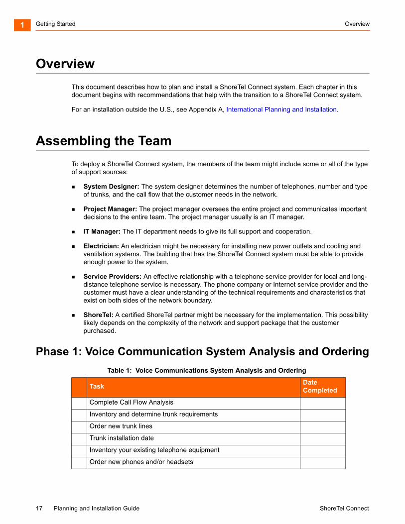
Phase 1: Voice Communication System Analysis and Ordering
Table 1: Voice Communications System Analysis and Ordering
TaskDate Completed
Complete Call Flow Analysis
Inventory and determine trunk requirements
Order new trunk lines
Trunk installation date
Inventory your existing telephone equipment
Order new phones and/or headsets
17 Planning and Installation Guide ShoreTel Connect

Phase 2: Environmental and Infrastructure Analysis and Upgrade Getting Started 1
Phase 2: Environmental and Infrastructure Analysis and Upgrade
Review your need for a ShoreTel Service Appliance
Order a ShoreTel Service Appliance
Review the need for a ShoreTel Connect Contact Center Solution
Order a ShoreTel Connect Contact Center Solution
Order ShoreTel voice switches
ShoreTel shipping date
Table 2: Environmental and Infrastructure Analysis and Upgrade
TaskDate Completed
Participate in the Phase 2 conference call
Read ShoreTel's power requirements
Order power upgrades (as necessary)
Scheduled power upgrade completion date
Read ShoreTel's racking requirements
Racking installation date (if racking is ordered)
Read ShoreTel's ventilation requirements
Ventilation system upgrade completion date (if ordered)
Read ShoreTel's recommendations for uninterruptable power source (UPS)
UPS installation date (if ordered)
Read ShoreTel's cabling requirements
Cabling installation date (if ordered)
Determine the overhead paging needs
Source your Music on Hold needs
Read ShoreTel's LAN requirements
Attach LAN topology map
LAN installation date (if ordered)
Read ShoreTel's WAN requirements
Attach WAN topology map
Table 1: Voice Communications System Analysis and Ordering (Continued)
TaskDate Completed
ShoreTel Connect Planning and Installation Guide 18

Getting Started Phase 3: Resource Scheduling and Tracking1
Phase 3: Resource Scheduling and Tracking
WAN upgrade installation date (if ordered)
Read ShoreTel's server requirements
Order your server for the ShoreTel Connect system
Server installation date
Read ShoreTel Connect client’s requirements
Schedule the ShoreTel Connect client’s software upgrade installation date (if required or ordered)
ShoreTel scheduled installation date
Table 3: Resource Scheduling and Tracking 21
TaskDate Completed
Participate in the Phase 3 conference call
Verify Telco order is on schedule
Verify phone order is on schedule
Verify power order is on schedule
Verify racking order is on schedule
Verify ventilation order is on schedule
Verify uninterruptable power source (UPS) order is on schedule
Verify cabling order is on schedule
Verify LAN upgrade order is on schedule
Verify WAN upgrade order is on schedule
Verify desktop upgrade order is on schedule
Verify ShoreTel order is on schedule
Read ShoreTel’s descriptions of the different ShoreTel Connect client applications
Schedule your System Administration training with ShoreTel
Order new business cards and business stationary if your phone numbers are changing
Verify that you have obtain all licenses and license keys for your planned installation.
Table 2: Environmental and Infrastructure Analysis and Upgrade (Continued)
TaskDate Completed
19 Planning and Installation Guide ShoreTel Connect
Phase 4: System Load and Configuration Getting Started 1
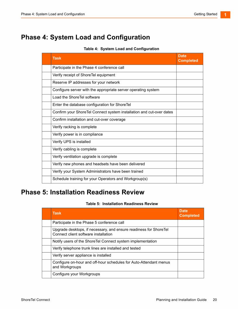
Phase 4: System Load and Configuration
Phase 5: Installation Readiness Review
Table 4: System Load and Configuration
TaskDate Completed
Participate in the Phase 4 conference call
Verify receipt of ShoreTel equipment
Reserve IP addresses for your network
Configure server with the appropriate server operating system
Load the ShoreTel software
Enter the database configuration for ShoreTel
Confirm your ShoreTel Connect system installation and cut-over dates
Confirm installation and cut-over coverage
Verify racking is complete
Verify power is in compliance
Verify UPS is installed
Verify cabling is complete
Verify ventilation upgrade is complete
Verify new phones and headsets have been delivered
Verify your System Administrators have been trained
Schedule training for your Operators and Workgroup(s)
Table 5: Installation Readiness Review
TaskDate Completed
Participate in the Phase 5 conference call
Upgrade desktops, if necessary, and ensure readiness for ShoreTel Connect client software installation
Notify users of the ShoreTel Connect system implementation
Verify telephone trunk lines are installed and tested
Verify server appliance is installed
Configure on-hour and off-hour schedules for Auto-Attendant menus and Workgroups
Configure your Workgroups
ShoreTel Connect Planning and Installation Guide 20
Getting Started Phase 6: Cut-Over1
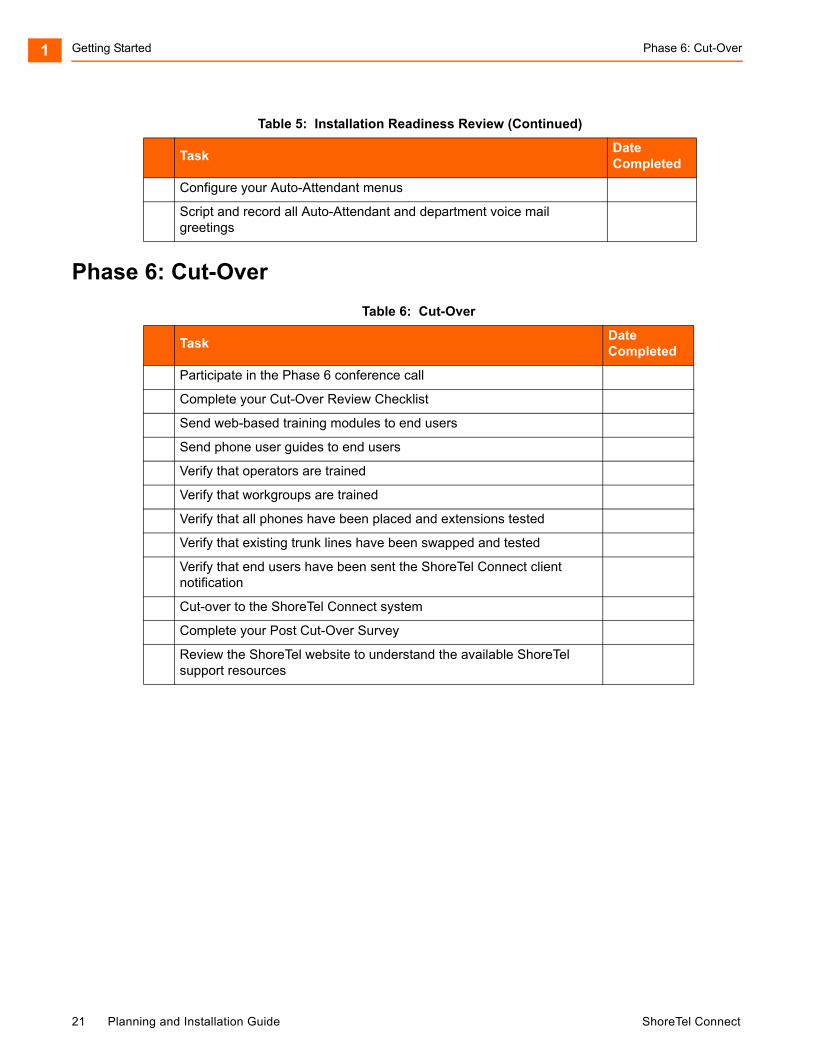
Phase 6: Cut-Over
Configure your Auto-Attendant menus
Script and record all Auto-Attendant and department voice mail greetings
Table 6: Cut-Over
TaskDate Completed
Participate in the Phase 6 conference call
Complete your Cut-Over Review Checklist
Send web-based training modules to end users
Send phone user guides to end users
Verify that operators are trained
Verify that workgroups are trained
Verify that all phones have been placed and extensions tested
Verify that existing trunk lines have been swapped and tested
Verify that end users have been sent the ShoreTel Connect client notification
Cut-over to the ShoreTel Connect system
Complete your Post Cut-Over Survey
Review the ShoreTel website to understand the available ShoreTel support resources
Table 5: Installation Readiness Review (Continued)
TaskDate Completed
21 Planning and Installation Guide ShoreTel Connect

CHAPTER
2. Planning and System Design
This chapter describes the initial design of the ShoreTel Connect system. It contains the following information:
Overview ................................................................................................................... 23
Recommendations .................................................................................................... 23
Network Assessment ................................................................................................ 23
Determine System Topology ..................................................................................... 23
Sites and Users .................................................................................................. 24
Headquarters and Distributed ShoreTel Servers ................................................ 24
Citrix and Windows Terminal Server................................................................... 25
Teleworker Sites ................................................................................................. 25
Telephone Requirements.................................................................................... 25
Trunk Requirements ........................................................................................... 26
Determine Number of ShoreTel Voice Switches ....................................................... 27
WAN Connections..................................................................................................... 28
Failover ..................................................................................................................... 28
System Capacity ....................................................................................................... 28
Virtual Phone and Virtual Trunk Switches........................................................... 34
BHCC Call Volume ............................................................................................. 34
BHCA Call Volume ............................................................................................. 35
Call Load Capacity for Switches ......................................................................... 35
Extension Monitoring Limitations ........................................................................ 35
ShoreTel Voice Switch Feature Capacity............................................................ 35
ShoreTel Connect Planning and Installation Guide 22
Planning and System Design Overview2
Overview
This chapter describes the initial design of the ShoreTel Connect system.
Recommendations
The following recommendations will assist you in designing your new voice communications system.
Make sure you understand all the unique routing and hunting requirements of your current system.
Be sure to account for all devices, including conference rooms, lobby phones, fax machines, and modems.
Make sure you consider the changes to the call flow and overall system design that may drive the need for additional trunks.
Network Assessment
As you plan your phone system, ShoreTel recommends that you have a network assessment performed. A network assessment does the following:
Ensure necessary protocols and standards are supported
Confirm that the infrastructure is optimally configured for IP telephony traffic
Verify that the installed WAN technologies are compatible with IP telephony.
Measure delay, packet loss and jitter to ensure that they meed acceptable thresholds for toll-quality voice calls
To complete your system design, the final step is to identify your network connectivity. You should identify the following for the network connections to each site:
Bandwidth
Latency
Jitter
Packet Loss
Determine System Topology
The ShoreTel Connect system has a unique distributed call control software architecture that enables you to deploy ShoreTel voice switches and IP phones anywhere across your IP network. Even though multiple sites are supported, the ShoreTel Connect system is a single system with an extensive set of
23 Planning and Installation Guide ShoreTel Connect
Sites and Users Planning and System Design 2
integrated applications and a single management image. The ShoreTel Connect system offers unmatched simplicity through this single image system, and delivers high availability, with no single point of failure, through its distributed architecture.
The first step in planning a voice network is to determine the overall network topology. Topology information includes the following:
Sites and Users. Number of sites and number of users at each site.
Headquarters and Distributed ShoreTel Servers. Number of servers required, plus the name or IP address of all ShoreTel servers (main and distributed).
Teleworker Sites. Number of teleworker installations and the type of telephones supported.
Telephone Requirements. Number of telephones at each site (by type).
Trunk Requirements. Number of trunks required for optimal performance.
ShoreTel Voice Switches. What models are needed and how many of each model.
WAN Connections. The number of WAN connections (per site) and complete service-level information.
For detailed information about planning your network for the ShoreTel Connect system, see Chapter 3, Network Requirements and Preparation on page 40.
Sites and Users
Your network topology diagram should provide an accurate inventory of the different physical sites and the number of users at each site.
Headquarters and Distributed ShoreTel Servers
The ShoreTel Connect Headquarters server hosts the voice applications platform and the management web site, as well as the integrated voice applications. Typically, the Headquarters ShoreTel server is located at the largest location, containing the majority of users. Make special note of the main ShoreTel Connect server on your topology diagram.
On your topology diagram, provide the following information about ShoreTel servers:
Total number of servers (that is, the sum of servers at all sites).
Number of servers at each site.
The name and IP address of every server.
The ShoreTel Connect system also supports Distributed Voice Servers (DVS) to allow distributing voicemail and other applications. Distributed servers help accomplish the following:
Reduce bandwidth, because local users’ calls to voice mail are answered by the local voice mail application and do not go across the WAN.
Increase system scale by extending the unified messaging and desktop call control services to additional users of the applications.
ShoreTel Connect Planning and Installation Guide 24
Planning and System Design Citrix and Windows Terminal Server2
Increase reliability by providing local support for some services and applications if a site loses connectivity with the Headquarters server.
Even though there are multiple servers, the ShoreTel Connect system provides a single image system across your entire network. The system is currently certified to support up to 21 servers, one at the headquarters site and up to 20 distributed servers. You should add a server at any site that exceeds 100 users. You must deploy a server for every 1,000 users.
The distributed voice applications platform can also provide an open applications platform for extending telephone services through TAPI-compliant third-party applications. A dedicated distributed server is required to host the third-party applications. This server is deployed like other distributed servers, except that it must not have voice mail users assigned to it.
The distributed voice application servers’ Remote TAPI Service Provider relies on the call control information from the main server. To add reliability to your remote server, consider using redundant network paths to the main server.
Citrix and Windows Terminal Server
Citrix and Windows Terminal Server (WTS) technologies enable processing for multiple users to be aggregated on a single Windows computer. The single Windows computer is a process- and disk-sharing server for multiple users who have lightweight or thin graphics stations on their desktop. Citrix communicates between the server and clients using the ICA protocol, whereas Windows Terminal Server uses the RDP protocol.
Teleworker Sites
ShoreTel IP Phones can operate away from the ShoreTel site. For example, employees (telecommuters) can have an IP phone at their home so that they can work from home. The ShoreTel topology diagram must include the number and location of off-site IP phones.
For information on configuring ShoreTel IP phones for teleworkers, see Chapter 14, IP Phone Installation on page 256.
Telephone Requirements
This section describes how to determine the telephone requirements, as follows.
1. Count the telephone users in the current environment. Include conference room telephones, lobby telephones, and telephones that multiple users share.
2. Count the number of ShoreTel BB24 or BB424 button boxes that operators and receptionists need. Up to four button boxes can be connected to a phone.
3. Count the number of ports that fax machines and modems will use.
4. If you are deploying IP phones, determine the number of telephones that will be IP phones and the number that will be analog phones.
25 Planning and Installation Guide ShoreTel Connect
Trunk Requirements Planning and System Design 2
5. Some users might need specialized features. For example, an operator needs a phone with programmable buttons. Therefore, consider the type of functions that each user needs to select the appropriate phone for each user.
6. Consider the needs for additional telephone ports for third-party systems, including server appliances and overhead paging systems.
7. Determine the number of user licenses you need.
Each user on the system requires a user access license. The types of user licenses are listed below:
Extension and mailbox: Purchase of this license entitles the user to be assigned to both a physical extension and a ShoreTel voice mailbox.
Extension-only: This license lets the user have a physical extension through an explicit assignment or through the Extension Assignment feature.
Mailbox-only: This license lets the user have only a ShoreTel voice mailbox.
Audio conference: Purchase this license for each audio port that you want to use in conferences managed by a ShoreTel Service Appliance. A license allows one audio endpoint to participate in a conference.
Web conference: Purchase this license for each Web port that you want to use in conferences managed by a ShoreTel Service Appliance. A license allows one data-compatible endpoint to participate in a conference
Trunk Requirements
Trunks provide connectivity between users on the ShoreTel Connect system and the public switched telephone network (PSTN). In this next task in the system design process, you determine the number of trunks required.
The number of trunks required on your system varies, depending on the number of users and your specific application needs. It is important to size your trunking correctly because not having enough trunks can lead to blocked calls when all trunks are busy, and too many trunks can lead to wasted money on monthly access charges.
See Telephone Planning and Ordering on page 156, for more information about trunk features, ordering, and installation.
Note
For more information about selecting telephones, see Telephone Planning and Ordering on page 156.
Note
An Extension-only license is a requirement for each conference room telephone, lobby telephone, fax machine, and modem. A user access license is not necessary for trunks and anonymous telephones.
ShoreTel Connect Planning and Installation Guide 26
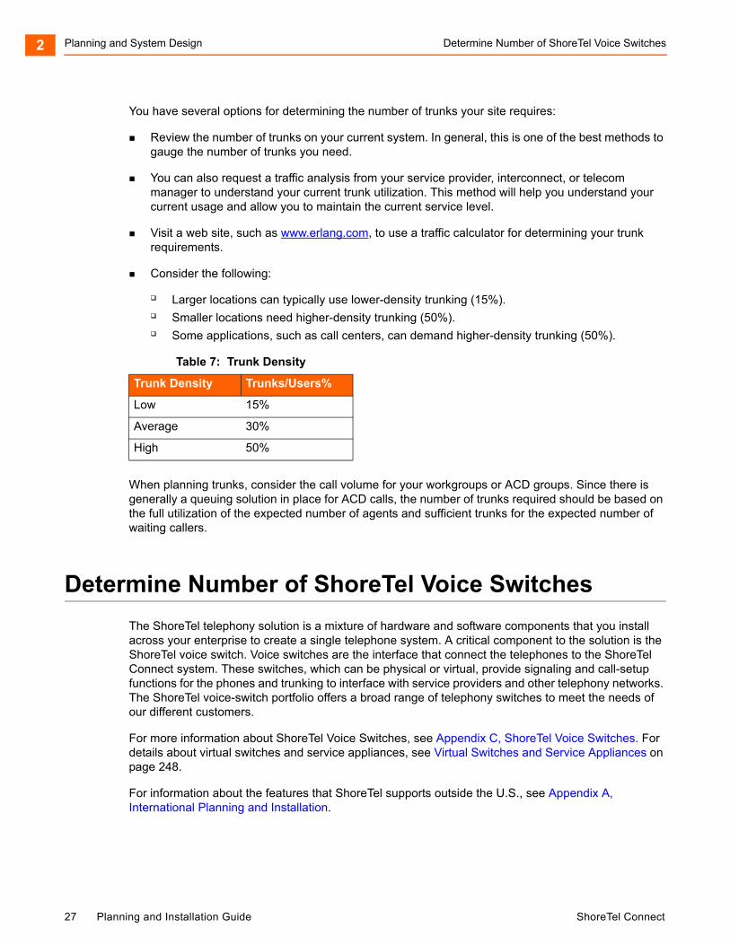
Planning and System Design Determine Number of ShoreTel Voice Switches2
You have several options for determining the number of trunks your site requires:
Review the number of trunks on your current system. In general, this is one of the best methods to gauge the number of trunks you need.
You can also request a traffic analysis from your service provider, interconnect, or telecom manager to understand your current trunk utilization. This method will help you understand your current usage and allow you to maintain the current service level.
Visit a web site, such as www.erlang.com, to use a traffic calculator for determining your trunk requirements.
Consider the following:
Larger locations can typically use lower-density trunking (15%). Smaller locations need higher-density trunking (50%). Some applications, such as call centers, can demand higher-density trunking (50%).
When planning trunks, consider the call volume for your workgroups or ACD groups. Since there is generally a queuing solution in place for ACD calls, the number of trunks required should be based on the full utilization of the expected number of agents and sufficient trunks for the expected number of waiting callers.
Determine Number of ShoreTel Voice Switches
The ShoreTel telephony solution is a mixture of hardware and software components that you install across your enterprise to create a single telephone system. A critical component to the solution is the ShoreTel voice switch. Voice switches are the interface that connect the telephones to the ShoreTel Connect system. These switches, which can be physical or virtual, provide signaling and call-setup functions for the phones and trunking to interface with service providers and other telephony networks. The ShoreTel voice-switch portfolio offers a broad range of telephony switches to meet the needs of our different customers.
For more information about ShoreTel Voice Switches, see Appendix C, ShoreTel Voice Switches. For details about virtual switches and service appliances, see Virtual Switches and Service Appliances on page 248.
For information about the features that ShoreTel supports outside the U.S., see Appendix A, International Planning and Installation.
Table 7: Trunk Density
Trunk Density Trunks/Users%
Low 15%
Average 30%
High 50%
27 Planning and Installation Guide ShoreTel Connect
WAN Connections Planning and System Design 2
WAN Connections
To complete your system design, the final step is to identify your network connectivity. You should identify the following for the network connections to each site:
Bandwidth
Latency
Jitter
Packet Loss
Failover
To provide high availability, ShoreTel supports failover at two very important points in the system. ShoreTel supports failover for the headquarters (HQ) server and for voice switches. For the HQ server, ShoreTel supports a back-up server that monitors and can duplicate the primary server. If the primary server fails, the back-up server immediately starts operating as the HQ server with minimal interruption. After the primary server returns to operation, the system administration must perform a manual fail-back to restore the servers to their previous operation.
For voice switch backup, ShoreTel supports two approaches. The system administrator can configure extra port capacity or install a dedicated spare voice switch. A spare voice switch can be on a network that is remote to the failed voice switch.
System Capacity
The ShoreTel Connect system can scale incrementally up to 20,000 ports (users and trunks) representing 500 ShoreTel voice switches over the entire system. The system is completely nonblocking and can support 10,000 simultaneous calls at a rate of 100,000 calls per hour depending upon server configurations.
Table 8 provides a summary of the ShoreTel Connect system capacity.
Table 8: ShoreTel Connect System Capacity
Component Capacity Notes
System
Sites 500 Exact number varies by configuration.
Switches 100/site500/system100/server
Exact number varies by configuration.
Note: For Very Large deployments, systems with more than 10,000 ports, the maximum number of switches per site is 60.
Route Points 254/server This is per server
ShoreTel Connect Planning and Installation Guide 28
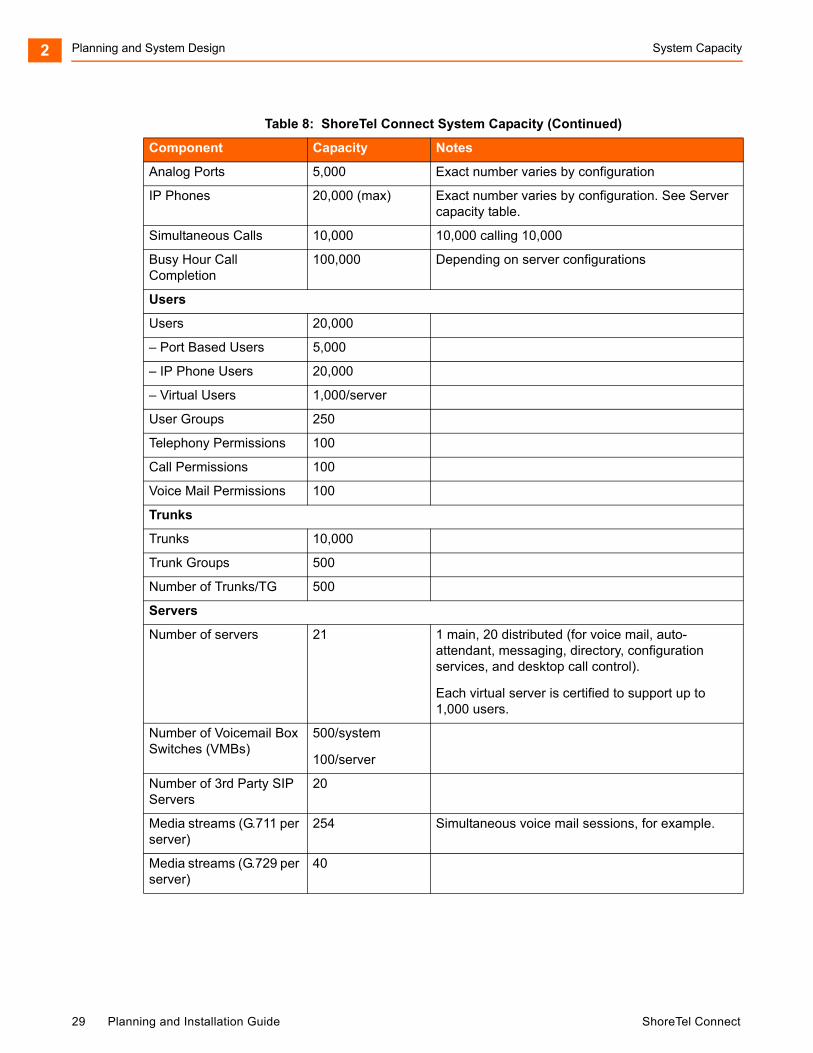
Planning and System Design System Capacity2
Analog Ports 5,000 Exact number varies by configuration
IP Phones 20,000 (max) Exact number varies by configuration. See Server capacity table.
Simultaneous Calls 10,000 10,000 calling 10,000
Busy Hour Call Completion
100,000 Depending on server configurations
Users
Users 20,000
– Port Based Users 5,000
– IP Phone Users 20,000
– Virtual Users 1,000/server
User Groups 250
Telephony Permissions 100
Call Permissions 100
Voice Mail Permissions 100
Trunks
Trunks 10,000
Trunk Groups 500
Number of Trunks/TG 500
Servers
Number of servers 21 1 main, 20 distributed (for voice mail, auto-attendant, messaging, directory, configuration services, and desktop call control).
Each virtual server is certified to support up to 1,000 users.
Number of Voicemail Box Switches (VMBs)
500/system
100/server
Number of 3rd Party SIP Servers
20
Media streams (G.711 per server)
254 Simultaneous voice mail sessions, for example.
Media streams (G.729 per server)
40
Table 8: ShoreTel Connect System Capacity (Continued)
Component Capacity Notes
29 Planning and Installation Guide ShoreTel Connect
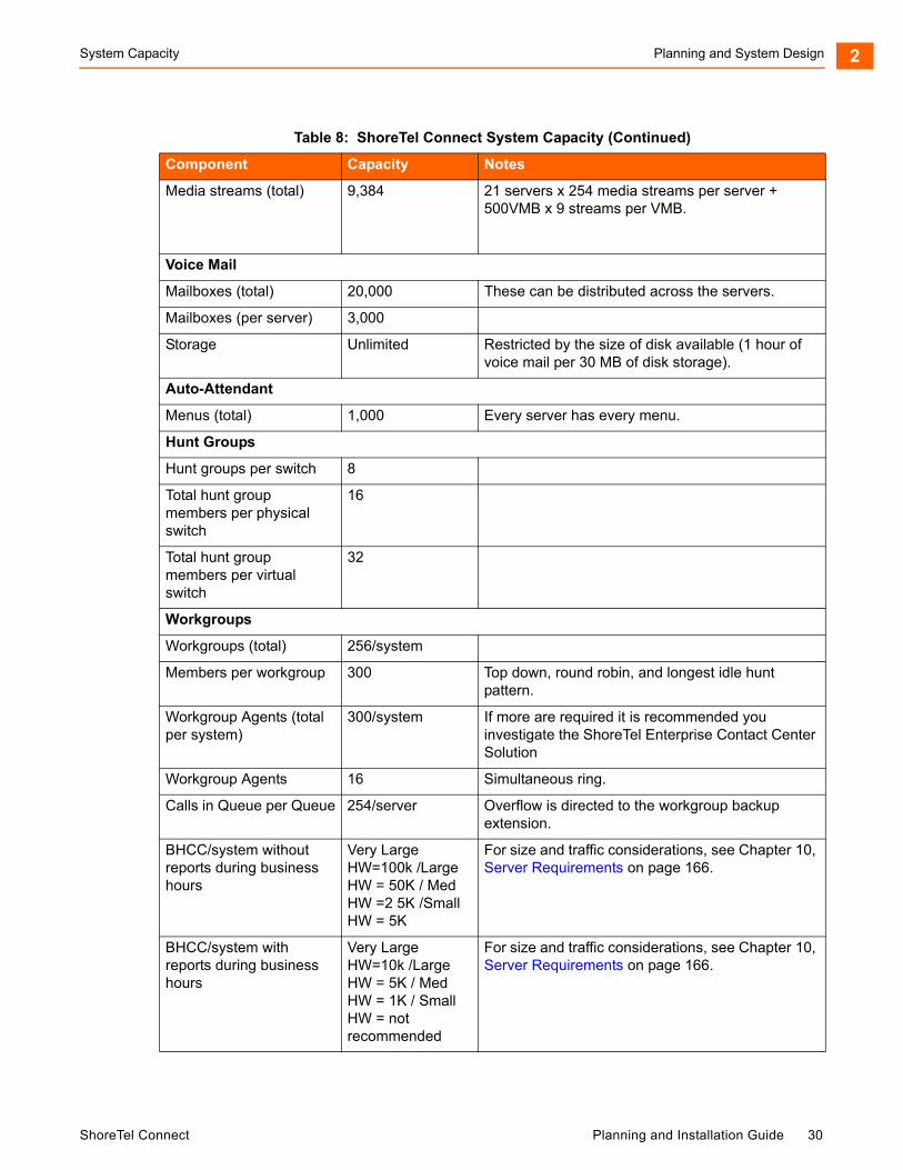
System Capacity Planning and System Design 2
Media streams (total) 9,384 21 servers x 254 media streams per server + 500VMB x 9 streams per VMB.
Voice Mail
Mailboxes (total) 20,000 These can be distributed across the servers.
Mailboxes (per server) 3,000
Storage Unlimited Restricted by the size of disk available (1 hour of voice mail per 30 MB of disk storage).
Auto-Attendant
Menus (total) 1,000 Every server has every menu.
Hunt Groups
Hunt groups per switch 8
Total hunt group members per physical switch
16
Total hunt group members per virtual switch
32
Workgroups
Workgroups (total) 256/system
Members per workgroup 300 Top down, round robin, and longest idle hunt pattern.
Workgroup Agents (total per system)
300/system If more are required it is recommended you investigate the ShoreTel Enterprise Contact Center Solution
Workgroup Agents 16 Simultaneous ring.
Calls in Queue per Queue 254/server Overflow is directed to the workgroup backup extension.
BHCC/system without reports during business hours
Very Large HW=100k /Large HW = 50K / Med HW =2 5K /Small HW = 5K
For size and traffic considerations, see Chapter 10, Server Requirements on page 166.
BHCC/system with reports during business hours
Very Large HW=10k /Large HW = 5K / Med HW = 1K / Small HW = not recommended
For size and traffic considerations, see Chapter 10, Server Requirements on page 166.
Table 8: ShoreTel Connect System Capacity (Continued)
Component Capacity Notes
ShoreTel Connect Planning and Installation Guide 30
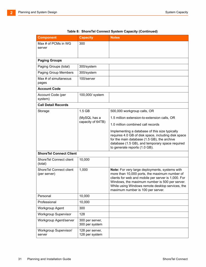
Planning and System Design System Capacity2
Max # of PCMs in WG server
300
Paging Groups
Paging Groups (total) 300/system
Paging Group Members 300/system
Max # of simultaneous pages
100/server
Account Code
Account Code (per system)
100,000/ system
Call Detail Records
Storage 1.5 GB
(MySQL has a capacity of 64TB)
500,000 workgroup calls, OR
1.5 million extension-to-extension calls, OR
1.0 million combined call records
Implementing a database of this size typically requires 4.0 GB of disk space, including disk space for the main database (1.5 GB), the archive database (1.5 GB), and temporary space required to generate reports (1.0 GB).
ShoreTel Connect Client
ShoreTel Connect client (total)
10,000
ShoreTel Connect client (per server)
1,000 Note: For very large deployments, systems with more than 10,000 ports, the maximum number of clients for web and mobile per server is 1,000. For Windows, the maximum number is 500 per server. While using Windows remote desktop services, the maximum number is 100 per server.
Personal 10,000
Professional 10,000
Workgroup Agent 300
Workgroup Supervisor 128
Workgroup Agent/server 300 per server, 300 per system
Workgroup Supervisor/server
128 per server, 128 per system
Table 8: ShoreTel Connect System Capacity (Continued)
Component Capacity Notes
31 Planning and Installation Guide ShoreTel Connect
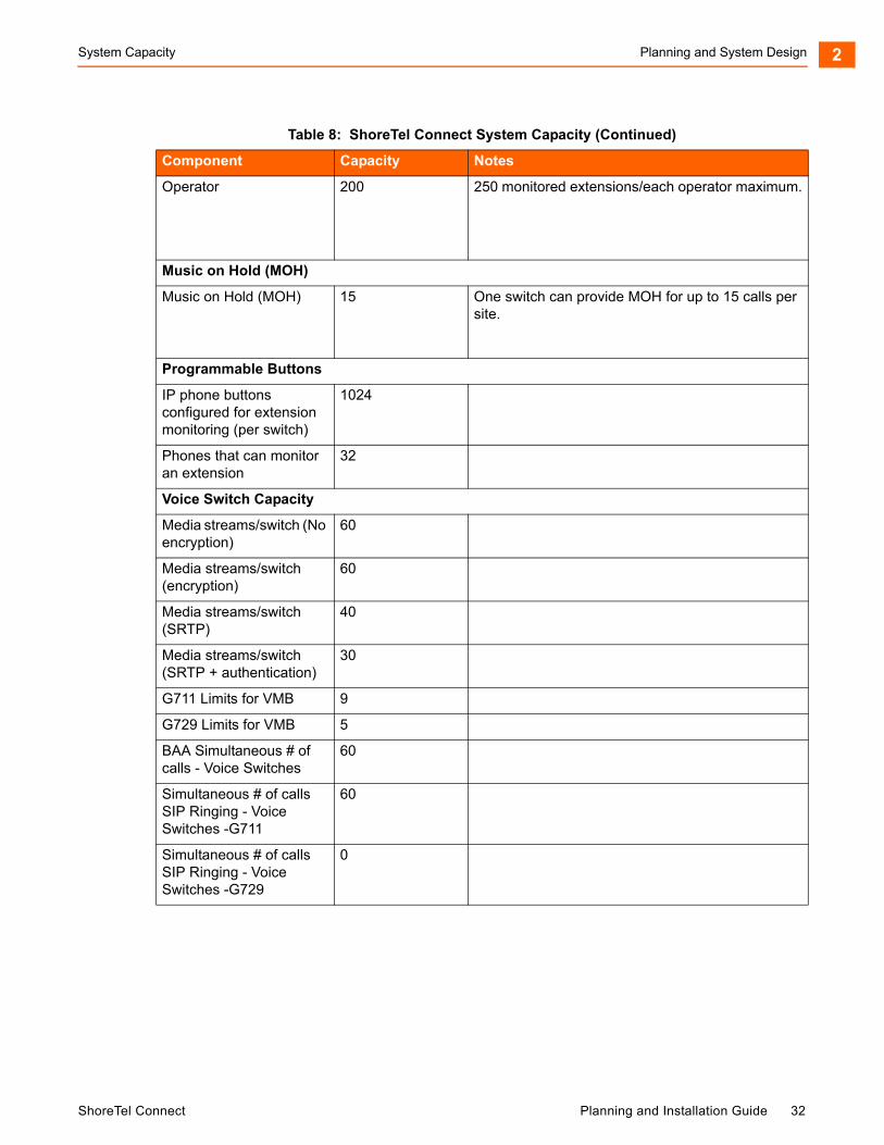
System Capacity Planning and System Design 2
Operator 200 250 monitored extensions/each operator maximum.
Music on Hold (MOH)
Music on Hold (MOH) 15 One switch can provide MOH for up to 15 calls per site.
Programmable Buttons
IP phone buttons configured for extension monitoring (per switch)
1024
Phones that can monitor an extension
32
Voice Switch Capacity
Media streams/switch (No encryption)
60
Media streams/switch (encryption)
60
Media streams/switch (SRTP)
40
Media streams/switch (SRTP + authentication)
30
G711 Limits for VMB 9
G729 Limits for VMB 5
BAA Simultaneous # of calls - Voice Switches
60
Simultaneous # of calls SIP Ringing - Voice Switches -G711
60
Simultaneous # of calls SIP Ringing - Voice Switches -G729
0
Table 8: ShoreTel Connect System Capacity (Continued)
Component Capacity Notes
ShoreTel Connect Planning and Installation Guide 32
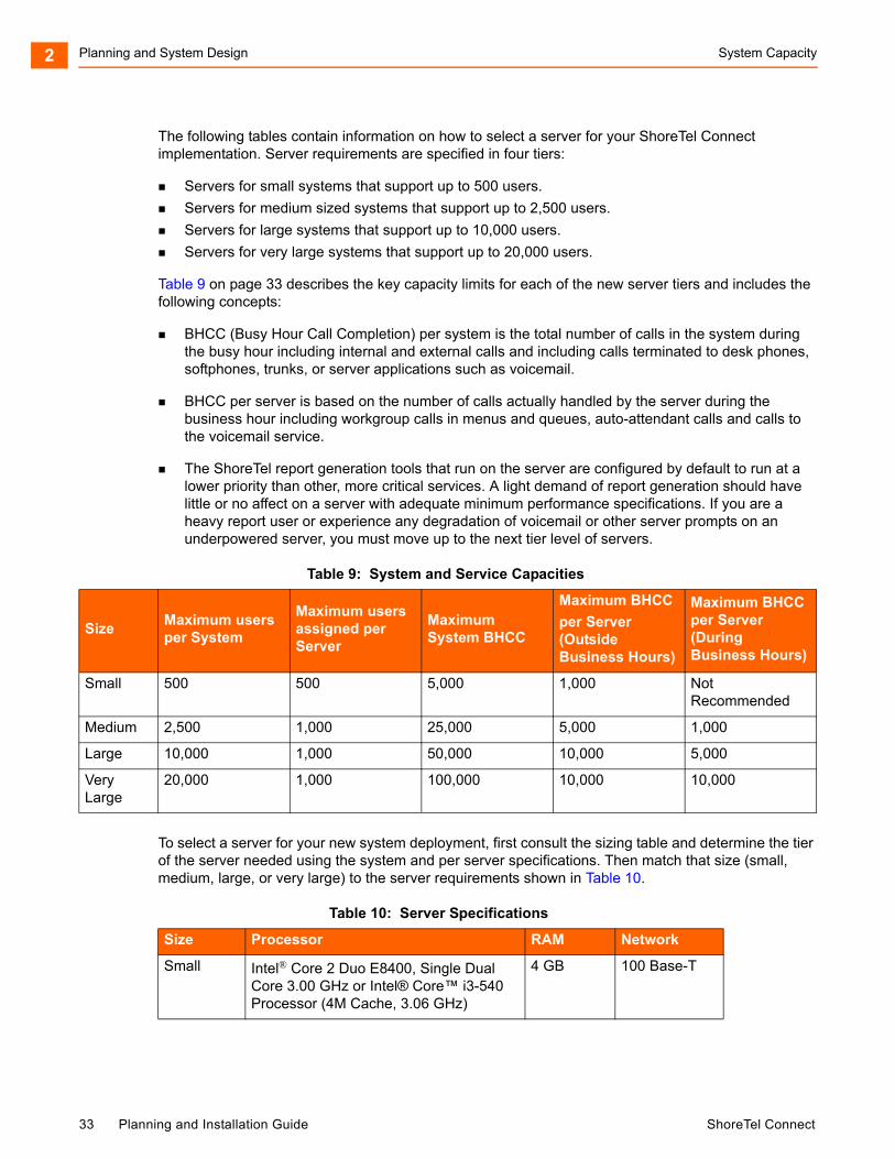
Planning and System Design System Capacity2
The following tables contain information on how to select a server for your ShoreTel Connect implementation. Server requirements are specified in four tiers:
Servers for small systems that support up to 500 users.
Servers for medium sized systems that support up to 2,500 users.
Servers for large systems that support up to 10,000 users.
Servers for very large systems that support up to 20,000 users.
Table 9 on page 33 describes the key capacity limits for each of the new server tiers and includes the following concepts:
BHCC (Busy Hour Call Completion) per system is the total number of calls in the system during the busy hour including internal and external calls and including calls terminated to desk phones, softphones, trunks, or server applications such as voicemail.
BHCC per server is based on the number of calls actually handled by the server during the business hour including workgroup calls in menus and queues, auto-attendant calls and calls to the voicemail service.
The ShoreTel report generation tools that run on the server are configured by default to run at a lower priority than other, more critical services. A light demand of report generation should have little or no affect on a server with adequate minimum performance specifications. If you are a heavy report user or experience any degradation of voicemail or other server prompts on an underpowered server, you must move up to the next tier level of servers.
To select a server for your new system deployment, first consult the sizing table and determine the tier of the server needed using the system and per server specifications. Then match that size (small, medium, large, or very large) to the server requirements shown in Table 10.
Table 9: System and Service Capacities
SizeMaximum users per System
Maximum users assigned per Server
Maximum System BHCC
Maximum BHCC
per Server
(Outside Business Hours)
Maximum BHCCper Server (During Business Hours)
Small 500 500 5,000 1,000 Not Recommended
Medium 2,500 1,000 25,000 5,000 1,000
Large 10,000 1,000 50,000 10,000 5,000
Very Large
20,000 1,000 100,000 10,000 10,000
Table 10: Server Specifications
Size Processor RAM Network
Small Intel® Core 2 Duo E8400, Single Dual Core 3.00 GHz or Intel® Core™ i3-540 Processor (4M Cache, 3.06 GHz)
4 GB 100 Base-T
33 Planning and Installation Guide ShoreTel Connect

Virtual Phone and Virtual Trunk Switches Planning and System Design 2
Virtual Phone and Virtual Trunk Switches
The ShoreTel Connect system supports virtual phone switches and virtual trunk switches.
The virtual phone switch supports the following features:
All non-TDM features (no physical trunks or analog phones)
Up to 1000 IP phones per switch
Requires the ShoreTel Virtual Switch Phone License
The virtual trunk switch supports up to 1,000 SIP trunks and requires the Virtual Switch SIP Trunk License.
For virtual switch capacities and requirements, see Virtual Switches and Service Appliances on page 248.
BHCC Call Volume
BHCC per system is the total number of calls in the system during the busy hour including internal and external calls and calls terminated to desk phones, softphones, trunks, or server applications such as voicemail. This includes all traffic that can occur in the server - regular voice calls, workgroup calls, voicemail etc. See Table 9 on page 33 for information about BHCC capacity for the different sizes of ShoreTel Connect systems.
Medium Intel Xeon 5520 Single Quad Core 2.27 GHz
8 GB 100 Base-T or Gigabit Ethernet
Large Intel Xeon 5520 Dual Quad Core 2.27 GHz
8 GB Gigabit Ethernet
Very Large Intel Xeon 5680 Dual Six Core 3.33 GHz 12 GB Gigabit Ethernet
Note
Use the hardware specifications to size servers running ShoreTel Headquarters server software and ShoreTel Distributed Voice Services software. For example, consider a two-location system with 2,000 users and 20,000 BHCC. A Headquarters server is located at the main site, and a Distributed Voice Services server is located at the remote site. Each of the servers handle 2,000 BHCC. In this case, both servers should be provisioned with hardware that meets the medium tier of hardware requirements because the system capacity and both server capacities fall within this tier.
Note
The virtual phone switch does not support the Nightbell or Overhead Paging features.
Table 10: Server Specifications(Continued)
ShoreTel Connect Planning and Installation Guide 34
Planning and System Design BHCA Call Volume2
BHCA Call Volume
Busy Hour Call Attempts (BHCA) is the number of calls attempted at the busiest hour of the day (peak hour). The higher the BHCA, the higher the stress on the network processors. If a bottleneck in the network exists with a capacity lower than the estimated BHCA, then congestion will occur resulting in many failed calls and customer dissatisfaction.
ShoreTel Connect systems support 5,000 BHCA.
Call Load Capacity for Switches
A ShoreTel Connect system supports a maximum of 500 Voicemail Model Switches. There are no restrictions concerning the allocation of switches among the sites defined by the system.
ShoreTel Voicemail Model Switches support the following call load capacities:
5400 BHCC when supporting 90 MGCP IP Phones or 90 SIP Trunks.
3600 BHCC when supporting 90 SIP IP Phones or 90 SIP Trunks.
Extension Monitoring Limitations
There is a limit to the number of extensions that can be monitored, whether from a ShoreTel IP Phone BB24 or BB424 device or from a ShoreTel IP Phone multi-line phone. This limitation is dependent on two factors:
Update rate (every call causes one or more monitoring phones to be updated).
Whether the monitoring phones are spread across one or more switches.
ShoreTel Voice Switches support an update rate of 1 per second. This limit is independent of whether the monitored extensions are on the same switch or a different switch. If the monitored extensions are on a different switch, then IPDS is involved.
ShoreTel Voice Switch Feature Capacity
The ShoreTel voice switch is designed to handle the maximum load for the services it provides. Some features place a higher real-time load on the ShoreTel voice switch processor than others, and the use of these features must be carefully planned to take into account the impact on the processing power of a switch to handle call control signaling messages.
Table 11 offers some general guidelines for the number of extensions and group members for several commonly used features. Keep in mind that in addition to observing these limitations, you must stay below the real-time requirements of the switch itself.
35 Planning and Installation Guide ShoreTel Connect
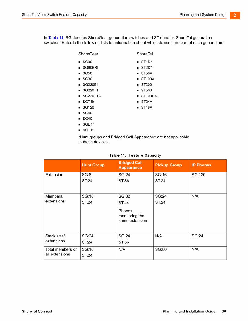
ShoreTel Voice Switch Feature Capacity Planning and System Design 2
In Table 11, SG denotes ShoreGear generation switches and ST denotes ShoreTel generation switches. Refer to the following lists for information about which devices are part of each generation:
ShoreGear
SG90
SG90BRI
SG50
SG30
SG220E1
SG220T1
SG220T1A
SGT1k
SG120
SG60
SG40
SGE1*
SGT1*
ShoreTel
ST1D*
ST2D*
ST50A
ST100A
ST200
ST500
ST100DA
ST24A
ST48A
*Hunt groups and Bridged Call Appearance are not applicable to these devices.
Table 11: Feature Capacity
Hunt GroupBridged Call Appearance
Pickup Group IP Phones
Extension SG:8
ST:24
SG:24
ST:36
SG:16
ST:24
SG:120
Members/extensions
SG:16
ST:24
SG:32
ST:44
Phones monitoring the same extension
SG:24
ST:24
N/A
Stack size/extensions
SG:24
ST:24
SG:24
ST:36
N/A SG:24
Total members on all extensions
SG:16
ST:24
N/A SG:80 N/A
ShoreTel Connect Planning and Installation Guide 36
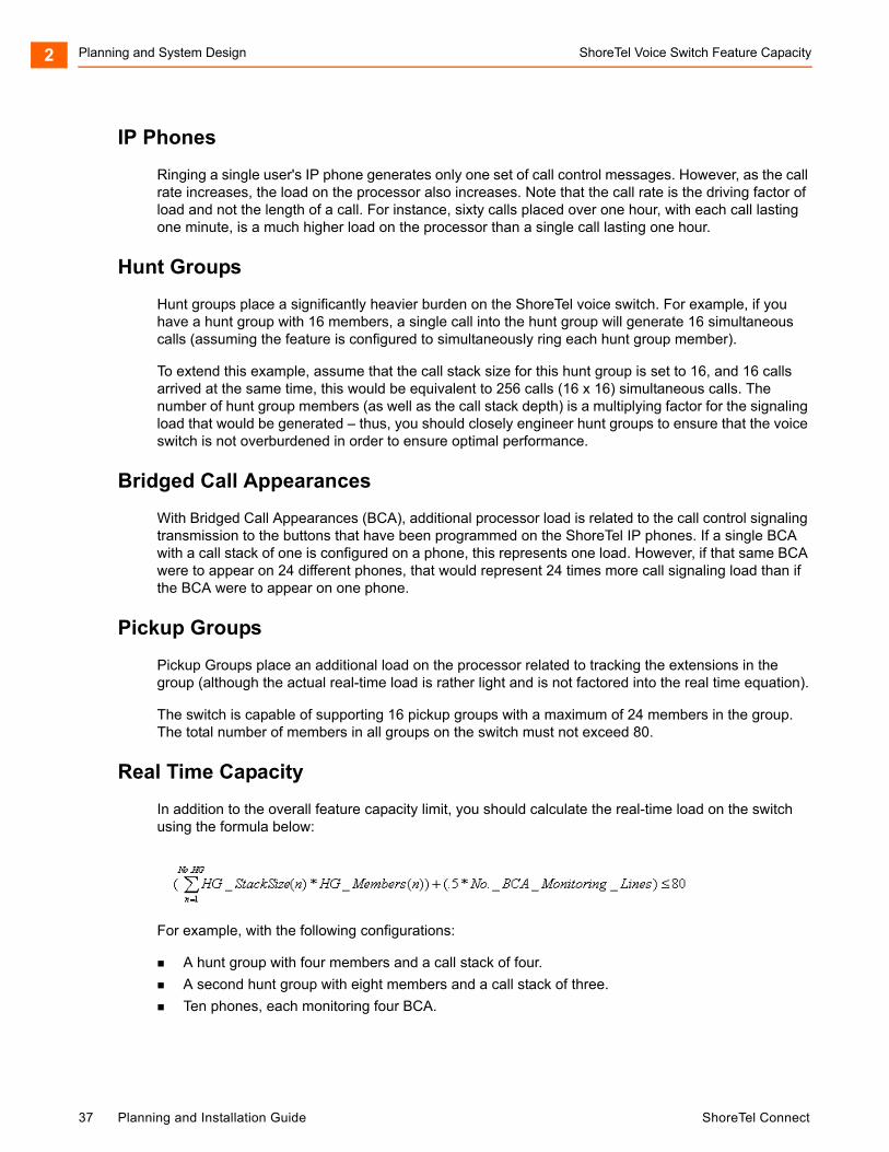
Planning and System Design ShoreTel Voice Switch Feature Capacity2
IP Phones
Ringing a single user's IP phone generates only one set of call control messages. However, as the call rate increases, the load on the processor also increases. Note that the call rate is the driving factor of load and not the length of a call. For instance, sixty calls placed over one hour, with each call lasting one minute, is a much higher load on the processor than a single call lasting one hour.
Hunt Groups
Hunt groups place a significantly heavier burden on the ShoreTel voice switch. For example, if you have a hunt group with 16 members, a single call into the hunt group will generate 16 simultaneous calls (assuming the feature is configured to simultaneously ring each hunt group member).
To extend this example, assume that the call stack size for this hunt group is set to 16, and 16 calls arrived at the same time, this would be equivalent to 256 calls (16 x 16) simultaneous calls. The number of hunt group members (as well as the call stack depth) is a multiplying factor for the signaling load that would be generated – thus, you should closely engineer hunt groups to ensure that the voice switch is not overburdened in order to ensure optimal performance.
Bridged Call Appearances
With Bridged Call Appearances (BCA), additional processor load is related to the call control signaling transmission to the buttons that have been programmed on the ShoreTel IP phones. If a single BCA with a call stack of one is configured on a phone, this represents one load. However, if that same BCA were to appear on 24 different phones, that would represent 24 times more call signaling load than if the BCA were to appear on one phone.
Pickup Groups
Pickup Groups place an additional load on the processor related to tracking the extensions in the group (although the actual real-time load is rather light and is not factored into the real time equation).
The switch is capable of supporting 16 pickup groups with a maximum of 24 members in the group. The total number of members in all groups on the switch must not exceed 80.
Real Time Capacity
In addition to the overall feature capacity limit, you should calculate the real-time load on the switch using the formula below:
For example, with the following configurations:
A hunt group with four members and a call stack of four.
A second hunt group with eight members and a call stack of three.
Ten phones, each monitoring four BCA.
37 Planning and Installation Guide ShoreTel Connect

ShoreTel Voice Switch Feature Capacity Planning and System Design 2
You would have room to spare:
HG 1 + HG 2 + BCAs = Total
4 x 4 + 8 x 3 + (10 x 4)/2 = 60
16 + 24 + 20 = 60
ShoreTel Connect Planning and Installation Guide 38

Planning and System Design ShoreTel Voice Switch Feature Capacity2
39 Planning and Installation Guide ShoreTel Connect

CHAPTER
3. Network Requirements andPreparation
This chapter describes the network requirements and preparation needed to use the ShoreTel Connect system. It contains the following information:
Overview ................................................................................................................... 42
Understanding the Network Requirements for Toll-Quality Voice ............................. 42
Bandwidth Requirements.................................................................................... 46
Latency ............................................................................................................... 47
Jitter for Voice Switches ..................................................................................... 47
Packet Loss ........................................................................................................ 48
Bandwidth Management ..................................................................................... 48
Local Area Network (LAN).................................................................................. 48
Virtual LANs........................................................................................................ 49
Wide Area Network............................................................................................. 50
Client Bandwidth................................................................................................. 50
Admission Control in the Wide Area Network..................................................... 51
Spanning Tree Protocol ...................................................................................... 51
Traffic Shaping to Reduce Bottlenecks............................................................... 52
Echo Cancellation............................................................................................... 52
WAN Technology Choices .................................................................................. 53
WAN Technology Choices......................................................................................... 53
Minimum Bandwidth Requirements .................................................................... 53
Leased T1........................................................................................................... 53
MPLS.................................................................................................................. 54
ShoreTel Connect Planning and Installation Guide 40

Network Requirements and Preparation3
SDSL .................................................................................................................. 54
IDSL.................................................................................................................... 54
ADSL .................................................................................................................. 54
Cable Modems ................................................................................................... 54
ISDN BRI ............................................................................................................ 54
Dial-Up Modems................................................................................................. 54
IP Address Assignment............................................................................................. 55
Configuring DHCP for ShoreTel IP Phones............................................................... 56
Configuring Automatic VLAN Assignment Using DHCP ........................................... 60
Configuring Automatic VLAN Assignment on a DHCP Server ........................... 60
Configuring Automatic VLAN Assignment Using DHCP During ShoreTel IP Phone Standard Boot Process....................................................................................... 60
Configuring Automatic VLAN Assignment Using LLDP ............................................ 61
Time Services............................................................................................................ 62
Virtual Private Network (VPN)................................................................................... 62
Tunneling ............................................................................................................ 63
Performance ....................................................................................................... 64
Integrated Security Appliances........................................................................... 64
Firewalls .................................................................................................................... 65
Media Encryption ...................................................................................................... 66
Security for ShoreTel 400-Series IP Phones............................................................. 66
Session Initiation Protocol (SIP)................................................................................ 67
Example Network Topologies.................................................................................... 68
Single-Site Implementation................................................................................. 68
Multisite Implementation ..................................................................................... 68
Computing Admission Control Bandwidth................................................................. 69
WAN Bandwidth per Call (Full Duplex) without cRTP......................................... 70
WAN Bandwidth per Call (Full Duplex) with cRTP.............................................. 71
Setting Admission Control .................................................................................. 73
41 Planning and Installation Guide ShoreTel Connect
Overview Network Requirements and Preparation 3
Overview
The ShoreTel Connect system is an IP-based voice solution deployed across your IP network. This allows the components of the system to be located anywhere on your IP network, resulting in a single system for all your voice applications at all locations. This single system approach significantly reduces the complexity associated with legacy systems that consist of multiple PBXs, multiple voice mail systems, multiple auto-attendants, and multiple automatic call distribution systems, each with their unique management interfaces.
Because the ShoreTel Connect system becomes another application on your IP network, it is important to understand how the system integrates with your data network. As you migrate your network to include voice as another application across your wide area network, it becomes necessary for your IP LAN and WAN to provide a network that meets the requirements for toll-quality voice. The ability of your network to deliver this performance will vary based on the number of simultaneous calls between locations, the voice quality required, and the other application traffic on the network. Some of the key considerations are:
Bandwidth
Latency
Jitter
Quality of service
Understanding the Network Requirements for Toll-Quality Voice
The ShoreTel Connect system is designed to deliver the highest possible voice quality. To ensure high quality voice transmissions, you must be sure that the entire network on which you deploy the ShoreTel telephony system is able to provide toll-quality voice communications throughout. Both LAN and WAN links must be adequately constructed to ensure the fluid transmission of time- and order-sensitive voice packets.
This section provides you with the background to understand the factors involved in engineering an IP network that is ready for voice communications.
General Network Requirements
When your voice traffic travels across your IP network, you must ensure that your network does all of the following:
Delivers enough bandwidth
Meets the following data network design universal quality standards to support VoIP:
Latency. No part of the VoIP data network infrastructure should have more than 150 ms, one-way (or 300 ms round-trip) propagation delay between any two VoIP end-points, ShoreTel servers, or switches.
ShoreTel Connect Planning and Installation Guide 42
Network Requirements and Preparation General Network Requirements3
Jitter. No more than 50 ms of spacing between VoIP media packets
Loss. No more than 1% of packet loss for VoIP RTP media stream packets. (No standard has been set to measure signaling loss, but while RTP is primarily time-sensitive, signaling is primarily drop-sensitive.)
You also need to prioritize your voice traffic over your data traffic and configure the ShoreTel Connect system’s Admission Control feature.
In general, to ensure voice quality on the LAN, the ShoreTel Connect system must be used in a switched Ethernet network. To ensure voice quality on the WAN, the ShoreTel Connect system requires that you do the following:
Get a service-level agreement (SLA) from your WAN service provider that guarantees prioritization of voice traffic: A WAN circuit that can prioritize traffic using QoS like MPLS is highly preferred. At least three queues for the provider to prioritize traffic are recommended:
a priority queue for RTP traffic a medium priority queue for call-control traffic a default-low priority queue for all other traffic
Prioritize your voice traffic ahead of your data traffic on network routers.
Set the ShoreTel admission control feature to ensure that the voice traffic does not flood the WAN links.
Other general network requirements are as follows:
Create separate VLANs for VOICE and DATA as well as any other types of traffic that may need to be segregated similarly to enhance data network performance on a LAN.
Trunk all voice and data VLANs on layer-2 switches across LAN uplinks to the site's layer-3 core switch or router.
In most cases, avoid trunking any LAN VLANs, particularly for voice, across WAN links to/from other sites.
Each site will have its own set of voice and data VLANs with separate IP addressing per VLAN at each site.
When using a single LAN switch for a site, ensure the switch supports both layer-2 and layer-3 routing functionality enabled to route IP traffic between local VLANs.
When using multiple LAN switches for a site, ensure at least one “core” data switch has layer-3 IP routing functionality enabled to route IP traffic between local VLANs on all local layer-2 switches.
Use a “hub and spoke” LAN topology where all layer-2 access level switches are the spokes connected via uplinks to the common “core” layer-3 switch.
Use a WAN topology where all remote sites' layer-3 switch or router uses a WAN point-to-point uplink to the hub or point-to-multi-point uplink to all sites.
Any private MPLS WAN circuits should bypass the firewall and connect directly to the L3 core switch. The firewall is an unnecessary single point of failure for a trusted, private network connection.
43 Planning and Installation Guide ShoreTel Connect
General Network Requirements Network Requirements and Preparation 3
Each VLAN will have its own VLAN interface IP address which also serves as that subnet/VLAN's Default Gateway. Avoid using a firewall, server, or any data switching device or appliance other than the designated “core” layer-3 switch at each site to address each VLAN interface with its respective Default Gateway.
Connect all ShoreGear switches and ShoreTel servers at a given site directly to the layer-3 data switch and only assign the local Voice VLAN as an untagged VLAN port for each.
Use a separate /30 point-to-point VLAN to address each uplink/downlink to a remote site or to a firewall from the hub site's layer-3 switch.
With these items taken into consideration, you can simply and easily achieve toll-quality voice using the ShoreTel Connect system.
The ShoreTel Connect system is designed to work in multi-vendor network environments and, therefore, leverages Quality of Services (QoS) standards, including the following, to ensure voice prioritization:
Layer 2 IP Precedence (802.1p and 802.1q) (CoS applies within a VLAN and DSCP applies between VLANs in both LAN and WAN environments.)
Layer 3 Differentiated Services Code Point (DiffServ/ToS)
The benefits of placing data and voice traffic in separate VLANs and QoS strategies include:
The number of Ethernet switches required in the network is reduced.
Broadcast packets from the data network are not sent to the voice network.
Large data traffic flows do not interfere with more time-sensitive voice traffic.
Congestion, packet loss, and viruses on the data network will not affect the voice network.
Quality of Service Traffic Marking Standard
ShoreTel recommends the following values for QoS traffic marking:
RTP Traffic – Expedited Forwarding or PHB-EF, that is, DSCP 46 or 184 (ToS (dec) value set on the Call Control Options page in ShoreTel Connect Director)
Signaling Traffic – Class Selector 3 or PHB-CS3, that is, DSCP 24 or 96 (ToS (dec) value set on the Call Control Options page in ShoreTel Connect Director)
ShoreTel’s QoS traffic marking standard is being updated to change the default signaling traffic DSCP value from AF31 to CS3 to better comply with industry standards. However, AF31 will still be supported during the transition period. RTP traffic will continue to be marked with DSCP value EF. ShoreTel devices mark traffic at layer 3 using the appropriate DSCP value. Switches automatically map the layer 3 DSCP marking down to layer 2 for QoS at layer-2.
In ShoreTel Connect Director, navigate to the Call Control Options page (Administration > Features > Call Control > Options) and verify the values for DiffServ /ToS Byte in the Voice Encoding and Quality of Service, Call Control Quality of Service, and Video Quality of Service sections. This value is set automatically for a new installation of ShoreTel Connect ONSITE, but any upgraded system will not be changed and will need to be changed manually when configuring QoS for your data networking environment to comply with the new recommendation.
ShoreTel Connect Planning and Installation Guide 44

Network Requirements and Preparation General Network Requirements3
Quality of Service Design Principles
The following QoS design principles are especially important for ShoreTel Connect systems:
Critical applications such as VoIP require service guarantees regardless of network conditions. The only way to provide service guarantees is to enable QoS queuing at any node that has the potential for congestion, regardless of how rarely this might occur.
If you assign too much traffic for strict priority queuing (that is, EF), beyond voice RTP traffic, then the overall effect is a dampening of QoS functionality.
Voice media is time-sensitive, and voice signaling is drop-sensitive. Due to different sensitivities, map EF voice media to the strict priority queue, exclusively, and AF31/CS3 signaling to a medium-priority queue. Never map VoIP media and VoIP signaling together in the same queue.
Allow VoIP endpoints to self-mark QoS values for VoIP traffic and trust throughout the network. Only remark if VoIP traffic is from an untrusted source.
RTP traffic should always be marked as EF, designated signaling traffic should be marked as CS3, and all other traffic (also called default traffic) should not be marked, while each is mapped to separate queues at each interface via QoS.
With QoS disabled, all traffic goes through one queue to egress an interface, so prioritization cannot occur. With QoS enabled, multiple queues with separate, reserved packet buffer memory are activated for prioritized classes of traffic to pass through the interface before non-prioritized traffic.
If VoIP traffic passes any single interface without QoS configured, the effects of quality issues are felt on a call as if no QoS is configured anywhere along the path.
Congested packet buffer memory, rather than a congested link, is most often the QoS bottleneck.
Consult the manufacturer of your network equipment or an experienced network administrator for detailed instructions on configuring Quality of Service in your specific environment.
Impact of Long Network Outages
The ShoreTel Connect system is a completely distributed system in which each ShoreTel voice switch provides all call control functionality for inbound and outbound calls, as well as features such as transfer, conference, pickup, and trunk selection. When there is a long network outage, the switches
Note
ShoreTel equipment marks traffic only at layer 3 with DSCP, not layer 2 with COS. The data networking equipment handles mapping the markings from L3 to L2 when needed. RTP traffic should be marked as DSCP 46 (EF), prioritized call control traffic as DSCP 24 (CS3) and all other traffic is not marked as DSCP 0. Also, as of Windows Server 2008 R2 as well as Windows Server 2012 R2, ShoreTel DSCP marking calls to Windows are ignored, so a QoS Policy has to be put into place on the server as a local group policy or domain-wide group policy as long as no other group policies are inherited by the ShoreTel servers.
45 Planning and Installation Guide ShoreTel Connect
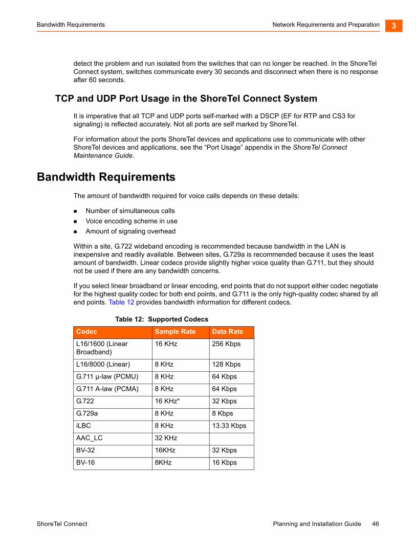
Bandwidth Requirements Network Requirements and Preparation 3
detect the problem and run isolated from the switches that can no longer be reached. In the ShoreTel Connect system, switches communicate every 30 seconds and disconnect when there is no response after 60 seconds.
TCP and UDP Port Usage in the ShoreTel Connect System
It is imperative that all TCP and UDP ports self-marked with a DSCP (EF for RTP and CS3 for signaling) is reflected accurately. Not all ports are self marked by ShoreTel.
For information about the ports ShoreTel devices and applications use to communicate with other ShoreTel devices and applications, see the “Port Usage” appendix in the ShoreTel Connect Maintenance Guide.
Bandwidth Requirements
The amount of bandwidth required for voice calls depends on these details:
Number of simultaneous calls
Voice encoding scheme in use
Amount of signaling overhead
Within a site, G.722 wideband encoding is recommended because bandwidth in the LAN is inexpensive and readily available. Between sites, G.729a is recommended because it uses the least amount of bandwidth. Linear codecs provide slightly higher voice quality than G.711, but they should not be used if there are any bandwidth concerns.
If you select linear broadband or linear encoding, end points that do not support either codec negotiate for the highest quality codec for both end points, and G.711 is the only high-quality codec shared by all end points. Table 12 provides bandwidth information for different codecs.
Table 12: Supported Codecs
Codec Sample Rate Data Rate
L16/1600 (Linear Broadband)
16 KHz 256 Kbps
L16/8000 (Linear) 8 KHz 128 Kbps
G.711 µ-law (PCMU) 8 KHz 64 Kbps
G.711 A-law (PCMA) 8 KHz 64 Kbps
G.722 16 KHz* 32 Kbps
G.729a 8 KHz 8 Kbps
iLBC 8 KHz 13.33 Kbps
AAC_LC 32 KHz
BV-32 16KHz 32 Kbps
BV-16 8KHz 16 Kbps
ShoreTel Connect Planning and Installation Guide 46
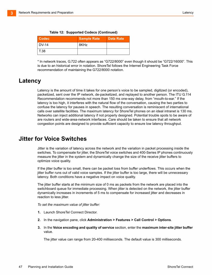
Network Requirements and Preparation Latency3
* In network traces, G.722 often appears as “G722/8000” even though it should be “G722/16000”. This is due to an historical error in notation. ShoreTel follows the Internet Engineering Task Force recommendation of maintaining the G722/8000 notation.
Latency
Latency is the amount of time it takes for one person’s voice to be sampled, digitized (or encoded), packetized, sent over the IP network, de-packetized, and replayed to another person. The ITU G.114 Recommendation recommends not more than 150 ms one-way delay, from “mouth-to-ear.” If the latency is too high, it interferes with the natural flow of the conversation, causing the two parties to confuse the latency for pauses in speech. The resulting conversation is reminiscent of international calls over satellite facilities. The maximum latency for ShoreTel phones on an ideal intranet is 130 ms. Networks can inject additional latency if not properly designed. Potential trouble spots to be aware of are routers and wide-area-network interfaces. Care should be taken to ensure that all network congestion points are designed to provide sufficient capacity to ensure low latency throughput.
Jitter for Voice Switches
Jitter is the variation of latency across the network and the variation in packet processing inside the switches. To compensate for jitter, the ShoreTel voice switches and 400-Series IP phones continuously measure the jitter in the system and dynamically change the size of the receive jitter buffers to optimize voice quality.
If the jitter buffer is too small, there can be packet loss from buffer underflows. This occurs when the jitter buffer runs out of valid voice samples. If the jitter buffer is too large, there will be unnecessary latency. Both conditions have a negative impact on voice quality.
The jitter buffer starts at the minimum size of 0 ms as packets from the network are placed into the switchboard queue for immediate processing. When jitter is detected on the network, the jitter buffer dynamically increases in increments of 5 ms to compensate for increased jitter and decreases in reaction to less jitter.
To set the maximum value of jitter buffer:
1. Launch ShoreTel Connect Director.
2. In the navigation pane, click Administration > Features > Call Control > Options.
3. In the Voice encoding and quality of service section, enter the maximum inter-site jitter buffer value.
The jitter value can range from 20-400 milliseconds. The default value is 300 milliseconds.
DV-14 8KHz
T.38
Table 12: Supported Codecs (Continued)
Codec Sample Rate Data Rate
47 Planning and Installation Guide ShoreTel Connect

Packet Loss Network Requirements and Preparation 3
4. Click Save.
The entered jitter buffer value is saved in the system.
As the jitter increases on the network and the jitter buffer needs to be increased to guarantee timely audio play, the latency of the audio also increases. The system attempts both to maintain a minimum jitter buffer size that provides good-quality voice without dropping packets and to provide minimum latency.
For third-party IP phones that are configured in the ShoreTel Connect system, the jitter buffer is not configurable. The minimum jitter buffer is 10 ms, and the maximum is 80 ms.
Maximum jitter buffer values greater than 100 ms should rarely be necessary. If needed, this could indicate a problem in your network that should be addressed in another way. As the jitter buffer depth increases, the latency experienced by the user increases. For this reason, network jitter should be kept to a minimum.
Packet Loss
Lost packets can occur on the IP network for any number of reasons. Packet loss above 1% begins to adversely affect voice quality. To help reduce this problem, ShoreTel voice switches and 400-Series IP phones have a feature called lost packet concealment. When a packet is lost on the network, the last sample received is replayed to the receiving party at a reduced level. This is repeated until a nominal level is reached, effectively reducing the clicking and popping associated with low levels of packet loss.
Fax and modem calls demand essentially zero packet loss to avoid missing lines on fax calls and to avoid dropped modem calls. In addition, fax and modem calls, when detected, may change to a higher-rate codec.
Bandwidth Management
In addition to the network requirements discussed above, bandwidth management techniques need to be deployed to ensure that real-time voice traffic is not affected by bursts or high amounts of data traffic.
Local Area Network (LAN)
To manage bandwidth in the local area network (intrasite) and meet the requirements for toll-quality voice, use Ethernet switching. Ethernet switching is cost effective and simple to provision. Your LAN configuration requirements will vary depending on your infrastructure and whether your network includes IP phones.
IP phones sample the user’s voice and convert the voice signal to IP packets using the Real Time Protocol (RTP). These packets must be tagged for higher prioritization in the network. ShoreTel IP phones have embedded Ethernet switches and automatically prioritize voice traffic ahead of any data traffic coming from piggy-backed personal computers (for example, large file transfers and e-mail).
On the local area network, methods to prioritize voice packets include the following:
IP Precedence – 5 (configurable, recommendation is 5)
DiffServ/ToS – EF (configurable, recommendation is EF)
ShoreTel Connect Planning and Installation Guide 48
Network Requirements and Preparation Virtual LANs3
The Ethernet switch configuration should prioritize traffic using one of these methods. This allows the voice traffic arriving at the switch to travel ahead of the data traffic.
ShoreTel customers typically prioritize voice traffic by setting the Differentiated Service (DiffServ) field because this configuration is easy to set up on smart Ethernet switches.
To configure the Differentiated Service (DiffServ) field for Call control quality of service:
1. Launch ShoreTel Connect Director.
2. In the navigation pane, click Administration > Features > Call Control > Options.
3. In the Call control quality of service section, in the DiffServ/ToS byte field enter a value of 96.
4. Click Save.
The differentiated service field value is configured for calls.
When IP phones are used, the desktop connection to the user’s computer and phone must also be part of the switched Ethernet network. The user's phone network port is connected to their home office router (that is, DSL or cable modem router's LAN switch ports) and their PC or laptop is connected to their phone's PC access port on the back of the IP phone, just like in the office. The phone uses its built-in VPN client to automatically connect securely to a ShoreTel VPN Concentrator located in the customer's corporate network to be able to register their ShoreTel IP phone as if it were in the office. The PC or laptop does not have access to the Voice VLAN that the VPN IP phone uses with its VPN client. The phone-connected PC or laptop has access only to the local data network for normal Internet access so voice and data are still on separate virtual networks. While piggy-backed to the phone, the PC or laptop can start its own VPN client to connect separately to the corporate data network without any conflict or issue with the phone.
If an IP phone loses power, a PC connected through the IP phone loses its connection to the network.
Voice quality can be guaranteed by putting each of the ShoreTel voice switches and the ShoreTel server on its own Ethernet switch port. A network with this topology meets the bandwidth, jitter, and latency requirements for toll-quality voice without the additional need for special prioritization of voice packets.
In summary, ShoreTel leverages the use of VLANs to integrate into the network topology that you, the network administrator, have decided is most appropriate for your LAN topology. ShoreTel does not require nor dictate that you use a specific vendor's equipment for your LAN edge, core, WAN, switches, routers, operating systems, and so on, as long as your data hardware supports the minimum recommended requirements.
Virtual LANs
Virtual LANs (that is, VLANs) are a data networking design construct by which more than one logical layer-2 (that is, L2) network subnet can exist on a single physical network segment/switch while also separating layer-2 broadcast domains. In a converged data network containing both voice and data
Note
ShoreTel only self-marks DSCP for certain ports. ShoreTel does not mark CoS, and the data networking equipment will automatically map the DSCP marking to CoS when needed.
49 Planning and Installation Guide ShoreTel Connect

Wide Area Network Network Requirements and Preparation 3
traffic, it is imperative that the voice and data packets are separated into at least two distinct VLANs (that is, a data VLAN and a voice VLAN). Failure to do so will likely result in poor voice quality, packet loss, client-to-server communication interruptions or disconnects, and lost call control/setup traffic during higher network traffic conditions.
Ethernet uses Carrier Sense Multiple Access with Collision Detection protocol (CSMA/CD) to determine when a single Ethernet device on a layer-2 subnet/VLAN can access the media similar to how a polite conversation works where one speaks and everyone else listening does not speak. In a non-switched network, when multiple devices on the subnet need to “speak”, they have to wait their turn until the one speaking or transmitting packets on the subnet is finished. In a switched network, this is less of a problem except for broadcast traffic. Transmitting voice traffic is time sensitive and the media access delay could become too great or too random at times, causing issues with voice. Smaller VLANs also control the quantity of MAC addresses that ARP tables have to store to communicate which is a more limited resource for IP phones. For example at a given site, create a data VLAN for PCs, a voice VLAN for all VoIP devices which should include ShoreGear switches, ShoreTel servers and all IP phones, create a Wi-Fi VLAN for wireless devices, a Printer VLAN for printers, a Server VLAN for all other servers and etc.
Segmenting similar layer-2 traffic into separate subnets/VLANs help mitigate propagating unnecessary traffic across too many data switch interfaces resulting in a more congested data network. ShoreTel IP phones and voice switches can be configured on a specific VLAN. Set the voice VLAN for higher prioritization in the network. The Ethernet switch infrastructure needs to be configured to prioritize the voice VLAN. This allows the voice traffic arriving at the switch to travel ahead of the data traffic.
The benefits of placing data and voice traffic in separate VLANs and QoS strategies include:
Reduction in the number of Ethernet switches required in the network.
Broadcast packets from the data network are not sent to the voice network.
Large data traffic flows do not interfere with more time sensitive voice traffic.
Congestion, packet loss, and viruses on the data network will not affect the voice network.
Wide Area Network
To manage bandwidth in the wide area network, prioritize your voice traffic ahead of your data traffic. You can prioritize based on the voice switch IP address, the MAC address, or the physical port on the Ethernet switch.
You can enable default QoS on all data networking equipment which generally takes care of Layer 2. Layer 3 will need to be manually created and/or applied if generated automatically to any VLANs or interfaces where VoIP traffic will cross and switch or router. Layer 4 ports are added to the layer 3 policy if DSCP markings are not trusted and need to be remarked. See the ShoreTel Connect Maintenance Guide appendix for TCP and UDP ports listed that are self-marked by Director.
Client Bandwidth
ShoreTel Connect client communicates with the ShoreTel server for call information and control, configuration changes, and advanced services such as extension monitoring. Table 13 provides an estimate of the client bandwidth used for each of the ShoreTel Connect client applications.
ShoreTel Connect Planning and Installation Guide 50
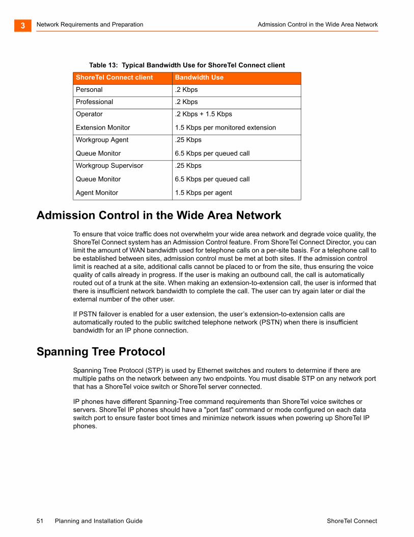
Network Requirements and Preparation Admission Control in the Wide Area Network3
Admission Control in the Wide Area Network
To ensure that voice traffic does not overwhelm your wide area network and degrade voice quality, the ShoreTel Connect system has an Admission Control feature. From ShoreTel Connect Director, you can limit the amount of WAN bandwidth used for telephone calls on a per-site basis. For a telephone call to be established between sites, admission control must be met at both sites. If the admission control limit is reached at a site, additional calls cannot be placed to or from the site, thus ensuring the voice quality of calls already in progress. If the user is making an outbound call, the call is automatically routed out of a trunk at the site. When making an extension-to-extension call, the user is informed that there is insufficient network bandwidth to complete the call. The user can try again later or dial the external number of the other user.
If PSTN failover is enabled for a user extension, the user’s extension-to-extension calls are automatically routed to the public switched telephone network (PSTN) when there is insufficient bandwidth for an IP phone connection.
Spanning Tree Protocol
Spanning Tree Protocol (STP) is used by Ethernet switches and routers to determine if there are multiple paths on the network between any two endpoints. You must disable STP on any network port that has a ShoreTel voice switch or ShoreTel server connected.
IP phones have different Spanning-Tree command requirements than ShoreTel voice switches or servers. ShoreTel IP phones should have a "port fast" command or mode configured on each data switch port to ensure faster boot times and minimize network issues when powering up ShoreTel IP phones.
Table 13: Typical Bandwidth Use for ShoreTel Connect client
ShoreTel Connect client Bandwidth Use
Personal .2 Kbps
Professional .2 Kbps
Operator
Extension Monitor
.2 Kbps + 1.5 Kbps
1.5 Kbps per monitored extension
Workgroup Agent
Queue Monitor
.25 Kbps
6.5 Kbps per queued call
Workgroup Supervisor
Queue Monitor
Agent Monitor
.25 Kbps
6.5 Kbps per queued call
1.5 Kbps per agent
51 Planning and Installation Guide ShoreTel Connect
Traffic Shaping to Reduce Bottlenecks Network Requirements and Preparation 3
To allow faster boot times and fewer network issues when connecting to ShoreTel phones, ShoreTel voice switches, or ShoreTel servers, do the following:
For Cisco switches, set Spanning Tree to either “portfast” or “rapid spanning tree” mode.
For Juniper switches, set Spanning Tree to “edge” mode.
For HP Procurve switches, set Spanning Tree to “admin-edge-port” mode.
Traffic Shaping to Reduce Bottlenecks
With many applications requiring WAN bandwidth, the need to optimize is increasingly important. This is particularly true for enterprises that want to deploy voice over virtual networks where quality of service and traffic shaping are required. With traffic shaping, it is possible to set policies that determine who or what gets top priority. For example, by prioritizing the various flows of traffic, an administrator can make sure that UDP (voice) traffic gets a higher priority than FTP (file download) traffic.
Echo Cancellation
Echo is a consideration for networks and IP phones.
Networks
Echo in a voice communication system is caused by signal reflections generated by the electrical circuits (called hybrids) that convert between two-wire (shared transmit and receive pair) and four-wire circuits (separate transmit and receive pairs). These reflections cause the speaker’s voice to be heard in the speaker’s ear as delayed by many milliseconds. Echo is present even in the traditional circuit-switched telephone network, but because the delay in a local circuit-switched call is so low, the echo is not perceivable. On a packet-based voice network, there is more delay, and the speaker may perceive the echo if it is not properly canceled.
The DSP software on ShoreTel voice switches provides dynamic echo cancellation. When a user places an extension-to-trunk call using an analog trunk on a ShoreTel voice switch, the user’s voice bounces off the initial four-wire to two-wire conversion in the analog trunk circuit, then off the two-wire to four-wire in the central office, and finally off the called party’s telephone. This echo returns from the central office and is canceled by the echo canceler on the trunk port of the voice switch. The echo from the called party’s phone, however, is usually canceled or suppressed by the central office. If this echo is not canceled, users might hear themselves talking.
In the opposite direction, the external person’s voice bounces off the user’s telephone. This echo returns from the telephone and is canceled by the echo canceler on the telephone port of the voice switch. If this echo is not canceled, the external party hears himself or herself talking. This same process of echo cancellation applies to extension-to-extension as well as trunk-to-trunk calls.
ShoreTel voice switches can cancel echo received up to 16 ms after being sent.
IP Phones
Most ShoreTel IP phones have hands-free, full-duplex speakerphones with built-in echo cancellation. The ShoreTel IP420, however, has a half-duplex speakerphone, and for this reason it is not appropriate for use as a speakerphone in a conference room.
ShoreTel Connect Planning and Installation Guide 52

Network Requirements and Preparation WAN Technology Choices3
WAN Technology Choices
Minimum Bandwidth Requirements
The minimum WAN bandwidth required to deploy a voice switch at a site depends on the number of calls expected. With ADPCM, a single call consumes 52 Kbps, and if this call becomes a conference call, another 52 Kbps is needed, yielding a total of 104 Kbps. From a broadband perspective, the first available technology is 128 Kbps (ISDN), which leaves only 24 Kbps for other IP traffic. For teleworking applications, where only a single call is needed, 128 Kbps can be used. For other sites on the voice network, the minimum bandwidth recommended is 384 Kbps.
Various technologies, as shown in Table 14, are available from different service providers to provide IP connectivity between locations.
Leased T1
Leased T1 facilities are the most robust WAN technology available. Leased T1s are point-to-point links that inherently meet the network requirements for toll-quality voice because no ISP is involved. Dedicated T1s are priced on a per-unit distance basis, making this a very cost-effective option over short distances.
Table 14: IP Connectivity Chart
TechnologyUpstream Bandwidth Kbps
Downstream Bandwidth Kbps
Calls with ADPCM
T1 1544 1544 26
MPLS 3000 1024 Varies
SDSL 1544 1544 26
SDSL 1024 1024 17
SDSL 768 768 13
SDSL 512 512 8
SDSL 384 384 6
IDSL 144 144 1 call only
ADSL 128 1,000 (varies) 1 call only
Cable 128 (varies) 1,000 (varies) 1 call only
ISDN BRI 128 128 Not supported
Note
Your bandwidth will vary, based on the WAN overhead for your particular system.
53 Planning and Installation Guide ShoreTel Connect
MPLS Network Requirements and Preparation 3
MPLS
MPLS protects against last mile failures. If you require more simultaneous calls between your premise network and the Shoretel Sky network, as well as better QoS guarantees and the option to deploy redundant network connections, a tail on the Shoretel MPLS network (layer 3) may be dropped into your site and a router will be installed on your network. QOS settings for the MPLS tail into your network is set by Shoretel to provide priority to Shoretel voice traffic.
SDSL
SDSL is considered “business-to-business” DSL in which you can negotiate a service-level agreement with the service provider. Unlike T1, SDSL is priced on a flat bandwidth basis, making the price “distance insensitive” and cost-effective over long distances.
Although this is an excellent option, especially moving forward, ShoreTel has found the use of SDSL challenging, since the service providers often commit to a Service-Level Agreement (SLA) they cannot fulfill. Many service providers have grown very fast, and the IP network is a patchwork of devices. These service providers are usually geared toward providing bandwidth for typical data applications, and a voice application highlights weaknesses in their network. Only with joint troubleshooting of the service provider’s network, using tools such as ping plotters, has ShoreTel been able to achieve the SLA the service provider promised.
IDSL
IDSL modems, which have an uplink and downlink speed of 144 Kbps, can be considered for teleworking applications. Actual performance varies based on your service provider and your applications.
ADSL
ADSL modems, which have an uplink speed of 128 Kbps, can be considered for teleworking applications. Actual performance varies based on your service provider and your applications.
Cable Modems
Cable modems, which can have an uplink speed of 128 Kbps, can be considered for teleworking applications. Actual performance varies based on your service provider and your applications.
ISDN BRI
ISDN BRI modems, which have an uplink speed of 128 Kbps, can be considered for teleworking applications. Actual performance varies based on your service provider and your applications.
Dial-Up Modems
Because of their inherent latency and low bandwidth, dial-up modems are not supported.
ShoreTel Connect Planning and Installation Guide 54
Network Requirements and Preparation IP Address Assignment3
IP Address Assignment
Each ShoreTel voice switch must have an IP address, and each ShoreTel server must have a static IP address. Use one of the following ways to assign an IP address to a voice switch:
DHCP on a network server. IP phones and PCs get their assigned IP address and other networking configuration information dynamically from a network DHCP server. This saves administrators a considerable amount of work from having to manually configure every IP phone or PC on their data network individually, especially when network parameters change across the entire network environment. ShoreTel does not support DHCP on its servers.
The maintenance port on the front of the ShoreTel voice switch. For information about the location of the maintenance port on the switch, see Appendix C, ShoreTel Voice Switches for all switch models or refer to the ShoreTel quick install guide for a specific ShoreTel voice switch model.
If a voice switch has been configured to request a dynamic IP address, it puts a DHCP request on the network when powered on. If the voice switch receives a response, it uses the new IP address. If no response is received, it reverts to the previous IP address. If there is no previous IP address, the voice switch continues trying to get an IP address.
If the network has a DHCP server, ShoreTel recommends that you reserve IP addresses so that the IP addresses of the voice switches do not dynamically change.
The maintenance port is for configuring the networking parameters.
The following recommendations can assist with the assignment of IP addresses:
Ensure that only one DHCP server is on the network. Multiple DHCP servers can unexpectedly change IP addresses and disrupt operation of voice switches.
The ShoreTel Connect system must be on a private network in some situations and on a public network in other situations. For example:
If the enterprise is using a firewall with Network Address Translation (NAT), all remote facilities must establish VPN connections to headquarters and be on the same private network.
If the enterprise is using firewalls but not NAT, all remote locations must use public IP addresses.
Each IP phone must have a unique IP address. You can configure the IP phone through DHCP or manually on the phone.
Phones at different sites must be configured on different subnets or assigned from different address ranges so that the ShoreTel Connect system can properly assign the voice switch for the IP telephone site.
55 Planning and Installation Guide ShoreTel Connect
Configuring DHCP for ShoreTel IP Phones Network Requirements and Preparation 3
Configuring DHCP for ShoreTel IP Phones
The ShoreTel server provides the latest application software and configuration information to ShoreTel IP phones. To receive this information, the ShoreTel IP phone must have the server’s IP address. The configuration task in this section is for specifying the IP address and other necessary information.
The phone receives the necessary information through a vendor-specific DHCP option. ShoreTel IP phones have a built-in configuration to seek the ShoreTel server’s address as Vendor Specific DHCP option 156. If these options are not available, ShoreTel’s IP phones use option 66. ShoreTel IP phones that support DHCP option 156 are ShoreTel models IP110, IP115, IP212k, IP230, IP230g, IP265, IP420, IP480, IP480g, IP485g, IP560, IP560g, and IP655.
The configuration task in this section involves a number for the country of the network or subnet where the phones reside. If necessary, find the number for a country in Table 15.
If your network has separate subnets, be sure to select the correct subnet. For example, if a multi-national organization needs the DHCP server to deliver Spanish tones and cadences to the IP phones in an office in Spain, specify the subnet for that office. Without this specification, all phones that boot from this DHCP server receive Spanish tones and cadences.
Another value for the configuration task is a number that points to a language by its country. Although this number refers to a language, it is bound to a country, not a language. For this reason, some countries with different languages have the same language number in the configuration of DHCP option 156. Table 16 lists the language numbers. (As Table 16 shows, language number 4 is a good example.) Selecting the correct language code ensures that the phone shows text in the desired language. Examples of this text are abbreviations for days and months and messages indicating that a requested service is unavailable.
Note
For information about DHCP settings for the ShoreTel 400-Series IP phones, see the ShoreTel Connect Maintenance Guide.
Note
The ShoreTel IP Phone 8000 does not support option 156 for this application.
Note
ShoreTel 400-Series IP phones do not use the language or country parameters in DHCP Option 156. Instead, these phones obtain country and language settings from ShoreTel Connect Director as follows:
The country is determined by the Country parameter on the Sites page.
For an Available phone, the language is determined by the Language parameter on the Sites page. For an assigned phone, the language is determined by the Language parameter on the Users page.
ShoreTel Connect Planning and Installation Guide 56
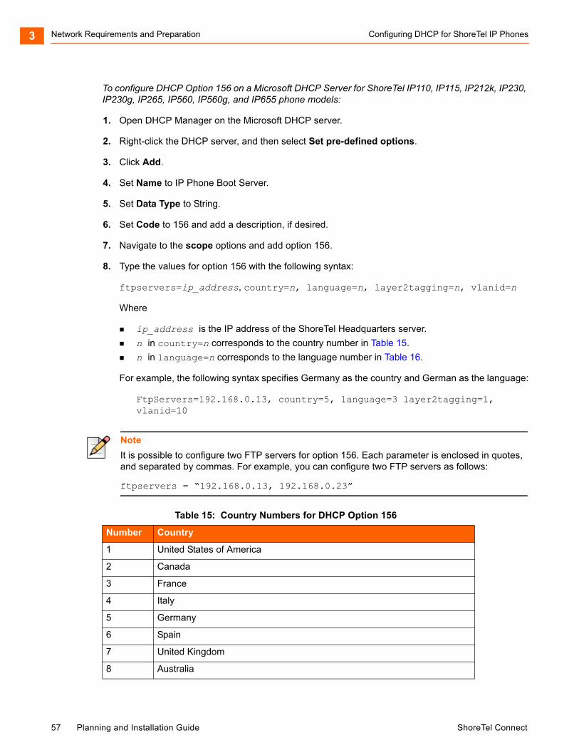
Network Requirements and Preparation Configuring DHCP for ShoreTel IP Phones3
To configure DHCP Option 156 on a Microsoft DHCP Server for ShoreTel IP110, IP115, IP212k, IP230, IP230g, IP265, IP560, IP560g, and IP655 phone models:
1. Open DHCP Manager on the Microsoft DHCP server.
2. Right-click the DHCP server, and then select Set pre-defined options.
3. Click Add.
4. Set Name to IP Phone Boot Server.
5. Set Data Type to String.
6. Set Code to 156 and add a description, if desired.
7. Navigate to the scope options and add option 156.
8. Type the values for option 156 with the following syntax:
ftpservers=ip_address, country=n, language=n, layer2tagging=n, vlanid=n
Where
ip_address is the IP address of the ShoreTel Headquarters server.
n in country=n corresponds to the country number in Table 15.
n in language=n corresponds to the language number in Table 16.
For example, the following syntax specifies Germany as the country and German as the language:
FtpServers=192.168.0.13, country=5, language=3 layer2tagging=1, vlanid=10
Note
It is possible to configure two FTP servers for option 156. Each parameter is enclosed in quotes, and separated by commas. For example, you can configure two FTP servers as follows:
ftpservers = “192.168.0.13, 192.168.0.23”
Table 15: Country Numbers for DHCP Option 156
Number Country
1 United States of America
2 Canada
3 France
4 Italy
5 Germany
6 Spain
7 United Kingdom
8 Australia
57 Planning and Installation Guide ShoreTel Connect

Configuring DHCP for ShoreTel IP Phones Network Requirements and Preparation 3
9 Hong Kong
10 Malaysia
11 Singapore
12 Brazil
13 Netherlands
14 New Zealand
15 Portugal
16 Ireland
17 Belgium
18 Mexico
19 Denmark
20 Sweden
21 Switzerland
22 Austria
23 India
24 China
25 Norway
26 United Arab Emirates
28 Japan
29 Taiwan
30 South Korea
31 Luxembourg
32 Finland
33 Philippines
34 Thailand
35 Poland
36 Czech Republic
37 South Africa
38 Costa Rica
39 Greece
41 Monaco (France)
42 Israel
44 Indonesia
Table 15: Country Numbers for DHCP Option 156 (Continued)
Number Country
ShoreTel Connect Planning and Installation Guide 58

Network Requirements and Preparation Configuring DHCP for ShoreTel IP Phones3
46 Hungary
48 Fiji
49 Mongolia
Table 16: Language Numbers by Country for DHCP Option 156
Number Language (Country)
1 U.S., Canada, Mongolia, Philippines, Thailand
2 Spain (CALA)
3 Germany, Austria
4 English (UK), Czech Republic, Ireland, Malaysia, Greece, Hong Kong, New Zealand, Poland, India, Romania, Singapore, South Africa, United Arab Emirates, Indonesia, Finland
5 France (Parisian), Belgium, Luxembourg, Switzerland, Monaco (France)
6 Netherlands
7 Mexico, Cost Rica, Chile
8 Denmark
9 Italy
10 Sweden
11 China
12 Norway, Finland
13 Brazil (Portuguese)
14 Japan
15 South Korea
17 Taiwan (Mandarin)
18 Portugal
22 Bulgaria
23 Australia, Fiji
Table 15: Country Numbers for DHCP Option 156 (Continued)
Number Country
59 Planning and Installation Guide ShoreTel Connect
Configuring Automatic VLAN Assignment Using DHCP Network Requirements and Preparation 3
Configuring Automatic VLAN Assignment Using DHCP
You can configure an IP phone to automatically determine its VLAN ID through DHCP. When the phone boots for the first time, it acquires an IP address via DHCP similar to any other network device. However, the DHCP response also specifies (using a proprietary DHCP option) the VLAN ID for the phone to use. The phone then releases the IP address originally assigned to it and reboots. After the phone reboots, all packets are tagged with the VLAN ID specified in the original DHCP response.
The Automatic VLAN Assignment feature is configured on the DHCP server rather than through ShoreTel Connect Director.
Configuring Automatic VLAN Assignment on a DHCP Server
1. Open DHCP Manager on your Microsoft DHCP server.
2. Right-click the DHCP server and select Set pre-defined options.
3. Click Add.
4. Set Name to IP Phone Boot Server.
5. Set Data Type to String.
6. Set Code to 156 and add a description, if desired.
7. Navigate to the scope options and add option 156.
8. Set the value of option 156 as follows:
ftpservers=ip_address, layer2tagging=n, vlanid=x
Where
ip_address is the IP address of the ShoreTel Headquarters server.
n in layer2tagging=n is 0 (to disable 802.1Q) or 1 (to enable 802.1Q). The default is 0.
x in vlanid=x corresponds to a VLAN ID number between 0 and 4094 when 802.1Q is enabled. The default is 0.
For example, the following would enable VLAN tagging using a VLAN ID of 10:
FtpServers=192.168.0.13, Layer2Tagging=1, vlanid=10
Configuring Automatic VLAN Assignment Using DHCP During ShoreTel IP Phone Standard Boot Process
1. As the ShoreTel IP Phone powers up, a DHCP request is sent to the data network on the default, untagged VLAN.
ShoreTel Connect Planning and Installation Guide 60
Network Requirements and Preparation Configuring Automatic VLAN Assignment Using LLDP3
2. The DHCP Server is on the same VLAN as the phone and replies back with the Option 156 information configured on the untagged Data VLAN DHCP Scope redirecting to the Voice VLAN ID 20.
3. Upon receipt of this information, the IP phone immediately resets and releases its Data VLAN IP address. The IP phone display briefly shows "Redirecting Network".
4. The ShoreTel IP Phone sends a second DHCP request but this time to the Voice VLAN 20 DHCP Scope.
5. The L3 data switch receives this request on the Voice VLAN and forwards it, via the "IP helper address" 10.10.10.10 to the DHCP server and the Data VLAN.
6. The DHCP server replies to the IP phone with a new IP address from the Voice VLAN DHCP Scope Address Pool as well as its Option 156 network settings and other scope options.
7. The IP Phone via FTP downloads its configuration file, upgrades the Boot Image, if needed, as well as other required files and finally reboots.
8. The Phone registers successfully and is ready for service.
Configuring Automatic VLAN Assignment Using LLDP
LLDP (IEEE 802.1AB) is a vendor agnostic Layer 2 protocol designed to be used by network devices for advertising their identity, capabilities, and neighbors on a IEEE 802 Ethernet LAN. LLDP performs similar functions as several proprietary protocols such as the Cisco Discovery Protocol (CDP), Extreme Discovery Protocol, Nortel Discovery Protocol and Microsoft’s Link Layer Topology Discovery. An enhancement to LLDP is LLDP-MED, Link Layer Discovery Protocol-Media Endpoint Discovery. LLDP eliminates the phone from using the untagged Data VLAN and allows only one DHCP request directly on the Voice VLAN.
Configuring Automatic VLAN Assignment Using LLDP-MED During the ShoreTel IP Phone Standard Boot Process
1. As the phone powers up, the Ethernet switch sends LLDP Data Units defined as LLDP_Multicast packets to the Phone.
2. The Phone responds in kind adding TIA Organizationally Specific LLDP-MED TLV's such as "TIA -Network Policy" with "VLAN Id: 0" among many other TLV extensions. "VLAN Id: 0" is the request from the phone asking the Ethernet switch for the Voice VLAN ID as well as L2 Priority, DSCP value, and etc.
3. The Ethernet switch in turn responds to the phone with the same TIA LLDP-MED TLV extensions and in the "TIA - Network Policy" TLV, the designated VLAN Id of the Voice VLAN is offered to the phone (e.g. VLAN Id: 50)
61 Planning and Installation Guide ShoreTel Connect
Time Services Network Requirements and Preparation 3
4. The Phone performs a typical DHCP sequence of Discover, Offer, Request, Ack to get an IP address plus available DHCP Options from the Voice VLAN.
5. The Phone via FTP downloads its configuration file, upgrades the Boot Image if needed as well as other required files and finally reboots.
6. The Phone registers successfully and is ready for service.
Time Services
For ShoreTel IP phones, time services must be available to provide the telephone’s date and time display. This requires a server that supports Simple Network Time Protocol (SNTP).
If an organization does not have an NTP server, it can use a publicly accessible time server. For information about publicly accessible time servers, see http://support.ntp.org/bin/view/Servers/WebHome.
ShoreTel 100-, 200-, 500-, and 600-Series IP phones receive SNTP server information from the DHCP server.
ShoreTel 400-Series IP phones depend on a Network Time Protocol (NTP) server to authenticate a secure connection and to provide the date and time to be displayed on for the phone’s screen. The time displayed on the phone is the GMT value provided by the NTP server plus the offset from the time zone setting of the phone. On the ShoreTel IP480, IP480g, and IP485g phone models, users can change the time zone from the default value through the Options menu on the phone.
Virtual Private Network (VPN)
Internet Protocol Virtual Private Networks (IP VPNs) are often the secure access of choice. IP VPNs establish secure communications between employees, branches, or partners by using strong IP-based encryption and authentication techniques for transport security over the public Internet.
IP VPNs are typically viewed as falling into three major categories: remote access VPNs, intranets (company site-to-site), and extranets (business-to-business). These services are used by companies of all sizes because of the powerful combination of high-speed access links and public networks. An example is the use of high-speed, low-cost broadband DSL connectivity to enable teleworkers or branch offices to link securely with the company network via the Internet, as if they were accessing the LAN, including all network applications, at the office. A sample VPN configuration is shown in Figure 1 on page 63.
ShoreTel Connect Planning and Installation Guide 62

Network Requirements and Preparation Tunneling3
Figure 1: VPN Topology
IP VPNs can be provided via hardware or software solutions located at the remote facility (branch office or teleworker’s home) and the customer premises. These devices or solutions use technologies such as tunneling, encryption, and authentication to guarantee secure communications across a public infrastructure.
All the components of your ShoreTel Connect system must exist in the same enterprise private network. VPNs can be used to bridge your private networks across the Internet so that the networks for two buildings are both part of the same private network. For multiple locations that share a private network, bandwidth calculations should include the effective bandwidth inside the private network, rather than the raw bandwidth.
Tunneling
Tunneling encapsulates one type of data packet into the packet of another protocol. Multiple tunneling protocols are used today on the market:
PPTP (Point-to-Point Tunneling Protocol): PPTP includes compression and encryption techniques. This protocol was introduced by Microsoft to support secure dial-up access for its desktop, which corresponds to a large share of the desktop market.
L2F (Layer 2 Forwarding): Introduced by Cisco Systems, L2F was primarily used to tunnel traffic between two Cisco routers. It also allows IPX traffic to tunnel over an IP WAN.
63 Planning and Installation Guide ShoreTel Connect
Performance Network Requirements and Preparation 3
L2TP (Layer 2 Tunneling Protocol): L2TP is an extension the PPP (Point-to-Point Protocol) that merges the best features of L2F and PPTP. L2TP is an emerging IETF (Internet Engineering Task Force) standard.
IPSEC: This is a collection of security protocols from the Security Working Group of the IETF. It provides ESP (Encapsulating Security Payload), AH (Authentication Header), and IKE (Key Exchange Protocol) support. This protocol, mature but still technically in a draft format, is currently considered the standard for encryption and tunneling support in VPNs.
For PPTP, IP VPN tunneling adds another dimension to the tunneling. Before encapsulation takes place, the packets are encrypted so that the data is unreadable to outsiders. Once the encapsulated packets reach their destination, the encapsulation headers are separated, and packets are decrypted and returned to their original format.
The L2TP tunneling protocol does not encrypt before encapsulation. It requires the IPSEC protocol to take the encapsulated packet and encrypt it before sending it over the Internet.
Performance
In the context of an IP VPN’s performance, encryption can be a CPU-intensive operation. Therefore, an enterprise must answer two questions about encryption when it evaluates VPN products:
With encryption, does the maximum throughput substantially decrease?
With encryption, can the network have a consistent level of throughput?
Typically, a business considers the tradeoffs between performance, price, and the characteristics of software-based and hardware-based encryption.
Integrated Security Appliances
A number of major vendors provide integrated broadband security appliances to eliminate security concerns. These devices use custom ASICs to deliver wire-speed firewall, Triple DES IPSec VPN, and traffic shaping in an easy-to-deploy, cost-effective solution. Installing a security appliance, such as a NetScreen-5, eliminates the need to deal with complex PC software installations and allows IT to centrally manage the security policies of these remote offices and teleworkers. The firewall protection secures sensitive data at the remote site and can prevent both U-turn attacks and the launching of denial-of-service attacks from these computers. By combining broadband access technologies with an integrated security appliance, enterprises and service providers can safely and securely capitalize on all of the benefits of the broadband Internet.
Note
Although a VPN is useful for data, for VoIP a VPN might not offer enough protection against latency and packet loss.
ShoreTel Connect Planning and Installation Guide 64
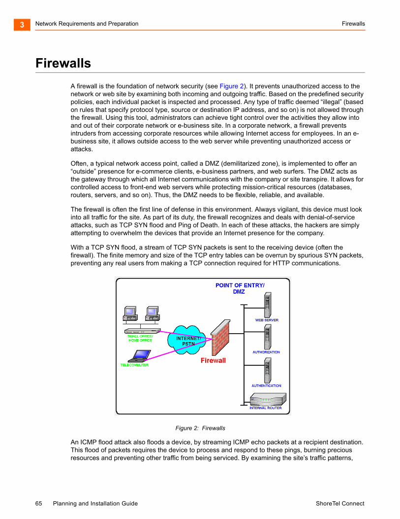
Network Requirements and Preparation Firewalls3
Firewalls
A firewall is the foundation of network security (see Figure 2). It prevents unauthorized access to the network or web site by examining both incoming and outgoing traffic. Based on the predefined security policies, each individual packet is inspected and processed. Any type of traffic deemed “illegal” (based on rules that specify protocol type, source or destination IP address, and so on) is not allowed through the firewall. Using this tool, administrators can achieve tight control over the activities they allow into and out of their corporate network or e-business site. In a corporate network, a firewall prevents intruders from accessing corporate resources while allowing Internet access for employees. In an e-business site, it allows outside access to the web server while preventing unauthorized access or attacks.
Often, a typical network access point, called a DMZ (demilitarized zone), is implemented to offer an “outside” presence for e-commerce clients, e-business partners, and web surfers. The DMZ acts as the gateway through which all Internet communications with the company or site transpire. It allows for controlled access to front-end web servers while protecting mission-critical resources (databases, routers, servers, and so on). Thus, the DMZ needs to be flexible, reliable, and available.
The firewall is often the first line of defense in this environment. Always vigilant, this device must look into all traffic for the site. As part of its duty, the firewall recognizes and deals with denial-of-service attacks, such as TCP SYN flood and Ping of Death. In each of these attacks, the hackers are simply attempting to overwhelm the devices that provide an Internet presence for the company.
With a TCP SYN flood, a stream of TCP SYN packets is sent to the receiving device (often the firewall). The finite memory and size of the TCP entry tables can be overrun by spurious SYN packets, preventing any real users from making a TCP connection required for HTTP communications.
Figure 2: Firewalls
An ICMP flood attack also floods a device, by streaming ICMP echo packets at a recipient destination. This flood of packets requires the device to process and respond to these pings, burning precious resources and preventing other traffic from being serviced. By examining the site’s traffic patterns,
65 Planning and Installation Guide ShoreTel Connect
Media Encryption Network Requirements and Preparation 3
advanced firewalls can apply logical rules that prevent the device from trying to keep up with the denial-of-service attack traffic. They also prevent this traffic from reaching the valuable web, application, and database servers that create your Internet presence and service your customers.
By using firewalls in conjunction with the DMZ design technique, many businesses and service providers are striving to present as much information without permitting unwanted access to the corporate resources.
One way to keep your mission-critical resources as private as possible, while still allowing for a strong Internet presence, is to use Network Address Translation (NAT). NAT offers the outside world one, or a few, IP addresses. This allows a manager to set up whatever internal IP addressing scheme may be required by corporate policies and business needs. An internal resource’s IP address (source IP) is changed as it passes through the NAT function to one of the “outside” IP addresses. Thus, the external world does not know any of the enterprise’s internal IP addresses. Only the NAT device presents an IP address that is known, and used by external devices. The NAT device keeps track of these conversations and performs the IP address translation as needed.
Extending the private network of the corporate LAN to remote sites via VPN is a proven method of deploying a ShoreTel Connect system across multiple sites. All IP telephony endpoints (such as ShoreTel servers, ShoreTel Voice Switches, and IP telephones) should participate in the same private network, with firewalls between ShoreTel equipment and the public Internet. If needed, you can elect to open access to the ShoreTel server to access ShoreTel Connect Director via HTTP using the same precautions you would when exposing any critical web services server to the public network.
Configuring firewalls to function correctly with VoIP traffic is very difficult. ShoreTel does not recommend deploying ShoreTel equipment across firewalls.
Media Encryption
In addition to using a VPN or a firewall, another method of enhancing the security on your network is to enable media encryption through ShoreTel Connect Director. Media encryption, as the name suggests, encrypts calls between users on a ShoreTel Connect system. The encryption scrambles communications between callers so an intruder on the network cannot eavesdrop on the conversation.
For details about media encryption, see the ShoreTel Connect System Administration Guide.
Security for ShoreTel 400-Series IP Phones
ShoreTel 400-Series IP phones use a combination of methods to provide secure communications.
The ShoreTel Headquarters server functions as a X.509 Certificate Authority for the system’s public-key infrastructure (PKI). An X.509 certificate is a public key with identifying information, which has been digitally signed through either the associated private key (a self-signed certificate) or a Certificate Authority (CA). The X.509 certificate also includes an expiration date. In addition to the X.509 certificate, the ShoreTel Connect system uses Secure Session Initiation Protocol (SIPS), which is SIP plus Transport Layer Security (TLS). This is a standard protocol that uses PKI to establish a secure connection between two entities on an IP network.
ShoreTel Connect Planning and Installation Guide 66
Network Requirements and Preparation Session Initiation Protocol (SIP)3
The ShoreTel Headquarters server software installation process generates its own self-signed CA certificate when it first boots up. This root certificate uses a 2048-bit RSA key-pair and is valid for 30 years.
ShoreTel IP phones download the Headquarters Certificate Authority X.509 certificate when provisioning into the system. Using that certificate, the phone is able to connect to the voice switches via SIPS, and to the server using HTTPS. The phones also have a pre-installed, unique certificate, signed by ShoreTel, that allows the voice switches and servers to authenticate the phone.
The following architecture also ensures system security:
Access to ShoreTel 400-Series IP phones is restricted to the Headquarters server and ShoreTel equipment. The only open in-bound ports are Secure Session Initiation Protocol (SIPS) and secure-shell (ssh) ports.
Call signaling between 400-Series IP phones and voice switches is encrypted, and participants are authenticated using standards-based security.
If enabled in ShoreTel Connect Director, voice encryption uses standard SRTP AES-128 encryption. In this case, voice media is encrypted on all calls, with the following exceptions:
Media in calls between 400-Series IP phones and older ShoreTel IP phone models is not encrypted.
Media in calls that include non-ShoreTel equipment is not encrypted.
Media in calls to softphone and to Windows-based voicemail, auto attendant, workgroups, and account codes is not encrypted.
For 400-Series IP phones, Directory, History, visual voicemail, extension assignment, and user preference settings are communicated between the Headquarters server and the phones through Hypertext Transfer Protocol Secure (HTTPS).
Low-level maintenance access to the ShoreTel 400-Series IP phone is limited to secure-shell (ssh) access from the Headquarters server (or any server that has a copy of the Headquarters server’s private ssh key). Password-based login is not permitted. Login to the phone is permitted from some models of the controlling voice switch.
Session Initiation Protocol (SIP)
Deploying SIP does not involve special network requirements. The general system requirements should be adequate for SIP support. Note the following considerations:
If third-party SIP devices (SIP phones) have a static configuration, they are supported behind NAT (Network Address Translation).
WARNING!
The root private keys, which are the basis for securing all connections, are stored in the Headquarters server in <drive>:/Shoreline Data/keystore. Because exposure of these private keys could invalidate the security of the system, access to this data must be physically restricted.
67 Planning and Installation Guide ShoreTel Connect
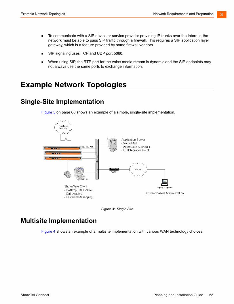
Example Network Topologies Network Requirements and Preparation 3
To communicate with a SIP device or service provider providing IP trunks over the Internet, the network must be able to pass SIP traffic through a firewall. This requires a SIP application layer gateway, which is a feature provided by some firewall vendors.
SIP signaling uses TCP and UDP port 5060.
When using SIP, the RTP port for the voice media stream is dynamic and the SIP endpoints may not always use the same ports to exchange information.
Example Network Topologies
Single-Site Implementation
Figure 3 on page 68 shows an example of a simple, single-site implementation.
Figure 3: Single Site
Multisite Implementation
Figure 4 shows an example of a multisite implementation with various WAN technology choices.
ShoreTel Connect Planning and Installation Guide 68
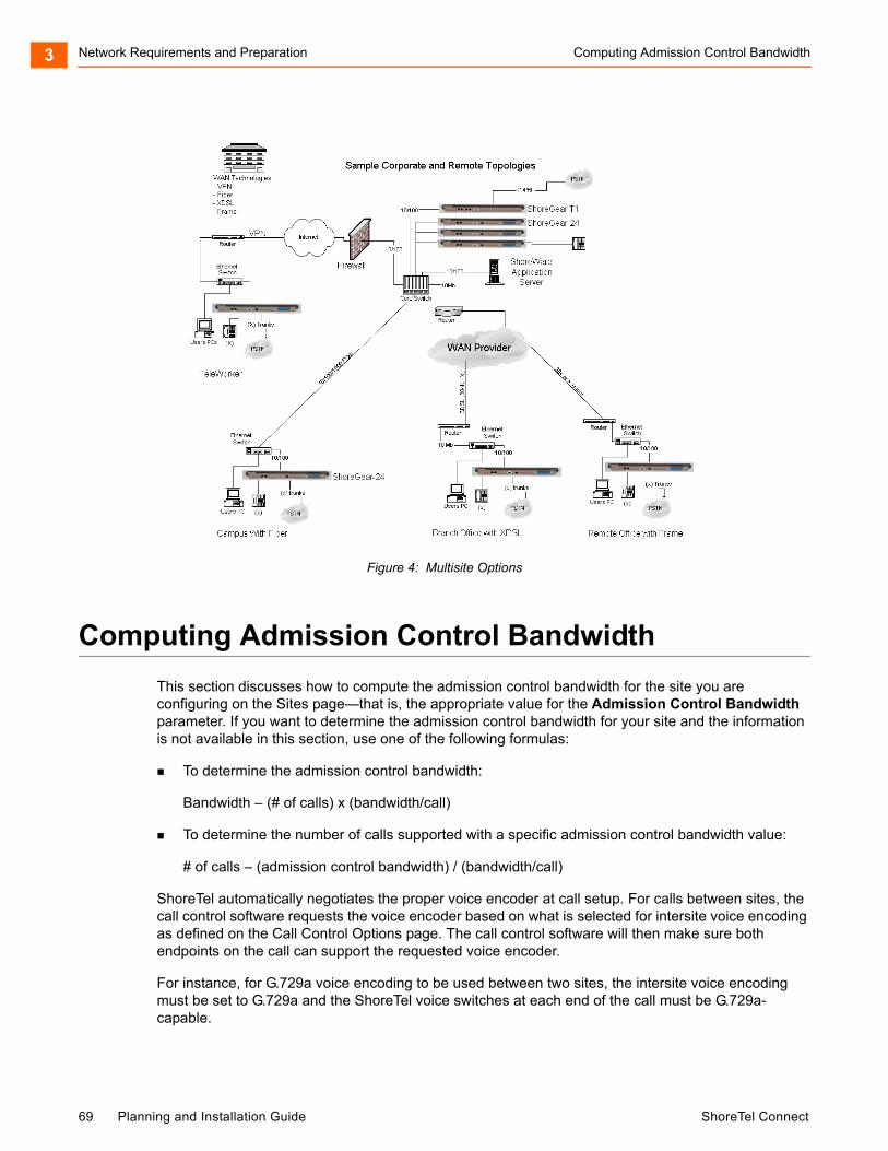
Network Requirements and Preparation Computing Admission Control Bandwidth3
Figure 4: Multisite Options
Computing Admission Control Bandwidth
This section discusses how to compute the admission control bandwidth for the site you are configuring on the Sites page—that is, the appropriate value for the Admission Control Bandwidth parameter. If you want to determine the admission control bandwidth for your site and the information is not available in this section, use one of the following formulas:
To determine the admission control bandwidth:
Bandwidth – (# of calls) x (bandwidth/call)
To determine the number of calls supported with a specific admission control bandwidth value:
# of calls – (admission control bandwidth) / (bandwidth/call)
ShoreTel automatically negotiates the proper voice encoder at call setup. For calls between sites, the call control software requests the voice encoder based on what is selected for intersite voice encoding as defined on the Call Control Options page. The call control software will then make sure both endpoints on the call can support the requested voice encoder.
For instance, for G.729a voice encoding to be used between two sites, the intersite voice encoding must be set to G.729a and the ShoreTel voice switches at each end of the call must be G.729a-capable.
69 Planning and Installation Guide ShoreTel Connect
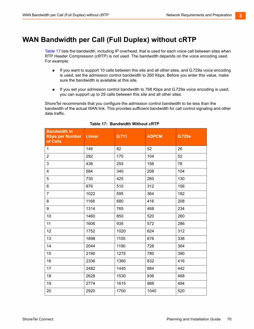
WAN Bandwidth per Call (Full Duplex) without cRTP Network Requirements and Preparation 3
WAN Bandwidth per Call (Full Duplex) without cRTP
Table 17 lists the bandwidth, including IP overhead, that is used for each voice call between sites when RTP Header Compression (cRTP) is not used. The bandwidth depends on the voice encoding used. For example:
If you want to support 10 calls between this site and all other sites, and G.729a voice encoding is used, set the admission control bandwidth to 260 Kbps. Before you enter this value, make sure the bandwidth is available at this site.
If you set your admission control bandwidth to 768 Kbps and G.729a voice encoding is used, you can support up to 29 calls between this site and all other sites.
ShoreTel recommends that you configure the admission control bandwidth to be less than the bandwidth of the actual WAN link. This provides sufficient bandwidth for call control signaling and other data traffic.
Table 17: Bandwidth Without cRTP
Bandwidth in Kbps per Number of Calls
Linear G.711 ADPCM G.729a
1 146 82 52 26
2 292 170 104 52
3 438 255 156 78
4 584 340 208 104
5 730 425 260 130
6 876 510 312 156
7 1022 595 364 182
8 1168 680 416 208
9 1314 765 468 234
10 1460 850 520 260
11 1606 935 572 286
12 1752 1020 624 312
13 1898 1105 676 338
14 2044 1190 728 364
15 2190 1275 780 390
16 2336 1360 832 416
17 2482 1445 884 442
18 2628 1530 936 468
19 2774 1615 988 494
20 2920 1700 1040 520
ShoreTel Connect Planning and Installation Guide 70
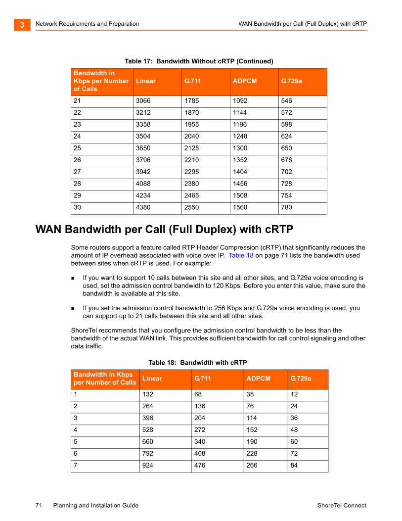
Network Requirements and Preparation WAN Bandwidth per Call (Full Duplex) with cRTP3
WAN Bandwidth per Call (Full Duplex) with cRTP
Some routers support a feature called RTP Header Compression (cRTP) that significantly reduces the amount of IP overhead associated with voice over IP. Table 18 on page 71 lists the bandwidth used between sites when cRTP is used. For example:
If you want to support 10 calls between this site and all other sites, and G.729a voice encoding is used, set the admission control bandwidth to 120 Kbps. Before you enter this value, make sure the bandwidth is available at this site.
If you set the admission control bandwidth to 256 Kbps and G.729a voice encoding is used, you can support up to 21 calls between this site and all other sites.
ShoreTel recommends that you configure the admission control bandwidth to be less than the bandwidth of the actual WAN link. This provides sufficient bandwidth for call control signaling and other data traffic.
21 3066 1785 1092 546
22 3212 1870 1144 572
23 3358 1955 1196 598
24 3504 2040 1248 624
25 3650 2125 1300 650
26 3796 2210 1352 676
27 3942 2295 1404 702
28 4088 2380 1456 728
29 4234 2465 1508 754
30 4380 2550 1560 780
Table 18: Bandwidth with cRTP
Bandwidth in Kbps per Number of Calls
Linear G.711 ADPCM G.729a
1 132 68 38 12
2 264 136 76 24
3 396 204 114 36
4 528 272 152 48
5 660 340 190 60
6 792 408 228 72
7 924 476 266 84
Table 17: Bandwidth Without cRTP (Continued)
Bandwidth in Kbps per Number of Calls
Linear G.711 ADPCM G.729a
71 Planning and Installation Guide ShoreTel Connect
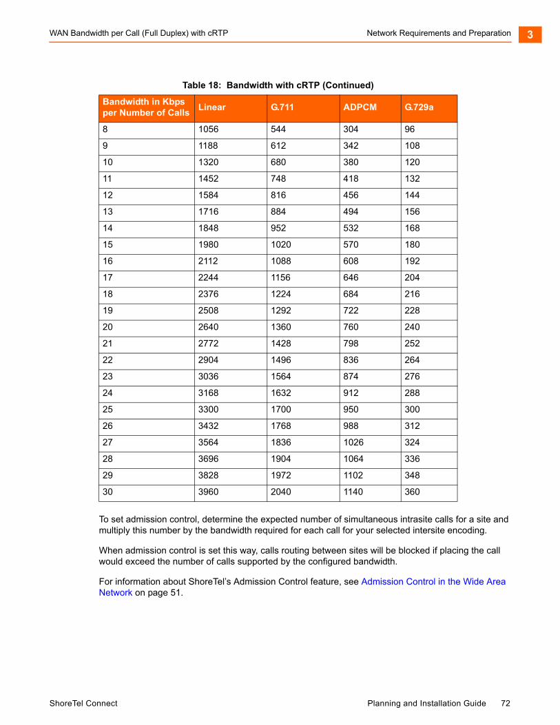
WAN Bandwidth per Call (Full Duplex) with cRTP Network Requirements and Preparation 3
To set admission control, determine the expected number of simultaneous intrasite calls for a site and multiply this number by the bandwidth required for each call for your selected intersite encoding.
When admission control is set this way, calls routing between sites will be blocked if placing the call would exceed the number of calls supported by the configured bandwidth.
For information about ShoreTel’s Admission Control feature, see Admission Control in the Wide Area Network on page 51.
8 1056 544 304 96
9 1188 612 342 108
10 1320 680 380 120
11 1452 748 418 132
12 1584 816 456 144
13 1716 884 494 156
14 1848 952 532 168
15 1980 1020 570 180
16 2112 1088 608 192
17 2244 1156 646 204
18 2376 1224 684 216
19 2508 1292 722 228
20 2640 1360 760 240
21 2772 1428 798 252
22 2904 1496 836 264
23 3036 1564 874 276
24 3168 1632 912 288
25 3300 1700 950 300
26 3432 1768 988 312
27 3564 1836 1026 324
28 3696 1904 1064 336
29 3828 1972 1102 348
30 3960 2040 1140 360
Table 18: Bandwidth with cRTP (Continued)
Bandwidth in Kbps per Number of Calls
Linear G.711 ADPCM G.729a
ShoreTel Connect Planning and Installation Guide 72

Network Requirements and Preparation Setting Admission Control3
Setting Admission Control
The Admission Control Bandwidth parameters are set on the Sites page of ShoreTel Connect Director. For information on setting these parameters, see the chapter on configuring sites in the ShoreTel Connect System Administration Guide.
73 Planning and Installation Guide ShoreTel Connect
CHAPTER
4. Routing Calls
This chapter contains information about identifying the appropriate routing for inbound and outbound calls in the following sections:
Overview ................................................................................................................... 75
Recommendations .................................................................................................... 75
Hunt Groups.............................................................................................................. 76
Direct All Calls to an Auto Attendant .................................................................. 76
After-Hours Call Routing..................................................................................... 78
Direct All Calls to a Live Operator....................................................................... 78
Direct All Calls to Extensions.............................................................................. 82
Blended Call Routing ................................................................................................ 83
Trunk Considerations.......................................................................................... 84
Analyze Outbound Call Routing ......................................................................... 86
ShoreTel Connect Planning and Installation Guide 74
Routing Calls Overview4
Overview
The purpose of this chapter is to help with identifying the appropriate routing for inbound and outbound calls. This information is important for determining the requirements for configuration and trunking.
Before installing a voice communications system, one of the most important decisions to make is how to route incoming calls. The voice communications includes the inbound calls to the ShoreTel customer, its individual employees, or a group of employees. The consideration is important for routing calls to their intended destination and also routing calls when they cannot reach their destination. Calls that fail to reach the intended person or group can then go to an auto attendant, operator, off-site number, pager, cell phone, or voice mail.
Another consideration is the outbound call routing. Every site has trunks that support outbound and inbound calls, and the outbound calling behavior also needs planning. At least one trunk at a site must also be able to support emergency calls.
For information about other aspects of designing a voice communications network, see Planning and System Design on page 22.
Call routing for ShoreTel Connect Contact Center is a separate task. This document does not describe Enterprise Contact Center. For more information on the ShoreTel Connect Contact Center, refer to the ShoreTel Connect Contact Center Administration Guide.
Recommendations
Consider the following recommendations when designing your call flow plan:
Determine how calls should reach employees and workgroups. You need to identify the desired call routing for inbound calls at each site.
Identify contingencies, such as alternate plans in the event that the receptionist has an unplanned absence, or the physical phone fails. For example, creating hunt groups can ensure an operator is available if the receptionist or workgroup is unavailable.
Consider the inter-site call flow, such as your operator’s or receptionist’s role in handling inbound calls, and the role of others who are not physically present at the main site.
Identify call flow early. Do not wait until the last minute, or try to identify the call flow the day of cut-over.
Interview the key members of your organization, such as workgroups, operators, assistants, and executives, to determine their individual preferences and needs, and make sure they agree with any decisions that affect their respective areas.
Create an off-hours call routing plan.
75 Planning and Installation Guide ShoreTel Connect
Hunt Groups Routing Calls 4
Hunt Groups
Hunt groups allow you to route calls to a list of extensions. Hunt groups can be accessed through an extension, DID, and/or DNIS. Hunt groups are supported by ShoreTel Voice Switches and remain available even when connectivity to the Headquarters server is lost. A single switch can host up to 8 hunt groups and a maximum of 16 hunt group extensions per switch. A hunt group can be used as the backup destination for an operator or workgroup, so that basic hunting occurs even when the operator or workgroup is not reachable. To maximize reliability, assign hunt groups to a switch close to the majority of the members and/or trunks associated with the hunt group.
Hunt groups can be used for:
Backup Routing for a workgroup
Hunt groups can be used when the workgroup server is not reachable because of a network outage or admission control. When the hunt group is set to offer each member a single call at a time, then call offering is similar to a workgroup.
Hunt Group as a Call Forward Destination
In a small office where individuals generally receive calls directly, users may want someone in the office to answer calls when they are unable to answer. Hunt groups can provide alternate destinations in this case.
Distribution of Calls to Backup Operators
A hunt group can provide backup operators for the primary operator who handles calls to a main company number.
Common Line Monitoring
A hunt group can enable users to monitor a phone line. For example, multiple operators can monitor a line and answer calls at the same time.
Direct All Calls to an Auto Attendant
You can direct all inbound calls to the auto attendant, and prompt the calling party to route the call, based on menu options. Auto attendant answering is typically used by smaller companies and smaller locations that do not choose to use direct inward dial (DID) numbers. Refer to Figure 5 on page 77 for an illustration of auto attendant call flow.
ShoreTel Connect Planning and Installation Guide 76

Routing Calls Direct All Calls to an Auto Attendant4
Figure 5: Auto Attendant Call Routing
Organize the auto attendant with options for various departments. In addition, include an out for callers if they must speak to a live attendant or have a rotary telephone. This destination must be one that will always be answered. In many cases, it is a receptionist’s extension that is staffed at all times, or a night bell that can be answered by any employee. If you route calls to a receptionist’s position that is not always staffed or the receptionist needs to be mobile, consider installing a cordless telephone for the receptionist to wear while roaming around the office. If this is not an option, make sure the receptionist’s availability states are set up appropriately.
Trunk Considerations
An auto attendant menu can be reached through analog loop-start, digital loop-start, and T1/E1 PRI trunks by pointing the trunk group at the desired menu. You can also reach a specific menu using DID or DNIS entries received over analog wink-start, digital wink-start, or T1/E1 PRI trunks.
The ShoreTel Connect system supports International Caller ID, Caller ID Name, Caller ID Number, ANI, and DNIS. The Caller ID and trunk group or DNIS information is provided to the user to assist in answering the call.
77 Planning and Installation Guide ShoreTel Connect
After-Hours Call Routing Routing Calls 4
Call Routing and Collecting Caller ID Information
The switch delays each inbound loop-start call by 1.5 rings to collect caller ID information before ringing the user’s telephone. This allows caller ID information to reach the user’s client at the time the call rings the extension, rather than after it rings the extension.
Features available on trunks vary by trunk type. See Trunk Planning and Ordering on page 88, for more information.
After-Hours Call Routing
For after hours, weekends, and holidays, consider how your call flow will change. Typically, a different prompt is played, since callers are routed directly to voice mail rather than to workgroups or the operator.
Example
In the call flow example shown in Figure 5 on page 77, all calls are received by the auto attendant. The calling party can choose to be directed to one of the following:
The support workgroup by dialing a digit
Calls are presented to the support workgroup with a mailbox that provides coverage. The calling party can dial “0” in the mailbox to reach the workgroup assistant, or “9” to return to the auto attendant.
An employee using Dial by Number or Dial by Name
Calls are presented to the employee with a mailbox that provides coverage. The calling party can dial “0” in the mailbox to reach the employee’s personal assistant, or “9” to return to the auto attendant.
The operator by dialing the digit 0
Calls are presented to the operator. If the operator does not answer, a backup operator provides coverage using the operator’s availability state. If the backup operator does not answer, a mailbox provides coverage, and the calling party can dial “0” in the mailbox to reach the operator’s personal assistant, or “9” to return to the auto attendant.
In this example, the workgroup, users, and operator route calls directly to voice mail after hours.
Direct All Calls to a Live Operator
Some companies choose to answer all inbound calls during business hours with a live operator to give callers a more personal experience. If you use a live operator, the most important thing to remember is that the operator’s telephone must always be staffed. ShoreTel recommends the following:
Use the ShoreTel Connect client Operator Access License, because the standard telephone without this access manages only a single call at a time. When a second call arrives, using the Flash button invokes call waiting, generating a swap hold situation in which calls cannot be transferred. This problem is eliminated when you use the ShoreTel Connect client Operator Access License.
ShoreTel Connect Planning and Installation Guide 78
Routing Calls Direct All Calls to a Live Operator4
If the organization is a large one, consider using a button box (the ShoreTel BB24 or BB424). A button box provides additional shortcut functions for ShoreTel IP phones with multiple lines. The button box behaves like an additional set of 24 custom buttons that can be used by the operator to quickly and easily route calls to executives and other employees who receive a high volume of phone calls. Phones that support button boxes can be associated with up to four button boxes.
If the operator does not receive a lot of telephone calls and is required to roam around the office to deliver mail, pick up faxes, make copies, and so on, a two-line cordless telephone can be used. The first line is reserved for incoming calls, while the second line is the operator’s personal extension.
Create hunt groups to ensure someone is always available to take an incoming call.
You can choose to have calls initially routed to the operator and then forwarded to the auto attendant after a fixed number of rings.
Operators work in one of two modes:
Answer all calls and transfer them to the appropriate destination. Answer all calls and hold them until the parties are found.
If your operator works in the second mode, you should consider installing an overhead paging system or should consider using the Paging Groups feature. Refer to the ShoreTel Administration Guide for details about Paging Groups.
The ShoreTel Connect system supports single-zone overhead paging on a per-site basis, using the audio output jack on the switches supplied with the jack. When you need multiple-zone paging, please use ShoreTel’s online knowledge base at www.shoretel.com to access the application note on paging.
Trunk Considerations
The operator can be reached through analog loop-start, digital loop-start, and T1/E1 PRI trunks by pointing the trunk group directly at the operator. You can also reach the operator using DID or DNIS entries received over analog wink-start, digital wink-start, or T1/E1 PRI trunks.
The ShoreTel Connect system supports International Caller ID, Caller ID Name, Caller ID Number, ANI, and DNIS. The Caller ID and trunk group or DNIS information is provided to the user to assist in answering the call.
Features available on trunks vary by trunk type. See Trunk Planning and Ordering on page 88, for more information.
After-Hours Call Routing
If you route all calls to the operator’s extension, auto-attendant scheduling does not apply; only those calls routed to the auto attendant use the schedule. Therefore, if you want to use the off-hours, holiday, and custom schedules, set the operator’s availability state to forward all calls to the auto attendant when the operator is unavailable.
79 Planning and Installation Guide ShoreTel Connect
Direct All Calls to a Live Operator Routing Calls 4
Example
To route calls to a prioritized list of backup operators, create hunt groups with users who can serve as backup operators. In this scenario, a primary operator who handles calls to a main company number requires one or more secondary operators to receive the calls when the primary operator becomes too busy.
Complete the following steps to create a hunt group to back up the primary operator:
1. Create a hunt group with backup operators.
2. Enter the main operator and all the backups as members of the hunt group in the order in which they are to serve as backups.
3. Set the hunt group for multiple calls to be hunted to a given member.
4. Set the call stack size for each of the users to control the number of calls he or she can receive.
When there are incoming calls to the hunt group, the primary operator is offered the calls first. The operator may be offered multiple calls concurrently up to the limit of his or her call stack. If a member’s call stack is full, the member is skipped and that particular call is not offered again unless the hunt group is set to hunt forever and no member picks up the call before the member is reached again in the hunt list.
If a member of the operator group does not answer the hunt call, the call is offered to the next member after the number of configured rings. Thus, even if the primary operator has room on his or her call stack, the call is offered to the next member in the list when the operator does not answer the call in time.
For more information on Hunt Groups, refer to Hunt Groups on page 141.
Example of Operator Call Routing
In the example call flow shown in Figure 6, all calls are received by the operator, who then transfers the calls to the appropriate destination.
ShoreTel Connect Planning and Installation Guide 80

Routing Calls Direct All Calls to a Live Operator4
Figure 6: Operator Call Routing
Calls are transferred to the support workgroup with a mailbox that provides coverage.
The calling party can dial “0” in the mailbox to reach the workgroup assistant, or “9” to return to the auto attendant.
Calls are transferred to the employees with a mailbox that provides coverage.
The calling party can dial “0” in the mailbox to reach his or her personal assistant, or “9” to return to the auto attendant.
If the operator does not answer, a backup operator provides coverage, using the operator’s availability state.
If the backup operator does not answer, a mailbox provides coverage and the calling party can dial “0” in the mailbox to reach the operator’s personal assistant, or “9” to return to the auto attendant.
In this example, after-hours call routing is handled by an auto attendant in a very similar fashion to the previous example, which is shown in Figure 5 on page 77. To start after-hours call handling, the operator changes his or her availability state. This can be done automatically using Microsoft Outlook Calendar in conjunction with Automated Call Handling, although it does require the operator’s personal computer to remain connected with Microsoft Outlook running on it.
81 Planning and Installation Guide ShoreTel Connect
Direct All Calls to Extensions Routing Calls 4
Direct All Calls to Extensions
ShoreTel recommends using Direct Inward Dial (DID) trunks so that callers can dial extensions directly without having to go through the operator. This provides the most efficient, professional call handling experience to your customers.
In the event that an individual is not available, preconfigured availability states route callers. This routing might include a cellular telephone, a pager, an alternate extension, or a personal assistant. Additionally, consider using the voice mail notification capabilities of the ShoreTel Connect system when employees are not able to answer the telephone but need to stay in touch.
Even if you choose to direct all calls to extensions, you should still configure the auto attendant for Dial by Number, Dial by Name, and zero out to an operator.
Trunk Considerations
When using Direct Inward Dial, you must use analog wink-start, digital wink-start, SIP or T1/E1 PRI trunks. The ShoreTel Connect system can receive Automatic Number Identification (ANI) over analog and digital wink-start trunks as well as Caller ID Number over T1/E1 PRI.
Features available on trunks vary by trunk type. See Trunk Planning and Ordering on page 88, for more information.
After-Hours Call Routing
By routing all calls to the individual extensions, each individual user and workgroup defines its after-hours call handling.
Example of Direct Inward Dial Call Routing
In the illustration shown in Figure 7, all calls are received by workgroups or by individuals.
ShoreTel Connect Planning and Installation Guide 82
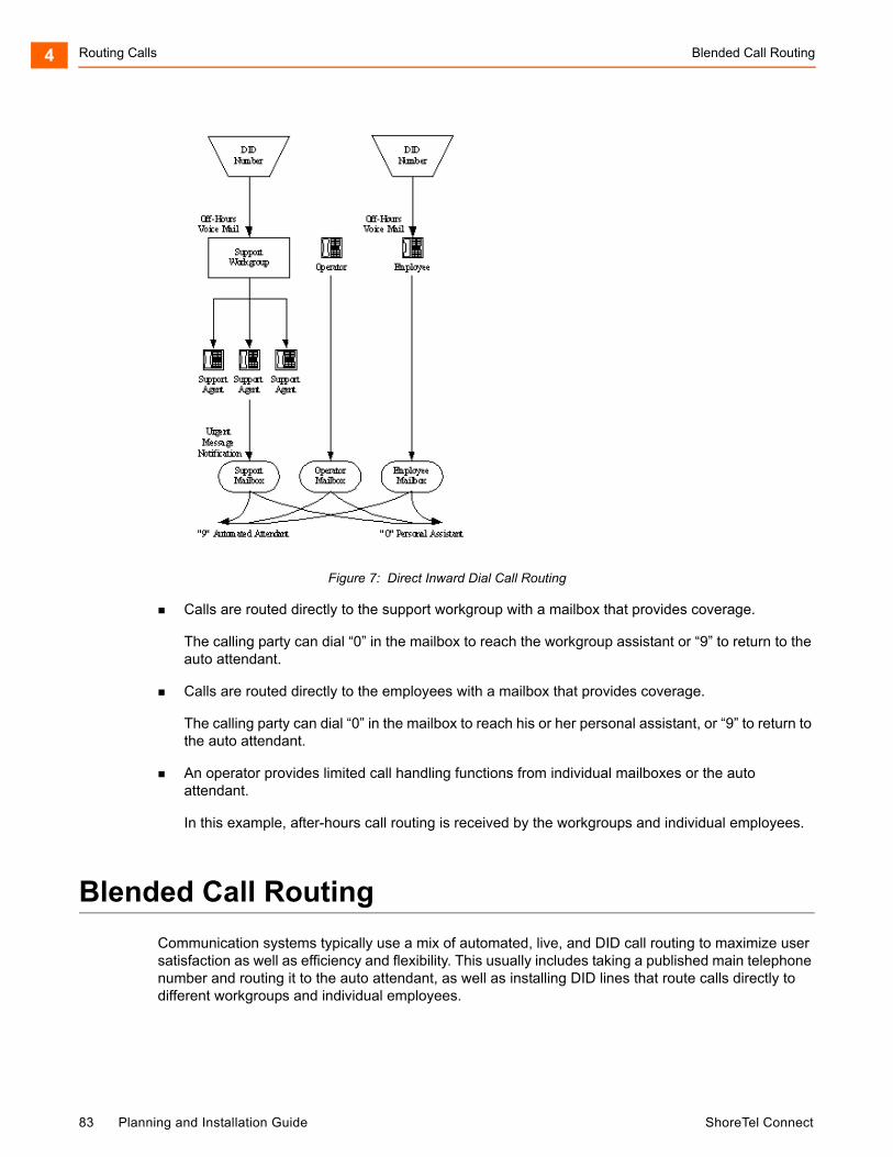
Routing Calls Blended Call Routing4
Figure 7: Direct Inward Dial Call Routing
Calls are routed directly to the support workgroup with a mailbox that provides coverage.
The calling party can dial “0” in the mailbox to reach the workgroup assistant or “9” to return to the auto attendant.
Calls are routed directly to the employees with a mailbox that provides coverage.
The calling party can dial “0” in the mailbox to reach his or her personal assistant, or “9” to return to the auto attendant.
An operator provides limited call handling functions from individual mailboxes or the auto attendant.
In this example, after-hours call routing is received by the workgroups and individual employees.
Blended Call Routing
Communication systems typically use a mix of automated, live, and DID call routing to maximize user satisfaction as well as efficiency and flexibility. This usually includes taking a published main telephone number and routing it to the auto attendant, as well as installing DID lines that route calls directly to different workgroups and individual employees.
83 Planning and Installation Guide ShoreTel Connect
Trunk Considerations Routing Calls 4
Trunk Considerations
An auto attendant menu can be reached through analog loop-start, digital loop-start, SIP, and T1/E1 PRI trunks by pointing the trunk group at the desired menu. You can also reach a specific menu using DID or DNIS entries received over analog wink-start, digital wink-start, or T1/E1 PRI trunks.
The operator can be reached through analog loop-start, digital loop-start, and T1/E1 PRI trunks by pointing the trunk group directly at the operator. You can also reach the operator using DID or DNIS entries received over analog wink-start, digital wink-start, or T1/E1 PRI trunks.
The ShoreTel Connect system supports International Caller ID, Caller ID Name, Caller ID Number, ANI, and DNIS. The Caller ID and trunk group or DNIS information will be provided to the user to assist in answering the call.
When using Direct Inward Dial, you must use analog wink-start, digital-wink start, or T1/E1 PRI trunks. The ShoreTel Connect system can receive Automatic Number Identification (ANI) over analog and digital wink-start trunks as well as Caller ID Number over T1/E1 PRI.
Features available on trunks vary by trunk type. See Trunk Planning and Ordering on page 88, for more information.
After-Hours Call Routing
For after hours, weekends, and holidays, you should consider how your call flow will change. Typically, a different prompt should be played, since callers are routed directly to voice mail rather than to workgroups or the operator.
If you route all calls to the operator’s extension, auto attendant scheduling does not apply; only those calls routed to the auto attendant use the schedule. Therefore, when you want to use the off-hours, holiday, and custom schedules, set the operator’s availability state to forward all calls to the auto attendant when unavailable.
By routing all calls to the individual extensions, each individual user and workgroup defines its after-hours call handling.
Example of Blended Call Routing
In the example shown in Figure 8, a mix of inbound call routing is used.
ShoreTel Connect Planning and Installation Guide 84
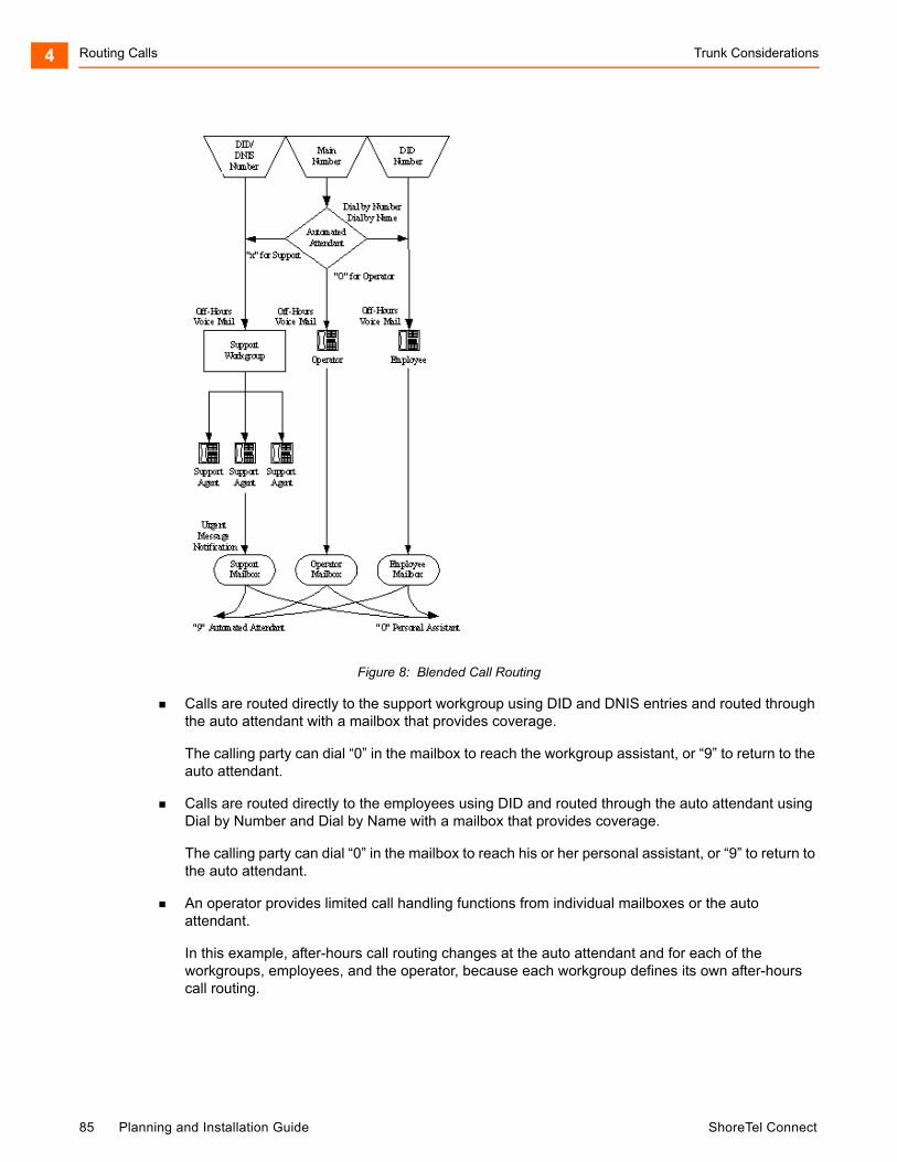
Routing Calls Trunk Considerations4
Figure 8: Blended Call Routing
Calls are routed directly to the support workgroup using DID and DNIS entries and routed through the auto attendant with a mailbox that provides coverage.
The calling party can dial “0” in the mailbox to reach the workgroup assistant, or “9” to return to the auto attendant.
Calls are routed directly to the employees using DID and routed through the auto attendant using Dial by Number and Dial by Name with a mailbox that provides coverage.
The calling party can dial “0” in the mailbox to reach his or her personal assistant, or “9” to return to the auto attendant.
An operator provides limited call handling functions from individual mailboxes or the auto attendant.
In this example, after-hours call routing changes at the auto attendant and for each of the workgroups, employees, and the operator, because each workgroup defines its own after-hours call routing.
85 Planning and Installation Guide ShoreTel Connect
Analyze Outbound Call Routing Routing Calls 4
Analyze Outbound Call Routing
In general, you should have trunks at every site that support both outbound and inbound calling. The following are general facts about outbound trunking:
ISDN PRI provides the most feature-rich inbound and outbound calling experience.
This includes the support for Caller ID, DID, and DNIS. Caller ID Number is supported for both inbound and outbound calls. Caller ID Name is supported only on inbound NI-2 trunks with the exception of outbound calls to off-system extensions.
SIP trunks can be used to place outbound calls.
Analog wink-start trunks do not support outbound calls.
You may want to purchase some analog loop-start trunks for emergency dial tone in case of total power failure. For more information, see Analog Loop-Start Trunks (North America) on page 91.
Calls can be automatically routed across your wide area network (WAN) using the Network Call Routing feature. This allows users to access local and nearby area codes at one site from another site.
You need to plan for emergency calls, such as 911 in the United States, on your voice system.
The ShoreTel Connect system supports all the necessary signaling for emergency calls, but note that in the case of a power failure you would need an analog loop-start trunk to have the dial tone needed to make an emergency call. Refer to the appendix on emergency 911 operations in the ShoreTel Connect System Administration Guide for information on how to configure your system for emergency calls.
If your system uses three-digit extensions, ShoreTel recommends that you do not assign x11 extensions to users.
For more information, see Trunk Planning and Ordering on page 88 and Dialing Plan on page 104.
ShoreTel Connect Planning and Installation Guide 86

Routing Calls Analyze Outbound Call Routing4
87 Planning and Installation Guide ShoreTel Connect
CHAPTER
5. Trunk Planning and Ordering
This chapter provides information about trunk planning and ordering in the following sections:
Recommendations .................................................................................................... 90
Reviewing and Selecting Trunk Types ...................................................................... 90
Analog Loop-Start Trunks (North America)......................................................... 91
Analog Loop-Start Trunks (EMEA) ..................................................................... 92
Digital Loop-Start Trunks .................................................................................... 92
Analog Wink-Start Trunks (Analog DID) ............................................................. 93
Digital Wink-Start Trunks .................................................................................... 93
BRI Trunks.......................................................................................................... 94
T1 PRI Trunks..................................................................................................... 94
E1 PRI Trunks .................................................................................................... 95
SIP Trunks .......................................................................................................... 95
Understanding Trunk Features.................................................................................. 96
Caller ID Number ................................................................................................ 97
Caller ID Name ................................................................................................... 97
Automatic Number Identification (ANI) ............................................................... 97
Direct Inward Dial (DID)...................................................................................... 98
Dialed Number Identification Service (DNIS)...................................................... 98
Outbound Caller ID............................................................................................. 99
Tandem Trunking ................................................................................................ 99
Tie Trunks ........................................................................................................... 99
Performing Traffic Calculations ............................................................................... 100
Ordering Telephone Service.................................................................................... 100
Analog Service ................................................................................................. 101
ShoreTel Connect Planning and Installation Guide 88

Trunk Planning and Ordering5
T1 Service ........................................................................................................ 101
T1 PRI Service ................................................................................................. 102
Ordering Service............................................................................................... 103
E1 PRI Service ................................................................................................. 103
89 Planning and Installation Guide ShoreTel Connect
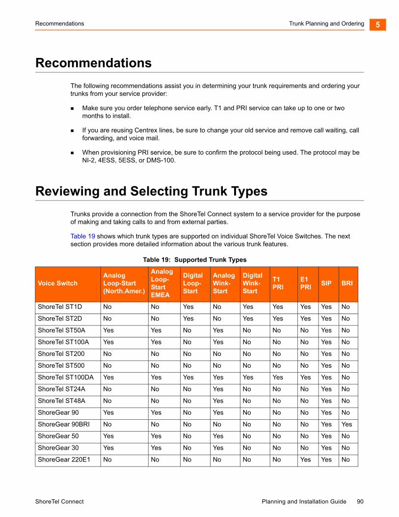
Recommendations Trunk Planning and Ordering 5
Recommendations
The following recommendations assist you in determining your trunk requirements and ordering your trunks from your service provider:
Make sure you order telephone service early. T1 and PRI service can take up to one or two months to install.
If you are reusing Centrex lines, be sure to change your old service and remove call waiting, call forwarding, and voice mail.
When provisioning PRI service, be sure to confirm the protocol being used. The protocol may be NI-2, 4ESS, 5ESS, or DMS-100.
Reviewing and Selecting Trunk Types
Trunks provide a connection from the ShoreTel Connect system to a service provider for the purpose of making and taking calls to and from external parties.
Table 19 shows which trunk types are supported on individual ShoreTel Voice Switches. The next section provides more detailed information about the various trunk features.
Table 19: Supported Trunk Types
Voice SwitchAnalogLoop-Start(North.Amer.)
AnalogLoop-StartEMEA
DigitalLoop-Start
AnalogWink-Start
DigitalWink-Start
T1PRI
E1PRI
SIP BRI
ShoreTel ST1D No No Yes No Yes Yes Yes Yes No
ShoreTel ST2D No No Yes No Yes Yes Yes Yes No
ShoreTel ST50A Yes Yes No Yes No No No Yes No
ShoreTel ST100A Yes Yes No Yes No No No Yes No
ShoreTel ST200 No No No No No No No Yes No
ShoreTel ST500 No No No No No No No Yes No
ShoreTel ST100DA Yes Yes Yes Yes Yes Yes Yes Yes No
ShoreTel ST24A No No No Yes No No No Yes No
ShoreTel ST48A No No No Yes No No No Yes No
ShoreGear 90 Yes Yes No Yes No No No Yes No
ShoreGear 90BRI No No No No No No No Yes Yes
ShoreGear 50 Yes Yes No Yes No No No Yes No
ShoreGear 30 Yes Yes No Yes No No No Yes No
ShoreGear 220E1 No No No No No No Yes Yes No
ShoreTel Connect Planning and Installation Guide 90

Trunk Planning and Ordering Analog Loop-Start Trunks (North America)5
Analog Loop-Start Trunks (North America)
Analog loop-start trunks are typically used for inbound calls to a main telephone number that are directed to an auto attendant menu, company operator, or workgroup. A caller can route a call from the auto-attendant to a user extension by entering the extension number or by spelling the user’s name from the telephone keypad. Analog loop-start trunks are also used to make outbound calls.
Analog loop-start trunks support the following:
Inbound calls
Outbound calls
Caller ID number
Caller ID name
Caller ID blocking
Analog provisioning is provided by the loop-start protocol and Dual-Tone Multi-Frequency (DTMF) signaling.
Analog loop-start trunks are used to provide power-fail transfer to selected telephones — for instance, to the operator, security station, executives, and so on. When there is a complete power failure, including loss of UPS power backup, power-fail transfer connects a specified trunk port to a specified extension port. This power-fail transfer ability provides a dial tone for making and taking critical calls in the event of power failure. Refer to the ShoreTel Connect System Administration Guide for more information about the power-fail transfer port on each ShoreTel Voice Switch that supports this feature.
Centrex lines are analog lines that can be used as analog loop-start trunks. Your organization may already have these installed, and want to use them instead of ordering new loop-start trunks. If you have Centrex lines and do not want to change your primary company telephone number, you can keep Centrex lines. Centrex lines support Caller ID. Be sure to remove the Centrex features, including call waiting, call forward, and voice mail.
ShoreGear 220T1 No No Yes No Yes Yes No Yes No
ShoreGear 220T1A Yes No Yes No Yes Yes No Yes No
ShoreGear T1k No No Yes No Yes Yes No Yes No
ShoreGear 120 Yes No No Yes No No No Yes No
ShoreGear 60 Yes No No Yes No No No Yes No
ShoreGear 40 Yes No No Yes No No No Yes No
ShoreGear E1 No No No No No No Yes No No
ShoreGear T1 No No Yes No Yes Yes No No No
Table 19: Supported Trunk Types (Continued)
Voice SwitchAnalogLoop-Start(North.Amer.)
AnalogLoop-StartEMEA
DigitalLoop-Start
AnalogWink-Start
DigitalWink-Start
T1PRI
E1PRI
SIP BRI
91 Planning and Installation Guide ShoreTel Connect

Analog Loop-Start Trunks (EMEA) Trunk Planning and Ordering 5
EMEA analog loop start trunk support, based on the TBR 21 standard, is supported on all 1U Half Width ShoreTel voice switches. BT type 1, or on hook, caller ID support is based on SIN 227 and SIN 242 standards in the UK.
Analog Loop-Start Trunks (EMEA)
Analog Loop-Start trunks are supported in Europe, the Middle East, and Africa. These trunks use the TBR 21 standard.
Analog loop-start Trunks (EMEA) are typically used for inbound calls to a main telephone number that are directed to an auto-attendant menu, company operator, or workgroup. A caller can route a call from the auto-attendant to a user extension by entering the extension number or by spelling the user’s name from the telephone keypad. Analog loop-start trunks are also used to make outbound calls.
Analog loop-start trunks (EMEA) support:
Inbound calls
Outbound calls
Analog provisioning is provided by the loop-start protocol and Dual-Tone Multi-Frequency (DTMF) signaling.
Analog loop-start trunks are used to provide power-fail transfer to selected telephones — for instance, to the operator, security station, executives, and so on. When there is a complete power failure, including loss of UPS power backup, the ShoreTel Voice Switches provides power-fail transfer. Refer to the ShoreTel Connect System Administration Guide for the power-fail transfer port on each ShoreTel Voice Switch that supports this feature. This power-fail transfer ability provides a dial tone for making and taking critical calls in the event of power failure.
Centrex lines are analog lines that can be used as analog loop-start trunks on the ShoreTel Voice Switches. Your organization may already have these installed, and want to use them instead of ordering new loop-start trunks. If you have Centrex lines and do not want to change your primary company telephone number, you can keep Centrex lines. Centrex lines support Caller ID. Be sure to remove the Centrex features, including call waiting, call forward, and voice mail.
Digital Loop-Start Trunks
Digital loop-start trunks are typically used for inbound calls to the main telephone number that are directed to an auto-attendant menu, company operator, or workgroup. A caller can route a call from the auto-attendant to a user extension by entering the extension number or by spelling the user’s name from the telephone keypad. Digital loop-start trunks are also used to make outbound calls.
Digital loop-start trunks support the following:
Inbound calls
Outbound calls
Caller ID number
Caller ID name
Caller ID blocking
ShoreTel Connect Planning and Installation Guide 92
Trunk Planning and Ordering Analog Wink-Start Trunks (Analog DID)5
Digital provisioning is provided by the loop-start protocol and Dual-Tone Multi-Frequency (DTMF) signaling. ShoreTel Voice Switches support the following:
ESF or D4 framing formats
B8ZS or AMI line coding
Analog Wink-Start Trunks (Analog DID)
Analog wink-start trunks allow external callers to dial a user’s phone number directly, without having to use an auto-attendant or operator. Analog wink-start trunks support only inbound calls; they are not capable of handling outbound calls.
Analog wink-start trunks support the following:
Inbound calls (outbound calls are not supported)
ANI
DID
DNIS
Analog provisioning is provided by the wink-start protocol and Dual-Tone Multi-Frequency (DTMF) signaling.
If ANI is being used, the star (*) key must be used to delimit the ANI digits from the DID/DNIS digits — that is:
<DID>
<DNIS>
*<ANI>*<DID/DNIS>*
Digital Wink-Start Trunks
Digital wink-start trunks allow external callers to dial a user’s phone number directly, without having to use an auto attendant or operator. Digital wink-start trunks support both inbound and outbound calls.
Digital wink-start trunks support the following:
Inbound calls
Outbound calls
ANI
DID
DNIS
Digital provisioning is provided by the wink-start protocol, which is often called E&M wink-start, and Dual-Tone Multi-Frequency (DTMF) signaling.
ShoreTel Voice Switches support the following:
ESF or D4 framing formats
B8ZS or AMI line coding
93 Planning and Installation Guide ShoreTel Connect
BRI Trunks Trunk Planning and Ordering 5
If ANI is being used, the star (*) key must be used to delimit the ANI digits from the DID/DNIS digits — that is:
<DID>
<DNIS>
*<ANI>*<DID/DNIS>*
BRI Trunks
BRI trunks are flexible trunks that support both inbound and outbound calls.
PRI trunks support the following:
Inbound calls
Outbound calls
DID
DNIS
Caller ID number
Caller ID name is supported for NI-2 configured trunks
QSIG – Calling name is supported if the standard is similar to NI2
Inbound calling name is fully supported, but outbound calling name is only supported for Off-System Extension calls
Digital provisioning is provided by the PRI protocol and D-channel signaling. ShoreTel Voice Switches support:
DMS-100, 4ESS, 5ESS, and NI-2 signaling types
ESF or D4 framing formats
B8ZS or AMI line coding.
The NFAS and Call-by-Call features are not supported.
T1 PRI Trunks
T1 PRI trunks are flexible trunks that support both inbound and outbound calls.
PRI trunks support the following:
Inbound calls
Outbound calls
DID
DNIS
Caller ID number
Caller ID name is supported for NI-2 configured trunks
QSIG – Calling name is supported if the standard is similar to NI2
Inbound calling name is fully supported, but outbound calling name is only supported for Off-System Extension calls
ShoreTel Connect Planning and Installation Guide 94
Trunk Planning and Ordering E1 PRI Trunks5
Digital provisioning is provided by the PRI protocol and D-channel signaling. ShoreTel Voice Switch supports the following:
DMS-100, 4ESS, 5ESS, and NI-2 signaling types
ESF or D4 framing formats
B8ZS or AMI line coding.
The NFAS and Call-by-Call features are not supported.
E1 PRI Trunks
E1 PRI trunks are flexible trunks that support both inbound and outbound calls for international locations.
E1 PRI trunks support the following:
Inbound calls
Outbound calls
DID
DNIS
Caller ID number
Caller ID name is supported for NI-2 configured trunks
QSIG – Calling name is supported if the standard is similar to NI2
Inbound calling name is fully supported, but outbound calling name is only supported for Off-System Extension calls
The ShoreTel Voice Switches support PRI signaling using Euro-ISDN as well as other international protocols. See International Planning and Installation on page 324.
SIP Trunks
SIP trunks are flexible trunks that support both inbound and outbound calls. SIP trunks are logical trunk end points that only handle SIP call control. Media flows directly between the call initiator and the call terminator.
SIP trunks support the following:
Inbound calls
Outbound calls
Extension, Tandem, and default destinations for inbound calls
Caller ID name
Caller ID number
DID
DNIS
By default, the Enable SIP Info for G711 DTMF signaling check box is not selected. This check box must be enabled for ShoreTel-to-ShoreTel SIP tie trunks or for SIP devices that do not support RFC 2833 for G711.
95 Planning and Installation Guide ShoreTel Connect
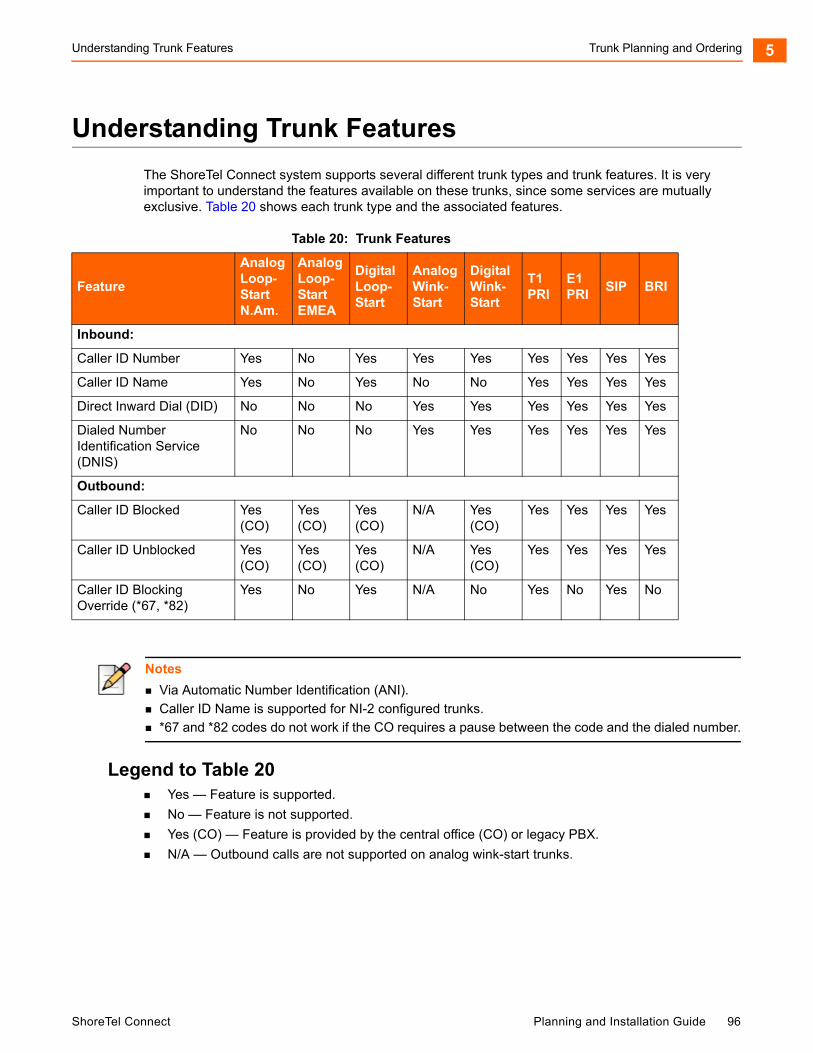
Understanding Trunk Features Trunk Planning and Ordering 5
Understanding Trunk Features
The ShoreTel Connect system supports several different trunk types and trunk features. It is very important to understand the features available on these trunks, since some services are mutually exclusive. Table 20 shows each trunk type and the associated features.
Legend to Table 20 Yes — Feature is supported.
No — Feature is not supported.
Yes (CO) — Feature is provided by the central office (CO) or legacy PBX.
N/A — Outbound calls are not supported on analog wink-start trunks.
Table 20: Trunk Features
Feature
Analog Loop-Start N.Am.
Analog Loop- Start EMEA
Digital Loop- Start
Analog Wink- Start
Digital Wink- Start
T1 PRI
E1 PRI
SIP BRI
Inbound:
Caller ID Number Yes No Yes Yes Yes Yes Yes Yes Yes
Caller ID Name Yes No Yes No No Yes Yes Yes Yes
Direct Inward Dial (DID) No No No Yes Yes Yes Yes Yes Yes
Dialed Number Identification Service (DNIS)
No No No Yes Yes Yes Yes Yes Yes
Outbound:
Caller ID Blocked Yes (CO)
Yes (CO)
Yes (CO)
N/A Yes (CO)
Yes Yes Yes Yes
Caller ID Unblocked Yes (CO)
Yes (CO)
Yes (CO)
N/A Yes (CO)
Yes Yes Yes Yes
Caller ID Blocking Override (*67, *82)
Yes No Yes N/A No Yes No Yes No
Notes
Via Automatic Number Identification (ANI).
Caller ID Name is supported for NI-2 configured trunks.
*67 and *82 codes do not work if the CO requires a pause between the code and the dialed number.
ShoreTel Connect Planning and Installation Guide 96
Trunk Planning and Ordering Caller ID Number5
Caller ID Number
Caller ID Number delivers to the ShoreTel Connect system the number of the calling party, which is displayed in the ShoreTel Connect client as well as on Caller ID – compatible telephones. The delivery of the caller ID number can be blocked by the calling party. The caller ID number is delivered unless the calling party has blocked the call, in which case the call is marked as Blocked, or the service provider does not have the information, in which case the call is marked as Unavailable.
Caller ID Number has the following limitations:
The calling party may block his or her caller ID number.
The calling party may be calling from a business and the calling number may be incorrect.
The calling party may be calling from someone else’s number.
Caller ID Number is available on analog loop-start, digital loop-start, SIP, T1 PRI, and E1 PRI trunks.
Two different Caller ID Number formats are used to deliver caller information via loop-start trunks: Single Data Message Format (SDMF) and Multiple Data Message Format (MDMF). SDMF provides the calling number, while MDMF provides any combination of calling name and number. The ShoreTel voice switches support both SMDF and MDMF dynamically, without the need for configuration. When PRI is used, the caller ID number is delivered as a D-Channel message.
ShoreTel supports International Caller ID, ensuring that when a switch is configured for a certain site (for example, Spain), the International ID information is automatically filled in as appropriate for that country. The feature is transparent from the user's standpoint, and no configuration is necessary.
Caller ID Name
Caller ID Name delivers the name of the calling party to the ShoreTel Connect system. The name is displayed in the ShoreTel Connect client as well as on any telephones that support caller ID Name.
By default, the caller ID name is delivered unless the calling party has blocked the transfer of this information, in which case the call is marked as “Blocked”. If the service provider does not have the information, the call is marked as “Unavailable.”
Caller ID Name is available on analog loop-start and digital loop-start trunks, as well as SIP, T1 PRI, and E1 PRI trunks and is only supported on IP phone and analog phones in North America. This feature is not supported on analog phones in other countries.
When using NI-2 signaling on PRI trunks — for example in a tie-trunk scenario — Caller-ID Name is now also captured when available on all inbound calls. For outbound calls, Caller-ID Name is delivered for calls that are made to off-system extensions, but not for outbound calls.
Automatic Number Identification (ANI)
Automatic Number Identification (ANI) delivers the number of the calling party to the ShoreTel Connect system. Although similar to Caller ID Number, ANI is tariffed differently and is not subject to the same blocking restrictions as Caller ID Number. For example, when you purchase ANI services from your service provider, you are always delivered the calling number for 800-number calls. Business practices can vary from region to region.
97 Planning and Installation Guide ShoreTel Connect
Direct Inward Dial (DID) Trunk Planning and Ordering 5
ANI is available on analog wink-start and digital wink-start trunks.
When ANI is being used, the star key (*) must be used to delimit the ANI digits from the DID/DNIS digits — that is, *<ANI>*<DID/DNIS>*.
Direct Inward Dial (DID)
Direct Inward Dial (DID) allows extensions on the system, such as users, menus, workgroups, route points, and so on, to be accessed directly, without the need of an auto-attendant or operator. This is particularly useful when users on the system want their own telephone number.
DID is available on analog wink-start, digital wink-start, PRI and SIP trunks.
DID numbers are ordered in blocks of 20 or more 10-digit telephone numbers. These numbers are assigned to a customer and are routed to a wink-start, PRI or SIP trunk connected to a voice switch. When a call is made, the service provider sends a predefined set of digits, from 3 to 10 digits, via the wink-start, PRI, or SIP trunk. The voice switches capture the digits and route the calling party to the called party.
If ANI is not being used on wink-start trunks, only the DNIS digits need to be delivered. If ANI is being used, the star (*) key must be used to delimit the ANI digits from the DID/DNIS digits as follows:
<DID>
<DNIS>
*<ANI>*<DID/DNIS>*
Dialed Number Identification Service (DNIS)
Dialed Number Identification Service (DNIS) allows extensions on the system, such as users, menus, workgroups, route points, and so on, to be accessed directly without the need for an auto attendant or operator. This is particularly useful for workgroup and other call center applications. The DNIS information is delivered to the ShoreTel Connect client - Personal Access and stored in the call detail record.
DNIS is available on analog wink-start, digital wink-start, PRI, and SIP trunks.
DNIS numbers are ordered individually and map to a dialed number. When a calling party dials a specific telephone number, the service provider routes the call to a wink-start or PRI trunk connected to a voice switch. The service provider sends a predefined set of digits, from 3 to 10 digits — the DNIS digits — using DTMF signaling or a D-Channel message or SIP message. The voice switches capture the digits and route the calling party to the called party.
If ANI is not being used on wink-start trunks, only the DNIS digits need to be delivered. If ANI is being used, the star (*) key must be used to delimit the ANI digits from the DID/DNIS digits as follows:
<DID>
<DNIS>
*<ANI>*<DID/DNIS>*
ShoreTel Connect Planning and Installation Guide 98
Trunk Planning and Ordering Outbound Caller ID5
Outbound Caller ID
ShoreTel sends the user’s DID number as the caller ID number for outbound calls over PRI or SIP trunks. If the DID number is unavailable, the site Caller Emergency Service ID (CESID) is used. If that number is unavailable, no caller ID is sent.
Additionally, the outbound caller ID can be configured on a per-user basis such that the configured value can take precedence over the user's DID number or the site CESID. Note that this feature is only available on outbound calls using a T1 PRI trunk.
To send a single main number rather than individual user DID numbers, assign DNIS entries instead of DID numbers to each user. The Site Contact Number will be sent on outbound calls.
To block all outbound caller ID numbers from being sent, you can configure the PRI trunk group to always block the caller ID number.
On wink-start and loop-start trunks, the outbound caller ID is defined by the service provider.
On T1 PRI and loop-start trunks, users can override the Caller ID Blocking configuration on a call-by-call basis by using commands at the telephone, such as *67, *82. Users cannot override the Caller ID Blocking configuration of wink-start and E1 PRI trunks.
For more information on configuring outbound caller ID, please refer to the ShoreTel Connect System Administration Guide.
Tandem Trunking
Tandem trunking allows legacy voice systems to utilize a ShoreTel Connect system for outbound dialing. The ShoreTel Connect system supports both user-side and network-side PRI, allowing ShoreTel Connect systems to flexibly support digital tie trunks to other systems.
You can enable tandem trunking support for any PRI trunk group with a check box in ShoreTel Connect Director. Tandem calls are associated with a user group for outbound trunk selection. Inbound calls recognized as tandem calls are redirected to an outbound trunk based on user group call permissions and trunk group access. When needed, a “dial-in prefix” can be specified that is prepended to digits collected on tandem calls. The concatenated set of digits is then used in outbound trunk selection for the tandem call.
Tie Trunks
The addition of network-side PRI support makes PRI tie trunks easier and more compelling to deploy. ShoreTel Voice Switches that support T1 PRI can act as either the user-side or network-side of a PRI tie trunk. The tie trunk may be used to tie a ShoreTel Connect system to a legacy voice system, or potentially to another independent ShoreTel Connect system.
99 Planning and Installation Guide ShoreTel Connect
Performing Traffic Calculations Trunk Planning and Ordering 5
Performing Traffic Calculations
The number of trunks required on your system will vary depending on the number of users and your specific application needs. It is important to order your trunking correctly; too few can lead to blocked calls when all trunks are busy, and too many trunks can lead to wasted money on monthly access charges.
For information about calculating the trunk requirements, refer to Planning and System Design on page 22.
Ordering Telephone Service
Once you have determined the types of trunks you need, you will have to either place a new order or make a change order. You can use the associated Telephone Service Order Forms that are available on the ShoreTel USB flash drive or on the ShoreTel support web site. Three order forms are provided for your use:
Analog Service
T1 Service
T1 PRI Service
ShoreTel does not provide an E1 PRI form because this service varies by country. Instead, we provide a table of the E1 PRI parameters that must be set. See International Planning and Installation on page 324, for more information.
When the form is completed, arrange a meeting with your telephone company service representative to order the new telephone services. The forms contain specific information that the service representative must have before services can be ordered.
Before ordering your telephone service, pay special attention to the installation date and time, as follows:
If you are ordering new service, it should be installed one week before the planned cut-over date. This allows the services to be terminated on the ShoreTel Connect system and tested before cut-over.
If you are changing existing service, any changes before the cut-over date might render your existing service unusable. You must schedule these changes outside normal business hours and work closely with your service provider for a seamless transition.
When ordering DID service, the last digits of the DID numbers should match your extension numbers for ease of use. You must make sure your extension numbers do not begin with a trunk access code, zero, or any emergency numbers such as 911 in North America.
Please see the appendix on emergency 911 operations in the ShoreTel Connect System Administration Guide for information on how to configure your system for emergency calls.
ShoreTel Connect Planning and Installation Guide 100
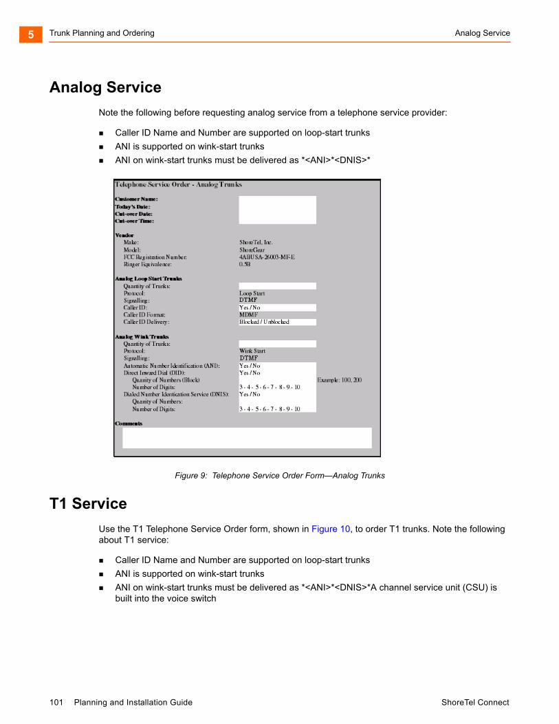
Trunk Planning and Ordering Analog Service5
Analog Service
Note the following before requesting analog service from a telephone service provider:
Caller ID Name and Number are supported on loop-start trunks
ANI is supported on wink-start trunks
ANI on wink-start trunks must be delivered as *<ANI>*<DNIS>*
Figure 9: Telephone Service Order Form—Analog Trunks
T1 Service
Use the T1 Telephone Service Order form, shown in Figure 10, to order T1 trunks. Note the following about T1 service:
Caller ID Name and Number are supported on loop-start trunks
ANI is supported on wink-start trunks
ANI on wink-start trunks must be delivered as *<ANI>*<DNIS>*A channel service unit (CSU) is built into the voice switch
101 Planning and Installation Guide ShoreTel Connect
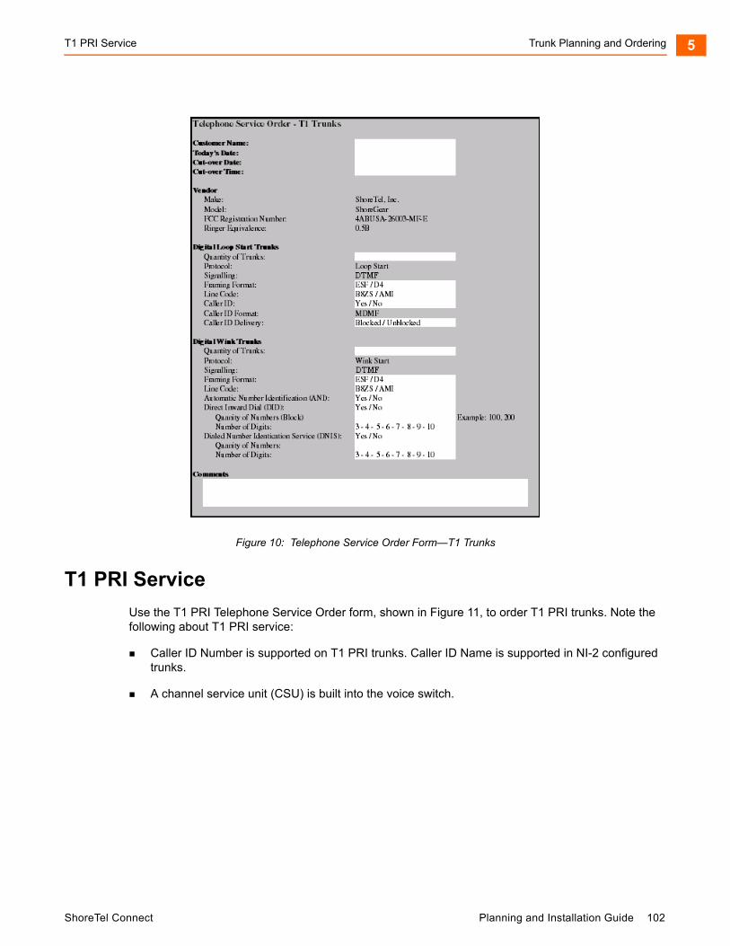
T1 PRI Service Trunk Planning and Ordering 5
Figure 10: Telephone Service Order Form—T1 Trunks
T1 PRI Service
Use the T1 PRI Telephone Service Order form, shown in Figure 11, to order T1 PRI trunks. Note the following about T1 PRI service:
Caller ID Number is supported on T1 PRI trunks. Caller ID Name is supported in NI-2 configured trunks.
A channel service unit (CSU) is built into the voice switch.
ShoreTel Connect Planning and Installation Guide 102
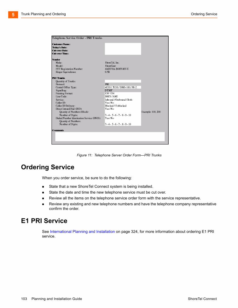
Trunk Planning and Ordering Ordering Service5
Figure 11: Telephone Server Order Form—PRI Trunks
Ordering Service
When you order service, be sure to do the following:
State that a new ShoreTel Connect system is being installed.
State the date and time the new telephone service must be cut over.
Review all the items on the telephone service order form with the service representative.
Review any existing and new telephone numbers and have the telephone company representative confirm the order.
E1 PRI Service
See International Planning and Installation on page 324, for more information about ordering E1 PRI service.
103 Planning and Installation Guide ShoreTel Connect

CHAPTER
6. Dialing Plan
This chapter provides an overview of the dialing, call routing, and digit-manipulation capabilities of the ShoreTel Connect system in the following sections:
Overview ................................................................................................................. 105
Dialing ..................................................................................................................... 105
Define Digit Collection ...................................................................................... 105
Configuring Internal Numbers........................................................................... 105
Configuring External Numbers ......................................................................... 107
Define Digit Manipulation.................................................................................. 109
On-Net Dialing .................................................................................................. 111
Quick Reference of Star Codes............................................................................... 114
Common Star Codes ........................................................................................ 114
Extension Assignment Star Codes ................................................................... 115
Trunk Star Codes.............................................................................................. 116
ShoreTel Connect Planning and Installation Guide 104
Dialing Plan Overview6
Overview
This chapter provides an overview of the dialing, call routing, and digit-manipulation capabilities of the ShoreTel Connect system. The information in this chapter is useful for administrators of larger, multisite installations.
Dialing
When a phone number is dialed in a ShoreTel Connect system, the system performs two distinct operations on a telephone number:
Digit collection — Voice switches collect the digits in a telephone number.
Digit manipulation — The switches manipulate the dialed numbers before outpulsing them to the service provider.
Define Digit Collection
When someone picks up a telephone in a ShoreTel Connect system and begins dialing a telephone number, the voice switch software (or, on ShoreTel 400-Series IP phones, the phone software) examines each digit in the number and determines whether digit collection should continue or be terminated.
Configuring Internal Numbers
In a ShoreTel Connect system where users dial internal numbers without an access code, the rules for digit collection are relatively straightforward.
Digit collection rules are configured through ShoreTel Connect Director.
Planning Your Dialing Configuration
When setting up a dialing plan for internal numbers, you need to consider the following:
Choose an extension length. ShoreTel Connect supports 3-, 4-, and 5-digit dialing for internal numbers. For most enterprises, 4-digit dialing works. Use an extension number scheme that conforms to your company’s size and the convenience of your users.
Map extension ranges. After choosing the extension length, you can allocate blocks of numbers for use by extension, starting with the first number.
For example, if you want to reserve the range of numbers 3000-3999 for extension assignment, you allocate the “3” number block for extensions.
For maximum usability, map extension numbers to the final digits of your DID (if DID is used).
105 Planning and Installation Guide ShoreTel Connect
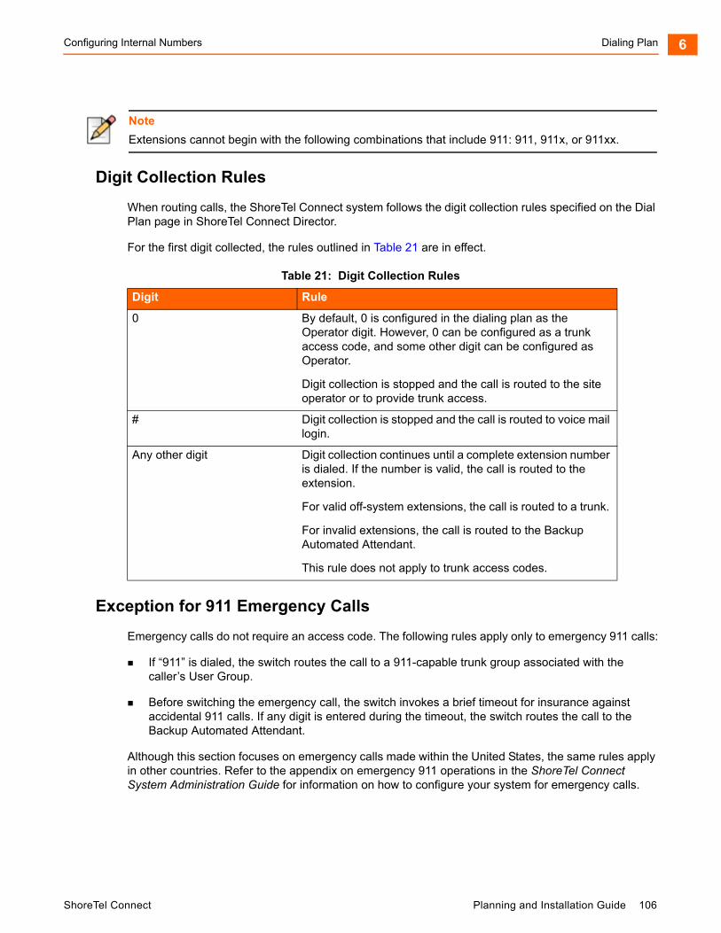
Configuring Internal Numbers Dialing Plan 6
Digit Collection Rules
When routing calls, the ShoreTel Connect system follows the digit collection rules specified on the Dial Plan page in ShoreTel Connect Director.
For the first digit collected, the rules outlined in Table 21 are in effect.
Exception for 911 Emergency Calls
Emergency calls do not require an access code. The following rules apply only to emergency 911 calls:
If “911” is dialed, the switch routes the call to a 911-capable trunk group associated with the caller’s User Group.
Before switching the emergency call, the switch invokes a brief timeout for insurance against accidental 911 calls. If any digit is entered during the timeout, the switch routes the call to the Backup Automated Attendant.
Although this section focuses on emergency calls made within the United States, the same rules apply in other countries. Refer to the appendix on emergency 911 operations in the ShoreTel Connect System Administration Guide for information on how to configure your system for emergency calls.
Note
Extensions cannot begin with the following combinations that include 911: 911, 911x, or 911xx.
Table 21: Digit Collection Rules
Digit Rule
0 By default, 0 is configured in the dialing plan as the Operator digit. However, 0 can be configured as a trunk access code, and some other digit can be configured as Operator.
Digit collection is stopped and the call is routed to the site operator or to provide trunk access.
# Digit collection is stopped and the call is routed to voice mail login.
Any other digit Digit collection continues until a complete extension number is dialed. If the number is valid, the call is routed to the extension.
For valid off-system extensions, the call is routed to a trunk.
For invalid extensions, the call is routed to the Backup Automated Attendant.
This rule does not apply to trunk access codes.
ShoreTel Connect Planning and Installation Guide 106
Dialing Plan Configuring External Numbers6
Changing Extension Length
The ShoreTel Connect system supports 3-, 4-, and 5-digit extensions. If your system uses 3-digit extensions, ShoreTel recommends that you do not assign x11 extensions to users.
Configuring External Numbers
The ShoreTel Connect system supports 1-, 2-, and 3-digit trunk access codes. When an access code is dialed, the system looks for a valid digit in the parameters.
If an invalid number is dialed, the system plays a recording to the calling party.
There are several types of valid telephone numbers, which are described in the following sections.
The ShoreTel Connect system allows the system administrator to provide users at each site with a unique dialing plan to match the dialing plan of the site’s geographic region. The ShoreTel Connect system supports 7-digit local dialing, 10-digit local dialing, and mixed local dialing.
External numbers are converted into a standard “canonical format” by call control software to provide a globally consistent way of handling phone numbers. The canonical format starts with a “+” representing the international prefix, followed by the country code, area code, and subscriber number.
External numbers that can be converted into canonical format are considered “routable” and will leverage the network call routing feature of the call control software.
External numbers that are unique to the country (n11, 112, 911, and so on) are considered “unroutable” and will not leverage the network call routing software. These calls will be placed from the local site or the associated proxy site.
Configuring 7-Digit Local Dialing
The Local Area Code on the Sites page defines 7-digit dialing for all users at the site. When a user dials an access code followed by 7 digits, the switching software assumes the site local area has been dialed. The switching software then converts the 7-digit number into canonical format before checking call permissions and doing network call routing.
The Local Area Code and Additional Local Area Codes set on the Sites page have nothing to do with the Local Area Code, Additional Local Area Codes, and Nearby Area Codes on the Trunk Groups page. The distinctions are as follows:
Area codes on the Sites page relate only to digit collection.
Area codes on the Trunk Groups page relate only to Network Call Routing and Digit Manipulation.
Note
Once you increase an extension length, you cannot decrease an extension length. For example, once it is increased to 4, the minimum is 4.
107 Planning and Installation Guide ShoreTel Connect

Configuring External Numbers Dialing Plan 6
To define 7-digit dialing, enter the 3-digit area code in the Local Area Code parameter on the Sites page (General tab) in ShoreTel Connect Director.
Configuring 10-Digit Local Dialing
If the site is in a location with overlay area codes, it can be configured to support 10-digit dialing for all the local area codes. The Additional local area codes parameter on the Sites page (General tab) in ShoreTel Connect Director defines the area codes for 10-digit dialing. When a user dials an access code followed by a local area code, the system collects 7 additional digits, which comes to 10 digits total, before stopping digit collection. The switching software then converts the 10-digit number into canonical format before checking call permissions and doing network call routing.
Configuring Mixed Dialing in the Same Area
In locations where users are forced to dial 7 digits for some prefixes and 1+10 digits for other prefixes in the same area, the ShoreTel Connect system supports permissive dialing — that is, you can dial these numbers either as 7 digits or as 1+10 digits. It also supports permissive dialing in locations with mixed 10-digit and 1+10 digit dialing in the same area.
From a digit-manipulation, or outpulsing, point of view, the trunk group must be configured properly because some service providers do not support permissive dialing. See Define Digit Manipulation on page 109.
1+10 Digit Long-Distance Dialing
The ShoreTel Connect system supports long-distance dialing. When a user dials an access code followed by “1,” the software collects 10 additional digits before stopping digit collection.
International Dialing
The ShoreTel Connect system supports international dialing. If the user dials a trunk access code followed by an international access code, digit collection is terminated after a timeout. The timeout can be bypassed by dialing pound (#).
n11 Dialing
The ShoreTel Connect system supports “n11” dialing, including 411 for information and 611 for support. If the user dials an access code followed by “n11,” digit collection is terminated after a brief timeout and the call is routed to a trunk.
If your system uses three-digit extensions, ShoreTel recommends that you do not assign x11 extensions to users.
911 Dialing
The ShoreTel Connect system supports 911 dialing to emergency services. If the user dials an access code followed by “911,” digit collection is terminated immediately and the call is routed to a trunk.
911 calls are routed out of the local site’s associated trunks. If there are no 911 trunks available at the local site, the call is routed via the designated proxy site.
ShoreTel Connect Planning and Installation Guide 108
Dialing Plan Define Digit Manipulation6
Explicit Carrier Selection (101xxxx) Dialing
The ShoreTel Connect system supports explicit carrier selection. If the user dials an access code followed by “101,” the next four digits collected are for explicit carrier selection (101xxxx). The carrier information is retained and passed to the trunk.The digits collected are treated as unroutable calls; the digits are routed “as-is” out either local site or proxy site trunks only.
Operator-Assisted (0, 00) Dialing
The ShoreTel Connect system supports operator-assisted dialing. If the user dials an access code followed by “0x,” digit collection is terminated after a brief timeout and the call is routed to a trunk.
Vertical Service Code (*67, *82) Dialing
The ShoreTel Connect system supports some vertical service codes for feature activation. If the user dials an access code and then the star (*) button, the system collects the subsequent digits and then terminates after a brief timeout. The digits collected are treated as unroutable calls — they are routed “as-is” out either local site or proxy site trunks only. If the trunk is a PRI or SIP trunk, the trunk strips and interprets *67 to block outbound Caller ID, and *82 to unblock outbound Caller ID.
End Digit Collection (#)
In some cases, digit collection ends after a timeout period. To bypass the timeout and immediately send the call, the caller presses the (#) button.
Define Digit Manipulation
Once the route decision has been made, the call is passed to the trunk. The dialed number, which is normally passed within the system in canonical format, is examined and manipulated based on the trunk group configuration. This ensures that the number can be properly received by the service provider.
First, the trunk access code dialed by the user is removed. If the number is in canonical format, which is local, long distance, ERC, or international, digit manipulation can occur. If the number is unroutable, which is n11, ECS, operator, and vertical service code numbers, digit manipulation, other than the dial-out prefix, is not applied.
You specify the trunk digit manipulation parameters on the Trunk Groups page (Outbound tab) in ShoreTel Connect Director. See Table 22 on page 110 for some guidelines. For more general information about configuring trunks, see the “Configuring Trunks” chapter of the ShoreTel Connect System Administration Guide.
109 Planning and Installation Guide ShoreTel Connect

Define Digit Manipulation Dialing Plan 6
Table 22: Digital Manipulation Options
Option Description Example
Remove leading 1 from 1+10D This option is required by some long-distance service providers that only accept numbers dialed as 10 digits.
AT&T typically only supports 10-digit dialing.
Remove leading 1 for Local Area Codes
This option is required by some local service providers that have mixed 10-digit and 1+10 digit dialing in the same area code. Local Area Codes include both the Local Area Code and Additional Local Area Codes configured against the trunk group.
Atlanta has three local area codes that must be dialed as 10 digits.
This could also be called “Dial 10 digits for Local Area Codes.”
Dial 7 digits for Local Area Code This option is required by some local service providers that have mixed 10-digit and 1+10 digit dialing in the same area code.
Massachusetts and Maine
Prepend this Dial Out Prefix The Dial Out Prefix is prepended to the number. This feature is typically used when connecting the ShoreTel Connect system to a legacy PBX system using a ShoreTel voice switch. The Dial Out Prefix enables the ShoreTel Connect system to seize a trunk on the legacy PBX. The Dial Out Prefix is not applied to Off-System Extensions.
Not applicable.
ShoreTel Connect Planning and Installation Guide 110
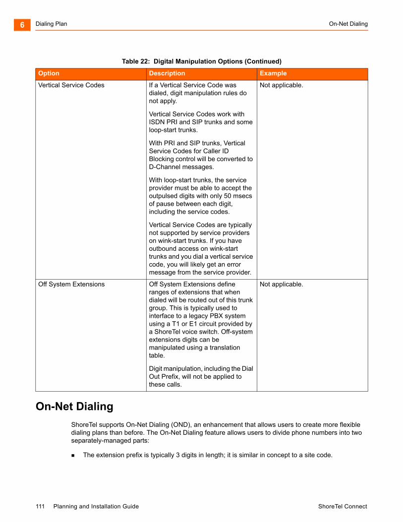
Dialing Plan On-Net Dialing6
On-Net Dialing
ShoreTel supports On-Net Dialing (OND), an enhancement that allows users to create more flexible dialing plans than before. The On-Net Dialing feature allows users to divide phone numbers into two separately-managed parts:
The extension prefix is typically 3 digits in length; it is similar in concept to a site code.
Vertical Service Codes If a Vertical Service Code was dialed, digit manipulation rules do not apply.
Vertical Service Codes work with ISDN PRI and SIP trunks and some loop-start trunks.
With PRI and SIP trunks, Vertical Service Codes for Caller ID Blocking control will be converted to D-Channel messages.
With loop-start trunks, the service provider must be able to accept the outpulsed digits with only 50 msecs of pause between each digit, including the service codes.
Vertical Service Codes are typically not supported by service providers on wink-start trunks. If you have outbound access on wink-start trunks and you dial a vertical service code, you will likely get an error message from the service provider.
Not applicable.
Off System Extensions Off System Extensions define ranges of extensions that when dialed will be routed out of this trunk group. This is typically used to interface to a legacy PBX system using a T1 or E1 circuit provided by a ShoreTel voice switch. Off-system extensions digits can be manipulated using a translation table.
Digit manipulation, including the Dial Out Prefix, will not be applied to these calls.
Not applicable.
Table 22: Digital Manipulation Options (Continued)
Option Description Example
111 Planning and Installation Guide ShoreTel Connect
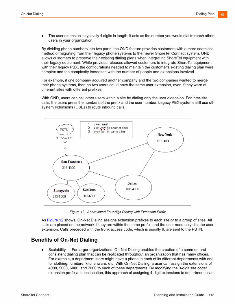
On-Net Dialing Dialing Plan 6
The user extension is typically 4 digits in length; it acts as the number you would dial to reach other users in your organization.
By dividing phone numbers into two parts, the OND feature provides customers with a more seamless method of migrating from their legacy phone systems to the newer ShoreTel Connect system. OND allows customers to preserve their existing dialing plans when integrating ShoreTel equipment with their legacy equipment. While previous releases allowed customers to integrate ShoreTel equipment with their legacy PBX, the configurations needed to maintain the customer's existing dialing plan were complex and the complexity increased with the number of people and extensions involved.
For example, if one company acquired another company and the two companies wanted to merge their phone systems, then no two users could have the same user extension, even if they were at different sites with different prefixes.
With OND, users can call other users within a site by dialing only the user extension. For inter-site calls, the users press the numbers of the prefix and the user number. Legacy PBX systems still use off-system extensions (OSEs) to route inbound calls.
Figure 12: Abbreviated Four-digit Dialing with Extension Prefix
As Figure 12 shows, On-Net Dialing assigns extension prefixes to each site or to a group of sites. All calls are placed on the network if they are within the same prefix, and the user need only dial the user extension. Calls preceded with the trunk access code, which is usually 9, are sent to the PSTN.
Benefits of On-Net Dialing
Scalability — For larger organizations, On-Net Dialing enables the creation of a common and consistent dialing plan that can be replicated throughout an organization that has many offices. For example, a department store might have a phone in each of its different departments with one for clothing, furniture, kitchenware, etc. With On-Net Dialing, a user can assign the extensions of 4000, 5000, 6000, and 7000 to each of these departments. By modifying the 3-digit site code/extension prefix at each location, this approach of assigning 4-digit extensions to departments can
ShoreTel Connect Planning and Installation Guide 112
Dialing Plan On-Net Dialing6
be replicated across an entire department store, nationwide, so that a user who knows the extension for the automotive department in one city could travel to another city and would know how to reach the automotive department if he knew the site code.
Preserve existing legacy dialing plans — To preserve the existing dialing plans when adding ShoreTel equipment to a deployment with legacy equipment, assign a new prefix to each new site or to users on the new ShoreTel Connect system.
Legacy integration via OSEs (Off-System Extensions) — Ability to call multiple legacy PBXs from the ShoreTel Connect system.
Multi-tenant — On-Net Dialing allows a landlord to maintain one phone system at a building that houses two or more businesses or organizations in such a way that neither organization is aware that the infrastructure or trunk lines are being shared. Despite the fact that both organizations are in the same building, you can assign different prefixes to each company and could then hide one organization's phone numbers from the other group so that neither group would see the other.
Configuration
The process of configuring On-Net Dialing consists of the following tasks:
Planning and configuring the dialing plan
Adding sites
Associating an extension prefix with a site
Assigning user extensions
The following sections include details for each of these tasks.
Planning and Configuring the Dialing Plan
Assigning extension prefixes to a specific digit must be done all at once. Once the dialing plan has been configured and saved, there is no way to make changes to the extension prefix assignments without erasing the database and starting all over. Therefore, we recommend carefully planning and reviewing your dialing plans before configuring the dialing plan window.
System extensions are not associated with a hard port in the system. They are always global and have a user number and a null extension prefix. Therefore, these system extensions are not affected by changes made to the extension prefix on the Dial Plan page in ShoreTel Connect Director. Only dialed numbers, such as user extensions, menus, workgroups, and distribution lists, are affected by changes to the extension prefix.
For details about configuring the dialing plan, see the ShoreTel Connect System Administration Guide.
Notes
ShoreTel’s Small Business Edition does not support On-Net Dialing.
Enabling On-Net Dialing is an irreversible process. It permanently changes the database. Therefore, plan carefully before proceeding with the configuration.
113 Planning and Installation Guide ShoreTel Connect

Quick Reference of Star Codes Dialing Plan 6
Adding Sites
You can add the sites via ShoreTel Connect Director before configuring your dialing plan, or you can configure your dialing plan and then add sites at a later time. For information about how to add sites, see the “ShoreTel Connect Sites” chapter of the ShoreTel Connect System Administration Guide.
Once you have created the dialing plan and saved your dialing plan configurations, you can return to the Sites page in ShoreTel Connect Director to verify that the changes have been propagated throughout the system.
Adding Users to the System
When the On-Net Dialing feature has been enabled and the extension prefix for a site has been updated, the first new user added to the system may not receive the site's new prefix. This issue is caused by cookies in the system populating the new user's extension with outdated information. However, after this first user has been added, subsequent users will have their extensions automatically populated with the correct site prefix.
Quick Reference of Star Codes
Certain features and functions can be performed via the telephone interface through the use of star codes. By pressing the star key, or asterisk, on your phone’s keypad, followed by a combination of numbers, you can perform many tasks that would otherwise require the use of a soft key, option button, or programmable button.
Common Star Codes
Note
User numbers can vary in length from 3 to 5 digits. All user numbers in the system must be the same length.
Table 23: Common Star Codes
Function Star Code
Park a call *11 + ext.
Unpark a call *12 + ext.
Picking Up a Remote Extension
*13 + ext.
Picking Up the Night Bell *14
Using the Intercom *15 + ext.
Barge In *16 + ext.
Silent Monitor *17 + ext.
ShoreTel Connect Planning and Installation Guide 114

Dialing Plan Extension Assignment Star Codes6
Extension Assignment Star Codes
Toggling the Hunt Group Status
*18 + Hunt Group ext.
Whisper Page *19 + ext.
Silent Coach *22 + ext.
Move a call *23 + ext.
Changing Availability State and Forwarding
VoiceMail + password +# + 72
Changing Extension Assignment
VoiceMail + password + # + 731
Unassign Extension Assignment
VoiceMail + password + # + 732
Assign Extension to External Number
VoiceMail + password + # + 733
Table 24: Extension Assignment Star Codes
Function Star Code
Transfer a call ** + destination + # #
Conference a call ** + destination + **
Hold a call **
Hang up # #
Access other “common” star codes
** + *star code (between 11 and 19) + ext.
Table 23: Common Star Codes(Continued)
Function Star Code
115 Planning and Installation Guide ShoreTel Connect
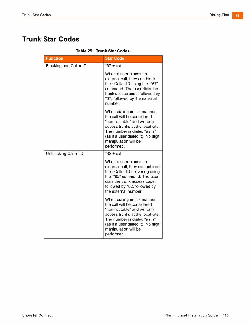
Trunk Star Codes Dialing Plan 6
Trunk Star Codes
Table 25: Trunk Star Codes
Function Star Code
Blocking and Caller ID *67 + ext.
When a user places an external call, they can block their Caller ID using the “*67” command. The user dials the trunk access code, followed by *67, followed by the external number.
When dialing in this manner, the call will be considered “non-routable” and will only access trunks at the local site. The number is dialed “as is” (as if a user dialed it). No digit manipulation will be performed.
Unblocking Caller ID *82 + ext.
When a user places an external call, they can unblock their Caller ID delivering using the “*82” command. The user dials the trunk access code, followed by *82, followed by the external number.
When dialing in this manner, the call will be considered “non-routable” and will only access trunks at the local site. The number is dialed “as is” (as if a user dialed it). No digit manipulation will be performed.
ShoreTel Connect Planning and Installation Guide 116

Dialing Plan Trunk Star Codes6
117 Planning and Installation Guide ShoreTel Connect

CHAPTER
7. Network Call Routing
This chapter provides an overview of call routing and digit-manipulation capabilities of the ShoreTel Connect system. The information in this chapter is particularly useful for administrators of larger, multisite installations. The topics discussed include the following:
Overview ................................................................................................................. 119
Define Network Call Routing ................................................................................... 119
Call Permissions............................................................................................... 119
Account Codes ................................................................................................. 120
Trunk Availability............................................................................................... 121
Specifying Parameters for the Routing Decision .............................................. 122
ShoreTel Connect Planning and Installation Guide 118
Network Call Routing Overview7
Overview
When a phone number is dialed in a ShoreTel Connect system, the system performs three distinct operations on the telephone number:
Digit collection — Voice switches collect the digits in a telephone number.
Network call routing — After collecting the digits, the switch checks the number against a user’s call permissions, adds trunks to the route list, and makes a final route decision for the call.
Digit manipulation — The switches manipulate the dialed numbers before outpulsing them to the service provider.
This chapter describes how to plan your network call routing.
Define Network Call Routing
Once an external telephone number has been collected, the switching software checks the number against the user’s call permissions, finds the list of available trunks, and then makes a routing decision based on several criteria.
Call Permissions
Each dialed number is compared against the user’s call permissions. If the call is denied, the calling party will be routed to a fast busy intercept tone. If the call is allowed, the routing continues.
Complete the following steps to define call permissions:
1. Launch ShoreTel Connect Director.
2. In the navigation pane, click Administration > Users > Class of Service > Call Permissions.
The Call Permissions page is displayed.
3. Click the name of the call permissions you want to edit.
The General tab in the details pane displays parameters for the selected call permissions.
4. Under Scope select the scope for the call permission.
5. In the Restrictions and Permissions fields, enter the desired restriction and permission rules, which are applied in addition to the scope setting. (Refer to the ShoreTel Connect System Administration Guide for guidelines about entering restrictions and permissions.)
119 Planning and Installation Guide ShoreTel Connect
Account Codes Network Call Routing 7
Account Codes
If Account Code Collection Service is enabled, when a user dials a number that is outside the scope of his or her call permissions, the call is automatically routed to the Account Code Collection Service extension on the Headquarters (HQ) server or Distributed Voice Server (DVS). The Account Code Collection Service captures call details that can be reviewed in the call detail reports. For more information on these reports, refer to the ShoreTel Connect System Administration Guide.
The collection of account codes is enabled on a per-user group basis and can be set to be one of three states: disabled, optional, or required.
The Account Code Collection Service is associated with a configurable extension and has a dedicated user group that defines ultimate call permissions and trunk group access.
When account code collection is enabled or required for a member of the user group, calls placed via the telephone or the ShoreTel Connect client are first filtered by call permissions. Calls restricted by call permissions are automatically routed to the extension associated with the Account Code Collection Service. Upon receiving the call, the Account Code Collection Service prompts the user to enter an account code and press the pound (#) key.
If the user enters an account code that does not match the digits in a stored account code, the system plays a message explaining the problem and prompts the user to re-enter the account code. When the user enters an account code that matches one of the stored codes, the code is collected, and the call is completed.
Call Permissions specifies the dialed numbers that are directed to the Account Code Collection Service for any user groups configured for account codes.
Calls redirected to the account codes extension are completed using the trunk access and call permissions associated with the Account Code Collection Service.
The Account Code Collection Service examines outbound calls against two sets of permissions:
The call permissions for the caller’s user group are checked to determine if an account code must be collected.
If user group permissions specify the collection of an account code, a check is performed on the call permissions for the Account Code Collection Service to determine whether the call will be permitted or rejected.
If the call is rejected, the intercept tone is played.
The Account Code Collection Service is associated with a system extension hosted on a SoftSwitch that runs on the HQ server or user’s managing DVS.
If the SoftSwitch is unavailable to the ShoreTel Voice Switch from which a call originates, the call is handled according to the permissions set for the caller’s user group. Calls placed by users who are configured for optional account code collection are placed. Calls placed by users who are configured for required account code collection are rejected.
Wildcard characters, which are represented with a question mark, can be used in place of DTMF digits in the account code. When wildcards are used, a length check is performed instead of a more thorough validation of the code. Although this reduces the stringency of the validation process, it allows the system to support a large number of account codes.
ShoreTel Connect Planning and Installation Guide 120
Network Call Routing Trunk Availability7
For more information about account codes and account code wildcards, refer to the “Setting Call Control Options” chapter in the ShoreTel Connect System Administration Guide.
Trunk Availability
For a trunk to be included in the list of possible trunks that can be hunted, the following conditions must apply:
The trunk must have an access code that matches the access code dialed.
The trunk must be assigned to the user. Trunk groups are assigned to user groups.
The trunk must be capable of the requested service — Local, Long Distance, International, n11, 911, Easily Recognizable Codes, Explicit Carrier Selection, and Operator Assisted. These services are defined on the Trunk Groups page.
The trunk must be in service.
The trunk must not already be in use.
The trunk must be on a switch that the user’s switch can reach, meaning the network is up and running.
For multisite calls, the admission control must be met at both sites. Admission control is defined on the Sites page.
If the call is long distance from the trunk, it was not local to the caller. For example, network call routing will not send a local call via a trunk in another state.
Defining Trunk Services
1. Launch ShoreTel Connect Director.
2. In the navigation pane, click Administration > Trunks > Trunk Groups.
The Trunk Groups page is displayed.
3. In the list pane, click the name of the trunk group you want to edit.
The General tab in the details pane displays parameters for the selected trunk group.
4. Select the Outbound tab.
5. Under Trunk services, select the check box next to each service to enable for the selected trunk.
Refer to the ShoreTel Connect System Administration Guide for more information about configuring trunk groups.
Defining Admission Control
1. Launch ShoreTel Connect Director.
2. In the navigation pane, click Administration > System > Sites.
121 Planning and Installation Guide ShoreTel Connect

Specifying Parameters for the Routing Decision Network Call Routing 7
The Sites page is displayed.
3. In the list pane, click the name of the site you want to edit.
4. In the Admission control bandwidth field, enter the desired value.
Refer to the ShoreTel Connect System Administration Guide for more information about configuring sites and for instructions about computing admission control bandwidth.
Specifying Parameters for the Routing Decision
After the available set of trunks is established, the switching software makes a routing decision, with the goal of minimizing toll charges and WAN bandwidth. The Network Call Routing algorithm bases the routing decision on the Local Area Code, Additional Local Area Codes, and Nearby Area Codes defined on the Trunk Groups page.
Network Call Routing Algorithm
When multiple trunks meet the same criteria, a trunk is seized randomly. In general, trunks that are configured last are hunted first. Over time, however, as trunks are deleted and added, hunting becomes increasingly random.
SIP trunks are given precedence over digital trunks, which are given precedence over analog trunks in all routing decisions. When determining the routing decision, the algorithm poses the following questions:
1. Is there a trunk at the originating site for which the call is local?
2. Is there a trunk at the proxy site for which the call is local?
3. Is there a trunk at any other site for which the call is local?
4. Is there a trunk at the originating site for which the call is considered nearby?
5. Is there a trunk at the proxy site for which the call is considered nearby?
6. Is there a trunk at any other site for which the call is considered nearby?
7. Is there a trunk at the originating site designated for long distance?
8. Is there a trunk at any proxy site designated for long distance?
9. Is there a trunk at any other site designated for long distance?
10. Are there any remaining trunks available at originating site?
11. Are there any remaining trunks available at the proxy site?
Specifying Parameters for the Routing Decision
1. Launch ShoreTel Connect Director.
2. In the navigation pane, click Administration > Trunks > Trunk Groups > Trunk Groups.
ShoreTel Connect Planning and Installation Guide 122

Network Call Routing Specifying Parameters for the Routing Decision7
The Trunk Groups page is displayed.
3. In the list pane, click the name of the trunk group you want to edit.
The General tab in the details pane displays parameters for the selected trunk group.
4. Select the Outbound tab.
5. Select the Outgoing check box.
6. Enter values in the Local Area Code, Additional Local Area Codes, and Nearby Area Codes fields.
7. In the Local prefixes list, select the local prefix exceptions list to use for the selected trunk group.
You can create and edit local prefix lists on the Local Prefixes page (Administration > System > Local Prefixes). The Network Call Routing algorithm handles prefix exceptions for the local area code as long distance, which minimizes toll charges.
Refer to the ShoreTel Connect System Administration Guide for more information about the Trunk Groups page and the Local Prefixes page.
The area codes on the Sites page have no impact on call routing decisions.
123 Planning and Installation Guide ShoreTel Connect

CHAPTER
8. Planning Applications andServices
This chapter reviews the key ShoreTel Connect applications and services to use to plan your system configuration and determine the equipment you need for completing deployment. The topics discussed include the following:
Account Code Collection Service............................................................................ 126
Account Codes ................................................................................................. 126
Call Permissions............................................................................................... 127
Distributed Voice Mail ....................................................................................... 127
Escalation Notifications .................................................................................... 129
Auto-Deletion of Voice Mail Messages ............................................................. 129
Mailbox Full Notifications.................................................................................. 129
AMIS Protocol Support ..................................................................................... 129
SMDI Protocol Support ..................................................................................... 130
Find Me Call Handling ...................................................................................... 131
Call Sender....................................................................................................... 132
Time Stamps..................................................................................................... 132
Planning Fax Handling ............................................................................................ 132
Fax Options ...................................................................................................... 132
Using a Fax Server ........................................................................................... 134
Private Numbers ..................................................................................................... 138
Conditions for Private Numbers........................................................................ 138
Auto Attendant ........................................................................................................ 138
Applications for the Auto-Attendant Menus ...................................................... 139
ShoreTel Connect Planning and Installation Guide 124

Planning Applications and Services8
Call Handling Delegation......................................................................................... 139
ShoreTel Connect Client for Desktops .................................................................... 139
Bridged Call Appearances ...................................................................................... 140
Switch Support for Bridged Call Appearances.................................................. 141
Hunt Groups............................................................................................................ 141
Hunt Group Busy State ..................................................................................... 142
Configurable Hunting........................................................................................ 142
Hunt Group Applications................................................................................... 142
Pickup Groups......................................................................................................... 144
Types of Extensions for Pickup Groups............................................................ 144
Workgroups............................................................................................................. 145
Agent Multiplicity............................................................................................... 145
Call Monitor and Barge In ................................................................................. 146
Enterprise Telephony Features ............................................................................... 148
Overhead Paging.............................................................................................. 151
Multi-site Paging Groups .................................................................................. 151
Night Bell .......................................................................................................... 152
Intercom............................................................................................................ 152
Call Recording .................................................................................................. 153
Make Me Conferencing ........................................................................................... 153
ShoreTel Connect Contact Center .......................................................................... 154
125 Planning and Installation Guide ShoreTel Connect
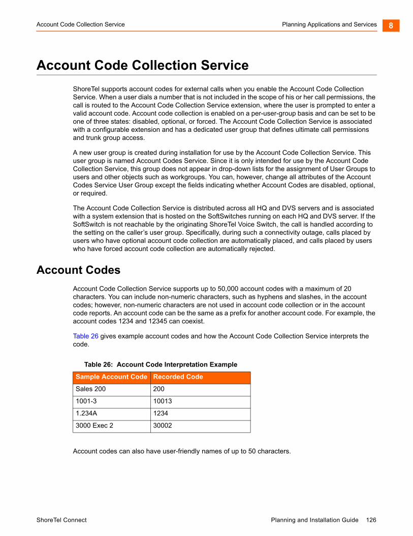
Account Code Collection Service Planning Applications and Services 8
Account Code Collection Service
ShoreTel supports account codes for external calls when you enable the Account Code Collection Service. When a user dials a number that is not included in the scope of his or her call permissions, the call is routed to the Account Code Collection Service extension, where the user is prompted to enter a valid account code. Account code collection is enabled on a per-user-group basis and can be set to be one of three states: disabled, optional, or forced. The Account Code Collection Service is associated with a configurable extension and has a dedicated user group that defines ultimate call permissions and trunk group access.
A new user group is created during installation for use by the Account Code Collection Service. This user group is named Account Codes Service. Since it is only intended for use by the Account Code Collection Service, this group does not appear in drop-down lists for the assignment of User Groups to users and other objects such as workgroups. You can, however, change all attributes of the Account Codes Service User Group except the fields indicating whether Account Codes are disabled, optional, or required.
The Account Code Collection Service is distributed across all HQ and DVS servers and is associated with a system extension that is hosted on the SoftSwitches running on each HQ and DVS server. If the SoftSwitch is not reachable by the originating ShoreTel Voice Switch, the call is handled according to the setting on the caller’s user group. Specifically, during such a connectivity outage, calls placed by users who have optional account code collection are automatically placed, and calls placed by users who have forced account code collection are automatically rejected.
Account Codes
Account Code Collection Service supports up to 50,000 account codes with a maximum of 20 characters. You can include non-numeric characters, such as hyphens and slashes, in the account codes; however, non-numeric characters are not used in account code collection or in the account code reports. An account code can be the same as a prefix for another account code. For example, the account codes 1234 and 12345 can coexist.
Table 26 gives example account codes and how the Account Code Collection Service interprets the code.
Account codes can also have user-friendly names of up to 50 characters.
Table 26: Account Code Interpretation Example
Sample Account Code Recorded Code
Sales 200 200
1001-3 10013
1.234A 1234
3000 Exec 2 30002
ShoreTel Connect Planning and Installation Guide 126
Planning Applications and Services Call Permissions8
Call Permissions
The call permissions define what dialed numbers are directed to the Account Codes Service for user groups configured with account codes. For calls that are redirected to the account codes extension, the call is completed with the trunk access and call permissions of the Account Codes Service.
This structure imposes two sets of permissions on outbound calls:
The call permissions for the user group of the user who places the call are used to determine if an account code must be collected or not.
The call permissions for the Account Codes Service determine whether calls are finally placed, or if the intercept tone is to be played.
Distributed Voice Mail
ShoreTel Distributed Voice Mail provides greater availability. Each ShoreTel Distributed Voice Server (DVS) has an instance of the telephony platform, allowing full functionality of voice mail and auto attendant services at that location during WAN outages. The Distributed Voice Mail feature allows users with mailboxes on that server to receive and pick up voice mail messages without having to depend on a WAN connection to the headquarters server that hosts the configuration database. The message waiting indicator (MWI) lights correctly update local users about voice mail with or without WAN connectivity.
Additionally, incoming calls reach the auto attendant, access the dial-by-name directory, and reach their intended local party during a WAN outage. If a party cannot be reached directly and his call handling setting would send unanswered calls to voice mail, the call is handled by the local voice mail server. If the user’s voice mailbox resides on a different voice mail server, the local ShoreTel server will accept, store, and forward the message when connectivity to the proper voice mail server is restarted. The caller hears a generic greeting, including the intended party's recorded name, and the caller has the option to leave a message. This message will be forwarded at a later time to the home voice mail server for the addressee via SMTP.
Although each voice mail server is autonomous in delivering voice services, it must have connectivity to the headquarters server in order to carry out configuration changes. Specifically, users on an isolated remote server are not able to change availability state or make other changes that require modification to the configuration database on the headquarters server.
The ShoreTel Connect client applications may provide limited call control access and may not display some contents on IP phones at a remote site during WAN outages. These both require connectivity to the headquarters server for full service. For users who have their ShoreTel Connect client application running at the time of a WAN outage, graphical access to their voice mail box is provided, including the ability to compose and playback messages, but ShoreTel Connect client may not display the corresponding call activity associated with any actions.
You should provision a DVS at any site with more than 100 users to effectively manage your WAN bandwidth between that site and the headquarters or main site. In addition, you must add a distributed server with the voice mail application at any site where the required number of mailboxes exceeds 1,000.
Users should be configured for the server that is located at their home or most frequent site. If that site does not have a server, the nearest server or headquarters server should be used.
127 Planning and Installation Guide ShoreTel Connect
Distributed Voice Mail Planning Applications and Services 8
When there are multiple voice mail servers, the system-wide voice mail extension automatically maps to the extension of the local server. Voice mail media streams are therefore recorded in the CDR reports by the voice mail extension that actually handles the call.
The ShoreTel Connect system provides each user with six availability states, and workgroups with four routing modes, allowing employees and workgroups to customize how calls are routed. Employees typically use the Available state to route calls to voice mail after three or four rings, and use the Out of the Office state to route calls directly to voice mail.
Users should consider the following:
Forwarding calls to a cell phone
Forwarding calls to an external answering service for critical users or workgroups
You must enable external call handling as part of the class of service for users who want to use these options.
To enable external call handling for a class of service:
1. Launch ShoreTel Connect Director.
2. Click Administration > Users > Class of Service > Telephony Features Permissions.
3. Select one of the following classes of service for which you want to enable external call handling:
Fully Featured
Minimally Featured
Partially Featured
4. Scroll down to the Silent monitor / Silent coach other's calls section.
5. Select the Allow external call forwarding and find me destinations option.
6. Click Save.
You have successfully enabled external call handling for the selected class of service.
The Message Notification feature delivers a notice to users that a message has arrived for them. Notifications can be sent upon receipt of all messages, or only upon receipt of urgent messages. The system can deliver a notification to the following destinations:
An E-mail address, which can also include a voice mail attachment in WAV format
A pager model that allows message notification
An extension that allows message playback
An external number, such as a cell phone if it allows message playback.
Users who address and compose voice mail through the Telephone User Interface (TUI), the Visual Voicemail application, or the Outlook Voicemail form can mark their messages with a request for a return receipt.
ShoreTel Connect Planning and Installation Guide 128
Planning Applications and Services Escalation Notifications8
Escalation Notifications
Similarly, the ShoreTel Connect system can send any of these notifications types to specific members of an escalation profile, in support of an Escalation Notification feature.
The Escalation Notifications feature is a traditional voice mail feature that allows support groups to offer round-the-clock service to their customers. For example, if a customer calls into the ShoreTel Connect system and leaves a message, the voice mail system sends out a page, phone call, or email to a designated employee in the support department. If this first employee ignores his beeping pager, the next designated employee within the escalation profile list is contacted, and so on.
Employees in the escalation profile will continue to be contacted sequentially until someone listens to the voice mail. Refer to the “Configuring Users” chapter in the ShoreTel Connect System Administration Guide for more information.
Auto-Deletion of Voice Mail Messages
The ShoreTel Connect system also supports the ability to automatically delete user voicemail messages that are older than a specified time limit. The system administrator can set a maximum time limit for the storage of voice mail messages, and if this time limit is exceeded, messages are automatically deleted. The tool can be used to encourage users to better manage their voice mailboxes.
Mailbox Full Notifications
The ShoreTel Connect system can be configured to notify users when their voice mailboxes are almost full. This features warns users of the impending lack of storage space to give them ample time to delete messages, as opposed to logging into their voice mailbox only to discover that the mailbox is full. Once a user’s mailbox has passed a threshold, the system sends a notice informing them that their mailbox is almost full and that there is only enough room for 10 additional messages. This prevents users from being caught off-guard by an unexpected notification that their mailbox is full.
Refer to the “Configuring Users” chapter in the ShoreTel Connect System Administration Guide.
AMIS Protocol Support
The ShoreTel Connect system can send and receive voice mail messages to and from legacy voice mail systems that use the AMIS protocol Version 1 - Specification; February 1992. To send voice mail messages to remote AMIS sites, ShoreTel dials the access phone number for the remote system. Likewise, to receive voice messages from a remote system, the remote system must know the number to dial into the ShoreTel Connect system. To reach the ShoreTel Connect system, the remote system must be configured to dial any number that reaches an auto-attendant menu.
Note
The ShoreTel Small Business Edition system does not support AMIS.
129 Planning and Installation Guide ShoreTel Connect
SMDI Protocol Support Planning Applications and Services 8
ShoreTel enables AMIS call support by default. Incoming AMIS voice mail is delivered in the same manner as other voice mail; however, replies cannot be sent. To send outbound AMIS voice mail, you must create AMIS systems in ShoreTel Connect Director.
ShoreTel negotiates the setup, handshaking, and teardown of AMIS system calls. Each voice mail requires a call over the AMIS delivery and call-back numbers.
Simplifying AMIS Systems, and Increasing Usability
To simplify AMIS systems and improve usability, adhere to the following guidelines:
Use the same extension length across your enterprise.
Use off-system extensions to match remote users’ mail boxes with their extension numbers.
To identify the remote site location, assign each system a System ID.
For more information on AMIS systems, refer to the ShoreTel Connect System Administration Guide.
SMDI Protocol Support
The ShoreTel Connect system supports the SMDI protocol. Two modes of operation are supported:
In the first mode of operation, the ShoreTel Connect system acts as a PBX for a legacy voice mail system. The ShoreTel Connect system provides call information for forwarded or direct calls to the legacy voice mail system, and receives incoming message waiting indication from the legacy voice mail system.
In the second mode of operation, the ShoreTel Connect system acts as the voice mail system for a number of users on a legacy PBX.
Both configurations require a serial link between a ShoreTel server and the legacy voice mail system, as this is the medium required by the SMDI protocol.
If using the first mode mentioned above, a group of analog trunks must be used to connect the ShoreTel Connect system to the legacy voice mail system where the ShoreTel Connect system is on the extension side of the trunks. The ShoreTel voice mail application manages the group of outgoing extensions. The ShoreTel server can provide digit translation if the legacy voice mail and ShoreTel Connect system have different extension lengths.
It is possible to have some ShoreTel users on the ShoreTel voice mail and some on the legacy voice mail. However, these users will not be able to send messages to each other unless AMIS is implemented between the two systems. Voice mailboxes for workgroups and agents must be on the ShoreTel voice mail system.
ShoreTel Connect client operates the same way it does when a user has no mailbox:
Voice mail viewer is not available
Windows Control Panel does not contain Voice Mail tab
Find Me and Notification features are not available
Dial Mailbox and Transfer to Mailbox are not available for this user from other user’s clients
To Voice Mail button on ShoreTel Connect client transfers the call to the system voice mail extension.
ShoreTel Connect Planning and Installation Guide 130

Planning Applications and Services Find Me Call Handling8
For more information about using a serial link and SMDI protocol to integrate the ShoreTel Connect system with a legacy voice mail system, refer to SMDI Protocol Support on page 299.
Find Me Call Handling
Find Me and Auto Find Me call handling allow callers to find users at other locations when they reach the user’s voice mail. When Find Me is enabled for the current availability state, inbound callers that reach a ShoreTel user's voice mail box can activate Find Me call handling by pressing “1.” If the caller activates Find Me call handling, the system plays a prompt indicating that it is now finding the called party: “Please hold while I try to find your party.”
ShoreTel users can specify two Find Me destinations, which can be internal or external numbers. These numbers can be enabled or disabled for each availability state. If a call is forwarded to the first number and is not answered within a configurable number of rings, the call can either be forwarded to a second Find Me destination or can be returned to voice mail.
The Caller ID that appears on Find Me calls is the voice mail Caller ID and not the ID of the original caller. However, if the source of the original call is external to the system, then the Caller ID will be displayed. Personal Assistant (pressing “0”) also works when Find Me forwarding is enabled. The voice mail system dials the configured Find Me numbers in sequence. When a Find Me call is answered, voice mail announces the call through a sequence of prompts.
The party that answers a Find Me call hears prompts similar to the following:
“I have a call for Sam Smith from 4085551212.”
“To accept this call, press one.”
“To send this call to voice mail, press two.”
“To repeat the caller ID, press three.”
The party at the Find Me number has three options for directing the call:
Pressing 1 connects the original caller with the intended party at the Find Me destination.
Pressing 2 directs the voice mail system to immediately start taking a message for the intended party from the original caller.
Pressing 3 repeats the Caller ID information available on the call, if any. This also extends the timeout by 1 ring, or 6 seconds.
The voice mail system does not automatically notify callers of the Find Me call handling option. ShoreTel users can elect to tell callers of the Find Me option in their recorded greeting. For example, they can tell callers to “press 1 to Find Me.” If the user does not tell callers about the Find Me option in their greeting, the Find Me option can remain a hidden capability available only to selected callers. Conversely, users can automate the Find Me behavior so that when a call enters voice mail and Auto Find Me is enabled, the call is immediately sent to the Find Me destination numbers without requiring any action on the part of the caller.
131 Planning and Installation Guide ShoreTel Connect

Call Sender Planning Applications and Services 8
Call Sender
Users can place a return call to the originator of a voice mail by pressing “5” from the phone during message playback. Users can also call back the voice mail sender from ShoreTel Connect client, Agent Monitor, or Microsoft Outlook, if the user is so provisioned. To use this feature, the user must belong to a user group with trunk-to-trunk transfer Class of Service enabled. For more information, see the ShoreTel Connect System Administration Guide.
The user has the option of replying with either a voice message or a phone call if Caller ID information is available on the call. If no Caller ID information is available for the call, such as on calls from an outside caller, the “reply with a call” option is not available for that message.
When the user chooses to reply with a phone call, the call is transferred to the number of the originating party. When the originating party is an external caller, the message recipient must have the dialing permission to dial the Caller ID number. Once the message recipient is transferred to the number of the message originator, there is no option to return to the mailbox.
Time Stamps
The time stamp of the message is relative to the time on the server where the message is taken, as shown in the following examples:
When the user views messages in the Voice Mail Viewer or Outlook Form, the user interface will adjust the time stamp based upon the time of the user’s computer.
When the user dials into voice mail to retrieve their messages, the time stamp will be based on the time of the server.
Planning Fax Handling
The ShoreTel Connect system supports fax calls. There are several ways to configure your fax service:
A direct fax number for each site
Direct fax numbers for each user using either individual fax machines or a fax server
Redirect faxes that are sent to the site’s main number to a fax machine extension at the site
Redirect faxes that are sent to a user’s extension to user’s local fax extension
Fax Options
Figure 13 shows how to plan your fax options.
ShoreTel Connect Planning and Installation Guide 132
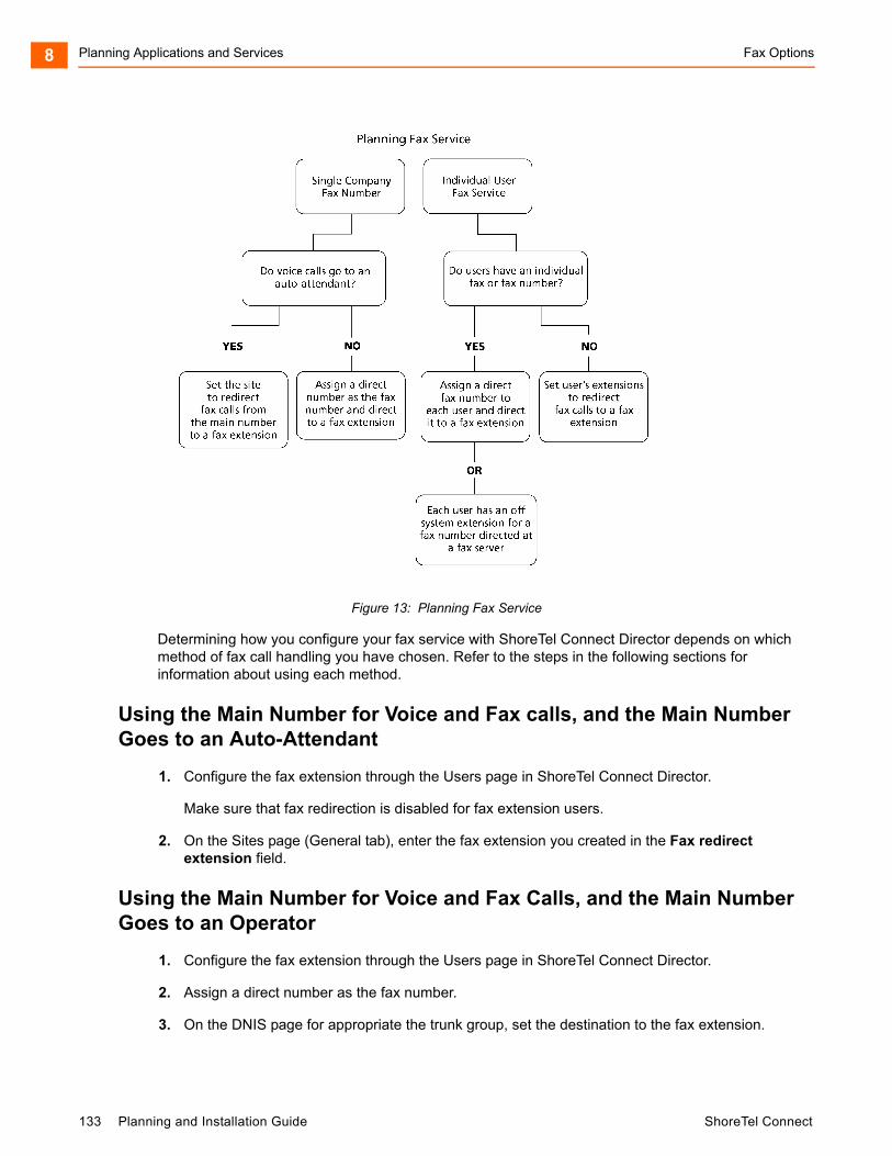
Planning Applications and Services Fax Options8
Figure 13: Planning Fax Service
Determining how you configure your fax service with ShoreTel Connect Director depends on which method of fax call handling you have chosen. Refer to the steps in the following sections for information about using each method.
Using the Main Number for Voice and Fax calls, and the Main Number Goes to an Auto-Attendant
1. Configure the fax extension through the Users page in ShoreTel Connect Director.
Make sure that fax redirection is disabled for fax extension users.
2. On the Sites page (General tab), enter the fax extension you created in the Fax redirect extension field.
Using the Main Number for Voice and Fax Calls, and the Main Number Goes to an Operator
1. Configure the fax extension through the Users page in ShoreTel Connect Director.
2. Assign a direct number as the fax number.
3. On the DNIS page for appropriate the trunk group, set the destination to the fax extension.
133 Planning and Installation Guide ShoreTel Connect
Using a Fax Server Planning Applications and Services 8
If Users Have Their own Faxes or Fax Service
1. Configure the fax extensions through the Users page in ShoreTel Connect Director.
2. Assign a range of direct fax numbers.
3. On the DNIS page for appropriate the trunk group, set the destination for each fax number to the appropriate fax extension.
If You Plan for Each User to Have a Single Number for Both Voice and Fax
1. Configure the fax extensions through the Users page in ShoreTel Connect Director.
2. On the Telephony tab of the Users page, enable fax redirection and then enable fax redirect for the site by entering a fax extension in the Fax redirect extension field on the Sites page.
For more information on these settings, refer to the ShoreTel Connect System Administration Guide.
Using a Fax Server
A fax server improves services available to your users, helping them be more productive. With a fax server, users can perform the following functions:
Send faxes directly from the desktop eliminating the need to print faxes to send.
Receive faxes directly on the desktop.
Integrate fax communications with e-mail and voice mail applications.
Have individual fax numbers
Maintain soft copies of all faxes for easy printing and document management
Using a fax server with the ShoreTel Connect system provides the following benefits:
Share inbound and outbound trunks for fax services.
Reduce toll charges by leveraging your VoIP network for outbound faxes.
For inbound fax support, users can be assigned a personal fax number from the DID range of one of the trunk groups and this DID number can be the same as the user’s regular telephone extension. When a call is received, if the fax redirect feature is enabled, the system can differentiate between voice calls and fax calls and react appropriately.
Outbound faxes are queued by the server and then sent across the IP network to the best available trunk.
Fax Server Requirements Sufficient ports on ShoreTel voice switches
Sufficient ShoreTel User Licenses
Sufficient DID trunks to support both fax and voice DID for all users
ShoreTel Connect Planning and Installation Guide 134
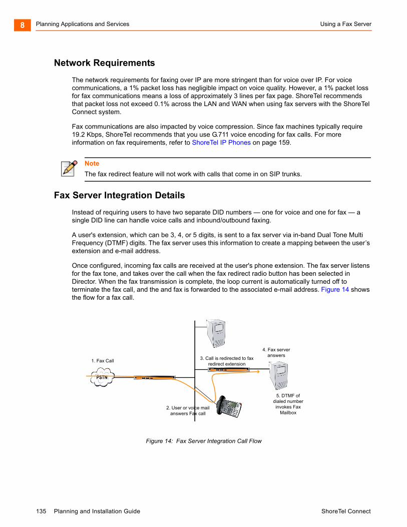
Planning Applications and Services Using a Fax Server8
Network Requirements
The network requirements for faxing over IP are more stringent than for voice over IP. For voice communications, a 1% packet loss has negligible impact on voice quality. However, a 1% packet loss for fax communications means a loss of approximately 3 lines per fax page. ShoreTel recommends that packet loss not exceed 0.1% across the LAN and WAN when using fax servers with the ShoreTel Connect system.
Fax communications are also impacted by voice compression. Since fax machines typically require 19.2 Kbps, ShoreTel recommends that you use G.711 voice encoding for fax calls. For more information on fax requirements, refer to ShoreTel IP Phones on page 159.
Fax Server Integration Details
Instead of requiring users to have two separate DID numbers — one for voice and one for fax — a single DID line can handle voice calls and inbound/outbound faxing.
A user's extension, which can be 3, 4, or 5 digits, is sent to a fax server via in-band Dual Tone Multi Frequency (DTMF) digits. The fax server uses this information to create a mapping between the user’s extension and e-mail address.
Once configured, incoming fax calls are received at the user's phone extension. The fax server listens for the fax tone, and takes over the call when the fax redirect radio button has been selected in Director. When the fax transmission is complete, the loop current is automatically turned off to terminate the fax call, and the and fax is forwarded to the associated e-mail address. Figure 14 shows the flow for a fax call.
Figure 14: Fax Server Integration Call Flow
Note
The fax redirect feature will not work with calls that come in on SIP trunks.
PSTNPSTN
1. Fax Call
2. User or voice mailanswers Fax call
3. Call is redirected to faxredirect extension
4. Fax serveranswers
5. DTMF ofdialed numberinvokes Fax
Mailbox
135 Planning and Installation Guide ShoreTel Connect
Using a Fax Server Planning Applications and Services 8
Enhanced FAX Server Integration
The ShoreTel Connect system delivers digits to a Fax Server for DID calls routed directly to a FAX server, thus allowing the call to go directly to the fax extension and provide DID/DNIS digits, instead of to an extension number and then to the fax server.
Configuring Fax Server Integration
At a high level, the process of setting up the Fax Server Integration feature involves three tasks:
Connecting the hardware (i.e., connecting the fax server ports to the analog ports on the switch)
Creating a user account to represent each analog port
Enabling the Fax Server Integration feature for each user account
Configuring the Fax Server Integration Feature
1. Configure a fax server per the manufacturer's instructions.
2. Connect the fax server to one of the analog ports on a ShoreTel Voice Switch that supports analog.
Next, you will create user accounts to represent each analog switch port that connects to the fax server.
3. Launch ShoreTel Connect Director.
4. In the navigation pane, click Administration > Users > Users.
The Users page is displayed.
5. Click New.
The General tab is displayed with blank parameters.
6. On the General tab, enter information for the following fields:
License Type — Extension-Only
User Group — Select the user group that you have already appropriately configured for a fax server. The User Group should have the Class of Service for Call Permissions set to No Restrictions to transfer inbound and outbound faxes.
Primary Phone Port — Select the Port radio button and then use the drop-down menu to select the switch where the fax server will be connected.
Include in System Dial By Name Directory — Enable this option if you want callers to be able to locate the fax number using the Dial by Name feature.
7. Click the Telephony tab, and make the following changes:
In the Call stack depth field, enter 1.
in the Fax support field select Fax Server from the drop-down list.
8. Click the Voice Mail tab, and enable the Accept broadcast messages option.
ShoreTel Connect Planning and Installation Guide 136
Planning Applications and Services Using a Fax Server8
9. Click Save.
Next, configure the availability state for each of the user accounts associated with a port connected to the fax server.
10. On the Users page, select the user account representing the fax server connection.
11. Click the Routing tab and the Availability States subtab.
12. On the Available subtab, in the Call forward condition field, select the No Answer/Busy option.
13. In the Busy destination and No answer destination fields, specify the analog port where incoming fax calls will be directed if the first fax port is busy.
For example, if you have set up three ports to receive fax calls, you might configure the first port in this series to redirect to the second port, and the second port would specify the third as a failover.
14. Click Save.
This configuration assumes multiple analog ports will be used to connect the switch to the fax server. If only one fax server port will be used to connect to the fax server, then set the Call forward condition field to Never. Similarly, if this port is the last one in a chain of ports dedicated to the fax server, then the Call forward condition field must be set to Never.
If you are using multiple analog switch ports to connect to the fax server you must specify the first redirect extension in that chain. This is the site's fax redirect extension.
1. Launch ShoreTel Connect Director.
2. In the navigation pane, click Administration > System > Sites.
The Sites page is displayed.
3. Click the site where the switch and fax server are located.
4. On the General tab, in the FAX redirect extension field, enter the extension associated with the first port in the chain of fax server ports. (This is the first place incoming faxes will be sent.)
5. Click Save.
Next, you must configure settings for each user that will be using the Fax Server Integration feature.
6. In the navigation pane, click Administration > Users > Users.
The Users page is displayed.
7. Click the name of a user who will be using the Fax Server Integration feature.
8. Click the Telephony tab, and in the Fax support field, select User-Redirect from the drop-down list.
9. Click Save.
137 Planning and Installation Guide ShoreTel Connect
Private Numbers Planning Applications and Services 8
Private Numbers
Users can have private numbers that are not listed in the System Directory or in ShoreTel Connect client Quick Dialer and for which Caller ID information suppressed. Private Numbers are enabled through a check box on the User edit page in ShoreTel Connect Director. When checked, the user's extension becomes a Private Number.
Conditions for Private Numbers
Private Numbers do not appear in the QuickDialer for dial-by-name operations or in the ShoreTel Connect Directory Viewer.
Calls placed from a Private Number to an internal party show the caller's name but not his or her number to the dialed party.
Calls placed from a Private Number to an external party do not deliver a Direct-Inward-Dial (DID) number as Caller ID when PRI trunks are used for the outbound call. The site CESID number is used for the outbound Caller ID.
Calls from a Private Number to an off-system extension on PRI trunks with NI2 signaling deliver calling name information but not calling number information.
Routing slips and the ShoreTel Connect client History viewer show the Private Number user's name but not his or her extension number.
The Private Number users are listed with name and number in the Extension Monitor extension selection dialog box.
The Private Number user can be dialed directly via the telephone or the ShoreTel Connect client if his or her extension is known.
Contacts imported from Outlook or Exchange are never private and are fully visible in the ShoreTel Connect client Quick Dialer.
CDR database records show both number and name for Private Number users. However, the Caller-ID Flags field indicates that only the name is valid.
CDR legacy log files show the number of Private Number user calls that are inbound or outbound calls.
ShoreTel Connect Director shows number information for Private Number users as with other users, for example on the User list page.
Auto Attendant
The ShoreTel Connect system comes bundled with an automated attendant feature that runs on the HQ servers and DVSs. The system supports up to 1000 menus, with every server having all menus and with four scheduled modes, providing a simple, flexible solution.
ShoreTel Connect Planning and Installation Guide 138
Planning Applications and Services Applications for the Auto-Attendant Menus8
Applications for the Auto-Attendant Menus
You can set up auto-attendant menus for the following purposes:
Answering the main number
Routing calls to workgroups, such as sales, support, and so on
Providing automated directions
Providing a way for users to log in to voice mail. ShoreTel recommends using the “#” button.
Although the automated attendant is a useful tool, you should take care to design a menu structure that does not frustrate your callers. Here are some helpful hints to keep in mind:
Create no more than two or three levels of menus.
Provide a “zero-out” option on every menu, so the call can go to a live person. ShoreTel recommends using the “0” key for this option.
Provide an option to return to the previous menu. ShoreTel recommends using the “*” key for this option.
Keep prompts short, quick, and efficient.
Users can record auto attendant menu prompts from their own telephone instead of having to go through Director. This ability frees the system administrator from having to be involved with the task of recording attendant menu menus, allowing him or her to delegate the task to more appropriate team members. For details on enabling this feature, refer to the ShoreTel Connect System Administration Guide.
Call Handling Delegation
Some users of the ShoreTel Connect system, particularly senior management, often have an administrative assistant who helps them manage items such as their e-mail, calendar, and voice communication. The ShoreTel Connect system administrator can grant permission from ShoreTel Connect Director to individual users to change another’s current availability state settings. Users with the proper access license who have been delegated to change availability state settings can make changes to the current availability state settings for other users using the ShoreTel Connect client. For more information on configuring call-handling delegation, refer to the ShoreTel Connect System Administration Guide.
ShoreTel Connect Client for Desktops
ShoreTel Connect client for Windows is the Windows-based client application that runs on the user’s computer. ShoreTel Connect client for Windows offers the following features:
Search Bar: Find a contact instantly by entering their name or number in the search bar.
139 Planning and Installation Guide ShoreTel Connect
Bridged Call Appearances Planning Applications and Services 8
Contact Card: Look up information about a contact instantly, including all your interactions with the contact (also known as conversation history).
Contact Groups: Create and organize your contacts into favorites and custom groups. On creating groups you can send a group message or voicemail.
Availability State: Find out if your contacts are available to talk or chat by checking their availability state. Your availability state reflects your Microsoft Office Outlook schedule, whether you are in a meeting, out of office, or simply do not want to be disturbed.
Calling: Call your contacts instantly through your desk phone.
Instant Messaging (IM): Chat instantly with one or more contacts.
Call Transfer: Transfer an incoming call to a selected contact.
Call Routing: Automatically route calls to external or other numbers based on your availability state.
Voicemail: Leave a voicemail message for a contact who is unavailable to talk, or record a voicemail greeting message for contacts leaving a message in your voicemail inbox.
Conferencing and Collaboration: Create a conference to communicate and collaborate with a wide variety of contacts.
Conversation History: Instantly check all call, voicemail, and IM history with a contact.
Sharing Screens: Choose to share your screen with a contact any time on or off a call.
For a list of all the capabilities and other details about ShoreTel Connect client, see the ShoreTel Connect Client User Guide.
Bridged Call Appearances
The Bridged Call Appearances (BCA) feature provides “bridged” information between many separate IP phones, offering the benefit of faster call handling between users. The feature is intended for key system environments, such as a small office with a moderate number of trunks, ShoreTel IP Phones, and users.
Custom buttons are configured on each IP phone so that information about incoming calls to a BCA extension is shared among the phones via blinking colored LEDs. Similarly, IP phones can share information about outbound calls placed from a BCA extension by blinking green or red on each phone. Refer to the ShoreTel Connect System Administration Guide for details.
Custom buttons can be programmed on an IP phone such that each button represents a position in the call stack.
ShoreTel Connect Planning and Installation Guide 140
Planning Applications and Services Switch Support for Bridged Call Appearances8
Pressing the top-most BCA custom button for outbound calls does not necessarily access trunk 1. There is no one-to-one correlation between the custom buttons programmed for BCA extensions and a particular trunk. Trunks can be associated with BCA extensions in any manner specified by the system administrator.
Switch Support for Bridged Call Appearances
The ShoreTel voice switches support BCA functionality with the following caveats:
Up to 24 BCA extensions can be configured per switch.
The sum of all the trunks that are assigned to a BCA, plus the call stack size of all BCAs used for extension appearances on a switch cannot exceed 24. For example, you can configure 8 BCAs, each targeted with 3 trunks on the same switch.
A maximum of 32 phones can be configured to point to the same BCA extension.
Up to 128 BCA extensions on other switches can be monitored.
For details on configuring the BCA feature, refer to the ShoreTel Connect System Administration Guide.
Hunt Groups
Hunt groups allow you to route calls to a list of extensions. Hunt groups can be accessed through an extension, DID, and/or DNIS. Hunt groups are supported by ShoreTel Voice Switches and remain available when connectivity to the ShoreTel servers is lost. The hunt group can be used as the backup destination for a workgroup, which allows basic hunting even when the workgroup server is not reachable. To maximize reliability, assign hunt groups to a switch close to the majority of the members and/or trunks associated with the hunt group.
A maximum of 8 hunt groups can be assigned to a single switch. A total of 16 user numbers can be assigned to hunt groups on a single switch — for example, 8 hunt groups with 2 extensions each, 2 hunt groups with 8 extensions, or 1 hunt group with 16 extensions.
Hunt groups have scheduled call handling modes similar to route points. For more information about route points, refer to the “Setting Call Control Options” chapter in the ShoreTel Connect System Administration Guide. There are call handling modes for on-hours and off-hours/holiday (combined). For on-hours, destinations can be set for Always, Busy, and No Answer. For the other call handling modes, only a Call Forward Always destination is provided. When the hunt group is in a call handling mode other than on-hours, the hunt group forwards calls to the Call Forward Always destination.
A hunt group can be a destination anywhere in the system where a workgroup is allowed as a destination. This includes call forward destinations from users, workgroups, route points, personal assistants, site operators, site fax redirect extensions, and Find Me destinations.
141 Planning and Installation Guide ShoreTel Connect

Hunt Group Busy State Planning Applications and Services 8
Hunt Group Busy State
The hunt group can be set as busy from both the switch maintenance page in Director and with a star code from the Telephone User Interface. This feature allows hunt group members to disable hunt group routing when they are temporarily unavailable or leave work early. The busy state of the hunt group is maintained by the hunt group’s switch and is not saved in the configuration database or to flash memory. When a switch boots or reboots, the hunt group is in the available state.
Use the star code “*18” followed by the hunt group extension to toggle the busy state of the hunt group from a telephone. A class of service setting controls whether a user can change the hunt group busy state.
When the hunt group is in the busy state during on-hours, calls are forwarded to the busy destination.
Configurable Hunting
There are two types of hunting available with hunt groups: top down or simultaneous ring. All hunt group members are hunted for each call received. For example, in top-down hunting, if the switch is hunting members for an initial call when a second call is received, the second call hunts through all the members again. In other words, each call is hunted independently and in the case of top down, hunting starts at the top.
You can also configure the following:
The number of rings per member. The same number of rings are used for each member to whom the call is offered.
Whether calls should go to a no answer destination after all members have been hunted once or whether members are hunted again.
Whether multiple calls are offered to a member simultaneously when the hunt group receives multiple calls. Calls are not offered to members with full call stacks.
Whether members should be hunted when the member’s call handling is set to Call Forward Always (DND).
Hunt Group Applications
Hunt groups provide solutions to a several call routing scenarios.
Backup Routing for Workgroup
To use a hunt group as a backup when the workgroup server cannot be reached, create a hunt group with workgroup members who will serve as backup members. To use the hunt group when the workgroup server is not reachable because of a network outage, admission control, or a server outage, set the workgroup’s backup number to the hunt group. When the hunt group is set to offer each member a single call at a time, then call offering is similar to a workgroup. Hunt group members are hunted even though they are logged out or in wrap-up with respect to the workgroup.
ShoreTel Connect Planning and Installation Guide 142
Planning Applications and Services Hunt Group Applications8
Hunt Group as a Call Forward Destination
In a small office where individuals generally receive calls directly, users may want someone in the office to answer calls when they are unable to answer. To handle this situation, create a hunt group with everyone in the small office as a member. Individual users can set their call forward destinations to this hunt group. The hunt group can be configured with simultaneous ring, which rings to hunt members only once, and to go to voice mail with Call Forward Busy and Call Forward No Answer conditions.
When configured as described above, if a user's call was forwarded to the hunt group after it wasn't answered, the hunt switch hunts everyone in the office. If the call was not answered after the maximum number of rings, the call is forwarded to voice mail where the caller can leave a message in the original target's mailbox.
Distribution of Calls to Backup Operators
In this scenario, a primary operator who handles calls to a main company number requires one or more secondary operators to receive the calls when the primary operator becomes too busy.
To create a hunt group to back up the primary operator, create a hunt group with backup operators. Enter the main operator and all the backups as members of the hunt group in the order in which they are to serve as backups. Set the hunt group for multiple calls to be hunted to a given member, and set the call stack size for each of the users to control the number of calls he or she can receive.
When there are incoming calls to the hunt group, the primary operator is offered the calls first. The operator may be offered multiple calls concurrently up to the limit of his or her call stack. If a member's call stack is full, the member is skipped and that particular call is not be offered again unless the hunt group is set to hunt forever and no member picks up the call before the member is reached again in the hunt list.
If a member of the operator group does not answer the hunt call, the call is offered to the next member after the number of rings configured for call forwarding. Thus, even if the primary operator has room on his or her call stack, the call is offered to the next member in the list when the operator does not answer the call in time.
If you want calls to go directly to a backup when the primary operator is not available, then set the hunt group not to hunt the members when their current availability state is configured to Call Forward Always (DND). Operators can use this configuration to pass calls to other hunt group members by changing their availability state to a state that has Call Forward Always configured.
You may wish to have a hunt group that goes immediately to voice mail or another number during non-working hours. The hunt group can be configured with an off-hours schedule. Setup a schedule for on-hours during which the call handling mode for the hunt group is configured to forward calls to another number only if the hunt group is busy or no one answers. For off-hours, set the hunt group to call forward always to voice mail or another number. The auto-attendant automatically changes the hunt group's current call handling mode based upon the configured schedule.
Common Line Monitoring
A hunt group can be used for line monitoring. For example, several operators may wish to monitor the same line and all have an opportunity to answer calls at the same time. For this case, set up a hunt group with simultaneous ring. When a call is received, the hunt switch rings all operators in the hunt
143 Planning and Installation Guide ShoreTel Connect

Pickup Groups Planning Applications and Services 8
group whose call stack is not full to the number of rings configured. If the hunt group is set to hunt forever, when the number of rings is reached the hunt switch hunts the same users again. However, the members who have room on their call stack for additional calls may have changed, so each additional hunt may result in different phones ringing.
Pickup Groups
Group Pickup is a traditional PBX and key system feature used in group environments. The feature allows users in a pickup group to answer any ringing phone in that group, and the feature works best in places where several people work together on a daily basis, such as design firms. If a group member is away from her desk and across the room while her phone rings, she can quickly answer the call from another person's IP phone by pressing the relevant soft key or programmable button, or by using a simple star command from an analog phone.
The following example may help illustrate how this feature is used.
Assume three users — Mike, Joe, and Sarah — work together and have jobs that require extensive collaboration. They also sit near one another. Their extensions — x1001, x1002, x1003, respectively — would be added to an extension list, and then this list would be associated with a pickup group.
The pickup group would have its own extension, for example x3755. Note that this extension is invalid and cannot be dialed, and thus acts more like a code than an extension. This non-dialable extension could be programmed into a ShoreTel Connect client toolbar button or an IP phone programmable button on Mike's, Joe's, and Sarah's phones.
So, assume Joe's phone, x1002, rings while he is having a conversation with Sarah at her desk. He would hear his phone ringing at his desk, yet he could press the pre-programmed button on Sarah's IP phone to answer his own call.
Alternatively, if Sarah had an analog phone, Joe could press *13 + 3755 to answer the call.
Types of Extensions for Pickup Groups
User extensions
Workgroup extensions
Bridged Call Appearance (BCA) extensions
Details
Pickup groups can be associated with a programmable toolbar button, or with a programmable button on an IP phone, and can work with Extension Assignment.
The user whose phone will be picked up must have class of service “Call Pickup Allowed” to use this feature. However, other users need not be members of the pickup group to pickup a call.
This feature is not supported on the ShoreTel T1 and ShoreTel E1 voice switches.
ShoreTel Connect Planning and Installation Guide 144
Planning Applications and Services Workgroups8
The call pickup feature will support:
24 members per group 16 groups per switch The sum of all members assigned to all Pickup Groups on a switch cannot exceed 80. A single user can be a member of up to 5 Pickup Groups.
A single switch can host a combined total of up to 24 Hunt Groups, Bridged Call Appearances, and Pickup Groups.
Users can use this feature in several different ways:
IP Phone — If a programmable button has been configured for Pickup Groups, the user can press the button, or key, and enter the extension for the Pickup Group to answer the call.
IP Phone — If a soft key has been programmed, the user can press the “pickup” soft key and enter the extension to answer the call.
ShoreTel Connect client — If one of the pre-programmed buttons in ShoreTel Connect client has been set up for Pickup Groups, a user can enter the extension of the Pickup Group to answer the call. If the key has already been programmed with the extension of the Pickup Group, then it is not necessary to enter the extension.
ShoreTel Connect client — Alternatively, the user can access the “pickup” command from the Call Menu, followed by the extension.
Analog Phone — The user can enter the *13 command, followed by the Pickup Group extension to answer calls from an analog phone.
Workgroups
The ShoreTel Connect system supports up to 256 workgroups, with up to 300 members per workgroup, with a maximum of 300 agents total in the ShoreTel Connect system. A workgroup enables a group of users to appear as a single unit to calling parties. Calls can be routed in top-down, longest-idle, round-robin, and simultaneous-ring fashion. The Simultaneous Ring feature is limited to workgroups that contain a maximum of 16 members. Workgroups are typically used by support and sales groups to help automate call handling.
The ShoreTel Connect system provides a ShoreTel Connect client - Workgroup Agent Access and ShoreTel Connect client - Workgroup Supervisor Access with the proper software licenses. In addition, you can run workgroup reports on the server to help you understand and assess workgroup activity and performance.
ShoreTel analog phones do not display Caller ID for calls forwarded from a workgroup.
Agent Multiplicity
Users can be members of multiple workgroups. The workgroups can be configured for any hunt pattern and can have queuing enabled.
145 Planning and Installation Guide ShoreTel Connect
Call Monitor and Barge In Planning Applications and Services 8
A single agent status is applied to all workgroups of which the user is a member. With one status, an agent is either logged-in, logged-out, or in wrap-up for all workgroups of which he or she is a member. In order to manage their own logged in status, users must be provisioned with the ShoreTel Connect client - Workgroup Agent. Agents can manage their logged-in state via ShoreTel Connect client, or through the TUI menu in their voice mailbox or via their IP phone programmable button.
When an agent is a member of more than one workgroup, that agent can receive calls from any of the workgroups. When an agent is available to take calls from more than one workgroup, and the workgroup would select that agent based on the current hunt pattern for a call, the oldest call is offered to the agent.
Queue Monitor shows calls from all the queues of which the user is a member. If the user is a member of only one queue, there is no change to the interface. However, if the user is a member of multiple workgroups, the Queue Monitor shows statistics for each workgroup, and for all workgroups. The user can specify a filter to show only a subset of the queues. The filter only changes the information displayed and does not alter the hunting behavior; the user will still be offered calls from all workgroups of which the user is a member.
For workgroup supervisors the Agent Monitor shows all agents from the workgroups of which the supervisor is a member. The Agent Monitor also allows supervisors to filter agents being monitored by selecting individual workgroups.
Call Monitor and Barge In
Call Monitor creates a limited conference call where the monitoring party hears the other parties, but the monitored parties do not hear the monitoring party. When a call is being monitored, a warning tone may be played to the participants of the call. The warning tone can be disabled using an option for an Auto-Attendant Menu. Call center administrators typically disable the warning tone to silently evaluate agent performance. When the warning tone is disabled, the menu prompt typically informs the caller that their conversation may be monitored or recorded.
Barge In allows one party to join an existing call as a fully conferenced participant. When Barge In is initiated, a brief intrusion tone is played to the other participants.
A recording warning tone may be played to the customer during silent monitor. The warning tone is enabled from ShoreTel Connect Director. No tone is played during a Barge In call.
To simplify discussion of this feature, we will refer to three parties: the supervisor, the agent, and the customer. The supervisor initiates the silent monitor by selecting an agent. The agent is on a call with the customer. The customer may be an internal or external caller, but supervisors and agents must be on extensions.
WARNING!
ShoreTel, Inc. does not warrant or represent that your use of silent monitoring or barge in features of the Software will be in compliance with local, state, federal, or international laws that you may be subject to. ShoreTel, Inc. is not responsible for ensuring your compliance with all applicable laws. Before configuring the call monitoring features, you may wish to consult with legal counsel regarding your intended use.
ShoreTel Connect Planning and Installation Guide 146

Planning Applications and Services Call Monitor and Barge In8
In Silent Monitor, a supervisor hook flash is ignored. However, a hook flash by the other parties works the same as in a two-party call. In particular, an agent flash puts the call on hold and allows a consultative transfer or conference.
Because there is a limit of three parties in a conference call, if the agent or customer makes a consultative transfer or conference, the supervisor is automatically dropped. Similarly, if another party barges in a monitored extension, then the silent monitor is dropped.
If a conference call is already in progress, it cannot be monitored. If a silent monitor is already in progress, no one else can monitor the call.
The supervisor can barge in on a call he or she is silent monitoring. It is not possible to revert a barge in call to a monitored call. If desired, the supervisor can hang up and restart monitoring.
After a barge in, the agent remains the controlling party of the call. A subsequent agent hook flash disconnects the supervisor, who is the last party added.
Barge In and Silent Monitor Telephony COS Configuration
Each telephony class-of-service (COS) permission has several additional check boxes and radio buttons in ShoreTel Connect Director to configure Intercom/Paging, Barge In, Call Recording, and Silent Monitor.
Table 27: Barge In and Silent Monitor Telephony COS Configuration Parameters
Parameter Definition
Allow initiation for Intercom/Paging If this check box is selected, users within this COS may place an intercom call or page to other system users. If cleared, then no intercom/paging can be initiated.
Accept Intercom/Paging Accept None — If selected, users within this COS may not receive intercom calls or pages.
Accept All — If selected, users within this COS may receive intercom calls or pages from anyone in the COS.
Accept Only From — If selected, users within this COS may only receive intercom calls or pages from the person specified in the associated field.
Allow initiation for barge in If this check box is selected, users within this COS may barge in on the calls of other system users. If cleared, then no barge in can be initiated.
Accept barge in Accept None — If selected, users within this COS may not receive barge-in’s from anyone.
Accept Al — If selected, users within this COS may receive barge-in’s from anyone else with this COS permission.
Accept Only From — If selected, users within this COS may only receive barge-in’s from the person specified in the field accosted with this radio button.
147 Planning and Installation Guide ShoreTel Connect

Enterprise Telephony Features Planning Applications and Services 8
There are no special permissions for ShoreTel Enterprise Contact Center agents or supervisors. They must have these same COS permissions with appropriate settings to enable contact center silent monitoring and barge in.
Enterprise Telephony Features
Music on Hold
ShoreTel provides two options for implementing music on hold (MOH).
Jack-Based Music on Hold: Audio is provided through the audio input port on the ShoreTel Voice Switches that support MOH. A site needs only one MOHsource. Appendix C describes the switches that support MOH.
File-Based Music on Hold: Audio is provided through a digital file.
Allow initiation for record others calls If this check box is selected, users within this COS may record the calls of other system users. If cleared, then no call recording of others can be initiated.
Accept record others calls Accept None — If selected, users within this COS may not have their calls recorded from anyone.
Accept All — If selected, users within this COS may have their calls recorded from anyone else with this COS permission.
Accept Only From — If selected, users within this COS may only have their calls recorded by the person specified in the field associated with this radio button.
Allow initiation for silent monitor If this check box is selected, users within this COS may monitor other system users. If cleared, then no monitoring of others can be initiated.
Accept silent monitor Accept None — If selected, users within this COS cannot be monitored by anyone.
Accept All — If selected, users within this COS can be monitored by anyone else with this COS permission.
Accept Only From — If selected, users within this COS can only be monitored by the person specified in the field associated with this radio button.
Table 27: Barge In and Silent Monitor Telephony COS Configuration Parameters(Continued)
Parameter Definition
ShoreTel Connect Planning and Installation Guide 148
Planning Applications and Services Music on Hold8
Jack-Based Music on Hold
Connecting the desired music source to the selected ShoreTel Voice Switch provides MOH. The source can be recorded music or custom music, with prerecorded announcements or other information for callers.
Each site with music on hold must have its own music source. To conserve bandwidth, music is not sent across the WAN between sites, and MOH is selected by the ShoreTel Voice Switch where the CO trunks are configured (that is, the holding party). IP phone users do not receive MOH when they are on an internal call. See the ShoreTel Connect System Administration Guide for additional information.
Before installing the system, confirm that you have music sources for each site, including the music and the required equipment for playback.
Details related to MOH over SIP Trunks
Music On Hold for SIP trunks is offered for environments where external users reach the ShoreTel Connect system through SIP trunks (such as BRI via a SIP gateway).
If there is a MOH source at the same site as a SIP trunk, these trunks are connected to that source when placed on hold, and the device at the other end of the trunk connects directly to the MOH switch.
The existing rules for MOH also apply to MOH for SIP Trunks:
MOH is not sent across sites. The MOH source must be at the same site as the SIP trunk that utilizes it.
If one of the parties in a conversation places the other party on hold, only the person who was placed on hold hears MOH.
MOH is supported on a SIP tie trunk to IP Phones in the following scenarios:
From an IP phone to another IP phone. From an analog phone to an IP phone (that is, putting the call on hold from an analog phone). From any trunk (PRI/analog) while placing an IP phone caller on hold. From any phone type to a SIP trunk device such as a Hitachi phone over the SIP tie trunk and
onto the SIP trunk device.
File-Based Music on Hold
Music on hold audio files can be added to the system using ShoreTel Connect Director. The file can be recorded music or custom music, with prerecorded announcements or other information for callers. When file-based MOH is enabled, files can be played to all endpoints, except SIP-tie trunks.
To enable file-based MOH, MOH source(s) must be configured to play the uploaded music files. Any combination of Headquarters Server, DVS Server(s), or V-Switch(es) can be configured as MOH sources.
When an MOH file is added to the system, the file is stored on the Headquarters server, and is then automatically distributed to each server in the system that has file-based MOH enabled.
149 Planning and Installation Guide ShoreTel Connect
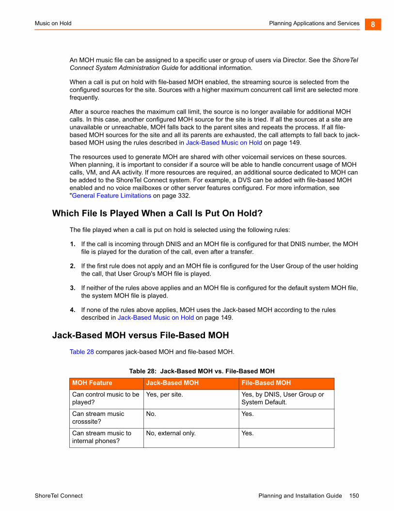
Music on Hold Planning Applications and Services 8
An MOH music file can be assigned to a specific user or group of users via Director. See the ShoreTel Connect System Administration Guide for additional information.
When a call is put on hold with file-based MOH enabled, the streaming source is selected from the configured sources for the site. Sources with a higher maximum concurrent call limit are selected more frequently.
After a source reaches the maximum call limit, the source is no longer available for additional MOH calls. In this case, another configured MOH source for the site is tried. If all the sources at a site are unavailable or unreachable, MOH falls back to the parent sites and repeats the process. If all file-based MOH sources for the site and all its parents are exhausted, the call attempts to fall back to jack-based MOH using the rules described in Jack-Based Music on Hold on page 149.
The resources used to generate MOH are shared with other voicemail services on these sources. When planning, it is important to consider if a source will be able to handle concurrent usage of MOH calls, VM, and AA activity. If more resources are required, an additional source dedicated to MOH can be added to the ShoreTel Connect system. For example, a DVS can be added with file-based MOH enabled and no voice mailboxes or other server features configured. For more information, see "General Feature Limitations on page 332.
Which File Is Played When a Call Is Put On Hold?
The file played when a call is put on hold is selected using the following rules:
1. If the call is incoming through DNIS and an MOH file is configured for that DNIS number, the MOH file is played for the duration of the call, even after a transfer.
2. If the first rule does not apply and an MOH file is configured for the User Group of the user holding the call, that User Group's MOH file is played.
3. If neither of the rules above applies and an MOH file is configured for the default system MOH file, the system MOH file is played.
4. If none of the rules above applies, MOH uses the Jack-based MOH according to the rules described in Jack-Based Music on Hold on page 149.
Jack-Based MOH versus File-Based MOH
Table 28 compares jack-based MOH and file-based MOH.
Table 28: Jack-Based MOH vs. File-Based MOH
MOH Feature Jack-Based MOH File-Based MOH
Can control music to be played?
Yes, per site. Yes, by DNIS, User Group or System Default.
Can stream music crosssite?
No. Yes.
Can stream music to internal phones?
No, external only. Yes.
ShoreTel Connect Planning and Installation Guide 150
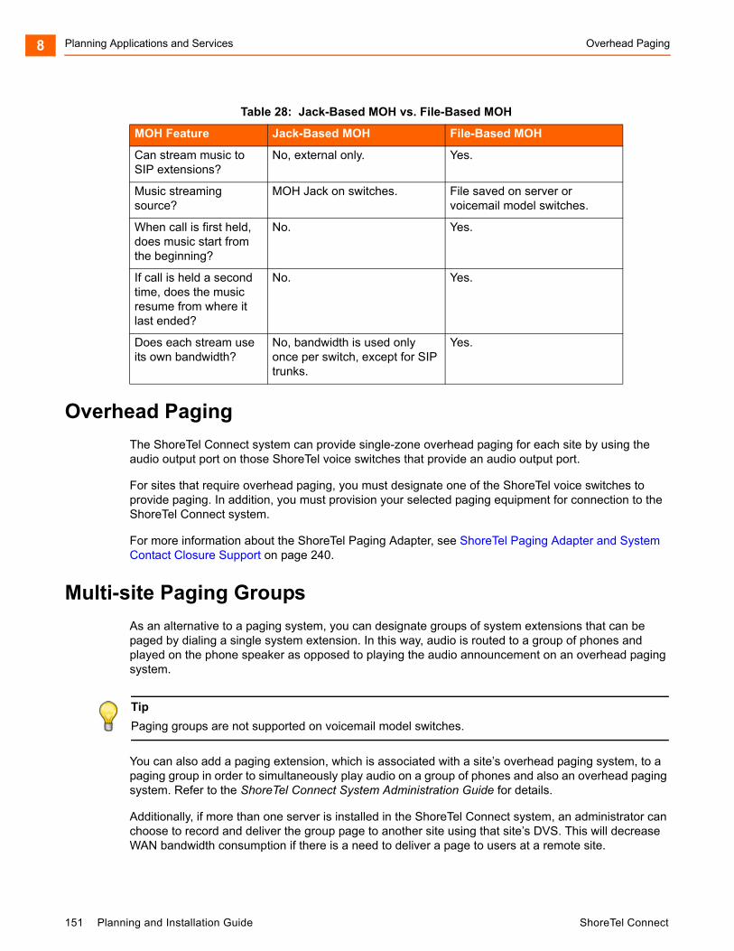
Planning Applications and Services Overhead Paging8
Overhead Paging
The ShoreTel Connect system can provide single-zone overhead paging for each site by using the audio output port on those ShoreTel voice switches that provide an audio output port.
For sites that require overhead paging, you must designate one of the ShoreTel voice switches to provide paging. In addition, you must provision your selected paging equipment for connection to the ShoreTel Connect system.
For more information about the ShoreTel Paging Adapter, see ShoreTel Paging Adapter and System Contact Closure Support on page 240.
Multi-site Paging Groups
As an alternative to a paging system, you can designate groups of system extensions that can be paged by dialing a single system extension. In this way, audio is routed to a group of phones and played on the phone speaker as opposed to playing the audio announcement on an overhead paging system.
You can also add a paging extension, which is associated with a site’s overhead paging system, to a paging group in order to simultaneously play audio on a group of phones and also an overhead paging system. Refer to the ShoreTel Connect System Administration Guide for details.
Additionally, if more than one server is installed in the ShoreTel Connect system, an administrator can choose to record and deliver the group page to another site using that site’s DVS. This will decrease WAN bandwidth consumption if there is a need to deliver a page to users at a remote site.
Can stream music to SIP extensions?
No, external only. Yes.
Music streaming source?
MOH Jack on switches. File saved on server or voicemail model switches.
When call is first held, does music start from the beginning?
No. Yes.
If call is held a second time, does the music resume from where it last ended?
No. Yes.
Does each stream use its own bandwidth?
No, bandwidth is used only once per switch, except for SIP trunks.
Yes.
Tip
Paging groups are not supported on voicemail model switches.
Table 28: Jack-Based MOH vs. File-Based MOH
MOH Feature Jack-Based MOH File-Based MOH
151 Planning and Installation Guide ShoreTel Connect
Night Bell Planning Applications and Services 8
Pages to on-hook IP phones will automatically be announced on the IP phone speaker. Pages to IP phones or analog phones that are already on a call are treated as a normal call. Availability states and their associated call handling do not apply to page calls.
A maximum of 100 extensions can be paged at one time. Group paging is not available to external callers.
Refer to the ShoreTel Connect System Administration Guide for more information about establishing and managing paging groups.
Night Bell
The ShoreTel Connect system can provide an overhead night bell on a per site basis using the audio output port associated with ShoreTel Voice Switches that provide an audio output port.
Intercom
A user can initiate an intercom call through a programmable button on an IP phone that has been programmed with the Intercom feature, via the ShoreTel Connect client, or via the phone by entering “*15” + extension number. Users must be configured to use the intercom feature through ShoreTel Connect Director.
All intercom calls defeat the user's availability state settings, and cannot be forwarded.
An intercom call to an idle IP phone is auto-answered and connected through the called party's speakerphone. Immediately after the call is auto-answered, the called party hears an announcement tone and the calling party hears a beep tone. If the called phone was taken off-hook automatically, the switch puts the phone back on-hook when the intercom call terminates.
An intercom call to an analog phone or SoftPhone that is off-hook with no active call, such as in hands-free mode, is auto-answered through the audio device that is currently active. If the called party is on-hook or is on an active call, the call is offered as an ordinary call, except that call coverage is still defeated.
An intercept tone (fast-busy) is played if the calling user does not have the appropriate permissions. If the called party does not accept intercom calls due to CoS permissions, the call is offered as an ordinary call.
Intercom Telephony COS Configuration
Each telephony class-of-service permission has two additional check box settings in ShoreTel Connect Director to configure intercom permissions:
Allow initiation for Directed Intercom/Paging — If enabled, users with this COS may make intercom calls to other users of the system. If disabled, then intercom calls cannot be made.
Accept Directed Intercom/Paging — If enabled, users with this COS may accept intercom calls. If disabled, then intercom calls are received as normal calls.
ShoreTel Connect Planning and Installation Guide 152
Planning Applications and Services Call Recording8
Call Recording
The ShoreTel Connect system provides the capability for users to record calls. To be available, call recording must be configured in ShoreTel Connect Director by a system administrator. Refer to the ShoreTel Connect System Administration Guide for details on configuring this feature.
Users can use ShoreTel Connect client -Personal Access to request that a call be recorded to voice mail. Supervisors may use Agent Monitor to record an agent’s call. Ordinarily, both ShoreTel Connect client and Agent Monitor will indicate when a call is being recorded, but this behavior can be overridden with the Silent Recording feature to prevent agents from knowing that their calls are being recorded.
With Silent Recording, if the call is recorded by the workgroup supervisor, the indicator does not appear in Agent Monitor. The person invoking the recording sees the indicator — other parties do not. In this way, calls can be silently recorded to allow operators and supervisors to hide the fact that they are recording agents' calls. This hidden behavior may be desirable when a supervisor is monitoring the telephone manners of a new employee. When the recording is silent or hidden, ShoreTel Connect client offers no visual or audible indication that the call is being recorded, and the periodic beeping sound, which is used to notify call participants that their calls are being recorded, is suppressed.
The maximum number of simultaneous recordings equals the number of trunk ports.
The following limitations apply to call recording:
Call recording is only available via ShoreTel Connect client - Personal Access or a programmable button on IP phones.
Only calls on trunks (not extensions-to-extensions) can be recorded.
2-way and 3-way calls can be recorded if one of the legs of the call is a trunk.
Calls to a legacy ShoreTel Conference Bridge cannot be recorded.
Recording stops when the call is parked, unparked, or transferred.
ShoreTel, Inc. does not warrant or represent that your use of call monitoring or recording features of the software will be in compliance with local, state, federal or international laws that you may be subject to. ShoreTel, Inc. is not responsible for ensuring your compliance with all applicable laws. Before configuring the call recording feature, you may wish to consult with legal counsel regarding your intended use.
Make Me Conferencing
The ShoreTel Connect system allows up to eight callers to participate in a conference call without the use of a ShoreTel Conferencing Service or ShoreTel Converged Conferencing Solution. To use the Make Me conference feature you need a ShoreTel IP Phone and, for calls greater than three parties, the proper Class of Service must be configured in ShoreTel Connect Director. If you do not have an IP phone, the feature can also be used from the soft button “join” on an analog phone, in conjunction with ShoreTel Connect client. The conference ports must also be reserved on the ShoreTel Voice Switch,
153 Planning and Installation Guide ShoreTel Connect
ShoreTel Connect Contact Center Planning Applications and Services 8
and the maximum number of callers allowed in a Make Me conference depends on the voice switch type. The Make Me conference feature does not require ShoreTel Conferencing Services or a ShoreTel service appliance.
ShoreTel Connect Contact Center
If you purchased ShoreTel Connect Contact Center, you must configure an appropriate number of route points with adequate call stacks. Route points are a licensed feature. Ensure that you have sufficient licenses to support your planned deployment.
For information on route points, see the ShoreTel Connect System Administration Guide. For information on ShoreTel Connect Contact Center, see the ShoreTel Connect Contact Center Installation Guide and the ShoreTel Connect Contact Center Administration Guide.
ShoreTel Connect Planning and Installation Guide 154

Planning Applications and Services ShoreTel Connect Contact Center8
155 Planning and Installation Guide ShoreTel Connect
CHAPTER
9. Telephone Planning andOrdering
This chapter provides information about the types of telephones supported by the ShoreTel Connect system and what to consider when planning phones for your system. The topics discussed include:
Recommendations .................................................................................................. 157
Considerations for Selecting Phones ...................................................................... 157
Operators and Call Center Agents.................................................................... 157
Administrative Assistants and Receptionists .................................................... 157
Executives and Professionals........................................................................... 158
Roaming Workers ............................................................................................. 158
General Users .................................................................................................. 158
Conference Rooms........................................................................................... 158
Lobby Phones................................................................................................... 158
Teleworkers ...................................................................................................... 158
ShoreTel IP Phones ................................................................................................ 159
Planning Considerations for ShoreTel IP Phones ................................................... 160
Analog Phone Requirements .................................................................................. 161
Caller ID Standard Support for Analog Phones ................................................ 163
Fax Machines and Modems .................................................................................... 164
Fax Machines ................................................................................................... 165
Modems............................................................................................................ 165
ShoreTel Connect Planning and Installation Guide 156
Telephone Planning and Ordering Recommendations9
Recommendations
The following recommendations can assist you with planning, ordering, and installing your telephones:
Select your telephones based on user requirements, your wiring infrastructure, and system objectives.
Order your telephones early. If you need a large quantity of telephones, you should order them several weeks in advance.
Have your cabling contractor place and test all your telephones. Have the contractor unpack, assemble, place, and test every telephone so that you can avoid this simple but time-consuming task.
If the telephone you choose requires local power, make sure an outlet is available at each location.
Considerations for Selecting Phones
Before ordering telephones, you should consider how the phone will be used by various types of users or in certain locations (such as in a conference room or lobby). This section describes the phone features and functionality that different types of users or locations typically require.
Operators and Call Center Agents
Operators and other employees who answer and transfer large numbers of calls could benefit from phones that support the following features:
The programmable buttons feature, which is available on ShoreTel multi-line IP phones and on the BB24 and BB424 button box devices, allows users or administrators to assign functions to custom keys. For example, an operator could assign speed dial numbers to programmable buttons.
The Automatic Off-Hook Preference feature, which is available on ShoreTel multi-line IP phones, allows users to select which audio path (speakerphone or headset) is automatically activated when a call is placed or received. In addition, the HandsFree Mode feature suppresses the dial tone, which is a preference that people who use headsets often prefer. With these supports, employees can use the ShoreTel Connect client to answer and transfer calls rapidly. Many employees in this type of job role stop using their telephone, opting instead to use the ShoreTel Connect client and their headset.
Administrative Assistants and Receptionists
Phone users in these roles are typically satisfied with a standard desk telephone that has speakerphone and mute buttons and supports Caller ID and Message Waiting. In addition, administrative assistants or receptionists could benefit from ShoreTel multi-line phones that offer programmable buttons that support extension monitoring. With this feature, users can monitor multiple system extensions.
157 Planning and Installation Guide ShoreTel Connect

Executives and Professionals Telephone Planning and Ordering 9
Executives and Professionals
Most executives and professionals need advanced phones with full feature sets to handle multiple calls themselves or enable assistants to monitor their extension. For this reason, people in this role generally need multi-line phones with several programmable buttons to support features such as shared call appearance and speed dial.
Roaming Workers
Employees whose jobs involve walking around rather than sitting at a desk need a cordless telephone that they can carry with them so that they can receive calls wherever they roam at the work site. The following ShoreTel DECT cordless phones meet these needs:
IP8430M (multi-cell)
IP8630M (multi-cell)
IP8830M
IP93OD
Workers who need the flexibility to work inside or outside the office can use the ShoreTel Mobility applications integrated with a smartphone.
General Users
Typically, most general users are satisfied with a standard desk telephone that has speakerphone and mute buttons and supports Caller ID and Message Waiting. ShoreTel IP phones are fully featured and appropriate for most users. IP phones come with the ShoreTel features such as Directory and Conference available on preprogrammed buttons.
Conference Rooms
Most conference rooms need a speakerphone that supports discussions including multiple people. In addition, a phone in a conference room should offer single-button access to features such as transferring and conferencing calls.
Lobby Phones
A cost-effective wall-mount, slim-line, or desk telephone is adequate for most lobby phones, hall phones, and the like.
Teleworkers
Both analog and IP phones can be included in a ShoreTel Connect system as remote phones. Analog phones require use of the Extension Assignment, while IP phones are supported by setting an IP address range through ShoreTel Connect Director.
ShoreTel Connect Planning and Installation Guide 158

Telephone Planning and Ordering ShoreTel IP Phones9
ShoreTel IP Phones
Table 29 on page 159 provides information about ShoreTel IP phones. For complete details about each model, see http://www.shoretel.com/products/ip_phones andhttp://media.shoretel.com/documents/IP+Phones+specs.pdf.
The ShoreTel IP Phone BB24 and BB424 are devices that provide multiple additional programmable buttons for a phone.
Table 29: ShoreTel IP Phone Models
Phone Model User or Purpose Features
IP 930D Handset, Base, and Repeater
Roaming employees such as floor managers, filing clerks, and security guards
Cordless (DECT technology), 3 lines
IP 8830M Handset Roaming employees such as floor managers, filing clerks, and security guards
Ruggedized cordless (multi-cell DECT) handset for tough duty applications, such as factories and hospitals
IP 8660M Base Roaming employees such as floor managers, filing clerks, and security guards
Base unit for all multi-cell DECT handsets
IP 8630M Handset Roaming employees such as floor managers, filing clerks, and security guards
Mid-range, mainstream cordless (multi-cell DECT) handset for offices
IP 8430M Handset Roaming employees such as floor managers, filing clerks, and security guards
Entry-level cordless (multi-cell DECT) handset
IP 655 Executives, advanced professionals, remote workers, conference rooms
12 lines, large color touch screen, integrated VPN client, Gigabit Ethernet
Enhanced directory and call history applications, with real-time telephony presence information and visual voicemail
IP 565g Executives, advanced professionals, remote workers
6 lines, integrated VPN client, Gigabit Ethernet, Bluetooth
IP 560g Operators, contact center agents, assistants, receptionists, advanced professionals, remote workers
6 lines, integrated VPN client, Gigabit Ethernet
IP 485g Executives, advanced professionals 8 lines, large color screen, SIP, Gigabit Ethernet, USB port, visual voicemail, enhanced directory and call history applications, real-time telephony presence information
IP 480g Operators, contact center agents, assistants, receptionists, advanced professionals
8 lines, large black and white screen, SIP, Gigabit Ethernet, visual voicemail, enhanced directory and call history applications, real-time telephony presence information
159 Planning and Installation Guide ShoreTel Connect
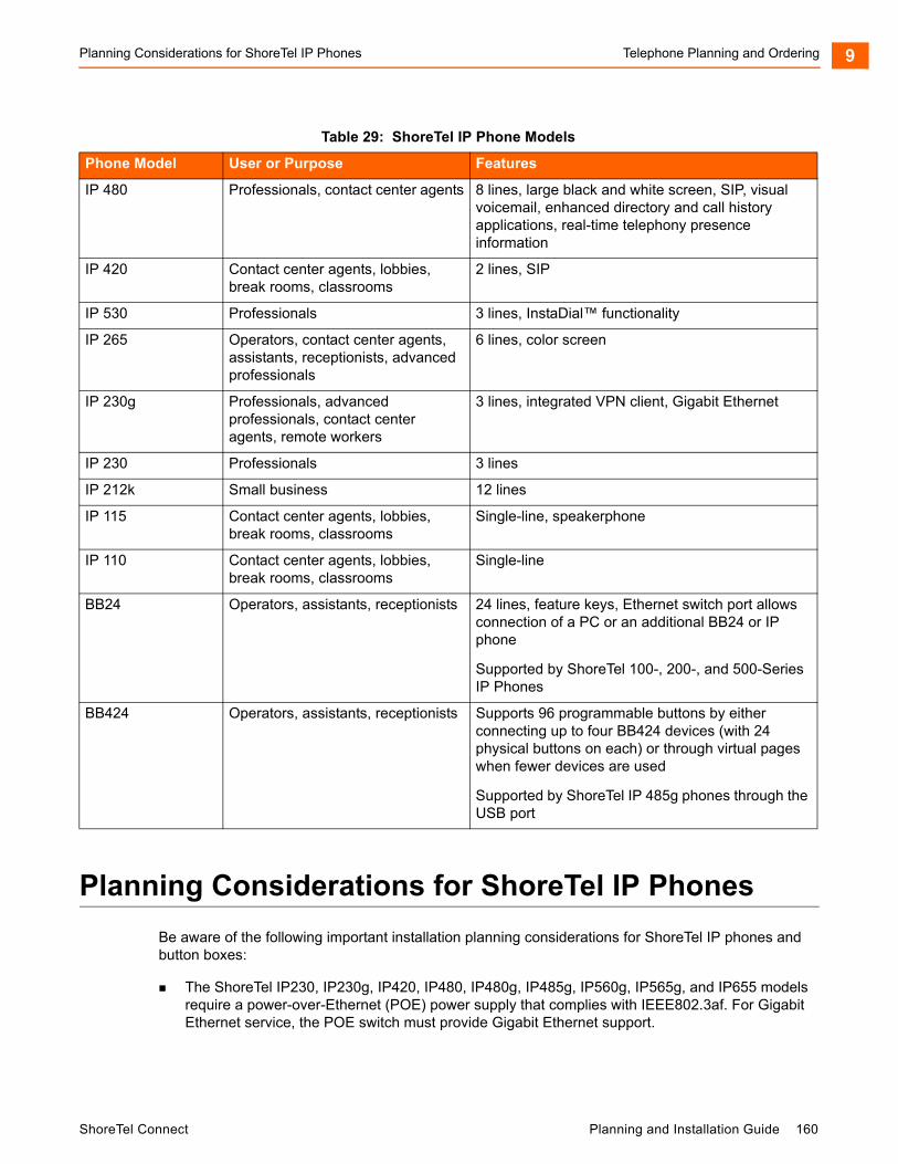
Planning Considerations for ShoreTel IP Phones Telephone Planning and Ordering 9
Planning Considerations for ShoreTel IP Phones
Be aware of the following important installation planning considerations for ShoreTel IP phones and button boxes:
The ShoreTel IP230, IP230g, IP420, IP480, IP480g, IP485g, IP560g, IP565g, and IP655 models require a power-over-Ethernet (POE) power supply that complies with IEEE802.3af. For Gigabit Ethernet service, the POE switch must provide Gigabit Ethernet support.
IP 480 Professionals, contact center agents 8 lines, large black and white screen, SIP, visual voicemail, enhanced directory and call history applications, real-time telephony presence information
IP 420 Contact center agents, lobbies, break rooms, classrooms
2 lines, SIP
IP 530 Professionals 3 lines, InstaDial™ functionality
IP 265 Operators, contact center agents, assistants, receptionists, advanced professionals
6 lines, color screen
IP 230g Professionals, advanced professionals, contact center agents, remote workers
3 lines, integrated VPN client, Gigabit Ethernet
IP 230 Professionals 3 lines
IP 212k Small business 12 lines
IP 115 Contact center agents, lobbies, break rooms, classrooms
Single-line, speakerphone
IP 110 Contact center agents, lobbies, break rooms, classrooms
Single-line
BB24 Operators, assistants, receptionists 24 lines, feature keys, Ethernet switch port allows connection of a PC or an additional BB24 or IP phone
Supported by ShoreTel 100-, 200-, and 500-Series IP Phones
BB424 Operators, assistants, receptionists Supports 96 programmable buttons by either connecting up to four BB424 devices (with 24 physical buttons on each) or through virtual pages when fewer devices are used
Supported by ShoreTel IP 485g phones through the USB port
Table 29: ShoreTel IP Phone Models
Phone Model User or Purpose Features
ShoreTel Connect Planning and Installation Guide 160
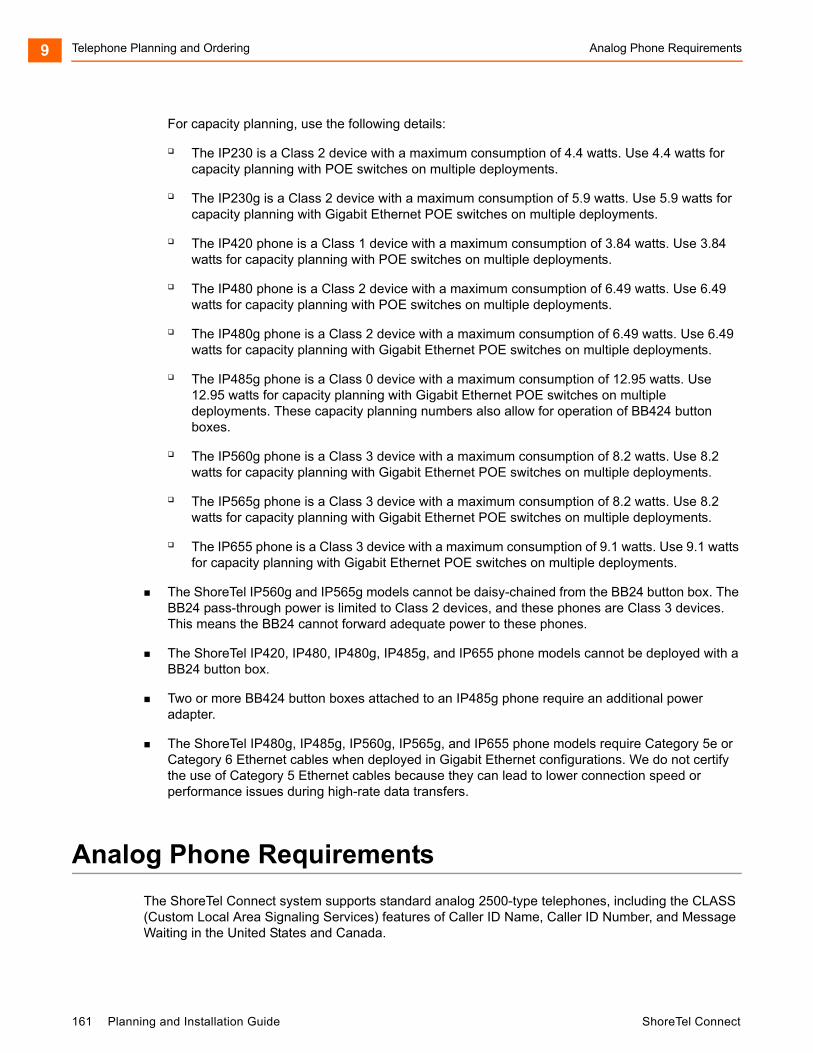
Telephone Planning and Ordering Analog Phone Requirements9
For capacity planning, use the following details:
The IP230 is a Class 2 device with a maximum consumption of 4.4 watts. Use 4.4 watts for capacity planning with POE switches on multiple deployments.
The IP230g is a Class 2 device with a maximum consumption of 5.9 watts. Use 5.9 watts for capacity planning with Gigabit Ethernet POE switches on multiple deployments.
The IP420 phone is a Class 1 device with a maximum consumption of 3.84 watts. Use 3.84 watts for capacity planning with POE switches on multiple deployments.
The IP480 phone is a Class 2 device with a maximum consumption of 6.49 watts. Use 6.49 watts for capacity planning with POE switches on multiple deployments.
The IP480g phone is a Class 2 device with a maximum consumption of 6.49 watts. Use 6.49 watts for capacity planning with Gigabit Ethernet POE switches on multiple deployments.
The IP485g phone is a Class 0 device with a maximum consumption of 12.95 watts. Use 12.95 watts for capacity planning with Gigabit Ethernet POE switches on multiple deployments. These capacity planning numbers also allow for operation of BB424 button boxes.
The IP560g phone is a Class 3 device with a maximum consumption of 8.2 watts. Use 8.2 watts for capacity planning with Gigabit Ethernet POE switches on multiple deployments.
The IP565g phone is a Class 3 device with a maximum consumption of 8.2 watts. Use 8.2 watts for capacity planning with Gigabit Ethernet POE switches on multiple deployments.
The IP655 phone is a Class 3 device with a maximum consumption of 9.1 watts. Use 9.1 watts for capacity planning with Gigabit Ethernet POE switches on multiple deployments.
The ShoreTel IP560g and IP565g models cannot be daisy-chained from the BB24 button box. The BB24 pass-through power is limited to Class 2 devices, and these phones are Class 3 devices. This means the BB24 cannot forward adequate power to these phones.
The ShoreTel IP420, IP480, IP480g, IP485g, and IP655 phone models cannot be deployed with a BB24 button box.
Two or more BB424 button boxes attached to an IP485g phone require an additional power adapter.
The ShoreTel IP480g, IP485g, IP560g, IP565g, and IP655 phone models require Category 5e or Category 6 Ethernet cables when deployed in Gigabit Ethernet configurations. We do not certify the use of Category 5 Ethernet cables because they can lead to lower connection speed or performance issues during high-rate data transfers.
Analog Phone Requirements
The ShoreTel Connect system supports standard analog 2500-type telephones, including the CLASS (Custom Local Area Signaling Services) features of Caller ID Name, Caller ID Number, and Message Waiting in the United States and Canada.
161 Planning and Installation Guide ShoreTel Connect
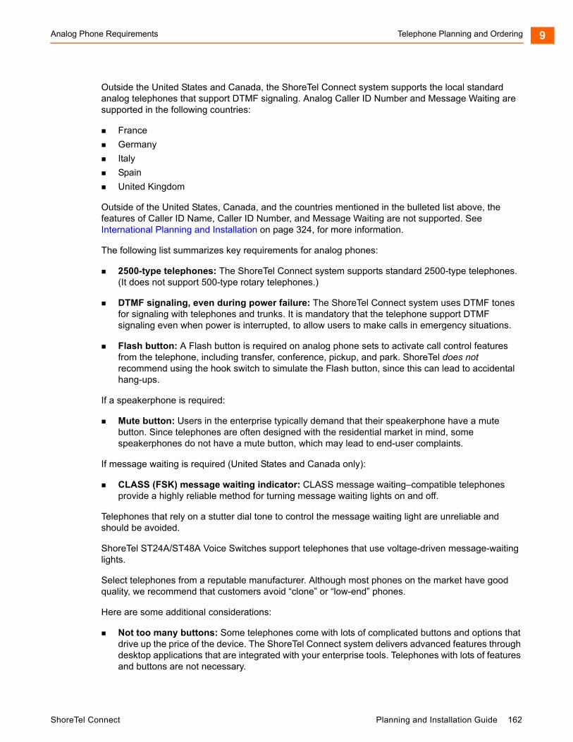
Analog Phone Requirements Telephone Planning and Ordering 9
Outside the United States and Canada, the ShoreTel Connect system supports the local standard analog telephones that support DTMF signaling. Analog Caller ID Number and Message Waiting are supported in the following countries:
France
Germany
Italy
Spain
United Kingdom
Outside of the United States, Canada, and the countries mentioned in the bulleted list above, the features of Caller ID Name, Caller ID Number, and Message Waiting are not supported. See International Planning and Installation on page 324, for more information.
The following list summarizes key requirements for analog phones:
2500-type telephones: The ShoreTel Connect system supports standard 2500-type telephones. (It does not support 500-type rotary telephones.)
DTMF signaling, even during power failure: The ShoreTel Connect system uses DTMF tones for signaling with telephones and trunks. It is mandatory that the telephone support DTMF signaling even when power is interrupted, to allow users to make calls in emergency situations.
Flash button: A Flash button is required on analog phone sets to activate call control features from the telephone, including transfer, conference, pickup, and park. ShoreTel does not recommend using the hook switch to simulate the Flash button, since this can lead to accidental hang-ups.
If a speakerphone is required:
Mute button: Users in the enterprise typically demand that their speakerphone have a mute button. Since telephones are often designed with the residential market in mind, some speakerphones do not have a mute button, which may lead to end-user complaints.
If message waiting is required (United States and Canada only):
CLASS (FSK) message waiting indicator: CLASS message waiting–compatible telephones provide a highly reliable method for turning message waiting lights on and off.
Telephones that rely on a stutter dial tone to control the message waiting light are unreliable and should be avoided.
ShoreTel ST24A/ST48A Voice Switches support telephones that use voltage-driven message-waiting lights.
Select telephones from a reputable manufacturer. Although most phones on the market have good quality, we recommend that customers avoid “clone” or “low-end” phones.
Here are some additional considerations:
Not too many buttons: Some telephones come with lots of complicated buttons and options that drive up the price of the device. The ShoreTel Connect system delivers advanced features through desktop applications that are integrated with your enterprise tools. Telephones with lots of features and buttons are not necessary.
ShoreTel Connect Planning and Installation Guide 162
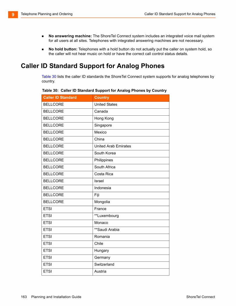
Telephone Planning and Ordering Caller ID Standard Support for Analog Phones9
No answering machine: The ShoreTel Connect system includes an integrated voice mail system for all users at all sites. Telephones with integrated answering machines are not necessary.
No hold button: Telephones with a hold button do not actually put the caller on system hold, so the caller will not hear music on hold or have the correct call control status details.
Caller ID Standard Support for Analog Phones
Table 30 lists the caller ID standards the ShoreTel Connect system supports for analog telephones by country.
Table 30: Caller ID Standard Support for Analog Phones by Country
Caller ID Standard Country
BELLCORE United States
BELLCORE Canada
BELLCORE Hong Kong
BELLCORE Singapore
BELLCORE Mexico
BELLCORE China
BELLCORE United Arab Emirates
BELLCORE South Korea
BELLCORE Philippines
BELLCORE South Africa
BELLCORE Costa Rica
BELLCORE Israel
BELLCORE Indonesia
BELLCORE Fiji
BELLCORE Mongolia
ETSI France
ETSI **Luxembourg
ETSI Monaco
ETSI **Saudi Arabia
ETSI Romania
ETSI Chile
ETSI Hungary
ETSI Germany
ETSI Switzerland
ETSI Austria
163 Planning and Installation Guide ShoreTel Connect

Fax Machines and Modems Telephone Planning and Ordering 9
**Indicates uncertainty as to whether country supports configured standard.
Fax Machines and Modems
The ShoreTel Connect system supports fax machines and modems in the United States and Canada (and not elsewhere).
ETSI Norway
ETSI **Taiwan
ETSI **Thailand
ETSI Poland
ETSI **Czech Republic
ETSI Italy
ETSI Spain
ETSI *Argentina
BT United Kingdom
BT Ireland
None Australia
None Malaysia
None Brazil
None Netherlands
None New Zealand
None Portugal
None Belgium
None Denmark
None Sweden
None India
None Japan
None Finland (unsupported DTMF variation)
None Greece
None Bulgaria
Table 30: Caller ID Standard Support for Analog Phones by Country (Continued)
Caller ID Standard Country
ShoreTel Connect Planning and Installation Guide 164

Telephone Planning and Ordering Fax Machines9
Fax and modem calls are more sensitive to network problems than voice conversations. The human ear does not notice a lost packet during a voice conversation, but when a packet is lost during a fax transmission the line may be dropped. During a modem call, a lost packet can cause a retransmission. In the worst case, fax machines and modems will not establish a connection or may drop the call altogether. In general, fax and modem calls work across a local area network, but work on wide area networks only when there is virtually no packet loss and little jitter.
The ShoreTel Connect system automatically detects both fax and modem tones, and boosts the voice encoding to a higher value to increase throughput. (G.711 at 64 Kbps is recommended.) It also stops the nonlinear processing of the echo canceler and fixes the size of the jitter buffer to a preset level. In addition, for modems, the echo canceler is frozen or stopped, since the modems use their own network echo cancelers.
Fax Machines
Fax machines require a high-quality IP network for proper operation.
The ShoreTel Connect system supports distinctive ringing for inbound calls: calls from external parties have the classic single ring, whereas calls from internal parties have a distinctive double ring. Some fax machines detect the ringing pattern before answering and might not answer internal calls because of the distinctive ring pattern. In particular, you must turn off the “Intelligent Ring Mode” on some Hewlett-Packard fax machines to receive calls from internal parties.
Modems
The ShoreTel Connect system supports “moderate-use” modem applications on the system. This is generally considered to be modem calls up to 28.8 Kbps that do not last longer than 15 minutes. If your application demands greater performance, you should bypass the ShoreTel Connect system or move your modem application to a pure IP-based solution.
The expected modem performance in different configurations is as follows:
Analog connection speeds will not exceed 33.6 Kbps and could be lower. External factors, including poor-quality trunk lines, ISP limitations, and multiple analog-to-digital conversions in the network, can have a significant impact on connection speeds.
Modem calls demand a high-quality network with virtually no packet loss. Packet loss should not exceed 0.1%, which can be achieved on a local area network or in a wide area network using leased T1 facilities.
Analog trunk ports should not be used if a digital trunk (T1) is available, since performance will be limited to 28.8 Kbps maximum. Digital trunks should be used instead.
Connection speeds are significantly affected by multiple packet-to-circuit conversions (including modem calls from one ShoreTel Connect system to another). If a T1 line is used, modems should be able to connect at K56Flex/V.90 or approximately 48 Kbps.
165 Planning and Installation Guide ShoreTel Connect

CHAPTER
10. Server Requirements
This chapter provides specific hardware and software requirements for ShoreTel Headquarters servers and ShoreTel Distributed Voice servers. The topics in include:
General Recommendations .................................................................................... 168
Requirements for ShoreTel Enterprise Systems ..................................................... 168
Capacity and Hardware Requirements for Headquarters Servers ................... 169
Capacity and Hardware Requirements for Distributed Voice Servers .............. 171
Operating System Requirements for All Servers .............................................. 172
Capacities of the ShoreTel SBE 100 Systems ........................................................ 173
SBE 100 Requirements .................................................................................... 174
SBE 100 Operating System Requirements ...................................................... 175
Requirements for VMware Environments ............................................................... 175
ShoreTel Capacity in VMWare Environments ................................................... 175
Capacity and Hardware Requirements for Virtual IP Phone Switch ................. 179
Capacity and Hardware Requirements for Virtual SIP Trunk Switch (G.711 Signaling).......................................................................................................... 179
Capacity and Hardware Requirements for Virtual SIP Trunk Switch (G.729 Signaling).......................................................................................................... 180
Operating System Requirements for VMware .................................................. 181
VMware Software Requirements ...................................................................... 182
Deploying ShoreTel servers under VMware ..................................................... 182
Requirements for Microsoft Hyper-V Environments ................................................ 182
Supported Configurations and Hyper-V Features............................................. 182
ShoreTel Capacities in Hyper-V Environments................................................. 182
Hardware Requirements for Hyper-V Installation ............................................. 183
ShoreTel Connect Planning and Installation Guide 166

Server Requirements10
Software Requirements for Hyper-V................................................................. 183
Deploying ShoreTel Servers Under Hyper-V .................................................... 183
Double-Take Availability Software for Failover ........................................................ 183
Hard Disk Requirements ......................................................................................... 184
Voicemail Utilization.......................................................................................... 184
Call Detail Records ........................................................................................... 185
Log Files ........................................................................................................... 185
Preparing the Server for ShoreTel Operation.......................................................... 186
Server IP Address ............................................................................................ 186
DHCP on the ShoreTel Server.......................................................................... 186
Microsoft Windows Server 2008 R2 Configuration ........................................... 186
Microsoft Windows Server 2012 R2 Configuration ........................................... 189
Additional Considerations................................................................................. 192
Requirements for ShoreTel Connect Mobility Router .............................................. 194
Third-Party Applications Supported ........................................................................ 194
167 Planning and Installation Guide ShoreTel Connect
General Recommendations Server Requirements 10
General Recommendations
The following recommendations can help the customer to select the servers to buy:
Buy a server that is intended to function as a server and to host the ShoreTel Connect software. The headquarters server must be a dedicated server with no other applications installed. This means you should not use this server for any of the following: Windows Domain controller, Terminal Server, Database Server (with MySQL), Web server, nor exchange server.
Be sure each server that runs ShoreTel server software has enough processing capacity to support the planned telephony workload. The Softswitch on ShoreTel servers perform call control for calls that traverse the Softswitch. The ShoreTel server also provides services for voicemail, automated attendant, workgroup management, configuration databases, and more. The headquarters server also hosts the system configuration tool, Web pages for the user-interface and conferencing; and maintains call records and the history database.
Do not use a ShoreTel server as a domain controller.
System Licenses
ShoreTel ships the Unified Communications system with 4 types of system licenses:
Enterprise Edition (EE)—Fully featured ShoreTel Connect system with no restrictions imposed by the system license.
Small Business Edition 100 (SBE 100)—ShoreTel's solution for small businesses under 100 users is provided as a turn-key bundle. By installing an SBE 100 system license, the system is restricted to 100 users, 120 mailboxes, 5 sites, and 7 switches. Other restrictions also apply. Customers can upgrade from Small Business Edition 100 to Enterprise Edition by applying a new system license (a license to upgrade from SBE 100 to EE).
Small Business Edition (SBE)—ShoreTel's solution for small businesses under 50 users. Small Business Edition is supported, but is no longer available for sale.
ShoreTel Demo Kit—Special version of ShoreTel's system used for demo purposes as a sales tool.
Requirements for ShoreTel Enterprise Systems
This section provides information necessary to provision servers on which to install ShoreTel Enterprise software.
The ShoreTel Enterprise Edition system is scalable. In the spirit of economy and efficiency, ShoreTel Enterprise customers provide their own server hardware allowing them to build the optimum phone system for their environment. To assist in creating the optimum system, ShoreTel has defined a tier system based on the number of users the system is to support and set minimum server requirements for each tier.
ShoreTel Connect Planning and Installation Guide 168

Server Requirements Capacity and Hardware Requirements for Headquarters Servers10
The tiers ShoreTel defines are as follows:
Branch Office Bundle based off Dell Optiplex 390 server that support up to 100 users. UC 20 server or later versions of the SBE 100 servers that support up to 200 users when used in the Enterprise Edition setup.
Small servers that support up to 500 users.
Medium servers that support up to 2,500 users.
Large servers that support up to 10,000 users.
Very large servers that support up to 20,000 users.
Capacity and Hardware Requirements for Headquarters Servers
Table 31 shows information about system capacity for each tier of the Headquarters servers. The table shows the number of users, calls, and reports that the server can support for each tier. Table 32 shows our recommendations for each tier of Headquarters server. Use these tables to determine the needs for Headquarters servers in the ShoreTel deployment. You can mix servers of different capacities, but choose the right servers for the telephony environment.
Note
If a planned upgrade to the current release means that the current server cannot adequately support the new release of ShoreTel software, upgrade the server to a model with greater capacity before doing the server software upgrade.
Note
SBE 100 systems upgraded to Enterprise Edition support the same capacities as the Enterprise system. However, appropriate hardware needs to be provided to support the required capacities.
Table 31: Headquarter Server Capacity for Enterprise System
Size
Maximum number of users per System
Maximum number of users assigned to HQ Server
Maximum
System BHCC
Maximum BHCC
per server
Reports run outsidebusiness hours
Maximum BHCC
per server
Reports run duringbusiness hours
Small Business Edition
UC 25 (Small Business Edition 100)
100 1,000 1,000 Not Recommended
Not Recommended
Enterprise Edition
169 Planning and Installation Guide ShoreTel Connect
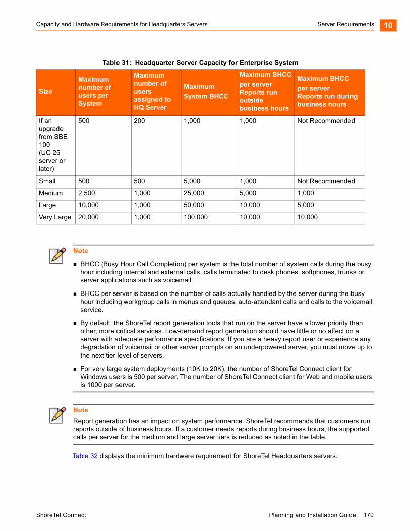
Capacity and Hardware Requirements for Headquarters Servers Server Requirements 10
1
Table 32 displays the minimum hardware requirement for ShoreTel Headquarters servers.
If an upgrade from SBE 100 (UC 25 server or later)
500 200 1,000 1,000 Not Recommended
Small 500 500 5,000 1,000 Not Recommended
Medium 2,500 1,000 25,000 5,000 1,000
Large 10,000 1,000 50,000 10,000 5,000
Very Large 20,000 1,000 100,000 10,000 10,000
Note
BHCC (Busy Hour Call Completion) per system is the total number of system calls during the busy hour including internal and external calls, calls terminated to desk phones, softphones, trunks or server applications such as voicemail.
BHCC per server is based on the number of calls actually handled by the server during the busy hour including workgroup calls in menus and queues, auto-attendant calls and calls to the voicemail service.
By default, the ShoreTel report generation tools that run on the server have a lower priority than other, more critical services. Low-demand report generation should have little or no affect on a server with adequate performance specifications. If you are a heavy report user or experience any degradation of voicemail or other server prompts on an underpowered server, you must move up to the next tier level of servers.
For very large system deployments (10K to 20K), the number of ShoreTel Connect client for Windows users is 500 per server. The number of ShoreTel Connect client for Web and mobile users is 1000 per server.
Note
Report generation has an impact on system performance. ShoreTel recommends that customers run reports outside of business hours. If a customer needs reports during business hours, the supported calls per server for the medium and large server tiers is reduced as noted in the table.
Table 31: Headquarter Server Capacity for Enterprise System
Size
Maximum number of users per System
Maximum number of users assigned to HQ Server
Maximum
System BHCC
Maximum BHCC
per server
Reports run outsidebusiness hours
Maximum BHCC
per server
Reports run duringbusiness hours
ShoreTel Connect Planning and Installation Guide 170
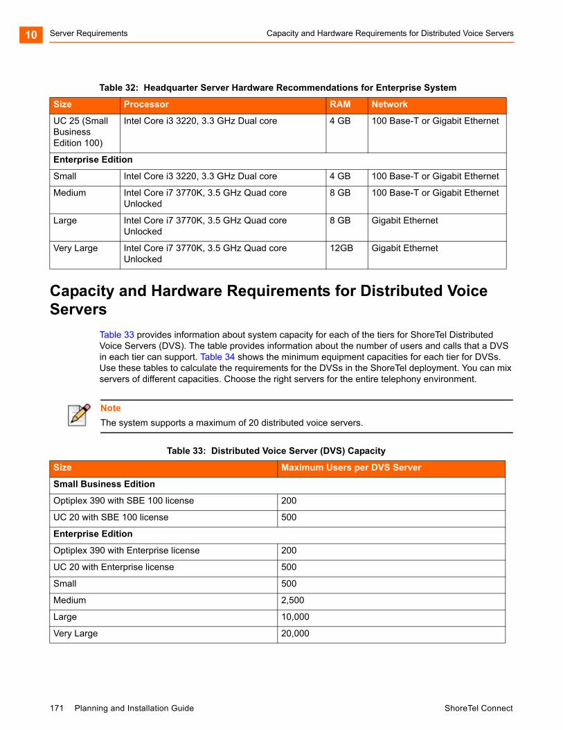
Server Requirements Capacity and Hardware Requirements for Distributed Voice Servers10
Capacity and Hardware Requirements for Distributed Voice Servers
Table 33 provides information about system capacity for each of the tiers for ShoreTel Distributed Voice Servers (DVS). The table provides information about the number of users and calls that a DVS in each tier can support. Table 34 shows the minimum equipment capacities for each tier for DVSs. Use these tables to calculate the requirements for the DVSs in the ShoreTel deployment. You can mix servers of different capacities. Choose the right servers for the entire telephony environment.
Table 32: Headquarter Server Hardware Recommendations for Enterprise System
Size Processor RAM Network
UC 25 (Small Business Edition 100)
Intel Core i3 3220, 3.3 GHz Dual core 4 GB 100 Base-T or Gigabit Ethernet
Enterprise Edition
Small Intel Core i3 3220, 3.3 GHz Dual core 4 GB 100 Base-T or Gigabit Ethernet
Medium Intel Core i7 3770K, 3.5 GHz Quad core Unlocked
8 GB 100 Base-T or Gigabit Ethernet
Large Intel Core i7 3770K, 3.5 GHz Quad core Unlocked
8 GB Gigabit Ethernet
Very Large Intel Core i7 3770K, 3.5 GHz Quad core Unlocked
12GB Gigabit Ethernet
Note
The system supports a maximum of 20 distributed voice servers.
Table 33: Distributed Voice Server (DVS) Capacity
Size Maximum Users per DVS Server
Small Business Edition
Optiplex 390 with SBE 100 license 200
UC 20 with SBE 100 license 500
Enterprise Edition
Optiplex 390 with Enterprise license 200
UC 20 with Enterprise license 500
Small 500
Medium 2,500
Large 10,000
Very Large 20,000
171 Planning and Installation Guide ShoreTel Connect
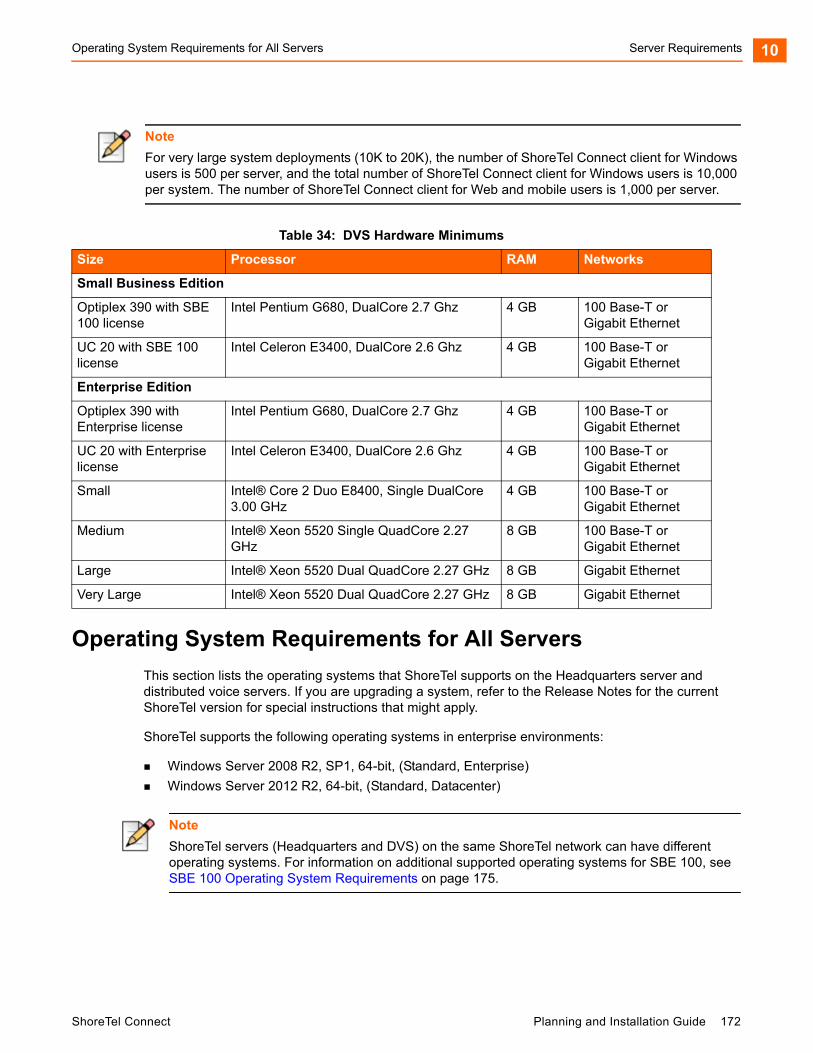
Operating System Requirements for All Servers Server Requirements 10
Operating System Requirements for All Servers
This section lists the operating systems that ShoreTel supports on the Headquarters server and distributed voice servers. If you are upgrading a system, refer to the Release Notes for the current ShoreTel version for special instructions that might apply.
ShoreTel supports the following operating systems in enterprise environments:
Windows Server 2008 R2, SP1, 64-bit, (Standard, Enterprise)
Windows Server 2012 R2, 64-bit, (Standard, Datacenter)
Note
For very large system deployments (10K to 20K), the number of ShoreTel Connect client for Windows users is 500 per server, and the total number of ShoreTel Connect client for Windows users is 10,000 per system. The number of ShoreTel Connect client for Web and mobile users is 1,000 per server.
Table 34: DVS Hardware Minimums
Size Processor RAM Networks
Small Business Edition
Optiplex 390 with SBE 100 license
Intel Pentium G680, DualCore 2.7 Ghz 4 GB 100 Base-T or Gigabit Ethernet
UC 20 with SBE 100 license
Intel Celeron E3400, DualCore 2.6 Ghz 4 GB 100 Base-T or Gigabit Ethernet
Enterprise Edition
Optiplex 390 with Enterprise license
Intel Pentium G680, DualCore 2.7 Ghz 4 GB 100 Base-T or Gigabit Ethernet
UC 20 with Enterprise license
Intel Celeron E3400, DualCore 2.6 Ghz 4 GB 100 Base-T or Gigabit Ethernet
Small Intel® Core 2 Duo E8400, Single DualCore 3.00 GHz
4 GB 100 Base-T or Gigabit Ethernet
Medium Intel® Xeon 5520 Single QuadCore 2.27 GHz
8 GB 100 Base-T or Gigabit Ethernet
Large Intel® Xeon 5520 Dual QuadCore 2.27 GHz 8 GB Gigabit Ethernet
Very Large Intel® Xeon 5520 Dual QuadCore 2.27 GHz 8 GB Gigabit Ethernet
Note
ShoreTel servers (Headquarters and DVS) on the same ShoreTel network can have different operating systems. For information on additional supported operating systems for SBE 100, see SBE 100 Operating System Requirements on page 175.
ShoreTel Connect Planning and Installation Guide 172

Server Requirements Capacities of the ShoreTel SBE 100 Systems10
Capacities of the ShoreTel SBE 100 Systems
The section describes the capacities of the ShoreTel Small Business Edition (SBE) 100 systems. It begins with a summary of the major differences between the features supported on the SBE 100, and the EE (ShoreTel Enterprise Edition).
Table 35 lists the major differences between the features supported on the SBE 100, and the EE systems.
Table 35: Major Differences between the Features Supported on SBE 100, and EE
Feature SBE 100 EE
Sites 5 500
Switches 7 500
Users (with extensions) 100 20,000
Telephones 100 20,000
Trunks 100 10,000
Simultaneous calls, extension-to-extension 50 10,000
Busy Hour Call Completion 1,000 100,000
DVS 4 20
Integration with third-party PBX No Yes
On-net dialing No Yes
Voice mailboxes 120 20,000
Simultaneous calls per server 25 254
AMIS No Yes
SMDI - External voicemail No Yes
SMDI - ShoreTel voicemail No Yes
Service Appliance 100 (SA100) 2 5
SA100 audio/web/IM ports 100/60/100 256/300/128
Service Appliance 400 (SA400) No Yes
Virtual Service Appliance 1 5
Workgroups (groups, agents, supervisors) 100/100/100 256/300/128
ShoreTel Mobility clients 100 5,000
173 Planning and Installation Guide ShoreTel Connect
SBE 100 Requirements Server Requirements 10
1
SBE 100 Requirements
ShoreTel can ship the Small Business Edition (SBE) 100 with or without a server. If ShoreTel ships an SBE 100 with a server, the server has the embedded Microsoft Windows Server OS for Telecommunications Systems. ShoreTel configures, tests, and prepares the server for the installation of the ShoreTel Connect Director SBE software.
ShoreTel SBE 100 Option with the ShoreTel Server
The server that ShoreTel uses for its SBE 100 (ShoreTel UC Server 20) meets or exceeds the following specifications:
Processor: Intel Celeron E3400, DualCore 2.6 Ghz, 800FSB
Memory: 4.0GB, DDR3
Hard Drive: 500GB, SATA
Rack-Mountable (1U) Form-factor
Windows 2008 R2 Embedded OS or Windows 2012 R2 Embedded OS (for UC 20 Rev.-02)
ShoreTel SBE 100 Option without the ShoreTel Server
For customers who buy their own server, the server must meet or exceed the specifications of the server shipped by ShoreTel specified above.
Using a ShoreTel SBE 100 Server in the Enterprise Setup
If an SBE 100 customer grows more than 100 phone users, an upgrade from a ShoreTel SBE 100 to the ShoreTel Enterprise Edition is required. When upgrading from the SBE 100 to the Enterprise Edition, the customer can use the server shipped with the SBE 100 (the ShoreTel UC Server 20) in the Enterprise system as either a Headquarters server or a DVS server.
Note
The SBE 100 is available with a ShoreTel-provided server or a customer-provided server. The Server supplied by the customer must meet the minimum server requirements as indicated below.
The SBE 100 can be upgraded to the Enterprise Edition (EE).
The Headquarters server must be at least dual-core and have 4GB of RAM.
Note
The ShoreTel server that is shipped with SBE 100 (ShoreTel UC Server 20) is usually appropriate for up to 100 users. However, some customers might have plans to grow fast (for example, to more than 100 users) by buying an SBE 100 upgrade to the Enterprise license. Also, some customers may need to use more server resources than 25 simultaneous calls to server for features, such as paging to multiple phones, using more than 25 workgroups simultaneously, or running Web Reports. These customers should consider buying their own server that has, at a minimum, the hardware parameters of the ShoreTel Small Enterprise Server specified in Table 32.
ShoreTel Connect Planning and Installation Guide 174
Server Requirements SBE 100 Operating System Requirements10
Option1: Using a ShoreTel UC Server 20 as a Headquarters Server
With this configuration, the number of users in the system cannot exceed 200. Other restrictions include:
Simultaneous media paths have a limit of 25 (media paths provide access for voice mail, workgroups, or auto-attendant).
Busy hour call completion has a limit of 1000.
Web Reports are not supported.
Option 2: Using a ShoreTel UC Server 20 as a Distributed Voice Server (DVS)
With this configuration, the number of users in the system cannot exceed 500, and the maximum number of users on the DVS cannot exceed 200. Other characteristics include:
Simultaneous media paths have a limit of 25 (media paths provide access for voice mail, workgroups, or auto-attendant).
Busy hour call completion has a limit of 1000.
The SBE 100 supports Web Reports because these reports run on the Headquarters server.
SBE 100 Operating System Requirements
For SBE 100, ShoreTel supports the operating systems listed below.
Supported OS for Servers Shipped by ShoreTel Windows Server 2008 R2, 64-bit, SPx, Embedded Telecom Edition
Windows Server 2012 R2, 64-bit, Embedded Telecom Edition
OS Requirements for Servers Shipped by End-Customer Windows Server 2008 R2, 64-bit, SP1 (Standard, Enterprise)
Windows Server 2012 R2 (Standard, Datacenter)
Requirements for VMware Environments
This section provides information necessary to install the ShoreTel Connect system software on servers running VMware.
ShoreTel Capacity in VMWare Environments
Table 36 provides information about ShoreTel capacities when installed on ShoreTel Headquarters server running VMware.
175 Planning and Installation Guide ShoreTel Connect
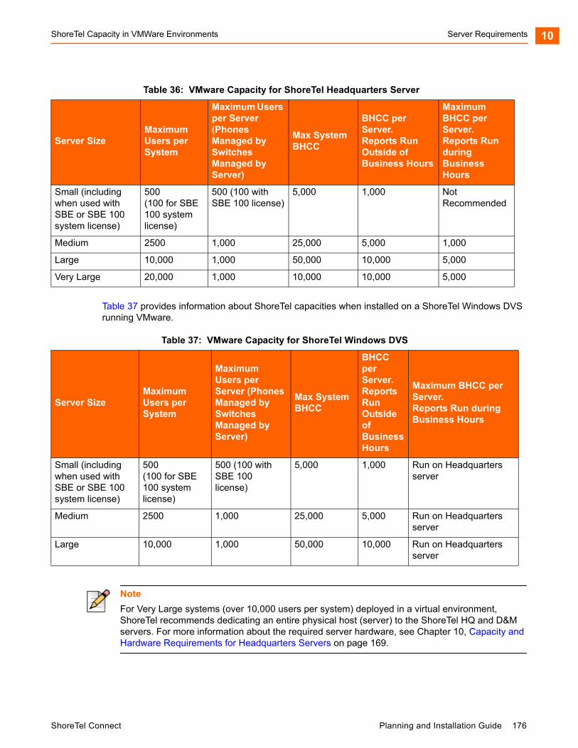
ShoreTel Capacity in VMWare Environments Server Requirements 10
Table 37 provides information about ShoreTel capacities when installed on a ShoreTel Windows DVS running VMware.
Table 36: VMware Capacity for ShoreTel Headquarters Server
Server SizeMaximum Users per System
Maximum Users per Server (Phones Managed by Switches Managed by Server)
Max System BHCC
BHCC per Server.Reports Run Outside of Business Hours
Maximum BHCC per Server. Reports Run during Business Hours
Small (including when used with SBE or SBE 100 system license)
500 (100 for SBE 100 system license)
500 (100 with SBE 100 license)
5,000 1,000 Not Recommended
Medium 2500 1,000 25,000 5,000 1,000
Large 10,000 1,000 50,000 10,000 5,000
Very Large 20,000 1,000 10,000 10,000 5,000
Table 37: VMware Capacity for ShoreTel Windows DVS
Server SizeMaximum Users per System
Maximum Users per Server (Phones Managed by Switches Managed by Server)
Max System BHCC
BHCC per Server.Reports Run Outside of Business Hours
Maximum BHCC per Server. Reports Run during Business Hours
Small (including when used with SBE or SBE 100 system license)
500 (100 for SBE 100 system license)
500 (100 with SBE 100 license)
5,000 1,000 Run on Headquarters server
Medium 2500 1,000 25,000 5,000 Run on Headquarters server
Large 10,000 1,000 50,000 10,000 Run on Headquarters server
Note
For Very Large systems (over 10,000 users per system) deployed in a virtual environment, ShoreTel recommends dedicating an entire physical host (server) to the ShoreTel HQ and D&M servers. For more information about the required server hardware, see Chapter 10, Capacity and Hardware Requirements for Headquarters Servers on page 169.
ShoreTel Connect Planning and Installation Guide 176
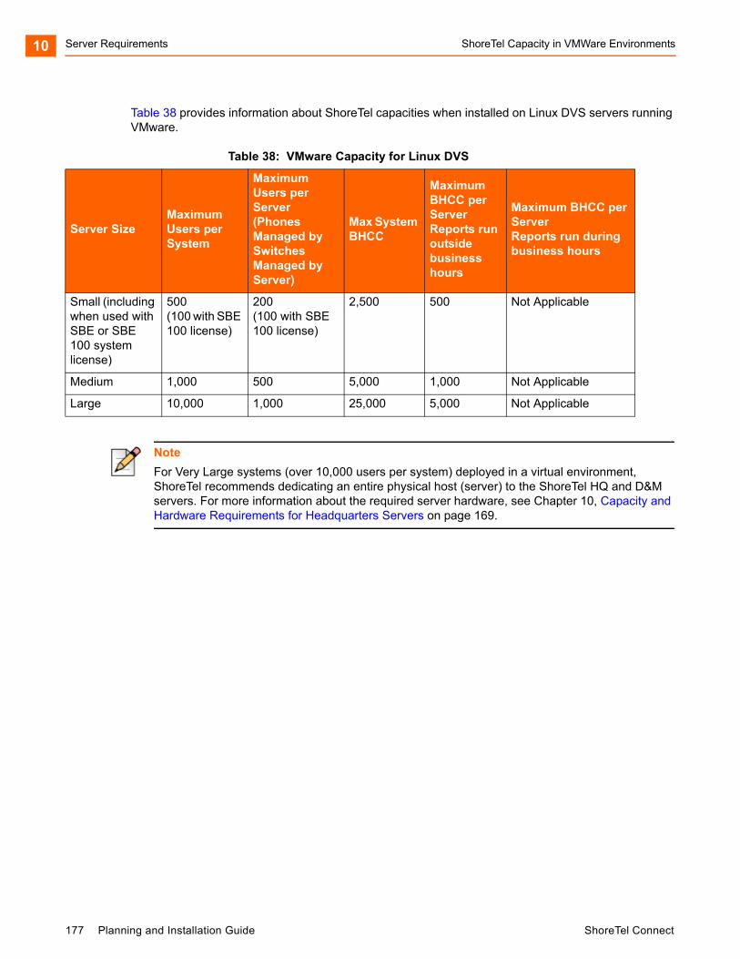
Server Requirements ShoreTel Capacity in VMWare Environments10
Table 38 provides information about ShoreTel capacities when installed on Linux DVS servers running VMware.
Table 38: VMware Capacity for Linux DVS
Server SizeMaximum Users per System
Maximum Users per Server (Phones Managed by Switches Managed by Server)
Max System BHCC
Maximum BHCC per ServerReports run outside business hours
Maximum BHCC per Server Reports run during business hours
Small (including when used with SBE or SBE 100 system license)
500 (100 with SBE 100 license)
200 (100 with SBE 100 license)
2,500 500 Not Applicable
Medium 1,000 500 5,000 1,000 Not Applicable
Large 10,000 1,000 25,000 5,000 Not Applicable
Note
For Very Large systems (over 10,000 users per system) deployed in a virtual environment, ShoreTel recommends dedicating an entire physical host (server) to the ShoreTel HQ and D&M servers. For more information about the required server hardware, see Chapter 10, Capacity and Hardware Requirements for Headquarters Servers on page 169.
177 Planning and Installation Guide ShoreTel Connect
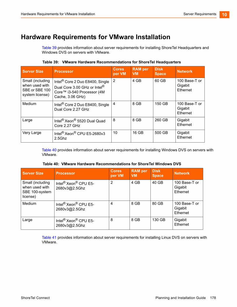
Hardware Requirements for VMware Installation Server Requirements 10
Hardware Requirements for VMware Installation
Table 39 provides information about server requirements for installing ShoreTel Headquarters and Windows DVS on servers with VMware.
Table 40 provides information about server requirements for installing Windows DVS on servers with VMware.
Table 41 provides information about server requirements for installing Linux DVS on servers with VMware.
Table 39: VMware Hardware Recommendations for ShoreTel Headquarters
Server Size ProcessorCores per VM
RAM per VM
Disk Space
Network
Small (including when used with SBE or SBE 100 system license)
Intel® Core 2 Duo E8400, Single
Dual Core 3.00 GHz or Intel® Core™ i3-540 Processor (4M Cache, 3.06 GHz)
2 4 GB 60 GB 100 Base-T or Gigabit Ethernet
Medium Intel® Core 2 Duo E8400, Single Dual Core 2.27 GHz
4 8 GB 150 GB 100 Base-T or Gigabit Ethernet
Large Intel® Xeon® 5520 Dual Quad Core 2.27 GHz
8 8 GB 260 GB Gigabit Ethernet
Very Large Intel® Xeon® CPU E5-2680v3 2.5Ghz
10 16 GB 500 GB Gigabit Ethernet
Table 40: VMware Hardware Recommendations for ShoreTel Windows DVS
Server Size ProcessorCores per VM
RAM per VM
Disk Space
Network
Small (including when used with SBE 100-system license)
Intel® Xeon® CPU [email protected]
2 4 GB 40 GB 100 Base-T or Gigabit Ethernet
Medium Intel® Xeon® CPU [email protected]
4 8 GB 80 GB 100 Base-T or Gigabit Ethernet
Large Intel® Xeon® CPU [email protected]
8 8 GB 130 GB Gigabit Ethernet
ShoreTel Connect Planning and Installation Guide 178
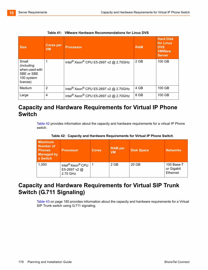
Server Requirements Capacity and Hardware Requirements for Virtual IP Phone Switch10
Capacity and Hardware Requirements for Virtual IP Phone Switch
Table 42 provides information about the capacity and hardware requirements for a virtual IP Phone switch.
Capacity and Hardware Requirements for Virtual SIP Trunk Switch (G.711 Signaling)
Table 43 on page 180 provides information about the capacity and hardware requirements for a Virtual SIP Trunk switch using G.711 signaling.
Table 41: VMware Hardware Recommendations for Linux DVS
SizeCores per VM
Processor RAM
Hard Disk for Linux DVS VMWare Server
Small (including when used with SBE or SBE 100 system license)
1 Intel® Xeon® CPU E5-2697 v2 @ 2.70GHz 2 GB 100 GB
Medium 2 Intel® Xeon® CPU E5-2697 v2 @ 2.70GHz 4 GB 100 GB
Large 4 Intel® Xeon® CPU E5-2697 v2 @ 2.70GHz 8 GB 100 GB
Table 42: Capacity and Hardware Requirements for Virtual IP Phone Switch
Maximum Number of Phones Managed by a Switch
Processor CoresRAM per VM
Disk Space Networks
1,000 Intel® Xeon® CPU E5-2697 v2 @ 2.70 GHz
1 2 GB 20 GB 100 Base-T or Gigabit Ethernet
179 Planning and Installation Guide ShoreTel Connect

Capacity and Hardware Requirements for Virtual SIP Trunk Switch (G.729 Signaling) Server Requirements 10
Capacity and Hardware Requirements for Virtual SIP Trunk Switch (G.729 Signaling)
Table 44 on page 181 provides information about the capacity and hardware requirements for a Virtual SIP Trunk Switch using G.729 signaling.
Table 43: Capacity and Hardware Requirements for Virtual SIP Trunk Switch (G.711 Signaling)
Maximum SIP Trunks without Advanced
Featuresa,b,c
a.Every core can handle up to 125 streams in G.711 signaling.b.Basic calls utilize two streams. Advanced features (Call Recording and Three-Party Conferencing) re-quire one additional stream. Consider usage of advanced features for capacity and hardware require-ments.c. The numbers in this table are recommended guidelines, but you can choose to provision above these numbers. However, you must monitor the performance of your VMs and ensure that CPU utilization does not exceed 75 percent.
Total Number of Streams
Cores Processord
d. All other servers should be benchmarked against this processor to ensure equivalent or better perfor-mance. CPU benchmarking is available at http://www.cpubenchmark.net/.
RAM per VM
Disk Size Network
50 100 1 Intel® Xeon® CPU E5-2697 v2 @ 2.70 GHz
2 GB 20 GB 100 Base-T or Gigabit Ethernet
100 200 2 Intel® Xeon® CPU E5-2697 v2 @ 2.70 GHz
2 GB 20 GB 100 Base-T or Gigabit Ethernet
200 400 4 Intel® Xeon® CPU E5-2697 v2 @ 2.70 GHz
2 GB 20 GB Gigabit Ethernet
400 800 7 Intel® Xeon® CPU E5-2697 v2 @ 2.70 GHz
2 GB 20 GB Gigabit Ethernet
600 1,200 10 Intel® Xeon® CPU E5-2697 v2 @ 2.70 GHz
2 GB 20 GB Gigabit Ethernet
1,000 2,000 16 Intel® Xeon® CPU E5-2697 v2 @ 2.70 GHz
2 GB 20 GB Gigabit Ethernet
ShoreTel Connect Planning and Installation Guide 180
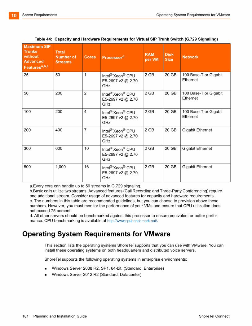
Server Requirements Operating System Requirements for VMware10
Operating System Requirements for VMware
This section lists the operating systems ShoreTel supports that you can use with VMware. You can install these operating systems on both headquarters and distributed voice servers.
ShoreTel supports the following operating systems in enterprise environments:
Windows Server 2008 R2, SP1, 64-bit, (Standard, Enterprise)
Windows Server 2012 R2 (Standard, Datacenter)
Table 44: Capacity and Hardware Requirements for Virtual SIP Trunk Switch (G.729 Signaling)
Maximum SIP Trunks without Advanced
Featuresa,b,c
a.Every core can handle up to 50 streams in G.729 signaling.b.Basic calls utilize two streams. Advanced features (Call Recording and Three-Party Conferencing) require one additional stream. Consider usage of advanced features for capacity and hardware requirements.c. The numbers in this table are recommended guidelines, but you can choose to provision above these numbers. However, you must monitor the performance of your VMs and ensure that CPU utilization does not exceed 75 percent.
Total Number of Streams
Cores Processord
d. All other servers should be benchmarked against this processor to ensure equivalent or better perfor-mance. CPU benchmarking is available at http://www.cpubenchmark.net/.
RAM per VM
Disk Size
Network
25 50 1 Intel® Xeon® CPU E5-2697 v2 @ 2.70 GHz
2 GB 20 GB 100 Base-T or Gigabit Ethernet
50 200 2 Intel® Xeon® CPU E5-2697 v2 @ 2.70 GHz
2 GB 20 GB 100 Base-T or Gigabit Ethernet
100 200 4 Intel® Xeon® CPU E5-2697 v2 @ 2.70 GHz
2 GB 20 GB 100 Base-T or Gigabit Ethernet
200 400 7 Intel® Xeon® CPU E5-2697 v2 @ 2.70 GHz
2 GB 20 GB Gigabit Ethernet
300 600 10 Intel® Xeon® CPU E5-2697 v2 @ 2.70 GHz
2 GB 20 GB Gigabit Ethernet
500 1,000 16 Intel® Xeon® CPU E5-2697 v2 @ 2.70 GHz
2 GB 20 GB Gigabit Ethernet
181 Planning and Installation Guide ShoreTel Connect
VMware Software Requirements Server Requirements 10
VMware Software Requirements
ShoreTel supports the use of VMware on both headquarters servers and distributed voice servers. You can install the following versions of VMware on headquarters servers and distributed voice servers:
VMware ESXi 5.5 for High Availability or VMotion configurations
VMware vSphere ESXi 6.0 for High Availability or VMotion configurations
Deploying ShoreTel servers under VMware
For details on how to deploy ShoreTel servers under VMware, see the example given in ShoreTel Application Note AN 10391, “Deploying ShoreTel Servers under VMware 5.0,” on the ShoreTel Partners web site: http://support.shoretel.com/.
Requirements for Microsoft Hyper-V Environments
Hyper-V is the Microsoft virtual computing infrastructure, consisting of Hyper-V servers, Hyper-V Manager, and related components.
This section provides information necessary to install the ShoreTel Connect system software on servers running Hyper-V.
Supported Configurations and Hyper-V Features
ShoreTel supports the following configurations and features on Hyper-V:
ShoreTel 14.2 and later
ShoreTel HQ and DVS servers
ShoreTel Capacities in Hyper-V Environments
When you create a virtual machine (VM), you must specify various properties related to size, such as the number of CPUs, the amount of memory, and the size of the disk.
Table 45 provides the recommended configuration values for small, medium, and large ShoreTel deployments.
Note
The values shown in Table 45 are typical, but they may not be appropriate for all deployments.
ShoreTel Connect Planning and Installation Guide 182

Server Requirements Hardware Requirements for Hyper-V Installation10
(
Hardware Requirements for Hyper-V Installation
Intel and AMD CPUs that meet the Hyper-V 3.0 CPU requirements include the following types:
Intel Virtualization Technology (Intel VT) or AMD Virtualization (AMD-V) technology.
Hardware-enforced Data Execution Prevention (DEP) must be available and enabled. Specifically, enable Intel XD bit (execute disable bit) or AMD NX bit (no execute bit).
Operating System Requirements for Hyper-V
ShoreTel supports Hyper-V on Microsoft Windows Server 2012 R2 with Hyper-V role installed, Standard and Datacenter Editions.
Software Requirements for Hyper-V
ShoreTel supports Hyper-V on Microsoft Windows Server 2012 R2.
Deploying ShoreTel Servers Under Hyper-V
For details on how to deploy ShoreTel servers under Hyper-V, see the ShoreTel Application Note AN-14008, “Deploying ShoreTel Servers under Microsoft Hyper-V 3.0,” in the Technical Knowledge Base on the ShoreTel Partners support site: http://support.shoretel.com/.
Double-Take Availability Software for Failover
For system failover in the current release, ShoreTel supports Double-Take Availability software version 7.0 only. The Double-Take version 7.0 supports redundancy of the HQ server (physical or virtual) across the LAN or WAN. With the Full Server Protection option, there is no need to install ShoreTel software on the backup server, and select files and folders that need to be replicated. Instead, ShoreTel software only needs to be installed on the HQ server. Double-Take Availability supports:
Initial replication of data, applications, and Windows Server state to the backup (target) server.
Table 45: Recommended Sizing Parameters
System Size
Users
Call Load per System
Call Load per Server (w/o Reports)
Minimum Virtual Processors per VM
RAM per VM(GB)
Storage System Through-put (MB/s)
Voice Network Through-put (Mb/s)
Disk Size per HQ VM(GB)
Disk Size per DVS VM(GB)
Small 500 5,000 1,000 2 4 0.17 16 60 40
Medium 2,500 25,000 5,000 4 8 0.83 80 150 80
Large 10,000 50,000 10,000 8 8 3.1 320 260 130
183 Planning and Installation Guide ShoreTel Connect
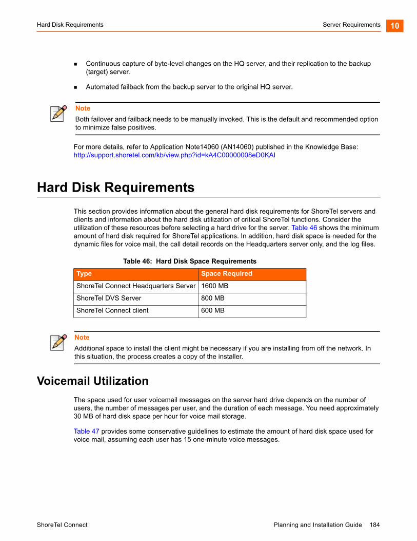
Hard Disk Requirements Server Requirements 10
Continuous capture of byte-level changes on the HQ server, and their replication to the backup (target) server.
Automated failback from the backup server to the original HQ server.
For more details, refer to Application Note14060 (AN14060) published in the Knowledge Base:http://support.shoretel.com/kb/view.php?id=kA4C00000008eD0KAI
Hard Disk Requirements
This section provides information about the general hard disk requirements for ShoreTel servers and clients and information about the hard disk utilization of critical ShoreTel functions. Consider the utilization of these resources before selecting a hard drive for the server. Table 46 shows the minimum amount of hard disk required for ShoreTel applications. In addition, hard disk space is needed for the dynamic files for voice mail, the call detail records on the Headquarters server only, and the log files.
Voicemail Utilization
The space used for user voicemail messages on the server hard drive depends on the number of users, the number of messages per user, and the duration of each message. You need approximately 30 MB of hard disk space per hour for voice mail storage.
Table 47 provides some conservative guidelines to estimate the amount of hard disk space used for voice mail, assuming each user has 15 one-minute voice messages.
Note
Both failover and failback needs to be manually invoked. This is the default and recommended option to minimize false positives.
Table 46: Hard Disk Space Requirements
Type Space Required
ShoreTel Connect Headquarters Server 1600 MB
ShoreTel DVS Server 800 MB
ShoreTel Connect client 600 MB
Note
Additional space to install the client might be necessary if you are installing from off the network. In this situation, the process creates a copy of the installer.
ShoreTel Connect Planning and Installation Guide 184
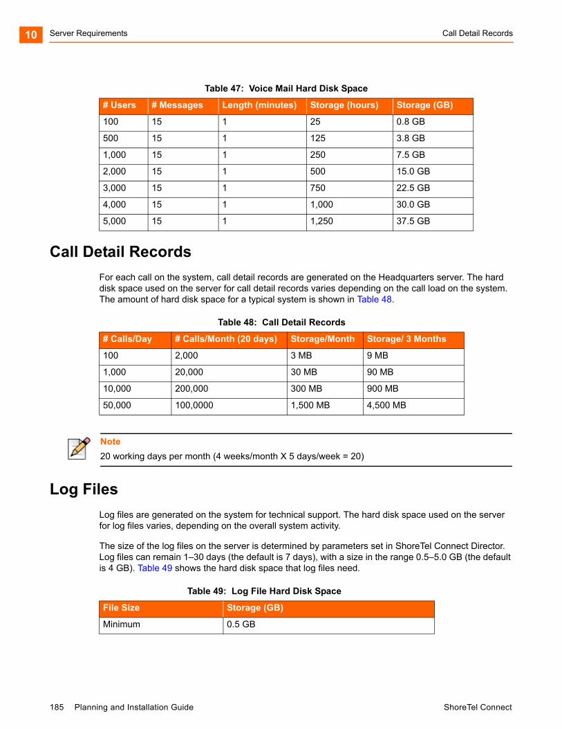
Server Requirements Call Detail Records10
Call Detail Records
For each call on the system, call detail records are generated on the Headquarters server. The hard disk space used on the server for call detail records varies depending on the call load on the system. The amount of hard disk space for a typical system is shown in Table 48.
Log Files
Log files are generated on the system for technical support. The hard disk space used on the server for log files varies, depending on the overall system activity.
The size of the log files on the server is determined by parameters set in ShoreTel Connect Director. Log files can remain 1–30 days (the default is 7 days), with a size in the range 0.5–5.0 GB (the default is 4 GB). Table 49 shows the hard disk space that log files need.
Table 47: Voice Mail Hard Disk Space
# Users # Messages Length (minutes) Storage (hours) Storage (GB)
100 15 1 25 0.8 GB
500 15 1 125 3.8 GB
1,000 15 1 250 7.5 GB
2,000 15 1 500 15.0 GB
3,000 15 1 750 22.5 GB
4,000 15 1 1,000 30.0 GB
5,000 15 1 1,250 37.5 GB
Table 48: Call Detail Records
# Calls/Day # Calls/Month (20 days) Storage/Month Storage/ 3 Months
100 2,000 3 MB 9 MB
1,000 20,000 30 MB 90 MB
10,000 200,000 300 MB 900 MB
50,000 100,0000 1,500 MB 4,500 MB
Note
20 working days per month (4 weeks/month X 5 days/week = 20)
Table 49: Log File Hard Disk Space
File Size Storage (GB)
Minimum 0.5 GB
185 Planning and Installation Guide ShoreTel Connect
Preparing the Server for ShoreTel Operation Server Requirements 10
Preparing the Server for ShoreTel Operation
This section describes how to prepare the server for operation in the ShoreTel Connect telephony network.
Server IP Address
The ShoreTel Connect server should have a static IP address. If the server suddenly gets a new IP address, system operation can be unpredictable.
DHCP on the ShoreTel Server
ShoreTel recommends that the ShoreTel server not be used as a Dynamic Host Configuration Protocol (DHCP) server.
Microsoft Windows Server 2008 R2 Configuration
Before you install ShoreTel server software, you must prepare Microsoft Windows Server 2008 R2 to run ShoreTel services by enabling IIS, COM+, SMTP, and FTP, as well as changing the SMTP and FTP startup type to automatic. You must also ensure that all recommended Microsoft updates for the operating system are installed on the server. This section describes how to prepare a Microsoft Windows Server 2008 R2 server to use ShoreTel software.
Default 4.0 GB
Maximum 30.0 GB
Note
You should always configure the server to be part of a domain and make sure that it remains in the domain.
Notes
User Account Control must be disabled on the server before installing the ShoreTel server software.
Windows Server 2008 R2 must be activated through Microsoft before installing the ShoreTel server software.
Disable the Windows Base Filtering Engine, and Windows Firewall services.
Table 49: Log File Hard Disk Space (Continued)
File Size Storage (GB)
ShoreTel Connect Planning and Installation Guide 186
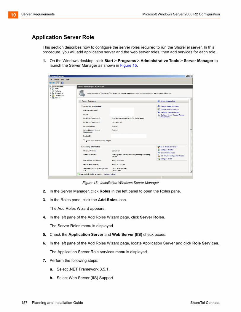
Server Requirements Microsoft Windows Server 2008 R2 Configuration10
Application Server Role
This section describes how to configure the server roles required to run the ShoreTel server. In this procedure, you will add application server and the web server roles, then add services for each role.
1. On the Windows desktop, click Start > Programs > Administrative Tools > Server Manager to launch the Server Manager as shown in Figure 15.
Figure 15: Installation Windows Server Manager
2. In the Server Manager, click Roles in the left panel to open the Roles pane.
3. In the Roles pane, click the Add Roles icon.
The Add Roles Wizard appears.
4. In the left pane of the Add Roles Wizard page, click Server Roles.
The Server Roles menu is displayed.
5. Check the Application Server and Web Server (IIS) check boxes.
6. In the left pane of the Add Roles Wizard page, locate Application Server and click Role Services.
The Application Server Role services menu is displayed.
7. Perform the following steps:
a. Select .NET Framework 3.5.1.
b. Select Web Server (IIS) Support.
187 Planning and Installation Guide ShoreTel Connect
Microsoft Windows Server 2008 R2 Configuration Server Requirements 10
c. Select COM+ Network Access.
d. Select TCP Port Sharing.
e. Select all Windows Process Activation Service Support features.
f. Select all Distributed Transactions features.
8. In the left pane of the Add Roles Wizard page, locate Web Server (IIS) and click Role Services.
The Web Server Role services menu is displayed.
9. Perform the following steps:
a. Select all Common HTTP Features.
b. Select all Application Development Features.
c. Select the following Health and Diagnostics Features:
HTTP Logging
Logging Tools
Request Monitor
Tracing
d. Select all Security options
e. Select all Performance options
f. Select all Management Tools options.
g. Select all FTP Publishing Service options.
10. Click Next.
The Confirm Installation Selections page appears.
11. Click Install.
Installing SMTP
ShoreTel requires the installation of SMTP Server. To install SMTP, do the following:
1. On the Windows desktop, click Start > Programs > Administrative Tools > Server Manager.
The Service Manager page appears.
2. Click Features.
The Features panel appears on the right.
3. Click the Add Features icon.
The Add Features Wizard appears.
ShoreTel Connect Planning and Installation Guide 188
Server Requirements Microsoft Windows Server 2012 R2 Configuration10
4. Select Features in the menu.
The Select Features Installation page appears.
5. Check the SMTP Server check box.
6. Click Next.
The Confirm Installation Selections page appears.
7. Click Install.
Setting SMTP and FTP Properties
After SMTP and FTP are installed, the startup type must be changed from manual to automatic. The following procedure changes the startup type for SMTP and FTP.
1. Access the Services table by selecting Server Manager > Configuration > Services.
2. Right click Simple Mail Transfer Protocol and select Properties on the menu.
The Simple Mail Transfer Protocol (SMTP) Properties page appears.
3. Select Automatic on the Startup Type drop down menu, then click the OK button.
4. Return to the Services page.
5. On a Windows 2008 32-bit server: Right click FTP Publishing Service and select Properties on the menu. The FTP Publishing Service properties page appears. In the Startup Type field, select Automatic and click the OK button.
6. On a Windows 2008 R2 64-bit server: Right click Microsoft FTP Service and select Properties on the menu. The Microsoft FTP Service properties page appears. In the Startup Type field, select Automatic and click the OK button.
Microsoft Windows Server 2012 R2 Configuration
Before you install ShoreTel server software, you must prepare Microsoft Windows Server 2012 R2 to run ShoreTel services by enabling IIS, COM+, SMTP, and FTP, as well as changing the SMTP and FTP startup type to automatic. This section describes how to prepare a Microsoft Windows Server 2012 R2 server to use ShoreTel Connect software.
Note
Verify that the FTProot folder in the Inetpubs directory has at least read access.
189 Planning and Installation Guide ShoreTel Connect
Microsoft Windows Server 2012 R2 Configuration Server Requirements 10
Application Server Role
This section describes how to configure the server roles required to run the ShoreTel Connect server. In this procedure, you add application server and web server roles, and then you add services for each role.
1. On the Windows desktop, click Start > Programs > Administrative Tools > Server Manager to launch the Server Manager Dashboard.
2. In the Server Manager Dashboard, under Configure this local server, click Add roles and features.
The Add Roles and Features Wizard appears, showing the Before you begin page.
3. After reading the Before you begin page, click Next.
The Select installation type page appears.
4. In the middle pane, select Role-based or feature-based installation, then click Next.
The Select destination server page appears.
5. Check Select a server from the server pool, then highlight a server in the pool and click Next.
The Select server roles page appears.
6. Check the Application Server and Web Server (IIS) check boxes.
The “Add features that are required for Web Server (IIS)?” page is displayed.
7. Click Add Features, and click Next.
The Select features page appears, showing the Application Server Features menu.
8. Perform the following steps:
a. Select .NET Framework 3.5 Features.
b. Select Quality Windows Audio Video Experience.
c. Select SMTP Server.
Note
Windows Server 2012 R2 must be activated through Microsoft before installing the ShoreTel server software.
During installing the server operating system, select the Server with a GUI option, instead of Server Core Installation option.
Note
Run the Windows updates and all the related patches before adding the Roles and Features.
ShoreTel Connect Planning and Installation Guide 190
Server Requirements Microsoft Windows Server 2012 R2 Configuration10
The "Add features that are required for SMTP Server?" page is displayed.
d. Click Add Features, and click Next.
The Application Server page is displayed.
9. Click Next.
The Select role services page is displayed.
10. Check Web Server (IIS) Support.
The “Add features that are required for Web Server (IIS) Support?” page is displayed.
11. Click Add features, and click Next.
The Web Server Role (IIS) page appears.
12. Click Next.
The Select role services page appears.
13. Perform the following steps:
a. Select all Common HTTP Features.
b. Select the following Health and Diagnostics Features:
HTTP Logging
Logging Tools
Request Monitor
Tracing
c. Select all Performance options.
d. Select all Security options.
e. Select all Application Development Features.
f. Select all FTP Server options.
g. Select all IIS Hostable Web Core options.
h. Select all Management Tools options.
14. Click Next.
The Confirm installation selections page appears.
15. Click Install.
Setting SMTP and FTP Properties
After SMTP and FTP are installed, by default the SMTP startup up type is Manual, and for FTP the startup type is Automatic.
191 Planning and Installation Guide ShoreTel Connect
Additional Considerations Server Requirements 10
The following procedure changes the startup type for SMTP.
1. Access the Services table by selecting Server Manager > Tools > Services.
2. Right click Simple Mail Transfer Protocol and select Properties on the menu.
The Simple Mail Transfer Protocol (SMTP) Properties page appears.
3. Select Automatic on the Startup Type drop down menu, then click the OK button.
4. Return to the Services page.
5. Right click Microsoft FTP Service and select Properties on the menu.
The Microsoft FTP Service properties page appears.
6. In the Startup Type field, confirm that the Automatic option appears.
7. Click the OK button.
Additional Considerations
This section discusses additional recommendations and requirements for installing the ShoreTel server.
Maximum Transmission Unit (MTU) Size for Connections
The default Maximum Transmission Unit (MTU) setting for PPP (Point-to-Point Protocol) clients, VPN (Virtual Private Network) clients, PPP servers, or VPN servers running Routing and Remote Access on ShoreTel Connect systems is 1400. To change the MTU value, you must edit the registry. For further information, contact ShoreTel TAC.
Windows Firewall Settings
The basic Windows firewall must be disabled for the Headquarters server and Windows DVS.
IE Enhanced Security Configuration
The IE Enhanced Security Configuration parameter must be disabled for Administrators.
IPv6
IPv6 parameter must be disabled for the primary NIC.
Note
Verify that the FTProot folder in the Inetpubs directory has at least read access.
ShoreTel Connect Planning and Installation Guide 192
Server Requirements Additional Considerations10
Data Execution Prevention (DEP)
Data Execution Prevention is recommended for essential Windows Programs and Services only. The default is for all programs and services.
Adobe Acrobat Reader
Install Adobe Acrobat Reader on the server if you do not already have it, so that you can access the online documentation. You can install Adobe Acrobat Reader from the ShoreTel USB flash drive or download it from the Adobe web site.
Internet Information Server (IIS) Default Web Site
The web site for ShoreTel Connect Director is http://<server_name>/shorewaredirector. You should not change the default IIS web site of the server to redirect to ShoreTel Connect Director, since this will cause navigation problems within ShoreTel Connect Director.
Access to the Distributed Server Maintenance Page
If you are using Microsoft Internet Explorer and the distributed server is configured with an IP address rather than a server name, you must enable session cookies on your client computer to access the Distributed Server Maintenance Page. To enable session cookies:
1. Launch Internet Explorer.
2. Click Tools > Internet Options.
The Internet Options dialog box appears.
3. Click the Privacy tab then the Advanced button.
The Advanced Privacy Settings dialog box appears.
4. Check the Override automatic cookies check box.
5. Select Always allow session cookies.
6. Click OK to save the change.
Microsoft Updates on the Server
When releasing a new build, ShoreTel publishes build notes listing the Microsoft patches that are certified against the build. ShoreTel also highlights software changes required by the Microsoft patches. No additional Microsoft updates should be applied to your ShoreTel Connect server between ShoreTel builds. If you install Microsoft updates between ShoreTel Connect builds, they may have an adverse effect on your telephone system.
Virus Protection on the Main and Distributed Servers
ShoreTel allows the use of industry-standard virus protection software on the main and distributed servers.
193 Planning and Installation Guide ShoreTel Connect
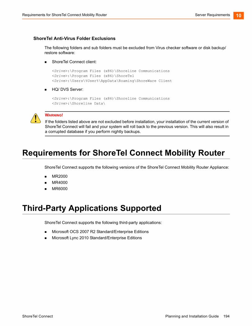
Requirements for ShoreTel Connect Mobility Router Server Requirements 10
ShoreTel Anti-Virus Folder Exclusions
The following folders and sub folders must be excluded from Virus checker software or disk backup/restore software:
ShoreTel Connect client:
<Drive>:\Program Files (x86)\Shoreline Communications<Drive>:\Program Files (x86)\ShoreTel<Drive>:\Users\%User%\AppData\Roaming\ShoreWare Client
HQ/ DVS Server:
<Drive>:\Program Files (x86)\Shoreline Communications<Drive>:\Shoreline Data\
Requirements for ShoreTel Connect Mobility Router
ShoreTel Connect supports the following versions of the ShoreTel Connect Mobility Router Appliance:
MR2000
MR4000
MR6000
Third-Party Applications Supported
ShoreTel Connect supports the following third-party applications:
Microsoft OCS 2007 R2 Standard/Enterprise Editions
Microsoft Lync 2010 Standard/Enterprise Editions
WARNING!
If the folders listed above are not excluded before installation, your installation of the current version of ShoreTel Connect will fail and your system will roll back to the previous version. This will also result in a corrupted database if you perform nightly backups.
ShoreTel Connect Planning and Installation Guide 194

Server Requirements Third-Party Applications Supported10
195 Planning and Installation Guide ShoreTel Connect
CHAPTER
11. ShoreTel Connect ServerInstallation
This chapter describes installation procedures for main and distributed ShoreTel Connect headquarters servers and distributed servers. The topics discussed in this chapter include:
Checking Server Compatibility ................................................................................ 197
Running the Compatibility Checker .................................................................. 197
Headquarters Server Software Installation ............................................................. 198
Installing the Headquarters Server Software Using the USB ........................... 199
Installing the Headquarters Server Software using the Shortpath Name ......... 200
Verifying the Headquarters Installation ............................................................. 200
Registering the Headquarters Server Software ................................................ 201
Installing the Diagnostics & Monitoring Service on a Remote Server............... 206
Distributed Voice Server Software Installation ........................................................ 207
Installing the DVS Software: Windows ............................................................. 208
Installing the DVS Software: Linux ................................................................... 210
Backing up the Headquarters Server ............................................................... 212
Backing up the Headquarters Server ...................................................................... 212
Upgrading the ShoreTel Server System.................................................................. 214
Upgrading the uBoot Version (Half-Width Switches Only)................................ 216
Upgrading from 64-bit Windows Server to 64-bit Windows Server................... 219
Upgrading the System to New Hardware (Same OS) ...................................... 223
Upgrading the DVS Software .................................................................................. 225
Migrating the Headquarters Server ........................................................................ 227
Ensuring Proper Server Performance ..................................................................... 228
ShoreTel Connect Planning and Installation Guide 196

ShoreTel Connect Server Installation Checking Server Compatibility11
Checking Server Compatibility
A compatibility checker is available for identifying potential issues prior to installing or upgrading the ShoreTel Server software. The compatibility checker is included as part of the installer and as a separate utility.
When running the compatibility checker on a system that does not currently have the ShoreTel Server software installed, the utility checks for the following:
Roles and features needed for HQ and DVM
Supported OS and service packs
VBScript issues that may occur during installation
Amount of space needed for the installation
When running the compatibility checker prior to upgrading the ShoreTel Server software, the utility checks for the following:
Roles and features needed for HQ and DVM
Supported OS and service packs
Supported upgrade paths
Amount of space needed for the installation
State of MySQL services and ShoreTel services
Running the Compatibility Checker
Run the compatibility checker from the DVD before running the installer.
1. Insert the ShoreTel DVD into the DVD drive.
2. Navigate to the DVD drive on your computer, open the Tools folder.
3. Double-click CompatibilityChecker.exe.
4. Select Run.
5. Click Compatibility Checker. All components and any compatibility issues are listed.
Note
You must address all compatibility issues before beginning the software installation.
The compatibility checker is also available as part of the installer and can be run from the installation wizard.
197 Planning and Installation Guide ShoreTel Connect
Headquarters Server Software Installation ShoreTel Connect Server Installation 11
Headquarters Server Software Installation
This section describes how to install, verify, and register the ShoreTel Connect headquarters server software. Use the procedures for upgrades or new installations.
Installing the Headquarters Server Software Using the USB on page 199
Installing the Headquarters Server Software using the Shortpath Name on page 200
Verifying the Headquarters Installation on page 200
Registering the Headquarters Server Software on page 201
Before you Begin
Before beginning software installation or upgrade, do the following:
Make sure that the server meets the physical requirements for the implementation. For more information, see Chapter 10, Server Requirements.
If you are using Microsoft Server 2008 R2, ensure that all recommended Microsoft software updates are installed before beginning the installation process.
Close all programs on the server.
Verify that no anti-virus software or endpoint software is running during installation
Verify that Microsoft Visual C ++ with the SP1 Redistributable Package (x86) is installed. Microsoft Visual C++ versions 2005 and 2010 are supported.
Connect the server to the Ethernet network. The server must be connected to the network with the correct IP address before installing the software.
Install ShoreTel Connect server software on an NTFS partition.
(Optional, but strongly recommended) Run the compatibility checker. You can run the compatibility checker from the installation wizard. For more information, see Checking Server Compatibility on page 197.
Your server must be equipped with at least 2-GB RAM. If it has less than 2-GB RAM, the installer displays a warning message before it starts the installation or upgrade.
Install the OS, IIS, and all other pertinent software.
Back up the registry on the server.
Note
It is recommended to install the HQ server software using the USB.
ShoreTel Connect Planning and Installation Guide 198
ShoreTel Connect Server Installation Installing the Headquarters Server Software Using the USB11
Installing the Headquarters Server Software Using the USB
The default parameters presented by the ShoreTel installer are recommended. However, if ShoreTel software is to be located in a different location, select the correct installation path during the install process.
1. Insert the ShoreTel USB flash drive. The installer launches automatically.
2. Click Install ShoreTel Server.
The ShoreTel installation software performs an initial check of your system. You are prompted to install any required software that is not already installed. You must install the required software before continuing.
The ShoreTel Server InstallShield Wizard appears.
3. Click Compatibility Checker to check for any compatibility issues.
4. Follow the instructions in the wizard to install the server software.
5. When the installation completes, you are prompted to restart your server. Click Finish to restart.
6. If upgrading, restart the ShoreTel Voice Switches to finish the upgrade.
This process upgrades the firmware on the switches but also affects all calls in progress.
Note
The data files are unique to your system and include your system configuration, voice messages, and automated attendant prompts. These files will be stored in a Shoreline data folder and should be included as part of your back-up plan for the server.
Note
If the installer does not launch automatically, navigate to the USB flash drive on your computer, open the Server and Setup folders, and then double-click setup.exe.
Note
You must address all compatibility issues before continuing with the installation.
Note
The current software release does not support port 5004. If you are upgrading from an older release with port 5004 enabled, the installer displays the warning message.
199 Planning and Installation Guide ShoreTel Connect
Installing the Headquarters Server Software using the Shortpath Name ShoreTel Connect Server Installation 11
7. Register the software. (This is mandatory.) For more information, see Registering the Headquarters Server Software on page 201.
8. Install your license keys. For more information, see Installing License Keys on page 205.
Installing the Headquarters Server Software using the Shortpath Name
The default parameters presented by the ShoreTel installer are recommended. However, if ShoreTel software is to be located in a different location, select the installation path during the install process.
1. Set the 8dot3name
2. Enter:
Fsutil set 8dot3name <install drive location>: 0
3. Navigate to the Registry Editor. In the command prompt, enter Regedit:
4. Expand HKEY_LOCAL_MACHINE > SYSTEM > CurrentControlSet > Control > FileSystem. In the right window, select NtfsDisable8dot3NameCreation. Set the value to 0.
5. Stop all the ShoreTel related services.
6. In the command prompt, go to C:\program files (x86)\shoreline communications\shoreware server\quickinstall.exe -man
7. Reboot the server.
8. To identify which folder does not have shortpath, run the command dir /X at the root of the folders. This displays all the folders which have shortpaths.
9. If there are no shortpaths, use the following procedure to create one. Enter the following:
C:\>fsutil file setshortname "C:\Program Files (x86)" PROGRA~2
Verifying the Headquarters Installation
It typically takes about 30 to 60 seconds after the operating system is up and running for the Microsoft Internet Information Services (IIS) and ShoreTel voice services to be running. You can do the following to verify that these applications are running.
1. Click the ShoreTel Connect Director desktop icon to launch ShoreTel Connect Director.
Note
Be aware that selecting the checkbox to apply an upgrade to all appliances in the Maintenance > Status > Appliances page selects only the appliances on that page. If you want to upgrade more appliances than those shown on a page, you must manually select additional appliances on subsequent pages.
ShoreTel Connect Planning and Installation Guide 200
ShoreTel Connect Server Installation Registering the Headquarters Server Software11
If IIS is not running, an error message appears. If IIS is running, the ShoreTel Connect Director log in page appears.
2. Log in to ShoreTel Connect Director.
a. In the User ID field, enter the user name that you want to use.
The default user ID is admin.
b. In the Password field, enter the password for the user.
The default password is changeme.
c. Click Login.
3. To verify that ShoreTel Connect Director has been successfully installed on your system, do the following:
a. In the navigation menu, click Maintenance > Status > Servers.
The Servers page is displayed.
b. In the Servers list pane, verify that the Headquarters server has a green circle in the first column and that the value in the Status column is “In Service.”
Registering the Headquarters Server Software
After upgrading or installing headquarters server software, you must register the software with ShoreTel. Registration is mandatory.
ShoreTel encourages you to register the software promptly so that we have the most up-to-date information concerning your ShoreTel products and installation. If registration is not received by ShoreTel within 45 days of installation, access to ShoreTel Connect Director is limited. You can only see the registration form. All other portions of the ShoreTel Connect Director is not displayed.
The software can be registered automatically, over the Internet, or through email.
When registering automatically or over the Internet, registration data is transmitted to ShoreTel over a secure connection to ensure integrity and privacy. The software is registered automatically for upgrades that meet the following prerequisites:
Contact Information is saved in ShoreTel Connect Director before starting the upgrade process.
A valid ShoreTel Connect system license key is installed before starting the upgrade process.
Your system can connect through the Internet to the ShoreTel support web site (https://support.shoretel.com).
For new installations or upgrades that do not meet these prerequisites, you are prompted to register the software the first time you launch ShoreTel Connect Director after installing or upgrading.
You can also choose to register the software over the Internet or through email. Registration over the Internet is quicker than registration through email.
201 Planning and Installation Guide ShoreTel Connect
Registering the Headquarters Server Software ShoreTel Connect Server Installation 11
If an installation does not have adequate or current licenses, ShoreTel Connect Director opens at the License Preview page when you have completed or skipped registration. If registration is not received by ShoreTel within 45 days of installation, access to ShoreTel Connect Director is limited. You can only see the registration form. All other portions of ShoreTel Connect Director are not displayed.
Information Collected through Product Registration
When a customer performs an upgrade or performs a fresh install and requests license keys, the following information is collected through product registration:
Contact information
License key list: features activated; features available for activation for each licensed feature
Server MAC address
Sales Order Number (for initial installations only)
Switch inventory: switch types; MAC addresses; serial numbers
Installed software version information: product name; build number; install timestamp
All this information is included in the EULA (End User License Agreement) provided for an upgrade or installation.
Automatic Registration
1. Upgrade ShoreTel software.
2. Reboot ShoreTel HQ Services.
Registration information is sent over the Internet to ShoreTel. Upon receipt, a response is sent. When the response is received, a Compliance Token is created on the Headquarters server, and ShoreTel Connect Director is unlocked. Until registration is completed, a Reminder Notification message (“out-of-date”) is posted in red letters on the Contact Information page.
3. Confirm registration:
1. Click Administration > System Parameters > Contact Information to navigate to the Contact Information page.
2. Click Refresh this page.
The Reminder Notification message is no longer posted.
4. Install your license keys, if necessary. See Installing License Keys on page 205.
If registration information is not received by ShoreTel (for any reason), ShoreTel Connect Director submits the information every hour for seven days after upgrading. If the process is unsuccessful, you must submit the Contact Information again (over the internet or through email) as often as necessary until registration is completed. If registration is not received by ShoreTel within 45 days of installation, access to ShoreTel Connect Director is limited. You can only see the registration form. All other portions of the ShoreTel Connect Director is not displayed.
ShoreTel Connect Planning and Installation Guide 202
ShoreTel Connect Server Installation Registering the Headquarters Server Software11
Internet Registration
1. Upgrade or install ShoreTel software, and launch ShoreTel Connect Director.
2. Do one of the following to display the Contact Information page:
When prompted to register, click Now.
Click Administration > System Parameters > Contact Information.
3. Enter the requested information in the applicable fields.
The Server MAC Address field is automatically populated with information from the ShoreTel Server. You should change this information only if you want a license for a server other than the one to which you are currently connected. If you have changed this information but instead want the defaults, click Refresh this page. The Sales Order Number is on the ShoreTel packing slip. (Supplying this information is optional for system upgrades.)
4. Click Now to Register and request product verification. The License Preview page appears.
5. Request a license key, if you do not have one:
1. Review the information in the License Preview page.
2. Do one of the following:
Click Print at the top of the page to print the information.
Click Submit to send the request immediately to ShoreTel, Inc. After verifying the information, ShoreTel emails the license key within three business days. Until the license key arrives, you can click on Later in the ShoreTel Connect Director Welcome screen to enter ShoreTel Connect Director. You have up to 45 days to install the license key.
Click Save to File to save the request for later submission.
6. Click Submit.
Registration information is sent over the Internet to ShoreTel. Upon receipt, a response is sent. When the response is received, a Compliance Token is created on the Headquarters server, and ShoreTel Connect Director is unlocked. Until registration is completed, a Reminder Notification message (“out-of date”) is posted in red letters on the Contact Information page.
7. Confirm registration:
1. Exit and then relaunch ShoreTel Connect Director.
2. Navigate to the Contact Information page.
3. Click Refresh this page. The Reminder Notification message is no longer posted.
8. Install your license keys, if necessary. see Installing License Keys on page 205.
If registration information is not received by ShoreTel (for any reason), ShoreTel Connect Director submits the information every hour for seven days after upgrading. If the process is unsuccessful, you must submit the Contact Information again (over the Internet or through email) as often as necessary
203 Planning and Installation Guide ShoreTel Connect
Registering the Headquarters Server Software ShoreTel Connect Server Installation 11
until registration is completed. If registration is not received by ShoreTel within 45 days of installation, access to ShoreTel Connect Director is limited. You can only see the registration form. All other portions of the ShoreTel Connect Director is not displayed.
Email Registration
1. Upgrade or install ShoreTel software, and launch ShoreTel Connect Director.
2. Display the Contact Information page by doing one of the following:
Click Now when prompted to register.
Click Administration > System Parameters > Contact Information.
3. Enter the requested information in the applicable fields.
The Server MAC Address field is automatically populated with information from the ShoreTel Server. You should change this information only if you want a license for a server other than the one to which you are currently connected. If you have changed this information but instead want the defaults, click Refresh this page. The Sales Order Number is on the ShoreTel packing slip. (Supplying this information is optional for system upgrades.)
4. Click Now to Register and request product verification. The License Preview page appears.
5. Request a license key, if you do not have one:
1. Review the information in the License Preview page.
2. Do one of the following:
Click Print at the top of the page to print the information.
Click Submit to send the request immediately to ShoreTel, Inc. After verifying the information, ShoreTel emails the license key within three business days. Until the license key arrives, you can click on Later in the ShoreTel Connect Director Welcome screen to enter ShoreTel Connect Director. You have up to 45 days to install the license key.
Click Save to File to save the request for later submission.
6. Click Save to File. Follow the steps required to save the (SLR) file on your desktop.
7. Email the SLR file to ShoreTel at: [email protected].
Upon receipt, a response is sent containing a compliance token granting access to ShoreTel Connect Director. This token (or, license key) is associated with the Server MAC address and a System Build Number.
8. Verify the compliance token.
1. Click Administration > System Parameters > Product Verification. The Product Verification page appears.
2. Enter the Compliance Token and click Verify. If the token is valid, a confirmation message is displayed.
ShoreTel Connect Planning and Installation Guide 204
ShoreTel Connect Server Installation Registering the Headquarters Server Software11
9. Confirm registration:
1. Exit then relaunch ShoreTel Connect Director.
2. Navigate to the Contact Information page.
3. Click Refresh this page. The Reminder Notification message is no longer posted.
10. Install your license keys, if necessary. See Installing License Keys on page 205.
If registration information is not received by ShoreTel (for any reason), ShoreTel Connect Director submits the information every hour for seven days after upgrading. If the process is unsuccessful, you must submit the Contact Information again (over the internet or through email) as often as necessary until registration is completed. If registration is not received by ShoreTel within 45 days of installation, access to ShoreTel Connect Director is limited. You can only see the registration form. All other portions of the ShoreTel Connect Director is not displayed.
Installing License Keys
1. View the license packet that you received from ShoreTel.
2. Launch ShoreTel Connect ShoreTel Connect Director.
3. In the navigation pane, click Administration > System Parameters > Licenses > Keys.
The License Key Info dialog box appears.
4. Click the New button at the top of the page.
5. In the Key field, enter the license key that you received from ShoreTel.
6. In the Comment field, enter a description of the license.
7. Click Save.
The license activates and the information is posted in the License Key page.
If you have not already obtained your license keys, see Obtaining Licenses.
Obtaining Licenses
1. Contact your ShoreTel partner or reseller and purchase the number and type of needed licenses. The partner or reseller will give you a purchase order number.
2. Launch ShoreTel Connect Director and then log in.
3. Click Administrator > System Parameters >Licenses > Keys.
The License Keys page appears.
4. Click the Register and Request System Key button at the top of the page. The Contact Information page appears.
205 Planning and Installation Guide ShoreTel Connect
Installing the Diagnostics & Monitoring Service on a Remote Server ShoreTel Connect Server Installation 11
5. Enter the information requested in the Register and request system key section. Be sure to include the Sales order number from the purchase order and the customer’s primary contact information.
6. Click the Now button above the information fields.
The system sends the request to ShoreTel for processing. After processing the request, ShoreTel sends the licenses in a email.
Installing the Diagnostics & Monitoring Service on a Remote Server
Although the installation wizard automatically installs a Monitoring service instance on the Headquarters server when you initially install or upgrade to the current ShoreTel release, you can also choose to install it on a remote server.
If your system has more than 10,000 busy-hour call attempts (BHCA), ShoreTel recommends that you install the Monitoring service instance on a remote server to reduce the processing load on the Headquarters server. You would then be able to use the remote server for monitoring the system; however, the system still stores the Diagnostics & Monitoring database on the Headquarters server.
After you install the Monitoring service instance on a remote system, you must also change the role of the Headquarters server and the remote server, so that the Headquarters server becomes the Event Collector and the remote server is the Main Service.
To install a Monitoring service instance on a remote server and change the role of the servers, follow these steps:
1. On the USB flash drive that contains the ShoreTel installation software, navigate to the Monitoring Service folder.
2. To start the installation wizard, double-click ShoreTelMonitoringService.
3. Click Run.
4. Follow the instructions in the wizard to install the Monitoring service instance.
5. After the installation wizard completes, restart the standalone server.
Note
You must install the Monitoring service instance on a server that is not running either ShoreTel Headquarters server software or ShoreTel Distributed Voice Server software. The remote server must be running a currently supported version of Microsoft Windows Server software and, at a minimum, meet the requirements for a small server as described in Table 10 on page 37.
Note
When the installation wizard prompts you to enter the IP address of the Headquarters server, you must enter the actual IP address and not the server name.
ShoreTel Connect Planning and Installation Guide 206
ShoreTel Connect Server Installation Distributed Voice Server Software Installation11
6. On the Headquarters server, launch ShoreTel Connect Director.
7. In the navigation menu, click Maintenance > Configuration > Monitoring Service.
The Monitoring Service page appears and displays both the Headquarters server and the remote server.
8. In the list pane, click the Headquarters server to select it, and then use the Role drop-down list to change the role of the Headquarters server to Event Collector.
9. In the list pane, click the remote server to select it, and then use the Role drop-down list to change the role of the remote server to Main Service.
10. Click Save.
11. Restart the Headquarters server.
For more information, see the Diagnosing and Monitoring chapter in the ShoreTel Connect System Administration Guide.
Distributed Voice Server Software Installation
The ShoreTel Distributed Voice Server (DVS) must be a dedicated server with no other applications installed. This means you should not use this server for any of the following: Windows Domain controller, Terminal Server, Database Server (with MySQL), Web server, nor exchange server. This DVS server must be exclusively dedicated to supporting ShoreTel.
A DVS has the same software prerequisites as the ShoreTel Headquarters server.
Before beginning software installation, do the following:
Make sure that the server meets the requirements for either a Windows DVS or Linux DVS implementation. For more information, see Server Requirements on page 179.
Connect the server to the Ethernet network. The server must be connected to the network with the correct IP address before installing the software.
If you are running anti-virus software, ensure that you disable it.
Verify that Microsoft Visual C ++ with the SP1 Redistributable Package (x86) is installed.
Linux DVS: Verify access to a vSphere Client and connection to an EXSi server, version 5.0 or higher.
Install the remote server software on an NTFS partition.
Note
Installing the anti-virus software is not mandatory on the ShorTel Connect system.
207 Planning and Installation Guide ShoreTel Connect
Installing the DVS Software: Windows ShoreTel Connect Server Installation 11
(Optional) Run the compatibility checker to check for any compatibility issues. The compatibility checker is available as part of the server installation and as a standalone utility. For information about using the compatibility checker, see Checking Server Compatibility on page 197.
Installing the DVS Software: Windows
Installing the DVS Software Using the USB Flash Drive on page 208
Installing the DVS Software Using the shortpath Name on page 209
Installing the DVS Software Using the USB Flash Drive
1. Insert the ShoreTel USB flash drive.
2. Copy all the contents from the USB flash drive to a local folder.
3. Click Install ShoreTel Remote Server. The ShoreTel Server InstallShield Wizard appears.
The ShoreTel installation software performs an initial check of your system. You are prompted to install any required software that is not already installed. You must install the required software before continuing.
The installer launches automatically and the ShoreTel Intelligent Phone Systems splash screen appears
4. Select the Compatibility Checker as described in Running the Compatibility Checker on page 197.
5. Follow the instructions in the wizard to install the server software.
The wizard prompts you to enter the IP address of the Headquarters server. Make sure that the IP address of the remote server does not conflict with the IP address of the Headquarters server.
Note
ShoreTel recommends that you install the DVS software from the USB flash drive.
Note
If the installer does not launch automatically, go to the folder and right-click and run as Administrator on setup.exe.
Note
You must address all compatibility issues before continuing with the installation.
Note
During installation, the installer pauses and prompts you to install Microsoft .NET Framework 4, which is required for the current software release. The installer downloads .NET Framework 4 from the Microsoft site, so you will need an Internet connection to complete the installation.
ShoreTel Connect Planning and Installation Guide 208
ShoreTel Connect Server Installation Installing the DVS Software: Windows11
6. When the installation completes, click Finish. A dialog box appears, prompting you to restart the server.
7. Click Yes.
After the server restarts, all the necessary software restarts automatically. It typically takes about 30 to 60 seconds after the operating system is up and running for the Microsoft Internet Information Services (IIS) and ShoreTel voice services to be running.
Installing the DVS Software Using the shortpath Name
1. Set the 8dot3name
2. Enter:
Fsutil set 8dot3name <install drive location>: 0
3. Navigate to the Registry Editor. In the command prompt, enter Regedit:
4. Expand HKEY_LOCAL_MACHINE > SYSTEM > CurrentControlSet > Control > FileSystem. In. the right window, select NtfsDisable8dot3NameCreation. Set the value to 0.
5. Stop all the ShoreTel related services.
6. In the command prompt, go to C:\program files (x86)\shoreline communications\shoreware server\quickinstall.exe -man
7. Reboot the server.
8. To identify which folder does not have a shortpath, run the command dir /X at the root of the folders. This displays all the folders which have shortpaths.
9. If there are no shortpaths, enter the following to create one:
C:\>fsutil file setshortname "C:\Program Files (x86)" PROGRA~2
Note
ShoreTel supports the use of a remote desktop to install the remote server software.
209 Planning and Installation Guide ShoreTel Connect
Installing the DVS Software: Linux ShoreTel Connect Server Installation 11
Installing the DVS Software: Linux
1. From the DVD included in your packaging, either load the DVD into the HQ server or move the downloaded Linux DVS package to a hard drive on the HQ server.
2. Go to the Linux DVS > Setup folder.
3. Right-click Setup.exe and run as Administrator.
4. Follow the installation wizard.
5. Launch ShoreTel Connect Director.
6. In the navigation menu, click System > Downloads.
The Downloads page is displayed.
7. Click Linux DVS install.
A download progress pop-up window is displayed.
8. Select and save the file VMWareShoreTelLDVS.ova to a local drive/location.
9. Run the vSphere Client.
10. Select File > Deploy OVF Template.
11. Browse and select VMWareShoreTelLDVS.ova from the location where you saved the file in Step 8.
12. Select Open and follow the prompts. Change the name if desired and note this name for configuring the DVS later and choose the options best suited for your environment.
13. On the OVF Template Details page, click Next.
14. Enter the Name for the Linux DVS, and then click Next.
The Storage page opens.
15. Select the datastore hard drive.
Note
This procedure requires the vSphere Client and connection to an EXSi server, version 5.0 or higher.
Note
First time Linux DVS installation is completed using a combination of the following steps, including using the DVD in your packaging and steps performed using ShoreTel Connect Director. Refer to the ShoreTel Connect System Administration Guide for Linux DVS configuration information after completing these steps.
ShoreTel Connect Planning and Installation Guide 210

ShoreTel Connect Server Installation Installing the Software from the Web11
16. Click Next.
The Disk Format page opens.
17. Check the Thin Provision Lazy Zeroed check box.
18. Click Next.
The Ready to Complete page opens.
19. Select the Power on after deployment check box.
20. Select Finish.
21. Select the newly created virtual machine.
22. Open the Linux DVS console. Log in with root / ShoreTel.
23. Enter DHCP, Server IP Address, and LDVS IP Address to download the firmware files.
24. Reboot the Linux DVS.
25. In vSphere client, go to its console and log in (root / ShoreTel).
26. Type stcli to open the ShoreTel parameters screen.
27. From the stcli screen, you can view the Linux DVS IP Address and MAC address.
28. In ShoreTel Connect Director, add a new Linux DVS appliance in the required site (it can be HQ, Windows DVS, or its own site) and enter the Linux DVS IP address and MAC address.
29. Add a DNS entry for the fully qualified domain name of the Linux DVS.
30. Enter the Backup parameters as required. (By default, Daily backup is enabled.)
The Linux DVS installation is complete.
Installing the Software from the Web
1. Start the Web browser.
2. In the URL field enter support.shoretel.com. The ShoreTel Support page appears.
3. In the left pane, click Support > IP Phone System.
Note
Note that the virtual machine IP address, netmask, and gateway information are required if using a static configuration.
Note
ShoreTel supports the use of a remote desktop to install the remote server software. Note these instructions do not apply for first time installation for Linux DVS.
211 Planning and Installation Guide ShoreTel Connect
Backing up the Headquarters Server ShoreTel Connect Server Installation 11
4. Under Software Downloads, click the current version of ShoreTel Remote server to download the remote server software.
5. Enter your login information, and then click Sign In.
6. Navigate to the file on your computer and double-click to launch the installer. The ShoreTel Intelligent Phone Systems splash screen appears.
7. Click Install ShoreTel Remote Server.
The ShoreTel Server InstallShield Wizard appears. The installation wizard checks for any compatibility issues.
8. Follow the instructions in the wizard to install the server software.
9. The wizard prompts you to enter the IP address for the Headquarters server. Make sure that the IP address for the remote server does not conflict with the IP address for the Headquarters server.
10. When the installation completes, click Finish.
A dialog box appears, prompting you to restart the server.
11. Click Yes.
After the server restarts, all the necessary software restarts automatically. It typically takes about 30 to 60 seconds after the operating system is up and running for the Microsoft Internet Information Services (IIS) and ShoreTel Connect voice services to be running.
Backing up the Headquarters Server
This section describes how to back up the server operating system.
You have multiple options for backing up a ShoreTel server. Both options take the system down during the backup. Either option to create a backup interrupts the normal system operations. Therefore, it should be performed when service impact can be minimized or during the scheduled maintenance period, off-hours.
Option 1. Run the Stop All Script and Copy the Shoreline Data Folder
1. Stop and disable all ShoreTel services, then reboot after confirming services are stopped:
For 64-bit systems: C:\Program Files (x86)\Shoreline Communications\ShoreWare Server\Scripts\hq_shoretel-stop-svcs.bat
Note
You must address all compatibility issues before continuing with the installation.
ShoreTel Connect Planning and Installation Guide 212

ShoreTel Connect Server Installation Backing up the Headquarters Server11
2. Copy the Shoreline Data folder to a safe location, and label the version and build in the folder in which it is located. Note: When upgrading to ShoreTel Connect, this location is required in Upgrading the uBoot Version (Half-Width Switches Only) on page 216.
3. Run the start services script to get the phone system services running:
For 64-bit systems: C:\Program Files (x86)\Shoreline Communications\ShoreWare Server\Scripts\hq_shoretel-start-svcs.bat
Option 2. Automating the Scheduled Back-up Tasks for ShoreTel Server
Use the Windows Task Scheduler to automate a scheduled backup for the ShoreTel Connect server.
1. Navigate to the following directory:
For 64-bit systems: C:\Program Files (x86)\Shoreline Communications\ShoreWareServer\Scripts\Sample_Backup_Restore
2. Edit the file sw_backup_restore.ini:
[Shoreware File Locations]ShoreWare.Drive = C:ShoreWare.Scripts.Root.Directory = C:\Program Files (x86)\Shoreline Communications\ShoreWare Server\Scripts\ShoreWare.Scripts.DVM.Root.Directory = C:\Program Files (x86)\Shoreline Communications\ShoreWare Server\Scripts\ShoreWare.SVCCLI.CMD = /shoretel/bin/svccliShoreWare.Root.Directory = \Program Files (x86)\Shoreline Communications\ShoreWare ServerShoreWare.DVM.Root.Directory = \Program Files (x86)\Shoreline Communications\ShoreWare Remote Server
Make sure the Shoreware.Drive parameter value in the [Shoreware File Locations] section, specifies the location where the Shoreline Communications is located.
If your system includes any V-switch models, make sure the VMB.ip.list parameter under the [VMB] section specifies all of their assigned IP addresses in a comma separated list.
If your system includes conference bridges, make sure the UCB.ip.list parameter under the [UCB] section specifies all of their assigned IP addresses in a comma separated list.
Make sure the backup is labeled correctly, and that it is on the correct drive and folder location.
3. Open the Task Scheduler by clicking Start > Programs > Accessories > System Tools > Task Scheduler.
4. Right-click and select Create new Task.
The Create Task screen appears.
Note
If you chose a network drive for your backup, be sure the user profile that runs the task has permissions to write to that drive and directory.
213 Planning and Installation Guide ShoreTel Connect
Upgrading the ShoreTel Server System ShoreTel Connect Server Installation 11
5. Enter a name for the task.
6. Choose the following Security options:
Run whether user is logged on or not
Run with highest privileges
Configure for: Windows 7, Windows Server 2008 R2, and Windows Server 2012 R2
Configure Change User or Group to be a user you created to be the back-up user, or the server administrator. You must enter your password for this user.
7. Click the Triggers tab.
8. Click New to create a new trigger, or click Edit to change an existing trigger.
The Edit Trigger screen appears.
9. Fill out the schedule for when you want the process to run.
10. Click the Actions tab and then click New.
The New Action screen appears.
11. Click Browse to locate the script: shoreware_backup.bat.
12. Enter the path to the script in the Start in (optional) field and be sure the script name is shown in the Program/script field.
13. Click OK.
14. Click the Conditions tab and fill in the form according to your business requirements.
15. Click the Settings tab and fill in the form according to your business requirements.
16. Click OK to save the task.
Upgrading the ShoreTel Server System
This section describes how to migrate a ShoreTel Server System to ShoreTel Connect. It also provides information on how to upgrade a system with new hardware:
Overview on page 215
Upgrading the uBoot Version (Half-Width Switches Only) on page 216
Upgrading from 64-bit Windows Server to 64-bit Windows Server on page 219
Upgrading the System to New Hardware (Same OS) on page 223
Note
During non-business hours, be sure to right-click the script task and run it to ensure that it works.
ShoreTel Connect Planning and Installation Guide 214
ShoreTel Connect Server Installation Overview11
Overview
This section is a summary of the upgrade instructions below. The following Warnings/Notes are prerequisites to upgrading the ShoreTel Connect System.
In addition to completing the procedures in the following sections, refer to the ShoreTel Connect Software Build Notice for additional instructions.
WARNING!
Complete the instructions for backing up your server in Backing up the Headquarters Server on page 212 before proceeding.
WARNING!
Make sure that Windows 2008 R2 64-bit Server or Windows 2012 R2 64-bit Server is installed. ShoreTel Connect is supported only on one of these Windows Servers.
Note
Shoreline data from ShoreTel Connect systems older than ShoreTel 14 are not supported on Windows 2012 R2 64bit. To upgrade a system older than ShoreTel 14, the following steps must be completed and are described later in detail:
Upgrade your ShoreTel Server to ShoreTel 14.2.
Upgrade your Windows server to Windows 2012 R2 64bit.
Install ShoreTel 14.2 on the Windows 2012 R2 64bit server.
Copy the Shoreline data folder from the saved directory and place it in [drive]:\shoreline data.
Upgrade to ShoreTel Connect.
215 Planning and Installation Guide ShoreTel Connect

Upgrading the uBoot Version (Half-Width Switches Only) ShoreTel Connect Server Installation 11
Upgrading the uBoot Version (Half-Width Switches Only)
Perform this procedure to upgrade the uBoot version for half-width switches. The V-switches will download and install the new uBoot version automatically during the upgrade, whereas the half-width switches require a manual update.
1. Telnet or SSH to the half-width switch (non V-switch).
2. Go to Shell by typing gotoshell.
3. Enter the command uboot_update on the CLI.
Tip
The following instructions are recommended to install the HQ server in a folder that has a shortpath:
Set the 8dot3name
1. Enter:
Fsutil set 8dot3name <install drive location>: 0
2. Navigate to the Registry Editor. In the command prompt, enter Regedit:
3. Expand HKEY_LOCAL_MACHINE > SYSTEM > CurrentControlSet > Control > FileSystem. In the right window, select NtfsDisable8dot3NameCreation. Set the value to 0.
3. Stop all the ShoreTel related services.
4. In the command prompt, go to C:\program files (x86)\shoreline communications\shoreware server\quickinstall.exe -man
5. Reboot the server.
6. To identify which folder does not have shortpath, run the command dir /X at the root of the folders. This displays all the folders which have shortpaths.
If there are no shortpaths, use the following procedure to create one:
Enter:
C:\>fsutil file setshortname "C:\Program Files (x86)" PROGRA~2
7. To fix the shortpath issue on "Shoreline Data" folder, enter:
C:\>fsutil file setshortname "C:\Shoreline Data" SHOREL~1
Note
SSHing into an ST-generation Voice Switch requires use of the hq_rsa key. Refer to the SSH Access for Utilities section of the ShoreTel Connect Maintenance Guide for details about generating and using this key on ST-generation Voice Switches.
ShoreTel Connect Planning and Installation Guide 216
ShoreTel Connect Server Installation Upgrading the uBoot Version (Half-Width Switches Only)11
4. Exit the shell by typing exit.
5. Select option 4 from the STCLI to reboot the switch.
6. Verify uBoot version on the Maintenance > Status > Appliances page in ShoreTel Connect Director.
Performing a Backup of the SQL Databases
Perform this procedure to create a backup of the SQL databases.
1. Locate the following Directory:
\Program Files (x86)\Shoreline Communications\ShoreWare Server\MySQL\MySQL Server\Examples
2. Create a backup dump of the config database using the command: backupconfig.bat.
3. Create a backup dump of the shorewarewebbridge database using the command: backupwebbridge.bat (12.x and above if applicable)
4. Create a backup dump of the CDR database using the command: backupcdr.bat
5. Create a backup dump of the CDRArchive database using the command: backupcdrarchive.bat (if applicable)
6. Create a backup dump of the backup monitoring database using the command: backupmonitoring.bat (if applicable, and only from ShoreTel 14.2.)
7. Copy the backup sql files to a safe location off the current server to another PC on the C drive.
8. Stop and disable all the ShoreTel services by running the following batch file:
\Program Files (x86)\Shoreline Communications\ShoreWare Server\Script\hq_shoretel-stop-svcs.bat
9. Install the Windows 2012 R2 64-bit Operating System by rebooting the server and starting the boot from the device with the OS installer.
10. Windows will start and you will be prompted to enter correct host name. It will then shut down the machine after boot record is applied and recovery partition is completed.
11. Turn on Machine and Windows setup will continue.
Note
Do not turn off the unit until the operation is complete.
Note
Make sure you have a copy of your current ShoreTel Software Build. You will need to reinstall this prior to upgrading to ShoreTel Connect.
217 Planning and Installation Guide ShoreTel Connect
Upgrading the uBoot Version (Half-Width Switches Only) ShoreTel Connect Server Installation 11
12. After the setup, log in to windows using the following credentials:
User: Administrator
Password: changeme
13. Set up network connectivity based on customer environment.
14. Install Windows updates. Make sure all updates are complete.
15. Go to Server Manager -> configuration -> services
Search for ASP.NET State Services and select properties ‐> set to automatic ‐> start
Search for Quality Audio Wave Experience Services and select properties -> set to automatic -> start
16. Move the Shoreline Data folder back onto the Server at C:\ directory.
17. After the reboot, log into ShoreTel Connect Director and make sure the switches and phones are connected to the newly upgraded Windows Server.
18. Upgrade to ShoreTel Connect.
19. Test the system to ensure all of the following system functionality is working properly:
Workgroups
Route Points
ShoreTel Connect client
Voicemail
Auto Attendants
Availability state changes
Extension-to-extension calling
External calling to internal ext calling
An upgrade to ShoreTel Connect can now be completed. Please refer to the ShoreTel Connect Build Notes for additional upgrade instructions.
Note
Use the same IP address, netmask, gateway, DNS, Wins that was being used on your previous Windows OS version.
Note
On Windows 2012 R2 64-bit operating system, the ShoreTel Shoreline Data folder and ShoreTel Installation files must reside on the C:\ drive partition.d
ShoreTel Connect Planning and Installation Guide 218

ShoreTel Connect Server Installation Migrating from a 32-bit Windows Server to a 64-bit Windows Server11
Migrating from a 32-bit Windows Server to a 64-bit Windows Server
The following procedure is required to migrate the server operating system, from any 32-bit Windows Server to a 64-bit Windows Server.
1. Complete the instructions for backing up your server in Backing up the Headquarters Server on page 212 before proceeding.
2. Make sure that Windows 2008 R2 64-bit Server or Windows 2012 R2 64-bit Server is installed. ShoreTel Connect is supported only on one of these Windows Servers. Refer to the ShoreTel Connect Build Notes for details in addition to the instructions below.
Upgrading from 64-bit Windows Server to 64-bit Windows Server
The following procedure is required to upgrade the operating system from any Windows Server 64-bit to a higher version of 64-bit Windows Server on a server.
1. Ensure that the server meets the hardware requirements as set forth in the Build Notes.
2. Disable a user's Active Directory setting (if enabled). This is an administrator's account into ShoreTel Connect Director.
3. Perform the upgrade during a time window that allows you between 3-8 hours. Systems with only 1-5 switches usually take anywhere between 1-3 hours. The time frame depends on the size of your ShoreTel Connect system.
4. Back up the following databases with the commands listed:
Note
Disable a user's Active Directory settings before proceeding with the upgrade process. If a user's Active Directory setting is not disabled, you will not be able to log into ShoreTel Connect Director after upgrading.
Note
Disable a user's Active Directory settings before proceeding with the upgrade process. If a user's Active Directory setting is not disabled, you will not be able to log into ShoreTel Connect Director after upgrading.
WARNING!
You will be taking services down in order to perform this backup and upgrade. Be sure to perform this procedure during a maintenance window.
219 Planning and Installation Guide ShoreTel Connect
Upgrading from 64-bit Windows Server to 64-bit Windows Server ShoreTel Connect Server Installation 11
CDR database
C:\Program Files (x86)\Shoreline Communications\ShoreWare Server\MySQL\MySQL Server\Examples\backupCDR.bat
Configuration database
C:\Program Files (x86)\Shoreline Communications\ShoreWare Server\MySQL\MySQL Server\Examples\backupConfig.bat
WebBridge database
C:\Program Files (x86)\Shoreline Communications\ShoreWare Server\MySQL\MySQL Server\Examples\backupWebBridge.bat
Monitoring database
C:\Program Files (x86)\Shoreline Communications\ShoreWare Server\MySQL\MySQL Server\Examples\RestoreMonitoring.bat
Archive database on ShoreTel 12.3 and before: (If your system has an archived database, run the following command.)
C:\Program Files (x86)Shoreline Communications\ShoreWare Server\MySQL\MySQL Server 5.0\bin\mysql.exe --user=root --password=shorewaredba --port=4309 --database databasename >"c:\ArchiveCDRdump.sql" 2>>C:\\RestoreArchiveCDR.log
Archive database on ShoreTel 13 and above: (If your system has an archived database, run the following command.)
C:\Program Files (x86)\Shoreline Communications\ShoreWare Server\MySQLConfig\MySQL Server\bin\mysql.exe --user=root --password=shorewaredba --port=4309 --database databasename >"c:\ArchiveCDRdump.sql" 2>>C:\\RestoreArchiveCDR.log
5. For all the backups, be sure the file size is greater than 0 KB.
6. Stop and disable all ShoreTel services by running the following batch file:
Note
The default location for the database dumps is C:\.
Note
Before you back up the CDR database, stop archiving on the headquarters server.
Note
The \Database folder is excluded from the backup because, in a few rare cases, Windows 2008 is unable to read database files after they are moved from Windows 2003. To avoid this scenario, ShoreTel recommends that you backup and restore the databases.
ShoreTel Connect Planning and Installation Guide 220
ShoreTel Connect Server Installation Upgrading from 64-bit Windows Server to 64-bit Windows Server11
C:\Program Files\Shoreline Communications\ShoreWare Server\Scripts\hq_shoretel-stop-svcs.bat
7. Confirm that all ShoreTel services have stopped.
8. Reboot.
9. Copy the Shoreline Data folder (excluding the \Database folder) to a safe location and label the version and build in the folder in which it is located. It is recommended that you copy off the server to a safe location.
10. Restart the ShoreTel services by running the following command:
C:\Program Files\Shoreline Communications\ShoreWare Server\Scripts\hq_shoretel-start-svcs.bat
11. Ensure that everything is up and running properly.
12. Reboot.
13. Pull off to a safe location the ShoreTel Connect Director Installation files and any other files that you may want to keep.
14. After everything is off the server, reboot and boot from the Windows 64-bit CD-ROM.
15. Format the hard drive and install the Windows 64-bit.
16. Log in through the local Admin Account.
17. Adjust the NIC so that it has the same static IP and name that it did before.
18. Add the server to the domain. (Be sure that it is placed in an empty Organizational Unit (OU) with Block Inheritance.) No Group Policies should be applied. If Group Policies do need to be applied, be sure that they have already been tested against ShoreTel.
19. Turn off User Access Control (UAC).
20. Ensure that all of the Application Server Roles and Web Server Roles are installed.
21. Install the SMTP Role under Features.
22. Set DEP to Windows Programs and Services.
23. Install all of the Windows updates approved to the date specified in the Build Notes for the build on your system.
24. Disable Windows updates.
25. Disable Internet Explorer Enhanced Security.
WARNING!
Do not install any Anti-Virus software or Network security software. The ShoreTel Server is a Telephony Appliance. If you absolutely need Anti-Virus software or Network security software due to security regulations, use KB16704 to configure this properly.
221 Planning and Installation Guide ShoreTel Connect
Upgrading from 64-bit Windows Server to 64-bit Windows Server ShoreTel Connect Server Installation 11
26. Disable the pop-up blocker.
27. Copy your old Shoreline Data folder back to the drive where you want to install the software.
28. Install overtop the old Shoreline Data folder the exact same version of the ShoreTel Server software that was installed before.
29. Copy the following database dumps to the C:\ directory:
CDR
Config
WebBridge
Monitoring
Archive SQL (if your system has an archived database)
30. Import the SQL database dumps by running the following commands:
To import the CDR database dump:
C:\Program Files (x86)\Shoreline Communications\ShoreWare Server\MySQL\MySQL Server\Examples\RestoreCDR.bat
To import the Config database dump:
C:\Program Files (x86)\Shoreline Communications\ShoreWare Server\MySQL\MySQL Server\Examples\RestoreConfig.bat
To import the WebBridge database dump:
C:\Program Files (x86)\Shoreline Communications\ShoreWare Server\MySQL\MySQL Server\Examples\RestoreWebBridge.bat
To import the Monitoring database dump:
C:\Program Files (x86)\Shoreline Communications\ShoreWare Server\MySQL\MySQL Server\Examples\RestoreMonitoring.bat
To import the Archive database dump on ShoreTel 12.3 and before (if your system has an archived database):
Note
When installing the ShoreTel server on Windows Server 2008 R2 64-bit or 2012 R2 64-bit, you must launch Setup.exe using “Run as Administrator.”
Note
While restoring the Config DB, services must be stopped excluding the shoreTel MySQL Config. After the restore, start all the services.
ShoreTel Connect Planning and Installation Guide 222
ShoreTel Connect Server Installation Upgrading the System to New Hardware (Same OS)11
C:\Program Files (x86)\Shoreline Communications\ShoreWare Server\MySQL\MySQL Server 5.0\bin\mysql.exe --user=root --password=shorewaredba --port=4309 --database databasename > "c:\ArchiveCDRdump.sql" 2>>C:\\RestoreArchiveCDR.log
To import the Archive database dump (if your system has an archived database):
C:\Program Files (x86)\Shoreline Communications\ShoreWare Server\MySQLConfig\MySQL Server\bin\mysql.exe --user=root --password=shorewaredba --port=4309 --database databasename > "c:\ArchiveCDRdump.sql" 2>>C:\\RestoreArchiveCDR.log
Perform the following steps on the new server
1. Change the IP of the new server to the IP of the original server.
2. Change the Name of the new server to the Name of the original server.
3. Reboot.
4. Copy the Shoreline data folder that you copied from Step 5 to the new server.
5. Install overtop the old Shoreline Data folder the exact same version of the ShoreTel Server software that was installed before.
When installing the ShoreTel server on Windows Server, you must launch Setup.exe using “Run as Administrator.”
6. Log into ShoreTel Connect Director.
Upgrading the System to New Hardware (Same OS)
Be aware that after the ShoreTel software is installed on the server, the server is considered a Telephony Appliance. As a Telephony Appliance, it does not adhere to the same policies, procedures, or security as a data server.
Perform the following steps on the new server
1. Ensure that the new server meets the hardware requirements in the Build Notes.
2. Format the hard drive and install the supported Windows Server software.
3. Log in via the local Admin Account.
4. Add the server to the domain. (Be sure that it is placed in an empty Organizational Unit (OU) with Block Inheritance.) No Group Policies should be applied. If Group Policies need to be applied, be sure that they have already been tested against ShoreTel.
WARNING!
This procedure will take down all services performed by the server. ShoreTel recommends that you perform this procedure during non-business hours.
223 Planning and Installation Guide ShoreTel Connect
Upgrading the System to New Hardware (Same OS) ShoreTel Connect Server Installation 11
5. Turn off User Access Control (UAC).
6. Ensure that all of the Application Server Roles and Web Server Roles are installed.
7. Install the SMTP Role under Features.
8. Set DEP to Windows Programs and Services.
9. Install all of the Windows updates approved to the date specified in the Build Notes for the build on your system.
10. Disable Windows updates.
11. Disable Internet Explorer Enhanced Security.
12. Disable the pop-up blocker.
Perform the following steps on the old server
1. Disable a user's Active Directory setting (if enabled). This is an administrator's account into ShoreTel Connect Director.
2. Stop and disable all ShoreTel services by running the following batch file:
C:\Program Files (x86)\Shoreline Communications\ShoreWare Server\Scripts\hq_shoretel-stop-svcs.bat
3. Confirm that all ShoreTel services have stopped:
a. Go to the Run menu (WIN + R).
b. Type services.msc.
c. Review all of the ShoreTel services to ensure that they show “Manual” and that the services are stopped.
4. Reboot.
5. Copy the Shoreline Data folder (excluding the \Database folder) to a safe location and label the version and build in the folder in which it is located. It is highly recommended that you copy off the server to a safe location.
ShoreTel recommends that you back up these files to a storage device separate from the server that you intend to upgrade.
6. Restart the ShoreTel services by running the following batch file:
WARNING!
Do not install any Anti-Virus software or Network security software. The ShoreTel Server is a Telephony Appliance. If you absolutely need Anti-Virus software or Network security software due to security regulations, use KB16704 to configure this properly.
ShoreTel Connect Planning and Installation Guide 224

ShoreTel Connect Server Installation Upgrading the DVS Software11
C:\Program Files\Shoreline Communications\ShoreWare Server\Scripts\hq_shoretel-start-svcs.bat
7. Confirm that all ShoreTel services are up and running:
a. Go to the Run menu (WIN + R).
b. Type services.msc.
c. Review all of the ShoreTel services to ensure that they show “Automatic” and that the services are started.
8. Change the name of the server.
9. Change the IP of the server to something different.
10. Reboot.
Perform the following steps on the new server
1. Change the IP of the new server to the IP of the original server.
2. Change the Name of the new server to the Name of the original server.
3. Reboot.
4. Copy the Shoreline data folder that you copied from Step 5 to the new server.
5. Install overtop the old Shoreline Data folder the exact same version of the ShoreTel Server software that was installed before.
When installing the ShoreTel server on Windows Server, you must launch Setup.exe using “Run as Administrator.”
6. Log into ShoreTel Connect Director.
Upgrading the DVS Software
If you are upgrading the Windows DVS server software, follow the instructions in the Installing the DVS Software on page 219 or Installing the Software from the Web on page 220. Setup will automatically determine that an upgrade is in process, and you will be presented with a subset of the installation wizard screens. (There is no need to change the destination folders of the ShoreTel files.)
Note: Moving Users from a Windows DVS to a Linux DVS
If upgrading and moving users to a Linux DVS, complete the instructions in the “Move Users from a Windows DVS to a Linux DVS” section of the “Configuring Application Servers” chapter of the ShoreTel Connect System Administration Guide. Perform this procedure after adding a Linux DVS to the system. If moving users to a new site, see Chapter 10, Server Requirements on page 166 for planning information before completing the task of moving users from Windows DVS to Linux DVS.
225 Planning and Installation Guide ShoreTel Connect
Upgrading the DVS Software to Windows Server 2008 R2 64-bit or 2012 R2 64-bit ShoreTel Connect Server Installation 11
Upgrading the DVS Software to Windows Server 2008 R2 64-bit or 2012 R2 64-bit
If you are upgrading the server software to Windows 2012 R2 64-bit from Windows 2008 R2 32-bit/64-bit, perform the following steps:
1. Stop all ShoreTel services, and then copy the Shoreline Data folder to a safe location on a different storage device. (If any ShoreTel processes are running that prevent you from copying the Shoreline Data folder, use Task Manager to stop the processes.)
2. Back up the registry keys to the same backup location as the Shoreline Data folder. (For a server running a 64-bit operating system, you can open the Registry Editor, right-click the HKEY_LOCAL_MACHINE\SOFTWARE\ShorelineTeleworks folder, and select Export.)
3. Uninstall the ShoreTel system software.
4. Upgrade the operating system to Windows Server 2012 R2, Standard or Data Center Edition.
5. Install the same version of the ShoreTel system software that you uninstalled in Step 3.
6. Copy the Shoreline Data folder back to the original location.
7. Restore the registry keys as follows:
For a 64-bit operating system, restore the registry by opening the Registry Editor, right-clicking the HKEY_LOCAL_MACHINE\SOFTWARE\ShorelineTeleworks folder, selecting Import, and specifying the location where you backed up the registry keys folder.
For a 32-bit operating system, manually copy the registry entries modified specifically for your system.
ShoreTel Connect Planning and Installation Guide 226
ShoreTel Connect Server Installation Migrating the Headquarters Server 11
Migrating the Headquarters Server
Sometimes it is necessary to replace an existing Headquarters server. This might be the case when a hardware failure has occurred, the server is being migrated onto a VMWare server, or you want to upgrade the operating system.
When you migrate a Headquarters server, you must take care to properly migrate the data and certificates, as described in this section.
The following instructions describe how to replace Server A with Server B on Windows Server 2012.
1. Install ShoreTel Connect on Server B by following the instructions in this chapter. Install the same ShoreTel Connect version that is running on Server A.
2. On Server A, make a complete backup copy of the Headquarters server files, as described in the “Backing Up the Headquarters Server” section in the “System Backup and Restore” chapter of the ShoreTel Connect System Administration Guide.
3. Copy the entire backup directory (typically <drive>:\Shoreware Backup) from Server A to Server B.
4. Shut down Server A.
5. Reconfigure Server B to have Server A’s old IP address, as follows:
a. In Windows Explorer, right-click Network and select Properties.
b. In the left pane, click Change adapter settings.
c. Right-click primary interface and select Properties.
d. Select the Internet Protocol Version 4 (TCP/IPv4) check box and then click the Properties button.
e. Enter the old IP address of Server A, and click OK.
6. Edit the registry to replace Server B’s old IP address with the IP address of Server A, as follows:
a. Run regedit to open the Registry Editor.
b. Select the following path:
Computer\HKEY_LOCAL_MACHINE\SOFTWARE\WOW6432Node\Shoreline Teleworks
c. Change the IP addresses for the following registry values:
HQServerAddress
LocalDBServerAddress
ServiceIPAddress
7. On Server B, remove the IIS binding for port 443, as follows:
a. Run IIS Manager.
227 Planning and Installation Guide ShoreTel Connect
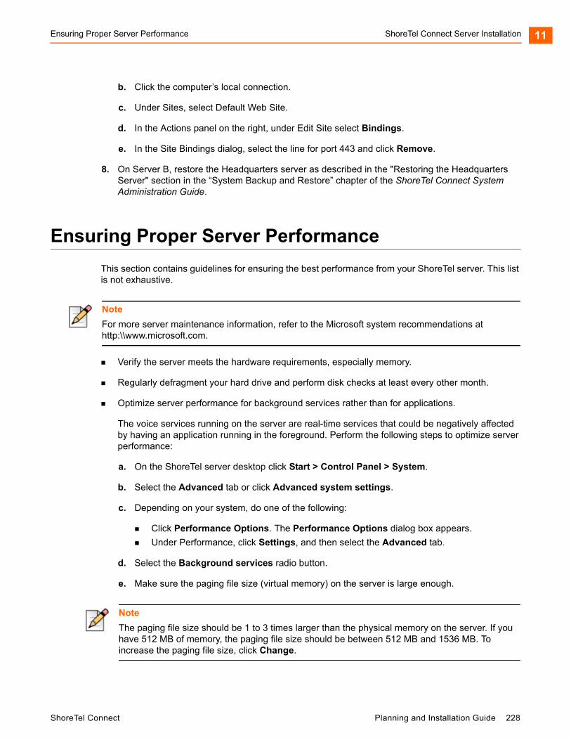
Ensuring Proper Server Performance ShoreTel Connect Server Installation 11
b. Click the computer’s local connection.
c. Under Sites, select Default Web Site.
d. In the Actions panel on the right, under Edit Site select Bindings.
e. In the Site Bindings dialog, select the line for port 443 and click Remove.
8. On Server B, restore the Headquarters server as described in the "Restoring the Headquarters Server" section in the “System Backup and Restore” chapter of the ShoreTel Connect System Administration Guide.
Ensuring Proper Server Performance
This section contains guidelines for ensuring the best performance from your ShoreTel server. This list is not exhaustive.
Verify the server meets the hardware requirements, especially memory.
Regularly defragment your hard drive and perform disk checks at least every other month.
Optimize server performance for background services rather than for applications.
The voice services running on the server are real-time services that could be negatively affected by having an application running in the foreground. Perform the following steps to optimize server performance:
a. On the ShoreTel server desktop click Start > Control Panel > System.
b. Select the Advanced tab or click Advanced system settings.
c. Depending on your system, do one of the following:
Click Performance Options. The Performance Options dialog box appears.
Under Performance, click Settings, and then select the Advanced tab.
d. Select the Background services radio button.
e. Make sure the paging file size (virtual memory) on the server is large enough.
Note
For more server maintenance information, refer to the Microsoft system recommendations at http:\\www.microsoft.com.
Note
The paging file size should be 1 to 3 times larger than the physical memory on the server. If you have 512 MB of memory, the paging file size should be between 512 MB and 1536 MB. To increase the paging file size, click Change.
ShoreTel Connect Planning and Installation Guide 228
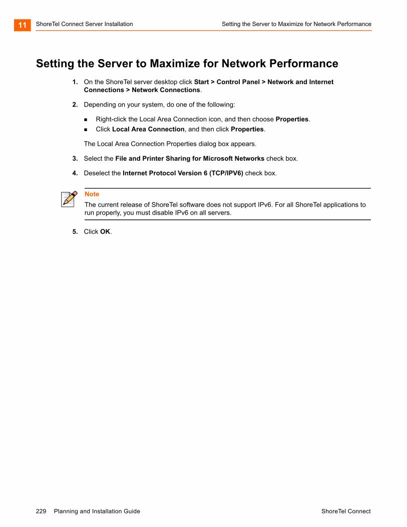
ShoreTel Connect Server Installation Setting the Server to Maximize for Network Performance11
Setting the Server to Maximize for Network Performance
1. On the ShoreTel server desktop click Start > Control Panel > Network and Internet Connections > Network Connections.
2. Depending on your system, do one of the following:
Right-click the Local Area Connection icon, and then choose Properties.
Click Local Area Connection, and then click Properties.
The Local Area Connection Properties dialog box appears.
3. Select the File and Printer Sharing for Microsoft Networks check box.
4. Deselect the Internet Protocol Version 6 (TCP/IPV6) check box.
5. Click OK.
Note
The current release of ShoreTel software does not support IPv6. For all ShoreTel applications to run properly, you must disable IPv6 on all servers.
229 Planning and Installation Guide ShoreTel Connect

CHAPTER
12. Site Requirements andPreparation
This chapter provides information about preparing a site for the ShoreTel Connect system. The topics are:
Recommendations .................................................................................................. 231
Switch Models .................................................................................................. 231
Voice Switch Requirements .................................................................................... 231
Physical Requirements ..................................................................................... 231
Input Power ...................................................................................................... 232
Power and Heat Dissipation ............................................................................. 233
Environmental Requirements ........................................................................... 234
Reliability and Availability ................................................................................. 234
Memory and Processing................................................................................... 236
Connectors ....................................................................................................... 237
Racks and Cabling .................................................................................................. 240
General Cabling Overview................................................................................ 240
Rack Overview ................................................................................................. 242
ShoreTel Connect Planning and Installation Guide 230

Site Requirements and Preparation Recommendations12
Recommendations
The following recommendations can assist in the planning and preparation of a site for a ShoreTel Connect system.
Hire a cabling contractor to install the equipment racks, patch panels, and cabling.
Have RJ-48C cables available for each ShoreTel Voice Switch.
Switch Models
You can locate the model number of your switches on the rear panel as shown in Figure 16. This document distinguishes between switches based on the model number and the number of RUs the switch occupies.
Figure 16: ShoreTel SG-24 Model Number Label
See Appendix C, ShoreTel Voice Switches for information about all ShoreTel Voice Switches. The information describes phone capabilities, connectors, and LED behavior.
Voice Switch Requirements
This section includes requirements for mounting the ShoreTel voice switches, along with other switch-related requirements and specifications.
Physical Requirements
The ShoreTel voice switches are designed to be mounted in a standard 19-inch rack. Table 50 shows the specifications for each voice switch. For more information refer to the Quick Install Guide, included with each ShoreTel voice switch.
231 Planning and Installation Guide ShoreTel Connect
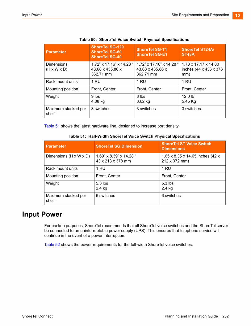
Input Power Site Requirements and Preparation 12
Table 51 shows the latest hardware line, designed to increase port density.
Input Power
For backup purposes, ShoreTel recommends that all ShoreTel voice switches and the ShoreTel server be connected to an uninterruptable power supply (UPS). This ensures that telephone service will continue in the event of a power interruption.
Table 52 shows the power requirements for the full-width ShoreTel voice switches.
Table 50: ShoreTel Voice Switch Physical Specifications
ParameterShoreTel SG-120ShoreTel SG-60ShoreTel SG-40
ShoreTel SG-T1ShoreTel SG-E1
ShoreTel ST24A/ST48A
Dimensions (H x W x D)
1.72” x 17.16” x 14.28 “43.68 x 435.86 x 362.71 mm
1.72” x 17.16” x 14.28 “43.68 x 435.86 x 362.71 mm
1.73 x 17.17 x 14.80 inches (44 x 436 x 376 mm)
Rack mount units 1 RU 1 RU 1 RU
Mounting position Front, Center Front, Center Front, Center
Weight 9 lbs4.08 kg
8 lbs3.62 kg
12.0 lb 5.45 Kg
Maximum stacked per shelf
3 switches 3 switches 3 switches
Table 51: Half-Width ShoreTel Voice Switch Physical Specifications
Parameter ShoreTel SG DimensionShoreTel ST Voice Switch Dimensions
Dimensions (H x W x D) 1.69” x 8.39” x 14.28 “43 x 213 x 378 mm
1.65 x 8.35 x 14.65 inches (42 x 212 x 372 mm)
Rack mount units 1 RU 1 RU
Mounting position Front, Center Front, Center
Weight 5.3 lbs2.4 kg
5.3 lbs2.4 kg
Maximum stacked per shelf
6 switches 6 switches
ShoreTel Connect Planning and Installation Guide 232
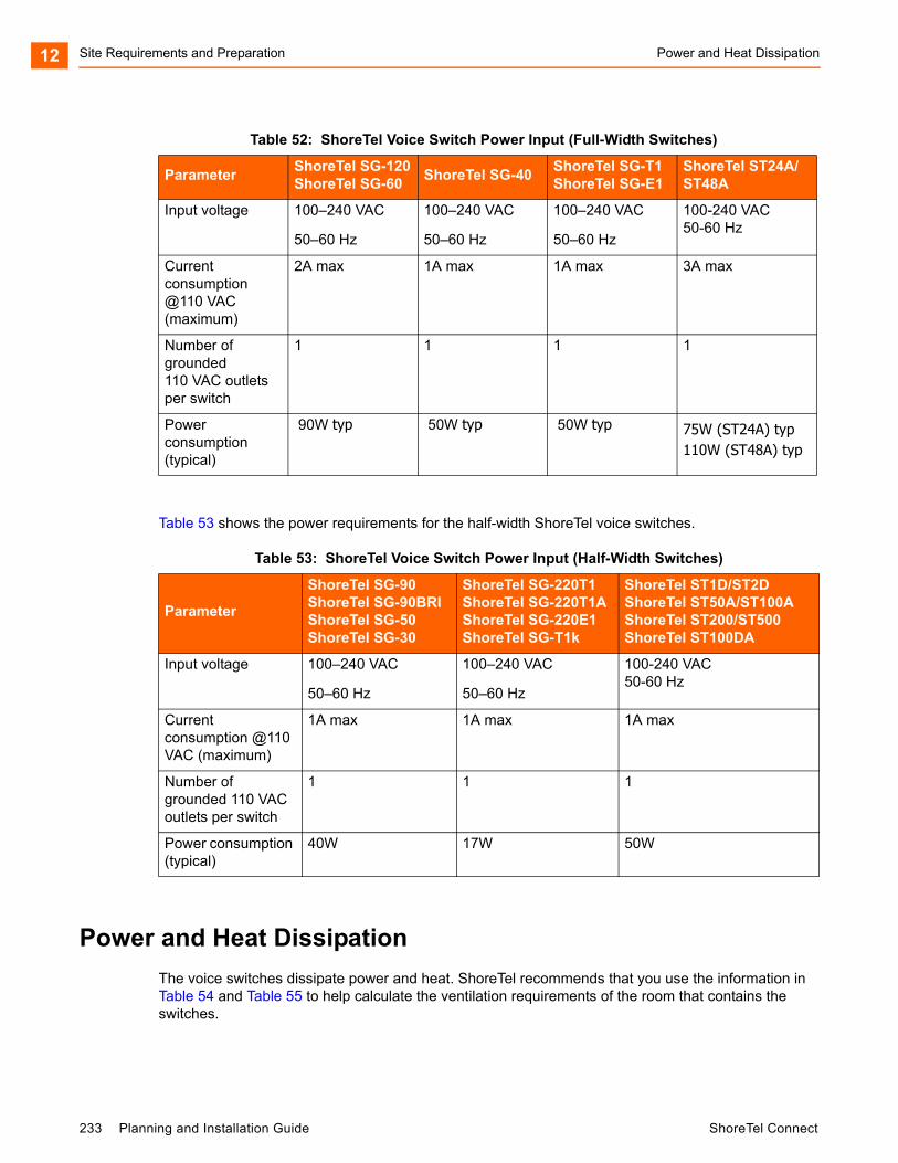
Site Requirements and Preparation Power and Heat Dissipation12
Table 53 shows the power requirements for the half-width ShoreTel voice switches.
Power and Heat Dissipation
The voice switches dissipate power and heat. ShoreTel recommends that you use the information in Table 54 and Table 55 to help calculate the ventilation requirements of the room that contains the switches.
Table 52: ShoreTel Voice Switch Power Input (Full-Width Switches)
ParameterShoreTel SG-120ShoreTel SG-60
ShoreTel SG-40ShoreTel SG-T1ShoreTel SG-E1
ShoreTel ST24A/ST48A
Input voltage 100–240 VAC
50–60 Hz
100–240 VAC
50–60 Hz
100–240 VAC
50–60 Hz
100-240 VAC50-60 Hz
Current consumption @110 VAC (maximum)
2A max 1A max 1A max 3A max
Number of grounded 110 VAC outlets per switch
1 1 1 1
Power consumption (typical)
90W typ 50W typ 50W typ 75W (ST24A) typ110W (ST48A) typ
Table 53: ShoreTel Voice Switch Power Input (Half-Width Switches)
Parameter
ShoreTel SG-90ShoreTel SG-90BRIShoreTel SG-50ShoreTel SG-30
ShoreTel SG-220T1ShoreTel SG-220T1AShoreTel SG-220E1ShoreTel SG-T1k
ShoreTel ST1D/ST2DShoreTel ST50A/ST100AShoreTel ST200/ST500ShoreTel ST100DA
Input voltage 100–240 VAC
50–60 Hz
100–240 VAC
50–60 Hz
100-240 VAC50-60 Hz
Current consumption @110 VAC (maximum)
1A max 1A max 1A max
Number of grounded 110 VAC outlets per switch
1 1 1
Power consumption (typical)
40W 17W 50W
233 Planning and Installation Guide ShoreTel Connect
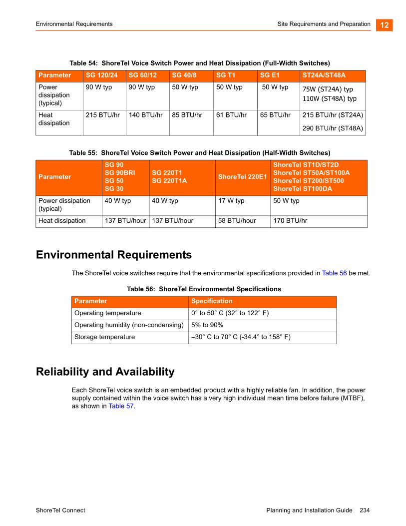
Environmental Requirements Site Requirements and Preparation 12
Environmental Requirements
The ShoreTel voice switches require that the environmental specifications provided in Table 56 be met.
Reliability and Availability
Each ShoreTel voice switch is an embedded product with a highly reliable fan. In addition, the power supply contained within the voice switch has a very high individual mean time before failure (MTBF), as shown in Table 57.
Table 54: ShoreTel Voice Switch Power and Heat Dissipation (Full-Width Switches)
Parameter SG 120/24 SG 60/12 SG 40/8 SG T1 SG E1 ST24A/ST48A
Power dissipation (typical)
90 W typ 90 W typ 50 W typ 50 W typ 50 W typ 75W (ST24A) typ110W (ST48A) typ
Heat dissipation
215 BTU/hr 140 BTU/hr 85 BTU/hr 61 BTU/hr 65 BTU/hr 215 BTU/hr (ST24A)
290 BTU/hr (ST48A)
Table 55: ShoreTel Voice Switch Power and Heat Dissipation (Half-Width Switches)
Parameter
SG 90SG 90BRISG 50SG 30
SG 220T1SG 220T1A
ShoreTel 220E1
ShoreTel ST1D/ST2DShoreTel ST50A/ST100AShoreTel ST200/ST500ShoreTel ST100DA
Power dissipation (typical)
40 W typ 40 W typ 17 W typ 50 W typ
Heat dissipation 137 BTU/hour 137 BTU/hour 58 BTU/hour 170 BTU/hr
Table 56: ShoreTel Environmental Specifications
Parameter Specification
Operating temperature 0° to 50° C (32° to 122° F)
Operating humidity (non-condensing) 5% to 90%
Storage temperature –30° C to 70° C (-34.4° to 158° F)
ShoreTel Connect Planning and Installation Guide 234
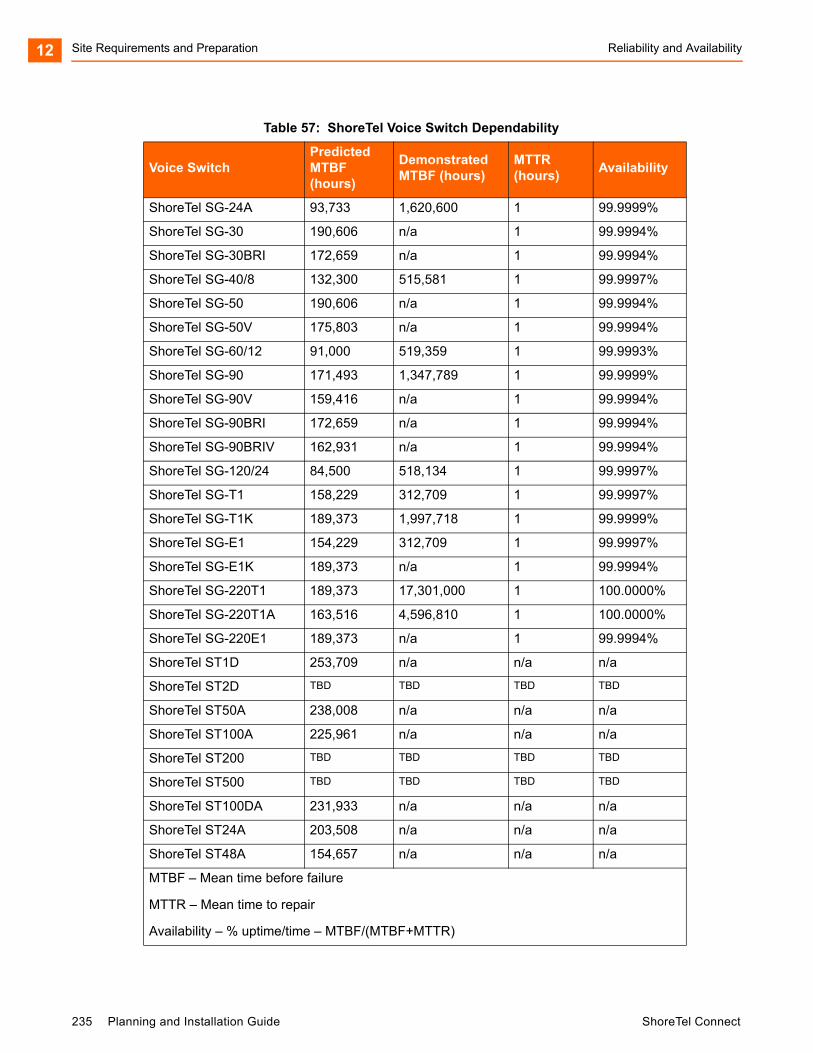
Site Requirements and Preparation Reliability and Availability12
Table 57: ShoreTel Voice Switch Dependability
Voice SwitchPredicted MTBF (hours)
Demonstrated MTBF (hours)
MTTR (hours)
Availability
ShoreTel SG-24A 93,733 1,620,600 1 99.9999%
ShoreTel SG-30 190,606 n/a 1 99.9994%
ShoreTel SG-30BRI 172,659 n/a 1 99.9994%
ShoreTel SG-40/8 132,300 515,581 1 99.9997%
ShoreTel SG-50 190,606 n/a 1 99.9994%
ShoreTel SG-50V 175,803 n/a 1 99.9994%
ShoreTel SG-60/12 91,000 519,359 1 99.9993%
ShoreTel SG-90 171,493 1,347,789 1 99.9999%
ShoreTel SG-90V 159,416 n/a 1 99.9994%
ShoreTel SG-90BRI 172,659 n/a 1 99.9994%
ShoreTel SG-90BRIV 162,931 n/a 1 99.9994%
ShoreTel SG-120/24 84,500 518,134 1 99.9997%
ShoreTel SG-T1 158,229 312,709 1 99.9997%
ShoreTel SG-T1K 189,373 1,997,718 1 99.9999%
ShoreTel SG-E1 154,229 312,709 1 99.9997%
ShoreTel SG-E1K 189,373 n/a 1 99.9994%
ShoreTel SG-220T1 189,373 17,301,000 1 100.0000%
ShoreTel SG-220T1A 163,516 4,596,810 1 100.0000%
ShoreTel SG-220E1 189,373 n/a 1 99.9994%
ShoreTel ST1D 253,709 n/a n/a n/a
ShoreTel ST2D TBD TBD TBD TBD
ShoreTel ST50A 238,008 n/a n/a n/a
ShoreTel ST100A 225,961 n/a n/a n/a
ShoreTel ST200 TBD TBD TBD TBD
ShoreTel ST500 TBD TBD TBD TBD
ShoreTel ST100DA 231,933 n/a n/a n/a
ShoreTel ST24A 203,508 n/a n/a n/a
ShoreTel ST48A 154,657 n/a n/a n/a
MTBF – Mean time before failure
MTTR – Mean time to repair
Availability – % uptime/time – MTBF/(MTBF+MTTR)
235 Planning and Installation Guide ShoreTel Connect

Memory and Processing Site Requirements and Preparation 12
Because the ShoreTel Connect system is plug-and-play, a switch can be replaced in minutes.
Distributed call control software means there is no system-wide single point of failure. If a single ShoreTel voice switch fails, all the other voice switches continue to operate.
Table 58 shows the reliability information for the ShoreTel IP phones. Hourly numbers shown are based on demonstrated reliability (as opposed to calculated).
Memory and Processing
Each ShoreTel voice switch has the same memory and processing (see Table 59).
Table 58: ShoreTel IP Phone Dependability
Phone MTBF Hours (Predicted) MTBF Hours (Demonstrated)
IP110 64,800 490,000
IP115 64,800 1,737,921
IP212k 58,200 350,000
IP230 58,200 2,648,465
IP230g 58,200 1,200,794
IP265 N/A 58,546
IP420 1,705,617 1,510,739
IP480 548,454 1,350,626
IP480g 547,751 1,116,368
IP485g 406,839 906,031
IP560 56,300 360,000
IP560g 56,400 TBD
IP565g N/A 44,105
IP655 TBD TBD
BB424 423,971 N/A
BB24 72,600 TBD
Table 59: ShoreTel Voice Switch Memory and Processing
TypeShoreGear Voice Switches Details
ShoreTel ST Voice Switches Details
Flash Memory 16 MB 4 GB
Random Access Memory 128 MB 1 GB
Main Processor PowerPC 8245 MIPS 6K, multi-core
Digital Signal Processor Texas Instruments 5409A Texas Instruments 665x, multi-core
ShoreTel Connect Planning and Installation Guide 236
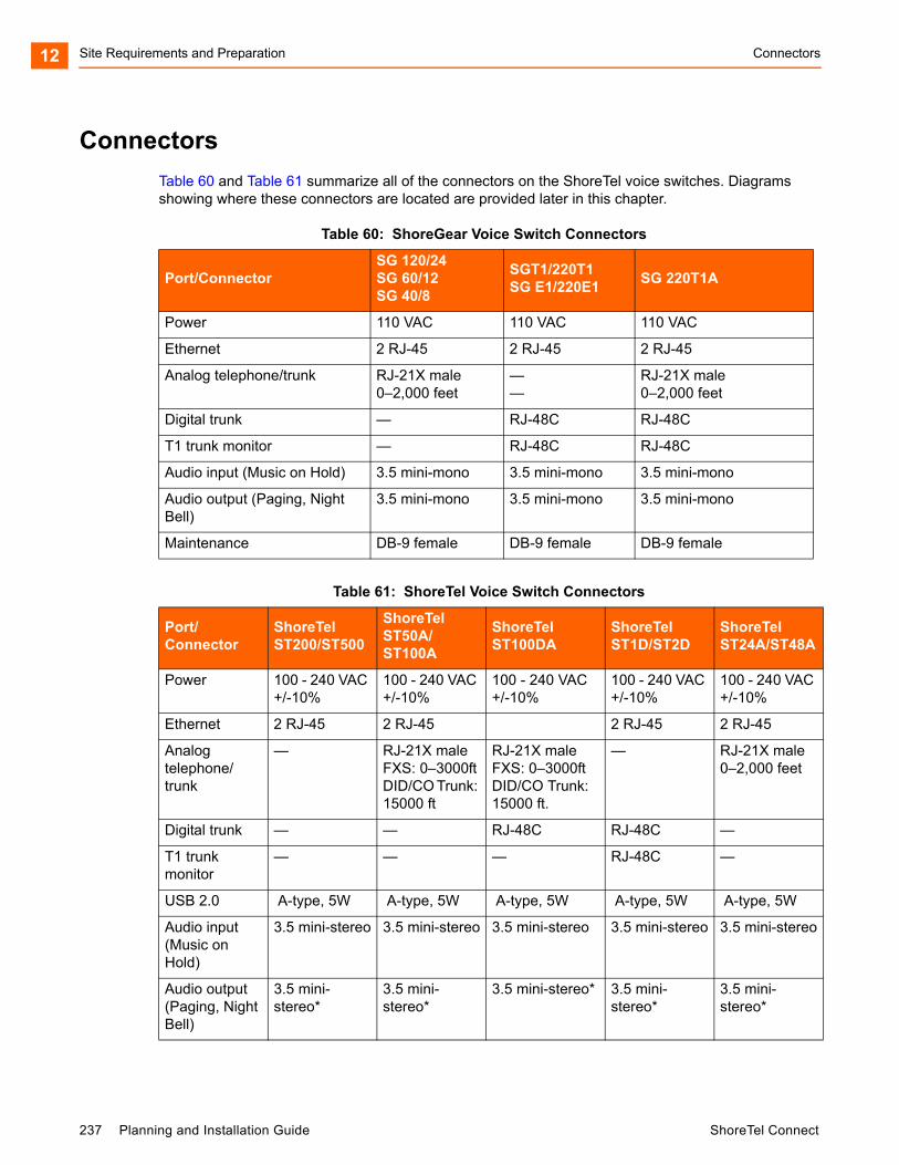
Site Requirements and Preparation Connectors12
Connectors
Table 60 and Table 61 summarize all of the connectors on the ShoreTel voice switches. Diagrams showing where these connectors are located are provided later in this chapter.
Table 60: ShoreGear Voice Switch Connectors
Port/ConnectorSG 120/24SG 60/12SG 40/8
SGT1/220T1SG E1/220E1
SG 220T1A
Power 110 VAC 110 VAC 110 VAC
Ethernet 2 RJ-45 2 RJ-45 2 RJ-45
Analog telephone/trunk RJ-21X male0–2,000 feet
——
RJ-21X male0–2,000 feet
Digital trunk — RJ-48C RJ-48C
T1 trunk monitor — RJ-48C RJ-48C
Audio input (Music on Hold) 3.5 mini-mono 3.5 mini-mono 3.5 mini-mono
Audio output (Paging, Night Bell)
3.5 mini-mono 3.5 mini-mono 3.5 mini-mono
Maintenance DB-9 female DB-9 female DB-9 female
Table 61: ShoreTel Voice Switch Connectors
Port/Connector
ShoreTel ST200/ST500
ShoreTel ST50A/ST100A
ShoreTel ST100DA
ShoreTel ST1D/ST2D
ShoreTel ST24A/ST48A
Power 100 - 240 VAC +/-10%
100 - 240 VAC +/-10%
100 - 240 VAC +/-10%
100 - 240 VAC +/-10%
100 - 240 VAC +/-10%
Ethernet 2 RJ-45 2 RJ-45 2 RJ-45 2 RJ-45
Analog telephone/trunk
— RJ-21X maleFXS: 0–3000ftDID/CO Trunk: 15000 ft
RJ-21X maleFXS: 0–3000ftDID/CO Trunk: 15000 ft.
— RJ-21X male0–2,000 feet
Digital trunk — — RJ-48C RJ-48C —
T1 trunk monitor
— — — RJ-48C —
USB 2.0 A-type, 5W A-type, 5W A-type, 5W A-type, 5W A-type, 5W
Audio input (Music on Hold)
3.5 mini-stereo 3.5 mini-stereo 3.5 mini-stereo 3.5 mini-stereo 3.5 mini-stereo
Audio output (Paging, Night Bell)
3.5 mini-stereo*
3.5 mini-stereo*
3.5 mini-stereo* 3.5 mini-stereo*
3.5 mini-stereo*
237 Planning and Installation Guide ShoreTel Connect
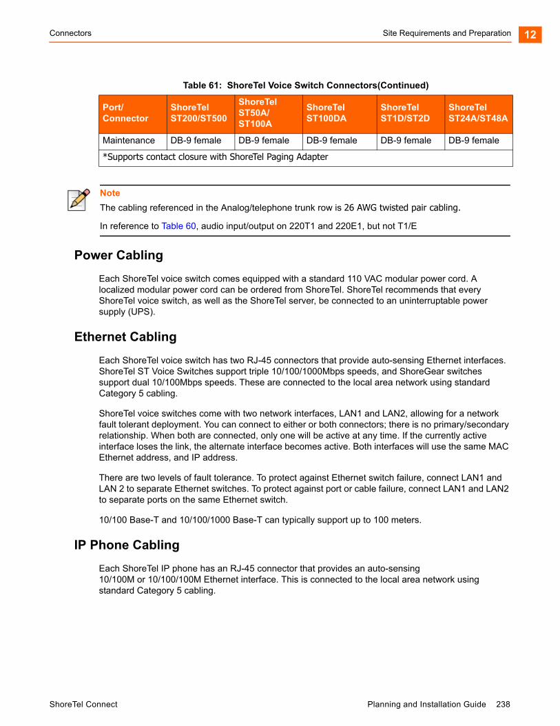
Connectors Site Requirements and Preparation 12
Power Cabling
Each ShoreTel voice switch comes equipped with a standard 110 VAC modular power cord. A localized modular power cord can be ordered from ShoreTel. ShoreTel recommends that every ShoreTel voice switch, as well as the ShoreTel server, be connected to an uninterruptable power supply (UPS).
Ethernet Cabling
Each ShoreTel voice switch has two RJ-45 connectors that provide auto-sensing Ethernet interfaces. ShoreTel ST Voice Switches support triple 10/100/1000Mbps speeds, and ShoreGear switches support dual 10/100Mbps speeds. These are connected to the local area network using standard Category 5 cabling.
ShoreTel voice switches come with two network interfaces, LAN1 and LAN2, allowing for a network fault tolerant deployment. You can connect to either or both connectors; there is no primary/secondary relationship. When both are connected, only one will be active at any time. If the currently active interface loses the link, the alternate interface becomes active. Both interfaces will use the same MAC Ethernet address, and IP address.
There are two levels of fault tolerance. To protect against Ethernet switch failure, connect LAN1 and LAN 2 to separate Ethernet switches. To protect against port or cable failure, connect LAN1 and LAN2 to separate ports on the same Ethernet switch.
10/100 Base-T and 10/100/1000 Base-T can typically support up to 100 meters.
IP Phone Cabling
Each ShoreTel IP phone has an RJ-45 connector that provides an auto-sensing 10/100M or 10/100/100M Ethernet interface. This is connected to the local area network using standard Category 5 cabling.
Maintenance DB-9 female DB-9 female DB-9 female DB-9 female DB-9 female
*Supports contact closure with ShoreTel Paging Adapter
Note
The cabling referenced in the Analog/telephone trunk row is 26 AWG twisted pair cabling.
In reference to Table 60, audio input/output on 220T1 and 220E1, but not T1/E
Table 61: ShoreTel Voice Switch Connectors(Continued)
Port/Connector
ShoreTel ST200/ST500
ShoreTel ST50A/ST100A
ShoreTel ST100DA
ShoreTel ST1D/ST2D
ShoreTel ST24A/ST48A
ShoreTel Connect Planning and Installation Guide 238
Site Requirements and Preparation Connectors12
Analog Telephone and Trunk Cabling
ShoreTel voice switches that support analog protocols provide an RJ-21X male connector for mass termination of the telephones and trunks. This should be connected using a standard 25-pair cable. ShoreTel recommends using the RJ-21X and connecting to a patch panel to provide simple moves, adds, and changes.
Telephones can be supported from 0 to 3,000 feet from the voice switch over standard cabling. Use larger gauge wires for longer distances.
It is recommended that an analog telephone be provisioned in the equipment room for troubleshooting purposes.
Pinout information for ShoreTel Voice Switches is provided in the quick install guide for each voice switch.
Digital Trunk and Trunk Monitor Cabling
ShoreTel voice switches that support digital trunks have an RJ-48C connector as the telco interface to the T1/E1 trunk from the telephone service provider.
These voice switches provide an internal Channel Service Unit (CSU).
ShoreTel voice switches that support T1 and E1 trunks have an additional RJ-48C connector that is wired to the telco interface for the purpose of troubleshooting the T1 or E1 interface with specialized test equipment. This connector is normally not used.
ShoreTel ST Voice switches with T1/E1 interfaces do not include the additional RJ-48C monitor connector.
Audio Input (Music on Hold) Cabling
Various ShoreTel voice switches have a 3.5 mm mini-stereo input connector that provide music or some other recording to callers when they are on hold. The input port supports low-level line audio from a preamplifier or mini-CD player, at 47 k nominal impedance. The audio input cable can be up to 10 feet long. Refer to the ShoreTel quick install guide for your voice switch to determine whether your switch provides the 3.5 mm mini-stereo input connector.
The audio input port on the ShoreTel voice switches is a mono connection. If you connect a stereo input, the stereo signal is converted to a mono signal.
To minimize bandwidth, music on hold is not streamed across the wide area network, so you will need one music source per site.
The music and music source are not included with the ShoreTel Connect system.
WARNING!
In accordance with United States copyright laws, a license may be required from the American Society of Composers, Authors, and Publishers, or a similar organization, if radio or TV broadcasts are played for music on hold. As an alternative, an ASCAP-approved CD or tape can be used. ShoreTel, Inc. disclaims any liability out of failure to obtain such a license.
239 Planning and Installation Guide ShoreTel Connect

Racks and Cabling Site Requirements and Preparation 12
Audio Output (Paging and Night Bell) Cabling
Various ShoreTel voice switches have a 3.5 mm mini-stereo audio output connector for overhead paging and night bell on a per site basis. The audio output port provides low-level line audio with a sufficient input level for a typical amplifier. The paging port output is about one volt peak to peak, similar to the line output of a CD player, and can drive inputs that are 600 ohms or higher. Refer to the ShoreTel quick install guide for your voice switch to determine whether your switch provides the 3.5 mm mini-stereo input connector.
The audio output is mono signal. If you use a stereo jack, the signal is available on one channel, but the other channel will be silent.
This is a single-zone paging system. If more zones are required, see the application note on ShoreTel’s online knowledge base.
ShoreTel Paging Adapter and System Contact Closure Support
The ShoreTel Paging Adapter is an accessory that provides transformer-coupled line level audio between a ShoreTel Voice Switch and a paging system. This accessory is useful for mitigating 60Hz and ground noise found in some paging installations, and it supports contact closure when used with ShoreTel ST Voice Switch paging ports. Refer to the ShoreTel Paging Adapter Quick Install Guide for more information.
Maintenance Cabling
ShoreTel voice switches support a maintenance port for connection terminal using a standard, straight-through DB-9 female connector. This maintenance port is typically used only when assigning networking parameters if DHCP is not being used.
USB 2.0 Port
ShoreTel ST Voice Switches provide a USB 2.0 A-type port to support logging and troubleshooting.
Racks and Cabling
General Cabling Overview
The diagram in Figure 17 highlights the key components with respect to cabling for your voice network.
ShoreTel Connect Planning and Installation Guide 240

Site Requirements and Preparation General Cabling Overview12
Figure 17: Cabling Overview
Starting from the lower left in this diagram, the telephone cabling is organized as follows:
A telephone jack (RJ-11) is provided for each telephone.
Telephone cabling (Category 3 or better) is terminated on the telephone jack and runs back to the equipment room to a modular connector (RJ-21X) on a telephone patch panel.
The telephone patch panel provides a flexible cable management solution for the telephone cabling. The patch panel has RJ-21X connections for the telephone cabling and RJ-11 connections on the front.
Patch cords are connected from the telephone patch panel (RJ-11) to the voice switch patch panel (RJ-11).
The voice switch patch panel provides a flexible cable management solution for the voice switches. The patch panel has RJ-21X connections running to the voice switches and RJ-11 connections on the front.
Starting from the right in Figure 17 on page 241, the trunk cabling is organized as follows:
The digital (T1/E1) and analog trunks are terminated on a punch-down block.
The digital service is further terminated at a service provider demark with an RJ-48 connector.
An RJ-48 cable from the T1/E1 demark connects to the ShoreTel T1 or ShoreTel E1.
The analog service is cross-connected to a modular (RJ-21X) punch-down block.
A telco cable is connected to the modular (RJ-21X) punch-down jack and runs to a modular connector (RJ-21X) on an analog trunk patch panel.
241 Planning and Installation Guide ShoreTel Connect
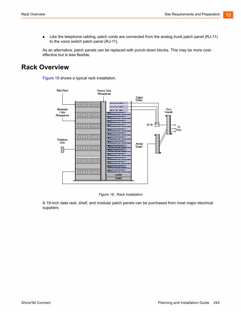
Rack Overview Site Requirements and Preparation 12
Like the telephone cabling, patch cords are connected from the analog trunk patch panel (RJ-11) to the voice switch patch panel (RJ-11).
As an alternative, patch panels can be replaced with punch-down blocks. This may be more cost-effective but is less flexible.
Rack Overview
Figure 18 shows a typical rack installation.
Figure 18: Rack Installation
A 19-inch data rack, shelf, and modular patch panels can be purchased from most major electrical suppliers.
ShoreTel Connect Planning and Installation Guide 242

Site Requirements and Preparation Rack Overview12
243 Planning and Installation Guide ShoreTel Connect

CHAPTER
13. Installing ShoreTel VoiceSwitches
This chapter provides planning and installation information for the ShoreTel voice switches, virtual switches, and virtual Service Appliances. Information on switch connectors and LEDs can be found in Site Requirements and Preparation on page 230. The topics discussed include the following:
Planning .................................................................................................................. 245
Mounting the ShoreTel Voice Switches ................................................................... 245
Stacking the ShoreTel Voice Switch in a Rack.................................................. 245
Mounting a Full-width ShoreTel Voice Switch in a Rack with Brackets............. 245
Mounting a Half-width ShoreTel Voice Switch in a Rack with Brackets ............ 246
Installing ShoreTel Voice Switches.......................................................................... 246
Installing a ShoreTel Voice Switch .................................................................... 246
RJ-21X Cable Retainer Installation................................................................... 247
Installing the Retainer ....................................................................................... 248
Virtual Switches and Service Appliances ................................................................ 248
Default Configurations ...................................................................................... 248
Downloading and Installing a Virtual Device..................................................... 251
ShoreTel Connect Director Switch Configuration .................................................... 252
Environmental Requirements ........................................................................... 252
Packaging Requirements.................................................................................. 253
Regulatory Compliance .................................................................................... 254
General Specifications...................................................................................... 255
Reference................................................................................................................ 252
ShoreTel Connect Planning and Installation Guide 244
Installing ShoreTel Voice Switches Planning13
Planning
In the ShoreTel Connect system, switches perform vital roles in connecting endpoints in a call whether the endpoints are located on the ShoreTel network, another private network, or the PSTN. Every IP phone on the ShoreTel network must register with a switch. The switch provides dial and ring tone to the phone when required, performs call setup and teardown task, sets up call legs, communicates with other switches and devices. ShoreTel switches also provide the physical and logical interface that allows the system to connect with external service providers and other phone networks. When you plan for switches, consider the following:
The number of IP phones that will connect to the switch
The type of interface you provision from the external service provider
Failover
Mounting the ShoreTel Voice Switches
Stacking the ShoreTel Voice Switch in a Rack
1. Remove the voice switch from its shipping container.
2. Place the switch on a flat platform, such as a shelf.
3. Stack up to three switches on top of each other.
Mounting a Full-width ShoreTel Voice Switch in a Rack with Brackets
1. Remove the voice switch from its shipping container.
2. Attach the two included mounting brackets by using the screws ShoreTel provides.
3. Use standard screws to mount the switch in the rack.
Tip
Throughout this document, references to ShoreTel switches encompass the ShoreTel ST and ShoreTel SG generations of switches.
245 Planning and Installation Guide ShoreTel Connect
Mounting a Half-width ShoreTel Voice Switch in a Rack with Brackets Installing ShoreTel Voice Switches 13
Mounting a Half-width ShoreTel Voice Switch in a Rack with Brackets
1. Remove the voice switch from its shipping container.
2. Mount a ShoreTel Dual Tray into the rack with the screws provided.
3. Install the half-width switch into the tray on either the left or right side of the tray. Two half-width switches can be placed in the same tray.
4. Use standard screws to mount the switch in the tray.
Installing ShoreTel Voice Switches
Installing a ShoreTel Voice Switch
1. Connect the switch to the appropriate LAN segment, such as a LAN switch, with the Category 5 RJ-45 interface cable. For guaranteed voice quality, all ShoreTel voice switches can be connected to an isolated LAN segment.
2. Plug an AC surge protector into a grounded AC power source (not provided). Electrical surges, typically lightning transients, are very destructive to equipment connected to AC power sources.
3. Plug the power cord into the power receptacle on the switch’s back panel and then into an available socket on the AC surge protector. Most ShoreTel Voice Switch models do not have a power switch. They turn on when you connect the switch to a power source.
The power LED flashes momentarily, and remains lit. If the LED is not lit, ensure that the power cord is plugged into the switch and the power source. If the LED continues flashing, there is an internal error. Unplug the switch to power it off, then power it back on. Refer to the ShoreTel Connect System Administration Guide for a description of the flash patterns and their meaning.
WARNING!
To prevent overheating and fire hazard, do not use the Rack Mount Dual Switch Tray to wall mount the following devices: ST1D/ST2D, ST50A/ST100A, ST200/ST500, or ST100DA. Use the ST Voice Switch Wall Mount Bracket to wall mount these devices. Refer to the ST Voice Switch Wall Mount Bracket Kit Quick Install Guide for information about this kit.
Note
Refer to the Quick Install Guide for the ShoreTel Dual Tray, which is included with half-width switches, for information about the kit.
Note
Before applying power to a new ShoreTel voice switch, configure the DHCP server.
ShoreTel Connect Planning and Installation Guide 246
Installing ShoreTel Voice Switches RJ-21X Cable Retainer Installation13
Once network communications are established, the network LEDs will indicate that the switch is connected to a 10 Mbps or 100 Mbps Ethernet environment, and that the switch is receiving and transmitting data.
4. If applicable, connect the music-on-hold source to the audio input port.
5. If applicable, connect your site's paging system to the audio output port.
6. Configure the switch network parameters:
a. Use a straight-through serial cable, DB9 male to DB9 female, or suitable USB-to-RS-232 serial adapter to connect the switch maintenance port to a console PC.
b. On the PC or laptop, start a terminal emulation program and connect to the voice switch using the following serial communication settings:
115,200 bps for ShoreTel ST Voice Switches or 19,200 bps for ShoreTel SG Voice Switches
8 data bits no parity one stop bit no handshake
c. At the login prompt, enter:
Login: root Password: ShoreTel
d. Type stcli to bring up a ShoreTel configuration tool to set network parameters and view current status. The default switch configuration is to use DHCP for network parameters and automatic detection of speed, duplex, and flow control settings.
e. Choose Menu Options and follow the onscreen instructions for setting network parameters, including IP address, subnet mask, and gateway.
7. Use Director to configure the ShoreTel voice switch according to your site’s requirements. Refer to the Configuring Voice Switches chapter of the ShoreTel Connect System Administration Guide for information about this procedure.
8. Connect your trunk and telephone lines using the appropriate connector for your switch. Refer to the quick install guide for your ShoreTel switch for connector pinout information.
RJ-21X Cable Retainer Installation
A cable retainer for the RJ-21X port is included with some ShoreTel voice switches. The retainer consists of a metal bracket with a velcro strap.
Tip
ShoreTel offers a Paging Adapter to facilitate paging connections. Refer to the ShoreTel Paging Adapter Quick Install Guide for more information.
247 Planning and Installation Guide ShoreTel Connect
Installing the Retainer Installing ShoreTel Voice Switches 13
Installing the Retainer
1. Using a number 1 Phillips screwdriver, remove the two black Phillips head screws on either side of the RJ-21X port.
2. Place the retainer in the recessed area around the RJ-21X port.
3. Reinstall the two screws.
4. Plug in the RJ-21X cable.
5. Pull the velcro strap tightly around the connector on the RJ-21X cable, and fasten it.
Virtual Switches and Service Appliances
This section describes the following virtual devices:
ShoreTel Virtual Phone Switch (vPhone Switch)
ShoreTel Virtual Trunk Switch (vTrunk Switch)
ShoreTel Virtual Service Appliance (SA-vCollab)
These virtual devices get delivered as separate OVA files and are part of the system installation on the Headquarters Server and the DVS.
You deploy a virtual device by using a VMware vSphere client on a vSphere ESXi server.
Default Configurations
The installation process creates default configurations for ShoreTel virtual switches and service appliances.
Memory: 2 GB
CPU/Cores: 1 socket, 4 cores
Hard disk: 100 GB, thin provisioned
Video card: 1 display, 4 MB video memory, no 3D support
SCSI controller: BusLogicParallel
Network adapter: vmxnet3 (VM network)
Note
For recommended virtual service appliance capacities, see Chapter 4, Site Requirements and preparation, in the ShoreTel Connect Conferencing and Instant Messaging Planning and Installation Guide.
ShoreTel Connect Planning and Installation Guide 248
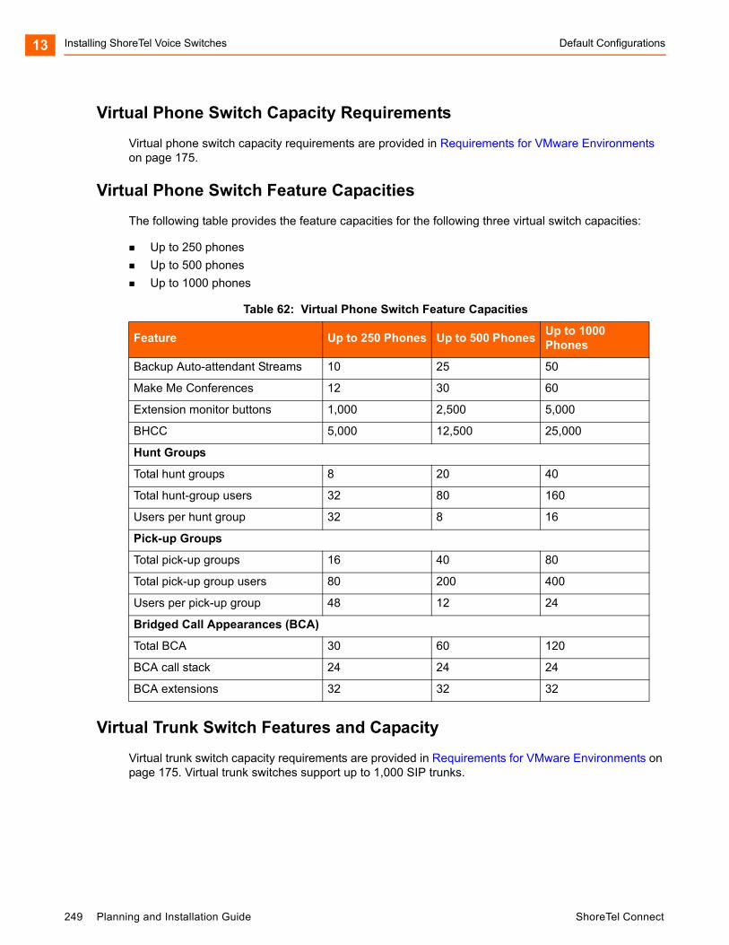
Installing ShoreTel Voice Switches Default Configurations13
Virtual Phone Switch Capacity Requirements
Virtual phone switch capacity requirements are provided in Requirements for VMware Environments on page 175.
Virtual Phone Switch Feature Capacities
The following table provides the feature capacities for the following three virtual switch capacities:
Up to 250 phones
Up to 500 phones
Up to 1000 phones
Virtual Trunk Switch Features and Capacity
Virtual trunk switch capacity requirements are provided in Requirements for VMware Environments on page 175. Virtual trunk switches support up to 1,000 SIP trunks.
Table 62: Virtual Phone Switch Feature Capacities
Feature Up to 250 Phones Up to 500 PhonesUp to 1000 Phones
Backup Auto-attendant Streams 10 25 50
Make Me Conferences 12 30 60
Extension monitor buttons 1,000 2,500 5,000
BHCC 5,000 12,500 25,000
Hunt Groups
Total hunt groups 8 20 40
Total hunt-group users 32 80 160
Users per hunt group 32 8 16
Pick-up Groups
Total pick-up groups 16 40 80
Total pick-up group users 80 200 400
Users per pick-up group 48 12 24
Bridged Call Appearances (BCA)
Total BCA 30 60 120
BCA call stack 24 24 24
BCA extensions 32 32 32
249 Planning and Installation Guide ShoreTel Connect
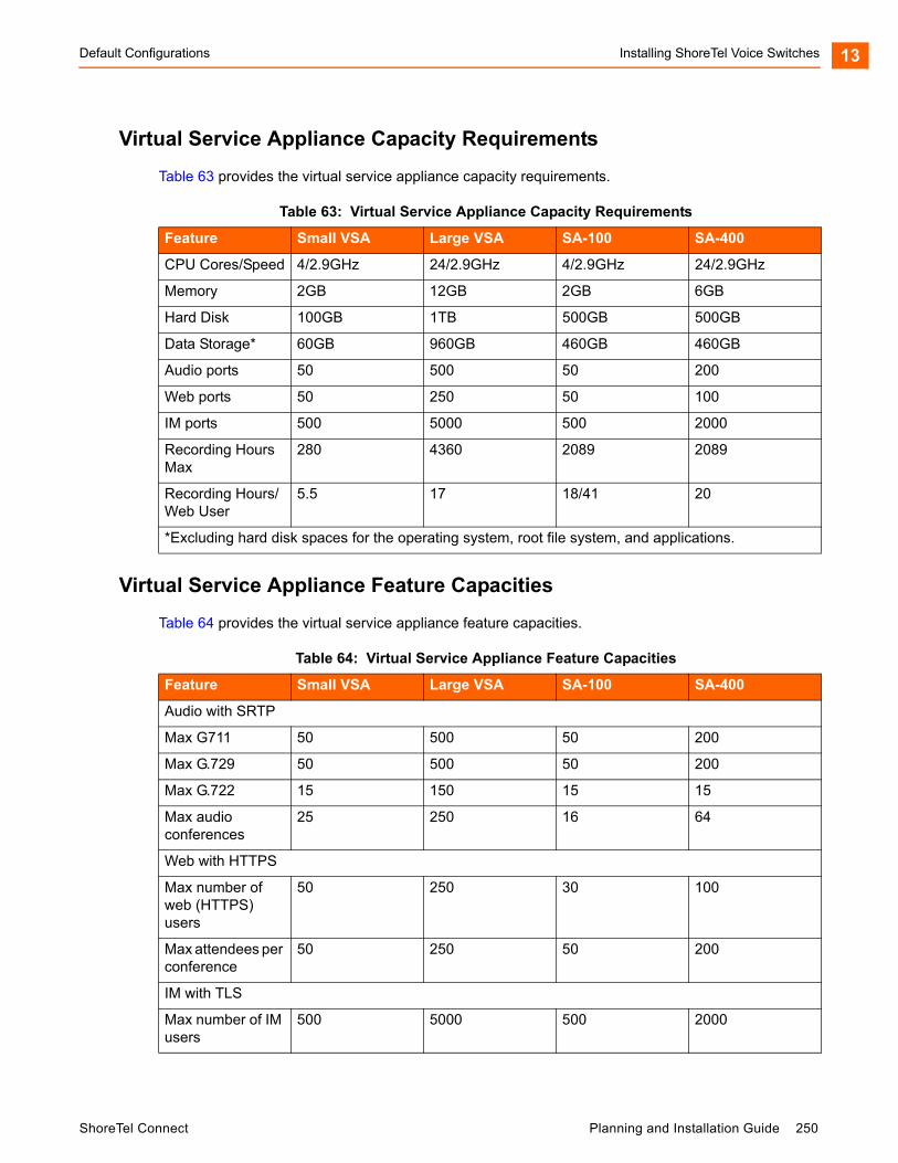
Default Configurations Installing ShoreTel Voice Switches 13
Virtual Service Appliance Capacity Requirements
Table 63 provides the virtual service appliance capacity requirements.
Virtual Service Appliance Feature Capacities
Table 64 provides the virtual service appliance feature capacities.
Table 63: Virtual Service Appliance Capacity Requirements
Feature Small VSA Large VSA SA-100 SA-400
CPU Cores/Speed 4/2.9GHz 24/2.9GHz 4/2.9GHz 24/2.9GHz
Memory 2GB 12GB 2GB 6GB
Hard Disk 100GB 1TB 500GB 500GB
Data Storage* 60GB 960GB 460GB 460GB
Audio ports 50 500 50 200
Web ports 50 250 50 100
IM ports 500 5000 500 2000
Recording Hours Max
280 4360 2089 2089
Recording Hours/Web User
5.5 17 18/41 20
*Excluding hard disk spaces for the operating system, root file system, and applications.
Table 64: Virtual Service Appliance Feature Capacities
Feature Small VSA Large VSA SA-100 SA-400
Audio with SRTP
Max G711 50 500 50 200
Max G.729 50 500 50 200
Max G.722 15 150 15 15
Max audio conferences
25 250 16 64
Web with HTTPS
Max number of web (HTTPS) users
50 250 30 100
Max attendees per conference
50 250 50 200
IM with TLS
Max number of IM users
500 5000 500 2000
ShoreTel Connect Planning and Installation Guide 250
Installing ShoreTel Voice Switches Downloading and Installing a Virtual Device13
Downloading and Installing a Virtual Device
To install a virtual device, follow these steps:
1. Create a virtual machine (VM) for the switch and allocate the required resources, depending on the capacity of the virtual phone or virtual trunk switch you want to create:
250, 500, or 1000 IP phones
100, 250, 500, or 1000 SIP trunks
2. Run vSphere Client and connect to an EXSi server, version 5.0 or higher.
3. Select File > Deploy OVF/OVA.
4. Enter the URL to the OVA file for the type of device you want to install.
To install a ShoreTel Virtual Phone and Virtual Trunk Switch, enter the following URL:
http:<HQ or DVS IP address>/ftproot/tsv/BareMetalInstall.ova
To install a ShoreTel Virtual Service Appliance, enter the following URL:
http:<HQ or DVS IP address>/ftproot/tsu/VMWareShoreTelVSA.ova
5. Click Next.
6. Enter a name for the virtual switch and click Next.
7. On the Storage screen, highlight the datastore1 hard drive and click Next.
8. On the Disk Format screen, accept the default option, Thick Provision Lazy Zeroed, and click Next.
9. On the Ready to Complete screen, check the Power On after deployment checkbox.
10. Finish the installation by following the on-screen instructions.
The installation process creates a virtual machine with the default hardware configuration. For more information about default virtual device configurations, see Default Configurations on page 248.
Note
The ShoreTel Connect system analyzes the allocated resources and determines the capacity of the switch. To change the capacity of the switch, you must change the allocated VM resources.
Note
You can also download the OVA file directly from ShoreTel Connect Director. Click Download switch image from the Edit ShoreGear vPhone Switch or Edit ShoreGear vTrunk Switch page.
251 Planning and Installation Guide ShoreTel Connect

ShoreTel Connect Director Switch Configuration Installing ShoreTel Voice Switches 13
11. Power on the virtual machine.
12. Open the console on the virtual switch you want to configure and log in with the following credentials:
User ID: admin
Password: ShoreTel
13. Enter the DHCP and server IP information that the server will use to download firmware updates. When you finish entering this information, the switch will begin downloading and installing, and when the installation is complete, the switch will reboot.
14. When the virtual switch comes back online, open its console and log back in using root/ShoreTel.
15. To open the ShoreTel parameters screen, enter stcli.
16. On the ShoreTel parameters screen, note the values for IP address and MAC address. Save these values for configuring the virtual switches in Step 17.
17. Configure the virtual device:
To configure virtual switches, see Chapter 5, Configuring Voice Switches, in the ShoreTel Connect System Administration Guide.
To configure virtual Service Appliances, see Chapter 6, Configuring the Service Appliance, in the ShoreTel Connect Conferencing and Instant Messaging Planning and Installation Guide.
ShoreTel Connect Director Switch Configuration
To complete the installation, configure the ShoreTel voice switches with ShoreTel Connect Director. For more information, refer to Chapter 5, Configuring Voice Switches, in the ShoreTel Connect System Administration Guide.
Reference
Environmental Requirements
The ShoreTel voice switches require that the environmental specifications provided in Table 65 be met.
Note
You can only increase the disk size before you power on the virtual machine. If you need to have more disk space for conference recording, you must change it before you power on the virtual machine.
ShoreTel Connect Planning and Installation Guide 252
Installing ShoreTel Voice Switches Packaging Requirements13
Packaging Requirements
Table 66 lists the packaging requirements for the following ShoreTel voice switches:
Full-width switches – (ST24A/ST48A, SG-120/24, SG-60/12, SG-40/8, SG-T1/E1)
Half-width switches – (ST1D/ST2D, ST50A/ST100A, ST100DA, ST200/ST500, SG-90, SG-50, SG-220T1/E1/T1A)
Table 65: ShoreTel Voice Switch Environmental Specifications
Parameter Specification
Operating temperature 0° C to 50° C
Operating humidity (non-condensing) 5% to 90%
Storage temperature –30° C to 70° C
Storage humidity (non-condensing) 20% to 90%
Table 66: ShoreTel Voice Switch Packaging Specifications
Parameter Specification
Vibration Devices can withstand the following:
3 to 5 Hz sinusoidal vibrations (variable) that are 0.5 inch in amplitude (1-inch peak-to-peak).
Vibration in the vertical direction that lasts for 45 minutes.
Power: 0.4 Grms, 1h per axis
Spectral Density: 5-500Hz @ 0.000323303 g2/Hz
Operation
Power: 1.5G RMS
Spectral Density: 5-500Hz @ 0.00454645 g2/Hz
Packaged Transportation
Material: 275 C Brown
Dimensions (full-width switches): 21.5 x 19.5 x 6.5
Dimensions (half-width switches): 18.0 x 12.75 x 6.0
Weight (full-width switches): 13.0 lbs (5.9 kg)
Weight (half-width switches): 8.0 lbs (3.6 kg)
Mechanical Shock: 80 Gs non-operating
Packaged Bounce Face: 76cm drop on eachCorner: 76cm drop on each
253 Planning and Installation Guide ShoreTel Connect
Regulatory Compliance Installing ShoreTel Voice Switches 13
Regulatory Compliance
Compliance Specifications
Table 67: SG-E1 Voice Switch Physical Specifications
Parameter ShoreTel-24
Safety UL 60950, 3rd Edition, CAN/CSA 22.2 No. 60950, EN60950 (2000)
EMI FCC Part 15, ICES-003, EN 55022, Class A/Class B
Radio and Telecommunications Terminating Device Directive (R&TTE) 99/5/EC
Low Voltage Directive 73 / 23 / EEC
EMC Directive 89 / 336 / EEC With Amendment 93 / 68 / EEC
GS Mark from TUV Rheinland (Notified Body)
EN 55024: 1998 +A1:2001 +A2:2003
Table 68: SG 120/24, SG 90, SG 60/12, SG 50, SG 40/8, SG 30Voice Switch Physical Specifications
Parameter Physical Specification
Safety UL 60950, 3rd Edition, CAN/CSA 22.2 No. 60950, EN60950 (2000)
Telephony Registration FCC Part 68, Canada CS-03
EMI FCC Part 15, ICES-003, EN 55022, Class A
Radio and Telecommunications Terminating Device Directive (R&TTE) 99/5/EC
Low Voltage Directive 73 / 23 / EEC
EMC Directive 89 / 336 / EEC With Amendment 93 / 68 / EEC
GS Mark from TUV Rheinland (Notified Body)
EN 55024: 1998 +A1:2001 +A2:2003
Table 69: SG T1, SG-220T1, SG 220T1A, SG T1k Voice Switch Compliance Specifications
Parameter Compliance Specification
Safety UL 60950, 3rd Edition, CAN/CSA 22.2 No. 60950, EN60950 (2000)
Telephony Registration FCC Part 68, Canada CS-03
EMI FCC Part 15, ICES-003, EN 55022, Class A
Radio and Telecommunications Terminating Device Directive (R&TTE) 99/5/EC
ShoreTel Connect Planning and Installation Guide 254
Installing ShoreTel Voice Switches General Specifications13
General Specifications
The specifications in Table 70 on page 255 apply to the following devices:
SG-120/24
SG-90
SG-60/12
SG-50
SG-40/8
SG-E1/T1
SG-220T1/E1/T1A
ST50A
ST100A
ST100DA
ST1D
ST2D
ST200
ST500
ST24A
ST48A
Low Voltage Directive 73 / 23 / EEC
EMC Directive 89 / 336 / EEC With Amendment 93 / 68 / EEC
Table 70: Voice Switch Specifications
Parameter Specifications
Power Supply 100-240 VAC50-60 Hz2A max (ShoreGear full-width switches)3A max (ShoreTel full-width switches)1A max (all half-width switches)
Mounting Options 19 inch rack mount
Integrated OA&M
Table 69: SG T1, SG-220T1, SG 220T1A, SG T1k Voice Switch Compliance Specifications(Continued)
Parameter Compliance Specification
255 Planning and Installation Guide ShoreTel Connect

CHAPTER
14. IP Phone Installation
This chapter describes the steps required to install IP phones. It contains the following information:
Overview ................................................................................................................. 257
Preparing Your ShoreTel Connect System for IP Phones ....................................... 257
Configuring Voice Switches for IP Phone Support ........................................... 257
Assigning the Configuration Switches .............................................................. 257
Setting IP Address Ranges .............................................................................. 258
Implementing LLDP-MED ....................................................................................... 259
Implementing IEEE 802.1x...................................................................................... 260
DHCP Settings ........................................................................................................ 261
Installing ShoreTel IP Phones ................................................................................. 261
Updating Firmware for IP Phones ........................................................................... 261
ShoreTel 400-Series IP Phones ....................................................................... 261
ShoreTel 100-, 200-, 500-, 600-, and 900-Series IP Phones............................ 262
Manually Configuring ShoreTel IP Phones.............................................................. 262
Manual Configuration at Bootup ....................................................................... 262
Manual Configuration from the Key Pad........................................................... 265
Displaying Settings for a ShoreTel IP Phone .......................................................... 267
Resetting a ShoreTel IP Phone ............................................................................... 267
Clearing a Phone’s Configuration Settings ............................................................. 268
ShoreTel Connect Planning and Installation Guide 256
IP Phone Installation Overview14
Overview
ShoreTel’s IP phones are pre-configured to work with a ShoreTel Connect system and the network’s Dynamic Host Configuration Protocol (DHCP) server. After you configure the servers and voice switches and plug the phones into the network, the ShoreTel Connect system automatically adds the phones to the network.
This chapter describes prerequisites, network considerations, and procedures for installing IP phones in your system.
Preparing Your ShoreTel Connect System for IP Phones
Preparing your system for IP phones involves the following steps:
Configure voice switches to support IP phones.
Assign configuration switches to phones.
Set IP address ranges for each site if your system includes more than one site.
Configuring Voice Switches for IP Phone Support
To provide PSTN local dialing for IP phone users, every site where IP phones are in use must have a ShoreTel voice switch configured to support the number of IP phones at the site, plus local analog or T1 trunks.
Configuring IP phone support on a ShoreTel voice switch involves reserving ports for IP phones. You do this through the Platform Equipment page in ShoreTel Connect Director. For additional information, see the chapter on configuring switches in the ShoreTel Connect System Administration Guide.
ShoreTel voice switches send a heartbeat to the IP phones every 60 seconds. If the heartbeat is not acknowledged within approximately 4 seconds, the switch considers the IP phone to be offline or unavailable. The voice switches continue to broadcast the heartbeat every 60 seconds. If an IP phone that was previously offline recovers and returns an acknowledgment, it is then considered online and available.
Assigning the Configuration Switches
You need to designate a voice switch to handle configuration, including initial service requests, for IP phones installed on your ShoreTel Connect system. Every IP phone installation must have at least one configuration switch. In addition, to provide a backup in case of network problems, you have the option of assigning two switches for the IP phone configuration function. If you do not assign a switch for configuration, the ShoreTel Connect system automatically assigns the first two ShoreTel voice switches added to the system that are managed by the Headquarters server.
257 Planning and Installation Guide ShoreTel Connect

Setting IP Address Ranges IP Phone Installation 14
To be added to the system, IP phones must be able to contact at least one voice switch, as follows:
ShoreTel 400-Series IP phones must be able to contact any voice switch at the site to which their IP address is mapped or at Headquarters.
ShoreTel 100-, 200-, 500-, and 600-Series IP phones must be able to contact at least one of the assigned configuration switches when first connected to the network.
1. Launch ShoreTel Connect Director.
2. Click Administration > Telephones > Options.
The Telephone Options page is displayed.
3. In the IP phone configuration switch 1 drop-down list, select a switch to serve as the first configuration switch.
4. In the IP phone configuration switch 2 drop-down list, select a switch to serve as the second configuration switch.
5. Click Save.
Setting IP Address Ranges
If your ShoreTel Connect system consists of more than one site, you must define an IP address range for IP phones at each site. Setting IP address ranges for each site ensures that new phones added to the system are associated with the correct voice switch at the designated site.
If a phone with an IP address that is not within a specified range for any site is added or there are no IP address ranges defined for any site, the phone is automatically assigned to the Headquarters site. As a result:
Any seven-digit numbers dialed from the IP phone are dialed as numbers within the area code of the Headquarters site.
All calls to users who are not at the Headquarters site use the configured intersite voice encoding for that system.
To set the IP address range for phones at each site:
1. Launch ShoreTel Connect Director.
2. Click Administration > Telephones > IP Phone Address Map.
The IP Phone Address Map page is displayed.
3. Click New.
The General tab is displayed.
4. In the Site drop-down list, select the site for which you want to configure an IP address range.
5. In the Low IP address field, enter the lowest IP address to use for the site. The IP address must be valid for the network in which the site is located.
ShoreTel Connect Planning and Installation Guide 258
IP Phone Installation Implementing LLDP-MED14
6. In the High IP address field, enter the highest IP address to use for the site. The IP address must be valid for the network in which the site is located.
7. In the Caller’s emergency service identification (CESID) field, type the caller ID number that the system passes to emergency responders when an emergency call originates on an IP phone at the site. For information about configuring a system for emergency calls, see the ShoreTel Connect System Administration Guide.
8. If teleworkers might use the site, select the Use remote IP phone codec list check box.
9. Click Save.
The information you configured for the site is listed on the IP Phone Address Map page list pane.
10. Repeat steps 3-9 to set IP address ranges for other sites in the system.
Implementing LLDP-MED
Link Layer Discovery Protocol-Media Endpoint Discovery (LLDP-MED) is an enhancement to the Link Layer Discovery Protocol (LLDP) that addresses the following aspects:
Device location discovery to support location databases and VoIP E911 services
Auto-discovery of LAN policies to support “plug and play” networking
Extended and automated power management of PoE endpoints
Inventory management
Implementing LLDP-MED requires network switches that support the protocol.
ShoreTel implements LLDP-MED through the following methods:
By setting a parameter on ShoreTel IP phones:
On ShoreTel 100-, 200-, 500-, and 600-Series IP phones, you can enable or disable LLDP-MED through the LLDP Enable option, which you can access through MUTE 73887# (SETUP#). The default is “On” (enabled).
On ShoreTel 400-Series IP phones, you can enable or disable LLDP-MED through the Use LLDP-MED option available in the Admin options > Network policy menu, which you can access through MUTE 73887# (SETUP#). The default is “On” (enabled).
By modifying configuration settings. When setting up ShoreTel IP phones, parameter settings are obtained from the following sources, listed in order of highest to lowest precedence:
Configuration files DHCP (if active) LLDP (if active) Setup command Default values
The ShoreTel IP Phone models IP110 and IP115 do not support LLDP-MED.
259 Planning and Installation Guide ShoreTel Connect
Implementing IEEE 802.1x IP Phone Installation 14
Implementing IEEE 802.1x
Most ShoreTel IP phones support 802.1x network authentication. ShoreTel IP phones support the following aspects of 802.1x authentication:
MD-5 challenge method only (However, the MD-5 challenge method is not supported in Windows Server 2008 R2 and later. Using 802.1x with the MD-5 challenge method requires a separate authentication server.)
Multicast and unicast frames
Devices attached to the second Ethernet port (PC port) using 802.1x PAE multicast frames
EAPOL frames can be prioritized. EAPOL VLAN tags are not supported.
Mandatory TIA-1057 LLDP-MED functionality for Class III communication device endpoints
ShoreTel IP phones that support 802.1x authentication are shipped with the feature enabled by default. The first time the phone connects to a network that has 802.1x enabled, the phone must present an ID and password for the user. The default secure user ID is the last six characters of the phone’s MAC address; the password must be manually entered when the phone boots for the first time. The password is cached if authentication succeeds. If the authentication fails, the phone does not boot.
On networks where 802.1x authentication is not enabled, ShoreTel IP phones boot normally when they connect to the Ethernet switch.
If upgrading from a firmware version that supports 802.1x (3.3.x or 3.4.x), the previous settings (802.1x on/off, SID, password) are preserved. If upgrading from a firmware version that does not support 802.1x (2.2, 2.3, 3.1, 3.2), Logical Link Discovery Protocol (LLDP) is turned on by default, and a default SID of the last six characters of the MAC address is applied.
While 802.1x is enabled by default in ShoreTel 11 and higher, 802.1x might have been explicitly enabled in earlier releases through the ShoreTel IP phone parameter 802.1xEnable (a 1-character ASCII parameter). If 802.1x is enabled on the ShoreTel IP phone and disabled on the network switch, the ShoreTel IP phone never comes up.
You can modify the 802.1x setting through a parameter on ShoreTel IP phones:
On ShoreTel 100-, 200-, 500-, and 600-Series IP phones, you can enable or disable 802.1x through the 802.1xEnable option, which you can access through MUTE 73887# (SETUP#). Valid settings are as follows:
8021xEnable – 1 (802.1 authentication is enabled.) 8021xEnable – 0 (802.1 authentication is disabled. This is the default.)
On ShoreTel 400-Series IP phones, you can enable or disable 802.1x through the Use 802.1X option available in the Admin options > Ethernet menu, which you can access through MUTE 73887# (SETUP#). The default is “On” (enabled).
The ShoreTel IP Phone models IP110 and IP115 do not support 802.1x.
ShoreTel Connect Planning and Installation Guide 260
IP Phone Installation DHCP Settings14
DHCP Settings
ShoreTel IP phones are pre-configured to use the network’s DHCP server for addressing. In addition to its address and standard network addresses, the DHCP server’s response also provides the following addresses for phone configuration:
ShoreTel server address
The ShoreTel server provides the IP phones with the latest application software and the configuration information that enables IP phones to be automatically added to the ShoreTel Connect system. The ShoreTel server’s address must be provided to the phone as a vendor-specific option. ShoreTel IP phones are pre-configured to look for the ShoreTel server’s address to be specified as Vendor Specific DHCP Option 156. If this option is not available, the ShoreTel IP phones use Option 66. For information about configuring these DHCP options, see Configuring DHCP for ShoreTel IP Phones on page 56.
SNTP server address
The DHCP server should be configured to provide the address of your network’s SNTP server to provide date and time information to the IP phones.
Installing ShoreTel IP Phones
Installing ShoreTel IP phones involves plugging the phones into the network. The ShoreTel Connect system automatically adds the phones to the network. For instructions on manually configuring phones, see Manually Configuring ShoreTel IP Phones on page 262.
Updating Firmware for IP Phones
After you install new IP phones, you should update the phone firmware.
ShoreTel 400-Series IP Phones
After ShoreTel 400-Series IP phones are added to the ShoreTel Connect system, rebooting the phones updates configuration information and can update the phone firmware to the recommended firmware, depending on settings in the Diagnostics & Monitoring system (Maintenance menu) available through ShoreTel Connect Director. To update phone firmware or specify automatic upgrades to the
Note
If you previously used phones in an environment where automatic provisioning through DHCP was not used or the phones are from a vendor other than ShoreTel, the phones might not boot properly because incorrect configuration information is present in the phone. For information about clearing a phone’s configuration, see Clearing a Phone’s Configuration Settings on page 268.
261 Planning and Installation Guide ShoreTel Connect
ShoreTel 100-, 200-, 500-, 600-, and 900-Series IP Phones IP Phone Installation 14
recommended firmware level, use the Diagnostics & Monitoring system (Maintenance page) in ShoreTel Connect Director. For details on upgrading phone firmware, see the ShoreTel Connect Maintenance Guide.
ShoreTel 100-, 200-, 500-, 600-, and 900-Series IP Phones
When these phones are initially connected to the network, they reboot and their firmware is updated automatically. You can initiate subsequent firmware updates by triggering a reboot through the Diagnostics & Monitoring system, which is available through ShoreTel Connect Director. For details on upgrading phone firmware, see the ShoreTel Connect Maintenance Guide.
The boot sequence for these phones is as follows:
1. DHCP on default VLAN. Reboot.
2. DHCP on voice VLAN. Reboot.
3. Connect to the Headquarters server for firmware code. Reboot.
4. Connect to Media Gateway Control Protocol (MGCP).
Manually Configuring ShoreTel IP Phones
If you are not using a DHCP server to provide the IP address and configuration parameters to the phone, you need to manually set configuration parameters on the phone. You can enter the phone configuration menu at bootup or by entering a key sequence from the phone’s keypad.
Manual Configuration at Bootup
Use the following procedures to enter the configuration menu while the phone is booting up.
On ShoreTel 100-, 200-, 500-, and 600-Series IP Phones
1. Connect the Ethernet cable to the data jack on the back of the IP phone or BB24.
Note
The Headquarters server uploads the latest phone firmware code to the phone. When the firmware code on the phone is an old version, the server uploads each successive firmware update until the firmware code on the phone is the current version. The phone reboots after each update. The update can take several minutes if the system makes many updates.
Note
To access the BB24 setup screen, press the upper left and lower right buttons.
ShoreTel Connect Planning and Installation Guide 262
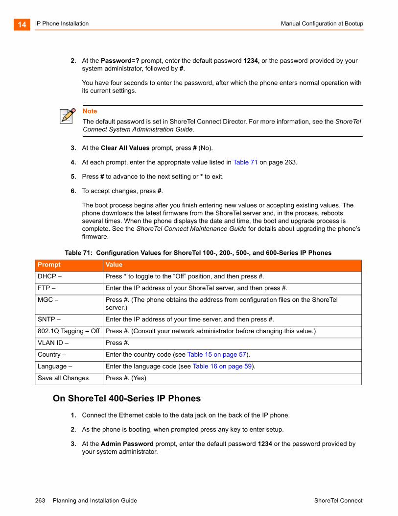
IP Phone Installation Manual Configuration at Bootup14
2. At the Password=? prompt, enter the default password 1234, or the password provided by your system administrator, followed by #.
You have four seconds to enter the password, after which the phone enters normal operation with its current settings.
3. At the Clear All Values prompt, press # (No).
4. At each prompt, enter the appropriate value listed in Table 71 on page 263.
5. Press # to advance to the next setting or * to exit.
6. To accept changes, press #.
The boot process begins after you finish entering new values or accepting existing values. The phone downloads the latest firmware from the ShoreTel server and, in the process, reboots several times. When the phone displays the date and time, the boot and upgrade process is complete. See the ShoreTel Connect Maintenance Guide for details about upgrading the phone’s firmware.
On ShoreTel 400-Series IP Phones
1. Connect the Ethernet cable to the data jack on the back of the IP phone.
2. As the phone is booting, when prompted press any key to enter setup.
3. At the Admin Password prompt, enter the default password 1234 or the password provided by your system administrator.
Note
The default password is set in ShoreTel Connect Director. For more information, see the ShoreTel Connect System Administration Guide.
Table 71: Configuration Values for ShoreTel 100-, 200-, 500-, and 600-Series IP Phones
Prompt Value
DHCP – Press * to toggle to the “Off” position, and then press #.
FTP – Enter the IP address of your ShoreTel server, and then press #.
MGC – Press #. (The phone obtains the address from configuration files on the ShoreTel server.)
SNTP – Enter the IP address of your time server, and then press #.
802.1Q Tagging – Off Press #. (Consult your network administrator before changing this value.)
VLAN ID – Press #.
Country – Enter the country code (see Table 15 on page 57).
Language – Enter the language code (see Table 16 on page 59).
Save all Changes Press #. (Yes)
263 Planning and Installation Guide ShoreTel Connect
Manual Configuration at Bootup IP Phone Installation 14
4. Do one of the following:
On the IP420, press #.
On the IP480, IP480g, and IP485g, press the OK soft key.
The Admin options menu opens.
5. Use the navigation key pad and the selector button to open the submenus necessary to configure parameters as follows:
If you are not using a DHCP server to provide an IP address, enter the following information:
Internet protocol > Use DHCP (Toggle to Off.) Internet protocol > IPv4 address (Enter the static IP address of the phone.) Internet protocol > Subnet mask (Enter the static IP subnet mask of the phone.) Internet protocol > Gateway (Enter the static IP gateway.) Internet protocol > SNTP server (Enter the IP address of the time server.)
If you are not using DHCP to provide configuration parameters, enter the following information:
Services> Config server (Enter the IP address of the ShoreTel configuration server.)
For descriptions of these parameters, see Table 72 on page 265.
6. With the appropriate submenu highlighted, do one of the following:
On the IP420, press the selector button on the navigation key pad.
On the IP480, IP480g, and IP485g, press the Edit soft key.
7. To return to the previous menu, do one of the following:
On the IP420, scroll down to the Back option and press the selector button on the navigation key pad until you return to the top-level menu.
On the IP480, IP480g, and IP485g, press the Back soft key until you return to the top-level menu.
8. To apply the changes, do one of the following:
On the IP420, with Exit highlighted press the selector button on the navigation key pad.
On the IP480, IP480g, and IP485g, press the Apply soft key.
Note
This password is configured through ShoreTel Connect Director in the Administration > Telephones > Options page. The parameter name is IP phone password. If the phone uses factory defaults, the phone has never been connected to a server, and you have not modified the IP phone password value, use the default password, 1234.
Tip
On IP480, IP480g, and IP485g phones, to exit the menu and apply changes, press and hold the Back soft key for 2 seconds.
ShoreTel Connect Planning and Installation Guide 264

IP Phone Installation Manual Configuration from the Key Pad14
The phone reboots and applies settings.
Manual Configuration from the Key Pad
Use the following procedures to enter the configuration menu after the phone has booted.
On ShoreTel 100-, 200-, 500-, and 600-Series IP Phones
1. With the phone on hook, press the MUTE key followed by 73887# (SETUP#).
2. At the Password prompt, enter 1234, or the password provided by your system administrator, followed by the # key.
3. Enter the values listed in Table 71 on page 263 when prompted. Press # to advance to the next setting or * to exit.
The phone downloads the latest firmware from the ShoreTel server and, in the process, it reboots several times. When the phone displays the date and time, the boot and upgrade process is complete. See the ShoreTel Connect Maintenance Guide for details about upgrading the phone’s firmware.
On ShoreTel 400-Series IP Phones
1. With the phone on hook, press the MUTE key followed by 73887# (SETUP#).
2. At the Admin Password prompt, enter the default password 1234 or the password provided by your system administrator.
Table 72: Configuration Values for ShoreTel 400-Series IP Phones
Admin Options Menu Submenu
Option Name Value to Enter
Internet Protocol Use DHCP Toggle to Off.
IPv4 address Enter the static IP address of the phone.
Subnet mask Enter the static IP subnet mask of the phone.
Gateway Enter the static IP gateway.
SNTP server Enter the IP address of the time server.
Services Config server Enter the IP address of the ShoreTel configuration server.
Note
This password is configured through ShoreTel Connect Director in the Administration > Telephones > Options page. The parameter name is IP phone password. If the phone uses factory defaults, the phone has never been connected to a server, and you have not modified the IP phone password value, use the default password, 1234.
265 Planning and Installation Guide ShoreTel Connect

Manual Configuration from the Key Pad IP Phone Installation 14
3. Do one of the following:
On the IP420, press #.
On the IP480, IP480g, and IP485g, press the OK soft key.
The Admin Options menu opens.
4. Use the navigation key pad and the selector button to open the submenus necessary to configure parameters as follows:
If you are not using a DHCP server to provide an IP address, enter the following information:
Internet protocol > Use DHCP (Toggle to Off.) Internet protocol > IPv4 address (Enter the static IP address of the phone.) Internet protocol > Subnet mask (Enter the static IP subnet mask of the phone.) Internet protocol > Gateway (Enter the static IP gateway.) Internet protocol > SNTP server (Enter the IP address of the time server.)
If you are not using DHCP to provide configuration parameters, enter the following information:
Services> Config server (Enter the IP address of the ShoreTel configuration server.)
For descriptions of these parameters, see Table 72 on page 265.
5. With the appropriate submenu highlighted, do one of the following:
On the IP420, press the selector button on the navigation key pad.
On the IP480, IP480g, and IP485g, press the Edit soft key.
6. To return to the previous menu, do one of the following:
On the IP420, scroll down to the Back option and press the selector button on the navigation key pad until you return to the top-level menu.
On the IP480, IP480g, and IP485g, press the Back soft key until you return to the top-level menu.
7. To apply the changes, do one of the following:
On the IP420, with Exit highlighted press the selector button on the navigation key pad.
On the IP480, IP480g, and IP485g, press the Apply soft key.
The phone reboots and applies settings.
Tip
On IP480, IP480g, and IP485g phones, to exit the menu and apply changes, press and hold the Back soft key for 2 seconds.
ShoreTel Connect Planning and Installation Guide 266
IP Phone Installation Displaying Settings for a ShoreTel IP Phone14
Displaying Settings for a ShoreTel IP Phone
You can display information about a ShoreTel IP phone by entering a key sequence on the phone’s key pad.
On ShoreTel 100-, 200-, 500-, and 600-Series IP Phones
1. With the phone on hook, press the MUTE key followed by 4636# (INFO#).
The phone displays the first one or two parameters, depending on the phone model.
2. Press # to advance the display or * to exit.
The phone resumes normal operation after the last parameter has been displayed.
On ShoreTel 400-Series IP Phones
1. With the phone on hook, press the MUTE key followed by 4636# (INFO#).
The Admin Options menu opens.
2. Use the navigation key pad and the selector button to scroll through and open the submenus as necessary to see the phone’s settings.
For descriptions of the parameters, see the ShoreTel Connect Maintenance Guide.
3. To close the Admin options menu, do one of the following:
On the IP420, with Exit highlighted press the selector button on the navigation key pad.
On the IP480, IP480g, and IP485g, press the Exit soft key.
Resetting a ShoreTel IP Phone
You can reset a phone by entering a key sequence on the phone’s key pad.
On ShoreTel 100-, 200-, 500-, and 600-Series IP Phones
1. With the phone on hook, press the MUTE key followed by 73738# (RESET#).
The phone reboots.
2. At the Reset Phone? prompt, press #.
The phone reboots. The reboot process is complete when the phone displays the date and time.
267 Planning and Installation Guide ShoreTel Connect
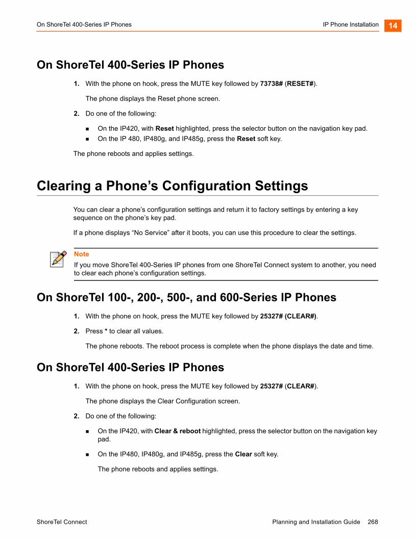
On ShoreTel 400-Series IP Phones IP Phone Installation 14
On ShoreTel 400-Series IP Phones
1. With the phone on hook, press the MUTE key followed by 73738# (RESET#).
The phone displays the Reset phone screen.
2. Do one of the following:
On the IP420, with Reset highlighted, press the selector button on the navigation key pad.
On the IP 480, IP480g, and IP485g, press the Reset soft key.
The phone reboots and applies settings.
Clearing a Phone’s Configuration Settings
You can clear a phone’s configuration settings and return it to factory settings by entering a key sequence on the phone’s key pad.
If a phone displays “No Service” after it boots, you can use this procedure to clear the settings.
On ShoreTel 100-, 200-, 500-, and 600-Series IP Phones
1. With the phone on hook, press the MUTE key followed by 25327# (CLEAR#).
2. Press * to clear all values.
The phone reboots. The reboot process is complete when the phone displays the date and time.
On ShoreTel 400-Series IP Phones
1. With the phone on hook, press the MUTE key followed by 25327# (CLEAR#).
The phone displays the Clear Configuration screen.
2. Do one of the following:
On the IP420, with Clear & reboot highlighted, press the selector button on the navigation key pad.
On the IP480, IP480g, and IP485g, press the Clear soft key.
The phone reboots and applies settings.
Note
If you move ShoreTel 400-Series IP phones from one ShoreTel Connect system to another, you need to clear each phone’s configuration settings.
ShoreTel Connect Planning and Installation Guide 268

IP Phone Installation On ShoreTel 400-Series IP Phones14
269 Planning and Installation Guide ShoreTel Connect

CHAPTER
15. Desktop Installation
This chapter describes the procedures for installing the ShoreTel Connect client software on desktop computers and includes the following sections:
Overview ................................................................................................................. 271
Prerequisites ........................................................................................................... 271
Methods of Installation ............................................................................................ 272
Silent Client Install ............................................................................................ 272
Standard Integrated Software Distribution ........................................................ 274
Configuring Instant Messaging................................................................................ 275
Enabling Instant Messaging for the ShoreTel Connect Client........................... 275
Enabling Instant Messaging for a Class of Service .......................................... 275
Migrating Instant Messaging Users to a Service Appliance.............................. 276
Upgrading ShoreTel Software ................................................................................. 278
User Licensing ........................................................................................................ 278
ShoreTel Connect Planning and Installation Guide 270
Desktop Installation Overview15
Overview
This chapter describes the hardware and software requirements and the subsequent procedures for installing the ShoreTel Connect client software, and the ShoreTel Connect client for Windows and Mac computers.
There are two methods of installing ShoreTel Connect client software:
Silent Client Install
Standard Integrated Software Distribution
Prerequisites
The following section describes the requirements and recommendations to be fulfilled prior to installing the ShoreTel Connect client application on a Windows or Mac computer.
Verify that each computer meets the minimum hardware and software requirements as outlined in the ShoreTel Connect Client User Guide.
Install the Client for the Microsoft Networking component.
Close all applications before starting the ShoreTel software installation.
Users must have local administrative privileges to install the ShoreTel software.
During a fresh install or upgrade to the ShoreTel Connect client, Visual Studio Tools for Office (VSTO) pre-requisites need to be installed first. The VSTO prerequisites will be installed automatically during the ShoreTel Connect client installation.
Learn the following information: the server name, user name, password, and extension number. This information must be available before the first-time use of the ShoreTel Connect client application.
Microsoft Outlook must be configured in Corporate or Workgroup mode for Microsoft Outlook Integration to function properly. Internet Only mode is not supported.
Users should be informed of which ShoreTel Connect client application they will be using.
Close all applications before starting the ShoreTel software installation.
Note
The procedures for installing the ShoreTel Connect client are covered in this chapter. The procedures for installing other ShoreTel Connect client software are in described in Chapter 10, Server Requirements on page 166.
271 Planning and Installation Guide ShoreTel Connect
Methods of Installation Desktop Installation 15
With the Silent Client Install feature, the client software upgrade process on remote machines do not require administrative rights by the person installing or upgrading software on client machines. Administrators can upgrade the software on all client machines using Active Directory Group Policies regardless of the permissions associated with those machines or the users who log into those machines.
Many of the changes are reliant on Microsoft Active Directory. Microsoft Outlook must be configured in “Corporate or Workgroup” mode for Outlook integration to function properly. “Internet Only” mode is not supported.
.NET Installation
On Windows-based computers, ShoreTel Connect client requires the installation of .NET Framework version 4 or higher. The ShoreTel Connect client installer automatically downloads the correct .NET Framework version if it is not present during the upgrade or install. Users are then prompted to accept the End User License Agreement from Microsoft to proceed with the .NET installation. Internet connectivity is required during the installation process.
Installing ShoreTel Connect client for Windows on a 64-bit platform places files in the default location: C:\Program Files(x86). The default location for 32-bit client dll files is C:\Windows\SysWow64.
Methods of Installation
This section describes the two ways in which ShoreTel software can be installed on your computer.
Silent Client Install
Standard Integrated Software Distribution
Silent Client Install
The Silent Client install allows the ShoreTel Connect client software to be installed or upgraded on a client machine from a remote machines without the need for administrative rights. An administrator can easily upgrade the software on all client machines regardless of the permissions associated with those machines or the users who log into those machines.
Many of the changes are reliant on Microsoft Active Directory. The Microsoft Active Directory software handles the following tasks:
Creating a Group Policy Object to use to distribute the software package
Assigning a package to a group of computers running Windows Vista, Windows 7, Windows 8, or Windows 8.1
Publishing a package
Removing a package
ShoreTel Connect Planning and Installation Guide 272

Desktop Installation Silent Client Install15
You will need to have the following files from the Client USB flash drive accessible with file permissions set to Share and File level Access by group <everyone>:
Data1.cab
Setup.exe
ShoreTel Call Manger.msi
Enabling the new Remote Client Upgrade functionality requires performing a number of tasks using Microsoft Active Directory. For information on performing those tasks, refer to the following Microsoft Reference article:
How To Use Group Policy to Remotely Install Software in Windows Server 2008 and Windows Server 2003, Microsoft Article ID 816102
ShoreTel recommends selecting the Prevent users from initiating client upgrades check box on the Other System Parameters page in ShoreTel Connect Director. For details about other parameters, refer to the ShoreTel Connect System Administration Guide.
Installation in a Large Deployment that Uses Active Directory
Some unique requirements exist for the installation of ShoreTel Connect client in a large deployment that uses Active Directory. This section outlines both the manual and the automated installation of ShoreTel Connect client in a large site with Active Directory. The decision for how to proceed depends on the following key factors:
Whether manual (local) or remote installation is used
Presence on the server of .NET Framework version 4.0 or higher
Access to the World Wide Web (if .NET Framework 4.0 is not on the server)
The version of .NET Framework that is used should be the 32-bit version for a 32-bit server or the 64-bit version for a 64-bit server.
Manual Installation
The ability to install ShoreTel software manually depends on the availability of .Net Framework 4.0. If the Prerequisites folder contains .Net Framework 4.0 and other, correct files, the system administrator can run setup.exe while the system is disconnected from the Internet. If the Prerequisites folder does not contain .Net Framework 4.0, the system must have Internet connectivity because, when the system administrator runs setup.exe, the system automatically downloads .Net Framework 4.0.
Automated Installation
To use the ShoreTel Connect client in a large-scale deployment that includes Active Directory, the remedy is for system administrators to install individual items in the order listed below. The administrator must push the following packages in the order shown through GPO or any other deployment tool:
1. Microsoft .Net Framework 4.0 (not located in the Prerequisites folder). Either .Net Framework exists on the system or the system must be connected to the Web (so that initiation of setup.exe causes a download of .Net Framework.)
273 Planning and Installation Guide ShoreTel Connect
Standard Integrated Software Distribution Desktop Installation 15
2. Interop Assemblies (in the Prerequisites folder) should contain Primary Interop Assemblies for 2007 and Visual Studio Tools for Office (VSTO). This resides in the Prerequisites folder.
3. ShoreTel Connect client located in the Setup folder.
Standard Integrated Software Distribution
To simplify installation, the ShoreTel Connect system provides an integrated software distribution feature. Using ShoreTel Connect Director, the system administrator can send an e-mail message to each user configured with an e-mail address.
You can send all users, some users, or just one user an e-mail message using the following procedure:
1. Launch ShoreTel Connect Director.
2. Click Administration > Features > Client > Notify Users.
The Notify Users page is displayed.
ShoreTel Connect’s integrated software distribution feature simplifies installation. Although the process presents a number of screens, there is a default installation that requires no input; you click through the screens until the installation completes.
Users receive an e-mail message from the ShoreTel Connect system containing the information they need to install the ShoreTel Connect client application. The installation program is accessed using the URL listed in the e-mail notification. Notice that the e-mail notification includes the server name and the user name: Users will need this information when they start the ShoreTel Connect client application for the first time. The software can also be installed from the ShoreTel Connect client CD.
For the procedures and related requirements on installing the ShoreTel Connect client, see the ShoreTel Connect Client User Guide.
ShoreTel Connect Planning and Installation Guide 274
Desktop Installation Configuring Instant Messaging15
Configuring Instant Messaging
To configure the instant messaging feature for users of ShoreTel Connect client, use the following procedures:
Enabling Instant Messaging for the ShoreTel Connect client
Enabling Class of Service for Instant Messaging
Enabling Instant Messaging for a User
Enabling Instant Messaging for the ShoreTel Connect Client
1. Launch ShoreTel Connect Director.
2. Click Administration > System > Other System Parameters.
The Other System Parameters page is displayed.
3. Enter the following information in the Instant Messaging section:
a. In the Domain Name field, enter the domain name used for your organization.
b. In the Sessions Timeout field, enter the duration, in minutes, that you want the system to keep an IM session open without an exchange before timing out. You can enter a range between 10 and 600 minutes.
c. Select the Enable Offline Messaging option if you want to allow users to leave off line messages for their contacts.
d. If you are using an SSL certificate, select the Enable TLS option to allow users to encrypt IM messages using Transport Layer Security (TLS) protocol.
e. Enter the number of days you want the ShoreTel Connect client to retain the history in the Client History Retention Period field. You can select a range between 0 and 549 days. If you want the retention period to not have a limit, select the Unlimited box.
4. Click Save at the bottom right corner of the page.
Instant messaging has been successfully enabled on the ShoreTel Connect client.
Enabling Instant Messaging for a Class of Service
1. Launch ShoreTel Connect Director.
2. Click Administration > Users > Class of Service > Telephony Features Permissions.
The following different classes of service are displayed for telephony:
Fully Featured
Minimally Featured
Partially Featured
275 Planning and Installation Guide ShoreTel Connect
Migrating Instant Messaging Users to a Service Appliance Desktop Installation 15
3. Select the feature class on the list pane for which you want to enable instant messaging services.
The details pane displays more information about the selected class.
4. On the IM Presence Invitation Handling drop-down list, select one of the following options:
User defined: Allows the user to choose the method of handling IM invitations.
Auto accept invitation: Forces IM invitations to be accepted automatically. The invitee must still invite the inviter.
Prompt to accept invitation: User is prompted when a new invitation is issued.
5. Click Save.
Instant messaging has been successfully enabled for the selected class of service.
Migrating Instant Messaging Users to a Service Appliance
1. Launch ShoreTel Connect Director.
2. Click Administration > Users > Users.
The Users page is displayed.
3. Select the user on the list pane for whom you want to enable the service.
The user details are displayed on the details pane.
4. Click the Applications tab.
5. In the Instant Messaging Server / Appliance section, select the service appliance you want to be associated with the user for instant messaging.
6. Click Save.
The selected service appliance replaces the ShoreTel server that is used for handling instant messages sent and received by the user.
You should notify the user to uninstall and reinstall Outlook calendar integration in ShoreTel Connect client for Windows if they are using Outlook calendar integration. See the ShoreTel Connect Client User Guide for instructions about how to configure Outlook calendar integration.
Configuring Apple iChat
iChat is an instant messaging software application by Apple Inc. for the Mac OS X operating system.The iChat client connects to the ShoreTel IM service and offers the following features:
Seamless authentication into the ShoreTel system
Secure communication
Contact list management
ShoreTel Connect Planning and Installation Guide 276
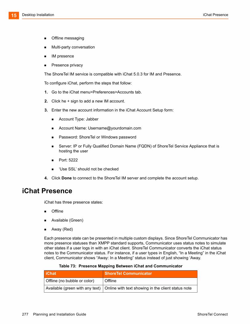
Desktop Installation iChat Presence15
Offline messaging
Multi-party conversation
IM presence
Presence privacy
The ShoreTel IM service is compatible with iChat 5.0.3 for IM and Presence.
To configure iChat, perform the steps that follow:
1. Go to the iChat menu>Preferences>Accounts tab.
2. Click he + sign to add a new IM account.
3. Enter the new account information in the iChat Account Setup form:
Account Type: Jabber
Account Name: [email protected]
Password: ShoreTel or Windows password
Server: IP or Fully Qualified Domain Name (FQDN) of ShoreTel Service Appliance that is hosting the user
Port: 5222
‘Use SSL’ should not be checked
4. Click Done to connect to the ShoreTel IM server and complete the account setup.
iChat Presence
iChat has three presence states:
Offline
Available (Green)
Away (Red)
Each presence state can be presented in multiple custom displays. Since ShoreTel Communicator has more presence statuses than XMPP standard supports, Communicator uses status notes to simulate other states if a user logs in with an iChat client. ShoreTel Communicator converts the iChat status notes to the Communicator status. For instance, if a user types in English, “In a Meeting” in the iChat client, Communicator shows “Away: In a Meeting” status instead of just showing ‘Away.
Table 73: Presence Mapping Between iChat and Communicator
iChat ShoreTel Communicator
Offline (no bubble or color) Offline
Available (green with any text) Online with text showing in the client status note
277 Planning and Installation Guide ShoreTel Connect
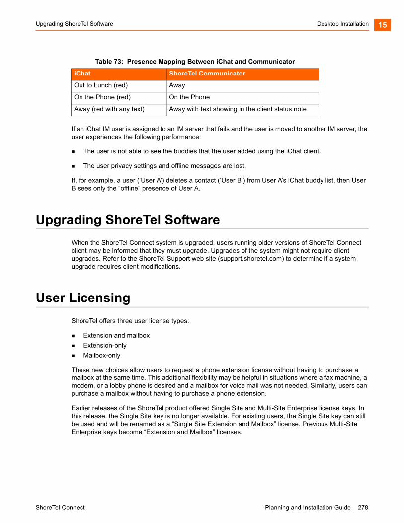
Upgrading ShoreTel Software Desktop Installation 15
If an iChat IM user is assigned to an IM server that fails and the user is moved to another IM server, the user experiences the following performance:
The user is not able to see the buddies that the user added using the iChat client.
The user privacy settings and offline messages are lost.
If, for example, a user (‘User A’) deletes a contact (‘User B’) from User A’s iChat buddy list, then User B sees only the “offline” presence of User A.
Upgrading ShoreTel Software
When the ShoreTel Connect system is upgraded, users running older versions of ShoreTel Connect client may be informed that they must upgrade. Upgrades of the system might not require client upgrades. Refer to the ShoreTel Support web site (support.shoretel.com) to determine if a system upgrade requires client modifications.
User Licensing
ShoreTel offers three user license types:
Extension and mailbox
Extension-only
Mailbox-only
These new choices allow users to request a phone extension license without having to purchase a mailbox at the same time. This additional flexibility may be helpful in situations where a fax machine, a modem, or a lobby phone is desired and a mailbox for voice mail was not needed. Similarly, users can purchase a mailbox without having to purchase a phone extension.
Earlier releases of the ShoreTel product offered Single Site and Multi-Site Enterprise license keys. In this release, the Single Site key is no longer available. For existing users, the Single Site key can still be used and will be renamed as a “Single Site Extension and Mailbox” license. Previous Multi-Site Enterprise keys become “Extension and Mailbox” licenses.
Out to Lunch (red) Away
On the Phone (red) On the Phone
Away (red with any text) Away with text showing in the client status note
Table 73: Presence Mapping Between iChat and Communicator
iChat ShoreTel Communicator
ShoreTel Connect Planning and Installation Guide 278
Desktop Installation User Licensing15
Purchasing User Licenses
Each user must be configured with one of those three license types. A license must be purchased for each user, based upon the needs of that user. To see if an installation is in compliance with the number of licenses purchased, all Extension-Only, Mailbox-Only, and Mailbox-and-Extension users are counted and compared against the sum of the licenses purchased.
Extension and mailbox: Purchase of this license entitles the user to be assigned to both a physical extension and a ShoreTel mailbox.
Extension-only: Purchase of this license entitles the user to be assigned to a physical extension, either via explicit assignment or via Extension Assignment.
Mailbox-only: Purchase of this license allows the user to be assigned to a ShoreTel voice mail-box.
Language Licenses
ShoreTel supports multiple languages in addition to US English (which will remain the default language for new installations). One or more languages can be running at a site by purchasing a language license.
If only one language is needed at a single site, there is no need to purchase a language license.
For instructions on configuring the User Licenses or Language Licenses via Director, please refer to the ShoreTel Connect System Administration Guide.
License Control
License Control adds enforcement and branding to the ShoreTel product and provides tighter enforcement (via MAC address-based node locking) on existing licensing. When an existing ShoreTel Connect system is upgraded to the current software release, an enforcement scheme requires entry of a system key.
When launching ShoreTel Connect Director, you are asked to enter either a Small Business Edition (SBE) or Enterprise Edition (EE) key (see below for details on the differences between these two). You can request a key online via Director. If an invalid key is entered or if the field is left empty, you will be allowed to log into the system for 45 days.
If no action is taken within the 45-day grace period, ShoreTel Connect Director will be locked and you will be unable to make any configuration changes to the system (although the phones will continue to work).
This 45-day period allows for unplanned, ad hoc changes that may cause you to exceed license limits while providing time to comply with the license requirements by either removing unneeded configurations or by ordering additional licenses.
You will be forced to purchase one of two keys available:
SBE 100 key – required for Small Business Edition 100
This key is for smaller systems under 100 users and 5 sites.
279 Planning and Installation Guide ShoreTel Connect
User Licensing Desktop Installation 15
Use of this key results in the display of SBE 100 branding (on the initial login page above the navigation pane).
The SBE 100 license allows a maximum of 100 users with an extension and mailbox, and the customer can add up to 20 users who have only a mailbox.
For an SBE system, the following features are not available:
AMIS SMDI On-net Dialing Distributed Database, workgroups, account codes SBE does not support integration with another ShoreTel Connect system or any third-party
PBX. TSP
EE key – required for Enterprise Edition
This is for larger businesses with more than three sites. The existing branding appears. System behaves as it does today, except that number of sites is enforced via nagging. Block adding an additional SBE or EE key.
For instructions on configuring licenses in ShoreTel Connect Director or for information about Keyed and Self-Audited licenses, see the ShoreTel Connect System Administration Guide.
ShoreTel Connect Planning and Installation Guide 280

Desktop Installation User Licensing15
281 Planning and Installation Guide ShoreTel Connect
CHAPTER
16. ShoreTel Integration withExternal Applications
To work with some external applications, the ShoreTel Connect system may require additional set-up after system installation. This chapter identifies and describes how to set up the system to integrate with external applications.
This chapter includes the following topics:
Overview ................................................................................................................. 283
Important Considerations.................................................................................. 283
Uploading Public Contacts ...................................................................................... 283
Prerequisites..................................................................................................... 284
Running the Import Public Contacts Windows Batch File................................. 286
Verifying that Public Contacts Are Uploaded .................................................... 288
Using the Windows Task Scheduler to Upload Public Contacts ....................... 288
Installing the ShoreTel Telephony Interface ............................................................ 289
Prerequisites..................................................................................................... 289
Installing the STI ............................................................................................... 289
Verifying that the Interface Is Installed.............................................................. 289
Installing the TSP Package ..................................................................................... 290
Running Setup.................................................................................................. 290
Using the Microsoft GPO Deployment Tool ...................................................... 291
Using ShoreTel Advanced Applications............................................................ 291
Installing Third-party TSP Package in a Terminal Licensing Server Environment (Citrix and Windows) ........................................................................................ 291
ShoreTel Connect Planning and Installation Guide 282
ShoreTel Integration with External Applications Overview16
Overview
Using the ShoreTel ImportContacts.bat utility, you can import public contacts from the Public Folder on a Microsoft Exchange Server and upload them into the System Directory in ShoreTel Connect Director for use by ShoreTel Connect system users. Before running the utility, you must configure the settings for the batch file in a ShoreTel configuration file (ImportContactsconfig). When run, the ShoreTel batch utility performs the following procedures:
Connects to your Microsoft Exchange Server (2013) via the Exchange Web Services.
Reads the contacts in the Exchange Public Folder.
Copies the contacts into a comma-separated value (CSV) file. Be aware that the batch utility provides an option to ignore fields during CSV-file generation.
Invokes the ShoreTel DBImport tool (dbimport.exe), which uses the contents of the CSV file to update the ShoreTel MYSQL user database. The tool adds, deletes, and modifies user account records based on the contents of the CSV file.
The imported and uploaded contacts are displayed in endpoints that can access the ShoreTel Connect System Directory, such as Outlook, telephones, and ShoreTel Connect client. ShoreTel Connect system users can dial the numbers of the imported and uploaded contacts, create buddies, and so on.
Important Considerations
When you upload public contacts from a Microsoft Exchange Server, be aware of the following considerations:
Client hardware memory requirements can change if public contacts are imported and uploaded: Memory requirements can increase in relation to the number of contacts imported and uploaded.
Contacts imported from a Microsoft Exchange Server and uploaded to the ShoreTel Connect System Directory are never private and are fully visible in the ShoreTel Connect client.
Uploading Public Contacts
Running the ShoreTel ImportContacts.bat utility updates the ShoreTel Connect System Directory as follows:
Contacts added to the Public Folder on a Microsoft Exchange Server are added to the ShoreTel Connect System Directory.
Contacts modified in the Public Folder on a Microsoft Exchange Server are modified in the ShoreTel Connect System Directory.
Contacts deleted from the Public Folder on a Microsoft Exchange Server are deleted from the ShoreTel Connect System Directory.
283 Planning and Installation Guide ShoreTel Connect
Prerequisites ShoreTel Integration with External Applications 16
To limit exposure, contacts imported from the Public Folder on a Microsoft Exchange Server and uploaded into the ShoreTel Connect System Directory can be deleted from the System Directory using ShoreTel Connect Director. See the ShoreTel Connect System Administration Guide for information on using ShoreTel Connect Director to manage the System Directory, including adding and deleting records.
Contacts in the Public Folder can be imported and uploaded at any time, but it is usually best to run the batch utility during off-peak system hours.
You can also import and upload contacts by using the Windows Task Scheduler. For more information, see Using the Windows Task Scheduler to Upload Public Contacts on page 288.
Prerequisites
To upload public contacts, you system must comply with the following prerequisites:
Your system must be running Microsoft Exchange Server 2013.
Your Microsoft Exchange Server must contain Public Folders.
You must be familiar with Exchange server concepts and terminology and be proficient at managing an Exchange server. This document is not a tutorial on Exchange servers. For complete information on installing, configuring, and managing Exchange servers, see the Microsoft web site (http://www.microsoft.com/exchange).
You must have System Administrator permissions to perform the following tasks:
Read Public Contacts from a Microsoft Exchange Server. Edit the Import Contacts Configuration file. Run the Public Contacts Windows Batch file.
Editing the Import Contacts Configuration File
To edit the import contacts configuration file on the Headquarters server, follow this procedure:
1. Open a Command Prompt window (on your Headquarters server).
Note
Contacts that you delete from the System Directory by using ShoreTel Connect Director are deleted only from the System Directory; they are not deleted from the Public Folder on a Microsoft Exchange Server.
Note
To perform this procedure, you must have system administrator permissions.
ShoreTel Connect Planning and Installation Guide 284

ShoreTel Integration with External Applications Editing the Import Contacts Configuration File16
2. CD to the location of the Import Contacts Configuration file as follows:
On 32-bit systems:
C:\Program Files\Shoreline Communications\Shoreware Server\ImportContacts\ImportContactsconfig
On 64-bit systems:
C:\Program Files (x86)\Shoreline Communications\Shoreware Server\ImportContacts\ImportContactsconfig
3. Open the Import Contacts Configuration file.
4. Modify the parameters. (The parameters are listed and described in Table 74 on page 285.)
5. Save and close the Import Contacts Configuration file.
Table 74: Import Contacts Configuration File Parameters
Parameter Definition
Version Exchange server version (0 or 1).
0 = Exchange server 2010.
1 = Exchange server 2013.
UserName Your Exchange user name.
Required only if you are not using Network Credentials.
Password Your Exchange password.
Required only if you are not using Network Credentials.
Domain Name of your Exchange domain.
Required only if you are not using Network Credentials.
EWSUrl Exchange Web Service location.
For example, https://10.XX.XXX.XX/EWS/exchange.asmx.
PF Path to your company’s Public Folder.
Location where your company’s public contacts are stored. (“Testfolder” and Testcontact” are placeholders in the example.)
OptionalColumns Specifies information that is not imported and uploaded.
For example, the home address or height of a contact.
285 Planning and Installation Guide ShoreTel Connect
Running the Import Public Contacts Windows Batch File ShoreTel Integration with External Applications 16
Running the Import Public Contacts Windows Batch File
To run the Import Public Contacts Windows batch file, follow these steps:
1. Open a Command Prompt window (on your Headquarters server).
2. CD to the location of the Import Public Contacts Windows Batch File:
On 32-bit systems:
C:\Program Files\Shoreline Communications\Shoreware Server\ImportContacts\
On 64-bit systems:
C:\Program Files (x86)\Shoreline Communications\Shoreware Server\ImportContacts\
The location of the file is shown in Figure 19.
3. Run the Import Public Contacts Windows Batch File. The status of the procedure is shown in the example in Figure 20. The contacts are imported from the Public Folder on your Microsoft Exchange Server and uploaded to the ShoreTel Connect System Directory for use by ShoreTel Connect system users.
LogFile Specifies the log file name.
The default location for 64 bit systems is C:\Program Files (x86)\Shoreline Communications\ShoreWare Server\ImportContacts.
CSVFile Specifies the CSV file name that is generated.
The default location for 64 bit systems is C:\Program Files (x86)\Shoreline Communications\ShoreWare Server\ImportContacts.
Note
To perform this procedure, you must have system administrator permissions.
Table 74: Import Contacts Configuration File Parameters (Continued)
ShoreTel Connect Planning and Installation Guide 286
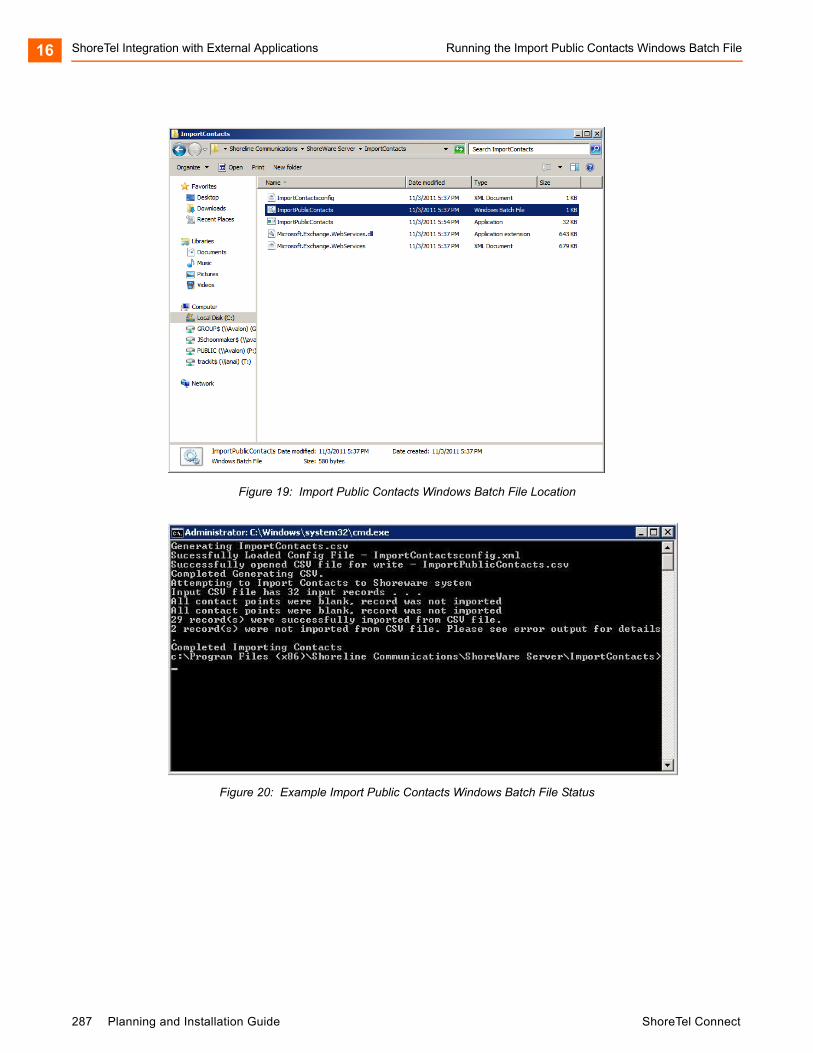
ShoreTel Integration with External Applications Running the Import Public Contacts Windows Batch File16
Figure 19: Import Public Contacts Windows Batch File Location
Figure 20: Example Import Public Contacts Windows Batch File Status
287 Planning and Installation Guide ShoreTel Connect
Verifying that Public Contacts Are Uploaded ShoreTel Integration with External Applications 16
Verifying that Public Contacts Are Uploaded
To run the Import Public Contacts Windows batch file, follow these steps:
1. Open ShoreTel Connect Director.
2. Under Administration, click System Directory.
The System Directory window appears, which displays the imported and uploaded contacts. If the Public Contacts are not displayed in the System Directory, they were not imported and uploaded.
3. To check for errors in the import and upload process, open and view a Log File (DBImport.err) on your Headquarters server.
On 32-bit OS systems:
C:\Program Files\Shoreline Communications\Shoreware Server\ImportContacts\DBImport.err
On 64-bit OS systems:
C:\Program Files (x86)\Shoreline Communications\Shoreware Server\ImportContacts\DBImport.err
Using the Windows Task Scheduler to Upload Public Contacts
Using the Windows Task Scheduler, you can also import public contacts from the Public Folder on a Microsoft Exchange Server and upload them into the System Directory in ShoreTel Connect Director.
The Task Scheduler enables you to automatically run the Import Public Contacts Batch File on your ShoreTel Headquarters Server.
The Task Scheduler wizard opens the Import Public Contacts Batch File according to the schedule you choose. The tasks can be scheduled to execute at a specific time on a daily, weekly, or monthly schedule.
For more information on how to use the Task Scheduler on your Windows Server, see the Microsoft Corporation website.
Note
To perform this procedure, you must have system administrator permissions.
Note
To perform this procedure, you must have system administrator permissions.
ShoreTel Connect Planning and Installation Guide 288
ShoreTel Integration with External Applications Installing the ShoreTel Telephony Interface16
Installing the ShoreTel Telephony Interface
The system installation wizard does not automatically install the ShoreTel Telephony Interface (STI) during installation.
If you are using third-party or supplementary ShoreTel applications that interact with the ShoreTel Connect system, you may need to manually install the STI.
This section describes how to install the STI on Windows clients with third-party applications that integrate with ShoreTel Connect client for Windows.
For information on installing STI on Citrix servers, see Appendix D, Installing the ShoreTel Connect Client on Citrix and Windows Servers.
Prerequisites
Before you install the STI, perform the following prerequisite steps:
Close all open programs, because a reboot will be required during the installation process.
Ensure that the ShoreTel Connect client for Windows is installed, and log into the client to enable the required configuration settings.
Be sure you know the location of ShoreTel Connect system software on your system.
Installing the STI
1. If it is not already installed, install (or upgrade) ShoreTel Connect client for Windows.
2. Launch Windows Explorer.
3. Enter the following URL:
http://serverIP/shorewareresources/shoreteltelephonyinterface
The ShoreTel Telephony Interface Install site appears.
4. Click the link to install the ShoreTel Telephony Interface, and then download and install the interface on the client computer.
If you are running Windows 7 64 bit with UAC turned on, make sure to download the installer, right click and select Run as Administrator to properly install the TAPI provider.
5. Reboot the client computer.
Verifying that the Interface Is Installed
1. Open Control Panel.
2. Click Phone and Modem Options.
289 Planning and Installation Guide ShoreTel Connect
Installing the TSP Package ShoreTel Integration with External Applications 16
3. Click Advanced.
4. Verify that ShoreTel Remote TAPI Service Provider is installed.
5. Select ShoreTel Remote TAPI Service Provider.
6. Click Configure. The ShoreTel Remote TSP dialog appears.
7. In Provider Usage, verify that the provider is enabled.
8. Launch ShoreTel Connect client for Windows.
The TAPI service registers the ID, password, and address of the user for transactions with the third-party application.
Installing the TSP Package
You must install the Telephony Service Provider (TSP) package on clients that require TAPI for third-party applications (for example, ShoreTel Professional Service applications).
This software can be found in the Third Party Support folder included with the ShoreTel Connect client software.
There are three ways to install the Third Party TSP package on client operating systems for third-party Applications:
Running setup
Using the Microsoft GPO Deployment tool
Using the ShoreTel Professional Services application
The installation procedure for each method is described in the following sections.
Running Setup
1. Perform a fresh install or upgrade of the ShoreTel Connect client for Windows.
2. Configure the ShoreTel Connect client.
3. Install the Third Party TSP package.
4. Follow the default settings and finish the installation.
5. Reboot the client machine.
This user can now run third-party applications that use TAPI.
Note
You must upgrade the ShoreTel Connect client for Windows first before you upgrade the third-party TSP package.
ShoreTel Connect Planning and Installation Guide 290
ShoreTel Integration with External Applications Using the Microsoft GPO Deployment Tool16
Using the Microsoft GPO Deployment Tool
Using GPO, install (push) the TSP package to larger sites. GPO is Microsoft Corporation’s Group Policy Object (GPO) deployment tool. It can be used to remotely install (push) software in Windows Server 2008. For more information about GPO, see the Microsoft support website, http://support.microsoft.com, and search for GPO.
Using ShoreTel Advanced Applications
When a user runs an advanced application that needs the TSP, the user will be prompted to download and install the TSP.
Installing Third-party TSP Package in a Terminal Licensing Server Environment (Citrix and Windows)
1. Perform a fresh install or upgrade of the ShoreTel Connect client for Windows.
2. Install the third Party TSP package.
3. On the Windows desktop, open the Control Panel.
4. Click Phone and Modem.
5. Click My Location.
6. Click Advanced.
7. Select ShoreTel Remote TAPI Service Provider.
8. Click Remove.
9. Click OK.
10. On the Windows desktop, open a command prompt window.
11. Navigate to the following location:
\Program Files\ShoreTel\ShoreTel 3rd Party
12. Run the following command:
TSPinstall -i StServer HQ servername (IP address)
13. On the Windows desktop, open the Control Panel.
14. Click Phone and Modem > My Location > Advanced.
Verify that the ShoreTel Remote TAPI Service Provider is listed.
ShoreTel Connect client can now use Third Party applications.
291 Planning and Installation Guide ShoreTel Connect
CHAPTER
17. Legacy Integration
ShoreTel provides a way to convert a TDM-based voice network into the ShoreTel Connect system. Integrating the ShoreTel Connect system with an old PBX allows a customer with different systems to support phone and voice mail communication between systems. This chapter describes how to migrate your legacy system to the ShoreTel Connect system. This chapter covers the following topics:
Overview ................................................................................................................. 294
Legacy PBX ............................................................................................................ 294
Coordinated Dialing................................................................................................. 295
Trunk Requirements................................................................................................ 295
Coordinated Dialing Plan ........................................................................................ 295
PSTN Services........................................................................................................ 296
Multi-Site Integration ............................................................................................... 297
Single Site Integration ............................................................................................. 297
Consolidated Long Distance ................................................................................... 298
Voice Mail Integration.............................................................................................. 298
AMIS Protocol Support ..................................................................................... 298
SMDI Protocol Support ..................................................................................... 299
Configuring Legacy Voice Mail Integration Using SMDI ................................... 302
Configuring ShoreTel Voice Mail Integration Using SMDI................................. 307
System Requirements............................................................................................. 313
Connection Cable.................................................................................................... 313
Special Considerations — Nortel PBX.............................................................. 313
Special Considerations — Avaya/Lucent PBX.................................................. 314
Administration and Configuration ............................................................................ 314
Tie Trunk Configuration .................................................................................... 314
ShoreTel Connect Planning and Installation Guide 292

Legacy Integration17
Services Summary ........................................................................................... 314
Trunk Configuration for Legacy PBX Integration..................................................... 315
Creating a New Trunk Group............................................................................ 315
Configuring Inbound Services with Extension Routing..................................... 316
Configuring Off-System Extensions.................................................................. 316
Configuring Outbound Call Routing via the Remote PBX................................. 316
293 Planning and Installation Guide ShoreTel Connect
Overview Legacy Integration 17
Overview
An integrated voice network can provide the following streamlining for your system:
Simplify communications for your users with an enterprise-wide coordinated dialing plan using extension dialing.
Exchange voice mail messages between users on different sites using different voice mail systems. Standard commands such as compose, forward, and replay, extend the value of your different voice mail systems.
Consolidate trunks with different traffic types.
Reduce service costs by redirecting inter-site calls across your IP network.
Legacy PBX
A digital trunk tie line integrates the ShoreTel Connect system with a legacy PBX. The connection is between the legacy system’s PRI interface and the PRI interface of a ShoreTel Voice Switch located anywhere in your IP network.
There are four different types of activities that occur on the interface:
Calls from ShoreTel users or applications to an extension located on the other system are routed across the tie trunk. When a call is placed, the trunk is accessed and the ShoreTel Connect system sends the configured number of digits to the PBX identifying the called extension.
Calls from users on the legacy system or from trunks, or other applications on the legacy PBX, are routed across this interface. When the legacy user places their call, the legacy system accesses the trunk and then sends the digits as DNIS.
Outbound calls from users or applications on the ShoreTel Connect system can be routed across the trunk to the legacy PBX. When a call is placed, the trunk access code or trunk configuration of the connection to the legacy PBX indicates the outbound call is to be placed to the PBX.
Calls between the ShoreTel and legacy system's voice mail applications are carried across the trunk connecting the two systems. The voice mail systems make calls to configured destinations on the other system to send voice mail messages to users on the other system.
A tie trunk is not required to enable voice mail or AMIS integration. The two voice mail systems can communicate by dialing each other via the PSTN. In general, when a tie trunk is in place, AMIS calls should be routed via the trunk to reduce PSTN costs.
The connection between the two systems can be provided by either T1 trunks, PRI, or SIP interface. ShoreTel recommends that you use PRI or SIP to enable calling number information exchanges between the two systems.
ShoreTel Connect Planning and Installation Guide 294
Legacy Integration Coordinated Dialing17
Coordinated Dialing
Coordinated dialing allows users to dial between the systems using extension-to-extension dialing as well as enabling consolidation of inbound and outbound services. To effectively plan the integration, consider the following items:
Expected call traffic between the two systems to provide sufficient trunking
Current numbers of extensions and extension lengths at both systems
Service plans to determine which PSTN services are provided at each voice system
What type of legacy PBX equipment is integrated with the ShoreTel Connect system
Trunk Requirements
The number of digital trunks required between the ShoreTel Connect system and the legacy PBX depends on the expected traffic between the two systems. To determine the number of trunks, you need to estimate the number of calls per hour that are placed between the two systems. When estimating the call volume between the two systems, consider the following:
The volume of direct calls between users on the two systems
Traffic related to Automated Call Distributor (ADC) calls
Outbound call volume (when outbound trunking to the PSTN is provided by one of the systems for all users, such as a PSTN trunk connected to the legacy PBX that provides long distance services for users on both the legacy and ShoreTel Connect system)
Inbound call volume (when inbound services are provided by one system to all users)
Additionally, you can rely on the estimated calls-per-hour number to determine the number of trunks to configure between the two systems.
For more information on trunk requirements, see Trunk Planning and Ordering on page 88.
Coordinated Dialing Plan
With legacy integration, users on both systems can dial one another using abbreviated or extension dialing. This includes dialing from applications on the systems, such as the ShoreTel voice mail application, and would also include forwarding a call to an assistant at an extension on the legacy PBX. To determine the coordinated dialing plan configuration, you must identify the current numbering of users on both systems:
When the systems are located together, extensions can normally be assigned from a single numbering plan, or from a single DID number range provided by the local carrier. In this case, the extensions on the two systems are assigned such that there is no overlap using the desired extension length.
295 Planning and Installation Guide ShoreTel Connect
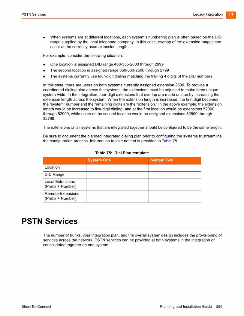
PSTN Services Legacy Integration 17
When systems are at different locations, each system’s numbering plan is often based on the DID range supplied by the local telephone company. In this case, overlap of the extension ranges can occur at the currently used extension length.
For example, consider the following situation:
One location is assigned DID range 408-555-2000 through 2999
The second location is assigned range 650-333-2500 through 2799
The systems currently use four-digit dialing matching the trailing 4 digits of the DID numbers.
In this case, there are users on both systems currently assigned extension 2500. To provide a coordinated dialing plan across the systems, the extensions must be adjusted to make them unique system-wide. In the integration, four-digit extensions that overlap are made unique by increasing the extension length across the system. When the extension length is increased, the first digit becomes the “system” number and the remaining digits are the “extension.” In the above example, the extension length would be increased to five-digit dialing, and at the first location would be extensions 52000 through 52999, while users at the second location would be assigned extensions 32500 through 32799.
The extensions on all systems that are integrated together should be configured to be the same length.
Be sure to document the planned integrated dialing plan prior to configuring the systems to streamline the configuration process. Information to take note of is provided in Table 75.
PSTN Services
The number of trunks, your integration plan, and the overall system design includes the provisioning of services across the network. PSTN services can be provided at both systems in the integration or consolidated together on one system.
Table 75: Dial Plan template
System One System Two
Location
DID Range
Local Extensions(Prefix + Number)
Remote Extensions(Prefix + Number)
ShoreTel Connect Planning and Installation Guide 296
Legacy Integration Multi-Site Integration17
Multi-Site Integration
When the systems are located at different sites, both systems should have local trunking for both inbound and outbound calls. Local inbound numbers make it easy for nearby customers to reach you, while local outbound trunks allow you to save on telephone charges by using local services at the site.
In this configuration, the trunk lines connecting the systems are used for the inter-site calling between extensions or applications on the two systems. The interfaces on the two systems are configured to dial out to the remote or off-system extensions, and to accept incoming calls using DNIS.
The ShoreTel voice switch that connects to the legacy PBX should be located at the site with the legacy PBX. This leverages the IP network to extend the calls to the other sites with the ShoreTel Connect system.
Single Site Integration
When the systems are located at the same site, it is not required that both systems be connected to the PSTN. The systems can be configured to best match your requirements.
In a single site configuration, the PSTN connections for inbound calls can be connected to each system. In this environment, the trunks connecting the two systems are configured to dial out the remote or off-system extensions and to accept incoming calls using DNIS.
Alternatively, inbound services can be consolidated on either the ShoreTel Connect system or the legacy PBX. In this environment, calls to users on the other systems are forwarded to the remote or off-system extensions through the trunk lines connecting the systems.
When all inbound trunks are consolidated on the ShoreTel Connect system, the trunks are configured to support off-system extensions within the range of extensions on the other PBX.
When all inbound trunks are configured on the legacy PBX, the trunks on the ShoreTel Connect system are configured to support inbound services with call routing to the extensions on the ShoreTel Connect system.
When DID numbers are already in place on one of the PBX’s which will be connected, ShoreTel recommends that the inbound DID service not be moved or split between the systems but configured to remain on the system where they are currently configured and have calls to users on the other system forward across the connecting trunks.
In the single site configuration, ShoreTel recommends that services for outbound calls be connected to the legacy PBX. In this configuration the trunk interfaces on the system are configured to support outbound local and long distance dialing while the interface on the PBX is configured to route the received outbound calls.
297 Planning and Installation Guide ShoreTel Connect

Consolidated Long Distance Legacy Integration 17
Consolidated Long Distance
Long distance calls can be consolidated into a single PSTN interface across both the ShoreTel Connect system and the integrated legacy PBX. In this configuration, you gain the benefits of reduced long distance rates by consolidating all your enterprise's long distance calls into a single carrier. When it is required, the outbound long distance trunks are connected to the legacy PBX and the ShoreTel Connect system is configured to route long distance calls outbound across the digital trunk connecting the systems.
Voice Mail Integration
The primary issue with voice mail integration is they are often proprietary and the interfaces defined to connect the same and disparate systems are very old, complex and difficult to implement. In fact, many voice systems from the same vendor are not connected. The interface with which most customers are familiar is AMIS. This is an analog interface that has been around for a long time, but is a real challenge to implement and can be very expensive from legacy voice mail providers. It is not uncommon to pay $10,000 per site for this capability. Another widely-used interface, Simplified Message Desk Interface (SMDI), was developed in the days when the PBX and voice mail systems were separate systems. It operates on a serial link between a PBX and voice mail system and allows them to work together. ShoreTel supports both AMIS and SMDI protocols for voice mail integration.
AMIS Protocol Support
The ShoreTel Connect system sends and receives voice mail messages to and from legacy voice mail systems using AMIS protocol Version 1 - Specification February 1992. To send voice mail messages to remote AMIS sites, ShoreTel dials the access phone number for the remote system. Likewise, to receive voice messages from a remote system, the remote system must know the number to dial into the ShoreTel Connect system. To reach the ShoreTel Connect system, the remote system must be configured to dial any number that reaches an auto-attendant menu.
AMIS call support is enabled by default. Incoming AMIS voice mail is delivered in the same manner as other voice mail; however, users cannot send replies. To send outbound AMIS voice mail, you must define AMIS System profiles in ShoreTel Connect Director.
ShoreTel negotiates the setup, handshaking, and teardown of AMIS system calls. Each voice mail requires a call over the trunk group defined for the AMIS delivery and call-back numbers.
Simplifying AMIS Systems and Increasing Usability Use the same extension length across your enterprise.
Use off-system extensions to match remote users’ mail boxes with their extension numbers.
Assign each system a System ID to identify the remote site location
For more information on AMIS systems, see the ShoreTel Connect System Administration Guide.
ShoreTel Connect Planning and Installation Guide 298

Legacy Integration SMDI Protocol Support17
SMDI Protocol Support
The ShoreTel product supports the SMDI protocol, enabling seamless integration of ShoreTel equipment with legacy phone systems and enabling a smooth migration toward an all-IP telephony solution.
The SMDI protocol evolved at a time when voice mail services and PBX services were provided by separate physical devices. Over the years, manufacturers have managed to offer both PBX and voice mail services within a single device, and the need for SMDI has diminished. However, the protocol can still be useful in situations where newer equipment will be integrated into a network of older devices.
How It Works
SMDI enables the separate devices that provide PBX and voice mail services to share information over an out-of-band serial cable connection. The PBX shares information with the voice mail system about incoming calls. The following information is passed to the voice mail system:
Who the call is from
Where the call is going (i.e. user extension)
The reason the call is going to voice mail instead of being answered
In response, the voice mail system returns a notification to the PBX that a message was left on the voice mail server. The PBX system then uses this information to alert the user by turning on the message waiting light on his or her phone.
Configurations of Integrated Equipment
With SMDI support, there are essentially two possible ways the ShoreTel and legacy equipment can be configured:
External Voice Mail Configuration — The legacy system provides voice mail services while the ShoreTel Connect system acts as the PBX.
ShoreTel Voice Mail Configuration — The ShoreTel Connect system provides voice mail services while the legacy system acts as the PBX.
Additional Details
A group of analog trunks from the ShoreTel Connect system is used to access the legacy voice mail system. The ShoreTel Connect system is on the extension side of the trunks. The ShoreTel voice mail application manages the group of outgoing extensions. The ShoreTel server can provide digit translations if the legacy voice mail and ShoreTel Connect system have different extension lengths.
Figure 21 shows the ShoreTel Connect system providing PBX services and the legacy equipment providing voice mail services.
299 Planning and Installation Guide ShoreTel Connect

SMDI Protocol Support Legacy Integration 17
Figure 21: External Voice Mail with ShoreTel as PBX
Figure 22 shows the legacy system providing PBX services and the ShoreTel equipment providing voice mail services.
ShoreTel Connect Planning and Installation Guide 300

Legacy Integration SMDI Protocol Support17
Figure 22: ShoreTel Voice Mail with Legacy PBX
Details
Figure 22 shows a ShoreTel Voice Switch connected to a legacy PBX through several analog trunks. These phone lines carry voice information from the PBX to the voice mail server. Signaling information is carried out-of-band on the separate serial line, which is shown near the bottom of the illustration.
A ShoreTel voice mail server is connected through a serial cable to a PBX link device. The PBX link device provides the basic SMDI services that were not included in some of the older legacy PBX devices. This device must be purchased separately and configured per the manufacturer's instructions.
The ShoreTel server and PBX link exchange information. The PBX link sends call data to the ShoreTel voice mail server, and the call data contains information related to the source and destination of the phone call, and provides information about why the call is going to voice mail — user did not answer, line was busy, and so on.
The ShoreTel server, in return, sends MWI (Message Waiting Indicator) information that is used by the legacy PBX to turn on the message-waiting mechanism on a user's phone to let her know she has received a message.
301 Planning and Installation Guide ShoreTel Connect
Configuring Legacy Voice Mail Integration Using SMDI Legacy Integration 17
Information Transferred via SMDI
The COM port is used to send call information between the ShoreTel Connect system and the legacy voice mail system. The SMDI protocol transmits the following call information from the ShoreTel Connect system to the legacy system:
Message desk number: 1-999
Logical Terminal number (terminal identifier): 1-9999
Call type (All, Busy, Direct, No Answer, Unknown)
Called party
Calling party
The SMDI MWI protocol transmits the following information from the legacy voice mail system to the ShoreTel Connect system:
Message waiting indication control
Extension
On/Off indication
Configuring Legacy Voice Mail Integration Using SMDI
As mentioned before, there are two modes of operation with respect to integrating a ShoreTel Connect system and a legacy system:
External Voice Mail Configuration — In this configuration, the legacy system provides voice mail services while the ShoreTel Connect system acts as PBX for users.
ShoreTel Voice Mail Configuration — In this configuration, the ShoreTel Connect system provides voice mail services while the legacy system acts as a PBX for users.
External voice mail configuration is discussed below, while the procedure for ShoreTel voice mail configuration is in Configuring ShoreTel Voice Mail Integration Using SMDI on page 307.
Integrating a Legacy Voice Mail System with ShoreTel Configure the server’s COM port for SMDI connections to the legacy system.
Configure interface options from ShoreTel Connect Director.
Create a user group for users with access to the integration extensions.
COM Port Setup
To establish the SMDI link between the ShoreTel server and the legacy voice mail system, connect one end of a DB-9 serial cable to the COM port on the ShoreTel server and the other end of the cable to a COM port on the legacy voice mail server.
ShoreTel Connect Planning and Installation Guide 302
Legacy Integration Configuring Legacy Voice Mail Integration Using SMDI17
The COM port settings on the ShoreTel server must match the settings of the COM port on the legacy voice mail server. Obtain the legacy voice mail COM port settings from the legacy voice mail server’s administration guide or from your system integration manager. You need the following information:
Baud rate
Data bits
Parity
Stop bits
Flow control
Configuring COM Port Communication
1. From the Start menu on the Windows server connected to the legacy voice mail server, select Settings, and then Control Panel.
2. In the Control Panel, open the Computer Management folder.
3. Open the Device Manager.
4. From the right pane in the window, expand the item Ports (COM & LTP).
5. Right-click the COM port used to connect the ShoreTel server and legacy voice mail system, and select Properties from the menu.
6. In the Properties window, enter the settings for the legacy voice mail server COM port.
7. Click OK to save the settings.
8. Follow the instructions for configuring the server as described in Configuring the ShoreTel Server to Communicate with the Legacy Voice Mail Server on page 304.
Analog Trunk Port Setup
The ShoreTel Connect system sends calls to the legacy voice mail server over analog trunks connecting the two systems. The extensions are on the ShoreTel side, and the legacy voice mail system is on the trunk side. The ShoreTel Connect system sends calls made to these extensions to the legacy voice mail system when voice mail is needed. Before the call is sent, the SMDI protocol sends information about the call to the legacy voice mail system via the SMDI serial link. This allows the legacy voice mail system to handle the call correctly.
Configuring the Extensions
Create a list of the extensions and include the Logical Terminal Number for each extension.
Configure the extensions with a new dial number (DN) type and marked as private users with no mail box.
Note
Contact your server administrator if you need help in determining the correct COM port.
303 Planning and Installation Guide ShoreTel Connect
Configuring Legacy Voice Mail Integration Using SMDI Legacy Integration 17
Assign a physical port to each extension in Director. Configure the extensions to forward to the Backup Auto Attendant on no answer or busy.
Configuring the ShoreTel Server to Communicate with the Legacy Voice Mail Server
Follow these steps to set up communication between ShoreTel Connect Director and the legacy voice mail server.
1. Launch ShoreTel Connect Director.
2. Navigate to Administration > Appliances/Servers > Platform Equipment.
The Platform Equipment page opens.
3. Click the name of the server connected to the legacy voice mail system.
Details for the server are displayed in the details pane.
4. Select the Voice Application tab.
5. In the Voice mail interface mode field, from the drop-down list select External Voice Mail, SMDI.
6. In the COM port field, enter the COM port the server will use for SMDI communications.
7. In the Message desk number field, enter the Message Desk number. This number identifies a specific voice mail system and must be set to the value the voice mail system expects. In configurations where a number of SMDI links are daisy chained together, this value is used to allow each system to know what data belongs to it. Because most systems use only one SMDI link, this parameter is normally set to 1.
8. In the Number of digits field, enter the extension length. The range is 2-32 digits. This value is used to determine how many digits the ShoreTel Connect system sends in SMDI extension fields. This value needs to be set to the value the voice mail system expects. The most common values are either 7 or 10. If the system extension length is less than the number of SMDI digits, then the extension number will be padded. For example, if the ShoreTel Connect system needs to send extension 456 and the number of SMDI digits is set to 7, extension 0000456 is sent. If no padding is desired, the number of digits should be set to 2. In the above example with the number of SMDI digits set to 2 only 456 will be sent.
9. In the Translation table field, select a translation table. Translation tables are created in ShoreTel Connect Director. If you are using a translation table, make sure the Use for Call data and Use for MWI data check boxes are selected. For more information on building translation tables, refer to the ShoreTel Connect System Administration Guide.
10. Click Save.
ShoreTel Connect Planning and Installation Guide 304
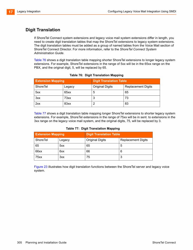
Legacy Integration Configuring Legacy Voice Mail Integration Using SMDI17
Digit Translation
If ShoreTel Connect system extensions and legacy voice mail system extensions differ in length, you need to create digit translation tables that map the ShoreTel extensions to legacy system extensions. The digit translation tables must be added as a group of named tables from the Voice Mail section of ShoreTel Connect Director. For more information, refer to the ShoreTel Connect System Administration Guide.
Table 76 shows a digit translation table mapping shorter ShoreTel extensions to longer legacy system extensions. For example, ShoreTel extensions in the range of 5xx will be in the 65xx range on the PBX, and the original digit, 5, will be replaced by 65.
Table 77 shows a digit translation table mapping longer ShoreTel extensions to shorter legacy system extensions. For example, ShoreTel extensions in the range of 75xx will be in sent. to extensions in the 3xx range on the legacy voice mail system, and the original digits, 75, will be replaced by 3.
Figure 23 illustrates how digit translation functions between the ShoreTel server and legacy voice system.
Table 76: Digit Translation Mapping
Extension Mapping Digit Translation Table
ShoreTel Legacy Original Digits Replacement Digits
5xx 65xx 5 65
3xx 73xx 3 73
2xx 83xx 2 83
Table 77: Digit Translation Mapping
Extension Mapping Digit Translation Table
ShoreTel Legacy Original Digits Replacement Digits
65 5xx 65 5
66xx 6xx 66 6
75xx 3xx 75 3
305 Planning and Installation Guide ShoreTel Connect
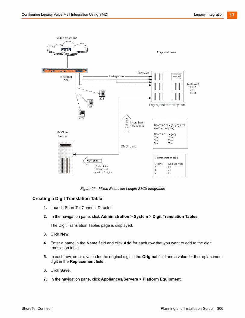
Configuring Legacy Voice Mail Integration Using SMDI Legacy Integration 17
Figure 23: Mixed Extension Length SMDI Integration
Creating a Digit Translation Table
1. Launch ShoreTel Connect Director.
2. In the navigation pane, click Administration > System > Digit Translation Tables.
The Digit Translation Tables page is displayed.
3. Click New.
4. Enter a name in the Name field and click Add for each row that you want to add to the digit translation table.
5. In each row, enter a value for the original digit in the Original field and a value for the replacement digit in the Replacement field.
6. Click Save.
7. In the navigation pane, click Appliances/Servers > Platform Equipment.
ShoreTel Connect Planning and Installation Guide 306

Legacy Integration Configuring ShoreTel Voice Mail Integration Using SMDI17
8. Click the name of the ShoreTel server that will handle the digit translation.
9. Click the Voice Application tab.
10. In the Voice mail interface mode field, from the drop-down list select ShoreTel Voice Mail, SMDI.
Additional fields are displayed on the Voice Application tab.
11. In the Translation table field, from the drop-down list select the appropriate digit translation table.
12. Enable the Use for Call data and Use for MWI data options. Doing so allows for the digit translation to occur under the following circumstances:
Data about a call is transferred between the legacy and ShoreTel Connect systems.
Message Waiting Indicator information is transferred between the two systems to notify the legacy PBX that a message was left on the ShoreTel voice mail.
13. By default, the Use flash to route calls check box is enabled. Leave this as is. If enabled, calls sent to the ShoreTel Auto Attendant from the SMDI trunk group are automatically transferred to the dialed extension using flash. If not selected, calls are routed using other lines.
The extension length must be the same on each of the systems for the Use flash to route calls feature to work because no translation is applied.
14. Click Save.
Setting up the User Group in ShoreTel Connect Director
Follow these steps to set up a user group for those users who will have their voice mail re-directed to the legacy voice mail system.
1. Launch ShoreTel Connect Director.
2. In the navigation pane, click Administration > Users > User Groups.
The User Groups page is displayed.
3. Click the name of an existing user group or click New to create a new user group.
The General tab for the selected or new user group is displayed.
4. In the Voice mail interface mode field, from the drop-down list select ShoreTel Voice Mail, SMDI.
5. Click Save.
Configuring ShoreTel Voice Mail Integration Using SMDI
As mentioned before, there are two modes of operation with respect to integrating a ShoreTel Connect system and a legacy system:
External Voice Mail Configuration — In this configuration, the legacy system provides voice mail services while the ShoreTel Connect system acts as PBX for users.
307 Planning and Installation Guide ShoreTel Connect
Configuring ShoreTel Voice Mail Integration Using SMDI Legacy Integration 17
ShoreTel Voice Mail Configuration — In this configuration, the ShoreTel Connect system provides voice mail services while the legacy system acts as a PBX for users.
External voice mail configuration is discussed in Configuring Legacy Voice Mail Integration Using SMDI on page 302. The procedure for ShoreTel voice mail configuration follows.
ShoreTel voice mail configuration consists of the following major tasks:
Creating a Trunk Group
Creating Trunks
Configuring the ShoreTel Server for SMDI
Creating a User Group
Adding an Individual User
Configuring the Serial Connection
Configuring Digit Translation Tables
PBX link
Creating a Trunk Group
One of the first tasks involved in configuring SMDI is to create a trunk group. The trunk group is used to manage the individual trunk lines between the ShoreTel voice switch and the legacy PBX. Instructions for creating the trunk group are provided below. For additional details on setting up trunk groups, refer to the ShoreTel Connect System Administration Guide.
Complete the following steps to create a trunk group for SMDI trunks:
1. Launch ShoreTel Connect Director.
2. In the navigation pane, click Administration > Trunks > Trunk Groups > Trunk Groups.
The Trunk Groups page is displayed.
3. Click New.
4. Enter the trunk group’s name and site in the appropriate fields.
5. In the Trunk type field, from the drop-down list select Analog Loop Start.
6. Click the Inbound tab, and enter a voice mail extension in the Destination field to direct inbound calls to the ShoreTel Auto Attendant system.
7. Click Save.
Creating Trunks
After creating the trunk group, the next step is to create one or more trunk lines representing each data connection between the ShoreTel voice mail system and the legacy PBX. The lines between the PBX and ShoreTel voice mail must be trunk lines, with ShoreTel as the trunk side and the legacy PBX as the extension side. For example, calls leaving the PBX for the voice mail system will leave on extensions. The PBX-to-voice mail connection might also be a T1 trunk that uses a channel bank to provide extensions to the legacy PBX.
ShoreTel Connect Planning and Installation Guide 308
Legacy Integration Configuring ShoreTel Voice Mail Integration Using SMDI17
1. Launch ShoreTel Connect Director.
2. In the navigation pane, click Administration > Trunks > Trunks.
The Trunks page is displayed.
3. Click New.
The General tab is displayed in the details pane.
4. In the Site field, select the site name from the drop-down list.
5. In the Trunk group field, select the trunk group name from the drop-down list.
6. In the Number field, enter the Logical Terminal Number (LTN). This value can range from 1 to 9999. For many systems the extension number of the port is used.
The LTN identifies the port the PBX will use to send the call to the ShoreTel voice mail system. It is very important that the LTN match what the PBX will send. You must check with your PBX vendor to determine what will be sent.
7. Click Save.
Configuring the ShoreTel Server for SMDI
After creating the trunk lines, you will configure the ShoreTel voice mail server. Configuration involves setting up the various SMDI parameters:
1. Launch ShoreTel Connect Director.
2. Navigate to Administration > Appliances/Servers > Platform Equipment.
The Platform Equipment page opens.
3. Click the name of the ShoreTel server that will act as the voice mail server for the legacy PBX.
Details for the server are displayed in the details pane.
4. Select the Voice Application tab.
5. In the Voice mail interface mode field, from the drop-down list select ShoreTel Voice Mail, SMDI.
Additional fields are displayed on the Voice Application tab.
6. From the Trunk group drop-down list, select the name of the SMDI trunk group that you created earlier. (This tells the server the name of the trunk group from which it should expect to receive voice mail calls.)
7. In the COM port field, enter the numerical value, which is between 1 and 10, that corresponds to the serial port of the ShoreTel server where you will be connecting the serial port. This serial port will be used to route out-of-band SMDI signaling information between the PBX link device and the ShoreTel server.
309 Planning and Installation Guide ShoreTel Connect
Configuring ShoreTel Voice Mail Integration Using SMDI Legacy Integration 17
8. The Message desk number, which has a range of 1-999, is optional and can be set to the default value of 1. Check with the vendor for this value.
The Message desk number is used to indicate a specific system in situations where a number of SMDI links have been daisy-chained together. This value allows each system to known which data belongs to it. In most cases this parameter is set to 1, because only one system will be using the SMDI link.
9. The Number of Digits field, which has a range of 2-32, is optional.
This value determines how many digits the ShoreTel Connect system sends in SMDI extension fields. This value needs to be set to the value the voice mail system expects. The most common values are either 7 or 10. If the system extension length is less than the number of SMDI digits, then the extension number will be padded. For example, if the ShoreTel Connect system needs to send extension 456 and the number of SMDI digits is set to 7, extension 0000456 will be sent. If no padding is desired the number of digits should be set to 2. In the above example with the number of SMDI digits set to 2 only 456 will be sent.
10. The translation table is optional and can be left as is for now.
11. Click Save.
Creating a User Group
After setting up the ShoreTel voice mail server for SMDI, the next step is to add users to the system. To do this, you first create a user group that specifies that all members will use ShoreTel voice mail. After this step is complete, you modify individual users’ profiles.
Complete the following steps to create a user group for users on the legacy PBX system:
1. Launch ShoreTel Connect Director.
2. In the navigation pane, click Administration > Users > User Groups.
The User Groups page is displayed.
3. Click New.
The General tab for the new user group is displayed.
4. In the Name field, enter the name of the user group.
5. In the Voice mail interface mode field, from the drop-down list select ShoreTel Voice Mail, SMDI.
6. Click Save.
Adding an Individual User
After creating the user group, you can create user profiles for the legacy PBX users.
1. Launch ShoreTel Connect Director.
2. In the navigation pane, click Administration > Users > Users.
ShoreTel Connect Planning and Installation Guide 310
Legacy Integration Configuring ShoreTel Voice Mail Integration Using SMDI17
The Users page is displayed.
3. Click New.
The General tab for the new user is displayed.
4. On the General tab, enter a name for the user in the First name and Last name fields.
5. In the License type drop-down list, select Mailbox-Only. (Because the new user is located on the legacy system, the user does not require a ShoreTel extension.)
6. In the User Group drop-down list, select the name of the user group you just created.
7. Click Save.
Configuring the Serial Connection
The ShoreTel Connect voice mail system supports only one serial link per application server. To support another legacy PBX, you will need another ShoreTel distributed application server. A serial cable, such as a null modem, should be used to connect the legacy PBX to one of the COM ports of the ShoreTel server. Note that the ShoreTel Connect system will extract the serial port settings, such as baud rate and parity bit values, from the Windows COM port settings. These settings can be verified by following the procedure below:
1. Right-click My Computer.
2. Select Manage.
3. Select Device Manager.
4. Left-click on Ports (COM & LPT).
5. Right-click Communications Port (COM1) and select Properties.
6. Left-click on the Port Settings tab.
7. Verify that the settings match those suggested by the documentation that came with your legacy PBX device.
311 Planning and Installation Guide ShoreTel Connect

Configuring ShoreTel Voice Mail Integration Using SMDI Legacy Integration 17
PBX
PBX link
A PBXLink device may be needed to provide SMDI services for a legacy PBX that does not offer support for SMDI. The PBXLink devices, manufactured by CTL, provide integration services to allow certain digital PBXs to interface seamlessly with a Voice Messaging System. The PBXLink connects to the PBX using a digital telephone line and to the Voice Messaging System using an RS-232 link. The PBXLink uses information appearing on the emulated digital set to determine the original source and destination of the calls being forwarded to the voice mail system. This information is then communicated to the voice mail system on an RS-232 serial link using the industry standard Centrex SMDI protocol. The PBXLink is compatible with SMDI-compatible voice mail systems.
When using SMDI and ShoreTel voice mail configuration, the following features are not supported:
Extension Assignment
Setting availability state
Setting agent state
Table 78: Supported PBXs
Manufacturer Model
Nortel Meridian 1
Nortel Norstar
Avaya System 75/85
Definity
Mitel SX50
SX200
SX2000
Siemens 300S
NEC NEAX
ShoreTel Connect Planning and Installation Guide 312
Legacy Integration System Requirements17
The following features are supported:
Recording greeting and name
Setting TUI password
Enable/disable envelope information
Email voice message options
Find Me
Message functions including call back
Message sending functions
Workgroup
ShoreTel voice mail
Agents cannot be extensions in the legacy PBX
System configuration
Configuration parameters
System Requirements
The following are required on the ShoreTel Connect system, or on the legacy PBX to enable the integration of the two systems:
ShoreTel Connect system
ShoreTel Voice Switch that supports a T1 circuit.
Legacy PBX
T1 or PRI card for the PBX Available card slot and capacity for the added trunks Required software or licenses to support the desired trunk interface
If PRI is used in the integration interface, the legacy PBX must emulate the CO or support Network Side PRI.
Connection Cable
Special Considerations — Nortel PBX
When integrating with a Nortel Meridian PBX, a T1 connection must be used since the legacy system does not support Network Side PRI.
313 Planning and Installation Guide ShoreTel Connect
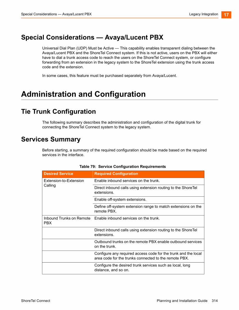
Special Considerations — Avaya/Lucent PBX Legacy Integration 17
Special Considerations — Avaya/Lucent PBX
Universal Dial Plan (UDP) Must be Active — This capability enables transparent dialing between the Avaya/Lucent PBX and the ShoreTel Connect system. If this is not active, users on the PBX will either have to dial a trunk access code to reach the users on the ShoreTel Connect system, or configure forwarding from an extension in the legacy system to the ShoreTel extension using the trunk access code and the extension.
In some cases, this feature must be purchased separately from Avaya/Lucent.
Administration and Configuration
Tie Trunk Configuration
The following summary describes the administration and configuration of the digital trunk for connecting the ShoreTel Connect system to the legacy system.
Services Summary
Before starting, a summary of the required configuration should be made based on the required services in the interface.
Table 79: Service Configuration Requirements
Desired Service Required Configuration
Extension-to-Extension Calling
Enable inbound services on the trunk.
Direct inbound calls using extension routing to the ShoreTel extensions.
Enable off-system extensions.
Define off-system extension range to match extensions on the remote PBX.
Inbound Trunks on Remote PBX
Enable inbound services on the trunk.
Direct inbound calls using extension routing to the ShoreTel extensions.
Outbound trunks on the remote PBX enable outbound services on the trunk.
Configure any required access code for the trunk and the local area code for the trunks connected to the remote PBX.
Configure the desired trunk services such as local, long distance, and so on.
ShoreTel Connect Planning and Installation Guide 314
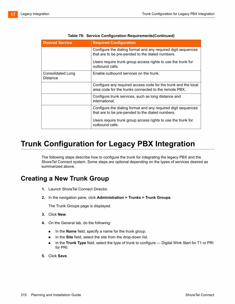
Legacy Integration Trunk Configuration for Legacy PBX Integration17
Trunk Configuration for Legacy PBX Integration
The following steps describe how to configure the trunk for integrating the legacy PBX and the ShoreTel Connect system. Some steps are optional depending on the types of services desired as summarized above.
Creating a New Trunk Group
1. Launch ShoreTel Connect Director.
2. In the navigation pane, click Administration > Trunks > Trunk Groups.
The Trunk Groups page is displayed.
3. Click New.
4. On the General tab, do the following:
In the Name field, specify a name for the trunk group.
In the Site field, select the site from the drop-down list.
In the Trunk Type field, select the type of trunk to configure — Digital Wink Start for T1 or PRI for PRI.
5. Click Save.
Configure the dialing format and any required digit sequences that are to be pre-pended to the dialed numbers.
Users require trunk group access rights to use the trunk for outbound calls.
Consolidated Long Distance
Enable outbound services on the trunk.
Configure any required access code for the trunk and the local area code for the trunks connected to the remote PBX.
Configure trunk services, such as long distance and international.
Configure the dialing format and any required digit sequences that are to be pre-pended to the dialed numbers.
Users require trunk group access rights to use the trunk for outbound calls.
Table 79: Service Configuration Requirements(Continued)
Desired Service Required Configuration
315 Planning and Installation Guide ShoreTel Connect

Configuring Inbound Services with Extension Routing Legacy Integration 17
Configuring Inbound Services with Extension Routing
1. Launch ShoreTel Connect Director.
2. In the navigation pane, click Administration > Trunks > Trunk Groups > Trunk Groups.
The Trunk Groups page is displayed.
3. Click the name of the trunk group for which you want to configure inbound services.
Details for the selected trunk group are displayed on the General tab.
4. Click the Inbound tab.
5. In the Number of digits from CO field, enter the number of digits received to match the number of digits sent by the remote PBX. This must match the extension length.
6. Enable the Extension option. (This directs all the received calls to the configured ShoreTel extension that matches the received DNIS digits.)
7. In the Destination field, provide a back-up extension to use when the received digits do not match an extension in the ShoreTel Connect system.
8. Click Save.
Configuring Off-System Extensions
1. Launch ShoreTel Connect Director.
2. In the navigation pane, click Administration > Trunks > Trunk Groups > Off-System Extensions.
The Off System Extensions page is displayed.
3. Click New.
4. On the General tab, in the Trunk group field select the trunk group for which you want to configure off-system extensions.
5. In the From and To fields, define the extension ranges for the extensions off the remote PBX.
6. Click Save.
Configuring Outbound Call Routing via the Remote PBX
1. Launch ShoreTel Connect Director.
2. In the navigation pane, click Administration > Trunks > Trunk Groups > Trunk Groups.
The Trunk Groups page is displayed.
3. Click the name of the trunk group for the tie trunk.
ShoreTel Connect Planning and Installation Guide 316

Legacy Integration Configuring Outbound Call Routing via the Remote PBX17
Details for the selected trunk group are displayed on the General tab.
4. Click the Outbound tab, and enable the Outgoing option.
5. Configure the access code and area codes for the trunk to match the PSTN connection of the remote PBX.
6. Select the desired trunk services to match the services provided via the remote PBX.
7. Select the desired Trunk Digit Manipulations to match the tie trunk and the required dialing for the PSTN connection to your legacy PBX.
8. As needed, configure the local prefixes and pre-pend digits to match the tie trunk and the required dialing for the PSTN connection to your legacy PBX.
For additional information on trunk configuration and options, refer to the ShoreTel Connect System Administration Guide.
317 Planning and Installation Guide ShoreTel Connect

CHAPTER
18. Cut-Over
This chapter provides the requirements and other information for implementing the cut-over from your existing telephone system to the ShoreTel Connect system. The topics discussed in this chapter include the following:
Cut-Over Requirements .......................................................................................... 319
Cut-Over Worksheet ............................................................................................... 319
New Trunks....................................................................................................... 319
Cut-Over Coverage .......................................................................................... 319
Cut-Over Implementation ........................................................................................ 319
Basic Cut-Over Checklist.................................................................................. 320
Trunking Cut-Over ............................................................................................ 320
Cut-Over of Remaining Devices ....................................................................... 321
Cut-Over Coverage .......................................................................................... 319
ShoreTel Connect Planning and Installation Guide 318
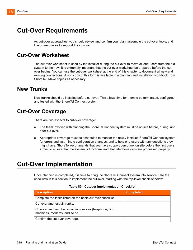
Cut-Over Cut-Over Requirements18
Cut-Over Requirements
As cut-over approaches, you should review and confirm your plan, assemble the cut-over tools, and line up resources to support the cut-over.
Cut-Over Worksheet
The cut-over worksheet is used by the installer during the cut-over to move all end-users from the old system to the new. It is extremely important that the cut-over worksheet be prepared before the cut-over begins. You can use the cut-over worksheet at the end of this chapter to document all new and existing connections. A soft copy of this form is available in a planning and installation workbook from ShoreTel. Make copies as necessary.
New Trunks
New trunks should be installed before cut-over. This allows time for them to be terminated, configured, and tested with the ShoreTel Connect system.
Cut-Over Coverage
There are two aspects to cut-over coverage:
The team involved with planning the ShoreTel Connect system must be on site before, during, and after cut-over.
Appropriate coverage must be scheduled to monitor the newly installed ShoreTel Connect system for errors and last-minute configuration changes, and to help end-users with any questions they might have. ShoreTel recommends that you have support personnel on site before the first users arrive, to ensure that the system is functional and that telephone calls are processed properly.
Cut-Over Implementation
Once planning is completed, it is time to bring the ShoreTel Connect system into service. Use the checklists in this section to implement the cut-over, starting with the top-level checklist below.
Table 80: Cutover Implementation Checklist
Description Completed
Complete the tasks listed on the basic cut-over checklist.
Cut-over and test all trunks.
Cut-over and test the remaining devices (telephone, fax machines, modems, and so on).
Confirm the cut-over coverage.
319 Planning and Installation Guide ShoreTel Connect
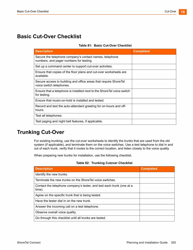
Basic Cut-Over Checklist Cut-Over 18
Basic Cut-Over Checklist
Trunking Cut-Over
For existing trunking, use the cut-over worksheets to identify the trunks that are used from the old system (if applicable), and terminate them on the voice switches. Use a test telephone to dial in and out of each trunk, verify that it routes to the correct location, and listen closely to the voice quality.
When preparing new trunks for installation, use the following checklist.
Table 81: Basic Cut-Over Checklist
Description Completed
Secure the telephone company’s contact names, telephone numbers, and pager numbers for testing.
Set up a command center to support cut-over activities.
Ensure that copies of the floor plans and cut-over worksheets are available.
Secure access to building and office areas that require ShoreTel voice switch telephones.
Ensure that a telephone is installed next to the ShoreTel voice switch for testing.
Ensure that music-on-hold is installed and tested.
Record and test the auto-attendant greeting for on-hours and off-hours.
Test all telephones.
Test paging and night bell features, if applicable.
Table 82: Trunking Cutover Checklist
Description Completed
Identify the new trunks.
Terminate the new trunks on the ShoreTel voice switches.
Contact the telephone company’s tester, and test each trunk (one at a time).
Agree on the specific trunk that is being tested.
Have the tester dial in on the new trunk.
Answer the incoming call on a test telephone.
Observe overall voice quality.
Go through this checklist until all trunks are tested.
ShoreTel Connect Planning and Installation Guide 320

Cut-Over Cut-Over of Remaining Devices18
When all of the trunks have been tested, have the telephone company’s tester open the trunk group, and allow the callers to use the new trunks.
Cut-Over of Remaining Devices
Use the following checklist to test each new end-user device that is being installed.
Cut-Over Coverage
It is recommended that the cut-over team arrive on site before the beginning of the next business day after cut-over, to answer questions from end-users as they begin to use the ShoreTel Connect system.
Table 83: Remaining Devices Cutover List
Description Completed
Place an internal call from the new device.
Place an external call from the new device.
If applicable, place a DID call.
If the device is for a user with voice mail, leave a welcome message.
Leave user guides or quick reference cards for the phone and the client on the user’s desk. These guides provide information about ShoreTel Connect’s commonly used features as well as general system information.
321 Planning and Installation Guide ShoreTel Connect

Cut-Over Worksheet Cut-Over 18
Cut-Over Worksheet
Table 84: Cutover Worksheet
Name Extension ShoreTel Port # Patch Panel # IDF # Station Cable #
ShoreTel Connect Planning and Installation Guide 322

Cut-Over Cut-Over Worksheet18
323 Planning and Installation Guide ShoreTel Connect

APPENDIX
A. International Planning andInstallation
This chapter provides information about voice switches, operating systems, and features that are supported when the ShoreTel Connect system operates outside the United States of America. The topics in this appendix include:
Software and Feature Support ................................................................................ 325
Language Packs ..................................................................................................... 325
Language Options ............................................................................................ 325
Analog Telephones, Tones, Cadences, and Impedances ....................................... 326
Dialing Plan Considerations .................................................................................... 326
Single-Extension Plan ...................................................................................... 326
Trunk Access Codes......................................................................................... 326
Operator Digit ................................................................................................... 327
Emergency Numbers........................................................................................ 327
DID Numbers .................................................................................................... 327
Carrier Codes.......................................................................................................... 327
ShoreTel Connect Planning and Installation Guide 324
International Planning and Installation Software and Feature SupportA
Software and Feature Support
For information about our worldwide support for software and features, contact a ShoreTel Sales Partner or refer to the ShoreTel Country Availability Web page at:
http://www.shoretel.com/international/
Language Packs
Language packs determine the language in the following parts of the system:
Voice prompts (Voice mail, Auto Attendant, system announcements)
Telephone User Interface (telephone display and ShoreTel Connect client interface)
Online help for ShoreTel Connect client
Language pack availability affects the behavior of the system in the following areas:
Site
Trunk
Workgroup
Auto Attendant
Voice Mail
User
ShoreTel Connect client
Language Options
The following pages in ShoreTel Connect Director allow you to program language options. In language priority, a workgroup language overrides the language associated with a trunk, which in turn overrides the language associated with an individual user.
The Sites page specifies the language pack used by the Backup Auto-Attendant (BAA) or by any ShoreTel 400-Series IP phones that do not have a user assigned. To access the Sites page, in the navigation pane select Administration > System > Sites. Click the name of the desired site, and then locate the Language field on the General tab.
The Workgroups page specifies the language the system uses for playing prompts to inbound callers. To access the Workgroups page, in the navigation pane select Administration > Features > Workgroups. Click the name of the desired workgroup, and then locate the Language field on the General tab.
The Trunk Groups page specifies the language for prompts that are played to incoming callers. To access the Trunk Groups page, in the navigation pane select Administration > Trunks > Trunk Groups. Click the name of the desired trunk group, and then locate the Language field on the General tab.
325 Planning and Installation Guide ShoreTel Connect
Analog Telephones, Tones, Cadences, and Impedances International Planning and Installation A
The Users page specifies the language prompts used for the user’s telephone interface and voicemail prompts. To access the Users page, in the navigation pane select Administration > Users > Users. Click the name of the desired user, and then locate the Language field on the General tab.
Analog Telephones, Tones, Cadences, and Impedances
For all supported countries, standard analog telephones are available on a per-country basis. The main difference between telephones in different countries is the line impedance. The ShoreTel Distributed Call Control software will provide the appropriate impedance required for each supported country. Tones, cadences, and impedance requirements are matched on a per-country basis.
Dialing Plan Considerations
When planning a global voice network, remember that the ShoreTel Connect system is a single image system and that you must consider all countries and locations when designing the international dialing plan. The ShoreTel Connect system can match the dialing plan requirements of the local service provider for the supported countries.
Single-Extension Plan
Across the global voice network, all extensions must be unique and cannot overlap.
Trunk Access Codes
Across the global voice network, when you configure trunk access codes, that portion of the dialing plan will be reserved so you will be sacrificing one digit. Typically in the US, customers use 9 as a trunk access code. Internationally, those in the EMEA, for instance, often use 0 as a trunk access code. The following are some things to consider when you create a trunk access code:
Using two different trunk access codes will limit users to only being able to access certain trunk groups.
If you use a single trunk access code, some users will need to be retrained.
Alternatively, 8 could be defined for the trunk access code globally.
ShoreTel recommends proper identification from the beginning. The trunk access code should not be changed later.
ShoreTel Connect Planning and Installation Guide 326

International Planning and Installation Operator DigitA
Operator Digit
The leading digit of 0 is typically reserved for dialing the operator in the US. The operator digit is configurable. Similarly, EMEA customers are accustomed to dialing 9 to reach the operator.
ShoreTel recommends choosing a single digit for the trunk access code and selecting a different single digit for the operator.
Emergency Numbers
The ShoreTel Connect system allows dialing of emergency numbers with and without trunk access codes. For this reason, you should architect the dialing plan for this feature.
911 is used in the US.
112 is used in Europe and other countries.
Check for other countries and regions for local requirements.
Thus, extensions should not begin with 0, 1, or 9 to make use of this feature.
Each site can have a maximum of ten emergency numbers to accommodate locations where multiple emergency service numbers are required.
For more information about emergency numbers, see the appendix in the ShoreTel Connect System Administration Guide about emergency 911 operations.
DID Numbers
DID numbers are related to the trunk group in which they are associated. You should strive to match the last digits of the DID number to the user’s extension number.
Carrier Codes
Certain countries provide an option for requiring one or two numbers that the ShoreTel user must press after the trunk access code (usually a 9 or an 8) and before an area code or another nation’s country code. The purpose of this option is to get the lowest-cost route for long-distance or international calls. When the user presses this code, the call goes out a trunk to a carrier that the system administrator has specified. If the user makes a long-distance or international call without this code, the ShoreTel Connect system selects the trunk.
This section defines the carrier codes that certain countries use and lists the numbers that the user presses to utilize the associated trunks. The two definitions that readers need for this description are as follows:
Carrier code: This number specifies a carrier. The system administrator assigns this code to a trunk group so that calls go to that carrier when the user prepends the country code to a phone number. System administrators in applicable countries must know the code for the carriers they want to give preferential business. The user does not see this carrier code.
327 Planning and Installation Guide ShoreTel Connect

Carrier Codes International Planning and Installation A
Country code: This country code is a nation-wide number that a user presses to direct long-distance or international calls to the carrier that the carrier code specifies. This country code is not the number that callers from outside a country use to reach the country. For example, the country code that callers outside of Singapore use to reach that country is 65, but from inside Singapore, the country code that a caller presses to direct an international call to a specific carrier is 01.
Using the Singapore example: if a trunk access code is 9 and the ShoreTel user with international calling permission initiates a call to India, the number sequence is as follows:
9 01 91 <telephone number>
As of the current release, six countries use this code function. Table 85 lists the carrier code and application for the countries that use them.
Table 85: Carrier Code by Country
Code Country and Application
55 Brazil, all calls
1 Hong Kong, international calls
2 South Korea, international calls
01 Singapore, international calls
2 Taiwan, international calls
1 Thailand, international calls
ShoreTel Connect Planning and Installation Guide 328

International Planning and Installation Carrier CodesA
329 Planning and Installation Guide ShoreTel Connect
APPENDIX
B. Session Initiation Protocol
This chapter provides information about the Session Initiation Protocol (SIP). You should refer to this chapter for help in planning a SIP deployment on your ShoreTel Connect system.
The topics discussed in this appendix include:
Overview ................................................................................................................. 331
General SIP Comments .......................................................................................... 331
Conferencing .................................................................................................... 331
DTMF................................................................................................................ 332
Foreign Language Support ............................................................................... 332
General Feature Limitations ............................................................................. 332
Additional Configuration Considerations .......................................................... 333
Note
For SIP configuration steps and other SIP details, see the “Session Initiation Protocol (SIP)” chapter in the ShoreTel Connect System Administration Guide.
ShoreTel Connect Planning and Installation Guide 330
Session Initiation Protocol OverviewB
Overview
The protocol, which works at the application layer, allows users to initiate interactive sessions between any network devices that support the protocol. SIP is capable of initiating or terminating Internet telephony calls and other multimedia applications such as video or gaming.
The protocol is based on a client-server model. With support for redirection services, networked users can initiate a call or receive a call, regardless of their physical location.
In its networking negotiations SIP takes into account the following pieces of information:
The address of the end system
The physical media
The call recipient's acceptance to the invitation
The protocol then configures the parameters for the session and handles the call setup and tear-down.
SIP allows two discrete ShoreTel Connect systems to be integrated with any IP connection, without the need for physical tie trunking. (Note that care should be taken to make sure that the extension numbering plans in the two systems do not overlap, and that if they do overlap, translation tables need to be used to resolve conflicts.)
In the current release of the ShoreTel Connect system, the SIP trunks and SIP tie-trunks support the SIP capabilities. Like other trunk, the SIP trunk assignments are switches, so that SIP calls into and out of the ShoreTel Connect system traverse these SIP trunks. However, up to five SIP trunks can be associated with one analog switch port, meaning that there will be no physical channel/port associated with each SIP trunk. The SIP trunk is a logical trunk end point which only handles call control responsibilities. The media flows directly between the end-point SIP devices (i.e. call initiator and the call terminator), freeing the switch from the burden of controlling media flow.
General SIP Comments
Conferencing
Ports for Make Me conferences must be available on the initiating side of a 3-way conference call involving a SIP end-point.
On ShoreTel IP800 models or third-party SIP phones, Make Me conference ports are needed even for 3-way conferences. Note that configuration of any Make Me conferencing support in ShoreTel Connect Director requires at least 4 available conference ports.
ShoreTel SIP trunks support from 4-way up to a maximum of 8-way conferences. This conferencing relies on ShoreTel’s Make Me capability. End-users can set up Make Me conference calls by using their ShoreTel Connect client. Like extensions with support of Media Gateway Control Protocol (MGCP), SIP extensions require permissions and a minimum of 4 Make Me ports to set up Make Me conference call.
331 Planning and Installation Guide ShoreTel Connect
DTMF Session Initiation Protocol B
An individual SIP trunk must be provisioned for each call to the SIP device (including conference-in or transferred calls). Thus, static SIP trunks must be provisioned with additional trunks in line with the highest anticipated number of such calls.
DTMF
ShoreTel supports RFC2833 (DTMF) for users calling over SIP trunks regardless of the negotiated voice codec.
ShoreTel can be configured to use SIP INFO for DTMF signaling in environments where out-of-band DTMF is needed but RFC 2833 is not applicable. SIP INFO for DTMF signaling is available on only SIP trunks.
Foreign Language Support
In addition to English, ShoreTel support other languages (for Caller Name, Called Name, User Name, and so on) over SIP tie trunks and service provider trunks. Some third-party devices might not be able to display all of a languages’ characters.
General Feature Limitations
A music on hold (MOH) switch supports 15 streams of MOH, but some of these can be used to fan out MOH to other trunk switches. If some MOH streams go to other switches, the actual number of MOH streams on SIP trunks is less than 15.
Three-way conference on a SIP trunk call uses Make Me conference ports. A minimum of 3 Make Me ports must be configured to support 3-way conferencing.
A SIP trunk can be a member of a 3-party conference but cannot initiate a 3-way conference (unless the SIP device merges the media streams itself).
ShoreTel SIP supports basic transfers (blind transfers) and attended transfers (consultative transfers).
In the current release, the following features are supported by SIP only if the trunk has a SIP trunk profile with hairpinning and the trunk is on a half-width switch:
Silent Coach Silent Monitor Barge-In Call recording
Silence detection on trunk-to-trunk transfers is not supported because it requires a physical trunk.
Extension Assignment is limited using SIP trunks. Either DTMF over INFO must be used, or in—the absence of such support—the features that use DTMF are not supported (including “Accept call by pressing 1.”)
Fax (and modem) redirection on SIP trunks is supported if T.38 is used.
ShoreTel Connect Planning and Installation Guide 332

Session Initiation Protocol Additional Configuration ConsiderationsB
Additional Configuration Considerations
Overlapping number plans are not allowed between two systems tied with SIP trunks unless digit translation is used.
When translating digits between two ShoreTel Connect systems tied with SIP trunks, even system extensions like VM, AA should be properly translated.
Multiple trunks (SIP and non-SIP trunks) can be created or deleted at one time.
333 Planning and Installation Guide ShoreTel Connect

APPENDIX
C. ShoreTel Voice Switches
This appendix describes the ShoreTel voice switches. It contains the following information:
Overview ................................................................................................................. 336
Switch Models ......................................................................................................... 336
ShoreTel 1-U Half Width Voice Switches ................................................................ 337
ShoreTel Voicemail Model Voice Switches ....................................................... 337
ShoreTel 1-U Full Width Voice Switches........................................................... 339
Specifications - ST 1-U Half-Width Switches .......................................................... 340
ShoreTel Voice Switch ST1D/ST2D.................................................................. 340
ShoreTel Voice Switch ST50A/ST100A ............................................................ 343
ShoreTel Voice Switch ST200/ST500............................................................... 348
ShoreTel Voice Switch ST100DA ..................................................................... 351
ShoreTel SG-90 Voice Switch........................................................................... 355
Specifications – SG 1-U Half-Width Switches ......................................................... 355
ShoreTel SG-90BRI Voice Switch..................................................................... 359
ShoreTel SG-120 Voice Switch......................................................................... 363
ShoreTel SG-30 Voice Switch........................................................................... 367
ShoreTel SG-30BRI Voice Switch..................................................................... 371
ShoreTel SG-220T1 Voice Switch .................................................................... 375
ShoreTel SG-220T1A Voice Switch .................................................................. 378ShoreTel SG-220E1 Voice Switch .................................................................... 383
ShoreTel SG-T1k Voice Switch......................................................................... 386
ShoreTel SG-E1k Voice Switch ........................................................................ 390
Specifications – SG Voice Model Switches ............................................................. 393
ShoreTel SG-90V Voice Switch ........................................................................ 393
ShoreTel Connect Planning and Installation Guide 334
ShoreTel Voice SwitchesC
ShoreTel SG-90BRIV Voice Switch .................................................................. 397
ShoreTel SG-50V Voice Switch ........................................................................ 401
Specification – ST 1U Full Width Switches ............................................................. 405
ShoreTel Voice Switch ST24A/ST48A .............................................................. 405
Specification – SG 1U Full Width Switches............................................................. 409
ShoreTel SG-120 Voice Switch......................................................................... 409
ShoreTel SG-24A Voice Switch ........................................................................ 413
ShoreTel SG-60 Voice Switch........................................................................... 417
ShoreTel SG-T1 and ShoreTel SG-E1 Voice Switches..................................... 426
335 Planning and Installation Guide ShoreTel Connect

Overview ShoreTel Voice Switches C
Overview
Switch model numbers are located on the rear panel, as shown in Figure 24.
Figure 24: Switch Model Number Label
All ShoreTel Voice Switches include a Default Switch, which is a recessed button available on the front panel. This switch can be used to reset the following static configurations to factory default:
Static IP address
Server address
Phone extension assignments
Ethernet negotiation settings
Press and hold the default switch for more than five seconds to reset the listed configurations to factory defaults. Refer to the front panel images in the following sections for the location of the Default Switch.
Switch Models
The classification of ShoreTel Voice Switch models is in three switch families that depend on the chassis type of the switch:
1-U Half Width Switches
1-U Full Width Switches
The following is a brief description of each switch family.
ShoreTel Connect Planning and Installation Guide 336

ShoreTel Voice Switches ShoreTel 1-U Half Width Voice SwitchesC
ShoreTel 1-U Half Width Voice Switches
The ShoreTel 1-U Half Width Switch family is the most recent ShoreTel switch design. 1-U Half Width have a smaller footprint, use less power, and have lower heat dissipation requirements than earlier ShoreTel switches. These switches offer higher granularity in the number of IP users supported, allowing customers to precisely program the switch to satisfy their requirements.
The switches can be stacked or mounted in a standard 19-inch rack. Rack mounting 1-U Half Width Switches requires the ShoreTel Dual Tray. One or two switches are inserted into the Dual Tray, which is then mounted into the 19-inch rack. Two switches are mounted side by side Rack mounting the switches require the ShoreTel Dual Tray
ShoreTel 1-U Half Width Voice Switch models include:
ShoreTel Voice Switch ST1D/ST2D
ShoreTel Voice Switch ST50A/ST100A
ShoreTel Voice Switch ST200/ST500
ShoreTel Voice Switch ST100DA
ShoreTel Voice Switch SG-30
ShoreTel Voice Switch SG-30BRI
ShoreTel Voice Switch SG-50
ShoreTel Voice Switch SG-90
ShoreTel Voice Switch SG-90BRI
ShoreTel Voice Switch SG-220T1
ShoreTel Voice Switch SG-220T1A
ShoreTel Voice Switch SG-T1k
ShoreTel Voice Switch SG-220E1
ShoreTel Voice Switch SG-E1k
ShoreTel Voicemail Model Voice Switches
Voicemail Model Switches are ShoreTel switches that provide voicemail services and access to auto attendant menus for extensions hosted by the switch. Voicemail Model (V Model) switches provide local access to voicemail while being controlled by a Distributed server at a different location.
The switches can be stacked or mounted in a standard 19-inch rack. Rack mounting 1-U Half Width Switches requires the ShoreTel Dual Tray. One or two switches are inserted into the Dual Tray, which is then mounted into the 19-inch rack. Two switches are mounted side by side Rack mounting the switches require the ShoreTel Dual Tray.
337 Planning and Installation Guide ShoreTel Connect
ShoreTel Voicemail Model Voice Switches ShoreTel Voice Switches C
ShoreTel V Model Switch models include:
ShoreTel Voice Switch SG-90V
ShoreTel Voice Switch SG-50V
ShoreTel Voice Switch SG-90BRIV
Capacity
Number of V Model switches allowed per system
A ShoreTel Connect system supports a maximum of 500 V Model Switches. There are no restrictions concerning the allocation of switches among the sites defined by the system.
Simultaneous Voicemail Calls per V Model switches
Voicemail Model Switches support the following number of simultaneous voicemail calls.
SG50V – Maximum of 5 Voicemail calls per switch
G711 calls: 5 G729 calls: 2
SG90V – Maximum of 9 Voicemail calls per switch
G711 calls: 9 G729 calls: 4
SG90BRIV – Maximum of 9 Voicemail calls per switch
G711 calls: 9 G729 calls: 4
Call Load
Voicemail Model Switches call load capacity is as follows:
5400 BHCC when supporting 90 MGCP IP Phones or 90 SIP Trunks
3600 BHCC when supporting 90 SIP IP Phones or 90 SIP Trunks
Compact Flash Memory
Voicemail Model switches store voicemail and Auto Attendant files on compact flash. Flash card capacity for V Model Switches is:
SG50V: 1 Gb
SG90V: 2 Gb
SG90BRIV: 2 Gb
ShoreTel Connect Planning and Installation Guide 338

ShoreTel Voice Switches ShoreTel 1-U Full Width Voice SwitchesC
Media Support
Voicemail Model Switches support the following media streams:
G711
Music on Hold (MOH): 15 calls
Backup Auto Attendant (BAA): 50 calls
G729
Music on Hold (MOH): none
Backup Auto Attendant (BAA): none
SIP support
Voicemail Model Switches support the following SIP media streams:
G711 Ringback tone (Hunt Groups and Work Group calls): 50 media streams
G729 Ringback tone (Hunt Groups and Work Group calls): no support
ShoreTel 1-U Full Width Voice Switches
The ShoreTel 1-U Full Width Switch family includes three models that support analog, IP, SIP, T1, and E1 voice data streams. Full width switch models can be stacked or mounted directly into a standard 19-inch equipment rack. These switches are all 1 RU and have an RJ21X connector for connection to analog phones and trunks. They also feature redundant Ethernet LAN connections for greater availability and reliability.
ShoreTel 1-U Full Width Voice Switch models include:
ShoreTel Voice Switch ST24A/ST48A
ShoreTel Voice Switch SG-120 – also referred to as ShoreTel Voice Switch SG-120/24
ShoreTel Voice Switch SG-60 – also referred to as ShoreTel Voice Switch SG-60/12
ShoreTel Voice Switch SG-48 – also referred to as ShoreTel Voice Switch SG-40/8
ShoreTel Voice Switch SG-T1
ShoreTel Voice Switch SG-E1
ShoreTel Voice Switch SG-24A
339 Planning and Installation Guide ShoreTel Connect
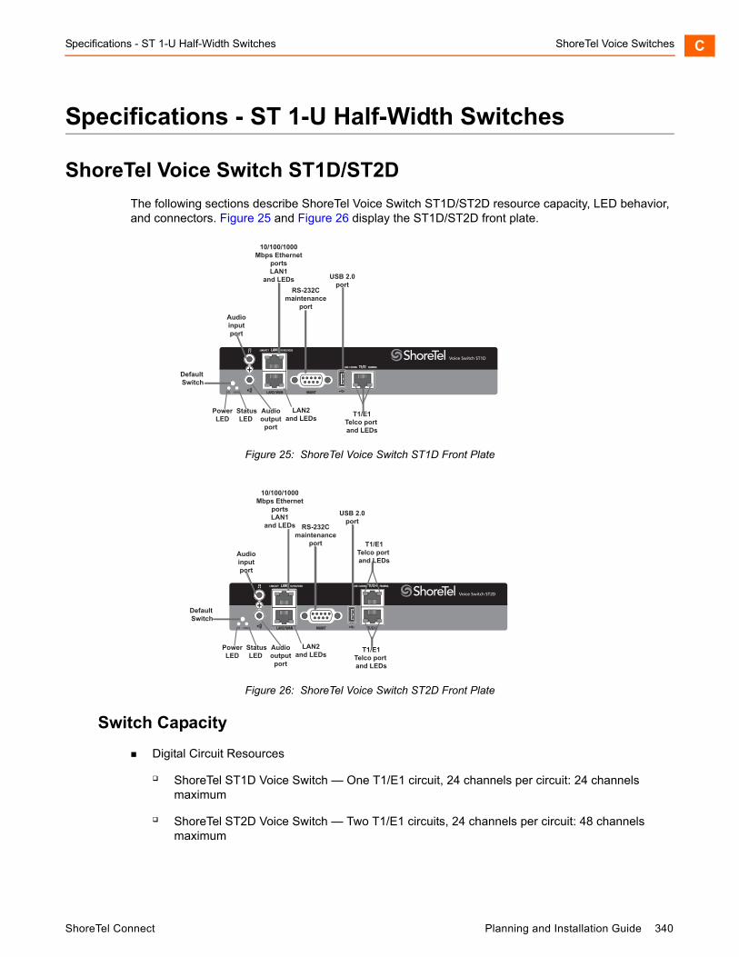
Specifications - ST 1-U Half-Width Switches ShoreTel Voice Switches C
Specifications - ST 1-U Half-Width Switches
ShoreTel Voice Switch ST1D/ST2D
The following sections describe ShoreTel Voice Switch ST1D/ST2D resource capacity, LED behavior, and connectors. Figure 25 and Figure 26 display the ST1D/ST2D front plate.
Figure 25: ShoreTel Voice Switch ST1D Front Plate
Figure 26: ShoreTel Voice Switch ST2D Front Plate
Switch Capacity
Digital Circuit Resources
ShoreTel ST1D Voice Switch — One T1/E1 circuit, 24 channels per circuit: 24 channels maximum
ShoreTel ST2D Voice Switch — Two T1/E1 circuits, 24 channels per circuit: 48 channels maximum
Audioinputport
10/100/1000Mbps Ethernet
portsLAN1
and LEDsRS-232C
maintenanceport
T1/E1Telco port and LEDs
USB 2.0port
StatusLED
Audiooutput
port
LAN2and LEDs
PowerLED
Default Switch
Audioinputport
10/100/1000Mbps Ethernet
portsLAN1
and LEDs RS-232Cmaintenance
port
USB 2.0port
StatusLED
Audiooutput
port
LAN2and LEDs
PowerLED
T1/E1Telco port and LEDs
T1/E1Telco port and LEDs
Default Switch
ShoreTel Connect Planning and Installation Guide 340
ShoreTel Voice Switches ShoreTel Voice Switch ST1D/ST2DC
Make Me Conference Resource: None for both devices
Maximum IP Phone Resources: None for both devices
LED Descriptions
Power LED
The ShoreTel Voice Switch ST1D/ST2D has one power LED, which indicates the following:
On: The switch is operating normally.
Off: The switch has no power.
Flashing: Continuous flashing or a two-flash pattern indicates a failed internal self-test (i.e. hardware failure).
Network LEDs
The ShoreTel Voice Switch ST1D/ST2D network LEDs (LAN1 and LAN2) indicate the speed at which the switch is communicating with the network and whether there is network activity.
When both LAN connectors are connected into a redundant network configuration, one network port is active while the other is in standby mode. If one LAN connection fails, the switch activates the other port.
The network LED descriptions are as follows:
Link/Activity: When lit, this LED indicates that the switch is connected to an Ethernet network. This LED indicates network activity, as follows:
When flashing, network activity is detected.
When on (not flashing), the switch is connected to an Ethernet network.
When off, the switch cannot detect an Ethernet network.
This LED is not directly related to any switch’s individual network activity. For example, if three switches are connected to the same hub and one switch’s Traffic LED shows activity, the other switches will indicate the same activity.
10/100/1000 Mbps
When off, the switch is connected to a 10BaseT network.
When green, the switch is connected to a 100BaseT network.
When yellow, the switch is connected to a 1000BaseT network
341 Planning and Installation Guide ShoreTel Connect
ShoreTel Voice Switch ST1D/ST2D ShoreTel Voice Switches C
Status LED
The ShoreTel Voice Switch ST1D/ST2D has one status LED to provide general information about the ports. The color and blink pattern of the LED indicate the port function:
Off — No ports are assigned
Green Steady— No ports are handling active calls
Green Flashing Fast — At least one port is handling an active call.
Yellow Steady — No ports are handling active calls and at least one port is out of service.
Yellow Flashing Slow — The switch is not connected (or has lost connection) to a ShoreTel server.
Yellow Flashing Fast — At least one port is handling an active call and at least one port is out of service.
T1/E1 LEDs
The ShoreTel Voice Switch ST1D/ST2D has one status LED to provide general information about the ports. The color and blink pattern of the LED indicate the port function:
Line coding
Green — For the T1 connection, this indicates the AMI or B8ZS line coding signal is good. For the E1 connection, this indicates the HDB3 line coding signal is good.
Yellow — This switch is receiving bipolar violations (BPV) at one-second intervals.
Solid Red — The trunk is configured for SIP Media Proxy.
Flashing Red* — A loss of signal (LOS) has occurred.
Off — The switch has no power.
Framing
Green — The T1 or E1 signal is in frame (synchronized)
Yellow — The CO has sent a yellow alarm.
Yellow Flashing — The frame-bit error rate has exceeded its limits.
Solid Red — The trunk is configured for SIP Media Proxy.
Flashing Red* — T1 signal is out-of-frame (OOF) and cannot be framed to the Extended Superframe (ESF) or D4 format. E1 signal is out-of-frame (OOF).
Off — The switch has no power.
*If both the line coding and framing LEDs are simultaneously flashing red, loopback is enabled.
ShoreTel Connect Planning and Installation Guide 342

ShoreTel Voice Switches ShoreTel Voice Switch ST50A/ST100AC
ShoreTel Voice Switch ST1D/ST2D Connectors
The ShoreTel Voice Switch ST1D voice switch contains the following components:
One audio input port (3.5 mm stereo) for connecting to a music-on-hold source
One audio output port (3.5 mm stereo) for connecting to a corporate paging system or night bell.
Two RJ-45 10/100/1000 Mbps LAN connectors
One DB-9 (female), RS-232C maintenance port (default 115,200 bps, 8 bits, no parity, 1 stop bit, no handshake) for serial communications
USB port for logging/troubleshooting
RJ-48C Telco port(s) for connecting the switch to a telephone company line(s). This is the T1/E1 configurable connection.
ShoreTel Voice Switch ST50A/ST100A
The following sections describe ShoreTel Voice Switch ST50A/ST100A resource capacity, LED behavior, and connectors. Figure 27 and Figure 28 display the ST50A/ST100A front plate.
Figure 27: ShoreTel Voice Switch ST50A Front Plate
Tip
Only vFAT/FAT32 storage is supported for USB logging.
PowerLED
USB 2.0port
Audioinputport
10/100/1000Mbps Ethernet
portsLAN1
and LEDsRS-232C
maintenanceport
StatusLED
Audiooutput
portRJ-21X
portLAN2
and LEDs
Default Switch
343 Planning and Installation Guide ShoreTel Connect
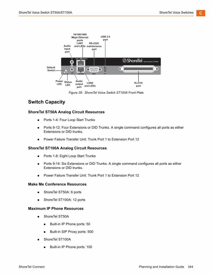
ShoreTel Voice Switch ST50A/ST100A ShoreTel Voice Switches C
Figure 28: ShoreTel Voice Switch ST100A Front Plate
Switch Capacity
ShoreTel ST50A Analog Circuit Resources
Ports 1-4: Four Loop Start Trunks
Ports 9-12: Four Extensions or DID Trunks. A single command configures all ports as either Extensions or DID trunks.
Power Failure Transfer Unit: Trunk Port 1 to Extension Port 12
ShoreTel ST100A Analog Circuit Resources
Ports 1-8: Eight Loop Start Trunks
Ports 9-14: Six Extensions or DID Trunks. A single command configures all ports as either Extensions or DID trunks.
Power Failure Transfer Unit: Trunk Port 1 to Extension Port 12
Make Me Conference Resources
ShoreTel ST50A: 6 ports
ShoreTel ST100A: 12 ports
Maximum IP Phone Resources
ShoreTel ST50A
Built-in IP Phone ports: 50
Built-in SIP Proxy ports: 500
ShoreTel ST100A
Built-in IP Phone ports: 100
PowerLED
USB 2.0port
Audioinputport
10/100/1000Mbps Ethernet
portsLAN1
and LEDsRS-232C
maintenanceport
StatusLED
Audiooutput
portRJ-21X
portLAN2
and LEDs
Default Switch
ShoreTel Connect Planning and Installation Guide 344
ShoreTel Voice Switches ShoreTel Voice Switch ST50A/ST100AC
Built-in SIP Proxy ports: 500
LED Descriptions
Power LED
The ShoreTel Voice Switch ST50A/ST100A has one power LED, which indicates the following:
On: The switch is operating normally.
Off: The switch has no power.
Flashing: Continuous flashing or a two-flash pattern indicates a failed internal self-test (i.e. hardware failure).
Network LEDs
The ShoreTel Voice Switch ST50A/ST100A network LEDs (LAN1 and LAN2) indicate the speed at which the switch is communicating with the network and whether there is network activity.
When both LAN connectors are connected into a redundant network configuration, one network port is active while the other is in standby mode. If one LAN connection fails, the switch activates the other port.
The network LED descriptions are as follows:
Link/Activity: When lit, this LED indicates that the switch is connected to an Ethernet network. This LED indicates network activity, as follows:
When flashing, network activity is detected.
When on (not flashing), the switch is connected to an Ethernet network.
When off, the switch cannot detect an Ethernet network.
This LED is not directly related to any switch’s individual network activity. For example, if three switches are connected to the same hub and one switch’s Traffic LED shows activity, the other switches will indicate the same activity.
10/100/1000 Mbps
When off, the switch is connected to a 10BaseT network.
When green, the switch is connected to a 100BaseT network.
When yellow, the switch is connected to a 1000BaseT network
Status LED
The ShoreTel Voice Switch ST50A/ST100A has one status LED to provide general information about the ports. The color and blink pattern of the LED indicate the port function:
Off — No ports are assigned
345 Planning and Installation Guide ShoreTel Connect
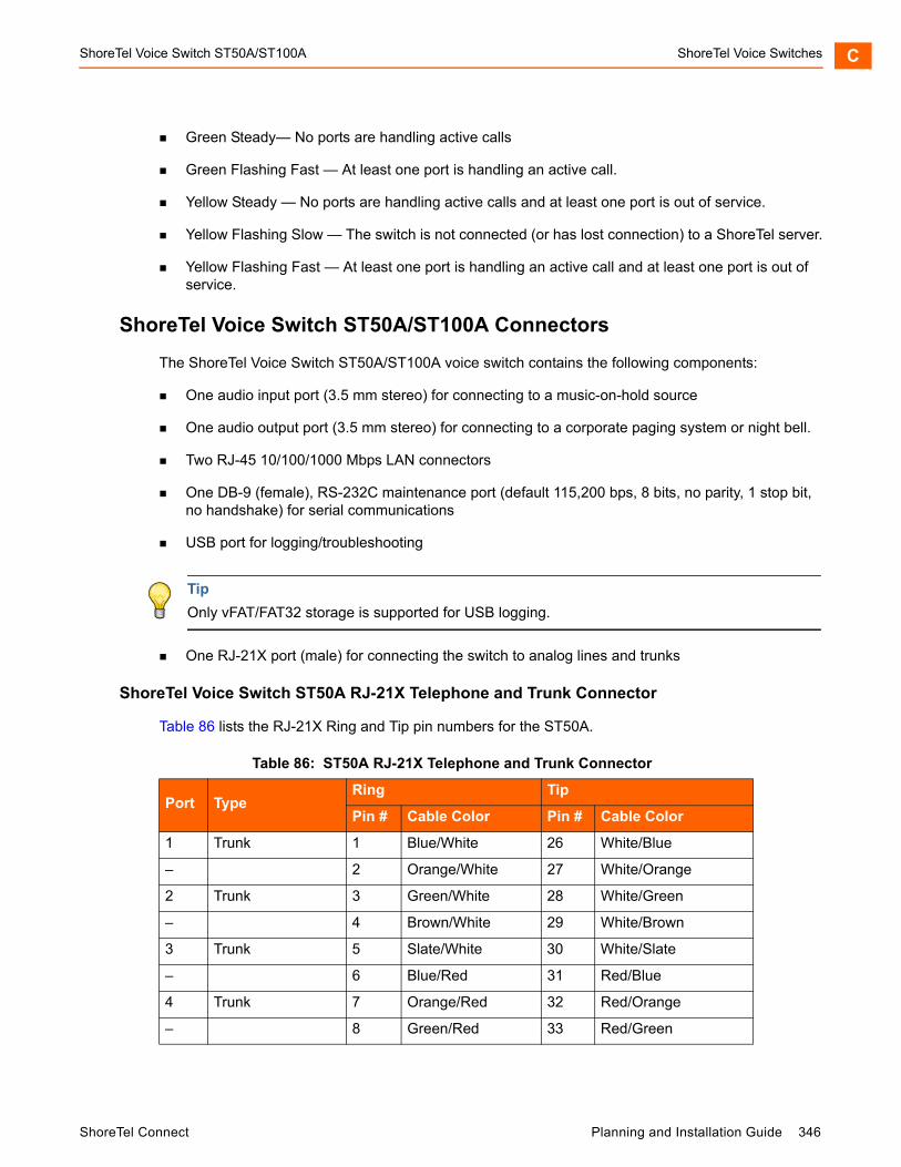
ShoreTel Voice Switch ST50A/ST100A ShoreTel Voice Switches C
Green Steady— No ports are handling active calls
Green Flashing Fast — At least one port is handling an active call.
Yellow Steady — No ports are handling active calls and at least one port is out of service.
Yellow Flashing Slow — The switch is not connected (or has lost connection) to a ShoreTel server.
Yellow Flashing Fast — At least one port is handling an active call and at least one port is out of service.
ShoreTel Voice Switch ST50A/ST100A Connectors
The ShoreTel Voice Switch ST50A/ST100A voice switch contains the following components:
One audio input port (3.5 mm stereo) for connecting to a music-on-hold source
One audio output port (3.5 mm stereo) for connecting to a corporate paging system or night bell.
Two RJ-45 10/100/1000 Mbps LAN connectors
One DB-9 (female), RS-232C maintenance port (default 115,200 bps, 8 bits, no parity, 1 stop bit, no handshake) for serial communications
USB port for logging/troubleshooting
One RJ-21X port (male) for connecting the switch to analog lines and trunks
ShoreTel Voice Switch ST50A RJ-21X Telephone and Trunk Connector
Table 86 lists the RJ-21X Ring and Tip pin numbers for the ST50A.
Tip
Only vFAT/FAT32 storage is supported for USB logging.
Table 86: ST50A RJ-21X Telephone and Trunk Connector
Port TypeRing Tip
Pin # Cable Color Pin # Cable Color
1 Trunk 1 Blue/White 26 White/Blue
– 2 Orange/White 27 White/Orange
2 Trunk 3 Green/White 28 White/Green
– 4 Brown/White 29 White/Brown
3 Trunk 5 Slate/White 30 White/Slate
– 6 Blue/Red 31 Red/Blue
4 Trunk 7 Orange/Red 32 Red/Orange
– 8 Green/Red 33 Red/Green
ShoreTel Connect Planning and Installation Guide 346
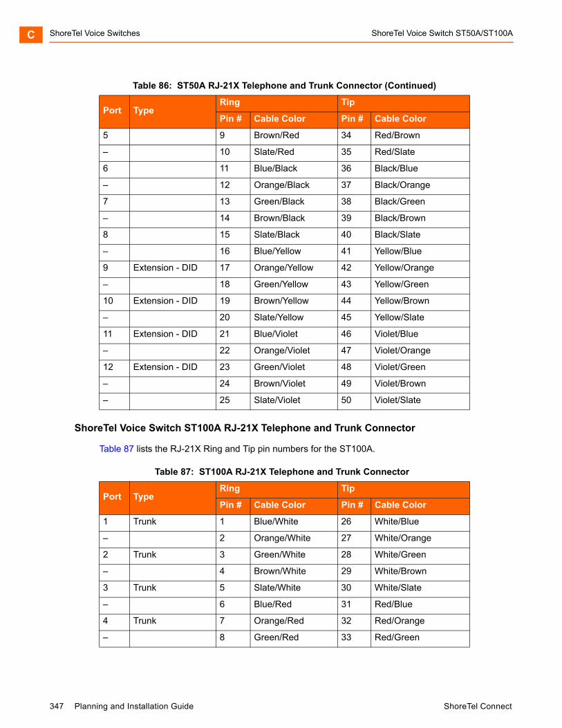
ShoreTel Voice Switches ShoreTel Voice Switch ST50A/ST100AC
ShoreTel Voice Switch ST100A RJ-21X Telephone and Trunk Connector
Table 87 lists the RJ-21X Ring and Tip pin numbers for the ST100A.
5 9 Brown/Red 34 Red/Brown
– 10 Slate/Red 35 Red/Slate
6 11 Blue/Black 36 Black/Blue
– 12 Orange/Black 37 Black/Orange
7 13 Green/Black 38 Black/Green
– 14 Brown/Black 39 Black/Brown
8 15 Slate/Black 40 Black/Slate
– 16 Blue/Yellow 41 Yellow/Blue
9 Extension - DID 17 Orange/Yellow 42 Yellow/Orange
– 18 Green/Yellow 43 Yellow/Green
10 Extension - DID 19 Brown/Yellow 44 Yellow/Brown
– 20 Slate/Yellow 45 Yellow/Slate
11 Extension - DID 21 Blue/Violet 46 Violet/Blue
– 22 Orange/Violet 47 Violet/Orange
12 Extension - DID 23 Green/Violet 48 Violet/Green
– 24 Brown/Violet 49 Violet/Brown
– 25 Slate/Violet 50 Violet/Slate
Table 87: ST100A RJ-21X Telephone and Trunk Connector
Port TypeRing Tip
Pin # Cable Color Pin # Cable Color
1 Trunk 1 Blue/White 26 White/Blue
– 2 Orange/White 27 White/Orange
2 Trunk 3 Green/White 28 White/Green
– 4 Brown/White 29 White/Brown
3 Trunk 5 Slate/White 30 White/Slate
– 6 Blue/Red 31 Red/Blue
4 Trunk 7 Orange/Red 32 Red/Orange
– 8 Green/Red 33 Red/Green
Table 86: ST50A RJ-21X Telephone and Trunk Connector (Continued)
Port TypeRing Tip
Pin # Cable Color Pin # Cable Color
347 Planning and Installation Guide ShoreTel Connect
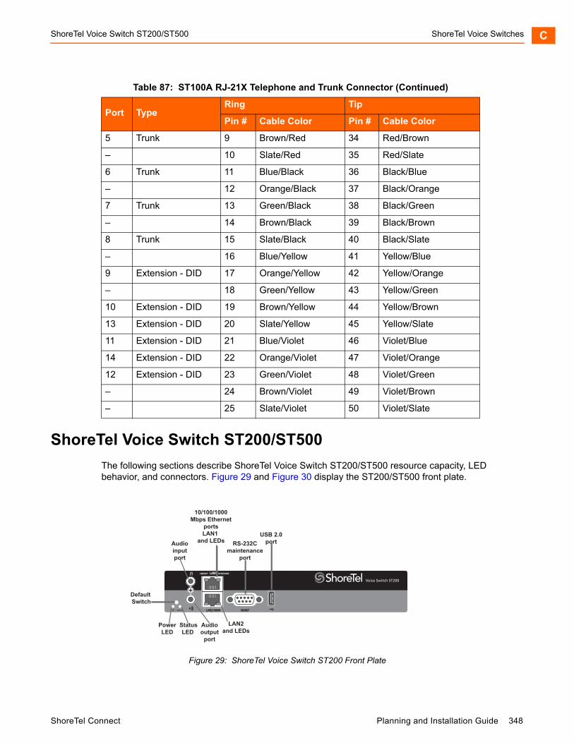
ShoreTel Voice Switch ST200/ST500 ShoreTel Voice Switches C
ShoreTel Voice Switch ST200/ST500
The following sections describe ShoreTel Voice Switch ST200/ST500 resource capacity, LED behavior, and connectors. Figure 29 and Figure 30 display the ST200/ST500 front plate.
Figure 29: ShoreTel Voice Switch ST200 Front Plate
5 Trunk 9 Brown/Red 34 Red/Brown
– 10 Slate/Red 35 Red/Slate
6 Trunk 11 Blue/Black 36 Black/Blue
– 12 Orange/Black 37 Black/Orange
7 Trunk 13 Green/Black 38 Black/Green
– 14 Brown/Black 39 Black/Brown
8 Trunk 15 Slate/Black 40 Black/Slate
– 16 Blue/Yellow 41 Yellow/Blue
9 Extension - DID 17 Orange/Yellow 42 Yellow/Orange
– 18 Green/Yellow 43 Yellow/Green
10 Extension - DID 19 Brown/Yellow 44 Yellow/Brown
13 Extension - DID 20 Slate/Yellow 45 Yellow/Slate
11 Extension - DID 21 Blue/Violet 46 Violet/Blue
14 Extension - DID 22 Orange/Violet 47 Violet/Orange
12 Extension - DID 23 Green/Violet 48 Violet/Green
– 24 Brown/Violet 49 Violet/Brown
– 25 Slate/Violet 50 Violet/Slate
Table 87: ST100A RJ-21X Telephone and Trunk Connector (Continued)
Port TypeRing Tip
Pin # Cable Color Pin # Cable Color
USB 2.0portAudio
inputport
10/100/1000Mbps Ethernet
portsLAN1
and LEDs RS-232Cmaintenance
port
StatusLED
Audiooutput
port
LAN2and LEDs
PowerLED
Default Switch
ShoreTel Connect Planning and Installation Guide 348

ShoreTel Voice Switches ShoreTel Voice Switch ST200/ST500C
Figure 30: ShoreTel Voice Switch ST500 Front Plate
Switch Capacity
Make Me Conference Resources
ShoreTel ST200: 12 ports
ShoreTel ST500: 24 ports
Maximum IP Phone Resources
ShoreTel ST200
Built-in IP Phone ports: 200
Built-in SIP Proxy ports: 500
ShoreTel ST500
Built-in IP Phone ports: 500
Built-in SIP Proxy ports: 1000
LED Descriptions
Power LED
The ShoreTel Voice Switch ST200/ST500 has one power LED, which indicates the following:
On: The switch is operating normally.
Off: The switch has no power.
Flashing: Continuous flashing or a two-flash pattern indicates a failed internal self-test (i.e. hardware failure).
PowerLED
USB 2.0portAudio
inputport
10/100/1000Mbps Ethernet
portsLAN1
and LEDs
RS-232Cmaintenance
port
StatusLED
Audiooutput
port
LAN2and LEDs
Default Switch
349 Planning and Installation Guide ShoreTel Connect

ShoreTel Voice Switch ST200/ST500 ShoreTel Voice Switches C
Network LEDs
The ShoreTel Voice Switch ST200/ST500 network LEDs (LAN1 and LAN2) indicate the speed at which the switch is communicating with the network and whether there is network activity.
When both LAN connectors are connected into a redundant network configuration, one network port is active while the other is in standby mode. If one LAN connection fails, the switch activates the other port.
The network LED descriptions are as follows:
Link/Activity: When lit, this LED indicates that the switch is connected to an Ethernet network. This LED indicates network activity, as follows:
When flashing, network activity is detected.
When on (not flashing), the switch is connected to an Ethernet network.
When off, the switch cannot detect an Ethernet network.
This LED is not directly related to any switch’s individual network activity. For example, if three switches are connected to the same hub and one switch’s Traffic LED shows activity, the other switches will indicate the same activity.
10/100/1000 Mbps
When off, the switch is connected to a 10BaseT network.
When green, the switch is connected to a 100BaseT network.
When yellow, the switch is connected to a 1000BaseT network
Status LED
The ShoreTel Voice Switch ST200/ST500 has one status LED to provide general information about the ports. The color and blink pattern of the LED indicate the port function:
Off — No ports are assigned
Green Steady— No ports are handling active calls
Green Flashing Fast — At least one port is handling an active call.
Yellow Steady — No ports are handling active calls and at least one port is out of service.
Yellow Flashing Slow — The switch is not connected (or has lost connection) to a ShoreTel server.
Yellow Flashing Fast — At least one port is handling an active call and at least one port is out of service.
ShoreTel Voice Switch ST200/ST500 Connectors
The ShoreTel Voice Switch ST200/ST500 voice switch contains the following components:
One audio input port (3.5 mm stereo) for connecting to a music-on-hold source
ShoreTel Connect Planning and Installation Guide 350

ShoreTel Voice Switches ShoreTel Voice Switch ST100DAC
One audio output port (3.5 mm stereo) for connecting to a corporate paging system or night bell.
Two RJ-45 10/100/1000 Mbps LAN connectors
One DB-9 (female), RS-232C maintenance port (default 115,200 bps, 8 bits, no parity, 1 stop bit, no handshake) for serial communications
USB port for logging/troubleshooting
ShoreTel Voice Switch ST100DA
The following sections describe ShoreTel Voice Switch ST100DA resource capacity, LED behavior, and connectors. Figure 31 displays the ST100DA front plate.
Figure 31: ShoreTel Voice Switch ST100DA Front Plate
Switch Capacity
Digital Circuit Resources
One T1/E1 circuit, 24 channels per circuit: 24 channels maximum
Analog Circuit Resources
Ports 1 and 2: Two Loop Start Trunks
Ports 9-12: Six Extensions or DID Trunks. A single command configures all ports as either Extensions or DID trunks.
Power Failure Transfer Unit: Trunk Port 1 to Extension Port 12
Tip
Only vFAT/FAT32 storage is supported for USB logging.
PowerLED
USB 2.0port
Audioinputport
10/100/1000Mbps Ethernet
portsLAN1
and LEDs RS-232Cmaintenance
port
StatusLED
Audiooutput
portRJ-21X
port
T1/E1Telcoport
LAN2and LEDs
Default Switch
351 Planning and Installation Guide ShoreTel Connect
ShoreTel Voice Switch ST100DA ShoreTel Voice Switches C
Make Me Conference Resources: 12 ports
Maximum IP Phone Resources
Built-in IP Phone ports: 100
Built-in SIP Proxy ports: 500
LED Descriptions
Power LED
The ShoreTel Voice Switch ST100DA has one power LED, which indicates the following:
On: The switch is operating normally.
Off: The switch has no power.
Flashing: Continuous flashing or a two-flash pattern indicates a failed internal self-test (i.e. hardware failure).
Network LEDs
The ShoreTel Voice Switch ST100DA network LEDs (LAN1 and LAN2) indicate the speed at which the switch is communicating with the network and whether there is network activity.
When both LAN connectors are connected into a redundant network configuration, one network port is active while the other is in standby mode. If one LAN connection fails, the switch activates the other port.
The network LED descriptions are as follows:
Link/Activity: When lit, this LED indicates that the switch is connected to an Ethernet network. This LED indicates network activity, as follows:
When flashing, network activity is detected.
When on (not flashing), the switch is connected to an Ethernet network.
When off, the switch cannot detect an Ethernet network.
This LED is not directly related to any switch’s individual network activity. For example, if three switches are connected to the same hub and one switch’s Traffic LED shows activity, the other switches will indicate the same activity.
10/100/1000 Mbps
When off, the switch is connected to a 10BaseT network.
When green, the switch is connected to a 100BaseT network.
When yellow, the switch is connected to a 1000BaseT network
ShoreTel Connect Planning and Installation Guide 352

ShoreTel Voice Switches ShoreTel Voice Switch ST100DAC
Status LED
The ShoreTel Voice Switch ST100DA has one status LED to provide general information about the ports. The color and blink pattern of the LED indicate the port function:
Off — No ports are assigned
Green Steady— No ports are handling active calls
Green Flashing Fast — At least one port is handling an active call.
Yellow Steady — No ports are handling active calls and at least one port is out of service.
Yellow Flashing Slow — The switch is not connected (or has lost connection) to a ShoreTel server.
Yellow Flashing Fast — At least one port is handling an active call and at least one port is out of service.
T1/E1 LEDs
The ShoreTel Voice Switch ST100DA has one status LED to provide general information about the ports. The color and blink pattern of the LED indicate the port function:
Line coding
Green — For the T1 connection, this indicates the AMI or B8ZS line coding signal is good. For the E1 connection, this indicates the HDB3 line coding signal is good.
Yellow — This switch is receiving bipolar violations (BPV) at one-second intervals.
Solid Red — The trunk is configured for SIP Media Proxy.
Flashing Red* — A loss of signal (LOS) has occurred.
Off — The switch has no power.
Framing
Green — The T1 or E1 signal is in frame (synchronized)
Yellow — The CO has sent a yellow alarm.
Yellow Flashing — The frame-bit error rate has exceeded its limits.
Solid Red — The trunk is configured for SIP Media Proxy.
Flashing Red* — T1 signal is out-of-frame (OOF) and cannot be framed to the Extended Superframe (ESF) or D4 format. E1 signal is out-of-frame (OOF).
Off — The switch has no power.
*If both the line coding and framing LEDs are simultaneously flashing red, loopback is enabled.
353 Planning and Installation Guide ShoreTel Connect

ShoreTel Voice Switch ST100DA ShoreTel Voice Switches C
ShoreTel Voice Switch ST100DA Connectors
The ShoreTel Voice Switch ST100DA voice switch contains the following components:
One audio input port (3.5 mm stereo) for connecting to a music-on-hold source
One audio output port (3.5 mm stereo) for connecting to a corporate paging system or night bell.
Two RJ-45 10/100/1000 Mbps LAN connectors
One DB-9 (female), RS-232C maintenance port (default 115,200 bps, 8 bits, no parity, 1 stop bit, no handshake) for serial communications
USB port for logging/troubleshooting
RJ-48C Telco port(s) for connecting the switch to a telephone company line(s). This is the T1/E1 configurable connection.
RJ-21X port for connections to analog lines and trunks
ShoreTel Voice Switch ST100DA RJ-21X Telephone and Trunk Connector
Table 86 lists the RJ-21X Ring and Tip pin numbers for the ST100DA.
Tip
Only vFAT/FAT32 storage is supported for USB logging.
Table 88: ST100DA RJ-21X Telephone and Trunk Connector
Port TypeRing Tip
Pin # Cable Color Pin # Cable Color
1 Trunk 1 Blue/White 26 White/Blue
– 2 Orange/White 27 White/Orange
2 Trunk 3 Green/White 28 White/Green
– 4 Brown/White 29 White/Brown
3 5 Slate/White 30 White/Slate
– 6 Blue/Red 31 Red/Blue
4 7 Orange/Red 32 Red/Orange
– 8 Green/Red 33 Red/Green
5 9 Brown/Red 34 Red/Brown
– 10 Slate/Red 35 Red/Slate
6 11 Blue/Black 36 Black/Blue
– 12 Orange/Black 37 Black/Orange
7 13 Green/Black 38 Black/Green
ShoreTel Connect Planning and Installation Guide 354

ShoreTel Voice Switches Specifications – SG 1-U Half-Width SwitchesC
Specifications – SG 1-U Half-Width Switches
ShoreTel SG-90 Voice Switch
The following sections describe ShoreTel SG-90 resource capacity, LED behavior, and connectors. The ShoreTel SG-90 is not supported in installations outside the U.S. and Canada. Figure 32 displays the ShoreTel SG-90 front plate.
Figure 32: ShoreTel SG-90 Front Plate
– 14 Brown/Black 39 Black/Brown
8 15 Slate/Black 40 Black/Slate
– 16 Blue/Yellow 41 Yellow/Blue
9 Extension - DID 17 Orange/Yellow 42 Yellow/Orange
– 18 Green/Yellow 43 Yellow/Green
10 Extension - DID 19 Brown/Yellow 44 Yellow/Brown
13 Extension - DID 20 Slate/Yellow 45 Yellow/Slate
11 Extension - DID 21 Blue/Violet 46 Violet/Blue
14 Extension - DID 22 Orange/Violet 47 Violet/Orange
12 Extension - DID 23 Green/Violet 48 Violet/Green
– 24 Brown/Violet 49 Violet/Brown
– 25 Slate/Violet 50 Violet/Slate
Table 88: ST100DA RJ-21X Telephone and Trunk Connector (Continued)
Port TypeRing Tip
Pin # Cable Color Pin # Cable Color
DefaultSwitch
Audio Output Port(night bell)
PowerLED
NetworkLEDs
LAN 2Connector
RS-232CMaintentance
Port
RJ-21XTelco Port
StatusLED
Audio Input Port(music on hold)
NetworkLEDs
LAN 1Connector
355 Planning and Installation Guide ShoreTel Connect

ShoreTel SG-90 Voice Switch ShoreTel Voice Switches C
Switch Capacity
Analog Circuit Resources
Ports 1-8: Eight Loop Start Trunks
Ports 9-12: Four Extensions or DID Trunks. A single command configures all ports as either Extensions or DID trunks.
Power Failure Transfer Unit: Trunk Port 1 to Extension Port 12
Make Me Conference Resources: 12 ports
Ports 1-12
Maximum IP Phone Resources: 90 devices
Analog Port Reallocation: 60
Built-in Resources: 30
LED Descriptions
Power LED
The ShoreTel SG-90 has one power LED, which indicates the following:
On: The switch is operating normally.
Off: The switch has no power.
Flashing:
2 flashes — The switch failed its internal self-test. This indicates a hardware failure. Replace the unit and submit a Return Material Authorization (RMA) to ShoreTel, Inc.
3 flashes — Booting via FTP. Flash memory might be corrupted. Use the pages available through the Maintenance menu in ShoreTel Connect Director to ensure that the system is running properly.
4 flashes — The IP address is unavailable. DHCP did not respond to the IP address request, and the IP address is not available in nonvolatile memory to continue boot process. The switch will automatically reboot in five seconds and try again. Check the DHCP server and the network configuration to ensure that the voice switch is receiving a valid IP address.
5 flashes — The operating system is not available. The switch is booting from FTP but cannot find the boot files. It automatically reboots in five seconds. You can use DHCP to tell the switch where the files are. If you are using a DHCP server that supports options 66 and 67, set option 66 to the ShoreTel server’s IP address, and set option 67 to /tsk/vxworks.
6 flashes — Using a previously stored IP address. A DHCP transaction was attempted, but the DHCP server did not respond. The switch continues to use the IP address stored in nonvolatile memory until it receives a valid response. If the switch receives a response that provides a different IP address, it reboots using the new IP address. If the switch receives a
ShoreTel Connect Planning and Installation Guide 356
ShoreTel Voice Switches ShoreTel SG-90 Voice SwitchC
response that matches the IP address stored in nonvolatile memory, it continues operation, and the power LED stops flashing. If the problem persists, check the DHCP server and network configuration.
Network LEDs
The ShoreTel SG-90 network LEDs (LAN1 and LAN2) indicate the speed at which the switch is communicating with the network and whether there is network activity.
When both LAN connectors are connected into a redundant network configuration, one network port is active while the other is in standby mode. If one LAN connection fails, the switch activates the other port.
The network LED descriptions are as follows:
Link/Activity: When lit, this LED indicates that the switch is connected to an Ethernet network. This LED indicates network activity, as follows:
When flashing, network activity is detected.
When on (not flashing), the switch is connected to an Ethernet network.
When off, the switch cannot detect an Ethernet network.
This LED is not directly related to any switch’s individual network activity. For example, if three switches are connected to the same hub and one switch’s Traffic LED shows activity, the other switches will indicate the same activity.
100M
When green, the switch is connected to a 100BaseT network.
When off, the switch is connected to a 10BaseT network.
Status LED
The ShoreTel SG-90 has one status LED to provide general information about the ports. The color and blink pattern of the LED indicate the port function:
Status LED (Green)
When on steady, no ports are handling active calls.
When flashing fast, at least one port is handling an active call.
Status LED (Yellow)
When on steady, no ports are handling active calls and at least one port is out of service.
When flashing slow, the switch is not connected (or has lost connection) to a ShoreTel server.
When flashing fast, at least one port is handling an active call and at least one port is out of service.
Off: No ports are assigned.
357 Planning and Installation Guide ShoreTel Connect

ShoreTel SG-90 Voice Switch ShoreTel Voice Switches C
ShoreTel SG-90 Connectors
The ShoreTel SG-90 voice switch contains the following components:
1 3.5 mm mono connector for audio input (music on hold)
1 3.5 mm mono connector for audio output (overhead paging and night bell)
1 DB-9 female connector for maintenance
2 RJ-45 connectors for the LAN interface
1 RJ-21X male connector for mass termination of the telephone/trunk ports
Power Failure Transfer Unit: Trunk Port 1 to Extension Port 12
Backup Operator: Extension Port 12
ShoreTel SG-90 RJ-21X Telephone and Trunk Connector
Table 89 lists the RJ-21X Ring and Tip pin numbers for the SG 90.
Table 89: ShoreTel SG-90 RJ-21X Telephone and Trunk Connector
Port TypeRing Tip
Pin # Cable Color Pin # Cable Color
1 Trunk 1 Blue/White 26 White/Blue
– 2 Orange/White 27 White/Orange
2 Trunk 3 Green/White 28 White/Green
– 4 Brown/White 29 White/Brown
3 Trunk 5 Slate/White 30 White/Slate
– 6 Blue/Red 31 Red/Blue
4 Trunk 7 Orange/Red 32 Red/Orange
– 8 Green/Red 33 Red/Green
5 Trunk 9 Brown/Red 34 Red/Brown
– 10 Slate/Red 35 Red/Slate
6 Trunk 11 Blue/Black 36 Black/Blue
– 12 Orange/Black 37 Black/Orange
7 Trunk 13 Green/Black 38 Black/Green
– 14 Brown/Black 39 Black/Brown
8 Trunk 15 Slate/Black 40 Black/Slate
– 16 Blue/Yellow 41 Yellow/Blue
9 Extension - DID 17 Orange/Yellow 42 Yellow/Orange
– 18 Green/Yellow 43 Yellow/Green
ShoreTel Connect Planning and Installation Guide 358
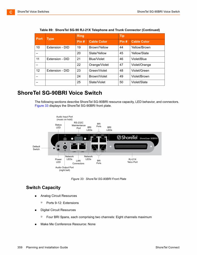
ShoreTel Voice Switches ShoreTel SG-90BRI Voice SwitchC
ShoreTel SG-90BRI Voice Switch
The following sections describe ShoreTel SG-90BRI resource capacity, LED behavior, and connectors. Figure 33 displays the ShoreTel SG-90BRI front plate.
Figure 33: ShoreTel SG-90BRI Front Plate
Switch Capacity
Analog Circuit Resources
Ports 9-12: Extensions
Digital Circuit Resources
Four BRI Spans, each comprising two channels: Eight channels maximum
Make Me Conference Resource: None
10 Extension - DID 19 Brown/Yellow 44 Yellow/Brown
– 20 Slate/Yellow 45 Yellow/Slate
11 Extension - DID 21 Blue/Violet 46 Violet/Blue
– 22 Orange/Violet 47 Violet/Orange
12 Extension - DID 23 Green/Violet 48 Violet/Green
– 24 Brown/Violet 49 Violet/Brown
– 25 Slate/Violet 50 Violet/Slate
Table 89: ShoreTel SG-90 RJ-21X Telephone and Trunk Connector (Continued)
Port TypeRing Tip
Pin # Cable Color Pin # Cable Color
DefaultSwitch
Audio Output Port(night bell)
PowerLED
NetworkLEDs
RS-232CMaintentance
Port
RJ-21XTelco Port
StatusLED
Audio Input Port(music on hold)
NetworkLEDs
LANConnectors
BRILEDs
BRILEDs
BRIPorts
BRIPorts
359 Planning and Installation Guide ShoreTel Connect

ShoreTel SG-90BRI Voice Switch ShoreTel Voice Switches C
Maximum IP Phone Resources: 90 devices
Analog Port Reallocation: 20
Digital Channel Reallocation: 40
Built-in Resources: 30
LED Descriptions
Power LED
The ShoreTel SG-90BRI has one power LED, which indicates the following:
On: The switch is operating normally.
Off: The switch has no power.
Flashing:
2 flashes — The switch failed its internal self-test. This indicates a hardware failure; replace the unit and submit a Return Material Authorization (RMA) to ShoreTel, Inc.
3 flashes — Booting via FTP. Flash memory might be corrupted. Use the pages available through the Maintenance menu in ShoreTel Connect Director to ensure that the system is running properly.
4 flashes — The IP address is unavailable. DHCP did not respond to the IP address request, and the IP address is not available in nonvolatile memory to continue boot process. The switch will automatically reboot in five seconds and try again. Check the DHCP server and the network configuration to ensure that the voice switch is receiving a valid IP address.
5 flashes — The operating system is not available. The switch is booting from FTP but cannot find the boot files. It automatically reboots in five seconds. You can use DHCP to tell the switch where the files are. If you are using a DHCP server that supports options 66 and 67, set option 66 to the ShoreTel server’s IP address, and set option 67 to /tsk/vxworks.
6 flashes — Using a previously stored IP address. A DHCP transaction was attempted, but the DHCP server did not respond. The switch continues to use the IP address stored in nonvolatile memory until it receives a valid response. If the switch receives a response that provides a different IP address, it reboots using the new IP address. If the switch receives a response that matches the IP address stored in nonvolatile memory, it continues operation, and the power LED stops flashing. If the problem persists, check the DHCP server and network configuration.
Network LEDs
The ShoreTel SG-90BRI network LEDs (LAN1 and LAN2) indicate the speed at which the switch is communicating with the network and whether there is network activity.
When both LAN connectors are connected into a redundant network configuration, one network port is active while the other is in standby mode. If one LAN connection fails, the switch activates the other port.
ShoreTel Connect Planning and Installation Guide 360
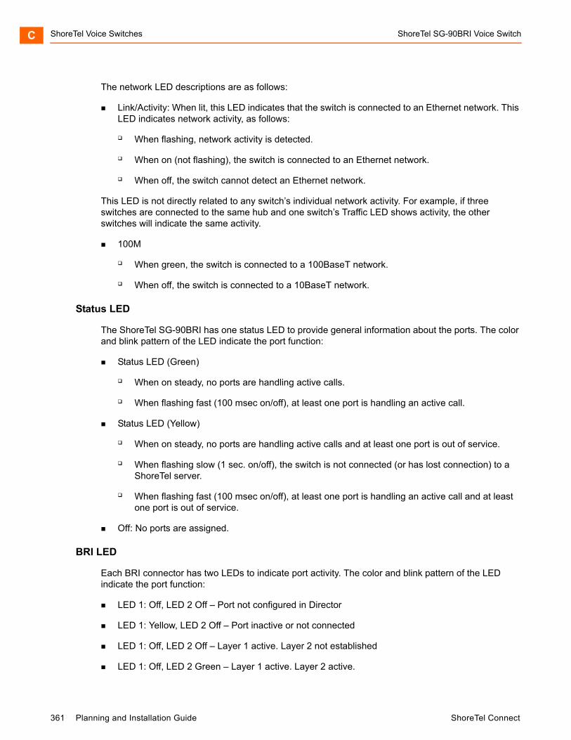
ShoreTel Voice Switches ShoreTel SG-90BRI Voice SwitchC
The network LED descriptions are as follows:
Link/Activity: When lit, this LED indicates that the switch is connected to an Ethernet network. This LED indicates network activity, as follows:
When flashing, network activity is detected.
When on (not flashing), the switch is connected to an Ethernet network.
When off, the switch cannot detect an Ethernet network.
This LED is not directly related to any switch’s individual network activity. For example, if three switches are connected to the same hub and one switch’s Traffic LED shows activity, the other switches will indicate the same activity.
100M
When green, the switch is connected to a 100BaseT network.
When off, the switch is connected to a 10BaseT network.
Status LED
The ShoreTel SG-90BRI has one status LED to provide general information about the ports. The color and blink pattern of the LED indicate the port function:
Status LED (Green)
When on steady, no ports are handling active calls.
When flashing fast (100 msec on/off), at least one port is handling an active call.
Status LED (Yellow)
When on steady, no ports are handling active calls and at least one port is out of service.
When flashing slow (1 sec. on/off), the switch is not connected (or has lost connection) to a ShoreTel server.
When flashing fast (100 msec on/off), at least one port is handling an active call and at least one port is out of service.
Off: No ports are assigned.
BRI LED
Each BRI connector has two LEDs to indicate port activity. The color and blink pattern of the LED indicate the port function:
LED 1: Off, LED 2 Off – Port not configured in Director
LED 1: Yellow, LED 2 Off – Port inactive or not connected
LED 1: Off, LED 2 Off – Layer 1 active. Layer 2 not established
LED 1: Off, LED 2 Green – Layer 1 active. Layer 2 active.
361 Planning and Installation Guide ShoreTel Connect
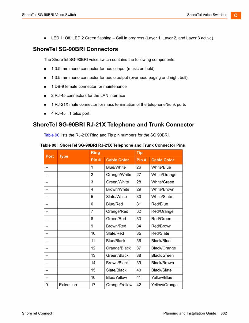
ShoreTel SG-90BRI Voice Switch ShoreTel Voice Switches C
LED 1: Off, LED 2 Green flashing – Call in progress (Layer 1, Layer 2, and Layer 3 active).
ShoreTel SG-90BRI Connectors
The ShoreTel SG-90BRI voice switch contains the following components:
1 3.5 mm mono connector for audio input (music on hold)
1 3.5 mm mono connector for audio output (overhead paging and night bell)
1 DB-9 female connector for maintenance
2 RJ-45 connectors for the LAN interface
1 RJ-21X male connector for mass termination of the telephone/trunk ports
4 RJ-45 T1 telco port
ShoreTel SG-90BRI RJ-21X Telephone and Trunk Connector
Table 90 lists the RJ-21X Ring and Tip pin numbers for the SG 90BRI.
Table 90: ShoreTel SG-90BRI RJ-21X Telephone and Trunk Connector Pins
Port TypeRing Tip
Pin # Cable Color Pin # Cable Color
– 1 Blue/White 26 White/Blue
– 2 Orange/White 27 White/Orange
– 3 Green/White 28 White/Green
– 4 Brown/White 29 White/Brown
– 5 Slate/White 30 White/Slate
– 6 Blue/Red 31 Red/Blue
– 7 Orange/Red 32 Red/Orange
– 8 Green/Red 33 Red/Green
– 9 Brown/Red 34 Red/Brown
– 10 Slate/Red 35 Red/Slate
– 11 Blue/Black 36 Black/Blue
– 12 Orange/Black 37 Black/Orange
– 13 Green/Black 38 Black/Green
– 14 Brown/Black 39 Black/Brown
– 15 Slate/Black 40 Black/Slate
– 16 Blue/Yellow 41 Yellow/Blue
9 Extension 17 Orange/Yellow 42 Yellow/Orange
ShoreTel Connect Planning and Installation Guide 362
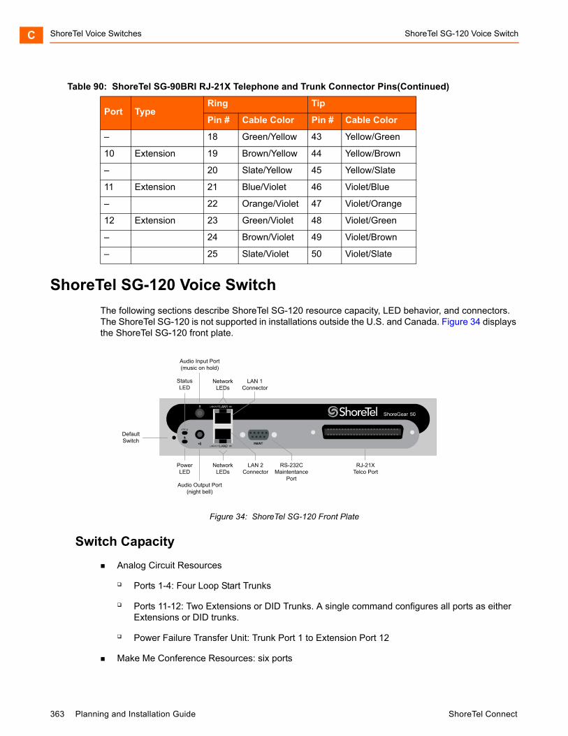
ShoreTel Voice Switches ShoreTel SG-120 Voice SwitchC
ShoreTel SG-120 Voice Switch
The following sections describe ShoreTel SG-120 resource capacity, LED behavior, and connectors. The ShoreTel SG-120 is not supported in installations outside the U.S. and Canada. Figure 34 displays the ShoreTel SG-120 front plate.
Figure 34: ShoreTel SG-120 Front Plate
Switch Capacity
Analog Circuit Resources
Ports 1-4: Four Loop Start Trunks
Ports 11-12: Two Extensions or DID Trunks. A single command configures all ports as either Extensions or DID trunks.
Power Failure Transfer Unit: Trunk Port 1 to Extension Port 12
Make Me Conference Resources: six ports
– 18 Green/Yellow 43 Yellow/Green
10 Extension 19 Brown/Yellow 44 Yellow/Brown
– 20 Slate/Yellow 45 Yellow/Slate
11 Extension 21 Blue/Violet 46 Violet/Blue
– 22 Orange/Violet 47 Violet/Orange
12 Extension 23 Green/Violet 48 Violet/Green
– 24 Brown/Violet 49 Violet/Brown
– 25 Slate/Violet 50 Violet/Slate
Table 90: ShoreTel SG-90BRI RJ-21X Telephone and Trunk Connector Pins(Continued)
Port TypeRing Tip
Pin # Cable Color Pin # Cable Color
DefaultSwitch
Audio Output Port(night bell)
PowerLED
NetworkLEDs
LAN 2Connector
RS-232CMaintentance
Port
RJ-21XTelco Port
StatusLED
Audio Input Port(music on hold)
NetworkLEDs
LAN 1Connector
363 Planning and Installation Guide ShoreTel Connect

ShoreTel SG-120 Voice Switch ShoreTel Voice Switches C
Ports 1-4, 11-12
Maximum IP Phone Resources: 50 devices
Analog Port Reallocation: 30
Built-in Resources: 20
LED Descriptions
Power LED
The ShoreTel SG-120 has one power LED, which indicates the following:
On: The switch is operating normally.
Off: The switch has no power.
Flashing:
2 flashes — The switch failed its internal self-test. This indicates a hardware failure; replace the unit and submit a Return Material Authorization (RMA) to ShoreTel, Inc.
3 flashes — Booting via FTP. Flash memory might be corrupted. Use the pages available through the Maintenance menu in ShoreTel Connect Director to ensure that the system is running properly.
4 flashes — The IP address is unavailable. DHCP did not respond to the IP address request, and the IP address is not available in nonvolatile memory to continue boot process. The switch will automatically reboot in five seconds and try again. Check the DHCP server and the network configuration to ensure that the voice switch is receiving a valid IP address.
5 flashes —The operating system is not available. The switch is booting from FTP but cannot find the boot files. It automatically reboots in five seconds. You can use DHCP to tell the switch where the files are. If you are using a DHCP server that supports options 66 and 67, set option 66 to the ShoreTel server’s IP address, and set option 67 to /tsk/vxworks.
6 flashes — Using a previously stored IP address. A DHCP transaction was attempted, but the DHCP server did not respond. The switch continues to use the IP address stored in nonvolatile memory until it receives a valid response. If the switch receives a response that provides a different IP address, it reboots using the new IP address. If the switch receives a response that matches the IP address stored in nonvolatile memory, it continues operation, and the power LED stops flashing. If the problem persists, check the DHCP server and network configuration.
Network LEDs
The ShoreTel SG-120 network LEDs (LAN1 and LAN2) indicate the speed at which the switch is communicating with the network and whether there is network activity.
When both LAN connectors are connected into a redundant network configuration, one network port is active while the other is in standby mode. If one LAN connection fails, the switch activates the other port.
ShoreTel Connect Planning and Installation Guide 364
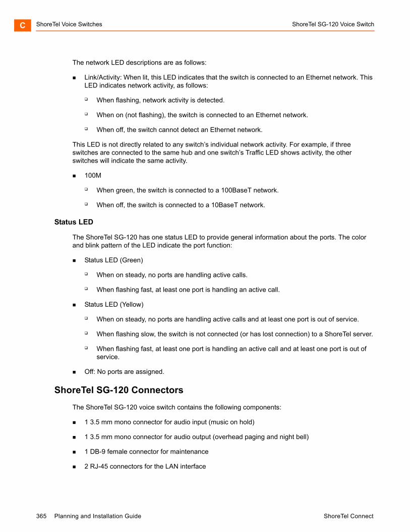
ShoreTel Voice Switches ShoreTel SG-120 Voice SwitchC
The network LED descriptions are as follows:
Link/Activity: When lit, this LED indicates that the switch is connected to an Ethernet network. This LED indicates network activity, as follows:
When flashing, network activity is detected.
When on (not flashing), the switch is connected to an Ethernet network.
When off, the switch cannot detect an Ethernet network.
This LED is not directly related to any switch’s individual network activity. For example, if three switches are connected to the same hub and one switch’s Traffic LED shows activity, the other switches will indicate the same activity.
100M
When green, the switch is connected to a 100BaseT network.
When off, the switch is connected to a 10BaseT network.
Status LED
The ShoreTel SG-120 has one status LED to provide general information about the ports. The color and blink pattern of the LED indicate the port function:
Status LED (Green)
When on steady, no ports are handling active calls.
When flashing fast, at least one port is handling an active call.
Status LED (Yellow)
When on steady, no ports are handling active calls and at least one port is out of service.
When flashing slow, the switch is not connected (or has lost connection) to a ShoreTel server.
When flashing fast, at least one port is handling an active call and at least one port is out of service.
Off: No ports are assigned.
ShoreTel SG-120 Connectors
The ShoreTel SG-120 voice switch contains the following components:
1 3.5 mm mono connector for audio input (music on hold)
1 3.5 mm mono connector for audio output (overhead paging and night bell)
1 DB-9 female connector for maintenance
2 RJ-45 connectors for the LAN interface
365 Planning and Installation Guide ShoreTel Connect
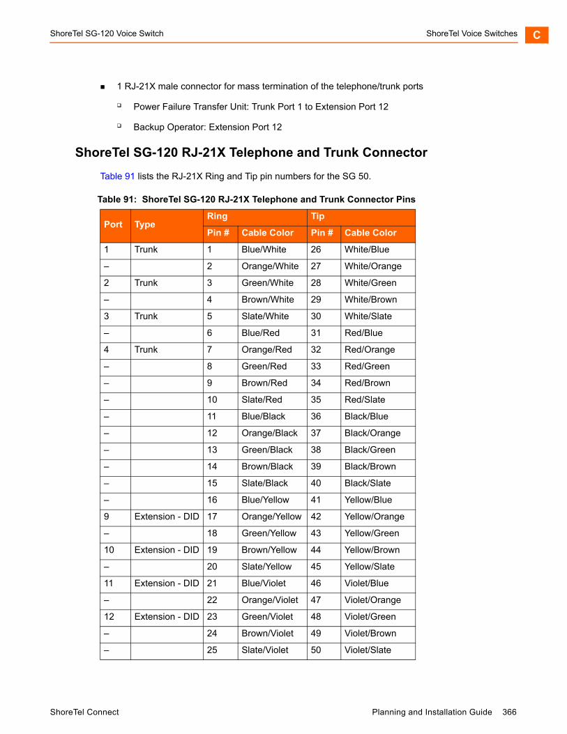
ShoreTel SG-120 Voice Switch ShoreTel Voice Switches C
1 RJ-21X male connector for mass termination of the telephone/trunk ports
Power Failure Transfer Unit: Trunk Port 1 to Extension Port 12
Backup Operator: Extension Port 12
ShoreTel SG-120 RJ-21X Telephone and Trunk Connector
Table 91 lists the RJ-21X Ring and Tip pin numbers for the SG 50.
Table 91: ShoreTel SG-120 RJ-21X Telephone and Trunk Connector Pins
Port TypeRing Tip
Pin # Cable Color Pin # Cable Color
1 Trunk 1 Blue/White 26 White/Blue
– 2 Orange/White 27 White/Orange
2 Trunk 3 Green/White 28 White/Green
– 4 Brown/White 29 White/Brown
3 Trunk 5 Slate/White 30 White/Slate
– 6 Blue/Red 31 Red/Blue
4 Trunk 7 Orange/Red 32 Red/Orange
– 8 Green/Red 33 Red/Green
– 9 Brown/Red 34 Red/Brown
– 10 Slate/Red 35 Red/Slate
– 11 Blue/Black 36 Black/Blue
– 12 Orange/Black 37 Black/Orange
– 13 Green/Black 38 Black/Green
– 14 Brown/Black 39 Black/Brown
– 15 Slate/Black 40 Black/Slate
– 16 Blue/Yellow 41 Yellow/Blue
9 Extension - DID 17 Orange/Yellow 42 Yellow/Orange
– 18 Green/Yellow 43 Yellow/Green
10 Extension - DID 19 Brown/Yellow 44 Yellow/Brown
– 20 Slate/Yellow 45 Yellow/Slate
11 Extension - DID 21 Blue/Violet 46 Violet/Blue
– 22 Orange/Violet 47 Violet/Orange
12 Extension - DID 23 Green/Violet 48 Violet/Green
– 24 Brown/Violet 49 Violet/Brown
– 25 Slate/Violet 50 Violet/Slate
ShoreTel Connect Planning and Installation Guide 366

ShoreTel Voice Switches ShoreTel SG-30 Voice SwitchC
ShoreTel SG-30 Voice Switch
The following sections describe ShoreTel SG-30 resource capacity, LED behavior, and connectors. The ShoreTel SG-30 is not supported in installations outside the U.S. and Canada. Figure 35 displays the ShoreTel SG-30 front plate.
Figure 35: ShoreTel SG-30 Front Plate
Switch Capacity
Analog Circuit Resources
Ports 1-2: Two Loop Start Trunks
Ports 11-12: Two Extensions or DID Trunks. A single command configures all ports as either Extensions or DID trunks.
Power Failure Transfer Unit: Trunk Port 1 to Extension Port 12
Make Me Conference Resources: none
Maximum IP Phone Resources: none
Analog Port Reallocation: 20
Built-in Resources: 10
LED Descriptions
Power LED
The ShoreTel SG-30 has one power LED, which indicates the following:
On: The switch is operating normally.
Off: The switch has no power.
DefaultSwitch
Audio Output Port(night bell)
PowerLED
NetworkLEDs
LAN 2Connector
RS-232CMaintentance
Port
RJ-21XTelco Port
StatusLED
Audio Input Port(music on hold)
NetworkLEDs
LAN 1Connector
367 Planning and Installation Guide ShoreTel Connect

ShoreTel SG-30 Voice Switch ShoreTel Voice Switches C
Flashing:
2 flashes — The switch failed its internal self-test. This indicates a hardware failure. Replace the unit and submit a Return Material Authorization (RMA) to ShoreTel, Inc.
3 flashes — Booting via FTP. Flash memory might be corrupted. Use the pages available through the Maintenance menu in ShoreTel Connect Director to ensure that the system is running properly.
4 flashes — The IP address is unavailable. DHCP did not respond to the IP address request, and the IP address is not available in nonvolatile memory to continue boot process. The switch will automatically reboot in five seconds and try again. Check the DHCP server and the network configuration to ensure that the voice switch is receiving a valid IP address.
5 flashes — The operating system is not available. The switch is booting from FTP but cannot find the boot files. It automatically reboots in five seconds. You can use DHCP to tell the switch where the files are. If you are using a DHCP server that supports options 66 and 67, set option 66 to the ShoreTel server’s IP address, and set option 67 to /tsk/vxworks.
6 flashes — Using a previously stored IP address. A DHCP transaction was attempted, but the DHCP server did not respond. The switch continues to use the IP address stored in nonvolatile memory until it receives a valid response. If the switch receives a response that provides a different IP address, it reboots using the new IP address. If the switch receives a response that matches the IP address stored in nonvolatile memory, it continues operation, and the power LED stops flashing. If the problem persists, check the DHCP server and network configuration.
Network LEDs
The ShoreTel SG-30 network LEDs (LAN1 and LAN2) indicate the speed at which the switch is communicating with the network and whether there is network activity.
When both LAN connectors are connected into a redundant network configuration, one network port is active while the other is in standby mode. If one LAN connection fails, the switch activates the other port.
The network LED descriptions are as follows:
Link/Activity: When lit, this LED indicates that the switch is connected to an Ethernet network. This LED indicates network activity, as follows:
When flashing, network activity is detected.
When on (not flashing), the switch is connected to an Ethernet network.
When off, the switch cannot detect an Ethernet network.
This LED is not directly related to any switch’s individual network activity. For example, if three switches are connected to the same hub and one switch’s Traffic LED shows activity, the other switches will indicate the same activity.
100M
When green, the switch is connected to a 100BaseT network.
ShoreTel Connect Planning and Installation Guide 368
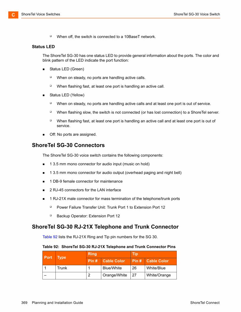
ShoreTel Voice Switches ShoreTel SG-30 Voice SwitchC
When off, the switch is connected to a 10BaseT network.
Status LED
The ShoreTel SG-30 has one status LED to provide general information about the ports. The color and blink pattern of the LED indicate the port function:
Status LED (Green)
When on steady, no ports are handling active calls.
When flashing fast, at least one port is handling an active call.
Status LED (Yellow)
When on steady, no ports are handling active calls and at least one port is out of service.
When flashing slow, the switch is not connected (or has lost connection) to a ShoreTel server.
When flashing fast, at least one port is handling an active call and at least one port is out of service.
Off: No ports are assigned.
ShoreTel SG-30 Connectors
The ShoreTel SG-30 voice switch contains the following components:
1 3.5 mm mono connector for audio input (music on hold)
1 3.5 mm mono connector for audio output (overhead paging and night bell)
1 DB-9 female connector for maintenance
2 RJ-45 connectors for the LAN interface
1 RJ-21X male connector for mass termination of the telephone/trunk ports
Power Failure Transfer Unit: Trunk Port 1 to Extension Port 12
Backup Operator: Extension Port 12
ShoreTel SG-30 RJ-21X Telephone and Trunk Connector
Table 92 lists the RJ-21X Ring and Tip pin numbers for the SG 30.
Table 92: ShoreTel SG-30 RJ-21X Telephone and Trunk Connector Pins
Port TypeRing Tip
Pin # Cable Color Pin # Cable Color
1 Trunk 1 Blue/White 26 White/Blue
– 2 Orange/White 27 White/Orange
369 Planning and Installation Guide ShoreTel Connect

ShoreTel SG-30 Voice Switch ShoreTel Voice Switches C
2 Trunk 3 Green/White 28 White/Green
– 4 Brown/White 29 White/Brown
– 5 Slate/White 30 White/Slate
– 6 Blue/Red 31 Red/Blue
– 7 Orange/Red 32 Red/Orange
– 8 Green/Red 33 Red/Green
– 9 Brown/Red 34 Red/Brown
– 10 Slate/Red 35 Red/Slate
– 11 Blue/Black 36 Black/Blue
– 12 Orange/Black 37 Black/Orange
– 13 Green/Black 38 Black/Green
– 14 Brown/Black 39 Black/Brown
– 15 Slate/Black 40 Black/Slate
– 16 Blue/Yellow 41 Yellow/Blue
– 17 Orange/Yellow 42 Yellow/Orange
– 18 Green/Yellow 43 Yellow/Green
– 19 Brown/Yellow 44 Yellow/Brown
– 20 Slate/Yellow 45 Yellow/Slate
11 Extension - DID 21 Blue/Violet 46 Violet/Blue
– 22 Orange/Violet 47 Violet/Orange
12 Extension - DID 23 Green/Violet 48 Violet/Green
– 24 Brown/Violet 49 Violet/Brown
– 25 Slate/Violet 50 Violet/Slate
Table 92: ShoreTel SG-30 RJ-21X Telephone and Trunk Connector Pins(Continued)
Port TypeRing Tip
Pin # Cable Color Pin # Cable Color
ShoreTel Connect Planning and Installation Guide 370
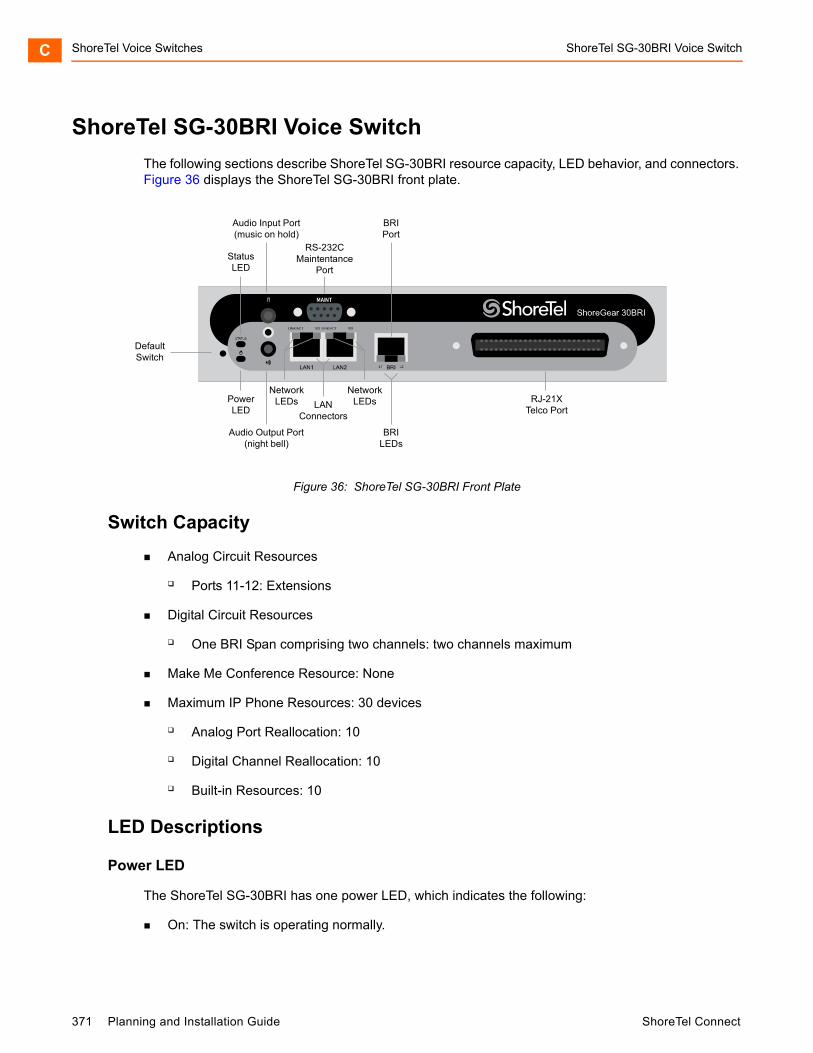
ShoreTel Voice Switches ShoreTel SG-30BRI Voice SwitchC
ShoreTel SG-30BRI Voice Switch
The following sections describe ShoreTel SG-30BRI resource capacity, LED behavior, and connectors. Figure 36 displays the ShoreTel SG-30BRI front plate.
Figure 36: ShoreTel SG-30BRI Front Plate
Switch Capacity
Analog Circuit Resources
Ports 11-12: Extensions
Digital Circuit Resources
One BRI Span comprising two channels: two channels maximum
Make Me Conference Resource: None
Maximum IP Phone Resources: 30 devices
Analog Port Reallocation: 10
Digital Channel Reallocation: 10
Built-in Resources: 10
LED Descriptions
Power LED
The ShoreTel SG-30BRI has one power LED, which indicates the following:
On: The switch is operating normally.
DefaultSwitch
Audio Output Port(night bell)
PowerLED
NetworkLEDs
RS-232CMaintentance
Port
RJ-21XTelco Port
StatusLED
Audio Input Port(music on hold)
NetworkLEDs LAN
Connectors
BRILEDs
BRIPort
371 Planning and Installation Guide ShoreTel Connect
ShoreTel SG-30BRI Voice Switch ShoreTel Voice Switches C
Off: The switch has no power.
Flashing:
2 flashes — The switch failed its internal self-test. This indicates a hardware failure; replace the unit and submit a Return Material Authorization (RMA) to ShoreTel, Inc.
3 flashes — Booting via FTP. Flash memory might be corrupted. Use the pages available through the Maintenance menu in ShoreTel Connect Director to ensure that the system is running properly.
4 flashes — The IP address is unavailable. DHCP did not respond to the IP address request, and the IP address is not available in nonvolatile memory to continue boot process. The switch will automatically reboot in five seconds and try again. Check the DHCP server and the network configuration to ensure that the voice switch is receiving a valid IP address.
5 flashes — The operating system is not available. The switch is booting from FTP but cannot find the boot files. It automatically reboots in five seconds. You can use DHCP to tell the switch where the files are. If you are using a DHCP server that supports options 66 and 67, set option 66 to the ShoreTel server’s IP address, and set option 67 to /tsk/vxworks.
6 flashes — Using a previously stored IP address. A DHCP transaction was attempted, but the DHCP server did not respond. The switch continues to use the IP address stored in nonvolatile memory until it receives a valid response. If the switch receives a response that provides a different IP address, it reboots using the new IP address. If the switch receives a response that matches the IP address stored in nonvolatile memory, it continues operation, and the power LED stops flashing. If the problem persists, check the DHCP server and network configuration.
Network LEDs
The ShoreTel SG-30BRI network LEDs (LAN1 and LAN2) indicate the speed at which the switch is communicating with the network and whether there is network activity.
When both LAN connectors are connected into a redundant network configuration, one network port is active while the other is in standby mode. If one LAN connection fails, the switch activates the other port.
The network LED descriptions are as follows:
Link/Activity: When lit, this LED indicates that the switch is connected to an Ethernet network. This LED indicates network activity, as follows:
When flashing, network activity is detected.
When on (not flashing), the switch is connected to an Ethernet network.
When off, the switch cannot detect an Ethernet network.
This LED is not directly related to any switch’s individual network activity. For example, if three switches are connected to the same hub and one switch’s Traffic LED shows activity, the other switches will indicate the same activity.
100M
ShoreTel Connect Planning and Installation Guide 372
ShoreTel Voice Switches ShoreTel SG-30BRI Voice SwitchC
When green, the switch is connected to a 100BaseT network.
When off, the switch is connected to a 10BaseT network.
Status LED
The ShoreTel SG-30BRI has one status LED to provide general information about the ports. The color and blink pattern of the LED indicate the port function:
Status LED (Green)
When on steady, no ports are handling active calls.
When flashing fast (100 msec on/off), at least one port is handling an active call.
Status LED (Yellow)
When on steady, no ports are handling active calls and at least one port is out of service.
When flashing slow (1 sec. on/off), the switch is not connected (or has lost connection) to a ShoreTel server.
When flashing fast (100 msec on/off), at least one port is handling an active call and at least one port is out of service.
Off: No ports are assigned.
BRI LED
Each BRI connector has two LEDs to indicate port activity. The color and blink pattern of the LED indicate the port function:
LED 1: Off, LED 2 Off – Port not configured in Director
LED 1: Yellow, LED 2 Off – Port inactive or not connected
LED 1: Off, LED 2 Off – Layer 1 active. Layer 2 not established
LED 1: Off, LED 2 Green – Layer 1 active. Layer 2 active.
LED 1: Off, LED 2 Green flashing – Call in progress (Layer 1, Layer 2, and Layer 3 active).
ShoreTel SG-30BRI Connectors
The ShoreTel SG-30BRI voice switch contains the following components:
1 3.5 mm mono connector for audio input (music on hold)
1 3.5 mm mono connector for audio output (overhead paging and night bell)
1 DB-9 female connector for maintenance
2 RJ-45 connectors for the LAN interface
1 RJ-21X male connector for mass termination of the telephone/trunk ports
373 Planning and Installation Guide ShoreTel Connect
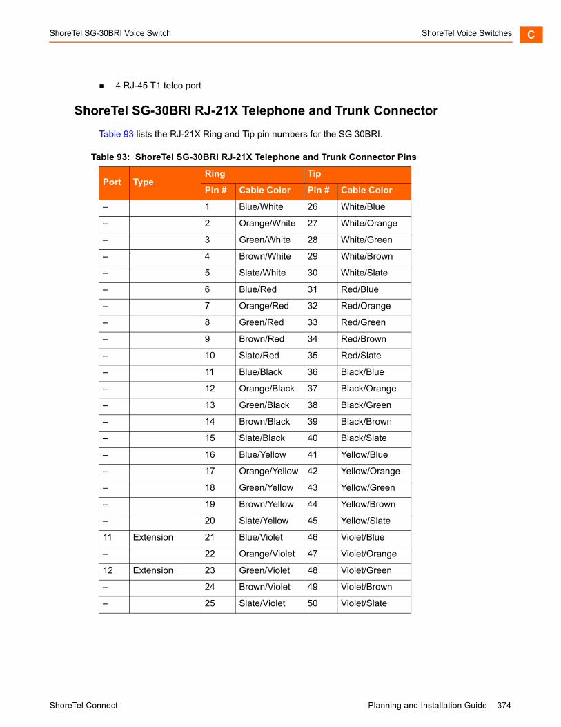
ShoreTel SG-30BRI Voice Switch ShoreTel Voice Switches C
4 RJ-45 T1 telco port
ShoreTel SG-30BRI RJ-21X Telephone and Trunk Connector
Table 93 lists the RJ-21X Ring and Tip pin numbers for the SG 30BRI.
Table 93: ShoreTel SG-30BRI RJ-21X Telephone and Trunk Connector Pins
Port TypeRing Tip
Pin # Cable Color Pin # Cable Color
– 1 Blue/White 26 White/Blue
– 2 Orange/White 27 White/Orange
– 3 Green/White 28 White/Green
– 4 Brown/White 29 White/Brown
– 5 Slate/White 30 White/Slate
– 6 Blue/Red 31 Red/Blue
– 7 Orange/Red 32 Red/Orange
– 8 Green/Red 33 Red/Green
– 9 Brown/Red 34 Red/Brown
– 10 Slate/Red 35 Red/Slate
– 11 Blue/Black 36 Black/Blue
– 12 Orange/Black 37 Black/Orange
– 13 Green/Black 38 Black/Green
– 14 Brown/Black 39 Black/Brown
– 15 Slate/Black 40 Black/Slate
– 16 Blue/Yellow 41 Yellow/Blue
– 17 Orange/Yellow 42 Yellow/Orange
– 18 Green/Yellow 43 Yellow/Green
– 19 Brown/Yellow 44 Yellow/Brown
– 20 Slate/Yellow 45 Yellow/Slate
11 Extension 21 Blue/Violet 46 Violet/Blue
– 22 Orange/Violet 47 Violet/Orange
12 Extension 23 Green/Violet 48 Violet/Green
– 24 Brown/Violet 49 Violet/Brown
– 25 Slate/Violet 50 Violet/Slate
ShoreTel Connect Planning and Installation Guide 374

ShoreTel Voice Switches ShoreTel SG-220T1 Voice SwitchC
ShoreTel SG-220T1 Voice Switch
The following sections describe ShoreTel SG-220T1 resource capacity, LED behavior, and connectors. The ShoreTel SG-220T1 is not supported in installations outside the U.S. and Canada. Figure 37 displays the ShoreTel SG-220T1 front plate.
Figure 37: ShoreTel SG-220T1 Front Plate
Switch Capacity
Digital Circuit Resources: 24 channels maximum
One T1 circuit, 24 channels per circuit: 24 channels maximum
Make Me Conference Resource: None
Maximum IP Phone Resources: 220
Digital Channel Reallocation: 120
Built-in Resources: 100
LED Descriptions
Power LED
The ShoreTel SG-220T1 has one power LED, which indicates the following:
On: The switch is operating normally.
Off: The switch has no power.
Flashing
2 flashes — The switch failed its internal self-test. This indicates a hardware failure; replace the unit and submit a Return Material Authorization (RMA) to ShoreTel, Inc.
DefaultSwitch
Audio Output Port(night bell)
PowerLED
NetworkLEDs
LAN 2Connector
RS-232CMaintentance
Port
StatusLED
Audio Input Port(music on hold)
NetworkLEDs
LAN 1Connector T1 LEDs
MonitorPort
TelcoPort
375 Planning and Installation Guide ShoreTel Connect
ShoreTel SG-220T1 Voice Switch ShoreTel Voice Switches C
3 flashes — Booting via FTP. Flash memory might be corrupted. Use the pages available through the Maintenance menu in ShoreTel Connect Director to ensure that the system is running properly.
4 flashes — The IP address is unavailable. DHCP did not respond to the IP address request, and the IP address is not available in nonvolatile memory to continue boot process. The switch will automatically reboot in five seconds and try again. Check the DHCP server and the network configuration to ensure that the voice switch is receiving a valid IP address.
5 flashes — The operating system is not available. The switch is booting from FTP but cannot find the boot files. It automatically reboots in five seconds. You can use DHCP to tell the switch where the files are. If you are using a DHCP server that supports options 66 and 67, set option 66 to the ShoreTel server’s IP address, and set option 67 to /tsk/vxworks.
6 flashes — Using a previously stored IP address. A DHCP transaction was attempted, but the DHCP server did not respond. The switch continues to use the IP address stored in nonvolatile memory until it receives a valid response. If the switch receives a response that provides a different IP address, it reboots using the new IP address. If the switch receives a response that matches the IP address stored in nonvolatile memory, it continues operation, and the power LED stops flashing. If the problem persists, check the DHCP server and network configuration.
Network LEDs
The ShoreTel SG-220T1 network LEDs (LAN1 and LAN2) indicate the speed at which the switch is communicating with the network and whether there is network activity.
When both LAN connectors are connected into a redundant network configuration, one network port is active while the other is in standby mode. If one LAN connection fails, the switch activates the other port.
The network LED descriptions are as follows:
Link/Activity: When lit, this LED indicates that the switch is connected to an Ethernet network. This LED indicates network activity, as follows:
When flashing, network activity is detected.
When on (not flashing), the switch is connected to an Ethernet network.
When off, the switch cannot detect an Ethernet network.
This LED is not directly related to any switch’s individual network activity. For example, if three switches are connected to the same hub and one switch’s Traffic LED shows activity, the other switches will indicate the same activity.
100M
When green, the switch is connected to a 100BaseT network.
When off, the switch is connected to a 10BaseT network.
ShoreTel Connect Planning and Installation Guide 376

ShoreTel Voice Switches ShoreTel SG-220T1 Voice SwitchC
Status LED
The ShoreTel SG-220T1 has one status LED to provide general information about the ports. The color and blink pattern of the LED indicate the port function:
Status LED (Green)
When on steady, no ports are handling active calls.
When flashing fast, at least one port is handling an active call.
Status LED (Yellow)
When on steady, no ports are handling active calls and at least one port is out of service.
When flashing slow, the switch is not connected (or has lost connection) to a ShoreTel server.
When flashing fast, at least one port is handling an active call and at least one port is out of service.
Off: No ports are assigned.
Monitor and Telco LEDs
The Monitor and Telco LEDs indicate line coding, network framing, and loopback status. These LEDs are color coded—green, yellow, and red. The Monitor and Telco LED descriptions follow.
Telco and Monitor LED alarms and errors are logged as switch events in ShoreTel Connect Director’s event log.
Line Coding: This LED indicates line coding status, as follows:
When green, the line coding signal is good.
When yellow, bipolar violations (BPV) are being received at one second intervals.
When red, a loss of signal (LOS) has occurred.
When flashing red, loopback is active (local or CO).
When off, the switch has no power.
Framing: This LED indicates network framing status, as follows:
When green, the T1/E1 signal is in frame; the signal is synchronized.
When yellow, a yellow alarm has been received from the Central Office.
When flashing yellow, the frame-bit error rate has exceeded its limits. A small number of frame-bit errors (>1 per million) have occurred; this state will take up to 10 minutes to clear.
When flashing fast yellow, a series of frame-bit errors (>1 per 1000) have occurred.
When red, the T1/E1 signal is out-of-frame (OOF). The received signal cannot be framed to the Extended Superframe (ESF) or D4 format.
377 Planning and Installation Guide ShoreTel Connect

ShoreTel SG-220T1A Voice Switch ShoreTel Voice Switches C
When flashing red, loopback is active (local or CO).
When off, the switch has no power.
ShoreTel SG-220T1 Connectors
The ShoreTel SG-220T1 voice switch contains the following components:
1 3.5 mm mono connector for audio input (music on hold)
1 3.5 mm mono connector for audio output (overhead paging and night bell)
1 DB-9 female connector for maintenance
2 RJ-45 connectors for the LAN interface
1 RJ-45 T1 telco port
1 RJ-45 T1 monitor port for connecting test equipment
ShoreTel SG-220T1A Voice Switch
The following sections describe ShoreTel SG-220T1A resource capacity, LED behavior, and connectors. The ShoreTel SG-220T1A is not supported in installations outside the U.S. and Canada. Figure 38 displays the ShoreTel SG-220T1A front plate.
Figure 38: ShoreTel SG-220T1A Front Plate
Switch Capacity
Analog Circuit Resources
Ports 1-2: Two Loop Start Trunks
Ports 9-12: Four Extensions or DID Trunks. A single command configures all ports as either Extensions or DID trunks.
DefaultSwitch
Audio Output Port(night bell)
PowerLED
NetworkLEDs
LAN 2Connector
RS-232CMaintentance
Port
StatusLED
Audio Input Port(music on hold)
NetworkLEDs
T1 LEDs
T1 LEDsLAN 1
Connector
T1 MonitorPort
T1 TelcoPort
RJ-21XTelco Port
ShoreTel Connect Planning and Installation Guide 378

ShoreTel Voice Switches ShoreTel SG-220T1A Voice SwitchC
Power Failure Transfer Unit: Trunk Port 1 to Extension Port 12
Digital Circuit Resources: 24 channels maximum
One T1 circuit, 24 channels per circuit
Make Me Conference Resource: Six ports
Ports 1-2, 9-12
Maximum IP Phone Resources: 220 devices
Analog Channel Reallocation: 30
Digital Channel Reallocation: 120
Built-in Resources: 70
LED Descriptions
Power LED
The ShoreTel SG-220T1A has one power LED, which indicates the following:
On: The switch is operating normally.
Off: The switch has no power.
Flashing
2 flashes — The switch failed its internal self-test. This indicates a hardware failure; replace the unit and submit a Return Material Authorization (RMA) to ShoreTel, Inc.
3 flashes — Booting via FTP. Flash memory might be corrupted. Use the pages available through the Maintenance menu in ShoreTel Connect Director to ensure that the system is running properly.
4 flashes — The IP address is unavailable. DHCP did not respond to the IP address request, and the IP address is not available in nonvolatile memory to continue boot process. The switch will automatically reboot in five seconds and try again. Check the DHCP server and the network configuration to ensure that the voice switch is receiving a valid IP address.
5 flashes — The operating system is not available. The switch is booting from FTP but cannot find the boot files. It automatically reboots in five seconds. You can use DHCP to tell the switch where the files are. If you are using a DHCP server that supports options 66 and 67, set option 66 to the ShoreTel server’s IP address, and set option 67 to /tsk/vxworks.
6 flashes — Using a previously stored IP address. A DHCP transaction was attempted, but the DHCP server did not respond. The switch continues to use the IP address stored in nonvolatile memory until it receives a valid response. If the switch receives a response that provides a different IP address, it reboots using the new IP address. If the switch receives a response that matches the IP address stored in nonvolatile memory, it continues operation, and the power LED stops flashing. If the problem persists, check the DHCP server and network configuration.
379 Planning and Installation Guide ShoreTel Connect

ShoreTel SG-220T1A Voice Switch ShoreTel Voice Switches C
Network LEDs
The ShoreTel SG-220T1A network LEDs (LAN1 and LAN2) indicate the speed at which the switch is communicating with the network and whether there is network activity.
When both LAN connectors are connected into a redundant network configuration, one network port is active while the other is in standby mode. If one LAN connection fails, the switch activates the other port.
The network LED descriptions are as follows:
Link/Activity: When lit, this LED indicates that the switch is connected to an Ethernet network. This LED indicates network activity, as follows:
When flashing, network activity is detected.
When on (not flashing), the switch is connected to an Ethernet network.
When off, the switch cannot detect an Ethernet network.
This LED is not directly related to any switch’s individual network activity. For example, if three switches are connected to the same hub and one switch’s Traffic LED shows activity, the other switches will indicate the same activity.
100M
When green, the switch is connected to a 100BaseT network.
When off, the switch is connected to a 10BaseT network.
Status LED
The ShoreTel SG-220T1A has one status LED to provide general information about the ports. The color and blink pattern of the LED indicate the port function:
Status LED (Green)
When on steady, no ports are handling active calls.
When flashing fast (100 msec on/off), at least one port is handling an active call.
Status LED (Yellow)
When on steady, no ports are handling active calls and at least one port is out of service.
When flashing slow (1 sec. on/off), the switch is not connected (or has lost connection) to a ShoreTel server.
When flashing fast (100 msec on/off), at least one port is handling an active call and at least one port is out of service.
Off: No ports are assigned.
ShoreTel Connect Planning and Installation Guide 380
ShoreTel Voice Switches ShoreTel SG-220T1A Voice SwitchC
Monitor and Telco LEDs
The Monitor and Telco LEDs indicate line coding, network framing, and loopback status. These LEDs are color coded—green, yellow, and red. The Monitor and Telco LED descriptions follow.
Telco and Monitor LED alarms and errors are logged as switch events in ShoreTel Connect Director’s event log.
Line Coding: This LED indicates line coding status, as follows:
When green, the line coding signal is good.
When yellow, bipolar violations (BPV) are received at one second intervals.
When red, a loss of signal (LOS) has occurred.
When flashing red, loopback is active (local or CO).
When off, the switch has no power.
Framing: This LED indicates network framing status, as follows:
When green, the T1/E1 signal is in frame; the signal is synchronized.
When yellow, a yellow alarm has been received from the Central Office.
When flashing yellow, the frame-bit error rate has exceeded its limits.
When flashing slow yellow, a small number of frame-bit errors (>1 per million) have occurred; this state will take up to 10 minutes to clear.
When flashing fast yellow, a series of frame-bit errors (> 1 per 1000) have occurred.
When red, the T1/E1 signal is out-of-frame (OOF). The received signal cannot be framed to the Extended Superframe (ESF) or D4 format.
When flashing red, loopback is active (local or CO).
When off, the switch has no power.
ShoreTel SG-220T1A Connectors
The ShoreTel SG-220T1A voice switch contains the following components:
1 3.5 mm mono connector for audio input (music on hold)
1 3.5 mm mono connector for audio output (overhead paging and night bell)
1 DB-9 female connector for maintenance
1 RJ-21X male connector for mass termination of the telephone/trunk ports
2 RJ-45 connectors for the LAN interface
1 RJ-45 T1 telco port
381 Planning and Installation Guide ShoreTel Connect
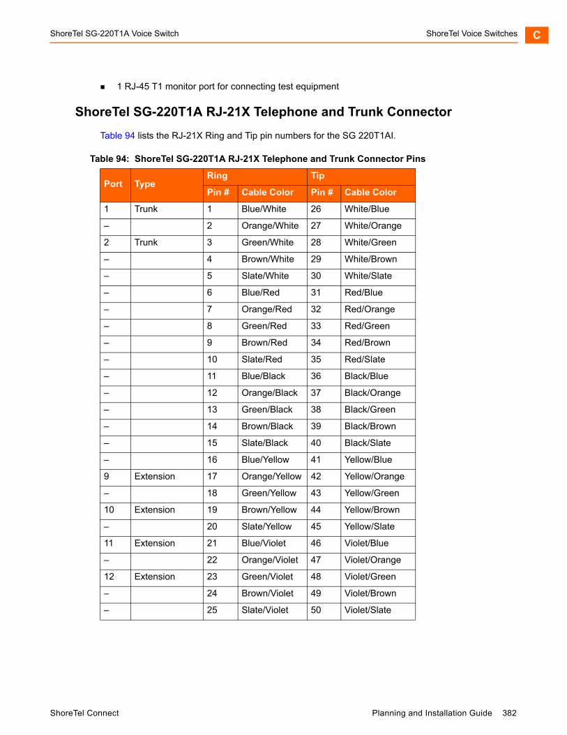
ShoreTel SG-220T1A Voice Switch ShoreTel Voice Switches C
1 RJ-45 T1 monitor port for connecting test equipment
ShoreTel SG-220T1A RJ-21X Telephone and Trunk Connector
Table 94 lists the RJ-21X Ring and Tip pin numbers for the SG 220T1AI.
Table 94: ShoreTel SG-220T1A RJ-21X Telephone and Trunk Connector Pins
Port TypeRing Tip
Pin # Cable Color Pin # Cable Color
1 Trunk 1 Blue/White 26 White/Blue
– 2 Orange/White 27 White/Orange
2 Trunk 3 Green/White 28 White/Green
– 4 Brown/White 29 White/Brown
– 5 Slate/White 30 White/Slate
– 6 Blue/Red 31 Red/Blue
– 7 Orange/Red 32 Red/Orange
– 8 Green/Red 33 Red/Green
– 9 Brown/Red 34 Red/Brown
– 10 Slate/Red 35 Red/Slate
– 11 Blue/Black 36 Black/Blue
– 12 Orange/Black 37 Black/Orange
– 13 Green/Black 38 Black/Green
– 14 Brown/Black 39 Black/Brown
– 15 Slate/Black 40 Black/Slate
– 16 Blue/Yellow 41 Yellow/Blue
9 Extension 17 Orange/Yellow 42 Yellow/Orange
– 18 Green/Yellow 43 Yellow/Green
10 Extension 19 Brown/Yellow 44 Yellow/Brown
– 20 Slate/Yellow 45 Yellow/Slate
11 Extension 21 Blue/Violet 46 Violet/Blue
– 22 Orange/Violet 47 Violet/Orange
12 Extension 23 Green/Violet 48 Violet/Green
– 24 Brown/Violet 49 Violet/Brown
– 25 Slate/Violet 50 Violet/Slate
ShoreTel Connect Planning and Installation Guide 382
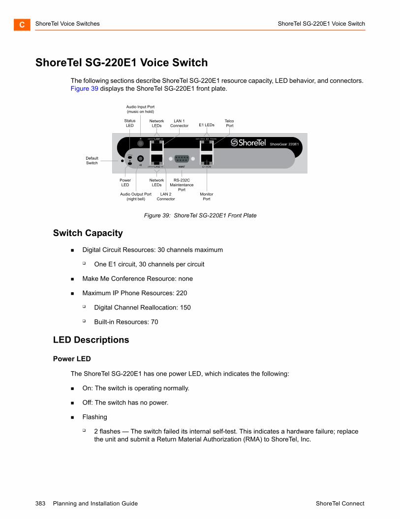
ShoreTel Voice Switches ShoreTel SG-220E1 Voice SwitchC
ShoreTel SG-220E1 Voice Switch
The following sections describe ShoreTel SG-220E1 resource capacity, LED behavior, and connectors. Figure 39 displays the ShoreTel SG-220E1 front plate.
Figure 39: ShoreTel SG-220E1 Front Plate
Switch Capacity
Digital Circuit Resources: 30 channels maximum
One E1 circuit, 30 channels per circuit
Make Me Conference Resource: none
Maximum IP Phone Resources: 220
Digital Channel Reallocation: 150
Built-in Resources: 70
LED Descriptions
Power LED
The ShoreTel SG-220E1 has one power LED, which indicates the following:
On: The switch is operating normally.
Off: The switch has no power.
Flashing
2 flashes — The switch failed its internal self-test. This indicates a hardware failure; replace the unit and submit a Return Material Authorization (RMA) to ShoreTel, Inc.
DefaultSwitch
Audio Output Port(night bell)
PowerLED
NetworkLEDs
LAN 2Connector
RS-232CMaintentance
Port
StatusLED
Audio Input Port(music on hold)
NetworkLEDs E1 LEDs
LAN 1Connector
MonitorPort
Telco Port
383 Planning and Installation Guide ShoreTel Connect
ShoreTel SG-220E1 Voice Switch ShoreTel Voice Switches C
3 flashes — Booting via FTP. Flash memory might be corrupted. Use the pages available through the Maintenance menu in ShoreTel Connect Director to ensure that the system is running properly.
4 flashes — The IP address is unavailable. DHCP did not respond to the IP address request, and the IP address is not available in nonvolatile memory to continue boot process. The switch will automatically reboot in five seconds and try again. Check the DHCP server and the network configuration to ensure that the voice switch is receiving a valid IP address.
5 flashes — The operating system is not available. The switch is booting from FTP but cannot find the boot files. It automatically reboots in five seconds. You can use DHCP to tell the switch where the files are. If you are using a DHCP server that supports options 66 and 67, set option 66 to the ShoreTel server’s IP address, and set option 67 to /tsk/vxworks.
6 flashes — Using a previously stored IP address. A DHCP transaction was attempted, but the DHCP server did not respond. The switch continues to use the IP address stored in nonvolatile memory until it receives a valid response. If the switch receives a response that provides a different IP address, it reboots using the new IP address. If the switch receives a response that matches the IP address stored in nonvolatile memory, it continues operation, and the power LED stops flashing. If the problem persists, check the DHCP server and network configuration.
Network LEDs
The ShoreTel SG-220E1 network LEDs (LAN1 and LAN2) indicate the speed at which the switch is communicating with the network and whether there is network activity.
When both LAN connectors are connected into a redundant network configuration, one network port is active while the other is in standby mode. If one LAN connection fails, the switch activates the other port.
The network LED descriptions are as follows:
Link/Activity: When lit, this LED indicates that the switch is connected to an Ethernet network. This LED indicates network activity, as follows:
When flashing, network activity is detected.
When on (not flashing), the switch is connected to an Ethernet network.
When off, the switch cannot detect an Ethernet network.
This LED is not directly related to any switch’s individual network activity. For example, if three switches are connected to the same hub and one switch’s Traffic LED shows activity, the other switches will indicate the same activity.
100M
When green, the switch is connected to a 100BaseT network.
When off, the switch is connected to a 10BaseT network.
ShoreTel Connect Planning and Installation Guide 384
ShoreTel Voice Switches ShoreTel SG-220E1 Voice SwitchC
Status LED
The ShoreTel SG-220E1 has one status LED to provide general information about the ports. The color and blink pattern of the LED indicate the port function:
Status LED (Green)
When on steady, no ports are handling active calls.
When flashing fast, at least one port is handling an active call.
Status LED (Yellow)
When on steady, no ports are handling active calls and at least one port is out of service.
When flashing slow, the switch is not connected (or has lost connection) to a ShoreTel server.
When flashing fast, at least one port is handling an active call and at least one port is out of service.
Off: No ports are assigned.
Monitor and Telco LEDs
The Monitor and Telco LEDs indicate line coding, network framing, and loopback status. These LEDs are color coded—green, yellow, and red. The Monitor and Telco LED descriptions follow.
Telco and Monitor LED alarms and errors are logged as switch events in ShoreTel Connect Director’s event log.
Line Coding: This LED indicates line coding status, as follows:
When green, the line coding signal is good.
When yellow, bipolar violations (BPV) are being received at one second intervals.
When red, a loss of signal (LOS) has occurred.
When flashing red, loopback is active (local or CO).
When off, the switch has no power.
Framing: This LED indicates network framing status, as follows:
When green, the T1/E1 signal is in frame; the signal is synchronized.
When yellow, a yellow alarm has been received from the Central Office.
When flashing yellow, the frame-bit error rate has exceeded its limits.
When flashing slow yellow, a small number of frame-bit errors (10e-6) have occurred; this state will take up to 10 minutes to clear.
When flashing fast yellow, a series of frame-bit errors (10e-3) have occurred.
385 Planning and Installation Guide ShoreTel Connect

ShoreTel SG-T1k Voice Switch ShoreTel Voice Switches C
When red, the T1/E1 signal is out-of-frame (OOF). The received signal cannot be framed to the Extended Superframe (ESF) or D4 format.
When flashing red, loopback is active (local or CO).
When off, the switch has no power.
ShoreTel SG-220E1 Connectors
The ShoreTel SG-220E1 voice switch contains the following components:
1 3.5 mm mono connector for audio input (music on hold)
1 3.5 mm mono connector for audio output (overhead paging and night bell)
1 DB-9 female connector for maintenance
2 RJ-45 connectors for the LAN interface
1 RJ-45 T1 telco port
1 RJ-45 T1 monitor port for connecting test equipment
ShoreTel SG-T1k Voice Switch
The following sections describe ShoreTel SG-T1k resource capacity, LED behavior, and connectors. The ShoreTel SG-T1k is not supported in installations outside the U.S. and Canada. Figure 40 displays the ShoreTel SG-T1k front plate.
Figure 40: ShoreTel SG-T1k Front Plate
Switch Capacity
Digital Circuit Resources: 24 channels maximum
DefaultSwitch
Audio Output Port(night bell)
PowerLED
NetworkLEDs
LAN 2Connector
RS-232CMaintentance
Port
StatusLED
Audio Input Port(music on hold)
NetworkLEDs
LAN 1Connector T1 LEDs
MonitorPort
TelcoPort
ShoreTel Connect Planning and Installation Guide 386

ShoreTel Voice Switches ShoreTel SG-T1k Voice SwitchC
One T1 circuit, 24 channels per circuit
Make Me Conference Resource: None
Maximum IP Phone Resources: None
LED Descriptions
Power LED
The ShoreTel SG-T1k has one power LED, which indicates the following:
On: The switch is operating normally.
Off: The switch has no power.
Flashing
2 flashes — The switch failed its internal self-test. This indicates a hardware failure; replace the unit and submit a Return Material Authorization (RMA) to ShoreTel, Inc.
3 flashes — Booting via FTP. Flash memory might be corrupted. Use the pages available through the Maintenance menu in ShoreTel Connect Director to ensure that the system is running properly.
4 flashes — The IP address is unavailable. DHCP did not respond to the IP address request, and the IP address is not available in nonvolatile memory to continue boot process. The switch will automatically reboot in five seconds and try again. Check the DHCP server and the network configuration to ensure that the voice switch is receiving a valid IP address.
5 flashes — The operating system is not available. The switch is booting from FTP but cannot find the boot files. It automatically reboots in five seconds. You can use DHCP to tell the switch where the files are. If you are using a DHCP server that supports options 66 and 67, set option 66 to the ShoreTel server’s IP address, and set option 67 to /tsk/vxworks.
6 flashes — Using a previously stored IP address. A DHCP transaction was attempted, but the DHCP server did not respond. The switch continues to use the IP address stored in nonvolatile memory until it receives a valid response. If the switch receives a response that provides a different IP address, it reboots using the new IP address. If the switch receives a response that matches the IP address stored in nonvolatile memory, it continues operation, and the power LED stops flashing. If the problem persists, check the DHCP server and network configuration.
Network LEDs
The ShoreTel SG-T1k network LEDs (LAN1 and LAN2) indicate the speed at which the switch is communicating with the network and whether there is network activity.
When both LAN connectors are connected into a redundant network configuration, one network port is active while the other is in standby mode. If one LAN connection fails, the switch activates the other port.
387 Planning and Installation Guide ShoreTel Connect
ShoreTel SG-T1k Voice Switch ShoreTel Voice Switches C
The network LED descriptions are as follows:
Link/Activity: When lit, this LED indicates that the switch is connected to an Ethernet network. This LED indicates network activity, as follows:
When flashing, network activity is detected.
When on (not flashing), the switch is connected to an Ethernet network.
When off, the switch cannot detect an Ethernet network.
This LED is not directly related to any switch’s individual network activity. For example, if three switches are connected to the same hub and one switch’s Traffic LED shows activity, the other switches will indicate the same activity.
100M
When green, the switch is connected to a 100BaseT network.
When off, the switch is connected to a 10BaseT network.
Status LED
The ShoreTel SG-T1k has one status LED to provide general information about the ports. The color and blink pattern of the LED indicate the port function:
Status LED (Green)
When on steady, no ports are handling active calls.
When flashing fast, at least one port is handling an active call.
Status LED (Yellow)
When on steady, no ports are handling active calls and at least one port is out of service.
When flashing slow, the switch is not connected (or has lost connection) to a ShoreTel server.
When flashing fast, at least one port is handling an active call and at least one port is out of service.
Off: No ports are assigned.
Monitor and Telco LEDs
The Monitor and Telco LEDs indicate line coding, network framing, and loopback status. These LEDs are color coded—green, yellow, and red. The Monitor and Telco LED descriptions follow.
Telco and Monitor LED alarms and errors are logged as switch events in ShoreTel Connect Director’s event log.
Line Coding: This LED indicates line coding status, as follows:
When green, the line coding signal is good.
When yellow, bipolar violations (BPV) are being received at one second intervals.
ShoreTel Connect Planning and Installation Guide 388

ShoreTel Voice Switches ShoreTel SG-T1k Voice SwitchC
When red, a loss of signal (LOS) has occurred.
When flashing red, loopback is active (local or CO).
When off, the switch has no power.
Framing: This LED indicates network framing status, as follows:
When green, the T1/E1 signal is in frame; the signal is synchronized.
When yellow, a yellow alarm has been received from the Central Office.
When flashing yellow, the frame-bit error rate has exceeded its limits. A small number of frame-bit errors (>1 per million) have occurred; this state will take up to 10 minutes to clear.
When flashing fast yellow, a series of frame-bit errors (>1 per 1000) have occurred.
When red, the T1/E1 signal is out-of-frame (OOF). The received signal cannot be framed to the Extended Superframe (ESF) or D4 format.
When flashing red, loopback is active (local or CO).
When off, the switch has no power.
ShoreTel SG-T1k Connectors
The ShoreTel SG-T1k voice switch contains the following components:
1 3.5 mm mono connector for audio input (music on hold)
1 3.5 mm mono connector for audio output (overhead paging and night bell)
1 DB-9 female connector for maintenance
2 RJ-45 connectors for the LAN interface
1 RJ-45 T1 telco port
1 RJ-45 T1 monitor port for connecting test equipment
389 Planning and Installation Guide ShoreTel Connect
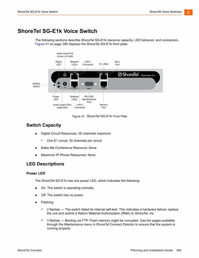
ShoreTel SG-E1k Voice Switch ShoreTel Voice Switches C
ShoreTel SG-E1k Voice Switch
The following sections describe ShoreTel SG-E1k resource capacity, LED behavior, and connectors. Figure 41 on page 390 displays the ShoreTel SG-E1k front plate.
Figure 41: ShoreTel SG-E1k Front Plate
Switch Capacity
Digital Circuit Resources: 30 channels maximum
One E1 circuit, 30 channels per circuit
Make Me Conference Resource: None
Maximum IP Phone Resources: None
LED Descriptions
Power LED
The ShoreTel SG-E1k has one power LED, which indicates the following:
On: The switch is operating normally.
Off: The switch has no power.
Flashing
2 flashes — The switch failed its internal self-test. This indicates a hardware failure; replace the unit and submit a Return Material Authorization (RMA) to ShoreTel, Inc.
3 flashes — Booting via FTP. Flash memory might be corrupted. Use the pages available through the Maintenance menu in ShoreTel Connect Director to ensure that the system is running properly.
DefaultSwitch
Audio Output Port(night bell)
PowerLED
NetworkLEDs
LAN 2Connector
RS-232CMaintentance
Port
StatusLED
Audio Input Port(music on hold)
NetworkLEDs E1 LEDs
LAN 1Connector
MonitorPort
Telco Port
ShoreTel Connect Planning and Installation Guide 390
ShoreTel Voice Switches ShoreTel SG-E1k Voice SwitchC
4 flashes — The IP address is unavailable. DHCP did not respond to the IP address request, and the IP address is not available in nonvolatile memory to continue boot process. The switch will automatically reboot in five seconds and try again. Check the DHCP server and the network configuration to ensure that the voice switch is receiving a valid IP address.
5 flashes — The operating system is not available. The switch is booting from FTP but cannot find the boot files. It automatically reboots in five seconds. You can use DHCP to tell the switch where the files are. If you are using a DHCP server that supports options 66 and 67, set option 66 to the ShoreTel server’s IP address, and set option 67 to /tsk/vxworks.
6 flashes — Using a previously stored IP address. A DHCP transaction was attempted, but the DHCP server did not respond. The switch continues to use the IP address stored in nonvolatile memory until it receives a valid response. If the switch receives a response that provides a different IP address, it reboots using the new IP address. If the switch receives a response that matches the IP address stored in nonvolatile memory, it continues operation, and the power LED stops flashing. If the problem persists, check the DHCP server and network configuration.
Network LEDs
The ShoreTel SG-E1k network LEDs (LAN1 and LAN2) indicate the speed at which the switch is communicating with the network and whether there is network activity.
When both LAN connectors are connected into a redundant network configuration, one network port is active while the other is in standby mode. If one LAN connection fails, the switch activates the other port.
The network LED descriptions are as follows:
Link/Activity: When lit, this LED indicates that the switch is connected to an Ethernet network. This LED indicates network activity, as follows:
When flashing, network activity is detected.
When on (not flashing), the switch is connected to an Ethernet network.
When off, the switch cannot detect an Ethernet network.
This LED is not directly related to any switch’s individual network activity. For example, if three switches are connected to the same hub and one switch’s Traffic LED shows activity, the other switches will indicate the same activity.
100M
When green, the switch is connected to a 100BaseT network.
When off, the switch is connected to a 10BaseT network.
Status LED
The ShoreTel SG-E1k has one status LED to provide general information about the ports. The color and blink pattern of the LED indicate the port function:
Status LED (Green)
391 Planning and Installation Guide ShoreTel Connect
ShoreTel SG-E1k Voice Switch ShoreTel Voice Switches C
When on steady, no ports are handling active calls.
When flashing fast, at least one port is handling an active call.
Status LED (Yellow)
When on steady, no ports are handling active calls and at least one port is out of service.
When flashing slow, the switch is not connected (or has lost connection) to a ShoreTel server.
When flashing fast, at least one port is handling an active call and at least one port is out of service.
Off: No ports are assigned.
Monitor and Telco LEDs
The Monitor and Telco LEDs indicate line coding, network framing, and loopback status. These LEDs are color coded—green, yellow, and red. The Monitor and Telco LED descriptions follow.
Telco and Monitor LED alarms and errors are logged as switch events in ShoreTel Connect Director’s event log.
Line Coding: This LED indicates line coding status, as follows:
When green, the line coding signal is good.
When yellow, bipolar violations (BPV) are being received at one second intervals.
When red, a loss of signal (LOS) has occurred.
When flashing red, loopback is active (local or CO).
When off, the switch has no power.
Framing: This LED indicates network framing status, as follows:
When green, the E1 signal is in frame; the signal is synchronized.
When yellow, a yellow alarm has been received from the Central Office.
When flashing yellow, the frame-bit error rate has exceeded its limits. A small number of frame-bit errors (>1 per million) have occurred; this state will take up to 10 minutes to clear.
When flashing fast yellow, a series of frame-bit errors (>1 per 1000) have occurred.
When red, the T1/E1 signal is out-of-frame (OOF). The received signal cannot be framed to the Extended Superframe (ESF) or D4 format.
When flashing red, loopback is active (local or CO).
When off, the switch has no power.
ShoreTel Connect Planning and Installation Guide 392

ShoreTel Voice Switches Specifications – SG Voice Model SwitchesC
ShoreTel SG-E1k Connectors
The ShoreTel SG-E1k voice switch contains the following components:
1 3.5 mm mono connector for audio input (music on hold)
1 3.5 mm mono connector for audio output (overhead paging and night bell)
1 DB-9 female connector for maintenance
2 RJ-45 connectors for the LAN interface
1 RJ-45 T1 telco port
1 RJ-45 T1 monitor port for connecting test equipment
Specifications – SG Voice Model Switches
ShoreTel SG-90V Voice Switch
The following sections describe ShoreTel SG-90V resource capacity, LED behavior, and connectors. The ShoreTel SG-90V is not supported in installations outside the U.S. and Canada. Figure 42 displays the ShoreTel SG-90V front plate.
Figure 42: ShoreTel SG-90V Front Plate
Switch Capacity
Analog Circuit Resources
Ports 1-8: Eight Loop Start Trunks
DefaultSwitch
Audio Output Port(night bell)
PowerLED
NetworkLEDs
LAN 2Connector
RS-232CMaintentance
Port
RJ-21XTelco Port
StatusLED
Audio Input Port(music on hold)
NetworkLEDs
LAN 1Connector
RS-232CAuxilary
Port
393 Planning and Installation Guide ShoreTel Connect
ShoreTel SG-90V Voice Switch ShoreTel Voice Switches C
Ports 9-12: Four Extensions or DID Trunks. A single command configures all ports as either Extensions or DID trunks.
Power Failure Transfer Unit: Trunk Port 1 to Extension Port 12
Make Me Conference Resources: 12 ports
Ports 1-12
Maximum IP Phone Resources: 90 devices
Analog Port Reallocation: 60
Built-in Resources: 30
LED Descriptions
Power LED
The ShoreTel SG-90V has one power LED, which indicates the following:
On: The switch is operating normally.
Off: The switch has no power.
Flashing:
2 flashes — The switch failed its internal self-test. This indicates a hardware failure. Replace the unit and submit a Return Material Authorization (RMA) to ShoreTel, Inc.
3 flashes — Booting via FTP. Flash memory might be corrupted. Use the pages available through the Maintenance menu in ShoreTel Connect Director to ensure that the system is running properly.
4 flashes — The IP address is unavailable. DHCP did not respond to the IP address request, and the IP address is not available in nonvolatile memory to continue boot process. The switch will automatically reboot in five seconds and try again. Check the DHCP server and the network configuration to ensure that the voice switch is receiving a valid IP address.
5 flashes — The operating system is not available. The switch is booting from FTP but cannot find the boot files. It automatically reboots in five seconds. You can use DHCP to tell the switch where the files are. If you are using a DHCP server that supports options 66 and 67, set option 66 to the ShoreTel server’s IP address, and set option 67 to /tsk/vxworks.
6 flashes — Using a previously stored IP address. A DHCP transaction was attempted, but the DHCP server did not respond. The switch continues to use the IP address stored in nonvolatile memory until it receives a valid response. If the switch receives a response that provides a different IP address, it reboots using the new IP address. If the switch receives a response that matches the IP address stored in nonvolatile memory, it continues operation, and the power LED stops flashing. If the problem persists, check the DHCP server and network configuration.
ShoreTel Connect Planning and Installation Guide 394

ShoreTel Voice Switches ShoreTel SG-90V Voice SwitchC
Network LEDs
The ShoreTel SG-90V network LEDs (LAN1 and LAN2) indicate the speed at which the switch is communicating with the network and whether there is network activity.
When both LAN connectors are connected into a redundant network configuration, one network port is active while the other is in standby mode. If one LAN connection fails, the switch activates the other port.
The network LED descriptions are as follows:
Link/Activity: When lit, this LED indicates that the switch is connected to an Ethernet network. This LED indicates network activity, as follows:
When flashing, network activity is detected.
When on (not flashing), the switch is connected to an Ethernet network.
When off, the switch cannot detect an Ethernet network.
This LED is not directly related to any switch’s individual network activity. For example, if three switches are connected to the same hub and one switch’s Traffic LED shows activity, the other switches will indicate the same activity.
100M
When green, the switch is connected to a 100BaseT network.
When off, the switch is connected to a 10BaseT network.
Status LED
The ShoreTel SG-90V has one status LED to provide general information about the ports. The color and blink pattern of the LED indicate the port function:
Status LED (Green)
When on steady, no ports are handling active calls.
When flashing fast, at least one port is handling an active call.
Status LED (Yellow)
When on steady, no ports are handling active calls and at least one port is out of service.
When flashing slow, the switch is not connected (or has lost connection) to a ShoreTel server.
When flashing fast, at least one port is handling an active call and at least one port is out of service.
Off: No ports are assigned.
395 Planning and Installation Guide ShoreTel Connect
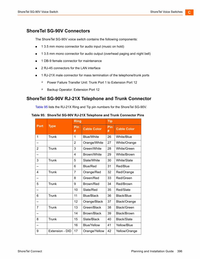
ShoreTel SG-90V Voice Switch ShoreTel Voice Switches C
ShoreTel SG-90V Connectors
The ShoreTel SG-90V voice switch contains the following components:
1 3.5 mm mono connector for audio input (music on hold)
1 3.5 mm mono connector for audio output (overhead paging and night bell)
1 DB-9 female connector for maintenance
2 RJ-45 connectors for the LAN interface
1 RJ-21X male connector for mass termination of the telephone/trunk ports
Power Failure Transfer Unit: Trunk Port 1 to Extension Port 12
Backup Operator: Extension Port 12
ShoreTel SG-90V RJ-21X Telephone and Trunk Connector
Table 95 lists the RJ-21X Ring and Tip pin numbers for the ShoreTel SG-90V.
Table 95: ShoreTel SG-90V RJ-21X Telephone and Trunk Connector Pins
Port Type
Ring Tip
Pin #
Cable ColorPin #
Cable Color
1 Trunk 1 Blue/White 26 White/Blue
– 2 Orange/White 27 White/Orange
2 Trunk 3 Green/White 28 White/Green
– 4 Brown/White 29 White/Brown
3 Trunk 5 Slate/White 30 White/Slate
– 6 Blue/Red 31 Red/Blue
4 Trunk 7 Orange/Red 32 Red/Orange
– 8 Green/Red 33 Red/Green
5 Trunk 9 Brown/Red 34 Red/Brown
– 10 Slate/Red 35 Red/Slate
6 Trunk 11 Blue/Black 36 Black/Blue
– 12 Orange/Black 37 Black/Orange
7 Trunk 13 Green/Black 38 Black/Green
– 14 Brown/Black 39 Black/Brown
8 Trunk 15 Slate/Black 40 Black/Slate
– 16 Blue/Yellow 41 Yellow/Blue
9 Extension - DID 17 Orange/Yellow 42 Yellow/Orange
ShoreTel Connect Planning and Installation Guide 396
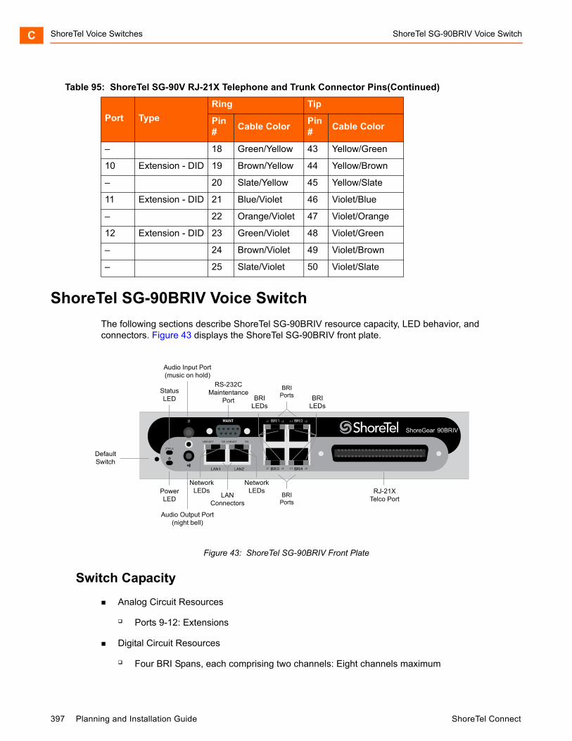
ShoreTel Voice Switches ShoreTel SG-90BRIV Voice SwitchC
ShoreTel SG-90BRIV Voice Switch
The following sections describe ShoreTel SG-90BRIV resource capacity, LED behavior, and connectors. Figure 43 displays the ShoreTel SG-90BRIV front plate.
Figure 43: ShoreTel SG-90BRIV Front Plate
Switch Capacity
Analog Circuit Resources
Ports 9-12: Extensions
Digital Circuit Resources
Four BRI Spans, each comprising two channels: Eight channels maximum
– 18 Green/Yellow 43 Yellow/Green
10 Extension - DID 19 Brown/Yellow 44 Yellow/Brown
– 20 Slate/Yellow 45 Yellow/Slate
11 Extension - DID 21 Blue/Violet 46 Violet/Blue
– 22 Orange/Violet 47 Violet/Orange
12 Extension - DID 23 Green/Violet 48 Violet/Green
– 24 Brown/Violet 49 Violet/Brown
– 25 Slate/Violet 50 Violet/Slate
Table 95: ShoreTel SG-90V RJ-21X Telephone and Trunk Connector Pins(Continued)
Port Type
Ring Tip
Pin #
Cable ColorPin #
Cable Color
DefaultSwitch
Audio Output Port(night bell)
PowerLED
NetworkLEDs
RS-232CMaintentance
Port
RJ-21XTelco Port
StatusLED
Audio Input Port(music on hold)
NetworkLEDs
LANConnectors
BRILEDs
BRILEDs
BRIPorts
BRIPorts
397 Planning and Installation Guide ShoreTel Connect
ShoreTel SG-90BRIV Voice Switch ShoreTel Voice Switches C
Make Me Conference Resource: None
Maximum IP Phone Resources: 90 devices
Analog Port Reallocation: 20
Digital Channel Reallocation: 40
Built-in Resources: 30
LED Descriptions
Power LED
The ShoreTel SG-90BRIV has one power LED, which indicates the following:
On: The switch is operating normally.
Off: The switch has no power.
Flashing
2 flashes — The switch failed its internal self-test. This indicates a hardware failure; replace the unit and submit a Return Material Authorization (RMA) to ShoreTel, Inc.
3 flashes—Booting via FTP. Flash memory might be corrupted. Use the pages available through the Maintenance menu in ShoreTel Connect Director to ensure that the system is running properly.
4 flashes — The IP address is unavailable. DHCP did not respond to the IP address request, and the IP address is not available in nonvolatile memory to continue boot process. The switch will automatically reboot in five seconds and try again. Check the DHCP server and the network configuration to ensure that the voice switch is receiving a valid IP address.
5 flashes — The operating system is not available. The switch is booting from FTP but cannot find the boot files. It automatically reboots in five seconds. You can use DHCP to tell the switch where the files are. If you are using a DHCP server that supports options 66 and 67, set option 66 to the ShoreTel server’s IP address, and set option 67 to /tsk/vxworks.
6 flashes — Using a previously stored IP address. A DHCP transaction was attempted, but the DHCP server did not respond. The switch continues to use the IP address stored in nonvolatile memory until it receives a valid response. If the switch receives a response that provides a different IP address, it reboots using the new IP address. If the switch receives a response that matches the IP address stored in nonvolatile memory, it continues operation, and the power LED stops flashing. If the problem persists, check the DHCP server and network configuration.
Network LEDs
The ShoreTel SG-90BRIV network LEDs (LAN1 and LAN2) indicate the speed at which the switch is communicating with the network and whether there is network activity.
ShoreTel Connect Planning and Installation Guide 398
ShoreTel Voice Switches ShoreTel SG-90BRIV Voice SwitchC
When both LAN connectors are connected into a redundant network configuration, one network port is active while the other is in standby mode. If one LAN connection fails, the switch activates the other port.
The network LED descriptions are as follows:
Link/Activity: When lit, this LED indicates that the switch is connected to an Ethernet network. This LED indicates network activity, as follows:
When flashing, network activity is detected.
When on (not flashing), the switch is connected to an Ethernet network.
When off, the switch cannot detect an Ethernet network.
This LED is not directly related to any switch’s individual network activity. For example, if three switches are connected to the same hub and one switch’s Traffic LED shows activity, the other switches will indicate the same activity.
100M
When green, the switch is connected to a 100BaseT network.
When off, the switch is connected to a 10BaseT network.
Status LED
The ShoreTel SG-90BRIV has one status LED to provide general information about the ports. The color and blink pattern of the LED indicate the port function:
Status LED (Green)
When on steady, no ports are handling active calls.
When flashing fast (100 msec on/off), at least one port is handling an active call.
Status LED (Yellow)
When on steady, no ports are handling active calls and at least one port is out of service.
When flashing slow (1 sec. on/off), the switch is not connected (or has lost connection) to a ShoreTel server.
When flashing fast (100 msec on/off), at least one port is handling an active call and at least one port is out of service.
Off: No ports are assigned.
BRI LED
Each BRI connector has two LEDs to indicate port activity. The color and blink pattern of the LED indicate the port function:
LED 1: Off, LED 2 Off – Port not configured in Director
399 Planning and Installation Guide ShoreTel Connect
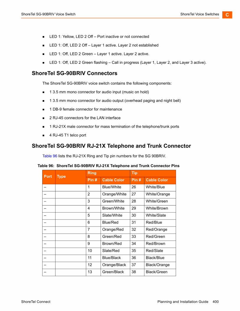
ShoreTel SG-90BRIV Voice Switch ShoreTel Voice Switches C
LED 1: Yellow, LED 2 Off – Port inactive or not connected
LED 1: Off, LED 2 Off – Layer 1 active. Layer 2 not established
LED 1: Off, LED 2 Green – Layer 1 active. Layer 2 active.
LED 1: Off, LED 2 Green flashing – Call in progress (Layer 1, Layer 2, and Layer 3 active).
ShoreTel SG-90BRIV Connectors
The ShoreTel SG-90BRIV voice switch contains the following components:
1 3.5 mm mono connector for audio input (music on hold)
1 3.5 mm mono connector for audio output (overhead paging and night bell)
1 DB-9 female connector for maintenance
2 RJ-45 connectors for the LAN interface
1 RJ-21X male connector for mass termination of the telephone/trunk ports
4 RJ-45 T1 telco port
ShoreTel SG-90BRIV RJ-21X Telephone and Trunk Connector
Table 96 lists the RJ-21X Ring and Tip pin numbers for the SG 90BRIV.
Table 96: ShoreTel SG-90BRIV RJ-21X Telephone and Trunk Connector Pins
Port TypeRing Tip
Pin # Cable Color Pin # Cable Color
– 1 Blue/White 26 White/Blue
– 2 Orange/White 27 White/Orange
– 3 Green/White 28 White/Green
– 4 Brown/White 29 White/Brown
– 5 Slate/White 30 White/Slate
– 6 Blue/Red 31 Red/Blue
– 7 Orange/Red 32 Red/Orange
– 8 Green/Red 33 Red/Green
– 9 Brown/Red 34 Red/Brown
– 10 Slate/Red 35 Red/Slate
– 11 Blue/Black 36 Black/Blue
– 12 Orange/Black 37 Black/Orange
– 13 Green/Black 38 Black/Green
ShoreTel Connect Planning and Installation Guide 400
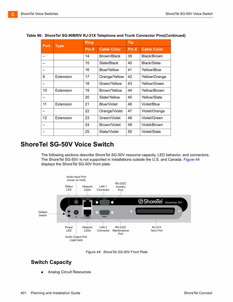
ShoreTel Voice Switches ShoreTel SG-50V Voice SwitchC
ShoreTel SG-50V Voice Switch
The following sections describe ShoreTel SG-50V resource capacity, LED behavior, and connectors. The ShoreTel SG-50V is not supported in installations outside the U.S. and Canada. Figure 44 displays the ShoreTel SG-50V front plate.
Figure 44: ShoreTel SG-50V Front Plate
Switch Capacity
Analog Circuit Resources
– 14 Brown/Black 39 Black/Brown
– 15 Slate/Black 40 Black/Slate
– 16 Blue/Yellow 41 Yellow/Blue
9 Extension 17 Orange/Yellow 42 Yellow/Orange
– 18 Green/Yellow 43 Yellow/Green
10 Extension 19 Brown/Yellow 44 Yellow/Brown
– 20 Slate/Yellow 45 Yellow/Slate
11 Extension 21 Blue/Violet 46 Violet/Blue
– 22 Orange/Violet 47 Violet/Orange
12 Extension 23 Green/Violet 48 Violet/Green
– 24 Brown/Violet 49 Violet/Brown
– 25 Slate/Violet 50 Violet/Slate
Table 96: ShoreTel SG-90BRIV RJ-21X Telephone and Trunk Connector Pins(Continued)
Port TypeRing Tip
Pin # Cable Color Pin # Cable Color
DefaultSwitch
Audio Output Port(night bell)
PowerLED
NetworkLEDs
LAN 2Connector
RS-232CMaintentance
Port
RJ-21XTelco Port
StatusLED
Audio Input Port(music on hold)
NetworkLEDs
LAN 1Connector
RS-232CAuxilary
Port
401 Planning and Installation Guide ShoreTel Connect

ShoreTel SG-50V Voice Switch ShoreTel Voice Switches C
Ports 1-4: Four Loop Start Trunks
Ports 11-12: Two Extensions or DID Trunks. A single command configures all ports as either Extensions or DID trunks.
Power Failure Transfer Unit: Trunk Port 1 to Extension Port 12
Make Me Conference Resources: six ports
Ports 1-4, 11-12
Maximum IP Phone Resources: 50 devices
Analog Port Reallocation: 30
Built-in Resources: 20
LED Descriptions
Power LED
The ShoreTel SG-50V has one power LED, which indicates the following:
On: The switch is operating normally.
Off: The switch has no power.
Flashing
2 flashes — The switch failed its internal self-test. This indicates a hardware failure; replace the unit and submit a Return Material Authorization (RMA) to ShoreTel, Inc.
3 flashes — Booting via FTP. Flash memory might be corrupted. Use the pages available through the Maintenance menu in ShoreTel Connect Director to ensure that the system is running properly.
4 flashes — The IP address is unavailable. DHCP did not respond to the IP address request, and the IP address is not available in nonvolatile memory to continue boot process. The switch will automatically reboot in five seconds and try again. Check the DHCP server and the network configuration to ensure that the voice switch is receiving a valid IP address.
5 flashes — The operating system is not available. The switch is booting from FTP but cannot find the boot files. It automatically reboots in five seconds. You can use DHCP to tell the switch where the files are. If you are using a DHCP server that supports options 66 and 67, set option 66 to the ShoreTel server’s IP address, and set option 67 to /tsk/vxworks.
6 flashes — Using a previously stored IP address. A DHCP transaction was attempted, but the DHCP server did not respond. The switch continues to use the IP address stored in nonvolatile memory until it receives a valid response. If the switch receives a response that provides a different IP address, it reboots using the new IP address. If the switch receives a response that matches the IP address stored in nonvolatile memory, it continues operation, and the power LED stops flashing. If the problem persists, check the DHCP server and network configuration.
ShoreTel Connect Planning and Installation Guide 402
ShoreTel Voice Switches ShoreTel SG-50V Voice SwitchC
Network LEDs
The ShoreTel SG-50V network LEDs (LAN1 and LAN2) indicate the speed at which the switch is communicating with the network and whether there is network activity.
When both LAN connectors are connected into a redundant network configuration, one network port is active while the other is in standby mode. If one LAN connection fails, the switch activates the other port.
The network LED descriptions are as follows:
Link/Activity: When lit, this LED indicates that the switch is connected to an Ethernet network. This LED indicates network activity, as follows:
When flashing, network activity is detected.
When on (not flashing), the switch is connected to an Ethernet network.
When off, the switch cannot detect an Ethernet network.
This LED is not directly related to any switch’s individual network activity. For example, if three switches are connected to the same hub and one switch’s Traffic LED shows activity, the other switches will indicate the same activity.
100M
When green, the switch is connected to a 100BaseT network.
When off, the switch is connected to a 10BaseT network.
Status LED
The ShoreTel SG-50V has one status LED to provide general information about the ports. The color and blink pattern of the LED indicate the port function:
Status LED (Green)
When on steady, no ports are handling active calls.
When flashing fast, at least one port is handling an active call.
Status LED (Yellow)
When on steady, no ports are handling active calls and at least one port is out of service.
When flashing slow, the switch is not connected (or has lost connection) to a ShoreTel server.
When flashing fast, at least one port is handling an active call and at least one port is out of service.
Off: No ports are assigned.
403 Planning and Installation Guide ShoreTel Connect
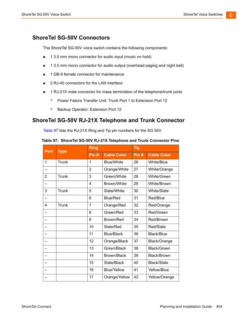
ShoreTel SG-50V Voice Switch ShoreTel Voice Switches C
ShoreTel SG-50V Connectors
The ShoreTel SG-50V voice switch contains the following components:
1 3.5 mm mono connector for audio input (music on hold)
1 3.5 mm mono connector for audio output (overhead paging and night bell)
1 DB-9 female connector for maintenance
2 RJ-45 connectors for the LAN interface
1 RJ-21X male connector for mass termination of the telephone/trunk ports
Power Failure Transfer Unit: Trunk Port 1 to Extension Port 12
Backup Operator: Extension Port 12
ShoreTel SG-50V RJ-21X Telephone and Trunk Connector
Table 97 lists the RJ-21X Ring and Tip pin numbers for the SG 50V.
Table 97: ShoreTel SG-50V RJ-21X Telephone and Trunk Connector Pins
Port TypeRing Tip
Pin # Cable Color Pin # Cable Color
1 Trunk 1 Blue/White 26 White/Blue
– 2 Orange/White 27 White/Orange
2 Trunk 3 Green/White 28 White/Green
– 4 Brown/White 29 White/Brown
3 Trunk 5 Slate/White 30 White/Slate
– 6 Blue/Red 31 Red/Blue
4 Trunk 7 Orange/Red 32 Red/Orange
– 8 Green/Red 33 Red/Green
– 9 Brown/Red 34 Red/Brown
– 10 Slate/Red 35 Red/Slate
– 11 Blue/Black 36 Black/Blue
– 12 Orange/Black 37 Black/Orange
– 13 Green/Black 38 Black/Green
– 14 Brown/Black 39 Black/Brown
– 15 Slate/Black 40 Black/Slate
– 16 Blue/Yellow 41 Yellow/Blue
– 17 Orange/Yellow 42 Yellow/Orange
ShoreTel Connect Planning and Installation Guide 404

ShoreTel Voice Switches Specification – ST 1U Full Width SwitchesC
Specification – ST 1U Full Width Switches
ShoreTel Voice Switch ST24A/ST48A
The following sections describe ST24A/ST48A resource capacity, LED behavior, and connectors. The ST24A/ST48A is not supported in installations outside the U.S. and Canada. Figure 47 and Figure 46 display the ST24A/ST48A front plates.
Figure 45: ShoreTel Voice Switch ST24A Front Plate
– 18 Green/Yellow 43 Yellow/Green
– 19 Brown/Yellow 44 Yellow/Brown
– 20 Slate/Yellow 45 Yellow/Slate
11 Extension - DID 21 Blue/Violet 46 Violet/Blue
– 22 Orange/Violet 47 Violet/Orange
12 Extension - DID 23 Green/Violet 48 Violet/Green
– 24 Brown/Violet 49 Violet/Brown
– 25 Slate/Violet 50 Violet/Slate
Table 97: ShoreTel SG-50V RJ-21X Telephone and Trunk Connector Pins(Continued)
Port TypeRing Tip
Pin # Cable Color Pin # Cable Color
PowerLED
USB 2.0port
Audioinputport
10/100/1000Mbps Ethernet
portsLAN1
and LEDsRS-232C
maintenanceport
StatusLED
Audiooutput
portRJ-21X
portExtensions 1 - 24
LAN2and LEDs
Default Switch
405 Planning and Installation Guide ShoreTel Connect
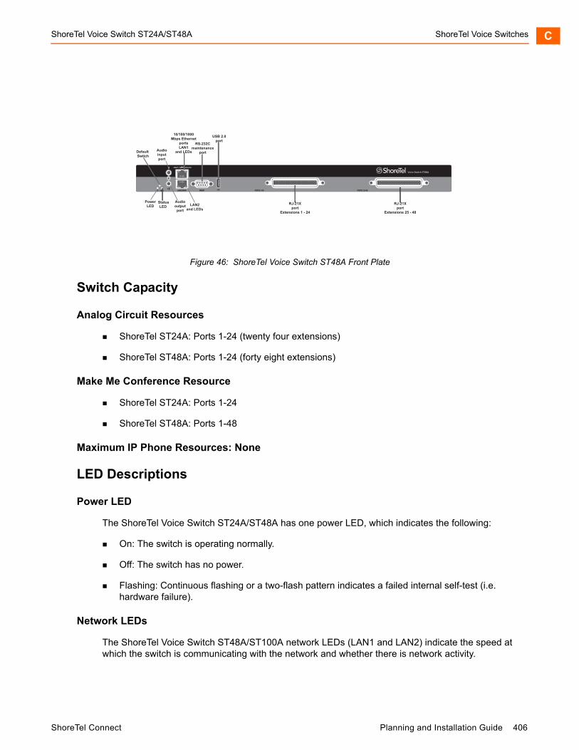
ShoreTel Voice Switch ST24A/ST48A ShoreTel Voice Switches C
Figure 46: ShoreTel Voice Switch ST48A Front Plate
Switch Capacity
Analog Circuit Resources
ShoreTel ST24A: Ports 1-24 (twenty four extensions)
ShoreTel ST48A: Ports 1-24 (forty eight extensions)
Make Me Conference Resource
ShoreTel ST24A: Ports 1-24
ShoreTel ST48A: Ports 1-48
Maximum IP Phone Resources: None
LED Descriptions
Power LED
The ShoreTel Voice Switch ST24A/ST48A has one power LED, which indicates the following:
On: The switch is operating normally.
Off: The switch has no power.
Flashing: Continuous flashing or a two-flash pattern indicates a failed internal self-test (i.e. hardware failure).
Network LEDs
The ShoreTel Voice Switch ST48A/ST100A network LEDs (LAN1 and LAN2) indicate the speed at which the switch is communicating with the network and whether there is network activity.
PowerLED
USB 2.0port
Audioinputport
10/100/1000Mbps Ethernet
portsLAN1
and LEDs
RS-232Cmaintenance
port
StatusLED
Audiooutput
port
RJ-21Xport
Extensions 1 - 24
RJ-21Xport
Extensions 25 - 48
LAN2and LEDs
Default Switch
ShoreTel Connect Planning and Installation Guide 406
ShoreTel Voice Switches ShoreTel Voice Switch ST24A/ST48AC
When both LAN connectors are connected into a redundant network configuration, one network port is active while the other is in standby mode. If one LAN connection fails, the switch activates the other port.
The network LED descriptions are as follows:
Link/Activity: When lit, this LED indicates that the switch is connected to an Ethernet network. This LED indicates network activity, as follows:
When flashing, network activity is detected.
When on (not flashing), the switch is connected to an Ethernet network.
When off, the switch cannot detect an Ethernet network.
This LED is not directly related to any switch’s individual network activity. For example, if three switches are connected to the same hub and one switch’s Traffic LED shows activity, the other switches will indicate the same activity.
10/100/1000 Mbps
When off, the switch is connected to a 10BaseT network.
When green, the switch is connected to a 100BaseT network.
When yellow, the switch is connected to a 1000BaseT network
Status LED
The ShoreTel Voice Switch ST24A/ST48A has one status LED to provide general information about the ports. The color and blink pattern of the LED indicate the port function:
Off — No ports are assigned
Green Steady— No ports are handling active calls
Green Flashing Fast — At least one port is handling an active call.
Yellow Steady — No ports are handling active calls and at least one port is out of service.
Yellow Flashing Slow — The switch is not connected (or has lost connection) to a ShoreTel server.
Yellow Flashing Fast — At least one port is handling an active call and at least one port is out of service.
ShoreTel Voice Switch ST24A/ST48A Connectors
The ShoreTel Voice Switch ST24A/ST48A voice switch contains the following components:
One audio input port (3.5 mm stereo) for connecting to a music-on-hold source
One audio output port (3.5 mm stereo) for connecting to a corporate paging system or night bell.
Two RJ-45 10/100/1000 Mbps LAN connectors
407 Planning and Installation Guide ShoreTel Connect
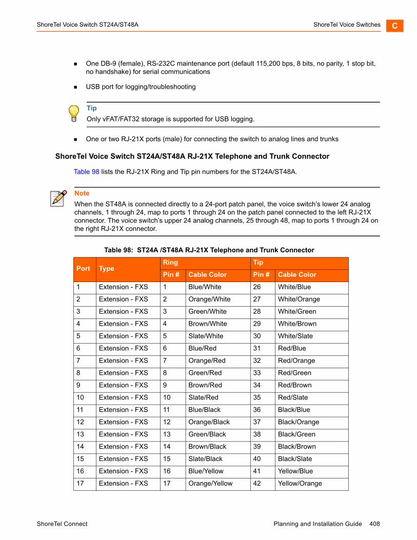
ShoreTel Voice Switch ST24A/ST48A ShoreTel Voice Switches C
One DB-9 (female), RS-232C maintenance port (default 115,200 bps, 8 bits, no parity, 1 stop bit, no handshake) for serial communications
USB port for logging/troubleshooting
One or two RJ-21X ports (male) for connecting the switch to analog lines and trunks
ShoreTel Voice Switch ST24A/ST48A RJ-21X Telephone and Trunk Connector
Table 98 lists the RJ-21X Ring and Tip pin numbers for the ST24A/ST48A.
Tip
Only vFAT/FAT32 storage is supported for USB logging.
Note
When the ST48A is connected directly to a 24-port patch panel, the voice switch’s lower 24 analog channels, 1 through 24, map to ports 1 through 24 on the patch panel connected to the left RJ-21X connector. The voice switch’s upper 24 analog channels, 25 through 48, map to ports 1 through 24 on the right RJ-21X connector.
Table 98: ST24A /ST48A RJ-21X Telephone and Trunk Connector
Port TypeRing Tip
Pin # Cable Color Pin # Cable Color
1 Extension - FXS 1 Blue/White 26 White/Blue
2 Extension - FXS 2 Orange/White 27 White/Orange
3 Extension - FXS 3 Green/White 28 White/Green
4 Extension - FXS 4 Brown/White 29 White/Brown
5 Extension - FXS 5 Slate/White 30 White/Slate
6 Extension - FXS 6 Blue/Red 31 Red/Blue
7 Extension - FXS 7 Orange/Red 32 Red/Orange
8 Extension - FXS 8 Green/Red 33 Red/Green
9 Extension - FXS 9 Brown/Red 34 Red/Brown
10 Extension - FXS 10 Slate/Red 35 Red/Slate
11 Extension - FXS 11 Blue/Black 36 Black/Blue
12 Extension - FXS 12 Orange/Black 37 Black/Orange
13 Extension - FXS 13 Green/Black 38 Black/Green
14 Extension - FXS 14 Brown/Black 39 Black/Brown
15 Extension - FXS 15 Slate/Black 40 Black/Slate
16 Extension - FXS 16 Blue/Yellow 41 Yellow/Blue
17 Extension - FXS 17 Orange/Yellow 42 Yellow/Orange
ShoreTel Connect Planning and Installation Guide 408
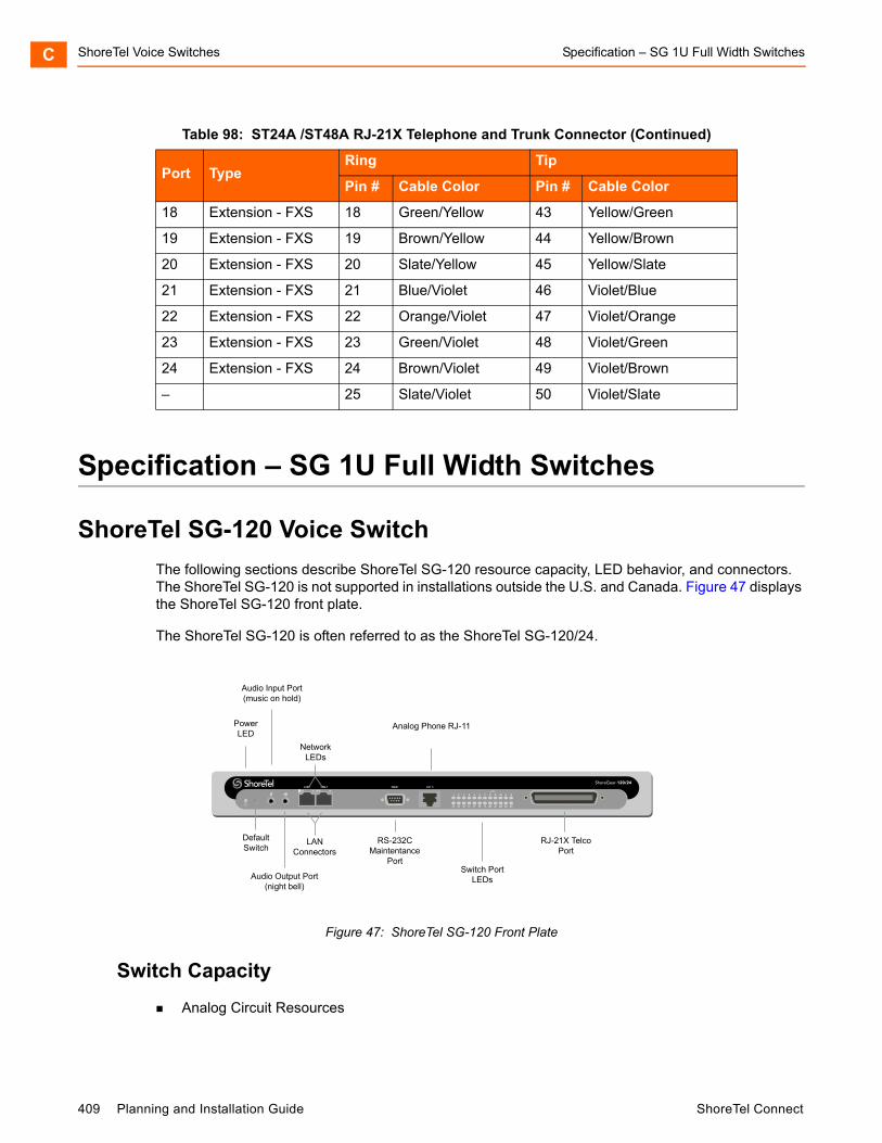
ShoreTel Voice Switches Specification – SG 1U Full Width SwitchesC
Specification – SG 1U Full Width Switches
ShoreTel SG-120 Voice Switch
The following sections describe ShoreTel SG-120 resource capacity, LED behavior, and connectors. The ShoreTel SG-120 is not supported in installations outside the U.S. and Canada. Figure 47 displays the ShoreTel SG-120 front plate.
The ShoreTel SG-120 is often referred to as the ShoreTel SG-120/24.
Figure 47: ShoreTel SG-120 Front Plate
Switch Capacity
Analog Circuit Resources
18 Extension - FXS 18 Green/Yellow 43 Yellow/Green
19 Extension - FXS 19 Brown/Yellow 44 Yellow/Brown
20 Extension - FXS 20 Slate/Yellow 45 Yellow/Slate
21 Extension - FXS 21 Blue/Violet 46 Violet/Blue
22 Extension - FXS 22 Orange/Violet 47 Violet/Orange
23 Extension - FXS 23 Green/Violet 48 Violet/Green
24 Extension - FXS 24 Brown/Violet 49 Violet/Brown
– 25 Slate/Violet 50 Violet/Slate
Table 98: ST24A /ST48A RJ-21X Telephone and Trunk Connector (Continued)
Port TypeRing Tip
Pin # Cable Color Pin # Cable Color
ShoreGear-120/24
DefaultSwitch
Audio Output Port(night bell)
PowerLED
RS-232CMaintentance
Port
RJ-21X TelcoPort
Audio Input Port(music on hold)
NetworkLEDs
LANConnectors
Analog Phone RJ-11
Switch PortLEDs
409 Planning and Installation Guide ShoreTel Connect
ShoreTel SG-120 Voice Switch ShoreTel Voice Switches C
Ports 1-8: Eight Loop Start Trunks, DID Trunks, or Extensions
Ports 9-24: Sixteen Extensions.
Power Failure Transfer Unit: Trunk Port 8 to Extension Port 9
Make Me Conference Resource: 24 Ports
Ports 1-24
Maximum IP Phone Resources: 120 devices
Analog Port Reallocation: 120
LED Descriptions
Power LED
The ShoreTel SG-120 has one power LED, which indicates the following:
On: The switch is operating normally.
Off: The switch has no power.
Flashing
2 flashes — The switch failed its internal self-test. This indicates a hardware failure; replace the unit and submit a Return Material Authorization (RMA) to ShoreTel, Inc.
3 flashes — Booting via FTP. Flash memory might be corrupted. Use the pages available through the Maintenance menu in ShoreTel Connect Director to ensure that the system is running properly.
4 flashes — The IP address is unavailable. DHCP did not respond to the IP address request, and the IP address is not available in nonvolatile memory to continue boot process. The switch will automatically reboot in five seconds and try again. Check the DHCP server and the network configuration to ensure that the voice switch is receiving a valid IP address.
5 flashes — The operating system is not available. The switch is booting from FTP but cannot find the boot files. It automatically reboots in five seconds. You can use DHCP to tell the switch where the files are. If you are using a DHCP server that supports options 66 and 67, set option 66 to the ShoreTel server’s IP address, and set option 67 to /tsa/vxworks.
6 flashes — Using a previously stored IP address. A DHCP transaction was attempted, but the DHCP server did not respond. The switch continues to use the IP address stored in nonvolatile memory until it receives a valid response. If the switch receives a response that provides a different IP address, it reboots using the new IP address. If the switch receives a response that matches the IP address stored in nonvolatile memory, it continues operation, and the power LED stops flashing. If the problem persists, check the DHCP server and network configuration.
ShoreTel Connect Planning and Installation Guide 410
ShoreTel Voice Switches ShoreTel SG-120 Voice SwitchC
Switch Port LEDs
The ShoreTel SG-120 has 24 telephone/trunk port LEDs. The color of the LED indicates the port function:
Green when the port is a telephone port.
Yellow when the port is a trunk port.
Off indicates the port is reserved for IP phones, for conferencing, or is not configured.
The following describes the switch port LED behavior and meaning:
Telephone Port LEDs (Green)
When on steady, the port is configured as a telephone port and the telephone is idle.
When flashing with ring cadence, the telephone is ringing.
When flashing slowly, the telephone is off hook.
When flashing fast, the port is in use (call in progress).
Trunk Port LED (Yellow)
When on steady, the port is configured as a trunk port and the trunk is idle.
When flashing slowly, the trunk is off hook.
When flashing fast, the trunk is in use (call in progress).
Port LED Alternating Green/Yellow: The port is out of service. The LED periodically alternates green/yellow or yellow/green. The color of the LED between alternating colors indicates the port type: green for phone and yellow for trunk.
Off (IP phone): When the LED is off, the port is reserved for IP phones, for conferencing, or is not configured.
Network LEDs
The network LEDs (LAN1 and LAN2) indicate the speed at which the switch is communicating with the network and whether there is network activity.
When both LAN connectors are connected into a redundant network configuration, one network port is active while the other is in standby mode. If one LAN connection fails, the switch activates the other port.
The network LED descriptions are as follows:
Link/Activity: When lit, this LED indicates that the switch is connected to an Ethernet network. This LED indicates network activity, as follows:
When flashing, network activity is detected.
When on (not flashing), heavy network activity is detected.
411 Planning and Installation Guide ShoreTel Connect

ShoreTel SG-120 Voice Switch ShoreTel Voice Switches C
When off, the switch has no power.
This LED is not directly related to any switch’s individual network activity. For example, if three switches are connected to the same hub and one switch’s Traffic LED shows activity, the other switches will indicate the same activity.
100M
When green, the switch is connected to a 100BaseT network.
When off, the switch is connected to a 10BaseT network.
ShoreTel SG-120 Connectors
The ShoreTel SG-120 voice switch contains the following components:
1 3.5 mm mono connector for audio input (music on hold)
1 3.5 mm mono connector for audio output (overhead paging and night bell)
1 DB-9 female connector for maintenance
2 RJ-45 connectors for the LAN interface
1 RJ-11 connector for connecting an analog phone (extension 9)
1 RJ-21X male connector for mass termination of the telephone/trunk ports
Power Failure Transfer Unit: Trunk Port 8 to Extension Port 9
Backup Operator: Extension Port 9
ShoreTel SG-120 RJ-21X Telephone and Trunk Connector
Table 99 lists the RJ-21X Ring and Tip pin numbers for the SG 120I.
Table 99: ShoreTel SG-120 RJ-21X Telephone and Trunk Connector Pins
Port TypeRing Tip
Pin # Cable Color Pin # Cable Color
1 Trunk, DID, Extension 1 Blue/White 26 White/Blue
2 Trunk, DID, Extension 2 Orange/White 27 White/Orange
3 Trunk, DID, Extension 3 Green/White 28 White/Green
4 Trunk, DID, Extension 4 Brown/White 29 White/Brown
5 Trunk, DID, Extension 5 Slate/White 30 White/Slate
6 Trunk, DID, Extension 6 Blue/Red 31 Red/Blue
7 Trunk, DID, Extension 7 Orange/Red 32 Red/Orange
8 Trunk, DID, Extension 8 Green/Red 33 Red/Green
ShoreTel Connect Planning and Installation Guide 412
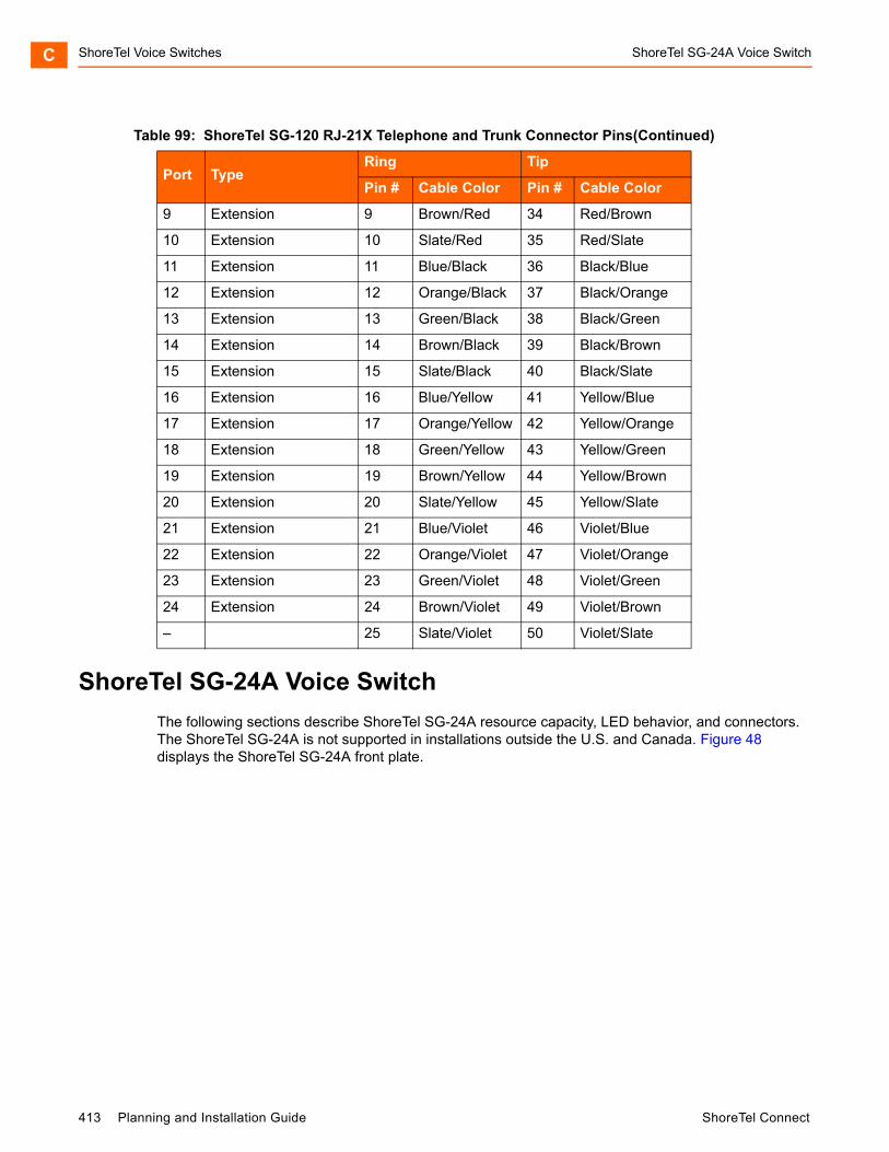
ShoreTel Voice Switches ShoreTel SG-24A Voice SwitchC
ShoreTel SG-24A Voice Switch
The following sections describe ShoreTel SG-24A resource capacity, LED behavior, and connectors. The ShoreTel SG-24A is not supported in installations outside the U.S. and Canada. Figure 48 displays the ShoreTel SG-24A front plate.
9 Extension 9 Brown/Red 34 Red/Brown
10 Extension 10 Slate/Red 35 Red/Slate
11 Extension 11 Blue/Black 36 Black/Blue
12 Extension 12 Orange/Black 37 Black/Orange
13 Extension 13 Green/Black 38 Black/Green
14 Extension 14 Brown/Black 39 Black/Brown
15 Extension 15 Slate/Black 40 Black/Slate
16 Extension 16 Blue/Yellow 41 Yellow/Blue
17 Extension 17 Orange/Yellow 42 Yellow/Orange
18 Extension 18 Green/Yellow 43 Yellow/Green
19 Extension 19 Brown/Yellow 44 Yellow/Brown
20 Extension 20 Slate/Yellow 45 Yellow/Slate
21 Extension 21 Blue/Violet 46 Violet/Blue
22 Extension 22 Orange/Violet 47 Violet/Orange
23 Extension 23 Green/Violet 48 Violet/Green
24 Extension 24 Brown/Violet 49 Violet/Brown
– 25 Slate/Violet 50 Violet/Slate
Table 99: ShoreTel SG-120 RJ-21X Telephone and Trunk Connector Pins(Continued)
Port TypeRing Tip
Pin # Cable Color Pin # Cable Color
413 Planning and Installation Guide ShoreTel Connect
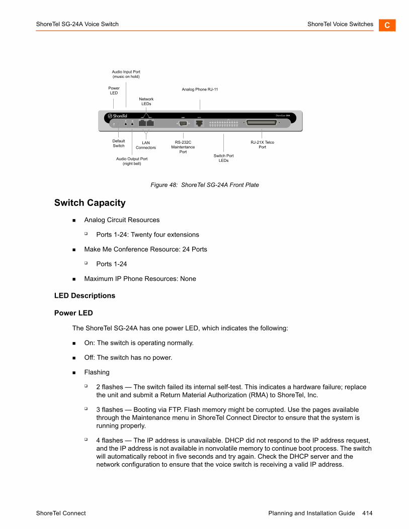
ShoreTel SG-24A Voice Switch ShoreTel Voice Switches C
Figure 48: ShoreTel SG-24A Front Plate
Switch Capacity
Analog Circuit Resources
Ports 1-24: Twenty four extensions
Make Me Conference Resource: 24 Ports
Ports 1-24
Maximum IP Phone Resources: None
LED Descriptions
Power LED
The ShoreTel SG-24A has one power LED, which indicates the following:
On: The switch is operating normally.
Off: The switch has no power.
Flashing
2 flashes — The switch failed its internal self-test. This indicates a hardware failure; replace the unit and submit a Return Material Authorization (RMA) to ShoreTel, Inc.
3 flashes — Booting via FTP. Flash memory might be corrupted. Use the pages available through the Maintenance menu in ShoreTel Connect Director to ensure that the system is running properly.
4 flashes — The IP address is unavailable. DHCP did not respond to the IP address request, and the IP address is not available in nonvolatile memory to continue boot process. The switch will automatically reboot in five seconds and try again. Check the DHCP server and the network configuration to ensure that the voice switch is receiving a valid IP address.
ShoreGear-24A
DefaultSwitch
Audio Output Port(night bell)
PowerLED
RS-232CMaintentance
Port
RJ-21X TelcoPort
Audio Input Port(music on hold)
NetworkLEDs
LANConnectors
Analog Phone RJ-11
Switch PortLEDs
ShoreTel Connect Planning and Installation Guide 414
ShoreTel Voice Switches ShoreTel SG-24A Voice SwitchC
5 flashes — The operating system is not available. The switch is booting from FTP but cannot find the boot files. It automatically reboots in five seconds. You can use DHCP to tell the switch where the files are. If you are using a DHCP server that supports options 66 and 67, set option 66 to the ShoreTel server’s IP address, and set option 67 to /tsa/vxworks.
6 flashes — Using a previously stored IP address. A DHCP transaction was attempted, but the DHCP server did not respond. The switch continues to use the IP address stored in nonvolatile memory until it receives a valid response. If the switch receives a response that provides a different IP address, it reboots using the new IP address. If the switch receives a response that matches the IP address stored in nonvolatile memory, it continues operation, and the power LED stops flashing. If the problem persists, check the DHCP server and network configuration.
Switch Port LEDs
The ShoreTel SG-24A has 24 telephone/trunk port LEDs. The color of the LED indicates the port function:
Green when the port is a telephone port.
Yellow when the port is a trunk port.
Off indicates the port is reserved for IP phones, for conferencing, or is not configured.
The following describes the switch port LED behavior and meaning:
Telephone Port LEDs (Green)
When on steady, the port is configured as a telephone port and the telephone is idle.
When flashing with ring cadence, the telephone is ringing.
When flashing slowly, the telephone is off hook.
When flashing fast, the port is in use (call in progress).
Trunk Port LED (Yellow):
When on steady, the port is configured as a trunk port and the trunk is idle.
When flashing slowly, the trunk is off hook.
When flashing fast, the trunk is in use (call in progress).
Port LED Alternating Green/Yellow: The port is out of service. The LED periodically alternates green/yellow or yellow/green. The color of the LED between alternating colors indicates the port type: green for phone and yellow for trunk.
Off (IP phone): When the LED is off, the port is reserved for IP phones, for conferencing, or is not configured.
Network LEDs
The network LEDs (LAN1 and LAN2) indicate the speed at which the switch is communicating with the network and whether there is network activity.
415 Planning and Installation Guide ShoreTel Connect
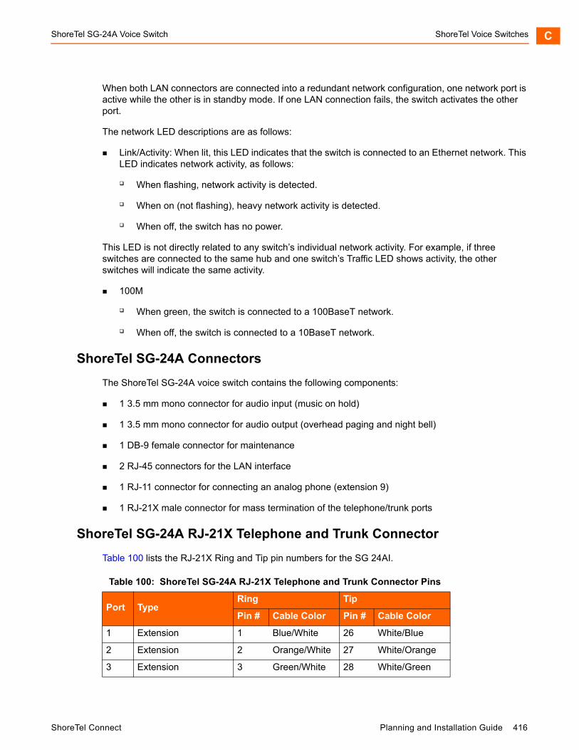
ShoreTel SG-24A Voice Switch ShoreTel Voice Switches C
When both LAN connectors are connected into a redundant network configuration, one network port is active while the other is in standby mode. If one LAN connection fails, the switch activates the other port.
The network LED descriptions are as follows:
Link/Activity: When lit, this LED indicates that the switch is connected to an Ethernet network. This LED indicates network activity, as follows:
When flashing, network activity is detected.
When on (not flashing), heavy network activity is detected.
When off, the switch has no power.
This LED is not directly related to any switch’s individual network activity. For example, if three switches are connected to the same hub and one switch’s Traffic LED shows activity, the other switches will indicate the same activity.
100M
When green, the switch is connected to a 100BaseT network.
When off, the switch is connected to a 10BaseT network.
ShoreTel SG-24A Connectors
The ShoreTel SG-24A voice switch contains the following components:
1 3.5 mm mono connector for audio input (music on hold)
1 3.5 mm mono connector for audio output (overhead paging and night bell)
1 DB-9 female connector for maintenance
2 RJ-45 connectors for the LAN interface
1 RJ-11 connector for connecting an analog phone (extension 9)
1 RJ-21X male connector for mass termination of the telephone/trunk ports
ShoreTel SG-24A RJ-21X Telephone and Trunk Connector
Table 100 lists the RJ-21X Ring and Tip pin numbers for the SG 24AI.
Table 100: ShoreTel SG-24A RJ-21X Telephone and Trunk Connector Pins
Port TypeRing Tip
Pin # Cable Color Pin # Cable Color
1 Extension 1 Blue/White 26 White/Blue
2 Extension 2 Orange/White 27 White/Orange
3 Extension 3 Green/White 28 White/Green
ShoreTel Connect Planning and Installation Guide 416
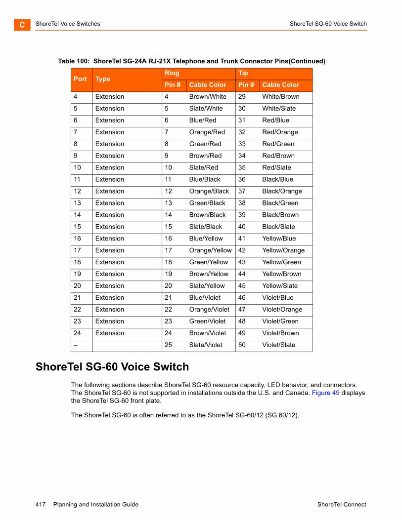
ShoreTel Voice Switches ShoreTel SG-60 Voice SwitchC
ShoreTel SG-60 Voice Switch
The following sections describe ShoreTel SG-60 resource capacity, LED behavior, and connectors. The ShoreTel SG-60 is not supported in installations outside the U.S. and Canada. Figure 49 displays the ShoreTel SG-60 front plate.
The ShoreTel SG-60 is often referred to as the ShoreTel SG-60/12 (SG 60/12).
4 Extension 4 Brown/White 29 White/Brown
5 Extension 5 Slate/White 30 White/Slate
6 Extension 6 Blue/Red 31 Red/Blue
7 Extension 7 Orange/Red 32 Red/Orange
8 Extension 8 Green/Red 33 Red/Green
9 Extension 9 Brown/Red 34 Red/Brown
10 Extension 10 Slate/Red 35 Red/Slate
11 Extension 11 Blue/Black 36 Black/Blue
12 Extension 12 Orange/Black 37 Black/Orange
13 Extension 13 Green/Black 38 Black/Green
14 Extension 14 Brown/Black 39 Black/Brown
15 Extension 15 Slate/Black 40 Black/Slate
16 Extension 16 Blue/Yellow 41 Yellow/Blue
17 Extension 17 Orange/Yellow 42 Yellow/Orange
18 Extension 18 Green/Yellow 43 Yellow/Green
19 Extension 19 Brown/Yellow 44 Yellow/Brown
20 Extension 20 Slate/Yellow 45 Yellow/Slate
21 Extension 21 Blue/Violet 46 Violet/Blue
22 Extension 22 Orange/Violet 47 Violet/Orange
23 Extension 23 Green/Violet 48 Violet/Green
24 Extension 24 Brown/Violet 49 Violet/Brown
– 25 Slate/Violet 50 Violet/Slate
Table 100: ShoreTel SG-24A RJ-21X Telephone and Trunk Connector Pins(Continued)
Port TypeRing Tip
Pin # Cable Color Pin # Cable Color
417 Planning and Installation Guide ShoreTel Connect

ShoreTel SG-60 Voice Switch ShoreTel Voice Switches C
Figure 49: ShoreTel SG-60 Front Plat
Switch Capacity
Analog Circuit Resources
Ports 1-8: Eight Loop Start Trunks, DID Trunks, or Extensions
Ports 9-12: Four Extensions.
Backup Operator: Extension Port 9
Power Failure Transfer Unit: Trunk Port 8 to Extension Port 9
Make Me Conference Resource: 12 ports
Ports 1-12
Maximum IP Phone Resources: 60 devices
Analog Port Reallocation: 60
LED Descriptions
Power LED
The ShoreTel SG-60 has one power LED, which indicates the following:
On: The switch is operating normally.
Off: The switch has no power.
Flashing
2 flashes — The switch failed its internal self-test. This indicates a hardware failure; replace the unit and submit a Return Material Authorization (RMA) to ShoreTel, Inc.
ShoreGear-60/12
DefaultSwitch
Audio Output Port(night bell)
PowerLED
RS-232CMaintentance
Port
RJ-21X TelcoPort
Audio Input Port(music on hold)
NetworkLEDs
LANConnectors
Analog Phone RJ-11
Switch PortLEDs
ShoreTel Connect Planning and Installation Guide 418
ShoreTel Voice Switches ShoreTel SG-60 Voice SwitchC
3 flashes — Booting via FTP. Flash memory might be corrupted. Use the pages available through the Maintenance menu in ShoreTel Connect Director to ensure that the system is running properly.
4 flashes — The IP address is unavailable. DHCP did not respond to the IP address request, and the IP address is not available in nonvolatile memory to continue boot process. The switch will automatically reboot in five seconds and try again. Check the DHCP server and the network configuration to ensure that the voice switch is receiving a valid IP address.
5 flashes — The operating system is not available. The switch is booting from FTP but cannot find the boot files. It automatically reboots in five seconds. You can use DHCP to tell the switch where the files are. If you are using a DHCP server that supports options 66 and 67, set option 66 to the ShoreTel server’s IP address, and set option 67 to /tsa/vxworks.
6 flashes — Using a previously stored IP address. A DHCP transaction was attempted, but the DHCP server did not respond. The switch continues to use the IP address stored in nonvolatile memory until it receives a valid response. If the switch receives a response that provides a different IP address, it reboots using the new IP address. If the switch receives a response that matches the IP address stored in nonvolatile memory, it continues operation, and the power LED stops flashing. If the problem persists, check the DHCP server and network configuration.
Switch Port LEDs
The ShoreTel SG-60 has 12 telephone/trunk port LEDs. The color of the LED indicates the port function:
Green when the port is a telephone port.
Yellow when the port is a trunk port.
Off indicates the port is reserved for IP phones, for conferencing, or is not configured.
The following describes the switch port LED behavior and meaning:
Telephone Port LEDs (Green)
When on steady, the port is configured as a telephone port and the telephone is idle.
When flashing with ring cadence, the telephone is ringing.
When flashing slowly, the telephone is off hook.
When flashing fast, the port is in use (call in progress).
Trunk Port LED (Yellow)
When on steady, the port is configured as a trunk port and the trunk is idle.
When flashing slowly, the trunk is off hook.
When flashing fast, the trunk is in use (call in progress).
419 Planning and Installation Guide ShoreTel Connect
ShoreTel SG-60 Voice Switch ShoreTel Voice Switches C
Port LED Alternating Green/Yellow: The port is out of service. The LED periodically alternates green/yellow or yellow/green. The LED color between alternating colors indicates the port type: green for phone and yellow for trunk.
Off (IP phone): When the LED is off, the port is reserved for IP phones, for conferencing, or is not configured.
Network LEDs
The network LEDs (LAN1 and LAN2) indicate the speed at which the switch is communicating with the network and whether there is network activity.
When both LAN connectors are connected into a redundant network configuration, one network port is active while the other is in standby mode. If one LAN connection fails, the switch activates the other port.
The network LED descriptions are as follows:
Link/Activity: When lit, this LED indicates that the switch is connected to an Ethernet network. This LED indicates network activity, as follows:
When flashing, network activity is detected.
When on (not flashing), heavy network activity is detected.
When off, the switch has no power.
This LED is not directly related to any switch’s individual network activity. For example, if three switches are connected to the same hub and one switch’s Traffic LED shows activity, the other switches will indicate the same activity.
100M
When green, the switch is connected to a 100BaseT network.
When off, the switch is connected to a 10BaseT network.
ShoreTel SG-60 Connectors
ShoreTel SG-60 voice switch contains the following components:
1 3.5 mm mono connector for audio input (music on hold)
1 3.5 mm mono connector for audio output (overhead paging and night bell)
1 DB-9 female connector for maintenance
2 RJ-45 connectors for the LAN interface
1 RJ-11 connector for connecting an analog phone (extension 9)
1 RJ-21X male connector for mass termination of the telephone/trunk ports
Power Failure Transfer Unit: Trunk Port 8 to Extension Port 9
ShoreTel Connect Planning and Installation Guide 420
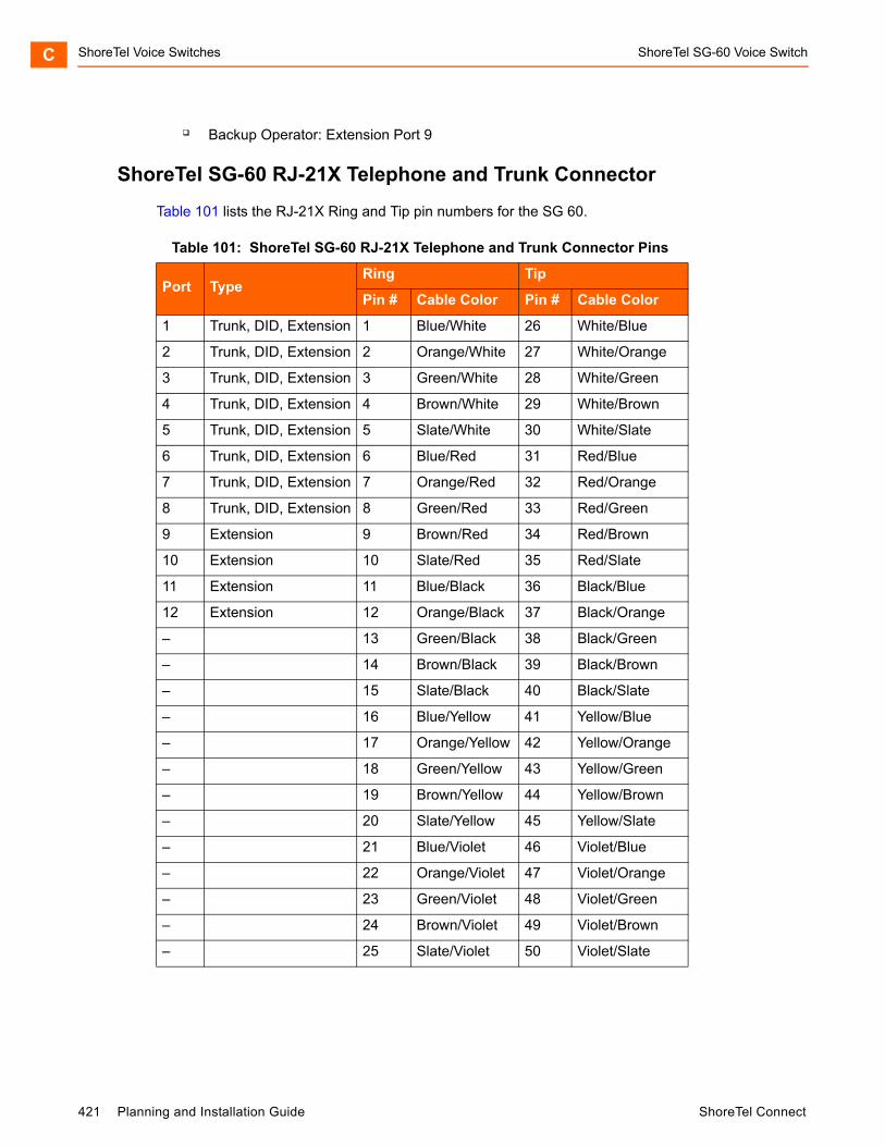
ShoreTel Voice Switches ShoreTel SG-60 Voice SwitchC
Backup Operator: Extension Port 9
ShoreTel SG-60 RJ-21X Telephone and Trunk Connector
Table 101 lists the RJ-21X Ring and Tip pin numbers for the SG 60.
Table 101: ShoreTel SG-60 RJ-21X Telephone and Trunk Connector Pins
Port TypeRing Tip
Pin # Cable Color Pin # Cable Color
1 Trunk, DID, Extension 1 Blue/White 26 White/Blue
2 Trunk, DID, Extension 2 Orange/White 27 White/Orange
3 Trunk, DID, Extension 3 Green/White 28 White/Green
4 Trunk, DID, Extension 4 Brown/White 29 White/Brown
5 Trunk, DID, Extension 5 Slate/White 30 White/Slate
6 Trunk, DID, Extension 6 Blue/Red 31 Red/Blue
7 Trunk, DID, Extension 7 Orange/Red 32 Red/Orange
8 Trunk, DID, Extension 8 Green/Red 33 Red/Green
9 Extension 9 Brown/Red 34 Red/Brown
10 Extension 10 Slate/Red 35 Red/Slate
11 Extension 11 Blue/Black 36 Black/Blue
12 Extension 12 Orange/Black 37 Black/Orange
– 13 Green/Black 38 Black/Green
– 14 Brown/Black 39 Black/Brown
– 15 Slate/Black 40 Black/Slate
– 16 Blue/Yellow 41 Yellow/Blue
– 17 Orange/Yellow 42 Yellow/Orange
– 18 Green/Yellow 43 Yellow/Green
– 19 Brown/Yellow 44 Yellow/Brown
– 20 Slate/Yellow 45 Yellow/Slate
– 21 Blue/Violet 46 Violet/Blue
– 22 Orange/Violet 47 Violet/Orange
– 23 Green/Violet 48 Violet/Green
– 24 Brown/Violet 49 Violet/Brown
– 25 Slate/Violet 50 Violet/Slate
421 Planning and Installation Guide ShoreTel Connect

ShoreTel SG-60 Voice Switch ShoreTel Voice Switches C
ShoreTel 40 Voice Switch
The following sections describe ShoreTel 40 resource capacity, LED behavior, and connectors. The ShoreTel 40 is not supported in installations outside the U.S. and Canada. Figure 50 displays the ShoreTel 40 front plate.
The ShoreTel 40 is often referred to as the ShoreTel 40/8 (SG 40/8).
Figure 50: ShoreTel 40 Front Plate
Switch Capacity
Analog Circuit Resources
Ports 1-2: Two Loop Start Trunks, DID Trunks, or Extensions
Ports 3-4: Two Loop Start Trunks.
Ports 5-8: Four Extensions
Power Failure Transfer Unit: Trunk Port 4 to Extension Port 5
Make Me Conference Resource: eight ports
Ports 1-8
Maximum IP Phone Resources: 40 devices
Analog Port Reallocation: 40
LED Descriptions
Power LED
The ShoreTel 40 has one power LED, which indicates the following:
On: The switch is operating normally.
ShoreGear-40/8
DefaultSwitch
Audio Output Port(night bell)
PowerLED
RS-232CMaintentance
Port
RJ-21X TelcoPort
Audio Input Port(music on hold)
NetworkLEDs
LANConnectors
Analog Phone RJ-11
Switch PortLEDs
ShoreTel Connect Planning and Installation Guide 422
ShoreTel Voice Switches ShoreTel SG-60 Voice SwitchC
Off: The switch has no power.
Flashing
2 flashes — The switch failed its internal self-test. This indicates a hardware failure; replace the unit and submit a Return Material Authorization (RMA) to ShoreTel, Inc.
3 flashes — Booting via FTP. Flash memory might be corrupted. Use the pages available through the Maintenance menu in ShoreTel Connect Director to ensure that the system is running properly.
4 flashes — The IP address is unavailable. DHCP did not respond to the IP address request, and the IP address is not available in nonvolatile memory to continue boot process. The switch will automatically reboot in five seconds and try again. Check the DHCP server and the network configuration to ensure that the voice switch is receiving a valid IP address.
5 flashes — The operating system is not available. The switch is booting from FTP but cannot find the boot files. It automatically reboots in five seconds. You can use DHCP to tell the switch where the files are. If you are using a DHCP server that supports options 66 and 67, set option 66 to the ShoreTel server’s IP address, and set option 67 to /tsa/vxworks.
6 flashes — Using a previously stored IP address. A DHCP transaction was attempted, but the DHCP server did not respond. The switch continues to use the IP address stored in nonvolatile memory until it receives a valid response. If the switch receives a response that provides a different IP address, it reboots using the new IP address. If the switch receives a response that matches the IP address stored in nonvolatile memory, it continues operation, and the power LED stops flashing. If the problem persists, check the DHCP server and network configuration.
Switch Port LEDs
The ShoreTel 40 has 8 telephone/trunk port LEDs. The color of the LED indicates the port function:
Green when the port is a telephone port.
Yellow when the port is a trunk port.
Off indicates the port is reserved for IP phones, for conferencing, or is not configured.
The following describes the switch port LED behavior and meaning.
Telephone Port LEDs (Green)
When on steady, the port is configured as a telephone port and the telephone is idle.
When flashing with ring cadence, the telephone is ringing.
When flashing slowly, the telephone is off hook.
When flashing fast, the port is in use (call in progress).
Trunk Port LED (Yellow)
When on steady, the port is configured as a trunk port and the trunk is idle.
423 Planning and Installation Guide ShoreTel Connect
ShoreTel SG-60 Voice Switch ShoreTel Voice Switches C
When flashing slowly, the trunk is off hook.
When flashing fast, the trunk is in use (call in progress).
Port LED Alternating Green/Yellow: The port is out of service. The LED periodically alternates green/yellow or yellow/green. The color of the LED between alternating colors indicates the port type: green for phone and yellow for trunk.
Off (IP phone): When the LED is off, the port is reserved for IP phones, for conferencing, or is not configured.
Network LEDs
The network LEDs (LAN1 and LAN2) indicate the speed at which the switch is communicating with the network and whether there is network activity.
When both LAN connectors are connected into a redundant network configuration, one network port is active while the other is in standby mode. If one LAN connection fails, the switch activates the other port.
The network LED descriptions are as follows:
Link/Activity: When lit, this LED indicates that the switch is connected to an Ethernet network. This LED indicates network activity, as follows:
When flashing, network activity is detected.
When on (not flashing), heavy network activity is detected.
When off, network activity is not detected.
This LED is not directly related to any switch’s individual network activity. For example, if three switches are connected to the same hub and one switch’s Traffic LED shows activity, the other switches will indicate the same activity.
100M
When green, the switch is connected to a 100BaseT network.
When off, the switch is connected to a 10BaseT network.
ShoreTel 40 Connectors
The ShoreTel 40 voice switch contains the following components:
1 3.5 mm mono connector for audio input (music on hold)
1 3.5 mm mono connector for audio output (overhead paging and night bell)
1 DB-9 female connector for maintenance
2 RJ-45 connectors for the LAN interface
1 RJ-11 connector for connecting an analog phone (extension 9)
ShoreTel Connect Planning and Installation Guide 424

ShoreTel Voice Switches ShoreTel SG-60 Voice SwitchC
1 RJ-21X male connector for mass termination of the telephone/trunk ports
Power Failure Transfer Unit: Trunk Port 4 to Extension Port 5
Backup Operator: Extension Port 5
ShoreTel 40 RJ-21X Telephone and Trunk Connector
Table 102 lists the RJ-21X Ring and Tip pin numbers for the SG 40I.
Table 102: ShoreTel 40 RJ-21X Telephone and Trunk Connector Pins
Port TypeRing Tip
Pin # Cable Color Pin # Cable Color
– 1 Blue/White 26 White/Blue
– 2 Orange/White 27 White/Orange
– 3 Green/White 28 White/Green
– 4 Brown/White 29 White/Brown
1 Trunk, DID, Extension 5 Slate/White 30 White/Slate
2 Trunk, DID, Extension 6 Blue/Red 31 Red/Blue
3 Trunk 7 Orange/Red 32 Red/Orange
4 Trunk 8 Green/Red 33 Red/Green
5 Extension 9 Brown/Red 34 Red/Brown
6 Extension 10 Slate/Red 35 Red/Slate
7 Extension 11 Blue/Black 36 Black/Blue
8 Extension 12 Orange/Black 37 Black/Orange
– 13 Green/Black 38 Black/Green
– 14 Brown/Black 39 Black/Brown
– 15 Slate/Black 40 Black/Slate
– 16 Blue/Yellow 41 Yellow/Blue
– 17 Orange/Yellow 42 Yellow/Orange
– 18 Green/Yellow 43 Yellow/Green
– 19 Brown/Yellow 44 Yellow/Brown
– 20 Slate/Yellow 45 Yellow/Slate
– 21 Blue/Violet 46 Violet/Blue
– 22 Orange/Violet 47 Violet/Orange
– 23 Green/Violet 48 Violet/Green
– 24 Brown/Violet 49 Violet/Brown
– 25 Slate/Violet 50 Violet/Slate
425 Planning and Installation Guide ShoreTel Connect

ShoreTel SG-T1 and ShoreTel SG-E1 Voice Switches ShoreTel Voice Switches C
ShoreTel SG-T1 and ShoreTel SG-E1 Voice Switches
The following sections describe ShoreTel SG-T1 and ShoreTel SG-E1 resource capacity, LED behavior, and connectors. The ShoreTel SG-T1 is not supported in installations outside the U.S. and Canada. Figure 51 displays the ShoreTel SG-T1 front plate. The ShoreTel SG-E1 front plate is identical to the ShoreTel SG-T1 except for the E1 labeling.
Figure 51: ShoreTel SG-T1 Front Plate
The ShoreTel SG-T1 provides higher-density trunking to the central office using CAS or PRI signaling. The ShoreTel SG-T1 can also be used as a gateway to legacy PBX systems.
The ShoreTel SG-E1 provides higher-density trunking to the central office using PRI signaling. The ShoreTel SG-E1 can also be used as a gateway to legacy PBX systems.
Switch Capacity
Digital Circuit Resources
SG T1 – One T1 circuit, 24 channels per circuit: 24 channels maximum.
SG E1 – One T1 circuit, 30 channels per circuit: 30 channels maximum.
Make Me Conference Resources: None
Maximum IP Phone Resources: None
LED Descriptions
Power LED
The ShoreTel SG-T1 and ShoreTel SG-E1 voice switches have one power LED, which indicates the following:
On: The switch is operating normally.
Off: The switch has no power.
Flashing
ShoreGear-T1
DefaultSwitch
PowerLED
RS-232CMaintentance
Port
NetworkLEDs
LANConnectors
T1 Monitor Port(RJ-48C)
T1 Port(RJ-48C)
ShoreTel Connect Planning and Installation Guide 426
ShoreTel Voice Switches ShoreTel SG-T1 and ShoreTel SG-E1 Voice SwitchesC
2 flashes — The switch failed its internal self-test. This indicates a hardware failure; replace the unit and submit a Return Material Authorization (RMA) to ShoreTel, Inc.
3 flashes — Booting via FTP. Flash memory may be corrupted. Use the pages available through the Maintenance menu in ShoreTel Connect Director to ensure that the system is running properly.
4 flashes — The IP address is unavailable. DHCP did not respond to the IP address request, and the IP address is not available in nonvolatile memory to continue boot process. The switch will automatically reboot in five seconds and try again. Check the DHCP server and the network configuration to ensure that the voice switch is receiving a valid IP address.
5 flashes — The operating system is not available. The switch is booting from FTP but cannot find the boot files. It automatically reboots in five seconds.
6 flashes — Using a previously stored IP address. A DHCP transaction was attempted, but the DHCP server did not respond. The switch continues to use the IP address stored in nonvolatile memory until it receives a valid response. If the switch receives a response that provides a different IP address, it reboots using the new IP address. If the switch receives a response that matches the IP address stored in nonvolatile memory, it continues operation, and the power LED stops flashing. If the problem persists, check the DHCP server and network configuration.
Network LEDs
The network LEDs (LAN1 and LAN2) indicate the speed at which the switch is communicating with the network and whether there is network activity. The network LED descriptions are as follows:
Link/Activity: When lit, this LED indicates that the switch is connected to an Ethernet network. This LED indicates network activity, as follows:
When flashing, network activity is detected.
When on (not flashing), heavy network activity is detected.
When off, network activity is not detected.
This LED is not directly related to any switch’s individual network activity. For example, if three switches are connected to the same hub and one switch’s Traffic LED shows activity, the other switches will indicate the same activity.
100M
When green, the switch is connected to a 100BaseT network.
When off, the switch is connected to a 10BaseT network.
Monitor and Telco LEDs
The Monitor and Telco LEDs indicate line coding, network framing, and loopback status. These LEDs are color coded—green, yellow, and red. The Monitor and Telco LED descriptions follow.
Telco and Monitor LED alarms and errors are logged as switch events in ShoreTel Connect Director’s event log.
427 Planning and Installation Guide ShoreTel Connect
ShoreTel SG-T1 and ShoreTel SG-E1 Voice Switches ShoreTel Voice Switches C
Line Coding: This LED indicates line coding status, as follows:
When green, the line coding signal is good.
When yellow, bipolar violations (BPV) are being received at one second intervals.
When red, a loss of signal (LOS) has occurred.
When flashing red, loopback is active (local or CO).
When off, the switch has no power.
Framing: This LED indicates network framing status, as follows:
When green, the T1/E1 signal is in frame; the signal is synchronized.
When yellow, a yellow alarm has been received from the Central Office.
When flashing yellow, the frame-bit error rate has exceeded its limits.
When flashing slow yellow, a small number of frame-bit errors (>1 per million) have occurred; this state will take up to 10 minutes to clear.
When flashing fast yellow, a series of frame-bit errors (>1 per 1000) have occurred.
When red, the T1/E1 signal is out-of-frame (OOF). The received signal cannot be framed to the Extended Superframe (ESF) or D4 format.
When flashing red, loopback is active (local or CO).
When off, the switch has no power.
ShoreTel SG-T1 and ShoreTel SG-E1 Connectors
The ShoreTel SG-T1 and ShoreTel SG-E1 voice switches contain the following components:
1 DB-9 female connector for maintenance
2 RJ-45 connectors for the LAN interface
1 RJ-45 T1 telco port
1 RJ-45 T1 monitor port for connecting test equipment
ShoreTel Connect Planning and Installation Guide 428

ShoreTel Voice Switches ShoreTel SG-T1 and ShoreTel SG-E1 Voice SwitchesC
429 Planning and Installation Guide ShoreTel Connect
APPENDIX
D. Installing the ShoreTelConnect Client on Citrix and
Windows Servers
This appendix describes how to install the ShoreTel Connect client for Windows on Citrix and Windows servers. It contains the following information:
Overview ................................................................................................................. 432
XenApp Support Considerations............................................................................. 432
Citrix XenApp Environment Best Practices....................................................... 432
Citrix XenApp Restrictions................................................................................ 432
Windows Server Support Considerations ............................................................... 433
Windows Server Restrictions............................................................................ 433
Installing ShoreTel Connect on WTS or Citrix XenApp ........................................... 433
Preliminary Steps for Upgrading ShoreTel Connect on 64-bit Platforms .......... 433
Installing the ShoreTel Connect Client on a Terminal Server............................ 434
Using 3rd-Party Applications on a Citrix or Terminal Server ................................... 434
Installing the Microsoft Office 2010/2013 Outlook Add-in................................. 435
Installing ShoreTel Telephony Interface (STI) on a Citrix or Terminal Server ... 435
Installing Citrix XenDesktop 7.5 for ShoreTel Connect ........................................... 437
Creating a Site for XenDesktop 7.5 .................................................................. 439
Note
In Windows Server 2008 R2, Windows Terminal Services is known as Remote Terminal Services.
ShoreTel Connect Planning and Installation Guide 430

Installing the ShoreTel Connect Client on Citrix and Windows ServersD
Creating a Master Client Image for XenDesktop 7.5 ........................................ 440
Creating a Machine Catalog ............................................................................. 440
Adding the ShoreTel Connect Client Application in Citrix Studio ...................... 442
431 Planning and Installation Guide ShoreTel Connect
Overview Installing the ShoreTel Connect Client on Citrix and Windows Servers D
Overview
You can install the ShoreTel Connect client for Windows on Citrix XenApp and Windows Terminal Servers to provide ShoreTel Connect functionality to Terminal Services clients.
The ShoreTel Connect client for Windows on Citrix XenApp supports desktop and published modes in standard environments, but it does not support isolation environments.
For information on Citrix XenApp and Windows Terminal Services, refer to the documentation from the manufacturer.
XenApp Support Considerations
This section provides information about best practices and restrictions when installing the ShoreTel Connect client for Windows in a Citrix XenApp environment.
Citrix XenApp Environment Best Practices
ShoreTel recommends the following best practices for computers running the ShoreTel Connect client on XenApp servers:
Use only Citrix-ready anti-virus software on XenApp servers.
Run XenApp and ShoreTel servers on a Citrix-qualified server platform.
Perform frequent defragmentation of the XenApp server disk.
Co-locate the Citrix/WTS server with the Headquarters server or the DVS servicing the ShoreTel Connect clients.
Citrix XenApp Restrictions
ShoreTel Connect client for Windows does not support the following XenApp operations:
Desktop mode or Published mode
Seamless mode
Streaming mode
Application Isolation Environment (AIE)
Virtual deployment
Note
To prevent the user from receiving a warning message about enhanced security, ShoreTel recommends that you disable Enhanced Security on the Microsoft server running Citrix XenApp or Windows Terminal Services.
ShoreTel Connect Planning and Installation Guide 432
Installing the ShoreTel Connect Client on Citrix and Windows Servers Windows Server Support ConsiderationsD
The following ShoreTel Connect client for Windows features are not supported in the Citrix XenApp environment:
SoftPhone
Video
Automatic import of Outlook contacts
Voicemail in Outlook
Call Handling Mode integrated into Outlook
Collaboration Tab in Outlook
Docking in Seamless Mode (Docked Top, Docked Bottom, Docked Left, Docked Right)
Presenter for Windows (ShoreTel Collaboration)
Windows Server Support Considerations
This section provides information about restrictions when installing the ShoreTel Connect client for Windows in a Windows Server environment.
Windows Server Restrictions
The following ShoreTel Connect client for Windows features are not supported in the Windows Server environment:
SoftPhone
Video
Installing ShoreTel Connect on WTS or Citrix XenApp
ShoreTel Connect is supported on the following platforms:
Windows Server 2008 R2
Windows Server 2012 R2 (Standard and Data Center)
XenApp 6.0 on Windows Server 2008 R2
XenApp 6.5 on Windows Server 2008 R2
XenDesktop 7.5
Preliminary Steps for Upgrading ShoreTel Connect on 64-bit Platforms
The ShoreTel Connect client for Windows requires .NET Framework version 3.5 or higher on 64-bit Windows Terminal Services platforms.
ShoreTel does not ship the .NET Framework as part of the software package.
433 Planning and Installation Guide ShoreTel Connect
Installing the ShoreTel Connect Client on a Terminal Server Installing the ShoreTel Connect Client on Citrix and Windows Serv- D
For first-time upgrade the .NET Framework is required, ShoreTel Connect client prompts you to download and save it to a file on the ShoreTel server.
Installing the ShoreTel Connect Client on a Terminal Server
1. Open a browser on the terminal server.
2. Enter the following URL:
http://<ShoreTel_server_name>/ShoreWareresources/clientinstall
ShoreTel_server_name is the name or IP address of the ShoreTel Headquarters server or DVS that manages the client software on the ShoreTel server.
The ShoreTel Connect Install page for Windows is displayed.
3. Review the information on this page, then click Click Here to Install ShoreTel Connect.
The download process starts, and the InstallShield Wizard is launched.
4. Follow the prompts to install the ShoreTel Connect client.
Using 3rd-Party Applications on a Citrix or Terminal Server
Third-party applications can interact with the ShoreTel Connect client for Windows on a Citrix/Terminal Server only if the terminal server is running the ShoreTel Telephony Interface (STI).
This section describes how to set up the Citrix/Terminal Server to use third-party applications with the ShoreTel Connect client for Windows.
Note
If the .NET Framework is not installed on the target terminal server and the .NET Framework file in the ShoreTel folder is empty, the target terminal server must be able to access the Internet so that the .NET Framework can be downloaded during the ShoreTel Connect client installation process.
Note
Administrative rights on the terminal server are required in order to install the ShoreTel Connect client for Windows.
Note
On 64-bit systems, the installation process places files in this folder by default:
C:\Program Files (x86)\Shoreline Communications\ShoreWare Client\ShoreWare Director\ClientInstall
ShoreTel Connect Planning and Installation Guide 434
Installing the ShoreTel Connect Client on Citrix and Windows Servers Installing the Microsoft Office 2010/2013 Outlook Add-inD
Installing the Microsoft Office 2010/2013 Outlook Add-in
WTS/Citrix XenApp supports the Microsoft Office 2010/2013 Outlook add-in for ShoreTel Connect.
This feature supports contact import, voice mail, conference scheduling, availability state, and Outlook presence.
1. Log on to the Citrix XenApp server for the desired individual user.
2. Start ShoreTel Connect client.
3. To install the Microsoft Office 2010/2013 Outlook add-in for ShoreTel Connect client, open Tools > Options > Outlook, and click Install for the options you want to install.
Installing ShoreTel Telephony Interface (STI) on a Citrix or Terminal Server
1. Install or upgrade the ShoreTel Connect client.
2. Install ShoreTel Telephony Interface:
a. Launch Windows Explorer.
b. Enter the following URL:
http://serverIP/shorewareresources/shoreteltelephonyinterface
The ShoreTel Telephony Interface Install site appears.
c. Click the link to install the ShoreTel Telephony Interface. Download and install the interface on the Citrix/Terminal Server.
3. Reboot the terminal server.
4. Launch the Control Panel.
5. Select Phone and Modem Options.
The Phone and Modem Options dialog appears.
Note
You must install Microsoft Outlook prior to installing ShoreTel Connect.
Note
ShoreTel supports Citrix XenApp 6.0 and 6.5. For more information, refer to Installing ShoreTel Connect on WTS or Citrix XenApp on page 433.
435 Planning and Installation Guide ShoreTel Connect
Installing ShoreTel Telephony Interface (STI) on a Citrix or Terminal Server Installing the ShoreTel Connect Client on Citrix and D
6. Click Advanced.
7. Remove all ShoreTel providers.
8. Click OK.
The changes are saved and the dialog closes.
9. On the terminal server, click Start > Run.
10. Type cmd, then click OK.
The Command Prompt appears, as shown in Figure 52.
11. Navigate to the directory where the ShoreTel Telephony Interface is installed: \Program Files\ShoreTel\ShoreTel 3rd Party.
12. At the prompt, type the following:
TSPinstall -i StServer HQ servername
HQ servername is the hostname or IP address of your ShoreTel Headquarters server.
The TSPinstall utility is launched.
13. Close the cmd prompt and reboot the server.
14. Verify that multiple lines are provided for the ShoreTel Telephony Interface:
a. On the terminal server, navigate to the Phone and Modem Options Advanced tab.
b. In the Provider list, select the ShoreTel provider, then click Configure.
The ShoreTel Remote TSP dialog appears, as shown in Figure 53.
If the ShoreTel Remote TAPI Service Provider is connected to the ShoreTel Server, the fields are populated automatically.
If an error message is posted in Provider Status and Server Name and Login are blank, the ShoreTel Remote TAPI Service Provider must be removed.
Complete the following steps to remove the provider:
1. Go to the Control Panel and open Phone and Modem Options Advanced.
2. Click ShoreTel Remote TAPI Service Provider.
3. Click Remove.
Note
If this is the first time this option is activated, another dialog box is opened first, requiring outbound dialing information.
ShoreTel Connect Planning and Installation Guide 436
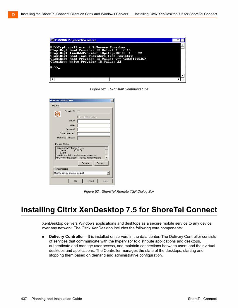
Installing the ShoreTel Connect Client on Citrix and Windows Servers Installing Citrix XenDesktop 7.5 for ShoreTel ConnectD
Figure 52: TSPInstall Command Line
Figure 53: ShoreTel Remote TSP Dialog Box
Installing Citrix XenDesktop 7.5 for ShoreTel Connect
XenDesktop delivers Windows applications and desktops as a secure mobile service to any device over any network. The Citrix XenDesktop includes the following core components:
Delivery Controller—It is installed on servers in the data center. The Delivery Controller consists of services that communicate with the hypervisor to distribute applications and desktops, authenticate and manage user access, and maintain connections between users and their virtual desktops and applications. The Controller manages the state of the desktops, starting and stopping them based on demand and administrative configuration.
437 Planning and Installation Guide ShoreTel Connect

Installing Citrix XenDesktop 7.5 for ShoreTel Connect Installing the ShoreTel Connect Client on Citrix and Windows Servers D
Studio—Studio is the management console that enables you to configure and manage your deployment, eliminating the need for separate management consoles for managing delivery of applications and desktops. Studio provides various wizards to guide you through the process of setting up your environment, creating your workloads to host applications and desktops, and assigning applications and desktops to users.
Director—Director is a web-based tool that enables IT support and help desk teams to monitor an environment, troubleshoot issues before they become system-critical, and perform support tasks for end users.
License Server—License server manages your product licenses. You must create at least one license server to store and manage your license files.
StoreFront—StoreFront authenticates users to sites hosting resources and manages desktops and applications that users access.
Virtual Delivery Agent (VDA) - The Citrix Virtual Delivery Agent is introduced in XenDesktop 7.5 version. VDA is installed on server or workstation operating systems, the VDA enables connections for desktops and apps. For Remote PC Access, install the VDA on a different machine.
The core components can be installed on the same server or on different servers.
To install Citrix XenDesktop 7.5 on your system:
1. Log on to the server where you are installing the components, using a local administrator account.
2. To install Citrix XenDesktop 7.5, perform either of the following:
Download XenDesktop 7.5 package from the Citrix product download portal and unzip the file, and then double-click the XenDesktop executable file.
If you are using a DVD, insert the DVD in the drive. If the installer does not launch automatically, double-click the AutoSelect application.
3. Click Delivery Controller in XenDesktop 7.5 install screen.
4. Select the component you want to install:
a. If you are installing the product for the first time, click Component (Select all) and follow the install instructions.
b. If you have already installed some components and want to extend your deployment, click the components you want to install from the Extend Deployment tab.
c. To install a Virtual Delivery Agent (VDA), click Virtual Delivery Agent for Windows Server OS - The installer automatically detects your operating system and allows you to install only the VDA type supported on your operating system: VDA for Windows Server OS or VDA for Windows Desktop OS.
ShoreTel Connect Planning and Installation Guide 438

Installing the ShoreTel Connect Client on Citrix and Windows Servers Creating a Site for XenDesktop 7.5D
You must install the VDA on a different machine than that of the Citrix XenDesktop and the VDA machine should have a Windows Server OS, if you had selected VDA for Widows Server OS option when creating a site for XenDesktop.
5. Select Features (Select All) in the Features tab.
6. Select Automatically option in the Firewall tab.
7. Click Install in the Summary window.
Creating a Site for XenDesktop 7.5
A Site is the name given to your product deployment. It includes the Delivery Controller, other core components, VDAs, and machine catalogs that you will create and manage.
By default, Citrix Studio Site creates a site on the server where you install the Delivery Controller. Site creation includes creating the Site Configuration database. Ensure that the SQL Server software is installed before you create a Site.
To create a new site in the Citrix Studio Site window:
1. Select Configure the Site and start delivery applications and desktops to users option.
2. Enter the Site Name and click Next.
3. In the Database tab, enter the address of the SQL Server and its name in the Database Server Location text box and click Next.
You may get a message that services could not connect to a database if you do not have SQL installed on the same server.
4. Click OK if you would like Citrix Studio to create the database automatically.
5. In the Licensing tab, enter the License Server Address and click Connect.
The licensing server address should be in the form name:[port] format, where name is a Fully Qualified Domain Name (FQDN), NetBIOS, or IP address. FQDN is the recommended format. If you omit the port number, the default port number is 27000.
You cannot proceed until a successful connection is made to the license server.
6. In Select a License area, select the required option and Click Next.
7. Select None of Server Management under Connection Type drop-down and click Next.
Note
For first-time installation, create a site before you proceed with the XenDesktop installation.
Note
If you had selected the default SQL Server while installing the Delivery Controller, the database server and name will auto populate.
439 Planning and Installation Guide ShoreTel Connect
Creating a Master Client Image for XenDesktop 7.5 Installing the ShoreTel Connect Client on Citrix and Windows Servers D
8. Click Next in the Network tab.
9. Click Next in the Storage tab.
10. In the App-V publishing tab, create a host by adding users and machine accounts.
a. To Add Users, select users and user groups, and then click Add Users.
b. To Add machine accounts, select machine accounts, and then click Add machine accounts.
c. To Add OUs, select the domain and organizational units, and indicate if items in subfolders should be included and then click Add OUs.
11. Click Finish.
You have successfully configured a site for XenDesktop.
Creating a Master Client Image for XenDesktop 7.5
After creating the site, you must create a master client image. The master image is a template that you use to deploy your environment. The master image, created and stored on your hypervisor, contains the operating system and common applications and settings you are providing to your users, such as Anti-virus software, Citrix plug-ins, and other default programs.
1. In the Environment tab, select Create a Master Image and click Next.
2. Click Next in the HDX 3D Pro tab.
3. Click Next in the Core Components tab.
4. Provide the Controller Address and click Test Connection and then click Next.
5. Click Next in the Features tab.
In the Features tab, do not select the Personal vDisk option.
The Summary screen listing the pre-requisites and core components is displayed.
6. In the Summary tab, click Install.
The XenDesktop is installed on your system.
Creating a Machine Catalog
A machine catalog is a collection of virtual machines and physical machines managed as a single entity. Machine catalogs contain information about virtual or physical machines available to host applications or desktops and the Active Directory computer accounts assigned to those virtual machines or computers.
Note
If you have your master VM's created, you can skip this step by selecting None, in the drop-down and click Next. The Configuration Summary screen is displayed.
ShoreTel Connect Planning and Installation Guide 440
Installing the ShoreTel Connect Client on Citrix and Windows Servers Creating a Machine CatalogD
The machines within these machine catalogs are configured to run either a Windows Desktop OS or a Windows Server OS. After the XenDesktop installation, create an OVA file with the master image that was used to create the client hosts on VMware ESXi. After creating the client hosts, add the hosts to the machine catalog.
Use the Create Machine Catalog wizard to create new machine catalogs. The wizard prompts you about your environment and helps you select the machine catalog type that fits your requirements based on your responses.
To create a new machine catalog and add hosts to the machine catalog, perform the following steps:
1. Log on to the computer running Citrix Studio.
2. Select the Machine Catalogs node, and click Create Machine Catalog.
3. In the Operating System tab, select the Windows Desktop OS option.
4. In the Machine Management tab:
a. Select the Machines that are power managed option in This Machine Catalog will use area.
b. Select the Another service or technology option in Deploy machines using area.
5. In the Desktop Experience tab, select the Random desktop or Static desktop option as required.
6. In the Machines tab:
a. Select the number of machines for the catalog.
b. Select the machine computing specifications, such as CPU and memory.
c. Click Add computer accounts to add the active directory computer accounts for Desktop OS and Server OS machine catalogs.
7. In the Summary tab, add descriptions, and create the machine catalog.
You have successfully created a machine catalog that provides the machines on which users' desktops reside.
Note
If the Machine Catalogs node is not visible, you must create a site using the Citrix Studio before you can begin creating the first machine catalog.
Note
If you have machines in the machine catalog that are running Windows XP or Windows Vista, select the some of the machines are running Windows XP or Windows Vista option.
441 Planning and Installation Guide ShoreTel Connect
Adding the ShoreTel Connect Client Application in Citrix Studio Installing the ShoreTel Connect Client on Citrix and Windows D
Adding the ShoreTel Connect Client Application in Citrix Studio
You can add the ShoreTel Connect application in Citrix Studio by using the Delivery Groups functionality. A Delivery group is a collection of machines selected from one or more machine catalogs. The Delivery group specifies which users can use those machines, and the applications available to those users.
To add the ShoreTel Connect application in a delivery group:
1. Launch the Citrix Studio.
2. Click Delivery Groups in the Studio navigation pane.
3. Click Applications tab and then select Create Applications in the Actions pane.
A list displays the applications that were discovered on the App-V management server.
4. Choose an application to add to the delivery group.
5. Select or add StoreFront URLs that will be used by the Citrix Receiver that is installed on each machine in the Delivery group.
You have successfully added the ShoreTel Connect client in Citrix Studio.
Launching ShoreTel Connect Application on User's Desktop
To add ShoreTel Connect application on the user's desktop:
1. Launch the browser, type the following URL: http://<FQDN>/Citrix/XenApp.
2. Install the Citrix Receiver.
3. Login to the Citrix server from the Citrix Receiver and run the ShoreTel Connect application.
You have successfully lunched the ShoreTel Connect client on the user desktop.
ShoreTel Connect Planning and Installation Guide 442

Installing the ShoreTel Connect Client on Citrix and Windows ServersLaunching ShoreTel Connect Application on User's Desk-D
443 Planning and Installation Guide ShoreTel Connect