shear moduli determination using torsional stiffness
TRANSCRIPT
SHEAR MODULI DETERMINATION USING TORSIONAL STIFFNESS MEASUREMENTS
John J. Janowiak Assistant Professor
School of Forest Resources College of Agriculture
Pennsylvania State University University Park, PA 16802
and
Roy F. Pellerin Professor
Civil Engineering Department College of Engineering and Architecture
Washington State University Pullman, WA 99 164
(Received September 199 1)
ABSTRACT
The orthotropic shear moduli were determined for three different reconstituted wood materials. Shear moduli determination was accomplished using the respective formulae that define torsional stiffness for a linear elastic orthotropic rectangular parallelepiped. Applied test procedures required the experimental evaluation of torsional stiffness constants for rectangular specimens of decreasing width to thickness slenderness ratio. Anticlastic plate bending tests were also conducted to derive in- plane shear modulus values using standard ASTM D3044 procedures. In-plane shear modulus values derived from applied torsional theory were found to be in reasonable agreement with the standard ASTM test procedure.
Keywords: Shear moduli, torsional stiffness, plate bending tests, reconstituted wood material.
INTRODUCTION
Orthotropic materials are characterized by nine independent elastic constants. Of these, three are elasticity moduli that define material resistance to shear distortion for each mutually orthogonal plane. Research to investigate shear distortion elasticity for wood and wood-com- posites has previously emphasized prescrip- tions of plate bending tests (Biblis and Lee 1976; Bodig and Goodman 1973; Gunnerson et al. 1973; and McMatt 1973). Two methods of plate bending test are prevalent for in-plane shear distortion elasticity determination. The more commonly implemented method has been the two-point or "anticlastic" square plate test. A second method is identified as either the modified anticlastic or three-point square Wood and Fiber Scrence, 24(4), 1992, pp. 392400 0 1992 by the Soc~ety of Wood Science and Technology
plate test procedure. Anticlastic refers to the bent surface shape acquired by the plate ele- ment under applied flexural load and given support conditions. The actual term of anti- clastic relates to any bent surface having two principal curvatures with opposite directional sense.
The established anticlastic plate test proce- dure for elasticity modulus measurement is ASTM D3044, "Standard Method for Shear Modulus of Plywood" (ASTM 1982). Unfor- tunately, reconstituted wood materials are manufactured in the form of thin sheets or panels which limits, if not prohibits, direct plate specimen preparation for two elastic orthog- onal planes. This limitation seriously restricts plate test procedures to determine values for
Janowiak and Pellerin-SHEAR MODULI USING TORSIONAL MEASUREMENTS 393
shear moduli, G,, and G,,, for the transverse material planar directions where the major panel surface is defined by the x-y plane. Though most engineering design problems for sheathing applications may require only the in-plane shear modulus (G,,) value, knowledge of remaining two moduli is still of importance. Transverse shear values are essential for ex- perimental investigation of material mechan- ical response under extremely concentrated static loading conditions. Knowledge of all the shear elasticity constants is critical, not only for research to model localized deformation of rigidly restrained sheathing sections under concentrated static loads but more important- ly the specific investigation of impact contact response behavior. Recent experimentation to predict the impact performance of several dif- ferent reconstituted panel materials did indeed require the quantification of the shear moduli associated with each symmetric plane of or- thogonal elasticity (Janowiak 1988). Greater understanding of transverse shear distortion elasticity may also be required if wood-based composites are to be used in more sophisti- cated structural unit geometries beyond cur- rent panel sheathing applications.
Review of the Annual Book of ASTM stan- dards, Section 4 Construction, Volume 04.09 Wood, provides several additional test pro- cedures established for shear strength and dis- tortion elasticity determination ofwood-based composites. These procedures include ASTM D 1037.128-"Interlaminar Shear" along with ASTM D2718 and D2719. ASTM D2718, "Standard Test Method for Structural Panels in Planar Shear," is essentially the same test configuration described under D1037, which is devoted to nonstructural panel materials. The other options for shear modulus mea- surement include the three methods detailed within ASTM D2719 or "Standard Methods for Structural Panels Through-the-Thick- ness." Option methods within D27 19 are: 1. Small Panel Shear Test; 2. Large Panel Shear Test; and 3. Two-Rail Test. These additional ASTM standards, along with plate test pro- cedure, do not provide for a reasonable meth-
odology for the simultaneous determination of orthotropic shear elasticity within a single test procedure scheme. Also, some doubt may be expressed for the identified ASTM procedures to induce pure shear strain for elasticity mea- surement. ASTM Dl037 does in fact indicate the potential for secondary strains with respect to the test configuration.
The purpose of this article is to inform other researchers of an alternative shear modulus characterization test procedure based on tor- sional stiffness constants. This torsional pro- cedure does not suffer from the general limi- tation as mentioned for the commonly implemented ASTM D3044 anticlastic plate bending test methodology. Rather, the tor- sional methodology provides for the simulta- neous solution of both in-plane and transverse shear distortion moduli. Torsional shear mod- uli determination has the added advantage of elasticity measurement within a pure shear strain field in contrast to conditional second- ary strains of the ASTM Dl037 test configu- ration. Thus, torsional tests may permit a more efficient method for obtaining the orthotropic shear moduli values needed for investigative experimentation.
THEORY
Torsional loading is not a new procedural approach for shear moduli determination at least for solid wood material. Literature review indicates the application of torsion techniques for shear modulus measurement of wood sec- tions used for aircraft production (Trayer and March 1930). More recently, torsion test pro- cedures are reported for other material studies. A torsion test procedure and experimental re- sults are presented on DSP-B resin-impreg- nated plywood (Semenov 1966). Shear mod- ulus values were also obtained for beryllium sheet material (Dai 1966). Both shear strength and modulus of unidirectional carbon fiber re- inforced composites were derived through the use of a torsion test apparatus (Hancox 1972). A torsion shear modulus test analysis has also been employed in the study of moisture-in-
394 WOOD AND FIBER SCIENCE, OCTOBER 1992, V. 24(4)
duced property changes for graphite-epoxy composites (Sumsion and Rajapakse 1978).
Shear moduli determination originates from the loading analysis solution, which defines the specific constant for torsional stiffness. From the rigorous torsional loading analysis for an orthotropic strip (Love 1944), the following torsional stiffness formula is observed:
where
K, = torsional stiffness constant for the material x-axis
G,, = shear modulus of the x-y plane
G,, = shear modulus of the x-z plane
b = strip thickness
h = strip width Equation 1 represents the specific torsional
stiffness formula for an orthotropic strip or parallelepiped in torsion about the longitudi- nal or x-axis. Noting that a second analogous formula for K,, torsional stiffness about the y-axis, is obtained by the appropriate per- mutation of subscripts. Formulae for K, and K, are the explicit relationships that equate torsional stiffness to orthotropic shear modu- lus, and cross-sectional dimension. Initial ex- amination of either torsional stiffness formula does not suggest an immediate computation method for solution of a single shear modulus value due to the inherent involvement of both unknown moduli. However, a computational method is possible in solution of the individual shear modulus values under conditions of ei- ther large or small width to thickness slender- ness ratios. As indicated by Lempriere et al. (1969), computational difficulties are eradi- cated under the following slenderness ratio conditions:
For these expressed conditions, Eq. 1 reduces to the following approximate form:
(3/bh3)Kx = Gxy - 0.63025Gxy(G, JG,.J1'2(h/b)
or, equivalently t31
(3/b3h)K, = G,, - 0.63025G,,(G,,/G,,)1/2~ . (b/h) [41
Equations 3 and 4 are linear functions that relate torsional stiffness capacity to the re- spective h/b and b/h slenderness ratios. The left-hand terms, (3/bh3)K, and (3/b3h)K,, for these simplified expressions may be referred to as the reduced torsional stiffness constants. These linear relationships for the reduced tor- sional stiffness constants provide the basis for the simultaneous solution of both in-plane and transverse shear moduli values. Linear func- tionality associated with the independent h/b or b/h variables enables a relatively simple data reduction procedure in the computation of material shear moduli values. It should be emphasized that shear moduli computation using either of these reduced stiffness torsional mathematical expressions is valid only within the original conditional slenderness restric- tions with respect to shear modulus anisotropy set forth by Eq. 2.
The actual test procedure for shear moduli determination requires the experimental data collection of several Kx values of varying slen- derness ratio. Torsional stiffness, K,, equals the applied torque times the torsional gage length divided by the observed twist angle. Us- ing for example, Eq. 3, collected experimental data of the form (3/bh3)K, are plotted versus the different corresponding h/b slenderness ra- tios. As suggested by the linearity of the re- duced torsional stiffness function, G,, is de- rived as h/b approaches zero. The in-plane modulus is uniquely defined through the linear plot with straight line extrapolation to the in- tersection point on the reduced torsional stiff-
Janowiak and Pellerin-SHEAR MODULI USING TORSIONAL MEASUREMENTS 395
ness ordinate axis. With the explicit value for G,,, substitution into the equation provides for solution of the transverse modulus value. The mathematical statements for G,, at h/b = 0 and subsequent solution for G,, computation are given as follows:
G,, = (3/bh3)K, [51
and
G,, = (0.3972 G;,)/kI [61
where
K, = TL/O T = applied torque, in-lb L = torsional gage length, inches O = measured torsional twist angle, radians k, = slope of the (3/bh3)K, line
Equations 5 and 6 are developed within the postulate of an assumed system of free tor- sional deformation. However, a distinct lim- itation must be acknowledged and accounted for within any experimental torsional loading apparatus that prohibits free torsional defor- mation. An applied torsion couple requires rig- id clamping through which rotational forces are imposed on the test specimen. Rigid clamping or grips affixed to specimen end cross sections generates torsional deformation re- straint. This deviation from free or unre- strained deformation inherent to the torsional loading grip results in a potentially significant experimental source of error for moduli test computation.
Experimental error due to restrained defor- mation or grip effect may be avoided by using torsional angle measurements taken a suffi- cient distance from the application points of the torsional moment. Review of the literature reveals at least one recommended procedure for determination of the grip effect zone to isolate the experimental error associated with restrained deformation. Nikolaev and No- vichkov (1968) proposed a relatively simple procedural approach to establish minimum length (z,,,) beyond which grip effect becomes negligible. This procedural approach requires that the twist angle measurements be taken
over a section with appropriate distance from the torsional loading points. The appropriate distance (z) is defined using the following em- pirical statement:
where
c = the greater of dimensions b and h G,, G, = respectively, the greater and
smaller of the shear moduli G,,, G,,
Application of Eq. 7 to define the proper twist angle measurement position requires an initial assumption or estimation of shear modulus magnitudes. This procedural approach does not provide for restraint correction when twist an- gle measurements are obtained by monitoring grip rotation.
Direct grip rotation for torsional deforma- tion analysis necessitates an alternative cor- rection procedure. Experimental error correc- tion in assessment of grip effect through analytical techniques is impossible. Alterna- tively, grip effect and the general suitability of varying grip configuration assemblies must be evaluated through experimentation. Neder- veen and Tilstra (1971) introduced a viable experimental correction procedure based on the concept of the theoretical twist gage length (L) for free torsion being adjustable to real tor- sion through a virtual increase of elementary length. Elementary length (AL) serves as the correction term to compensate for grip effect. The correction method consists of a prismatic bar repeatedly loaded to constant torque mag- nitude for a decreasing gage length (L,) with resultant twist angle (A+,) measurement. Re- sulting (Aai,Li) x data extrapolation explicitly defines the real torsion correction term AL at
equals zero. Correction terms may assume either a positive or negative sense dependent on specimen torsional capacity and grip con- figuration enhances torsional stiffness. Ccm- versely, a negative value is observed for re- duced stiffness behavior. Reduction oftorsional stiffness due to grip attachment is termed warping restraint behavior. Enhanced stiffness
WOOD AND RBER SCIENC :E, OCTOBER 1992, V. 24(4)
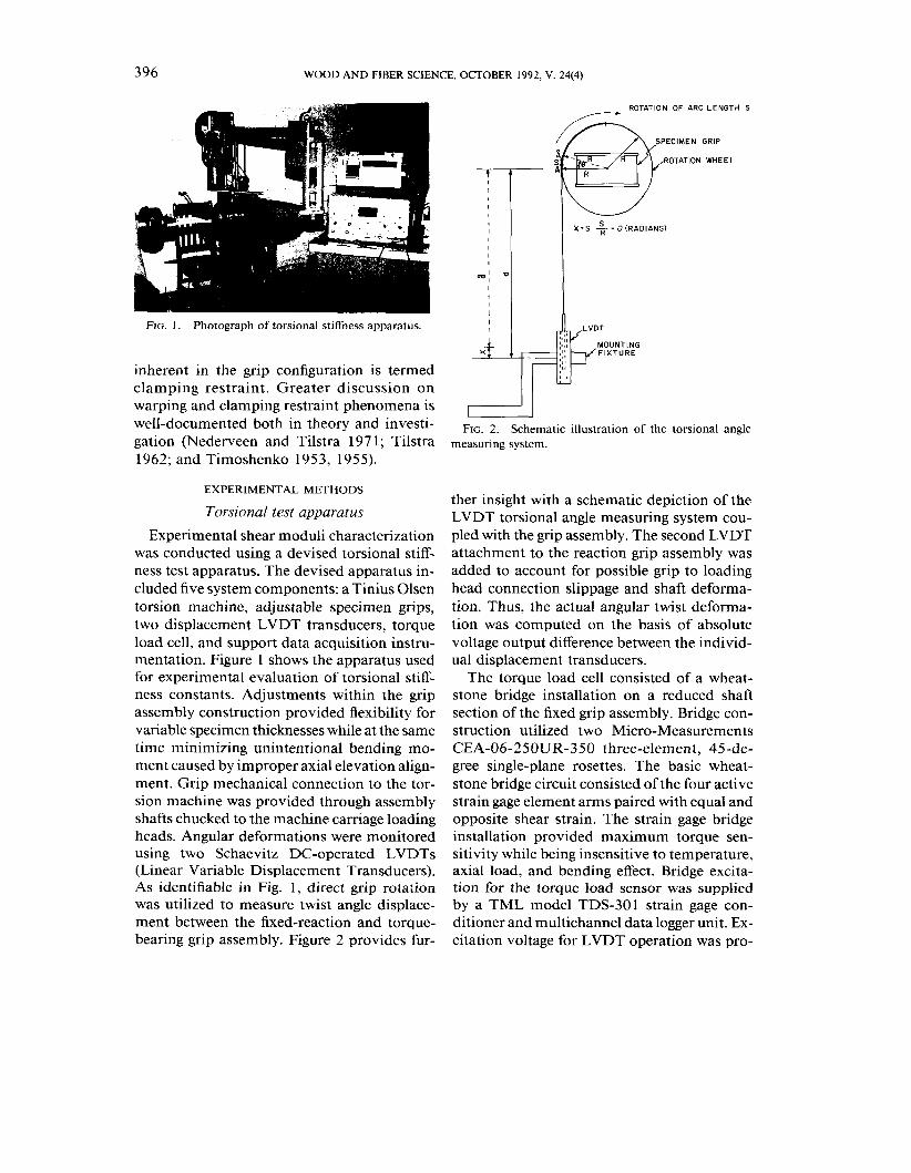
FIG. 1 . Photograph of torsional stiffness apparatus.
inherent in the grip configuration is termed clamping restraint. Greater discussion on warping and clamping restraint phenomena is well-documented both in theory and investi- gation (Nederveen and Tilstra 197 1 ; Tilstra 1962; and Timoshenko 1953, 1955).
EXPERIMENTAL METHODS
Torsional test apparatus
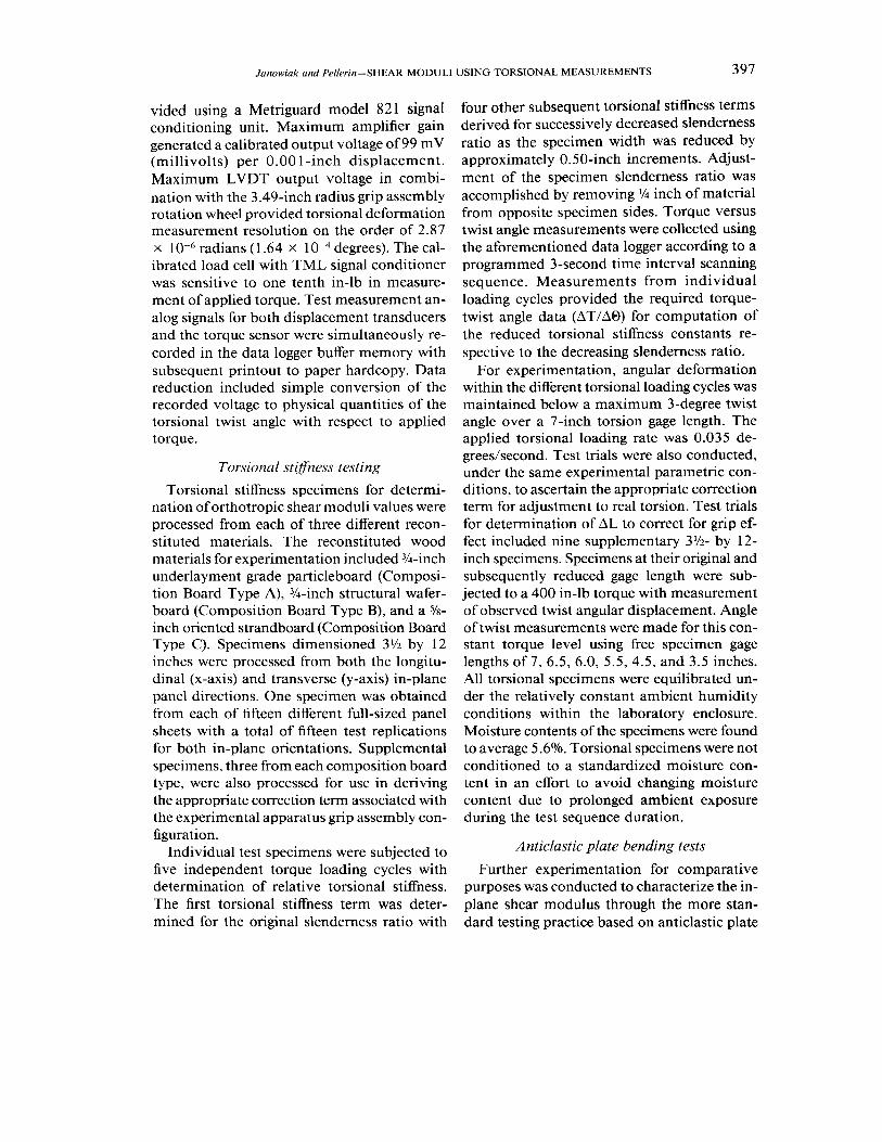
Experimental shear moduli characterization was conducted using a devised torsional stiff- ness test apparatus. The devised apparatus in- cluded five system components: a Tinius Olsen torsion machine, adjustable specimen grips, two displacement LVDT transducers, torque load cell, and support data acquisition instru- mentation. Figure 1 shows the apparatus used for experimental evaluation of torsional stiff- ness constants. Adjustments within the grip assembly construction provided flexibility for variable specimen thicknesses while at the same time minimizing unintentional bending mo- ment caused by improper axial elevation align- ment. Grip mechanical connection to the tor- sion machine was provided through assembly shafts chucked to the machine carriage loading heads. Angular deformations were monitored using two Schaevitz DC-operated LVDTs (Linear Variable Displacement Transducers). As identifiable in Fig. 1, direct grip rotation was utilized to measure twist angle displace- ment between the fixed-reaction and torque- bearing grip assembly. Figure 2 provides fur-
ROTATION OF ARC LENGTH S
SPECIMEN GRIP
ROTATION WHEEL
FIG. 2. Schematic illustration of the torsional angle measuring system.
ther insight with a schematic depiction of the LVDT torsional angle measuring system cou- pled with the grip assembly. The second LVDT attachment to the reaction grip assembly was added to account for possible grip to loading head connection slippage and shaft deforma- tion. Thus, the actual angular twist deforma- tion was computed on the basis of absolute voltage output difference between the individ- ual displacement transducers.
The torque load cell consisted of a wheat- stone bridge installation on a reduced shaft section of the fixed grip assembly. Bridge con- struction utilized two Micro-Measurements CEA-06-250UR-350 three-element, 45-de- gree single-plane rosettes. The basic wheat- stone bridge circuit consisted of the four active strain gage element arms paired with equal and opposite shear strain. The strain gage bridge installation provided maximum torque sen- sitivity while being insensitive to temperature, axial load, and bending effect. Bridge excita- tion for the torque load sensor was supplied by a TML model TDS-30 1 strain gage con- ditioner and multichannel data logger unit. Ex- citation voltage for LVDT operation was pro-
Janowiak and Pellerin-SHEAR MODULI USING TORSIONAL MEASUREMENTS 397
vided using a Metriguard model 821 signal conditioning unit. Maximum amplifier gain generated a calibrated output voltage of 99 mV (millivolts) per 0.00 1 -inch displacement. Maximum LVDT output voltage in combi- nation with the 3.49-inch radius grip assembly rotation wheel provided torsional deformation measurement resolution on the order of 2.87 x radians (1.64 x degrees). The cal- ibrated load cell with TML signal conditioner was sensitive to one tenth in-lb in measure- ment of applied torque. Test measurement an- alog signals for both displacement transducers and the torque sensor were simultaneously re- corded in the data logger buffer memory with subsequent printout to paper hardcopy. Data reduction included simple conversion of the recorded voltage to physical quantities of the torsional twist angle with respect to applied torque.
Torsional stifness testing
Torsional stiffness specimens for determi- nation of orthotropic shear moduli values were processed from each of three different recon- stituted materials. The reconstituted wood materials for experimentation included %-inch underlayment grade particleboard (Composi- tion Board Type A), %-inch structural wafer- board (Composition Board Type B), and a %- inch oriented strandboard (Composition Board Type C). Specimens dimensioned 3% by 12 inches were processed from both the longitu- dinal (x-axis) and transverse (y-axis) in-plane panel directions. One specimen was obtained from each of fifteen different full-sized panel sheets with a total of fifteen test replications for both in-plane orientations. Supplemental specimens, three from each composition board type, were also processed for use in deriving the appropriate correction term associated with the experimental apparatus grip assembly con- figuration.
Individual test specimens were subjected to five independent torque loading cycles with determination of relative torsional stiffness. The first torsional stiffness term was deter- mined for the original slenderness ratio with
four other subsequent torsional stiffness terms derived for successively decreased slenderness ratio as the specimen width was reduced by approximately 0.50-inch increments. Adjust- ment of the specimen slenderness ratio was accomplished by removing '/4 inch of material from opposite specimen sides. Torque versus twist angle measurements were collected using the aforementioned data logger according to a programmed 3-second time interval scanning sequence. Measurements from individual loading cycles provided the required torque- twist angle data (AT/AO) for computation of the reduced torsional stiffness constants re- spective to the decreasing slenderness ratio.
For experimentation, angular deformation within the different torsional loading cycles was maintained below a maximum 3-degree twist angle over a 7-inch torsion gage length. The applied torsional loading rate was 0.035 de- greedsecond. Test trials were also conducted, under the same experimental parametric con- ditions, to ascertain the appropriate correction term for adjustment to real torsion. Test trials for determination of AL to correct for grip ef- fect included nine supplementary 3l/2- by 12- inch specimens. Specimens at their original and subsequently reduced gage length were sub- jected to a 400 in-lb torque with measurement of observed twist angular displacement. Angle of twist measurements were made for this con- stant torque level using free specimen gage lengths of 7, 6.5, 6.0, 5.5, 4.5, and 3.5 inches. All torsional specimens were equilibrated un- der the relatively constant ambient humidity conditions within the laboratory enclosure. Moisture contents of the specimens were found to average 5.6%. Torsional specimens were not conditioned to a standardized moisture con- tent in an effort to avoid changing moisture content due to prolonged ambient exposure during the test sequence duration.
Anticlastic plate bending tests
Further experimentation for comparative purposes was conducted to characterize the in- plane shear modulus through the more stan- dard testing practice based on anticlastic plate
398 WOOD AND FIBER SCIENCE, OCTOBER 1992, V. 24(4)
TABLE 1 Orthotroplc shear modull values derlvedfrorn torsional load~ng
Compos~ t~on Mean Max~mum value Mln~mum vlaue Standard dev~ation Propert\ board type (PSI) (PSI) (PSI) (PSI)
G,,l A 142,000 173,400 1 16,400 12,500 (Gxv) B 154,400 219,100 123,500 2 1,900
C 217,700 258,600 188,500 19,300
G, ,2 A 28,500 35,200 23,700 2,700 (G.,) B 2 1,400 28,500 15,900 4,000
C 30,800 37,500 25,400 3,500
G,,l A 23,300 29,200 19,700 2,900 (G,,) B 20,300 29,400 10,900 6,300
C 34,200 4 1,600 29,500 3,500
' Based on 30 test specimens w ~ t h the exceptlon of composition board type B whlch IS based on 29 specimens obtained from 15 d~fferent panels Based on 15 test observat~ons with the exceptlon of composltlon board type B for whlch G , is based on 14 test specimens obta~ned from 15 d~Kerent
panels
bending. As specified by ASTM D3044, in- plane modulus of rigidity determination was pursued through plate deformation in forma- tion of a hyperbolic paraboloid surface. Shear modulus was computed using the plate solu- tion expression for an applied twisting mo- ment. Plate specimens were not obtained from the same five full-sized panel sets used for preparation of the torsional stiffness speci- mens. However, both anticlastic and torsional panel sets for specimen preparation were ran- domly selected from a larger sample group population. Three specimens were processed from each of five full-sized panels with fifteen total test replications for each composition board type. Specimen materials were condi- tioned prior to test evaluation as prescribed under the ASTM standard. Average moisture content was found to equal 1 1.9%. Some clar- ification should be made to emphasize that the difference in moisture content between the two shear moduli determination test procedures was an unintentional experimental parameter variation. Irrespective of the moisture content variation, the assumption is made that general comparisons of in-plane shear modulus values derived from anticlastic versus torsional test methodology are valid.
RESULTS AND DISCUSSION
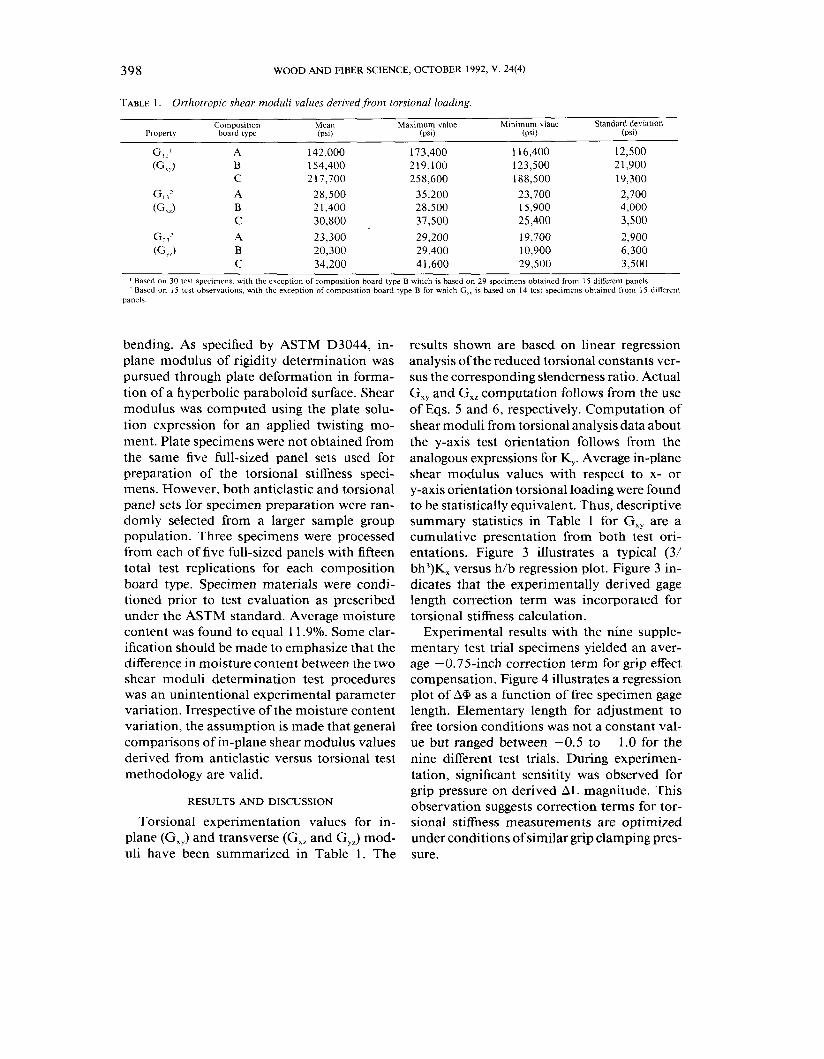
results shown are based on linear regression analysis of the reduced torsional constants ver- sus the corresponding slenderness ratio. Actual G,, and G,, computation follows from the use of Eqs. 5 and 6, respectively. Computation of shear moduli from torsional analysis data about the y-axis test orientation follows from the analogous expressions for K,. Average in-plane shear modulus values with respect to x- or y-axis orientation torsional loading were found to be statistically equivalent. Thus, descriptive summary statistics in Table 1 for G,, are a cumulative presentation from both test ori- entations. Figure 3 illustrates a typical (3/ bh3)K, versus h/b regression plot. Figure 3 in- dicates that the experimentally derived gage length correction term was incorporated for torsional stiffness calculation.
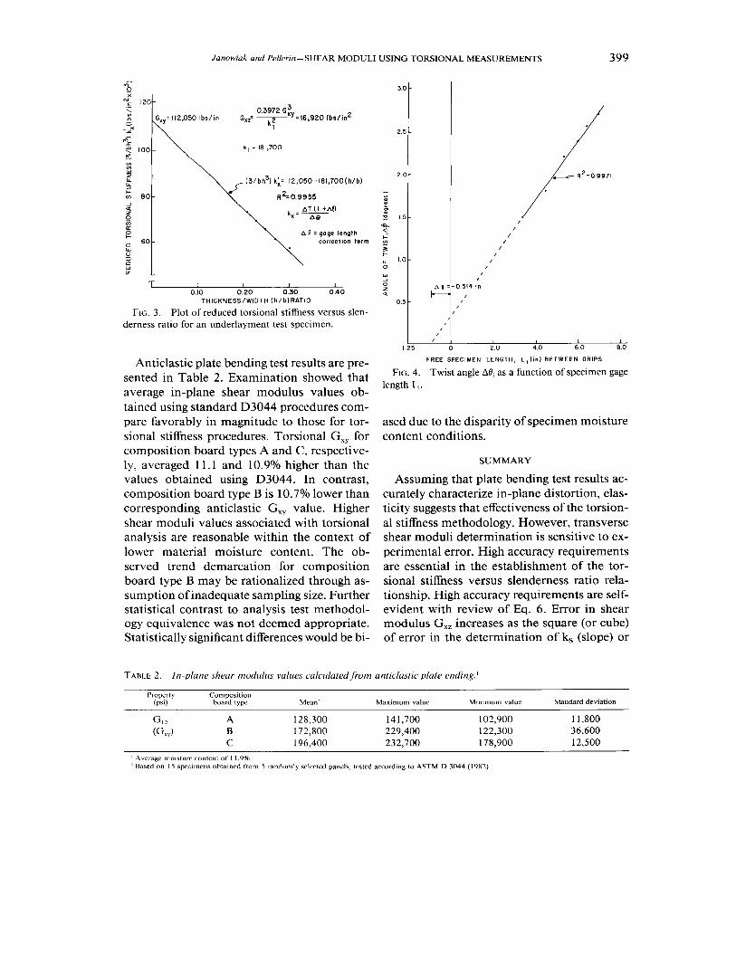
Experimental results with the nine supple- mentary test trial specimens yielded an aver- age -0.75-inch correction term for grip effect compensation. Figure 4 illustrates a regression plot of A+ as a function of free specimen gage length. Elementary length for adjustment to free torsion conditions was not a constant val- ue but ranged between -0.5 to - 1.0 for the nine different test trials. During experimen- tation, significant sensitity was observed for grip pressure on derived A L magnitude. This observation suggests correction terms for tor-
- -
Torsional experimentation values for in- sional stiffness measurements are optimized plane (G,,) and transverse (G,, and G,,) mod- under conditions of similar grip clamping pres- uli have been summarized in Table 1. The sure.
Janowiak and Pellerin-SHEAR MODULI USING TORSIONAL MEASUREMENTS 399
\ b' = gage length correction term
T I I I I
0.10 0.20 0.30 0.40 T H I C K N E S S / W I D T H ( h / b ) R A T I O
FIG. 3. Plot of reduced torsional stiffness versus slen- derness ratio for an underlayment test specimen.
Anticlastic plate bending test results are pre- sented in Table 2. Examination showed that average in-plane shear modulus values ob- tained using standard D3044 procedures com- pare favorably in magnitude to those for tor- sional stiffness procedures. Torsional G,, for composition board types A and C , respective- ly, averaged 11.1 and 10.9% higher than the values obtained using D3044. In contrast, composition board type B is 10.7O/o lower than corresponding anticlastic G,, value. Higher shear moduli values associated with torsional analysis are reasonable within the context of lower material moisture content. The ob- served trend demarcation for composition board type B may be rationalized through as- sumption of inadequate sampling size. Further statistical contrast to analysis test methodol- ogy equivalence was not deemed appropriate. Statistically significant differences would be bi-
2.5 -
2 0-
- t 0 15.
"a.
2 I / "7 - 3
F R E E SPECIMEN L E N G T H , L i ( i n ) B E T W E E N G R I P S
FIG. 4. Twist angle AO, as a function of specimen gage length L,.
ased due to the disparity of specimen moisture content conditions.
SUMMARY
Assuming that plate bending test results ac- curately characterize in-plane distortion, elas- ticity suggests that effectiveness of the torsion- al stiffness methodology. However, transverse shear moduli determination is sensitive to ex- perimental error. High accuracy requirements are essential in the establishment of the tor- sional stiffness versus slenderness ratio rela- tionship. High accuracy requirements are self- evident with review of Eq. 6. Error in shear modulus G,, increases as the square (or cube) of error in the determination of k, (slope) or
TABLE 2. In-plane shear modulus values calculated from anticlastic plate ending.!
Property Composition (psi) board type Mean' Maximum value Minimum value Standard deviat~on
' Average molsture content of 11.9%. ' Based on 15 specimens obta~ned from 5 randomly selected panels, tested according to ASTM D 3044 (1982).
400 WOOD AND FIBER SCIENCE, OCTOBER 1992, V. 24(4)
GXy (intercept). Thus, a high order of test ac- curacy is critical for reliable shear modulus values. In addition, shear moduli calculations using Eqs. 5 and 6 must be valid within orig- inally stated simplifying assumptions. To re- iterate, restrictions on these equations are the mathematical conditions that the slenderness (thicknesdwidth) ratio be small or large rela- tive to anisotropy: (b/h) < (T/~)(G,,/G,,)"* or (h/b) < (T/~)(G,,/G,,)"~. Experimentally de- rived shear values for each composition board material were found valid within these restric- tions. Several supplemental recommendations are made as guidelines for computation of re- liable shear moduli values:
1. Torsional stiffness constants should be evaluated for four or more slenderness ra- tios.
2. Correction for restrained deformation or grip effect needs to be considered.
3. Constant grip pressure should be main- tained for all torsional testing.
4. Torsional stiffness data evaluation should be conducted through least squares regres- sion fit.
5. Regression analyses of R 2 below approxi- mately 0.9 may suggest excessive experi- mental testing variation.
6. Simplifying mathematical restrictions must remain valid for the shear moduli equa- tions.
REFERENCES
DAI, P. K. 1965. Mechanical considerations in utiliza- tion of beryllium structural systems. Report No. AFML- TR-64-395. Air Force Materials Laboratory. Wright- Patterson Air Force Base, GA.
GUNNERSON, R. A,, J. R. GOODMAN, AND J. BODIG, 1973. Plate tests for determination of elastic parameters for wood. Wood Sci. 5(4):24 1-248.
HANCOX, N. L. 1972. The use of a torsion machine to measure the shear strength and modulus of unidirec- tional carbon fibre reinforced plastics. J. Material Sci. 7(7): 1030-1036.
JANOWIAK, J. J. 1988. Impact dynamics of reconstituted wood plates. Unpublished Ph.D. dissertation, Wash- ington State University, Pullman, WA.
LEMPRIERE, B. M., R. W. FENN, JR., D. D. CROOKS, AND
W. C. KINDER. 1969. Torsional testing for shear mod- ulus ofthis orthotropic sheet. AIAA J. 7(12):2341-2342.
LOVE, A. E. H. 1944. A treatise on the mathematical theory of elasticity, 4th ed. The Macmillan Company. New York, NY.
MCNATT, J. D. 1973. Basic engineering properties of particleboard. Research Paper FPL 206. USDA, Forest Products Laboratory. Madison, WI.
NEVERDEEN, C. J., AND J. F. TILSTRA. 197 1. Clamping corrections for torsional stiffness of prismatic bars. J. Appl. Physics, Series D. 4(11):1661-1667.
NIKOLAEV, V. P., AND Y. N. NOVICHKOV. 1968. On the experimental determination of shear moduli of glass fiber composites. Raschoti Na Prochnost 13:355-369. Mashinostroyniye Press. Moscow. (In Russian).
SEMENOV, P. I. 1966. Determination of shear moduli of orthotropic materials from torsion tests. Polymer Me- chanics. 2(1): 17-2 1. Translated from Mekhanika Poli- merov.
SUMSION, H. T., AND Y. D. S. RAJAPAKSE. 1978. Simple torsion test for shear moduli determination. ICCM/Z. Pages 994-1002 in Proceedings of the 1978 Interna- tional Conference on Composite Materials. New York, NY.
TILSTRA, J. F. 1962. Central laboratorium. TNO Report
AMERICAN SOCIETY FOR TESTING AND MATERIALS. 1982. Standard method of test for shear modulus of plywood. ASTM D3044-76, Part 22 ASTM. Philadelphia, PA.
BIBLIS, E. G., AND W. C. LEE. 1976. Simplification of the experimental method for determining plate shear modulus of plywood and particle-board. Forest Prod. J. 26(4):38-42.
BODIG, J., AND J . R. GOODMAN. 1973. Predication of clastic parameters for wood. Wood Sci. 5(4):249-264.
No. C1 62/123. Delft, Netherlands. TIMOSHENKO, S. 1953. Collected papers. McGraw-Hill
Book Company. New York, NY. -. 1955. Strength of materials. Third edition. D.
Van Nostrand Company, Inc. New York, NY. Pp. 289. TRAYER, G. W., AND H. W. MARCH. 1930. The torsion
of members having sections common in aircraft con- struction. National Advisiory Committee on Aeronau- tics. Report No. 334.