flexural-torsional buckling strength of i-girders with discrete torsional braces under various...
TRANSCRIPT
Engineering Structures 36 (2012) 337–350
Contents lists available at SciVerse ScienceDirect
Engineering Structures
journal homepage: www.elsevier .com/ locate /engstruct
Flexural-torsional buckling strength of I-girders with discrete torsional bracesunder various loading conditions
Canh Tuan Nguyen a, Hyun-Sung Joo a, Jiho Moon b, Hak-Eun Lee a,⇑a Civil, Environmental and Architectural Engineering, Korea University, 5-1, Anam-dong, Sungbuk-gu, Seoul 136-701, South Koreab Civil and Environmental Engineering, University of Washington, Seattle, WA 98195-2700, USA
a r t i c l e i n f o a b s t r a c t
Article history:Received 6 June 2011Revised 7 December 2011Accepted 8 December 2011Available online 20 January 2012
Keywords:Flexural-torsional bucklingBifurcation analysisInelastic bucklingTorsional restraintTorsional bracingStiffness requirementEquivalent moment factor
0141-0296/$ - see front matter � 2011 Elsevier Ltd. Adoi:10.1016/j.engstruct.2011.12.022
⇑ Corresponding author. Tel.: +82 2 3290 3315; faxE-mail address: [email protected] (H.-E. Lee).
Torsional bracing systems have been used widely in I-girder bridges to increase the flexural-torsionalbuckling strength and distribute the load to the adjacent girders. To evaluate the required stiffness ofthe bracing and the flexural-torsional buckling strength of the I-girder with a multiple torsional bracingsystem, the equivalent continuous torsional bracing concept is often adopted regardless of the type oftorsional bracing system. However, a previous study on the I-girder with discrete torsional bracingsunder uniform bending reported that the equivalent continuous torsional bracing concept has certainlimitations on discrete torsional bracing problems and it needs to be investigated for general loadingcases. This article presents an analytical solution for the elastic flexural-torsional buckling strengthand stiffness requirements of I-girders with discrete torsional bracings under various loading conditions.First, a review was performed of the previous study on the elastic critical buckling moment and torsionalstiffness requirement of the I-girder with discrete torsional bracings under uniform bending. This solu-tion was then extended for various loading conditions. From the derived analytical solutions, the equiv-alent moment factor was proposed for practical engineering purposes and the proposed solutions wereverified by comparing them with the results of finite element analysis and those of other previous stud-ies. Finally, non-linear finite element analyses including the effects of the initial imperfection and resid-ual stresses were conducted to examine the inelastic buckling strengths of I-girders with discretetorsional bracings under various loading conditions. The results showed that the buckling curves fromthe current design specification provide reasonably conservative flexural-torsional buckling strengthsof the I-girder with discrete torsional bracings when the proposed elastic solutions are applied to obtainthe buckling parameters.
� 2011 Elsevier Ltd. All rights reserved.
1. Introduction Wakabayashi and Nakamura [2] conducted experimental study
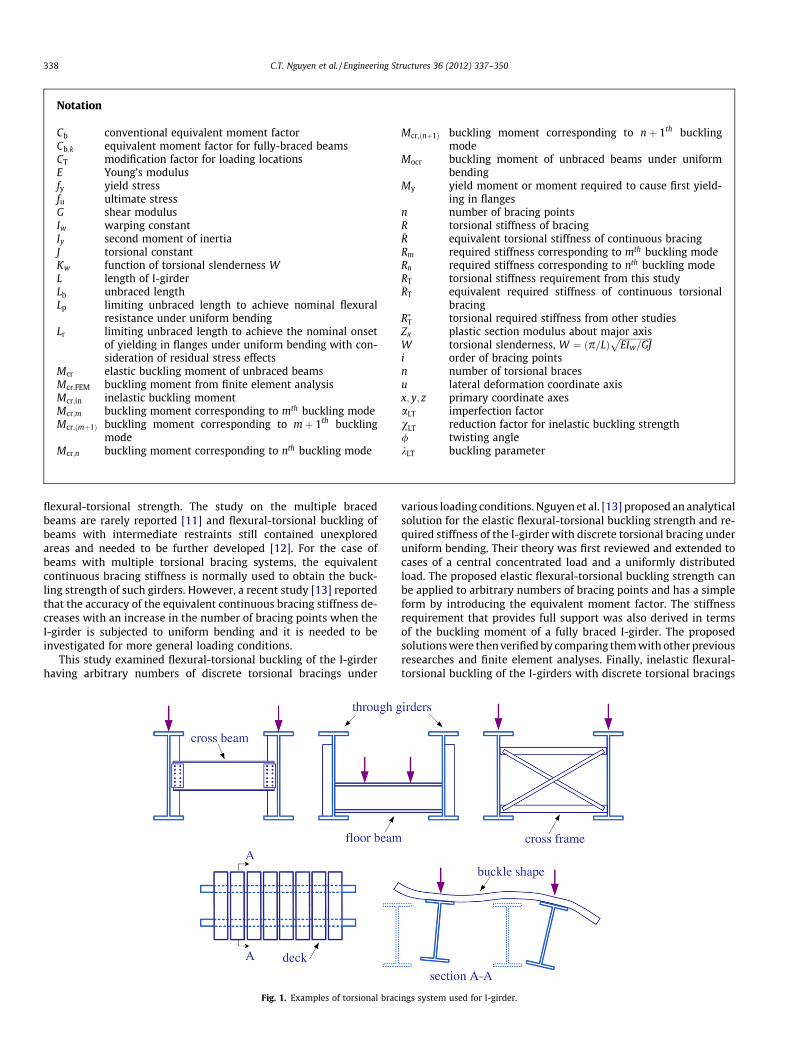
Torsional bracing systems are often used to connect the sepa-rated girders, as shown in Fig. 1. The flexural-torsional bucklingstrengths can be improved by introducing an adequate bracing sys-tem, and the torsional bracing system allows load transfer to theadjacent girders. A concrete slab or deck attached to the girders iscategorized into a continuous bracing system, as shown in Fig. 1.For this bracing system, Taylor and Ojalvo [1] derived the exact solu-tion for the elastic flexural-torsional buckling strength of the beamunder uniform bending. The cross beams or frames are typical exam-ples of a discrete torsional bracing system, which are commonlyused in I-girder systems. In this study, the focus was made on theI-girder with a discrete torsional bracing system.
Several studies have been presented on the flexural-torsionalbuckling of the I-girder with a discrete torsional bracing system.
ll rights reserved.
: +82 2 928 5217.
on H-shaped beams braced by purlins or a sub-beam at centralspan. Tong and Chen [3,4] derived the elastic flexural-torsionalbuckling strength and stiffness requirement for a beam with a tor-sional bracing at mid-span under uniform bending. Trahair [5] pro-posed equations for the elastic buckling moment and the stiffnessrequirement for beams with a torsional restraint at the mid-spanbased on numerical approximations. Valentino et al. [6] extendedTrahair’s work [5] to the inelastic flexural-torsional bucklingstrength. Tong and Chen [4] and Yura [7] proposed analytical solu-tions based on the concept of continuous torsional bracing. Theyassumed that the discrete bracings can be considered as a contin-uous bracing by summing the stiffness of each brace and dividingby the beam length. This value is called the equivalent continuousbracing stiffness [4,7]. The effects of the moment gradient andtransverse loading on the flexural-torsional buckling strength ofthe I-girder with a torsional restraint at mid-span have also beeninvestigated by several researchers [8–10].
A literature review shows that most studies are limited tobeams with torsional bracing at the mid-span and elastic
Notation
Cb conventional equivalent moment factorCb;k equivalent moment factor for fully-braced beamsCT modification factor for loading locationsE Young’s modulusfy yield stressfu ultimate stressG shear modulusIw warping constantIy second moment of inertiaJ torsional constantKw function of torsional slenderness WL length of I-girderLb unbraced lengthLp limiting unbraced length to achieve nominal flexural
resistance under uniform bendingLr limiting unbraced length to achieve the nominal onset
of yielding in flanges under uniform bending with con-sideration of residual stress effects
Mcr elastic buckling moment of unbraced beamsMcr;FEM buckling moment from finite element analysisMcr;in inelastic buckling momentMcr;m buckling moment corresponding to mth buckling modeMcr;ðmþ1Þ buckling moment corresponding to mþ 1th buckling
modeMcr;n buckling moment corresponding to nth buckling mode
Mcr;ðnþ1Þ buckling moment corresponding to nþ 1th bucklingmode
Mocr buckling moment of unbraced beams under uniformbending
My yield moment or moment required to cause first yield-ing in flanges
n number of bracing pointsR torsional stiffness of bracing�R equivalent torsional stiffness of continuous bracingRm required stiffness corresponding to mth buckling modeRn required stiffness corresponding to nth buckling modeRT torsional stiffness requirement from this study�RT equivalent required stiffness of continuous torsional
bracingR�T torsional required stiffness from other studiesZx plastic section modulus about major axisW torsional slenderness, W ¼ p=Lð Þ
ffiffiffiffiffiffiffiffiffiffiffiffiffiffiffiEIw=GJ
pi order of bracing pointsn number of torsional bracesu lateral deformation coordinate axisx; y; z primary coordinate axesaLT imperfection factorvLT reduction factor for inelastic buckling strength/ twisting anglekLT buckling parameter
338 C.T. Nguyen et al. / Engineering Structures 36 (2012) 337–350
flexural-torsional strength. The study on the multiple bracedbeams are rarely reported [11] and flexural-torsional buckling ofbeams with intermediate restraints still contained unexploredareas and needed to be further developed [12]. For the case ofbeams with multiple torsional bracing systems, the equivalentcontinuous bracing stiffness is normally used to obtain the buck-ling strength of such girders. However, a recent study [13] reportedthat the accuracy of the equivalent continuous bracing stiffness de-creases with an increase in the number of bracing points when theI-girder is subjected to uniform bending and it is needed to beinvestigated for more general loading conditions.
This study examined flexural-torsional buckling of the I-girderhaving arbitrary numbers of discrete torsional bracings under
Fig. 1. Examples of torsional brac
various loading conditions. Nguyen et al. [13] proposed an analyticalsolution for the elastic flexural-torsional buckling strength and re-quired stiffness of the I-girder with discrete torsional bracing underuniform bending. Their theory was first reviewed and extended tocases of a central concentrated load and a uniformly distributedload. The proposed elastic flexural-torsional buckling strength canbe applied to arbitrary numbers of bracing points and has a simpleform by introducing the equivalent moment factor. The stiffnessrequirement that provides full support was also derived in termsof the buckling moment of a fully braced I-girder. The proposedsolutions were then verified by comparing them with other previousresearches and finite element analyses. Finally, inelastic flexural-torsional buckling of the I-girders with discrete torsional bracings
ings system used for I-girder.
C.T. Nguyen et al. / Engineering Structures 36 (2012) 337–350 339
under various loading conditions was investigated including the ef-fects of initial imperfections and residual stresses. The inelastic flex-ural-torsional buckling strength was proposed based on the currentdesign curves [14] and compared with the results of finite elementanalysis [15]. Effects of web distortions on flexural-torsional buck-ling strengths were described. The results show that the proposedinelastic buckling strengths based on the buckling curves from thecurrent design specifications provide a conservative prediction ofthe inelastic buckling strength of the I-girder with discrete torsionalbracing under various loading conditions.
2. Elastic flexural-torsional buckling of I-girders with discretetorsional bracings
2.1. I-girder with discrete torsional bracings under uniform bending
Nguyen et al. [13] proposed the elastic flexural-torsional buck-ling strength and torsional stiffness requirement for the I-girderwith arbitrary numbers of bracing points under uniform bendingcondition. The proposed elastic flexural-torsional bucklingstrengths are given as
Mcr;m ¼
ffiffiffiffiffiffiffiffiffiffiffiffiffiffiffiffiffiffiffiffiffiffiffiffiffiffiffiffiffiffiffiffiffiffiffiffiffiffiffiffiffiffiffiffiffiffiffiffiffiffiffiffiffiffiffiffiffiffiffiffiffiffiffiffiffiffiffiffiffiffiffiffiffiffiffiffiffiffiffiffiffiffiffiffiffiffiffiffiffiffiffiffiffiffiffiffiffiffiffiffiffiffip
L=m
� �2
EIyGJ 1þ pL=m
� �2 EIw
GJ
!þ ðnþ 1ÞREIy
L
vuut for m
¼ 1;2;3; . . . ;n� 1 when R 6 RRm;
ð1aÞ
Mcr;n¼pL
ffiffiffiffiffiffiffiffiffiffiffiffiffiffiffiffiffiffiffiffiffiffiffiffiffiffiffiffiffiffiffiffiffiffiffiffiffiffiffiffiffiffiffiffiffiffiffiffiffiffiffiffiffiffiffiffiffiffiffiffiffiffiffiffiffiffiffiffiffiffiffiffiffiffiffiffiffiffiffiffiffiffiffiffiffiffiffiffiffiffiffiffiffiffiffiffiffiffiffiffiffiffiffiffiffiffiffiffiffiffiffiffiffiffiffiffiffiffiffiffiffiffiffiffiffiffiffiffiffiffiffiffiEIyGJ anþbnW2�2cn
ffiffiffiffiffiffiffiffiffiffiffiffiffiffiffiffiffiffiffiffiffiffiffiffiffiffiffiffiffiffiffiffiffiffiffiffiffiffiffiffiffiffiffiffiffiffiffiffiffiffiffiffiffiffiffiffiffiffi1þ2anW2� �2
þ LR2p2GJ
� �2s
þ cnLRp2GJ
0@
1A
vuuutwhen RRm <R<RT ð1bÞ
Mcr;ðnþ1Þ ¼p
L=ðnþ1Þ
ffiffiffiffiffiffiffiffiffiffiffiffiffiffiffiffiffiffiffiffiffiffiffiffiffiffiffiffiffiffiffiffiffiffiffiffiffiffiffiffiffiffiffiffiffiffiffiffiffiffiffiffiffiffiffiffiffiffiffiffiffiffiEIyGJ 1þ p
L=ðnþ1Þ
� �2 EIw
GJ
!vuut when R P RT ð1cÞ
where
an ¼ ðnþ 1Þ2 þ 1; bn ¼ ðnþ 1Þ4 þ 6ðnþ 1Þ2 þ 1; cn
¼ nþ 1: ð2Þ
In Eq. (1b), W is the torsional slenderness that is defined asW ¼ ðp=LÞ
ffiffiffiffiffiffiffiffiffiffiffiffiffiffiffiEIw=GJ
p; Mcr;m;Mcr;n, and Mcr;ðnþ1Þ represent the critical
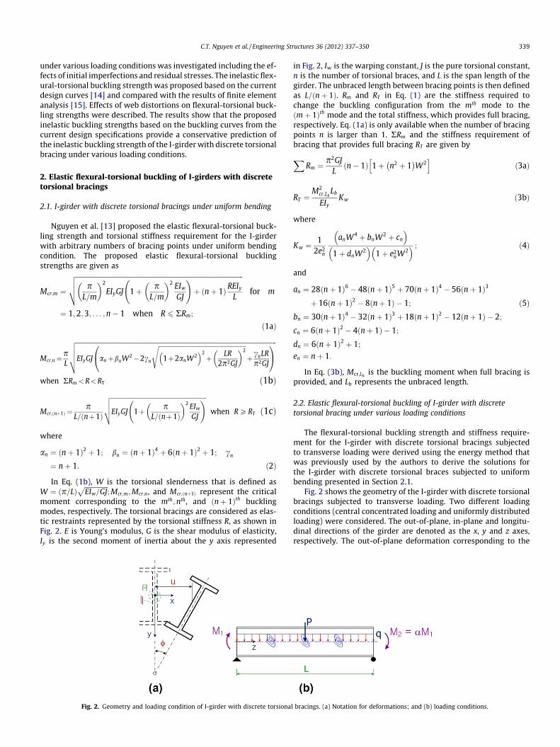
moment corresponding to the mth;nth, and ðnþ 1Þth bucklingmodes, respectively. The torsional bracings are considered as elas-tic restraints represented by the torsional stiffness R, as shown inFig. 2. E is Young’s modulus, G is the shear modulus of elasticity,Iy is the second moment of inertia about the y axis represented
Fig. 2. Geometry and loading condition of I-girder with discrete torsiona
in Fig. 2, Iw is the warping constant, J is the pure torsional constant,n is the number of torsional braces, and L is the span length of thegirder. The unbraced length between bracing points is then definedas L=ðnþ 1Þ. Rm and RT in Eq. (1) are the stiffness required tochange the buckling configuration from the mth mode to theðmþ 1Þth mode and the total stiffness, which provides full bracing,respectively. Eq. (1a) is only available when the number of bracingpoints n is larger than 1. RRm and the stiffness requirement ofbracing that provides full bracing RT are given by
XRm ¼
p2GJL
n� 1ð Þ 1þ n2 þ 1� �
W2h i
ð3aÞ
RT ¼M2
cr;LbLb
EIyKw ð3bÞ
where
Kw ¼1
2e2n
anW4 þ bnW2 þ cn
� �1þ dnW2� �
1þ e2nW2
� � ; ð4Þ
and
an ¼ 28ðnþ 1Þ6 � 48ðnþ 1Þ5 þ 70ðnþ 1Þ4 � 56ðnþ 1Þ3
þ 16ðnþ 1Þ2 � 8ðnþ 1Þ � 1; ð5Þbn ¼ 30ðnþ 1Þ4 � 32ðnþ 1Þ3 þ 18ðnþ 1Þ2 � 12ðnþ 1Þ � 2;
cn ¼ 6ðnþ 1Þ2 � 4ðnþ 1Þ � 1;
dn ¼ 6ðnþ 1Þ2 þ 1;
en ¼ nþ 1:
In Eq. (3b), Mcr;Lbis the buckling moment when full bracing is
provided, and Lb represents the unbraced length.
2.2. Elastic flexural-torsional buckling of I-girder with discretetorsional bracing under various loading conditions
The flexural-torsional buckling strength and stiffness require-ment for the I-girder with discrete torsional bracings subjectedto transverse loading were derived using the energy method thatwas previously used by the authors to derive the solutions forthe I-girder with discrete torsional braces subjected to uniformbending presented in Section 2.1.
Fig. 2 shows the geometry of the I-girder with discrete torsionalbracings subjected to transverse loading. Two different loadingconditions (central concentrated loading and uniformly distributedloading) were considered. The out-of-plane, in-plane and longitu-dinal directions of the girder are denoted as the x, y and z axes,respectively. The out-of-plane deformation corresponding to the
l bracings. (a) Notation for deformations; and (b) loading conditions.
340 C.T. Nguyen et al. / Engineering Structures 36 (2012) 337–350
x axis is denoted as u and the rotation of the cross section is repre-sented by the twisting angle u. The I-girder was assumed to have adoubly symmetric section and simply supported boundary condi-tions in torsion and flexure. The span length was equally spacedby n bracing points. The assumptions used to derive the flexural-torsional buckling strength and stiffness requirement are givenas follows: (a) the deformation is small enough; (b) the distortionof the cross-section is neglected; (c) the material follows Hook’slaw; (d) the elastic restraints are attached to the centroidal axis;and (e) the effect of in-plane deformation can be ignored.
The total potential energy of the I-girder, including the strainenergy of the rotational elastic restraints is defined as [16,17]
P ¼Z L
0
12
EIyðu00Þ2 þ12
EIwð/00Þ2 þ12
GJð/0Þ2 �Mxu00/
dz
þ 12
RXn
i¼1
/2i ð6Þ
where /i is the twisting angle of the cross section at the bracingpoints. The I-girder is equally spaced by n number of torsionalbraces. Therefore, the location of the ith torsional bracing can be de-fined as z ¼ i=ðnþ 1Þð ÞL, where i ¼ 1;2;3; . . . ; n.
The bending moment about the x axis Mx is a function of the zcoordinate and can be expressed as Mx ¼ MofðzÞ, where Mo is themaximum moment at mid-span, which is defined as Mo ¼ PL=4and Mo ¼ qL2=8 for the central concentrated load and uniformlydistributed load, respectively. To simplify the integration process,a Fourier series [18] was used for the fðzÞ function. For the centralconcentrated load, fðzÞ was assumed as
fðzÞ ¼ 8p2
Xm
k¼1
1
k2 sinkp2
sinkpz
Lð7Þ
where m is the number of terms in the series that represents a de-gree of accuracy and m ¼ 5 was used in this derivation. In the caseof a uniformly distributed loading condition, fðzÞ was taken as
fðzÞ ¼ sinpzL: ð8Þ
The geometric boundary conditions for the simply supportedgirders in flexure and torsion are given as follows: (a) uð0Þ ¼/ð0Þ ¼ u00ð0Þ ¼ /00ð0Þ ¼ 0; and (b) uðLÞ ¼ /ðLÞ ¼ u00ðLÞ ¼ /00ðLÞ ¼ 0.The admissible functions that satisfy the boundary conditions forsimply supported girders in flexure and torsion for the out-of-planedeformation uðzÞ and twisting /ðzÞ of the I-girder were assumed asfollows
uðzÞ ¼Xnþ2
k¼1
uk sinkpz
L; and /ðzÞ ¼
Xnþ2
k¼1
/k sinkpz
Lð9Þ
where uk and /k are the generalized coordinates for the out-of-plane displacement and twisting angle, respectively.
Substituting Eqs. (7)–(9) into Eq. (6), the total potential energycan be expressed in terms of uk and /k as
P ¼ 12
Z L
0EIyðu00Þ2dzþ 1
2
Z L
0EIwð/00Þ2dzþ 1
2
Z L
0GJð/0Þ2dz
�Mo
Z L
0u00/fdzþ 1
2RXn
i¼1
/2i : ð10Þ
Applying the Rayleigh-Ritz method [16], the first variation ofthe total potential energy with respect to uk and /k are given bythe following:
@P@uk¼ 0; and
@P@/k¼ 0: ð11Þ
Substituting the integration results from Eq. (10) into Eq. (11)yields a set of homogeneous algebraic equations that can beexpressed in matrix form as
A11 A12
A21 A22
uk
uk
� �¼
00
� �ð12Þ
where Aij is the ðnþ 2Þ � ðnþ 2Þ matrix. The critical moments canbe obtained from nontrivial solutions of Eq. (12). However, findingthe closed form solution of Eq. (12) for an arbitrary number of brac-ing points n is a complicated task. Thus, the solution of Eq. (12) wasobtained by increasing the number of bracing points n (forn ¼ 1;2;3 . . .Þ. It is then found that the critical moments of theI-girder with discrete torsional bracings have the following form:
Mcr;m ¼
ffiffiffiffiffiffiffiffiffiffiffiffiffiffiffiffiffiffiffiffiffiffiffiffiffiffiffiffiffiffiffiffiffiffiffiffiffiffiffiffiffiffiffiffiffiffiffiffiffiffiffiffiffiffiffiffiffiffiffiffiffiffiffiffiffiffiffiffiffiffiffiffiffiffiffiffiffiffiffiffiffiffiffiffiffiffiffiffiffiffiffiffiffiffiffiffiffiffiffiffiffiffiffiffiffiffiffiffiffiffiffiffiffiffiffiffiffiffiffiffiffiffiffiC2
b;mp
L=m
� �2
EIyGJ 1þ pL=m
� �2 EIw
GJ
!þðnþ1Þ
Cb;ðmþ1ÞREIy
L
vuut for m
¼1;2; . . . :;n�1 when R6RRm
ð13aÞ
Mcr;n¼Cb;npL
ffiffiffiffiffiffiffiffiffiffiffiffiffiffiffiffiffiffiffiffiffiffiffiffiffiffiffiffiffiffiffiffiffiffiffiffiffiffiffiffiffiffiffiffiffiffiffiffiffiffiffiffiffiffiffiffiffiffiffiffiffiffiffiffiffiffiffiffiffiffiffiffiffiffiffiffiffiffiffiffiffiffiffiffiffiffiffiffiffiffiffiffiffiffiffiffiffiffiffiffiffiffiffiffiffiffiffiffiffiffiffiffiffiffiffiffiffiffiffiffiffiffiffiffiffiffiffiffiffiffiffiffiffiffiffiffiffiffiffiffiffiffiffiffiffiffiffiffiffiffiffiffiffiffiEIyGJ anþbnW2�2cn
ffiffiffiffiffiffiffiffiffiffiffiffiffiffiffiffiffiffiffiffiffiffiffiffiffiffiffiffiffiffiffiffiffiffiffiffiffiffiffiffiffiffiffiffiffiffiffiffiffiffiffiffiffiffiffiffiffiffiffiffiffiffiffiffiffiffi1þ2anW2� �2
þ 1
C2b;n
LR2p2GJ
� �2vuut þCb;ðnþ1Þ
C2b;n
cnLRp2GJ
0@
1A
vuuutwhen RRm<R6RT ð13bÞ
Mcr;ðnþ1Þ ¼Cb;ðnþ1ÞpL=ðnþ 1Þ
ffiffiffiffiffiffiffiffiffiffiffiffiffiffiffiffiffiffiffiffiffiffiffiffiffiffiffiffiffiffiffiffiffiffiffiffiffiffiffiffiffiffiffiffiffiffiffiffiffiffiffiffiffiffiffiffiffiffiffiffiffiffiffiffiEIyGJ 1þ p
L=ðnþ 1Þ
� �2 EIw
GJ
!vuutwhen R > RT: ð13cÞ
where W is the torsional slenderness; an;bn, and cn are functions ofthe number of bracing points n and are the same as the uniformbending case described in Eq. (2); Cb;k is the equivalent momentfactor that depends on the loading conditions. From the solutionsof Eq. (12) for various numbers of n, Cb;k was approximated as
Cb;k ¼ Cb 1þ k
k2
� �for k ¼ 2;3; . . . ;nþ 1: ð14Þ
In Eq. (14), Cb is the conventional equivalent moment factor forthe unbraced girder (Cb ¼ 1:35 and 1.13 for concentrated load anduniformly distributed load, respectively [16]); and k is the loadingfactor. k is equal to 1.0 and 0.5 for a concentrated load and auniformly distributed load, respectively. Eq. (14) is only valid whenk is larger than 2 and Cb;k ¼ Cb when k ¼ 1.
Similarly, using Eq. (13), the elastic critical moment of the I-gir-der with discrete torsional bracings under unequal end momentcan be obtained using the equivalent moment factor for the moment
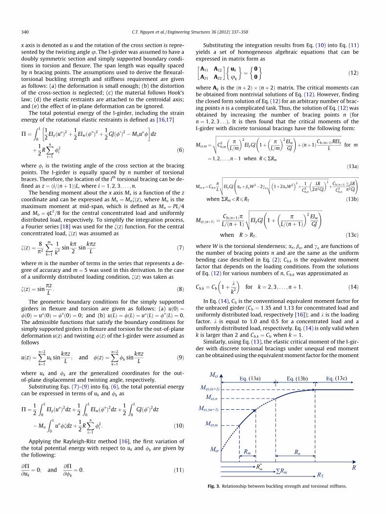
Fig. 3. Relationship between buckling strength and torsional stiffness.
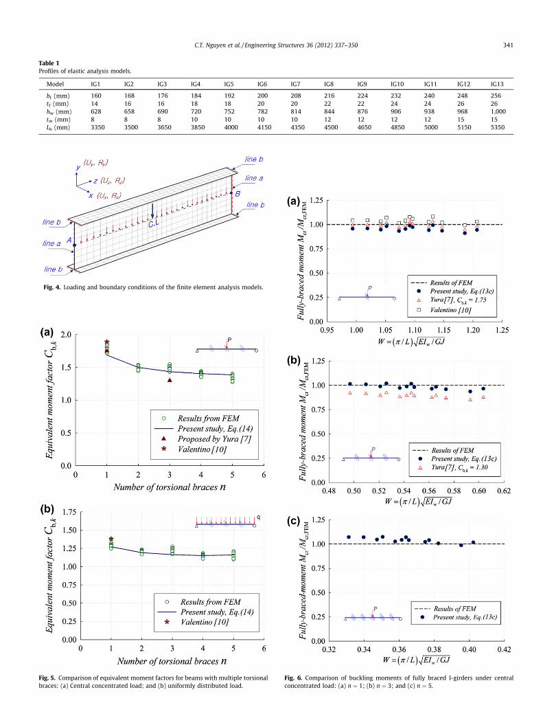
Table 1Profiles of elastic analysis models.
Model IG1 IG2 IG3 IG4 IG5 IG6 IG7 IG8 IG9 IG10 IG11 IG12 IG13
bf (mm) 160 168 176 184 192 200 208 216 224 232 240 248 256tf (mm) 14 16 16 18 18 20 20 22 22 24 24 26 26hw (mm) 628 658 690 720 752 782 814 844 876 906 938 968 1,000tw (mm) 8 8 8 10 10 10 10 12 12 12 12 15 15Lb (mm) 3350 3500 3650 3850 4000 4150 4350 4500 4650 4850 5000 5150 5350
Fig. 4. Loading and boundary conditions of the finite element analysis models.
Fig. 5. Comparison of equivalent moment factors for beams with multiple torsionalbraces: (a) Central concentrated load; and (b) uniformly distributed load.
Fig. 6. Comparison of buckling moments of fully braced I-girders under centralconcentrated load: (a) n ¼ 1; (b) n ¼ 3; and (c) n ¼ 5.
C.T. Nguyen et al. / Engineering Structures 36 (2012) 337–350 341
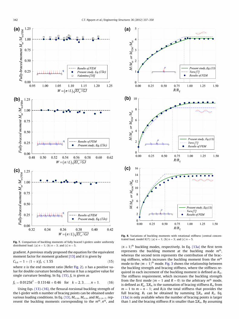
Fig. 7. Comparison of buckling moments of fully braced I-girders under uniformlydistributed load: (a) n ¼ 1; (b) n ¼ 3; and (c) n ¼ 5.
Fig. 8. Variations of buckling moments with rotational stiffness (central concen-trated load, model IG7): (a) n ¼ 1; (b) n ¼ 3; and (c) n ¼ 5.
342 C.T. Nguyen et al. / Engineering Structures 36 (2012) 337–350
gradient. A previous study proposed the equation for the equivalentmoment factor for moment gradient [13] and it is given by
Cb;k ¼ 1þ 1þ að Þfk 6 1:55 ð15Þwhere a is the end moment ratio (Refer Fig. 2). a has a positive va-lue for double curvature bending whereas it has a negative value forsingle curvature bending. In Eq. (15), fk is given as
fk ¼ 0:0125k2 � 0:1314kþ 0:46 for k ¼ 2;3; . . . ; nþ 1: ð16Þ
Using Eqs. (13)–(16), the flexural-torsional buckling strength ofthe I-girder with n number of bracing points can be obtained undervarious loading conditions. In Eq. (13), Mcr;m;Mcr;n, and Mcr;ðnþ1Þ rep-resent the buckling moments corresponding to the mth;nth, and
ðnþ 1Þth buckling modes, respectively. In Eq. (13a) the first termrepresents the buckling moment at the buckling mode mth,whereas the second term represents the contribution of the brac-ing stiffness, which increases the buckling moment from the mth
mode to the ðmþ 1Þth mode. Fig. 3 shows the relationship betweenthe buckling strength and bracing stiffness, where the stiffness re-quired in each increment of the buckling moment is defined as Rm.The stiffness requirement, which increases the buckling strengthfrom the first mode (m ¼ 1 and R ¼ 0Þ to the arbitrary mth mode,is defined as R�m. RRm is the summation of bracing stiffness Rm fromm ¼ 1 to m ¼ n� 1; and RTis the total stiffness that provides thefull bracing. RT can be obtained by summing RRm and Rn. Eq.(13a) is only available when the number of bracing points is largerthan 1 and the bracing stiffness R is smaller than RRm. By assuming

Fig. 9. Variations of buckling moments with rotational stiffness (uniformlydistributed load, model IG5): (a) n ¼ 1; (b) n ¼ 3; and (c) n ¼ 5.
Fig. 10. Comparison of total torsional stiffness requirement (central concentratedload): (a) n ¼ 1; (b) n ¼ 3; and (c) n ¼ 5.
C.T. Nguyen et al. / Engineering Structures 36 (2012) 337–350 343
a bracing stiffness equal to zero, Eq. (13b) becomes the bucklingmoment corresponding to the nth mode. Therefore, Eq. (13b) repre-sents an increase in the buckling moment from the nth mode to theðnþ 1Þth mode, and Eq. (13c) represents the buckling momentwhen full bracing is provided.
2.3. Elastic torsional stiffness requirement of I-girder with discretetorsional bracing under various loading conditions
To apply Eqs. 13(a)–(c) to the I-girder with torsional stiffness R,RRm and RT need to be determined. RRm and RT can be determined
by summing the required stiffness in each increment of thebuckling moment Rm up to the nth and ðnþ 1Þth buckling modes,respectively. Thus, RRm is then given by
RRm ¼1
Cb;n
M2cr;n �M2
cr
� �L
nþ 1ð ÞEIyð17Þ
where Mcr is the buckling moment of the unbraced beam under thecorresponding loading conditions. The total stiffness requirement RT
is also simply given by
RT ¼M2
cr;ðnþ1ÞLb
Cb;ðnþ1ÞEIyKw ð18Þ
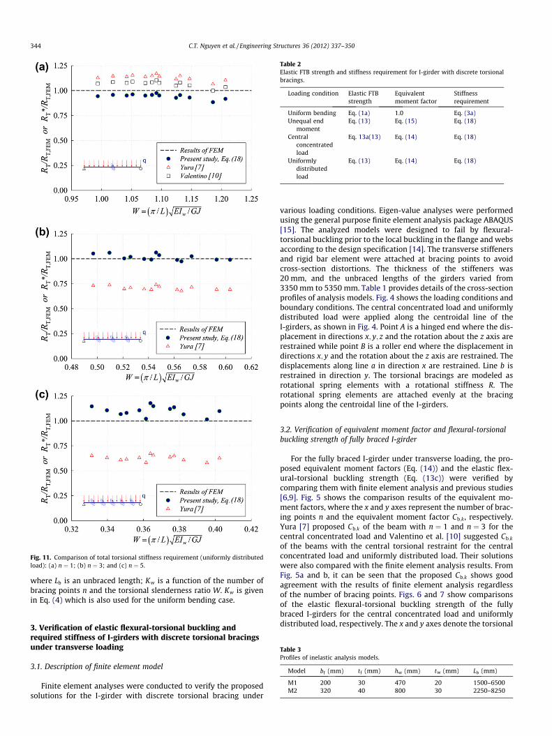
Fig. 11. Comparison of total torsional stiffness requirement (uniformly distributedload): (a) n ¼ 1; (b) n ¼ 3; and (c) n ¼ 5.
Table 2Elastic FTB strength and stiffness requirement for I-girder with discrete torsionalbracings.
Loading condition Elastic FTBstrength
Equivalentmoment factor
Stiffnessrequirement
Uniform bending Eq. (1a) 1.0 Eq. (3a)Unequal end
momentEq. (13) Eq. (15) Eq. (18)
Centralconcentratedload
Eq. 13a(13) Eq. (14) Eq. (18)
Uniformlydistributedload
Eq. (13) Eq. (14) Eq. (18)
344 C.T. Nguyen et al. / Engineering Structures 36 (2012) 337–350
where Lb is an unbraced length; Kw is a function of the number ofbracing points n and the torsional slenderness ratio W. Kw is givenin Eq. (4) which is also used for the uniform bending case.
Table 3Profiles of inelastic analysis models.
Model bf (mm) tf (mm) hw (mm) tw (mm) Lb (mm)
M1 200 30 470 20 1500–6500M2 320 40 800 30 2250–8250
3. Verification of elastic flexural-torsional buckling andrequired stiffness of I-girders with discrete torsional bracingsunder transverse loading
3.1. Description of finite element model
Finite element analyses were conducted to verify the proposedsolutions for the I-girder with discrete torsional bracing under
various loading conditions. Eigen-value analyses were performedusing the general purpose finite element analysis package ABAQUS[15]. The analyzed models were designed to fail by flexural-torsional buckling prior to the local buckling in the flange and websaccording to the design specification [14]. The transverse stiffenersand rigid bar element were attached at bracing points to avoidcross-section distortions. The thickness of the stiffeners was20 mm, and the unbraced lengths of the girders varied from3350 mm to 5350 mm. Table 1 provides details of the cross-sectionprofiles of analysis models. Fig. 4 shows the loading conditions andboundary conditions. The central concentrated load and uniformlydistributed load were applied along the centroidal line of theI-girders, as shown in Fig. 4. Point A is a hinged end where the dis-placement in directions x; y; z and the rotation about the z axis arerestrained while point B is a roller end where the displacement indirections x; y and the rotation about the z axis are restrained. Thedisplacements along line a in direction x are restrained. Line b isrestrained in direction y. The torsional bracings are modeled asrotational spring elements with a rotational stiffness R. Therotational spring elements are attached evenly at the bracingpoints along the centroidal line of the I-girders.
3.2. Verification of equivalent moment factor and flexural-torsionalbuckling strength of fully braced I-girder
For the fully braced I-girder under transverse loading, the pro-posed equivalent moment factors (Eq. (14)) and the elastic flex-ural-torsional buckling strength (Eq. (13c)) were verified bycomparing them with finite element analysis and previous studies[6,9]. Fig. 5 shows the comparison results of the equivalent mo-ment factors, where the x and y axes represent the number of brac-ing points n and the equivalent moment factor Cb;k, respectively.Yura [7] proposed Cb;k of the beam with n ¼ 1 and n ¼ 3 for thecentral concentrated load and Valentino et al. [10] suggested Cb;k
of the beams with the central torsional restraint for the centralconcentrated load and uniformly distributed load. Their solutionswere also compared with the finite element analysis results. FromFig. 5a and b, it can be seen that the proposed Cb;k shows goodagreement with the results of finite element analysis regardlessof the number of bracing points. Figs. 6 and 7 show comparisonsof the elastic flexural-torsional buckling strength of the fullybraced I-girders for the central concentrated load and uniformlydistributed load, respectively. The x and y axes denote the torsional
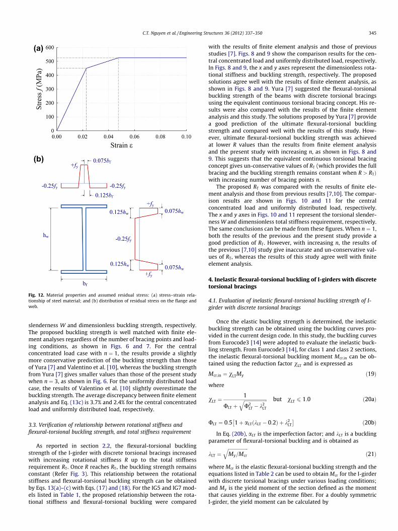
Fig. 12. Material properties and assumed residual stress: (a) stress–strain rela-tionship of steel material; and (b) distribution of residual stress on the flange andweb.
C.T. Nguyen et al. / Engineering Structures 36 (2012) 337–350 345
slenderness W and dimensionless buckling strength, respectively.The proposed buckling strength is well matched with finite ele-ment analyses regardless of the number of bracing points and load-ing conditions, as shown in Figs. 6 and 7. For the centralconcentrated load case with n ¼ 1, the results provide a slightlymore conservative prediction of the buckling strength than thoseof Yura [7] and Valentino et al. [10], whereas the buckling strengthfrom Yura [7] gives smaller values than those of the present studywhen n ¼ 3, as shown in Fig. 6. For the uniformly distributed loadcase, the results of Valentino et al. [10] slightly overestimate thebuckling strength. The average discrepancy between finite elementanalysis and Eq. (13c) is 3.7% and 2.4% for the central concentratedload and uniformly distributed load, respectively.
3.3. Verification of relationship between rotational stiffness andflexural-torsional buckling strength, and total stiffness requirement
As reported in section 2.2, the flexural-torsional bucklingstrength of the I-girder with discrete torsional bracings increasedwith increasing rotational stiffness R up to the total stiffnessrequirement RT. Once R reaches RT, the buckling strength remainsconstant (Refer Fig. 3). This relationship between the rotationalstiffness and flexural-torsional buckling strength can be obtainedby Eqs. 13(a)–(c) with Eqs. (17) and (18). For the IG5 and IG7 mod-els listed in Table 1, the proposed relationship between the rota-tional stiffness and flexural-torsional buckling were compared
with the results of finite element analysis and those of previousstudies [7]. Figs. 8 and 9 show the comparison results for the cen-tral concentrated load and uniformly distributed load, respectively.In Figs. 8 and 9, the x and y axes represent the dimensionless rota-tional stiffness and buckling strength, respectively. The proposedsolutions agree well with the results of finite element analysis, asshown in Figs. 8 and 9. Yura [7] suggested the flexural-torsionalbuckling strength of the beams with discrete torsional bracingsusing the equivalent continuous torsional bracing concept. His re-sults were also compared with the results of the finite elementanalysis and this study. The solutions proposed by Yura [7] providea good prediction of the ultimate flexural-torsional bucklingstrength and compared well with the results of this study. How-ever, ultimate flexural-torsional buckling strength was achievedat lower R values than the results from finite element analysisand the present study with increasing n, as shown in Figs. 8 and9. This suggests that the equivalent continuous torsional bracingconcept gives un-conservative values of RT (which provides the fullbracing and the buckling strength remains constant when R > RTÞwith increasing number of bracing points n.
The proposed RT was compared with the results of finite ele-ment analysis and those from previous results [7,10]. The compar-ison results are shown in Figs. 10 and 11 for the centralconcentrated load and uniformly distributed load, respectively.The x and y axes in Figs. 10 and 11 represent the torsional slender-ness W and dimensionless total stiffness requirement, respectively.The same conclusions can be made from these figures. When n ¼ 1,both the results of the previous and the present study provide agood prediction of RT. However, with increasing n, the results ofthe previous [7,10] study give inaccurate and un-conservative val-ues of RT, whereas the results of this study agree well with finiteelement analysis.
4. Inelastic flexural-torsional buckling of I-girders with discretetorsional bracings
4.1. Evaluation of inelastic flexural-torsional buckling strength of I-girder with discrete torsional bracings
Once the elastic buckling strength is determined, the inelasticbuckling strength can be obtained using the buckling curves pro-vided in the current design code. In this study, the buckling curvesfrom Eurocode3 [14] were adopted to evaluate the inelastic buck-ling strength. From Eurocode3 [14], for class 1 and class 2 sections,the inelastic flexural-torsional buckling moment Mcr;in can be ob-tained using the reduction factor vLT and is expressed as
Mcr;in ¼ vLTMy ð19Þ
where
vLT ¼1
ULT þffiffiffiffiffiffiffiffiffiffiffiffiffiffiffiffiffiffiffiffiU2
LT � k2LT
q but vLT 6 1:0 ð20aÞ
ULT ¼ 0:5 1þ aLT kLT � 0:2ð Þ þ k2LT
�ð20bÞ
In Eq. (20b), aLT is the imperfection factor; and kLT is a bucklingparameter of flexural-torsional buckling and is obtained as
kLT ¼ffiffiffiffiffiffiffiffiffiffiffiffiffiffiffiffiffiMy=Mcr
qð21Þ
where Mcr is the elastic flexural-torsional buckling strength and theequations listed in Table 2 can be used to obtain Mcr for the I-girderwith discrete torsional bracings under various loading conditions;and My is the yield moment of the section defined as the momentthat causes yielding in the extreme fiber. For a doubly symmetricI-girder, the yield moment can be calculated by
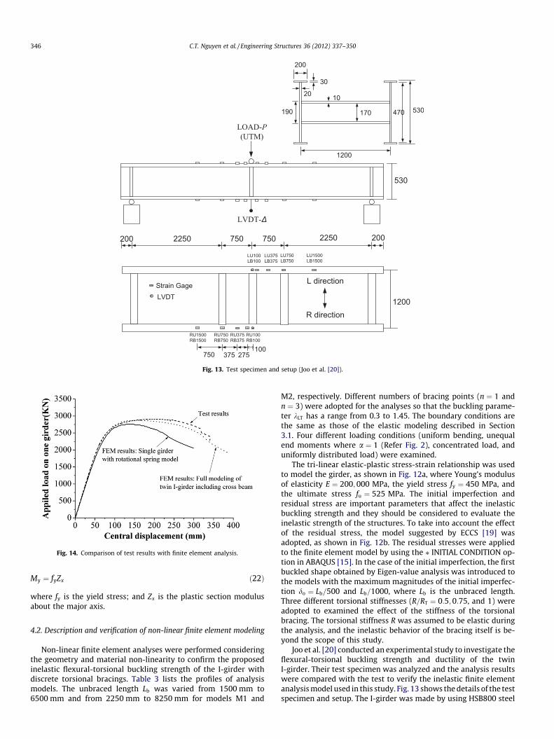
Fig. 13. Test specimen and setup (Joo et al. [20]).
Fig. 14. Comparison of test results with finite element analysis.
346 C.T. Nguyen et al. / Engineering Structures 36 (2012) 337–350
My ¼ fyZx ð22Þ
where fy is the yield stress; and Zx is the plastic section modulusabout the major axis.
4.2. Description and verification of non-linear finite element modeling
Non-linear finite element analyses were performed consideringthe geometry and material non-linearity to confirm the proposedinelastic flexural-torsional buckling strength of the I-girder withdiscrete torsional bracings. Table 3 lists the profiles of analysismodels. The unbraced length Lb was varied from 1500 mm to6500 mm and from 2250 mm to 8250 mm for models M1 and
M2, respectively. Different numbers of bracing points (n ¼ 1 andn ¼ 3) were adopted for the analyses so that the buckling parame-ter kLT has a range from 0.3 to 1.45. The boundary conditions arethe same as those of the elastic modeling described in Section3.1. Four different loading conditions (uniform bending, unequalend moments where a ¼ 1 (Refer Fig. 2), concentrated load, anduniformly distributed load) were examined.
The tri-linear elastic-plastic stress-strain relationship was usedto model the girder, as shown in Fig. 12a, where Young’s modulusof elasticity E ¼ 200; 000 MPa, the yield stress fy ¼ 450 MPa, andthe ultimate stress fu ¼ 525 MPa. The initial imperfection andresidual stress are important parameters that affect the inelasticbuckling strength and they should be considered to evaluate theinelastic strength of the structures. To take into account the effectof the residual stress, the model suggested by ECCS [19] wasadopted, as shown in Fig. 12b. The residual stresses were appliedto the finite element model by using the ⁄ INITIAL CONDITION op-tion in ABAQUS [15]. In the case of the initial imperfection, the firstbuckled shape obtained by Eigen-value analysis was introduced tothe models with the maximum magnitudes of the initial imperfec-tion do ¼ Lb=500 and Lb=1000, where Lb is the unbraced length.Three different torsional stiffnesses (R=RT ¼ 0:5;0:75, and 1) wereadopted to examined the effect of the stiffness of the torsionalbracing. The torsional stiffness R was assumed to be elastic duringthe analysis, and the inelastic behavior of the bracing itself is be-yond the scope of this study.
Joo et al. [20] conducted an experimental study to investigate theflexural-torsional buckling strength and ductility of the twinI-girder. Their test specimen was analyzed and the analysis resultswere compared with the test to verify the inelastic finite elementanalysis model used in this study. Fig. 13 shows the details of the testspecimen and setup. The I-girder was made by using HSB800 steel
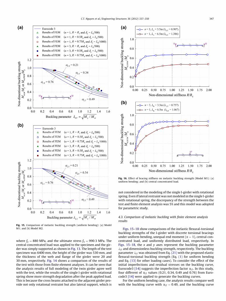
Fig. 15. Comparison of inelastic buckling strength (uniform bending): (a) ModelM1; and (b) Model M2.
Fig. 16. Effect of bracing stiffness on inelastic buckling strength (Model M1): (a)uniform bending; and (b) central concentrated load.
C.T. Nguyen et al. / Engineering Structures 36 (2012) 337–350 347
where fy ¼ 880 MPa, and the ultimate stress fu ¼ 990:3 MPa. Thecentral concentrated load was applied to the specimen and the gir-der was simply supported as shown in Fig. 13. The length of the testspecimen was 6400 mm, the height of the girder was 530 mm, andthe thickness of the web and flange of the girder were 20 and30 mm, respectively. Fig. 14 shows a comparison of the results ofthe test with those from finite element analyses. It can be seen thatthe analysis results of full modeling of the twin girder agree wellwith the test, while the results of the single I-girder with rotationalspring show more strength degradation after the peak applied load.This is because the cross beams attached to the adjacent girder pro-vide not only rotational restraint but also lateral support, which is
not considered in the modeling of the single I-girder with rotationalspring. Even if lateral restraint was not modeled in the single I-girderwith rotational spring, the discrepancy of the strength between thetest and finite element analysis was 5% and this model was adoptedfor parametric study.
4.3. Comparison of inelastic buckling with finite element analysisresults
Figs. 15–18 show comparisons of the inelastic flexural-torsionalbuckling strengths of the I-girder with discrete torsional bracingsunder uniform bending, unequal end moment (a ¼ 1), central con-centrated load, and uniformly distributed load, respectively. InFigs. 15–18, the x and y axes represent the buckling parameterkLT and dimensionless buckling strength, respectively. The bucklingparameter kLT was obtained from Eq. (21) with the proposed elasticflexural-torsional buckling strength (Eq. (1) for uniform bendingand Eq. (13) for other loading cases). To consider the effect of theinitial imperfections and residual stresses on the buckling curve,Eurocode3 [14] suggests the imperfection factor aLT. In this study,four different of aLT values (0.21, 0.34, 0.49 and 0.76) from Euro-code3 [14] were applied to generate the buckling curves.
For the uniform bending case, the analysis results compare wellwith the buckling curve with aLT ¼ 0:49, and the buckling curve
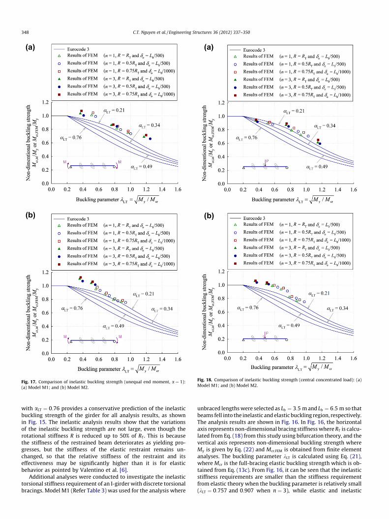
Fig. 17. Comparison of inelastic buckling strength (unequal end moment, a ¼ 1):(a) Model M1; and (b) Model M2.
Fig. 18. Comparison of inelastic buckling strength (central concentrated load): (a)Model M1; and (b) Model M2.
348 C.T. Nguyen et al. / Engineering Structures 36 (2012) 337–350
with aLT ¼ 0:76 provides a conservative prediction of the inelasticbuckling strength of the girder for all analysis results, as shownin Fig. 15. The inelastic analysis results show that the variationsof the inelastic buckling strength are not large, even though therotational stiffness R is reduced up to 50% of RT. This is becausethe stiffness of the restrained beam deteriorates as yielding pro-gresses, but the stiffness of the elastic restraint remains un-changed, so that the relative stiffness of the restraint and itseffectiveness may be significantly higher than it is for elasticbehavior as pointed by Valentino et al. [6].
Additional analyses were conducted to investigate the inelastictorsional stiffness requirement of an I-girder with discrete torsionalbracings. Model M1 (Refer Table 3) was used for the analysis where
unbraced lengths were selected as Lb ¼ 3:5 m and Lb ¼ 6:5 m so thatbeams fell into the inelastic and elastic buckling region, respectively.The analysis results are shown in Fig. 16. In Fig. 16, the horizontalaxis represents non-dimensional bracing stiffness where RT is calcu-lated from Eq. (18) from this study using bifurcation theory, and thevertical axis represents non-dimensional buckling strength whereMy is given by Eq. (22) and Mcr;FEM is obtained from finite elementanalyses. The buckling parameter kLT is calculated using Eq. (21),where Mcr is the full-bracing elastic buckling strength which is ob-tained from Eq. (13c). From Fig. 16, it can be seen that the inelasticstiffness requirements are smaller than the stiffness requirementfrom elastic theory when the buckling parameter is relatively small(kLT ¼ 0:757 and 0:907 when n ¼ 3), while elastic and inelastic
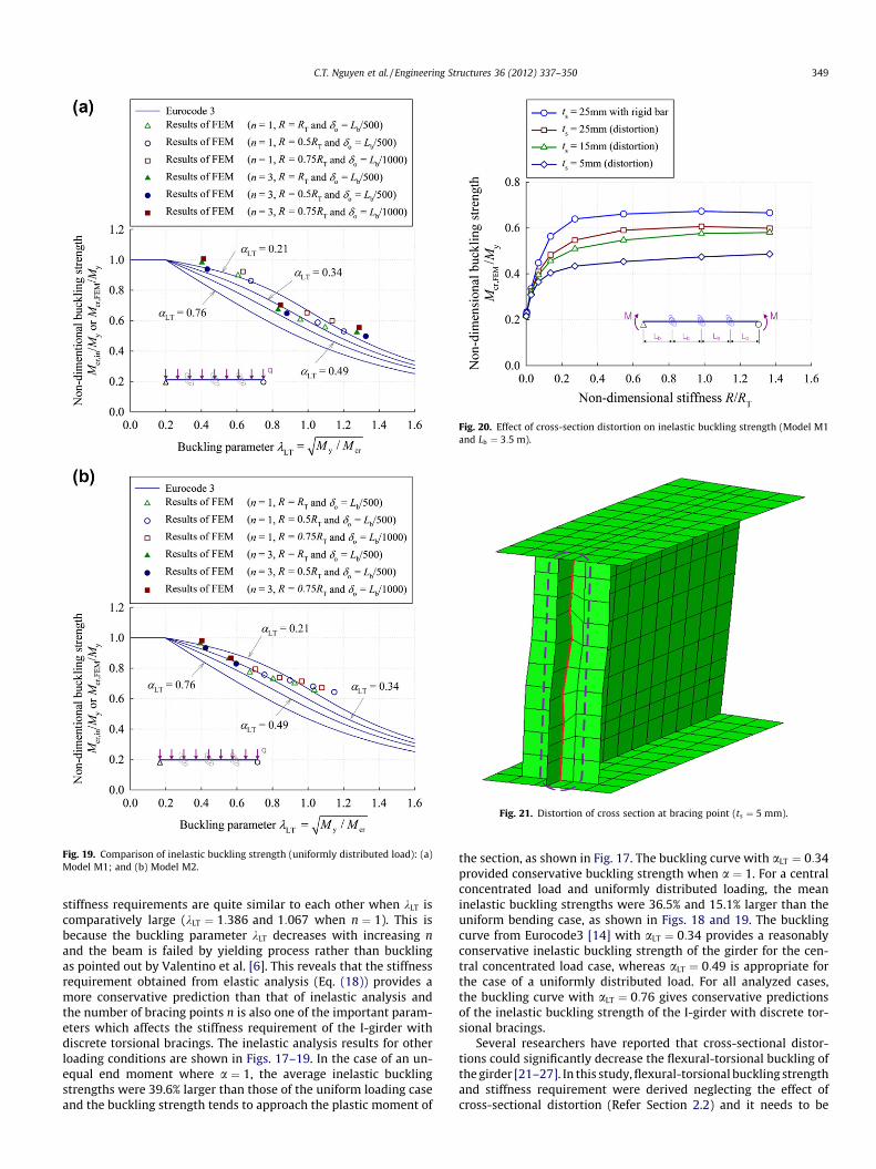
Fig. 19. Comparison of inelastic buckling strength (uniformly distributed load): (a)Model M1; and (b) Model M2.
Fig. 20. Effect of cross-section distortion on inelastic buckling strength (Model M1and Lb ¼ 3:5 m).
Fig. 21. Distortion of cross section at bracing point (ts ¼ 5 mm).
C.T. Nguyen et al. / Engineering Structures 36 (2012) 337–350 349
stiffness requirements are quite similar to each other when kLT iscomparatively large (kLT ¼ 1:386 and 1:067 when n ¼ 1). This isbecause the buckling parameter kLT decreases with increasing nand the beam is failed by yielding process rather than bucklingas pointed out by Valentino et al. [6]. This reveals that the stiffnessrequirement obtained from elastic analysis (Eq. (18)) provides amore conservative prediction than that of inelastic analysis andthe number of bracing points n is also one of the important param-eters which affects the stiffness requirement of the I-girder withdiscrete torsional bracings. The inelastic analysis results for otherloading conditions are shown in Figs. 17–19. In the case of an un-equal end moment where a ¼ 1, the average inelastic bucklingstrengths were 39.6% larger than those of the uniform loading caseand the buckling strength tends to approach the plastic moment of
the section, as shown in Fig. 17. The buckling curve with aLT ¼ 0:34provided conservative buckling strength when a ¼ 1. For a centralconcentrated load and uniformly distributed loading, the meaninelastic buckling strengths were 36.5% and 15.1% larger than theuniform bending case, as shown in Figs. 18 and 19. The bucklingcurve from Eurocode3 [14] with aLT ¼ 0:34 provides a reasonablyconservative inelastic buckling strength of the girder for the cen-tral concentrated load case, whereas aLT ¼ 0:49 is appropriate forthe case of a uniformly distributed load. For all analyzed cases,the buckling curve with aLT ¼ 0:76 gives conservative predictionsof the inelastic buckling strength of the I-girder with discrete tor-sional bracings.
Several researchers have reported that cross-sectional distor-tions could significantly decrease the flexural-torsional buckling ofthe girder [21–27]. In this study, flexural-torsional buckling strengthand stiffness requirement were derived neglecting the effect ofcross-sectional distortion (Refer Section 2.2) and it needs to be
350 C.T. Nguyen et al. / Engineering Structures 36 (2012) 337–350
verified. To investigate the effects of cross-section distortions, non-linear analyses were conducted for model M1 (Refer to Table 3) withan unbraced length Lb ¼ 3:5 m under uniform bending by varyingthe web-stiffener thickness. Inelastic buckling strengths were ob-tained from nonlinear analyses considering material nonlinearitywith residual stresses and initial imperfection (do ¼ Lb=1000). Theresults of flexural-torsional buckling strength were compared withthose without cross-section distortion. It is found that cross-sec-tion distortions significantly decrease the flexural-torsional buck-ling strength of the girder as shown in Fig. 20. For example, FTBstrengths are reduced by approximately 9.0% more than that ofthe girder with the rigid bar element at the bracing point whenthe web stiffener thickness ts is 25 mm. Due to cross-section dis-tortion at the bracing points (See Fig. 21), the buckling strengthsdecrease as the stiffener thickness decreases. The effects of cross-section distortions should be considered to evaluate the flexural-torsional buckling strength of the I-girder with discrete torsionalbracings and the proposed buckling strength is only applicablewhen the cross-section distortion is fully prevented.
5. Conclusions
Flexural-torsional buckling of the I-girder with an arbitrary num-ber of discrete torsional bracings under various loading conditionswas investigated. The analytical solutions for the elastic flexural-torsional buckling strength (Eq. (13)) and stiffness requirements(Eq. (18)) of I-girders with discrete torsional bracings under variousloading conditions were derived. The proposed solutions were thenverified by comparing the results of finite element analysis and otherprevious studies. The comparison results showed that the proposedsolutions provide accurate predictions of the elastic critical bucklingmoment and the stiffness requirement RT regardless of the numberof bracing points and the loading conditions, whereas the resultsfrom the equivalent continuous torsional bracing concept givenon-conservative values of RT with increasing number of bracingpoints n.
The inelastic bucking strength of the I-girder with discrete tor-sional bracings was also examined in this study. The inelastic buck-ling strength was proposed based on the buckling curve fromEurocode3 and proposed elastic solutions. The proposed inelasticbuckling strength was confirmed by comparisons with the non-lin-ear finite element analysis results. From the comparison results,the buckling curve from Eurocode3 with imperfection factoraLT ¼ 0:34 provides a reasonably conservative inelastic bucklingstrength of the girder for the unequal end moment (a ¼ 1) and cen-tral concentrated load cases, whereas aLT ¼ 0:49 and 0.76 provideconservative predictions of inelastic buckling strength for the uni-form bending and uniformly distributed load cases, respectively.
Finally, the inelastic stiffness requirement and the effect ofcross-section distortion on the buckling strength were investigatedby using limited inelastic finite element analysis. The resultsshowed that the stiffness requirement is smaller than that forthe elastic analysis (Eq. (18) (for beams with a lower slendernessratio. As the slenderness increases, the stiffness requirement in-creases and approaches the value for the elastic analysis (Eq.
(18)). Due to cross-section distortions at the bracing points, thebuckling strengths decrease as web thickness deceases. Thus, theeffect of cross-section distortions should be prevented to applythe proposed equations for the flexural-torsional buckling strengthof the I-girder with discrete torsional bracings.
Acknowledgments
This work was supported by grants provided by POSCO Corpo-ration and Korea University. The authors wish to express their grat-itude for the financial support.
References
[1] Taylor AC, Ojalvo M. Torsional restraint of lateral buckling. J Struct Div ASCE1966;92(ST2):115–29.
[2] Wakabayashi M, Nakamura T. Buckling of laterally braced beams. Eng Struct1983;5:108–18.
[3] Tong GS, Chen SF. Buckling of laterally and torsionally braced beams. JConstruct Steel Res 1988;11:41–55.
[4] Tong GS, Chen SF. The elastic buckling of interbraced girders. J Construct SteelRes 1989;14:87–105.
[5] Trahair NS. Flexural-torsional buckling of structures. London: E & FN Spon;1993.
[6] Valentino J, Pi YL, Trahair NS. Inelastic buckling of steel beams with centraltorsional restraints. J Struct Eng ASCE 1997;123(9):1180–6.
[7] Yura JA. Fundamentals of beam bracing. Eng J AISC 2001; First Quarter: 11–26.[8] Nethercot DA. Buckling of laterally or torsionally restrained beams. J Eng Mech
Div ASCE 1973;99(EM4):773–91.[9] Mutton BR, Trahair NS. Stiffness requirements for lateral bracing. J Struct Div
ASCE 1973;99(ST10):2167–82.[10] Valentino J, Trahair NS. Torsional restraint against elastic lateral buckling. J
Struct Eng ASCE 1998;124(10):1217–25.[11] Medland IC. Buckling of interbraced beam systems. Eng Struct 1980;2:90–6.[12] Trahair NS. Laterally unsupported beams. Eng Struct 1996;18(10):759–68.[13] Nguyen CT, Moon J, Le VN, Lee H. Lateral-torsional buckling of I-girders with
discrete torsional bracings. J Construct Steel Res 2010;66(2):170–7.[14] Eurocode 3: Design of steel structures. European Committee for
Standardization, 2003.[15] ABAQUS Standard User’s Manual Version 6.2. Hibbit, Karson and Sorensen Inc.,
2001.[16] Chen WF, Lui EM. Structural stability-theory and implementation. Elsevier
Science Publishing C., Inc.; 1987.[17] Bazant PZ, Cedolin L. Stability of structures-elastic, inelastic, fracture, and
damage theories. New York: Oxford University Press; 1991.[18] Brown JW, Churchill RV. Fourier series and boundary value problems. 5th
ed. New York: McGraw-Hill; 1993.[19] Essentials of Eurocode 3-design manual for steel structures in building.
European convention for constructional steelwork (ECCS). ECCS-advisorycommittee 5, No. 65; 1991.
[20] Joo H, Moon J, Choi B-H, Lee H-E. Evaluation of flexural ductility of negativemoment region of I-girder with high strength steel. J Korean Soc Civil Engrs A:Struct Eng 2010;30(6A):513–23 [in Korean].
[21] Hancock GJ, Bradford MA, Trahair NS. Web distortion and flexural-torsionalbuckling. J Struct Div ASCE 1980;106(ST7):1557–71.
[22] Bradford MA. Inelastic distortional buckling of I-beams. Comput Struct1986;24(6):923–33.
[23] Bradford MA. Buckling of elastically restrained beams with web distortions.Thin-Walled Struct 1988;6:287–304.
[24] Bradford MA. Buckling strength of partially restrained I-beams. J Struct Eng1989;115(5):1272–6.
[25] Bradford MA. Lateral-distortional buckling of steel I-section members. JConstruct Steel Res 1992;23:97–116.
[26] Bradford MA. Inelastic buckling of I-beams with continuous elastic tensionflange restraint. J Construct Steel Res 1998;48:63–77.
[27] White DW, Jung SK. Effect of distortion on the buckling strength ofnoncomposite discretely-braced steel I-section members. Eng Struct2007;29(8):1872–88.