theoretical influence of stirrup ductility on shear assessment of concrete girders
TRANSCRIPT
236 Scientific Paper Structural Engineering International 22014
Peer-reviewed by international ex-perts and accepted for publication by SEI Editorial Board
Paper received May 15 2012Paper accepted September 9 2013
Theoretical Influence of Stirrup Ductility on Shear Assessment of Concrete GirdersDaia Zwicky Prof Dr Institute of Construction and Environmental Technology iTEC College of Engineering and Architecture of
Fribourg EIA-FR Univ of Applied Sciences of Western Switzerland HES-SO Switzerland Contact daiazwickyhefrch
DOI 102749101686614X13830790993168
Abstract
Applying simplified design code provisions for the shear assessment of existing concrete girders may result in unnecessary strengthening justifying the effort to apply more refined approaches Based on the cross-sectional analysis for con-tinuous girder zones (B-regions) this paper discusses the theoretical influences of transverse reinforcement ductility and effective web concrete-compressive strength on shear resistance It is shown that the plastic deformation capacity is fundamentally influenced by the hardening behavior of the transverse rein-forcement and by the bond properties between reinforcement and concrete For typical examples of stirrup configurations allowable compression field inclina-tions are derived and are also compared to the provisions of the fib Model Code 2010 and the Generalized Stress Field Approach This paper concludes with an outlook on practical considerations and how the findings have been integrated in the recently published Swiss code SIA 269221 on existing concrete structures
Keywords structural concrete girder shear ultimate limit state stress fields compression softening reinforcement bond strain localization ductility codes
moments due to plastic hinge forma-tion at ultimate limit state (ULS)
Any redistribution of internal forces can only be attained if the structurersquos plastic deformation capacity is suf-ficient Although it is commonly accepted that reinforcement ductility has a considerable effect on allowable redistribution of bending moments little attention has been provided to date to its influence on redistribution of shear forces
After introducing the basic features of the stress field model used in the Swiss concrete code2 SIA 262 for determin-ing the shear resistance of girder webs at ULS this paper discusses the influ-ence of plastic deformation capacity of the transverse reinforcement on allow-able compression field inclinations and compares the results with other proposals
Shear Resistance Model For Girder Webs
Stress Field Model
Since the 1970s the Swiss concrete codes implicitly or explicitly apply plasticity-based approaches for the structural design of concrete girders with transverse reinforcement at ULS According to the latest design code
SIA 2622 application of stress fields3 is explicitly required
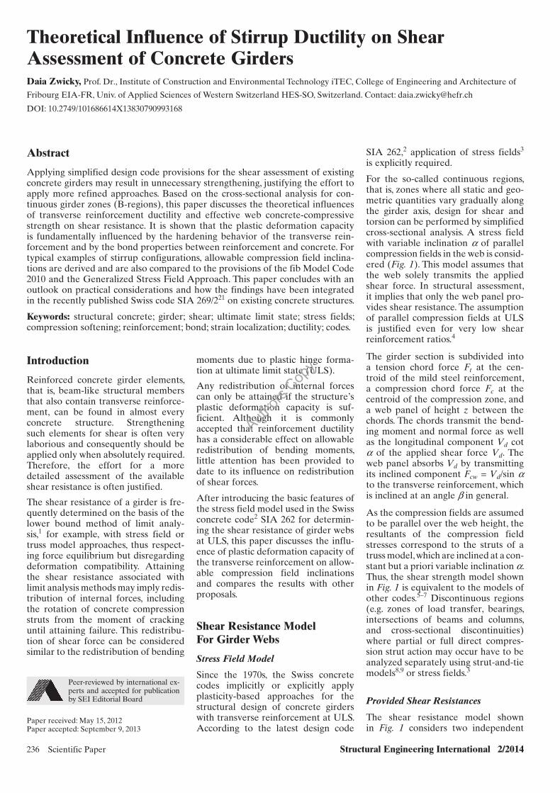
For the so-called continuous regions that is zones where all static and geo-metric quantities vary gradually along the girder axis design for shear and torsion can be performed by simplified cross-sectional analysis A stress field with variable inclination a of parallel compression fields in the web is consid-ered (Fig 1) This model assumes that the web solely transmits the applied shear force In structural assessment it implies that only the web panel pro-vides shear resistance The assumption of parallel compression fields at ULS is justified even for very low shear reinforcement ratios4
The girder section is subdivided into a tension chord force Ft at the cen-troid of the mild steel reinforcement a compression chord force Fc at the centroid of the compression zone and a web panel of height z between the chords The chords transmit the bend-ing moment and normal force as well as the long itudinal component Vd cot a of the applied shear force Vd The web panel absorbs Vd by transmitting its inclined component Fcw = Vdsin a to the transverse reinforcement which is inclined at an angle b in general
As the compression fields are assumed to be parallel over the web height the resultants of the compression field stresses correspond to the struts of a truss model which are inclined at a con-stant but a priori variable inclination a Thus the shear strength model shown in Fig 1 is equivalent to the models of other codes5ndash7 Discontinuous regions (eg zones of load transfer bearings intersections of beams and columns and cross- sectional discontinuities) where partial or full direct compres-sion strut action may occur have to be analyzed separately using strut-and-tie models89 or stress fields3
Provided Shear Resistances
The shear resistance model shown in Fig 1 considers two independent
Introduction
Reinforced concrete girder elements that is beam-like structural members that also contain transverse reinforce-ment can be found in almost every concrete structure Strengthening such elements for shear is often very laborious and consequently should be applied only when absolutely required Therefore the effort for a more detailed assessment of the available shear resistance is often justified
The shear resistance of a girder is fre-quently determined on the basis of the lower bound method of limit analy-sis1 for example with stress field or truss model approaches thus respect-ing force equilibrium but disregarding deformation compatibility Attaining the shear resistance associated with limit analysis methods may imply redis-tribution of internal forces including the rotation of concrete compression struts from the moment of cracking until attaining failure This redistribu-tion of shear force can be considered similar to the redistribution of bending
Authors
Cop
y
Structural Engineering International 22014 Scientific Paper 237
failure criteria the resistance provided by the transverse reinforcement and the resistance provided by the com-pression fields A concrete contribu-tion to shear resistance for example from aggregate interlock action or inclined compression chord forces is not explicitly considered Implicitly however aggregate interlock has to be available at ULS because shear or inclined compression stresses respec-tively have to be transmitted across earlier cracks as the strut inclination is lower than the initial crack inclination
The shear resistance VRds provided by the transverse reinforcement is given27 by
VRds = Asw
____ s fsdz(cot a + cot b)sin b (1)
where Asw is the cross section of one transverse reinforcement element for example the cross section of both legs of a stirrup s is its longitudinal spac-ing fsd is its design yield strength b is its inclination (for usual vertical stir-rups b = 90deg) z is the flexural lever arm between compression and tension chord and a is the constant but a pri-ori variable inclination of compression fields in the web concrete
It can be concluded from Eq (1) that a given transverse reinforcement provides an increasing shear resis-tance with decreasing a The expres-sion z(cot a + cot b)s represents the number of inclined stirrups of which the vertical component of their yield resistance Aswfsdsin b is activated for shear resistance Thus an inclination a as small as possible is usually sought in the assessment of an existing girder The flexural lever arm z is defined as the distance between the couple of
chord forces that is between the cen-troids of mild steel reinforcement and compression zone Usually the depth of the compression zone determined at the section of maximum bending moment is considered for defining the centroid of the compression zone In initial approximations z = 09d may be assumed27 where d is the effective depth of the mild steel longitudinal reinforcement
The shear resistance from Eq (1) can-not exceed the resistance VRdc of the inclined compression fields27 that is the limitation by the so-called web crushing failure10
VRdc = bwnom zkc fcd(cos a
+ cot b sin a) sin a (2)
where bwnom is the nominal web width accounting for the presence of any ducts for prestressing tendons kc is a reduction factor accounting for trans-verse strain state effects and fcd is the design value of uniaxial compressive strength of the web concrete deter-mined with fcd = ηfc fckgc where27 ηfc = (30fck)13 le 1 is a conversion factor pro-viding an equivalent plastic concrete strength11 accounting for the more brittle behavior of higher strength con-crete fck is the characteristic value of cylinder compressive strength in MPa and gc is the resistance factor for con-crete usually taken as 15 In existing structures fck often is greater than 30 MPa and the upper limit of the conver-sion factor ηfc can usually be ignored
VRdc decreases as inclination a decreases and if ducts (grouted or not) are present in the web12 In the design of new concrete girders web crushing fail-ure can be excluded by an appropriate
choice of the web width Often it does not govern since construction and structural detailing requirements fre-quently demand a larger web width
Prestressing tendon forces inclined at an angle bp provide additional shear resistance through their vertical com-ponent ΔVRdp = Fpsin bp (Fig 1) The normal forces from prestressing act-ing on the whole cross section also proportionally load the web Constant inclination of the compression fields over the web height implies that the forces are not deviated at the pre-stressing tendon and thus the force in the tendon is not increased until ULS Without more detailed analysis Fp is to be limited2 to the value considering all friction and long-term losses due to shrinkage creep and relaxation
Design Code Limits for Compression Field Inclinations
In the cracked elastic state shear crack inclinations or directions of pri nci-pal compressive stresses respectively are a function of the longitudinal and transverse reinforcement ratios the ratio of Youngrsquos moduli of rein-forcement and concrete as well as the applied normal and shear stresses1314 For girders with lower transverse than longitudinal reinforcement ratio and normal stresses in the longitudinal direction only principal compressive stress directions in the cracked elastic state are flatter than at cracking
The choice of a compression field incli-nation a at ULS which is considerably lower than the principal compressive stress direction in the cracked elas-tic state implies internal redistribu-tion of shear forces and thus involves plastic deformation of the transverse reinforcement For a given spacing s the number of stirrups within the dis-tance zcot a increases as a decreases requiring plastic deformation of the stirrups activated in the cracked state that is at a lower longitudinal strain Even though reinforcement ductility is often high it is not unlimited This is one of the two reasons4 why the allowable range of compression field inclination usually is limited in codes (also see section on Interaction with Longitudinal Strains and Compression Field Inclination a)
SIA 2622 allows free choice of the compression field inclination within the limits 25deg le a le 45deg at ULS It also allows explicitly an inclination beyond these limits if the choice is justified The European design code5 consid-
s
Aswfsd
Ft
Fp
Vd
Fcw
Fc
Md
Nd
Vd
z =
Fig 1 Stress field in girder web with variable inclination a of parallel compression fields
Authors
Cop
y
238 Scientific Paper Structural Engineering International 22014
ers a ge 218deg while other sources1516 recommend a ge 30deg to also account for reinforcement of limited ductility
Just assuming the minimum design code compression field inclination in the assessment of existing concrete girders may result in underestimat-ing the available shear resistance and consequently in unnecessary strength-ening More detailed investigations on allowable lower limits of compression field inclination are therefore advisable and necessary A possible approach is outlined in the following sections
Available Maximum Shea r Resistance
Optimum Compression Field Inclination
Provided that structural detailing is correct such that premature failure can be excluded for example bond fail-ure between concrete and longitudinal reinforcement or insufficient anchor-age of shear reinforcement the maxi-mum shear resistance of a girder web is attained if the transverse reinforcement and the inclined compression fields both reach failure at the same time The associated optimum inclination aopt is found from equating Eqs (1) and (2)
sin2 aopt = Asw
_______ bwnoms
fsd
_____ kc fcd
sin b (3)
For the given transverse reinforcem ent and concrete properties the optimum compression field inclination aopt pri-marily depends on the reduction factor kc representing the ratio of effective to uniaxial compressive strength of the web concrete and being influenced by transverse strain effects (see section on Effective Compressive Strength of Web Concrete) The available maximum shear resistance is found by applying aopt in Eqs (1) or (2) However this optimum compression field inclination can only be attained if the plastic deformation capacity of the structure is sufficient (see sections on Design Code Limits for Compression Field Inclinations and Deriving Allowable Limits for Compression Field Inclination)
The compression field inclination from Eq (3) should not be flatter than inclinations resulting from geometri-cal conditions for example it cannot be flatter than the line from top of the beam at the section of maximum bending moment or from the edge of a concentrated load to the edge of the support (also see section on Stress Field Model)
Effective Compressive Strength of Web Concrete
Influence of Transverse Str ains
The parallel compression fields in the web concrete transmitting the applied shear force to the transverse reinforce-ment as shown in Fig 1 are crossed by this tensioned transverse reinforcement Its strains are partially transferred by bond to the diagonally compressed web concrete causing a strength reduction17 referred to as compression soften-ing1819 For determining the reduction of the web concrete strength in the principal compressive direction due to transverse strain effects a depen-dence on the average major principal strain e1 is usually considered20 Some reduction of the compressive strength of reinforced panels in comparison to plain concrete has also been found17 in the absence of tension in the trans-verse reinforcement But in general the compressive strength of reinforced concrete panels will be similar to that of plain concrete as long as the transverse reinforcement does not yield4
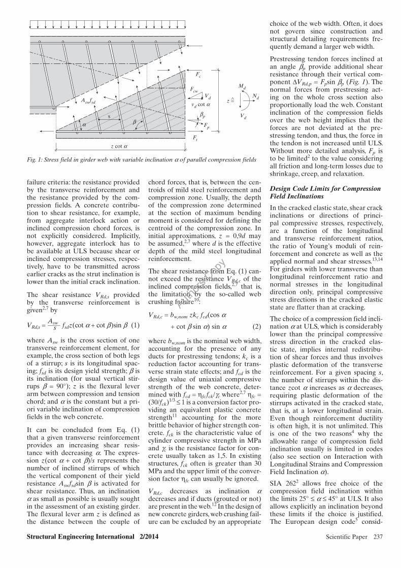
For the given longitudinal strain ex strain e2 in the compression fields and their inclination a the major principal strain e1 can be derived from Mohrrsquos circle of strains (Fig 2)
e1 = ex + (ex ndash e2)cot2a (4)
Web Concrete Strength Reduction Factor kc
SIA 269221 recommends the following expression for the strength reduction factor kc
kc = 1 ___________ 12 + 60e1
le 10 (5)
where e1 is the major principal strain of Eq (4) Equation (5) is a modification of a recent proposal152223 where kc = (12 + 55e1)minus1 The modification con-siders an overall resistance model fac-tor of 105 estimated from statistical information on the original proposal as well as a calculation model factor of 105 for e1 in order to obtain character-istic strength values
The proposal152223 underlying Eq (5) has been calibrated based on a signifi-cant number of experimental results and exhibits a small coefficient of vari-ation It is included in the model code7 without considering further model or reduction factors As this code pri-marily targets design of new concrete structures where compression field strength is often not governing due to construction and detailing require-ments such an approach is acceptable In the assessment of existing struc-tures however web crushing failure10 often has to be accepted if unnecessary strengthening should be prevented This justifies the model factors consid-ered in Eq (5)
Interaction with Longitudinal Strains and Compression Field Inclination a
Introducing Eq (4) i n Eq (5) reveals an interaction of the reduction factor kc with the longitudinal strain ex the strain e2 in the compression fields and their inclination a
At attaining web crushing the strain e2 in the compression fields approxi-
Fig 2 Web panel with skew reinforcement and associated Mohrrsquos circle of strains
Authors
Cop
y
Structural Engineering International 22014 Scientific Paper 239
mately reaches the same value as plain concrete Note that in tests24 on orthogonally reinforced panels a slight reduction of minor princi-pal strains at peak compressive stress could be observed This reduction can also be explained by theoretical analy-sis but it is recommended4 to neglect it in comparison to the values of the other implied strains Design codes27 usually fix the strain at peak compres-sive stress at ec0 = minus2permil More refined approaches could also be considered for example25 ec0 = minus06middot(fcm)13 where fcm is the average cylinder compressive strength in MPa and ec0 results in permil
Figure 3 shows the reduction factor kc of Eq (5) as a function of the compres-sion field inclination a for different levels of longitudinal strain ex A com-parison with other proposals4202627 can be found elsewhere28 They all show a progressively decreasing value of kc with decreasing compression field inclination a This progressive soften-ing of the web concrete is the second reason for limiting the compression field inclinations in codes (Design Code Limits for Compression Field Inclinations Section)
In the design of new concrete girders the major principal strain e1 at mid-height of the web panel is used272930 for determining the strength reduction factor kc requiring the longitudinal strain ex at the same height (Eq (4)) The influence of considering other val-ues of ex is discussed in more detail in Consideration of Longitudinal Strain Section
Coherence with Design Code Provisions
For webs in new structures that are diagonally cracked at ULS a value of kc of 055 to 06 is fixed271531 and a ge 25deg can be assumed (Design Code Limits for Compression Field Inclinations
Section) If plastic deformation of the tension chord cannot be excluded kc = 04 should be assumed2 Note that other design codes567 do not differentiate for the strain state in tension chords Elastic tension chords at ULS are often found near end supports Plastic deformation of tension chords should be assumed in plastic hinge zones normally located at inner supports
An elastic tension chord requires that the reinforcement strain at cracks must be lower than the yield strain esy The average steel strain esm between cracks for regularly ribbed reinforcement bars may be assumed1531 as roughly 80 of esy resulting in esm asymp 12 to 17permil for reinforcing steel used in existing struc-tures21 Further assuming that the com-pression chord also remains elastic a peak compressive fiber strain of minus04 to minus05permil can be expected The strain at the centroid of the compression zone is 23 of the peak strain that is approximately minus025 to minus035permil With these chord strains an average longitu-dinal strain ex of approximately 04 to 08permil at mid-depth of the flexural lever arm is found Applying Eq (4) with a = 25deg and e2 = minus2permil in Eq (5) results in values for kc of approximately 052 to 048 (Fig 3) These values are some-what lower than the recommended design values but still of comparable order of magnitude
The same approach can be applied for plastified tension chords presum-ing that esm ge 25esy that is approxi-mately 5 to 6permil Further assuming that the strain of the extreme compressive fiber attains minus2 to minus3permil the strain at the centroid of the compression zone amounts to minus12 to minus17permil With these chord strains a longitudinal strain ex at mid-depth of the web of approxi-mately 2permil is found resulting in kc = 04 for a = 25deg (Fig 3) and agreeing with design code provisions2
Deriving Allowable Limits for Compression Field Inclination
Justification for Lower and Upper Limits
The maximum shear resistance can only be attained if the plastic defor-mation capacity of the web panel is sufficient This can be checked1516 for example by verifying that the optimum compression field inclination from Eq (3) is within the allowable limits alim of compression field inclination
If aopt lt alimm in failure is determined by rupture of the transverse reinforce-ment without we b concrete crushing If aopt gt alimmax crushing of the com-pression fields without stirrup yielding has to be expected that is very brittle failure In all other cases shear fail-ure is attained by web crushing while the transverse reinforcement yields or hardens respectively The compression field limits help to identify these cases
Thus the shear reinforcement strain at attaining the strength of the compres-sion fields defines the limits for allow-able compression field inclinations at ULS The attainable strain in the shear reinforcement in turn depends on the ductility properties of the reinforcing steel and on strain localization due to tension stiffening
Ductility of Shear Reinforcement
Ductility Properties of Steel
The Swiss codes221 for existing and new concrete structures consider duc-tility classes for reinforcing steel with the following requirements
ndash Low ductility (class A) (ftfs)k ge 105 and euk ge 25permil
ndash Normal ductility (class B) (ftfs)k ge 108 and euk ge 50permil
ndash High ductility (class C) (ftfs)k ge 115 and le 135 and euk ge 75permil
where ftk is the tensile st rength fsk is the yield strength and euk is the ulti- mate strain all on characteristic value level (5th percentile) Other codes532 may designate these classes differently but with identical requirements For reinforcing steel in existing structures the ultimate strain euk is often deci-sive for determining the ductility class Reinforcement of low-ductility class A usually exhibits the mechanical behav-ior of cold-worked steel Classes B and C are habitually associated with hot-rolled steel behavior
Steel Strain Localization
As it is commonly known strain com-patibility in structural concrete only applies to average strains Average strains in the reinforcement are lower than the maximum steel strains at cracks as cracking leads to strain local-ization due to tension stiffening by the concrete between the cracks Tension stiffening effects have a significant influence3334 on plastic deformation capacity of structural concrete and chiefly depend on the bond properties between reinforcement and concrete
02
03
04
05
06
07
08
15 20 25 30 35 40 45
kc (ndash)
Fig 3 Influence of compression field in-clination a and longitudinal strain ex on reduction factor kc
Authors
Cop
y
240 Scientific Paper Structural Engineering International 22014
The steel strains at cracks have to be considered for assessing the exploi ta-tion of ductility properties An efficient way is applying strain localization fac-tors ks = esmesmax expressing the ratio of average steel strain esm between adjacent cracks to maximum steel strain esmax at cracks A very simple yet comprehensive model for determin-ing such factors is the Tension Chord Model3536
Figure 4a shows different options for capturing the hardening behavior of class B reinforcing steel that is model-ing as hot-rolled or cold-worked steel and a linear approximation Figure 4b illustrates the effect of hardening behavior on strain localization for given concrete strength crack spac-ing and geometrical properties of the rebar Analytical expressions for aver-age steel strains esm and steel behavior modeling can be found elsewhere3336
Figure 4b reveals that steel strain local-ization at and beyond onset of yielding strongly depends on the hardening behavior36 It thus also has a marked influence at attaining ultimate steel strain that is at steel rupture A lower value of ks corresponds to increased strain localization effects
The set of parameters indicated in Fig 4 also points out that further influ-ences have to be considered yield strength fsk and tensile strength ftk or hardening ratio (ftfs)k respectively ultimate strain euk bar diameter Oslash rel-ative rib area fR concrete strength fck and average crack spacing srm Strain localization factors may be further affected by construction details and other structure-specific features34
A detailed discussion on strain localiza-tion factors is beyond the scope of this contribution Yet the values ksy = esym
esy at yielding (solid lines in Fig 5) and ksu = esumeuk at steel rupture ( dotted lines in Fig 5) are of particular interest
The degree of strain localization should be determined as a function of the transverse reinforcement prop-erties the concrete quality and the expected average crack spacing For regularly ribbed bars of small to mod-erate diameter and usually rather large crack spacing in lightly to moderately reinforced web panels made of normal strength concrete the following val-ues are recommended for preliminary investigations
ndash Low-ductility reinforcement (class A) ksy asymp 040 and ksu asymp 025
ndash Normal-ductility reinforcement (class B) ksy asymp 065 and ksu asymp 030
ndash High-ductility reinforcement (class C) ksy asymp 065 and ksu asymp 035
Derivation of Allowable Compression Field Inclination Limits
Compatibility of web strains is used to determine allowable compression field inclinations at ULS considering trans-verse reinforcement ductility prop-erties at attaining compression field crushing (Justification for Lower and Upper Limits Section) Strain com-patibility in a shear panel with trans-verse reinforcement inclined at angle b requires25 (Fig 2)
(cos b + sin b cot a)2 = eb ndash e2 ______ ex ndash e2 (6)
where eb is the strain in the direction of the transverse reinforcement ex is the
00
02
04
06
08
10600(a) (b)
550
500
450
40010 20 30 40 500 10 20 30 40 50
BilinearCold-workedHot-rolled
Yielding
Fig 4 Steel strain localization ndash (a) modeling of hardening be havior and (b) its effect on strain localization
0
02
04
06
08
10
5 10 15 20 25 300
02
04
06
08
10
0 002 004 0060
02
04
06
08
10
200 300 400 500 600
0
02
04
06
08
10
25 50 75 1000
02
04
06
08
10
30 45 60 75 900
02
04
06
08
10
100 150 200 250 300
Fig 5 Strain localization factors ks = esmesmax at yielding (solid lines) and at rupture (dotted lines) for different steel hardening (color scheme according to Fig 4) Basic values Oslash12 fR = 0 05 fsk = 450 MPa (ftfs)k = 12 euk = 50permil fck = 50 MPa and srm = 200 mm Note values of ksy for hot-rolled hardening behavior and bilinear approximation coincide
Authors
Cop
y
Structural Engineering International 22014 Scientific Paper 241
longitudinal strain and e2 is the strain in the direction of the compression fields The strain in direction b follows from Eq (6) as
eb = e2 + (ex ndash e2)(cos b + sin b cot a)2
(7)
Figure 2 shows that eb may vary consid-erably as a function of the reinforce-ment inclination b For the frequent case of girders with vertical stirrups that is b = 90deg Eqs (6) and (7) are fur-ther simplified29
Allowable ranges for the compres-sion field inclination a can be deter-mined15162223 from Eq (6) Usually e2 = ec0 = minus2permil is applied2715 but more refined approaches could also be used (see section on Interaction with Longitudinal Strains and Compression Field Inclination a) For determining the upper limit alimmax eb = ksymiddotesy = ksymiddotfsmEs is introduced in Eq (6) Applying the average value fsm of the yield strength instead of a charac-teristic value and neglecting the par-tial resistance factor will ensure that attaining yielding of the transverse reinforcement is not underestimated For determining a lower limit alimmin eb = ksumiddoteud = ksumiddoteukgs is introduced considering a partial resistance factor for steel for example27 gs = 115 to not overestimate the average strain at steel rupture
Consideration of Longitudinal Strain
Determining allowable compression field inclination limits with Eq (6) requires the introduction of the longi-tudinal strain ex Two approaches are proposed in the literature
minus If the strength reduction factor kc is determined at mid-height of the web the longitudinal strain ex at this same height should be used7152930 This should go together with an assessment of average transverse reinforcement strains that is includ-ing strain localization effects
minus The lowest effective compressive strength can be expected at the ten-sion chord as the longitudinal strain is highest there (Fig 3) This can also be observed in load tests on profi led girder s where web crushing usually occurs just above the tension chord For longitudinal strains vary-ing over the web height the strains in the transverse reinforcement also vary and are highest at the ten-sion chord (Eq (7)) Assuming that a crack is present there eb from Eq (7) can be directly compared to the
strain of the naked transverse steel4 or strain localization factors are set equal to 1 respectively In other words the ultimate steel strain eud or the average yield strain fsmEs respectively are substituted for eb in Eq (6)
The first approach usually results in conservative limits for the allowable compression field inclination If longi-tudinal strains ex are to be calculated in more detail the following assump-tions2 should be considered plane sections remain plane and orthogonal to the beam axis the reinforcement only transmits tensile and compres-sive forces in its own direction con-crete tensile strength is neglected and axial forces and the longitudinal component of shear force have to be considered21 (Fig 1) The beneficial effect of tension stiffening in the ten-sion chord can be considered1516 or it is neglected731 for more conservative results
Examples
Generally applicable limits for allow-able compression field inclination are difficult to derive due to the many influences on strain localization (Steel Strain Localization Section) Sample results are shown here for transverse reinforcement configurations typically present in existing girders
The vertical shear reinforcement that is b = 90deg consists of bars Oslash8 or Oslash16 respectively considered practical extremes The relative rib area fR of the bars is assumed2 as fR = 0040 for Oslash8 and fR = 0056 for Oslash16 Characteristic and mean yield strength are fsk = 450 MPa and fsm = 550 MPa respectively representing reinforcing steel typically used21 in the 1970s The characteristic tensile strength ftk is determined from the required minimum hardening ratio of ductility classes A (cold-worked steel) or B (hot-rolled steel) respec-tively and the ultimate strain euk is the required minimum value (Ductility Properties of Steel Section) Concrete strength is fck = 50 MPa with a strain ec0 = minus2permil at peak compressive stress The average crack spacing is srm = 200 mm or srm = 300 mm respectively
For these combinations of reinforce-ment properties and crack spacing the strain localization factors of Table 1 can be derived The analytically exact values are rounded to the next mul-tiple of 005 as the bond strengths in the Tension Chord Model35 are a function of the average concrete ten-sile strength As the latter may vary considerably it is deemed justified to apply slightly rounded values for strain localization factors in the evaluation of Eq (6) (Derivation of Allowable Compression Field Inclination Limits Section)
The resulting limits alimmin and alimmax for compression field inclinations are shown in Fig 6 considering the longi-tudinal strain at different web heights (Consideration of Longitudinal Strain Section) For inclined transverse rein-forcement the allowable compression field inclinations would principally become steeper28
General Discussion
The results in Fig 6 suggest that the reinforcement ductility properties which are often implicitly related to a specific hardening behavior play an important role for allowable com-pression field limits Furthermore the range of allowable compression field inclinations may be rather narrow for low-ductility transverse reinforcement (Fig 6a and b) For enhanced ductility properties the range becomes larger The bar diameter should also have some influence a bigger bar diameter may allow a lower alimmin (Fig 6d and e) For a given bar spacing this would result in a doubly beneficial effect as the higher yield resistance of the trans-verse reinforcement would be associ-ated with a flatter compression field inclination resulting in a more than proportional increase in the shear resistance provided by the transverse reinforcement (Eq (1))
The comparison of Fig 6a and b or d and e respectively implies that the average crack spacing would also have some effect on alim in particular in combination with a larger bar diame-ter If the longitudinal strain at the ten-sion chord is considered (Fig 6c and
Ductility class A (cold-worked) B (hot-rolled)Crack spacing srm 200 mm 300 mm 200 mm 300 mm
ksy ksu ksy ksu ksy ksu ksy ksu
Oslash8 035 010 030 010 060 010 040 010Oslash16 045 015 035 010 075 020 065 015
Table 1 Strain localization factors applied in the example
Authors
Cop
y
242 Scientific Paper Structural Engineering International 22014
f) both influences could be completely eliminated from the analytical deriva-tion and an increased range of allow-able compression field inclination may be found
The results also imply that a brittle web-crushing failure10 without yielding of the stirrups may not be identified if alimmax = 45deg is assumed Depending on the strain profile in the cross sec-tion on the crack spacing in the web and less pronounced on the bar diam-eter of the transverse reinforcement this upper limit may be considerably lower than 45deg
Quantitative validation of the pro-pos ed approach against test data to determine its accuracy is still required Test data should be primarily evalu-ated with regard to the effects of duc-tility class and longitudinal strain but should also analyze the influences of hardening behavior bar diameter crack spacing and bar ribbing
Comparison with Other Models
The Model Code7 proposes several levels of approximation for the com-pression field inclination For all levels alimmax = 45deg is set In approximation level I a lower limit alimmin = 30deg is given for reinforced concrete mem-bers If significant axial compression or prestressing is present alimmin = 25deg may be chosen while alimmin = 40deg is set for members with significant axial tension In approximation level II the
lower limit of compression field incli-nation is determined from alimmin = 20deg + 10 000ex where ex is the longi-tudinal strain at mid-depth of the web with vertical stirrups The expression may be applied for strains ex le 3permil and ex = 0permil should be chosen if strain pro-file analysis returns a negative value This approximation level disregards any concrete contribution to shear resistance as it is also assumed here (Provided Shear Resistances Section) In level III the expression for alimmin of level II is applied and addition-ally the shear resistance provided by aggregate interlock of the web con-crete is considered as derived from the Modified Compression Field Theory29 A level IV of approximation implicitly targets non-linear finite element anal-ysis and the necessary calibration on experimental results is mentioned
The lines labeled ldquoMC2010rdquo in Fig 6a b d and e correspond to approximation level II of the lower compression field inclination limit For stirrups of ductil-ity class A the MC2010 lower limit only attains values beyond the lower limit derived here for a longitudinal strain of approximately 22permil (ie a plastified tension chord (Coherence with Design Code Provisions Section)) a large stir-rup bar diameter and rather narrow crack spacing (Fig 6a) For larger crack spacing as in Fig 6b the MC2010 line is below the lower limit derived here in the whole range of longitudinal strain For stirrups with ductility class B and
small bar diameter the MC2010 line attains values above the lower limit derived here for longitudinal strains higher than approximately 18permil for large bar diameter the MC2010 line is above the lower limit derived here for longitudinal strains higher than 07permil to 11permil depending on the crack spac-ing or for rather important negative longitudinal strains
A further comparison is made to the Generalized Stress Field Approach1516 lines labeled ldquoGSFArdquo in Fig 6 It pro-poses alimminB = 20deg + 5 000ex for stir-rups of ductility class B and alimminC = 16deg + 4 000ex for class C where ex is the longitudinal strain at mid-depth of the web The upper limit is alimmax = 35deg + 5 000ex for both ductility classes The applicability of the expressions is limited to vertical stirrups with yield strengths between 400 and 550 MPa and longitudinal strains minus05permil le ex le 15permil The proposals are explicitly not apt for the evaluation of plastic hinge zones and shear reinforcement of duc-tility class A
Figure 6d and e shows that the gradi-ents of the GSFA expressions and the results derived here show the same trends in the associated range of longi-tudinal strain This is not surprising as both rely on the same principles that is consideration of strain localization and of limit strains in the reinforce-ment The differences in ordinate inter-cept are mainly due to different strain
Fig 6 Allowable compression field inclinations as a function of the longitudinal strain for different crack spacing and bar diameters ndash (a) to (c) for ductility class A and (d) to (f) for ductility class B
35
25
15
45
ndash1 1 3
srm = 200 mm
srm = 200 mm
Ductility class A(a) (b) (c)
(f)(e)(d)
35
25
15
45
35
25
15
45
35
25
15
45
35
25
15
45
35
25
15
45
ndash1 1 3 0 10 15 205
ndash1 1 3 ndash1 1 3 0 10 15 205
Ductility class B Ductility class B Ductility class B
Ductility class A Ductility class A
srm = 300 mm
srm = 300 mm
MC2010
GSFA
empty16empty8 Max
Min
Authors
Cop
y
Structural Engineering International 22014 Scientific Paper 243
refined determination of structural resistances Consequently the code series SIA 269 only treats the possible and necessary deviations from the directives in series SIA 260
Code Provisions for Assessment of Shear Resistance and Reinforcement Detailing
In a few paragraphs only general requirements deemed necessary for shear resistance assessment of girder webs and panels are provided in SIA 269221 being implicitly based on the stress field model of Fig 1 and the approach shown in this paper
minus The choice of a compression fi eld inclination beyond the recom-mended design limits2 in particu-lar a lt 25deg should be justifi ed by considering strain compatibility ductility properties of reinforce-ment and bond properties between reinforcement and concrete (Ductility of Shear Reinforcement and Derivation of Allowable Compression Field Inclination Limits Sections)
ndash Plastic deformation capacity should in general be verifi ed by consider-ing the hardening behavior of the reinforcement and bond proper-ties between reinforcing steel and concrete (Steel Strain Localization Section)
minus When determining the web concrete strength reduction factor kc with Eq (5) the major principal strain e1 should be determined at mid-height of the web also considering the lon-gitudinal components of shear force and prestressing (Consideration of Longitudinal Strain Section)
It is further mentioned that a reduced relative rib area fR of the longitudi-nal reinforcement generally results in a further decrease in kc This is due34 to decreasing bond strength with decreasing fR or less pronounced steel strain localization in the tension chord respectively (Fig 5) Consequently the longitudinal strain ex at mid-depth of the web generally increases leading to an increase in e1 and a decrease in kc
For vertical stirrups of ductility class A a compression field inclination alimmin ge 30deg should be chosen if plastic defor-mations of the tension chord cannot be excluded (Coherence with Design Code Provisions Section and Fig 6c) No further provisions are provided for normal- or high-ductility transverse reinforcement
III Refi ned detailed assessment for example with discontinuous rigid-plastic stress fi elds3
IV Further refi ned detailed assess-ment with non-linear analysis methods for example elasto- plastic stress fi elds38 or other numerical methods3940
In level I the compression field inclinat ion a should be chosen with caution if the transverse reinforce-ment possibly provides low ductility Contrary to design code provisions (Design Code Limits for Compression Field Inclinations Section) a ge 30deg should be assumed if plastic deforma-tion of the tension chord cannot be excluded (Fig 6c and Coherence with Design Code Provisions Section) For normal- or high-ductility transverse reinforcement alimmin = 25deg is deemed a conservative choice
A level II assessment corresponds to applying the approaches discussed in Comparison with Other Models Section For determining the available maximum shear resistance (Eq (3)) an iterative procedure is necessary Based on a first estimate of effective web con-crete strength for example kc = 04 a first approximation of the available shear resistance from Eqs (1) or (2) is derived as well as the approximate location of the shear control section at a distance zcot a away from the face of a support or a point load27 There a strain profile analysis is performed allowing to refine the initial assump-tion for kc and to determine allowable limits for a (Derivation of Allowable Compression Field Inclination Limits Section) The procedure is repeated until a sufficient accuracy of the results is obtained The discussion of levels III and IV is beyond the scope of this paper
Implementation in SIA 2692
General Approach in Swiss Codes on Existing Structures
The code series SIA 269 for existing structures has a strong link to the code series SIA 260 for new structures All material-specific subcodes treat condi-tion survey and evaluation construc-tion materials from the past structural analysis and verifications as well as maintenance and strengthening inter-ventions41 No new resistance models are introduced for structural safety assessment but simplifications made in design models for new structures are eliminated or detailed to allow more
localization factors The strain local-ization factors applied here (Table 1) differ from those in GSFA where globally ksy = 08 and ksu = 025 is used The latter have been estimated inde-pendently of bar diameter and aver-age crack spacing from the original Tension Chord Model35 where a bilin-ear approximation of reinforcing steel behavior is considered Such a linear approximation of hardening tends to overestimate36 strain localization fac-tors in comparison to cold-worked or hot-rolled steel behavior in particular at attaining the ultimate strain of the reinforcement (Fig 4b)
Practical Considerations
Required Information on Structure
The available shear resistance of an existing concrete girder depends on many parameters
ndash Reinforcement cross sections (Oslash) and spacing s inclination b of the transverse reinforcement relative rib area fR yield limit fsk hardening ratio (ftfs)k ultimate strain euk and hardening behavior
ndash Web concrete compressive strength fck and web width bwnom
ndash Prestressing tendon profi le and cross sections duct material state of grouting and level of remaining prestressing
Some parameters can be easily updated from files or by probing for example concrete strength or bar spacing For other parameters for example relative rib area or hardening behavior this may be difficult or simply uneconomi-cal at a preliminary assessment level In such cases apply sound engineer-ing estimates and perform a sensitivity analysis on the influence of the con-cerned parameter on the end result This will give a basis for decisions on further surveys
Assessment Levels
Recall that the shear resistance model discussed here is based on sec-tional analysis If insufficient shear resistance is found in a first level of assessment there are several levels of increasing accuracy but also of increasing effort37
I General assessment with sectional analysis according to design codes (eg Ref 2)
II Detailed assessment with sectional analysis according to refi ned code direct ives (eg Ref 217)
Authors
Cop
y
244 Scientific Paper Structural Engineering International 22014
SIA 269221 allows consideration of the shear resistances of girder flanges but requires justification This may be achieved for example with non-lin-ear numerical analysis by continuous elasto-plastic stress fields38
The code21 further provides directives on the assessment of bond strength and detailing of reinforcement splices and anchorage of shear reinforce-ment at chords The requirements on transverse reinforcement detailing in particular for open stirrups have been taken from the European code5 The rules for bond strength are based on the Tension Chord Model35 and have been complemented34 by reduction factors for small concrete cover nar-row bar spacing and poor bar ribbing
If bar ribbing of the longitudinal rein-forcement in the tension chord does not meet the requirements for new struc-tures2 force transfer between com-pression field and tension chord should be checked This can be treated42 for example by comparing the tension chord force increment derived from the stress field analysis to the allow-able force increment derived from the available bond strength The beneficial effect of lateral pressure exerted by the transverse reinforcement forces on the bond strength could be further considered for example by a simple friction approach26
Conclusions
The hardening behavior the ductil-ity properties of the reinforcing steel and tension stiffening effectsmdashbeing chiefly dependent on the bond prop-erties between reinforcement and the concrete ndash essentially control the plas-tic deformation capacity of structural concrete This capacity may have an important influence on the allowable minimum inclination of compression fields in a girder web when assessing shear resistance at ULS with a con-ventional plasticity-based stress field model in particular if the transverse reinforcement exhibits poor ductility
Except for the recent Swiss code21 on existing concrete structures current structural concrete design codes25ndash7 do not explicitly consider the influence of plastic deformation capacity on shear resistance Possible future refinements should be evaluated by considering the influences discussed here being verified against experimental data and being further simplified for efficient practical application
Acknowledgements
The rules in SIA 2692 on the assessment of structural safety and structural detailing were developed under the responsibility of the author However code rules are usually not formulated by a single person The hundreds of comments received during the consultation phase of the Swiss code21 on existing concrete structures allowed the author to considerably improve and condense his proposals The work of all commenters as well as the very pleasant collaboration with other involved persons in the working group for SIA 2692 is thankfully acknowledged
References
[1] Nielsen MP Hoang LC Limit Analysis and Concrete Plasticity 3rd edn Taylor amp Francis Group London 2010
[2] SIA 262 Concrete Structures Swiss Society of Engineers and Architects Zurich 2003
[3] Muttoni A Schwartz J Thuumlrlimann B Design of Concrete Structures with Stress Fields Birkhaumluser Boston 1997
[4] Kaufma nn W Strength and Deformations of Structural Concrete Subjected to In-Plane Shear and Normal Forces Swiss Federal Institute of Technology Insti tute of Structural Engineering Zurich 1998 Report no 234
[5] Eurocode 2 EN 1992-1-1 Design of Concrete Structures ndash Part 1 General Rules and Rules for Buildings European Committee for Standardization (CEN) Brussels 2 004
[6] DIN 1045-1 Tragwerke aus Beton Stahlbeton und Spannbeton ndash Teil 1 Bemessung und Konstruktion (Structures Made of Concrete Reinforced Concrete and Prestressed Concrete ndash Part 1 Structural Design and Construction) Deutsches Institut fuumlr Normung eV (DIN) Beuth 2008
[7] fib MC 2010 Model code 2010 ndash first com-plete draft ndash Vol 2 Feacutedeacuteration Internationale du Beacuteton (fib) 2010 Lausanne Bulletin no 56
[8] Schlaich J Weischede D Ein praktisches Verfahr en zum methodischen Bemessen und Konstruieren im Stahlbetonbau (A Practical Procedure for M ethodical Structural Design and Detailing in Reinforced Concrete) Comiteacute Euro-International du Beacuteton (CEB) Lausanne 1982 Bulletin drsquoInformation No 150
[9] Schlaich J Schaumlfer K Jennewein M Toward a consistent design of structural concrete PCI J 1987 32(3) 74ndash150
[10] Braestrup MW Plastic analysis of shear in reinforced concrete Mag Concr Res 1974 26(89) 221ndash228
[11] Muttoni A Die Anwendbarkeit der Plastizi-taumltstheorie in der Bemessung von Stahlbeton (The Applicability of the Theory of Plasticity in the Design of Reinforced Concrete) Swiss Federal Institute of Technology Institute of Structural Engineering Zurich CH 1990 Report no 176
[12] Mutt oni A Burdet O Hars E Effect of duct type on shear strength of thin webs ACI Struct J 2006 103(5) 729ndash735
[13] Kupfe r H Erweiterung der Moumlrschrsquoschen Fachwerkanalogie mit Hilfe des Prinzips
vom Minimum der Formaumlnderungs energie (Generalization of Moumlrschrsquos truss analogy using the principle of minimum strain energy) In Bulletin drsquoInformation no 40 Comiteacute Euro-International du Beacuteton (CEB) Wexham Springs 1964 44ndash57
[14] Baumann T Zur Frage der Netzbewehrung von Flaumlchentragwerken (On the matter of grid reinforcement of surface structures) Bauingenieur 1972 47(10) 367ndash377
[15] Sigrist V Hackbarth B A structured approach to the design and analysis of beams in shear In Shear and Punching Shear in RC and FRC Elements ndash Salograve Workshop 15ndash16 October 2010 Feacutedeacuteration Internationale du Beacuteton (fib) Lausanne 2010 Bulletin no 57 93ndash104
[16] Sigrist V Generalized stress field approach for analysis of beams in shear ACI Struct J 2011 108(4) 479ndash487
[17] Robinson JR Demorieux JM Essais de traction-compression sur modegraveles drsquoacircme de poutre en beacuteton armeacute (Tension-compression tests on models of reinforced concrete girder web s) In Annales ITBTP Institut Technique du Bacirctiment et des Travaux Publics (ITBTP) Paris F 1969 980ndash982
[18] Collins MP Stress-strain characteristics of diagonally cracked concrete In IABSE col-loquium lsquoPlasticity in Reinforced Concretersquo Copenhagen International Association for Bridge and Structural Engineering (IABSE) Zurich 1979 Report no 29 27ndash34
[19] Vecchio FJ Collins MP Stress-strain char-acteristics of reinforced concrete in pure shear In IABSE colloquium lsquoAdvanced Mechanics of Reinforced Concretersquo Delft 1981 International Association for Bridge and Structural Engineering (IABSE) Zurich 1981 Report no 34 211ndash225
[20] Collins MP Mitchell D Adebar P Vecchio FJ A general shear design method ACI Struct J 1996 93(1) 36ndash45
[21] SIA 2692 Maintenance des Structures Porteuses ndash Structures en Beacuteton (Existing Structures ndash Concrete Structures) Swiss Society of Engineers and Architects Zurich 2011
[22] Sigrist V Hackbarth B Stress field analysis of structural concrete beams In 3rd International Congress and exhibition fib PrecastPrestressed Concrete Institute PCI Washington 2010 Paper no 377
[23] Sigrist V Hackbarth B Querkrafttragfaumlhigkeit von Stahlbetontraumlgern ndash Bemessung Uumlberpruumlfung Beurteilung (Shear resistance of reinforced concrete girders ndash design verificati on assessment) Beton- und Stahlbetonbau 2010 105(11) 686ndash694
[24] Vecchio FJ Collins MP The Response of Reinforced Concrete to In-Plane Shear and Normal Stresses Department of Civil Engineering University of Toronto Toronto 1982 Publication no 82-03
[25] Seelhofer H Ebener Spannungszustand Grundlagen amp Anwendungen ( Plane Stress State Basics and Applications) Swiss Federal Institute of Technology Institute of Structural Engineering Zurich 2009 Report no 320
[26] Zwicky D Vogel T Critical inclination of compression struts in concrete beams ASCE J Struct Eng 2006 132(5) 686ndash693
Authors
Cop
y
Structural Engineering International 22014 Scientific Paper 245
[32] fib MC Model Code 2010 ndash First Complete Draft ndash Vol 1 Feacutedeacuteration Internationale du Beacuteton ( fib) Lausanne 2010 Bulletin no 55
[33] Zwicky D Bond and ductility a theoretical study on the impact of construction details ndash part 1 basic considerations Adv Concr Constr 2013 1(1) 103ndash119
[34] Zwicky D Bond and ductility a theoretical study on the impact of construction details ndash part 2 structure-specific features Adv Concr Constr 2013 1(2) 137ndash149
[35] Marti P Alvarez M Kaufmann W Sigrist V Tension chord model for structural concrete Struct Eng Int 1998 8(4) 287ndash298
[36] Alvarez M Einfluss des Verbundverhalten s auf das Verformungsvermoumlgen von Stahlbeton (Influence of Bond Behavior on the Deformation Capacity of Structural Concrete) Swiss Federal Institute of Technology Institute of Structural Engineering Zurich 1998 Report no 236
[37] Muttoni A Fernaacutendez Ruiz M Design through an incremental approach the Swiss experienc e In Codes in Structural Engineering ndash
[27] Belarbi A Hsu TTC Constitutive laws of softened concrete in biaxial tension-compres-sion ACI Struct J 1995 92(5) 562ndash573
[28] Zwicky D Girder shear resistance assess-ment ndash applications of SIA 2692 In Life-Cycle and Sustainability of Civil Infrastructure Systems Strauss A Frangopol DM Bergmeister K (eds) Taylor amp Fr ancis Group London 2013 193 on CD-ROM
[29] Vecchio FJ Collins MP The modified com-pression field theory for reinforced concrete elements subjected to shear ACI Struct J 198 6 83(2) 219ndash231
[30] Bentz EC Vecchio FJ Collins MP The sim-plified MCFT for calculating the shear strength of reinforced concrete elements ACI Struct J 2006 103(4) 614ndash624
[31] Bentz EC MC2010 Shear strength of beams and implications of the new approaches In Shear and Punching Shear in RC and FRC Elements ndash Salograve Workshop 15ndash16 October 2010 Feacutedeacuteration Internationale du Beacuteton (fib) Lausanne 2010 Bulletin no 57 15ndash30
Development and Needs for International Practice Hirt MA Radic J Mandic A (eds) SECON-CSSE Staro Cice HR 2010 419ndash426
[38] Fernaacutendez Ruiz M Muttoni A On develop-ment of suitable stress fiel ds for structural con-crete ACI Struct J 2007 104(4) 495ndash502
[39] Bentz EC Sectional Analysis of Reinforced Concrete Members PhD Thesis Department of Civil Engineering University of Toronto Toronto ON Canada 2000
[40] Vecchio FJ Nonlinear finite element anal-ysis of reinforced concrete membranes ACI Struct J 1989 86(1) 26ndash35
[41] Bruumlhwiler E Vogel T Lang T Luumlchinger P Swiss standards for existing structures Struct Eng Int 2012 22(2) 275ndash280
[42] Zwicky D Querkraft in Balken mit Buumlgelbewehrung (Shear in Beams with Transverse Reinforcement) In Erhaltung von Tragwerken ndash Vertiefung und Anwendung (Con servation of Structures ndash Deepening and Application) Swiss Society of Engineers and Architects Zurich 2011 Documentation no D0240 215ndash226
Elegance in StructuresIABSE Conference Nara Japan
Organised byThe Japanese Group of IABSE
May 13-15 2015
Call for Papers May 15 2014
wwwiabseorgnara2015
photo courtesy Nikken Sekkei Ltd
Authors
Cop
y
Structural Engineering International 22014 Scientific Paper 237
failure criteria the resistance provided by the transverse reinforcement and the resistance provided by the com-pression fields A concrete contribu-tion to shear resistance for example from aggregate interlock action or inclined compression chord forces is not explicitly considered Implicitly however aggregate interlock has to be available at ULS because shear or inclined compression stresses respec-tively have to be transmitted across earlier cracks as the strut inclination is lower than the initial crack inclination
The shear resistance VRds provided by the transverse reinforcement is given27 by
VRds = Asw
____ s fsdz(cot a + cot b)sin b (1)
where Asw is the cross section of one transverse reinforcement element for example the cross section of both legs of a stirrup s is its longitudinal spac-ing fsd is its design yield strength b is its inclination (for usual vertical stir-rups b = 90deg) z is the flexural lever arm between compression and tension chord and a is the constant but a pri-ori variable inclination of compression fields in the web concrete
It can be concluded from Eq (1) that a given transverse reinforcement provides an increasing shear resis-tance with decreasing a The expres-sion z(cot a + cot b)s represents the number of inclined stirrups of which the vertical component of their yield resistance Aswfsdsin b is activated for shear resistance Thus an inclination a as small as possible is usually sought in the assessment of an existing girder The flexural lever arm z is defined as the distance between the couple of
chord forces that is between the cen-troids of mild steel reinforcement and compression zone Usually the depth of the compression zone determined at the section of maximum bending moment is considered for defining the centroid of the compression zone In initial approximations z = 09d may be assumed27 where d is the effective depth of the mild steel longitudinal reinforcement
The shear resistance from Eq (1) can-not exceed the resistance VRdc of the inclined compression fields27 that is the limitation by the so-called web crushing failure10
VRdc = bwnom zkc fcd(cos a
+ cot b sin a) sin a (2)
where bwnom is the nominal web width accounting for the presence of any ducts for prestressing tendons kc is a reduction factor accounting for trans-verse strain state effects and fcd is the design value of uniaxial compressive strength of the web concrete deter-mined with fcd = ηfc fckgc where27 ηfc = (30fck)13 le 1 is a conversion factor pro-viding an equivalent plastic concrete strength11 accounting for the more brittle behavior of higher strength con-crete fck is the characteristic value of cylinder compressive strength in MPa and gc is the resistance factor for con-crete usually taken as 15 In existing structures fck often is greater than 30 MPa and the upper limit of the conver-sion factor ηfc can usually be ignored
VRdc decreases as inclination a decreases and if ducts (grouted or not) are present in the web12 In the design of new concrete girders web crushing fail-ure can be excluded by an appropriate
choice of the web width Often it does not govern since construction and structural detailing requirements fre-quently demand a larger web width
Prestressing tendon forces inclined at an angle bp provide additional shear resistance through their vertical com-ponent ΔVRdp = Fpsin bp (Fig 1) The normal forces from prestressing act-ing on the whole cross section also proportionally load the web Constant inclination of the compression fields over the web height implies that the forces are not deviated at the pre-stressing tendon and thus the force in the tendon is not increased until ULS Without more detailed analysis Fp is to be limited2 to the value considering all friction and long-term losses due to shrinkage creep and relaxation
Design Code Limits for Compression Field Inclinations
In the cracked elastic state shear crack inclinations or directions of pri nci-pal compressive stresses respectively are a function of the longitudinal and transverse reinforcement ratios the ratio of Youngrsquos moduli of rein-forcement and concrete as well as the applied normal and shear stresses1314 For girders with lower transverse than longitudinal reinforcement ratio and normal stresses in the longitudinal direction only principal compressive stress directions in the cracked elastic state are flatter than at cracking
The choice of a compression field incli-nation a at ULS which is considerably lower than the principal compressive stress direction in the cracked elas-tic state implies internal redistribu-tion of shear forces and thus involves plastic deformation of the transverse reinforcement For a given spacing s the number of stirrups within the dis-tance zcot a increases as a decreases requiring plastic deformation of the stirrups activated in the cracked state that is at a lower longitudinal strain Even though reinforcement ductility is often high it is not unlimited This is one of the two reasons4 why the allowable range of compression field inclination usually is limited in codes (also see section on Interaction with Longitudinal Strains and Compression Field Inclination a)
SIA 2622 allows free choice of the compression field inclination within the limits 25deg le a le 45deg at ULS It also allows explicitly an inclination beyond these limits if the choice is justified The European design code5 consid-
s
Aswfsd
Ft
Fp
Vd
Fcw
Fc
Md
Nd
Vd
z =
Fig 1 Stress field in girder web with variable inclination a of parallel compression fields
Authors
Cop
y
238 Scientific Paper Structural Engineering International 22014
ers a ge 218deg while other sources1516 recommend a ge 30deg to also account for reinforcement of limited ductility
Just assuming the minimum design code compression field inclination in the assessment of existing concrete girders may result in underestimat-ing the available shear resistance and consequently in unnecessary strength-ening More detailed investigations on allowable lower limits of compression field inclination are therefore advisable and necessary A possible approach is outlined in the following sections
Available Maximum Shea r Resistance
Optimum Compression Field Inclination
Provided that structural detailing is correct such that premature failure can be excluded for example bond fail-ure between concrete and longitudinal reinforcement or insufficient anchor-age of shear reinforcement the maxi-mum shear resistance of a girder web is attained if the transverse reinforcement and the inclined compression fields both reach failure at the same time The associated optimum inclination aopt is found from equating Eqs (1) and (2)
sin2 aopt = Asw
_______ bwnoms
fsd
_____ kc fcd
sin b (3)
For the given transverse reinforcem ent and concrete properties the optimum compression field inclination aopt pri-marily depends on the reduction factor kc representing the ratio of effective to uniaxial compressive strength of the web concrete and being influenced by transverse strain effects (see section on Effective Compressive Strength of Web Concrete) The available maximum shear resistance is found by applying aopt in Eqs (1) or (2) However this optimum compression field inclination can only be attained if the plastic deformation capacity of the structure is sufficient (see sections on Design Code Limits for Compression Field Inclinations and Deriving Allowable Limits for Compression Field Inclination)
The compression field inclination from Eq (3) should not be flatter than inclinations resulting from geometri-cal conditions for example it cannot be flatter than the line from top of the beam at the section of maximum bending moment or from the edge of a concentrated load to the edge of the support (also see section on Stress Field Model)
Effective Compressive Strength of Web Concrete
Influence of Transverse Str ains
The parallel compression fields in the web concrete transmitting the applied shear force to the transverse reinforce-ment as shown in Fig 1 are crossed by this tensioned transverse reinforcement Its strains are partially transferred by bond to the diagonally compressed web concrete causing a strength reduction17 referred to as compression soften-ing1819 For determining the reduction of the web concrete strength in the principal compressive direction due to transverse strain effects a depen-dence on the average major principal strain e1 is usually considered20 Some reduction of the compressive strength of reinforced panels in comparison to plain concrete has also been found17 in the absence of tension in the trans-verse reinforcement But in general the compressive strength of reinforced concrete panels will be similar to that of plain concrete as long as the transverse reinforcement does not yield4
For the given longitudinal strain ex strain e2 in the compression fields and their inclination a the major principal strain e1 can be derived from Mohrrsquos circle of strains (Fig 2)
e1 = ex + (ex ndash e2)cot2a (4)
Web Concrete Strength Reduction Factor kc
SIA 269221 recommends the following expression for the strength reduction factor kc
kc = 1 ___________ 12 + 60e1
le 10 (5)
where e1 is the major principal strain of Eq (4) Equation (5) is a modification of a recent proposal152223 where kc = (12 + 55e1)minus1 The modification con-siders an overall resistance model fac-tor of 105 estimated from statistical information on the original proposal as well as a calculation model factor of 105 for e1 in order to obtain character-istic strength values
The proposal152223 underlying Eq (5) has been calibrated based on a signifi-cant number of experimental results and exhibits a small coefficient of vari-ation It is included in the model code7 without considering further model or reduction factors As this code pri-marily targets design of new concrete structures where compression field strength is often not governing due to construction and detailing require-ments such an approach is acceptable In the assessment of existing struc-tures however web crushing failure10 often has to be accepted if unnecessary strengthening should be prevented This justifies the model factors consid-ered in Eq (5)
Interaction with Longitudinal Strains and Compression Field Inclination a
Introducing Eq (4) i n Eq (5) reveals an interaction of the reduction factor kc with the longitudinal strain ex the strain e2 in the compression fields and their inclination a
At attaining web crushing the strain e2 in the compression fields approxi-
Fig 2 Web panel with skew reinforcement and associated Mohrrsquos circle of strains
Authors
Cop
y
Structural Engineering International 22014 Scientific Paper 239
mately reaches the same value as plain concrete Note that in tests24 on orthogonally reinforced panels a slight reduction of minor princi-pal strains at peak compressive stress could be observed This reduction can also be explained by theoretical analy-sis but it is recommended4 to neglect it in comparison to the values of the other implied strains Design codes27 usually fix the strain at peak compres-sive stress at ec0 = minus2permil More refined approaches could also be considered for example25 ec0 = minus06middot(fcm)13 where fcm is the average cylinder compressive strength in MPa and ec0 results in permil
Figure 3 shows the reduction factor kc of Eq (5) as a function of the compres-sion field inclination a for different levels of longitudinal strain ex A com-parison with other proposals4202627 can be found elsewhere28 They all show a progressively decreasing value of kc with decreasing compression field inclination a This progressive soften-ing of the web concrete is the second reason for limiting the compression field inclinations in codes (Design Code Limits for Compression Field Inclinations Section)
In the design of new concrete girders the major principal strain e1 at mid-height of the web panel is used272930 for determining the strength reduction factor kc requiring the longitudinal strain ex at the same height (Eq (4)) The influence of considering other val-ues of ex is discussed in more detail in Consideration of Longitudinal Strain Section
Coherence with Design Code Provisions
For webs in new structures that are diagonally cracked at ULS a value of kc of 055 to 06 is fixed271531 and a ge 25deg can be assumed (Design Code Limits for Compression Field Inclinations
Section) If plastic deformation of the tension chord cannot be excluded kc = 04 should be assumed2 Note that other design codes567 do not differentiate for the strain state in tension chords Elastic tension chords at ULS are often found near end supports Plastic deformation of tension chords should be assumed in plastic hinge zones normally located at inner supports
An elastic tension chord requires that the reinforcement strain at cracks must be lower than the yield strain esy The average steel strain esm between cracks for regularly ribbed reinforcement bars may be assumed1531 as roughly 80 of esy resulting in esm asymp 12 to 17permil for reinforcing steel used in existing struc-tures21 Further assuming that the com-pression chord also remains elastic a peak compressive fiber strain of minus04 to minus05permil can be expected The strain at the centroid of the compression zone is 23 of the peak strain that is approximately minus025 to minus035permil With these chord strains an average longitu-dinal strain ex of approximately 04 to 08permil at mid-depth of the flexural lever arm is found Applying Eq (4) with a = 25deg and e2 = minus2permil in Eq (5) results in values for kc of approximately 052 to 048 (Fig 3) These values are some-what lower than the recommended design values but still of comparable order of magnitude
The same approach can be applied for plastified tension chords presum-ing that esm ge 25esy that is approxi-mately 5 to 6permil Further assuming that the strain of the extreme compressive fiber attains minus2 to minus3permil the strain at the centroid of the compression zone amounts to minus12 to minus17permil With these chord strains a longitudinal strain ex at mid-depth of the web of approxi-mately 2permil is found resulting in kc = 04 for a = 25deg (Fig 3) and agreeing with design code provisions2
Deriving Allowable Limits for Compression Field Inclination
Justification for Lower and Upper Limits
The maximum shear resistance can only be attained if the plastic defor-mation capacity of the web panel is sufficient This can be checked1516 for example by verifying that the optimum compression field inclination from Eq (3) is within the allowable limits alim of compression field inclination
If aopt lt alimm in failure is determined by rupture of the transverse reinforce-ment without we b concrete crushing If aopt gt alimmax crushing of the com-pression fields without stirrup yielding has to be expected that is very brittle failure In all other cases shear fail-ure is attained by web crushing while the transverse reinforcement yields or hardens respectively The compression field limits help to identify these cases
Thus the shear reinforcement strain at attaining the strength of the compres-sion fields defines the limits for allow-able compression field inclinations at ULS The attainable strain in the shear reinforcement in turn depends on the ductility properties of the reinforcing steel and on strain localization due to tension stiffening
Ductility of Shear Reinforcement
Ductility Properties of Steel
The Swiss codes221 for existing and new concrete structures consider duc-tility classes for reinforcing steel with the following requirements
ndash Low ductility (class A) (ftfs)k ge 105 and euk ge 25permil
ndash Normal ductility (class B) (ftfs)k ge 108 and euk ge 50permil
ndash High ductility (class C) (ftfs)k ge 115 and le 135 and euk ge 75permil
where ftk is the tensile st rength fsk is the yield strength and euk is the ulti- mate strain all on characteristic value level (5th percentile) Other codes532 may designate these classes differently but with identical requirements For reinforcing steel in existing structures the ultimate strain euk is often deci-sive for determining the ductility class Reinforcement of low-ductility class A usually exhibits the mechanical behav-ior of cold-worked steel Classes B and C are habitually associated with hot-rolled steel behavior
Steel Strain Localization
As it is commonly known strain com-patibility in structural concrete only applies to average strains Average strains in the reinforcement are lower than the maximum steel strains at cracks as cracking leads to strain local-ization due to tension stiffening by the concrete between the cracks Tension stiffening effects have a significant influence3334 on plastic deformation capacity of structural concrete and chiefly depend on the bond properties between reinforcement and concrete
02
03
04
05
06
07
08
15 20 25 30 35 40 45
kc (ndash)
Fig 3 Influence of compression field in-clination a and longitudinal strain ex on reduction factor kc
Authors
Cop
y
240 Scientific Paper Structural Engineering International 22014
The steel strains at cracks have to be considered for assessing the exploi ta-tion of ductility properties An efficient way is applying strain localization fac-tors ks = esmesmax expressing the ratio of average steel strain esm between adjacent cracks to maximum steel strain esmax at cracks A very simple yet comprehensive model for determin-ing such factors is the Tension Chord Model3536
Figure 4a shows different options for capturing the hardening behavior of class B reinforcing steel that is model-ing as hot-rolled or cold-worked steel and a linear approximation Figure 4b illustrates the effect of hardening behavior on strain localization for given concrete strength crack spac-ing and geometrical properties of the rebar Analytical expressions for aver-age steel strains esm and steel behavior modeling can be found elsewhere3336
Figure 4b reveals that steel strain local-ization at and beyond onset of yielding strongly depends on the hardening behavior36 It thus also has a marked influence at attaining ultimate steel strain that is at steel rupture A lower value of ks corresponds to increased strain localization effects
The set of parameters indicated in Fig 4 also points out that further influ-ences have to be considered yield strength fsk and tensile strength ftk or hardening ratio (ftfs)k respectively ultimate strain euk bar diameter Oslash rel-ative rib area fR concrete strength fck and average crack spacing srm Strain localization factors may be further affected by construction details and other structure-specific features34
A detailed discussion on strain localiza-tion factors is beyond the scope of this contribution Yet the values ksy = esym
esy at yielding (solid lines in Fig 5) and ksu = esumeuk at steel rupture ( dotted lines in Fig 5) are of particular interest
The degree of strain localization should be determined as a function of the transverse reinforcement prop-erties the concrete quality and the expected average crack spacing For regularly ribbed bars of small to mod-erate diameter and usually rather large crack spacing in lightly to moderately reinforced web panels made of normal strength concrete the following val-ues are recommended for preliminary investigations
ndash Low-ductility reinforcement (class A) ksy asymp 040 and ksu asymp 025
ndash Normal-ductility reinforcement (class B) ksy asymp 065 and ksu asymp 030
ndash High-ductility reinforcement (class C) ksy asymp 065 and ksu asymp 035
Derivation of Allowable Compression Field Inclination Limits
Compatibility of web strains is used to determine allowable compression field inclinations at ULS considering trans-verse reinforcement ductility prop-erties at attaining compression field crushing (Justification for Lower and Upper Limits Section) Strain com-patibility in a shear panel with trans-verse reinforcement inclined at angle b requires25 (Fig 2)
(cos b + sin b cot a)2 = eb ndash e2 ______ ex ndash e2 (6)
where eb is the strain in the direction of the transverse reinforcement ex is the
00
02
04
06
08
10600(a) (b)
550
500
450
40010 20 30 40 500 10 20 30 40 50
BilinearCold-workedHot-rolled
Yielding
Fig 4 Steel strain localization ndash (a) modeling of hardening be havior and (b) its effect on strain localization
0
02
04
06
08
10
5 10 15 20 25 300
02
04
06
08
10
0 002 004 0060
02
04
06
08
10
200 300 400 500 600
0
02
04
06
08
10
25 50 75 1000
02
04
06
08
10
30 45 60 75 900
02
04
06
08
10
100 150 200 250 300
Fig 5 Strain localization factors ks = esmesmax at yielding (solid lines) and at rupture (dotted lines) for different steel hardening (color scheme according to Fig 4) Basic values Oslash12 fR = 0 05 fsk = 450 MPa (ftfs)k = 12 euk = 50permil fck = 50 MPa and srm = 200 mm Note values of ksy for hot-rolled hardening behavior and bilinear approximation coincide
Authors
Cop
y
Structural Engineering International 22014 Scientific Paper 241
longitudinal strain and e2 is the strain in the direction of the compression fields The strain in direction b follows from Eq (6) as
eb = e2 + (ex ndash e2)(cos b + sin b cot a)2
(7)
Figure 2 shows that eb may vary consid-erably as a function of the reinforce-ment inclination b For the frequent case of girders with vertical stirrups that is b = 90deg Eqs (6) and (7) are fur-ther simplified29
Allowable ranges for the compres-sion field inclination a can be deter-mined15162223 from Eq (6) Usually e2 = ec0 = minus2permil is applied2715 but more refined approaches could also be used (see section on Interaction with Longitudinal Strains and Compression Field Inclination a) For determining the upper limit alimmax eb = ksymiddotesy = ksymiddotfsmEs is introduced in Eq (6) Applying the average value fsm of the yield strength instead of a charac-teristic value and neglecting the par-tial resistance factor will ensure that attaining yielding of the transverse reinforcement is not underestimated For determining a lower limit alimmin eb = ksumiddoteud = ksumiddoteukgs is introduced considering a partial resistance factor for steel for example27 gs = 115 to not overestimate the average strain at steel rupture
Consideration of Longitudinal Strain
Determining allowable compression field inclination limits with Eq (6) requires the introduction of the longi-tudinal strain ex Two approaches are proposed in the literature
minus If the strength reduction factor kc is determined at mid-height of the web the longitudinal strain ex at this same height should be used7152930 This should go together with an assessment of average transverse reinforcement strains that is includ-ing strain localization effects
minus The lowest effective compressive strength can be expected at the ten-sion chord as the longitudinal strain is highest there (Fig 3) This can also be observed in load tests on profi led girder s where web crushing usually occurs just above the tension chord For longitudinal strains vary-ing over the web height the strains in the transverse reinforcement also vary and are highest at the ten-sion chord (Eq (7)) Assuming that a crack is present there eb from Eq (7) can be directly compared to the
strain of the naked transverse steel4 or strain localization factors are set equal to 1 respectively In other words the ultimate steel strain eud or the average yield strain fsmEs respectively are substituted for eb in Eq (6)
The first approach usually results in conservative limits for the allowable compression field inclination If longi-tudinal strains ex are to be calculated in more detail the following assump-tions2 should be considered plane sections remain plane and orthogonal to the beam axis the reinforcement only transmits tensile and compres-sive forces in its own direction con-crete tensile strength is neglected and axial forces and the longitudinal component of shear force have to be considered21 (Fig 1) The beneficial effect of tension stiffening in the ten-sion chord can be considered1516 or it is neglected731 for more conservative results
Examples
Generally applicable limits for allow-able compression field inclination are difficult to derive due to the many influences on strain localization (Steel Strain Localization Section) Sample results are shown here for transverse reinforcement configurations typically present in existing girders
The vertical shear reinforcement that is b = 90deg consists of bars Oslash8 or Oslash16 respectively considered practical extremes The relative rib area fR of the bars is assumed2 as fR = 0040 for Oslash8 and fR = 0056 for Oslash16 Characteristic and mean yield strength are fsk = 450 MPa and fsm = 550 MPa respectively representing reinforcing steel typically used21 in the 1970s The characteristic tensile strength ftk is determined from the required minimum hardening ratio of ductility classes A (cold-worked steel) or B (hot-rolled steel) respec-tively and the ultimate strain euk is the required minimum value (Ductility Properties of Steel Section) Concrete strength is fck = 50 MPa with a strain ec0 = minus2permil at peak compressive stress The average crack spacing is srm = 200 mm or srm = 300 mm respectively
For these combinations of reinforce-ment properties and crack spacing the strain localization factors of Table 1 can be derived The analytically exact values are rounded to the next mul-tiple of 005 as the bond strengths in the Tension Chord Model35 are a function of the average concrete ten-sile strength As the latter may vary considerably it is deemed justified to apply slightly rounded values for strain localization factors in the evaluation of Eq (6) (Derivation of Allowable Compression Field Inclination Limits Section)
The resulting limits alimmin and alimmax for compression field inclinations are shown in Fig 6 considering the longi-tudinal strain at different web heights (Consideration of Longitudinal Strain Section) For inclined transverse rein-forcement the allowable compression field inclinations would principally become steeper28
General Discussion
The results in Fig 6 suggest that the reinforcement ductility properties which are often implicitly related to a specific hardening behavior play an important role for allowable com-pression field limits Furthermore the range of allowable compression field inclinations may be rather narrow for low-ductility transverse reinforcement (Fig 6a and b) For enhanced ductility properties the range becomes larger The bar diameter should also have some influence a bigger bar diameter may allow a lower alimmin (Fig 6d and e) For a given bar spacing this would result in a doubly beneficial effect as the higher yield resistance of the trans-verse reinforcement would be associ-ated with a flatter compression field inclination resulting in a more than proportional increase in the shear resistance provided by the transverse reinforcement (Eq (1))
The comparison of Fig 6a and b or d and e respectively implies that the average crack spacing would also have some effect on alim in particular in combination with a larger bar diame-ter If the longitudinal strain at the ten-sion chord is considered (Fig 6c and
Ductility class A (cold-worked) B (hot-rolled)Crack spacing srm 200 mm 300 mm 200 mm 300 mm
ksy ksu ksy ksu ksy ksu ksy ksu
Oslash8 035 010 030 010 060 010 040 010Oslash16 045 015 035 010 075 020 065 015
Table 1 Strain localization factors applied in the example
Authors
Cop
y
242 Scientific Paper Structural Engineering International 22014
f) both influences could be completely eliminated from the analytical deriva-tion and an increased range of allow-able compression field inclination may be found
The results also imply that a brittle web-crushing failure10 without yielding of the stirrups may not be identified if alimmax = 45deg is assumed Depending on the strain profile in the cross sec-tion on the crack spacing in the web and less pronounced on the bar diam-eter of the transverse reinforcement this upper limit may be considerably lower than 45deg
Quantitative validation of the pro-pos ed approach against test data to determine its accuracy is still required Test data should be primarily evalu-ated with regard to the effects of duc-tility class and longitudinal strain but should also analyze the influences of hardening behavior bar diameter crack spacing and bar ribbing
Comparison with Other Models
The Model Code7 proposes several levels of approximation for the com-pression field inclination For all levels alimmax = 45deg is set In approximation level I a lower limit alimmin = 30deg is given for reinforced concrete mem-bers If significant axial compression or prestressing is present alimmin = 25deg may be chosen while alimmin = 40deg is set for members with significant axial tension In approximation level II the
lower limit of compression field incli-nation is determined from alimmin = 20deg + 10 000ex where ex is the longi-tudinal strain at mid-depth of the web with vertical stirrups The expression may be applied for strains ex le 3permil and ex = 0permil should be chosen if strain pro-file analysis returns a negative value This approximation level disregards any concrete contribution to shear resistance as it is also assumed here (Provided Shear Resistances Section) In level III the expression for alimmin of level II is applied and addition-ally the shear resistance provided by aggregate interlock of the web con-crete is considered as derived from the Modified Compression Field Theory29 A level IV of approximation implicitly targets non-linear finite element anal-ysis and the necessary calibration on experimental results is mentioned
The lines labeled ldquoMC2010rdquo in Fig 6a b d and e correspond to approximation level II of the lower compression field inclination limit For stirrups of ductil-ity class A the MC2010 lower limit only attains values beyond the lower limit derived here for a longitudinal strain of approximately 22permil (ie a plastified tension chord (Coherence with Design Code Provisions Section)) a large stir-rup bar diameter and rather narrow crack spacing (Fig 6a) For larger crack spacing as in Fig 6b the MC2010 line is below the lower limit derived here in the whole range of longitudinal strain For stirrups with ductility class B and
small bar diameter the MC2010 line attains values above the lower limit derived here for longitudinal strains higher than approximately 18permil for large bar diameter the MC2010 line is above the lower limit derived here for longitudinal strains higher than 07permil to 11permil depending on the crack spac-ing or for rather important negative longitudinal strains
A further comparison is made to the Generalized Stress Field Approach1516 lines labeled ldquoGSFArdquo in Fig 6 It pro-poses alimminB = 20deg + 5 000ex for stir-rups of ductility class B and alimminC = 16deg + 4 000ex for class C where ex is the longitudinal strain at mid-depth of the web The upper limit is alimmax = 35deg + 5 000ex for both ductility classes The applicability of the expressions is limited to vertical stirrups with yield strengths between 400 and 550 MPa and longitudinal strains minus05permil le ex le 15permil The proposals are explicitly not apt for the evaluation of plastic hinge zones and shear reinforcement of duc-tility class A
Figure 6d and e shows that the gradi-ents of the GSFA expressions and the results derived here show the same trends in the associated range of longi-tudinal strain This is not surprising as both rely on the same principles that is consideration of strain localization and of limit strains in the reinforce-ment The differences in ordinate inter-cept are mainly due to different strain
Fig 6 Allowable compression field inclinations as a function of the longitudinal strain for different crack spacing and bar diameters ndash (a) to (c) for ductility class A and (d) to (f) for ductility class B
35
25
15
45
ndash1 1 3
srm = 200 mm
srm = 200 mm
Ductility class A(a) (b) (c)
(f)(e)(d)
35
25
15
45
35
25
15
45
35
25
15
45
35
25
15
45
35
25
15
45
ndash1 1 3 0 10 15 205
ndash1 1 3 ndash1 1 3 0 10 15 205
Ductility class B Ductility class B Ductility class B
Ductility class A Ductility class A
srm = 300 mm
srm = 300 mm
MC2010
GSFA
empty16empty8 Max
Min
Authors
Cop
y
Structural Engineering International 22014 Scientific Paper 243
refined determination of structural resistances Consequently the code series SIA 269 only treats the possible and necessary deviations from the directives in series SIA 260
Code Provisions for Assessment of Shear Resistance and Reinforcement Detailing
In a few paragraphs only general requirements deemed necessary for shear resistance assessment of girder webs and panels are provided in SIA 269221 being implicitly based on the stress field model of Fig 1 and the approach shown in this paper
minus The choice of a compression fi eld inclination beyond the recom-mended design limits2 in particu-lar a lt 25deg should be justifi ed by considering strain compatibility ductility properties of reinforce-ment and bond properties between reinforcement and concrete (Ductility of Shear Reinforcement and Derivation of Allowable Compression Field Inclination Limits Sections)
ndash Plastic deformation capacity should in general be verifi ed by consider-ing the hardening behavior of the reinforcement and bond proper-ties between reinforcing steel and concrete (Steel Strain Localization Section)
minus When determining the web concrete strength reduction factor kc with Eq (5) the major principal strain e1 should be determined at mid-height of the web also considering the lon-gitudinal components of shear force and prestressing (Consideration of Longitudinal Strain Section)
It is further mentioned that a reduced relative rib area fR of the longitudi-nal reinforcement generally results in a further decrease in kc This is due34 to decreasing bond strength with decreasing fR or less pronounced steel strain localization in the tension chord respectively (Fig 5) Consequently the longitudinal strain ex at mid-depth of the web generally increases leading to an increase in e1 and a decrease in kc
For vertical stirrups of ductility class A a compression field inclination alimmin ge 30deg should be chosen if plastic defor-mations of the tension chord cannot be excluded (Coherence with Design Code Provisions Section and Fig 6c) No further provisions are provided for normal- or high-ductility transverse reinforcement
III Refi ned detailed assessment for example with discontinuous rigid-plastic stress fi elds3
IV Further refi ned detailed assess-ment with non-linear analysis methods for example elasto- plastic stress fi elds38 or other numerical methods3940
In level I the compression field inclinat ion a should be chosen with caution if the transverse reinforce-ment possibly provides low ductility Contrary to design code provisions (Design Code Limits for Compression Field Inclinations Section) a ge 30deg should be assumed if plastic deforma-tion of the tension chord cannot be excluded (Fig 6c and Coherence with Design Code Provisions Section) For normal- or high-ductility transverse reinforcement alimmin = 25deg is deemed a conservative choice
A level II assessment corresponds to applying the approaches discussed in Comparison with Other Models Section For determining the available maximum shear resistance (Eq (3)) an iterative procedure is necessary Based on a first estimate of effective web con-crete strength for example kc = 04 a first approximation of the available shear resistance from Eqs (1) or (2) is derived as well as the approximate location of the shear control section at a distance zcot a away from the face of a support or a point load27 There a strain profile analysis is performed allowing to refine the initial assump-tion for kc and to determine allowable limits for a (Derivation of Allowable Compression Field Inclination Limits Section) The procedure is repeated until a sufficient accuracy of the results is obtained The discussion of levels III and IV is beyond the scope of this paper
Implementation in SIA 2692
General Approach in Swiss Codes on Existing Structures
The code series SIA 269 for existing structures has a strong link to the code series SIA 260 for new structures All material-specific subcodes treat condi-tion survey and evaluation construc-tion materials from the past structural analysis and verifications as well as maintenance and strengthening inter-ventions41 No new resistance models are introduced for structural safety assessment but simplifications made in design models for new structures are eliminated or detailed to allow more
localization factors The strain local-ization factors applied here (Table 1) differ from those in GSFA where globally ksy = 08 and ksu = 025 is used The latter have been estimated inde-pendently of bar diameter and aver-age crack spacing from the original Tension Chord Model35 where a bilin-ear approximation of reinforcing steel behavior is considered Such a linear approximation of hardening tends to overestimate36 strain localization fac-tors in comparison to cold-worked or hot-rolled steel behavior in particular at attaining the ultimate strain of the reinforcement (Fig 4b)
Practical Considerations
Required Information on Structure
The available shear resistance of an existing concrete girder depends on many parameters
ndash Reinforcement cross sections (Oslash) and spacing s inclination b of the transverse reinforcement relative rib area fR yield limit fsk hardening ratio (ftfs)k ultimate strain euk and hardening behavior
ndash Web concrete compressive strength fck and web width bwnom
ndash Prestressing tendon profi le and cross sections duct material state of grouting and level of remaining prestressing
Some parameters can be easily updated from files or by probing for example concrete strength or bar spacing For other parameters for example relative rib area or hardening behavior this may be difficult or simply uneconomi-cal at a preliminary assessment level In such cases apply sound engineer-ing estimates and perform a sensitivity analysis on the influence of the con-cerned parameter on the end result This will give a basis for decisions on further surveys
Assessment Levels
Recall that the shear resistance model discussed here is based on sec-tional analysis If insufficient shear resistance is found in a first level of assessment there are several levels of increasing accuracy but also of increasing effort37
I General assessment with sectional analysis according to design codes (eg Ref 2)
II Detailed assessment with sectional analysis according to refi ned code direct ives (eg Ref 217)
Authors
Cop
y
244 Scientific Paper Structural Engineering International 22014
SIA 269221 allows consideration of the shear resistances of girder flanges but requires justification This may be achieved for example with non-lin-ear numerical analysis by continuous elasto-plastic stress fields38
The code21 further provides directives on the assessment of bond strength and detailing of reinforcement splices and anchorage of shear reinforce-ment at chords The requirements on transverse reinforcement detailing in particular for open stirrups have been taken from the European code5 The rules for bond strength are based on the Tension Chord Model35 and have been complemented34 by reduction factors for small concrete cover nar-row bar spacing and poor bar ribbing
If bar ribbing of the longitudinal rein-forcement in the tension chord does not meet the requirements for new struc-tures2 force transfer between com-pression field and tension chord should be checked This can be treated42 for example by comparing the tension chord force increment derived from the stress field analysis to the allow-able force increment derived from the available bond strength The beneficial effect of lateral pressure exerted by the transverse reinforcement forces on the bond strength could be further considered for example by a simple friction approach26
Conclusions
The hardening behavior the ductil-ity properties of the reinforcing steel and tension stiffening effectsmdashbeing chiefly dependent on the bond prop-erties between reinforcement and the concrete ndash essentially control the plas-tic deformation capacity of structural concrete This capacity may have an important influence on the allowable minimum inclination of compression fields in a girder web when assessing shear resistance at ULS with a con-ventional plasticity-based stress field model in particular if the transverse reinforcement exhibits poor ductility
Except for the recent Swiss code21 on existing concrete structures current structural concrete design codes25ndash7 do not explicitly consider the influence of plastic deformation capacity on shear resistance Possible future refinements should be evaluated by considering the influences discussed here being verified against experimental data and being further simplified for efficient practical application
Acknowledgements
The rules in SIA 2692 on the assessment of structural safety and structural detailing were developed under the responsibility of the author However code rules are usually not formulated by a single person The hundreds of comments received during the consultation phase of the Swiss code21 on existing concrete structures allowed the author to considerably improve and condense his proposals The work of all commenters as well as the very pleasant collaboration with other involved persons in the working group for SIA 2692 is thankfully acknowledged
References
[1] Nielsen MP Hoang LC Limit Analysis and Concrete Plasticity 3rd edn Taylor amp Francis Group London 2010
[2] SIA 262 Concrete Structures Swiss Society of Engineers and Architects Zurich 2003
[3] Muttoni A Schwartz J Thuumlrlimann B Design of Concrete Structures with Stress Fields Birkhaumluser Boston 1997
[4] Kaufma nn W Strength and Deformations of Structural Concrete Subjected to In-Plane Shear and Normal Forces Swiss Federal Institute of Technology Insti tute of Structural Engineering Zurich 1998 Report no 234
[5] Eurocode 2 EN 1992-1-1 Design of Concrete Structures ndash Part 1 General Rules and Rules for Buildings European Committee for Standardization (CEN) Brussels 2 004
[6] DIN 1045-1 Tragwerke aus Beton Stahlbeton und Spannbeton ndash Teil 1 Bemessung und Konstruktion (Structures Made of Concrete Reinforced Concrete and Prestressed Concrete ndash Part 1 Structural Design and Construction) Deutsches Institut fuumlr Normung eV (DIN) Beuth 2008
[7] fib MC 2010 Model code 2010 ndash first com-plete draft ndash Vol 2 Feacutedeacuteration Internationale du Beacuteton (fib) 2010 Lausanne Bulletin no 56
[8] Schlaich J Weischede D Ein praktisches Verfahr en zum methodischen Bemessen und Konstruieren im Stahlbetonbau (A Practical Procedure for M ethodical Structural Design and Detailing in Reinforced Concrete) Comiteacute Euro-International du Beacuteton (CEB) Lausanne 1982 Bulletin drsquoInformation No 150
[9] Schlaich J Schaumlfer K Jennewein M Toward a consistent design of structural concrete PCI J 1987 32(3) 74ndash150
[10] Braestrup MW Plastic analysis of shear in reinforced concrete Mag Concr Res 1974 26(89) 221ndash228
[11] Muttoni A Die Anwendbarkeit der Plastizi-taumltstheorie in der Bemessung von Stahlbeton (The Applicability of the Theory of Plasticity in the Design of Reinforced Concrete) Swiss Federal Institute of Technology Institute of Structural Engineering Zurich CH 1990 Report no 176
[12] Mutt oni A Burdet O Hars E Effect of duct type on shear strength of thin webs ACI Struct J 2006 103(5) 729ndash735
[13] Kupfe r H Erweiterung der Moumlrschrsquoschen Fachwerkanalogie mit Hilfe des Prinzips
vom Minimum der Formaumlnderungs energie (Generalization of Moumlrschrsquos truss analogy using the principle of minimum strain energy) In Bulletin drsquoInformation no 40 Comiteacute Euro-International du Beacuteton (CEB) Wexham Springs 1964 44ndash57
[14] Baumann T Zur Frage der Netzbewehrung von Flaumlchentragwerken (On the matter of grid reinforcement of surface structures) Bauingenieur 1972 47(10) 367ndash377
[15] Sigrist V Hackbarth B A structured approach to the design and analysis of beams in shear In Shear and Punching Shear in RC and FRC Elements ndash Salograve Workshop 15ndash16 October 2010 Feacutedeacuteration Internationale du Beacuteton (fib) Lausanne 2010 Bulletin no 57 93ndash104
[16] Sigrist V Generalized stress field approach for analysis of beams in shear ACI Struct J 2011 108(4) 479ndash487
[17] Robinson JR Demorieux JM Essais de traction-compression sur modegraveles drsquoacircme de poutre en beacuteton armeacute (Tension-compression tests on models of reinforced concrete girder web s) In Annales ITBTP Institut Technique du Bacirctiment et des Travaux Publics (ITBTP) Paris F 1969 980ndash982
[18] Collins MP Stress-strain characteristics of diagonally cracked concrete In IABSE col-loquium lsquoPlasticity in Reinforced Concretersquo Copenhagen International Association for Bridge and Structural Engineering (IABSE) Zurich 1979 Report no 29 27ndash34
[19] Vecchio FJ Collins MP Stress-strain char-acteristics of reinforced concrete in pure shear In IABSE colloquium lsquoAdvanced Mechanics of Reinforced Concretersquo Delft 1981 International Association for Bridge and Structural Engineering (IABSE) Zurich 1981 Report no 34 211ndash225
[20] Collins MP Mitchell D Adebar P Vecchio FJ A general shear design method ACI Struct J 1996 93(1) 36ndash45
[21] SIA 2692 Maintenance des Structures Porteuses ndash Structures en Beacuteton (Existing Structures ndash Concrete Structures) Swiss Society of Engineers and Architects Zurich 2011
[22] Sigrist V Hackbarth B Stress field analysis of structural concrete beams In 3rd International Congress and exhibition fib PrecastPrestressed Concrete Institute PCI Washington 2010 Paper no 377
[23] Sigrist V Hackbarth B Querkrafttragfaumlhigkeit von Stahlbetontraumlgern ndash Bemessung Uumlberpruumlfung Beurteilung (Shear resistance of reinforced concrete girders ndash design verificati on assessment) Beton- und Stahlbetonbau 2010 105(11) 686ndash694
[24] Vecchio FJ Collins MP The Response of Reinforced Concrete to In-Plane Shear and Normal Stresses Department of Civil Engineering University of Toronto Toronto 1982 Publication no 82-03
[25] Seelhofer H Ebener Spannungszustand Grundlagen amp Anwendungen ( Plane Stress State Basics and Applications) Swiss Federal Institute of Technology Institute of Structural Engineering Zurich 2009 Report no 320
[26] Zwicky D Vogel T Critical inclination of compression struts in concrete beams ASCE J Struct Eng 2006 132(5) 686ndash693
Authors
Cop
y
Structural Engineering International 22014 Scientific Paper 245
[32] fib MC Model Code 2010 ndash First Complete Draft ndash Vol 1 Feacutedeacuteration Internationale du Beacuteton ( fib) Lausanne 2010 Bulletin no 55
[33] Zwicky D Bond and ductility a theoretical study on the impact of construction details ndash part 1 basic considerations Adv Concr Constr 2013 1(1) 103ndash119
[34] Zwicky D Bond and ductility a theoretical study on the impact of construction details ndash part 2 structure-specific features Adv Concr Constr 2013 1(2) 137ndash149
[35] Marti P Alvarez M Kaufmann W Sigrist V Tension chord model for structural concrete Struct Eng Int 1998 8(4) 287ndash298
[36] Alvarez M Einfluss des Verbundverhalten s auf das Verformungsvermoumlgen von Stahlbeton (Influence of Bond Behavior on the Deformation Capacity of Structural Concrete) Swiss Federal Institute of Technology Institute of Structural Engineering Zurich 1998 Report no 236
[37] Muttoni A Fernaacutendez Ruiz M Design through an incremental approach the Swiss experienc e In Codes in Structural Engineering ndash
[27] Belarbi A Hsu TTC Constitutive laws of softened concrete in biaxial tension-compres-sion ACI Struct J 1995 92(5) 562ndash573
[28] Zwicky D Girder shear resistance assess-ment ndash applications of SIA 2692 In Life-Cycle and Sustainability of Civil Infrastructure Systems Strauss A Frangopol DM Bergmeister K (eds) Taylor amp Fr ancis Group London 2013 193 on CD-ROM
[29] Vecchio FJ Collins MP The modified com-pression field theory for reinforced concrete elements subjected to shear ACI Struct J 198 6 83(2) 219ndash231
[30] Bentz EC Vecchio FJ Collins MP The sim-plified MCFT for calculating the shear strength of reinforced concrete elements ACI Struct J 2006 103(4) 614ndash624
[31] Bentz EC MC2010 Shear strength of beams and implications of the new approaches In Shear and Punching Shear in RC and FRC Elements ndash Salograve Workshop 15ndash16 October 2010 Feacutedeacuteration Internationale du Beacuteton (fib) Lausanne 2010 Bulletin no 57 15ndash30
Development and Needs for International Practice Hirt MA Radic J Mandic A (eds) SECON-CSSE Staro Cice HR 2010 419ndash426
[38] Fernaacutendez Ruiz M Muttoni A On develop-ment of suitable stress fiel ds for structural con-crete ACI Struct J 2007 104(4) 495ndash502
[39] Bentz EC Sectional Analysis of Reinforced Concrete Members PhD Thesis Department of Civil Engineering University of Toronto Toronto ON Canada 2000
[40] Vecchio FJ Nonlinear finite element anal-ysis of reinforced concrete membranes ACI Struct J 1989 86(1) 26ndash35
[41] Bruumlhwiler E Vogel T Lang T Luumlchinger P Swiss standards for existing structures Struct Eng Int 2012 22(2) 275ndash280
[42] Zwicky D Querkraft in Balken mit Buumlgelbewehrung (Shear in Beams with Transverse Reinforcement) In Erhaltung von Tragwerken ndash Vertiefung und Anwendung (Con servation of Structures ndash Deepening and Application) Swiss Society of Engineers and Architects Zurich 2011 Documentation no D0240 215ndash226
Elegance in StructuresIABSE Conference Nara Japan
Organised byThe Japanese Group of IABSE
May 13-15 2015
Call for Papers May 15 2014
wwwiabseorgnara2015
photo courtesy Nikken Sekkei Ltd
Authors
Cop
y
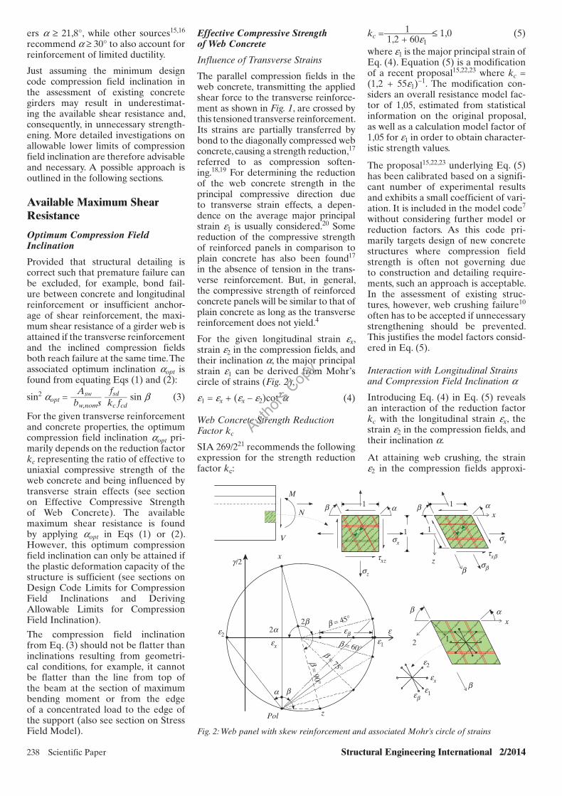
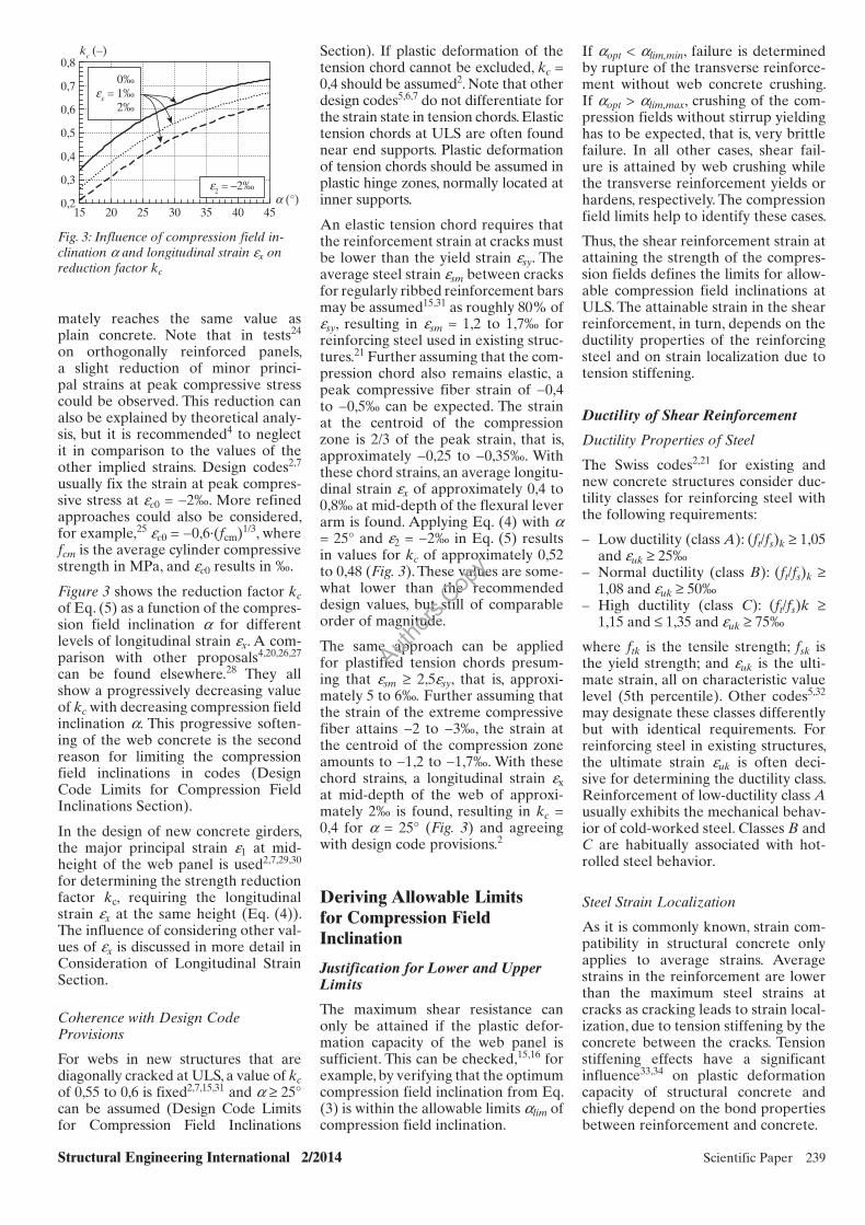
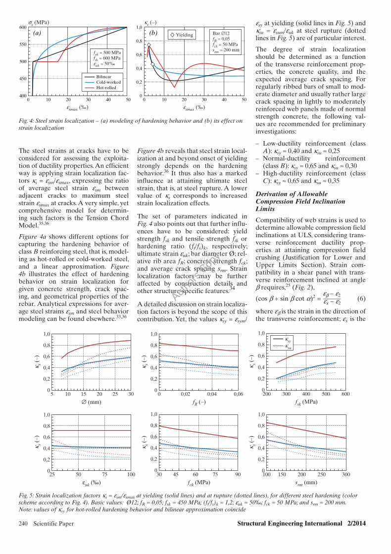
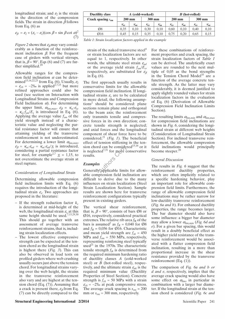
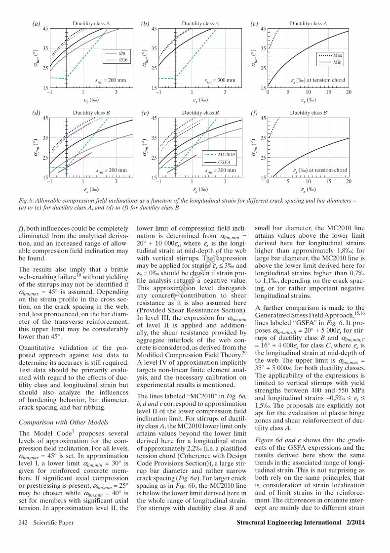