static stiffness coefficients for circular
TRANSCRIPT
STATIC STIFFNESS COEFFICIENTS FORCIRCULAR FOUNDATIONS EMBEDDED
IN AN ELASTIC MEDIUM
by
FARID ELSABEE
BE, S.U.N.Y. at Stony Brook(1973)
Submitted in partial fulfillment
of the requirements for the degree of
Master of Science in
Civil Engineering
at the
Massachusetts Institute of Technology
(May, 1975)
Signature of Author . . . . . .Department of Civil Enqineerinq, May 9, 1975
Certified by . . .Thesis Supervisor
Accepted by . . . . . . . . . .Chairman, Departmenal Committe on GraduateStudents of the Department of Civil Engineering
Archives
JUN 2019,
2
ABSTRACT
STATIC STIFFNESS COEFFICIENTS FORCIRCULAR FOUNDATIONS EMBEDDED
IN AN ELASTIC MEDIUM
by
FARID ELSABEE
Submitted to the Department of Civil Engineeringon May 9, 1975 in partial fulfillment of therequirements for the degree of Master of Sciencein Civil Engineering.
Approximate empirical relations for thestatic stiffness coefficients of circularfoundations embedded in (or resting on) aviscoelastic homogeneous stratum (or half-space) are developed. The relations areobtained from a parametric study using afinite element technique. Approximate fre-quency dependent functions for the stiffnessand radiation damping coefficients, andequivalent constant viscous damping ratioshave been suggested.
The approximations are used to obtainthe response of a rigid cylinder embeddedin an elastic stratum which compares wellwith the response obtained using frequencydependent stiffness functions from a finiteelement analysis.
Thesis Supervisor: Robert V. Whitman
Professor of Civil EngineeringTitle:
3
ACKNOWLEDGMENT
The author would like to thank Prof. R. V. Whitman for his
advisement and supervision in writting this thesis. Greatest
appreciation is due to Dr. E. Kausel for his most valuable
suggestions and time consuming efforts. Special thanks to
Prof. J. M. Roesset who suggested the topic.
Last but not least, a great deal is owed to Prof. J. Connor
and Mr. C. Reeves for the initiation and support of the
Engineering Residence Program with Stone Webster Eng. Co.,
without which this work could not have been possible.
To my parents,
Emile and Nelly
4
CONTENTS
I. Title page ......................................... 1
II. Abstract ......................... ......... ........ 2
III. Acknowledgment .. ....................... 3
IV. Table of contents ....... ........................... 4
List of tables ........... ........ .................. 6
List of figures .................................... 7
V. List of symbols .................................... 9
VI. Body of text
1. Introduction ... o .............................. 11
1.1 Statement of the Problem .................... 11
1.2 Available Solutions ......................... 14
1.2.1 Surface Footings ...................... 14
1.2.2 Embedded Footings ..................... 16
1.3 Scope of this Work ......... ...... ........... 18
1.4 Description of the Model .................. 24
2. Parametric Study of Static StiffnessCoefficients ..... .............................. 27
2.1 Method of Solution .......................... 27
2.2 Effect of Stratum and Embedment Depthson the Static Stiffness Constants ........... 30
2.2.1 Swaying and Rocking ................... 35
2.2.2 Coupling Term ......................... 46
2.3 Effect of Weaker Backfill ................... 50
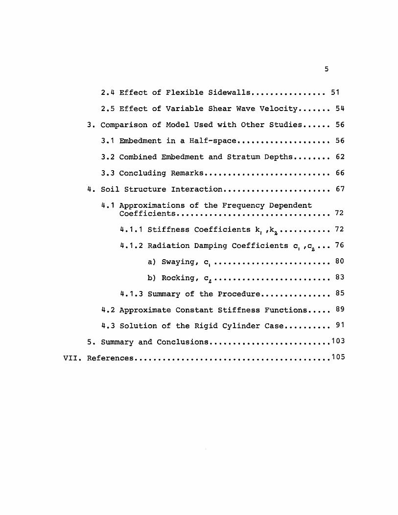
5
2.4 Effect of Flexible Sidewalls ................ 51
2.5 Effect of Variable Shear Wave Velocity ....... 54
3. Comparison of Model Used with Other Studies ...... 56
3.1 Embedment in a Half-space.................... 56
3.2 Combined Embedment and Stratum Depths ........ 62
3.3 Concluding Remarks ........................... 66
4. Soil Structure Interaction ....................... 67
4.1 Approximations of the Frequency DependentCoefficients ............................ ........ 72
4.1.1 Stiffness Coefficients k,,k ............ 72
4.1.2 Radiation Damping Coefficients c, ,c... 76
a) Swaying, c, ......................... 80
b) Rocking, c ... ...,..... ..... ......... 83
4.1.3 Summary of the Procedure .............. 85
4.2 Approximate Constant Stiffness Functions ..... 89
4.3 Solution of the Rigid Cylinder Case .......... 91
5. Summary and Conclusions ...................... 103
VII. References ............................................105
6
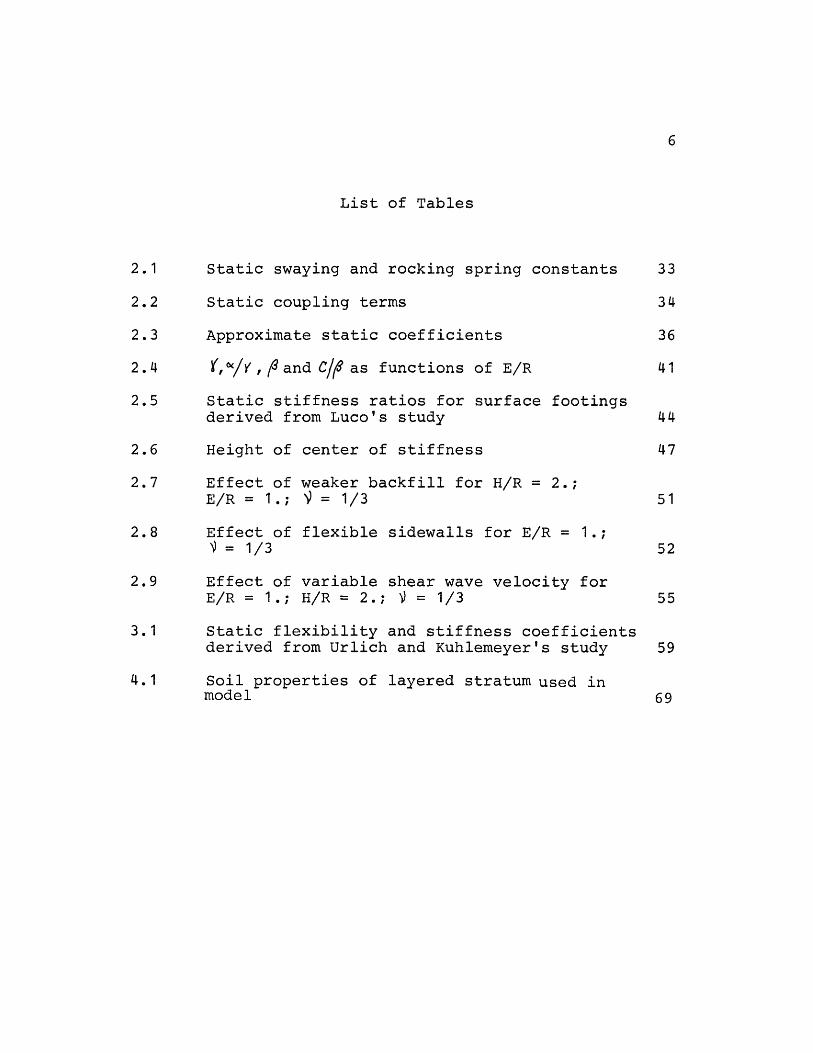
List of Tables
2.1 Static swaying and rocking spring constants 33
2.2 Static coupling terms 34
2.3 Approximate static coefficients 36
2.4 Y,/Y, and C/~ as functions of E/R 41
2.5 Static stiffness ratios for surface footingsderived from Luco's study 44
2.6 Height of center of stiffness 47
2.7 Effect of weaker backfill for H/R = 2.;E/R = 1.; = 1/3 51
2.8 Effect of flexible sidewalls for E/R = 1.;= 1/3 52
2.9 Effect of variable shear wave velocity forE/R = 1.; H/R = 2.; = 1/3 55
3.1 Static flexibility and stiffness coefficientsderived from Urlich and Kuhlemeyer's study 59
4.1 Soil properties of layered stratum used inmodel 69
7
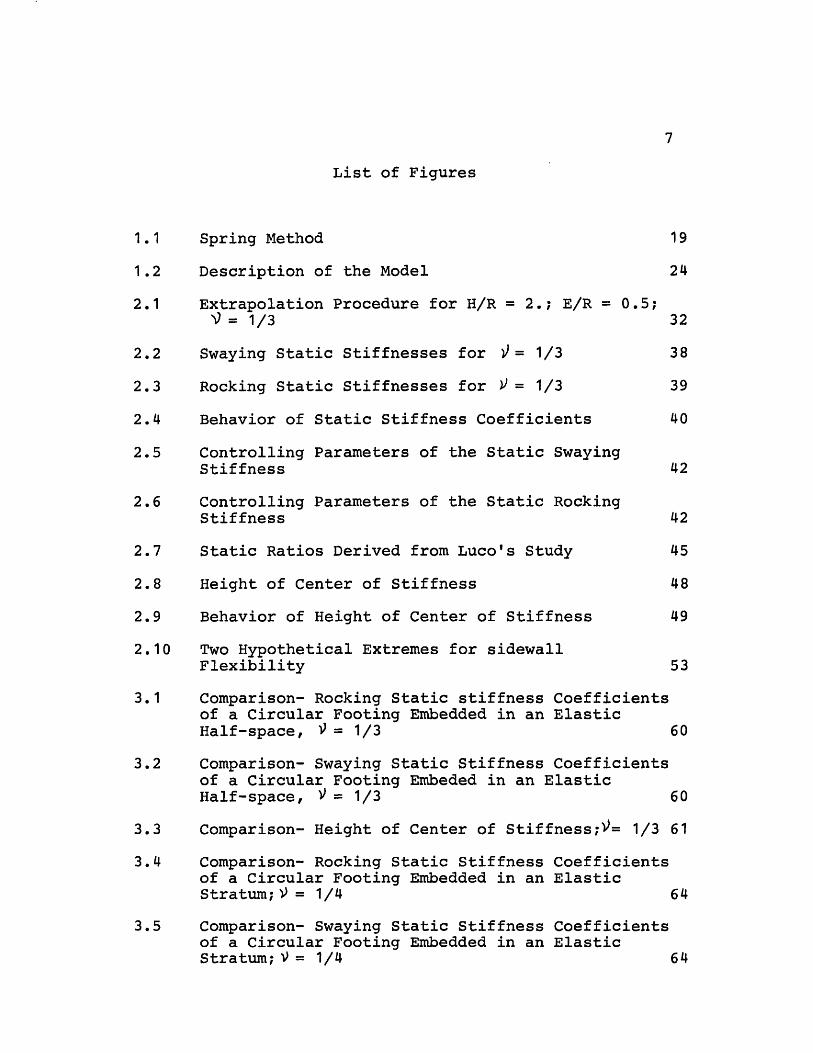
List of Figures
1.1 Spring Method 19
1.2 Description of the Model 24
2.1 Extrapolation Procedure for H/R = 2.; E/R = 0.5;= 1/3 32
2.2 Swaying Static Stiffnesses for 2= 1/3 38
2.3 Rocking Static Stiffnesses for p = 1/3 39
2.4 Behavior of Static Stiffness Coefficients 40
2.5 Controlling Parameters of the Static SwayingStiffness 42
2.6 Controlling Parameters of the Static RockingStiffness 42
2.7 Static Ratios Derived from Luco's Study 45
2.8 Height of Center of Stiffness 48
2.9 Behavior of Height of Center of Stiffness 49
2.10 Two Hypothetical Extremes for sidewallFlexibility 53
3.1 Comparison- Rocking Static stiffness Coefficientsof a Circular Footing Embedded in an ElasticHalf-space, 9 = 1/3 60
3.2 Comparison- Swaying Static Stiffness Coefficientsof a Circular Footing Embeded in an ElasticHalf-space, 9 = 1/3 60
3.3 Comparison- Height of Center of Stiffness;V= 1/3 61
3.4 Comparison- Rocking Static Stiffness Coefficientsof a Circular Footing Embedded in an ElasticStratum; = 1/4 64
3.5 Comparison- Swaying Static Stiffness Coefficientsof a Circular Footing Embedded in an ElasticStratum;9 = 1/4 64
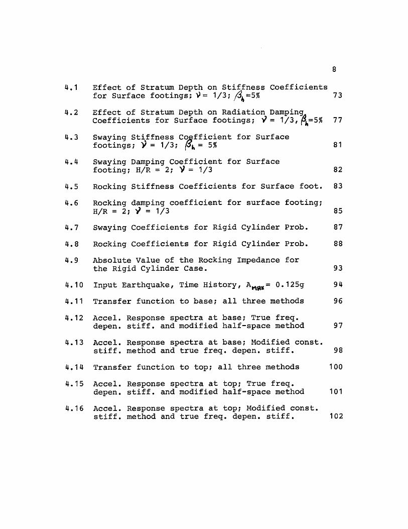
8
4.1 Effect of Stratum Depth on Stiffness Coefficientsfor Surface footings; M= 1/3; /3=5% 73
4.2 Effect of Stratum Depth on Radiation DampingACoefficients for Surface footings; = 1/3, P=5% 77
4.3 Swaying Stiffness Cofficient for Surfacefootings; = 1/3; [$k= 5% 81
4.4 Swaying Damping Coefficient for Surfacefooting; H/R = 2; = 1/3 82
4.5 Rocking Stiffness Coefficients for Surface foot. 83
4.6 Rocking damping coefficient for surface footing;H/R = 2; = 1/3 85
4.7 Swaying Coefficients for Rigid Cylinder Prob. 87
4.8 Rocking Coefficients for Rigid Cylinder Prob. 88
4.9 Absolute Value of the Rocking Impedance forthe Rigid Cylinder Case. 93
4.10 Input Earthquake, Time History, A= 0.125g 94
4.11 Transfer function to base; all three methods 96
4.12 Accel. Response spectra at base; True freq.depen. stiff. and modified half-space method 97
4.13 Accel. Response spectra at base; Modified const.stiff. method and true freq. depen. stiff. 98
4.14 Transfer function to top; all three methods 100
4.15 Accel. Response spectra at top; True freq.depen. stiff. and modified half-space method 101
4.16 Accel. Response spectra at top; Modified const.stiff. method and true freq. depen. stiff. 102
9
List of Symbols
Note: throughout the entire thesis the subscriptx denotes swaying andq denotes rocking
cqx and Xfq denote coupling terms
ao Dimensionless circular frequency. If a subscript isadded, reference is specifically made to the resonantfrequency of the appropriate mode.
C5 Shear wave velocity in the homogeneous soil
c, Swaying radiation damping coefficient
cz Rocking radiation damping coefficient
E Embedment depth below grade level
f Frequency in cps
fo Dimensionless frequency in cps. If a subscript isadded, reference is specifically made to the resonantfrequency of the appropriate mode.
H Stratum depth below grade level
h Height of center of stiffness above bottom of footing
i Imaginary unit
I Moment of inertia about base
G Shear modulus of the homogeneous soil
K Stiffness function
Ka Static stiffness coefficient
Ko Static stiffness coefficient for a surface footingresting on an elastic half-space
k, Swaying stiffness coefficient
ki Rocking stiffness coefficient
10
M Total mass of structure
R Radius of circular footing
Ph Hysteretic damping ratio
/9 Equivalent viscous damping ratio
9 Poisson's ratio of the homogeneous soil
- Forcing circular frequency
w Circular resonant frequency
P Mass density of the homogeneous soil
HNFS Horizontal natural shear beam frequency of stratumin cps
VNFS Vertical natural shear beam frequency of stratumin cps
11
1.- Introduction:
1.1 Statement of the Problem:
Considerable amount of research has been done in recent years
to improve and develop effective solutions for the dynamic
response of foundations embedded in a stratum or an elastic
half-space. This problem is of special interest in the study
of soil-structure interaction as it relates to the seismic
analysis and design of structures.
Soil-structure interaction is often accounted for in analyses
by a set of springs, one for each degree of freedom, rep-
resenting the soil stiffnesses. These springs are derived
from theoretical solutions of the surface footing problem,
for ideally elastic, homogeneous, isotropic half-spaces.
Footings of buildings, however, are usually founded beneath
the surface of the ground. This has in many cases consider-
able effect on the dynamic response of such footings in that
it increases the resonant frequencies and reduces the reso-
nant amplitudes. The solution of the embedded footing problem
is a very difficult one to obtain by rigorous analytical
methods, thus only approximate analytical solutions were
obtained. Finite element and other techniques were then used
to solve the problem for these complicated geometries. A main
12
problem encountered in numerical solutions for dynamic cases,
based on finite element or finite difference techniques, is
usage of the proper boundary conditions at the edges of the
finite domain which will not result in undesirable reflection
of waves into the region of interest. This problem was over-
come by Waas (41) for layered media. His solution was then
generalized by Kausel (21) and extended for the analysis of
axisymmetric systems (e.g. nuclear power plants) subjected to
arbitrary non-axisymmetric loads or displacements. A similar
procedure was also followed by Liang (25) for the case of a
strip footing resting on or embedded in a soil stratum.
Two equivalent general approaches can be used to estimate the
dynamic soil-structure interaction effects:
A- The direct (or complete) approach in which the
whole system, soil and structure , is modeled and
analyzed together. The excitation or the earth-
quake motion is specified at some control point in
the free field.
B- The spring(or substructure) method, which consists
of three steps. First, the system with a massless
structure is subjected to the prescribed ground
motion, producing a displacement (acceleration)
vector in the structure. Second, the frequency
dependent subgrade stiffnesses are determined to
13
yield the so called "soil springs". Finally the
response of the real structure, supported on the
frequency dependent soil springs, is computed
while the structure is subjected to inertial
forces proportional to the acceleration vector
obtained in the first step.
If certain simplifying assumptions are made, the second ap-
proach is a useful method of solution as it is easily under-
stood by the designer who has to successfully predict the
behavior of the real system. As will be explained in sec.1.3,
in many cases it is possible to omit the first step and, in-
stead, in the third step subject the structure supported by
the soil springs to the control motion applied directly under
the foundation. In such an analysis, the frequency dependent
stiffnesses are needed, and in many cases only the static
ones suffice.
The objective of this study is then to determine a simple
method to obtain the soil springs needed in calculating the
response of the real structure.
14
1.2 Available Solutions:
This historical background section will be presented in two
parts. The first will include the studies made for surface
footings, while the second is reserved for embedded footings.
1.2.1 Surface Footings:
The dynamic response of foundations resting on an elastic
half-space and wave propagation theories are summarized in
Richart, Hall and Woods (35). In most of these theories, the
foundation is represented as a rigid circular cylinder and
the soil on which the foundation rests as an elastic half-
space. The elastic half-space representation by Reissner(34),
Sung (37), Bycroft (7) and others, idealizes the soil as a
homogeneous isotropic, elastic, semi-infinite medium. The
rigid foundation has six degrees of freedom: three in trans-
lation and three in rotation. In addition to the studies
discussed in Richart, Hall and Woods (35), many others have
investigated the dynamic response of surface footings, some
of which are listed below.
For the elastic, homogeneous, isotropic half-space case,
Awojobi and Grootenhuis (4) investigated the response of both
rigid circular and very long rectangular bodies for the
15
vertical, torsional and rocking modes. Awojobi (3) discussed
the torsional mode for a rigid circular body, while
Grootenhuis (15) discussed the vertical, torsional and
rocking modes for a rigid circular or rectangular body (both
half-space and elastic stratum cases). Luco and Westmann(27)
investigated the vertical, horizontal, torsional, rocking
and coupled (rocking and sliding) modes for a rigid circular
disc. Veletsos and Wei (40) presented numerical results for
flexibility, stiffness and damping coefficients (for various
values of Poisson's ratio) over a wide range of dimensionless
frequencies for the rigid massless disc. Weissmann (43) pre-
sented expressions for the resonant frequency and resonant
amplitude of a rigid circular surface footing for the tor-
sional mode, while taking into effect the hysteretic damping
of the soil.
Experimental studies on the dynamic behavior of surface foun-
dations have been reported by many investigators. The follow-
ing comprises some of these studies for the circular surface
footing. The vertical mode of vibration has been experimen-
tally investigated by Eastwood (12), Fry (14), Chae (8,9),
Drnevich and Hall (11), Grootenhuis and Awojobi (16), Stokoe
(36) and Erden (13). Both the torsional and coupled (rocking
and sliding) modes have been investigated by Fry (14), Stokoe
16
(36) and Erden (13).
1.2.2 Embedded Footings:
Most of the above mentioned studies apply to ideally elastic,
homogeneous, isotropic half-spaces, assumptions which do not
apply to many practical cases. Soils are usually non-homoge-
neous and found in layered strata. Also, most structures are
embedded and thus it is necessary to investigate the effect
of the embedment on their response.
Approximate analytical solutions of the embedded rigid circu-
lar footing on an elastic half-space for the vertical, hori-
zontal and rocking modes were presented by Baranov (5), Novak
and Beredugo (32) and Beredugo (6) (he also included embed-
ment in elastic stratum for the vertical mode). Approximate
equations of rocking motion are given in terms of input earth-
quake acceleration, spring constant and damping by Tajimi(38)
for a rigid cylindrical body completely embedded in an elastic
stratum. Frequency independent stiffness and damping param-
eters were approximated by Novak (31) for the vertical, tor-
sional and coupled (rocking and sliding) modes of the rigid
circular footing on an elastic half-space, while the tor-
sional and coupled (torsional, horizontal and rocking) modes
for the same footing are presented by Novak and Sachs (33)
17
for both half-spaces and elastic strata.
Finite element solutions were obtained for a rigid circular
footing embedded in an elastic homogeneous half-space by
Kaldjian (19), Kuhlemeyer (24) and Lysmer and Kuhlemeyer(28),
for the vertical mode; Kaldjian (20) for the torsional mode;
Waas (42) for the vertical and torsional modes (he also in-
cluded both homogeneous and layered cases); Urlich and
Kuhlemeyer (39) for rocking and sliding, Johnson and Christi-
ano (18) for all modes, while Kausel (21) presented a model
applicable to all four modes for layered media. Krizek,
Gupta and Parmelee (23) presented the rocking and sliding
modes for an infinitely long, rigid footing embedded in
homogeneous, isotropic and linearly elastic half-space.
Experimental studies on the dynamic behavior of embedded
circular footings were made by Anandakrishnan and Krishna-
swamy (1), Chae (10), and Gupta (17) for the vertical mode of
vibration. Stokoe (36) and Erden (13) presented the vertical,
torsional and coupled (rocking and sliding) modes.
The soil springs for complicated geometries (embedment and
stratum depths) can be obtained more accurately using finite
element techniques, rather than approximate analytical methods.
18
But such a solution can amount to high computation costs.
Thus a parametric study, using a finite element technique, of
the embedment and stratum depths for the soil stiffnesses
can be quite advantageous. Such a parametric study is the
objective of this investigation.
1.3 Scope of this Work:
Traditionally, the earthquake motion in the interaction
analysis using the spring method has been specified directly
under the foundation using the half-space soil springs. A
more careful consideration (22) shows, however, that at least
three steps are necessary for a rigorous solution of embedded
foundations. These steps are (the spring method, see fig 1.1):
A- First, the motion that would occur at the mass-
less foundation is determined. This step is
eliminated for surface footings when the motion
is specified at the free surface of the soil,
and when one dimensional theory (only vertically
propagating waves are assumed) is used. In the
case of embedded footings, this step is theore-
tically necessary and both horizontal motion
and rocking are expected to occur at the massless
foundation.
B- Frequency dependent stiffnesses ("springs") are
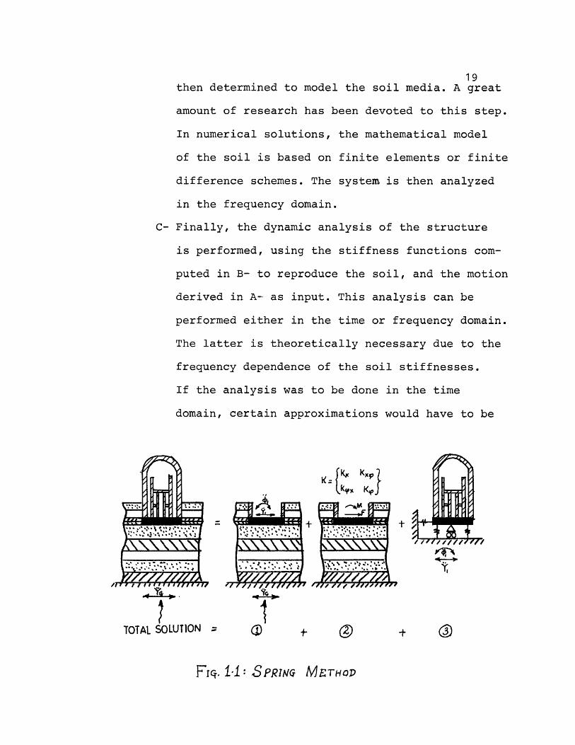
19then determined to model the soil media. A great
amount of research has been devoted to this step.
In numerical solutions, the mathematical model
of the soil is based on finite elements or finite
difference schemes. The system is then analyzed
in the frequency domain.
C- Finally, the dynamic analysis of the structure
is performed, using the stiffness functions com-
puted in B- to reproduce the soil, and the motion
derived in A- as input. This analysis can be
performed either in the time or frequency domain.
The latter is theoretically necessary due to the
frequency dependence of the soil stiffnesses.
If the analysis was to be done in the time
domain, certain approximations would have to be
K I KXP
] e~~~~~k KJ
1
TOTAL SOLUTION = ( . +
Frc. 1 : SPRI, METHOD
//V=ZA1
VEa~i
· �·.r ........
.. .. f r _ I\X \X ".' 1I J~~
L
4- Ye - ,
PTX
Y,
20
used to account for the frequency dependence of
the subgrade stiffnesses (soil springs).
However, the frequency solution is limited to linear problems
since it is based on the applicability of the principle of
superposition. The non-linear soil behavior must then be
simulated using an approximate method which introduces an
iterative analysis where modulus and damping are adjusted
in each cycle according to the measure of strain resulting
from the previous cycle.
The first step becomes quite important for the embedded
foundation case. The problem requires the use of finite ele-
ments or finite difference techniques, but the structural
degrees of freedom are neglected and only an embedded
massless rigid footing is considered.
Since only three degrees of freedom are needed to describe
the motion of a rigid footing (in a plane), the structural
displacements in the first step can be expressed directly in
terms of these motion components. As shown in ref. (22), the
third step can then be performed subjecting the base of the
structure to a prescribed translation (rotation) equal to
that of the massless rigid foundation instead of applying the
21
inertial forces to the structure. It is beleived that conser-
vative results can be obtained if the motion obtained from
the first step is approximated by the control motion, and the
rotational component is neglected. Since the main purpose of
this study is to compare true and approximate static stiff-
nesses, this procedure will be used throughout.
After obtaining the components of motion of the massless
foundation, the frequency dependent soil stiffnesses are
computed in the second step. The procedure is to subject the
base of the foundation, which is assumed to be infinitely
rigid and massless, to unit steady state harmonic displace-
ment and rotation, and calculate the corresponding reactions.
The following approximations to this step are listed in
probable order of decreasing accuracy (22):
- Determine the static stiffnesses of the embedded
foundation by finite elements and assume the same
frequency variation as for a surface footing on
the actual layered medium.
- Apply a scaling factor to the frequency dependent
stiffnesses of the surface footing on the layered
medium, to account for embedment.
- Apply the static stiffnesses of the actual condi-
tions to the frequency variation of an elastic half-
space.
22
- Use frequency independent stiffness functions
obtained by finite elements.
- Use frequency independent stiffness functions
obtained by applying the derived scaling factors.
- Use the frequency dependent stiffness functions of
the surface footing on an elastic half-space.
- Use the frequency independent stiffnesses of the
surface footing on an elastic half-space.
It was suggested in E. Kausel's doctoral dissertation (21),
that for an embedded footing the static values are approxi-
mately linearly dependent on the embedment and stratum depths.
Thus, once these relations are determined, they can be used
with some frequency variation obtained from previous studies,
resulting in considerable savings in computation costs.
This study aims in determining approximate simple rules (the
scaling factors), for the static stiffness coefficients of
embedded rigid circular footings in a stratum of soil resting
on a rigid half-space. The sidewall is also taken as rigid
as the footing. These assumptions apply mostly to the reactor
containment structure of nuclear power plants. These struc-
tures are usually resting on a rigid circular plate embedded
in a stratum which lies on a rigid half-space, i.e. rock. The
23
sidewalls of the containment, which is embedded, are also
considered rigid. The soil is considered homogeneous, isotro-
pic and linearly elastic with hysteretic damping. For simpli-
city the stratum is considered homogeneous throughout the
whole domain. The effect of layering as well as flexibility
of the walls will also be discussed later. A computer program
written by E. Kausel, hereon referred to as "TRIAX", based
on his finite element solution (21) (using the special energy
absorbing boundary described in 1.4), will be used in the
determination of the simple rules.
The parametric study of embedment and stratum depths is
presented in chapter 2. Two typical values for Poisson's
ratio will be used ( =1/3 60.45). The simple rules for the
static stiffness coefficients will be determined graphically.
Further study of the effect of weaker backfill, soil layering
and flexible sidewalls is also included.
In chapter 3, a comparison of the model used with those of
other studies is presented. Comparison of results, of a
dynamic analysis of a rigid structure, using the simple rules
and the exact stiffnesses obtained from the finite element
program for the exact conditions, is included in chapter 4.
The comparisons will be in terms of the floor (amplified
24
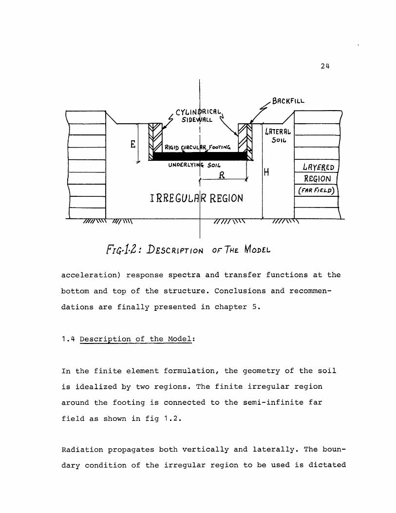
Fr4.12: DESCRIPTION Or THE MODEL
acceleration) response spectra and transfer functions at the
bottom and top of the structure. Conclusions and recommen-
dations are finally presented in chapter 5.
1.4 Description of the Model:
In the finite element formulation, the geometry of the soil
is idealized by two regions. The finite irregular region
around the footing is connected to the semi-infinite far
field as shown in fig 1.2.
Radiation propagates both vertically and laterally. The boun-
dary condition of the irregular region to be used is dictated
25
by the fact that the radiation of waves away from that region
into the far field causes a loss of energy. This boundary
condition can be modelled exactly (41,21) when a stratum of
soil is resting on a material with higher stiffness proper-
ties(e.g.rock), which is the actual case in most practical
problems. In such cases, the vertical radiation into the half-
space is a small fraction of the lateral radiation in the
stratum which occurs only above the fundamental frequency of
the stratum. Thus the proper boundary conditions should be
of major concern above this fundamental frequency. It is also
known that very elongated elements in the horizontal direc-
tion will automatically enforce a one dimensional shear type
behavior and they will eliminate any lateral radiation.
Such a boundary, representing the actual condition of the
finite element columns extending to infinity, has been
developed by Waas & Lysmer (30,41) for the two dimensional
plane-strain case and the torsional or vertical vibrations
of a circular footing. This boundary has the great advantage
that it can be located directly at the edge of the footing,
with excellent results, leading to an economical and more
accurate solution than previous ones by Lysmer and Kuhlemeyer
(28,29) or Ang and Newmark ( 2) who developed viscous type
boundaries based on a perfect absorption for specific types
of waves and incidence angles.
26
Kausel (21) has recently generalized Waas and Lysmer's
boundary to the case of arbitrary Fourier number and expansion
order in the finite elements. He has represented the irregu-
lar region by means of toroidal finite elements of arbitrary
expansion order having three degrees of freedom per nodal
ring. In the following study, linear expansions (with four
nodes) will be used to minimize computer costs without
significant loss of accuracy. The far field is represented
by the semi-analytic energy absorbing boundary based on the
exact displacement functions in the horizontal direction
and expansion in the vertical direction consistent with that
used for the finite elements.
27
2.- Parametric Study of Static Stiffness Coefficients:
The effects of embedment on a rigid circular plate welded
to a soil stratum, with rigid sidewalls also welded to the
lateral soil, subjected to a static displacement and rotation
are studied. Approximate correction factors, to account for
the embedment effect, are derived and applied to the static
stiffnesses of a surface footing resting on a viscoelastic
stratum on top of a rigid rock base, or on an elastic half-
space. The effects of weaker backfill, soil layering and
flexible sidewalls are also briefly investigated.
2.1 Method of Solution:
The stiffnesses for the two planesymmetric displacement modes,
rocking and swaying, are discussed. The rigid circular plate
and sidewalls are idealized by massless finite elements with
very high rigidity (10% times greater than that of the soil)
and the lateral soil is assumed homogeneous throughout the
stratum, unless otherwise stated.
The plate is subjected to a unit displacement (or rotation)
at the plate-soil interface, and the force (or moment)
necessary for equilibrium which by definition is the stiffness,
28
is computed using TRIAX. The forced horizontal displacement
case will be referred to as the swaying mode, while the forced
rotation about a horizontal axis as the rocking mode.
The accuracy of the results derived by a finite element
analysis is very dependent on the refinement of the mesh used.
As one uses finer elements, the theoretical solution is ap-
proached. It was concluded from Kausel's dissertation(21),that
the rate of convergence of the static stiffness coefficients
(for the swaying and rocking modes) to the continuum solution
is approximately a linear one. When finite elements with
linear expansions are used: "...the relative error in the
displacements should be proportional to the square of the
typical element size. Stresses and forces are given with less
degree of accuracy: as they depend on the partial derivatives
of the displacements, the error for them should be approxi-
mately linear. The spring constants are determined as reaction
forces, and therefore, should converge at an approximate
linear rate towards the continuum solution as the mesh is
refined." This result suggested a useful linear extrapolation
procedure to determine static continuum stiffnesses with the
aid of a coarse and a fine mesh. This procedure will be used
throughout this study.
29
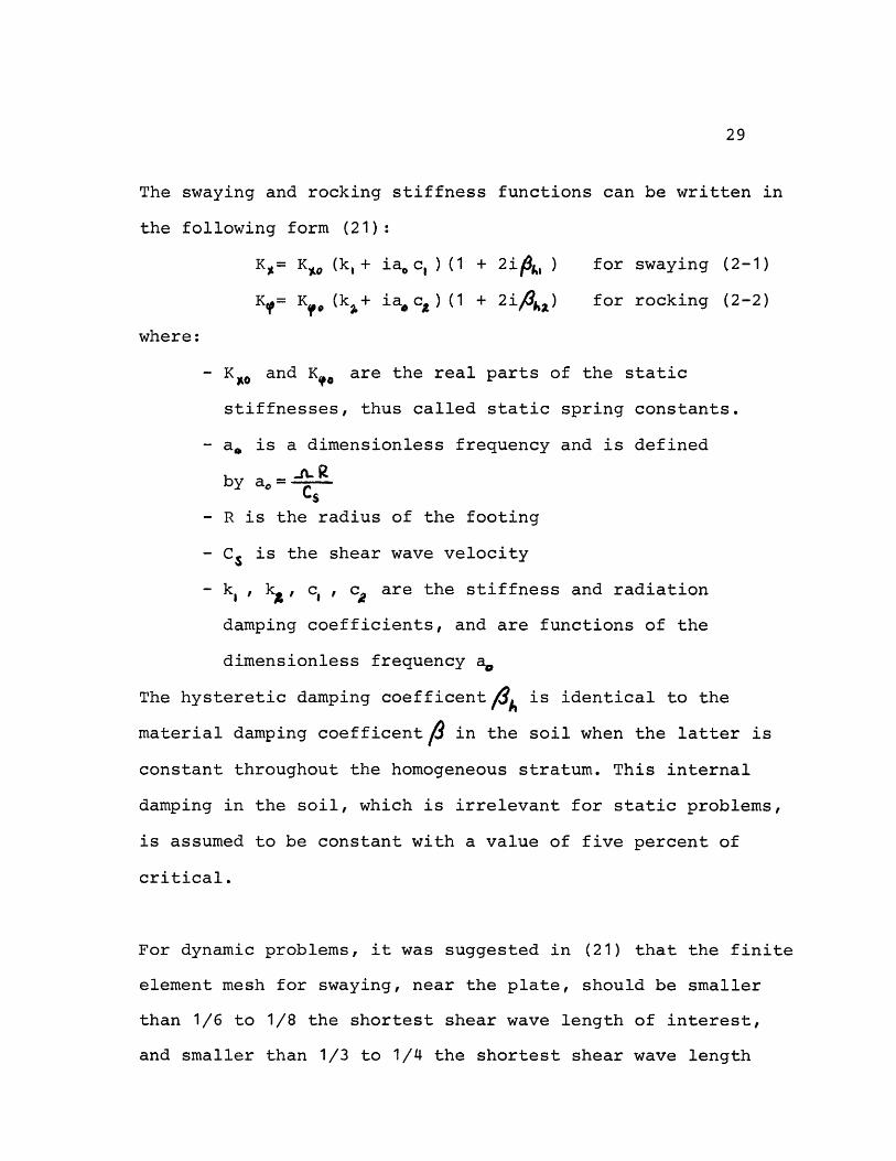
The swaying and rocking stiffness functions can be written in
the following form (21):
Ka= Ko (kl+ iaoc, ) (1 + 2i4, ) for swaying (2-1)
K= Kf (kx+ iac) (1 + 2i##) for rocking (2-2)
where:
- K and K are the real parts of the static
stiffnesses, thus called static spring constants.
- a is a dimensionless frequency and is defined
JLRby a -C
- R is the radius of the footing
- Cs is the shear wave velocity
- k, , k, c,, Ca are the stiffness and radiation
damping coefficients, and are functions of the
dimensionless frequency a.
The hysteretic damping coefficent4A is identical to the
material damping coefficentf in the soil when the latter is
constant throughout the homogeneous stratum. This internal
damping in the soil, which is irrelevant for static problems,
is assumed to be constant with a value of five percent of
critical.
For dynamic problems, it was suggested in (21) that the finite
element mesh for swaying, near the plate, should be smaller
than 1/6 to 1/8 the shortest shear wave length of interest,
and smaller than 1/3 to 1/4 the shortest shear wave length
30
throughout the finite element region. Because only the static
stiffness coefficients are of interest in this parametric
study, this rule does not apply. However the meshes will be
chosen such that the elements are square with no less than
four rows of elements below the footing to insure adequate
representation of the subgrade in the region with high strain
gradients. Also a correction (as described below) will be
applied to account for the discretization error.
2.2 Effect of Stratum and Embedment Depths on the Static
Stiffness Constants:
Stratum and embedment depths will influence the stiffness
functions over the whole frequency range. They are known to
increase the static values of the half-space stiffness
functions, and affect their frequency dependence. The half-
space functions were calculated by Veletsos and Wei (40).
Kausel (21) presented the following approximate empirical
relations for the static stiffness constants (for a surface
footing), which correct the half-space values for the
homogeneous stratum depth:
Z K(H)- 2-9 ) (2-3)
+ 6 3(R (8G 6 (2-4)~~b~ H 3( ,o)
31
where: -KXo and Kao are the half-space static stiffnesses
-H is the stratum depth as defined in fig 1.2
-G is the shear modulus of the soil and is defined
by G =
- is the mass density of the soil
One can define a point at a distance h above the plate footing
(for either a surface or embedded plate), referred to which
the cross coupling term of the stiffnesses is zero. This
point is denoted as the center of stiffness and is given by
h = K / K.,,, where K is the static coupling term. For
surface footings, h is small and results in a small value
for the coupling term and thus is usually neglected.
Parametric studies are performed for the following nine cases:
H/R = 2. and E/R = .5, 1., 1.5
H/R = 3. and E/R = .5, 1., 1.5 where E is the
H/R = 4. and E/R = .5, 1., 1.5 embedment depth
For all models used R, C and P are set to unity. The struc-
tural properties used are: 10' for weight density, 10' for
shear wave velocity, and 0.167 for Poisson's ratio (9).
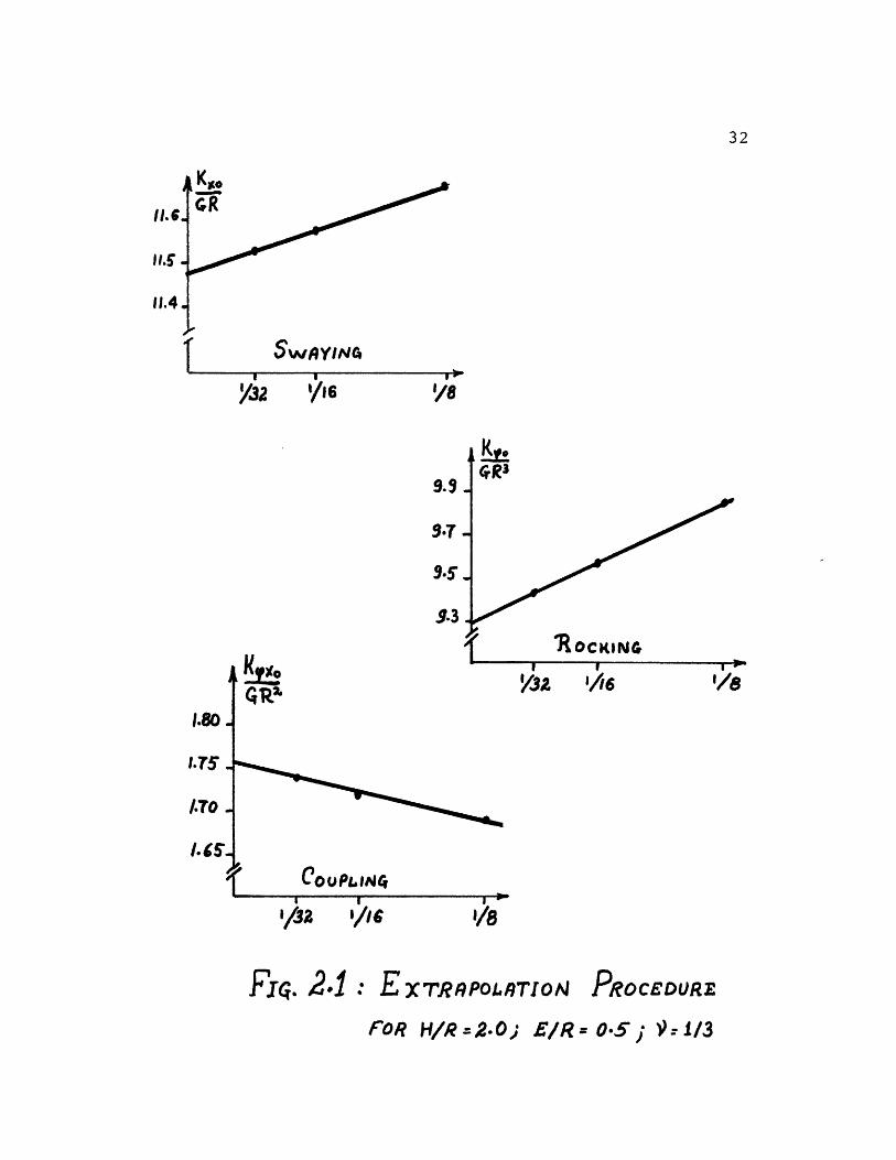
First, the extrapolation procedure is tested for H/R = 2.
and E/R =0.5. Three meshes are tested and the static stiffnes-
ses plotted vs. the inverse of the total number of layers
(fig 2.1). Thus we see that the extrapolation procedure appears
wKsYocR
I SWAYINfa
I/8
I)
9.3
9.T
9.5
9.3
I/3 p /16
p COUPLDaJi
FT. 2.1I E XTRPOI.LTIOA PROCEDURE
FOR H/R:2.-0
11.4
32
.q m -
!;2 '/16
KH
QRII1.80
.75 ,
I.TO .
I. .-
1/32/8
I/8i - - 2 w b
16
EIR 05 V x 1/3
o c oooo00 o
I rCr*V *0
co w (N
o00 C
I O" o- I r- V-
00 Jf. J3
a ILN Oc
I omn I T- -
I tN O m M0 0c C0r- 00N ' O~ CO "- 0t N P~ -
00 CN O
r- O0
I - (N--r
-I Ln n
I O - CI cn
0 LO o-- 00 -
co LN CO
I O' NO
- O ) 00o CN CO 00 I IO - Om IZ 30 00 IN ko mO
I . . 1. . . I I . . . I . . . I CIN CO 1- I O r l-a I I CN J I O --T I ° ° °
C C CN J-T M M CD
I C
n O O Ot O O o I Lnr) TM N 1- 1 OC OJ r O 00 O CtO J t- I D in o N n M 0- 0 O o1 O
C) CV 00 1-O O or In O m Q I In O O co n Irc ' 1- n o 1-oOWOO O' I O -O - CNO
o m 0 C 0 -- - 00 1 ; CN C QI O C n 1 0 qC D mO - m t m I >Nm L m I co co 'IO
LC o -_ 0c 0 S0 0 t I r S C 00 0 J 0 0 OI* I * * * I I . .I . .I .II kO n I O 1 NIL;n I Ia co oLn I co CO v I OD Ln
I
I o oo I · u o· o I · o o I I Io o I
NIc I O . I .L I) I M I . I
.I
UO )x 00 CD oO U^ N ) \ t-O>O I 0 O C F O 14 0 o -H m)I · · 'l ' ·· '- I ··'l · · '
O o O ooo I o o o o O o
0 0 3 d >r ~ H I rY O 21r 1 zz~~~~~~Y 1s: 1 Yld~~~~~~
Il
I)
1>
,)
Lj<
U)
U
0
-1-Iaj
0
O.H
OUH4
Ul,1-P
U
.,l00tQ
U)-H
O0
0
>1U
Cl)
(N
a)
H-
33
-4
r
00
o
IO
rd
-
U0
HU) -I4J4
0O
0) 04
J O03 I4
5-I040
a)
4J0U- aino
-
__
IIIIl
Ln 0 LOn m CO N - C1 T-r', r . -- LN L0 O ' c: o ' oL 'D in .OCN N LCn Ln o - o
C) LC) m O LO CO - CO
)O O O 00 JO C 00 rr)
C k L On ' 4 LC )o o·- ~;· ..w LO C\N %D m t m O
·- C\J O~ '.0 0 N o 0T t0 N O w 0 S
N L) IC L- O,
o C ' oCN r'7 LO
1- Lfl (N
M ,t ko C' c,U) o r- o C -
M Ll - -
v- :: 0% T-
CNCN
.~
', 0 N ' CC Ln 0 )CO m (N r- \ %D LO) 'I ND I' T C) L M - CN
L )) J Z Z C)
N N tO m) n C J
LO 0 LO LO '0 L. Lnl 0 L.
0 ' '4
X w_ ~ ~ ~ ~ ~ ,,.
34
I'
n
U)
.o00O4-H
Cl
0)
(apd
q--Ia)zc
a)
U
0U
H
4~r:;r:j
0uOrOP
4I
0)U)
0OU
0U
It
I!
-,-:10)0o
co0.os-I
O00
E)5-o
U)
a)k
.,
-
ar
oz
- : -
=
35
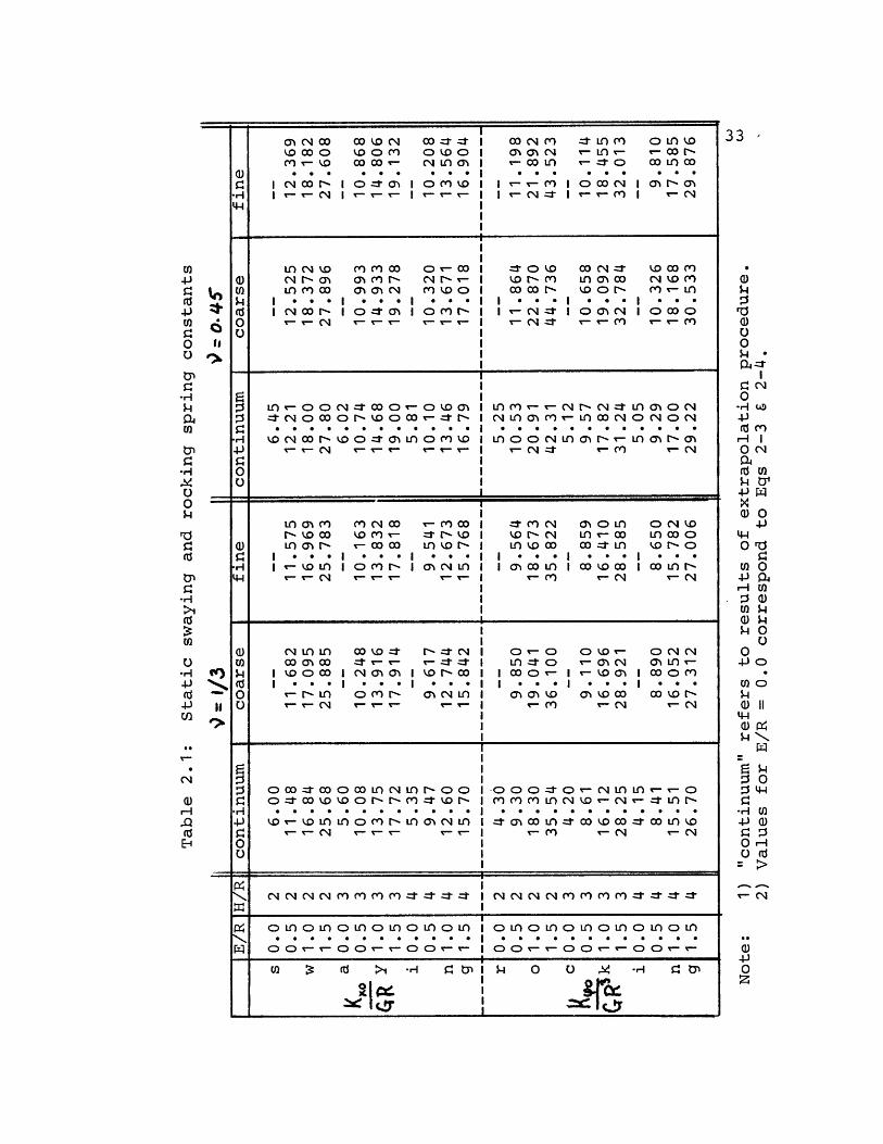
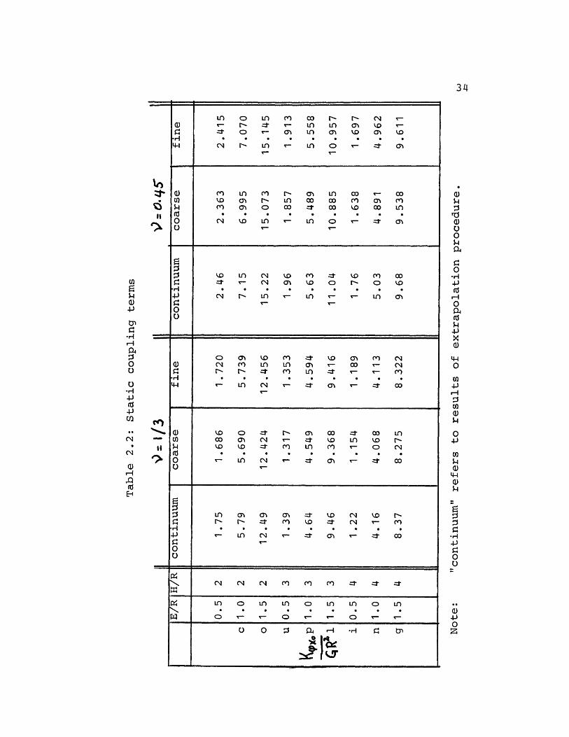
valid for the coupling term as well as for swaying and rocking.
This procedure, using a fine and a coarse mesh is used in all
other eight cases. Tables 2.1 and 2.2 summarize the results
for the two sets of runs: = 1/3 and 9= 0.45. The values for
E/R = 0 (surface footing) are obtained from equations 2-3 and
2-4, where the effect of embedment was not considered but
accounting for stratum depth.
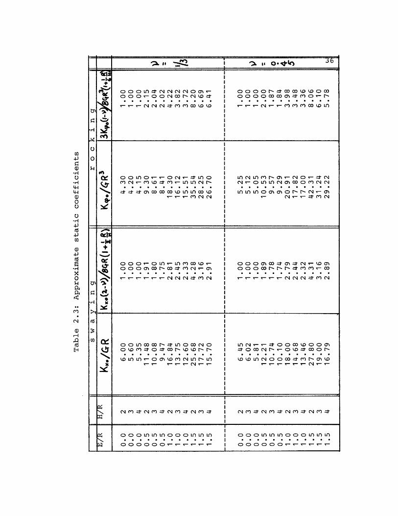
2.2.1 Swaying and Rocking:
As was mentioned previously, the aim of the parametric study
is to determine approximate coefficients, to be applied to
equations 2-3 and 2-4 to include the effect of embedment on
the static spring constants. These coefficients are determined
by evaluating:
KxO (2-) and 3 Kp (I-')
8GR(i+l B) 8gJ3 (1+6)
from the static continuum values for all cases(see Table 2.3).
For swaying, we see that for all practical purposes, the
values of the coefficients for = 1/3 and 9 = 0.45 are the
same. Therefore we can conclude that for a homogeneous stratum
the coefficients are independent of the soil properties. For
rocking, on the other hand, we see a maximum difference of 10%
between the two sets of coefficients. This difference can be
traced back to two origins:
-, I
r-c o oo o o oo N
e I* I
o I
0 I
Y) N () o C T L L) CN r C C L ) O tM O JM N cg -r r N m I o o co o n o o L
.. C.......D I ............ -r_-, M
O4 '4 - 4 I t v CN C ' N
* I
i Ii
o o o o-tO r- -- 0 Dr-- I O O O o N r- r to mat4 O O LO 'o LO' 'I 8 L C0 1- 00 J 1 C) 1 Zt O 0I .
K Cj CN ' v-3 I
0 o o L 1 o o o I ) 1 I I O O D n umL I o o o L0 ) L)O O O O O 0- I O O O 0 0
U)CD-
.,iU
4-)
--I
Q)
-I)
0
,)Hr
37
1) The extrapolation procedure, even though is
theoretically correct, can result in small
inacurracies.
2) Even though equations 2-3 and 2-4 are assumed
correct for this study, during the derivation
of the coefficient (1+1/6 R/H) for the effect
of stratum depth (21), the author showed that
in the rocking mode the coefficient was not
completely independent of Poisson's ratio.
However, this dependence was neglegible and
the coeffecient was derived for the case
9 = 1/3.
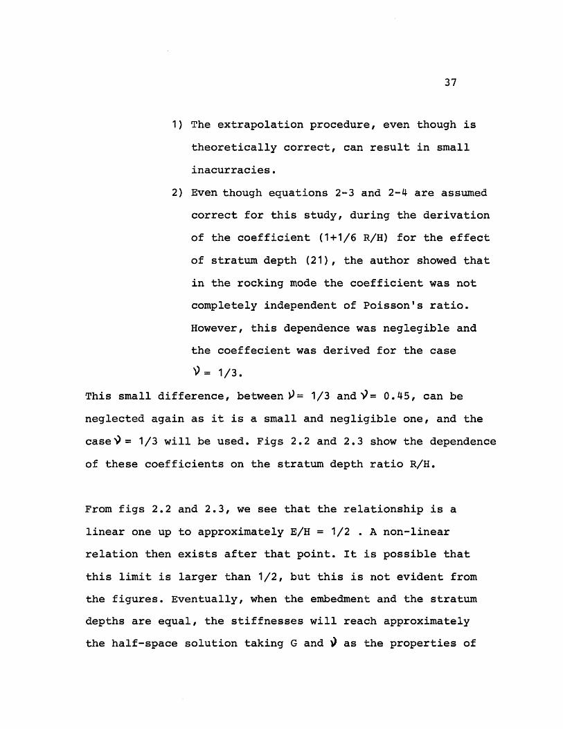
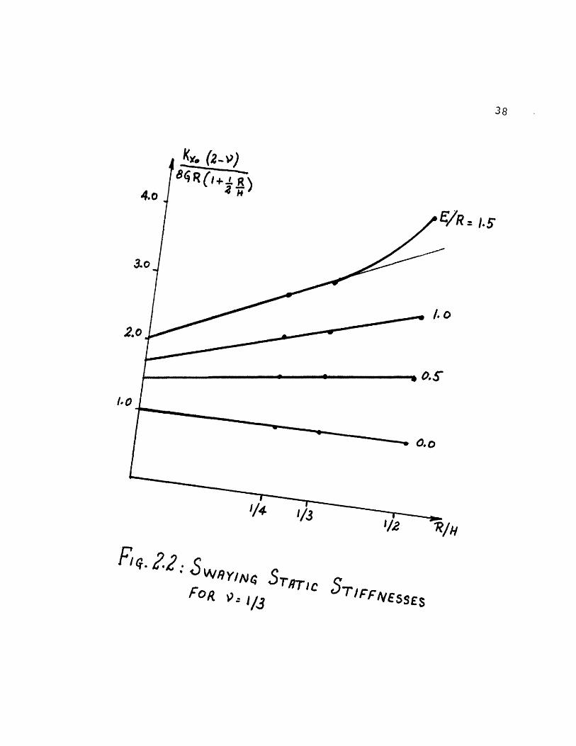
This small difference, between = 1/3 and = 0.45, can be
neglected again as it is a small and negligible one, and the
case = 1/3 will be used. Figs 2.2 and 2.3 show the dependence
of these coefficients on the stratum depth ratio R/H.
From figs 2.2 and 2.3, we see that the relationship is a
linear one up to approximately E/H = 1/2 . A non-linear
relation then exists after that point. It is possible that
this limit is larger than 1/2, but this is not evident from
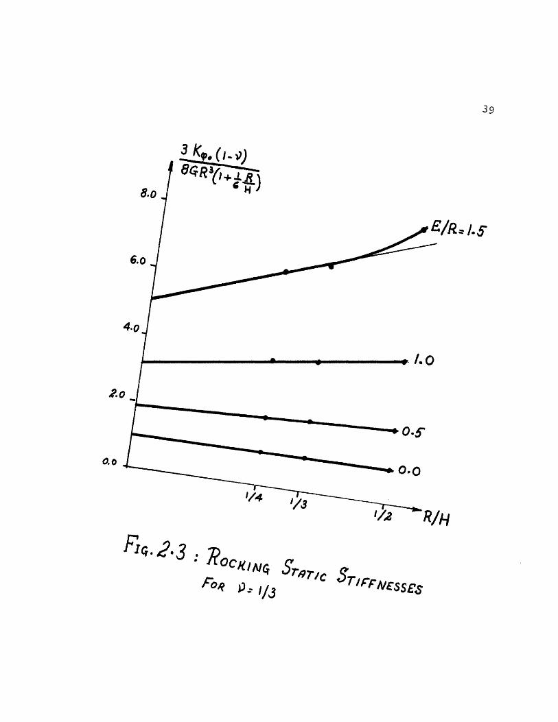
the figures. Eventually, when the embedment and the stratum
depths are equal, the stiffnesses will reach approximately
the half-space solution taking G and ) as the properties of
Fiq . : Sw2ylFoR 1/3
Sr,Rr,cSTIFFiESSES
38
1.5'
/
I
I
I
y
39
31/v.(I .
.0o
'/4
R OCK/N4
A°'e LP 1/d
8.o
6.0 J
/R. /.S
(LJ-''F
S,7r/c ST/rFNssEsi
F14. 2-3
'
F4. 4: BEHAVIOR oF ST TC,STIFFNE5S COEFFICIIEN5
the rock (see fig 2.4). Actually, the lateral soil will still
exist, but will not noticeably affect the stiffnesses.
Therefore, the relationships which are to be derived will
apply only when E/H 1/2. The majority of containment struc-
tures for nuclear power plants fall within this range.
The relations of interest proposed here are of the following
I ·
K.- r 0
41
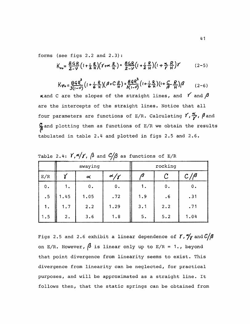
forms (see figs 2.2 and 2.3):
K, =8R (,+ ^I R 84Rf(1 R)( \ ( 2-5)
Kc=O 8- (+ -R )(C = 8G (i &6 H)+ R) (2-6)
Kand C are the slopes of the straight lines, and K and
are the intercepts of the straight lines. Notice that all
four parameters are functions of E/R. Calculating ,, 9and
and plotting them as functions of E/R we obtain the results
tabulated in table 2.4 and plotted in figs 2.5 and 2.6.
Table 2.4: Y,/(, 3 and C/ as functions of E/R
swaying rocking
E/R ( I /_I C c /0. 1. 0. 0. 1. 0. 0.
.5 1.45 1.05 .72 1.9 .6 .31
1. 1.7 2.2 1.29 3.1 2.2 .71
1.5 2. 3.6 1.8 5. 5.2 1.04
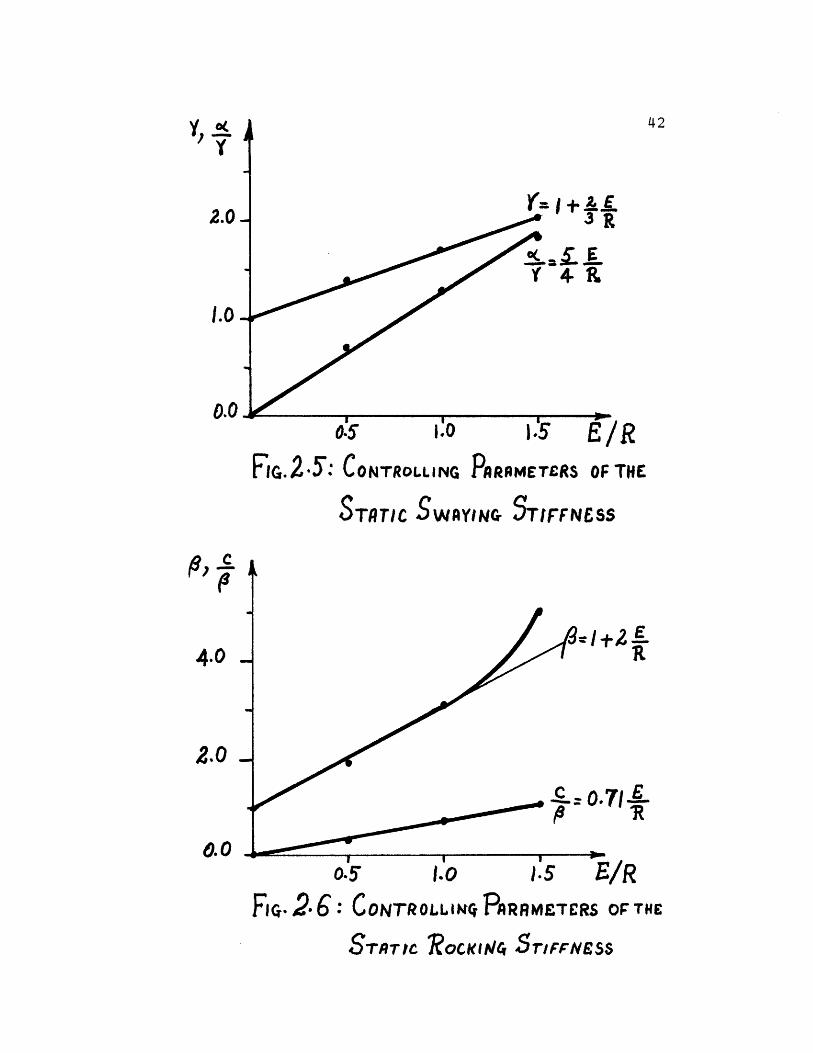
Figs 2.5 and 2.6 exhibit a linear dependence of r, or and C/1
on E/R. However, ( is linear only up to E/R = 1., beyond
that point divergence from linearity seems to exist. This
divergence from linearity can be neglected, for practical
purposes, and will be approximated as a straight line. It
follows then, that the static springs can be obtained from
42
r A r- f nrlG.-,': CONTROLLING rARMETERS OF THE
STATIC SWAYING STIFFNESS
F2 ER
71 ?
i:,_
0.5 1.0 .s5 E/R
FiG. 2 6: CONTROLLINQ PARRMETERS OF THE
STATIC ROCKIA/C S5riCFNESS
Y (Iy
2.0
1.0
0.0
I,
4.0
2.0
0.0
i
43
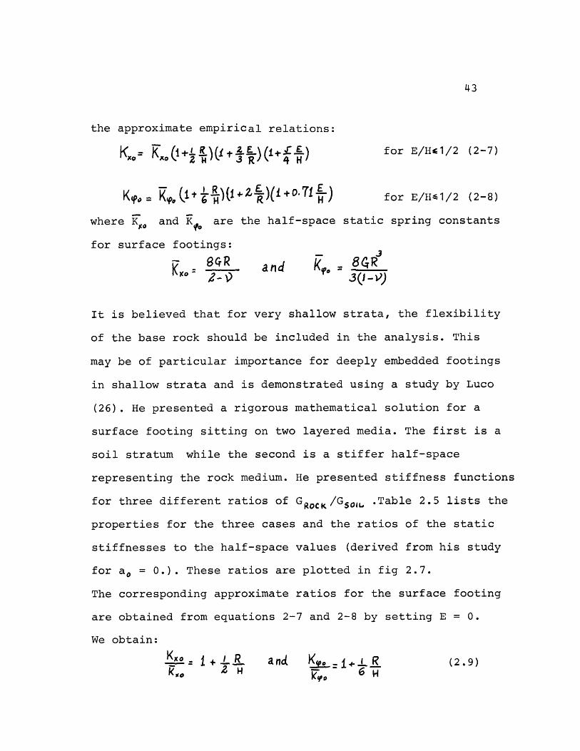
the approximate empirical relations:
KX= R E (l+ E for E/H41/2 (2-7)
K0= i+o 6 )(1+Z )(l+O.71 ) for E/H-1/2 (2-8)
where Ko and K are the half-space static spring constants
for surface footings:
K~to ' nR and K(O 8GRK - ;arid) 3Q-'(
It is believed that for very shallow strata, the flexibility
of the base rock should be included in the analysis. This
may be of particular importance for deeply embedded footings
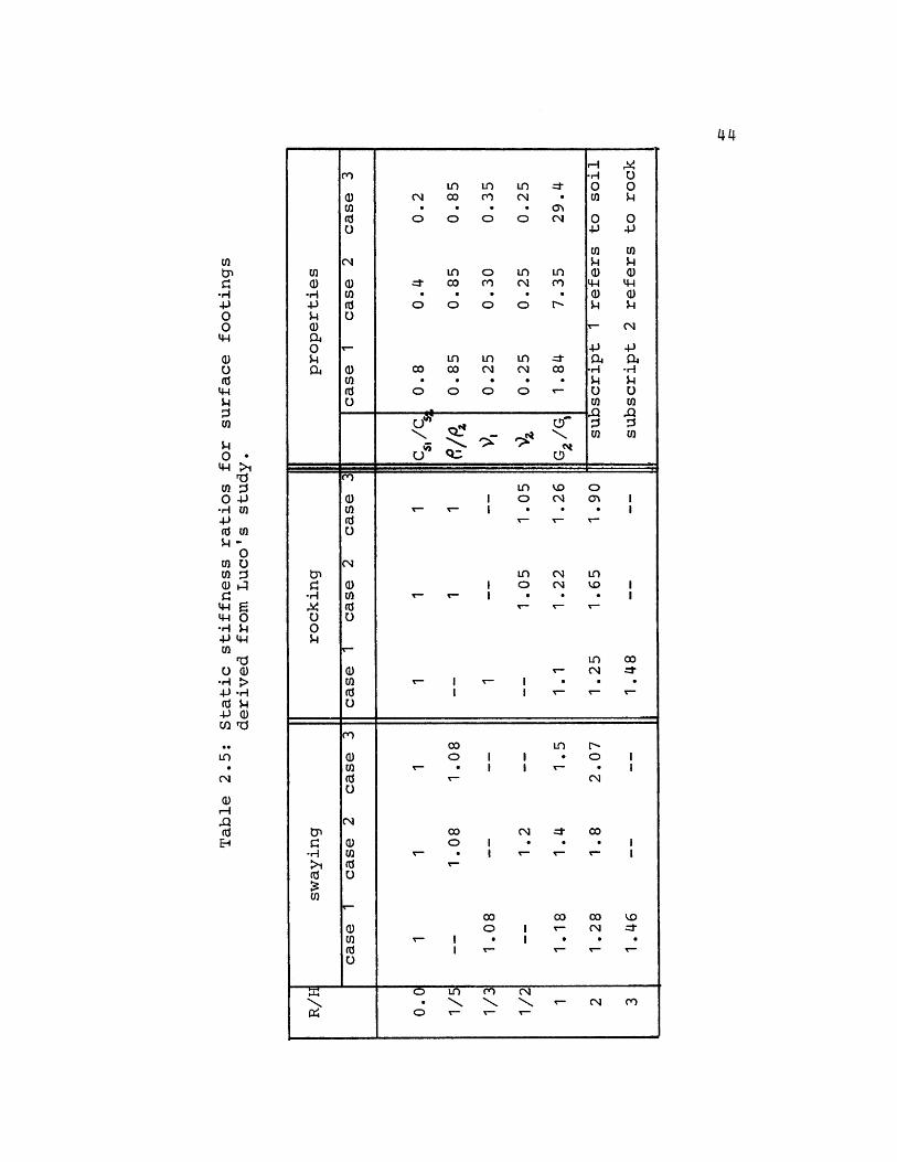
in shallow strata and is demonstrated using a study by Luco
(26). He presented a rigorous mathematical solution for a
surface footing sitting on two layered media. The first is a
soil stratum while the second is a stiffer half-space
representing the rock medium. He presented stiffness functions
for three different ratios of GRoC /GSoIL .Table 2.5 lists the
properties for the three cases and the ratios of the static
stiffnesses to the half-space values (derived from his study
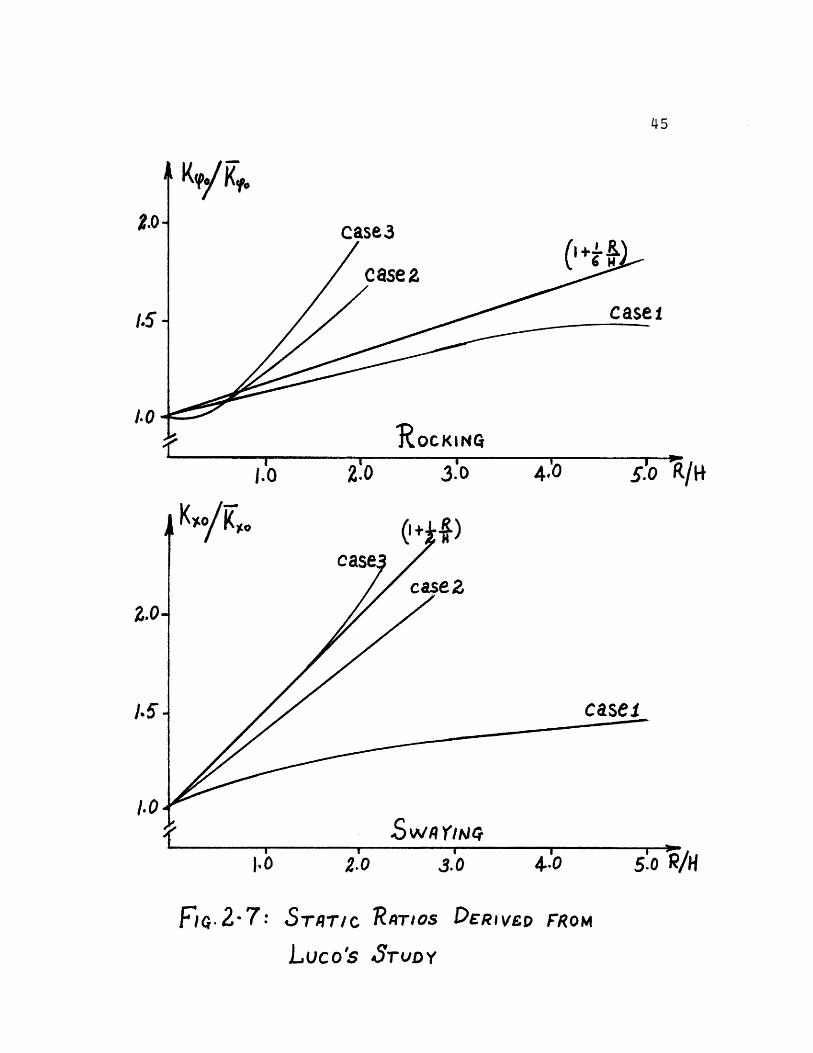
for a = 0.). These ratios are plotted in fig 2.7.
The corresponding approximate ratios for the surface footing
are obtained from equations 2-7 and 2-8 by setting E = 0.
We obtain:
Kxo 1+ ' R and Ks + R (2.9)X0 k'P 0~ E
Ln LC
o 00
o; 00
iL) occ co o
o o C0CO 00 C
V _
C. QIN Q ; 3·(.; Q.:
(N
o N·
Ln LnN m
o r"
CqN c0
O
0rt;v N1-
0!~
H
0
EO04Ja)
'H
0u
U)En
00
0-pUI
.,,a4
U0
.i
U)
n o oI o ,N o I
I cq .OI 0 (N 1)
~ T I . . It I
I
:-TT- I
I
LOr- (N
- I I 1
co L) No I I * o'- I I -
00 00 0o I r- (N
I I
C L() C? N, - C(N m
o I- T-
44
U2
-H
00t)
0
U)
Oa0 rd
0 O-I(d mJ- -0
U)w1
U)rd
0 Q)
Ln
(N
Eq
U)
(d
N
U)U)rdU
U0
En
N
0
Cd
C-
U
V
'In
U0En
0
0N
(a
0UI)CdU
{/}U)0
U))
-H
)
0ia-
-H
05.-U4
-H
.,
>1rdU)U)
I iiirl
-
--
IiII
__
- II I I i li I
I--,
I
I
I
T
case 2
case!
R ocKINQ
I / .r
z
C
S wn qr/jI
10 2.0
FG.2- 7: S-rT4qrC
I
3.0 4.0
RATIOS DERIV£D FROM
Luco's 3rUDY
45
( 6
5.o k/H
j
KdT
46
These ratios are also included in fig 2.7. For the rocking
mode the approximate ratio agrees well with Luco's values for
all three cases in the region R/H4 1. On the other hand, the
approximate ratio for the swaying mode, agrees perfectly with
Luco's case 3 (rigid rock). This comparison demonstrates that
the rock flexibility cannot be disregarded for very shallow
strata, say H/R 1.
2.2.2 Coupling Term:
When a plate, whether at the surface or embedded, is rotated
at the base, a certain amount of horizontal force will
develop. Thus a coupling term will always exist. For an
embedded footing it is more pronounced than for a surface
footing. Table 2.2 lists the coupling terms obtained from
TRIAX for the coarse and fine meshes. The extrapolation
procedure is also used to obtain the continuum values. The
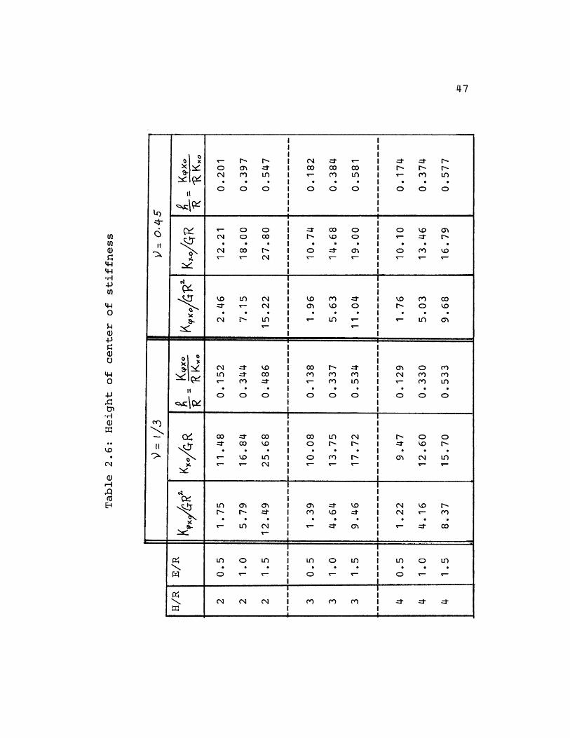
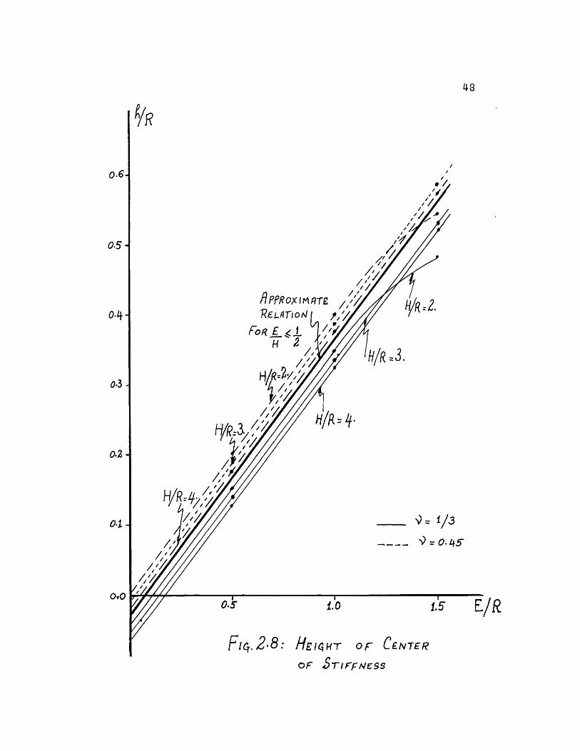
height of center of stiffness (h= Ko0 /K ) is then calculated
and listed in table 2.6. Fig 2.8 shows the relationship
between h/R and E/R. We see that the static coupling term
is also linear (with respect to E/R) in the region where
E/H 1/2. Again when E/R = H/R, we reach approximately the
case of a surface footing on a half-space (rock). For such
condition h is very small, thus we expect h/R to decrease
as E/R approaches H/R (see fig 2.9).
47
N- n n
o o o
v- 0 0
(N :r rCO co oo
o o o
L-: CO 0
' L
o o 0
0 'IO O
Ci 0 C I N .D o0 I '- V [ -
c- N, I 0 - o C I 0-o -I
I II I
\o Li (N-- r C
C- (n(N N L
If) J cor re o1
o o
Uo ) _::Uo o) o
' n
00- 1 Li
O O O
N- o IO
- n L O
Cfi O ciCO C)"V- C L
O O OI I
I II I
o - co I oo Lln C I N o o:t 00 'O I o N N I T 'o .-
ri Lfr- '- C14
LI) 0 o
N Ln ztr-Li (
on o in
Y- T-
ci J~ ::t*- :* O@m 'O _J Ch
1-: 0
I I Cm CN LO~I e- Y-
l
!
N . r(N r- C)
* * o
I ______________ I
LO 0 L0) r- rin o LiC0 '- '-
I ....... I , -I I
L0
Itcr
II
EnU)
,4-40.
-,0c4-)
.(aH-
0 xX ,
,,1itip
o I
0 I
II!
.R
a-
N
m J.
CQe
4t
I ---
'z"CI P
01-1
AI--
_
Ix clq N lq
II3 c
i
--t --t --
IIIIIIII
IIIIIII
I IIIIIIII
IIIIIIII
IIIIIIII
IIIIIIII
IIIIII
IIIIII
II
II
PPR oxi M TreRELToRlI I
Fc. 2.8:OF SrTIFFNSSs
48
!
I/
!!
,
/,' -2.
0.6
0.5
o.4
0.3
0.2
0o.
OtC
/R -3.
-= 1/3
I.
oF CENTER
/R
49
R R
-/R
F;ic.29: BEHRVIOR o F E I HT
OF CENTER OF STIFFNESS
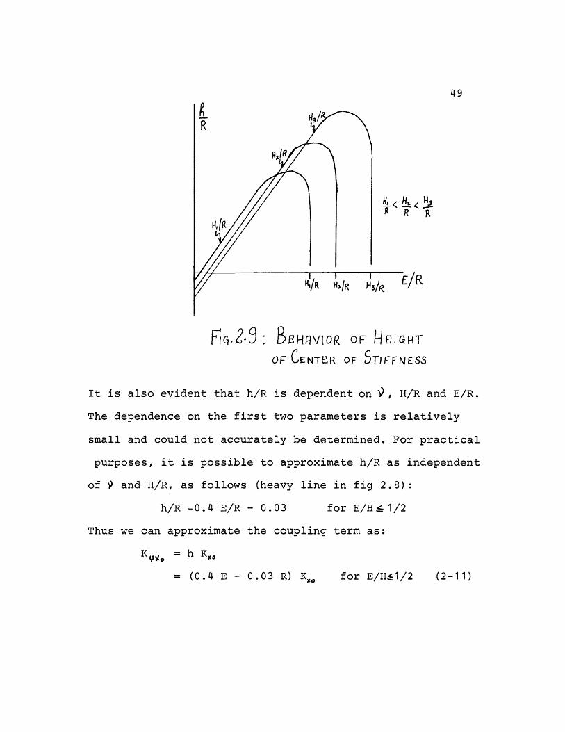
It is also evident that h/R is dependent on , H/R and E/R.
The dependence on the first two parameters is relatively
small and could not accurately be determined. For practical
purposes, it is possible to approximate h/R as independent
of and H/R, as follows (heavy line in fig 2.8):
h/R =0.4 E/R - 0.03 for E/H! 41/2
Thus we can approximate the coupling term as:
K = h Ko
= (0.4 E - 0.03 R) K for E/H1/2 (2-11)
50
2.3 Effect of Weaker Backfill:
One of the assumptions made in the derivation of equations
2-7, 2-8 and 2-11 was that the soil next to the embedded
footing has the same properties as beneath it. However,
in realty, after the footing and the sidewalls of an embedded
structure are poured in place the rest of the excavation is
filled in, thus leaving disturbed lateral soil, producing
a weaker backfill than the soil beneath the footing. In
addition, soils are layered and their stiffness increases
with depth.
A new model for the case H/R = 2., E/R = 1. was developed.
The ratio of the thickness of the backfill to the radius of
the footing was taken as 0.1, while the shear modulus of the
backfill was taken as 0.81 times the shear modulus of the
undisturbed soil. The structural properties were unchanged
from the previous models. The static stiffnesses were then
calculated using TRIAX for the case = 1/3. The above ratios
were used because they represent actual values found in many
containment structures. Table 2.7 shows the results, where the
continuum values were obtained from the same extrapolation
procedure previously used.
51
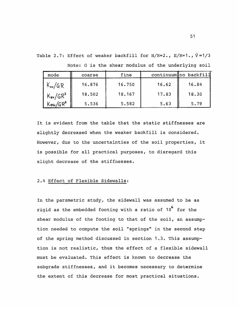
Table 2.7: Effect of weaker backfill for H/R=2., E/R=1., =1/3
Note: G is the shear modulus of the underlying soil
mode coarse fine continuum no backfill
KXO/G'R 16.876 16.750 16.62 16.84
Kt0/GR' 18.502 18.167 17.83 18.30
Kq)Io/CTR2 1 W 5.536 5.582 5.63 5.79
It is evident from the table that the static stiffnesses are
slightly decreased when the weaker backfill is considered.
However, due to the uncertainties of the soil properties, it
is possible for all practical purposes, to disregard this
slight decrease of the stiffnesses.
2.4 Effect of Flexible Sidewalls:
In the parametric study, the sidewall was assumed to be as
rigid as the embedded footing with a ratio of 106 for the
shear modulus of the footing to that of the soil, an assump-
tion needed to compute the soil "springs" in the second step
of the spring method discussed in section 1.3. This assump-
tion is not realistic, thus the effect of a flexible sidewall
must be evaluated. This effect is known to decrease the
subgrade stiffnesses, and it becomes necessary to determine
the extent of this decrease for most practical situations.
52
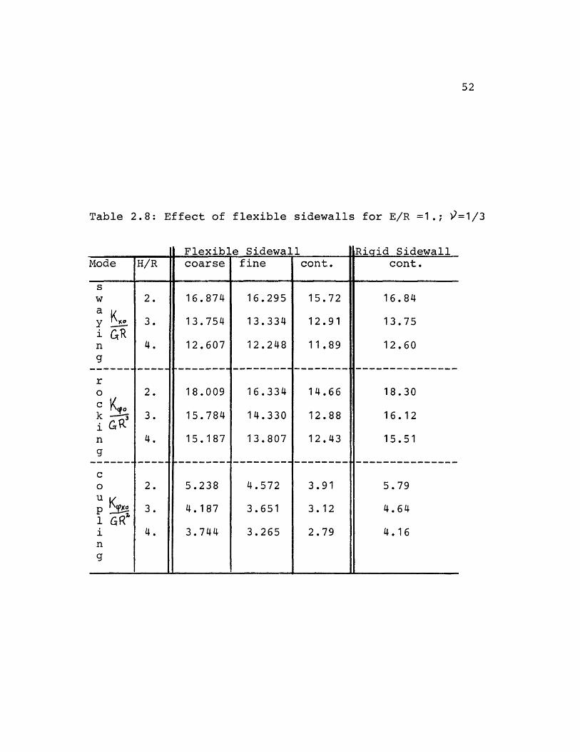
Table 2.8: Effect of flexible sidewalls for E/R =1.; 9=1/3
Mode H/R
sw 2.a KoY 3.i GRn 4.
g
ro 2.
k X 3.
n 4.
g
co 2.
u vqo3.1 GR'i 4.
ng
Flexible Sidewallcoarse fine cont.
16.874 16.295 15.72
13.754 13.334 12.91
12.607 12.248 11.89
18.009 16.334 14.66
15.784 14.330 12.88
15.187 13.807 12.43
5.238 4.572 3.91
4.187 3.651 3.12
3.744 3.265 2.79
Riaid Sidewallcont.
16.84
13.75
12.60
18.30
16.12
15.51
5.79
4.64
4.16
53
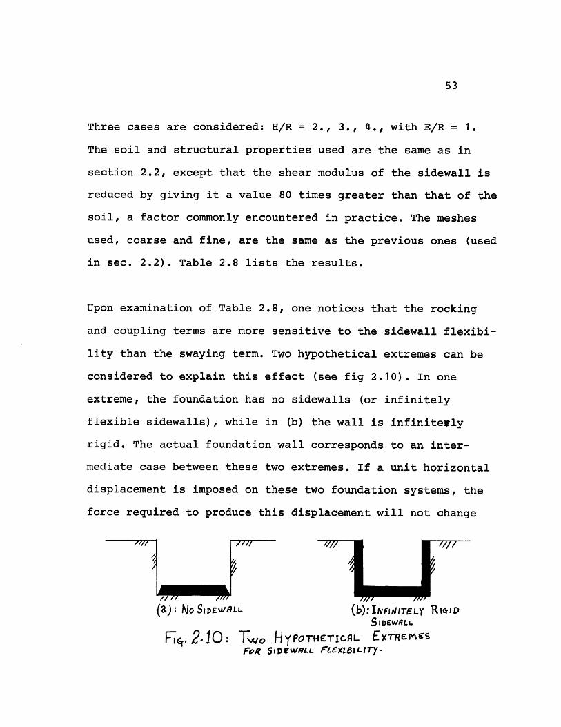
Three cases are considered: H/R = 2., 3., 4., with E/R = 1.
The soil and structural properties used are the same as in
section 2.2, except that the shear modulus of the sidewall is
reduced by giving it a value 80 times greater than that of the
soil, a factor commonly encountered in practice. The meshes
used, coarse and fine, are the same as the previous ones (used
in sec. 2.2). Table 2.8 lists the results.
Upon examination of Table 2.8, one notices that the rocking
and coupling terms are more sensitive to the sidewall flexibi-
lity than the swaying term. Two hypothetical extremes can be
considered to explain this effect (see fig 2.10). In one
extreme, the foundation has no sidewalls (or infinitely
flexible sidewalls), while in (b) the wall is infinitewly
rigid. The actual foundation wall corresponds to an inter-
mediate case between these two extremes. If a unit horizontal
displacement is imposed on these two foundation systems, the
force required to produce this displacement will not change
f/i
/ t /,I/ // 11(a): NoSIDEWALL (b): IJTELY R1D
SIDEWALL
cn. 2.10: Two HYPOTHETICAL EXTREmrSFoR SIDEWRSLL FLEXZSI.LT7r
7/~
54
substantially, since only small tensile/compressive reaction
forces act on the rigid sidewall in case (b). Most of the
resisting force is offered by shearing stresses below the
plate. Rocking, on the other hand, is very sensitive to
changes in the stiffnesses of the lateral walls. This results
from the fact that the shearing stresses along the sidewalls,
which contribute to the rocking stiffness and are magnified
by the moment arm, decrease with increasing flexibility of
the sidewall. This decrease in the static stiffness coeffi-
cients is obviously a function of the extent of the sidewall
flexibility assumed. Further analytical and experimental
investigations are required to approximate the appropriate
decrease to be used.
2.5 Effect of Variable Shear Wave Velocity:
Up to this point, the stratum was taken to be homogeneous in
all directions. However, in real problems, the soil exists in
layers with the shear wave velocity, and thus also the shear
modulus, increasing with depth. If one chooses homogeneous
properties as existing at the foundation level, the static
stiffnesses will be over-estimated. Table 2.9 shows the
results obtained for the case E/R = 1., H/R = 2., = 1/3,
with the shear wave velocity varying from 0.5 at the surface
55
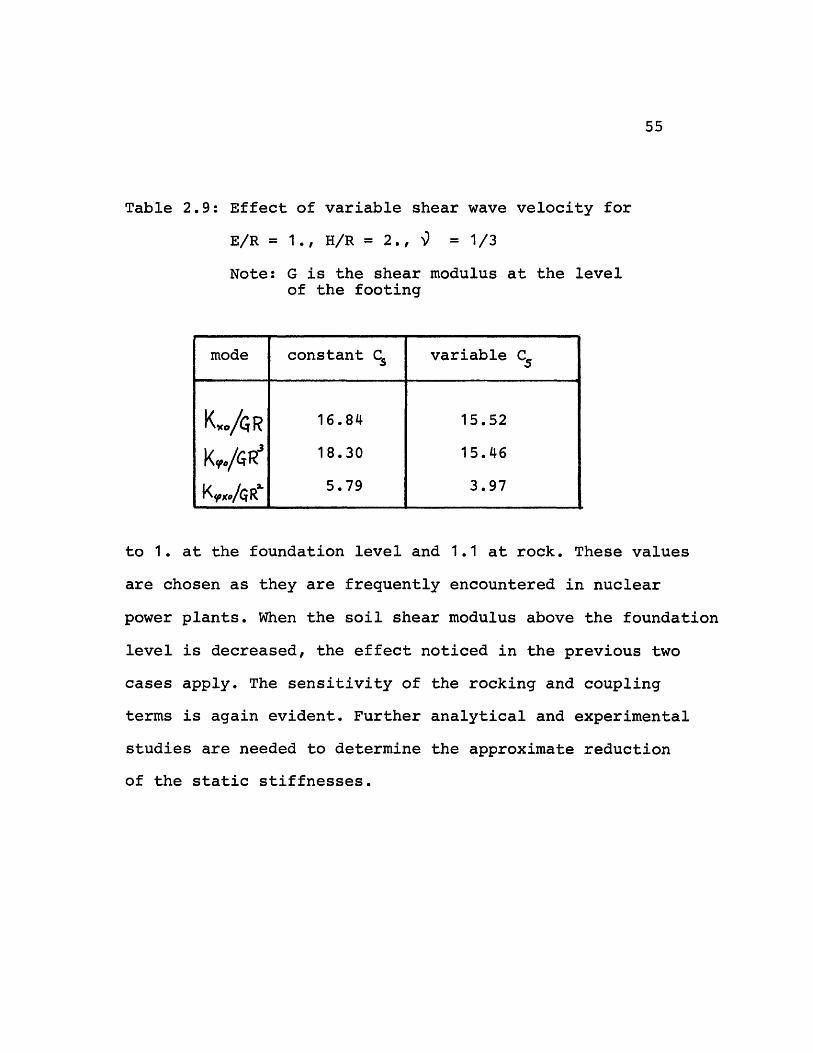
Table 2.9: Effect of variable shear wave velocity for
E/R = 1., H/R = 2., ' = 1/3
Note: G is the shear modulus at the levelof the footing
to 1. at the foundation level and 1.1 at rock. These values
are chosen as they are frequently encountered in nuclear
power plants. When the soil shear modulus above the foundation
level is decreased, the effect noticed in the previous two
cases apply. The sensitivity of the rocking and coupling
terms is again evident. Further analytical and experimental
studies are needed to determine the approximate reduction
of the static stiffnesses.
mode constant C variable C5
KO/iR 1 6. 84 15.52
Ko,./&R 1' 18.30 15.4 6
K,~oo/Rl 5 v79 3.97
56
3.- Comparison of Model Used with Other Studies:
In this section, comparisons of the approximate relations
derived in sections 2.2.1 and 2.2.2 with results by Urlich
and Kuhlemeyer (39) for the influence of embedment in a
half-space, and by Johnson and Christiano (18) for the com-
bined effects of embedment and stratum depths are presented.
Since the approximate relations provide a good fit to results
obtained from TRIAX, this section essentially provides
comparisons between the finite element model with the trans-
mitting boundary, used in this study, and other more "con-
ventional" finite element models. As was shown in section
2.2.1, the approximate relations are in good agreement with
Luco's theoretical results for surface footings on an
elastic stratum underlaid by a rigid base (case 3), and thus
provide reasonable validation for the empirical rules derived
in this study. Therefore this section will give insight into
the magnitude of the errors resulting from standard modeling.
3.1 Embedment in a Half-space:
Urlich and Kuhlemeyer (39) presented a numerical model which
was used to solve the problem of steady state coupled rocking
and lateral vibrations of footings embedded in an elastic
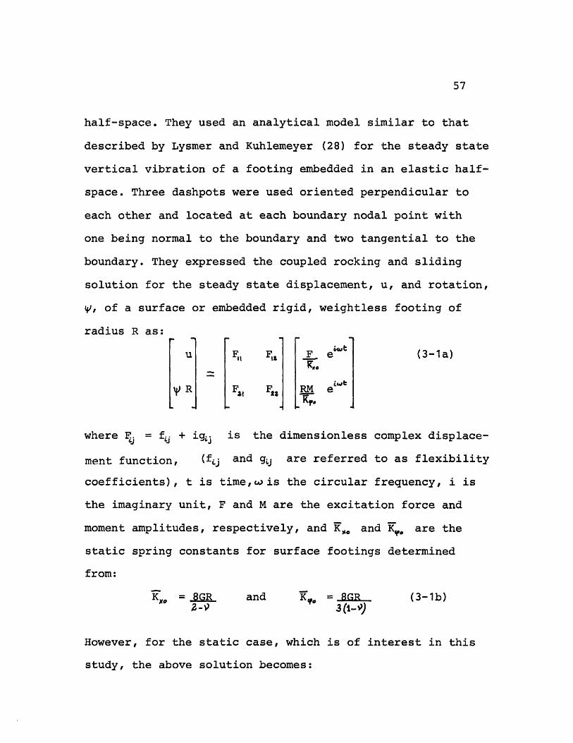
57
half-space. They used an analytical model similar to that
described by Lysmer and Kuhlemeyer (28) for the steady state
vertical vibration of a footing embedded in an elastic half-
space. Three dashpots were used oriented perpendicular to
each other and located at each boundary nodal point with
one being normal to the boundary and two tangential to the
boundary. They expressed the coupled rocking and sliding
solution for the steady state displacement, u, and rotation,
V, of a surface or embedded rigid, weightless footing of
radius R as:
u F, F1 F e (3-1a)
RFs , RM el e
where Fj = f + igj is the dimensionless complex displace-
ment function, (fj and g are referred to as flexibility
coefficients), t is time,wis the circular frequency, i is
the imaginary unit, F and M are the excitation force and
moment amplitudes, respectively, and K,o and K are the
static spring constants for surface footings determined
from:
KX, =8GR and KO = GR (3-1b)2-9 3(1-0)
However, for the static case, which is of interest in this
study, the above solution becomes:

58
U1= FF, F: [;/KI;1 (3-2)
yR] sr 2RM
Taking the inverse of the flexibility to obtain the stiffness
matrix K, one obtains:
Kf2 f2 Ko -fz K. Ri (3-3)
D , ,f, K/R f
where D = f,, fz - f~, f, ,and Fj have been replaced by fj
as g are zero for the static case. From Eq.3-3 we see that
the static stiffness coefficients have been expressed as:
Kxo = f2 Kx*o/D ; K = f,, K. /D (3-4)
K= ' -f, R. /D ; K,-f£l ko /RD (3-5)
Urlich and Kuhlemeyer showed that a relation exists between
fez and f :
f2 R Kf , /K o
Thus the expressions in Eq.3-5 become, as expected:
Key= K =-f3 iX? /RD
or the height of center of stiffness h (as defined in section
2.2.2) is given by:
_h = Ko = fro K = -(2-V)fl (3-6)
R? RK.O R 24 Ego 3O-J)
For the static solution, Urlich and Kuhlemeyer used boundary
conditions such that vertical and base boundaries of the mesh
were fixed from moving normally and free to move tangentially.
The dynamic dashpots were not used for the static solution as
59
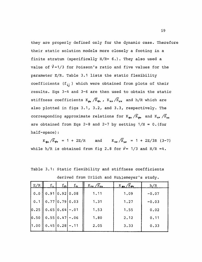
they are properly defined only for the dynamic case. Therefore
their static solution models more closely a footing in a
finite stratum (specifically H/R= 6.). They also used a
value of 9=1/3 for Poisson's ratio and five values for the
parameter E/R. Table 3.1 lists the static flexibility
coefficients (fLj ) which were obtained from plots of their
results. Eqs 3-4 and 3-6 are then used to obtain the static
stiffness coefficients K /K? , Ko /Ko and h/R which are
also plotted in figs 3.1, 3.2, and 3.3, respectively. The
corresponding approximate relations for K, /K.o and K /Ko
are obtained from Eqs 2-8 and 2-7 by setting 1/H = O.(for
half-space):
Ko/K o = 1 + 2E/R and KO /Ko = 1 + 2E/3R (3-7)
while h/R is obtained from fig 2.8 for = 1/3 and H/R =4.
Table 3.1: Static flexibility and stiffness coefficients
derived from Urlich and Kuhlemeyer's study.
E/R f f2z. fl, K.. /K ,K /K. h/R
0.0 0.91 0.92 0.08 1.11 1.09 -0.07
0.1 0.77 0.79 0.03 1.31 1.27 -0.03
0.25 0.65 0.64 -.01 1.53 1.55 0.02
0.50 0.55 0.47 -.06 1.80 2.12 0.11
1.00 0.45 0.28 -.11 2.05 3.33 0.33. ,,l
5 8'I o
CZ\
\ \
Ch.car L2CAO~
0
z
o ,r E -"I I
zLJ
-4
-_C cI
Ni- ik."-I
O! 0'S
' V) LLw
%S ..£1 trt'In O
N
6 ll
L, ru
4z,
( 14ou.O QF
o
(4 '0. k
o~~~~~~~~~~~~~~ 0o -k~r~
A I
60
laI'
4Jpt
' _w _
wa m I-
t`j 4
% tjLZ
%OQC l
u it~'k, r)
It I-
0c~
85'
LEc END:
UJRLICH 4 KUILEMEYeR(DRIvcO FRoa Ti.ER STUPy)
, .cI. _. .
'RoM rR9frfTleRc rLu Oy
fi. 2.8; H/R= 4 P = 11/3
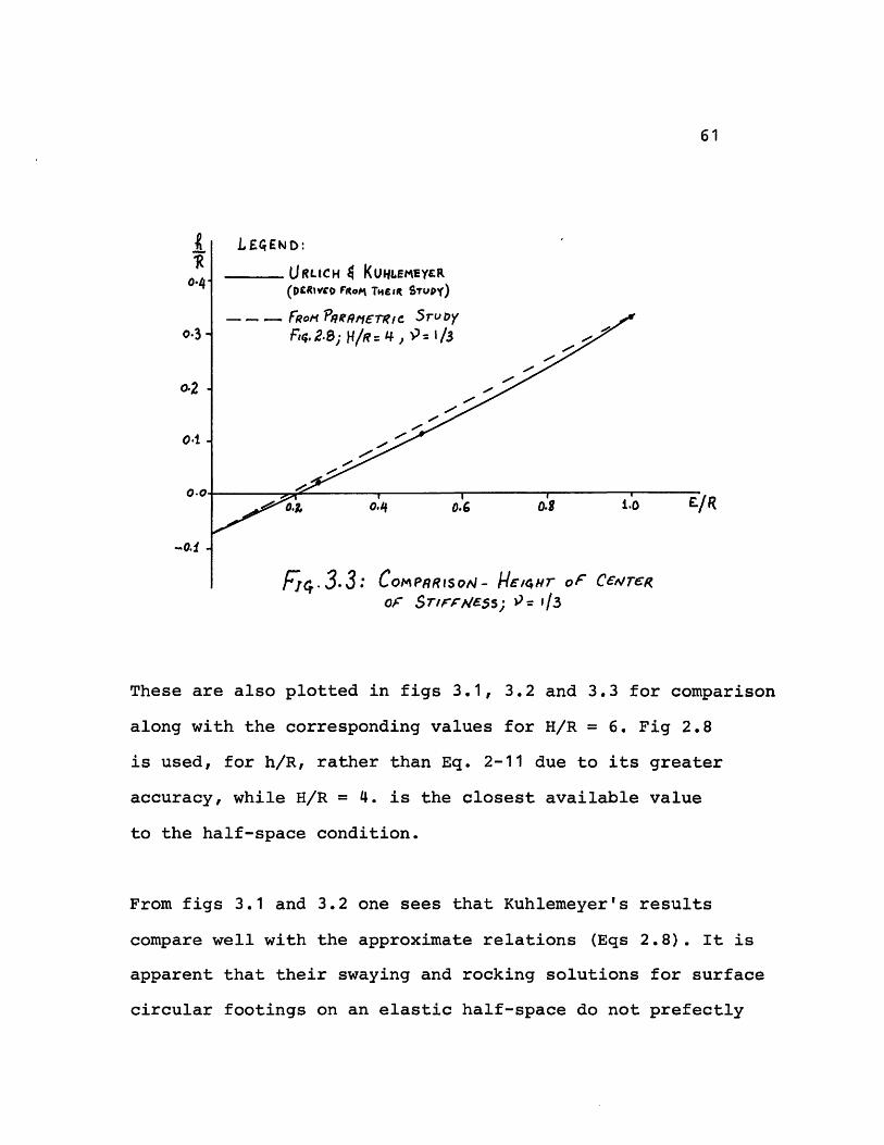
0.Z o0.4
Fa. 33 : ComP.RtsOJ- HE/4r oF CeWreROF ST,rf.CESS; P= 1/3
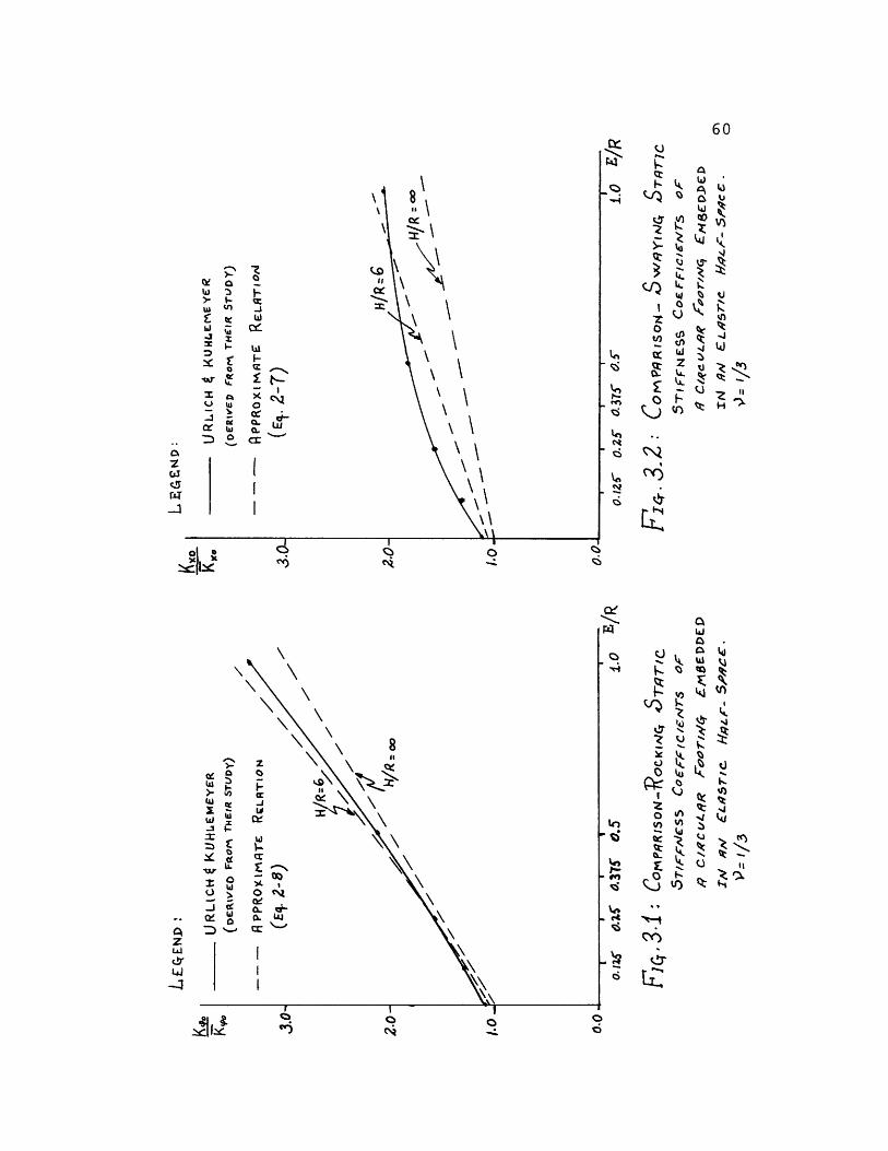
These are also plotted in figs 3.1, 3.2 and 3.3 for comparison
along with the corresponding values for H/R = 6. Fig 2.8
is used, for h/R, rather than Eq. 2-11 due to its greater
accuracy, while H/R = 4. is the closest available value
to the half-space condition.
From figs 3.1 and 3.2 one sees that Kuhlemeyer's results
compare well with the approximate relations (Eqs 2.8). It is
apparent that their swaying and rocking solutions for surface
circular footings on an elastic half-space do not prefectly
61
0-4
0.3 -
0.2
04.0.0.6 o .0 E/R
- - t0.8
62
agree with rigorous analytical solutions, i.e. K = 8GR/3(1-9)
and K,,= 8GR/(2-9). These discrepancies do not occur in Eq. 3-7
due to the extrapolation procedure used for the correction
of mesh size. Other sources of error in Kuhlemeyer's solution
are the boundary conditions and the position of the
boundaries relative to the footing used for the half-space
representation. These boundary conditions, as mentioned
earlier, model more closely an H/R = 6. stratum rather than
a half-space. The swaying term seems to be more sensitive
to such modeling errors than both the rocking and the off-
diagonal coupling terms. On the other hand, if we apply the
approximate relations for H/R = 6. to account for the fact
that Kuhlemeyer's solution does not model the half-space
condition, then the agreement improves significantly. The
remaining differences are due to Kuhlemeyer's discretization
error and his lateral boundary conditions. This shows that
great care must be exercised for an accurate determination
of the static stiffnesses.
3.2 Combined Embedment and Stratum Depths:
Johnson and Christiano (18) dealt with the static load-
displacement behavior of circular and strip footings embedded
in an elastic stratum which is underlaid by a rigid base.

63
They reported the results of static finite element analyses
of all modes describing the behavior of embedded footings.
Their finite element model consists of triangular elements,
base boundaries which prevent vertical and horizontal
displacements and vertical boundaries which prevent vertical
displacements alone. The methods for formulating the governing
stiffness equations follow the work of Wilson (45) for axi-
symmetric systems. They considered a rigid footing with full
continuity between the footing and the soil, so that possi-
bility of slip or cleavage, as in Kausel's model used for
determining the approximate relations, was precluded. Linear
isotropic soil was assumed throughout the stratum with a
Poisson's ratio 9= 1/4. Their results are presented as a
set of plots showing the ratios of the static stiffness
coefficients to the corresponding elastic half-space solutions
for surface footings (Eq 3-1b).
They concluded that the influence of embedment on the rocking
static stiffnesses is greater than for the swaying mode,
an effect which can also be predicted from the approximate
relations proposed in this study. They also concluded that
the inflence of the proximity of bedrock is greater for the
swaying mode than for the rocking one. Again, this effect
is also predicted by the approximate relations.
a'Z P
I-I
2Ci'o
C% oZ D
O
W '3-4
II
I
//
/I
0z
a-I
u'z
0
,4zhl
4"I
Q vktJ_QC:
,'A.
o -C W
It/O/2,'Ic,
., .7/0
I
I
II
I''
I
iI
I
II-C
I
I
I
C)I~
-I 'ao L- 0z
KC-'E2 %_ C- L
,CI
. o
IL
ce-
-C2
VSQ
_ QTzu
toZe-444
%n-+ kt._N
_ <r
LZ
64a4.
K r e
d J t
4tO
o G'
a E-'
2 '
Uu
nne AC
V) b
4 s
0
I
_ _· · · __ u w
I
I
I
II
I
I
I
I
I
I
I
I
I
ex " tr)1d
I
I'D
!
(Ii
!
I
I
I
I I
0
65
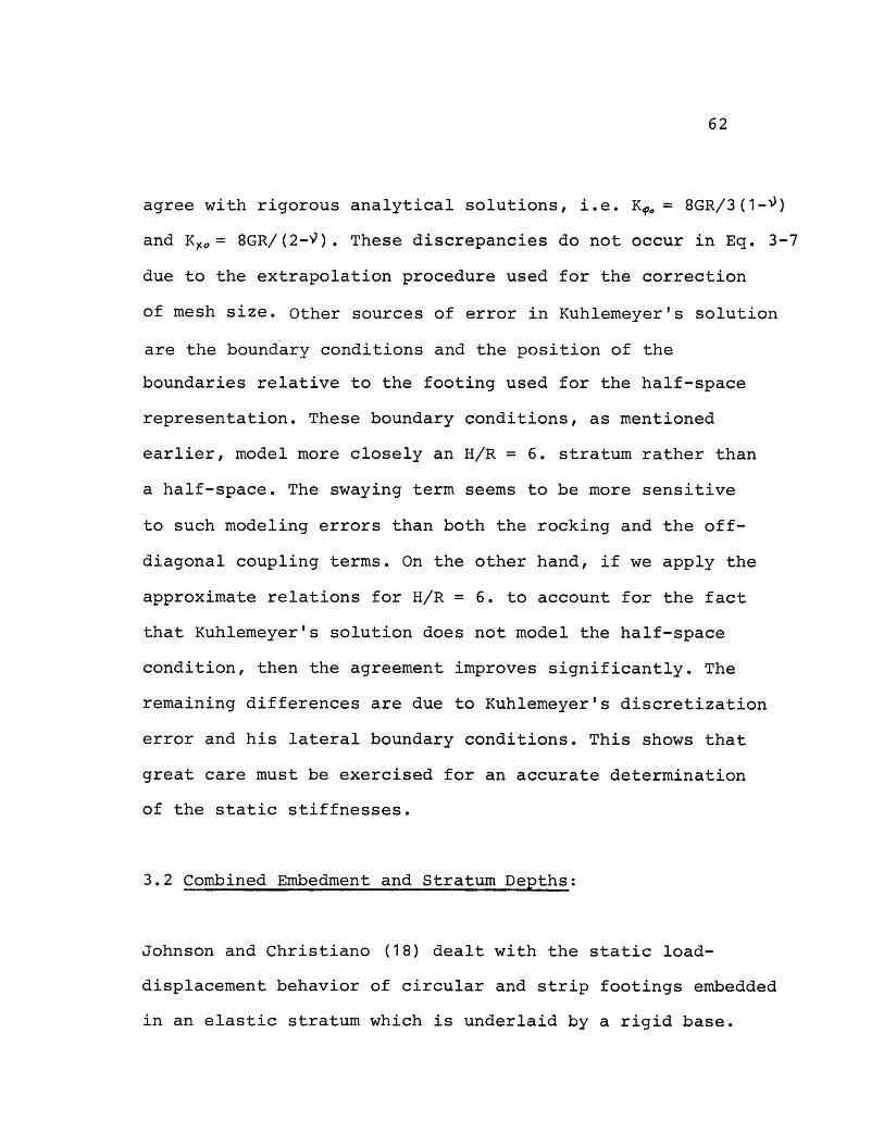
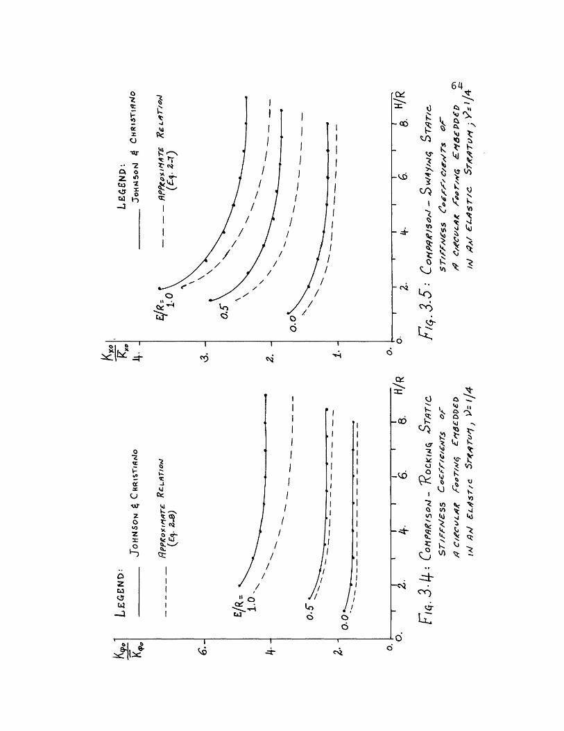
Figs 3.4 and 3.5 present Johnson and Christiano's static
stiffness coefficients for circular footings embedded in an
elastic stratum for the rocking and the swaying modes
respectively. The corresponding values obtained from the
approximate relations (Eqs 2-8 and 2-7) are also included
for comparison.
Johnson and Christiano's static stiffness coefficients
compare well with the approximate relations. Their values
are always larger than those from the approximate relations,
and the difference between them appear to be approximately
constant for a specific embedment ratio. In the case of the
surface footing (E/R = 0.0) their values do not tend to the
half-space analytical solutions as H/R -- while the
approximate relations do. However, the general effects of
the embedment and stratum depths, evident from their study,
seem to agree well with those from the approximate relations.
The sources of discrepancies are again attributable to the
mesh size used by Johnson and Christiano and the location
of the lateral boundary in their finite element mesh.
66
3.3 Concluding Remarks:
The emirical relations. derived in this study provide a good
approximation for the homogeneous stratum condition and are
preferred to a static finite element solution when correction
for mesh size is excluded.
However, if accurate values for the static stiffnesses in
a layered medium are desired, then the approximate relations
should be corrected for this condition, or finite element
analyses accounting for mesh size correction be used instead.
The correction in this latter alternative is necessary,
because the discretization error can be of the same order
of magnitude than the effect of layering (see tables 2.1
and 2.9).
67
4.- Soil-Structure Interaction:
As explained in section 1.1, two general approaches can be
used to estimate the dynamic soil-structure interaction
effects: the direct (or complete) approach in which the whole
system, soil and structure, is modeled and analyzed together;
and the spring (or substructure) method which consists of
the three steps discussed in section 1.3. Even though numer-
ical methods, such as the finite element method used in the
direct approach, are ideally suited for the analysis of
complex problems, they result in considerable increases in
the cost of computation. In many cases, this cost increase
will restrain the analyst from covering a wide range of
design parameters to ensure adequate protection against the
uncertainties inherent to the nature of soils, thus making
the second approach more attractive for many cases.
In performing the seismic analysis of a structure, the
stiffness functions given by equations 4-1 and 4-2 are
needed to represent the soil under the structure.
K = K (k + iac ) (1 + 2 i) (4-1)
K = K+ (kz+ ia~q) l + 2Pi) (4-2)
The static stiffnesses, Ko and K, , can be approximated by
the relations derived in section 2.2. However, the problem

68
of approximating the frequency dependent coefficients k, ,k,
cf, and c still remains. In this chapter two methods will
be presented to approximate these coefficients, and a seis-
mic analysis is performed for a structure using these ap-
proximations. The analysis is also performed using the
stiffness functions obtained from TRIAX for the specific
case to be studied.
For earthquake loadings, the controversial question as to
where the control motion should be specified is often intro-
duced. This question, however, should be resolved in the
first step of the spring method. Since our main aim is to
test the validity of approximate subgrade stiffness func-
tions, the controversy can be avoided, arbitrarily specifying
the horizontal control motion under the foundation as input
to the springs. Also, for the same reason it suffices to
model the structure as a rigid cylinder embedded in an
elastic stratum which is underlain by a rigid base. However,
the mass properties and geometry used for the cylinder, and
the soil properties of the stratum are typical values for
nuclear containment structures. The assumed structural prop-
erties are:
Radius (R) = 67.5 ft.
Embedment (E) = 55.0 ft.
69
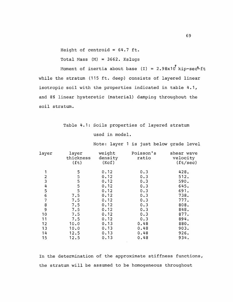
Height of centroid = 64.7 ft.
Total Mass (M) = 3662. Kslugs
Moment of inertia about base (I) = 2.98x10 kip-sec-ft
while the stratum (115 ft. deep) consists of layered linear
isotropic soil with the properties indicated in table 4.1,
and 8% linear hysteretic (material) damping throughout the
soil stratum.
Table 4.1: Soils properties of layered stratum
used in model.
Note: layer 1 is just below grade level
layer layer weight Poisson's shear wavethickness density ratio velocity
(ft) (Kcf) (ft/sec)
1 5 0.12 0.3 428.2 5 0.12 0.3 512.3 5 0.12 0.3 590.4 5 0.12 0.3 645.5 5 0.12 0.3 691.6 7.5 0.12 0.3 738.7 7.5 0.12 0.3 777.8 7.5 0.12 0.3 808.9 7.5 0.12 0.3 848.10 7.5 0.12 0.3 877.11 7.5 0.12 0.3 894.12 10.0 0.13 0.48 880.13 10.0 0.13 0.48 903.14 12.5 0.13 0.48 926.15 12.5 0.13 0.48 934.
In the determination of the approximate stiffness functions,
the stratum will be assumed to be homogeneous throughout
70
the domain with properties equal to those of the layer just
below the footing:
Cs = 877. ft/sec
G = 2866. K/ft
9= 0.3
Using equations 2-7 and 2-8, the approximate static
stiffnesses are:
K = 2.90x10 K/ft
K,.= 1.30x10 K-ft/rad
and the height of center of stiffness (eq. 2-11) is:
h = 19.98 ft or K Xo= 57.94x10 K/rad
The finite element analysis using TRIAX with the soil
properties in table 4.1 resulted in the following static
stiffness values:
Ke = 2.8x10 K/ft
K,,= 1.2x10 K-ft/rad
Kt.= 37.3x10 K/rad
The swaying and rocking static stiffnesses agree very well
with the approximate values. The coupling term K has an
error of 55%; however as will be seen from the results, this
discrepancy will not introduce great errors, because the
response is not very sensitive to the coupling term if the
center of mass of the structure is well above the center of
stiffness. It should be noted that the extrapolation proce-
dure is not used in obtaining the finite element static
71
stiffnesses and also the effect of soil layering is not
included in the approximate values. As was discussed in
section 2.5 ("Effect of variable shear wave velocity"), the
approximate static stiffnesses will be decreased when the
effect of soil layering (layer properties in table 4.1) is
considered. In addition, the finite element static swaying
and rocking stiffnesses should be reduced by applying the
extrapolation procedure (see section 2.2). Since the two
effects could decrease the stiffnesses by a comparable
amount, these corrections are neglected in this study.
Due to the excellent agreement of the finite element static
stiffnesses with the approximate ones, the remainder of the
chapter will mainly deal with an evaluation of the importance
of the frequency dependence of the stiffness and damping
coefficients k, k, ct and c, on the structural response.
The following resonant swaying and rocking frequencies will
be referred to in the sections to follow:
SAX = ? j a= CR a fox· t (4-3)
a,, 35WFlra.,_ i f n(4-4)
72
4.1 Approximation of the Frequency Dependent Coefficients:
In the following, a method to account in an approximate
manner for the frequency dependence of the coefficients will
be analyzed. The discussion will be based on results presen-
ted in ref.(21), and the suggested procedures will be
evaluated for the rigid cylinder model of a nuclear contain-
ment structure described earlier.
4.1.1 Stiffness Coefficients kiand kz:
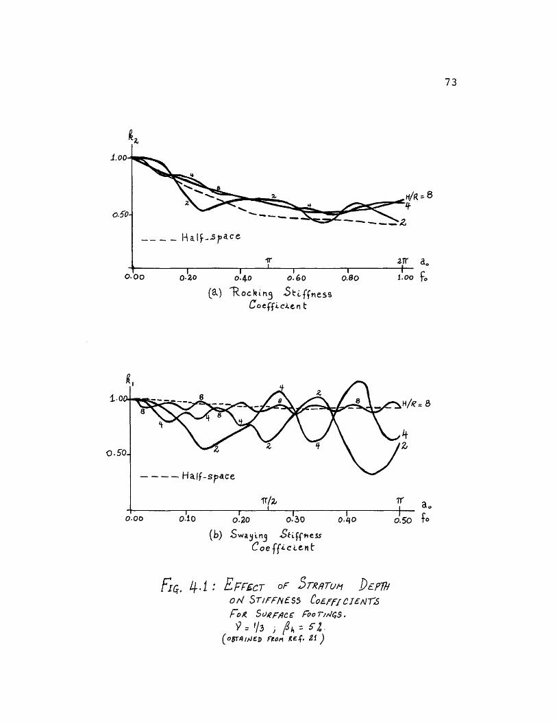
The first interesting feature in the frequency dependence
of the stiffness functions is that the real part behaves
markedly different for rocking and swaying (see fig. 4.1).
The former is a relatively smooth curve, for which the depth
of the layer exercises little influence and approaches quite
closely the analytical half-space solution for a surface
footing after Veletsos and Wei (40). Swaying, however, shows
a wavy pattern in which valleys occur close to the natural
shear beam frequencies of the soil, an effect which is more
pronounced for shallow strata. However, as the stratum depth
increases, the amplitudes of the peaks and valleys decrease
rapidly, and for H/R = 8 k already approaches Veletsos
and Wei's half-space solution.
73
a 8
ao
Fo
(a) R ock Mog St anlessCoefficin t
I?
o= 8
a0
fo·
(b) Say'ng SiffnessCoe ffic ent
Fo. 4.1: EFFCCT oF SrTqreR," JDE p7odv ST/FFIVES5 Co£F£j-I&,SA1S-Fo Suerc Foo r/c,$.
1'/3 4 52.(oSrlJElD FRo g 21 )
1
0.
74
The preceeding comparison is done for a hysteretic damping
value of 5%. For more typical values of the hysteretic
damping ratio (5%-<9/15%) the agreement of the stiffness
coefficients with those of the half-space improve even
further (ref. 21). A similar effect can be observed by
varying Poisson's ratio. On the other hand, embedment does
not substantially alter the shape of the stiffness coeffi-
cients as was pointed out in said reference.
To better assess the relative importance of the frequency
variation of the stiffness coefficients, consider the
response of a 1-DOF system supported with a frequency
dependent "spring". Its impedance function can be defined as:
Z = K ( k + 2 )
where =p() is the equivalent viscous damping given by:
2-= aoc, and W is some reference frequency. For
the case at hand, this frequency corresponds to the undamped
natural resonant frequency of the system computed with the
static value of the subgrade stiffness (Eq. 4-3 or 4-4).
In the very low frequency range, (L<<W), the stiffness
term k dominates the response. At intermediate frequencies,
(-l/w i), the amplitude of motion is very sensitive to the
equivalent viscous damping coefficient , while in the
high frequency range (->> ) the response is totally
75
controlled by the inertia of the system, and thus the shape
of the stiffness function is irrelevant. Therefore, the
stiffness coefficients are of major concern only in the
low frequency range.
If one limits the depth of the stratum to be greater than
the diameter of the foundation (H/R>2), the half-space
solution for k and k can be adapted (with reasonable
accuracy) to the actual finite depth stratum as a good
agreement in the low frequency range, where these coefficients
influence the response the most, exists between the two
conditions. The relatively moderate differences between
the half-space stiffness coefficients and the actual ones
will result in slight shifts in the resonant frequencies
of the impedance (and thus the transfer) functions. However,
since these shifts depend on the square root of the error,
they will be smalll in magnitude.
A more important point in this adaptation is a proper
representation of the damping coefficients, as they control
the amplitude of the response at resonance. This point is
addressed in detail in the following section.
76
4.1.2 Radiation Damping Coefficients cand c:
The imaginary part of the stiffness functions, which can be
interpreted as an equivalent viscous damping ratio due to
radiation of energy away from the footing, is a critical
parameter to which the response of the structure is very
sensitive.
Referring to fig. 4.2 it can be seen that there are negli-
gible differences of the radiation damping coefficient with
respect to the half-space solution for rocking, and except
for the wavy nature in shallow strata, the agreement is also
remarkably close for swaying. There exists one important
difference, however, between the strata and the half-space
solutions; namely the former has little radiation damping
in the low frequency range, and then rises abruptly at
certain critical frequencies. These critical frequencies
correspond to the first horizontal natural frequency of the
stratum, for swaying, and the first vertical natural
frequency of the stratum, for rocking. In the following,
these frequencies will be abreviated by HNFS and VNFS
respectively. For a homogeneous stratum, they are given by:
HNFS = _ (4-5)
or for dimensionless frequency: RVHH
VNFS=12) HNFS (4-6)1-29
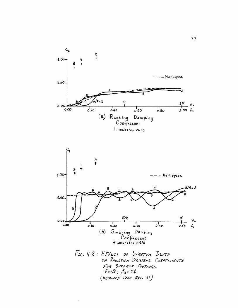
2r I
----- H af-sf ace
a.
(a) Rockin9 DampingC oefficien t
I : indicates VpNF
*1
=2
a.gF
(b) Swaying Dampin3Coefficient
+: hdicAes HNFS
FLc. 4.2 z EFFEC r or rSTWTCM DEPT
o,1 q ''/lA,4/ot Doi Pf Co FF/ C 1CW70/ raR SPrw o£'/e/C'Aoo7-r
(,e $','A Povp g.2 1)9:,1s &-rR~F )
6
77
1.
II
C,
78
Thus below the stratum natural frequencies, the radiation
damping is very low, but it is not zero if there is material
damping in the soil. Above the stratum frequencies, the
radiation damping is essentially similar to Veletsos and
Wei's half-space solution. At first, one would attempt to
approximate these coefficients by using zero damping below
the stratum natural frequencies (which can be obtained for
the actual layered medium) and the half-space solution above
them. However, it is quite possible, and it is the case for
the rigid cylinder considered here, that the fundamental
rocking-swaying frequency of the structure falls below one
of the stratum natural frequencies. In such cases the
response obtained using the above mentioned approximation
for the radiation damping coefficients, would be over-
conservative, as one would be using zero radiation damping
at the resonant frequency. Thus it is essential to find a
better approximation of the radiation damping below the
HNFS for swaying and VNFS for rocking.
Kausel (21) presented the following alternate definition of
the stiffness functions (Eqs. 4-1 and 4-2), when hysteretic
damping is included in the analysis:
Kx = Ko (k+ i(a.o +2A) ) (4-7)
and K~ = Kfo (k2 + i(a0 c~+23 ) ) (4-8)
79
Examination of figs. 32 through 35 in ref. (21) reveals
that cl and are essentially zero below the HNFS and VNFS
respectively for all hysteretic damping ratios considered
(1%, 10%, 20%). This observation may be used to evaluate
cj and c by the following steps. Since:
(k + iac,) (1 + 2i/3) = (I+ i(ao .+2%) )
(k + iac)(1 + 2iPh) = (ke+ i(a,c5+2a) )
it follows that
ca= c + (1 - k)
c,= c,+ l (1 - k,)a,
or if L and co are zero:
c,= 4 (1 - k,) if L ~ HNFS (4-9)
cz= A (1 - k) if A- L VNFS (4-10)
However, above the fundamental stratum frequencies, the
half-space coefficients are a better approximation to the
actual coefficients than to the coefficients evaluated
using Kausel's and Fc. Thus, c and c are only used
to approximate c and c below the stratum natural fre-
quencies.
In order to evaluate Eqs. 4-9 and 4-10, approximate expres-
sions for k, kz are needed. Limiting H/R >2 and 9 0.45,
it is possible to satisfactorily approximate the stiffness
coefficients k, k in the low frequency range by parabolas.
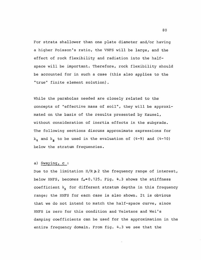
80
For strata shallower than one plate diameter and/or having
a higher Poisson's ratio, the VNFS will be large, and the
effect of rock flexibility and radiation into the half-
space will be important. Therefore, rock flexibility should
be accounted for in such a case (this also applies to the
"true" finite element solution).
While the parabolas needed are closely related to the
concepts of "effective mass of soil", they will be approxi-
mated on the basis of the results presented by Kausel,
without consideration of inertia effects in the subgrade.
The following sections discuss approximate expressions for
kl and k to be used in the evaluation of (4-9) and (4-10)
below the stratum frequencies.
a) Swaying, c :
Due to the limitation H/R 2 the frequency range of interest,
below HNFS, becomes f'0.125. Fig. 4.3 shows the stiffness
coefficient k for different stratum depths in this frequency
range; the HNFS for each case is also shown. It is obvious
that we do not intend to match the half-space curve, since
HNFS is zero for this condition and Veletsos and Wei's
damping coefficients can be used for the approximation in the
entire frequency domain. From fig. 4.3 we see that the
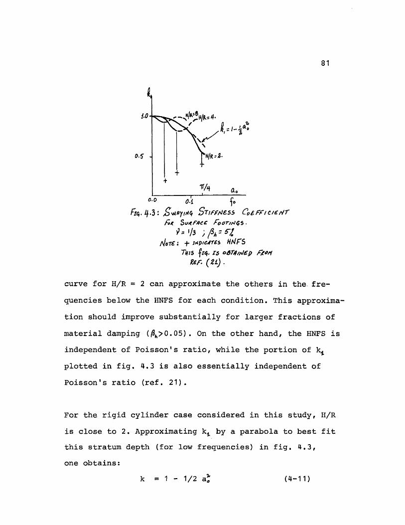
81
0.5
ao
Fb4. 4.3: Swrtyc STIFJeS C, C/V
/o Su~*eC' Foor/ip5s.
ofwr: + mpic.4r5 HFS
TVIS freq. rs o6r4,dp nRotREg. ().
curve for H/R = 2 can approximate the others in the fre-
quencies below the HNFS for each condition. This approxima-
tion should improve substantially for larger fractions of
material damping (h>0.05). On the other hand, the HNFS is
independent of Poisson's ratio, while the portion of k,
plotted in fig. 4.3 is also essentially independent of
Poisson's ratio (ref. 21).
For the rigid cylinder case considered in this study, H/R
is close to 2. Approximating k by a parabola to best fit
this stratum depth (for low frequencies) in fig. 4.3,
one obtains:
k = 1 - 1/2 a) (4-11)
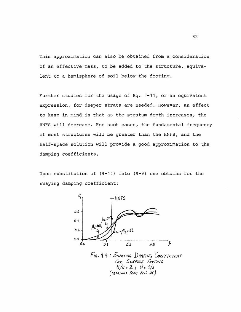
82
This approximation can also be obtained from a consideration
of an effective mass, to be added to the structure, equiva-
lent to a hemisphere of soil below the footing.
Further studies for the usage of Eq. 4-11, or an equivalent
expression, for deeper strata are needed. However, an effect
to keep in mind is that as the stratum depth increases, the
HNFS will decrease. For such cases, the fundamental frequency
of most structures will be greater than the HNFS, and the
half-space solution will provide a good approximation to the
damping coefficients.
Upon substitution of (4-11) into (4-9) one obtains for the
swaying damping coefficient:
"II
0.6
0.4
o.Z
0.o
7P
FIc,. 4-4 $S'1YIjc DtlP1t4C CocfnCrerFox S/fe4 Aooi2rH/g- 2.; V- 1/3
(06'r,1P fool As. .2i)
83
ci = 2Tfo. for f HNFS (4-12)
= v, ao
This expression for c approximates, with reasonable
accuracy, the swaying damping coefficients, in the low
frequency range, for various hysteretic dampings presented
in ref. (21) and fig. 4.4.
b) Rocking, c:
The rocking damping coefficient presents a more delicate
situation, because as we can see from Eq. 4-6 the VNFS is
a function of both Poisson's ratio and H/R. Considering the
limits H/R >2 and 9 0.45, the frequency range of interest
0oo-
o.o0
V:' 3 o.qr
k& I I -4
-t-/ ~o-45
/I z r
U.o 0.2 O :V Jo
-) H/R.-2. ; S4 b) H/R=4.; /4=5
Fi. 4.5: RocKrfN 5TIFFNESS COEFFICENTS
Fo SRurCE c Foort4LjS.
| rD CF,4TS5 VN FS.o0rREJD fRoM RF. 21
84
becomes f 0.41. Fig. 4.5a shows the rocking stiffness
coefficient, k, for H/R = 2. One notices that k is almost
independent of Poisson's ratio for f less than VNFS for
9 = 1/3, while in the region between VNFS for = 1/3 and
VNFS for 9= 0.45, k is more sensitive to this parameter.
As the stratum becomes deeper the VNFS will become smaller
and the rocking stiffness coefficient will not depend a
great deal on Poisson's ratio in the whole region of interest
(see fig. 4.5b for H/R = 4 where the range of interest
becomes f0.21).
Thus approximating the kz curve for H/R = 2, shallow stratum,
by a parabola to best fit the low frequency range of the
high Poisson's ratio curve, one obtains:
k2 = 1 - 6fZ (4-13)
This relation is also plotted in fig. 4.5, and one can see
that it approximates the actual curves reasonably well in
the regions of interest. Again, this approximation for kz
can also be obtained from a consideration of an effective
soil mass, to be added to the structure, equivalent to
0.4pRr of soil below the footing. This value of the equiva-
lent mass was also presented by Whitman (44). Substituting
(4-13) into (4-10), the resulting approximation of the
rocking damping coefficient, below the VNFS, is:
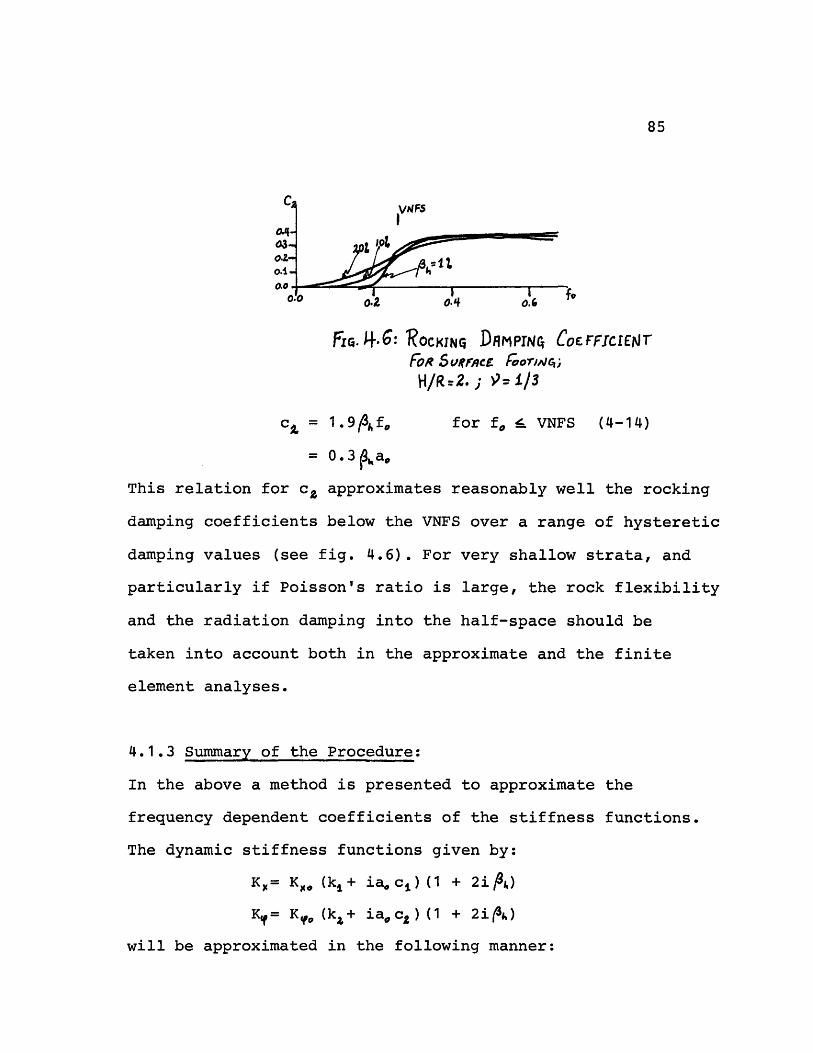
85
Fic. j.6: ROCK(IN DnMPrN CoErFEIJNrFoR SVRACE OO /oC; ,
H/IR-2.; -= 1/3
c, = 1.93pf.o for f i_ VNFS (4-14)
= 0.3 ao
This relation for c approximates reasonably well the rocking
damping coefficients below the VNFS over a range of hysteretic
damping values (see fig. 4.6). For very shallow strata, and
particularly if Poisson's ratio is large, the rock flexibility
and the radiation damping into the half-space should be
taken into account both in the approximate and the finite
element analyses.
4.1.3 Summary of the Procedure:
In the above a method is presented to approximate the
frequency dependent coefficients of the stiffness functions.
The dynamic stiffness functions given by:
Kg= K (kl+ ia.c A) (1 + 2i)
Ky= K (kz+ iac 2) (1 + 2i&)
will be approximated in the following manner:
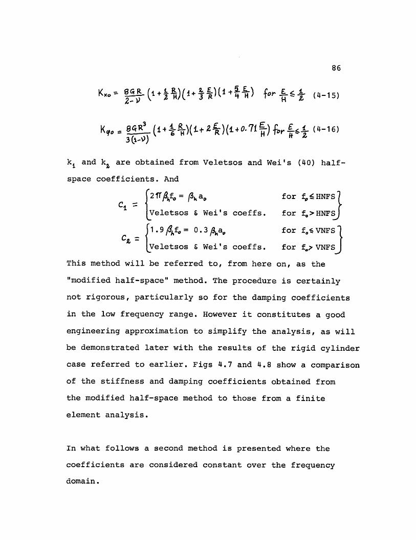
86
sfo= +Z H/4+` 3R'\- 3 (1M - --O ) (4-16)2-) H
kl and k are obtained from Veletsos and Wei's (40) half-
space coefficients. And
t2 /fo S a,, for fHNFSt
C ! LVeletsos 6 Wei's coeffs. for f>HNFS
12.9 Af,= 0 3 ,ao for foeVNFSfor f0QVNFS)
Veletsos & Wei's coeffs. for f VNFS
This method will be referred to, from here on, as the
"modified half-space" method. The procedure is certainly
not rigorous, particularly so for the damping coefficients
in the low frequency range. However it constitutes a good
engineering approximation to simplify the analysis, as will
be demonstrated later with the results of the rigid cylinder
case referred to earlier. Figs 4.7 and 4.8 show a comparison
of the stiffness and damping coefficients obtained from
the modified half-space method to those from a finite
element analysis.
In what follows a second method is presented where the
coefficients are considered constant over the frequency
domain.
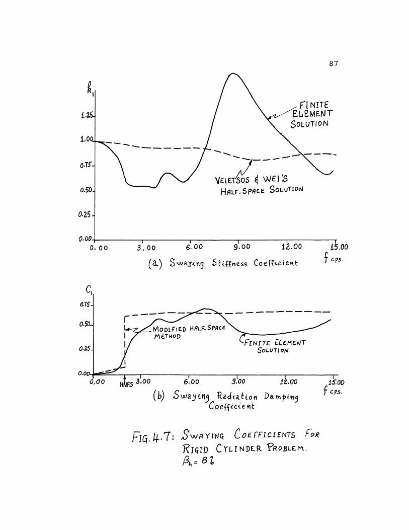
NITEME NTr
\(LES 0 4 WEI S
HALF-SPACE SOLUTIO04
(a) SwainhS Stifnmess Coe Ficievt
k L
Fq. 4.7:
AJ V,4 _ trj 1\atLtoto Vdrapth 3Coeffice t
,SWRYTNQ COE FICIENTs
]IGID CYLI NDER
p: =sz
1.
87
O o 0 3.00 6. oo 00
Fog
?R 03 LE r .
f cps.
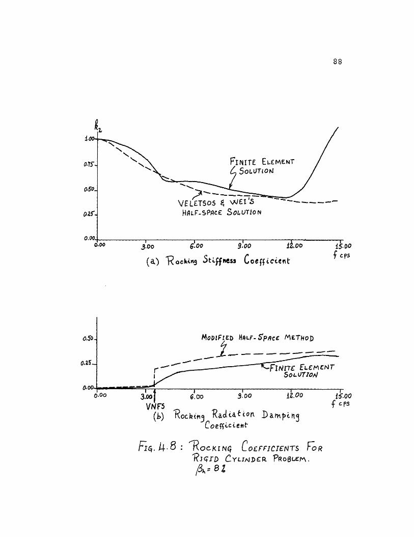
88
oo0
Fs(a) V ocking J4c)ttCSS Woeff ctefnt
MoDIFIeD HLF-SpACC METHoD
I_ - -- - - -
r ~FINITE ELMCNTiff " SocuL Tzon
cps
(b) Kockig Xadat iOnCoefizc tent
FIc,. 4.8 : ROCKINq COE FFlCTIEN-TS FRiJ'qrD CYLIJDEPR PRo6LEM.
A= a2
'OR
89
4.2 Approximate Constant Stiffnesses:
In many cases, it is desirable to choose frequency indepen-
dent stiffnesses to represent the soil in the seismic
analysis. If one can obtain such stiffnesses, a preliminary
analysis could be performed in the conventional time domain.
Due to the low costs of such a method, the effect of many
variables could be tested for the structure on hand. The
procedure described in this section shall be referred to as
the modified constant stiffness method.
As in the modified half-space method, the static value of
the stiffness function is evaluated first, using the
approximate relations (Eqs. 4-15 and 4-16). Then, the
stiffness coefficients, k and k, in Eqs. 4-1 and 4-2 could
be either approximated to unity, or evaluated with the half-
space curves at the resonant swaying and rocking frequencies
respectively and taken independent of the frequency- (or f).
On the other hand, the equivalent viscous damping ratios
Ou, p may follow from an evaluation of the radiation damping
coefficients c, c at the resonant swaying and rocking
frequencies respectively. The relationship between the
damping ratios and the damping coefficients is:
90
C or 3 C_ 1
C2 y or /3 Cz2
where the reference frequencies are:
In general A, and A are functions of the driving frequency
. To estimate these damping ratios, the following procedure
based on the modified half-space method can be used:
- If the resonant frequency is below the stratum frequency,
then the damping ratio can be evaluated using the
approximations derived in section 4.1.2 for c and c,
and evaluated at the resonant frequency Wxor Wf. The
result is:
= (1/2) ( a if f 4 HNFS
= 2 0 fo~ where p4 is the hysteretic
damping ratio
also, I = 0.15fh aoq if f VNFS
6 & ft
- If the resonant frequency is above the stratum frequency,
then the damping ratio is evaluated using the half-space
values for c and c, at the resonant frequency.
Frequently, the half-space solution is not available, or
it is desired to get a closed form expression without
using tabulated half-space values. In such cases, the
91
following expressions suggested by Richart et al (35)
give excellent approximations:
A = o.288 ax if f 2 HNFS
/3t . s af f 2 VNFS
!+(a,/p
The damping coefficients c and c corresponding to these
approximations are:
c = 0.576
c= 0 3
If these expressions are plotted as a function of
frequency, one will notice an excellent agreement with
Veletsos and Wei's half-space solution.
4.3 Solution of the Rigid Cylinder Case:
The rigid cylinder, described previously, is now analyzed
using the "true" finite element solution, the modified
half-space method and the modified constant stiffness method.
In the latter method, the coefficients k, kz were equated
to unity, while the equivalent viscous damping ratios above
the stratum frequencies were evaluated using Richart's
approximations.
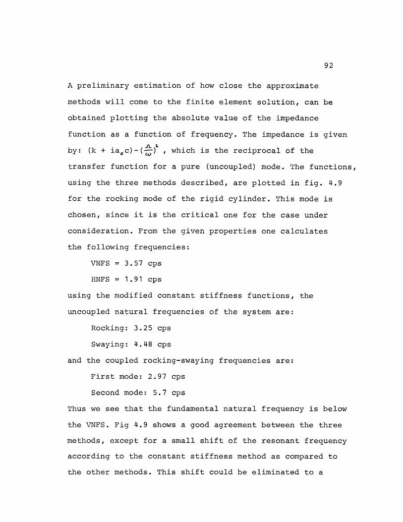
92
A preliminary estimation of how close the approximate
methods will come to the finite element solution, can be
obtained plotting the absolute value of the impedance
function as a function of frequency. The impedance is given
by: (k + ia0 c)-(j) , which is the reciprocal of the
transfer function for a pure (uncoupled) mode. The functions,
using the three methods described, are plotted in fig. 4.9
for the rocking mode of the rigid cylinder. This mode is
chosen, since it is the critical one for the case under
consideration. From the given properties one calculates
the following frequencies:
VNFS = 3.57 cps
HNFS = 1.91 cps
using the modified constant stiffness functions, the
uncoupled natural frequencies of the system are:
Rocking: 3.25 cps
Swaying: 4.48 cps
and the coupled rocking-swaying frequencies are:
First mode: 2.97 cps
Second mode: 5.7 cps
Thus we see that the fundamental natural frequency is below
the VNFS. Fig 4.9 shows a good agreement between the three
methods, except for a small shift of the resonant frequency
according to the constant stiffness method as compared to
the other methods. This shift could be eliminated to a
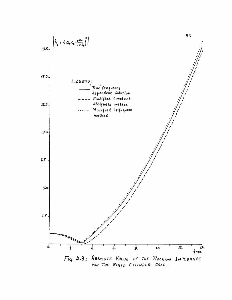
93
,'
L, E :ND:
dependent Solution
MojifieA comstaht /Stiffmess he to /
..... I odife d half- space. ettod .r /
. i"^ I | i l , | I s , ' |e | Fa/
6. 10. JA. lIt.
$CPs.
Fc,. 4 9: fSSOLUTE VRLUE OF THE ROCKIAC, IPEDANCE
FOtR THE RIGID CJDCR ,CA9C.
17.5
50.
Z.5'.
i.0 2. 8..
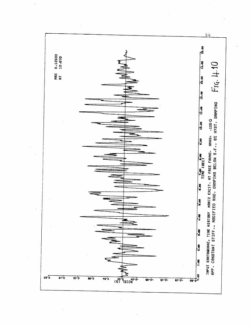
OVO0 0w -N 00'-.
-- Izz
o'to aio - ;o o -, -- _ ro'd oad- 'd- s- - T--OZ1O 3W- 0 '1|0 WD 7 ( t33 -d - O 0t.
-- --C" 9 ------~`----94gai
g oi ;tq c:
-t
C
z:
L,-* e
LL _j
k sz
:
Ca-4t3
LU* UiA COr X
S-
_
z
FLUt
B W
a- 0..
po
L
�;F�Sp. �--- W=
........ .
--�11�1�Z=- -
--
--
- -i^. -
----- --· --=
- - _ ---- ----.
- --
Irre�------------�--
- --
I.......
__l - C-
- _�
-1....--
-- --
---
iI
Ii
I
II
IIIII
I
I
- I
i
Fr, -
z =
:F:a
. jw-
5:FMrlx_
I
I
95
great extent, if one would evaluate k at the resonant
frequency rather than assigning to it the constant value 1.
Fig. 4.10 shows the time history of the 0.125g peak accel-
eration artificial earthquake used for the horizontal
excitation.
Fig. 4.11 contains the absolute value of the transfer
functions at the base of the cylinder using the true
stiffness functions and the two approximate methods. While
the three transfer functions follow similar trends, the
frequency shift of the modified constant stiffness method,
noticed in the absolute value of the rocking impedance
(fig. 4.9), is again apparent in the transfer function.
It is also evident that the approximate methods result in
some unconservative values (25% at 2 cps) close to the
first peak in the low frequency range (1.5 to 2.5 cps).
This is due to a combination of effects, some of which are:
the static coupling term K,o was overestimated by the
approximate relation; also the swaying damping coefficients
were overestimated in this low frequency range while the
rocking damping coefficients were overestimated after the
VNFS. On the other hand, this discrepancy does not result
in large differences in the acceleration response spectra
plots (15% at T=0.45 sec in figs 4.12 and 4.13). In the
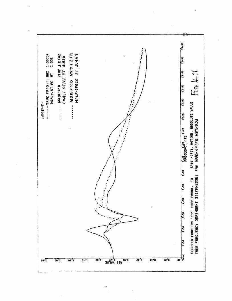
LI-J
luI- C
co q
CC
a,C,LUe O
ZOCZ
LUWL-
, C
zZLULU
L; LL
_ _I__
-
mj*J
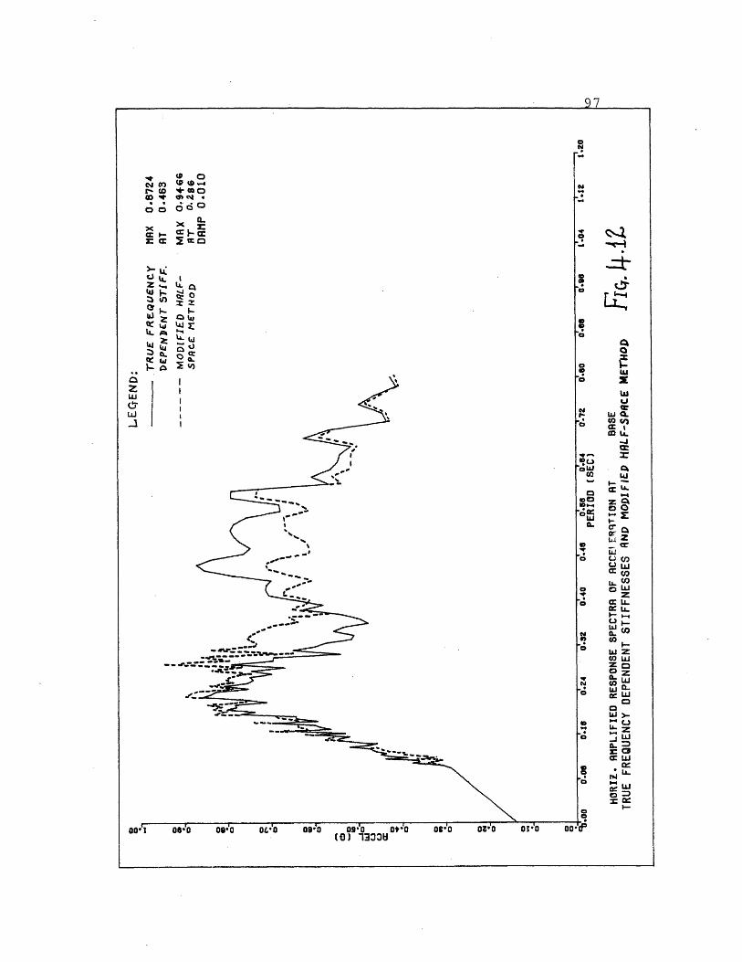
o ·
a.
~.e,cct w U. I
'.'
4 __-
. - - - 1 .00! Oe'0 0wo0 o.'O 089 0920 O0(0) 330
97
U-
L
C U.
I -oaL
I-ad Z
cr C
U. LU
4. zW C
C3 cw Zb W. N
LU
WCZ
C_m I I C
I __ _ _
Or;0 Or"O 01i
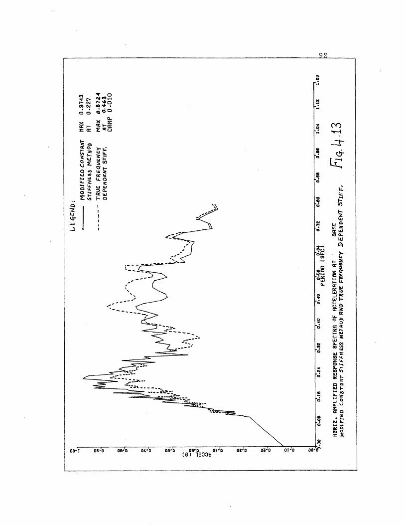
£ N P-OO} N o
IOIQ)x L=Wq
cee~C
LLZ 1
CCn- 4
> --'
dD- --
- |L --w--
OO! 0o0; 08;0 OL'O 09;0 09"0 Ot'*O(0) 1333
oe0'0 03'0 O'O o00'
IJ
a
CL
U
o
- ctw
S F
LL U
Od O
coLU
co
t
cc
...LL
_I ii
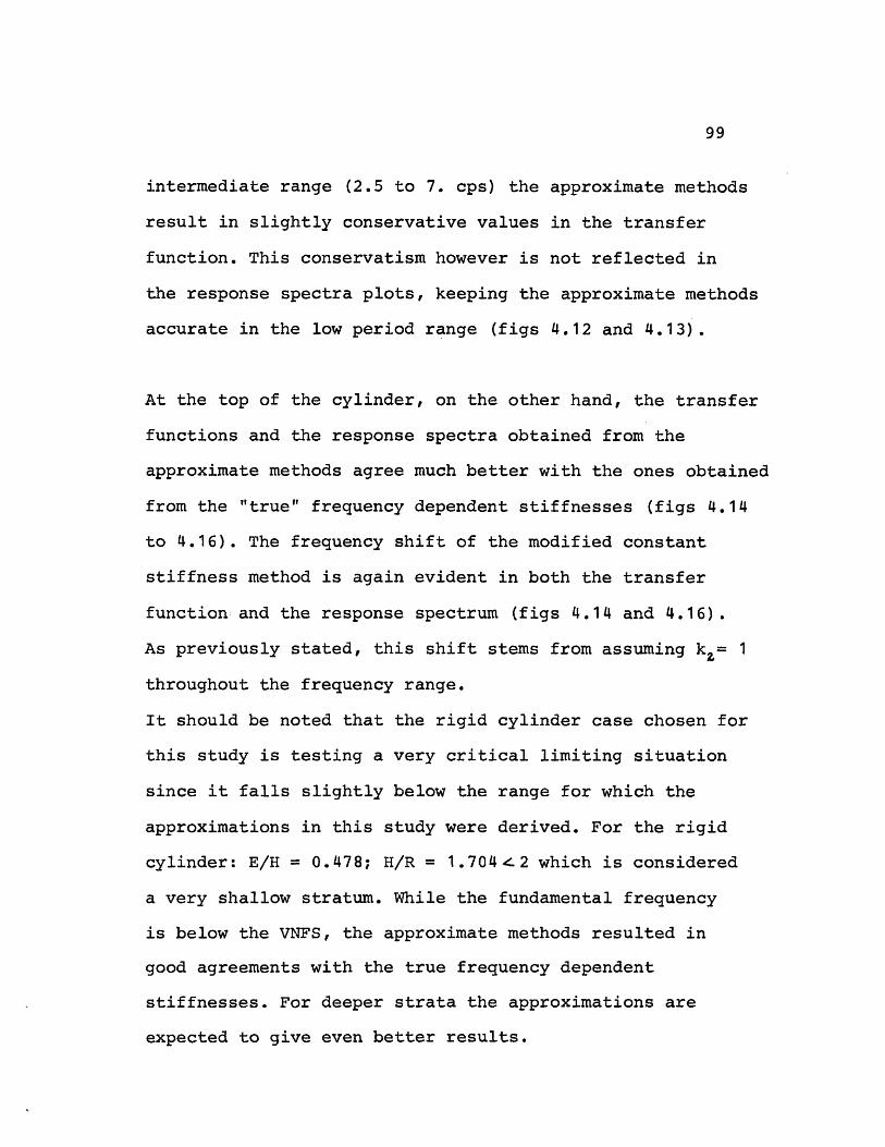
99
intermediate range (2.5 to 7. cps) the approximate methods
result in slightly conservative values in the transfer
function. This conservatism however is not reflected in
the response spectra plots, keeping the approximate methods
accurate in the low period range (figs 4.12 and 4.13).
At the top of the cylinder, on the other hand, the transfer
functions and the response spectra obtained from the
approximate methods agree much better with the ones obtained
from the "true" frequency dependent stiffnesses (figs 4.14
to 4.16). The frequency shift of the modified constant
stiffness method is again evident in both the transfer
function and the response spectrum (figs 4.14 and 4.16).
As previously stated, this shift stems from assuming k= 1
throughout the frequency range.
It should be noted that the rigid cylinder case chosen for
this study is testing a very critical limiting situation
since it falls slightly below the range for which the
approximations in this study were derived. For the rigid
cylinder: E/H = 0.478; H/R = 1.704e2 which is considered
a very shallow stratum. While the fundamental frequency
is below the VNFS, the approximate methods resulted in
good agreements with the true frequency dependent
stiffnesses. For deeper strata the approximations are
expected to give even better results.
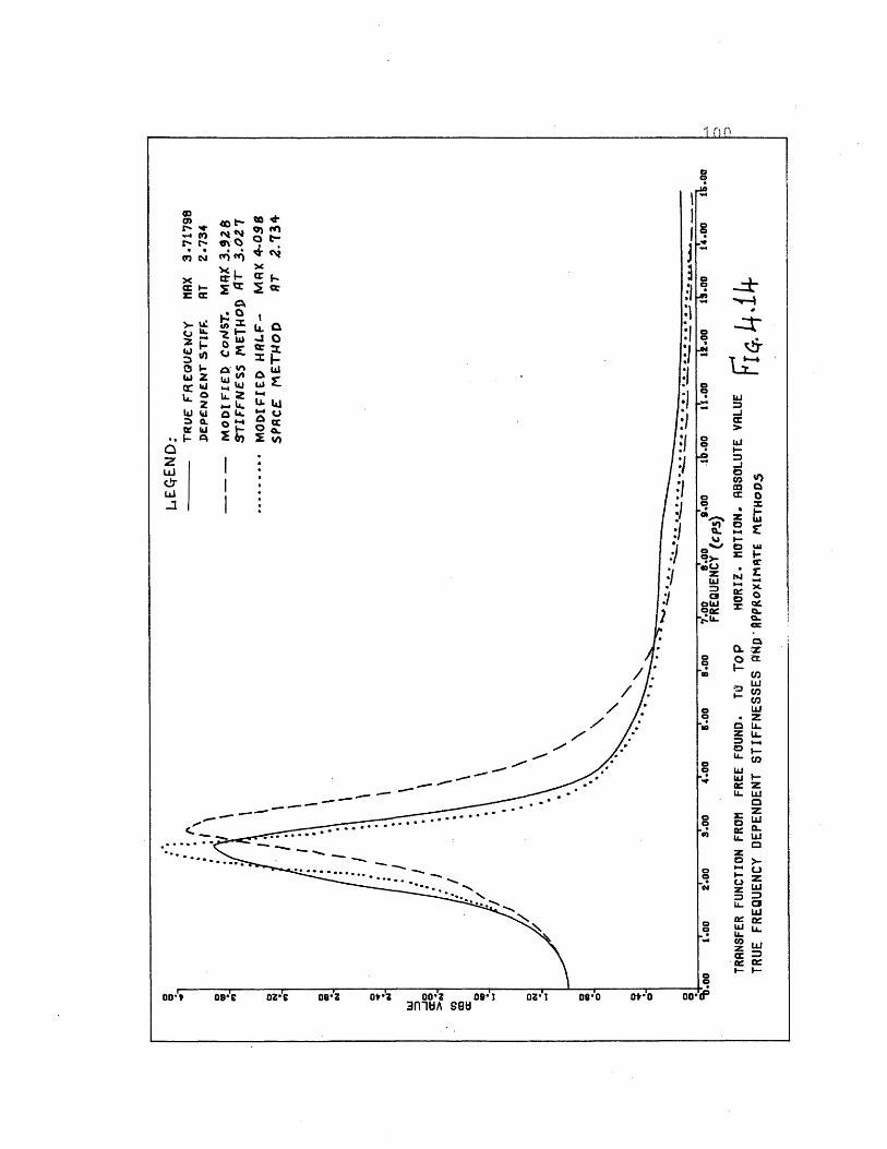
1 (1
Ia
0 td
Li
-c
-
-
cr
a
O.
, Z
n
Z L
zL LLW
Z L
uwU-
-cc
-'0,
C
LCL
0a -- -~~~~~~~~~~~~~~~~~~~~~~~~~~~~~~~~~~~~~-
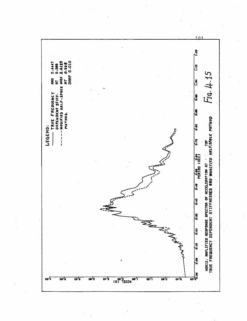
1 1i
aw
&
'CC
L
hiO fh 'i
zccL.UWcc
toczUJL09 W
UJ hiJ-t,
U. m
W
W
Nt ietL=- CGrer
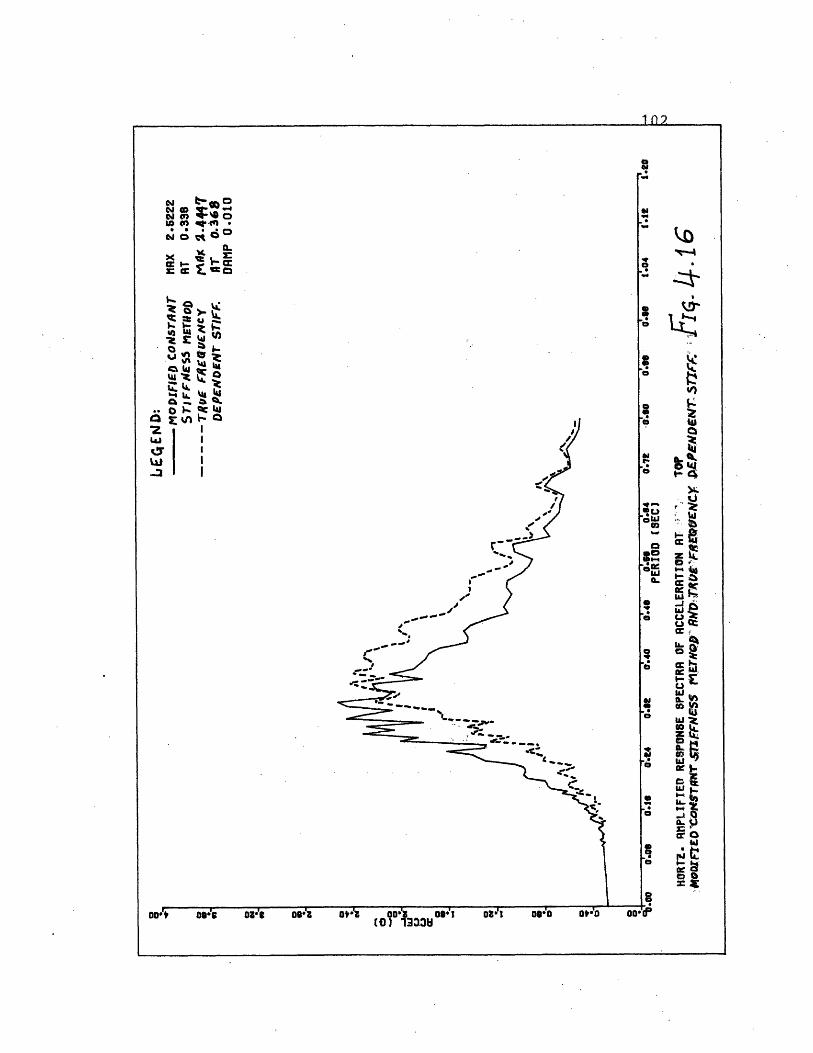
102
a
':
I'DHeS
'r-
z~a
i(f)Z
Ic Or.
CC Et
0e >
Z .CLucr
Lcc-go e
J:
L.-
cSo :rx
B ....
- - - - - - - - - -
103
5.- Summary and Conclusions:
Approximate empirical relations for the static stiffness
coefficients of circular foundations embedded in (or resting
on) an elastic homogeneous medium have been developed.
Approximate frequency dependent functions for the stiffness
and radiation damping coefficients and equivalent constant
viscous damping ratios have been suggested. The approximate
solutions were used to compute the response of a rigid
cylinder embedded in a layered stratum and compared to the
response obtained from a finite element analysis of the
soil. The approximate static stiffnesses proved to be quite
accurate for the rigid cylinder case, while the approximate
stiffness and damping coefficients resulted in a good
agreement in the response of the cylinder with that obtained
using the finite element coefficients. It was found that
the modified constant stiffness method gave results which
agree well with those using the actual frequency dependent
stiffnesses. Thus, such a method can be used to lower
the computation costs of a preliminary analysis in the
time domain.
During the derivation of the empirical relations and
approximate methods, the following restrictions were
imposed on the parameters:
104
E/H < 1/2
H/R 2
3)< 0. 45
If a problem falls outside these ranges, a finite element
analysis should be undertaken where the flexibility of the
base rock should be taken into account.
Further studies are needed to investigate the effects of
soil layering and the flexibility of the sidewall in greater
detail, as they could change the results to some extent.
Given all the uncertainties inherent in the determination
of the subgrade properties and soil behavior, it is felt
that the relations proposed are in excellent agreement
with more involved finite element studies. As an engi-
neering tool, approximate methods may prove to be of
considerable value, avoiding the use of unnecessarily
costly studies, while giving reliable results.
105
REFERENCES
1) Anandakrishnan, M., and Krishnaswamy,N.R.: "Response
of embedded footings to vertical vibrations," Jour of
Soil Mech. Found. Div., ASCE, Vol 99, No. SM10, Oct.
1973, pp. 863-883
2) Ang, A.H., and Newmark, N.M.:"Development of a trans-
miting boundary for a numerical wave motion calculation"
Report to the Defense Atomic Support Agency, Wash. D.C.,
contract DASA-01-0040, 1971
3) Awojobi, A.O.: "Torsional vibration of a rigid circular
body on an infinite elastic stratum," Int. Jour. Solids
Struct., Vol. 5, 1969, pp 369-378
4) Awojobi, A.O., and Grootenhuis, P.: "Vibrations of
rigid bodies on semi-infinite elastic media," Proc.
Roy. Soc. London,Series A, Vol. 287, No 1408, 1965
5) Baranov, V.A.: "On the calculation of excited vibrations
of an embedded foundation," (in Russian), Voprosy
Dynamiki: Prochnocti, No 14, Polytechnical Institute
of Riga, 1967, pp 195-209
6) Beredugo, Y.O.: "Vibrations of embedded symmetric
footings," Ph.D. Dissertation, Univ. of Western Ontario,
Canada, 1971, 247 pp.
7) Bycroft, G.N.: "Forced vibrations of a rigid circular
106
plate on a semi-infinite elastic space and on an elastic
stratum," Philos. Trans., Roy. Soc. London, Series A,
No 948, Vol 248, Jan. 1956, pp 327-368
8) Chae, Y.S.: "Dynamic pressure distribution at the base
of a rigid footing subjected to vibratory loads,"
Ph.D. Dissertation, Univ. of Michigan, 1964, 214pp.
9) Chae, Y.S.: "Vibrations of noncircular foundations,"
Jour. Soil Mech. Found. Div., ASCE, Vol. 95, No SMG,
Nov. 1969, pp 1411-1430
10) Chae, Y.S.: "Dynamic behavior of embedded foundation
soil system," Highway Research Record, No 323,1971
11) Drnevich, V.P., and Hall,J.R.: "transient loading tests
on a circular footing," Jour. Soil Mech. Found. Div.,
ASCE, Vol 92, No SMG, Nov. 1966, pp 153-167
12) Eastwood, W.: "The factors which affect the natural
frequency of foundations, and the effect of vibrations
on bearing power of foundations on sand," Proc. 3rd
Int. Conf. Soil Mech. Found. Eng., Vol 1, 1953,pp118-122
13) Erden, S.M.: "Influence of shape and embedment on
dynamic foundation response," Ph.D. Dissertation,
Univ. of Massachusetts, March 1974, 437 pp
14) Fry, Z.B.: "Development evaluation of soil bearing
capacity. Foundations of structures; Field vibratory
test data," Technical report No 3-632, Report No 1,
107
U.S. Army Eng. Waterway Exper. Station, Bicksburg,
Miss., 1963
15) Grootenhuis, P.: "The dynamics of foundation blocks,"
Proc. Conf. Sec. Earthq. Civil Engng. Dyn., "Dynamic
Waves in Civil Eng.," Swansea, July 1970, pp 95-105
16) Grootenhuis, P., and Awojobi, A.O.: "The in site
measurement of the dynamic properties of soils," Proc.
Vibr. Civil Engng., Session5, London, England, 1966
17) Gupta, B.N.: "Effect of foundation embedment on the
dynamic behavior of the foundation-soil system,"
Geotechnique, Bol 22, No 1, March 1972, pp 129-137
18) Johnson,G.R., Christiano, P., and Epstein, H.I.:
"Stiffness coefficients for embedded footings," Proc.,
ASCE Power Div. Specialty Conf., Denver, Col., Aug 1974
pp 499-523
19) Kaldjian, J.M.: Disscussion of "Design procedures for
dynamically loaded foundation," by R.V. Whitman and
F.E. Richart, Jour. Soil Mech. Found. Div., ASCE, Vol 95
No SM1, Jan. 1969, pp 464-366
20) Kaldjian, J.M.: "Torsional stiffness of embedded
footings," Jour. Soil Mech. Found. Div., ASCE, Vol 97,
No SM7, July 1971, pp 969-980
21) Kausel, E.: "Forced vibrations of circular foundations
on layered media," Ph.D. Dissertation, Massachusetts
Institute of Technology, Jan. 1974, 240 pp
108
22) Kausel, E., and Roesset, J.M.: "Soil structure
interaction problems for nuclear containment
structures," Proc., ASCE Power Div. Specialty Conf.,
Denver, Col., Aug 1974, pp 469-498
23) Krizek, R.J., Gupta, D.C., and Parmelee, R.A.: "Coupled
sliding and rocking of embedded foundations," Jour.
Soil Mech. Found. Div., ASCE, Vol 98, No SM12,
Dec. 1971, pp 1347-1358
24) Kuhlemeyer, R.L.: "Vertical vibrations of footings
embedded in layered media," Ph. D. Dissertation, Univ.
of California, Berkeley, 1969, 253pp
25) Liang-Chang, V.: "Dynamic response of structures in
layered soils," Ph.D. Dissertation, Massachusetts
Institute of Technology, Jan. 1974
26) Luco, J.E.: "O,!edamce fimctions for a rigid foundations
on a layered medium," Submitted for publication to
Nuclear Engineering and Design
27) Luco, J.E., and Westman, R.A.: "Dynamic response of
circular footings," Jour. Engng, Mech. Div., ASCE,
Vol 97, No EM5, Oct. 1971, pp 1381-1395
28) Lysmer, J., and Kuhlemeyer, R.L.: "Finite dynamic model
for infinite media," Jour. Engng., Mech. Div., ASCE,
Vol 95, No EM4, Aug 1969, pp 859-877
29) Lysmer, J., and Kuhlemeyer, R.L.: Closure to "Finite
109
dynamic model for infinite media," Jour. Engng., Mech.
Div., ASCE, Vol 97, No EM1, Feb 1969, pp 129-131
30) Lysmer, T., and Waas G.: "Shear waves in plane infinite
structures," Jour. Engng. Mech. Div., ASCE, Vol 98,
Feb. 1972, pp 85-105
31) Novak, M.: "Vibrations of embedded footings and
structures," Preprint 2029, ASCE, National Struct. Eng.
Meeting, San Francisco, Calif., April 1973, 25pp
32) Novak, M., and Beredugo, Y.O.: "The effect of embedment
on footing vibrations," Proc. First Canadian Conf.
Earthq. Engng. Research, Vancouver, B.C., May 1971,
pp 1-14
33) Novak, M., and Sachs, K.: "Torsional and coupled
vibrations of embedded footings," Int. Journ. Earthq.
Engng. Struct. Dyn., Vol 2, No 1, July-Sept. 1973,
pp 11-33
34) Reissner, E.: "Stationare, axialsymmetrische durch
eine schuttelude masse erregte schwingungen eines
homogenen elastischen halbraumes," Ingenieur - Archiv,
Vol 7, Part 6, Dec. 1936, pp 381-396
35) Richart, F.E., Hall, J.R., Woods, R.D.: "Vibrations of
soils and foundations," Prentice Hall, 1970
36) Stokoe, K.H.,II.: "Dynamic response of embedded
foundations," Ph.D. Dissertation, Univ. of Michigan,
110
Jan. 1972, 251 pp
37) Sung, T.Y.: "Vibrations in semi-infinite solids due
to periodic surface loading," Sympl Dyn. Test. Soils,
ASTM, STP No 156, July 1953, pp 35-64
38) Tajimi, H.: "Dynamic analysis of a structure embedded
in an elastic stratum," Proc. 4th World Conf. Earthq.
Engng., Santiago, 1969, pp 53-69
39) Urlich, C.M., and Kuhlemeyer, R.L.: "Coupled rocking
and lateral vibrations of embedded footings," Can.
Geotech. Jour., Vol 10, No 2, May 1973, pp 145-160
40) Veletsos, A.S., and Wei, Y.T.: "Lateral and rocking
vibration of footings," Jour. Soil Mech. Found. Div.,
ASCE, Vol 97, No SM9, Sept. 1971, pp 1227-1248
41) Waas, G.: "Linear two-dimensional analysis of soil
dynamics problems in semi-infinite layer media," Ph.D.
Dissertation, Univ. of California, Berkeley, 1972
42) Waas, G.: "Earth vibration effects and abatement for
military facilities," Technical Report, S-71-14,
Report 3, U.S. Army Engineer Waterways exper. Station,
Sept. 1972, 182 pp
43) Weissman, G.F.: "Torsional vibrations of circular
foundations," Jour. Soil Mech. Found. Div., ASCE,
Vol 97, No SM9, Sept 1971, pp 1293-1316
44) Whitman, R.V.: "Analysis of foundation vibrations,"
111
appearing in "Vibration in Civil Engineering," Proc.
of a symposium organized by the British National section
of the Int. Assoc. for Earthq. Engng.
45) Wilson,E.L.: "Structural analysis of axisymmetric
solids," Journ. of the Amer. Inst. of Aeronautics and
Astronautics, Vol 3, Dec 1965, pp 2269-2274