separation of particles from hot gases using metallic foams
TRANSCRIPT

This article appeared in a journal published by Elsevier. The attachedcopy is furnished to the author for internal non-commercial researchand education use, including for instruction at the authors institution
and sharing with colleagues.
Other uses, including reproduction and distribution, or selling orlicensing copies, or posting to personal, institutional or third party
websites are prohibited.
In most cases authors are permitted to post their version of thearticle (e.g. in Word or Tex form) to their personal website orinstitutional repository. Authors requiring further information
regarding Elsevier’s archiving and manuscript policies areencouraged to visit:
http://www.elsevier.com/copyright
Author's personal copy
j o u r n a l o f m a t e r i a l s p r o c e s s i n g t e c h n o l o g y 2 0 9 ( 2 0 0 9 ) 3859–3868
journa l homepage: www.e lsev ier .com/ locate / jmatprotec
Separation of particles from hot gases using metallic foams
Rémy Ghidossia, Jean-Philippe Bonneta, Georgette Rebollar-Pereza, Emilie Carretiera,Jean-Henry Ferrassea, Jérôme Vicenteb, Frédéric Topinb, Philippe Moulina,∗
a M2P2 UMR CNRS 6181, Université Paul Cézanne, Europôle de l’Arbois, Bâtiment Laennec, Hall C,13545 Aix en Provence Cedex 4, Franceb POLYTECH Marseille (CNRS-UMR 6595), Technopôle de Château-Gombert, 5 rue Enrico Fermi, 13453 Marseille Cedex 3, France
a r t i c l e i n f o
Article history:
Received 4 May 2008
Accepted 30 August 2008
Keywords:
Metallic foam
Hot gas cleaning
Filtration
Particles
a b s t r a c t
One of the most complicated tasks in the field of hot gas cleaning is the removal of particles
from a complex mixture of degradation products formed during thermal treatment. A robust
and completely reliable technology is still to be developed to achieve high efficiencies. In the
past few years, significant improvements have been brought to gas cleaning technologies.
Nevertheless, none of the existing processes has proved fully successful.
The aim of this work is to perform the filtration of particles generated in fluidized bed
gasification experiments using metallic foams. The gasified material used is dried sewage
sludge. Nickel–chromium metallic foams are likely to have inherent properties that would
make them suitable for use in structures where strength, high temperature-resistance and
corrosion resistance are required. Moreover, metallic foams are characterized structurally
by their cell topology, relative density, high porosity (ε = 0.95) and cell size. In hot gas filtra-
tion, high temperature-resistance and low pressure drop to specific area ratio are essential
characteristics. In the present work, several experimental operating conditions (heating
time, temperature, washing method and metallic foam thickness) are investigated. The
pressure drops in the metallic foams during filtration are calculated. The experimental
results obtained are compared with numerical simulation results and a good agreement
is obtained. The metallic foams are simulated from tomography results and a model is
created.
© 2008 Elsevier B.V. All rights reserved.
1. Introduction
Pollution is one of the major environmental problems today.Improved pollutant filtration technologies have an importantpart to play in addressing some environmental issues and pro-moting a healthy environment. The combustion of materialssuch as oil, fuels, municipal waste, biomass, etc. generatesa vast amount of gases, heavy metals and particles. One ofthe main problems is the accumulation of particles, whichresults in the creation of droplets in the product gas. Cur-rent processes have some significant limitations, particularly
∗ Corresponding author. Tel.: +33 4 42 90 85 01; fax: +33 4 42 90 85 15.E-mail address: [email protected] (P. Moulin).
in the particle removal phase. In fact, tar condenses at reducedtemperature, which generates the fouling of process equip-ment as well as that of engines or turbines. Consequently,hot gas cleaning and tar reduction has been the focus ofmany research projects (Houben et al., 2005; Li et al., 2004;Lopamudra et al., 2003). Several approaches for tar reductionhave been reported in the literature. A major part of ongoingresearch deals with the development of efficient methods fortar removal in an economical and optimized way.
The objective of this work is to evaluate the retention bymetallic foams of particles produced in fluidized bed gasifi-
0924-0136/$ – see front matter © 2008 Elsevier B.V. All rights reserved.doi:10.1016/j.jmatprotec.2008.08.033
Author's personal copy
3860 j o u r n a l o f m a t e r i a l s p r o c e s s i n g t e c h n o l o g y 2 0 9 ( 2 0 0 9 ) 3859–3868
cation of dried sewage sludge. The defining characteristic ofmetallic foams is a very high porosity (typically, well over90% of the volume consists of void spaces). Open celledmetallic foams are already used in a wide variety of applica-tions, including heat exchangers (Narasimhan and Raju, 2007),energy absorption (Markaki and Clyne, 2002), flow diffusion(Arisetty et al., 2007) and catalyst supports (Sirijaruphan et al.,2005).
In our work, metallic foams are used as particle filters.The influence of the operating parameters such as heatingtime, temperature, regenerating method and metallic foamcharacteristics are studied. Different optimizations in termsof metallic foam thickness, washing method and temperatureare defined. The pressure drops are also determined with theuse of a model during the filtration (Bonnet et al., 2006). Theresults obtained are compared to numerical simulations anda good agreement is observed.
2. Previous studies
The European Union has issued a directive (2000/76) to reg-ulate flue gas emissions from waste and co-combustionunits. This directive regulates the emissions of several gasesand particles. In fact, waste materials typically contain highconcentrations of components that are transformed duringcombustion. Harmful compounds are formed that could bereleased from the units unless they are removed from thehot gases. Gas containing particles can be produced by threeoperating modes: combustion, gasification and pyrolysis.
For each mode, the following general relation can beapplied:
sludge + energy = residues + tar + gas (1)
In this paper, the case of gasification is investigated. Gasi-fication technologies are expected to play a key role in thedevelopment of renewable energy sources. This process isa significant source of potentially toxic elements, which arereleased into the environment and affect especially the pop-ulation in the vicinity of industrial areas. The gas producedcan be used for several applications such as co-firing and elec-tricity generation. One of the problems that have not beencompletely solved is the tar content in the produced gas. Itis necessary to remove the particles from the gas before it canbe re-used as energy product.
The typical impurities produced in each particular caseduring gasification need to be investigated. According toPetersen and Werther (2005), 60–80% of the primary com-pounds can be cracked into low molecular weight gases. Thispercentage corresponds to volatile elements. These impuri-ties depend on many parameters such as temperature andmaterial components. They also depend on the characteris-tics of the gasification conditions and the removal efficiencyof the air pollution control device. These impurities may beeither gaseous (SO2, NOx, dioxins, organic compounds andsome trace metals) or appear as solid particles. Generally, toxicelements such as As, Ba, Cr, Ni, Sb are associated with thesolid particles. In modern power plants, the major part ofthe airborne particles is precipitated by means of electrostatic
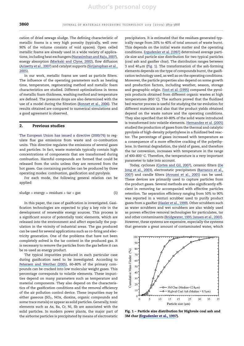
precipitators. It is estimated that the residues generated typ-ically range from 20% to 40% of total amount of waste burnt.This depends on the initial waste matter and the operatingconditions. Ergudenler et al. (1997) determined average parti-cle size and particle size distribution for two typical particles(coal ash and gasifier char). The distribution ranges between3 and 40 �m (Fig. 1). The transformation of the ash-formingelements depends on the type of compounds burnt, the gasifi-cation technology used, as well as on the operating conditions.Moreover, the particle properties also depend on some growthand production factors, including weather, season, storageand geographic origin. Font et al. (1995) compared the pyrol-ysis products obtained from different organic wastes at hightemperatures (850 ◦C). The authors proved that the fluidizedbed reactor process is useful for studying the tar evolution fordifferent materials and also that the product yields obtaineddepend on the waste nature and the operating conditions.They also specified that 60–80% of the solid waste introducedis transformed into volatile elements. Hernandez et al. (2005)studied the production of gases from the thermal and catalyticpyrolysis of high-density polyethylene in a fluidized bed reac-tor. The percentage of gases increased with temperature asa consequence of a more effective cracking of the polyethy-lene. In thermal degradation, the yield of gases, and thereforethe tar conversion, increases with temperature in the rangeof 400–800 ◦C. Therefore, the temperature is a very importantparameter to take into account.
Today, cyclones (Cortes and Gil, 2007), ceramic filters (DeJong et al., 2003), electrostatic precipitators (Barranco et al.,2007) and candle filters (Aroussi et al., 2001) can be used.These devices are primarily used to capture particles fromthe product gases. Several methods are also significantly effi-cient in removing tar accompanied with effective particlesretention. Tar separation efficiency ranging from 50% to 90%was reported in a venturi scrubber used to purify productgases from a gasifier (Hasler et al., 1999). Other scrubbers suchas water scrubbers and wet scrubbers are also widely usedas proven effective removal technologies for particulates, tarand other contaminants (Bridgwater, 1995; Jansen et al., 2002).However, these systems are expensive, especially the systemsthat generate a great amount of contaminated water, which
Fig. 1 – Particle size distribution for Highvale coal ash and3M char (Ergudenler et al., 1997).
Author's personal copy
j o u r n a l o f m a t e r i a l s p r o c e s s i n g t e c h n o l o g y 2 0 9 ( 2 0 0 9 ) 3859–3868 3861
induces a wastewater disposal problem. Few attempts havebeen made to clean the product gases instead of water.
Sharma et al. (2007) published a very interesting reviewon the current processes. The authors stated that one of themost developed technologies for gas cleaning by removingsolid contaminants at high temperature involves candle fil-ters. Most of these candle filters appeared to have operated fora maximum period of 2700 h at 400 ◦C and for an even longerperiod of about 15,000 h a lower temperature of 285 ◦C in acoal gasification environment. The failing of the candle filtersleads to an uneconomical industrial plant scale. The users ofthese filters have developed deeper fundamental understand-ing of the filter materials and of the impact of various processparameters, such as operating temperature, ash type and par-ticle size, on the performance of the filter system. However,these systems still have a poor rentability index. This factordepends on their ability to reduce the amount of particles inhot gas to below specific limits (set by the turbine and environ-mental regulations). In fact, these systems must maintain thesystem pressure drop within acceptable limits and to achievereliable operation. The main factors affecting the reliability ofthe performance of these filters are their tensile strength, thelevel of corrosion and of residual ash accumulation.
Multi-stage cyclones may reduce particle concentration toa range acceptable for the operation of the gas turbine. How-ever, their low efficiency for submicron particles is their maindrawback. Ceramic filters are the most popular high tempera-ture purification systems, because they are highly efficient athigh temperatures? Nevertheless, there have been failures andperformance limitations, due to bridging, filter bowing, innerpore clogging, etc. The increase in pressure drop attributedto a poor cleaning of the filter, the densification of the dustlayer and the closing of pores by reaction or sintering of ashand filter also hinder the long-term stable operation. The maincauses of filter failure are the design of the filter unit, the typeof filter material, the candle design (wall thickness and rein-forcement), the thermal transient and residual ash deposition.Therefore, three fracture mechanisms have been identified forrigid ceramic filters:
• thermal stress or shock due to tar combustion on the filtersurface;
• ash bridging between candles;• explosion, due to either flammable gas combustion or dust
within filter tubes.
Filter malfunction due to rupture depends largely on the mate-rial of construction of the filter. Three materials are commonlyused: monolithic oxide, monolithic silicon carbide (SiC) andcontinuous fiber-reinforced ceramic composite. By improvingthe mechanism and selecting the proper filter material, filterelements dysfunction could be prevented.
In order to obtain information about the optimal operationparameters, several gasification experiments were performedwith dried sewage sludge (>90% dry matter) in a pilot-scalefluidized bed at high temperature. Metallic foams were usedto perform the filtration of the hot gas obtained during thegasification of sludge in a fluidized bed. These experimentswere carried out for several quantities of sludge, metallicfoam thicknesses, regeneration methods and temperatures.
The regeneration of the metallic foam was studied and thepressure drop during the experiments was estimated. Theseresults were obtained mathematically because the pressuredrop was small. The sensors should be very powerful to detectthis pressure drop. This study allowed better understandingof the metallic foam performance for hot gas cleaning. On thebasis of our experimental results, a model was determined inorder to create numerical simulation for a possible industrialscale.
3. Materials and methods
3.1. Metallic foam
Cellular metals are a new class of materials that have beenthe focus of numerous scientific studies over the last decades(Sevilla et al., 2007; Loretz et al., 2008; Barrabes et al., 2008;Brothers et al., 2005). Metallic foams have low density andhigh strength cellular structures. Their physical characteris-tics, such as thermal conductivity and mechanical strength,depend on the type of material used. Moreover, additionalstudies are carried out to develop new manufacturing meth-ods in order to improve properties to given application(MetFoam, 2005). Another important research theme concernsflow laws through such media.
The light weight, open porosity and high permeability ofthe foam, combined with the high thermal conductivity of themetal, make it promising material for many industrial applica-tions involving fluid flow and heat transfer (heat exchangers,evaporators, burners, separators, etc.). They are also used inchemical processes as physical supports for catalysts or evenas catalyst substrates.
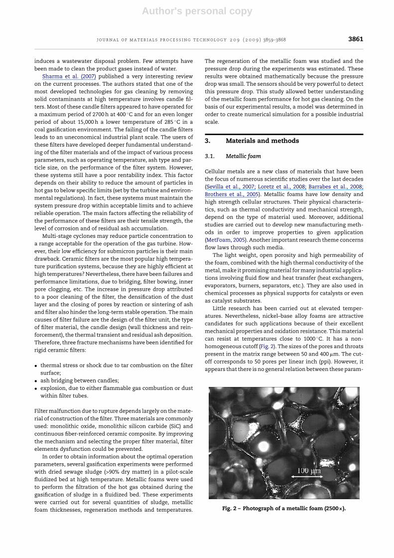
Little research has been carried out at elevated temper-atures. Nevertheless, nickel–base alloy foams are attractivecandidates for such applications because of their excellentmechanical properties and oxidation resistance. This materialcan resist at temperatures close to 1000 ◦C. It has a non-homogeneous cutoff (Fig. 2). The sizes of the pores and throatspresent in the matrix range between 50 and 400 �m. The cut-off corresponds to 50 pores per linear inch (ppi). However, itappears that there is no general relation between these param-
Fig. 2 – Photograph of a metallic foam (2500×).

Author's personal copy
3862 j o u r n a l o f m a t e r i a l s p r o c e s s i n g t e c h n o l o g y 2 0 9 ( 2 0 0 9 ) 3859–3868
eters and the measured morphological parameters (Vicenteand Daurelle, 2005). Hence, these filters can find applicationsto replace more expensive processes. In this study, we workedwith a metallic foam from Recemat (Netherlands). The speci-ficity of this metallic foam is that it is produced from nickeland nickel chromium plates. The alloy nickel chromium plateswith good inherent properties such as solidity, a good con-ductivity, resistance to high temperatures. The result is anextremely porous 3D structure. Moreover, they have an excel-lent resistance to extreme pHs and corrosion. The materialcan be machined, cut or curved with high precision. Thisvariability enables metallic foams to be employed in severalfields such as catalytic aeronautics, electronics, engines, thecar industry, etc.
3.2. The experimental set-up
The tests were performed at atmospheric pressure in air,indirectly heated fluidized bed gasification system, which isshown schematically in Fig. 3. The main components were:a sludge feeder, a CO2 tank, a fluidized bed gasifier, metallicfoams and a tar protocol system. The reactor was a refrac-tory stainless steel pipe (Thyssenkrup Materials) and wasexternally heated. The fluidized bed consisted of a verticalcylindrical vessel with a grid in the lower section to supportthe dry sewage sludge. The sludge was injected into the lowersection of the vessel above a grid that could support the 25 gintroduced. The CO2 fluidized the mixture of hot sludge. Theminimal fluidization inlet flow was calculated and a highervalue of 50% was applied to ensure optimal fluidization.
The total height of the reactor was 800 mm, the bed diam-eter was 48 mm and the external diameter was 52 mm. Alongthe reactor, there were two temperature sensors. In eachexperiment, 25 g of uniform bio-solids pellets (dry sewagesludge) were introduced. These pellets measure between 1and 1.2 mm and are considered spherical. This material hasbeen experimented because the gasification produced a highquantity of particles. CO2 was used as the fluidizing agent.Before the CO2 entered the reactor, it was heated at the desiredtemperature.
Table 1 – Averaged characteristics of the dry sewagesludge considered
ε 0.5dp (mm) 1.1�sludge (kg m−3) 800
Minkova et al. (2000) proved that CO2 is an unreactivemolecule at ambient temperature. CO2 becomes reactive whenthe temperature is high enough and can be used as an activat-ing agent in gasification. Under such a reactive atmosphere, itmay significantly influence the yield and the quality of theproducts. However, few studies can be found in the literatureon the effect of CO2 on gasification.
The different solids formed during gasification are par-ticles and gas. Therefore, the present work explores thecapacity of particle filtration obtained from CO2 atmosphericgasification in the temperature range of 500–700 ◦C by evalu-ating the metallic foam removal capacities. Averaged valuesof the sludge characteristics are considered in this paper(Table 1).
The minimal fluidization inlet flow corresponds to approx-imately 2 kg h−1 of CO2. This flow ensures homogeneousgasification inside the reactor. Fluidized bed furnaces produceonly very fine ash (Petersen and Werther, 2005). Sludge ashesconsist primarily of silica, iron and calcium. The ash compo-sition can vary significantly as previously noted, and dependsto a great extent on the additives introduced during the sludgeconditioning operation.
The equipment for a tar sampling protocol was installedon the experimental apparatus. The tar sampling system con-sisted of a series of three bottles containing solvents. Waterwas used as the tar absorbing solvent. The bottles were placedin a cold bath. The recommendations for suitable sampling gasflow rates and gas temperatures given by Simell et al. (2000)were respected. This procedure allowed all the particles ema-nating from the reactor to be caught. Thus, this protocol makesit possible to determine the quantity of tar produced duringthe gasification or the quantity of matter that passes throughthe metallic foam.
Fig. 3 – Experimental set-up.
Author's personal copy
j o u r n a l o f m a t e r i a l s p r o c e s s i n g t e c h n o l o g y 2 0 9 ( 2 0 0 9 ) 3859–3868 3863
4. Results and discussion
The influences of the temperature (T) and of the metallic foamthickness (e) are studied on the removal efficiency. All of theexperimental conditions were fixed to exclude the effect ofother parameters. For each experiment, minimal inlet flu-idization flow was respected and 25 g (M) of sludge wereintroduced. The experiments were carried out for differentheating times (t = 0, 10, 20, 30, 35 and 45 min) for several tem-peratures (T = 500, 600 and 700 ◦C) and several metallic foamthicknesses (e = 15 and 25 mm). The regeneration was studiedwith different methods (acid, basic and catalytic).
4.1. Preliminary study
A preliminary study was thought to be necessary to obtainreferences values. In this part, no metallic foam was intro-duced at the top of the reactor. This allowed us to determinethe percentage of particles retained for further experiments.Thus, the effect of temperature for 45 min of heating wasdetermined. This parameter is essential because the gas andparticles are not the same for high (700 ◦C) or low temperature(500 ◦C). For each experiment, the mass captured by the tarprotocol system was determined. All the particles were cap-tured by the tar protocol system. The particles retained by thetar protocol were weighted for three different temperatures(500, 600 and 700 ◦C) (Table 2).
The temperature influences the nature of the particlesgenerated. Appreciatively, 50–70% of the mass introduced isgasified and 36–40% of the mass is transformed into particles.In fact, gaseous compounds are generated at high temperaturewhile oil is preferentially generated at low temperature. More-over, the higher the temperature is, the smaller the amount ofresidues. The higher the temperature, the smaller the masscollected by the tar protocol system.
On the basis of the literature (Karellas and Karl, 2007), thetar formation has lower activation energy in comparison tothat of the fragmentation. Indeed, creation of tar is caused bydehydration, while the fragmentation occurs with a scissionof C–C bonds.
4.2. Influence of heating time
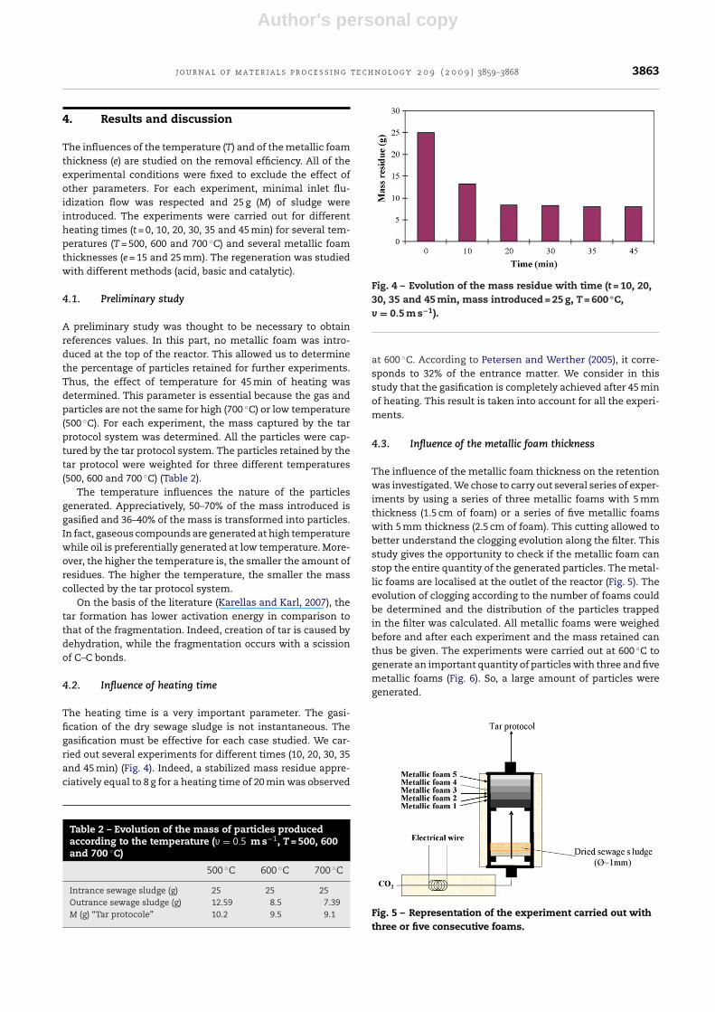
The heating time is a very important parameter. The gasi-fication of the dry sewage sludge is not instantaneous. Thegasification must be effective for each case studied. We car-ried out several experiments for different times (10, 20, 30, 35and 45 min) (Fig. 4). Indeed, a stabilized mass residue appre-ciatively equal to 8 g for a heating time of 20 min was observed
Table 2 – Evolution of the mass of particles producedaccording to the temperature (v = 0.5 m s−1, T = 500, 600and 700 ◦C)
500 ◦C 600 ◦C 700 ◦C
Intrance sewage sludge (g) 25 25 25Outrance sewage sludge (g) 12.59 8.5 7.39M (g) “Tar protocole” 10.2 9.5 9.1
Fig. 4 – Evolution of the mass residue with time (t = 10, 20,30, 35 and 45 min, mass introduced = 25 g, T = 600 ◦C,v = 0.5 m s−1).
at 600 ◦C. According to Petersen and Werther (2005), it corre-sponds to 32% of the entrance matter. We consider in thisstudy that the gasification is completely achieved after 45 minof heating. This result is taken into account for all the experi-ments.
4.3. Influence of the metallic foam thickness
The influence of the metallic foam thickness on the retentionwas investigated. We chose to carry out several series of exper-iments by using a series of three metallic foams with 5 mmthickness (1.5 cm of foam) or a series of five metallic foamswith 5 mm thickness (2.5 cm of foam). This cutting allowed tobetter understand the clogging evolution along the filter. Thisstudy gives the opportunity to check if the metallic foam canstop the entire quantity of the generated particles. The metal-lic foams are localised at the outlet of the reactor (Fig. 5). Theevolution of clogging according to the number of foams couldbe determined and the distribution of the particles trappedin the filter was calculated. All metallic foams were weighedbefore and after each experiment and the mass retained canthus be given. The experiments were carried out at 600 ◦C togenerate an important quantity of particles with three and fivemetallic foams (Fig. 6). So, a large amount of particles weregenerated.
Fig. 5 – Representation of the experiment carried out withthree or five consecutive foams.

Author's personal copy
3864 j o u r n a l o f m a t e r i a l s p r o c e s s i n g t e c h n o l o g y 2 0 9 ( 2 0 0 9 ) 3859–3868
Fig. 6 – Evolution of the mass retained by the metallicfoams according to their position.
Several trends appear in Fig. 6. First of all, the “more dis-tant” the metallic foam is from the fluidized bed, the fewerparticles are retained. A high percentage of generated parti-cles are captured by the first metallic foam (∼40%). This meansthat the particles are well fixed on the metallic foam medium.The particle flow is less and less important with the progres-sion through volume of the metallic foam and the retentionbecomes less efficient. With an increase of metallic foam, anaugmentation of the particles retained is observed. Indeed, thetotal mass retained by three successive foams is 5.7 g, whereas7.7 g are retained by five successive foams. This increase inparticle removal is explained by the appearance of coalescenceinside the porous medium. This is the reason why the firstmetallic foam is appreciatively 40% louder for five consecu-tives metallic foams. An optimum between the particles flowand the metallic foam surface exchange is to be determined.In the case of a 2.5 cm thickness, the mass of particles retainedby the last foam is practically negligible. Several visual obser-vations corroborate these results. The following photographshows the degree of clogging of the metallic foam (M1, M2,M3, M4 and M5) for the experiments carried out with threeand five consecutives metallic foams (Fig. 7). Another visualobservation validates the fact that 2.5 cm thickness are neces-sary to remove the particles emanating from the gasificationof 25 g of dry sewage sludge. We note that with three metal-lic foams the water contained in the “Tar” protocol [bottles]tarnishes during the experiment. In the case of five consecu-tive metallic foams, the water in the bottles remains clear. So,all the particles are completely stopped for five consecutivefoams.
Fig. 8 – Evolution of the mass retained on each metallicfoam for several temperatures (e = 2.5 cm, T = 500, 600 and700 ◦C).
Fig. 9 – Evolution of the mass retained on each metallicfoam at 400 ◦C for an introduced mass of 50 g (e = 2.5 cm,m = 50 g).
These experiments were carried out for higher tempera-ture (Fig. 8). To test the potential development of these metallicfoams, additional experiments were performed with a greateramount of dry sewage sludge. Fifty grams of sludge were intro-duced in the reactor and gasification was performed at 400 ◦C.The clogging of each metallic foam was determined (Fig. 9).This experiment was done at low temperature to create agreat amount of particles. Therefore, the metallic foams wereused under severe conditions of work. This experiment did notallow all the particles generated to be retained because the“tar protocol” water was seriously contaminated. The parti-cles were confined in the bottles. This experiment proves that
Fig. 7 – Photographs representing the evolution of the clogging of the consecutive metallic foams according to their position(e = 1.5 cm (a) and t = 2.5 cm (b)).
Author's personal copy
j o u r n a l o f m a t e r i a l s p r o c e s s i n g t e c h n o l o g y 2 0 9 ( 2 0 0 9 ) 3859–3868 3865
the metallic foam can fix a maximal amount of particles in themedia. This value is appreciatively equal to 4 g for a volume ofmetal foam equal to 18 cm3. Beyond this value, the particlesare not retained and clearly pass through the metallic foam.An adequation between the quantity of matter introduced andmetal foam surface exchange proposed is to determine for anindustrial plant scale.
4.4. Chemical and optical analyses
These analyses were carried out for two main reasons: first,to better understand the geometry and the composition ofthe particles retained, and also to better apprehend how themetallic foams become clogged. Chemical and optical analy-ses were performed on the clogged metallic foams.
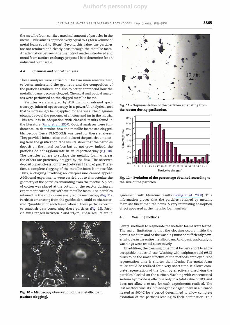
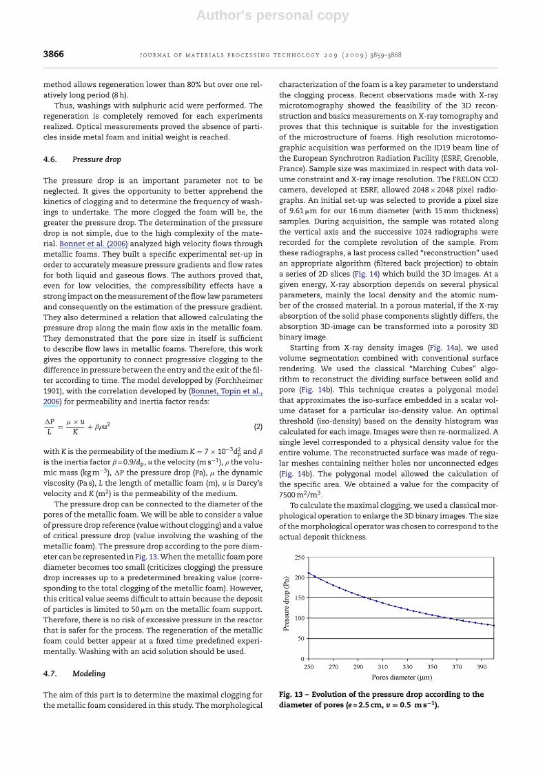
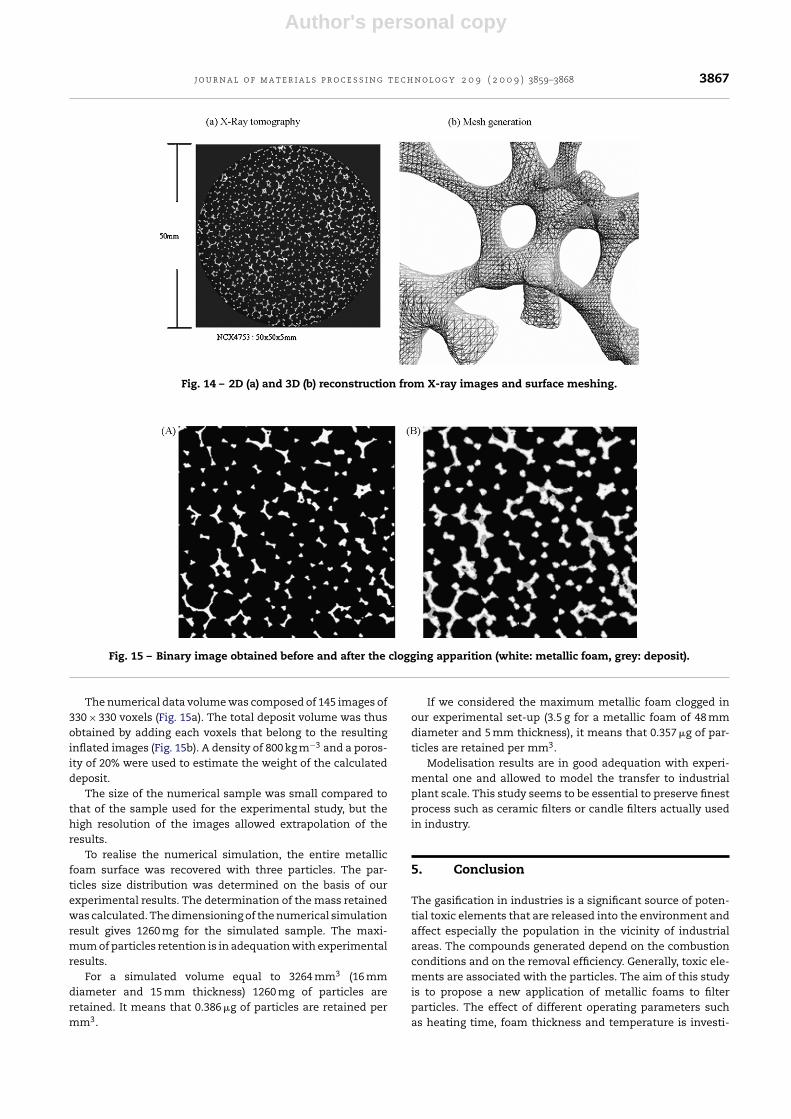
Particles were analyzed by ATR diamond infrared spec-troscopy. Infrared spectroscopy is a powerful analytical toolthat is increasingly being applied for analyses. The diagramsobtained reveal the presence of silicone and tar in the matrix.This result is in adequation with classical results found inthe literature (Pinto et al., 2007). Optical analyses were fun-damental to determine how the metallic foams are clogged.Microscopy (Leica DM-2500M) was used for these analyses.They provided information on the size of the particles emanat-ing from the gasification. The results show that the particlesdeposit on the metal surface but do not grow. Indeed, theparticles do not agglomerate in an important way (Fig. 10).The particles adhere to surface the metallic foam whereasthe others are preferably dragged by the flow. The observeddeposit of particles is comprised between 25 and 45 �m. There-fore, a complete clogging of the metallic foam is impossible.Thus, a clogging involving an overpressure cannot appear.Additional experiments were carried out to characterize thegeometry of the particles emanating from the reactor. A pieceof cotton was placed at the bottom of the reactor during anexperiment carried out without metallic foam. The particlesretained by the cotton were analyzed by microscopy (Fig. 11).Particles emanating from the gasification could be character-ized. Quantification and classification of these particles permitto establish data concerning these particles (Fig. 12). Parti-cle sizes ranged between 7 and 29 �m. These results are in
Fig. 10 – Microscopy observation of the metallic foam(surface clogging).
Fig. 11 – Representation of the particles emanating fromthe reactor during gasification.
Fig. 12 – Evolution of the percentage obtained according tothe size of the particles.
agreement with literature results (Wang et al., 2008). Thisinformation proves that the particles retained by metallicfoam are finest than the pores. A very interesting adsorptioneffect appeared at the metallic foam surface.
4.5. Washing methods
Several methods to regenerate the metallic foams were tested.The major limitation is that the clogging occurs inside theporous medium and so the washing must be sufficiently pow-erful to clean the entire metallic foam. Acid, basic and catalyticwashings were tested successively.
In addition, the cleaning time must be very short to allowacceptable industrial use. Washing with sulphuric acid (98%)turns to be the most effective of the methods employed. Theregeneration time is shorter than 10 min. The metal foamreuse could be realized for a very short time. It allows com-plete regeneration of the foam by effectively dissolving theparticles blocked on the surface. Washing with concentratedsodium hydroxide is effective only to a total value of 90% anddoes not allow a re-use for each experiments realized. Thelast method consists in placing the clogged foam in a furnaceheated at 900 ◦C for a period determined to allow completeoxidation of the particles leading to their elimination. This
Author's personal copy
3866 j o u r n a l o f m a t e r i a l s p r o c e s s i n g t e c h n o l o g y 2 0 9 ( 2 0 0 9 ) 3859–3868
method allows regeneration lower than 80% but over one rel-atively long period (8 h).
Thus, washings with sulphuric acid were performed. Theregeneration is completely removed for each experimentsrealized. Optical measurements proved the absence of parti-cles inside metal foam and initial weight is reached.
4.6. Pressure drop
The pressure drop is an important parameter not to beneglected. It gives the opportunity to better apprehend thekinetics of clogging and to determine the frequency of wash-ings to undertake. The more clogged the foam will be, thegreater the pressure drop. The determination of the pressuredrop is not simple, due to the high complexity of the mate-rial. Bonnet et al. (2006) analyzed high velocity flows throughmetallic foams. They built a specific experimental set-up inorder to accurately measure pressure gradients and flow ratesfor both liquid and gaseous flows. The authors proved that,even for low velocities, the compressibility effects have astrong impact on the measurement of the flow law parametersand consequently on the estimation of the pressure gradient.They also determined a relation that allowed calculating thepressure drop along the main flow axis in the metallic foam.They demonstrated that the pore size in itself is sufficientto describe flow laws in metallic foams. Therefore, this workgives the opportunity to connect progressive clogging to thedifference in pressure between the entry and the exit of the fil-ter according to time. The model developped by (Forchheimer1901), with the correlation developed by (Bonnet, Topin et al.,2006) for permeability and inertia factor reads:
�P
L= � × u
K+ ˇ�u2 (2)
with K is the permeability of the medium K = 7 × 10⁻³d2p and ˇ
is the inertia factor ˇ = 0.9/dp, u the velocity (m s−1), � the volu-mic mass (kg m−3), �P the pressure drop (Pa), � the dynamicviscosity (Pa s), L the length of metallic foam (m), u is Darcy’svelocity and K (m2) is the permeability of the medium.
The pressure drop can be connected to the diameter of thepores of the metallic foam. We will be able to consider a valueof pressure drop reference (value without clogging) and a valueof critical pressure drop (value involving the washing of themetallic foam). The pressure drop according to the pore diam-eter can be represented in Fig. 13. When the metallic foam porediameter becomes too small (criticizes clogging) the pressuredrop increases up to a predetermined breaking value (corre-sponding to the total clogging of the metallic foam). However,this critical value seems difficult to attain because the depositof particles is limited to 50 �m on the metallic foam support.Therefore, there is no risk of excessive pressure in the reactorthat is safer for the process. The regeneration of the metallicfoam could better appear at a fixed time predefined experi-mentally. Washing with an acid solution should be used.
4.7. Modeling
The aim of this part is to determine the maximal clogging forthe metallic foam considered in this study. The morphological
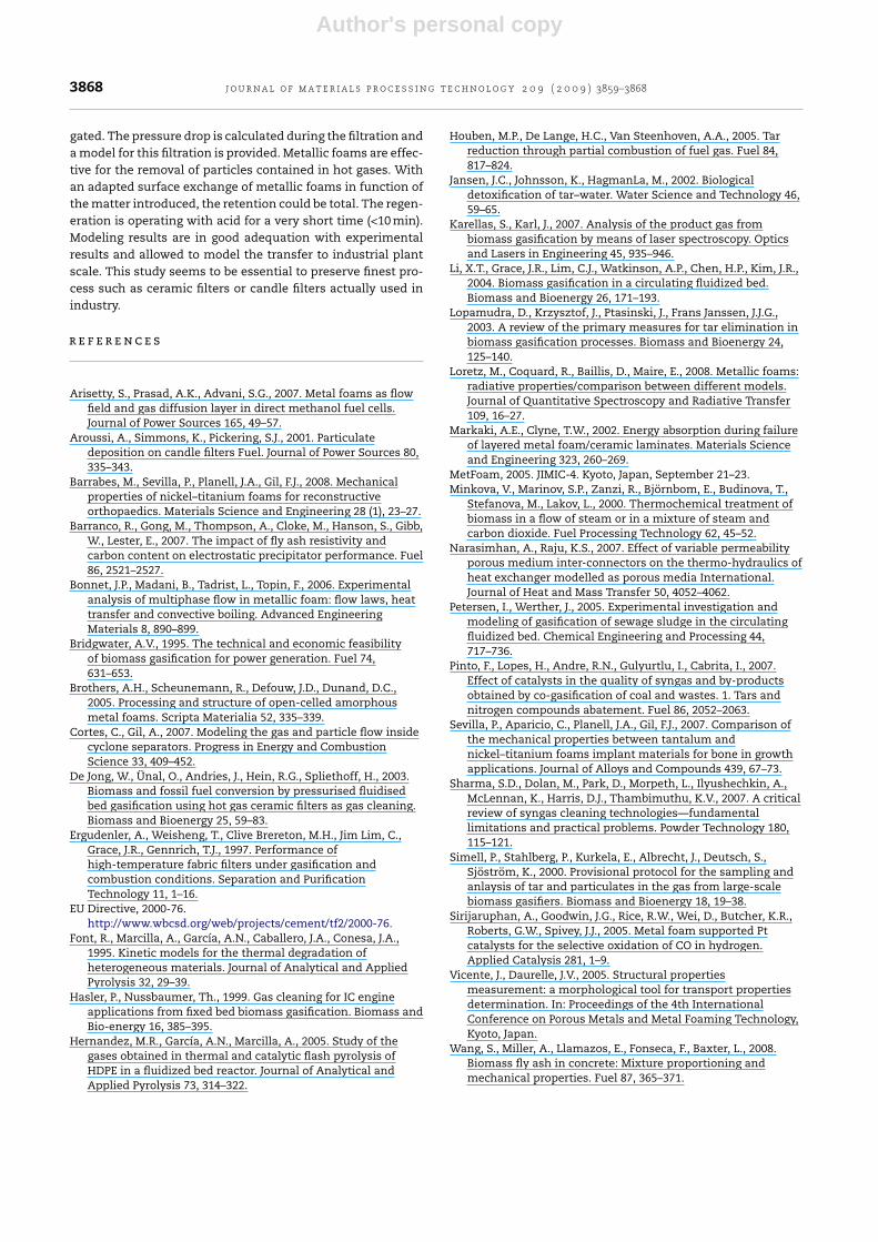
characterization of the foam is a key parameter to understandthe clogging process. Recent observations made with X-raymicrotomography showed the feasibility of the 3D recon-struction and basics measurements on X-ray tomography andproves that this technique is suitable for the investigationof the microstructure of foams. High resolution microtomo-graphic acquisition was performed on the ID19 beam line ofthe European Synchrotron Radiation Facility (ESRF, Grenoble,France). Sample size was maximized in respect with data vol-ume constraint and X-ray image resolution. The FRELON CCDcamera, developed at ESRF, allowed 2048 × 2048 pixel radio-graphs. An initial set-up was selected to provide a pixel sizeof 9.61 �m for our 16 mm diameter (with 15 mm thickness)samples. During acquisition, the sample was rotated alongthe vertical axis and the successive 1024 radiographs wererecorded for the complete revolution of the sample. Fromthese radiographs, a last process called “reconstruction” usedan appropriate algorithm (filtered back projection) to obtaina series of 2D slices (Fig. 14) which build the 3D images. At agiven energy, X-ray absorption depends on several physicalparameters, mainly the local density and the atomic num-ber of the crossed material. In a porous material, if the X-rayabsorption of the solid phase components slightly differs, theabsorption 3D-image can be transformed into a porosity 3Dbinary image.
Starting from X-ray density images (Fig. 14a), we usedvolume segmentation combined with conventional surfacerendering. We used the classical “Marching Cubes” algo-rithm to reconstruct the dividing surface between solid andpore (Fig. 14b). This technique creates a polygonal modelthat approximates the iso-surface embedded in a scalar vol-ume dataset for a particular iso-density value. An optimalthreshold (iso-density) based on the density histogram wascalculated for each image. Images were then re-normalized. Asingle level corresponded to a physical density value for theentire volume. The reconstructed surface was made of regu-lar meshes containing neither holes nor unconnected edges(Fig. 14b). The polygonal model allowed the calculation ofthe specific area. We obtained a value for the compacity of7500 m2/m3.
To calculate the maximal clogging, we used a classical mor-phological operation to enlarge the 3D binary images. The sizeof the morphological operator was chosen to correspond to theactual deposit thickness.
Fig. 13 – Evolution of the pressure drop according to thediameter of pores (e = 2.5 cm, v = 0.5 m s−1).
Author's personal copy
j o u r n a l o f m a t e r i a l s p r o c e s s i n g t e c h n o l o g y 2 0 9 ( 2 0 0 9 ) 3859–3868 3867
Fig. 14 – 2D (a) and 3D (b) reconstruction from X-ray images and surface meshing.
Fig. 15 – Binary image obtained before and after the clogging apparition (white: metallic foam, grey: deposit).
The numerical data volume was composed of 145 images of330 × 330 voxels (Fig. 15a). The total deposit volume was thusobtained by adding each voxels that belong to the resultinginflated images (Fig. 15b). A density of 800 kg m−3 and a poros-ity of 20% were used to estimate the weight of the calculateddeposit.
The size of the numerical sample was small compared tothat of the sample used for the experimental study, but thehigh resolution of the images allowed extrapolation of theresults.
To realise the numerical simulation, the entire metallicfoam surface was recovered with three particles. The par-ticles size distribution was determined on the basis of ourexperimental results. The determination of the mass retainedwas calculated. The dimensioning of the numerical simulationresult gives 1260 mg for the simulated sample. The maxi-mum of particles retention is in adequation with experimentalresults.
For a simulated volume equal to 3264 mm3 (16 mmdiameter and 15 mm thickness) 1260 mg of particles areretained. It means that 0.386 �g of particles are retained permm3.
If we considered the maximum metallic foam clogged inour experimental set-up (3.5 g for a metallic foam of 48 mmdiameter and 5 mm thickness), it means that 0.357 �g of par-ticles are retained per mm3.
Modelisation results are in good adequation with experi-mental one and allowed to model the transfer to industrialplant scale. This study seems to be essential to preserve finestprocess such as ceramic filters or candle filters actually usedin industry.
5. Conclusion
The gasification in industries is a significant source of poten-tial toxic elements that are released into the environment andaffect especially the population in the vicinity of industrialareas. The compounds generated depend on the combustionconditions and on the removal efficiency. Generally, toxic ele-ments are associated with the particles. The aim of this studyis to propose a new application of metallic foams to filterparticles. The effect of different operating parameters suchas heating time, foam thickness and temperature is investi-
Author's personal copy
3868 j o u r n a l o f m a t e r i a l s p r o c e s s i n g t e c h n o l o g y 2 0 9 ( 2 0 0 9 ) 3859–3868
gated. The pressure drop is calculated during the filtration anda model for this filtration is provided. Metallic foams are effec-tive for the removal of particles contained in hot gases. Withan adapted surface exchange of metallic foams in function ofthe matter introduced, the retention could be total. The regen-eration is operating with acid for a very short time (<10 min).Modeling results are in good adequation with experimentalresults and allowed to model the transfer to industrial plantscale. This study seems to be essential to preserve finest pro-cess such as ceramic filters or candle filters actually used inindustry.
r e f e r e n c e s
Arisetty, S., Prasad, A.K., Advani, S.G., 2007. Metal foams as flowfield and gas diffusion layer in direct methanol fuel cells.Journal of Power Sources 165, 49–57.
Aroussi, A., Simmons, K., Pickering, S.J., 2001. Particulatedeposition on candle filters Fuel. Journal of Power Sources 80,335–343.
Barrabes, M., Sevilla, P., Planell, J.A., Gil, F.J., 2008. Mechanicalproperties of nickel–titanium foams for reconstructiveorthopaedics. Materials Science and Engineering 28 (1), 23–27.
Barranco, R., Gong, M., Thompson, A., Cloke, M., Hanson, S., Gibb,W., Lester, E., 2007. The impact of fly ash resistivity andcarbon content on electrostatic precipitator performance. Fuel86, 2521–2527.
Bonnet, J.P., Madani, B., Tadrist, L., Topin, F., 2006. Experimentalanalysis of multiphase flow in metallic foam: flow laws, heattransfer and convective boiling. Advanced EngineeringMaterials 8, 890–899.
Bridgwater, A.V., 1995. The technical and economic feasibilityof biomass gasification for power generation. Fuel 74,631–653.
Brothers, A.H., Scheunemann, R., Defouw, J.D., Dunand, D.C.,2005. Processing and structure of open-celled amorphousmetal foams. Scripta Materialia 52, 335–339.
Cortes, C., Gil, A., 2007. Modeling the gas and particle flow insidecyclone separators. Progress in Energy and CombustionScience 33, 409–452.
De Jong, W., Ünal, O., Andries, J., Hein, R.G., Spliethoff, H., 2003.Biomass and fossil fuel conversion by pressurised fluidisedbed gasification using hot gas ceramic filters as gas cleaning.Biomass and Bioenergy 25, 59–83.
Ergudenler, A., Weisheng, T., Clive Brereton, M.H., Jim Lim, C.,Grace, J.R., Gennrich, T.J., 1997. Performance ofhigh-temperature fabric filters under gasification andcombustion conditions. Separation and PurificationTechnology 11, 1–16.
EU Directive, 2000-76.http://www.wbcsd.org/web/projects/cement/tf2/2000-76.
Font, R., Marcilla, A., García, A.N., Caballero, J.A., Conesa, J.A.,1995. Kinetic models for the thermal degradation ofheterogeneous materials. Journal of Analytical and AppliedPyrolysis 32, 29–39.
Hasler, P., Nussbaumer, Th., 1999. Gas cleaning for IC engineapplications from fixed bed biomass gasification. Biomass andBio-energy 16, 385–395.
Hernandez, M.R., García, A.N., Marcilla, A., 2005. Study of thegases obtained in thermal and catalytic flash pyrolysis ofHDPE in a fluidized bed reactor. Journal of Analytical andApplied Pyrolysis 73, 314–322.
Houben, M.P., De Lange, H.C., Van Steenhoven, A.A., 2005. Tarreduction through partial combustion of fuel gas. Fuel 84,817–824.
Jansen, J.C., Johnsson, K., HagmanLa, M., 2002. Biologicaldetoxification of tar–water. Water Science and Technology 46,59–65.
Karellas, S., Karl, J., 2007. Analysis of the product gas frombiomass gasification by means of laser spectroscopy. Opticsand Lasers in Engineering 45, 935–946.
Li, X.T., Grace, J.R., Lim, C.J., Watkinson, A.P., Chen, H.P., Kim, J.R.,2004. Biomass gasification in a circulating fluidized bed.Biomass and Bioenergy 26, 171–193.
Lopamudra, D., Krzysztof, J., Ptasinski, J., Frans Janssen, J.J.G.,2003. A review of the primary measures for tar elimination inbiomass gasification processes. Biomass and Bioenergy 24,125–140.
Loretz, M., Coquard, R., Baillis, D., Maire, E., 2008. Metallic foams:radiative properties/comparison between different models.Journal of Quantitative Spectroscopy and Radiative Transfer109, 16–27.
Markaki, A.E., Clyne, T.W., 2002. Energy absorption during failureof layered metal foam/ceramic laminates. Materials Scienceand Engineering 323, 260–269.
MetFoam, 2005. JIMIC-4. Kyoto, Japan, September 21–23.Minkova, V., Marinov, S.P., Zanzi, R., Björnbom, E., Budinova, T.,
Stefanova, M., Lakov, L., 2000. Thermochemical treatment ofbiomass in a flow of steam or in a mixture of steam andcarbon dioxide. Fuel Processing Technology 62, 45–52.
Narasimhan, A., Raju, K.S., 2007. Effect of variable permeabilityporous medium inter-connectors on the thermo-hydraulics ofheat exchanger modelled as porous media International.Journal of Heat and Mass Transfer 50, 4052–4062.
Petersen, I., Werther, J., 2005. Experimental investigation andmodeling of gasification of sewage sludge in the circulatingfluidized bed. Chemical Engineering and Processing 44,717–736.
Pinto, F., Lopes, H., Andre, R.N., Gulyurtlu, I., Cabrita, I., 2007.Effect of catalysts in the quality of syngas and by-productsobtained by co-gasification of coal and wastes. 1. Tars andnitrogen compounds abatement. Fuel 86, 2052–2063.
Sevilla, P., Aparicio, C., Planell, J.A., Gil, F.J., 2007. Comparison ofthe mechanical properties between tantalum andnickel–titanium foams implant materials for bone in growthapplications. Journal of Alloys and Compounds 439, 67–73.
Sharma, S.D., Dolan, M., Park, D., Morpeth, L., Ilyushechkin, A.,McLennan, K., Harris, D.J., Thambimuthu, K.V., 2007. A criticalreview of syngas cleaning technologies—fundamentallimitations and practical problems. Powder Technology 180,115–121.
Simell, P., Stahlberg, P., Kurkela, E., Albrecht, J., Deutsch, S.,Sjöström, K., 2000. Provisional protocol for the sampling andanlaysis of tar and particulates in the gas from large-scalebiomass gasifiers. Biomass and Bioenergy 18, 19–38.
Sirijaruphan, A., Goodwin, J.G., Rice, R.W., Wei, D., Butcher, K.R.,Roberts, G.W., Spivey, J.J., 2005. Metal foam supported Ptcatalysts for the selective oxidation of CO in hydrogen.Applied Catalysis 281, 1–9.
Vicente, J., Daurelle, J.V., 2005. Structural propertiesmeasurement: a morphological tool for transport propertiesdetermination. In: Proceedings of the 4th InternationalConference on Porous Metals and Metal Foaming Technology,Kyoto, Japan.
Wang, S., Miller, A., Llamazos, E., Fonseca, F., Baxter, L., 2008.Biomass fly ash in concrete: Mixture proportioning andmechanical properties. Fuel 87, 365–371.