patterned superhydrophobic metallic surfaces
TRANSCRIPT
Subscriber access provided by The University of British Columbia Library
Langmuir is published by the American Chemical Society. 1155 Sixteenth Street N.W.,Washington, DC 20036
Article
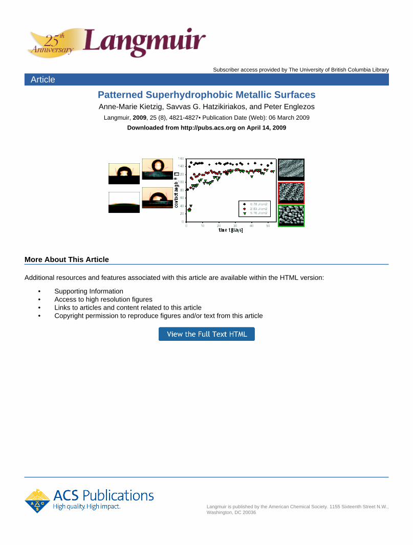
Patterned Superhydrophobic Metallic SurfacesAnne-Marie Kietzig, Savvas G. Hatzikiriakos, and Peter Englezos
Langmuir, 2009, 25 (8), 4821-4827• Publication Date (Web): 06 March 2009
Downloaded from http://pubs.acs.org on April 14, 2009
More About This Article
Additional resources and features associated with this article are available within the HTML version:
• Supporting Information• Access to high resolution figures• Links to articles and content related to this article• Copyright permission to reproduce figures and/or text from this article

pubs.acs.org/Langmuir
Patterned Superhydrophobic Metallic Surfaces
Anne-Marie Kietzig, Savvas G. Hatzikiriakos,* and Peter Englezos
Department of Chemical and Biological Engineering, The University of British Columbia, Vancouver BC,V6T 1Z3 Canada
Received November 12, 2008. Revised Manuscript Received February 10, 2009
This work shows that after creating certain dual scale roughness structures by femtosecond laser irradiationdifferent metal alloys initially show superhydrophilic behavior with complete wetting of the structured surface.However, over time, these surfaces become nearly superhydrophobic with contact angles in the vicinity of 150�and superhydrophobic with contact angles above 150�. The contact angle hysteresis was found to lie between 2and 6�. The change in wetting behavior correlates with the amount of carbon on the structured surface. Theexplanation for the time dependency of the surface wettability lies in the combined effect of surface morphologyand surface chemistry.
1.0. Introduction
When a raindrop falls onto a lotus leaf, it hardly wets thesurface. The water droplet rolls off easily, carrying away withit any contaminating particles.1,2 This superhydrophobicbehavior, also called the lotus effect, is attributed to theparticular roughness of the lotus leaf ’s surface. The surfaceof a lotus leaf is made up of a certain dual scale roughnessstructure.3Micrometer scale asperities in randomdistributionare covered by fine nanometer scale hairs. The hairs amplifythe surface tremendously.4When water gets into contact withthe leaf, the droplets only rest on the peaks of the asperities.Air is trapped between the surface and the drop. Therefore,the drop is supported by a composite surface made out of leafand air, as described by the Cassie-Baxter equation.5 Theresulting contact angle of water on the lotus leaf is as highas 162�.6
After the first investigations of the lotus leaf, efforts havefocused on understanding this roughness induced superhy-drophobicity in experiments and models.7-14 Hydrophobicsurfaces were created using lithography techniques incombination with self-assembled monolayers14,15 and with
silanization agents.9 Superhydrophobicity was achieved onsurfaces with aligned carbon nanotubes,16-19 solidified al-kylketene dimer wax,7 electrodeposited ZnO,20 and anodi-cally oxidized aluminum.21 The common characteristic of allthese surfaces is a certain microroughness. Laser irradiationhas been proven to be an effective technique to create dualscale roughness structures on silicone.22-25 Yoon et al.26
created superhydrophobic laser-structured poly(dimethylsi-loxane) surfaces, whileGroenendijk andMeijer27,28 irradiateda stainless steel moldwith a femtosecond laser to create a dualscale roughness structure. Thismoldwas subsequently used tocreate a replicate of this structure on hydrophobic polymers,which became superhydrophobic due to the dual scale rough-ness structure. However, the wetting behavior of the laserstructured steel mold was not reported.
Rendering an initially hydrophilic surface to hydrophobicwas achieved by Baldacchini et al.,29 by coating a laserirradiated silicon surface with fluorosilane. Zorba et al.24
have achieved a similar change in wetting behavior of sili-cone, however, without additional coating after the lasertreatment. This and Bhattacharya et al.’s findings on hydro-phobic clustered copper nanowires30 are to the best of ourknowledge the only reports on altering a material’s surface
*To whom correspondence should be addressed. E-mail: [email protected].
(1) Solga, A.; Cerman, Z.; Striffler, B. F.; Spaeth, M.; Barthlott, W.Bioinspiration Biomimimetics 2007, 2, 126.
(2) Forbes, P. Sci. Am. 2008, 299, 88.(3) Barthlott, W.; Neinhuis, C. Planta 1997, 202, 1.(4) Cheng, Y. T.; Rodak, D. E.; Wong, C. A.; Hayden, C. A. Nanotech-
nology 2006, 17, 1359.(5) Cassie, A. B. D.; Baxter, S. Trans. Faraday Soc. 1944, 40, 546.(6) Neinhuis, C.; Barthlott, W. Ann. Bot. 1997, 79, 667.(7) Onda, T.; Shibuichi, S.; Satoh, N.; Tsujii, K. Langmuir 1996, 12, 2125.(8) Shibuichi, S.; Onda, T.; Satoh, N.; Tsujii, K. J. Phys. Chem. 1996, 100,
19512.(9)
::Oner, D.; McCarthy, T. J. Langmuir 2000, 16, 7777.
(10) Marmur, A. Langmuir 2003, 19, 8343.(11) Marmur, A. Langmuir 2004, 20, 3517.(12) Patankar, N. A. Langmuir 2004, 20, 8209.(13) Nosonovsky, M.; Bushan, B. Microsyst. Technol. 2005, 11, 535.(14) Burton, Z.; Bushan, B. Nano Lett. 2005, 5, 1607.(15) Shiu, J. Y.; Kuo, C.W.; Chen, P.; Mou, C. Y.Chem.Mater. 2004, 16,
561.(16) Li, S.; Li, H.; Wang, X.; Song, Y.; Liu, Y.; Jiang, L.; Zhu, D. J. Phys.
Chem. B 2002, 106, 9274.(17) Lau, K. K. S.; Bico, J.; Teo, K. B. K.; Chhowalla, M.; Amaratunga,
G. A. J.; Milne, W. I.; McKinley, G. H.; Gleason, K. K. Nano Lett. 2003, 3,1701.
(18) Otten, A.; Herminghaus, S. Langmuir 2004, 20, 2405.(19) Zhu, L.; Xiu, Y.; Xu, J.; Tamirisa, P. A.; Hess, D. W.; Wong, C.-P.
Langmuir 2005, 21, 11208.(20) Li,M.; Zhai, J.; Liu, H.; Song, Y.; Jiang, L.; Zhu,D. J. Phys. Chem. B
2003, 107, 9954.(21) Shibuichi, S.; Yamamoto, T.; Onda, T.; Tsujii, K. J. Colloid Interface
Sci. 1998, 208, 287.(22) Her, T.-H.; Finlay, R. J.; Wu, C.; Deliwala, S.; Mazur, E.Appl. Phys.
Lett. 1998, 73, 1673.(23) Dolgaev, S. I.; Lavrishev, S. V.; Lyalin, A. A.; Simakin, A. V.;
Voronov, V. V.; Shafeev, G. A. Appl. Phys. A: Mater. Sci. Process. 2001,73, 177.
(24) Zorba, V.; Persano, L.; Pisignano, D.; Athanassiou, A.; Stratakis, E.;Cingolani, R.; Tzanetakis, P.; Fotakis, C. Nanotechnology 2006, 17, 3234.
(25) Zorba, V.; Stratakis, E.; Barberoglou, M.; Spanakis, E.; Tzanetakis,P.; Anastasiadis, S. H.; Fotakis, C. Adv. Mater. 2008, 20, 4049.
(26) Yoon, O. Y.; Shin, H. J.; Jeoung, S. C.; Park, Y.-I.Opt. Express 2008,16, 12715.
(27) Groenendjik, M. N. W.; Meijer, J. Ann. CIRP 2006, 55, 183.(28) Groenendjik, M. N. W. Laser Technol. 2008, 3, 44.(29) Baldacchini, T.; Carey, J. E.; Zhou,M.;Mazur, E.Langmuir 2006, 22,
4917.(30) Bhattacharya, P.; Gohil, S.; Mazher, J.; Ghosh, S.; Ayyub, P.
Nanotechnology 2008, 19, 075709.
Published on Web 3/6/2009
© 2009 American Chemical Society
DOI: 10.1021/la8037582Langmuir 2009, 25(8), 4821–4827 4821

wettability from hydrophilic to hydrophobic without using acoating.
In this Article, we show for the first time that differentmetallic alloys with initially smooth, hydrophilic surfacesbecome nearly superhydrophobic and some even becomesuperhydrophobic over time after being irradiated with afemtosecond laser. The laser irradiation immediately creates
a certain dual scale roughness structure on the samples’surfaces and appears to be responsible for carbon depositionon the substrate’s surface.
2.0. Experimental Section
2.1. Materials. The different alloys chosen for the ex-periments are stainless steel AISI 304L, stainless steel AISI 630,
Figure 1. SEM images of pristine and laser structured surfaces (same scale applies to all images).
DOI: 10.1021/la8037582 Langmuir 2009, 25(8),4821–48274822
Article Kietzig et al.

low-alloy steel AISI 4140, high speed tool steel AISI M2, moldsteel AISI P20 coated with Armoloy thin dense chromium(TDC) coating of about 4 μm thickness, and titanium alloy Ti-6-4.All samples are about 1mm thick andpolished to an averageroughness value (Ra) of about 800 nm. This is defined as theaverage length of protrusions above theirmean value, ameasureof roughness standard in literature.
2.2. Surface Laser Irradiation.The samples’ surfaces wereirradiatedwith a horizontally polarized beamof an amplified Ti:sapphire laser (seed laserCoherentMiraHP, amplifierCoherentLegend) with 800 nm wavelength, 1 kHz repetition rate, andabout 150 fs pulse width. The beamwas focused to a spot size of30 μm. The scan line overlap was set to be 50%. An x-y-translation stage moved the sample under the laser beam with0.25 mm/s, resulting in 120 pulses/spot. The samples wereirradiated at normal incidence in air. Three different structureswere created on each material with a fluence of 0.78, 2.83, and5.16 J/cm2.
2.3. Surface Analysis. The morphology of the surfacestructures was analyzed with scanning electron microscopy(SEM) and atomic force microscopy (AFM). The samples wereultrasonically cleaned in acetone, before assessing wettability bymeasuring the contact angle. A 1 μL droplet of distilled deio-nized water was dispensed on the sample surface, and thecontact angle was determined by analyzing droplet images andusing the software FTA32 version 2.0. Similarly, contact anglehysteresis was determined by comparing the advancing andreceding contact angles of the growing and shrinking droplet,respectively.27,28 X-ray photoelectron spectroscopy (XPS) ana-lysis was used to quantify the elemental composition of thesurface.
3.0. Results and Discussion
3.1. The Effect of Fluence on Surface Structure. TheSEM images (Figure 1) clearly show the effect of the laserirradiation on the surface roughness of the samples. Thepristine surfaces are characterized by scratchmarks from thepolishing process. After the laser process, the surfaces showregular protuberances. With increasing fluence, this surfacestructure becomes coarser. For the AISI P20+Cr sample,the SEM images clearly show that the coating got damagedby irradiation of 0.78 J/cm2. For higher fluences, the coatingwas completely removed.
Figure 2 shows the laser induced surface structure athigher magnification exemplarily for AISI 304L. For all
Figure 2. Laser induced dual scale roughness structure on AISI304L (same scale applies to all images).
Table 1. Geometric Characterization of Laser Irradiated Surfaces
(Ra, d, and z in μm)
0.78 J/cm2 2.83 J/cm2 5.16 J/cm2
304L Ra 0.32 0.45 1.12d 2.5 4 9z 3 3.5 9
630 Ra 0.35 0.42 0.76d 2.5 4 9z 2.5 3.5 6.5
4140 Ra 0.30 0.37 1.03d 2.5 4 9z 2 3 8.5
M2 Ra 0.15 0.25 0.61d 2.5 5 8z 1.5 3 5
P20+Cr Ra 0.24 0.37 0.69d 2.5 4 8z 2 3 8
Ti-6-4 Ra 0.57 1.23 1.72d 3.5 6 12z 5.5 10 12
DOI: 10.1021/la8037582Langmuir 2009, 25(8), 4821–4827 4823
ArticleKietzig et al.

fluences and materials, a periodic ripple structure is super-imposed onto the more chaotic protuberances. For thestructures created with 0.78 J/cm2, trenches perpendicularto the ripples isolate fine bumps with average diameters ofabout 2.5 μm. With increasing fluence, these bumps becomelarger and the overall microstructure appears coarser (geo-metric details are given in Table 1). Independent of theapplied fluence, however, these microscale bumps are cov-ered by a fine ripple structure with about 500 nm spacing.
Such a surface with roughness patterns on two differentlength scales is characteristic for such laser structured sur-faces.27,31,32
Structural characteristics, measured by AFM, such asaverage surface roughness Ra, average bump diameter d,and average bump height z are summarized in Table 1. Alldimensions are reported in μm.
3.2. Time Effects on Surface Hydrophilicity/Hydropho-
bicity. Directly after the laser treatment, the droplets werefound to wet the structured area on all samples completely;initially, all samples exhibit superhydrophilic behavior. Overtime, however, the contact angle started to increase. Due tothe small size of the structured area, the water drop wets theentire structured area until the contact angle exceeds 20�.Therefore, only after that lower limit the change in contactangle could be monitored. Figure 3 shows the dependence ofthe contact angle on time for all six materials and the three
Figure 3. Contact angle evolution over time.
Figure 4. Exponential growth regression on contact angle evolu-tion over time of AISI 630 irradiated with laser of fluence 2.83 J/cm2.
Table 2. Contact Angle Regression Coefficient λ (Days) for All
Fluences
λ (days)
material 0.78 J/cm2 2.83 J/cm2 5.16 J/cm2
304L 1.05 2.63 4.93630 1.01 4.45 6.134140 0.39 3.43 6.00M2 0.10 8.17 16.92P20+Cr 0.26 5.34 5.63Ti-6-4 0.49 12.27 26.35
Table 3. Contact Angle Regression Coefficient θeq (�) for All Fluencesθeq (�)
material 0.78 J/cm2 2.83 J/cm2 5.16 J/cm2
304L 147 127 123630 145 126 1254140 144 112 119M2 139 122 132P20+Cr 132 119 129Ti-6-4 143 132 124
(31) Birnbaum, M. J. Appl. Phys. 1965, 36, 3688.(32) B
::auerle, D. Laser Processing and Chemistry; Springer-Verlag: Berlin,
Germany, 1996.
DOI: 10.1021/la8037582 Langmuir 2009, 25(8),4821–48274824
Article Kietzig et al.

different fluences. Eachmeasurement point displayed here isthe average of three individual measurements.
The contact angle evolution can be described approxi-mately with exponential growth regressions of the type,θ/θeq = 1 - et/γ, where θeq is the equilibrium contact angle(maximum angle towardwhich the data converges) and λ is atime constant, which represents the time until 63.2% of themaximum contact angle value is reached. An example forsuch a regression is shown in Figure 4 forAISI 630 irradiatedwith 2.83 J/cm2.
Tables 2 and 3 summarize the values for θeq and λ,respectively, for all samples. Following an initial sharpincrease, the contact angles gradually reach a steady state.For all alloys, the low fluence structures show a fasterincrease (small time constant λ) in contact angles comparedto the samples irradiatedwith a higher fluence. Table 2 showsthat after only 1 day all the structures irradiated with 0.78 J/cm2 reached at least 63% of their steady state contact angle.Especially the titanium alloy and tool steelM2 are noticeablyslower in becoming hydrophobic for the structures irradiatedwith 2.83 and 5.16 J/cm2. Table 3 summarizes the steady statecontact angles for all structures. The structures created withirradiation of 2.83 and 5.16 J/cm2 converge to contact anglesbetween 110� and 130� depending on the alloy, while thesamples irradiated with 0.78 J/cm2 result in less than 10 daysin steady state contact angles between 130� and 150�.
To further assess the hydrophobic behavior, contact anglehysteresis was measured on the irradiated surfaces once theyreached their steady state contact angle. Figure 5 shows agrowing and shrinking drop sequence exemplarily for AISI304L irradiated with 0.78 J/cm2.With the advancing contactangle of 153� and the receding contact angle of 150.5�, thehysteresis for this particular sample is less than 3�. Accord-ingly, this sample meets the requirements of a superhydro-phobic surface. The hysteresis values Δθ (�) for all samplesare summarized in Table 4. Overall, the hysteresis values arevery lowwithmore than two-thirds of the samples exhibitingvalues below 3�. It is noted that the value of θeq = 147 � forAISI 304Lwas calculated (by fitting an exponential functionto experimental data) approximately 5 months before themeasurements of 153� and 150.5� for the advancing andreceding contact angles. Over this period, the θeq valueincreased slightly and this was observed to be the case formost substrates (typically 3.5% increase in most cases).However, such a variability of 3.5% falls within experimen-tal error, as each point inFigure 3 represents the average of at
least three measurements at different locations across thesample. This is also within the variability shown by the datawhen steady state was supposedly obtained (see Figure 4).
3.3. Elemental Surface Analysis. XPS analysis was per-formed on the untreated and treated surfaces of all materials.Figure 6 exemplarily shows the spectra for stainless steel304L before laser irradiation (Figure 6a), immediately afterirradiation (Figure 6b), and 52 days after irradiation(Figure 6c).
After irradiation with 5.16 J/cm2, one sample of stainlesssteel 304Lwas stored in vacuum until it could be analyzed byXPS (Figure 6b); the total exposure time to air between thelaser treatment and the analysis is estimated to be about 5 h.It is apparent that the relative amount of carbon increaseswith time, comparing the spectra before (Figure 6a), shortlyafter laser irradiation (Figure 6b), and after a longer periodof time (Figure 6c), when the contact angle has reached itsequilibrium value. While the surface of the untreated alloyconsists of iron, nickel, and chromium oxides, shortly afterthe laser irradiation, the nickel and chromium peaks aresmaller. After 52 days, nickel and chromium are not detect-able anymore, and the surface is solely made up of ironoxides and carbon. Table 5 and Figure 7 summarize therelationship between the contact angle and the carbon con-tent for all alloys.
From Figure 7, it can be seen that the equilibrium contactangle positively correlates with the carbon content. Theoverall correlation coefficient is 0.78, with the higher carboncontent corresponding to higher hydrophobicity. However,it is to note that there are some exceptions to this trend.Sample 304L irradiated with 2.83 J/cm2 exhibits a lowerrelative carbon content but higher equilibrium contact anglethan the sample irradiated with 5.16 J/cm2. Also the M2,P20+Cr, and Ti-6-4 samples irradiated with 0.78 J/cm2 havea lower carbon content than those irradiated with higherfluences but still show higher hydrophobicity.
3.4. Discussion and Explanation of Results. The presentwork startedwith the intention to utilize laser light to create acertain dual scale roughness structure on steel. This wasachieved successfully. However, we noticed that the initiallyhydrophilic samples became hydrophobic over time. Moreexperiments with metallic substrates of different composi-tions and different laser energies were performed to explorewhether this effect was actually reproducible. The multiplesubstrates analyzed have convincingly demonstrated thatthis effect is totally reproducible.
In 1936,Wenzel reported the influence of roughness on thecontact angle.33 Generally, Wenzel’s equation states thatroughness increases the intrinsic wetting behavior of a sur-face.However, this relationship fails to give a solution for thecontact angle on extremely rough surfaces and for the changefrom hydrophilic to hydrophobic behavior.34 Cassie and
Figure 5. Contact angle hysteresis sequence of AISI 304L irradiated with 0.78 J/cm2.
Table 4. Contact Angle Hysteresis Δθ (�) for All FluencesΔθ (�)
material 0.78 J/cm2 2.83 J/cm2 5.16 J/cm2
304L <3 <3 <2630 <1 <3 ∼34140 <2 <2 <2M2 ∼6 <3 <2P20+Cr <3 <4 <4Ti-6-4 <4 ∼3 ∼6
(33) Wenzel, R. N. Ind. Eng. Chem. 1936, 28, 988.(34) Johnson, R. E.; Dettre, R. H. Contact Angle, Wettability, and Adhe-
sion; American Chemical Society: Washington DC, 1964.
DOI: 10.1021/la8037582Langmuir 2009, 25(8), 4821–4827 4825
ArticleKietzig et al.

Baxter5 further investigated the relationship between rough-ness and hydrophobicity and realized that contact angles oncomposite surfaces are higher than predicted by Wenzel’sequation. Composite surfaces are characterized by incom-plete wetting. This is represented by the Cassie-Baxterequation, which can also explain a switch from hydrophilic
to hydrophobic wetting behavior.35 In our case, however, thesurface structure cannot solely be responsible for the ob-served high contact angles. The structure is in place imme-diately after the laser treatment. If the high hydrophobicitywas due only to the laser induced roughness, then thesamples would have been hydrophobic directly after the lasertreatment, since the structure does not change over time.Therefore, the final hydrophobicity and the evolution of thecontact angle over time are due to other factors. The XPSresults suggest that the observed change in wettability can beattributed to a certain extent to the presence of carbon and itscompounds on the laser irradiated surfaces discussed above.
We propose the decomposition of carbon dioxide intocarbonwith activemagnetite as a potential explanation assum-ing that laser energy is accountable for the creation of an activemagnetite scale. Active magnetite Fe3O4-δ (0 < δ < 1)is a nonstoichiometric oxygen deficient iron oxide scale,which was found to catalyze the dissociative adsorption ofcarbon dioxide.36-38 Carbon dioxide becomes carbon mon-oxide and zero valence carbon, and oxygen anions aretransferred into lattice vacancies of the alloy to form stoi-chiometric Fe3O4. All steel alloys are composed of a sub-stantial amount of iron, and even the as delivered titaniumalloy shows traces of iron in its composition, which wasconfirmed by XPS analysis. Furthermore, Zhang et al.illustrated in their experiments with pure CO2 that at roomtemperature the reaction rate is very slow.37 This could serve
Figure 6. XPS spectra for 304L before and after laser irradiationwith 5.16 J/cm2.
Table 5. Carbon Content and Contact Angle θeq for All Alloys
sample C (atom %) θeq (�)
304L substrate 26.56 840.73 J/cm2 63.92 1472.83 J/cm2 49.13 1275.16 J/cm2 54.69 123
630 substrate 26.07 830.73 J/cm2 55.15 1452.83 J/cm2 46.86 1265.16 J/cm2 41.79 125
4140 substrate 11.55 700.73 J/cm2 51.69 1432.83 J/cm2 40.22 1125.16 J/cm2 51.00 119
M2 substrate 38.81 750.73 J/cm2 41.29 1382.83 J/cm2 50.89 1225.16 J/cm2 50.67 132
P20+Cr substrate 12.33 600.73 J/cm2 31.47 1322.83 J/cm2 43.82 1195.16 J/cm2 43.72 129
Ti-6-4 substrate 27.32 650.73 J/cm2 32.42 1422.83 J/cm2 39.55 1225.16 J/cm2 41.90 123
(35) Patankar, N. A. Langmuir 2004, 20, 8209.(36) Tamaura, Y.; Tabata, M. Nature 1990, 346, 255.(37) Zhang, C.-L.; Li, S.; Wang, L.-J.; Wu, T.-H.; Peng, S. Y. Mater.
Chem. Phys. 2000, 62, 44.(38) Zhang, C.-L.; Li, S.; Wang, L.-J.; Wu, T.-H.; Peng, S. Y. Mater.
Chem. Phys. 2000, 62, 52.
DOI: 10.1021/la8037582 Langmuir 2009, 25(8),4821–48274826
Article Kietzig et al.

as an explanation for the observed gradual increase incontact angle over time.
Directly after the laser treatment, we already detected anincreased amount of carbon on the surface, which is believedto come from the fast decomposition reaction at the timewhen the laser beam first hits the surface. We suggest thatthe high energy from the very short laser pulse activates thedecomposition reaction and results in the initial carbondeposition on the irradiated surface. However, the carbonfrom this initial fast decomposition is not enough to coverthe entire structure and shield the hydrophilicity of theunderlying iron oxides. This intrinsic hydrophilicity of thepolar iron oxides is then amplified by the surface roughnessaccording to Wenzel’s theory, which clearly explains theinitial superhydrophilicity of the laser irradiated alloys.
Over time, the CO2 decomposition reaction continuesslowly and nonpolar carbon accumulates on the rough sur-face. Together with the laser created dual scale roughnessstructure, the result is a superhydrophobic surface. This canbe compared to the high hydrophobicity of carbon nano-tubes.39-41
To support this theory, different substrates made fromAISI 304L were irradiated with 5.16 J/cm2 and kept indifferent media immediately after the laser treatment. Theresults are shown in Figure 8.
One sample was stored in N2 for 2 weeks. After it wastaken out, the contact angle wasmeasured continuously, andthe sample showed approximately the same behavior as theone exposed to ambient air. Another sample was immersedinto boiling water for 2 days after the laser treatment. Evenafter being exposed to air, this sample never became hydro-phobic but remained superhydrophilic with a steady statecontact angle θeq of 21�. Tamaura and Tabata36 havedetected hydrogen gas after active magnetite was exposedto H2O instead of CO2. Accordingly, water is decomposedsimilarly toCO2 over activemagnetite. Therefore, we assumethat the activemagnetite sites of our sample were deactivatedby oxygen ions from the water to formmore hydrophilic iron
oxides. A third sample was stored in CO2 and only taken outonce a day to perform contact angle analysis. This sampleinitially shows the same increase in contact angle as the onekept in air. However, its steady state contact angle is higher.Due to H2O traces in an ambient air environment, H2Odecomposition is likely to take place parallel to CO2 decom-position at the active surface, which results in less carbon onthe irradiated surface compared to the same surface stored ina CO2 environment.
It was shown that the CO2 decomposition rate is highestfor the greatest oxygen deficiency.33,35 Comparing the samealloy irradiated with different fluences, it is obvious that thetime it takes for the samples to reach their steady stateincreases with increasing fluence. This can possibly be ex-plained by the difference in the degree of oxygen deficiency,which results in less carbon on the surface. If the presentedexplanation on the origin of the gradual increase in hydro-phobicity is valid, these results suggest that higher laserfluence creates less active magnetite and/or less oxygendeficiency.
4.0. Summary and Conclusions
In summary, it has been shown that after femtosecond laserirradiation hydrophilic metal alloys of different compositionwith typical contact angles between 60� and 85� show initiallysuperhydrophilic behavior and subsequently become nearlysuperhydrophobic and some even superhydrophobic withtime. The distinctive laser induced dual scale roughnessstructure definitely plays a significant role in the extremewetting behaviors. However, the change in and the timedependency of the wetting behavior indicate that the explana-tion lies in the combined effect of surface morphology andsurface chemistry.With thiswork,wehave shownapossibilityto modify the wetting behavior of common engineeringmaterials.
Acknowledgment.We thank SaeidKamal and the Labora-tory for Advanced Spectroscopy & Imaging Research(LASIR) for the assistance with the laser experiments.
Supporting Information Available: XPS spectra at steadystate and exponential growth regression models for allsamples. This material is available free of charge via theInternet at http://pubs.acs.org.
Figure 7. Relationship between steady state contact angle andcarbon content for all alloys.
Figure 8. Contact angle development of 304L samples irradiatedwith 5.16 J/cm2 stored in different media.
(39) Feng, L.; Li, S.; Li, Y.; Li, H.; Zhang, L.; Zhai, J.; Song, Y.; Liu, B.;Jiang, L.; Zhu, D. Adv. Mater. 2002, 14, 1857.
(40) Lau, K. K. S.; Bico, J.; Teo, K. B. K.; Chhowalla, M.; Amaratunga,G. A. J.; Milne, W. I.; McKinley, G. H.; Gleason, K. K. Nano Lett. 2003, 3,1701.
(41) Li, S.; Li, H.; Wang, X.; Song, Y.; Liu, Y.; Jiang, L.; Zhu, D. J. Phys.Chem. B 2002, 106, 9274.
DOI: 10.1021/la8037582Langmuir 2009, 25(8), 4821–4827 4827
ArticleKietzig et al.