review article outrigger and belt-truss system design for
TRANSCRIPT
Review ArticleOutrigger and Belt-Truss System Design for High-Rise Buildings:A Comprehensive Review Part II—Guideline for OptimumTopology and Size Design
Wael Alhaddad ,1,2 Yahia Halabi ,1 Hu Xu ,1 and HongGang Lei 2
1School of Civil Engineering, Southwest Jiaotong University, Chengdu 610031, Sichuan, China2School of Civil Engineering, Taiyuan University of Technology, Taiyuan 030024, Shanxi, China
Correspondence should be addressed to Yahia Halabi; [email protected] and Hu Xu; [email protected]
Received 19 October 2019; Revised 10 December 2019; Accepted 21 January 2020; Published 21 February 2020
Academic Editor: Tayfun Dede
Copyright © 2020 Wael Alhaddad et al. -is is an open access article distributed under the Creative Commons AttributionLicense, which permits unrestricted use, distribution, and reproduction in any medium, provided the original work isproperly cited.
-is article is the second part of the series of the comprehensive review which is related to the outrigger and belt-truss systemdesign for tall buildings. In this part, by presenting and analyzing as much relevant excellent resources as possible, a guideline foroptimum topology and size design of the outrigger system is provided. -is guideline will give an explanation and description forthe used theories, assumptions, concepts, and methods in the reviewed articles for optimum topology and size design. Finally, thispart ended up with a summary for the findings of the reviewed studies, which is useful to understand how different parametersinfluence the optimum topology and size design of a tall building with outrigger and belt-truss system.
1. Introduction
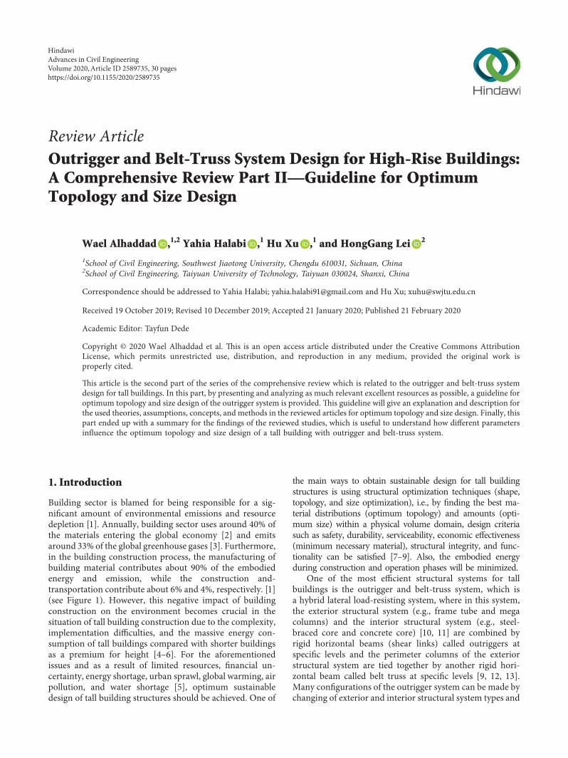
Building sector is blamed for being responsible for a sig-nificant amount of environmental emissions and resourcedepletion [1]. Annually, building sector uses around 40% ofthe materials entering the global economy [2] and emitsaround 33% of the global greenhouse gases [3]. Furthermore,in the building construction process, the manufacturing ofbuilding material contributes about 90% of the embodiedenergy and emission, while the construction and-transportation contribute about 6% and 4%, respectively. [1](see Figure 1). However, this negative impact of buildingconstruction on the environment becomes crucial in thesituation of tall building construction due to the complexity,implementation difficulties, and the massive energy con-sumption of tall buildings compared with shorter buildingsas a premium for height [4–6]. For the aforementionedissues and as a result of limited resources, financial un-certainty, energy shortage, urban sprawl, global warming, airpollution, and water shortage [5], optimum sustainabledesign of tall building structures should be achieved. One of
the main ways to obtain sustainable design for tall buildingstructures is using structural optimization techniques (shape,topology, and size optimization), i.e., by finding the best ma-terial distributions (optimum topology) and amounts (opti-mum size) within a physical volume domain, design criteriasuch as safety, durability, serviceability, economic effectiveness(minimum necessary material), structural integrity, and func-tionality can be satisfied [7–9]. Also, the embodied energyduring construction and operation phases will be minimized.
One of the most efficient structural systems for tallbuildings is the outrigger and belt-truss system, which isa hybrid lateral load-resisting system, where in this system,the exterior structural system (e.g., frame tube and megacolumns) and the interior structural system (e.g., steel-braced core and concrete core) [10, 11] are combined byrigid horizontal beams (shear links) called outriggers atspecific levels and the perimeter columns of the exteriorstructural system are tied together by another rigid hori-zontal beam called belt truss at specific levels [9, 12, 13].Many configurations of the outrigger system can be made bychanging of exterior and interior structural system types and
HindawiAdvances in Civil EngineeringVolume 2020, Article ID 2589735, 30 pageshttps://doi.org/10.1155/2020/2589735
structural system material, in addition to existence or ab-sence of one of the system components. -erefore, from thedefinition of the system and due to its multiple possibleconfigurations, the optimum topology and size design of theoutrigger and belt-truss system is essential in order to obtainan efficient and successful design.
In this paper, the optimum topology and size design ofthe outrigger and belt-truss system is discussed. Definitionof the topology and size terms of the outrigger system isgiven in Section 2. Section 3 clarifies the procedures of theoptimization process. Sections 4–7 explain these proceduresin detail. Summary of the findings of the reviewed articles inaddition to the conclusion is presented in sections 8 and 9,respectively.
2. What are the Topology and Size of Outriggerand Belt-Truss System?
2.1. Topology. In general, the topology in structures refers tothe material distribution within the structural elements (incontinuum structures) or refers to spatial order and con-nectivity of the bars (in discrete structures such as trusses).However, the topology of the outrigger system, which istermed in this review, indicates to
(a) -e topology of outrigger system in overall structure,which in its turn means (i) the locations and numberof outriggers or/and belt-truss and (ii) the variouscombinations of the system components (outriggersystem configurations).
(b) -e topology of components themselves: (i) out-rigger topology (truss shape, wall, etc.); (ii) belt-trusstopology (truss shape, wall, etc.); (iii) interiorstructural system topology (core topology, e.g., steelframe-braced core or shear-wall core, etc.); and (iv)exterior structural system topology (e.g., moment-resisting frame, mega columns, etc.).
2.2. Size. -e outrigger and belt-truss system size indicatesthe material amount of the specific material distributions(topology) of this system, i.e., cross sections of outriggersystem components.
Topologies and sections of outrigger system componentsare mutually interacting, which makes the optimum designof this system a complicated indeterminate process.
In this paper, based on the aforementioned definitions ofthe topology and size of the outrigger and belt-truss system,many studies and articles were reviewed. -erefore, it should
be noted that some of the reviewed articles did not adopt thesedefinitions, and they studied topics such as outrigger loca-tions, outrigger numbers, and other issues, without clearlystating that the considered issue is a topology or size problem.
3. Procedures of Optimum Topology and SizeDesign for Outrigger and Belt-Truss System
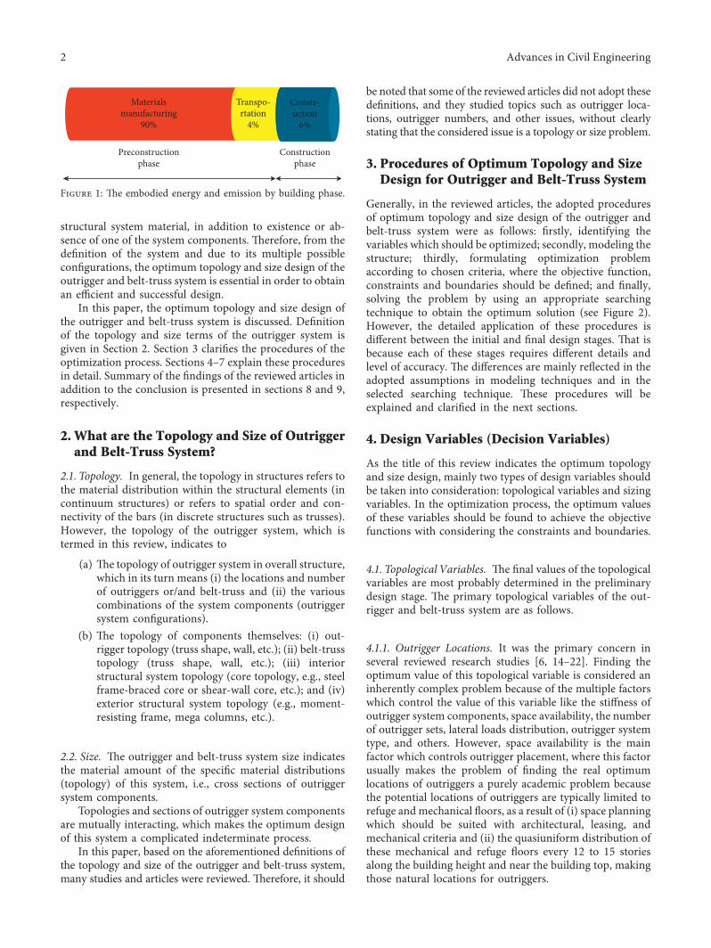
Generally, in the reviewed articles, the adopted proceduresof optimum topology and size design of the outrigger andbelt-truss system were as follows: firstly, identifying thevariables which should be optimized; secondly, modeling thestructure; thirdly, formulating optimization problemaccording to chosen criteria, where the objective function,constraints and boundaries should be defined; and finally,solving the problem by using an appropriate searchingtechnique to obtain the optimum solution (see Figure 2).However, the detailed application of these procedures isdifferent between the initial and final design stages. -at isbecause each of these stages requires different details andlevel of accuracy. -e differences are mainly reflected in theadopted assumptions in modeling techniques and in theselected searching technique. -ese procedures will beexplained and clarified in the next sections.
4. Design Variables (Decision Variables)
As the title of this review indicates the optimum topologyand size design, mainly two types of design variables shouldbe taken into consideration: topological variables and sizingvariables. In the optimization process, the optimum valuesof these variables should be found to achieve the objectivefunctions with considering the constraints and boundaries.
4.1. Topological Variables. -e final values of the topologicalvariables are most probably determined in the preliminarydesign stage. -e primary topological variables of the out-rigger and belt-truss system are as follows.
4.1.1. Outrigger Locations. It was the primary concern inseveral reviewed research studies [6, 14–22]. Finding theoptimum value of this topological variable is considered aninherently complex problem because of the multiple factorswhich control the value of this variable like the stiffness ofoutrigger system components, space availability, the numberof outrigger sets, lateral loads distribution, outrigger systemtype, and others. However, space availability is the mainfactor which controls outrigger placement, where this factorusually makes the problem of finding the real optimumlocations of outriggers a purely academic problem becausethe potential locations of outriggers are typically limited torefuge andmechanical floors, as a result of (i) space planningwhich should be suited with architectural, leasing, andmechanical criteria and (ii) the quasiuniform distribution ofthese mechanical and refuge floors every 12 to 15 storiesalong the building height and near the building top, makingthose natural locations for outriggers.
Constr-uction
6%
Transpo-rtation
4%
Materialsmanufacturing
90%
Preconstructionphase
Constructionphase
Figure 1: -e embodied energy and emission by building phase.
2 Advances in Civil Engineering
-erefore, the optimization problem becomes to bedetermining the optimum locations of the outrigger systembetween those potential locations, e.g., the optimum locationof outriggers in Suzhou Zhongnan center which is discussedin references [23–28]. However, acceptable performance canusually be achieved using these locations. In the situationthat the mechanical levels are not appropriate for outriggerplacement, such as in One Liberty Place in Philadelphia, theoptimum locations of outriggers can be found consideringthat each outrigger should be of several stories high (super-diagonal run through occupied space) in order to guaranteethat the obstructed width on any floor is less than one-quarter of the clear floor span. Tenants can conceal thesebraces behind partitions and cabinets with minimal influ-ence on floor functionality. Another solution is usinga virtual outrigger system. In all situations, any outriggerplacement strategy affecting occupied spaces must considerits likely acceptability in the local leasing environment [29].
4.1.2. Outrigger Numbers. It is an important factor whichdetermines the level of drift control and degree of stiffening,i.e., it drives the outrigger system effectiveness [6]. Outriggernumber is also limited by space availability and the efficiencyof the added outrigger, where the benefits of each addedoutrigger should be weighed against construction time andcost [22, 29]. To clarify that, more outrigger sets will lead to[29] (i) different optimum locations of outrigger sets; (ii)more opportunities for rotation restraint causing a reductionin drift; and (iii) more costs, time, effort for erection. In thesituation that the total material quantity of outriggers is
unchanged: (i) more outrigger sets will lead to distribute thetotal material quantity across more outriggers resulting inmore pieces for erection [29], while (ii) less outrigger setswill lead to involve fewer nontypical floors and minimizepiece counts, but the members will be too heavy; therefore,high-capacity and more costly erection equipment is re-quired. However, many studies referred that in most of thesituations, except super tall buildings, using more than fouroutriggers levels is not efficient because the improved per-formance of the structure will be very small compared withconstruction time and cost [22]. A lot of the reviewed studiesfound the optimum value of this variable in different situ-ations [15, 16, 20, 22, 30].
4.1.3. Core Topology. Core can be with different topologies,e.g., solid rigid walls, pure rigid frame, fully braced frame,partially and braced frame. -is variable was investigated inseveral research studies [16, 31]. In these studies, differenttopologies of the core were evaluated in the optimizationproblem in order to minimize the total cost of the structureand optimize the performance.
4.1.4. Outrigger and Belt-Truss Topologies. Outrigger andbelt truss can have different topologies from a fully solid wallor deep beam to any geometric shape of truss. -ese vari-ables have a direct impact on the provided ductility orstiffness to the structure by the outrigger and belt-trusssystem. Several reviewed articles studied [9, 32–35] theoptimum value of these variables by applying differentmethods.
4.1.5. Other Topological Variables. -e material type (steel,concrete, or composite) and even the grade of strength forthe same material (steel or concrete strength grade), whichare used to design and construct the outrigger system, canalso be considered as topological variables because eachmaterial has different behavior leading to different responseof the structure and thus different optimum design. -earticle of Chen et al. [19] is an example of the studies thattook this type of topological variables into consideration.
4.2. Sizing Variables. Sizing variables are critical variables toachieve the optimum design and obtain a reasonablestructural scheme. -is is because they have a very highimpact on the performance and cost of the structure. Also,these variables should have practical values which make theconstruction process possible and easier. Usually, sizingvariables take their approximate and initial values during thepreliminary design stage, whereas they take their final valuesduring the final design stage. -ese variables are representedby the section properties of outrigger and belt-truss systemcomponents, where the size of each component is repre-sented by the property which reflects the main role of thatcomponent, e.g., cross section areas for columns and secondmoment of inertia for core walls and outriggers. In order tomake the optimization process faster and easier, the numberof sizing variables can be reduced by assuming that the
Identifyingdesign variables
By using eithersimplified modeling
techniques or detailedmodeling
techniques
Modelingthe structure
For example,outrigger locations,
numbers, andcross sections
Formulatingoptimization problem
That is, objectivefunctions,
constraints, andboundaries
Solving the problemby using an appropriate
searching technique
For example, heuristic methods and
optimality criteriamethods
Figure 2: Procedures of optimum topology and size design foroutrigger and belt-truss system.
Advances in Civil Engineering 3
prementioned section properties are uniform or varyinglinearly or another known form along the building height.Several reviewed articles optimized these variables in theircase studies [6, 15, 16, 19, 20, 30, 36].
4.3. Other Related Variables. In the preliminary design stageof high-rise buildings, the ratio of the core wall area to thewhole floor area is a controlling factor, and it may beconsidered as an initial design variable, as in reference [37].Usually, this variable is represented in the design problem bythe distance from the edge of the core wall to the perimetercolumns, where in practical engineering, this distance re-flects the possible ratio of core wall area to the floor area [37].
5. Modeling Techniques
High-rise buildings are very complicated that even thedetailed computational models of these buildings are con-siderable simplifications, and the analysis results will alwaysbe approximate, which will have at best an equivalent qualityto the quality of the model and analysis method. However,modeling methods can be mainly classified into simplified(approximate) modeling methods and complex (detailed)modeling methods [38].
5.1. Detailed Modeling Techniques. In the final design stage,a high-fidelity model of the structure is required in order toconduct a three-dimensional analysis for taking full ad-vantage of the special interaction between different elementsof the structure, which can give a realistic simulation of theactual behavior of the building.-erefore, discrete modelingapproach, represented by the detailed finite element method(FEM), is the best choice for the detailed modeling of thestructure. In this approach, by using appropriate software,the structure is modeled as a three-dimensional model in-cluding all structural elements (core, columns, outriggers,belt truss, slabs, secondary beams, etc.). However, it takesmore time than the simplified modeling approaches[16, 17, 35, 38–41]. Several reviewed articles, such as[6, 7, 9, 12, 14–17, 30, 36, 38–61], adopted this approacheither as a primary modeling approach in their studies or tocheck the validity of the proposed simplified modelingmethods.
5.2. Simplified Modeling Techniques. Even though the de-tailed modeling techniques such as the finite element method(FEM) can provide a high-fidelity model, they cannot bea substitute for the simplified methods. -is is because of thenature of the simplified methods which may offer a betterunderstanding of the structural system behavior than FEM.Also, simplified modeling methods are fast and yield rea-sonably accurate design parameters if used correctly anda suitable set of assumptions is chosen. -e multiple featuresof the simplified methods make the use of these methods vitalduring the initial design stage in order to determine thegeneral design characteristics and initial parameters such asthe dimensions of members in rational values and during the
final design stage in order to check the computer analysisresults manually [12, 38, 40, 58, 59, 61–63].
For the outrigger and belt-truss system in tall structures,several simplified modeling techniques have been developedin the past decades [38], as follows.
5.2.1. Continuum Approach. In the literature, it has alsobeen termed “shear connection method,” “continuousmediummethod,” or “continuous connection method” [22].In this approach, the primary noncontinuous (discrete)structure, by using a set of assumptions, is modeled as anelastically equivalent continuous structure such as beammodel (one-dimensional analytical model based on beamtheory) [38, 53]. Usually, the continuum approach can beapplied to model the low and medium-rise buildings up to20 stories [64–69]. However, several reviewed articles usedthis approach tomodel the outrigger and belt-truss system intall buildings [12, 62, 70]. In these articles, based on thestudied configuration of the outrigger and belt-truss systemand the purpose of the study, the concept of the continuumapproach is applied as follows:
(i) In a multi-outrigger-braced structure or pair ofcoupled shear walls that is stiffened by a heavy beamand outrigger: the structure is simplified by as-suming that all horizontal connecting elements (theset of outriggers and the coupling beams) aresmeared along the building’s height in order toproduce an equivalent continuous connecting me-dium between the vertical elements (equivalentuniform bracing system or continuous distributionof lamina with equivalent stiffness) [22, 50, 71, 72].
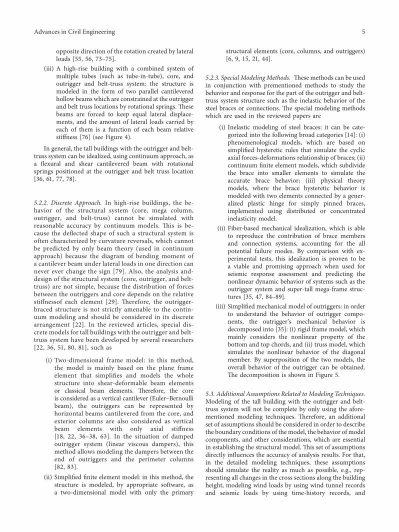
(ii) A high-rise building with a combined system ofsingle tube (framed tube), core, and outrigger andbelt-truss system: in accordance with the classicalbeam theory and by employing the orthotropic boxbeam analogy method, the framed tube structure ismodeled as a cantilevered hollow section beam oforthotropic plates (equivalent membranes withequivalent properties). -is model consists of threemain components [59, 60, 62]: (i) two web panels(parallel to the lateral loads) represent the webframes; (ii) two flange panels (perpendicular to thelateral loads) represent the flange frames; (iii) fourcolumns at the four corners of the perimeter framerepresent the corner columns (see Figure 3). -esestructural elements are interconnected to eachother along the joints of the panels and connectedto the floor slabs at each floor level [62]. -e in-teraction between the outrigger system and shearcore under lateral loads on framed tube system ismodeled as rotating springs (bending spring withconstant rotational stiffness) at outrigger-belt trusslocation along the height of the structure. -ere-fore, the effect of outrigger, belt truss, and shearcore on the framed tube can be considered asa concentrated moment applied at belt truss andoutrigger location. -is moment acts in the
4 Advances in Civil Engineering
opposite direction of the rotation created by lateralloads [55, 56, 73–75].
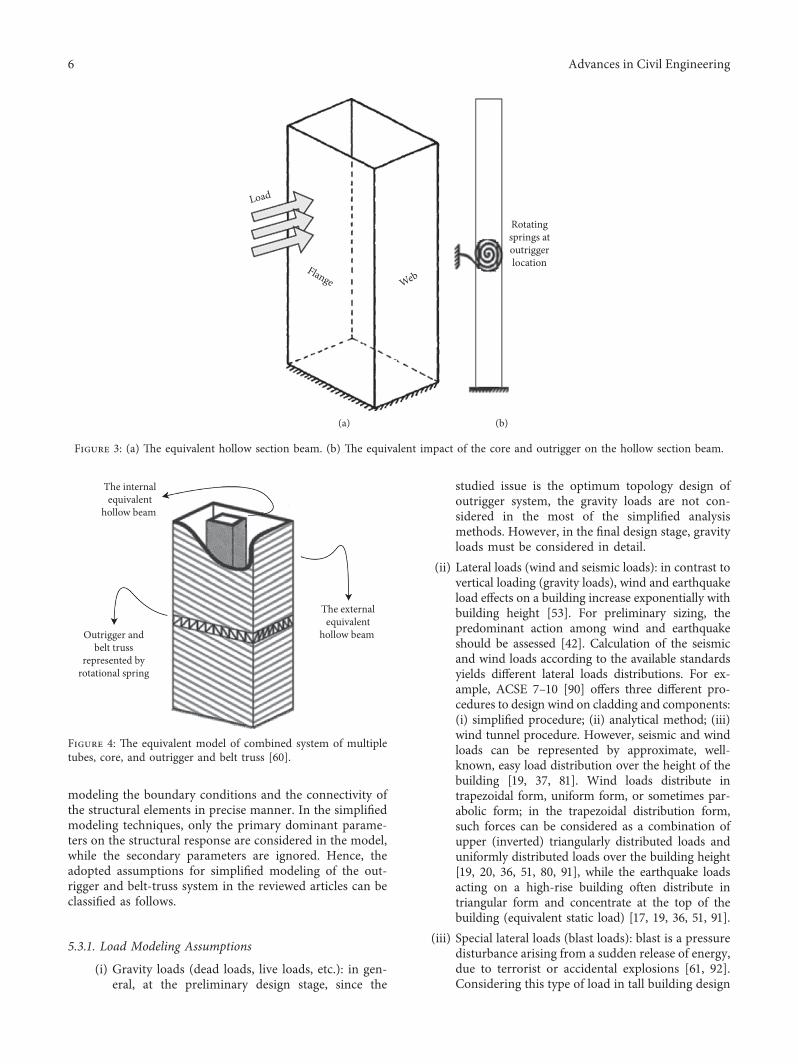
(iii) A high-rise building with a combined system ofmultiple tubes (such as tube-in-tube), core, andoutrigger and belt-truss system: the structure ismodeled in the form of two parallel cantileveredhollow beams which are constrained at the outriggerand belt truss locations by rotational springs. -esebeams are forced to keep equal lateral displace-ments, and the amount of lateral loads carried byeach of them is a function of each beam relativestiffness [76] (see Figure 4).
In general, the tall buildings with the outrigger and belt-truss system can be idealized, using continuum approach, asa flexural and shear cantilevered beam with rotationalsprings positioned at the outrigger and belt truss location[36, 61, 77, 78].
5.2.2. Discrete Approach. In high-rise buildings, the be-havior of the structural system (core, mega column,outrigger, and belt-truss) cannot be simulated withreasonable accuracy by continuum models. -is is be-cause the deflected shape of such a structural system isoften characterized by curvature reversals, which cannotbe predicted by only beam theory (used in continuumapproach) because the diagram of bending moment ofa cantilever beam under lateral loads in one direction cannever ever change the sign [79]. Also, the analysis and-design of the structural system (core, outrigger, and belt-truss) are not simple, because the distribution of forcesbetween the outriggers and core depends on the relativestiffnessof each element [29]. -erefore, the outrigger-braced structure is not strictly amenable to the contin-uum modeling and should be considered in its discretearrangement [22]. In the reviewed articles, special dis-crete models for tall buildings with the outrigger and belt-truss system have been developed by several researchers[22, 36, 51, 80, 81], such as
(i) Two-dimensional frame model: in this method,the model is mainly based on the plane frameelement that simplifies and models the wholestructure into shear-deformable beam elementsor classical beam elements. -erefore, the coreis considered as a vertical cantilever (Euler–Bernoullibeam), the outriggers can be represented byhorizontal beams cantilevered from the core, andexterior columns are also considered as verticalbeam elements with only axial stiffness[18, 22, 36–38, 63]. In the situation of dampedoutrigger system (linear viscous dampers), thismethod allows modeling the dampers between theend of outriggers and the perimeter columns[82, 83].
(ii) Simplified finite element model: in this method, thestructure is modeled, by appropriate software, asa two-dimensional model with only the primary
structural elements (core, columns, and outriggers)[6, 9, 15, 21, 44].
5.2.3. Special ModelingMethods. -ese methods can be usedin conjunction with prementioned methods to study thebehavior and response for the part of the outrigger and belt-truss system structure such as the inelastic behavior of thesteel braces or connections. -e special modeling methodswhich are used in the reviewed papers are
(i) Inelastic modeling of steel braces: it can be cate-gorized into the following broad categories [14]: (i)phenomenological models, which are based onsimplified hysteretic rules that simulate the cyclicaxial forces-deformations relationship of braces; (ii)continuum finite element models, which subdividethe brace into smaller elements to simulate theaccurate brace behavior; (iii) physical theorymodels, where the brace hysteretic behavior ismodeled with two elements connected by a gener-alized plastic hinge for simply pinned braces,implemented using distributed or concentratedinelasticity model.
(ii) Fiber-based mechanical idealization, which is ableto reproduce the contribution of brace membersand connection systems, accounting for the allpotential failure modes. By comparison with ex-perimental tests, this idealization is proven to bea viable and promising approach when used forseismic response assessment and predicting thenonlinear dynamic behavior of systems such as theoutrigger system and super-tall mega-frame struc-tures [35, 47, 84–89].
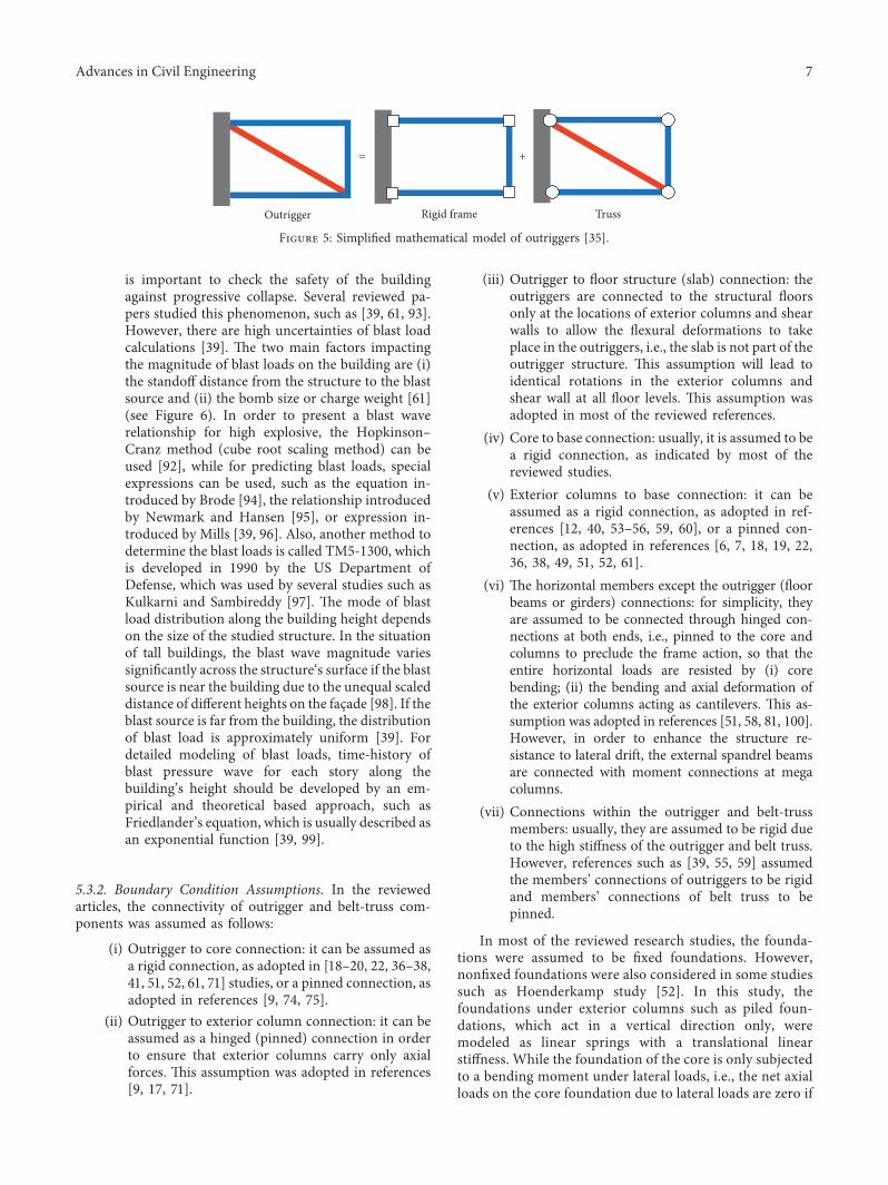
(iii) Simplified mechanical model of outriggers: in orderto understand the behavior of outrigger compo-nents, the outrigger’s mechanical behavior isdecomposed into [35]: (i) rigid frame model, whichmainly considers the nonlinear property of thebottom and top chords, and (ii) truss model, whichsimulates the nonlinear behavior of the diagonalmember. By superposition of the two models, theoverall behavior of the outrigger can be obtained.-e decomposition is shown in Figure 5.
5.3. Additional Assumptions Related to Modeling Techniques.Modeling of the tall building with the outrigger and belt-truss system will not be complete by only using the afore-mentioned modeling techniques. -erefore, an additionalset of assumptions should be considered in order to describethe boundary conditions of the model, the behavior of modelcomponents, and other considerations, which are essentialin establishing the structural model. -is set of assumptionsdirectly influences the accuracy of analysis results. For that,in the detailed modeling techniques, these assumptionsshould simulate the reality as much as possible, e.g., rep-resenting all changes in the cross sections along the buildingheight, modeling wind loads by using wind tunnel recordsand seismic loads by using time-history records, and
Advances in Civil Engineering 5
modeling the boundary conditions and the connectivity ofthe structural elements in precise manner. In the simplifiedmodeling techniques, only the primary dominant parame-ters on the structural response are considered in the model,while the secondary parameters are ignored. Hence, theadopted assumptions for simplified modeling of the out-rigger and belt-truss system in the reviewed articles can beclassified as follows.
5.3.1. Load Modeling Assumptions
(i) Gravity loads (dead loads, live loads, etc.): in gen-eral, at the preliminary design stage, since the
studied issue is the optimum topology design ofoutrigger system, the gravity loads are not con-sidered in the most of the simplified analysismethods. However, in the final design stage, gravityloads must be considered in detail.
(ii) Lateral loads (wind and seismic loads): in contrast tovertical loading (gravity loads), wind and earthquakeload effects on a building increase exponentially withbuilding height [53]. For preliminary sizing, thepredominant action among wind and earthquakeshould be assessed [42]. Calculation of the seismicand wind loads according to the available standardsyields different lateral loads distributions. For ex-ample, ACSE 7–10 [90] offers three different pro-cedures to design wind on cladding and components:(i) simplified procedure; (ii) analytical method; (iii)wind tunnel procedure. However, seismic and windloads can be represented by approximate, well-known, easy load distribution over the height of thebuilding [19, 37, 81]. Wind loads distribute intrapezoidal form, uniform form, or sometimes par-abolic form; in the trapezoidal distribution form,such forces can be considered as a combination ofupper (inverted) triangularly distributed loads anduniformly distributed loads over the building height[19, 20, 36, 51, 80, 91], while the earthquake loadsacting on a high-rise building often distribute intriangular form and concentrate at the top of thebuilding (equivalent static load) [17, 19, 36, 51, 91].
(iii) Special lateral loads (blast loads): blast is a pressuredisturbance arising from a sudden release of energy,due to terrorist or accidental explosions [61, 92].Considering this type of load in tall building design
Load
Flange Web
(a)
Rotatingsprings atoutriggerlocation
(b)
Figure 3: (a) -e equivalent hollow section beam. (b) -e equivalent impact of the core and outrigger on the hollow section beam.
Outrigger andbelt truss
represented byrotational spring
The externalequivalent
hollow beam
The internalequivalent
hollow beam
Figure 4: -e equivalent model of combined system of multipletubes, core, and outrigger and belt truss [60].
6 Advances in Civil Engineering
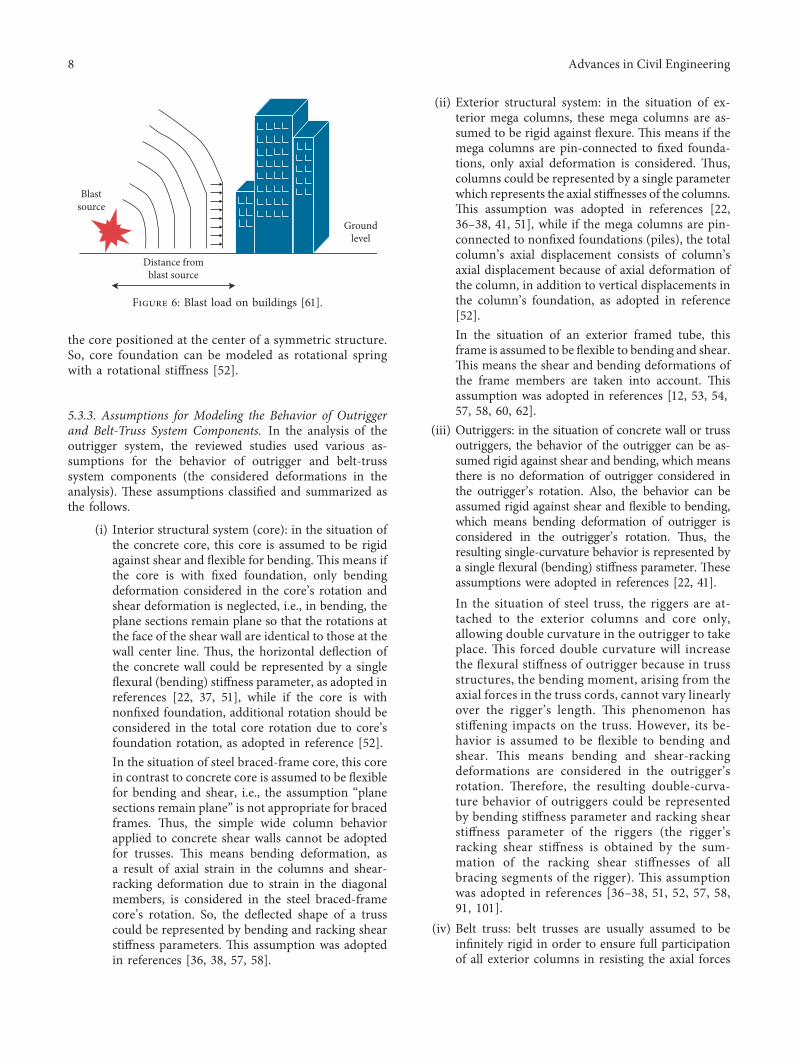
is important to check the safety of the buildingagainst progressive collapse. Several reviewed pa-pers studied this phenomenon, such as [39, 61, 93].However, there are high uncertainties of blast loadcalculations [39]. -e two main factors impactingthe magnitude of blast loads on the building are (i)the standoff distance from the structure to the blastsource and (ii) the bomb size or charge weight [61](see Figure 6). In order to present a blast waverelationship for high explosive, the Hopkinson–Cranz method (cube root scaling method) can beused [92], while for predicting blast loads, specialexpressions can be used, such as the equation in-troduced by Brode [94], the relationship introducedby Newmark and Hansen [95], or expression in-troduced by Mills [39, 96]. Also, another method todetermine the blast loads is called TM5-1300, whichis developed in 1990 by the US Department ofDefense, which was used by several studies such asKulkarni and Sambireddy [97]. -e mode of blastload distribution along the building height dependson the size of the studied structure. In the situationof tall buildings, the blast wave magnitude variessignificantly across the structure‘s surface if the blastsource is near the building due to the unequal scaleddistance of different heights on the façade [98]. If theblast source is far from the building, the distributionof blast load is approximately uniform [39]. Fordetailed modeling of blast loads, time-history ofblast pressure wave for each story along thebuilding’s height should be developed by an em-pirical and theoretical based approach, such asFriedlander’s equation, which is usually described asan exponential function [39, 99].
5.3.2. Boundary Condition Assumptions. In the reviewedarticles, the connectivity of outrigger and belt-truss com-ponents was assumed as follows:
(i) Outrigger to core connection: it can be assumed asa rigid connection, as adopted in [18–20, 22, 36–38,41, 51, 52, 61, 71] studies, or a pinned connection, asadopted in references [9, 74, 75].
(ii) Outrigger to exterior column connection: it can beassumed as a hinged (pinned) connection in orderto ensure that exterior columns carry only axialforces. -is assumption was adopted in references[9, 17, 71].
(iii) Outrigger to floor structure (slab) connection: theoutriggers are connected to the structural floorsonly at the locations of exterior columns and shearwalls to allow the flexural deformations to takeplace in the outriggers, i.e., the slab is not part of theoutrigger structure. -is assumption will lead toidentical rotations in the exterior columns andshear wall at all floor levels. -is assumption wasadopted in most of the reviewed references.
(iv) Core to base connection: usually, it is assumed to bea rigid connection, as indicated by most of thereviewed studies.
(v) Exterior columns to base connection: it can beassumed as a rigid connection, as adopted in ref-erences [12, 40, 53–56, 59, 60], or a pinned con-nection, as adopted in references [6, 7, 18, 19, 22,36, 38, 49, 51, 52, 61].
(vi) -e horizontal members except the outrigger (floorbeams or girders) connections: for simplicity, theyare assumed to be connected through hinged con-nections at both ends, i.e., pinned to the core andcolumns to preclude the frame action, so that theentire horizontal loads are resisted by (i) corebending; (ii) the bending and axial deformation ofthe exterior columns acting as cantilevers. -is as-sumption was adopted in references [51, 58, 81, 100].However, in order to enhance the structure re-sistance to lateral drift, the external spandrel beamsare connected with moment connections at megacolumns.
(vii) Connections within the outrigger and belt-trussmembers: usually, they are assumed to be rigid dueto the high stiffness of the outrigger and belt truss.However, references such as [39, 55, 59] assumedthe members’ connections of outriggers to be rigidand members’ connections of belt truss to bepinned.
In most of the reviewed research studies, the founda-tions were assumed to be fixed foundations. However,nonfixed foundations were also considered in some studiessuch as Hoenderkamp study [52]. In this study, thefoundations under exterior columns such as piled foun-dations, which act in a vertical direction only, weremodeled as linear springs with a translational linearstiffness. While the foundation of the core is only subjectedto a bending moment under lateral loads, i.e., the net axialloads on the core foundation due to lateral loads are zero if
= +
Outrigger Rigid frame Truss
Figure 5: Simplified mathematical model of outriggers [35].
Advances in Civil Engineering 7
the core positioned at the center of a symmetric structure.So, core foundation can be modeled as rotational springwith a rotational stiffness [52].
5.3.3. Assumptions for Modeling the Behavior of Outriggerand Belt-Truss System Components. In the analysis of theoutrigger system, the reviewed studies used various as-sumptions for the behavior of outrigger and belt-trusssystem components (the considered deformations in theanalysis). -ese assumptions classified and summarized asthe follows.
(i) Interior structural system (core): in the situation ofthe concrete core, this core is assumed to be rigidagainst shear and flexible for bending. -is means ifthe core is with fixed foundation, only bendingdeformation considered in the core’s rotation andshear deformation is neglected, i.e., in bending, theplane sections remain plane so that the rotations atthe face of the shear wall are identical to those at thewall center line. -us, the horizontal deflection ofthe concrete wall could be represented by a singleflexural (bending) stiffness parameter, as adopted inreferences [22, 37, 51], while if the core is withnonfixed foundation, additional rotation should beconsidered in the total core rotation due to core’sfoundation rotation, as adopted in reference [52].In the situation of steel braced-frame core, this corein contrast to concrete core is assumed to be flexiblefor bending and shear, i.e., the assumption “planesections remain plane” is not appropriate for bracedframes. -us, the simple wide column behaviorapplied to concrete shear walls cannot be adoptedfor trusses. -is means bending deformation, asa result of axial strain in the columns and shear-racking deformation due to strain in the diagonalmembers, is considered in the steel braced-framecore’s rotation. So, the deflected shape of a trusscould be represented by bending and racking shearstiffness parameters. -is assumption was adoptedin references [36, 38, 57, 58].
(ii) Exterior structural system: in the situation of ex-terior mega columns, these mega columns are as-sumed to be rigid against flexure. -is means if themega columns are pin-connected to fixed founda-tions, only axial deformation is considered. -us,columns could be represented by a single parameterwhich represents the axial stiffnesses of the columns.-is assumption was adopted in references [22,36–38, 41, 51], while if the mega columns are pin-connected to nonfixed foundations (piles), the totalcolumn’s axial displacement consists of column’saxial displacement because of axial deformation ofthe column, in addition to vertical displacements inthe column’s foundation, as adopted in reference[52].In the situation of an exterior framed tube, thisframe is assumed to be flexible to bending and shear.-is means the shear and bending deformations ofthe frame members are taken into account. -isassumption was adopted in references [12, 53, 54,57, 58, 60, 62].
(iii) Outriggers: in the situation of concrete wall or trussoutriggers, the behavior of the outrigger can be as-sumed rigid against shear and bending, which meansthere is no deformation of outrigger considered inthe outrigger’s rotation. Also, the behavior can beassumed rigid against shear and flexible to bending,which means bending deformation of outrigger isconsidered in the outrigger’s rotation. -us, theresulting single-curvature behavior is represented bya single flexural (bending) stiffness parameter. -eseassumptions were adopted in references [22, 41].In the situation of steel truss, the riggers are at-tached to the exterior columns and core only,allowing double curvature in the outrigger to takeplace. -is forced double curvature will increasethe flexural stiffness of outrigger because in trussstructures, the bending moment, arising from theaxial forces in the truss cords, cannot vary linearlyover the rigger’s length. -is phenomenon hasstiffening impacts on the truss. However, its be-havior is assumed to be flexible to bending andshear. -is means bending and shear-rackingdeformations are considered in the outrigger’srotation. -erefore, the resulting double-curva-ture behavior of outriggers could be representedby bending stiffness parameter and racking shearstiffness parameter of the riggers (the rigger’sracking shear stiffness is obtained by the sum-mation of the racking shear stiffnesses of allbracing segments of the rigger). -is assumptionwas adopted in references [36–38, 51, 52, 57, 58,91, 101].
(iv) Belt truss: belt trusses are usually assumed to beinfinitely rigid in order to ensure full participationof all exterior columns in resisting the axial forces
Blastsource
Groundlevel
Distance fromblast source
Figure 6: Blast load on buildings [61].
8 Advances in Civil Engineering
arising from the overturning moment, as assumedin references [18, 22, 41, 61, 74, 75, 100].
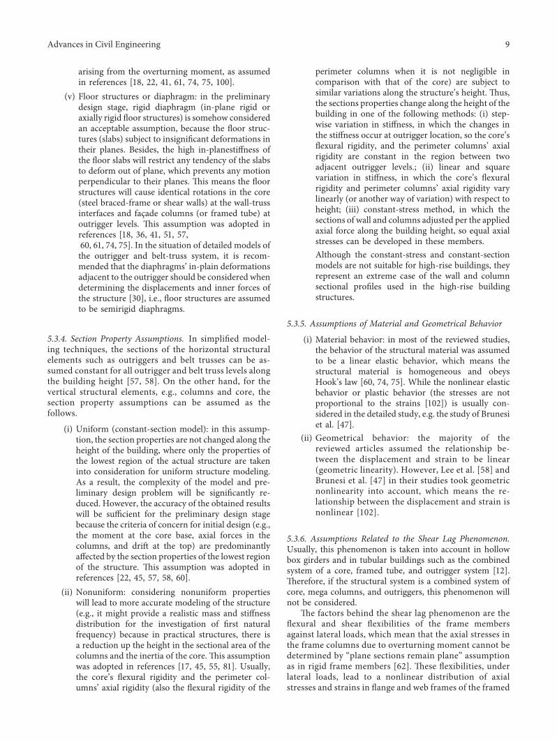
(v) Floor structures or diaphragm: in the preliminarydesign stage, rigid diaphragm (in-plane rigid oraxially rigid floor structures) is somehow consideredan acceptable assumption, because the floor struc-tures (slabs) subject to insignificant deformations intheir planes. Besides, the high in-planestiffness ofthe floor slabs will restrict any tendency of the slabsto deform out of plane, which prevents any motionperpendicular to their planes. -is means the floorstructures will cause identical rotations in the core(steel braced-frame or shear walls) at the wall-trussinterfaces and façade columns (or framed tube) atoutrigger levels. -is assumption was adopted inreferences [18, 36, 41, 51, 57,60, 61, 74, 75]. In the situation of detailed models ofthe outrigger and belt-truss system, it is recom-mended that the diaphragms’ in-plain deformationsadjacent to the outrigger should be considered whendetermining the displacements and inner forces ofthe structure [30], i.e., floor structures are assumedto be semirigid diaphragms.
5.3.4. Section Property Assumptions. In simplified model-ing techniques, the sections of the horizontal structuralelements such as outriggers and belt trusses can be as-sumed constant for all outrigger and belt truss levels alongthe building height [57, 58]. On the other hand, for thevertical structural elements, e.g., columns and core, thesection property assumptions can be assumed as thefollows.
(i) Uniform (constant-section model): in this assump-tion, the section properties are not changed along theheight of the building, where only the properties ofthe lowest region of the actual structure are takeninto consideration for uniform structure modeling.As a result, the complexity of the model and pre-liminary design problem will be significantly re-duced. However, the accuracy of the obtained resultswill be sufficient for the preliminary design stagebecause the criteria of concern for initial design (e.g.,the moment at the core base, axial forces in thecolumns, and drift at the top) are predominantlyaffected by the section properties of the lowest regionof the structure. -is assumption was adopted inreferences [22, 45, 57, 58, 60].
(ii) Nonuniform: considering nonuniform propertieswill lead to more accurate modeling of the structure(e.g., it might provide a realistic mass and stiffnessdistribution for the investigation of first naturalfrequency) because in practical structures, there isa reduction up the height in the sectional area of thecolumns and the inertia of the core. -is assumptionwas adopted in references [17, 45, 55, 81]. Usually,the core’s flexural rigidity and the perimeter col-umns’ axial rigidity (also the flexural rigidity of the
perimeter columns when it is not negligible incomparison with that of the core) are subject tosimilar variations along the structure’s height. -us,the sections properties change along the height of thebuilding in one of the following methods: (i) step-wise variation in stiffness, in which the changes inthe stiffness occur at outrigger location, so the core’sflexural rigidity, and the perimeter columns’ axialrigidity are constant in the region between twoadjacent outrigger levels.; (ii) linear and squarevariation in stiffness, in which the core’s flexuralrigidity and perimeter columns’ axial rigidity varylinearly (or another way of variation) with respect toheight; (iii) constant-stress method, in which thesections of wall and columns adjusted per the appliedaxial force along the building height, so equal axialstresses can be developed in these members.Although the constant-stress and constant-sectionmodels are not suitable for high-rise buildings, theyrepresent an extreme case of the wall and columnsectional profiles used in the high-rise buildingstructures.
5.3.5. Assumptions of Material and Geometrical Behavior
(i) Material behavior: in most of the reviewed studies,the behavior of the structural material was assumedto be a linear elastic behavior, which means thestructural material is homogeneous and obeysHook’s law [60, 74, 75]. While the nonlinear elasticbehavior or plastic behavior (the stresses are notproportional to the strains [102]) is usually con-sidered in the detailed study, e.g. the study of Brunesiet al. [47].
(ii) Geometrical behavior: the majority of thereviewed articles assumed the relationship be-tween the displacement and strain to be linear(geometric linearity). However, Lee et al. [58] andBrunesi et al. [47] in their studies took geometricnonlinearity into account, which means the re-lationship between the displacement and strain isnonlinear [102].
5.3.6. Assumptions Related to the Shear Lag Phenomenon.Usually, this phenomenon is taken into account in hollowbox girders and in tubular buildings such as the combinedsystem of a core, framed tube, and outrigger system [12].-erefore, if the structural system is a combined system ofcore, mega columns, and outriggers, this phenomenon willnot be considered.
-e factors behind the shear lag phenomenon are theflexural and shear flexibilities of the frame membersagainst lateral loads, which mean that the axial stresses inthe frame columns due to overturning moment cannot bedetermined by “plane sections remain plane” assumptionas in rigid frame members [62]. -ese flexibilities, underlateral loads, lead to a nonlinear distribution of axialstresses and strains in flange and web frames of the framed
Advances in Civil Engineering 9
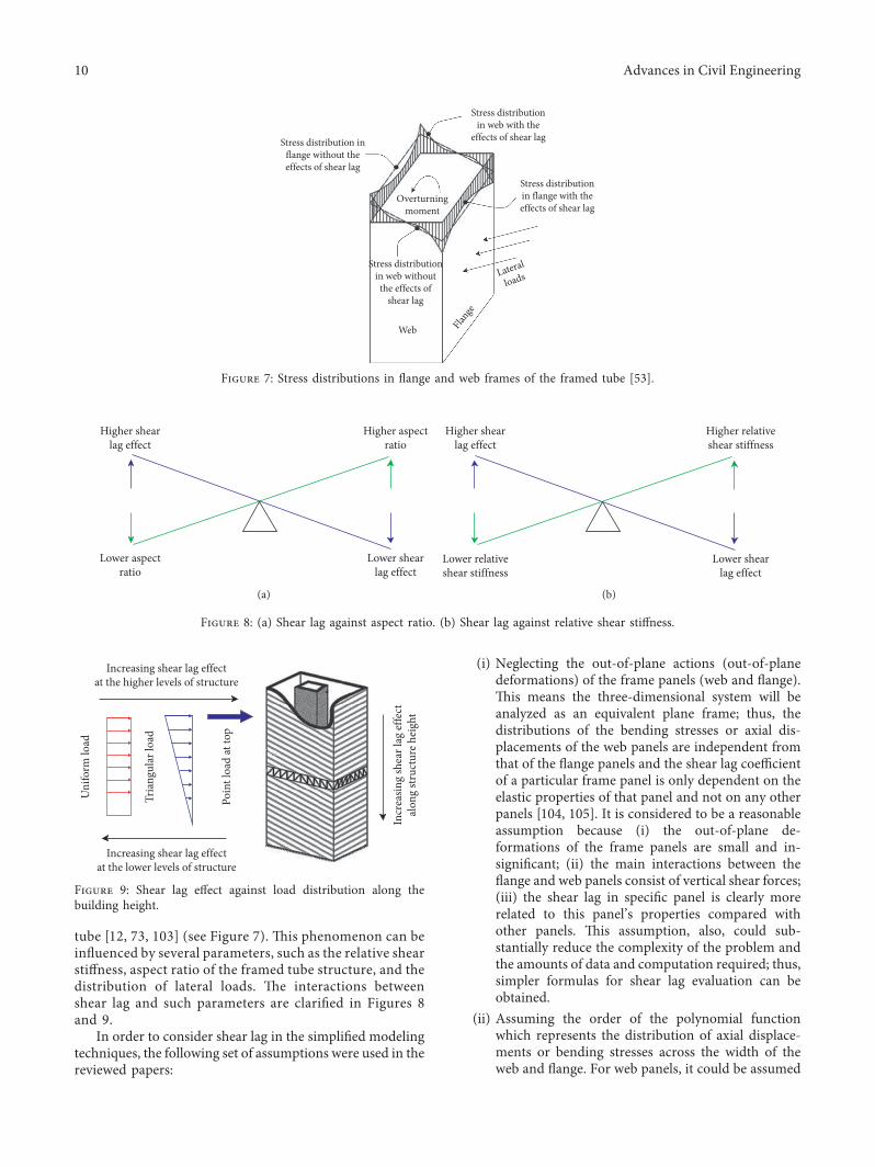
tube [12, 73, 103] (see Figure 7). -is phenomenon can beinfluenced by several parameters, such as the relative shearstiffness, aspect ratio of the framed tube structure, and thedistribution of lateral loads. -e interactions betweenshear lag and such parameters are clarified in Figures 8and 9.
In order to consider shear lag in the simplified modelingtechniques, the following set of assumptions were used in thereviewed papers:
(i) Neglecting the out-of-plane actions (out-of-planedeformations) of the frame panels (web and flange).-is means the three-dimensional system will beanalyzed as an equivalent plane frame; thus, thedistributions of the bending stresses or axial dis-placements of the web panels are independent fromthat of the flange panels and the shear lag coefficientof a particular frame panel is only dependent on theelastic properties of that panel and not on any otherpanels [104, 105]. It is considered to be a reasonableassumption because (i) the out-of-plane de-formations of the frame panels are small and in-significant; (ii) the main interactions between theflange and web panels consist of vertical shear forces;(iii) the shear lag in specific panel is clearly morerelated to this panel’s properties compared withother panels. -is assumption, also, could sub-stantially reduce the complexity of the problem andthe amounts of data and computation required; thus,simpler formulas for shear lag evaluation can beobtained.
(ii) Assuming the order of the polynomial functionwhich represents the distribution of axial displace-ments or bending stresses across the width of theweb and flange. For web panels, it could be assumed
Web Flange
Lateral
loads
Stress distributionin web with the
effects of shear lag
Stress distributionin web without
the effects ofshear lag
Stress distributionin flange with theeffects of shear lag
Stress distribution inflange without theeffects of shear lag
Overturningmoment
Figure 7: Stress distributions in flange and web frames of the framed tube [53].
Higher shearlag effect
Lower aspectratio
Lower shearlag effect
Higher aspectratio
(a)
Higher shearlag effect
Lower relativeshear stiffness
Lower shearlag effect
Higher relativeshear stiffness
(b)
Figure 8: (a) Shear lag against aspect ratio. (b) Shear lag against relative shear stiffness.
Uni
form
load
Tria
ngul
ar lo
ad
Poin
t loa
d at
top
Increasing shear lag effectat the lower levels of structure
Increasing shear lag effectat the higher levels of structure
Incr
easin
g sh
ear l
ag ef
fect
alon
g str
uctu
re h
eigh
t
Figure 9: Shear lag effect against load distribution along thebuilding height.
10 Advances in Civil Engineering
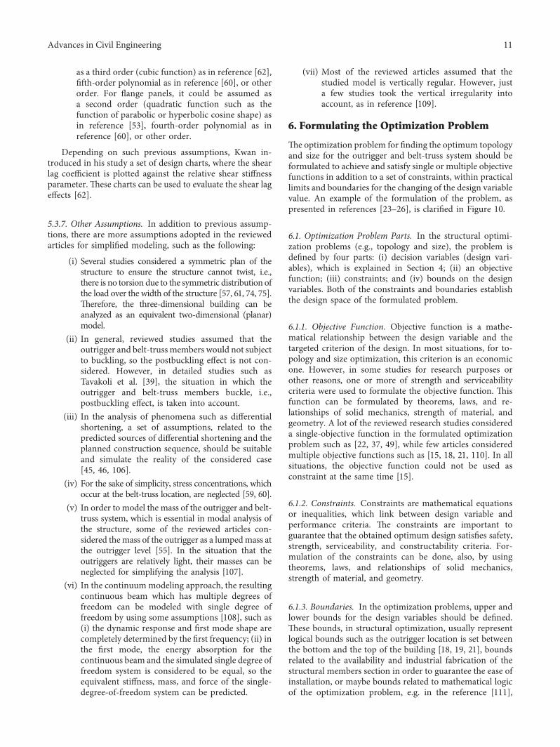
as a third order (cubic function) as in reference [62],fifth-order polynomial as in reference [60], or otherorder. For flange panels, it could be assumed asa second order (quadratic function such as thefunction of parabolic or hyperbolic cosine shape) asin reference [53], fourth-order polynomial as inreference [60], or other order.
Depending on such previous assumptions, Kwan in-troduced in his study a set of design charts, where the shearlag coefficient is plotted against the relative shear stiffnessparameter. -ese charts can be used to evaluate the shear lageffects [62].
5.3.7. Other Assumptions. In addition to previous assump-tions, there are more assumptions adopted in the reviewedarticles for simplified modeling, such as the following:
(i) Several studies considered a symmetric plan of thestructure to ensure the structure cannot twist, i.e.,there is no torsion due to the symmetric distribution ofthe load over the width of the structure [57, 61, 74, 75].-erefore, the three-dimensional building can beanalyzed as an equivalent two-dimensional (planar)model.
(ii) In general, reviewed studies assumed that theoutrigger and belt-truss members would not subjectto buckling, so the postbuckling effect is not con-sidered. However, in detailed studies such asTavakoli et al. [39], the situation in which theoutrigger and belt-truss members buckle, i.e.,postbuckling effect, is taken into account.
(iii) In the analysis of phenomena such as differentialshortening, a set of assumptions, related to thepredicted sources of differential shortening and theplanned construction sequence, should be suitableand simulate the reality of the considered case[45, 46, 106].
(iv) For the sake of simplicity, stress concentrations, whichoccur at the belt-truss location, are neglected [59, 60].
(v) In order to model the mass of the outrigger and belt-truss system, which is essential in modal analysis ofthe structure, some of the reviewed articles con-sidered themass of the outrigger as a lumpedmass atthe outrigger level [55]. In the situation that theoutriggers are relatively light, their masses can beneglected for simplifying the analysis [107].
(vi) In the continuummodeling approach, the resultingcontinuous beam which has multiple degrees offreedom can be modeled with single degree offreedom by using some assumptions [108], such as(i) the dynamic response and first mode shape arecompletely determined by the first frequency; (ii) inthe first mode, the energy absorption for thecontinuous beam and the simulated single degree offreedom system is considered to be equal, so theequivalent stiffness, mass, and force of the single-degree-of-freedom system can be predicted.
(vii) Most of the reviewed articles assumed that thestudied model is vertically regular. However, justa few studies took the vertical irregularity intoaccount, as in reference [109].
6. Formulating the Optimization Problem
-e optimization problem for finding the optimum topologyand size for the outrigger and belt-truss system should beformulated to achieve and satisfy single or multiple objectivefunctions in addition to a set of constraints, within practicallimits and boundaries for the changing of the design variablevalue. An example of the formulation of the problem, aspresented in references [23–26], is clarified in Figure 10.
6.1. Optimization Problem Parts. In the structural optimi-zation problems (e.g., topology and size), the problem isdefined by four parts: (i) decision variables (design vari-ables), which is explained in Section 4; (ii) an objectivefunction; (iii) constraints; and (iv) bounds on the designvariables. Both of the constraints and boundaries establishthe design space of the formulated problem.
6.1.1. Objective Function. Objective function is a mathe-matical relationship between the design variable and thetargeted criterion of the design. In most situations, for to-pology and size optimization, this criterion is an economicone. However, in some studies for research purposes orother reasons, one or more of strength and serviceabilitycriteria were used to formulate the objective function. -isfunction can be formulated by theorems, laws, and re-lationships of solid mechanics, strength of material, andgeometry. A lot of the reviewed research studies considereda single-objective function in the formulated optimizationproblem such as [22, 37, 49], while few articles consideredmultiple objective functions such as [15, 18, 21, 110]. In allsituations, the objective function could not be used asconstraint at the same time [15].
6.1.2. Constraints. Constraints are mathematical equationsor inequalities, which link between design variable andperformance criteria. -e constraints are important toguarantee that the obtained optimum design satisfies safety,strength, serviceability, and constructability criteria. For-mulation of the constraints can be done, also, by usingtheorems, laws, and relationships of solid mechanics,strength of material, and geometry.
6.1.3. Boundaries. In the optimization problems, upper andlower bounds for the design variables should be defined.-ese bounds, in structural optimization, usually representlogical bounds such as the outrigger location is set betweenthe bottom and the top of the building [18, 19, 21], boundsrelated to the availability and industrial fabrication of thestructural members section in order to guarantee the ease ofinstallation, or maybe bounds related to mathematical logicof the optimization problem, e.g. in the reference [111],
Advances in Civil Engineering 11
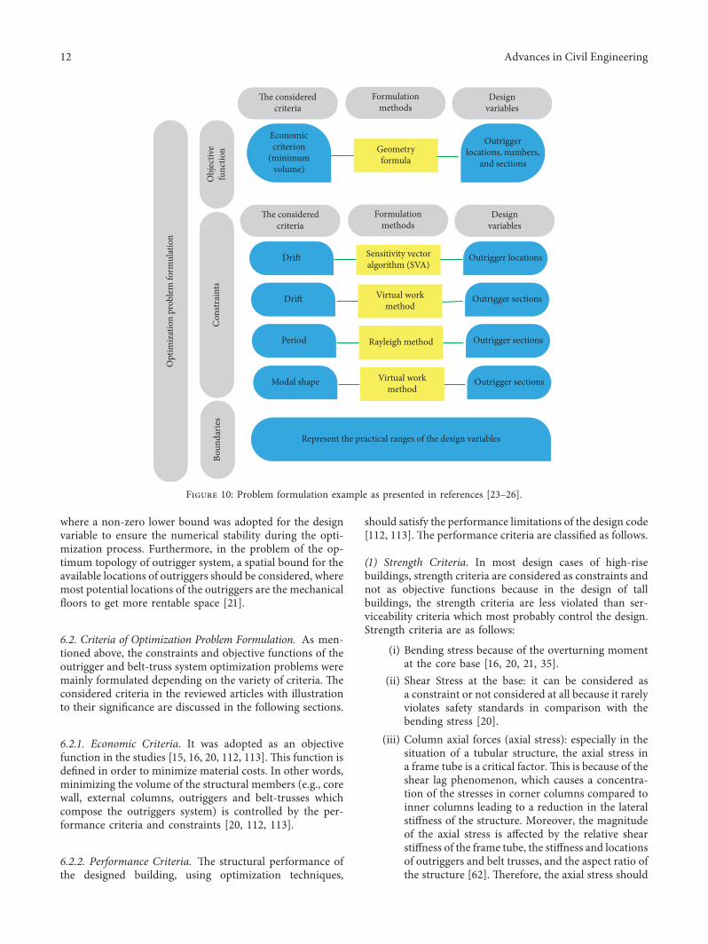
where a non-zero lower bound was adopted for the designvariable to ensure the numerical stability during the opti-mization process. Furthermore, in the problem of the op-timum topology of outrigger system, a spatial bound for theavailable locations of outriggers should be considered, wheremost potential locations of the outriggers are the mechanicalfloors to get more rentable space [21].
6.2. Criteria of Optimization Problem Formulation. As men-tioned above, the constraints and objective functions of theoutrigger and belt-truss system optimization problems weremainly formulated depending on the variety of criteria. -econsidered criteria in the reviewed articles with illustrationto their significance are discussed in the following sections.
6.2.1. Economic Criteria. It was adopted as an objectivefunction in the studies [15, 16, 20, 112, 113]. -is function isdefined in order to minimize material costs. In other words,minimizing the volume of the structural members (e.g., corewall, external columns, outriggers and belt-trusses whichcompose the outriggers system) is controlled by the per-formance criteria and constraints [20, 112, 113].
6.2.2. Performance Criteria. -e structural performance ofthe designed building, using optimization techniques,
should satisfy the performance limitations of the design code[112, 113]. -e performance criteria are classified as follows.
(1) Strength Criteria. In most design cases of high-risebuildings, strength criteria are considered as constraints andnot as objective functions because in the design of tallbuildings, the strength criteria are less violated than ser-viceability criteria which most probably control the design.Strength criteria are as follows:
(i) Bending stress because of the overturning momentat the core base [16, 20, 21, 35].
(ii) Shear Stress at the base: it can be considered asa constraint or not considered at all because it rarelyviolates safety standards in comparison with thebending stress [20].
(iii) Column axial forces (axial stress): especially in thesituation of a tubular structure, the axial stress ina frame tube is a critical factor.-is is because of theshear lag phenomenon, which causes a concentra-tion of the stresses in corner columns compared toinner columns leading to a reduction in the lateralstiffness of the structure. Moreover, the magnitudeof the axial stress is affected by the relative shearstiffness of the frame tube, the stiffness and locationsof outriggers and belt trusses, and the aspect ratio ofthe structure [62]. -erefore, the axial stress should
Economiccriterion
(minimumvolume)
Outriggerlocations, numbers,
and sections
Obj
ectiv
efu
nctio
n
The consideredcriteria
Designvariables
Formulationmethods
Geometryformula
Drift Outrigger locations
Con
strai
nts
The consideredcriteria
Designvariables
Formulationmethods
Sensitivity vectoralgorithm (SVA)
Drift Outrigger sectionsVirtual workmethod
Period Outrigger sectionsRayleigh method
Modal shape Outrigger sectionsVirtual workmethod
Represent the practical ranges of the design variables
Boun
darie
s
Opt
imiz
atio
n pr
oble
m fo
rmul
atio
n
Figure 10: Problem formulation example as presented in references [23–26].
12 Advances in Civil Engineering
be smoothed and decreased to be in the standards’limitations [16, 19, 53, 60].
(iv) Other criteria, e.g., static to seismic load ratios in thecritical braces at different floor levels, are consideredin the study [47].
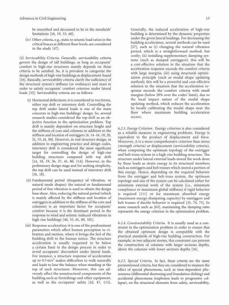
(2) Serviceability Criteria. Generally, serviceability criteriagovern the design of tall buildings, as long as occupants’comfort in high-rise structures mainly depends on thesecriteria to be satisfied. So, it is prevalent to categorize thedesignmethods of high-rise buildings as displacement-based[16]. Basically, serviceability criteria clarify the sufficiency ofthe structural system’s stiffness (or resilience) and mass inorder to satisfy occupants’ comfort criterion under lateralloads [35]. Serviceability criteria are as follows:
(i) Horizontal deflections: it is considered in two forms,either top drift or interstory drift. Controlling thetop drift under lateral loads is one of the mainconcerns in high-rise buildings’ design. So, severalresearch studies considered the top drift as an ob-jective function in the optimization problem. Topdrift is mainly dependent on structure height andthe stiffness of core and columns in addition to thestiffness and location of outriggers [6, 14–16, 18, 20,21, 55, 61, 80]. However, in real structure design, inaddition to engineering practice and design codes,interstory drift is considered the most significanttarget for controlling the design of high-risebuilding structures compared with top drift[14, 18, 19, 36, 37, 41, 80, 114]. However, in thepreliminary design stage and for seeking simplicity,the top drift can be used instead of interstory drift[16, 18].
(ii) Fundamental period (frequency of vibration, ornatural mode shapes): the natural or fundamentalperiod of free vibration is used to obtain the designbase shear. Also, reducing the natural period (whichis mainly affected by the stiffness and location ofoutriggers in addition to the stiffness of the core andcolumns) is an important factor for occupants’comfort because it is the dominant period in theresponse to wind and seismic-induced vibrations inhigh-rise buildings [40, 55, 61, 80, 101].
(iii) Response acceleration: it is one of the predominantparameters which affect human perception to vi-bration and motion, where it brings the feel of thebuilding drift to the human notice. -e structureacceleration is usually requested to be belowa certain limit in the design process in order toavoid occupants’ discomfort under lateral loads.For instance, a structure response of accelerationup to 0.5m/s2 makes difficulties to walk naturallyand leads to lose the balance when standing at thetop of such structures. Moreover, this can ad-versely affect the nonstructural components of thebuilding such as furnishings and other equipment,as well as the occupants’ safety [42, 47, 115].
Generally, the induced acceleration of high-risebuilding is determined by the dynamic propertiesunder the given lateral loadings. For decreasing thebuilding acceleration, several methods can be used[27], such as (i) changing the natural vibrationperiod, which is a straightforward method, butcostly; (ii) installing supplementary damping sys-tems (such as damped outriggers); this will bea cost-effective solution in the situation that theacceleration response exceeds the comfort criteriawith large margins; (iii) using structural optimi-zation principle (such as modal shape updatingmethod); this will be a powerful and cost-effectivesolution in the situation that the acceleration re-sponse exceeds the comfort criteria with smallmargins (below 20% over the codes’ limit), due tothe local impact nature of the modal shapeupdating method, which reduces the accelerationby locally calibrating the modal shape near thefloor where maximum building accelerationoccurs.
6.2.3. Energy Criterion. Energy criterion is also consideredas a reliable measure in engineering problems. Energy isequivalent to the product of displacement and force.Moreover, it is a more comprehensive criterion than stress(strength criteria) or displacement (serviceability criteria),when computing the optimum topology of the outriggerand belt-truss system in a high-rise building structure. -estructure under lateral external loads stored the work doneby these loads as strain energy in its structural memberssuch as outriggers and belt trusses which stored a portion ofthis energy. Hence, depending on the required behaviorfrom the outrigger and belt-truss system, the optimumtopology and size of the system can be calculated either forminimum external work of the system (i.e., minimumcompliance or maximum global stiffness) if rigid behavioris required [111] or for maximum absorbed energy(maximum energy-dissipating capacity) by outriggers andbelt trusses if ductile behavior is required [35, 74, 75]. Insome research such as [63], maximizing the damping ratiorepresents the energy criterion in the optimization problem.
6.2.4. Constructability Criteria. It is usually used as a con-straint in the optimization problem in order to ensure thatthe obtained optimum design is compatible with thepractical standards of high-rise building construction. Forexample, in two adjacent stories, this constraint can preventthe construction of columns with larger sections depths,above the columns with lower sections depths [16].
6.2.5. Special Criteria. In fact, these criteria are the sameprementioned criteria, but they are considered to measure theeffect of special phenomena, such as time-dependent phe-nomena (differential shortening and foundation dishing) andaccidental phenomena (explosion leads to progressive col-lapse), on the structural elements from safety, serviceability,
Advances in Civil Engineering 13
and economic viewpoints. However, these phenomena will bediscussed in detail in a special review by the authors.
(1) Differential Axial Shortening (DAS) and FoundationDishing (FD). As known, in tall buildings, the differences inthe stress between core and exterior columns lead to dif-ferent vertical shortening and settlements (especially forstructures built on compressible soil) between them whichaccumulate along the height of the structure and can developadverse impacts on the structural and nonstructuralmembers [45, 46]. It is important to understand axialshortening and foundation dishing behavior and reducetheir effects to (i) satisfy safety criteria (they can lead toredistribution for members forces, so stresses in outriggersmay increase 2 to 4 times [106]) and (ii) avoid serviceabilityfailures in tall buildings such as cracking of partitions andslabs and damage to lift guide rails and plumbing [106].Basically, DAS occurs due to time-dependent phenomenasuch as the short-term elastic shortening, in addition tolong-term inelastic shortening (creep and shrinkage), whichis an inevitable problem in concrete and composite tallbuildings. -erefore, with the increasing height of thestructures, these phenomena required special considerationin design and construction.
(2) Progressive Collapse. -is phenomenon occurs as a resultof a sudden loss for one or more of primary structuralmembers such as columns due to blast or other reasons.When this phenomenon is considered in the design, themain goal will be to find the optimum topology of theoutrigger system to prevent or mitigate the progressivecollapse and redesign the cross section of the adjacent el-ements to the expected failed column to achieve safety re-quirements [7, 39]. Progressive collapse issue and relatedproblems such as structure response to the blast loadingwere studied in several articles [116–121].
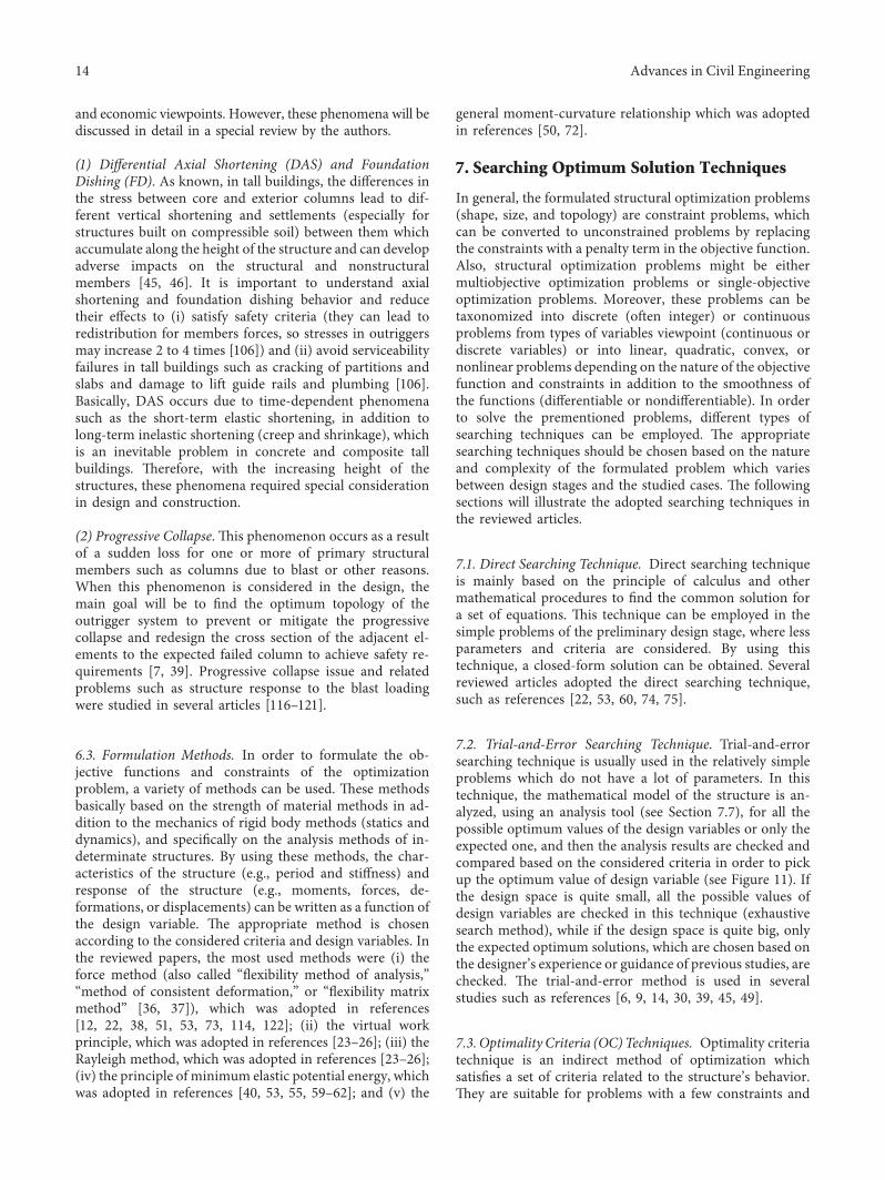
6.3. Formulation Methods. In order to formulate the ob-jective functions and constraints of the optimizationproblem, a variety of methods can be used. -ese methodsbasically based on the strength of material methods in ad-dition to the mechanics of rigid body methods (statics anddynamics), and specifically on the analysis methods of in-determinate structures. By using these methods, the char-acteristics of the structure (e.g., period and stiffness) andresponse of the structure (e.g., moments, forces, de-formations, or displacements) can be written as a function ofthe design variable. -e appropriate method is chosenaccording to the considered criteria and design variables. Inthe reviewed papers, the most used methods were (i) theforce method (also called “flexibility method of analysis,”“method of consistent deformation,” or “flexibility matrixmethod” [36, 37]), which was adopted in references[12, 22, 38, 51, 53, 73, 114, 122]; (ii) the virtual workprinciple, which was adopted in references [23–26]; (iii) theRayleigh method, which was adopted in references [23–26];(iv) the principle of minimum elastic potential energy, whichwas adopted in references [40, 53, 55, 59–62]; and (v) the
general moment-curvature relationship which was adoptedin references [50, 72].
7. Searching Optimum Solution Techniques
In general, the formulated structural optimization problems(shape, size, and topology) are constraint problems, whichcan be converted to unconstrained problems by replacingthe constraints with a penalty term in the objective function.Also, structural optimization problems might be eithermultiobjective optimization problems or single-objectiveoptimization problems. Moreover, these problems can betaxonomized into discrete (often integer) or continuousproblems from types of variables viewpoint (continuous ordiscrete variables) or into linear, quadratic, convex, ornonlinear problems depending on the nature of the objectivefunction and constraints in addition to the smoothness ofthe functions (differentiable or nondifferentiable). In orderto solve the prementioned problems, different types ofsearching techniques can be employed. -e appropriatesearching techniques should be chosen based on the natureand complexity of the formulated problem which variesbetween design stages and the studied cases. -e followingsections will illustrate the adopted searching techniques inthe reviewed articles.
7.1. Direct Searching Technique. Direct searching techniqueis mainly based on the principle of calculus and othermathematical procedures to find the common solution fora set of equations. -is technique can be employed in thesimple problems of the preliminary design stage, where lessparameters and criteria are considered. By using thistechnique, a closed-form solution can be obtained. Severalreviewed articles adopted the direct searching technique,such as references [22, 53, 60, 74, 75].
7.2. Trial-and-Error Searching Technique. Trial-and-errorsearching technique is usually used in the relatively simpleproblems which do not have a lot of parameters. In thistechnique, the mathematical model of the structure is an-alyzed, using an analysis tool (see Section 7.7), for all thepossible optimum values of the design variables or only theexpected one, and then the analysis results are checked andcompared based on the considered criteria in order to pickup the optimum value of design variable (see Figure 11). Ifthe design space is quite small, all the possible values ofdesign variables are checked in this technique (exhaustivesearch method), while if the design space is quite big, onlythe expected optimum solutions, which are chosen based onthe designer’s experience or guidance of previous studies, arechecked. -e trial-and-error method is used in severalstudies such as references [6, 9, 14, 30, 39, 45, 49].
7.3. Optimality Criteria (OC) Techniques. Optimality criteriatechnique is an indirect method of optimization whichsatisfies a set of criteria related to the structure’s behavior.-ey are suitable for problems with a few constraints and
14 Advances in Civil Engineering
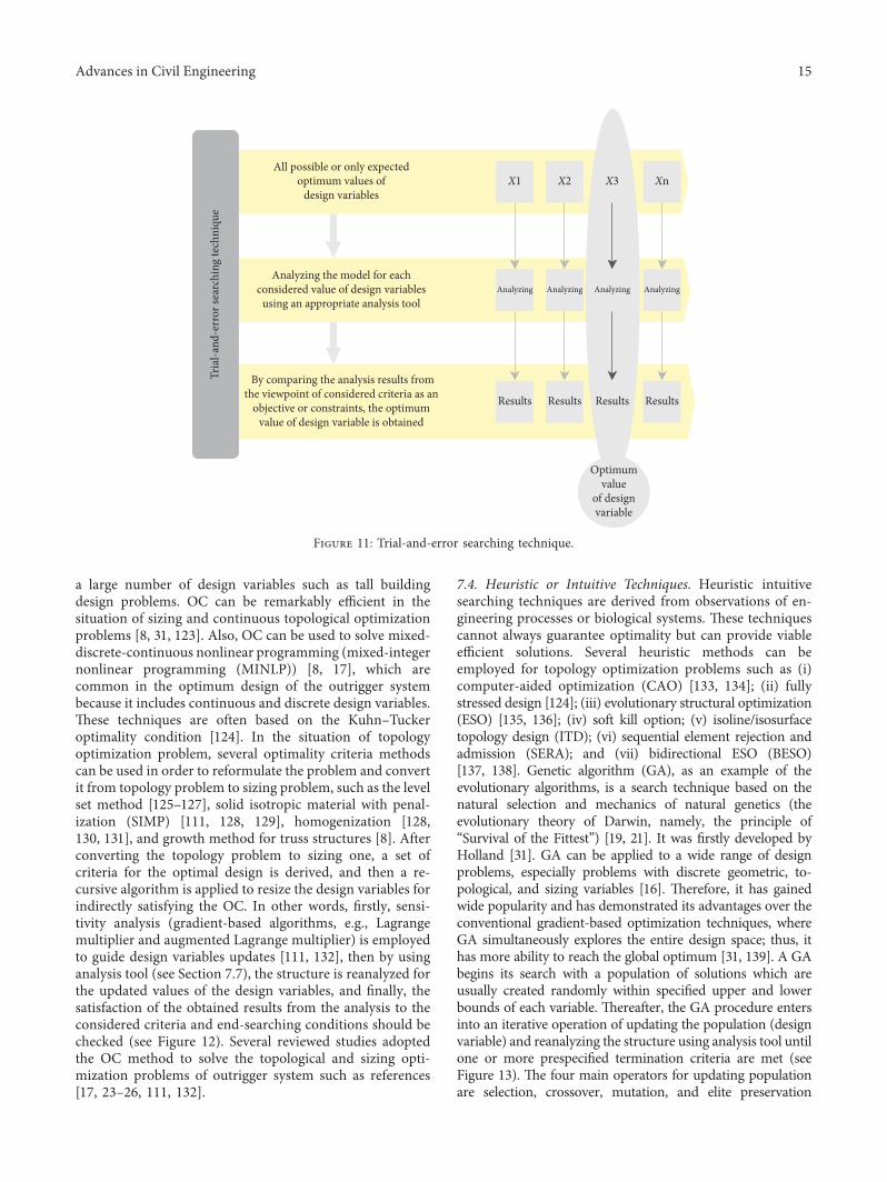
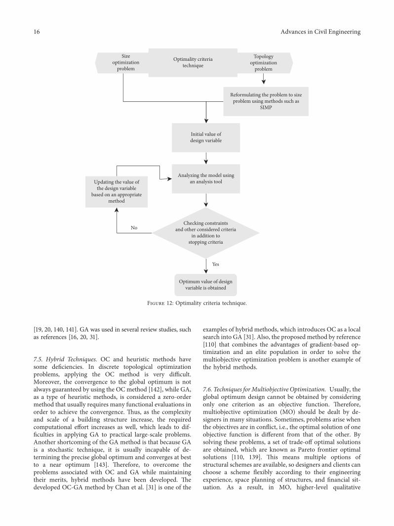
a large number of design variables such as tall buildingdesign problems. OC can be remarkably efficient in thesituation of sizing and continuous topological optimizationproblems [8, 31, 123]. Also, OC can be used to solve mixed-discrete-continuous nonlinear programming (mixed-integernonlinear programming (MINLP)) [8, 17], which arecommon in the optimum design of the outrigger systembecause it includes continuous and discrete design variables.-ese techniques are often based on the Kuhn–Tuckeroptimality condition [124]. In the situation of topologyoptimization problem, several optimality criteria methodscan be used in order to reformulate the problem and convertit from topology problem to sizing problem, such as the levelset method [125–127], solid isotropic material with penal-ization (SIMP) [111, 128, 129], homogenization [128,130, 131], and growth method for truss structures [8]. Afterconverting the topology problem to sizing one, a set ofcriteria for the optimal design is derived, and then a re-cursive algorithm is applied to resize the design variables forindirectly satisfying the OC. In other words, firstly, sensi-tivity analysis (gradient-based algorithms, e.g., Lagrangemultiplier and augmented Lagrange multiplier) is employedto guide design variables updates [111, 132], then by usinganalysis tool (see Section 7.7), the structure is reanalyzed forthe updated values of the design variables, and finally, thesatisfaction of the obtained results from the analysis to theconsidered criteria and end-searching conditions should bechecked (see Figure 12). Several reviewed studies adoptedthe OC method to solve the topological and sizing opti-mization problems of outrigger system such as references[17, 23–26, 111, 132].
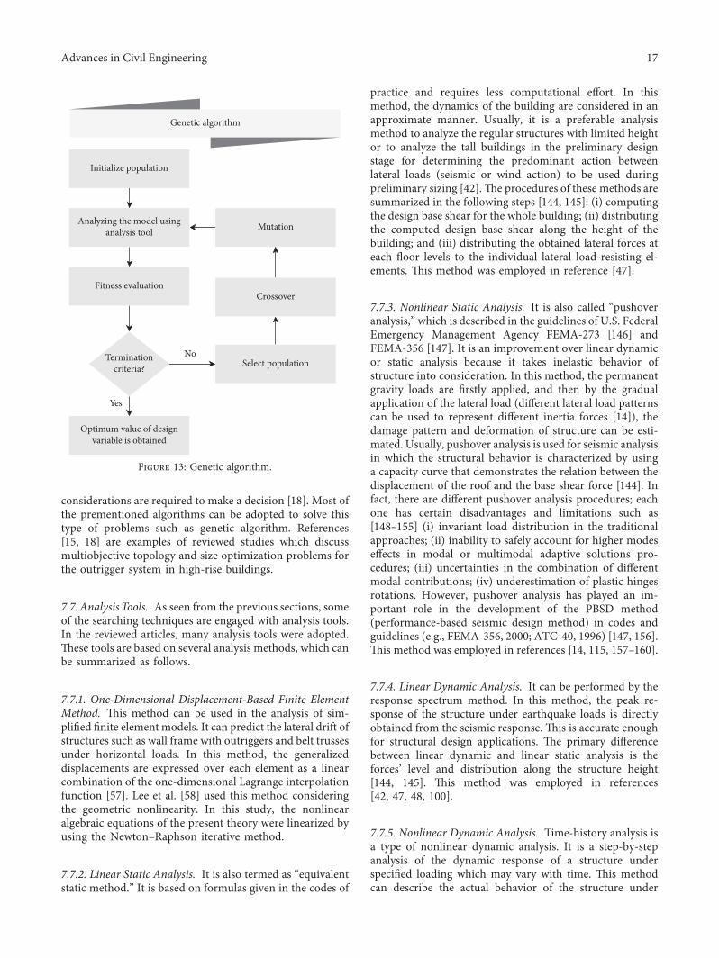
7.4. Heuristic or Intuitive Techniques. Heuristic intuitivesearching techniques are derived from observations of en-gineering processes or biological systems. -ese techniquescannot always guarantee optimality but can provide viableefficient solutions. Several heuristic methods can beemployed for topology optimization problems such as (i)computer-aided optimization (CAO) [133, 134]; (ii) fullystressed design [124]; (iii) evolutionary structural optimization(ESO) [135, 136]; (iv) soft kill option; (v) isoline/isosurfacetopology design (ITD); (vi) sequential element rejection andadmission (SERA); and (vii) bidirectional ESO (BESO)[137, 138]. Genetic algorithm (GA), as an example of theevolutionary algorithms, is a search technique based on thenatural selection and mechanics of natural genetics (theevolutionary theory of Darwin, namely, the principle of“Survival of the Fittest”) [19, 21]. It was firstly developed byHolland [31]. GA can be applied to a wide range of designproblems, especially problems with discrete geometric, to-pological, and sizing variables [16]. -erefore, it has gainedwide popularity and has demonstrated its advantages over theconventional gradient-based optimization techniques, whereGA simultaneously explores the entire design space; thus, ithas more ability to reach the global optimum [31, 139]. A GAbegins its search with a population of solutions which areusually created randomly within specified upper and lowerbounds of each variable. -ereafter, the GA procedure entersinto an iterative operation of updating the population (designvariable) and reanalyzing the structure using analysis tool untilone or more prespecified termination criteria are met (seeFigure 13). -e four main operators for updating populationare selection, crossover, mutation, and elite preservation
Tria
l-and
-err
or se
arch
ing
tech
niqu
e
All possible or only expectedoptimum values of
design variables
Analyzing the model for eachconsidered value of design variables
using an appropriate analysis tool
By comparing the analysis results fromthe viewpoint of considered criteria as an
objective or constraints, the optimumvalue of design variable is obtained
X1 X2 X3 Xn
Analyzing Analyzing Analyzing Analyzing
Results Results Results Results
Optimumvalue
of designvariable
Figure 11: Trial-and-error searching technique.
Advances in Civil Engineering 15
[19, 20, 140, 141]. GA was used in several review studies, suchas references [16, 20, 31].
7.5. Hybrid Techniques. OC and heuristic methods havesome deficiencies. In discrete topological optimizationproblems, applying the OC method is very difficult.Moreover, the convergence to the global optimum is notalways guaranteed by using the OCmethod [142], while GA,as a type of heuristic methods, is considered a zero-ordermethod that usually requires many functional evaluations inorder to achieve the convergence. -us, as the complexityand scale of a building structure increase, the requiredcomputational effort increases as well, which leads to dif-ficulties in applying GA to practical large-scale problems.Another shortcoming of the GA method is that because GAis a stochastic technique, it is usually incapable of de-termining the precise global optimum and converges at bestto a near optimum [143]. -erefore, to overcome theproblems associated with OC and GA while maintainingtheir merits, hybrid methods have been developed. -edeveloped OC-GA method by Chan et al. [31] is one of the
examples of hybrid methods, which introduces OC as a localsearch into GA [31]. Also, the proposed method by reference[110] that combines the advantages of gradient-based op-timization and an elite population in order to solve themultiobjective optimization problem is another example ofthe hybrid methods.
7.6. Techniques forMultiobjective Optimization. Usually, theglobal optimum design cannot be obtained by consideringonly one criterion as an objective function. -erefore,multiobjective optimization (MO) should be dealt by de-signers in many situations. Sometimes, problems arise whenthe objectives are in conflict, i.e., the optimal solution of oneobjective function is different from that of the other. Bysolving these problems, a set of trade-off optimal solutionsare obtained, which are known as Pareto frontier optimalsolutions [110, 139]. -is means multiple options ofstructural schemes are available, so designers and clients canchoose a scheme flexibly according to their engineeringexperience, space planning of structures, and financial sit-uation. As a result, in MO, higher-level qualitative
Optimality criteriatechnique
Sizeoptimization
problem
Topologyoptimization
problem
Reformulating the problem to sizeproblem using methods such as
SIMP
Initial value ofdesign variable
Analyzing the model usingan analysis tool
Checking constraintsand other considered criteria
in addition tostopping criteria
Optimum value of designvariable is obtained
Updating the value ofthe design variable
based on an appropriatemethod
No
Yes
Figure 12: Optimality criteria technique.
16 Advances in Civil Engineering
considerations are required to make a decision [18]. Most ofthe prementioned algorithms can be adopted to solve thistype of problems such as genetic algorithm. References[15, 18] are examples of reviewed studies which discussmultiobjective topology and size optimization problems forthe outrigger system in high-rise buildings.
7.7.Analysis Tools. As seen from the previous sections, someof the searching techniques are engaged with analysis tools.In the reviewed articles, many analysis tools were adopted.-ese tools are based on several analysis methods, which canbe summarized as follows.
7.7.1. One-Dimensional Displacement-Based Finite ElementMethod. -is method can be used in the analysis of sim-plified finite element models. It can predict the lateral drift ofstructures such as wall frame with outriggers and belt trussesunder horizontal loads. In this method, the generalizeddisplacements are expressed over each element as a linearcombination of the one-dimensional Lagrange interpolationfunction [57]. Lee et al. [58] used this method consideringthe geometric nonlinearity. In this study, the nonlinearalgebraic equations of the present theory were linearized byusing the Newton–Raphson iterative method.
7.7.2. Linear Static Analysis. It is also termed as “equivalentstatic method.” It is based on formulas given in the codes of
practice and requires less computational effort. In thismethod, the dynamics of the building are considered in anapproximate manner. Usually, it is a preferable analysismethod to analyze the regular structures with limited heightor to analyze the tall buildings in the preliminary designstage for determining the predominant action betweenlateral loads (seismic or wind action) to be used duringpreliminary sizing [42].-e procedures of these methods aresummarized in the following steps [144, 145]: (i) computingthe design base shear for the whole building; (ii) distributingthe computed design base shear along the height of thebuilding; and (iii) distributing the obtained lateral forces ateach floor levels to the individual lateral load-resisting el-ements. -is method was employed in reference [47].
7.7.3. Nonlinear Static Analysis. It is also called “pushoveranalysis,” which is described in the guidelines of U.S. FederalEmergency Management Agency FEMA-273 [146] andFEMA-356 [147]. It is an improvement over linear dynamicor static analysis because it takes inelastic behavior ofstructure into consideration. In this method, the permanentgravity loads are firstly applied, and then by the gradualapplication of the lateral load (different lateral load patternscan be used to represent different inertia forces [14]), thedamage pattern and deformation of structure can be esti-mated. Usually, pushover analysis is used for seismic analysisin which the structural behavior is characterized by usinga capacity curve that demonstrates the relation between thedisplacement of the roof and the base shear force [144]. Infact, there are different pushover analysis procedures; eachone has certain disadvantages and limitations such as[148–155] (i) invariant load distribution in the traditionalapproaches; (ii) inability to safely account for higher modeseffects in modal or multimodal adaptive solutions pro-cedures; (iii) uncertainties in the combination of differentmodal contributions; (iv) underestimation of plastic hingesrotations. However, pushover analysis has played an im-portant role in the development of the PBSD method(performance-based seismic design method) in codes andguidelines (e.g., FEMA-356, 2000; ATC-40, 1996) [147, 156].-is method was employed in references [14, 115, 157–160].
7.7.4. Linear Dynamic Analysis. It can be performed by theresponse spectrum method. In this method, the peak re-sponse of the structure under earthquake loads is directlyobtained from the seismic response. -is is accurate enoughfor structural design applications. -e primary differencebetween linear dynamic and linear static analysis is theforces’ level and distribution along the structure height[144, 145]. -is method was employed in references[42, 47, 48, 100].
7.7.5. Nonlinear Dynamic Analysis. Time-history analysis isa type of nonlinear dynamic analysis. It is a step-by-stepanalysis of the dynamic response of a structure underspecified loading which may vary with time. -is methodcan describe the actual behavior of the structure under
Initialize population
Fitness evaluation
Terminationcriteria? Select population
Crossover
MutationAnalyzing the model usinganalysis tool
Optimum value of designvariable is obtained
No
Genetic algorithm
Yes
Figure 13: Genetic algorithm.
Advances in Civil Engineering 17
different load conditions, e.g., earthquake. -erefore, it is animportant technique for seismic analysis of structure, par-ticularly when the evaluated structural response is nonlinear.Basically, this analysis is based on the direct numericalintegration of the differential equations of motion by con-sidering the elastoplastic deformations of the structuralelements. -ereby, to perform such an analysis, a repre-sentative earthquake time-history is required for a structureto be evaluated [144, 145, 161].-ismethod was employed inreferences [39, 47, 48].
Another type of nonlinear dynamic analysis is the in-cremental dynamic analysis (IDA). It is an extension ofa single time-history analysis, in which the seismic “loading”is scaled in increasing order. IDA was adopted by theguidelines of FEMA [162, 163] as the state-of-the-art methodto determine global structural collapse capacity.-is analysishas been developed in several different forms [164–170] toestimate the probabilistic distribution of structural responsein the terms of engineering demand parameters (e.g., peakfloor acceleration, peak interstory drift, shear, or moment)by conducting nonlinear dynamic analyses of the structuralmodel under a set of ground motion records, each scaled tomultiple intensity levels (which is designed to force thestructure all the way from elasticity to final global dynamicinstability). -us, curves of response versus intensity levelcan be obtained [171, 172]. -ereby, the designer will have[172] (i) better understanding of the structural implicationsof different ground motion levels (rare, basic, and frequentearthquakes); (ii) better understanding of the changes in thenature of the structural response as the intensity of groundmotion increases (i.e., how stable or variable all responseparameters are from one ground motion to another); and(iii) the ability to estimate the dynamic capacity of the globalstructural system. -is method was adopted in reference[42, 121, 173].
7.7.6. Modal Analysis. -e static analysis, quasistatic anal-ysis, and dynamic analysis provide a one-to-one relationshipbetween a particular input (e.g., the applied force) and thestructure response (e.g., displacement). In contrast, modalanalysis provides an overview of the limits of the response ofa system. In other words, for particular input (e.g., appliedload of certain frequency and amplitude), what are the limitsof the structure response (e.g., what and when is themaximum displacement). -erefore, modal analysis is thegathering of a variety of techniques, whose primary aim isobtaining the dynamic characterization of structures (e.g.,period, modal constants, natural frequencies, and dampingloss factors) from measured vibration data. Since themeasured vibration data can be either in the form of impulseresponse function or frequency response function, themodal analysis can be conducted either in time domain or infrequency domain [174, 175]. Basically, in the reviewedarticles, two types of modal analysis were employed:
(i) Linear modal analysis (LMA): LMA is usually ap-plied to a MDOF system (multi-degree-of-freedomsystem) in order to break it into several independent
SDOF systems (single-degree-of-freedom systems).As a result, several independent vibration modes canbe obtained and combined linearly to gain the finalvibration mode [175]. -is analysis was adopted inmost of the reviewed articles, such as [100].
(ii) Nonlinear modal analysis (NLMA): NLMA is useddue to the fact that a linear modal analysis sometimescannot adequately assess the contribution of highervibration modes to seismic response. -ese highermodes, in a specific case, represent a significant sourceof additional stresses in high-rise building prototypes.-is analysis was adopted in studies such as [42].
7.7.7. Special Analysis Methods. Studying phenomena suchas differential shortening or progressive collapse in tallbuildings with the outrigger and belt-truss system requiresspecial analysis methods. -e used methods in the reviewedpapers were as follows.
(1) Progressive Collapse Analysis. -is analysis can be con-ducted by applying the alternate path method (APM), whichis discussed by UFC09 code. APM is well applicable forinvestigating the structure ability to bridge the located failedelements. -emain philosophy of APM is bridging the loadsacross the local failed area and redistributing it to the ad-jacent elements. APM was adopted in reference [7].
(2) =e Long-Term Analysis Methods. Several long-termanalysis methods are available, such as the effective modulusmethod, rate of creep method, step-by-step method (con-struction sequence analysis), and age-adjusted effectivemodulus method. In general, the step-by-step method isconsidered the most precise method for analyzing and de-signing the outrigger system under time-dependent phe-nomena such as column shortening, due to its ability toaddress any creep function and any complexity of the high-rise building structure [46]. In [46], the analysis of tallbuildings with the outrigger system under differential set-tlement of foundations (foundation dishing) was conductedin three stages: (i) simplified analysis that takes the staticforces balances into consideration; (ii) incomplete in-teraction analysis that only takes the interaction of thefoundation and soil or the foundation and superstructureinto consideration; and (iii) complete interaction analysisthat takes the interaction of the integrated SFS (subgrade-foundation-superstructure) system into consideration.
8. Summary of the Reviewed Studies’ Findings
-e findings of the reviewed articles illustrate how the designvariables (topology and size) impact the response of thestructures, how modeling assumptions and other steps inoptimization process influence the accuracy of the obtainedoptimum values of topologies and size, and how these designvariables are mutually interacting, in addition to general in-structions such as one related to place the outriggers in theoptimum locations. However, these findings can be classifiedand summarized as follows.
18 Advances in Civil Engineering
8.1.=e Impact ofDesignVariables on the Structure’s Response
8.1.1. Design Variables (Number and Location of Outriggerand Belt Truss) vs Structure’s Response (Drift, Interstory Drift,and Displacement)
(i) Increasing the number of outrigger levels decreasesthe drift and interstory drift. But with each addi-tional level, the efficiency of the drift reductiongradually decreases [7, 13–15, 17, 18, 20, 21,30, 41, 43, 51, 58, 71, 81, 110, 111, 176].
(ii) In the situation of flexible outrigger, for effectivecontrol of the displacement and drift, it is recom-mended to put the outrigger at the upper part of thestructure [7, 17, 18, 20, 45, 57, 61, 80, 81, 111, 177, 178].
(iii) In the situation of rigid outrigger, it is recom-mended to lower its position to reduce the drift[45, 57, 61, 177].
(iv) A small changing of the outrigger level does notaffect its performance in reducing the drift[41, 50, 51, 72, 81].
(v) -e outrigger at the top story is not sufficient toreduce the drift and interstory drift. So, it is nota desirable state [14, 18, 43, 48, 54, 61, 74, 80, 107].
(vi) -e optimum location in terms of interstory drift islower than that of top drift [41, 61].
(vii) According to reference [173], the structure can havesmaller maximum interstory drift as well as ex-ceeding probabilities if the improved viscouslydamped outriggers are located at the lower part ofthe structure while the BRB outriggers are installedat the upper part of the structure.
8.1.2. Design Variables (Number and Location of Outriggerand Belt Truss) vs Structure’s Response (Core Bending Momentand Restraining Moment)
(i) Increasing the number of outriggers reduces thebase core moment [18, 20, 21, 48, 51, 179].
(ii) -e effective way to reduce the base core moment isto place the outrigger near the base of the structure[6, 20, 36, 38, 48, 50, 57, 71, 72, 80, 81, 111, 177, 179].
(iii) In the case of the flexible outrigger, placing theoutrigger at a lower position is not a desirable way toreduce base moment [57, 80, 107].
(iv) Increasing the number of outriggers reduces thecontribution of the core in resisting the bendingmoment [20].
8.1.3. Design Variables (Number and Location of Outriggerand Belt Truss) vs Structure’s Response (Base Shear)
(i) Generally, the outrigger increases the base shear[14, 42, 43, 47].
(ii) -e contribution of the higher modes in the baseshear is so sensitive for a small relative change of theoutrigger location [47, 100].
(iii) Placing flexible outrigger at a high level increases thecontribution of the second mode in the base shear[42, 100].
8.1.4. Design Variables (Number and Location of Outriggerand Belt Truss) vs Structure’s Response (Axial Forces in Coreand Mega Columns)
(i) Outrigger system increases the axial forces in theperimeter columns [6, 43, 47, 180].
(ii) Adding a belt truss increases the axial column forces[180].
8.1.5. Design Variables (Stiffness of Outrigger) vs Structure’sResponse (Drift, Interstory Drift, and Displacement)
(i) Reducing the stiffness of the outrigger truss in-creases the top drift [19, 21, 36, 37, 50, 57, 71,72, 80, 81, 177].
(ii) Too flexible outrigger induces an unknown stressstate in the core, and its effect on the drift is not clear[57, 61, 80, 177, 178].
(iii) -e relation between the stiffness of the outriggerand the drift is nonlinear [17].
(iv) -e diagonal member is more sensitive than thechord member in controlling the drift and dis-placement [24, 26, 32, 181].
(v) At the high levels, the chord member is moresensitive than the diagonal in controlling the drift[181].
(vi) Increasing the depth of the outrigger trusses sig-nificantly reduces the drift [177].
8.1.6. Design Variables (Stiffness of Outrigger) vs Structure’sResponse (Core Bending Moment and Restraining Moment)
(i) Increasing the stiffness of the outrigger increases therestraining moment of the core and thus decreasesthe base core moment [21, 36, 38, 50, 51, 57,72, 80, 107, 177].
8.1.7. Design Variables (Stiffness of Core Walls) vs Structure’sResponse (Drift, Interstory Drift, and Displacement)
(i) Increasing the stiffness of the core is not the opti-mum solution to reduce the drift [16].
(ii) Increasing the stiffness of the core reduces the topdrift and interstory drift [16, 19, 30, 50, 72, 74, 81].
8.1.8. Design Variables (Stiffness of Perimeter Columns) vsStructure’s Response (Drift, Interstory Drift, andDisplacement)
(i) Increasing the stiffness of the perimeter columnsreduces the top drift and interstory drift[16, 19, 29, 30, 50, 52, 72, 74, 81].
Advances in Civil Engineering 19
(ii) Increasing the columns’ sections to reduce the interstorydrift is better than increasing the core sections [30].
8.1.9. Design Variables (Stiffness of Perimeter Columns) vsStructure’s Response (Core Bending Moment and RestrainingMoment)
(i) Increasing the stiffness of the exterior column de-creases the core bending moment [29, 52].
8.1.10. Design Variables (Core to Column Relative Stiffness) vsStructure’s Response (Drift and Base Moment)
(i) Increasing the flexural rigidity ratio of core-to-col-umn reduces the drift. But with the value of this ratiomore than 3, the increasing efficiency in reducing thedrift is insignificant [19, 50, 72].
(ii) -e flexural rigidity ratio of core-to-column does nothave too much influence on the drift reduction ef-ficiency [182].
8.2. =e Impact of Design Variables on the DynamicCharacteristics of the Structure
8.2.1. Design Variables (Number and Location of Outriggerand Belt Truss) vs Structure’s Dynamic Characteristic (Period,Frequency, and Mode Shapes)
(i) Increasing the outrigger number decreases the pe-riod of the structure [14, 26, 80, 101, 115].
(ii) Placing the outriggers at high levels increases the pe-riod, i.e., reduces the frequency [14, 23, 26, 80, 101, 107].
(iii) For reducing the period of a structure, increasingthe number of outriggers is less efficient than in-creasing the members’ size [26].
(iv) -e contribution of the higher vibration modes issensitive to small alterations in the location of belttruss [100].
8.2.2. Design Variables (Number and Location of Outriggerand Belt Truss) vs Structure’s Dynamic Characteristic(Acceleration)
(i) Placing the outriggers at lower levels increases theacceleration [43, 47].
(ii) According to reference [183], the maximum flooracceleration belongs to the far-fault records andoccurs near the outrigger level.
8.2.3. Design Variables (Number and Location of Outriggerand Belt Truss) vs Structure’s Dynamic Characteristic (EnergyDissipation)
(i) Placing the outriggers around the midheight of thebuilding increases damping ratio [63].
(ii) With the increasing viscous damping coefficient, theoptimal position of damped outriggers goes down atthe first mode of vibration [63].
(iii) For higher energy dissipation, higher outriggerlocation is required in the situation of smalldampers [63].
(iv) From the energy dissipation viewpoint, the impor-tance of the optimum location of the outrigger trussesis less than the importance of the damper size [63].
8.2.4. Design Variables (Number and Location of Outriggerand Belt Truss) vs Structure’s Dynamic Characteristic(Stiffness and Mass/Weight)
(i) More outrigger levels increase the lateral stiffnessof the structure, i.e., reduce the structure duc-tility, but the efficiency of each additional out-rigger in improving the stiffness is less[14, 18, 48]. -erefore, some reviewed studiesrecommended that using more than four out-rigger levels is not efficient to increase structurestiffness [22, 77, 78].
(ii) Increasing the number of outriggers decreases thevolume of the core and increases the volume of theperimeter columns (because the axial force in theperimeter columns increases too), especially when thenumber increases from 1 to 2 outriggers [16, 17, 20].
(iii) Increasing the number of outriggers decreases theweight of the structure, especially from 2 outriggersto 3 outriggers [81].
8.2.5. Design Variables (Stiffness of Outrigger SystemComponents) vs Structure’s Dynamic Characteristic (Periodand Frequency)
(i) Increasing the stiffness of the outrigger and columnsreduces the fundamental period of the structure, i.e.,increases the frequency [40, 59, 80, 101, 107].
(ii) -e diagonal member in outrigger truss is moresensitive in controlling the period than the chordmember [24, 26, 181].
8.2.6. Design Variables (Stiffness of Outrigger SystemComponents) vs Structure’s Dynamic Characteristic(Mass/Weight)
(i) -e importance of diagonal members equals eighttimes that of chord members in order to control theweight. -us, increasing the diagonal cross sectiondecreases the weight of the structure [23, 24, 26, 181].
(ii) Increasing the stiffness of the outrigger reduces thebuilding weight [16].
8.2.7. Design Variables (Stiffness of Outrigger SystemComponents) vs Structure’s Dynamic Characteristic (EnergyDissipation)
(i) Increasing the axial rigidity of the columns increasesthe dissipated energy [42, 63].
20 Advances in Civil Engineering
(ii) Increasing core to column stiffness ratio decreasesthe dissipated energy [63].
(iii) Web member in the truss (diagonal) dissipates 96%of the input energy [35].
(iv) According to reference [184], when the plas-ticity can be extended anywhere in the corewalls over the height, the contribution of theBRB outriggers to inelastic energy demand isreduced.
8.3. Optimum Topology and Size of Outrigger and Belt-TrussSystem for Different Criteria
(i) For controlling the interstory drift and dis-placement, it is recommended to put the out-rigger between 0 and 0.5H from the top of thestructure [6, 41, 48, 53, 57, 61].
(ii) In order to resist both the drift and progressivecollapse (PC), it is recommended to place the belttrusses within the lower and upper thirds of thestructure [7].
(iii) For single outrigger, the optimum location to in-crease the stiffness is between 0.5H and 0.55H [100].
(iv) -e minimum number of outriggers to controlthe period is three outriggers [23, 26].
(v) -e optimum location of single outrigger in orderto reduce the period is at 0.5H [59, 107].
(vi) -e optimum number for satisfying the drift andthe period is five outriggers [23, 26].
(vii) Placing the outrigger at 0.5H leads to a reductionin differential shortening in columns, where atoutrigger level, the value of differential shorteningin the columns decreased approximately to zero[45, 106, 115].
(viii) According to reference [110], as the number ofoutriggers increases, the values of lateral dis-placement and differential axial shorteningdecrease.
(ix) According to reference [110], the optimal loca-tions of outriggers for differential axial shorteningare higher than the optimal locations for maxi-mum lateral displacement.
(x) -e optimum value of the flexural rigidity ratiobetween core and perimeter columns is three[19, 41, 50, 72, 74, 176, 182].
(xi) -e optimum value of the flexural rigidity ratiobetween core and perimeter columns is 3.7 toachieve 5% damping ratio [63].
(xii) -e optimum value of the relative stiffness be-tween core and outrigger is four [19, 41, 50,72, 74, 176, 182].
(xiii) -e outrigger geometry arrangement which de-livered maximum stiffness does not always yieldthe highest ultimate load capacity [32].
(xiv) -e diagonal member locations evaluated usingtopology optimization differ from the assumedmember line designed by engineers [33].
(xv) It is recommended to use symmetric truss shape[32].
(xvi) For braced core, up to 25 stories, zipper columncore will be more efficient as it provides sufficientlateral stiffness and more space for nonstructuralcomponents [16].
(xvii) According to reference [185], using two half-storyoutrigger system along the height instead of a one-story outrigger is more effective, while the numberof braced bays for outrigger arms is the same forboth of them. -is decreases the values of theinterstory drift, roof displacement, fundamentaltime period, and core base moment. -is result isalso valid for a four-half-story outrigger systeminstead of a two-story outrigger system.
(xviii) According to reference [186], using the distrib-uted belt wall system as virtual outriggers is ef-fective in reducing lateral drift of tall buildings asmuch as the conventional belt and outriggerstructure.
(xix) According to reference [187], the semiactiveoutrigger damping system can reduce both dis-placement and acceleration responses consider-ably compared to the conventional outriggersystem.
(xx) According to reference [188], the outrigger tunedinertial mass electromagnetic transduce (TIMET)improves energy generation efficiency to a largeextent with the input energy to the structure keptlow.
(xxi) According to reference [189], for all modes, theparallel system of dampers results in lower am-plitude of vibration and achieved more efficientlycompared to the damper is in series, until theparallel system arrives to 100% of damping for thethird mode.
In the reviewed articles, the obtained optimum topol-ogies in terms of optimum locations of the outrigger andbelt-truss system are clarified in Tables 1–11.
8.4.=e Impact of theModeling Assumptions on the OptimumTopology and Size of Outrigger System
(i) -e assumption related to load distribution(uniform or nonuniform) does significantly affectthe optimum location of outriggers [17, 41, 80,81, 182]. However, the optimum location in thesituation of uniformly distributed load is a bithigher than triangular and parabolic distributedloads [14, 19, 37, 74].
(ii) According to reference [19], when the concretegrades increase from C30 to C80, the maximuminterstory drift of the optimal schemes of the
Advances in Civil Engineering 21
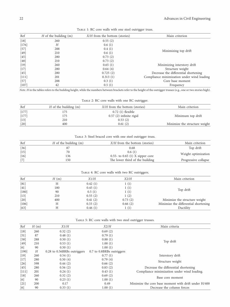
Table 3: Steel braced core with one steel outrigger truss.
Ref H of the building (m) X/H from the bottom (stories) Main criterion[36] 87 0.68 Top drift[15] 70 0.6 (1) Weight optimization[16] 136 0.55- to 0.65 (1) X zipper core[7] 150 -e lower third of the building Progressive collapse
Table 5: RC core walls with two steel outrigger trusses.
Ref H (m) X1/H X2/H Main criteria[18] 260 0.32 (2) 0.69 (2)
Top drift
[51] 87 0.48 (1) 0.79 (1)[58] 288 0.50 (1) 0.88 (1)[49] 210 0.53 (1) 1.00 (1)[6] 90 0.50 (1) 1.00 (1)[190] H 0.28 to 0.56BRBs outriggers 0.7 to 0.8BRBs outriggers[19] 260 0.54 (1) 0.77 (1) Interstory drift[17] 280 0.50 (4) 0.79 (4) Structure weight[26] 598 0.44 (2) 0.66 (2)[45] 280 0.56 (2) 0.83 (2) Decrease the differential shortening[111] 201 0.24 (1) 0.43 (1) Compliance minimization under wind loading.[18] 260 0.32 (2) 0.69 (2) Base core moment[6] 90 0.23 (1) 1.00 (1)[21] 200 0.17 0.49 Minimize the core base moment with drift under H/400[6] 90 0.33 (1) 1.00 (1) Decrease the column forces
Table 1: RC core walls with one steel outrigger truss.
Ref H of the building (m) X/H from the bottom (stories) Main criterion[18] 260 0.55 (2)
Minimizing top drift
[176] H 0.6 (1)[57] 288 0.4 (1)[49] 210 0.6 (1)[45] 280 0.73 (2)[48] 210 0.73 (2)[19] 260 0.65 (1) Minimizing interstory drift[17] 280 0.64 (4) Structure weight[45] 280 0.725 (2) Decrease the differential shortening[111] 201 0.313 (1) Compliance minimization under wind loading[57] 288 0.3 (1) Core base moment[107] 42 0.5 (1) FrequencyNote.H in the tables refers to the building height, while the numbers between brackets refer to the height of the outrigger trusses (e.g., one or two stories high).
Table 4: RC core walls with two RC outriggers.
Ref H (m) X1/H X2/H Main criterion[81] H 0.42 (1) 1 (1)
Top drift[41] 180 0.45 (1) 1 (1)[180] 90 0.5 (1) 1 (1)[13] 210 0.55 (2) 1 (2)[20] 400 0.41 (2) 0.73 (2) Minimize the structure weight[106] H 0.33 (2) 0.66 (2) Minimize the differential shortening[63] H 0.46 (1) 1 (1) Ductility
Table 2: RC core walls with one RC outrigger.
Ref H of the building (m) X/H from the bottom (stories) Main criterion[177] 175 0.72 (1) flexible
Minimum top drift[177] 175 0.57 (2) infinite rigid[13] 210 0.53 (2)[20] 400 0.61 (2) Minimize the structure weight
22 Advances in Civil Engineering
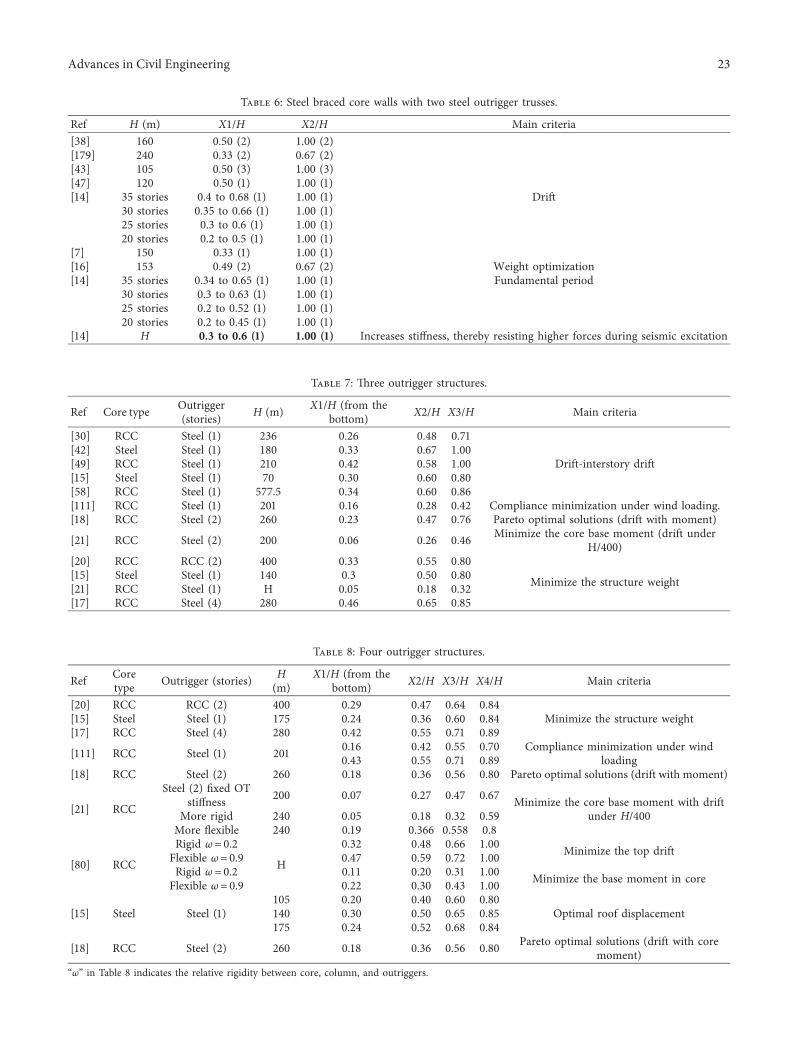
Table 8: Four outrigger structures.
Ref Coretype Outrigger (stories) H
(m)X1/H (from the
bottom) X2/H X3/H X4/H Main criteria
[20] RCC RCC (2) 400 0.29 0.47 0.64 0.84Minimize the structure weight[15] Steel Steel (1) 175 0.24 0.36 0.60 0.84
[17] RCC Steel (4) 280 0.42 0.55 0.71 0.89
[111] RCC Steel (1) 201 0.16 0.42 0.55 0.70 Compliance minimization under windloading0.43 0.55 0.71 0.89
[18] RCC Steel (2) 260 0.18 0.36 0.56 0.80 Pareto optimal solutions (drift with moment)
[21] RCC
Steel (2) fixed OTstiffness 200 0.07 0.27 0.47 0.67 Minimize the core base moment with drift
under H/400More rigid 240 0.05 0.18 0.32 0.59More flexible 240 0.19 0.366 0.558 0.8
[80] RCC
Rigid ω� 0.2
H
0.32 0.48 0.66 1.00 Minimize the top driftFlexible ω� 0.9 0.47 0.59 0.72 1.00Rigid ω� 0.2 0.11 0.20 0.31 1.00 Minimize the base moment in coreFlexible ω� 0.9 0.22 0.30 0.43 1.00
[15] Steel Steel (1)105 0.20 0.40 0.60 0.80
Optimal roof displacement140 0.30 0.50 0.65 0.85175 0.24 0.52 0.68 0.84
[18] RCC Steel (2) 260 0.18 0.36 0.56 0.80 Pareto optimal solutions (drift with coremoment)
“ω” in Table 8 indicates the relative rigidity between core, column, and outriggers.
Table 6: Steel braced core walls with two steel outrigger trusses.
Ref H (m) X1/H X2/H Main criteria[38] 160 0.50 (2) 1.00 (2)
Drift
[179] 240 0.33 (2) 0.67 (2)[43] 105 0.50 (3) 1.00 (3)[47] 120 0.50 (1) 1.00 (1)[14] 35 stories 0.4 to 0.68 (1) 1.00 (1)
30 stories 0.35 to 0.66 (1) 1.00 (1)25 stories 0.3 to 0.6 (1) 1.00 (1)20 stories 0.2 to 0.5 (1) 1.00 (1)
[7] 150 0.33 (1) 1.00 (1)[16] 153 0.49 (2) 0.67 (2) Weight optimization[14] 35 stories 0.34 to 0.65 (1) 1.00 (1) Fundamental period
30 stories 0.3 to 0.63 (1) 1.00 (1)25 stories 0.2 to 0.52 (1) 1.00 (1)20 stories 0.2 to 0.45 (1) 1.00 (1)
[14] H 0.3 to 0.6 (1) 1.00 (1) Increases stiffness, thereby resisting higher forces during seismic excitation
Table 7: -ree outrigger structures.
Ref Core type Outrigger(stories) H (m) X1/H (from the
bottom) X2/H X3/H Main criteria
[30] RCC Steel (1) 236 0.26 0.48 0.71
Drift-interstory drift[42] Steel Steel (1) 180 0.33 0.67 1.00[49] RCC Steel (1) 210 0.42 0.58 1.00[15] Steel Steel (1) 70 0.30 0.60 0.80[58] RCC Steel (1) 577.5 0.34 0.60 0.86[111] RCC Steel (1) 201 0.16 0.28 0.42 Compliance minimization under wind loading.[18] RCC Steel (2) 260 0.23 0.47 0.76 Pareto optimal solutions (drift with moment)
[21] RCC Steel (2) 200 0.06 0.26 0.46 Minimize the core base moment (drift underH/400)
[20] RCC RCC (2) 400 0.33 0.55 0.80
Minimize the structure weight[15] Steel Steel (1) 140 0.3 0.50 0.80[21] RCC Steel (1) H 0.05 0.18 0.32[17] RCC Steel (4) 280 0.46 0.65 0.85
Advances in Civil Engineering 23
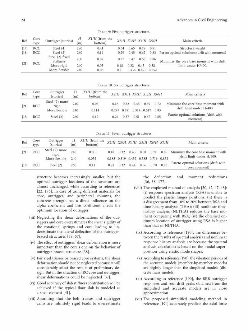
structure becomes increasingly smaller, but theoptimal outrigger locations of the structure arealmost unchanged, while according to references[22, 176], in case of using different materials forcore, outrigger, and peripheral columns, theconcrete strength has a direct influence on thealpha coefficient and this coefficient affects theoptimum location of outrigger.
(iii) Neglecting the shear deformations of the out-riggers and core overestimates the shear rigidity ofthe rotational springs and core leading to un-derestimate the lateral deflection of the outrigger-braced structures [38, 57].
(iv) -e effect of outriggers’ shear deformation is moreimportant than the core’s one on the behavior ofoutrigger-braced structure [38].
(v) For steel trusses or braced core systems, the sheardeformation should not be neglected because it willconsiderably affect the results of preliminary de-sign. But in the situation of RC core and outrigger,shear deformations could be neglected [37].
(vi) Good accuracy of slab stiffness contribution will beachieved if the typical floor slab is modeled asa shell element [41].
(vii) Assuming that the belt trusses and outriggerarms are infinitely rigid leads to overestimate
the deflection and moment reductions[36, 38, 177].
(viii) -e employed method of analysis [30, 42, 47, 48]:(i) response spectrum analysis (RSA) is unable topredict the plastic hinges positions; (ii) there isa disagreement from 10% to 20% between RSA andtime-history analysis (THA); (iii) nonlinear time-history analysis (NLTHA) reduces the base mo-ment comparing with RSA; (iv) the obtained op-timum location of outrigger using RSA is higherthan that of NLTHA.
(ix) According to reference [190], the differences be-tween the results of spectral analysis and nonlinearresponse history analysis are because the spectralanalysis calculation is based on the modal super-position using elastic mode shapes.
(x) According to reference [190], the vibration periods ofthe accurate models (member-by-member models)are slightly longer than the simplified models (dis-crete mass models).
(xi) According to reference [190], the BRB outriggerresponses and roof drift peaks obtained from thesimplified and accurate models are in closeapproximation.
(xii) -e proposed simplified modeling method inreference [191] accurately predicts the axial force
Table 9: Five outrigger structures.
Ref Coretype Outrigger (stories) H
(m)X1/H (from the
bottom) X2/H X3/H X4/H X5/H Main criteria
[17] RCC Steel (4) 280 0.41 0.54 0.65 0.78 0.91 Structure weight[18] RCC Steel (2) 260 0.14 0.29 0.45 0.62 0.83 Pareto optimal solutions (drift withmoment)
[21] RCC
Steel (2) fixedstiffness 200 0.07 0.27 0.47 0.66 0.86 Minimize the core base moment with drift
limit under H/400.More rigid 240 0.05 0.18 0.32 0.45 0.58More flexible 240 0.06 0.2 0.336 0.491 0.752
Table 10: Six outrigger structures.
Ref Coretype
Outrigger(stories)
H(m)
X1/H (from thebottom) X2/H X3/H X4/H X5/H X6/H Main criteria
[21] RCCSteel (2) more
rigid 240 0.05 0.18 0.32 0.45 0.59 0.72 Minimize the core base moment withdrift limit under H/400.More flexible 240 0.114 0.247 0.381 0.514 0.647 0.83
[18] RCC Steel (2) 260 0.12 0.24 0.37 0.51 0.67 0.85 Pareto optimal solutions (drift withmoment)
Table 11: Seven outrigger structures.
Ref Coretype
Outrigger(stories)
H(m)
X1/H (from thebottom) X2/H X3/H X4/H X5/H X6/H X7/H Main criteria
[21] RCC Steel (2) morerigid 240 0.05 0.18 0.32 0.45 0.58 0.71 0.85 Minimize the core base moment with
drift limit under H/400.More flexible 240 0.052 0.185 0.319 0.452 0.585 0.719 0.852
[18] RCC Steel (2) 260 0.11 0.21 0.32 0.44 0.56 0.70 0.86 Pareto optimal solutions (drift withcore moment)
24 Advances in Civil Engineering
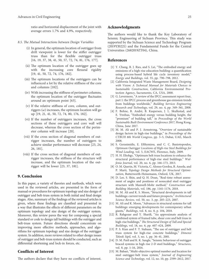
ratio and horizontal displacement of the joint withaverage errors 1.7% and 4.9%, respectively.
8.5. =e Mutual Interactions between Design Variables
(i) In general, the optimum location of outrigger fromdrift viewpoint is lower for the stiffer outriggertruss than for the flexible outrigger truss[16, 19, 37, 38, 41, 50, 57, 72, 74, 81, 176, 177].
(ii) -e optimum location of the outrigger goes upwith the increasing core flexural rigidity[19, 41, 50, 72, 74, 176, 182].
(iii) -e optimum locations of the outriggers can beinfluenced a lot by the relative stiffness of the coreand columns [182].
(iv) With increasing the stiffness of perimeter columns,the optimum location of the outrigger fluctuatesaround an optimum point [63].
(v) If the relative stiffness of core, column, and out-riggers (ω) increases, the optimum location will goup [19, 21, 41, 50, 72, 74, 80, 176, 182].
(vi) If the number of outriggers increases, the crosssections of these outriggers and core wall willdecrease, whereas the cross section of the perim-eter column will increase [20].
(vii) If the cross section of diagonal members of out-rigger increases, the number of outriggers toachieve similar performance will decrease [23, 24,26, 181].
(viii) If the cross section of diagonal members of out-rigger increases, the stiffness of the structure willincrease, and the optimum location of the out-rigger will be lower [23, 37, 181].
9. Conclusion
In this paper, a variety of theories and methods, which wereused in the reviewed articles, are presented in the form ofmanual or procedures for optimum topology and size design ofoutrigger and belt-truss system in both initial and final designstages. Also, summary of the findings of the reviewed articles isgiven, where these findings are classified and presented ina way that illustrates the effects of different parameters on theoptimum topology and size design of the outrigger system.Moreover, this review paves the way for composing a specialstandard or code to design tall buildings with the outrigger andbelt-truss system. Future directions should concentrate onimproving more effective methods, approaches, and algo-rithms for optimum topology and size design of the outriggersystem. In addition, more reviews related to other design issuesof outrigger and belt-truss system should be conducted, such asdifferential shortening and lock-in forces, etc.
Conflicts of Interest
-e authors declare that they have no conflicts of interest.
Acknowledgments
-e authors would like to thank the Key Laboratory ofSeismic Engineering of Sichuan Province. -is study wassupported by the Sichuan Science and Technology Program(2019YJ0221) and the Fundamental Funds for the CentralUniversities (2682019ZT04), China.
References
[1] Y. Chang, R. J. Ries, and S. Lei, “-e embodied energy andemissions of a high-rise education building: a quantificationusing process-based hybrid life cycle inventory model,”Energy and Buildings, vol. 55, pp. 790–798, 2012.
[2] California Integrated Waste Management Board, Designingwith Vision: A Technical Manual for Materials Choices inSustainable Construction, California Environmental Pro-tection Agency, Sacramento, CA, USA, 2000.
[3] G. Levermore, “A review of the IPCC assessment report four,part 1: the IPCC process and greenhouse gas emission trendsfrom buildings worldwide,” Building Services EngineeringResearch and Technology, vol. 29, no. 4, pp. 349–361, 2008.
[4] F. Bohne, R. Andre, B. Kaspersen, J. L. Skullestad, andE. Ytrehus, “Embodied energy versus building height, the“premium” of building tall,” in Proceedings of the WorldSustainable Built Environment Conference 2017, Hong Kong,China, June 2017.
[5] M. M. Ali and P. J. Armstrong, “Overview of sustainabledesign factors in high-rise buildings,” in Proceedings of theCTBUH 8th World Congress, pp. 3–5, Dubai, UAE, March2008.
[6] S. Gerasimidis, E. Efthymiou, and C. C. Baniotopoulos,Optimum Outrigger Locations of High-rise Steel Buildings forWind Loading, vol. 5, EACWE, Florence, Italy, 2009.
[7] H. H. Eltobgy, “Optimum belt truss locations to enhance thestructural performance of high-rise steel buildings,” Wul-fenia Journal, vol. 20, no. 6, pp. 166–173, 2013.
[8] O. M. Querin, M. Victoria, C. Alonso Gordoa, R. Ansola, andP. Martı, Topology Design Methods for Structural Optimi-zation, Butterworth-Heinemann, Oxford, UK, 2017.
[9] D. Lee, S. Shin, and Q. H. Doan, “Real-time robust assess-ment of angles and positions of nonscaled steel outriggerstructure with Maxwell-Mohr method,” Construction andBuilding Materials, vol. 186, pp. 1161–1176, 2018.
[10] M. M. Ali and K. S. Moon, “Structural developments in tallbuildings: current trends and future prospects,”ArchitecturalScience Review, vol. 50, no. 3, pp. 205–223, 2007.
[11] M. Ali and K. Moon, “Advances in structural systems for tallbuildings: emerging developments for contemporary urbangiants,” Buildings, vol. 8, no. 8, p. 104, 2018.
[12] R. Rahgozar and Y. Sharifi, “An approximate analysis ofcombined system of framed tube, shear core and belt truss inhigh-rise buildings,”=e Structural Design of Tall and SpecialBuildings, vol. 18, no. 6, pp. 607–624, 2009.
[13] P. S. Kian and F. T. Siahaan, “-e use of outrigger and belttruss system for high-rise concrete buildings,” DimensiTeknik Sipil, vol. 3, no. 1, pp. 36–41, 2001.
[14] D. M. Patil and K. K. Sangle, “Seismic behaviour of outriggerbraced systems in high rise 2-D steel buildings,” Structures,vol. 8, pp. 1–16, 2016.
[15] M. Babaei, “Multi-objective optimal number and location forsteel outrigger-belt truss system,” Journal of EngineeringScience and Technology, vol. 12, no. 10, pp. 2599–2612, 2017.
Advances in Civil Engineering 25
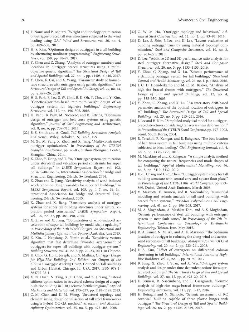
[16] F. Nouri and P. Ashtari, “Weight and topology optimizationof outrigger-braced tall steel structures subjected to the windloading using GA,” Wind and Structures, vol. 20, no. 4,pp. 489–508, 2015.
[17] H.-S. Kim, “Optimum design of outriggers in a tall buildingby alternating nonlinear programming,” Engineering Struc-tures, vol. 150, pp. 91–97, 2017.
[18] Y. Chen and Z. Zhang, “Analysis of outrigger numbers andlocations in outrigger braced structures using a multi-objective genetic algorithm,” =e Structural Design of Talland Special Buildings, vol. 27, no. 1, pp. e1408–e1416, 2017.
[19] Y. Chen, K. Cai, and X. Wang, “Parameter study of framed-tube structures with outriggers using genetic algorithm,”=eStructural Design of Tall and Special Buildings, vol. 27, no. 14,pp. e1499–26, 2018.
[20] H. S. Park, E. Lee, S. W. Choi, B. K. Oh, T. Cho, and Y. Kim,“Genetic-algorithm-based minimum weight design of anoutrigger system for high-rise buildings,” EngineeringStructures, vol. 117, pp. 496–505, 2016.
[21] H. Radu, B. Parv, M. Nicoreac, and B. Petrina, “Optimumdesign of outrigger and belt truss systems using geneticalgorithm,” Journal of Civil Engineering and Architecture,vol. 8, no. 6, pp. 709–715, 2014.
[22] B. S. Smith and A. Coull, Tall Building Structures: Analysisand Design, Wiley, Hoboken, NJ, USA, 1991.
[23] M. Xu, M. Yang, X. Zhao, and X. Jiang, “Multi-constrainedoutrigger optimization,” in Proceedings of the CTBUHShanghai Conference, pp. 76–83, Suzhou Zhongnan Center,Shanghai, China, 2014.
[24] X. Zhao, Y. Dong, and T. Yu, “Outrigger system optimizationunder storydrift and vibration period constraints for supertall buildings,” in IABSE Symposium Report, vol. 102,pp. 475–482, no. 37, International Association for Bridge andStructural Engineering, Zurich, Switzerland, 2014.
[25] X. Zhao and X. Jiang, “Sensitivity analysis of wind-inducedacceleration on design variables for super tall buildings,” inIABSE Symposium Report, vol. 105, pp. 1–7, no. 39, In-ternational Association for Bridge and Structural Engi-neering, Zurich, Switzerland, 2015.
[26] X. Zhao and X. Jiang, “Sensitivity analysis of outriggersystems for super tall building structures under natural vi-bration period constraints,” IABSE Symposium Report,vol. 102, no. 37, pp. 483–490, 2014.
[27] X. Zhao and X. Jiang, “Optimization of wind-induced ac-celeration of super tall buildings by modal shape updating,”in Proceedings of the 11th World Congress on Structural andMultidisciplinary Optimisation, Sydney, Australia, June 2015.
[28] Z. Xin, L. Nanxiang, Z. Yimin et al., “Sensitivity vectorsalgorithm that fast determine favorable arrangement ofoutriggers for super tall buildings with outrigger systems,”Building Structure, vol. 41, no. 5, pp. 20–23, 2011, in Chinese.
[29] H. Choi, G. Ho, L. Joseph, and N. Mathias, Outrigger Designfor High-Rise Buildings 2nd Edition: An Output of theCTBUHOutriggerWorking Group, Council on Tall Buildingsand Urban Habitat, Chicago, IL, USA, 2017, ISBN 978-1-864707-28-1.
[30] X. N. Duan, N. Tang, X. T. Chen, and Z. J. Yang, “Lateralstiffness optimization in structural scheme design of a superhigh-rise building in 0.30 g seismic fortified regions,”AppliedMechanics and Materials, vol. 275–277, pp. 1184–1189, 2013.
[31] C.-M. Chan and K.-M. Wong, “Structural topology andelement sizing design optimisation of tall steel frameworksusing a hybrid OC-GA method,” Structural and Multidis-ciplinary Optimization, vol. 35, no. 5, pp. 473–488, 2008.
[32] G. W. M. Ho, “Outrigger topology and behaviour,” Ad-vanced Steel Construction, vol. 12, no. 2, pp. 83–93, 2016.
[33] D. Lee, S. Shin, J. Lee, and K. Lee, “Layout evaluation ofbuilding outrigger truss by using material topology opti-mization,” Steel and Composite Structures, vol. 19, no. 2,pp. 263–275, 2015.
[34] D. Lee, “Additive 2D and 3D performance ratio analysis forsteel outrigger alternative design,” Steel and CompositeStructures, vol. 20, no. 5, pp. 1133–1153, 2016.
[35] Y. Zhou, C. Zhang, and X. Lu, “Seismic performance ofa damping outrigger system for tall buildings,” StructuralControl and Health Monitoring, vol. 24, no. 1, p. e1864, 2016.
[36] J. C. D. Hoenderkamp and M. C. M. Bakker, “Analysis ofhigh-rise braced frames with outriggers,” =e StructuralDesign of Tall and Special Buildings, vol. 12, no. 4,pp. 335–350, 2003.
[37] Y. Zhou, C. Zhang, and X. Lu, “An inter-story drift-basedparameter analysis of the optimal location of outriggers intall buildings,” =e Structural Design of Tall and SpecialBuildings, vol. 25, no. 5, pp. 215–231, 2016.
[38] J. Lee and H. Kim, “Simplified analytical model for outrigger-braced structures considering transverse shear deformation,”in Proceedings of the CTBUH Seoul Conference, pp. 997–1002,Seoul, South Korea, 2004.
[39] R. Tavakoli, R. Kamgar, and R. Rahgozar, “-e best locationof belt truss system in tall buildings using multiple criteriasubjected to blast loading,” Civil Engineering Journal, vol. 4,no. 6, pp. 1338–1353, 2018.
[40] M. Malekinejad and R. Rahgozar, “A simple analytic methodfor computing the natural frequencies and mode shapes oftall buildings,” Applied Mathematical Modelling, vol. 36,no. 8, pp. 3419–3432, 2012.
[41] K.-L. Chang and C.-C. Chen, “Outrigger system study for tallbuilding structure with central core and square floor plate,”in Proceedings of the CTBUH 8th World Congress, pp. 853–869, Dubai, United Arab Emirates, March 2008.
[42] V. Mazzotta, E. Brunesi, and R. Nascimbene, “Numericalmodeling and seismic analysis of tall steel buildings withbraced frame systems,” Periodica Polytechnica Civil Engi-neering, vol. 61, no. 2, pp. 196–208, 2017.
[43] M. A. Moghadam, A. Meshkat-Dini, and A. S. Moghadam,“Seismic performance of steel tall buildings with outriggersystem in near fault zones,” in Proceedings of the 7th In-ternational Conference on Seismology & EarthquakeEngineering, Tehran, Iran, May 2015.
[44] R. A. Samat, N. M. Ali, and A. K. Marsono, “-e optimumlocation of outrigger in reducing the along-wind and across-wind responses of tall buildings,”Malaysian Journal Of CivilEngineering, vol. 20, no. 2, pp. 223–241, 2008.
[45] H.-S. Kim, “Effect of outriggers on differential columnshortening in tall buildings,” International Journal of High-Rise Buildings, vol. 6, no. 1, pp. 91–99, 2017.
[46] B. Fang, X. Zhao, J. Yuan, and X. Wu, “Outrigger systemanalysis and design under time-dependent actions for super-tall steel buildings,”=e Structural Design of Tall and SpecialBuildings, vol. 27, no. 12, pp. e1492–20, 2018.
[47] E. Brunesi, R. Nascimbene, and L. Casagrande, “Seismicanalysis of high-rise mega-braced frame-core buildings,”Engineering Structures, vol. 115, pp. 1–17, 2016.
[48] H. Beiraghi and N. Siahpolo, “Seismic assessment of RCcore-wall building capable of three plastic hinges withoutrigger,” =e Structural Design of Tall and Special Build-ings, vol. 26, no. 2, pp. e1306–e1319, 2017.
26 Advances in Civil Engineering
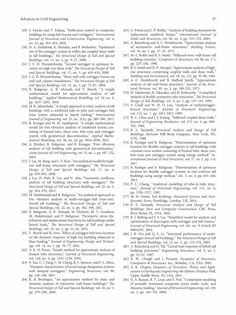
[49] S. Fawzia and T. Fatima, “Deflection control in compositebuildings by using belt trusses and outriggers,” InternationalJournal of Structural and Construction Engineering, vol. 4,no. 12, pp. 414–419, 2010.
[50] N. A. Zeidabadi, K. Mirtalae, and B. Mobasher, “Optimizeduse of the outrigger system to stiffen the coupled shear wallsin tall buildings,” =e Structural Design of Tall and SpecialBuildings, vol. 13, no. 1, pp. 9–27, 2004.
[51] J. C. D. Hoenderkamp, “Second outrigger at optimum lo-cation on high-rise shear wall,” =e Structural Design of Talland Special Buildings, vol. 17, no. 3, pp. 619–634, 2008.
[52] J. C. D. Hoenderkamp, “Shear wall with outrigger trusses onwall and column foundations,” =e Structural Design of Talland Special Buildings, vol. 13, no. 1, pp. 73–87, 2004.
[53] R. Rahgozar, A. R. Ahmadi, and Y. Sharifi, “A simplemathematical model for approximate analysis of tallbuildings,” Applied Mathematical Modelling, vol. 34, no. 9,pp. 2437–2451, 2010.
[54] M. R. Jahanshahi, “A simple approach to static analysis of tallbuildings with a combined tube-in-tube and outrigger-belttruss system subjected to lateral loading,” InternationalJournal of Engineering, vol. 25, no. 3(A), pp. 289–300, 2012.
[55] R. Kamgar and M. M. Saadatpour, “A simple mathematicalmodel for free vibration analysis of combined system con-sisting of framed tube, shear core, belt truss and outriggersystem with geometrical discontinuities,” Applied Mathe-matical Modelling, vol. 36, no. 10, pp. 4918–4930, 2012.
[56] A. Heidari, R. Rahgozar, and R. Kamgar, “Free vibrationanalysis of tall building with geometrical discontinuities,”Asian Journal of Civil Engineering, vol. 15, no. 1, pp. 107–122,2014.
[57] J. Lee, M. Bang, and J.-Y. Kim, “An analytical model for high-rise wall-frame structures with outriggers,” =e StructuralDesign of Tall and Special Buildings, vol. 17, no. 4,pp. 839–851, 2008.
[58] J. Lee, D. Park, K. Lee, and N. Ahn, “Geometric nonlinearanalysis of tall building structures with outriggers,” =eStructural Design of Tall and Special Buildings, vol. 22, no. 5,pp. 454–470, 2013.
[59] M. Malekinejad and R. Rahgozar, “An analytical approach tofree vibration analysis of multi-outrigger-belt truss-rein-forced tall buildings,” =e Structural Design of Tall andSpecial Buildings, vol. 22, no. 4, pp. 382–398, 2011.
[60] R. Rahgozar, A. R. Ahmadi, M. Ghelichi, M. Y. Goudarzi,M. Malekinejad, and P. Rahgozar, “Parametric stress dis-tribution and displacement functions for tall buildings underlateral loads,” =e Structural Design of Tall and SpecialBuildings, vol. 23, no. 1, pp. 22–41, 2012.
[61] Y. Sharifi and H. Aviz, “Effect of outrigger-belt truss locationon the dynamic response of high-rise building subjected toblast loading,” Journal of Engineering, Design and Technol-ogy, vol. 14, no. 1, pp. 54–77, 2016.
[62] A. K. H. Kwan, “Simple method for approximate analysis offramed tube structures,” Journal of Structural Engineering,vol. 120, no. 4, pp. 1221–1239, 1994.
[63] P. Tan, C. J. Fang, C. M. Chang, B. F. Spencer, and F. L. Zhou,“Dynamic characteristics of novel energy dissipation systemswith damped outriggers,” Engineering Structures, vol. 98,pp. 128–140, 2015.
[64] K. B. Bozdogan, “An approximate method for static anddynamic analyses of symmetric wall-frame buildings,” =eStructural Design of Tall and Special Buildings, vol. 18, no. 3,pp. 279–290, 2009.
[65] G. Potzta and L. P. Kollar, “Analysis of building structures byreplacement sandwich beams,” International Journal ofSolids and Structures, vol. 40, no. 3, pp. 535–553, 2003.
[66] A. Rutenberg and A. C. Heidebrecht, “Approximate analysisof asymmetric wall-frame structures,” Building Science,vol. 10, no. 1, pp. 27–35, 1975.
[67] M.-J. Nollet and B. S. Smith, “Stiffened-story wall-frame tallbuilding structure,” Computers & Structures, vol. 66, no. 2-3,pp. 225–240, 1998.
[68] B. S. Smith andD. P. Abergel, “Approximate analysis of high-rise structures comprising coupled walls and shear walls,”Building and Environment, vol. 18, no. 1/2, pp. 91–96, 1983.
[69] A. C. Heidebrecht and B. Stafford Smith, “Approximateanalysis of tall wall-frame structures,” Journal of the Struc-tural Division, vol. 99, no. 2, pp. 199–221, 1973.
[70] H. Takabatake, R. Takesako, andM. Kobayashi, “A simplifiedanalysis of doubly symmetric tube structures,”=e StructuralDesign of Tall Buildings, vol. 4, no. 2, pp. 137–153, 1995.
[71] A. Coull and W. H. O. Lau, “Analysis of multioutrigger-braced structures,” Journal of Structural Engineering,vol. 115, no. 7, pp. 1811–1815, 1989.
[72] H. C. Chan and J. S. Kuang, “Stiffened coupled shear walls,”Journal of Engineering Mechanics, vol. 115, no. 4, pp. 689–703, 1989.
[73] B. S. Taranath, Structural Analysis and Design of TallBuildings, McGraw Hill Book Company, New York, NY,USA, 1988.
[74] R. Kamgar and R. Rahgozar, “Determination of optimumlocation for flexible outrigger systems in tall buildings withconstant cross section consisting of framed tube, shear core,belt truss and outrigger system using energy method,” In-ternational Journal of Steel Structures, vol. 17, no. 1, pp. 1–8,2017.
[75] R. Kamgar and R. Rahgozar, “Determination of optimumlocation for flexible outrigger systems in non-uniform tallbuildings using energy method,” vol. 5, no. 4, pp. 433–444,2015.
[76] P. C. Chang, “Analytical modeling of tube-in-tube struc-ture,” Journal of Structural Engineering, vol. 111, no. 6,pp. 1326–1337, 1985.
[77] M. H. Gunel, Tall Buildings: Structural Systems and Aero-dynamic Form, Routledge, London, UK, 2014.
[78] B. S. Taranath, Structural Analysis and Design of TallBuildings: Steel and Composite Construction, CRC Press,Boca Rotan, FL, USA, 2016.
[79] R. J. Balling and J. S. Lee, “Simplified model for analysis andoptimization of skyscrapers with outrigger and belt trusses,”Journal of Structural Engineering, vol. 141, no. 9, Article ID04014231, 2014.
[80] J. R. Wu and Q. S. Li, “Structural performance of multi-outrigger-braced tall buildings,”=e Structural Design of Talland Special Buildings, vol. 12, no. 2, pp. 155–176, 2003.
[81] A. Rutenberg and D. Tal, “Lateral load response of belted tallbuilding structures,” Engineering Structures, vol. 9, no. 1,pp. 53–67, 1987.
[82] R. W. Clough and J. Penzien, Dynamics of Structures,Computers & Structures, Inc., Berkeley, CA, USA, 2003.
[83] A. K. Chopra, Dynamics of Structures: =eory and Appli-cations to Earthquake Engineering 4th Edition, Prentice-Hall,Upper Saddle River, NJ, USA, 2011.
[84] G. A. Rassati, R. T. Leon, and S. Noe, “Component modelingof partially restrained composite joints under cyclic anddynamic loading,” Journal of Structural Engineering, vol. 130,no. 2, pp. 343–351, 2004.
Advances in Civil Engineering 27
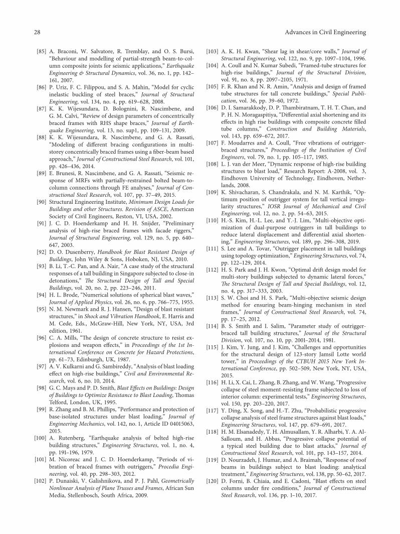
[85] A. Braconi, W. Salvatore, R. Tremblay, and O. S. Bursi,“Behaviour and modelling of partial-strength beam-to-col-umn composite joints for seismic applications,” EarthquakeEngineering & Structural Dynamics, vol. 36, no. 1, pp. 142–161, 2007.
[86] P. Uriz, F. C. Filippou, and S. A. Mahin, “Model for cyclicinelastic buckling of steel braces,” Journal of StructuralEngineering, vol. 134, no. 4, pp. 619–628, 2008.
[87] K. K. Wijesundara, D. Bolognini, R. Nascimbene, andG. M. Calvi, “Review of design parameters of concentricallybraced frames with RHS shape braces,” Journal of Earth-quake Engineering, vol. 13, no. sup1, pp. 109–131, 2009.
[88] K. K. Wijesundara, R. Nascimbene, and G. A. Rassati,“Modeling of different bracing configurations in multi-storey concentrically braced frames using a fiber-beam basedapproach,” Journal of Constructional Steel Research, vol. 101,pp. 426–436, 2014.
[89] E. Brunesi, R. Nascimbene, and G. A. Rassati, “Seismic re-sponse of MRFs with partially-restrained bolted beam-to-column connections through FE analyses,” Journal of Con-structional Steel Research, vol. 107, pp. 37–49, 2015.
[90] Structural Engineering Institute, Minimum Design Loads forBuildings and other Structures. Revision of ASCE, AmericanSociety of Civil Engineers, Reston, VI, USA, 2002.
[91] J. C. D. Hoenderkamp and H. H. Snijder, “Preliminaryanalysis of high-rise braced frames with facade riggers,”Journal of Structural Engineering, vol. 129, no. 5, pp. 640–647, 2003.
[92] D. O. Dusenberry, Handbook for Blast Resistant Design ofBuildings, John Wiley & Sons, Hoboken, NJ, USA, 2010.
[93] B. Li, T.-C. Pan, and A. Nair, “A case study of the structuralresponses of a tall building in Singapore subjected to close-indetonations,” =e Structural Design of Tall and SpecialBuildings, vol. 20, no. 2, pp. 223–246, 2011.
[94] H. L. Brode, “Numerical solutions of spherical blast waves,”Journal of Applied Physics, vol. 26, no. 6, pp. 766–775, 1955.
[95] N. M. Newmark and R. J. Hansen, “Design of blast resistantstructures,” in Shock and Vibration Handbook, E. Harris andM. Cede, Eds., McGraw-Hill, New York, NY, USA, 3rdedition, 1961.
[96] C. A. Mills, “-e design of concrete structure to resist ex-plosions and weapon effects,” in Proceedings of the 1st In-ternational Conference on Concrete for Hazard Protections,pp. 61–73, Edinburgh, UK, 1987.
[97] A. V. Kulkarni and G. Sambireddy, “Analysis of blast loadingeffect on high-rise buildings,” Civil and Environmental Re-search, vol. 6, no. 10, 2014.
[98] G. C. Mays and P. D. Smith, Blast Effects on Buildings: Designof Buildings to Optimize Resistance to Blast Loading, -omasTelford, London, UK, 1995.
[99] R. Zhang and B. M. Phillips, “Performance and protection ofbase-isolated structures under blast loading,” Journal ofEngineering Mechanics, vol. 142, no. 1, Article ID 04015063,2015.
[100] A. Rutenberg, “Earthquake analysis of belted high-risebuilding structures,” Engineering Structures, vol. 1, no. 4,pp. 191–196, 1979.
[101] M. Nicoreac and J. C. D. Hoenderkamp, “Periods of vi-bration of braced frames with outriggers,” Procedia Engi-neering, vol. 40, pp. 298–303, 2012.
[102] P. Dunaiski, V. Galishnikova, and P. J. Pahl, GeometricallyNonlinear Analysis of Plane Trusses and Frames, African SunMedia, Stellenbosch, South Africa, 2009.
[103] A. K. H. Kwan, “Shear lag in shear/core walls,” Journal ofStructural Engineering, vol. 122, no. 9, pp. 1097–1104, 1996.
[104] A. Coull and N. Kumar Subedi, “Framed-tube structures forhigh-rise buildings,” Journal of the Structural Division,vol. 91, no. 8, pp. 2097–2105, 1971.
[105] F. R. Khan and N. R. Amin, “Analysis and design of framedtube structures for tall concrete buildings,” Special Publi-cation, vol. 36, pp. 39–60, 1972.
[106] D. I. Samarakkody, D. P. -ambiratnam, T. H. T. Chan, andP. H. N. Moragaspitiya, “Differential axial shortening and itseffects in high rise buildings with composite concrete filledtube columns,” Construction and Building Materials,vol. 143, pp. 659–672, 2017.
[107] F. Moudarres and A. Coull, “Free vibrations of outrigger-braced structures,” Proceedings of the Institution of CivilEngineers, vol. 79, no. 1, pp. 105–117, 1985.
[108] L. J. van der Meer, “Dynamic response of high-rise buildingstructures to blast load,” Research Report: A-2008, vol. 3,Eindhoven University of Technology, Eindhoven, Nether-lands, 2008.
[109] K. Shivacharan, S. Chandrakala, and N. M. Karthik, “Op-timum position of outrigger system for tall vertical irregu-larity structures,” IOSR Journal of Mechanical and CivilEngineering, vol. 12, no. 2, pp. 54–63, 2015.
[110] H.-S. Kim, H.-L. Lee, and Y.-J. Lim, “Multi-objective opti-mization of dual-purpose outriggers in tall buildings toreduce lateral displacement and differential axial shorten-ing,” Engineering Structures, vol. 189, pp. 296–308, 2019.
[111] S. Lee and A. Tovar, “Outrigger placement in tall buildingsusing topology optimization,” Engineering Structures, vol. 74,pp. 122–129, 2014.
[112] H. S. Park and J. H. Kwon, “Optimal drift design model formulti-story buildings subjected to dynamic lateral forces,”=e Structural Design of Tall and Special Buildings, vol. 12,no. 4, pp. 317–333, 2003.
[113] S. W. Choi and H. S. Park, “Multi-objective seismic designmethod for ensuring beam-hinging mechanism in steelframes,” Journal of Constructional Steel Research, vol. 74,pp. 17–25, 2012.
[114] B. S. Smith and I. Salim, “Parameter study of outrigger-braced tall building structures,” Journal of the StructuralDivision, vol. 107, no. 10, pp. 2001–2014, 1981.
[115] J. Kim, Y. Jung, and J. Kim, “Challenges and opportunitiesfor the structural design of 123-story Jamsil Lotte worldtower,” in Proceedings of the CTBUH 2015 New York In-ternational Conference, pp. 502–509, New York, NY, USA,2015.
[116] H. Li, X. Cai, L. Zhang, B. Zhang, andW.Wang, “Progressivecollapse of steel moment-resisting frame subjected to loss ofinterior column: experimental tests,” Engineering Structures,vol. 150, pp. 203–220, 2017.
[117] Y. Ding, X. Song, and H.-T. Zhu, “Probabilistic progressivecollapse analysis of steel frame structures against blast loads,”Engineering Structures, vol. 147, pp. 679–691, 2017.
[118] H. M. Elsanadedy, T. H. Almusallam, Y. R. Alharbi, Y. A. Al-Salloum, and H. Abbas, “Progressive collapse potential ofa typical steel building due to blast attacks,” Journal ofConstructional Steel Research, vol. 101, pp. 143–157, 2014.
[119] D. Nourzadeh, J. Humar, and A. Braimah, “Response of roofbeams in buildings subject to blast loading: analyticaltreatment,” Engineering Structures, vol. 138, pp. 50–62, 2017.
[120] D. Forni, B. Chiaia, and E. Cadoni, “Blast effects on steelcolumns under fire conditions,” Journal of ConstructionalSteel Research, vol. 136, pp. 1–10, 2017.
28 Advances in Civil Engineering
[121] M. Samadi and N. Jahan, “Determining the effective level ofoutrigger in preventing collapse of tall buildings by IDA withan alternative damage measure,” Engineering Structures,vol. 191, pp. 104–116, 2019.
[122] Y. Chen, D. M. McFarland, Z. Wang, B. F. Spencer Jr., andL. A. Bergman, “Analysis of tall buildings with dampedoutriggers,” Journal of Structural Engineering, vol. 136,no. 11, pp. 1435–1443, 2010.
[123] C.-M. Chan, “Optimal lateral stiffness design of tall buildingsof mixed steel and concrete construction,” =e StructuralDesign of Tall Buildings, vol. 10, no. 3, pp. 155–177, 2001.
[124] R. T. Haftka and Z. Gurdal, Elements of StructuralOptimization, Springer Science & Business Media, Berlin,Germany, 3rd edition, 1992.
[125] G. Allaire, F. Jouve, and A.-M. Toader, “Structural optimi-zation using sensitivity analysis and a level-set method,”Journal of Computational Physics, vol. 194, no. 1, pp. 363–393, 2004.
[126] S. Amstutz and H. Andra, “A new algorithm for topologyoptimization using a level-set method,” Journal of Compu-tational Physics, vol. 216, no. 2, pp. 573–588, 2006.
[127] M. Y. Wang, X. Wang, and D. Guo, “A level set method forstructural topology optimization,” Computer Methods inApplied Mechanics and Engineering, vol. 192, no. 1-2,pp. 227–246, 2003.
[128] M. P. Bendsøe, “Optimal shape design as a material distri-bution problem,” Structural Optimization, vol. 1, no. 4,pp. 193–202, 1989.
[129] G. I. N. Rozvany and M. Zhou, “Applications of the COCalgorithm in layout optimization,” in Engineering Optimi-zation in Design Processes, pp. 59–70, Springer, Berlin,Germany, 1991.
[130] M. P. Bendsøe, Optimization of Structural Topology, Shapeand Material, Springer-Verlag, Berlin, Germany, 1995.
[131] M. P. Bendsøe, N. Kikuchi, and N. Kikuchi, “Generatingoptimal topologies in structural design using a homogeni-zation method,” Computer Methods in Applied Mechanicsand Engineering, vol. 71, no. 2, pp. 197–224, 1988.
[132] M. Zhu, Y. Yang, J. K. Guest, and M. D. Shields, “Topologyoptimization for linear stationary stochastic dynamics: ap-plications to frame structures,” Structural Safety, vol. 67,pp. 116–131, 2017.
[133] C. Mattheck, “Engineering components grow like trees,”Materialwissenschaft und Werkstofftechnik, vol. 21, no. 4,pp. 143–168, 1990.
[134] C. Mattheck, M. Scherrer, K. Bethge, and I. Tesari, “Shapeoptimization : an analytical approach,”WIT Transactions onthe Built Environment, vol. 80, pp. 137–146, 2005.
[135] Y.M. Xie andG. P. Steven, “A simple evolutionary procedurestructural optimization,” Computers & Structures, vol. 49,no. 5, pp. 885–896, 1993.
[136] Y. M. Xie and G. P. Steven, Evolutionary Structural Opti-mization, Springer-Verlag, Berlin, Germany, 1997.
[137] X. Huang andM. Xie, Evolutionary Topology Optimization ofContinuum Structures: Methods and Applications, JohnWiley & Sons, Hoboken, NJ, USA, 2010.
[138] O. M. Querin, G. P. Steven, and Y. M. Xie, “Evolutionarystructural optimisation (ESO) using a bidirectional algo-rithm,” Engineering Computations, vol. 15, no. 8,pp. 1031–1048, 1998.
[139] K. Deb, Multi-Objective Optimization Using EvolutionaryAlgorithms, Vol. 16, John Wiley & Sons, Hoboken, NJ, USA,2001.
[140] S. N. Sivanandam and S. N. Deepa, Introduction to GeneticAlgorithms, Springer Publication, New York, NY, USA, 2008.
[141] D. A. Coley, An Introduction to Genetic Algorithms forScientist and Engineers, World Scientific Publishing, Singa-pore, 1999.
[142] U. Kirsch, Structural Optimization: Fundamentals and Ap-plications, Springer-Verlag, Berlin, Germany, 1993.
[143] G. Renner and A. Ekart, “Genetic algorithms in computeraided design,” Computer-Aided Design, vol. 35, no. 8,pp. 709–726, 2003.
[144] A. S. Patil and P. D. Kumbhar, “Time history analysis ofmultistoried RCC buildings for different seismic intensities,”International Journal of Structural and Civil EngineeringResearch, vol. 2, no. 3, pp. 194–201, 2013.
[145] S. K. Duggal, Earthquake Resistance Design of Structure,Oxford University Press, New Delhi, India, 2007.
[146] FEMA 273, NEHRP Guidelines for the Seismic Rehabilitationof Buildings, FEMA 273 Federal Emergency ManagementAgency, Washington, DC, USA, 1997.
[147] FEMA 356, Pre-standard and Commentary for the SeismicRehabilitation of Buildings, FEMA 356 Federal EmergencyManagement Agency, Washington, DC, USA, 2000.
[148] R. K. Goel and A. K. Chopra, “Evaluation of modal andFEMA pushover analyses: SAC buildings,” EarthquakeSpectra, vol. 20, no. 1, pp. 225–254, 2004.
[149] M. Poursha, F. Khoshnoudian, and A. S. Moghadam, “As-sessment of conventional nonlinear static procedures withFEMA load distributions and modal pushover analysis forhigh-rise buildings,” International Journal of Civil Engi-neerng, vol. 6, no. 2, pp. 142–157, 2008.
[150] M. Poursha, F. Khoshnoudian, and A. S. Moghadam, “Abreakthrough in estimating the seismic demands of tallbuildings,” in Proceedings of the 14th World Conference onEarthquake Engineering, Beijing, China, 2008.
[151] S. Kim and E. D’Amore, “Pushover analysis procedure inearthquake engineering,” Earthquake Spectra, vol. 15, no. 3,pp. 417–434, 1999.
[152] H. Krawinkler and G. D. P. K. Seneviratna, “Pros and cons ofa pushover analysis of seismic performance evaluation,”Engineering Structures, vol. 20, no. 4–6, pp. 452–464, 1998.
[153] A. K. Chopra and R. K. Goel, “A modal pushover analysisprocedure for estimating seismic demands for buildings,”Earthquake Engineering & Structural Dynamics, vol. 31,no. 3, pp. 561–582, 2002.
[154] P. Fajfar, “A nonlinear analysis method for performancebased seismic design,” Earthquake Spectra, vol. 16, no. 3,pp. 573–592, 2000.
[155] A. K. Chopra and R. K. Goel, “A modal pushover analysisprocedure to estimate seismic demands for unsymmetric-plan buildings,” Earthquake Engineering & Structural Dy-namics, vol. 33, no. 8, pp. 903–927, 2004.
[156] Applied Technical Council, ATC-40 Seismic Evaluation andRetrofit of Concrete Buildings, vol. 1, Applied TechnicalCouncil, Redwood City, CA, USA, 1996.
[157] M. Poursha, F. Khoshnoudian, and A. S. Moghadam, “Aconsecutive modal pushover procedure for estimating theseismic demands of tall buildings,” Engineering Structures,vol. 31, no. 2, pp. 591–599, 2009.
[158] F. Khoshnoudian and M. M. B. Kashani, “Assessment ofmodified consecutive modal pushover analysis for esti-mating the seismic demands of tall buildings with dualsystem considering steel concentrically braced frames,”Journal of Constructional Steel Research, vol. 72,pp. 155–167, 2012.
Advances in Civil Engineering 29
[159] M. Poursha, F. Khoshnoudian, and A. S. Moghadam, “Aconsecutive modal pushover procedure for nonlinear staticanalysis of one-way unsymmetric-plan tall building struc-tures,” Engineering Structures, vol. 33, no. 9, pp. 2417–2434,2011.
[160] T. S. Jan, M. W. Liu, and Y. C. Kao, “An upper-boundpushover analysis procedure for estimating the seismic de-mands of high-rise buildings,” Engineering Structures,vol. 26, no. 1, pp. 117–128, 2004.
[161] S. M. Wilkinson and R. A. Hiley, “Aresponse history modelfor the seismic analysis of high-rise framed buildings,”Computers & Structures, vol. 84, no. 5-6, pp. 318–329, 2006.
[162] FEMA, “Recommended seismic design criteria for new steelmoment-frame buildings,” Report No. FEMA-350, SACJoint Venture, Federal Emergency Management Agency,Washington, DC, USA, 2000.
[163] FEMA, “Recommended seismic evaluation and upgradecriteria for existing welded steel moment-frame build-ings,” Report No. FEMA-351, SAC Joint Venture, FederalEmergency Management Agency, Washington, DC, USA,2000.
[164] N. Luco and C. A. Cornell, “Effects of connection fractureson SMRF seismic drift demands,” Journal of StructuralEngineering, vol. 126, no. 1, pp. 127–136, 2000.
[165] N. Luco and C. A. Cornell, “Effects of random connectionfractures on demands and reliability for a 3-story pre-Northridge SMRF structure,” in Proceedings of the 6th U.S.National Conference on Earthquake Engineering, pp. 1–12,Seattle, WA, USA, 1998.
[166] P. Bazzurro and C. A. Cornell, “Seismic hazard analysis ofnonlinear structures. I: methodology,” Journal of StructuralEngineering, vol. 120, no. 11, pp. 3320–3344, 1994.
[167] P. Bazzurro and C. A. Cornell, “Seismic hazard analysis ofnonlinear structures. II: applications,” Journal of StructuralEngineering, vol. 120, no. 11, pp. 3345–3365, 1994.
[168] S. S. Mehanny and G. G. Deierlein, “Modeling and assess-ment of seismic performance of composite frames withreinforced concrete columns and steel beams,” Report No.135, the John A. Blume Earthquake Engineering Center,Stanford University, Stanford, CA, USA, 2000.
[169] A. A. Nassar andH. Krawinkler, “Seismic demands for SDOFand MDOF systems,” Report No. 95, the John A.BlumeEarthquake Engineering Center, Stanford University, Stan-ford, CA, USA, 1991.
[170] I. N. Psycharis, D. Y. Papastamatiou, and A. P. Alexandris,“Parametric investigation of the stability of classical columnsunder harmonic and earthquake excitations,” EarthquakeEngineering & Structural Dynamics, vol. 29, no. 8,pp. 1093–1109, 2000.
[171] D. Vamvatsikos, “Incremental dynamic analysis,” in Ency-clopedia of Earthquake Engineering, pp. 1–8, Springer, Berlin,Germany, 2014.
[172] D. Vamvatsikos and C. A. Cornell, “Incremental dynamicanalysis,” Earthquake Engineering & Structural Dynamics,vol. 31, no. 3, pp. 491–514, 2002.
[173] X. He and Z. Lu, “Seismic fragility assessment of a super tallbuilding with hybrid control strategy using IDA method,”Soil Dynamics and Earthquake Engineering, vol. 123,pp. 278–291, 2019.
[174] J. He and Z.-F. Fu,Modal Analysis, Butterworth-Heinemann,Oxford, UK, 2001.
[175] S. H. R. Elizalde, Non-linear modal analysis methods forengineering structures, Ph.D. dissertation, University ofLondon, London, UK, 2004.
[176] B. S. Smith and I. Salim, “Formulae for optimum drift re-sistance of outrigger braced tall building structures,” Com-puters & Structures, vol. 17, no. 1, pp. 45–50, 1983.
[177] J. Zhang, Z.-X. Zhang, W.-G. Zhao, H.-P. Zhu, andC.-S. Zhou, “Safety analysis of optimal outriggers location inhigh-rise building structures,” Journal of Zhejiang Univer-sity-Science A, vol. 8, no. 2, pp. 264–269, 2007.
[178] M. Malekinejad and R. Rahgozar, “Free vibration analysis oftall buildings with outrigger-belt truss system,” Earthquakesand Structures, vol. 2, no. 1, pp. 89–107, 2011.
[179] K. S. Moon, “Outrigger systems for structural design ofcomplex-shaped tall buildings,” International Journal ofHigh-Rise Buildings, vol. 5, no. 1, pp. 13–20, 2016.
[180] P. M. B. R. K. Nanduri, B. Suresh, and I. Hussain, “Optimumposition of outrigger system for high-rise reinforced concretebuildings under wind and earthquake loadings,” AmericanJournal of Engineering Research (AJER), vol. 2, no. 8,pp. 76–89, 2013.
[181] X. Zhao, Q. Lang, Y. Dong, and X. Jiang, “Optimal design ofoutrigger systems for super tall buildings,” IABSE Sympo-sium Report, vol. 104, no. 10, pp. 1–8, 2015.
[182] M. F. Cheok, C. C. Lam, and K. Guo, “Optimum analysis ofoutrigger-braced structures with non-uniform core andminimum top-drift,” Blucher Mechanical Engineering Pro-ceedings, vol. 1, no. 1, pp. 1835–1848, 2012.
[183] H. Beiraghi, “Near-fault ground motion effects on the re-sponses of tall reinforced concrete walls with buckling-re-strained brace outriggers,” Scientia Iranica, vol. 25, no. 4,pp. 1987–1999, 2018.
[184] H. Beiraghi, “Earthquake effects on the energy demand of tallreinforced concrete walls with buckling-restrained braceoutriggers,” Structural Engineering and Mechanics, vol. 63,no. 4, pp. 521–536, 2017.
[185] A. Kheyroddin and H. Beiraghi, “Wind-induced response ofhalf-storey outrigger brace system in tall buildings,” CurrentScience, vol. 112, no. 4, p. 855, 2017.
[186] T.-S. Eom, H. Murmu, and W. Yi, “Behavior and design ofdistributed belt walls as virtual outriggers for concrete high-rise buildings,” International Journal of Concrete Structuresand Materials, vol. 13, no. 1, 2019.
[187] H.-S. Kim and J.-W. Kang, “Semi-active outrigger dampingsystem for seismic protection of building structure,” Journalof Asian Architecture and Building Engineering, vol. 16, no. 1,pp. 201–208, 2017.
[188] T. Asai and Y. Watanabe, “Outrigger tuned inertial masselectromagnetic transducers for high-rise buildings subjectto long period earthquakes,” Engineering Structures, vol. 153,pp. 404–410, 2017.
[189] A. A. E. Allawi and A. H. A. Mukhtar, “-e use of the ar-tificial damped outrigger systems in tall RC buildings underseismic loading,” Journal of Engineering, vol. 22, no. 4,pp. 30–49, 2016.
[190] P.-C. Lin, T. Takeuchi, and R. Matsui, “Optimal design ofmultiple damped-outrigger system incorporating buckling-restrained braces,” Engineering Structures, vol. 194,pp. 441–457, 2019.
[191] R. Ding, X. Nie, M.-X. Tao, and J.-S. Fan, “Fishbone-shapedbeam–column model for steel outrigger truss–concrete wallcomposite joints,” Journal of Constructional Steel Research,vol. 145, pp. 386–396, 2018.
30 Advances in Civil Engineering