link-belt® screw conveyors
TRANSCRIPT
Material Handling Solutions
Link-Belt®Screw Conveyors
1
Table of Contents
Introduction 2
Description of Components 6
ComponentsClamps 90Conveyor Screws, Helicoid 50Conveyor Screws, Sectional 52Covers, Flared 87Covers, Hip Roof 88Covers, Semi-Flanged and Flanged 86End Bearings 77End Flanges 91Flighting, Helicoid 51Flighting, Sectional 54Hangers 62Ribbon Conveyor Screws and Flighting 56Seal Glands 81Seals, Trough End 77Shafts, Coupling 59Shafts, Drive and End 58Slide Gates 92Split Flight Couplings 60Spout, Discharge 92Spout, inlet 94
Components (cont'd.)Shrouds 90 Supporting Feet / Saddles 91Trough End Plates 71Troughs, Double Flanged 84Troughs, Flanged and Angle Flanged 83Troughs, Flared 84Troughs, Tubular 85
EngineeringCapacity Factors 36Component Groups - Class of Service 39Component Group Selection 38Conveyor Designation System 49Conveyor Screw Deflection 44Horsepower Requirements 41Material Classification 25Selection of Conveyor Size and Speed 35Screw Feeders 46Torsional Ratings of Conveyor Screw Parts 43
Layout and DesignLayout Information 21Technical Data 20
©2009 by FMC Technologies, Inc.
www.fmctechnologies.com/materialhandling
Global Solutions
FMC Technologies, Inc. (NYSE:FTI) is a leading global provider
of technology solutions for the energy industry. Named by
FORTUNE Magazine as the World’s Most Admired Oil and Gas
Equipment, Service Company in 2012, the Company has
approximately 16,800 employees and operates 30 production
facilities in 16 countries. FMC Technologies designs,
manufactures and services technologically sophisticated
systems and products such as subsea production and
processing systems, surface wellhead systems, high pressure
fluid control equipment, measurements solutions, and marine
loading systems for the oil and gas industry.
Material Handling Solutions
Our versatile offerings and superior execution reduce
operating cost in a variety of material handling industries.
FMC Technologies has a long history of providing bulk material
solutions to industries worldwide. Around the globe, our
name is synonymous with problem solving capabilities and
material handling expertise.
Link-Belt Idlers
FMC Technologies offers both ball bearing and roller bearing
idlers. Our Tupelo facility caters to CEMA standards and produces
a wide range of roller bearing idlers as well as medium to
light-duty ball bearing rolls. We also provide enhanced idler
solutions like our Composite Roll for abrasive and corrosive
environments or our Extreme Service Roll used in the Oil
Sands industry.
Our Changshu, China facility focuses on metric ball bearing
idlers. Our metric idlers are designed around DIN Standards
and are performing well in mines, mineral processing and
port facility locations around the globe. Both facilities adhere
to strict design and quality standards so that idler performance
is maximized.
About Our Products
Aboveground and underground idlers, engineered screw
conveyors, standard industrial screw conveyor lines and
components, bucket elevators, vibrating feeders and screens,
and bin vibrators are the principal products manufactured by
FMC Technologies. Quality and safety are key ingredients in
the design and manufacture of FMC Technologies’ Material
Handling Solutions.
All of our equipment is produced to conform
to OSHA operational and safety requirements.
This includes the preparation of procedures
and instructions that meet the requirements of
ISO Standard 9001-2008, and effective implementation and
maintenance of these procedures and instructions.
Customer Service
Prompt shipment, on-time delivery, and after-the-sale
service are FMC Technologies’ trademarks. Timely response to
your inquiries and reliable delivery and follow through has built
our reputation as a service oriented company. Our customer
service specialists understand your needs and are experienced
in meeting them. Give us a call at 1.800.356.4898.
In addition to our substantial levels of inventory and
replacement parts at our Tupelo facility, we maintain close
working relationships with hundreds of authorized stocking
distributors located throughout North America and globally
to provide strong aftermarket support.
The Driving Force of Industry Standards
8
2 3
Greek mathematician and physicistArchimedes is acknowledged as theinventor of the screw conveyor in235-240 B.C., and essentially hisdesign has not changed since then.
FMC Technologies and Link-Beltadded the new and innovativeapplications which make theArchimedian screw the indispensabletool it is. Plus, FMC Technologies'conveyor equipment specialistsimproved materials and fabricationtechniques and added electricity as apower source in the 125 years wenave specialized in manufacturingscrew and conveyor components.
To the basic Archimedian screw Link-Belt and FMC Technologiesadded conveyor systems and screwfeeders, designed them for everyconceivable application andmanufactured them so well we havebecome the standard for the industry.
Application engineering is a majorreason for the industry's wideacceptance of the Link-Belt screwconveyor. Studied attention to detailduring this phase eliminates costlyinstallation and operation errors.
Close tolerance machining andfabrication in our state-of-the-artmanufacturing facility assureequipment quality and performance.
Our ability to meet your needs with abroad selection of screw conveyorsand components is important to you,plus your confidence that theequipment you purchase from FMCTechnologies’ Conveyor EquipmentDivision will earn its stripes and payits own way, giving you a good returnon your investment.
Link-Belt® Screw Conveyors and Screw FeedersQuality Bulk Handling Equipment that Pays Its Way
Unmatched versatility.
FMC Technologies Material HandlingSystems Division is industry's largestsupplier of screw conveyors, feedersand components. You'll find hard-working Link-Belt Screw Conveyors ina broad range of applications,handling everything from alfalfa mealto zinc oxide-over 250 types ofmaterials. And it doesn't matterwhether the material is light or heavy,fine or coarse, granular or flaky, hotor cold, wet or dry, sluggish or free-flowing. FMC Technologies’ Link-BeltScrew Conveyors can handle iteffectively and economically.
There is a wide selection of Link-BeltScrew Conveyor types to choosefrom. We make a complete line ofscrew feeders, conveyor screws,troughs, trough ends, hangers,bearings, shafts, seals and drives.
Link-Belt Screw Conveyors servemodern industry in a wide varietyof ways:
• Conveying • Distributing• Collecting • Mixing • Heating• Cooling • Elevating • Batching• Blending • Aerating • Providingcrystallization or coagulant actionand more.
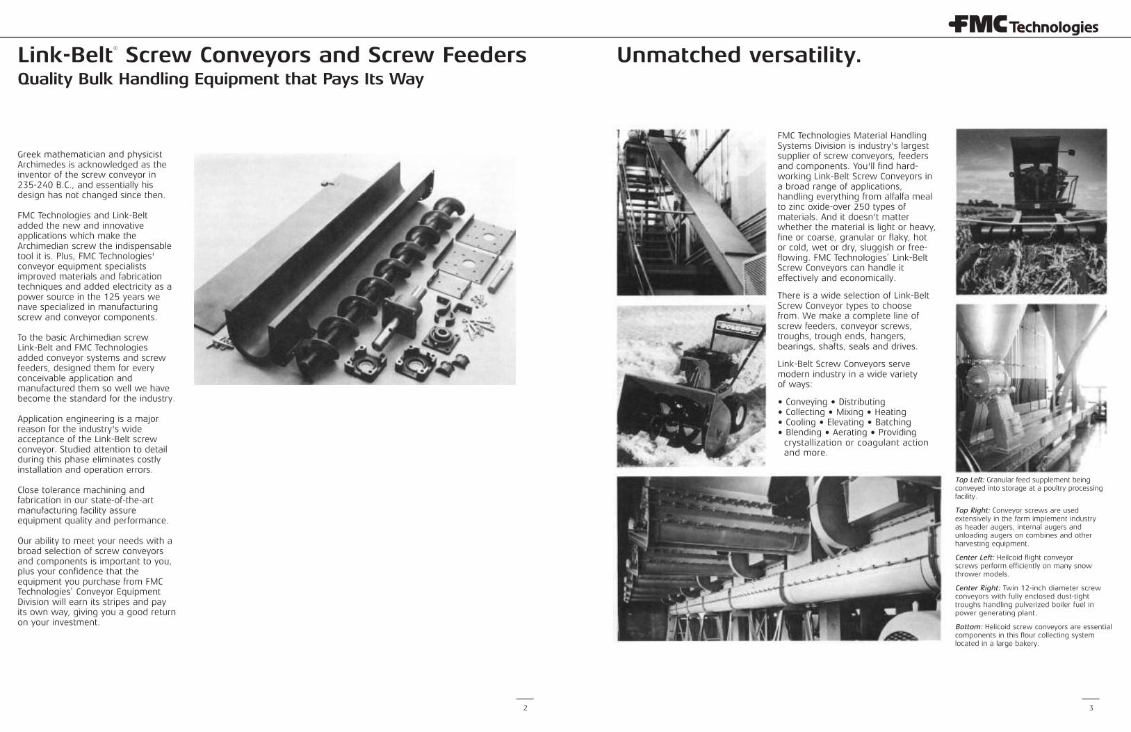
Top Left: Granular feed supplement beingconveyed into storage at a poultry processingfacility.
Top Right: Conveyor screws are usedextensively in the farm implement industryas header augers, internal augers andunloading augers on combines and otherharvesting equipment.
Center Left: Heilcoid flight conveyorscrews perform efficiently on many snowthrower models.
Center Right: Twin 12-inch diameter screwconveyors with fully enclosed dust-tighttroughs handling pulverized boiler fuel inpower generating plant.
Bottom: Helicoid screw conveyors are essentialcomponents in this flour collecting systemlocated in a large bakery.
4 5
When you buy from FMC Technologies,you can rely on our factory-stockedequipment and parts inventories whichare complemented by more than 140North American distributors with over400 branches. So you're guaranteed atimely response to your parts andservice needs. You keep downtime to aminimum because you get fastturnaround-from order entry to partsdelivery at your plant or jobsite.
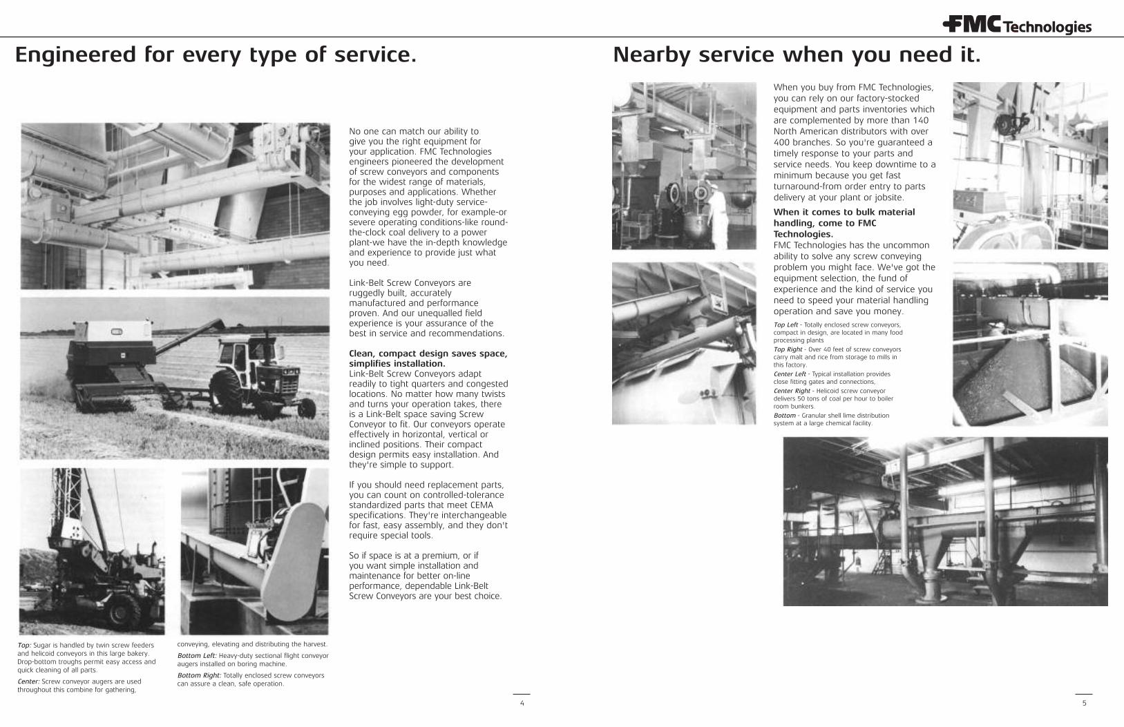
When it comes to bulk materialhandling, come to FMCTechnologies. FMC Technologies has the uncommonability to solve any screw conveyingproblem you might face. We've got theequipment selection, the fund ofexperience and the kind of service youneed to speed your material handlingoperation and save you money.Top Left - Totally enclosed screw conveyors,compact in design, are located in many foodprocessing plants
Top Right - Over 40 feet of screw conveyorscarry malt and rice from storage to mills inthis factory.
Center Left - Typical installation providesclose fitting gates and connections,
Center Right - Helicoid screw conveyordelivers 50 tons of coal per hour to boilerroom bunkers.
Bottom - Granular shell lime distributionsystem at a large chemical facility.
Nearby service when you need it.Engineered for every type of service.
No one can match our ability togive you the right equipment foryour application. FMC Technologiesengineers pioneered the developmentof screw conveyors and componentsfor the widest range of materials,purposes and applications. Whetherthe job involves light-duty service-conveying egg powder, for example-orsevere operating conditions-like round-the-clock coal delivery to a powerplant-we have the in-depth knowledgeand experience to provide just whatyou need.
Link-Belt Screw Conveyors areruggedly built, accuratelymanufactured and performanceproven. And our unequalled fieldexperience is your assurance of thebest in service and recommendations.
Clean, compact design saves space,simplifies installation.Link-Belt Screw Conveyors adaptreadily to tight quarters and congestedlocations. No matter how many twistsand turns your operation takes, thereis a Link-Belt space saving ScrewConveyor to fit. Our conveyors operateeffectively in horizontal, vertical orinclined positions. Their compactdesign permits easy installation. Andthey're simple to support.
If you should need replacement parts,you can count on controlled-tolerancestandardized parts that meet CEMAspecifications. They're interchangeablefor fast, easy assembly, and they don'trequire special tools.
So if space is at a premium, or ifyou want simple installation andmaintenance for better on-lineperformance, dependable Link-BeltScrew Conveyors are your best choice.
Top: Sugar is handled by twin screw feedersand helicoid conveyors in this large bakery.Drop-bottom troughs permit easy access andquick cleaning of all parts.
Center: Screw conveyor augers are usedthroughout this combine for gathering,
conveying, elevating and distributing the harvest.
Bottom Left: Heavy-duty sectional flight conveyoraugers installed on boring machine.
Bottom Right: Totally enclosed screw conveyorscan assure a clean, safe operation.
Component Description component description
6 7
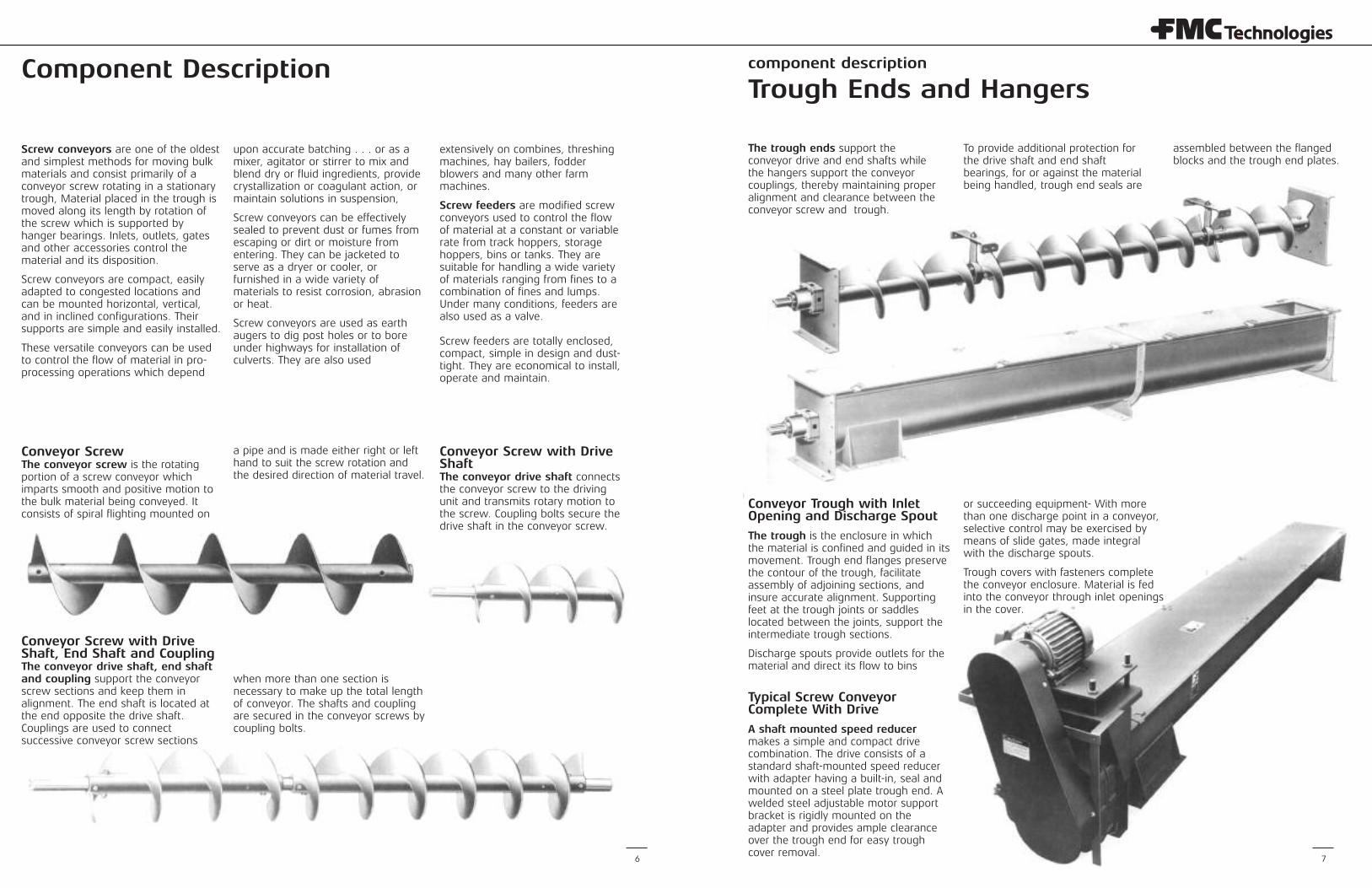
Screw conveyors are one of the oldestand simplest methods for moving bulkmaterials and consist primarily of aconveyor screw rotating in a stationarytrough, Material placed in the trough ismoved along its length by rotation ofthe screw which is supported byhanger bearings. Inlets, outlets, gatesand other accessories control thematerial and its disposition.
Screw conveyors are compact, easilyadapted to congested locations andcan be mounted horizontal, vertical,and in inclined configurations. Theirsupports are simple and easily installed.
These versatile conveyors can be usedto control the flow of material in pro-processing operations which depend
upon accurate batching . . . or as amixer, agitator or stirrer to mix andblend dry or fluid ingredients, providecrystallization or coagulant action, ormaintain solutions in suspension,
Screw conveyors can be effectivelysealed to prevent dust or fumes fromescaping or dirt or moisture fromentering. They can be jacketed toserve as a dryer or cooler, orfurnished in a wide variety ofmaterials to resist corrosion, abrasionor heat.
Screw conveyors are used as earthaugers to dig post holes or to boreunder highways for installation ofculverts. They are also used
extensively on combines, threshingmachines, hay bailers, fodderblowers and many other farmmachines.
Screw feeders are modified screwconveyors used to control the flowof material at a constant or variablerate from track hoppers, storagehoppers, bins or tanks. They aresuitable for handling a wide varietyof materials ranging from fines to acombination of fines and lumps.Under many conditions, feeders arealso used as a valve.
Screw feeders are totally enclosed,compact, simple in design and dust-tight. They are economical to install,operate and maintain.
Conveyor ScrewThe conveyor screw is the rotatingportion of a screw conveyor whichimparts smooth and positive motion tothe bulk material being conveyed. Itconsists of spiral flighting mounted on
a pipe and is made either right or lefthand to suit the screw rotation andthe desired direction of material travel.
Conveyor Screw with DriveShaftThe conveyor drive shaft connectsthe conveyor screw to the drivingunit and transmits rotary motion tothe screw. Coupling bolts secure thedrive shaft in the conveyor screw.
Conveyor Screw with DriveShaft, End Shaft and CouplingThe conveyor drive shaft, end shaftand coupling support the conveyorscrew sections and keep them inalignment. The end shaft is located atthe end opposite the drive shaft.Couplings are used to connectsuccessive conveyor screw sections
when more than one section isnecessary to make up the total lengthof conveyor. The shafts and couplingare secured in the conveyor screws bycoupling bolts.
Trough Ends and Hangers
The trough ends support theconveyor drive and end shafts whilethe hangers support the conveyorcouplings, thereby maintaining properalignment and clearance between theconveyor screw and trough.
To provide additional protection forthe drive shaft and end shaftbearings, for or against the materialbeing handled, trough end seals are
assembled between the flangedblocks and the trough end plates.
Conveyor Trough with InletOpening and Discharge Spout
The trough is the enclosure in whichthe material is confined and guided in itsmovement. Trough end flanges preservethe contour of the trough, facilitateassembly of adjoining sections, andinsure accurate alignment. Supportingfeet at the trough joints or saddleslocated between the joints, support theintermediate trough sections.
Discharge spouts provide outlets for thematerial and direct its flow to bins
or succeeding equipment- With morethan one discharge point in a conveyor,selective control may be exercised bymeans of slide gates, made integralwith the discharge spouts.
Trough covers with fasteners completethe conveyor enclosure. Material is fedinto the conveyor through inlet openingsin the cover.
Typical Screw ConveyorComplete With Drive
A shaft mounted speed reducermakes a simple and compact drivecombination. The drive consists of astandard shaft-mounted speed reducerwith adapter having a built-in, seal andmounted on a steel plate trough end. Awelded steel adjustable motor supportbracket is rigidly mounted on theadapter and provides ample clearanceover the trough end for easy troughcover removal.
component description
8 9
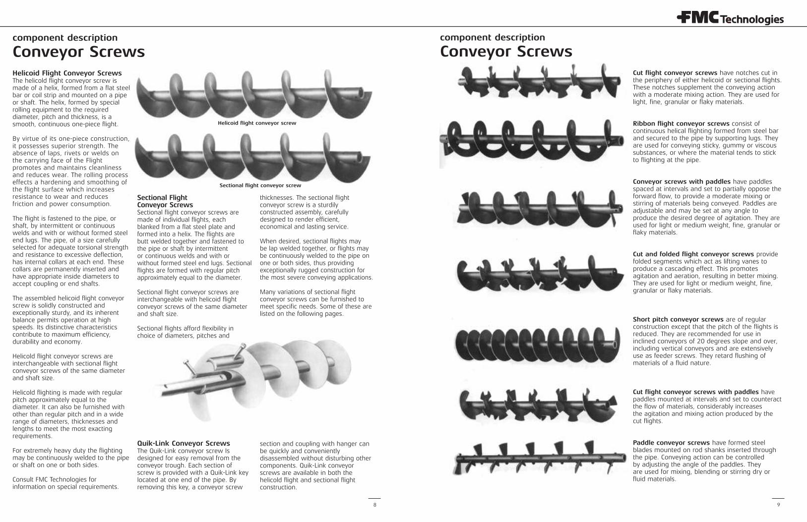
Helicoid Flight Conveyor ScrewsThe helicold flight conveyor screw ismade of a helix, formed from a flat steelbar or coil strip and mounted on a pipeor shaft. The helix, formed by specialrolling equipment to the requireddiameter, pitch and thickness, is asmooth, continuous one-piece flight.
By virtue of its one-piece construction,it possesses superior strength. Theabsence of laps, rivets or welds on the carrying face of the Flightpromotes and maintains cleanlinessand reduces wear. The rolling processeffects a hardening and smoothing ofthe flight surface which increasesresistance to wear and reducesfriction and power consumption.
The flight is fastened to the pipe, orshaft, by intermittent or continuouswelds and with or without formed steelend lugs. The pipe, of a size carefullyselected for adequate torsional strengthand resistance to excessive deflection,has internal collars at each end. Thesecollars are permanently inserted andhave appropriate inside diameters toaccept coupling or end shafts.
The assembled helicoid flight conveyorscrew is solidly constructed andexceptionally sturdy, and its inherentbalance permits operation at highspeeds. Its distinctive characteristicscontribute to maximum efficiency,durability and economy.
Helicold flight conveyor screws areinterchangeable with sectional flightconveyor screws of the same diameterand shaft size.
Helicold flighting is made with regularpitch approximately equal to thediameter. It can also be furnished withother than regular pitch and in a widerange of diameters, thicknesses andlengths to meet the most exactingrequirements.
For extremely heavy duty the flightingmay be continuously welded to the pipeor shaft on one or both sides.
Consult FMC Technologies forinformation on special requirements.
Sectional FlightConveyor ScrewsSectional flight conveyor screws aremade of individual flights, eachblanked from a flat steel plate andformed into a helix. The flights arebutt welded together and fastened tothe pipe or shaft by intermittentor continuous welds and with orwithout formed steel end lugs. Sectionalflights are formed with regular pitchapproximately equal to the diameter.
Sectional flight conveyor screws areinterchangeable with helicoid flightconveyor screws of the same diameterand shaft size.
Sectional flights afford flexibility inchoice of diameters, pitches and
thicknesses. The sectional flightconveyor screw is a sturdily constructed assembly, carefullydesigned to render efficient,economical and lasting service.
When desired, sectional flights may be lap welded together, or flights maybe continuously welded to the pipe onone or both sides, thus providingexceptionally rugged construction forthe most severe conveying applications.
Many variations of sectional flightconveyor screws can be furnished tomeet specific needs. Some of these arelisted on the following pages.
Quik-Link Conveyor ScrewsThe Quik-Link conveyor screw Isdesigned for easy removal from theconveyor trough. Each section ofscrew is provided with a Quik-Link keylocated at one end of the pipe. Byremoving this key, a conveyor screw
section and coupling with hanger canbe quickly and convenientlydisassembled without disturbing othercomponents. Quik-Link conveyorscrews are available in both thehelicold flight and sectional flightconstruction.
Conveyor Screws
Helicoid flight conveyor screw
Sectional flight conveyor screw
Cut flight conveyor screws have notches cut inthe periphery of either helicoid or sectional flights.These notches supplement the conveying actionwith a moderate mixing action. They are used forlight, fine, granular or flaky materials.
Ribbon flight conveyor screws consist ofcontinuous helical flighting formed from steel barand secured to the pipe by supporting lugs. Theyare used for conveying sticky, gummy or viscoussubstances, or where the material tends to stickto flighting at the pipe.
Conveyor screws with paddles have paddlesspaced at intervals and set to partially oppose theforward flow, to provide a moderate mixing orstirring of materials being conveyed. Paddles areadjustable and may be set at any angle toproduce the desired degree of agitation. They areused for light or medium weight, fine, granular orflaky materials.
Cut and folded flight conveyor screws providefolded segments which act as lifting vanes toproduce a cascading effect. This promotesagitation and aeration, resulting in better mixing.They are used for light or medium weight, fine,granular or flaky materials.
Short pitch conveyor screws are of regularconstruction except that the pitch of the flights isreduced. They are recommended for use ininclined conveyors of 20 degrees slope and over,including vertical conveyors and are extensivelyuse as feeder screws. They retard flushing ofmaterials of a fluid nature.
Cut flight conveyor screws with paddles havepaddles mounted at intervals and set to counteractthe flow of materials, considerably increasesthe agitation and mixing action produced by thecut flights.
Paddle conveyor screws have formed steelblades mounted on rod shanks inserted throughthe pipe. Conveying action can be controlledby adjusting the angle of the paddles. Theyare used for mixing, blending or stirring dry orfluid materials.
component description
Conveyor Screws
component description
10 11
Conveyor Screws
Ribbon Flight Conveyor Screwsconsist of sectional flights, butt weldedtogether to form a continuous helix.Flights are secured to the pipe bysupporting lugs.
Variations of diameter, pitch, flightwidth or thickness can be furnished.Also, these screws can be furnishedwith either continuous or sectionalflights, lap or butt welded together.
Ribbon flight conveyor screws are thesolution to most conveying problemsencountered in the handling of sticky,gummy or viscous materials. Thetendency of materials of this nature toadhere and build up at the juncture ofsolid flight with the pipe is overcomeby the open construction of the ribbonflight. Raw sugar, molasses, asphalt,hot tar, sticky feed mixes, and similarproducts are typical of the manymaterials successfully handled byribbon flight conveyor screws.
Providing the periphery of ribbonflights with a beveled edge improvesoperation and reduces powerconsumption when handling materialswhich tend to pack or trowel betweenflights and trough. Consequently,beveled edge ribbon flight conveyorscrews are usually subjected toextremely heavy loads, andconstruction is accordingly heavy andrugged. The ribbon flights aresupported on the pipe or shaft by steel lugs, generously proportioned toresist bending.
Where the material handled movesvirtually en masse, there is but veryslight difference in capacity betweenribbon and solid flight conveyorscrews of the same size. Mixing action without supplementary meansof agitation is negligible.
Ribbon Flight Conveyor Screwwith PaddlesTo provide moderate mixing or stirringof materials being conveyed, paddlescan be furnished, spaced at intervalsand set to partially oppose the forwardflow. Paddles are adjustable and maybe set at any angle to produce thedesired degree of agitation. They areused for light or medium weight, fine,granular or flaky materials.
Multiple Ribbon Flight ConveyorScrewsThis type of screw consists of two ormore ribbon flights of differentdiameters and opposite hand,mounted one with in the other on thesame pipe or shaft by rigid supportinglugs. Material is moved forward by oneflight and backward by the other,thereby including positive andthorough mixing.
Abrasion-Resistant ConveyorScrews The particularly severe serviceencountered when conveying abrasivematerials has prompted manyattempts to overcome excessive wearon flights. Several successful methodshave been developed.
Each of these methods offers specificadvantages depending on the natureof the material handled and theapplication. For a careful analysis andrecommendation, consult FMCTechnologies Conveyor EquipmentDivision.
Hard surfacing by application of aspecial compound, by arc or torch, tothe flight periphery or face, or both,provides an exceptionally hard surfaceat the points of greatest wear.
For severe applications, conveyors withhigh alumina ceramic tile bonded tothe flight periphery or face are alsoavailable.
Corrosion-Resistant ConveyorScrewsCorrosion is manifested in so manydifferent ways that no one choice ofmaterial will suit all requirements. Towithstand the effects of corrosionencountered in many fields of industry,conveyor screws are fabricated ofstainless steel, Monel metal,aluminum, and other materials.
Galvanizing and other coating methodshave proved effective under mildlycorrosive conditions. Vulcanized orbonded rubber covering of the entireconveyor is frequently satisfactory forresistance to extremely corrosiveaction.
Heat-Resistant Conveyor ScrewsConveyor screws for high temperatureapplications are made of many of theavailable heat-resistant alloys. Severalof the stainless steels and other high-chrome alloys are particularly suitablefor this service.
Ribbon flight conveyor screw
Ribbon flight conveyor screw with paddles
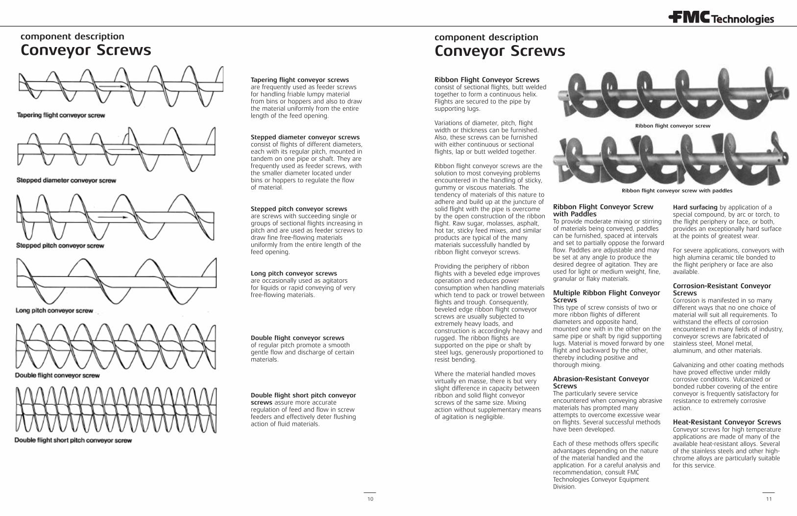
Tapering flight conveyor screwsare frequently used as feeder screwsfor handling friable lumpy materialfrom bins or hoppers and also to drawthe material uniformly from the entirelength of the feed opening.
Stepped diameter conveyor screwsconsist of flights of different diameters,each with its regular pitch, mounted intandem on one pipe or shaft. They arefrequently used as feeder screws, withthe smaller diameter located underbins or hoppers to regulate the flowof material.
Stepped pitch conveyor screwsare screws with succeeding single orgroups of sectional flights increasing inpitch and are used as feeder screws todraw fine free-fIowing materialsuniformly from the entire length of thefeed opening.
Long pitch conveyor screwsare occasionally used as agitatorsfor liquids or rapid conveying of veryfree-flowing materials.
Double fIight conveyor screwsof regular pitch promote a smoothgentle flow and discharge of certainmaterials.
Double flight short pitch conveyorscrews assure more accurateregulation of feed and flow in screwfeeders and effectively deter flushingaction of fluid materials.
component description
Conveyor Screws
component descriptioncomponent description
12 13
Drive Shafts, End Shafts and Couplings Hangers
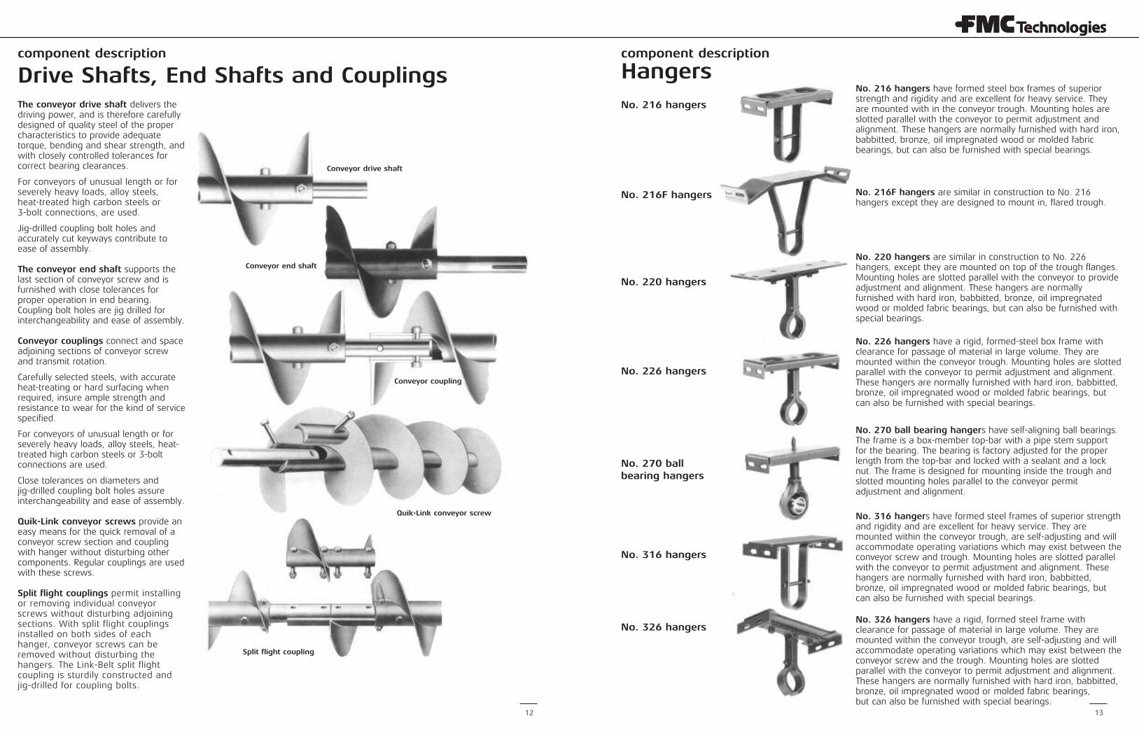
Conveyor drive shaft
Conveyor end shaft
Conveyor coupling
Quik-Link conveyor screw
Split flight coupling
The conveyor drive shaft delivers thedriving power, and is therefore carefullydesigned of quality steel of the propercharacteristics to provide adequatetorque, bending and shear strength, andwith closely controlled tolerances forcorrect bearing clearances.
For conveyors of unusual length or forseverely heavy loads, alloy steels, heat-treated high carbon steels or 3-bolt connections, are used.
Jig-drilled coupling bolt holes andaccurately cut keyways contribute toease of assembly.
The conveyor end shaft supports thelast section of conveyor screw and isfurnished with close tolerances forproper operation in end bearing.Coupling bolt holes are jig drilled forinterchangeability and ease of assembly.
Conveyor couplings connect and spaceadjoining sections of conveyor screwand transmit rotation.
Carefully selected steels, with accurateheat-treating or hard surfacing whenrequired, insure ample strength andresistance to wear for the kind of servicespecified.
For conveyors of unusual length or forseverely heavy loads, alloy steels, heat-treated high carbon steels or 3-boltconnections are used.
Close tolerances on diameters andjig-drilled coupling bolt holes assureinterchangeability and ease of assembly.
Quik-Link conveyor screws provide aneasy means for the quick removal of aconveyor screw section and couplingwith hanger without disturbing othercomponents. Regular couplings are usedwith these screws.
Split flight couplings permit installingor removing individual conveyorscrews without disturbing adjoiningsections. With split flight couplingsinstalled on both sides of eachhanger, conveyor screws can beremoved without disturbing thehangers. The Link-Belt split flightcoupling is sturdily constructed andjig-drilled for coupling bolts.
No. 216 hangers have formed steel box frames of superiorstrength and rigidity and are excellent for heavy service. Theyare mounted with in the conveyor trough. Mounting holes areslotted parallel with the conveyor to permit adjustment andalignment. These hangers are normally furnished with hard iron,babbitted, bronze, oil impregnated wood or molded fabricbearings, but can also be furnished with special bearings.
No. 216F hangers are similar in construction to No. 216hangers except they are designed to mount in, flared trough.
No. 220 hangers are similar in construction to No. 226hangers, except they are mounted on top of the trough flanges.Mounting holes are slotted parallel with the conveyor to provideadjustment and alignment. These hangers are normallyfurnished with hard iron, babbitted, bronze, oil impregnatedwood or molded fabric bearings, but can also be furnished withspecial bearings.
No. 226 hangers have a rigid, formed-steel box frame withclearance for passage of material in large volume. They aremounted within the conveyor trough. Mounting holes are slottedparallel with the conveyor to permit adjustment and alignment.These hangers are normally furnished with hard iron, babbitted,bronze, oil impregnated wood or molded fabric bearings, butcan also be furnished with special bearings.
No. 270 ball bearing hangers have self-aligning ball bearings.The frame is a box-member top-bar with a pipe stem supportfor the bearing. The bearing is factory adjusted for the properlength from the top-bar and locked with a sealant and a locknut. The frame is designed for mounting inside the trough andslotted mounting holes parallel to the conveyor permitadjustment and alignment.
No. 316 hangers have formed steel frames of superior strengthand rigidity and are excellent for heavy service. They aremounted within the conveyor trough, are self-adjusting and willaccommodate operating variations which may exist between theconveyor screw and trough. Mounting holes are slotted parallelwith the conveyor to permit adjustment and alignment. Thesehangers are normally furnished with hard iron, babbitted,bronze, oil impregnated wood or molded fabric bearings, butcan also be furnished with special bearings.
No. 326 hangers have a rigid, formed steel frame withclearance for passage of material in large volume. They aremounted within the conveyor trough, are self-adjusting and willaccommodate operating variations which may exist between theconveyor screw and the trough. Mounting holes are slottedparallel with the conveyor to permit adjustment and alignment.These hangers are normally furnished with hard iron, babbitted,bronze, oil impregnated wood or molded fabric bearings, but can also be furnished with special bearings.
No. 216 hangers
No. 216F hangers
No. 220 hangers
No. 226 hangers
No. 270 ballbearing hangers
No. 316 hangers
No. 326 hangers
component description component description
14 15
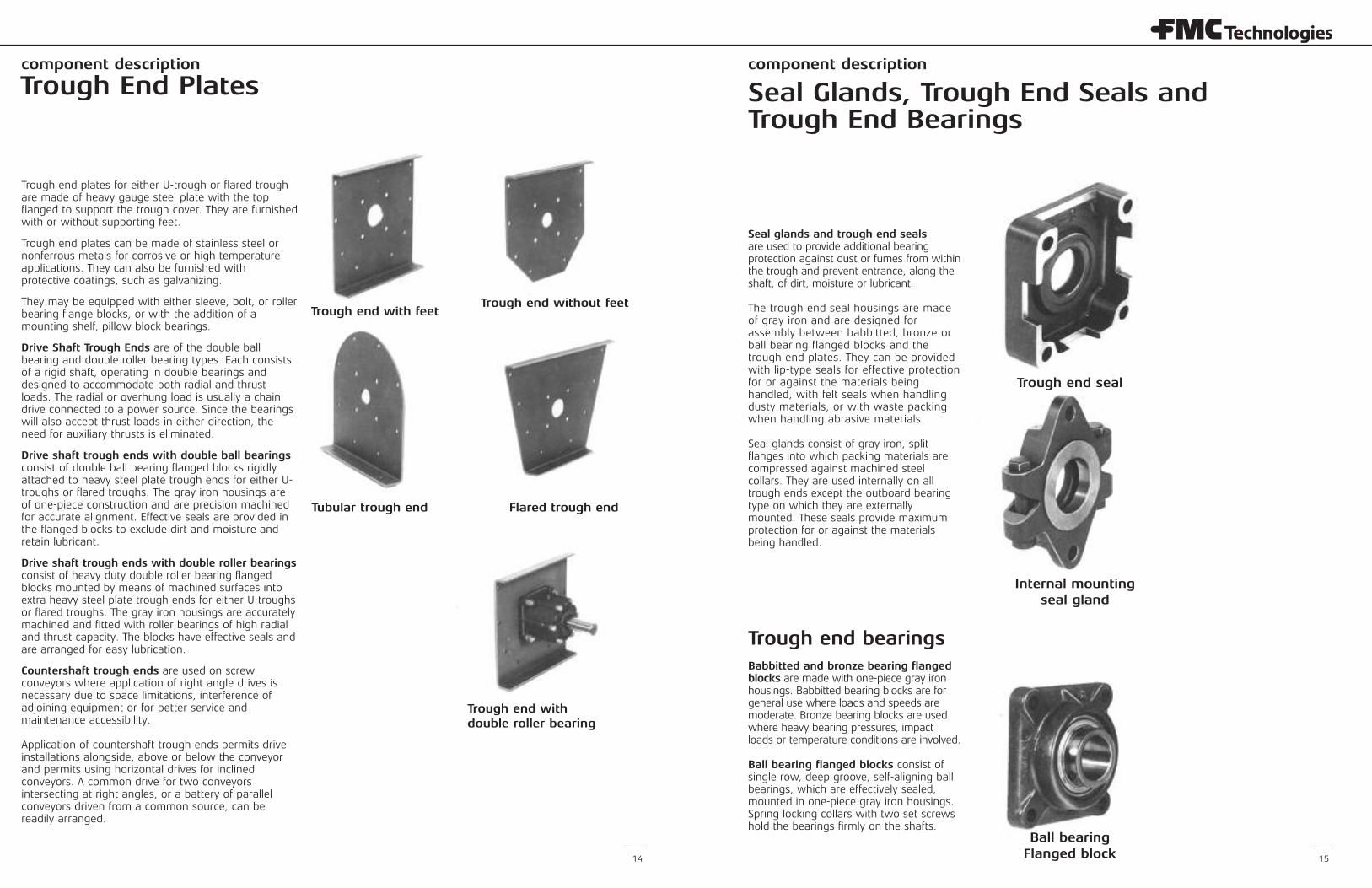
Trough End Plates Seal Glands, Trough End Seals andTrough End Bearings
Trough end with feetTrough end without feet
Tubular trough end Flared trough end
Trough end withdouble roller bearing
Trough end plates for either U-trough or flared troughare made of heavy gauge steel plate with the topflanged to support the trough cover. They are furnishedwith or without supporting feet.
Trough end plates can be made of stainless steel ornonferrous metals for corrosive or high temperatureapplications. They can also be furnished withprotective coatings, such as galvanizing.
They may be equipped with either sleeve, bolt, or rollerbearing flange blocks, or with the addition of amounting shelf, pillow block bearings.
Drive Shaft Trough Ends are of the double ballbearing and double roller bearing types. Each consistsof a rigid shaft, operating in double bearings anddesigned to accommodate both radial and thrustloads. The radial or overhung load is usually a chaindrive connected to a power source. Since the bearingswill also accept thrust loads in either direction, theneed for auxiliary thrusts is eliminated.
Drive shaft trough ends with double ball bearingsconsist of double ball bearing flanged blocks rigidlyattached to heavy steel plate trough ends for either U-troughs or flared troughs. The gray iron housings areof one-piece construction and are precision machinedfor accurate alignment. Effective seals are provided inthe flanged blocks to exclude dirt and moisture andretain lubricant.
Drive shaft trough ends with double roller bearingsconsist of heavy duty double roller bearing flangedblocks mounted by means of machined surfaces intoextra heavy steel plate trough ends for either U-troughsor flared troughs. The gray iron housings are accuratelymachined and fitted with roller bearings of high radialand thrust capacity. The blocks have effective seals andare arranged for easy lubrication.
Countershaft trough ends are used on screwconveyors where application of right angle drives isnecessary due to space limitations, interference ofadjoining equipment or for better service andmaintenance accessibility.
Application of countershaft trough ends permits driveinstallations alongside, above or below the conveyorand permits using horizontal drives for inclinedconveyors. A common drive for two conveyorsintersecting at right angles, or a battery of parallelconveyors driven from a common source, can bereadily arranged.
Seal glands and trough end sealsare used to provide additional bearingprotection against dust or fumes from withinthe trough and prevent entrance, along theshaft, of dirt, moisture or lubricant.
The trough end seal housings are madeof gray iron and are designed forassembly between babbitted, bronze orball bearing flanged blocks and thetrough end plates. They can be providedwith lip-type seals for effective protectionfor or against the materials beinghandled, with felt seals when handlingdusty materials, or with waste packingwhen handling abrasive materials.
Seal glands consist of gray iron, splitflanges into which packing materials arecompressed against machined steelcollars. They are used internally on alltrough ends except the outboard bearingtype on which they are externallymounted. These seals provide maximumprotection for or against the materialsbeing handled.
Trough end bearingsBabbitted and bronze bearing flangedblocks are made with one-piece gray ironhousings. Babbitted bearing blocks are forgeneral use where loads and speeds aremoderate. Bronze bearing blocks are usedwhere heavy bearing pressures, impactloads or temperature conditions are involved.
Ball bearing flanged blocks consist ofsingle row, deep groove, self-aligning ballbearings, which are effectively sealed,mounted in one-piece gray iron housings.Spring locking collars with two set screwshold the bearings firmly on the shafts.
Trough end seal
Internal mountingseal gland
Ball bearingFlanged block
component description component description
16 17
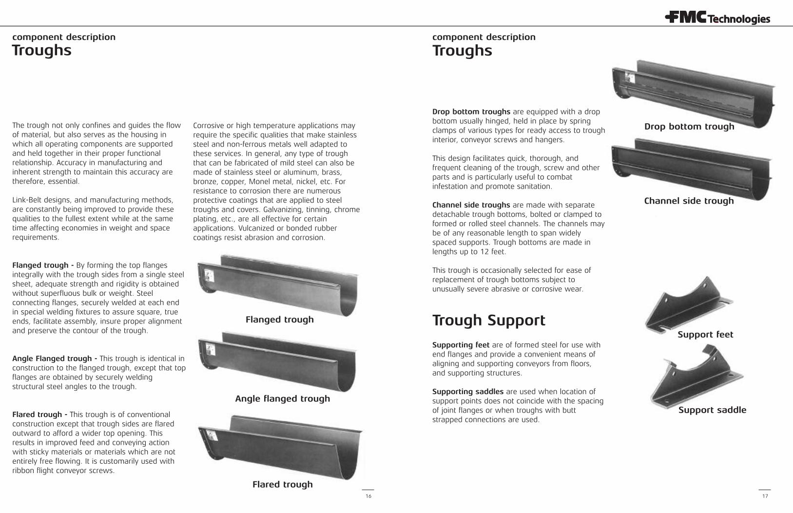
Troughs Troughs
The trough not only confines and guides the flowof material, but also serves as the housing inwhich all operating components are supportedand held together in their proper functionalrelationship. Accuracy in manufacturing andinherent strength to maintain this accuracy aretherefore, essential.
Link-Belt designs, and manufacturing methods,are constantly being improved to provide thesequalities to the fullest extent while at the sametime affecting economies in weight and spacerequirements.
Flanged trough - By forming the top flangesintegrally with the trough sides from a single steelsheet, adequate strength and rigidity is obtainedwithout superfluous bulk or weight. Steelconnecting flanges, securely welded at each endin special welding fixtures to assure square, trueends, facilitate assembly, insure proper alignmentand preserve the contour of the trough.
Angle Flanged trough - This trough is identical inconstruction to the flanged trough, except that topflanges are obtained by securely weldingstructural steel angles to the trough.
Flared trough - This trough is of conventionalconstruction except that trough sides are flaredoutward to afford a wider top opening. Thisresults in improved feed and conveying actionwith sticky materials or materials which are notentirely free flowing. It is customarily used withribbon flight conveyor screws.
Corrosive or high temperature applications mayrequire the specific qualities that make stainlesssteel and non-ferrous metals well adapted tothese services. In general, any type of troughthat can be fabricated of mild steel can also bemade of stainless steel or aluminum, brass,bronze, copper, Monel metal, nickel, etc. Forresistance to corrosion there are numerousprotective coatings that are applied to steeltroughs and covers. Galvanizing, tinning, chromeplating, etc., are all effective for certainapplications. Vulcanized or bonded rubbercoatings resist abrasion and corrosion.
Flanged trough
Angle flanged trough
Flared trough
Drop bottom troughs are equipped with a dropbottom usually hinged, held in place by springclamps of various types for ready access to troughinterior, conveyor screws and hangers.
This design facilitates quick, thorough, andfrequent cleaning of the trough, screw and otherparts and is particularly useful to combatinfestation and promote sanitation.
Channel side troughs are made with separatedetachable trough bottoms, bolted or clamped toformed or rolled steel channels. The channels maybe of any reasonable length to span widelyspaced supports. Trough bottoms are made inlengths up to 12 feet.
This trough is occasionally selected for ease ofreplacement of trough bottoms subject tounusually severe abrasive or corrosive wear.
Trough Support
Supporting feet are of formed steel for use withend flanges and provide a convenient means ofaligning and supporting conveyors from floors,and supporting structures.
Supporting saddles are used when location ofsupport points does not coincide with the spacingof joint flanges or when troughs with buttstrapped connections are used.
Support saddle
Support feet
Channel side trough
Drop bottom trough
component description component description
18 19
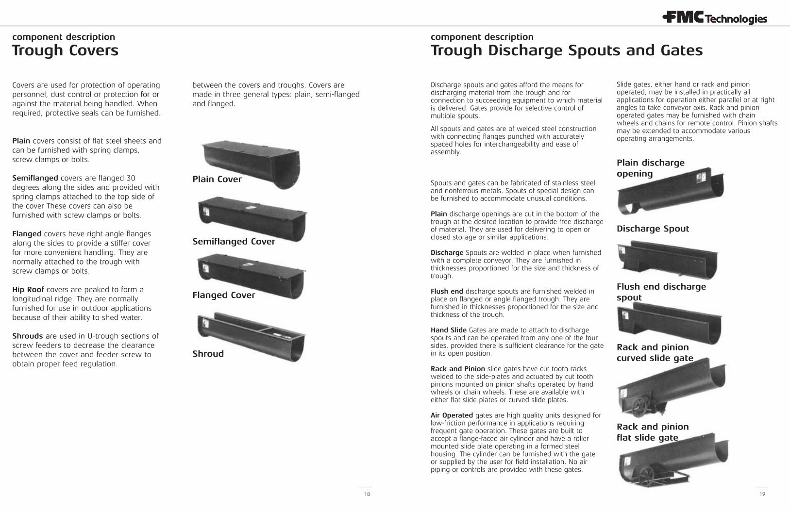
Trough Covers Trough Discharge Spouts and Gates
Covers are used for protection of operatingpersonnel, dust control or protection for oragainst the material being handled. Whenrequired, protective seals can be furnished.
Plain covers consist of flat steel sheets andcan be furnished with spring clamps,screw clamps or bolts.
Semiflanged covers are flanged 30degrees along the sides and provided withspring clamps attached to the top side ofthe cover These covers can also befurnished with screw clamps or bolts.
Flanged covers have right angle flangesalong the sides to provide a stiffer coverfor more convenient handling. They arenormally attached to the trough withscrew clamps or bolts.
Hip Roof covers are peaked to form alongitudinal ridge. They are normallyfurnished for use in outdoor applicationsbecause of their ability to shed water.
Shrouds are used in U-trough sections ofscrew feeders to decrease the clearancebetween the cover and feeder screw toobtain proper feed regulation.
between the covers and troughs. Covers aremade in three general types: plain, semi-flangedand flanged.
Plain Cover
Semiflanged Cover
Flanged Cover
Shroud
Discharge spouts and gates afford the means fordischarging material from the trough and forconnection to succeeding equipment to which materialis delivered. Gates provide for selective control ofmultiple spouts.
All spouts and gates are of welded steel constructionwith connecting flanges punched with accuratelyspaced holes for interchangeability and ease ofassembly.
Spouts and gates can be fabricated of stainless steeland nonferrous metals. Spouts of special design canbe furnished to accommodate unusual conditions.
Plain discharge openings are cut in the bottom of thetrough at the desired location to provide free dischargeof material. They are used for delivering to open orclosed storage or similar applications.
Discharge Spouts are welded in place when furnishedwith a complete conveyor. They are furnished inthicknesses proportioned for the size and thickness oftrough.
Flush end discharge spouts are furnished welded inplace on flanged or angle flanged trough. They arefurnished in thicknesses proportioned for the size andthickness of the trough.
Hand Slide Gates are made to attach to dischargespouts and can be operated from any one of the foursides, provided there is sufficient clearance for the gatein its open position.
Rack and Pinion slide gates have cut tooth rackswelded to the side-plates and actuated by cut toothpinions mounted on pinion shafts operated by handwheels or chain wheels. These are available witheither flat slide plates or curved slide plates.
Air Operated gates are high quality units designed forlow-friction performance in applications requiringfrequent gate operation. These gates are built toaccept a flange-faced air cylinder and have a rollermounted slide plate operating in a formed steelhousing. The cylinder can be furnished with the gateor supplied by the user for field installation. No airpiping or controls are provided with these gates.
Slide gates, either hand or rack and pinionoperated, may be installed in practically allapplications for operation either parallel or at rightangles to take conveyor axis. Rack and pinionoperated gates may be furnished with chainwheels and chains for remote control. Pinion shaftsmay be extended to accommodate variousoperating arrangements.
Plain dischargeopening
Discharge Spout
Flush end dischargespout
Rack and pinioncurved slide gate
Rack and pinionflat slide gate
layout information
20 21
Technical Data
The Link-Belt screw conveyor layout,engineering and component selectioninformation in this section is provided toassist you in the selection of the properconveyor components for your particularmaterial handling requirement. It hasbeen compiled during the many years ofexperience designing numerous andvaried screw conveyor installations, andincludes detailed information on all Link-Belt standard screw conveyorcomponents and accessories.
The data and formulas presented permiteasy selection of the necessarycomponents for handling materialsunder normal operating conditions byhorizontal screw conveyors and screwfeeders.
Where unusual applications or severeoperating conditions are a factor orwhere there is doubt concerning thecorrect selection, contact FMCTechnologies Conveyor EquipmentDivision, Tupelo, MS to assist you withadditional information.
For prompt delivery, many of thesecomponents are carried in inventory atour authorized FMC TechnologiesStocking Distributor locations and at ourmanufacturing facility in Tupelo,Mississippi.
Portions of Engineering and ComponentSelection sections are reproduced fromConveyor Equipment ManufacturersAssociation CEMA books 300 and 350.CEMA Book 350 contains comprehen-sive screw conveyor reference material.Book 300 contains screw conveyordimensional standards. CAUTION: Link-Belt Screw
Conveyors and components must beinstalled, operated and maintained inaccordance with accompanying FMCTechnologies Service Instructions.Failure to follow these instructionscan result in serious personal injury,property damage or both.FMC Technologies Service Instructionsaccompany the shipment of equipment.If additional copies of ServiceInstructions are required, they are available free of charge from FMC Technologies Corporation,Conveyor Equipment Division,Box 1370, Tupelo, Mississippi 38802.
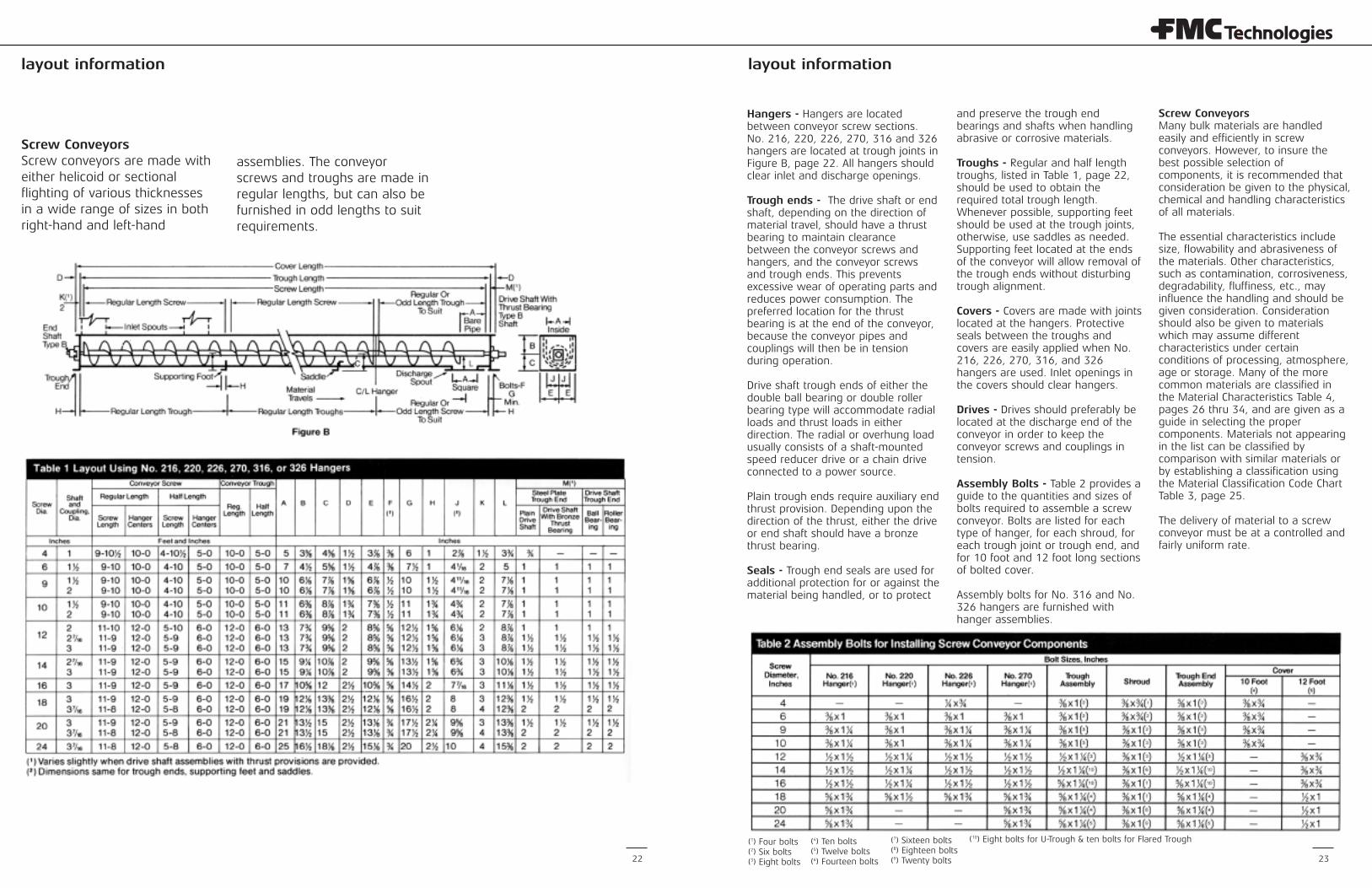
Layout Data Use the conveyor layout on page 22when selecting components. This layoutis based on using regular, or odd lengthscrews and troughs at the tail end ofthe conveyor and regular length screwsand troughs for the drive andintermediate sections. Hangers arelocated at the trough joints.
The drive shafts that provide a nominalclearance between the ends of theconveyor screws and the trough endare designated as Type A shafts.
The drive and tall end shafts that arelong enough to permit a clearancebetween the ends of the conveyorscrews and the trough ends equal toapproximately one-half the hangerbearing length are designated as Type B shafts.
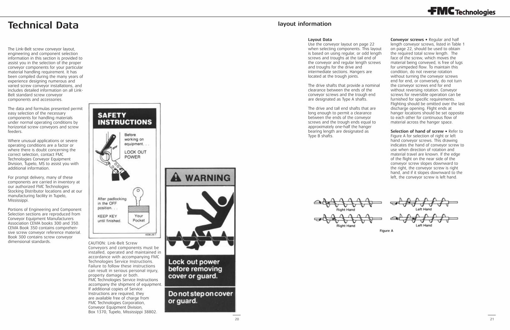
Conveyor screws • Regular and halflength conveyor screws, listed in Table 1on page 22, should be used to obtainthe required total screw length. Theface of the screw, which moves thematerial being conveyed, is free of lugsfor unimpeded flow. To maintain thiscondition, do not reverse rotationwithout turning the conveyor screwsend for end, or conversely, do not turnthe conveyor screws end for endwithout reversing rotation. Conveyorscrews for reversible operation can befurnished for specific requirements.Flighting should be omitted over the lastdischarge opening. Flight ends athanger locations should be set oppositeto each other for continuous flow ofmaterial across the hanger space.
Selection of hand of screw • Refer toFigure A for selection of right or lefthand conveyor screws. This drawingindicates the hand of conveyor screw touse when direction of rotation andmaterial travel are known. If the edgeof the flight on the near side of theconveyor screw slopes downward tothe right, the conveyor screw is righthand, and if it slopes downward to theleft, the conveyor screw is left hand.
Figure A
layout information layout information
22 23
Screw Conveyors Screw conveyors are made witheither helicoid or sectionalflighting of various thicknessesin a wide range of sizes in bothright-hand and left-hand
assemblies. The conveyorscrews and troughs are made inregular lengths, but can also befurnished in odd lengths to suitrequirements.
Hangers - Hangers are locatedbetween conveyor screw sections. No. 216, 220, 226, 270, 316 and 326hangers are located at trough joints inFigure B, page 22. All hangers shouldclear inlet and discharge openings.
Trough ends - The drive shaft or endshaft, depending on the direction ofmaterial travel, should have a thrustbearing to maintain clearancebetween the conveyor screws andhangers, and the conveyor screwsand trough ends. This preventsexcessive wear of operating parts andreduces power consumption. Thepreferred location for the thrustbearing is at the end of the conveyor,because the conveyor pipes andcouplings will then be in tensionduring operation.
Drive shaft trough ends of either thedouble ball bearing or double rollerbearing type will accommodate radialloads and thrust loads in eitherdirection. The radial or overhung loadusually consists of a shaft-mountedspeed reducer drive or a chain driveconnected to a power source.
Plain trough ends require auxiliary endthrust provision. Depending upon thedirection of the thrust, either the driveor end shaft should have a bronzethrust bearing.
Seals - Trough end seals are used foradditional protection for or against thematerial being handled, or to protect
and preserve the trough endbearings and shafts when handlingabrasive or corrosive materials.
Troughs - Regular and half lengthtroughs, listed in Table 1, page 22,should be used to obtain therequired total trough length.Whenever possible, supporting feetshould be used at the trough joints,otherwise, use saddles as needed.Supporting feet located at the endsof the conveyor will allow removal ofthe trough ends without disturbingtrough alignment.
Covers - Covers are made with jointslocated at the hangers. Protectiveseals between the troughs andcovers are easily applied when No.216, 226, 270, 316, and 326hangers are used. Inlet openings inthe covers should clear hangers.
Drives - Drives should preferably belocated at the discharge end of theconveyor in order to keep theconveyor screws and couplings intension.
Assembly Bolts - Table 2 provides aguide to the quantities and sizes ofbolts required to assemble a screwconveyor. Bolts are listed for eachtype of hanger, for each shroud, foreach trough joint or trough end, andfor 10 foot and 12 foot long sectionsof bolted cover.
Assembly bolts for No. 316 and No.326 hangers are furnished withhanger assemblies.
Screw ConveyorsMany bulk materials are handledeasily and efficiently in screwconveyors. However, to insure thebest possible selection ofcomponents, it is recommended thatconsideration be given to the physical,chemical and handling characteristicsof all materials.
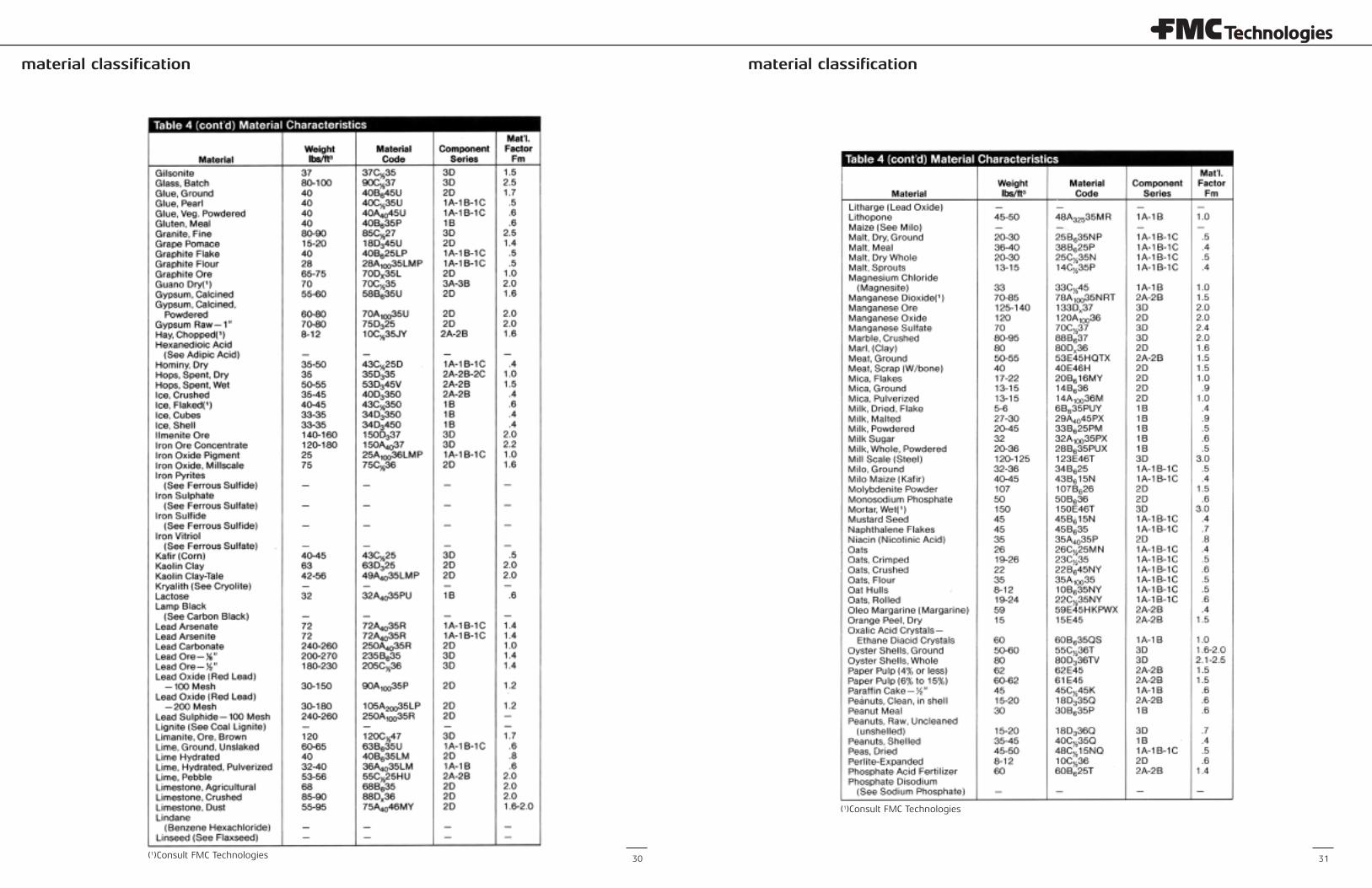
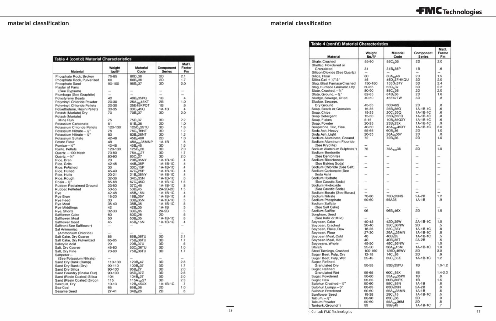
The essential characteristics includesize, flowability and abrasiveness ofthe materials. Other characteristics,such as contamination, corrosiveness,degradability, fluffiness, etc., mayinfluence the handling and should begiven consideration. Considerationshould also be given to materialswhich may assume differentcharacteristics under certainconditions of processing, atmosphere,age or storage. Many of the morecommon materials are classified in the Material Characteristics Table 4,pages 26 thru 34, and are given as aguide in selecting the propercomponents. Materials not appearingin the list can be classified bycomparison with similar materials orby establishing a classification usingthe Material Classification Code ChartTable 3, page 25.
The delivery of material to a screwconveyor must be at a controlled andfairly uniform rate.
(1) Four bolts(2) Six bolts(3) Eight bolts
(4) Ten bolts(5) Twelve bolts(6) Fourteen bolts
(7) Sixteen bolts(8) Eighteen bolts(9) Twenty bolts
(10) Eight bolts for U-Trough & ten bolts for Flared Trough
layout information material classification
24 25
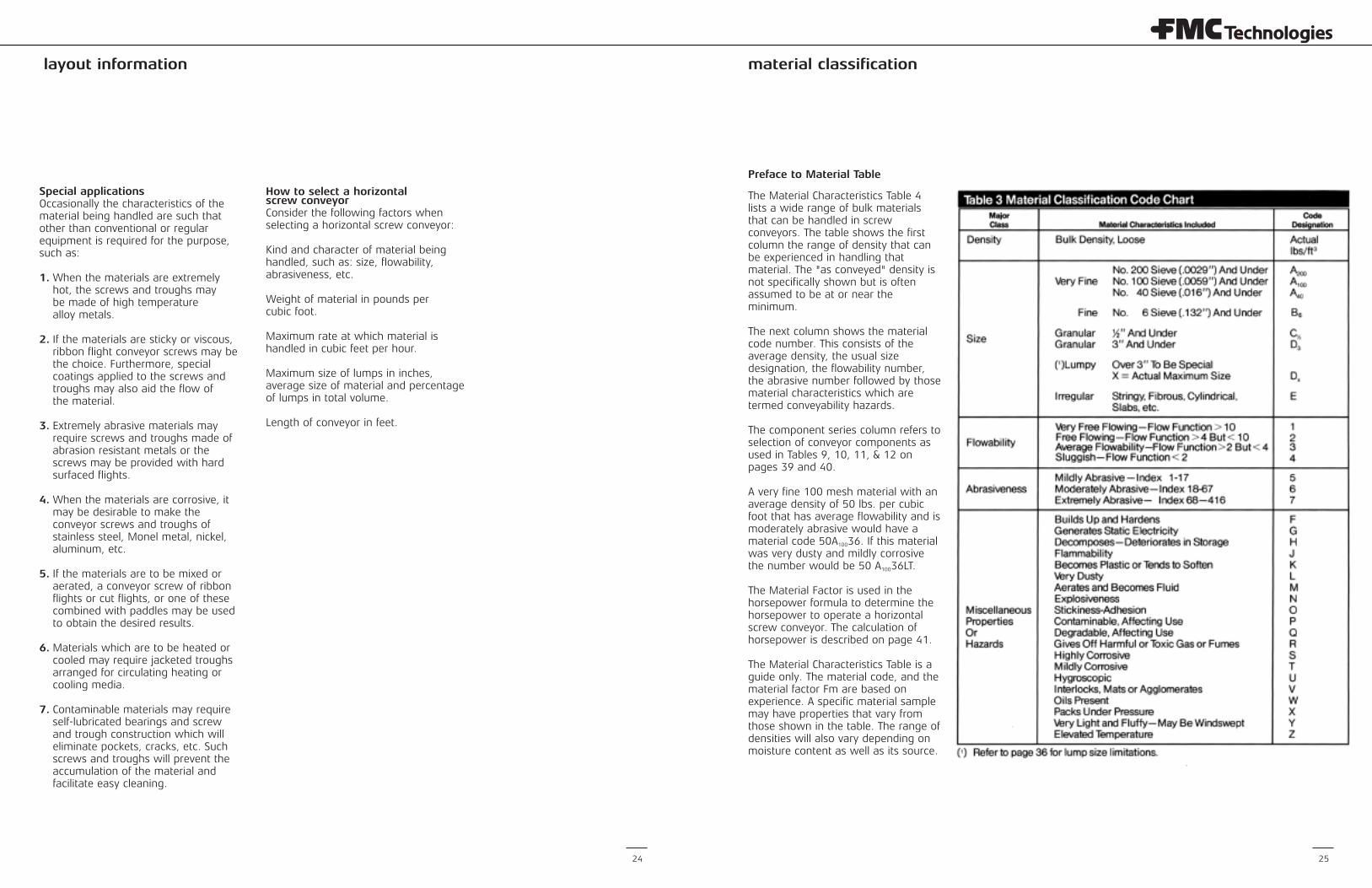
Preface to Material Table
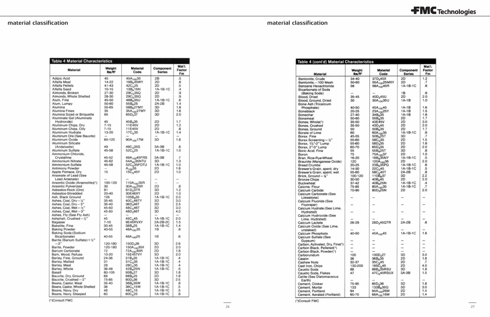
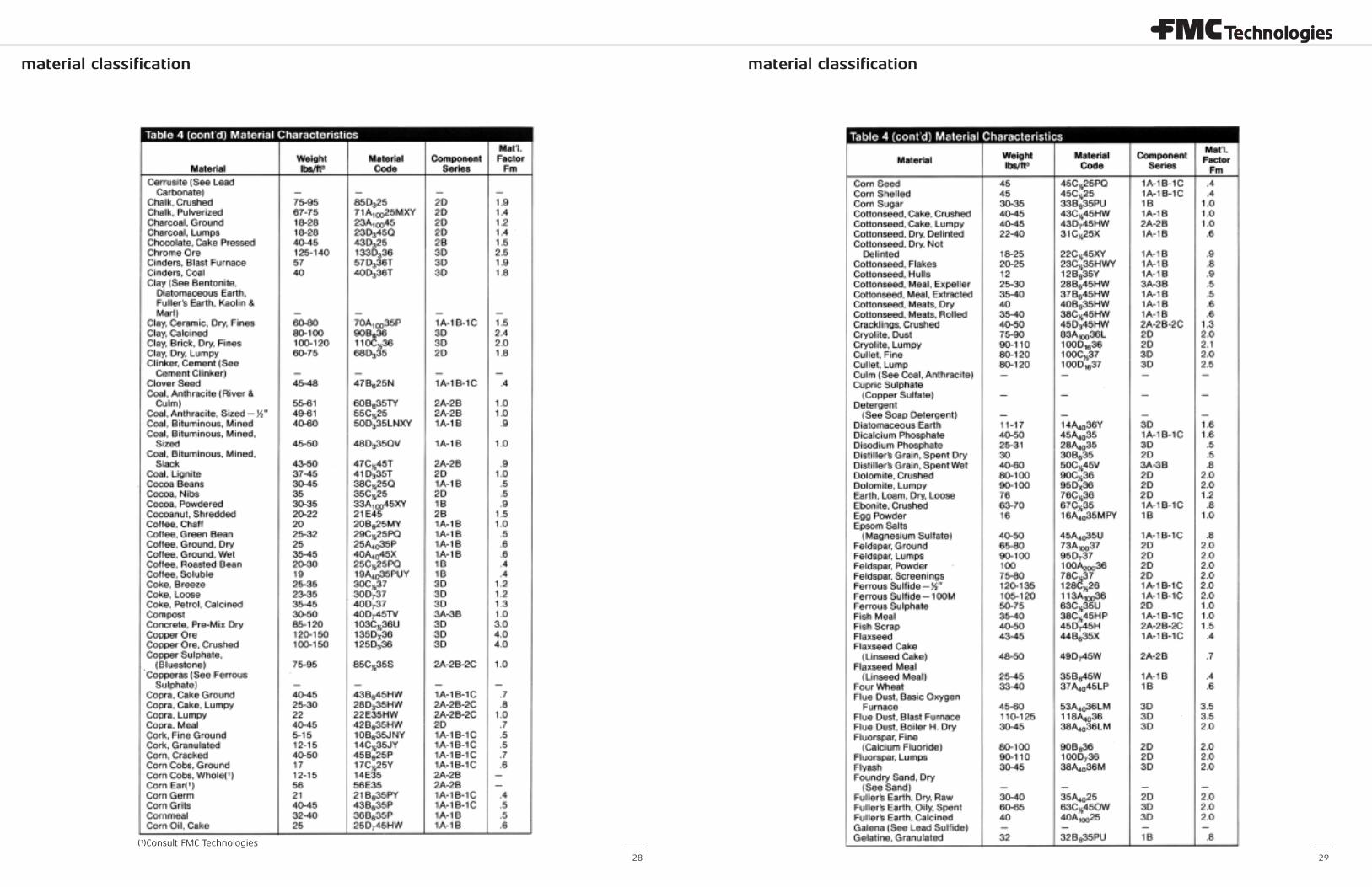
The Material Characteristics Table 4lists a wide range of bulk materialsthat can be handled in screwconveyors. The table shows the firstcolumn the range of density that canbe experienced in handling thatmaterial. The "as conveyed" density isnot specifically shown but is oftenassumed to be at or near theminimum.
The next column shows the materialcode number. This consists of theaverage density, the usual sizedesignation, the flowability number,the abrasive number followed by thosematerial characteristics which aretermed conveyability hazards.
The component series column refers toselection of conveyor components asused in Tables 9, 10, 11, & 12 onpages 39 and 40.
A very fine 100 mesh material with anaverage density of 50 lbs. per cubicfoot that has average flowability and ismoderately abrasive would have amaterial code 50A10036. If this materialwas very dusty and mildly corrosivethe number would be 50 A10036LT.
The Material Factor is used in thehorsepower formula to determine thehorsepower to operate a horizontalscrew conveyor. The calculation ofhorsepower is described on page 41.
The Material Characteristics Table is aguide only. The material code, and thematerial factor Fm are based onexperience. A specific material samplemay have properties that vary fromthose shown in the table. The range ofdensities will also vary depending onmoisture content as well as its source.
Special applicationsOccasionally the characteristics of thematerial being handled are such thatother than conventional or regularequipment is required for the purpose,such as:
1.When the materials are extremely hot, the screws and troughs maybe made of high temperaturealloy metals.
2. If the materials are sticky or viscous, ribbon flight conveyor screws may be the choice. Furthermore, special coatings applied to the screws and troughs may also aid the flow ofthe material.
3. Extremely abrasive materials may require screws and troughs made of abrasion resistant metals or the screws may be provided with hard surfaced flights.
4.When the materials are corrosive, it may be desirable to make the conveyor screws and troughs of stainless steel, Monel metal, nickel, aluminum, etc.
5. If the materials are to be mixed or aerated, a conveyor screw of ribbon flights or cut flights, or one of these combined with paddles may be used to obtain the desired results.
6. Materials which are to be heated or cooled may require jacketed troughs arranged for circulating heating or cooling media.
7. Contaminable materials may require self-lubricated bearings and screw and trough construction which will eliminate pockets, cracks, etc. Such screws and troughs will prevent the accumulation of the material and facilitate easy cleaning.
How to select a horizontalscrew conveyorConsider the following factors whenselecting a horizontal screw conveyor:
Kind and character of material beinghandled, such as: size, flowability,abrasiveness, etc.
Weight of material in pounds percubic foot.
Maximum rate at which material ishandled in cubic feet per hour.
Maximum size of lumps in inches,average size of material and percentageof lumps in total volume.
Length of conveyor in feet.
material classification material classification
26 27
material classification material classification
28 29
(1)Consult FMC Technologies
material classification material classification
30 31(1)Consult FMC Technologies
(1)Consult FMC Technologies
material classification material classification
32 33(1)Consult FMC Technologies
material classification engineering information
34 35
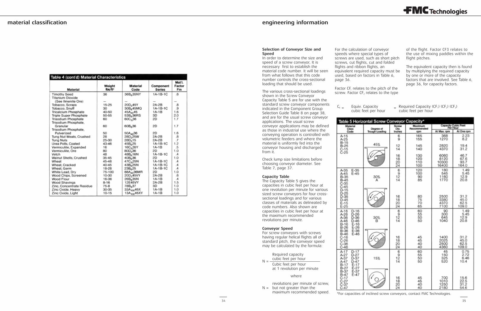
Selection of Conveyor Size andSpeedIn order to determine the size andspeed of a screw conveyor, It isnecessary first to establish thematerial code number. It will be seenfrom what follows that this codenumber controls the cross-sectionalloading that should be used.
The various cross-sectional loadingsshown in the Screw ConveyorCapacity Table 5 are for use with thestandard screw conveyor componentsindicated in the Component GroupSelection Guide Table 8 on page 38,and are for the usual screw conveyorapplications. The usual screwconveyor applications may be definedas those in industrial use where theconveying operation is controlled withvolumetric feeders and where thematerial is uniformly fed into theconveyor housing and dischargedfrom it.
Check lump size limitations beforechoosing conveyor diameter. SeeTable 7, page 37.
Capacity TableThe Capacity Table 5 gives thecapacities in cubic feet per hour atone revolution per minute for varioussized screw conveyors for four cross-sectional loadings and for variousclasses of materials as delineated bycode numbers. Also shown arecapacities in cubic feet per hour atthe maximum recommendedrevolutions per minute.
Conveyor SpeedFor screw conveyors with screwshaving regular helical flights all ofstandard pitch, the conveyor speedmay be calculated by the formula:
Required capacity cubic feet per hour
N = Cubic feet per hour at 1 revolution per minute
where
revolutions per minute of screw,N = but not greater than the
maximum recommended speed.
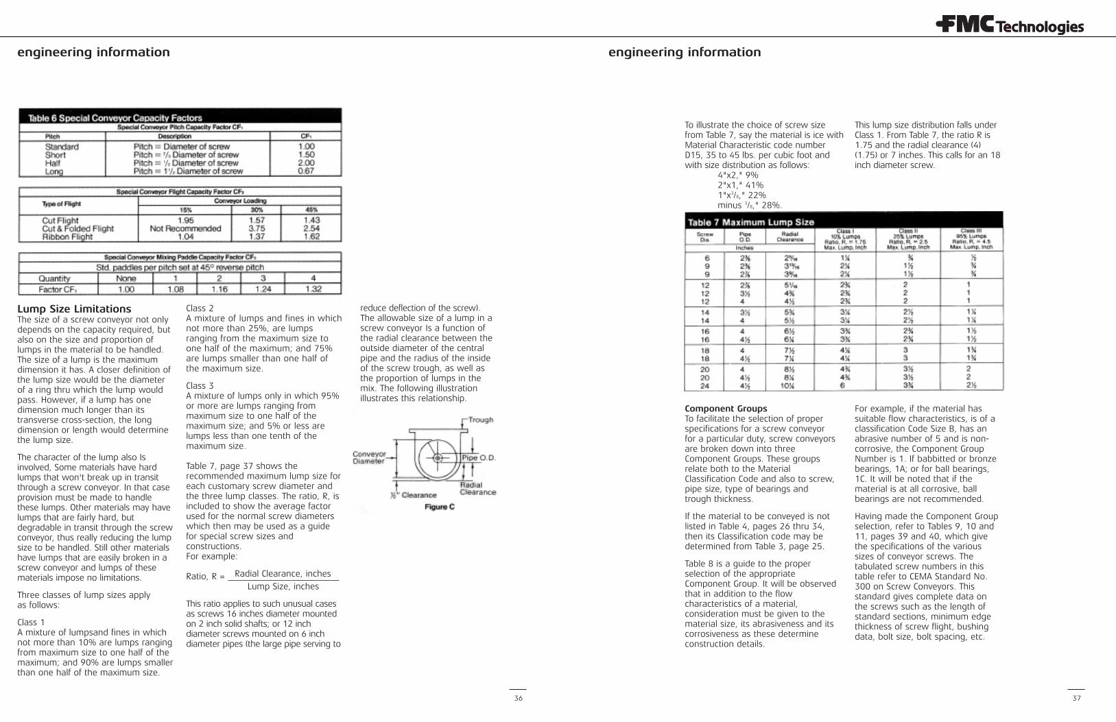
For the calculation of conveyorspeeds where special types ofscrews are used, such as short pitchscrews, cut flights, cut and foldedflights and ribbon flights, anequivalent required capacity must beused, based on factors in Table 6,page 36.
Factor CF, relates to the pitch of thescrew. Factor CF2 relates to the type
of the flight. Factor CF3 relates tothe use of mixing paddles within theflight pitches.
The equivalent capacity then is foundby multiplying the required capacityby one or more of the capacityfactors that are involved. See Table 6,page 36, for capacity factors.
CE = Equiv. Capacity = Required Capacity (CF1) (CF2) (CF3)cubic feet per hour cubic feet per hour
*For capacities of inclined screw conveyors, contact FMC Technologies.
engineering informationengineering information
36 37
Lump Size LimitationsThe size of a screw conveyor not onlydepends on the capacity required, butalso on the size and proportion oflumps in the material to be handled.The size of a lump is the maximumdimension it has. A closer definition ofthe lump size would be the diameterof a ring thru which the lump wouldpass. However, if a lump has onedimension much longer than itstransverse cross-section, the longdimension or length would determinethe lump size.
The character of the lump also Isinvolved, Some materials have hardlumps that won't break up in transitthrough a screw conveyor. In that caseprovision must be made to handlethese lumps. Other materials may havelumps that are fairly hard, butdegradable in transit through the screwconveyor, thus really reducing the lumpsize to be handled. Still other materialshave lumps that are easily broken in ascrew conveyor and lumps of thesematerials impose no limitations.
Three classes of lump sizes apply as follows:
Class 1 A mixture of lumpsand fines in whichnot more than 10% are lumps rangingfrom maximum size to one half of themaximum; and 90% are lumps smallerthan one half of the maximum size.
Class 2 A mixture of lumps and fines in whichnot more than 25%, are lumpsranging from the maximum size toone half of the maximum; and 75%are lumps smaller than one half ofthe maximum size.
Class 3 A mixture of lumps only in which 95%or more are lumps ranging frommaximum size to one half of themaximum size; and 5% or less arelumps less than one tenth of themaximum size.
Table 7, page 37 shows therecommended maximum lump size foreach customary screw diameter andthe three lump classes. The ratio, R, isincluded to show the average factorused for the normal screw diameterswhich then may be used as a guidefor special screw sizes andconstructions. For example:
Radial Clearance, inchesRatio, R = Lump Size, inches
This ratio applies to such unusual casesas screws 16 inches diameter mountedon 2 inch solid shafts; or 12 inchdiameter screws mounted on 6 inchdiameter pipes (the large pipe serving to
reduce deflection of the screw).The allowable size of a lump in ascrew conveyor Is a function ofthe radial clearance between theoutside diameter of the centralpipe and the radius of the insideof the screw trough, as well asthe proportion of lumps in themix. The following illustrationillustrates this relationship.
To illustrate the choice of screw sizefrom Table 7, say the material is ice withMaterial Characteristic code numberD15, 35 to 45 lbs. per cubic foot andwith size distribution as follows:
4"x2," 9% 2"x1," 41% 1"x3/8," 22% minus 3/8," 28%.
This lump size distribution falls underClass 1. From Table 7, the ratio R is1.75 and the radial clearance (4)(1.75) or 7 inches. This calls for an 18inch diameter screw.
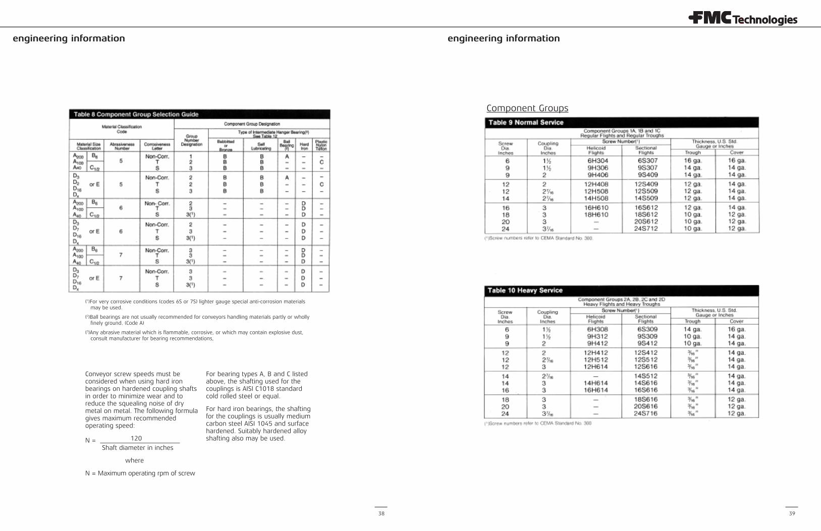
Component Groups To facilitate the selection of properspecifications for a screw conveyorfor a particular duty, screw conveyorsare broken down into threeComponent Groups. These groupsrelate both to the MaterialClassification Code and also to screw,pipe size, type of bearings andtrough thickness.
If the material to be conveyed is notlisted in Table 4, pages 26 thru 34,then its Classification code may bedetermined from Table 3, page 25.
Table 8 is a guide to the properselection of the appropriateComponent Group. It will be observedthat in addition to the flowcharacteristics of a material,consideration must be given to thematerial size, its abrasiveness and itscorrosiveness as these determineconstruction details.
For example, if the material hassuitable flow characteristics, is of aclassification Code Size B, has anabrasive number of 5 and is non-corrosive, the Component GroupNumber is 1. If babbitted or bronzebearings, 1A; or for balI bearings,1C. It will be noted that if thematerial is at all corrosive, ballbearings are not recommended.
Having made the Component Groupselection, refer to Tables 9, 10 and11, pages 39 and 40, which givethe specifications of the varioussizes of conveyor screws. Thetabulated screw numbers in thistable refer to CEMA Standard No.300 on Screw Conveyors. Thisstandard gives complete data onthe screws such as the length ofstandard sections, minimum edgethickness of screw flight, bushingdata, bolt size, bolt spacing, etc.
engineering information engineering information
38 39
Component Groups
(1)For very corrosive conditions (codes 6S or 7S) lighter gauge special anti-corrosion materialsmay be used.
(2)Ball bearings are not usually recommended for conveyors handling materials partly or whollyfinely ground. (Code A)
(3)Any abrasive material which is flammable, corrosive, or which may contain explosive dust,consult manufacturer for bearing recommendations,
Conveyor screw speeds must beconsidered when using hard ironbearings on hardened coupling shaftsin order to minimize wear and toreduce the squealing noise of drymetal on metal. The following formulagives maximum recommendedoperating speed:
120N = Shaft diameter in inches
where
N = Maximum operating rpm of screw
For bearing types A, B and C listedabove, the shafting used for thecouplings is AISI C1018 standardcold rolled steel or equal.
For hard iron bearings, the shaftingfor the couplings is usually mediumcarbon steel AISI 1045 and surfacehardened. Suitably hardened alloyshafting also may be used.
engineering information engineering information
40
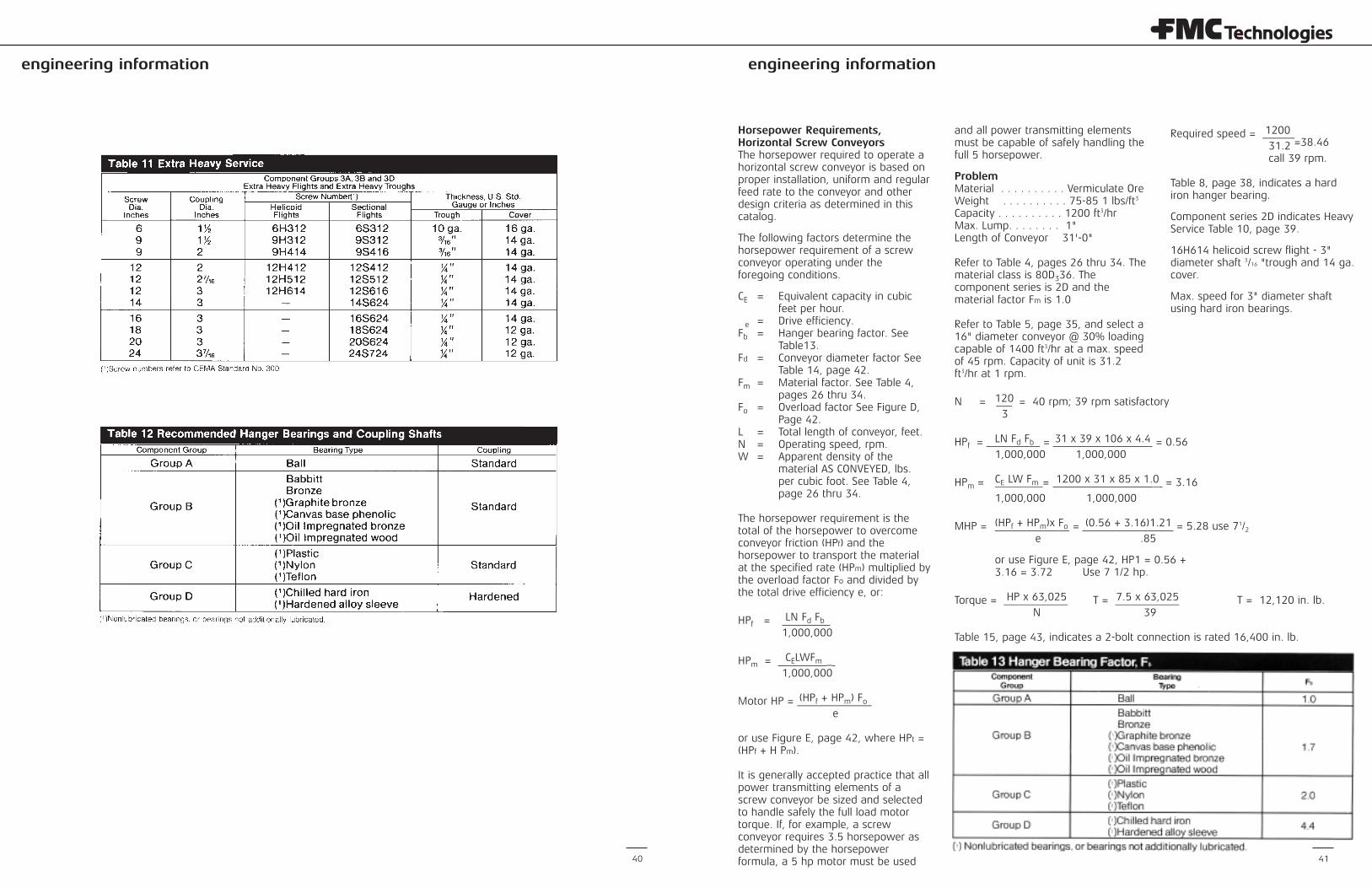
Horsepower Requirements,Horizontal Screw ConveyorsThe horsepower required to operate ahorizontal screw conveyor is based onproper installation, uniform and regularfeed rate to the conveyor and otherdesign criteria as determined in thiscatalog.
The following factors determine thehorsepower requirement of a screwconveyor operating under theforegoing conditions.
CE Equivalent capacity in cubic feet per hour.
e Drive efficiency.Fb Hanger bearing factor. See
Table13.Fd Conveyor diameter factor See
Table 14, page 42.Fm Material factor. See Table 4,
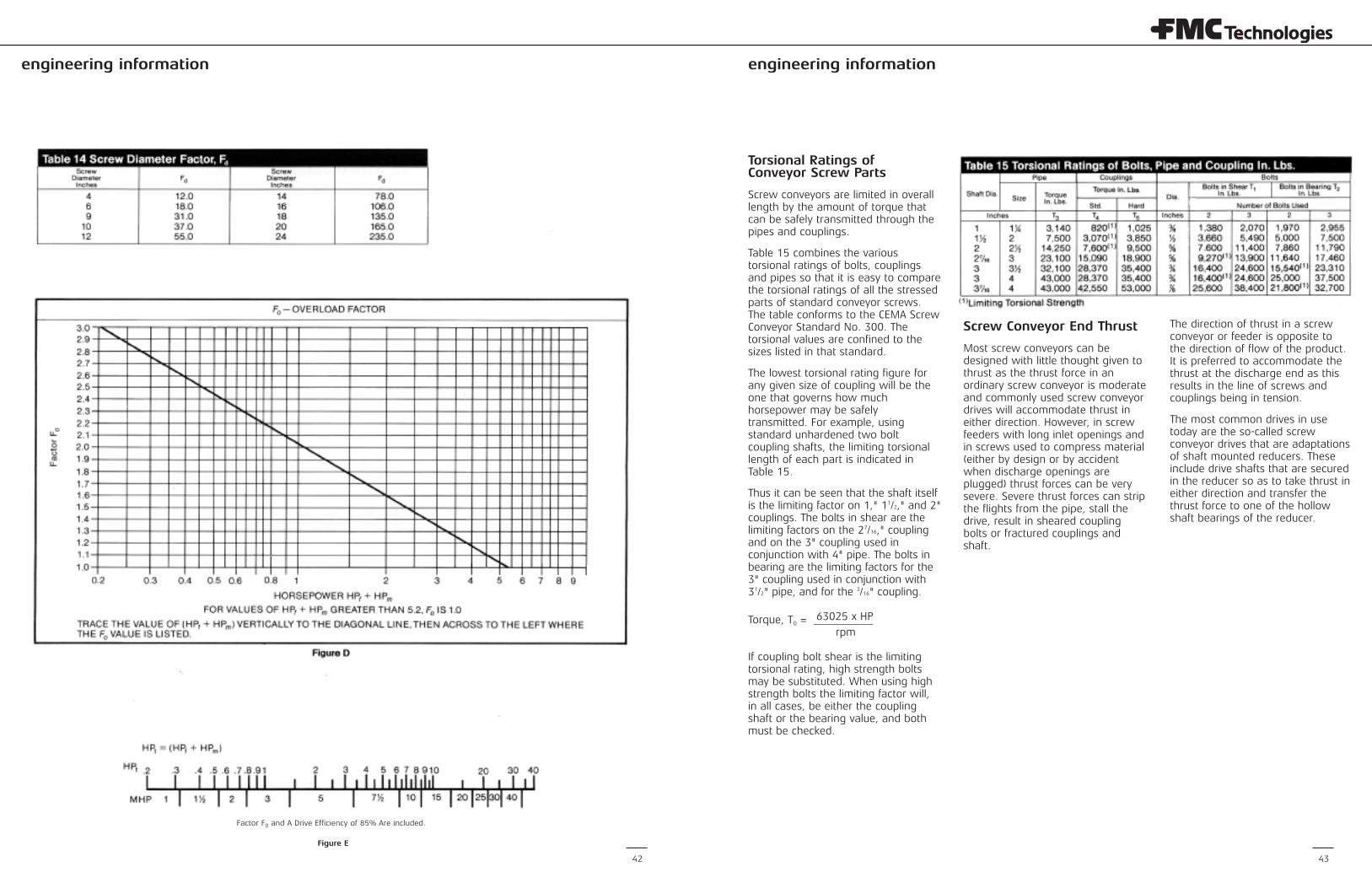
pages 26 thru 34.Fo Overload factor See Figure D,
Page 42.L Total length of conveyor, feet.N Operating speed, rpm.W Apparent density of the
material AS CONVEYED, lbs. per cubic foot. See Table 4, page 26 thru 34.
The horsepower requirement is thetotal of the horsepower to overcomeconveyor friction (HPf) and thehorsepower to transport the materialat the specified rate (HPm) multiplied bythe overload factor Fo and divided bythe total drive efficiency e, or:
LN Fd FbHPf = 1,000,000
CELWFmHPm = _ 1,000,000
(HPf + HPm) FoMotor HP = ______________e
or use Figure E, page 42, where HPt =(HPf + H Pm).
It is generally accepted practice that allpower transmitting elements of ascrew conveyor be sized and selectedto handle safely the full load motortorque. If, for example, a screwconveyor requires 3.5 horsepower asdetermined by the horsepowerformula, a 5 hp motor must be used
and all power transmitting elementsmust be capable of safely handling thefull 5 horsepower.
ProblemMaterial . . . . . . . . . . Vermiculate OreWeight . . . . . . . . . . 75-85 1 lbs/ft3
Capacity . . . . . . . . . . 1200 ft3/hrMax. Lump. . . . . . . . 1"Length of Conveyor 31'-0"
Refer to Table 4, pages 26 thru 34. Thematerial class is 80D336. Thecomponent series is 2D and thematerial factor Fm is 1.0
Refer to Table 5, page 35, and select a16" diameter conveyor @ 30% loadingcapable of 1400 ft3/hr at a max. speedof 45 rpm. Capacity of unit is 31.2ft3/hr at 1 rpm.
120N = ___ = 40 rpm; 39 rpm satisfactory3
LN Fd Fb 31 x 39 x 106 x 4.4HPf = __________ = _ = 0.561,000,000 1,000,000
CE LW Fm 1200 x 31 x 85 x 1.0HPm = _________= _ = 3.16
1,000,000 1,000,000
(HPf + HPm)x Fo (0.56 + 3.16)1.21MHP = ______________ = = 5.28 use 71/2e .85
or use Figure E, page 42, HP1 = 0.56 +3.16 = 3.72 Use 7 1/2 hp.
HP x 63,025 7.5 x 63,025Torque = ____________ T = ____________ T = 12,120 in. lb.N 39
Table 15, page 43, indicates a 2-bolt connection is rated 16,400 in. lb.
=
==
=
=
=
===
1200Required speed = ______31.2 =38.46
call 39 rpm.
Table 8, page 38, indicates a hardiron hanger bearing.
Component series 2D indicates HeavyService Table 10, page 39.
16H614 helicoid screw flight - 3"diameter shaft 3/16 "trough and 14 ga.cover.
Max. speed for 3" diameter shaftusing hard iron bearings.
41
engineering information engineering information
42 43
Factor F0 and A Drive Efficiency of 85% Are included.
Figure E
Torsional Ratings of Conveyor Screw Parts
Screw conveyors are limited in overalllength by the amount of torque thatcan be safely transmitted through thepipes and couplings.
Table 15 combines the varioustorsional ratings of bolts, couplingsand pipes so that it is easy to comparethe torsional ratings of all the stressedparts of standard conveyor screws.The table conforms to the CEMA ScrewConveyor Standard No. 300. Thetorsional values are confined to thesizes listed in that standard.
The lowest torsional rating figure forany given size of coupling will be theone that governs how muchhorsepower may be safelytransmitted. For example, usingstandard unhardened two boltcoupling shafts, the limiting torsionallength of each part is indicated inTable 15.
Thus it can be seen that the shaft itselfis the limiting factor on 1," 11/2," and 2"couplings. The bolts in shear are thelimiting factors on the 27/16," couplingand on the 3" coupling used inconjunction with 4" pipe. The bolts inbearing are the limiting factors for the3" coupling used in conjunction with31/2" pipe, and for the 3/16" coupling.
63025 x HPTorque, TQ = ___________rpm
If coupling bolt shear is the limitingtorsional rating, high strength boltsmay be substituted. When using highstrength bolts the limiting factor will,in all cases, be either the couplingshaft or the bearing value, and bothmust be checked.
Screw Conveyor End Thrust
Most screw conveyors can bedesigned with little thought given tothrust as the thrust force in anordinary screw conveyor is moderateand commonly used screw conveyordrives will accommodate thrust ineither direction. However, in screwfeeders with long inlet openings andin screws used to compress material(either by design or by accidentwhen discharge openings areplugged) thrust forces can be verysevere. Severe thrust forces can stripthe flights from the pipe, stall thedrive, result in sheared couplingbolts or fractured couplings andshaft.
The direction of thrust in a screwconveyor or feeder is opposite tothe direction of flow of the product.It is preferred to accommodate thethrust at the discharge end as thisresults in the line of screws andcouplings being in tension.
The most common drives in usetoday are the so-called screwconveyor drives that are adaptationsof shaft mounted reducers. Theseinclude drive shafts that are securedin the reducer so as to take thrust ineither direction and transfer thethrust force to one of the hollowshaft bearings of the reducer.
engineering information
44 45
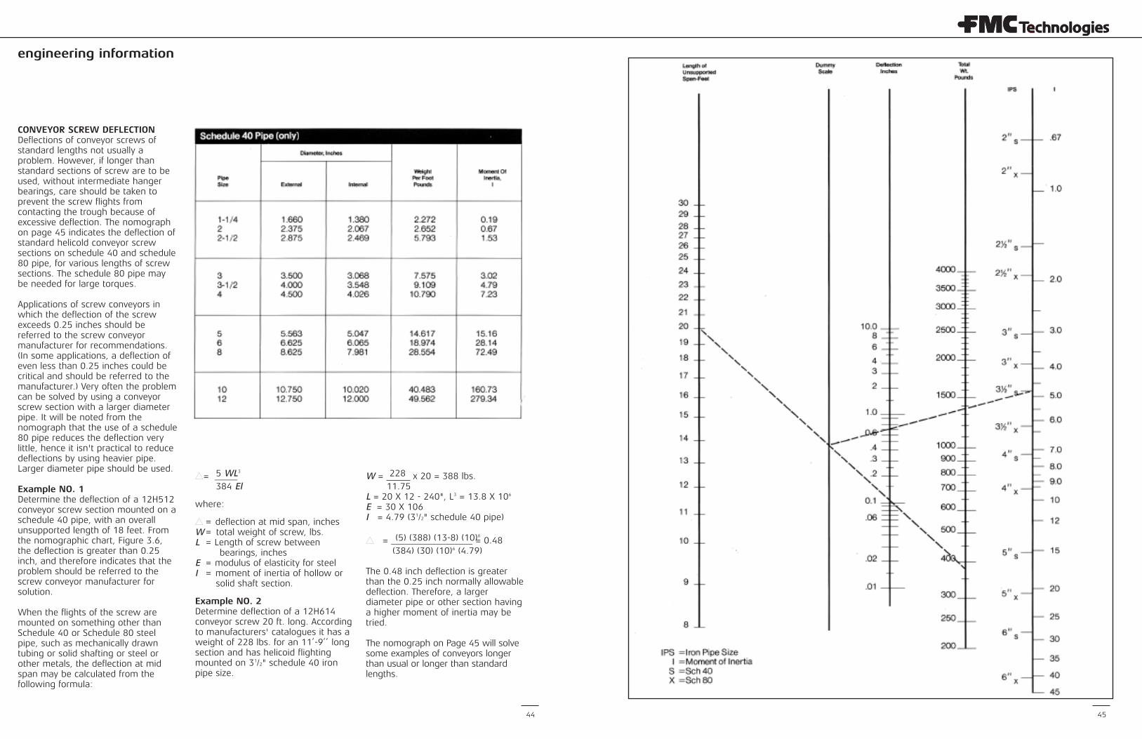
CONVEYOR SCREW DEFLECTIONDeflections of conveyor screws ofstandard lengths not usually aproblem. However, if longer thanstandard sections of screw are to beused, without intermediate hangerbearings, care should be taken toprevent the screw flights fromcontacting the trough because ofexcessive deflection. The nomographon page 45 indicates the deflection ofstandard helicold conveyor screwsections on schedule 40 and schedule80 pipe, for various lengths of screwsections. The schedule 80 pipe maybe needed for large torques.
Applications of screw conveyors inwhich the deflection of the screwexceeds 0.25 inches should bereferred to the screw conveyormanufacturer for recommendations.(In some applications, a deflection ofeven less than 0.25 inches could becritical and should be referred to themanufacturer.) Very often the problemcan be solved by using a conveyorscrew section with a larger diameterpipe. It will be noted from thenomograph that the use of a schedule80 pipe reduces the deflection verylittle, hence it isn't practical to reducedeflections by using heavier pipe.Larger diameter pipe should be used.
Example NO. 1Determine the deflection of a 12H512conveyor screw section mounted on aschedule 40 pipe, with an overallunsupported length of 18 feet. Fromthe nomographic chart, Figure 3.6,the deflection is greater than 0.25inch, and therefore indicates that theproblem should be referred to thescrew conveyor manufacturer forsolution.
When the flights of the screw aremounted on something other thanSchedule 40 or Schedule 80 steelpipe, such as mechanically drawntubing or solid shafting or steel orother metals, the deflection at midspan may be calculated from thefollowing formula:
5 WL3s= _____
384 El
where:
s deflection at mid span, inchesW total weight of screw, lbs.L Length of screw between
bearings, inchesE modulus of elasticity for steelI moment of inertia of hollow or
solid shaft section.
Example NO. 2 Determine deflection of a 12H614conveyor screw 20 ft. long. Accordingto manufacturers' catalogues it has aweight of 228 lbs. for an 11’-9’’ longsection and has helicoid flightingmounted on 31/2" schedule 40 ironpipe size.
228W = x 20 = 388 lbs.11.75
L = 20 X 12 - 240", L3 = 13.8 X 10⁶
E = 30 X 106I = 4.79 (31/2" schedule 40 pipe)
(5) (388) (13-8) (10)6s = __________________ = 0.48(384) (30) (10)6 (4.79)
The 0.48 inch deflection is greaterthan the 0.25 inch normally allowabledeflection. Therefore, a largerdiameter pipe or other section havinga higher moment of inertia may betried.
The nomograph on Page 45 will solvesome examples of conveyors longerthan usual or longer than standardlengths.
===
==
engineering information engineering information
46 47
Screw FeedersThis section relates to screw feedersthat are used to control the rate of flowof a bulk material from a bin or hopper.This is limited to the handling of bulkfree flowing materials less than 1/8" insize and which are classified as abrasive 5 or 6 as shown in Table 3,page 25.
In screw feeders, the inlet portion of thetrough is made to be flooded with thematerial and by means of a shroud inthe trough, or by the use of a tubulartrough, only a controlled amount iscarried to the discharge.
The screws in the feeder are arranged inseveral different ways, depending uponcircumstances. For relatively small inletopenings, the screw often has astandard diameter and pitch. Frequently,however the screw is tapered indiameter with its smallest diameter atthe extreme feed end. Screws also maybe made with a constant standarddiameter and a variable pitch, the pitchgrowing larger from the extreme feedend. The purpose of the tapereddiameter or variable pitch screw is toobtain an even flow from all areas of thefeed opening. The capacity of taperedscrews or variable pitch screws isdetermined by the diameter and pitch atthe downstream end of the inlet opening.
Several factors should be establishedbefore selecting a screw feeder, thesebeing:
A. Kind and character of material being handled.
B. Density of material as conveyed,lbs/ft3.
C. Maximum rate at which material isto be handled, ft3/hr.
D. Size consist or screen size analysis.
E. Overall length of feeder, or feederwith extended conveyor, feet.
F. Width and length of inlet opening.
Single screw feeders are mostcommonly used. However, if the inletopening is very wide, multiple screwfeeders are more practical.
Single Screw FeedersThe single screw feeder may be aseparate unit, or it may be extendedby sections of normal screw conveyorto any practical length. The procedureby which to choose a single screwfeeder is as follows:
Refer to Material Classification Code,Table 3, page 25, and the MaterialCharacteristics, Table 4, pages 26 thru34. Determine the material code classand density from Table 4.
Capacity and SpeedFrom Table 16, under the columncaptioned at maximum rpm, find thecapacity which equals or exceeds thedesired feeder capacity. Then findfrom that the feeder diameter and
capacity at one rpm or C,. Divide therequired feeder capacity by C, toobtain the required speed in rpm.
CN =
Ct
where:
N = Speed of feeder in rpm.
C = Required capacity of feeder,ft3/hr.
C1 = Capacity at one rpm, ft3/hr.
This maximum rpm is not absolutebut has been selected as generalrecommended practice. Experiencewith a particular set of conditions, orapplication, may establish slightlydifferent design limitations. Manyfactors including bin or hopper design,a subject not covered here, willsignificantly affect screw feederperformance.
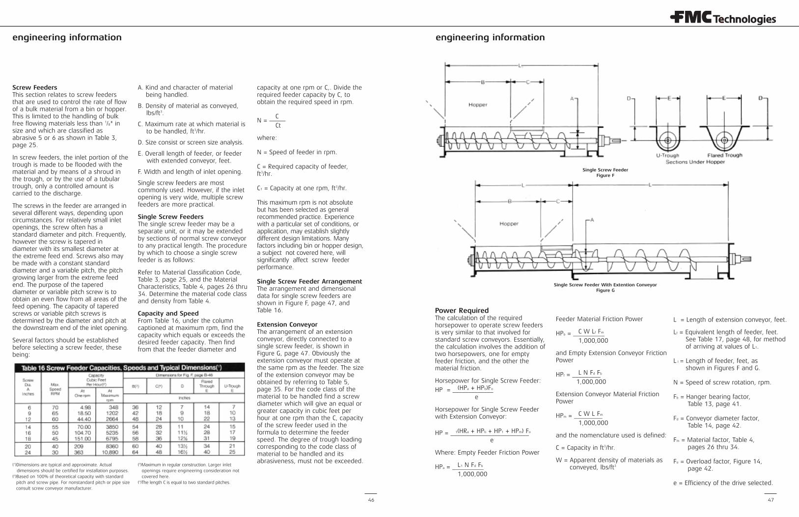
Single Screw Feeder ArrangementThe arrangement and dimensionaldata for single screw feeders areshown in Figure F, page 47, andTable 16.
Extension ConveyorThe arrangement of an extensionconveyor, directly connected to asingle screw feeder, is shown inFigure G, page 47. Obviously theextension conveyor must operate atthe same rpm as the feeder. The sizeof the extension conveyor may beobtained by referring to Table 5,page 35. For the code class of thematerial to be handled find a screwdiameter which will give an equal orgreater capacity in cubic feet perhour at one rpm than the C, capacityof the screw feeder used in theformula to determine the feederspeed. The degree of trough loadingcorresponding to the code class ofmaterial to be handled and itsabrasiveness, must not be exceeded.
(1)Dimensions are typical and approximate. Actualdimensions should be certified for installation purposes.
(2)Based on 100% of theoretical capacity with standardpitch and screw pipe. For nonstandard pitch or pipe sizeconsult screw conveyor manufacturer.
(3)Maximum in regular construction. Larger inletopenings require engineering consideration notcovered here.
(4)The length C is equal to two standard pitches.
Power RequiredThe calculation of the requiredhorsepower to operate screw feedersis very similar to that involved forstandard screw conveyors. Essentially,the calculation involves the addition oftwo horsepowers, one for emptyfeeder friction, and the other thematerial friction.
Horsepower for Single Screw Feeder:(HPa + HPb)FoHP = _____________
e
Horsepower for Single Screw Feederwith Extension Conveyor:
1(HRa + HPb + HP1 + HPm) FoHP = _________________________e
Where: Empty Feeder Friction Power
L1 N Fd FbHPa = __________1,000,000
Feeder Material Friction Power
C W Lf FmHPb = __________1,000,000
and Empty Extension Conveyor FrictionPower
L N Fd FbHPf = _________1,000,000
Extension Conveyor Material FrictionPower
C W L FmHPm = _________1,000,000
and the nomenclature used is defined:
C = Capacity in ft3/hr.
W = Apparent density of materials asconveyed, lbs/ft3
L = Length of extension conveyor, feet.
Lf = Equivalent length of feeder, feet.See Table 17, page 48, for methodof arriving at values of L1.
L l = Length of feeder, feet, asshown in Figures F and G.
N = Speed of screw rotation, rpm.
Fb = Hanger bearing factor,Table 13, page 41.
Fd = Conveyor diameter factor,Table 14, page 42.
Fm = Material factor, Table 4,pages 26 thru 34.
Fo = Overload factor, Figure 14,page 42.
e = Efficiency of the drive selected.
Single Screw FeederFigure F
Single Screw Feeder With Extention ConveyorFigure G
engineering information engineering information
49
Example ofSingle Screw Feeder SelectionProblem:Select a single screw feeder withoutextension conveyor for the followingconditions
Material to be handled Salt cake,dry,pulverized
Weight per cubic foot 65-85 lbs
per ft3
Capacity 26 tons(2000lb) perhour = 800cubic feetper hour
Length of feeder, L1 10 feet
Inlet opening 40incheslong, 10inches wide
Required is an even rate of flow alongthe whole inlet opening.
Solution:(a) From table 4, pages 26 thru 34, salt
cake is code classified at 75 B636 TUhas a component group designation of3-D and a material factor (Fm,) of 1.7.
(b) From Table 13, page 41, for aComponent Group D, the hangerbearing factor, Fb = 1.0. Since thisexample does not have a hanger, Fb
= 1.0. Use the appropriate factorwhen a hanger bearing or a tailbearing that utilizes a hanger inserttype bearing is used.
(c) To be prudent, for capacitycalculations use the lowest apparentdensity, 65 lbs/ft3.Then the volume for 26 tons per hour is
(26) (2000) ________ =65
800 ft3/hr required feed rate.
(d) Referring to Table 16, page 46, a 9-inch diameter single screw feeder willhandle 1202 ft3/hr at a maximum of 65rpm and C1 =18.5 at one rpm. Using theformula for speed.
C 800N = __ = ___ = 43.2 rpmCf 18.5
(e) From Table 17, the equivalentlength of the feeder is
B CL1 + ___ + ___ in which6 12
B 40L1 = 10, __ = ___ or 6.7, and6 6
C (18)___ = ___ = 1.512 12
Lf = 10 + 6.7 + 1.5 + 18.2 feet
(f) From Table 14, page 42, the “conveyor diameter factor Fd = 31.
(g) Again to be prudent, for powercalculations it is well to use thelargest apparent density forW, so W = 85 lbs/ft3.
L1 N Fd Fb(h) HPa = __________ =1,000,000
(10) (43.2) (31) (1.0)_________________ = .013 HP1,000,000
C W Lf Fm(i) HPb = __________ =1,000,000
(800) (85) (21.5) (1.7)__________________ = 2.10 HP1,000,000
(j) Referring to Figure D, page 42, thefactor Fo depends upon the sum of thehorsepower for friction of the emptyconveyor (feeder in the example) andthe horsepower of
(HPa + HPb) FoHP = _____________ =e
(.013 + 2.10) (1.57)_________________ = 3.90 HP.085
material friction. In this example this sumis .059 + 2.10 = 2.113 HP and Fo = 1.57.
(k) Then assuming a drive efficiency(expressed decimally) of 0.85,
Or use Figure E, page 42 HPt = (HPa + HPb) = 2.159 MHP = 5
(1) Use a 5 hp electric motor withspeed reduction to 43.2 rpm.
The theoretical estimated powerrequirements calculated in theforegoing example conceivably couldbe exceeded to the extent that the full5 horsepower of the motor would beused. Therefore, all components of thepower train, the feeder shaft, thescrew pipe shaft and the screw itselfshould be capable of withstanding-atthe speeds involved for each-thetorsion force or torque of full 5horsepower. See Table 15, page 43 for torsional capacities of screwconveyor components.
Effect of Material Loads on ScrewIn many cases, where screw feedersare mounted at the bottoms of bins orhoppers, the screw has to perform itsfunction under heavy loads of materialabove the bin opening or feeder inlet.Under certain conditions and withcertain materials the start-up torquecan be very high, resulting in biggerdrives and heavier feeder components.
An alternative solution is the use ofmultiple screw feeders. Multiple screwfeeders may consist of twin, triple, orquadruple screws, side by side to feedmaterials from very wide inlet openings.
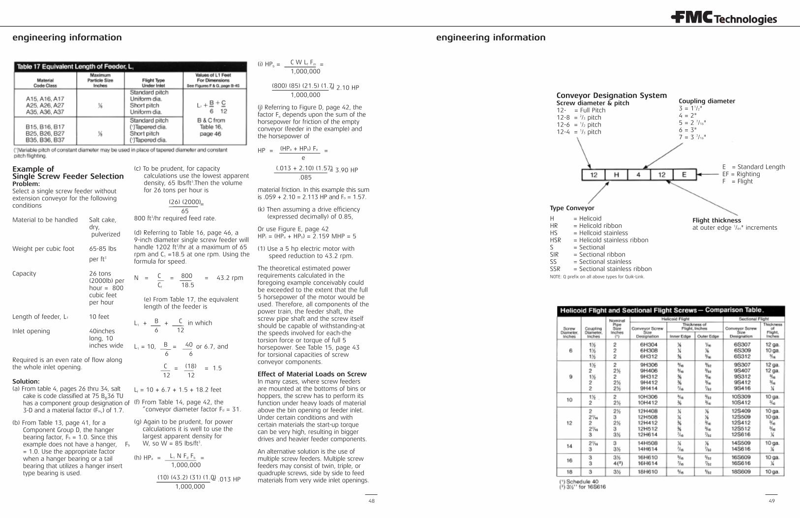
Conveyor Designation SystemScrew diameter & pitch12- = Full Pitch12-8 = 2/3 pitch12-6 = 1/2 pitch12-4 = 1/3 pitch
Coupling diameter3 = 11/2"4 = 2"5 = 2 7/16"6 = 3"7 = 3 7/16"
E = Standard LengthEF = RightingF = Flight
Type Conveyor
H = HelicoidHR = Helicold ribbonHS = Hellcoid stainlessHSR = Helicold stainless ribbonS = SectionalSIR = Sectional ribbonSS = Sectional stainlessSSR = Sectional stainless ribbonNOTE: Q prefix on all above types for Quik-Link.
Flight thicknessat outer edge 1/64" increments
48
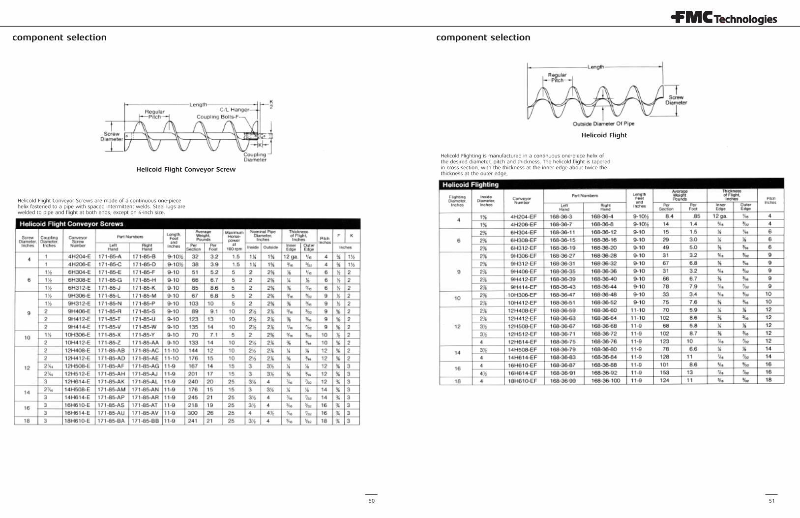
component selection component selection
50 51
Helicold Flight Conveyor Screws are made of a continuous one-piecehelix fastened to a pipe with spaced intermittent welds. Steel lugs arewelded to pipe and flight at both ends, except on 4-inch size.
Helicoid Flight Conveyor Screw
Helicoid Flight
Helicold Flighting is manufactured in a continuous one-piece helix ofthe desired diameter, pitch and thickness. The helicold flight is taperedin cross section, with the thickness at the inner edge about twice thethickness at the outer edge,
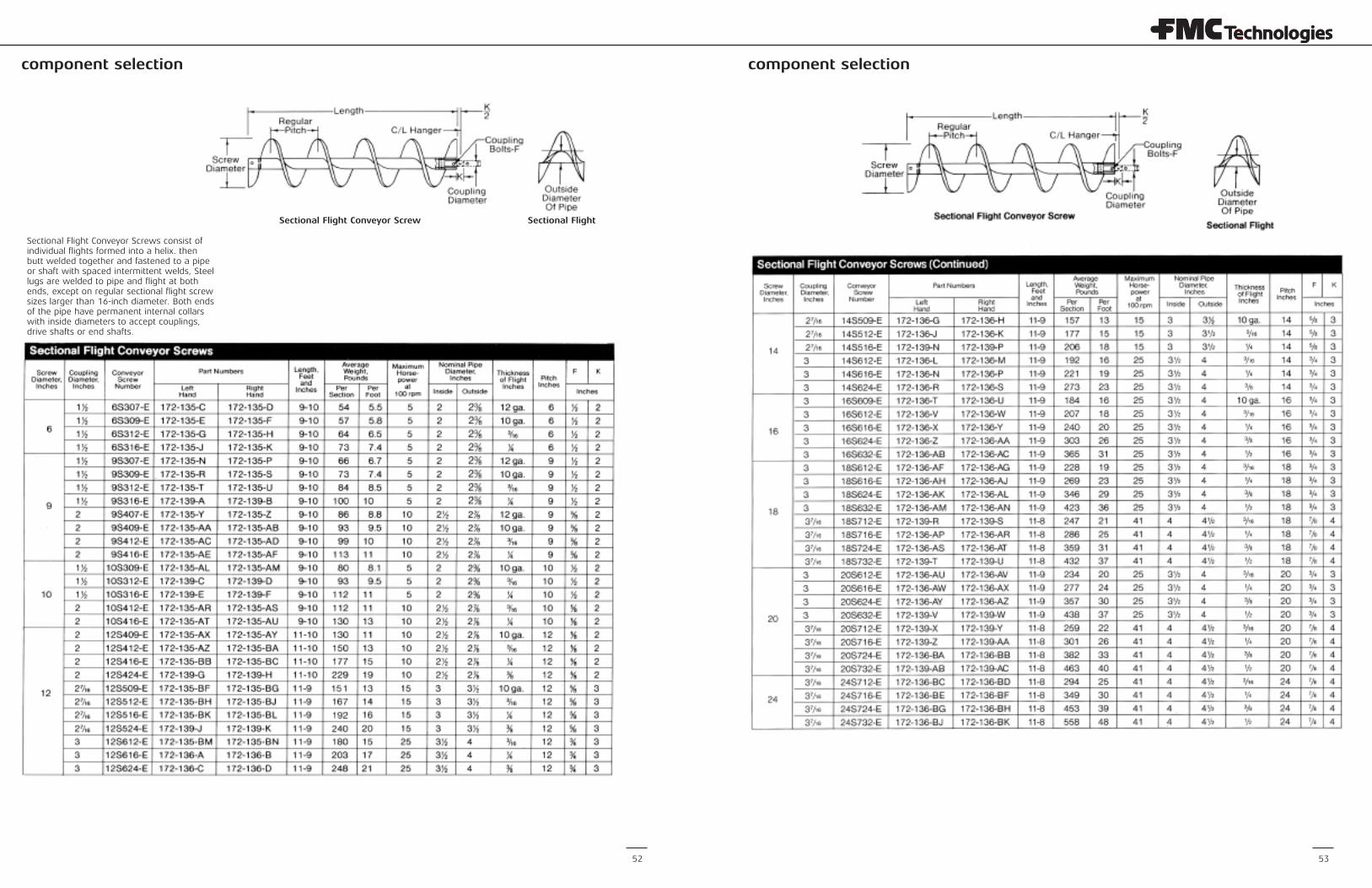
component selectioncomponent selection
52 53
Sectional Flight Conveyor Screws consist ofindividual flights formed into a helix. thenbutt welded together and fastened to a pipeor shaft with spaced intermittent welds, Steellugs are welded to pipe and flight at bothends, except on regular sectional flight screwsizes larger than 16-inch diameter. Both endsof the pipe have permanent internal collarswith inside diameters to accept couplings,drive shafts or end shafts.
Sectional Flight Conveyor Screw Sectional Flight
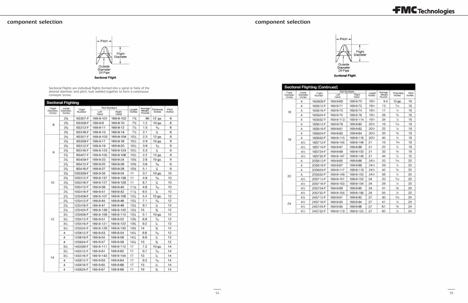
component selection component selection
54 55
Sectional Flights are individual flights formed into a spiral or helix of thedesired diameter and pitch, butt welded together to form a continuousconveyor screw.
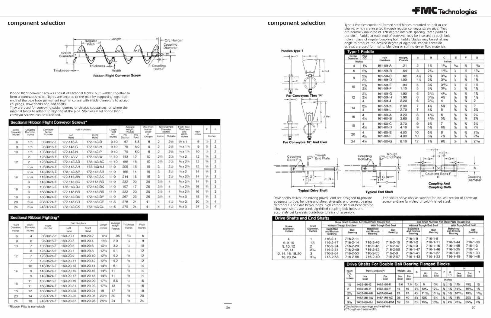
component selection component selection
57
Ribbon flight conveyor screws consist of sectional flights, butt welded together toform a continuous helix. Flights are secured to the pipe by supporting lugs. Bothends of the pipe have permanent internal collars with inside diameters to acceptcouplings, drive shafts and end shafts.They are used for conveying sticky, gummy or viscous substances, or where thematerial tends to adhere to flighting at the pipe. Stainless steel ribbon flightconveyor screws can be furnished.
Type 1 Paddles consist of formed steel blades mounted on bolt or rodshanks which are inserted through regular conveyor screw pipe. Theyare normally mounted at 120 degree intervals spacing, three paddlesper pitch. Paddle at each end of conveyor may be inserted through bolthole in place of regular coupling bolt. Paddle blades may be set at anyangle to produce the desired degree of agitation. Paddle conveyorscrews are used for mixing, blending or stirring dry or fluid materials.
Drive shafts deliver the driving power, and are designed to provideadequate torque, bending and shear strength, and correct bearingclearances. For extra heavy loads, high carbon steel or heat-treatedalloy steel shafts are used. Jig-drilled coupling bolt holes andaccurately cut keyseats contribute to ease of assembly.
End shafts serve only as support for the last section of conveyorscrew and are furnished of cold-finished steel.
56
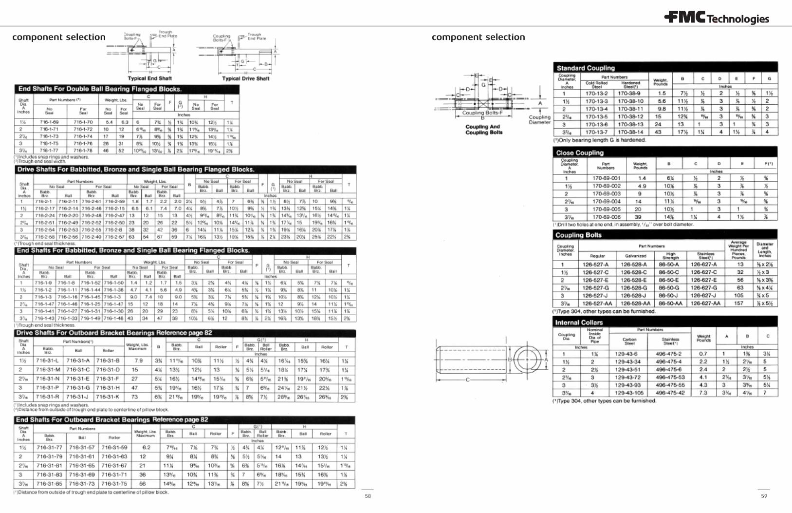
component selection component selection
58 59
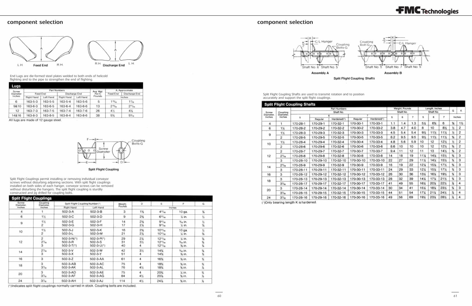
component selection component selection
60 61
End Lugs are die-formed steel plates welded to both ends of helicoldflighting and to the pipe to strengthen the end of flighting.
Split Flight Couplings permit installing or removing individual conveyorscrews without disturbing adjoining sections. With split flight couplingsinstalled on both sides of each hanger, conveyor screws can be removedwithout disturbing the hangers. The split flight coupling is sturdilyconstructed and jig drilled for coupling bolts.
Split Flight Coupling Shafts are used to transmit rotation and to positionaccurately and support the split flight couplings.
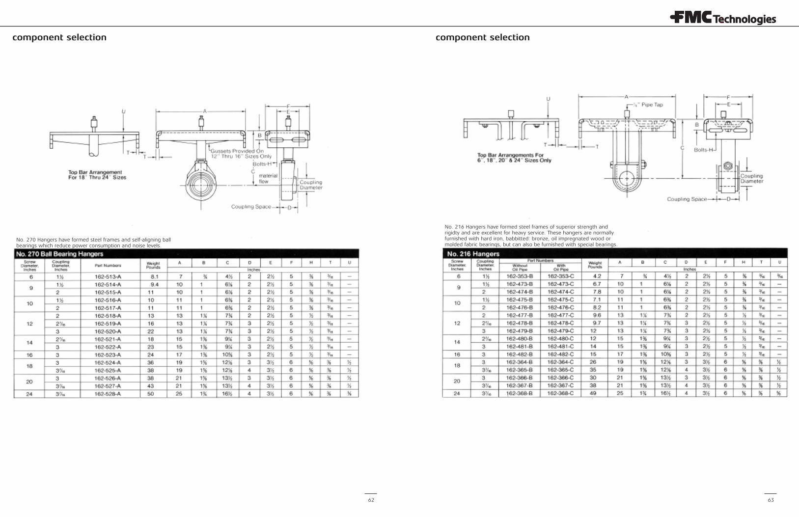
component selection component selection
62 63
No. 270 Hangers have formed steel frames and self-aligning ballbearings which reduce power consumption and noise levels.
No. 216 Hangers have formed steel frames of superior strength andrigidty and are excellent for heavy service. These hangers are normallyfurnished with hard iron, babbitted: bronze, oil impregnated wood ormolded fabric bearinqs, but can also be furnished with special bearings.
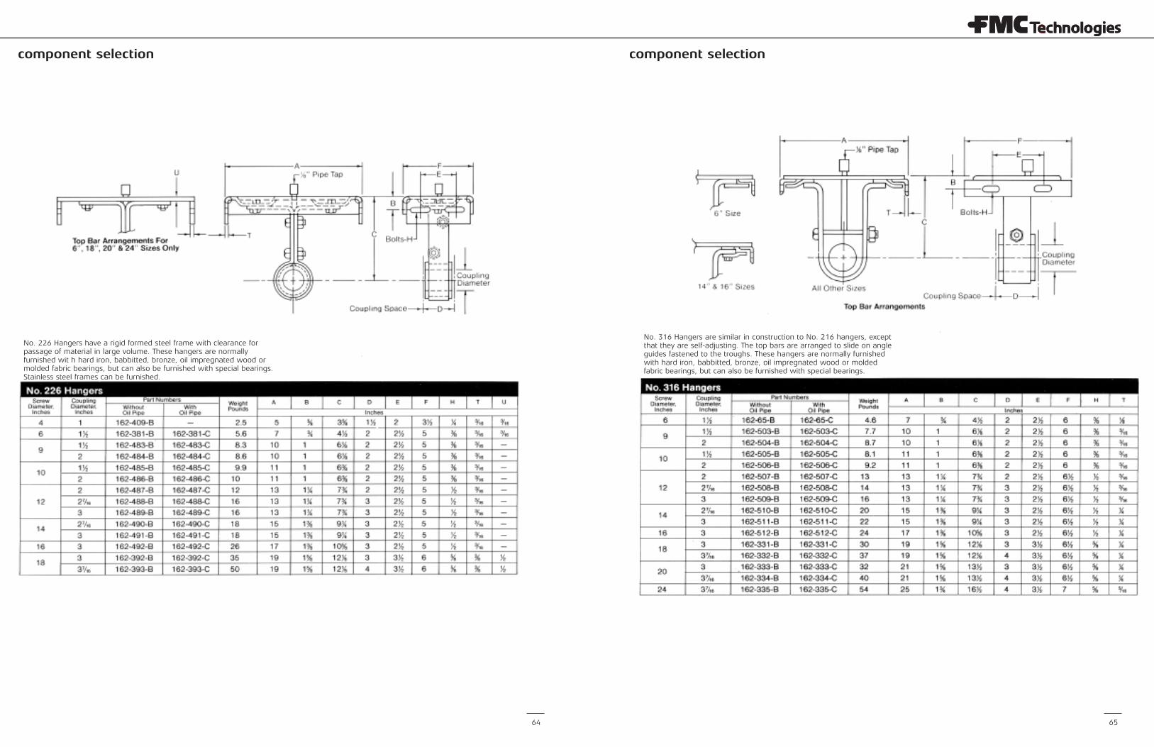
component selection component selection
64 65
No. 226 Hangers have a rigid formed steel frame with clearance forpassage of material in large volume. These hangers are normallyfurnished wit h hard iron, babbitted, bronze, oil impregnated wood ormolded fabric bearings, but can also be furnished with special bearings.Stainless steel frames can be furnished.
No. 316 Hangers are similar in construction to No. 216 hangers, exceptthat they are self-adjusting. The top bars are arranged to slide on angleguides fastened to the troughs. These hangers are normally furnishedwith hard iron, babbitted, bronze, oil impregnated wood or moldedfabric bearings, but can also be furnished with special bearings.
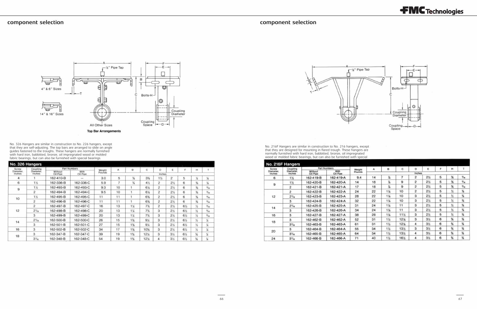
component selection component selection
66 67
No. 326 Hangers are similar in construction to No. 226 hangers, exceptthat they are self-adjusting. The top bars are arranged to slide on angleguides fastened to the troughs. These hangers are normally furnishedwith hard iron, babbitted, bronze, oil impregnated wood or moldedfabric bearings, but can also be furnished with special bearings.
No. 216F Hangers are similar in construction to No. 216 hangers, exceptthat they are designed for mounting in flared trough. These hangers arenormally furnished with hard iron, babbitted, bronze, oil impregnatedwood or molded fabric bearings, but can also be furnished with specialbearings.
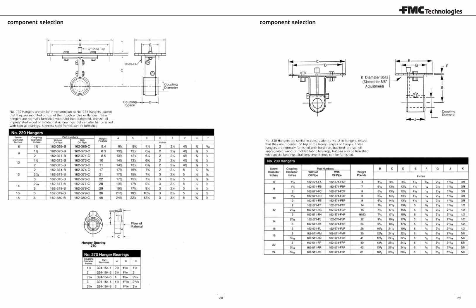
component selection component selection
6968
No. 220 Hangers are similar in construction to No. 226 hangers, exceptthat they are mounted on top of the trough angles or flanges. Thesehangers are normally furnished with hard iron, babbitted, bronze, oilimpregnated wood or molded fabric bearings, but can also be furnishedwith special bearings. Stainless steel frames can be furnished.
No. 230 Hangers are similar in construction to No. 216 hangers, exceptthat they are mounted on top of the trough angles or flanges. Thesehangers are normally furnished with hard iron, babitted, bronze, oilimpregnated wood or molded fabric bearings, but can also be furnishedwith special bearings. Stainless steel frames can be furnished.
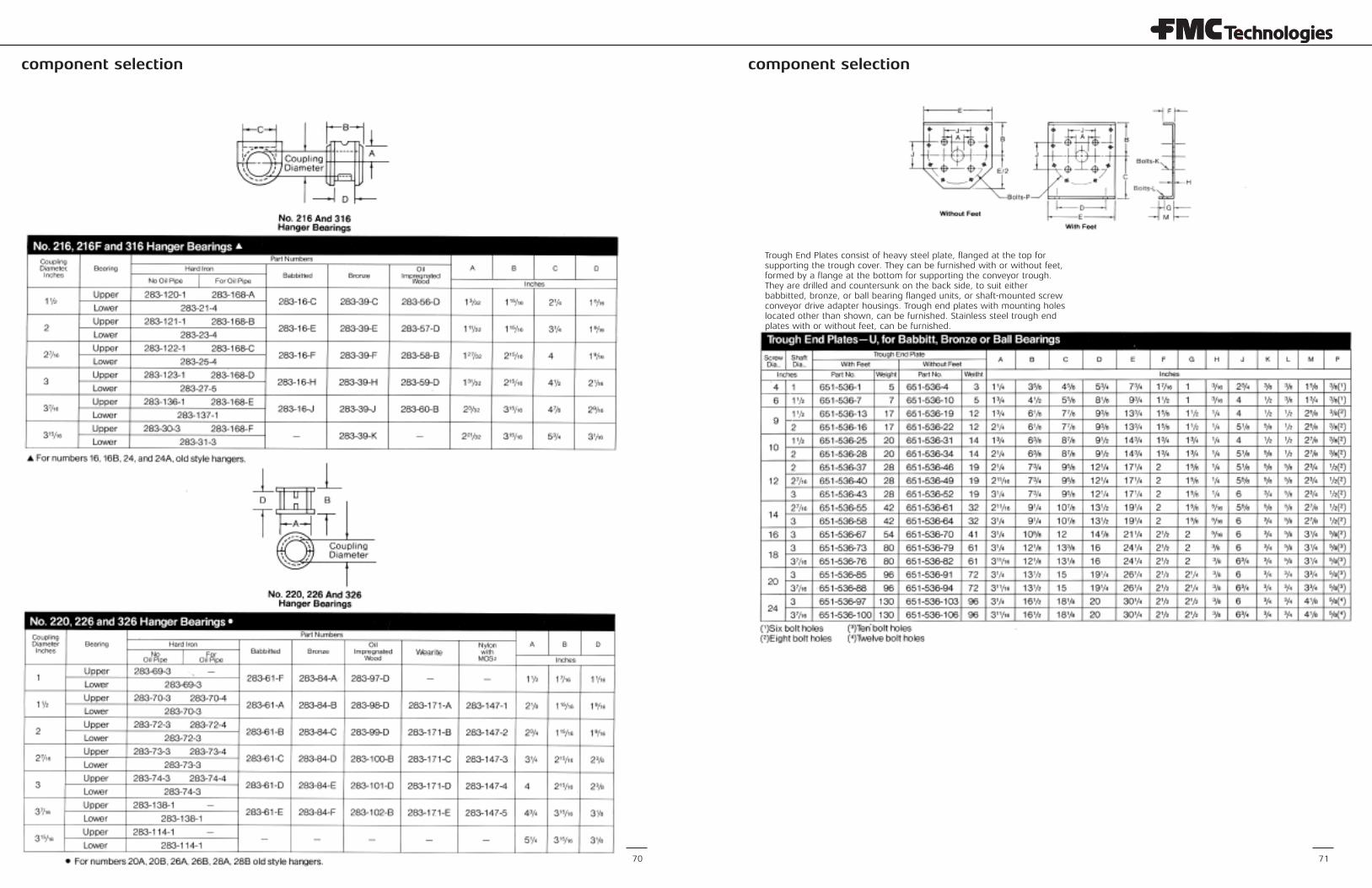
component selectioncomponent selection
70 71
Trough End Plates consist of heavy steel plate, flanged at the top forsupporting the trough cover. They can be furnished with or without feet,formed by a flange at the bottom for supporting the conveyor trough.They are drilled and countersunk on the back side, to suit eitherbabbitted, bronze, or ball bearing flanged units, or shaft-mounted screwconveyor drive adapter housings. Trough end plates with mounting holeslocated other than shown, can be furnished. Stainless steel trough endplates with or without feet, can be furnished.
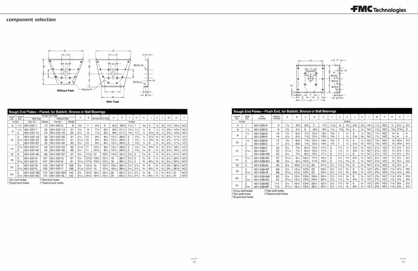
component selection
72 73
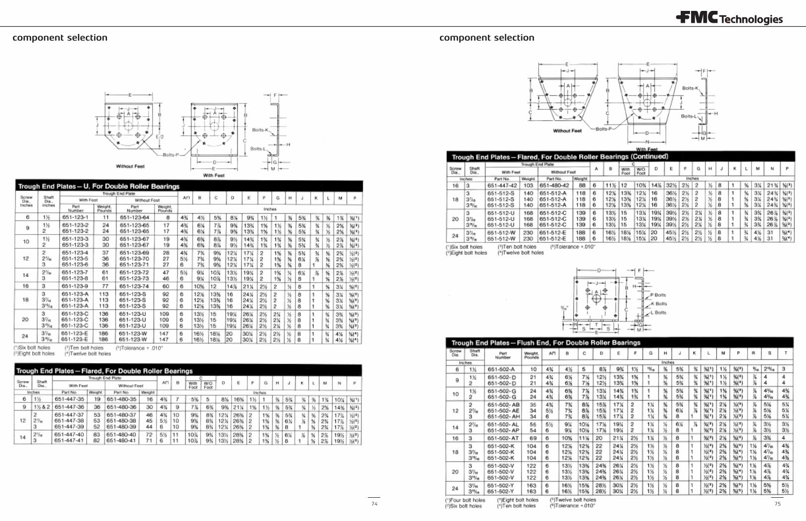
component selection component selection
74 75
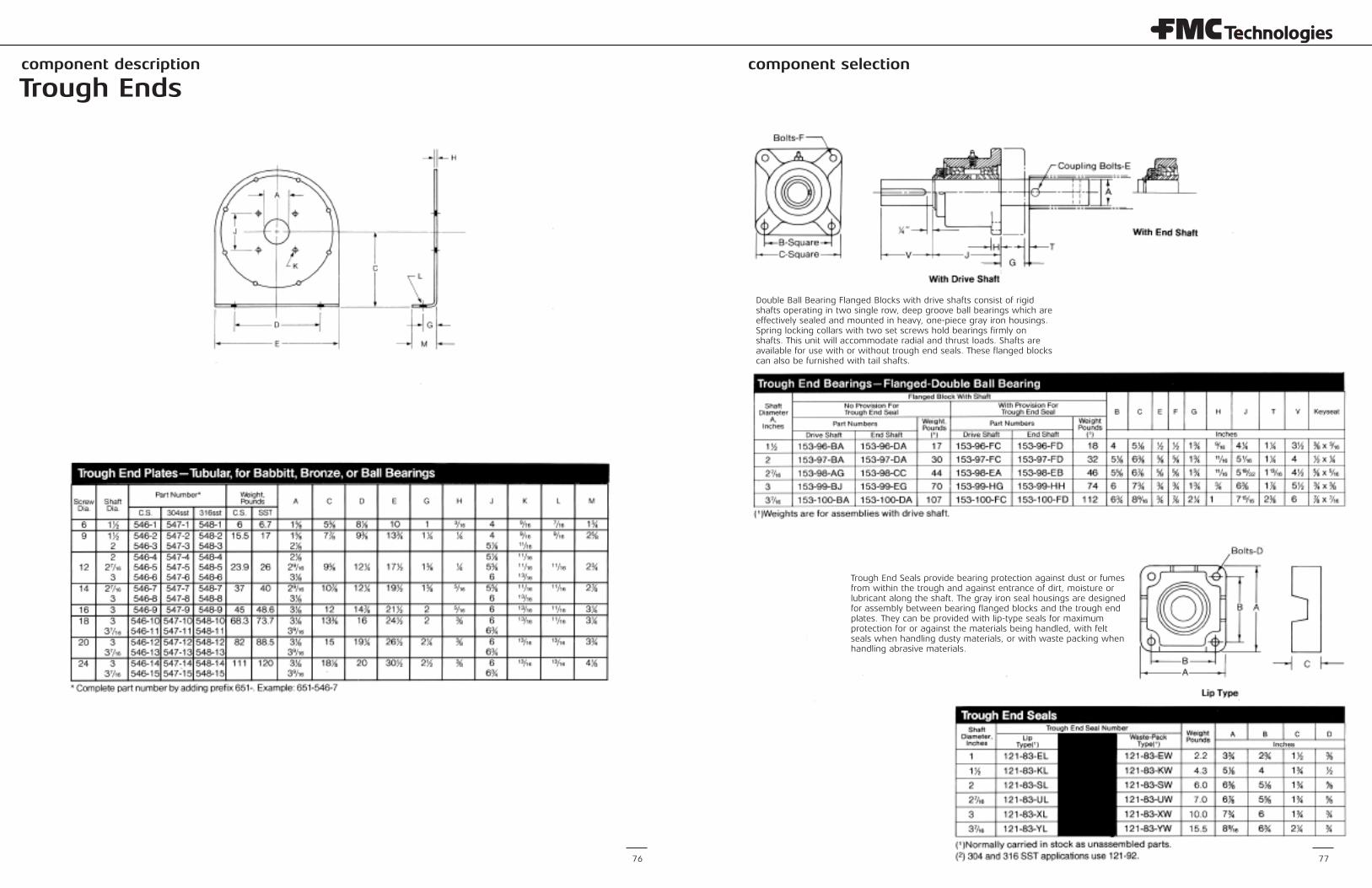
component description component selection
76
Trough Ends
Double Ball Bearing Flanged Blocks with drive shafts consist of rigidshafts operating in two single row, deep groove ball bearings which areeffectively sealed and mounted in heavy, one-piece gray iron housings.Spring locking collars with two set screws hold bearings firmly onshafts. This unit will accommodate radial and thrust loads. Shafts areavailable for use with or without trough end seals. These flanged blockscan also be furnished with tail shafts.
Trough End Seals provide bearing protection against dust or fumesfrom within the trough and against entrance of dirt, moisture orlubricant along the shaft. The gray iron seal housings are designedfor assembly between bearing flanged blocks and the trough endplates. They can be provided with lip-type seals for maximumprotection for or against the materials being handled, with feltseals when handling dusty materials, or with waste packing whenhandling abrasive materials.
77
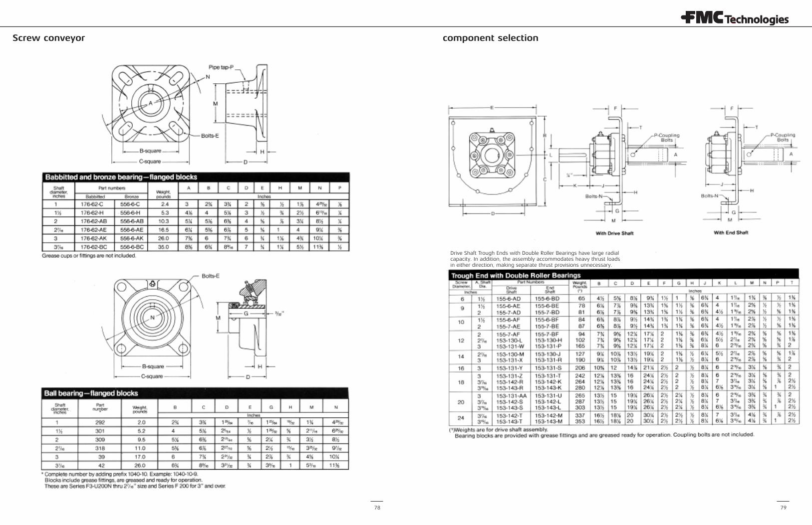
component selectionScrew conveyor
78 79
Drive Shaft Trough Ends with Double Roller Bearings have large radialcapacity. In addition, the assembly accommodates heavy thrust loadsin either direction, making separate thrust provisions unnecessary.
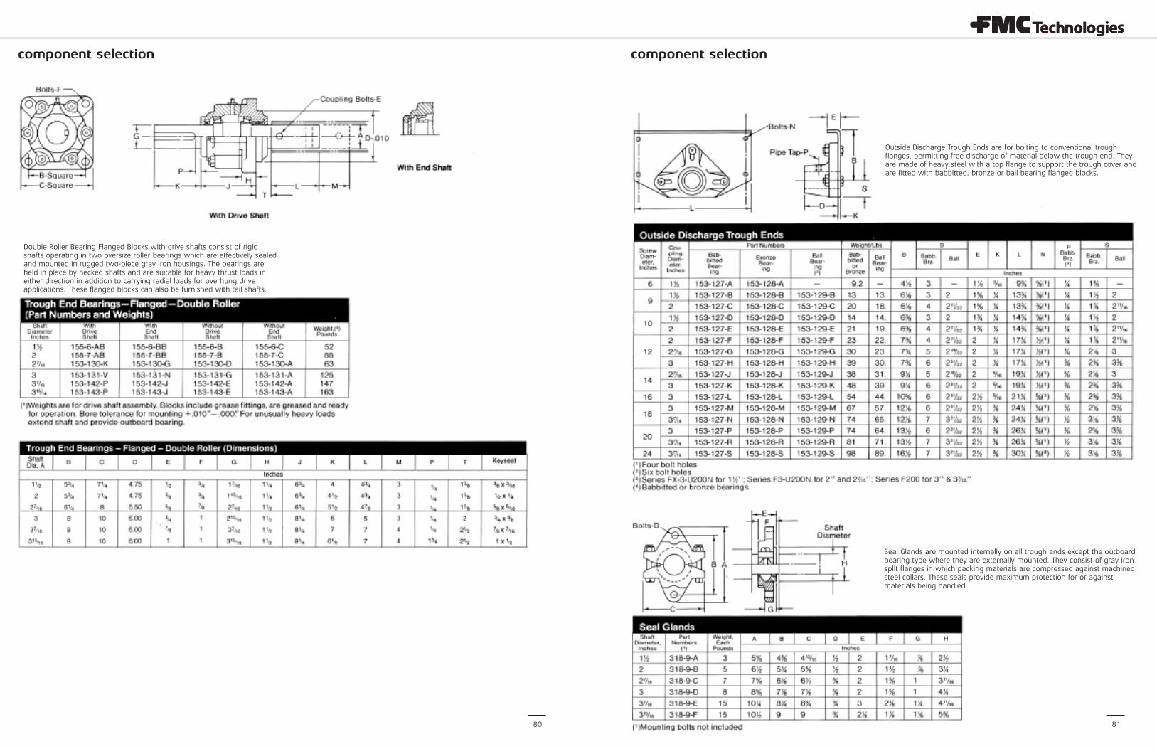
component selection component selection
Double Roller Bearing Flanged Blocks with drive shafts consist of rigidshafts operating in two oversize roller bearings which are effectively sealedand mounted in rugged two-piece gray iron housings. The bearings areheld in place by necked shafts and are suitable for heavy thrust loads ineither direction in addition to carrying radial loads for overhung driveapplications. These flanged blocks can also be furnished with tail shafts.
Outside Discharge Trough Ends are for bolting to conventional troughflanges, permitting free discharge of material below the trough end. Theyare made of heavy steel with a top flange to support the trough cover andare fitted with babbitted, bronze or ball bearing flanged blocks.
Seal Glands are mounted internally on all trough ends except the outboardbearing type where they are externally mounted. They consist of gray ironsplit flanges in which packing materials are compressed against machinedsteel collars. These seals provide maximum protection for or againstmaterials being handled.
80 81
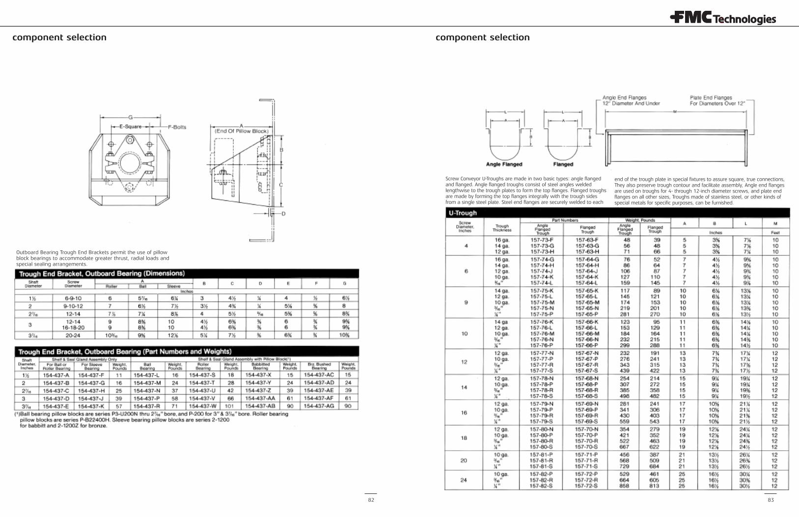
component selection component selection
82 83
Outboard Bearing Trough End Brackets permit the use of pillowblock bearings to accommodate greater thrust, radial loads andspecial sealing arrangements.
Screw Conveyor U-Troughs are made in two basic types: angle flangedand flanged. Angle flanged troughs consist of steel angles weldedlengthwise to the trough plates to form the top flanges. Flanged troughsare made by forming the top flanges integrally with the trough sidesfrom a single steel plate. Steel end flanges are securely welded to each
end of the trough plate in special fixtures to assure square, true connections,They also preserve trough contour and facilitate assembly, Angle end flangesare used on troughs for 4- through 12-inch diameter screws, and plate endflanges on all other sizes, Troughs made of stainless steel, or other kinds ofspecial metals for specific purposes, can be furnished.
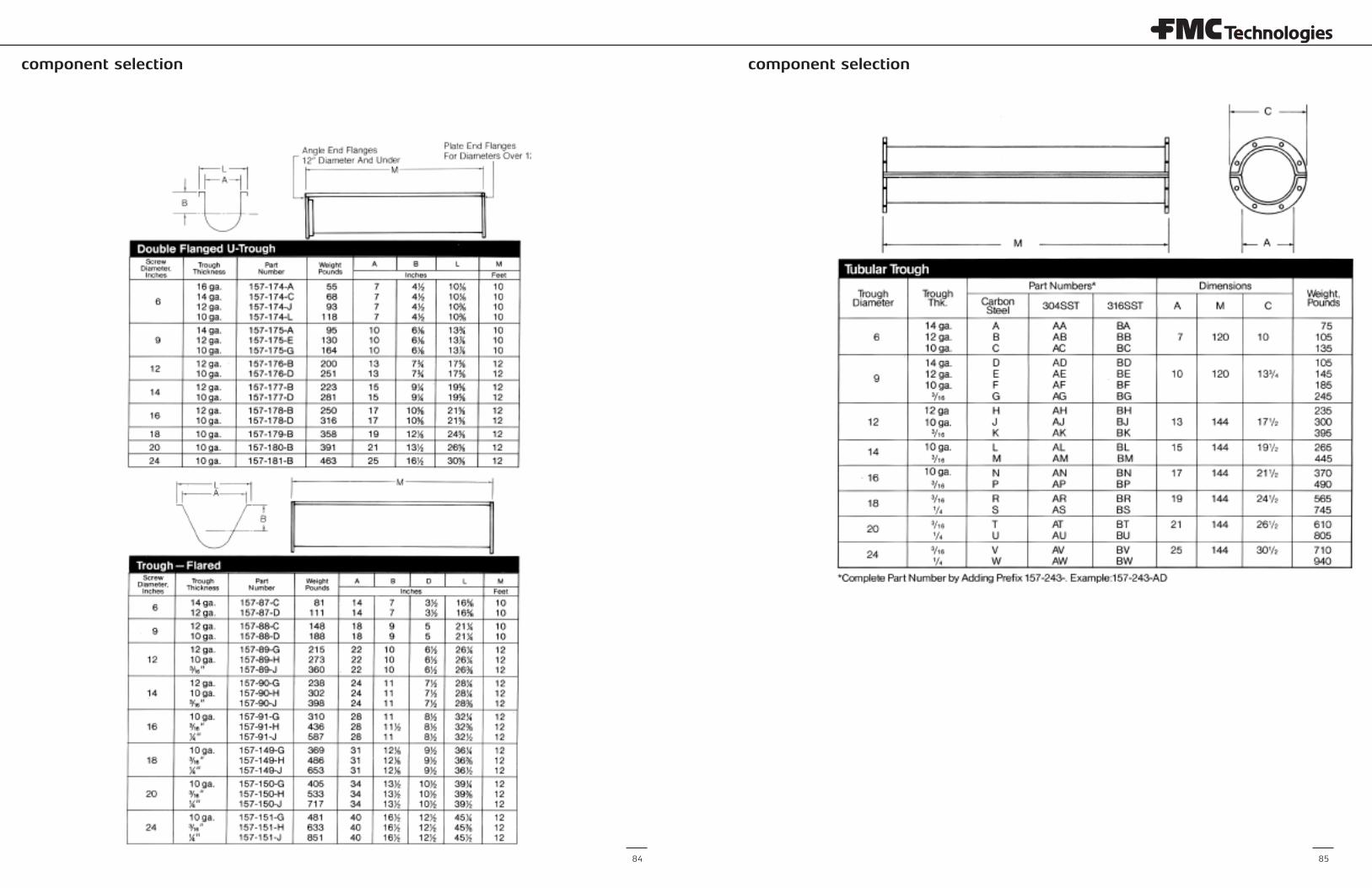
component selection component selection
84 85
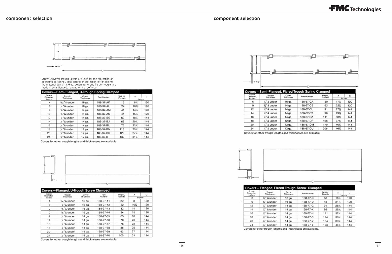
component selection component selection
86 87
Screw Conveyor Trough Covers are used for the protection ofoperating personnel, dust control or protection for or againstthe material being handled. Covers for U and flared troughs aremade in semi-flanged, flanged or hip roof types.
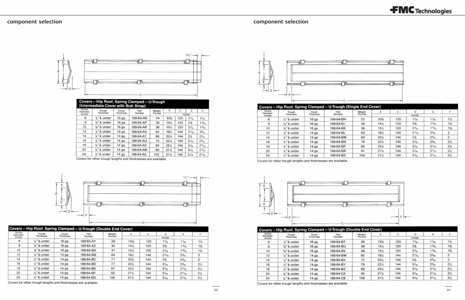
component selection component selection
88 89
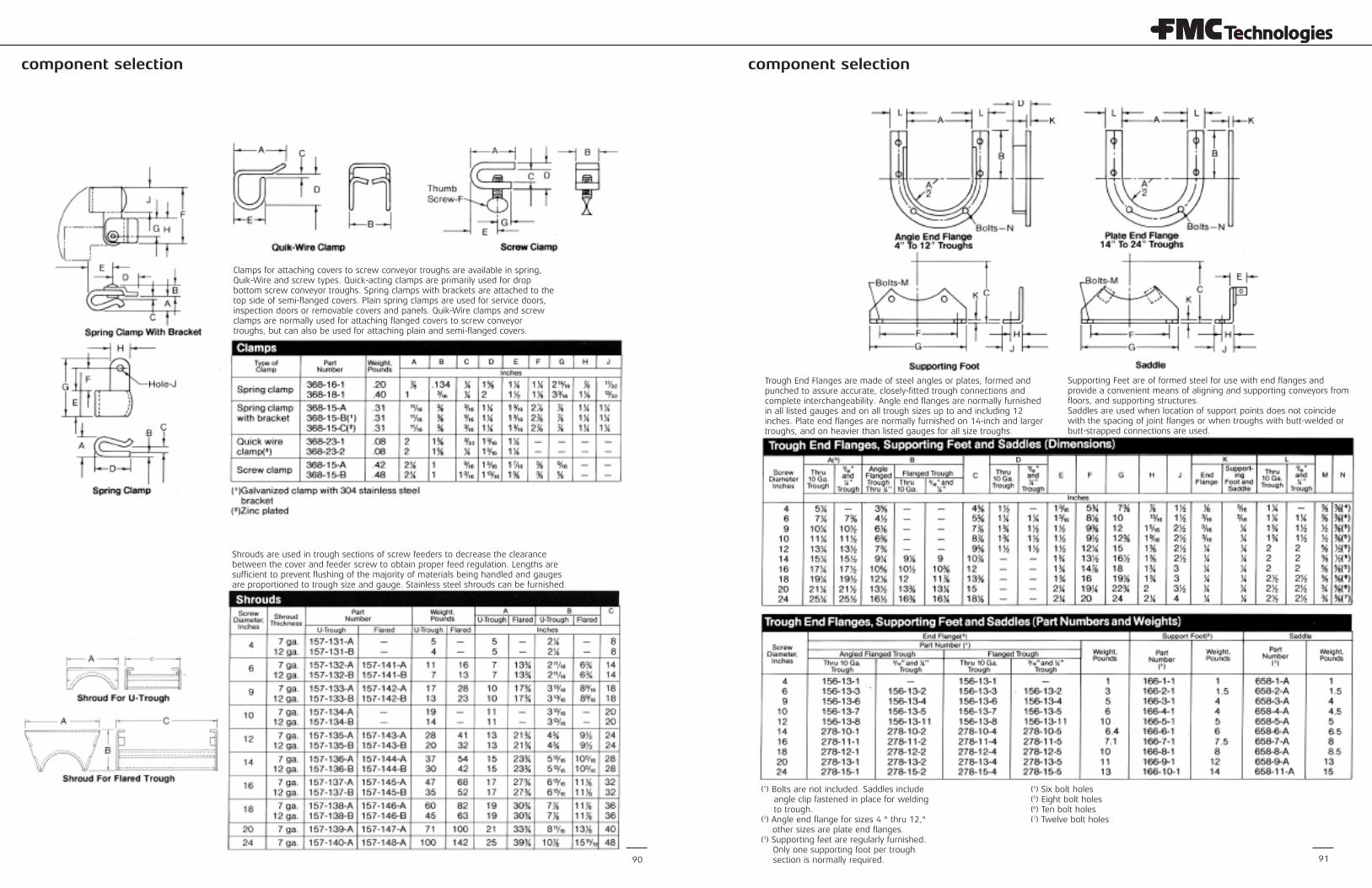
component selectioncomponent selection
90 91
Clamps for attaching covers to screw conveyor troughs are available in spring,Quik-Wire and screw types. Quick-acting clamps are primarily used for dropbottom screw conveyor troughs. Spring clamps with brackets are attached to thetop side of semi-flanged covers. Plain spring clamps are used for service doors,inspection doors or removable covers and panels. Quik-Wire clamps and screwclamps are normally used for attaching flanged covers to screw conveyortroughs, but can also be used for attaching plain and semi-flanged covers.
Shrouds are used in trough sections of screw feeders to decrease the clearancebetween the cover and feeder screw to obtain proper feed regulation. Lengths aresufficient to prevent flushing of the majority of materials being handled and gaugesare proportioned to trough size and gauge. Stainless steel shrouds can be furnished.
Trough End Flanges are made of steel angles or plates, formed andpunched to assure accurate, closely-fitted trough connections andcomplete interchangeability. Angle end flanges are normally furnishedin all listed gauges and on all trough sizes up to and including 12inches. Plate end flanges are normally furnished on 14-inch and largertroughs, and on heavier than listed gauges for all size troughs.
Supporting Feet are of formed steel for use with end flanges andprovide a convenient means of aligning and supporting conveyors fromfloors, and supporting structures. Saddles are used when location of support points does not coincidewith the spacing of joint flanges or when troughs with butt-welded orbutt-strapped connections are used.
(1) Bolts are not included. Saddles includeangle clip fastened in place for weldingto trough.
(2) Angle end flange for sizes 4 " thru 12,"other sizes are plate end flanges.
(3) Supporting feet are regularly furnished.Only one supporting foot per troughsection is normally required.
(4) Six bolt holes(5) Eight bolt holes(6) Ten bolt holes(7) Twelve bolt holes
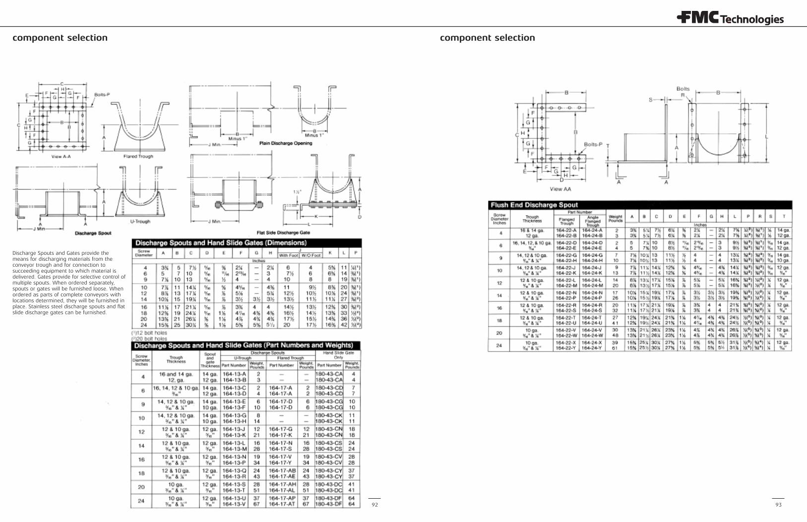
component selection component selection
93
Discharge Spouts and Gates provide themeans for discharging materials from theconveyor trough and for connection tosucceeding equipment to which material isdelivered. Gates provide for selective control ofmultiple spouts. When ordered separately,spouts or gates will be furnished loose. Whenordered as parts of complete conveyors withlocations determined, they will be furnished inplace. Stainless steel discharge spouts and flatslide discharge gates can be furnished.
92
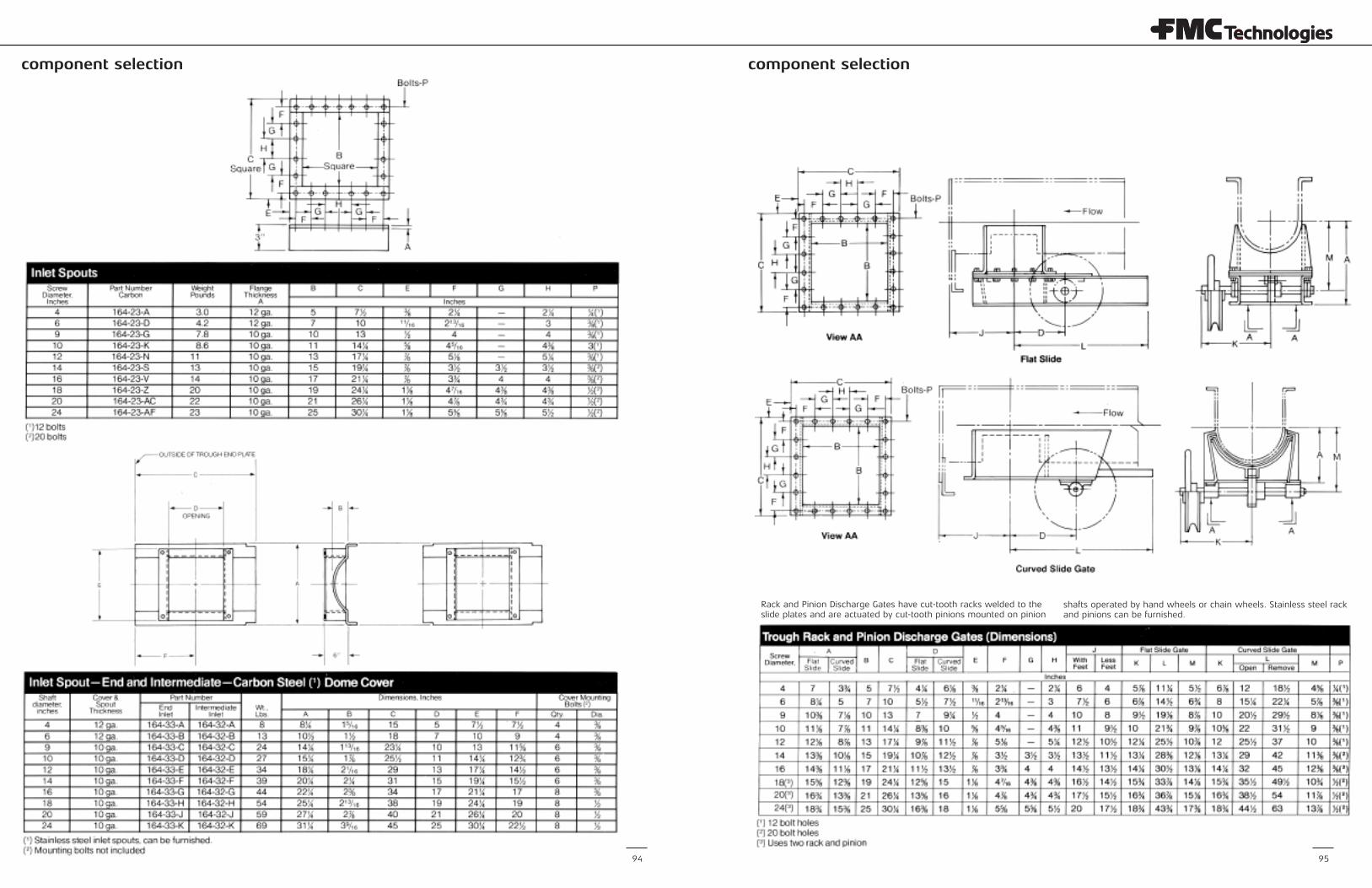
component selectioncomponent selection
Rack and Pinion Discharge Gates have cut-tooth racks welded to theslide plates and are actuated by cut-tooth pinions mounted on pinion
shafts operated by hand wheels or chain wheels. Stainless steel rackand pinions can be furnished.
9594
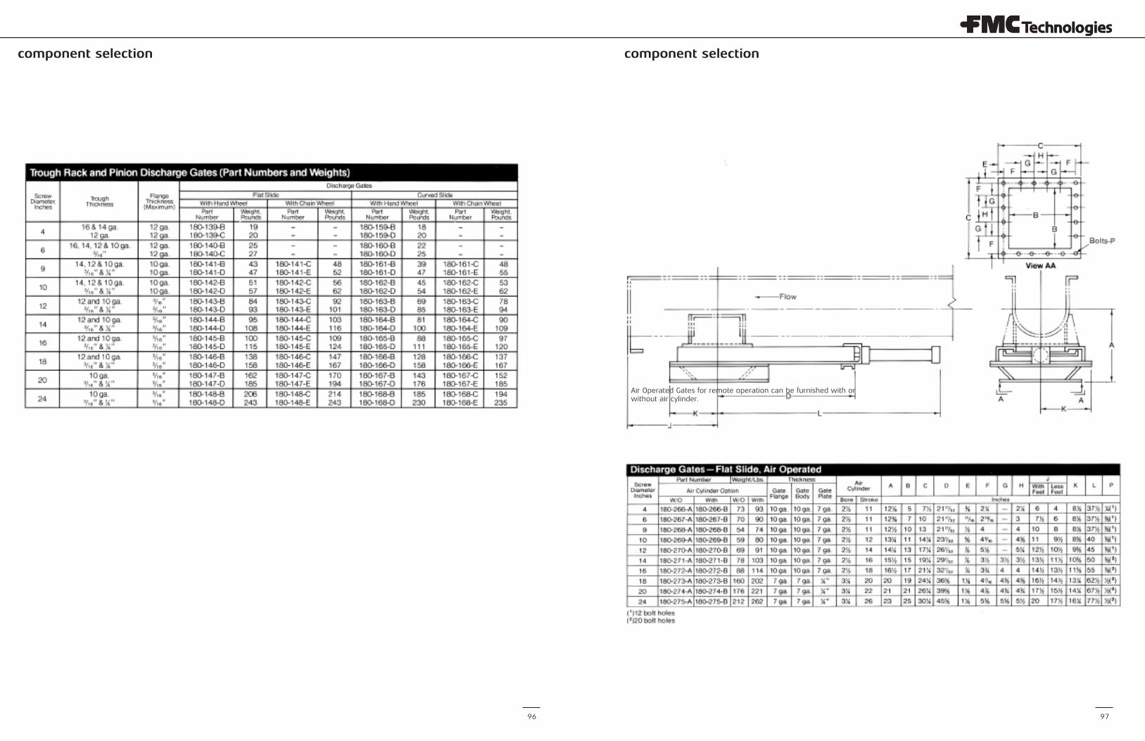
component selectioncomponent selection
96 97
Air Operated Gates for remote operation can be furnished with orwithout air cylinder.
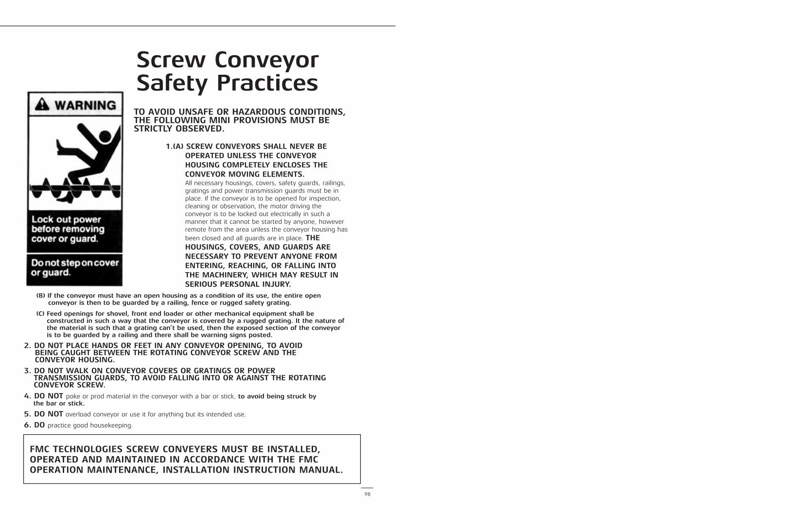
98
TO AVOID UNSAFE OR HAZARDOUS CONDITIONS,THE FOLLOWING MINI PROVISIONS MUST BESTRICTLY OBSERVED.
1.(A) SCREW CONVEYORS SHALL NEVER BEOPERATED UNLESS THE CONVEYORHOUSING COMPLETELY ENCLOSES THECONVEYOR MOVING ELEMENTS.All necessary housings, covers, safety guards, railings,gratings and power transmission guards must be inplace. If the conveyor is to be opened for inspection,cleaning or observation, the motor driving theconveyor is to be locked out electrically in such amanner that it cannot be started by anyone, howeverremote from the area unless the conveyor housing hasbeen closed and all guards are in place. THEHOUSINGS, COVERS, AND GUARDS ARENECESSARY TO PREVENT ANYONE FROMENTERING, REACHING, OR FALLING INTOTHE MACHINERY, WHICH MAY RESULT INSERIOUS PERSONAL INJURY.
(B) If the conveyor must have an open housing as a condition of its use, the entire openconveyor is then to be guarded by a railing, fence or rugged safety grating.
(C) Feed openings for shovel, front end loader or other mechanical equipment shall beconstructed in such a way that the conveyor is covered by a rugged grating. It the nature ofthe material is such that a grating can’t be used, then the exposed section of the conveyoris to be guarded by a railing and there shall be warning signs posted.
2. DO NOT PLACE HANDS OR FEET IN ANY CONVEYOR OPENING, TO AVOIDBEING CAUGHT BETWEEN THE ROTATING CONVEYOR SCREW AND THECONVEYOR HOUSING.
3. DO NOT WALK ON CONVEYOR COVERS OR GRATINGS OR POWER TRANSMISSION GUARDS, TO AVOID FALLING INTO OR AGAINST THE ROTATINGCONVEYOR SCREW.
4. DO NOT poke or prod material in the conveyor with a bar or stick, to avoid being struck bythe bar or stick.
5. DO NOT overload conveyor or use it for anything but its intended use.
6. DO practice good housekeeping.
Screw ConveyorSafety Practices
FMC TECHNOLOGIES SCREW CONVEYERS MUST BE INSTALLED,OPERATED AND MAINTAINED IN ACCORDANCE WITH THE FMCOPERATION MAINTENANCE, INSTALLATION INSTRUCTION MANUAL.
Corporate
FMC Technologies, Inc.5875 N. Sam Houston Pkwy. W. Houston, Texas 77086P: +1 281.591.4000
Regional
FMC Technologies, Inc.P.O. Box 1370Tupelo, Mississippi 38802P: 662.869.5711F: 662.869.7493Toll Free: [email protected]
FMC Technologies, Inc.1525 S. 4710 W. Unit: ESalt Lake City, Utah 84104P: 801.296.9500F: [email protected]
FMC Technologies Chile Ltda.Callao 2970, Office 704Las Condes, Santiago, ChileP: +56 2.234.4418
+56 2.246.4361F: +56 [email protected]
FMC Technologies, Inc.#2 Road No. 1Changshu Export Processing ZoneChangshu, Jiangsu, China 215513P: +82 0512.52299002F: +86 [email protected]
FMC Technologies Singapore Pte Ltd13 Benoi SectorSingapore 629860P: +65 66683600F: +65 [email protected]
Form No. 104-TUP
www.fmctechnologies.com
© 2013 FMC Technologies. All rights reserved.