reverse powering - its benefits and constraints - microsemi
TRANSCRIPT

Power Matters
Reverse PoweringIts Benefits and ConstraintsDaniel Feldman – VP Business Development, Microsemi

Power Matters
Why Fiber to the Distribution Point?
MDU ONT Reverse Power Fed
Benefits of Reverse Power Feeding (RPF)
Force Power vs ETSI RPF
Typical RPF Circuit
RPF Constraints
How much power can be delivered?
How fair is this to the end user?
Summary
Agenda
© 2014 Microsemi Corporation. 2
Power Matters
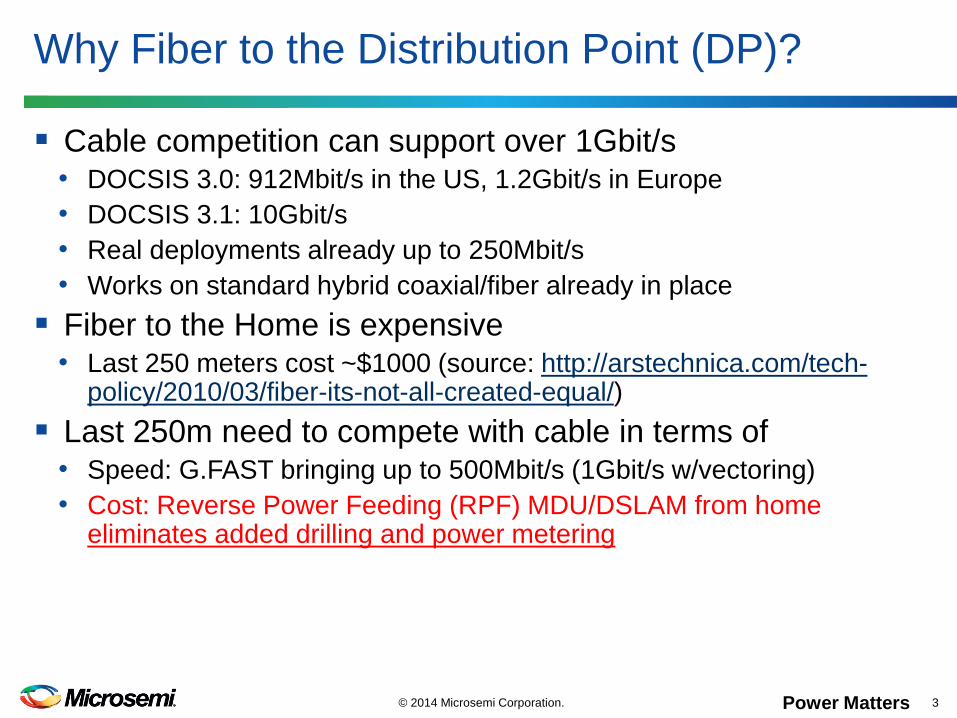
Cable competition can support over 1Gbit/s• DOCSIS 3.0: 912Mbit/s in the US, 1.2Gbit/s in Europe
• DOCSIS 3.1: 10Gbit/s
• Real deployments already up to 250Mbit/s
• Works on standard hybrid coaxial/fiber already in place
Fiber to the Home is expensive• Last 250 meters cost ~$1000 (source: http://arstechnica.com/tech-
policy/2010/03/fiber-its-not-all-created-equal/)
Last 250m need to compete with cable in terms of• Speed: G.FAST bringing up to 500Mbit/s (1Gbit/s w/vectoring)
• Cost: Reverse Power Feeding (RPF) MDU/DSLAM from home eliminates added drilling and power metering
Why Fiber to the Distribution Point (DP)?
© 2014 Microsemi Corporation. 3

Power Matters
Multiple Dweller Unit ONT Reverse Power Fed
© 2014 Microsemi Corporation. 4
DPCO
SG
Central Office Fibre-fed Remote Node
(cabinet or DP located)
Home network
POTSA/POTSD
Local Power Feed
Power fed to remote node over
same copper pair as XDSL signal
cabinetNTE
Derived Voice
POTSD
Definitions
RPF: Reverse Power Feeding
PSE: Power Sourcing Equipment
PD: Powered Device

Power Matters
Flexibility• No need for AC source proximity, or location safe for AC
• No need to wait for the electrical company to install
Cost per user lower than $31.25• 8 users can be covered by a single MDU ONT+DSLAM
• Average Smart Meter installation cost (for local power) is $250 (source: http://www.emeter.com/smart-grid-watch/2010/how-much-do-smart-meters-cost/
• RPF benefits increase with smaller MDU ONT+DSLAM
– $250/8=$31.25
– $250/4=$62.50
– $250/2=$125.00
Standardized by ETSI• Interoperability
• Safety
Benefits of Reverse Power Feeding
© 2014 Microsemi Corporation. 5
Power Matters
Force Power (non-ETSI) vs ETSI RPF
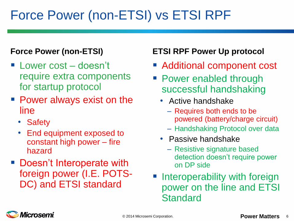
Force Power (non-ETSI)
Lower cost – doesn’t require extra components for startup protocol
Power always exist on the line• Safety
• End equipment exposed to constant high power – fire hazard
Doesn’t Interoperate with foreign power (I.E. POTS-DC) and ETSI standard
ETSI RPF Power Up protocol
Additional component cost
Power enabled through successful handshaking• Active handshake
– Requires both ends to be powered (battery/charge circuit)
– Handshaking Protocol over data
• Passive handshake
– Resistive signature based detection doesn’t require power on DP side
Interoperability with foreign power on the line and ETSI Standard
© 2014 Microsemi Corporation. 6
Power Matters
Typical RPF circuit for CPE and 8-port MDU
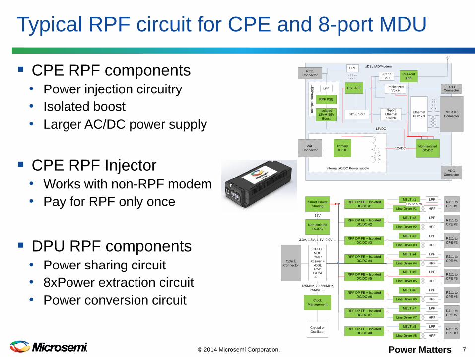
CPE RPF components• Power injection circuitry
• Isolated boost
• Larger AC/DC power supply
CPE RPF Injector• Works with non-RPF modem
• Pay for RPF only once
DPU RPF components• Power sharing circuit
• 8xPower extraction circuit
• Power conversion circuit
© 2014 Microsemi Corporation. 7
xDSL IAD/Modem
15
00V
rms Is
ola
tion
Internal AC/DC Power supply
Primary
AC/DCNon-Isolated
DC/DC
Nx RJ45
Connector
Ethernet
PHY xNxDSL SoC
12VDC
RF Front
End
DSL AFE
HPFRJ11
Connector
VAC
Connector
N-port
Ethernet
Switch
VDC
Connector
LPF
RPF PSE
802.11
SoC
Isolated
12Và 55V
Boost
12VDC
Packetized
Voice
RJ11
Connector
Optical
Connector
CPU +
MDU
ONT/
Xceiver +
xDSL
DSP
+xDSL
AFE
Line Driver #1 HPF
RJ11 to
CPE #1
LPFMELT #1
Line Driver #2 HPF
RJ11 to
CPE #2
LPFMELT #2
Line Driver #3 HPF
RJ11 to
CPE #3
LPFMELT #3
Line Driver #4 HPF
RJ11 to
CPE #4
LPFMELT #4
Line Driver #5 HPF
RJ11 to
CPE #5
LPFMELT #5
Line Driver #6 HPF
RJ11 to
CPE #6
LPFMELT #6
Line Driver #7 HPF
RJ11 to
CPE #7
LPFMELT #7
Line Driver #8 HPF
RJ11 to
CPE #8
LPFMELT #8
RPF DP FE + Isolated
DC/DC #137V to 57V
RPF DP FE + Isolated
DC/DC #2
RPF DP FE + Isolated
DC/DC #3
RPF DP FE + Isolated
DC/DC #4
RPF DP FE + Isolated
DC/DC #5
RPF DP FE + Isolated
DC/DC #6
RPF DP FE + Isolated
DC/DC #7
RPF DP FE + Isolated
DC/DC #8
Smart Power
Sharing12V
Clock
Management
Non-Isolated
DC/DC
12V
3.3V, 1.8V, 1.1V, 0.9V,...
Crystal or
Oscillator
125MHz, 70.656MHz,
25Mhz, ...
Power Matters
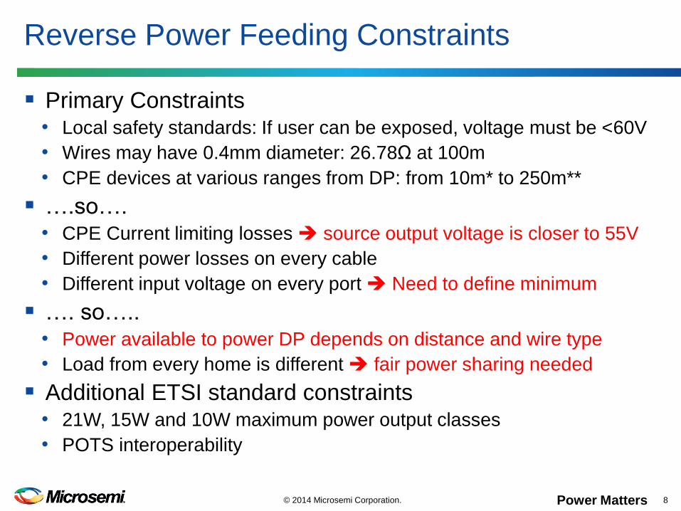
Primary Constraints• Local safety standards: If user can be exposed, voltage must be <60V
• Wires may have 0.4mm diameter: 26.78Ω at 100m
• CPE devices at various ranges from DP: from 10m* to 250m**
….so….• CPE Current limiting losses source output voltage is closer to 55V
• Different power losses on every cable
• Different input voltage on every port Need to define minimum
…. so…..• Power available to power DP depends on distance and wire type
• Load from every home is different fair power sharing needed
Additional ETSI standard constraints• 21W, 15W and 10W maximum power output classes
• POTS interoperability
Reverse Power Feeding Constraints
© 2014 Microsemi Corporation. 8
Power Matters
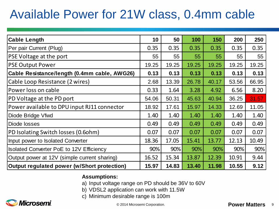
Cable Length 10 50 100 150 200 250
Per pair Current (Plug) 0.35 0.35 0.35 0.35 0.35 0.35
PSE Voltage at the port 55 55 55 55 55 55
PSE Output Power 19.25 19.25 19.25 19.25 19.25 19.25
Cable Resistance/length (0.4mm cable, AWG26) 0.13 0.13 0.13 0.13 0.13 0.13
Cable Loop Resistance (2 wires) 2.68 13.39 26.78 40.17 53.56 66.95
Power loss on cable 0.33 1.64 3.28 4.92 6.56 8.20
PD Voltage at the PD port 54.06 50.31 45.63 40.94 36.25 31.57
Power available to DPU input RJ11 connector 18.92 17.61 15.97 14.33 12.69 11.05
Diode Bridge Vfwd 1.40 1.40 1.40 1.40 1.40 1.40
Diode losses 0.49 0.49 0.49 0.49 0.49 0.49
PD Isolating Switch losses (0.6ohm) 0.07 0.07 0.07 0.07 0.07 0.07
Input power to Isolated Converter 18.36 17.05 15.41 13.77 12.13 10.49
Isolated Converter PoE to 12V Efficiency 90% 90% 90% 90% 90% 90%
Output power at 12V (simple current sharing) 16.52 15.34 13.87 12.39 10.91 9.44
Output regulated power (w/Short protection) 15.97 14.83 13.40 11.98 10.55 9.12
Available Power for 21W class, 0.4mm cable
© 2014 Microsemi Corporation. 9
Assumptions:
a) Input voltage range on PD should be 36V to 60V
b) VDSL2 application can work with 11.5W
c) Minimum desirable range is 100m
Power Matters
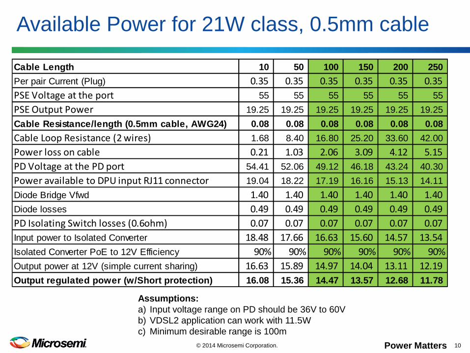
Cable Length 10 50 100 150 200 250
Per pair Current (Plug) 0.35 0.35 0.35 0.35 0.35 0.35
PSE Voltage at the port 55 55 55 55 55 55
PSE Output Power 19.25 19.25 19.25 19.25 19.25 19.25
Cable Resistance/length (0.5mm cable, AWG24) 0.08 0.08 0.08 0.08 0.08 0.08
Cable Loop Resistance (2 wires) 1.68 8.40 16.80 25.20 33.60 42.00
Power loss on cable 0.21 1.03 2.06 3.09 4.12 5.15
PD Voltage at the PD port 54.41 52.06 49.12 46.18 43.24 40.30
Power available to DPU input RJ11 connector 19.04 18.22 17.19 16.16 15.13 14.11
Diode Bridge Vfwd 1.40 1.40 1.40 1.40 1.40 1.40
Diode losses 0.49 0.49 0.49 0.49 0.49 0.49
PD Isolating Switch losses (0.6ohm) 0.07 0.07 0.07 0.07 0.07 0.07
Input power to Isolated Converter 18.48 17.66 16.63 15.60 14.57 13.54
Isolated Converter PoE to 12V Efficiency 90% 90% 90% 90% 90% 90%
Output power at 12V (simple current sharing) 16.63 15.89 14.97 14.04 13.11 12.19
Output regulated power (w/Short protection) 16.08 15.36 14.47 13.57 12.68 11.78
Available Power for 21W class, 0.5mm cable
© 2014 Microsemi Corporation. 10
Assumptions:
a) Input voltage range on PD should be 36V to 60V
b) VDSL2 application can work with 11.5W
c) Minimum desirable range is 100m

Power Matters
Cable Length 10 50 100 150 200 250
Per pair Current (Plug) 0.50 0.50 0.50 0.50 0.50 0.50
PSE Voltage at the port 55 55 55 55 55 55
PSE Output Power 27.50 27.50 27.50 27.50 27.50 27.50
Cable Resistance/length (0.4mm cable, AWG26) 0.13 0.13 0.13 0.13 0.13 0.13
Cable Loop Resistance (2 wires) 2.68 13.39 26.78 40.17 53.56 66.95
Power loss on cable 0.67 3.35 6.70 10.04 13.39 16.74
PD Voltage at the PD port 53.66 48.31 41.61 34.92 28.22 21.53
Power available to DPU input RJ11 connector 26.83 24.15 20.81 17.46 14.11 10.76
Diode Bridge Vfwd 1.40 1.40 1.40 1.40 1.40 1.40
Diode losses 0.70 0.70 0.70 0.70 0.70 0.70
PD Isolating Switch losses (0.6ohm) 0.15 0.15 0.15 0.15 0.15 0.15
Input power to Isolated Converter 25.98 23.30 19.96 16.61 13.26 9.91
Isolated Converter PoE to 12V Efficiency 90% 90% 90% 90% 90% 90%
Output power at 12V (simple current sharing) 23.38 20.97 17.96 14.95 11.93 8.92
Output regulated power (w/Short protection) 22.60 20.27 17.36 14.45 11.54 8.62
Available Power for 30W class, 0.4mm cable
© 2014 Microsemi Corporation. 11
Assumptions:
a) Input voltage range on PD should be 36V to 60V
b) G.FAST application can work with 17.5W
c) Minimum desirable range is 100m

Power Matters
Cable Length 10 50 100 150 200 250
Per pair Current (Plug) 0.50 0.50 0.50 0.50 0.50 0.50
PSE Voltage at the port 55 55 55 55 55 55
PSE Output Power 27.50 27.50 27.50 27.50 27.50 27.50
Cable Resistance/length (0.5mm cable, AWG24) 0.08 0.08 0.08 0.08 0.08 0.08
Cable Loop Resistance (2 wires) 1.68 8.40 16.80 25.20 33.60 42.00
Power loss on cable 0.42 2.10 4.20 6.30 8.40 10.50
PD Voltage at the PD port 54.16 50.80 46.60 42.40 38.20 34.00
Power available to DPU input RJ11 connector 27.08 25.40 23.30 21.20 19.10 17.00
Diode Bridge Vfwd 1.40 1.40 1.40 1.40 1.40 1.40
Diode losses 0.70 0.70 0.70 0.70 0.70 0.70
PD Isolating Switch losses (0.6ohm) 0.15 0.15 0.15 0.15 0.15 0.15
Input power to Isolated Converter 26.23 24.55 22.45 20.35 18.25 16.15
Isolated Converter PoE to 12V Efficiency 90% 90% 90% 90% 90% 90%
Output power at 12V (simple current sharing) 23.61 22.10 20.21 18.32 16.43 14.54
Output regulated power (w/Short protection) 22.82 21.36 19.53 17.70 15.88 14.05
Available Power for 30W class, 0.5mm cable
© 2014 Microsemi Corporation. 12
Assumptions:
a) Input voltage range on PD should be 36V to 60V
b) G.FAST application can work with 17.5W
c) Minimum desirable range is 100m
Power Matters
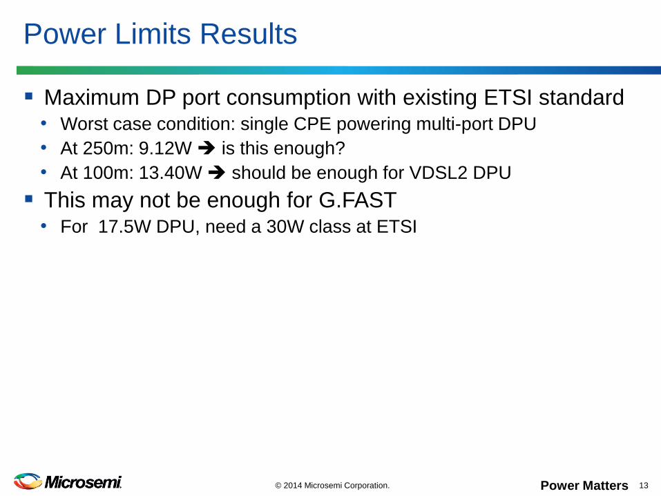
Maximum DP port consumption with existing ETSI standard• Worst case condition: single CPE powering multi-port DPU
• At 250m: 9.12W is this enough?
• At 100m: 13.40W should be enough for VDSL2 DPU
This may not be enough for G.FAST• For 17.5W DPU, need a 30W class at ETSI
Power Limits Results
© 2014 Microsemi Corporation. 13

Power Matters
End User cost allocation: is this fair?
© 2014 Microsemi Corporation. 14
Cable Length 10 150 10 150 10 250 10 250
Per pair Current (Plug) 0.22 0.27 0.22 0.24 0.17 0.25 0.17 0.20
PSE Voltage at the port 55 55 55 55 55 55 55 55
PSE Output Power 11.95 14.84 11.90 13.35 9.54 13.80 9.51 11.27
Cable Resistance/length 0.13 0.13 0.08 0.08 0.13 0.13 0.08 0.08
Cable Loop Resistance (2 wires) 2.68 40.17 1.68 25.20 2.68 66.95 1.68 42.00
Power loss on cable 0.13 2.92 0.08 1.49 0.08 4.21 0.05 1.76
PD Voltage at the PD port 54.42 44.16 54.64 48.88 54.54 38.20 54.71 46.39
Power available to DPU input RJ11 connector 11.83 11.92 11.83 11.87 9.46 9.58 9.46 9.51
Diode Bridge Vfwd 1.40 1.40 1.40 1.40 1.40 1.40 1.40 1.40
Diode losses 0.30 0.38 0.30 0.34 0.24 0.35 0.24 0.29
PD Isolating Switch losses (0.6ohm) 0.03 0.04 0.03 0.04 0.02 0.04 0.02 0.03
Input power to Isolated Converter 11.49 11.49 11.49 11.49 9.20 9.20 9.20 9.20
Isolated Converter PoE to 12V Efficiency 90% 90% 90% 90% 90% 90% 90% 90%
Output power at 12V (simple current sharing) 10.34 10.34 10.34 10.34 8.28 8.28 8.28 8.28
Output regulated power (w/Short protection) 10.00 10.00 10.00 10.00 8.00 8.00 8.00 8.00
PSE AC/DC efficiency 75% 75% 75% 75% 75% 75% 75% 75%
AC power consumption 15.94 19.79 15.87 17.81 12.72 18.40 12.67 15.03
Yearly power consumption 139.62 173.33 139.04 155.98 111.39 161.16 111.02 131.65
Electricity cost 0.20$ 0.20$ 0.20$ 0.20$ 0.20$ 0.20$ 0.20$ 0.20$
Yearly electricity cost 27.92$ 34.67$ 27.81$ 31.20$ 22.28$ 32.23$ 22.20$ 26.33$
Yearly end user cost difference 6.74$ 3.39$ 9.95$ 4.13$
20W load 10-150m 16W load 10-250m
0.4mm cable 0.5mm cable 0.4mm cable 0.5mm cable
Assumptions:
a) G.FAST application consumes 20W with 2 loads
b) VDSL2 application consumes 16W with 2 loads
c) Simple current sharing used, with 100% accuracy

Power Matters
Definition: load each DP ports based on CPE consumption including cable losses, so loads are identical
Option 1: communicate CPE power consumption • CPE host reads PSE power expensive isolation on every CPE
• DPU reads power consumed from each CPE does it interoperate?
• Precludes RPF Injector pay for RPF every CPE refresh
Option 2: determine power consumption on DPU• DPU FairPower™ infers cable length from input voltage
• DPU FairPower™ measures no load CPE output voltage
• Works with ANY CPE, with embedded RPF or RPF injector
• FairPower™ circuit cost spread over multiple ports
Fair Power Sharing
© 2014 Microsemi Corporation. 15

Power Matters
Reverse Power Feeding is an important G.FAST enabler
Work to be done at ETSI to fully support G.FAST• 30W class support
FairPower™ sharing can simplify the acceptance of RPF
Summary
© 2014 Microsemi Corporation. 16