powering the u.s. army of the future
TRANSCRIPT
DETAILS
Distribution, posting, or copying of this PDF is strictly prohibited without written permission of the National Academies Press. (Request Permission) Unless otherwise indicated, all materials in this PDF are copyrighted by the National Academy of Sciences.
Copyright © National Academy of Sciences. All rights reserved.
THE NATIONAL ACADEMIES PRESS
Visit the National Academies Press at NAP.edu and login or register to get:
– Access to free PDF downloads of thousands of scientific reports
– 10% off the price of print titles
– Email or social media notifications of new titles related to your interests
– Special offers and discounts
GET THIS BOOK
FIND RELATED TITLES
This PDF is available at SHARE
CONTRIBUTORS
SUGGESTED CITATION
http://nap.edu/26052
Powering the U.S. Army of the Future (2021)
163 pages | 6 x 9 | PAPERBACKISBN 978-0-309-25803-6 | DOI 10.17226/26052
Committee on Powering the U.S. Army of the Future; Board on Army Research andDevelopment; Division on Engineering and Physical Sciences; National Academiesof Sciences, Engineering, and Medicine
National Academies of Sciences, Engineering, and Medicine 2021. Powering theU.S. Army of the Future. Washington, DC: The National Academies Press.https://doi.org/10.17226/26052.
Powering the U.S. Army of the Future
Copyright National Academy of Sciences. All rights reserved.
PREPUBLICATION COPY – SUBJECT TO FURTHER EDITORIAL CORRECTION
Prepublication Copy – Subject to Further Editorial Correction
Powering the U.S. Army of the Future
Committee on Powering the U.S. Army of the Future
Board on Army Research and Development
Division on Engineering and Physical Sciences
A Consensus Study Report of
Powering the U.S. Army of the Future
Copyright National Academy of Sciences. All rights reserved.
PREPUBLICATION COPY – SUBJECT TO FURTHER EDITORIAL CORRECTION
THE NATIONAL ACADEMIES PRESS 500 Fifth Street, NW Washington, DC 20001 This activity was supported by Contract W911NF-18-D-0002-0001 with the Deputy Assistant Secretary of the Army for Research and Technology (DASA(RT)). Any opinions, findings, conclusions, or recommendations expressed in this publication do not necessarily reflect the views of any organization or agency that provided support for the project. International Standard Book Number-13: xxxxxxx International Standard Book Number-10: xxxxxxx Digital Object Identifier: https://doi.org/10.17226/26052 Limited copies of this report may be available through the Board on Army Research and Development, 500 Fifth Street, NW, Washington, DC 20001; (202) 334-3942 Additional copies of this publication are available for sale from the National Academies Press, 500 Fifth Street, NW, Keck 360, Washington, DC 20001; (800) 624-6242 or (202) 334-3313; http://www.nap.edu. Copyright 2021 by the National Academy of Sciences. All rights reserved. Printed in the United States of America Suggested citation: National Academies of Sciences, Engineering, and Medicine. 2021. Powering the U.S. Army of the Future. Washington, DC: The National Academies Press. https://doi.org/10.17226/26052.
Powering the U.S. Army of the Future
Copyright National Academy of Sciences. All rights reserved.
PREPUBLICATION COPY – SUBJECT TO FURTHER EDITORIAL CORRECTION
The National Academy of Sciences was established in 1863 by an Act of Congress, signed by President Lincoln, as a private, nongovernmental institution to advise the nation on issues related to science and technology. Members are elected by their peers for outstanding contributions to research. Dr. Marcia McNutt is president. The National Academy of Engineering was established in 1964 under the charter of the National Academy of Sciences to bring the practices of engineering to advising the nation. Members are elected by their peers for extraordinary contributions to engineering. Dr. John L. Anderson is president. The National Academy of Medicine (formerly the Institute of Medicine) was established in 1970 under the charter of the National Academy of Sciences to advise the nation on medical and health issues. Members are elected by their peers for distinguished contributions to medicine and health. Dr. Victor J. Dzau is president. The three Academies work together as the National Academies of Sciences, Engineering, and Medicine to provide independent, objective analysis and advice to the nation and conduct other activities to solve complex problems and inform public policy decisions. The National Academies also encourage education and research, recognize outstanding contributions to knowledge, and increase public understanding in matters of science, engineering, and medicine. Learn more about the National Academies of Sciences, Engineering, and Medicine at www.nationalacademies.org.
Powering the U.S. Army of the Future
Copyright National Academy of Sciences. All rights reserved.
PREPUBLICATION COPY – SUBJECT TO FURTHER EDITORIAL CORRECTION
Consensus Study Reports published by the National Academies of Sciences, Engineering, and Medicine document the evidence-based consensus on the study’s statement of task by an authoring committee of experts. Reports typically include findings, conclusions, and recommendations based on information gathered by the committee and the committee’s deliberations. Each report has been subjected to a rigorous and independent peer-review process and it represents the position of the National Academies on the statement of task. Proceedings published by the National Academies of Sciences, Engineering, and Medicine chronicle the presentations and discussions at a workshop, symposium, or other event convened by the National Academies. The statements and opinions contained in proceedings are those of the participants and are not endorsed by other participants, the planning committee, or the National Academies. For information about other products and activities of the National Academies, please visit www.nationalacademies.org/about/whatwedo.
Powering the U.S. Army of the Future
Copyright National Academy of Sciences. All rights reserved.
PREPUBLICATION COPY – SUBJECT TO FURTHER EDITORIAL CORRECTION v
COMMITTEE ON POWERING THE U.S. ARMY OF THE FUTURE JOHN KOSZEWNIK, NAE,1 Achates Power, Inc., Co-Chair JOHN LUGINSLAND, CONFLUENT SCIENCES, LLC, Co-Chair JOHN KASSAKIAN, NAE, MIT MICHAEL MACLACHLAN, National Intelligence University PAUL ROEGE, Creative Erg, LLC DEBRA ROLISON, U.S. Naval Research Laboratory SUBHASH SINGHAL, NAE, Pacific Northwest National Laboratory JOHN SZYMANSKI, Los Alamos National Laboratory Staff STEVEN DARBES, Study Director WILLIAM “BRUNO” MILLONIG, Board Director CAMERON MALCOM, Research Associate SARAH JUCKETT, Program Officer CLEMENT MULOCK, Program Assistant LINDA WALKER, Program Coordinator AANIKA SENN, Program Coordinator CHRIS JONES, Senior Finance Business Partner
1 Member, National Academy of Engineering.
Powering the U.S. Army of the Future
Copyright National Academy of Sciences. All rights reserved.
PREPUBLICATION COPY – SUBJECT TO FURTHER EDITORIAL CORRECTION vi
BOARD ON ARMY RESEARCH AND DEVELOPMENT KATHARINA MCFARLAND, U.S. Army (retired), Chair MICHAEL BEAR, BAE Systems, Vice Chair ANDREW ALLEYNE, University of Illinois, Urbana-Champaign DAVID AUCSMITH, University of Washington JAMES BAGIAN, NAE1/NAM,2 University of Michigan JOAN BIENVENUE, University of Virginia LYNN DUGLE, Independent Consultant JOHN FARR, United States Military Academy at West Point GEORGE “RUSTY” GRAY III, NAE, Los Alamos National Laboratory WILLIAM HIX, U.S. Army (retired) DUNCAN MCGILL, Mercyhurst University CHRISTINA MURATA, Deloitte ALBERT SCIARRETTA, CNS Technologies, Inc. GEOFFREY THOME, SAIC JAMES THOMSEN, Seaborne Defense, LLC JOSEP TORRELLAS, University of Illinois, Urbana-Champaign Staff WILLIAM “BRUNO” MILLONIG, Board Director STEVEN DARBES, Program Officer SARAH JUCKETT, Program Officer TINA LATIMER, Program Coordinator LINDA WALKER, Program Coordinator CAMERON MALCOM, Research Associate CLEMENT MULOCK, Program Assistant CHRIS JONES, Senior Finance Business Partner
1 Member, National Academy of Engineering. 2 Member, National Academy of Medicine.
Powering the U.S. Army of the Future
Copyright National Academy of Sciences. All rights reserved.
PREPUBLICATION COPY – SUBJECT TO FURTHER EDITORIAL CORRECTION vii
Preface
I consider it an honor and a privilege to have served as a member on the National Academies of Sciences, Engineering, and Medicine committee studying how to best “Power the U.S. Army of the Future.” Our warfighters who put their lives on the line for our country certainly deserve the very best capabilities that rapidly advancing technology in a number of areas can provide. This is particularly important as we move toward the Department of Defense’s vision of a multi-domain scenario, where the best land, air, space, and sea resources are brought together in a coordinated, strategic fashion against any adversary for competitive advantage.
The number one objective, consistent with Army Operational Energy doctrine developed 10 years ago, is to use energy in a manner that provides the greatest net operational advantage on the battlefield. This entails not just energy logistics, but encompasses a more complete information-driven understanding of how energy can best be used to win against near-peer and other adversaries.
Supporting this overall objective, there are a number of other important considerations that the committee had in providing its recommendations. These include the following:
• Supplying whatever energy is needed to whomever needs it wherever and whenever they need it. Just as one would never want a soldier to run out of ammunition, food, or water, having adequate power and energy saves warfighter lives and is essential to their success;
• Recognizing the need to meet growing power demands; • Supporting enhanced battlefield situational awareness for all our warfighters based on
improved communications, information processing, and artificial intelligence; • Reducing fuel transport needs to save lives during resupply; • Reducing the weight that the dismounted soldier has to carry; • Reduce the weight of all types of vehicles (i.e., ground and flight assets both manned and
unmanned); • Increasing the Army Brigade’s self-sustainment capability from 3 to 7 days; • Providing rapid mobility across a variety of terrain for dismounted soldiers, vehicles, and
forward operating bases. This includes rapid set-up and breakdown times for forward operating bases;
• Maintaining or reducing the time required to refuel, recharge, or provide new sources of power; • Possessing a capability to utilize a wider range of globally available resources (i.e. fuel
resources utilized by allies and adversaries); • Maintaining a capability to disable or lock-out energy resources fall into hostile hands
particularly those with proprietary technology; and • Employing environmentally friendly technologies wherever practical without compromising
military objectives.
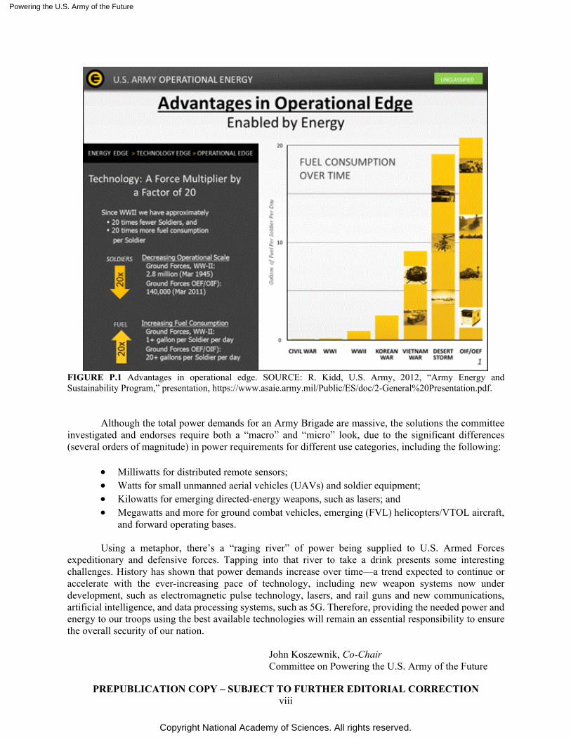
Figure P.1 tells an interesting story. Since World War II, the Army is using approximately 20 times more energy per soldier, while reducing the number of soldiers by a roughly equivalent amount. This direction will likely continue in the future and highlights the importance of energy supply and management.
Powering the U.S. Army of the Future
Copyright National Academy of Sciences. All rights reserved.
PREPUBLICATION COPY – SUBJECT TO FURTHER EDITORIAL CORRECTION viii
FIGURE P.1 Advantages in operational edge. SOURCE: R. Kidd, U.S. Army, 2012, “Army Energy and Sustainability Program,” presentation, https://www.asaie.army.mil/Public/ES/doc/2-General%20Presentation.pdf.
Although the total power demands for an Army Brigade are massive, the solutions the committee investigated and endorses require both a “macro” and “micro” look, due to the significant differences (several orders of magnitude) in power requirements for different use categories, including the following:
• Milliwatts for distributed remote sensors; • Watts for small unmanned aerial vehicles (UAVs) and soldier equipment; • Kilowatts for emerging directed-energy weapons, such as lasers; and • Megawatts and more for ground combat vehicles, emerging (FVL) helicopters/VTOL aircraft,
and forward operating bases.
Using a metaphor, there’s a “raging river” of power being supplied to U.S. Armed Forces expeditionary and defensive forces. Tapping into that river to take a drink presents some interesting challenges. History has shown that power demands increase over time—a trend expected to continue or accelerate with the ever-increasing pace of technology, including new weapon systems now under development, such as electromagnetic pulse technology, lasers, and rail guns and new communications, artificial intelligence, and data processing systems, such as 5G. Therefore, providing the needed power and energy to our troops using the best available technologies will remain an essential responsibility to ensure the overall security of our nation.
John Koszewnik, Co-Chair Committee on Powering the U.S. Army of the Future
Powering the U.S. Army of the Future
Copyright National Academy of Sciences. All rights reserved.
PREPUBLICATION COPY – SUBJECT TO FURTHER EDITORIAL CORRECTION ix
Acknowledgment of Reviewers This Consensus Study Report was reviewed in draft form by individuals chosen for their diverse
perspectives and technical expertise. The purpose of this independent review is to provide candid and critical comments that will assist the National Academies of Sciences, Engineering, and Medicine in making each published report as sound as possible and to ensure that it meets the institutional standards for quality, objectivity, evidence, and responsiveness to the study charge. The review comments and draft manuscript remain confidential to protect the integrity of the deliberative process.
We thank the following individuals for their review of this report: Eric Barth, Vanderbilt University, Nigel Clark, West Virginia University, Kevin Huang, University of South Carolina, Yilu Liu, NAE,1 University of Tennessee, Arumugam Manthiram, University of Texas, Austin Kathryn McCarthy, Oak Ridge National Laboratory, Eric Morgan, MIT Lincoln Laboratory, William Mustain, University of South Carolina, and Kenneth Rosen, NAE, General Aero-Science Consultants, LLC.
Although the reviewers listed above provided many constructive comments and suggestions, they
were not asked to endorse the conclusions or recommendations of this report nor did they see the final draft before its release. The review of this report was overseen by John Stenbit, NAE, TRW. Inc. (retired). He was responsible for making certain that an independent examination of this report was carried out in accordance with the standards of the National Academies and that all review comments were carefully considered. Responsibility for the final content rests entirely with the authoring committee and the National Academies.
1 Member, National Academy of Engineering.

Powering the U.S. Army of the Future
Copyright National Academy of Sciences. All rights reserved.
1
Powering the U.S. Army of the Future
Copyright National Academy of Sciences. All rights reserved.
PREPUBLICATION COPY – SUBJECT TO FURTHER EDITORIAL CORRECTION xi
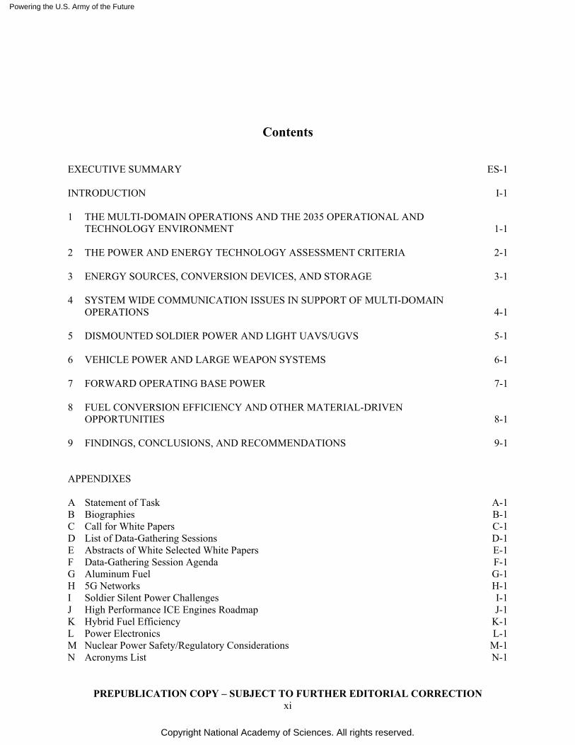
Contents EXECUTIVE SUMMARY ES-1 INTRODUCTION I-1 1 THE MULTI-DOMAIN OPERATIONS AND THE 2035 OPERATIONAL AND TECHNOLOGY ENVIRONMENT 1-1 2 THE POWER AND ENERGY TECHNOLOGY ASSESSMENT CRITERIA 2-1 3 ENERGY SOURCES, CONVERSION DEVICES, AND STORAGE 3-1 4 SYSTEM WIDE COMMUNICATION ISSUES IN SUPPORT OF MULTI-DOMAIN OPERATIONS 4-1 5 DISMOUNTED SOLDIER POWER AND LIGHT UAVS/UGVS 5-1 6 VEHICLE POWER AND LARGE WEAPON SYSTEMS 6-1 7 FORWARD OPERATING BASE POWER 7-1 8 FUEL CONVERSION EFFICIENCY AND OTHER MATERIAL-DRIVEN OPPORTUNITIES 8-1 9 FINDINGS, CONCLUSIONS, AND RECOMMENDATIONS 9-1 APPENDIXES A Statement of Task A-1 B Biographies B-1 C Call for White Papers C-1 D List of Data-Gathering Sessions D-1 E Abstracts of White Selected White Papers E-1 F Data-Gathering Session Agenda F-1 G Aluminum Fuel G-1 H 5G Networks H-1 I Soldier Silent Power Challenges I-1 J High Performance ICE Engines Roadmap J-1 K Hybrid Fuel Efficiency K-1 L Power Electronics L-1 M Nuclear Power Safety/Regulatory Considerations M-1 N Acronyms List N-1

Powering the U.S. Army of the Future
Copyright National Academy of Sciences. All rights reserved.
Powering the U.S. Army of the Future
Copyright National Academy of Sciences. All rights reserved.
PREPUBLICATION COPY – SUBJECT TO FURTHER EDITORIAL CORRECTION ES-1
Executive Summary The Committee on Powering the U.S. Army of the Future considered a range of Army power and
energy needs through 2035, identifying the breadth of requirements, gaps, and opportunities therein. This was a challenging task, given the tremendous diversity of needs, both in terms of the quantity of power needed and who is using it.
Given the range of technologies that will drive future power and energy (P&E) demands, the committee decided to focus the scope of the study on the power needs surrounding dismounted soldiers, existing vehicle platforms, and forward operating bases, as well as innovations under development that are expected to be in service in 2035, and technologies that could enhance the Army’s capabilities to fight as part of a multi-domain force.
The committee further scoped the study to place a heavy focus on the needs of an armored brigade combat team (ABCT) because they expend prodigious amounts of energy and the Army expects them to remain a primary, independently maneuvering unit for the foreseeable future. The ABCT provided a baseline that scaled well and allowed the committee to assess technologies across dismounted, mounted, and semi-stationary units.1
Using predictions of the Operational Logistics (OPLOG) Planner modeling tool provided by the Combined Arms Support Command (CASCOM), the committee anticipates that a typical ABCT will expend 18,800 megawatt-hours (MWh) of energy over a 12-day mission.2 This equates to an average energy consumption of roughly 1,600 MWh per day and an average power level of 65 megawatts (MW). It must be noted that during mounted maneuver, power demands are significantly higher than during sustained lower-intensity operations. These energy demands will only grow for the foreseeable future as ongoing improvements in communications, electronic sensing, artificial intelligence processing to improve battlefield situational awareness, increased vehicle mobility, and more lethal weaponry, threaten to overwhelm any feasible improvements in efficiency.
In finalizing its report, the committee concluded that some past power/energy studies advocating widespread use of pure battery electric ground combat vehicles recharged in the field with mobile nuclear power plants are not likely to be technically feasible in the timeframe of this report. To be more specific, the committee concluded that jet propellant 8 (JP8), diesel, and biodiesel3 (a renewable fuel) should serve as the primary sources of power and energy brought to the battlefield for the foreseeable future. Their high energy density (particularly per unit volume) is unmatched by most other liquid and gaseous fuels. It is this density measure that defines how many supply trucks in convoys carrying fuel are needed, which in turn increases the risks faced by soldiers and contractors and the integrity of the supply chain with each added convoy or truck.4
1 Army aviation accounts for a considerable portion of the Army’s JP8 consumption. Due to time and expertise
constraints, the committee did not focus on primary propulsion for aircraft. However, many of the recommendations in the report are applicable to aviation secondary power.
2 Schwankhart, R. 2020. Energy Consumption Requirements Overview – Armored Brigade Combat Team (ABCT) Case Study. Presentation to the study committee. RAND Corporation.
3 Although biodiesel, renewable diesel, and e-diesel refer to fuels produced by different processes, their performance properties are very similar, enabling them to be used interchangeably. As all three are environmentally friendly, a single term, “biodiesel,” is used to refer to all three such fuels throughout this report.
4 Although this study concludes that supply convoys will continue to be needed, there are multiple opportunities now under investigation to reduce the risk of lost lives in transport. These include active protection systems, autonomous vehicles, vehicle platooning, minesweeping vehicles, and helicopter and ground escorts.
Powering the U.S. Army of the Future
Copyright National Academy of Sciences. All rights reserved.
PREPUBLICATION COPY – SUBJECT TO FURTHER EDITORIAL CORRECTION ES-2
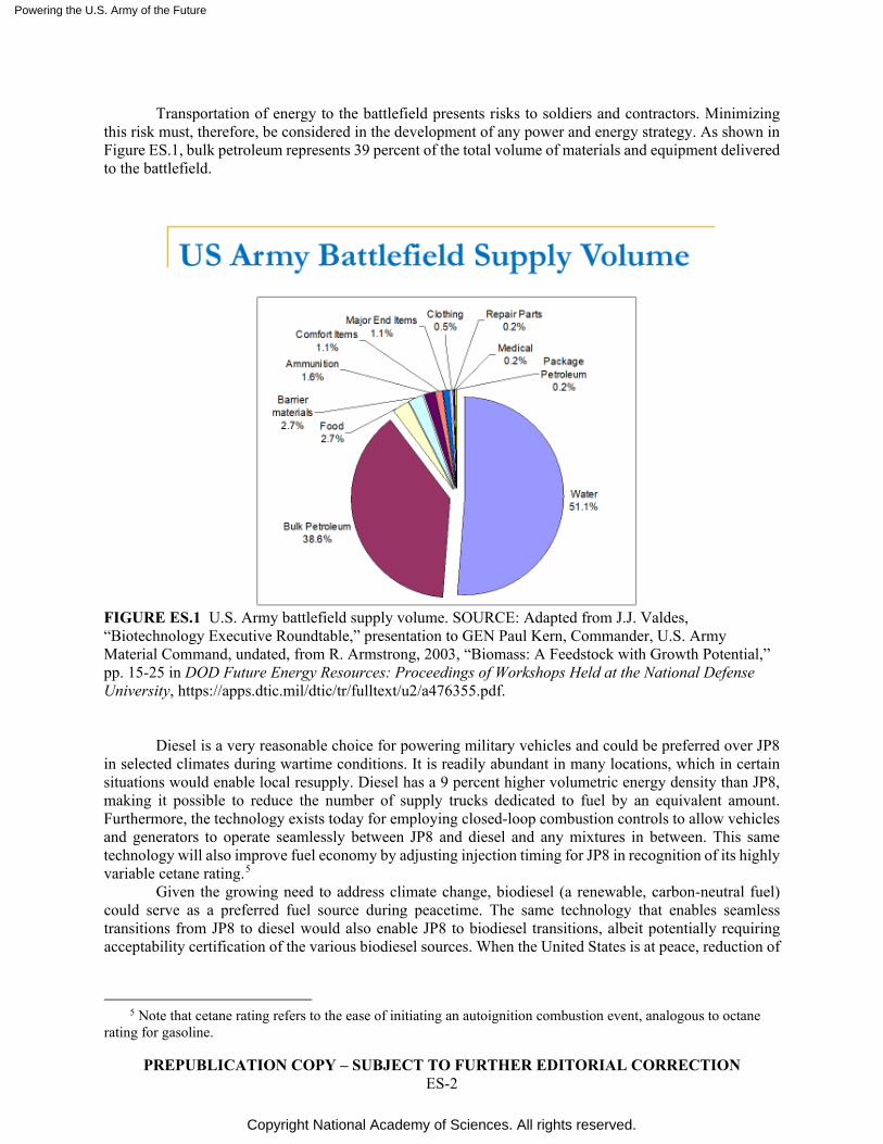
Transportation of energy to the battlefield presents risks to soldiers and contractors. Minimizing this risk must, therefore, be considered in the development of any power and energy strategy. As shown in Figure ES.1, bulk petroleum represents 39 percent of the total volume of materials and equipment delivered to the battlefield.
FIGURE ES.1 U.S. Army battlefield supply volume. SOURCE: Adapted from J.J. Valdes, “Biotechnology Executive Roundtable,” presentation to GEN Paul Kern, Commander, U.S. Army Material Command, undated, from R. Armstrong, 2003, “Biomass: A Feedstock with Growth Potential,” pp. 15-25 in DOD Future Energy Resources: Proceedings of Workshops Held at the National Defense University, https://apps.dtic.mil/dtic/tr/fulltext/u2/a476355.pdf.
Diesel is a very reasonable choice for powering military vehicles and could be preferred over JP8
in selected climates during wartime conditions. It is readily abundant in many locations, which in certain situations would enable local resupply. Diesel has a 9 percent higher volumetric energy density than JP8, making it possible to reduce the number of supply trucks dedicated to fuel by an equivalent amount. Furthermore, the technology exists today for employing closed-loop combustion controls to allow vehicles and generators to operate seamlessly between JP8 and diesel and any mixtures in between. This same technology will also improve fuel economy by adjusting injection timing for JP8 in recognition of its highly variable cetane rating.5
Given the growing need to address climate change, biodiesel (a renewable, carbon-neutral fuel) could serve as a preferred fuel source during peacetime. The same technology that enables seamless transitions from JP8 to diesel would also enable JP8 to biodiesel transitions, albeit potentially requiring acceptability certification of the various biodiesel sources. When the United States is at peace, reduction of
5 Note that cetane rating refers to the ease of initiating an autoignition combustion event, analogous to octane
rating for gasoline.
Powering the U.S. Army of the Future
Copyright National Academy of Sciences. All rights reserved.
PREPUBLICATION COPY – SUBJECT TO FURTHER EDITORIAL CORRECTION ES-3
greenhouse gases may be a more important concern than minimizing the number of trucks in fuel convoys. In addition, biodiesel is fairly available worldwide.6
It must be noted that future use of multiple fuels would violate the Army’s long-standing reliance on a “single fuel policy,” which provides for a common fuel to be used across all ground vehicle platforms, generator sets, and turbine-powered aircraft. Therefore, the advantages of using multiple fuels detailed above need to be balanced against the logistic complexity challenges associated with their distribution. If such logistics proves to be excessively challenging in certain situations, then JP8 use remains the preferred method of transported energy to the battlefield, to remain compatible with aircraft needs.
The committee’s analysis has concluded that all-electric ground combat vehicles and tactical supply vehicles (i.e., fully reliant upon battery energy storage versus liquid fuel) are not practical for a majority of battlefield vehicles now nor in the foreseeable future for two reasons. One is that the energy density of batteries today is roughly two orders of magnitude less than JP8 today, resulting in excessive package weight and volume to meet maneuver needs. Advances in battery energy density will undoubtedly take place, but not enough to offset that magnitude of a disadvantage. The second, and more important, reason from a practicality standpoint is that recharging such vehicles in a short period of time would require massive quantities of electric power that are not available on the battlefield.
To put this assertion in perspective, the committee’s analysis (confirmed by the Army’s internal analysis; see Figure 6.5) shows that to recharge just one heavy combat vehicle (50 to 70 tons) within 15 minutes, a power source of 14 to 29 megawatts (MW) would be required. Hardly practical when an Armored Brigade Combat Team may have 30 or more Abrams and a comparable number of other supporting armored ground combat vehicles.
Similarly, all-electric tactical vehicles have limited practicality on the battlefield given their recharging requirements. For example, the committee’s analysis showed that each Joint Light Tactical Vehicle would require roughly a 2.6 MW power source to recharge within 15 minutes.
Because nuclear energy dwarfs JP8 and diesel in terms of energy density, some have suggested that a mobile nuclear-based power source might meet the power demand needed to enable all-electric vehicles on the battlefield. However, the latest design proposals indicate that such a device would weigh 40 tons, require delivery of two 20-foot ISO7 containers to the battlefield, and have set-up and cool down times of 3 days and 2 days, respectively. Such operational constraints are not consistent with the multi-domain operations (MDO) strategy of deploying and operating mobile forward operating bases.
As still another constraint, the prototype nuclear power plant currently being developed for expeditionary use, with 2027 production planned, would provide only 2 MW of electricity, which is a far cry from the 65 MW average consumption of one maneuvering Armored Brigade Combat Team or the 14+ MW required to recharge just one heavy ground combat vehicle in 15 minutes. Nevertheless, in a more enduring base location that requires substantial energy for sustainment operations, such a nuclear plant might be attractive as a modular capability for 24/7 power, independent of fuel logistics, for an extended period of at least 3 years
This assessment does not mean that all-electric vehicles will not have an encouraging future in the domestic consumer, commercial, and trucking world. Rather the committee concluded that an all-electric tactical force would not be suitable for the Army to adopt through 2035. Non-tactical electric vehicles (EVs) require significantly less power or may operate over shorter ranges. They can return to the same location with a permanent connection to a high-power grid, and can be fully charged overnight. Contrast that with a multi-domain combat scenario where, in many cases, the energy must be brought to a constantly changing battlefield location and rapidly resupplied.
Of particular significance, hybrid technologies using internal combustion engines (ICEs), gas turbine engines, generators, power electronics, and battery storage can deliver many of the electrification advantages to the field without the recharging time and range constraints of EVs. Of particular importance
6 Sönnichsen, N. 2021. Leading biodiesel producers worldwide in 2019, by country (in billion liters). Statista.
https://www.statista.com/statistics/271472/biodiesel-production-in-selected-countries/. Accessed January 2021. 7 ISO refers to International Organization for Standardization.
Powering the U.S. Army of the Future
Copyright National Academy of Sciences. All rights reserved.
PREPUBLICATION COPY – SUBJECT TO FURTHER EDITORIAL CORRECTION ES-4
is the improved fuel economy of up to 20 percent that hybrids provide.8 The Army and its supporting defense industry suppliers have already initiated much encouraging work in this area.
Hybrids also provide low noise and low thermal signatures while idling or traveling over short distances, using the energy stored in the battery with the onboard power electronics to operate when the ICE is shut down. With existing battery energy densities, they may range up to 3 to 10 miles without engine engagement, a distance that will increase as battery energy density increases over time. Lastly, it would be possible to tap into vehicle hybrid energy systems (up to and including 1 MW for a heavy main battle tank) to provide power for a local microgrid, for a mobile weapon system, or to recharge dismounted soldier power packs.
The committee identified a number of fuel-efficiency opportunities that would enable the Army to further reduce the number of presently sized fuel trucks and/or convoy trips needed to bring power and energy to the field. Improvements in horizontally opposed two-stroke piston engines, a technology already pursued by the Army, are possible in the areas of fuel efficiency, power density, and heat rejection. Also encouraging are some of the four-stroke diesel technologies under development that offer lower friction, better combustion, and waste heat recovery, as part of the Department of Energy SuperTruck programs.
Further but longer-term opportunities may exist in the form of free-piston engines and linear generators. A possible additional application for these emerging low fuel consumption ICE engines is applicability for relatively long-duration unmanned aerial/ground vehicles (UAVs) where the fuel consumption (and fuel tank size) advantage overcomes the present power/weight advantage of gas turbines.
To improve self-sustainability, energy consumption needs to be minimized and its counterpart, energy efficiency, needs to be maximized throughout the complete chain from energy storage to power delivery. For example, lower rolling-resistance tracks, higher temperature–capable power electronics, batteries, motors, and more-efficient cooling systems together could enable considerable reductions in parasitic cooling and friction losses.
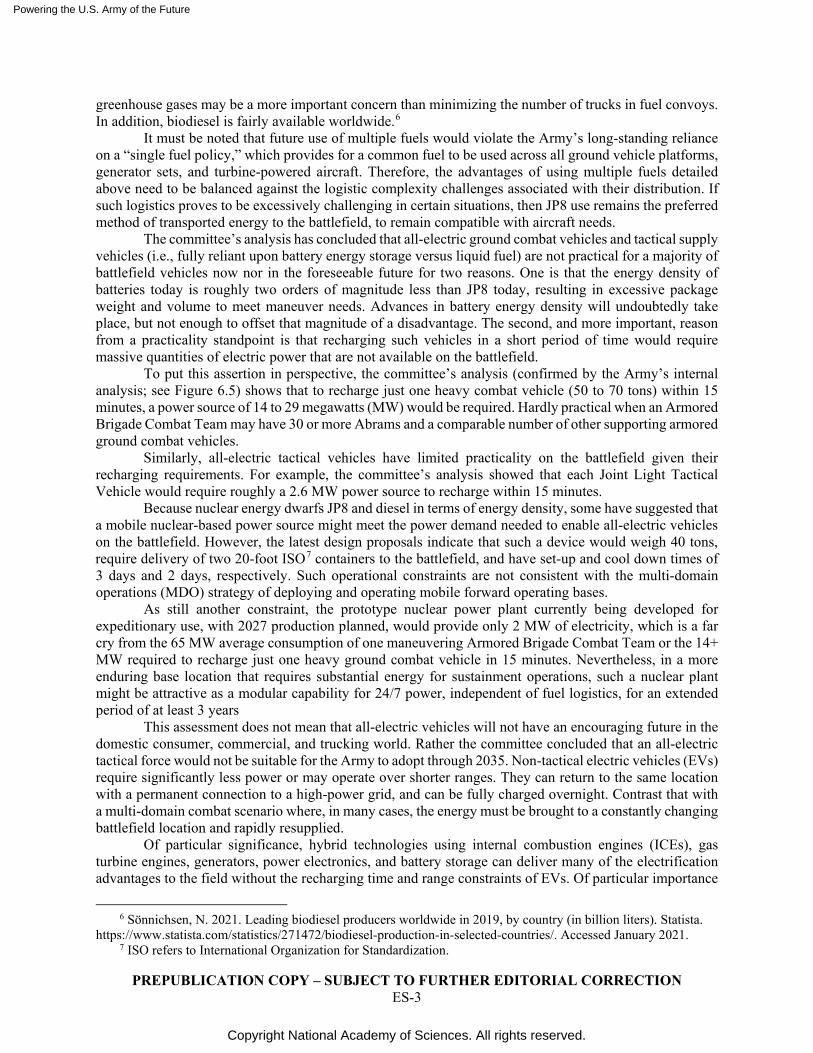
It must be noted that the above mentioned opportunities would significantly reduce the amount of liquid heavy hydrocarbon fuel that would need to be transported to provide an equivalent amount of energy. As a rough quantification, Figure ES.2 is provided.
FIGURE ES.2 Quantifying opportunities for fuel efficiency.
Note that a 48 percent improvement in fuel efficiency results in a 32 percent reduction in the fuel that needs to be transported to the field to provide an equivalent amount of energy. These numbers should not be considered a commitment but a vision of what may be possible and should be pursued. Experience has shown that it may not be possible to realize all of the fuel economy opportunities on a roadmap.
The committee identified some encouraging increases in battery energy density, which will provide more capable hybrids and UAVs, as well as lighten the load of the dismounted soldier. A number of these opportunities where further investment is justified are discussed in the report. Particularly encouraging are recent developments showing that zinc-based batteries with reconfigured three-dimensional (3D)
8 See Appendix K.
Internal Combustion Engine 28% improvement 39% BTE (present Army engines) to 50% BTE (SuperTruck levels)
Hybridization 10 to 20% Opportunity size dependent upon recovery of braking energy
Diesel Fuel in lieu of JP8 9% Higher volumetric energy density
Assorted Other 5 to 8% Transmission/Cooling/Vehicle Parasitic Loss Improvements
Total Fuel Efficiency Improvement 35 to 48% improvement Resulting in less risk of life during fuel transportation
Fuel Efficiency
Powering the U.S. Army of the Future
Copyright National Academy of Sciences. All rights reserved.
PREPUBLICATION COPY – SUBJECT TO FURTHER EDITORIAL CORRECTION ES-5
architectures, once moved to a new performance curve, bypass the safety issues associated with rechargeable Li-ion batteries while providing significant improvements in both energy and power density at the system level.
Direct energy conversion technologies being pursued by the Army continue to advance. For example, solid oxide fuel cells (SOFCs) offer promise in operations where a low noise signature over long distances is desired. Work is now proceeding on onboard JP8 reformers sized to fuel 10 kW SOFC auxiliary power units (APUs) for ground combat vehicles. The challenge, though, is significant; SOFC requires the sulfur level in the fuel to be below about 1 ppm, whereas JP8 and the ultra-low sulfur domestic diesel are allowed to have sulfur levels of 3000 ppm and 15 ppm, respectively. In addition, SOFCs operate above about 700°C, so somewhat lengthy start-up times (30 minutes to a few hours) need to be factored into their deployment. Proton exchange membrane (PEM) fuel cells, which are now being used to power commercial trucks and buses, could provide fast start-up but also introduce a new challenge of providing and handling hydrogen in the battlefield.
To assess the importance of stealth operation in selected prime propulsion powertrains, the use of combat force-on-force simulation studies are recommended. SOFCs (low acoustic signature) and PEM fuel cells (low acoustic and thermal signatures) may offer certain advantages in selected applications. A key question to consider is the following: When adversaries are employing drones and enhanced sensor technologies, can a ground combat vehicle brigade with or without tracks ever truly be undetectable?
In terms of forward operating bases and tactical command posts, the committee was encouraged by and commends high-priority Army advancements now under way on new microgrid concepts, such as the Secure Tactical Advanced Mobile Power (STAMP) project using a Tactical Microgrid Standard (TMS). The objective integration of power generation, distribution, battery storage, metering, control systems, and on-board vehicle power from mobile tactical platforms into an AC/DC microgrid essentially will make JP8 and electricity more fungible, thereby enhancing “Energy-Informed Operations” capability to manage energy more effectively to meet battlefield needs.
Consistent with past studies, the committee did not find wind, hydro, large-scale solar, or waste recovery to be practical for battlefield deployment. However, as with the case of small nuclear power plants, they may have an appropriate place in semi-stationary bases located in permissive locations. In addition, although they were not a focus of this study, small flexible roll-up solar panels and small solar trailers now commercially available and can provide expeditionary personnel with a fallback battery charger or power source for laptop computers and radios.
The study noted that the demands of some future operating environments (smaller formations supported by logistical and fire support) suggest that the Army’s P&E efforts should have an increased emphasis on how to support a distributed force structure, including the dismounted soldier.
For the dismounted soldier, the committee was particularly impressed with some of the work under way to adapt thermophotovoltaic (TPV) devices, another direct energy–conversion technology, to tactical application. The soldier silent power (SSP) project utilizes a micro-combustor to convert JP8 or diesel to heat a nano-engineered infrared emitter, and tuned photovoltaic (collector) cells to convert the heat to power. This solid-state conversion technology offers the potential to significantly lighten the dismounted soldier’s load as the Army seeks to increase the self-sustainment period from 3 to 7 days. TPV technology could also be used for other Army applications. It has already been proposed for small UAV propulsion. Furthermore, it could potentially be used to power “mule vehicles” intended to lighten the dismounted soldier’s weight burden.
The Army has already done much such work on mule vehicles underway with their small multi-purpose equipment transport (SMET) program. Each mule has the capability of carrying up to 450 kg of equipment while providing up to 3 kW of electrical power while stationary and 1 kW while moving. Other unmanned vehicles are actively being developed with the capability to export up to 30 kW of electrical power. Extra sets of rechargeable batteries could thereby be carried and recharged on the mule vehicle while the dismounted force was moving. This ability to replenish energy storage off of the warfighter would minimize the size of the batteries carried by each soldier as they could be swapped whenever needed with the replacement set on the mule vehicle.
Powering the U.S. Army of the Future
Copyright National Academy of Sciences. All rights reserved.
PREPUBLICATION COPY – SUBJECT TO FURTHER EDITORIAL CORRECTION ES-6
Substantial opportunities have arisen to enhance the battlefield situational awareness essential for Multi-Domain Operations by 2035, many of which will require significantly more power. For example, 5G communications has much higher bandwidth, but requires greater power to provide the same range as 4G. Service coverage is a particular challenge that needs to take into account varied terrain and environmental conditions. Energy-efficient power conversion using advanced power electronics, improved power-management control schemes, directional antennas, and dynamic network operation will be critical enablers for effective 5G mobile ad hoc networks (MANETs). Specific recommendations for future Army MANET studies are detailed within this report.
Use of nuclear isotope–decay devices, such as those used for space probes, may be practical for remote sensors, requiring extended lifetimes with relatively low power demands. However, their relatively low power-to-weight ratio limits them to an auxiliary role (such as battery charging) for higher power–demand applications such as the dismounted soldier or handheld weapon systems.
The committee became aware of several technologies that would generate hydrogen in the field, as an alternative to transporting it by a supply convoy. This locally produced hydrogen could then be used with PEM fuel cells, providing silent-range operation over extended ranges. One approach involves the use of electrolyzers, which are commercially available today. In this commercial application, the produced hydrogen is used as a storage mechanism today for energy produced by renewable sources.
Another approach, albeit less developed, to generating hydrogen in the field involves the use of aluminum alloys that produce hydrogen when activated and combined with water. Questions associated with this approach include what sort of apparatus would be required to generate the hydrogen, dehumidify it, compress it, and manage its flow in a given application. Despite the lower level of technology readiness for this technology, further work including detailed definition of a potential application and preliminary design is warranted.
Future P&E studies would benefit greatly from a series of detailed battlefield scenarios against which various power and energy alternatives could be evaluated. Furthermore, given the importance of P&E on overall operational capabilities, it is strongly recommended that the scope of future warfare computer simulations (i.e., tactical exercises without troops) be expanded to include P&E considerations. These simulations should include identification of the quantity and form of energy to be transported to the battlefield, how much of this mission-required energy could be replaced with local sources, where it would be stored, any set-up or take-down times, at what rate (i.e., power) that energy could be released, and how the energy needs of operating bases, vehicles, and dismounted soldiers would be replenished, including any refueling or recharging time requirements. When tabletop wargames are undertaken without computer simulation, personnel with power and energy expertise should be part of the adjudication and evaluation teams. It is worth noting that this is not a new insight, as a previous study by the Defense Science Board recommended “conducting realistic wargames and exercises that accurately reflect the threats to and capabilities of the joint logistics enterprise.”9
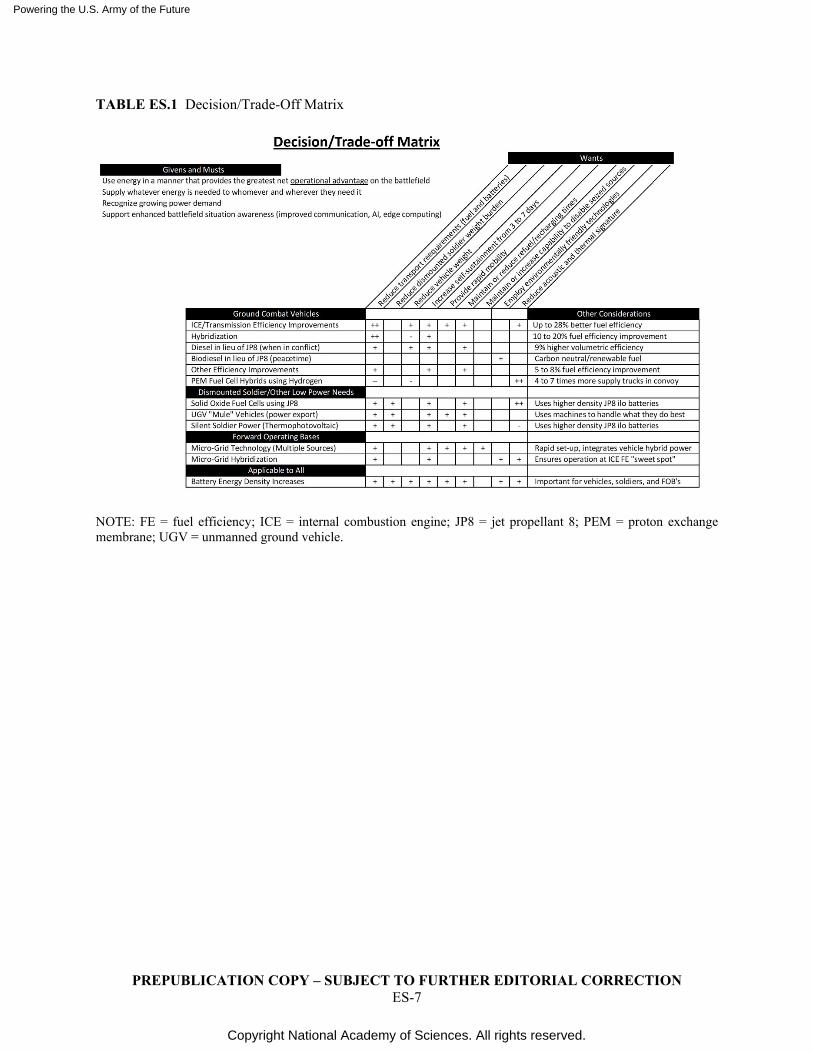
In short, the committee found many opportunities to enable a more capable Army within a very challenging and a somewhat uncertain future multi-domain environment. As in any study of multiple alternatives, there are some trade-offs. For example, if silent mobility and low thermal signatures are mandatory with an extended range, there may be a need to deploy a limited number of hydrogen PEM fuel cells, albeit with penalties in the number of convoy transport trucks. Some of these trade-offs for the major recommended technologies are summarized in the trade-off/decision matrix in Table ES.1.
Based on the technological opportunities presently being studied by the Army and those the committee identified for future study, the committee expects that this enhanced operational capability can be achieved with properly directed research and development efforts.
9 Defense Science Board. 2020. Task Force on Survivable Logistics: Executive Summary.
https://www.hsdl.org/?view&did=820550.
Powering the U.S. Army of the Future
Copyright National Academy of Sciences. All rights reserved.
PREPUBLICATION COPY – SUBJECT TO FURTHER EDITORIAL CORRECTION ES-7
TABLE ES.1 Decision/Trade-Off Matrix
NOTE: FE = fuel efficiency; ICE = internal combustion engine; JP8 = jet propellant 8; PEM = proton exchange membrane; UGV = unmanned ground vehicle.
Powering the U.S. Army of the Future
Copyright National Academy of Sciences. All rights reserved.
PREPUBLICATION COPY – SUBJECT TO FURTHER EDITORIAL CORRECTION I-8
Introduction At the request of the Deputy Assistant Secretary of the Army for Research and Technology
(DASA(RT)), the National Academies of Sciences, Engineering, and Medicine, under the auspices of the Board on Army Research and Development (BOARD), appointed an ad hoc committee—the Committee on Powering the U.S. Army of the Future—to conduct a fast-track study to examine U.S. Army’s future power requirements for sustaining a multi-domain operational conflict; and to what extent emerging power generation and transmission technologies can achieve the Army’s operational power requirements in 2035. The study was based on one operational usage case identified by the Army as part of its ongoing efforts in multi-domain operations.
To facilitate the request for a fast-track study, the data-collection phase of the project leveraged the recent work in assessing alternate energy technologies from the Defense Science Board, the Air Force Scientific Advisory Board, and the Army Science Board to survey and collate data on promising power technologies. Following the guidelines established by the Decadal Survey on Astronomy and Astrophysics 2020 (Astro2020) to create an opportunity for broad participation from the research community and identify emerging technologies, early in the data-gathering phase of the project, the committee issued a request for white papers on activities, projects, or state of the profession considerations. Following the call for white papers, the committee invited the authors of the most promising white papers to participate in a public forum to discuss their ideas with the committee.
In completing this study, the committee has
1. Reviewed the power needs as defined in the Army’s multi-domain operational scenario; 2. Assessed candidate power technologies against the requirements of the operational usage case;
and 3. Recommended the technologies that have the potential to achieve the operational requirements
at the scale appropriate for the U.S. Army in 2035. The recommendations contained in this report are meant to help inform the Army’s investment
priorities in technologies to help ensure that the power requirements of the Army’s future capability needs are achieved.
STUDY APPROACH
The study conducted a series of open data-gathering meetings and closed committee discussions, and was informed by testimony from experts in related fields, white-paper submissions, and committee and staff research. Early in the study’s data-gathering period, a call for white papers (see Appendix C) was released to solicit input from the broader scientific and engineering community on candidate power and energy technologies. The committee conducted four major data-gathering sessions and a series of smaller open discussions with experts over the course of the study. Included in the major data-gathering meetings was a public forum held with authors of selected white papers to discuss their concepts and inform the study committee’s analysis.
These activities were conducted contemporaneously with the COVID-19 pandemic from December 2019 to August 2020. As a result, the committee met only once in person (December 2019), and all subsequent data-gathering meetings and closed committee sessions were held virtually via online meeting
Powering the U.S. Army of the Future
Copyright National Academy of Sciences. All rights reserved.
PREPUBLICATION COPY – SUBJECT TO FURTHER EDITORIAL CORRECTION I-9
software. See Appendix D for a list of the dates and speakers that participated in the study committee’s data gathering activities.
In order to facilitate the evaluation of the diverse power and energy technologies presented to the committee for their operational suitability for future operating environments, the committee evaluated each across a three-tier structure (mapping to a 5-, 15-, and 15+-year outlook) and for their capacity to meet a diverse set of criteria. Finally, the committee used the Army’s Armored Brigade Combat Team unit as a benchmark case for the systems under consideration in this report.
ROLE OF THE WHITE PAPERS
As part of the data-collection phase of the study, white papers responding to the committee’s request provided insights into the latest power and energy technologies now being explored, and in particular how they might be applied in a battlefield scenario. These papers supported the committee’s work and informed the study. However, the committee was not beholden to the conclusions of the papers nor limited to them in its data-gathering efforts. Committee members conducted extensive independent research or relied on their own expertise to reach conclusions. The committee heard extensive testimony from a wide range of experts in various power and energy fields from across government, industry, and academia in developing its conclusions and recommendations.
A summary of the committee member backgrounds is contained in Appendix B. The call for white papers is reprinted in Appendix C. A summary of the committee meeting at which those papers were reviewed is contained in Appendix D. Abstracts of the white papers are contained in Appendix E. References to specific white papers of interest are contained within the main body of this report.
PAST ARMY STUDIES—ENERGY INFORMED OPERATIONS
As part of the study development, the committee built upon work previously conducted by the Army and past National Academies studies. Recent operations, contemporary Army doctrine, and projected operational concepts reflect a shift in energy conceptualization from a commodity logistic “problem” to a multifaceted domain that is integrally tied to operational capabilities. In this report, the following are considered: energy use for forward base power, combat vehicle mobility, aircraft, unmanned aerial vehicles and unmanned ground vehicles, and, perhaps most importantly, the dismounted soldier.
Information technology has transformed operations—not only by virtue of increased volume, but especially targeting latency, adequacy, relevance, veracity, concision, or other attributes as they are critical to the various applications. Similarly, energy value derives from timing, location, availability, interchangeability in form, and/or other attributes depending upon the application and situation. In that vein, the Army’s “Energy Informed Operations” (EIO) concept1 does not discourage use of energy; rather, it calls for forces to “use energy to the greatest benefit.”
High-priority needs include support of awareness and management of energy, including improvements to sensing/reporting/predicting, interoperability, efficiency, fungibility, and exchange. In particular, the document identifies two key technology-oriented systemic needs that span the operational use cases: scalable energy networks and an energy information and management system. An excerpt follows:
Energy Informed Operations aims to provide the Soldier the ability to interactively monitor and manage power systems in order to optimize power availability, allowing the unit to maintain mission critical systems needed to achieve mission success . . . A battlefield environment, based on energy-
1 Barrow, A. 2015. Army Demonstrates Energy Informed Operations Microgrid. Communications-Electronics
Research, Development and Engineering Center. https://www.army.mil/article/148287/Army_demonstrates_Energy_Informed_Operations_microgrid.

Powering the U.S. Army of the Future
Copyright National Academy of Sciences. All rights reserved.
PREPUBLICATION COPY – SUBJECT TO FURTHER EDITORIAL CORRECTION I-10
informed operations, will enable our forces to be more agile, more efficient and more able to rapidly adapt to any mission conditions. This assessment will result in increases in lethality, survivability and mission effectiveness.”2 Presentations by Army headquarters and science and technology representatives to the committee
highlighted ongoing initiatives to meet such needs, from networks of on-Soldier systems to tactical microgrids.
2 Ibid.
Powering the U.S. Army of the Future
Copyright National Academy of Sciences. All rights reserved.
PREPUBLICATION COPY – SUBJECT TO FURTHER EDITORIAL CORRECTION 1-1
1
The Multi-Domain Operations and the 2035 Operational and Technology Environment
TODAY’S OPERATING ENVIRONMENT
Multi-Domain Operations (MDO), by definition, involve a broad range of coordinated efforts involving not only combined arms maneuver, but also various information, cyber, and space operations. Moreover, the Army’s concept emphasizes conflict avoidance and influencing friendly, neutral, and adversarial groups.
The Army Training and Doctrine Command (TRADOC) Definition of Multi-Domain Operations
MDO describes how the U.S. Army, as part of the joint force, can counter and defeat an adversary capable of contesting the United States in all domains (air, land, maritime, space, and cyberspace) in both competition and armed conflict. The concept describes how U.S. ground forces deter adversaries and defeat highly capable near-peer enemies in the 2025–2050 timeframe. MDO provides commanders with numerous options for executing simultaneous and sequential operations using surprise and the rapid and continuous integration of capabilities across all domains to present multiple dilemmas to an adversary in order to gain physical and psychological advantages and influence and control over the operational environment.1
Although the study was intended to be based on an Army MDO scenario, tangible scenarios were not available at the time of the study effort. In lieu of such scenarios, the study committee held a data-gathering session dedicated to understanding the Army’s current thinking on MDO and the 2035 operating environment. The output of that meeting, combined with additional inputs, most notably from RAND’s Arroyo Center, guided the committee’s assessment of power and energy (P&E) systems. The committee chose to focus on maneuver operations of an Armored Brigade Combat Team (ABCT), because it is a predominant combat formation and represents one of the most challenging scenarios from a P&E standpoint.2
Overview of Total Energy Transported To the Field
For an ABCT today, the vast majority of energy transported to the field is in the form of jet propellant 8 (JP8) fuel, due to its volumetric energy-density superiority over every other source, except for
1 Congressional Research Service. 2020. Defense Primer: Army Multi-Domain Operations (MDO).
https://fas.org/sgp/crs/natsec/IF11409.pdf. 2 While the U.S. Marine Corps has similar needs to the Army, the committee scoped the study to focus on the
Army specifically. Furthermore, USMC requirements for mobility and transportation are different and the USMC has recently begun retiring their Abrams tanks, which are a major focus of this study. For these reasons the committee has chosen to focus on the Army.
Powering the U.S. Army of the Future
Copyright National Academy of Sciences. All rights reserved.
PREPUBLICATION COPY – SUBJECT TO FURTHER EDITORIAL CORRECTION 1-2
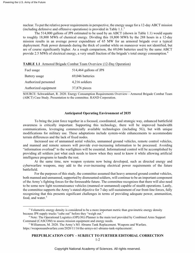
nuclear. To put the relative power requirements in perspective, the energy usage for a 12-day ABCT mission (including defensive and offensive operations) is provided in Table 1.1.3
The 514,000 gallons of JP8 estimated to be used by an ABCT (shown in Table 1.1) would equate to roughly 18,800 MWh of chemical energy. Dividing this 18,800 MWh by the 288 hours in a 12-day mission results in an average power expenditure of 65 MW for an armored brigade over a typical deployment. Peak power demands during the thick of combat while on maneuver were not identified, but are of course significantly higher. As a rough comparison, the 69,046 batteries used by the same ABCT provide 2.5 MWh of electrical energy, a very small fraction of the brigade’s total energy consumption.4
TABLE 1.1 Armored Brigade Combat Team Overview (12-Day Operation)
Fuel usage 514,464 gallons of JP8
Battery usage 69,046 batteries
Authorized personnel 4,216 soldiers
Authorized equipment 37,876 pieces
SOURCE: Schwankhart, R. 2020. Energy Consumption Requirements Overview—Armored Brigade Combat Team (ABCT) Case Study. Presentation to the committee. RAND Corporation.
Anticipated Operating Environment of 2035
To bring the joint force together in a focused, coordinated, and strategic way, enhanced battlefield awareness is critically important. Supporting this technology, there will be improved bandwidth communications, leveraging commercially available technologies (including 5G), but with unique modifications for military use. These adaptations include system-wide enhancements to accommodate terrain differences and the lack of fixed nodes.
Increased use of unmanned aerial vehicles, unmanned ground vehicles, remote control vehicles, and manned and remote sensors will provide ever-increasing information to be processed. Avoiding “information overload” to the warfighters will be essential. Informational control will be accomplished by providing all soldiers just what each needs to know when they need to know it while allowing artificial intelligence programs to handle the rest.
At the same time, new weapon systems now being developed, such as directed energy and cyberwarfare weapons, may add to the ever-increasing electrical power requirements of the future battlefield.
For the purposes of this study, the committee assumed that heavy armored ground combat vehicles, both manned and unmanned, supported by dismounted soldiers, will continue to be an important component of the Army’s fighting forces for the foreseeable future. The committee recognizes that there will also need to be some new light reconnaissance vehicles (manned or unmanned) capable of stealth operations. Lastly, the committee supports the Army’s stated objective for 7-day self-sustainment of our front-line forces, fully recognizing that this presents significant challenges in terms of providing adequate power, ammunition, food, and water.5
3 Volumetric energy density is considered to be a more important metric than gravimetric energy density
because JP8 supply trucks “cube out” before they “weigh out.” 4 Note: The Operational Logistics (OPLOG) Planner is the main tool provided by Combined Arms Support
Command (CASCOM) to assess mission equipment and energy needs. 5 Williamson, M. 2020. The Army’s M1 Abrams Tank Replacement. Weapons and Warfare.
https://weaponsandwarfare.com/2020/11/16/the-armys-m1-abrams-tank-replacement/.

Powering the U.S. Army of the Future
Copyright National Academy of Sciences. All rights reserved.
PREPUBLICATION COPY – SUBJECT TO FURTHER EDITORIAL CORRECTION 1-3
Upon reflection, the committee believes that its work would have benefited from a better understanding of how the Army expects to operate within a multiple service, multi-domain operational environment. More specifically, being provided at study initiation with a set of detailed scenarios of personnel, vehicles, and equipment to be deployed would have been helpful.
Recommendation: For future studies, the Army should make available a clearer view of how multi-domain operations would be conducted, such as through detailed scenarios that describe science and technology needs for Multi Domain Operations in 2035.
Powering the U.S. Army of the Future
Copyright National Academy of Sciences. All rights reserved.
PREPUBLICATION COPY – SUBJECT TO FURTHER EDITORIAL CORRECTION 2-1
2
The Power and Energy Technology Assessment Criteria
OPERATIONAL IMPORTANCE OF ENERGY ATTRIBUTES Army Field Manual 3-96 (8 Oct 2015) states an Armored Brigade Combat Team’s (ABCT’s) role
is to “concentrate overwhelming combat power. Mobility, protection, and firepower enable the ABCT to conduct offensive tasks with great precision and speed.”1 An ABCT’s combined-arms battalions include a variety of armored vehicles, artillery, intelligence and signals equipment, engineering capabilities, and chemical, biological, radiological, and nuclear (CBRN) reconnaissance. In addition, ABCT’s can be augmented with a variety of additional capabilities to adapt to mission requirements, such as aviation, armor, air defense, military police, civil affairs, military information support elements, and additional information-systems assets.
The basic concepts of mobility, protection, and firepower apply to higher echelons and also scale down to dismounted, small units. For example, the 2013 National Research Council report Making the Soldier Decisive on Future Battlefields called out the specific attributes of situational awareness, effects (lethal and non-lethal), maneuverability (agility, mobility), sustainability, and survivability as essential to small-unit success.2
The wide variety of missions present similar and continuing challenges to acquiring and fielding power and energy (P&E) systems that enable the ABCT to optimally carry out its offensive, defensive, and sustainment tasks. DoD acquisition policy continually evolves in an effort to meet the combined, joint, and coalition demands of the modern battlefield and echoes similar attributes needed for successful acquisition programs. DoD Directive 5000.01 sets the conditions for a responsive acquisition policy and places particular emphasis on the overall affordability; environmental, health, and safety concerns; and sustainability.3
More than any individual weapons system, it is P&E that enables maneuverability, awareness, and lethality from the other operational capabilities to a degree that ensures mission success. With this in mind, the committee considered various relevant energy attributes of importance including the following:
● Specific energy and power output; ● Energy efficiency; ● Weight; ● Volume; ● Endurance (time to refuel, recharge, or replace); ● Durability (performance in austere or hazardous environments or under shock or damage);
1 U.S. Army. 2015. Army Field Manual 3-96 Brigade Combat Team.
https://armypubs.army.mil/epubs/DR_pubs/DR_a/pdf/web/fm3_96.pdf. 2 National Research Council. 2013. Making the Soldier Decisive on Future Battlefields. The National
Academies Press, Washington, DC. 3 OUSD(A&S). 2020. DOD Directive 5000.01. Office of the Under Secretary of Defense for Acquisition and
Sustainment. https://www.esd.whs.mil/Portals/54/Documents/DD/issuances/dodd/500001p.pdf?ver=2020-09-09-160307-310.
Powering the U.S. Army of the Future
Copyright National Academy of Sciences. All rights reserved.
PREPUBLICATION COPY – SUBJECT TO FURTHER EDITORIAL CORRECTION 2-2
● Signature (acoustic, thermal, radio frequency); ● Vulnerability to attack and disruption, portability/mobility, supply and maintenance concerns
(e.g., challenges of materiel and fuel sourcing and rarity of materials); ● Financial considerations—investment, unit cost, and schedule; ● Safety issues; ● Personnel training requirements; and ● Policy and regulatory concerns.
Although the committee did not create a Kepner–Tregoe decision-making matrix with quantitative
assessments for each of the above parameters for each of the technologies evaluated, the above factors were all considered qualitatively as the committee developed its recommendations. Additionally, the committee considered the following subgoals to be of prime importance:
• Supplying whatever energy is needed to whomever needs it, wherever and whenever they need it. Just as one would never want a soldier to run out of ammunition, food, or water, having adequate P&E saves warfighter lives and is essential to their success.
• Recognizing the need to meet growing power demands. • Supporting enhanced battlefield situational awareness for all warfighters based on improved
communications, information processing, and artificial intelligence. • Reducing fuel transport needs to save lives during resupply. • Reducing the weight that the dismounted soldier has to carry. • Reducing the weight of all types of vehicles (i.e., ground and flight assets, both manned and
unmanned). • Increasing the Army Brigade’s self-sustainment capability from 3 to 7 days. • Providing rapid mobility across a variety of terrain for dismounted soldiers, vehicles, and
forward operating bases. This includes rapid set-up and breakdown times for forward operating bases.
• Maintaining or reducing the time required to refuel, recharge, or provide new sources of power. • Possessing a capability to utilize a wider range of globally available resources (i.e. fuel
resources utilized by allies and adversaries). • Maintaining a capability to disable or lock-out energy resources that fall into hostile hands,
particularly those with proprietary technology. • Employing environmentally friendly technologies wherever practical without compromising
military objectives.
THREE-TIERED TECHNOLOGY STRUCTURE
In order to provide the best assessment of P&E technologies to support Army operations in 2035, the committee adopted a three-tiered view with respect to technology readiness levels (TRLs).
● Tier 1. System demonstration achievable within 5 years from TRL 5–7 to TRL 7–8, and an operational system acquirable by 2035.
● Tier 2. Concept or system demonstration achievable in 15 years with an estimate of the additional time required for an acquired system.
● Tier 3. Beyond the 15-year horizon at the TRL 2–4 level. Tier 1 involves P&E technologies that would achieve a 5-year system demonstration from TRL 5–
7 to TRL 7–8, then 10 years to acquire an operational system by 2035. Tier 2 technologies would deliver a
Powering the U.S. Army of the Future
Copyright National Academy of Sciences. All rights reserved.
PREPUBLICATION COPY – SUBJECT TO FURTHER EDITORIAL CORRECTION 2-3
concept to feasibility demonstration from TRL 4–6 to TRL 6–8 in 15 years with an operational system acquired sometime after the demonstration. Tier 3 technologies would not deliver a concept-to-feasibility demonstration by 2035 and currently exist at the TRL 2–4 level. However, with investment and resource allocation, concept-to-feasibility or system demonstration could be achieved in the subsequent decade.
Physics and engineering principles are used to judge the credibility of the P&E sources for each tier. To be considered, detailed engineering and system descriptions that support the performance characteristics of each P&E source are required. For each of finding, conclusion, and recommendation, the committee identified the relevant corresponding tier.
LEAD, WATCH, FOLLOW
The private sector is currently investing resources and personnel into several P&E-related technology areas that can be leveraged by the Army in the 2035 timeframe. However, many technology areas have commercial market demand and several technologies require specific alterations and modifications to meet Army operational requirements. With this duality in mind, the committee opted for a “lead, watch, follow” methodology in assessing each technology area. For each finding, conclusion, and recommendation, the committee the relevant corresponding approach.
Lead: Technologies lacking primary market value in which the Army will need to lead on investment of funding and resources.
Watch: Technologies in which the majority of development will occur within the commercial sector in response to market demands but will require unique capabilities to meet Army specific operational needs.
Follow: Technologies that will likely be wholly developed within the commercial and private sector that the Army can acquire and adopt “off the shelf” as needed.
DIFFERENT USES DEMAND DIFFERENT SOLUTIONS
The significant differences in how power is provided and distributed to the battlefield are summarized below. Note that no single solution works for all users.
• Milliwatts for distributed remote sensors • Watts for small unmanned aerial vehicles (UAVs) and soldier equipment • Kilowatts for emerging directed-energy weapons, such as lasers • Megawatts and more for ground combat vehicles, emerging (FVL) helicopters/VTOL aircraft
and forward operating bases
The key is to find the appropriate power source for each use. In this regard, the committee chose to focus on the dismounted soldier and light UAV/unmanned ground vehicles (UGVs) in Chapter 4, on ground vehicles and large weapon systems in Chapter 5, and on forward operating bases in Chapter 6.
These significant differences in use cases (with the span of power requirements ranging several orders of magnitude) led to some interesting challenges in creating the structure for this report. To address this, Chapter 3, “Power Sources, Conversion Devices, and Storage,” contains an overview of various P&E sources and conversion devices. In cases where a given technology makes sense for only one specific use case, more detail is provided in the chapter about that use. For example, the detailed discussion of mobile nuclear power plants is contained in Chapter 7, “Forward Operating Base Power.” Similarly, a detailed

Powering the U.S. Army of the Future
Copyright National Academy of Sciences. All rights reserved.
PREPUBLICATION COPY – SUBJECT TO FURTHER EDITORIAL CORRECTION 2-4
discussion of radioisotope decay devices is included in the Chapter 5, “Dismounted Soldier Power and Light UAVs/UGVs.”
Because battery or capacitor improvements have applicability to all three use cases, the discussion on their potential technological improvements are wholly contained within Chapter 3, “Power Sources, Conversion Devices, and Storage.”
Powering the U.S. Army of the Future
Copyright National Academy of Sciences. All rights reserved.
PREPUBLICATION COPY – SUBJECT TO FURTHER EDITORIAL CORRECTION 3-1
3
Energy Sources, Conversion Devices, and Storage
ENERGY SOURCES, CONVERSION DEVICES. AND STORAGE
Power and energy (P&E) technology in its most basic form centers on energy sources, energy storage, conversion, and management functions. The overall goal is to use energy to provide the maximum operational advantage. How much energy can be stored, the source of that energy, how efficiently it can be converted into power to perform work are key in the assessment of a particular P&E technology. Military operations stress each of these criteria far beyond commercial demands—military vehicles demand far higher power levels while sources and storage create critical logistical concerns. For these reasons, the committee reviewed and investigated several technology areas from military staples, such as jet propellant 8 (JP8), to future concepts, such as nuclear batteries and small reactors, and assessed their viability against the likely demands of the future operating environment.
Energy Density Is Critically Important
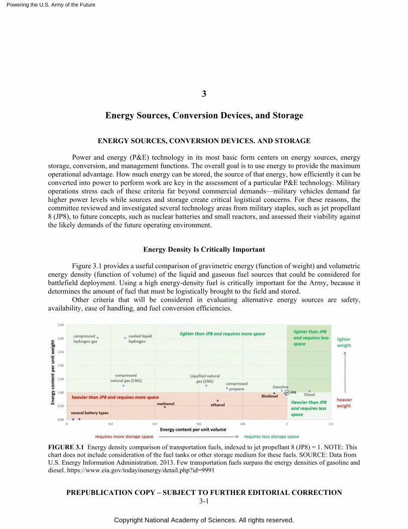
Figure 3.1 provides a useful comparison of gravimetric energy (function of weight) and volumetric energy density (function of volume) of the liquid and gaseous fuel sources that could be considered for battlefield deployment. Using a high energy-density fuel is critically important for the Army, because it determines the amount of fuel that must be logistically brought to the field and stored. Other criteria that will be considered in evaluating alternative energy sources are safety, availability, ease of handling, and fuel conversion efficiencies.
FIGURE 3.1 Energy density comparison of transportation fuels, indexed to jet propellant 8 (JP8) = 1. NOTE: This chart does not include consideration of the fuel tanks or other storage medium for these fuels. SOURCE: Data from U.S. Energy Information Administration. 2013. Few transportation fuels surpass the energy densities of gasoline and diesel. https://www.eia.gov/todayinenergy/detail.php?id=9991
Powering the U.S. Army of the Future
Copyright National Academy of Sciences. All rights reserved.
PREPUBLICATION COPY – SUBJECT TO FURTHER EDITORIAL CORRECTION 3-2
Liquid Energy Sources
Liquid petroleum-derived fuels have more energy per unit volume (which determines the number of supply trucks) than any other transportation fuel. This high energy density ensures widespread use of petroleum-derived fuels throughout the military. In comparison, the energy density of batteries (roughly 0.7 MJ/kg) is significantly less than JP8 (44 MJ/kg). In addition, as previously discussed in the executive summary, refueling times using liquid fuels are significantly less than recharging times for batteries.1
JP8 versus Diesel
The energy density (per unit volume) of JP8 and diesel exceeds that of all other commonly used transportation fuels, such as gasoline, biodiesel, and compressed natural gas (Figure 3.1). This superiority has a direct impact on the number of trucks per supply convoy (or number of convoys) that deliver energy to the battlefield. Minimizing that fuel transport also minimizes the number of soldiers and supporting personnel at risk during transport of that fuel.
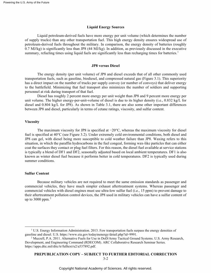
Diesel has roughly 2 percent more energy per unit weight than JP8 and 9 percent more energy per unit volume. The higher energy-per-unit-volume of diesel is due to its higher density (i.e., 0.832 kg/L for diesel and 0.804 kg/L for JP8). As shown in Table 3.1, there are also some other important differences between JP8 and diesel, particularly in terms of cetane ratings, viscosity, and sulfur content.
Viscosity
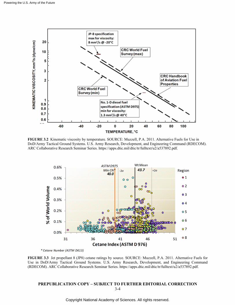
The maximum viscosity for JP8 is specified at −20°C, whereas the maximum viscosity for diesel fuel is specified at 40°C (see Figure 3.2). Under extremely cold environmental conditions, both diesel and JP8 can gel, with diesel being more susceptible to cold weather failure than JP8. Waxing refers to this situation, in which the paraffin hydrocarbons in the fuel congeal, forming wax-like particles that can either coat the surfaces they contact or plug fuel filters. For this reason, the diesel fuel available at service stations is typically a blend of DF1 and DF2, seasonally adjusted based on local ambient temperatures. DF1 is also known as winter diesel fuel because it performs better in cold temperatures. DF2 is typically used during summer conditions.
Sulfur Content
Because military vehicles are not required to meet the same emission standards as passenger and commercial vehicles, they have much simpler exhaust aftertreatment systems. Whereas passenger and commercial vehicles with diesel engines must use ultra-low sulfur fuel (i.e., 15 ppm) to prevent damage to their aftertreatment pollution control devices, the JP8 used in military vehicles can have a sulfur content of up to 3000 ppm.2
1 U.S. Energy Information Administration. 2013. Few transportation fuels surpass the energy densities of
gasoline and diesel. U.S. https://www.eia.gov/todayinenergy/detail.php?id=9991. 2 Muzzell, P.A. 2011. Alternative Fuels for Use in DoD/Army Tactical Ground Systems. U.S. Army Research,
Development, and Engineering Command (RDECOM). ARC Collaborative Research Seminar Series. https://apps.dtic.mil/dtic/tr/fulltext/u2/a537892.pdf.
Powering the U.S. Army of the Future
Copyright National Academy of Sciences. All rights reserved.
PREPUBLICATION COPY – SUBJECT TO FURTHER EDITORIAL CORRECTION 3-3
TABLE 3.1 Diesel versus Jet Fuel
SOURCE: Muzzell, P.A. 2011. Alternative Fuels for Use in DoD/Army Tactical Ground Systems. U.S. Army Research, Development, and Engineering Command (RDECOM). ARC Collaborative Research Seminar Series. Available at https://apps.dtic.mil/dtic/tr/fulltext/u2/a537892.pdf.
Cetane Rating
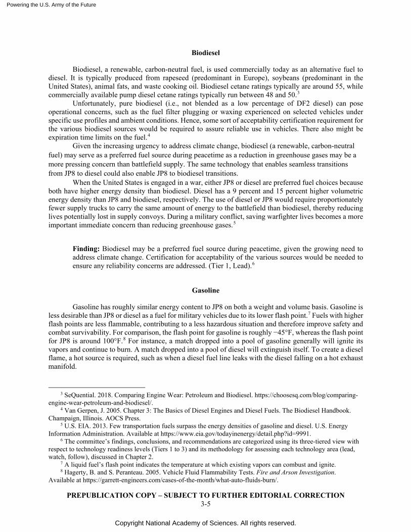
The biggest complaint about JP8 is the high degree of variability in its cetane rating, particularly at the lower end. Cetane is a measure of a fuel’s tendency to auto-ignite, with higher cetane being easier to auto-ignite than lower cetane. As shown in Figure 3.3, cetane ratings for JP8 vary widely with the source, whereas DF1 and DF2 diesel fuel require a minimum 40 cetane rating. Although the rating variability is not a problem with turbine-operated aircraft (or the turbine-operated Abrams tank), it can pose a problem for internal combustion engines, particularly in cold weather.
The cetane index of a fuel affects the engine’s ignition delay, i.e., the time between the introduction of fuel and the first indications of heat release. Selecting the optimal injection timing has a major impact on fuel efficiency. Although this optimization is difficult to do on diesel engines with pump/line/nozzle fuel injection systems, optimal injection timing can be achieved with modern diesels employing direct fuel injection with in-cylinder pressure sensors. Auto-ignition and the impact of cetane rating are also important considerations for some advanced combustion technologies, such as homogeneous charge compression ignition and free piston engines.
Powering the U.S. Army of the Future
Copyright National Academy of Sciences. All rights reserved.
PREPUBLICATION COPY – SUBJECT TO FURTHER EDITORIAL CORRECTION 3-4
FIGURE 3.2 Kinematic viscosity by temperature. SOURCE: Muzzell, P.A. 2011. Alternative Fuels for Use in DoD/Army Tactical Ground Systems. U.S. Army Research, Development, and Engineering Command (RDECOM). ARC Collaborative Research Seminar Series. https://apps.dtic.mil/dtic/tr/fulltext/u2/a537892.pdf.
FIGURE 3.3 Jet propellant 8 (JP8) cetane ratings by source. SOURCE: Muzzell, P.A. 2011. Alternative Fuels for Use in DoD/Army Tactical Ground Systems. U.S. Army Research, Development, and Engineering Command (RDECOM). ARC Collaborative Research Seminar Series. https://apps.dtic.mil/dtic/tr/fulltext/u2/a537892.pdf.
Powering the U.S. Army of the Future
Copyright National Academy of Sciences. All rights reserved.
PREPUBLICATION COPY – SUBJECT TO FURTHER EDITORIAL CORRECTION 3-5
Biodiesel
Biodiesel, a renewable, carbon-neutral fuel, is used commercially today as an alternative fuel to diesel. It is typically produced from rapeseed (predominant in Europe), soybeans (predominant in the United States), animal fats, and waste cooking oil. Biodiesel cetane ratings typically are around 55, while commercially available pump diesel cetane ratings typically run between 48 and 50.3
Unfortunately, pure biodiesel (i.e., not blended as a low percentage of DF2 diesel) can pose operational concerns, such as the fuel filter plugging or waxing experienced on selected vehicles under specific use profiles and ambient conditions. Hence, some sort of acceptability certification requirement for the various biodiesel sources would be required to assure reliable use in vehicles. There also might be expiration time limits on the fuel.4
Given the increasing urgency to address climate change, biodiesel (a renewable, carbon-neutral fuel) may serve as a preferred fuel source during peacetime as a reduction in greenhouse gases may be a more pressing concern than battlefield supply. The same technology that enables seamless transitions from JP8 to diesel could also enable JP8 to biodiesel transitions.
When the United States is engaged in a war, either JP8 or diesel are preferred fuel choices because both have higher energy density than biodiesel. Diesel has a 9 percent and 15 percent higher volumetric energy density than JP8 and biodiesel, respectively. The use of diesel or JP8 would require proportionately fewer supply trucks to carry the same amount of energy to the battlefield than biodiesel, thereby reducing lives potentially lost in supply convoys. During a military conflict, saving warfighter lives becomes a more important immediate concern than reducing greenhouse gases.5
Finding: Biodiesel may be a preferred fuel source during peacetime, given the growing need to address climate change. Certification for acceptability of the various sources would be needed to ensure any reliability concerns are addressed. (Tier 1, Lead).6
Gasoline
Gasoline has roughly similar energy content to JP8 on both a weight and volume basis. Gasoline is less desirable than JP8 or diesel as a fuel for military vehicles due to its lower flash point.7 Fuels with higher flash points are less flammable, contributing to a less hazardous situation and therefore improve safety and combat survivability. For comparison, the flash point for gasoline is roughly −45°F, whereas the flash point for JP8 is around 100°F.8 For instance, a match dropped into a pool of gasoline generally will ignite its vapors and continue to burn. A match dropped into a pool of diesel will extinguish itself. To create a diesel flame, a hot source is required, such as when a diesel fuel line leaks with the diesel falling on a hot exhaust manifold.
3 SeQuential. 2018. Comparing Engine Wear: Petroleum and Biodiesel. https://choosesq.com/blog/comparing-
engine-wear-petroleum-and-biodiesel/. 4 Van Gerpen, J. 2005. Chapter 3: The Basics of Diesel Engines and Diesel Fuels. The Biodiesel Handbook.
Champaign, Illinois. AOCS Press. 5 U.S. EIA. 2013. Few transportation fuels surpass the energy densities of gasoline and diesel. U.S. Energy
Information Administration. Available at https://www.eia.gov/todayinenergy/detail.php?id=9991. 6 The committee’s findings, conclusions, and recommendations are categorized using its three-tiered view with
respect to technology readiness levels (Tiers 1 to 3) and its methodology for assessing each technology area (lead, watch, follow), discussed in Chapter 2.
7 A liquid fuel’s flash point indicates the temperature at which existing vapors can combust and ignite. 8 Hagerty, B. and S. Peranteau. 2005. Vehicle Fluid Flammability Tests. Fire and Arson Investigation.
Available at https://garrett-engineers.com/cases-of-the-month/what-auto-fluids-burn/.
Powering the U.S. Army of the Future
Copyright National Academy of Sciences. All rights reserved.
PREPUBLICATION COPY – SUBJECT TO FURTHER EDITORIAL CORRECTION 3-6
Within the combustion chamber of an internal combustion engine, gasoline is more difficult to auto-ignite than diesel. The standard measure of a gasoline sample’s difficulty in autoignition is its octane rating. From a fuel efficiency standpoint, higher octane ratings are preferred in gasoline engines because they are harder to auto-ignite, thereby allowing spark timing to be advanced providing the combustion energy released by the fuel to be exercised for a greater percentage of the expansion stroke. This desirability of higher octane rating for gasoline fuels is comparable to the desirability of higher cetane ratings for diesel fuels, which is a measure of a diesel sample’s ease of autoignition. Higher cetane ratings are preferred in diesels to ensure reliable and consistent ignition and cold weather starting in the absence of a spark-actuated combustion event.
Alcohols
Ethanol is typically produced from corn, grains, or agriculture waste (cellulose). Methanol is typically produced from natural gas, coal, or woody biomass. Ethanol and methanol have 69 percent and 45 percent of the energy content per unit volume of JP8, respectively, making them impractical as a sole source of fuel for a military ground vehicle.1
NATO Single Fuel Forward Policy
To date, the Army has relied heavily on JP8 as part of its “single fuel forward” policy—one military fuel on the battlefield across all ground vehicle platforms. In addition to being an Army fuel for ground vehicles, JP8 is a fuel for turbine-powered aircraft and is specified by MIL-DTL-83133 and British Defense Standard 91-87. It is similar to commercial aviation’s Jet A-1 fuel, but with the addition of a corrosion inhibitor/lubricity improver, icing inhibitor, and an antistatic agent. Optionally, a metal deactivation additive and antioxidant may be included in the formulation. In addition to being used as a fuel for ground combat vehicles and generators, JP-8 is used as a fuel for heaters and stoves by the U.S. military and its NATO allies.9
This fuel was introduced in 1978 within NATO (with an F-34 fuel designation) in order to simplify the logistics supply chain for petroleum products. The primary goal of the single fuel policy (SFP) is to achieve equipment interoperability through using a single fuel and ensuring that the specification of the fuel is standardized with its commercial equivalent in common use. The physical and chemical characteristics of the fuel are such that it can be introduced, stored, transported, and distributed by the fuel logistic systems.
Finding: JP8, diesel, and/or biodiesel are all potential fuels to be supplied to the battlefield, particularly for high power–use applications such as armored ground combat vehicles. The complexity impact of using multiple fuels on the logistics chain needs to be compared to the benefits discussed. (Tier 1, Lead)
Alternatively Sourced Liquid Hydrocarbon Fuels
The Army is also studying a number of alternative fuels derived from biomass feedstock and fossil energy (shale, coal, petcoke). This initiative is intended to provide further military operation flexibility through the ability to use multiple, reliable fuel sources. In all such cases, the fuel procured must: (1) meet
9 Aydogan, H. and E. Altinok. 2019. Effects of Using JP8-Diesel Fuel Mixtures in a Pump Injector Engine on
Engine Performance. Bilge International Journal of Science and Technology Research. https://www.researchgate.net/publication/338283921_Effects_of_Using_JP8-Diesel_Fuel_Mixtures_in_a_Pump_Injector_Engine_on_Engine_Performance.
Powering the U.S. Army of the Future
Copyright National Academy of Sciences. All rights reserved.
PREPUBLICATION COPY – SUBJECT TO FURTHER EDITORIAL CORRECTION 3-7
JP8 fuel performance specifications; (2) require no changes in the vehicle, equipment, or supply infrastructure; and (3) be capable of being mixed and/or blended with petroleum-derived fuel.10
Biomass-derived jet (biojet) fuel, also known as alcohol-to-jet (ATJ) fuel, is another example of an alternatively sourced hydrocarbon fuel. It has become a key element in the aviation industry’s strategy to reduce operating costs and environmental impacts. As expected, the focus here has been on its acceptability within gas turbine applications with less emphasis on its use in internal combustion engines. ATJ fuel is mixed 50%/50% with JP8 to increase its aromatics content, which is essential to ensure that the seals with fuel systems swell to prevent leakage.
When used in internal combustion engines, the cetane ratings of ATJ-blended fuels can present some problems. As shown earlier, JP8 cetane ratings can be as low as 30 depending upon the region from which it is obtained. The cetane number of ATJ is even lower, roughly at 18. As a result, the ATJ/JP8 mixtures can create internal combustion engines problems while being fully acceptable for aviation turbines.
One possible approach to address low cetane ratings if ATJ/JP8 blends are used in internal combustion engines would be utilization of cetane additives. To minimize the impact on soldier tasking, one solution would be to use inline fuel filters that meter the addition. If sized properly, these filters could be part of the scheduled maintenance, just as diesel-exhaust fluid containers are replaced on today’s automotive diesels during oil changes.
Conclusion: Alternative liquid hydrocarbon fuels are compositionally variable and may introduce new durability concerns and, in the case of ATJ fuels, may not provide the cetane ratings needed to run properly in internal combustion engines. Although alternative fuels may be suitable for use on an ad hoc basis during combat operations, their suitability as a more permanent staple of the fuel supply system will require a careful cost benefit analysis on a case-by-case basis over a variety of environmental conditions. (Tier 1, Follow)
GASEOUS ENERGY SOURCES
Compressed Propane
Compressed propane has roughly 73 percent of the energy content per unit volume of JP8 and roughly 14 percent better energy content per unit weight. Much or all of this energy content per unit weight advantage is offset, however, by the heavier storage tank required versus a JP8 fuel tank.1 To put this in perspective, 250 gallons of compressed propane weigh roughly 1,050 pounds, whereas the tank required to contain it weighs roughly 480 pounds. Due to the volumetric energy density shortfall of compressed propane versus JP8, as well as safety concerns in its transportation, it is considered a less desirable fuel for the battlefield than JP8.
Natural Gas
Compressed (CNG) and liquefied natural gas (LNG) are produced from underground reserves or renewable biogas. The natural gas produced from renewable biogas, such as from landfills, is of a much lower quality with significantly more variability than that recovered from underground.
In the automotive and truck markets, usage of CNG, which consists mostly of methane, is growing because of environmental concerns. Because CNG burns more cleanly than either gasoline or diesel, it provides a significant advantage in greenhouse gas emissions versus both diesel and gasoline. CNG has
10 Congressional Research Service. 2012. DOD Alternative Fuels: Policy, Initiatives and Legislative Activity.
https://fas.org/sgp/crs/natsec/R42859.pdf.
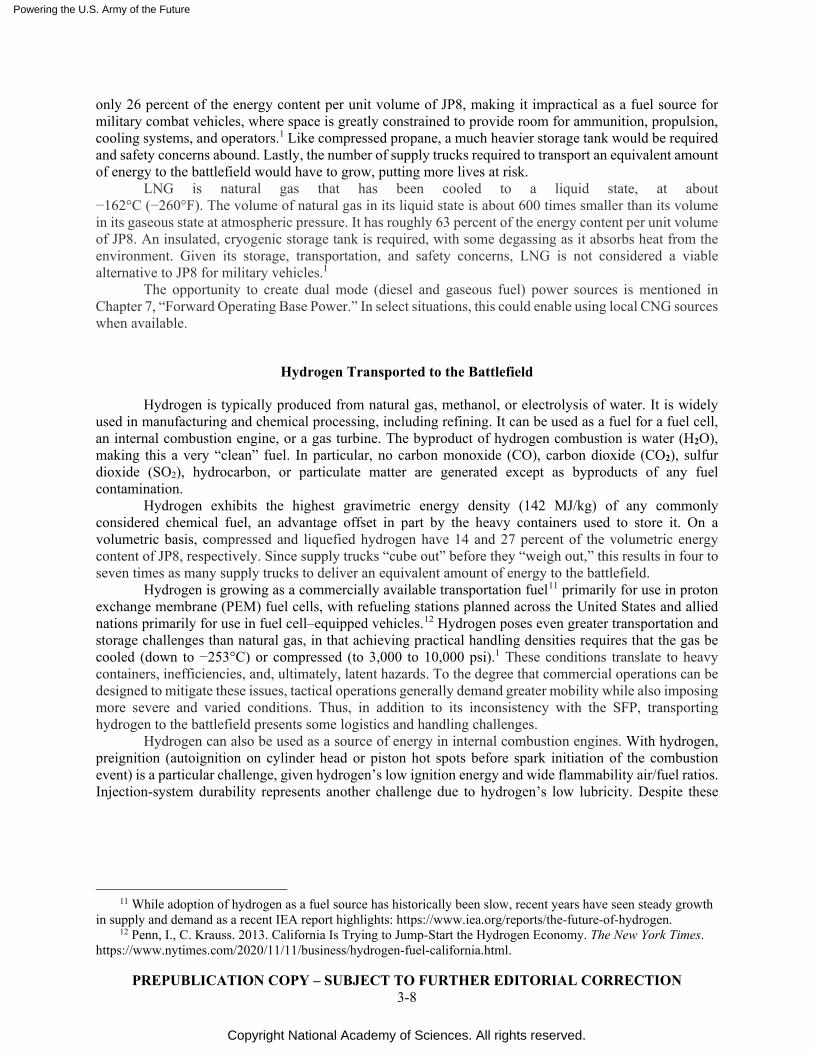
Powering the U.S. Army of the Future
Copyright National Academy of Sciences. All rights reserved.
PREPUBLICATION COPY – SUBJECT TO FURTHER EDITORIAL CORRECTION 3-8
only 26 percent of the energy content per unit volume of JP8, making it impractical as a fuel source for military combat vehicles, where space is greatly constrained to provide room for ammunition, propulsion, cooling systems, and operators.1 Like compressed propane, a much heavier storage tank would be required and safety concerns abound. Lastly, the number of supply trucks required to transport an equivalent amount of energy to the battlefield would have to grow, putting more lives at risk.
LNG is natural gas that has been cooled to a liquid state, at about −162°C (−260°F). The volume of natural gas in its liquid state is about 600 times smaller than its volume in its gaseous state at atmospheric pressure. It has roughly 63 percent of the energy content per unit volume of JP8. An insulated, cryogenic storage tank is required, with some degassing as it absorbs heat from the environment. Given its storage, transportation, and safety concerns, LNG is not considered a viable alternative to JP8 for military vehicles.1
The opportunity to create dual mode (diesel and gaseous fuel) power sources is mentioned in Chapter 7, “Forward Operating Base Power.” In select situations, this could enable using local CNG sources when available.
Hydrogen Transported to the Battlefield
Hydrogen is typically produced from natural gas, methanol, or electrolysis of water. It is widely used in manufacturing and chemical processing, including refining. It can be used as a fuel for a fuel cell, an internal combustion engine, or a gas turbine. The byproduct of hydrogen combustion is water (H2O), making this a very “clean” fuel. In particular, no carbon monoxide (CO), carbon dioxide (CO2), sulfur dioxide (SO2), hydrocarbon, or particulate matter are generated except as byproducts of any fuel contamination.
Hydrogen exhibits the highest gravimetric energy density (142 MJ/kg) of any commonly considered chemical fuel, an advantage offset in part by the heavy containers used to store it. On a volumetric basis, compressed and liquefied hydrogen have 14 and 27 percent of the volumetric energy content of JP8, respectively. Since supply trucks “cube out” before they “weigh out,” this results in four to seven times as many supply trucks to deliver an equivalent amount of energy to the battlefield.
Hydrogen is growing as a commercially available transportation fuel11 primarily for use in proton exchange membrane (PEM) fuel cells, with refueling stations planned across the United States and allied nations primarily for use in fuel cell–equipped vehicles.12 Hydrogen poses even greater transportation and storage challenges than natural gas, in that achieving practical handling densities requires that the gas be cooled (down to −253°C) or compressed (to 3,000 to 10,000 psi).1 These conditions translate to heavy containers, inefficiencies, and, ultimately, latent hazards. To the degree that commercial operations can be designed to mitigate these issues, tactical operations generally demand greater mobility while also imposing more severe and varied conditions. Thus, in addition to its inconsistency with the SFP, transporting hydrogen to the battlefield presents some logistics and handling challenges.
Hydrogen can also be used as a source of energy in internal combustion engines. With hydrogen, preignition (autoignition on cylinder head or piston hot spots before spark initiation of the combustion event) is a particular challenge, given hydrogen’s low ignition energy and wide flammability air/fuel ratios. Injection-system durability represents another challenge due to hydrogen’s low lubricity. Despite these
11 While adoption of hydrogen as a fuel source has historically been slow, recent years have seen steady growth
in supply and demand as a recent IEA report highlights: https://www.iea.org/reports/the-future-of-hydrogen. 12 Penn, I., C. Krauss. 2013. California Is Trying to Jump-Start the Hydrogen Economy. The New York Times.
https://www.nytimes.com/2020/11/11/business/hydrogen-fuel-california.html.
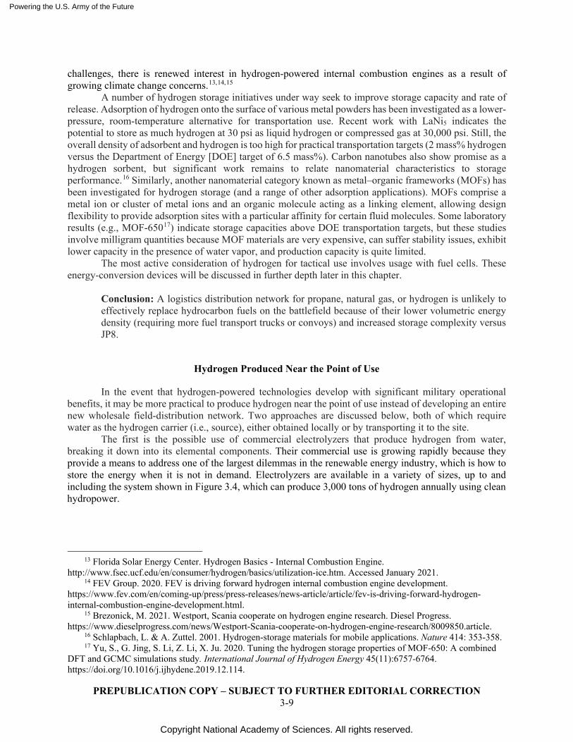
Powering the U.S. Army of the Future
Copyright National Academy of Sciences. All rights reserved.
PREPUBLICATION COPY – SUBJECT TO FURTHER EDITORIAL CORRECTION 3-9
challenges, there is renewed interest in hydrogen-powered internal combustion engines as a result of growing climate change concerns.13,14,15
A number of hydrogen storage initiatives under way seek to improve storage capacity and rate of release. Adsorption of hydrogen onto the surface of various metal powders has been investigated as a lower-pressure, room-temperature alternative for transportation use. Recent work with LaNi5 indicates the potential to store as much hydrogen at 30 psi as liquid hydrogen or compressed gas at 30,000 psi. Still, the overall density of adsorbent and hydrogen is too high for practical transportation targets (2 mass% hydrogen versus the Department of Energy [DOE] target of 6.5 mass%). Carbon nanotubes also show promise as a hydrogen sorbent, but significant work remains to relate nanomaterial characteristics to storage performance.16 Similarly, another nanomaterial category known as metal–organic frameworks (MOFs) has been investigated for hydrogen storage (and a range of other adsorption applications). MOFs comprise a metal ion or cluster of metal ions and an organic molecule acting as a linking element, allowing design flexibility to provide adsorption sites with a particular affinity for certain fluid molecules. Some laboratory results (e.g., MOF-65017) indicate storage capacities above DOE transportation targets, but these studies involve milligram quantities because MOF materials are very expensive, can suffer stability issues, exhibit lower capacity in the presence of water vapor, and production capacity is quite limited.
The most active consideration of hydrogen for tactical use involves usage with fuel cells. These energy-conversion devices will be discussed in further depth later in this chapter.
Conclusion: A logistics distribution network for propane, natural gas, or hydrogen is unlikely to effectively replace hydrocarbon fuels on the battlefield because of their lower volumetric energy density (requiring more fuel transport trucks or convoys) and increased storage complexity versus JP8.
Hydrogen Produced Near the Point of Use
In the event that hydrogen-powered technologies develop with significant military operational benefits, it may be more practical to produce hydrogen near the point of use instead of developing an entire new wholesale field-distribution network. Two approaches are discussed below, both of which require water as the hydrogen carrier (i.e., source), either obtained locally or by transporting it to the site.
The first is the possible use of commercial electrolyzers that produce hydrogen from water, breaking it down into its elemental components. Their commercial use is growing rapidly because they provide a means to address one of the largest dilemmas in the renewable energy industry, which is how to store the energy when it is not in demand. Electrolyzers are available in a variety of sizes, up to and including the system shown in Figure 3.4, which can produce 3,000 tons of hydrogen annually using clean hydropower.
13 Florida Solar Energy Center. Hydrogen Basics - Internal Combustion Engine.
http://www.fsec.ucf.edu/en/consumer/hydrogen/basics/utilization-ice.htm. Accessed January 2021. 14 FEV Group. 2020. FEV is driving forward hydrogen internal combustion engine development.
https://www.fev.com/en/coming-up/press/press-releases/news-article/article/fev-is-driving-forward-hydrogen-internal-combustion-engine-development.html.
15 Brezonick, M. 2021. Westport, Scania cooperate on hydrogen engine research. Diesel Progress. https://www.dieselprogress.com/news/Westport-Scania-cooperate-on-hydrogen-engine-research/8009850.article.
16 Schlapbach, L. & A. Zuttel. 2001. Hydrogen-storage materials for mobile applications. Nature 414: 353-358. 17 Yu, S., G. Jing, S. Li, Z. Li, X. Ju. 2020. Tuning the hydrogen storage properties of MOF-650: A combined
DFT and GCMC simulations study. International Journal of Hydrogen Energy 45(11):6757-6764. https://doi.org/10.1016/j.ijhydene.2019.12.114.
Powering the U.S. Army of the Future
Copyright National Academy of Sciences. All rights reserved.
PREPUBLICATION COPY – SUBJECT TO FURTHER EDITORIAL CORRECTION 3-10
FIGURE 3.4 HyLYZER® PEM electrolyzer system installed at the Air Liquide hydrogen production facility in Bécancour, Quebec and producing 3,000 tons of hydrogen annually using clean hydropower. SOURCE: Cummins, Inc. 2021. Cummins hydrogen technology powers the largest proton exchange membrane (PEM) electrolyzer in operation in the world. Online. Available at https://www.cummins.com/news/releases/2021/01/26/cummins-hydrogen-technology-powers-largest-proton-exchange-membrane-pem. Accessed January 2021.
Because electrical energy is required for electrolysis, using JP8 to power an internal combustion
engine to power a generator to power an electrolyzer to generate hydrogen to power a fuel cell has some inherent inefficiencies. In addition, as discussed above, using renewable energy sources (solar, wind, hydro, waste) will likely have a limited role in generating energy on the battlefield. It is certainly more efficient to power a ground combat vehicle or UAV directly with JP8. Nevertheless, in situations where silent operation over an extended range is desired, electrolyzers may provide an acceptable path to hydrogen production.
As an alternative to electrolyzers, powdered aluminum alloys containing gallium have been known for decades to spontaneously generate hydrogen when in contact with water.18 This process can produce high pressures, which can significantly reduce the energy required to compress hydrogen for storage. Theoretically, the aluminum powder and reactant water represent a lower effective energy density than logistic petroleum fuel. However, if water (potable or nonpotable) is locally available, then solid aluminum could afford a logistic and handling advantage.
MIT Lincoln Laboratory has developed a method to produce activated aluminum beads that react in a similar manner, producing aluminum hydroxide, hydrogen, steam, and residual contaminants.19
18 Woodall, J.M., Ziebarth, J.T.; Allen, C.R., Jeon, J., Choi, G., Kramer, R. 2008. Generating hydrogen on
demand by splitting water with Al rich alloys. Clean Technology 2008: Bio Energy, Renewables, Green Building, Smart Grid, Storage, and Water (Eds: Laudon, M., Romanowicz, B., Laird, D.L.) pp. 313–315; https://phys.org/news/2007-05-hydrogen-aluminum-alloy-fuel-cells.html.
19 Limpaecher, E. 2020. Activated Aluminum for Operational Energy presentation to the study committee. Massachusetts Institute of Technology Lincoln Laboratory.
Powering the U.S. Army of the Future
Copyright National Academy of Sciences. All rights reserved.
PREPUBLICATION COPY – SUBJECT TO FURTHER EDITORIAL CORRECTION 3-11
FIGURE 3.5 Computer aided design (CAD) rendering of the entire10 kW system integrated into the BMW i3. SOURCE: P. Godart, J. Fischman, D. Hart. 2020. Kilowatt-Scale Fuel Cell Systems Powered by Recycled Aluminum. Journal of Electrochemical Energy Conversion and Storage 18(1): 011003. https://asmedigitalcollection.asme.org/electrochemical/article-abstract/18/1/011003/1081620/Kilowatt-Scale-Fuel-Cell-Systems-Powered-by.
As shown in Figure 3.5, a preliminary prototype design by the MIT Lincoln Laboratory has
demonstrated the ability to generate 10 kW on an automotive application using a reaction chamber, conditioning system, and PEM fuel cell. However, some key questions remain to be answered. These include how much aluminum and water would be required to achieve a reasonable vehicle range. How would the aluminum, water, and waste aluminum hydroxide be handled? Could the overall size and weight of the system be competitive with other alternative power and energy systems?
More directly related to a military application, the Army awarded General Atomics, Inc., with a 2-year contract in November 2019 to design, fabricate, and test a prototype mobile platform for on-demand generation of high-pressure hydrogen suitable for refueling PEM fuel cell–equipped vehicles in the field. This technology is claimed to use the company’s proprietary aluminum alloy hydrogen-producing technology.20 The committee did not have access to a progress report from General Atomics at the time this report was written.
Despite the technology immaturity issues listed above, enough potential benefits remain to justify further investigation of this opportunity. Among the possible benefits, the hydrogen generated might enable some additional fuel-cell use with its low acoustic signature. A complete description of these opportunities—at the dismounted soldier and forward operating base level—is contained in Appendix G, “Aluminum as a Fuel.”
Conclusion: Generating hydrogen from water using aluminum near the point of use offers potential advantages vis-à-vis transporting hydrogen in a supply convoy. However, a number of critical questions remain, including definition of the complete process to be used for each application. Recommendation: The Army should continue to explore the potential use of aluminum for onsite generation of hydrogen for use in proton exchange membrane fuel cells, not only for use in vehicles, but also for potential use in dismounted and base-camp applications. The latter may leverage ongoing Navy efforts. (Tier 2, Watch [U.S. Marine Corps and Office of Naval Research-led effort])
20 General Atomics. 2019. General Atomics Awarded Army Contract for Hydrogen Generation System
Prototype. https://www.ga.com/general-atomics-awarded-army-contract-for-hydrogen-generation-system-prototype.
Powering the U.S. Army of the Future
Copyright National Academy of Sciences. All rights reserved.
PREPUBLICATION COPY – SUBJECT TO FURTHER EDITORIAL CORRECTION 3-12
Nuclear Energy Sources
Nuclear energy comprises the most energy-dense medium currently available for useful application. Various nuclear reactions provide the opportunity to extract more energy from a given form factor compared to the common technologies of thermal, electrochemical, kinetic, or even chemical energy storage. When nuclear fission was developed as an energy source in the past century, it offered a logical progression from petrochemical fuels, leveraging 5 orders of magnitude increase in energy density, abundant supply, and zero environmental emissions.
To put this in perspective, reactor-grade enriched uranium has an energy density of 3,456,000 MJ/kg, which is partially offset by the fact that current fission reactors tap only 5 percent of the latent specific energy in the fuel rods. Despite the inefficiencies, its value (172,800 MJ/kg) dwarfs the 44 MJ/kg of JP8. For all practical purposes, the energy density of the fissile fuel can be considered unlimited, with the challenge being constraints on the size and weight of the equipment required to provide the needed power for specific applications and the life-cycle costs of handling and disposing of highly radioactive spent fuel rods.21
Nuclear energy includes a family of processes, some of which potentially could be useful for current, and especially future, military operations. Miniature long-lived power sources could address challenges to power large numbers of persistent sensors. Larger portable devices could integrate electrochemical storage with radioactive sources to extend device life for dismounted operations. Today, the Army is reconsidering nuclear reactors as an alternative to the fueled generators that power large forward bases. If the Army further pursues any such alternatives, implementation may imply a number of related development needs related to such aspects as utilization, transportation, safety, and security.
Additional detail about the various forms of nuclear energy is contained in Appendix M. Miniature and portable devices employing radioisotope decay will be discussed in further depth in Chapter 5, “Dismounted Soldier Power and Light UAV/UGVs.” Nuclear reactor studies were advocated by the 2016 Defense Science Board report Task Force on Energy Systems for Forward/Remote Operating Bases and will be discussed further in Chapter 7, “Forward Operating Base Power.”22 Approaches to address safety and regulatory concerns are covered in Appendix M. Box 3.1 describes the challenges and opportunities of nuclear isomer energy storage.
BOX 3.1
Nuclear Isomer Energy Storage
Nuclear isomer energy storage involves absorption and release of energy during transitions in the
quantum energy state of atomic nuclei. Some researchers have hypothesized and explored the possibility to excite neutrons to some elevated “metastable” quantum state through bombardment with (for example) a neutron beam. If this could be achieved, they argue that the opportunity might exist to control release of the stored energy though a “triggering” mechanism, roughly analogous to a laser—thus producing coincident, or at least controlled, release of large amounts of energy on demand. This idea has received limited research funding, although the Defense Advanced Research Projects Agency famously invested in a project from 2003–2008; independent reviews concluded that the results did not indicate convincing
21 Greig, A. 2020. Fundamentals of Nuclear-Powered Engines. Book. P. 29 in Nuclear Engine Air Power.
https://airpower.airforce.gov.au/sites/default/files/2021-03/BPAF02_Nuclear-Engine-Air-Power.pdf. 22 Anastasio, M., P. Kern, F. Bowman, J. Edmunds, G. Galloway, W. Madia, W. Schneider. 2016. Task Force
on Energy Systems for Forward/Remote Operating Bases. Defense Science Board. Under Secretary of Defense for Acquisition, Technology, and Logistics (USD(AT&L)). https://dsb.cto.mil/reports/2010s/Energy_Systems_for_Forward_Remote_Operating_Bases.pdf.
Powering the U.S. Army of the Future
Copyright National Academy of Sciences. All rights reserved.
PREPUBLICATION COPY – SUBJECT TO FURTHER EDITORIAL CORRECTION 3-13
evidence of isomeric triggering. Given the underlying scientific uncertainties, this phenomenon would require substantial scientific exploration before practical applications and engineering technologies (control, energy conversion, etc.) could be explored productively.
Fuel Cells
Fuel cells electrochemically convert the chemical energy of a fuel into electrical power without any combustion. The exhaust from fuel cells is totally carbon-free if hydrogen is used as the fuel. However, if a hydrocarbon fuel is used, the exhaust contains CO2 in direct proportion to the amount of fuel consumed, but there are no NOx or particulate emissions. The two most common types of fuel cells today for power generation are PEM fuel cells and solid oxide fuel cells (SOFCs). Alkaline-exchange membrane (AEM) fuel cells are also undergoing a research renaissance with the recent development of more stable hydroxide-ion conductive polymers, but these cells are not at the same level of commercial adoption.
PEM fuel cells are the predominant technology for the hydrogen-powered passenger cars and trucks being tested today on the road. They operate at 60°C to 120°C and require pure hydrogen as the fuel. If the use of a hydrocarbon fuel is desired, it will first have to be reformed to produce pure hydrogen containing no CO or sulfur, because each easily poisons the platinum-based catalysts that reduce molecular oxygen and oxidize the fuel in PEM fuel cells.23 However, reformation of hydrocarbon fuels such as JP8 or diesel to produce hydrogen with no CO and S is extremely complex and should be further investigated regarding its applicability for onsite or on vehicle reformation. For military use, PEM fuel cells (PEMFCs) may be worth considering if either (1) the studies mentioned earlier of onsite hydrogen production from activated aluminum prove to be attractive or (2) the Army considers silent operation, low thermal infrared signature, or long-endurance UAVs/UGVs (>25 hours) to be so important that convoy transportation of hydrogen to the field is warranted.
An SOFC produces electricity by electrochemically oxidizing a fuel at efficiencies up to about 60 percent; actual efficiency depends on the fuel used and the operating conditions. It consists of a dense oxide electrolyte sandwiched between two electrodes—the anode and the cathode. In an SOFC power system, SOFC cell stacks are combined with the balance of the plant (BOP) consisting of fuel cleanup equipment (mainly for desulfurization) and fuel reformer (if any), blowers/compressors (for fuel/air delivery), heat exchangers/recuperators/combustors (for thermal management), power electronics (for power conditioning), and controllers (for system control). At present, the most common materials for SOFCs are yttria-stabilized zirconia (YSZ) for the electrolyte, nickel-YSZ for the anode, lanthanum strontium cobalt ferrite (LSCF) for the cathode, and stainless steel or a conducting ceramic for the cell interconnects.
SOFCs are fuel flexible. Suitable fuels for SOFCs include hydrogen, natural gas, biogas, alcohols, propane, and other low-sulfur hydrocarbons. SOFCs can either operate directly on natural gas (internal reformation) or on its reformates (predominantly a mixture of CO and H2) from external steam reformation.
Use of heavy hydrocarbon fuels is possible but requires reformation to break down the fuel into CO and H2. Reformation can be accomplished using steam reforming (SR), autothermal reforming (ATR), dry reforming (DR), catalytic partial oxidation (CPOX), or a combination of these processes.24 Each of these processes has certain advantages and disadvantages. Steam reformation is the most efficient reforming process; in addition, the water and heat required for the reformation can be supplied by recirculation of the hot SOFC exhaust gas. ATR is less efficient than steam reformation, but the system is lighter and more
23 Service, R. 2010. The case of the poisoned fuel cell. Science.
https://www.sciencemag.org/news/2010/07/case-poisoned-fuel-cell. 24 Sengodan, S., R. Lan, J. Humphreys, D. Du, W. Xu, H. Wang, S. Tao, 2018, Advances in reforming and
partial oxidation of hydrocarbons for hydrogen production and fuel cell applications, Renewable and Sustainable Energy Reviews 82, Part 1: 761–780.
Powering the U.S. Army of the Future
Copyright National Academy of Sciences. All rights reserved.
PREPUBLICATION COPY – SUBJECT TO FURTHER EDITORIAL CORRECTION 3-14
compact. Catalytic partial oxidation (CPOX) uses ubiquitous air as the oxidant; however, the syngas concentration is low due to the dilution by nitrogen from the air.
Sulfur compounds poison SOFC anode materials, and all fuels need to be desulfurized to about 1 ppm sulfur for use with SOFCs.25 To put this in perspective, JP8 and ultra-low sulfur diesel fuels are allowed to contain as much as 3,000 and 15 ppm sulfur, respectively. Liquid and gas-phase adsorptive desulfurization of JP8 can reduce sulfur to a level that would be acceptable for SOFC operation. However, it may require desulfurization both upstream and downstream of the reformer. In large applications, such as at operating bases, the sulfur-adsorbing beds could be thermally regenerated if needed.
The Army’s Ground Vehicle System Center (GVSC) will be integrating a 10 kW JP8-based SOFC power system using a monolith reformer into a Multi-Utility Tactical Transport Vehicle (MUTT) in 2021, thereby demonstrating the capability of full-time silent power generation. By designing this as a hybrid, the SOFC only needs to meet the average power demand while the batteries can assist in meeting the peak power demand. In fiscal year 2023 as part of the Next Generation of Combat Vehicle family work, GVSC also is planning to demonstrate a 10 kW JP8 power system on a light robotic combat vehicle (RCV-L). GVSC is also working on a heavier modified RCV platform using General Motors’ commercial hydrogen PEM fuel cell technology. The GM effort using hydrogen will use at least 80 kW fuel cell stacks. 26
A major disadvantage of SOFCs is their operation at 700°C to 1,000°C, which mandates either a lengthy start-up time (currently ranging from 30 minutes to a few hours) or ongoing continuous operation. This time lag will need to be factored into any decision to deploy a SOFC application in the field. Alternatively, use of an onboard diesel-fueled SOFC as a charger to battery propulsion power for ground vehicles might be a good option to extend the range of battery-powered vehicles and overcome the lengthy start-up issue of SOFCs.
Use of small power SOFCs for remote sensors and dismounted soldiers will be discussed in greater detail in Chapter 5, “Dismounted Soldier and Small UAV/UGVs.” Use of SOFCs for ground combat vehicles will be discussed in greater detail in Chapter 6, “Vehicle Power and Large Weapon Systems.” Use of SOFCs for forwardoperating bases will be covered in in Chapter 7, “Forward Operating Base Power.”
Conclusion: Given that fuel-cell technology may serve as a key enabling technology for near-silent operation, low thermal signature, and long-endurance UAVs/UGVs, combined with the prevalence of JP8 on the battlefield through 2035, the committee supports continued investment by the U.S. Army to fund the technology and economic analysis of the reformation process with diesel and JP8 fuels for use in SOFC power systems. (Tier 2, Lead)
Other Power and Energy Sources (Solar, Wind, Hydro, Geothermal)
A number of alternative energy sources are in growing use around the world today, most of which are intermittent and diffuse. The committee did not focus on these because of its focus on an Armored Combat Brigade Team use case. Wind and sunlight obviously depend on location, weather, time of day, and other factors beyond the control of users.
Nevertheless, the committee recognizes the importance of these alternatives as contributors to fuel-supply logistics and encourages the Army to continue exploring their use for its domestic and permanent overseas facilities. In addition, the committee recognizes that small, flexible roll-up solar panels and small solar trailers, which are now commercially available, can provide expeditionary personnel with a fallback battery charger or power source for laptop computers and radios.
25 Boldrin, P., E. Ruiz-Trejo, J. Mermelstein, J.M. Menéndez, T. Reina, N. Brandon. 2016. Strategies for
Carbon and Sulfur Tolerant Solid Oxide Fuel Cell Materials, Incorporating Lessons from Heterogeneous Catalysis. Chemical Reviews 116: 13633−13684. https://pubs.acs.org/doi/pdf/10.1021/acs.chemrev.6b00284.
26 Centeck, K. 2020. Email communications with committee member. U.S. Army CCDC Ground Vehicle Systems Center.
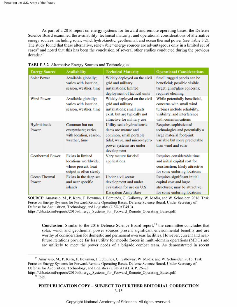
Powering the U.S. Army of the Future
Copyright National Academy of Sciences. All rights reserved.
PREPUBLICATION COPY – SUBJECT TO FURTHER EDITORIAL CORRECTION 3-15
As part of a 2016 report on energy systems for forward and remote operating bases, the Defense Science Board examined the availability, technical maturity, and operational considerations of alternative energy sources, including solar, wind, hydrokinetic, geothermal, and ocean thermal power (see Table 3.2). The study found that these alternative, renewable “energy sources are advantageous only in a limited set of cases” and noted that this has been the conclusion of several other studies conducted during the previous decade.27 TABLE 3.2 Alternative Energy Sources and Technologies
SOURCE: Anastasio, M., P. Kern, F. Bowman, J. Edmunds, G. Galloway, W. Madia, and W. Schneider. 2016. Task Force on Energy Systems for Forward/Remote Operating Bases. Defense Science Board. Under Secretary of Defense for Acquisition, Technology, and Logistics (USD(AT&L)). https://dsb.cto.mil/reports/2010s/Energy_Systems_for_Forward_Remote_Operating_Bases.pdf.
Conclusion: Similar to the 2016 Defense Science Board report,28 the committee concludes that solar, wind, and geothermal power sources present significant environmental benefits and are worthy of consideration for domestic and permanent overseas facilities. However, current and near-future iterations provide far less utility for mobile forces in multi-domain operations (MDO) and are unlikely to meet the power needs of a brigade combat team. As demonstrated in recent
27 Anastasio, M., P. Kern, F. Bowman, J. Edmunds, G. Galloway, W. Madia, and W. Schneider. 2016. Task
Force on Energy Systems for Forward/Remote Operating Bases. Defense Science Board. Under Secretary of Defense for Acquisition, Technology, and Logistics (USD(AT&L)). P. 26–28. https://dsb.cto.mil/reports/2010s/Energy_Systems_for_Forward_Remote_Operating_Bases.pdf.
28 Ibid.
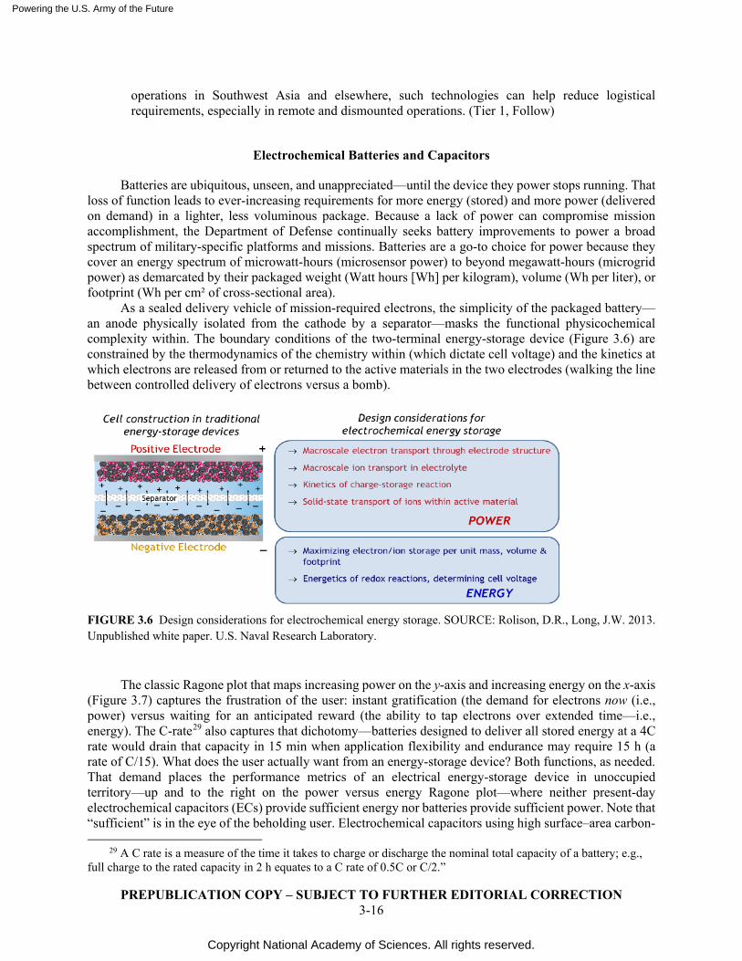
Powering the U.S. Army of the Future
Copyright National Academy of Sciences. All rights reserved.
PREPUBLICATION COPY – SUBJECT TO FURTHER EDITORIAL CORRECTION 3-16
operations in Southwest Asia and elsewhere, such technologies can help reduce logistical requirements, especially in remote and dismounted operations. (Tier 1, Follow)
Electrochemical Batteries and Capacitors
Batteries are ubiquitous, unseen, and unappreciated—until the device they power stops running. That loss of function leads to ever-increasing requirements for more energy (stored) and more power (delivered on demand) in a lighter, less voluminous package. Because a lack of power can compromise mission accomplishment, the Department of Defense continually seeks battery improvements to power a broad spectrum of military-specific platforms and missions. Batteries are a go-to choice for power because they cover an energy spectrum of microwatt-hours (microsensor power) to beyond megawatt-hours (microgrid power) as demarcated by their packaged weight (Watt hours [Wh] per kilogram), volume (Wh per liter), or footprint (Wh per cm² of cross-sectional area).
As a sealed delivery vehicle of mission-required electrons, the simplicity of the packaged battery—an anode physically isolated from the cathode by a separator—masks the functional physicochemical complexity within. The boundary conditions of the two-terminal energy-storage device (Figure 3.6) are constrained by the thermodynamics of the chemistry within (which dictate cell voltage) and the kinetics at which electrons are released from or returned to the active materials in the two electrodes (walking the line between controlled delivery of electrons versus a bomb).
FIGURE 3.6 Design considerations for electrochemical energy storage. SOURCE: Rolison, D.R., Long, J.W. 2013. Unpublished white paper. U.S. Naval Research Laboratory.
The classic Ragone plot that maps increasing power on the y-axis and increasing energy on the x-axis (Figure 3.7) captures the frustration of the user: instant gratification (the demand for electrons now (i.e., power) versus waiting for an anticipated reward (the ability to tap electrons over extended time—i.e., energy). The C-rate29 also captures that dichotomy—batteries designed to deliver all stored energy at a 4C rate would drain that capacity in 15 min when application flexibility and endurance may require 15 h (a rate of C/15). What does the user actually want from an energy-storage device? Both functions, as needed. That demand places the performance metrics of an electrical energy-storage device in unoccupied territory—up and to the right on the power versus energy Ragone plot—where neither present-day electrochemical capacitors (ECs) provide sufficient energy nor batteries provide sufficient power. Note that “sufficient” is in the eye of the beholding user. Electrochemical capacitors using high surface–area carbon-
29 A C rate is a measure of the time it takes to charge or discharge the nominal total capacity of a battery; e.g.,
full charge to the rated capacity in 2 h equates to a C rate of 0.5C or C/2.”
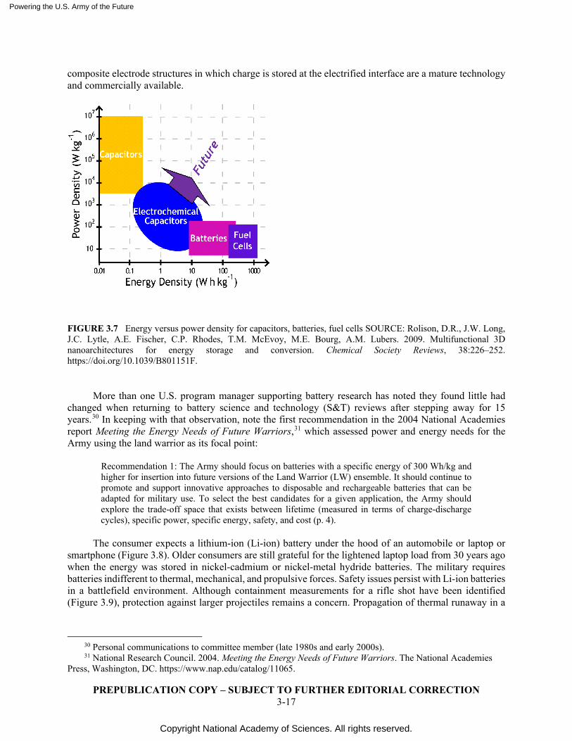
Powering the U.S. Army of the Future
Copyright National Academy of Sciences. All rights reserved.
PREPUBLICATION COPY – SUBJECT TO FURTHER EDITORIAL CORRECTION 3-17
composite electrode structures in which charge is stored at the electrified interface are a mature technology and commercially available.
FIGURE 3.7 Energy versus power density for capacitors, batteries, fuel cells SOURCE: Rolison, D.R., J.W. Long, J.C. Lytle, A.E. Fischer, C.P. Rhodes, T.M. McEvoy, M.E. Bourg, A.M. Lubers. 2009. Multifunctional 3D nanoarchitectures for energy storage and conversion. Chemical Society Reviews, 38:226–252. https://doi.org/10.1039/B801151F.
More than one U.S. program manager supporting battery research has noted they found little had
changed when returning to battery science and technology (S&T) reviews after stepping away for 15 years.30 In keeping with that observation, note the first recommendation in the 2004 National Academies report Meeting the Energy Needs of Future Warriors,31 which assessed power and energy needs for the Army using the land warrior as its focal point:
Recommendation 1: The Army should focus on batteries with a specific energy of 300 Wh/kg and higher for insertion into future versions of the Land Warrior (LW) ensemble. It should continue to promote and support innovative approaches to disposable and rechargeable batteries that can be adapted for military use. To select the best candidates for a given application, the Army should explore the trade-off space that exists between lifetime (measured in terms of charge-discharge cycles), specific power, specific energy, safety, and cost (p. 4).
The consumer expects a lithium-ion (Li-ion) battery under the hood of an automobile or laptop or
smartphone (Figure 3.8). Older consumers are still grateful for the lightened laptop load from 30 years ago when the energy was stored in nickel-cadmium or nickel-metal hydride batteries. The military requires batteries indifferent to thermal, mechanical, and propulsive forces. Safety issues persist with Li-ion batteries in a battlefield environment. Although containment measurements for a rifle shot have been identified (Figure 3.9), protection against larger projectiles remains a concern. Propagation of thermal runaway in a
30 Personal communications to committee member (late 1980s and early 2000s). 31 National Research Council. 2004. Meeting the Energy Needs of Future Warriors. The National Academies
Press, Washington, DC. https://www.nap.edu/catalog/11065.
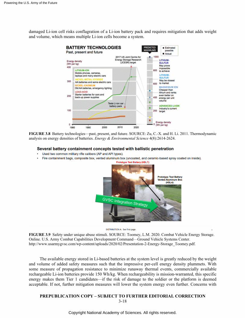
Powering the U.S. Army of the Future
Copyright National Academy of Sciences. All rights reserved.
PREPUBLICATION COPY – SUBJECT TO FURTHER EDITORIAL CORRECTION 3-18
damaged Li-ion cell risks conflagration of a Li-ion battery pack and requires mitigation that adds weight and volume, which means multiple Li-ion cells become a system.
FIGURE 3.8 Battery technologies—past, present, and future. SOURCE: Zu, C.-X. and H. Li. 2011. Thermodynamic analysis on energy densities of batteries. Energy & Environmental Science 4(8):2614-2624.
FIGURE 3.9 Safety under unique abuse stimuli. SOURCE: Toomey, L.M. 2020. Combat Vehicle Energy Storage. Online. U.S. Army Combat Capabilities Development Command—Ground Vehicle Systems Center. http://www.usarmygvsc.com/wp-content/uploads/2020/02/Presentation-2-Energy-Storage_Toomey.pdf.
The available energy stored in Li-based batteries at the system level is greatly reduced by the weight
and volume of added safety measures such that the impressive per-cell energy density plummets. With some measure of propagation resistance to minimize runaway thermal events, commercially available rechargeable Li-ion batteries provide 150 Wh/kg. When rechargeability is mission-warranted, this specific energy makes them Tier 1 candidates—if the risk of damage to the soldier or the platform is deemed acceptable. If not, further mitigation measures will lower the system energy even further. Concerns with
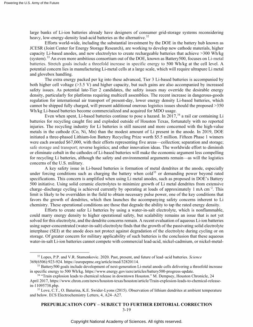
Powering the U.S. Army of the Future
Copyright National Academy of Sciences. All rights reserved.
PREPUBLICATION COPY – SUBJECT TO FURTHER EDITORIAL CORRECTION 3-19
large banks of Li-ion batteries already have designers of consumer grid-storage systems reconsidering heavy, low-energy-density lead-acid batteries as the alternative.32
Efforts world-wide, including the substantial investment by the DOE in the battery hub known as JCESR (Joint Center for Energy Storage Research), are working to develop new cathode materials, higher capacity Li-based anodes, and new electrolytes to create rechargeable batteries that achieve >300 Wh/kg (system).33 An even more ambitious consortium out of the DOE, known as Battery500, focuses on Li-metal batteries. Stretch goals include a threefold increase in specific energy to 500 Wh/kg at the cell level. A potential concern lies in manufacturing Li-metal cells at a large scale, which will require ultrapure Li metal and glovebox handling.
The extra energy packed per kg into these advanced, Tier 3 Li-based batteries is accompanied by both higher cell voltage (>3.5 V) and higher capacity, but such gains are also accompanied by increased safety issues. As potential late-Tier 2 candidates, the safety issues may override the desirable energy density, particularly for platforms requiring multicell assemblies. The recent increase in dangerous-goods regulation for international air transport of present-day, lower energy density Li-based batteries, which cannot be shipped fully charged, will present additional onerous logistics issues should the proposed >350 Wh/kg Li-based batteries become commercialized and acquired for MDO usage. Even when spent, Li-based batteries continue to pose a hazard. In 2017,34 a rail car containing Li batteries for recycling caught fire and exploded outside of Houston Texas, fortunately with no reported injuries. The recycling industry for Li batteries is still nascent and more concerned with the high-value metals in the cathode (Co, Ni, Mn) than the modest amount of Li present in the anode. In 2019, DOE initiated a three-phased Lithium-Ion Battery Recycling Prize worth $5.5 million. Fifteen Phase 1 winners were each awarded $67,000, with their efforts representing five areas—collection; separation and storage; safe storage and transport; reverse logistics; and other innovation ideas. The worldwide effort to diminish or eliminate cobalt in the cathodes of Li-based batteries will make the economic argument less compelling for recycling Li batteries, although the safety and environmental arguments remain—as will the logistics concerns of the U.S. military.
A key safety issue in Li-based batteries is formation of metal dendrites at the anode, especially under forcing conditions such as charging the battery when cold35 or demanding power beyond rated specifications. This concern is amplified when using Li metal anodes, such as proposed in DOE’s Battery 500 initiative. Using solid ceramic electrolytes to minimize growth of Li metal dendrites from extensive charge–discharge cycling is achieved currently by operating at loads of approximately 1 mA cm−2. This limit is likely to be overridden in the field to obtain necessary pulse power, one of the key conditions that favors the growth of dendrites, which then launches the accompanying safety concerns inherent to Li chemistry. These operational conditions are those that degrade the ability to tap the rated energy density.
Efforts to create safer Li batteries by using a water-in-salt electrolyte, which is nonflammable, could marry energy density to higher operational safety, but scalability remains an issue that is not yet solved for this electrolyte, and the dendrite concerns remain. A recent evaluation of aqueous Li-ion batteries using super-concentrated (water-in-salt) electrolyte finds that the growth of the passivating solid electrolyte interphase (SEI) at the anode does not protect against degradation of the electrolyte during cycling or on storage. Of greater concern for military applicability of such batteries is the conclusion that these aqueous water-in-salt Li-ion batteries cannot compete with commercial lead-acid, nickel-cadmium, or nickel-metal-
32 Lopes, P.P. and V.R. Stamenkovic. 2020. Past, present, and future of lead–acid batteries. Science
369(6506):923-924. https://europepmc.org/article/med/32820114. 33 Battery500 goals include development of next-generation Li-metal anode cells delivering a threefold increase
in specific energy to 500 Wh/kg. https://www.energy.gov/eere/articles/battery500-progress-update. 34 “Train explosion leads to chemical release in downtown Houston.” M. Dempsey, Houston Chronicle, 24
April 2017, https://www.chron.com/news/houston-texas/houston/article/Train-explosion-leads-to-chemical-release-in-11095738.php.
35 Love, C.T., O. Baturina, K.E. Swider-Lyons (2015). Observation of lithium dendrites at ambient temperature and below. ECS Electrochemistry Letters, 4, A24–A27.
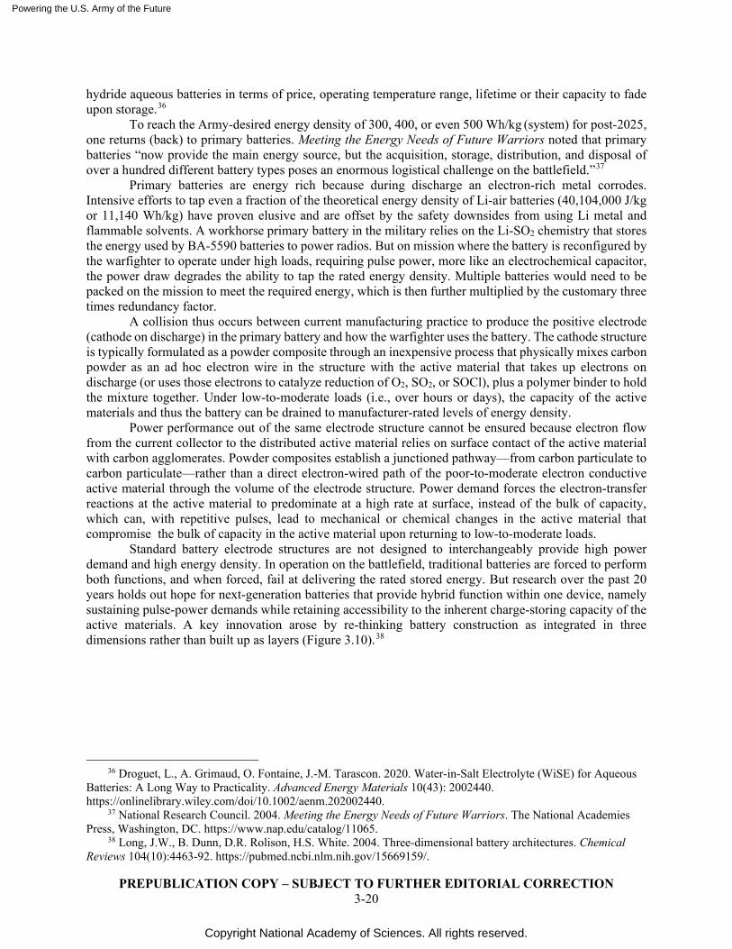
Powering the U.S. Army of the Future
Copyright National Academy of Sciences. All rights reserved.
PREPUBLICATION COPY – SUBJECT TO FURTHER EDITORIAL CORRECTION 3-20
hydride aqueous batteries in terms of price, operating temperature range, lifetime or their capacity to fade upon storage.36
To reach the Army-desired energy density of 300, 400, or even 500 Wh/kg (system) for post-2025, one returns (back) to primary batteries. Meeting the Energy Needs of Future Warriors noted that primary batteries “now provide the main energy source, but the acquisition, storage, distribution, and disposal of over a hundred different battery types poses an enormous logistical challenge on the battlefield.”37
Primary batteries are energy rich because during discharge an electron-rich metal corrodes. Intensive efforts to tap even a fraction of the theoretical energy density of Li-air batteries (40,104,000 J/kg or 11,140 Wh/kg) have proven elusive and are offset by the safety downsides from using Li metal and flammable solvents. A workhorse primary battery in the military relies on the Li-SO2 chemistry that stores the energy used by BA-5590 batteries to power radios. But on mission where the battery is reconfigured by the warfighter to operate under high loads, requiring pulse power, more like an electrochemical capacitor, the power draw degrades the ability to tap the rated energy density. Multiple batteries would need to be packed on the mission to meet the required energy, which is then further multiplied by the customary three times redundancy factor.
A collision thus occurs between current manufacturing practice to produce the positive electrode (cathode on discharge) in the primary battery and how the warfighter uses the battery. The cathode structure is typically formulated as a powder composite through an inexpensive process that physically mixes carbon powder as an ad hoc electron wire in the structure with the active material that takes up electrons on discharge (or uses those electrons to catalyze reduction of O2, SO2, or SOCl), plus a polymer binder to hold the mixture together. Under low-to-moderate loads (i.e., over hours or days), the capacity of the active materials and thus the battery can be drained to manufacturer-rated levels of energy density.
Power performance out of the same electrode structure cannot be ensured because electron flow from the current collector to the distributed active material relies on surface contact of the active material with carbon agglomerates. Powder composites establish a junctioned pathway—from carbon particulate to carbon particulate—rather than a direct electron-wired path of the poor-to-moderate electron conductive active material through the volume of the electrode structure. Power demand forces the electron-transfer reactions at the active material to predominate at a high rate at surface, instead of the bulk of capacity, which can, with repetitive pulses, lead to mechanical or chemical changes in the active material that compromise the bulk of capacity in the active material upon returning to low-to-moderate loads.
Standard battery electrode structures are not designed to interchangeably provide high power demand and high energy density. In operation on the battlefield, traditional batteries are forced to perform both functions, and when forced, fail at delivering the rated stored energy. But research over the past 20 years holds out hope for next-generation batteries that provide hybrid function within one device, namely sustaining pulse-power demands while retaining accessibility to the inherent charge-storing capacity of the active materials. A key innovation arose by re-thinking battery construction as integrated in three dimensions rather than built up as layers (Figure 3.10).38
36 Droguet, L., A. Grimaud, O. Fontaine, J.-M. Tarascon. 2020. Water-in-Salt Electrolyte (WiSE) for Aqueous
Batteries: A Long Way to Practicality. Advanced Energy Materials 10(43): 2002440. https://onlinelibrary.wiley.com/doi/10.1002/aenm.202002440.
37 National Research Council. 2004. Meeting the Energy Needs of Future Warriors. The National Academies Press, Washington, DC. https://www.nap.edu/catalog/11065.
38 Long, J.W., B. Dunn, D.R. Rolison, H.S. White. 2004. Three-dimensional battery architectures. Chemical Reviews 104(10):4463-92. https://pubmed.ncbi.nlm.nih.gov/15669159/.
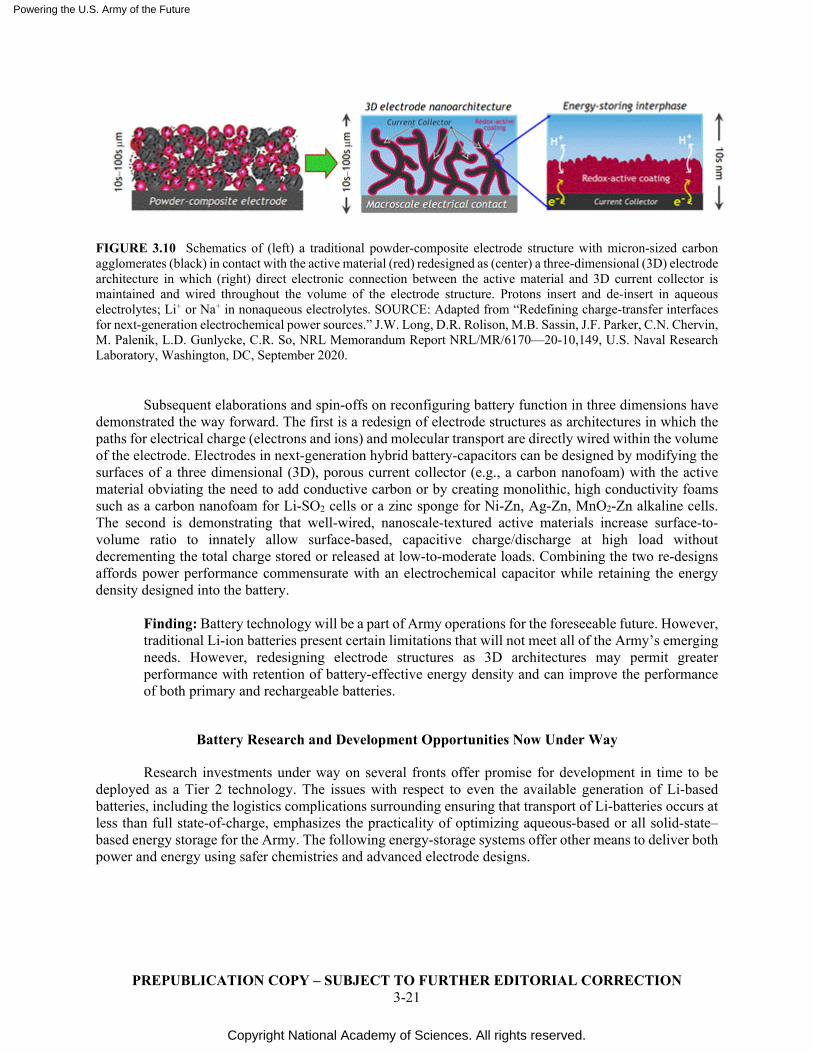
Powering the U.S. Army of the Future
Copyright National Academy of Sciences. All rights reserved.
PREPUBLICATION COPY – SUBJECT TO FURTHER EDITORIAL CORRECTION 3-21
FIGURE 3.10 Schematics of (left) a traditional powder-composite electrode structure with micron-sized carbon agglomerates (black) in contact with the active material (red) redesigned as (center) a three-dimensional (3D) electrode architecture in which (right) direct electronic connection between the active material and 3D current collector is maintained and wired throughout the volume of the electrode structure. Protons insert and de-insert in aqueous electrolytes; Li+ or Na+ in nonaqueous electrolytes. SOURCE: Adapted from “Redefining charge-transfer interfaces for next-generation electrochemical power sources.” J.W. Long, D.R. Rolison, M.B. Sassin, J.F. Parker, C.N. Chervin, M. Palenik, L.D. Gunlycke, C.R. So, NRL Memorandum Report NRL/MR/6170—20-10,149, U.S. Naval Research Laboratory, Washington, DC, September 2020.
Subsequent elaborations and spin-offs on reconfiguring battery function in three dimensions have demonstrated the way forward. The first is a redesign of electrode structures as architectures in which the paths for electrical charge (electrons and ions) and molecular transport are directly wired within the volume of the electrode. Electrodes in next-generation hybrid battery-capacitors can be designed by modifying the surfaces of a three dimensional (3D), porous current collector (e.g., a carbon nanofoam) with the active material obviating the need to add conductive carbon or by creating monolithic, high conductivity foams such as a carbon nanofoam for Li-SO2 cells or a zinc sponge for Ni-Zn, Ag-Zn, MnO2-Zn alkaline cells. The second is demonstrating that well-wired, nanoscale-textured active materials increase surface-to-volume ratio to innately allow surface-based, capacitive charge/discharge at high load without decrementing the total charge stored or released at low-to-moderate loads. Combining the two re-designs affords power performance commensurate with an electrochemical capacitor while retaining the energy density designed into the battery.
Finding: Battery technology will be a part of Army operations for the foreseeable future. However, traditional Li-ion batteries present certain limitations that will not meet all of the Army’s emerging needs. However, redesigning electrode structures as 3D architectures may permit greater performance with retention of battery-effective energy density and can improve the performance of both primary and rechargeable batteries.
Battery Research and Development Opportunities Now Under Way
Research investments under way on several fronts offer promise for development in time to be deployed as a Tier 2 technology. The issues with respect to even the available generation of Li-based batteries, including the logistics complications surrounding ensuring that transport of Li-batteries occurs at less than full state-of-charge, emphasizes the practicality of optimizing aqueous-based or all solid-state–based energy storage for the Army. The following energy-storage systems offer other means to deliver both power and energy using safer chemistries and advanced electrode designs.
Powering the U.S. Army of the Future
Copyright National Academy of Sciences. All rights reserved.
PREPUBLICATION COPY – SUBJECT TO FURTHER EDITORIAL CORRECTION 3-22
1. Increasing the TRL of asymmetric electrochemical capacitors in which nanometric coatings of battery materials deposited on 3D porous electrodes provide pulse power in aqueous electrolytes that are more energy dense than electrolytic double-layer capacitors (EDLCs).39,40
2. Developing Zn-ion batteries with neutral to mildly acidic aqueous electrolytes;41 when the positive electrode is designed as a 3D architecture and Na ions are added to the Zn2+-based electrolyte, capacitive power can be obtained while traditional powder-composite structures formulated with the same manganese oxide active material cannot deliver pulse power.42
3. Scaling 3D, tricontinuous, all solid–state batteries, including those manufactured using 3D printing,43 which already show promise for microbatteries and on-chip power, to sizes relevant for wearables using sponge form factors.
4. Developing rechargeable alkaline batteries using dendrite-suppressing Zn sponge and related 3D anodes.44
By reformulating Zn into a sponge form-factor, the Naval Research Laboratory (NRL) has pushed Zn utilization to >90 percent in primary Zn-air cells (versus the approximately 50–60 percent customarily obtained) and innately suppressed dendrite formation, even under demanding charge–discharge conditions—all while using aqueous electrolytes rather than the flammable nonaqueous electrolytes used in Li-ion batteries. This 21st-century design breakthrough using 19th-century battery chemistry provides DoD with a transformative opportunity to take the military-validated, aqueous-based Ag-Zn, Ni-Zn, MnO2-Zn, and Zn-air primary batteries and transform them into rechargeable batteries that are safe, cost-effective, domestically sourced, and meet or exceed the performance of Li-ion batteries on the system level (Table 3.3). Near-term payoffs arise by swapping out powder-composite Zn anodes for the Zn sponge and using it in existing Zn battery configurations. To match the innate capabilities of architected Zn electrodes—a two-electron anode versus the one-electron Li-based anode—further R&D will be required to optimize complementary positive electrode compositions and structures, including identifying multi-electron active materials (e.g., Ag/AgxO, potentially MnO2 and NiOOH, and trifunctional air-breathing cathodes that reduce O2 on discharge, evolve O2 on charge, and provide pulse power).
Conclusion: Zn-based batteries, once moved to a new performance curve, may bypass the safety issues associated with Li-ion and the low-energy limitations of lead-acid while providing the following critical functions: (1) extended mission life for a given battery weight or volume; (2) platform simplification, because less balance-of-plant is required for safe, aqueous-based cell chemistry; and (3) simultaneous energy and power delivery from a single device. (Tier 2, Lead)
39 Galek, P., A. Mackowiak, P. Bujewska, K. Fic. 2020. Three-Dimensional Architectures in Electrochemical
Capacitor Applications—Insights, Opinions, and Perspectives. Frontiers in Energy Research 8: 139. https://www.frontiersin.org/articles/10.3389/fenrg.2020.00139/full.
40 Shao, Y., M.F. El-Kady, J. Sun, Y. Li, Q.H. Zhang, M.F. Zhu, H.Z. Wang, B. Dunn, R.B. Kaner. 2018. Design and mechanisms of asymmetric supercapacitors. Chemical Reviews 118(18): 9233–9280. https://doi.org/10.1021/acs.chemrev.8b00252.
41 “Aqueous zinc ion batteries: Focus on zinc metal anodes.” J. Shin, J. Lee, Y. Park, J.W. Choi, Chemical Science, 2020, 11, 2028–2044.
42 Ko, J.S., M.B. Sassin, D.R. Rolison, J.W. Long. 2018. Combining battery-like and pseudocapacitive charge storage in 3D MnOx@carbon electrode architectures for zinc-ion cells. Sustainable Energy & Fuels 2, 626–636. https://pubs.rsc.org/en/content/articlelanding/2018/se/c7se00540g#!divAbstract.
43 Cheng, M., R. Deivanayagam, R. Shahbazian-Yassar. 2020. 3D printing of electrochemical energy storage devices: A review of printing techniques and electrode/electrolyte architectures. Batteries and Supercaps 3(2), 130–146. https://chemistry-europe.onlinelibrary.wiley.com/doi/abs/10.1002/batt.201900130.
44 Parker, J.F., C.N. Chervin, E.S. Nelson, D.R. Rolison, J.W. Long. 2014. Wiring zinc in three dimensions re-writes battery performance―Dendrite-free cycling. Energy & Environmental Science 7:1117–1124. https://pubs.rsc.org/en/content/articlelanding/2014/ee/c3ee43754j#!divAbstract.
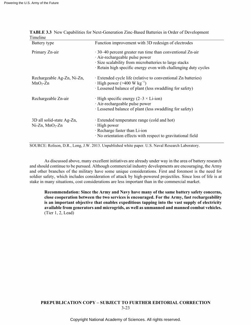
Powering the U.S. Army of the Future
Copyright National Academy of Sciences. All rights reserved.
PREPUBLICATION COPY – SUBJECT TO FURTHER EDITORIAL CORRECTION 3-23
TABLE 3.3 New Capabilities for Next-Generation Zinc-Based Batteries in Order of Development Timeline Battery type Function improvement with 3D redesign of electrodes
Primary Zn-air ∙ 30–40 percent greater run time than conventional Zn-air ∙ Air-rechargeable pulse power ∙ Size scalability from microbatteries to large stacks ∙ Retain high specific energy even with challenging duty cycles
Rechargeable Ag-Zn, Ni-Zn, MnO2-Zn
∙ Extended cycle life (relative to conventional Zn batteries) ∙ High power (>400 W kg−1) ∙ Lessened balance of plant (less swaddling for safety)
Rechargeable Zn-air ∙ High specific energy (2–3 × Li-ion) ∙ Air-rechargeable pulse power ∙ Lessened balance of plant (less swaddling for safety)
3D all solid-state Ag-Zn, Ni-Zn, MnO2-Zn
∙ Extended temperature range (cold and hot) ∙ High power ∙ Recharge faster than Li-ion ∙ No orientation effects with respect to gravitational field
SOURCE: Rolison, D.R., Long, J.W. 2013. Unpublished white paper. U.S. Naval Research Laboratory. As discussed above, many excellent initiatives are already under way in the area of battery research
and should continue to be pursued. Although commercial industry developments are encouraging, the Army and other branches of the military have some unique considerations. First and foremost is the need for soldier safety, which includes consideration of attack by high-powered projectiles. Since loss of life is at stake in many situations, cost considerations are less important than in the commercial market.
Recommendation: Since the Army and Navy have many of the same battery safety concerns, close cooperation between the two services is encouraged. For the Army, fast rechargeability is an important objective that enables expeditious tapping into the vast supply of electricity available from generators and microgrids, as well as unmanned and manned combat vehicles. (Tier 1, 2, Lead)
Powering the U.S. Army of the Future
Copyright National Academy of Sciences. All rights reserved.
PREPUBLICATION COPY – SUBJECT TO FURTHER EDITORIAL CORRECTION 4-1
4
System Wide Communication Issues in Support of Multi-Domain Operations The Army Modernization Strategy describes how the Total Army—Regular Army, National Guard,
Army Reserve, and Army Civilians—will transform into a multi-domain force by 2035 to meet its enduring responsibility as part of the Joint Force to provide for the defense of the United States and retain its position as the globally dominant land power.1 The essence of the Army’s Multi-Domain Operations (MDO) concept is to support the Joint Force in the rapid and continuous integration of all domains of warfare—land, sea, air, space, and cyberspace—to deter and prevail as the United States competes, as a nation, short of conflict, and fights and wins if deterrence fails.
The tenets of MDO create significant performance challenges for several integration technologies, including power and energy (P&E), over the next 15 years. The first tenet is “calibrated force posture”—a combination of forward presence, expeditionary capability, and access to joint, national, and partner capabilities. The second tenet is the use of “multi-domain formations” that have the capacity, capability, and endurance to maneuver and choreograph effects across multiple domains. The final tenet is “convergence”—the ability to rapidly converge effects from multiple domains, simultaneously and nearly continuously, using multiple forms of attack and redundant sensor-to-shooter networks enabled by robust mission command.2
These tenets will require a highly integrated and rapidly reconfigurable force posture that can execute and sustain complex operations with great speed and precision. The execution of missions and the degree of deterrence that can be achieved will strongly depend on the Army having the capability of competing and converging capabilities across echelons and domains in a single theater while also having the capacity to execute MDO in multiple theaters.
Evolving technologies, especially information technologies and those technologies that enable and sustain them, such as P&E, will be fundamental to achieving MDO objectives. For example, 5G technologies have compelling characteristics, among them much wider bandwidth and the potential for lower latency that can be a critical enabler of Army MDO. The wider bandwidth also has the potential to more effectively exploit artificial intelligence (AI), machine learning (ML), and autonomous systems, which can increase the speed and precision of executing complex military operations across all domains and echelons. The Department of Defense (DoD) will have to explore these technologies not only to advance its warfighting capabilities, but also to counter adversary efforts in this space as well.
Energy Challenges for Network-Enabled MDO
A key differentiator between military and commercial challenges, aside from the obvious threat to the lives of Soldiers, is the operating environment. Commercial solutions solve the problem of mobile devices in a static environment and are finely tuned over a long period of time to provide the best performance. However, military systems employ mobile devices in a mobile environment, requiring close
1 U.S. Army. 2014. 2019 Army Modernization Strategy: Investing in the Future.
https://www.army.mil/e2/downloads/rv7/2019_army_modernization_strategy_final.pdf. 2 Ibid.
Powering the U.S. Army of the Future
Copyright National Academy of Sciences. All rights reserved.
PREPUBLICATION COPY – SUBJECT TO FURTHER EDITORIAL CORRECTION 4-2
to optimum performance immediately upon deployment. Recently announced DoD investments, including $600 million for 5G experimentation,3 should yield substantial insights that inform prospective tactical application. These largely domestic efforts will provide technical information such as communication (routing, interference, bandwidth, coverage), data management (distributed processing, caches and prioritization), and energy (source and supply alternatives and power management) in a military context, albeit not tactical.
Army platforms, by definition, support component operational capabilities through mobility, power, communication, and other common functions. Obviously, the energy requirements for most vehicular platforms are driven by mobility, but networked information and sensing technologies—especially those involving electromagnetic radiation (radio, radar, etc.)—drive the ever-increasing need for power capacity. To the degree that platforms continue to utilize hydrocarbon fuels, information technologies will not drive new energy technology needs for large ground or aerial platforms. Quite the contrary, hydrocarbon-fueled engines will be actively optimized in real time in the future, driven by knowledge of the environment, mission status, and vehicle health diagnostics/prognosis—all facilitated by information technologies.
It is the growing need for onboard power, and the desire for exportable power, that will motivate ongoing advancements in energy conversion, power management, and thermal management.
Smaller-scale platforms—soldiers, autonomous ground vehicles, small electric and hybrid drones (less than 50 lbs.), and micro-autonomous systems—demand similar advancements in power capabilities as well as improved energy delivery and storage capabilities. Energy performance attributes like location, timing, delivery rate, reliability, and fungibility substantially impact energy-enabled technologies such as 5G and the Internet of Things (IoT), in turn enabling or constraining forward-deployed sensors, distributed data processing, and data sharing to support MDO command and control.
One particular challenge in specifying P&E performance parameters is the lack of detailed unclassified operational concepts and scenarios, within which energy attributes would be balanced with other factors. A common Army planning parameter is for 72-hours of self-sustained operations; a future aspiration is to extend that to seven days. New information technologies may not substantially impact that energy balance, but perhaps requirements for stationary operations or silent mobility (with substantial power requirements for information and other functions) may substantially influence needs for silent conversion or storage, efficient networking and management, or other functions. Notably, many of these facets point toward development of power electronic technologies that enable efficient and high-power switching associated with power converters, filters, and power management and distribution applications.
Resolving 5G Technical Challenges Through Science and Technology Studies
The Army’s multi-domain doctrine recognizes the continuing evolution of the complex military operating environment. In the past, the Army has responded by emphasizing experimentation and systems-oriented investigation.4 Salient examples include rapid equipping initiatives and the Network Integration Exercise—both of which emphasized field feedback on promising technologies and research capabilities such as the Network Science Research Laboratory (NSRL), which resides within the Network Science Division at the Army Research Laboratory (ARL).
3 U.S. Department of Defense. 2020. DOD Announces $600 Million for 5G Experimentation and Testing at
Five Installations. https://www.defense.gov/Newsroom/Releases/Release/Article/2376743/dod-announces-600-million-for-5g-experimentation-and-testing-at-five-installati/. 4 Ibid.
Powering the U.S. Army of the Future
Copyright National Academy of Sciences. All rights reserved.
PREPUBLICATION COPY – SUBJECT TO FURTHER EDITORIAL CORRECTION 4-3
The NSRL has developed a predictive model for Mobile Ad-hoc Network (MANET) performance based on current wireless technologies.5 This model needs to be updated to include 5G technologies to explore the performance characteristics of a 5G MANET. Simulations should be run that reflect various deployment and operating scenarios with co-simulation of P&E dynamics. Inputs for these analyses can be validated with data from sources other than the DoD 5G initiative.
Modeling alone is not sufficient. Testing and field experimentation are important to validate predictions and to account for network performance in a variety of warfighting scenarios. This experimentation will require emulators for 5G radios and their P&E sources, emulators for mobile air and ground processing and relay nodes along with their P&E sources, models of environmental effects, measurement instruments on real-world systems to collect data during experiments, engineering trade-off analyses to identify the “knees” in network performance, and realistic scenarios to drive model performance and the planning of experiments to validate model predictions. This intensive evaluation will require a combined effort that involves diverse entities among the operational and acquisition communities, with strong support of the Deputy Assistant Secretary of the Army for Research and Technology (DASA (R&T)).
Finding: 5G implementation on the battlefield offers significant bandwidth opportunities but presents some serious technical challenges, including P&E requirements on vehicles and for the dismounted soldier. 5G technologies should not be viewed as a “do it all” stand-alone solution but rather an opportunity to combine with other communications systems when appropriate. Recommendation: To realize the benefits associated with a significant bandwidth increase, the Network Science Research Laboratory’s (NSRL) MANET (mobile ad hoc network) predictive model of network performance needs to be updated for 5G technologies and other emerging communication technologies (e.g., Internet of Things, 6G, and short-range, directed, and secure communications across a variety of devices) complemented with subsequent testing and field experimentation. (Tier 1, Lead)
5 Verma, D., W. Leland, T. Pham, A. Swami, G. Cirincione. 2015. Advances in Network Sciences via
Collaborative MultiDisciplinary Research. White paper presented at the 18th International Conference on Information Fusion, Washington, DC. https://c4i.gmu.edu/~pcosta/F15/data/fileserver/file/472301/filename/Paper_1570112519.pdf.
Powering the U.S. Army of the Future
Copyright National Academy of Sciences. All rights reserved.
PREPUBLICATION COPY – SUBJECT TO FURTHER EDITORIAL CORRECTION 5-1
5
Dismounted Soldier Power and Light Unmanned Aerial Vehicles and Unmanned Ground Vehicles
ENERGY-INFORMED OPERATIONS
While most think of energy in commodity terms—where value is measured purely in terms of quantity—the field of operational energy demands recognition of energy as a differentiated entity. That is, energy comes in many forms, and its diverse attributes—such as density, availability, timing, location, delivery rate, and the ability to modulate—significantly impact value creation in a given application. Most energy programs base their principal metrics on the commodity perspective. In the Department of Defense (DoD), this focus translates to an enterprise emphasis on flight operations (the largest operational consumer of energy); ground operations in which armored vehicle consumption dominates during maneuver, and stability operations ensuring base-camp sustenance. However, the Army’s primary mission is not to save money; it is to prevent and/or win wars. As SLA Marshall famously observed in 1950, repeated by military scholars, and reiterated by McManus in 2010, “wars are won on the ground, usually by small groups of fighters, who require considerable logistical, firepower, and popular support.”1 On a comparative basis, dismounted Soldier energy consumption is miniscule when compared to jet fighters and tanks. However, if these observations are valid, then the military’s energy focus must not be dictated by the heaviest use; rather, by an understanding of how energy plays in the United States’ operational advantage.
Marshall, of course, took substantial personal risk and invested extensive effort to examine factors that influence the Infantryman’s combat capability. His work informed subsequent analysis on factors associated with cognitive condition, focus, motivation, and other factors that determine whether U.S. ground Soldiers need 10:1 numerical superiority, or if they can win with a 1:10 disadvantage.2 Inevitably, energy is a key determinant in these factors. In a simple illustration, Soldier-carried technology can provide navigation, awareness, and communication, but energy must provide adequate, reliable power with the flexibility to select and prioritize the use (without distracting the Soldier). The lesson, however, is not simply to ration energy—any more than ammunition can be rationed. The obvious metrics are not only “how much energy is used,” but also “how can one maximize the operational benefit of energy?” In fact, this is the crux of “Energy-Informed Operations,” captured in Army Operational Energy policy, which asserts the goal to manage energy to provide the greatest operational benefit.3
While past analyses focused directly on the Soldier and things they carry, modern technologies have uncovered powerful new opportunities to extend Soldier capabilities by projecting their senses and zone of influence. For 21st century operations, U.S. Soldiers have increasingly employed remote sensors, unmanned systems, and improved analytical tools to dramatically increase Soldier effectiveness. Like dismounted Soldiers, unmanned sensors and platforms use relatively small quantities of energy, but their
1 Marshall, S.L.A. Undated. McManus, J. 2010. Grunts: Inside the American Infantry Combat Experience,
World War II through Iraq. Penguin Random House. https://www.penguinrandomhouse.com/books/302305/grunts-by-john-c-mcmanus/.
2 Ibid. 3 Secretary of the Army, Army Operational Energy Policy Memorandum, April 20, 2013.
https://api.army.mil/e2/c/downloads/295964.pdf.
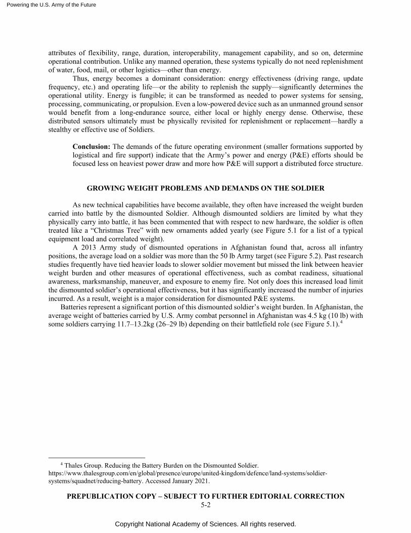
Powering the U.S. Army of the Future
Copyright National Academy of Sciences. All rights reserved.
PREPUBLICATION COPY – SUBJECT TO FURTHER EDITORIAL CORRECTION 5-2
attributes of flexibility, range, duration, interoperability, management capability, and so on, determine operational contribution. Unlike any manned operation, these systems typically do not need replenishment of water, food, mail, or other logistics—other than energy.
Thus, energy becomes a dominant consideration: energy effectiveness (driving range, update frequency, etc.) and operating life—or the ability to replenish the supply—significantly determines the operational utility. Energy is fungible; it can be transformed as needed to power systems for sensing, processing, communicating, or propulsion. Even a low-powered device such as an unmanned ground sensor would benefit from a long-endurance source, either local or highly energy dense. Otherwise, these distributed sensors ultimately must be physically revisited for replenishment or replacement—hardly a stealthy or effective use of Soldiers.
Conclusion: The demands of the future operating environment (smaller formations supported by logistical and fire support) indicate that the Army’s power and energy (P&E) efforts should be focused less on heaviest power draw and more how P&E will support a distributed force structure.
GROWING WEIGHT PROBLEMS AND DEMANDS ON THE SOLDIER
As new technical capabilities have become available, they often have increased the weight burden carried into battle by the dismounted Soldier. Although dismounted soldiers are limited by what they physically carry into battle, it has been commented that with respect to new hardware, the soldier is often treated like a “Christmas Tree” with new ornaments added yearly (see Figure 5.1 for a list of a typical equipment load and correlated weight).
A 2013 Army study of dismounted operations in Afghanistan found that, across all infantry positions, the average load on a soldier was more than the 50 lb Army target (see Figure 5.2). Past research studies frequently have tied heavier loads to slower soldier movement but missed the link between heavier weight burden and other measures of operational effectiveness, such as combat readiness, situational awareness, marksmanship, maneuver, and exposure to enemy fire. Not only does this increased load limit the dismounted soldier’s operational effectiveness, but it has significantly increased the number of injuries incurred. As a result, weight is a major consideration for dismounted P&E systems.
Batteries represent a significant portion of this dismounted soldier’s weight burden. In Afghanistan, the average weight of batteries carried by U.S. Army combat personnel in Afghanistan was 4.5 kg (10 lb) with some soldiers carrying 11.7–13.2kg (26–29 lb) depending on their battlefield role (see Figure 5.1).4
4 Thales Group. Reducing the Battery Burden on the Dismounted Soldier.
https://www.thalesgroup.com/en/global/presence/europe/united-kingdom/defence/land-systems/soldier-systems/squadnet/reducing-battery. Accessed January 2021.
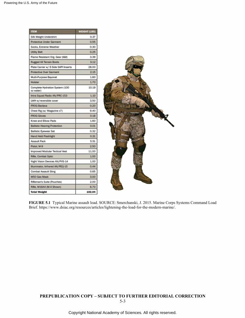
Powering the U.S. Army of the Future
Copyright National Academy of Sciences. All rights reserved.
PREPUBLICATION COPY – SUBJECT TO FURTHER EDITORIAL CORRECTION 5-3
FIGURE 5.1 Typical Marine assault load. SOURCE: Smerchanski, J. 2015. Marine Corps Systems Command Load Brief. https://www.dsiac.org/resources/articles/lightening-the-load-for-the-modern-marine/.
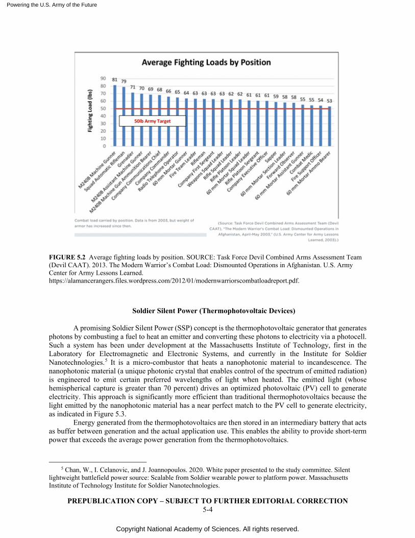
Powering the U.S. Army of the Future
Copyright National Academy of Sciences. All rights reserved.
PREPUBLICATION COPY – SUBJECT TO FURTHER EDITORIAL CORRECTION 5-4
FIGURE 5.2 Average fighting loads by position. SOURCE: Task Force Devil Combined Arms Assessment Team (Devil CAAT). 2013. The Modern Warrior’s Combat Load: Dismounted Operations in Afghanistan. U.S. Army Center for Army Lessons Learned. https://alamancerangers.files.wordpress.com/2012/01/modernwarriorscombatloadreport.pdf.
Soldier Silent Power (Thermophotovoltaic Devices)
A promising Soldier Silent Power (SSP) concept is the thermophotovoltaic generator that generates photons by combusting a fuel to heat an emitter and converting these photons to electricity via a photocell. Such a system has been under development at the Massachusetts Institute of Technology, first in the Laboratory for Electromagnetic and Electronic Systems, and currently in the Institute for Soldier Nanotechnologies.5 It is a micro-combustor that heats a nanophotonic material to incandescence. The nanophotonic material (a unique photonic crystal that enables control of the spectrum of emitted radiation) is engineered to emit certain preferred wavelengths of light when heated. The emitted light (whose hemispherical capture is greater than 70 percent) drives an optimized photovoltaic (PV) cell to generate electricity. This approach is significantly more efficient than traditional thermophotovoltaics because the light emitted by the nanophotonic material has a near perfect match to the PV cell to generate electricity, as indicated in Figure 5.3.
Energy generated from the thermophotovoltaics are then stored in an intermediary battery that acts as buffer between generation and the actual application use. This enables the ability to provide short-term power that exceeds the average power generation from the thermophotovoltaics.
5 Chan, W., I. Celanovic, and J. Joannopoulos. 2020. White paper presented to the study committee. Silent
lightweight battlefield power source: Scalable from Soldier wearable power to platform power. Massachusetts Institute of Technology Institute for Soldier Nanotechnologies.
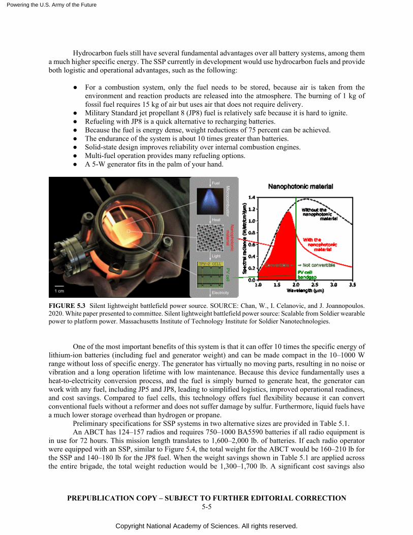
Powering the U.S. Army of the Future
Copyright National Academy of Sciences. All rights reserved.
PREPUBLICATION COPY – SUBJECT TO FURTHER EDITORIAL CORRECTION 5-5
Hydrocarbon fuels still have several fundamental advantages over all battery systems, among them a much higher specific energy. The SSP currently in development would use hydrocarbon fuels and provide both logistic and operational advantages, such as the following:
● For a combustion system, only the fuel needs to be stored, because air is taken from the
environment and reaction products are released into the atmosphere. The burning of 1 kg of fossil fuel requires 15 kg of air but uses air that does not require delivery.
● Military Standard jet propellant 8 (JP8) fuel is relatively safe because it is hard to ignite. ● Refueling with JP8 is a quick alternative to recharging batteries. ● Because the fuel is energy dense, weight reductions of 75 percent can be achieved. ● The endurance of the system is about 10 times greater than batteries. ● Solid-state design improves reliability over internal combustion engines. ● Multi-fuel operation provides many refueling options. ● A 5-W generator fits in the palm of your hand.
FIGURE 5.3 Silent lightweight battlefield power source. SOURCE: Chan, W., I. Celanovic, and J. Joannopoulos. 2020. White paper presented to committee. Silent lightweight battlefield power source: Scalable from Soldier wearable power to platform power. Massachusetts Institute of Technology Institute for Soldier Nanotechnologies.
One of the most important benefits of this system is that it can offer 10 times the specific energy of lithium-ion batteries (including fuel and generator weight) and can be made compact in the 10–1000 W range without loss of specific energy. The generator has virtually no moving parts, resulting in no noise or vibration and a long operation lifetime with low maintenance. Because this device fundamentally uses a heat-to-electricity conversion process, and the fuel is simply burned to generate heat, the generator can work with any fuel, including JP5 and JP8, leading to simplified logistics, improved operational readiness, and cost savings. Compared to fuel cells, this technology offers fuel flexibility because it can convert conventional fuels without a reformer and does not suffer damage by sulfur. Furthermore, liquid fuels have a much lower storage overhead than hydrogen or propane.
Preliminary specifications for SSP systems in two alternative sizes are provided in Table 5.1. An ABCT has 124–157 radios and requires 750–1000 BA5590 batteries if all radio equipment is
in use for 72 hours. This mission length translates to 1,600–2,000 lb. of batteries. If each radio operator were equipped with an SSP, similar to Figure 5.4, the total weight for the ABCT would be 160–210 lb for the SSP and 140–180 lb for the JP8 fuel. When the weight savings shown in Table 5.1 are applied across the entire brigade, the total weight reduction would be 1,300–1,700 lb. A significant cost savings also
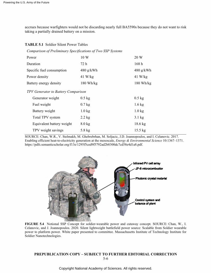
Powering the U.S. Army of the Future
Copyright National Academy of Sciences. All rights reserved.
PREPUBLICATION COPY – SUBJECT TO FURTHER EDITORIAL CORRECTION 5-6
accrues because warfighters would not be discarding nearly full BA5590s because they do not want to risk taking a partially drained battery on a mission. TABLE 5.1 Soldier Silent Power Tables
Comparison of Preliminary Specifications of Two SSP Systems
Power 10 W 20 W
Duration 72 h 168 h
Specific fuel consumption 480 g/kWh 480 g/kWh
Power density 41 W/kg 41 W/kg
Battery energy density 180 Wh/kg 180 Wh/kg
TPV Generator to Battery Comparison
Generator weight 0.5 kg 0.5 kg
Fuel weight 0.7 kg 1.6 kg
Battery weight 1.0 kg 1.0 kg
Total TPV system 2.2 kg 3.1 kg
Equivalent battery weight 8.0 kg 18.6 kg
TPV weight savings 5.8 kg 15.5 kg
SOURCE: Chan, W.R., V. Stelmakh, M. Ghebrebrhan, M. Soljacic, J.D. Joannopoulos, and I. Celanovic. 2017. Enabling efficient heat-to-electricity generation at the mesoscale, Energy & Environmental Science 10:1367–1371. https://pdfs.semanticscholar.org/f13e/1295f5ced9f5792ad2b8300dc7cd58e4d1a8.pdf.
FIGURE 5.4 Notional SSP Concept for soldier-wearable power and cutaway concept. SOURCE: Chan, W., I. Celanovic, and J. Joannopoulos. 2020. Silent lightweight battlefield power source: Scalable from Soldier wearable power to platform power. White paper presented to committee. Massachusetts Institute of Technology Institute for Soldier Nanotechnologies.
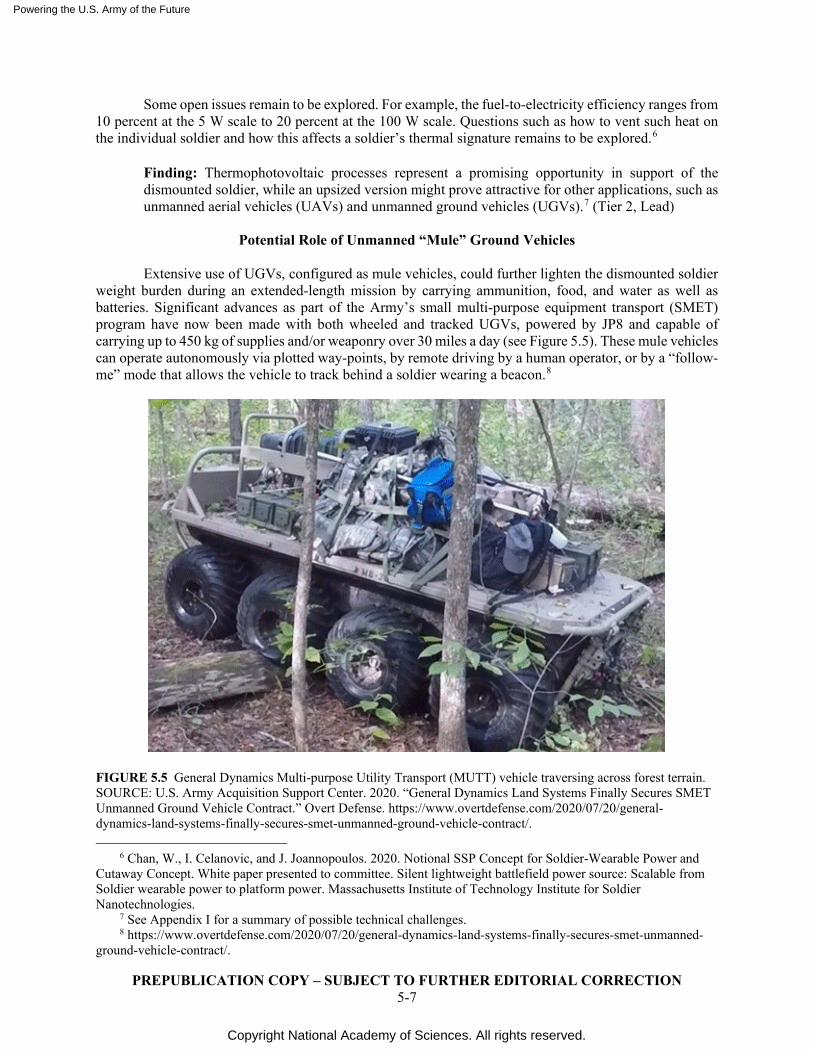
Powering the U.S. Army of the Future
Copyright National Academy of Sciences. All rights reserved.
PREPUBLICATION COPY – SUBJECT TO FURTHER EDITORIAL CORRECTION 5-7
Some open issues remain to be explored. For example, the fuel-to-electricity efficiency ranges from 10 percent at the 5 W scale to 20 percent at the 100 W scale. Questions such as how to vent such heat on the individual soldier and how this affects a soldier’s thermal signature remains to be explored.6
Finding: Thermophotovoltaic processes represent a promising opportunity in support of the dismounted soldier, while an upsized version might prove attractive for other applications, such as unmanned aerial vehicles (UAVs) and unmanned ground vehicles (UGVs).7 (Tier 2, Lead)
Potential Role of Unmanned “Mule” Ground Vehicles
Extensive use of UGVs, configured as mule vehicles, could further lighten the dismounted soldier
weight burden during an extended-length mission by carrying ammunition, food, and water as well as batteries. Significant advances as part of the Army’s small multi-purpose equipment transport (SMET) program have now been made with both wheeled and tracked UGVs, powered by JP8 and capable of carrying up to 450 kg of supplies and/or weaponry over 30 miles a day (see Figure 5.5). These mule vehicles can operate autonomously via plotted way-points, by remote driving by a human operator, or by a “follow-me” mode that allows the vehicle to track behind a soldier wearing a beacon.8
FIGURE 5.5 General Dynamics Multi-purpose Utility Transport (MUTT) vehicle traversing across forest terrain. SOURCE: U.S. Army Acquisition Support Center. 2020. “General Dynamics Land Systems Finally Secures SMET Unmanned Ground Vehicle Contract.” Overt Defense. https://www.overtdefense.com/2020/07/20/general-dynamics-land-systems-finally-secures-smet-unmanned-ground-vehicle-contract/.
6 Chan, W., I. Celanovic, and J. Joannopoulos. 2020. Notional SSP Concept for Soldier-Wearable Power and
Cutaway Concept. White paper presented to committee. Silent lightweight battlefield power source: Scalable from Soldier wearable power to platform power. Massachusetts Institute of Technology Institute for Soldier Nanotechnologies.
7 See Appendix I for a summary of possible technical challenges. 8 https://www.overtdefense.com/2020/07/20/general-dynamics-land-systems-finally-secures-smet-unmanned-
ground-vehicle-contract/.
Powering the U.S. Army of the Future
Copyright National Academy of Sciences. All rights reserved.
PREPUBLICATION COPY – SUBJECT TO FURTHER EDITORIAL CORRECTION 5-8
From a P&E standpoint, the impact of these mule vehicles on dismounted soldiers could be quite significant, providing a mobile station to recharge batteries for radios and similar devices directly from the vehicle. Each SMET is capable of generating 3 kW of electric power when stationary and 1 kW while moving.9
Interestingly, the Army is already working with an outside company to integrate a full 10 kW JP8-based solid-oxide fuel cell (SOFC) power system with reformer into a SMET vehicle in 2021. The 10 kW fuel cell is the primary propulsion, hybridized with a battery. A fuel-to-electricity efficiency (including reformer losses) is estimated to be between 30 and 40 percent. This program will demonstrate the capability of full-time silent electrical power generation from JP8.10 There are also larger unmanned vehicles under development now that could export even greater levels of electrical power. Examples include an Expeditionary Modular Autonomous Vehicle (EMAV) and a Robotic Combat Vehicle Light (RCV-L), both of which can export up to 30 kW of electrical power.11
By periodically swapping an individual dismounted soldier’s rechargeable batteries with an extra set of batteries being recharged and carried on the SMET while it moves, it would no longer be necessary for an individual soldier to carry more than a day or two’s worth of batteries.
Finding: Extensive use of “mule vehicles” from the Army’s SMET program provide an opportunity to recharge soldier batteries on the battlefield while lightening their weight burden, carrying ammunition, fuel, and water as well as batteries. (Tier 1, Lead)
SMALL POWER FUEL CELLS
DoD and Army agencies generally fund the development of small SOFC power systems for operation on logistic fuels under Small Business Innovation Research (SBIR) and Small Business Technology Transfer (STTR) programs. Examples of such programs in the past include the following: design and demonstration of small (250 to 350 W) SOFC units for soldiers, UAVs and UAGs, and communication devices, utilizing microtubular SOFCs with propane, butane, or LPG fuel (Adaptive Energy, Ann Arbor, MI); small fuel-cell power systems for use on the iRobot PackBot military robot used by the Army for dangerous tasks, including examining mines and checkpoints, to extend the operational time from 2 h to more than 10 h (Adaptive Energy, Ann Arbor, MI); and small SOFC power systems for portable, remote, and mobile applications operating on liquid fuels such as butanol, gasoline, kerosene, and desulfurized JP8 (Protonex Technology, MA).
Examples of current research solicitations by Army agencies include development of a lightweight, vibration-tolerant SOFC power system capable of high cycle life and rapid start up; development and integration of innovative materials and technologies to enable lowering the operating temperature of SOFCs to 300–600°C; and development of a man-portable 2 kW SOFC system to power robotic vehicles, ground vehicle auxiliary systems, and exoskeletons.12
9 GDLS awarded U.S. Army contract for Increment I of S-MET Small Multipurpose Equipment Transport
program, Army Recognition. Accessed December, 2020. https://www.armyrecognition.com/defense_news_july_2020_global_security_army_industry/gdls_awarded_u.s._army_contract_for_increment_i_of_s-met_small_multipurpose_equipment_transport_program.html.
10 Centeck, K. 2020. U.S. Army Ground Vehicle Systems Center. Email exchange with committee member. 11 Aerospace Manufacturing and Design. 2015. Pratt & Whitney AM engine parts poised for entry into service.
https://www.aerospacemanufacturinganddesign.com/article/pratt-whitney-additive-parts-engine-040615/. 12 See https://www.sbir.gov/node/1605929.13 Howell, John P. 2017. Magnuson, S. 2017. Fuel Cells Fail to
Make Inroads With the Military (UPDATED). Stated at the National Defense Industrial Association’s Joint Power Expo. https://www.nationaldefensemagazine.org/articles/2017/5/26/fuel-cells-fail-to-make-inroads-with-the-military.
Powering the U.S. Army of the Future
Copyright National Academy of Sciences. All rights reserved.
PREPUBLICATION COPY – SUBJECT TO FURTHER EDITORIAL CORRECTION 5-9
The Army has experimented with a 20 W soldier-wearable proton-exchange membrane (PEM) fuel-cell system with hydrogen fuel supplied from an alane (AlH3) cartridge for charging batteries. Similar 300 W systems have also been investigated by the Army to recharge Army mobile batteries. Such lightweight, nearly silent, fuel cell systems for battery charging can reduce the battery load carried by a soldier. The Army is also exploring the use of such systems for UAVs and UAGs.
Unfortunately, to date, fuel cells have not met expectations for the powerpacks carried by dismounted soldiers, according to officials at the National Defense Industry Association. “Fuel-cell technology has come a very long way and it’s something we are looking at,” said John P. Howell, project director of soldier systems integration at the Army’s project manager soldier warrior office.13 But fuel cells intended to be worn by dismounted troops currently are not providing enough energy to justify the extra weight, he said.
Conclusion: Further studies of dismounted soldier SOFC fuel cells utilizing propane, methanol, and other non-JP8 hydrocarbon fuels are not recommended beyond the work presently under way. This position might change under two scenarios. The first is that the field-implementable batch processing to desulfurize JP8 proves feasible to the 1 ppm level necessary for SOFCs. The second is that the point-of-use generation of hydrogen using activated aluminum or from hydrides such as alane (aluminum hydride) proves to be viable and practical, making possible the use of PEM fuel cells. (Tier 2, Watch)
NUCLEAR DECAY DEVICES
Radioactive materials offer extremely high energy density, providing constant, albeit relatively low, power for periods of decades (see Figure 5.6). Nuclear betavoltaics have demonstrated the capability to use electrons emitted from decaying nuclei directly to provide a current in a semiconductor. Current Army research hopes to create betavoltaic devices with power densities comparable to current low-power batteries before 2035. Meanwhile, there is utility in hybrid battery-radioisotope power systems. For higher power, long-duration applications, where personnel are not exposed to potential safety concerns, radioisotope thermoelectric generators (RTGs) are a proven option.
Combining a rechargeable battery with a low-power radioisotope source enables high-power operation within the energy capacity of the battery, followed by self-recharging using the constant low power available from the radionuclide source. This arrangement not only enables indefinite unattended operation for automated vehicles and sensors with short intervals of high power consumption, but can supplement other battery installations, allowing self-recharge when the time is available and reducing generator power requirements for recharging when it is not.
Incorporation of radioisotope sources entails accounting for heat produced by the radioactive materials in the design. In some environments, the excess heat might be welcome, in others, quite the opposite. Some materials, such as strontium-90, come with higher safety risks if dispersed, because of longer residence times when taken into a human body. Such materials could still be acceptable for unattended applications but should carry extra protection against dispersal of the radioactive material.14
13 Howell, John P. 2017. Magnuson, S. 2017. Fuel Cells Fail to Make Inroads With the Military (UPDATED).
Stated at the National Defense Industrial Association’s Joint Power Expo. https://www.nationaldefensemagazine.org/articles/2017/5/26/fuel-cells-fail-to-make-inroads-with-the-military.
14 Litz, M., R. Tompkins, S. Kelley, I. Kierzewski, C. Pullen. 2020. Radioisotope Power Sources - Technology and Applications: Maximizing Beta Interactions in Textured Energy Converters. Presentation to the study committee. U.S. Army Combat Capabilities Development Command (CCDC), Army Research Laboratory (ARL).
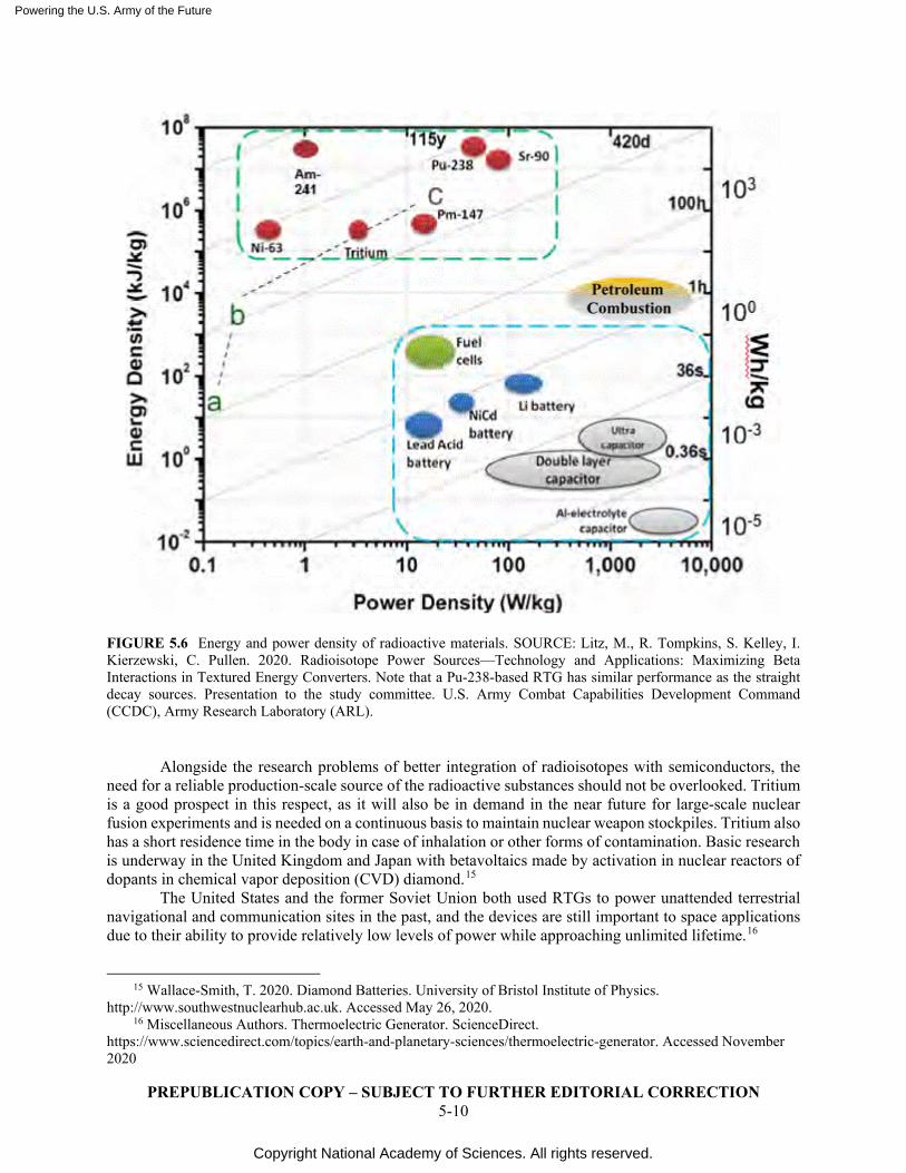
Powering the U.S. Army of the Future
Copyright National Academy of Sciences. All rights reserved.
PREPUBLICATION COPY – SUBJECT TO FURTHER EDITORIAL CORRECTION 5-10
FIGURE 5.6 Energy and power density of radioactive materials. SOURCE: Litz, M., R. Tompkins, S. Kelley, I. Kierzewski, C. Pullen. 2020. Radioisotope Power Sources—Technology and Applications: Maximizing Beta Interactions in Textured Energy Converters. Note that a Pu-238-based RTG has similar performance as the straight decay sources. Presentation to the study committee. U.S. Army Combat Capabilities Development Command (CCDC), Army Research Laboratory (ARL).
Alongside the research problems of better integration of radioisotopes with semiconductors, the need for a reliable production-scale source of the radioactive substances should not be overlooked. Tritium is a good prospect in this respect, as it will also be in demand in the near future for large-scale nuclear fusion experiments and is needed on a continuous basis to maintain nuclear weapon stockpiles. Tritium also has a short residence time in the body in case of inhalation or other forms of contamination. Basic research is underway in the United Kingdom and Japan with betavoltaics made by activation in nuclear reactors of dopants in chemical vapor deposition (CVD) diamond.15
The United States and the former Soviet Union both used RTGs to power unattended terrestrial navigational and communication sites in the past, and the devices are still important to space applications due to their ability to provide relatively low levels of power while approaching unlimited lifetime.16
15 Wallace-Smith, T. 2020. Diamond Batteries. University of Bristol Institute of Physics.
http://www.southwestnuclearhub.ac.uk. Accessed May 26, 2020. 16 Miscellaneous Authors. Thermoelectric Generator. ScienceDirect.
https://www.sciencedirect.com/topics/earth-and-planetary-sciences/thermoelectric-generator. Accessed November 2020
Powering the U.S. Army of the Future
Copyright National Academy of Sciences. All rights reserved.
PREPUBLICATION COPY – SUBJECT TO FURTHER EDITORIAL CORRECTION 5-11
Multi-domain operations will involve a proliferated network of persistent and mobile unattended sensors, processors, and communication devices. Radioisotope-driven power sources could enable long-lived persistent smart sensors—part of the incessant drive toward broad awareness (the Internet of Things [IoT], 5G, etc.)—where periodic battery replacement would become impractical.17
Successful device integration requires advancements in energy storage/power management (constant source, variable load); thermal management (especially stealthy heat rejection schema) to minimize signature; and advances in device energy efficiency and energy management (e.g., pulse communication) to utilize minimal power levels. While very small radiation sources have become routine in such applications as smoke detectors, larger quantities needed to produce useful electrical power would imply greater tracking, monitoring, and recovery protocols to avoid creating situations such as civilian discovery and unwitting radiation exposure from abandoned devices—as occurred in former Soviet Georgia in 2001.18
Dismounted Soldiers represent the greatest operational challenge in terms of enhancing capabilities without degrading capacity. Small radioisotopic power sources could extend Soldier endurance, for example, by charging batteries on the move, regardless of geography, weather, or time of day. The constant power-production aspect would require development of integrated energy management technologies, including electrical/thermal management, energy storage, flexible heat rejection methods, and signature mitigation. Moreover, while Soldiers already carry sensitive items such as weapons and communication devices, automated large-scale, real-time security/accountability methodologies would be important as in the case of unattended devices. From an energy-physics standpoint, development of a hybrid nuclear Soldier power device might involve investigation of phase change (thermal) versus capacitive (electrostatic) or battery (electrochemical) energy storage combinations; heat pipe, nanotube, or other small, flexible heat-transmission technologies; and novel (low observable) heat-sink geometries combined with emissivity-tuned coatings.
Modular architectures have been proposed to connect individual RTGs in a manner similar to electrochemical cells. Such a concept would allow for “stacking” of individual nuclear power supplies to support squad or platoon equipment when halted. Such a concept would require engineering and possibly research in order to enable both energy integration (especially cooling) of the modular unit and security, safety, and accountability issues.
It should be noted that the Army is already planning a 6.1 project from now through fiscal year 2025 entitled “Fundamentals for Alternative Energy Applied Physics Research.” It entails “developing new methods for efficiently transforming energy-storing radioisotopes into a faster-release form for high power output.”19
Conclusion: The current level of study and development is appropriate to identify applications where a lightweight radioisotope decay system possibly coupled with a rechargeable battery could provide adequate power for present and future demands of the dismounted soldier. (Tier 2, Lead).
17 Walton, R., C. Anthony, M. Ward, N. Metje, D.N. Chapman. 2013. Radioisotopic battery and capacitor
system for powering Wireless Sensor Networks. Sensors and Actuators A: Physical 203, 405–412. https://www.sciencedirect.com/science/article/abs/pii/S0924424713004548.
18 NTI. 2002. Radiothermal Generators Containing Strontium-90 Discovered in Liya, Georgia. http://nti.org/4606A. https://www.nti.org/analysis/articles/radiothermal-generators-containing-strontium-90-discovered-liya-georgia.
19 Schihl, P. 2020. Spreadsheet provided to individual committee member. U.S. Army CCDC Ground Vehicle Systems Center.
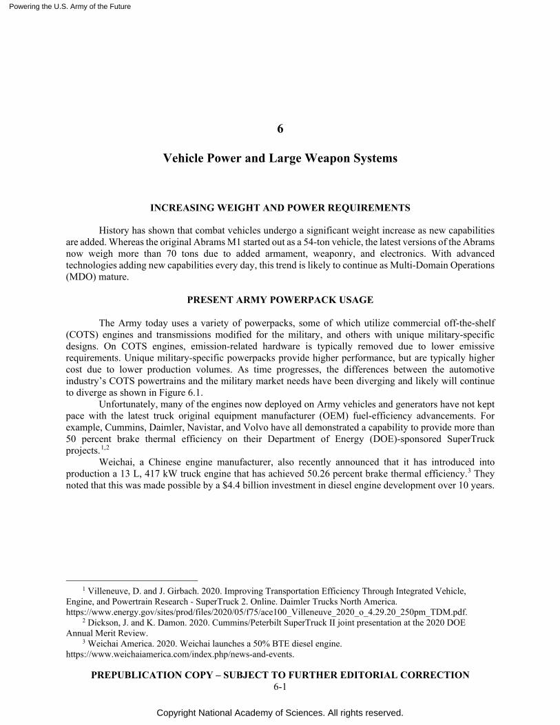
Powering the U.S. Army of the Future
Copyright National Academy of Sciences. All rights reserved.
PREPUBLICATION COPY – SUBJECT TO FURTHER EDITORIAL CORRECTION 6-1
6
Vehicle Power and Large Weapon Systems
INCREASING WEIGHT AND POWER REQUIREMENTS
History has shown that combat vehicles undergo a significant weight increase as new capabilities are added. Whereas the original Abrams M1 started out as a 54-ton vehicle, the latest versions of the Abrams now weigh more than 70 tons due to added armament, weaponry, and electronics. With advanced technologies adding new capabilities every day, this trend is likely to continue as Multi-Domain Operations (MDO) mature.
PRESENT ARMY POWERPACK USAGE
The Army today uses a variety of powerpacks, some of which utilize commercial off-the-shelf
(COTS) engines and transmissions modified for the military, and others with unique military-specific designs. On COTS engines, emission-related hardware is typically removed due to lower emissive requirements. Unique military-specific powerpacks provide higher performance, but are typically higher cost due to lower production volumes. As time progresses, the differences between the automotive industry’s COTS powertrains and the military market needs have been diverging and likely will continue to diverge as shown in Figure 6.1. Unfortunately, many of the engines now deployed on Army vehicles and generators have not kept pace with the latest truck original equipment manufacturer (OEM) fuel-efficiency advancements. For example, Cummins, Daimler, Navistar, and Volvo have all demonstrated a capability to provide more than 50 percent brake thermal efficiency on their Department of Energy (DOE)-sponsored SuperTruck projects.1,2
Weichai, a Chinese engine manufacturer, also recently announced that it has introduced into production a 13 L, 417 kW truck engine that has achieved 50.26 percent brake thermal efficiency.3 They noted that this was made possible by a $4.4 billion investment in diesel engine development over 10 years.
1 Villeneuve, D. and J. Girbach. 2020. Improving Transportation Efficiency Through Integrated Vehicle,
Engine, and Powertrain Research - SuperTruck 2. Online. Daimler Trucks North America. https://www.energy.gov/sites/prod/files/2020/05/f75/ace100_Villeneuve_2020_o_4.29.20_250pm_TDM.pdf.
2 Dickson, J. and K. Damon. 2020. Cummins/Peterbilt SuperTruck II joint presentation at the 2020 DOE Annual Merit Review.
3 Weichai America. 2020. Weichai launches a 50% BTE diesel engine. https://www.weichaiamerica.com/index.php/news-and-events.
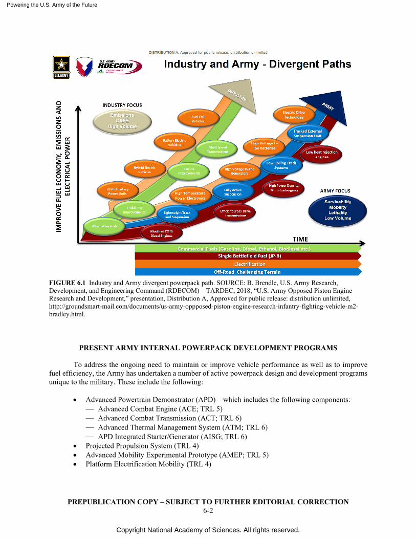
Powering the U.S. Army of the Future
Copyright National Academy of Sciences. All rights reserved.
PREPUBLICATION COPY – SUBJECT TO FURTHER EDITORIAL CORRECTION 6-2
FIGURE 6.1 Industry and Army divergent powerpack path. SOURCE: B. Brendle, U.S. Army Research, Development, and Engineering Command (RDECOM) – TARDEC, 2018, “U.S. Army Opposed Piston Engine Research and Development,” presentation, Distribution A, Approved for public release: distribution unlimited, http://groundsmart-mail.com/documents/us-army-oppposed-piston-engine-research-infantry-fighting-vehicle-m2-bradley.html.
PRESENT ARMY INTERNAL POWERPACK DEVELOPMENT PROGRAMS
To address the ongoing need to maintain or improve vehicle performance as well as to improve fuel efficiency, the Army has undertaken a number of active powerpack design and development programs unique to the military. These include the following:
• Advanced Powertrain Demonstrator (APD)—which includes the following components:
— Advanced Combat Engine (ACE; TRL 5) — Advanced Combat Transmission (ACT; TRL 6) — Advanced Thermal Management System (ATM; TRL 6) — APD Integrated Starter/Generator (AISG; TRL 6)
• Projected Propulsion System (TRL 4) • Advanced Mobility Experimental Prototype (AMEP; TRL 5) • Platform Electrification Mobility (TRL 4)
Powering the U.S. Army of the Future
Copyright National Academy of Sciences. All rights reserved.
PREPUBLICATION COPY – SUBJECT TO FURTHER EDITORIAL CORRECTION 6-3
Each of these programs will enhance the power density, fuel efficiency, and/or thermal signature of military powerpacks. Additional information regarding the content and functional benefits of each of the above programs is contained in Chapter 8, “Fuel Conversion Efficiency and Other Material Driven Opportunities.”
Recommendation: The Army has undertaken a number of internal vehicle power plant programs (Advanced Powertrain Demonstrator, Projected Propulsion System, Advanced Mobility Experimental Prototype, and Platform Electrification Mobility) that will significantly enhance the Army’s operational capabilities in a Multi-Domain Operations environment. The committee recommends that their funding and timing continue as presently planned.
U.S.-JAPAN PROJECT AGREEMENT STRYKER
The Army’s Ground Vehicle Systems Center (GVSC) also will be executing a parallel hybrid Stryker architecture building off of the Vehicle Electric Architecture (VEA) Mobile Demonstrator (VMD)/Advanced Propulsion with On-board Power (APOP II) development. Development of this hybrid system is part of a U.S./Japan Project Agreement that will launch in 2021. It adds a clutch, high-voltage energy storage (about 350V DC), and DC/DC converter to move power between the high-voltage energy storage and the 600 VDC vehicle power bus. The system is expected to provide approximately 3 miles of silent mobility, 40 percent improved acceleration, 30–35 percent reduced fuel use, and 15 percent improved speed on grade.4
JP8/DIESEL FLEX FUEL CAPABILITY (AN OPPORTUNITY TO SHORTEN THE FUEL SUPPLY LINE)
With funding, the technology exists today that would make it possible to design an internal combustion engine that provides optimal operation while running with a variety of fuels. One of the simplest capabilities to implement would be adding a capability to run DF1 diesel, DF2 diesel, and/or biodiesel fuels on an engine designed for JP8. Because of the different cetane values, density, and energy content of these fuels, closed-loop combustion control of fuel injection timing and quantity (or air/fuel ratio) would make this possible. One approach popular within today’s automotive market is to use control algorithms based on reading from in-cylinder pressure sensors.5 In addition, the Army’s Vehicle Technologies Office, is studying alternative, less intrusive (and possibly more reliable) approaches to determine the start of combustion, including use of knock/accelerometer sensors and crankshaft acceleration measurements. Feasibility for such alternatives has not yet been demonstrated.
Because DF2 has roughly 9 percent more energy content by volume than JP8, in battlefield situations where climatic conditions allow use of DF2, roughly 9 percent less fuel would need to be transported to complete a given mission with DF2 than JP8. In addition, by optimizing the injection timing and mass fraction burned as a function of crank angle for any fuel used, the engine’s torque, fuel efficiency, and cold-start capability would be enhanced. As a result, the range of each ground combat vehicle would be increased by more than the above cited 9 percent. Lastly, it may be possible to find local sources of DF2 on or near the battlefield, shortening the supply line even further.
It should be noted that one concern with locally supplied diesel is the amount of biodiesel it contains. Given studies done by OEMs and the major diesel injector suppliers, percentages up to 20 percent
4 McGrew, D. 2020. Email exchange with individual committee member. U.S. Army CCDC Ground Vehicle
Systems Center. 5 Such systems are available on Audi, Opel, Isuzu, and Volkswagen vehicles.
Powering the U.S. Army of the Future
Copyright National Academy of Sciences. All rights reserved.
PREPUBLICATION COPY – SUBJECT TO FURTHER EDITORIAL CORRECTION 6-4
should not be of concern, provided they are not stored for more than a year.6 However, in some overseas markets, biodiesel percentages exceed this. In such cases, the Army could revert to its presently planned JP8 use.
Conclusion: The use of DF2 in lieu of JP8 could reduce the fuel supply line due to its higher energy density, which would decrease the number resupply missions required to sustain the operational units. Although this violates the Army’s present “single fuel policy” and will present some added logistics complexity challenges, further consideration by the Army is warranted. (Tier 1, Lead) Recommendation: The Army should consider using closed-loop combustion control in all new engine designs as these engines, properly calibrated, could allow seamless operation between jet propellant 8 (JP8), diesel, and biodiesel while simultaneously increasing fuel efficiency while using JP8. (Tier 1, Lead)
JP8/GASOLINE FLEX FUEL CAPABILITY
Adding a capability to run gasoline to the list of allowable fuels for a compression ignition engine is also theoretically possible although difficult to implement. Multiple industry efforts are under way on gasoline compression ignition (GCI), including one sponsored by DOE’s Advanced Research Projects Agency-Energy (ARPA-E).7 GCI studies are also part of Navistar’s SuperTruck program.8 The same direct fuel injection system could be used for JP8, diesel, and gasoline. When running gasoline, a higher compression ratio would be desirable than when running diesel because of the latter’s reduced ignitability. Several approaches to vary compression ratio in a running engine now exist. As one example, Infiniti has a continuously variable system in production. As another, Germany’s IWIS Group has a simpler “bang/bang” compression ratio system going into production in 2023.9
Another approach that might enable use of gasoline in a diesel engine without modifying the compression ratio is to use spark plug assistance. Mazda’s Skyactive-X spark-assisted gasoline compression ignition engine provides such an example, with its 16.3:1 compression ratio. Potentially, use of Tenneco’s Advanced Corona Ignition system, which provides 25 mm–long ionized streamers to initiate ignition might provide some added capability.10
Both modifications (i.e., changing compression ratio or adding spark ignition) would require new engine designs. The benefits of fuel flexibility between JP8 and gasoline also may not be that significant, because it is likely that locally procured diesel is available in most world markets wherever locally procured gasoline would be available.
For unmanned aircraft systems, the Army is presently studying what is called a “variable energy–assisted ignition assistant.” Essentially, it consists of a temperature-controlled glow plug that is energized throughout the engine’s operation. A hot surface is created that assists autoignition of one of the diesel injector plumes, which in turn creates the added pressure and temperature needed to ignite the other plumes.
6 Alleman, T., R.L. McCormick, E.D. Christensen, G. Fioroni, K. Moriarty, and J. Yanowitz. 2016. Biodiesel
Handling and Use Guide (Fifth Edition). U.S. Department of Energy. https://afdc.energy.gov/files/u/publication/biodiesel_handling_use_guide.pdf.
7 ARPA-e. 2015. Efficient Engine Design. Online. Achates Power. https://arpa-e.energy.gov/technologies/projects/efficient-engine-design.
8 Cigler, J., D. Oppermann. 2020. Navistar SuperTruck II: Development and Demonstration of a Fuel-Efficient Class 8 Tractor & Trailer. Presented at the 2020 Department of Energy Merit Review. Navistar, Inc. https://www.energy.gov/sites/prod/files/2020/05/f75/ace103_%20zukouski_2020_o_4.27.20_108PM_LR.pdf.
9 IWIS. 2020. Dual Mode VCS. https://www.dual-mode-vcs.com/en. Accessed November 2020. 10 Tenneco Powertrain. Undated. ACIS - Advanced Corona Ignition System. http://www.federalmogul.com/en-
US/OE/Products/Pages/Product-Details.aspx?CategoryId=15&SubCategoryId=21&ProductId=224. Accessed November 2020.
Powering the U.S. Army of the Future
Copyright National Academy of Sciences. All rights reserved.
PREPUBLICATION COPY – SUBJECT TO FURTHER EDITORIAL CORRECTION 6-5
This ignition assist may enhance the ability to use gasoline and other low cetane fuels under high-altitude pressure and temperature conditions.
Conclusion: It is possible with substantial changes to design an engine that can run gasoline or diesel fuel interchangeability; however, the operational advantages such a capability would provide are judged to be small.
OTHER POTENTIAL JP8/GASEOUS-ICE FUEL AND FLEX-FUEL APPLICATIONS
Adding a capability to run propane, compressed natural gas/methane, or hydrogen in the same engine as JP8 is also possible. Each gaseous fuel is introduced to the engine with low pressure either in the intake manifold or engine intake ports or high pressure directly into the combustion chamber. Combustion is initiated either with a spark plug (or possibly two) in the combustion chamber combined with a high-energy ignition system or with a diesel pilot injection. Challenges that need to be addressed include possible incomplete combustion at light loads and possible knock/detonation at higher loads.
Wartsila, MAN Energy Systems, and Fairbanks-Morse already have dual-fuel (diesel and gas) engines in production, albeit in larger engines used for stationary power. The earliest of these were introduced back in 1995.11,12,13
Conclusion: Although technically possible, given the lower energy density of gaseous fuels and associated transport concerns, it is not recommended that mobile JP8/gaseous dual fuel engines be pursued.
FREE-PISTON ENGINES
A free-piston engine is a linear internal combustion engine in which the piston motion is not controlled by a crankshaft but instead determined by the interaction of forces from combustion chamber gases, an oscillator or rebound device (e.g., a gas spring chamber), and a linear alternator (see Figure 6.2).
Attractive features of a free-piston engine include the following: (1) direct conversion of piston motion into electrical energy, (2) no frictional losses from crank-slider and generator mechanisms, (3) reduced power cylinder losses because no side forces are exerted on the piston by a connecting rod, (4) variable compression ratio, and (5) electrical energy capture on both the compression and expansion strokes.
Historically, challenges arose with precisely controlling the piston’s position, which now is overcome with newer control systems. A number of companies are presently looking to commercialize this technology. Toyota is looking at using this technology as a range extender in a gasoline or diesel-powered passenger car application.14 Toyota says this mechanically simple engine achieves a claimed gasoline thermal-efficiency rating of 42 percent in continuous use, which compares favorably with the best gasoline engines under development today. As a two-cylinder engine, the free-piston engine is inherently balanced with a size of roughly 8 in. around and 2 ft long. An engine of that size and type could generate roughly 11 kW, enough to move a compact electric vehicle at highway speeds after its main drive battery has been depleted.
11 Wärtsilä. Undated. Dual-Fuel Engines from Wärtsilä. https://www.wartsila.com/encyclopedia/term/dual--
fuel-engines-from-w%C3%A4rtsil%C3%A4. Accessed January 2021. 12 Ibid. 13 Ibid. 14 Available at https://www.roadandtrack.com/car-culture/a6326/out-of-turn-toyota-engine.
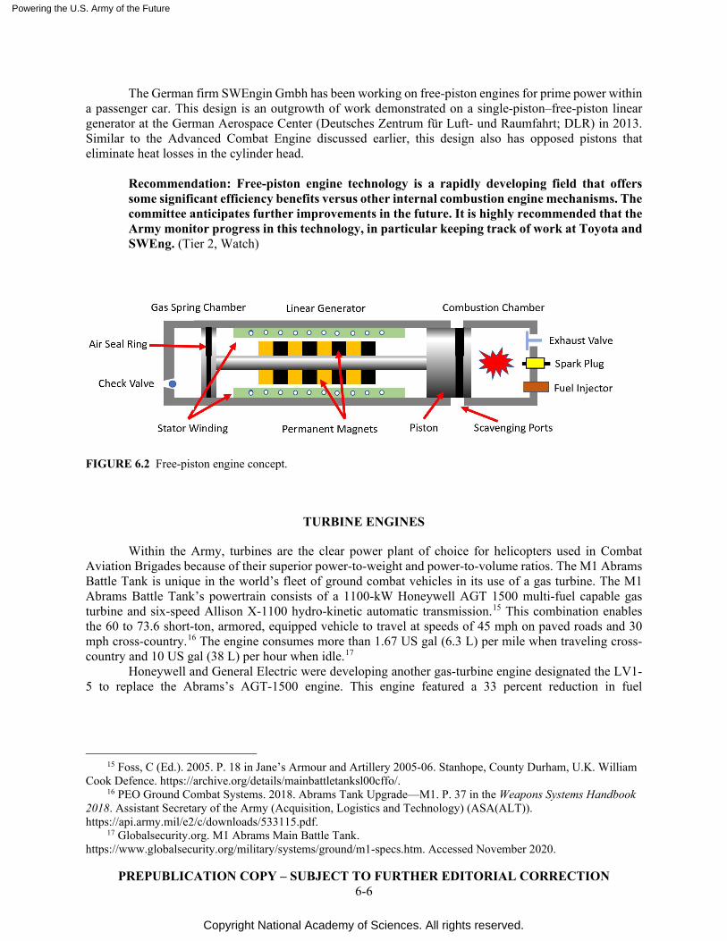
Powering the U.S. Army of the Future
Copyright National Academy of Sciences. All rights reserved.
PREPUBLICATION COPY – SUBJECT TO FURTHER EDITORIAL CORRECTION 6-6
The German firm SWEngin Gmbh has been working on free-piston engines for prime power within a passenger car. This design is an outgrowth of work demonstrated on a single-piston–free-piston linear generator at the German Aerospace Center (Deutsches Zentrum für Luft- und Raumfahrt; DLR) in 2013. Similar to the Advanced Combat Engine discussed earlier, this design also has opposed pistons that eliminate heat losses in the cylinder head.
Recommendation: Free-piston engine technology is a rapidly developing field that offers some significant efficiency benefits versus other internal combustion engine mechanisms. The committee anticipates further improvements in the future. It is highly recommended that the Army monitor progress in this technology, in particular keeping track of work at Toyota and SWEng. (Tier 2, Watch)
FIGURE 6.2 Free-piston engine concept.
TURBINE ENGINES
Within the Army, turbines are the clear power plant of choice for helicopters used in Combat Aviation Brigades because of their superior power-to-weight and power-to-volume ratios. The M1 Abrams Battle Tank is unique in the world’s fleet of ground combat vehicles in its use of a gas turbine. The M1 Abrams Battle Tank’s powertrain consists of a 1100-kW Honeywell AGT 1500 multi-fuel capable gas turbine and six-speed Allison X-1100 hydro-kinetic automatic transmission.15 This combination enables the 60 to 73.6 short-ton, armored, equipped vehicle to travel at speeds of 45 mph on paved roads and 30 mph cross-country.16 The engine consumes more than 1.67 US gal (6.3 L) per mile when traveling cross-country and 10 US gal (38 L) per hour when idle.17
Honeywell and General Electric were developing another gas-turbine engine designated the LV1-5 to replace the Abrams’s AGT-1500 engine. This engine featured a 33 percent reduction in fuel
15 Foss, C (Ed.). 2005. P. 18 in Jane’s Armour and Artillery 2005-06. Stanhope, County Durham, U.K. William
Cook Defence. https://archive.org/details/mainbattletanksl00cffo/. 16 PEO Ground Combat Systems. 2018. Abrams Tank Upgrade—M1. P. 37 in the Weapons Systems Handbook
2018. Assistant Secretary of the Army (Acquisition, Logistics and Technology) (ASA(ALT)). https://api.army.mil/e2/c/downloads/533115.pdf.
17 Globalsecurity.org. M1 Abrams Main Battle Tank. https://www.globalsecurity.org/military/systems/ground/m1-specs.htm. Accessed November 2020.
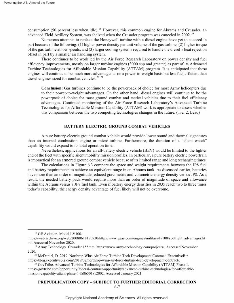
Powering the U.S. Army of the Future
Copyright National Academy of Sciences. All rights reserved.
PREPUBLICATION COPY – SUBJECT TO FURTHER EDITORIAL CORRECTION 6-7
consumption (50 percent less when idle).18 However, this common engine for Abrams and Crusader, an advanced Field Artillery System, was shelved when the Crusader program was canceled in 2002.19
Numerous attempts to replace the Honeywell turbine with a diesel engine have yet to succeed in part because of the following: (1) higher power density per unit volume of the gas turbine, (2) higher torque of the gas turbine at low speeds, and (3) larger cooling systems required to handle the diesel’s heat rejection offset in part by a smaller air handling system.
There continues to be work led by the Air Force Research Laboratory on power density and fuel efficiency improvements, mostly on larger turbine engines (3000 shp and greater) as part of its Advanced Turbine Technologies for Affordable Mission-Capability (ATTAM) program. It is anticipated that these engines will continue to be much more advantageous on a power-to-weight basis but less fuel efficient than diesel engines sized for combat vehicles.20 21
Conclusion: Gas turbines continue to be the powerpack of choice for most Army helicopters due to their power-to-weight advantages. On the other hand, diesel engines will continue to be the powerpack of choice for most ground combat and tactical vehicles due to their fuel efficiency advantages. Continued monitoring of the Air Force Research Laboratory’s Advanced Turbine Technologies for Affordable Mission-Capability (ATTAM) work is appropriate to assess whether this comparison between the two competing technologies changes in the future. (Tier 2, Lead)
BATTERY ELECTRIC GROUND COMBAT VEHICLES
A pure battery-electric ground combat vehicle would provide lower sound and thermal signatures than an internal combustion engine or micro-turbine. Furthermore, the duration of a “silent watch” capability would expand to its total operation time.
Nevertheless, applications for an all-battery electric vehicle (BEV) would be limited to the lighter end of the fleet with specific silent mobility mission profiles. In particular, a pure battery electric powertrain is impractical for an armored ground combat vehicle because of its limited range and long recharging times.
The calculations in Figure 6.3 compare the space and weight requirements between the JP8 fuel and battery requirements to achieve an equivalent range in an Abrams tank. As discussed earlier, batteries have more than an order of magnitude reduced gravimetric and volumetric energy density versus JP8. As a result, the needed battery pack would require more than an order of magnitude of space and allowance within the Abrams versus a JP8 fuel tank. Even if battery energy densities in 2035 reach two to three times today’s capability, the energy density advantage of fuel likely will not be overcome.
18 GE Aviation. Model LV100.
https://web.archive.org/web/20080618180930/http://www.geae.com/engines/military/lv100/spotlight_advantages.html. Accessed November 2020.
19 Army Technology. Crusader 155mm. https://www.army-technology.com/projects/. Accessed November 2020.
20 McDaniel, D. 2019. Northrop Wins Air Force Turbine Tech Development Contract. ExecutiveBiz. https://blog.executivebiz.com/2019/02/northrop-wins-air-force-turbine-tech-development-contract/.
21 GovTribe. Advanced Turbine Technologies for Affordable Mission Capability (ATTAM) Phase 1. https://govtribe.com/opportunity/federal-contract-opportunity/advanced-turbine-technologies-for-affordable-mission-capability-attam-phase-1-fa865018s2002. Accessed January 2021.
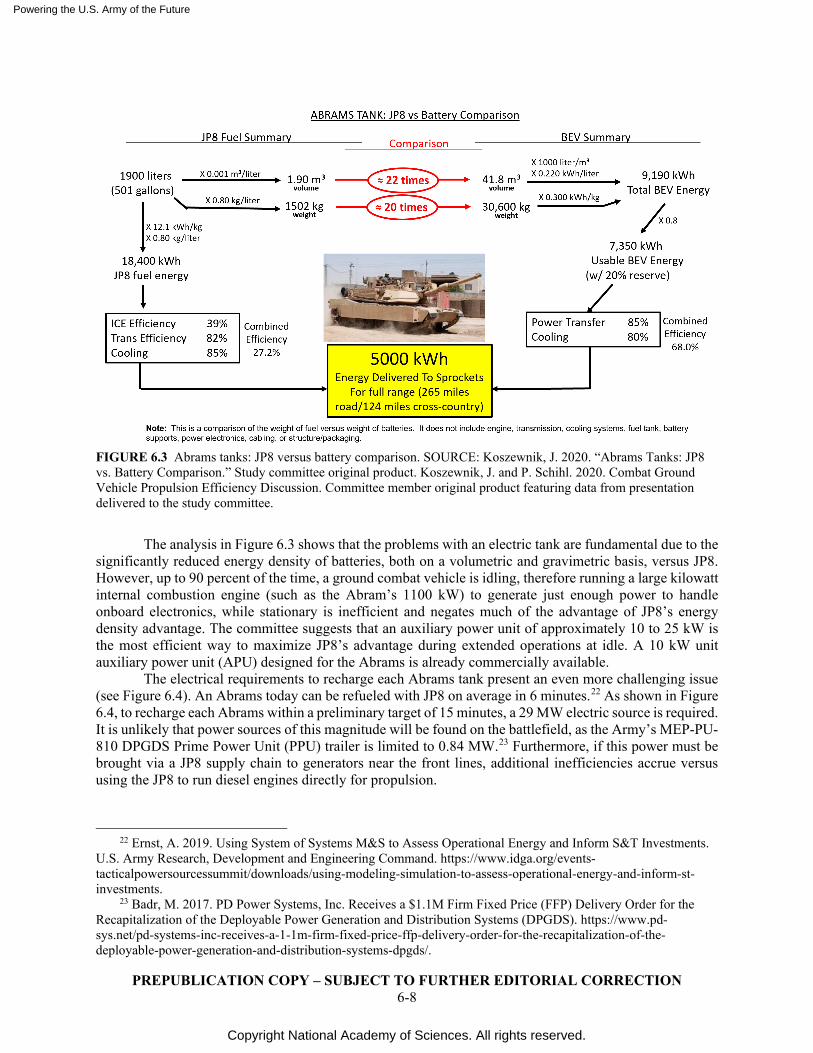
Powering the U.S. Army of the Future
Copyright National Academy of Sciences. All rights reserved.
PREPUBLICATION COPY – SUBJECT TO FURTHER EDITORIAL CORRECTION 6-8
FIGURE 6.3 Abrams tanks: JP8 versus battery comparison. SOURCE: Koszewnik, J. 2020. “Abrams Tanks: JP8 vs. Battery Comparison.” Study committee original product. Koszewnik, J. and P. Schihl. 2020. Combat Ground Vehicle Propulsion Efficiency Discussion. Committee member original product featuring data from presentation delivered to the study committee.
The analysis in Figure 6.3 shows that the problems with an electric tank are fundamental due to the significantly reduced energy density of batteries, both on a volumetric and gravimetric basis, versus JP8. However, up to 90 percent of the time, a ground combat vehicle is idling, therefore running a large kilowatt internal combustion engine (such as the Abram’s 1100 kW) to generate just enough power to handle onboard electronics, while stationary is inefficient and negates much of the advantage of JP8’s energy density advantage. The committee suggests that an auxiliary power unit of approximately 10 to 25 kW is the most efficient way to maximize JP8’s advantage during extended operations at idle. A 10 kW unit auxiliary power unit (APU) designed for the Abrams is already commercially available.
The electrical requirements to recharge each Abrams tank present an even more challenging issue (see Figure 6.4). An Abrams today can be refueled with JP8 on average in 6 minutes.22 As shown in Figure 6.4, to recharge each Abrams within a preliminary target of 15 minutes, a 29 MW electric source is required. It is unlikely that power sources of this magnitude will be found on the battlefield, as the Army’s MEP-PU-810 DPGDS Prime Power Unit (PPU) trailer is limited to 0.84 MW.23 Furthermore, if this power must be brought via a JP8 supply chain to generators near the front lines, additional inefficiencies accrue versus using the JP8 to run diesel engines directly for propulsion.
22 Ernst, A. 2019. Using System of Systems M&S to Assess Operational Energy and Inform S&T Investments.
U.S. Army Research, Development and Engineering Command. https://www.idga.org/events-tacticalpowersourcessummit/downloads/using-modeling-simulation-to-assess-operational-energy-and-inform-st-investments.
23 Badr, M. 2017. PD Power Systems, Inc. Receives a $1.1M Firm Fixed Price (FFP) Delivery Order for the Recapitalization of the Deployable Power Generation and Distribution Systems (DPGDS). https://www.pd-sys.net/pd-systems-inc-receives-a-1-1m-firm-fixed-price-ffp-delivery-order-for-the-recapitalization-of-the-deployable-power-generation-and-distribution-systems-dpgds/.
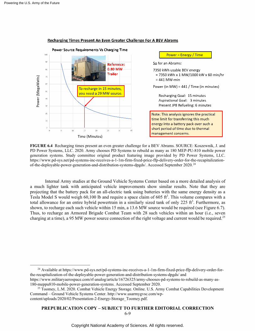
Powering the U.S. Army of the Future
Copyright National Academy of Sciences. All rights reserved.
PREPUBLICATION COPY – SUBJECT TO FURTHER EDITORIAL CORRECTION 6-9
FIGURE 6.4 Recharging times present an even greater challenge for a BEV Abrams. SOURCE: Koszewnik, J. and PD Power Systems, LLC. 2020. Army chooses PD Systems to rebuild as many as 180 MEP-PU-810 mobile power generation systems. Study committee original product featuring image provided by PD Power Systems, LLC. https://www.pd-sys.net/pd-systems-inc-receives-a-1-1m-firm-fixed-price-ffp-delivery-order-for-the-recapitalization-of-the-deployable-power-generation-and-distribution-systems-dpgds/. Accessed September 2020.24
Internal Army studies at the Ground Vehicle Systems Center based on a more detailed analysis of a much lighter tank with anticipated vehicle improvements show similar results. Note that they are projecting that the battery pack for an all-electric tank using batteries with the same energy density as a Tesla Model S would weigh 60,100 lb and require a space claim of 605 ft3. This volume compares with a total allowance for an entire hybrid powertrain in a similarly sized tank of only 225 ft3. Furthermore, as shown, to recharge each such vehicle within 15 min, a 13.6 MW source would be required (see Figure 6.7). Thus, to recharge an Armored Brigade Combat Team with 28 such vehicles within an hour (i.e., seven charging at a time), a 95 MW power source connection of the right voltage and current would be required.25
24 Available at https://www.pd-sys.net/pd-systems-inc-receives-a-1-1m-firm-fixed-price-ffp-delivery-order-for-
the-recapitalization-of-the-deployable-power-generation-and-distribution-systems-dpgds/ and https://www.militaryaerospace.com/rf-analog/article/16726325/army-chooses-pd-systems-to-rebuild-as-many-as-180-meppu810-mobile-power-generation-systems. Accessed September 2020.
25 Toomey, L.M. 2020. Combat Vehicle Energy Storage. Online. U.S. Army Combat Capabilities Development Command – Ground Vehicle Systems Center. http://www.usarmygvsc.com/wp-content/uploads/2020/02/Presentation-2-Energy-Storage_Toomey.pdf.
Powering the U.S. Army of the Future
Copyright National Academy of Sciences. All rights reserved.
PREPUBLICATION COPY – SUBJECT TO FURTHER EDITORIAL CORRECTION 6-10
FIGURE 6.5 All electric tank feasibility. SOURCE: Toomey, L.M. 2020. Combat Vehicle Energy Storage. Online. U.S. Army Combat Capabilities Development Command—Ground Vehicle Systems Center. Distribution A. http://www.usarmygvsc.com/wp-content/uploads/2020/02/Presentation-2-Energy-Storage_Toomey.pdf.
BATTERY ELECTRIC TACTICAL VEHICLES
Similar to the above conclusions for armored vehicles, all-electric tactical vehicles have limited practicality on the battlefield, given their recharging requirements. For example, as shown below, the committee’s analysis showed that each Joint Light Tactical Vehicle (JLTV) would require roughly a 2.6 MW power source to recharge within 15 minutes (see Figure 6.6). The Army has acknowledged this to be a major constraint on all-electric JLTV deployments.26
The Army is presently defining an All-Electric Powertrain (AECP) demonstrator, which is intended to leverage learning from present and planned battery electric vehicles, such as the Tesla Class 8 truck and the Advanced Mobility Experimental Prototype (AMEP) program mentioned earlier. Projected 6.2/6.3 funding in fiscal years 2023–2027 is $74 million.27
Conclusion: The power requirements to recharge the batteries of an all-electric armored ground combat vehicle make an all-electric design impractical. Because of lengthy recharging requirements and the requirement for extremely large electrical power sources, extensive use of battery electric tactical vehicles (including those in a supply convoy) also have limited practicality in a battlefield environment. The battery space requirements and additional weight limit effective all-battery vehicle use to select missions where silent operations are paramount and lengthy recharging times can be accommodated.
26 Koszewnik, J. and P. Schihl. 2020. Combat Ground Vehicle Propulsion Efficiency Discussion. Committee
member original product featuring data from presentation delivered to the study committee. 27 Schihl, P. 2020. Combat Ground Vehicle Propulsion Efficiency Discussion. Presentation to the study
committee, and email provided to individual committee member. U.S. Army CCDC Ground Vehicle Systems Center.
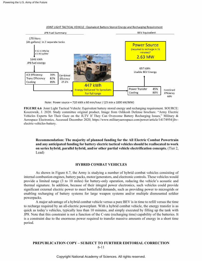
Powering the U.S. Army of the Future
Copyright National Academy of Sciences. All rights reserved.
PREPUBLICATION COPY – SUBJECT TO FURTHER EDITORIAL CORRECTION 6-11
FIGURE 6.6 Joint Light Tactical Vehicle: Equivalent battery stored energy and recharging requirement. SOURCE: Koszewnik, J. 2020. Study committee original product, Image from Oshkosh Defense brochure. “Army Electric Vehicles Experts Set Their Gaze on the JLTV If They Can Overcome Battery Recharging Issues,” Military & Aerospace Electronics, Accessed December 2020, https://www.militaryaerospace.com/power/article/14174954/jltv-electric-vehicles-battery.
Recommendation: The majority of planned funding for the All Electric Combat Powertrain and any anticipated funding for battery electric tactical vehicles should be reallocated to work on series hybrid, parallel hybrid, and/or other partial vehicle electrification concepts. (Tier 2, Lead)
HYBRID COMBAT VEHICLES
As shown in Figure 6.7, the Army is studying a number of hybrid combat vehicles consisting of internal combustion engines, battery packs, motor/generators, and electronic controls. These vehicles would provide a limited range (3 to 10 miles) for battery-only operation, reducing the vehicle’s acoustic and thermal signature. In addition, because of their integral power electronics, such vehicles could provide significant external electric power to meet battlefield demands, such as providing power to microgrids or enabling recharging of battery systems for large weapon systems and/or multiple dismounted soldier powerpacks.
A major advantage of a hybrid combat vehicle versus a pure BEV is in time to refill versus the time to recharge required by an all-electric powerplant. With a hybrid combat vehicle, the energy transfer is as quick as today’s vehicles, typically less than 10 minutes, and simply executed by filling up the tank with JP8. Note that this constraint is not a function of the C-rate (recharging time) capability of the batteries. It is a constraint due to the enormous power required to transfer massive amounts of energy in a short time period.
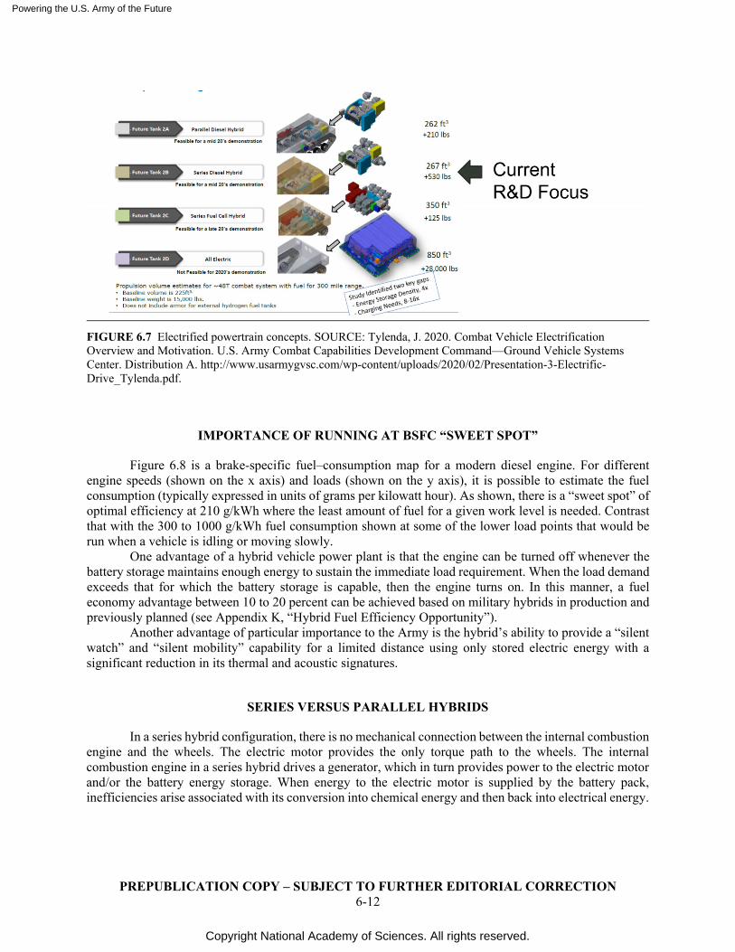
Powering the U.S. Army of the Future
Copyright National Academy of Sciences. All rights reserved.
PREPUBLICATION COPY – SUBJECT TO FURTHER EDITORIAL CORRECTION 6-12
FIGURE 6.7 Electrified powertrain concepts. SOURCE: Tylenda, J. 2020. Combat Vehicle Electrification Overview and Motivation. U.S. Army Combat Capabilities Development Command—Ground Vehicle Systems Center. Distribution A. http://www.usarmygvsc.com/wp-content/uploads/2020/02/Presentation-3-Electrific-Drive_Tylenda.pdf.
IMPORTANCE OF RUNNING AT BSFC “SWEET SPOT”
Figure 6.8 is a brake-specific fuel–consumption map for a modern diesel engine. For different engine speeds (shown on the x axis) and loads (shown on the y axis), it is possible to estimate the fuel consumption (typically expressed in units of grams per kilowatt hour). As shown, there is a “sweet spot” of optimal efficiency at 210 g/kWh where the least amount of fuel for a given work level is needed. Contrast that with the 300 to 1000 g/kWh fuel consumption shown at some of the lower load points that would be run when a vehicle is idling or moving slowly.
One advantage of a hybrid vehicle power plant is that the engine can be turned off whenever the battery storage maintains enough energy to sustain the immediate load requirement. When the load demand exceeds that for which the battery storage is capable, then the engine turns on. In this manner, a fuel economy advantage between 10 to 20 percent can be achieved based on military hybrids in production and previously planned (see Appendix K, “Hybrid Fuel Efficiency Opportunity”).
Another advantage of particular importance to the Army is the hybrid’s ability to provide a “silent watch” and “silent mobility” capability for a limited distance using only stored electric energy with a significant reduction in its thermal and acoustic signatures.
SERIES VERSUS PARALLEL HYBRIDS
In a series hybrid configuration, there is no mechanical connection between the internal combustion engine and the wheels. The electric motor provides the only torque path to the wheels. The internal combustion engine in a series hybrid drives a generator, which in turn provides power to the electric motor and/or the battery energy storage. When energy to the electric motor is supplied by the battery pack, inefficiencies arise associated with its conversion into chemical energy and then back into electrical energy.
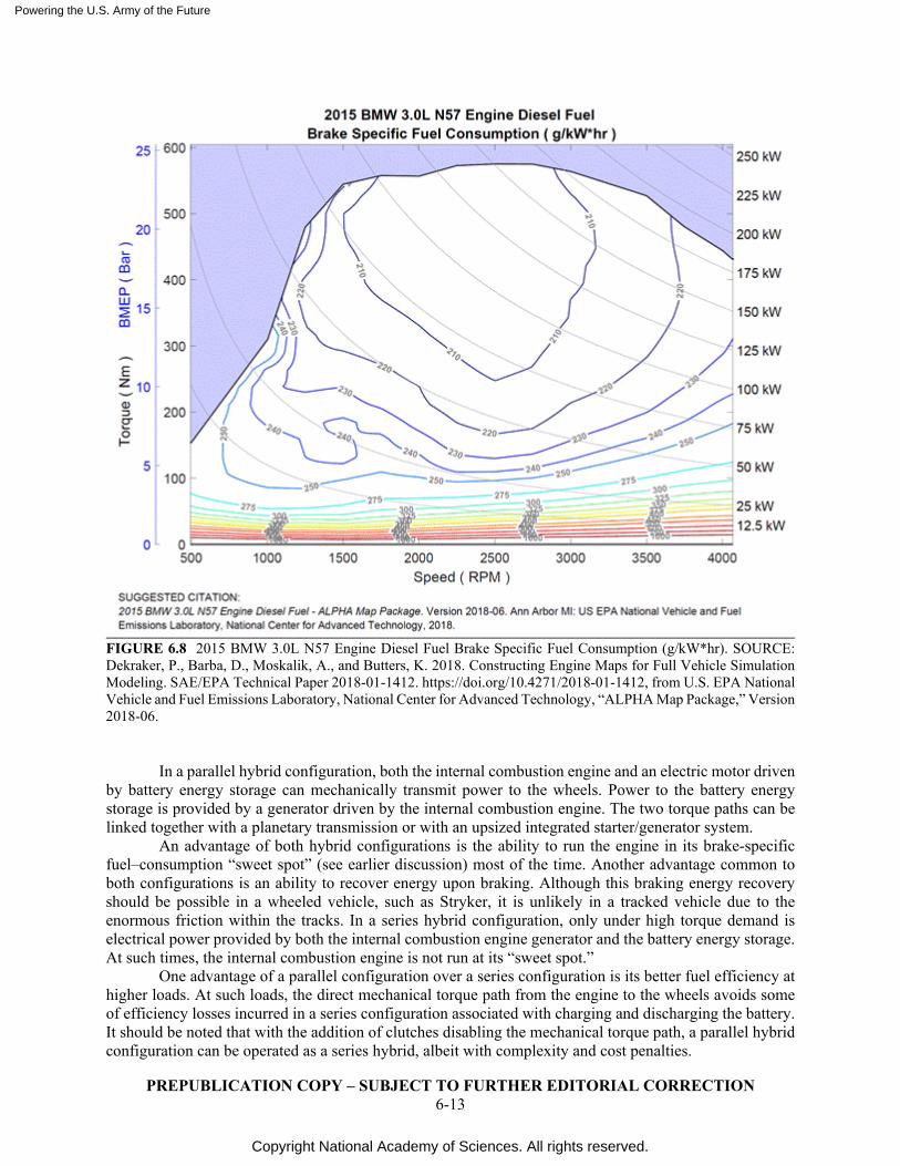
Powering the U.S. Army of the Future
Copyright National Academy of Sciences. All rights reserved.
PREPUBLICATION COPY – SUBJECT TO FURTHER EDITORIAL CORRECTION 6-13
FIGURE 6.8 2015 BMW 3.0L N57 Engine Diesel Fuel Brake Specific Fuel Consumption (g/kW*hr). SOURCE: Dekraker, P., Barba, D., Moskalik, A., and Butters, K. 2018. Constructing Engine Maps for Full Vehicle Simulation Modeling. SAE/EPA Technical Paper 2018-01-1412. https://doi.org/10.4271/2018-01-1412, from U.S. EPA National Vehicle and Fuel Emissions Laboratory, National Center for Advanced Technology, “ALPHA Map Package,” Version 2018-06.
In a parallel hybrid configuration, both the internal combustion engine and an electric motor driven by battery energy storage can mechanically transmit power to the wheels. Power to the battery energy storage is provided by a generator driven by the internal combustion engine. The two torque paths can be linked together with a planetary transmission or with an upsized integrated starter/generator system.
An advantage of both hybrid configurations is the ability to run the engine in its brake-specific fuel–consumption “sweet spot” (see earlier discussion) most of the time. Another advantage common to both configurations is an ability to recover energy upon braking. Although this braking energy recovery should be possible in a wheeled vehicle, such as Stryker, it is unlikely in a tracked vehicle due to the enormous friction within the tracks. In a series hybrid configuration, only under high torque demand is electrical power provided by both the internal combustion engine generator and the battery energy storage. At such times, the internal combustion engine is not run at its “sweet spot.”
One advantage of a parallel configuration over a series configuration is its better fuel efficiency at higher loads. At such loads, the direct mechanical torque path from the engine to the wheels avoids some of efficiency losses incurred in a series configuration associated with charging and discharging the battery. It should be noted that with the addition of clutches disabling the mechanical torque path, a parallel hybrid configuration can be operated as a series hybrid, albeit with complexity and cost penalties.
Powering the U.S. Army of the Future
Copyright National Academy of Sciences. All rights reserved.
PREPUBLICATION COPY – SUBJECT TO FURTHER EDITORIAL CORRECTION 6-14
As a result of the above considerations, the selection of an optimal hybrid system depends highly upon the intended duty cycle of the vehicle and the level of acceptable complexity or cost.
Recommendation: Continued engineering work on both series and parallel hybrids for the full complement of Army ground combat vehicles is strongly recommended because of the multiple benefits they provide. Although these studies can leverage work in the automotive industry, the specific needs of the Army (e.g., much heavier armored vehicles, less stringent emission standards) will result in significant differences. (Tier 2, Watch) Recommendation: The Army should conduct a modeling and simulation analysis of different battlefield scenarios to define the optimal silent mobility range that is required for ground combat vehicles. The results will influence the size of the battery storage required and inform the optimum mix of research and development for parallel and series hybrid configurations. (Tier 1, Lead)
FUEL CELLS FOR VEHICLES
SOFC power systems can be more efficient (up to 60 percent) in producing electricity than diesel or gas turbine gen-sets coupled with generators, depending on the fuel used. Because of higher efficiency, SOFC power systems can reduce vehicle fuel consumption. In addition, SOFC power systems produce significantly less noise than diesel or gas turbine gen-sets. The noise level of the SOFC systems is usually below 55 dB with only modest acoustic treatment, which is significantly below the noise level of typical diesel gen-sets (approximately 65 to 85 dB).28 Thus, SOFC power systems can provide sustained silent watch capabilities for mobile platforms like Bradley Infantry Fighting Vehicles. Such SOFC power systems running on reformed JP8 fuel can be used as APUs on Army vehicles or as range extenders for electric vehicles.
PEM fuel cells are the most suitable type of fuel cells for vehicular propulsion. As one example, Toyota and Hino will be delivering a class 8 PEM fuel-cell demonstration vehicle in 2021.29
However, these require hydrogen as the fuel. A worldwide emphasis is currently under way on generating and using large amounts of hydrogen to mitigate climate change. If hydrogen becomes practical and available in the field at some point in the future, PEM fuel cells can be considered for powertrains of Army vehicles.
A SUMMARY OF SILENT WATCH/MOBILITY OPTIONS
If the Army conducts force-on-force battlefield simulations and concludes that silent watch/mobility with a specific extended range is mandatory for at least some of their vehicles, the following options exist:
1. PEM fuel cells. This power source requires bringing fuel to the battlefield in the form of compressed or liquid hydrogen. Recognizing that the fuel trucks will “cube out” before they “weigh out,” the disadvantage to hydrogen as fuel is that to provide an equivalent amount of energy to the field, the number of supply trucks will need to be increased by 4 to 7 times
28 Williams, G.J., A. Siddle, K. Pointon. 2001. Design Optimisation of a Hybrid Solid Oxide Fuel Cell & Gas
Turbine Power Generation System. ALSTOM Power Technology Centre, under contract for the DTI Sustainable Energy Programmes. https://www.osti.gov/etdeweb/servlets/purl/20249899.
29 Bomey, N. 2020. Why the next truck you see may be a quiet, zero-emission hydrogen fuel cell rig. USA Today. https://www.usatoday.com/story/money/2020/10/26/hydrogen-trucks-nikola-gm-toyota-hyundai-zero-emissions/5981340002/.
Powering the U.S. Army of the Future
Copyright National Academy of Sciences. All rights reserved.
PREPUBLICATION COPY – SUBJECT TO FURTHER EDITORIAL CORRECTION 6-15
depending on whether they are bringing it in the form of liquid or compressed hydrogen, respectively. Local supply may be available as pure hydrogen fuel is rapidly making inroads in many world markets. So as just one example, if a conflict broke out in Eastern Europe, hydrogen fuel-supply trucks from Germany or Austria could be used to supply the battlefield.
2. All-battery electric vehicles (BEVs). Due to the limited energy density of batteries, the range of a BEV would be severely compromised versus one equipped with an internal combustion engine. As discussed in this report, their biggest drawback, however, is their impractically long recharging times, along with huge electric power demands that far exceed what will be available even with micro-nuclear reactors.
3. Hybrid configurations (using internal combustion engines). Based on committee discussions with the Army, such vehicles can have a lengthy silent watch capability but will be limited to only 3 to 10 mi of silent mobility, even with anticipated battery energy density improvements by 2035.30
Force-on-Force Combat Modeling and Simulation Enhancements As mentioned earlier, future power and energy studies could benefit greatly from a series of detailed
battlefield scenarios against which various power and energy alternatives could be evaluated. Previous studies have often taken power and energy availability for granted. For example, the
assumed silent watch capabilities of Future Combat Systems were clearly inconsistent with the technology available at the time.31
It is worth noting that this is not necessarily a new insight, as a previous study by the Defense Science Board recommended “conducting realistic wargames and exercises that accurately reflect the threats to and capabilities of the joint logistics enterprise.”32
Recommendation: Given the importance of power and energy on overall operational capabilities, it is strongly recommended that the scope of future warfare computer simulations (i.e., tactical exercises without troops) be expanded to include power and energy considerations. These simulations should include identification of the quantity and form of energy to be transported to the battlefield, how much of this could be replaced with local sources, where it would be stored, any set-up or take-down times, at what rate (i.e., power) that energy could be released, and how the energy needs of operating bases, vehicles, and dismounted soldiers would be replenished, including any refueling or recharging time requirements. When wargames are undertaken without computer simulation, a power and energy expert should be part of the evaluation team.
30 On the Abrams main battle tank, the complete power pack can be replaced when a repair is needed.
Potentially, future ground combat vehicles could be designed with multiple “plug and play” power packs (electric/ICE hybrid, fuel cell, battery electric) that could be substituted for one another, thereby enabling the same ground combat vehicle to provide different performance attributes dependent upon the specific battlefield mission profile.
31 Pernin, C. et al. 2020. Lessons from the Army’s Future Combat Systems Program. RAND Arroyo Center. https://www.rand.org/content/dam/rand/pubs/monographs/2012/RAND_MG1206.pdf.
32 Defense Science Board. 2020. Task Force on Survivable Logistics: Executive Summary. https://www.hsdl.org/?view&did=820550.
Powering the U.S. Army of the Future
Copyright National Academy of Sciences. All rights reserved.
PREPUBLICATION COPY – SUBJECT TO FURTHER EDITORIAL CORRECTION 7-1
7
Forward Operating Base Power
OVERVIEW OF FORWARD OPERATING BASE POWER NEEDS
Forward-operating bases have substantial power needs on the order of 1 to 5 MW to support communications, information processing, climate control, and other personnel needs. Today these needs are typically supplied by a variety of dedicated generator sets. As part of the Multi-Domain Operations (MDO) envisioned for 2035, there will be an increasing focus on highly mobile forward-operating bases (at times supported by vehicle-based electricity generation). By repetitively finding new locations and striving to reduce source signatures (acoustics and infrared) in which to operate, expeditionary forces hopefully will be able to evade detection and avoid exposure to enemy forces.
In defining how power is delivered to forward operating bases, care must be taken in choosing the appropriate number and size of power sources. Of particular concern, centralizing the power supply into one or more larger units may adversely impact warfighting because of concentrated single target vulnerability and somewhat reduced mobility.
Another key consideration related to power supply vulnerability on forward-operating bases is detection avoidance. Specifically, the capabilities of peer adversaries to detect and target sources using sophisticated acoustic and infrared sensors is well understood. The actual level of power supply signature and suppression needs to be better understood and established in a realistic warfighting model.
TODAY’S JP8-POWERED GENERATOR SETS
The AMMPS (Advanced Medium Mobile Power Source) product line consists of a series of JP8-fueled mobile generators in five unique power ratings (5, 10, 15, 30, and 60 kW), available in either skid, trailer-mounted, or microgrid configuration. AMMPS represents the latest and third generation of mobile power source available, providing a 21 percent fuel-efficiency improvement while reducing size, weight, and noise.1
The size of the particular AMMPS generator to be used is selected to best match the intended peak load. This sizing choice improves the AMMPS positioning on a brake-specific fuel–consumption map but is not as effective from a fuel-efficiency standpoint as a hybrid configuration. Use of larger genset hybrids, replacing numerous smaller gensets sized for particular applications, would also reduce the number of gensets needed in the field and improve overall system efficiency
Supporting higher power needs, the MEP-PU-810 DPGDS (Deployable Power Generation and Distribution system) Prime Power Unit (PPU) is a wheel-mounted, dual diesel engine–driven power plant of 840 kW, 4160 V at 60 Hz (see Figure 7.1). There are two versions. The Army Version was designed to
1 U.S. Army Acquisition Support Center (USAASC). Advanced Medium Mobile Power Source (AMMPS).
https://asc.army.mil/web/portfolio-item/cs-css-advanced-medium-mobile-power-source-ammps/. Accessed November 2020.
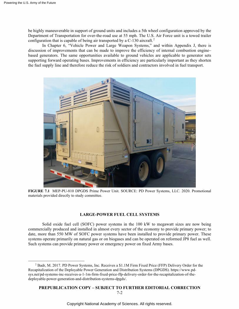
Powering the U.S. Army of the Future
Copyright National Academy of Sciences. All rights reserved.
PREPUBLICATION COPY – SUBJECT TO FURTHER EDITORIAL CORRECTION 7-2
be highly maneuverable in support of ground units and includes a 5th wheel configuration approved by the Department of Transportation for over-the-road use at 55 mph. The U.S. Air Force unit is a towed trailer configuration that is capable of being air transported by a C-130 aircraft.2
In Chapter 6, “Vehicle Power and Large Weapon Systems,” and within Appendix J, there is discussion of improvements that can be made to improve the efficiency of internal combustion engine–based generators. The same opportunities available to ground vehicles are applicable to generator sets supporting forward operating bases. Improvements in efficiency are particularly important as they shorten the fuel supply line and therefore reduce the risk of soldiers and contractors involved in fuel transport.
FIGURE 7.1 MEP-PU-810 DPGDS Prime Power Unit. SOURCE: PD Power Systems, LLC. 2020. Promotional materials provided directly to study committee.
LARGE-POWER FUEL CELL SYSTEMS
Solid oxide fuel cell (SOFC) power systems in the 100 kW to megawatt sizes are now being commercially produced and installed in almost every sector of the economy to provide primary power; to date, more than 550 MW of SOFC power systems have been installed to provide primary power. These systems operate primarily on natural gas or on biogases and can be operated on reformed JP8 fuel as well. Such systems can provide primary power or emergency power on fixed Army bases.
2 Badr, M. 2017. PD Power Systems, Inc. Receives a $1.1M Firm Fixed Price (FFP) Delivery Order for the
Recapitalization of the Deployable Power Generation and Distribution Systems (DPGDS). https://www.pd-sys.net/pd-systems-inc-receives-a-1-1m-firm-fixed-price-ffp-delivery-order-for-the-recapitalization-of-the-deployable-power-generation-and-distribution-systems-dpgds/.
Powering the U.S. Army of the Future
Copyright National Academy of Sciences. All rights reserved.
PREPUBLICATION COPY – SUBJECT TO FURTHER EDITORIAL CORRECTION 7-3
Conclusion: SOFC power systems would offer the same advantages and disadvantages in semi-permanent operating bases as in the commercial market. Their use could facilitate use of local fuel sources. (Tier 1, Watch)
NUCLEAR REACTORS FOR THE BATTLEFIELD
The U.S. Army demonstrated various nuclear reactor designs during the 1950s and 1960s on various scales, from an air/truck transportable model to fixed installations. In fact, the reactor (MH-1A) installed on a liberty ship (renamed Sturgis) supplied power to the Panama Canal Zone from 1968–1975 to reduce the need to divert lake water to hydroelectric production.3 Eventually, the Army dropped its nuclear power program because of the overhead associated with required safety and security standards, which in turn drove high operating costs to outweigh the fuel logistic advantage. At the time, military planners did not anticipate anti-access/area denial (A2/AD) as a prominent consideration, nor was sustainability a concern.
The Army is reconsidering fission nuclear power as a tactical solution because of chronic logistics and security challenges in operations in Southwest Asia and anticipation of future persistent conflict with A2/AD. As recommended by the Defense Science Board,4 a demonstration (Project Pele) is under way to incorporate technology advances from the past seven decades to inform today’s “art of the possible.” The specifications would provide electricity at up to 5 MW scale, which would displace fuel needed to power a typical brigade or larger-scale base camp. The 5-year project will demonstrate an “inherently safe” prototype reactor.5
In order to deploy such a system, the Army must address integration needs such as transportation, installation, operation, and removal. Particular challenges will include methods to provide requisite visibility and security associated with the nuclear material contents during all phases, and methods to provide appropriate physical protection using various local materials or transportable modules. Moreover, the Army will need architecture solutions that enable the energy to be utilized effectively. Although a nuclear reactor core itself could have extremely high energy density, the overall system footprint would be driven by needs for shielding, ballistic protection, and, especially, heat rejection equipment if closed-loop cooling is required. Creative system integration could enable the Army to minimize the required system size (and associated transportation, infrastructure, and security demands) by maximizing utilization of the reactor as it operates continuously near capacity.
The committee observes a possible disconnect between the emerging concept of MDO and the Department of Defense’s (DoD’s) ongoing nuclear reactor program objectives. The Westinghouse Government Services Mobile Nuclear Power Plant project targets a nominal 2 MW of electrical power production, which would correspond to observed sustainment needs of a brigade or larger force operating from a forward base during recent operations in Southwest Asia. However, literature and briefings provided to the committee characterize MDO as highly mobile, with hours-long halts at the longest, to minimize force vulnerability. With no base camps being established, it would be impractical to use a nuclear reactor (or any prime power source) in such a forward area. The committee did not examine the expected restructuring of sustainment architecture to determine if or where such a capability would provide the intended benefit. Westinghouse is presently working at the state of the art and is one of the leading contenders to continue this work.
3 The Maritime Executive. 2019. Floating Nuclear Plant Sturgis Dismantled. https://www.maritime-
executive.com/article/floating-nuclear-plant-sturgis-dismantled. 4 Anastasio, M., P. Kern, F. Bowman, J. Edmunds, G. Galloway, W. Madia, and W. Schneider. 2016. Task
Force on Energy Systems for Forward/Remote Operating Bases. Government report. Defense Science Board. Under Secretary of Defense for Acquisition, Technology, and Logistics (USD(AT&L)). https://dsb.cto.mil/reports/2010s/Energy_Systems_for_Forward_Remote_Operating_Bases.pdf.
5 Waksman, J. 2020. Project Pele Overview: Mobile Nuclear Power For Future DoD Needs. Strategic Capabilities Office. https://ric.nrc.gov/docs/abstracts/waksmanj-th34-hv.pdf. Accessed November 2020.
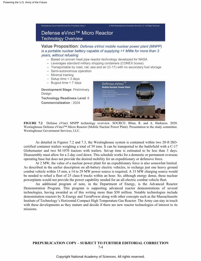
Powering the U.S. Army of the Future
Copyright National Academy of Sciences. All rights reserved.
PREPUBLICATION COPY – SUBJECT TO FURTHER EDITORIAL CORRECTION 7-4
FIGURE 7.2 Defense eVinci MNPP technology overview. SOURCE: Blinn, R. and A. Harkness. 2020. Westinghouse Defense eVinci™ Micro Reactor (Mobile Nuclear Power Plant). Presentation to the study committee. Westinghouse Government Services, LLC.
As detailed in Figures 7.2 and 7.3, the Westinghouse system is contained within two 20-ft ISO-certified container trailers weighing a total of 39 tons. It can be transported to the battlefield with a C-17 Globemaster and two M-1070 tractors with trailers. Set-up time is estimated to be less than 3 days. Disassembly must allow for a 2-day cool down. This schedule works for a domestic or permanent overseas operating base but does not provide the desired mobility for an expeditionary or defensive force.
At 2 MW, the value of a nuclear power plant for an expeditionary force is also somewhat limited. As described in the earlier description on all-battery electric vehicles, to recharge just one heavy ground combat vehicle within 15 min, a 14 to 29 MW power source is required. A 33 MW charging source would be needed to refuel a fleet of 25 class-8 trucks within an hour. So, although energy dense, these nuclear powerplants would not provide the power capability needed for an all-electric combat vehicle fleet.
An additional program of note, in the Department of Energy, is the Advanced Reactor Demonstration Program. This program is supporting advanced reactor demonstrations of several technologies, having awarded as of this writing more than $50 million. Notable technologies include demonstration reactors by X-Energy and TerraPower along with other concepts such as the Massachusetts Institute of Technology’s Horizontal Compact High Temperature Gas Reactor. The Army can stay in touch with these developments as they mature and decide if there are new reactor technologies of interest to its missions.
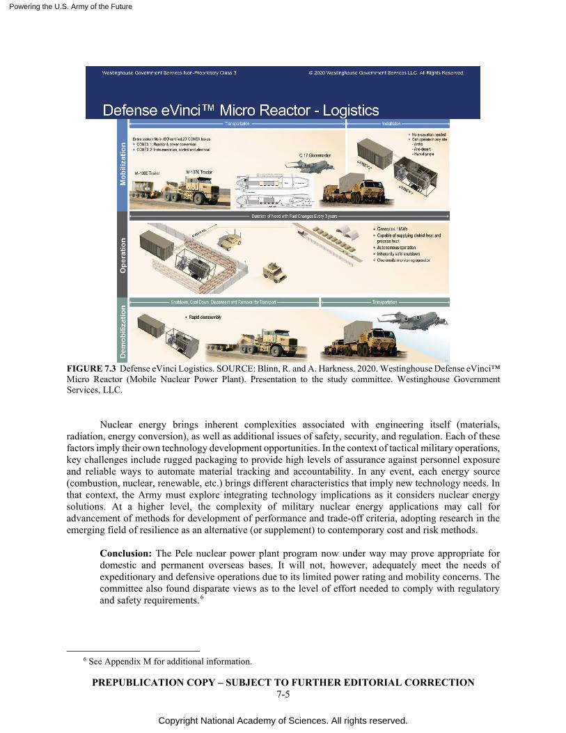
Powering the U.S. Army of the Future
Copyright National Academy of Sciences. All rights reserved.
PREPUBLICATION COPY – SUBJECT TO FURTHER EDITORIAL CORRECTION 7-5
FIGURE 7.3 Defense eVinci Logistics. SOURCE: Blinn, R. and A. Harkness. 2020. Westinghouse Defense eVinci™ Micro Reactor (Mobile Nuclear Power Plant). Presentation to the study committee. Westinghouse Government Services, LLC.
Nuclear energy brings inherent complexities associated with engineering itself (materials,
radiation, energy conversion), as well as additional issues of safety, security, and regulation. Each of these factors imply their own technology development opportunities. In the context of tactical military operations, key challenges include rugged packaging to provide high levels of assurance against personnel exposure and reliable ways to automate material tracking and accountability. In any event, each energy source (combustion, nuclear, renewable, etc.) brings different characteristics that imply new technology needs. In that context, the Army must explore integrating technology implications as it considers nuclear energy solutions. At a higher level, the complexity of military nuclear energy applications may call for advancement of methods for development of performance and trade-off criteria, adopting research in the emerging field of resilience as an alternative (or supplement) to contemporary cost and risk methods.
Conclusion: The Pele nuclear power plant program now under way may prove appropriate for domestic and permanent overseas bases. It will not, however, adequately meet the needs of expeditionary and defensive operations due to its limited power rating and mobility concerns. The committee also found disparate views as to the level of effort needed to comply with regulatory and safety requirements.6
6 See Appendix M for additional information.
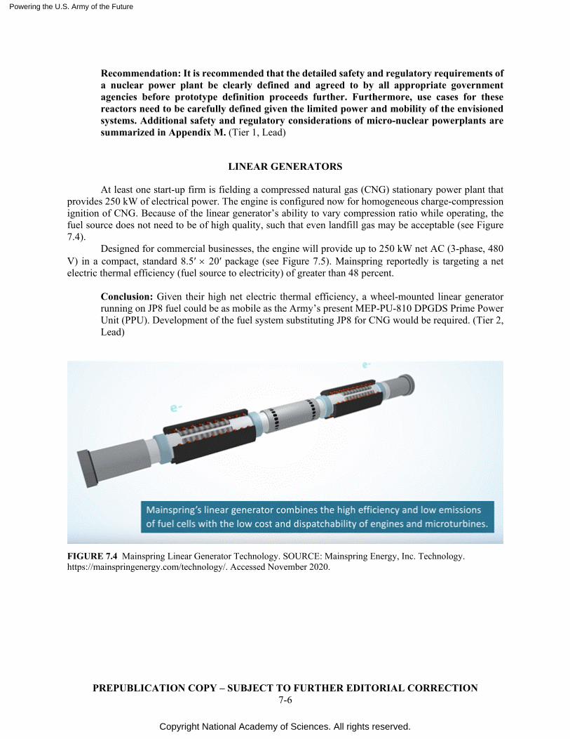
Powering the U.S. Army of the Future
Copyright National Academy of Sciences. All rights reserved.
PREPUBLICATION COPY – SUBJECT TO FURTHER EDITORIAL CORRECTION 7-6
Recommendation: It is recommended that the detailed safety and regulatory requirements of a nuclear power plant be clearly defined and agreed to by all appropriate government agencies before prototype definition proceeds further. Furthermore, use cases for these reactors need to be carefully defined given the limited power and mobility of the envisioned systems. Additional safety and regulatory considerations of micro-nuclear powerplants are summarized in Appendix M. (Tier 1, Lead)
LINEAR GENERATORS
At least one start-up firm is fielding a compressed natural gas (CNG) stationary power plant that provides 250 kW of electrical power. The engine is configured now for homogeneous charge-compression ignition of CNG. Because of the linear generator’s ability to vary compression ratio while operating, the fuel source does not need to be of high quality, such that even landfill gas may be acceptable (see Figure 7.4).
Designed for commercial businesses, the engine will provide up to 250 kW net AC (3-phase, 480 V) in a compact, standard 8.5′ × 20′ package (see Figure 7.5). Mainspring reportedly is targeting a net electric thermal efficiency (fuel source to electricity) of greater than 48 percent.
Conclusion: Given their high net electric thermal efficiency, a wheel-mounted linear generator running on JP8 fuel could be as mobile as the Army’s present MEP-PU-810 DPGDS Prime Power Unit (PPU). Development of the fuel system substituting JP8 for CNG would be required. (Tier 2, Lead)
FIGURE 7.4 Mainspring Linear Generator Technology. SOURCE: Mainspring Energy, Inc. Technology. https://mainspringenergy.com/technology/. Accessed November 2020.
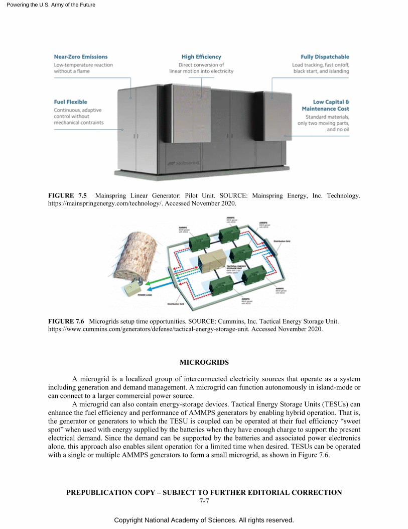
Powering the U.S. Army of the Future
Copyright National Academy of Sciences. All rights reserved.
PREPUBLICATION COPY – SUBJECT TO FURTHER EDITORIAL CORRECTION 7-7
FIGURE 7.5 Mainspring Linear Generator: Pilot Unit. SOURCE: Mainspring Energy, Inc. Technology. https://mainspringenergy.com/technology/. Accessed November 2020.
FIGURE 7.6 Microgrids setup time opportunities. SOURCE: Cummins, Inc. Tactical Energy Storage Unit. https://www.cummins.com/generators/defense/tactical-energy-storage-unit. Accessed November 2020.
MICROGRIDS
A microgrid is a localized group of interconnected electricity sources that operate as a system including generation and demand management. A microgrid can function autonomously in island-mode or can connect to a larger commercial power source.
A microgrid can also contain energy-storage devices. Tactical Energy Storage Units (TESUs) can enhance the fuel efficiency and performance of AMMPS generators by enabling hybrid operation. That is, the generator or generators to which the TESU is coupled can be operated at their fuel efficiency “sweet spot” when used with energy supplied by the batteries when they have enough charge to support the present electrical demand. Since the demand can be supported by the batteries and associated power electronics alone, this approach also enables silent operation for a limited time when desired. TESUs can be operated with a single or multiple AMMPS generators to form a small microgrid, as shown in Figure 7.6.
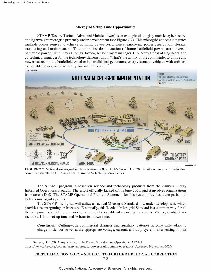
Powering the U.S. Army of the Future
Copyright National Academy of Sciences. All rights reserved.
PREPUBLICATION COPY – SUBJECT TO FURTHER EDITORIAL CORRECTION 7-8
Microgrid Setup Time Opportunities
STAMP (Secure Tactical Advanced Mobile Power) is an example of a highly mobile, cybersecure, and lightweight microgrid presently under development (see Figure 7.7). This microgrid concept integrates multiple power sources to achieve optimum power performance, improving power distribution, storage, monitoring and maintenance. “This is the first demonstration of future battlefield power, our universal battlefield power, UBP,” says Thomas Bozada, senior project manager, U.S. Army Corps of Engineers, and co-technical manager for the technology demonstration. “That’s the ability of the commander to utilize any power source on the battlefield whether it’s traditional generators, energy storage, vehicles with onboard exploitable power, and eventually host-nation power.”7
FIGURE 7.7 Notional micro-grid implementation. SOURCE: McGrew, D. 2020. Email exchange with individual committee member. U.S. Army CCDC Ground Vehicle Systems Center.
The STAMP program is based on science and technology products from the Army’s Energy Informed Operations program. The effort officially kicked off in June 2020, and it involves organizations from across DoD. The STAMP Operational Problem Statement for this system provides a comparison to today’s microgrid systems.
The STAMP microgrids will utilize a Tactical Microgrid Standard now under development, which provides the integrating architecture. Essentially, this Tactical Microgrid Standard is a common way for all the components to talk to one another and then be capable of reporting the results. Microgrid objectives include a 1-hour set-up time and ½-hour teardown time.
Conclusion: Cutting-edge commercial chargers and auxiliary batteries automatically adapt to charge or deliver power at the appropriate voltage, current, and duty cycle. Implementing similar
7 Seffers, G. 2020. Army Microgrid To Power Multidomain Operations. AFCEA.
https://www.afcea.org/content/army-microgrid-power-multidomain-operations. Accessed November 2020.
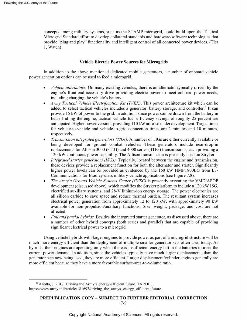
Powering the U.S. Army of the Future
Copyright National Academy of Sciences. All rights reserved.
PREPUBLICATION COPY – SUBJECT TO FURTHER EDITORIAL CORRECTION 7-9
concepts among military systems, such as the STAMP microgrid, could build upon the Tactical Microgrid Standard effort to develop collateral standards and hardware/software technologies that provide “plug and play” functionality and intelligent control of all connected power devices. (Tier 1, Watch)
Vehicle Electric Power Sources for Microgrids
In addition to the above mentioned dedicated mobile generators, a number of onboard vehicle power generation options can be used to feed a microgrid.
• Vehicle alternators. On many existing vehicles, there is an alternator typically driven by the
engine’s front-end accessory drive providing electric power to meet onboard power needs, including charging the vehicle’s battery.
• Army Tactical Vehicle Electrification Kit (TVEK). This power architecture kit which can be added to select tactical vehicles includes a generator, battery storage, and controller.8 It can provide 15 kW of power to the grid. In addition, since power can be drawn from the battery in lieu of idling the engine, tactical vehicle fuel efficiency savings of roughly 25 percent are anticipated. Higher power versions providing 110 kW are also under development. Target times for vehicle-to-vehicle and vehicle-to-grid connection times are 2 minutes and 10 minutes, respectively.
• Transmission integrated generators (TIGs). A number of TIGs are either currently available or being developed for ground combat vehicles. These generators include near-drop-in replacements for Allison 3000 (3TIG) and 4000 series (4TIG) transmissions, each providing a 120-kW continuous power capability. The Allison transmission is presently used on Stryker.
• Integrated starter generators (ISGs). Typically, located between the engine and transmission, these devices provide a replacement function for both the alternator and starter. Significantly higher power levels can be provided as evidenced by the 160 kW HMPT800EG from L3-Communications for Bradley-class military vehicle applications (see Figure 7.8).
• The Army’s Ground Vehicle Systems Center (GVSC) is presently executing the VMD/APOP development (discussed above), which modifies the Stryker platform to include a 120 kW ISG, electrified auxiliary systems, and 28-V lithium-ion energy storage. The power electronics are all silicon carbide to save space and reduce thermal burden. The resultant system increases electrical power generation from approximately 12 to 120 kW, with approximately 90 kW available for non-propulsion/auxiliary functions. Size, weight, package, and cost are not affected.
• Full and partial hybrids. Besides the integrated starter generator, as discussed above, there are a number of other hybrid concepts (both series and parallel) that are capable of providing significant electrical power to a microgrid.
Using vehicle hybrids with larger engines to provide power as part of a microgrid structure will be
much more energy efficient than the deployment of multiple smaller generator sets often used today. As hybrids, their engines are operating only when there is insufficient energy left in the batteries to meet the current power demand. In addition, since the vehicles typically have much larger displacements than the generator sets now being used, they are more efficient. Larger displacement/cylinder engines generally are more efficient because they have a more favorable surface-area-to-volume ratio.
8 Aliotta, J. 2017. Driving the Army’s energy-efficient future. TARDEC.
https://www.army.mil/article/181692/driving_the_armys_energy_efficient_future.
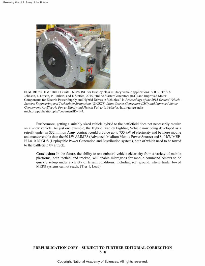
Powering the U.S. Army of the Future
Copyright National Academy of Sciences. All rights reserved.
PREPUBLICATION COPY – SUBJECT TO FURTHER EDITORIAL CORRECTION 7-10
FIGURE 7.8 HMPT800EG with 160kW ISG for Bradley class military vehicle applications. SOURCE: S.A. Johnson, J. Larson, P. Ehrhart, and J. Steffen, 2015, “Inline Starter Generators (ISG) and Improved Motor Components for Electric Power Supply and Hybrid Drives in Vehicles,” in Proceedings of the 2015 Ground Vehicle Systems Engineering and Technology Symposium (GVSETS) Inline Starter Generators (ISG) and Improved Motor Components for Electric Power Supply and Hybrid Drives in Vehicles, http://gvsets.ndia-mich.org/publication.php?documentID=144.
Furthermore, getting a suitably sized vehicle hybrid to the battlefield does not necessarily require an all-new vehicle. As just one example, the Hybrid Bradley Fighting Vehicle now being developed as a retrofit under an $32 million Army contract could provide up to 735 kW of electricity and be more mobile and maneuverable than the 60 kW AMMPS (Advanced Medium Mobile Power Source) and 840 kW MEP-PU-810 DPGDS (Deployable Power Generation and Distribution system), both of which need to be towed to the battlefield by a truck.
Conclusion: In the future, the ability to use onboard vehicle electricity from a variety of mobile platforms, both tactical and tracked, will enable microgrids for mobile command centers to be quickly set-up under a variety of terrain conditions, including soft ground, where trailer towed MEPS systems cannot reach. (Tier 1, Lead)
Powering the U.S. Army of the Future
Copyright National Academy of Sciences. All rights reserved.
PREPUBLICATION COPY – SUBJECT TO FURTHER EDITORIAL CORRECTION 8-1
8
Fuel Conversion Efficiency and Other Material Driven Opportunities
Although not directly related to the sourcing, storage, or transmission of energy, maximizing the utility of each megawatt-hour of energy delivered to the field is important to enable increased self-sustainability. This awareness minimizes the amount of energy that must be transported to the battlefield or collected locally.
To accomplish this, fuel-conversion efficiency needs to be maximized throughout the complete chain from energy storage to power delivery. For example, lower rolling-resistance tracks, higher temperature–capable power electronics, batteries, motors, and more-efficient cooling systems, together could enable considerable reductions in parasitic cooling and friction losses. Some of these opportunities are described below.
PRESENT ARMY POWER PACK FUEL EFFICIENCY AND PERFORMANCE UPGRADES
The Army already has a number of active powerpack initiatives in this area, which are then balanced against other key performance objectives such as power density and heat rejection. These initiatives are summarized below.
The Advanced Powertrain Demonstrator (APD) powerpack presently under development includes the following: (1) a low heat–rejection, high-efficiency, two-stroke opposed-piston engine, (2) a wide range, high-efficiency cross-drive transmission, (3) an advanced cooling/thermal management system, and (4) an advanced high-efficiency inline starter generator. Due to its increase in power density, it enables increased terrain access and higher vehicle speeds powerpacks using military on-the-shelf (MOTS) components (see Figure 8.1).
FIGURE 8.1 Increasing powertrain power density. SOURCE: Brendle, B. 2018. U.S. Army Opposed Piston Engine Research and Development. Slide presentation. U.S. Army Research, Development, and Engineering Command (RDECOM)-TARDEC. http://groundsmart-mail.com/documents/us-army-oppposed-piston-engine-research-infantry-fighting-vehicle-m2-bradley.html.
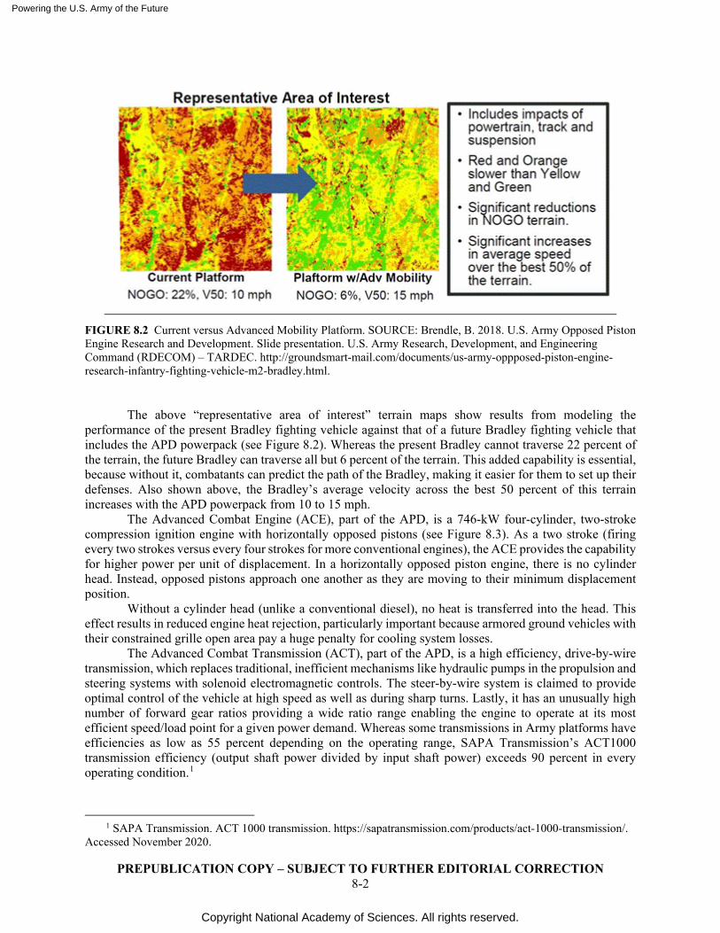
Powering the U.S. Army of the Future
Copyright National Academy of Sciences. All rights reserved.
PREPUBLICATION COPY – SUBJECT TO FURTHER EDITORIAL CORRECTION 8-2
FIGURE 8.2 Current versus Advanced Mobility Platform. SOURCE: Brendle, B. 2018. U.S. Army Opposed Piston Engine Research and Development. Slide presentation. U.S. Army Research, Development, and Engineering Command (RDECOM) – TARDEC. http://groundsmart-mail.com/documents/us-army-oppposed-piston-engine-research-infantry-fighting-vehicle-m2-bradley.html.
The above “representative area of interest” terrain maps show results from modeling the performance of the present Bradley fighting vehicle against that of a future Bradley fighting vehicle that includes the APD powerpack (see Figure 8.2). Whereas the present Bradley cannot traverse 22 percent of the terrain, the future Bradley can traverse all but 6 percent of the terrain. This added capability is essential, because without it, combatants can predict the path of the Bradley, making it easier for them to set up their defenses. Also shown above, the Bradley’s average velocity across the best 50 percent of this terrain increases with the APD powerpack from 10 to 15 mph.
The Advanced Combat Engine (ACE), part of the APD, is a 746-kW four-cylinder, two-stroke compression ignition engine with horizontally opposed pistons (see Figure 8.3). As a two stroke (firing every two strokes versus every four strokes for more conventional engines), the ACE provides the capability for higher power per unit of displacement. In a horizontally opposed piston engine, there is no cylinder head. Instead, opposed pistons approach one another as they are moving to their minimum displacement position.
Without a cylinder head (unlike a conventional diesel), no heat is transferred into the head. This effect results in reduced engine heat rejection, particularly important because armored ground vehicles with their constrained grille open area pay a huge penalty for cooling system losses.
The Advanced Combat Transmission (ACT), part of the APD, is a high efficiency, drive-by-wire transmission, which replaces traditional, inefficient mechanisms like hydraulic pumps in the propulsion and steering systems with solenoid electromagnetic controls. The steer-by-wire system is claimed to provide optimal control of the vehicle at high speed as well as during sharp turns. Lastly, it has an unusually high number of forward gear ratios providing a wide ratio range enabling the engine to operate at its most efficient speed/load point for a given power demand. Whereas some transmissions in Army platforms have efficiencies as low as 55 percent depending on the operating range, SAPA Transmission’s ACT1000 transmission efficiency (output shaft power divided by input shaft power) exceeds 90 percent in every operating condition.1
1 SAPA Transmission. ACT 1000 transmission. https://sapatransmission.com/products/act-1000-transmission/.
Accessed November 2020.
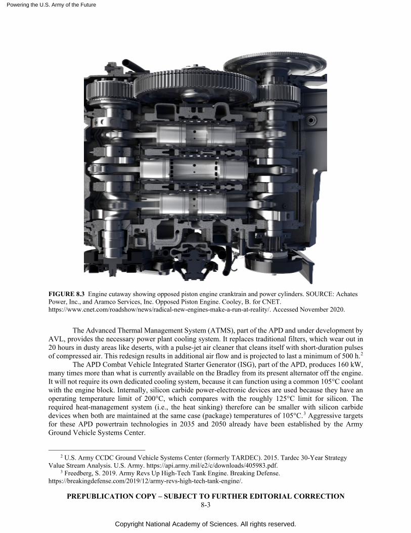
Powering the U.S. Army of the Future
Copyright National Academy of Sciences. All rights reserved.
PREPUBLICATION COPY – SUBJECT TO FURTHER EDITORIAL CORRECTION 8-3
FIGURE 8.3 Engine cutaway showing opposed piston engine cranktrain and power cylinders. SOURCE: Achates Power, Inc., and Aramco Services, Inc. Opposed Piston Engine. Cooley, B. for CNET. https://www.cnet.com/roadshow/news/radical-new-engines-make-a-run-at-reality/. Accessed November 2020.
The Advanced Thermal Management System (ATMS), part of the APD and under development by AVL, provides the necessary power plant cooling system. It replaces traditional filters, which wear out in 20 hours in dusty areas like deserts, with a pulse-jet air cleaner that cleans itself with short-duration pulses of compressed air. This redesign results in additional air flow and is projected to last a minimum of 500 h.2
The APD Combat Vehicle Integrated Starter Generator (ISG), part of the APD, produces 160 kW, many times more than what is currently available on the Bradley from its present alternator off the engine. It will not require its own dedicated cooling system, because it can function using a common 105°C coolant with the engine block. Internally, silicon carbide power-electronic devices are used because they have an operating temperature limit of 200°C, which compares with the roughly 125°C limit for silicon. The required heat-management system (i.e., the heat sinking) therefore can be smaller with silicon carbide devices when both are maintained at the same case (package) temperatures of 105°C.3 Aggressive targets for these APD powertrain technologies in 2035 and 2050 already have been established by the Army Ground Vehicle Systems Center.
2 U.S. Army CCDC Ground Vehicle Systems Center (formerly TARDEC). 2015. Tardec 30-Year Strategy
Value Stream Analysis. U.S. Army. https://api.army.mil/e2/c/downloads/405983.pdf. 3 Freedberg, S. 2019. Army Revs Up High-Tech Tank Engine. Breaking Defense.
https://breakingdefense.com/2019/12/army-revs-high-tech-tank-engine/.
Powering the U.S. Army of the Future
Copyright National Academy of Sciences. All rights reserved.
PREPUBLICATION COPY – SUBJECT TO FURTHER EDITORIAL CORRECTION 8-4
Another advanced propulsion system presently being defined by the Army Ground Vehicle Systems Center is simply entitled the “Projected Propulsion System.” This hybrid power pack includes the following: (1) a high-efficiency, fuel conversion source (engine or fuel cell), (2) a high-efficiency power/torque conversion device, (3) variable speed fan drive, (4) an 80-kWh energy storage device enabling idle engine shut-off and silent mobility, and (5) highly efficient battery charging.4
Another program is the Advanced Mobility Experimental Prototype (AMEP), which is to demonstrate potential propulsion solutions for the Extended Range Cannon Artillery program, a self-propelled howitzer. This prototype likely will use selected portions of the APD powerpack and include an advanced lower rolling–resistance track and a 150 kWe integrated starter generator. Spanning fiscal years (FY) 2020 through 2023, 6.3 funding of $16.5 million is approved with an additional $34.9 million funding anticipated.4
Still another program is the Platform Electrification Mobility Demonstrator. This program will include multiple vehicle prototype builds to demonstrate electrification capability in tracked combat applications. It will include 15–30 ton light and 35–60 ton heavy ground combat vehicles using a modular approach. The focus will be on hybrid electric propulsion system configurations. Spanning FY 2020 through 2025, 6.2/6.3 funding of $219 million is anticipated.4 M2 Bradley and M113 armored personnel carriers will be used as the base platforms.
Key elements of the study include the following: (1) high-temperature power electronics, motors, and generators and (2) investigation of fuel-cell capability to recharge batteries for on-board electric power, silent-mobility capability with an 80 kWh battery pack target for the heavy variant. Transmission alternatives to be evaluated include a cross-drive system (which integrates braking and motoring and enables one track to run at a higher speed than the other for steering) and independent track drives.
FURTHER EFFICIENCY IMPROVEMENTS IN COMPRESSION IGNITION ENGINES
Within the last decade, there have been some very impressive improvements in the efficiency and power density of compression ignition engines, in large part driven by the SuperTruck projects undertaken by Cummins, Navistar, Daimler, Volvo, and Paccar. Base engine thermal efficiencies exceeding 50 percent at their best speed/load operating point have been demonstrated.5
The brake thermal efficiency (BTE) of present four-stroke engines in Army service, such as High Mobility Multipurpose Wheeled Vehicles (HMMWVs), Bradleys, and Strykers, typically range from the high 30s to low 40s. Modernization of Army engine hardware to commercial BTE levels (approaching 50 percent) would reduce JP8 usage by roughly 20 percent. This decrease combined with the use of DF2 diesel fuel with its 9 percent higher energy content by volume, and further improvements made possible by adjusting injection timing/quantity, could reduce total fuel transported to the battlefield by almost a third.6
In addition to base engine improvements, the SuperTruck projects have also included demonstration of various waste-heat recovery systems (see Appendix J). If containable within the space constraints of new ground combat vehicles, they offer a 3 to 5 percent opportunity to reduce fuel use further, thereby increasing the vehicle range and shortening the fuel supply line. Most of the SuperTruck programs focus on the organic Rankine cycle (using cyclopentane). Encouraging work at Southwest Research Institute focusing on the Brayton cycle (using supercritical CO2) offers the potential for even further efficiency gains. Department of Energy (DOE) SuperTruck advances, including waste-heat recovery
4 Schihl, P. 2020. Combat Ground Vehicle Propulsion Efficiency Discussion. Presentation to the study
committee, and email provided to individual committee member. U.S. Army CCDC Ground Vehicle Systems Center.
5 A summary of the design actions taken on SuperTruck projects is included in Appendix J. 6 U.S. Army CCDC GVSC. 2020. Verbal conversation with committee member. U.S. Army CCDC Ground
Vehicle Systems Center.
Powering the U.S. Army of the Future
Copyright National Academy of Sciences. All rights reserved.
PREPUBLICATION COPY – SUBJECT TO FURTHER EDITORIAL CORRECTION 8-5
concepts, could be leveraged for military applications and provide the potential to significantly improve vehicle range and reduce the JP8 supply line.
Also included in Appendix J is a list of the possible design/development actions that might be considered on future horizontally opposed two-stroke compression ignition engine designs to enable some of the aggressive targets in these areas that the Army is setting for 2035 and beyond while maintaining low heat rejection.
THERMAL BARRIER COATINGS
Reduced heat rejection from a ground combat vehicle’s power plant is critically important. Unlike commercial and light-duty diesel trucks, a combat vehicle’s grille open area needs to be minimized to minimize its susceptibility to enemy projectiles. Lower heat-rejection values also reduce the vehicle’s thermal signature. Lastly, heat not lost in the cooling system can power the vehicle’s propulsion, providing improved fuel economy and range.
For these reasons, thermal barrier coatings (TBCs) of engine components (pistons, cylinder heads, valves) have been a highly desirable study area for many years dating back to 1950s adiabatic engine studies (so called because in theory heat would neither enter or leave the system). Managing heat flows throughout the power cylinder have always proven to be critically important, as the engine power cylinder surfaces are exposed to flame and extremely high pressure.
Historically, adhesion of ceramic-based thermal barrier coatings has proven to be a major inhibitor to getting thermal barrier coatings into production. Thin coatings adhered but did not provide a significant decrease in thermal conductivity. Thicker coatings provided the needed decrease in thermal conductivity but presented adhesion problems over time. More recently, it has been discovered that a functional coating also must have low thermal conductivity, excellent adhesion, and a low specific heat capacity. Without this low specific heat, the surfaces remain hot, compromising the volumetric efficiency (the engine’s ability to ingest air).
Toyota has been the clear leader in this technology, having introduced their “thermo swing wall insulation” into production in 2015. This SiRPA (a silica-reinforced porous, anodized aluminum coating), used on aluminum pistons, is claimed to reduce the cooling loss during combustion by about 30 percent.7
To deal with higher peak–cylinder pressures and temperatures, newer heavy-duty diesel engines are using steel pistons in lieu of aluminum. While several different original equipment manufacturer (OEM) component suppliers, coating suppliers, and universities are developing their own formulations for these, there are not presently any thermal barrier coatings in production on steel pistons.
In the most recent DOE annual merit review meeting, Cummins, Daimler, Volvo, and PACCAR all reported that they are studying use of thermal barrier coatings in their SuperTruck II projects. At that same meeting, others (e.g., Ford) reported they are studying such coatings for light-duty applications.8
Potentially, a next-generation thermal barrier coating could be based on an aerogel, a technology that was used to manage heat on the space shuttle upon reentry. Aerogel composites have also been used in aviation interiors where lightweight is critical.9 An aerogel is a synthetic porous material derived by extracting the liquid component of a gel through supercritical drying. With most of the volume being air (or vacuum), the resulting solid has extremely low thermal conductivity. Some initial experiments using an aerogel as a thermal barrier coating were unsuccessful due to adhesion problems, which could be solved with further materials development and surface engineering.
7 Toyota. 2015. Toyota’s Revamped Turbo Diesel Engines Offer More Torque, Greater Efficiency and Lower
Emissions. https://global.toyota/en/detail/8348091. 8 Misc. Authors. 2020. U.S. Department of Energy’s (DOE) Vehicle Technologies Office (VTO) 2020 Annual
Merit Review (AMR). U.S. Department of Energy. https://www.energy.gov/eere/vehicles/annual-merit-review-presentations.
9 Aerogel Technologies. Markets and Technology. http://www.aerogeltechnologies.com/applications/. Accessed November 2020.
Powering the U.S. Army of the Future
Copyright National Academy of Sciences. All rights reserved.
PREPUBLICATION COPY – SUBJECT TO FURTHER EDITORIAL CORRECTION 8-6
Ceramic thermal barrier coatings are already commonly used on production aviation turbo-shaft engines where extremely high temperatures are encountered on both moving and stationary components. Unlike the case for internal combustion engines where high temperatures during the intake stroke compromise volumetric efficiency, a low specific heat capacity is not needed for parts coated on gas turbines.10
POWER ELECTRONICS OPPORTUNITIES AND CHALLENGES
In their raw form, almost all electrical energy sources today are incompatible with the loads they are supplying. The parameters of supply—for example, voltage, frequency, current—must be converted to those required by the load. Examples are a solar array producing variable DC voltage supplying an AC grid of constant frequency and voltage, or batteries producing DC power in a hybrid vehicle to supply motors requiring variable AC voltage and frequency, or even a battery whose voltage varies with use to power a radio requiring constant voltage. The interface in these energy systems consists of electronic devices configured to provide the necessary transformations. Such an interface is known as a power-electronics converter and will be ubiquitous in the Army’s power and energy technologies of the future. These converters add volume and weight to the battlefield equipment inventory. To a large extent, the volume and weight are dictated by the thermal management requirements because the converters are not 100 percent efficient. Newly developed semiconductor devices using the wide band-gap materials silicon carbide (SiC) and gallium nitride (GaN) promise to improve the thermal performance of future power electronic converters.
Because thermal management plays such a critical role in all ground combat vehicles, technical electrification challenges in power density and temperature threshold have been identified by the Army as part of its hybrid studies. Running electronics at higher temperatures, preferably using coolant at the same temperature of the internal combustion engine, reduces cooling system losses. The Army’s “wants” for power electronics use are summarized in Table 8.1.
TABLE 8.1 U.S. Army Power Electronics Goals
Key Characteristic Power Density Temperature Threshold
Current/Army or industry 3 kW/L 85°C coolant
Future Army requirement 12 kW/L 105°C engine coolant
SOURCE: SAE Hybrid and Electric Vehicle Technologies Symposium, January 28, 2020, Combat Vehicle Energy Storage, Kevin Boice.
The current challenge using SiC and GaN is that the size of wafers of the necessary purity and
freedom from defects limits the power that transistors made of these materials can control. The development of SiC as a semiconductor device material was done by Cree with partial funding from the Defense Advanced Research Projects Agency (DARPA) and the State of New York.11 While SiC devices are fabricated on native substrate, GaN devices are produced in an epitaxial layer on a substrate of Si, SiC, or Al2O3 (sapphire). The disparate physical properties of the two materials—for example, thermal coefficient of expansion—produces a challenge at the interface of the epitaxy and substrate, resulting in suboptimal device behavior. A further important constraint imposed by devices fabricated on an epitaxial layer is that
10 Meier, S.M. and D. K. Gupta. 1994. The Evolution of Thermal Barrier Coatings in Gas Turbine Engine
Applications. Journal of Engineering for Gas Turbines and Power 116(1): 250–257. 11 Cree, Inc. 2019. Cree & NY CREATES Announce First Silicon Carbide Wafer Demonstration at SUNY Poly
in Albany. https://www.cree.com/news-events/news/article/cree-ny-creates-announce-first-silicon-carbide-wafer-demonstration-at-suny-poly-in-albany.
Powering the U.S. Army of the Future
Copyright National Academy of Sciences. All rights reserved.
PREPUBLICATION COPY – SUBJECT TO FURTHER EDITORIAL CORRECTION 8-7
their geometry has to be lateral, which is real-estate intensive. Power devices are almost universally vertical structures, meaning the current flows vertically through the substrate, providing the necessary length to support high voltage without sacrificing surface area. Research on using native GaN is proceeding, and success will be necessary before GaN device geometries can be vertical and useful in power applications.
The two most important parameters that provide SiC’s advantage over Si are its thermal conductivity and critical electric field Ec, the field at which the material breaks down. As Table L.1 in Appendix L shows, SiC has more than three times the thermal conductivity, and nearly a 10-fold increase in Ec of Si. The benefits of increased thermal conductivity are clear. The increase in the critical field permits a much thinner device to support a given voltage, which reduces both the thermal resistance and on-state voltage drop of the transistor.
The Army’s goals for volumetric and gravimetric parameters of energy-conversion apparatus (e.g., electric vehicle or hybrid traction drives) suggest designs at higher electrical frequencies. From a power-electronic perspective, higher frequencies result in smaller energy-storage components. These components comprise the principal sources of weight and volume. Capacitors and inductors form necessary filters, transformers provide required scaling of voltage, and electrical machines (motors and generators, which are essentially electrical to mechanical transformers) provide the required physical work.
A further factor influencing the gravimetric and volumetric specifications of power electronic systems is the thermal limitations of their components. Silicon carbide has made possible semiconductor devices with maximum junction temperatures exceeding 200°C, while Si transistors are generally limited to a junction temperature of 175°C. The thermal limits of current packaging technology currently prevent fully exploiting the higher thermal ratings of SiC. This increased upper temperature limit combined with the very high thermal conductivity of SiC compared to Si reduces the size of the thermal-management hardware for cooling the device. However, the passive components, especially capacitors, with compatible thermal ratings have not yet been developed. So, to truly reduce the size and weight of power electronics, magnetic and dielectric materials with higher thermal ratings need to be developed.
Additional background material on the power electronics challenge and how they can be addressed is contained in Appendix L.
Finding: Although SiC semiconductor devices can operate at higher temperatures than conventional Si devices, the operating temperature limits of passive components such as capacitors and inductors still establish the upper temperature limit of power electronic systems.
Recommendation: To increase the temperature in which electronic energy conversion systems can operate, the Army should engage in research to develop higher temperature passive electrical components.
ALUMINUM METAL MATRIX COMPOSITE (MMC) APPLICATIONS
Of growing importance, metal matrix composites (MMCs) are emerging as high-performance alternatives to traditional alloys. MMCs consist of two or more constituent parts, one being a metal and the other another material, such as a ceramic or organic compound dispersed throughout the metal matrix. For example, ultrafine particles of SiC are commonly used in an aluminum matrix to improve its material properties.
This reinforcement can serve a purely structural task, such as greater strength-to-weight, higher yield point and ultimate tensile strength, improved strength-to-weight ratio, and greater fatigue strength at elevated temperatures. In addition, the selected reinforcement can be used to change physical properties, such as providing a lower thermal expansion, lower friction coefficient, greater wear resistance, greater thermal conductivity, improved coefficient of thermal expansion, improved elastic modulus, and/or improved machinability or near-net-shape forgeability versus conventional engine materials.
Powering the U.S. Army of the Future
Copyright National Academy of Sciences. All rights reserved.
PREPUBLICATION COPY – SUBJECT TO FURTHER EDITORIAL CORRECTION 8-8
The Army is presently conducting extensive studies of aluminum MMCs. This area of investigation will enable improved structural properties in a lighter-weight format. Advances would be important for major engine components in specific applications, such as engine blocks and cylinder heads for unmanned aircraft systems.
Application of aluminum MMCs needs to be compared with other material alternatives, such as magnesium and titanium. The Army’s needs may deviate a significant amount from those of commercial OEMs because cost may play a less significant role, particularly in weight-sensitive applications such as unmanned aerial vehicles (UAVs).
UNIQUE METAL MATRIX COMPOSITE MATERIALS FOR PISTONS
Most modern military diesel engines use steel pistons based on their ability to tolerate higher temperatures and higher peak cylinder pressures. The yield and fatigue strength of aluminum is typically inadequate for diesel engine peak–cylinder pressures above 200 bar (also dependent on the piston compression height) and begins to fall off sharply at temperatures above 300°C.
Besides higher strength at high temperatures, another advantage of steel-piston use is their similar coefficient of thermal expansion to iron. When used with a grey iron or compacted graphite iron block, tighter piston-to-bore clearances are enabled. In contrast, aluminum, with its roughly three times greater coefficient of friction at rated power, often exceeds the bore and runs in a compressed mode within an iron block cylinder bore.
Aluminum MMC pistons may not be capable of standing up to the high piston crown temperatures and cylinder pressures of an opposed piston engine. However, titanium, with its higher melting point (about 1,000°C above aluminum) and comparable strength properties to steel may play a role in developing a suitable MMC piston material. Within industry, there has already been some work with titanium MMCs.
Titanium has higher tensile strength than steel but is not presently used in pistons because of its poor thermal conductivity. Although it can tolerate much higher temperatures, its inability to dissipate the heat of combustion can result in excessively hot crown temperatures leading to premature ignition and engine damage. This thermal conductivity would need to be increased with the addition of the second matrix component, perhaps some form of elemental carbon.
ARTIFICIAL INTELLIGENCE/MACHINE LEARNING-BASED MATERIAL OPTIMIZATION
Numerous studies have demonstrated the benefits of using artificial intelligence (AI)/machine learning (ML) to quickly evaluate the plethora of design options for improved material properties. Included among these are studies of various metallic alloys.12
As a research project, combining the following efforts with AI/ML materials studies may provide some significant benefits:
● MMC pistons and conrods (connecting rods); ● Ceramic matrix composites (CMC) for high-temperature components, such as exhaust
manifolds; ● Compatible liner materials or block materials (if a parent metal block) with piston skirt and
rings ● Possible unique skirt materials or coatings—possibly diamond like coating or higher
temperature–capable polymer base coating;
12 Wei, J. et al. 2019. Machine learning in materials science. InfoMat 1(3):338–358.
https://onlinelibrary.wiley.com/doi/pdf/10.1002/inf2.12028.
Powering the U.S. Army of the Future
Copyright National Academy of Sciences. All rights reserved.
PREPUBLICATION COPY – SUBJECT TO FURTHER EDITORIAL CORRECTION 8-9
● Thermal barrier coatings—matched to adhere to the MMC crown material and minimize heat transfer needed to undercrown—possibly used selectively on the outside of a liner to allow more uniform temperatures within the bore; and
● AI/ML algorithms to enable further exploration of the materials design space without relying exclusively on testing.
Such new piston materials and architecture may provide lower reciprocating mass, enabling higher speeds and increased power at equal peak cylinder pressures. Furthermore, reduced thermal expansion would enable tighter piston-to-bore crevice volumes, thereby improving power density and fuel efficiency.
3D PRINTING/ADDITIVE MANUFACTURING
3D printing, also known as additive manufacturing, is a process for making a physical object from a 3D digital model, typically by laying down many successive thin two-dimensional layers of a material. It brings a digital object (its computer-aided design [CAD] representation) into its physical form by adding layer by layer. As such, it enables geometries not previously possible, plus by making it possible to eliminate joints, it increases the reliability of the product while reducing size and weight. In addition, 3D printing can also accelerate design and testing of prototypes, thereby shortening the development period.
The earliest 3D printing process fabricated 3D plastic models using a photo-hardening thermoset polymer. Each layer would then be exposed to the appropriate ultraviolet (UV) beam to harden selected areas. Since that time, there have been a wide variety of improvements in 3D printing materials. Initially, plastic engine intake manifolds produced by 3D printing were not capable of withstanding high pressures associated with turbocharged engines. However, with improved plastic materials, that is now possible.
3D printing with a variety of metals has been demonstrated, including intake manifolds in aluminum. IAV, the German consulting firm, has proven that prototype steel pistons can be fabricated using 3D printing to quickly explore different engine combustion regimes.13 SpaceX is making rocket components using 3D printing.14 Pratt & Whitney will be the first to use additive machining technology to produce compressor stators and synch ring brackets for their production turbine engines.15 3D printing of titanium aerospace components is now available.
Chemnitz University of Technology in Germany recently showcased an electric motor produced entirely by additive manufacturing. Highly viscous metallic and ceramic pastes were extruded through a nozzle to build the body of the parts in layers. This assembly was then sintered to the required harness. They designated this process “multimedia 3D printing.”16
A key advantage of 3D printing is the ability to eliminate joints that are difficult to produce with more traditional casting and machining methods, thereby reducing cost, schedule time, and weight and improving reliability. The automotive industry has spent much effort using this and other innovative design approaches to eliminate joints. One joint-elimination example (not created with 3D printing) is the integrated exhaust-manifold cylinder head used in production by GM, where both the cylinder head and exhaust manifold are part of a common casting. Another approach used by Honda in their GC-family
13 Buchholz, K. 2018. IAV using 3D printed pistons for engine testing. SAE International.
https://www.sae.org/news/2018/04/iav-using-3d-printed-pistons-for-engine-testing. 14 Salmi, Bryce, The World’s Largest 3D Metal Printer Is Churning Out Rockets, IEEE Spectrum.
https://spectrum.ieee.org/aerospace/space-flight/the-worlds-largest-3d-metal-printer-is-churning-out-rockets. Accessed December 2020.15 Aerospace Manufacturing and Design. 2015. Pratt & Whitney AM engine parts poised for entry into service. https://www.aerospacemanufacturinganddesign.com/article/pratt-whitney-additive-parts-engine-040615/.
15 Aerospace Manufacturing and Design. 2015. Pratt & Whitney AM engine parts poised for entry into service. https://www.aerospacemanufacturinganddesign.com/article/pratt-whitney-additive-parts-engine-040615/.
16 Fejes, M. 2018. Premiere at Hannover Messe: Fully 3D-Printed Electric Motors. Chemnitz University of Technology. Available at https://www.tu-chemnitz.de/tu/pressestelle/aktuell/8718/en.
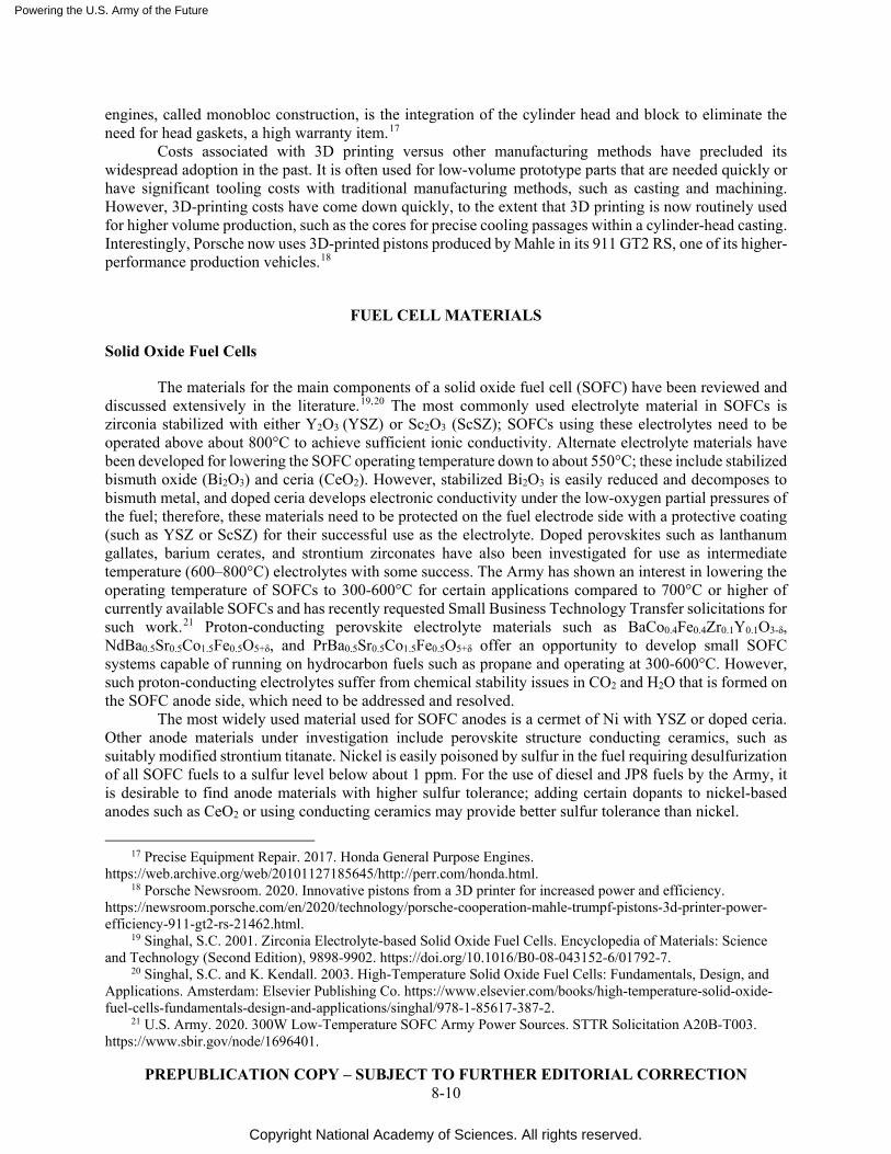
Powering the U.S. Army of the Future
Copyright National Academy of Sciences. All rights reserved.
PREPUBLICATION COPY – SUBJECT TO FURTHER EDITORIAL CORRECTION 8-10
engines, called monobloc construction, is the integration of the cylinder head and block to eliminate the need for head gaskets, a high warranty item.17
Costs associated with 3D printing versus other manufacturing methods have precluded its widespread adoption in the past. It is often used for low-volume prototype parts that are needed quickly or have significant tooling costs with traditional manufacturing methods, such as casting and machining. However, 3D-printing costs have come down quickly, to the extent that 3D printing is now routinely used for higher volume production, such as the cores for precise cooling passages within a cylinder-head casting. Interestingly, Porsche now uses 3D-printed pistons produced by Mahle in its 911 GT2 RS, one of its higher-performance production vehicles.18
FUEL CELL MATERIALS
Solid Oxide Fuel Cells
The materials for the main components of a solid oxide fuel cell (SOFC) have been reviewed and discussed extensively in the literature.19,20 The most commonly used electrolyte material in SOFCs is zirconia stabilized with either Y2O3 (YSZ) or Sc2O3 (ScSZ); SOFCs using these electrolytes need to be operated above about 800°C to achieve sufficient ionic conductivity. Alternate electrolyte materials have been developed for lowering the SOFC operating temperature down to about 550°C; these include stabilized bismuth oxide (Bi2O3) and ceria (CeO2). However, stabilized Bi2O3 is easily reduced and decomposes to bismuth metal, and doped ceria develops electronic conductivity under the low-oxygen partial pressures of the fuel; therefore, these materials need to be protected on the fuel electrode side with a protective coating (such as YSZ or ScSZ) for their successful use as the electrolyte. Doped perovskites such as lanthanum gallates, barium cerates, and strontium zirconates have also been investigated for use as intermediate temperature (600–800°C) electrolytes with some success. The Army has shown an interest in lowering the operating temperature of SOFCs to 300-600°C for certain applications compared to 700°C or higher of currently available SOFCs and has recently requested Small Business Technology Transfer solicitations for such work.21 Proton-conducting perovskite electrolyte materials such as BaCo0.4Fe0.4Zr0.1Y0.1O3-δ, NdBa0.5Sr0.5Co1.5Fe0.5O5+δ, and PrBa0.5Sr0.5Co1.5Fe0.5O5+δ offer an opportunity to develop small SOFC systems capable of running on hydrocarbon fuels such as propane and operating at 300-600°C. However, such proton-conducting electrolytes suffer from chemical stability issues in CO2 and H2O that is formed on the SOFC anode side, which need to be addressed and resolved.
The most widely used material used for SOFC anodes is a cermet of Ni with YSZ or doped ceria. Other anode materials under investigation include perovskite structure conducting ceramics, such as suitably modified strontium titanate. Nickel is easily poisoned by sulfur in the fuel requiring desulfurization of all SOFC fuels to a sulfur level below about 1 ppm. For the use of diesel and JP8 fuels by the Army, it is desirable to find anode materials with higher sulfur tolerance; adding certain dopants to nickel-based anodes such as CeO2 or using conducting ceramics may provide better sulfur tolerance than nickel.
17 Precise Equipment Repair. 2017. Honda General Purpose Engines.
https://web.archive.org/web/20101127185645/http://perr.com/honda.html. 18 Porsche Newsroom. 2020. Innovative pistons from a 3D printer for increased power and efficiency.
https://newsroom.porsche.com/en/2020/technology/porsche-cooperation-mahle-trumpf-pistons-3d-printer-power-efficiency-911-gt2-rs-21462.html.
19 Singhal, S.C. 2001. Zirconia Electrolyte-based Solid Oxide Fuel Cells. Encyclopedia of Materials: Science and Technology (Second Edition), 9898-9902. https://doi.org/10.1016/B0-08-043152-6/01792-7.
20 Singhal, S.C. and K. Kendall. 2003. High-Temperature Solid Oxide Fuel Cells: Fundamentals, Design, and Applications. Amsterdam: Elsevier Publishing Co. https://www.elsevier.com/books/high-temperature-solid-oxide-fuel-cells-fundamentals-design-and-applications/singhal/978-1-85617-387-2.
21 U.S. Army. 2020. 300W Low-Temperature SOFC Army Power Sources. STTR Solicitation A20B-T003. https://www.sbir.gov/node/1696401.
Powering the U.S. Army of the Future
Copyright National Academy of Sciences. All rights reserved.
PREPUBLICATION COPY – SUBJECT TO FURTHER EDITORIAL CORRECTION 8-11
The high operating temperature of SOFCs allows the use of only noble metals or electronic conducting oxides as cathode materials. However, the high cost of noble metals such as platinum or palladium prohibits their use in practical SOFCs. Doped lanthanum manganite (such as LSM) and doped lanthanum ferrite (such as LSCF) are most commonly used for SOFC cathodes. Other possible cathode materials include perovskite-structured oxides such as lanthanum cobaltite and lanthanum nickelates, suitably doped with alkali and alkaline earth ions to tailor the conductivity and thermal expansion coefficient. Selection and development of a suitable cathode material capable of providing high cell performance and performance stability with time is important in developing high power density and lower-cost SOFCs.
The choice of the interconnect material depends on the cell operating temperature. For cells operating at about 900-1,000°C, alkaline earth-doped lanthanum chromite (LaCrO3) is used for the SOFC cathode. However, this ceramic material is expensive and difficult to sinter. Therefore, in cells operating at 700-800°C, cheaper metallic interconnects, such as high Cr-content stainless steels, are used. However, chromium volatilization from these metallic interconnects tends to degrade the cell performance and therefore these interconnects require protective ceramic coatings to reduce chromium vaporization. Research is continuing to identify, develop, and optimize such protective coatings.
Proton-Exchange Membrane Fuel Cells
DOE has sponsored much of the work on proton-exchange membrane (PEM) fuel cells and has described the basic materials used for the various cell components.22 Central to a PEM fuel cell is the membrane electrode assembly (MEA), which includes the membrane (the proton conducting electrolyte), the two electrode layers (with catalysts), and the gas diffusion layers (GDLs). For low-temperature PEM fuel cells for operation from about 60°C to 90°C, the electrolyte membrane is generally a fully fluorinated polymer (such as Nafion manufactured by DuPont). For high-temperature PEM fuel cells for temperatures up to about 120°C, a polybenzimidazole (PBI) doped in phosphoric acid is generally used as the electrolyte. The electrolyte membrane is usually very thin, as thin as 20 microns. Anode and cathode catalyst layers are added to the two sides of the electrolyte membrane; conventional catalyst layers include nanometer-sized particles of platinum dispersed on a high-surface-area carbon support (Figure 8.4). The gas diffusion layer (GDL) typically consists of a sheet of carbon paper in which the carbon fibers are partially coated with polytetrafluoroethylene (PTFE); GDL facilitates transport of reactants into the catalyst layer and the removal of product water.
Continuing research and advancements are needed to reduce cost and improve performance and durability of PEM fuel cells. Platinum catalyst is a major cost of the cell; catalysts with reduced or no platinum group metal, increased activity and durability, and lower cost should be investigated. To reduce degradation, catalyst supports with increased durability and conductivity should also be investigated. To improve PEM fuel cell durability, research and development should focus on understanding the fuel cell degradation mechanisms and developing materials and strategies to overcome them. In addition, the practicality of on-board reformation of hydrocarbon fuels to produce CO- and S-free hydrogen for PEM fuel cells for mobile ground and air vehicles should be investigated.
22 U.S. DOE Office of Energy Efficiency and Renewable Energy. Parts of a Fuel Cell.
https://www.energy.gov/eere/fuelcells/parts-fuel-cell.
Powering the U.S. Army of the Future
Copyright National Academy of Sciences. All rights reserved.
PREPUBLICATION COPY – SUBJECT TO FURTHER EDITORIAL CORRECTION 8-12
FIGURE 8.4 (Left) transmission electron micrograph of the microstructure of the hydrogen oxidation catalyst (carbon-supported nanoscopic Pt) comprising the anode of a proton-exchange membrane (PEM) fuel cell and (right) schematic of the multifunctional catalytic nanophase where H2 molecules are oxidized to protons, which diffuse through a proton-conducting ionomer while electrons transport through the carbon to power a load. Rolison, D.R. 2004. Energy and the Environment: Perpetual Dilemma or Nanotechnology-Enabled Opportunity? Nanotechnology & the Environment, Karn, B., Masciangioli, T., Zhang, W.-X., Colvin, V., Alivisatos, A.P. (Eds.), (ACS Symp. Ser.) 890, Oxford University Press (Oxford, England), pp. 324-330.
TEMPERATURE AND RADIATION-RESISTANT MATERIALS FOR NUCLEAR REACTORS
A fundamental driving force in nuclear power is to have a higher safety margin in case of a reactor accident. There are three materials concepts with the goal to mitigate the negative zircaloy interactions with hot steam at high temperature, or to eliminate this chemical reaction altogether. One of the material concepts has the potential to advance the Army effort on developing a safe micro-nuclear reactor (MNR) for military installations based upon gas coolants, one of which is an inherently non-reactive gas, helium.
The most common and seemingly most straightforward solution for current light-water reactors is to coat the zircaloy cladding with a material that is resistant to oxidation with steam that produces dangerously explosive hydrogen gas. Over the last 8 years, chromium coating has gained a consensus in the nuclear reactor fuel community as being the most straightforward to deploy based on its stage of development and testing to date. It is a near-term option to improve current light-water reactor safety. Chromium-coated fuel rods were inserted into the Illinois Byron reactor in September 2019 to accumulate irradiation testing data and show that potential changes in the coefficient of thermal expansion, or chemical adhesion, do not cause the coating to delaminate under normal operating conditions. The final results of this testing effort are still pending; however, there still remains the question of how this coating will perform during a loss of coolant accident.
A second option is to use an alloy composed of iron, chromium, and aluminum. This metal can be extruded in the same way that zircaloy is and does not require the extra steps for coating. It also eliminates the problematic metal, zircaloy, that has such deleterious effects in accident conditions. However, this alloy introduces a significant penalty by absorbing neutrons, causing the fission process to generate less heat that can be converted into electricity. This problem would require additional fuel enrichment at a substantial cost to produce additional neutrons. Either way, there will be a negative effect on the economics of nuclear-generated electricity using this cladding. Although testing on this alloy started in February 2018 in a commercial reactor (Hatch-1 in Georgia) with no fuel, the neutron penalty makes it unlikely that it will eventually be a commercial product.
The third materials concept and the most promising option has been to replace the metal cladding with a pseudo-ductile ceramic. A unique ceramic material, SiC, has been in testing for decades and was first recognized by the fusion research community to be resistant to neutron damage. This robust material
Powering the U.S. Army of the Future
Copyright National Academy of Sciences. All rights reserved.
PREPUBLICATION COPY – SUBJECT TO FURTHER EDITORIAL CORRECTION 8-13
was already used in the nuclear industry to make the shell structure of Tri-structural Isotropic (TRISO) fuel particles, Each TRISO particle is made up of a uranium, carbon, and oxygen fuel kernel. The kernel is encapsulated by three layers of carbon- and ceramic-based materials that prevent the release of radioactive fission products. This shell structure is about 30-microns thick and has been extensively studied by Idaho National Laboratory, Oak Ridge National Laboratory, and Los Alamos National Laboratory. TRISO fuel is the current choice for the reactor designs to power Army micro-nuclear reactors (MNRs).
Today, SiC can also be made into 10-micron diameter fibers in bulk quantity. In addition, SiC is used in the semiconductor industry, as well as in the aerospace industry because of its temperature-resistant properties.
On the technology development side, the SiC fibers and SiC material can now be combined to make a ceramic fuel rod by having the fibers embedded in the bulk SiC material. This novel material is called SiC composite or SiC-SiC. The fundamental properties of the material enable resistance to high-temperature, high-stress, and high-neutron flux. In contrast, most metals tend to soften and lose their strength at temperatures above 700-800°C. Also, the metal in current reactors degrades as a result of neutron damage, which limits its lifetime. In addition, as mentioned earlier, zircoloy cladding has the deleterious thermal runaway reactions with steam that produce hydrogen gas and reactor core meltdowns. SiC-SiC would effectively eliminate all these problems because it does not disassociate until about 2,700°C. It also retains its strength to a temperature of 1,700°C in prototypical nuclear reactor accident conditions. It holds its shape during accident conditions through its reinforcing fibers, which act structurally like rebar in cement. Samples already tested in the high-flux isotope reactor (HFIR) at Oak Ridge National Laboratory show resilient material properties.23
TRISO fuel kernels are 200–500 microns in diameter, where the SiC shell serves as a tiny pressure vessel to retain fission gases that are the potentially dangerous emissions from a serious reactor accident. However, SiC-SiC composite matrix technologies can now be used to make fission gas leak-proof fuel rods and loaded in a similar fashion into light-water reactors as a standard fuel. This unique composite material is scheduled for insertion into the Idaho National Laboratory Advanced Test Reactor (ATR) in 2023.
SiC-SiC technology also applies to gas reactors, a coolant of choice for Army MNRs, that are typically designed to use costly TRISO fuel. However, using SiC-SiC fuel-rod elements can reduce the precious volume in the reactor core that is lost by using TRISO fuel. This replacement can enable higher power densities and increased electric power generation without a weight and volume penalty while maintaining safety.
Conclusion: The pursuit of higher performance nuclear reactors for the operational Army could benefit from Army S&T investments in the research and development of SiC-SiC materials to advance the safety of future deployed MNRs. (Tier 2/3, Lead)24
Other Material Considerations
Many technologies and systems of interest for the Army rely on critical materials. In general, it is better to develop technologies or systems that do not rely heavily on raw materials that are sourced outside the United States. Supply-chain issues can cause significant national security and economic implications for the country. As examples, ensuring sufficient availability of both lithium and cobalt for military
23 Linton, K. 2020. Scientists building 3D-printed nuclear reactor core use HFIR to test novel materials. Oak
Ridge National Laboratory. https://www.ornl.gov/news/scientists-building-3d-printed-nuclear-reactor-core-use-hfir-test-novel-materials.
24 See Appendix M and Chapter 7 for additional information.

Powering the U.S. Army of the Future
Copyright National Academy of Sciences. All rights reserved.
PREPUBLICATION COPY – SUBJECT TO FURTHER EDITORIAL CORRECTION 8-14
electrification are potential concerns.25 26 A recent evaluation of supply-chain risk versus natural abundance of battery-relevant elements buttressed this concern.27
Finding: As new material opportunities are identified, the countries to which they are sourced need to be considered.
25 Paraskova, T. 2020. A Major Supply Shortage Is Set to Hit Lithium Markets.
https://oilprice.com/Energy/Energy-General/A-Major-Supply-Shortage-Is-Set-To-Hit-Lithium-Markets.html. 26 Kobie, N. 2020. As electric car sales soar, the industry faces a cobalt crisis. Wired.
https://www.wired.co.uk/article/cobalt-battery-evs-shortage. 27 Hopkins, B.J., C.N. Chervin, M.B. Sassin, J.W. Long, D.R. Rolison, J.F. Parker. 2020. Low-cost green
synthesis of zinc sponge for rechargeable, sustainable batteries. Sustain. Energy Fuels 4:3363–3369.
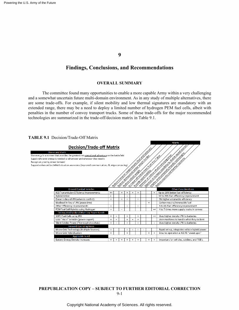
Powering the U.S. Army of the Future
Copyright National Academy of Sciences. All rights reserved.
PREPUBLICATION COPY – SUBJECT TO FURTHER EDITORIAL CORRECTION 9-1
9
Findings, Conclusions, and Recommendations
OVERALL SUMMARY
The committee found many opportunities to enable a more capable Army within a very challenging and a somewhat uncertain future multi-domain environment. As in any study of multiple alternatives, there are some trade-offs. For example, if silent mobility and low thermal signatures are mandatory with an extended range, there may be a need to deploy a limited number of hydrogen PEM fuel cells, albeit with penalties in the number of convoy transport trucks. Some of these trade-offs for the major recommended technologies are summarized in the trade-off/decision matrix in Table 9.1.
TABLE 9.1 Decision/Trade-Off Matrix
Powering the U.S. Army of the Future
Copyright National Academy of Sciences. All rights reserved.
PREPUBLICATION COPY – SUBJECT TO FURTHER EDITORIAL CORRECTION 9-2
CHAPTER 1—THE MULTI-DOMAIN OPERATIONS AND THE 2035 OPERATIONAL AND TECHNOLOGY ENVIRONMENT
Recommendation: For future studies, the Army should make available a clearer view of how multi-domain operations would be conducted, such as through detailed scenarios that describe science and technology needs for Multi Domain Operations in 2035.
CHAPTER 3—ENERGY SOURCES, CONVERSION DEVICES, AND STORAGE
Finding: Biodiesel may be a preferred fuel source during peacetime, given the growing need to address climate change. Certification for acceptability of the various sources would be needed to ensure any reliability concerns are addressed. (Tier 1, Lead). Finding: JP8, diesel, and/or biodiesel are all potential fuels to be supplied to the battlefield, particularly for high power–use applications such as armored ground combat vehicles. The complexity impact of using multiple fuels on the logistics chain needs to be compared to the benefits discussed. (Tier 1, Lead) Conclusion: Alternative liquid hydrocarbon fuels are compositionally variable and may introduce new durability concerns and, in the case of ATJ fuels, may not provide the cetane ratings needed to run properly in internal combustion engines. Although alternative fuels may be suitable for use on an ad hoc basis during combat operations, their suitability as a more permanent staple of the fuel supply system will require a careful cost benefit analysis on a case-by-case basis over a variety of environmental conditions. (Tier 1, Follow) Conclusion: A logistics distribution network for propane, natural gas, or hydrogen is unlikely to effectively replace hydrocarbon fuels on the battlefield because of their lower volumetric energy density (requiring more fuel transport trucks or convoys) and increased storage complexity versus JP8. Conclusion: Generating hydrogen from water using aluminum near the point of use offers potential advantages vis-à-vis transporting hydrogen in a supply convoy. However, a number of critical questions remain, including definition of the complete process to be used for each application. Recommendation: The Army should continue to explore the potential use of aluminum for onsite generation of hydrogen for use in proton exchange membrane fuel cells, not only for use in vehicles, but also for potential use in dismounted and base-camp applications. The latter may leverage ongoing Navy efforts. (Tier 2, Watch [U.S. Marine Corps and Office of Naval Research-led effort]) Conclusion: Given that fuel-cell technology may serve as a key enabling technology for near-silent operation, low thermal signature, and long-endurance UAVs/UGVs, combined with the prevalence of JP8 on the battlefield through 2035, the committee supports continued investment by the U.S. Army to fund the technology and economic analysis of the reformation process with diesel and JP8 fuels for use in SOFC power systems. (Tier 2, Lead) Conclusion: Similar to the 2016 Defense Science Board report,1 the committee concludes that solar, wind, and geothermal power sources present significant environmental benefits and are worthy of consideration
1 Anastasio, M., P. Kern, F. Bowman, J. Edmunds, G. Galloway, W. Madia, and W. Schneider. 2016. Task
Force on Energy Systems for Forward/Remote Operating Bases. Defense Science Board. Under Secretary of Defense for Acquisition, Technology, and Logistics (USD(AT&L)). P. 26–28. https://dsb.cto.mil/reports/2010s/Energy_Systems_for_Forward_Remote_Operating_Bases.pdf.
Powering the U.S. Army of the Future
Copyright National Academy of Sciences. All rights reserved.
PREPUBLICATION COPY – SUBJECT TO FURTHER EDITORIAL CORRECTION 9-3
for domestic and permanent overseas facilities. However, current and near-future iterations provide far less utility for mobile forces in multi-domain operations (MDO) and are unlikely to meet the power needs of a brigade combat team. As demonstrated in recent operations in Southwest Asia and elsewhere, such technologies can help reduce logistical requirements, especially in remote and dismounted operations. (Tier 1, Follow) Finding: Battery technology will be a part of Army operations for the foreseeable future. However, traditional Li-ion batteries present certain limitations that will not meet all of the Army’s emerging needs. However, redesigning electrode structures as 3D architectures may permit greater performance with retention of battery-effective energy density and can improve the performance of both primary and rechargeable batteries. Conclusion: Zn-based batteries, once moved to a new performance curve, may bypass the safety issues associated with Li-ion and the low-energy limitations of lead-acid while providing the following critical functions: (1) extended mission life for a given battery weight or volume; (2) platform simplification, because less balance-of-plant is required for safe, aqueous-based cell chemistry; and (3) simultaneous energy and power delivery from a single device. (Tier 2, Lead) Recommendation: Since the Army and Navy have many of the same battery safety concerns, close cooperation between the two services is encouraged. For the Army, fast rechargeability is an important objective that enables expeditious tapping into the vast supply of electricity available from generators and microgrids, as well as unmanned and manned combat vehicles. (Tier 1, 2, Lead)
CHAPTER 4—SYSTEM WIDE COMMUNICATION ISSUES IN SUPPORT OF MDO
Finding: 5G implementation on the battlefield offers significant bandwidth opportunities but presents some serious technical challenges, including P&E requirements on vehicles and for the dismounted soldier. 5G technologies should not be viewed as a “do it all” stand-alone solution but rather an opportunity to combine with other communications systems when appropriate.
Recommendation: To realize the benefits associated with a significant bandwidth increase, the Network Science Research Laboratory’s (NSRL) MANET (mobile ad hoc network) predictive model of network performance needs to be updated for 5G technologies and other emerging communication technologies (e.g., Internet of Things, 6G, and short-range, directed, and secure communications across a variety of devices) complemented with subsequent testing and field experimentation. (Tier 1, Lead)
CHAPTER 5—DISMOUNTED SOLDIER POWER AND LIGHT UAV/UGVs
Conclusion: The demands of the future operating environment (smaller formations supported by logistical and fire support) indicate that the Army’s power and energy (P&E) efforts should be focused less on heaviest power draw and more how P&E will support a distributed force structure. Finding: Thermophotovoltaic processes represent a promising opportunity in support of the dismounted soldier, while an upsized version might prove attractive for other applications, such as unmanned aerial vehicles (UAVs) and unmanned ground vehicles (UGVs).2 (Tier 2, Lead)
2 See Appendix I for a summary of possible technical challenges.
Powering the U.S. Army of the Future
Copyright National Academy of Sciences. All rights reserved.
PREPUBLICATION COPY – SUBJECT TO FURTHER EDITORIAL CORRECTION 9-4
Finding: Extensive use of “mule vehicles” from the Army’s SMET program provide an opportunity to recharge soldier batteries on the battlefield while lightening their weight burden, carrying ammunition, fuel, and water as well as batteries. (Tier 1, Lead) Conclusion: Further studies of dismounted soldier SOFC fuel cells utilizing propane, methanol, and other non-JP8 hydrocarbon fuels are not recommended beyond the work presently under way. This position might change under two scenarios. The first is that the field-implementable batch processing to desulfurize JP8 proves feasible to the 1 ppm level necessary for SOFCs. The second is that the point-of-use generation of hydrogen using activated aluminum or from hydrides such as alane (aluminum hydride) proves to be viable and practical, making possible the use of PEM fuel cells. (Tier 2, Watch)
Conclusion: The current level of study and development is appropriate to identify applications where a lightweight radioisotope decay system possibly coupled with a rechargeable battery could provide adequate power for present and future demands of the dismounted soldier. (Tier 2, Lead).
CHAPTER 6—VEHICLE POWER AND LARGE WEAPON SYSTEMS
Recommendation: The Army has undertaken a number of internal vehicle power plant programs (Advanced Powertrain Demonstrator, Projected Propulsion System, Advanced Mobility Experimental Prototype, and Platform Electrification Mobility) that will significantly enhance the Army’s operational capabilities in a Multi-Domain Operations environment. The committee recommends that their funding and timing continue as presently planned. Conclusion: The use of DF2 in lieu of JP8 could reduce the fuel supply line due to its higher energy density, which would decrease the number resupply missions required to sustain the operational units. Although this violates the Army’s present “single fuel policy” and will present some added logistics complexity challenges, further consideration by the Army is warranted. (Tier 1, Lead)
Recommendation: The Army should consider using closed-loop combustion control in all new engine designs as these engines, properly calibrated, could allow seamless operation between jet propellant 8 (JP8), diesel, and biodiesel while simultaneously increasing fuel efficiency while using JP8. (Tier 1, Lead) Conclusion: It is possible with substantial changes to design an engine that can run gasoline or diesel fuel interchangeability, however, the operational advantages such a capability would provide are judged to be small. Conclusion: Although technically possible, given the lower energy density of gaseous fuels and associated transport concerns, it is not recommended that mobile JP8/gaseous dual fuel engines be pursued. Recommendation: Free-piston engine technology is a rapidly developing field that offers some significant efficiency benefits versus other internal combustion engine mechanisms. The committee anticipates further improvements in the future. It is highly recommended that the Army monitor progress in this technology, in particular keeping track of work at Toyota and SWEng. (Tier 2, Watch) Conclusion: Gas turbines continue to be the powerpack of choice for most Army helicopters due to their power-to-weight advantages. On the other hand, diesel engines will continue to be the powerpack of choice for most ground combat and tactical vehicles due to their fuel efficiency advantages. Continued monitoring of the Air Force Research Laboratory’s Advanced Turbine Technologies for Affordable Mission-Capability
Powering the U.S. Army of the Future
Copyright National Academy of Sciences. All rights reserved.
PREPUBLICATION COPY – SUBJECT TO FURTHER EDITORIAL CORRECTION 9-5
(ATTAM) work is appropriate to assess whether this comparison between the two competing technologies changes in the future. (Tier 2, Lead) Conclusion: The power requirements to recharge the batteries of an all-electric armored ground combat vehicle make an all-electric design impractical. Because of lengthy recharging requirements and the requirement for extremely large electrical power sources, extensive use of battery electric tactical vehicles (including those in a supply convoy) also have limited practicality in a battlefield environment. The battery space requirements and additional weight limit effective all-battery vehicle use to select missions where silent operations are paramount and lengthy recharging times can be accommodated. Recommendation: The majority of planned funding for the All Electric Combat Powertrain and any anticipated funding for battery electric tactical vehicles should be reallocated to work on series hybrid, parallel hybrid, and/or other partial vehicle electrification concepts. (Tier 2, Lead) Recommendation: Continued engineering work on both series and parallel hybrids for the full complement of Army ground combat vehicles is strongly recommended because of the multiple benefits they provide. Although these studies can leverage work in the automotive industry, the specific needs of the Army (e.g., much heavier armored vehicles, less stringent emission standards) will result in significant differences. (Tier 2, Watch)
Recommendation: The Army should conduct a modeling and simulation analysis of different battlefield scenarios to define the optimal silent mobility range that is required for ground combat vehicles. The results will influence the size of the battery storage required and inform the optimum mix of research and development for parallel and series hybrid configurations. (Tier 1, Lead) Recommendation: Given the importance of power and energy on overall operational capabilities, it is strongly recommended that the scope of future warfare computer simulations (i.e., tactical exercises without troops) be expanded to include power and energy considerations. These simulations should include identification of the quantity and form of energy to be transported to the battlefield, how much of this could be replaced with local sources, where it would be stored, any set-up or take-down times, at what rate (i.e., power) that energy could be released, and how the energy needs of operating bases, vehicles, and dismounted soldiers would be replenished, including any refueling or recharging time requirements. When wargames are undertaken without computer simulation, a power and energy expert should be part of the evaluation team.
CHAPTER 7—FORWARD OPERATING BASE POWER
Conclusion: SOFC power systems would offer the same advantages and disadvantages in semi-permanent operating bases as in the commercial market. Their use could facilitate use of local fuel sources. (Tier 1, Watch) Conclusion: The Pele nuclear power plant program now under way may prove appropriate for domestic and permanent overseas bases. It will not, however, adequately meet the needs of expeditionary and defensive operations due to its limited power rating and mobility concerns. The committee also found disparate views as to the level of effort needed to comply with regulatory and safety requirements.3
3 See Appendix M for additional information.
Powering the U.S. Army of the Future
Copyright National Academy of Sciences. All rights reserved.
PREPUBLICATION COPY – SUBJECT TO FURTHER EDITORIAL CORRECTION 9-6
Recommendation: It is recommended that the detailed safety and regulatory requirements of a nuclear power plant be clearly defined and agreed to by all appropriate government agencies before prototype definition proceeds further. Furthermore, use cases for these reactors need to be carefully defined given the limited power and mobility of the envisioned systems. Additional safety and regulatory considerations of micro-nuclear powerplants are summarized in Appendix M. (Tier 1, Lead) Conclusion: Given their high net electric thermal efficiency, a wheel-mounted linear generator running on JP8 fuel could be as mobile as the Army’s present MEP-PU-810 DPGDS Prime Power Unit (PPU). Development of the fuel system substituting JP8 for CNG would be required. (Tier 2, Lead) Conclusion: Cutting-edge commercial chargers and auxiliary batteries automatically adapt to charge or deliver power at the appropriate voltage, current, and duty cycle. Implementing similar concepts among military systems, such as the STAMP microgrid, could build upon the Tactical Microgrid Standard effort to develop collateral standards and hardware/software technologies that provide “plug and play” functionality and intelligent control of all connected power devices. (Tier 1, Watch) Conclusion: In the future, the ability to use onboard vehicle electricity from a variety of mobile platforms, both tactical and tracked, will enable microgrids for mobile command centers to be quickly set-up under a variety of terrain conditions, including soft ground, where trailer towed MEPS systems cannot reach. (Tier 1, Lead)
CHAPTER 8—FUEL CONVERSION EFFICIENCY AND OTHER MATERIAL DRIVEN OPPORTUNITIES
Finding: Although SiC semiconductor devices can operate at higher temperatures than conventional Si devices, the operating temperature limits of passive components such as capacitors and inductors still establish the upper temperature limit of power electronic systems. Recommendation: To increase the temperature in which electronic energy conversion systems can operate, the Army should engage in research to develop higher temperature passive electrical components. Conclusion: The pursuit of higher performance nuclear reactors for the operational Army could benefit from Army S&T investments in the research and development of SiC-SiC materials to advance the safety of future deployed MNRs. (Tier 2/3, Lead)4 Finding: As new material opportunities are identified, the countries to which they are sourced need to be considered.
4 See Appendix M and Chapter 7 for additional information.

Powering the U.S. Army of the Future
Copyright National Academy of Sciences. All rights reserved.

Powering the U.S. Army of the Future
Copyright National Academy of Sciences. All rights reserved.
PREPUBLICATION COPY – SUBJECT TO FURTHER EDITORIAL CORRECTION
Appendixes

Powering the U.S. Army of the Future
Copyright National Academy of Sciences. All rights reserved.
Powering the U.S. Army of the Future
Copyright National Academy of Sciences. All rights reserved.
PREPUBLICATION COPY – SUBJECT TO FURTHER EDITORIAL CORRECTION A-1
A
Statement of Task
At the request of the Deputy Assistant Secretary of the Army for Research and Technology (DASA(RT)), the National Academies of Sciences, Engineering, and Medicine, under the auspices of the Board on Army Research and Development (BOARD), will appoint an ad hoc committee to conduct a fast-track study that examines U.S. Army’s future power requirements for sustaining a multi-domain operational conflict; and to what extent can emerging power generation and transmission technologies achieve the Army’s operational power requirements in 2035. The study will be based on one operational usage case identified by the Army as part of its ongoing efforts in multi-domain operations.
To facilitate the request for a Fast-Track Study, the data collection phase of the project will leverage the recent work in assessing alternate energy technologies from the Defense Science Board, the Air Force Scientific Advisory Board and the Army Science Board to survey and collate data on promising power technologies. Following the guidelines established by the Astro2020 decadal survey to create an opportunity for broad participation from the research community and ensure that the committee is aware of emerging technologies, early in the data-gathering phase of the project the committee will issue a request for white papers on activities, projects, or state of the profession considerations. Following the call for white papers, the committee will invite the authors of the most promising white papers to participate in a public forum to discuss their ideas with the committee.
The committee will:
a. Review the power needs as defined in the Army’s multi-domain operational scenario b. Assess candidate power technologies against the requirements of the operational usage case c. Recommend the technologies that have the potential to achieve the operational
requirements at the scale appropriate for the U.S. Army in 2035. The recommendations will help inform the Army’s investment priorities in technologies to help ensure that the power requirements of the Army’s future capability needs are achieved.
Powering the U.S. Army of the Future
Copyright National Academy of Sciences. All rights reserved.
PREPUBLICATION COPY – SUBJECT TO FURTHER EDITORIAL CORRECTION B-1
B
Biographies JOHN KOSZEWNIK, Co-Chair, is a retired chief technical officer for Achates Power, where his team has been responsible for the design and development of advanced diesel and gasoline opposed piston internal combustion engines. Among these is the Advanced Combat Engine (ACE) that is being jointly developed with Cummins, providing a leap-ahead capability in power density, fuel efficiency, and low heat rejection for the U.S. Army Ground Combat Fleet. Initial tests in the Bradley fighting vehicle are planned as pathways to the Next Generation Combat Vehicle. Prior to joining Achates Power in 2011, Koszewnik worked at Ford Motor Co. for 30 years, most recently as director of North American Diesel where he led engineering and business responsibilities for Ford diesel offerings within North America. Prior to that assignment Koszewnik was responsible for forward model engine engineering of all Ford’s gasoline V6, V8, and V10 engines leading an organization of approximately 1,200 employees. Koszewnik held a variety of other assignments while at Ford, including Manager of Worldwide Product Strategy and Manager of North American Marketing Product Plans. Following his distinguished career at Ford, Koszewnik was senior vice president of construction equipment product development at Case New Holland, where he managed 10 engineering centers worldwide and 650 employees. Additionally, he was director of production development at FEV Inc., an engineering services and consulting company, responsible for ensuring achievement of all functional requirements, quality, cost, and timing of production programs. He also supported product development and strategic study projects for the automotive, heavy truck, locomotive, and powertrain component supply industries. Koszewnik earned a bachelor’s degree in engineering from Stevens Institute of Technology and a Master in Business Administration from Harvard University. He is a Member of the National Academy of Engineering, elected in 2016 based on his past and present work in engine design. JOHN LUGINSLAND, Co-Chair, is a senior scientist and principal investigator at Confluent Sciences, LLC. Additionally, he is an adjunct professor of electrical and computer engineering at Michigan State University and a member of the Intelligence Science and Technology Experts Group (ISTEG) of the National Academy of Sciences. Previously, he served as a professor at Michigan State University in the Departments of Computational Mathematics, Science, and Engineering and Electrical and Computer Engineering, and various roles at the Air Force Office of Scientific Research (AFOSR), including acting division chief, division technical advisor, acting branch chief, program manager for plasma physics, and program manager for laser science. While at AFOSR, he also served as the program element monitor for Air Force Basic Research in the office of the Assistant Secretary of the Air Force for Acquisition. Additionally, Dr. Luginsland was a staff member at NumerEx LLC, Science Applications International Corporation, and the Air Force Research Laboratory (AFRL), where he was also a National Research Council postdoctoral researcher. He is a past chair of the IEEE’s Plasma Science and Applications Committee and a previous guest editor of IEEE Transactions on Plasma Science Special Issue on High Power Microwave Sources. Dr. Luginsland holds degrees from the University of Michigan in nuclear engineering. He is a fellow of the IEEE and the AFRL and received the IEEE Nuclear and Plasma Science Society’s Early Achievement Award. His research interests are in accelerator design, coherent radiation sources, dense kinetic plasmas, laser physics, serious games including agent-based models and wargames, as well as computational modeling including high-performance computing and machine learning
Powering the U.S. Army of the Future
Copyright National Academy of Sciences. All rights reserved.
PREPUBLICATION COPY – SUBJECT TO FURTHER EDITORIAL CORRECTION B-2
techniques. He has previously worked on operational energy issues, including compact modular nuclear fission reactors, magneto-inertial fusion energy concepts, directed energy electromagnetic power beaming for Stirling cycle engines, and plasma-based chemistry enhancements to combustion engines (Carnot, Brayton, and Otto cycles). JOHN KASSAKIAN is a professor of electrical engineering at the Massachusetts Institute of Technology (MIT) and former director of the MIT Laboratory for Electromagnetic and Electronic Systems. His field of expertise is power electronics and automotive electrical systems. He received his undergraduate and graduate degrees from MIT, and prior to joining the MIT faculty, he served a 2-year tour of duty in the U.S. Navy. Dr. Kassakian was the founding president of the Institute of Electrical and Electronic Engineers (IEEE) Power Electronics Society, served as the U.S. representative to the European Power Electronics Association, and is the recipient of the IEEE Centennial Medal, the IEEE William E. Newell Award, the IEEE Power Electronics Society’s Distinguished Service Award, the IEEE Millennium Medal, the European Power Electronics Association Achievement Award, and the Kabakjian Science Award. In 1989 he was elected a fellow of the IEEE and in 1993 he was elected to the National Academy of Engineering. In 1993 he was also awarded an IEEE Distinguished Lectureship through which he has lectured internationally. He has published extensively in the areas of power electronics, power systems, education and automotive electrical systems, co-chaired the MIT study “The Future of the Electric Grid” and is a co-author of the textbook Principles of Power Electronics. Prof. Kassakian is a member of the scientific advisory board of Lutron Electronics, and a former member of the boards of directors of ISO New England (the independent system operator of the New England electric utility system), Marvell Semiconductor, American Power Conversion Corp., Sheldahl Inc., and the scientific advisory boards of the AMP Automotive Business Unit and Tyco Electronics. MICHAEL MACLACHLAN is a physicist with experience in intelligence analysis, research and development, and counterproliferation, and topical background in space and missile systems, artificial intelligence, quantum information science, power and energy, energetics, international relations, and development, evaluation, and sustainment of advanced weapons. Dr. MacLachlan was a nuclear counterproliferation analyst for DIA and the Department of Energy for 10 years. During Operation Iraqi Freedom, he led the nuclear inspection team of the Iraq Survey Group in Baghdad. The rest of his career has been spent in research, development, test, and evaluation for the U.S. Air Force and the U.S. Army. He led a material-science research branch for AFRL, served as deputy chief of the laboratory’s advanced rocket-propulsion division, and managed development and sustainment projects in the Air Force’s ICBM and Space Shuttle programs. For the Army, he solicited, evaluated, and facilitated international basic-research projects, conferences, and scientific exchanges and was associate chief of the Army Research Laboratory’s Signal and Image Processing Division. PAUL ROEGE works with technology developers, communities, and national security leaders to build resilience with energy as a central focus. He leads strategic initiatives for Typhoon-HIL, Inc., a leading-edge power system modeling and simulation startup, and technology development for EthosGen, LLC, a heat harvesting innovator. He researches and publishes on energy and resilience topics, with more than 15 papers, articles and book chapters. Partnering with his wife, Colonel Roege is active in youth STEAM and leadership programs. He has nearly 40 years of experience as an engineer and leader in engineering, construction, and research, primarily in the energy field. As a U.S. Army engineer officer, Colonel Roege built military infrastructure and led combat engineering capabilities in Europe, Asia, Africa, and Central America. He planned and coordinated reconstruction of Iraqi oil production systems in 2003; later, he developed energy requirements and strategies for military operations, and was an early advocate within the Department of Defense for resilience as a guiding principle for community and national security. In his civilian career, Colonel Roege led engineering efforts associated with management and decommissioning of U.S. nuclear weapons production facilities, and disposition of plutonium from U.S. and former Soviet
Powering the U.S. Army of the Future
Copyright National Academy of Sciences. All rights reserved.
PREPUBLICATION COPY – SUBJECT TO FURTHER EDITORIAL CORRECTION B-3
weapons programs. He is a registered professional engineer and a West Point alumnus with graduate degrees from Boston University (MBA) and MIT (SM and Nuclear Engineer). DEBRA ROLISON heads the Advanced Electrochemical Materials section at the U.S. Naval Research Laboratory (NRL) in Washington, D.C., Her team designs, synthesizes, characterizes, and applies three-dimensionally structured, ultraporous, multifunctional, hold-in-your-hand nanoarchitectures for such rate-critical applications as catalysis, energy storage and conversion, and sensors. Dr. Rolison was a faculty scholar at Florida Atlantic University (1972–1975; B.S. in chemistry). She received her Ph.D. in chemistry from the University of North Carolina, Chapel Hill, in 1980 after demonstrating the Pt-like character of RuO2 electrodes in nonaqueous electrolytes, and helping to establish polymer-modified electrodes. She joined NRL as a staff scientist in 1980. Dr. Rolison is a fellow of the American Association for the Advancement of Science, the Association for Women in Science, the Materials Research Society, and the American Chemical Society. Among her major awards, she received the William H. Nichols Medal (2018), the E.O. Hulburt Award (2017; NRL’s top science award and the only female recipient in its 66 years of bestowal), the Department of the Navy Dr. Dolores M. Etter Top Scientist & Engineer Team Award (2016), the ACS Division of Analytical Chemistry Award in Electrochemistry (2014), the Charles N. Reilley Award of the Society for Electroanalytical Chemistry (2012), the ACS Award in the Chemistry of Materials (2011), and the Hillebrand Prize of the Chemical Society of Washington (2011). Her editorial advisory board service includes Chemical Reviews, Analytical Chemistry, Langmuir, Journal of Electroanalytical Chemistry, Advanced Energy Materials, and the inaugural boards of Nano Letters, the Encyclopedia of Nanoscience and Nanotechnology, Annual Review in Analytical Chemistry, and ACS Applied Energy Materials. She also writes and lectures widely on issues affecting women (and men) in science, including proposing Title IX assessments of science and engineering departments. She is the author of over 230 articles and holds 44 U.S. patents. SUBHASH SINGHAL served as a Battelle fellow and director, fuel cells, at Pacific Northwest National Laboratory (PNNL) from 2000 to 2013 and provided senior technical, managerial, and commercialization leadership to the laboratory’s extensive fuel cell and clean energy programs. Before that, he worked for over 29 years, initially as a scientist and later as manager-fuel cell technology at the Westinghouse Electric Corporation. While at Westinghouse (that later became part of Siemens), he conducted and/or managed major research, development, and demonstration programs on advanced materials and energy systems including steam and gas turbines, coal gasification, and fuel cells. From 1984 to 2000, as manager of Fuel Cell Technology there, he was responsible for the development of solid oxide fuel cells for stationary power generation. In this role, he led an internationally recognized group in fuel cell technology and brought these cells from a few-watt laboratory curiosity to fully integrated 200 kW size power generation systems. He has authored 100 scientific publications, edited 21 books, received 13 patents, and given over 340 plenary, keynote and invited presentations worldwide. Dr. Singhal is the recognized world leader in solid oxide fuel cells for power generation. He has served on the advisory boards of the Department of Materials Science and Engineering at the University of Florida, Florida Institute for Sustainable Energy, Division of Materials Science and Engineering at Boston University, Materials Research Science and Engineering Center at the University of Maryland, Center on Nanostructuring for Efficient Energy Conversion at Stanford University, and the Fuel Cell Institute at the National University of Malaysia. Dr. Singhal is a member of the U.S. National Academy of Engineering; a founding member and Past President of the Washington State Academy of Sciences; a fellow of American Ceramic Society, The Electrochemical Society, ASM International, and the American Association for the Advancement of Science; and a senior member of the Mineral, Metals & Materials Society. He served on the Electrochemical Society’s board of directors during 1992-1994; received its Outstanding Achievement Award in High Temperature Materials in 1994; its inaugural Subhash Singhal Award in 2019 in recognition and honor of seminal and long-lasting contributions to the science and technology of solid oxide fuel cells; and was the chairman of its International Symposium on Solid Oxide Fuel Cells during 1989-2019. He served as president of the International Society for Solid State Ionics during 2003-2005. He received the American Ceramic Society’s
Powering the U.S. Army of the Future
Copyright National Academy of Sciences. All rights reserved.
PREPUBLICATION COPY – SUBJECT TO FURTHER EDITORIAL CORRECTION B-4
Edward Orton Jr. Memorial Award in 2001; an Invited Professorship Award from the Japan Ministry of Science, Education, and Culture in 2002; Christian Friedrich Schoenbein Gold Medal from the European Fuel Cell Forum in 2006; Fuel Cell Seminar Award for outstanding leadership and innovation in the promotion and advancement of fuel cell technology in 2007; and the prestigious Grove Medal in 2008 for sustained advances in fuel cell technology. Dr. Singhal served on the editorial board of the Elsevier’s Journal of Power Sources and was an associate editor of ASME’s Journal of Fuel Cell Science and Technology. He has also served on many national and international advisory panels, including those of the National Academies of Sciences, Engineering, and Medicine, the Materials Properties Council, the National Science Foundation, U.S. Department of Energy, NATO Advanced Study Institutes and NATO Science for Peace Programs, United Nations Development Program (UNDP), United Nations Industrial Development Organization (UNIDO), International Energy Agency (IEA), and the European Commission. JOHN SZYMANSKI is the chief scientist for Global Security at Los Alamos National Laboratory. Before that assignment he was the chief scientist for Threat Identification and Response at Los Alamos. As a member of the Air Force Scientific Advisory Board, he was responsible for the SAB S&T reviews of AFRL. Before his present assignments, he was the acting deputy leader of the Defense Systems and Analysis Division at Los Alamos. From 2010 to May 2012, he was a member of the White House Office of Science and Technology Policy, where his portfolio included nuclear defense R&D, isotope supply, future computing, and national security space. Prior to joining the White House, Dr. Szymanski worked at Los Alamos as program director for nuclear nonproliferation, a portfolio of programs with funding exceeding $300 million. This portfolio included national security space programs, nuclear-materials safeguards and security, and nonproliferation and counterproliferation R&D. Previously, he was program manager for nuclear nonproliferation research and development. In the past, he led several research efforts at Los Alamos, including the development of the Multispectral Thermal Imager satellite data center and genetic algorithms used for automated feature extraction in images. His research interests include optical remote sensing, nuclear defense science and technology, and national-security policy issues. His technical experience includes the design and fabrication of high-speed digital electronics, radiation detectors, real-time data acquisition systems, algorithm development, applications of genetic algorithms, and large-scale simulations. Dr. Szymanski received his B.S., M.S., and Ph.D. degrees in physics from Carnegie Mellon University, where his thesis research was in experimental nuclear physics. He continued working in nuclear physics research at Los Alamos National Laboratory and then as a faculty member at Indiana University. The Department of Energy, National Science Foundation, internal sources, and other U.S. government agencies have funded his research. His activities have included the American Physical Society, Institute for Nuclear Materials Management, IEEE, and SPIE. He has organized workshops, several special conference sessions and served on many local and national committees. He is the author of 40 journal publications, many invited talks and numerous conference proceedings. His honors include an R&D 100 award, two Los Alamos Distinguished Performance awards, an INMM “support above and beyond” award, DOE/NNSA recognition for superior achievement, and several fellowships and teaching awards.
Powering the U.S. Army of the Future
Copyright National Academy of Sciences. All rights reserved.
PREPUBLICATION COPY – SUBJECT TO FURTHER EDITORIAL CORRECTION C-1
C
Call for White Papers
INTRODUCTION
The National Academies of Sciences, Engineering, and Medicine is issuing a call for white papers
in support of an ongoing study activity to assess existing and novel electric power and energy technologies to support Army multi-domain operations (MDO) in the 2035 environment. This call for white papers is soliciting input on candidate P&E technologies (existing or under development) with the potential to achieve operational readiness to support Army MDO in 2035. The white papers will serve as the primary data-gathering effort to inform the larger study report. The authors of the most promising white papers will be invited to join a public forum in May to discuss their ideas with the study committee.
BACKGROUND AND CONTEXT FOR THE CALL FOR WHITE PAPERS
Army Modernization Strategy and Multi-Domain Operations
The Army Modernization Strategy (AMS) (Link) describes how the Army will transform into a multi-domain operations (MDO) force by 2035 to meet its enduring responsibility as part of the Joint Force1 to provide for the defense of the United States. The essence of Army’s MDO concept is to support the Joint Force in the rapid and continuous integration of all domains of warfare—land, sea, air, space, and cyberspace—to deter short of conflict but fight and win if deterrence fails. The enabling technology for multi-domain operations will be advanced communications and information processing technology which will place new demands on the Army’s deployed P&E infrastructure to ensure that it can meet the demands of the MDO environment in 2035.
The tenets of MDO create significant performance challenges for several technologies over the next fifteen years. Calibrated force postures,2 multi-domain formations, and the ability to rapidly converge effects from multiple domains will require a highly integrated and rapidly reconfigurable force that can execute and sustain complex operations with great speed and precision. Rapidly evolving technologies, especially information technologies and those that enable and sustain them, particularly power and energy, will be fundamental to achieving these goals. The purpose of this call is to solicit white papers outlining feasible and practical technology options that could address potential P&E needs of the Army as it executes its MDO vision in 2035.
1 A force composed of elements, assigned or attached, of two or more Military Departments operating under a
single joint force commander. 2 Refers to the combination of position and the ability to maneuver across strategic distances. It includes, but is
not limited, to basing and facilities, formations and equipment readiness, the distribution of capabilities across components, strategic transport availability, interoperability, access, and authorities.
Powering the U.S. Army of the Future
Copyright National Academy of Sciences. All rights reserved.
PREPUBLICATION COPY – SUBJECT TO FURTHER EDITORIAL CORRECTION C-2
The Army’s MDO Strategic Goals and the Future Importance of Sensing and Information Technologies
The continuous integration of all domains of warfare demands a proliferation of sensors and intelligent devices, supported with increased communication bandwidth and high-speed processing of data sets into actionable information for use at all operational levels. Evolving 5G technologies in the commercial world can help with these technical challenges and offer a good pacing technology for assessment. However, commercial technology and infrastructure development will not fully satisfy the Army’s unique operational challenges, which require worldwide deployability and functionality under degraded/hostile conditions.
For example, little or no ground-based commercial communications infrastructure may be available within the battlespace; in future operations, even space-based networks may be challenged. This circumstance requires the Army to have a self-contained, mobile, and resilient integrated sensor, communications and information infrastructure. Furthermore, complex battlespace environments create significant technical challenges for modern cellular network technologies. For example, the Army typically fights in complex terrain while experiencing variable climates such as rain, snow, hail, dust, fog, etc. Emerging 5G communications, which promise disruptive bandwidth, are relatively short range and particularly sensitive to signal strength and environmental conditions (to include weather and terrain). These limitations can require increases in the density of nodes and signal strength; longer transmission duration; and proliferation of mobile processing stations. These trends alone will challenge mobile power and energy capabilities in terms of both power demand and energy endurance.
Mobile P&E to Support Network-Enabled MDO
Mobile P&E is fundamental to all Army capabilities; however, the P&E that support communications and information needs varies significantly depending upon the use case. During maneuver, the power plants for the Abrams and many other ground combat vehicles expend a small fraction of their energy on communications and processing. Technologies being developed to support onboard power needs for mobility and lethality over the next 15 years should be more than adequate to meet information processing and communication needs when underway. However, at times ground combat vehicles will enter “silent watch” which requires then to minimize all acoustic and infrared signal emissions. This in turn normally requires them to remain stationary and operate without the use of their main or auxiliary engines. As a result, a platform’s information and communications systems will need to operate without the main engine output.
Meanwhile, dismounted soldiers, small electric and hybrid drones, micro-autonomous sensors, systems, and communication nodes, autonomous ground vehicles, manned vehicles on “silent watch,” and mobile command posts and data centers each will require significant improvement in P&E technology over the next 15 years to support network-enabled MDO. Moreover, the ability to operate mobile command posts and the proliferation of persistent sensors, processors, and transceivers at the forward edge of the battlespace represent an important new focus area that supplements past soldier, platform (e.g. vehicle or drones), and forward operating base use cases.
In the past, P&E performance parameters were generated as an afterthought to new technology aspirations. Twenty-first century capabilities, however, require more sophisticated treatment of energy as an integral component within the system design process. Sensing, processing, and communicating technologies, for example, fundamentally involve the physics and management of energy. How effectively can a sensor distinguish electromagnetic or other signals from noise; convert the information into usable form; and securely transmit the signal to become integrated into the operational picture? Not only energy density but also power management, conversion efficiency, EM radiation and coupling efficiencies, environmental tolerance and reliability are just a few energy attributes that are fundamental to technology performance that will support MDO.
Powering the U.S. Army of the Future
Copyright National Academy of Sciences. All rights reserved.
PREPUBLICATION COPY – SUBJECT TO FURTHER EDITORIAL CORRECTION C-3
Multi-Domain Operations represents a new warfighting concept for which we lack field data regarding key performance parameters and constraints. The present study represents an opportunity to inform “the art of the possible,” with an emphasis on what is practical and feasible by identifying technologies that could significantly contribute to envisioned operations and feasibly could be made available. To that end, this white paper call will take a technology push approach to future mobile P&E technologies, especially taking account of the opportunities and demands of distributed information technologies (such as 5G) within the adverse environments the Army would be expected to fight.
Two-Tiered Approach to Estimating P&E Technology Performance for Distributed Information Enabled MDO
For this call for white papers, all P&E technologies will be considered; however, it is crucial to
keep in mind that the emphasis will be on those most practical and feasible technologies relevant for sustaining the support of distributed information capabilities associated with MDO. To effectively evaluate the performance headroom of P&E technologies out to the year 2035, this call for white papers will take a two-tiered approach to assessment. The first-tier involves P&E technologies that would achieve a five-year system demonstration from TRL 5-7 to TRL 7-8, then ten years to acquire an operational system by 2035. The second-tier sources would deliver a concept to feasibility demonstration from TRL 4-6 to TRL 6-8 in fifteen years with an operational system acquired sometime after the demo. The metrics used to assess technology and system performance will include specific energy and power output, efficiency, weight, volume, endurance (time to refuel, recharge, or replace), durability (performance in austere or hazardous environments or under shock or damage), vulnerability to attack and disruption, portability/mobility, supply and maintenance concerns (e.g. challenges of material and fuel sourcing and rarity of materials), investment and unit cost, safety issues, personnel training requirements, and policy and regulatory concerns. Physics and engineering principles will be used to judge the credibility of the P&E sources for each tier. To be considered, detailed engineering and system descriptions, which support the performance characteristics of each P&E source will be required.
WHITE PAPER GUIDELINES SUMMARY
The white papers should describe and evaluate existing or emerging P&E technologies and technical solutions that are feasible and practical to support Army P&E needs for MDO in the 2035 timeframe. The demands for distributed information technologies should be considered as a pacing technology but responses need not be limited to the specifics of systems available today (such as 5G); they should include alternative communications technologies that might also support Army MDO operations as described in the previous section. Papers may and should to the extent possible, consider all relevant P&E aspects of the architecture, including energy storage, conversion, transmission, and relay requirements, and power management technologies. Energy/power sources to be considered can range from as little as two watt systems, for individual soldier platforms and distributed and proliferated sensors, processors and transceivers in the battlespace, to more than 10 megawatt systems for forward and remote operating bases.
Each technology or technical solution should be categorized into one of the following categories:
• Tier 1: System demonstration achievable within 5 years from TRL 5-7 and TRL 7-8, and an operational system acquirable by 2035.
• Tier 2: Concept or System demonstration achievable in 15 years with an estimate of the additional time required for an acquired system
The white papers should assess the following parameters for each technology or technical solution
presented: specific energy and power output, efficiency, weight, volume, endurance (time to refuel,
Powering the U.S. Army of the Future
Copyright National Academy of Sciences. All rights reserved.
PREPUBLICATION COPY – SUBJECT TO FURTHER EDITORIAL CORRECTION C-4
recharge, or replace), durability (performance in austere or hazardous environments or under shock or damage), vulnerability to attack and disruption, portability/mobility, supply and maintenance concerns (e.g. challenges of material and fuel sourcing and rarity of materials), investment and unit cost, safety issues, personnel training requirements, and policy and regulatory concerns. The white papers may also offer additional or alternative assessment parameters that are critical or otherwise relevant but not listed here.
Selection Process and Next Steps White papers will be selected on their level of detail and analysis and the extent to which they meet
the parameters provided above. In April, the white paper authors selected to advance will be provided with additional details and parameters regarding the MDO operating environment in 2035 to adapt their proposals and presentations at the public forum to be held on May 18-21, 2020. Selected white paper authors will be asked to provide presentations and engage in dialogue with the study committee at the forum in May.
USE OF THE PAPERS
The white paper submissions will be evaluated by the study committee and used to inform report content. The authors of the most promising white papers will be invited to participate in a public forum to discuss their ideas with the committee and engage with the authors of other selected white papers. The papers and discussions with paper authors will provide the primary source of data gathering for the report findings, conclusions, and recommendations.
Information gathered will be used by the committee solely to inform this project and the study report. However, per the requirements established in the Federal Advisory Committee Act, to which this effort and committee is subject, all white papers will be collected in a Public Access File (PAF). Materials contained within the PAF are subject to release per the Freedom of Information Act (FOIA). Please do not include any proprietary information in your responses. Responses must be Distribution A. This activity is unclassified.
Powering the U.S. Army of the Future
Copyright National Academy of Sciences. All rights reserved.
PREPUBLICATION COPY – SUBJECT TO FURTHER EDITORIAL CORRECTION D-1
D
List of Data Gathering Sessions
• December 5, 2019 • February 12, 2020 (video teleconference) • March 30–April 1, 2020 (data-gathering session; video teleconference) • April 7, 2020 (data-gathering session; video teleconference) • April 14, 2020 (data-gathering session; video teleconference) • April 24, 2020 (data-gathering session; video teleconference) • May 11, 2020 (data-gathering session; video teleconference) • May 18–20, 2020 (data-gathering session; video teleconference) • May 21, 2020 (video teleconference) • June 12, 2020 (data-gathering session; video teleconference) • June 22, 2020 (data-gathering session; video teleconference) • July 7, 2020 (Video teleconference) • July 8–9, 2020 (data-gathering session; video teleconference) • August 10, 2020 (data-gathering session; video teleconference) • August 17, 2020 (data-gathering session; video teleconference) • August 18, 2020 (data-gathering session; video teleconference) • August 26–27, 2020 (video teleconference) • September 10, 2020 (data-gathering session; video teleconference) • December 14, 2020 (video teleconference)
Powering the U.S. Army of the Future
Copyright National Academy of Sciences. All rights reserved.
PREPUBLICATION COPY – SUBJECT TO FURTHER EDITORIAL CORRECTION E-1
E
Abstracts of Selected White Papers
All Graphene Nano Ribbon on Diamond Substrate Energy Efficient Power Electronics Switch
Dr. Cemal Basaran
In order to meet current and emerging needs and deliver future force capabilities the US Army needs to develop and implement the most sophisticated energy efficient power electronics technologies. This white paper focuses Army’s stated need for “increasing forces’ freedom of action through energy security and efficient power systems to provide desired power at the manned/unmanned platforms, at the system and personal levels.” Army requires “efficient and secure power systems for the forces to provide the required power when and where needed with great deal of reliability.” The existing power electronics systems are based on traditional metals, like copper and aluminum and traditional semiconductors. They cannot provide the future needs of the Army. Hence, there is a need to develop a new technology based on covalent bonded materials like graphene.
Insatiate demand for miniaturization of power electronics requires a substantial reduction in the dimensions of the components used in power electronics (such as metal interconnects and solder joints). At the same time, due to demand for faster and more functional power electronics that can operate at higher temperatures, there is an evolution toward higher voltages and higher power densities. These requirements lead to high current density in these components (>10^6 Amp/Cm^2). Physical limits to increasing the current density—and limiting further miniaturization—in metals are electromigration and thermomigration phenomena. Electromigration in interconnect metal lines, and solder joints is the major failure phenomenon in next generation power electronics As result there is a need to develop the next generation power electronics by replacing the traditional metals, with covalent bonded materials like Graphene Nano Ribbon which do not experience electromigration and thermomigration in the traditional sense.
The technology proposed in the white paper was developed by ONR funding in the last 10 years and recently, it was patented by USPTO,[Patent No.: US 10,593,778 B1]. However, there is a need for funding to develop the technology needed to package it and manufacture it. Because it was funded by US Navy, our patent requires US based manufacturing. Depending on the funding level, this device can be made available to US Army in 5 to 7 years.
Converting Wastewater to Distributed Power and Energy: Addressing Two Critical Utility Needs of the Future Army with One Advanced Technology
Dr. Aaron C. Petri, Dr. Dawn Morrison, Mr. Nicholas Josefik, Mr. Nathan Peterson, and Dr. Kathryn Guy
The future Army multi-domain operating (MDO) force will face significant changes and challenges over the next 15 years in terms of who, where and how they fight, and the tools and technology they use and confront on the battlefield. What will not change is the Army’s need to supply consistent power and energy (P&E) to deployed forces, and the Army’s requirement to manage human wastewater. The bottom
Powering the U.S. Army of the Future
Copyright National Academy of Sciences. All rights reserved.
PREPUBLICATION COPY – SUBJECT TO FURTHER EDITORIAL CORRECTION E-2
line: no matter where the future soldier goes or what they do, the saying “everybody poops” will continue to hold true. The Distributed Low-Energy Wastewater Treatment (DLEWT) system, developed by the U.S. Army Corps of Engineers, Engineer Research Development Center, Construction Engineering Research Laboratory (ERDC-CERL), is a compact, portable containerized wastewater treatment system that converts wastewater into P&E, and reusable water. As a Tier 1 technology, DLEWT has significant potential to increase operational energy and water endurance with a low-maintenance portable treatment system that will help future deployed forces overcome their dependence on resupply chain logistics. The DLEWT system uses a unique combination of advanced wastewater treatment technologies that offer at least 75 percent water reuse and energy harvesting. On average, 5.4 kilowatt hours of electricity can be generated per every 1,000 gallons of influent wastewater or 8.6 kWh/day for a battalion of 800 troops. We project that this technology will extend the tether of fuel and water in an MDO environment reducing annual resupply convoys in Iraq and Afghanistan by 2,100 trips and saving over $45 million dollars annually in fuel. Over 5-years, we estimate 175 water re-supply casualties could be avoided through implementation of DLEWT.
High Performance Hybrid Solar Photovoltaic Thermoelectric Panel
Dr. Hongbin Ma and Dr. Pengtao Wang
Solar photovoltaic (PV) panels and solar thermoelectric generators (TEG) are two major technologies for direct solar-electricity generation. One of the primary challenges of solar PV and TEG is low solar-electricity efficiency. The proposed hybrid solar PV/TEG panel integrates state-of-the-art technologies of low concentrating solar photovoltaic (CPV) cells, solar TEG, oscillating heat pipe (OHP), and radiative sky cooling (RSC). Utilizing the extra high thermal conductivity of OHPs, CPV, TEG, and RSC can be effectively integrated together to efficiently utilize the solar energy and generate electricity. The proposed hybrid solar panel can achieve a high solar electric efficiency of 40 percent with a power output of 100 W in 5 years and achieve an expected efficiency of 50 percent in 2035. The proposed PV/TEG panel has high reliability and durability, and requires no maintenance due to no mechanical moving parts. The proposed technology is now on the TRL-5, and on the TRL-7/8 within 5 years. The proposed PT/TEG panel supports the Army’s MDO as a basic unit of solar microgrids in installation and contingency basing, or as a single operational power source for “silent watching.” The efficiency and inertia of the proposed system will greatly benefit from the rapid expansion of the global solar panel market.
Multi-fuel Capable Hybrid-Electric Propulsion
Dr. Chol-Bum “Mike” Kweon
The Army’s Multi Domain Operations (MDO) will require extensive communications and information processing with the large number of unmanned systems which are teamed with manned systems in the future autonomous battlefield. Unmanned air and ground systems will play critical roles in executing new capabilities for MDO, especially in the close fight and deep maneuver areas. However, these advanced capabilities will require more energy and power. The current energy and power solutions for unmanned systems are extremely limited because technologies have not been developed in the power range from 5 to 200 kW. The Combat Capabilities Development Command Army Research Laboratory (CCDC ARL) initiated a new program, Multi-fuel Capable Hybrid-Electric Propulsion (MCHEP) to address the energy and power needs for the future autonomous systems. Specific technologies include ignition assistant, advanced aluminum alloys, advanced materials for fuel
Powering the U.S. Army of the Future
Copyright National Academy of Sciences. All rights reserved.
PREPUBLICATION COPY – SUBJECT TO FURTHER EDITORIAL CORRECTION E-3
systems, advanced electrified turbocharging, and hybrid-electric optimization and integration technologies. These technology areas were formulated to address the fundamental challenges in materials, design, and sensing and control methods, to accelerate component technology development to meet the future Army requirements.
Hybrid Power Source for the Military Aircraft Fleet of the 2035 Environment
Mr. Manuel Mar
This paper presents a general overview of military air fleet energy consumption and emphasizes the development of hybrid power sources for aircraft. Technologies such as lithium ion batteries and hydrogen fuel cells are still under development to be scaled and used in airplanes. However, it is inevitable the introduction of this technologies in a mid-term scenario by the next decade of 2030. The numbers are excellent on paper with high-efficiency performance and excellent energy density but the scalability of these technologies is still a challenge. The main idea of this white paper is not proposing a full electric or hydrogen fueled airplanes, instead they should still use hydrocarbons starting with at least 1 percent of electricity as part of energy power system.
Fuel Flexible Engine-Generators with High Power & Energy Densities for Future Unmanned Aircraft Systems and Soldiers
Dr. Sindhu Preetham Burugupally, Mr. Kyu Cho, Dr. Christopher Depcik, Ms. Alison Park, and Mr.
Suman Saripalli
There are limitations to the range of small Unmanned Aircraft Systems (UAS) along with critical power generation gaps for Soldiers stemming from the respectively low energy density of lithium (Li) ion batteries. The use of combustion using conventional fuels (liquid and gaseous based) can provide a significant range benefit for both UAS and Soldiers given their magnitude increase in mass and volume specific energy over Li-ion batteries. However, current internal combustion engines (ICEs) on the appropriate power generation scale needed (100-1000 W) are beset by low efficiencies. Here, employing the evolving technology of Additive Manufacturing (AM) changes the paradigm of construction for ICEs that opens new avenues of efficiency while reducing size and weight. Current Tier 2 efforts at the TRL 4 level by our group include the successful testing of an AM-enabled ICE fabricated in cooperation with the Army Research Laboratory. Looking towards 2035, utilizing advances in AM to move from this existing ICE to a novel free piston engine-linear generator design promises high efficiencies, fuel flexibility, and direct generation of electricity for hybrid configurations at a minimum of weight with reduced noise and exhaust signatures. This facilitates the single fuel forward concept while allowing for localized fuel compatibility and the continued advancement of alternative fuels. Overall, this enables Army multi-domain operations by delivering a modernized power & energy solution that draws upon an emerging technology.
Solid Oxide Fuel Cell (SOFC) Technology for Powering the U.S. Army of the Future
Dr. Nguyen Minh
Powering the U.S. Army of the Future
Copyright National Academy of Sciences. All rights reserved.
PREPUBLICATION COPY – SUBJECT TO FURTHER EDITORIAL CORRECTION E-4
Solid oxide fuel cell (SOFC) technology has been considered and developed for a broad spectrum of power generation applications ranging from watt-sized devices to multi-megawatt power plants. The attractive features of the SOFC are its flexibility (fuel), compatibility (environment), capability (multifunction), adaptability (diverse application) and affordability (cost effectiveness). This presentation discusses the technological status and examines the key parameters of the technology critical to supporting the U.S. Army power and energy (P&E) needs for multi-domain operations (MDO) in the 2035 timeframe - namely, specific energy and power output, efficiency, weight and volume, durability, vulnerability to attack and disruption, portability/mobility, supply and maintenance concerns, investment and unit cost, safety issues, personnel training requirements, and policy and regulatory concerns.
Powering the U.S. Army of the Future
Mr. Shailesh Atreya, Dr. Chellappa Balan, and Ms. Tina Stoia
Power demands across the board for the U.S. Army are expected to grow significantly to support state-of-the-art and emerging equipment required for modern warfare. This discussion will address Boeing’s concept for non-traditional power generation for Forward Operating Bases (FOBs), as well as solutions for ‘silent watch’ operation of tanks and Bradley vehicles. FOBs are currently supported by large diesel-powered gen-sets that are noisy, inefficient and emit high-temperature exhaust. Recent developments in SOFC technology enable a power plant, with a low acoustic signature, that is at least 50 percent more efficient than current diesel gen-sets. The fuel savings offered by an SOFC gen-set reduce operating costs and reduce the frequency of high-risk fuel transport in contested regions. Mobile platforms, such as tanks and Bradley Fighting Vehicles, are required to operate in ‘silent watch’ mode where they remain stationary and quiet for extended periods. In ‘silent watch’ mode, the main engine remains off to conserve fuel and reduce acoustic and IR signatures, but the use of batteries is limiting because the vehicle would need to periodically abandon ‘silent watch’ mode as it turns on its engine to recharge the batteries. An SOFC-based auxiliary power unit, operating on diesel fuel, enables extended periods of ‘silent watch’ with low acoustic and IR signatures.
Safe, High Energy and High Power Li-ion Batteries for Army Multi-domain Operations
Dr. Jiang Fan, Mr. Christopher Kompella, Dr. Lasantha Korala, and Dr. Dengguo Wu
The mobile power and energy (P&E) technologies are fundamental for all US Army capabilities, and Li-ion batteries provide a ubiquitous solution in this regard due to their comparatively high energy/power density and reduced life cycle cost. However, current state-of-the-art Li-ion battery technologies are incapable of delivering high energy/power output safely under degraded/hostile conditions. The American Lithium Energy corporation (ALE) has been leading the efforts to fulfill the performance demands required for the Army to transform into multi-domain operations (MDO) force via innovating Li-ion battery technologies that can deliver high energy/power performance safely. As a domestic technology developer and cell manufacturer, this presentation will introduce ALE’s contribution to the past DoD projects and performance of current generation of high energy/power Li-ion cells (18650 and pouch format). Furthermore, future performance targets and safety technologies that will enable transformation of Army into a multi-domain operations (MDO) force will be discussed.
Powering the U.S. Army of the Future
Copyright National Academy of Sciences. All rights reserved.
PREPUBLICATION COPY – SUBJECT TO FURTHER EDITORIAL CORRECTION E-5
Cubic Boron Carbonitride for Advanced Electronic Applications to Modernizing Communications Technology
Dr. Eunja Kim and Dr. Sergey Tkachev
The key future technologies such as communication devices are based on extremely high
frequency operations ranging from 3 to 300 GHz. Therefore, a significant support from advanced electronic materials is crucial to address high losses and high temperature instability occurring at high frequencies. Here we propose to carry out a combined theory-experimental case study of cubic BCN materials to advance the materials design concepts to develop new and improved materials and technologies based on diamond in future, as identified in Army Priority Research Area (2. RF Electronic Materials). Wide bandgap alongside with high saturated electron drift velocity and electric breakdown field makes diamond the semiconductor of choice for high-power and high-frequency electronics. The temperature dependence of forward current power loss in high voltage diodes clearly demonstrates the superiority of diamond as a semiconductor of choice at elevated temperatures, which means heavy usage in development of advanced strategic technologies that are capable of reliably functioning in variable climates (i.e., rain, snow, hail, dust, etc). Therefore, the proposed research based on our previous study is to support Army multi-domain operations in the 2035 environment, focusing on the synthesis, comprehensive investigation of this diamond based material by means of single-crystal synchrotron X-ray diffraction and, thus, unambiguously establishing structure property relationships, Raman and Brillouin scattering spectroscopy, which is solely based on laser characterization/interaction with this material, Physical Property Measurement System and hardness measurement studies in combination with predictive power of computational Physics at every step of progress in experimental development in order to enable revolutionary advances in future technologies through the discovery and characterization.
Silent lightweight battlefield power source: Scalable from Soldier wearable power to platform power
Dr. Ivan Čelanović, Dr. Walker Chan, and Dr. John Joannopoulos
We have developed a generator that fits in the palm of the hand: based on a high-temperature
nanophotonics enabled thermophotovoltaic conversion process, it has no moving parts, can operate on almost any fuel (liquid or gaseous), and exceeds ten times the energy density of lithium batteries. The nanophotonics enabled thermophotovoltaic (TPV) generator comprises a microcombustor that heats a photonic crystal emitter to incandescence and the resulting tailored thermal radiation drives low-bandgap photovoltaic (PV) cells to generate electricity. This portable power generation platform is a result of years of research and development in four areas: design, fabrication, and packaging of high-temperature nanophotonic crystals as selective thermal radiation emitters; design of advanced super-alloy high-T microcombustors that are easy to manufacture and low-cost; low-bandgap III-V photovoltaic diodes; advanced system level design and optimization.
A Research and Development Program to Meet the US Army’s Emerging Power and Energy Needs
Dr. Robert Hebner
Powering the U.S. Army of the Future
Copyright National Academy of Sciences. All rights reserved.
PREPUBLICATION COPY – SUBJECT TO FURTHER EDITORIAL CORRECTION E-6
Transportation electrification is stimulating the development of technology to achieve high power and energy density mobile power systems. The Navy and Air Force focus on electric ships and aircraft are adapting many of these technologies to military needs. While this provides a massive technology base to exploit, the Army also has a unique power management challenge. The envisioned hybrid man-machine units do not share energy via a platform specific grid. This has led to research at the US Military Academy on understanding the management, location, use and fungibility of the unit’s energy. This is research that the Army will need to pioneer.
Considering our research and that of others, the required system improvements can be achieved by balanced research and development in power and energy density, motors/generators, power electronics, electrical insulation, energy storage, prime power, thermal management, and machine learning.
Towards Multi-Modal Army Base Energy Management Systems: The Arctic Resilient Intelligent Integrated Energy System (ARIIES) Case
Dr. Amro Farid
This white paper advocates for the development of Multi-Modal Army Base Energy
Management Systems (M2ABEMS). As an example, it describes the Arctic Resilient Intelligent Integrated Energy System (ARIIES) project which is currently ongoing at the Thayer School of Engineering at Dartmouth (Hanover, NH) as part of a subcontract from the Cold Regions Research and Engineering Laboratory (CRREL). The ARIIES project is developing a real-time, multi-modal, energy management system that optimizes the supply, demand, and storage of energy for an Arctic military base’s operations. Unlike other energy management systems found either in electric microgrids or district heating systems, this system is multi-modal. It provides a systems understanding of energy needs and flows in Arctic bases and key control levers to increase energy services and reliability per unity of energy consumed. It identifies system integration opportunities and challenges so as to enable energy managers to lower costs, increase reliability, and increase energy services in response to the needs of a calibrated force posture in recognition of the degraded and often hostile conditions of the extreme Arctic climate.
Powering the U.S. Army of the Future
Copyright National Academy of Sciences. All rights reserved.
PREPUBLICATION COPY – SUBJECT TO FURTHER EDITORIAL CORRECTION F-1
F
Data-Gathering Session Agenda
MARCH 30–APRIL 1, 2020
March 30, 2020—Monday Sessions Open Sessions 1030 ET (0730 PT) – 1100 ET (0800 PT) Welcome and Introductions
BOARD Chair, Hon. Katharina McFarland Dr. John Parmentola Co-Chair and Dr. John Luginsland Co-Chair
1100 ET (0800 PT) – 1315 ET (1015 PT) Session 1: Why the Army is Adopting MDO as the Means to
Win Future Wars Session 1 Moderator: Co-Chair or Committee Member
- 1100-1130 Brig. Gen Robert Spalding (USAF, Ret.), Hudson institute - 1130-1200 Q&A - 1200-1215 Break - 1215-1245 Dr. Alexander Kott, Chief Scientist, ARL - 1245-1315 Q&A
1315 (1015) – 1345 (1045) Break 1345 ET (1045 PT) – 1715 ET (1415 PT) Session 2: How the Army Will Achieve MDO Capability
Session Moderator: Co-Chair or Committee Member - 1345-1415 Mr. John Kincaid, Deputy Chief, and Command Sergeant Major Paul E. Biggs,
Senior Enlisted Advisor, Combat Systems Integration Division, FCC - 1415-1445 Q&A - 1445-1500 Break - 1500-1530 MAJ Adam Taliaferro, Future Warfare Division, FCC - 1530-1600 Q&A - 1600-1615 Break - 1615-1645 Mr. Jeffrey Witsken/COL Drew Fletcher, Mission Command Network Integration,
Mission Command Center of Excellence, Army Combined Arms Center - 1645-1715 Q&A
1715 (1415 PT) – 1730 (1430 PT) Break

Powering the U.S. Army of the Future
Copyright National Academy of Sciences. All rights reserved.
PREPUBLICATION COPY – SUBJECT TO FURTHER EDITORIAL CORRECTION F-2
1730 (1430 PT) – 1830 (1530 PT) Closing Discussion
March 31, 2020—Tuesday Sessions Open Sessions 1030 ET (0730 PT) – 1100 ET (0800 PT) Welcome and Introductions
BOARD Chair, Hon. Katharina McFarland Dr. John Parmentola Co-Chair and Dr. John Luginsland Co-Chair
1100 ET (0800 PT) – 1315 ET (1015 PT) Session 3: The Capabilities and Processes the Army Needs to
be Enhanced/Modified by MDO and MDC2 Session Moderator: Co-Chair or Committee Member
- 1100-1130 Mr. Ian Sullivan, Deputy Chief of Staff for Intel, ISR, and Futures, TRADOC G-2 - 1130-1200 Q&A - 1200-1245 Mr. Andrew Toth, ARL - 1245-1315 Dr. Bret Strogen, Special Assistant for Energy and Sustainability, OASA(IE&E) - 1315-1345 Q&A
1345 (1045) – 1415 (1115) Break 1415 ET (1115 PT) – 1515 ET (1215 PT) Panel: Past and Present Challenges for P&E Systems in Support
of Army Operations Panel Moderator: Co-Chair or Committee Member
- 1415-1435 Dr. Ed Shaffer, Army Futures Command - 1435–1455 Mr. Ed Plichta, Independent Consultant - 1455-1515 Q&A
1515 (1215 PT) – 1530 (1230 PT) Break 1530 (1230 PT) – 1630 ET (1330 PT) Session 4: What Will Power the Systems That Will Constitute an
MDO Operational Force? Session Moderator: Co-Chair or Committee Member
- 1530-1600 COL Adrian Marsh, PM/Mr. Cory Goetz, Chief Engineer, Program Office for Expeditionary Energy & Sustainment Systems
- 1600-1630 Q&A 1630 (1330 PT) – 1645 (1345 PT) Break 1645 (1345 PT) – 1745 (1445 PT) Closing Discussion
April 1, 2020—Wednesday Sessions Closed Sessions 1030 ET (0730 PT) – 1100 ET (0800 PT) Post-Meeting Wrap and Metric Development
All Committee members and NAS Staff

Powering the U.S. Army of the Future
Copyright National Academy of Sciences. All rights reserved.
PREPUBLICATION COPY – SUBJECT TO FURTHER EDITORIAL CORRECTION F-3
- 1030-1100 Recap 1100 (0800 PT) – 1200 ET (0900 PT) Session 4: What Will Power the Systems That Will Constitute an MDO Operational Force? (continued) Session Moderator: Co-Chair or Committee Member
- 1100 – 1130 Ms. Elizabeth Ferry, Division Chief/Mr. Mike Brundage, Chief Engineer, Power and Battery Strategy C5ISR Center, DEVCOM
- 1130 – 1200 Q&A 1200 ET (0900 PT) – 1415 ET (1115 PT) Post-Meeting Wrap and Metric Development All Committee members and NAS Staff (continued)
- 1200-1300 Develop a common set of metrics to assess the white paper responses - 1300-1315 Break - 1315-1415 Develop an assessment map and ask the leading white paper responders to address in
advance of the May meeting. 1415 (1115) – 1445 (1145) Break 1445 ET (1145 PT) – 1800 ET (1500 PT) Future Meeting Planning and White Paper Review
All Committee members and NAS Staff - 1445-1545 Outline final report structure - 1545-1600 Assign section sub teams - 1600-1615 Break - 1615-1700 Assign white paper assessment sub teams - 1700-1800 Plan for future meetings: May Forum and follow-on writing session
1800 ET (1500 PT) Meeting Adjourn
APRIL 7, 2020
1530 (1230 PT) – 1630 ET (1330 PT) AMMPS Generators and Hybrid Systems - 1530 – 1600 Dr. Pete Schihl, Senior Research Scientist, U.S. Army Combat Capabilities
Development Center and Mr. Cory Goetz, Chief Engineer, Program Office for Expeditionary Energy & Sustainment Systems, U.S. Army
- 1600 – 1630 Q&A
APRIL 16, 2020
1400 (1100 PT) – 1500 ET (1200 PT) Energy Consumption Requirements Overview: Armored Brigade Combat Team Case Study
- 1400 – 1430 Mr. Ryan Schwankhart, RAND Corporation - 1430 – 1500 Q&A
Powering the U.S. Army of the Future
Copyright National Academy of Sciences. All rights reserved.
PREPUBLICATION COPY – SUBJECT TO FURTHER EDITORIAL CORRECTION F-4
APRIL 24, 2020
1100 (0800 PT) – 1200 ET (0900 PT) Army Power: Watts, Kilowatts & Megawatts - 1100 – 1130 Dr. Alan Epstein, Professor Emeritus, Massachusetts Institute of
Technology - 1130 – 1200 Q&A
MAY 11, 2020
1300 (1000 PT) – 1400 ET (1100 PT) Advanced Energy Storage Systems: Lithium Ion & Beyond - 1300 – 1330 Dr. Khalil Amine, Argonne Distinguished Fellow, Argonne National
Laboratory - 1330 – 1400 Q&A
MAY 18– 20, 2020
May 18, 2020—Day One
Closed Session 1030 ET (0730 PT) – 1130 ET (0930 PT) Closed Session
- Committee and Staff Only Open Sessions 1230 (0930) – 1300 (1000) Welcome and Introductions
William Millonig, BOARD Director and Steven Darbes, Study Director Dr. John Parmentola, Co-Chair and Dr. John Luginsland, Co-Chair
1300 (1000) – 1400 (1100) Session 1 (30 minute presentation, 30 Minute Q&A) All Graphene Nano Ribbon on Diamond Substrate Energy Efficient Power Electronics Switch Author: Cemal Basaran
Session Moderator: John Parmentola, Co-Chair 1400 (1100) – 1415 (1115) Break (15 minutes) 1415 (1115) – 1515 (1215) Session 2 (30 minute presentation, 30 Minute Q&A) Converting Wastewater to Distributed Power and Energy: Addressing Two Critical Utility Needs of the Future Army with One Advanced Technology Authors: Aaron Petri, Dawn Morrison, Nicholas Josefik, Nathan Peterson, and Kathryn Guy
Session Moderator: Paul Roege 1515 (1215) – 1530 (1230) Break (15 minutes) 1530 (1230) – 1630 (1330) Session 3 (30 minute presentation, 30 Minute Q&A)
Powering the U.S. Army of the Future
Copyright National Academy of Sciences. All rights reserved.
PREPUBLICATION COPY – SUBJECT TO FURTHER EDITORIAL CORRECTION F-5
High Performance Hybrid Solar Photovoltaic Thermoelectric Panel Authors: Hongbin Ma and Pengtao Wang
Session Moderator: Michael MacLachlan 1630 (1330) – 1700 (1400) Day One Wrap Up 1700 (1400) – Day One Adjourn
May 19, 2020—Day Two
Open Sessions 1030 ET (0730 PT) – 1100 (0800 PT) Welcome and Introductions
William Millonig, BOARD Director and Steven Darbes, Study Director Dr. John Parmentola, Co-Chair and Dr. John Luginsland, Co-Chair
1100 (0800) – 1200 (0900) Session 1 (30 minute presentation, 30 Minute Q&A) Multi-fuel Capable Hybrid-Electric Propulsion Author: Chol-Bum “Mike” Kweon Session Moderator: John Koszewnik 1200 (0900) – 1215 (0915) Break (15 minutes) 1215 (0915) – 1315 (1015) Session 2 (30 minute presentation, 30 Minute Q&A) Hybrid Power Source for the Military Aircraft Fleet of the 2035 Environment Author: Manuel Mar
Session Moderator: John Kassakian 1315 (1015) – 1345 (1045) Lunch Break (30 minutes) 1345 (1045) – 1445 (1145) Session 3 (30 minute presentation, 30 Minute Q&A) Fuel Flexible Engine-Generators with High Power & Energy Densities for Future Unmanned Aircraft Systems and Soldiers
Authors: Christopher Depcik, Sindhu Preetham Burugupally, Suman Saripalli, Alison Park, and Kyu Cho Session Moderator: John Koszewnik
1445 (1145) – 1545 (1245) Session 4 (30 minute presentation, 30 Minute Q&A) Solid Oxide Fuel Cell (SOFC) Technology for Powering the U.S. Army of the Future Author: Nguyen Minh
Session Moderator: Subhash Singhal 1545 (1245) – 1600 (1300) Break (15 Minutes) 1600 (1300) – 1700 (1400) Session 5 (30 minute presentation, 30 Minute Q&A) Powering the U.S. Army of the Future
Powering the U.S. Army of the Future
Copyright National Academy of Sciences. All rights reserved.
PREPUBLICATION COPY – SUBJECT TO FURTHER EDITORIAL CORRECTION F-6
Authors: Tina Stoia, Shailesh Atreya, Chellappa Balan Session Moderator: John Szymanski 1700 (1400) – 1730 (1430) Day Two Wrap Up Discussion 1730 (1430) Day Two Adjourn
May 20, 2020—Day Three
Open Sessions 1030 ET (0730 PT) – 1100 (0800 PT) Welcome and Introductions
William Millonig, BOARD Director and Steven Darbes, Study Director Dr. John Parmentola, Co-Chair and Dr. John Luginsland, Co-Chair
1100 (0800) – 1200 (0900) Session 1 (30 minute presentation, 30 Minute Q&A) Safe, High Energy and High Power Li-ion Batteries for Army Multi-domain Operations Authors: Jiang Fan, Lasantha Korala, Chris Kompella, and Dengguo Wu
Session Moderator: Debra Rolison 1200 (0900) – 1215 (0915) Break (15 minutes) 1215 (0915) – 1315 (1015) Session 2 (30 minute presentation, 30 Minute Q&A) Cubic Boron Carbonitride for Advanced Electronic Applications to Modernizing Communications Technology
Authors: Eunja Kim, Sergey Tkachev Session Moderator: John Luginsland
1315 (1015) – 1345 (1045) Lunch Break (30 minutes) 1345 (1045) – 1445 (1145) Session 3 (30 minute presentation, 30 Minute Q&A) Silent lightweight battlefield power source: Scalable from Soldier wearable power to platform power
Authors: Ivan Čelanović, Walker Chan, and John Joannopoulos Session Moderator: John Kassakian
1445 (1145) – 1545 (1245) Session 4 (30 minute presentation, 30 Minute Q&A) A Research and Development Program to Meet the US Army’s Emerging Power and Energy Needs Author: Robert Hebner
Session Moderator: Michael MacLachlan 1545 (1245) – 1600 (1300) Break (15 minutes) 1600 (1300) – 1700 (1400) Session 5 (30 minute presentation, 30 Minute Q&A) Towards Multi-Modal Army Base Energy Management Systems: The Arctic Resilient Intelligent Integrated Energy System (ARIIES) Case Author: Amro Farid
Powering the U.S. Army of the Future
Copyright National Academy of Sciences. All rights reserved.
PREPUBLICATION COPY – SUBJECT TO FURTHER EDITORIAL CORRECTION F-7
Session Moderator: Paul Roege 1700 (1400) – 1730 (1430) Day Two Wrap Up Discussion 1730 (1430) Day Three Adjourn
JUNE 12, 2020
1600 (1300 PT) – 1700 ET (1400 PT) Next-generation rechargeable batteries enabled by 3D zinc anodes - 1600 – 1630 Dr. Jeffrey Long, Code 6170, Surface Chemistry Branch, U.S. Naval
Research Laboratory - 1630 – 1700 Q&A
JUNE 22, 2020
1000 (0700 PT) – 1100 ET (0800 PT) Radioisotope Power Sources – Technology and Applications - 1000 – 1030 Dr. Marc Litz, Physicist, U.S. Army Research Laboratory - 1030 – 1100 Q&A
1100 (0800 PT) – 1200 ET (0900 PT) Power Beaming and Space Solar - 1100 – 1130 Dr. Paul Jaffe, OUSD(R&E) RT&L / OE-Innovation Power Beaming and
Space Solar Portfolio Lead, U.S. Army Research Laboratory - 1130 – 1200 Q&A
JULY 8-9, 2020
July 8, 2020—Day One
Open Session: 1100 (0800) – 1200 (0900) Session 1 – Mr. Dean McGrew, U.S. Army Futures Command Electrification and Military Vehicles Closed Session (Committee and Staff Only): 1200 (0900) – 1400 (1100) – Committee Writing/Discussion Session Open Session: 1400 (1100) – 1500 (1200) – Dr. Juan Vitali
Discussion on the State of Mobile Nuclear Reactors Technology Closed Session (Committee and Staff Only): 1500(1200) – 1600 (1300) – Committee Writing/Discussion Session
Powering the U.S. Army of the Future
Copyright National Academy of Sciences. All rights reserved.
PREPUBLICATION COPY – SUBJECT TO FURTHER EDITORIAL CORRECTION F-8
July 9, 2020—Day Two
Open Sessions: 1100 (0800) – 1200 (0900) Session 1 – Dr. Dave Perreault and Dr. Joel Dawson Semiconductor Materials and 5G Communications Closed Sessions (Committee and Staff Only): 1200 (0900) – 1600 (1300) – Committee Writing/Discussion Session
AUGUST 10, 2020
1300 (1000 PT) – 1400 ET (1100 PT) Materials Design and Discovery Using Learning Machines - 1300 – 1330 Dr. Ghanshyam Pilania, Scientist 3 (Group MST-8), Materials Science and
Technology Division, Los Alamos National Laboratory - 1330 – 1400 Q&A
1500 (1200 PT) – 1600 (1300 PT) Nanoramic Laboratories
- 1500 – 1530 Dr. John Cooley, Founder, Chairman, President, COO, Nanoramic Laboratories
- 1530 – 1600 Q&A
AUGUST 17, 2020
1100 (0800 PT) – 1200 ET (0900 PT) Westinghouse DeVinci™ Micro Reactor - 1100 – 1130 with Mr. Ryan Blinn, Program Director, eVinci™ MicroReactor and
DeVinci™ MNPP, Westinghouse Government Services - 1130 – 1200 Q&A
1200 (0900 PT) – 1300 ET (1000 PT) LANL Microreactors
- 1200 – 1230 Mr. Matthew Griffin, Applied Energy Program Manager, and Mr. Patrick McClure, Project Lead, Kilopower project, Los Alamos National Laboratory
- 1230 – 1300 Q&A
AUGUST 18, 2020
1245 (0945 PT) – 1400 ET (1100 PT) Robotic Warfare - 1245 – 1330 Dr. Paul Decker, Deputy Chief Roboticist, GVSC, and Dr. Robert Sadowski,
Chief Roboticist, GVSC, U.S. Army Combat Capabilities Development Command (CCDC)
- 1330 – 1400 Q&A
Powering the U.S. Army of the Future
Copyright National Academy of Sciences. All rights reserved.
PREPUBLICATION COPY – SUBJECT TO FURTHER EDITORIAL CORRECTION F-9
SEPTEMBER 10, 2020
1600 (1300 PT) – 1700 ET (1400 PT) MIT LL Presentations - 1600 – 1615 Tactical Microgrid Standard (TMS)
o Mr. Erik Limpaecher, Leader, Energy Systems Group, MIT Lincoln Laboratory - 1615 – 1630 Activated Aluminum for Operational Energy
o Mr. Daniel Herring, Associate Staff, MIT Lincoln Laboratory - 1630 – 1700 Q&A
Powering the U.S. Army of the Future
Copyright National Academy of Sciences. All rights reserved.
PREPUBLICATION COPY – SUBJECT TO FURTHER EDITORIAL CORRECTION G-1
G
Aluminum Fuel
In 2013, an MIT student accidentally discovered that aluminum BBs heated on a hot plate with a small amount of activation metals (2-4 percent by weight of gallium and indium) would react vigorously with water. Subsequent investigation has revealed that common forms of aluminum (e.g., beverage cans and aluminum electrical wire) can be activated simply by heating them in an oven together with the activation metals, to eliminate the aluminum oxide not just on the surface but throughout the entire volume of the aluminum. Experiments show that the resulting activated metal is highly reactive with water. Once activated, aluminum can also be ground up and mixed with common oils, such as canola oil or mineral oil, to create a paste or liquid version of the fuel that reacts equally well. The collected off-gas (nominally, hydrogen) can be used in commercial fuel cells or internal combustion engines, and the liquid effluent is mildly basic. Experimenters have disposed of residual liquids as non-hazardous waste.
Using the activated aluminum reaction, proof-of-concept prototypes have been built to power: a one-man-portable battery charging system; a BMW sedan; a two-stroke combustion engine; a 100 W fuel cell driving a watercraft motor; and to inflate a stratospheric balloon with hydrogen lifting gas. Reaction heat has also been used to produce the pressure needed for reverse osmosis water purification.
TECHNOLOGY READINESS
Both the production of activated aluminum and its reaction with water—have been demonstrated reliably using known feedstock, but operation under the full range of field conditions with various aluminum and water contaminants requires additional investigation. For example, researchers previously thought that the activated aluminum could not be reacted with saline water, but commonly available additives since have been observed to allow the reaction to proceed fully. Copper contamination in the aluminum or water also inhibits the reaction, but other additives may mitigate this effect. Reactant water impurities carried over into the hydrogen and steam off-gas stream could foul fuel cell membranes—a problem already constraining use of reformed fossil fuel sources. Liquid effluent characteristics also would be strongly influenced by ingredients and reaction conditions. Reaction heat management also poses an engineering challenge, as the reaction proceeds more rapidly at elevated temperatures. Work remains to optimize the reaction rate, reactor cooling, reaction controls, and other system considerations.
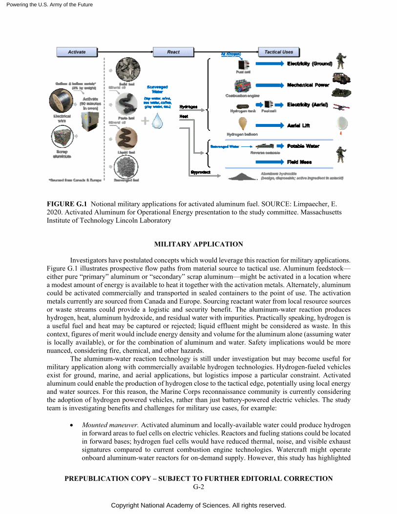
Powering the U.S. Army of the Future
Copyright National Academy of Sciences. All rights reserved.
PREPUBLICATION COPY – SUBJECT TO FURTHER EDITORIAL CORRECTION G-2
FIGURE G.1 Notional military applications for activated aluminum fuel. SOURCE: Limpaecher, E. 2020. Activated Aluminum for Operational Energy presentation to the study committee. Massachusetts Institute of Technology Lincoln Laboratory
MILITARY APPLICATION
Investigators have postulated concepts which would leverage this reaction for military applications. Figure G.1 illustrates prospective flow paths from material source to tactical use. Aluminum feedstock—either pure “primary” aluminum or “secondary” scrap aluminum—might be activated in a location where a modest amount of energy is available to heat it together with the activation metals. Alternately, aluminum could be activated commercially and transported in sealed containers to the point of use. The activation metals currently are sourced from Canada and Europe. Sourcing reactant water from local resource sources or waste streams could provide a logistic and security benefit. The aluminum-water reaction produces hydrogen, heat, aluminum hydroxide, and residual water with impurities. Practically speaking, hydrogen is a useful fuel and heat may be captured or rejected; liquid effluent might be considered as waste. In this context, figures of merit would include energy density and volume for the aluminum alone (assuming water is locally available), or for the combination of aluminum and water. Safety implications would be more nuanced, considering fire, chemical, and other hazards.
The aluminum-water reaction technology is still under investigation but may become useful for military application along with commercially available hydrogen technologies. Hydrogen-fueled vehicles exist for ground, marine, and aerial applications, but logistics impose a particular constraint. Activated aluminum could enable the production of hydrogen close to the tactical edge, potentially using local energy and water sources. For this reason, the Marine Corps reconnaissance community is currently considering the adoption of hydrogen powered vehicles, rather than just battery-powered electric vehicles. The study team is investigating benefits and challenges for military use cases, for example:
• Mounted maneuver. Activated aluminum and locally-available water could produce hydrogen
in forward areas to fuel cells on electric vehicles. Reactors and fueling stations could be located in forward bases; hydrogen fuel cells would have reduced thermal, noise, and visible exhaust signatures compared to current combustion engine technologies. Watercraft might operate onboard aluminum-water reactors for on-demand supply. However, this study has highlighted
Powering the U.S. Army of the Future
Copyright National Academy of Sciences. All rights reserved.
PREPUBLICATION COPY – SUBJECT TO FURTHER EDITORIAL CORRECTION G-3
the continued advantage of hydrocarbon fuel over hydrogen or other alternatives for heavy vehicles, especially in maneuver operations.
• Dismounted maneuver. Soldiers could carry pouches of activated aluminum for multiple uses. Reactant water could come from sources of opportunity (surface water, seawater, rainwater, or urine) and could be added to produce hydrogen (for fuel cell battery chargers) and heat (useful for comfort, or food/water heating). Soldiers currently carry various energy sources such as (diverse) batteries, ration heaters (combustible trioxane and water-activated magnesium-iron heat sources), and PV panels. Perhaps sealed pouches of aluminum pellets could serve as a relatively safe, compact, universal energy source with long shelf life.
• Reconnaissance and communications. Aerostats have been used for over a century and a half for military observation purposes. Field Manual FM 4-193 outlined procedures to produce hydrogen in the field using an aluminum-caustic reactor in forward locations. Each of the military services has contemporary programs to deploy stratospheric balloons for surveillance and communications; the Navy has demonstrated rapid inflation of balloons with hydrogen lift gas. Similarly, Group 1 and Group 2 UAVs could be fueled with gaseous hydrogen with significant range improvements over similarly sized battery-powered variants.
• Base camps and stability operations. Soldiers in forward bases face competing challenges of efficiency (outcome vs. “boots on the ground”) and vulnerability (security and logistics dependencies). Activated aluminum technology could represent a relatively compact, safe, and flexible energy storage mechanism to support base camp functions such as power (electronic systems and lighting) and heat (food, water, and space). The technology offers potential resilience attributes given its simplicity: aluminum might be recycled from local waste or packaging materials (e.g., pallets). Activation heat could be scavenged from the sun or local biomass source. Current renewable energy base camp solutions, intended to reduce logistic effort, depend upon international shipment of electronic PV or wind systems. Activated aluminum technology might be implemented as a locally produced technology for both field forces (base camps) and indigenous communities (stability operations).
• Logistics. By using aluminum as a fuel, a “distributed logistics” approach may be possible, in contrast to a more linear and long-distance logistics lines of communication necessitated by petroleum resupply operations. Scrap aluminum could be sourced from neighboring regions and transported in shipping containers or on trash barges, potentially less vulnerable to hostile attack compared to fuel tankers.
Activated aluminum may not be a promising energy storage mechanism to replace hydrocarbon
fuels for energy-intensive combat vehicles, but its inherent simplicity and flexibility may provide value in various remote situations and/or in longer-term, small-scale operations.
Powering the U.S. Army of the Future
Copyright National Academy of Sciences. All rights reserved.
PREPUBLICATION COPY – SUBJECT TO FURTHER EDITORIAL CORRECTION H-1
H
5G Networks
Although the 5G frequency range varies by the commercial carrier, there are generally three frequency ranges (called the multi-layer spectrum), which are:
1) Coverage and capacity - C-band - 2–6 GHz 2) High-bandwidth areas - Super Data Layer - over 6 GHz (e.g., 24–29 GHz and 37–43 GHz) 3) Indoor and broader coverage areas - Coverage Area - below 2 GHz (like 700 MHz)
For discussion, three frequencies are chosen for comparison:
1) 1850 MHz - high end of Rifleman Radio range 2) 6 GHz – high-end of C-band 3) 27GHz – close to mid-band Super Data Layer
The Coverage Area is excluded since the Rifleman radio frequencies overlap. Starting with the 5W Rifleman Radio assuming 2km range at 1850 MHz (which may be an optimistic range), you could cover most of a 100 sq. km. area with about 16 radios. There would be some dead spots, but this is just a cookie-cutter estimate. This discussion assumes a flat Earth and no path loss due to foliage, buildings, or environmental effects. It also ignores the additional power required to transmit at higher data rates. An increase in data rate of ten times requires ten times the power with greater power losses. This factor was omitted to illustrate the effects of communication frequency on range. The calculations were all made assuming isotropic-antenna at transmit and receive radios (directional-antenna could perform better).
The required radio transmission powers per radio frequency to achieve a 2 km range in ideal conditions are:
1) 5W at 1850 MHz 2) 53W at 6 GHz 3) 1065 at 27 GHz
For comparison, based on a radio transmission power of 5W, the following are the achievable ranges in ideal conditions:
1) 2 km at1850 MHz 2) 616 m at 6 GHz 3) 137 m at 27 GHz
Powering the U.S. Army of the Future
Copyright National Academy of Sciences. All rights reserved.
PREPUBLICATION COPY – SUBJECT TO FURTHER EDITORIAL CORRECTION H-2
It’s challenging to get range as the frequency increases at a fixed power of 5W. To cover the 100 sq. km. area would require 289 5W radios operating at 6 GHz or 5184 radios at 27 GHz, making the higher frequencies unsupportable. These numbers are excessive.
Looking at this in terms of transmission power at a fixed range, the radio transmission powers per frequency required to achieve 1 km range are:
1)1850 MHz at 1.3W 2) 6 GHz at 14W 3) 27 GHz at 266W
and at 500 m they are:
1)1850 MHz at 0.4W 2) 6 GHz at 4W 3) 27 GHz at 67W
For coverage of 100 sq. km, if the range of each radio were reduced to 1 km in an attempt to balance
the number of required relay nodes with the power transmission requirements, you would need about 80 radios to cover the area. That’s a reasonably low number that could be accomplished using a combination of unmanned aerial vehicles, robotic, and combat vehicle-based relay systems.
Based on physics, it doesn’t seem likely that the highest frequencies will reach 2 km unless the transmission power is much higher than 5W. Most base stations have ranges of about 500 meters with mixed results. That range was achieved with MIMO antenna arrays and beamforming techniques and is highly susceptible to loss of connectivity.
UAV platforms provide the best opportunity for high bandwidth coverage on the battlefield. Lift and loitering capabilities of current UAVs could carry repeaters and steerable antenna arrays to a vantage point at which coverage could be provided to areas of need. Platforms equipped with multiple repeaters may sacrifice coverage area for higher data rates by ganging up repeaters on different channels. It’s conceivable the repeaters on these platforms could be reconfigurable in flight to provide higher data rates, greater coverage area, or redundancy required to meet mission needs. Further research is necessary to determine the optimal number and configuration of UAVs.
Large combat platforms could be augmented with expendable platforms to provide rapidly available high bandwidth hot spots. These expendable UAVs could potentially cover an area of a few hundred square meters serving squad operations. These smaller lightweight UAVs, potentially 3D printed close to the point of need, would carry lower power repeaters operating at the higher operating frequencies with higher bandwidth.
Ground-based robotic platforms are potential candidates for carrying repeaters and the high-speed processing of data. Like the UAV platforms, they can be deployed in a variety of sizes. The most significant impediment to their success in a given situation is the relatively low antenna height, where environmental effects are more likely to limit coverage area. The primary benefit is that once positioned, energy is not required to maintain their location, as is the case with the UAV.
New component devices in the high-frequency ranges (30-50 GHz) are becoming easier to source and are dropping in price as more products are being developed. Where previously cost-prohibitive, these devices can now reasonably be used to develop Army-specific RF equipment. While custom ASIC devices may improve radio energy utilization, they can be costly and not necessarily of high value considering ultra-compact device size is rarely high on the priority list.
The key enabling aspects of 5G for the battlefield are high bandwidth and low latency. These are the key drivers for advanced capabilities for the Soldier. However, some obstacles presented by current commercial and consumer-driven developments are significant, possibly preventing immediate adoption by the Army, such as limited range and security. Of course, the limited range may also be seen as a benefit
Powering the U.S. Army of the Future
Copyright National Academy of Sciences. All rights reserved.
PREPUBLICATION COPY – SUBJECT TO FURTHER EDITORIAL CORRECTION H-3
by creating a lower probability of detection by the adversary. However, the radio range can be improved through the use of UAVs and mobile ground platforms with higher power and greater area coverage.
These obstacles should not detract from the Army’s pursuit of 5G battlefield systems; instead, they should guide the research and acquisition decisions to most efficiently advance the state of the art so that they can be more easily adopted. For instance, 5G does not employ frequency hopping to improve security. The Army should conduct research into methods to accomplish this potentially important security feature. As with planned provider rollouts, 5G should not be seen as a single solution but should be coupled with existing well-known 3G, 4G, and 4G LTE architectures for resilience and speed of deployment. Research should explore the application of these capabilities to existing combat scenarios, while also developing the resources to include 5G capabilities.
Powering the U.S. Army of the Future
Copyright National Academy of Sciences. All rights reserved.
PREPUBLICATION COPY – SUBJECT TO FURTHER EDITORIAL CORRECTION I-1
I
Soldier Silent Power Challenges
As discussed in Chapter 5 “Dismounted Soldier and Light UAV/UGVs,” thermophotovoltaic power sources utilizing JP8 present a major opportunity to reduce the weight burden of the dismounted soldier. Nevertheless, some technical challenges remain to be addressed before introduction onto the battlefield.
DEVELOPMENTS FOR TRL 6
Major development efforts are required to develop SSP to TRL 6. The cost of the program will be $1-2M and take 12-24 months for a feasibility demonstration in laboratory conditions, and an additional $2-4M and 12-24 months to deliver a fully functional and integrated prototype capable of operation under realistic conditions (a field experimentation). The areas of required development are outlined below.
INFRARED PV CELLS
Several companies are capable of producing high-performance indium gallium arsenide (InGaAs)
on indium phosphide (InP) PV cells. Several fabrication-runs will be required to optimize performance in terms of open circuit voltage, fill factor, and quantum efficiency (ratio of incident photons to electrons at the terminals). The production runs will provide the cells necessary for system development and testing.
PHOTONIC CRYSTAL INTEGRATION
Photonic crystal integration has been demonstrated experimentally by the Army’s Institute for
Soldier Nanotechnology at MIT in small planar systems (W. R. Chan, V. Stelmakh, M. Ghebrebrhan, M. Soljacic, J. D. Joannopoulos, I. Celanovic, “Enabling efficient heat-to-electricity generation at the mesoscale,” Energy Environ. Sci., 2017, vol. 10, no. 6, pp. 1367-1371). Two minor challenges remaining for integration of photonic crystal emitters into larger cylindrical systems. The crystal emitter needs to be packaged in a vacuum (to prevent degradation by reaction with air) and the photonic crystal needs to be bonded to the micro-combustor:
1. Mesodyne has developed a process for fabricating photonic crystals on flexible substrates that can
be wrapped around and brazed to a cylindrical micro-combustor. A small amount of additional work is required to perfect the process.
2. The vacuum package is an IR-transparent (quartz or sapphire) tube that encapsulates the micro-combustor and photonic crystal, which optimizes the thermal band used by the PV to produce electricity. One end of the tube is sealed, and the other end is hermetically bonded to a metal tube for subsequent bonding to the micro-combustor. There are no COTS products that match these requirements, although there are numerous companies that offer similar products and could custom
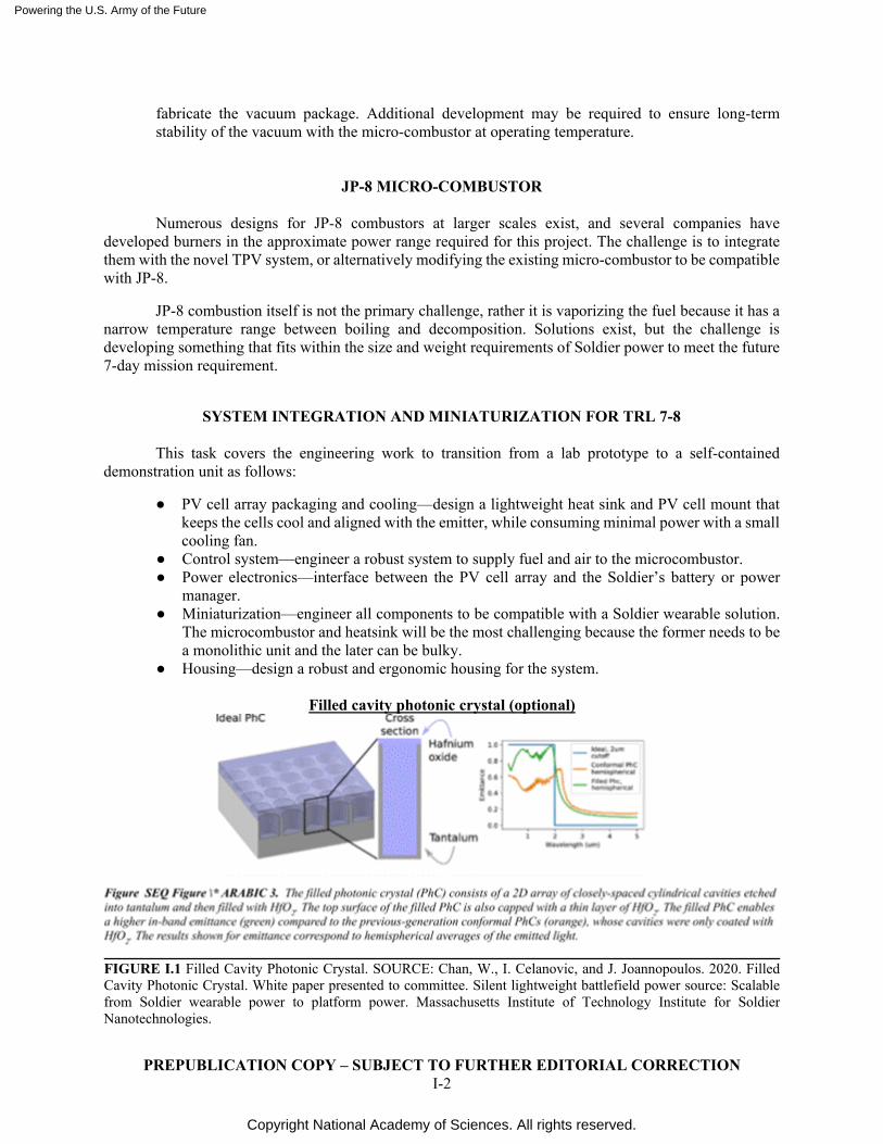
Powering the U.S. Army of the Future
Copyright National Academy of Sciences. All rights reserved.
PREPUBLICATION COPY – SUBJECT TO FURTHER EDITORIAL CORRECTION I-2
fabricate the vacuum package. Additional development may be required to ensure long-term stability of the vacuum with the micro-combustor at operating temperature.
JP-8 MICRO-COMBUSTOR
Numerous designs for JP-8 combustors at larger scales exist, and several companies have developed burners in the approximate power range required for this project. The challenge is to integrate them with the novel TPV system, or alternatively modifying the existing micro-combustor to be compatible with JP-8.
JP-8 combustion itself is not the primary challenge, rather it is vaporizing the fuel because it has a narrow temperature range between boiling and decomposition. Solutions exist, but the challenge is developing something that fits within the size and weight requirements of Soldier power to meet the future 7-day mission requirement.
SYSTEM INTEGRATION AND MINIATURIZATION FOR TRL 7-8
This task covers the engineering work to transition from a lab prototype to a self-contained
demonstration unit as follows:
● PV cell array packaging and cooling—design a lightweight heat sink and PV cell mount that keeps the cells cool and aligned with the emitter, while consuming minimal power with a small cooling fan.
● Control system—engineer a robust system to supply fuel and air to the microcombustor. ● Power electronics—interface between the PV cell array and the Soldier’s battery or power
manager. ● Miniaturization—engineer all components to be compatible with a Soldier wearable solution.
The microcombustor and heatsink will be the most challenging because the former needs to be a monolithic unit and the later can be bulky.
● Housing—design a robust and ergonomic housing for the system.
Filled cavity photonic crystal (optional)
FIGURE I.1 Filled Cavity Photonic Crystal. SOURCE: Chan, W., I. Celanovic, and J. Joannopoulos. 2020. Filled Cavity Photonic Crystal. White paper presented to committee. Silent lightweight battlefield power source: Scalable from Soldier wearable power to platform power. Massachusetts Institute of Technology Institute for Soldier Nanotechnologies.
Powering the U.S. Army of the Future
Copyright National Academy of Sciences. All rights reserved.
PREPUBLICATION COPY – SUBJECT TO FURTHER EDITORIAL CORRECTION I-3
In order to further improve efficiency and power density, the Army’s Institute for Soldier Nanotechnologies at MIT has developed a next-generation photonic crystal capable of omnidirectional emission approaching the blackbody limit for in-band wavelengths (see Figure I.1). This is accomplished by filling the cavities with a dielectric material and decoupling the physical and optical dimensions. Small samples have been fabricated by MIT, but a scalable fabrication method compatible with standard semiconductor processes needs to be developed.
The numbers presented here are all based on the mature photonic crystal design from the Army’s Institute for Soldier Nanotechnologies at MIT. Maturing and adopting the filled cavity photonic crystal could improve the already very impressive bottom-line performance by an estimated 50 percent more.
DEVELOPMENTS FOR TRL 9
These efforts focus on manufacturability and production scale-up, ruggedization, etc. The cost of
the program will be $5-10M and take 2-4 years for the first fieldable production run.
Photonic Crystal Fabrication Scaleup
This effort aims to mass produce the photonic crystal. A company, Mesodyne, has already
eliminated a key bottleneck in the fabrication process, i.e., removing wafer size limitations. Additional required development efforts include transitioning from small batches of small diameter wafers to large batches of large wafers, making the tantalum wafers compatible with non-academic cleanrooms. For example, by mounting the thin tantalum substrate on silicon wafers, and streamlining the process to eliminate the need for manual real time adjustments to process parameters.
PV Cell Scaleup
This effort aims to mass produce the InGaAs PV cells. The primary barrier is the high cost of the
indium phosphate (InP) substrate. At scale (10000 wafers/month) the majority of the cost of the finished device is the substrate. Epitaxial liftoff, already developed for III-V solar PV cells, allows for multiple reuses of the same substrate, reducing cost by up to 70 percent. Additionally, the liftoff process will produce flexible cells, allowing for improved coupling to the cylindrical emitter.
Integration, Miniaturization, and Ruggedization
At this stage, the product can be designed for minimal weight and volume rather than ability to be
built and modified rapidly. Additionally, the product will need to be ruggedized against drops and rough handling as well as dirt and water.
Design for Manufacturing
This effort covers manufacturing scaleup of the rest of the system. We do not anticipate major hurdles because every component has an analog that is already manufactured at scale.

Powering the U.S. Army of the Future
Copyright National Academy of Sciences. All rights reserved.
PREPUBLICATION COPY – SUBJECT TO FURTHER EDITORIAL CORRECTION I-4
Testing and Qualification
A significant amount of testing will be required to ensure the product meets performance, safety, and environmental standards. Additionally, user testing will ensure the product is easy to use in a battlefield environment.
Powering the U.S. Army of the Future
Copyright National Academy of Sciences. All rights reserved.
PREPUBLICATION COPY – SUBJECT TO FURTHER EDITORIAL CORRECTION J-1
J
High Performance ICE Engines Roadmap
POSSIBLE FOUR-STROKE COMPRESSION IGNITION ENGINE IMPROVEMENTS
There have been a number of advances made in four-stroke internal combustion engines over the last 10 years, many of them resulting from Department of Energy (DOE) sponsored studies. Among these, some of the most impressive gains have come from the SuperTruck I and SuperTruck 2 programs. As just one example, in this year’s DOE Annual Merit Review, Cummins and Daimler reported engine only status of 53.5 percent and 52.9 percent brake thermal efficiency, respectively… both with plans to exceed the 55 percent program target. This compares with an actual best-point brake thermal efficiency status of roughly 42 percent for their comparably sized engine available in 2007.1
It would be worthwhile to consider which of the following SuperTruck improvements might be applicable to the internal combustion engines used today in the Army’s ground combat vehicles, tactical vehicles, and mobile/stationary power plants:
• Improved high heat release rate combustion • Variable valve timing/displacement-on-demand • Increased compression ratio/higher peak cylinder pressure • High efficiency turbochargers • Interstage cooling • Electrified accessories • Power cylinder friction reduction actions, such as thermal spray bores • Variable displacement oil pump • Split cooling • Active piston oil nozzle jets • Thermal barrier coatings
WASTE HEAT RECOVERY
Waste heat recovery takes advantage of energy that would otherwise be lost to the exhaust or cooling system to improve the system efficiency. This energy can either be supplied to the electrical system or to the crankshaft. Waste recovery systems could be deployed on ground vehicles and/or stationary power plants.
All major truck engine suppliers (Cummins, Volvo, Daimler, Navistar, and Daimler) have included waste heat recovery in their SuperTruck programs. These systems typically are based on an organic Rankine cycle (using cyclopentane), including a superheater/expander, turbine, recuperator, and cooler. The associated brake thermal efficiency improvements are projected to range from 2 to 4 percent, depending
1 Misc. Authors. 2020. U.S. Department of Energy’s (DOE) Vehicle Technologies Office (VTO) 2020 Annual
Merit Review (AMR). Online. U.S. Department of Energy. Available at https://www.energy.gov/eere/vehicles/annual-merit-review-presentations. Accessed November 2020.
Powering the U.S. Army of the Future
Copyright National Academy of Sciences. All rights reserved.
PREPUBLICATION COPY – SUBJECT TO FURTHER EDITORIAL CORRECTION J-2
upon heat source content. For example, the Cummins waste heat recovery system is one of the most extensive, collecting heat from charge air, the EGR cooler, engine coolant, and the exhaust system.
Given that military engines don’t run exhaust gas recirculation (EGR), the available waste heat will not be as great as that in these SuperTruck programs. Using only exhaust heat in lieu of exhaust heat plus EGR, it is estimated that the fuel efficiency benefit will be roughly half that of the SuperTruck programs. However, it will still be substantial enough to be worth considering.
Interestingly, Southwest Research Institute is working on a waste heat recovery system that uses supercritical carbon dioxide as its media in lieu of cyclopentane. It deploys a Brayton cycle with a compressor in lieu of the pump on the organic Rankin cycle. Southwest Research claims that this system has roughly three times the superior efficiency of the organic Rankine cycle. As such, work on this system should continue to be monitored for potential inclusion in a future Army program.
Another interesting waste heat recovery system is turbo compounding, where energy collected from a turbine is converted directly into mechanical energy and supplied back to the crankshaft. Volvo recently introduced into production their next generation of turbocompounding on their D13 engine, claiming a 20 percent improvement in fuel efficiency.2
A further waste heat recovery advancement now under development is the SuperTurbo, which enables power transfer to and from the turbo shaft through a high-speed planetary traction drive and continuously variable transmission. At this year’s DOE annual merit review meeting, Caterpillar reported that they are using this SuperTurbo technology on their 13-liter concept engine for off-road applications. This particular Caterpillar concept engine also includes a motor/generator unit and high-speed flywheel to improve transient performance.
Capturing this energy would also help to reduce the heat signature of the Army’s combat vehicles.
HORIZONTALLY OPPOSED PISTON COMPRESSION IGNITION ENGINES
Development work on conventional four-stroke engines has been steady over close to a hundred years by many different original equipment manufacturers, universities, and national laboratories. In sharp contrast, development of opposed piston two stroke compression ignition engines within the US using computer aided engineering tools has been much more recent starting with OPOC (opposed piston opposed cylinders) in the 1990’s. The Opposed Piston Opposed Cylinder (OPOC) engine under development at that time had some inherent architectural flaws, but it led to the subsequent development of the Advanced Combat Engine. Recognizing the potential for further improvements, the Army has set some aggressive mid-term targets (i.e., through 2035) for this technology, including significant improvements in heat rejection, power density, and brake specific fuel consumption. To achieve those targets, it is recommended that the following actions be considered:
• Higher fidelity combustion CFD modeling—for improved indicated specific fuel consumption. • Improvements in conjugate heat transfer models – to ensure even temperature distribution
along the bore with minimum hot bore distortion; also for piston temperature predictions; needed to achieve increased power density
• Complete engine thermal surveys and hot bore distortion measurements to correlate against CAE thermal models (note: Cold bore distortion measurements are easy to do with a PAT gauge; physical hot bore distortion measurements are possible but time-consuming and expensive)
• Form honing – to provide even less hot bore distortion at rated power
2 Volvo Truck North America. 2019. Volvo Trucks Introduces Enhanced Turbo Compound Engine in VNL Models. Online. Available at https://www.volvotrucks.us/news-and-stories/press-releases/2019/august/volvo-trucks-introduces-enhanced-turbo-compound-engine-in-vnl-models/. Accessed November 2020.
Powering the U.S. Army of the Future
Copyright National Academy of Sciences. All rights reserved.
PREPUBLICATION COPY – SUBJECT TO FURTHER EDITORIAL CORRECTION J-3
• Some genetic algorithm studies to improve the in-cylinder combustion recipe (only practical after improvements in combustion CFD modeling)
• Potential use of metal matrix composites for pistons – higher strength and toughness at high temperature, improved thermal conductivity, reduced coefficient of thermal expansion (enabling reduced piston skirt to bore clearance), better skirt conformability, and lower reciprocating mass (Note: possible use of titanium metal matrix materials in lieu of aluminum metal matrix)
• Possible use of Tenneco’s EnviroKoolTM technology, which decouples the cooling media in the gallery from engine oil, thereby avoiding oil degradation problems due to hot undercrown temperatures.3
• Use of titanium or MMC piston rods for reduced reciprocating mass • Improvements in thermal barrier coatings (on MMC piston crowns) to minimize heat transfer;
this requires a combination of low thermal conductivity and low specific heat • Improvements in piston undercrown cooling to better manage temperatures within safe material
limits • Much higher power e-Turbos for improved air handling plus ability to recover energy from the
exhaust • Potential use of Artificial Intelligence/Machine Learning models to optimize the MMC
properties used in the piston and conrods. • Additional work on friction… use of iron-based thermal spray bores, perhaps use of some
advanced diamond like coatings on piston skirts, bearings, rings, etc. • Perhaps some architectural changes, such as a longer conrod length to stroke ratio and added
crankshaft offset to minimize piston side forces on the bore. • Perhaps using free piston technology to effectively eliminate piston side forces on the bore
almost entirely and reducing power cylinder friction • Possible use of additive manufacturing for pistons to provide cooling gallery and localized skirt
compliance opportunities not possible with traditional machining processes Of particular importance, there have been several instances in past OP2S engine combustion studies
where the combustion CFD studies have suggested design directions that were subsequently proven on dynamometer to be incorrect. Examples include studies of injector spray angle, number of holes, hole sizing, and piston crown shape.
As a first step, it is suggested that these faulty CFD studies be closely examined to determine the “root cause” for their failure. The fault may lie in one of the submodels, such as the injector spray break-up model. Perhaps only some revisions to the “tuning constants” used in these models may be needed. But perhaps a more extensive rewrite of the code will be required. Since most OEM’s use commercially sourced CFD code, the most likely candidates to resolve this issue will be the software suppliers (e.g., Convergent Science, AVL, FEV, etc.), Sandia or Argonne National Laboratory, or a major university (e.g., University of Wisconsin Engine Research Laboratory, MIT, etc.)
Once these models have been corrected, “analysis led design” can be much more effective, enabling combustion optimization approaches such as genetic algorithms. This will minimize the number of required hardware iterations to achieve the targets.
3 Westbrooke, K. and D. Konson. 2020. What is the Future for Diesel? Presentation at the Diesel Technology
Forum. Tenneco. Available at https://www.dieselforum.org/files/dmfile/future-of-diesel-presentation-final.pdf. Accessed November 2020.
Powering the U.S. Army of the Future
Copyright National Academy of Sciences. All rights reserved.
PREPUBLICATION COPY – SUBJECT TO FURTHER EDITORIAL CORRECTION K-1
K
Hybrid Fuel Efficiency
In addition to Army internal hybrid studies, there have been a number of hybrid studies initiated with some completed by the major defense industry suppliers. Some of those efforts are summarized below.
Oshkosh Defense presently offers in production a series hybrid diesel-electric power train system called ProPulse® on its Heavy Expanded Mobility Tactical Truck (HEMTT-A3) and Medium Vehicle Replacement (MTVR). Reportedly, this system increases the HEMTT fuel economy by up to 20 percent versus the non-hybrid version. The system also is capable of providing up to 120 kW of electrical power to external users.
BAE Systems recently received a $32 million agreement to develop a 35-ton series diesel-electric hybrid Bradley Fighting Vehicle. QinetiQ, a partner on this project, is developing the electric cross drive transmission (Modular E-X-Drive).
As another example, General Dynamics Land Systems completed a drive evaluation in 2009 of a series hybrid “E-Drive Stryker,” part of an internal R&D project. Using independent electric hub-drives, it leveraged the existing architecture and hardware of the Advanced Hybrid Electric Drive (AHED) vehicle, developed by GDLS from 1999 to 2007. It was subsequently dropped as the integration of braking, motoring, and gearing into the independent wheel hubs proved to have problematic reliability. Overseas suppliers have also been active in military vehicle hybrids as shown by the below hybrid powerpack (civilian rail) and land defense marketing materials from MTU Solutions (Figure K.3).
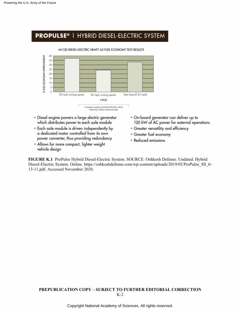
Powering the U.S. Army of the Future
Copyright National Academy of Sciences. All rights reserved.
PREPUBLICATION COPY – SUBJECT TO FURTHER EDITORIAL CORRECTION K-2
FIGURE K.1 ProPulse Hybrid Diesel-Electric System. SOURCE: Oshkosh Defense. Undated. Hybrid Diesel-Electric System. Online. https://oshkoshdefense.com/wp-content/uploads/2019/02/ProPulse_SS_6-13-11.pdf. Accessed November 2020.
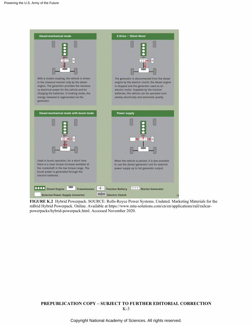
Powering the U.S. Army of the Future
Copyright National Academy of Sciences. All rights reserved.
PREPUBLICATION COPY – SUBJECT TO FURTHER EDITORIAL CORRECTION K-3
FIGURE K.2 Hybrid Powerpack. SOURCE: Rolls-Royce Power Systems. Undated. Marketing Materials for the mBrid Hybrid Powerpack. Online. Available at https://www.mtu-solutions.com/cn/en/applications/rail/railcar-powerpacks/hybrid-powerpack.html. Accessed November 2020.
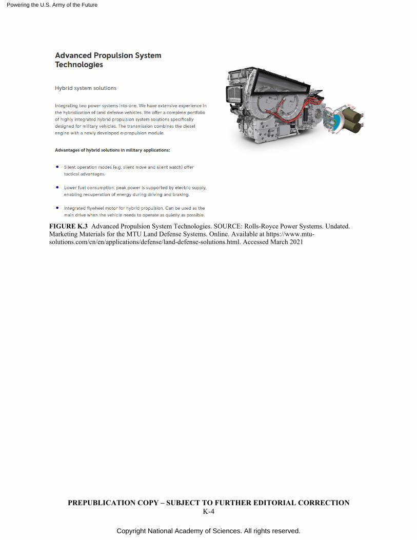
Powering the U.S. Army of the Future
Copyright National Academy of Sciences. All rights reserved.
PREPUBLICATION COPY – SUBJECT TO FURTHER EDITORIAL CORRECTION K-4
FIGURE K.3 Advanced Propulsion System Technologies. SOURCE: Rolls-Royce Power Systems. Undated. Marketing Materials for the MTU Land Defense Systems. Online. Available at https://www.mtu-solutions.com/cn/en/applications/defense/land-defense-solutions.html. Accessed March 2021
Powering the U.S. Army of the Future
Copyright National Academy of Sciences. All rights reserved.
PREPUBLICATION COPY – SUBJECT TO FURTHER EDITORIAL CORRECTION L-1
L
Power Electronics
Power electronics is defined as electronics where the processing of energy is of concern, as opposed to signal-level electronics where the purpose is to process information. Power electronics is ubiquitous in energy systems as the interface between energy sources and the systems that they supply, providing the necessary conversion of the source characteristics (e.g., voltage, frequency, stability) to those required by the powered apparatus (e.g., constant voltage, constant power, specific or variable frequency). Because the power semiconductor devices used in power electronic circuits operate as switches, they ideally carry zero current when they are off, and support zero voltage when they are on. Consequently, they produce zero loss in operation. However, this ideal case is never realized and there is some loss associated with the “on” state. The “off” state is, for practical purposes, lossless. For this reason, the conversion of energy using power electronics can achieve efficiencies that are typically in the high 90 percent range.
The switches used in power electronic circuits can be of various types. The most ubiquitous in today’s systems, and those applicable to the Army’s needs, are two types of transistors: the metal-oxide-field-effect-transistor (MOSFET) and the integrated gate bipolar transistor (IGBT). The Si power MOSFET can be applied at voltages up to about 1 kV, while the SiC MOSFET can support voltages approaching 3 kV. The IGBT can be used at voltages as high as 10 kV. A significant difference between the two devices is that the MOSFET can switch at much higher frequencies than the IGBT which gives it a distinct advantage where light weight and small size are important.
CHARACTERISTICS OF SEMICONDUCTOR DEVICES
As noted earlier, when a power transistor functioning as a switch is “on,” the voltage across its terminals is not zero. Therefore, there is energy being dissipated in the switch, which is known as on-state loss. The transition from on-to-off or vice-versa of a transistor is not instantaneous, resulting in there being simultaneously a voltage across its terminals and a current through them, creating an additional energy loss known as switching loss. While the former is relatively constant with switching frequency, the latter increases linearly. Therefore, there is always a trade-off between going to higher frequencies to reduce filtering requirements or minimize component sizes (particularly inductors and transformers), and a countervailing concern that such benefits not be compromised by increased switching losses in the circuit.
The bipolar transistor has been superseded in practice by the power MOSFET and the IGBT. The IGBT can be viewed as the combination of a bipolar transistor whose base is driven by a MOSFET. The structure of the power MOSFET is distinct from MOS transistors used to process information, typically in an integrated circuit, and permits the blocking of high voltages and the carrying of high currents. The IGBT can switch at maximum frequencies in the 50-100 kHz range, while the power MOSFET can switch at frequencies in the 10’s of MHz range for silicon based devices, and in the 100’s of MHz for devices fabricated in gallium nitride (GaN).
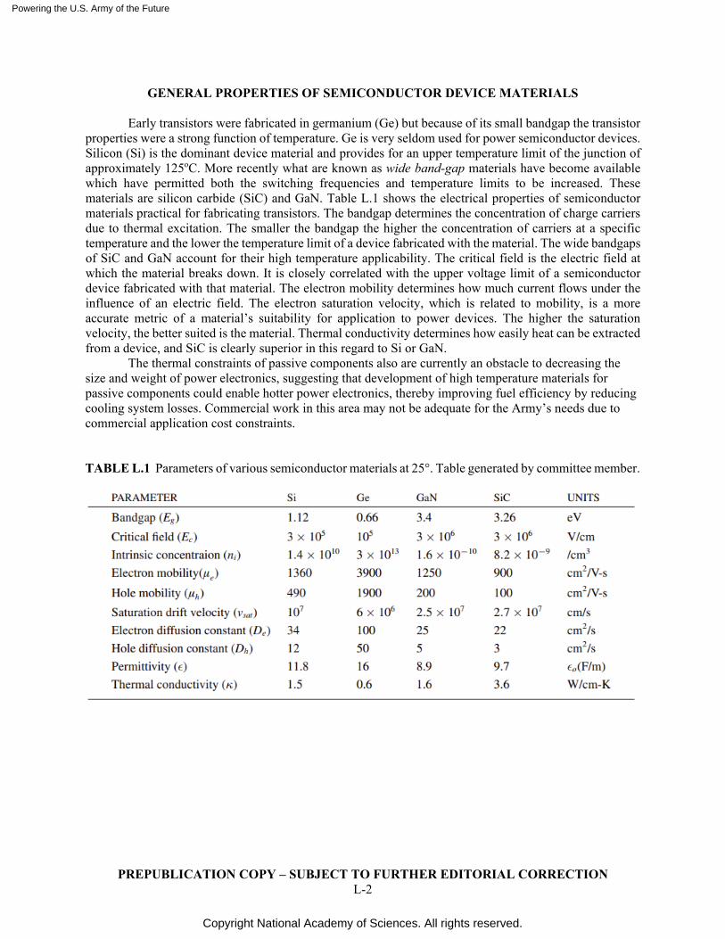
Powering the U.S. Army of the Future
Copyright National Academy of Sciences. All rights reserved.
PREPUBLICATION COPY – SUBJECT TO FURTHER EDITORIAL CORRECTION L-2
GENERAL PROPERTIES OF SEMICONDUCTOR DEVICE MATERIALS
Early transistors were fabricated in germanium (Ge) but because of its small bandgap the transistor properties were a strong function of temperature. Ge is very seldom used for power semiconductor devices. Silicon (Si) is the dominant device material and provides for an upper temperature limit of the junction of approximately 125oC. More recently what are known as wide band-gap materials have become available which have permitted both the switching frequencies and temperature limits to be increased. These materials are silicon carbide (SiC) and GaN. Table L.1 shows the electrical properties of semiconductor materials practical for fabricating transistors. The bandgap determines the concentration of charge carriers due to thermal excitation. The smaller the bandgap the higher the concentration of carriers at a specific temperature and the lower the temperature limit of a device fabricated with the material. The wide bandgaps of SiC and GaN account for their high temperature applicability. The critical field is the electric field at which the material breaks down. It is closely correlated with the upper voltage limit of a semiconductor device fabricated with that material. The electron mobility determines how much current flows under the influence of an electric field. The electron saturation velocity, which is related to mobility, is a more accurate metric of a material’s suitability for application to power devices. The higher the saturation velocity, the better suited is the material. Thermal conductivity determines how easily heat can be extracted from a device, and SiC is clearly superior in this regard to Si or GaN.
The thermal constraints of passive components also are currently an obstacle to decreasing the size and weight of power electronics, suggesting that development of high temperature materials for passive components could enable hotter power electronics, thereby improving fuel efficiency by reducing cooling system losses. Commercial work in this area may not be adequate for the Army’s needs due to commercial application cost constraints. TABLE L.1 Parameters of various semiconductor materials at 25°. Table generated by committee member.
Powering the U.S. Army of the Future
Copyright National Academy of Sciences. All rights reserved.
PREPUBLICATION COPY – SUBJECT TO FURTHER EDITORIAL CORRECTION M-1
M
Nuclear Power Safety/Regulatory Considerations
Perhaps the most daunting aspects of nuclear power for Army bases are the policy and regulatory aspects of this endeavor. Commercial nuclear power is highly regulated by the Nuclear Regulatory Commission (NRC) for good reason, as the handling of nuclear material and operation of nuclear reactors has unique and challenging safety and security aspects. This section summarizes the approach to regulatory policies and procedures taken by two key departments: the Department of Energy and of the Navy. These two departments jointly operate the Naval Reactors program (NR, or just the program) to provide naval nuclear propulsion. We suggest that this model is well worth following for the Department of the Army as it develops a nuclear power program.1
The Department of Energy has the authority to regulate its nuclear facilities as does the Department of the Navy. Given the joint nature of the NR program, a means was needed to fulfill requirements of both departments without undue bureaucracy. The Director of NR (a four-star appointment), therefore, is a joint appointment in both departments with the discretion to apply DOE policies in a flexible manner. Indeed, the Director has typically adopted policies and procedures consistent with the best NRC requirements while meeting DOE requirements. Note that the Director reports to the Chief of Naval Operations and has full access to the Secretary of Energy.
It makes sense to have a similar program structure and safety/security approach for an Army program. Much of the development and procurement of the reactors could be done by DOE, and the Army should strongly resist developing new policies and procedures for their program. The exception is to take into account the advanced nature of the anticipated Army reactor design and appropriate relaxation of requirements is recommended with heavy peer review.
The design basis threat for an Army reactor outside of the United States is quite different than the threats faced by naval reactors, surface or submarine. The design must by capable of safe operation under some types of attack (e.g., terrorist), despite not being deployed to front-line installations. Hence, the safety basis for the reactor needs to include the effects of small-scale explosions and small arms fire.
TRAINING
Once again following the Navy model, the Navy employs both enlisted personal and officers with
specific nuclear power training. The officer career tracks include: • Naval Reactors Engineer – training results in post-graduate level nuclear engineering. These
engineers work for naval reactors and may have assignments throughout the program, including on-ship.
• Surface Warfare Officer (Nuclear) – includes post-graduate training and substantial surface-combatant tours
• Nuclear submarine Officer – similar to Surface Warfare Officer but for submarines.
1 The diplomatic aspects of deploying nuclear reactors abroad should not be overlooked. Other countries’ laws
and sensitivities are not the same as those in the US.
Powering the U.S. Army of the Future
Copyright National Academy of Sciences. All rights reserved.
PREPUBLICATION COPY – SUBJECT TO FURTHER EDITORIAL CORRECTION M-2
The latter two officer tracks do not participate in running the NR program and facilities. The enlisted career tracks include: Enlisted Nuclear Machinist’s Mates, Electrician’s Mates, and Electronics Technicians.
For Army deployments of the envisioned simple-to-run, inherently safe reactor, the Navy enterprise is more elaborate than needed, but nevertheless provides a useful model. It would be important to have both officers with nuclear training and enlisted personnel with key technical skills and a working knowledge of nuclear reactor operations and theory. Training courses for Navy enlisted personnel include, post basic training, 3-6 months of general technical training, 6 months weeks of specific nuclear power training, and 6 months working with a real reactor on land. Officers undergo similar training with similar time scales. It is hard to envision significantly less training needed for Army nuclear officers and enlisted, although with fewer occupations, particularly for officers.
The Army would want to have similar capabilities to train individuals on real reactor hardware and a real operating reactor. These are non-trivial facilities to develop, perhaps in conjunction with the DOE, and should be part of the program planning after initial feasibility is determined.
Powering the U.S. Army of the Future
Copyright National Academy of Sciences. All rights reserved.
PREPUBLICATION COPY – SUBJECT TO FURTHER EDITORIAL CORRECTION N-1
N
Acronyms List ABCT armored brigade combat team ACE Advanced Combat Engine ACT Advanced Combat Transmission AECP All Electric Combat Powertrain AISG APD Integrated Starter/Generator AMEP Advanced Mobility Experimental Prototype AMMPS Advanced Medium Mobile Power Source APD Advanced Powertrain Demonstrator APOP Advanced Propulsion with On-board Power APU auxiliary power unit ARL Army Research Laboratory ARPA-E Advanced Research Projects Agency–Energy ATJ alcohol-to-jet ATM(S) Advanced Thermal Management (System) ATTAM Advanced Turbine Technologies for Affordable Mission-Capability BEV battery electric vehicle; all-battery electric vehicle BOARD Board on Army Research and Development BOP balance of the plant CAD Computer Aided Design CASCOM Combined Arms Support Command CNG compressed natural gas DASA(RT) Deputy Assistant Secretary of the Army for Research and Technology DF1 Diesel Fuel 1 DoD Department of Defense DOE (U.S.) Department of Energy DPGDS Deployable Power Generation and Distribution system DSB Defense Science Board EC electrochemical capacitors EDLC electrolytic double-layer capacitors
Powering the U.S. Army of the Future
Copyright National Academy of Sciences. All rights reserved.
PREPUBLICATION COPY – SUBJECT TO FURTHER EDITORIAL CORRECTION N-2
EIO Energy-Informed Operations EV electric vehicle FOB forwad operating base FY fiscal year GCI gasoline compression ignition GVSC (U.S. Army DEVCOM) Ground Vehicle Systems Center HMMWV High Mobility Multipurpose Wheeled Vehicle (i.e. “Humvee”) ICE internal combustion engine IoT Internet of Things ISG Integrated Starter Generator JCESR Joint Center for Energy Storage Research JLTV Joint Light Tactical Vehicle JP8 Jet Propellant 8 LNG liquefied natural gas LSCF lanthanum strontium cobalt ferrite LW Land Warrior MANET mobile ad hoc networks MDO Multi-Domain Operations MEPS Mobile Electric Power Solutions MMC metal matrix composite MNR micro nuclear reactor or modular nuclear reactor MOF metal-organic frameworks MOTS military on-the-shelf MUTT Multi-Utility Tactical Transport NATO The North Atlantic Treaty Organization NSRC Network Science Research Center OPLOG Operational logistics P&E power and energy PEM Platform Electrification Mobility PEM proton-exchange membrane or polymer electrolyte membrane PFTE polytetrafluoroethylene PPU Prime Power Unit PV Photovoltaic
Powering the U.S. Army of the Future
Copyright National Academy of Sciences. All rights reserved.
PREPUBLICATION COPY – SUBJECT TO FURTHER EDITORIAL CORRECTION N-3
RCV remote control vehicles RDECOM U.S. Army Research, Development, and Engineering Command RTG Radioisotope Thermoelectric Generator SiRPA silica-reinforced porous, anodized aluminum SMET small multi-purpose equipment transport SOFC solid oxide fuel cell SSP soldier silent power STAMP Secure Tactical Advanced Mobile Power TBC thermal barrier coating TESU Tactical Energy Storage Unit TIG Transmission Integrated Generator TMS Tactical Microgrid Standard TPV thermophotovoltaic TRISO tri-structural isotropic TVEK (U.S. Army) Tactical Vehicle Electrification Kit UAV unmanned aerial vehicle UGV unmanned ground vehicle USD(AT&L) Under Secretary of Defense for Acquisition, Technology, and Logistics VEA Vehicle Electric Architecture VMD Vehicle Mobile Demonstrator YSZ yttria-stabilized zirconia