reliability axles
TRANSCRIPT
Structural Integrity and Reliability Assessment ofRailway Axles and Wheelsets - Researches at
PoliMi
Stefano BerettaPolitecnico di Milano, Dipartimento di Meccanica
March 2013
Abstract
Railway axles are a longstanding problem for structural integrity,since they are designed against fatigue limit but their very long servicelife (30 year or 3·106 [km]) exposes them to agents (impacts, corrosion)that can trigger the growth of cracks that severely reduce the servicelife. In the following a statement of the problem and a summary of theresearches at the Department of Mechanical Engineering at Politec-nico di Milano are presented. Similar exploitations for other wheelsetcomponents are also mentioned.
1 Statement of the problemRailway axles are commonly operated over a service life of 30 years ormore which refers to a very high number of loading cycles in the orderof some 109. They are designed for an infinite life with admissible stresslevels which correspond to generous safety factors applied to full-scalefatigue properties of materials (see EN13103, EN13104). Nevertheless,some failures occur due to corrosion, ballast impacts [1, 2].
It should be emphasised that railway axles are usually safe. In theforeword to a special issue of the Journal of Rail and Rapid Transitfrom 2004 the editor noted: "their safety record is generally second tonone." [3]. Nevertheless, railway axles are safety-critical components.When an axle breaks there is a high risk of derailment with potentiallydisastrous consequences.
According to the Railway Safety Performance Report of the Euro-pean Railway Agency (ERA) of 2011 [4] the number of broken axles inthe European Union between 2006 and 2009 was in total 329. Relatedto the number of about 1.66 × 10¹⁰ train kilometres over these fouryears this refers to one fracture event per 50.45 Millions train kilome-tres: for an average train size of 40 axles (which is an average valueover the last years) the number of axle failures per axle kilometres
1
would reduce to approximately one fracture event per two Billions ofaxle kilometres.
This means that improving the reliability of axles needs the carefulimplementation of new design concepts(i.e. the adoption of damagetolerance) or new monitoring strategies (see Bruni [5]).
2 Damage tolerant design of railway axlesIn order to avoid the rare failures, which are related to a numberof factors not easily predictable, the solution is to define a suitableinspection strategy supported by the damage tolerance analyses [6].
The application of damage tolerance concepts to railway axles hasbeen the subject of an intense European cooperation which begun in2004 with a Special Issue of the journal J. Rail Rapid Transit andthe constitution of TC24 (Structural Integrity of Railway Structures)of ESIS - European Structural Integrity Society, where the technicalissues about the development of the damage tolerance of railway axleshave been discussed in these years.
According to Zerbst [6] the key factors for a damage tolerance anal-ysis are: i) component geometry and dimensions, ii) location and ori-entation of potential cracks or crack-like defects, iii) loading includ-ing secondary loads such as thermal or residual stresses, iv) deforma-tion characteristics of the material (its stress-strain curve) and crackresistance of the material, v) fatigue crack extension characteristics(da/dN −∆K curve) of the material, vi) initial crack size due to thenon-destructive inspection (NDI) detection limit or service experience,vii) initial crack shape, and viii) probability of crack detection (POD)versus crack size characteristics of the NDI technique applied.
The research activity of the research group led by Prof. S. Berettahas addressed some of the above points and the results are summa-rized in the following sections. Some other points are currently beinganalyzed.
Component geometry and secondary loads
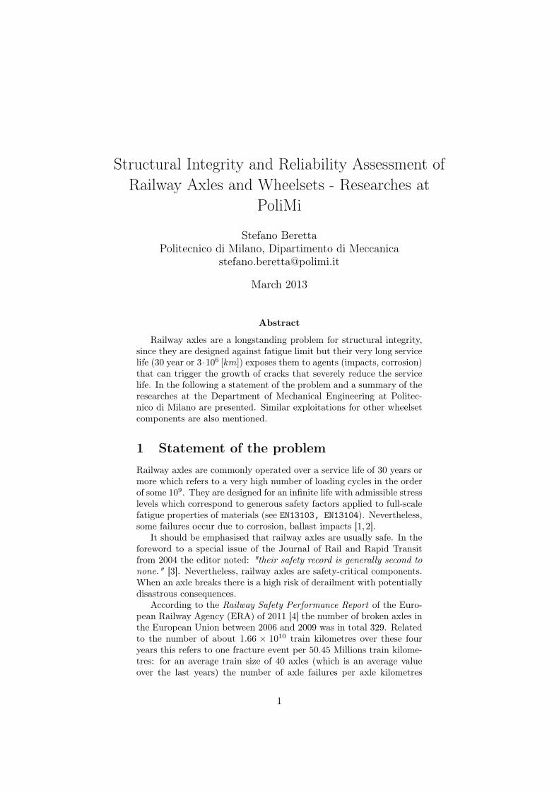
A number of SIF solutions for cracks on smooth axles were initiallydetermined within the EU project WIDEM [8]. The analysis of SIF atthe typical axle geometrical transitions was then developed in coopera-tion with Prof. U. Zerbst (BAM - Berlin, Germany). The main resultsof the activity are: i) the press-fits of wheels and gears induce, in thegroove between them (see Fig.1), positive residual stresses which arevery detrimental for propagation lifetime [7]; ii) a compendium of SIFsolutions for common axle transitions [9].
Crack growth properties and algorithm
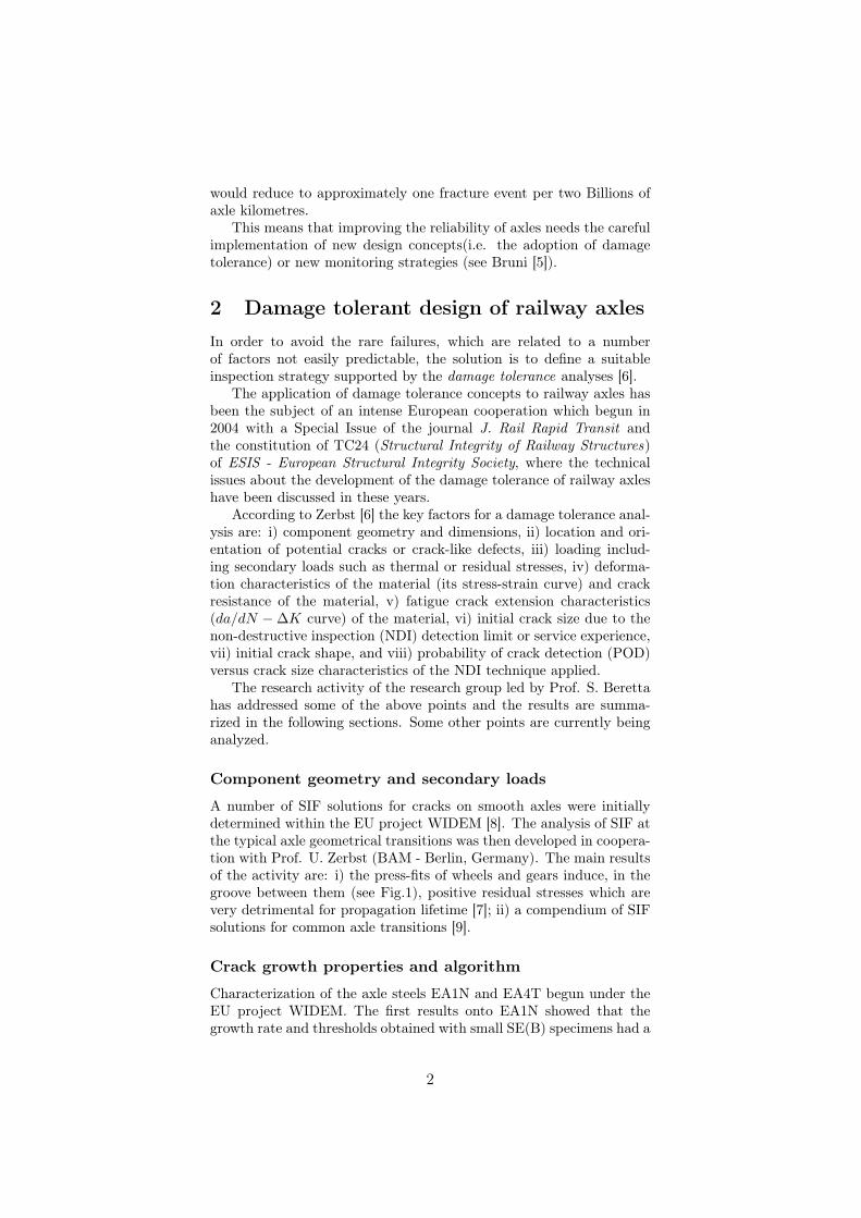
Characterization of the axle steels EA1N and EA4T begun under theEU project WIDEM. The first results onto EA1N showed that thegrowth rate and thresholds obtained with small SE(B) specimens had a
2
F F
Figure 1: A railway axle: FE model for a crack at groove between thewheel and the gear press-fittings [7].
wide scatter, especially in the region of near-threshold propagation [10].Then the data on small scale specimens were significantly different tocrack growth data obtained onto full-scale axles: in order to overcomethis problem new SE(T) specimens with the same constraint of thefull-scale axle were designed [11]. The latest findings (within the EUproject WOLAXIM) show that this scale effect is less pronounced whencompression-precracking is adopted for tests on small scale specimens.The new SE(T) specimens were then adopted for other research projectsfor investigating the crack growth retardation with different axle steels:the analysis of the tests carried out within WIDEM onto EA1N steelshow that full-scale axles (tests at low ∆K levels) show a significant re-tardation, while tests onto SE(T) specimens at higher ∆K show almostno retardation [12].
Design optimization: ’One million miles axle’
One of the expected results of WIDEM was to obtain a new axle de-sign on the basis of the ’damage tolerance’ tools developed within theproject. A simple concept derived from ’damage tolerance’ for a reli-able axle design is to assure that during service lifetime a prospectivecrack could only grow of a few millimeters, so that failure probabilityand to the number of NDT inspections are drastically reduced (thisdesign concept had been named one-million mile axle).
In order to see the effect of changing axle design onto prospectivepropagation lifetime, the stress spectra that had been measured fora freight train have been multiplied by a K-factor (K > 1 implies
3
increase in the stress levels and therefore corresponds to decrease axleflexural modulus) in order to determine the stress levels at which thereis a limited propagation, comparing this result with traditional fatiguedamage calculations. The results are summarized in Fig. 6 (initialcrack size a = 2 [mm]): it can be seen that K factors correspondingto traditional fatigue optimization imply a propagation lifetime muchthan 100, 000 [km]: this clearly show that ’damage tolerance’ is a muchmore stringent and rigorous criterion than traditional fatigue [13].
New design criteria which improve and formalize this concepts arecurrently being developed within the EU project EURAXLES.
Initial defect size and damage
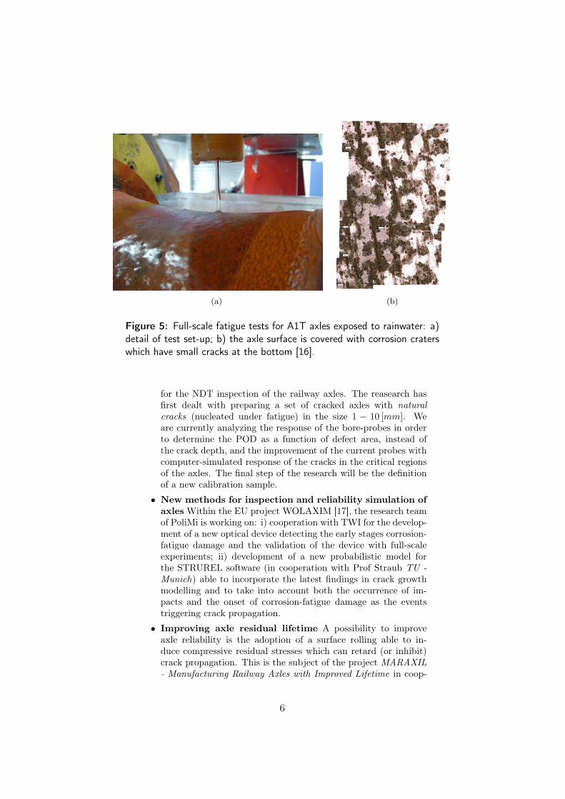
One the main factors in the initiation and incubation of a crack inrailway axles is corrosion. A resarch project begun in 2005 has shownthat the presence of rainwater is able to induce, onto A1N steel, theonset of corrosion-fatigue [14], the propagation of multiple small fa-tigue cracks under the combined action of cyclic loads and the mildcorrosive medium, even at stress levels much lower than current designlimits [15] (see Fig. 4).
Similar results were also obtained for A1T steel within the RSSB-T728 project (a reserach contract by RSSB to a consortium formedby: Deltarail-TWI-PoliMi) onto the A1T steel. In this project, theS-N curve obtained with small scale specimens was validated with full-scale tests. These tests also showed that corrosion-fatigue damagecan be detected by the presence of small cracks and corrosion-craters:this idea is being exploited within the EU project WOLAXIM. TheRSSB-T728 has also dealt with the statistical description of otherkind of surface damages (impacts, surface deterioration), even if a fully
(a)
(b)
Figure 2: Crack growth rate of EA1N steel [11,12]: a) small scale spec-imens vs. full-scale; b) data obtained with the new SE(T) specimens.
4
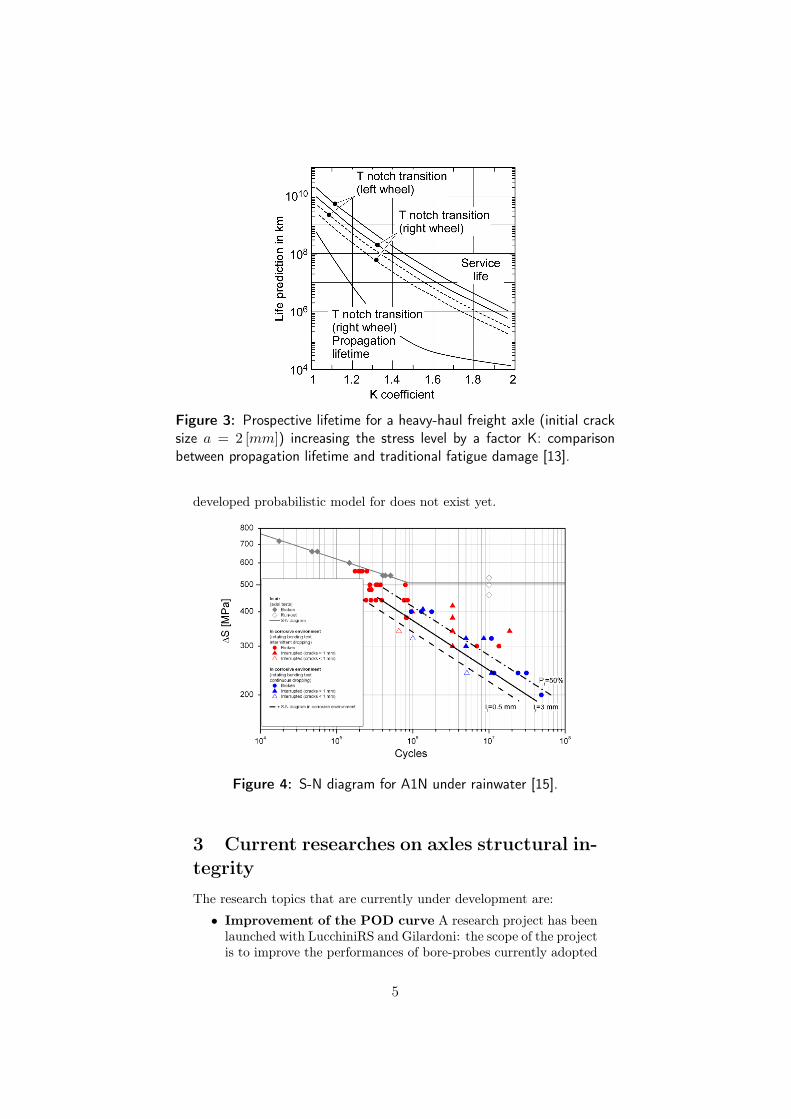
Figure 3: Prospective lifetime for a heavy-haul freight axle (initial cracksize a = 2 [mm]) increasing the stress level by a factor K: comparisonbetween propagation lifetime and traditional fatigue damage [13].
developed probabilistic model for does not exist yet.
Figure 4: S-N diagram for A1N under rainwater [15].
3 Current researches on axles structural in-tegrityThe research topics that are currently under development are:
• Improvement of the POD curve A research project has beenlaunched with LucchiniRS and Gilardoni: the scope of the projectis to improve the performances of bore-probes currently adopted
5
(a) (b)
Figure 5: Full-scale fatigue tests for A1T axles exposed to rainwater: a)detail of test set-up; b) the axle surface is covered with corrosion craterswhich have small cracks at the bottom [16].
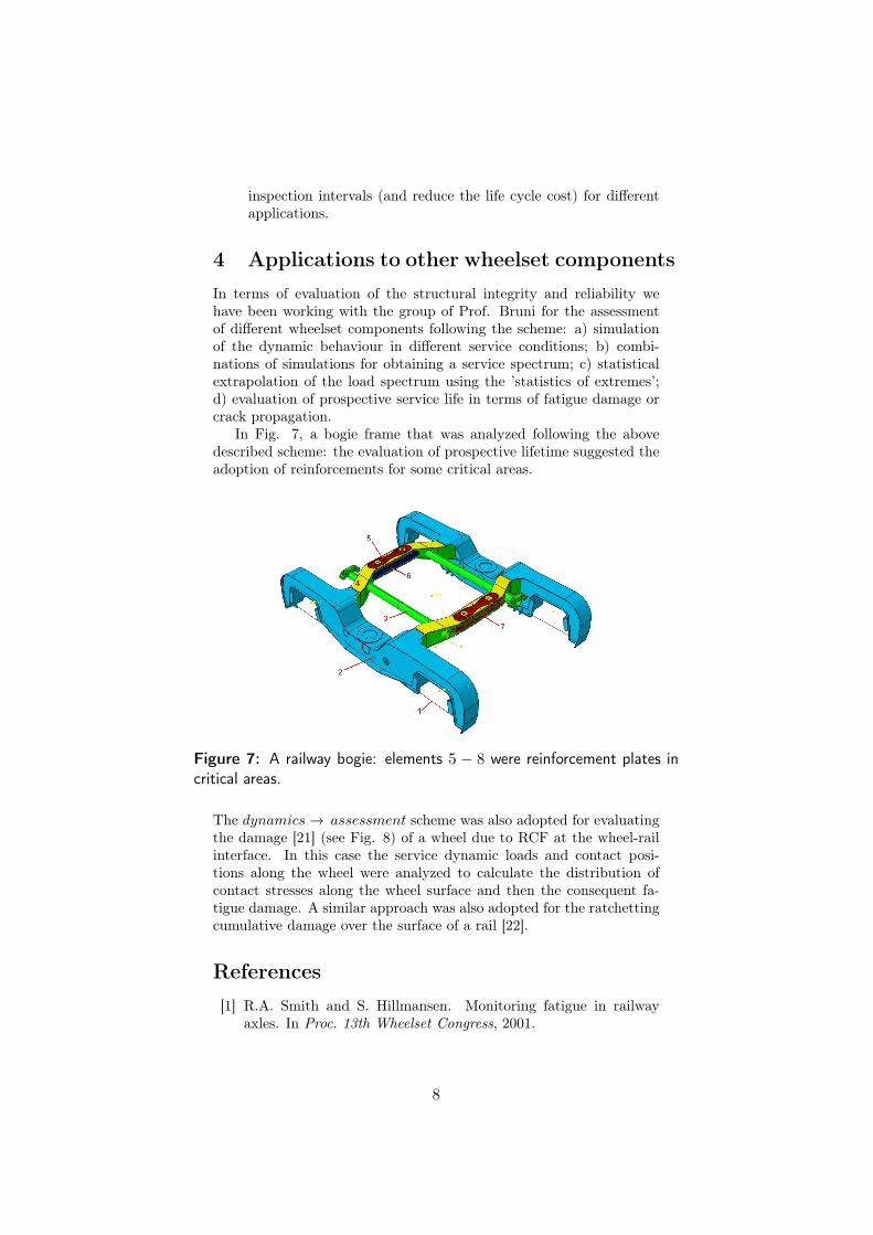
for the NDT inspection of the railway axles. The reasearch hasfirst dealt with preparing a set of cracked axles with naturalcracks (nucleated under fatigue) in the size 1 − 10 [mm]. Weare currently analyzing the response of the bore-probes in orderto determine the POD as a function of defect area, instead ofthe crack depth, and the improvement of the current probes withcomputer-simulated response of the cracks in the critical regionsof the axles. The final step of the research will be the definitionof a new calibration sample.
• New methods for inspection and reliability simulation ofaxles Within the EU project WOLAXIM [17], the research teamof PoliMi is working on: i) cooperation with TWI for the develop-ment of a new optical device detecting the early stages corrosion-fatigue damage and the validation of the device with full-scaleexperiments; ii) development of a new probabilistic model forthe STRUREL software (in cooperation with Prof Straub TU -Munich) able to incorporate the latest findings in crack growthmodelling and to take into account both the occurrence of im-pacts and the onset of corrosion-fatigue damage as the eventstriggering crack propagation.
• Improving axle residual lifetime A possibility to improveaxle reliability is the adoption of a surface rolling able to in-duce compressive residual stresses which can retard (or inhibit)crack propagation. This is the subject of the project MARAXIL- Manufacturing Railway Axles with Improved Lifetime in coop-
6
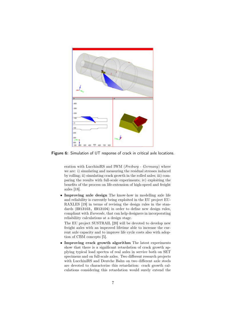
Figure 6: Simulation of UT response of crack in critical axle locations.
eration with LucchiniRS and IWM (Freiburg - Germany) wherewe are: i) simulating and measuring the residual stresses inducedby rolling; ii) simulating crack growth in the rolled axles; iii) com-paring the results with full-scale experiments; iv) exploiting thebenefits of the process on life-extension of high-speed and freightaxles [18].
• Improving axle design The know-how in modelling axle lifeand reliability is currently being exploited in the EU project EU-RAXLES [19] in terms of revising the design rules in the stan-dards (EN13103, EN13104) in order to define new design rules,compliant with Eurocode, that can help designers in incorporatingreliabiliity calculations at a design stage.The EU project SUSTRAIL [20] will be devoted to develop newfreight axles with an improved lifetime able to increase the cur-rent axle capacity and to improve life cycle costs also with adop-tion of CBM concepts [5].
• Improving crack growth algorithm The latest experimentsshow that there is a significant retardation of crack growth ap-plying typical load spectra of real axles in service both on SETspecimens and on full-scale axles. Two different research projectswith LucchiniRS and Deutche Bahn on two different axle steelsare devoted to characterize this retardation: crack growth cal-culations considering this retardation would surely extend the
7
inspection intervals (and reduce the life cycle cost) for differentapplications.
4 Applications to other wheelset componentsIn terms of evaluation of the structural integrity and reliability wehave been working with the group of Prof. Bruni for the assessmentof different wheelset components following the scheme: a) simulationof the dynamic behaviour in different service conditions; b) combi-nations of simulations for obtaining a service spectrum; c) statisticalextrapolation of the load spectrum using the ’statistics of extremes’;d) evaluation of prospective service life in terms of fatigue damage orcrack propagation.
In Fig. 7, a bogie frame that was analyzed following the abovedescribed scheme: the evaluation of prospective lifetime suggested theadoption of reinforcements for some critical areas.
Figure 7: A railway bogie: elements 5 − 8 were reinforcement plates incritical areas.
The dynamics→ assessment scheme was also adopted for evaluatingthe damage [21] (see Fig. 8) of a wheel due to RCF at the wheel-railinterface. In this case the service dynamic loads and contact posi-tions along the wheel were analyzed to calculate the distribution ofcontact stresses along the wheel surface and then the consequent fa-tigue damage. A similar approach was also adopted for the ratchettingcumulative damage over the surface of a rail [22].
References[1] R.A. Smith and S. Hillmansen. Monitoring fatigue in railway
axles. In Proc. 13th Wheelset Congress, 2001.
8
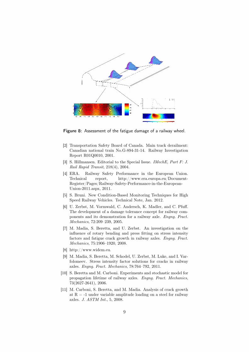
Figure 8: Assessment of the fatigue damage of a railway wheel.
[2] Transportation Safety Board of Canada. Main track derailment:Canadian national train No.G-894-31-14. Railway InvestigationReport R01Q0010, 2001.
[3] S. Hillmansen. Editorial to the Special Issue. IMechE, Part F: J.Rail Rapid Transit, 218(4), 2004.
[4] ERA. Railway Safety Performance in the European Union.Technical report, http://www.era.europa.eu/Document-Register/Pages/Railway-Safety-Performance-in-the-European-Union-2011.aspx, 2011.
[5] S. Bruni. New Condition-Based Monitoring Techniques for HighSpeed Railway Vehicles. Technical Note, Jan. 2012.
[6] U. Zerbst, M. Vormwald, C. Andersch, K. Madler, and C. Pfuff.The development of a damage tolerance concept for railway com-ponents and its demonstration for a railway axle. Engng. Fract.Mechanics, 72:209–239, 2005.
[7] M. Madia, S. Beretta, and U. Zerbst. An investigation on theinfluence of rotary bending and press fitting on stress intensityfactors and fatigue crack growth in railway axles. Engng. Fract.Mechanics, 75:1906–1920, 2008.
[8] http://www.widem.eu.
[9] M. Madia, S. Beretta, M. Schodel, U. Zerbst, M. Luke, and I. Var-folomeev. Stress intensity factor solutions for cracks in railwayaxles. Engng. Fract. Mechanics, 78:764–792, 2011.
[10] S. Beretta and M. Carboni. Experiments and stochastic model forpropagation lifetime of railway axles. Engng. Fract. Mechanics,73(2627-2641), 2006.
[11] M. Carboni, S. Beretta, and M. Madia. Analysis of crack growthat R = -1 under variable amplitude loading on a steel for railwayaxles. J. ASTM Int., 5, 2008.
9
[12] S. Beretta and M. Carboni. Variable amplitude fatigue crackgrowth in a mild steel for railway axles: Experiments and pre-dictive models. Engng. Fract. Mechanics, 78:848–862, 2011.
[13] S. Beretta, M. Carboni, and S.Cervello. Design review of a freightrailway axle: fatigue damage versus damage tolerance. Material-wissenschaft und Werkstofftechnik, 42:1099–1104, 2011.
[14] S. Beretta, M. Carboni, A. Lo Conte, and E. Palermo. An inves-tigation of the effects of corrosion on the fatigue strength of AlNaxle steel. IMechE, Part F: J. Rail Rapid Transit, 222:129–143,2008.
[15] S. Beretta, M. Carboni, G. Fiore, and A. Lo Conte. Corrosion–fatigue of A1N railway axle steel exposed to rainwater. Int. J.Fatigue, 32:952–961, 2010.
[16] M. Carboni, S. Beretta, and A. Loconte. Research on corrosionfatigue of railway axles. Insight, 53(361-367), 2011.
[17] http://www.wolaxim.eu/project/overview.jsp.
[18] http://maraxil.mecc.polimi.it.
[19] www.euraxles.eu.
[20] www.sustrail.eu.
[21] A. Bernasconi, P. Davoli, M. Filippini, and S. Foletti. An inte-grated approach to rolling contact sub-surface fatigue assessmentof railway wheels. WEAR, 258:973–980, 2005.
[22] S. Foletti, S. Beretta, and G. Bucca. A numerical 3D model tostudy ratcheting damage of a tramcar line. WEAR, 268:737–746,2010.
10