raman amplification and optical short pulse generation in a waveguide with periodic gain
TRANSCRIPT

Optics Communications 281 (2008) 5804–5810
Contents lists available at ScienceDirect
Optics Communications
journal homepage: www.elsevier .com/locate/optcom
Raman amplification and optical short pulse generationin a waveguide with periodic gain
J.M.S. Filho a,b, J.W.M. Menezes a, G.F. Guimarães a,b, A.C. Ferreira a,b,W.B. de Fraga a,b, A.F.G.F. Filho a,b, A.S.B. Sombra a,b,*
a Laboratório de Telecomunicações e Ciência e Engenharia de Materiais LOCEM, Departamento de Física, Universidade Federal do Ceará,Caixa Postal 6030, 60455-760 Fortaleza, Ceará, Brazilb Departamento de Engenharia de Teleinformática (DETI), Centro de Tecnologia, Universidade Federal do Ceará, Ceará, Brazil
a r t i c l e i n f o a b s t r a c t
Article history:Received 3 July 2008Received in revised form 22 August 2008Accepted 27 August 2008
0030-4018/$ - see front matter � 2008 Elsevier B.V. Adoi:10.1016/j.optcom.2008.08.038
* Corresponding author. Address: Laboratório de TEngenharia de Materiais LOCEM, Departamento de FíCeará, Caixa Postal 6030, 60455-760 Fortaleza, Ceará,fax: +55 85 288 9450.
E-mail address: [email protected] (A.S.B. SombrURL: http://www.locem.ufc.br (A.S.B. Sombra).
In this paper a new configuration of amplification is proposed for Raman amplification. In this new con-figuration a spatial periodic Raman gain is used to amplify a CW Raman seed that generates a short opti-cal pulse taking into account the SPM, XPM, walk-off and pulse depletion. The amplification process isaccomplished by using an intense pump pulse where its energy is transferred through SRS effect. ACW weak seed is used to represent the signal to be amplified and for pump is used a Gaussian pulse.We discuss the advantages to this configuration. First, this scheme means that the Raman-gain coefficientassumes a periodic characteristic and like a modulation process, it gives possibility to control the energytransfer from the pump to Raman seed. Second, the efficient use of the parameters of the periodic Ramancoefficient function, like amplitude and frequency of the modulation, can result in a more efficient controlof the signal amplification. This new configuration provides some very interesting features in the Ramanamplification process when compared to the standard procedure. A complete discussion of this configu-ration is presented.
� 2008 Elsevier B.V. All rights reserved.
1. Introduction
Raman amplification is found almost in every long-haul (usuallydefined �300–800 km) or ultra long-haul (typically defined above800 km) fiber-optic transmission systems. There are some funda-mental and technological advantages and disadvantages by usingthis kind of optical amplification.
Raman gain arises from the transfer of power from one opticalbeam that is downshifted in frequency by the energy of an opticalphonon [2]. The energy transfer is achieved by a very well knownphenomenon called stimulated Raman scattering (SRS). ThroughSRS the energy is transported from a very intense pump pulse tothe attenuated signal. SRS scatters light waves in both directions,forward and backward and the backward-propagating light be-comes a penalty to the signal, but that undesirable scattered lightcan be eliminated by using optical isolators. Therefore, the forwardscattered light is of more concern. One of the important parameterof the fiber that has been exploited in this present work is the Ra-man-gain coefficient that is about three orders of magnitude smal-
ll rights reserved.
elecomunicações e Ciência esica, Universidade Federal doBrazil. Tel.: +55 85 288 9909;
a).
ler than the Brillouin gain coefficient, and the SRS threshold isknown to be around 1 W for a single-channel system. In the otherhand, the gain bandwidth of SRS is of the order of 12 THz, whichare about six orders of magnitude bigger than that of SBS. Ramanamplification gives rise of Raman amplifiers that have some funda-mental advantages. First, Raman gain exists in every fiber, whichprovides a cost-effective means of upgrading from the terminalends. Second, the gain is non-resonant, which means that gain isavailable over the entire transparency region of the fiber rangingfrom approximately 0.3 to 2 � 10�6 m. A third advantage of Ramanamplification is that the gain spectrum can be tailored by adjustingthe pump wavelengths. For instance, multiple pump lines can beused to increase the optical bandwidth, and the pump distributiondetermines the gain flatness. Another advantage of Raman amplifi-cation is that it is relatively broad-band amplification with a band-width >5 THz and the gain is reasonably flat over a widewavelength range. Certainly, there are also some disadvantagesby using Raman amplification such as a relatively poor pumpingefficiency at lower signal powers compared to the EDFAs. Anotherdrawback is that it requires a longer gain fiber. However, this dis-advantage can be mitigated by combining gain and the dispersioncompensation in a single fiber. Finally, Raman amplifiers have afast response time, which gives rise to new source of noise.
An essential feature of this present model is the inclusion of theperiodic characteristic in Raman-gain coefficient due to the varia-tion of the refractive index parameter across the fiber core. In order

J.M.S. Filho et al. / Optics Communications 281 (2008) 5804–5810 5805
to accomplish this characteristic we redefined the Raman-gaincoefficients by using a periodic function on a single-mode step-in-dex fiber that preserves its polarization over the fast axis. So themain scope of this present work is the improvement of Raman gainresults comparing to standard model that uses Raman gain withoutperiodicity. The specific target application of this model is the pos-sibility of controlling Raman gain and improving the amplificationperformance.
2. Theoretical model
We consider the case in which a pump pulse and Raman seed atdifferent wavelengths are linearly polarized and co-propagatedalong one the principal axes of a polarization-preserving single-mode fiber. Including the effects of group-velocity dispersion(GVD), self-phase modulation (SPM), cross phase modulation(XPM), pulse walk-off and pump depletion all play an importantrole. If fiber loss is neglected because of relatively small fiberlengths used in most experiments, and if time is measured in aframe of reference moving with the pump pulse, we can definethe coupled equations that represent the pump pulse and Raman[4] seed as
oAp
ozþ
ib2p
2o2Ap
oT2 ¼ icp jApj2 þ ð2� fRÞjAsj2h i
Ap �gp
2jAsj2Ap; ð1Þ
oAs
oz� d
oAs
oTþ ib2s
2o2As
oT2 ¼ ics jAsj2 þ ð2� fRÞjApj2h i
As þgs
2jApj2As;
ð2Þ
where Aj(z,t) with j = p (pump) or j = s (seed) is the complex ampli-tude of wave envelope, vgj is its group velocity, b2j is the GVD coef-ficient, cj is the non-linearity parameter, and gj is the Raman-gainparameter. The parameter cj is related to the non-linear-index coef-ficient n2 by the expression cj ¼ 2pn2=ðkjAeff Þ, Aeff is the core affec-tive area of the fiber and kj is the wavelength of the wave. TheRaman-gain parameters gs and gp are related to the peak value ofthe Raman-gain coefficient gRp
[4] according to
gs ¼gRp
Aeff; gp ¼
ks
kpgs: ð3Þ
The first and the second terms on the right-hand side of Eqs. (1)and (2) represent SPM and XPM, respectively, while the last termdescribes the SRS effect that is responsible for the energy transferform the pump pulse to the Raman seed. Here the four-wave mix-ing is not considered in our numerical model. This is reasonablewhen the pump and the Raman seed are linearly polarized alongthe fast axis of the polarization-preserving single-mode fiber. It isimpossible to satisfy the phase-matching condition required forfour-mixing.
We think it is convenient only to write z and T in a standarddimensionless form by introducing
s ¼ TT0; n ¼ z
LW: ð4Þ
The walk-off parameter d ¼ v�1gp � v�1
gs accounts for the group-velocity mismatch between the pump and Raman pulses and istypically 2–6 ps/m [5]. Because of Raman shift of about 13 THz be-tween their carrier frequencies the parameters GVD, non-linearityare slightly different for pump and Raman pulses and are related as
b2s ¼kp
ksb2p; cs ¼
kp
kscp: ð5Þ
Other important parameter relations are the four length scalesthat determine the relative importance of various terms in Eqs.(1) and (2). For pump pulse of duration T0 and the peak powerP0, these are defined as
LD ¼T2
0
jb2pj; LW ¼
T0
jdj ; LNL ¼1
cpP0; LG ¼
1gpP0
: ð6Þ
Without loss of generality, the input pump pulse is assumed tobe Gaussian in shape and the same width. The Raman seed is CWlight. Thus, the pump and seed can be expressed as
Apð0; TÞ ¼ffiffiffiffiffiP0
pexp � T2
2T20
!; ð7Þ
Asð0; TÞ ¼ Peffs0
� �1=2; ð8Þ
where Peffs0
= 2�10�7 W.Comparing the above standard model to the model proposed
here, our periodic Raman-gain model has maintained most of theirparameters and specifically the relevant difference is that the Ra-man-gain coefficients Eq. (3) are redefined as periodic functions(that will be presented further) which their parameters will beused to improve the Raman-gain results and also control the en-ergy transfer giving more flexibility and more choices for designinga specific system using Raman amplification.
3. Numerical results and discussion
3.1. Periodic raman-gain regime
For simplicity but without loss of generality, it was consid-ered the case in which only one pump pulse is coupled witha CW Raman seed at the input end of an optical fiber. In ourstudy we consider kp = 1.06 lm, ks = 1.12 lm, and initial pumppulse width T0 = 1 ps. The group-velocity mismatch betweenthe pump and the Raman seed is represented by the walk-offparameter d = 4 ps/m in our numerical model. Defining the val-ues cp = 100 km�1 W�1 and b2p = 4 ps2 km�1. The input peakpump power P0 is 1 W and the fractional Raman contributionof the delayed Raman response to non-linear polarization fR is0.18.
The Raman-gain coefficient for the pump pulse can also be de-fined as gp ¼ kpcpgRp
=2pn2 in this case we have a constant Ramangain as a result a constant Raman-gain regime [5]. Neglecting thisstandard model and redefining the Raman-gain coefficient as aperiodic function we can rewrite the Raman-gain coefficients forpump and Raman seed as following
Gp ¼gp
21þ A sin x0
zL
� �� �h i; ð9Þ
Gs ¼gs
21þ A sin x0
zL
� �� �h i; ð10Þ
where x and A are the periodic sinusoidal function parameters andA is limited over the interval 0 6 A 6 1 in order that the new config-uration can always return to the unmodulated regime and theboundary and initial conditions to be respected. The constantparameter L represents the final fiber length and gj (j = p or j = s)the Raman-gain coefficient for the constant regime.
In this new amplification configuration, where we have a Ra-man amplification process, a spatial periodic Raman gain is usedto amplify a CW Raman seed. Under an experimental point ofview we believe that an optical waveguide that could presenta spatial periodic Raman gain should be produced under a con-trolled doping process to produce the gain modulation. In refer-ence, doped fibers with different doping level of Germania(GeO2), for example, could present different Raman gain. An in-crease by a factor of 10 could be obtained associated to the dop-ing level [10].
Now we can rewrite the two coupled non-linear SchrödingerEquations. (1) and (2) replacing the constant gain coefficients forEqs. (9) and (10) as following:

Fig. 1. Raman gain as a function of x0 for different values of the modulationamplitude parameter A.
Fig. 2. Raman gain as a function of the modulation amplitude parameter A fordifferent values of x0.
Fig. 3. Raman gain as a function of the normalized distance n for different values ofthe modulation amplitude parameter A for x0 = 2.47.
Fig. 4. Raman gain as a function of the normalized distance n for different values ofthe frequency modulation parameter x0 for A = 0.4.
Fig. 5. Time width as a function of the modulation amplitude parameter A fordifferent values of x0 at n = 3.
Fig. 6. Time width as a function of the frequency modulation x0 for different valuesof A at n = 3.
5806 J.M.S. Filho et al. / Optics Communications 281 (2008) 5804–5810
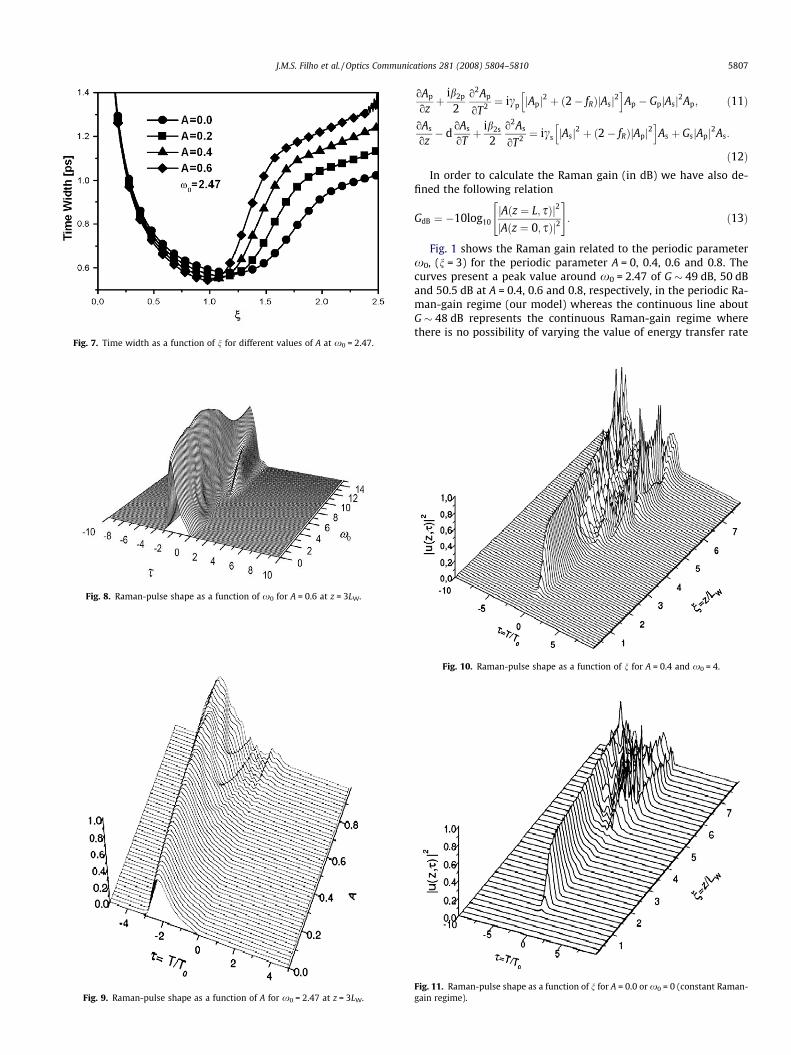
Fig. 7. Time width as a function of n for different values of A at x0 = 2.47.
Fig. 8. Raman-pulse shape as a function of x0 for A = 0.6 at z = 3LW.
Fig. 9. Raman-pulse shape as a function of A for x0 = 2.47 at z = 3LW.
J.M.S. Filho et al. / Optics Communications 281 (2008) 5804–5810 5807
oAp
ozþ
ib2p
2o2Ap
oT2 ¼ icp jApj2 þ ð2� fRÞjAsj2h i
Ap � GpjAsj2Ap; ð11Þ
oAs
oz� d
oAs
oTþ ib2s
2o2As
oT2 ¼ ics jAsj2 þ ð2� fRÞjApj2h i
As þ GsjApj2As:
ð12ÞIn order to calculate the Raman gain (in dB) we have also de-
fined the following relation
GdB ¼ �10log10jAðz ¼ L; sÞj2
jAðz ¼ 0; sÞj2
" #: ð13Þ
Fig. 1 shows the Raman gain related to the periodic parameterx0, (n = 3) for the periodic parameter A = 0, 0.4, 0.6 and 0.8. Thecurves present a peak value around x0 = 2.47 of G � 49 dB, 50 dBand 50.5 dB at A = 0.4, 0.6 and 0.8, respectively, in the periodic Ra-man-gain regime (our model) whereas the continuous line aboutG � 48 dB represents the continuous Raman-gain regime wherethere is no possibility of varying the value of energy transfer rate
Fig. 10. Raman-pulse shape as a function of n for A = 0.4 and x0 = 4.
Fig. 11. Raman-pulse shape as a function of n for A = 0.0 or x0 = 0 (constant Raman-gain regime).

5808 J.M.S. Filho et al. / Optics Communications 281 (2008) 5804–5810
along the process of amplification consequently no flexibility. Sothese relevant differences make periodic Raman-gain model veryinteresting comparing to ref. An interesting aspect of this gaincurve is as x0 increases it approaches to continuous line whichcorresponds to the constant Raman-gain regime at G � 48.1 dBseen in Agrawal’s book [1]. Fig. 2 shows the Raman gain relatedto periodic parameter A (n = 3) for x0 = 0, 2, 8 and 20. The Ra-man-gain curve at x0 = 2 shows a smooth increasing value withthe increase of the A values. However, the situation is quite differ-ent at x0 = 8 where the curve has a lower gain compared to x0 = 2,for small values of A. As x0 increases, the gain curve approaches to
Fig. 12. Evolutions of pump and Raman pulses for x0 = 0 or A = 0 (first row), x0 = 2.47 androw).
a constant line. It means that the gain curve tends to the constantRaman-gain regime. Fig. 3 shows the Raman gain along the fiberlength for x0 = 2.47 and A = 0.2, 0.4, 0.6 and 0.8. The curves havea similar behavior with different gain intensities. Thus, we can de-duce that the intensity of the gain is directly in proportional to thevalue of the parameter A as expected. Fig. 4 shows the gain curvesat A = 0.4 for x0 = 0, 2, 8 and 20. The Raman-gain curve at x0 = 4shows the optimum value in the final end of the fiber which corre-sponding to saturation case. For x0 = 8 the gain curve has a lowergain intensity in the final end of the fiber. Generally, the gain sat-uration value is used to design the amplifier [3,6].
A = 0.2 (second row), x0 = 2.47 and A = 0.4 (third row), x0 = 2.47 and A = 0.6 (fourth

Fig. 13. Spectra of pump and Raman pulses (upper row) in a constant Raman-gainregime for z = 2LW and in a periodic Raman-gain regime (lower row) for A = 0.4 ex0 = 2.47 at z = 2LW.
Fig. 14. Spectra of pump and Raman pulses (upper row) in a periodic Raman-gainregime at for A = 0.4 e x0 = 2.47 at z = 3LW and their chirp frequency, respectively(lower row).
J.M.S. Filho et al. / Optics Communications 281 (2008) 5804–5810 5809
In Fig. 5 we have the time width of the Raman pulse as a func-tion of the periodic parameter A for x0 = 0, 2, 4 and 6 (n = 3). Thecurves show that the time width is increasing with the increaseof the amplitude modulation parameter A and x0. Fig. 6 showsthe pulse time width related to x0 for A = 0.0, 0.2, 0.4 and 0.6(n = 3). The curves are somewhat similar to that of Fig. 5 regardingthe proportionality between time width and periodic parameters.Fig 7 shows Raman pulse time width related to the distance prop-agated in the fiber n (x0 = 2.47) for A = 0, 0.2, 0.4 and 0.6. Ramanpulse starts to build up after n = 1 and the time width curves arebroadening with the increase of the A parameter.
Fig. 8 shows the Raman-pulse shape in the final end of the fiber(n = 3) for A = 0.4 as a function of the frequency of modulationparameter x0 (see Fig. 6). From x0 = 0 to x0 = 2 we can observelow level of interference in the Raman-pulse shape. For higher val-ues of the frequency of modulation parameter x0 we can observethat the Raman pulse undergoes distortion up to x0 = 6.
Fig. 9 shows the Raman-pulse shape as a function of the modu-lation parameter A in the final end of the fiber (n = 3). In this casex0 = 2.47 (see Fig. 5). As can be seen, the side interference is indeedassociated with the high values of the A parameter. Thus, we canconclude that the optimum value for A must be a function of thegain and low level of distortions. In Fig. 10 we have the Raman-pulse intensity during propagation along the fiber (related to theparameter n) for A = 0.4 and x0 = 2.47. We can observe that forn = 3 we start having strong distortions in the Raman pulse. InFig. 11 we have the Raman-pulse shape in a constant Raman-gainregime for comparison. We can conclude that for the gain modu-lated configuration, the distortions in the Raman pulse is startingin a shorter distance compared to the unmodulated configurationthat we can confirm in Agrawal’s model.
Fig. 12 shows the evolution of the Raman and pump pulses formodulated and unmodulated configurations. For the unmodulatedcase (A = 0 or x0 = 0 (first row)), the Raman pulse builds up aftern = 1 and pump pulse shows two-peak structure. In the secondrow (for A = 0.2 and x0 = 2.47) we have a similar behavior, how-ever, the intensity of Raman pulse is stronger. Fig. 12 (third rowand fourth row) also show that Raman-pulse intensity has a con-siderable increase with the increase of the amplitude of modula-tion (A = 0.4 and x0 = 2.47, A = 0.6 and x0 = 2.47, respectively). Ina typical long-distance soliton communication system that em-ploys lumped amplifiers, however, the soliton period is much long-er than the fiber attenuation length and the spacing between theamplifiers. In our case the periodicity effect of Raman gain allowsus to control the energy transfer.
Spectra of the Raman and pump pulses show several interestingfeatures as a result of the combination of SPM, XPM, group-velocitymismatch and pump pulse depletion. Fig. 13 shows the spectra ofthe pump and Raman pulses (upper row) in a constant Raman-gainregime and spectra of pump and Raman pulses (lower row) in aperiodic Raman-gain regime (A = 0.4 and e x0 = 2.47) for n = 2.The asymmetric nature of these spectra due to XPM is more in-tense for periodic Raman-gain regime when compared with theconstant profile, resulting from the dependence of this effect onthe Raman-pulse intensity where in periodic regime the energytransfer is stronger. High-frequency side of the pump spectrumexhibits an oscillatory structure that is characteristic of SPM inboth regimes, but in periodic regime this frequency is lower thanin constant regime what makes us deduce that the periodicity isthe reason for this enhancement. It is important to remember thatin the absence of SRS, the spectrum would be symmetric with thesame structure appearing on the low-frequency side. As the low-frequency components occur near the leading edge of the pumppulse and because the pump is depleted on the leading side, theenergy is transferred mainly from the low-frequency componentsof the pump pulse. So, for the periodic regime, the leading edge
of the pump pulse is unlike the constant regime one because thedepletion effect is intense that indicates that more energy transferfrom the pump to the Raman seed [9]. The frequency bandwidth ofthe spectrum of the Raman seed in Fig. 13d for periodic regime iswider than in constant one and it is also partly for the same reason.In addition, the wider frequency bandwidth in periodic regime re-sults from a narrower Raman pulse in time domain. In constant Ra-man-gain regime the spectrum of Raman pulse is nearlyfeatureless at z = 2LW but in periodic Raman-gain regime it devel-ops a considerable internal structure. This is due to the combina-tion of XPM and pump depletion that has more effective inperiodic Raman-gain regime; the frequency chirp across the Ra-man pulse induced by these effects can vary rapidly both in mag-nitude and sign and leads to a complicated spectral shape [7]. In

5810 J.M.S. Filho et al. / Optics Communications 281 (2008) 5804–5810
Fig. 14 the spectra of pump and Raman for both regimes are plottedat z = 3LW. The spectrum of Raman pulse in constant regime overthis range develops internal structure unlike at z = 2LW. Regardingthe spectrum of Raman pulse in periodic regime that had alreadydeveloped internal structure at z = 2LW, now at z = 3LW the spec-trum develops much more internal structure. In Fig. 14a–b thespectra of the pump and Raman pulses and their respective fre-quency chirps in Fig. 14c–d for periodic Raman-gain regime atz = 3LW are also simulated. The low-frequency side of the spectrumin Fig. 14b is smooth; hence the only one part of the pulse contrib-utes to a given frequency in this spectral region [8]. The largebroadening of this side of the spectrum suggests a steep chirp onthe downshifted part of the pulse as shown in Fig. 14d. Further-more, since this part of the spectrum contains about half of totalenergy, one can conclude that approximately half of the pulse liesin the region of the negative chirp [11]. The energy in the low-fre-quency end comes from the leading edge of the pulse, where thepulse amplitude is decreasing. There are also high elevations at thisend of the spectrum and some small ones, which characterize theperiodic regime comparing to constant Raman-gain regime. Theenergy of the high-frequency side is concentrated mainly in pro-nounced peak and two considerable two peaks, which indicatesthat the slope of the chirp is far from the zero in a temporal regionwhere the pulse amplitude is high. The behavior has deducedabove is exhibited in Fig. 14d.
4. Conclusions
In this paper a new amplification configuration is proposed forRaman amplification. In this new configuration a spatial periodicRaman gain is used to amplify a CW Raman seed that generates ashort optical pulse taking into account the SPM, XPM, walk-offand pulse depletion. The amplification process is accomplishedby using an intense pump pulse where its energy is transferredthrough SRS effect. A CW weak seed is used to represent the signalto be amplified and for pump is used a Gaussian pulse. We discuss
the advantages to this configuration. First, this scheme means thatthe Raman-gain coefficient assumes a periodic characteristic andlike a modulation process, it gives the possibility to control the en-ergy transfer from the pump to Raman seed. The numerical meth-od is based on Split-Step Fourier method where the coupled non-linear Schrödinger equations are solved. It was shown that, whenwe tailor the Raman-gain coefficients as a sinusoidal function, weaccomplish a quantitative improvement. In addition, this modelalso allows us to control the energy transfer through the modula-tion parameters of the sinusoidal functions.
This new configuration provides some very interesting featuresin the Raman amplification process when compared to the stan-dard procedure. A complete discussion of this configuration ispresented.
Acknowledgments
We thank FFB, CNPq, FINEP, FUNCAP, CAPES and ANP for thefinancial support.
References
[1] G.P. Agrawal, Non-Linear Fiber Optics, third ed., Academic Press, 2001.[2] Q. Lin, G.P. Agrawal, Opt. Lett. 27 (2002) 2194.[3] L. Harte, D. Eckard, Fiber Optic Basics, Technology, Systems and Installation,
Athos Publishing, USA, 2006.[4] G. Ravet et al., Measurement of the distributed Raman Gain spectrum in single-
mode optical fibers, in: IEEE Laser and Electro-Optics Society Symposium –Benelux Chapter, 2002, p. 242.
[5] G.P. Agrawal, Fiber-Optic Communication Systems, third ed., Wiley, New York,2002.
[6] M. Wuilpart et al., IEE Electron. Lett. 39 (2003) 88.[7] D. Derikson (Ed.), Fiber Optic Test and Measurement, Prentice Hall PTR, 1998.[8] M.N. Islam (Ed.), Raman Amplifiers for Telecommunications, Springer, 2004;
V.M. Mashinsky et al., Opt. Lett. 29 (2004) 2596.[9] W. Wang et al., in: Proceedings of Optical Fiber Communication Conference,
Paper ThN3, 2004.[10] F. Vanholsbeeck, S. Coen, P. Emplit, M. Haelterman, T. Sylvestre, Opt. Commun.
250 (2005) 191.[11] J.C. Travers, S.V. Popov, J.R. Taylor, Appl. Phys. Lett. 87 (2005) 31106.