polymer waveguide optical filter
TRANSCRIPT
This article appeared in a journal published by Elsevier. The attachedcopy is furnished to the author for internal non-commercial researchand education use, including for instruction at the authors institution
and sharing with colleagues.
Other uses, including reproduction and distribution, or selling orlicensing copies, or posting to personal, institutional or third party
websites are prohibited.
In most cases authors are permitted to post their version of thearticle (e.g. in Word or Tex form) to their personal website orinstitutional repository. Authors requiring further information
regarding Elsevier’s archiving and manuscript policies areencouraged to visit:
http://www.elsevier.com/authorsrights
Author's personal copy
A tunable polymer waveguide ring filter fabricated with UV-based softimprint technique
Linghua Wang a, Xiuyou Han a,n, Yiying Gu a, Yu Wang a, Pin Zou a, Jinyan Wang b, Xigao Jian b,Geert Morthier c, Mingshan Zhao a
a School of Physics and Optoelectronic Engineering, Dalian University of Technology, 116023 Dalian, Chinab Department of Polymer Science and Materials, Dalian University of Technology 116023 Dalian, Chinac Photonics Research Group, INTEC-Department, Ghent University-IMEC, 9000 Ghent, Belgium
a r t i c l e i n f o
Article history:
Received 19 December 2012
Received in revised form
3 February 2013
Accepted 6 February 2013Available online 28 February 2013
Keywords:
Polymer waveguide
Optical filter
Ring resonator
Soft imprint
a b s t r a c t
Photonic integrated components with tunability, low power consumption and low fabrication cost are
of considerable interest for optical communications and optical signal processing systems. Based on the
high thermo-optic coefficient of polymer material, we demonstrate a tunable integrated waveguide
ring filter with a novel but very simple UV-based soft imprint technique. By properly incorporating a
Mach–Zencher interferometer (MZI), the tunability of the ring filter’s coupling states and resonant
wavelength are realized flexibly by the micro-heaters. The tuning efficiency of resonant wavelength is
8.2 pm/mW within one free spectrum range of the ring filter.
& 2013 Elsevier B.V. All rights reserved.
1. Introduction
Photonic integration has been widely adopted for opticalcommunication, signal processing and optical sensors because itcan help significantly reduce the power consumption, cost andsize of the system while enhancing its reliability and functionality[1–3]. As a basic photonic integrated component, the ring reso-nator plays an important role for the realization of differentoptical functions such as filtering, modulation, and switching.Ring resonator-based devices with high performance have beendesigned and demonstrated on different material platforms, e.g.
glass, silica, silicon-on-insulator (SOI) or polymer [4,5]. Amongthem, polymer-based ring resonator devices, for example filters,modulators and reflectors [6–10], have been attracting more andmore attention because of their advantages of low cost, goodperformance and potential for hybrid integration with otherdevices in inorganic or organic materials [11,12].
Polymer waveguide ring resonators with notch and bandpassfiltering functions and their relevant application have beenreported in References [6,10]. For the notch filter consisting ofone ring coupled to one bus waveguide, in order to achieve a highnotch depth, the critical coupling condition is usually required[13]. It means that the optical power coupled from the bus
waveguide into the ring should be equal with the round trip lossof the ring itself. However, this condition cannot be achievedeasily due to the possible deviation between the designed andfabricated devices. Therefore, it increases the complexity anddifficulty of device design and fabrication. If the coupling coeffi-cient or the round trip loss (gain) could be tuned, for example,with a tunable coupler instead of the fixed directional coupler orwith an optical amplifier inserted in the ring, the notch filteringfunction would be obtained conveniently [14–16].
In this paper, a tunable coupler with a Mach–Zencher inter-ferometer (MZI) is brought into the structure of a ring resonator.The high thermal–optical (TO) coefficient of the polymer is utilizedto tune the equivalent MZI coupler with low power consumption.Different states of coupling condition, namely, over-, critical- andunder-coupling, are realized. At the same time, the tunability ofresonant wavelengths is realized with the TO phase shifter on thepolymer waveguide ring. The tunable polymer ring resonatorhas potential applications for microwave photonic filter, opticalswitching and optical true time delay.
2. Material
In our work, a silicate based inorganic–organic hybrid opticalmaterial named as polysiloxane-liquid series (PSQ-Ls), which isdeveloped in our group, is chosen for the fabrication of waveguidedevices [17]. Its two components, PSQ-LH and PSQ-LL, have
Contents lists available at SciVerse ScienceDirect
journal homepage: www.elsevier.com/locate/optcom
Optics Communications
0030-4018/$ - see front matter & 2013 Elsevier B.V. All rights reserved.
http://dx.doi.org/10.1016/j.optcom.2013.02.021
n Corresponding author. Tel.: þ86 411 84706492.
E-mail address: [email protected] (X. Han).
Optics Communications 298–299 (2013) 95–100

Author's personal copy
refractive index values of 1.515 and 1.454 at 1550 nm, low opticalloss and high thermal stability, which can be used as waveguidecore and cladding, respectively [18]. The unique solvent-freeproperty and good UV curable property make it highly compatiblewith our developed UV-based soft imprint technique [19].
3. Design and simulation
Fig. 1 shows the schematic picture for the structure of theproposed tunable polymer ring resonator. The layout design forthe device is shown in Fig. 1(a). A MZI consisting of two 3 dBdirectional couplers is used as the equivalent tunable coupler forthe ring resonator, while the ring resonator itself is constructedby connecting one output port of MZI to one of its input ports. Thelengths of the two arms of MZI are equal. One micro-heater isplaced on one of them. The change of the phase relationshipbetween two arms through TO effect can result in a difference ofthe optical power which is coupled into the ring resonator, thusachieving the tunability of the coupling efficiency. Another micro-heater is placed on the ring waveguide. The resonant wavelengthposition control can be realized with this phase shifter. Thedetails of the dimension for this structure are as follows: thelength of the MZI arm L1¼1000 mm, the coupling length of the3 dB directional coupler L2¼58 mm and the gap between thewaveguides d1¼1 mm. The bend radius of the ring resonatorR1¼500 mm. Several quasi-S bend waveguides are used to con-nect the 3 dB directional couplers with the input ports, outputports and the half circle bend waveguides. Their bend angles jare designed to be 121 and bend radius R2 to be 1400 mm. Thelength and width of the micro-heater on the ring resonator are2000 mm and 10 mm, while that on the MZI arm are 1000 mm and5 mm, respectively.
The cross section of the polymer waveguide loaded withmicro-heater is shown in Fig. 1(b). To prevent extra substrateleakage loss, the thickness of the under cladding layer hl is chosento be 6 mm. The single mode condition of the polymer waveguidecan be guaranteed by selecting the waveguide width w to be2.5 mm and height hc to be 2.1 mm. With such waveguide dimen-sions, the bending loss of the curved waveguides can be negli-gible. In our current design, there is an extra layer (SU-8 polymerin experiment) with a thickness of around 1 mm on top of thewaveguide’s upper cladding. It is used to protect the waveguidelayer during the later lift-off process and this will be furtherexplained in the Section 4. Although its refractive index of 1.57 isa little bit higher than that of the waveguide core, according toour simulation, if the thickness of the upper cladding between thewaveguide core and the layer hu can be controlled appropriately,the extra radiation loss of the waveguide mode caused by thislayer can be neglected. The simulation result is shown in Fig. 2.The device is designed to be working in the TE mode, as its loss ismuch lower than that of the TM mode with a radius of 500 mm. Inthis work, the thickness of the upper cladding is chosen to be2.8 mm. Further increasing such thickness can hardly decrease theradiation loss but lower the power efficiency of the micro-heater[20].
4. Fabrication of the device
A simple UV-based soft imprint method was adopted in ourwork to fabricate polymer waveguide structures. Such a trans-formed soft lithography method has been proved to be a cost- andthroughput-efficient way for patterning not only the photo resistbut also the polymer waveguides straightforwardly [19,21].Especially for the waveguide devices fabrication, the simple UV
Fig. 1. The schematic picture for the structure of the proposed tunable polymer ring resonator. (a) The device layout design and (b) The waveguide cross section with
micro-heater.
L. Wang et al. / Optics Communications 298–299 (2013) 95–10096

Author's personal copy
imprinting technique makes good use of the plastic property ofpolymer material, which avoids the complicated multi-steps ofthe CMOS process, such as lithography, metal mask fabricationand dry etching. As a result, it reduces the fabrication time andcost efficiently.
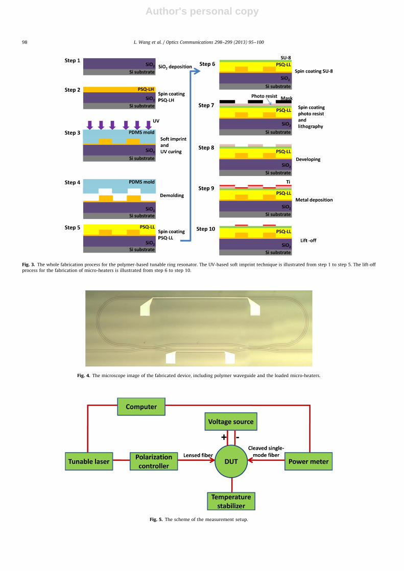
The detailed fabrication process is shown from step 1 to step5 in Fig. 3. First, a SiO2 layer with a thickness of 6 mm is depositedon top of the silicon substrate by plasma-enhanced chemicalvapor deposition (PECVD), which acts as the under cladding of thewaveguide. Secondly, a thin layer of PSQ-LH is spin-coated on topof it, followed by the imprinting of the soft PDMS mold upon thislayer. The mold is replicated from a master mold using the castingmethod. When the PSQ-LH layer becomes solidified after UVexposure, the PDMS mold is peeled off. Because of the good UVcuring property of PSQ-Ls material and its solvent-free character-istic, the waveguide structures can be transferred from the PDMSmold to the PSQ-LH layer with this one step imprinting, drama-tically reducing the fabrication time and cost. Besides that, thewaveguide quality can be further optimized by methods such asthe thermal reflow technique [22], which helps reduce thepropagation loss of the polymer waveguide. The sample is thenbaked for 2 h at a temperature of 180 1C to fully cure thewaveguide core layer. PSQ-LL layer of around 4.9 mm is used asupper cladding.
For the fabrication of the micro-heaters, although photo litho-graphy and dry etching are widely used, such a process will
counteract the benefits brought by the UV imprinting process,which is rather simple and of low cost. Compared with that, thelift-off process has been proved to be an ideal alternative for thefabrication of the micro-heaters [23]. In our work, in order to takeadvantage of this process, a thin SU-8 protecting layer with athickness of 1 mm is added on top of the upper cladding. Byexperiment, it was found not only to have good adhesion with thedeposited metal, but more importantly, it is quite stable duringthe whole process of lift-off, protecting the already fabricatedwaveguide’s structures underneath from the attack of differentsolvents. These processes are shown from step 6 to step 10 inFig. 3. The pattern definition for the micro-heaters was achievedwith the positive photo resist AZ5214 (MicroChemicals), afterwhich titanium with a thickness of 110 nm was sputtered. Themetal lift-off process was finally realized by immerging thesample into acetone for 1 h. As can be seen, the fabricationprocess, including both the waveguide fabrication and themicro-heaters’ definition, is very simple, of low cost and suitablefor mass production. The microscope image of the final fabricateddevices is shown in Fig. 4.
5. Measurement results
The measurement setup is shown in Fig. 5. The electric poweris loaded onto the fabricated device through four micro-needles,the head size of which is 12 mm. In order to measure thetransmission of the device, the light from a tunable laser islaunched into the input waveguide via a lensed fiber. Its polariza-tion state is carefully tuned to TE with a polarization controller toprevent extra loss, as predicted by the simulation. The output lightis collected by a cleaved single-mode fiber, which is connected to apower meter.
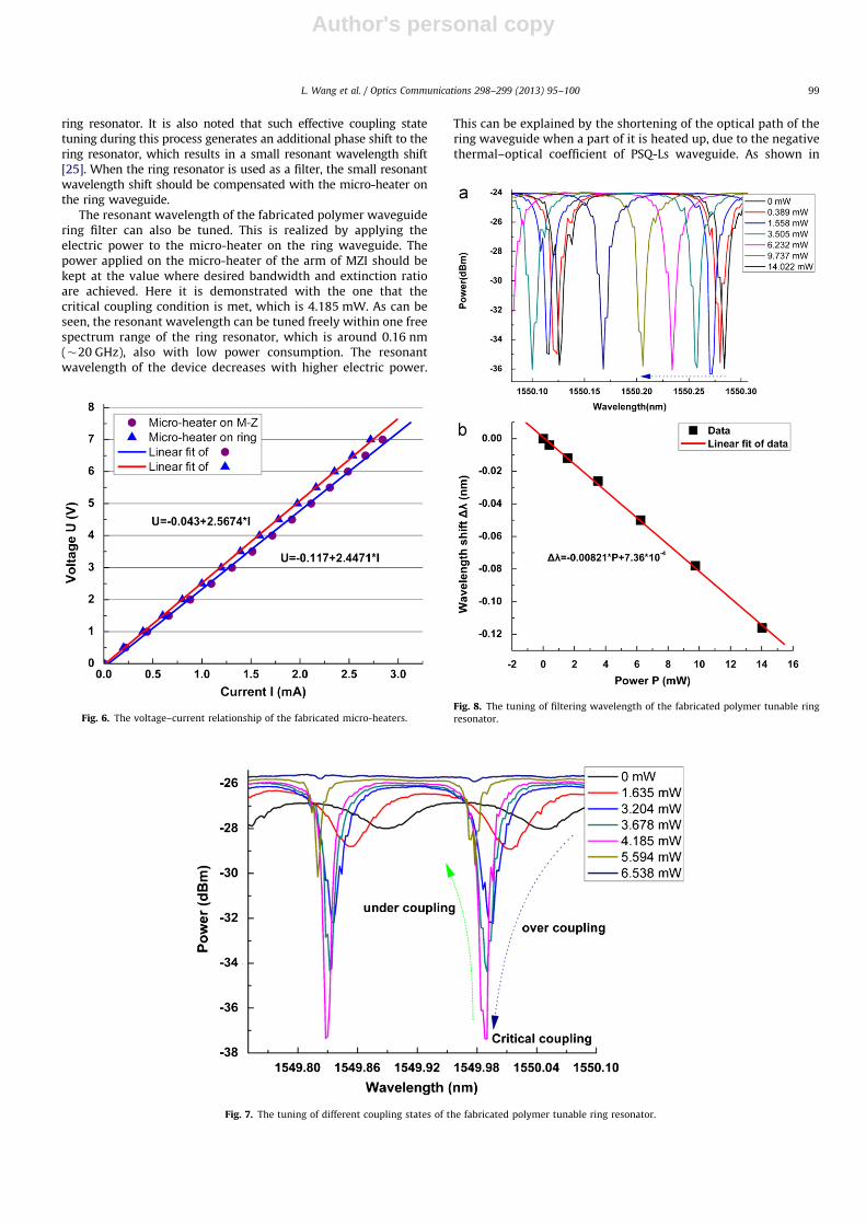
The resistance of two micro-heaters, one on the arm of MZIand the other on ring resonator, is first obtained by measuringtheir voltage–current relationship. The results are shown in Fig. 6.With linear fitting, resistance value of 2.4471 kO for the MZImicro-heater and that of 2.5674 kO for the micro-heater of thering resonator can be estimated. Due to its length, the latter is alittle bit larger than the former, although it has a larger width.
Different coupling states are realized by applying the electricpower only to the micro-heater on the MZI arm. The result isshown in Fig. 7. As can be seen, the extinction ratio of the filtercan be tuned by the applied electric power, corresponding to thecoupling coefficient of the MZI-based coupler. At first, the ringresonator is working under the state of over-coupling as most ofthe light in input waveguide is coupled into the ring resonatorafter passing the MZI. Although in theory there should be noresonance under zero applied electric power, a shallow dip around1 dB is observed. This is because the two fabricated directionalcouplers constituting the MZI are not strictly 3 dB. The light coupledinto the ring resonator is decreased with the applied power. Whenthis coupled energy equals with the roundtrip loss of the ring, e.g.
critical coupling condition [13] is met, the highest extinction ratio(�11.5 dB) and narrowest bandwidth (�0.0163 nm) of the filter areobtained. The Q factor of the device under such state can thus beestimated to be around 9.5�104. The result for such a high Q factorcan be partly attributed to the low propagation loss of the fabricatedpolymer waveguide, which is around 1.7 dB/cm for TE mode. Thecontinued increasing electric power will make the ring workingunder under-coupling state. The tunability of coupling states can beutilized to achieve the switch function. Compared with other kindsof thermo-optics device (e.g. optical switch in Ref. [24]), the powerconsumption for our device to obtain high extinction ratio of thetransmitted light is much lower if the working wavelength is chosenappropriately. Such benefit is brought by the resonant effect of the
Fig. 2. (a) The relationship between the bend loss of the fundamental waveguide
mode and the thickness of the polymer upper cladding and (b) The fundamental
TE mode of the designed waveguide with a bend radius of 500 mm.
L. Wang et al. / Optics Communications 298–299 (2013) 95–100 97
Author's personal copy
Fig. 4. The microscope image of the fabricated device, including polymer waveguide and the loaded micro-heaters.
Fig. 5. The scheme of the measurement setup.
Fig. 3. The whole fabrication process for the polymer-based tunable ring resonator. The UV-based soft imprint technique is illustrated from step 1 to step 5. The lift-off
process for the fabrication of micro-heaters is illustrated from step 6 to step 10.
L. Wang et al. / Optics Communications 298–299 (2013) 95–10098
Author's personal copy
ring resonator. It is also noted that such effective coupling statetuning during this process generates an additional phase shift to thering resonator, which results in a small resonant wavelength shift[25]. When the ring resonator is used as a filter, the small resonantwavelength shift should be compensated with the micro-heater onthe ring waveguide.
The resonant wavelength of the fabricated polymer waveguidering filter can also be tuned. This is realized by applying theelectric power to the micro-heater on the ring waveguide. Thepower applied on the micro-heater of the arm of MZI should bekept at the value where desired bandwidth and extinction ratioare achieved. Here it is demonstrated with the one that thecritical coupling condition is met, which is 4.185 mW. As can beseen, the resonant wavelength can be tuned freely within one freespectrum range of the ring resonator, which is around 0.16 nm(�20 GHz), also with low power consumption. The resonantwavelength of the device decreases with higher electric power.
This can be explained by the shortening of the optical path of thering waveguide when a part of it is heated up, due to the negativethermal–optical coefficient of PSQ-Ls waveguide. As shown in
Fig. 6. The voltage–current relationship of the fabricated micro-heaters.
Fig. 7. The tuning of different coupling states of the fabricated polymer tunable ring resonator.
Fig. 8. The tuning of filtering wavelength of the fabricated polymer tunable ring
resonator.
L. Wang et al. / Optics Communications 298–299 (2013) 95–100 99
Author's personal copy
Fig. 8, the resonant wavelength shifts linearly with the appliedpower, and the tuning efficiency is about 8.2 pm/mW. Accordingto request, flexible filtering performance can be realized bycascading such tunable ring resonators.
6. Conclusion
In this work, we propose and demonstrate a tunable ringresonator based on polymer material. Different from the tradi-tional one, the device gives much more flexibility by incorporat-ing a MZI and two micro-heaters. Not only can different couplingstates be realized, but also the resonant wavelength can be tunedeasily, both with low power consumption. Moreover, the novelUV-based soft imprint technique has been adopted to fabricatethe prototype device, which is compatible with the polymerproperty and has the advantages of low cost and high throughput.The device is expected to find useful applications in opticalswitching and optical filtering.
Acknowledgments
This work was supported in part by the National Natural ScienceFoundation of China (Nos. 60807015, 61077015, and 60577014), theNational High-tech R&D Program (No.2012AA040406), the Specia-lized Research Fund for the Doctoral Program of Higher Education(No. 200801411037), the Natural Science Foundation of LiaoningProvince (No. 20102020) and the Fundamental Research Funds forthe Central Universities.
References
[1] D. Kim, J. Luo, Y. Tian, A.K. Jen, N. Peyghambarian, Nature Photonics 1 (2007) 180.[2] N. Bamiedakis, A. Hashim, R.V. Penty, I.H. White, Optics Express 20 (2012)
11625.
[3] Xudong Fan, Ian M. White, Siyka I. Shopova, Hongying Zhu, Jonathan D. Suter,Yuze Sun, Analytics Chimica Acta 620 (2008) 8.
[4] S. Otto, Proceedings of the SPIE 6872 (2008) 68720H.[5] Jesus Palacı, Guillermo Eduardo Villanueva, Jose Vicente Galan, Javier Martı,
Borja Vidal, Photonics Technology Letters 22 (2010) 1276.[6] Joyce K.S. Poon, Lin Zhu, Guy A. DeRose, J. Amnon Yariv, Lightwave
Technology 24 (2006) 1843.[7] Gun-Duk Kim, Sang-Shin Lee, Optics Communications 278 (2007) 303.[8] Bartosz Bortnik, Yu-Chueh Hung, Hidehisa Tazawa, Byoung-Joon Seo,
Jingdong Luo, K.-Y. Jen, William H. Steier, Harold R. Fetterman, Journal ofSelected Topics in Quantum Electronics 13 (2007) 104.
[9] Joonoh Park, Taehyung Lee, Donghyun Lee, Suhyun Kim, Woonglin Hwang,Youngchul Chung, Photonics Technology Letters 20 (2008) 988.
[10] Xiuyou Han, Jianing Zhang, Linghua Wang, Yiying Gu, Meng Wang, Jie Teng,Jinyan Wang, Xigao Jian, Geert Morthier, Mingshan Zhao, Optical Engineering
50 (2011) 124601.[11] Hong Ma, Alex K.-Y. Jen, Larry R. Dalton, Advanced Materials 14 (2002) 1339.[12] Nan Jokerst, Matthew Royal, Sabarni Palit, Lin Luan, Sulochana Dhar,
Talmage TylerChip, Journal of Biophotonics 2 (2009) 212.[13] A. Yariv, Electronics Letters 36 (2000) 321.[14] Xiao-Yang Zhang, Tong Zhang, Xiao-Jun Xue, Jin-Ling Zhang, Jun Hong, Peng-
Qin Wu, Qiu-Yue Chen, Journal of Lightwave Technology 28 (2010) 2512.[15] Jin Yao, David Leuenberger, Ming-Chang M. Lee, Ming C. Wu, Journal of
Selected Topics in Quantum Electronics 13 (2007) 202.[16] V.M. Menon, W. Tong, S.R. Forrest, Photonics Technology Letters 16 (2004)
1343.[17] Hongbo Zhang, Jinyan Wang, Linke Li, Yuan Song, Mingshan Zhao, Xigao Jian,
Thin Solid Films 517 (2008) 857.[18] Xiuyou Han, Linghua Wang, Yuhui Liu, Hongbo Zhang, Jinyan Wang,
Xigao Jian, Mingshan Zhao, Proceedings of the SPIE 7134 (2008) 713416.[19] Jie Teng, Stijn scheerlinck, Hongbo Zhang, Xigao Jian, Geert Morthier,
Roel Beats, Xiuyou Han, Mingshan Zhao, Photonics Technology Letters 21
(2009) 1323.[20] Hongyan Song, Xiuyou Han, Pin Zou, Linghua Wang, Yiying Gu, Jinyan Wang,
Xigao Jian, Mingshan Zhao, Acta Optica Sinica 32 (2012) 0723003.[21] L.J. Guo, Advanced Materials 19 (2007) 495.[22] C.Y. Chao, W. Fung, L.J. Guo, IEEE Journal of Selected Topics in Quanatum
Electronics 12 (2006) 134.[23] Matteo Calaon, Aminul Islam, Hans N. Hansen, Christian Ravn, International
Journal of Advanced Manufacturing Technology 59 (2012) 101.[24] Nan Xie, Takafumi Hashimoto, Katsuyuki Utaka, Photonics Technology
Letters 21 (2009) 1335.[25] Jianing Zhang, Xiuyou Han, Hongyan Song, Jie Teng, Pengsheng Wu,
Linghua Wang, Mingshan Zhao, Acta Optica Sinica 30 (2010) 2098.
L. Wang et al. / Optics Communications 298–299 (2013) 95–100100