qa record / dne calculations
TRANSCRIPT
TVA floq'7 fnAN.-g-QA Record / DNE CALCULATIONS/
TITLE Plant/Unit
REPARING'ORGANIZATION KEY NOUNS (Consult RIMS DESCRIPTORS LIST)NEbasco Services Inc.BRANCH/PROJECT IDENTIFIERS Each time these calculations are issued, preparers must ensure that the
original (RO) RIMS accession number is filled in.I'c• - 7- 71 Rev/ , (for RIMS' use) RIMS accession number
R_ B]18 910415 251APPLICABLE DESIGN DOCUMENT(S) -
R
SAR SECTION(S) UNID SYSTEM(S)4,, IVI94
Revision 0 - R1 R2 R3 Safety-related? Yes Nl No r IECN NO.(or indicate Not Applicable) Statement of Problem.
A/M 5, 441Z-41Prepared: 5-/---i-A. L/A/
Checked/verCfd -G - 16,' WL/
Reviewed: _7,,1.• U,
Approved: / .-.-e f,./,
Date ~ , e
'JSE FORM List all pages addedTVA 10534 by this revision
IF MORE List all pages deletedSPACE by this revision O R I G I NREQUIRED List all pages changed
by this revision
Abstract: These calculations contain an unverifiedthat must be verified later. Yes [ ]
assumption(s)
No[ ]
dZ/v$r-z9 6(eyw04' '- /#/e
" • #-,¥•r•_ ,• •,y e,,•'•.. o • LEGIBILITY EVALUATED andACCEPTED for issue.
Signature I/ Date
J Microfilm and store calculations in RIMS Service CenterIX] Microfilm and return calculations to: Calculations Library
RIMS, SL 26 C-K D. Kilgore
Microfilm and destroy.Address: WBN N OA RLD(~.
WBN Trailer No. E-2Z
91-0:;0300082 '9108222F:DR ADOCK 05000390A PDR
69
7224x
-- , i I #
,ý5,Aeý-Fy 117etVw,:(- A41d-
1r-F7-7 1 6Sheet 2, of
TITE £XA=MPLE CALcuLATtON =OR GUALIIAICAT-Ov RV NI =i. 7LeR,:'4tuRC..r,41,,m, .7Rucra.-7 REVISION LOAGPREI". BY: , . DATE: . --/-CRMEGDT BY: (14ENG -/H 6 DATE:
-T - I
DESCRIPTION OF REVISION
I .*~. -
TVA O•3'4 (EM CES-.1-.7
SHEET.3"OF _
CALCULATION DESIGN VERIFICATION (INDEPENDENT REVIEW) FORM
c,)606$- I- - 777/BRANCH/PROIJECT IDVCalculation No.
0Revision
Method of design verification (independent review) used (check-method used):
1. Design Review I2. Alternate Calculation3. Qualification Test
Justification (explain below):
In the design review method, justify the technical adequacy of thecalculation and e"plain how the adequacy was verified (calculation issimilar to another, based on accepted handbook methods, appropriatesensitivity studies included for confidence, etc.).
In the alternate calculation method, identify the pages where thealternate calculation has been included in the calculation packageand explain why this method is adequate.
In. the qualification test method, identify the QA documentedsource(s) where testing adequately demonstrates the adequacy of thiscalculation and explain.
DESIGN REVIEW IS APPLICABLE TO THIS CALCULATION, SINCE IT IS BASED ON~'T'AJT'~A~fl. ~ ~AMT~Anr M~Afl~
Cl-fEN46-,H 6&& /0 Aýt 4
Design Verifier(Independent Reviewer)
D e --Dace
Method 1:
Method 2:
Method 3:
7'Kn 'DTVr- WA?=Znn7 Vr'7Wn'nC
EBASCO SERVICES INCORPORATED
Wc• !-77/BRANCH/PROJECT ID:
BY:
CHECE TD B Y: L4
CLIENT: TVA "
PROJECT: WBNP/UBTT -
DATE: : -io- q/
DATE: ý /-9
SE 4 OF
DEPT NO.: -
OFS No.: -
SUBJECT: ~s,5( &~~~ 9 6 ~ /7~~~•r
SECT.NO.
1
TABRT OF CONTINTS
PAGE NO. OFNO, PAGESDESCRIPTION
COVER SHEET
REVISION LOG
CALC DESIGN VERIFICAZION (INDEPENDENT REVIEW) FORM
TABLE. OF CONIITETS
PURPOSE
CRITERI
APPLICATLE CODES AND S`TADARDS
ASSUPTIONS, LITRA SARCS AND O=EX.. APPLICABLE D .T.. - - -
DESIGN INPUT DATA
CALCULATI ONS
SUMMART OF CALCULATION RESULTS
CONCLUSION
ATTACHME=TS
SUPERSEDED PAGES:
1
I
/
TOTAL PAGES='AIS CALCULATION PACKAGE CONTAINS 70 TOTAL PAGES.
EBASCO SERVICES INCORPORATEDBRANCH/PROJECT ID. : -WCq -/-77/
( BY _ __DATE V/ 0-1-9/CHKD. BY 6 6L/& DATE '-"?(
CLIENT TVAPROJECT WBNP-UnitSUBJECT
SHEET..5 OFL4-DEPT.
FS NO. - NO -
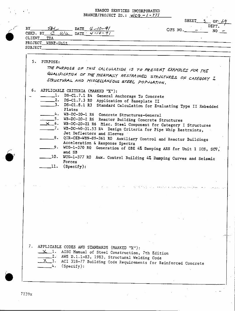
5. PURPOSE:77f= PURPoSE OF THIS. CALCULATI04 IS 7To PRAESNT -kAMPLES F'OR rMEQA4htbIC"ATION O Tr9E T-E.MALLY RE-StAINED sr-•T rU&•Es F COFT" Z
STucTUAAL ANID MISCELLANIFOO. SEE. POPULATION.
6. APPLICABLE CRITERIA (MARKED f"X):1. DS-CI.7.1 R4 General Anchorage To Concrete2. DS-Cl.7.3 RO Application of Baseplate II.3. DS-CI.8.1 R3 Standard Calculation for Evaluating Type II Embedded
:Plates4. WB-DC-20-1 R6 Concrete Structures-General5. WB-DC-20-2 R6 Reactor Building Concrete Structures
_ 6. WB-DC-20-21 R6 Misc. Steel Component for Category I Structures7. WB-DC-40-31.53 R4 Design Criteria for Pipe Whip Restraints,
Jet Deflectors and Sleeves8. QIR-CEB-WBN-89-361 RO Auxiliary Control and Reactor Buildings
Acceleration & Response Spectra9. WCG-1-370 RO Generation of OBE 4% Damping ARS for Unit I ICS, SCV,
and SB10. WCG-1-377 RO Aux. Control Building 4% Damping Curves and Seismic
Forces11. (Specify):
7. APPLICABLE CODES AND STANDARDS (MARKED "X"):___ I. AISC Manual of Steel Construction, 7th Edition
2.- AWS D.1.I-83, 1983, Structural Welding Code___3. ACI 318-77 Building Code Requirements for Reinforced Concrete
4. (Specify):
7 239x
EBASCO SERVICES INCORPORATEDBRANCH/PROJECT ID.: ^)jie- 1- -i7'/
BY 44Al DATE .•-q- qCHKD. BY (I 60,_ DATE '-io-9/CLIENT TVAPROJECT WBNP-UnitSUBJECT 2XAleol ', I -c,, -ni.•,A,
SHEET 6 OFi;4DEPT.
OFS NO. - NO.
1l4~rmod(u Ve4v½1 ~ueA td•~ ~&5
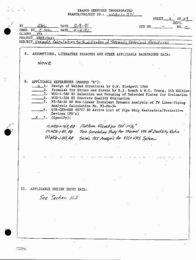
8. ASSUMPTIONS, LITERATURE SEARCHES AND OTHER APPLICABLE BACKGROUND DATA:
NoN•~
9_. APPLICABLE REFERENCES (MARKED "X"):1. Design of Welded Structures by O.W. Blodgett 19662. Formulas for Stress and Strain by R.J. Roark & W.C. Young, 5th Edition
-3. WCG-1-580 RO Selection and Grouping of Embedded Plates for Evaluation__4. WCG-1-Z56 RO Concrete Quality Evaluation
5. N3-PA-34 RO Non-linear Transient Dynamic Analysis of FW Lines-PipingAnalysis Calculation No. N3-PA-34
6. QIR-CEB-WBN 90757 RO Active List of Pipe Whip Restraints/ProtectiveDevices (PD's)
_( 7. (Specify):
/~5 5e,~ •s-.z-
10. APPLICABLE DESIGN INPUT DATA:
4ArIn 15*447' ?n 72ýP' /0,ýz
At- 7*mal afe AeýýAel, /, le A!&A 0ca) ie, ý__ -ell, RO/
,9qOv
EBASCO SERVICES INCORPORATED
BRANCH/PROJECT ID: WCG-1-771B y~ Date & jI oSheet -7 Of_1_Chkd. bChk/VýCd. byD ate zjQ0-j. OFS No.- - Dept. No. -Client TVA
"
Project WBNP Unit 1Subject Example Calculation for Qualification of Thermally Restrained Structures
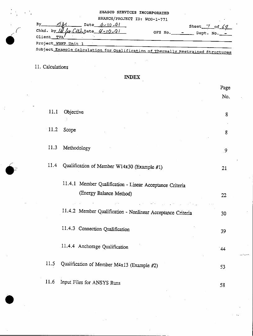
11. Calculations
INDEX
Page
No.
11.1 Objective
11.2 Scope
11.3 Methodology
11.4 Qualification of Member W14x3O (Example #1)
11.4.1 Member Qualification - Linear Acceptance Criteria
(Energy Balance Method)
11.4.2 Member Qualification - Nonlinear Acceptance Criteria
11.4.3 Connection Qualification
11.4.4 Anchorage Qualification
11.5 Qualification of Member M4x13 (Example #2)
11.6 Input Files for ANSYS Runs
EBASCO SERVICES INCORPORATED
BRANCH/PROJECT ID: WCG-1-771
B Date g1•9t 9/ Sheet •_ of•_ZChkd. by C 4/0 Date 0-/0--/ OFS No.- Dept. No. -
Client TVA
Project WBNP Unit 1Subject Example Calculation for Qualification of Thermall' Restrained Structures
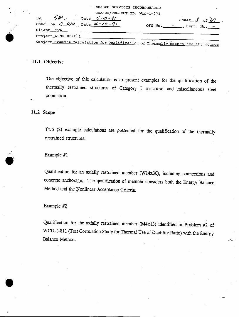
11.1 Objective
The objective of this calculation is to present examples for the qualification of thethermally restrained structures of Category I structural and miscellaneous steel
population.
11.2 Scope
Two (2) example calculations are presented for the qualification of the thermally
restrained structures:
Example #1
Qualification for an axially restrained member (W14x3O), including connections andconcrete anchorage; The qualification of member considers both the Energy BalanceMethod and the Nonlinear Acceptance Criteria.
Example_#2
Qualification for the axially restrained member (M4x13) identified in Problem #2 ofWCG-1-811 (Test Correlation Study for Thermal Use of Ductility Ratio) with the Energy
Balance Method.
EBASCO SERVICES INCORPORATED
BRANCH/PROJECT ID: WCG-1-771
. Date [ "I 0 - / Sheet of• _Chkd. by (11'V Date 4 -/0- 4 ' OFS No. - Dept. No. -
Client TVA
Project WBNP Unit 1Subject Example Calculation for Qualification of Thermally Restrained Structures
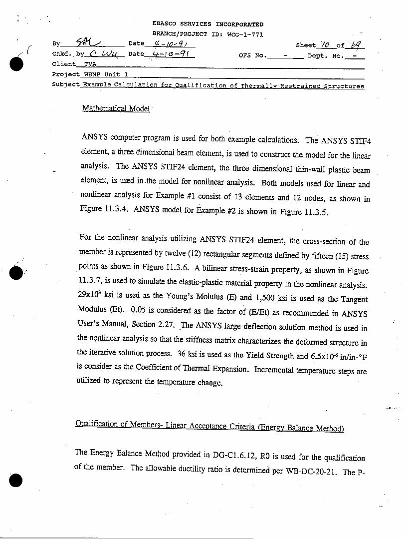
11.3 Methodology
Geometric Configuration
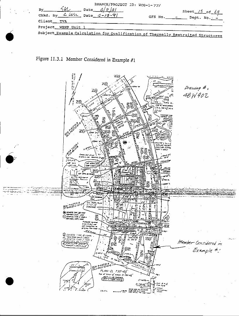
A W14x3O member in the RB Instrument Room, platform elevation 730'-10.5", as shownin Figure 11.3.1 (for detail, see Drawing 48W902), is considered for Example #1. Thegeometry of this member is presented in Figure 11.3.2.
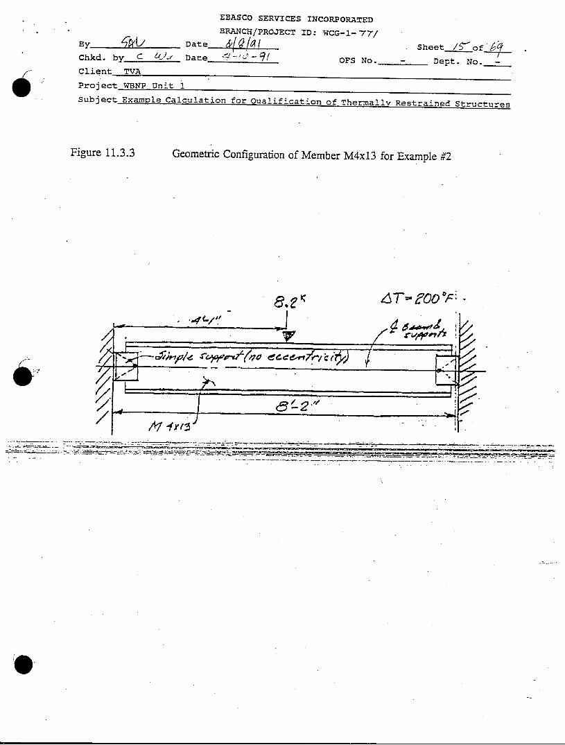
The geometric configuration of the member M4x13 used in Example #2 is shown in
Figure 11.3.3.
Loading Condition
According to A8.1.2 of WB-DC-20-21, thermal effects and loads during normaloperating condition (To) can be ignored since the operating temperature of this memberdoes not exceed 120'F; Therefore, only loading combination (8a) in Appendix A ofWB-DC-20-21 is selected for evaluation. Dead Load, Live Load, SSE Load as well asThermal Load are considered in this loading combination.
All loading data are obtained from the calculation WCG-1-769 and the G-values for SSEloadings are obtained from the ARS results in WCG-1-343. 1.5 is used for the MMF(Multi-Mode Magnification Factor) for Floor SSE loads and 1.2 is used for the M7MFfor Conduit SSE loads. A unit weight of 0.786 pci is considered for Dead Load and100.0 psf is used for Live Load. Unfactored conduit load and the pipe foot-print loadare directly obtained from the GTSTRUDL input file used in WCG-1-769.
EBASCO SERVICES INCORPORATED
BRANCH/PROJECT ID: WCG-1-771B Date Z-/I Z Sheet /0 of_-4
( Chkd. by Date z-0-9(-- OFS No. - Dept. No. -
Client TVA
Project WBNP Unit 1Subject Example Calculation for Qualification of Thermally Restrained Structures
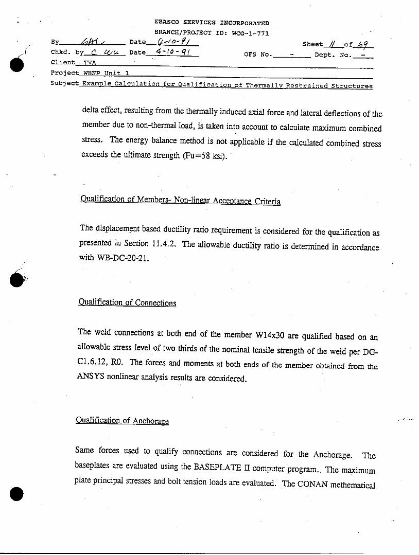
Mathematical Model
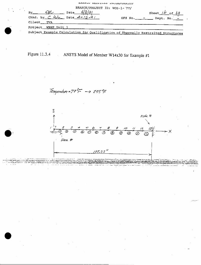
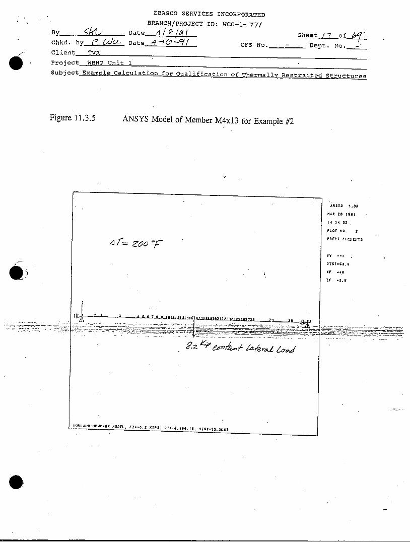
ANSYS computer program is used for both example calculations. The ANSYS STIF4element, a three dimensional beam element, is used to construct the model for the linearanalysis. The ANSYS STIF24 element, the three dimensional thin-wall plastic beamelement, is used in the model for nonlinear analysis. Both models used for linear andnonlinear analysis for Example #1 consist of 13 elements and 12 nodes, as shown inFigure 11.3.4. ANSYS model for Example #2 is shown in Figure 11.3.5.
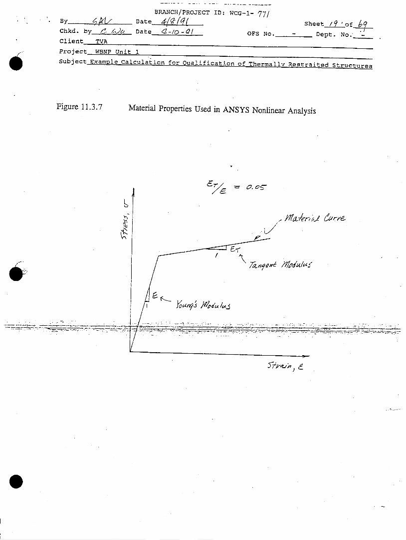
For the nonlinear analysis utilizing ANSYS STIF24 element, the cross-section of themember is represented by twelve (12) rectangular segments defined by fifteen (15) stresspoints as shown in Figure 11.3.6. A bilinear stress-strain property, as shown in Figure11.3.7, is used to simulate the elastic-plastic material property in the nonlinear analysis.29x0l ksi is used as the Young's Molulus (E) and 1,500 ksi is used as the TangentModulus (Et). 0.05 is considered as the factor of (EEt) as recommended in ANSYSUser's Manual, Section 2.27. The ANSYS large deflection solution method is used inthe nonlinear analysis so that the stiffness matrix characterizes the deformed structure inthe iterative solution process. 36 ksi is used as the Yield Strength and 6.5x10' in/in-0 Fis consider as the Coefficient of Thermal Expansion. Incremental temperature steps areutilized to represent the temperature change.
Qualification of Members- Linear Acceptance Criteria (Enerzy Balance Method)
The Energy Balance Method provided in DG-C1.6.12, RO is used for the qualificationof the member. The allowable ductility ratio is determined per WB-DC-20-21. The P-
EBASCO SERVICES INCORPORATED
BRANCH/PROJECT ID: WCG-1-771
By Date__ __0_ _/ S heet-_//_o fk( Chkd. by 0 4 Date 4-10- f OFS No. - Dept. No. -
Client TVA
Project WBNP Unit 1Subject Example Calculation for Qualification of Thermally Restrained Structures
delta effect, resulting from the thermally induced axial force and lateral deflections of themember due to non-thermal load, is taken into account to calculate maximum combinedstress. The energy balance method is not applicable if the calculated combined stress
exceeds the ultimate strength (Fu=58 ksi).
Oualification of Members- Non-linear Acceptance Criteria
The displacement based ductility ratio requirement is considered for the qualification aspresented in Section 11.4.2. The allowable ductility ratio is determined in accordance
with WB-DC-20-21.
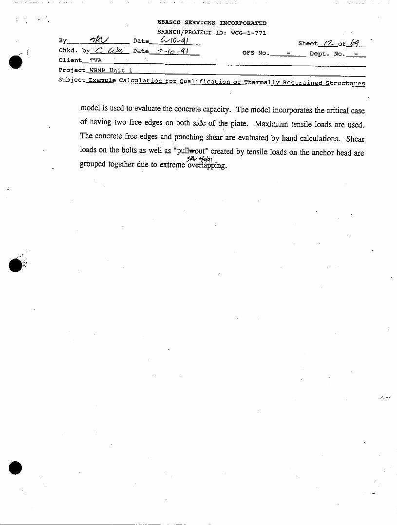
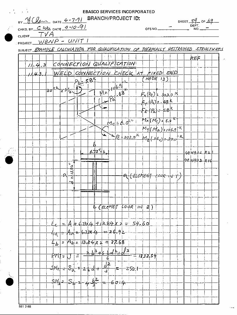
Qualification of Connections
The weld connections at both end of the member W14x3O are qualified based on anallowable stress level of two thirds of the nominal tensile strength of the weld per DG-C1.6.12, RO. The forces and moments at both ends of the member obtained from theANSYS nonlinear analysis results are considered.
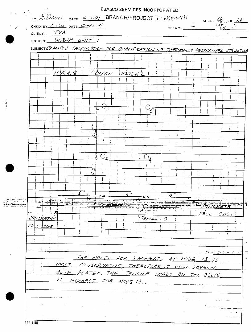
Qualification of Anchorage
Same forces used to qualify connections are considered for the Anchorage. Thebaseplates are evaluated using the BASEPLATE II computer program.. The maximumplate principal stresses and bolt tension loads are evaluated. The CONAN methematical
EBASCO SERVICES INCORPORATED
BRANCH/PROJECT ID: WCG-1-771
Date __ 0__I Sheet /Z ofChkd. by • Date •-/•-q, OFS No. - Dept. No. -Client TVA
Project WBNP Unit 1Subject Example Calculation for Qualification of Thermally Restrained Structures
model is used to evaluate the concrete capacity. The model incorporates the critical caseof having two free edges on both side of the plate. Maximum tensile loads are used.The concrete free edges and punching shear are evaluated by hand calculations. Shearloads on the bolts as well as "puilwout" created by tensile loads on the anchor head aregrouped together due to extreme overlappmg.
BRANCH/PROJECT ID: WCG-I- -7/
By_ Date I•e I/ll SheetZ ofChkd. by ' •'/- Date _ OFS No. - Dept. No. -
Client TVA
Project WBNP Unit 1
Subject Example Calculation for Qualification of Thermally Restraited Structures
Figure 11.3.1 Member Considered in Example #1

EBASCO SERVICES INCORPORATED
BRANCH/PROJECT ID: WCG-l-77/
ByDate 1-1 9/0 Sheet Zd of~Chkd. by &J Date 4-10-91 OFS No. - Dept. No. -
Client TVA
Project WBNP Unit 1
Subject Example Calculation for Qualification of Thermally Restrained Structures
Figure 11.3.2 Geometric Configuration of Member W14x3O for Example #1
W/,l4x-3O
I
103.23"
EBASCO SERVICES INCORPORATED
BRANCH/PROJECT ID: WCG-l- 77/
B y Date &e 4q Sheet /I ofi4Chkd. by C_ _ J Date___-_______ OFS No. - Dept. No._-
Client TVA
Project WBNP Unit 1
Subject Example Calculation for Qualification of Thermally Restrained Structures
Figure 11.3.3 Geometric Configuration of Member M4x13 for Example #2
T67- zOo OF.
* -- -- - ____ _____- -. - - * - -- -. ~ ~a.c- ~ -- - - --- - --- -- ~,- ______ -
BRANCH/PROJECT ID: WCG-l- 77/
By L/ . Date_____ Sheet_ of qChkd. by Date ý4--/'_q OFS No. - Dept. No. -
Client TVA
Project WBNP Unit 1
Subject Example Calculation for Qualification of Thermally Restraited Structures
Figure 11.3.4 ANSYS Model of Member W14x3O for Example #1
2
. .. ...... __ _.. . ..... ...... ..... .
EBASCO SERVICES INCORPORATED
BRANCH/PROJECT ID: WCG-1-77/
By Date d Sheet_/-7 ofkChkd. by___Date_1_________ OFS No. - Dept. No. -
Client TVA
Project WBNP Unit 1Subject Example Calculation for Qualification of Thermally Restraited Structures
Figure 11.3.5 ANSYS Model of Member M4x13 for Example #2
AII¥3$ 4.3A
MIAR 20 199t
14 34 52
PLOT iiG. z
PRC?7 ELEl1E)IT3
YV -- I
OtrS.-3. 9
37 .49ZF -2.6
1111il. Alin -li WMIAK MlODEL) . rz--0.2 K•ps. OT.-I8,0 6.l 1. srayos .3K~5

BRANCH/PROJECT ID: WCG-I- Se"/f'B • • Date-V910•/ Sheet_/,ý_ of (-
Chkd. by ( 6ý/l Date_ ____ OFS No. - Dept. No.-Client TVA
Project WBNP Unit 1Subject Example Calculation for Qualification of Thermally Restraited Structures
Figure 11.3.6 Stress Point Definition for ANSYS STIF24 Element
Tz-axis
6.73"1
.5 .4 .3,6 2. 1.
-> <- 0.270"
7
•8 - * y-axis
6.73"
9 .0.385"
1 12~
BRANCH/PROJECT ID: WCG-l- 77/By,, Date. 4 (. Sheet o ofChkd. by ' t)& Date c.-/iO-Q/ OFS No. - Dept. No.Client TVA
Project WBNP Unit 1Subject Example Calculation for Qualification of Thermally Restraited Structures
Figure 11.3.7 Material Properties Used in ANSYS Nonlinear Analysis
TI l
Co
11
4

EBASCO SERVICES INCORPORATED
BRANCH/PROJECT ID: WCG-1-771
B Date-J/jJ/. Sheet ZS of
Chkd. by .•j Date /--/ L-q( OFS No. - Dept. No. -
Client TVA
Project WBNP Unit 1
Subject Example Calculation for Qualification of Thermally Restrained Structures
This Page is Left Blank Intentionally

BRANCH/PROJECT ID: WCG-l- 71]By Date_ _•_l__ _ Sheet LoShe• iýo---•--Chkd. by-. c &- Date 4--/0' ( OFS No. - Dept. No. .
Client TVA
Project WBNP Unit 1Subject Example Calculation for Qualification of Thermally Restraited Structures
11.4 Qualification of Member W14x3O (Example #1)
EBASCO SERVICES INCORPORATED
BRANCH/PROJECT ID: WCG-1-771
By 4- Date q--/0 F/ Sheet _I/__f
Chkd. by__(-_• Date -at OFS No. - Dept. No. -
Client TVA
Project WBNP Unit 1
Subject Example Calculation for Qualification of Thermally Restrained Structures
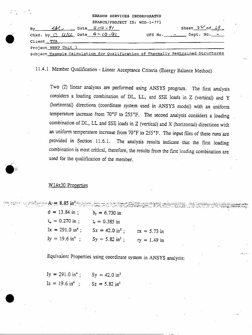
11.4.1 Member Qualification - Linear Acceptance Criteria (Energy Balance Method)
Two (2) linear analyses are performed using ANSYS program. The first analysisconsiders a loading combination of DL, LL, and SSE loads in Z (vertical) and Y(horizontal) directions (coordinate system used in ANSYS model) with an uniformtemperature increase from 70°F to 255°F. The second analysis considers a loadingcombination of DL, LL and SSE loads in Z (vertical) and X (horizontal) directions withan uniform temperature increase from 70'F to 255°F. The input files of these runs areprovided in Section 11.6.1. The analysis results indicate that the first loadingcombination is most critical, therefore, the results from the first loading combination are
used for the qualification of the member.
W14x30 Properties
'""" 8.. . -8 in " -- . . : .. .. : • " . .
d =13.84 in; bf= 6.730 in
, = 0.270 in; t 0.385 in
Ix =291.0 in'; Sx = 42.0 in3 ; rx = 5.73 in
Iy =19.6 in4 ; Sy = 5.82 in3 ; ry = 1.49 in
Equivalent Properties using coordinate system in ANSYS analysis:
Iy = 291.0 in4
Iz = 19.6 in4
Sy = 42.0 in3
Sz = 5.82 in3
EBASCO SERVICES INCORPORATED
BRANCH/PROJECT ID: WCG-1-771By_ Date4.4 - I Sheet *7/3 ofChkd.ý by C- '4.• Date -.- /o-ý/ OFS No. - Dept. No. -
Client TVA
Project WBNP Unit 1Subject Example Calculation for Qualification of Thermally Restrained Structures
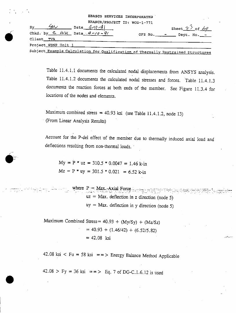
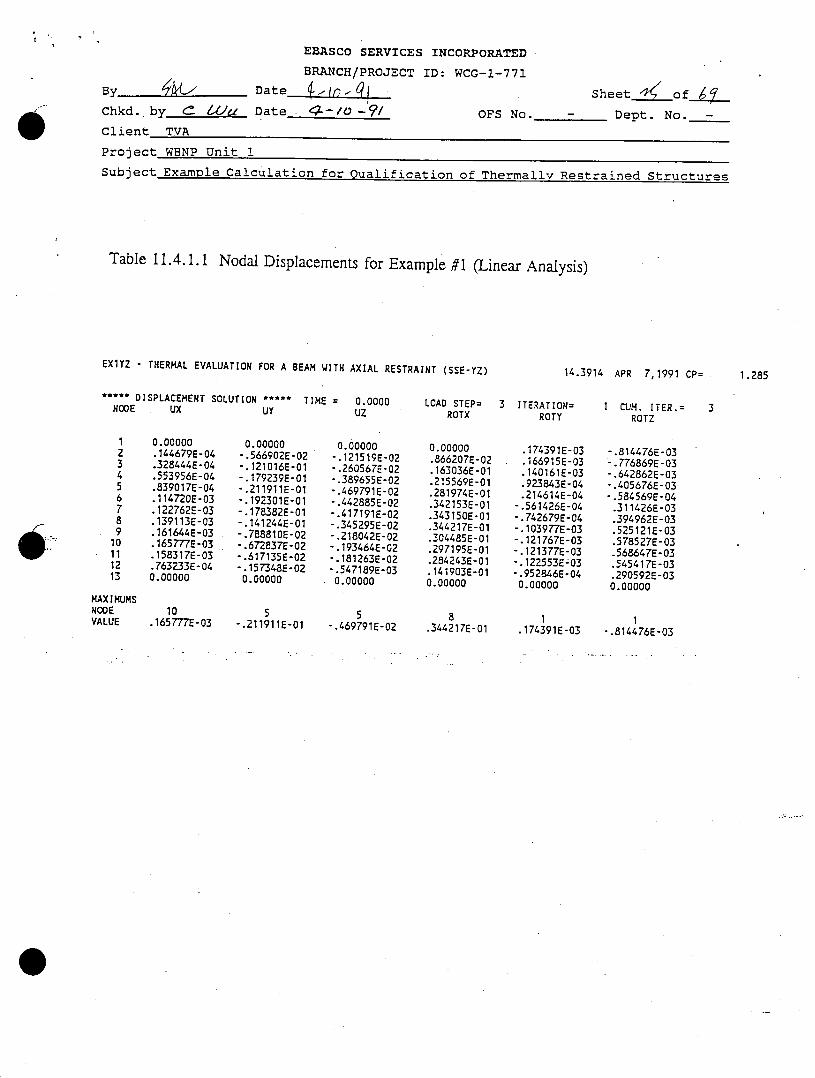
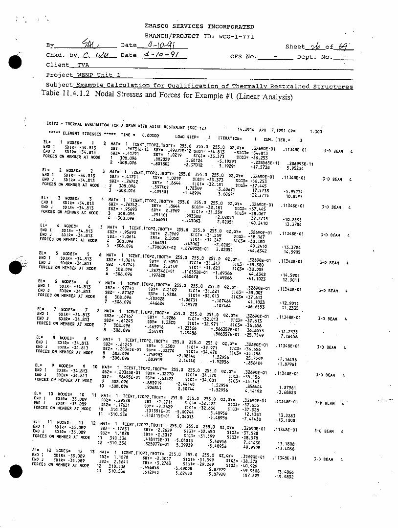
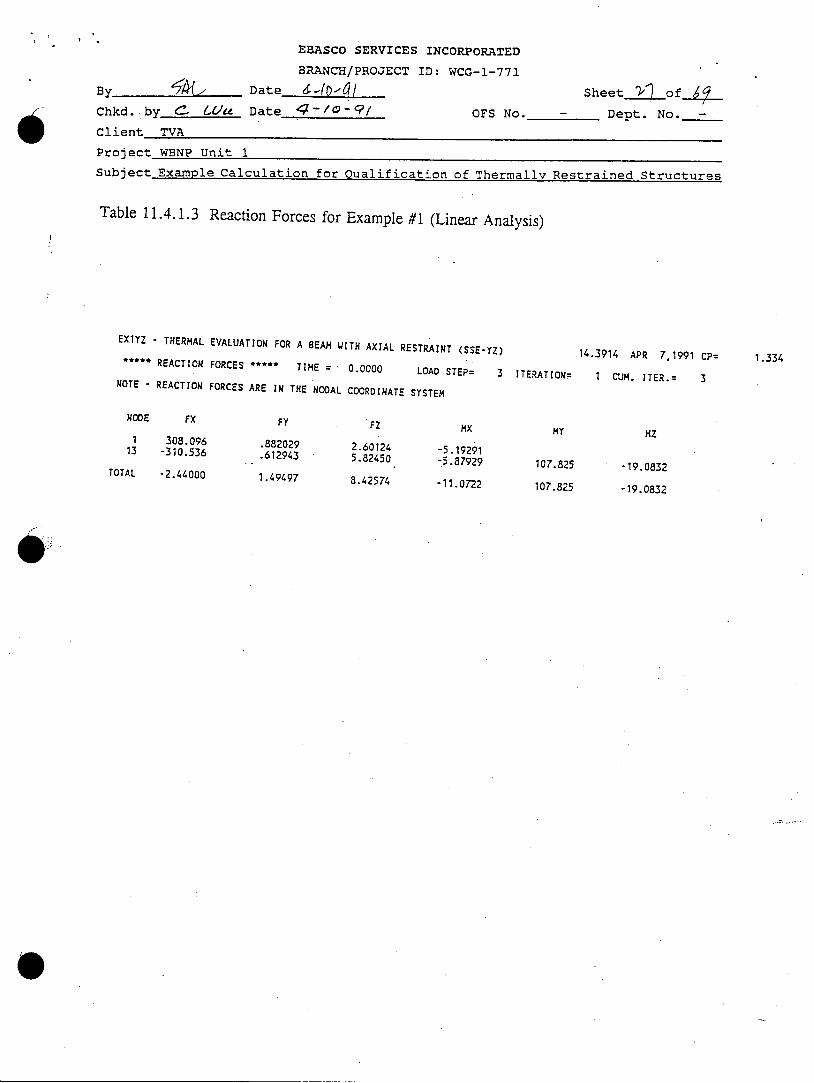
Table 11.4.1.1 documents the calculated nodal displacements from ANSYS analysis.Table 11.4.1.2 documents the calculated nodal stresses and forces. Table 11.4.1.3documents the reaction forces at both ends of the member. See Figure 11.3.4 for
locations of the nodes and elements.
Maximum combined stress = 40.93 ksi (see Table 11.4.1.2, node 13)
(From Linear Analysis Results)
Account for the P-del effect of the member due to thermally induced axial load and
deflections resulting from non-thermal loads.
My = P * uz = 310.5 * 0.0047 = 1.46 k-in
Mz = P *uy = 301.5 * 0.021 = 6.52 k-in
where P 1Max..Axial~tForce_-...- -
uz = Max. deflection in z direction (node 5)
uy = Max. deflection in y direction (node 5)
Maximum Combined Stress= 40.93 + (My/Sy) + (Mz/Sz)
= 40.93 + (1.46/42) + (6.52/5.82)
= 42.08 ksi
42.08 ksi < Fu = 58 ksi = => Energy Balance Method Applicable
42.08 > Fy = 36 ksi ==> Eq. 7 of DG-C.1. 6.12 is used
EBASCO SERVICES INCORPORATED
BRANCH/PROJECT ID: WCG-1-771
By <A/ Date •-q Sheet A of__Chkd. b Date 4---- OFS No. - Dept. No.
Client TVA
Project WBNP Unit 1
Subject Example Calculation for Qualification of Thermally Restrained Structures
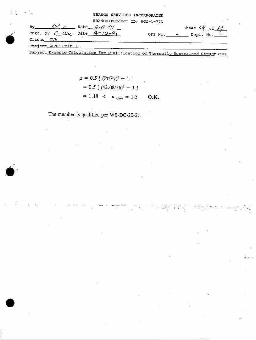
= 0.5 [(Pr/Py)2 + 1]
= 0.5 [(42.08/36)2 + 1]
= 1.18 < •tLn. = 1.5 O.K.
The member is qualified per WB-DC-20-21.
EBASCO SERVICES INCORPORATED
BRANCH/PROJECT ID: WCG-1-771
B Date Lo 4
Chkd. by C Lea. Date 4L-,O -/ OFS No.
Client TVA
Sheet D )of_6•__
- Dept. No. -
Project WBNP Unit 1
Subject Example Calculation for Qualification of Thermally Restrained Structures
Table 11.4.1.1 Nodal Displacements for Example #1 (Linear Analysis)
EX1YZ - THERMAL EVALUATION FOR A BEAM WITH AXIAL RESTRAINT (SSE-YZ)
***** DISPLACEMENT SOLUTION ***** TIME = 0.0000NODE UX UY UZ
0. 00000.144679E-04.328444E-04.553956E-04.839017E-04.114720E-03.122762E-03.139113E-03.161644E-03.165777E-03.158317E-03.763233E-040.00000
0.00000-.566902E-02-.121016E-01-.179239E-01-.211911E-01-.192301E-01-.178382E-01-.141244E-01-.788810E-02-.672837E-02-.617135E-02-.157348E-020.00000
10 5.165777E-03 -.211911E-01
0.00000-.121519E-02-.260567E-02-.389655E-02-.469791E-02-.442885E-02-.417191E-02-.345295E-02-.218042E-02-.193464E-02-.181263E-02-.547189E-030.00000
14.3914 APR 7,1991 CP=
LOAD STEP= 3 ITERATION= 1 CUM. ITER.=ROTX ROTY ROTZ
0.00000.866207E-02.163036E-01.215569E-01.281974E-01.342153E-01.343150E-01.344217E-01.304485E-01.297195E-01.284243E-01.141903E-010.00000
.174391E-03
.166915E-03
.140161E-03
.923843E-04
.214614E-04-.561426E-04-.742679E-04".103977E-03".121767E-03-.121377E-03-.122553E-03-.952846E-040.00000
5 8 1".469791E-02 .344217E-01 .174391E-03
-.814476E-03-.776869E-03-.642862E-03-.405676E-03-.584569E-04.311426E-03.394962E-03.525121E-03.578527E-03.568647E-03.545417E-03.290592E-030.00000
1-.814476E-03
1.285
12345678910111213
MAXIMUMSNODEVALUE
EBASCO SERVICES INCORPORATED
BRANCH/PROJECT ID: WCG-1-771
By Date Sheet__4 of ,Chkd. by C (,/d Date 4-/o-9/ OFS No. - Dept. No. -
Client TVA
Project WBNP Unit 1Subject Examole Calculation for Qualification of Thermally Restrained StructuresTable 11.4.1.2 Nodal Stresses and Forces for Example #1 (Linear Analysis)
EX1YZ - THERMAL EVALUATION FOR A BEAM WITH AXIAL RESTRAINT (SSE-YZ) 14.3914 APR 7,1991 CP=ELEMENT STRESSES ."'.- TIME = 0.00000 LOAO STEP= 3 ITERATION= 1 CUM. itER.= 3
-Q I= ISDIR= -34.813SOIR= -34.813
ON MEMBER AT NO
2 NODES= 2SDIR= -34.813SDIR= -34.813
ON MEMBER AT NO0
3 NODES= 3SDIR= -34.813SOIR= -34.813
ON MEMBER AT NO0
4 NOOES= 4S0IR= -34.813SOIR= -34.813
ON MEMBER AT NODE
EL= 5 NODES= 5END I SOIR= -34.813END J SDIR= -34.813FORCES ON MEMBER AT NODE
EL- 6 NODES= 6ENO I SDIR= -34.813END J SOIR= -34.813FORCES ON MEMBER AT NODE
EL= 7 NODES= 7END I SOIR= -34.813END J SOIR= -34.813FORCES ON MEMBER AT NODE
EL- 8 NODES= 8END I SDIR= -34.813ENO J SOIR= -34.813FORCES ON MEMBER AT NODE
EL= 9 NODES= 9 10END I SDIR= -34.813END J SDIR= -34.813FORCES ON MEMBER AT NODE
EL= 10 NODES= 10 11END I SOIR= -35.089END J SDIR= -35.089FORCES ON MEMBER AT NODE
ELz 11 NODES= 11 12END I SOIR= -35.089END J SDIR= -35.089FORCES ON MEMBER AT NODE
EL= 12 NODES= 12 13ENO I SDIR' -35.089END J SDIR' -35.089FORCES ON MEMBER AT NODE
END IENO JFORCES
EL=END IENO JFORCES
EL-ENO IENO JFORCES
EL=ENO IENO JFORCES
F2 MAT= 1 TCENT,TTOPZTBOTY= 255.0 255.0 255.0 OZ,ay= .32690E-01S8Z= .56731E-13 SBY= -.49272E-12 SIG1= -34.813 -Si.3= -34,813SBZ= -.41791 SBY= 1.0219 SIG1= -33.373 SIG3= -36.253DE 1 308.096 .882029 2.60124 -5.19291 -.238565E-112 -308.096 -.801802 -2.37012 5.19291 --17.57383 MAT- 1 TCENT,TTOPZTBOTY= 255.0 255.0 255.0 oz,oy= .32690E-01SBZ= -.41791 SBy= 1.0219 SIGI= "33.373 5IG3= -36.2535Z= -.76742 SBY= 1.8644 SIGlt -32.181 IG3' -37.445IE 2 308.096 .597402 1.78349 -3.60671 17.57383 -308.096 -.495501 -1.48994 3.60671 -32.27154 MAT= 1 TCENTTTOPZTBOTY= 255.0 255.0 255.0 QZ,QY= .3269OE-01SBZ= -.76742- SBy= 1.8644 SIG1= -32.181 SI3= -37.445SBZ' -.95693 SBY= 2.2969 SIG11 -31.559 SIG3= -38.067E 3 308.096 .291101 .903308 -2.02051 32.27154 -308.096 -.166051 ..543063 2.02051 -40.24105 MAT= I TCENTTTOPZ,TBOTY= 255.0 255.0 255.0 QZ,Oy= .32690E-01SBZ= -.95693 SBY= 2.2969 SI31= -31.559 SIG3= -38.067SBZ= -1.0614 SBY= 2.5050 SIG1= -31.247 IG3= -38.3804 308.096 .166051 .543063 -2.02051 40.24105 -308.096 -.
798039E-02 -.876902E-01 2.02051 -44.6342
6 MAT= 1 TCENTTTOPZ,TBOTY= 255.0 255.0 255.0 QZ,Oy= .32690E-01 .SBZ= -1.0614 SBY= 2.5050 SIG1= -31.247 Si3= -38.380S5Z= -.97741 SBY= 2.2149 SI1= -31.621 5IG3= -38.0055 308.096 - .267346E-01 .116352E-01 -1.69366 44.63426 -308.096 .197628 .480678 1.69366 -41.10237 MAT= 1 TCENTTTOPZTBOTY= 255.0 255.0 255.0 GZ,OY= .32690E-01S0Z= -.97741 SBY= 2.2149 SIGI= -31.621 SIG3= -38.005SBZ - .87167 SBY= 1.9286 SIG1= -32.013 SIG3= -37.6136 308.096 -.4'02028 -1.06731 -.107464 41.10237 -308.096 .446624 1.19578 .107464 -36.65538 MAT= I TCENTTTOPZTBOTY= 255.0 255.0 255.0 0Z,QY= .32690E-01 .1S8Z= -.87167 SBT= 1.9286 SlOt= -32.013 SIG3= -37.613S8Z= -.61245 SBY= 1.2300 SIG1 -32.971 SIG3= -36.6567 308.096 -.463916 -1.23366 -.
566357E-01 36.6553 -8 -308.096 .554583 1.49486 .566357E-01 -25.7549
9 MAT= I TCENT,TTOPZTBOTY= 255.0 255.0 255.0 azoy= .32690E-01 .1SBZ= -.61245 SBY= 1.2300 SIO1= -32.971 SI3= -36.656SBZ= -.20365E-01 SHY= -.32270 SIGI= -34.470 SiG13 -35.1568 308.096 -.758983 -2.08148 1.52956 25.7549 .;9 -308.096 .883919 2.44140 -1.52956 -.856404 -.MAT= 1 TCENT,TTOPZTBOTY= 255.0 255.0 255.0 OZQY= .32690E-01 .11SBZ= -.20365E-01 SBY= -.32270 SIlt= -34.470 SI03= -35.156SBZ= .98495E-01 SBY= -.63322 SIGI= -34.081 SIG3= -35.5459 308.096 -.883919 -2.44140 1.52956 .85640410 -308.096 .906841 2.50744 -1.52956 4.14192 -3MAT= I TCENT,TTOPZTBOTY= 255.0 255.0 255.0 OZ,oT= .32690E-01 .11SBZ= -.29578 SBY= -2.2711 SIGI= -32.522 SIG3= -37.656SBZ= -.17631 SHY= -2.2629 SIG1= -32.650 SIG3= -37.52810 310.536 .531591E-01 -5.00744 5.48956 12.4381 111 -310.536 -.418115E-01 5.04013 -5.48956 -7.41430 -1.MAT= 1 TCENT,TTOPZ,TBOTY= 255.0 255.0 255.0 OZ,QY= .
32690E-01 .11iSBZ= -.17631 SBY= -2.2629 SIGI= -32.650 SIG3= -37.528SBZ= 1.1878 SBY= -2.3017 SIGI= -31.599 S1.3= -38.57811 310.536 .418115E-01 -5.04013 5.48956 7.41430 1:12 -310.536 .828977E-01 5.39939 -5.48956 49.9508 -1:
MAT= I TCENT,TTOPZ,TBOTY= 255.0 255.0 255.0 OZ,QY= .32690E-01 .11SBZ= 1.1878 SBY= -2.3017 SIGI= -31.599 SIG3= -38.578SZ= 2.5641 SBY= -3.2763 SIGI= -29.249 SIG3= -40.92912 310.536 -.496858 -5.49008 5.87929 -49.9508 1313 -310.536 .612943 5.82450 -5.87929 107.825 -19
.11348E-01
.286993E-115.95234
.11348E-01
-5.9523410.8595
.11348E-01
-10.859513.3784
.11348E-01
-13.378414.5905
11348E-01
-14.590512.9011
11348E-01
12.901111.2335
1348E-01
11.23357.16456
1348E-01
7.164561.87961
[348E-01
.87961
.68828
348E-01
3.22833.1808
348E-01
3.18083.4066
348E-01
.40669.0832
300
3-0 BEAM 4
3-0 BEAM 4
3-0 BEAM 4
3-0 BEAM 4
3-0 BEAM 4
3-D BEAM 4
3-D BEAM 4
3-0 BEAM 4
3-0 BEAM 4
3-0 BEAM 4
3-0 BEAM 4
3-0 BEAM 4
EBASCO SERVICES INCORPORATED
BRANCH/PROJECT ID: WCG-l-771
By Date 64041 Sheet '_1ofChkd. by r WaLe Date '-/o-91 OFS No. - Dept. No._-
Client TVA
Project WBNP Unit 1
Subject Example Calculation for Qualification of Thermally Restrained Structures
Table 11.4.1.3 Reaction Forces for Example #1 (Linear Analysis)
EX1YZ - THERMAL EVALUATION FOR A BEAM WITH AXIAL RESTRAINT (SSE-YZ)* REACTION FORCES ***** TIME = 0.0000 LOAD STEP= 3 ITERATION=
NOTE REACTION FORCES ARE IN THE NODAL COORDINATE SYSTEM
NODE FX
1 308.09613 -310.536
TOTAL -2.44000
FY
.882029
.612943
1.49497
FZ
2.601245.82450
8.42574
MX
-5.19291-5.87929
-11.0722
MY
107.825
107.825
14.3914 APR 7,1991 CP=
1 CUM. ITER.= 3
MZ
-19.0832
-19.0832
1.334

EBASCO SERVICES INCORPORATED
BRANCH/PROJECT ID: WCG-1-771
4y 9/ Date d'-10-qI Sheeta_•of 6q
Chkd. by 6 Date)U ______ OFS No. - Dept. No. -
Client TVA
Project WBNP Unit 1
Subject Example Calculation for Qualification of Thermally Restrained Structures
This Page is Left Blank Intentionally

EBASCO SERVICES INCORPORATED
BRANCH/PROJECT ID: WCG-1-771
ByDate__-1- SheetL4.of~...Chkd. b 6116z Date 4-0 9/ OFS No. - Dept. No. -
Client TVA
Project WBNP Unit 1
Subject Example Calculation for Qualification of Thermally Restrained Structures
This Page is Left Blank Intentionally

EBASCO SERVICES INCORPORATED
BRANCH/PROJECT ID: WCG-1-771
By Date 4-4/9- 9' Sheet Y of3_Chkd. by C jtt/ Date a-1-0 I OFS No. - Dept. No. -
Client TVA
Project WBNP Unit 1Subject Examole Calculation for Qualification of Thermally Restrained Structures
11.4.2 Member Qualification - Nonlinear Acceptance Criteria
ANSYS computer program is used to perform nonlinear analysis for the same member
W14x3O in section 11.4.1.
The nonlinear analysis considers the same loading condition used in Section 11.4.1 forlinear analysis. The worst load combination including seismic horizontal and verticalSSE accelerations is selected for ANSYS nonlinear analysis. Uniform temperature isapplied on the model incrementally from 70'F to 255*F (5 degrees per increment).
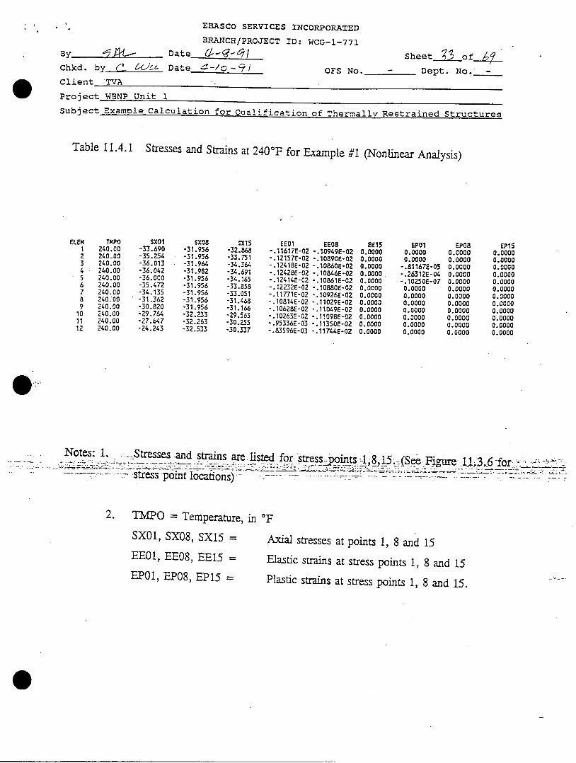
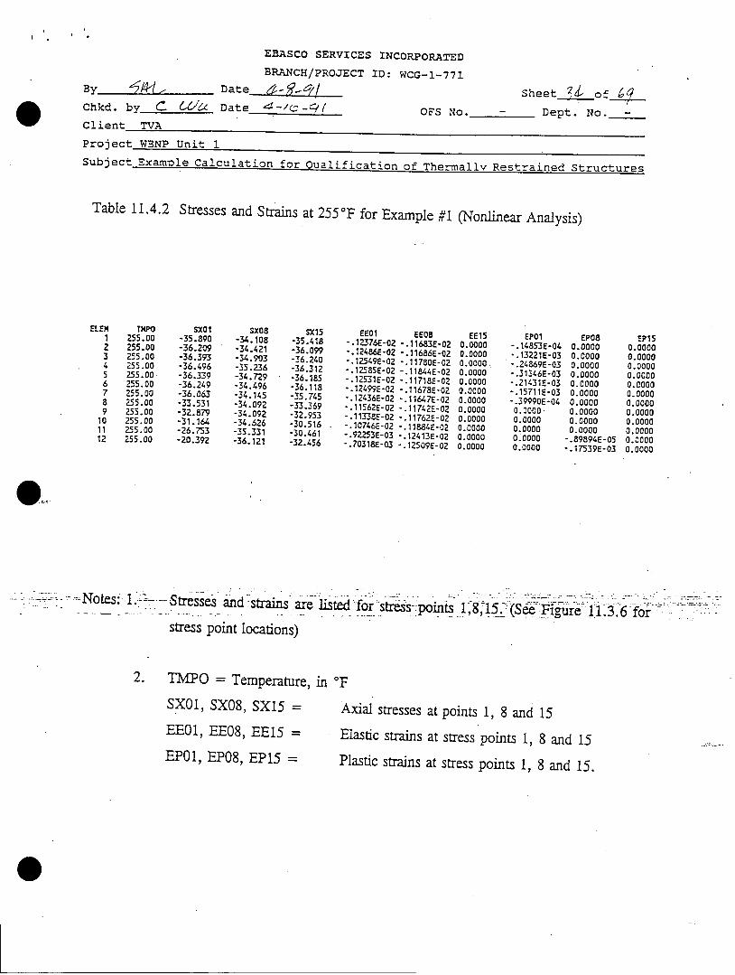
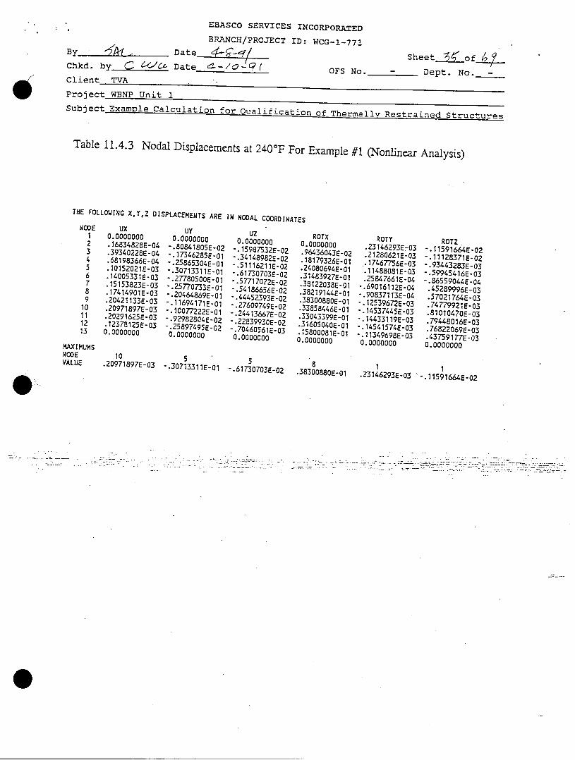
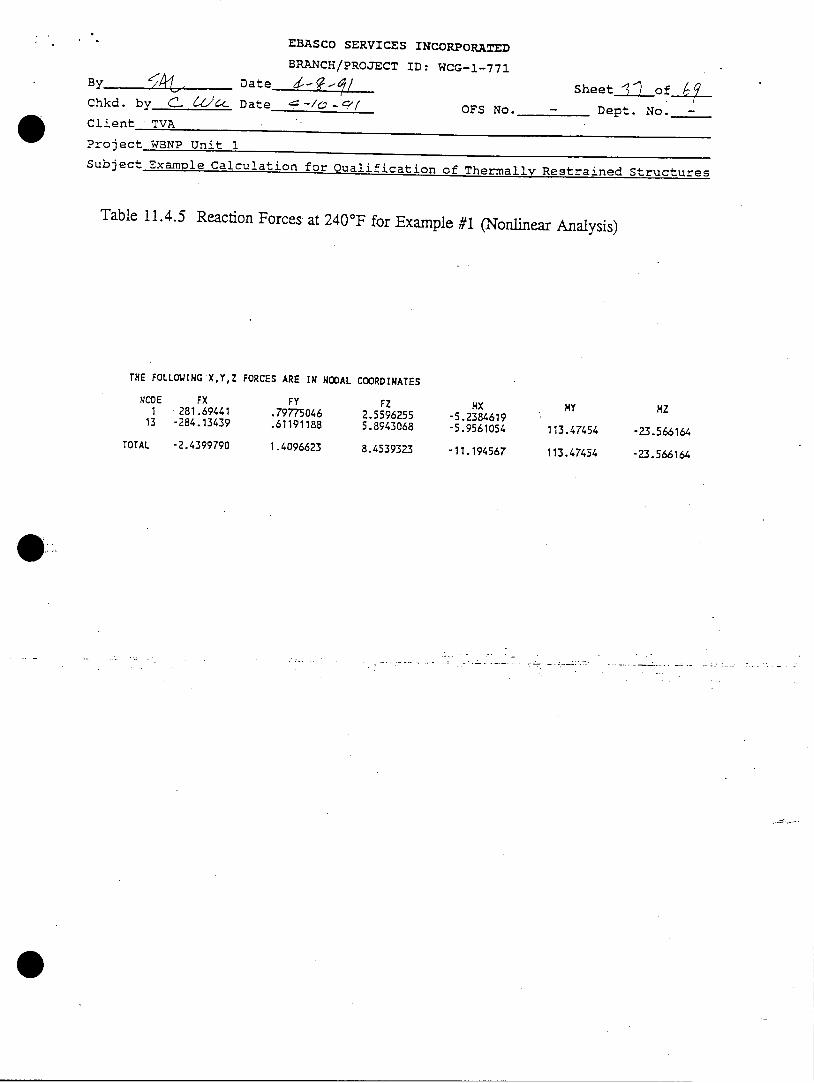
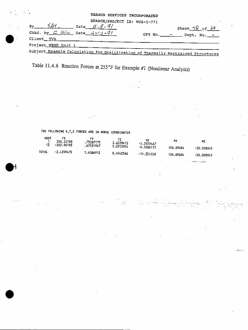
The first plastic deformation occurs at 240'F at nodes 3, 4 and 5 (See Figure 11.3.4 forlocations of nodes). At temperature of 255°F, the region of plastic deformation isexpanded to node 1 through 7. The stresses and strains at stress points 1, 8 and 15 atmember cross-section for the 2nd (J) node of each element are presented in Tables 11.4.1and 11.4.2 for temperatures 240'F and 255°F respectively. The locations of stresspoints on member cross-section are defined in Figure 11.3.6. The nodal displacementsare presented in Tables 11.4.3 and 11.4.4 for temperatures 240'F and 255°Frespectively. The reaction forces are listed in Tables 11.4.5 and 11.4.6 for temperatures
240'F and 255'F, respectively.
Primary member is accepted on the basis of the displacement based ductility ratio:
P = (Ux 2 + UY 2 + Uz 2 ) / xy2 + -Uyy2 + Uzy2)
where
Ad = the displacement based ductility ratio
EBASCO SERVICES INCORPORATED
BRANCH/PROJECT ID: WCG-1-771
By _ _ _ Date io -?•/ Sheet _1Jof /_4Chkd. by ( f A6CL Date 4-10-91 OFS No. - Dept. No. -
Client TVA
Project WBNP Unit 1
Subject Example Calculation for Oualification of Thermally Restrained Structures
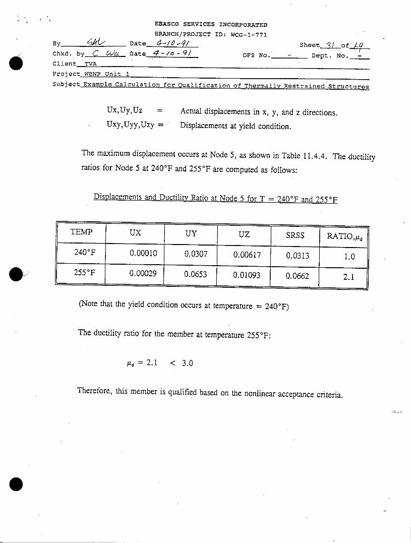
Ux,Uy,Uz=
Uxy,Uyy,TUzy=
Actual displacements in x, y, and z directions.
Displacements at yield condition.
The maximum displacement occurs at Node 5, as shown in Table 11.4.4. The ductility
ratios for Node 5 at 240'F and 255°F are computed as follows:
Displacements and Ductility Ratio at Node 5 for T = 240'F and 255°F
(Note that the yield condition occurs at temperature = 240 0F)
The ductility ratio for the member at temperature 255 0F:
/ld = 2.1 < 3.0
Therefore, this member is qualified based on the nonlinear acceptance criteria.
EBASCO SERVICES INCORPORATED
BRANCH/PROJECT ID: WCG-1-771
By f L I Date (Z- D a
Chkd. by r- 6U'-Z Date -
Sheet 2 F of _
OFS No. - Dept. No. -
Client TVA
Project WBNP Unit 1
Subject Examole Calculation for gualification of Th~rmaMv ~~1rained Strur~~
This Page is Left Blank Intentionally
Thermallv Restrained Structures
EBASCO SERVICES INCORPORATED
BRANCH/PROJECT ID: WCG-1-771
By ' -- Date •--j
Chkd. byk__ • Date 4 -/O- OFS NoClient TVA
SheetLof
Dept. No. -
Project WBNP Unit 1
Subject Examole Calculation for Qualification of Thermally Restrained Structures
Table 11.4.1
TMPO240.00240.00240.00240.00240.00240.00240.00240.00240.00240.00240.00240.00
Stresses and Strains at 240'F for Example #1 (Nonlinear Analysis)
SX01-33.690-35.254-36.013-36.042-36.000-35.472-34.135-31.362-30.820'-29.764-27.647-24.243
SX08-31.956-31.956-31.964-31.982-31.956-31.956-31.956-31.956-31.956-32.233-32.263-32.533
SX15-32.868-33.751-34.364-34.691-34.165-33.858-33.051-31.468-31.166-29.563-30.255-30.337
EE01 EE08-.11617E-02 -.10949E-02-.12157E-02 -.10890E-02-.12418E-02 -.10860E-02-.124288-02 -.10846E-02-.12414E-02 -.10861E-02-.12232E-02 -.10880E-02-.11771E-02 -.10926E-02-.10814E-02 -.11029E-02-.10628E-02 -.11049E-02-.10263E-02 -.11098E-02-.95336E-03 -.11350E-02-.83596E-03 -.11744E-02
Notes: 1. ,Stresses and Strains ae listed for stress.-Doints -(SeFil 6.fYr-- stress point locations)?... . -...--- --------- - ---
2. TMPO = Temperature, in OF
SX01, SX08, SX15 =
EE01, EE08, EEl5 =
Axial stresses at points 1, 8 and 15
Elastic strains at stress points 1, 8 and 15EP01, EPO8, EP15 = Plastic strains at stress points 1, 8 and 15.
EE150.00000.00000.00000.00000.00000.00000.00000.00000.00000.O00000.00000.0000
EP010.00000.0000-.81167E-05-.26312E-04-.10250E-070.00000.00000.00000.00000.00000.00000.0000
EP080.00000.00000. 00000.00000.00000.00000.00000.00000.00000.00000.00000.0000
EP150.00000.00000.00000.00000. 00000.00000. 00000.00000.00000.00000.00000.0000
EBASCO SERVICES INCORPORATED
BRANCH/PROJECT ID: WCG-1-771
8y D ateChkd. by _. CL//C Date 4-/ -C(
Client TVA
Sheet _of.__
OFS No. - Dept. No. -
Project WBNP Unit 1Subject Example Calculation for Qualification of Thermally Restrained Structures
Table 11.4.2
TWPO255.00255.00255.00255.00255.00255.00255.00255.00255.00255.00255.00255.00
Stresses and Strains at 255°F for Example #1 (Nonlinear Analysis)
SX01-35.890-36.209-36.393-36.496-36.339-36.249-36.063-33.531-32.879-31.164-26.753-20.392
SX08-34.108-34.421-34.903-35.236-34.729-34.496-34.145-34.092-34.092-34.626-35.331-36.121
SX15-35.418-36.099-36.240-36.312-36.185-36.118-35.745-33.369-32.953-30.516-30.461-32.456
EE01 EE08".12376E-02 -.11683E-02".124865-02 ".11686E-02".12549E-02 -.117805-02".12585E-02 -. 11844E-02-.12531E-02 -.11718E-02".12499E-02 -.11678E-02-. 12436E-02 ".11647E-02-. 11562E-02 -. 11742E-02-.11338E-02 -.11762E-02-.10746E-02 -.11884E-02".92253E-03 -.12413E-02-.70318E-03 -.12509E-02
..Notes: .t-.-- Stresses-and ;strains -are listed for str(s-points 1,8,15:(S-;Fi g-ure-13.-6: forstress point locations)
2. TMPO = Temperature, in OF
SX01, SX08, SX15 =
EE01, EE08, EEl5 =
Axial stresses at points 1, 8 and 15Elastic strains at stress points 1, 8 and 15
EP01, EP08, EP15 = Plastic strains at stress points 1, 8 and 15.
EEl50.00000.00000.00000.00000.00000.00000.00000.00000.00000.00000.00000.0000
EP01-.14853E-04-.13221E-03-.24869E-03-.31346E-03-.21431E-03-.15711E-03-.39990E-040.00000.00000.00000.00000.0000
EP080.00000.00000.00000.00000.00000.00000.00000.00000.00000.0000-.89894E-05-.17539E-03
EPI50.00000.00000.00000.00000.00000.00000.00000.00000.00000.00000.00000.0000
EBASCO SERVICES INCORPORATED
BRANCH/PROJECT ID: WCG-1-771
By Date -:7 Sheet__LofjChkd. by C &64 Date d*-/0-2q OFS No. - Dept. No. -Client TVA
Project WBNP Unit 1Subject Example Calculation for Qualification of Thermally Restrained Structures
Table 11.4.3 Nodal Displacements at 240OF For Example #1 (Nonlinear Analysis)
THE FOLLOWING X,Y,Z DISPLACEMENTS ARE IN NODAL COORDINATEs
UX0.0000000.16834828E-04.39340228E-04.68198366E-04.10152021E-03.14005331E-03.15153823E-03.17414901E-03.20421133E-03.20971897E-03.20291625E-03.12378125E-030.0000000
UY0.0000000-.80841805E-02".17346285E-01".25865304E-01-.30713311E-01".27780500E-01".25770733E-01".20464869E-01-.11694171E-01-1.0077222E-01-.92982804E-02".25897495E-020.0000000
Uz0.0000000-.15987532E-02".34148982E-02".51116211E-02".61730703E-02-.57717072E-02".54186656E-02-.
44452393E-02-.27609749E-02-.24413667E-02-.22839930E-02-.70460561E-030.0000000
10 5 5.20971897E-03 -.30713311E-01 -.61730703E-02
ROTX0.0000000.96436043E-02.18179326E-01.24080694E-01.31483927E-01.38122038E-01.38219144E-01.38300880E-01.33858446E-01.33043399E-01.31605040E-01.15800081E-010.0000000
-38.38300880E-01
ROTY.23146293E203.21280621E-03.174677356E-03.11488081E-03.25847661E-04".69016112E-04-.90837113E-04.12539672E-03
".14537445E-03-.14433119E-03-.14541574E-03-.11349698E-030.0000000
ROTZ-.11591664E-02-.11128371E-02-.93443283E-03-.59945416E-03-.86559044E-04.45289996E-03.57021764E-03.74779921E-03.81010470E-03.79448016E-03.76822069E-03.43759177E-030.0000000
.23146293E-03 -.11591664E-02
NOOE
2345678910111213
MAXIMUMSNODEVALUE

EBASCO SERVICES INCORPORATED
BRANCH/PROJECT ID: WCG-1-771ny • D ate •4 /
Sheetdo fji_ -nkd. by 46 4/c. Date '-/-- OFS No. - Dept. No. -* Client TVA
Project WBNP Unit 1Subject Example Calculation for Qualification of Thermally Restrained Structures
Table 11.4.4 Nodal Displacements at 255°F For Example #1 (Nonlinear Analysis)
THE FOLLOWING XY,Z DISPLACEMENTS ARE IN NODAL COORDINATES
NOOE
23456789
10111213
AXIMUMS. NODEVALUE
Ux0.0000000.16891783E-03.33 54 1515E-03.39723055E-03.29214325E-03.22386096E-03.25578057E-03.39988237E-03.67208489E-03.7238 1029E-03.73161798E-03.68067237E-030.0000000
UY0.0000000-.16364845E-01-.35804021E-01-.54517121E-01.65353300E-01
-.58293182E-01-.53953476E-01-.42811912E-01.25323399E-01
-.22099773E-01-.20532902E-01".61176815E-020.0000000
UZ0.0000000-.27080379E-02-.58637903E-02-.89192849E-02-.10928293E-01-.10233465E-01-.96247243E-02-.79571669E-02- .51593106E-02
-.46237298E-02-.43579701E-02-.15219759E-020.0000000
11 5 5.73161798E-03 -.65353300E-01 -.10928293E-01
ROTX0.0000000.97438699E-02.18404900E-01.24439734E-01.31938521E-01.38558689E-01.38635325E-01.38664289E-01.34142059E-01.33312301E-01.31863045E-01.15944359E-010.0000000
ROTY.39133739E-03.36046453E-03.30286922E-03.20621254E-03.51298973E-04.11443097E-03
-.15097324E-03-.20375115E-03-.23786335E-03".23877225E-03-.24187524E-03-.205154732-030.O0000000
8 1 1.38664289E-01 .39133739E-03 ".23344520E-02
ROTZ-.23344520E-02-.22737670E-02-.19837627E-02-.13152893E-02-.17941603E-03.98296795E-03.12122517E-02.15136822E-02.16087128E-02.15896761E-02.15516110E-02.95746966E-030.0000000
EBASCO SERVICES INCORpORAr=
BRANCH/PROJECT ID: WCG-1-771
B Date d- SheetI_)of _,Chkd. by_ Date - OFS No. - Dept. No. -
Client TVA
Project WBNP Unit 1Subject Example Calculation for Qualification of Thermally Restrained Structures
Table 11.4.5 Reaction Forces at 240°F for Example #1 (Nonlinear Analysis)
THE FOLLOWING X,Y,Z
NODE FX1 281.69441
13 -284.13439
TOTAL -2.4399790
FORCES ARE IN NODAL
FY.79775046.61191188
1.4096623
COORDINATES
FZ2.55962555.8943068
8.4539323
MX-5.2384619-5.9561054
-11.194567
MY
113.47454
113.47454
MZ
-23.566164
-23.566164
EBASCO SERVICES INCORPORATED
BRANCH/PROJECT ID: WCG-1-771By j• Date ad- - ?/ Sheet 0 1 _of-_Chkd. by • Date . .//)-g OFS No. - Dept. No. -Client TVA
Project WBNP Unit 1Subject Example Calculation for Qualification of Thermally Restrained Structures
Table 11.4.6 Reaction Forces at 255 0F for Example #1 (Nonlinear Analysis)
THE FOLLOWING X,Y,Z
NODE FX1 300.52198
13 -302.96193
TOTAL -2.4399475
FORCES ARE IN NODAL COORDINATES
FY.73287175.67581947
1.4086912
FZ2.62284125.8313954
8.4542366
MX-5.2929467-6.0386113
-11.331558
MY
106.89684
106.89684
- Z
-30.008045
-30.008045
EBASCO SERVICES INCORPORATED
BY 1"• " Z"•4 . DATE /.7[/ BRANCH/PROJECT ID:
CHKD. BY • f"'-" DATE 4 /t "I
SH EET__T $ 0 F-DEPT.
OFS NO. NO. -
g CLIENT
PROJECT WBNP - Ui/V/T I
SUBJECT 5MM,24P/ CALCUML1A 4 O T/ 2aI V A & LIF/cA 77(4' TfleRAAL'A5fAAPFD~~C~
I J J I•_r I
I 1 k2 l Ai Np =
..... i .____
J- ' --A--- _--
_ II I
io
-- -2d . '. ,
-Tr i &-v
7:0I
1- -- 1- l r.._J _ L 1
, .-. 1i_ 2 T6 8
~~~LL4_J14~- --Z~~.~G,2
5 i1- ' __8 L581 2-88
wI . . .
EBASCO SERVICES INCORPORATEDSBNCH/PROJECT ID: W661-r1,11[
a Y L4,DATE______7CHKD.BY - "
J DATE ' -"2 OFS NO.
CLIENT TVA
SHEET 4D OF-. _yrL 0-1-' bEPT. ""- NO.
PROJECT WBNP/UNIT- I
SUBJECTA97/'IPL- CAL-CWLATWA) 1-67R c2Y4iJ1F/&i'77ipJ OF: TiI~r-A'%4'-- 7Q/IC~~
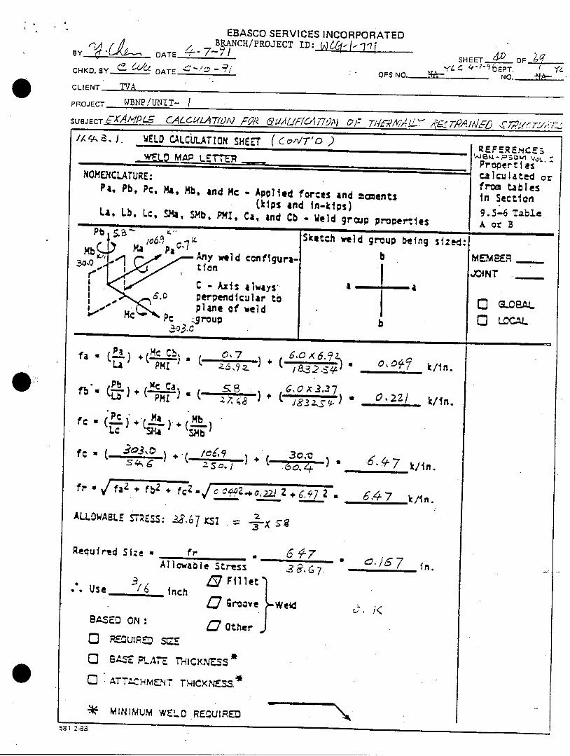
', ,-r z, J u. XCJ U-LCULATION SHEET(Cc"VTD)
WLMAP LETTER
NOMENCLATURE:Pa. Pb, Pc, Ma, Mb, and Mc - Applied forces and moments
(kips and in-kips)La. Lb. Lc, S2Ma, SMb, PMI, C4, and Cb - Weld group properties
.Sktch weld group being szed:-•~~ or B.,
A wnld configui
C - Axis always',0 perpendicular tO
plane of weldPc Sroup.•o3.c
PHILA
Pbfb =(tt)
LE • ( +1) H.aLc S. "
(ý.O 6.11i,7.Z 9a Z +
,Xt Ca ) _S . 6. Cx.•,37;H -) 3' ,C(A .
,, , O, • _k/in.
0,2Z/ k/in.
Mb
S,, ) 66.4-7 k/ in.
fAW a /faT , Fb2 + f Z C - -, 9 7 2 6,47
ALLOWABLE S~S:.~6 5
Required Size
3• Use -6
BASED ON:
0 RE.U:ED
f a, 6 47 .Allowable Stress 7.
n Fillet- inch Groove Weld
Other
in.
:~ /K
CD BASE PL.AT T-HICKN-SSC ATT1-H---NT THICXNEXSS.*
"* MINIMUM WELD REC{UIRE581 2-38
:REFERENCES
Propert iesCalculated orfrOM tablesIn Section
9.5-6 Table
MEMeER -
JOINT --
LOCAL
( C c:IT'O 0 )
GLOP-AL
Llxý'
EBASCO SERVICES INCORPORATED
*By" DATE4- 7"?/ BRANCH/PROJECT ID0: iC•lil/ SHEET._4,1 OFCHKD. BY • DATE OFS NO.- DEPT.
CLIENT TVAi PROJECT WA-v p .,A 1 -/
SUBJECT --- A , ' ,. cg/, ,i " C. , "U F/ '.',. " _, ,e.. -,, , ,.. - .
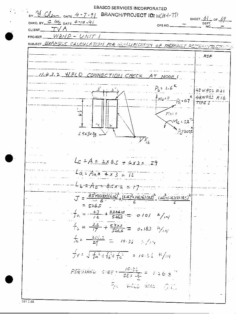
•.__ZZ!,2 2. W .. O co/Nlyfc T71OAI CN-11F I A 7- NO-OC:/ .... ......
.. ...... ,- -6.
§.;Pb: cr. 2•- _ , ... . _ - . .-.. . < -•2 •
"1 •
~ *'• '<
L~c Z A..-_ 8_ D~- _$ 4X~ 2 ...z....... ...... ..... . .... .-- . - -- -- -,--:_ - - -.. .. ..
- - . . .. . L- --- 4q:. _ -
: • 4 . -: . .~/ / /
• -:• ... gI-8i_. k,
i z *- * =...o o -. ,,
D,,
C. '?•¢ - 2• 0 "Z7,.•
jTIZ cuiC. .
- -.
Cr
Z7,,, . .- . '•: ., .
531 233
581 2-88
EBASCO SERVICES INCORPORATED
BY DATE4-/0 21 / IRNqpqjc Di WCq--l-77/ HE1O~
CHKD. _YC___ - DEPT.CLIENT 7VA•4 DATE ~ ~ 91 OFS NO. NO.--
PROJECT WP-U/VITSUBJECTEAIP LCA''/C9 ~//-i .I;0C-½-;
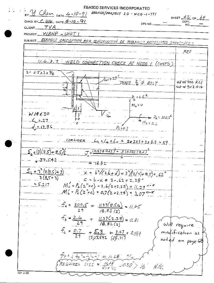
17 3.Z P, 2-1Dcrq~~o¶ YffA TAc~ c~
________ _.7___S_____ '
&I CL
' 2 i
,37513Z 0 7
- ~ ~ ~ ~ / 3 - - --
- c 3-.2.=z3~z
21~ (a cko a
EBASCO SERVICES INCORPORATED
B-DATE 13O-,l A cai/,'lwoje E~ kc--7 SHEETA±1 OF 69-_____ __ -DEPT.CHKD. BY____ DATE
OFS NO._________
CLIENT- TVIAPROJECT W89 P -41A) /7 1SUBJECT E5914A1PLý CALCLILITfc2, FOP- QL(FIC-t-T(W OF 7ThC1^e4LLr' )ýETTI"fdEy STit tc7L;
Ck-y- ~ ~ f - r J L 7 ~ ~ 2--_ _
4rI-_ --
I(7 13z 4') 0.7 00+f 17_
581 2-88
EBASCO SERVICES INCORPORATED
, .Y_______ DATE - 7- BRANCH/PROJECT ID: J"---( SHEET •.OF _L6/V DEPT.
CHKD. BY_______ DATE OFS NO. NO.
CLIENT 7K-Z"
PROJECT JV/'eA/ /J/•/7 ,/SUBJECT /f0'9-.-e CA-C A>'' v// J,6/7•i,- • 7,,,",, / .,J-eA S.-,r. r 7-J/1
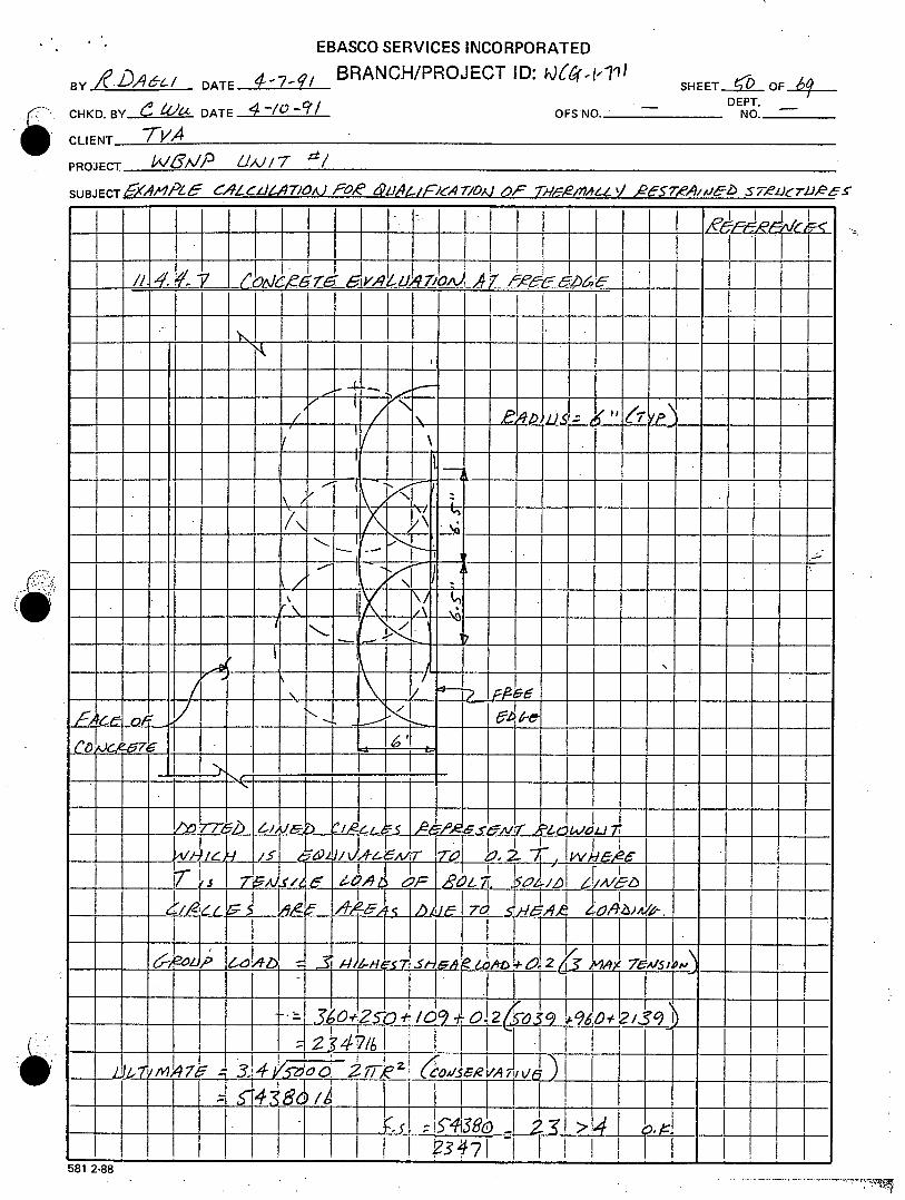
/4. A. 4t. ,¢LdA,'Jl. - J- .n1 ,4 e-.,!0A,,/
.... _ _ M•_/__P ., ./_ *1T_ ..............
1Wv Z)) 5L_24__•/2 z_ o: V od. 6j .C • •
--. 1T1
CA 'V'i~)~ -
__o__ 8 -6 / 5'. •
/"1,< 2-ZX /" D"'e YZ 7-4
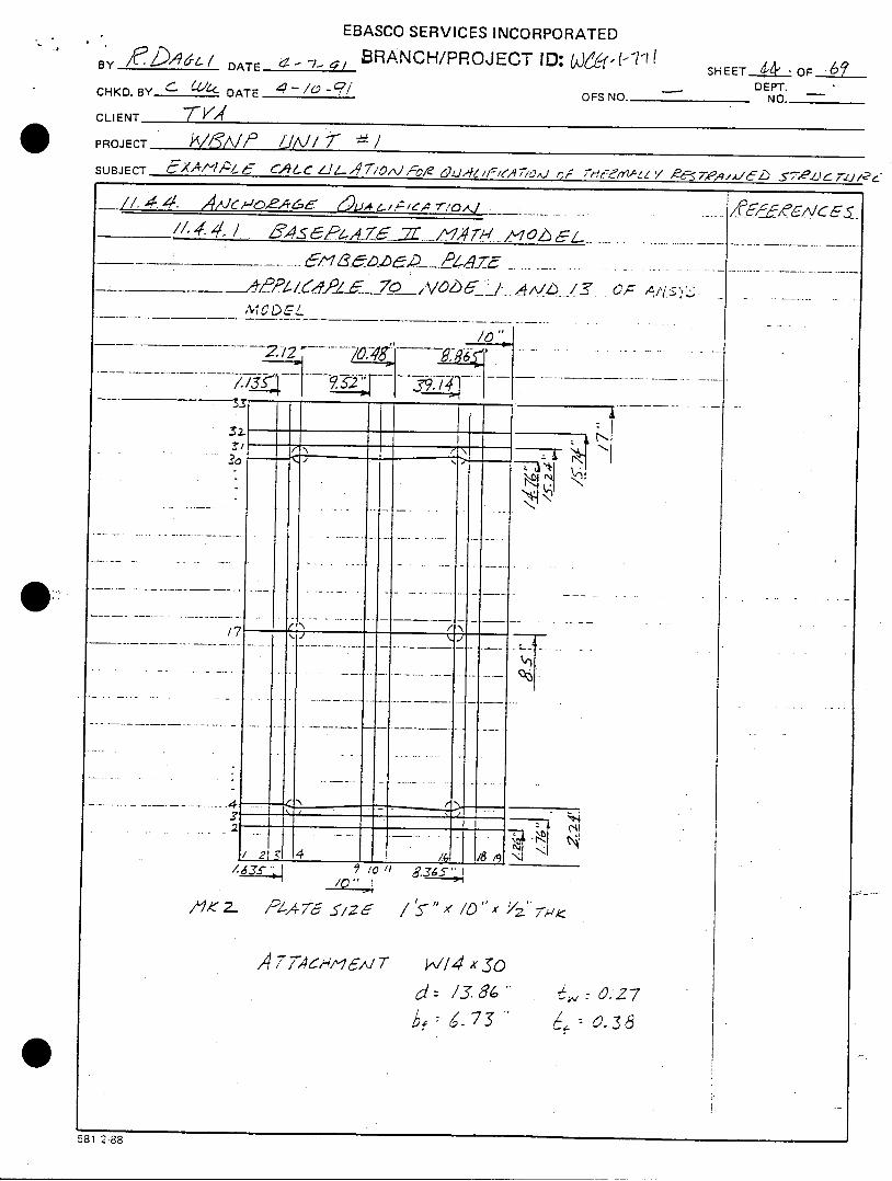
4 77A44 e-M T
d/: 13.8"•,: 4. • 6.,,, L9.27
&/C 65
581 2-88
el
EBASCO SERVICES INCORPORATEDBY_ -./__' L/ DATE ''7-•/ BRANCH/PROJECTID: L [-Vql SHEET1 W.OF 1..-111
By___ -A_____ DAE-
7 ? H E PT.4" O
CHKD. BY " DATE , " OFS NO.. NO ._
CLIENT-
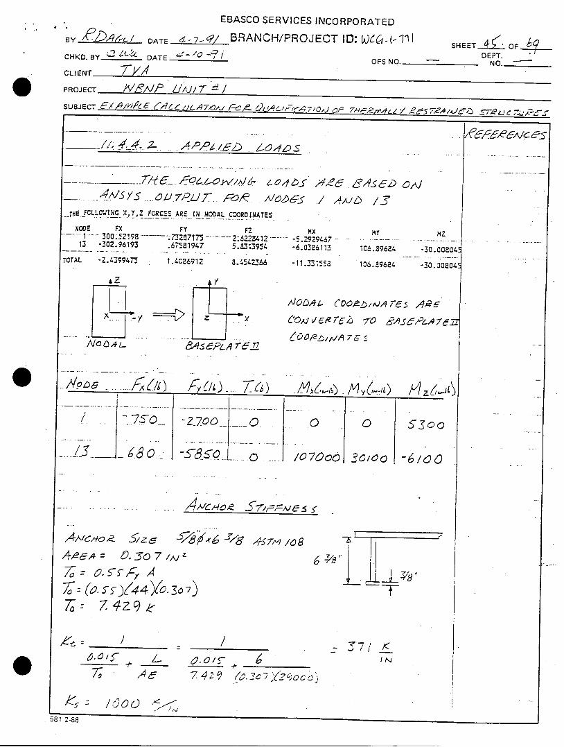
PROJECT / 1/lAJP 7JA.1T(- z/SUBJECT 6 '~._•.P~I~'•L'6 ( L Z6.A79,,J I -C6A 71C--. 0A}2 T/n4 ,/ 2eY 5 7Z,,/AJ-- SL-.. ;'J -
A,Dz,141, ý z-o54L)s
-__ _ • •L~z.JL _. 'z o, 'f ,•e6 8Asdz) co}- 0-U A....I7 Z JT/. .A-o--)6DR / 4AIZ-) /Z'
__rTE. FICLL.CJING_ X,Y,Z FORCES ARE IN NCAL COORDINATES
NCOE FX Fy FZ ?x m1 30 G.*5 2198 7"32-7175 2: 62-)3412. -5.2929467 - . . ..- .-- ---... .13 -302.96193 .67581947 5.,313954 -6.0386113 106.89684 -
TOTAL -2.43•9947t 1.4086912 8.4542Z66 -11.3-1558 106.!9624 -
0 1-2 A7 E S-T/vo A ., L- 7-51Z? Z~~A~
?Z
30.O0804!
-0.00804c
-6100'
- AAIC/4~ ~FA~'~ 5~
,4 Nclyol 51zc, •& ,x6 -rl67 4s57M- /0
,4-A- = D, 30 7 z
To: 7 479 e-
7 eA • • ~42~ ( 9 2 7Y }Z2Soe o•
6 7/~P
- K71 _
581 2-88
EBASCO SERVICES INCORPORATED
BY ?.._,,,4~-/ DATE 2"-/ BRANCH/PROJECT ID: LU,,I,-1lI SHEET Z"LOF•DEPT.
CHKD. BY c -'"' DATE "(--/- OFS NO. NO.
CLIENT "/A,,
PROJECT LIM 7/-, Z1,x ,
SUBJECT A')/Z' 6A'6//.4"//OJ -- K2LJA4-F'•iA 7/OJ , 7-/'/,4,/ , J6", E.
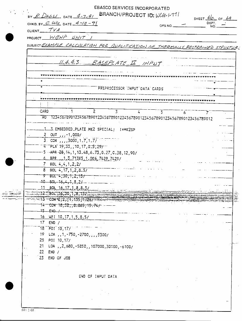
_ _ __ J/_/_#. 44.3. .. &-_6 P , A ' _ .2 T - . _ //IF•ZJ 7"__
PKEPROCESSOR INPUT-DATA CARDS
CARD 1 2 3 4 5 6 7No 723-r56-57 30123-45-673901-2345687390123456739012345678901234567390123456739012
___L3 .E.MBEDDEDPLAT.E MK2 SPECIAL; I=MK2SP
2 OUT ,,,-1,000/
3 CON .... 3000,1.7,1.7/-- PLA--19,33, 1"0,17,0.5129/ .
-5- -AP-R- -2.B-lt4-,1,13.48,6.7",o 0.27,0.38•12,90/_ ,PR_,_,1.713E5_,1.E._,7429,7429/
7 BOL 4,4,1,2,2/8 BOL 4,17,1,2,8.5/ .. ...
2--4----OL--4--,- 8,2/ - ...... . ...... . .1.1 BOL. 16 17,,i .. . .. ....S_ _ . : .. ..... :. . :. ........- -- ...... _ .. - _ __-. .: _
-- N It , , 2 , 8.865-, -5-.-7 - ......
15 END I
16 WFI 10,17,1 5,8.5/17 END /
1f P01 18)f17/ -
19 LOA ,,1,-750,-2700,,,,5300/
20 PoI 10,17/21 LOA ,,2,680,-5850,,107000,30100,-6100/
22 END /
23 END OF JOB
END OF INPUT DATA
2 .--- 3
EBASCO SERVICES INCORPORATED
13Y IeDAZ)A16/ DATE 7- Cl RANCH/PROJECT ID: W)66(WI7 SHEETd-Jil OFp-/_____ ___ _ _____ _____DEPT.
_CHKD.BY-( 6(-L&- DATE 4!V-q OFS NO. NO._____CLIENT
PROJECT- Z.VAA J/'J/T /SUBJECT C'1AMEe4P1 4 CAI647½A91V P& ,iLJ6F/A71, Ofy
I/ I I Ak~1~II~~~ý Iý I' T1 -I/1 ~AK 7Lo 6
,4X,)$/5-0 -77 427~
IZ4 7- e 7/ 0 4>
H4 l. ZM A
EBASCO SERVICES INCORPORATED
BY _-_,___-_i DATE 7 BRANCH/PROJECT ID: k)6-(-["'1 SHEET iL OF .DEPT.CHKD. BY- L•-'1-16" DATE ,-/// OFS NO. NO.
CLIENT -
PROJECT 1-"6',V,/ LIAJ/7 /
SUBJECT,'AA',4/",' Z "i'6L/',"r/ 4 A/ •'e ,/ 6/'/&A7AOI ?, 74A=/4A1i-i -7,e'7.•-/,D 9,2,L.J/t
* 1- *. i- -Is.-
W~L~i~zV 2
I I
I I . .
I I
1II1LLL11
0/4
611
581 2-88
I } I I I
EBASCO SERVICES INCORPORATED
BY R-k'/ i DATE 4l-7-4/ BRANCH/PROJECT ID: -SHEET_..OF•____ BY-
DEPT.CHD B . 6 "ZDATE ~ 9(OFS NO.-_______ NO._____
CLIENT -7 V,4
PROJECT -- W ,/ ZIPI, T /SUBJECT eA'P- R•617 g /,A 7 0J LY' ~~~Z 7~,
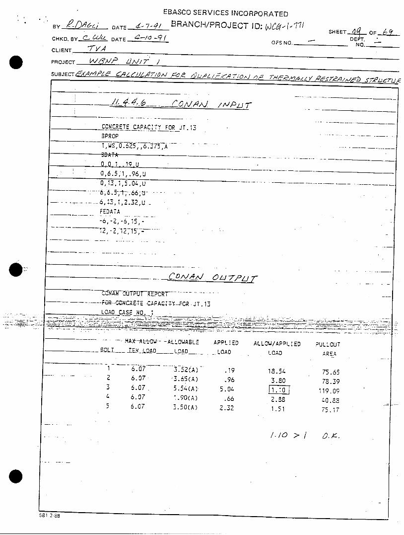
_____ _/. 44'.6 6," v i ,,J /II , _,
CONCRETE CAPACITY FOR JT.13
BPROP
1,WS,o.625,,6. 3 75_, A .
8D A TA ......0,0,1,.19-U
0,6.5,1,.96,U0,13,1,5.04,,U
-..... 6, 6.5-,--T.66 ;I U . . .. .
... ...... ..... 6,13,1,2.32,U U
FEDATA
-62, -6, 15 -.....
_.C01o_• A IM. 7L "z
--- W FGR--CcGONCRETE -CAPAC-$-T---GCR JT. 13LOAD CASE NO. 1 ._..._...
.....-_ -!-• -"-.- ... . ... -•- - •. - -.. .. --" - ---.. .... ..-*..-.-S•-=•..--. z..=.-.. ~..~= -.-. -. ......-.-.--' 77 .. . T " .' ":7....:... . . ..... - -....- ..-• - . -.. .... : .. • -: .- -.i -.. -. ~ - _ . - -".:
% C -
..... - MAX--ALt4-OW--A-LLCWA6L= APPLIED ALLOW/APPLIED PULLOUTSOLE-_ .TLQADL OCADO ... LOAD LOAD AREA
1 .6.0 3.52(A) .19 18.54 75.652 6.07 3.65(A) .96 3.80 78.393 6.07. 5.54(A) 5.04 1 119.094 6.07 1.90(A) .66 2.88 .0.85 6.07 3.50(A) 2.32 1.51 75.17
/./0 2 - o.8.
581 2-88
0
EBASCO SERVICES INCORPORATED
BY /.' If-DA-6 DATE L -7-L BRANC.H/PROJECT ID: - SHEET•1)OFIDEPT.
CHKD. BY L..424 DATE OFS NO. NO._-
CLIENT 7'VA
PROJECT WCS1A//f /1/7- /
SUBJECT 6,3A,'PL 9 Cl JIA 710A-) 50,f~ /PaI,4kFP,64710AJ Q)A" 7?9z~e~,flA-1 V oe57,,,4AAf-'bi s 7efde;5s,
/ H11
I .
---------- L I "--"LL-'--
• i •• 0- it ._.(axE•V
-- --! -
4128v- M17 3! -70
93f4- I5812-88
EBASCO SERVICES INCORPORATED
BY /l /--L46 / DATE Z -7' BRANCH/PROJECT ID: W66-1-111 SHEET•$Z__ OF__.T -/,/O ?/ -DEPT.
CHKD. BY DATE OFS NO. -- _ NO.CLIENT 7•V,4
PROJECT - &'V/ jJ,/7 ," I
SUBJECT A%--A/-/?/5 &/-/A A"/ ,% 6)1-A/ / J. .7/0/J e TB'f i / , •7ZJcr'Zid•
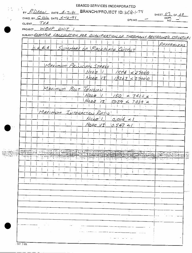
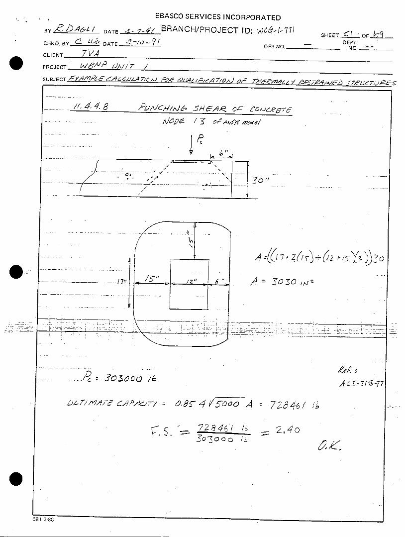
......./(./ 4.4.8 •/_.!c,, AJi6/L, •'E,, or CO7de~
....... ..... ....... • O • I o• •4/ m v 'el
301"
,4 7 Zo (o- , Z(
14 To -oz
Joe ... - -3 So /6
. 4 /5000 ,4 r720-74o 2 / /_;
3- 7 2 8 i(o
581 2-88
Acof- -!/g -77
17t
p.L "' . -' ' 4. • .. . i -- "

EBASCO SERVICES INCORPORATED~, ~.A~/ ATA~ILBRANCH/PROJECT ID: VJ46i6(-(-11( SHEET- 1-L F"SYX ___4_4__ DT .. 4--2
- DEPT.CHKD.BY_______ DATE. OFS NO.______ NO.-
CLIENT - V
PROJECT tVSJ- / 7'-SUBJECT )-4-," ILL /,/(lA 6- rp4ýd//f,/A,-~.~ L
2o4 c.~
____________________________ - --- 1
6'ZcAIC,7S
~ai Z.38

BRANCH/PROJECT ID: WCG-1--7-1By Date e & /aChkd. by (•. CC/LL Date___________ OFS No.Client TVA
Project WBNP Unit 1Subject Example Calculation for oualification of Therma
S heet _ o f __
• - Dept. No.-
l1Y Restraited Structures
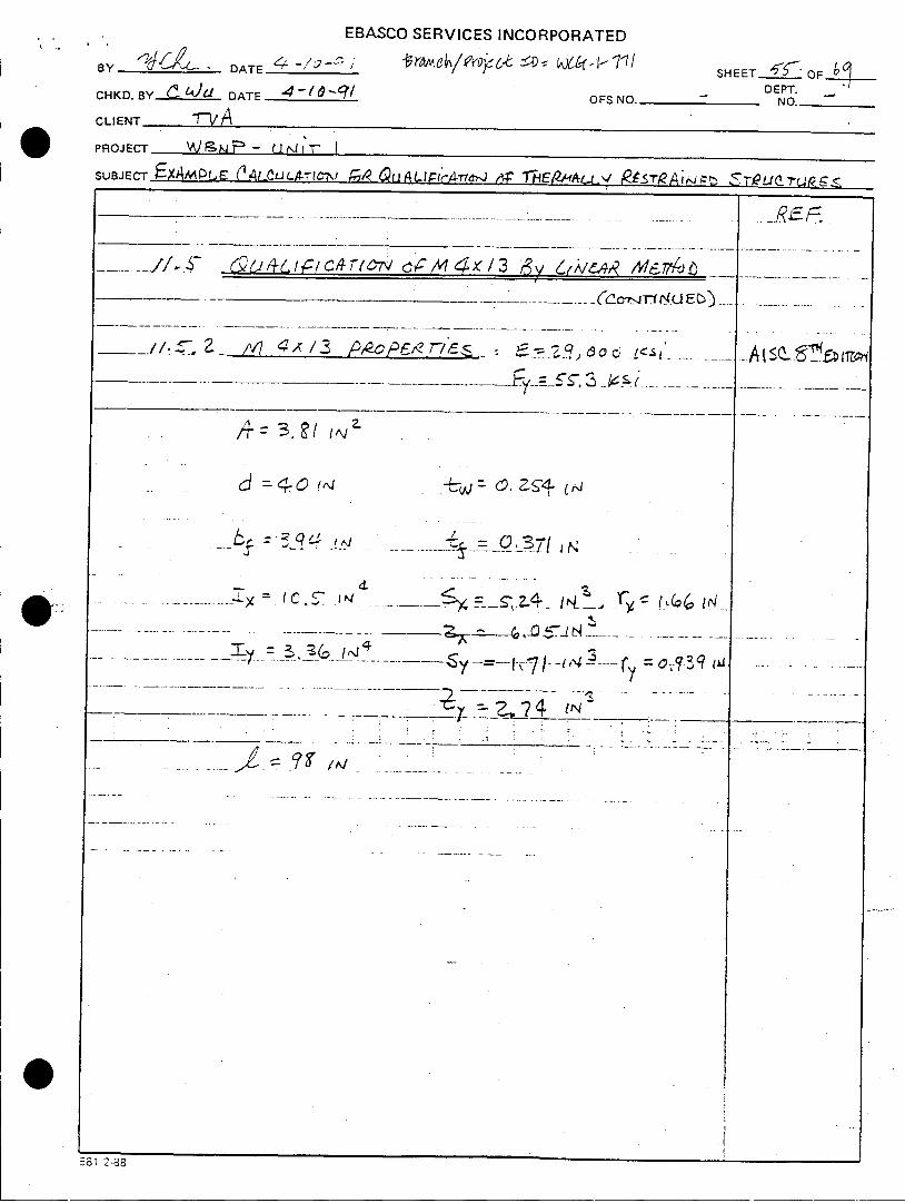
11.5 Qualification of Member M4x13 (Example #2)
EBASCO SERVICES INCORPORATED
BY -'4C;I-. DATE4-,-q BRAN CH/PROJ ECT 10: w6tý41-q SHEET•LOF--b_______
-YrLk DT
DEPT.CHK.B_____ DTE_______OFS NO._ _____ NO._____CLIENT- TVAPROJECT v8/ .~hSU B JE CT•1J cuArrC J /A7j F R.-NprDT/',c
~~jA..& LIFYC-1T10C7AV/3~ Z.NS/_ C.4JIVýC 1 /F
DIC Us~'.LA VC,/ A' ~'yI d L ~ '
J!--P--ib S'/z ~ Ci/L & / 4t 2 C 1-s TP N,3..E. l-r
581 2-88
EBASCO SERVICES INCORPORATED
BY____ DATE____~ ~ c - SHEET___5ODEPT.
CHKD.BY ___,__ DATE 4 / f OFSNO. - NO-________
CLIENT -vA
PROJECT -W&MF- urm I
SUBJECT fXAMPlE 0-.4- ..JJLA--l-7,/ ý rmEImL..tIv R-A-Tt-,J , S- .rru r<
___./Z /V? qx13 $oPE &7-•7"L -_.SIo L'-__ ,_=_ s .3 _1•ý .. ......
A~3.~/ Aja
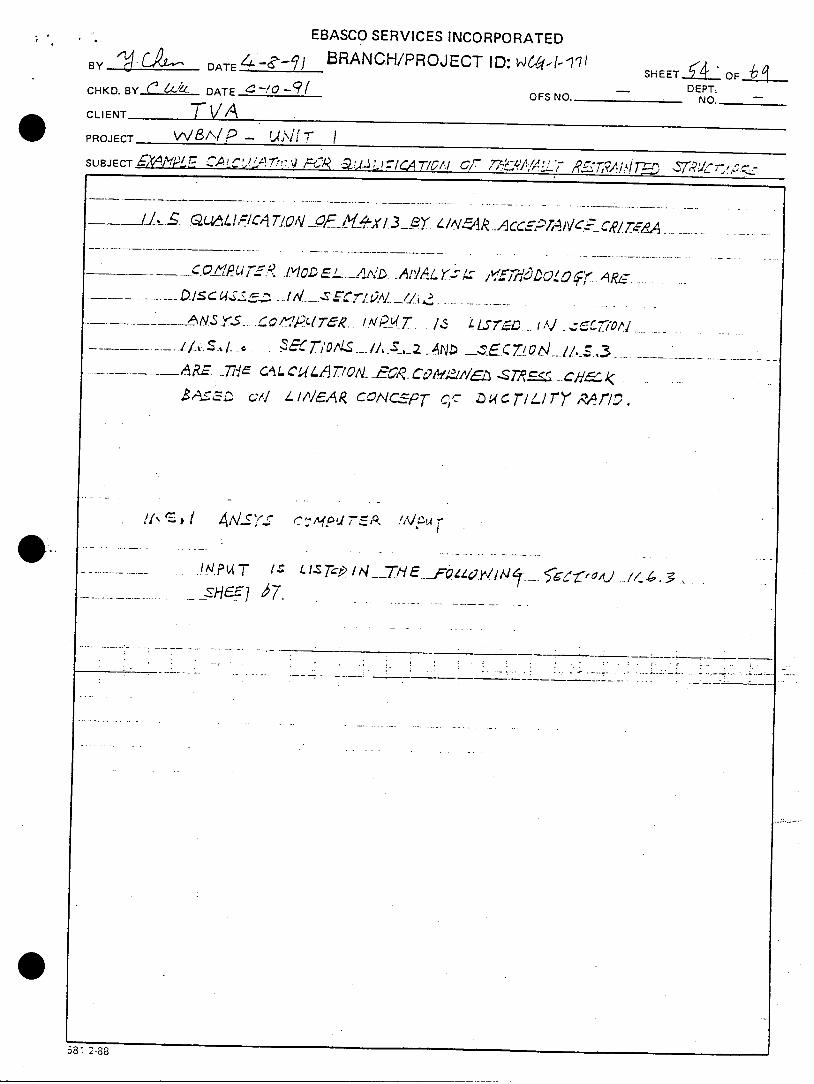
a ::A~c~
~ w . _-3_- 7 N
..L c (C- I t~4. -i$ =-z4 It±j
_7 ,-__ i. --INý
IAl
581 2-88
+
At sQ-sfý 170?
EBASCO SERVICES INCORPORATED
BY DATE .-/&-2 /-SHEET OF.DEPT.CHKD. BY....-4&2Ai DATE OFS NO. -- NO.
CLIENT 1-VA
PROJECT 4 - UN !! !
SUBJECT E4A*4PLE C-C;~~7Z QuA/-Li PCA-rIL-j OF* 7 -tlrAu"-.tc(rJL
______-_ __/ 1r __
.................. ._(A a'i• ,>,•/•& ,'i<e r~rLf d e • f-, a• -&)
-9 J . . ... . ...... . .~-~ L_ .. .... .. ..... . .. ..
4V• Y -C& 7p U "7.A_'YS P.Tl P
p
581 2-88
R..., E F.-

I I . I
This Page is Left Blank Intentionally
EBASCO SERVICES INCORPORATED
BRANCH/PROJECT ID: WCG-1-771
B Date /,-1 -•/ Sheet _ of4Chkd. by & 4 ce Date *-/0-9/ OFS No. - Dept. No. -
Client TVA
Project WBNP Unit 1
Subject Example Calculation for Oualification of Thermally Restrained Structures

BRANCH/PROJECT ID: WCG-!- 7-1By fkL/ Date. 4-(/fq Sheet 15eofj_Chkd. by C ZV/4_ Date .- /O-9/ OFS No. - Dept. No.,Client TVA
Project WENP Unit 1Subject Example Calculation for Oualification of Thermally Restraited Structures
11.6 Input Files for ANSYS Runs
BRANCH/PROJECT ID: WCG-I--ll
By / Date 4-(/I4' Sheet ,q off
Chkd. by L <l-&• Date e-10 *qf OFS No. - Dept. No..-.
Client TVA
Project WBNP Unit 1
Subject Example Calculation for Qualification of Thermally Restraited Structures
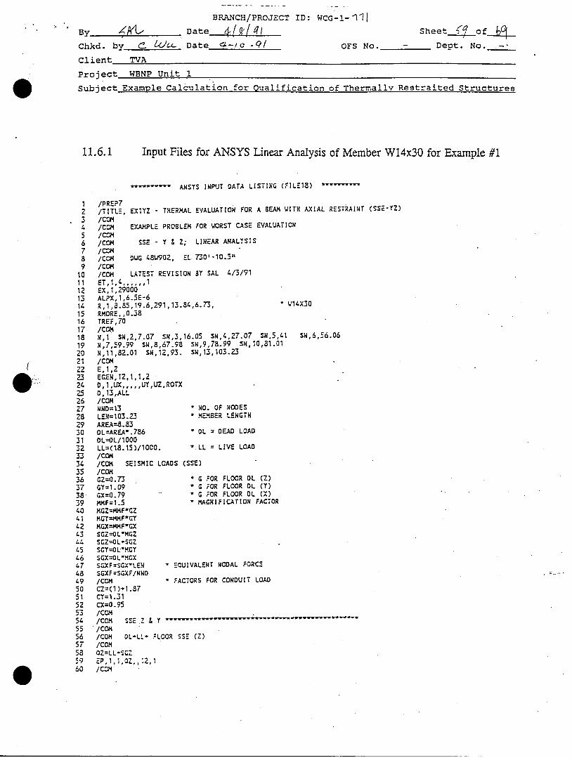
11.6.1 Input Files for ANSYS Linear Analysis of Member W14x3O for Example #1
ANSYS INPUT DATA LISTING (FILE18)
/PREP7/TITLE, EXlYZ - THERMAL EVALUATION FOR A BEAM W
/CCO/COM EXAMPLE PROBLEM FOR WORST CASE EVALUATI/COM/COM SSE - Y & Z; LINEAR ANALYSIS/CON/C-M DUG 48W902, EL 7350--10.544
/CCM/COM LATEST REVISION BY SAL 4/3/91ET,1,4 ...... 1
EX,1,29000ALPX, 1,6.5E-6R, 1,8.85,19.6,291,13.84,6.73,RMORE,,0.38TREF,70/CONH,1 SN,2,7.07 SN,3,16.05 SN,4,27.07 SN,5,41
N,7,59.99 SN,8,67.98 SN,9,78.99 SN,10,81.01
N,11,82.01 SN,12,93. SM,13,103.23/COME,1,2EGEN, 12,1,1 ,2D, 1I,UX ,,,,,UY,UZ,ROTX0, 13,ALL/COMNND=13 * NO. OF NODES
LEN=103.23 * MEMBER LENGTHAREA=8.83DL=AREA*.786 " OL = DEAD LOAD
OL=OL/1000LL=(18.15)/1000. LL = LIVE LOAD
/COM/CCM SEISMIC LOADS (SSE)
/COMGZ=0.73 * G FOR FLOOR OL (Z)
GY=1.09 * G FOR FLOOR DL (Y)
GX=0.79 ' G FOR FLOOR DL MX)
MMF=1.5 * MAGNIFICATION FACTOR
MGZ=MMFIGZMGT=MMF'GTMGX=MMF'GXSGZ--OL'MGZSGZ--OL*SGZSGY=OL'MGYSGX=OL'MGXSGXF=SGXILEN - ECUIVALENT NODAL FORCE
SGXF=SGXF/NND/COM * FACTORS FOR CONDUIT LOAD
CZ=(I )*1.87CY=1.31CX=0.95/COM/COM SSE .Z & Y ., -. .. ... ..., ,, W ... . .
/CO•/COM DL-LL* FLOOR SSE (Z)
/COMOZ=LL-SGZEP, 1,1,OZ., 12,1/COM
ITH AXIAL RESTRAINT (SSE-YZ)
ON
14X30
SN, 6,56.06
11,•,Ip ,I• f "*W•I# ,W
EBASCO SERVICES INCORPORATED
BRANCH/PROJECT ID: WCG-l- .J1By Date 41n4l Sheet o fChkd. by c 6/•- Date -- /O-• OFS No. - Dept. No. -
Client TVA
Project WBNP Unit 1
Subject Example Calculation for Qualification of Thermally Restraited Structures
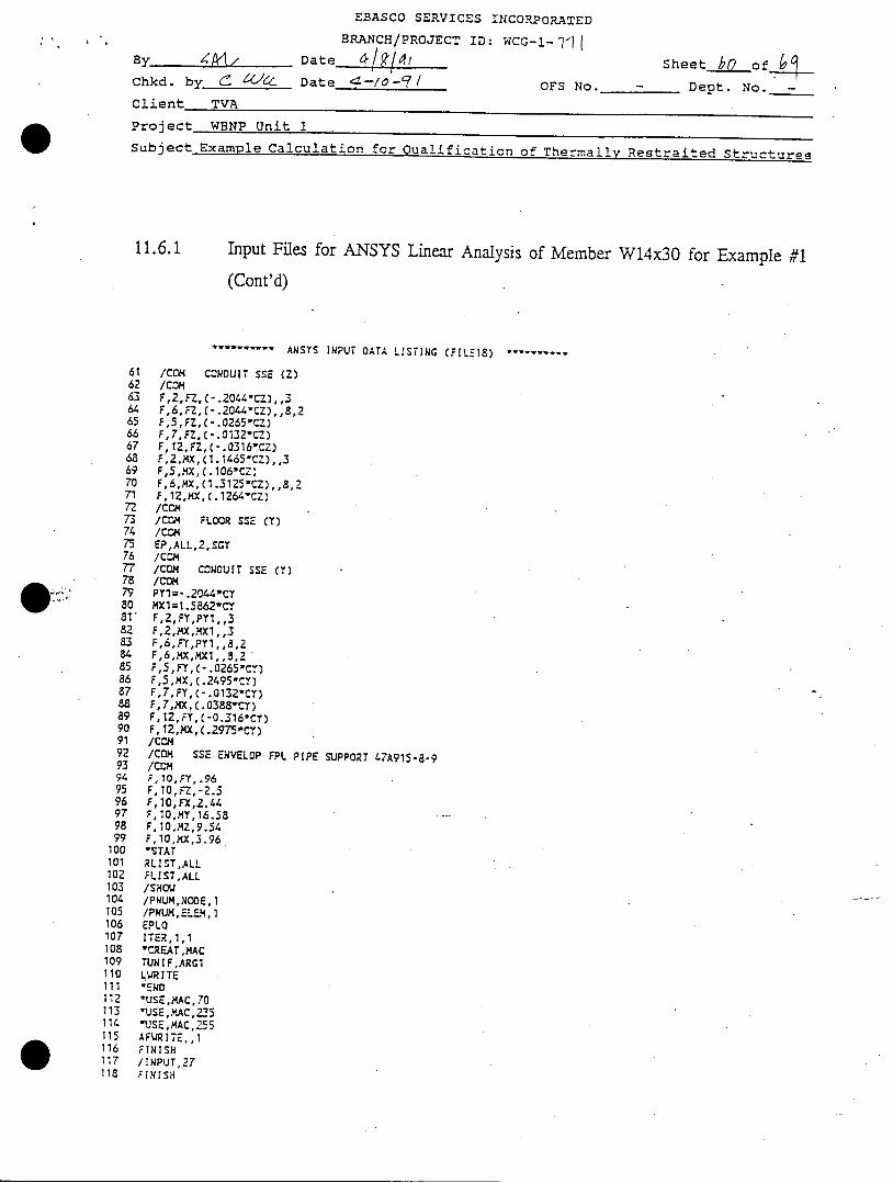
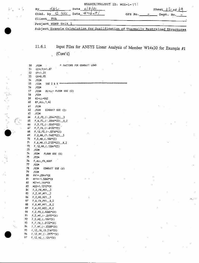
11.6.1 Input Files for ANSYS Linear Analysis of Member W14x3O for Example #1
(Cont'd)
ANSYS INPUT DATA LISTING (FILEIS) - w
61 /COM CONDUIT SSE (Z)62 ICOm63 F,2,FZ,(-.20U-.CZ),,364 F,6,r-z,(-.20o'Cz),,8,265 F,S,FZ,(-.0265-CZ)66 F,7,FZ,(-.0132"CZ)67 F, 12,FZ, (-.0316"CZ)68 F,2,MX, C1. 1465"CZ), ,369 F,5,4x, (c. 106CZ)70 F, 6,MX, (1.3125-CZ),,8, 271 F, 12,XX, C. 1264.CZ)72 /Com73 /COM FLOOR SSE (T)74 /COI75 EP,ALL,2,SGY76 /C•O77 ICOm CONDUIT SSE (Y)78 /CON79 PY1=- .2044*CT80 MX1=1.5862*CY81' F,2,FY,PY1,,382 F,2,,KX,yMX1,,383 F,6,FY,PY1,,8,284 F,6,)X,MX1,,8,285 F,5,FY,(-.0265"Cr)86 F,5,XX,(.2495-Cy)87 F,7,FY,(-.0132-CY)88 F,7,4X,(.0388,CTr)89 F,12,FY,(-a..16-CT)90 F, 12,MX, (.297--C-)91 /COm92 /COM SSE ENVELOP FPL PIPE SUPPORT 47A915-8-993 ICOM94 F,10,FY,.9695 F, 10,FZ, -2.596 F,10,FX,2.4497 F,10,MY,16.5898 F, 10,MZ,9.5499 F,10,MX,3.96
100 "STAT101 RLIST,ALL102 FLIST,ALL103 /SHOW104 /PNUM,NODE,1105 /PWUM,ELE-,1I106 EPLO107 ITER,1,1108 "CREAT,MAC109 TUNIF,ARG1110 LWRITE111 'END112 *USE,XAC,70113 1USE,M1AC,235114 "USE,MAC,255115 AFWRITE, ,1116 FINISH117 /INPUT,27118 FINISH

BRANCH/PROJECT ID: WCG-1-11i
BDate 4l-a(Chkd. by ' 6 Date___________
Client TVA
Sheet & I of g
OFS No. - Dept. No. -
Project WBNP Unit 1
Subject Example Calculation for Qualification of Thermally Restrained Structures
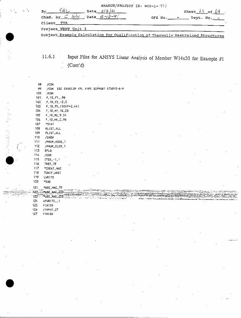
Input Files for ANSYS Linear Analysis of Member W14x3O for Example #1
(Cont'd)
ANSYS INPUT DATA LISTING (FILE18) .
/PREP7
/TITLE, EX1XZ - THERMAL EVALUATION FOR A BEAM WITH AXIAL RESTRAINT (SSE-XZ)
/CEM/COM EXAMPLE PROBLEM FOR WORST CASE EVALUATION
SSE - X & Z; LINEAR ANALYSIS
DWG 48W902, EL 730'-10.5"
LATEST REVISION BY SAL 4/3/91
,AN, 0TREF, 70
ET,1,4 ...... 1
EX, 1,29000
ALPX, 1,6.5E-6
R,l,.8.85,19.6,291,13.84,6.73, W14X30
RMORE, O, 0.376
ICONN,1 SR,2,7.07 SN,3,16.05 SR,4,27.07 SN,5,41
R,7,59.99 S,8,67.98 S,9,78.99 S,10,31.01
N,11,82.01 S,1Z,93. SN,13,103.23/COM
E,1,2
EGEN, 12,1,1,2
D,1,UX,,,, ,I,', LrY, ROTXD, 13 ,ALL
I
2
34
* S
6
7
a9
10
11
12
13
14
16
17
18
19
20
21
22
23
24
25
26
27
25
2930
31
32
335
34
35
36
37
38
39
40
41
42
43I.L
'5
46
47 S
48 S
49 S
SN,6,56.06
" NO. OF NODES
* MEMBER LENGTH
DL = DEAD LOAD
" LL = LIVE LOAD
;SE)
* G FOR FLOOR DL (Z)
* G FOR FLOOR OL (T)
* G FOR FLOOR DL (X)
' MAGNIFICATION FACTOR
VALENT NCDAL FORCZ
11.6.1
I/CON/COM/CCM/COM/r.•/COM
/COM.
NND=13
LEN=103.23AREA=8.'83
DL=AREA*.786
DL=OL/I1000
LL=(18.15)/1000.
/COM
/COM SEISMIC LOADS C:
/COM
GZ:O. 73
GY=1.09
GX=O.79
MMF=1.5
MGZ:4MF*GZMGT=MMFICT
MGX=MMF1GX
SGZ=OL'AGZ
SGZ=OL-SGZ
CGY=OL'MGY
CX=OL'MGX
CXF=SX¶'EY ECUIGXF=S F/NND
BRANCH/PROJECT ID: WCG-1-71 I
By 4/(1 LDate
Chkd. by . /-C L Date___________
clipnt TVA
Sheet Z of
OFS No. - Dept. No. -
Project WBNP Unit 1
Subject Example Calculation for Qualification of Thermally Restrained Structures
11.6.1 Input Files for ANSYS Linear Analysis of Member W14x30 for Example #1
(Cont'd)
' FACTORS FOR CONDUIT LOAD/COMCZ=(I)+1.87
C'r=I.31
CX=0.95
/CCJ4/COM
/COM
/COM
/CON
SSE Z z X
OL+LL+ FLOOR SSE (Z)
5'
55;
54
55
5657
58
59
60
61
62
63
6/-
66
67
68
69
70
71
727374
75
7677
787980
81
82
83
8485
86
87
88
89
90
91
92
9394
95
9697
o
23
QZ=LL+SGZ
EP,ALL, 1,QZ/CCH
/CON CONDUIT SSE (Z)
F,2,FZ,C-.20".CZ),,3
F,6,FZ,(-.20't.CZ),,-,2
F,5,FZ,(-.0265,CZ)
F,7,FZ,(-.0132-CZ)
F,12,FZ,(-.0316-CZ)
F,Z,MX, (I. 1465*CZ),,3
F,5,MX, (. 106-CZ)F,6,MX,C1.3125*CZ), ,8,2
F, 12,MX,(.1264*CZ)/CCM
/COM FLOOR SSE (X)
/COM
F,ALL,FX,S.XF
/CCO
/COM CONDUIT SSE (X)
/CoN
PX1=.2044*CX¥1=-1 .5862'r-c
MZI=1. 146,CX
MZ2=I. 1312-CX
F,2, FX,PX1, ,3F,2,,MT,MY1,,3
F,Z,MZMZI,,3
F,6, FX, PX1,,3,2
F,6,MY,MY1, ,3,2
F,6,.4ZMZ2, ,8,2
F,5,FX,C.0265"CX)
F,5,MY,(-.2495""X)
F,5, 4Z, (. 106'cX)
F,7,FX, C.0132"CX)
F,7,,4Y,C-.03a8"CX)
F, 12,FX, (O.316"CX)
F, 12,.Y, (-. 297' CX)
BRANCH/PROJECT ID: WCG-1--11
B_ __ Date
Chkd. by ' A Date 4/-/•-9/
Client TVA
Sheet /_ ofj_
OFS No. - Dept. No.. -
Project WBNP Unit 1
Subject Example Calcuilation for Qualification of Thermallv Restrained Structures
11.6.1 Input Files for ANSYS Linear Analysis of Member W14x3O for Example #1
(Cont'd)
/CVA/CCM SSE ENVEL0P FL PIPE SUPPORT 47A915-8-9/CCM
F, 10,FY, .96
F,10,FZ,-2.5F, 10, FX, (SGXF-2.44 )
F, 10,Y, 16.58F, 10,MZ,9.54• F, 10,MX,3.96
'STATRLIST,ALL
FLIST,ALL
/SHOC
/PNUMN,MCOE, 1
/PNUM, ELEX, 1E.LO/COMa!TER,- I, 1
;REF, 70
-CREAT ,,4ACTUnI F ,ARGr
LWR I TE'E.140
121."1JS. . . -- --7- . .... - - _- . - _ -
-12.2 .2-.
124. AFWR IT-z,, 1125 FINISH126 /INPUT,27
127 FINISH
9899
100101.
102io03104.
105
106107108
109110111
112113114.115116117118119
120

BRANCH/PROJECT ID: WCG-I-71•(
By <A,-t Date d/ /6f Sheet f-J of j _Chkd. by Date__--_______ OFS No. - Dept. No._
Client TVA
Project WBNP Unit 1
Subject Examnle Calculation for Qualification of Thermally Restrained Structures
11.6.2 Input Files for ANSYS Nonlinear Analysis of Member W14x3O for Example #1
.......... ANSYS INPUT DATA LISTING (FIL.18) .. ....
1 IPREF72 fTrLE. E-YZ - THERMAL EVALUATION FOR A BEAM Wr-H AXIAL RESTRAINT (SSE-YZ)3 /COM4 ICOM ECAMPLE PROBLEM FOR WORST CASE EVALUATION5 /COM6 /COM SSE - Y & Z; NONLINEAR ANALYSIS7 /COM8 /COM DW0 48W902, EL 730'-10-5-9 /COM
10 /COM LATEST REVISION BY SAL 4/6/9111 KAN,012 KAY,6,113 KNL,-I14 TREF,7015 ET,1,24 ...... 116 EXM1,29000
* : 17 A..X,1,6.5E-618 C- NONLINEAR MATERIAL CONSTANT
• . / 19 NL,1,13,1020 NL,1.19,70,47021 NL,1,25,36,36f- NL,1,31,1500,150023 C- CROSS SECTIONAL DIBENSION24 BF=6.7325 TP=0.38526 D =13.9427 TW=0.27
28 AREA = 8.8329 C...30 AA=BF/2
• . 31 BB = (D-TF)12
324 =.A T ............ .. . ....
34 STAT. . ..-
35 R,1.AA.BB,0,QA.BB,TF36 RMORF.0,BB,TF,-QA.BB,TF37 RMORE.-AA,BB,TF,0,BBO38 RMORPE0,QB,TW,0,0,TW39 RMORE.0,-QB,TW,0,-BB,TW40 RMORE?.-AA,-BB,0,•A,-BB.TF41 RMORE,0,-BB,TFQA,-BB,TF42 RMOREAA,-BB,TF43 C*** LINER PROPERTIES:44 C... R.1,8.85,19.6,291,13.g4,6.73 W14X30 FOR LINE-AR ANALYSIS ONLY45 /COM46 N,1 SN,2,7.07 SN,3,16.05 $1N,4,27.0 SN,5,41 SN,6,56.0647 N,7,59.99 SN,8,67.98 SN,9,78.99 $N,10,81.0148 N,11,82.01 SN,12,93. $N,13,103.2349 N,1I00,,,.10
50 /COM51 E,1,2,10052 RPI2,1,1,053 D,I,UX ..... UY,U7.,ROTX54 D,13,ALL55 /COM56 NND=13 "NO. OFNODES57 LEN= 103.23 MEMBER LENGTH58 AREA=8.8359 DL=AR.-k*.786 " DL = DEAD LOAD60 DL= DLJI000
BRANCH/PROJECT ID: WCG-!-1'I1
By Date Stheet
Chkd. by Z .&/. Date --/O--9 OFS No. Dept. No. -
Client TVA
Project WBNP Unit 1
Subject Example Calculation for Qualification of Thermally Restrained Structures
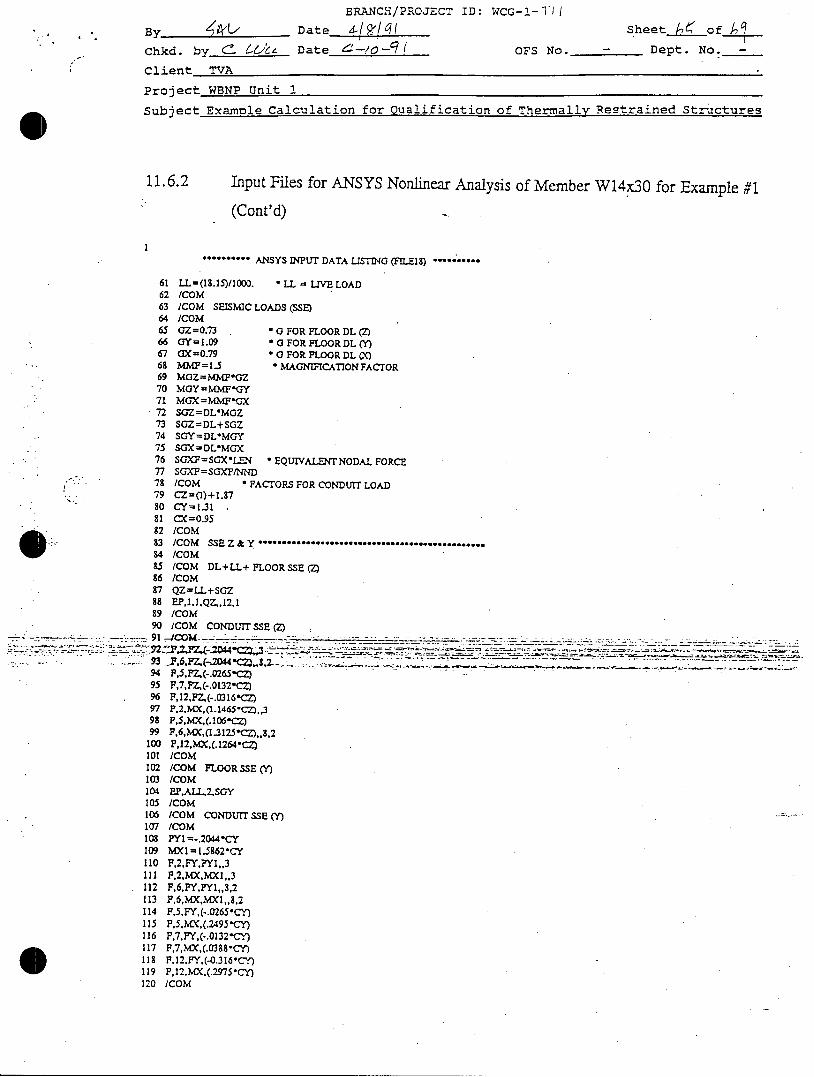
11.6.2 Input Files for ANSYS Nonlinear Analysis of Member W14x30 for Example #1
(Cont'd)
.**'°'*'" ANSYS INPUT DATA LISTING (FLElS) ..........
61 LL=(18.15)/1000. LL = LIVE LOAD62 /COM63 /COM SEISMIC LOADS (SSE)64 ICOM65 GZ=0.73 OFOR FLOOR DL (Z)66 GY=1.09 OFOR FLOOR DL (Y)67 CX=0.79 *O FOR FLOOR DL C)68 M1P=1.5 * MAGNIFICATIONFACTOR69 MGZ=MM*GZ70 MGY= MMF*GY71 MGX= MMFGX72 SGZ=DL*MGZ73 SGZ=DL+SGZ74 SGY=DL*MGY75 SGX=DL*MGX76 SGXF=SGXLEIN -EQUIVALENT NODAL FORCE77 SOXPF=SGXF/NND78 /COM " FACTORS FOR CONDUIT LOAD79 CZ=(I)+1.8780 CY= 1.3181 CX=0.9582 ICOM83 /COM SSE Z &Y* .....................................84 ICOM85 /COM DL+LL+ FLOOR SSE (Z)86 /COM87 QZ=LL+SGZ88 EP,I,I.QZ,.12,189 /COM90 ICOM CONDUIT SSE (Z)
" 91 --4C O M . - -. ......... _ _ _ _ ._-
94 PF,,FZ,(-.0265CZ.95 F,7,FZ,(-.0132-CZ)96 F,12,FZ,(-.0316CZ)97 F.2,NMX,(I.I465oCz.,,398 F,5,MX,(.106-C)99 F,6,)AX,(I .3125 "C"M ,,8,2
100 F,12,MX,(.1264*CZ)101 /COM102 /COM FLOOR SSE (Y)103 /COM104 EPALL,2,SGY105 /COM106 /COM CONDUIT SSE (Y)107 /COM108 PY1=-.2044"CY109 MXI=1.5862"CY110 F,2,FY,PYI,,3111 F,2,MX,MXI,.3112 F,6,FYFYI,,3,2113 P,6,MXMX1,,8,2114 F,5,FY,(-.0265*CY)115 F,5.•'a,(.2495"CY)116 F,7,FY.(-.0132-CY)117 F,7,MX,(.0388"Cy)118 F,12,FY,(-0.316-CY)119 P,12,MX.(.2975"CY)120 /COM
BRANCH/PROJECT ID: WCG-!---11
By________ Date- /0 laChkd. by 6 Z -- Date 4 /o-q/Client TVA
Sheet ofl
OFS No. - Dept. No. ,
Project WBNP Unit 1
Subject Example Calculation for Qualification of
11.6.2
121122123124125126127128129130131132133134135136137138139140141142
____ 143-.- I144
-- 145
146
Thermallv Restrained Structures
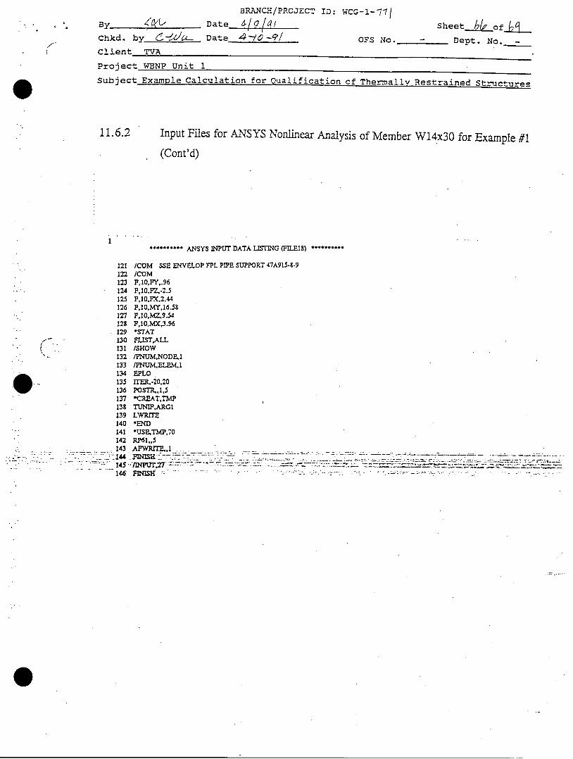
Input Files for ANSYS Nonlinear Analysis of Member W14x3O for Example #1
(Cont'd)
. ........ ANSYS INPUT DATA LISTING (F -EIS) ..........
/COM SSE ENVELOP FPL PIPE SUPPORT 47A915-8-9ICOMF,10,FY,.96F,10,PZ,-2.5F,10,FX,2.44F,10,MY,16.58F,10,MZ,9.54F,10,MX,3.96*STATFLISTALL/SHOW
/FNUM,NODE,1/PNUM,ELPM,1EPLOrr=,-20,20POSTR,.1,5-CRE.AT,TNPTUNIF,ARGILWRITE
*USPETMP,70RP61,,5AzWRr ,I. . . . . ....F..-.H -
F I rr,:77 " "- " "... " : - - -.- '- 2- 2: '- • - '. --. : :• .• _:.t • '" : -- : - " - -. -- L -
:

BRANtoi.lD: WCG-J.- l
By X Date a/9 l/t Sheet -___ of4Chkd. by (6 Date 4-/C-/ ' OFS No. - Dept. No. -
Client TVA
Project WBNP Unit 1
,Subject Example Calculation for Qualification of Thermally Restrained Structures
11.6.3 Input Files for ANSYS Linear Analysis of Member M4x13 for Example #2
2
3I,
56789
1011121311.15
- 16
18192021222324252627282930
.33.34
35363738,9404142'3
454.6474Z'95051525354
56
ANSTS INPUT nATA LISTING (FILE18) --- •--
/PREPT7/PMcOEisHoW[TITLE, XCWLAHO-HE'wMARX IODEL, FZ=-B.2XIPS, 0T--3,400 F, SiGT=55.3KSI
/CCM HOW.LAND )EI.MARKX MOEL/CCM REF. XE'MRK LOAD TESTS/C•M SPECIMEN 415 S (M13.0/CCM E=29E3 XSI, FY=-•-•. XS
/CCM INPUT: JOHN2LI/CCX OUTPUT: .XCC.-2L 1/CCM LINEAR ANALTSIS/CO PLOT FILE: SEE WCZ-I-811/CI:•
/c:4).ANJ, CET,l,4, ...... I
TREF , 70EX,1,Z9EALPX, 1 ,6.SE-6C-.R, 1, ,.81,3.26 ,10 .5,4 .0 ,.. 94C''"
L--98
mUq=31M ID=(NUMN I)/2
NW=3AL:L/4
F! LL.*,.NUN, I.
FILL
X, UNLD. 1 ,L/2, 0, 5E, 1,2. XL4m'.'RP30,1,1,0 RPYNN, HNMWNUN-iC"-
ITER,-I,IC- BUJNOARY C'OITTONS:0,1,UX,0 .... UY,LUZ,. ROTx0,XUM,UXo .... UY, UZ, Z0T-XC- 0EFINE REPEATING LOADINGS AS )4ACIOF,1IDO,FZ, -8.2CREAT, TMP
TUN IF,ARGILWRITE
-JSE, TNP, 270AFWRITE,_,1FINISH/INPUT,27FINISH

I.j EBASCO SERVICES INCORPORATED
BRANCH/PROJECT ID: WCG-l-771Date d 0q Sheet_ of e_
Chkd. by L!Dat e 1 / -l l OFS No. - Dept. No. -
Client TVAf
Project WBNP Unit 1Subject Example Calculation for Qualification of Thermally Restrained Structures
12.0 Summary of Results
The member in Example #1 is qualified with both the Engergy Balance Method (ductilityratio = 1.18 < 1.5) and the Non-linear Acceptance Criteria (Diplacement basedDuctility Ratio = 2.1 < 3). The connections and anchorages are evaluated using theresults obtained from the nonlinear analysis. One of the weld connections is qualifiedand the other requires modification. The anchorage is also qualified.
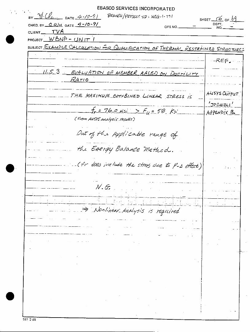
The member in Example #2 is not qualified with the Energy Balance Method (Combinedstress = 76 ksi, out of the applicable range of Energy Balance Method) while it isqualified with Nonlinear Acceptance Criteria (Displacement based Ductility Ratio = 1.9< 3) as documented in Calculation WCG-1-811.
EBASCO SERVICES INCORPORATEDBRANCH/PROJECT ID: WCG-1-771
Sheet X42 _of _ _Chkd. by - Ci LOLDate..4$// OFS No. - Dept. No. -
Client- TVA/
Project WBNP Unit 1Subject Example Calculation for Oualification of Thermally Restrained Structures
13.0 Conclusion
The linear acceptance criteria using Energy Balance Method, with a limitation ofapplicability, is conservative. Energy Balance Method is not applicable for memberswith calculated combined stress exceeding the ultimate strength of steel (Fu= 58 ksi).It is expected that rigorous nonlinear analysis will be used as required for thequalification of thermally restrained structures.
EBASCO SERVICES INCORPORATEDBRANCH/PROJECT ID.: V) c- '- I "i
SHEET L_ F FBDTDEPT.'
B Y 7 DATE OFS NO. NA NO. NACHKD. BY DATE 4.-,,QQf"O CLIENT TVA
PROJECT WBNP - UnitSUBJECT .6-ý, /? L CIf -4 ,C_ Vo' C'/-- ,/-/,6,,/ c?/ - - -fc- ,j,,
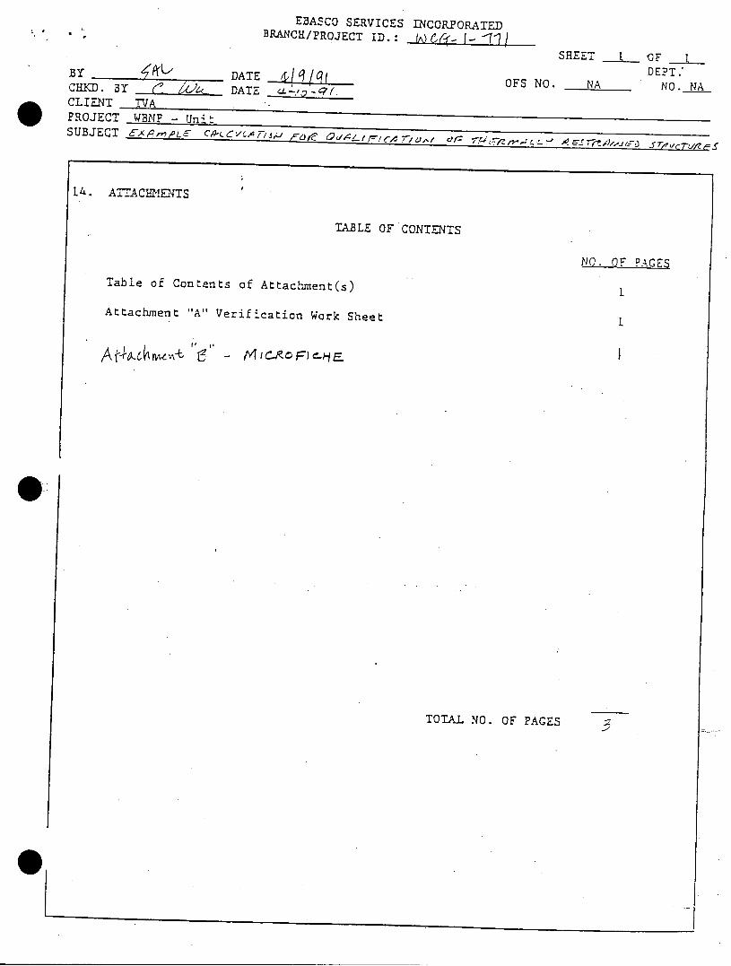
14. ATTACHMENTS
TABLE OF CONTENTS
NO. OF PAGES
Table of Contents of Attachment(s)
Attachment "A" Verification Work Sheet
S
TOTAL NO. OF PAGES
0
&i 4 Ill i
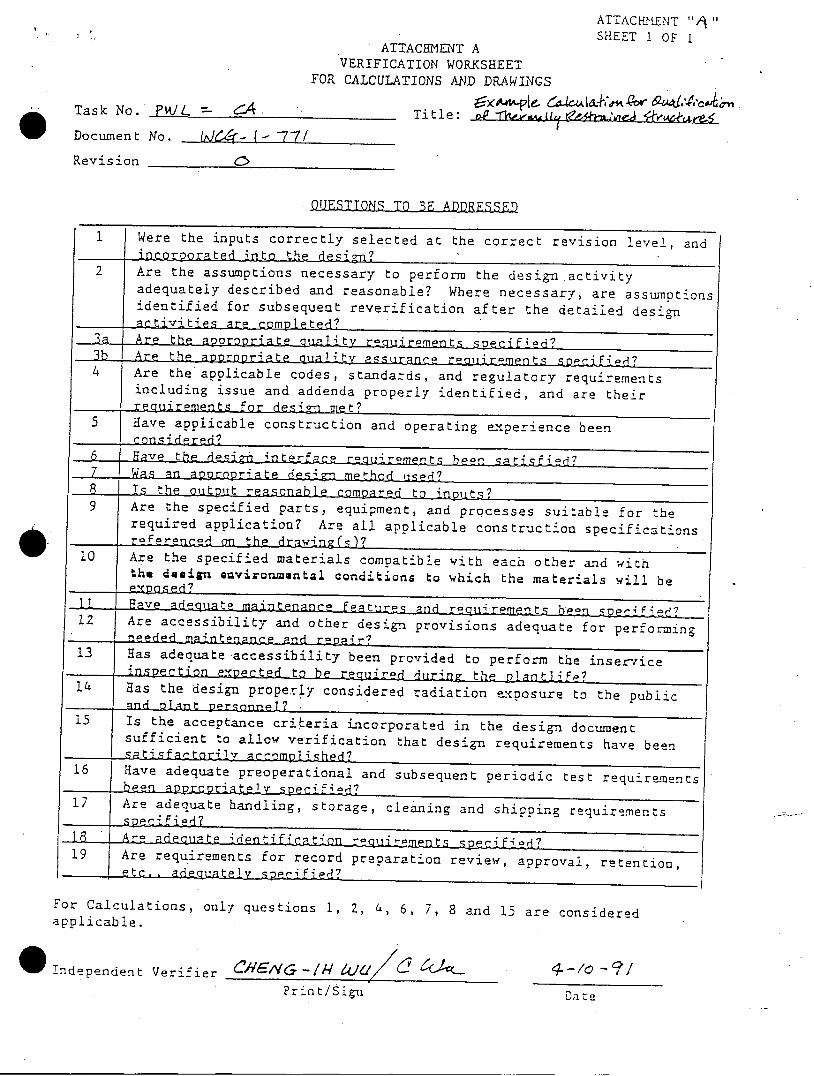
ATTACHME-NT AVERIFICATION WORKSHEET
FOR CALCULATIONS AND DRAWINGS
ATTACHKENT ",I"SHEET 1 OF I
Task No. PW&/L - - Title: a rl-, iu,. , -
Document No.
Revision
OUESTTONS TO •R AflfRWsqqn
1 IWere the inputs correctly selected at the correct revision level, andincorporated into the 4
2 Are the assumptions necessary to perform the design activityadequately described and reasonable? Where necessary, are assumptionsidentified for subsequent reverification after the detailed desig-nactivities are completed?
3a... Are the aopropriat- ua~iltv requirements specified?3b Are the appropriate quality assurance reoti reents secii ted?4 Are the applicable codes, standards, and regulatory requirements
including issue and addenda properly identified, and are theirrequirements for desinmet?
5 Have applicable construction and operating experience beencons-i dered?
6 Have the desi9• interfaco rouirements heen satisfied?7 Was an appropriate design method use-?
S -1-s the output reasonable comparPd to inputs?Are the specified parts, equipment, and processes suitable for therequired application? Are all applicable construction specificationsre~ren~ced th edrawinz(s)?
I -~ I - -- ____________________________________________________________________________________
10 Are the specified materials compatible with each other and withthe. design Qwez onmqntal conditions to which the materials will be
Have adeouatp maintenanc a
12 Are accessibility and other inc in t desquate for performing-- ne.eded maintenance and repair?13 Has adequate accessibility been provided to perform the insez-tice
- inspection e'xpected to berqirze urn the nlant!•fe?14 Has the designa properly considered radiation exposure to the public
- and olant prsonne!?115 Is the acceptance cri.Leria incorporated in the design document
sufficient to allow verification that design requirements have beensat ia
16 Have adequate preoperational and subsequent periodic test requirements- been appropriatelly specified?
17 Are adequate handling, storage, cleaning and shipping requirementsS snpe ifi ed?
18 "ArC adequate ide-ntficati r -uir n s C id19 Are requirements for record preparation review, approval, retention,
etc.. adaouialely speciFied?
For Calculations, only questions 1, 2, 4, 6, 7, 8 and 15 are consideredapplicable.
*T!ndependent Verifier r/NG-IA lckI d c<
Print/Signt-/e -. 7
LOa t e
6- I
W(,4 - ( - -7 -7 /
EHASCO SERVICES INCORPORATED
By Z____ Date 4--//-F/ Sheet I of -Chkd. by ( O/& Date 4--//-_/ OFS No. - Dept. No. -
Client TVA
Project WBNP Unit 1Subject Example Calculation for Qualification of Thermally Restraited Structures
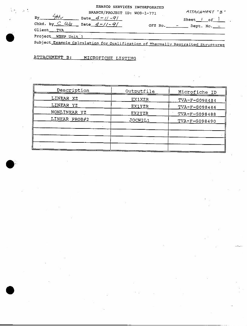
ATTACITh¶FNT ~*ATTACMENTno " , LJ-L 0 rc'mr1TQ7
Description Outputfile Microfiche ID
LINEAR XZ EXIXZR TVA-F-G098484LINEAR YZ EX1YZR TVA-F-G098486NONLINEAR YZ EX2YZR TVA-F-G098488LINEAR PROB#2 JOCW2L1 TVA-F-G098490
,A TT/A c/,4 -A " ' e" r '"
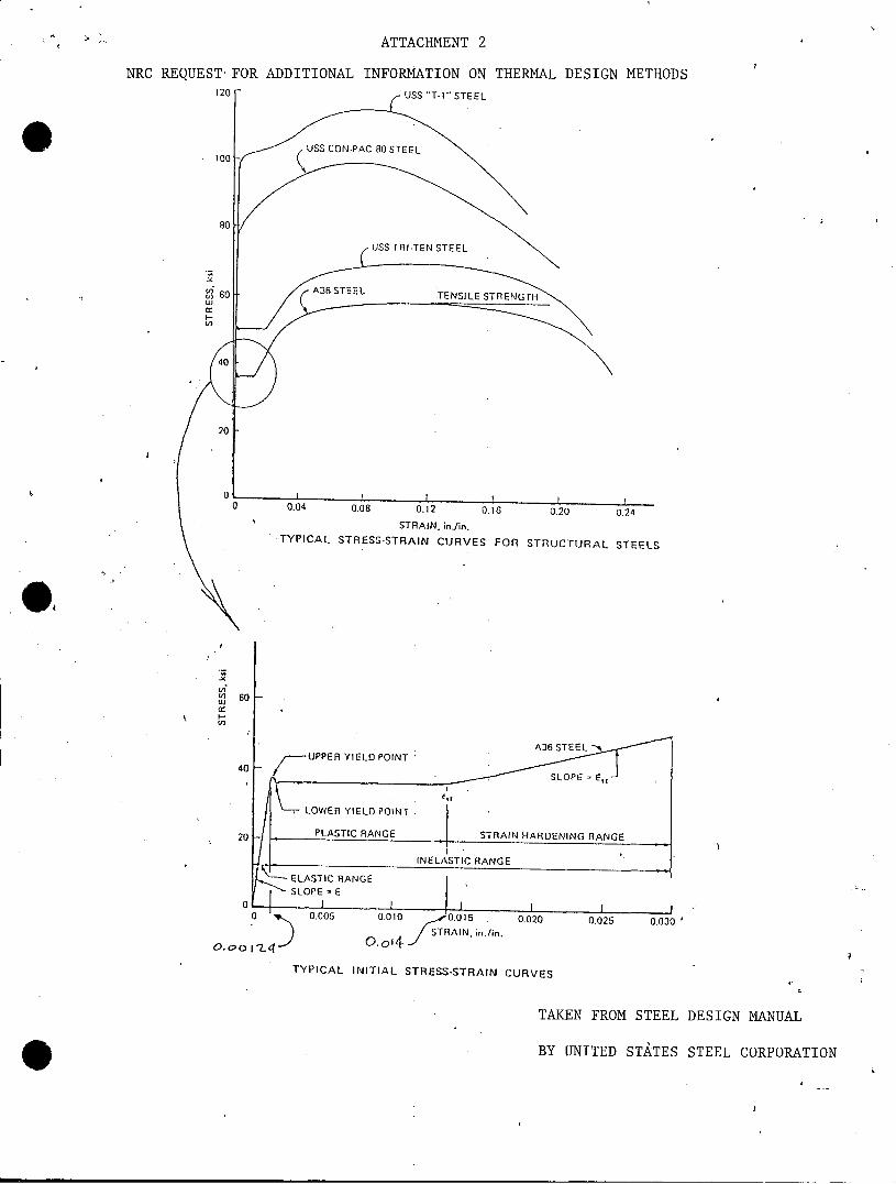
ATTACHMENT 2
NRC REQUEST FOR ADDITIONAL INFORMATION ON THERMAL DESIGN METHODS120 F - USS "T-I " STEEL
USS CON-PAC 80 STEEL
0.04 0.08 0.12 0.16 0.20 0.24
STRAIN. in./in.TYPICAL STRESS-STRAIN CURVES FOR STRUCTURAL STEELS
Uoiu] 60
a:I-U]
TAKEN FROM STEEL DESIGN MANUAL
BY UNITED STATES STEEL CORPORATION
O.c' o I'2.4 1' 0, oo _.J
TYPICAL INITIAL STRESS-STRAIN CURVES

ATTACHMENT 3
NRC REQUEST FOR ADDITIONAL INFORMATION
ON THERMAL DESIGN METHODS
SHEET 1 OF 2
TAKEN FROMEBASCO SERVICEs INCORPOR-----
BRANCH/PROJECT ID: WCG-I- StBv 662~ Date 3L--C7 Sheet ý2-of csChkd. by.1,•_ Dat t OTS No. - Dept. No.-Client- -VA t
Project WBNP Unit 1Subjecz Test Correlation Study for Thermna! Use of Ductility Ratio
11.6.2 (Continued)FauJ I!.re 116.2A
DI 3 PLA C-IEIT R.\T/ VS S-ENpE_.MTTlRE_ bHOW/LAND NEK/AIARK T//ERNAL tO4Q L" ,,"IPPLIEiD CONSTANT --ArFeAL LdAJ) (,D •2 k)
•. % = .. 4To- AC AL -a a.7 bl"rR"L D..3P
SLATERAL jlp. Y-5L
Qj
<4 04
- S - 4.*,44 4
)
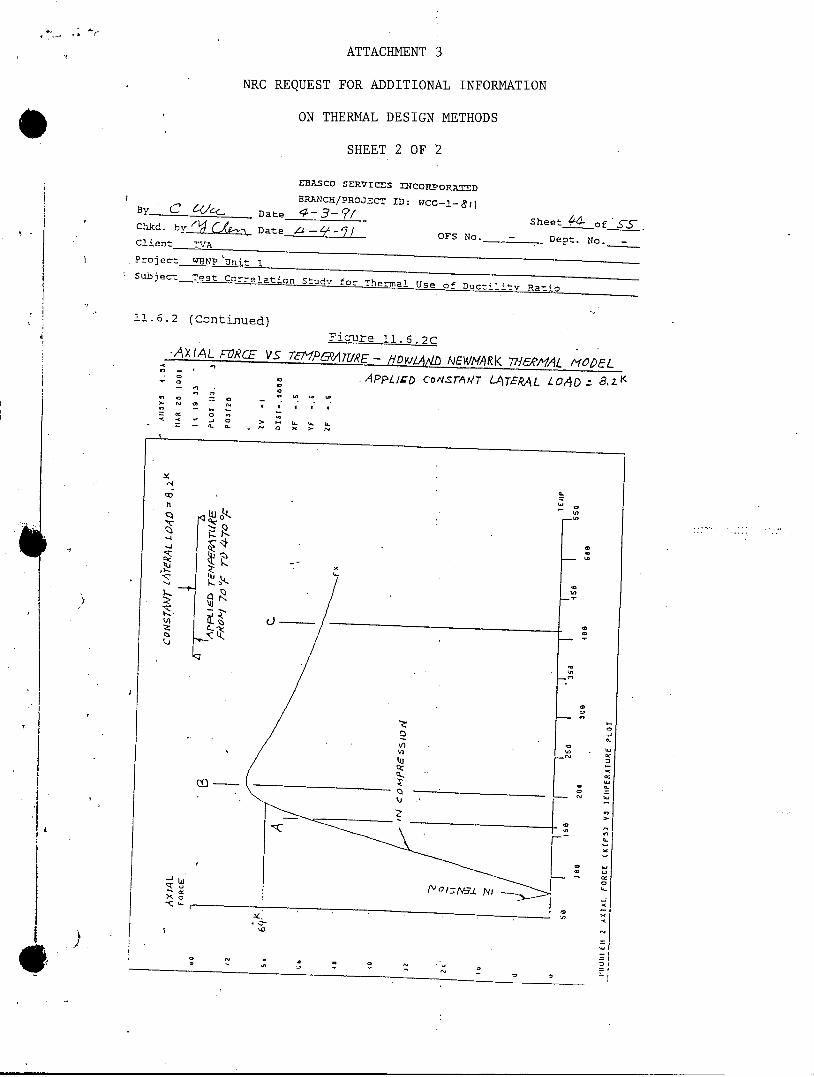
ATTACHMENT 3
NRC REQUEST FOR ADDITIONAL INFORMATION
ON THERMAL DESIGN METHODS
SHEET 2 OF 2
EBASCO SERVICXS DNCORpORATED
HBRANCE/PROJECT ID: WCG-!-,;Iy. C 6 &'_c Date • / Sheet-_f"-Chkd. b Yvf Date -- oFs No. - Dept. No.-Client 2ND o
Projec-t WNHP 'Unit !Subject Test Correlation StudV for Therma, Use of Duc-ilitv Ratio
11.6.2 (Continued)
Ficure 11.6.2c-AXIAL FORCE VS "•/'OP6A TU7RE - D)/_K 'ALD AJEW/,ARk 77bF-A1AL MODEL
S. APP4ED CON-SrAMT LATER6AL LOA/D:
a, 0 0(40
.. N C N S S
. w.
Vh
oN
-J -------- -- --
-z 7
/:;t -4 tNx 4 t0