power generation system and troubleshooting of diesel generator at rahimafrooz energy services...
TRANSCRIPT

1
Presentation On
Power Generation System and Troubleshooting of Diesel Generator at Rahimafrooz Energy Services Limited

2
Prepared By
--------------------
Date:…….

3
Overview Introduction Objective About Rahimafrooz And RESL Power generation process Main components of a generator The Control Panel Automatic Transfer Switch (ATS) Four Stroke Cycle Controlling Apparatus Troubleshooting Remarks

4
Introduction
In our country presently only 49% of the total populations have access to electricity, which is very poor comparing with even other developing countries. In our country the crisis of electricity in national grid is a common problem where in industrial sector the electricity is required for 24 hours.
Due to failure of national grid, private industry and owners are using their own power plants & generators combining with national grid to meet the demand of electricity.

5
Objective General Objective
The prime objective of this practicum project are to extrovert my theoretical knowledge to the practical field and understanding the performance of the parameters in case of Power Generation, Operation, Maintenance and Troubleshooting of Diesel engine, Alternator, Control Panel, etc.
Specific Objective To identify and analysis the structure and all the parts related with
a Diesel Generator. To study working procedure of Diesel Generator. To determine the process of maintaining, operation and
troubleshooting of a Diesel Generator. Suggest probable solution of the identified problem.

6
About Rahimafrooz And RESLIncorporated by Mr. A.C. Abdur Rahim in the year of 1954,Rahimafrooz has been a partner in the development journey of this nation for more than fifty-nine years now.
Rahimafrooz operates in four broad segments – Storage Power, Automotive & Electronics, Energy and Retail.

7
Rahimafrooz Energy Services Limited (RESL)
Rahimafrooz Energy Services Ltd. (RESL) was established in the year 2000 as a standby, captive and distributed power solution provider. It is a leading name in the diesel generator industry having a customer base of nearly 3000. At present the number of RESL installed generators is more than 6000 (20 KVA to 1500 KVA).
The company is marketing diesel generators from Pramac Power Engineering, Italy and Spain (20 to 2500 KVA), and Mitsubishi Heavy Industries Limited, Japan (650 to 4500 KVA). RESL is also providing Rental Power with both diesel and gas generators. The company is planning to launch Mitsubishi gas generator (1.0 MW) in the near future.

8
Values & Quality Policy

9
Different generator brand available at Rahimafrooz Energy Services Limited

10
Power Generation & Transfer System

11
Power Generation Process
Though a diesel generator is a single device that functionally converts diesel fuel into electricity, it is, in essence, two separate components that work together in order to produce power.
The two components (the engine and the electromagnetic generator) are connected by a crankshaft, facilitating the easy transfer of the mechanical energy produced by the diesel engine to the magnets of the generator assembly.
A diesel engine burns diesel fuel in order to produce mechanical energy in form of rotation, for the generator, which converts the mechanical energy into electricity by using electromagnet.

12
Powering the Diesel Engine
A number of fuels can be used to power internal combustion engine , diesel is generally preferred for generators because of its ability to burn but not explode.
The fuel tank of the diesel engine is filled, and the engine is started (sometimes with a key or automatic starter).
A governor is used to keep the speed of the diesel engine under control in order to regulate the power output of the generator while also preventing damage to components that could be caused by the engine operating at too high speed.

13
Producing ElectricityThe generator consists of a rotating magnetic field called a Rotor and a stationary coil of wire called a Stator.
During startup, an engine controller circuit board delivers battery voltage to the Rotor, via the brushes and slip rings. This results in the creation of a regulated magnetic field around the rotor.
As the rotor turns, its magnetic field cuts across the stationary stator. A voltage is induced into the stator windings. Regulated current delivered to the rotor is called "Excitation" current.
Excitation winding unregulated AC output is delivered to an electronic voltage regulator, via an excitation circuit breaker.
Figure: AC Generator System

14
Cont…When an electrical load is connected across the Stator power windings, the circuit is completed and an electrical current will flow.
The Rotor's magnetic field also induces a voltage into the stator battery charge windings.
Battery charge winding AC output is delivered to a battery charge rectifier (BCR) which changes the AC to direct current (DC).
The rectified DC is then delivered to the unit battery, to maintain the battery in a charged state.

15
Speed & FrequencyThe rotational speed of an alternator depends on the number of poles and the output frequency.
The relation equation between speed and frequency is N = 120f / P Where f = Frequency in Hz (cycles per second), P = Number of poles N = Rotational speed in Revolutions per minute (RPM)
Poles RPM at 50 Hz RPM at 60 Hz2 3000 36004 1500 18006 1000 12008 750 900

16
Main components of a generator
An electric generator is a device that converts mechanical energy obtained from an external source into electrical energy as the output.
The main components of an electric generator can be broadly classified as follows
(1) Engine (2) Alternator(3) Fuel System(4) Voltage Regulator(5) Cooling and Exhaust Systems(6) Lubrication System(7) Battery Charger(8) Control Panel(9) Main Assembly / Frame Figure: Main Component of Generator

17
EngineThe engine is the source of the input mechanical energy to the generator. The size of the engine is directly proportional to the maximum power output the generator can supply.
Figure: Diesel Engine Set
Generator engines operate on a variety of fuels such as diesel, gasoline, propane (in liquefied or gaseous form), or natural gas.
Smaller engines usually operate on gasoline while larger engines run on diesel, liquid propane, propane gas, or natural gas.

18
AlternatorThe alternator, also known as the ‘genhead’, is the part of the generator that produces the electrical output from the mechanical input supplied by the engine. It contains an assembly of stationary and moving parts. The components work together to cause relative movement between the magnetic and electric fields, which in turn generates electricity.
(a) Stator – This is the stationary component. It contains a set of electrical conductors wound in coils over an iron core.(b) Rotor – This is the moving component that produces a rotating magnetic field in any one of the following three ways:(i) By induction – These are usually used in large generators.(ii) By permanent magnets – This is common in small alternator units.(iii) By using an exciter – An exciter is a small source of direct current (DC) that energizes the rotor through an assembly of conducting slip rings and brushes.
The rotor generates a moving magnetic field around the stator, which induces a voltage difference between the windings of the stator. This produces the alternating current (AC) output of the generator.

19
Fuel SystemThe fuel tank usually has sufficient capacity to keep the generator operational for 6 to 8 hours on an average.
Common features of the fuel system include the following:
1) Pipe connection from fuel tank to engine 2) Ventilation pipe for fuel tank 3)Overflow connection from fuel tank to the drain pipe 4) Fuel pump 5) Fuel Water Separator / Fuel Filter 6)Fuel Injector

20
Automatic Voltage Regulator A voltage regulator is an electrical regulator designed to automatically maintain a constant voltage level.
A "Reference" voltage has been preset into the Voltage Regulator. An "Actual" ("sensing") voltage is delivered to the Voltage Regulator via
sensing leads from the Stator AC power windings. The Regulator "compares" the actual (sensing) voltage to its pre-set
reference voltage. If the actual (sensing) voltage is greater than the preset reference voltage,
the Regulator will decrease the regulated current flow to the Rotor. If the actual (sensing) voltage is less than the preset reference voltage, the
Regulator will increase the regulated current flow to the Rotor.
In this manner , the Regulator maintains an actual (sensing) voltage that is equal to the pre-set reference voltage.

21
Cooling & Exhaust Systems
Cooling SystemContinuous usage of the generator causes its various components to get heated up. It is essential to have a cooling and ventilation system to withdraw heat produced in the process.
Raw/fresh water, Hydrogen is sometimes used as a coolant for generators.
22
Exhaust System
Exhaust fumes emitted by a generator are just like exhaust from any other diesel or gasoline engine and contain highly toxic chemicals that need to be properly managed.
The exhaust pipe terminates outdoors and leads away from doors, windows and other openings to the house or building.

23
Lubricating System
The generator comprises moving parts in its engine, it requires lubrication to ensure durability and smooth operations for a long period of time.
Internal combustions engines require lubrication in operation that moving parts slide smoothly over each other.
Insufficient lubrication subjects the parts of the engine to metal-to-metal contact, friction, heat build-up etc.

24
Battery ChargerThe start function of a generator is battery-operated. The battery charger keeps the generator battery charged by supplying it with a precise ‘float’ voltage.
If the float voltage is very low, the battery will remain undercharged. If the float voltage is very high, it will shorten the life of the battery.
Main Assembly / FrameAll generators, portable or stationary, have customized housings that provide a structural base support. The frame also allows for the generated to be earthed for safety.

25
The Control Panel
Electric start and shut-down – Auto start control panels automatically start your generator during a power outage, monitor the generator while in operation, and automatically shut down the unit when no longer required.
Engine gauges – Different gauges indicate important parameters such as oil pressure, temperature of coolant, battery voltage, engine rotation speed, and duration of operation.
Generator gauges – The control panel also has meters for the measurement of output current and voltage, and operating frequency.
Other controls – Phase selector switch, frequency switch, and engine control switch (manual mode, auto mode) among others.
This is the user interface of the generator and contains provisions for electrical outlets and controls.
Figure: Generator Controller (AC-02)

26
Automatic Transfer Switch (ATS)
An Automatic Transfer Switch (ATS) is often installed where a backup generator is located, so that the generator may provide temporary electrical power if the utility source fails.

27
An automatic transfer switch (ATS) transfers power from a standard source, like utility, to emergency power, such as a generator.
When the standard source fails, an ATS senses the power interruption on the line and in turn signals the engine panel to start.
When the standard source is restored to normal power the ATS transfers power back to the standard source and shuts the generator down.
Figure: Automatic Transfer Switch (ATS) Box

28
Four-stroke cycle The diesel engine is an internal combustion engine or precisely it can be called as a compression ignition engine.
Four-stroke cycle Intake or Suction Compression Power or Working or expansion Exhaust
29
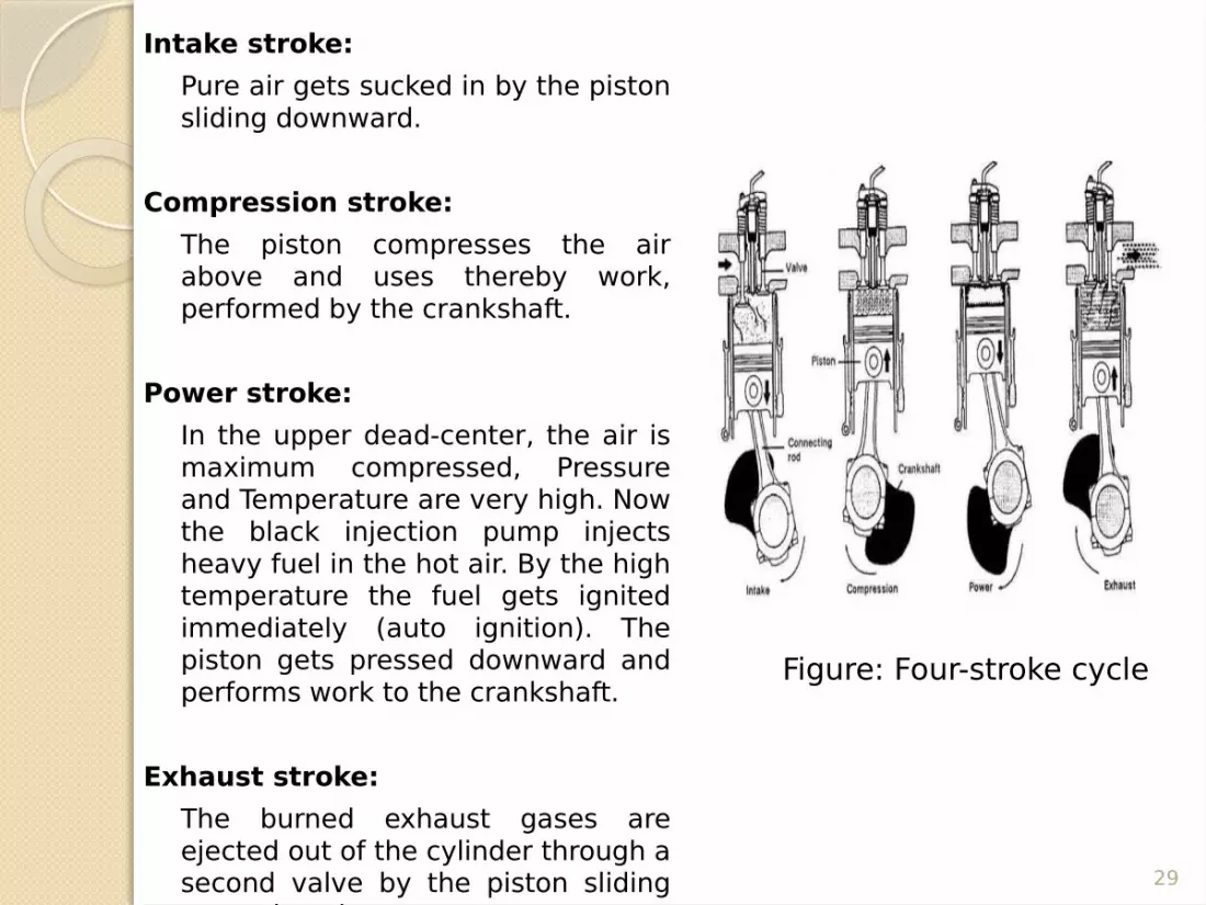
Intake stroke: Pure air gets sucked in by the piston sliding downward.
Compression stroke: The piston compresses the air above and uses thereby work, performed by the crankshaft.
Power stroke: In the upper dead-center, the air is maximum compressed, Pressure and Temperature are very high. Now the black injection pump injects heavy fuel in the hot air. By the high temperature the fuel gets ignited immediately (auto ignition). The piston gets pressed downward and performs work to the crankshaft.
Exhaust stroke: The burned exhaust gases are ejected out of the cylinder through a second valve by the piston sliding upward again.
Figure: Four-stroke cycle
30
Controlling Apparatus
Circuit Breakers
A circuit breaker is an automatically operated electrical switch designed to protect an electrical circuit from damage caused by overload or short circuit.
A circuit breaker is so designed that it can be operated manually under normal condition and automatically under fault condition.

31
Air Circuit Breaker (ACB)ACB is used as medium voltage circuit breaker.
The breakers employ a high pressure air-blast as arc quenching medium. Figure: Air Circuit Breaker (ACB)

32
Molded Case Circuit Breaker (MCCB)
Molded case circuit breaker (MCCB) is a low voltage circuit breaker.
It is the most used circuit breaker.
Figure: Molded case circuit breaker (MCCB)

33
Magnetic Contactor
A magnetic contactor is an electrically controlled switch used for switching a power circuit, similar to a relay except with higher current ratings.
Figure: Magnetic Contactor

34
Fuse A fuse is a short piece of metal, inserted in the circuit, which melts when excessive current flows through it and thus break the circuit.
It is inserted in series with the circuit to be protected.
Under normal operating conditions the fuse element it at a temperature below its melting point.
Figure: Fuses

35
Relay
The relay's switch connections are usually labeled as COM, NC and NO:
COM = CommonNC = Normally ClosedNO = Normally Open
A relay is an electrically operated switch. Current flowing through the coil of the relay creates a magnetic field which attracts a lever and changes the switch contacts.
Figure: Relay

36
TimerA timer is an electromechanical device used for automatically timing process or an observed event.
The basic diagram of timer is almost same with relay except the timer has a timer IC.
Timers are mainly two types-
On-delay timer Off-delay timer
Figure: Timer

37
TroubleshootingTroubleshooting is process discovering true cause by eliminating other possibilities.
Some basic rules to follow
RULE 1: Check out the complaint yourselfRULE 2: Don’t make an assumptionRULE 3: Consider all the possibilitiesRULE 4: Don’t guessRULE 5: Be patient

38
Problem no. 01: Engine Fail to Start
Activities: After receiving the gen-set at stop position we have to perform the following task
Checked the battery voltage Checked the fuel solenoid Checked the starting motor
Figure: Starting Motor
Observation: Found starting motor does not work
Solution: Repair the starting motor or arrange a new one. We bring Staring motor for repair in RESL.

39
Problem no. 02: Fuel Supply hampered and engine fails to start
Activities: After receiving the gen-set at stop position we have to perform the following task
Checked fuel pump Checked water separator filter and fuel filter Checked fuel line
Figure: Fuel and Oil filter
Observation: Found diesel fuel filter is blocked due to contamination. It may happen due to water that can enter the fuel tanks or the wrong fuel is put in your diesel fuel tank at the filling time.
Solution:
Changed the fuel filter and oil filter and also change lube oil as a part of schedule service.

40
Problem no. 03: Gen-Set suddenly shutdownActivities: After receiving the gen-set at stop position we have to
perform the following task
Checked the controller alarm Checked the cylinder exhaust temperature Checked the radiator Checked fuel level
Observation: Exhaust temperature deviations low and after 50 minutes running high temperature alarm break out due to dirty radiator.
Solution: Radiator servicing needed, Engine is okay.
Figure: Radiator

41
Problem no. 04 : Engine Vibration and Fail to StartActivities: After receiving the gen-set at stop position we have to perform
the following task
Clean the air filter Checked the timing of engine Checked fuel solenoid Checked the fuel supply line
Observation: Found insufficient fuel supply in fuel injector due to fuel
solenoid was faulty. Solution: Fuel solenoid was bringing to RESL for repairing. Engine set to
manual start.
Figure: Fuel Solenoid

42
Problem no. 05: Hard Starting Problem due to low cranking speed Activities: After receiving the gen-set at stop position we have to
perform the following task Checked battery voltage Checked starting motor Checked fuel line Checked fuel injector
Observation: Found diesel pump can't generate enough fuel pressure to initialize fuel injection causing hard starting problems. During the colder periods of the year low cranking speed is more common due the battery being flat or faulty. Battery was faulty.
Solution: Changed the old battery by a new one.

43
Problem no.06: Exhaust temperature of cylinder is high and Black smock out. Activities: After receiving the gen-set at stop position we have to perform the
following task
Checked air filterChecked fuel filter & fuel lineChecked diesel injector
Observation: Found air to fuel ratio imbalance. This occurs when the diesel fuel system is delivering either too much fuel into the engine or there is not enough air. Find air filter jam.
Solution: Change air filter and advised to make better air circulation facility to
generator room.
Figure: Exhaust / Silencer pipe

44
Problem no.07: Both auto and manually start fail.
Activities: After receiving the
gen-set at stop position we have to perform the following task
Checked fuel pumpChecked battery connectionCheck starting motorChecked controller Observation: Starting motor
was faulty, controller was damaged too, fuel pump are connected so tightly.
Solution: Bypass system is used
for starting via a wire. Controller need to replace.
Problem no.08 : Battery Charges and Gradually Discharges, causes starting problem.
Activities: After receiving the gen-set at stop position we have to perform the following task
Checked battery cable Checked battery voltage Checked battery water
level Checked starting motor
Observation: Improper ground
causing battery to lose charge when accessories activated & Faulty battery is not holding charge.
Solution: Replace the faulty
battery by new one.

45
How it is performed This is performed by following way: Official Training Web resources of Diesel generator Latest Technology Guiding Manual Modern Tools and Rapid Response Related Experience & Expertise

46
Remarks Though in Bangladesh, approximately 45% power is produced from different types of generator. There are some feasibility study in this regard is recommended and suggested.
Generator should be properly examined time to time to get rid of system failure, as sometimes working problem of starting motor and battery of generator and inadequate voltage in secondary winding cause the failure.
Replacement of faulty and frequent equipment’s should be done with equipment of better
performance and quality.
Generator should be installed in a place with adequate air circulation facility to generator room.
Batteries should be checked to make sure they are fully charged. The batteries must be tested under load. Connections should be tight and free from corrosion.
Schedule service should be done within every 200 hour running time.

47
ConclusionGenerators are available in different electrical configurations for use in different applications. In this regard the govt. has a lot to do to ensure smooth running of the power sector in private sector. The main reason for the power crisis is the shortage of supply. Demand is never meet by supply. Generation of power needs to be increased transferred to the desired distribution centers of power.
My experience during the short stay at Rahimafrooz Energy Services Limited has not only increased my depth of knowledge but also has given me the feeling of challenges faced in engineering profession. Thanks to Rahimafrooz Energy Services Limited for providing me with the opportunity to conduct my industrial attachment in their Company.

48
Thanks To All

49
Question Session
????