diesel generator set 1010 kva - hll lifecare limited
TRANSCRIPT
HLL Lifecare Limited, Kanagala
Tender NO.HL:BG:PS:1010:DG:2014-15 Dated: 18 March 2014 Page 1 of 73
HLL LIFECARE LIMITED (Formerly Hindustan Latex Limited)
(A Government of India Enterprise)
KANAGALA
BELGAUM DIST. PIN – 591 225
KARNATAKA STATE
PH.NO: 08333-279240, 279244. FAX: 08333-279245.
Website: www.lifecarehll.com
E-mail: [email protected]
TENDER NO. HL:BG:PS:1010:DG:2014-15
TENDER DOCUMENT
FOR
DIESEL GENERATOR SET 1010 KVA
Date of Pre Bid Meeting at HLL Kanagala : 15-APR-2014, 14:00 Hrs.
Last Date and Time for Receipt of Technical & Price Bid : 28-APR-2014 up to 17:00 Hrs.
Date and Time of Opening of Technical Bid : 29-APR-2014, 10:30 Hrs.
Date and Time of Opening of Price Bid : Will be intimated later.
HLL Lifecare Limited, Kanagala
Tender NO.HL:BG:PS:1010:DG:2014-15 Dated: 18 March 2014 Page 2 of 73
NOTICE INVITING TENDER (NIT)
HLL Lifecare Limited (Formerly Hindustan Latex Ltd), India’s leading Manufacturers and
Marketers of Contraceptive, Health Care and Pharma Products is a Mini Ratna Company.
HLL Lifecare Limited (Formerly Hindustan Latex Ltd), a PSU under the Ministry of Health & Family Welfare, Govt. of India invites Sealed & Superscribed Tenders under Two Bid System (Technical
& Price) in the prescribed forms enclosed from Manufacturers / Authorized Dealers for the
supply, erecting and commissioning of DIESEL GENERATOR SET 1010 KVA at our Factory site at
Kanagala, Belgaum Dist (Karnataka).
Specifications and Terms & Conditions etc. are detailed in Tender Documents. NIT / Tender
Documents / NIT can be had from our Office on any working day between 11:00 AM to 3:30 PM by paying ` 500/- by Cash / DD (inclusive of ST) drawn in favor of HLL LIFECARE LTD,
payable at State Bank of India, NIPANI – 591 237. Further, Tender Documents can also be
downloaded from our website: www.lifecarehll.com. However cost of Tender Documents i.e. `
500/- in the form of DD should be enclosed along with Technical Bid.
NAME OF THE ITEM QTY. REQUIRED (SET)
DIESEL GENERATOR SET 1010 KVA
Specifications as detailed in ANNEXURE AN2 TO AN3.
01
11.. DDaattee ooff PPrree BBiidd MMeeeettiinngg aatt HHLLLL KKaannaaggaallaa :: 1155..0044..22001144 ((1144::0000 HHrrss..))
22.. LLaasstt ddaattee ffoorr RReecceeiipptt ooff TTeecchhnniiccaall && PPrriiccee BBiidd :: 2288..0044..22001144 ((1177::0000 HHrrss..))
33.. OOppeenniinngg ooff TTeecchhnniiccaall BBiidd :: 2299..0044..22001144 ((1100::3300 HHrrss..))
4. In the event of the date/s mentioned above being declared subsequently as holiday/s
for the Purchaser’s Office, the due date for meeting, submission and opening of bids will be the next working day at the same venue and time.
5. Addendums / Amendments issued if any to this NIT / Tender Documents shall be part of this NIT / Tender Documents and shall be published in our website specified above. It is
Bidders responsibility to keep themselves updated on any such Addendums /
Amendments issued, if any.
6. In order to provide reasonable time to the Prospective Bidders to take necessary action
in preparing their Tenders / Bids as per the Addendums / Amendments, HLL may, at its
discretion extend the deadline for the submission of Tenders / Bids and other allied time
frames, which are linked with that deadline.
7. Earnest Money Deposit (Refundable): An amount of ` 2,00,000/- by DD drawn in favor of
“HLL LIFECARE LTD” payable at State Bank of India, NIPANI – 591 237 towards EMD should
be enclosed along with the Technical Bid only.
HLL Lifecare Limited, Kanagala
Tender NO.HL:BG:PS:1010:DG:2014-15 Dated: 18 March 2014 Page 3 of 73
NOTICE INVITING TENDER (NIT)
8. Tender Cost (Nonrefundable): An amount of ` 500/- (inclusive of S.T.) by DD drawn in
favor of “HLL LIFECARE LTD” payable at State Bank of India, NIPANI – 591 237 towards
cost of Tender Form should be enclosed along with the Technical Bid only.
9. Technical Bids received without enclosure of EMD & Tender Cost will
be summarily rejected. Please note that HLL Lifecare Ltd. will not be responsible
for any delay in submission of Tender.
10. Exemption from payment of EMD: However, SSI Units who wish to avail exemption from
payment of EMD should produce an Exemption Certificate issued by the concerned DIC or NSIC stating that the SSI Unit should be exempted from payment of EMD in respect of
the relevant Tender NO. indicated in the NIT / Tender Document.
11. Acceptance / Rejection of the Tender is entirely at the discretion of HLL.
DEPUTY GENERAL MANAGER (PURCHASE)
HLL Lifecare Limited, Kanagala
Tender NO.HL:BG:PS:1010:DG:2014-15 Dated: 18 March 2014 Page 4 of 73
1) FORMATS FOR TECHNICAL BID
a) INSTRUCTIONS TO THE BIDDERS (ANNEXURE AN1)
b) BILL OF QUANTITIES (BOQ) FOR 1010 KVA DG SET (ANNEXURE AN2)
c) SPECIFICATIONS OF 1010 KVA DG SET AND ACCESSORIES (ANNEXURE AN3)
d) QUESTIONNAIRE (ANNEXURE AN4) e) DECLARATION ACCEPTING TERMS AND CONDITIONS OF THE TENDER (ANNEXURE AN5)
f) FORMAT FOR MANUFACTURERS AUTHORIZATION FORM (ANNEXURE AN6)
g) GENERAL CONDITIONS FORMING PART OF THE BID
2) FORMS FOR PRICE BID
a) SCHEDULE - A: PRICE BID / RATE SCHEDULE
(WITH TERMS & CONDITIONS)
NOTE: Technical Bid & Price Bid forms shall be submitted in Separate Covers.
How to send the Bid:
Both the Bids i.e. Technical Bid & Price Bid shall be submitted in sealed covers separately.
Technical Bid & Price Bid shall be superscribed on the respective covers in order to clearly identify between the 2 Bids. The two separately marked Bids enclosed in single sealed cover
with Tender NO. Complete in all respect addressed to The Deputy General Manager
(Purchase), HLL Lifecare Ltd., Kanagala - 591 225 Dist. Belgaum, Karnataka State should reach
us on or before the due date and time mentioned in the NIT. CONTENTS OF THE BIDDING DOCUMENTS:
1. Technical Bid:
a) DD for ` 2,00,000/- towards EMD / Exemption Certificate from concerned DIC / NSIC.
b) DD for ` 500/- towards Tender Cost.
c) BILL OF QUANTITIES (BOQ) FOR 1010 KVA DG SET (ANNEXURE AN2) duly signed and
sealed. d) SPECIFICATIONS OF 1010 KVA DG SET AND ACCESSORIES (ANNEXURE AN3) duly filled,
signed and sealed. Details shall be enclosed as required by us.
e) QUESTIONNAIRE (ANNEXURE AN4) duly filled, signed and sealed. Details shall be
enclosed as required by us. f) DECLARATION ACCEPTING TERMS AND CONDITIONS OF THE TENDER (ANNEXURE AN5)
(on the letterhead of the Bidder firm).
g) FORMAT FOR MANUFACTURERS AUTHORIZATION FORM (ANNEXURE AN6) (on the letterhead of the Manufacturing firm).
h) GENERAL CONDITIONS FORMING PART OF THE BID duly signed and sealed.
2. Price Bid:
a) SCHEDULE – A: Price Bid duly filled, signed and sealed.
b) Terms & Conditions of Price Bid duly signed and sealed.
HLL Lifecare Limited, Kanagala
Tender NO.HL:BG:PS:1010:DG:2014-15 Dated: 18 March 2014 Page 5 of 73
INSTRUCTIONS TO THE BIDDERS
ANNEXURE AN1
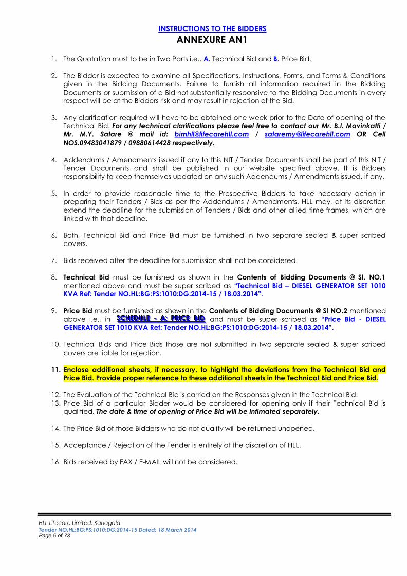
1. The Quotation must to be in Two Parts i.e., A. Technical Bid and B. Price Bid.
2. The Bidder is expected to examine all Specifications, Instructions, Forms, and Terms & Conditions
given in the Bidding Documents. Failure to furnish all information required in the Bidding
Documents or submission of a Bid not substantially responsive to the Bidding Documents in every
respect will be at the Bidders risk and may result in rejection of the Bid.
3. Any clarification required will have to be obtained one week prior to the Date of opening of the Technical Bid. For any technical clarifications please feel free to contact our Mr. B.I. Mavinkatti /
Mr. M.Y. Satare @ mail id: [email protected] / [email protected] OR Cell
NOS.09483041879 / 09880614428 respectively.
4. Addendums / Amendments issued if any to this NIT / Tender Documents shall be part of this NIT /
Tender Documents and shall be published in our website specified above. It is Bidders
responsibility to keep themselves updated on any such Addendums / Amendments issued, if any.
5. In order to provide reasonable time to the Prospective Bidders to take necessary action in
preparing their Tenders / Bids as per the Addendums / Amendments, HLL may, at its discretion
extend the deadline for the submission of Tenders / Bids and other allied time frames, which are
linked with that deadline.
6. Both, Technical Bid and Price Bid must be furnished in two separate sealed & super scribed
covers.
7. Bids received after the deadline for submission shall not be considered.
8. Technical Bid must be furnished as shown in the Contents of Bidding Documents @ Sl. NO.1
mentioned above and must be super scribed as “Technical Bid – DIESEL GENERATOR SET 1010
KVA Ref: Tender NO.HL:BG:PS:1010:DG:2014-15 / 18.03.2014”.
9. Price Bid must be furnished as shown in the Contents of Bidding Documents @ Sl NO.2 mentioned
above i.e., in SSSCCCHHHEEEDDD UUU LLLEEE --- AAA::: PPPRRR IIICCCEEE BBB IIIDDD and must be super scribed as “Price Bid - DIESEL
GENERATOR SET 1010 KVA Ref: Tender NO.HL:BG:PS:1010:DG:2014-15 / 18.03.2014”.
10. Technical Bids and Price Bids those are not submitted in two separate sealed & super scribed
covers are liable for rejection.
11. Enclose additional sheets, if necessary, to highlight the deviations from the Technical Bid and
Price Bid. Provide proper reference to these additional sheets in the Technical Bid and Price Bid.
12. The Evaluation of the Technical Bid is carried on the Responses given in the Technical Bid.
13. Price Bid of a particular Bidder would be considered for opening only if their Technical Bid is
qualified. The date & time of opening of Price Bid will be intimated separately.
14. The Price Bid of those Bidders who do not qualify will be returned unopened.
15. Acceptance / Rejection of the Tender is entirely at the discretion of HLL.
16. Bids received by FAX / E-MAIL will not be considered.
HLL Lifecare Limited, Kanagala
Tender NO.HL:BG:PS:1010:DG:2014-15 Dated: 18 March 2014 Page 6 of 73
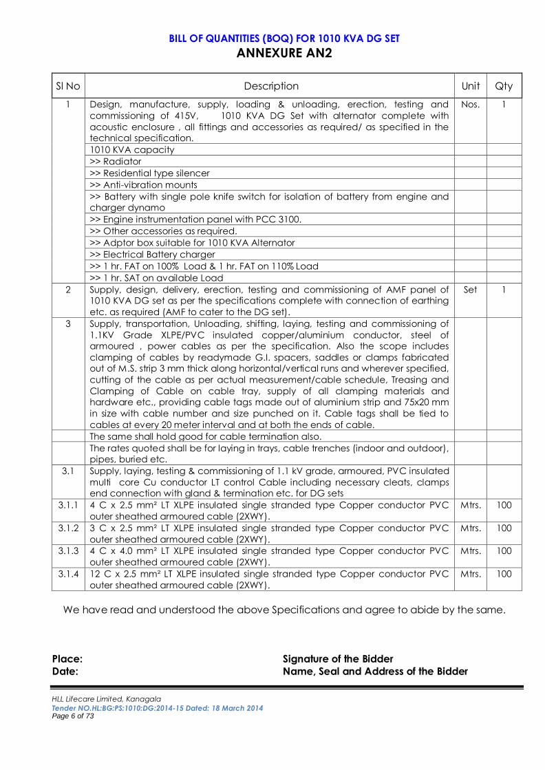
BILL OF QUANTITIES (BOQ) FOR 1010 KVA DG SET
ANNEXURE AN2
Sl No Description Unit Qty
1 Design, manufacture, supply, loading & unloading, erection, testing and
commissioning of 415V, 1010 KVA DG Set with alternator complete with
acoustic enclosure , all fittings and accessories as required/ as specified in the
technical specification.
Nos. 1
1010 KVA capacity
>> Radiator
>> Residential type silencer
>> Anti-vibration mounts
>> Battery with single pole knife switch for isolation of battery from engine and
charger dynamo
>> Engine instrumentation panel with PCC 3100.
>> Other accessories as required.
>> Adptor box suitable for 1010 KVA Alternator
>> Electrical Battery charger
>> 1 hr. FAT on 100% Load & 1 hr. FAT on 110% Load
>> 1 hr. SAT on available Load
2 Supply, design, delivery, erection, testing and commissioning of AMF panel of
1010 KVA DG set as per the specifications complete with connection of earthing
etc. as required (AMF to cater to the DG set).
Set 1
3 Supply, transportation, Unloading, shifting, laying, testing and commissioning of
1.1KV Grade XLPE/PVC insulated copper/aluminium conductor, steel of
armoured , power cables as per the specification. Also the scope includes
clamping of cables by readymade G.I. spacers, saddles or clamps fabricated
out of M.S. strip 3 mm thick along horizontal/vertical runs and wherever specified,
cutting of the cable as per actual measurement/cable schedule, Treasing and
Clamping of Cable on cable tray, supply of all clamping materials and
hardware etc., providing cable tags made out of aluminium strip and 75x20 mm
in size with cable number and size punched on it. Cable tags shall be tied to
cables at every 20 meter interval and at both the ends of cable.
The same shall hold good for cable termination also.
The rates quoted shall be for laying in trays, cable trenches (indoor and outdoor),
pipes, buried etc.
3.1 Supply, laying, testing & commissioning of 1.1 kV grade, armoured, PVC insulated
multi core Cu conductor LT control Cable including necessary cleats, clamps
end connection with gland & termination etc. for DG sets
3.1.1 4 C x 2.5 mm² LT XLPE insulated single stranded type Copper conductor PVC
outer sheathed armoured cable (2XWY).
Mtrs. 100
3.1.2 3 C x 2.5 mm² LT XLPE insulated single stranded type Copper conductor PVC
outer sheathed armoured cable (2XWY).
Mtrs. 100
3.1.3 4 C x 4.0 mm² LT XLPE insulated single stranded type Copper conductor PVC
outer sheathed armoured cable (2XWY).
Mtrs. 100
3.1.4 12 C x 2.5 mm² LT XLPE insulated single stranded type Copper conductor PVC
outer sheathed armoured cable (2XWY).
Mtrs. 100
We have read and understood the above Specifications and agree to abide by the same.
Place: Signature of the Bidder
Date: Name, Seal and Address of the Bidder
HLL Lifecare Limited, Kanagala
Tender NO.HL:BG:PS:1010:DG:2014-15 Dated: 18 March 2014 Page 7 of 73
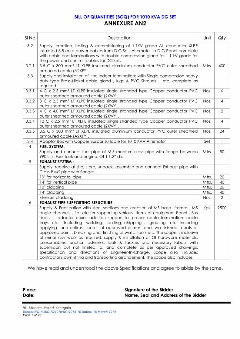
BILL OF QUANTITIES (BOQ) FOR 1010 KVA DG SET
ANNEXURE AN2
Sl No Description Unit Qty
3.2 Supply, erection, testing & commissioning of 1.1KV grade Al. conductor XLPE
insulated 3.5 core power cables from D.G.Sets Alternator to D.G.Panel complete
with cable end terminations with double compression gland for 1.1 kV grade for
the power and control cables for DG sets
3.2.1 3.5 C x 300 mm² LT XLPE insulated aluminium conductor PVC outer sheathed
armoured cable (A2XFY).
Mtrs. 400
3.3 Supply and installation of the indoor terminations with Single compression heavy
duty type Brass-Nickel cable gland , lugs & PVC Shrouds. , etc. complete as
required.
3.3.1 4 C x 2.5 mm² LT XLPE insulated single stranded type Copper conductor PVC
outer sheathed armoured cable (2XWY).
Nos. 6
3.3.2 3 C x 2.5 mm² LT XLPE insulated single stranded type Copper conductor PVC
outer sheathed armoured cable (2XWY).
Nos. 4
3.3.3 4 C x 4.0 mm² LT XLPE insulated single stranded type Copper conductor PVC
outer sheathed armoured cable (2XWY).
Nos. 2
3.3.4 12 C x 2.5 mm² LT XLPE insulated single stranded type Copper conductor PVC
outer sheathed armoured cable (2XWY).
Nos. 4
3.3.5 3.5 C x 300 mm² LT XLPE insulated aluminium conductor PVC outer sheathed
armoured cable (A2XFY).
Nos. 24
3.4 Adaptor Box with Copper Busbar suitable for 1010 KVA Alternator Set 1
4 FUEL SYSTEM :
Supply and connect fuel pipe of M.S medium class pipe with flange between
990 Ltrs. Fuel tank and engine. Of 1 1.2” dia.
Mtrs. 50
5 EXHAUST SYSTEM :
Supply, receive at site, store, unpack, assemble and connect Exhaust pipe with
Class-B MS pipe with flanges,
10" for horizontal pipe Mtrs. 20
14" for vertical pipe Mtrs. 40
10" cladding Mtrs. 20
14" cladding Mtrs. 40
Silencer cladding Nos. 2
6 EXHAUST PIPE SUPPORTING STRUCTURE :
Supply & Fabrication with steel sections and erection of MS base frames , MS
angle channels , flat etc for supporting various items of equipment Panel , Bus
ducts , adaptor boxes addition support for proper cable termination, cable
trays, etc. Including welding, bolting, chipping , grouting etc, including
applying one antirust coat of approved primer and two finished coats of
approved paint , breaking and finishing of walls, floors etc. The scope is inclusive
of minor civil work as required, supply & installation of GI hardware materials,
consumables, anchor fasteners, tools & tackles and necessary labour with
supervision but not limited to, and complete as per approved drawings,
specification and directions of Engineer-In-Charge. Scope also includes
contractor's own lifting and transporting arrangement. The scope also includes
Kgs. 9500
We have read and understood the above Specifications and agree to abide by the same.
Place: Signature of the Bidder
Date: Name, Seal and Address of the Bidder
HLL Lifecare Limited, Kanagala
Tender NO.HL:BG:PS:1010:DG:2014-15 Dated: 18 March 2014 Page 8 of 73
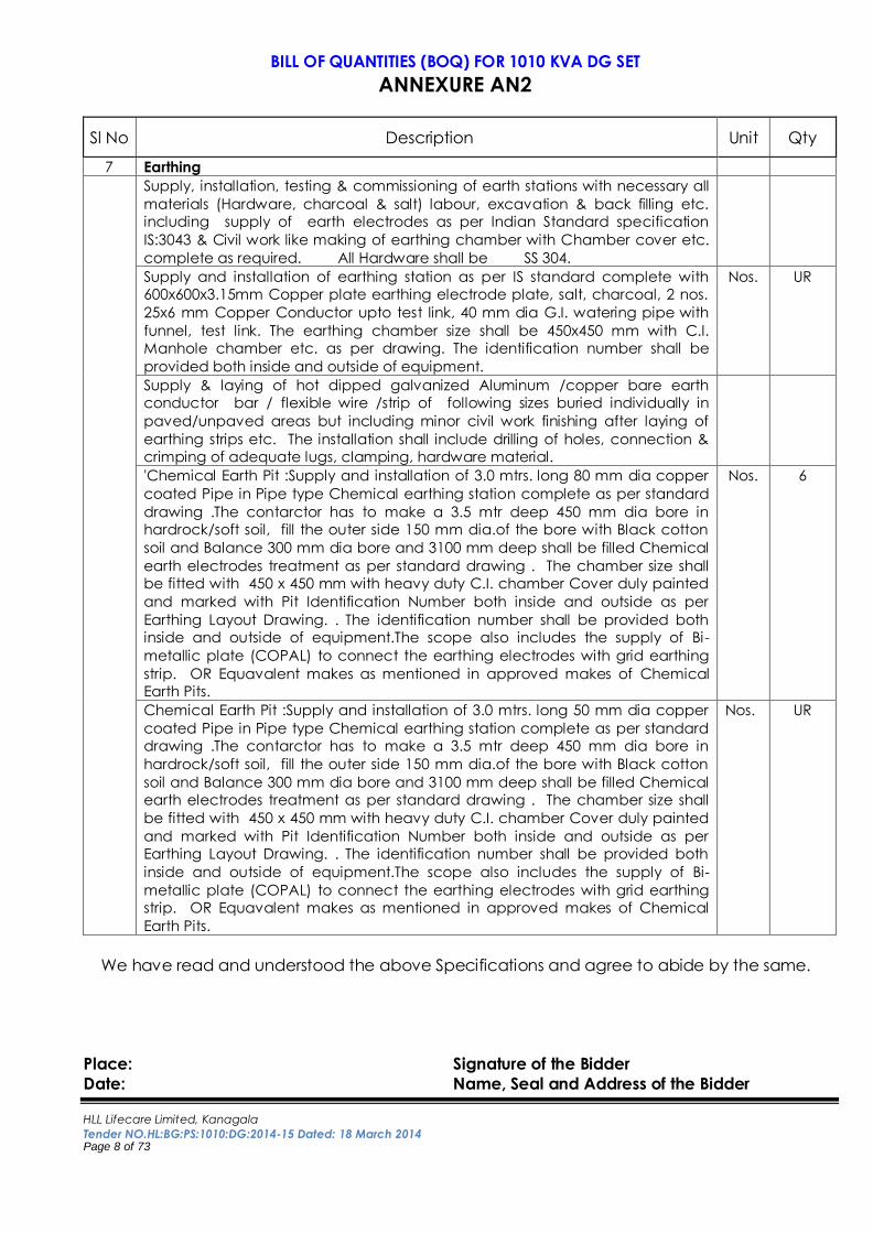
BILL OF QUANTITIES (BOQ) FOR 1010 KVA DG SET
ANNEXURE AN2
Sl No Description Unit Qty
7 Earthing
Supply, installation, testing & commissioning of earth stations with necessary all
materials (Hardware, charcoal & salt) labour, excavation & back filling etc.
including supply of earth electrodes as per Indian Standard specification
IS:3043 & Civil work like making of earthing chamber with Chamber cover etc.
complete as required. All Hardware shall be SS 304.
Supply and installation of earthing station as per IS standard complete with
600x600x3.15mm Copper plate earthing electrode plate, salt, charcoal, 2 nos.
25x6 mm Copper Conductor upto test link, 40 mm dia G.I. watering pipe with
funnel, test link. The earthing chamber size shall be 450x450 mm with C.I.
Manhole chamber etc. as per drawing. The identification number shall be
provided both inside and outside of equipment.
Nos. UR
Supply & laying of hot dipped galvanized Aluminum /copper bare earth
conductor bar / flexible wire /strip of following sizes buried individually in
paved/unpaved areas but including minor civil work finishing after laying of
earthing strips etc. The installation shall include drilling of holes, connection &
crimping of adequate lugs, clamping, hardware material.
'Chemical Earth Pit :Supply and installation of 3.0 mtrs. long 80 mm dia copper
coated Pipe in Pipe type Chemical earthing station complete as per standard
drawing .The contarctor has to make a 3.5 mtr deep 450 mm dia bore in
hardrock/soft soil, fill the outer side 150 mm dia.of the bore with Black cotton
soil and Balance 300 mm dia bore and 3100 mm deep shall be filled Chemical
earth electrodes treatment as per standard drawing . The chamber size shall
be fitted with 450 x 450 mm with heavy duty C.I. chamber Cover duly painted
and marked with Pit Identification Number both inside and outside as per
Earthing Layout Drawing. . The identification number shall be provided both
inside and outside of equipment.The scope also includes the supply of Bi-
metallic plate (COPAL) to connect the earthing electrodes with grid earthing
strip. OR Equavalent makes as mentioned in approved makes of Chemical
Earth Pits.
Nos. 6
Chemical Earth Pit :Supply and installation of 3.0 mtrs. long 50 mm dia copper
coated Pipe in Pipe type Chemical earthing station complete as per standard
drawing .The contarctor has to make a 3.5 mtr deep 450 mm dia bore in
hardrock/soft soil, fill the outer side 150 mm dia.of the bore with Black cotton
soil and Balance 300 mm dia bore and 3100 mm deep shall be filled Chemical
earth electrodes treatment as per standard drawing . The chamber size shall
be fitted with 450 x 450 mm with heavy duty C.I. chamber Cover duly painted
and marked with Pit Identification Number both inside and outside as per
Earthing Layout Drawing. . The identification number shall be provided both
inside and outside of equipment.The scope also includes the supply of Bi-
metallic plate (COPAL) to connect the earthing electrodes with grid earthing
strip. OR Equavalent makes as mentioned in approved makes of Chemical
Earth Pits.
Nos. UR
We have read and understood the above Specifications and agree to abide by the same.
Place: Signature of the Bidder
Date: Name, Seal and Address of the Bidder
HLL Lifecare Limited, Kanagala
Tender NO.HL:BG:PS:1010:DG:2014-15 Dated: 18 March 2014 Page 9 of 73
BILL OF QUANTITIES (BOQ) FOR 1010 KVA DG SET
ANNEXURE AN2
Sl No Description Unit Qty
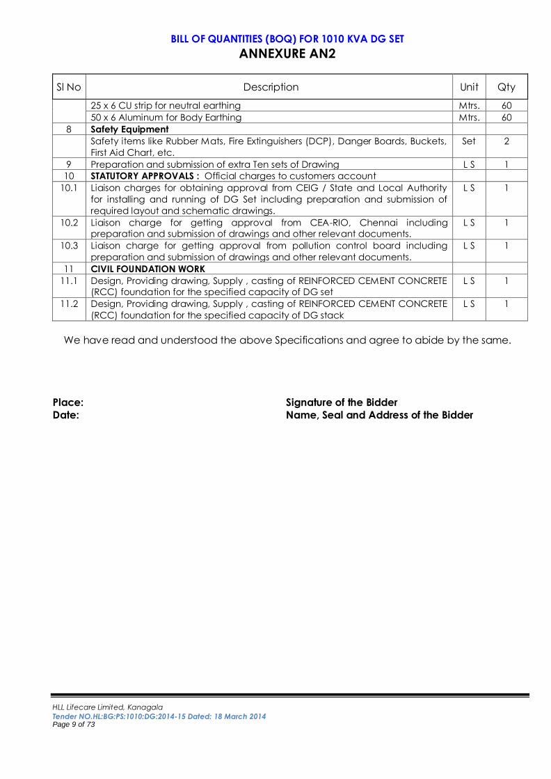
25 x 6 CU strip for neutral earthing Mtrs. 60
50 x 6 Aluminum for Body Earthing Mtrs. 60
8 Safety Equipment
Safety items like Rubber Mats, Fire Extinguishers (DCP), Danger Boards, Buckets,
First Aid Chart, etc.
Set 2
9 Preparation and submission of extra Ten sets of Drawing L S 1
10 STATUTORY APPROVALS : Official charges to customers account
10.1 Liaison charges for obtaining approval from CEIG / State and Local Authority
for installing and running of DG Set including preparation and submission of
required layout and schematic drawings.
L S 1
10.2 Liaison charge for getting approval from CEA-RIO, Chennai including
preparation and submission of drawings and other relevant documents.
L S 1
10.3 Liaison charge for getting approval from pollution control board including
preparation and submission of drawings and other relevant documents.
L S 1
11 CIVIL FOUNDATION WORK
11.1 Design, Providing drawing, Supply , casting of REINFORCED CEMENT CONCRETE
(RCC) foundation for the specified capacity of DG set
L S 1
11.2 Design, Providing drawing, Supply , casting of REINFORCED CEMENT CONCRETE
(RCC) foundation for the specified capacity of DG stack
L S 1
We have read and understood the above Specifications and agree to abide by the same.
Place: Signature of the Bidder
Date: Name, Seal and Address of the Bidder
HLL Lifecare Limited, Kanagala
Tender NO.HL:BG:PS:1010:DG:2014-15 Dated: 18 March 2014 Page 10 of 73
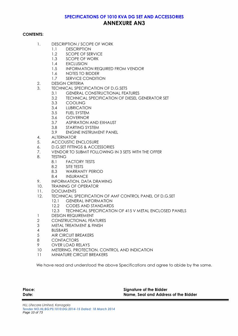
SPECIFICATIONS OF 1010 KVA DG SET AND ACCESSORIES
ANNEXURE AN3 CONTENTS:
1. DESCRIPTION / SCOPE OF WORK
1.1 DESCRIPTION
1.2 SCOPE OF SERVICE
1.3 SCOPE OF WORK
1.4 EXCLUSION
1.5 INFORMATION REQUIRED FROM VENDOR
1.6 NOTES TO BIDDER
1.7 SERVICE CONDITION
2. DESIGN CRITERIA
3. TECHNICAL SPECIFICATION OF D.G.SETS
3.1 GENERAL CONSTRUCTIONAL FEATURES
3.2 TECHNICAL SPECIFICATION OF DIESEL GENERATOR SET
3.3 COOLING
3.4 LUBRICATION
3.5 FUEL SYSTEM
3.6 GOVERNOR
3.7 ASPIRATION AND EXHAUST
3.8 STARTING SYSTEM
3.9 ENGINE INSTRUMENT PANEL
4. ALTERNATOR
5. ACCOUSTIC ENCLOSURE
6. D.G.SET FITTINGS & ACCESSORIES
7. VENDOR TO SUBMIT FOLLOWING IN 3 SETS WITH THE OFFER
8. TESTING
8.1 FACTORY TESTS
8.2 SITE TESTS
8.3 WARRANTY PERIOD
8.4 INSURANCE
9. INFORMATION, DATA DRAWING
10. TRAINING OF OPERATOR
11. DOCUMENTS
12. TECHNICAL SPECIFICATION OF AMF CONTROL PANEL OF D.G.SET
12.1 GENERAL INFORMATION
12.2 CODES AND STANDARDS
12.3 TECHNICAL SPECIFICATION OF 415 V METAL ENCLOSED PANELS
1 DESIGN REQUIREMENT
2 CONSTRUCTIONAL FEATURES
3 METAL TREATMENT & FINISH
4 BUSBARS
5 AIR CIRCUIT BREAKERS
8 CONTACTORS
9 OVER LOAD RELAYS
10 METERING, PROTECTION, CONTROL AND INDICATION
11 MINIATURE CIRCUIT BREAKERS
We have read and understood the above Specifications and agree to abide by the same.
Place: Signature of the Bidder
Date: Name, Seal and Address of the Bidder
HLL Lifecare Limited, Kanagala
Tender NO.HL:BG:PS:1010:DG:2014-15 Dated: 18 March 2014 Page 11 of 73
SPECIFICATIONS OF 1010 KVA DG SET AND ACCESSORIES
ANNEXURE AN3
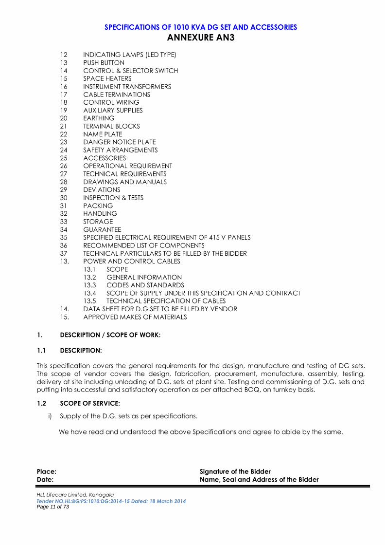
12 INDICATING LAMPS (LED TYPE)
13 PUSH BUTTON
14 CONTROL & SELECTOR SWITCH
15 SPACE HEATERS
16 INSTRUMENT TRANSFORMERS
17 CABLE TERMINATIONS
18 CONTROL WIRING
19 AUXILIARY SUPPLIES
20 EARTHING
21 TERMINAL BLOCKS
22 NAME PLATE
23 DANGER NOTICE PLATE
24 SAFETY ARRANGEMENTS
25 ACCESSORIES
26 OPERATIONAL REQUIREMENT
27 TECHNICAL REQUIREMENTS
28 DRAWINGS AND MANUALS
29 DEVIATIONS
30 INSPECTION & TESTS
31 PACKING
32 HANDLING
33 STORAGE
34 GUARANTEE
35 SPECIFIED ELECTRICAL REQUIREMENT OF 415 V PANELS
36 RECOMMENDED LIST OF COMPONENTS
37 TECHNICAL PARTICULARS TO BE FILLED BY THE BIDDER
13. POWER AND CONTROL CABLES
13.1 SCOPE
13.2 GENERAL INFORMATION
13.3 CODES AND STANDARDS
13.4 SCOPE OF SUPPLY UNDER THIS SPECIFICATION AND CONTRACT
13.5 TECHNICAL SPECIFICATION OF CABLES
14. DATA SHEET FOR D.G.SET TO BE FILLED BY VENDOR
15. APPROVED MAKES OF MATERIALS
1. DESCRIPTION / SCOPE OF WORK:
1.1 DESCRIPTION:
This specification covers the general requirements for the design, manufacture and testing of DG sets.
The scope of vendor covers the design, fabrication, procurement, manufacture, assembly, testing,
delivery at site including unloading of D.G. sets at plant site. Testing and commissioning of D.G. sets and
putting into successful and satisfactory operation as per attached BOQ, on turnkey basis. 1.2 SCOPE OF SERVICE:
i) Supply of the D.G. sets as per specifications.
We have read and understood the above Specifications and agree to abide by the same.
Place: Signature of the Bidder
Date: Name, Seal and Address of the Bidder
HLL Lifecare Limited, Kanagala
Tender NO.HL:BG:PS:1010:DG:2014-15 Dated: 18 March 2014 Page 12 of 73
SPECIFICATIONS OF 1010 KVA DG SET AND ACCESSORIES
ANNEXURE AN3
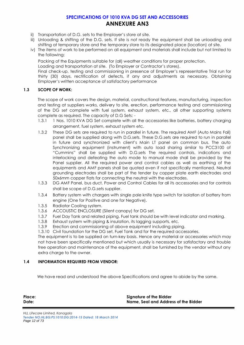
ii) Transportation of D.G. sets to the Employer’s store at site.
iii) Unloading & shifting of the D.G. sets. If site is not ready the equipment shall be unloading and
shifting at temporary store and the temporary store to its designated place (location) at site.
iv) The items of work to be performed on all equipment and materials shall include but not limited to
the following:
Packing of the Equipments suitable for (all) weather conditions for proper protection.
Loading and transportation at site. (To Employer or Contractor’s stores).
Final check-up, testing and commissioning in presence of Employer’s representative Trial run for
thirty (30) days, rectification of defects, if any and adjustments as necessary. Obtaining
Employer’s written acceptance of satisfactory performance 1.3 SCOPE OF WORK:
The scope of work covers the design, material, constructional features, manufacturing, inspection
and testing at suppliers works, delivery to site, erection, performance testing and commissioning
of the DG set complete with fuel system, exhaust system, etc., all other supporting systems
complete as required. The capacity of D.G Sets: -
1.3.1 1 Nos. 1010 KVA DG Set complete with all the accessories like batteries, battery charging
arrangement, fuel system, exhaust system etc.
1.3.2 These DG sets are required to run in parallel in future. The required AMF (Auto Mains Fail)
panel shall be supplied along with D.G.sets. These D.G.sets are required to run in parallel
in future and synchronized with client’s Main LT panel on common bus. The auto
Synchronizing equipment (instrument) with auto load sharing similar to PCC3100 of
“Cummins” shall be supplied with D.G.sets The required controls, indications and
interlocking and defeating the auto mode to manual mode shall be provided by the
Panel supplier. All the required power and control cables as well as earthing of the
equipments and AMF panels shall be quoted even if not specifically mentioned. Neutral
grounding electrodes shall be part of the tender by copper plate earth electrodes and
50x6mm copper flats for connecting the neutral with the electrodes.
1.3.3 DG AMF Panel, bus duct, Power and Control Cables for all its accessories and for controls
shall be scope of D.G.sets supplier.
1.3.4 Battery system with chargers with single pole knife type switch for isolation of battery from
engine (One for Positive and one for Negative).
1.3.5 Radiator Cooling system.
1.3.6 ACCOUSTIC ENCLOSURE (Silent canopy) for DG set. 1.3.7 Fuel Day Tank and related piping. Fuel tank should be with level indicator and marking.
1.3.8 Exhaust system with piping & insulation, its lagging supports, etc.
1.3.9 Erection and commissioning of above equipment including piping.
1.3.10 Civil foundation for the DG set, Fuel Tank and for the required accessories.
The equipment is to be supplied on turn-key basis. Hence any material or accessories which may
not have been specifically mentioned but which usually is necessary for satisfactory and trouble
free operation and maintenance of the equipment, shall be furnished by the vendor without any
extra charge to the owner. 1.4 INFORMATION REQUIRED FROM VENDOR:
We have read and understood the above Specifications and agree to abide by the same.
Place: Signature of the Bidder
Date: Name, Seal and Address of the Bidder
HLL Lifecare Limited, Kanagala
Tender NO.HL:BG:PS:1010:DG:2014-15 Dated: 18 March 2014 Page 13 of 73
SPECIFICATIONS OF 1010 KVA DG SET AND ACCESSORIES
ANNEXURE AN3
1.5.1 Following information shall be furnished by the contractor:
a) Along with the offer
i) Technical particulars of various equipments as format (Annexure) enclosed with this
specification. This shall include the engine model no., its output at the ambient temp. and
elevation, Alternator details, switchgear and control panel etc.
ii) G.A. drawing of DG Set.
iii) GA Drawing of Synchronizing Panel
b) After award of work (For approval)
i) Foundation drawings of all equipment, GA drawings of engine, alternator (clearly
showing terminal arrangement in plan & in elevation) and all other equipment (within
one week of the award of contract).
ii) Terminal Box drawing of the Alternator
iii) Cable list/schedule & interconnection diagram, interconnection diagram between Main
LT Panel and D.G.sets, P&I diagram & piping layout drawings (within two weeks after
award of contract)
iv) Test certificates of equipment.
v) Four copies of final drawings with one auto cad CD, operation, installation and
maintenance manual shall be supplied well in advance before inspection.
vi) D.G.set supplier has to check the scheme and control circuit of Main LT panel along with
logic prepare by Panel Manufacturer. (Due to Synchronization of the D.G.sets with Main
LT Panel)
1.6 NOTES TO BIDDER:
It is necessary to follow the following points while submitting the offer:
a) All equipment shall meet the requirement of this specification. Deviations (if any) with respect
to these specifications shall clearly be indicated in the offer in Annexure under “Deviations”
with page no. & clause no. of specification.
b) Quantities of equipment indicated herein are subject to change.
All technical particulars and other details as asked for shall be furnished in the specification only.
Additional information, if desired by the bidder, can also be furnished separately.
1.7 SERVICE CONDITION:
a) D.G.sets shall, in all respects, be suitable for operation outdoor under site environmental
and service conditions stated in Design criteria.
b) For the purpose of equipment de-rating and component operability, the above
specification states that the equipment design temperature shall be 50 DegC.
c) D.G.sets shall in all respects be suitable for operation in typical tropical area.
d) The atmosphere is to be considered sulphurous and dusty. The possibility of condensation,
as experienced during large temperature variations in a humid environment in the tropic.
We have read and understood the above Specifications and agree to abide by the same.
Place: Signature of the Bidder
Date: Name, Seal and Address of the Bidder
HLL Lifecare Limited, Kanagala
Tender NO.HL:BG:PS:1010:DG:2014-15 Dated: 18 March 2014 Page 14 of 73
SPECIFICATIONS OF 1010 KVA DG SET AND ACCESSORIES
ANNEXURE AN3
2. DESIGN CRITERIA:
The D.G.sets and components specified here in or not, shall be designed, manufactured and
tested with the latest revisions of relevant Indian or equivalent British or International Standards.
The design, material, construction, manufacture inspection, testing and commissioning of diesel
generator sets shall comply with all currently applicable states, regulations and safety codes in
the locality where the equipment will be installed and in particular shall comply with NEMA-MGI-
22 and IEC-39-1. The equipment shall also confirm to the latest applicable standards and code of
practice. Nothing in this specification shall be construed to relieve the supplier of this
responsibility.
Diesel Engine : ISO 3046 / DIN 6271 / BS-5514 / BS-649
Alternator : BS 2613 / IS 4722
Control Panel : IS 4230 for manufacturing standards
All other relevant standards
Wherever Indian Standards are not available, the D.G.sets shall conform to relevant International
Standard.
1) All electrical components shall also conform to the latest Electricity rules as regards safety
and other essential provisions.
2) All electrical installation work shall comply with the requirements of the following
Act/Rules/Codes as amended upto date:
a. Indian Electricity Act. b. Indian electricity Rules.
c. National Electric Code published by BIS.
d. All relevant IS codes of practice.
e. Regulations published by Tariff Advisory Committee.
f. Indian Standards for Electrical Equipment for use in Hazardous Atmospheres.
3) Ambient air temperature shall be taken as 50°C for the purpose of designing electrical
equipments.
4) Nominal system supply available shall be as follows:
a) Incoming : Provided by the client.
b) Utilization : 415V, 3 Ph., 4 wire, 50 Hz.
5) DG Sets are intended to provide base load of 415V, 3 Ph. 4 wire, 50 Hz to various loads of
plant.
a) All controls shall be of 24V DC. b) DG Sets shall be suitable for continuous operation.
c) DG Sets shall be started/ stopped from Engine / DG Panel/ Remote.
d) The height of exhaust pipes shall be in line with requirements of pollution
control rules.
e) Main features of DG sets shall be as follows:
We have read and understood the above Specifications and agree to abide by the same.
Place: Signature of the Bidder
Date: Name, Seal and Address of the Bidder
HLL Lifecare Limited, Kanagala
Tender NO.HL:BG:PS:1010:DG:2014-15 Dated: 18 March 2014 Page 15 of 73
SPECIFICATIONS OF 1010 KVA DG SET AND ACCESSORIES
ANNEXURE AN3
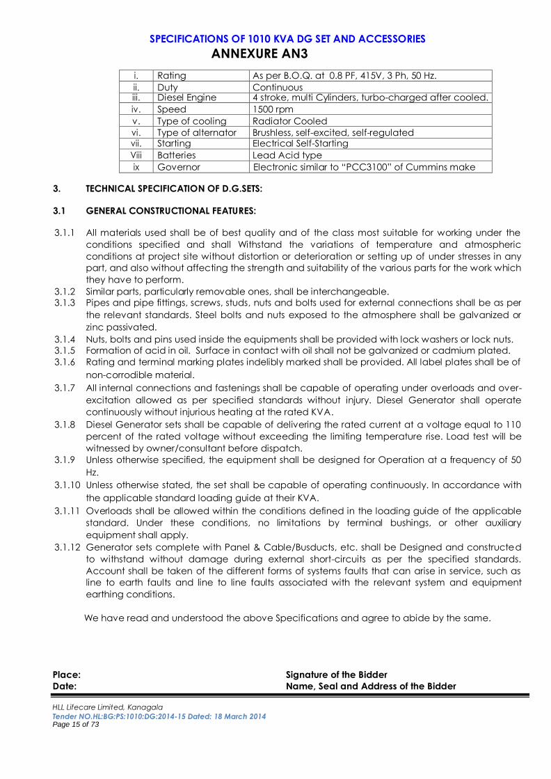
i. Rating As per B.O.Q. at 0.8 PF, 415V, 3 Ph, 50 Hz.
ii. Duty Continuous iii. Diesel Engine 4 stroke, multi Cylinders, turbo-charged after cooled.
iv. Speed 1500 rpm
v. Type of cooling Radiator Cooled
vi. Type of alternator Brushless, self-excited, self-regulated vii. Starting Electrical Self-Starting
Viii Batteries Lead Acid type
ix Governor Electronic similar to “PCC3100” of Cummins make
3. TECHNICAL SPECIFICATION OF D.G.SETS:
3.1 GENERAL CONSTRUCTIONAL FEATURES:
3.1.1 All materials used shall be of best quality and of the class most suitable for working under the
conditions specified and shall Withstand the variations of temperature and atmospheric
conditions at project site without distortion or deterioration or setting up of under stresses in any
part, and also without affecting the strength and suitability of the various parts for the work which
they have to perform.
3.1.2 Similar parts, particularly removable ones, shall be interchangeable.
3.1.3 Pipes and pipe fittings, screws, studs, nuts and bolts used for external connections shall be as per
the relevant standards. Steel bolts and nuts exposed to the atmosphere shall be galvanized or
zinc passivated.
3.1.4 Nuts, bolts and pins used inside the equipments shall be provided with lock washers or lock nuts.
3.1.5 Formation of acid in oil. Surface in contact with oil shall not be galvanized or cadmium plated.
3.1.6 Rating and terminal marking plates indelibly marked shall be provided. All label plates shall be of
non-corrodible material.
3.1.7 All internal connections and fastenings shall be capable of operating under overloads and over-
excitation allowed as per specified standards without injury. Diesel Generator shall operate
continuously without injurious heating at the rated KVA.
3.1.8 Diesel Generator sets shall be capable of delivering the rated current at a voltage equal to 110
percent of the rated voltage without exceeding the limiting temperature rise. Load test will be
witnessed by owner/consultant before dispatch. 3.1.9 Unless otherwise specified, the equipment shall be designed for Operation at a frequency of 50
Hz.
3.1.10 Unless otherwise stated, the set shall be capable of operating continuously. In accordance with
the applicable standard loading guide at their KVA.
3.1.11 Overloads shall be allowed within the conditions defined in the loading guide of the applicable
standard. Under these conditions, no limitations by terminal bushings, or other auxiliary
equipment shall apply.
3.1.12 Generator sets complete with Panel & Cable/Busducts, etc. shall be Designed and constructed
to withstand without damage during external short-circuits as per the specified standards.
Account shall be taken of the different forms of systems faults that can arise in service, such as
line to earth faults and line to line faults associated with the relevant system and equipment
earthing conditions.
We have read and understood the above Specifications and agree to abide by the same.
Place: Signature of the Bidder
Date: Name, Seal and Address of the Bidder
HLL Lifecare Limited, Kanagala
Tender NO.HL:BG:PS:1010:DG:2014-15 Dated: 18 March 2014 Page 16 of 73
SPECIFICATIONS OF 1010 KVA DG SET AND ACCESSORIES
ANNEXURE AN3 3.1.13 Every care shall be taken to ensure that the design and manufacture of the equipment shall be
such as to reduce noise and vibration to the Level acceptable to Safety norms. The supplier shall
ensure that the noise level shall not be more than specified in the standards.
3.1.14 The equipment shall be designed with particular attention to the Suppression of harmonic
voltage, especially the third and fifth, so as to eliminate wave form distortion and form any
possibility of high frequency disturbances reaching such a magnitude as to cause interference
with communication system.
3.1.15 All rated quantities subject to the supplier’s guarantees shall be within the tolerances given in
applicable standards.
3.1.16 All statutory approvals such as EB and pollution control board NOC and approval of Electrical
inspector for installation drawing and installation work and approval from local authority is in
supplier’s scope.
3.1.17 Earthing Grid for DG and panel earth pit in supplier’s scope.
3.1.18 All piping /hose between day tank and DG set in supplier’s scope.
3.1.19 AVM pads for engine & Alternative frame mounting, Cabling between DG and panel (control
cable) will be in supplier’s scope.
3.2 TECHNICAL SPECIFICATION OF DIESEL GENERATOR SET:
3.2.1 DIESEL ENGINE
General: Diesel Engine shall be of heavy duty robust construction, suitable for both intermittent
and continuous duty.
Direct injection “Diesel Engine of suitable BHP, turbo charged, water cooled (Heat Exchanger
type), 4 stroke multi cylinder vertical in line, suitable for old weather starting, heavy duty industrial
design continuous rating, low noise, suitable for generating set application, coupled to alternator
and complete with the accessories as specified mounted on a common base frame, suitable for
erection on AVMs.
The DG set shall be designed for ambient temperature of 50 C. the engine BHP and alternator
KVA shall be designed to deliver the rated output (1010 kVA) at 50 C. The bidder should submit
de-rating/sizing calculation for the offered engine and alternator.
All parts subjected to substantial temperature variations shall be designed & supported to permit
free expansion and contraction without resulting in leakage, excess of clearance, harmful
distortion or misalignment.
Vibration, noise, mechanical, thermal stresses & exhaust gas conditions shall be not exceed the
permissible or acceptable limits of the guiding standards / codes
The diesel engine shall be provided with the following:-
a) Electronic governor with all accessories suitable for parallel operation.
b) Lubricating oil distribution arrangements shall be of force- feed type with gear pump, oil
pan, oil filters and high pressure relief valve and lubricating oil cooler.
We have read and understood the above Specifications and agree to abide by the same.
Place: Signature of the Bidder
Date: Name, Seal and Address of the Bidder
HLL Lifecare Limited, Kanagala
Tender NO.HL:BG:PS:1010:DG:2014-15 Dated: 18 March 2014 Page 17 of 73
SPECIFICATIONS OF 1010 KVA DG SET AND ACCESSORIES
ANNEXURE AN3
c) Fuel injection system comprising of a common fuel pump for all cylinders with fuel pumps
for individual cylinder with filters, etc.
d) Starting system consisting of a 24 V DC electric motor operated by a lead acid battery.
e) The engine shall be suitable for Prime power application and should be capable to run
on 10% overload for 1 hour duration in every 12 hours of operation as per ISO regulations.
f) Cooling water pump with high water temperature safety trip and thermostat to keep the
temperature of the water in the engine at all loads around 85oC.
g) Air cleaner dry type/oil bath filter with suction pipe.
h) Exhaust pipe with flexible coupling (flanged type) with necessary flanges, class pipe glass
wool insulation with aluminum sheet cladding and industrial/residential silencer as
mentioned in data sheet.
i) Turbo charge/after cooler, whichever is applicable
j) Engine speed adjusting /stopping lever
k) Sensors for safety alarm and trips like over temperature of water, low lube oil pressure,
over speed etc.
l) Suitable ‘stop’ device to stop the engine in case of any of the controlled variables
exceed the upper or lower limit (temperature of cooling water and lubricant oil and
pressures of lubricant oil)
m) Instrument panel consisting of the following:
Starting push button and switch with key. “AUTO / MANUAL Selector Switch. “DG TRIP / DG ON / DG OFF / SUPPLY ON / SUPPLY OFF” Indications with LED
lamps. Lube oil pressure gauge.
Lube oil temperature gauge.
Water temperature gauge.
Mechanical tacho hour meter and RPM indicator. Safety control for engine shut off (TRIP) with visual indication for low lube oil
pressure.
Safety control for engine shut off (TRIP) with visual indication for high water
temperature.
Safety control (TRIP) with visual indication for low fuel level.
Safety control for engine shut off (TRIP) with visual indication for engine
overspeed. Electrically operated fuel solenoid- Emergency stop. D.C. Ammeter and voltmeter to indicate status of battery & battery charger.
n) HSD Service tank with all accessories such as level indicator, manhole, valve inlet and outlet, air
vent, drain plug, mounting pedestals, etc. Dimension of rectangular day tank shall be decided to
suit the layout.
3.2.2 BASE & MOUNTING
We have read and understood the above Specifications and agree to abide by the same.
Place: Signature of the Bidder
Date: Name, Seal and Address of the Bidder
HLL Lifecare Limited, Kanagala
Tender NO.HL:BG:PS:1010:DG:2014-15 Dated: 18 March 2014 Page 18 of 73
SPECIFICATIONS OF 1010 KVA DG SET AND ACCESSORIES
ANNEXURE AN3
a) Common Base Frame: The engine and alternator shall be coupled with flexible coupling aligned
and mounted on a sturdily fabricated, welded construction and properly machined base frame
made of high quality MS channels of cross section not less than the recommended size by the
engine manufacturer. The base frame shall be provided with lifting holes and foundation bolt
holes suitable for permanent installation on anti-vibration mountings. Two separate earthing studs
shall be provided for earthing the set.
b) Mounting: The set shall be mounted on anti-vibration mounts/pads. The bidder to indicate
complete details with offer regarding weight of the total set etc. and mounting details and
general arrangement details of the set.
3.3 COOLING
a. The engine cooling shall be done through a radiator cooled system. Engine driven pumps shall
be used to circulate the radiator cooled water through the cylinder jackets, charge air cooler,
lube oil cooler, valves, cylinder block & other water cooled moving parts.
b. Necessary cooling water pumps complete filter, piping, valve fittings expansion joints, controls
and instrumentation, pipe supports hangers etc. shall be provided along with D.G.Set and in
case any item has not been indicated in the BOQ the same shall be spelt out by the contractor
and included in the price quoted by the contractor.
c. Radiator Cooled water circuit shall be provided with corrosion resistors.
d. Thermostat, temperature gauge, with high temperature alarm trip shall be provided in the
control circuit.
3.4 LUBRICATION
a) The engine lubricating oil system shall comprise an engine driven pump complete with oil
coolers, duplex oil filters, bypass filters, strainers, lube oil sump pan etc. Also Priming pump shall be
provided with Auto On/OFF during Standstill condition.
b) Lubricating system shall also consist of pressure gauge, temperature and oil level indicators,
pressure switch for “oil pressure low” alarm for interlock and alarm along with necessary piping,
fittings, valves etc.
3.5 FUEL SYSTEM
a) Engine shall be suitable to run on High-Speed Diesel fuel.
b) The fuel oil system of the engine shall be direct injection type provided with fuel filter with
separator, fuel hoses, fuel piping, governor, injectors, shutdown valve with fuel strainer and filters.
c) Fuel day tank of suitable capacity for each DG set shall be provided with level gauge, valve and
complete piping up to engine.
3.6 GOVERNOR
Electronic governor shall be provided for automatic load controls.
We have read and understood the above Specifications and agree to abide by the same.
Place: Signature of the Bidder Date: Name, Seal and Address of the Bidder
HLL Lifecare Limited, Kanagala
Tender NO.HL:BG:PS:1010:DG:2014-15 Dated: 18 March 2014 Page 19 of 73
SPECIFICATIONS OF 1010 KVA DG SET AND ACCESSORIES
ANNEXURE AN3
3.7 ASPIRATION AND EXHAUST
a) Engine shall be turbo-charged with after cooled. Air intake shall be provided either with dry type
replaceable filters or oil bath type filters. Air cleaner assembly shall also have service indicator, air
intake manifold.
b) Exhaust manifold and exhaust pipe shall be suitably insulated with mineral work. Exhaust system
shall be insulated and shall be fitted with bellows type coupling and supported suitably with anti
vibration spring mountings.
c) Silencer shall be of the residential type.
d) The height and size of the exhaust hooks shall be fixed considering the emission of gases and the
environmental law of Government of India and the local authorities.
e) The noise level and gas emission temperature and volume shall be as per relevant standards.
3.8 STARTING SYSTEM
Engines shall be started with 24 volts starter motor complete with 1 set of 24V DC SMF battery (Exide
or equivalent make) of adequate AH rating, new dry uncharged batteries in PVC containers, with
PVC insulated cables copper conductor leads from battery to motor etc, mounted on fabricated
M.S. angle frame fitted with castor wheels filling up the battery with acid to be done before starting,
free of any charges. Also Engine shall be provided with battery charging alternator.
3.9 ENGINE INSTRUMENT PANEL:
As per the specification given in 3.2.1 (m).
4. ALTERNATOR
a. The Alternator shall be of Rated 1010 KVA output at 0.8 power factor and suitable for 3 phase, 4
wire, 415 volts, 50 HZ system continuously rated confirming to IS 4722. b. The Alternator shall be of brushless type self excited; self regulated, provided with auto voltage
regulator and fitted with static excitation unit. Band of voltage regulation shall be +or –1% or
better of rated voltage from no load to full load. The frequency shall not differ by more than + 4%
of rated value.
c. The Alternator shall be self cooled fully tropicalised, screen protected, drip proof construction
with insulation class ‘H’. The terminal box shall be of detachable type and suitable for top Bus
Duct outgoings either on entry i.e. on left or right side looking from rear.
d. The Bus Duct shall be liberally sized to take the bending of Aluminum Armoured Cable. Auto
voltage Regulator – AVR shall be suitable for independent running and parallel operation with
identical D.G. Set.
e. Stator core: Stator core shall be built up of silicon steel laminations compressed hydraulically and
rigidly supported by either case iron or steel end rings. The core shall be designed for a minimum
reactance, low voltage wave form distortion and maximum efficiency stator coils shall be wound
with synthetic enamel coated copper wires and main slot insulation shall be of tropicalised mica
or leather old. End windings shall be taped with fiber glass tape and the complete windings are
impregnated with spray finished with moisture protection varnish. Otherwise, 100% epoxy
impregnation with an overcoat of resilient insulating material shall be carried out.
We have read and understood the above Specifications and agree to abide by the same.
Place: Signature of the Bidder Date: Name, Seal and Address of the Bidder
HLL Lifecare Limited, Kanagala
Tender NO.HL:BG:PS:1010:DG:2014-15 Dated: 18 March 2014 Page 20 of 73
SPECIFICATIONS OF 1010 KVA DG SET AND ACCESSORIES
ANNEXURE AN3
f. End Frames: End frames shall be of well ribbed cast iron /fabricated sheet steel design. The end
frames shall be spigotted to the stator frame and secured by easily available set screws dowels.
Ventilation openings shall be cast into the vertical and bottom side faces which shall be screen
protected and drip proof. g. Bearings: The bearings shall be of heavy duty pre lubricated cartridge design, ball or roller
bearings. Single bearing alternators shall have self-aligning ball or roller bearings. The end frames
of the rotor shall be removable (from stator) without disturbing the bearings.
h. The Rotor: Rotor shaft shall be turned either from a high tensile MS bar or from a MS forging. Field
coils shall be wound with synthetic enamel covered or varnish bonded and glass covered
copper strips of high conductivity. Poles shall be of bolt-up type made of sheet steel of high
permeability. The insulation between the pole and coil shall comprise of vanished fiber glass
cloth backed mica around the body and thick insulating washers on the top and bottom of the
coil. Coils shall be impregnated with resin and the complete rotor is spray finished with a moisture
protection vanish suitable for tropical Conditions. However, 100% epoxy impregnation and an
overcoat of resilient insulating material shall be preferable.
i. Damper windings: Damper windings shall be provided to assist parallel operation of alternators.
The damper bars of copper brazed to heavy copper and connectors shall be located in a semi-
closed circular slots situated in the pole faces.
j. Ventilation: Axial ventilation shall be employed. A direct driven centrifugal fan shall be fitted on
the shaft and direct adequate airflow for efficient cooling of the alternator.
k. Terminals: Terminals shall be housed in a suitable cast iron box fixed on to the stator frame. The
terminals shall have ample clearance between phases and between phases to earth and shall
be readily accessible. The terminals shall be suitable for receiving 2000A TPN Al. Bus Duct as
indicated in the schematic.
l. Temperature rise: The alternator shall be suitable for ambient temperature of 50 degree
centigrade and shall be capable of withstanding 10% over load for one hour continuously.
m. Brushless Exciter – Voltage Regulators: The exciter shall be overhung, rotating type without any
bearings. Exciter of semiconductor type to be provided. Solid-state voltage regulator with all
accessories and relays shall be provided for proper voltage regulation.
n. Balancing: The alternator rotating parts shall be dynamically balanced to 10 micron level to
ensure smooth vibration free running.
o. Alternator winding shall have 2/3 Pole pitch winding to take care of heating due to “Harmonics”
in the system.
4.1 The Alternator shall withstand 10% overload for 1 hour at every twelve hours.
4.2 Transient Voltage Dip shall not be more than 14% on application of full load at rated
power factor.
4.3 The Alternator shall be capable to withstand minimum 25% unbalance load of its rated
load without exceeding the current in any of the phases beyond full load current.
4.4 Alternator winding shall be suitable to take minimum 70% Thyristor load of rated capacity.
4.5 The alternator shall be provided with six numbers of RTDs in stator winding and four nos. in
both ends bearing
4.6 Anti Condensation heater of 240V, 1Ph, 50Hz shall be provided with thermostat control
switch.
We have read and understood the above Specifications and agree to abide by the same.
Place: Signature of the Bidder
Date: Name, Seal and Address of the Bidder
HLL Lifecare Limited, Kanagala
Tender NO.HL:BG:PS:1010:DG:2014-15 Dated: 18 March 2014 Page 21 of 73
SPECIFICATIONS OF 1010 KVA DG SET AND ACCESSORIES
ANNEXURE AN3
5. ACOUSTIC ENCLOSURE:
The acoustic enclosure proposed herein will be free standing floor mounting type independent of
the DG Set. The enclosure shall be pre-fabricated, factory built and modular in construction so that it
can be easily assembled at site around the DG Set.
The enclosure shall consist of acoustically treated panels, housed in rugged frames, which will be
bolted together to form the body of the enclosure. Sliding doors shall be provided for easy access to
the DG set while minimizing the operating space requirements. Ventilating louvers will be provided
for cool air entry as well as hot air discharges. Necessary forced ventilation if required shall be
provided.
The enclosure panels shall be filled with a special grade high-density acoustic grade materials on the
inside surface by perforated A1. Sheet specifically designed for optimum sound attention.
CONSRUCTION FEATURE
The construction and design of the Acoustic equipment should be rugged and durable and virtually
maintenance free. All materials used for acoustic treatment shall be fire resistant/fire retardant and
moisture resistant grade. For effective sealing, necessary gasketing materials shall be provided.
The sheet metal components shall be hot dip seven tank pretreated.
Enclosure shall be polyester based powder coated (inside as well outside). Nut, bolts & hardwares
shall be Zinc coated.
The doors shall be gasketed with EPDM gaskets to avoid leakage of sound. The door handles shall be lockable type.
Sound proofing of enclosure shall be done with high quality rock wool/mineral wool confirming to IS 8183. Mineral thickness to be considering as per 75 Kg/M³ to 100 Kg/M³ for sound absorption and acoustic enclosure panel thickness shall be calculated by vendor accordingly.
The rock wool shall be further covered with fiber glass cloth and perforated powder coated sheet.
Insertion loss shall be 25 dB (A).
Specially designed attenuators shall be provided to control sound at air entry to the container and
exit from the container.
Adequate ventilation shall be provided to meet air requirement for combustion and heat removal. If
required, a blower shall be used to meet total air requirement & air changes.
Temperature of enclosure shall not exceed beyond 5-7 C of ambient temp.
PERFORMANCE
The acoustic enclosure shall achieve a substantial reduction of noise Level of well over 30% from the
existing higher levels ensuring that adequate ventilation is provided, wherein temperature inside
enclosure is maintained to DG Set requirement.
We have read and understood the above Specifications and agree to abide by the same.
Place: Signature of the Bidder
Date: Name, Seal and Address of the Bidder
HLL Lifecare Limited, Kanagala
Tender NO.HL:BG:PS:1010:DG:2014-15 Dated: 18 March 2014 Page 22 of 73
SPECIFICATIONS OF 1010 KVA DG SET AND ACCESSORIES
ANNEXURE AN3
6. D.G.SET FITTINGS & ACCESSORIES
Following accessories shall be provided for D.G.set, but not limiting to that
a. Flexible coupling.
b. Air cleaner (heavy duty oil bath type / dry type )
c. Corrosion resistant paint.
d. Techo-meter with hour meter
e. Flywheel and guard
f. Suitable for Heat Exchanger
g. Fuel pump.
h. Electronic governor
i. Fuel filters both on suction line and delivery side.
j. Full flow lubricating oil filter completer with strainer in pump.
k. Gear type lubricating oil pump.
l. Engine driven water circulation pump
m. Bypass filter.
n. Engine speed adjusting/ idling lever and control board
o. Crank case breather
p. Fuel flexible hoses
q. Air intake manifold with common inlet connections.
r. Exhaust manifold outlet directed upwards.
s. Flanged flexible exhaust connection with bolts and nuts.
t. Turbo charger, after cooler as required.
u. Residential type exhaust silencer with pipe flange, insert with exhaust piping
v. Integrated engine mounting brackets.
w. Anti – Vibration Mounts (AVM) – Make Dunlop.
x. First charge of lubrication oil- Castrol Deusol 40.
y. First fill of 200 Ltrs. Diesel for testing and commissioning.
z. 24 Volts DC electrical starting arrangements consisting of Dynamo and self starting
electric motor. In addition to the battery charger and dynamo mentioned above, a
separate battery charger shall be provided for each DG set. When DG is running, the
corresponding battery charger is to be disconnected automatically.
aa) Day tank – Capacity – 990 Ltrs with glass type level indicator & level controllers. bb) Any Other Accessories required for successful completion of Entire work.
cc) AMF Panel .
dd) Bus Duct/Cable of appropriate rating for each DG from Alternator to AMF Panel and
AMF Panel to Main LT Panel
7. VENDOR TO SUBMIT FOLLOWING IN 3 SETS WITH THE OFFER
a. Layout drawings. b. Shaft HP engine calculation.
c. Room Dimensions indicating height etc.
d. Exhaust piping arrangement including height of exhaust.
e. Exhaust stack support calculation.
We have read and understood the above Specifications and agree to abide by the same.
Place: Signature of the Bidder
Date: Name, Seal and Address of the Bidder
HLL Lifecare Limited, Kanagala
Tender NO.HL:BG:PS:1010:DG:2014-15 Dated: 18 March 2014 Page 23 of 73
SPECIFICATIONS OF 1010 KVA DG SET AND ACCESSORIES
ANNEXURE AN3
8. TESTING:
Inspection and testing shall be carried out based on latest revision of this specification and
approved vendor drawing certified for construction.
Purchaser shall have right to carry out stage inspection and shop visit to review the manufacturing
progress. However, manufacturer need not hold any manufacturing activity for witness of
purchaser/consultant’s stage inspection.
All routine and type tests shall be carried out during final inspection.
8.1 FACTORY TESTS:
The Factory tests shall incorporate the following:
a) Routine Tests of alternator and Engine at respective manufacturer’s works.
b) Load Test of the complete DG set with control panel at UPF at 100% load about 6Hrs. (FAT ) and 1
Hrs. (FAT) on 110% load. Total 7 Hrs. FAT
c) Fuel consumption tests by using flow meters. (Fuel costs shall be included)
These tests shall be conducted and the original test certificates shall be furnished. Copies of type test
certificates conducted on similar type of D.G. sets shall also be submitted.
1. DG set starting time 2. Fuel consumption test
3. Full load test for 6 hrs.
4. One hour over load test
TEST ON CONTROL PANEL 1. Insulation Resistance Test
2. High voltage withstand test
3. Functional and operation test
4. Mechanical test on components
8.2 SITE TESTs:
After the erection and wiring and earthing of D.G. Set the tests as stipulated by the manufacturers
shall be conducted. a) Insulation resistance of the generator b) Speed, no-load voltage and full load voltage regulation.
c) Load Test of the complete DG set with control panel at UPF at 100% load about 1 Hrs (SAT).
d) Fuel consumption tests by using flow meters.
e) Sequence checking, interlocks checking, measurement of starting time, loading of generator
etc. shall be carried out by the vendor.
f) Vendor shall supply first fill of lubrication oil & fuel oil.
g) Statutory clearance: VENDOR shall be responsible to obtain following clearances:-
Electrical Inspector clearance
We have read and understood the above Specifications and agree to abide by the same.
Place: Signature of the Bidder
Date: Name, Seal and Address of the Bidder
HLL Lifecare Limited, Kanagala
Tender NO.HL:BG:PS:1010:DG:2014-15 Dated: 18 March 2014 Page 24 of 73
SPECIFICATIONS OF 1010 KVA DG SET AND ACCESSORIES
ANNEXURE AN3
Supply authorities (State Electricity Board) clearance
State Pollution Control Board clearance.
Clearance from Local Authority.
h) Testing of Controls: All the safety controls and protective device of the D.G. set shall be tested for
correct calibration and operation. The results of the tests shall be tabulated and submitted in
triplicate.
The reading shall be observed with calibrated meters. Only one meter shall be used for the test. The
readings shall be properly tabulated and submitted in triplicate.
8.3 WARRANTY PERIOD:
a) The D.G. set shall be guaranteed to perform without any flaw for a period of 18 months from the
date of commissioning or 24 months from the date of dispatch.
b) The performance figures, indicated shall be guaranteed within the tolerance specified or as
permitted by relevant standards. The following items of performance shall be guaranteed by the
vendor in respect of diesel generator set and the auxiliaries. When operating under the specified
site conditions and when using the specified fuel Vendor to furnish the following detail with offer.
Net electrical output at generator terminal Fuel oil
consumption at ½, ¾ & full load. Lube oil
consumption at full load. Generator efficiency at
½, ¾ & Full Load 10% O/L for 1 hrs. Without overheating or showing signs of undue stresses on engine &
generator alternator to have 50% over load capacity for 15 sec. during starting. Governor
response, over speed trip and over speed capacity. Voltage regulator response.
c) In case of failure of equipment to meet the guaranteed performance, purchaser reserves the
right to reject the equipment. However, purchaser also reserves the right to use the rejected
equipment until new equipment meeting the guaranteed performance requirements is supplied
by the vendor.
d) If any equipment supplied by the vendor fails at site during erection, commissioning or
service(within the guarantee period), the vendor shall repair and put back to work within the
time frame and at no extra cost to the purchaser.
8.4 INSURANCE:
The successful contractor shall take out transit, unloading, storing, erection and commissioning risk
insurance policy, jointly in the name of Owner and Contractor and the original policy shall be
deposited with the Owner.
9. INFORMATION, DATA DRAWING:
Documents for approval within 10 days of LOI/PO (4 copies each)
a) General arrangement drawings showing plan, elevation of the DG set and its accessories
including control panels, alternator, terminal box etc. complete with overall dimension
foundation planes, weight etc.
We have read and understood the above Specifications and agree to abide by the same.
Place: Signature of the Bidder
Date: Name, Seal and Address of the Bidder
HLL Lifecare Limited, Kanagala
Tender NO.HL:BG:PS:1010:DG:2014-15 Dated: 18 March 2014 Page 25 of 73
SPECIFICATIONS OF 1010 KVA DG SET AND ACCESSORIES
ANNEXURE AN3
b) General arrangement drawing of control panel and battery charger along with foundation
plans, overall dimensions, front view etc.
c) Schematic wiring diagram for the control panel and battery charge with complete BOM (make,
range, size, rating accuracy class etc.) and control cable requirement.
d) Erection, testing & commissioning, operation and maintenance instruction manuals along with
test certificates spare parts list (for 2 years trouble free operation) shall be furnished.
10. TRAINING OF OPERATOR:
Vendor has to provide at their works necessary training of purchaser’s operator on proper
operations/maintenance of the D.G. Set without any extra cost.
11. DOCUMENTS:
a) D.G. Set Test Certificate b) Engine Operation & Maintenance Manual
c) Engine Parts Catalogue
d) Alternator Operation, Maintenance & Spare Part Manual
e) Alternator Test Certificate
12. TECHNICAL SPECIFICATION OF AMF CONTROL PANEL OF D.G.SET:
12.1 GENERAL INFORMATION:
The AMF Panel shall be designed, fabrication and equipped with accessories in accordance with
this specification and the applicable codes, standards indicated below. Materials and components
not specifically stated in this specification but which are necessary for satisfactory and trouble free
operation and maintenance of the panel shall be supplied.
The design and workmanship shall be in accordance with the good electrical engineering
practices to ensure satisfactory performance and service life as specified herein.
AMF Panel shall be suitable for an ambient temperature of 50º C.
Panel shall be metal clad, totally enclosed, rigid, floor / wall mounted, air- insulation, cubical type
suitable for operation on three phase / single phase, 415 / 230 volts, 50 Hz.
AMF Panel shall be designed to withstand the severe conditions at site, with minimum expected
ambient temperature of 50°C and 70% humidity weather.
The AMF panel also requires approval of the Client or his representative at various stage of their
manufacture such as design, selection, construction, testing, shipping etc.
12.2 CODES AND STANDARDS:
The AMF Panel and components shall confirm to the latest applicable standard mentioned below. Also
this specification shall unless otherwise stated be designed, constructed and tested in accordance with
the requirements of the Indian Electricity Act and Rules and latest revision of relevant Indian or
equivalent British or International Standards.
We have read and understood the above Specifications and agree to abide by the same.
Place: Signature of the Bidder
Date: Name, Seal and Address of the Bidder
HLL Lifecare Limited, Kanagala
Tender NO.HL:BG:PS:1010:DG:2014-15 Dated: 18 March 2014 Page 26 of 73
SPECIFICATIONS OF 1010 KVA DG SET AND ACCESSORIES
ANNEXURE AN3
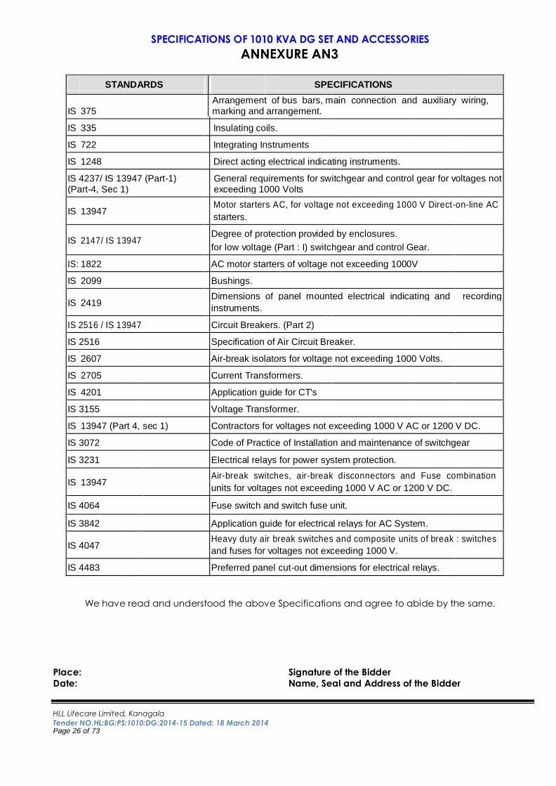
STANDARDS SPECIFICATIONS
IS 375
Arrangement of bus bars, main connection and auxiliary wiring, marking and arrangement.
IS 335 Insulating coils.
IS 722 Integrating Instruments
IS 1248 Direct acting electrical indicating instruments.
IS 4237/ IS 13947 (Part-1) (Part-4, Sec 1)
General requirements for switchgear and control gear for voltages not exceeding 1000 Volts
IS 13947
Motor starters AC, for voltage not exceeding 1000 V Direct-on-line AC
starters.
IS 2147/ IS 13947
Degree of protection provided by enclosures.
for low voltage (Part : I) switchgear and control Gear.
IS: 1822 AC motor starters of voltage not exceeding 1000V
IS 2099 Bushings.
IS 2419
Dimensions of panel mounted electrical indicating and recording
instruments.
IS 2516 / IS 13947 Circuit Breakers. (Part 2)
IS 2516 Specification of Air Circuit Breaker.
IS 2607 Air-break isolators for voltage not exceeding 1000 Volts.
IS 2705 Current Transformers.
IS 4201 Application guide for CT's
IS 3155 Voltage Transformer.
IS 13947 (Part 4, sec 1) Contractors for voltages not exceeding 1000 V AC or 1200 V DC.
IS 3072 Code of Practice of Installation and maintenance of switchgear
IS 3231 Electrical relays for power system protection.
IS 13947
Air-break switches, air-break disconnectors and Fuse combination
units for voltages not exceeding 1000 V AC or 1200 V DC.
IS 4064 Fuse switch and switch fuse unit.
IS 3842 Application guide for electrical relays for AC System.
IS 4047
Heavy duty air break switches and composite units of break : switches
and fuses for voltages not exceeding 1000 V.
IS 4483 Preferred panel cut-out dimensions for electrical relays.
We have read and understood the above Specifications and agree to abide by the same.
Place: Signature of the Bidder
Date: Name, Seal and Address of the Bidder
HLL Lifecare Limited, Kanagala
Tender NO.HL:BG:PS:1010:DG:2014-15 Dated: 18 March 2014 Page 27 of 73
SPECIFICATIONS OF 1010 KVA DG SET AND ACCESSORIES
ANNEXURE AN3
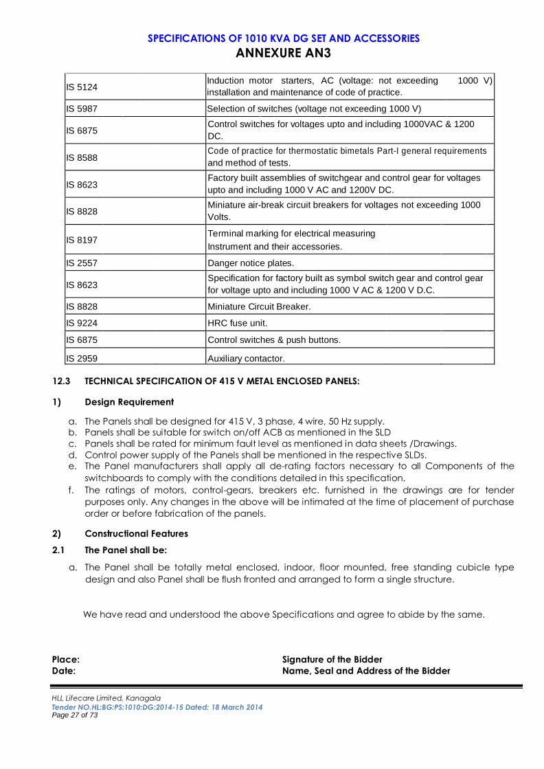
IS 5124
Induction motor starters, AC (voltage: not exceeding 1000 V)
installation and maintenance of code of practice.
IS 5987 Selection of switches (voltage not exceeding 1000 V)
IS 6875
Control switches for voltages upto and including 1000VAC & 1200
DC.
IS 8588
Code of practice for thermostatic bimetals Part-I general requirements
and method of tests.
IS 8623
Factory built assemblies of switchgear and control gear for voltages
upto and including 1000 V AC and 1200V DC.
IS 8828
Miniature air-break circuit breakers for voltages not exceeding 1000
Volts.
IS 8197
Terminal marking for electrical measuring
Instrument and their accessories.
IS 2557 Danger notice plates.
IS 8623
Specification for factory built as symbol switch gear and control gear
for voltage upto and including 1000 V AC & 1200 V D.C.
IS 8828 Miniature Circuit Breaker.
IS 9224 HRC fuse unit.
IS 6875 Control switches & push buttons.
IS 2959 Auxiliary contactor.
12.3 TECHNICAL SPECIFICATION OF 415 V METAL ENCLOSED PANELS:
1) Design Requirement
a. The Panels shall be designed for 415 V, 3 phase, 4 wire, 50 Hz supply.
b. Panels shall be suitable for switch on/off ACB as mentioned in the SLD
c. Panels shall be rated for minimum fault level as mentioned in data sheets /Drawings.
d. Control power supply of the Panels shall be mentioned in the respective SLDs.
e. The Panel manufacturers shall apply all de-rating factors necessary to all Components of the
switchboards to comply with the conditions detailed in this specification.
f. The ratings of motors, control-gears, breakers etc. furnished in the drawings are for tender
purposes only. Any changes in the above will be intimated at the time of placement of purchase
order or before fabrication of the panels. 2) Constructional Features 2.1 The Panel shall be:
a. The Panel shall be totally metal enclosed, indoor, floor mounted, free standing cubicle type
design and also Panel shall be flush fronted and arranged to form a single structure.
We have read and understood the above Specifications and agree to abide by the same.
Place: Signature of the Bidder
Date: Name, Seal and Address of the Bidder
HLL Lifecare Limited, Kanagala
Tender NO.HL:BG:PS:1010:DG:2014-15 Dated: 18 March 2014 Page 28 of 73
SPECIFICATIONS OF 1010 KVA DG SET AND ACCESSORIES
ANNEXURE AN3
b. The AMF panel shall be provided with integral base frame which shall be suitable for directly
bolting or tack welding to the Client's base frame. The frame of panel shall be fabricated using
suitable mild steel structural section. Wherever required, stiffeners shall be provided to increase
stiffness of large size doors and covers.
c. The height of the panel should not be more than 2075 mm. Maximum operating height shall be
approximately 1500 mm above the floor level and minimum operating height shall be
approximately 375 mm above floor level for compartment type panel.
d. Structures, including doors and panels, shall be capable of withstanding the internal pressure
created by faults within the structure (equal to the maximum fault-current rating for a specified
duration) without danger to the operating personnel. The minimum standard required is detailed
in IS 3427. Type test certificate(s) shall be provided with the quotation.
e. Structures shall be capable of bearing all mechanical loads viz., cubicle module rack in, rack out
and in no case the frame/base plate shall deform during the normal specified operation.
f. AMF panel shall generally be self-ventilating.
g. AMF Panel shall be designed and constructed to facilitate inspection, cleaning, repair and
maintenance and to ensure absolute safety during operation, inspection and maintenance
h. Similar parts and components shall be interchangeable.
i. Unless otherwise stated in the SLD, switchgear intended for indoor installation shall have minimum
protection of IP 42 and outdoor installation shall have minimum protection of IP 55 in
accordance IS 2147.
j. All hardware shall be corrosion resistant. All joints and connections of the panel members shall be
Zinc passivated or Cadmium plated, high quality steel bolts, nuts and washers secured against
loosening.
k. AMF Panel shall be designed and constructed to facilitate inspection, cleaning, repair and
maintenance and to ensure absolute safety during operation, inspection and maintenance
2.2 Each vertical section shall comprise:
a. AMF Panel shall be comprise of rigid welded structural frames made pressed and formed CRCA
sheet of thickness not less than 12 SWG (2.5 mm). This structure shall house the components
contributing to the major weight of the equipment.
b. Cladding of the frames (Covers) and partitions shall be of minimum 16 SWG (1.6 mm) CRCA
sheet, whereas doors shall be of min. 14 SWG (2 mm) sheet. All cable gland plates shall be made
of 10 SWG (3.15 mm) thick sheet steel. All sheet steel work forming the exterior of switchboards
shall be smoothly finished, leveled and free from flaws. The corners shall be rounded.
c. The structure shall be mounted on a rigid channel base frame of minimum ISMC 75. The design
shall ensure that the weight of the components is adequately supported without deformation or
loss of alignment during transit or during operation.
d. AMF Panel shall be provided with a hinged door. Doors shall be provided with right angle turn
type door lock.
e. AMF Panel shall be single front type. Panel shall have access from rear side for operation and
maintenance purpose. Each switchgear shall also be fitted with a label indicating the switchgear
rating and duty. Each instrument switch, fuse and contactor/Aux. relay shall be provided with a
separate label.
We have read and understood the above Specifications and agree to abide by the same.
Place: Signature of the Bidder
Date: Name, Seal and Address of the Bidder
HLL Lifecare Limited, Kanagala
Tender NO.HL:BG:PS:1010:DG:2014-15 Dated: 18 March 2014 Page 29 of 73
SPECIFICATIONS OF 1010 KVA DG SET AND ACCESSORIES
ANNEXURE AN3
f. Front and rear doors shall be fitted with dust tight neoprene gaskets with easy operating type
fasteners designed to ensure proper compression of the gaskets.
g. All busbar taps shall be insulated with close fitting sleeve of hard, smooth, dust and dirt free heat
shrinkable PVC insulated of high dielectric strength to provide a permanent high dielectric non-
agingand non tracking protection impervious to water, tropical condition and fungi. The
insulation shall be non-inflammable and self extinguishing and in fast colours to indicate phases.
h. The joint shall be insulated in such a way as to provide for accessibility of contact bolts for
maintenance. The dielectric strength and properties shall hold good for the temperature range of 0°C
to 90°C. If insulating sleeve is not coloured, busbars shall be colour coded with coloured bands at
suitable intervals
i. Busbar joints shall be bolted & projections shall be insulated. Spring washers shall be provided to
ensure good contact at the joints. Busbars shall be thoroughly cleaned at the joint locations and
suitable contact grease shall be applied just before making a joint.
j. Incoming/ Outgoing terminals of panel shall be provided with insulted shrouds to avoid
accidental contact with live parts.
k. All operating devices shall be incorporated in the front of panel and shall be flush/semi-flush
mounted.
l. The apparatus and circuits shall be so arranged as to facilitate their operation and maintenance
and at the same time to ensure the necessary of degree of safety.
m. Apparatus forming part of the panel shall have the minimum clearances as per relevant IS.
Clearances shall be maintained during normal service conditions. Creepage distances shall
comply with those specified in relevant standards.
n. All insulating material shall be of DMC/SMC to withstand the effects of high humidity, high
temperature, tropical ambient service conditions etc.
o. Foundation bolts and nuts for panel shall be supplied along with the respective panel.
p. The lifting eyes for each shipping section and danger notice plates shall be provided for panel.
q. Extra protection covers over removable cover providing access to live power equipment/circuits
shall be provided with tool operated fasteners to prevent unauthorized access.
r. Provision shall be made for permanently earthing the frames and other metal parts of the panel
by the independent connections.
s. All identical equipment and corresponding parts be fully interchangeable without any
modification.
t. Panel shall be complete with inter-panel wiring.
u. After isolation of the power and control connections of a circuit, it shall be possible to safely carry
out maintenance with the busbars and adjacent circuits alive.
3 Metal treatment & finish: All steel work used in the construction of the panel should have undergone rigorous metal treatment
process.
a. Oil, Grease, Dirt and Swarf shall be thoroughly removed by emulsion cleaning.
b. Rust and scales shall be removed by pickling with dilute acid followed by washing with running
water, rinsing with slightly alkaline hot water and drying.
c. After phosphating, finishing shall be carried out with clean water, followed by final rinsing with
dilute dichromate solution and oven drying.
We have read and understood the above Specifications and agree to abide by the same.
Place: Signature of the Bidder
Date: Name, Seal and Address of the Bidder
HLL Lifecare Limited, Kanagala
Tender NO.HL:BG:PS:1010:DG:2014-15 Dated: 18 March 2014 Page 30 of 73
SPECIFICATIONS OF 1010 KVA DG SET AND ACCESSORIES
ANNEXURE AN3
d. Two coats of finishing powder coating Siemens Grey RAL 7032 paint shall be applied with each
coat followed by stoving in the dust free atmosphere. The second finishing coat shall be free
from imperfection like pinholes, orange pills etc. The sample sheet for the finishing paint shall be
approved by Client/Consultant.
e. The final finished thickness of paint film on steel shall not be less than 90 microns.
f. Finished painted appearance of equipment shall present aesthetically pleasing appearance,
free from dents and uneven surface. 4 Busbars:
a. Busbars and connections shall either be manufactured from non flammable hard drawn tinned
copper or high conductivity aluminium/aluminium alloy mounted on non hygroscopic ceramic or
resin cast insulators at sufficiently close interval to prevent busbar sag and shall effectively
withstand electromagnetic stresses in the event of short circuit capacity for one second as
mentioned in the SLD.
b. Busbars including branch connections shall be fully insulated except in the cable
compartment(s). FRP/Hylam shrouds shall be provided at joints and tapoffs. Busbars exposed to
air shall be silver plated.
c. Main busbar shall be rectangular cross section and shall have same cross sectional area
throughout the length of the switchgear. The current rating of the neutral busbar may be half of
the phase busbars. Busbars shall be capable of carrying the rated current at 415 V continuously.
The busbars shall be designed to withstand a temperature rise of 40º C above the ambient. A
current density of 0.80 Amps/Sq.mm for Aluminum and 1.3 Amps/Sq. mm for Copper Bus Bars
shall not be exceeded. Vendor has to submit the Bus bar calculation of each panel along with
GA drawing at the time of drawing approval.
d. All busbars, links etc. shall be provided with 3 mm thick FRP sheet/Hylam sheet to prevent
accidental contacts.
e. The busbar shall be arranged such that minimum clearances between the busbar are
maintained as below.
f. Between phases : 27 mm min.
g. Between phases and neutral : 25 mm min.
h. Between phases and earth : 25 mm min.
i. Between neutral and earth : 23 mm min.
j. The busbar shall be of three phases and neutral system with separate neutral and earth bar. The
busbar and interconnection between busbar and various components shall be of high conductivity,
hard drawn, aluminum and High tensile bolts and spring washers shall be provided at all busbar joints.
k. Busbars and interconnection shall be insulated with heat-shrink sleeves of applicable grade and
marked to indicate the phase colouring, which shall be red, yellow, blue and black unless
specified otherwise. Necessary de-rating due to insulation shall be considered for sizing the
busbars.
l. Busbars, equipment like ACB, shall be arranged to permit safe work with one bus-section de-
energized. In addition it shall not be possible for arcs to transfer across a section or coupler.
We have read and understood the above Specifications and agree to abide by the same.
Place: Signature of the Bidder
Date: Name, Seal and Address of the Bidder
HLL Lifecare Limited, Kanagala
Tender NO.HL:BG:PS:1010:DG:2014-15 Dated: 18 March 2014 Page 31 of 73
SPECIFICATIONS OF 1010 KVA DG SET AND ACCESSORIES
ANNEXURE AN3
m. An earthing busbar sized for the full rating of the switchboard shall be provided along the full
length of the switchgear structure with provision for earth cable / bar connections at each end. It
shall be possible to disconnect the earth cable / bar connection to facilitate meggering, when
required. Where frame leakage protection is specified a separate insulated bus bar is required in
addition.
n. Busbars and connections shall be adequately sized, braced and supported to withstand the
mechanical forces and thermal effects resulting from the switchgear rated short circuit current
and carry certification from a recognized testing authority.
o. All bus connections, joints and taps shall be short and as straight as possible, and applied with
contact grease in the mating surface.
5 Air Circuit Breakers:-
Circuit breakers shall be:
Withdraw-able Operating mechanism (EDO/MDO) shall be specified in the
SLD. Have the number of poles specified in the SLD.
Suitable for uninterrupted duty and utilization category B to IEC 60947 or IS 13947.
a. Circuit breakers shall have four pole or three pole mentioned in SLD, manual/motorized
operation, air break, and horizontal draw out type of circuit breaker as specified with a stored
energy closing mechanism, integral spring charging handle, status of indicators (close/open and
trip) including breaker ready to close indicator, close and trip pushbutton for manual operation
and provision for pad locking in open position in addition to lock draw out mechanism. b. Electrically operated breaker shall have provision for manual (mechanical) operation. A control
isolating switch shall be provided on the fuse plate to isolate the supply to the charging motor.
c. Tripping, closing, control and indication supplies for circuit breakers shall be as shown in the SLDs.
d. Mechanical operation indicators shall be provided to show open & close position of the breaker
and Circuit breaker operating mechanisms shall be motor wound spring. The closing spring shall
be automatically recharged after discharge and be ready for next closing command. The
closing spring condition - “charged” or “discharged” shall be shown via a positively driven
indicator.
e. Breaker shall be provided for slow closing and opening of the breaker for maintenance purposes,
and for manual charging and closing of electrically operated breakers during emergencies.
f. Circuit breakers shall be provided with trip circuit supervision to monitor trip circuit continuity and
trip circuit supply. Alarm and indication facilities shall be provided for each circuit breaker and a
volt free group contact provided via internal bus wiring for remote common alarm.
g. The ACB shall have CT operated microprocessor based/solid state/thermal release providing for
over current and earth fault protection specified in the SLD. The release shall have provision for
settable current and time as required for respective protection. Each pole of the ACB's shall be
equipped with over current and short circuit release. The ACB's shall be equipped with shunt trip
and under voltage release also. The trip devices shall be direct acting. The breakers shall be of
the shunt or series trip type as specified.
h. The ACB of same rating shall be identical and interchangeable.
i. The ACB's shall have an arc quenching device on each pole. The ACB's shall have auxiliary
contacts for signaling, interlocking etc. The ACB's shall have slow close facilities for checking
contact operation and contact gap adjustment.
We have read and understood the above Specifications and agree to abide by the same.
Place: Signature of the Bidder
Date: Name, Seal and Address of the Bidder
HLL Lifecare Limited, Kanagala
Tender NO.HL:BG:PS:1010:DG:2014-15 Dated: 18 March 2014 Page 32 of 73
SPECIFICATIONS OF 1010 KVA DG SET AND ACCESSORIES
ANNEXURE AN3
j. Circuit breakers shall be provided with eight normally open and four normally closed spare
auxiliary contacts wired out to terminals.
i. In addition auxiliary contacts shall be provided for:- ii. Circuit breaker in service position.
iii. Circuit breaker in test position
k. Auxiliary contacts shall be suitable for inductive circuit switching. Auxiliary contacts multiplication
shall be by latch type relays to prevent inadvertent change of contact position on loss of
auxiliary supply.
l. The breakers shall have short circuit breaking capacity of not less than 50 KA RMS at 415 Volts 50
Hz AC or as specified ion SLD.
m. A short-time withstand circuit of 50 KA for 1 second or specified in SLD.
n. Electrical overload performance at 6 times the rated current, 110% of the rated voltage as
recovery voltage and 0.5 power factor.
o. Dielectric test of 2.5 KV applied for one minute on main circuits. Test evidence from a recognized
independent Laboratory / Institution shall be furnished for compliance of the breakers with the
above requirements.
p. The circuit breakers shall be fitted with detachable arc chutes on each pole designed to permit
rapid dispersion, cooling and extinction of the arc. Interface barriers shall be provided to prevent
flashover between phases.
q. Arcing contacts shall be of hard wearing material of copper tungsten or silver tungsten tipped with arc
resisting material and contact shall be multi-finger and spring loaded type and shall be readily
replaceable. Main contacts shall be of pure silver of high pressure butt type of generous cross section.
r. The operating mechanism shall be of robust design, with a minimum number of linkages to ensure
maximum reliability. Manually operated circuit breakers shall be provided with spring operated
closing mechanism which are independent of speed of manual operation. Electrically operated
breakers shall have a motor wound spring charged closing mechanism. Breaker operation shall
be independent of the motor which shall be used solely for charging the closing spring.
s. The operating mechanism shall be such that the breaker is at all times free to open immediately
the trip coil is energized.
t. Circuit breakers shall be individually housed in sheet metal cassettes provided with hinged doors.
The breaker along with its operating mechanism shall be mounted on a robust carriage moving
on guide rollers within the cassette. Isolating contacts for both power and control circuits shall be
of robust design and fully self- aligning. The assembly shall be designed to allow smooth and easy
movement of the breaker within its cassette.
u. The breaker shall have three distinct positions within the cassette as follows.
i. 'Service' position : with main and auxiliary contacts connected.
ii. 'Test' position : with power contacts fully disconnected and control circuit contacts
connected.
iii. 'Isolated' position : with both power and control circuit contacts fully disconnected
v. Test facilities shall be provided to permit operation of the circuit breaker whilst in the test position.
w. It shall be possible to achieve any of the above positions with the cassette door closed.
Mechanical position indicators shall be provided for the three positions of the breaker.
We have read and understood the above Specifications and agree to abide by the same.
Place: Signature of the Bidder
Date: Name, Seal and Address of the Bidder
HLL Lifecare Limited, Kanagala
Tender NO.HL:BG:PS:1010:DG:2014-15 Dated: 18 March 2014 Page 33 of 73
SPECIFICATIONS OF 1010 KVA DG SET AND ACCESSORIES
ANNEXURE AN3
x. The moving portion of the circuit breaker shall be so interlocked that:-
i. With drawable circuit breakers and their Cubicles shall be interlocked to prevent.
ii. The breaker being inserted into the service position unless it is open.
iii. The breaker being withdrawn from the service position unless it is open.
iv. The breaker being closed unless it is fully in the service, withdrawn/test or earthing position.
v. Remote operation whilst in the withdrawn/test position.
y. It shall not be possible to open the hinged door of the cassette unless the breaker is drawn to the
isolated position. When the breaker is in the inspection position it shall be completely withdrawn.
z. Inadvertent withdrawal of the circuit breaker too far beyond its supports is prevented by suitable
stops.
aa. Be fitted with busbar and cable circuit shutters.
bb. Provision shall be available for the padlocking of the circuit access flaps in any of the three
positions.
cc. Colored red for busbar and yellow for circuit. For bus-section and coupler applications the
shutters shall be labelled with the busbar number.
dd. Metal construction and effectively earthed to the main housing.
ee. The positively driven type, gravity drop shutters are not acceptable.
ff. Capable of being individually operated by hand.
gg. Each circuit breaker shall have provision for padlocking in the test and isolated positions and
have indications for these positions.
hh. Each circuit breaker shall be provided with an anti pumping facility in the circuit breaker closing
circuit.
ii. Moving portion of breakers of same rating shall be interchangeable.
jj. The moving portion of the circuit breaker shall be provided with a heavy duty self aligning earth
contact, which shall make before and break after the main isolating contacts during insertion
into and withdrawal from the service position of the breaker. Even in the isolated position positive
earthing contact should exist.
8 Contactors: -
a. The Auxiliary contactor shall conform to the latest IS specification IS – 13947 (4). The Contactors
shall be suitable for 650 V AC with impulse withstand capacity of 8 kV.
b. The Auxiliary contactor shall be of full voltage, air break, single throw electromagnetic type.
c. The Auxiliary contactor shall have no derating upto 45 C service temperature. In case the
contactors need derating, manufacturer shall declare the derated current carrying capacity at
45 C service temperature.
9 Over load relays: -
a. The overload relays shall conform to the latest IS specification IS – 13947(4). The overload relays
shall be suitable for 650 V AC.
b. Overload protection shall be bi-metallic type provided together with single phasing protection
and have ambient temperature compensation and also with 1NO+1NC auxiliary contacts.
We have read and understood the above Specifications and agree to abide by the same.
Place: Signature of the Bidder
Date: Name, Seal and Address of the Bidder
HLL Lifecare Limited, Kanagala
Tender NO.HL:BG:PS:1010:DG:2014-15 Dated: 18 March 2014 Page 34 of 73
SPECIFICATIONS OF 1010 KVA DG SET AND ACCESSORIES
ANNEXURE AN3
c. The overload relays shall have no de-rating upto 55 C service temperatures. In case the overload
relays need de-rating, manufacturer shall declare the de-rated current carrying capacity at 55 C
service temperature.
d. The overload relay shall have facility to hand reset and test and also auto / manual reset facility.
10 Metering, Protection, Control and Indication :-
a. Control and monitoring system shall be provided.
b. Metering, protection and control shall be provided as requirement.
c. Meters and relays shall be flush mounting and fitted in the front of the panel door.
d. Meters and relays shall be capable of withstanding without damage the secondary currents
associated with the switchgear rated fault current flowing in the primary of current transformers.
e. External zero adjustment / calibration shall be possible on all indicating instruments to facilitate
adjustment without dismantling the instrument.
f. The instruments shall have either analog type or digital type. Analog instrument shall be 96 Sqmm
with 90°C scale or 96 Sqmm with 90°C scale and shall be provided with adjusting devices in the
front.
g. Analog instrument shall be white with black numbers and lettering. Dial shall be parallax free.
h. Analog meter normally maximum meter reading shall be the order of 60% normal full scale
deflection. Ammeters shall be scaled such that full load corresponds to between 50 and 80% of
the angular deflection
i. Voltmeter shall comply with BS-90. The dial of the meter shall be square in shape of 96 x 96 mm
size. The voltmeter shall be moving iron type, flush pattern with dust and moisture proof
enclosure.
j. The voltmeter selector switch shall be arranged to provide line to line voltage reading.
k. Ammeter shall comply with BS: 89. The dial of the ammeter shall be square in 96x96 mm in size.
The ammeter shall be moving iron type, flush pattern with dust and moisture proof enclosure.
Separate current transformer shall be provided for all Ammeters.
l. Protective relays shall, wherever possible, be of the draw out type with hand reset operation
indicator. Lockout relays shall be of the hand-reset type.
m. Status indication illuminators (green-open, red-closed, amber-tripped) and positive drive
mechanical position indicators shall be provided for circuit breaker. Contacts for remote
indication shall be provided.
n. Control of circuit breakers shall be carried out at either:-Control Switch at Cubicle Door
o. Where earth fault relays are specified in the SLD, it may be necessary to incorporate time delay
relays to prevent the ACB from attempting to interrupt the earth fault in excess of its rated
interrupting capacity. The time delay should ensure that values of earth fault current in excess of
the ACB rating. The vendor shall be responsible for ensuring proper component co-ordination.
The timer relay may be incorporated within the earth fault relay, and shall have adjustable
settings.
p. The Ammeter and Voltmeter in panel shall be Digital type with in built selector switch.
11 Miniature Circuit Breakers:-
a. The MCB shall conform to the latest IS specification IS – 8828.
b. The MCB shall have a minimum breaking capacity of 10 KA or as specified on SLD.
We have read and understood the above Specifications and agree to abide by the same.
Place: Signature of the Bidder
Date: Name, Seal and Address of the Bidder
HLL Lifecare Limited, Kanagala
Tender NO.HL:BG:PS:1010:DG:2014-15 Dated: 18 March 2014 Page 35 of 73
SPECIFICATIONS OF 1010 KVA DG SET AND ACCESSORIES
ANNEXURE AN3
c. The MCB shall be with overload and short circuit protection
d. The MCB shall have C class characteristics.
12 Indicating Lamps (LED TYPE):-
a. The indicating lamps shall be LED cluster type indicating lamps with low watt consumption.
Indicating lamp shall be of the double contact, bayonet cap type rated for operating for either
a 240 VAC or specified AC/DC auxiliary voltage in the SLD.
b. The lamps assembly shall be complete with cluster of LEDs, holders, lenses with transparent
covers.
c. The indicating lamps shall have built in resistor and shall be suitable for the control voltage
specified.
d. The lamps shall be LED type. The lamps shall be provided with translucent lamp covers of
required colour (For ACB- ON-RED, OFF-GREEN, TRIP -AMBER. For Incomer of Panels R Phase-RED,
Y phase-YELLOW, B phase-BLUE).
e. Bulbs and covers shall be easily replaceable from the front.
13 Push Button:-
a. The push button unit shall comprise of the contact element, a fixing holder, and
push button actuator.
b. The push button shall be momentary contact type. The contacts shall be of silver
alloy and rated at 10 Amps continuous current rating.
c. The actuator shall be of stranded type and colour as per its usage for ON, OFF and Trip.
14 Control & Selector Switch:-
a. The control and selector switch shall be of the rotary type, having enclosed contacts, which are
accessible by the removal of the cover.
b. Control and selector switch for instruments shall be flush mounted on the front of the panels and desks.
c. Local/remote selector switches when located on switchgear cubicles, shall be mounted inside
the relay compartment at an accessible location.
d. All control switches shall be of the spring return to normal type. Circuit breaker control switch on
the panel cubicle shall be lockable in the “trip” position.
e. Control switches have momentary contact, Circuit breaker control switches shall be provided
with sequencing device to prevent repetitive closing operations without first moving to the trip
position.
f. Selector switches shall be of the stay put type, maintained contact type. 15 Space Heaters:-
a. Each vertical section of the panel shall be provided with thermostat controlled anti -
condensation, industrial strip continuous duty type space heaters rated for 240 Volts ±10%, single
phase, 50 Hz. The heaters shall be provided with DP MCB.
b. Wiring of space heaters in each panel shall be grouped and brought out to easily accessible
terminals for connection to power supply, through MCB.
We have read and understood the above Specifications and agree to abide by the same.
Place: Signature of the Bidder
Date: Name, Seal and Address of the Bidder
HLL Lifecare Limited, Kanagala
Tender NO.HL:BG:PS:1010:DG:2014-15 Dated: 18 March 2014 Page 36 of 73
SPECIFICATIONS OF 1010 KVA DG SET AND ACCESSORIES
ANNEXURE AN3
c. Each switchboard shall be provided with plug-socket with MCB for the connection of hand lamp
rated 240 V, 50 Hz. single phase.
d. Motor anti-condensation heaters (where specified) shall be supplied from the same source as those
for the Panel. They shall be controlled through MCB and contactor’s auxiliary contacts such that the
heater is energized when the motor is stopped and totally isolated when Main Circuit Isolator or MCB is
open.
16 Instrument Transformers:-
a. Voltage and current transformers of appropriate ratio, no. of cores, output, class
and accuracy for protection and metering, shall be provided as shown in the
SLD.
b. The Vendor shall provide details of ratio, output, class and accuracy for all the instrument
transformers in technical offer.
c. The secondary windings of instrument transformers shall be earthed at one point through a
removable link, with the provision for attaching test links.
d. Current transformers wherever required is called for CT as specified in the SLD.
e. Current transformers shall comply with the requirements of IS 2705.
f. Current transformers shall be rated to withstand the thermal and magnetic stresses resulting
through fault currents equal to the switchgear fault rating.
g. CT shall be Nar type in epoxy resin cast type rated for 415 V. In exceptional circumstances the
Client may authorize the use of wound primary CTs where a bar type cannot provide a suitable
ratio.
h. CT shall be provided with Class A/Class B insulation and proper polarity markings in a suitable
manner.
i. The vendor shall be responsible for the VA output of the CTs which are adequate for the relays,
meters and loads connecting them.
j. Shorting terminals for current transformers shall be provided at the outgoing
terminals where external connections are required.
k. Voltage transformers shall be provided as per requirement.
l. Voltage transformer primary winding shall be protected by High Rupturing Capacity Cartridge
fuses and secondary winding shall be protected by the MCB.
m. Voltage transformers shall have provisions for safely disconnecting the fuses and transformers
from the energized Busbars.
n. Instrument transformer nameplates shall be giving type, output and serial numbers and
Instrument Transformer shall be fixed in a position so that details can easily be read/visible when
fitted in the cubicle.
17 Cable Terminations:-
a. AMF Panel shall be designed either for top or bottom or combined entries and outgoings which
will be confirmed by clients/consultant at the time of drawing approval.
We have read and understood the above Specifications and agree to abide by the same.
Place: Signature of the Bidder
Date: Name, Seal and Address of the Bidder
HLL Lifecare Limited, Kanagala
Tender NO.HL:BG:PS:1010:DG:2014-15 Dated: 18 March 2014 Page 37 of 73
SPECIFICATIONS OF 1010 KVA DG SET AND ACCESSORIES
ANNEXURE AN3
b. Generous size of cable compartments shall be provided, with the position of cable gland such
that cables can be easily and safely terminated. A Panel with removable undrilled gland plate
shall be provided.
c. Control & Indication terminal blocks shall be mounted in a single deck arrangement. Terminal
blocks for the connection of external control wiring shall be of the clamp type with a facility to
connect two wires on each side of the terminal. A minimum of 20% spare terminals shall be
provided in each module. And also each control terminal connection of 2 x 2.5 Sqmm standard
copper wire.
d. Positioning of cable terminations shall avoid obstruction of other cable terminations, removable
covers, etc. and provide for easy access for terminating cables.
e. Multiway terminal blocks complete with screws, nuts, washers and marking strips shall be
furnished for terminating the internal wiring and outgoing cables.
f. Not more than two wires shall be connected to any terminal. If necessary a number of
terminals shall be jumpered together to provide wiring points.
g. All terminal blocks shall be shrouded or provided with transparent covers. Also shrouds or
covers shall be to permit safe working at the terminals of one circuit without accidentally
touching that of another live circuit. Pinch screw type terminals re not acceptable.
h. Terminals for different voltages shall be separated by partitions.
i. Terminal boxes (where specified) shall be suitable for dry type terminations unless
otherwise specified.
j. Adequate support arrangement shall be provided for each cable to avoid undue strain on the
cable terminations.
18 Control Wiring:-
a. The control wiring shall be carried out with 650/1100 V grade PVC insulated fire retardant
stranded copper conductor wires of minimum size 1.5 Sqmm except for electronics wiring. The
wiring shall be complete in all respects so as to ensure proper functioning of control, indication
and interlocking scheme.
b. Control wiring within the panel shall be securely held in position (either loomed or run in
conduit/trunking) neatly bunched, adequately supported and properly routed to allow easy
access and maintenance.
c. All wiring for external connections shall be brought out to individual terminals on a readily
accessible terminal block without joints or tees in their runs. Generally no more than two wires
shall be connected to a terminal.
d. Flexible wires shall be used for connections on door mounted equipment. Wiring shall be
loomed, wrapped in flexible PVC conduit and be firmly clamped at both ends to prevent
movement at terminations.
e. Wiring identification shall be by numbered and/or lettered sleeves, of insulating material
adjacent to the terminals. Wires with in panel shall be identified by numbered ferrules at each
end. The ferrules shall be of the “T type and of non- deteriorating material. They shall be firmly
located on each wire so as to prevent free movement and they shall be indelibly marked and
removal without disconnecting the wire from its terminal shall not be possible.
f. No more than two wires shall be connected to a terminal.
We have read and understood the above Specifications and agree to abide by the same.
Place: Signature of the Bidder
Date: Name, Seal and Address of the Bidder
HLL Lifecare Limited, Kanagala
Tender NO.HL:BG:PS:1010:DG:2014-15 Dated: 18 March 2014 Page 38 of 73
SPECIFICATIONS OF 1010 KVA DG SET AND ACCESSORIES
ANNEXURE AN3
g. All spare contacts of Aux. relays and switches shall be wired upto the terminal blocks.
h. Each of the DC circuit shall be provided with two fuses one in the positive and the other in the
negative for 2 wire DC underground system of specified voltage.
i. Final wiring diagram of Panel’s control circuit with ferrules number shall be submitted along with
panels as one of the documents.
j. All wiring shall be colour coded as follows
a) Instrument transformer: Red, Yellow or Blue determined by the ACcircuits phase with which
wire is associated.
b) AC Phase wire :white
c) AC Neutral :Black
d) DC Circuits :Grey
e) Earth Connection :Green
19 Auxiliary Supplies:-
a. Auxiliary supplies (closing, tripping, control, indication, heaters, etc.) shall be mentioned in the
SLD and auxiliary power supply unit shall be the part of the panel.
b. Where motor charging spring operating mechanism is specified for circuit breaker, it shall be
rated for the rated auxiliary control supply operation.
c. Circuit breaker closing, tripping, control and indication power shall be supplied from suitably
rated DC supply units and it shall be part of the panel.
d. For shunt trip circuits, the protection shall be rated at least 300% of the load.
e. Anti-condensation heater supplies shall be derived internally from each busbar section.
20 Earthing:-
a. Aluminium earthing bus shall be provided for the entire length of the panel and shall be rated to
carry maximum fault current. Earth busbar shall be located at the bottom/top of the panel. All
metallic non-current carrying parts of the switchgear shall be bonded together and connected
to the switchgear earth busbar.
b. All doors shall be bonded to the main structure by means of a flexible copper connection
arranged so that it cannot be trapped as the door is opened or closed.
c. With-drawable parts (e.g. circuit breakers) shall be effectively earthed until they are
completely withdrawn with all power and control connections disconnected.
d. Provision shall be made, for earthing cable screen and armouring to the earth busbar, near
the gland.
e. Provision shall be made for connection from earth busbar to the main earthing busbar coming
from the earth pit on both side of the panel.
f. All control, instrument and communication cables, if any, shall be earthed suitably to prevent
any electromagnetic interference and ensure electromagnetic compatibility.
We have read and understood the above Specifications and agree to abide by the same.
Place: Signature of the Bidder
Date: Name, Seal and Address of the Bidder
HLL Lifecare Limited, Kanagala
Tender NO.HL:BG:PS:1010:DG:2014-15 Dated: 18 March 2014 Page 39 of 73
SPECIFICATIONS OF 1010 KVA DG SET AND ACCESSORIES
ANNEXURE AN3
g. Earth busbar shall be rated to carry the rated symmetrical short circuit current of associated
panel for one second and earth busbar shall be supported to withstand stresses induced by
the momentary current of value equal to the momentary rating of the associated Panels.
h. Vendor has to submit earth bus calculation along with GA Drawing at the time of Drawing approval.
i. Each earthing point shall be marked with letter ‘E’.
j. Provision shall be made for an instrument clean earth.
21 Terminal Blocks:-
a. Terminal blocks shall be of 650 Volts grade of stud type. Insulating barriers shall be
provided between adjacent terminals.
b. Terminal blocks shall have a minimum current rating of 10 Amps and shall be shrouded.
Provisions shall be made for label inscriptions. The wire terminations to the blocks shall be of
screw type suitable for crimp type socket. 22 Name Plate:-
a. Panel’s components shall be identified by labels.
b. A main label (AMF Panel designation) shall be affixed in a prominent position on Panel giving the
following information in bold letter:
Manufacturers name and type
Panel Tag Number
System voltage, phases, wires and frequency
Year of manufacture
Purchasers name
Order Item No
Characters shall be 12 mm high.
c. Labels shall be fitted on front and back of cubicles. When the operating sequence of the
equipment is not evident, e.g. mechanical / key interlocking features; instruction labels shall be
provided and fixed near the point of operation.
d. Labels shall be affixed by means of self tapping screws or rivetsat the top of the cubicles. Use
of adhesives shall not be accepted.
e. Labels shall be made out from anodized aluminum and shall have black characters on a
white background. Warning / Danger labels shall have White lettering on a red
background.
f. Engraved name plates shall preferably be of 3 ply, (red-white-red or black - white -black)
lamicold sheet. However black engraved perplex sheet nameplates shall also be applicable.
Engraving shall be done with square groove cutters.
g. Inside the feeder compartment, the electrical component, equipments, accessories like
switchgear, contactor, lamp, relays etc. shall suitably be identified by providing stickers.
23 Danger Notice plate:-
a. The danger plate shall be affixed in a permanent manner on operating side of the panel.
b. The danger notice plate shall indicate danger notice both in Hindi and English and with a sign
of skull and bones.
We have read and understood the above Specifications and agree to abide by the same.
Place: Signature of the Bidder
Date: Name, Seal and Address of the Bidder
HLL Lifecare Limited, Kanagala
Tender NO.HL:BG:PS:1010:DG:2014-15 Dated: 18 March 2014 Page 40 of 73
SPECIFICATIONS OF 1010 KVA DG SET AND ACCESSORIES
ANNEXURE AN3
c. The danger notice plate in general shall meet the requirements of local inspecting authorities.
d. Overall dimension of the danger notice plate shall be 200 mm wide and 150 mm high. The
danger notice plate shall be made from minimum 1.6 mm thick mild steel sheet and after due
pretreatment to the plate, the same shall be painted white with vitreous enamel paint on both
front and rear surface of the plate.
e. The letter, the figure, the conventional skull and bones shall etc. shall be positioned on the plate
as per recommendations of IS : 2551-1982.
f. The said letter, the figure and the sign of skull and bones shall be painted with white lettering
on red colour background.
g. The danger plate shall have rounded corners. Locations of fixing holes for the plate shall be
decided to suit design of the panel.
h. The danger notice plate, if possible, be of ISI certification mark.
24 Safety Arrangements:-
a. All terminals, connections, and other components, which may be “LIVE” when front access
doors are open shall be adequately screened.
b. Where provision is made for the padlocking of components under specific condition (Safety
shutters, earthing selectors etc.) one padlock shall be supplied for each cubicle and each
shall have a different lock change number with two keys being provided. 25 Accessories:-
The following accessories shall be furnished along with each switchboard.
a. A complete set of any special tools required for operation, maintenance and testing of the
switchgear shall be provided. The Vendor shall provide a list of special tools, individually priced,
with his offer. A suitable storage box or wall-mounted rack shall be provided. The Vendor shall
provide with his offer, separate priced lists of recommended commissioning and operating
spares.
b. The Vendor shall provide 3 extra sets of switchgear cubicle locking keys within a storage box.
c. One (1) no. handle for withdrawing breaker from the cubicle.
d. Commissioning spares (approved by the Client/Consultant) shall be included with the
switchboard.
26 Operational Requirement :-
a. Normally Mains supply shall be 'ON '& load will be connected with mains supply in the Main LT
panel.
b. As and when the mains fail & it shall send signal through mains supervisory relay (LVM) to AMF
unit of the D.G.Set.
c. The Main LT panel shall have supplies as input from 1010 KVA D.G.set.
d. AMF Unit shall pass signal to D.G.set and the D.G.set will start and develop the supply. Supply is
available at incomer of D.G. set’s ACB in Main LT panel and DG Set’s ACB will close
automatically through DG Controller.
e. Now the D.G.Set will supply power on main LT panel’s common Bus and Power shall be
available at down stream panel for utilization.
We have read and understood the above Specifications and agree to abide by the same.
Place: Signature of the Bidder
Date: Name, Seal and Address of the Bidder
HLL Lifecare Limited, Kanagala
Tender NO.HL:BG:PS:1010:DG:2014-15 Dated: 18 March 2014 Page 41 of 73
SPECIFICATIONS OF 1010 KVA DG SET AND ACCESSORIES
ANNEXURE AN3
f. Differential protection Relay will be installed in Main LT panel , Phase CTs in Isolator panel and
Neutral CT in Alternator by DG supplier , Main Purpose of DPR is to trip Main LT Panel ACB
during differential in Alternator and Signal Has to be given to controller from the DPR to trip the
engine.
g. AMF module will give three impulses to start engine & if engine fail to start in three attempts
which will give Audio signal. In this case engine should be started in manual mode by pressing
manual start P.B. in which, three attempt circuit shall get by-passed & it shall also be started in
Test mode by pressing test P.B. in which only three attempt circuit. Can be tested & no impulse
will go to D.G.ACB to close.
h. Initial low oil by -pass circuit & full proof scheme shall be provided such that in running
condition, no impulse shall be concentrated to start cranking motor (starter) due to any
fluctuation.
i. On restoring of mains, Main LT panel with single bus, signal is given to the DG feeder of Main LT
panel. The panel will transfer the load automatically to Mains and Open the D.G.ACB. The same
shall follow for D.G.panel
j. An audio-visual fault annunciation system with Accept & reset facilities for following fault shall
also be provided with circuit trip D.G.ACB & D.G.Set. The following signals and indication can be
incorporated within the DG power panel or to be given in separate control box.
1. Low Oil pressure 2. Over speed
3. High water jacket temp
4. Engine failed to start.
5. Over load relay operated
6. Mains failed.
k. During the operation, incase total requirement goes below, the auto load sharing mode
shall get activated. 27 Technical Requirements
(A) Indication Window Fascia
Low lube oil pressure
High water temp
Engine over speed
O/L of alternator
Earth fault of alternator
Winding temp high
Bearing temp high
D.G.Set on Load
Not in Auto ( PCC In Manual mode or OFF mode)
(B) Other Provisions
Set control terminals
Push button
We have read and understood the above Specifications and agree to abide by the same.
Place: Signature of the Bidder
Date: Name, Seal and Address of the Bidder
HLL Lifecare Limited, Kanagala
Tender NO.HL:BG:PS:1010:DG:2014-15 Dated: 18 March 2014 Page 42 of 73
SPECIFICATIONS OF 1010 KVA DG SET AND ACCESSORIES
ANNEXURE AN3
Space heater MCB
Static battery charger with trickle/boost mode auto/manual selector switch with DC
Ammeter & DC voltmeter.
Reset push button for unhealthy condition like over speed/high water temp/low lub. oil
pressure etc.
(C) AMF module
Mains power sensing relay with timer for Auto start set while mains supply is not there. The AMF logic shall constantly monitor EB supply & wherever EB supply fails it shall start
the DG set and give command to DG ACB to close and than give command to client
ACB in Main LT Panel. The AMF panel shall have auto/manual selector switch on Auto work, DG Set shall
start automatically when EB power fails in manual mode. It shall be possible to
start DG set irrespective of status of SEB supply. In auto mode DG can be stopped by automatic mode with manual override.
NOTE: This module shall switch ON/OFF the Standby D.G. Automatically depending on non
availability / availability of main EB Power & accordingly supply power to the downstream
loads. The operation shall be as under.
Case 1 : On failure of Electricity Board Power :
a. The AMF module senses the EB supply failure by means of line voltage monitors (LVM’s)
b. The LVM Contact shall start the DG automatically (an adjustable time delay is introduced
here to take care of momentary EB failure so that DG does not start unnecessarily and
shall break the EB breaker. c. After auto-starting, once the DG has attained full voltage, the DG side breaker is closed
in the AMF circuit.
d. The supply from DG is thus automatically transferred to downstream loads.
Case 2: On restoration of EB supply, the AMF module shall perform the following functions.
a. The LMV senses presence of EB supply.
b. LVM contact with time delay switches off the DG Side and switch on EB breaker.
c. After some time delay, the DG will be automatically switched off (this delay is given to
avoid restarting of DG if the EB supply restoration was only momentary). 28 Drawings and Manuals:-
28.1 At Enquiry stage
a. Descriptive literature of the various equipment offered with catalogues, if any.
b. Guaranteed technical particulars of the equipment.
c. Approximate dimensions and weight and preliminary GA drawings as follows.
d. General arrangement showing plan, elevation and typical section views particularly typical cross
sections to illustrate cable connections.
e. Foundation plan showing location of fixing channels, floor openings etc.
f. Schematic wiring diagram.
We have read and understood the above Specifications and agree to abide by the same.
Place: Signature of the Bidder
Date: Name, Seal and Address of the Bidder
HLL Lifecare Limited, Kanagala
Tender NO.HL:BG:PS:1010:DG:2014-15 Dated: 18 March 2014 Page 43 of 73
SPECIFICATIONS OF 1010 KVA DG SET AND ACCESSORIES
ANNEXURE AN3
28.2 At Order stage
Within two weeks of order, vendor shall submit 4 sets of following documents for
clients/Consultant’s approval
a. The manufacturer shall develop his own general arrangement and schematic drawing adding
necessary auxiliary devices, accessories, components particular to supplied equipments etc.
which are required for safe, convenient, efficient and proper operation of the Panel.
b. Manufacturer shall submit for Client/consultant's approval the single line diagrams, general
arrangement drawings, flooring and mounting detail drawings and schematic diagrams with
dead load and impact load, plan, sections and foundation details.
c. Manufacturer shall submit for Main Bus bar calculation and earth bus calculation of each panel
along with GA drawings
d. Set of General arrangement drawing for each type of panel showing constructional features and
space required in the front for withdrawal of breaker and back , power and control cable entry
points, location of various devices, terminal blocks, cross sectional details, bus bar supports, number of
buses, Power & Control wiring diagram for each cubicle. These diagrams shall show any wiring inside
the cubicle starting from the cubicle terminal strips. These diagrams shall be used by the owner
for trouble shooting and shall show any device, terminal and wire number, shall be submitted
within 15 days from the date of letter of intent for approval.
e. Drawing and data sheet for each component with design calculation , indicating type , short
circuit rating of all electrical components used , busbar size Horizontal as well as Vertical, internal
wiring size , terminal size including colour and mounting details.
f. Electrical wiring diagram, inert panel, inter connection wiring diagram including terminal
numbers and ferrule numbers.
g. Bill of Material with Model number, make, type and quantity.
h. Terminal block arrangement drawing for outgoing feeders with size.
i. Complete relay technical particulars and recommended settings.
j. Operation, maintenance and installation manuals, (one set to Consultants).
k. Technical Catalogues/Leaflets of CTs, meters, lamps, etc. shall be submitted along with drawing.
l. Client’s/consultant's approval for the GA drawings is required before the fabrication of the
cubicle is started.
m. The Client/consultant's approval as the manufacturer's drawings shall not relieve the
manufacturer of his responsibility for supplying equipment conforming with the relevant
specifications and stan-dards or for any other mistakes, errors or omissions in drawings for proper
and correctness of functioning/operation of the system.
28.3 At Final Order Execution stage
The following shall be submitted after inspection but before dispatch of the equipment
a. Manufacturer shall submit four sets of as built drawings with soft copy
b. Routine test certificate ( including all brought out components) in 4 sets
c. Detail operation manuals in 4 sets
d. Detailed erection , testing and commissioning manuals in 4 sets
We have read and understood the above Specifications and agree to abide by the same.
Place: Signature of the Bidder
Date: Name, Seal and Address of the Bidder
HLL Lifecare Limited, Kanagala
Tender NO.HL:BG:PS:1010:DG:2014-15 Dated: 18 March 2014 Page 44 of 73
SPECIFICATIONS OF 1010 KVA DG SET AND ACCESSORIES
ANNEXURE AN3
29 Deviations:-
a. Deviations from this specification are only acceptable where the Vendor has listed in his
technical offer, the requirements he cannot or does not wish to comply with and the
Client/Consultant has accepted, in writing, the deviations before order is placed.
b. If the manufacturer is able to offer alternatives resulting in technical or price advantages they
should submit a supplement to the main tender with a separate list of deviations.
c. In the absence of a list of deviations it will be assumed by the Client/consultant that the Vendor
complies fully with this specification. 30 Inspection & Tests:-
a. During fabrication, panel shall be subjected for inspection by Client/Consultant or by an agency
authorized by the Client. Manufacturer shall furnish all necessary information concerning the supply to
inspectors. The client/ Contractor has right to witness the test carried out on all the equipments.
b. Tests shall be carried out at the manufacturers' works under his care.
c. All routine tests on all major components shall be made as per relevant specification.
d. Inspection of panel including in wiring and electrical operational tests by the client/consultant
before dispatch.
e. In addition specific tests shall be conducted to check mechanical and electrical operation and
panel wiring to this specification and approved schematic drawings.
f. Shop tests shall be witnessed by an inspector of Client / Consultant or of an agency authorized
by the owner.
g. The Vendor shall give two weeks notice for the tests prior to commencement.
h. The Client reserves the right to inspect switchgear at the Manufacturer’s works at any time prior
to dispatch to prove compliance with this specification. The Client shall also have the right to
carry out intermediate inspection at Vender’s works during manufacturing stage.
i. Acceptance tests shall be as follows:
A general visual check. This shall cover measurement of overall dimensions, location, number
and type of devices, terminal boxes, location and connection of terminals etc.
Manual and electrical operation of CB/Relays shall be checked under the worst conditions of
auxiliary supply voltage.
Dielectric Tests: Insulation of the main circuit that is the insulation resistance of each pole to the
earth and that between the poles shall be measured.
Insulation resistance Test: Insulation Resistance to earth of all the control wiring should be tested
with 1000 V Megger.
A high voltage test with 2.5 KV for one minute shall be applied between the pole and earth. Test
shall be carried out on each pole in turn with the remaining poles earthed. All units racked in
position and the breakers closed. Originals test certificate shall be submitted along with panel.
Insulation test shall be carried out both before and after high voltage test.
Panel will be completely assembled, wired, adjusted and tested for operation under simulated
conditions to ensure correctness of wiring and proper functioning of all equipments. Operation
check shall be carried out for every control function as per the approved schematic diagrams by
manually stimulating the fault conditions and operation of control switches/relays etc.
We have read and understood the above Specifications and agree to abide by the same.
Place: Signature of the Bidder
Date: Name, Seal and Address of the Bidder
HLL Lifecare Limited, Kanagala
Tender NO.HL:BG:PS:1010:DG:2014-15 Dated: 18 March 2014 Page 45 of 73
SPECIFICATIONS OF 1010 KVA DG SET AND ACCESSORIES
ANNEXURE AN3
All current carrying parts and wiring shall be subjected to a high potential test.
Type test certificates and results as per relevant Standards (Specification) for all the equipment
offered under the scope of this specification shall be furnished.
The tests shall include but not necessarily limited to the following:
Operation under simulated service condition to ensure accuracy of wiring, correctness of control
schemes, protection/ metering scheme and proper functioning of the equipment.
All wiring and current carrying part shall be given appropriate High Voltage tests.
Primary current and voltage shall be applied to all instrument transformers.
Routine tests shall be carried out on all the equipment such as circuit breakers, instrument
transformers, relays, meters etc. which shall be calibrated in accordance with relevant IS
standards.
Any other test prescribed by relevant IS shall be carried out upon the Client’s request.
Four copies of test certificates shall be submitted by the vender to the owner for all the items
including bought out items.
For equipment bought from other sub - suppliers certified test reports of tests carried out at the
manufacturer's works shall be submitted. Normally, all routine tests as specified in the relevant
standards shall be conducted by the sub - supplier at his works. 31 Packing:-
a. Panel shall be shipped in sections to suit ease of handling for transportation and installation.
b. Panel shipping section shall be provided with supports in the form of suitable steel sections, lifting
eyes etc. to maintain alignment of parts during shipping, handling, hoisting and installation.
Location of lifting points shall be clearly marked on shipping containers and on drawings. Each
shipping section shall have its weight and centre of gravity clearly marked on the container.
c. Preparation for shipment shall protect the panel & accessories, etc. against corrosion, dampness,
And breakage or vibration injury during transportation and handling.
d. Each shipping container shall be identified with the contents, purchase order number and
item number.
e. Instructions shall be provided for reassembly of sections in the field. Where bus wiring has to
be reconnected after assembly, pre-terminated and ferruled wiring looms shall be provide.
f. The Vendor shall comply fully with the ‘Packing and Shipping’ instructions which form part of
the Purchase Order.
32 Handling:-
a. Panels and all its accessories shall be handled carefully in its upright position as indicated in the
packing case.
b. Lifting lugs and jacking pads shall be used for lifting of the switchgear panel. While using jacking
pads utmost care shall be taken in proper application of jacks.
c. Where switchgear panel is dragged or pulled on sleeper or rollers of the traction eyes provided
at the bottom frame shall be used with suitable wire ropes and shackles.
We have read and understood the above Specifications and agree to abide by the same.
Place: Signature of the Bidder
Date: Name, Seal and Address of the Bidder
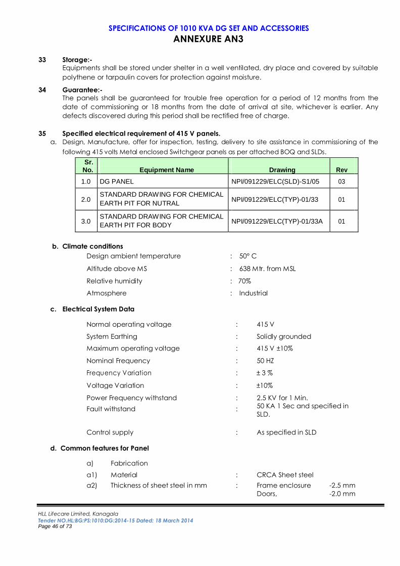
HLL Lifecare Limited, Kanagala
Tender NO.HL:BG:PS:1010:DG:2014-15 Dated: 18 March 2014 Page 46 of 73
SPECIFICATIONS OF 1010 KVA DG SET AND ACCESSORIES
ANNEXURE AN3
33 Storage:-
Equipments shall be stored under shelter in a well ventilated, dry place and covered by suitable
polythene or tarpaulin covers for protection against moisture. 34 Guarantee:-
The panels shall be guaranteed for trouble free operation for a period of 12 months from the
date of commissioning or 18 months from the date of arrival at site, whichever is earlier. Any
defects discovered during this period shall be rectified free of charge.
35 Specified electrical requirement of 415 V panels.
a. Design, Manufacture, offer for inspection, testing, delivery to site assistance in commissioning of the
following 415 volts Metal enclosed Switchgear panels as per attached BOQ and SLDs.
Sr.
No. Equipment Name Drawing Rev
1.0 DG PANEL NPI/091229/ELC(SLD)-S1/05 03
2.0 STANDARD DRAWING FOR CHEMICAL
NPI/091229/ELC(TYP)-01/33 01
EARTH PIT FOR NUTRAL
3.0 STANDARD DRAWING FOR CHEMICAL
NPI/091229/ELC(TYP)-01/33A 01
EARTH PIT FOR BODY
b. Climate conditions
Design ambient temperature : 50° C
Altitude above MS : 638 Mtr. from MSL
Relative humidity : 70%
Atmosphere : Industrial
c. Electrical System Data
Normal operating voltage : 415 V
System Earthing : Solidly grounded
Maximum operating voltage : 415 V ±10%
Nominal Frequency : 50 HZ
Frequency Variation : ± 3 %
Voltage Variation : ±10%
Power Frequency withstand : 2.5 KV for 1 Min.
Fault withstand : 50 KA 1 Sec and specified in
SLD.
Control supply : As specified in SLD
d. Common features for Panel
a) Fabrication
a1) Material : CRCA Sheet steel
a2) Thickness of sheet steel in mm : Frame enclosure -2.5 mm
Doors, -2.0 mm
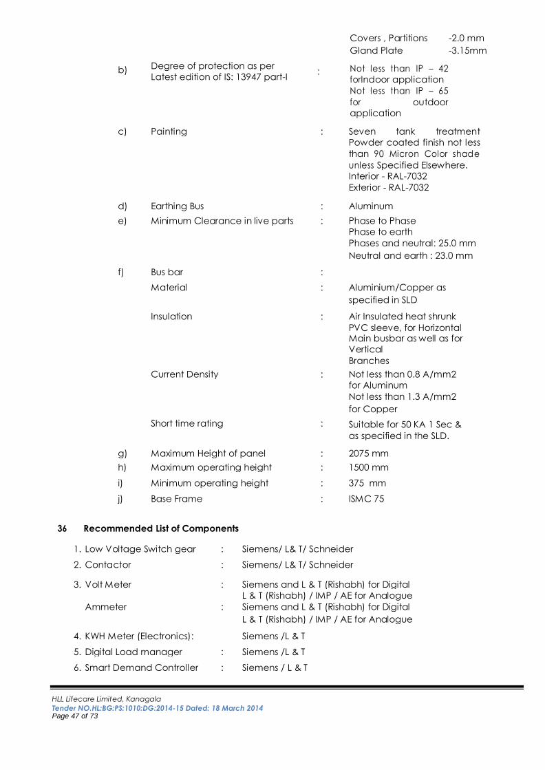
HLL Lifecare Limited, Kanagala
Tender NO.HL:BG:PS:1010:DG:2014-15 Dated: 18 March 2014 Page 47 of 73
Covers , Partitions -2.0 mm
Gland Plate -3.15mm
b) Degree of protection as per
Latest edition of IS: 13947 part-I : Not less than IP – 42
forIndoor application
Not less than IP – 65
for outdoor
application
c) Painting : Seven tank treatment
Powder coated finish not less
than 90 Micron Color shade
unless Specified Elsewhere.
Interior - RAL-7032
Exterior - RAL-7032
d) Earthing Bus : Aluminum
e) Minimum Clearance in live parts : Phase to Phase
Phase to earth
Phases and neutral: 25.0 mm
Neutral and earth : 23.0 mm
f) Bus bar :
Material : Aluminium/Copper as
specified in SLD
Insulation : Air Insulated heat shrunk
PVC sleeve, for Horizontal Main busbar as well as for
Vertical
Branches
Current Density : Not less than 0.8 A/mm2
for Aluminum
Not less than 1.3 A/mm2
for Copper
Short time rating : Suitable for 50 KA 1 Sec &
as specified in the SLD.
g) Maximum Height of panel : 2075 mm
h) Maximum operating height : 1500 mm
i) Minimum operating height : 375 mm
j) Base Frame : ISMC 75
36 Recommended List of Components
1. Low Voltage Switch gear : Siemens/ L& T/ Schneider
2. Contactor : Siemens/ L& T/ Schneider
3. Volt Meter : Siemens and L & T (Rishabh) for Digital
L & T (Rishabh) / IMP / AE for Analogue
Ammeter : Siemens and L & T (Rishabh) for Digital
L & T (Rishabh) / IMP / AE for Analogue
4. KWH Meter (Electronics): Siemens /L & T
5. Digital Load manager : Siemens /L & T
6. Smart Demand Controller : Siemens / L & T
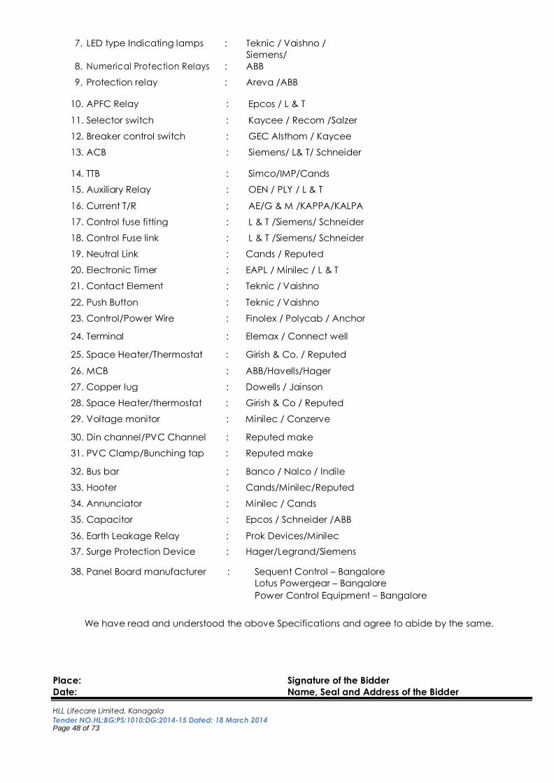
HLL Lifecare Limited, Kanagala
Tender NO.HL:BG:PS:1010:DG:2014-15 Dated: 18 March 2014 Page 48 of 73
7. LED type Indicating lamps : Teknic / Vaishno /
8. Numerical Protection Relays :
Siemens/
ABB
9. Protection relay : Areva /ABB
10. APFC Relay : Epcos / L & T
11. Selector switch : Kaycee / Recom /Salzer
12. Breaker control switch : GEC Alsthom / Kaycee
13. ACB : Siemens/ L& T/ Schneider
14. TTB : Simco/IMP/Cands
15. Auxiliary Relay : OEN / PLY / L & T
16. Current T/R : AE/G & M /KAPPA/KALPA
17. Control fuse fitting : L & T /Siemens/ Schneider
18. Control Fuse link : L & T /Siemens/ Schneider
19. Neutral Link : Cands / Reputed
20. Electronic Timer : EAPL / Minilec / L & T
21. Contact Element : Teknic / Vaishno
22. Push Button : Teknic / Vaishno
23. Control/Power Wire : Finolex / Polycab / Anchor
24. Terminal : Elemax / Connect well
25. Space Heater/Thermostat : Girish & Co. / Reputed
26. MCB : ABB/Havells/Hager
27. Copper lug : Dowells / Jainson
28. Space Heater/thermostat : Girish & Co / Reputed
29. Voltage monitor : Minilec / Conzerve
30. Din channel/PVC Channel : Reputed make
31. PVC Clamp/Bunching tap : Reputed make
32. Bus bar : Banco / Nalco / Indile
33. Hooter : Cands/Minilec/Reputed
34. Annunciator : Minilec / Cands
35. Capacitor : Epcos / Schneider /ABB
36. Earth Leakage Relay : Prok Devices/Minilec
37. Surge Protection Device : Hager/Legrand/Siemens
38. Panel Board manufacturer : Sequent Control – Bangalore
Lotus Powergear – Bangalore
Power Control Equipment – Bangalore
We have read and understood the above Specifications and agree to abide by the same.
Place: Signature of the Bidder
Date: Name, Seal and Address of the Bidder
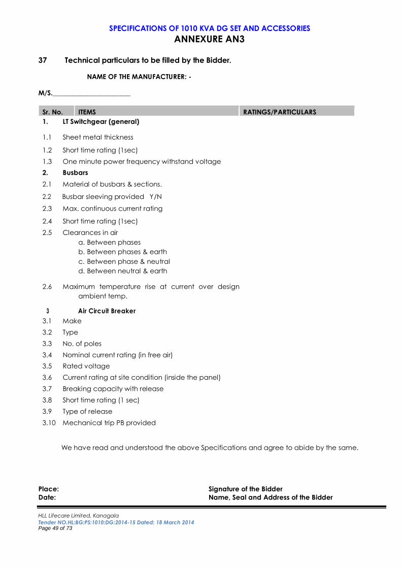
HLL Lifecare Limited, Kanagala
Tender NO.HL:BG:PS:1010:DG:2014-15 Dated: 18 March 2014 Page 49 of 73
SPECIFICATIONS OF 1010 KVA DG SET AND ACCESSORIES
ANNEXURE AN3
37 Technical particulars to be filled by the Bidder.
NAME OF THE MANUFACTURER: -
M/S._______________________
Sr. No. ITEMS RATINGS/PARTICULARS 1. LT Switchgear (general)
1.1 Sheet metal thickness
1.2 Short time rating (1sec)
1.3 One minute power frequency withstand voltage
2. Busbars
2.1 Material of busbars & sections.
2.2 Busbar sleeving provided Y/N
2.3 Max. continuous current rating
2.4 Short time rating (1sec)
2.5 Clearances in air a. Between phases b. Between phases & earth c. Between phase & neutral d. Between neutral & earth
2.6 Maximum temperature rise at current over design
ambient temp.
3 Air Circuit Breaker 3.1 Make
3.2 Type
3.3 No. of poles
3.4 Nominal current rating (in free air)
3.5 Rated voltage
3.6 Current rating at site condition (inside the panel)
3.7 Breaking capacity with release
3.8 Short time rating (1 sec)
3.9 Type of release
3.10 Mechanical trip PB provided
We have read and understood the above Specifications and agree to abide by the same.
Place: Signature of the Bidder
Date: Name, Seal and Address of the Bidder
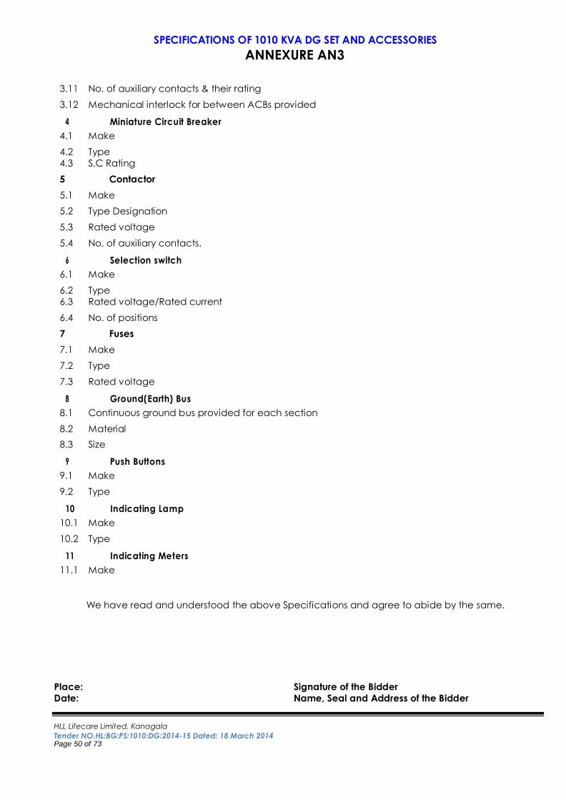
HLL Lifecare Limited, Kanagala
Tender NO.HL:BG:PS:1010:DG:2014-15 Dated: 18 March 2014 Page 50 of 73
SPECIFICATIONS OF 1010 KVA DG SET AND ACCESSORIES
ANNEXURE AN3
3.11 No. of auxiliary contacts & their rating
3.12 Mechanical interlock for between ACBs provided
4 Miniature Circuit Breaker 4.1 Make
4.2 Type
4.3 S.C Rating
5 Contactor
5.1 Make
5.2 Type Designation
5.3 Rated voltage
5.4 No. of auxiliary contacts.
6 Selection switch 6.1 Make
6.2 Type
6.3 Rated voltage/Rated current
6.4 No. of positions
7 Fuses
7.1 Make
7.2 Type
7.3 Rated voltage
8 Ground(Earth) Bus 8.1 Continuous ground bus provided for each section
8.2 Material
8.3 Size
9 Push Buttons 9.1 Make
9.2 Type
10 Indicating Lamp 10.1 Make
10.2 Type
11 Indicating Meters 11.1 Make
We have read and understood the above Specifications and agree to abide by the same.
Place: Signature of the Bidder
Date: Name, Seal and Address of the Bidder
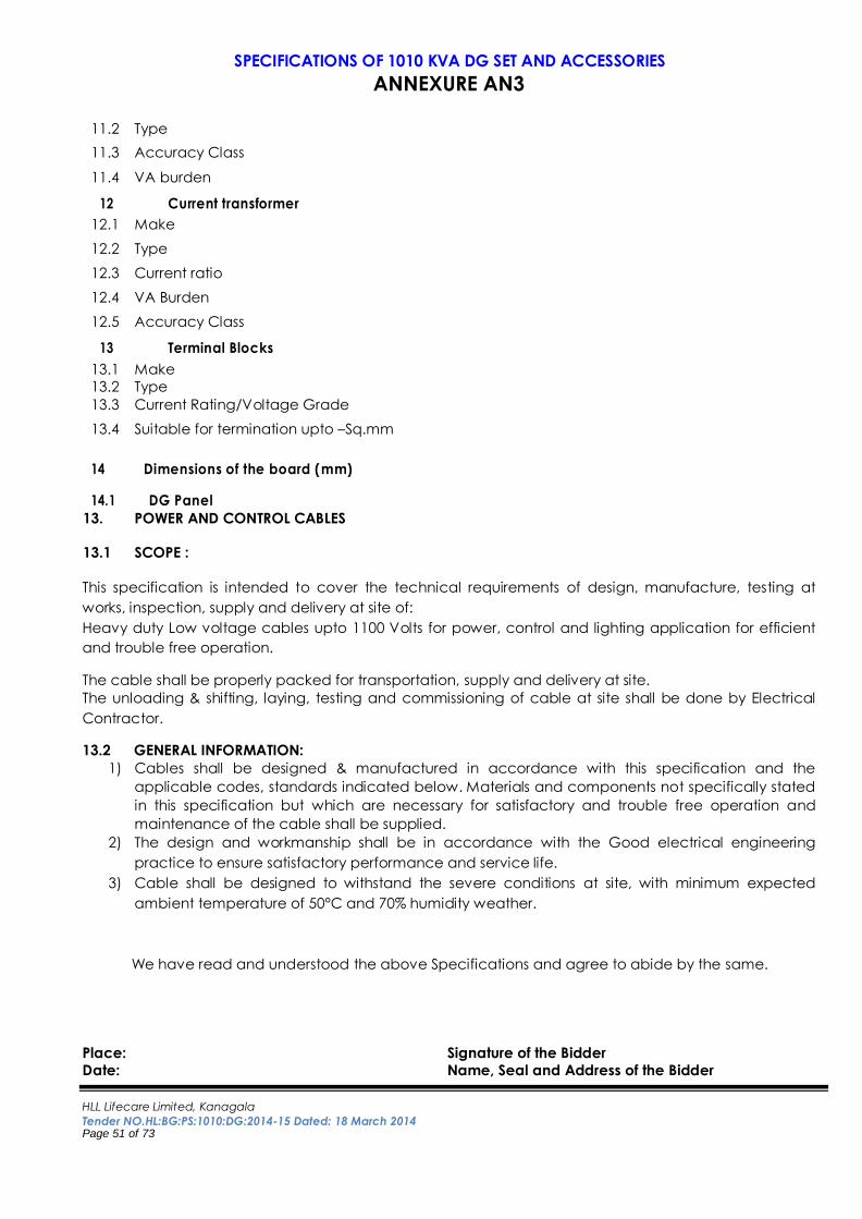
HLL Lifecare Limited, Kanagala
Tender NO.HL:BG:PS:1010:DG:2014-15 Dated: 18 March 2014 Page 51 of 73
SPECIFICATIONS OF 1010 KVA DG SET AND ACCESSORIES
ANNEXURE AN3
11.2 Type
11.3 Accuracy Class
11.4 VA burden
12 Current transformer 12.1 Make
12.2 Type
12.3 Current ratio
12.4 VA Burden
12.5 Accuracy Class
13 Terminal Blocks 13.1 Make
13.2 Type
13.3 Current Rating/Voltage Grade
13.4 Suitable for termination upto –Sq.mm
14 Dimensions of the board (mm)
14.1 DG Panel
13. POWER AND CONTROL CABLES
13.1 SCOPE :
This specification is intended to cover the technical requirements of design, manufacture, testing at
works, inspection, supply and delivery at site of:
Heavy duty Low voltage cables upto 1100 Volts for power, control and lighting application for efficient
and trouble free operation.
The cable shall be properly packed for transportation, supply and delivery at site.
The unloading & shifting, laying, testing and commissioning of cable at site shall be done by Electrical
Contractor.
13.2 GENERAL INFORMATION:
1) Cables shall be designed & manufactured in accordance with this specification and the
applicable codes, standards indicated below. Materials and components not specifically stated
in this specification but which are necessary for satisfactory and trouble free operation and
maintenance of the cable shall be supplied.
2) The design and workmanship shall be in accordance with the Good electrical engineering
practice to ensure satisfactory performance and service life.
3) Cable shall be designed to withstand the severe conditions at site, with minimum expected
ambient temperature of 50°C and 70% humidity weather.
We have read and understood the above Specifications and agree to abide by the same.
Place: Signature of the Bidder
Date: Name, Seal and Address of the Bidder
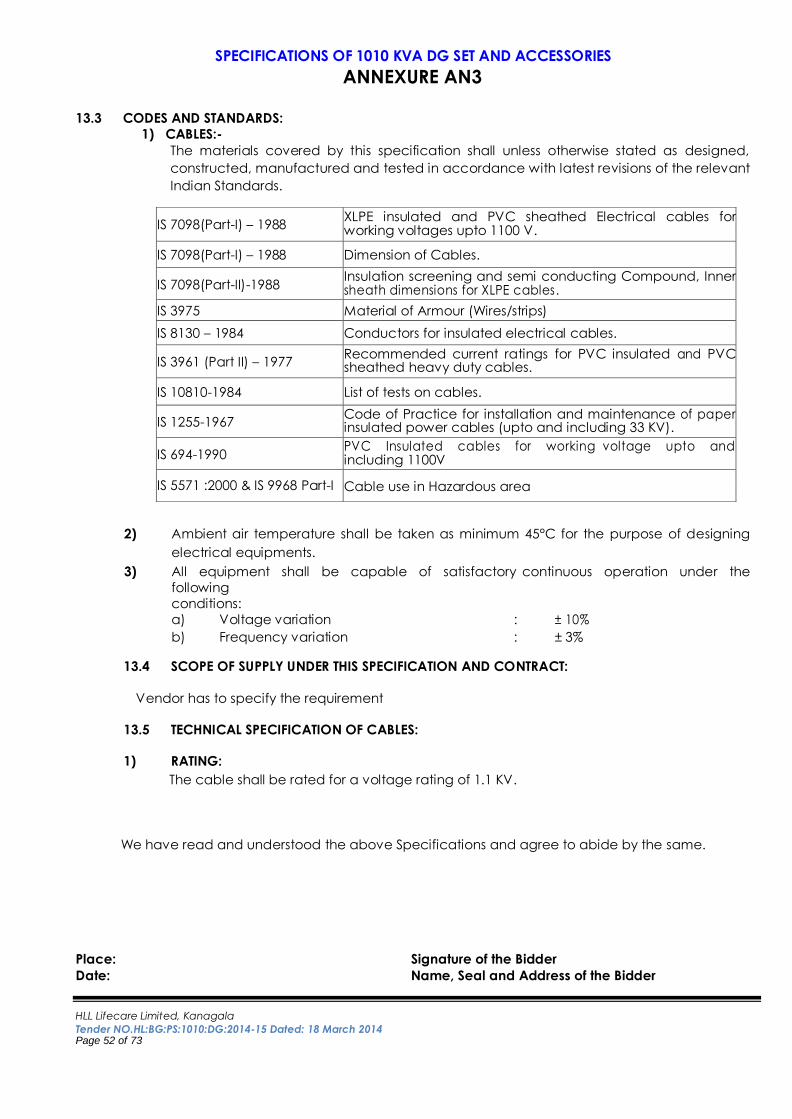
HLL Lifecare Limited, Kanagala
Tender NO.HL:BG:PS:1010:DG:2014-15 Dated: 18 March 2014 Page 52 of 73
SPECIFICATIONS OF 1010 KVA DG SET AND ACCESSORIES
ANNEXURE AN3
13.3 CODES AND STANDARDS:
1) CABLES:-
The materials covered by this specification shall unless otherwise stated as designed,
constructed, manufactured and tested in accordance with latest revisions of the relevant
Indian Standards.
2) Ambient air temperature shall be taken as minimum 45°C for the purpose of designing
electrical equipments.
3) All equipment shall be capable of satisfactory continuous operation under the
following conditions:
a) Voltage variation : ± 10%
b) Frequency variation : ± 3%
13.4 SCOPE OF SUPPLY UNDER THIS SPECIFICATION AND CONTRACT:
Vendor has to specify the requirement
13.5 TECHNICAL SPECIFICATION OF CABLES:
1) RATING: The cable shall be rated for a voltage rating of 1.1 KV.
We have read and understood the above Specifications and agree to abide by the same.
Place: Signature of the Bidder
Date: Name, Seal and Address of the Bidder
IS 7098(Part-I) – 1988 XLPE insulated and PVC sheathed Electrical cables for working voltages upto 1100 V.
IS 7098(Part-I) – 1988 Dimension of Cables.
IS 7098(Part-II)-1988 Insulation screening and semi conducting Compound, Inner sheath dimensions for XLPE cables.
IS 3975 Material of Armour (Wires/strips)
IS 8130 – 1984 Conductors for insulated electrical cables.
IS 3961 (Part II) – 1977 Recommended current ratings for PVC insulated and PVC sheathed heavy duty cables.
IS 10810-1984 List of tests on cables.
IS 1255-1967 Code of Practice for installation and maintenance of paper insulated power cables (upto and including 33 KV).
IS 694-1990 PVC Insulated cables for working voltage upto and including 1100V
IS 5571 :2000 & IS 9968 Part-I Cable use in Hazardous area
HLL Lifecare Limited, Kanagala
Tender NO.HL:BG:PS:1010:DG:2014-15 Dated: 18 March 2014 Page 53 of 73
SPECIFICATIONS OF 1010 KVA DG SET AND ACCESSORIES
ANNEXURE AN3
2) CONDUCTOR:
The conductor shall be Aluminum or Copper as stated in BOQ. It shall be manufactured
with stranded shaped/circular conductors and shall have easy to handle while shaping
makes them compact. Cables from 16 sqmm size, conductors are in “stranded shaped”.
The conductors shall be manufactured in equal segments and compacted, then laid
together to minimize the AC losses due to skin and proximity effects.
Conductor shall comprise High tensile strength, electrical grade superior conductivity, and
better flexibility.
3) INSULATION:
The conductor shall be insulated with suitably compounded PVC/XLPE applied to the
conductor by the extrusion. Insulation shall withstand to thermal and thermo mechanical
stresses safely at continuous normal and short circuit temperature conditions.
The PVC/XLPE compound used for insulation shall have reduced flame propagation
property.
This shall also have reduced emission of hydrogen-chloride gas fumes etc. when severely
overheated during fires. It shall be capable to limiting displacement of cores in cables
during short circuit.
The cables shall be manufactured with latest manufacturing process to get improved
reliability and compactness of cables.
4) CORE IDENTIFICATION:
The cores of the cables shall be provided with the colour scheme of XLPE/PVC insulation
as per IS for any easy identification.
Different cores in a cable are identified by colours. Flowing colour scheme is followed.
a. Single core: Red, Yellow, Blue, Black or Neutral.
b. Two core: Red and Black.
c. Three core : Red, Yellow, and Blue
d. Four core: Red, Yellow, Blue, and Black.
e. Five core: Red, Yellow, Blue, Black and Grey.
Wherever the number of cores exceeds 5, two adjacent cores (counting core and
direction core) in each layer are colored blue and yellow respectively and the remaining
cores are Grey. In 3.5 core cables, three main cores are Red, Yellow, Blue and reduced
core is black. Controlcables with core identification shall be provided with numerals. All
multi core cables are laid up as per the colour scheme indicated above with
thermoplastic fillers in the center and the interstices whenever applicable to make the
cable circular. Top layer of the laid up is always with right hand direction.
5) INNER SHEATH:
Inner sheath shall be provided thermoplastic material softer than insulation compatible
with thermal rating of insulation. Inner sheath shall be applied either with extrusion or by
wrapping closely on the laid of cores and stripped with ease without damaging insulation.
We have read and understood the above Specifications and agree to abide by the same.
Place: Signature of the Bidder
Date: Name, Seal and Address of the Bidder
HLL Lifecare Limited, Kanagala
Tender NO.HL:BG:PS:1010:DG:2014-15 Dated: 18 March 2014 Page 54 of 73
SPECIFICATIONS OF 1010 KVA DG SET AND ACCESSORIES
ANNEXURE AN3
6) OUTER SHEATH:
The Outer sheath shall be provided with an extruded PVC/Polymer on armouring. The
PVC/polymer compound used for outer sheath shall be resistant to termites, fungus and
rodent attacks and shall also have reduced flame propagation property.
Tests for cable flame retardancy shall be in accordance with the referenced standards.
The outer sheath of cables shall be embossed or engraved with
a) The voltage designation
b) Manufacturers identification
c) Number of Cores and nominal cross sectional area of conductors
d) The drum progressive length of cable at every meter. (The starting point being the cable
end at its inner coil on the cable drum.)
e) In case of XLPE insulated PVC sheathed cables, cable filler, inner and outer sheath shall
confirm to ST-2 compound as per IS-5831. The inner sheath shall be applied over laid
cores by extrusion.
7) IDENTIFICATION:
The manufacturer shall be provide Drum identification labels as under
Drum identification labels shall be of non-corrosive, non-hygroscopic material and
attached to the outside and inside of the drum flanges.
Labels shall be protected by transparent plastic envelopes and give the following
information:
a) Drum identification number and its direction of rotation for cable removal.
b) Cable voltage grade
c) Cable construction (e.g. PVC or AYFY)
d) Number of cores and cross sectional area
e) Cable quantity (Metres)
f) Purchase order number and item number
g) Total weight of cable and drum (kg)
h) Manufacturer's name
i) Year of manufacture
j) Stock code number
8) TESTING AND QUALITY TESTING:
All Raw materials shall be used in manufacture of power cables are inspected and tested
for compliance with relevant Indian standards and shall meet the requirement of relevant
Indian standards. Cables shall be inspected at all stages of manufacturing to ensure
conformity with internal processing standards with the requirement of relevant Indian
standards. The cables shall be inspected stringent physical and dimensional checks for
conformity to the required standards. The cables shall be tested for all applicable Routine
tests, from a lot of cables one of the cables of each type shall be tested for type tests as
per relevant standards. 6 copies each of the above test certificates shall be submitted to
the Owner. The Client/consultant reserve the right to witness all tests specified on
completed cables. The Vendor shall give two weeks notice of tests prior to
commencement. The Client/consultant reserve the right to inspect cables at the Sellers
works at any time prior to dispatch to prove compliance with the specifications. Cables
shall not be dispatched unless the test certificates have been approved by the Client.
We have read and understood the above Specifications and agree to abide by the same.
Place: Signature of the Bidder
Date: Name, Seal and Address of the Bidder
HLL Lifecare Limited, Kanagala
Tender NO.HL:BG:PS:1010:DG:2014-15 Dated: 18 March 2014 Page 55 of 73
SPECIFICATIONS OF 1010 KVA DG SET AND ACCESSORIES
ANNEXURE AN3
9) PACKING:
The cables shall be drummed & supplied in strong, returnable steel drums for HV Cable
and non-returnable wooden drums of heavy construction for LV cable with suitable
size barrel diameter, width and spindle hole.
Non-returnable wooden drums, where the manufacturer can guarantee that such
drums are of sufficient strength to protect cable during shipping, handling and outdoor
storage for three year period.
Each cable drum shall be marked with particulars of cable size, voltage class, Cable
length, direction of rolling, position of outer end, gross weight ISI certification mark
etc.
Cable ends shall be sealed to protect against incase of moisture with non-
hygroscopic heat shrink caps and fixed to the drum so that both ends are accessible.
To protect mechanical damage the cable drum shall be overall lagged with wooden
battens and steel straps.
Drums shall be suitable for long term outdoor storage at site.
All cable drums shall have the Purchase Order Number, Purchase Order Item Number,
Drum Number and Stock Code Number clearly stenciled on the outside of both
flanges.
10) DATA SHEET:
The Vendor shall provide the following data with his quotation:
Standard and maximum drum lengths for all the types of cable offered and his proposed
drum lengths for all items.
Descriptive literature (catalogues etc.).
Note: For PVC/XLPE Cables* Vendor to specify in each size of the cables
11) DEVIATION:
Deviations from this specification are only acceptable where the Vendor has listed in his
quotation the requirements he cannot, or does not, wish to comply with and the client
has accepted, in writing, the deviations before the order is placed.
In the absence of a list of deviations, it will be assumed by the client that the vendor
complies fully with this specification.
12) CABLE SPECIFICATION SHEET
Type of Low Voltage Power & Control Cables
1 Low Voltage Power & Control Cables
1.1 PVC 1.1 KV grade (or 1100 V grade) FRLS Cable
1.2 XLPE 1.1 KV grade (or 1100 V grade) FRLS Cable
We have read and understood the above Specifications and agree to abide by the same.
Place: Signature of the Bidder
Date: Name, Seal and Address of the Bidder
HLL Lifecare Limited, Kanagala
Tender NO.HL:BG:PS:1010:DG:2014-15 Dated: 18 March 2014 Page 56 of 73
SPECIFICATIONS OF 1010 KVA DG SET AND ACCESSORIES
ANNEXURE AN3
Abbreviations
o o o O
- - - Y PVC Sheathed
- - W - Wire Armoured (GI)
- - F - Strip Armoured (GI)
- - Wa - Wire Armoured (Al.)
- - Fa - Strip Armoured (Al.)
- - - - Un armour
- 2X - - XLPE Insulated
- Y - - PVC Insulated
- - - - Copper Conductor
A - - - Aluminum Conductor
PVC Polyvinyl-chloride XLPE Cross linked polyethylene
SWA Single Wire Armoured
- (Galvanised steel flat or round wire armour for multicore cables.)
- (Aluminium wire armour for single core cables.)
13.1 Low Voltage Power & Control Cables
Cable Type: 1.1 PVC 1.1 kV grade (or 1100 V grade)
Rated Voltage: 650/1100V (IS 1554 part 1)
System Voltage: Up to 1000 V, 3 phase, 3 or 4 wire AC. Neutral solidly earthed.
Up to 250 V DC.
Service: General purpose power distribution and control.
Construction: Conductors (As specified in the Specification)
Or
Conductors up to and including 6mm2 shall be stranded copper.
Stranded aluminium conductor above 10mm2 above circular or
shaped section.
Insulation PVC
Core Identification Up to four cores – colours
1 core – black
2 core - red, black
2 core + earth - red, black, green/yellow
3 core - red, yellow, blue
4 core - red, yellow, blue, black.
We have read and understood the above Specifications and agree to abide by the same.
Place: Signature of the Bidder Date: Name, Seal and Address of the Bidder
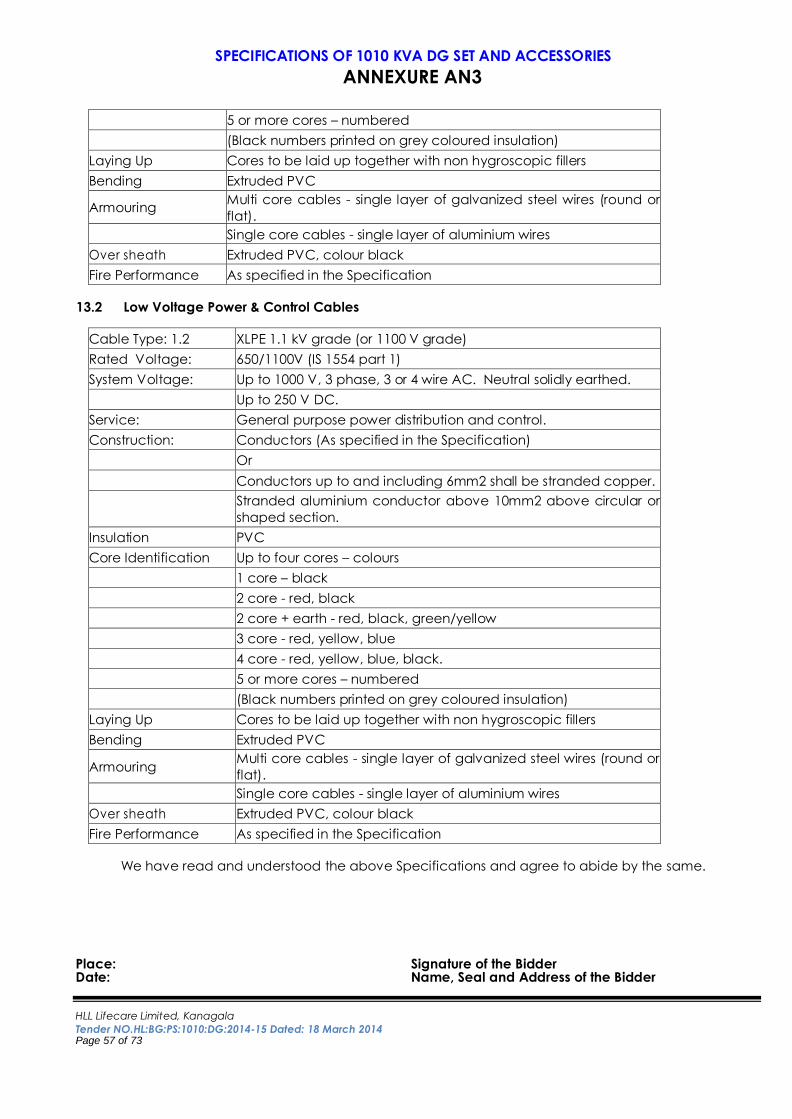
HLL Lifecare Limited, Kanagala
Tender NO.HL:BG:PS:1010:DG:2014-15 Dated: 18 March 2014 Page 57 of 73
SPECIFICATIONS OF 1010 KVA DG SET AND ACCESSORIES
ANNEXURE AN3
5 or more cores – numbered
(Black numbers printed on grey coloured insulation)
Laying Up Cores to be laid up together with non hygroscopic fillers
Bending Extruded PVC
Armouring
Multi core cables - single layer of galvanized steel wires (round or
flat).
Single core cables - single layer of aluminium wires
Over sheath Extruded PVC, colour black
Fire Performance As specified in the Specification
13.2 Low Voltage Power & Control Cables
Cable Type: 1.2 XLPE 1.1 kV grade (or 1100 V grade)
Rated Voltage: 650/1100V (IS 1554 part 1)
System Voltage: Up to 1000 V, 3 phase, 3 or 4 wire AC. Neutral solidly earthed.
Up to 250 V DC.
Service: General purpose power distribution and control.
Construction: Conductors (As specified in the Specification)
Or
Conductors up to and including 6mm2 shall be stranded copper.
Stranded aluminium conductor above 10mm2 above circular or
shaped section.
Insulation PVC
Core Identification Up to four cores – colours
1 core – black
2 core - red, black
2 core + earth - red, black, green/yellow
3 core - red, yellow, blue
4 core - red, yellow, blue, black.
5 or more cores – numbered
(Black numbers printed on grey coloured insulation)
Laying Up Cores to be laid up together with non hygroscopic fillers
Bending Extruded PVC
Armouring Multi core cables - single layer of galvanized steel wires (round or
flat).
Single core cables - single layer of aluminium wires
Over sheath Extruded PVC, colour black
Fire Performance As specified in the Specification
We have read and understood the above Specifications and agree to abide by the same.
Place: Signature of the Bidder Date: Name, Seal and Address of the Bidder
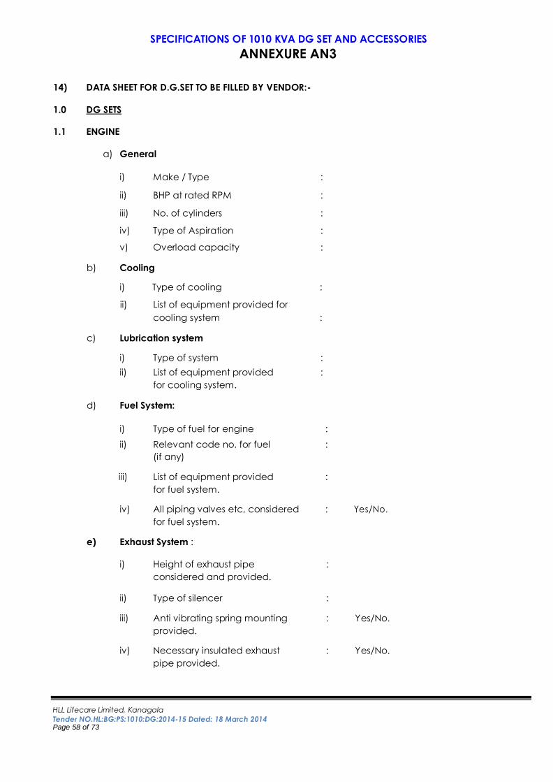
HLL Lifecare Limited, Kanagala
Tender NO.HL:BG:PS:1010:DG:2014-15 Dated: 18 March 2014 Page 58 of 73
SPECIFICATIONS OF 1010 KVA DG SET AND ACCESSORIES
ANNEXURE AN3
14) DATA SHEET FOR D.G.SET TO BE FILLED BY VENDOR:-
1.0 DG SETS
1.1 ENGINE
a) General
i) Make / Type :
ii) BHP at rated RPM :
iii) No. of cylinders :
iv) Type of Aspiration :
v) Overload capacity :
b) Cooling
i) Type of cooling :
ii) List of equipment provided for cooling system :
c) Lubrication system
i) Type of system :
ii) List of equipment provided :
for cooling system.
d) Fuel System:
i) Type of fuel for engine :
ii) Relevant code no. for fuel : (if any)
iii) List of equipment provided : for fuel system.
iv) All piping valves etc, considered : Yes/No.
for fuel system.
e) Exhaust System :
i) Height of exhaust pipe :
considered and provided.
ii) Type of silencer :
iii) Anti vibrating spring mounting : Yes/No.
provided.
iv) Necessary insulated exhaust : Yes/No.
pipe provided.
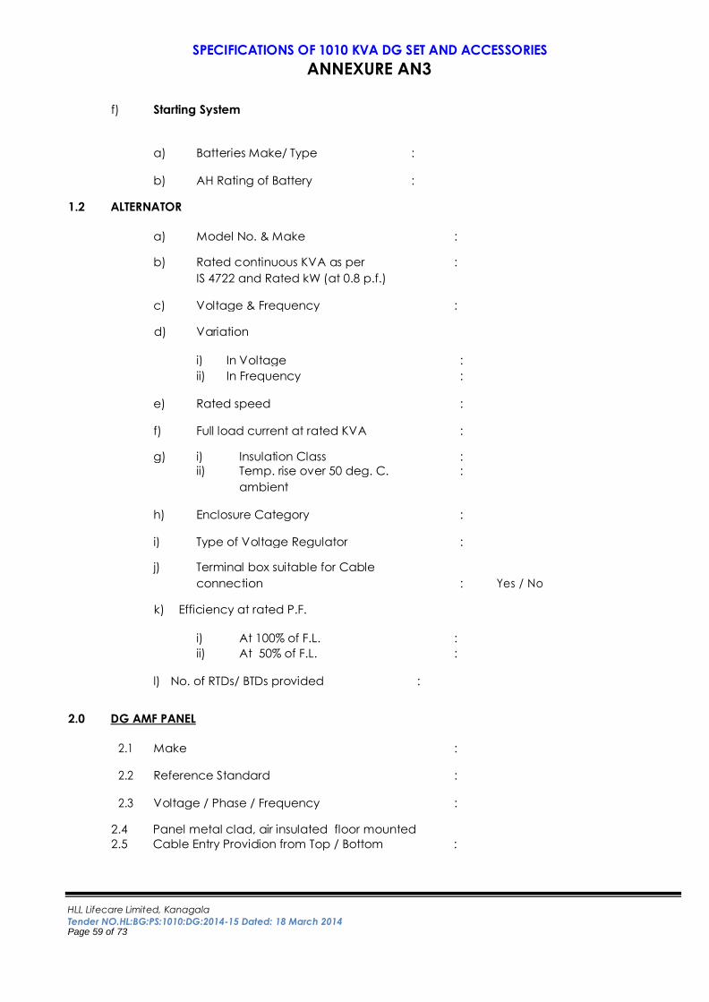
HLL Lifecare Limited, Kanagala
Tender NO.HL:BG:PS:1010:DG:2014-15 Dated: 18 March 2014 Page 59 of 73
SPECIFICATIONS OF 1010 KVA DG SET AND ACCESSORIES
ANNEXURE AN3
f) Starting System
a) Batteries Make/ Type :
b) AH Rating of Battery :
1.2 ALTERNATOR
a) Model No. & Make :
b) Rated continuous KVA as per :
IS 4722 and Rated kW (at 0.8 p.f.)
c) Voltage & Frequency :
d) Variation
i) In Voltage :
ii) In Frequency :
e) Rated speed :
f) Full load current at rated KVA :
g) i) Insulation Class : ii) Temp. rise over 50 deg. C. :
ambient
h) Enclosure Category :
i) Type of Voltage Regulator :
j) Terminal box suitable for Cable connection : Yes / No
k) Efficiency at rated P.F.
i) At 100% of F.L. :
ii) At 50% of F.L. :
l) No. of RTDs/ BTDs provided :
2.0 DG AMF PANEL
2.1 Make :
2.2 Reference Standard :
2.3 Voltage / Phase / Frequency :
2.4 Panel metal clad, air insulated floor mounted
2.5 Cable Entry Providion from Top / Bottom :
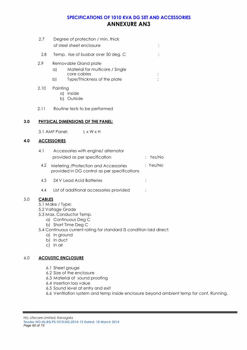
HLL Lifecare Limited, Kanagala
Tender NO.HL:BG:PS:1010:DG:2014-15 Dated: 18 March 2014 Page 60 of 73
SPECIFICATIONS OF 1010 KVA DG SET AND ACCESSORIES
ANNEXURE AN3
2.7 Degree of protection / min. thick of steel sheet enclosure :
2.8 Temp. rise of busbar over 50 deg. C : 2.9 Removable Gland plate
a) Material for multicore / Single core cables :
b) Type/Thickness of the plate : 2.10 Painting
a) Inside
b) Outside
2.11 Routine tests to be performed 3.0 PHYSICAL DIMENSIONS OF THE PANEL:
3.1 AMF Panel: L x W x H 4.0 ACCESSORIES
4.1 Accessories with engine/ alternator provided as per specification : Yes/No
4.2 Metering /Protection and Accessories
provided in DG control as per specifications
: Yes/No
4.3 24 V Lead Acid Batteries :
4.4 List of additional accessories provided :
5.0 CABLES
5.1 Make / Type:
5.2 Voltage Grade
5.3 Max. Conductor Temp.
a) Continuous Deg C
b) Short Time Deg C
5.4 Continuous current rating for standard IS condition laid direct:
a) In ground
b) In duct
c) In air
6.0 ACOUSTIC ENCLOSURE
6.1 Sheet gauge
6.2 Size of the enclosure
6.3 Material of sound proofing
6.4 Insertion loss value
6.5 Sound level at entry and exit
6.6 Ventilation system and temp inside enclosure beyond ambient temp for cont. Running.
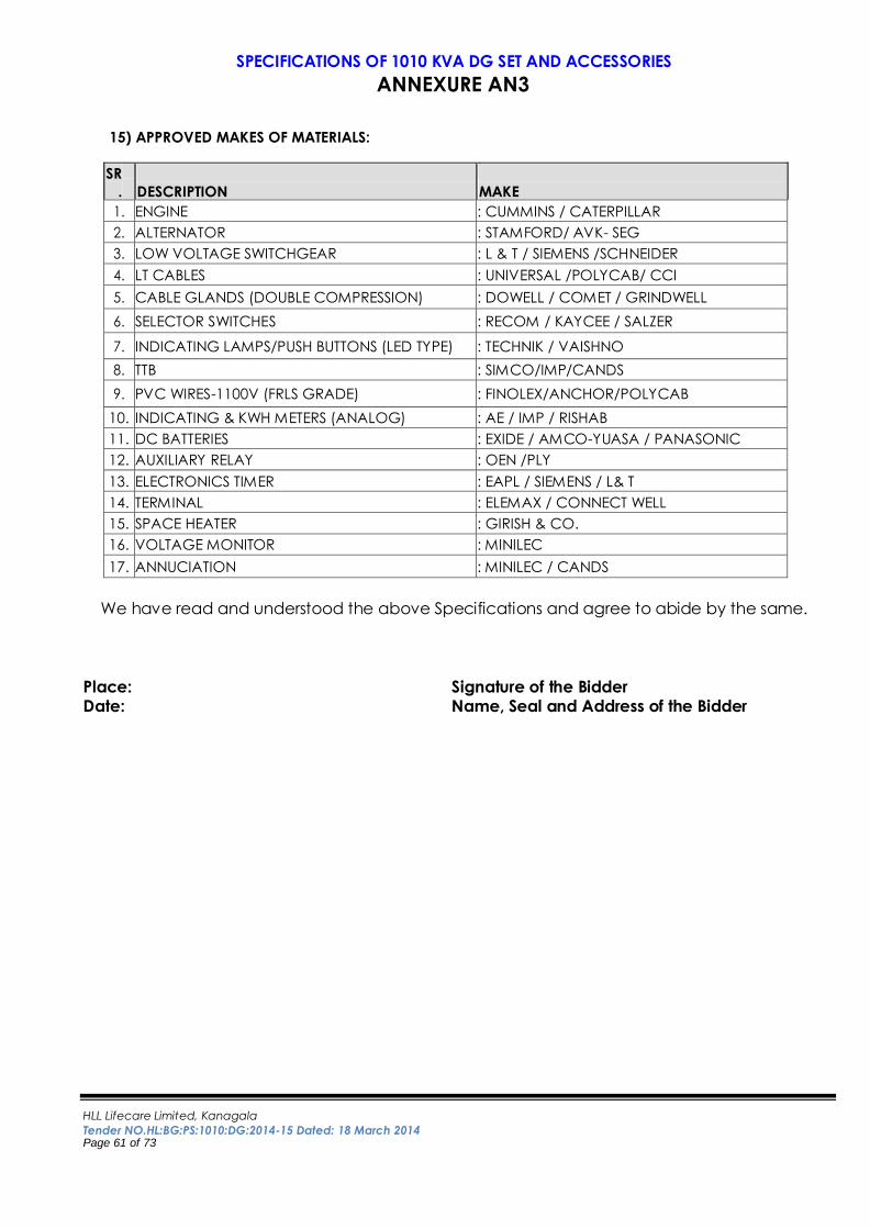
HLL Lifecare Limited, Kanagala
Tender NO.HL:BG:PS:1010:DG:2014-15 Dated: 18 March 2014 Page 61 of 73
SPECIFICATIONS OF 1010 KVA DG SET AND ACCESSORIES
ANNEXURE AN3
15) APPROVED MAKES OF MATERIALS:
SR
. DESCRIPTION MAKE
1. ENGINE : CUMMINS / CATERPILLAR
2. ALTERNATOR : STAMFORD/ AVK- SEG
3. LOW VOLTAGE SWITCHGEAR : L & T / SIEMENS /SCHNEIDER
4. LT CABLES : UNIVERSAL /POLYCAB/ CCI
5. CABLE GLANDS (DOUBLE COMPRESSION) : DOWELL / COMET / GRINDWELL
6. SELECTOR SWITCHES : RECOM / KAYCEE / SALZER
7. INDICATING LAMPS/PUSH BUTTONS (LED TYPE) : TECHNIK / VAISHNO
8. TTB : SIMCO/IMP/CANDS
9. PVC WIRES-1100V (FRLS GRADE) : FINOLEX/ANCHOR/POLYCAB
10. INDICATING & KWH METERS (ANALOG) : AE / IMP / RISHAB
11. DC BATTERIES : EXIDE / AMCO-YUASA / PANASONIC
12. AUXILIARY RELAY : OEN /PLY
13. ELECTRONICS TIMER : EAPL / SIEMENS / L& T
14. TERMINAL : ELEMAX / CONNECT WELL
15. SPACE HEATER : GIRISH & CO.
16. VOLTAGE MONITOR : MINILEC
17. ANNUCIATION : MINILEC / CANDS
We have read and understood the above Specifications and agree to abide by the same.
Place: Signature of the Bidder Date: Name, Seal and Address of the Bidder
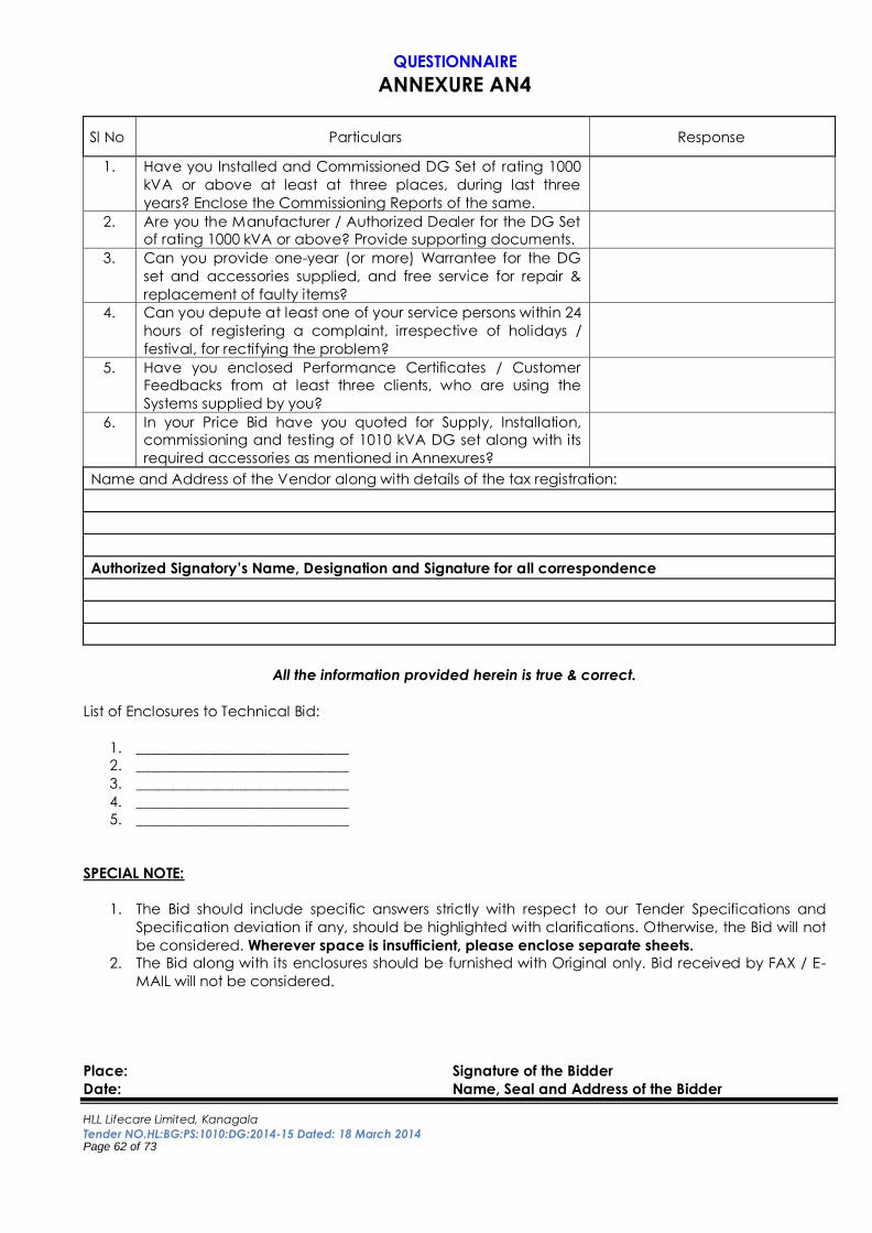
HLL Lifecare Limited, Kanagala
Tender NO.HL:BG:PS:1010:DG:2014-15 Dated: 18 March 2014 Page 62 of 73
QUESTIONNAIRE
ANNEXURE AN4
Sl No Particulars Response
1. Have you Installed and Commissioned DG Set of rating 1000
kVA or above at least at three places, during last three
years? Enclose the Commissioning Reports of the same.
2. Are you the Manufacturer / Authorized Dealer for the DG Set
of rating 1000 kVA or above? Provide supporting documents.
3. Can you provide one-year (or more) Warrantee for the DG
set and accessories supplied, and free service for repair &
replacement of faulty items?
4. Can you depute at least one of your service persons within 24
hours of registering a complaint, irrespective of holidays /
festival, for rectifying the problem?
5. Have you enclosed Performance Certificates / Customer
Feedbacks from at least three clients, who are using the
Systems supplied by you?
6. In your Price Bid have you quoted for Supply, Installation,
commissioning and testing of 1010 kVA DG set along with its
required accessories as mentioned in Annexures?
Name and Address of the Vendor along with details of the tax registration:
Authorized Signatory’s Name, Designation and Signature for all correspondence
All the information provided herein is true & correct.
List of Enclosures to Technical Bid:
1. _____________________________
2. _____________________________
3. _____________________________
4. _____________________________
5. _____________________________
SPECIAL NOTE:
1. The Bid should include specific answers strictly with respect to our Tender Specifications and
Specification deviation if any, should be highlighted with clarifications. Otherwise, the Bid will not
be considered. Wherever space is insufficient, please enclose separate sheets.
2. The Bid along with its enclosures should be furnished with Original only. Bid received by FAX / E-
MAIL will not be considered.
Place: Signature of the Bidder
Date: Name, Seal and Address of the Bidder
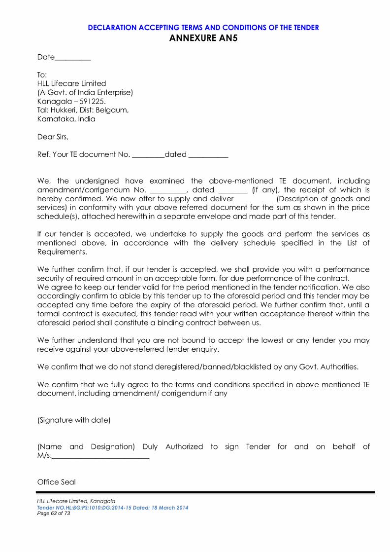
HLL Lifecare Limited, Kanagala
Tender NO.HL:BG:PS:1010:DG:2014-15 Dated: 18 March 2014 Page 63 of 73
DECLARATION ACCEPTING TERMS AND CONDITIONS OF THE TENDER
ANNEXURE AN5
Date__________
To: HLL Lifecare Limited
(A Govt. of India Enterprise)
Kanagala – 591225. Tal: Hukkeri, Dist: Belgaum,
Karnataka, India
Dear Sirs,
Ref. Your TE document No. _________dated ___________
We, the undersigned have examined the above-mentioned TE document, including
amendment/corrigendum No. __________, dated ________ (if any), the receipt of which is
hereby confirmed. We now offer to supply and deliver___________ (Description of goods and services) in conformity with your above referred document for the sum as shown in the price
schedule(s), attached herewith in a separate envelope and made part of this tender.
If our tender is accepted, we undertake to supply the goods and perform the services as
mentioned above, in accordance with the delivery schedule specified in the List of
Requirements.
We further confirm that, if our tender is accepted, we shall provide you with a performance
security of required amount in an acceptable form, for due performance of the contract.
We agree to keep our tender valid for the period mentioned in the tender notification. We also accordingly confirm to abide by this tender up to the aforesaid period and this tender may be
accepted any time before the expiry of the aforesaid period. We further confirm that, until a
formal contract is executed, this tender read with your written acceptance thereof within the
aforesaid period shall constitute a binding contract between us.
We further understand that you are not bound to accept the lowest or any tender you may
receive against your above-referred tender enquiry.
We confirm that we do not stand deregistered/banned/blacklisted by any Govt. Authorities.
We confirm that we fully agree to the terms and conditions specified in above mentioned TE document, including amendment/ corrigendum if any
(Signature with date)
(Name and Designation) Duly Authorized to sign Tender for and on behalf of M/s.___________________________
Office Seal
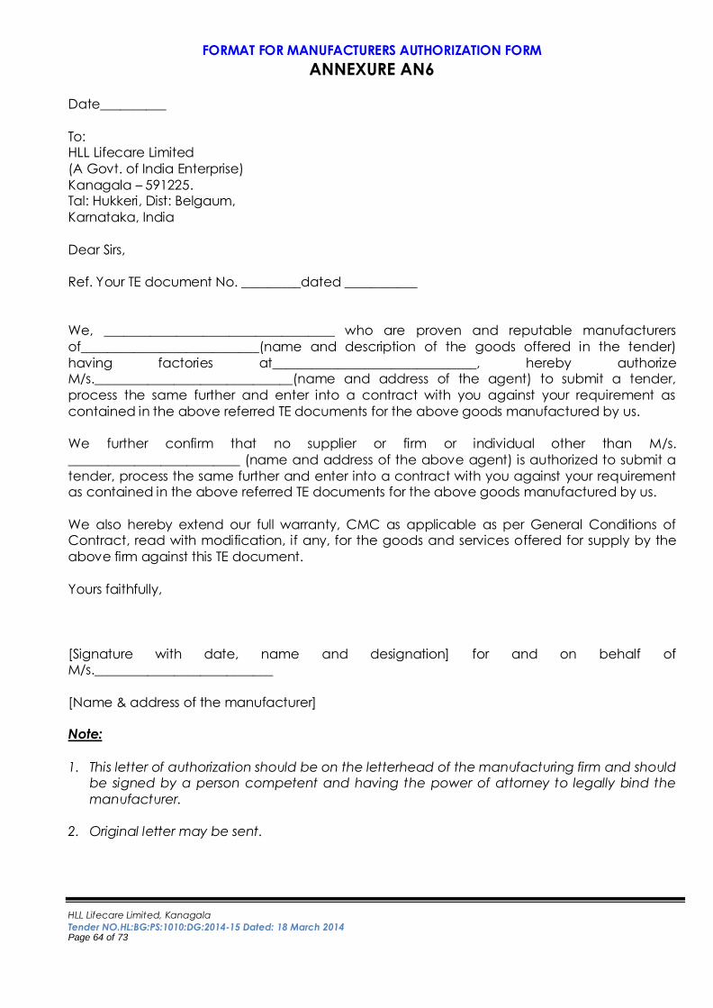
HLL Lifecare Limited, Kanagala
Tender NO.HL:BG:PS:1010:DG:2014-15 Dated: 18 March 2014 Page 64 of 73
FORMAT FOR MANUFACTURERS AUTHORIZATION FORM
ANNEXURE AN6
Date__________
To: HLL Lifecare Limited
(A Govt. of India Enterprise)
Kanagala – 591225. Tal: Hukkeri, Dist: Belgaum,
Karnataka, India
Dear Sirs,
Ref. Your TE document No. _________dated ___________
We, ___________________________________ who are proven and reputable manufacturers
of___________________________(name and description of the goods offered in the tender)
having factories at_______________________________, hereby authorize M/s.______________________________(name and address of the agent) to submit a tender,
process the same further and enter into a contract with you against your requirement as
contained in the above referred TE documents for the above goods manufactured by us.
We further confirm that no supplier or firm or individual other than M/s.
__________________________ (name and address of the above agent) is authorized to submit a
tender, process the same further and enter into a contract with you against your requirement as contained in the above referred TE documents for the above goods manufactured by us.
We also hereby extend our full warranty, CMC as applicable as per General Conditions of Contract, read with modification, if any, for the goods and services offered for supply by the
above firm against this TE document.
Yours faithfully,
[Signature with date, name and designation] for and on behalf of M/s.___________________________
[Name & address of the manufacturer] Note:
1. This letter of authorization should be on the letterhead of the manufacturing firm and should be signed by a person competent and having the power of attorney to legally bind the
manufacturer.
2. Original letter may be sent.
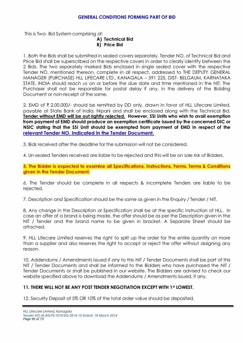
HLL Lifecare Limited, Kanagala
Tender NO.HL:BG:PS:1010:DG:2014-15 Dated: 18 March 2014 Page 65 of 73
GENERAL CONDITIONS FORMING PART OF BID
This is Two- Bid System comprising of: A) Technical Bid
B) Price Bid
1. Both the Bids shall be submitted in sealed covers separately. Tender NO. of Technical Bid and
Price Bid shall be superscribed on the respective covers in order to clearly identify between the 2 Bids. The two separately marked Bids enclosed in single sealed cover with the respective
Tender NO. mentioned thereon, complete in all respect, addressed to THE DEPUTY GENERAL
MANAGER (PURCHASE) HLL LIFECARE LTD., KANAGALA – 591 225, DIST- BELGAUM, KARNATAKA
STATE, INDIA should reach us on or before the due date and time mentioned in the NIT. The Purchaser shall not be responsible for postal delay if any, in the delivery of the Bidding
Document or non-receipt of the same.
2. EMD of ` 2,00,000/- should be remitted by DD only, drawn in favor of HLL Lifecare Limited,
payable at State Bank of India, Nipani and shall be enclosed along with the Technical Bid. Tender without EMD will be out rightly rejected. However, SSI Units who wish to avail exemption
from payment of EMD should produce an exemption certificate issued by the concerned DIC or
NSIC stating that the SSI Unit should be exempted from payment of EMD in respect of the
relevant Tender NO. Indicated in the Tender Document.
3. Bids received after the deadline for the submission will not be considered.
4. Un-sealed Tenders received are liable to be rejected and this will be on sole risk of Bidders.
5. The Bidder is expected to examine all Specifications, Instructions, Forms, Terms & Conditions
given in the Tender Document.
6. The Tender should be complete in all respects & incomplete Tenders are liable to be
rejected.
7. Description and Specification should be the same as given in the Enquiry / Tender / NIT.
8. Any change in the Description or Specification shall be at the specific instruction of HLL. In case an offer of a brand is being made, the offer should be as per the Description given in the
NIT / Tender and the brand name to be given in bracket. A Separate Sheet should be
attached.
9. HLL Lifecare Limited reserves the right to split up the order for the entire quantity on more
than a supplier and also reserves the right to accept or reject the offer without assigning any
reason.
10. Addendums / Amendments issued if any to this NIT / Tender Documents shall be part of this
NIT / Tender Documents and shall be informed to the Bidders who have purchased the NIT / Tender Documents or shall be published in our website. The Bidders are advised to check our
website specified above to download the Addendums / Amendments issued, if any.
11. THERE WILL NOT BE ANY POST TENDER NEGOTIATION EXCEPT WITH 1st LOWEST.
12. Security Deposit of 5% OR 10% of the total order value should be deposited.
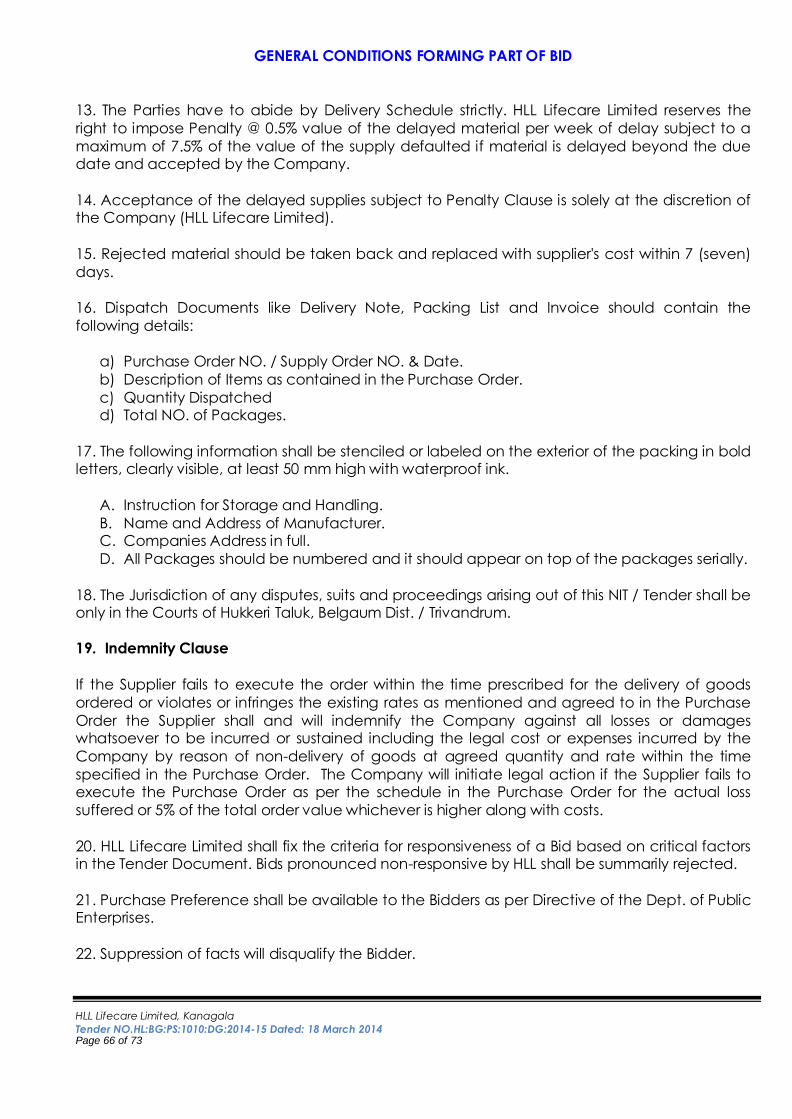
HLL Lifecare Limited, Kanagala
Tender NO.HL:BG:PS:1010:DG:2014-15 Dated: 18 March 2014 Page 66 of 73
GENERAL CONDITIONS FORMING PART OF BID
13. The Parties have to abide by Delivery Schedule strictly. HLL Lifecare Limited reserves the
right to impose Penalty @ 0.5% value of the delayed material per week of delay subject to a
maximum of 7.5% of the value of the supply defaulted if material is delayed beyond the due date and accepted by the Company.
14. Acceptance of the delayed supplies subject to Penalty Clause is solely at the discretion of the Company (HLL Lifecare Limited).
15. Rejected material should be taken back and replaced with supplier's cost within 7 (seven)
days.
16. Dispatch Documents like Delivery Note, Packing List and Invoice should contain the
following details:
a) Purchase Order NO. / Supply Order NO. & Date.
b) Description of Items as contained in the Purchase Order.
c) Quantity Dispatched d) Total NO. of Packages.
17. The following information shall be stenciled or labeled on the exterior of the packing in bold letters, clearly visible, at least 50 mm high with waterproof ink.
A. Instruction for Storage and Handling.
B. Name and Address of Manufacturer. C. Companies Address in full.
D. All Packages should be numbered and it should appear on top of the packages serially.
18. The Jurisdiction of any disputes, suits and proceedings arising out of this NIT / Tender shall be only in the Courts of Hukkeri Taluk, Belgaum Dist. / Trivandrum.
19. Indemnity Clause
If the Supplier fails to execute the order within the time prescribed for the delivery of goods
ordered or violates or infringes the existing rates as mentioned and agreed to in the Purchase
Order the Supplier shall and will indemnify the Company against all losses or damages whatsoever to be incurred or sustained including the legal cost or expenses incurred by the
Company by reason of non-delivery of goods at agreed quantity and rate within the time
specified in the Purchase Order. The Company will initiate legal action if the Supplier fails to execute the Purchase Order as per the schedule in the Purchase Order for the actual loss
suffered or 5% of the total order value whichever is higher along with costs.
20. HLL Lifecare Limited shall fix the criteria for responsiveness of a Bid based on critical factors in the Tender Document. Bids pronounced non-responsive by HLL shall be summarily rejected.
21. Purchase Preference shall be available to the Bidders as per Directive of the Dept. of Public Enterprises.
22. Suppression of facts will disqualify the Bidder.
HLL Lifecare Limited, Kanagala
Tender NO.HL:BG:PS:1010:DG:2014-15 Dated: 18 March 2014 Page 67 of 73
GENERAL CONDITIONS FORMING PART OF BID
23. Payment Terms: Our intention is to make payment by cheque within 30 days of receipt;
inspection and acceptance of the material and cheque will be forwarded to parties through Speed Post.
24. HLL Lifecare Limited reserves the right to qualify or not a Tender without assigning any
reasons. The decision of HLL will be final and no correspondence will be entertained in this regard.
25. The Tender is liable to be suspended or cancelled at anytime at the discretion of the Company without assigning any reasons.
We have read and understood the above conditions and agree to abide by the same.
Place: Signature of the Bidder
Date: Name, Seal and Address of the Bidder
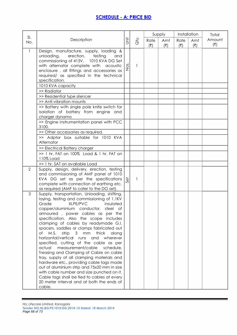
HLL Lifecare Limited, Kanagala
Tender NO.HL:BG:PS:1010:DG:2014-15 Dated: 18 March 2014 Page 68 of 73
SSCCHHEEDDUULLEE -- AA:: PPRRIICCEE BBIIDD
Sl.
No. Description
Un
it
Qty
.
Supply Installation Total
Amount
(`) Rate
(`)
Amt
(`)
Rate
(`)
Amt
(`)
1 Design, manufacture, supply, loading &
unloading, erection, testing and
commissioning of 415V, 1010 KVA DG Set
with alternator complete with acoustic
enclosure , all fittings and accessories as
required/ as specified in the technical
specification.
No
s.
1
1010 KVA capacity
>> Radiator
>> Residential type silencer
>> Anti-vibration mounts
>> Battery with single pole knife switch for
isolation of battery from engine and
charger dynamo
>> Engine instrumentation panel with PCC
3100.
>> Other accessories as required.
>> Adptor box suitable for 1010 KVA
Alternator
>> Electrical Battery charger
>> 1 hr. FAT on 100% Load & 1 hr. FAT on
110% Load
>> 1 hr. SAT on available Load
2 Supply, design, delivery, erection, testing
and commissioning of AMF panel of 1010
KVA DG set as per the specifications
complete with connection of earthing etc.
as required (AMF to cater to the DG set).
Se
t 1
3 Supply, transportation, Unloading, shifting,
laying, testing and commissioning of 1.1KV
Grade XLPE/PVC insulated
copper/aluminium conductor, steel of
armoured , power cables as per the
specification. Also the scope includes
clamping of cables by readymade G.I.
spacers, saddles or clamps fabricated out
of M.S. strip 3 mm thick along
horizontal/vertical runs and wherever
specified, cutting of the cable as per
actual measurement/cable schedule,
Treasing and Clamping of Cable on cable
tray, supply of all clamping materials and
hardware etc., providing cable tags made
out of aluminium strip and 75x20 mm in size
with cable number and size punched on it.
Cable tags shall be tied to cables at every
20 meter interval and at both the ends of
cable.

HLL Lifecare Limited, Kanagala
Tender NO.HL:BG:PS:1010:DG:2014-15 Dated: 18 March 2014 Page 69 of 73
The same shall hold good for cable
termination also.
The rates quoted shall be for laying in trays,
cable trenches (indoor and outdoor),
pipes, buried etc.
3.1 Supply, laying, testing & commissioning of
1.1 kV grade, armoured, PVC insulated
multi core Cu conductor LT control Cable
including necessary cleats, clamps end
connection with gland & termination etc.
for DG sets
3.1.1 4 C x 2.5 mm² LT XLPE insulated single
stranded type Copper conductor PVC
outer sheathed armoured cable (2XWY). Mtr
s.
100
3.1.2 3 C x 2.5 mm² LT XLPE insulated single
stranded type Copper conductor PVC
outer sheathed armoured cable (2XWY). Mtr
s.
100
3.1.3 4 C x 4.0 mm² LT XLPE insulated single
stranded type Copper conductor PVC
outer sheathed armoured cable (2XWY). Mtr
s.
100
3.1.4 12 C x 2.5 mm² LT XLPE insulated single
stranded type Copper conductor PVC
outer sheathed armoured cable (2XWY). Mtr
s.
100
3.2 Supply, erection, testing & commissioning
of 1.1KV grade Al. conductor XLPE
insulated 3.5 core power cables from
D.G.Sets Alternator to D.G.Panel complete
with cable end terminations with double
compression gland for 1.1 kV grade for the
power and control cables for DG sets
3.2.1 3.5 C x 300 mm² LT XLPE insulated
aluminium conductor PVC outer sheathed
armoured cable (A2XFY). Mtr
s
400
3.3 Supply and installation of the indoor
terminations with Single compression
heavy duty type Brass-Nickel cable gland,
lugs & PVC Shrouds. , etc. complete as
required.
3.3.1 4 C x 2.5 mm² LT XLPE insulated single
stranded type Copper conductor PVC
outer sheathed armoured cable (2XWY). No
s.
6
3.3.2 3 C x 2.5 mm² LT XLPE insulated single
stranded type Copper conductor PVC
outer sheathed armoured cable (2XWY). No
s.
4
3.3.3 4 C x 4.0 mm² LT XLPE insulated single
stranded type Copper conductor PVC
outer sheathed armoured cable (2XWY). No
s.
2
3.3.4 12 C x 2.5 mm² LT XLPE insulated single
stranded type Copper conductor PVC
outer sheathed armoured cable (2XWY). No
s.
4
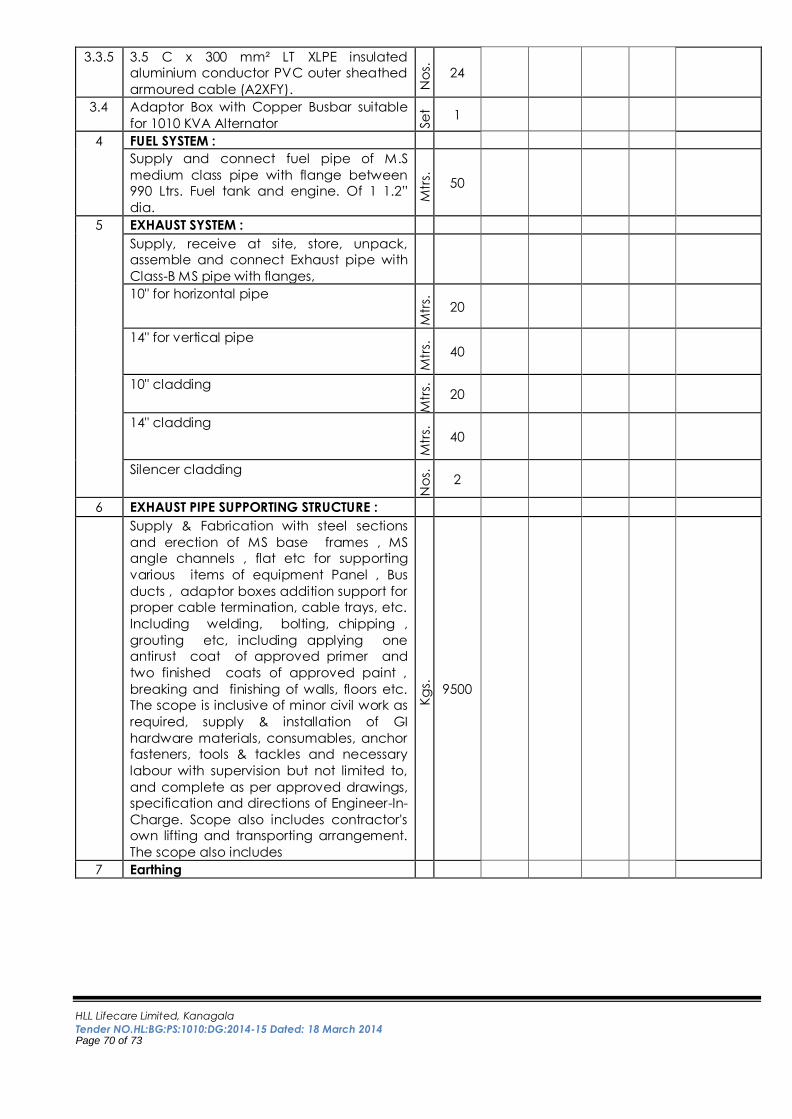
HLL Lifecare Limited, Kanagala
Tender NO.HL:BG:PS:1010:DG:2014-15 Dated: 18 March 2014 Page 70 of 73
3.3.5 3.5 C x 300 mm² LT XLPE insulated
aluminium conductor PVC outer sheathed
armoured cable (A2XFY). No
s.
24
3.4 Adaptor Box with Copper Busbar suitable
for 1010 KVA Alternator Se
t 1
4 FUEL SYSTEM :
Supply and connect fuel pipe of M.S
medium class pipe with flange between
990 Ltrs. Fuel tank and engine. Of 1 1.2”
dia.
Mtr
s.
50
5 EXHAUST SYSTEM :
Supply, receive at site, store, unpack,
assemble and connect Exhaust pipe with
Class-B MS pipe with flanges,
10" for horizontal pipe
Mtr
s.
20
14" for vertical pipe
Mtr
s.
40
10" cladding
Mtr
s.
20
14" cladding M
trs.
40
Silencer cladding
No
s.
2
6 EXHAUST PIPE SUPPORTING STRUCTURE :
Supply & Fabrication with steel sections
and erection of MS base frames , MS
angle channels , flat etc for supporting
various items of equipment Panel , Bus
ducts , adaptor boxes addition support for
proper cable termination, cable trays, etc.
Including welding, bolting, chipping ,
grouting etc, including applying one
antirust coat of approved primer and
two finished coats of approved paint ,
breaking and finishing of walls, floors etc.
The scope is inclusive of minor civil work as
required, supply & installation of GI
hardware materials, consumables, anchor
fasteners, tools & tackles and necessary
labour with supervision but not limited to,
and complete as per approved drawings,
specification and directions of Engineer-In-
Charge. Scope also includes contractor's
own lifting and transporting arrangement.
The scope also includes
Kg
s.
9500
7 Earthing
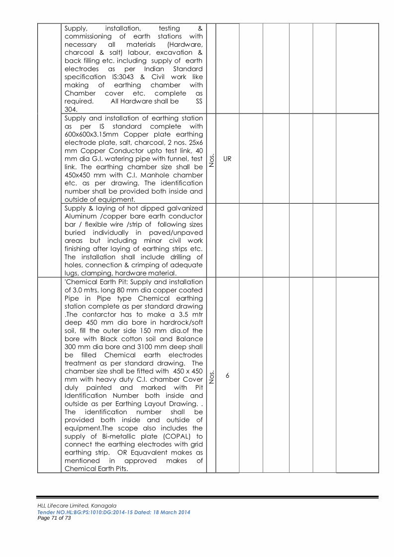
HLL Lifecare Limited, Kanagala
Tender NO.HL:BG:PS:1010:DG:2014-15 Dated: 18 March 2014 Page 71 of 73
Supply, installation, testing &
commissioning of earth stations with
necessary all materials (Hardware,
charcoal & salt) labour, excavation &
back filling etc. including supply of earth
electrodes as per Indian Standard
specification IS:3043 & Civil work like
making of earthing chamber with
Chamber cover etc. complete as
required. All Hardware shall be SS
304.
Supply and installation of earthing station
as per IS standard complete with
600x600x3.15mm Copper plate earthing
electrode plate, salt, charcoal, 2 nos. 25x6
mm Copper Conductor upto test link, 40
mm dia G.I. watering pipe with funnel, test
link. The earthing chamber size shall be
450x450 mm with C.I. Manhole chamber
etc. as per drawing. The identification
number shall be provided both inside and
outside of equipment.
No
s.
UR
Supply & laying of hot dipped galvanized
Aluminum /copper bare earth conductor
bar / flexible wire /strip of following sizes
buried individually in paved/unpaved
areas but including minor civil work
finishing after laying of earthing strips etc.
The installation shall include drilling of
holes, connection & crimping of adequate
lugs, clamping, hardware material.
'Chemical Earth Pit: Supply and installation
of 3.0 mtrs. long 80 mm dia copper coated
Pipe in Pipe type Chemical earthing
station complete as per standard drawing
.The contarctor has to make a 3.5 mtr
deep 450 mm dia bore in hardrock/soft
soil, fill the outer side 150 mm dia.of the
bore with Black cotton soil and Balance
300 mm dia bore and 3100 mm deep shall
be filled Chemical earth electrodes
treatment as per standard drawing. The
chamber size shall be fitted with 450 x 450
mm with heavy duty C.I. chamber Cover
duly painted and marked with Pit
Identification Number both inside and
outside as per Earthing Layout Drawing. .
The identification number shall be
provided both inside and outside of
equipment.The scope also includes the
supply of Bi-metallic plate (COPAL) to
connect the earthing electrodes with grid
earthing strip. OR Equavalent makes as
mentioned in approved makes of
Chemical Earth Pits.
No
s.
6
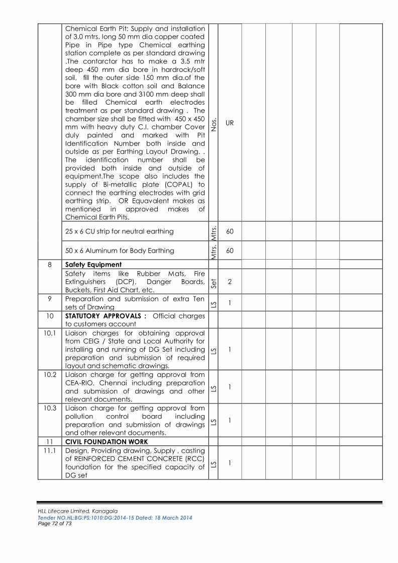
HLL Lifecare Limited, Kanagala
Tender NO.HL:BG:PS:1010:DG:2014-15 Dated: 18 March 2014 Page 72 of 73
Chemical Earth Pit: Supply and installation
of 3.0 mtrs. long 50 mm dia copper coated
Pipe in Pipe type Chemical earthing
station complete as per standard drawing
.The contarctor has to make a 3.5 mtr
deep 450 mm dia bore in hardrock/soft
soil, fill the outer side 150 mm dia.of the
bore with Black cotton soil and Balance
300 mm dia bore and 3100 mm deep shall
be filled Chemical earth electrodes
treatment as per standard drawing . The
chamber size shall be fitted with 450 x 450
mm with heavy duty C.I. chamber Cover
duly painted and marked with Pit
Identification Number both inside and
outside as per Earthing Layout Drawing. .
The identification number shall be
provided both inside and outside of
equipment.The scope also includes the
supply of Bi-metallic plate (COPAL) to
connect the earthing electrodes with grid
earthing strip. OR Equavalent makes as
mentioned in approved makes of
Chemical Earth Pits. N
os.
UR
25 x 6 CU strip for neutral earthing
Mtr
s.
60
50 x 6 Aluminum for Body Earthing
Mtr
s.
60
8 Safety Equipment
Safety items like Rubber Mats, Fire
Extinguishers (DCP), Danger Boards,
Buckets, First Aid Chart, etc.
Se
t 2
9 Preparation and submission of extra Ten
sets of Drawing LS
1
10 STATUTORY APPROVALS : Official charges
to customers account
10.1 Liaison charges for obtaining approval
from CEIG / State and Local Authority for
installing and running of DG Set including
preparation and submission of required
layout and schematic drawings.
LS
1
10.2 Liaison charge for getting approval from
CEA-RIO, Chennai including preparation
and submission of drawings and other
relevant documents.
LS
1
10.3 Liaison charge for getting approval from
pollution control board including
preparation and submission of drawings
and other relevant documents.
LS
1
11 CIVIL FOUNDATION WORK
11.1 Design, Providing drawing, Supply , casting
of REINFORCED CEMENT CONCRETE (RCC)
foundation for the specified capacity of
DG set
LS
1
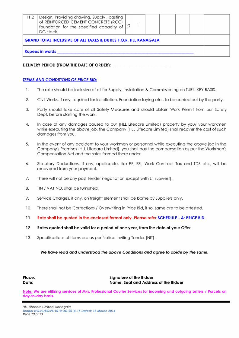
HLL Lifecare Limited, Kanagala
Tender NO.HL:BG:PS:1010:DG:2014-15 Dated: 18 March 2014 Page 73 of 73
11.2 Design, Providing drawing, Supply , casting
of REINFORCED CEMENT CONCRETE (RCC)
foundation for the specified capacity of
DG stack
LS
1
GRAND TOTAL INCLUSIVE OF ALL TAXES & DUTIES F.O.R. HLL KANAGALA
Rupees in words ____________________________________________________________________
DELIVERY PERIOD (FROM THE DATE OF ORDER): ____________________________
TERMS AND CONDITIONS OF PRICE BID:
1. The rate should be inclusive of all for Supply, Installation & Commissioning on TURN KEY BASIS.
2. Civil Works, if any, required for Installation, Foundation laying etc., to be carried out by the party.
3. Party should take care of all Safety Measures and should obtain Work Permit from our Safety
Dept. before starting the work.
4. In case of any damages caused to our (HLL Lifecare Limited) property by you/ your workmen
while executing the above job, the Company (HLL Lifecare Limited) shall recover the cost of such
damages from you.
5. In the event of any accident to your workmen or personnel while executing the above job in the
Company's Premises (HLL Lifecare Limited), you shall pay the compensation as per the Workmen's
Compensation Act and the rates framed there under.
6. Statutory Deductions, if any, applicable, like PF, ESI, Work Contract Tax and TDS etc., will be
recovered from your payment.
7. There will not be any post Tender negotiation except with L1 (Lowest).
8. TIN / VAT NO. shall be furnished.
9. Service Charges, if any, on freight element shall be borne by Suppliers only.
10. There shall not be Corrections / Overwriting in Price Bid, if so, same are to be attested.
11. Rate shall be quoted in the enclosed format only. Please refer SCHEDULE - A: PRICE BID.
12. Rates quoted shall be valid for a period of one year, from the date of your Offer.
13. Specifications of Items are as per Notice Inviting Tender (NIT).
We have read and understood the above Conditions and agree to abide by the same.
Place: Signature of the Bidder
Date: Name, Seal and Address of the Bidder Note: We are utilizing services of M/s. Professional Courier Services for incoming and outgoing Letters / Parcels on
day-to-day basis.