hll infra tech services limited (a fully owned
TRANSCRIPT

HLL INFRA TECH SERVICES LIMITED
(A Fully owned Subsidiary of HLL Lifecare Limited)
Date: 19.01.2021
ADDENDUM NO. 1
ADDENDUM TO THE TENDER DOCUMENT FOR CONSTRUCTION OF KONNI GOVERNMENT MEDICAL COLLEGE, TEACHING HOSPITAL AND ALLIED BUILDINGS IN PATHANAMTHITTA
DISTRICT -PHASE II
Reference: Tender No. HITES/IDS/20/18 Dated:-12.01.2021
Please find attached Technical Specification for HVAC Works and it shall form part of the tender
document. All other terms and conditions will be as per the Tender No HITES/IDS/20/18 Dated:-
12.01.2021 and addendum.
CHIEF ENGINEER(DESIGN)
1
I. TECHNICAL SPECIFICATION FOR WATER COOLED CHILLDE WATER AIR CONDITIOING SYSTEM
1.0 BASIC SYSTEM DESIGN
1. SCOPE
1.1 Central air conditioning system has been proposed for the air conditioning of proposed Hospital Block at Konni Medical College, Kerala
1.2 This system is designed to cater air conditioning requirement to the different
areas of the building.
The Chilled water system with 200 TR chiller shall be working as add on to the existing chiller plant of capacity 3X250 TR (2 working and One standby ). The Total capacity of the Chiller plant will be (3 X 250 TR + 1 X 200TR )( 3 working). The contractor has to sychronise the proposed system with the existing system. All connections to the existing system have to be done by the contractor .
2. BASIS OF DESIGN
Location: Konni,,Kerala
2.1 Design Parameters
Outside Conditions Summer : 35 degree C DB; 28 degree C WB (55% RH)
Monsoon : 29 degree C DB; 28 degree C WB (88% RH)
2.2 Inside Conditions General : 24.0 degree C, 1.0 degree C DB (for General areas)
(Summer & Winter) RH not exceeding 60% in all areas.
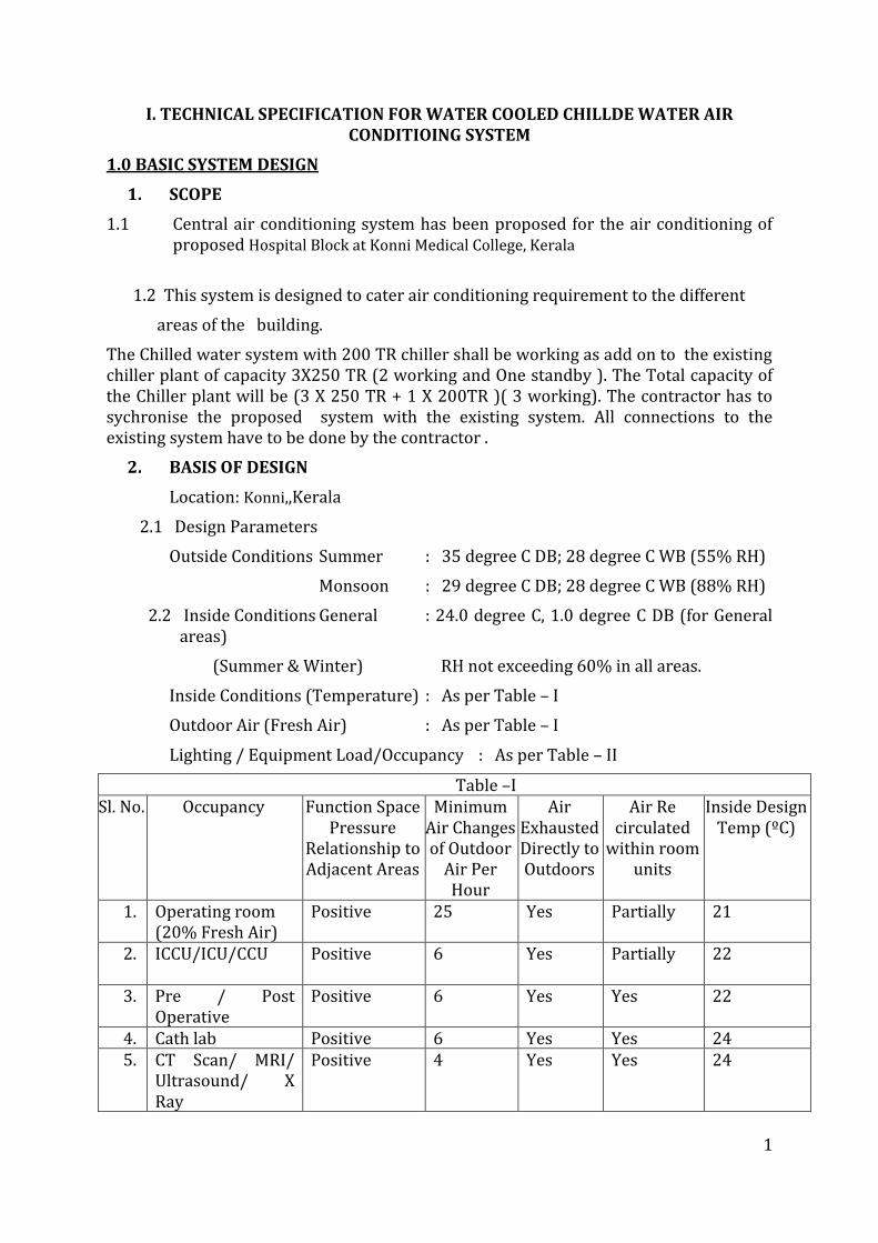
Inside Conditions (Temperature) : As per Table – I
Outdoor Air (Fresh Air) : As per Table – I
Lighting / Equipment Load/Occupancy : As per Table – II
Table –I Sl. No. Occupancy Function Space
Pressure Relationship to Adjacent Areas
Minimum Air Changes of Outdoor
Air Per Hour
Air Exhausted Directly to Outdoors
Air Re circulated
within room units
Inside Design Temp (ºC)
1. Operating room (20% Fresh Air)
Positive 25
Yes Partially 21
2. ICCU/ICU/CCU Positive 6 Yes Partially
22
3. Pre / Post Operative
Positive 6 Yes Yes 22
4. Cath lab Positive 6 Yes Yes 24 5. CT Scan/ MRI/
Ultrasound/ X Ray
Positive 4 Yes Yes 24
2
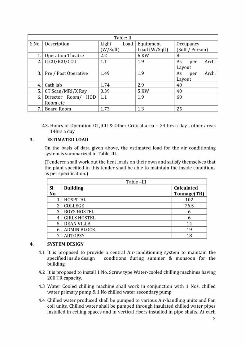
Table: II S.No Description Light Load
(W/Sqft) Equipment Load (W/Sqft)
Occupancy (Sqft / Person)
1. Operation Theatre 2.2 6 KW 8 2. ICCU/ICU/CCU
1.1 1.9 As per Arch.
Layout 3. Pre / Post Operative 1.49 1.9 As per Arch.
Layout 4. Cath lab 1.74 2.9 40 5. CT Scan/MRI/X Ray 0.39 5 KW 40 6. Director Room/ HOD
Room etc 1.1 1.9 60
7. Board Room 1.73 1.3 25
2.3. Hours of Operation OT,ICU & Other Critical area – 24 hrs a day , other areas 14hrs a day
3. ESTIMATED LOAD
On the basis of data given above, the estimated load for the air conditioning system is summarized in Table-III.
(Tenderer shall work out the heat loads on their own and satisfy themselves that the plant specified in this tender shall be able to maintain the inside conditions as per specification.)
Table –III Sl No
Building Calculated Tonnage(TR)
1 HOSPITAL 102 2 COLLEGE 76.5 3 BOYS HOSTEL 6 4 GIRLS HOSTEL 6 5 DEAN VILLA 14 6 ADMIN BLOCK 19 7 AUTOPSY 18
4. SYSTEM DESIGN
4.1 It is proposed to provide a central Air-conditioning system to maintain the specified inside design conditions during summer & monsoon for the building.
4.2 It is proposed to install 1 No. Screw type Water-cooled chilling machines having 200 TR capacity.
4.3 Water Cooled chilling machine shall work in conjunction with 1 Nos. chilled water primary pump & 1 No chilled water secondary pump
4.4 Chilled water produced shall be pumped to various Air-handling units and Fan coil units. Chilled water shall be pumped through insulated chilled water pipes installed in ceiling spaces and in vertical risers installed in pipe shafts. At each
3
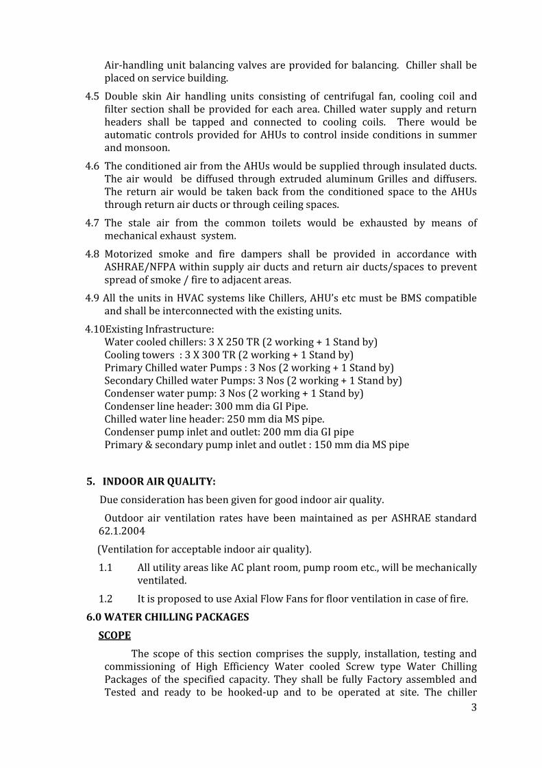
Air-handling unit balancing valves are provided for balancing. Chiller shall be placed on service building.
4.5 Double skin Air handling units consisting of centrifugal fan, cooling coil and filter section shall be provided for each area. Chilled water supply and return headers shall be tapped and connected to cooling coils. There would be automatic controls provided for AHUs to control inside conditions in summer and monsoon.
4.6 The conditioned air from the AHUs would be supplied through insulated ducts. The air would be diffused through extruded aluminum Grilles and diffusers. The return air would be taken back from the conditioned space to the AHUs through return air ducts or through ceiling spaces.
4.7 The stale air from the common toilets would be exhausted by means of mechanical exhaust system.
4.8 Motorized smoke and fire dampers shall be provided in accordance with ASHRAE/NFPA within supply air ducts and return air ducts/spaces to prevent spread of smoke / fire to adjacent areas.
4.9 All the units in HVAC systems like Chillers, AHU’s etc must be BMS compatible and shall be interconnected with the existing units.
4.10Existing Infrastructure: Water cooled chillers: 3 X 250 TR (2 working + 1 Stand by) Cooling towers : 3 X 300 TR (2 working + 1 Stand by) Primary Chilled water Pumps : 3 Nos (2 working + 1 Stand by) Secondary Chilled water Pumps: 3 Nos (2 working + 1 Stand by) Condenser water pump: 3 Nos (2 working + 1 Stand by) Condenser line header: 300 mm dia GI Pipe. Chilled water line header: 250 mm dia MS pipe. Condenser pump inlet and outlet: 200 mm dia GI pipe Primary & secondary pump inlet and outlet : 150 mm dia MS pipe
5. INDOOR AIR QUALITY:
Due consideration has been given for good indoor air quality.
Outdoor air ventilation rates have been maintained as per ASHRAE standard 62.1.2004
(Ventilation for acceptable indoor air quality).
1.1 All utility areas like AC plant room, pump room etc., will be mechanically ventilated.
1.2 It is proposed to use Axial Flow Fans for floor ventilation in case of fire.
6.0 WATER CHILLING PACKAGES
SCOPE
The scope of this section comprises the supply, installation, testing and commissioning of High Efficiency Water cooled Screw type Water Chilling Packages of the specified capacity. They shall be fully Factory assembled and Tested and ready to be hooked-up and to be operated at site. The chiller
4
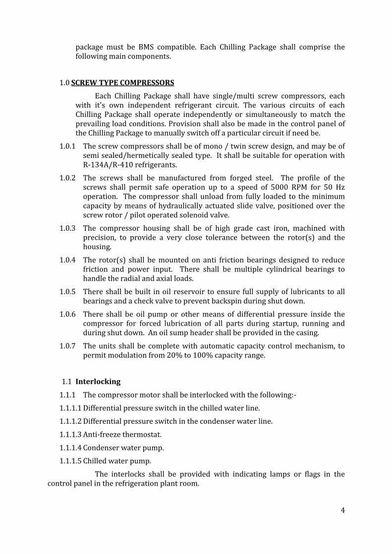
package must be BMS compatible. Each Chilling Package shall comprise the following main components.
1.0 SCREW TYPE COMPRESSORS
Each Chilling Package shall have single/multi screw compressors, each with it's own independent refrigerant circuit. The various circuits of each Chilling Package shall operate independently or simultaneously to match the prevailing load conditions. Provision shall also be made in the control panel of the Chilling Package to manually switch off a particular circuit if need be.
1.0.1 The screw compressors shall be of mono / twin screw design, and may be of semi sealed/hermetically sealed type. It shall be suitable for operation with R-134A/R-410 refrigerants.
1.0.2 The screws shall be manufactured from forged steel. The profile of the screws shall permit safe operation up to a speed of 5000 RPM for 50 Hz operation. The compressor shall unload from fully loaded to the minimum capacity by means of hydraulically actuated slide valve, positioned over the screw rotor / pilot operated solenoid valve.
1.0.3 The compressor housing shall be of high grade cast iron, machined with precision, to provide a very close tolerance between the rotor(s) and the housing.
1.0.4 The rotor(s) shall be mounted on anti friction bearings designed to reduce friction and power input. There shall be multiple cylindrical bearings to handle the radial and axial loads.
1.0.5 There shall be built in oil reservoir to ensure full supply of lubricants to all bearings and a check valve to prevent backspin during shut down.
1.0.6 There shall be oil pump or other means of differential pressure inside the compressor for forced lubrication of all parts during startup, running and during shut down. An oil sump header shall be provided in the casing.
1.0.7 The units shall be complete with automatic capacity control mechanism, to permit modulation from 20% to 100% capacity range.
1.1 Interlocking
1.1.1 The compressor motor shall be interlocked with the following:-
1.1.1.1 Differential pressure switch in the chilled water line.
1.1.1.2 Differential pressure switch in the condenser water line.
1.1.1.3 Anti-freeze thermostat.
1.1.1.4 Condenser water pump.
1.1.1.5 Chilled water pump.
The interlocks shall be provided with indicating lamps or flags in the control panel in the refrigeration plant room.
5
The compressor drive motors shall be double squirrel cage type and of hermetic / semi hermetic design, and protected against damage by means of built in protection devices.
6.4 CONDENSER .
6.4.1 General
This section deals with shell and tube type water cooled condensers.
6.4.2 Rating
i) The condenser(s) capacity shall match the compressor(s) capacity specified in the tender specifications. The selection shall be for 4.2 degree C temperature rise of water through the condenser unless otherwise specified in the tender specifications.
ii) The condenser shall be designed for a fouling factor of 0.0002 hr. sq. m. degree C difference / K. Cal.
iii) Unless otherwise specified, the condenser shall be designed for a entering water temperature of 30.5 degree C.
6.4.3 Material and Construction
i) The condenser shall be horizontal, shell and tube type, designed, constructed and tested for the refrigerant specified in the tender specifications.
ii) The shell of the condenser shall be made of MS of thickness not less than 8mm, with electric fusion welded seams. The shell capacity shall be such as to hold 1.25 times the refrigerant charge in the machine of which the condenser is a part, under pumped down conditions.
iii) The end plates of condenser shall be made of MS of thickness not less than 25mm.
iv) The condenser shall be designed for a working pressure on the refrigerant side suitable for the refrigerant offered, and on the water side for 10 kg./sq. cm. gauge.
v) The tubes shall be of seamless hard drawn copper and finned, unless otherwise specified. The minimum wall thickness shall be 1.0mm with root thickness of 0.63 mm below the fins.
vi) Intermediate tube supports of steel shall be provided at not more than 1250 mm intervals to prevent sagging and vibration of the tubes. The condensers shall have water boxes designed for multi pass flow.
vii) The tubes may be provided with special tabulating arrangement to improve heat transfer where such an arrangement is a standard design of the manufacturer.
6
viii) The condensers shall be provided with removable heads on either side made of cast iron or steel with neatly machined surface for effective jointing with the shell for easy accessibility for cleaning / replacement of the tubes. Suitable baffles shall be incorporated to achieve the required number of passes.
ix) The condenser shall be provided with baffle arrangement for preventing direct impingement of hot gas over the tubes and to enable even distribution of the gas over the tube bundles.
x) The condenser shall include necessary provision for sub-cooling of the refrigerant where the refrigerating machine is selected with such sub-cooling requirement. The arrangement shall be such that the cold water entering the condenser first cools the liquid refrigerant in the sub-cooler.
xi) The condenser shall be sand blasted from both inside & outside before assembly.
6.4.4 Connections and Accessories
The condenser shall be provided with the following connections and accessories and conforming to Section 'Refrigerant Piping' where applicable:-
i) Hot gas inlet and liquid outlet connection. The liquid line connections shall be provided with isolating valves.
ii) Water inlet and outlet connections
iii) Pressure relief device
iv) Drain connection with valve for water side.
ii) Differential flow switch / pressure switch / flow switch / flow sensor in the water line(s).
6.4.5 Pressure Testing
i) The condenser shall be tested at the works to 1.5 times the maximum working pressure for the refrigerant specified in the tender specifications or 15 kg./sq. cm. , whichever is higher
ii) The water side of the condenser shall be tested to a hydraulic pressure of 10 kg./sq. cm.
6.5 CHILLER
6.5.1 General
This section deals with shell and tube type Chillers
6.5.2 Rating
i) The chiller(s) shall match the compressor(s) capacity specified in the tender specifications. The chiller shall be selected for a water temperature drop between 4.5 to 5.5 degree C through the chiller.
7
ii) The fouling factor shall be 0.0001 hr. sq. mtr. degree C temperature difference / K. Cal.
6.5.3 Material and Construction
i) The water chiller shall be horizontal, shell and tube type, designed, constructed and tested for the specified refrigerant
ii) The chiller shall be designed for a working pressure on the refrigerant side suitable for the refrigerant offered, and on the water side for 10 kg./sq. cm. gauge.
iii) The end plates of chiller shall be made of MS of thickness not less than 25mm.
iv) The shell of the chiller shall be made of MS of thickness not less than 8mm with electric fusion welded seams.
v) The tubes shall be of seamless, hard drawn copper with a minimum tube wall thickness of 0.71 mm for plain tubes & minimum 0.63mm at the root of fins for finned tubes.
vi) The tubes shall be rolled into grooves in the tubes sheets and flared at ends.
vii) The chiller shall be smooth finished with one coat of zinc chromate primer before the insulation is applied.
viii) The chiller shall be sand blasted from both inside (before insertion of tubes) & outside.
6.5.4 Connections and Accessories
The chiller shall be provided with the following connections and accessories and conforming to the Section 'Refrigerant Piping' where applicable:-
i) Refrigerant inlet and outlet connections
ii) Thermostatic/electronic expansion valve(s) with adjustable superheat control and external equalizer.
iii) Line solenoid valve, or pilot solenoid valves as required
iv) Water inlet and water outlet connections
v) Drain connection with stop valve for water side only
vi) Vent connection with valve
vii) Flow switch in water line
6.5.5 Pressure Testing
8
i) The chiller shall be tested in the works to 1.5 times the maximum working pressure for the refrigerant specified in the tender specifications, or 21 kg./sq. cm. (Pneumatic), whichever is higher.
ii) The water side of the chiller shall also be tested to a hydraulic pressure of 10 kg./sq. cm.
6.5.6 The equipment shall be packed on metallic skids to permit easy installation and shall be provided with spring vibration isolators.
6.5.7 Hydrostatic, volumetric and refrigerant leak tests shall be carried out at the manufacturer’s works before the dispatch of the compressor/chiller.
6.5.8 ARI test certificate shall be submitted for the chiller.
6.6 REFRIGERANT PIPING
6.6.1 General
This section deals with the refrigerant piping of the chilling package.
6.6.2 Design aspects of Refrigerant Piping
i) Refrigerant piping shall be designed and installed so as to:
a) Ensure circulation of adequate refrigerant at all loads.
b) Ensure oil return to crank case of compressor positively and
continuously.
c) Keep pressure losses within limits, especially in suction lines.
d) Prevent liquid refrigerant from entering the compressor when the compressor is working as well as when it has stopped.
e) Prevent trapping of oil in evaporator or suction lines, which may return to the compressor in the form of slugs.
ii) Hot gas lines:
a) Oil shall be entrained and carried by hot gas under all load conditions likely to be encountered in normal operation.
iii) Liquid Lines:
a) Liquid lines shall be designed to ensure that flashing of liquid refrigerant does not occur by minimizing the pressure drop suitably and by appropriate sub cooling.
9
b) Each liquid line shall be provided with a permanently installed refrigerant
drier of throw away or rechargeable type. The drier shall be installed in a
valved line.
c) Flow indicator (moisture indicating type) shall be installed on all liquid
lines.
vi) Suction Lines:
a) Oil shall be entrained and carried by the suction gas under all conditions
of load likely to be encountered in normal operation.
b) Piping shall be designed for a suitable velocity of refrigerant (similar to
hot gas line) to ensure that oil will not separate from the gas and drain to the compressor in slugs.
c) The refrigeration system shall be equipped with controls for pump down
system so that the evaporator and suction line are emptied before the compressor shuts off, thus preventing liquid refrigerant from entering the compressor when restarted.
d) Refrigerant lines shall be sized to limit pressure drop between evaporator
and condensing unit to less than 0.2 kg. per sq. cm. (3 psi).
v) Isolating valve shall be provided to enable isolation of each compressor in case of multiple compressor units (as built in valves), strainer, drier and any other components as may be required for proper operation and maintenance.
vi) Thermostatic/electronic expansion valve shall be provided in the refrigerant circuit.
6.6.3 Material
i) Refrigerant piping shall be of copper to manufacturer’s standards.
ii) Valves shall be of the packed, back-seating type and these shall be of forged brass construction.
6.6.4 Pressure Testing
10
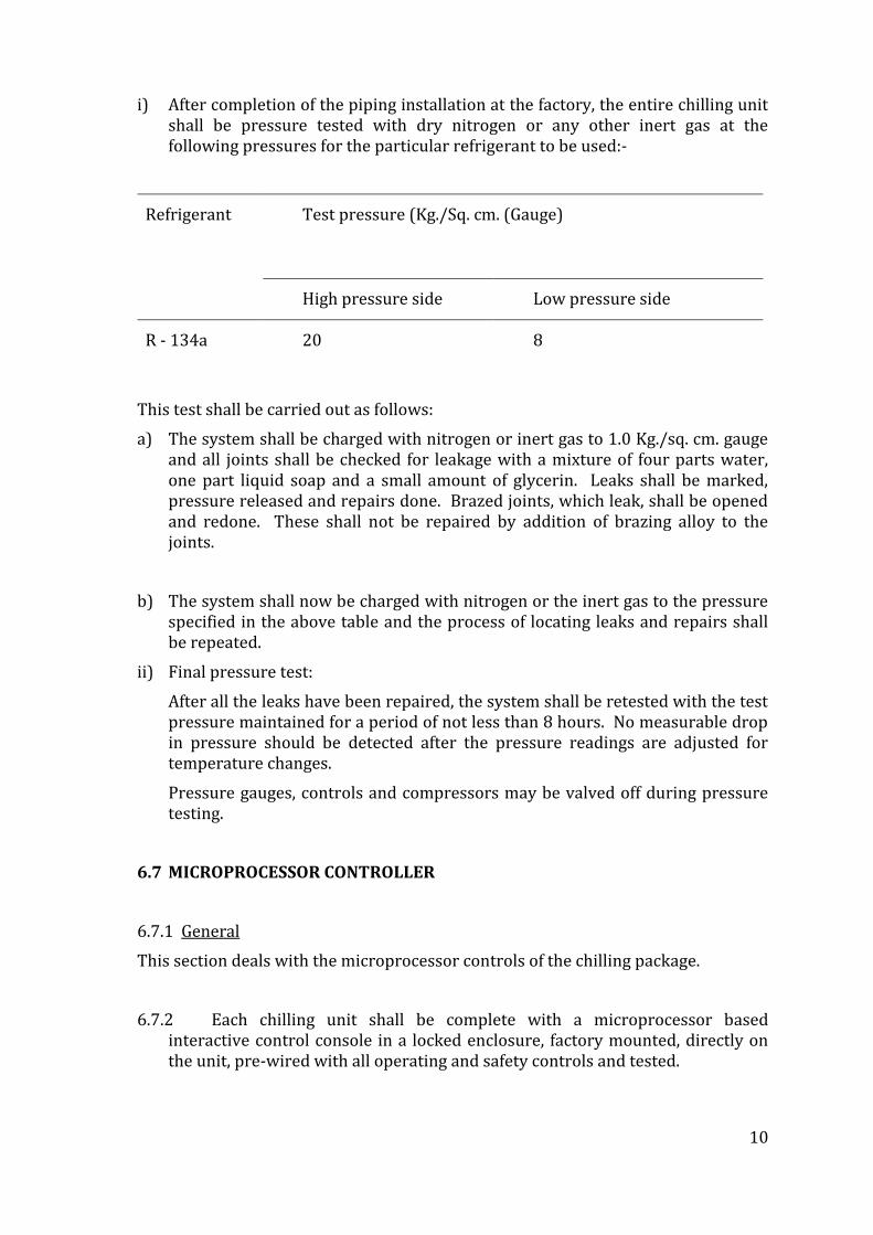
i) After completion of the piping installation at the factory, the entire chilling unit shall be pressure tested with dry nitrogen or any other inert gas at the following pressures for the particular refrigerant to be used:-
Refrigerant Test pressure (Kg./Sq. cm. (Gauge)
High pressure side Low pressure side
R - 134a 20 8
This test shall be carried out as follows:
a) The system shall be charged with nitrogen or inert gas to 1.0 Kg./sq. cm. gauge and all joints shall be checked for leakage with a mixture of four parts water, one part liquid soap and a small amount of glycerin. Leaks shall be marked, pressure released and repairs done. Brazed joints, which leak, shall be opened and redone. These shall not be repaired by addition of brazing alloy to the joints.
b) The system shall now be charged with nitrogen or the inert gas to the pressure specified in the above table and the process of locating leaks and repairs shall be repeated.
ii) Final pressure test:
After all the leaks have been repaired, the system shall be retested with the test pressure maintained for a period of not less than 8 hours. No measurable drop in pressure should be detected after the pressure readings are adjusted for temperature changes.
Pressure gauges, controls and compressors may be valved off during pressure testing.
6.7 MICROPROCESSOR CONTROLLER
6.7.1 General
This section deals with the microprocessor controls of the chilling package.
6.7.2 Each chilling unit shall be complete with a microprocessor based interactive control console in a locked enclosure, factory mounted, directly on the unit, pre-wired with all operating and safety controls and tested.
11
6.7.3 It will provide start, stop, safety, interlock, capacity control and indications for operation of the chiller unit through an alphanumeric / graphical display.
6.7.4 Controls shall provide to view and change digital programmable essential set points, cause of shutdown and type of restart required.
a) Leaving chilled water temperature,
b) Percent current limit.
c) Remote reset temperature range.
6.7.5 All safety and cycling shutdowns shall be enunciated through the alphanumeric / graphical display and consist of day, time, cause of shutdown and type of restart required.
6.7.6 Cycling shutdown shall include low leaving chilled water temperature, chiller / condenser water flow interruption, power fault, internal time clock and anti-recycle.
6.7.7 Safety shutdowns shall include low oil pressure, high compressor discharge temperature, low evaporator pressure, motor controller fault and sensor malfunction.
6.7.8 The display screen shall indicate the following minimum information
i) date and time
ii) supply and return chilled water temperatures
iii) supply and return condenser water temperatures
iv) differential oil pressure
v) percent motor rated current
vi) evaporator & condenser refrigerant saturation temperatures
vii) chiller operating hours and number of compressor starts
viii) oil sump temperature
ix) status message
6.7.9 Security access shall be provided to prevent unauthorized change of set points, to allow local or remote control of the chiller and to allow manual operation of the pre rotation vanes and oil pump.
12
6.7.10 The chiller shall be provided with ports compatible with any building management system offered, to output all system operating information, shutdown / cycling message and a record of the last four cycling or safety shutdowns to a remote printer (option). The control centre shall be programmable to provide data logs to the printer at a set time interval.
6.7.11 Control centre shall be able to interface with an automatic controls system to provide remote chiller start / stop; reset of chilled water temperature, reset of current limit, and status messages indicating chiller is ready to start, chiller is operating, chiller is shut down on a safety requiring reset and chiller is shut down on a recycling safety.
6.7.12 The microprocessor control system shall include the interlocking of the compressor motor with chilled and condenser water flows and lubricating oil pump pressure.
6.7.13 At the time of START, the microprocessor control system shall check all pre-start safeties to verify that all restart safeties are within limits. If any one is not within limits, an indication of the fault will be displayed and the start aborted.
6.8 INSTALLATION
6.8.1 General
This section deals with the installation of the chilling package.
The complete chilling unit shall be installed over a RCC foundation and shall be adequately isolated against transmission of vibrations to the building structure. Necessary foundation bolts, nuts, leveling screws etc wherever required for mounting the unit shall be provided by the contractor.
6.8.2 PAINTING
The equipment shall be supplied as per manufacturer’s standard finish painting on zinc chromate primer.
6.8.3 FACTORY INSPECTION
The assembled chilling packages will be inspected, if the need be, by the Users / Consultants before they are dispatched to the site. The Bidders shall include the cost involved for this factory visit and testing by the Users / Consultants in their scope.
7.0 COOLING TOWERS
7.1 SCOPE
13
The scope of this section comprises the supply, installation, testing and commissioning of Induced draft type Cooling towers.
7.2 DESIGN
i) Rating:
The cooling tower shall be rated for the heat rejection capacity specified in the tender specifications.
ii) Range:
The Cooling tower shall be designed to cool the requisite quantity of water through 4.2 degree C or as specified in the tender specifications, against the prevailing wet bulb temperature.
iii) Wet Bulb approach:
The cooling tower shall be selected for a wet bulb approach of not more than 4.0 degree C.
iv) Outlet temperature:
The Cold water temperature from the cooling tower shall match the entering temperature for which the condenser selection is made.
v) Flow rate:
The flow rate through the cooling tower shall match the flow rate of the condenser(s).
7.3 MATERIAL AND CONSTRUCTION
Fiberglass Reinforced Plastic (FRP) Cooling tower:
i) The structural framework of the cooling tower including all members shall be designed for the load encountered during the normal operation of the cooling tower and its maintenance. The structure shall be rugged and rigid to prevent distortion and shall include tie arrangements as may be necessary.
ii) The cooling tower shall be induced draft type, with FRP casing in square/rectangular shape and with a FRP basin to match the shape of the casing. Rotating type sprinklers will not be accepted.
iii) The air intake shall be from openings all along the sides of the casing near its base. These openings shall be covered with hot dip galvanized expanded metal mesh screens.
iv) The basin shall have a holding capacity adequate for operation for at least 30 minutes without addition of make-up water to the basin. The construction should be such as to eliminate the danger of drawing air into the pump when operating with minimum water in the basin.
v) The basin fittings shall include the following:
a. Bottom / side outlet.
14
b. Drain connection with valve.
c. Float valve type automatic make-up connection with valve.
d. Overflow connection.
e. Bleed off with valve, from inlet header to overflow pipe.
vi) The supporting framework for the tower casing and the water basin shall be made of hot dip galvanized steel and it shall be further protected with epoxy painting.
vii) The filling shall be of PVC. Thickness of PVC fills shall not be less than 0.2 mm. These shall be of such construction as to provide low air resistance, large wetted surface for a high heat transfer efficiency, and easy replaceability.
viii) The water distribution shall be either through fixed type sprinklers or through balancing, sub balancing and spreader troughs (un pressurized system) “ open gravity type with polypropylene nozzle”, ensuring uniform water loading and distribution of water over the fill. All pipes and fittings shall be of PVC. The sprinklers shall operate from the residual velocity head at the headers. Due care shall be taken with regard to corrosive effects and maintainability in the design of the water distribution system.
ix) Drift eliminators of PVC shall be provided for maximum removal of entrained water droplets. The spacers and tie rods used shall be of plastic material.
x) The fan shall be multi-blade axial flow type, made of aluminium alloy or FRP. The fan assembly shall be statically and dynamically balanced.
xi) The fan drive shall be direct from a three phase induction motor. The entire drive arrangement shall be designed for a minimum noise and it shall be rigidly supported to the tower structure.
xii) To ensure safety of personnel at the time of working on cooling tower a steel ladder shall be provided in such a manner and location as necessary to give safe and complete access to all the parts of the cooling tower requiring inspection or adjustments. The ladder shall be bolted to the tower at the top and grouted in masonry at the bottom end.
xiii) A thermostat shall be provided in the sump of the Cooling Tower, to sense the water temperature and to switch off the Fan motor during night times and other favorable weather conditions.
7.4 INSTALLATION
The cooling towers will be located at a well-ventilated place on the terrace of the plant room building. The structural loading of the terrace shall be considered. Cooling towers shall be installed in such a way that their load is transferred directly to the columns for which necessary Mild steel-I sections shall be provided by the air conditioning contractor. The cooling towers shall be rested on Mild steel-I sections and not on terrace slab. Sufficient free space shall be left all around for efficient operation of the cooling tower.
15
7.5 PAINTING
The cooling towers shall be supplied with the manufacturer’s standard finish painting with zinc chromate primer.
8.0 PUMPS – SPECIFICATIONS
1. SCOPE
1.1 This section of specification covers the supply, installation, testing, commissioning of water pumps along with accessories conforming to these specifications and in accordance with requirement of drawings, ‘Technical Schedule of Equipment’ and of the ‘Schedule of Quantities’
2. CODES AND STANDARDS
2.1 The design, materials of construction, manufacture, inspection, performance and testing of Horizontal Centrifugal Pumps shall comply with all currently applicable statutory regulations and safety codes in the locality where the equipment will be installed. Nothing in this specification shall be construed to relieve the VENDOR of this responsibility. The equipment supplied shall comply with the latest applicable Indian, American, British or equivalent standards.
3. TYPE
3.1 All chilled, condensing water pumps shall be of capacity and size in accordance with the requirements indicated in the drawings and ‘Schedule of Quantities’ Pumps shall conform to relevant IS standards/codes.
4. MATERIAL OF CONSTRUCTION
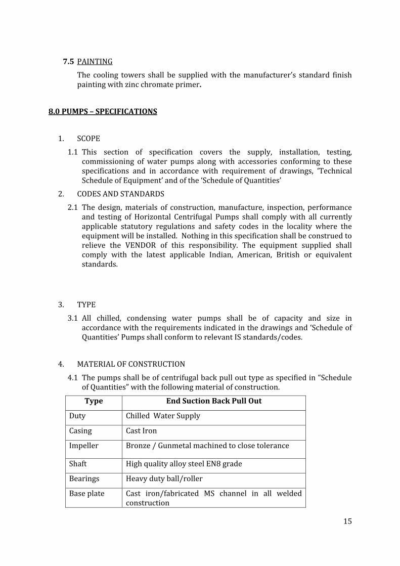
4.1 The pumps shall be of centrifugal back pull out type as specified in “Schedule of Quantities” with the following material of construction.
Type End Suction Back Pull Out
Duty Chilled Water Supply
Casing Cast Iron
Impeller Bronze / Gunmetal machined to close tolerance
Shaft High quality alloy steel EN8 grade
Bearings Heavy duty ball/roller
Base plate Cast iron/fabricated MS channel in all welded construction
16
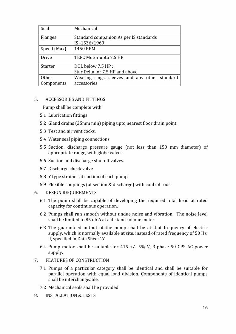
Seal Mechanical
Flanges Standard companion As per IS standards IS -1536/1960
Speed (Max) 1450 RPM
Drive TEFC Motor upto 7.5 HP
Starter DOL below 7.5 HP ; Star Delta for 7.5 HP and above
Other Components
Wearing rings, sleeves and any other standard accessories
5. ACCESSORIES AND FITTINGS
Pump shall be complete with
5.1 Lubrication fittings
5.2 Gland drains (25mm min) piping upto nearest floor drain point.
5.3 Test and air vent cocks.
5.4 Water seal piping connections
5.5 Suction, discharge pressure gauge (not less than 150 mm diameter) of appropriate range, with globe valves.
5.6 Suction and discharge shut off valves.
5.7 Discharge check valve
5.8 Y type strainer at suction of each pump
5.9 Flexible couplings (at section & discharge) with control rods.
6. DESIGN REQUIREMENTS
6.1 The pump shall be capable of developing the required total head at rated capacity for continuous operation.
6.2 Pumps shall run smooth without undue noise and vibration. The noise level shall be limited to 85 db A at a distance of one meter.
6.3 The guaranteed output of the pump shall be at that frequency of electric supply, which is normally available at site, instead of rated frequency of 50 Hz, if, specified in Data Sheet 'A'.
6.4 Pump motor shall be suitable for 415 +/- 5% V, 3-phase 50 CPS AC power supply.
7. FEATURES OF CONSTRUCTION
7.1 Pumps of a particular category shall be identical and shall be suitable for parallel operation with equal load division. Components of identical pumps shall be interchangeable.
7.2 Mechanical seals shall be provided
8. INSTALLATION & TESTS
17
8.1 The pump sets shall be mounted on cement concrete foundation, which shall be provided by other agencies. However, grouting nuts, bolts, channels, shims etc shall be provided by the HVAC contractor.
9. MECHANICAL BALANCING
9.1 The impeller shall be statically and dynamically balanced.
10. VISUAL INSPECTION
10.1 Pumps shall be offered for Visual inspection (if specifically asked for) before dispatch. The components of the pumps shall not be painted before inspection.
11. MATERIAL TEST CERTIFICATE
11.1 Materials of the various pump components shall be tested in accordance with the relevant standard and Test Certificates shall be furnished along with the Pumps.
12. FIELD TESTING
12.1 After installation, the pumps shall be subjected to testing at site also. If the performance does not meet the requirements regarding capacity, power consumption, vibration and noise etc. as specified, then the equipment shall be rectified or replaced by the VENDOR, at no extra cost to the CUSTOMER.
13. TENDER DRAWINGS
13.1 The following drawings shall be submitted by the tenderers along with their Bids: -
13.1.1 Preliminary outlines dimensional drawing of pump. (Suction and discharge connections and foundation details shall also be indicated).
13.1.2 Performance curves (capacity vs. total head, efficiency, NPSH and KW requirement) ranging from zero to maximum capacity.
13.1.2.1 Pump Catalogues.
14. NAME PLATE
14.1 Each pump shall be provided with a name plate indicating the following details:-
a) Design capacity
b) Total head
c) Speed
d) Motor rating
e) Model number
f) Manufacturer's serial number
g) Weight of equipment
h) Tag number
15. PAINTING
18
15.1 All ferrous surfaces shall be painted with one coat of red oxide primer paint followed by two coats of synthetic enamel paint (approved shade).
16. INSULATION
16.1 The Pump casings for chilled water along with its accessories and fittings shall be insulated as specified in section on insulation. The cost of this insulation should be included in the cost of the pump.
16.2 Pumps shall be insulated only after they have been tested and test results have been approved by the engineer.
Note: - All the hardware required for the installation and equipments required for testing & commissioning shall be supplied by the Contractor.
17. VARIABLE SPEED PUMPING SYSTEM
17.1 SCOPE
The scope of this section comprise the supply, erection, testing and commissioning of variable speed pumping package consisting of following :
a. Individual Components
b. Pump Control Panel
c. Adjustable Frequency Drive
d. Different pressure transmitted
e. Logic Programming for sequence of Operation
f. Power wiring and control wiring shall be carried out by installation contractor as shown on the field connection drawings and wiring diagrams supplied with the pumping package.
17.2 REFERENCES
a. ANSI - American National Standards Institute
b. NEMA - National Electrical Manufacturers Association
c. UL - Underwriters Laboratories Inc.
d. ETL - Electrical Testing Laboratories
e. CSA - Canadian Standards Association
f. NEC - National Electrical Code
g. ISO - International Standards Organization
h. IEC - International Electrochemical Commission
17.3 SUBMITTALS
Submittals shall include the following and shall be specific to this project. General Submittals shall not be accepted.
a. System summary sheet.
b. Sequence of operation
c. Shop drawing indicating dimensions, required clearances and location and size of each field connection.
19
d. Power and control wiring diagrams.
e. System profile analysis including variable speed pump curves and system curve. The analysis shall also include pump, motor and Adjustable Frequency Drive (AFD) efficiencies, job specific load profile, staging points, horse power and kilowatt/hour consumption.
f. Pump data sheets.
17.4 QUALITY ASSURANCE
a. The pumping package shall be assembled by the pump manufacturer. An assembler of pumping systems not actively engaged in the design and construction of centrifugal pumps shall not be considered a pump manufacturer. The manufacturer shall assume “Unit Responsibility” for the complete pumping package. Unit responsibility shall be defined as responsibility for interface and successful operation of all system components supplied by the pumping system manufacturer.
b. The manufacturer shall have a minimum of 20 years experience in the design and construction of variable speed pumping systems.
c. The local supplier of Chilled Water Variable Speed Pumping System (VSPS) shall have relevant expertise in all aspects of design, application engineering, installation, programming, interfacing, commissioning and after sales service. Supplier must have commissioned minimum 25 sets of chilled water VSPS in India.
d. All functions of the variable speed pump control system shall be tested at the factory prior to shipment. This test shall be conducted with motors connected to AFD output and it shall test all inputs, outputs and program execution specific to this application.
e. The manufacturer shall be fully certified by the International Standards Organization per ISO 9001. Proof of this certification shall be furnished at time of submittal.
f. Manufacturer shall be listed by Underwrite’s Laboratories as manufacturer of packaged pumping systems.
g. Tenderer shall comply with all sections of this specification relating to packaged pumping systems. Any deviations from this specifications shall be clearly defined in writing at time of bid. If no exceptions are taken at time of bid, the supplier shall be bound by these specifications.
17.5 MANUFACTURED UNITS
a. Furnish and install as shown on the plans a Variable Speed Pumping System as per approved manufacturers.
b. The control system shall include as, a minimum, the programmable logic pump controller, adjustable frequency drive(s) and remote sensor / transmitters as indicated in the drawings and schedule of quantities on the plans. Additional items shall be included as specified or as required to properly execute the sequence of operation.
20
c. The variable speed pump logic controller, adjustable frequency drives, AFD bypass if indicated in schedule of quantities, and remote sensor / transmitters shall be shipped as individual components to the job site.
d. Pump logic controller, adjustable frequency drives, sensor / transmitters and related equipment shall be installed by the mechanical contractor as shown on the plans.
e. Power wiring shall be installed by the mechanical contractor as shown on the field connection drawings and wiring diagrams supplied with the pumping package.
f. Low voltage wiring shall be installed by the mechanical controls contractor as shown on the field connection drawings and wiring diagrams supplied with the pumping package.
17.6 PUMP LOGIC CONTROLLER
a. The pump logic controller assembly shall be listed by and bear the label of Underwriter’s Laboratory INC. (UL). The controller shall meet Part 15 of FCC regulations pertaining to class A computing devices. The controller shall specifically designed for variable speed pumping applications.
b. The controller shall function to a proven program that safeguards against hydraulic conditions including :
i. Pump flow surges
ii. Hunting
iii. End of curve
iv. System over pressure.
v. NPSHR above NPSHA
vi. Motor overload
c. The pump logic controller shall be capable of receiving up to two discrete analog inputs from zone sensor / transmitter as indicated on the plans. It will then select the analogue signal that has deviated the greatest amount from its setpoint. This selected signal shall be used as the command feedback input for a hydraulic stabilization function to minimize hunting. Each input signal shall be capable of maintaining a different set point value. Controller shall be capable of controlling upto three pumps in parallel.
d. The pump logic controller shall have an additional analog input for a flow sensor. This input shall serve as the criteria for the end of curve protection algorithm.
e. The hydraulic stabilization program shall utilize a proportional-integral-derivative control function. The proportional, integral and derivative values shall be user adjustable over an infinite range.
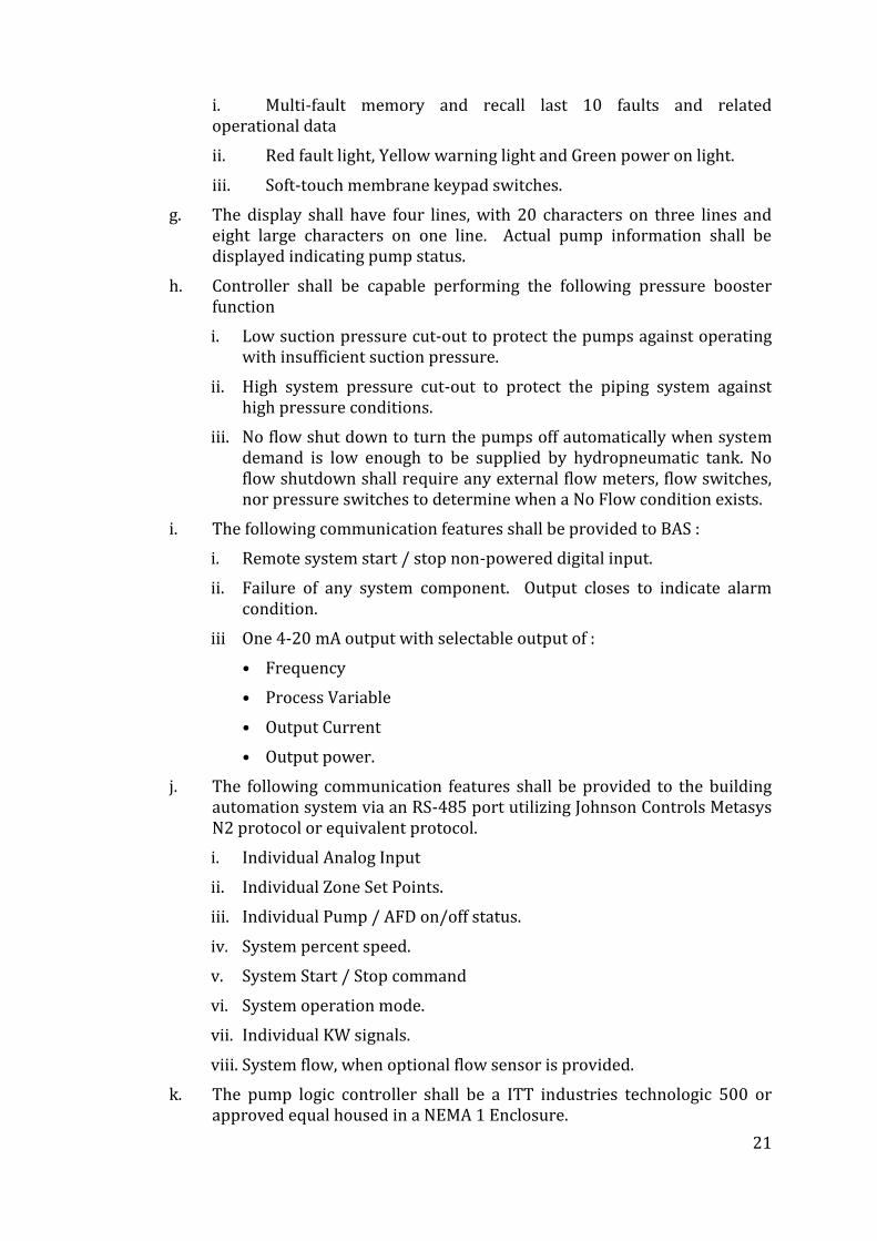
f. The pump logic controller shall be self-prompting. All messages shall be displayed in plain English. The operator interface shall have the following features :
21
i. Multi-fault memory and recall last 10 faults and related operational data
ii. Red fault light, Yellow warning light and Green power on light.
iii. Soft-touch membrane keypad switches.
g. The display shall have four lines, with 20 characters on three lines and eight large characters on one line. Actual pump information shall be displayed indicating pump status.
h. Controller shall be capable performing the following pressure booster function
i. Low suction pressure cut-out to protect the pumps against operating with insufficient suction pressure.
ii. High system pressure cut-out to protect the piping system against high pressure conditions.
iii. No flow shut down to turn the pumps off automatically when system demand is low enough to be supplied by hydropneumatic tank. No flow shutdown shall require any external flow meters, flow switches, nor pressure switches to determine when a No Flow condition exists.
i. The following communication features shall be provided to BAS :
i. Remote system start / stop non-powered digital input.
ii. Failure of any system component. Output closes to indicate alarm condition.
iii One 4-20 mA output with selectable output of :
• Frequency
• Process Variable
• Output Current
• Output power.
j. The following communication features shall be provided to the building automation system via an RS-485 port utilizing Johnson Controls Metasys N2 protocol or equivalent protocol.
i. Individual Analog Input
ii. Individual Zone Set Points.
iii. Individual Pump / AFD on/off status.
iv. System percent speed.
v. System Start / Stop command
vi. System operation mode.
vii. Individual KW signals.
viii. System flow, when optional flow sensor is provided.
k. The pump logic controller shall be a ITT industries technologic 500 or approved equal housed in a NEMA 1 Enclosure.
22
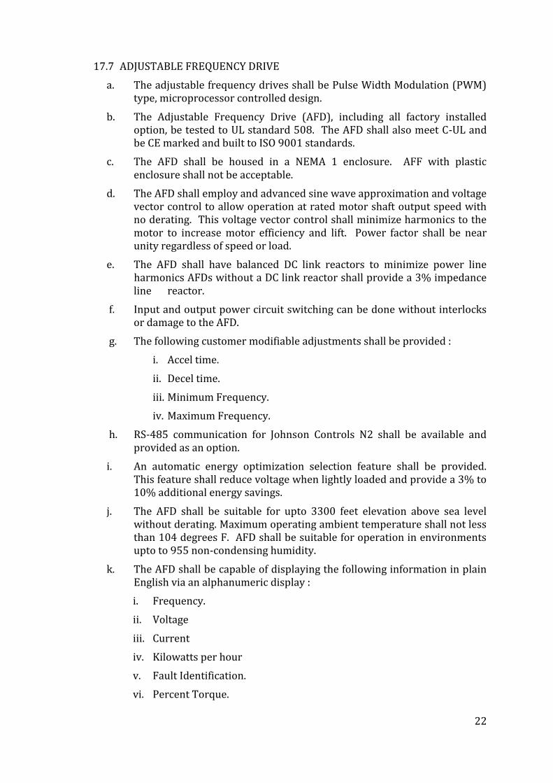
17.7 ADJUSTABLE FREQUENCY DRIVE
a. The adjustable frequency drives shall be Pulse Width Modulation (PWM) type, microprocessor controlled design.
b. The Adjustable Frequency Drive (AFD), including all factory installed option, be tested to UL standard 508. The AFD shall also meet C-UL and be CE marked and built to ISO 9001 standards.
c. The AFD shall be housed in a NEMA 1 enclosure. AFF with plastic enclosure shall not be acceptable.
d. The AFD shall employ and advanced sine wave approximation and voltage vector control to allow operation at rated motor shaft output speed with no derating. This voltage vector control shall minimize harmonics to the motor to increase motor efficiency and lift. Power factor shall be near unity regardless of speed or load.
e. The AFD shall have balanced DC link reactors to minimize power line harmonics AFDs without a DC link reactor shall provide a 3% impedance line reactor.
f. Input and output power circuit switching can be done without interlocks or damage to the AFD.
g. The following customer modifiable adjustments shall be provided :
i. Accel time.
ii. Decel time.
iii. Minimum Frequency.
iv. Maximum Frequency.
h. RS-485 communication for Johnson Controls N2 shall be available and provided as an option.
i. An automatic energy optimization selection feature shall be provided. This feature shall reduce voltage when lightly loaded and provide a 3% to 10% additional energy savings.
j. The AFD shall be suitable for upto 3300 feet elevation above sea level without derating. Maximum operating ambient temperature shall not less than 104 degrees F. AFD shall be suitable for operation in environments upto to 955 non-condensing humidity.
k. The AFD shall be capable of displaying the following information in plain English via an alphanumeric display :
i. Frequency.
ii. Voltage
iii. Current
iv. Kilowatts per hour
v. Fault Identification.
vi. Percent Torque.
23
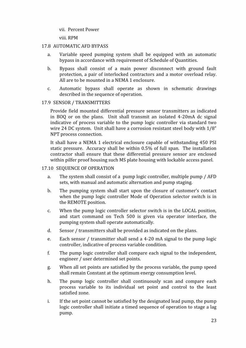
vii. Percent Power
viii. RPM
17.8 AUTOMATIC AFD BYPASS
a. Variable speed pumping system shall be equipped with an automatic bypass in accordance with requirement of Schedule of Quantities.
b. Bypass shall consist of a main power disconnect with ground fault protection, a pair of interlocked contractors and a motor overload relay. All are to be mounted in a NEMA 1 enclosure.
c. Automatic bypass shall operate as shown in schematic drawings described in the sequence of operation.
17.9 SENSOR / TRANSMITTERS
Provide field mounted differential pressure sensor transmitters as indicated in BOQ or on the plans. Unit shall transmit an isolated 4-20mA dc signal indicative of process variable to the pump logic controller via standard two wire 24 DC system. Unit shall have a corrosion resistant steel body with 1/8” NPT process connection.
It shall have a NEMA 1 electrical enclosure capable of withstanding 450 PSI static pressure. Accuracy shall be within 0.5% of full span. The installation contractor shall ensure that these differential pressure sensor are enclosed within pilfer proof housing such MS plate housing with lockable access panel.
17.10 SEQUENCE OF OPERATION
a. The system shall consist of a pump logic controller, multiple pump / AFD sets, with manual and automatic alternation and pump staging.
b. The pumping system shall start upon the closure of customer’s contact when the pump logic controller Mode of Operation selector switch is in the REMOTE position.
c. When the pump logic controller selector switch is in the LOCAL position, and start command on Tech 500 is given via operator interface, the pumping system shall operate automatically.
d. Sensor / transmitters shall be provided as indicated on the plans.
e. Each sensor / transmitter shall send a 4-20 mA signal to the pump logic controller, indicative of process variable condition.
f. The pump logic controller shall compare each signal to the independent, engineer / user determined set points.
g. When all set points are satisfied by the process variable, the pump speed shall remain Constant at the optimum energy consumption level.
h. The pump logic controller shall continuously scan and compare each process variable to its individual set point and control to the least satisfied zone.
i. If the set point cannot be satisfied by the designated lead pump, the pump logic controller shall initiate a timed sequence of operation to stage a lag pump.
24
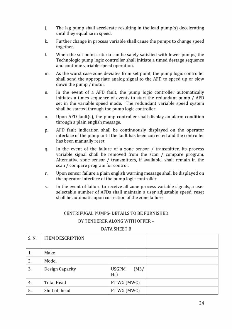
j. The lag pump shall accelerate resulting in the lead pump(s) decelerating until they equalize in speed.
k. Further change in process variable shall cause the pumps to change speed together.
l. When the set point criteria can be safely satisfied with fewer pumps, the Technologic pump logic controller shall initiate a timed destage sequence and continue variable speed operation.
m. As the worst case zone deviates from set point, the pump logic controller shall send the appropriate analog signal to the AFD to speed up or slow down the pump / motor.
n. In the event of a AFD fault, the pump logic controller automatically initiates a times sequence of events to start the redundant pump / AFD set in the variable speed mode. The redundant variable speed system shall be started through the pump logic controller.
o. Upon AFD fault(s), the pump controller shall display an alarm condition through a plain english message.
p. AFD fault indication shall be continuously displayed on the operator interface of the pump until the fault has been corrected and the controller has been manually reset.
q. In the event of the failure of a zone sensor / transmitter, its process variable signal shall be removed from the scan / compare program. Alternative zone sensor / transmitters, if available, shall remain in the scan / compare program for control.
r. Upon sensor failure a plain english warning message shall be displayed on the operator interface of the pump logic controller.
s. In the event of failure to receive all zone process variable signals, a user selectable number of AFDs shall maintain a user adjustable speed, reset shall be automatic upon correction of the zone failure.
CENTRIFUGAL PUMPS- DETAILS TO BE FURNISHED
BY TENDERER ALONG WITH OFFER –
DATA SHEET B
S. N. ITEM DESCRIPTION
1. Make
2. Model
3. Design Capacity USGPM (M3/ Hr)
4. Total Head FT WG (MWC)
5. Shut off head FT WG (MWC)
25
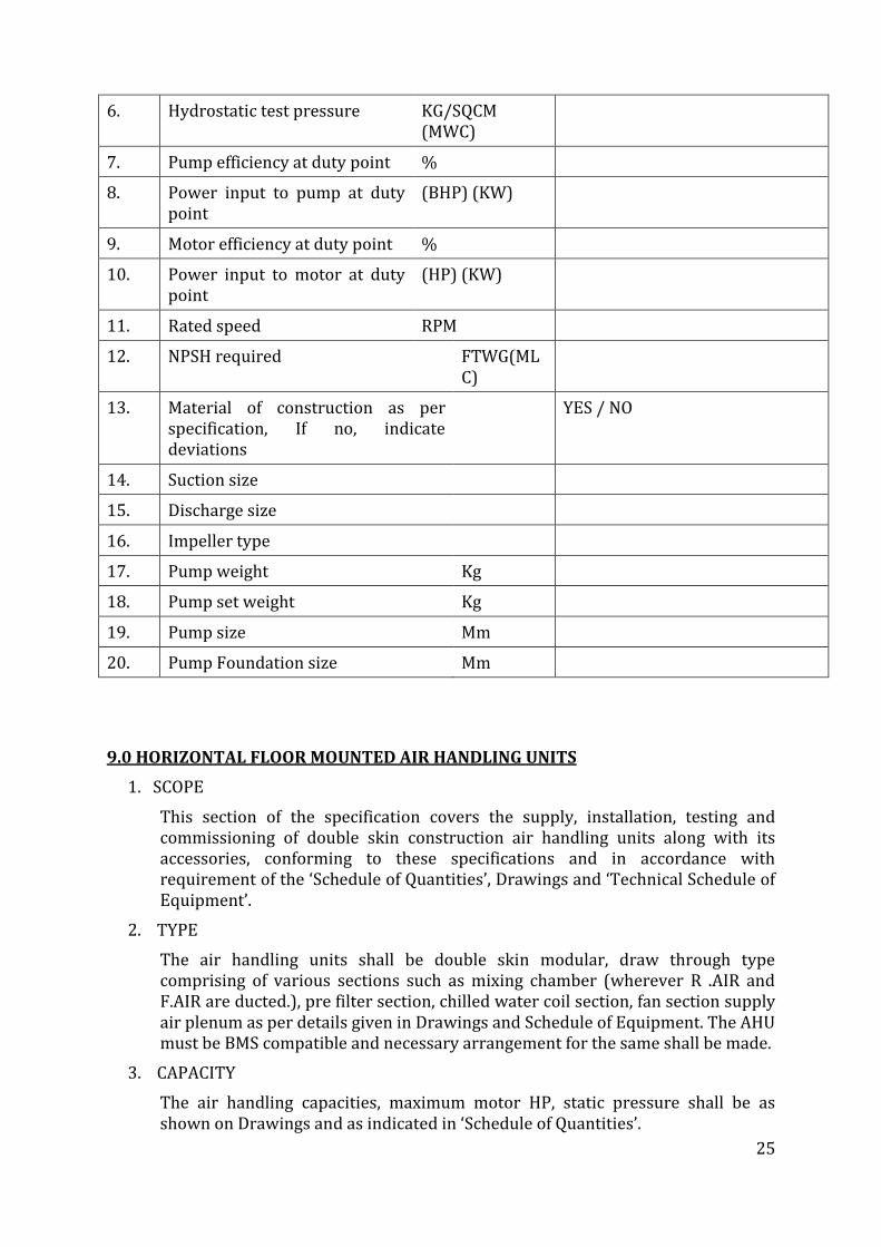
6. Hydrostatic test pressure KG/SQCM (MWC)
7. Pump efficiency at duty point %
8. Power input to pump at duty point
(BHP) (KW)
9. Motor efficiency at duty point %
10. Power input to motor at duty point
(HP) (KW)
11. Rated speed RPM
12. NPSH required FTWG(MLC)
13. Material of construction as per specification, If no, indicate deviations
YES / NO
14. Suction size
15. Discharge size
16. Impeller type
17. Pump weight Kg
18. Pump set weight Kg
19. Pump size Mm
20. Pump Foundation size Mm
9.0 HORIZONTAL FLOOR MOUNTED AIR HANDLING UNITS
1. SCOPE
This section of the specification covers the supply, installation, testing and commissioning of double skin construction air handling units along with its accessories, conforming to these specifications and in accordance with requirement of the ‘Schedule of Quantities’, Drawings and ‘Technical Schedule of Equipment’.
2. TYPE
The air handling units shall be double skin modular, draw through type comprising of various sections such as mixing chamber (wherever R .AIR and F.AIR are ducted.), pre filter section, chilled water coil section, fan section supply air plenum as per details given in Drawings and Schedule of Equipment. The AHU must be BMS compatible and necessary arrangement for the same shall be made.
3. CAPACITY
The air handling capacities, maximum motor HP, static pressure shall be as shown on Drawings and as indicated in ‘Schedule of Quantities’.
26
4. CONSTRUCTION
4.1 AHU HOUSING / Casing:
4.1.1 The AHU housing shall be of double skin construction with main structure made of extruded aluminum hollow sections. The panels shall be double skin sandwich type with 0.8 mm pre painted GSS/ pre-plasticized on the outside and 0.8 mm galvanized sheet inside with 25 mm thick PUF insulation or equivalent material injected in between or as specified in th BoQ. These panels shall be screwed with soft rubber gasket fixed in built in groove of aluminum frame in between to make the joints airtight.
4.1.2 Framework for each section shall be joined together with soft Neoprene rubber gasket in between to make the joints airtight. Suitable airtight access doors /panels with nylon hinges and locks shall be provided for access to various sections for maintenance. The entire housing shall be mounted on roller-formed GSS channel framework having pressure die cast aluminum jointers.
4.2 Drain Pan
The drain pan shall be of 18 G aluminum/stainless steel with necessary slope to facilitate fast removal of condensate. It shall be provided with drain connection of suitable size complete with 25 mm rigid insulation. Necessary arrangement will be provided to slide the coil in the drain pan. The drain pan shall be insulated with 12 mm thick close cell Nitrile insulation (self adhesive) or equivalent.
4.3 Cooling / Heating Coil
The chilled /hot water coil shall be of seamless copper tubes not less than 0.5 mm thick and 12mm OD. Coil face areas shall be such as to ensure rated capacity from each unit and such that air velocity across each coil shall not exceed 150 meters per minute. The coil shall be pitched in the unit casing for proper drainage. The fins shall be spaced by collars forming integral part of the fins. The tubes shall be staggered in the direction of airflow.
The fins shall be uniformly bonded to the tubes by mechanical expansion of the tube for minimum thermal contact resistance with fins. Fin spacing shall be 11to 13 FPI. The coils shall be tested against leaks at a hydraulic pressure of 21-kg/sq. cm. This pressure shall be maintained for a period of at least 2 hours. No drop should be observed indicating any leaks. The water headers shall be complete with water in /out connections, vent plug on top and drain at bottom and designed to provide water velocity between 2 to 6 FPS.
4.4 Fan Section with Fan
The fan shall be backward curved, double inlet double width type. The wheel & housing shall be fabricated from heavy gauge galvanized steel. The fan impeller shall be mounted on a solid shaft supported to housing with angle iron frame & pillow block heavy-duty ball bearings.
27
The fan shall be selected for a speed not exceeding 1000 RPM. The impeller & fan shaft shall be statically and dynamically balanced. The fan outlet velocity shall not be more than 550 MPM. Fan housing with motor shall be mounted on a common extruded aluminum base mounted inside the air handling housing on anti vibration spring mounts or cushy foot mounts of at least 90% vibration isolation efficiency. The fan outlet shall be connected to casing with the help of fire retardant double canvas or Neoprene rubber of imported Origin. The fan shall be selected for a noise level of less than 70 DB (A) at one meter distance.
4.5 Filter Section
Each unit shall be provided with a factory assembled filter section containing synthetic media washable air filters with efficiency of 90% down to 10-micron particle size. Filters shall have aluminum frame. Filter face velocity shall not exceed 150 meters per minute. Filter shall fit so as to prevent by pass. Holding frames shall be provided for installing number of filter cells in banks. These cells shall be held within the frames by sliding the cells between guiding channels.
5. FRESH AIR INTAKES
Extruded aluminum construction duly anodized fresh air louvers with bird screen and extruded construction dampers shall be provided in the clear opening in masonry walls of the air handling unit room having at least one external wall. Fresh air louver, damper, pre filters, ducts and fresh air fan with speed regulator (wherever specified in ‘Schedule of Quantities’) shall be provided. Fresh air dampers shall be of the interlocking, opposed blade louver type. Blades shall be rattle free. Damper shall be similar to those specified in ‘air distribution’. Fresh air fans and fresh air intakes shall be as per the requirements of ‘Schedule of Quantities’.
6. ACCESSORIES
Each air handling unit shall be provided with manual air vent at highest point in the cooling /heating coil. In addition, the following accessories may be required at air handling units. Their detailed specifications are indicated in individual sections and quantities separately identified in ‘Schedule of Quantities’.
(a) Stem type thermometer at each AHU coil inlet and outlet with tubing and gauge cocks and specification as per the section, ‘Automatic Controls and Instruments’
(b) Pressure gauge with globe valves at inlet and outlet of each AHU coil with tubing and specifications as per the section, ‘Automatic Control and Instruments’.
(c) Butterfly valves at inlet and outlet of the each coil.
28
(d) Balancing valve at the outlet of each coil.
(e) Y strainer at inlet of each coil.
(f) Union and condensate drain piping from the unit up to the drain trap as described in section piping.
(g) Motorized three way mixing valves located in chilled /hot water lines connected to the coil. This valve shall be operated by the cooling/heating thermostat and shall control the flow of chilled/hot water as per section ‘automatic controls and instruments’.
(h) Cooling /heating thermostat as per section
‘Automatic Controls and Instruments’ shall be located in return air
stream.
(i) Flexible connection between the fan outlet and duct.
(j) Vibration isolators of at least 90% efficiency.
7. SAFETY FEATURES
Each handling unit must have safety features as under:-
(a) The fan access door must have micro switch interlocked with fan motor to enable switching off the fan motor automatically in the event of door opening.
The access door shall further have wire mesh screen as an added feature, bolted on to the unit frame.
(b)Fan and motor base shall be properly earthed from the factory.
(c) All screws used for panel fixing and projecting inside the unit shall be covered with PVC caps to avoid human injury.
8. DRIVE
Fan drive shall be 3phase-squirrel cage totally enclosed fan cooled motor
for quiet operation and motor speed shall not exceed 1440 RPM. Direct drive arrangement shall be provided to the fan.
9. DESIGN DATA FOR AIR HANDLING UNITS
(a) Fan outlet velocity shall not exceed 500 MPM.
(b) The air velocity across coil shall not exceed 150 MPM.
(c) The air velocity across air pre filter shall not exceed 150 MPM.
Motor ratings are only tentative and shall be suitable for the duty but not less than the specified HP. The motor shall be selected with a safety factor of at least 20% over and above the brake power.
The AHU fan shall be selected for a total static pressure as indicated in ‘Schedule of Quantities’.
10. INSTALLATION
29
Air Handling Unit shall be installed inside the AHU room to permit the removal of all the parts of AHU for any maintenance work without dismantling other equipment such as plenum, pipes, ducts etc. Air handling unit installation shall be carried out as per manufacturer’s recommendation and mounted on serrated rubber pads. The serrated rubber pads shall be in two layers with 16G GI sheet sandwiched in between.
11. PERFORMANCE DATA
Air handling unit shall be selected for the lowest operating noise level of the equipment. Fan performance rating and power consumption data with operating points clearly indicated shall be submitted and verified at the time of testing, commissioning of the installation.
12. TESTING
Cooling/Heating capacity of various air-handling unit models shall be computed from the measurements of airflow and dry and wet bulb temperatures of air entering and leaving the coil.
Flow measurements shall be by anemometer and temperature measurements by accurately calibrated mercury in glass thermometer. Computed result shall conform to the specified capacities and quoted ratings. Consumption shall be computed from measurements of incoming voltage and input current.
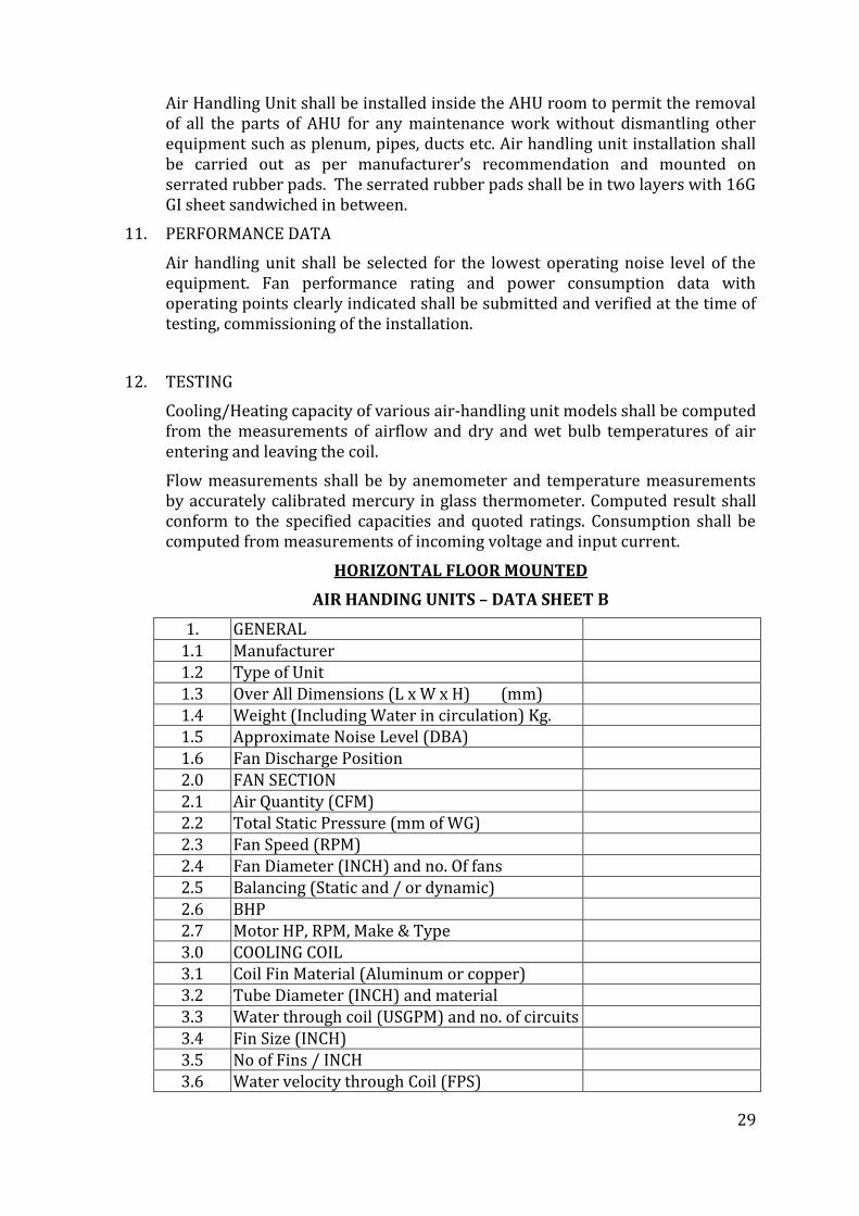
HORIZONTAL FLOOR MOUNTED
AIR HANDING UNITS – DATA SHEET B
1. GENERAL 1.1 Manufacturer 1.2 Type of Unit 1.3 Over All Dimensions (L x W x H) (mm) 1.4 Weight (Including Water in circulation) Kg. 1.5 Approximate Noise Level (DBA) 1.6 Fan Discharge Position 2.0 FAN SECTION 2.1 Air Quantity (CFM) 2.2 Total Static Pressure (mm of WG) 2.3 Fan Speed (RPM) 2.4 Fan Diameter (INCH) and no. Of fans 2.5 Balancing (Static and / or dynamic) 2.6 BHP 2.7 Motor HP, RPM, Make & Type 3.0 COOLING COIL 3.1 Coil Fin Material (Aluminum or copper) 3.2 Tube Diameter (INCH) and material 3.3 Water through coil (USGPM) and no. of circuits 3.4 Fin Size (INCH) 3.5 No of Fins / INCH 3.6 Water velocity through Coil (FPS)
30
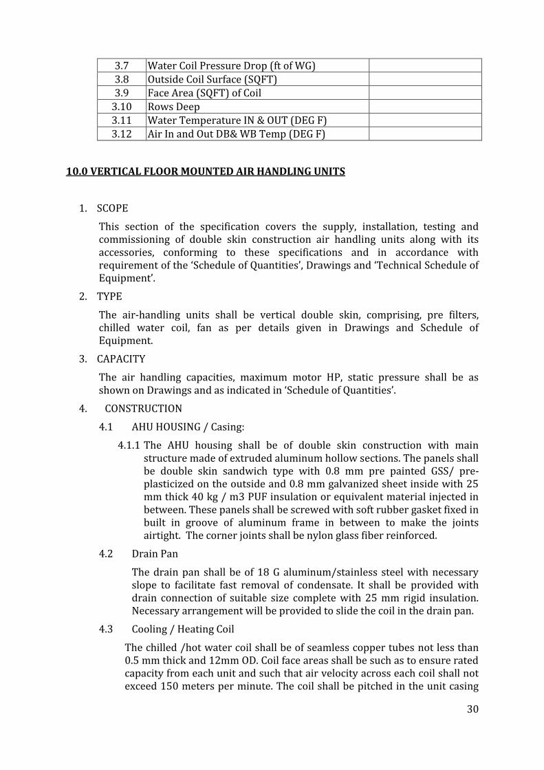
3.7 Water Coil Pressure Drop (ft of WG) 3.8 Outside Coil Surface (SQFT) 3.9 Face Area (SQFT) of Coil
3.10 Rows Deep 3.11 Water Temperature IN & OUT (DEG F) 3.12 Air In and Out DB& WB Temp (DEG F)
10.0 VERTICAL FLOOR MOUNTED AIR HANDLING UNITS
1. SCOPE
This section of the specification covers the supply, installation, testing and commissioning of double skin construction air handling units along with its accessories, conforming to these specifications and in accordance with requirement of the ‘Schedule of Quantities’, Drawings and ‘Technical Schedule of Equipment’.
2. TYPE
The air-handling units shall be vertical double skin, comprising, pre filters, chilled water coil, fan as per details given in Drawings and Schedule of Equipment.
3. CAPACITY
The air handling capacities, maximum motor HP, static pressure shall be as shown on Drawings and as indicated in ‘Schedule of Quantities’.
4. CONSTRUCTION
4.1 AHU HOUSING / Casing:
4.1.1 The AHU housing shall be of double skin construction with main structure made of extruded aluminum hollow sections. The panels shall be double skin sandwich type with 0.8 mm pre painted GSS/ pre-plasticized on the outside and 0.8 mm galvanized sheet inside with 25 mm thick 40 kg / m3 PUF insulation or equivalent material injected in between. These panels shall be screwed with soft rubber gasket fixed in built in groove of aluminum frame in between to make the joints airtight. The corner joints shall be nylon glass fiber reinforced.
4.2 Drain Pan
The drain pan shall be of 18 G aluminum/stainless steel with necessary slope to facilitate fast removal of condensate. It shall be provided with drain connection of suitable size complete with 25 mm rigid insulation. Necessary arrangement will be provided to slide the coil in the drain pan.
4.3 Cooling / Heating Coil
The chilled /hot water coil shall be of seamless copper tubes not less than 0.5 mm thick and 12mm OD. Coil face areas shall be such as to ensure rated capacity from each unit and such that air velocity across each coil shall not exceed 150 meters per minute. The coil shall be pitched in the unit casing
31
for proper drainage. The fins shall be spaced by collars forming integral part of the fins. The tubes shall be staggered in the direction of airflow.
The fins shall be uniformly bonded to the tubes by mechanical expansion of the tube for minimum thermal contact resistance with fins. Fin spacing shall be 11 to 13 FPI. The coils shall be tested against leaks at a hydraulic pressure of 21-kg/sq cm. This pressure shall be maintained for a period of at least 2 hours. No drop should be observed indicating any leaks. The water headers shall be completed with water in /out connections, vent plug on top and drain at bottom and designed to provide water velocity between 2 to 6 FPS.
4.4 FAN SECTION WITH FAN
Fan section shall have two Nos. blowers.
The fans shall be backward curved, double inlet double width type. The fan shall be selected for a speed not exceeding 1000 RPM. The impeller & fan shaft shall be statically and dynamically balanced. The fan outlet velocity shall not be more than 550 MPM. Fans & motor shall be mounted above the coil /sections. The fan outlet shall be connected to casing with the help of fire retardant canvas.
The fan shall be selected for a noise level less than 70 DB (A) 1M away from the unit.
4.5 Filter Section
Each unit shall be provided with a factory assembled filter section containing 48 thick synthetic media washable air filters with efficiency of 90% down to 10-micron particle size. Filters shall have aluminum frame. Filter face velocity shall not exceed 150 meters per minute. Filter shall fit so as to prevent by pass. Holding frames shall be provided for installing number of filter cells in banks. These cells shall be held within the frames by sliding the cells between guiding channels.
5. FRESH AIR INTAKES
Extruded aluminum construction duly anodized fresh air louver with bird screen and extruded construction dampers shall be provided in the clear opening in masonry walls of the air handling unit room having at least one external wall. Fresh air louver, damper, pre-filters, ducts and fresh air fan with speed regulator (wherever specified in ‘Schedule of Quantities’) shall be provided. Fresh air dampers shall be of the interlocking, opposed blade louver type. Blades shall be rattle free. Damper shall be similar to those specified in ‘air distribution’. Fresh air fans and fresh air intakes shall be as per the requirements of ‘Schedule of Quantities’.
6. ACCESSORIES
Each air handling unit shall be provided with manual air vent at highest point in the cooling /heating coil. In addition, the following accessories may be required at air handling units. Their detailed specifications are in
32
individual sections and quantities separately identified in ‘Schedule of Quantities’.
(a) Stem type thermometer at each coil inlet and outlet with tubing and gauge cocks and specification as per the section, ‘Automatic Controls and Instruments’
(b) Pressure gauge with globe valves at inlet and outlet of each coil with tubing and specifications as per the section, ‘Automatic Control and Instruments’.
(c) Butterfly valves at inlet and outlet of each coil.
(d) Balancing valve at the outlet of each coil.
(e) Y strainer at inlet of each coil.
(f) Union and condensate drain piping from the unit up to the drain trap as described in section piping.
(g) Motorized three way mixing valves located in chilled /hot water lines connected to the coil. This valve shall be operated by the cooling/heating thermostat and shall control the flow of chilled/hot water as per section ‘automatic controls and instruments’ for detailed specification.
(h) Cooling /heating thermostat as per section
‘Automatic Controls and Instruments’ shall be located in return air
stream.
(i) Double Flexible connection of fireproofs material between the fan outlet and duct.
(j) Vibration isolators of at least 90% efficiency.
7. PERFORMANCE DATA
Air handling unit shall be selected for the lowest operating noise level. Fan performance rating and power consumption data with operating points clearly indicated shall be submitted and verified at the time of testing & commissioning of the installation.
8. TESTING
Cooling/Heating capacity of various air-handling unit models shall be computed from the measurements of airflow and dry and wet bulb temperatures of air entering and leaving the coil.
Flow measurements shall be by anemometer and temperature measurements by accurately calibrated mercury in glass thermometer. Computed result shall conform to the specified capacities and quoted ratings. Power consumption shall be computed from measurements of incoming voltage and input current.
VERTICAL FLOOR MOUNTED
AIR HANDING UNITS – DATA SHEET B
33
1 GENERAL 1.1 Manufacturer 1.2 Type of Unit 1.3 Over All Dimensions (L x W x H) (mm) 1.4 Weight (Including Water in circulation) Kg. 1.5 Approximate Noise Level (DBA) 1.6 Fan Discharge Position 2.0 FAN SECTION 2.1 Air Quantity (CFM) 2.2 Total Static Pressure (mm of WG) 2.3 Fan Speed (RPM) 2.4 Fan Diameter (INCH) and no. Of fans 2.5 Balancing (Static and / or dynamic) 2.6 BHP 2.7 Motor HP, RPM, Make & Type 3.0 COOLING COIL 3.1 Coil Fin Material (Aluminum or copper) 3.2 Tube Diameter (INCH) and material
3.3 Water through coil (USGPM) and no. of circuits
3.4 Fin Size (INCH) 3.5 No of Fins / INCH 3.6 Water velocity through Coil (FPS) 3.7 Water Coil Pressure Drop (ft of WG) 3.8 Outside Coil Surface (SQFT) 3.9 Face Area (SQFT) of Coil 3.10 Rows Deep 3.11 Water Temperature IN & OUT (DEG F) 3.12 Air In and Out DB& WB Temp (DEG F)
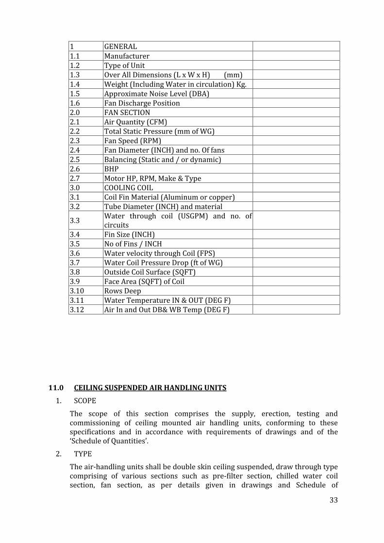
11.0 CEILING SUSPENDED AIR HANDLING UNITS
1. SCOPE
The scope of this section comprises the supply, erection, testing and commissioning of ceiling mounted air handling units, conforming to these specifications and in accordance with requirements of drawings and of the ‘Schedule of Quantities’.
2. TYPE
The air-handling units shall be double skin ceiling suspended, draw through type comprising of various sections such as pre-filter section, chilled water coil section, fan section, as per details given in drawings and Schedule of
34
Equipment.The AHU must be BMS compatible and necessary arrangement for the same shall be made.
3. CAPACITY
The air moving and coil capacities shall be as shown on the drawings and indicated in ‘Schedule of Quantities’.
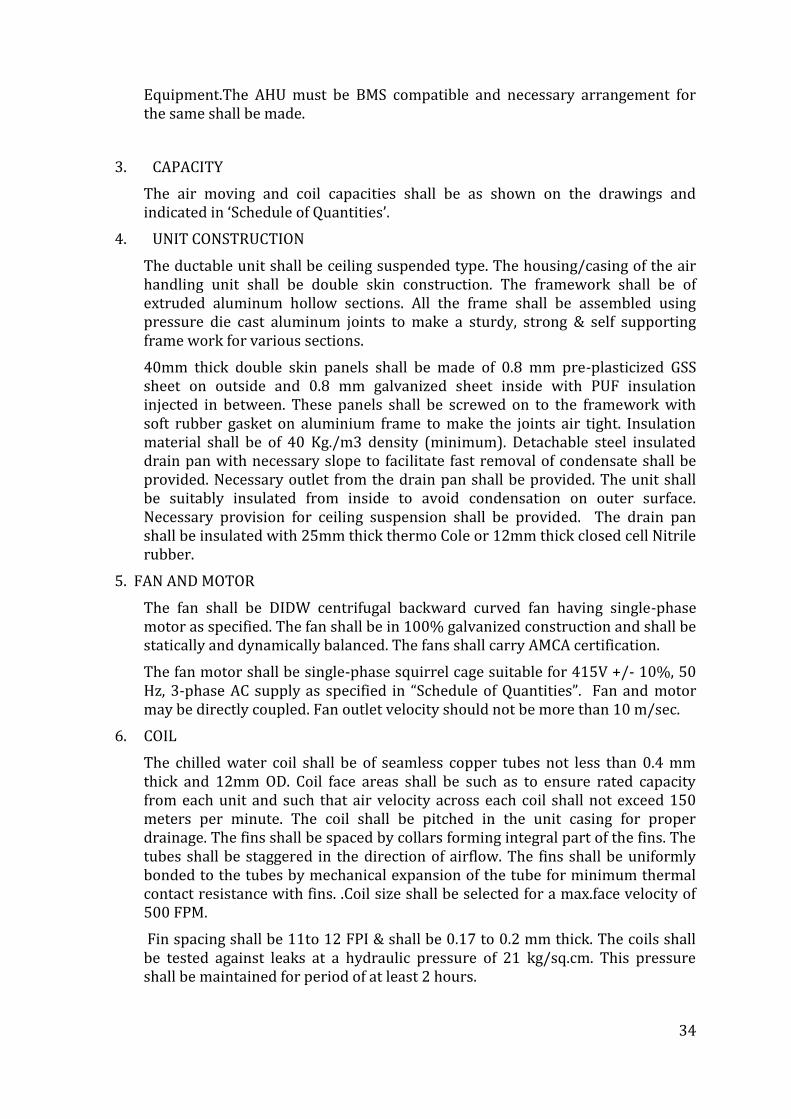
4. UNIT CONSTRUCTION
The ductable unit shall be ceiling suspended type. The housing/casing of the air handling unit shall be double skin construction. The framework shall be of extruded aluminum hollow sections. All the frame shall be assembled using pressure die cast aluminum joints to make a sturdy, strong & self supporting frame work for various sections.
40mm thick double skin panels shall be made of 0.8 mm pre-plasticized GSS sheet on outside and 0.8 mm galvanized sheet inside with PUF insulation injected in between. These panels shall be screwed on to the framework with soft rubber gasket on aluminium frame to make the joints air tight. Insulation material shall be of 40 Kg./m3 density (minimum). Detachable steel insulated drain pan with necessary slope to facilitate fast removal of condensate shall be provided. Necessary outlet from the drain pan shall be provided. The unit shall be suitably insulated from inside to avoid condensation on outer surface. Necessary provision for ceiling suspension shall be provided. The drain pan shall be insulated with 25mm thick thermo Cole or 12mm thick closed cell Nitrile rubber.
5. FAN AND MOTOR
The fan shall be DIDW centrifugal backward curved fan having single-phase motor as specified. The fan shall be in 100% galvanized construction and shall be statically and dynamically balanced. The fans shall carry AMCA certification.
The fan motor shall be single-phase squirrel cage suitable for 415V +/- 10%, 50 Hz, 3-phase AC supply as specified in “Schedule of Quantities”. Fan and motor may be directly coupled. Fan outlet velocity should not be more than 10 m/sec.
6. COIL
The chilled water coil shall be of seamless copper tubes not less than 0.4 mm thick and 12mm OD. Coil face areas shall be such as to ensure rated capacity from each unit and such that air velocity across each coil shall not exceed 150 meters per minute. The coil shall be pitched in the unit casing for proper drainage. The fins shall be spaced by collars forming integral part of the fins. The tubes shall be staggered in the direction of airflow. The fins shall be uniformly bonded to the tubes by mechanical expansion of the tube for minimum thermal contact resistance with fins. .Coil size shall be selected for a max.face velocity of 500 FPM.
Fin spacing shall be 11to 12 FPI & shall be 0.17 to 0.2 mm thick. The coils shall be tested against leaks at a hydraulic pressure of 21 kg/sq.cm. This pressure shall be maintained for period of at least 2 hours.
35
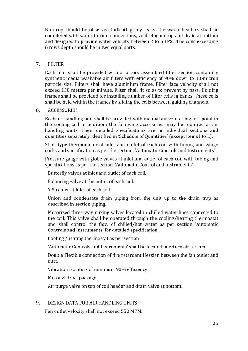
No drop should be observed indicating any leaks .the water headers shall be completed with water in /out connections, vent plug on top and drain at bottom and designed to provide water velocity between 2 to 6 FPS. The coils exceeding 6 rows depth should be in two equal parts.
7. FILTER
Each unit shall be provided with a factory assembled filter section containing synthetic media washable air filters with efficiency of 90% down to 10-micron particle size. Filters shall have aluminium frame. Filter face velocity shall not exceed 150 meters per minute. Filter shall fit so as to prevent by pass. Holding frames shall be provided for installing number of filter cells in banks. These cells shall be held within the frames by sliding the cells between guiding channels.
8. ACCESSORIES
Each air-handling unit shall be provided with manual air vent at highest point in the cooling coil in addition; the following accessories may be required at air handling units. Their detailed specifications are in individual sections and quantities separately identified in ‘Schedule of Quantities’ (except items I to L).
Stem type thermometer at inlet and outlet of each coil with tubing and gauge cocks and specification as per the section, ‘Automatic Controls and Instruments’
Pressure gauge with globe valves at inlet and outlet of each coil with tubing and specifications as per the section, ‘Automatic Control and Instruments’.
Butterfly valves at inlet and outlet of each coil.
Balancing valve at the outlet of each coil.
Y Strainer at inlet of each coil.
Union and condensate drain piping from the unit up to the drain trap as described in section piping.
Motorized three way mixing valves located in chilled water lines connected to the coil. This valve shall be operated through the cooling/heating thermostat and shall control the flow of chilled/hot water as per section ‘Automatic Controls and Instruments’ for detailed specification.
Cooling /heating thermostat as per section
‘Automatic Controls and Instruments’ shall be located in return air stream.
Double Flexible connection of fire retardant Hessian between the fan outlet and duct.
Vibration isolators of minimum 90% efficiency.
Motor & drive package
Air purge valve on top of coil header and drain valve at bottom.
9. DESIGN DATA FOR AIR HANDLING UNITS
Fan outlet velocity shall not exceed 550 MPM.
36
The air velocity across coil shall not exceed 150 MPM.
The air velocity across air pre filter shall not exceed 150 MPM.
Motor rating is tentative only and shall be suitable for the duty but not less than the specified HP. Motors shall be selected considering at least 20% margin over the break power.
The AHU fan shall be selected for a total static pressure as indicated under Technical Schedule for Equipment’.
10. INSTALLATION
Unit shall be installed above the false ceiling in a manner so as to permit the removal of all the parts of AHU for any maintenance work without dismantling other equipment such as plenum, pipes, ducts etc. Air handling unit installation shall be carried out as per manufacturer’s recommendation. Rubber in shear type suspension hangers shall be provided for vibration isolation.
11. PERFORMANCE DATA
Air handling unit shall be selected for the lowest operating noise level. Fan performance rating and power consumption data with operating points clearly indicated shall be submitted and verified at the time of testing & commissioning of the installation.
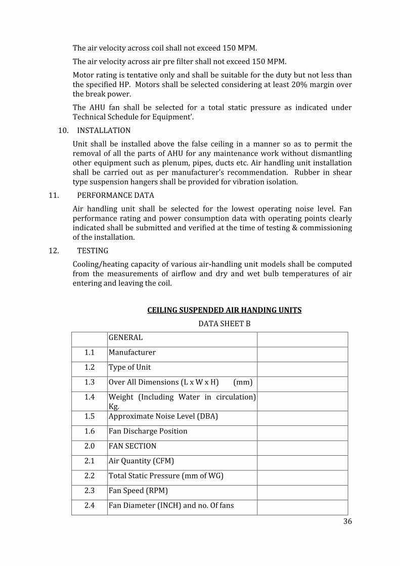
12. TESTING
Cooling/heating capacity of various air-handling unit models shall be computed from the measurements of airflow and dry and wet bulb temperatures of air entering and leaving the coil.
CEILING SUSPENDED AIR HANDING UNITS
DATA SHEET B
GENERAL
1.1 Manufacturer
1.2 Type of Unit
1.3 Over All Dimensions (L x W x H) (mm)
1.4 Weight (Including Water in circulation) Kg.
1.5 Approximate Noise Level (DBA)
1.6 Fan Discharge Position
2.0 FAN SECTION
2.1 Air Quantity (CFM)
2.2 Total Static Pressure (mm of WG)
2.3 Fan Speed (RPM)
2.4 Fan Diameter (INCH) and no. Of fans
37
2.5 Balancing (Static and / or dynamic)
2.6 BHP
2.7 Motor HP, RPM, Make & Type
3.0 COOLING COIL
3.1 Coil Fin Material (Aluminum or copper)
3.2 Tube Diameter (INCH) and material
3.3 Water through coil (USGPM) and no. of circuits
3.4 Fin Size (INCH)
3.5 No of Fins / INCH
3.6 Water velocity through Coil (FPS)
3.7 Water Coil Pressure Drop (ft of WG)
3.8 Outside Coil Surface (SQFT)
3.9 Face Area (SQFT) of Coil
3.10 Rows Deep
3.11 Water Temperature IN & OUT (DEG F)
3.12 Air In and Out DB& WB Temp (DEG F)
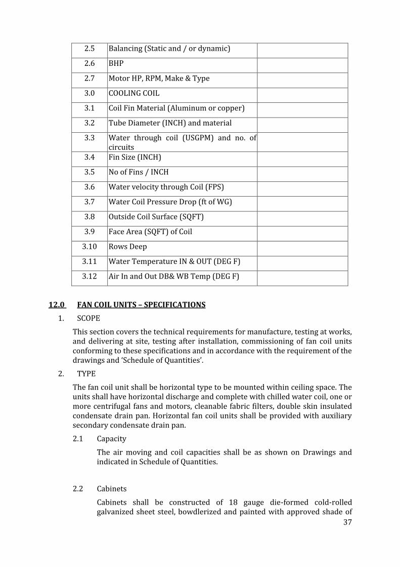
12.0 FAN COIL UNITS – SPECIFICATIONS
1. SCOPE
This section covers the technical requirements for manufacture, testing at works, and delivering at site, testing after installation, commissioning of fan coil units conforming to these specifications and in accordance with the requirement of the drawings and ‘Schedule of Quantities’.
2. TYPE
The fan coil unit shall be horizontal type to be mounted within ceiling space. The units shall have horizontal discharge and complete with chilled water coil, one or more centrifugal fans and motors, cleanable fabric filters, double skin insulated condensate drain pan. Horizontal fan coil units shall be provided with auxiliary secondary condensate drain pan.
2.1 Capacity
The air moving and coil capacities shall be as shown on Drawings and indicated in Schedule of Quantities.
2.2 Cabinets
Cabinets shall be constructed of 18 gauge die-formed cold-rolled galvanized sheet steel, bowdlerized and painted with approved shade of
38
powder coating finish and shall have access doors to piping and controls. Access panels shall have positive locking fasteners for easy removal. Horizontal furred-in type units mounted within ceiling space shall be provided with a cabinet housing, the coil and fan section with provision to mount filters within the fan section.
2.3 Interior Chassis
The interior chassis shall be constructed of not less than 16 gauge cold rolled galvanized sheet steel bowdlerized and painted with approved shade of powder coating finish. All ceiling suspended fan coil units shall be securely mounted from the building structure with top panel set dead level in both directions. In case of ceiling suspended horizontal units, fan deck and cooling coil shall be easily removable from FCU without lowering down of the FCU or disturbing the other installation.
2.4 Fan Section
This shall consist of two lightweight aluminum impellers of forward curved type, both statically and dynamically balanced.
The two impellers shall be directly mounted on to a double shaft, single phase multiple winding motor capable of running at three speeds
A GI plenum shall connect fan outlet to the coil.
2.5 Cooling Coil
The coil shall be of seamless copper tube of minimum 10 mm OD and wall thickness shall be minimum 0.5 mm. All bends and joints shall be enclosed within insulated end sections of the base unit for protection against sweating. Each coil shall be provided with air vent. All coils shall be factory tested at 21 kg per sq.cm. (300psig) air pressure when submerged in water. Fin spacing shall be 4 to 5 fins per cm. Tubes shall be mechanically/ hydraulically expanded for minimum thermal contact resistance with fins. Air vent shall be provided in headers at a level higher than coils. The cooling coil shall be easily removable from backside of FCU without disturbing the other installations. The copper tube or pipe should not be manufactured from reprocessed or recycled copper
2.6 Drain Pans
Primary drain pan shall be of double skin construction fabricated from 18 gauge stainless steel with all corners enclosed. An additional inner bottom panel of 18 G thick stainless steel sheet shall be provided to prevent damage to insulation. The pan shall be insulated with minimum 15mm thick expanded polyethylene insulation sandwiched between top and bottom panels to prevent condensation. The pan shall be of sufficient size to accommodate cooling coil supply and return water header and bends and control valves.
The auxiliary condensate drain pan shall be similar in construction to primary drain pan and size larger than primary drain pan to catch all overflows in case primary drain pan gets choked. Drain from auxiliary drain pan shall be connected to drain from primary drain pan through a tee connection and piped to vertical risers.
39
2.7 Motor
Motor shall be 220 ± 6% volts, 50 cycle, single phase, six poles, shaded pole type, rpm not exceeding 1000 at maximum airflow. Motor shall have three speed windings and shall be factory wired to a terminal block mounted within the fan section. Motors shall have extended shaft on both sides.
3. AIR FILTER
The filter shall be cleanable type 12mm thick AL. wire mesh and mounted behind the pan in a filter plenum of GI sheet.
4. PAINTING
The fan coil units shall be powder coated in approved colour.
5. CONTROLS
All units shall be complete with following controls
Motorized two way valve in water lines
Wall mounted thermostat containing three speed and on/off control for fan, speed and temperature control for summer/ winter air conditioning
'Y' strainer, ball valve and globe valve as shown on drawings and ‘schedule of quantities’
6. PERFORMANCE DATA
Fan coil units shall be selected for the lowest operating noise level having standard sound level rating of NC 30 at low speed and NC 35 at medium / high speed. Fan performance rating and power consumption data, with operating points clearly indicated, shall be submitted by the Contractor and verified at the time of testing and commissioning of the installation.
7. TESTING
Cooling capacity of various fan coil unit models shall be computed from the measurements of airflow and dry and wet bulb temperatures of entering and leaving the coil. Flow measurements shall be by anemometer and temperature measurements by accurately calibrated mercury -in-glass thermometers. Computed ratings shall conform to the specified capacities and quoted ratings. Power consumption shall be computed from measurements of incoming voltage and input current.
CEILING MOUNTED FAN COIL UNITS
DATA SHEET B
GENERAL
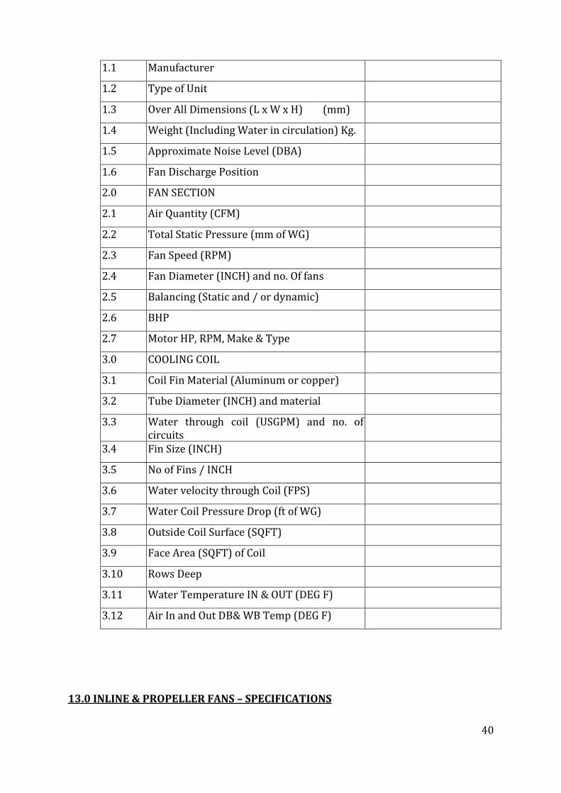
40
1.1 Manufacturer
1.2 Type of Unit
1.3 Over All Dimensions (L x W x H) (mm)
1.4 Weight (Including Water in circulation) Kg.
1.5 Approximate Noise Level (DBA)
1.6 Fan Discharge Position
2.0 FAN SECTION
2.1 Air Quantity (CFM)
2.2 Total Static Pressure (mm of WG)
2.3 Fan Speed (RPM)
2.4 Fan Diameter (INCH) and no. Of fans
2.5 Balancing (Static and / or dynamic)
2.6 BHP
2.7 Motor HP, RPM, Make & Type
3.0 COOLING COIL
3.1 Coil Fin Material (Aluminum or copper)
3.2 Tube Diameter (INCH) and material
3.3 Water through coil (USGPM) and no. of circuits
3.4 Fin Size (INCH)
3.5 No of Fins / INCH
3.6 Water velocity through Coil (FPS)
3.7 Water Coil Pressure Drop (ft of WG)
3.8 Outside Coil Surface (SQFT)
3.9 Face Area (SQFT) of Coil
3.10 Rows Deep
3.11 Water Temperature IN & OUT (DEG F)
3.12 Air In and Out DB& WB Temp (DEG F)
13.0 INLINE & PROPELLER FANS – SPECIFICATIONS
41
1 SCOPE
The scope of this section comprises the supply, installation, testing and commissioning of centrifugal and inline fans conforming to these specifications and in accordance with the requirement of drawings and ‘Schedule of Quantities’.
2 TYPE
Centrifugal and inline fans shall be of type as indicated in drawings and ‘Schedule of Quantities’
3 INLINE FANS
Inline fan shall incorporate SISW direct driven centrifugal fan with TEFC (IP-44) motor. The fan assembly shall be enclosed in a sheet metal housing of 22 gauge GSS and with necessary inspection cover with proper gasket assembly. The fan material shall be galvanized sheet steel. Flanges shall be provided on both sides of inline fan to facilitate easy connection. Flexible anti-vibration joints shall be provided to arrest vibration being transferred to other equipments connected to inline fan. Motor shall be single phase/three phase as per duty conditions.
All single-phase fans shall be provided with speed regulators while all three phase fans shall be provided with opposed blade dampers in GSS construction at fan outlet for air balancing.
4 PROPELLER FANS
Propeller fans shall be direct driven, three or four blade type mounted on a steel mounting plate with orifice ring.
Mounting plate shall be of steel construction, square with streamlined venturi inlet coated with baked enamel paint. Mounting plate shall be of standard size, constructed of 12 to 16 gauge steel sheet depending upon the fan size. Orifice ring shall be correctly formed by spinning or stamping to provide easy passage of air without turbulence and to direct the air stream.
Fan blades shall be constructed of aluminum or glass reinforced polypropylene. Fan hub shall be of heavy welded steel construction with blades bolted to the hub fan blades and assembly shall be statically and dynamically balanced
Shaft shall be of steel accurately ground and shall not pass through first critical speed through entire range of specified fan speed.
Motor shall be standard permanent split capacitor of shaded pole for small sizes, totally enclosed with pre-lubricated sleeve or ball bearings, designed for a quiet operation with a maximum speed of 1000 RPM for fans 60 cm dia. or larger and 1440 RPM for fans 45 cm dia. and smaller. Motors for larger fans shall be suitable for 415 ± 6% volts. 50 cycle 3-phase power supply and for smaller fans shall be suitable for 220 ± 6% volts, 50 cycles single-phase power supply. Motors shall be suitable for horizontal or vertical service as indicated in drawings and Schedule of Quantities.
Propeller fans shall be provided with following accessories: -
Wire guard and bird-screen
Gravity louvers at outlet
Regulator for controlling fan speed for single-phase fan motor.
42
Single-phase preventors for 3 phase fans.
Wiring between regulator and fan motor including termination at both ends.
5 PERFORMANCE DATA
All fans shall be selected for the lowest operating noise level. Capacity rating, power consumption with operating points clearly indicated shall be submitted and verified at the time of testing and commissioning of installation.
6 TESTING
Capacity of all fans shall be measured by an anemometer. Measured airflow capacities shall conform to the specified capacities and quoted ratings, power consumption shall be computed from measurements of incoming voltage and incoming current.
14.0 VENTILATION FAN SECTIONS – SPECIFICATIONS
1. SCOPE
The scope of this section comprises the supply, installation, testing and commissioning of ventilation fan sections conforming to these specifications and in accordance with the requirement of drawings and ‘Schedule of Quantities’.
2. TYPE
Ventilation fan sections shall be complete with Centrifugal Fans, belt driven fans complete with motor drive and housing with weatherproof cowl.
3. UNIT CONSTRUCTION
3.1 Housing
The housing shall be fabricated out of 16 gauge steel sheet and shall have flange to be connected to duct. The discharge cowl shall be hinged along one edge for easy access to motor and drive, for inspection and maintenance. The entire assembly shall be weatherproof and provided with 18 gauge galvanized steel mesh bird screen of 6 mm size on all discharge cowls around the outlet areas.
3.2 Fan
Fan shall be forward / backward inclined wheel type designed for maximum efficiency, minimum turbulence and quiet operation. Fan shall be statically and dynamically balanced. Fan shall conform to specifications as given in specification No.SPC/CF – PF/01
3.3 Motor
enclosed fan cooled motor provided with class ‘F’ insulation. Motor shall be designed for quiet operation and motor speed shall not exceed 1440 RPM. Drive to fan shall be through belts.
3.4 Back draft Damper
Where called for in schedule of quantities the ventilation fan section shall be provided with a rattle free back draft damper to prevent air from re-entering the fan when fan is not in operation, thus sealing completely in closed position. Damper shall be chatterproof under all conditions.
43
4. VIBRATION ISOLATION
The motor and fan assembly shall be isolated from base through Dunlop/Resistoflex vibration isolators.
5. PERFORMANCE DATA
All fans shall be selected for the lowest operating noise level. Capacity rating, power consumption with operating points clearly indicated shall be submitted and verified at the time of testing and commissioning of installation.
6. TESTING
Capacity of all fans shall be measured by an anemometer. Measured airflow capacities shall conform to the specified capacities and quoted ratings, power consumption shall be computed from measurements of incoming voltage and incoming current.
15.0 AXIAL FLOW FANS – SPECIFICATIONS
1. SCOPE
This section covers the technical requirements for manufacture, testing at works, delivery at site, testing after installation, commissioning of axial flow fan equipments for ventilation and exhaust system. Their location shall be as given in ‘Schedule of Quantities’ and drawings.
The fans shall be complete with all the accessories required for proper installation and performance consisting mainly of the following: -
(a) Suction and discharge side flanges and counter flanges suitably drilled, complete with bolts & nuts, direct driving electric motor, suspension hangers (for ceiling hung fans only) for vibration isolation (rubber in shear type). Any structural steel and hardware required for assembly, installation, supporting of fan or accessories.2 mm thick flexible connectors, fire resistant type at suction and discharge end, Foundation bolts and vibration isolators (in case of floor mounting only).
Gravity louvers
2. APPLICABLE SPECIFICATIONS STANDARDS AND CODES.
Documents listed below should be read along with the technical data given in the ‘Schedule of Quantities’ and shall be applicable to the material, manufacture, testing and installation of axial flow fans and accessories.
(a) I.S.S.: 3588 – 1986; specifications for electric axial flow fans.
(b) ANSI/ASHRAE: standard 51
(c) ANSI/AMCA: standard 210 for preparing performance curves, charts and testing of fans
(d) IS-2312 – Propeller type A.C ventilation fans
(e) BS – 848 – Methods of performance test for fans
3. DESIGN & MANUFACTURING
Fan and Components
44
3.1 The fan shall be designed to handle the quantity of air against the static pressure and at conditions indicated in the technical data. The fan shall have optimum efficiency at operating conditions and shall have performance characteristics to match the approved performance curves.
3.2 The unit shall be factory built to the highest standards to ensure rigidity, maximum mechanical and electrical reliability, quite, stable and vibration free operation at the prescribed conditions of flow, static and speed.
3.3 The casing shall be fabricated from heavy gauge sheet steel with suction and discharge ends flanged and complete with counter flanges, G.I. nuts and bolts. The flanges and counter flanges shall be matched and drilled suitably to receive flexible PVC connections. An inspection door with handle and neoprene gaskets shall be provided. Support brackets for ceiling suspension shall be welded to the casing for connection to hanger bolts.
Impeller & Blades
The impeller shall be cast aluminum; aerofoil type with well-balanced blades made from cast aluminum alloy or cast steel construction.
3.4 Drive
The fan hub and blades shall be directly mounted on the shaft of a totally enclosed motor, rotor of fan motor shall be well balanced. The motor shall be TEFC, squirrel cage, IP 55 0– phase AC power supply. The motor shall be dual speed wherever called for in ‘Schedule of Quantities’. The maximum motor speed shall be limited to 1450 RPM. Motor conduit box shall be mounted on exterior of fan casing and lead wires from motor to conduit box shall be protected from air stream by enclosing in a flexible metal conduit.
4. TECHNICAL SPECIFICATIONS
4.1 The firm shall submit the technical data and performance characteristics with operating points duly marked for approval prior to fabrication. The supplier shall supply the test certificates of all the fans.
5. GENERAL REQUIREMENTS
5.1 Static, dynamic balancing and vibration: the individual fan impeller, blades, motor shall be statically and dynamically balanced independently. After assembly the entire fan motor unit shall not give rise to any vibrations. The balancing shall be as per ISO: 1940 GR 6.3.
5.2 NOISE LEVEL: The tendered shall indicate the noise level generated by the fan/motor unit in terms of decibel units to be measured at 3M from the unit. This shall fall in line with best engineering standard.
6. PAINTING
45
All fans and their accessories shall be painted with two coats of suitable enamel paint after one coat of Red Oxide primer.
7. PACKING
The fans shall be dispatched in packed condition to avoid damage during transportation to site. Transit insurance for the fans shall be included in this offer.
8. INSPECTION & TESTING
All fans shall be subjected to inspection and testing requirements as given below. The contactor shall be responsible for providing all inspection facilities and for conducting all tests at works and at site after erection. Test certificates for all fans shall be submitted, some fans at the discretion of HITES may be tested at the factory in his presence.
The performance of the fan motor unit shall be tested by operating at design conditions. The following parameters will be tested vis-à-vis the approved performance curves
Airflow capacity
Static head developed
BHP requirement
Vibration and noise level
16.0 VARIABLE FREQUENCY DRIVES FOR HVAC SYSTEMS
1 GENERAL REQUIREMENTS
a. This specification covers complete variable frequency drives (VFDs) designated on the drawing schedules to be variable speed. All standard and optional features shall be included within the VFD.
b. The frequency converter shall not be a general purpose product, but a dedicated HVAC engineered product.
c. The VFD and its options shall be factory mounted and tested as a single unit under full load before dispatch.
d. The VFD shall be tested to UL 508C. The appropriate UL label shall be applied.
e. The VFD shall be CE marked and conform to the European Union Electro Magnetic Compatibility directive.
f. The VFD shall be UL listed for a short circuit current rating of 100 kA and labeled with this rating.
2 TECHNICAL REQUIREMENTS
2.1 The VFD shall convert incoming fixed frequency three-phase AC power into an adjustable frequency and voltage for controlling the speed of three-phase AC motors. The motor current shall closely approximate a sine wave. Motor voltage shall be varied with frequency to maintain desired motor
46
magnetization current suitable for the driven load and to eliminate the need for motor derating.
When properly sized, the VFD shall allow the motor to produce full rated power at rated motor voltage, current, and speed without using the motor's service factor. VFDs utilizing sine weighted/coded modulation (with or without 3rd harmonic injection) must provide data verifying that the motors will not draw more than full load current during full load and full speed operation.
2.2 The VFD shall convert incoming fixed frequency three-phase AC power into an adjustable frequency and voltage for controlling the speed of three-phase AC motors. The motor current shall closely approximate a sine wave. Motor voltage shall be varied with frequency to maintain desired motor magnetization current suitable for the driven load and to eliminate the need for motor derating.
When properly sized, the VFD shall allow the motor to produce full rated power at rated motor voltage, current, and speed without using the motor's service factor. VFDs utilizing sine weighted/coded modulation (with or without 3rd harmonic injection) must provide data verifying that the motors will not draw more than full load current during full load and full speed operation.
2.3 The VFD shall include an input full-wave bridge rectifier and maintain a fundamental (displacement) power factor near unity regardless of speed or load.
2..4 The VFD shall have a dual 5% impedance DC link reactor (harmonic filters) on the positive and negative rails of the DC bus to minimize power line harmonics and protect the VFD from power line transients. The chokes shall be non-saturating. Swinging chokes that do not provide full harmonic filtering throughout the entire load range are not acceptable.
2.5 VFDs with saturating (non-linear) DC link reactors shall require an additional 3% AC line reactor to provide acceptable harmonic performance at full load, where harmonic performance is most critical.
IEEE519, 1992 recommendations shall be used for the basis of calculation of total harmonic distortion (THD) at the point of common coupling (PCC). On request VFD manufacturer shall provide THD figures for the total connected load. The contractor shall provide details of supply transformer rating, impedance, short circuit current, short circuit impedance etc to allow this calculation to be made.
2.6 All VFDs shall contain integral EMC Filters to attenuate Radio Frequency Interference conducted to the AC power line. The VFDs shall comply with the emission and immunity requirements of IEC 61800-3 : 2004, Category C1 with 50m motor cable (unrestricted distribution). The suppliers of VFDs shall include additional EMC filters if required to meet compliance to this requirement.
2.7 The VFD’s full load output current rating shall meet or exceed the normal rated currents of standard IEC induction motors. The VFD shall be able to
47
provide full rated output current continuously, 110% of rated current for 60 seconds and 120% of rated torque for up to 0.5 second while starting.
2.8 The VFD shall provide full motor torque at any selected frequency from 20 Hz to base speed while providing a variable torque V/Hz output at reduced speed. This is to allow driving direct drive fans without high speed derating or low speed excessive magnetization, as would occur if a constant torque V/Hz curve was used at reduced speeds. Breakaway current of 160% shall be available.
2.9 A programmable automatic energy optimization selection feature shall be provided as standard in the VFD. This feature shall automatically and continuously monitor the motor’s speed and load to adjust the applied voltage to maximize energy savings.
2.10 The VFD must be able to produce full torque at low speed to operate direct driven fans.
2.11 Output power circuit switching shall be able to be accomplished without interlocks or damage to the VFD.
2.12 An Automatic Motor Adaptation algorithm shall measure motor stator resistance and reactance to optimize performance and efficiency. It shall not be necessary to run the motor or de-couple the motor from the load to perform the test.
2.13 Galvanic isolation shall be provided between the VFD’s power circuitry and control circuitry to ensure operator safety and to protect connected electronic control equipment from damage caused by voltage spikes, current surges, and ground loop currents. VFDs not including either galvanic or optical isolation on both analog I/O and discrete digital I/O shall include additional isolation modules.
2.14 VFD shall minimize the audible motor noise through the used of an adjustable carrier frequency. The carrier frequency shall be automatically adjusted to optimize motor and VFD operation while reducing motor noise. VFDs with fixed carrier frequency are not acceptable.
2.15 The VFD shall allow up to at least 100 meters of SWA (Single Wire Armour) cable to be used between the FC and the motor and allow the use of MICS (Mineral Insulated Copper Sheath) cable in the motor circuit for fire locations.
3 PROTECTIVE FEATURES
3.1 A minimum of Class 20 I2t electronic motor overload protection for single motor applications shall be provided. Overload protection shall automatically compensate for changes in motor speed.
3.2 Protection against input transients, loss of AC line phase, output short circuit, output ground fault, over voltage, under voltage, VFD over temperature and motor over temperature. The VFD shall display all faults in plain language. Codes are not acceptable.
3.3 Protect VFD from input phase loss. The VFD should be able to protect itself from damage and indicate the phase loss condition. During an input phase loss
48
condition, the VFD shall be able to be programmed to either trip off while displaying an alarm, issue a warning while running at reduced output capacity, or issue a warning while running at full commanded speed. This function is independent of which input power phase is lost.
3.4 Protect from under voltage. The VFD shall provide full rated output with an input voltage as low as 90% of the nominal. The VFD will continue to operate with reduced output, without faulting, with an input voltage as low as 70% of the nominal voltage.
3.5 VFD shall include current sensors on all three output phases to accurately measure motor current, protect the VFD from output short circuits, output ground faults, and act as a motor overload. If an output phase loss is detected, the VFD will trip off and identify which of the output phases is low or lost.
3.6 automatically reduce its carrier frequency to reduce the heat sink temperature. It shall also be possible to program the VFD so that it reduces its output current limit value if the VFD’s temperature becomes too high.
3.7 In order to ensure operation during periods of overload, it must be possible to program the VFD to automatically reduce its output current to a programmed value during periods of excessive load. This allows the VFD to continue to run the load without tripping.
3.8 The VFD shall have temperature controlled cooling fan(s) for quiet operation, minimized losses, and increased fan life. At low loads or low ambient temperatures, the fan(s) may be off even when the VFD is running.
3.9 Protect from output switching : The VFD shall be fully protected from switching a contactor / isolator at the output without causing tripping e.g.: for switching on/off the isolators of the AHU / ventilation fans / pumps near the motor with VFD in ON mode.
3.10 The VFD shall store in memory the last 10 alarms. A description of the alarm, and the date and time of the alarm shall be recorded.
3.11 When used with a pumping system, the VFD shall be able to detect no-flow situations, dry pump conditions, and operation off the end of the pump curve. It shall be programmable to take appropriate protective action when one of the above situations is detected.
4 INTERFACE FEATURES
4.1 Hand, Off and Auto keys shall be provided on the control panel to start and stop the VFD and determine the source of the speed reference. It shall be possible to either disable these keys or password protect them from undesired operation.
4.2 There shall be an “Info” key on the keypad. The Info key shall include “on-line” context sensitive assistance for programming and troubleshooting.
4.3 The VFD shall be programmable to provide a digital output signal to indicate whether the VFD is in Hand or Auto mode. This is to alert the Building Automation System whether the VFD is being controlled locally or by the Building Automation System.
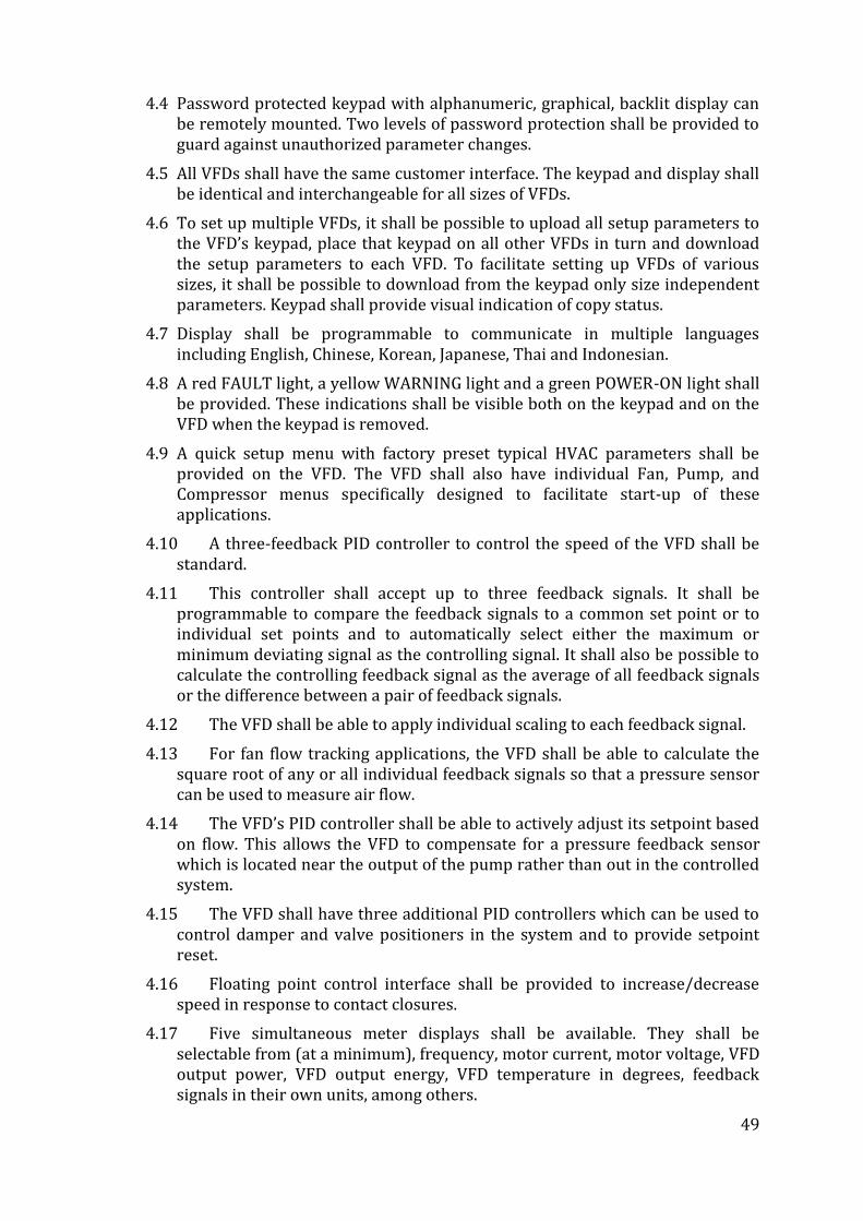
49
4.4 Password protected keypad with alphanumeric, graphical, backlit display can be remotely mounted. Two levels of password protection shall be provided to guard against unauthorized parameter changes.
4.5 All VFDs shall have the same customer interface. The keypad and display shall be identical and interchangeable for all sizes of VFDs.
4.6 To set up multiple VFDs, it shall be possible to upload all setup parameters to the VFD’s keypad, place that keypad on all other VFDs in turn and download the setup parameters to each VFD. To facilitate setting up VFDs of various sizes, it shall be possible to download from the keypad only size independent parameters. Keypad shall provide visual indication of copy status.
4.7 Display shall be programmable to communicate in multiple languages including English, Chinese, Korean, Japanese, Thai and Indonesian.
4.8 A red FAULT light, a yellow WARNING light and a green POWER-ON light shall be provided. These indications shall be visible both on the keypad and on the VFD when the keypad is removed.
4.9 A quick setup menu with factory preset typical HVAC parameters shall be provided on the VFD. The VFD shall also have individual Fan, Pump, and Compressor menus specifically designed to facilitate start-up of these applications.
4.10 A three-feedback PID controller to control the speed of the VFD shall be standard.
4.11 This controller shall accept up to three feedback signals. It shall be programmable to compare the feedback signals to a common set point or to individual set points and to automatically select either the maximum or minimum deviating signal as the controlling signal. It shall also be possible to calculate the controlling feedback signal as the average of all feedback signals or the difference between a pair of feedback signals.
4.12 The VFD shall be able to apply individual scaling to each feedback signal.
4.13 For fan flow tracking applications, the VFD shall be able to calculate the square root of any or all individual feedback signals so that a pressure sensor can be used to measure air flow.
4.14 The VFD’s PID controller shall be able to actively adjust its setpoint based on flow. This allows the VFD to compensate for a pressure feedback sensor which is located near the output of the pump rather than out in the controlled system.
4.15 The VFD shall have three additional PID controllers which can be used to control damper and valve positioners in the system and to provide setpoint reset.
4.16 Floating point control interface shall be provided to increase/decrease speed in response to contact closures.
4.17 Five simultaneous meter displays shall be available. They shall be selectable from (at a minimum), frequency, motor current, motor voltage, VFD output power, VFD output energy, VFD temperature in degrees, feedback signals in their own units, among others.
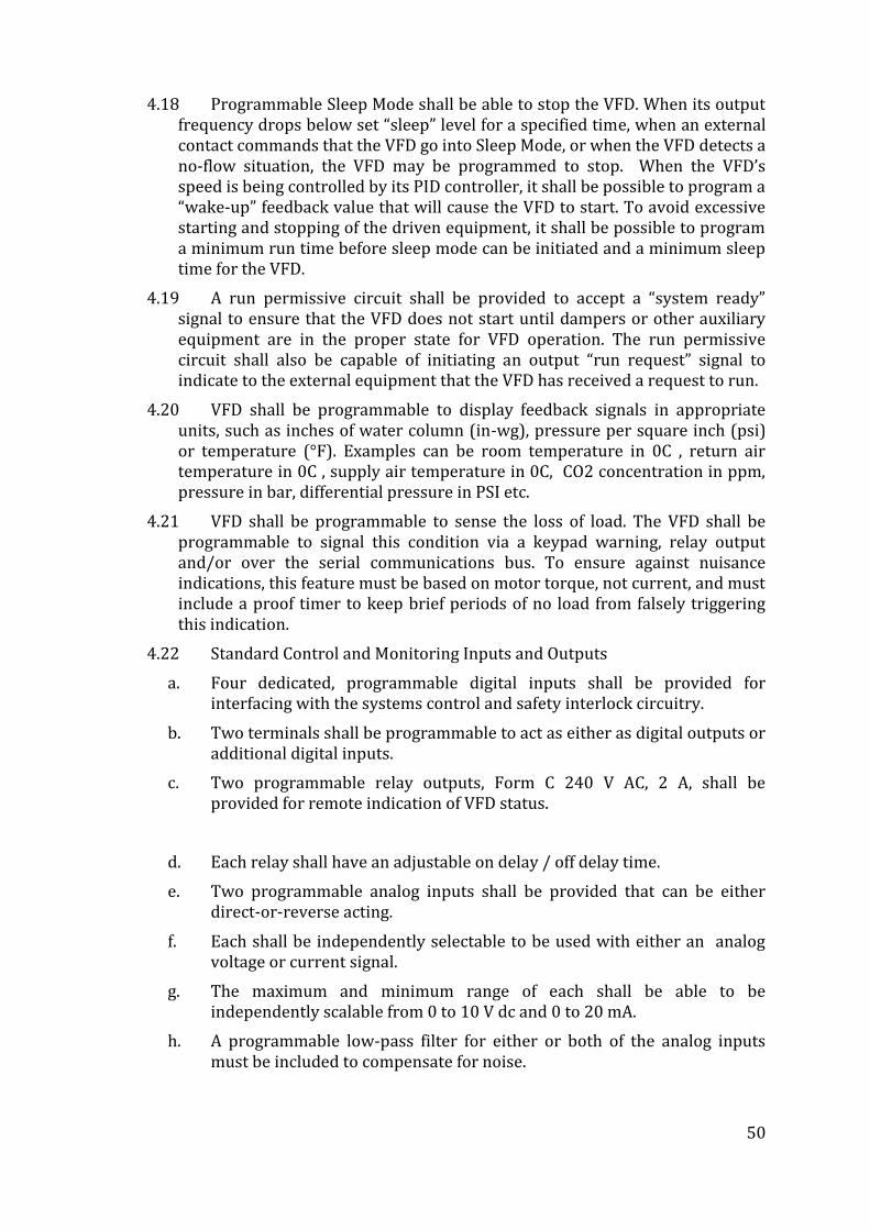
50
4.18 Programmable Sleep Mode shall be able to stop the VFD. When its output frequency drops below set “sleep” level for a specified time, when an external contact commands that the VFD go into Sleep Mode, or when the VFD detects a no-flow situation, the VFD may be programmed to stop. When the VFD’s speed is being controlled by its PID controller, it shall be possible to program a “wake-up” feedback value that will cause the VFD to start. To avoid excessive starting and stopping of the driven equipment, it shall be possible to program a minimum run time before sleep mode can be initiated and a minimum sleep time for the VFD.
4.19 A run permissive circuit shall be provided to accept a “system ready” signal to ensure that the VFD does not start until dampers or other auxiliary equipment are in the proper state for VFD operation. The run permissive circuit shall also be capable of initiating an output “run request” signal to indicate to the external equipment that the VFD has received a request to run.
4.20 VFD shall be programmable to display feedback signals in appropriate units, such as inches of water column (in-wg), pressure per square inch (psi) or temperature (°F). Examples can be room temperature in 0C , return air temperature in 0C , supply air temperature in 0C, CO2 concentration in ppm, pressure in bar, differential pressure in PSI etc.
4.21 VFD shall be programmable to sense the loss of load. The VFD shall be programmable to signal this condition via a keypad warning, relay output and/or over the serial communications bus. To ensure against nuisance indications, this feature must be based on motor torque, not current, and must include a proof timer to keep brief periods of no load from falsely triggering this indication.
4.22 Standard Control and Monitoring Inputs and Outputs
a. Four dedicated, programmable digital inputs shall be provided for interfacing with the systems control and safety interlock circuitry.
b. Two terminals shall be programmable to act as either as digital outputs or additional digital inputs.
c. Two programmable relay outputs, Form C 240 V AC, 2 A, shall be provided for remote indication of VFD status.
d. Each relay shall have an adjustable on delay / off delay time.
e. Two programmable analog inputs shall be provided that can be either direct-or-reverse acting.
f. Each shall be independently selectable to be used with either an analog voltage or current signal.
g. The maximum and minimum range of each shall be able to be independently scalable from 0 to 10 V dc and 0 to 20 mA.
h. A programmable low-pass filter for either or both of the analog inputs must be included to compensate for noise.
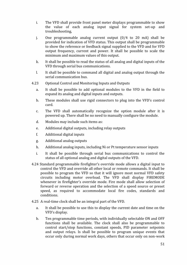
51
i. The VFD shall provide front panel meter displays programmable to show the value of each analog input signal for system set-up and troubleshooting,
j. One programmable analog current output (0/4 to 20 mA) shall be provided for indication of VFD status. This output shall be programmable to show the reference or feedback signal supplied to the VFD and for VFD output frequency, current and power. It shall be possible to scale the minimum and maximum values of this output.
k. It shall be possible to read the status of all analog and digital inputs of the VFD through serial bus communications.
l. It shall be possible to command all digital and analog output through the serial communication bus.
4.23 Optional Control and Monitoring Inputs and Outputs
a. It shall be possible to add optional modules to the VFD in the field to expand its analog and digital inputs and outputs.
b. These modules shall use rigid connectors to plug into the VFD’s control card.
c. The VFD shall automatically recognize the option module after it is powered up. There shall be no need to manually configure the module.
d. Modules may include such items as:
e. Additional digital outputs, including relay outputs
f. Additional digital inputs
g. Additional analog outputs
h. Additional analog inputs, including Ni or Pt temperature sensor inputs
i. It shall be possible through serial bus communications to control the status of all optional analog and digital outputs of the VFD.
4.24 Standard programmable firefighter’s override mode allows a digital input to control the VFD and override all other local or remote commands. It shall be possible to program the VFD so that it will ignore most normal VFD safety circuits including motor overload. The VFD shall display FIREMODE whenever in firefighter’s override mode. Fire mode shall allow selection of forward or reverse operation and the selection of a speed source or preset speed, as required to accommodate local fire codes, standards and conditions.
4.25 A real-time clock shall be an integral part of the VFD.
a. It shall be possible to use this to display the current date and time on the VFD’s display.
b. Ten programmable time periods, with individually selectable ON and OFF functions shall be available. The clock shall also be programmable to control start/stop functions, constant speeds, PID parameter setpoints and output relays. Is shall be possible to program unique events that occur only during normal work days, others that occur only on non-work
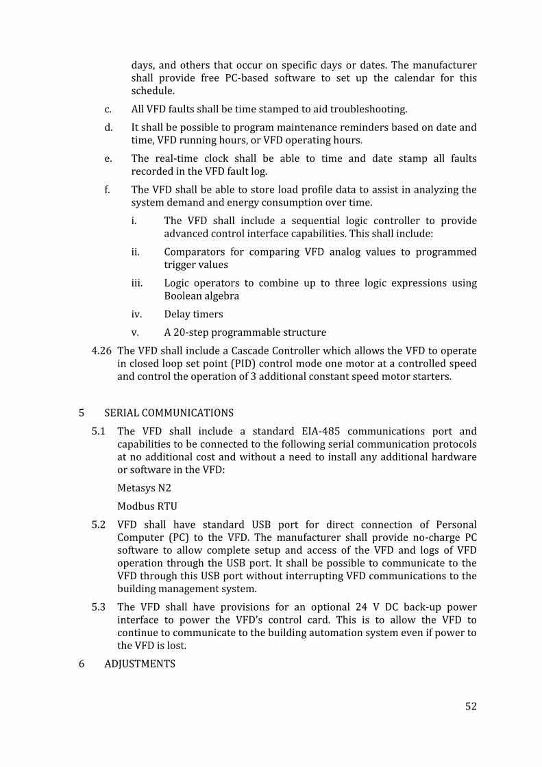
52
days, and others that occur on specific days or dates. The manufacturer shall provide free PC-based software to set up the calendar for this schedule.
c. All VFD faults shall be time stamped to aid troubleshooting.
d. It shall be possible to program maintenance reminders based on date and time, VFD running hours, or VFD operating hours.
e. The real-time clock shall be able to time and date stamp all faults recorded in the VFD fault log.
f. The VFD shall be able to store load profile data to assist in analyzing the system demand and energy consumption over time.
i. The VFD shall include a sequential logic controller to provide advanced control interface capabilities. This shall include:
ii. Comparators for comparing VFD analog values to programmed trigger values
iii. Logic operators to combine up to three logic expressions using Boolean algebra
iv. Delay timers
v. A 20-step programmable structure
4.26 The VFD shall include a Cascade Controller which allows the VFD to operate in closed loop set point (PID) control mode one motor at a controlled speed and control the operation of 3 additional constant speed motor starters.
5 SERIAL COMMUNICATIONS
5.1 The VFD shall include a standard EIA-485 communications port and capabilities to be connected to the following serial communication protocols at no additional cost and without a need to install any additional hardware or software in the VFD:
Metasys N2
Modbus RTU
5.2 VFD shall have standard USB port for direct connection of Personal Computer (PC) to the VFD. The manufacturer shall provide no-charge PC software to allow complete setup and access of the VFD and logs of VFD operation through the USB port. It shall be possible to communicate to the VFD through this USB port without interrupting VFD communications to the building management system.
5.3 The VFD shall have provisions for an optional 24 V DC back-up power interface to power the VFD’s control card. This is to allow the VFD to continue to communicate to the building automation system even if power to the VFD is lost.
6 ADJUSTMENTS
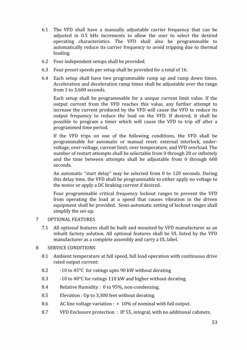
53
6.1 The VFD shall have a manually adjustable carrier frequency that can be adjusted in 0.5 kHz increments to allow the user to select the desired operating characteristics. The VFD shall also be programmable to automatically reduce its carrier frequency to avoid tripping due to thermal loading.
6.2 Four independent setups shall be provided.
6.3 Four preset speeds per setup shall be provided for a total of 16.
6.4 Each setup shall have two programmable ramp up and ramp down times. Acceleration and deceleration ramp times shall be adjustable over the range from 1 to 3,600 seconds.
Each setup shall be programmable for a unique current limit value. If the output current from the VFD reaches this value, any further attempt to increase the current produced by the VFD will cause the VFD to reduce its output frequency to reduce the load on the VFD. If desired, it shall be possible to program a timer which will cause the VFD to trip off after a programmed time period.
If the VFD trips on one of the following conditions, the VFD shall be programmable for automatic or manual reset: external interlock, under-voltage, over-voltage, current limit, over temperature, and VFD overload. The number of restart attempts shall be selectable from 0 through 20 or infinitely and the time between attempts shall be adjustable from 0 through 600 seconds.
An automatic “start delay” may be selected from 0 to 120 seconds. During this delay time, the VFD shall be programmable to either apply no voltage to the motor or apply a DC braking current if desired.
Four programmable critical frequency lockout ranges to prevent the VFD from operating the load at a speed that causes vibration in the driven equipment shall be provided. Semi-automatic setting of lockout ranges shall simplify the set-up.
7 OPTIONAL FEATURES
7.1 All optional features shall be built and mounted by VFD manufacturer as an inbuilt factory solution. All optional features shall be UL listed by the VFD manufacturer as a complete assembly and carry a UL label.
8 SERVICE CONDITIONS
8.1 Ambient temperature at full speed, full load operation with continuous drive rated output current:
8.2 -10 to 45°C for ratings upto 90 kW without derating
8.3 -10 to 40°C for ratings 110 kW and higher without derating
8.4 Relative Humidity : 0 to 95%, non-condensing.
8.5 Elevation : Up to 3,300 feet without derating.
8.6 AC line voltage variation : + 10% of nominal with full output.
8.7 VFD Enclosure protection : IP 55, integral, with no additional cabinets.
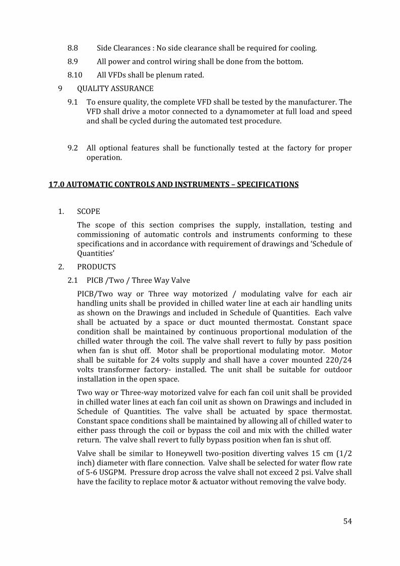
54
8.8 Side Clearances : No side clearance shall be required for cooling.
8.9 All power and control wiring shall be done from the bottom.
8.10 All VFDs shall be plenum rated.
9 QUALITY ASSURANCE
9.1 To ensure quality, the complete VFD shall be tested by the manufacturer. The VFD shall drive a motor connected to a dynamometer at full load and speed and shall be cycled during the automated test procedure.
9.2 All optional features shall be functionally tested at the factory for proper operation.
17.0 AUTOMATIC CONTROLS AND INSTRUMENTS – SPECIFICATIONS
1. SCOPE
The scope of this section comprises the supply, installation, testing and commissioning of automatic controls and instruments conforming to these specifications and in accordance with requirement of drawings and ‘Schedule of Quantities’
2. PRODUCTS
2.1 PICB /Two / Three Way Valve
PICB/Two way or Three way motorized / modulating valve for each air handling units shall be provided in chilled water line at each air handling units as shown on the Drawings and included in Schedule of Quantities. Each valve shall be actuated by a space or duct mounted thermostat. Constant space condition shall be maintained by continuous proportional modulation of the chilled water through the coil. The valve shall revert to fully by pass position when fan is shut off. Motor shall be proportional modulating motor. Motor shall be suitable for 24 volts supply and shall have a cover mounted 220/24 volts transformer factory- installed. The unit shall be suitable for outdoor installation in the open space.
Two way or Three-way motorized valve for each fan coil unit shall be provided in chilled water lines at each fan coil unit as shown on Drawings and included in Schedule of Quantities. The valve shall be actuated by space thermostat. Constant space conditions shall be maintained by allowing all of chilled water to either pass through the coil or bypass the coil and mix with the chilled water return. The valve shall revert to fully bypass position when fan is shut off.
Valve shall be similar to Honeywell two-position diverting valves 15 cm (1/2 inch) diameter with flare connection. Valve shall be selected for water flow rate of 5-6 USGPM. Pressure drop across the valve shall not exceed 2 psi. Valve shall have the facility to replace motor & actuator without removing the valve body.
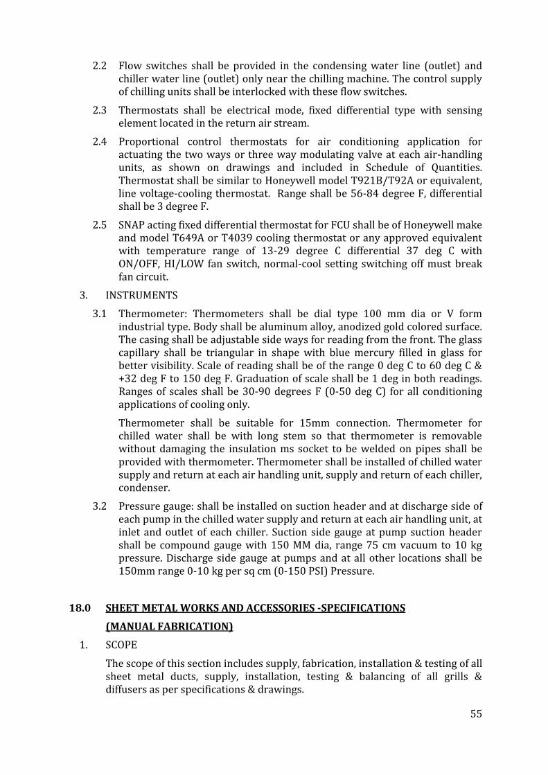
55
2.2 Flow switches shall be provided in the condensing water line (outlet) and chiller water line (outlet) only near the chilling machine. The control supply of chilling units shall be interlocked with these flow switches.
2.3 Thermostats shall be electrical mode, fixed differential type with sensing element located in the return air stream.
2.4 Proportional control thermostats for air conditioning application for actuating the two ways or three way modulating valve at each air-handling units, as shown on drawings and included in Schedule of Quantities. Thermostat shall be similar to Honeywell model T921B/T92A or equivalent, line voltage-cooling thermostat. Range shall be 56-84 degree F, differential shall be 3 degree F.
2.5 SNAP acting fixed differential thermostat for FCU shall be of Honeywell make and model T649A or T4039 cooling thermostat or any approved equivalent with temperature range of 13-29 degree C differential 37 deg C with ON/OFF, HI/LOW fan switch, normal-cool setting switching off must break fan circuit.
3. INSTRUMENTS
3.1 Thermometer: Thermometers shall be dial type 100 mm dia or V form industrial type. Body shall be aluminum alloy, anodized gold colored surface. The casing shall be adjustable side ways for reading from the front. The glass capillary shall be triangular in shape with blue mercury filled in glass for better visibility. Scale of reading shall be of the range 0 deg C to 60 deg C & +32 deg F to 150 deg F. Graduation of scale shall be 1 deg in both readings. Ranges of scales shall be 30-90 degrees F (0-50 deg C) for all conditioning applications of cooling only.
Thermometer shall be suitable for 15mm connection. Thermometer for chilled water shall be with long stem so that thermometer is removable without damaging the insulation ms socket to be welded on pipes shall be provided with thermometer. Thermometer shall be installed of chilled water supply and return at each air handling unit, supply and return of each chiller, condenser.
3.2 Pressure gauge: shall be installed on suction header and at discharge side of each pump in the chilled water supply and return at each air handling unit, at inlet and outlet of each chiller. Suction side gauge at pump suction header shall be compound gauge with 150 MM dia, range 75 cm vacuum to 10 kg pressure. Discharge side gauge at pumps and at all other locations shall be 150mm range 0-10 kg per sq cm (0-150 PSI) Pressure.
18.0 SHEET METAL WORKS AND ACCESSORIES -SPECIFICATIONS
(MANUAL FABRICATION)
1. SCOPE
The scope of this section includes supply, fabrication, installation & testing of all sheet metal ducts, supply, installation, testing & balancing of all grills & diffusers as per specifications & drawings.
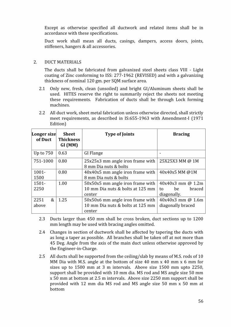
56
Except as otherwise specified all ductwork and related items shall be in accordance with these specifications.
Duct work shall mean all ducts, casings, dampers, access doors, joints, stiffeners, hangers & all accessories.
2. DUCT MATERIALS
The ducts shall be fabricated from galvanized steel sheets class VIII - Light coating of Zinc conforming to ISS: 277-1962 (REVISED) and with a galvanizing thickness of nominal 120 gm. per SQM surface area.
2.1 Only new, fresh, clean (unsoiled) and bright GI/Aluminum sheets shall be used. HITES reserve the right to summarily reject the sheets not meeting these requirements. Fabrication of ducts shall be through Lock forming machines.
2.2 All duct work, sheet metal fabrication unless otherwise directed, shall strictly meet requirements, as described in IS:655-1963 with Amendment-I (1971 Edition)
Longer size of Duct
Sheet Thickness
GI (MM)
Type of Joints Bracing
Up to 750 0.63 GI Flange -
751-1000 0.80 25x25x3 mm angle iron frame with 8 mm Dia nuts & bolts
25X25X3 MM @ 1M
1001-1500
0.80 40x40x5 mm angle iron frame with 8 mm Dia nuts & bolts
40x40x5 MM @1M
1501-2250
1.00 50x50x5 mm angle iron frame with 10 mm Dia nuts & bolts at 125 mm center
40x40x3 mm @ 1.2m to be braced diagonally.
2251 & above
1.25 50x50x6 mm angle iron frame with 10 mm Dia nuts & bolts at 125 mm center
40x40x3 mm @ 1.6m diagonally braced
2.3 Ducts larger than 450 mm shall be cross broken, duct sections up to 1200 mm length may be used with bracing angles omitted.
2.4 Changes in section of ductwork shall be affected by tapering the ducts with as long a taper as possible. All branches shall be taken off at not more than 45 Deg. Angle from the axis of the main duct unless otherwise approved by the Engineer-in-Charge.
2.5 All ducts shall be supported from the ceiling/slab by means of M.S. rods of 10 MM Dia with M.S. angle at the bottom of size 40 mm x 40 mm x 6 mm for sizes up to 1500 mm at 3 m intervals. Above size 1500 mm upto 2250, support shall be provided with 10 mm dia. MS rod and MS angle size 50 mm x 50 mm at bottom at 2.5 m intervals. Above size 2250 mm support shall be provided with 12 mm dia MS rod and MS angle size 50 mm x 50 mm at bottom
57
3. INSTALLATION
3.1 All ducts shall be fabricated and installed in workman like manner, generally conforming to relevant BIS codes. Round exposed ducts shall be die formed for achieving perfect circle configuration
3.1.1 Ducts so identified on the drawing shall be acoustically lined and thermally insulated as described in the section ‘Insulation’ and as indicated in ‘Schedule of Quantities. Duct dimensions shown in drawings are overall sheet metal dimensions inclusive of the acoustic lining where required and indicated in ‘Schedule of Quantities’.
3.1.2 Ducts shall be straight and smooth on the inside with neatly finished joints. All joints shall be made airtight.
3.1.3 All exposed ducts upto 60 cm width within conditioned spaces shall have slip joints. The internal ends of the slip joints shall be in the direction of airflow. Ducts and accessories within ceiling spaces visible from air-conditioned areas shall be provided with two coats of matt black finish paint.
3.1.4 Change in dimensions and shape of ducts shall be gradual. Air turns shall be installed in all vanes arranged to permit the air to make the turn without appreciable turbulence.
3.1.5 Ducts shall be fabricated as per details shown on drawings. All ducts shall be rigid and shall be adequately supported and braced where required with standing seams, tees of ample size to keep the ducts true to shape and to prevent buckling, vibration or breaking.
3.1.6 All sheets metal connections, partitions and plenums required to confine the flow of air to and through the filters and fans shall be constructed of 18 Gauge GSS thoroughly stiffened with 25mm x 25mm x 3mm angle iron braces and fitted with all necessary inspection doors as required to give access to all parts of the apparatus. Doors shall be not less than 45cm X 45cm in size.
3.1.7 Plenums shall be panel type and assembled at site. Fixing of MS angle iron flanges of duct pieces shall be with rivet heads inside i.e. Towards G.S. sheet and riveting shall be done from outside.
3.1.8 Rubber gasket 3 mm thick shall be used between duct flanges and between duct and duct supports instead of felt in all ducting installation for complete sealing.
3.2 During the construction, the Contractor shall temporarily close duct openings with sheet metal covers to prevent debris-entering ducts and to maintain opening straight and square, as per direction of Engineer-in-Charge.
3.2.1 Great care should be taken to ensure that the ductwork does not extend outside and beyond height limits as noted on the drawings.
3.2.2 All duct work shall be of high quality approved galvanized sheet steel guaranteed not to crack or peel on bending or fabrication of ducts. All joints shall be tight and shall be made in the direction of airflow.
58
3.2.3 The ducts shall be reinforced where necessary, and must be secured in place so as to avoid vibration of the duct on its support.
3.2.4 All air turns of 45 degrees or more shall include curved metal blades or vanes arranged so as to permit the air to make the abrupt turns without an appreciable turbulence. Turning vanes shall be securely fastened to prevent noise or vibration. All ducts shall be fabricated and installed in accordance with modern design practice. The sheet metal gauges and fabrication procedures as given in I.S. specifications shall be adhered to and shall be considered as an integral part of these specifications.
3.2.5 The ductwork shall be varied in shape and position to fit actual conditions at building. All changes shall be in accordance with accepted duct design and subject to the approval of the engineer-in-charge. The Contractor shall verify all measurements at building and shall notify the Engineer-in-Charge of any difficulty in carrying out his work before fabrication.
3.2.6 Sponge rubber or approved equal gaskets shall be installed between all connections of sheet metal ducts to walls. Sheet metal connections shall be made to walls and floors by means of galvanized steel angles anchored to the building structure with anchor bolts and with the sheet bolted to the angles. Sheet metal connections shall be as shown in the drawings or as directed by Engineer-in-Charge.
3.2.7 All ductwork shall be independently supported from building construction. All horizontal ducts shall be rigidly and securely supported, in an approved manner, with trapeze hangers formed of galvanized steel rods and galvanized steel angel/channel under ducts. All vertical ductwork shall be supported by structural members on each floor slab. Duct supports may be through galvanized steel insert plates left in slab at the time of slab casting. Galvanized steel cleat with a hole for passing the hanger rods shall be welded to the plates. Trapeze hanger formed of galvanized steel rods and angles / channels shall be hung through these cleats. Wherever use of metal insert plates is not feasible, duct support shall be through dash / anchor fastener driven into the concrete slab by electrically operated gun. Hanger rods shall then hang through the cleats.
3.2.8 Where ducts pass through brick or masonry openings, it shall be provided with 25 mm thick TF quality thermo Cole around the duct prior to sealing of the opening.
3.2.9 All ducts shall be totally free from vibration under all conditions of operation. Whenever ductwork is connected to fans, air handling units or blower coil units that may cause vibration in the ducts, ducts shall be provided with a flexible connection, located at the unit discharge. Flexible connections shall be constructed of fire retarding flexible heavy canvas sleeve at least 100 mm long but not more than 200 mm, securely bonded and bolted on both sides. Sleeve shall be made smooth and the connecting ductwork rigidly held by independent supports on both sides of the flexible connection. The
59
flexible connection shall be suitable for pressure at the point of installation.
3.2.10 Flanges and supports are to be black, mild steel and are to be primer coated on all surfaces before erection and painted with aluminum thereafter. Accessories such as damper blades and access panels are to be of materials of appropriate thickness and the finish similar to the adjacent ducting, as specified.
3.2.11 The ductwork should be carried out in a manner and at such time as not to hinder or delay the work of the other agencies especially the boxing or false ceiling Contractors.
4 DAMPERS
At the junction of each branch duct with main duct and split of main duct, volume control dampers must be provided. Dampers shall be rigid in construction to the passage of air.
The volume dampers shall be of an approved type, lever operated and complete with suitable level links & quadrants, locking devices, which will permit the dampers to be adjusted and locked in any position.
The dampers shall be of opposed blade or louver type. The damper blade shall not be less than 1.25 mm (18) gauge and shall not be over 225 mm wide. Automatic and manual volume opposed blade dampers shall be complete with frames and bronze bearings as per drawings. Damper frames shall be constructed of 16 gauge steel
After completion of the ductwork, dampers are to be adjusted and set to deliver the required amount of air as specified in the drawings.
5 ACCESS PANEL
A hinged and gasket access panel shall be provided on ductwork before each control device that may be located inside the ductwork. Doors shall be provided with neoprene rubber gaskets. Angle joints shall be provided with neoprene rubber gaskets for leak tightness of the joints. Access door/panels shall be provided: - Near each smoke sensor Any other place specifically mentioned in the drawing or if asked by MoHFW/HITESs during execution stage.
6 MISCELLANEOUS
Sponge rubber gaskets also to be provided behind the flange of all grills.
Each shoot from the duct, leading to a grille, shall be provided with an air deflector to divert the air into the grille through the shoot.
Inspection doors measuring at least 450 mm x 450 mm are to be provided in each system at an appropriate location, as directed by Engineer-in-Charge.
Diverting vanes must be provided at the bends exceeding 600 mm and at branches connected into the main duct without a neck.
Proper hangers and supports should be provided to hold the duct rigidly, to keep them straight and to avoid vibrations. Additional supports are to be provided where required for rigidity or as directed by Engineer-in-Charge.
60
All duct supports, flanges, hangers and damper boxes etc. Shall be given 2 coats of red oxide paint before installation and one coat of aluminum paint after the erection, at no extra cost.
All angle iron flanges are to be welded electrically and holes to be drilled.
All the angle iron flanges are to be connected to the GSS ducts by rivets at 100 mm centers.
7 GRILLS / DIFFUSERS
SUPPLY AND RETURN AIR DIFFUSERS
Supply and return air diffusers shall be made of extruded aluminum section as specified in BOQ. The diffusers shall be powder coated in finish. Supply air diffusers shall be provided with screw operated opposed blade volume control devices of extruded aluminum in black anodized finish. The diffusers shall be suitable for concealed fixing arrangement and as approved by Engineer-in-charge/HITES.
The diffusers shall be provided with removable central core.
All diffusers shall be selected as per selection curves and in consultation with Engineer-in-charge / HITES. All diffusers shall have soft continuous rubber/foam gasket between the periphery of the diffusers and the surface on which it has to be mounted.
LINEAR GRILLS:
Linear continuous supply or return air grills shall be extruded aluminum construction with fixed horizontal bars at 15 0 inclination with flanges on both sides. The thickness of fixed bar louvers shall be 5mm in front and the flange shall be 20mm wide with round edges. The grille shall be suitable for concealed fixing and horizontal bars of the grille shall be mechanically crimped from the back to hold them.
Volume control device of extruded aluminum construction in black anodized finish shall be provided in S.A. duct collars.
DOUBLE ADJUSTABLE LOUVERED SUPPLY / RETURN AIR GRILLS WITH HORIZONTAL/VERTICAL OR VERTICAL/ HORIZONTAL LOUVER ARRANGEMENT:
The grille shall be adjustable as each louver shall be pivoted to provide pattern with 00 to plus or minus 150 ARC upto 300 deflection down towards. The louvers shall hold deflection settings under all conditions of velocity and pressure. The rear louver of the register shall be in black shade.
Volume control device of extruded aluminum construction with black anodized finish shall be provided in S.A. grills.
EXHAUST AIR REGISTER:
Exhaust air register shall be made of extruded aluminum with fixed horizontal louvers at 40 degree angle setting on a 20 mm louvers pitch. The register shall have 20 mm wide flange with round edges all around. The register shall be suitable for front screw fixing.
61
Volume control device of extruded aluminum construction with black anodized finish shall be provided.
MULTI SLOT CEILING DIFFUSERS:
Multi slot ceiling diffuser shall be made of extruded aluminum with various slot width and air pattern deflectors. Deflectors in each slot provide an adjustable air pattern of 180 degree full. A special plenum shall be provided for each supply air diffuser. The linear diffuser shall have alignment strips to give straight look while installation.
Hit & miss type volume control damper of extruded aluminum construction with mill finish shall be with multi-slot supply air diffuser.
LINEAR CEILING MOUNTED DIFFUSERS:
Linear ceiling mounted air terminals shall be made of extruded aluminum surface mounted one way or two way pattern. The linear terminal shall have alignment strips to give straight look while installation. Volume control device of extruded aluminum construction in mill finish shall be provided in S.A. diffuser.
FRESH AIR INTAKE LOUVERS:
Fresh air intake louvers 50 mm deep (minimum) wherever required as per shop drawing will be made of extruded aluminum construction duly anodized or powder coated. Bird/insect screen will be provided with the intake louvers. The blades are inclined at 450 on a 40 mm blade pitch to minimize water ingress. The lowest blade of the assembly shall extend out slightly to facilitate disposal of rainwater without falling in door/wall on which it is mounted.
Wherever specified, the intake louvers shall be provided with factory fitted all aluminum construction volume control dampers in black anodized finish.
LAMINAR FLOW DIFFUSERS
Introduction
Diffusers are available for flush mounting in the ceiling. Suitable angle frames are also provided for the modular panel construction. The units are available in three standard sizes for top entry complete with opposed blade dampers
Description
LFD laminar flow diffusers are constructed from 18 swg Aluminium sheet,perforated face with approx 50% perforation. The perforated front face is openable hinge type complete with key operated dampers from front.
Sizes
Available in standard sizes of 600 x 600 mm, 900 x 600 mm & 1200 x 600 mm or as mentioned in the BOQ.
Features
• Suitable for modular panel assemblies.
• Top entry with opposed blade dampers.
• Pivoting type face plate for damper operation from front.
62
• Easy maintenance and cleaning
Finishes
Standard
a) Epoxy Polyester Powder Coated off white/pure white
b) Natural anodised.
8. MOTORIZED COMBINED SMOKE & FIRE DAMPERS – SPRING RETURN
All supply and return air ducts at AHU room crossings (or ducts as applicable) and at all floor crossings shall be provided with approved make fire and smoke dampers of at least 90 minutes fire rating certified by CBRI ROORKEE as per UL 555:1973
Fire damper blades & outer frame shall be formed of 1.6 mm galvanized sheet steel. The damper blade shall be provided on both ends using chrome-plated spindles in self-lubricated bronze bushes. Stop seals will be provided on top and bottom of the damper housing made of 16 g galvanized sheet steel. For preventing smoke leakage side seals will be provided.
In normal position damper blade shall be held in open position with the help of a 24 V operated electric actuators thereby providing maximum air passage without creating any noise or chatter.
The damper shall be actuated through electric actuator. The actuator shall be energized with the help of a signal from smoke detector installed in AHU room/R.A. duct/damper. The A/C Contractor shall also provide smoke detector. The fire damper shall also close due to Temp. rise in S.A. ducts thru the electric temp. sensor factory set at 165 Deg. F micro switches with bake lite base will be provided to stop fan motor and give open & close signal at remote panel in case of motorized actuator.
Each dampers in case of motorized smoke-cum-fire damper shall have its own panel which will incorporate necessary circuit required to step down voltage available from power supply to shown status of the damper (open or close), to allow remote testing of damper & indication in event of damper closure due to signal from smoke sensor/temp. sensor & reset button. Additional terminal will be provided to have signal (sound beep or visual) in central control room.
Damper actuator shall be spring return so as to close the damper in the event of power failure automatically and open the same in case of power being restored.
Spring return action of the actuator shall be an in-built mechanism and shall not be mounted externally.
The damper shall be installed in accordance with the installation method recommended by the manufacturer.
9 PAINTING
All grilles, and diffusers shall be powder coated in color as approved by Engineer-in-charge/HITES before installation.
63
All ducts immediately behind the grilles/diffusers etc. Are to be given two coats of black paint in Matt finish.
10 TESTING
After completion, all duct system shall be tested for air leakage.
The entire air distribution system shall be balanced to supply the air quantity as required in various areas and the final balance of air quantity through each outlet shall be submitted to the engineer-in-charge for approval. Measured air quantities at fan discharge and at various outlets shall be identical to or less than 5% in excess of those specified and quoted. Branch duct adjustments shall be permanently marked after air balancing is completed so that these can be restored to their correct position if disturbed at any time.
19.0 SHEET METAL WORKS –(FACTORY FABRICATED)
1. GENERAL
1.1 The work under this part shall consist of furnishing labour materials, equipment and appliances as specified necessary and required to install all sheet metal and other allied work to make the air conditioning supply, ventilating, and exhaust system ready for operation as per drawings.
1.2 Except as otherwise specified all duct work and related items shall be in accordance with these specifications.
1.3 Ductwork shall mean all ducts, casings, dampers, access doors, joints, stiffeners and hangers.
2. DUCT MATERIALS
2.1 The ducts shall be fabricated from galvanized steel sheets class VIII conforming to ISS:277-1962 (revised) or aluminium sheets conforming to ISS:737-1955 (wherever aluminium ducts are specified).
2.2 All duct work, sheet metal thickness and fabrication unless otherwise directed, shall strictly meet requirements, as described in IS:655-1963 with amendment-I (1971 edition)
Governing Standards
2.3 Unless otherwise specified here, the construction, erection, testing and performance of the ducting system shall conform to the SMACNA-1995 standards (“HVAC Duct Construction Standards-Metal and Flexible-Second Edition-1995” SMACNA)
3. RAW MATERIAL
3.1 Ducting
3.1.1 All ducting shall be fabricated of LFQ (Lock Forming Quality) grade prime G.I. row material furnished with accompanying Mill test Certificates.
3.1.2 Galvanizing shall be of 120gms/sq.m. (total coating on both sides).
64
3.1.3 In addition, if deemed necessary, samples of raw material, selected at random by Engineer in Charge shall be subject to approval and tested for thickness and zinc coating at contractor’s expense.
3.1.4 The G.I. raw material should be used in coil-form (instead of sheets) so as to limit the longitudinal joints at the edges only irrespective of cross-section dimensions.
3.2 Duct Connectors and Accessories
All transverse duct connectors (flanges/cleats) and accessories/related hardware are such as support system shall be zinc-coated (galvanized)
4. FABRICATION STANDARDS
4.1 All ductwork including straight sections, tapers, elbows, branches, show pieces, collars, terminal boxes and other transformation pieces must be as per approved make list.
4.2 Coil lines to ensure location of longitudinal seams at comes/folded edges only to obtain the required duct rigidity and low leakage characteristics. No longitudinal seams permitted along any face side of the duct.
4.3 All ducts, transformation pieces and fittings to be made on CNC profile cutlers for required accuracy of dimensions, location and dimensions of notches at the folding lines.
4.4 All edges to be machine treated using lock formers, flanges and roller for fuming up edges.
4.5 Sealant dispensing equipment for applying built-in sealant in Pittsburgh lock where sealing of longitudinal joints are specified.
5. SELECTION OF G.I. GAUGE AND TRANSVERSE CONNECTORS
Duct Construction shall be in compliance with 1” (250 Pa)w.g. static norms as per SMACNA.
All transverse connectors shall be with built-in sealant if any to avoid any leakage additional sealant to be used.
The specific class of transverse connector and duct gauge for a given duct dimensions will be 1”(250 Pa) pressure class.
Non-toxic, AC-applications grade P.E. or PVC Casketing is required between all mating flanged joints. Gasket sizes should conform to flange manufacturer’s specification.
6. DUCT CONSTRUCTION
The fabricated duct dimensions should be as per approved drawings and all connecting sections are dimensionally matched to avoid any gaps.
7 specified dimension. To obtain required perpendicularity, permissible diagonal
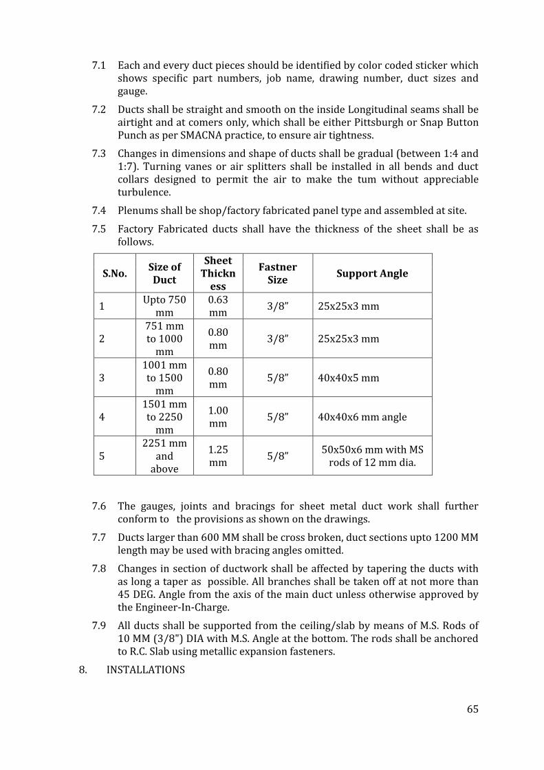
65
7.1 Each and every duct pieces should be identified by color coded sticker which shows specific part numbers, job name, drawing number, duct sizes and gauge.
7.2 Ducts shall be straight and smooth on the inside Longitudinal seams shall be airtight and at comers only, which shall be either Pittsburgh or Snap Button Punch as per SMACNA practice, to ensure air tightness.
7.3 Changes in dimensions and shape of ducts shall be gradual (between 1:4 and 1:7). Turning vanes or air splitters shall be installed in all bends and duct collars designed to permit the air to make the tum without appreciable turbulence.
7.4 Plenums shall be shop/factory fabricated panel type and assembled at site.
7.5 Factory Fabricated ducts shall have the thickness of the sheet shall be as follows.
S.No. Size of Duct
Sheet Thickn
ess
Fastner Size
Support Angle
1 Upto 750
mm 0.63 mm
3/8” 25x25x3 mm
2 751 mm to 1000
mm
0.80 mm
3/8” 25x25x3 mm
3 1001 mm to 1500
mm
0.80 mm
5/8” 40x40x5 mm
4 1501 mm to 2250
mm
1.00 mm
5/8” 40x40x6 mm angle
5 2251 mm
and above
1.25 mm
5/8” 50x50x6 mm with MS
rods of 12 mm dia.
7.6 The gauges, joints and bracings for sheet metal duct work shall further conform to the provisions as shown on the drawings.
7.7 Ducts larger than 600 MM shall be cross broken, duct sections upto 1200 MM length may be used with bracing angles omitted.
7.8 Changes in section of ductwork shall be affected by tapering the ducts with as long a taper as possible. All branches shall be taken off at not more than 45 DEG. Angle from the axis of the main duct unless otherwise approved by the Engineer-In-Charge.
7.9 All ducts shall be supported from the ceiling/slab by means of M.S. Rods of 10 MM (3/8") DIA with M.S. Angle at the bottom. The rods shall be anchored to R.C. Slab using metallic expansion fasteners.
8. INSTALLATIONS
66
8.1 During the construction, the contractor shall temporarily close duct openings with sheet metal covers to prevent debris entering ducts and to maintain opening straight and square, as per direction of Engineer-In-Charge.
8.2 Great care shall be taken to ensure that the duct work does not extend outside and beyond height limits as noted on the drawings.
8.3 All duct work shall be of high quality approved galvanized sheet steel guaranteed not to crack or peel on bending or fabrication of ducts. All joints shall be air tight and shall be made in the direction of air flow.
8.4 The ducts shall be re-inforced with structured members where necessary, and must be secured in place so as to avoid vibration of the duct on its support.
8.5 All air turns of 45 degrees or more shall include curved metal blades or vanes arranged so as to permit the air to make the abrupt turns without an appreciable turbulence. Turning vanes shall be securely fastened to prevent noise or vibration.
The duct work shall be varied in shape and position to fit actual conditions at building site. All changes shall be subjected to the approval of the Engineer-In-Charge. The contractor shall verify all measurements at site and shall notify the Engineer-In-Charge of any difficulty in carrying out his work before fabrication.
8.6 Sponge rubber or approved equal gaskets of 6 MM maximum thickness shall be installed between duct flanges as well as between all connections of sheet metal ducts to walls, floor columns, heater casings and filter casings. Sheet metal connections shall be made to walls and floors by means of wooden member anchored to the building structure with anchor bolts and with the sheet screwed to them.
8.7 Accessories such as damper blades and access panels are to be of materials of appropriate thickness and the finish similar to the adjacent ducting, as specified.
8.8 Joints, seams, sleeves, splitters, branches, takeoffs and supports are to be as per duct details as specified, or as decided by Engineer-In-Charge.
8.9 Joints requiring bolting or riveting may be fixed by Hexagon nuts and bolts, stove bolts or buck bolts, rivets or closed centre top rivets or spot welding. Self tapping screws must not be used. All jointing material must have a finish such as cadmium plating or Galvanized as appropriate.
8.10 Fire retarding flexible joints are to be fitted to the suction and delivery of all fans. The material is to be normally double heavy canvass or as directed by Engineer-In-Charge. On all circular spigots the flexible materials are to be screwed or clip band with adjustable screws or toggle fitting. For rectangular ducts the material is to be flanged and bolted with a backing flat or bolted to mating flange with backing flat.
8.11 The flexible joints are to be not less than 75 MM and not more than 250 MM between faces.
67
8.12 The duct work should be carried out in a manner and at such time as not to hinder or delay the work of the other agencies especially the boxing or false ceiling contractors.
8.13 Duct passing through brick or masonary, wooden frame work shall be provided within the opening. Crossing duct shall have heavy flanges, collars on each side of wooden frame to make the duct leak proof.
9. DOCUMENTATION TO MEASUREMENTS
For each drawing, all supply of ductwork must be accompanied by computer-generated detailed bill of material indicating all relevant duct sizes, dimensions and quantities. In addition, summary sheets are also to be provided showing duct areas by gauge and duct size range as applicable.
Measurement sheet covering each fabricated duct piece showing dimensions and external surface area along with summary of external surface area of duct gauge-wise.
All duct pieces to have a part number, which should correspond to the serial number, assigned to it in the measurement sheet. The above system will ensure speedy and proper site measurement, verification and approvals.
10. TESTING
After duct installation, a part of duct section (approximately 5% of total ductwork) may be selected at random and tested for leakage. The procedure for leak testing should be followed as per SMACNA- “HVAC Air Duct Leakage Test Manual: (First Edition).
DUCTS INSULATION
SCOPE
The scope of this section comprises the supply and application of insulation conforming to these Specifications.
Insulation material shall be non toxic , chemically inert , non combustible, non ignitable, shall have zero ozone depletion potential, zero calorific value no heat evolution and shall be inherently proof against rotting , mould and fungal growth and attack by vermin.
The materials shall comply with following standards.
BS 476: Part 4 – Non Combustible
BS 476: Part 5 – Not easily Ignitable (Class P)
BS 476: Part 6 – Fire propagation Index (I<12)
BS 476: Part 7 - Surface spread of flame (Class 1)
The material should comply to Class’O’ fire rating as per BS 476 part 6&7.
The product shall be able to work effectively at ambient temperature range of -100ºC to 150 ºC
DUCT ACOUSTIC LINING
Insulation material for Duct Acoustic Lining shall be open cell antimicrobial nitrile rubber with self adhesive. The thermal conductivity of the material for air-
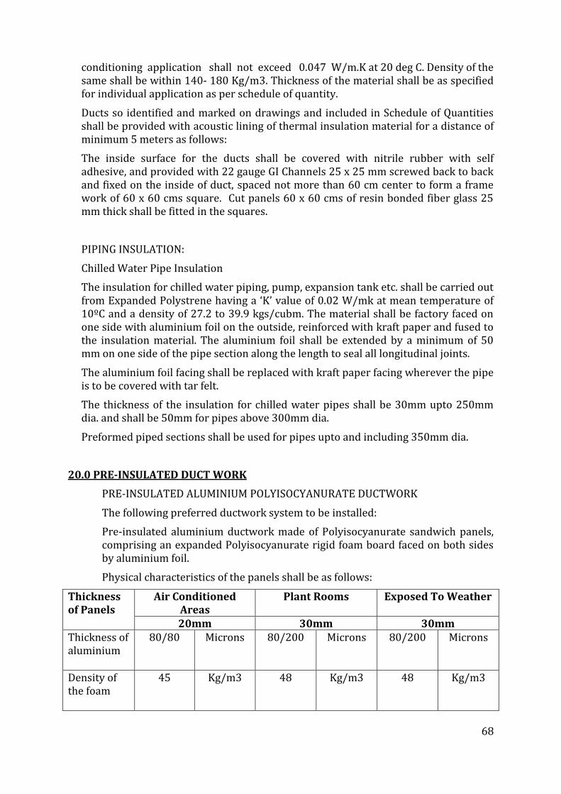
68
conditioning application shall not exceed 0.047 W/m.K at 20 deg C. Density of the same shall be within 140- 180 Kg/m3. Thickness of the material shall be as specified for individual application as per schedule of quantity.
Ducts so identified and marked on drawings and included in Schedule of Quantities shall be provided with acoustic lining of thermal insulation material for a distance of minimum 5 meters as follows:
The inside surface for the ducts shall be covered with nitrile rubber with self adhesive, and provided with 22 gauge GI Channels 25 x 25 mm screwed back to back and fixed on the inside of duct, spaced not more than 60 cm center to form a frame work of 60 x 60 cms square. Cut panels 60 x 60 cms of resin bonded fiber glass 25 mm thick shall be fitted in the squares.
PIPING INSULATION:
Chilled Water Pipe Insulation
The insulation for chilled water piping, pump, expansion tank etc. shall be carried out from Expanded Polystrene having a ‘K’ value of 0.02 W/mk at mean temperature of 10ºC and a density of 27.2 to 39.9 kgs/cubm. The material shall be factory faced on one side with aluminium foil on the outside, reinforced with kraft paper and fused to the insulation material. The aluminium foil shall be extended by a minimum of 50 mm on one side of the pipe section along the length to seal all longitudinal joints.
The aluminium foil facing shall be replaced with kraft paper facing wherever the pipe is to be covered with tar felt.
The thickness of the insulation for chilled water pipes shall be 30mm upto 250mm dia. and shall be 50mm for pipes above 300mm dia.
Preformed piped sections shall be used for pipes upto and including 350mm dia.
20.0 PRE-INSULATED DUCT WORK
PRE-INSULATED ALUMINIUM POLYISOCYANURATE DUCTWORK
The following preferred ductwork system to be installed:
Pre-insulated aluminium ductwork made of Polyisocyanurate sandwich panels, comprising an expanded Polyisocyanurate rigid foam board faced on both sides by aluminium foil.
Physical characteristics of the panels shall be as follows:
Thickness of Panels
Air Conditioned Areas
Plant Rooms Exposed To Weather
20mm 30mm 30mm Thickness of aluminium
80/80 Microns
80/200 Microns 80/200 Microns
Density of the foam
45 Kg/m3
48 Kg/m3
48 Kg/m3
69
Finishing of aluminium
Embossed
Embossed
Embossed
Embossed
Embossed
Embossed
Both sides of the aluminium foils shall be lacquered with a 3g/m2 weatherproof and ultraviolet rays protection polyester lacquer.
All the panels shall have to be embossed with the name of the manufacturer and production date.
Thermal insulation characteristics shall be as follows:
Insulating material: Close cell rigid expanded polyurethane foam, CFC free, density 45 to 48 Kg/m3, material physiologically and chemically inert and insoluble, vermin proof,fungus proof, non metabolisable.
Thermal conductivity: 0.022 W/mK or better.
Water absorption shall be less than 0.5% by 24 hours immersion test.
Water vapour diffusion: M= infinity resistance.
The aluminium foil covering the panel to be maintained intact after installation to ensure vapour barrier continuity.
Proposed material should have minimum 5 years installation reference in the region.
The panel manufacturer should be of European/Foreign origin.
All the panels to be used should be labelled by authorised international fire laboratories.
The panel manufacturer shall comply with Fire Mideast Product Listing (MPL) and Factory Production Control Certificate (FPC), by authorised international laboratories.
The panel shall be tested and comply with the following standards:
● NFPA 101 Life Safety Code Class ‘A’
● ASTM E84 Class “1”
● NFPA 255
● UL 723
● Toxicity Index shall not exceed 5.7 according to NES 713
● Class ‘O’ according to BS 476 Part 6 & 7
Temperature Range:
No relevant reduction of insulation, chemical or physical characteristics of the panels to be measurable, when conveying air in the temperature range of –35oC to +110oC.
Installation shall be supervised & certified by the manufacturer’s representative.
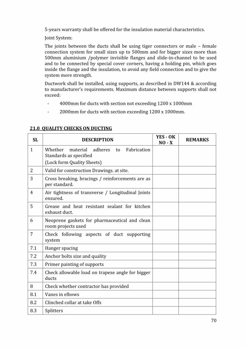
70
5-years warranty shall be offered for the insulation material characteristics.
Joint System:
The joints between the ducts shall be using tiger connectors or male – female connection system for small sizes up to 500mm and for bigger sizes more than 500mm aluminium /polymer invisible flanges and slide-in-channel to be used and to be connected by special cover corners, having a holding pin, which goes inside the flange and the insulation, to avoid any field connection and to give the system more strength.
Ductwork shall be installed, using supports, as described in DW144 & according to manufacturer’s requirements. Maximum distance between supports shall not exceed:
- 4000mm for ducts with section not exceeding 1200 x 1000mm
- 2000mm for ducts with section exceeding 1200 x 1000mm.
21.0 QUALITY CHECKS ON DUCTING
SL DESCRIPTION YES - OK
NO - X REMARKS
1 Whether material adheres to Fabrication Standards as specified
(Lock form Quality Sheets)
2 Valid for construction Drawings. at site.
3 Cross breaking, bracings / reinforcements are as per standard.
4 Air tightness of transverse / Longitudinal Joints ensured.
5 Grease and heat resistant sealant for kitchen exhaust duct.
6 Neoprene gaskets for pharmaceutical and clean room projects used
7 Check following aspects of duct supporting system
7.1 Hanger spacing
7.2 Anchor bolts size and quality
7.3 Primer painting of supports
7.4 Check allowable load on trapeze angle for bigger ducts
8 Check whether contractor has provided
8.1 Vanes in elbows
8.2 Clinched collar at take Offs
8.3 Splitters
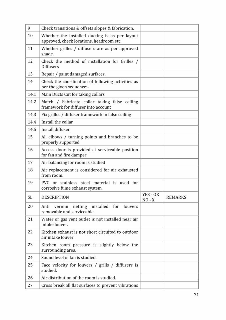
71
9 Check transitions & offsets slopes & fabrication.
10 Whether the installed ducting is as per layout approved, check locations, headroom etc.
11 Whether grilles / diffusers are as per approved shade.
12 Check the method of installation for Grilles / Diffusers
13 Repair / paint damaged surfaces.
14 Check the coordination of following activities as per the given sequence:-
14.1 Main Ducts Cut for taking collars
14.2 Match / Fabricate collar taking false ceiling framework for diffuser into account
14.3 Fix grilles / diffuser framework in false ceiling
14.4 Install the collar
14.5 Install diffuser
15 All elbows / turning points and branches to be properly supported
16 Access door is provided at serviceable position for fan and fire damper
17 Air balancing for room is studied
18 Air replacement is considered for air exhausted from room.
19 PVC or stainless steel material is used for corrosive fume exhaust system.
SL DESCRIPTION YES - OK NO - X
REMARKS
20 Anti vermin netting installed for louvers removable and serviceable.
21 Water or gas vent outlet is not installed near air intake louver.
22 Kitchen exhaust is not short circuited to outdoor air intake louver.
23 Kitchen room pressure is slightly below the surrounding area.
24 Sound level of fan is studied.
25 Face velocity for louvers / grills / diffusers is studied.
26 Air distribution of the room is studied.
27 Cross break all flat surfaces to prevent vibrations
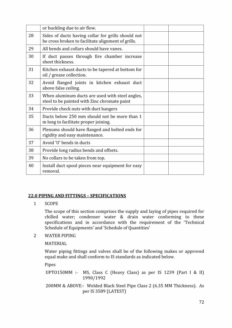
72
or buckling due to air flow.
28 Sides of ducts having collar for grills should not be cross broken to facilitate alignment of grills.
29 All bends and collars should have vanes.
30 If duct passes through fire chamber increase sheet thickness.
31 Kitchen exhaust ducts to be tapered at bottom for oil / grease collection.
32 Avoid flanged joints in kitchen exhaust duct above false ceiling.
33 When aluminum ducts are used with steel angles, steel to be painted with Zinc chromate paint
34 Provide check nuts with duct hangers
35 Ducts below 250 mm should not be more than 1 m long to facilitate proper joining.
36 Plenums should have flanged and bolted ends for rigidity and easy maintenance.
37 Avoid 'U' bends in ducts
38 Provide long radius bends and offsets.
39 No collars to be taken from top.
40 Install duct spool pieces near equipment for easy removal.
22.0 PIPING AND FITTINGS – SPECIFICATIONS
1 SCOPE
The scope of this section comprises the supply and laying of pipes required for chilled water; condenser water & drain water conforming to these specifications and in accordance with the requirement of the ‘Technical Schedule of Equipments’ and ‘Schedule of Quantities’
2 WATER PIPING
MATERIAL
Water piping fittings and valves shall be of the following makes or approved equal make and shall conform to IS standards as indicated below.
Pipes
UPTO150MM :- MS, Class C (Heavy Class) as per IS 1239 (Part I & II) 1990/1992
200MM & ABOVE:- Welded Black Steel Pipe Class 2 (6.35 MM Thickness). As per IS 3589 (LATEST)
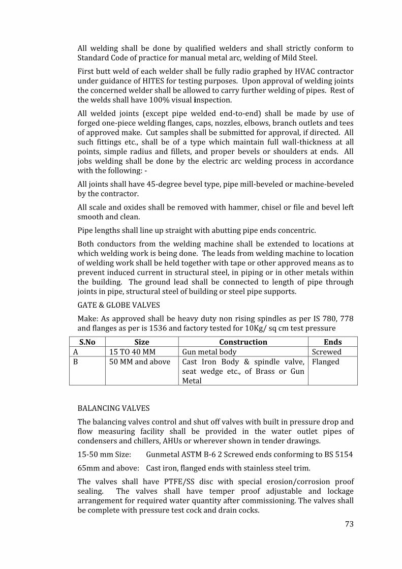
73
All welding shall be done by qualified welders and shall strictly conform to Standard Code of practice for manual metal arc, welding of Mild Steel.
First butt weld of each welder shall be fully radio graphed by HVAC contractor under guidance of HITES for testing purposes. Upon approval of welding joints the concerned welder shall be allowed to carry further welding of pipes. Rest of the welds shall have 100% visual inspection.
All welded joints (except pipe welded end-to-end) shall be made by use of forged one-piece welding flanges, caps, nozzles, elbows, branch outlets and tees of approved make. Cut samples shall be submitted for approval, if directed. All such fittings etc., shall be of a type which maintain full wall-thickness at all points, simple radius and fillets, and proper bevels or shoulders at ends. All jobs welding shall be done by the electric arc welding process in accordance with the following: -
All joints shall have 45-degree bevel type, pipe mill-beveled or machine-beveled by the contractor.
All scale and oxides shall be removed with hammer, chisel or file and bevel left smooth and clean.
Pipe lengths shall line up straight with abutting pipe ends concentric.
Both conductors from the welding machine shall be extended to locations at which welding work is being done. The leads from welding machine to location of welding work shall be held together with tape or other approved means as to prevent induced current in structural steel, in piping or in other metals within the building. The ground lead shall be connected to length of pipe through joints in pipe, structural steel of building or steel pipe supports.
GATE & GLOBE VALVES
Make: As approved shall be heavy duty non rising spindles as per IS 780, 778 and flanges as per is 1536 and factory tested for 10Kg/ sq cm test pressure
S.No Size Construction Ends A 15 TO 40 MM Gun metal body Screwed B 50 MM and above Cast Iron Body & spindle valve,
seat wedge etc., of Brass or Gun Metal
Flanged
BALANCING VALVES
The balancing valves control and shut off valves with built in pressure drop and flow measuring facility shall be provided in the water outlet pipes of condensers and chillers, AHUs or wherever shown in tender drawings.
15-50 mm Size: Gunmetal ASTM B-6 2 Screwed ends conforming to BS 5154
65mm and above: Cast iron, flanged ends with stainless steel trim.
The valves shall have PTFE/SS disc with special erosion/corrosion proof sealing. The valves shall have temper proof adjustable and lockage arrangement for required water quantity after commissioning. The valves shall be complete with pressure test cock and drain cocks.
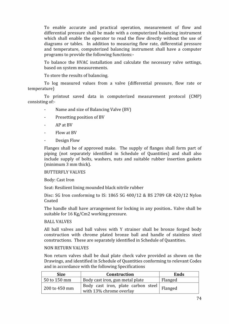
74
To enable accurate and practical operation, measurement of flow and differential pressure shall be made with a computerized balancing instrument which shall enable the operator to read the flow directly without the use of diagrams or tables. In addition to measuring flow rate, differential pressure and temperature, computerized balancing instrument shall have a computer programs to provide the following functions:-
To balance the HVAC installation and calculate the necessary valve settings, based on system measurements.
To store the results of balancing.
To log measured values from a valve (differential pressure, flow rate or temperature)
To printout saved data in computerized measurement protocol (CMP) consisting of:-
- Name and size of Balancing Valve (BV)
- Presetting position of BV
- AP at BV
- Flow at BV
- Design Flow
Flanges shall be of approved make. The supply of flanges shall form part of piping (not separately identified in Schedule of Quantities) and shall also include supply of bolts, washers, nuts and suitable rubber insertion gaskets (minimum 3 mm thick).
BUTTERFLY VALVES
Body: Cast Iron
Seat: Resilient lining mounded black nitrile rubber
Disc: SG Iron conforming to IS: 1865 SG 400/12 & BS 2789 GR 420/12 Nylon Coated
The handle shall have arrangement for locking in any position.. Valve shall be suitable for 16 Kg/Cm2 working pressure.
BALL VALVES
All ball valves and ball valves with Y strainer shall be bronze forged body construction with chrome plated bronze ball and handle of stainless steel constructions. These are separately identified in Schedule of Quantities.
NON RETURN VALVES
Non return valves shall be dual plate check valve provided as shown on the Drawings, and identified in Schedule of Quantities conforming to relevant Codes and in accordance with the following Specifications
Size Construction Ends 50 to 150 mm Body cast iron, gun metal plate Flanged
200 to 450 mm Body cast iron, plate carbon steel with 13% chrome overlay
Flanged
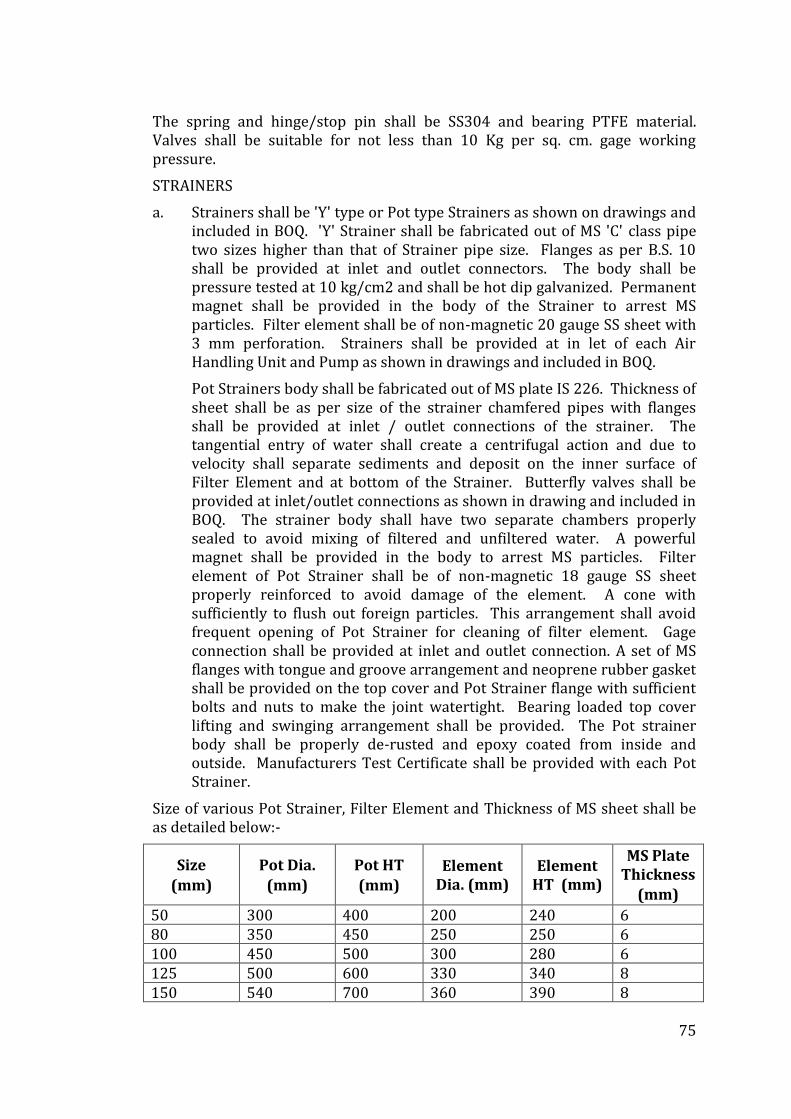
75
The spring and hinge/stop pin shall be SS304 and bearing PTFE material. Valves shall be suitable for not less than 10 Kg per sq. cm. gage working pressure.
STRAINERS
a. Strainers shall be 'Y' type or Pot type Strainers as shown on drawings and included in BOQ. 'Y' Strainer shall be fabricated out of MS 'C' class pipe two sizes higher than that of Strainer pipe size. Flanges as per B.S. 10 shall be provided at inlet and outlet connectors. The body shall be pressure tested at 10 kg/cm2 and shall be hot dip galvanized. Permanent magnet shall be provided in the body of the Strainer to arrest MS particles. Filter element shall be of non-magnetic 20 gauge SS sheet with 3 mm perforation. Strainers shall be provided at in let of each Air Handling Unit and Pump as shown in drawings and included in BOQ.
Pot Strainers body shall be fabricated out of MS plate IS 226. Thickness of sheet shall be as per size of the strainer chamfered pipes with flanges shall be provided at inlet / outlet connections of the strainer. The tangential entry of water shall create a centrifugal action and due to velocity shall separate sediments and deposit on the inner surface of Filter Element and at bottom of the Strainer. Butterfly valves shall be provided at inlet/outlet connections as shown in drawing and included in BOQ. The strainer body shall have two separate chambers properly sealed to avoid mixing of filtered and unfiltered water. A powerful magnet shall be provided in the body to arrest MS particles. Filter element of Pot Strainer shall be of non-magnetic 18 gauge SS sheet properly reinforced to avoid damage of the element. A cone with sufficiently to flush out foreign particles. This arrangement shall avoid frequent opening of Pot Strainer for cleaning of filter element. Gage connection shall be provided at inlet and outlet connection. A set of MS flanges with tongue and groove arrangement and neoprene rubber gasket shall be provided on the top cover and Pot Strainer flange with sufficient bolts and nuts to make the joint watertight. Bearing loaded top cover lifting and swinging arrangement shall be provided. The Pot strainer body shall be properly de-rusted and epoxy coated from inside and outside. Manufacturers Test Certificate shall be provided with each Pot Strainer.
Size of various Pot Strainer, Filter Element and Thickness of MS sheet shall be as detailed below:-
Size
(mm)
Pot Dia.
(mm)
Pot HT
(mm) Element
Dia. (mm) Element
HT (mm)
MS Plate Thickness
(mm)
50 300 400 200 240 6 80 350 450 250 250 6 100 450 500 300 280 6 125 500 600 330 340 8 150 540 700 360 390 8
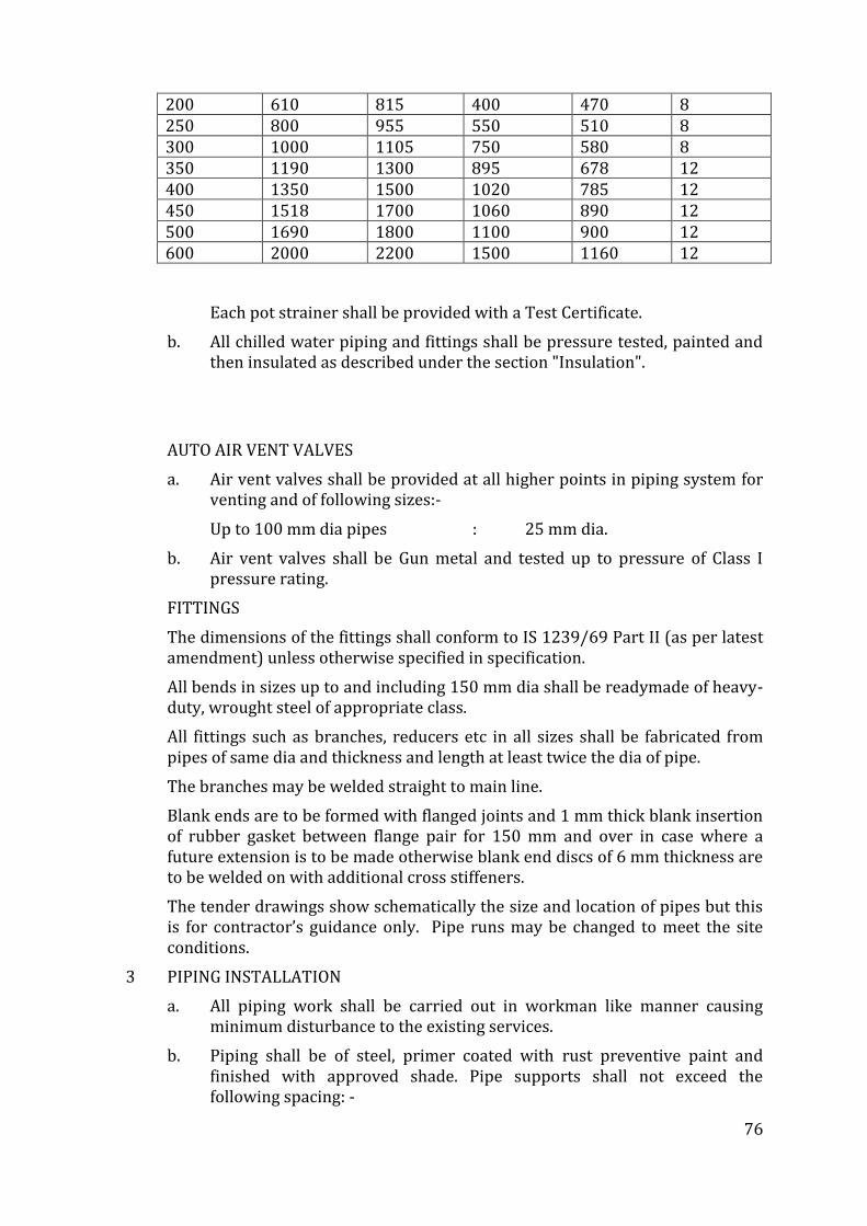
76
200 610 815 400 470 8 250 800 955 550 510 8 300 1000 1105 750 580 8 350 1190 1300 895 678 12 400 1350 1500 1020 785 12 450 1518 1700 1060 890 12 500 1690 1800 1100 900 12 600 2000 2200 1500 1160 12
Each pot strainer shall be provided with a Test Certificate.
b. All chilled water piping and fittings shall be pressure tested, painted and then insulated as described under the section "Insulation".
AUTO AIR VENT VALVES
a. Air vent valves shall be provided at all higher points in piping system for venting and of following sizes:-
Up to 100 mm dia pipes : 25 mm dia.
b. Air vent valves shall be Gun metal and tested up to pressure of Class I pressure rating.
FITTINGS
The dimensions of the fittings shall conform to IS 1239/69 Part II (as per latest amendment) unless otherwise specified in specification.
All bends in sizes up to and including 150 mm dia shall be readymade of heavy-duty, wrought steel of appropriate class.
All fittings such as branches, reducers etc in all sizes shall be fabricated from pipes of same dia and thickness and length at least twice the dia of pipe.
The branches may be welded straight to main line.
Blank ends are to be formed with flanged joints and 1 mm thick blank insertion of rubber gasket between flange pair for 150 mm and over in case where a future extension is to be made otherwise blank end discs of 6 mm thickness are to be welded on with additional cross stiffeners.
The tender drawings show schematically the size and location of pipes but this is for contractor’s guidance only. Pipe runs may be changed to meet the site conditions.
3 PIPING INSTALLATION
a. All piping work shall be carried out in workman like manner causing minimum disturbance to the existing services.
b. Piping shall be of steel, primer coated with rust preventive paint and finished with approved shade. Pipe supports shall not exceed the following spacing: -
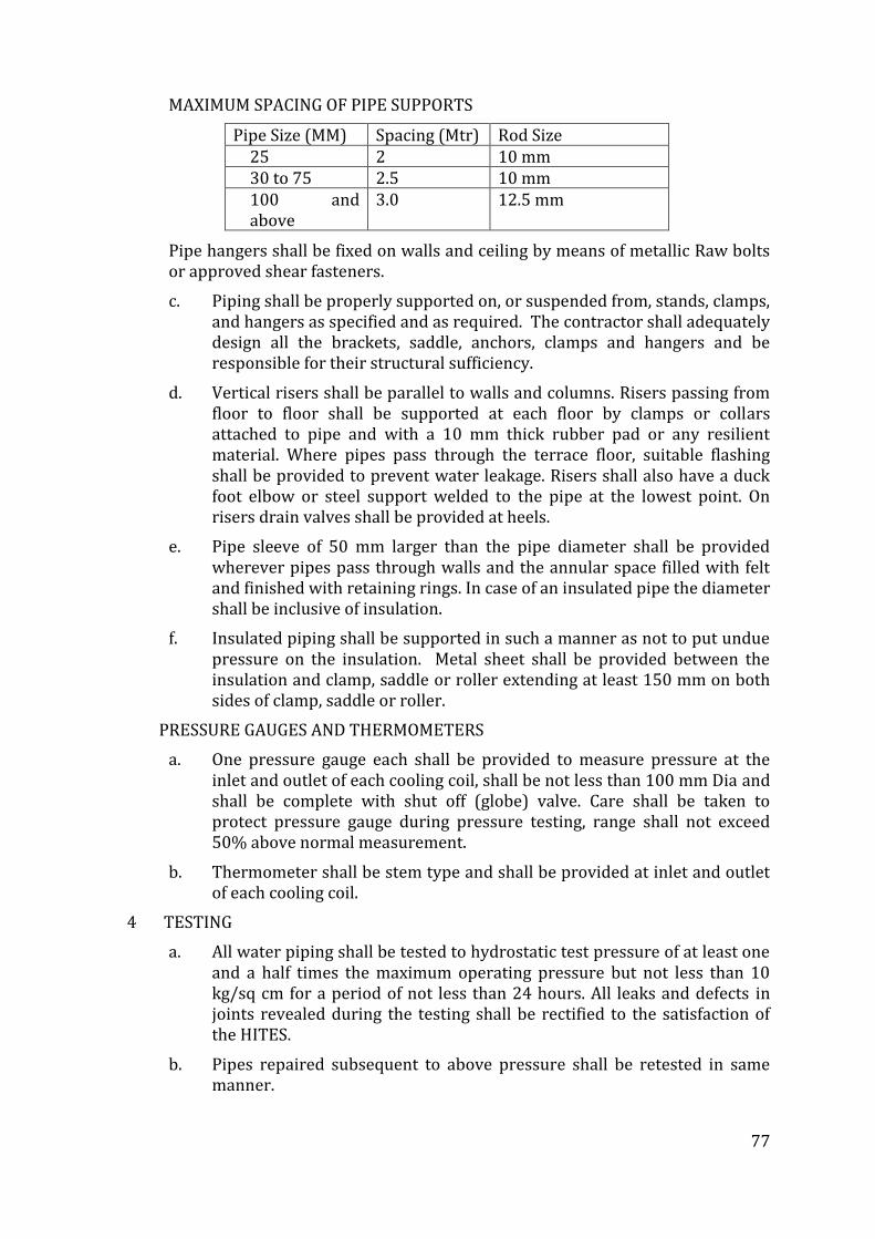
77
MAXIMUM SPACING OF PIPE SUPPORTS
Pipe Size (MM) Spacing (Mtr) Rod Size 25 2 10 mm 30 to 75 2.5 10 mm 100 and above
3.0 12.5 mm
Pipe hangers shall be fixed on walls and ceiling by means of metallic Raw bolts or approved shear fasteners.
c. Piping shall be properly supported on, or suspended from, stands, clamps, and hangers as specified and as required. The contractor shall adequately design all the brackets, saddle, anchors, clamps and hangers and be responsible for their structural sufficiency.
d. Vertical risers shall be parallel to walls and columns. Risers passing from floor to floor shall be supported at each floor by clamps or collars attached to pipe and with a 10 mm thick rubber pad or any resilient material. Where pipes pass through the terrace floor, suitable flashing shall be provided to prevent water leakage. Risers shall also have a duck foot elbow or steel support welded to the pipe at the lowest point. On risers drain valves shall be provided at heels.
e. Pipe sleeve of 50 mm larger than the pipe diameter shall be provided wherever pipes pass through walls and the annular space filled with felt and finished with retaining rings. In case of an insulated pipe the diameter shall be inclusive of insulation.
f. Insulated piping shall be supported in such a manner as not to put undue pressure on the insulation. Metal sheet shall be provided between the insulation and clamp, saddle or roller extending at least 150 mm on both sides of clamp, saddle or roller.
PRESSURE GAUGES AND THERMOMETERS
a. One pressure gauge each shall be provided to measure pressure at the inlet and outlet of each cooling coil, shall be not less than 100 mm Dia and shall be complete with shut off (globe) valve. Care shall be taken to protect pressure gauge during pressure testing, range shall not exceed 50% above normal measurement.
b. Thermometer shall be stem type and shall be provided at inlet and outlet of each cooling coil.
4 TESTING
a. All water piping shall be tested to hydrostatic test pressure of at least one and a half times the maximum operating pressure but not less than 10 kg/sq cm for a period of not less than 24 hours. All leaks and defects in joints revealed during the testing shall be rectified to the satisfaction of the HITES.
b. Pipes repaired subsequent to above pressure shall be retested in same manner.
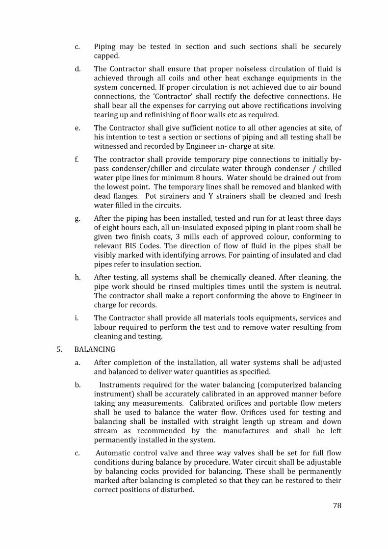
78
c. Piping may be tested in section and such sections shall be securely capped.
d. The Contractor shall ensure that proper noiseless circulation of fluid is achieved through all coils and other heat exchange equipments in the system concerned. If proper circulation is not achieved due to air bound connections, the ‘Contractor’ shall rectify the defective connections. He shall bear all the expenses for carrying out above rectifications involving tearing up and refinishing of floor walls etc as required.
e. The Contractor shall give sufficient notice to all other agencies at site, of his intention to test a section or sections of piping and all testing shall be witnessed and recorded by Engineer in- charge at site.
f. The contractor shall provide temporary pipe connections to initially by-pass condenser/chiller and circulate water through condenser / chilled water pipe lines for minimum 8 hours. Water should be drained out from the lowest point. The temporary lines shall be removed and blanked with dead flanges. Pot strainers and Y strainers shall be cleaned and fresh water filled in the circuits.
g. After the piping has been installed, tested and run for at least three days of eight hours each, all un-insulated exposed piping in plant room shall be given two finish coats, 3 mills each of approved colour, conforming to relevant BIS Codes. The direction of flow of fluid in the pipes shall be visibly marked with identifying arrows. For painting of insulated and clad pipes refer to insulation section.
h. After testing, all systems shall be chemically cleaned. After cleaning, the pipe work should be rinsed multiples times until the system is neutral. The contractor shall make a report conforming the above to Engineer in charge for records.
i. The Contractor shall provide all materials tools equipments, services and labour required to perform the test and to remove water resulting from cleaning and testing.
5. BALANCING
a. After completion of the installation, all water systems shall be adjusted and balanced to deliver water quantities as specified.
b. Instruments required for the water balancing (computerized balancing instrument) shall be accurately calibrated in an approved manner before taking any measurements. Calibrated orifices and portable flow meters shall be used to balance the water flow. Orifices used for testing and balancing shall be installed with straight length up stream and down stream as recommended by the manufactures and shall be left permanently installed in the system.
c. Automatic control valve and three way valves shall be set for full flow conditions during balance by procedure. Water circuit shall be adjustable by balancing cocks provided for balancing. These shall be permanently marked after balancing is completed so that they can be restored to their correct positions of disturbed.
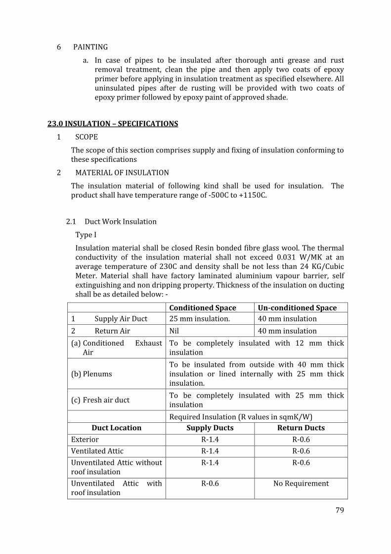
79
6 PAINTING
a. In case of pipes to be insulated after thorough anti grease and rust removal treatment, clean the pipe and then apply two coats of epoxy primer before applying in insulation treatment as specified elsewhere. All uninsulated pipes after de rusting will be provided with two coats of epoxy primer followed by epoxy paint of approved shade.
23.0 INSULATION – SPECIFICATIONS
1 SCOPE
The scope of this section comprises supply and fixing of insulation conforming to these specifications
2 MATERIAL OF INSULATION
The insulation material of following kind shall be used for insulation. The product shall have temperature range of -500C to +1150C.
2.1 Duct Work Insulation
Type I
Insulation material shall be closed Resin bonded fibre glass wool. The thermal conductivity of the insulation material shall not exceed 0.031 W/MK at an average temperature of 230C and density shall be not less than 24 KG/Cubic Meter. Material shall have factory laminated aluminium vapour barrier, self extinguishing and non dripping property. Thickness of the insulation on ducting shall be as detailed below: -
Conditioned Space Un-conditioned Space
1 Supply Air Duct 25 mm insulation. 40 mm insulation
2 Return Air Nil 40 mm insulation
(a) Conditioned Exhaust Air
To be completely insulated with 12 mm thick insulation
(b) Plenums To be insulated from outside with 40 mm thick insulation or lined internally with 25 mm thick insulation.
(c) Fresh air duct To be completely insulated with 25 mm thick insulation
Required Insulation (R values in sqmK/W)
Duct Location Supply Ducts Return Ducts
Exterior R-1.4 R-0.6
Ventilated Attic R-1.4 R-0.6
Unventilated Attic without roof insulation
R-1.4 R-0.6
Unventilated Attic with roof insulation
R-0.6 No Requirement
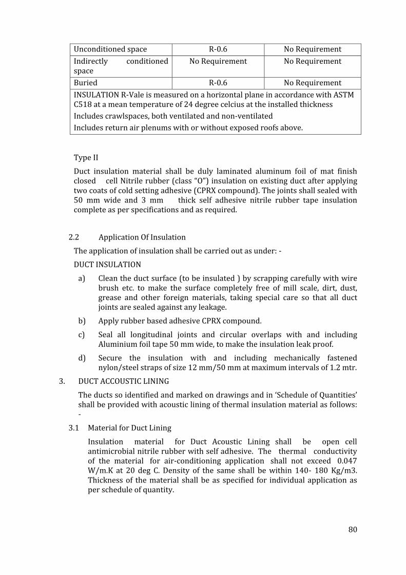
80
Unconditioned space R-0.6 No Requirement
Indirectly conditioned space
No Requirement No Requirement
Buried R-0.6 No Requirement
INSULATION R-Vale is measured on a horizontal plane in accordance with ASTM C518 at a mean temperature of 24 degree celcius at the installed thickness
Includes crawlspaces, both ventilated and non-ventilated
Includes return air plenums with or without exposed roofs above.
Type II
Duct insulation material shall be duly laminated aluminum foil of mat finish closed cell Nitrile rubber (class “O”) insulation on existing duct after applying two coats of cold setting adhesive (CPRX compound). The joints shall sealed with 50 mm wide and 3 mm thick self adhesive nitrile rubber tape insulation complete as per specifications and as required.
2.2 Application Of Insulation
The application of insulation shall be carried out as under: -
DUCT INSULATION
a) Clean the duct surface (to be insulated ) by scrapping carefully with wire brush etc. to make the surface completely free of mill scale, dirt, dust, grease and other foreign materials, taking special care so that all duct joints are sealed against any leakage.
b) Apply rubber based adhesive CPRX compound.
c) Seal all longitudinal joints and circular overlaps with and including Aluminium foil tape 50 mm wide, to make the insulation leak proof.
d) Secure the insulation with and including mechanically fastened nylon/steel straps of size 12 mm/50 mm at maximum intervals of 1.2 mtr.
3. DUCT ACCOUSTIC LINING
The ducts so identified and marked on drawings and in ‘Schedule of Quantities’ shall be provided with acoustic lining of thermal insulation material as follows: -
3.1 Material for Duct Lining
Insulation material for Duct Acoustic Lining shall be open cell antimicrobial nitrile rubber with self adhesive. The thermal conductivity of the material for air-conditioning application shall not exceed 0.047 W/m.K at 20 deg C. Density of the same shall be within 140- 180 Kg/m3. Thickness of the material shall be as specified for individual application as per schedule of quantity.
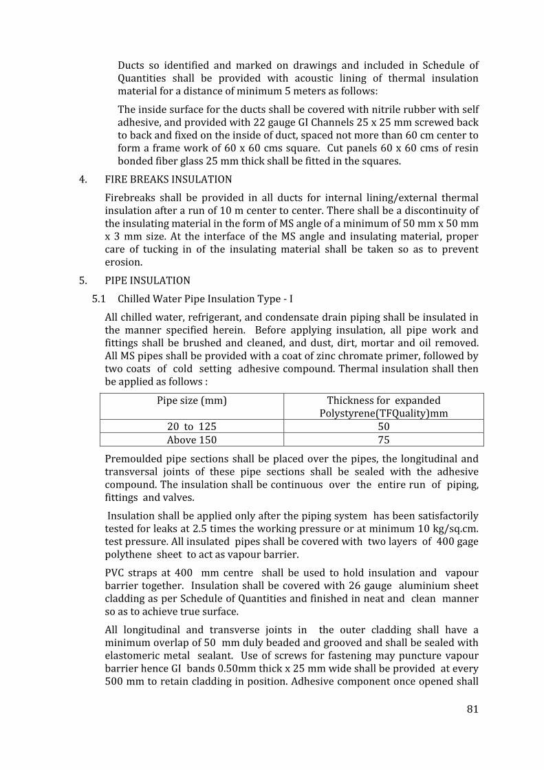
81
Ducts so identified and marked on drawings and included in Schedule of Quantities shall be provided with acoustic lining of thermal insulation material for a distance of minimum 5 meters as follows:
The inside surface for the ducts shall be covered with nitrile rubber with self adhesive, and provided with 22 gauge GI Channels 25 x 25 mm screwed back to back and fixed on the inside of duct, spaced not more than 60 cm center to form a frame work of 60 x 60 cms square. Cut panels 60 x 60 cms of resin bonded fiber glass 25 mm thick shall be fitted in the squares.
4. FIRE BREAKS INSULATION
Firebreaks shall be provided in all ducts for internal lining/external thermal insulation after a run of 10 m center to center. There shall be a discontinuity of the insulating material in the form of MS angle of a minimum of 50 mm x 50 mm x 3 mm size. At the interface of the MS angle and insulating material, proper care of tucking in of the insulating material shall be taken so as to prevent erosion.
5. PIPE INSULATION
5.1 Chilled Water Pipe Insulation Type - I
All chilled water, refrigerant, and condensate drain piping shall be insulated in the manner specified herein. Before applying insulation, all pipe work and fittings shall be brushed and cleaned, and dust, dirt, mortar and oil removed. All MS pipes shall be provided with a coat of zinc chromate primer, followed by two coats of cold setting adhesive compound. Thermal insulation shall then be applied as follows :
Pipe size (mm) Thickness for expanded Polystyrene(TFQuality)mm
20 to 125 50 Above 150 75
Premoulded pipe sections shall be placed over the pipes, the longitudinal and transversal joints of these pipe sections shall be sealed with the adhesive compound. The insulation shall be continuous over the entire run of piping, fittings and valves.
Insulation shall be applied only after the piping system has been satisfactorily tested for leaks at 2.5 times the working pressure or at minimum 10 kg/sq.cm. test pressure. All insulated pipes shall be covered with two layers of 400 gage polythene sheet to act as vapour barrier.
PVC straps at 400 mm centre shall be used to hold insulation and vapour barrier together. Insulation shall be covered with 26 gauge aluminium sheet cladding as per Schedule of Quantities and finished in neat and clean manner so as to achieve true surface.
All longitudinal and transverse joints in the outer cladding shall have a minimum overlap of 50 mm duly beaded and grooved and shall be sealed with elastomeric metal sealant. Use of screws for fastening may puncture vapour barrier hence GI bands 0.50mm thick x 25 mm wide shall be provided at every 500 mm to retain cladding in position. Adhesive component once opened shall
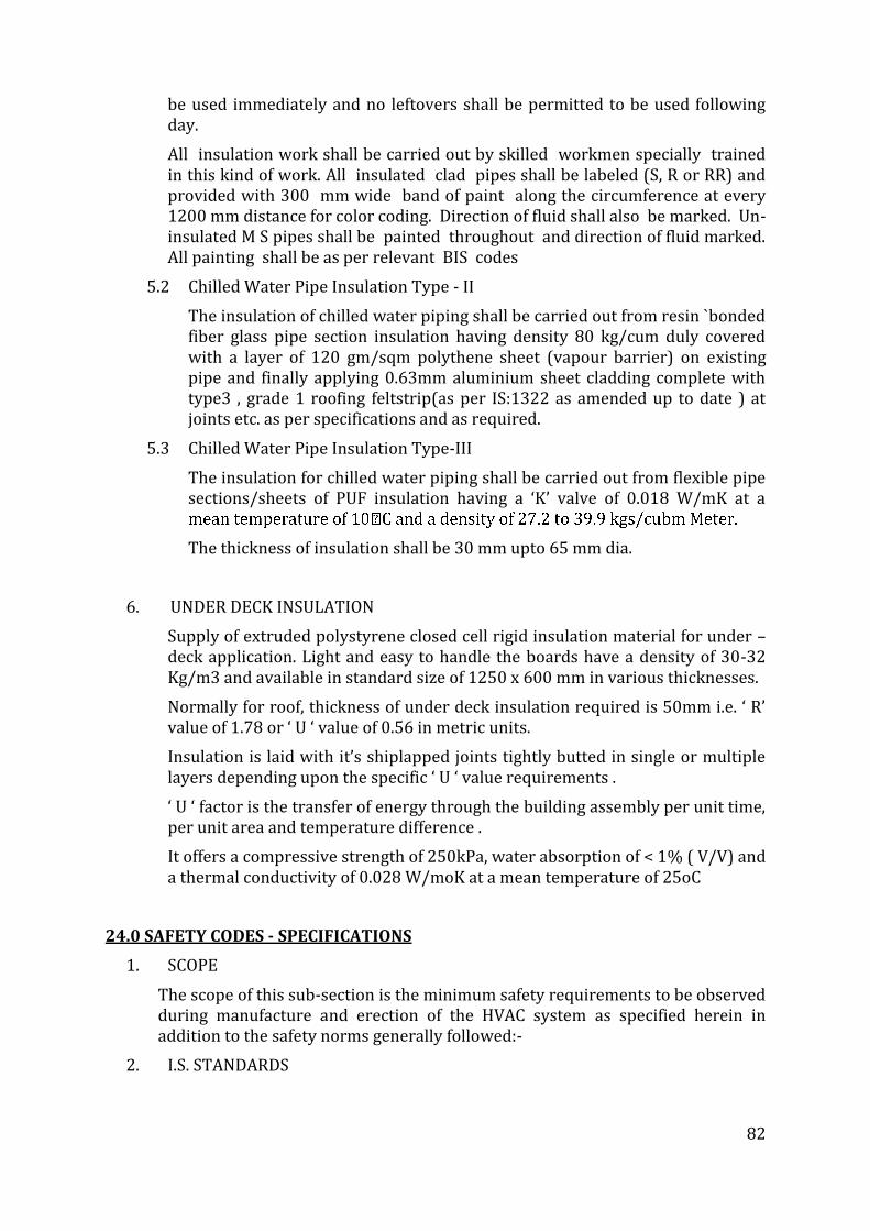
82
be used immediately and no leftovers shall be permitted to be used following day.
All insulation work shall be carried out by skilled workmen specially trained in this kind of work. All insulated clad pipes shall be labeled (S, R or RR) and provided with 300 mm wide band of paint along the circumference at every 1200 mm distance for color coding. Direction of fluid shall also be marked. Un-insulated M S pipes shall be painted throughout and direction of fluid marked. All painting shall be as per relevant BIS codes
5.2 Chilled Water Pipe Insulation Type - II
The insulation of chilled water piping shall be carried out from resin `bonded fiber glass pipe section insulation having density 80 kg/cum duly covered with a layer of 120 gm/sqm polythene sheet (vapour barrier) on existing pipe and finally applying 0.63mm aluminium sheet cladding complete with type3 , grade 1 roofing feltstrip(as per IS:1322 as amended up to date ) at joints etc. as per specifications and as required.
5.3 Chilled Water Pipe Insulation Type-III
The insulation for chilled water piping shall be carried out from flexible pipe sections/sheets of PUF insulation having a ‘K’ valve of 0.018 W/mK at a
The thickness of insulation shall be 30 mm upto 65 mm dia.
6. UNDER DECK INSULATION
Supply of extruded polystyrene closed cell rigid insulation material for under – deck application. Light and easy to handle the boards have a density of 30-32 Kg/m3 and available in standard size of 1250 x 600 mm in various thicknesses.
Normally for roof, thickness of under deck insulation required is 50mm i.e. ‘ R’ value of 1.78 or ‘ U ‘ value of 0.56 in metric units.
Insulation is laid with it’s shiplapped joints tightly butted in single or multiple layers depending upon the specific ‘ U ‘ value requirements .
‘ U ‘ factor is the transfer of energy through the building assembly per unit time, per unit area and temperature difference .
It offers a compressive strength of 250kPa, water absorption of < 1% ( V/V) and a thermal conductivity of 0.028 W/moK at a mean temperature of 25oC
24.0 SAFETY CODES - SPECIFICATIONS
1. SCOPE
The scope of this sub-section is the minimum safety requirements to be observed during manufacture and erection of the HVAC system as specified herein in addition to the safety norms generally followed:-
2. I.S. STANDARDS
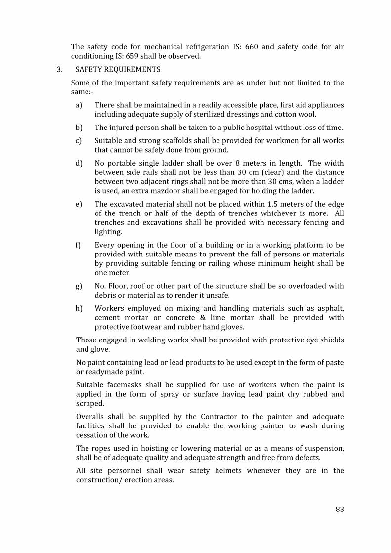
83
The safety code for mechanical refrigeration IS: 660 and safety code for air conditioning IS: 659 shall be observed.
3. SAFETY REQUIREMENTS
Some of the important safety requirements are as under but not limited to the same:-
a) There shall be maintained in a readily accessible place, first aid appliances including adequate supply of sterilized dressings and cotton wool.
b) The injured person shall be taken to a public hospital without loss of time.
c) Suitable and strong scaffolds shall be provided for workmen for all works that cannot be safely done from ground.
d) No portable single ladder shall be over 8 meters in length. The width between side rails shall not be less than 30 cm (clear) and the distance between two adjacent rings shall not be more than 30 cms, when a ladder is used, an extra mazdoor shall be engaged for holding the ladder.
e) The excavated material shall not be placed within 1.5 meters of the edge of the trench or half of the depth of trenches whichever is more. All trenches and excavations shall be provided with necessary fencing and lighting.
f) Every opening in the floor of a building or in a working platform to be provided with suitable means to prevent the fall of persons or materials by providing suitable fencing or railing whose minimum height shall be one meter.
g) No. Floor, roof or other part of the structure shall be so overloaded with debris or material as to render it unsafe.
h) Workers employed on mixing and handling materials such as asphalt, cement mortar or concrete & lime mortar shall be provided with protective footwear and rubber hand gloves.
Those engaged in welding works shall be provided with protective eye shields and glove.
No paint containing lead or lead products to be used except in the form of paste or readymade paint.
Suitable facemasks shall be supplied for use of workers when the paint is applied in the form of spray or surface having lead paint dry rubbed and scraped.
Overalls shall be supplied by the Contractor to the painter and adequate facilities shall be provided to enable the working painter to wash during cessation of the work.
The ropes used in hoisting or lowering material or as a means of suspension, shall be of adequate quality and adequate strength and free from defects.
All site personnel shall wear safety helmets whenever they are in the construction/ erection areas.
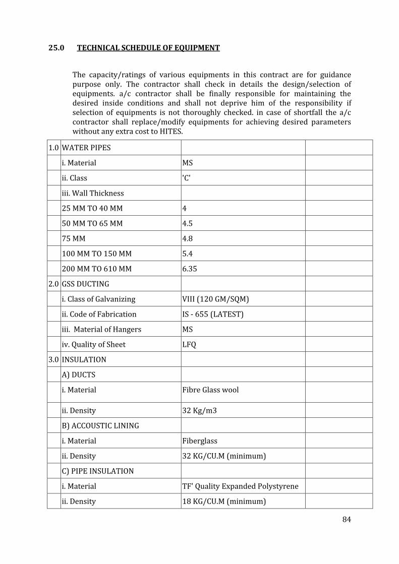
84
25.0 TECHNICAL SCHEDULE OF EQUIPMENT
The capacity/ratings of various equipments in this contract are for guidance purpose only. The contractor shall check in details the design/selection of equipments. a/c contractor shall be finally responsible for maintaining the desired inside conditions and shall not deprive him of the responsibility if selection of equipments is not thoroughly checked. in case of shortfall the a/c contractor shall replace/modify equipments for achieving desired parameters without any extra cost to HITES.
1.0 WATER PIPES
i. Material MS
ii. Class 'C'
iii. Wall Thickness
25 MM TO 40 MM 4
50 MM TO 65 MM 4.5
75 MM 4.8
100 MM TO 150 MM 5.4
200 MM TO 610 MM 6.35
2.0 GSS DUCTING
i. Class of Galvanizing VIII (120 GM/SQM)
ii. Code of Fabrication IS - 655 (LATEST)
iii. Material of Hangers MS
iv. Quality of Sheet LFQ
3.0 INSULATION
A) DUCTS
i. Material Fibre Glass wool
ii. Density 32 Kg/m3
B) ACCOUSTIC LINING
i. Material Fiberglass
ii. Density 32 KG/CU.M (minimum)
C) PIPE INSULATION
i. Material TF' Quality Expanded Polystyrene
ii. Density 18 KG/CU.M (minimum)
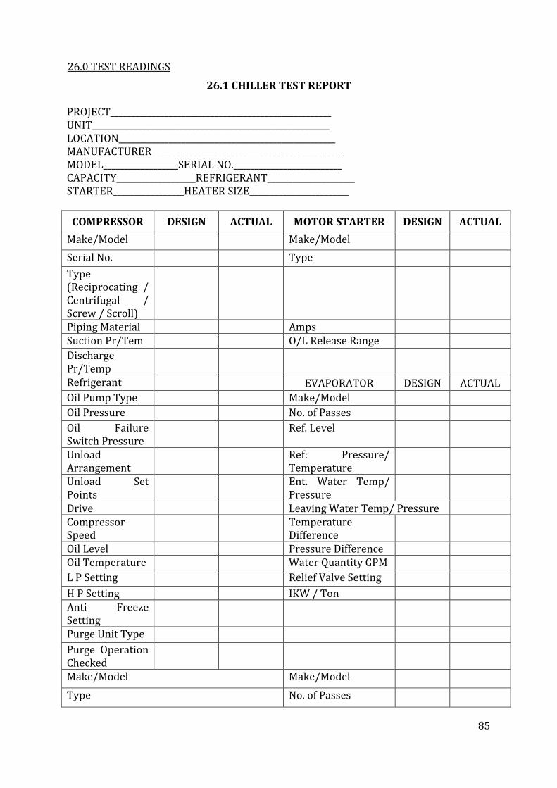
85
26.0 TEST READINGS
26.1 CHILLER TEST REPORT PROJECT_____________________________________________________ UNIT_________________________________________________________ LOCATION____________________________________________________ MANUFACTURER______________________________________________ MODEL__________________SERIAL NO.__________________________ CAPACITY___________________REFRIGERANT_____________________ STARTER_________________HEATER SIZE________________________
COMPRESSOR DESIGN ACTUAL MOTOR STARTER DESIGN ACTUAL
Make/Model Make/Model
Serial No. Type
Type (Reciprocating / Centrifugal / Screw / Scroll)
Piping Material Amps Suction Pr/Tem O/L Release Range
Discharge Pr/Temp
Refrigerant EVAPORATOR DESIGN ACTUAL
Oil Pump Type Make/Model
Oil Pressure No. of Passes
Oil Failure Switch Pressure
Ref. Level
Unload Arrangement
Ref: Pressure/ Temperature
Unload Set Points
Ent. Water Temp/ Pressure
Drive Leaving Water Temp/ Pressure Compressor Speed
Temperature Difference
Oil Level Pressure Difference Oil Temperature Water Quantity GPM
L P Setting Relief Valve Setting
H P Setting IKW / Ton Anti Freeze Setting
Purge Unit Type
Purge Operation Checked
Make/Model Make/Model
Type No. of Passes
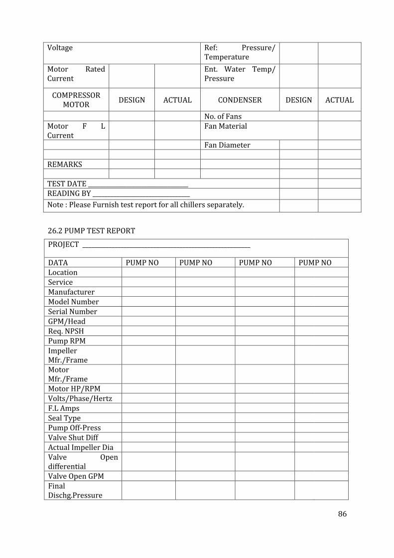
86
Voltage Ref: Pressure/ Temperature
Motor Rated Current
Ent. Water Temp/ Pressure
COMPRESSOR MOTOR
DESIGN ACTUAL CONDENSER DESIGN ACTUAL
No. of Fans Motor F L Current
Fan Material
Fan Diameter REMARKS TEST DATE __________________________________ READING BY _________________________________
Note : Please Furnish test report for all chillers separately.
26.2 PUMP TEST REPORT
PROJECT _________________________________________________________
DATA PUMP NO PUMP NO PUMP NO PUMP NO Location Service Manufacturer Model Number Serial Number GPM/Head Req. NPSH Pump RPM Impeller Mfr./Frame
Motor Mfr./Frame
Motor HP/RPM Volts/Phase/Hertz F.L Amps Seal Type Pump Off-Press Valve Shut Diff Actual Impeller Dia Valve Open differential
Valve Open GPM Final Dischg.Pressure
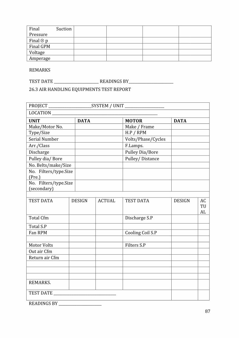
87
Final Suction Pressure
Final p
Final GPM Voltage Amperage REMARKS TEST DATE _________________________ READINGS BY_________________________
26.3 AIR HANDLING EQUIPMENTS TEST REPORT
PROJECT ________________________SYSTEM / UNIT ______________________
LOCATION ___________________________________________________________
UNIT DATA MOTOR DATA Make/Motor No. Make / Frame Type/Size H.P / RPM
Serial Number Volts/Phase/Cycles
Arr./Class F.Lamps.
Discharge Pulley Dia/Bore
Pulley dia/ Bore Pulley/ Distance
No. Belts/make/Size
No. Filters/type.Size (Pre.)
No. Filters/type.Size (secondary)
TEST DATA DESIGN ACTUAL TEST DATA DESIGN ACTUAL
Total Cfm Discharge S.P
Total S.P
Fan RPM Cooling Coil S.P
Motor Volts Filters S.P
Out air Cfm
Return air Cfm
REMARKS.
TEST DATE ___________________________________
READINGS BY ________________________
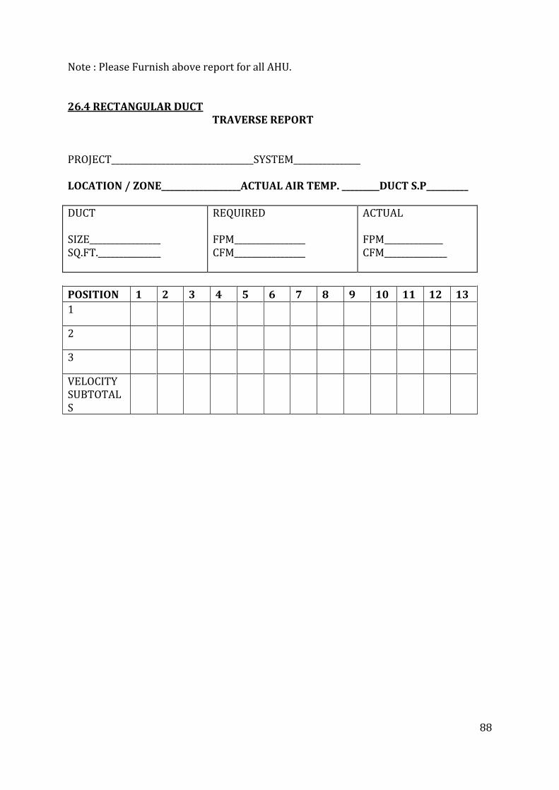
88
Note : Please Furnish above report for all AHU. 26.4 RECTANGULAR DUCT
TRAVERSE REPORT PROJECT__________________________________SYSTEM________________ LOCATION / ZONE___________________ACTUAL AIR TEMP. _________DUCT S.P__________ DUCT SIZE_________________ SQ.FT._______________
REQUIRED FPM_________________ CFM_________________
ACTUAL FPM______________ CFM_______________
POSITION 1 2 3 4 5 6 7 8 9 10 11 12 13
1
2
3
VELOCITY SUBTOTALS
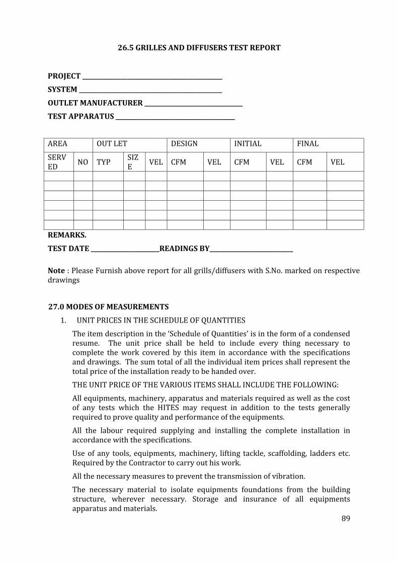
89
26.5 GRILLES AND DIFFUSERS TEST REPORT PROJECT _______________________________________________
SYSTEM ________________________________________________
OUTLET MANUFACTURER _________________________________
TEST APPARATUS ________________________________________
AREA OUT LET DESIGN INITIAL FINAL
SERVED
NO TYP SIZE
VEL CFM VEL CFM VEL CFM VEL
REMARKS.
TEST DATE _______________________READINGS BY____________________________
Note : Please Furnish above report for all grills/diffusers with S.No. marked on respective drawings
27.0 MODES OF MEASUREMENTS
1. UNIT PRICES IN THE SCHEDULE OF QUANTITIES
The item description in the ‘Schedule of Quantities’ is in the form of a condensed resume. The unit price shall be held to include every thing necessary to complete the work covered by this item in accordance with the specifications and drawings. The sum total of all the individual item prices shall represent the total price of the installation ready to be handed over.
THE UNIT PRICE OF THE VARIOUS ITEMS SHALL INCLUDE THE FOLLOWING:
All equipments, machinery, apparatus and materials required as well as the cost of any tests which the HITES may request in addition to the tests generally required to prove quality and performance of the equipments.
All the labour required supplying and installing the complete installation in accordance with the specifications.
Use of any tools, equipments, machinery, lifting tackle, scaffolding, ladders etc. Required by the Contractor to carry out his work.
All the necessary measures to prevent the transmission of vibration.
The necessary material to isolate equipments foundations from the building structure, wherever necessary. Storage and insurance of all equipments apparatus and materials.
90
The Contractor’s unit price shall include all equipments, apparatus, material and labour indicated in the drawings and/or specifications in conjunction with the item in question, as well as all additional equipments, apparatus, material and labour usual and necessary to make in question on its own (and within the system as a whole) complete even though not specifically shown, described or otherwise referred to.
2. MEASUREMENTS OF SHEET METAL DUCTS, GRILLES/DIFFUSERS ETC.
2.1 Sheet Metal Ducts
2.1.1 Duct Work shall be measured on the basis of external surface area of ducts. Duct measurements shall be taken before application of the insulation. The external surface areas shall be calculated by measuring the perimeter comprising overall width and depth, including the corner joints, in the center of each duct section, multiplying with the overall length from flange face to flange face of each duct section and adding up areas of all duct sections. Plenums shall also be measured in similar manner.
2.1.2 For tapered rectangular ducts, the average width and depth shall be considered for perimeter, whereas for tapered circular ducts, the diameter of the section midway large and small diameter shall be adopted, the length of tapered duct section shall be the center line distance between the flanges of the duct section.
2.1.3 For special pieces like bends, tees, reducers, branches and collars, mode of measurement shall be identical to that described above using the length along the centerline.
2.1.4 The quoted unit rate for external surface of ducts shall include all wastage allowances, flanges and gaskets for joints, nuts and bolts, hangers and angles with double nuts for supports, rubber strip 3 mm thick between duct and support, vibration isolator suspension where specified or required, inspection chamber / access panel.
Splitter damper with quadrant and lever for position indication, turning vanes, straightening vanes, and all other accessories required to complete the duct installation as per the Specifications. These accessories shall NOT be separately measured nor paid for.
2.2 Grilles/Diffusers
Grilles and registers - width multiplied by height, excluding flanges. Volume control dampers shall form part of the unit rate for registers and shall not be separately accounted.
Diffusers - cross section area for airflow at discharge areas, excluding flanges. Volume control dampers shall form part of unit rate for supply air diffusers and shall not be separately accounted.
Linear diffusers - shall be measured by cross - sectional areas and shall exclude flanges for mounting of linear diffusers. The supply air plenum for linear diffusers shall be measured with ducting as described earlier.
91
Fire dampers - shall be measured by their cross sectional areas perpendicular to the direction of airflow. Quoted rates shall include the necessary collars and flanges for mounting, inspection pieces with access door, electrical actuators and panel No special allowance shall be payable for extension of cross section outside the air stream.
Flexible connection - shall be measured by their cross sectional areas perpendicular to the direction of airflow. Quoted rates shall include the necessary mounting arrangement, flanges, nuts and bolts and treated-for-fire requisite length of canvas cloth.
Exhaust Hoods - shall be measured by their cross sectional area at the capture point of fumes, parallel to the surface of kitchen equipments. Quoted rates shall include the grease filters, provision for hood light, suspension arrangement for the hood, profile to direct the air to ventilation ducts and provision for removable drip tray.
DAMPERS
Measurement of dampers shall be as per internal cross sectional area of the
damper
3. MEASUREMENTS OF PIPING, FITTINGS, VALVES, FABRICATED ITEMS
3.1 Pipes
3.1.1 All pipes shall be measured in linear meter (to the nearest cm) along the axis of the pipes and rates shall be inclusive of all fittings e.g., tees, bends, reducers, elbows etc. Deduction shall be made for valves in the line.
3.1.2 The rate quoted shall be inclusive of cutting holes, exposing reinforcement in wall and ceiling and floors and making good the same and inclusive of all items as specified in specifications and ‘Schedule of Quantities’.
3.1.3 Rates quoted shall be inclusive of providing and fixing vibration pads and wooden pieces. Wherever specified or required by the project engineer.
3.1.4 Flexible connections, wherever required or specified shall be measured as part of straight length of same diameter with no additional allowance being made for providing the same.
3.1.5 The length of the pipe for the purpose of payment will be taken through the centerline of the pipe and all through the fittings (e.g., tees. Bends, reducers, elbows, etc.) As through the fittings are also presumed to be pipe lengths. Nothing extra whatsoever will be paid for over and above for the fittings for valves and flanges section 3.2 below applies.
3.2 Valves and Flanges
3.2.1 All the extra CI & CM flanged valves shall be measured according to the nominal size in mm and shall be measured by number. Such valves shall not be counted as part of pipe length hence deduction in pipe length will be made wherever valves occur.
3.2.2 All gun metal (gate & globe) valves shall include two nos. Of flanges and two numbers 150 mm long ms nipples, with one side threaded matching
92
one of the valves and other welded to the MS Slip-on-flange. Rate shall also include the necessary number of bolts, nuts and washers, 3 mm thick insertion gasket of required temp., grade and all items specified in the specifications.
3.2.3 The rates quoted shall be inclusive of making connections to the equipments, tanks, pumps etc. And the connection made with an installed pipe line shall be included in the rates as per the ‘Bill of Quantities’.
3.3 Structural Supports
Structural supports including supports fabricated from pipe lengths for pipes shall be measured as part of pipe line and hence no separate payment will be made. Rates shall be inclusive o hoisting, cutting, jointing, welding, cutting of holes and chases in walls, slabs or floors, painting supports and other items as described in specifications, drawings and ‘Schedule of Quantities’.
3.4 Insulation
Unless otherwise specified measurement for duct and pipe insulation for the project shall be on the basis of centerline measurements described herewith.
a) Pipe Insulation
This service shall be measure be measured in units of length along the centerline of the installed pipe, strictly on the same basis as the piping measurements described earlier. The linear measurements shall be taken before the application of the insulation.
It may be noted that for piping measurement, all valves, orifice plates and strainers are separately measurable by their number and size. It is to be clearly understood that for the insulation measurements, all these accessories including cladding, valves, orifice plates and strainers shall be considered strictly by linear measurements along the centerline of pipe and no special rate shall be applicable for insulation of any accessories, fixtures or fittings whatsoever.
b) Duct Insulation and Acoustic Lining:
This service shall be measured on the basis of surface area along the centerline of insulation thickness. Thus the surface areas of externally thermally insulated or acoustically lined duct shall be based on the perimeter comprising centerline (of thickness of insulation) width and depth of the cross section of insulated or lined duct, multiplied by the centerline length including tapered pieces, bends, tees, branches etc. as measured for bare ducting.
28.0 FORMATS FOR INFORMATION TO ACCOMPANY BIDS
28.1 CONTRACTOR’S CONFIRMATION
1. SAFETY CODES
We confirm that we shall strictly follow the safety codes as given in subsection 2.3
93
2. DESIGN CONFIRMATION
2.1 Except for the deviation contained in enclosed format 3.1, we agree to all the conditions of the Contract, special conditions, technical specification, makes and BOQ
2.2 The design on which this bid is prepared has been verified by us and we guarantee to maintain the inside conditions as stipulated in the Contract documents with the system offered. We further confirm that design meets with the requirements of all government, semi-government, municipal, local and other authorities, whose permission would become necessarily for completion of the project. In our opinion the design is economical and safe and we have nothing further to suggest either by way of effecting further economy or providing additional safety.
2.3 The space allocation shown on the drawings for the various equipments has been checked by us and it will be possible for us to install our equipments in the space allocated.
2.4 Routing of ducting as shown in tender drawings is feasible and can be executed by us without any additional space requirements.
2.5 The technical information on the equipments / material offered by us and any other information / clarification required by you or your HITESs will be furnished strictly in conformity with the tender documents within two weeks from date of receipt of letter of intent.
28.2 TRAINING
1. The Vendor/Contractor shall train the Cleints engineering personnel in the shops, where the equipments will be manufactured and or in their collaborator’s woks and where possible, in any other plant where equipments manufactured by the Vendor/Contractor or his collaborator is under installation or test to enable those personnel to become familiar with the equipments being furnished by the Vendor/Contractor, either at his works or at his Sub-Vendor’s/Sub-Contractor’s works or at site.
2. The period of training shall be adequate and mutually agreed upon by the HITES and the Vendor/Contractor.
3. The training shall be so oriented as to make the HITES’s personnel proficient in operating the equipments.
4. The HITES’s personnel shall also be trained for routine maintenance work and lubrication, overhauling, adjustments, testing and replacement procedures to be adopted for the equipments offered.
5. The Vendor/Contractor shall train the HITES’s personnel in carrying out minor repairs, if need arises, during the operation of the equipments.
6. The charges for training the HITES’s personnel, if any, be included in the price for supply, erection, testing and commissioning.
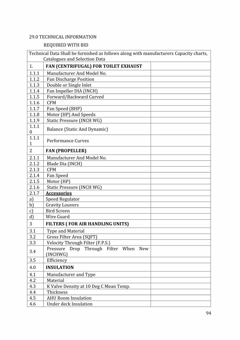
94
29.0 TECHNICAL INFORMATION
REQUIRED WITH BID
Technical Data Shall be furnished as follows along with manufacturers Capacity charts, Catalogues and Selection Data
1. FAN (CENTRIFUGAL) FOR TOILET EXHAUST
1.1.1 Manufacturer And Model No. 1.1.2 Fan Discharge Position 1.1.3 Double or Single Inlet 1.1.4 Fan Impeller DIA (INCH) 1.1.5 Forward/Backward Curved 1.1.6 CFM 1.1.7 Fan Speed (BHP) 1.1.8 Motor (HP) And Speeds 1.1.9 Static Pressure (INCH WG) 1.1.10
Balance (Static And Dynamic)
1.1.11
Performance Curves
2 FAN (PROPELLER)
2.1.1 Manufacturer And Model No. 2.1.2 Blade Dia (INCH) 2.1.3 CFM 2.1.4 Fan Speed 2.1.5 Motor (HP) 2.1.6 Static Pressure (INCH WG) 2.1.7 Accessories a) Speed Regulator b) Gravity Louvers c) Bird Screen d) Wire Guard
3 FILTERS ( FOR AIR HANDLING UNITS)
3.1 Type and Material 3.2 Gross Filter Area (SQFT) 3.3 Velocity Through Filter (F.P.S.)
3.4 Pressure Drop Through Filter When New (INCHWG)
3.5 Efficiency
4.0 INSULATION
4.1 Manufacturer and Type 4.2 Material 4.3 K Valve Density at 10 Deg C Mean Temp. 4.4 Thickness 4.5 AHU Room Insulation 4.6 Under deck Insulation
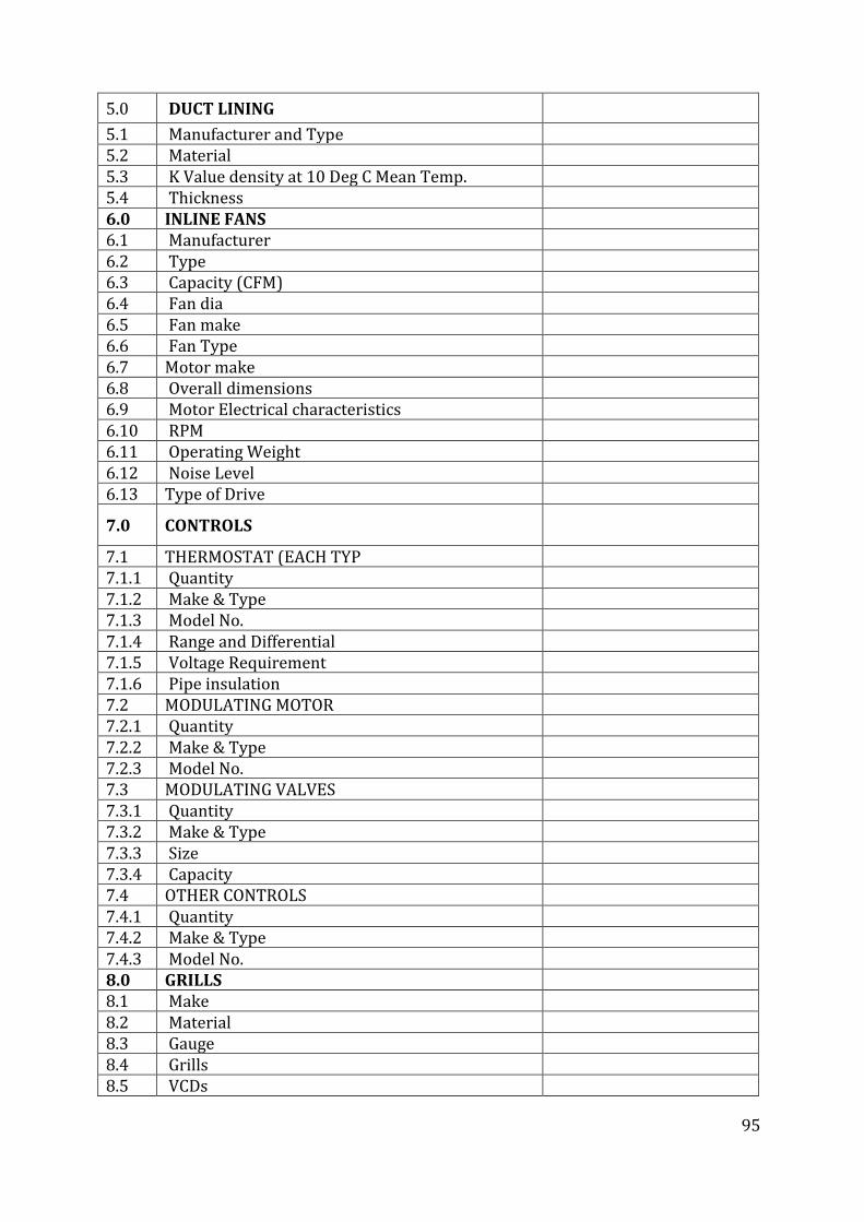
95
5.0 DUCT LINING
5.1 Manufacturer and Type 5.2 Material 5.3 K Value density at 10 Deg C Mean Temp. 5.4 Thickness 6.0 INLINE FANS 6.1 Manufacturer 6.2 Type 6.3 Capacity (CFM) 6.4 Fan dia 6.5 Fan make 6.6 Fan Type 6.7 Motor make 6.8 Overall dimensions 6.9 Motor Electrical characteristics 6.10 RPM 6.11 Operating Weight 6.12 Noise Level 6.13 Type of Drive
7.0 CONTROLS
7.1 THERMOSTAT (EACH TYP 7.1.1 Quantity 7.1.2 Make & Type 7.1.3 Model No. 7.1.4 Range and Differential 7.1.5 Voltage Requirement 7.1.6 Pipe insulation 7.2 MODULATING MOTOR 7.2.1 Quantity 7.2.2 Make & Type 7.2.3 Model No. 7.3 MODULATING VALVES 7.3.1 Quantity 7.3.2 Make & Type 7.3.3 Size 7.3.4 Capacity 7.4 OTHER CONTROLS 7.4.1 Quantity 7.4.2 Make & Type 7.4.3 Model No. 8.0 GRILLS 8.1 Make 8.2 Material 8.3 Gauge 8.4 Grills 8.5 VCDs
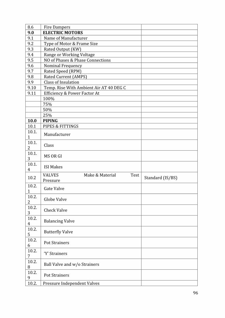
96
8.6 Fire Dampers 9.0 ELECTRIC MOTORS 9.1 Name of Manufacturer 9.2 Type of Motor & Frame Size 9.3 Rated Output (KW) 9.4 Range or Working Voltage 9.5 NO of Phases & Phase Connections 9.6 Nominal Frequency 9.7 Rated Speed (RPM) 9.8 Rated Current (AMPS) 9.9 Class of Insulation 9.10 Temp. Rise With Ambient Air AT 40 DEG C 9.11 Efficiency & Power Factor At 100% 75% 50% 25% 10.0 PIPING 10.1 PIPES & FITTINGS 10.1.1
Manufacturer
10.1.2
Class
10.1.3
MS OR GI
10.1.4
ISI Makes
10.2 VALVES Make & Material Test Pressure
Standard (IS/BS)
10.2.1
Gate Valve
10.2.2
Globe Valve
10.2.3
Check Valve
10.2.4
Balancing Valve
10.2.5
Butterfly Valve
10.2.6
Pot Strainers
10.2.7
‘Y’ Strainers
10.2.8
Ball Valve and w/o Strainers
10.2.9
Pot Strainers
10.2. Pressure Independent Valves
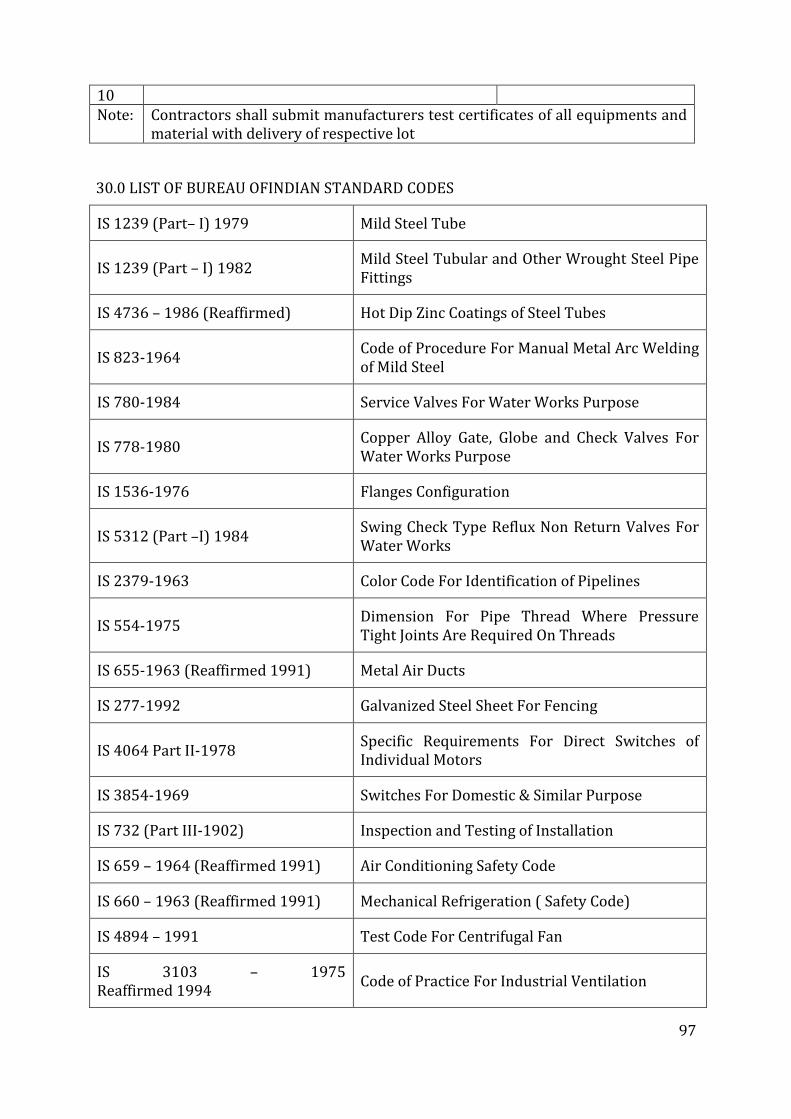
97
10 Note: Contractors shall submit manufacturers test certificates of all equipments and
material with delivery of respective lot
30.0 LIST OF BUREAU OFINDIAN STANDARD CODES
IS 1239 (Part– I) 1979 Mild Steel Tube
IS 1239 (Part – I) 1982 Mild Steel Tubular and Other Wrought Steel Pipe Fittings
IS 4736 – 1986 (Reaffirmed) Hot Dip Zinc Coatings of Steel Tubes
IS 823-1964 Code of Procedure For Manual Metal Arc Welding of Mild Steel
IS 780-1984 Service Valves For Water Works Purpose
IS 778-1980 Copper Alloy Gate, Globe and Check Valves For Water Works Purpose
IS 1536-1976 Flanges Configuration
IS 5312 (Part –I) 1984 Swing Check Type Reflux Non Return Valves For Water Works
IS 2379-1963 Color Code For Identification of Pipelines
IS 554-1975 Dimension For Pipe Thread Where Pressure Tight Joints Are Required On Threads
IS 655-1963 (Reaffirmed 1991) Metal Air Ducts
IS 277-1992 Galvanized Steel Sheet For Fencing
IS 4064 Part II-1978 Specific Requirements For Direct Switches of Individual Motors
IS 3854-1969 Switches For Domestic & Similar Purpose
IS 732 (Part III-1902) Inspection and Testing of Installation
IS 659 – 1964 (Reaffirmed 1991) Air Conditioning Safety Code
IS 660 – 1963 (Reaffirmed 1991) Mechanical Refrigeration ( Safety Code)
IS 4894 – 1991 Test Code For Centrifugal Fan
IS 3103 – 1975 Reaffirmed 1994
Code of Practice For Industrial Ventilation
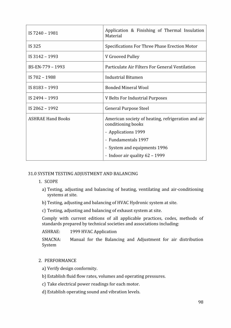
98
IS 7240 – 1981 Application & Finishing of Thermal Insulation Material
IS 325 Specifications For Three Phase Erection Motor
IS 3142 – 1993 V Grooved Pulley
BS-EN-779 – 1993 Particulate Air Filters For General Ventilation
IS 702 – 1988 Industrial Bitumen
IS 8183 – 1993 Bonded Mineral Wool
IS 2494 – 1993 V Belts For Industrial Purposes
IS 2062 – 1992 General Purpose Steel
ASHRAE Hand Books American society of heating, refrigeration and air conditioning books
- Applications 1999
- Fundamentals 1997
- System and equipments 1996
- Indoor air quality 62 – 1999
31.0 SYSTEM TESTING ADJUSTMENT AND BALANCING
1. SCOPE
a) Testing, adjusting and balancing of heating, ventilating and air-conditioning systems at site.
b) Testing, adjusting and balancing of HVAC Hydronic system at site.
c) Testing, adjusting and balancing of exhaust system at site.
Comply with current editions of all applicable practices, codes, methods of standards prepared by technical societies and associations including:
ASHRAE: 1999 HVAC Application
SMACNA: Manual for the Balancing and Adjustment for air distribution System
2. PERFORMANCE
a) Verify design conformity.
b) Establish fluid flow rates, volumes and operating pressures.
c) Take electrical power readings for each motor.
d) Establish operating sound and vibration levels.
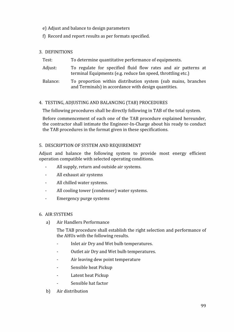
99
e) Adjust and balance to design parameters
f) Record and report results as per formats specified.
3. DEFINITIONS
Test: To determine quantitative performance of equipments.
Adjust: To regulate for specified fluid flow rates and air patterns at terminal Equipments (e.g. reduce fan speed, throttling etc.)
Balance: To proportion within distribution system (sub mains, branches and Terminals) in accordance with design quantities.
4. TESTING, ADJUSTING AND BALANCING (TAB) PROCEDURES
The following procedures shall be directly following in TAB of the total system.
Before commencement of each one of the TAB procedure explained hereunder, the contractor shall intimate the Engineer-In-Charge about his ready to conduct the TAB procedures in the format given in these specifications.
5. DESCRIPTION OF SYSTEM AND REQUIREMENT
Adjust and balance the following system to provide most energy efficient operation compatible with selected operating conditions.
- All supply, return and outside air systems.
- All exhaust air systems
- All chilled water systems.
- All cooling tower (condenser) water systems.
- Emergency purge systems
6. AIR SYSTEMS
a) Air Handlers Performance
The TAB procedure shall establish the right selection and performance of the AHUs with the following results.
- Inlet air Dry and Wet bulb temperatures.
- Outlet air Dry and Wet bulb temperatures.
- Air leaving dew point temperature
- Sensible heat Pickup
- Latent heat Pickup
- Sensible hat factor
b) Air distribution
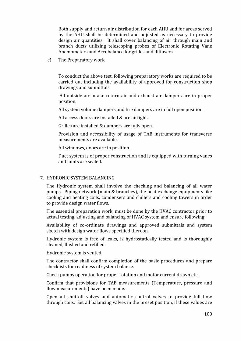
100
Both supply and return air distribution for each AHU and for areas served by the AHU shall be determined and adjusted as necessary to provide design air quantities. It shall cover balancing of air through main and branch ducts utilizing telescoping probes of Electronic Rotating Vane Anemometers and Accubalance for grilles and diffusers.
c) The Preparatory work
To conduct the above test, following preparatory works are required to be carried out including the availability of approved for construction shop drawings and submittals.
All outside air intake return air and exhaust air dampers are in proper position.
All system volume dampers and fire dampers are in full open position.
All access doors are installed & are airtight.
Grilles are installed & dampers are fully open.
Provision and accessibility of usage of TAB instruments for transverse measurements are available.
All windows, doors are in position.
Duct system is of proper construction and is equipped with turning vanes and joints are sealed.
7. HYDRONIC SYSTEM BALANCING
The Hydronic system shall involve the checking and balancing of all water pumps. Piping network (main & branches), the heat exchange equipments like cooling and heating coils, condensers and chillers and cooling towers in order to provide design water flows.
The essential preparation work, must be done by the HVAC contractor prior to actual testing, adjusting and balancing of HVAC system and ensure following:
Availability of co-ordinate drawings and approved submittals and system sketch with design water flows specified thereon.
Hydronic system is free of leaks, is hydrostatically tested and is thoroughly cleaned, flushed and refilled.
Hydronic system is vented.
The contractor shall confirm completion of the basic procedures and prepare checklists for readiness of system balance.
Check pumps operation for proper rotation and motor current drawn etc.
Confirm that provisions for TAB measurements (Temperature, pressure and flow measurements) have been made.
Open all shut-off valves and automatic control valves to provide full flow through coils. Set all balancing valves in the preset position, if these values are
101
known. If not, shut all riser balancing valves except the one intended to be balanced first.
Balancing work for both Chilled Water System and Condenser Water System shall be carried out in a professional manner and test reports in the specified format shall be prepared and presented to the HITES / Engineer-In-Charge for approval.
8. READINESS FOR COMMENCEMENT OF TAB
Prior to commencement of any test, the readiness to do so should be recorded as per the prescribed checklist.
9. TAB INSTRUMENTS
1. Air measuring Instruments
a) For measuring DB and WB temperature, RH and dew point, microprocessor based TSI USA make VelociCalc Plus Meter, Model 8386, or equivalent shall be used. This instrument shall be capable of calculating the sensible, latent total heat flows, sensible heat factor and give printouts at site and have data logging/downloading facility.
b) For measuring Air velocity, DB temperature and Air volume, TSI USA make VelociCalc meter model 8345 or equivalent shall be used. It shall be able to provide instant print out of recorded Air Volume readings.
c) Pitot tube.
d) Electronic Rotary Vane Anemometer TSI make or equivalent.
e) Accubalance Flow Measuring Hood TSI make or equivalent.
[All above instruments shall have NIST testification (US Institute of Science and Technology) Calibration Certificate]
2. Hydronic Measuring Instruments
For measurement of water flow differential pressure and temperature, CBI measuring instrument Tour & Anderson AB Sweden or equivalent shall be used. The instrument shall have a built-in-microcomputer capable of giving readings for pressure differential flow rate and temperature.
3. Rotation Measuring Instrument
● Electronic Digital Tachometer
4. Temperature & RH Measuring Instrument
● TSI VelociCalc model 8386 and VelociCalc model 8345 or equivalent.
5. Electrical Measuring Devices
● Clamp on Volt ammeter
102
● Continuity Meter
6. Vibration and Noise Levels
Vibration and alignment field measurements shall be taken for each circulating water pump, water chilling unit, air handling unit and fan driven by a motor over 10 HP. Readings shall include shaft alignment, equipments vibration, bearing housing vibration, and other test as directed by the Engineer-In-Charge.
Sound level readings shall be taken at ten (10) locations in the building as selected by the Engineer-In-Charge. The readings shall be taken on an Octave Band Analyzer in a manner acceptable to him. The contractor shall submit test equipments data and reporting forms for review. In order to reduce the ambient noise level the readings shall be taken at night. All test shall be performed in the presence of HITES / Engineer-In-Charge.
32.0 SPECIFICATIONS FOR ELECTRICAL WORKS
1. GENERAL
The specifications of electrical works associated for HVAC works shall be as given for the electrical works subject to variation if any, as per bill of quantities.
2. SCOPE
The bidder shall supply, install and commission along with requisite spare, maintenance tools and tackles the following equipments and system in the Building. The scope also covers the detailed engineering and calculations of the various equipments/system mentioned hereunder and the same shall be approved by the MoHFW /Engineer-in-charge prior to execution of the job.
● Medium voltage switchgear.
● Earthing.
● Laying and termination of L.T. cables.
● Safety to personnel and equipment during both operation and maintenance.
● Reliability of Service.
● Minimum fire risk.
● Ease of maintenance and convenience of operation.
● Automatic protection of all electrical equipment through selective relaying system.
● Electrical supply to equipment and machinery within the design operating limits.
● Adequate provision for future expansion and modification.
● Maximum interchange ability of equipment.
● Fail-safe feature.
● Suitability for applicable environmental factors.
103
This specification defines the basic guidelines to develop a suitable electrical system as necessary for the commercial complex. All data required in this regard shall be taken into consideration to develop a detailed engineering of the system. Site conditions as applicable are mentioned elsewhere.
Compliance with these specifications and/or approval of any of the Contractor’s documents shall in no case relieve the Contractor of his contractual obligations.
All work to be performed and supplies shall be affected as a part of contract requires specific approval/review Engineer in Charge his authorized representative. Major activities requiring approval/review shall include but not be limited to the following:
The engineering activities shall comprise the submission for approval of the following:
● Basic engineering documents e.g. single line diagram, overall cable layout, testing, type test report, guaranteed particulars of all equipments and maintenance manuals.
● Quality assurance procedures.
● Field testing and commissioning procedures.
● Basic engineering calculations viz. load analysis; load flow, fault level calculations, and voltage drop calculations during motor start-up/re-acceleration etc.
● Control and protection schemes.
● Sizing calculation for cable trays/cable trenches.
Bidder shall be responsible for:
● Detailed co-ordination with other services, shop drawings for various electrical layouts such as equipment layout, lighting layouts, cabling layouts, earthing and lightning protection layouts, including equipment installation and cable termination details etc. prior to start of work.
● Preparation of bill of materials for cabling, earthing and miscellaneous items etc.
● Cable schedule.
● Interconnection drawing.
● Protection co-ordination drawings/tables for complete power system.
● Shop inspection and testing procedures.
● Field testing and commissioning procedures.
● Preparation of as built drawings for all services.
Bidder shall also be responsible for:
● Any other work/activity which is not listed above however is necessary for completeness of electrical system.
3. CODES & STANDARDS
104
The design engineering manufacturing and the installation shall be in accordance with established codes, sound engineering, practices, and specifications and shall conform to the statutory regulations applicable in the country. Contractor shall obtain all approvals from statutory authorities’ e.g. Electrical inspector, pollution control boards, SEB as applicable before commissioning of electrical/DGs.
● Indian Electricity Act.
● Indian Electricity Rules.
● Factory Act.
● Pollution Control Act.
IS-3043 : Earthing.
IS-7689 : Guide for control of undesirable static electricity.
IS-3716 : Insulation co-ordination application guide.
IS-8130 : Conductors for insulated electrical cables and flexible cords.
IS-5831 : PVC insulation and sheath of electric cables.
IS-3975 : Mild steel wire, strips & tapes for armouring cable.
IS-3961 : Current rating of cables
IS-694 : PVC insulated (heavy duty) electric cables for working. Voltage up to and including 1100 volts.
IS-424- 1475 (F-3) : Power cable flexibility test.
IEC-439/IS-7098 : Specification for cross linked polyethylene insulated PVC sheathed cable for working voltage up to 1.1 KV.
IS-1554 : PVC insulated cables up to 1100 volts.
IS-10810: Test procedures for cables.
IS-6121: Cable glands.
IS-10418: Cable drums.
IEC-754(1) : FRLS PVC insulated cable.
ASTM-D-2863 : Standard method for measuring minimum oxygen concentration to support candle-like combustion of plastic (oxygen index).
ASTM-D-2843 : Standard test method for measuring the density of smoke from burning or decomposition.
ASTM E-662/IEC 754(A)
Standard test method for specific optical density of smoke generated by solid materials.
IEEE-383: Standard for type test class-IE, electric cables, field splicers and connections for power generation station.
IS 13947/IEC 947 : Air circuit breaker/moulded case circuit breaker.
IS-8623: Specification for factory built assemblies of switch gear and control gear for voltage upto and including 1000vac/1200vdc
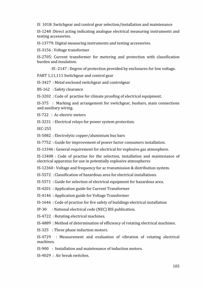
105
IS 1018: Switchgear and control gear selection/installation and maintenance
IS-1248 :Direct acting indicating analogue electrical measuring instruments and testing accessories.
IS-13779: Digital measuring instruments and testing accessories.
IS-3156 : Voltage transformer
IS-2705: Current transformer for metering and protection with classification burden and insulation.
-IS -2147 : Degree of protection provided by enclosures for low voltage.
PART 1,11,111 Switchgear and control gear
IS-3427 : Metal enclosed switchgear and controlgear
BS-162 : Safety clearance
IS-3202 : Code of practise for climate proofing of electrical equipment.
IS-375 : Marking and arrangement for switchgear, busbars, main connections and auxiliary wiring.
IS-722 : Ac electric meters
IS-3231 : Electrical relays for power system protection.
IEC-255
IS-5082 : Electrolytic copper/aluminium bus bars
IS-7752 : Guide for improvement of power factor consumers installation.
IS-13346 : General requirement for electrical for explosive gas atmosphere.
IS-13408 : Code of practise for the selection, installation and maintenance of electrical apparatus for use in potentially explosive atmospheres
IS-12360 : Voltage and frequency for ac transmission & distribution system.
IS-5572 : Classification of hazardous area for electrical installations.
IS-5571 : Guide for selection of electrical equipment for hazardous area.
IS-4201 : Application guide for Current Transformer
IS-4146 : Application guide for Voltage Transformer
IS-1646 : Code of practise for fire safety of buildings electrical installation
IP-30 : National electrical code (NEC) BIS publication.
IS-4722 : Rotating electrical machines.
IS-4889 : Method of determination of efficiency of rotating electrical machines.
IS-325 : Three phase induction motors.
IS-4729 : Measurement and evaluation of vibration of rotating electrical machines.
IS-900 : Installation and maintenance of induction motors.
IS-4029 : Air break switches.
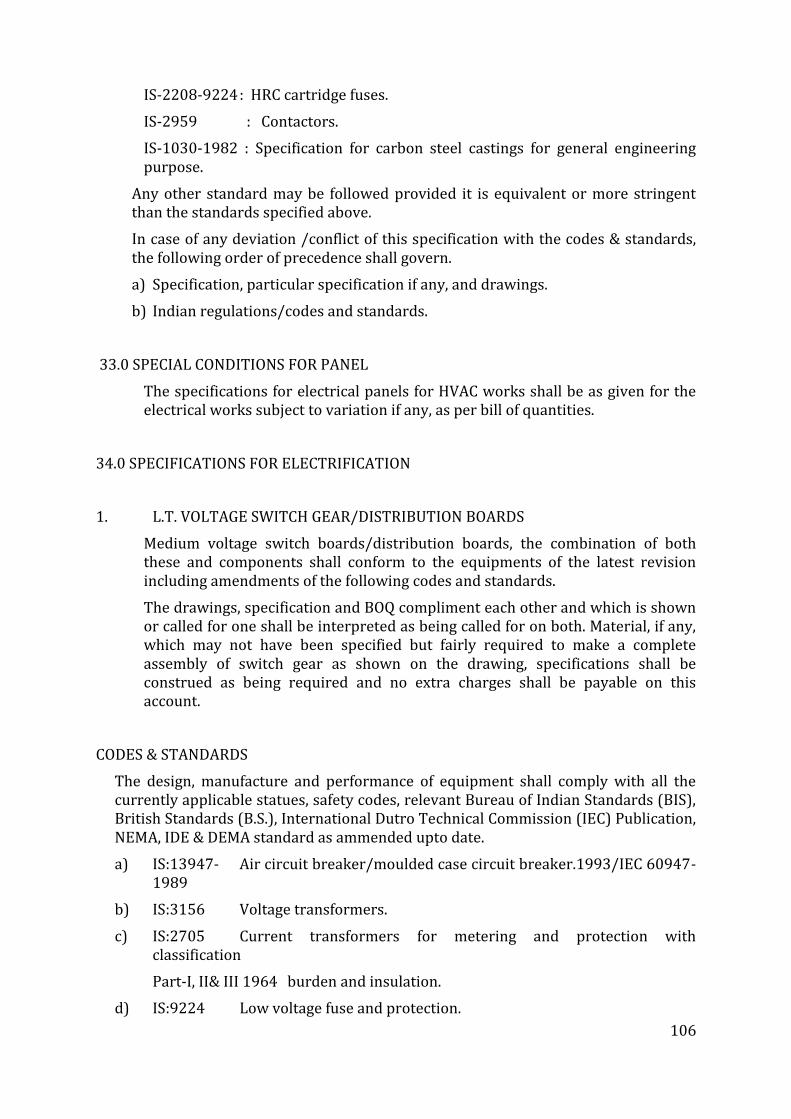
106
IS-2208-9224 : HRC cartridge fuses.
IS-2959 : Contactors.
IS-1030-1982 : Specification for carbon steel castings for general engineering purpose.
Any other standard may be followed provided it is equivalent or more stringent than the standards specified above.
In case of any deviation /conflict of this specification with the codes & standards, the following order of precedence shall govern.
a) Specification, particular specification if any, and drawings.
b) Indian regulations/codes and standards.
33.0 SPECIAL CONDITIONS FOR PANEL
The specifications for electrical panels for HVAC works shall be as given for the electrical works subject to variation if any, as per bill of quantities.
34.0 SPECIFICATIONS FOR ELECTRIFICATION
1. L.T. VOLTAGE SWITCH GEAR/DISTRIBUTION BOARDS
Medium voltage switch boards/distribution boards, the combination of both these and components shall conform to the equipments of the latest revision including amendments of the following codes and standards.
The drawings, specification and BOQ compliment each other and which is shown or called for one shall be interpreted as being called for on both. Material, if any, which may not have been specified but fairly required to make a complete assembly of switch gear as shown on the drawing, specifications shall be construed as being required and no extra charges shall be payable on this account.
CODES & STANDARDS
The design, manufacture and performance of equipment shall comply with all the currently applicable statues, safety codes, relevant Bureau of Indian Standards (BIS), British Standards (B.S.), International Dutro Technical Commission (IEC) Publication, NEMA, IDE & DEMA standard as ammended upto date.
a) IS:13947- Air circuit breaker/moulded case circuit breaker.1993/IEC 60947-1989
b) IS:3156 Voltage transformers.
c) IS:2705 Current transformers for metering and protection with classification
Part-I, II& III 1964 burden and insulation.
d) IS:9224 Low voltage fuse and protection.
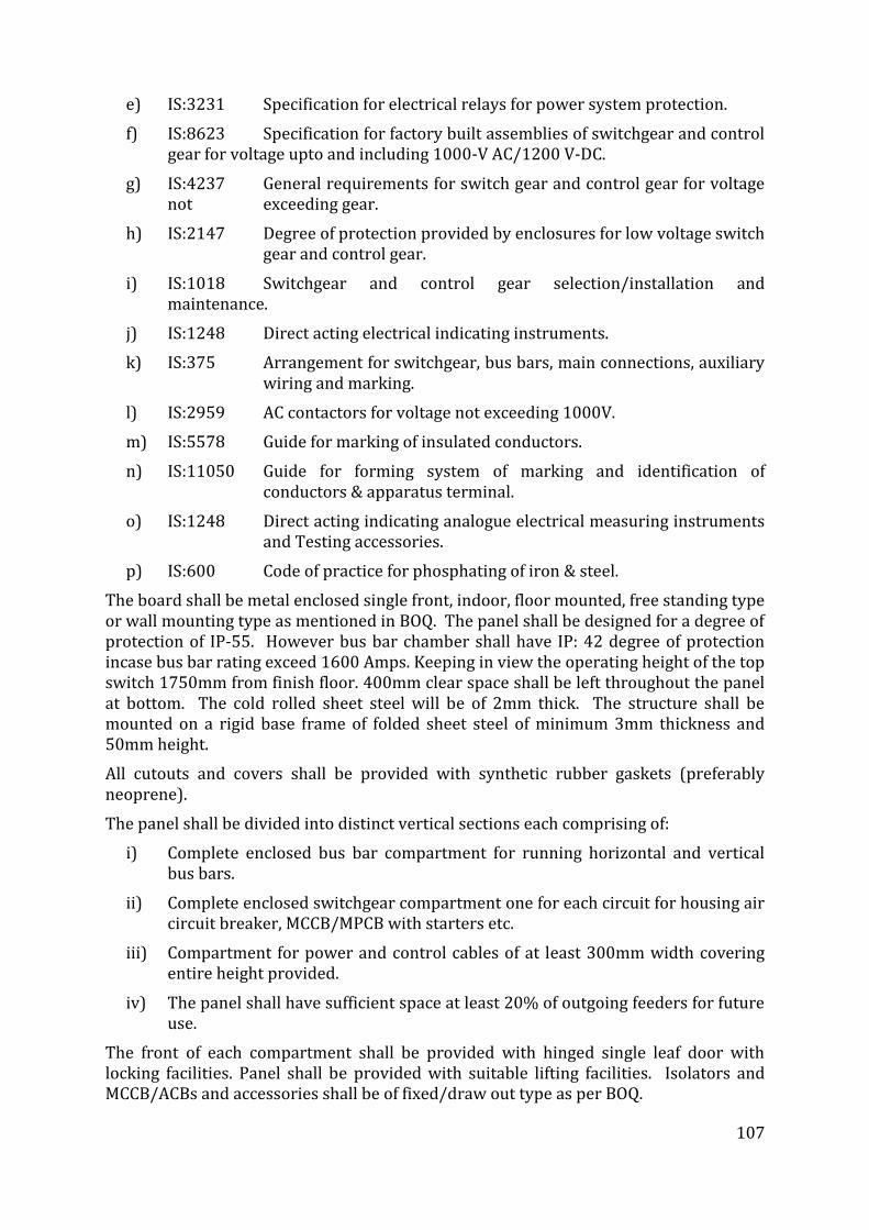
107
e) IS:3231 Specification for electrical relays for power system protection.
f) IS:8623 Specification for factory built assemblies of switchgear and control gear for voltage upto and including 1000-V AC/1200 V-DC.
g) IS:4237 General requirements for switch gear and control gear for voltage not exceeding gear.
h) IS:2147 Degree of protection provided by enclosures for low voltage switch gear and control gear.
i) IS:1018 Switchgear and control gear selection/installation and maintenance.
j) IS:1248 Direct acting electrical indicating instruments.
k) IS:375 Arrangement for switchgear, bus bars, main connections, auxiliary wiring and marking.
l) IS:2959 AC contactors for voltage not exceeding 1000V.
m) IS:5578 Guide for marking of insulated conductors.
n) IS:11050 Guide for forming system of marking and identification of conductors & apparatus terminal.
o) IS:1248 Direct acting indicating analogue electrical measuring instruments and Testing accessories.
p) IS:600 Code of practice for phosphating of iron & steel.
The board shall be metal enclosed single front, indoor, floor mounted, free standing type or wall mounting type as mentioned in BOQ. The panel shall be designed for a degree of protection of IP-55. However bus bar chamber shall have IP: 42 degree of protection incase bus bar rating exceed 1600 Amps. Keeping in view the operating height of the top switch 1750mm from finish floor. 400mm clear space shall be left throughout the panel at bottom. The cold rolled sheet steel will be of 2mm thick. The structure shall be mounted on a rigid base frame of folded sheet steel of minimum 3mm thickness and 50mm height.
All cutouts and covers shall be provided with synthetic rubber gaskets (preferably neoprene).
The panel shall be divided into distinct vertical sections each comprising of:
i) Complete enclosed bus bar compartment for running horizontal and vertical bus bars.
ii) Complete enclosed switchgear compartment one for each circuit for housing air circuit breaker, MCCB/MPCB with starters etc.
iii) Compartment for power and control cables of at least 300mm width covering entire height provided.
iv) The panel shall have sufficient space at least 20% of outgoing feeders for future use.
The front of each compartment shall be provided with hinged single leaf door with locking facilities. Panel shall be provided with suitable lifting facilities. Isolators and MCCB/ACBs and accessories shall be of fixed/draw out type as per BOQ.
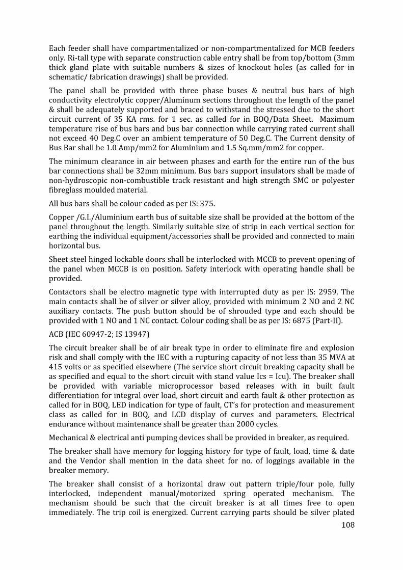
108
Each feeder shall have compartmentalized or non-compartmentalized for MCB feeders only. Ri-tall type with separate construction cable entry shall be from top/bottom (3mm thick gland plate with suitable numbers & sizes of knockout holes (as called for in schematic/ fabrication drawings) shall be provided.
The panel shall be provided with three phase buses & neutral bus bars of high conductivity electrolytic copper/Aluminum sections throughout the length of the panel & shall be adequately supported and braced to withstand the stressed due to the short circuit current of 35 KA rms. for 1 sec. as called for in BOQ/Data Sheet. Maximum temperature rise of bus bars and bus bar connection while carrying rated current shall not exceed 40 Deg.C over an ambient temperature of 50 Deg.C. The Current density of Bus Bar shall be 1.0 Amp/mm2 for Aluminium and 1.5 Sq.mm/mm2 for copper.
The minimum clearance in air between phases and earth for the entire run of the bus bar connections shall be 32mm minimum. Bus bars support insulators shall be made of non-hydroscopic non-combustible track resistant and high strength SMC or polyester fibreglass moulded material.
All bus bars shall be colour coded as per IS: 375.
Copper /G.I./Aluminium earth bus of suitable size shall be provided at the bottom of the panel throughout the length. Similarly suitable size of strip in each vertical section for earthing the individual equipment/accessories shall be provided and connected to main horizontal bus.
Sheet steel hinged lockable doors shall be interlocked with MCCB to prevent opening of the panel when MCCB is on position. Safety interlock with operating handle shall be provided.
Contactors shall be electro magnetic type with interrupted duty as per IS: 2959. The main contacts shall be of silver or silver alloy, provided with minimum 2 NO and 2 NC auxiliary contacts. The push button should be of shrouded type and each should be provided with 1 NO and 1 NC contact. Colour coding shall be as per IS: 6875 (Part-II).
ACB (IEC 60947-2; IS 13947)
The circuit breaker shall be of air break type in order to eliminate fire and explosion risk and shall comply with the IEC with a rupturing capacity of not less than 35 MVA at 415 volts or as specified elsewhere (The service short circuit breaking capacity shall be as specified and equal to the short circuit with stand value Ics = Icu). The breaker shall be provided with variable microprocessor based releases with in built fault differentiation for integral over load, short circuit and earth fault & other protection as called for in BOQ, LED indication for type of fault, CT’s for protection and measurement class as called for in BOQ, and LCD display of curves and parameters. Electrical endurance without maintenance shall be greater than 2000 cycles.
Mechanical & electrical anti pumping devices shall be provided in breaker, as required.
The breaker shall have memory for logging history for type of fault, load, time & date and the Vendor shall mention in the data sheet for no. of loggings available in the breaker memory.
The breaker shall consist of a horizontal draw out pattern triple/four pole, fully interlocked, independent manual/motorized spring operated mechanism. The mechanism should be such that the circuit breaker is at all times free to open immediately. The trip coil is energized. Current carrying parts should be silver plated
109
and suitable arcing contacts shall be provided to protect the main contact arc-chutes for each pole shall be provided and shall be lifted out for the inspection of main and arching contact.
Self-aligning cluster type isolating contacts shall be provided on breaker for interlocking protection metering and for any other purposes. The breaker should have 3 distinct positions - SERVICE/TEST/ISOLATED within the cubicle.
The ACB shall be with molded housing class II front fuse and shall be suitable for Isolation as per the annexure 7.1.2 in the standard.
Breaker shall be provided with automatic safety shutters to screen the main live contact when the breaker is withdrawn. The frame of the circuit breaker could be positively earthed when the breaker is racked into the cubicle.
The following safety arrangements shall be provided for the safety of the personnel to prevent mal-operation.
i) Interlock to prevent the truck from being withdrawn or replaced except in the fully isolated position.
ii) Interlock to prevent earth connection from being made by the earthing device except breaker is open.
iii) Interlock to prevent the breaker being closed unless it is fully raised.
iv) Interlock to prevent the breaker from being made alive without its rack in position.
Protection Releases
Self powered & true RMS sensing microprocessor based release with following features.
a) Incomer ACB of Panels:
Long time short circuit protection with time delay. Instantaneous and earth fault protection with LCD display to show RMS current in all three phases, neutral (for 4pole) simultaneously. The other features of the release to be as under.
• The release should display distinct fault indication for each type of tripping for faster fault diagnosis and reduce down time & should protect ACB from over temperature and Phase unbalance.
• Release should provide contact wear indication in display no. of operation seen by the breaker for case of maintenance.
• The release shall be self diagnosis & should provide fault history including cause of fault as well as level of fault current. It should be possible to store minimum 20 last trip data with nonvolatile memory.
• The protection setting of release should be accessible to change locally.
• LCD display should be at least 4 line display and should be able to display current in all the 3 phases and neutral (4 pole) simultaneously.
b) For Outgoing ACB feeder:
Long time Short circuit protection with time delay (for discrimination), instantaneous. The other features of the release to be as under.
110
The release should have distinct fault indication for each type of tripping for faster fault diagnosis and reduced down time and shall protect ACB from over temperature and phase unbalance.
• Operation counter
• Alarm and warning indication
Type test certificate : The ACB’s shall be type tested and certified for coplion is to IS 13947/equivalent / EC standard from Indian / International testing authority, supplier to submit certificate of the same.
MOULDED CASE CIRCUIT BREAKER (MCCB)
MCCB shall confirm to the latest IS13947-1993/IEC 60947. The Service Short Circuit Breaking Capacity (Ics at 415 VAC) should be as specified.
MCCB shall be Current Limiting and comprise of Quick Make – Quick Break switching mechanism & Double Break Contact system. The arc extinguishing device and the tripping unit contained in a compact, high strength, heat resistant, flame retardant, insulating molded case with high withstand capability against thermal and mechanical stresses. All MCCBs shall be capable of defined variable overload short circuit and earth fault adjustment with thermo- magnetic releases upto 250A and with electronic release above 250A onwards.
The Service Short Circuit Breaking Capacity (Ics at 415 VAC) should be as called for in BOQ and is the required minimum value for that feeders/ panel, however if the rating of feeder mentioned is not available, the contractor shall used next higher rating without any extra charges. The service short circuit breaking capacity shall be equal to ultimate breaking capacity of MCCB, i.e. Ics= 100%Icu
The trip command shall over ride all other commands. MCCB shall employ maintenance free double break contact system to minimize the let thru’ energies and capable of achieving discrimination upto the full short circuit capacity of downstream MCCB. The manufacturer shall provide both the discrimination tables and let thru’ energy curves. The MCCB shall not be restricted to Line/Load connections.
The handle position shall give positive indication of ‘ON’, ‘OFF’ or ‘Tripped’ thus qualifying to disconnection as per the IS/IEC indicating the true position of all the contacts. In case of 4 pole MCCB the neutral shall be defined and capable of offering protection upto full rating. The remote tripping coil should be of continuous duty. The general-purpose control switch shall be provided for ON/OFF Auto/Manual. The switch shall be provided with engraving plates on the front with the complete inscription.
The switch shall be normally a fixed control box type heavy-duty unit.
Indicating lamps shall be of the panel mounting, LED type and shall have execution plates marked with its function wherever necessary. The color of the lamp cover shall be red for ‘ON’ and green for ‘OFF’ indicating lamps shall be provided with series resistor. MCCB shall be provided with interlocking devise for interlocking the door of switchboard. Following shall be included if specified in the drawing or in the schedule of quantities:
i. Under voltage trip
ii. Shunt trip
iii. Alarm Switch
111
iv. Auxiliary switch
CONTACTORS
The contactors should comply with the latest IEC947-4 and the corresponding IS13947-4 standards. They shall have UL and CSA approval. The contactors should be rated for AC3 duty at 415V and 50Hz. The contacts should be fast closing and fast opening type. The making and breaking capacity values of the contactors should be as follows (as per IEC947-4):
For AC3 Duty
- Making Capacity equal to or more than 10 Ie
- Breaking Capacity equal to or more than 8 Ie
For AC4 Duty
- Making Capacity equal to or more than 12 Ie
- Breaking Capacity equal to or more than 10 Ie
The contactors should be capable of frequent switching and should operate without derating at 600C for AC3 applications. They should be climate proof as standard .The coil of the contactor should have class H insulation to support frequent switching.
The rated voltage of the contactor shall be equal or superior at 690 V, and rated insulation voltage shall be 690 V. The rated impluse voltage of the contactor should be 8 KV.
The contactor should be modular in design with minimum inventory requirements and built in mechanically interlocked 1NO 1NC auxiliary contact up to 32A. They should be suitable for the addition of auxiliary contacts and other electrical auxiliaries without any compromise on the performance or the operation of the contactors .The contactors from 4 KW to 400 KW will be associated with the same auxiliary contact block range.
Wherever D.C control is required, the contactor should have wide range (0.7 to 1.25Uc) D.C coil with built in interference suppression as standard.
The control and power terminals should be at separate layers preferably with colour coding (black for power and white for control)
All contactors power connection will be finger safe (IP2X) as standard.
They should be capable of being integrated into automated system (PLCs etc.) without any interposing components in minimum operating conditions.
The thermal over load relay if used will be directly mounting under the contactor without any specific connections.
NAME PLATES & LABELS
i) Panel and all modules shall be provided with prominent engraved identification plates. The module identification designation. For single front switchboards, similar panel and board identification labels shall be provided at the rear also.
ii) All nameplates shall be of non-rusting metal or 3-ply lamicold, with white engraved lettering on black background. Inscription and lettering sizes shall be subject to HITES’s approval.
112
iii) Suitable stenticilled paint marks shall be provided inside the panel/module identification of all equipments in addition to the plastic sticker labels. These labels shall be partitioned so as to be clearly visible and shall have the device number, as mentioned in the module wiring design.
PAINTING
All steel work shall be pretreated in tanks and finally powder coated of approved shade.
WIRING
Control and protective wiring shall be done with copper conductor PVC insulated 1100 volts grade multi-stranded flexible wire of 2.5sq.mm cross section. The colour coding shall be as per latest edition of IS: 375.
Each wire shall be identified by plastic ferrule. All wire termination shall be made with type connection. Wire shall not be taped or splied between terminal points.
Terminal blocks shall preferably by grouped according to circuit function and each terminal block group shall have at least 20% spare capacity.
Not more than one wire shall be connected to any terminal block. All doorframe of L.T. switchboard shall be earthed with bare braided copper wire.
TESTING & INSPECTION
After completion of all work at the manufacturer’s works the switchboards shall be inspected and tested in presence of Purchaser’s representative. However, stage inspection may be carried out from time to time to check progress of work and workmanship. The following tests shall be carried out:
i) All routine tests specified in relevant Indian/British Standards shall be carried out on all circuit breakers.
ii) Test for protective relay operation by primary or secondary injection method.
iii) Operation of all meters.
iv) Secondary wiring continuity test.
v) Insulation test with 1000 Volts megger, before and after voltage test.
vi) HV test on secondary wiring and components on which such test is permissible (2 KV for one minute)
vii) Simulating external circuits for remote operation of breaker, remote indicating lights and other remote operations, if any.
viii) Measurement of power required for closing/trip coil of the breaker.
ix) Pick up and drop out voltages for shunt trip and closing coils.
x) CT Polarity test.
Vendor shall provide all facilities such as power supply, testing instruments and apparatus required for carrying out the tests. Required copies of test certificates for all the tests carried out alongwith copies of type test certificates and certificates from Sub-Vendor for the components procured from them are to be submitted before despatch of switchboards.
DRAWINGS AND INFORMATION
113
The Vendor shall furnish following drawings/documents in accordance with enclosed requirements:
i) General Arrangement drawing of the Switchboard, showing front view, plan, foundation plan, floor cutouts/trenches for external cables and elevations, transport sections and weights.
ii) Sectional drawings of the circuit breaker panels, showing general constructional features, mounting details of various devices, bus bars, current transformers, cable boxes, terminal boxes for control cables etc.
iii) Schematic and control wiring diagram for circuit breaker and protection including indicating devices, metering instruments, alarms, space heaters etc.
iv) Terminal plans showing terminal numbers, ferrules markings, device terminal numbers, function etc.
v) Relay wiring diagrams.
vi) Equipment List.
Vendor shall furnish required number of copies of above drawings for Purchaser’s review, fabrication of switch boards shall start only after Purchaser’s clearance for the same. After final review, required number of copies and reproducibles shall be furnished as final certified drawings.
The information furnished shall include the following:
i) Technical literature giving complete information of the equipment.
ii) Erection, Operation and Maintenance Manual complete with all relevant information, drawings and literature for auxiliary equipment and accessories, characteristics curves for relays etc.
iii) A compréhensive spare parts catalogue.
Tools
One complete set of all special or non-standard tools required for installation, operation and maintenance of the switchboard shall be provided. The manufacturer shall provide a list of such tools with his quotation.
Spares
The manufacturer/tenderer shall also supply a complete list of commissioning spares and tools. The same shall be included in the bid price. No extra payment shall be made on account of non-availability of spares during commissioning.
Quality Assurance
Quality Assurance shall follow the requirements of HITES as applicable.
Quality Assurance involvement will commence at enquiry and follow through to completion and acceptance thus ensuring total conformity to Purchaser’s requirements.
Deviations
Deviation from specification must be stated in writing at the quotation stage.
114
In absence of such a statement, it will be assumed that the requirements of the specifications are met without exception.
2. EARTHING
All electrical equipment is to be earthed by connecting two earth tapes from the frame of the equipment to a main earth ring. The earthing ring will be connected via several earth electrodes. The cable armour will be earthed through cable glands. Earthing shall be in conformity with provision of rules 32, 61, 62, 67 & 68 of Indian Electricity Rules 1956 and as per IS-3843-1966.
The following shall be earthed:
1. Non-current carrying metallic parts of electrical equipment such as switchgear, bus ducts, rising mains, panel boards, motor control centres, power panels, distribution boards, cable trays, metal conduits, welding sockets etc.
The shop drawing for earthing system shall be prepared by the contractor and be got approved by Engineer-in-charge. The work shall be done in accordance with approved drawings.
a) At each electrical system ground or system neutral ground.
b) At one point on each grounding system used to ground electrical equipment enclosures.
c) At one point on each grounding system used to ground wiring system enclosures such as metal conduits and cable seaths or armoured.
All earthing conductors shall be of high conductivity copper/ G.I. as per B.O.Q. and shall protected against mechanical damage. The cross-sectional area of earth conductors shall not be smaller than half that of the largest current carrying conductor. However, the contractor shall use the sizes specified in the bill of quantities of the Tender.
Testing and Commissioning
Testing and commissioning shall be done as per the programme/ instructions to be given by HITES’s authorised representative. All testing equipments necessary to carry out the tests shall be arranged by the electrical Contractor.
Before the electrical system is made live, the electrical Contractor shall carry out suitable tests to the satisfaction of HITES that all equipment wiring and connections have been correctly done and are in good working condition and will operate as intended.
All tests shall be conducted in the presence of the MoHFW/HITES’s authorised representative by the electrical Contractor and shall be notified one week before tests are to take place. All measurements shall conform to establish minimum acceptable test values. HITES’s Engineer reserves the right to approve all test results before circuit or equipments are energized for the first time.
3. L.T. CABLES & WIRE
a) Wires
115
The design manufacture, testing and supply of single core FRLS PVC insulated 1.1 KV grade multi-stranded twisted wires under this specification shall comply with latest edition of following standards.
IS : 3961 Current rating for cables.
IS: 5831 PVC insulation and sheath of electric cables.
IS : 694 PVC insulated cables for working voltage upto and including 1100 volts. IEC: 754(i) FRLS PVC insulated cable.
Copper multi-stranded twisted conductor FRLS PVC insulated wires shall be used in conduit as per item of work.
The wires shall be colour coded R Y B, for phases, Black for neutral and Green for earth.
Progressive automatic in line indelible, legible and sequential marking of the length of cable in metres at every one metre shall be provided on the outer sheath of wire.
b) Cables
The design, manufacture, testing and supply of the cable under this specification shall comply with latest edition of following standards:
IS : 8130 Conductors for insulated electric cables and flexible cords.
IS: 7098 XLPE insulation and sheath of electric cables.
IS : 3975 Mild steel wires, strips and tapes for armouring cables.
IS : 7098 Current rating of cables.
IS: 7098 XLPE insulated (heavy duty) electric cables for working voltage upto and including 1100 volts.
IS: 424-1475(F-3) Power cable-flammability test.
Specification for cross-linked polyethylene insulated XLPE sheathed cable for working voltage upto 1.1 KV.
Specification for XLPE insulated (heavy duty) electric cables for working voltages upto and including 1100 volts.
ASTM-D: 2863 Standard method for measuring the minimum oxygen concentration to support candle-like combustion of plastics (Oxygen Index).
ASTM-D: 2843 Standard test method for measuring the density of smoke from the burning or decomposition.
IEEE : 383 Standard for type of test Class-IE, Electric cables, feild splicers and connections for power generation station.
ASTME:662IEC:754(x) Standard test method for specific optical density of smoke generated by solid materials.
IS : 10418 Cable drums.
116
c) Technical Requirements:
i) The cables shall be suitable for laying in racks, ducts, trenches conduits and under-ground buried installation with uncontrolled back fill and chances of flooding by water.
ii) They shall be designed to withstand all mechanical, electrical and thermal stresses under steady state and transient operating condition.
iii) The aluminum/copper wires used for manufacturing the cables shall be true circular/sector in shape before stranding and shall be of uniformally good quality, free from defects. The conductor used in manufacture of the cable shall be of H2 grade.
iv) The cable should withstand 25 KA for 1 sec with insulation armour insulated at one end. Bidder shall furnish calculation in support of capability to withstand the earth fault currents. The current carrying capacity of armour and screen (as applicable) shall not be less than the earth fault current values and duration.
v) The fillers and inner sheath shall be of non-hygroscopic fire retardant materials and shall be suitable for the operating temperature of the cable. Filler and inner sheath shall not stick to insulation and outer sheath.
vi) Progressive automatic in line indelible, legible and sequential marking of the length of the cable in metres at every one meters shall be provided on the outer sheath of all cables and at every 5 metre ‘FRLS’ marking in case of ‘FRLS’ cables.
vii) Strip/Wire armouring following method (b) mentioned in IS: 3975 shall only be acceptable. For single core cable aluminium wire armouring shall be used.
viii) Allowable tolerance on the overall diameter of the cables shall be + 2mm.
ix) The normal current rating of all XLPE insulated cables shall be as per IS: 7098.
x) A distinct inner sheath shall be provided by pressure extrusion process for all multicore armoured and unarmoured cables as per IS: 5831.
xi) Outer sheath shall be provided by extrusion process as per IS: 5831
xii) The breaking load of armour joint shall not be less than 95% of that armour wire. Zinc rich paint shall be applied on armoured joint surface.
xiii) In plant repairs to the cables shall not be accepted.
xiv) All the cables shall be supplied in non-returnable drums as per IS: 10418.
d) In Case of FRLS Cables
i) The outer sheath of cables shall have an oxygen index of not less than 29 as per ASIMD: 2863.
ii) The maximum acid gas generation by weight as per IEC: 754 (i) shall not be more than 20% for outer sheath material of all cables. Bidder shall also guarantee the maximum theoretical acid gas generation with 20% by weight of outer sheath.
iii) The cables outer sheath shall meet the requirement of light transmission of 40% (minimum and shall be tested as per ISTMD: 2843). In case the test for light transmission is conducted as per ASTME: 662. The bidder shall furnish smoke density values as per this standard and shall co-relate the anticipated light transmission when tested as per ASTMD: 2843.
117
iv) The cable shall pass the fire resistance test as per SS: 42, 41, 475 (I) and flammability test as per EEE: 383.
e) Inspection:
All cables shall be inspected on receipt of the same at site and checked for any damage during transit.
f) Joint in Cables
The contractor shall take care that the cables received at site are distributed to various locations in such a manner as to ensure maximum utilisation and avoidance of cable jointing. Cable shall be rechecked before cutting in lengths, where the joints are unavoidable, and the location of such joints shall be got approved from the HITES. The joints shall be done by qualified jointer strictly in accordance with manufacturer’s instruction/drawings.
g) Joint Boxes for Cables
The cable joint boxes shall be of appropriate size suitable for type of cable of particular voltage rating.
h) Jointing of Cables
All straight through joints shall be done in epoxy mould boxes with epoxy resins. Straight through joints shall not be permitted unless the length of run is in excess of cable drum.
End terminations of cables more than 1.1 KV grade shall be done with epoxy mould boxed and epoxy resin. Cable glands shall be 1.1KV grade double compression type and made to tin plated heavy-duty brass casting and machine finished. Glands shall be of robust construction capable of clamping cable and cable armour, firmly without injury of cable.
All washers and hardwares shall be made of brass tinned. Rubber components used in the glands shall be made of neoprene of tested quality.
Cable lugs shall be tinned copper/aluminium solderless crimping type conforming to IS: 8309 suitable for aluminium or copper conductor.
Crimping of terminals shall be done by using Corrosion inhabitory compound, with crimping tool.
Fire resistant paint has to be applied 1 Metre on either side of cable joint.
The contractor shall liaise fully with all other contractors to achieve an efficient and properly coordinated installation where equipment has to be re-positioned due to lack of site liaison; no extra cost shall be incurred by the HITES.
i) Testing of Cables
Cables shall be tested at factory as per requirement of IS: 7098 Part-I. The tests shall incorporate routine tests, type tests and acceptance tests. Prior to laying of cables, following tests shall be carried out:
i) Insulation test between phases and phase to earth for each length of cable before and after jointing.
On completion of cable laying work, the following test shall be conducted in the presence of Engineer-in-charge
118
ii) Insulation resistance test (Sectional and overall) 1000/5000V depending upon the voltage grade of cable.
iii) Continuity resistance test.
iv) Sheathing continuity test.
v) Earth test.
j) Laying of Cable
The cable drum shall be placed on jacks before unwinding the cable. Great care shall be exercised in laying cables to avoid forming links. At all changes in directions in horizontal & vertical places, the cable shall be bent with a radius of bend not less than 8 times the diameter of cable.
The cable of 1.1KV grade shall be laid not less than 750mm below ground level in a 375mm wide trench (throughout), where more than one cable is to be laid in the same trench, the width of the trench shall be increased such that the interaxial spacing between the cables except where otherwise specified shall at least be 150mm minimum or as per site requirements or as approved by the Engineer-in-charge. Where single core cables are used in multiphase systems, the cables shall be installed in trefoil where possible.
In case the cables are laid in vertical formation due to unavoidable circumstance the depth per tier shall be increased by 200mm (minimum). Cable shall be laid in reasonably straight line, where a change in direction takes place a suitable cur-vature shall be i.e. either 12 times the dia meter of the cable or the radius of the bend shall not be less than twice the diameter of the cable drum or whichever is less. Minimum 3-meter long loop shall be provided at both sides of every straight through joint & 3 meters at each end of cable or as directed at site.
Greater care shall be exercised in handling the cable in order to avoid forming ‘Kinks’. The cable drum shall in-verbally convey on wheels and the cable unrolled in right direction as indicated on the drum by the manufacturer. The cable shall be pulled over rollers in the trench steadily and uniformly without jerks and strains.
Cables laid in trenches in single tier formation, 10 cms. All around sand cushioning is provided below and above the cable before a protective cover is laid. For every additional vertical tier. The 30cm of sand cushion are provided over the initial tier. The cable shall be protected by 2nd class bricks of size not less than 230x115x75mm, stone tiles/RCC curved channel be placed on top of the sand breadth wise for the full length of the cable and where more than one cable is to be laid in the same trench the brick shall cover all cables and project at least 8 cms. Over the outer sides of the end cables.
Filling of trenches shall be done after the sand cushioning and laying of tiles or bricks are carried out to the satisfaction of the Engineer-in-charge (Refer drawing). Back fill for trenches shall be filled in layer not exceeding 150 mm. Each layer shall be properly rammed & consolidate before laying the next layer.
PVC pipe shall be provided for all road crossing. The size of the pipe shall be according to the cable and a minimum 100mm dia. pipe shall be provided. The pipe shall be laid in ground with special arrangement and shall be cement jointed and concreting with 1:5:10 shall be made as per relevant IS with latest amendment. Location of cables laid directly underground shall be indicated by cable marker at an interval of 30 meters &
119
with change of direction. Aluminium strip cable tag of 20mm wide with engraved tag no. shall be provided at both ends of cable.
Where the cables are to be laid in ducts (pucca trenches) in side the building, they will have to be laid on MS rack/ on MS cable trays grouted in walls trenches. Cables sizing through floors shall be protected from mechanical damage by a steel channel to a height of one meter above the floor where cable pass through wall they shall be sleeved with PVC/steel conduit.
Where the cables are laid in open (in building) along walls, ceiling or above false ceiling, cable rack (ladder type) or cable tray shall be provided. The size of the cable tray or rack shall depend on the number of cables to pass over that rack. Cable tray/rack shall be properly supported through wall/ceiling according to the site conditions.
Cable laid on tray & riser shall be neatly dressed &clamped at an interval of 1000 mm & 750mm for horizontal & vertical cable run respectively either side at each bend of cable. All power cables shall be clamped individually & control cables shall be clamped in groups of three or four cables. Clamps for multicore cables shall be fabricated of 25x3 GI flats. Single core power cable shall be laid in trefoil formation & clamped with trefoil clamps made of PVC/fibre glass.
Cable openings in wall/floor shall be sealed by the contractor suitably by hession tape & bitumen compound or by any other proven to prevent ingress of water.
After the cables are laid, these shall be tested as per IS and the results submitted to Engineer-in-charges/Engineer and in case the results found unsatisfactory, all the repairing/ replacing of cables will be done by the contractor free of charge.
k) Fire Seal System
i) All the floor/wall opening provided for cable crossing shall be sealed by fire seal system.
ii) The fire proof sealing system shall fully comply with the requirements of relevant IS/BS: 476 Part-B. The fireproof seal system shall have minimum one hour fire resistance rating.
iii) The fire proof seal system shall be physically, chemically, thermally stable and shall be mechanically secured to the masonary concrete members. The system shall be completely gas and smoke tight, antirodent and anti-termite.
iv) The material used in fireproof seal system shall be non-toxic and harmless to the working personnel.
v) Type of fireproof seal system shall be foaming type or flamemastic type compound or approved equivalent.
After laying and jointing work is completed, high voltage test should be applied to all cables to ensure that they have not been damaged during or after the laying operation and that there is not fault in the jointing.
Cables for use on low and medium voltage system (1.1KV grade cables) should withstand for 15 minutes a pressure of 3000V DC applied between conductors and also between each conductor and sheaths. In the absence of pressure testing facilities it is sufficient to test for one minute with a 1000V insulation tester In case the test results are unsatisfactory the cost of repairs and replacements and extra work of removal & laying will be made good by the contractor.
120
Cable shall be installed so that separation shown in the table below are observed.
HV Cable (33 KV) - HV Cable (33 KV) 50 mm ELV & LV 230 V/433 V - ELV & LV cable 230 V/433 V Equal to the diameter of the bigger cable. HV cables (33 KV) - ELV & LV cables 230 V/433 V 300 mm LV cables 433 V - Telephone/Instrument cable 350 mm All cables - All hot pipe work 200 mm
l) Quality Assurance
Quality Assurance shall follow the requirements of HITES as applicable. Quality Assurance involvement will commence at enquiry and follow through to completion and acceptance thus ensuring total conformity to Purchaser’s requirements.
m) Deviations
Deviation from specification must be stated in writing at the quotation stage.
In absence of such a statement, it will be assumed that the requirements of the specifications are met without exception.
n) Spares for Commissioning Including Consumables
The manufacturer/tenderer shall also supply a complete list of commissioning spares and tools and consumables. The same shall be included in the bid price. No extra payment shall be made on account of non-availability of spares during commissioning.
4. CABLE TRAYS
Ladder type Cable tray
Cable trays shall be ladder type fabricated out of mild steel/slotted angles and flats of required width as per design. Bends shall be prefabricated. The cable tray shall be hot dip galvanized or primed and painted with powder coating as asked for in BoQ or as approved by MoHFW/HITES. The minimum weight of the zinc coating shall be 460 gm/sq.m and minimum thickness of coating shall not be less than 75 microns.
Perforated Cable tray
The perforated cable trays are fabricated out of 1.6mm thick CRCA sheet steel having minimum 50mm depth or as called for in BOQ, hot dip galvanized or epoxy coated of approved shade. Perforations are maximum 10mm spaced at maximum 20mm distance. The cables shall be tied with the cable tray with nylon strip/aluminium clamps/M.S. clamps as per requirements.
Suitable provision shall be made where a tray crosses expansion joints. The width of the tray shall allow for a suitable separation between cables the design shall allow for adequate bending radius for the sizes of cables. No sharp bend to be allowed in cable tray. Joints between sections shall be bolted.
The tray shall be suspended from the surface of the concrete slab by means of approved steel hangers spaced at a distance of not more than 125cms. Suitable bushes shall be
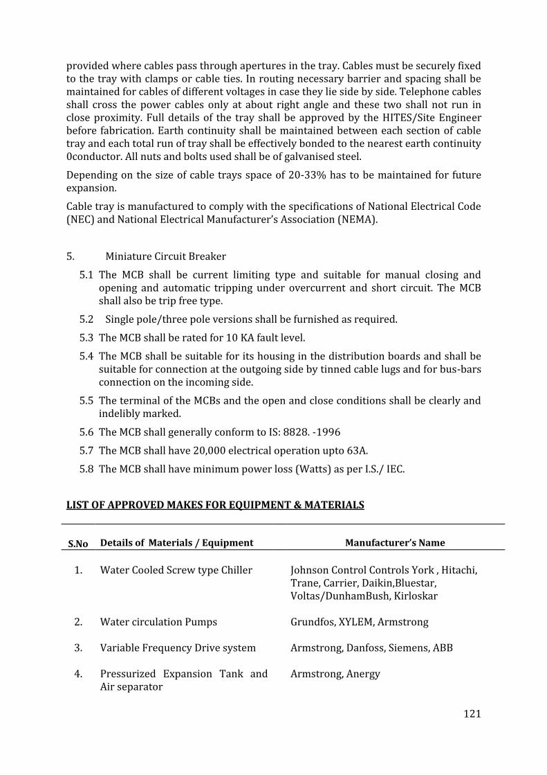
121
provided where cables pass through apertures in the tray. Cables must be securely fixed to the tray with clamps or cable ties. In routing necessary barrier and spacing shall be maintained for cables of different voltages in case they lie side by side. Telephone cables shall cross the power cables only at about right angle and these two shall not run in close proximity. Full details of the tray shall be approved by the HITES/Site Engineer before fabrication. Earth continuity shall be maintained between each section of cable tray and each total run of tray shall be effectively bonded to the nearest earth continuity 0conductor. All nuts and bolts used shall be of galvanised steel.
Depending on the size of cable trays space of 20-33% has to be maintained for future expansion.
Cable tray is manufactured to comply with the specifications of National Electrical Code (NEC) and National Electrical Manufacturer’s Association (NEMA).
5. Miniature Circuit Breaker
5.1 The MCB shall be current limiting type and suitable for manual closing and opening and automatic tripping under overcurrent and short circuit. The MCB shall also be trip free type.
5.2 Single pole/three pole versions shall be furnished as required.
5.3 The MCB shall be rated for 10 KA fault level.
5.4 The MCB shall be suitable for its housing in the distribution boards and shall be suitable for connection at the outgoing side by tinned cable lugs and for bus-bars connection on the incoming side.
5.5 The terminal of the MCBs and the open and close conditions shall be clearly and indelibly marked.
5.6 The MCB shall generally conform to IS: 8828. -1996
5.7 The MCB shall have 20,000 electrical operation upto 63A.
5.8 The MCB shall have minimum power loss (Watts) as per I.S./ IEC.
LIST OF APPROVED MAKES FOR EQUIPMENT & MATERIALS
S.No
Details of Materials / Equipment
Manufacturer’s Name
1. Water Cooled Screw type Chiller Johnson Control Controls York , Hitachi,
Trane, Carrier, Daikin,Bluestar, Voltas/DunhamBush, Kirloskar
2. Water circulation Pumps Grundfos, XYLEM, Armstrong
3. Variable Frequency Drive system
Armstrong, Danfoss, Siemens, ABB
4. Pressurized Expansion Tank and
Air separator
Armstrong, Anergy
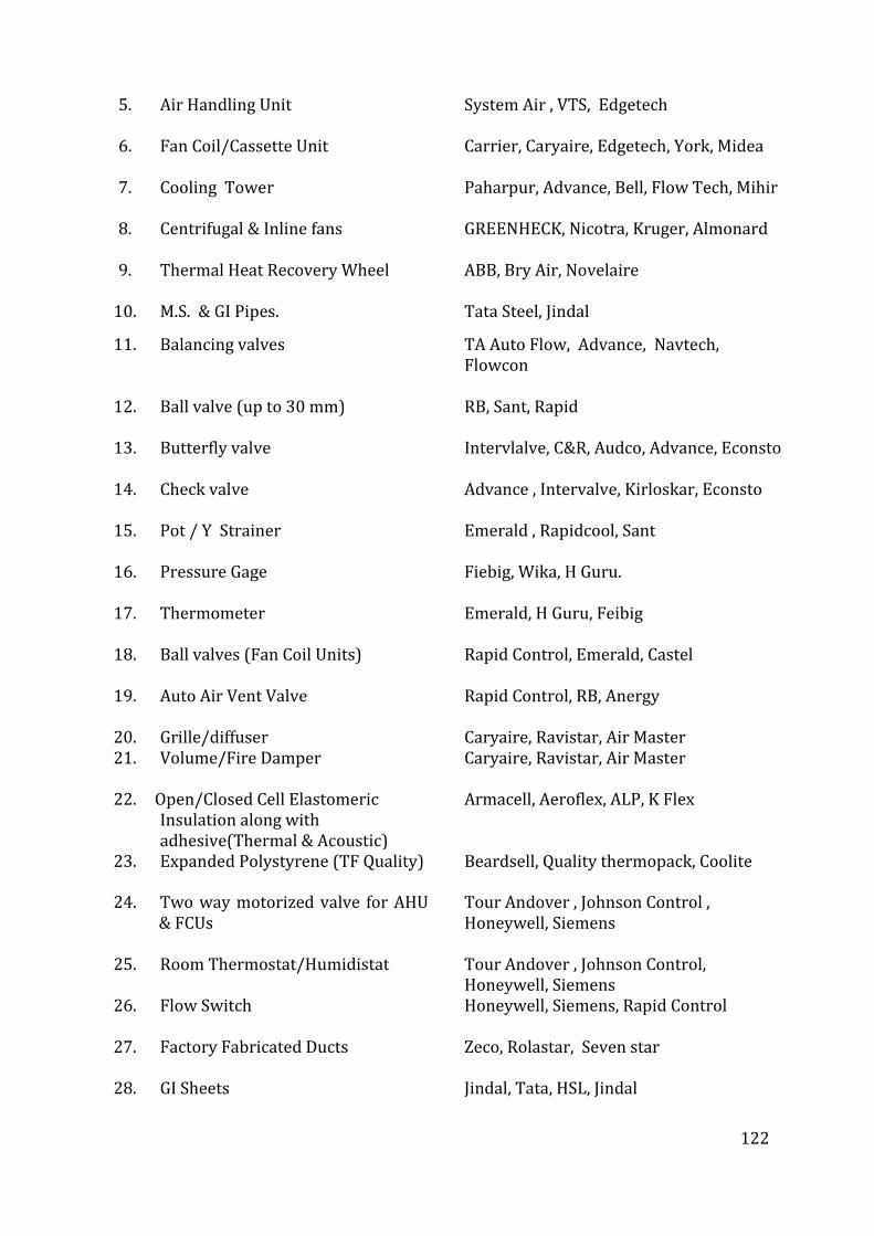
122
5. Air Handling Unit System Air , VTS, Edgetech
6. Fan Coil/Cassette Unit Carrier, Caryaire, Edgetech, York, Midea
7. Cooling Tower Paharpur, Advance, Bell, Flow Tech, Mihir
8. Centrifugal & Inline fans GREENHECK, Nicotra, Kruger, Almonard
9. Thermal Heat Recovery Wheel ABB, Bry Air, Novelaire
10. M.S. & GI Pipes. Tata Steel, Jindal
11. Balancing valves TA Auto Flow, Advance, Navtech, Flowcon
12. Ball valve (up to 30 mm) RB, Sant, Rapid
13. Butterfly valve Intervlalve, C&R, Audco, Advance, Econsto
14. Check valve Advance , Intervalve, Kirloskar, Econsto
15. Pot / Y Strainer Emerald , Rapidcool, Sant
16.
17.
Pressure Gage Thermometer
Fiebig, Wika, H Guru. Emerald, H Guru, Feibig
18. Ball valves (Fan Coil Units) Rapid Control, Emerald, Castel
19. Auto Air Vent Valve Rapid Control, RB, Anergy
20. Grille/diffuser Caryaire, Ravistar, Air Master 21. Volume/Fire Damper Caryaire, Ravistar, Air Master
22. Open Open/Closed Cell Elastomeric
Insulation along with adhesive(Thermal & Acoustic)
Armacell, Aeroflex, ALP, K Flex
23. Expanded Polystyrene (TF Quality) Beardsell, Quality thermopack, Coolite
24. Two way motorized valve for AHU & FCUs
Tour Andover , Johnson Control , Honeywell, Siemens
25. Room Thermostat/Humidistat Tour Andover , Johnson Control, Honeywell, Siemens
26.
27.
28.
Flow Switch Factory Fabricated Ducts GI Sheets
Honeywell, Siemens, Rapid Control Zeco, Rolastar, Seven star Jindal, Tata, HSL, Jindal
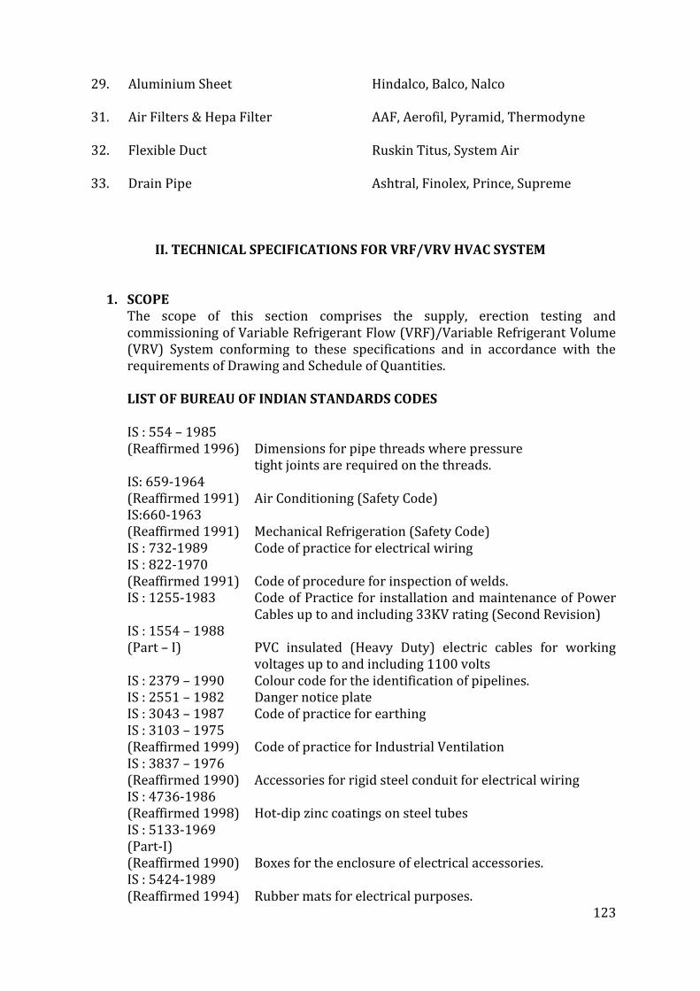
123
29.
31.
32.
33.
Aluminium Sheet Air Filters & Hepa Filter Flexible Duct Drain Pipe
Hindalco, Balco, Nalco AAF, Aerofil, Pyramid, Thermodyne Ruskin Titus, System Air Ashtral, Finolex, Prince, Supreme
II. TECHNICAL SPECIFICATIONS FOR VRF/VRV HVAC SYSTEM
1. SCOPE
The scope of this section comprises the supply, erection testing and commissioning of Variable Refrigerant Flow (VRF)/Variable Refrigerant Volume (VRV) System conforming to these specifications and in accordance with the requirements of Drawing and Schedule of Quantities.
LIST OF BUREAU OF INDIAN STANDARDS CODES IS : 554 – 1985
(Reaffirmed 1996) Dimensions for pipe threads where pressure tight joints are required on the threads. IS: 659-1964
(Reaffirmed 1991) Air Conditioning (Safety Code) IS:660-1963
(Reaffirmed 1991) Mechanical Refrigeration (Safety Code) IS : 732-1989 Code of practice for electrical wiring IS : 822-1970
(Reaffirmed 1991) Code of procedure for inspection of welds. IS : 1255-1983 Code of Practice for installation and maintenance of Power
Cables up to and including 33KV rating (Second Revision) IS : 1554 – 1988
(Part – I) PVC insulated (Heavy Duty) electric cables for working voltages up to and including 1100 volts
IS : 2379 – 1990 Colour code for the identification of pipelines. IS : 2551 – 1982 Danger notice plate IS : 3043 – 1987 Code of practice for earthing IS : 3103 – 1975
(Reaffirmed 1999) Code of practice for Industrial Ventilation IS : 3837 – 1976
(Reaffirmed 1990) Accessories for rigid steel conduit for electrical wiring IS : 4736-1986
(Reaffirmed 1998) Hot-dip zinc coatings on steel tubes IS : 5133-1969
(Part-I) (Reaffirmed 1990) Boxes for the enclosure of electrical accessories.
IS : 5424-1989 (Reaffirmed 1994) Rubber mats for electrical purposes.
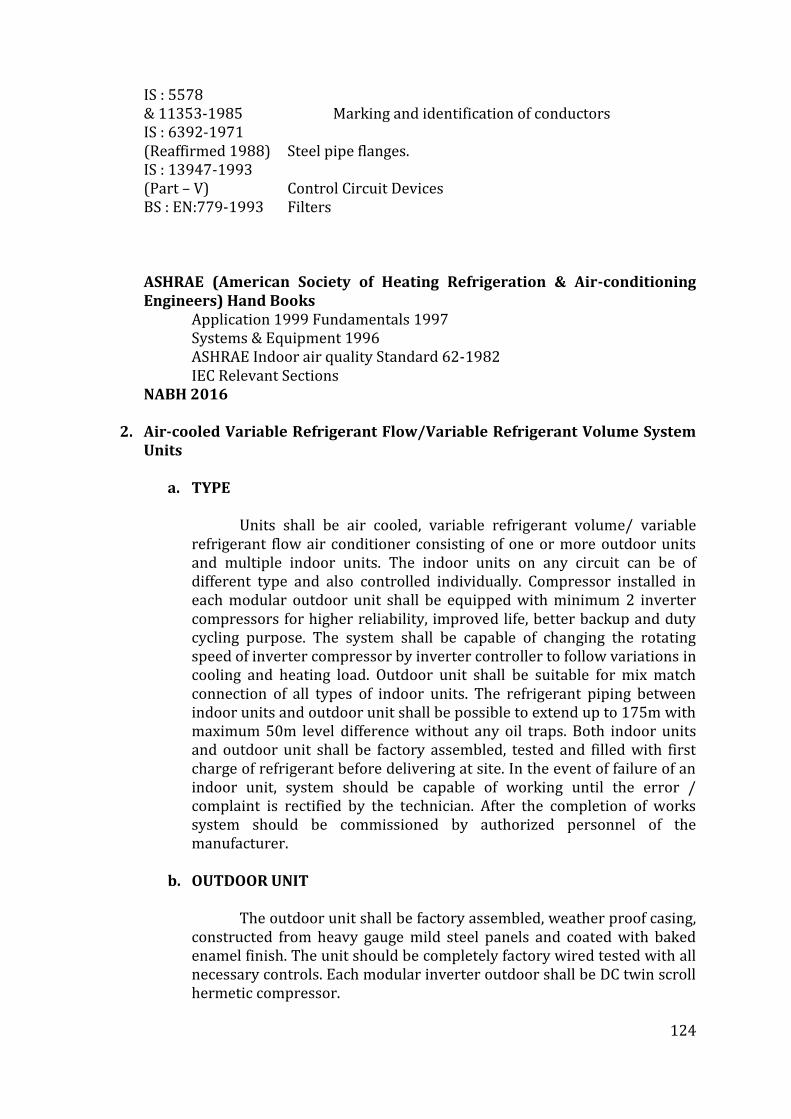
124
IS : 5578 & 11353-1985 Marking and identification of conductors
IS : 6392-1971 (Reaffirmed 1988) Steel pipe flanges.
IS : 13947-1993 (Part – V) Control Circuit Devices
BS : EN:779-1993 Filters
ASHRAE (American Society of Heating Refrigeration & Air-conditioning Engineers) Hand Books
Application 1999 Fundamentals 1997 Systems & Equipment 1996 ASHRAE Indoor air quality Standard 62-1982 IEC Relevant Sections
NABH 2016
2. Air-cooled Variable Refrigerant Flow/Variable Refrigerant Volume System Units
a. TYPE
Units shall be air cooled, variable refrigerant volume/ variable refrigerant flow air conditioner consisting of one or more outdoor units and multiple indoor units. The indoor units on any circuit can be of different type and also controlled individually. Compressor installed in each modular outdoor unit shall be equipped with minimum 2 inverter compressors for higher reliability, improved life, better backup and duty cycling purpose. The system shall be capable of changing the rotating speed of inverter compressor by inverter controller to follow variations in cooling and heating load. Outdoor unit shall be suitable for mix match connection of all types of indoor units. The refrigerant piping between indoor units and outdoor unit shall be possible to extend up to 175m with maximum 50m level difference without any oil traps. Both indoor units and outdoor unit shall be factory assembled, tested and filled with first charge of refrigerant before delivering at site. In the event of failure of an indoor unit, system should be capable of working until the error / complaint is rectified by the technician. After the completion of works system should be commissioned by authorized personnel of the manufacturer.
b. OUTDOOR UNIT
The outdoor unit shall be factory assembled, weather proof casing, constructed from heavy gauge mild steel panels and coated with baked enamel finish. The unit should be completely factory wired tested with all necessary controls. Each modular inverter outdoor shall be DC twin scroll hermetic compressor.
125
The outdoor units shall have multiple compressors with multi step capacity control and shall be able to operate in case of failure of one of the compressors. The outdoor units shall be capable of connecting all types of indoor units. They shall be provided with duty cycling and starting sequence changing facility for multiple inverter compressor and multiple outdoor units working in one system. The outdoor units shall be of modular construction and should be able to install side by side and shall be provided with microprocessor based control panel with provision for integration with Building Management System using BACNET/MODBUS protocol. The outdoor unit shall be compatible for three phase 415V 50 Hz AC supply. All outdoor units shall have minimum two compressors so that in the event of failure of one compressor, other can work. The outdoor unit shall be delivered with first charge of refrigerant. The outdoor unit should be fitted with low noise, aero spiral design fan with aero fitting grill for C spiral discharge airflow to reduce pressure loss and should be fitted with DC fan motor inverter type for better efficiency. The condensing unit shall be designed to operate safely when connected to multiple indoor units. Note: The Outdoor machines shall be preferably compact machines for Purpose of space saving and smaller foot print shall be preferred.
c. COMPRESSOR
The compressor shall be highly efficient hermetic scroll type with
DC inverter control capable of changing the speed in accordance with load requirements inside the building. The refrigerant used shall be R 410A/ R 407A. All parts of the compressor shall be lubricated and shall have oil separator for stable operation. Oil heater also shall be provided. Forced lubrication may also be employed. Oil heater shall be provided in the compressor casing.
d. HEAT EXCHANGER
The heat exchanger shall be constructed with copper tubes
mechanically bonded to aluminum fins to form a cross fin coil. The aluminum fins shall be covered by anti-corrosion resin film. The unit should be with e-pass heat exchanger to optimize the path of heat exchanger and for better efficiency of condenser. The unit shall be provided with necessary number of direct driven low noise level propeller type fans arranged for vertical discharge. Each fan shall have a safety guard.
e. REFRIGERANT CIRCUIT
The refrigerant circuit shall include liquid & gas shut-off valves and
a solenoid valves at condenser end. The equipment must have in built refrigerant stabilization control for proper refrigerant distribution. All necessary safety devices shall be provided to ensure the safely operation of the system.
126
Refrigerant should be R410A/R407A Only. The refrigerant piping between indoor and outdoor units shall be constructed from soft seamless up to 19.1mm and hard drawn copper pipes above 19.1 mm with copper fittings and silver soldered joints. All joints in copper piping shall be sweat joints using low temperature brazing and or silver solder. After the installation, the piping shall be pressure tested using nitrogen at 20kg/cm2 and 10 kg/cm2 for low side. The sizing and flow of refrigerant shall be designed as specified by the manufacturer. All refrigerant pipelines shall be properly supported and anchored to the building structure using steel supports/brackets/clamps of adequate size to support the load.
f. SAFETY DEVICES
All necessary safety devices shall be provided to ensure safe operation of the system. The outdoor units shall be equipped with the following safety devices. High pressure switch.
Over load relay Fusible plug Overload protector for inverter Over load protector for Fan drive Oil recovery system
g. OIL RECOVERY SYSTEM
Unit shall be equipped with an oil recovery system to ensure stable operation with long refrigeration piping lengths. The system must be provided with oil balancing circuit to avoid poor lubrication.
h. INDOOR UNIT
This section deals with supply, installation, testing, commissioning
of indoor units confirming to general specification and suitable for the duty selected. The type, capacity and size of indoor units shall be as specified in detailed Bill of Quantities. The address of the indoor unit shall be set automatically in case of individual and group control. In case of centralized control, it shall be set by liquid crystal display remote controller. The fan shall be dual suction, aerodynamically designed turbo, multi blade type, statically & dynamically balanced to ensure low noise and vibration free operation of the system. The fan shall be direct driven type, mounted directly on motor shaft having supported from housing. The cooling coil shall be made out of seamless copper tubes and have continuous aluminum fins. The fins shall be spaced by collars forming an integral part. The tubes shall be staggered in the direction of airflow. The tubes shall be hydraulically/ mechanically expanded for minimum thermal contact resistance with fins. Each coil shall be factory tested at
127
21kg/sqm air pressure under water. Unit shall have cleanable type filter fixed to an integrally molded plastic/aluminum frame. The filter shall be easily serviceable. Each indoor unit shall have computerized PID control for maintaining design room temperature. Each unit shall be provided with microprocessor thermostat for cooling or cooling and heating. Each unit shall be with wired LCD type remote controller for Hi Wall and Cassette and Cordless remote for Ductable and Concealed units. The remote controller shall memorize the latest malfunction code for easy maintenance. The controller shall have self-diagnostic features for easy and quick maintenance and service. The controller shall be able to change fan speed and angle of swing flap individually as per requirement.
3. AIR HANDLING UNITS
a. SCOPE
This section of the specification covers the supply, installation, testing and commissioning of double skin construction air handling units along with its accessories, conforming to these specifications and in accordance with requirement of the ‘Schedule of Quantities’, Drawings and ‘Technical Schedule of Equipment’.
b. TYPE
The air-handling units shall be double skin, comprising, filters as per BoQ, DX coil, fan as per details given in Drawings and Schedule of Equipment.
c. CAPACITY
The air handling capacities, maximum motor HP, static pressure shall be as per actual ducting coming in the approved shop drawing, even though the nearby static pressure can be taken from the tender drawing/BOQ.
d. CONSTRUCTION
i. AHU HOUSING / Casing:
The AHU housing shall be of double skin construction with main structure made of extruded aluminum hollow sections. The panels shall be double skin sandwich type with 0.8 mm pre painted GSS/ pre-plasticized on the outside and 0.8 mm galvanized sheet inside with 25 mm thick 40 kg/m3 PUF insulation or equivalent material injected in between. These panels shall be screwed with soft rubber gasket fixed in built in groove of aluminum frame in between to make the joints airtight. The corner joints shall be nylon glass fiber reinforced.
ii. Drain Pan
128
The drain pan shall be of 18 G aluminum/stainless steel with necessary slope to facilitate fast removal of condensate. It shall be provided with drain connection of suitable size complete with 25 mm rigid insulation. Necessary arrangement will be provided to slide the coil in the drain pan.
iii. Cooling Coil
The DX coil shall be of seamless copper tubes not less than 0.5 mm thick and 12mm OD. Coil face areas shall be such as to ensure rated capacity from each unit and such that air velocity across each coil shall not exceed 150 meters per minute. The coil shall be pitched in the unit casing for proper drainage. The fins shall be spaced by collars forming integral part of the fins. The tubes shall be staggered in the direction of airflow.
The fins shall be uniformly bonded to the tubes by mechanical expansion of the tube for minimum thermal contact resistance with fins. Fin spacing shall be 11to 13 FPI. The coils shall be tested against leaks at a hydraulic pressure of 21-kg/sq cm. This pressure shall be maintained for a period of at least 2 hours. No drop should be observed indicating any leaks.
iv. FAN SECTION WITH FAN
Fan section shall have two Nos. blowers.
The fans shall be backward curved plugin type. The fan shall be selected for a speed not exceeding 1000 RPM. The fan outlet velocity shall not be more than 550 MPM. Fans & motor shall be mounted above the coil /sections. The fan outlet shall be connected to casing with the help of fire retardant canvas.
The fan shall be selected for a noise level less than 70 DB (A) 1M away from the unit.
v. Filter Section Each unit shall be provided with a factory assembled filter as per BoQ. Filters shall have aluminum frame. One stage of filtration consisting of normal washable filters upto 10 micron particle size and Two stages of filtration consisting of Pre-filter & Microvee filter upto 5 micron particle size. Filter face velocity shall not exceed 150 meters per minute. Filter shall fit so as to prevent by pass. Holding frames shall be provided for installing number of filter cells in banks. These cells shall be held within the frames by sliding the cells between guiding channels. .
vi. FRESH AIR INTAKES
Extruded aluminum construction duly anodized fresh air louver with bird screen and extruded construction dampers shall be
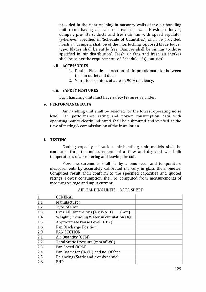
129
provided in the clear opening in masonry walls of the air handling unit room having at least one external wall. Fresh air louver, damper, pre-filters, ducts and fresh air fan with speed regulator (wherever specified in ‘Schedule of Quantities’) shall be provided. Fresh air dampers shall be of the interlocking, opposed blade louver type. Blades shall be rattle free. Damper shall be similar to those specified in ‘air distribution’. Fresh air fans and fresh air intakes shall be as per the requirements of ‘Schedule of Quantities’.
vii. ACCESSORIES 1. Double Flexible connection of fireproofs material between
the fan outlet and duct. 2. Vibration isolators of at least 90% efficiency.
viii. SAFETY FEATURES
Each handling unit must have safety features as under:
e. PERFORMANCE DATA
Air handling unit shall be selected for the lowest operating noise level. Fan performance rating and power consumption data with operating points clearly indicated shall be submitted and verified at the time of testing & commissioning of the installation.
f. TESTING
Cooling capacity of various air-handling unit models shall be computed from the measurements of airflow and dry and wet bulb temperatures of air entering and leaving the coil.
Flow measurements shall be by anemometer and temperature measurements by accurately calibrated mercury in glass thermometer. Computed result shall conform to the specified capacities and quoted ratings. Power consumption shall be computed from measurements of incoming voltage and input current.
AIR HANDING UNITS – DATA SHEET
1 GENERAL 1.1 Manufacturer 1.2 Type of Unit 1.3 Over All Dimensions (L x W x H) (mm) 1.4 Weight (Including Water in circulation) Kg. 1.5 Approximate Noise Level (DBA) 1.6 Fan Discharge Position 2.0 FAN SECTION 2.1 Air Quantity (CFM) 2.2 Total Static Pressure (mm of WG) 2.3 Fan Speed (RPM) 2.4 Fan Diameter (INCH) and no. Of fans 2.5 Balancing (Static and / or dynamic) 2.6 BHP
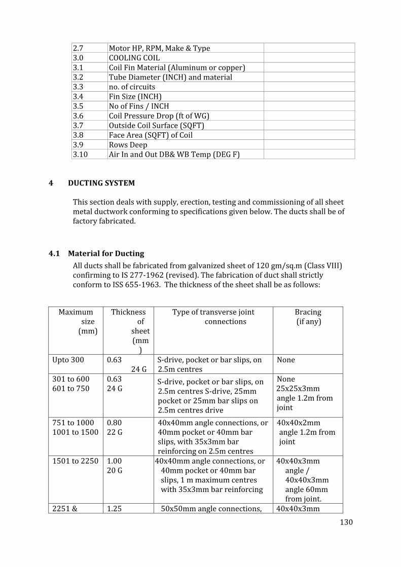
130
2.7 Motor HP, RPM, Make & Type 3.0 COOLING COIL 3.1 Coil Fin Material (Aluminum or copper) 3.2 Tube Diameter (INCH) and material 3.3 no. of circuits 3.4 Fin Size (INCH) 3.5 No of Fins / INCH 3.6 Coil Pressure Drop (ft of WG) 3.7 Outside Coil Surface (SQFT) 3.8 Face Area (SQFT) of Coil 3.9 Rows Deep 3.10 Air In and Out DB& WB Temp (DEG F)
4 DUCTING SYSTEM This section deals with supply, erection, testing and commissioning of all sheet
metal ductwork conforming to specifications given below. The ducts shall be of factory fabricated.
4.1 Material for Ducting
All ducts shall be fabricated from galvanized sheet of 120 gm/sq.m (Class VIII) confirming to IS 277-1962 (revised). The fabrication of duct shall strictly conform to ISS 655-1963. The thickness of the sheet shall be as follows:
Maximum size
(mm)
Thickness of
sheet (mm
)
Type of transverse joint connections
Bracing (if any)
Upto 300 0.63 24 G
S-drive, pocket or bar slips, on 2.5m centres
None
301 to 600 601 to 750
0.63 24 G
S-drive, pocket or bar slips, on 2.5m centres S-drive, 25mm pocket or 25mm bar slips on 2.5m centres drive
None 25x25x3mm angle 1.2m from joint
751 to 1000 1001 to 1500
0.80 22 G
40x40mm angle connections, or 40mm pocket or 40mm bar slips, with 35x3mm bar reinforcing on 2.5m centres
40x40x2mm angle 1.2m from joint
1501 to 2250 1.00 20 G
40x40mm angle connections, or 40mm pocket or 40mm bar slips, 1 m maximum centres with 35x3mm bar reinforcing
40x40x3mm angle / 40x40x3mm angle 60mm from joint.
2251 & 1.25 50x50mm angle connections, 40x40x3mm
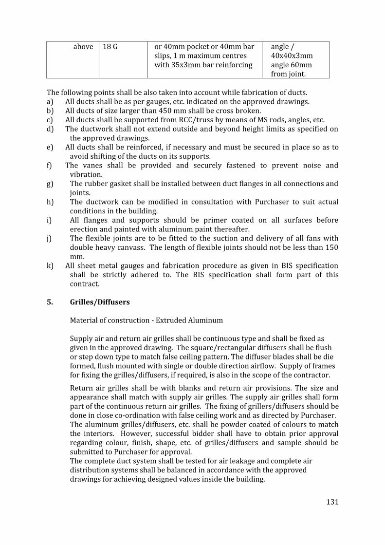
131
above 18 G or 40mm pocket or 40mm bar slips, 1 m maximum centres with 35x3mm bar reinforcing
angle / 40x40x3mm angle 60mm from joint.
The following points shall be also taken into account while fabrication of ducts. a) All ducts shall be as per gauges, etc. indicated on the approved drawings. b) All ducts of size larger than 450 mm shall be cross broken. c) All ducts shall be supported from RCC/truss by means of MS rods, angles, etc. d) The ductwork shall not extend outside and beyond height limits as specified on
the approved drawings. e) All ducts shall be reinforced, if necessary and must be secured in place so as to
avoid shifting of the ducts on its supports. f) The vanes shall be provided and securely fastened to prevent noise and
vibration. g) The rubber gasket shall be installed between duct flanges in all connections and
joints. h) The ductwork can be modified in consultation with Purchaser to suit actual
conditions in the building. i) All flanges and supports should be primer coated on all surfaces before
erection and painted with aluminum paint thereafter. j) The flexible joints are to be fitted to the suction and delivery of all fans with
double heavy canvass. The length of flexible joints should not be less than 150 mm.
k) All sheet metal gauges and fabrication procedure as given in BIS specification shall be strictly adhered to. The BIS specification shall form part of this contract.
5. Grilles/Diffusers Material of construction - Extruded Aluminum Supply air and return air grilles shall be continuous type and shall be fixed as
given in the approved drawing. The square/rectangular diffusers shall be flush or step down type to match false ceiling pattern. The diffuser blades shall be die formed, flush mounted with single or double direction airflow. Supply of frames for fixing the grilles/diffusers, if required, is also in the scope of the contractor.
Return air grilles shall be with blanks and return air provisions. The size and appearance shall match with supply air grilles. The supply air grilles shall form part of the continuous return air grilles. The fixing of grillers/diffusers should be done in close co-ordination with false ceiling work and as directed by Purchaser.
The aluminum grilles/diffusers, etc. shall be powder coated of colours to match the interiors. However, successful bidder shall have to obtain prior approval regarding colour, finish, shape, etc. of grilles/diffusers and sample should be submitted to Purchaser for approval.
The complete duct system shall be tested for air leakage and complete air distribution systems shall be balanced in accordance with the approved drawings for achieving designed values inside the building.
132
6 THERMAL / ACOUSTIC INSULATION 6.1 Material
Insulation material shall be Closed Cell Elastomeric Nitrile Butadiene Rubber.
Insulation material shall have anti-microbial product protection. The antimicrobial product protection shall be an integral part of insulation that is built-in during the manufacturing process and the product protection should not allow the microbes to function, grow and reproduce.
Resistance towards microbiological growth on insulation surface should confirm to following standards: Fungi Resistance – ASTM G21 where the fungal growth on the surface is NIL after 28 days of incubation at 28 – 30 deg C and Bacterial resistance – ASTM E 2180 where the reduction of bacterial growth is minimum 99.9% after 24 hours of incubation at 34 – 38 deg C.
Thermal conductivity of Elastomeric Nitrile rubber shall not exceed 0.035 W/m K at an average temperature of 20 C in accordance to EN12667
The insulation shall have fire performance such that it passes Class 1 as per BS476 Part 7 for surface spread of flame as per BS 476 and also pass Fire Propagation requirement as per BS476 Part 6 to meet the Class ‘O’ Fire category as per 1991 Building Regulations (England & Wales) and the Building Standards (Scotland) Regulations 1990.
Water vapour permeability shall not exceed 1.74 x 10⁻¹⁴ Kg/m.s.Pa, i.e. Moisture Diffusion Resistance Factor or ‘µ’ value should be minimum 10,000 according to EN 12086
Density of Material shall be between 40 to 60 Kg/m3. 6.2 Duct Insulation
External thermal insulation shall be provided as follow:
The thickness of Nitrile rubber shall be as shown on drawing or identified in the schedule of quantity. Following procedure shall be adhered to:
Duct surfaces shall be cleaned to remove all grease, oil, dirt, etc. prior to carrying out insulation work. Measurement of surface dimensions shall be taken properly to cut closed cell elastomeric rubbers sheets to size with sufficient allowance in dimension.
Material shall be fitted under compression and no stretching of material shall be permitted. A thin film of adhesive shall be applied on the back of the insulating material sheet and then on to the metal surface. When adhesive is tack dry, insulating material sheet shall be placed in position and pressed firmly to achieve a good bond. All longitudinal and transverse joints shall be sealed as per manufacturer recommendations. The adhesive shall be strictly as recommended by the manufacturer.
The detailed Application specifications are mentioned separately.
133
6.3 Insulation of Ducts Exposed Directly to Sunlight For installations exposed to sunlight, after giving 36 hours curing time for the
adhesive apply manufacturer’s recommended UV/Mechanical Protection. Please refer the separate detailed guidelines on UV/Mechanical Protection.
6.4 Piping Insulation All refrigerant and condensate drain pipe shall be insulated in the manner
specified herein. An air gap of 25 mm shall be present between adjacent insulation surfaces carrying chilled water or refrigerant. Before applying insulation, all pipes shall be brushed and cleaned. All Pipe surfaces shall be free from dirt, dust, mortar, grease, oil, etc. Nitrile Rubber insulation shall be applied as follows:
Insulating material in tube form shall be sleeved on the pipes. On existing piping, slit opened tube of the insulating material (slit with a
very sharp knife in a straight line) shall be placed over the pipe and adhesive shall be applied as suggested by the manufacturer.
Adhesive must be allowed to tack dry and then press surface firmly together starting from butt ends and working towards centre.
Wherever flat sheets shall be used it shall be cut out in correct dimension. All longitudinal and transverse joints shall be sealed as per manufacturer recommendations.
The insulation shall be continuous over the entire run of piping, fittings and valves.
All valves, fittings, joints, strainers, etc. in chilled water piping shall be insulated to the same thickness as specified for the main run of piping and application shall be same as above. Valves bonnet, yokes and spindles shall be insulated in such a manner as not to cause damage to insulation when the valve is used or serviced.
The detailed application specifications are as mentioned separately. The manufacturer’s trained installer should only be used for installation.
6.5 Recommended Adhesive In all cases, the manufacturer’s recommended Adhesive should be used for the
specified purpose.
6.6 Acoustic Insulation
Material shall be engineered Nitrile Rubber open cell foam. The Random Incidence Sound Absorption Coefficients (RISACs) across the octave
band frequencies; tested as per ISO 354, and Noise Reduction Coefficients (NRCs) for the Acoustic Insulation should be minimum as per the below chart:
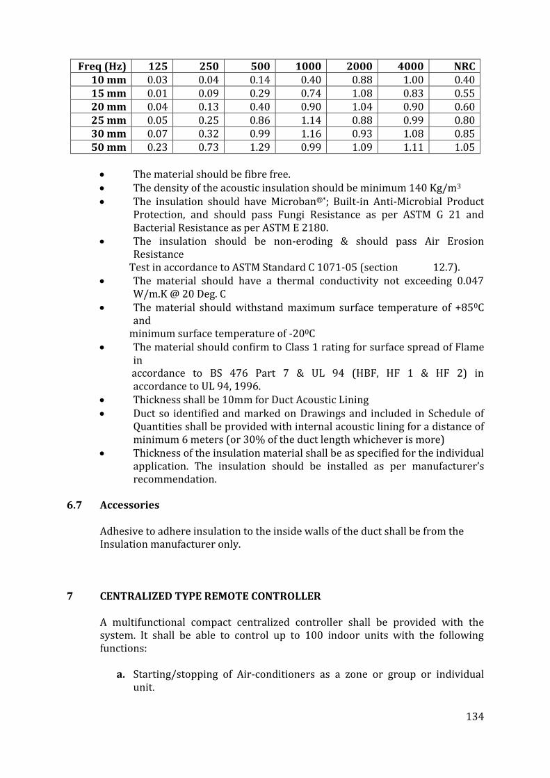
134
Freq (Hz) 125 250 500 1000 2000 4000 NRC 10 mm 0.03 0.04 0.14 0.40 0.88 1.00 0.40 15 mm 0.01 0.09 0.29 0.74 1.08 0.83 0.55 20 mm 0.04 0.13 0.40 0.90 1.04 0.90 0.60 25 mm 0.05 0.25 0.86 1.14 0.88 0.99 0.80 30 mm 0.07 0.32 0.99 1.16 0.93 1.08 0.85 50 mm 0.23 0.73 1.29 0.99 1.09 1.11 1.05
The material should be fibre free. The density of the acoustic insulation should be minimum 140 Kg/m3 The insulation should have Microban®*; Built-in Anti-Microbial Product Protection, and should pass Fungi Resistance as per ASTM G 21 and Bacterial Resistance as per ASTM E 2180. The insulation should be non-eroding & should pass Air Erosion Resistance Test in accordance to ASTM Standard C 1071-05 (section 12.7). The material should have a thermal conductivity not exceeding 0.047 W/m.K @ 20 Deg. C The material should withstand maximum surface temperature of +850C and minimum surface temperature of -200C The material should confirm to Class 1 rating for surface spread of Flame in accordance to BS 476 Part 7 & UL 94 (HBF, HF 1 & HF 2) in accordance to UL 94, 1996. Thickness shall be 10mm for Duct Acoustic Lining Duct so identified and marked on Drawings and included in Schedule of Quantities shall be provided with internal acoustic lining for a distance of minimum 6 meters (or 30% of the duct length whichever is more) Thickness of the insulation material shall be as specified for the individual application. The insulation should be installed as per manufacturer’s recommendation.
6.7 Accessories Adhesive to adhere insulation to the inside walls of the duct shall be from the
Insulation manufacturer only.
7 CENTRALIZED TYPE REMOTE CONTROLLER
A multifunctional compact centralized controller shall be provided with the system. It shall be able to control up to 100 indoor units with the following functions:
a. Starting/stopping of Air-conditioners as a zone or group or individual
unit.
135
b. Temperature settling for each indoor unit or zone c. Switching between temperature control modes, switching of fan speed
and direction of airflow, enabling/disabling of individual remote controller operation.
d. Monitoring of operation status such as operation mode & temperature
setting of individual indoor units, maintenance information, and troubleshooting information.
e. Display of air conditioner operation history. f. Daily management automation through yearly schedule function with
possibility of various schedules.
The controller shall have wide screen user friendly display and can be wired
8. FIELD TEST AND INSPECTION
a. Inspection:
Materials, equipment and the completed installation will be inspected by Engineer. Equipment, materials or work rejected because of defects or non- conformance with Drawings and Specifications shall be replaced or corrected by Contractor as directed by Engineer. Start-up air conditioning system, in accordance with manufacturer's start-up instructions, and in presence of the manufacturer's technical representative. Test controls and demonstrate compliance with requirements. Replace damaged or malfunctioning controls and equipment, and retest.
b. Tests: A. Provide materials and equipment required to perform the tests.
Defects disclosed by the test shall be corrected at no cost to Owner.
B. Tests after installation and prior to acceptance shall be performed in the presence of Engineer and subject to his Approval.
C. Equipment and material certified as having complied with referenced Specifications and Standards will not require retesting before installation. Equipment and materials not tested at place of manufacture will be tested before and after installation, as applicable, where necessary to determine compliance with referenced specifications and Standards.
9. ROOM THERMOSTATS:
Thermostats shall be compatible in design and appearance and shall be of modern, compact design with option of key locking type conversant concealed temperature set point adjustment. No room thermostat shall operate on Voltage in excess 24 Volt unless the thermostat is controlling a 240V fan or unit heater or unless specifically
136
noted otherwise. Thermostat shall have on/off switch, three speed fan switch and LED's.
10. FREEZE PROTECTION THERMOSTATS:
Sensing element shall be fixed to the front of the coil or wrapped around the pipe to guard against freezing at any point. If the capillary is damaged the thermostat shall cut- out to the safety side.
11. REMOTE SETTING UNITS:
Remote setting unit shall have tough non-flammable plastic case on back plate suitable for surface or conduit box mounting. This unit shall enable control adjustments to be from a position remote from the controller.
12. OUTSIDE TEMPERATURE SENSOR:
Sensing element of sensor shall have a negative temperature coefficient thermistor and housing shall be sealed aluminum tube, alloy head, with plastic cover.
13. ROOM HUMIDITY SENSOR: The sensing element shall be foil dielectric coated both sides with
gold to form a capacitor; sensor shall have 0-10V dc output.
14. UNDER DECK INSULATION:
Insulation material shall be Closed Cell Elastomeric Nitrile Rubber Density of Material shall be between 40 to 60 Kg/m3 Thermal conductivity of elastomeric nitrile rubber shall not exceed
0.035 W/m K at an average temperature of 0 C
The insulation shall have fire performance such that it passes Class 1 as per BS476 Part 7 for surface spread of flame as per BS 476 and also pass Fire Propagation requirement as per BS476 Part 6 to meet the Class ‘O’ Fire category as per 1991 Building Regulations (England & Wales) and the Building Standards (Scotland) Regulations 1990
Material should be FM (Factory Mutual), USA approved. Water vapour permeability shall not exceed 0.017 Perm inch (2.48 x
10-14 Kg/m.s.Pa), i.e. Moisture Diffusion Resistance Factor ‘µ’ value should be minimum 7000.
Installation procedure: The ceiling surface shall be cleaned with brush to remove all dirt, cement
etc. If surface is uneven it should be made smooth prior to carrying out insulation work.
A layer of synthetic rubber adhesive should be applied on the ceiling with the help of brush so that all the pores are filled and surface becomes smooth and allow it to dry.
Allow an additional 5 mm to the total dimensions while cutting Insulation sheet. Ensure you measure the cutting dimensions on the top surface of
137
the insulation sheet. This can be identified by the products markings; “they are always on the top surface”. This surface is the one you will see after installation.
All Insulation sheet and ceiling surfaces shall have all-over adhesive coverage. Adhesive should be applied on the side that has no product markings and identification printing. This side is the one that curves inwards.
During installation avoid air bubbles. Always apply pressure while fixing the Insulation sheet, this action will ensure maximum bond strength.
All cut Insulation sheet edges shall be of a “clean cut nature and not cut rough”.
All seams and joint shall be sealed with synthetic rubber adhesive. Measurement of surface dimensions shall be taken properly to cut closed
cell elastomeric rubbers sheets to size with sufficient allowance in dimension. Material shall be fitted under compression and no stretching of material shall be permitted. A thin film of adhesive shall be applied on the ceiling with brush and then on to the back of the insulating material sheet with brush/small piece of sheet metal having smooth edges. When adhesive is tack dry, insulating material sheet shall be placed in position and pressed firmly to achieve a good bond. All joints shall be sealed. The adhesive shall be strictly as recommended by the manufacturer. There is no need to make holes for wires etc. as no supporting wires/screws are required.
While doing installation on the metal roofing, it is important to ensure that metal roof should not face direct sun light, as metal sheets becomes very hot and adhesive may not work.
In such conditions work should be done in the evening / night.
15. FIRE DAMPERS
This section deals with supply, erection, testing and commissioning of fire dampers and box type dampers, conforming to general specification and suitable for duty selected, indicated in schedule of equipment/material.
15.1 Dampers
a) The fire dampers of at least two hour rating shall be provided in all return air ducts at wall crossing. All fire dampers shall be fire tested by CBRI Roorkee for 120 minutes fire rating as per UL555-1995.
b) 6G GSS sheet blade and frame with 165mm casing, heavy duty interlocking blades and fuly enclosed bade linkage mechanism, SS lateral seal blade seals, self lubricating sintered bronze bushes, fire rating as per UL555-1995 tested as per BS-476 part 20 with 18G extended sleeve 450mm and with fusible link, spring mechanism control panel temp sensor, smoke sensor, limit swith with lever for auto shut off in case of fire/smoke
138
c) In the normal position the blades of the dampers shall remain open to allow maximum air to flow. The dampers shall be actuated using fusible link and spring mechanism. The fire damper shall also close due to temperature rise above 74oC.
d) All fire dampers shall be mounted on wall with a duct sleeve 400 mm long depending on the wall thickness. The sleeve shall be factory fitted on the fire damper. The joint at the sleeve end shall be slip on type. Minimum thickness of GI sheet used for sleeves shall be 18G.
16. Exhaust Air Blowers
line exhaust air flow duct blowers suitable for single phase operations with direct driven class F motor, IP 54 insulation, max 1400rpm, necessary steel frame, and complete with GI box, with an operating sound level not exceeding 60dB at 3m distance.
17. Hepa Filter
Hepa Filter shall be of efficiency 99.97%. HEPA filters shall be aluminium corrugated and Mini pleat style. All filters shall made up of high quality mico-fine glass fiber media. Filter frames shall made up of Galvanized steel. Hepa filter shall ensure low pressure drop even at high airflows & with Antimicrobial protection. All filters shall be made in accordance and tested to EN 1822 / ASHRAE 52.2 standards. These filters shall be tested at factory and test certificates from OEM’s shall be produced. The Hepa filter shall be fixed in a plenum constructed at the AHU mouth.
18. PAINTING WORK
18.1 All equipment shall be painted as specified under respective headings. Grilles/ diffusers shall be powder coated as per approved colour matching with interiors. The contractor has to get approval of the quality and colour of paints for all types of painting work.
All pipes for chilled water shall be painted as per standard code of practice and arrows indicating direction of flow of water shall be marked.
19. Colour scheme for the plant and equipment
i) Compressor .. Battle ship grey ii)Condenser .. Battle ship grey iii)Refrigerant discharge line .. Red iv) Refrigerant liquid line .. Yellow v) Steel supports .. Black vi) Direction of flow of water .. White arrows vii) Electrical panels/sub-panel/remote control console .. Light grey or any approved
viii) Cable trays .. Black
139
xi) Supports for ducts/open ducts .. Black.
20. SUBMITTALS
Product Data: Submit manufacturer's technical data for air distribution equipment, including capacity ratings, fan performance curves with operating point clearly indicated, Finishes of materials, dimensions, weights, furnished accessories, and installation and instructions.
Shop Drawings: Submit manufacturer's assembly type shop drawings indicating dimensions, required clearances, installation details and field connection details.
Wiring Diagrams: Submit the manufacturer's electrical requirements for power supply, wiring to the units.
Operation and Maintenance Data: Submit maintenance and lubrication instructions, motor and drive replacement instructions, and spare parts list for each unit.
Spare Parts List: Submit the manufacturer's spare parts list for ventilation equipment for a period of 2 years for the Engineer's review and approval.
21. TRANSPORTATION, HANDLING AND STORAGE
A. Transportation, handling and storage of materials shall be in accordance
with Manufacturer’s recommendations regarding transportation, handling and storage of materials.
B. Deliver materials to the site in manufacturer's original factory wrappings
and containers, clearly labeled for identification of manufacturer, brand name and contents. Store materials off ground in original undamaged packages and containers, inside well- ventilated area protected from weather, moisture, soiling, extreme temperatures, and humidity. Follow manufacturer's instructions regarding transportation, handling and storage of materials.
22. WARRANTY
Materials shall be provided of standard products of specialist manufacturers who have long experience of manufacturing and installing control equipment specified in this section. The system shall be installed by competent personnel, regularly employed by the Controls manufacturer with full responsibility for proper operation of the Controls including debugging and proper calibration of each component in the entire system. Supplier shall have in-place support facility within 30 km of the site with technical staff, spare parts inventory and all necessary test and diagnostic equipment. Submit a written guarantee signed by manufacturer, contractor, and installer agreeing to replace partitions
140
which fail in material or workmanship within a period of 1 year from the date of handing over.
23. QUALITY ASSURANCE
A. Motors and electrical accessories shall comply with the
applicable Indian Standards. B. Electrical components and installation shall comply with
National Electrical Code. C. Test, adjust and balance air conditioning systems during hot
season.
D. Training
1. Train Owner's maintenance personnel on the troubleshooting procedures and testing, adjusting, and balancing procedures. Review with Owner's personnel, the information contained in the Operating and Maintenance Data.
2. Schedule training through the Project Manager with at least 7 days prior notice.
24. Piping with/without insulation
a) Piping with insulation shall be measured in running length (meters) for each size of pipe.
b) The length of piping including accessories and fittings shall be measured along the center line of piping.
c) No separate measurement of flanges, bends, elbows, reducer, expanders, tees, cross pipe supports, hangers, anchors, sockets for thermometer, pressure gauge, etc. shall be made. All such fittings / accessories shall be treated as normal piping.
d) All accessories and finishes connected with insulation work shall be deemed to form part of insulation, and no separate measurement shall be made for such items.
25. Equipment Insulation:
No separate measurement for insulation of any equipment shall be made. Insulation of equipment shall be deemed to form part of the equipment. Insulation on equipment shall be done as per specifications provided.
26. ASSOCIATED CIVIL WORKS
The rate shall include all civil works associated with HVAC installation executed in accordance with approved shop drawings under direct supervision of the Project Manger such as PCC foundation blocks for all OUT DOOR UNITS/wall openings etc.
141
27. PERFORMANCE GUARANTEE
The contractor shall carry out the work in accordance with the Drawings, Specifications, Schedule of Quantities and other documents forming part of the Contract. The Contractor shall be fully responsible for the performance of each equipment installed by him at the specified parameters and for the efficiency of the installation to deliver the required end result. The Contractor shall guarantee that the HVAC system as installed shall maintain the inside conditions in the air-conditioned spaces as described under “Basis of Design” included in the specifications. The contractor shall also guarantee that the performance of various equipment individually, shall not be less than the quoted capacity; also actual power consumption shall not exceed the quoted rating, during testing, commissioning and handing over.
28. BYE-LAWS AND REGULATIONS
The installation shall be in conformity with the Bye-laws, Regulations and Standards of the local authorities concerned, in so far as these become applicable to the installation. But if these Specifications and drawings call for a higher standard of materials and / or workmanship than those required by any of the above regulations and standards, then these specifications and drawings shall take precedence over the said regulations and standards. However, if the drawings and specifications require something which violates the Bye-laws and Regulations, then the Bye-laws and Regulations shall govern the requirement of this installation.
29. FEES AND PERMITS
The contractor shall obtain all permits / licenses and pay for any and all fees required for the inspection, approval and commissioning of the installation. It shall be reimbursed by the owner on submission documentary evidence.
30. DRAWINGS.
The HVAC drawings issued with tenders are diagrammatic only and indicate arrangement of various systems and extent of work covered in the contract. These drawings indicate the points of supply and of termination of services and broadly suggest the routes to be followed. Under no circumstances shall dimensions be scaled from these Drawings. The architectural/interiors drawings and details shall be examined for exact location of equipment, controls, grilles and diffusers. The Contractor shall follow the tender drawings for preparing his shop drawings, and for subsequent installation work. He shall check the drawings of other trades to verify spaces in which his work will be installed. Maximum headroom and space conditions shall be maintained at all points. Where headroom appears inadequate, the contractor shall notify the Architect/ Consultant/
142
Owner’s site representative before proceeding with the installation. In case installation is carried out without notifying, the work shall be rejected and contractor shall rectify the same at his own cost. The contractor shall examine all architectural, structural, plumbing, electrical and other services drawings and check the as-built works before starting the work, report to the Owner’s site representative any discrepancies and obtain clarification. Any changes found essential to coordinate installation of this work with other services and trades, shall be made with prior approval of the Architect/ Consultant/ Owner’s site representative without additional cost to the Owner. The data given in the Drawings and Specifications is as exact as could be procured, but its accuracy is guaranteed.
31. TECHNICAL DATA
Each tenderer shall submit along with his tender, the technical data for all items Failure to furnish complete technical data with tenders may result in rejection of the tender. Manufacturer’s drawings, catalogues and other documents submitted for approval shall be in four sets. Each item in each set shall be properly labeled, indicating the specific services for which material or equipment is to be used, giving reference to the governing section and clause number and clearly identifying in ink the items and the operating characteristics. Data of general nature shall not be accepted. Samples of all materials like grilles, diffusers, controls, insulation, pre-molded pipe section, control wires etc. shall be submitted to the Owner’s site representative prior to procurement. These will be submitted in for approval and retention by Owner’s site representative and shall be kept in their site office for reference and verification till the completion of the project. Wherever directed a mockup or sample installation shall be carried out for approval before proceeding for further installation. Where the contractor proposes to use an item of equipment other than that specified or detailed on the drawings, which requires any redesign of the structure, partitions, foundation, piping, wiring or any other part of the mechanical, electrical or architectural layouts; all such re-design, and all new drawings and detailing required therefore, shall be prepared by the contractor at his own expense and gotten approved by the Architect/ Consultant/ Owner’s site representative. Delay on such account shall be at the cost of and consequence of the Contractor. Where the work of the contractor has to be installed in close proximity to, or will interfere with work of other trades, he shall assist in working out space conditions to make a satisfactory adjustment. If so directed by the Owner’s site representative, if the contractor installs his work before coordinating with other trades, or so as to cause any interference with work of other trades, he shall make all the necessary changes without extra cost to the Owner.
32. QUIET OPERATION AND VIBRATION ISOLATION
143
All equipment shall operate under all conditions of load without any sound or vibration which is objectionable in the opinion of the Owners site representative. In case of rotating machinery sound or vibration noticeable outside the room in which it is installed, or annoyingly noticeable inside its own room, shall be considered objectionable. Such condition shall be corrected by the contractor at his own expense. The contractor shall guarantee that the equipment installed shall maintain the specified NC levels.
33. ACCESSIBILITY
The contractor shall verify the sufficiency of the size of the shaft openings, clearances in cavity walls and suspended ceilings for proper installation of his ducting and piping. His failure to communicate insufficiency of any of the above shall constitute his acceptance of sufficiency of the same. The contractor shall locate all equipment’s which must be service, operated or maintained in fully accessible positions. The exact location and size of all access panels, required for each concealed damper, valve or other devices requiring attendance shall be finalized and communicated in sufficient time, to be provided in the normal cause of the work. Failing this, the contractor shall make all the necessary repairs and changes at his own expense. Access panel shall be standardized for each piece of equipment / device / accessory and shall be clearly nomenclature / marked.
34. MATERIALS AND EQUIPMENT
All materials and equipment shall conform to the relevant Indian Standards and shall be of the approved make and design. Makes shall be strictly in conformity with list of approved manufacturer’s.
35. MANUFACTURER’S INSTRUCTIONS
A Manufacturer has furnished specific instruction, relating to the material and equipment used in this project, covering points not specifically mentioned in these documents, such instructions shall be followed in all cases.
36. ELECTRICAL INSTALLATION
The electrical work related to air conditioning services shall be carried out in full knowledge of and with complete coordination of the contractor. The electrical installation shall be in total conformity with the control wiring drawings prepared by the contractor and approved by the Architect/Consultant. All air conditioning equipment shall be connected and tested in the presence of an authorized representative of the contractor. The air conditioning system shall be commissioned only after the contractor has certified in writing that the electrical installation work or air conditioning services has been thoroughly checked, tested and found to
144
be totally satisfactory and all in full conformity with contract drawings, specifications, and manufacturer’s instructions. It is to be clearly understood that the final responsibility for the sufficiency, adequacy and conformity to the contract requirements, of the electrical installation work for air conditioning services, lies solely with the contractor.
37. COMPLETION CERTIFICATE
On completion of the Electrical installation for air conditioning, a certificate shall be furnished by the contractor, counter signed by the licensed supervisor, under whose direct supervision the installation was carried out. This certificate shall be in the prescribed form as required by the local authority. The contractor shall be responsible for getting the entire electrical installation for air conditioning system duly approved by the local authorities concerned, and shall bear expenses in connection with the same.
38. OPERATING INSTRUCTION & MAINTENANCE MANUAL
Upon completion and commissioning of HVAC system the contractor shall submit a draft copy comprehensive operating instructions, maintenance schedule and log sheets for all systems and equipment included in this contract. This shall be supplementary to manufacturer’s operating and maintenance manuals. Upon approval of the draft, the contractor shall submit four (4) complete bound sets of typewritten operating instructions and maintenance manuals; one each for retention by Consultant and Owner’s site representative and two for Owners Operating Personnel. These manuals shall also include basis of design, detailed technical data for each piece of equipment as installed, spare parts manual and recommended spares for 4 year period of maintenance of each equipment.
39. ON SITE TRAINING
Upon completion of all work and all tests, the Contractor shall furnish necessary operators, labour and helpers for operating the entire installation for a period of fifteen (15) working days of twelve (12) hours each, to enable the Owner’s staff to get acquainted with the operation of the system. During this period, the contractor shall train the Owner’s personnel in the operation, adjustment and maintenance of all equipment installed.
40. MAINTENANCE DURING LIABILITY PERIOD
40.1 Complaints
The contractor shall receive calls for any and all problems experienced in the operation of the system under this contract, attend to these within 10 hours of receiving the complaints and shall take steps to immediately correct any deficiencies that may exist.
40.2 Repairs
All equipment that requires repairing shall be immediately serviced and repaired. Since the period of Mechanical Maintenance runs concurrently
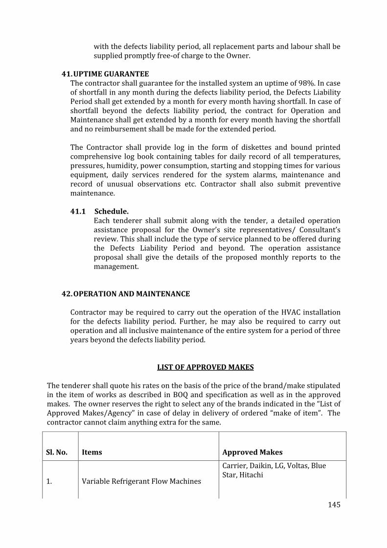
145
with the defects liability period, all replacement parts and labour shall be supplied promptly free-of charge to the Owner.
41. UPTIME GUARANTEE
The contractor shall guarantee for the installed system an uptime of 98%. In case of shortfall in any month during the defects liability period, the Defects Liability Period shall get extended by a month for every month having shortfall. In case of shortfall beyond the defects liability period, the contract for Operation and Maintenance shall get extended by a month for every month having the shortfall and no reimbursement shall be made for the extended period.
The Contractor shall provide log in the form of diskettes and bound printed comprehensive log book containing tables for daily record of all temperatures, pressures, humidity, power consumption, starting and stopping times for various equipment, daily services rendered for the system alarms, maintenance and record of unusual observations etc. Contractor shall also submit preventive maintenance.
41.1 Schedule.
Each tenderer shall submit along with the tender, a detailed operation assistance proposal for the Owner’s site representatives/ Consultant’s review. This shall include the type of service planned to be offered during the Defects Liability Period and beyond. The operation assistance proposal shall give the details of the proposed monthly reports to the management.
42. OPERATION AND MAINTENANCE
Contractor may be required to carry out the operation of the HVAC installation for the defects liability period. Further, he may also be required to carry out operation and all inclusive maintenance of the entire system for a period of three years beyond the defects liability period.
LIST OF APPROVED MAKES
The tenderer shall quote his rates on the basis of the price of the brand/make stipulated in the item of works as described in BOQ and specification as well as in the approved makes. The owner reserves the right to select any of the brands indicated in the “List of Approved Makes/Agency” in case of delay in delivery of ordered “make of item”. The contractor cannot claim anything extra for the same.
Sl. No. Items Approved Makes
1. Variable Refrigerant Flow Machines
Carrier, Daikin, LG, Voltas, Blue Star, Hitachi
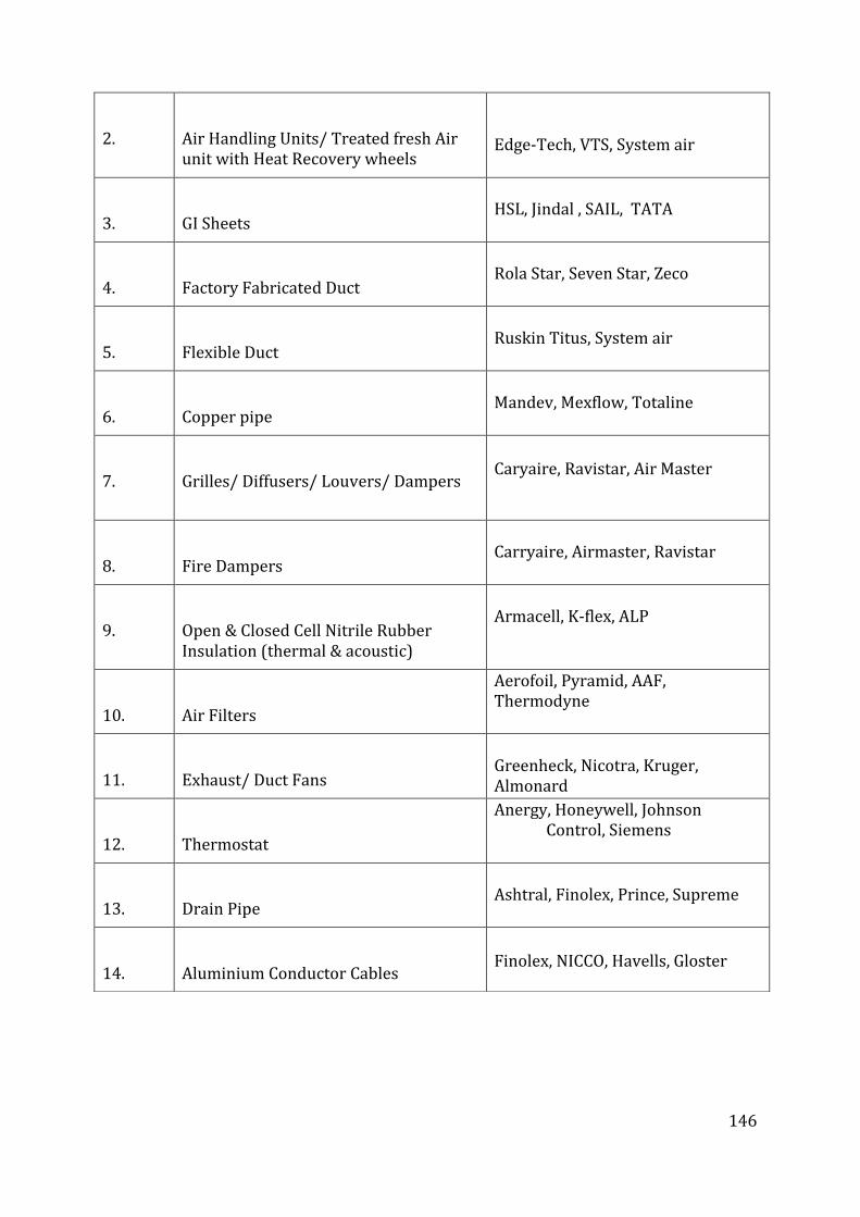
146
2. Air Handling Units/ Treated fresh Air unit with Heat Recovery wheels
Edge-Tech, VTS, System air
3. GI Sheets
HSL, Jindal , SAIL, TATA
4. Factory Fabricated Duct
Rola Star, Seven Star, Zeco
5. Flexible Duct
Ruskin Titus, System air
6. Copper pipe
Mandev, Mexflow, Totaline
7. Grilles/ Diffusers/ Louvers/ Dampers
Caryaire, Ravistar, Air Master
8. Fire Dampers
Carryaire, Airmaster, Ravistar
9. Open & Closed Cell Nitrile Rubber Insulation (thermal & acoustic)
Armacell, K-flex, ALP
10. Air Filters
Aerofoil, Pyramid, AAF, Thermodyne
11. Exhaust/ Duct Fans
Greenheck, Nicotra, Kruger, Almonard
12. Thermostat
Anergy, Honeywell, Johnson Control, Siemens
13. Drain Pipe
Ashtral, Finolex, Prince, Supreme
14. Aluminium Conductor Cables
Finolex, NICCO, Havells, Gloster

147