positive displacement carbon dioxide expansion machines
TRANSCRIPT
Purdue UniversityPurdue e-Pubs
International Compressor Engineering Conference School of Mechanical Engineering
2006
Positive Displacement Carbon Dioxide ExpansionMachines - Changes and Limitations -Horst KruseFKW GmbH
Hans RüssmannFKW GmbH
Eduardo MartinFKW GmbH
Rainer JakobsIZW
Follow this and additional works at: https://docs.lib.purdue.edu/icec
This document has been made available through Purdue e-Pubs, a service of the Purdue University Libraries. Please contact [email protected] foradditional information.Complete proceedings may be acquired in print and on CD-ROM directly from the Ray W. Herrick Laboratories at https://engineering.purdue.edu/Herrick/Events/orderlit.html
Kruse, Horst; Rüssmann, Hans; Martin, Eduardo; and Jakobs, Rainer, "Positive Displacement Carbon Dioxide Expansion Machines -Changes and Limitations -" (2006). International Compressor Engineering Conference. Paper 1766.https://docs.lib.purdue.edu/icec/1766
C138, Page 1
International Compressor Engineering Conference at Purdue, July 17-20, 2006
Positive Displacement Carbon Dioxide Expansion Machines - Chances and Limitations -
Horst KRUSE1, Hans RÜSSMANN2, Eduardo MARTIN³, Rainer JAKOBS4
1,2,3 FKW – Forschungszentrum für Kältetechnik und Wärmepumpen GmbH
Weidendamm 12-14, D-30167 Hannover, Germany Tel: +49–511–167475–0, E-mail: [email protected]
4 IZW – Informationszentrum Wärmepumpen und Kältetechnik e.V.
Welfengarten 1a, D-30167 Hannover, Germany Tel: +49-511-167475-15, E-mail: [email protected]
ABSTRACT
Over the past years carbon dioxide has experienced a revival after it had been re-introduced by Lorentzen. In contrast to conventional refrigeration cycles the expansion of CO2 in refrigeration machines is a potential source of energy efficiency improvement, when the expansion energy can be put to practical use. Various efforts to realize expanders for CO2 have been reported at Purdue and IIR conferences. At FKW a simple reciprocating CO2 expansion machine without special valve- or slot-control has been studied as previously designed by Doll and Eder for cryogenic helium expansion /7/. This simple kind of charge and discharge control works without any additional control components except the piston and allows also dead volume capacity control. With a flexible simulation program for expansion machines thermodynamic calculations were done. The results of these calculations and the design of the machine will be described and discussed in the presentation as well as experimental investigations concerning the gained work both in transcritical two-phase operation and in the superheated single-phase region at comparable pressures. From these results conclusions will be drawn concerning the chances and limitations of the application of positive displacement expansion machines of the reciprocating and rotating types.
1. INTRODUCTION At the 4th IIR-Gustav-Lorentzen Conference on Natural Working Fluids at Purdue 2000 several papers had been presented concerning CO2-expansion machines with the intention to improve the Coefficient of Performance (COP) of the transcritical carbon dioxide vapour compression cycle. Among these papers Heidelck and Kruse /10/ presented first ideas of expansion machines for carbon dioxide based on modified reciprocating machines. In this sense reciprocating compressors were modified to use some cylinders for compression and others for the expansion driven by the same shaft for a direct work return from the expansion to the compression side. In order to describe the work done before this publication the following table 1 shows after the revival of the refrigerant carbon dioxide by Lorentzen /24/ 1990 his proposal 1993 to use expansion machines in heat pumps of large capacities. Next Quack and Kraus /19/, /20/, /29/ in 1994 followed this idea and proposed a free piston compressor expansion machine. Heyl, Kraus and Quack /13/, /14/, /15/ realized this proposal 1998 and designed and constructed a free piston compression expansion machine, which they investigated experimentally. After Robinson and Groll /31/ as well as Bullard and Hrnjak /5/ proposed the application of turbo expanders in 1996 and 1997 and Driver and Davidson /6/ a so called “hingevane” compressor-expansion machine in 1999, Heidelck, Kruse and Süß /21/ as well as Maurer and Zinn /26/ investigated reciprocating axial piston machines as used in hydraulic systems and the latter also hydraulic gear pumps for expansion. Kruse, Heidelck and Brandes /3/ reported 1999 about the patent application for an expansion-compression machine as well as based on axial piston swash plate automotive air conditioning compressors or reciprocating crankshaft driven refrigeration compressors. In the same year Denso /36/ 1999 applied for patents concerning expansion machines based on scroll or rolling piston type design. Very favourable seems to be the combination of a compressor and expander in one machine based on an already existing compressor design, in order to feed back the recovered expansion work by the common shaft directly to the compressor side. In a patent application by Kruse /22/ two compressor expansion machines were shown, namely one derived from an axial piston compressor for automotive air conditioning and two different crankshaft machines with slot control as shown in the Figure 1.
C138, Page 2
International Compressor Engineering Conference at Purdue, July 17-20, 2006
Table 1: Investigations of expansion machines for CO2 until 2000
Researcher Year Literature Application
Lorentzen 1993 /24/ Proposal to use expansion machines in heat pumps of larger capacity
Quack, Kraus Heyl, Quack, Kraus
1994 1998-1999
/19/, /20/, /29/ /13/, /14/, /15/
Proposal to use free piston type expansion machines Investigations of a free piston machine
Robinson, Groll und Bullard, Hrnjak
1996- 1997 /31/, /5/ Proposal to use turbo machines
Driver, Davidson 1999 /6/ Concept of a „hinge-vane“ compression expansion machine
Heidelck, Kruse, Süß und Maurer, Zinn
1998-2000 1999
/21/, /10/, /11/ /26/
Investigations of axil piston machines, as well as also of hydraulic gear pumps
Kruse, Heidelck, Brandes
1999 /3/, /22/ Patent application for an expansion compression machine in axial-and trunk piston design with past control
Denso 1999 /36/ Patent application for an expansion machine in scroll or rolling piston design
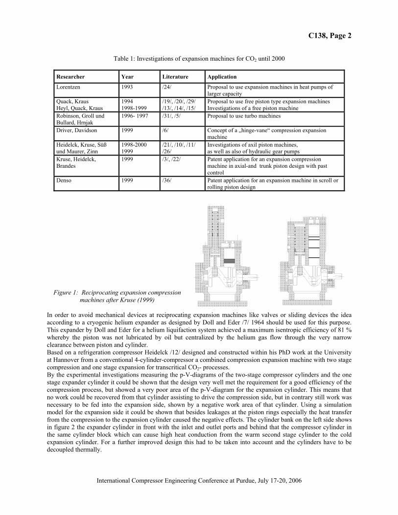
Figure 1: Reciprocating expansion compression machines after Kruse (1999)
In order to avoid mechanical devices at reciprocating expansion machines like valves or sliding devices the idea according to a cryogenic helium expander as designed by Doll and Eder /7/ 1964 should be used for this purpose. This expander by Doll and Eder for a helium liquifaction system achieved a maximum isentropic efficiency of 81 % whereby the piston was not lubricated by oil but centralized by the helium gas flow through the very narrow clearance between piston and cylinder. Based on a refrigeration compressor Heidelck /12/ designed and constructed within his PhD work at the University at Hannover from a conventional 4-cylinder-compressor a combined compression expansion machine with two stage compression and one stage expansion for transcritical CO2- processes. By the experimental investigations measuring the p-V-diagrams of the two-stage compressor cylinders and the one stage expander cylinder it could be shown that the design very well met the requirement for a good efficiency of the compression process, but showed a very poor area of the p-V-diagram for the expansion cylinder. This means that no work could be recovered from that cylinder assisting to drive the compression side, but in contrary still work was necessary to be fed into the expansion side, shown by a negative work area of that cylinder. Using a simulation model for the expansion side it could be shown that besides leakages at the piston rings especially the heat transfer from the compression to the expansion cylinder caused the negative effects. The cylinder bank on the left side shows in figure 2 the expander cylinder in front with the inlet and outlet ports and behind that the compressor cylinder in the same cylinder block which can cause high heat conduction from the warm second stage cylinder to the cold expansion cylinder. For a further improved design this had to be taken into account and the cylinders have to be decoupled thermally.
C138, Page 3
International Compressor Engineering Conference at Purdue, July 17-20, 2006
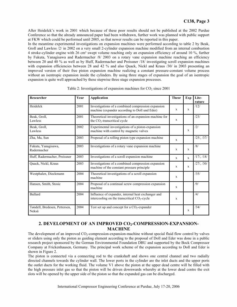
After Heidelck’s work in 2001 which because of these poor results should not be published at the 2002 Purdue Conference so that the already announced paper had been withdrawn, further work was planned with public support at FKW which could be performed until 2005, so that newer results can be reported in this paper. In the meantime experimental investigations on expansion machines were performed according to table 2 by Beak, Groll and Lawless /2/ in 2002 on a very small 2-cylinder expansion machine modified from an internal combustion 4 stroke-cylinder engine with 26 cm³ swept volume reaching only an expansion efficiency of around 10 %, further by Fukuta, Yanagisawa and Radermacher /8/ 2003 on a rotary vane expansion machine reaching an efficiency between 20 and 40 % as well as by Huff, Radermacher and Preissner /18/ investigating scroll expansion machines with expansion efficiencies between 28 and 42 % and also Quack, Nickl and Kraus /30/ in 2003 presenting an improved version of their free piston expansion machine realizing a constant pressure-constant volume process without an isentropic expansion inside the cylinders. By using three stages of expansion the goal of an isentropic expansion is quite well approached by these stepwise three stage expansion processes.
Table 2: Investigations of expansion machines for CO2 since 2001
Researcher Year Application Theor Exp Lite-rature
Heidelck 2001 Investigations of a combined compression expansion machine (expander according to Doll und Eder) x x
/12/
Beak, Groll, Lawless
2001 Theoretical investigations of an expansion machine for the CO2-transcritical cycle x
/23/
Beak, Groll, Lawless
2002 Experimental investigations of a piston-expansion machine with control by magnetic valves x
/2/
Zha, Ma, Sun 2003 Proposal of a rolling piston type expansion machine x /25/, /37/
Fukuta, Yanagisawa, Radermacher
2003 Investigations of a rotary vane expansion machine x x
/8/
Huff, Radermacher, Preissner 2003 Investigations of a scroll expansion machine x x /17/, /18/
Quack, Nickl, Kraus 2003 Investigations of a combined compression expansion machine of the constant pressure principle x x
/27/, /30/
Westphalen, Dieckmann 2004 Theoretical investigations of a scroll expansion machine x
/35/
Hansen, Smith, Stosic 2004 Proposal of a continual screw compression expansion machine x
/9/
Bullard 2004 Influence of expander, internal heat exchanger and intercooling on the transcritical CO2-cycle x
/4/
Tøndell, Bredesen, Pettersen, Nekså
2004 Test set up and concept for a CO2-expander x
/34/
2. DEVELOPMENT OF AN IMPROVED CO2-COMPRESSION-EXPANSION-
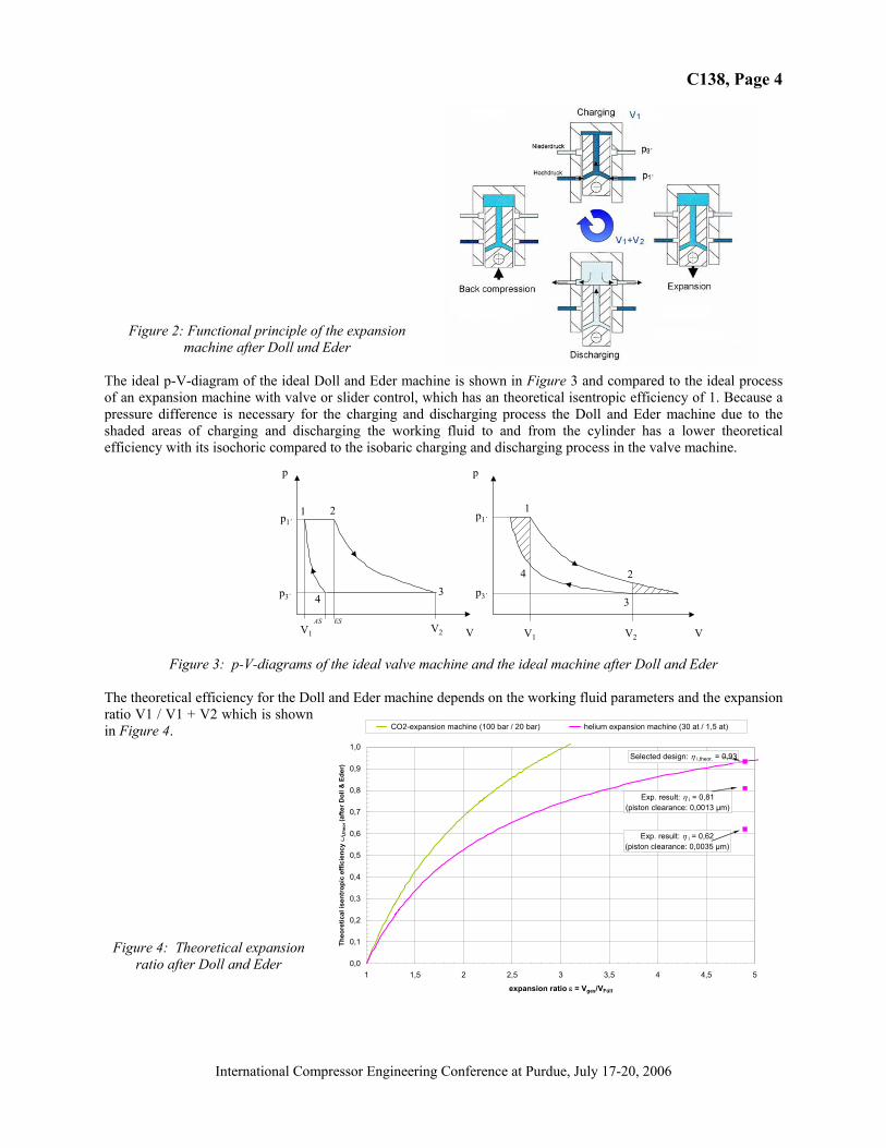
MACHINE The development of an improved CO2-compression-expansion-machine without special fluid flow control by valves or sliders using only the piston as guiding element according to the proposal of Doll and Eder was done in a public research project sponsored by the German Environmental Foundation DBU and supported by the Bock Compressor Company at Frickenhausen, Germany. The principal work scheme of the expansion according to Doll and Eder is shown in Figure 2. The piston is connected via a connecting rod to the crankshaft and shows one central channel and two radially directed channels towards the cylinder wall. The lower ports in the cylinder are the inlet ducts and the upper ports the outlet ducts for the working fluid. The volume V1 above the piston at the upper dead centre will be filled with the high pressure inlet gas so that the piston will be driven downwards whereby at the lower dead centre the exit slots will be opened by the upper side of the piston so that the expanded gas can be discharged.
C138, Page 4
International Compressor Engineering Conference at Purdue, July 17-20, 2006
p
VV2V1
1 2
34
p1´
p3´
ESAS
p
VV2V1
1
3
24
p1´
p3´
Figure 2: Functional principle of the expansion machine after Doll und Eder
The ideal p-V-diagram of the ideal Doll and Eder machine is shown in Figure 3 and compared to the ideal process of an expansion machine with valve or slider control, which has an theoretical isentropic efficiency of 1. Because a pressure difference is necessary for the charging and discharging process the Doll and Eder machine due to the shaded areas of charging and discharging the working fluid to and from the cylinder has a lower theoretical efficiency with its isochoric compared to the isobaric charging and discharging process in the valve machine.
Figure 3: p-V-diagrams of the ideal valve machine and the ideal machine after Doll and Eder The theoretical efficiency for the Doll and Eder machine depends on the working fluid parameters and the expansion ratio V1 / V1 + V2 which is shown in Figure 4.
Figure 4: Theoretical expansion ratio after Doll and Eder
0,0
0,1
0,2
0,3
0,4
0,5
0,6
0,7
0,8
0,9
1,0
1 1,5 2 2,5 3 3,5 4 4,5 5
expansion ratio ε = Vges/VFüll
Theo
retic
al is
entr
opic
effi
cien
cy ∪
i,the
or (a
fter D
oll &
Ede
r)
CO2-expansion machine (100 bar / 20 bar) helium expansion machine (30 at / 1,5 at)
Selected design: η i,theor. = 0,93
Exp. result: η i = 0,81(piston clearance: 0,0013 µm)
Exp. result: η i = 0,62(piston clearance: 0,0035 µm)
C138, Page 5
International Compressor Engineering Conference at Purdue, July 17-20, 2006
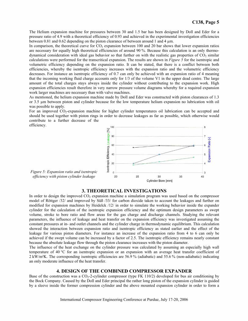
The Helium expansion machine for pressures between 30 and 1.5 bar has been designed by Doll and Eder for a pressure ratio of 4.9 with a theoretical efficiency of 0.93 and achieved in the experimental investigation efficiencies between 0.81 and 0.62 depending on the piston clearance of between around 1 and 4 µm. In comparison, the theoretical curve for CO2 expansion between 100 and 20 bar shows that lower expansion ratios are necessary for equally high theoretical efficiencies of around 90 %. Because this calculation is an only thermo- dynamical consideration with ideal gas behavior so that further on with the realistic gas properties of CO2 similar calculations were performed for the transcritical expansion. The results are shown in Figure 5 for the isentropic and volumetric efficiency depending on the expansion ratio. It can be stated, that there is a conflict between both efficiencies, whereby the isentropic efficiency increases with the expansion ratio and the volumetric efficiency decreases. For instance an isentropic efficiency of 0.7 can only be achieved with an expansion ratio of 4 meaning that the incoming working fluid charge accounts only for 1/3 of the volume V1 in the upper dead centre. The large amount of the total charges stays always inside the cylinder without contributing to the expansion work. High expansion efficiencies result therefore in very narrow pressure volume diagrams whereby for a required expansion work larger machines are necessary than with valve machines. As mentioned, the helium expansion machine made by Doll and Eder was constructed with piston clearances of 1.3 or 3.5 µm between piston and cylinder because for the low temperature helium expansion no lubrication with oil was possible to apply. For an improved CO2-expansion machine for higher cylinder temperatures oil lubrication can be accepted and should be used together with piston rings in order to decrease leakages as far as possible, which otherwise would contribute to a further decrease of the efficiency.
Figure 5: Expansion ratio and isentropic efficiency with piston cylinder leakage
3. THEORETICAL INVESTIGATIONS In order to design the improved CO2 expansion machine a simulation program was used based on the compressor model of Röttger /32/ and improved by Süß /33/ for carbon dioxide taken to account the leakages and further on modified for expansion machines by Heidelck /12/ in order to simulate the working behavior inside the expander cylinder for the calculation of the isentropic expansion efficiency and the optimum design parameters as swept volume, stroke to bore ratio and flow areas for the gas charge and discharge channels. Studying the relevant parameters, the influence of leakage and heat transfer on the expansion efficiency was investigated assuming the constant pressures at in- and outlet channels and the cylinder charge in thermodynamic equilibrium. This calculation showed the interaction between expansion ratio and isentropic efficiency as stated earlier and the effect of the leakage for various piston diameters. For instance an increase of the expansion ratio from 4 to 6 can only be achieved if the swept volume can be increased by a factor of 2.5. The isentropic efficiency remains nearly constant because the absolute leakage flow through the piston clearance increases with the piston diameter. The influence of the heat exchange on the cylinder pressure was calculated by assuming an especially high wall temperature of 40 °C for an isentropic expansion or an expansion with an average heat transfer coefficient of 2 kW/m²K. The corresponding isentropic efficiencies are 56.9 % (adiabatic) and 55.6 % (non-adiabatic) indicating an only moderate influence of the heat transfer.
4. DESIGN OF THE COMBINED COMPRESSOR EXPANDER Base of the construction was a CO2-2-cylinder compressor (type FK 110/2) developed for bus air conditioning by the Bock Company. Caused by the Doll and Eder principal the rather long piston of the expansion cylinder is guided by a sleeve inside the former compression cylinder and the above mounted expansion cylinder in order to form a
C138, Page 6
International Compressor Engineering Conference at Purdue, July 17-20, 2006
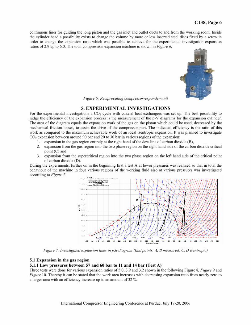
continuous liner for guiding the long piston and the gas inlet and outlet ducts to and from the working room. Inside the cylinder head a possibility exists to change the volume by more or less inserted steel discs fixed by a screw in order to change the expansion ratio which was possible to achieve for the experimental investigation expansion ratios of 2.9 up to 6.0. The total compression expansion machine is shown in Figure 6.
Figure 6: Reciprocating compressor-expander-unit
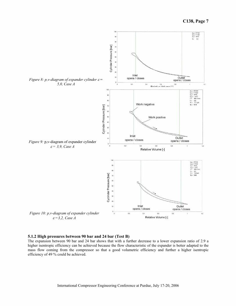
5. EXPERIMENTAL INVESTIGATIONS For the experimental investigations a CO2 cycle with coaxial heat exchangers was set up. The best possibility to judge the efficiency of the expansion process is the measurement of the p-V diagrams for the expansion cylinder. The area of the diagram equals the expansion work of the gas on the piston which could be used, decreased by the mechanical friction losses, to assist the drive of the compressor part. The indicated efficiency is the ratio of this work as compared to the maximum achievable work of an ideal isentropic expansion. It was planned to investigate CO2 expansion between around 90 bar and 20 to 30 bar in various regions of the expansion:
1. expansion in the gas region entirely at the right hand of the dew line of carbon dioxide (B), 2. expansion from the gas region into the two phase region on the right hand side of the carbon dioxide critical
point (C) and 3. expansion from the supercritical region into the two phase region on the left hand side of the critical point
of carbon dioxide (D). During the experiments, further on in the beginning first a test A at lower pressures was realized so that in total the behaviour of the machine in four various regions of the working fluid also at various pressures was investigated according to Figure 7.
Figure 7: Investigated expansion lines in p,h-diagram (End points: A, B measured; C, D isentropic) 5.1 Expansion in the gas region 5.1.1 Low pressures between 57 and 60 bar to 11 and 14 bar (Test A) Three tests were done for various expansion ratios of 5.0, 3.9 and 3.2 shown in the following Figure 8, Figure 9 and Figure 10. Thereby it can be stated that the work area increases with decreasing expansion ratio from nearly zero to a larger area with an efficiency increase up to an amount of 32 %.
C138, Page 7
International Compressor Engineering Conference at Purdue, July 17-20, 2006
Figure 8: p,v-diagram of expander cylinder ε = 5,0, Case A
Figure 9: p,v-diagram of expander cylinder ε = 3,9, Case A
Figure 10: p,v-diagram of expander cylinder
ε =3,2, Case A
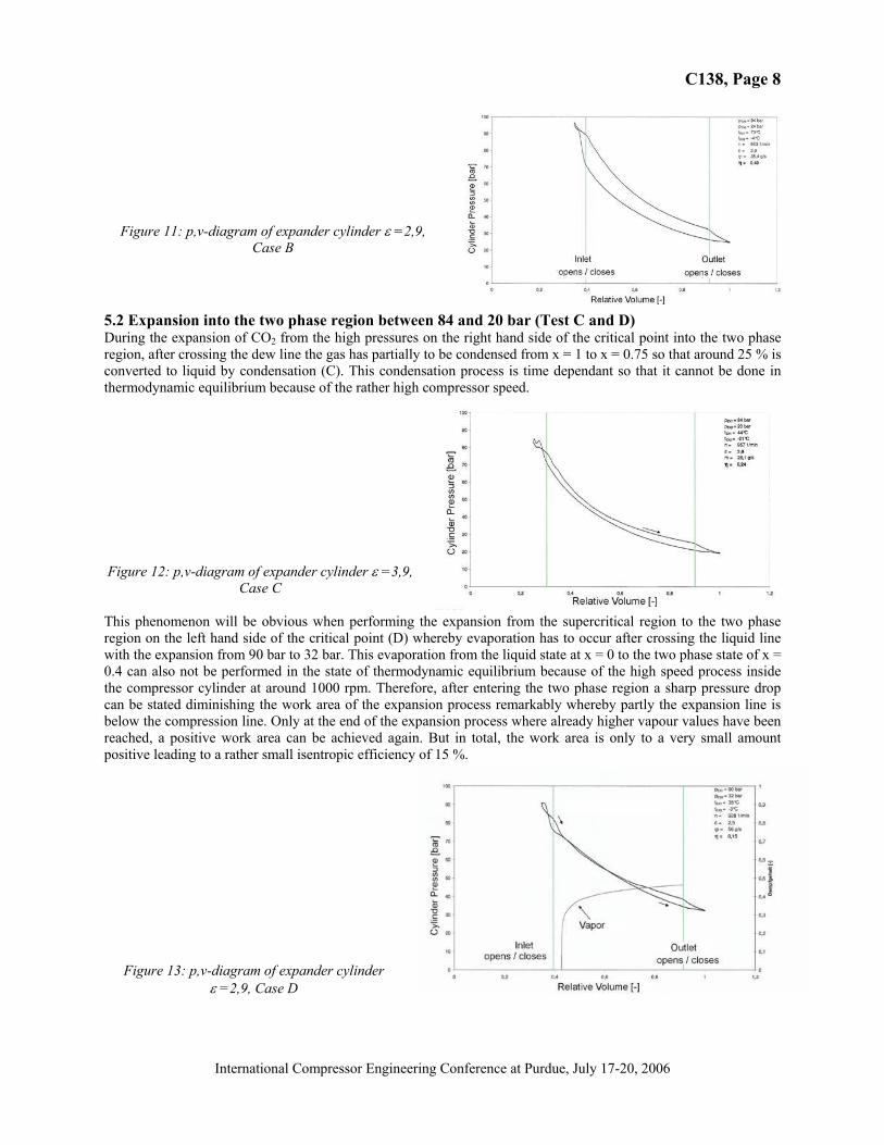
5.1.2 High pressures between 90 bar and 24 bar (Test B) The expansion between 90 bar and 24 bar shows that with a further decrease to a lower expansion ratio of 2.9 a higher isentropic efficiency can be achieved because the flow characteristic of the expander is better adapted to the mass flow coming from the compressor so that a good volumetric efficiency and further a higher isentropic efficiency of 49 % could be achieved.
C138, Page 8
International Compressor Engineering Conference at Purdue, July 17-20, 2006
Figure 11: p,v-diagram of expander cylinder ε =2,9, Case B
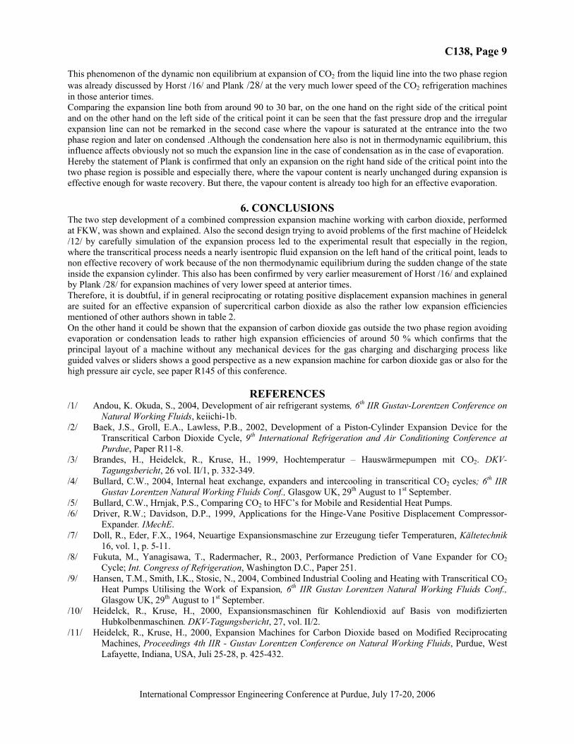
5.2 Expansion into the two phase region between 84 and 20 bar (Test C and D) During the expansion of CO2 from the high pressures on the right hand side of the critical point into the two phase region, after crossing the dew line the gas has partially to be condensed from x = 1 to x = 0.75 so that around 25 % is converted to liquid by condensation (C). This condensation process is time dependant so that it cannot be done in thermodynamic equilibrium because of the rather high compressor speed.
Figure 12: p,v-diagram of expander cylinder ε =3,9,
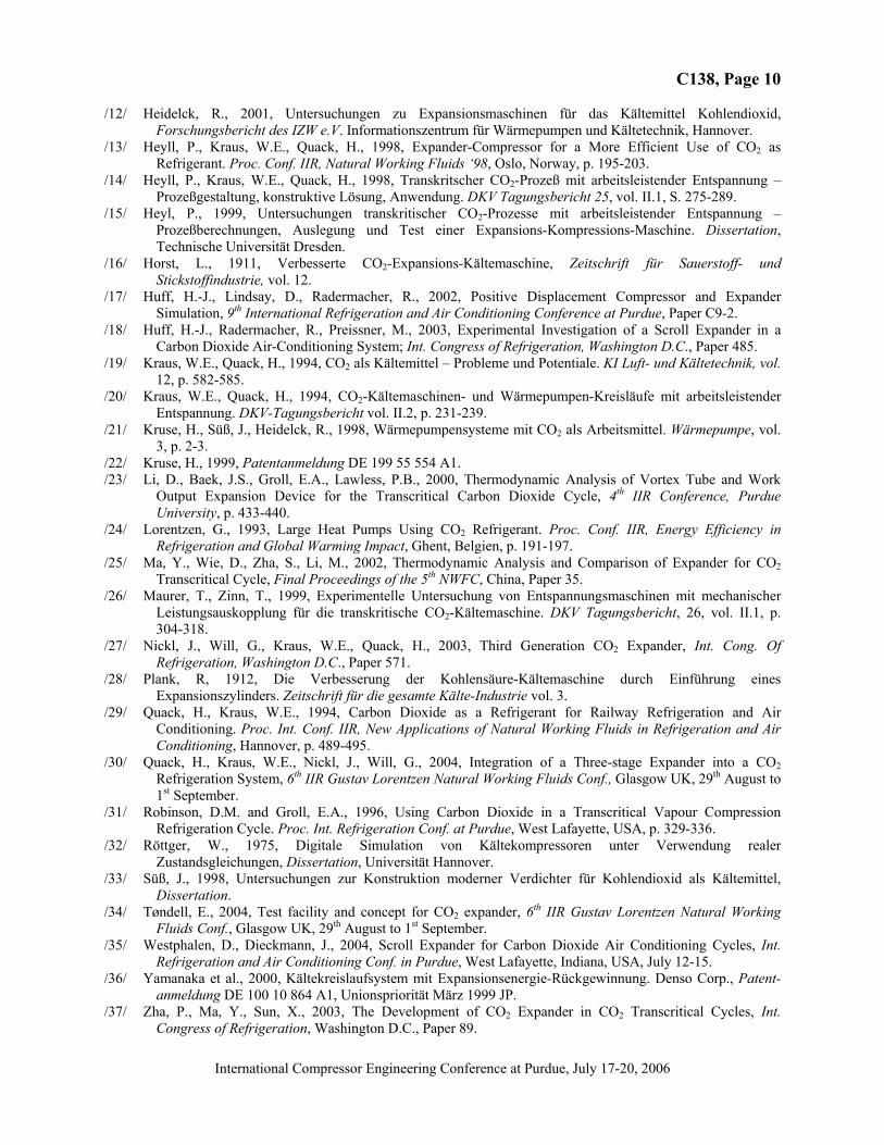
Case C This phenomenon will be obvious when performing the expansion from the supercritical region to the two phase region on the left hand side of the critical point (D) whereby evaporation has to occur after crossing the liquid line with the expansion from 90 bar to 32 bar. This evaporation from the liquid state at x = 0 to the two phase state of x = 0.4 can also not be performed in the state of thermodynamic equilibrium because of the high speed process inside the compressor cylinder at around 1000 rpm. Therefore, after entering the two phase region a sharp pressure drop can be stated diminishing the work area of the expansion process remarkably whereby partly the expansion line is below the compression line. Only at the end of the expansion process where already higher vapour values have been reached, a positive work area can be achieved again. But in total, the work area is only to a very small amount positive leading to a rather small isentropic efficiency of 15 %.
Figure 13: p,v-diagram of expander cylinder ε =2,9, Case D
C138, Page 9
International Compressor Engineering Conference at Purdue, July 17-20, 2006
This phenomenon of the dynamic non equilibrium at expansion of CO2 from the liquid line into the two phase region was already discussed by Horst /16/ and Plank /28/ at the very much lower speed of the CO2 refrigeration machines in those anterior times. Comparing the expansion line both from around 90 to 30 bar, on the one hand on the right side of the critical point and on the other hand on the left side of the critical point it can be seen that the fast pressure drop and the irregular expansion line can not be remarked in the second case where the vapour is saturated at the entrance into the two phase region and later on condensed .Although the condensation here also is not in thermodynamic equilibrium, this influence affects obviously not so much the expansion line in the case of condensation as in the case of evaporation. Hereby the statement of Plank is confirmed that only an expansion on the right hand side of the critical point into the two phase region is possible and especially there, where the vapour content is nearly unchanged during expansion is effective enough for waste recovery. But there, the vapour content is already too high for an effective evaporation.
6. CONCLUSIONS
The two step development of a combined compression expansion machine working with carbon dioxide, performed at FKW, was shown and explained. Also the second design trying to avoid problems of the first machine of Heidelck /12/ by carefully simulation of the expansion process led to the experimental result that especially in the region, where the transcritical process needs a nearly isentropic fluid expansion on the left hand of the critical point, leads to non effective recovery of work because of the non thermodynamic equilibrium during the sudden change of the state inside the expansion cylinder. This also has been confirmed by very earlier measurement of Horst /16/ and explained by Plank /28/ for expansion machines of very lower speed at anterior times. Therefore, it is doubtful, if in general reciprocating or rotating positive displacement expansion machines in general are suited for an effective expansion of supercritical carbon dioxide as also the rather low expansion efficiencies mentioned of other authors shown in table 2. On the other hand it could be shown that the expansion of carbon dioxide gas outside the two phase region avoiding evaporation or condensation leads to rather high expansion efficiencies of around 50 % which confirms that the principal layout of a machine without any mechanical devices for the gas charging and discharging process like guided valves or sliders shows a good perspective as a new expansion machine for carbon dioxide gas or also for the high pressure air cycle, see paper R145 of this conference.
REFERENCES /1/ Andou, K. Okuda, S., 2004, Development of air refrigerant systems, 6th IIR Gustav-Lorentzen Conference on
Natural Working Fluids, keiichi-1b. /2/ Baek, J.S., Groll, E.A., Lawless, P.B., 2002, Development of a Piston-Cylinder Expansion Device for the
Transcritical Carbon Dioxide Cycle, 9th International Refrigeration and Air Conditioning Conference at Purdue, Paper R11-8.
/3/ Brandes, H., Heidelck, R., Kruse, H., 1999, Hochtemperatur – Hauswärmepumpen mit CO2. DKV-Tagungsbericht, 26 vol. II/1, p. 332-349.
/4/ Bullard, C.W., 2004, Internal heat exchange, expanders and intercooling in transcritical CO2 cycles; 6th IIR Gustav Lorentzen Natural Working Fluids Conf., Glasgow UK, 29th August to 1st September.
/5/ Bullard, C.W., Hrnjak, P.S., Comparing CO2 to HFC’s for Mobile and Residential Heat Pumps. /6/ Driver, R.W.; Davidson, D.P., 1999, Applications for the Hinge-Vane Positive Displacement Compressor-
Expander. IMechE. /7/ Doll, R., Eder, F.X., 1964, Neuartige Expansionsmaschine zur Erzeugung tiefer Temperaturen, Kältetechnik
16, vol. 1, p. 5-11. /8/ Fukuta, M., Yanagisawa, T., Radermacher, R., 2003, Performance Prediction of Vane Expander for CO2
Cycle; Int. Congress of Refrigeration, Washington D.C., Paper 251. /9/ Hansen, T.M., Smith, I.K., Stosic, N., 2004, Combined Industrial Cooling and Heating with Transcritical CO2
Heat Pumps Utilising the Work of Expansion, 6th IIR Gustav Lorentzen Natural Working Fluids Conf., Glasgow UK, 29th August to 1st September.
/10/ Heidelck, R., Kruse, H., 2000, Expansionsmaschinen für Kohlendioxid auf Basis von modifizierten Hubkolbenmaschinen. DKV-Tagungsbericht, 27, vol. II/2.
/11/ Heidelck, R., Kruse, H., 2000, Expansion Machines for Carbon Dioxide based on Modified Reciprocating Machines, Proceedings 4th IIR - Gustav Lorentzen Conference on Natural Working Fluids, Purdue, West Lafayette, Indiana, USA, Juli 25-28, p. 425-432.
C138, Page 10
International Compressor Engineering Conference at Purdue, July 17-20, 2006
/12/ Heidelck, R., 2001, Untersuchungen zu Expansionsmaschinen für das Kältemittel Kohlendioxid, Forschungsbericht des IZW e.V. Informationszentrum für Wärmepumpen und Kältetechnik, Hannover.
/13/ Heyll, P., Kraus, W.E., Quack, H., 1998, Expander-Compressor for a More Efficient Use of CO2 as Refrigerant. Proc. Conf. IIR, Natural Working Fluids ‘98, Oslo, Norway, p. 195-203.
/14/ Heyll, P., Kraus, W.E., Quack, H., 1998, Transkritscher CO2-Prozeß mit arbeitsleistender Entspannung – Prozeßgestaltung, konstruktive Lösung, Anwendung. DKV Tagungsbericht 25, vol. II.1, S. 275-289.
/15/ Heyl, P., 1999, Untersuchungen transkritischer CO2-Prozesse mit arbeitsleistender Entspannung – Prozeßberechnungen, Auslegung und Test einer Expansions-Kompressions-Maschine. Dissertation, Technische Universität Dresden.
/16/ Horst, L., 1911, Verbesserte CO2-Expansions-Kältemaschine, Zeitschrift für Sauerstoff- und Stickstoffindustrie, vol. 12.
/17/ Huff, H.-J., Lindsay, D., Radermacher, R., 2002, Positive Displacement Compressor and Expander Simulation, 9th International Refrigeration and Air Conditioning Conference at Purdue, Paper C9-2.
/18/ Huff, H.-J., Radermacher, R., Preissner, M., 2003, Experimental Investigation of a Scroll Expander in a Carbon Dioxide Air-Conditioning System; Int. Congress of Refrigeration, Washington D.C., Paper 485.
/19/ Kraus, W.E., Quack, H., 1994, CO2 als Kältemittel – Probleme und Potentiale. KI Luft- und Kältetechnik, vol. 12, p. 582-585.
/20/ Kraus, W.E., Quack, H., 1994, CO2-Kältemaschinen- und Wärmepumpen-Kreisläufe mit arbeitsleistender Entspannung. DKV-Tagungsbericht vol. II.2, p. 231-239.
/21/ Kruse, H., Süß, J., Heidelck, R., 1998, Wärmepumpensysteme mit CO2 als Arbeitsmittel. Wärmepumpe, vol. 3, p. 2-3.
/22/ Kruse, H., 1999, Patentanmeldung DE 199 55 554 A1. /23/ Li, D., Baek, J.S., Groll, E.A., Lawless, P.B., 2000, Thermodynamic Analysis of Vortex Tube and Work
Output Expansion Device for the Transcritical Carbon Dioxide Cycle, 4th IIR Conference, Purdue University, p. 433-440.
/24/ Lorentzen, G., 1993, Large Heat Pumps Using CO2 Refrigerant. Proc. Conf. IIR, Energy Efficiency in Refrigeration and Global Warming Impact, Ghent, Belgien, p. 191-197.
/25/ Ma, Y., Wie, D., Zha, S., Li, M., 2002, Thermodynamic Analysis and Comparison of Expander for CO2 Transcritical Cycle, Final Proceedings of the 5th NWFC, China, Paper 35.
/26/ Maurer, T., Zinn, T., 1999, Experimentelle Untersuchung von Entspannungsmaschinen mit mechanischer Leistungsauskopplung für die transkritische CO2-Kältemaschine. DKV Tagungsbericht, 26, vol. II.1, p. 304-318.
/27/ Nickl, J., Will, G., Kraus, W.E., Quack, H., 2003, Third Generation CO2 Expander, Int. Cong. Of Refrigeration, Washington D.C., Paper 571.
/28/ Plank, R, 1912, Die Verbesserung der Kohlensäure-Kältemaschine durch Einführung eines Expansionszylinders. Zeitschrift für die gesamte Kälte-Industrie vol. 3.
/29/ Quack, H., Kraus, W.E., 1994, Carbon Dioxide as a Refrigerant for Railway Refrigeration and Air Conditioning. Proc. Int. Conf. IIR, New Applications of Natural Working Fluids in Refrigeration and Air Conditioning, Hannover, p. 489-495.
/30/ Quack, H., Kraus, W.E., Nickl, J., Will, G., 2004, Integration of a Three-stage Expander into a CO2 Refrigeration System, 6th IIR Gustav Lorentzen Natural Working Fluids Conf., Glasgow UK, 29th August to 1st September.
/31/ Robinson, D.M. and Groll, E.A., 1996, Using Carbon Dioxide in a Transcritical Vapour Compression Refrigeration Cycle. Proc. Int. Refrigeration Conf. at Purdue, West Lafayette, USA, p. 329-336.
/32/ Röttger, W., 1975, Digitale Simulation von Kältekompressoren unter Verwendung realer Zustandsgleichungen, Dissertation, Universität Hannover.
/33/ Süß, J., 1998, Untersuchungen zur Konstruktion moderner Verdichter für Kohlendioxid als Kältemittel, Dissertation.
/34/ Tøndell, E., 2004, Test facility and concept for CO2 expander, 6th IIR Gustav Lorentzen Natural Working Fluids Conf., Glasgow UK, 29th August to 1st September.
/35/ Westphalen, D., Dieckmann, J., 2004, Scroll Expander for Carbon Dioxide Air Conditioning Cycles, Int. Refrigeration and Air Conditioning Conf. in Purdue, West Lafayette, Indiana, USA, July 12-15.
/36/ Yamanaka et al., 2000, Kältekreislaufsystem mit Expansionsenergie-Rückgewinnung. Denso Corp., Patent-anmeldung DE 100 10 864 A1, Unionspriorität März 1999 JP.
/37/ Zha, P., Ma, Y., Sun, X., 2003, The Development of CO2 Expander in CO2 Transcritical Cycles, Int. Congress of Refrigeration, Washington D.C., Paper 89.