spring 2010 cse370 -xiv -finite state machines i 1 finite state machines finite state machines...
TRANSCRIPT
Spring 2010 CSE370 - XIV - Finite State Machines I 1
Finite State Machines
Finite State Machines (FSMs) general models for representing sequential circuits two principal types based on output behavior (Moore and Mealy)
Basic sequential circuits revisited and cast as FSMs shift registers counters
Design procedure for FSMs state diagrams state transition table next state functions potential optimizations
Hardware description languages
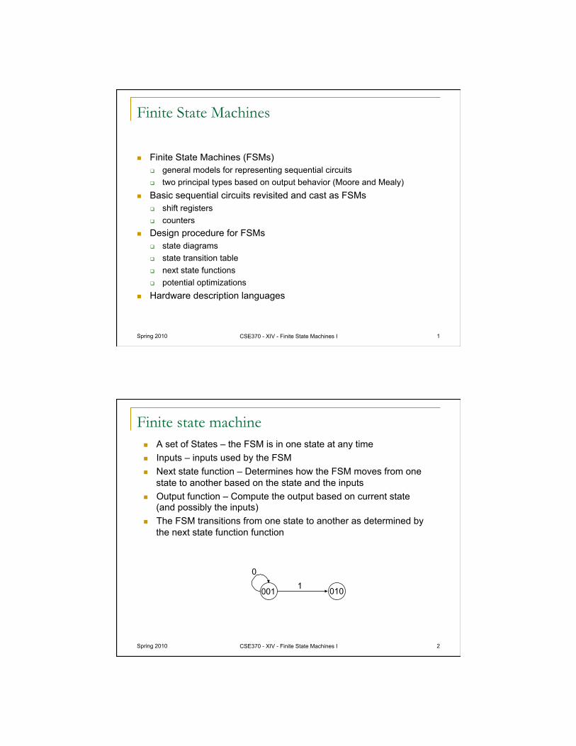
Finite state machine A set of States – the FSM is in one state at any time Inputs – inputs used by the FSM Next state function – Determines how the FSM moves from one
state to another based on the state and the inputs Output function – Compute the output based on current state
(and possibly the inputs) The FSM transitions from one state to another as determined by
the next state function function
Spring 2010 CSE370 - XIV - Finite State Machines I 2
In = 0
In = 1
In = 0 In = 1
100
010
110
111 001 In = 1
In = 0
In = X
In = X 010 001
1
0
Spring 2010 CSE370 - XIV - Finite State Machines I 3
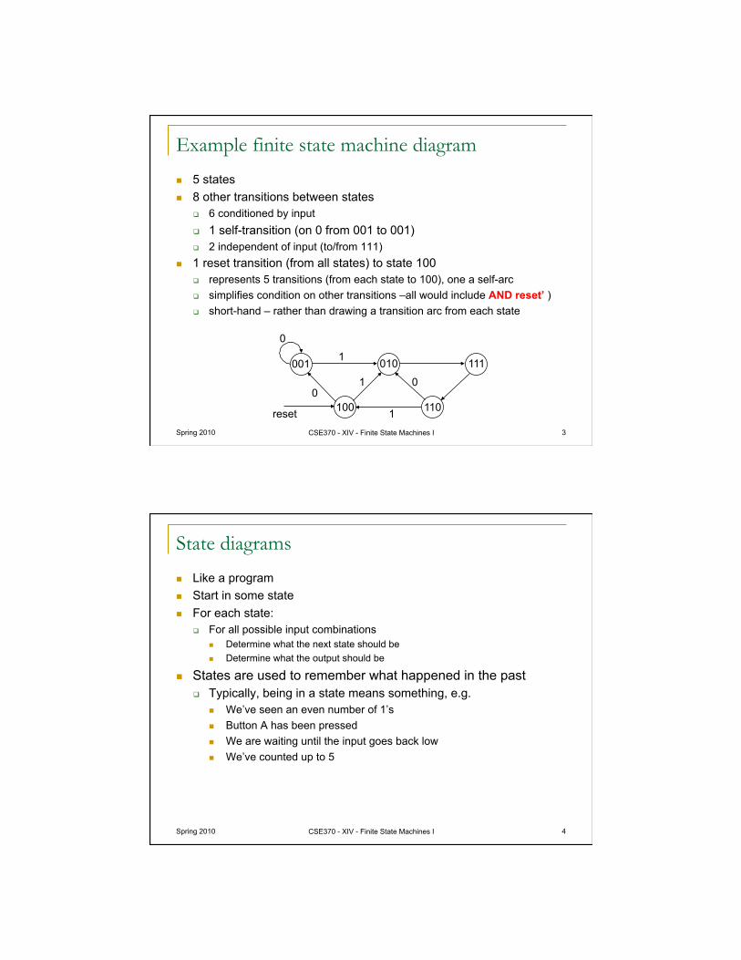
Example finite state machine diagram
5 states 8 other transitions between states
6 conditioned by input 1 self-transition (on 0 from 001 to 001) 2 independent of input (to/from 111)
1 reset transition (from all states) to state 100 represents 5 transitions (from each state to 100), one a self-arc simplifies condition on other transitions –all would include AND reset’ ) short-hand – rather than drawing a transition arc from each state
0
1
0 1
100
010
110
111 001 1
0
reset
Spring 2010 CSE370 - XIV - Finite State Machines I 4
State diagrams
Like a program Start in some state For each state:
For all possible input combinations Determine what the next state should be Determine what the output should be
States are used to remember what happened in the past Typically, being in a state means something, e.g.
We’ve seen an even number of 1’s Button A has been pressed We are waiting until the input goes back low We’ve counted up to 5
Spring 2010 CSE370 - XIV - Finite State Machines I 5
010
100
110
011 001
000
101 111
3-bit up-counter
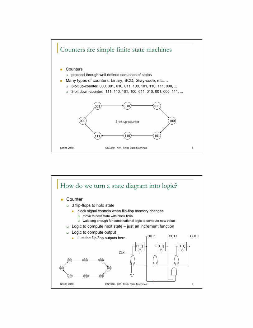
Counters are simple finite state machines
Counters proceed through well-defined sequence of states
Many types of counters: binary, BCD, Gray-code, etc…. 3-bit up-counter: 000, 001, 010, 011, 100, 101, 110, 111, 000, ... 3-bit down-counter: 111, 110, 101, 100, 011, 010, 001, 000, 111, ...
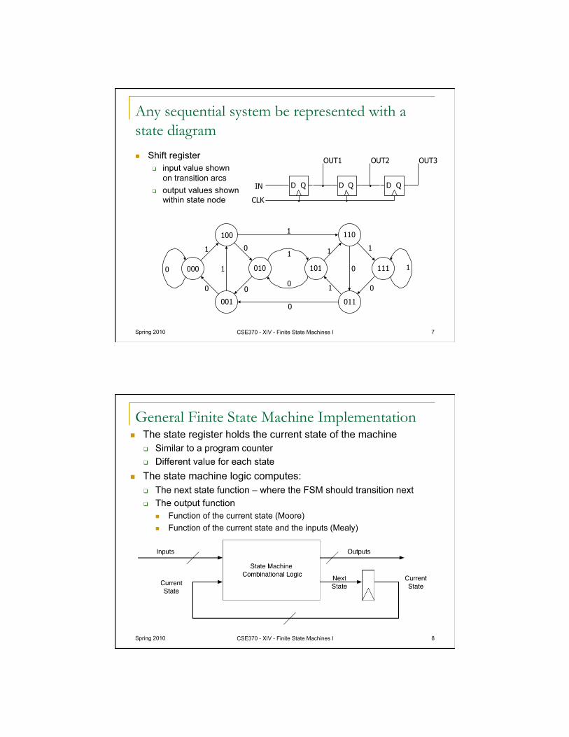
How do we turn a state diagram into logic?
Counter 3 flip-flops to hold state
clock signal controls when flip-flop memory changes move to next state with clock ticks wait long enough for combinational logic to compute new value
Logic to compute next state – just an increment function Logic to compute output
Just the flip-flop outputs here
Spring 2010 CSE370 - XIV - Finite State Machines I 6
D Q D Q D Q
OUT1 OUT2 OUT3
CLK
"1"
010
100
110
011 001
000
101 111
Spring 2010 CSE370 - XIV - Finite State Machines I 7
Any sequential system be represented with a state diagram
Shift register input value shown
on transition arcs output values shown
within state node
100 110
111
011
101 010 000
001
1
1 1 0 1
1
1
1
0 0 0 1
0
0
0 0
D Q D Q D Q IN
OUT1 OUT2 OUT3
CLK
General Finite State Machine Implementation The state register holds the current state of the machine
Similar to a program counter Different value for each state
The state machine logic computes: The next state function – where the FSM should transition next The output function
Function of the current state (Moore) Function of the current state and the inputs (Mealy)
Spring 2010 CSE370 - XIV - Finite State Machines I 8
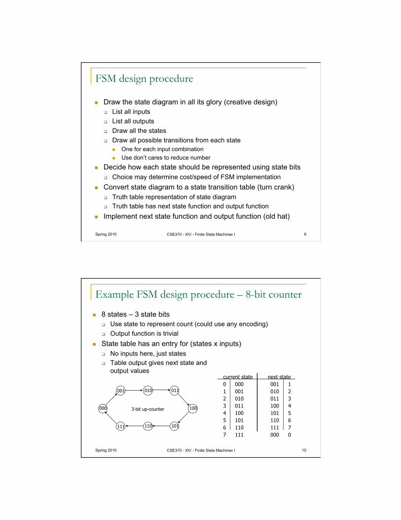
FSM design procedure
Draw the state diagram in all its glory (creative design) List all inputs List all outputs Draw all the states Draw all possible transitions from each state
One for each input combination Use don’t cares to reduce number
Decide how each state should be represented using state bits Choice may determine cost/speed of FSM implementation
Convert state diagram to a state transition table (turn crank) Truth table representation of state diagram Truth table has next state function and output function
Implement next state function and output function (old hat)
Spring 2010 CSE370 - XIV - Finite State Machines I 9
Example FSM design procedure – 8-bit counter
8 states – 3 state bits Use state to represent count (could use any encoding) Output function is trivial
State table has an entry for (states x inputs) No inputs here, just states Table output gives next state and
output values
Spring 2010 CSE370 - XIV - Finite State Machines I 10
010
100
110
011 001
000
101 111
3-bit up-counter
current state next state 0 000 001 1 1 001 010 2 2 010 011 3 3 011 100 4 4 100 101 5 5 101 110 6 6 110 111 7 7 111 000 0
Spring 2010 CSE370 - XIV - Finite State Machines I 11
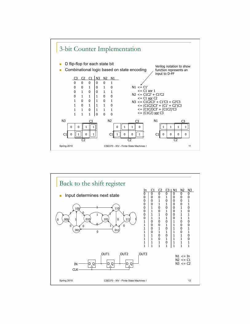
C3 C2 C1 N3 N2 N1 0 0 0 0 0 1 0 0 1 0 1 0 0 1 0 0 1 1 0 1 1 1 0 0 1 0 0 1 0 1 1 0 1 1 1 0 1 1 0 1 1 1 1 1 1 0 0 0
N1 <= C1’ <= C1 xor 1
N2 <= C1C2’ + C1’C2 <= C1 xor C2
N3 <= C1C2C3’ + C1’C3 + C2’C3 <= (C1C2)C3’ + (C1’ + C2’)C3 <= (C1C2)C3’ + (C1C2)’C3 <= (C1C2) xor C3
Verilog notation to show function represents an input to D-FF
3-bit Counter Implementation
D flip-flop for each state bit Combinational logic based on state encoding
0 0
0 1
1 1
0 1 C1
C2
C3 N3
0 1
1 0
1 0
0 1 C1
C2
C3 N2
1 1
0 0
1 1
0 0 C1
C2
C3 N1
Back to the shift register
Input determines next state
Spring 2010 CSE370 - XIV - Finite State Machines I 12
In C1 C2 C3 N1 N2 N3 0 0 0 0 0 0 0 0 0 0 1 0 0 0 0 0 1 0 0 0 1 0 0 1 1 0 0 1 0 1 0 0 0 1 0 0 1 0 1 0 1 0 0 1 1 0 0 1 1 0 1 1 1 0 1 1 1 0 0 0 1 0 0 1 0 0 1 1 0 0 1 0 1 0 1 0 1 1 0 1 1 1 0 1 1 1 0 0 1 1 0 1 1 0 1 1 1 0 1 1 1 0 1 1 1 1 1 1 1 1 1 1
N1 <= In N2 <= C1 N3 <= C2
100 110
111
011
101 010 000
001
0
1
1 1
1 1
1
1
0
0
0
0 0
1
0 0
D Q D Q D Q IN
OUT1 OUT2 OUT3
CLK
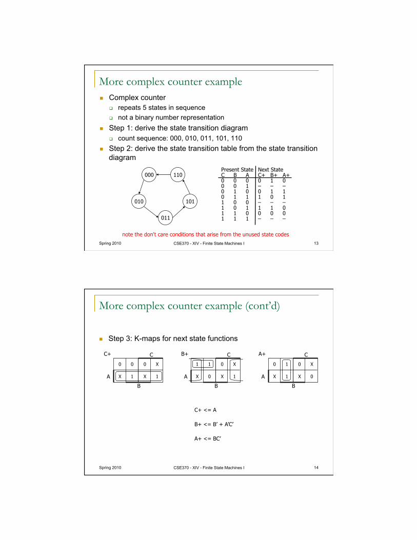
More complex counter example Complex counter
repeats 5 states in sequence not a binary number representation
Step 1: derive the state transition diagram count sequence: 000, 010, 011, 101, 110
Step 2: derive the state transition table from the state transition diagram
Spring 2010 CSE370 - XIV - Finite State Machines I 13
Present State Next State C B A C+ B+ A+ 0 0 0 0 1 0 0 0 1 – – – 0 1 0 0 1 1 0 1 1 1 0 1 1 0 0 – – – 1 0 1 1 1 0 1 1 0 0 0 0 1 1 1 – – –
note the don't care conditions that arise from the unused state codes
010
000 110
101
011
Spring 2010 CSE370 - XIV - Finite State Machines I 14
C+ <= A
B+ <= B’ + A’C’
A+ <= BC’
More complex counter example (cont’d)
Step 3: K-maps for next state functions
0 0
X 1
0 X
X 1 A
B
C C+
1 1
X 0
0 X
X 1 A
B
C B+
0 1
X 1
0 X
X 0 A
B
C A+
Spring 2010 CSE370 - XIV - Finite State Machines I 15
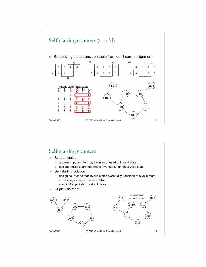
Self-starting counters (cont’d)
Re-deriving state transition table from don't care assignment
0 0
1 1
0 0
1 1 A
B
C C+
1 1
1 0
0 1
0 1 A
B
C B+
0 1
0 1
0 0
0 0 A
B
C A+
Present State Next State C B A C+ B+ A+ 0 0 0 0 1 0 0 0 1 1 1 0 0 1 0 0 1 1 0 1 1 1 0 1 1 0 0 0 1 0 1 0 1 1 1 0 1 1 0 0 0 0 1 1 1 1 0 0
010
000 110
101
011
001 111
100
Self-starting counters Start-up states
at power-up, counter may be in an unused or invalid state designer must guarantee that it (eventually) enters a valid state
Self-starting solution design counter so that invalid states eventually transition to a valid state
this may or may not be acceptable may limit exploitation of don't cares
Or just use reset
Spring 2010 CSE370 - XIV - Finite State Machines I 16
implementation on previous slide
010
000 110
101
011
001 111
100
010
000 110
101
011
001 111
100
Spring 2010 CSE370 - XIV - Finite State Machines I 18
Activity
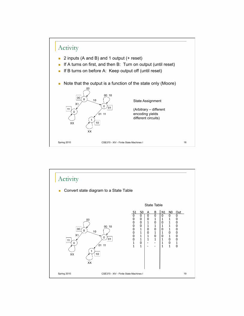
State Assignment
(Arbitrary – different encoding yields different circuits)
2 inputs (A and B) and 1 output (+ reset) If A turns on first, and then B: Turn on output (until reset) If B turns on before A: Keep output off (until reset)
Note that the output is a function of the state only (Moore)
Spring 2010 CSE370 - XIV - Finite State Machines I 19
Activity
Convert state diagram to a State Table
S1 S0 A B N1 N0 Out 0 0 0 0 0 0 0 0 0 0 1 1 1 0 0 0 1 0 0 1 0 0 0 1 1 1 1 0 0 1 0 0 0 1 0 0 1 0 1 1 0 0 0 1 1 0 0 1 0 0 1 1 1 1 0 0 1 0 - - 1 0 1 1 1 - - 1 1 0
State Table
Spring 2010 CSE370 - XIV - Finite State Machines I 20
Activity
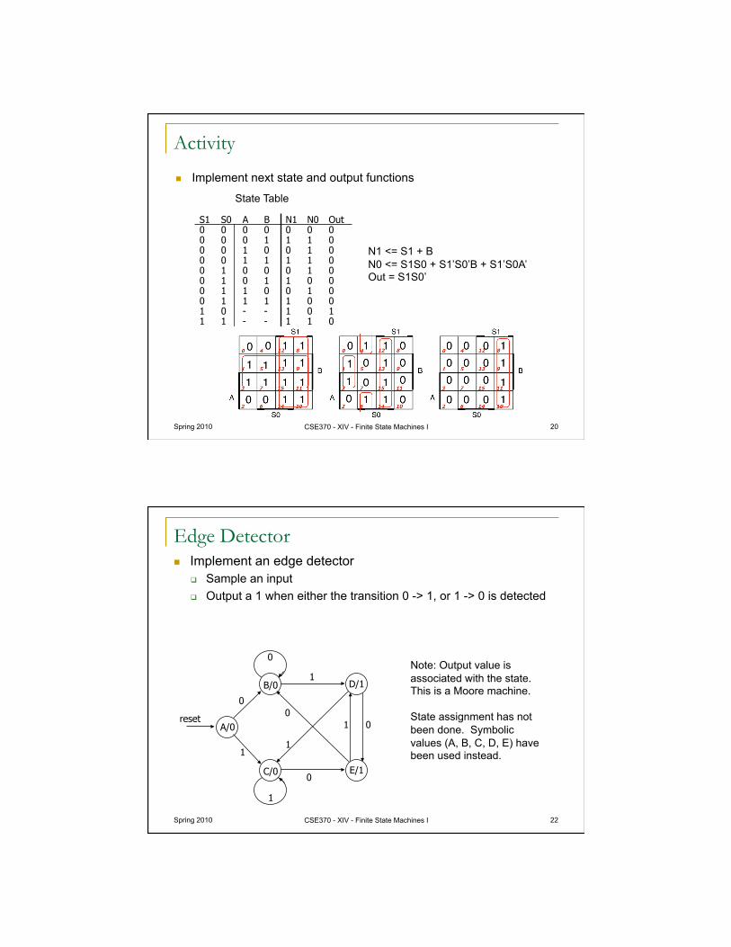
Implement next state and output functions
S1 S0 A B N1 N0 Out 0 0 0 0 0 0 0 0 0 0 1 1 1 0 0 0 1 0 0 1 0 0 0 1 1 1 1 0 0 1 0 0 0 1 0 0 1 0 1 1 0 0 0 1 1 0 0 1 0 0 1 1 1 1 0 0 1 0 - - 1 0 1 1 1 - - 1 1 0
State Table
N1 <= S1 + B N0 <= S1S0 + S1’S0’B + S1’S0A’ Out = S1S0’
Edge Detector Implement an edge detector
Sample an input Output a 1 when either the transition 0 -> 1, or 1 -> 0 is detected
Spring 2010 CSE370 - XIV - Finite State Machines I 22
D/1
E/1
B/0
A/0
C/0
1
0
0
0 0
1
1
1
1
0
reset
Note: Output value is associated with the state. This is a Moore machine.
State assignment has not been done. Symbolic values (A, B, C, D, E) have been used instead.
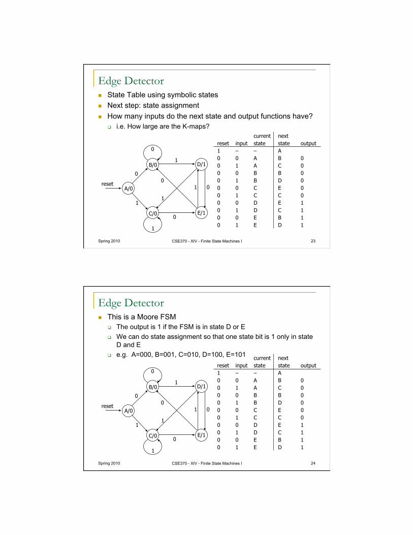
Edge Detector State Table using symbolic states Next step: state assignment How many inputs do the next state and output functions have?
i.e. How large are the K-maps?
Spring 2010 CSE370 - XIV - Finite State Machines I 23
D/1
E/1
B/0
A/0
C/0
1
0
0
0 0
1
1
1
1
0
reset
current next reset input state state output 1 – – A 0 0 A B 0 0 1 A C 0 0 0 B B 0 0 1 B D 0 0 0 C E 0 0 1 C C 0 0 0 D E 1 0 1 D C 1 0 0 E B 1 0 1 E D 1
Edge Detector This is a Moore FSM
The output is 1 if the FSM is in state D or E We can do state assignment so that one state bit is 1 only in state
D and E e.g. A=000, B=001, C=010, D=100, E=101
Spring 2010 CSE370 - XIV - Finite State Machines I 24
D/1
E/1
B/0
A/0
C/0
1
0
0
0 0
1
1
1
1
0
reset
current next reset input state state output 1 – – A 0 0 A B 0 0 1 A C 0 0 0 B B 0 0 1 B D 0 0 0 C E 0 0 1 C C 0 0 0 D E 1 0 1 D C 1 0 0 E B 1 0 1 E D 1
Edge Detector
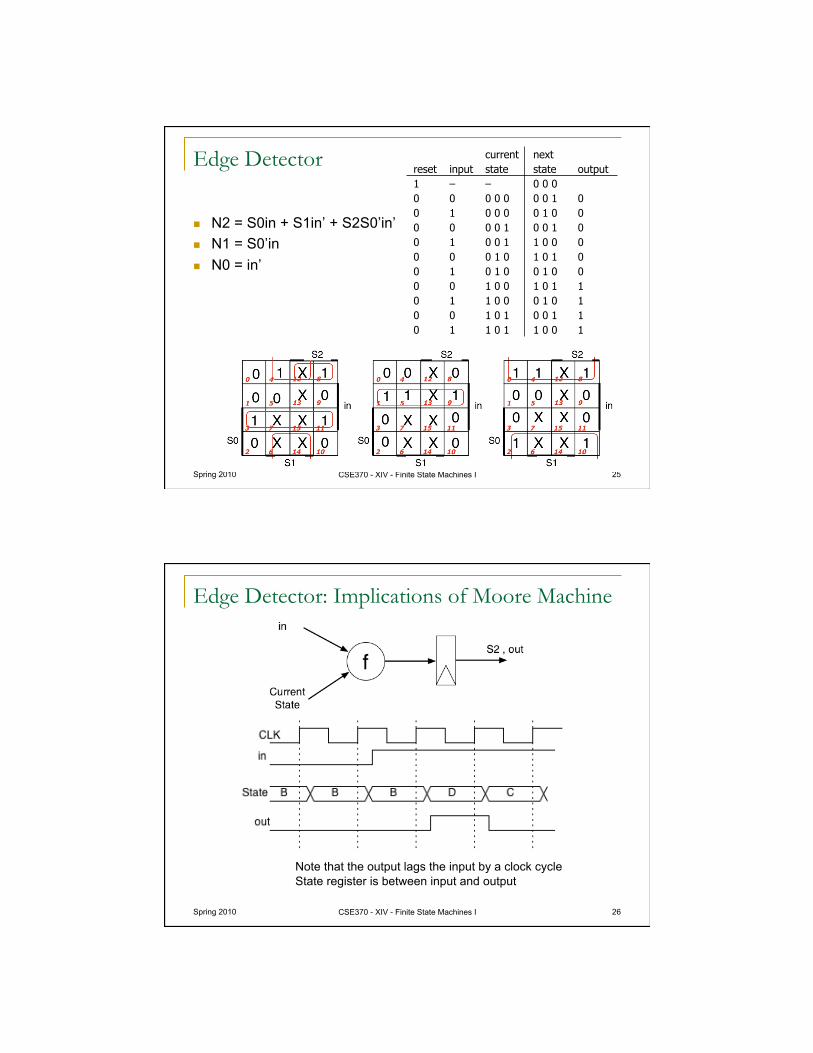
N2 = S0in + S1in’ + S2S0’in’ N1 = S0’in N0 = in’
Spring 2010 CSE370 - XIV - Finite State Machines I 25
current next reset input state state output 1 – – 0 0 0 0 0 0 0 0 0 0 1 0 0 1 0 0 0 0 1 0 0 0 0 0 0 1 0 0 1 0 0 1 0 0 1 1 0 0 0 0 0 0 1 0 1 0 1 0 0 1 0 1 0 0 1 0 0 0 0 1 0 0 1 0 1 1 0 1 1 0 0 0 1 0 1 0 0 1 0 1 0 0 1 1 0 1 1 0 1 1 0 0 1
Edge Detector: Implications of Moore Machine
Spring 2010 CSE370 - XIV - Finite State Machines I 26
Note that the output lags the input by a clock cycle State register is between input and output
Spring 2010 CSE370 - XIV - Finite State Machines I 27
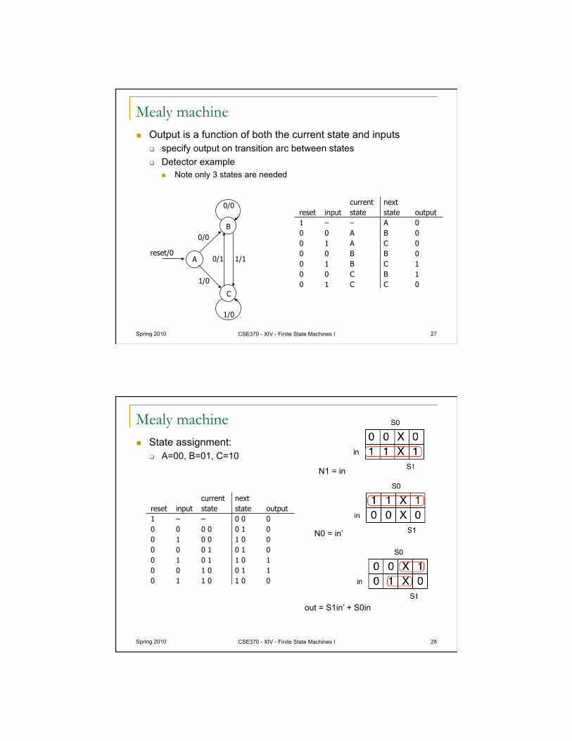
current next reset input state state output 1 – – A 0 0 0 A B 0 0 1 A C 0 0 0 B B 0 0 1 B C 1 0 0 C B 1 0 1 C C 0
B
A
C
0/1
0/0
0/0
1/1
1/0
1/0
reset/0
Mealy machine Output is a function of both the current state and inputs
specify output on transition arc between states Detector example
Note only 3 states are needed
Spring 2010 CSE370 - XIV - Finite State Machines I 28
current next reset input state state output 1 – – 0 0 0 0 0 0 0 0 1 0 0 1 0 0 1 0 0 0 0 0 1 0 1 0 0 1 0 1 1 0 1 0 0 1 0 0 1 1 0 1 1 0 1 0 0
Mealy machine State assignment:
A=00, B=01, C=10 N1 = in
N0 = in’
out = S1in’ + S0in
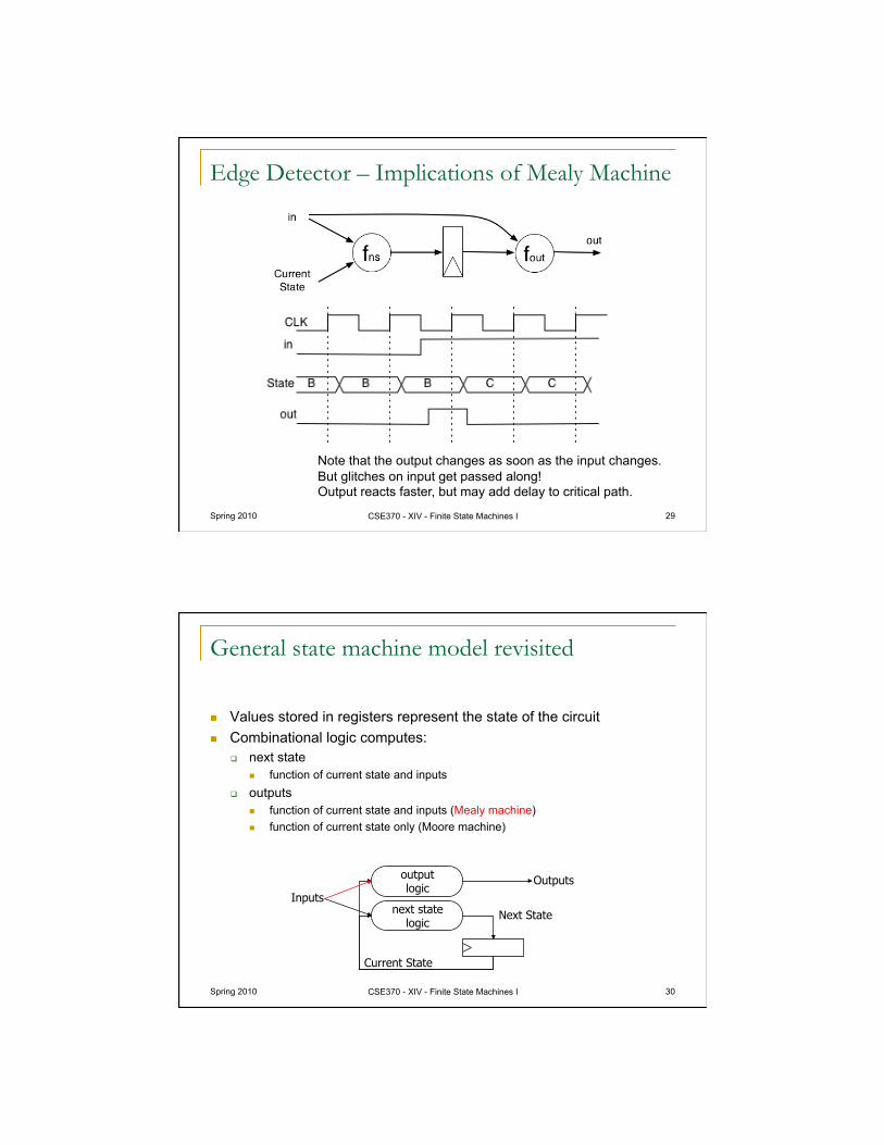
Edge Detector – Implications of Mealy Machine
Spring 2010 CSE370 - XIV - Finite State Machines I 29
Note that the output changes as soon as the input changes. But glitches on input get passed along! Output reacts faster, but may add delay to critical path.
Spring 2010 CSE370 - XIV - Finite State Machines I 30
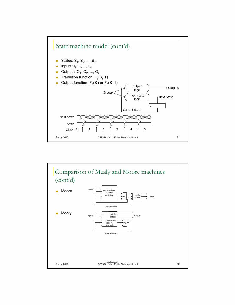
General state machine model revisited
Values stored in registers represent the state of the circuit Combinational logic computes:
next state function of current state and inputs
outputs function of current state and inputs (Mealy machine) function of current state only (Moore machine)
Inputs Outputs
Next State
Current State
output logic
next state logic
Spring 2010 CSE370 - XIV - Finite State Machines I 31
State machine model (cont’d)
States: S1, S2, ..., Sk
Inputs: I1, I2, ..., Im
Outputs: O1, O2, ..., On
Transition function: Fs(Si, Ij) Output function: Fo(Si) or Fo(Si, Ij)
Inputs Outputs
Next State
Current State
output logic
next state logic
Clock
Next State
State
0 1 2 3 4 5
Spring 2010 CSE370 - XIV - Finite State Machines I 32
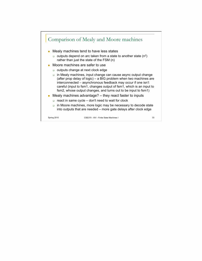
Comparison of Mealy and Moore machines (cont’d)
Moore
Mealy
state feedback
inputs
outputs reg
combinational logic for
next state logic for outputs
inputs outputs
state feedback
reg combinational
logic for next state
logic for outputs
state feedback
Spring 2010 CSE370 - XIV - Finite State Machines I 33
Comparison of Mealy and Moore machines
Mealy machines tend to have less states outputs depend on arc taken from a state to another state (n2)
rather than just the state of the FSM (n) Moore machines are safer to use
outputs change at next clock edge in Mealy machines, input change can cause async output change
(after prop delay of logic) – a BIG problem when two machines are interconnected – asynchronous feedback may occur if one isn’t careful (input to fsm1, changes output of fsm1, which is an input to fsm2, whose output changes, and turns out to be input to fsm1)
Mealy machines advantage? – they react faster to inputs react in same cycle – don't need to wait for clock in Moore machines, more logic may be necessary to decode state
into outputs that are needed – more gate delays after clock edge