testing programmable logic controllers from finite state machines specification
TRANSCRIPT
Testing Programmable Logic Controllersfrom Finite State Machines specification
Julien Provost, Jean-Marc Roussel and Jean-Marc FaureLURPA, ENS Cachan
61 Avenue du President Wilson, 94235 Cachan Cedex, France.Email: {provost,roussel,faure}@lurpa.ens-cachan.fr
Abstract—This paper shows, on the basis of experiments, thatexecution of conformance tests of programmable logic controllerswith minimum-length test sequences built from specifications inFSMs may yield spurious results. A new approach to build testsequences is then proposed to remove, or at least strongly lessen,this issue.
I. INTRODUCTION
Conformance test is a model-based functional test techniquewhose aim is to check whether an implementation behavescorrectly with respect to a specification. In this paper, theimplementation is a PLC (Programmable Logic Controller)which executes cyclically a control algorithm and it will beassumed that the specification is described in the form of aFinite State Machine (FSM) with inputs and outputs. Industrialspecifications of logic control are obviously not described asFSMs but it has been shown [1] that any specification in theIEC 60848 standardized language [2] can be translated intothis formalism. Moreover, the approach proposed in the pre-vious reference can be applied to other industrial specificationlanguages; the assumption on the specification model is thenquite realistic.
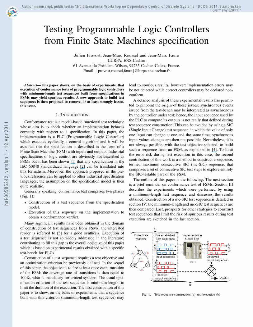
Generally speaking, conformance test comprises two phases(Fig. 1):• Construction of a test sequence from the specification
model.• Execution of this sequence on the implementation to
obtain a conformance verdict.Many significant results have been obtained in the domain
of construction of test sequences from FSMs; the interestedreader is referred to [3] for a good synthesis. Execution ofa test sequence is not so widely addressed in the literature;contributing to fill this gap is the overall objective of this paperwhich is based on experimental results obtained with a specifictest-bench for PLCs.
Construction of a test sequence requires a test objective andan optimization criterion be previously defined. In the sequelof this paper, the objective is to fire at least once each transitionof the FSM; the coverage rate of transitions is then equal to100%, what is mandatory for critical systems. The usual opti-mization criterion of the test sequence is minimum-length, tolimit the duration of the execution. The first contribution of thispaper is to show, on the basis of experiments, that a sequencebuilt with this criterion (minimum-length test sequence) may
lead to spurious results, however: implementation errors maybe not detected while correct controllers may be declared non-conform.
A detailed analysis of these experimental results has permit-ted to pinpoint the origin of these issues: synchronous eventsissued from the test-bench may be interpreted as asynchronousby the controller under test; hence, the input sequence used bythe PLC to compute its outputs is not really that defined duringtest sequence construction. This can be avoided by using a SIC(Single Input Change) test sequence, in which the value of onlyone input can change at one and the same time; synchronousinput values changes are then not possible. Nevertheless, it isnot always possible, with the test objective selected, to buildsuch a sequence from an FSM, as explained in [4]. To limitthe error risk during test execution in this case, the secondcontribution of this work is a method to construct a sequence,termed maximum consecutive SIC (mc-SIC) sequence, thatcomprises a set of consecutive SIC test steps to explore entirelythe SIC-testable part of the FSM.
The outline of this paper is the following. The next sectionis a brief reminder on conformance test of FSMs. Section IIIdescribes the experiments which were performed by usinga minimum-length test sequence and discusses the resultsobtained. Construction of a mc-SIC test sequence is detailed insection IV; the minimum-length and mc-SIC test sequences arethen compared. Last, prospects for other strategies to constructtest sequences that limit the risk of spurious results during testexecution are sketched in the last section.
Fig. 1. Test sequence construction (a) and execution (b)
hal-0
0585
242,
ver
sion
1 -
12 A
pr 2
011
Author manuscript, published in "3rd International Workshop on Dependable Control of Discrete Systems - DCDS 2011, Saarbrücken: Germany (2011)"
II. BACKGROUND
A. PLCs behavior specification with FSMs
Among the numerous formalisms developed to describe thebehavior of discrete event systems (DES), finite state machines(FSMs) with inputs/outputs, e.g. Mealy machines, are wellsuited to formal specification of PLCs that receive and sendlogic data from/to the plant. This formalism cannot be usedby control engineers obviously, but it is possible to translatemodels in industrial standardized languages in this kind offormal models, as presented in [1].
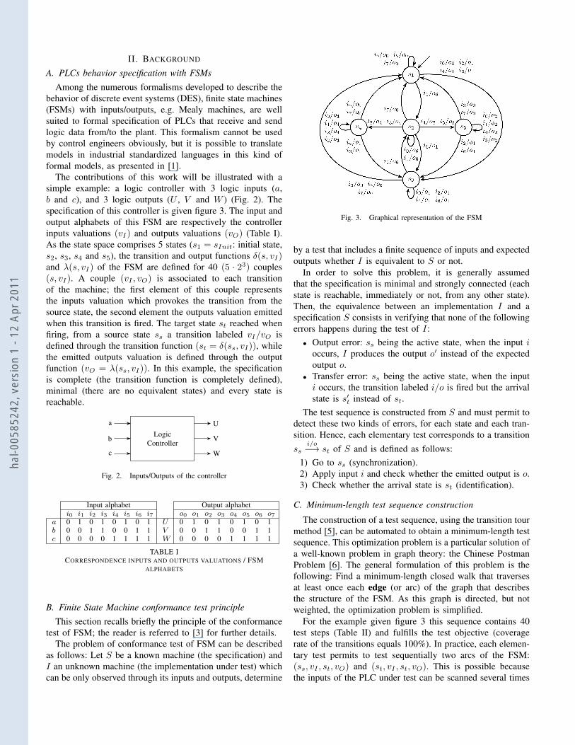
The contributions of this work will be illustrated with asimple example: a logic controller with 3 logic inputs (a,b and c), and 3 logic outputs (U , V and W ) (Fig. 2). Thespecification of this controller is given figure 3. The input andoutput alphabets of this FSM are respectively the controllerinputs valuations (vI) and outputs valuations (vO) (Table I).As the state space comprises 5 states (s1 = sInit: initial state,s2, s3, s4 and s5), the transition and output functions δ(s, vI)and λ(s, vI) of the FSM are defined for 40 (5 · 23) couples(s, vI). A couple (vI , vO) is associated to each transitionof the machine; the first element of this couple representsthe inputs valuation which provokes the transition from thesource state, the second element the outputs valuation emittedwhen this transition is fired. The target state st reached whenfiring, from a source state ss a transition labeled vI/vO isdefined through the transition function (st = δ(ss, vI)), whilethe emitted outputs valuation is defined through the outputfunction (vO = λ(ss, vI)). In this example, the specificationis complete (the transition function is completely defined),minimal (there are no equivalent states) and every state isreachable.
LogicController
U
V
W
a
b
c
Fig. 2. Inputs/Outputs of the controller
Input alphabet Output alphabeti0 i1 i2 i3 i4 i5 i6 i7 o0 o1 o2 o3 o4 o5 o6 o7
a 0 1 0 1 0 1 0 1 U 0 1 0 1 0 1 0 1b 0 0 1 1 0 0 1 1 V 0 0 1 1 0 0 1 1c 0 0 0 0 1 1 1 1 W 0 0 0 0 1 1 1 1
TABLE ICORRESPONDENCE INPUTS AND OUTPUTS VALUATIONS / FSM
ALPHABETS
B. Finite State Machine conformance test principle
This section recalls briefly the principle of the conformancetest of FSM; the reader is referred to [3] for further details.
The problem of conformance test of FSM can be describedas follows: Let S be a known machine (the specification) andI an unknown machine (the implementation under test) whichcan be only observed through its inputs and outputs, determine
Fig. 3. Graphical representation of the FSM
by a test that includes a finite sequence of inputs and expectedoutputs whether I is equivalent to S or not.
In order to solve this problem, it is generally assumedthat the specification is minimal and strongly connected (eachstate is reachable, immediately or not, from any other state).Then, the equivalence between an implementation I and aspecification S consists in verifying that none of the followingerrors happens during the test of I:• Output error: ss being the active state, when the input i
occurs, I produces the output o′ instead of the expectedoutput o.
• Transfer error: ss being the active state, when the inputi occurs, the transition labeled i/o is fired but the arrivalstate is s′t instead of st.
The test sequence is constructed from S and must permit todetect these two kinds of errors, for each state and each tran-sition. Hence, each elementary test corresponds to a transitionss
i/o−→ st of S and is defined as follows:1) Go to ss (synchronization).2) Apply input i and check whether the emitted output is o.3) Check whether the arrival state is st (identification).
C. Minimum-length test sequence construction
The construction of a test sequence, using the transition tourmethod [5], can be automated to obtain a minimum-length testsequence. This optimization problem is a particular solution ofa well-known problem in graph theory: the Chinese PostmanProblem [6]. The general formulation of this problem is thefollowing: Find a minimum-length closed walk that traversesat least once each edge (or arc) of the graph that describesthe structure of the FSM. As this graph is directed, but notweighted, the optimization problem is simplified.
For the example given figure 3 this sequence contains 40test steps (Table II) and fulfills the test objective (coveragerate of the transitions equals 100%). In practice, each elemen-tary test permits to test sequentially two arcs of the FSM:(ss, vI , st, vO) and (st, vI , st, vO). This is possible becausethe inputs of the PLC under test can be scanned several times
hal-0
0585
242,
ver
sion
1 -
12 A
pr 2
011
1 2 3 4 5 6 7 8 9 10 11 12 13 14 15 16 17ss: s1 s2 s3 s2 s2 s4 s3 s2 s4 s3 s2 s4 s4 s4 s1 s2 s4st: s2 s3 s2 s2 s4 s3 s2 s4 s3 s2 s4 s4 s4 s1 s2 s4 s1a: 1 0 1 0 1 0 1 0 0 1 0 1 0 1 1 0 1b: 0 1 0 0 1 1 0 1 0 0 1 0 0 1 0 1 0c: 0 1 0 0 0 1 0 0 1 0 0 0 0 1 0 0 1
18 19 20 21 22 23 24 25 26 27 28 29 30 31 32 33 34s1 s2 s5 s3 s2 s5 s3 s2 s5 s5 s5 s1 s2 s5 s1 s3 s2s2 s5 s3 s2 s5 s3 s2 s5 s5 s5 s1 s2 s5 s1 s3 s2 s11 1 0 1 0 0 1 0 1 0 1 1 0 1 0 1 10 0 1 0 0 1 0 0 0 0 1 0 0 1 1 0 10 1 1 0 1 0 0 1 0 0 1 0 1 0 1 0 135 36 37 38 39 40s1 s3 s1 s3 s1 s3s3 s1 s3 s1 s3 s10 1 0 1 0 10 1 1 0 0 11 1 0 1 0 0
TABLE IIINPUTS VALUATIONS FOR THE MINIMUM-LENGTH TEST SEQUENCE
during one test step if the duration of the step is greater thanseveral PLC scanning cycles.
III. EXPERIMENTATION
This section focuses on execution of the conformancetest of a PLC from a minimum-length test sequence. Theexperimental conditions are first given. As spurious test resultsmay be obtained, an explanation is then proposed and verifiedby complementary experiments. The last sub-section providessome guidelines for conformance test from FSM.
A. Experimental conditions
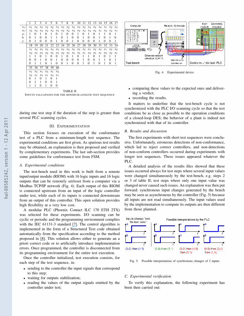
The test-bench used in this work is built from a remoteinput/output module (RIOM) with 16 logic inputs and 16 logicoutputs that can be remotely set/reset from a computer via aModbus TCP/IP network (Fig. 4). Each output of this RIOMis connected upstream from an input of the logic controllerunder test, while each of its inputs is connected downstreamfrom an output of this controller. This open solution provideshigh flexibility at a very low cost.
A modular PLC (Phoenix Contact ILC 170 ETH 2TX)was selected for these experiments. I/O scanning can becyclic or periodic and the programming environment complieswith the IEC 61131-3 standard [7]. The control algorithm isimplemented in the form of a Structured Text code obtainedautomatically from the specification according to the methodproposed in [8]. This solution allows either to generate an apriori correct code or to artificially introduce implementationerrors. Once programmed, the controller is disconnected fromits programming environment for the entire test execution.
Once the controller initialized, test execution consists, foreach step of the test sequence, in:• sending to the controller the input signals that correspond
to this step;• waiting for outputs stabilization;• reading the values of the output signals emitted by the
controller under test;
Fig. 4. Experimental device
• comparing these values to the expected ones and deliver-ing a verdict;
• recording the results.It matters to underline that the test-bench cycle is not
synchronized with the PLC I/O scanning cycle so that the testconditions be as close as possible to the operation conditionsof a closed-loop DES; the behavior of a plant is indeed notsynchronized with that of its controller.
B. Results and discussion
The first experiments with short test sequences were conclu-sive. Unfortunately, erroneous detections of non-conformance,which led to reject correct controllers, and non-detectionsof non-conform controllers occurred during experiments withlonger test sequences. These issues appeared whatever thePLC.
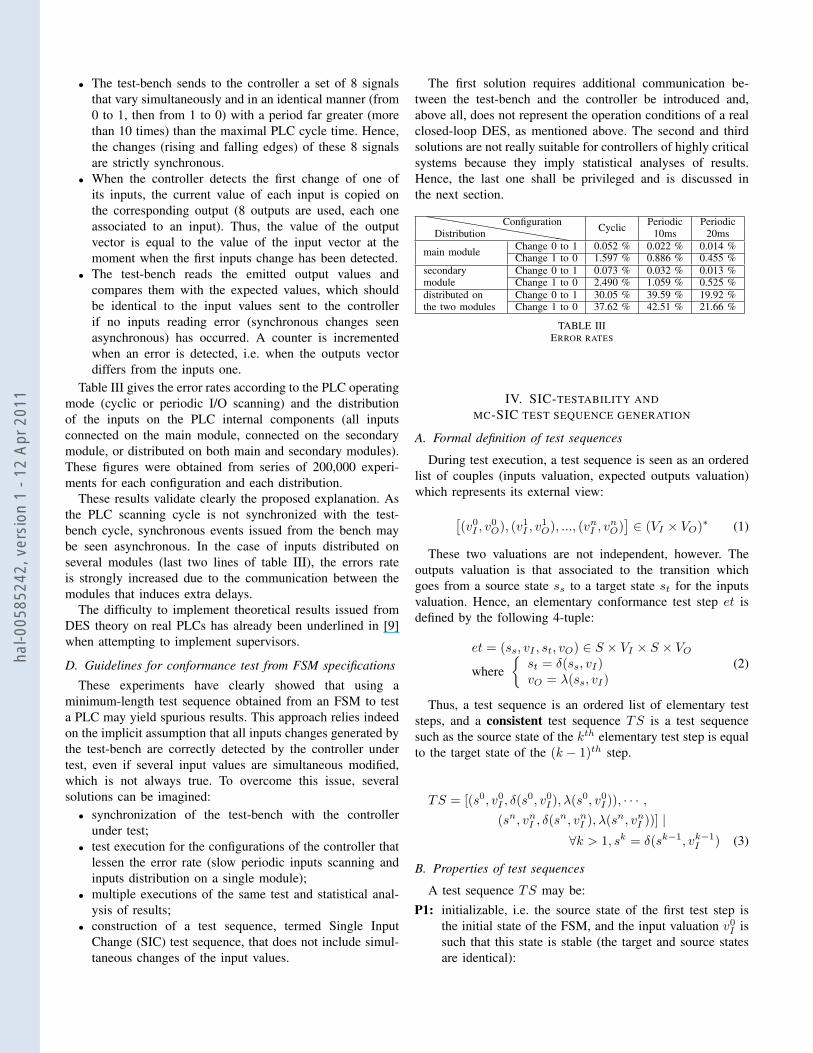
A detailed analysis of the results files showed that theseissues occurred always for test steps where several input valueswere changed simultaneously by the test-bench, e.g. steps 2or 3 of table II; test steps where only one input value waschanged never caused such issues. An explanation was then putforward: synchronous input changes generated by the benchmay be seen as asynchronous by the controller (Fig. 5) becauseall inputs are not read simultaneously. The input values usedby the implementation to compute its outputs are then differentfrom those planned.
Fig. 5. Possible interpretations of synchronous changes of 2 inputs
C. Experimental verification
To verify this explanation, the following experiment hasbeen then carried out:
hal-0
0585
242,
ver
sion
1 -
12 A
pr 2
011
• The test-bench sends to the controller a set of 8 signalsthat vary simultaneously and in an identical manner (from0 to 1, then from 1 to 0) with a period far greater (morethan 10 times) than the maximal PLC cycle time. Hence,the changes (rising and falling edges) of these 8 signalsare strictly synchronous.
• When the controller detects the first change of one ofits inputs, the current value of each input is copied onthe corresponding output (8 outputs are used, each oneassociated to an input). Thus, the value of the outputvector is equal to the value of the input vector at themoment when the first inputs change has been detected.
• The test-bench reads the emitted output values andcompares them with the expected values, which shouldbe identical to the input values sent to the controllerif no inputs reading error (synchronous changes seenasynchronous) has occurred. A counter is incrementedwhen an error is detected, i.e. when the outputs vectordiffers from the inputs one.
Table III gives the error rates according to the PLC operatingmode (cyclic or periodic I/O scanning) and the distributionof the inputs on the PLC internal components (all inputsconnected on the main module, connected on the secondarymodule, or distributed on both main and secondary modules).These figures were obtained from series of 200,000 experi-ments for each configuration and each distribution.
These results validate clearly the proposed explanation. Asthe PLC scanning cycle is not synchronized with the test-bench cycle, synchronous events issued from the bench maybe seen asynchronous. In the case of inputs distributed onseveral modules (last two lines of table III), the errors rateis strongly increased due to the communication between themodules that induces extra delays.
The difficulty to implement theoretical results issued fromDES theory on real PLCs has already been underlined in [9]when attempting to implement supervisors.
D. Guidelines for conformance test from FSM specifications
These experiments have clearly showed that using aminimum-length test sequence obtained from an FSM to testa PLC may yield spurious results. This approach relies indeedon the implicit assumption that all inputs changes generated bythe test-bench are correctly detected by the controller undertest, even if several input values are simultaneous modified,which is not always true. To overcome this issue, severalsolutions can be imagined:• synchronization of the test-bench with the controller
under test;• test execution for the configurations of the controller that
lessen the error rate (slow periodic inputs scanning andinputs distribution on a single module);
• multiple executions of the same test and statistical anal-ysis of results;
• construction of a test sequence, termed Single InputChange (SIC) test sequence, that does not include simul-taneous changes of the input values.
The first solution requires additional communication be-tween the test-bench and the controller be introduced and,above all, does not represent the operation conditions of a realclosed-loop DES, as mentioned above. The second and thirdsolutions are not really suitable for controllers of highly criticalsystems because they imply statistical analyses of results.Hence, the last one shall be privileged and is discussed inthe next section.
hhhhhhhhhhhDistributionConfiguration Cyclic Periodic Periodic
10ms 20ms
main module Change 0 to 1 0.052 % 0.022 % 0.014 %Change 1 to 0 1.597 % 0.886 % 0.455 %
secondarymodule
Change 0 to 1 0.073 % 0.032 % 0.013 %Change 1 to 0 2.490 % 1.059 % 0.525 %
distributed onthe two modules
Change 0 to 1 30.05 % 39.59 % 19.92 %Change 1 to 0 37.62 % 42.51 % 21.66 %
TABLE IIIERROR RATES
IV. SIC-TESTABILITY ANDMC-SIC TEST SEQUENCE GENERATION
A. Formal definition of test sequences
During test execution, a test sequence is seen as an orderedlist of couples (inputs valuation, expected outputs valuation)which represents its external view:[
(v0I , v0O), (v
1I , v
1O), ..., (v
nI , v
nO)]∈ (VI × VO)∗ (1)
These two valuations are not independent, however. Theoutputs valuation is that associated to the transition whichgoes from a source state ss to a target state st for the inputsvaluation. Hence, an elementary conformance test step et isdefined by the following 4-tuple:
et = (ss, vI , st, vO) ∈ S × VI × S × VOwhere
{st = δ(ss, vI)vO = λ(ss, vI)
(2)
Thus, a test sequence is an ordered list of elementary teststeps, and a consistent test sequence TS is a test sequencesuch as the source state of the kth elementary test step is equalto the target state of the (k − 1)th step.
TS = [(s0, v0I , δ(s0, v0I ), λ(s
0, v0I )), · · · ,(sn, vnI , δ(s
n, vnI ), λ(sn, vnI ))] |
∀k > 1, sk = δ(sk−1, vk−1I ) (3)
B. Properties of test sequences
A test sequence TS may be:P1: initializable, i.e. the source state of the first test step is
the initial state of the FSM, and the input valuation v0I issuch that this state is stable (the target and source statesare identical):
hal-0
0585
242,
ver
sion
1 -
12 A
pr 2
011
{s0 = sInit
δ(s0, v0I ) = s0(4)
P2: complete, i.e. there is at least one test step for eachelement of the transition function:
∀(s, vI) ∈ (S × I), (s, vI , δ(s, vI), λ(s, vI)) ∈ TS (5)
P3: based on a SIC test sequence.To express formally this latter property, the SIC relation
between two inputs valuations must be first defined. Thedefinition below is based on the representation of an inputsvaluation by the subset of logic inputs that only contains theinputs that are True (also noted 1) for this valuation. Thus,two inputs valuations vI and v′I satisfy a SIC relation iff1:
dim((vI\v′I) ∪ (v′I\vI)) = 1 (6)
For example, the inputs valuations used in steps 3 and 4of the test sequence given table II satisfy a SIC relation sincedim(({a}\{}) ∪ ({}\{a})) = dim({a} ∪ {}) = 1
Unfortunately, any FSM does not always permit to constructa test sequence that satisfies these three properties. Thus,before considering the construction of a SIC test sequence,the SIC-testability of the FSM – ability of this FSM to satisfythe three properties previously pinpointed – must be checked.
C. Checking SIC-testability of an FSM
A detailed presentation of the algorithm to check whethera specification is SIC-testable or not can be found in [4].For room reasons, only its principles and an illustrationare presented in this paper. This algorithm is based on thefollowing two observations:• An elementary test step (ss, vI , st, vO) is SIC-testable if
it can be included into an initializable SIC test sequence.If the elementary test step (ss, vI , st, vO) is SIC-testable,the elementary test step (st, vI , st, vO) is also SIC-testable.
• If the elementary step (st, vI , st, vO) is SIC-testable, it isalways possible to add to the test sequence an elementarystep (st, v
′I , δ(st, v
′I), λ(st, v
′I)) where vI and v′I satisfy
a SIC relation.On these bases, the set of elementary test steps which are
SIC-testable can be obtained by a fixed-point calculation onthe elementary test steps; this calculation begins with the set ofelementary steps which start from the initial state of the FSMand satisfy δ(sInit, v
0I ) = sInit. At the end of this iterative
calculation, the FSM is SIC-testable iff the final set containsall elementary test steps that can be defined from its behaviordescription; it is then possible to build a SIC and complete (andalso consistent and initializable) test sequence. Otherwise, thisfinal set defines the SIC-testable part of the FSM.
1dim(A) is the dimension of set A.An input valuation can be represented either by a minterm or by the set ofinput variables that are True (noted 1) for this valuation (see table IV).
@@
@@@@
s
vI
i 0or
{}
i 4or
{c}
i 6or
{b,c}
i 2or
{b}
i 3or
{a,b}
i 7or
{a,b,c}
i 5or
{a,c}
i 1or
{a}
s1 s31s3
1s3
1s3
0 ms1 0 ms1 0 ms1 1s2
s22 ms2 3
s5 s33s4
2s4 s1
2s5
1 ms2s3
2 ms3 1 ms3 1 ms3 1 ms3 2s1
2s1
2s1
3s2
s44 ms4 5
s34s3
3 ms4 2 ms4 3s1
4s1
3 ms4s5
4 ms5 3 ms5 4s3
5s3
4s1
3s1
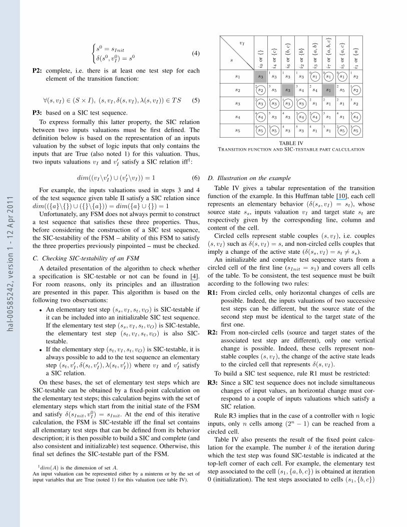
2 ms5 3 ms5TABLE IV
TRANSITION FUNCTION AND SIC-TESTABLE PART CALCULATION
D. Illustration on the example
Table IV gives a tabular representation of the transitionfunction of the example. In this Huffman table [10], each cellrepresents an elementary behavior (δ(ss, vI) = st), whosesource state ss, inputs valuation vI and target state st arerespectively given by the corresponding line, column andcontent of the cell.
Circled cells represent stable couples (s, vI), i.e. couples(s, vI) such as δ(s, vI) = s, and non-circled cells couples thatimply a change of the active state (δ(ss, vI) = st 6= ss).
An initializable and complete test sequence starts from acircled cell of the first line (sInit = s1) and covers all cellsof the table. To be consistent, the test sequence must be builtaccording to the following two rules:R1: From circled cells, only horizontal changes of cells are
possible. Indeed, the inputs valuations of two successivetest steps can be different, but the source state of thesecond step must be identical to the target state of thefirst one.
R2: From non-circled cells (source and target states of theassociated test step are different), only one verticalchange is possible. Indeed, these cells represent non-stable couples (s, vI), the change of the active state leadsto the circled cell that represents δ(s, vI).
To build a SIC test sequence, rule R1 must be restricted:R3: Since a SIC test sequence does not include simultaneous
changes of input values, an horizontal change must cor-respond to a couple of inputs valuations which satisfy aSIC relation.
Rule R3 implies that in the case of a controller with n logicinputs, only n cells among (2n − 1) can be reached from acircled cell.
Table IV also presents the result of the fixed point calcu-lation for the example. The number k of the iteration duringwhich the test step was found SIC-testable is indicated at thetop-left corner of each cell. For example, the elementary teststep associated to the cell (s1, {a, b, c}) is obtained at iteration0 (initialization). The test steps associated to cells (s1, {b, c})
hal-0
0585
242,
ver
sion
1 -
12 A
pr 2
011
and (s3, {b, c}) are obtained at iteration 1, since {a, b, c} and{b, c} satisfy a SIC relation, and so on. Calculation stops atthe fifth iteration. The final set contains only 37 test steps; thesteps that do not belong to this set are represented by grayedcells. Hence, the FSM is not SIC-testable; its SIC-testable partis given by the cells which are not grayed.
E. Construction of the mc-SIC test sequence
When the FSM is not SIC-testable, a maximum consecutiveSIC (mc-SIC) test sequence must be built to limit the risk ofspurious results during test execution. This sequence is com-posed of an initializable minimum-length SIC test sequence,which is computed from the SIC-testable part, followed by aminimum-length MIC test sequence, obtained from the non-SIC-testable part. Both sequences start from and end on theinitial state of the FSM; there is no gap between the final stateof the SIC sequence and the initial state of the MIC sequence.
The construction of the SIC sequence is based on a directedgraph whose nodes represent all couples (s, vI) that can bedefined on the SIC-testable part. For a controller with n logicinputs, the arcs between the nodes are defined as follows:• only one arc starts from a node that corresponds to a
couple (s, vI) such as δ(s, vI) 6= s; the target node ofthis arc is the node that corresponds to (δ(s, vI), vI);
• n arcs start from a node that corresponds to a couple(s, vI) such as δ(s, vI) = s; the target nodes of these arcscorrespond to couples (s, v′I) such as vI and v′I satisfy aSIC relation.
The minimum-length SIC test sequence can then be ob-tained by using the results of graph theory on a well-knownproblem: the Traveling Salesman Problem [11]. The generalformulation of this problem is the following: Find a minimum-length closed walk that traverses each node of the graph atleast once.
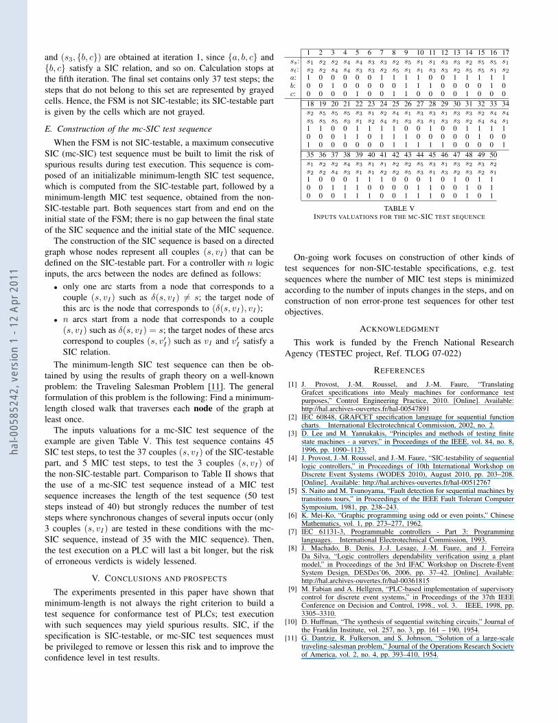
The inputs valuations for a mc-SIC test sequence of theexample are given Table V. This test sequence contains 45SIC test steps, to test the 37 couples (s, vI) of the SIC-testablepart, and 5 MIC test steps, to test the 3 couples (s, vI) ofthe non-SIC-testable part. Comparison to Table II shows thatthe use of a mc-SIC test sequence instead of a MIC testsequence increases the length of the test sequence (50 teststeps instead of 40) but strongly reduces the number of teststeps where synchronous changes of several inputs occur (only3 couples (s, vI) are tested in these conditions with the mc-SIC sequence, instead of 35 with the MIC sequence). Then,the test execution on a PLC will last a bit longer, but the riskof erroneous verdicts is widely lessened.
V. CONCLUSIONS AND PROSPECTS
The experiments presented in this paper have shown thatminimum-length is not always the right criterion to build atest sequence for conformance test of PLCs; test executionwith such sequences may yield spurious results. SIC, if thespecification is SIC-testable, or mc-SIC test sequences mustbe privileged to remove or lessen this risk and to improve theconfidence level in test results.
1 2 3 4 5 6 7 8 9 10 11 12 13 14 15 16 17ss: s1 s2 s2 s4 s4 s3 s3 s2 s5 s1 s1 s3 s3 s2 s5 s5 s1st: s2 s2 s4 s4 s3 s3 s2 s5 s1 s1 s3 s3 s2 s5 s5 s1 s2a: 1 0 0 0 0 0 1 1 1 1 0 0 1 1 1 1 1b: 0 0 1 0 0 0 0 0 1 1 1 0 0 0 0 1 0c: 0 0 0 0 1 0 0 1 1 0 0 0 0 1 0 0 0
18 19 20 21 22 23 24 25 26 27 28 29 30 31 32 33 34s2 s5 s5 s5 s3 s1 s2 s4 s1 s3 s3 s1 s3 s3 s2 s4 s4s5 s5 s5 s3 s1 s2 s4 s1 s3 s3 s1 s3 s3 s2 s4 s4 s11 1 0 0 1 1 1 1 0 0 1 0 0 1 1 1 10 0 0 1 1 0 1 1 1 0 0 0 0 0 1 0 01 0 0 0 0 0 0 1 1 1 1 1 0 0 0 0 135 36 37 38 39 40 41 42 43 44 45 46 47 48 49 50s1 s2 s2 s4 s3 s1 s1 s2 s2 s5 s3 s1 s3 s2 s3 s2s2 s2 s4 s3 s1 s1 s2 s2 s5 s3 s1 s3 s2 s3 s2 s11 0 0 0 1 1 1 0 0 0 1 0 1 0 1 10 0 1 1 1 0 0 0 0 1 1 0 0 1 0 10 0 0 1 1 1 0 0 1 1 1 0 0 1 0 1
TABLE VINPUTS VALUATIONS FOR THE MC-SIC TEST SEQUENCE
On-going work focuses on construction of other kinds oftest sequences for non-SIC-testable specifications, e.g. testsequences where the number of MIC test steps is minimizedaccording to the number of inputs changes in the steps, and onconstruction of non error-prone test sequences for other testobjectives.
ACKNOWLEDGMENT
This work is funded by the French National ResearchAgency (TESTEC project, Ref. TLOG 07-022)
REFERENCES
[1] J. Provost, J.-M. Roussel, and J.-M. Faure, “TranslatingGrafcet specifications into Mealy machines for conformance testpurposes,” Control Engineering Practice, 2010. [Online]. Available:http://hal.archives-ouvertes.fr/hal-00547891
[2] IEC 60848, GRAFCET specification language for sequential functioncharts. International Electrotechnical Commission, 2002, no. 2.
[3] D. Lee and M. Yannakakis, “Principles and methods of testing finitestate machines - a survey,” in Proceedings of the IEEE, vol. 84, no. 8,1996, pp. 1090–1123.
[4] J. Provost, J.-M. Roussel, and J.-M. Faure, “SIC-testability of sequentiallogic controllers,” in Proceedings of 10th International Workshop onDiscrete Event Systems (WODES 2010), August 2010, pp. 203–208.[Online]. Available: http://hal.archives-ouvertes.fr/hal-00512767
[5] S. Naito and M. Tsunoyama, “Fault detection for sequential machines bytransitions tours,” in Proceedings of the IEEE Fault Tolerant ComputerSymposium, 1981, pp. 238–243.
[6] K. Mei-Ko, “Graphic programming using odd or even points,” ChineseMathematics, vol. 1, pp. 273–277, 1962.
[7] IEC 61131-3, Programmable controllers - Part 3: Programminglanguages. International Electrotechnical Commission, 1993.
[8] J. Machado, B. Denis, J.-J. Lesage, J.-M. Faure, and J. FerreiraDa Silva, “Logic controllers dependability verification using a plantmodel,” in Proceedings of the 3rd IFAC Workshop on Discrete-EventSystem Design, DESDes’06, 2006, pp. 37–42. [Online]. Available:http://hal.archives-ouvertes.fr/hal-00361815
[9] M. Fabian and A. Hellgren, “PLC-based implementation of supervisorycontrol for discrete event systems,” in Proceedings of the 37th IEEEConference on Decision and Control, 1998., vol. 3. IEEE, 1998, pp.3305–3310.
[10] D. Huffman, “The synthesis of sequential switching circuits,” Journal ofthe Franklin Institute, vol. 257, no. 3, pp. 161 – 190, 1954.
[11] G. Dantzig, R. Fulkerson, and S. Johnson, “Solution of a large-scaletraveling-salesman problem,” Journal of the Operations Research Societyof America, vol. 2, no. 4, pp. 393–410, 1954.
hal-0
0585
242,
ver
sion
1 -
12 A
pr 2
011