planing and milling - forgotten books
TRANSCRIPT

P L A N ING A ND
M I L L ING
A TREATISE ON THE USE OF PLANERS,
SHAPERS, SLOTTERS, AND VARIOUS
TYPES OF HORI Z ONTAL AND VERTI
CAL MILLING MACHINES AND THEIR
ATTACHMENTS
BY FRANKL IN D. "ONESASSOCIATE EDITOR or MACHINERY
Amen or TunmmAND Bounce”
FI RS T EDI TI ON
SECOND pR INTING
NEW YORK
THE . INDUSTR IAL PRESS
LONDON : THE MACHINERY PUBLISHING CO LTD.
Con fluent , 1914
BY
THE INDUSTRIAL PRESSNEW YORK
THI S book deals with the practical problems connec ted withthe adjustment and use of planets, shapers, slotters andmillingmachines of standard and special designs. Each subject istreated fromthe standpoint of the man in the shop, and a
special efiort has beenmade to present needed information pertaining to problems which the practicalman often finds difi cult
to solve . Many operations fromactual practice are illustratedand described to show the adaptability of different machinesfor certain classes of work
,and the relation between various
designs and types. Examples and operations have been selectedthat would not only show how a spec ific result is obtained,b utillustrate fundamental principles and serve as a general guide.
Descriptions of methods involving mathematical calculationscontain the necessary rules or formulas and are accompaniedby examples illustrating the problems which arise in actualpractice.
While some of thematerial is rather elementary,many of the
more advanced and difli cult operations are explained,so that
the book is not only a general treatise but containsmuch usefulinformation of value even to experiencedmachinists . Detaileddescriptionsof differen t c lasses of plan ing andmillingmachinesare given to show, in a general way, howmodernmachine toolsare constructed and controlled, but, as far as possible, the praetical application or use of the machine has been emphasizedrather than its constructional details. Themachines illustratedwere selected as designs typical of difierent types, and not nec
essarily because they were considered superior to othermachinesof the same class.
Readers of mechanical literature are familiar with MACHIN
BRY’
S 25-cent Reference Books
,of which one hundred and
twenty-nve difierent titles have been published during the pastV
vi PREFACE
six years. Asmany subjects cannot be covered adequately inall their phases in books of this size, and in response to a demandfor more comprehensive and detailed treatments of the moreimportantmechanical subjects , it has been deemed advisable topublish a number of larger volumes, of which this Is one. Thiswork includes MACHINERY’
5 Reference Books Nos. 93 96 and
97 , together with a large amoun t of additional information on
modern planing and milling practice . In the preparation ofthe subjec t matter, many practical methods and interestingOperations were obtained fromthe columns of MACHINERY and
represent approvedmachine-shOp practice.
As the illustrations in a book of this kind constitu te a veryimportant feature , they have received particular atten tion .
P ractically all of the drawings are original andmost of themare
simple diagrams which can easily be understood , even by thosenot accustomed to “ reading ” drawings. Care was taken also
to sec ure photographs which would c learly illustrate the difierent
subjects presented. The cooperation of themachine toolmanufac turers who generously supplied many of these views isgreatly appreciated.
F. D. ".
NEw You , " uly, 1914.
CONTENTS
CHAPTER I
PLANING MACHINES
Des c ription of P laner Examples Of P lanerWork Use ofTwo-head P laner P laning Vertical and Angular SurfacesMethods of Holding Work on P laner Use of MagneticChucks Holding Cylindrical Parts for P laning Causes Of
Distorted Work Points on Setting up P laner WorkVarious Forms of P laner Tools Points on Grinding P lanerTools Multiple or Gang P laning Use of Planer IndexCenters Attachments for P laning Curved Surfaces At
tachments for P laning Spiral Flutes Rack Cutting on the
P laner P laner Extension Head and Independent HousingOpen
-side P laners P laning Locomotive Frames and Cylin
ders P laning Speeds and Feeds Determining Net or
Actual Cutting Speed of P laner Variable Speed and Elec
tric P laner Drives Double—cutting P laners
CHAPTER I I
SHAPER AND SLOTTER
Des c ription Of a Crank Shaper Examples of ShaperWork Shaper Attachments Morton Draw-cut Shaper
Pratt Whitney Vertical Shaper Cochrane—Bly UniversalShaper Shaper Attachment for Machining Clutches The
SlottingMachine Examples of Straight and Circular Slotting
CHAPTER II I
PLAIN MILLING MACHINE
Des c ription of P lain Milling Machine Method Of Ad;
justing and Operating Methods of Holding Work on Mil"vii
PAGES
viii CONTENTSPm
ing Machine Difierent Forms of Milling Cutters FormMilling Straddle and Gang M illing with Examples of WorkEnd and Face Milling Keyseat Milling Speeds and
Feeds for M illing Lubricants forM illing 106- 142
CHAPTER IV
UNIVERSAL MILLING MACHINE
Des cription of Universal Milling Machine Constructionand Application of Spiral Head Simple, Compound, Difierential, and Angular Indexing Helical or Spiral MillingCalculating Change Gears for Spiral Milling Attachmentfor Vertical M illing Slotting Attachment for Milling Ma
chine Milling Taper Flutes M illing Clutch TeethMilling P late Cams in the Universal Machine CuttingTeeth in End and Side Mills M illing Angular Cutters . 143
-195
CHAPTER V
GEAR CUTTING IN MILLING MACHINE
Method of Cutting a Spur Gear in M illing Machine— Testing Chordal Tooth Thickness of Spur Gear Teeth Attachment for Cutting Large Gears Rack Cutting in the MillingMachine Index Table for Rack Cutting Gashing and
Hobbing a Worm-wheel in Milling Machine How to SelectCutter and Adjust Machine for M illing a Spiral GearMilling Teeth in Bevel Gears Milling Teeth in ChainSprockets Formulas for Determining Roller and B lock
chain Sprocket Diameters 196—227
CHAPTER VI
MISCELLANEOUS MILLING MACHINES
Des cription of Vertical M illing Machine Examples ofVertical Milling Operations Continuous Circular M illingSingle and Double SpindleDie-sinking Machines Under
cutting Diemilling Machine Combined Horizontal and
Vertical M illing Machine Pratt Whitney P rofiling Ma

CONTENTS ix
PmExamples of P rofiling Different Types of Profiling
Fixtures and Formers Semi-automatic P rofiler Lincoln
Type Milling Machine Horizontal or P laner-type M illingMachine Examples of Horizontal Milling Planing vs.
M illing Multiple-head Milling Machine Open-side Hori
zontal M illing Machine Duplex Milling Machine HandMilling Machine Camor FormM illing Machine M illingFace and Cylinder Cams Thread Milling Machines 228- 298

PLAN ING AND M ILL ING
CHAPTER I
PLANING MACHINES AND THEIR APPLICATION
THE planer is used prin cipally for producing flat surfaces.
The construction or design of planers of differentmakes variessomewhat , and spec ial types are built for doing certain kinds ofwork. There is
,however
,what might be called a standard
type which is found in allmachine shops and is adapted to general work . A typical planer of small size is illustrated in Fig. I .
The prin cipal parts are the bed B ,the housings H which are
bolted to the bed, the table or platen P to which the work is
attached , the cross-rail C, and the tool-head Twhich ismountedon the cross-rail. When the planer is in operation ,
the platenslides back and forth on the bed in V-shaped grooves G whichcause it
'
to move in a straight line . While this reciprocatingmovement takes place
, the work , which is clamped to the platen ,
is planed by a tool held in position by clamps A This tool temains stationary while cu tting, and when the platen is near
the end of the return stroke, the tool-head and tool feed slightlyfor taking a new c ut. The amount of feed for each stroke canbe varied to su it the conditions, as will be explained later. Themovement of the table or of the length of its stroke is governedby the position of the dogs D and D1. These dogsmay be ad
justed along the groove shown and they serve to reverse thetable movement by engaging tappet I . Before explaining justhow themovement of tappet I controls the point of reversal,the arrangement of the driving mechanism,
a plan view ofwhich is shown inFig. 2
, will be explained.
Planer Driving and Reversing Mechanism.— The shaft on
which the belt pulleysf , f ;and r, 7 1 aremounted carries a pinion a
THE PLANER
thatmesheswith a gear on shaft b . This shaft drives, through thegears c and d
,a second shaft which carries a pinion e
,meshingwith a large gear g. This large gear, which is called the
“ bullwheel
,engages a rack attached to the under side of the table,
and, as the gear revolves, the table moves along the ways ofthe bed. There are two pairs of driving pulleys and also twodriving belts connecting with an overhead countershaft. One
pulley of each set is keyed to the shaft and the other is loose and
Fig . 1 . S ingle-head Planing Machine
revolves freely . The belt operating on the large pulleys j and
f l is crossed , whereas the belt for the smaller pulleys r and r;
is open ,which gives a reversemotion . The position of both
belts is controlled by guides I (one of which is seen in Fig. I )which are operated by tappet I . Now when the crossed belt
is running on the tight pulley f , the reverse belt is on the loose
pulley n ,and the tablemoves as shown by the arrow as
,which
is in the direction for the cu tting stroke. When the table is
advanced far enough to bring dog D (Fig. 1) into engagement
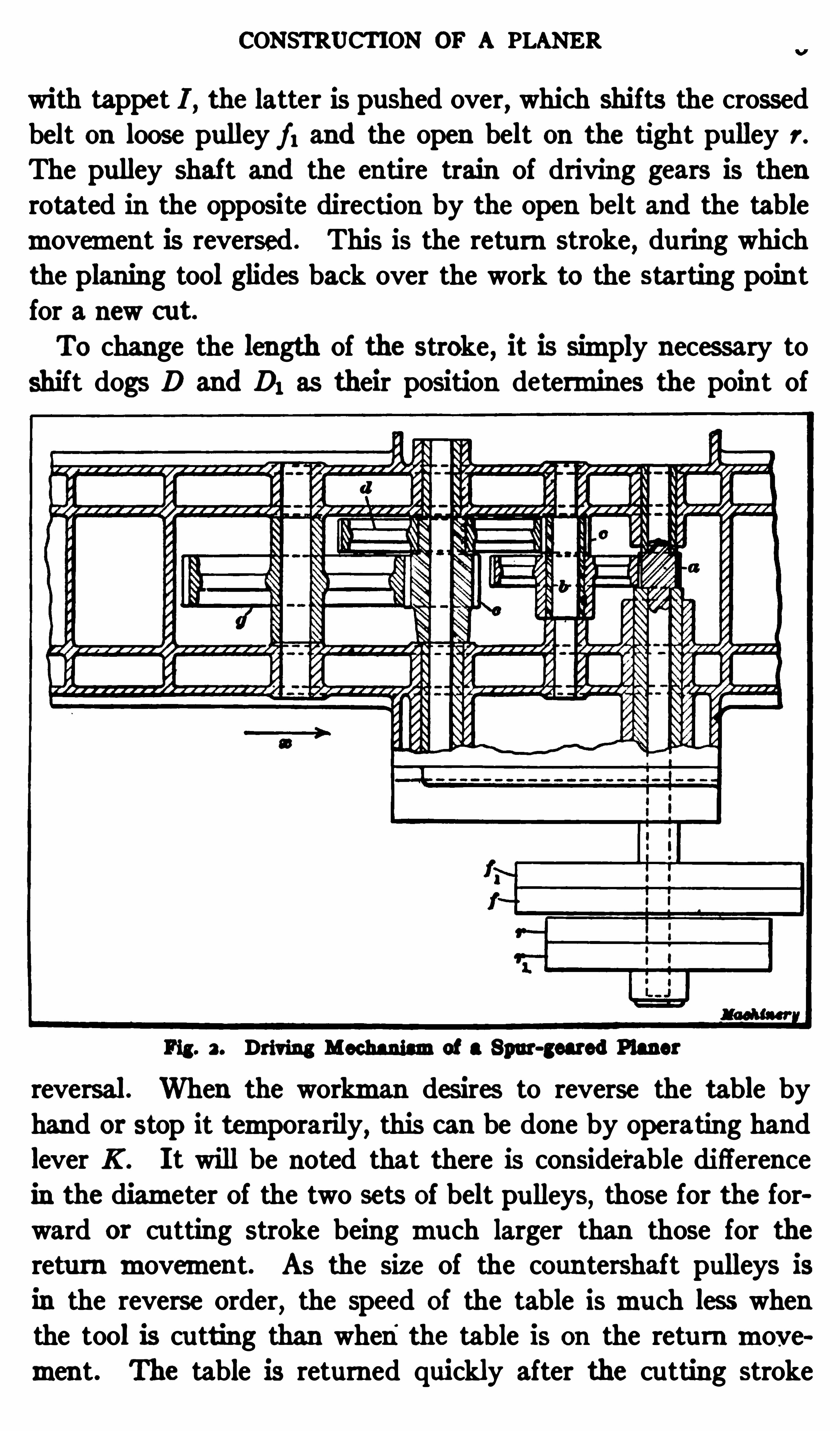
CONSTRUCTION OF A PLANER
with tappet I , the latter is pushed over, which shifts the crossedbelt on loose pulley f l and the open belt on the tight pulley r.
The pulley shaft and the entire train of driving gears is thenrotated in the opposite direction by the open belt and the tablemovement is reversed . This is the return stroke, during whichthe planing tool glides back over the work to the starting poin tfor a new c ut.
To change the length of the stroke, it is simply necessary to
shift dogs D and D; as their position determines the poin t of
Pig. 3 . Driving Mechanismof a Spur-geared Planer
reversal. When the workman desires to reverse the table byhand or stop it temporarily, this can be done by operating handlever K . I t will be noted that there is considerable diff erence
in the diameter of the two sets Of belt pulleys, those for the forward or cutting stroke being much larger than those for thereturn movement. As the size of the countershaft pulleys is
in the reverse order, the speed Of the table ismuch less whenthe tool is cu tting than when
'
the table is on the returnmovement. The table is returned quickly after the cutting stroke
4 THE PLANER
in order to reduce the idle time that elapses between the end
of one c ut and the beginning of the next.The Feeding Mechanism. As previously mentioned the
feedingmovement of the tool takes place on the return strokeand before the tool begins to cut. I f a horizontal surface isbeing planed, the tool has a crosswisemovement parallel to theplaten , b ut if the surface is vertical
,the tool is fed downward
at right angles to the platen . In the first case the entire toolhead Tmoves along the cross-rail C
,but for vertical planing
,
slide S moves downward . Su rfaces which are at an anglewith the table can also beplaned by loosening nu ts Nand swiveling slide S to therequired angle as shown bygraduations on the circularbase. The horizontal and
vertical movements of thetool can be efi
'
ec ted by handor automatically. The handfeed is used principally foradjusting the tool to the
proper position for starting
a cut. The tool can be setPig. 3 . Planer Friction Feed Disk to the right height by a
crank at the top of the tool-head , and the cross-wise position
of the tool and head can be varied by tu rning horizontal feedscrew E .
The au tomatic feedingmovement is derived froma feed diskF
,which tu rns part of a revolution at each end of the stroke
and is connected to a rack R . This rack slides up and downwith each movement of the crank and imparts its motion to
gear M whichmeshes with a gear 0 placed on the feed-screw.
The feedingmovement is engaged, disengaged or reversed by a
pawl attached to gear M (on this particular planer) and theamount of feed per stroke is varied by adjusting the crankpinof the disk F
,to or fromthe center. The vertical feed is Oper
ated by a splined shaft L which transmits its motion to the
CONSTRUCTION OF A PLANER 5
tool-head feed-screw through gearing. This shaft is also drivenby gear 0 which is removable and is placed on shaft L when an
automatic vertical feed is desired .
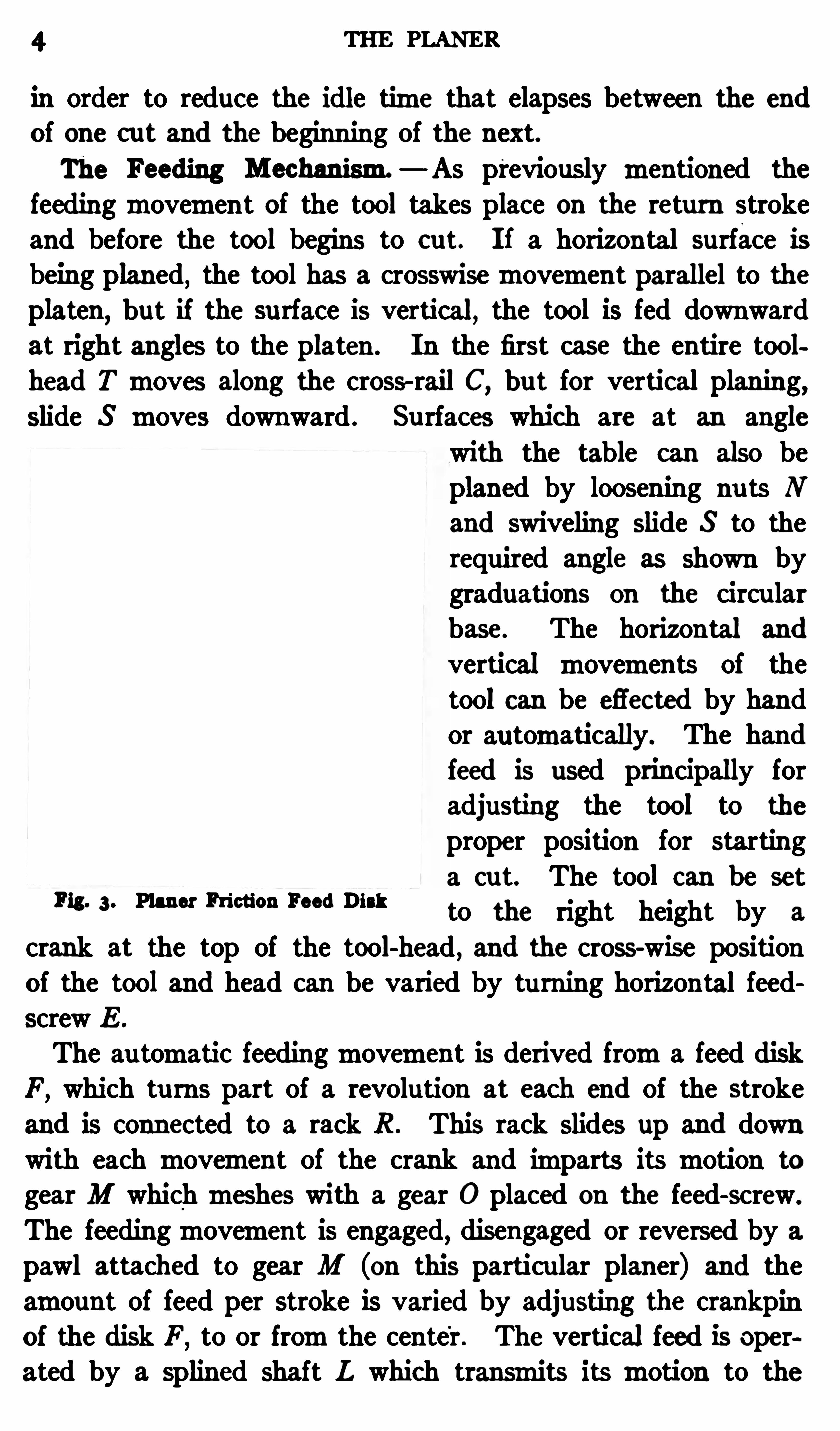
The friction disk F is turned by pinion shaft 6 (Fig. 2) Of the
driving mechanism. The number of revolutions made by thispinion shaft for each stroke depends
,of course
,on the length of
the stroke, but the feed disk is so arranged that it only rotates partof a revolution at each end of the stroke
,so that
,
the feedingmovement is not governed by the length Of the stroke. In otherwords the feed disk is disengaged fromthe driving shaft afterbeing turned part of a revolution . One type of feed disk is shownin the sectional view
,Fig. 3 . The c up-shaped part A having an
inner tapering surface is attached to the main pinion shaft.Crank-disk B has a tapering hub C which fits into part A as
shown . I f the hub is engaged with cupA when the planer isstarted
,the crank-disk is tu rned until a tapered projection D
strikes a stationary taper boss on the bed which disengages hub Cfromthe drivingmember bymoving it outward against the tension of spring E . The disk then stops turning and remainsstationary until the drivingmember A reverses at the end of thestroke. The hub then springs back into engagement and the diskturns in the opposite direction until another taper projection D1,on the opposite side
,strikes a second boss on the bed which
again arrests the feedingmovement . I t will be seen that thissimplemechanismcauses the disk to oscillate through the samearc whether the stroke is long or short .
Spiral-geared P laner.
— There are two general methods of
driving a planer table. Themost common formof drive is thatin which themotion is transmitted fromthe belt pulleys throughspur gearing to a bull-wheel or spur gear
,whichmeshes with
a rack attached to the under side of the planer table, as described
in connection with Figs. 1 and 2 . A planer driven in this wayis known as a
“Spur-geared ” type to distinguish it fromthe
spiral-geared planer . With a spiral-gear drive (sometimesknown as the Sellers drive) themotion is transmitted fromthe
belt pulleys through bevel gears to a shaft which extends under
the bed diagonally and carries a spiral pinion or wormwhich
6 THE PLANER
meshes with the table rack . The belt pulleys aremounted on a
shaft that is parallel to the table, instead of being at right anglesas with a spur gear drive. Smoothness of action is the principaladvantage claimed for the spiral gear drive .
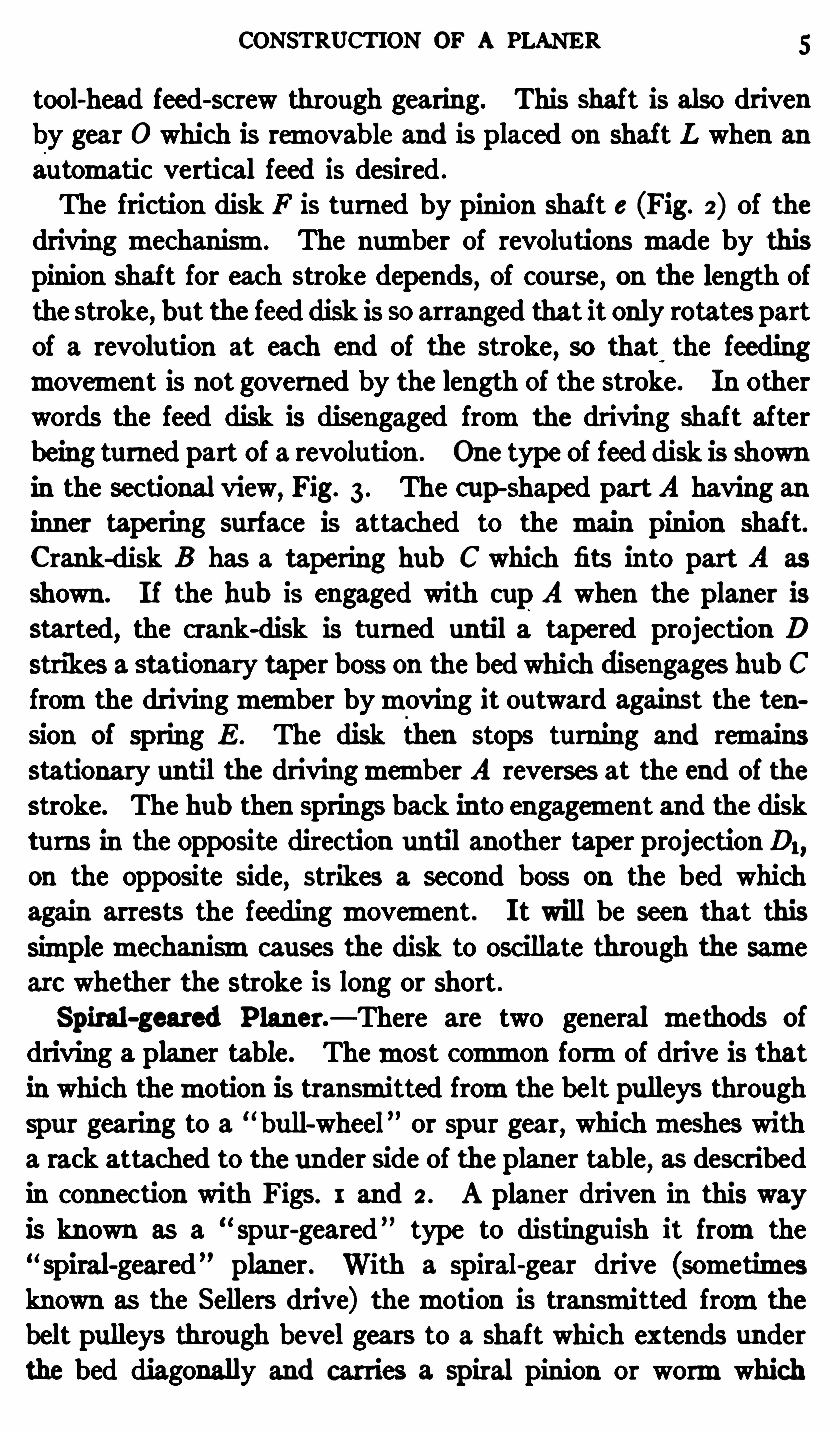
Example of Planer Work. A simple example of planing isillustrated in Fig. 4. The work W is a base casting , the topsurface of which is to be planed true . The casting is first fas
ll‘ig. 4. Side View of Planer with Work in Position
tened to the table by bolts and clamps C and C1, and it is furtherheld fromshifting by stop-pins S . The platens of all planersare provided with a number of slots and holes for the receptionof clamping bolts and stop-pins. When the casting is secu relyattached to the platen ,
a planing tool T is clamped in the toolpost
, and cross-rail R is set a little above the top surface of thework. The dogs D and D1 are then placed opposite the casting
EXAMPLE OF PLANING
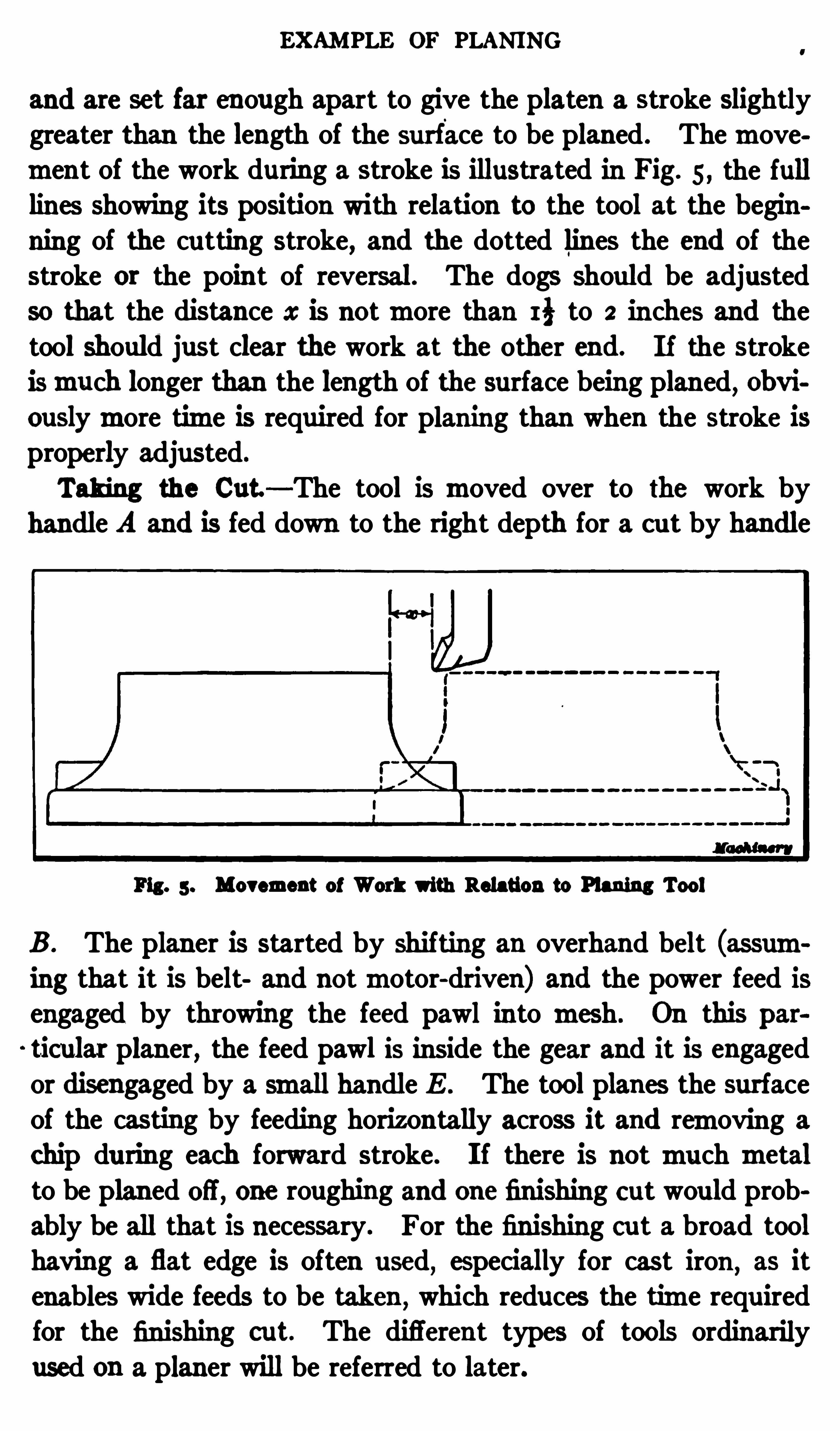
and are set far enough apart to give the platen a stroke slightlygreater than the length of the surface to be planed . Themovement of the work during a stroke is illustrated in Fig. 5 , the fulllines showing its position wi th relation to the tool at the beginning of the cutting stroke
,and the dotted lines the end of the
stroke or the point of reversal . The dogs should be adjustedso that the distance x is notmore than I } to 2 inches and the
tool should just clear the work at the other end. I f the strokeismuch longer than the length of the surface being planed, obviouslymore time is required for planing than when the stroke isproperly adjusted.
Taking the Cut — The tool is moved over to the work by
handle A and is fed down to the right depth for a cut by handle
Fig. 5 . Movement of Work with Relation to Planing Tool
B . The planer is started by shifting an overhand belt (assuming that it is belt and notmotor-driven) and the power feed isengaged by throwing the feed pawl into mesh. On this par
ticular planer, the feed pawl is inside the gear and it is engagedor disengaged by a small handle E . The tool planes the surfaceof the casting by feeding horizontally across it and removing a
chip during each forward stroke. I f there is notmuch metalto be planed off , one roughing and one finishing cut would prob
ably be all that is necessary. For the finishing cut a broad toolhaving a flat edge is often used
,especially for cast iron ,
as it
enables wide feeds to be taken , which reduces the time requiredfor the finishing cut. The different types of tools ordinarily
used on a planer will be referred to later.
THE PLANER
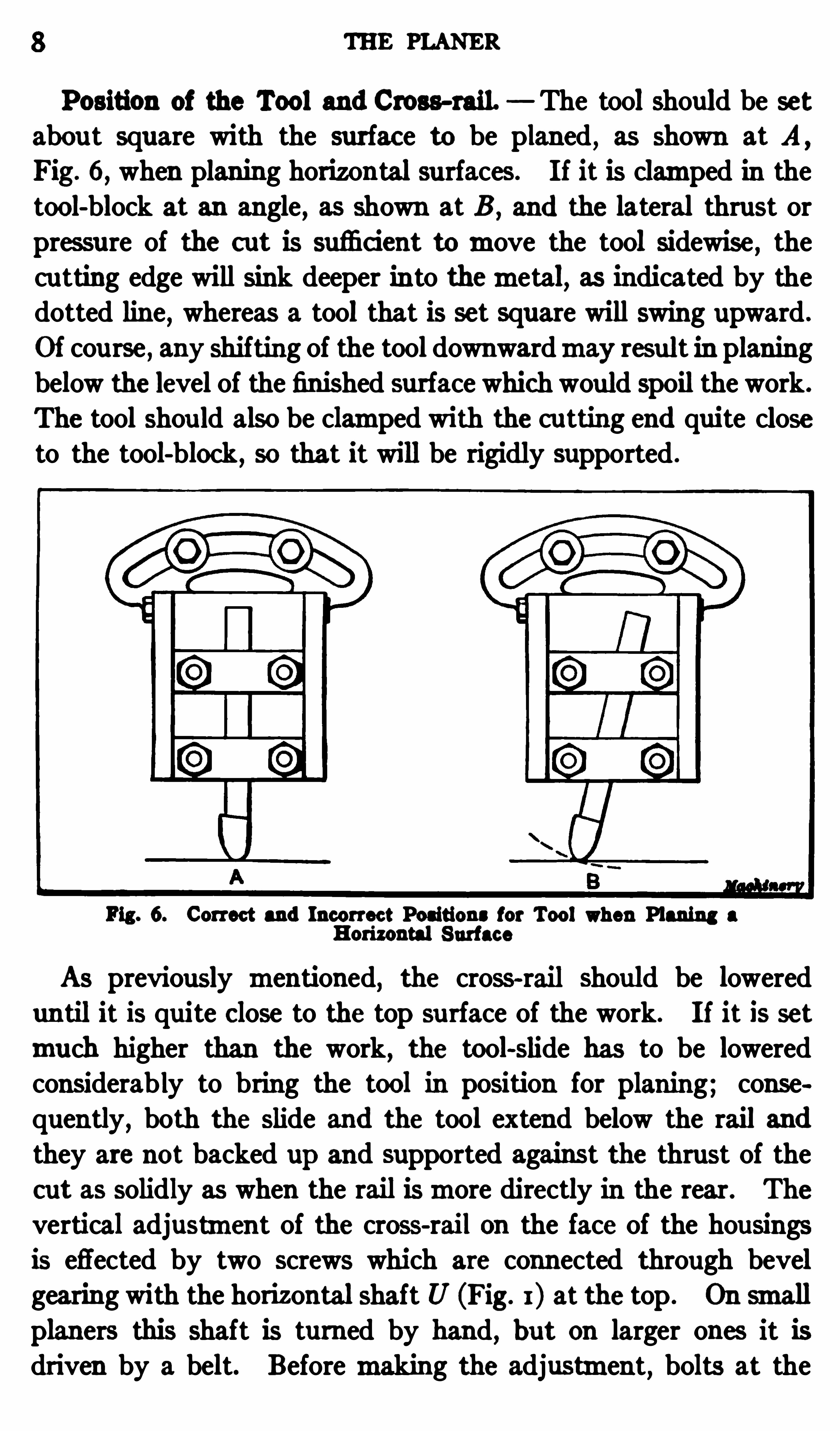
Position of the Tool and Cross-rail. The tool should be set
abou t square with the surfac e to be planed , as shown at A ,
Fig. 6, when planing horizontal surfaces. I f it is clamped in thetool-block at an angle, as shown at B , and the lateral thrust orpressure of the cut is sufi c ient tomove the tool sidewise , thecutting edge will sink deeper in to themetal, as indicated by thedotted line
,whereas a tool that is set square will swing upward .
Of course , any shifting of the tool downwardmay result in planingbelow the level of the finished surface which would spoil the work.
The tool shou ld also be clamped with the cu tting end quite closeto the tool-block ,
so that it will be rigidly supported .
Fig. 6. Correct and Incorrec t Positions for Tool when Planing a
Horizontal Surface
As previously mentioned, the cross-rail should be lowereduntil it is quite Close to the top surface of the work. I f it is set
much higher than the work, the tool-slide has to be loweredconsiderably to bring the tool in position for planing; cousequently , both the slide and the tool extend below the rail andthey are not backed up and supported against the thrust of thecut as solidly as when the rail ismore directly in the rear. The
vertical adjustment of the cross-rail on the face of the housingsis effected by two screws which are connected through bevelgearing with the horizontal shaft U (Fig. I ) at the top . On smallplaners this shaft is turned by hand, but on larger ones it isdriven by a belt. Beforemaking the adjustment
,bolts at the

10 THE PLANER
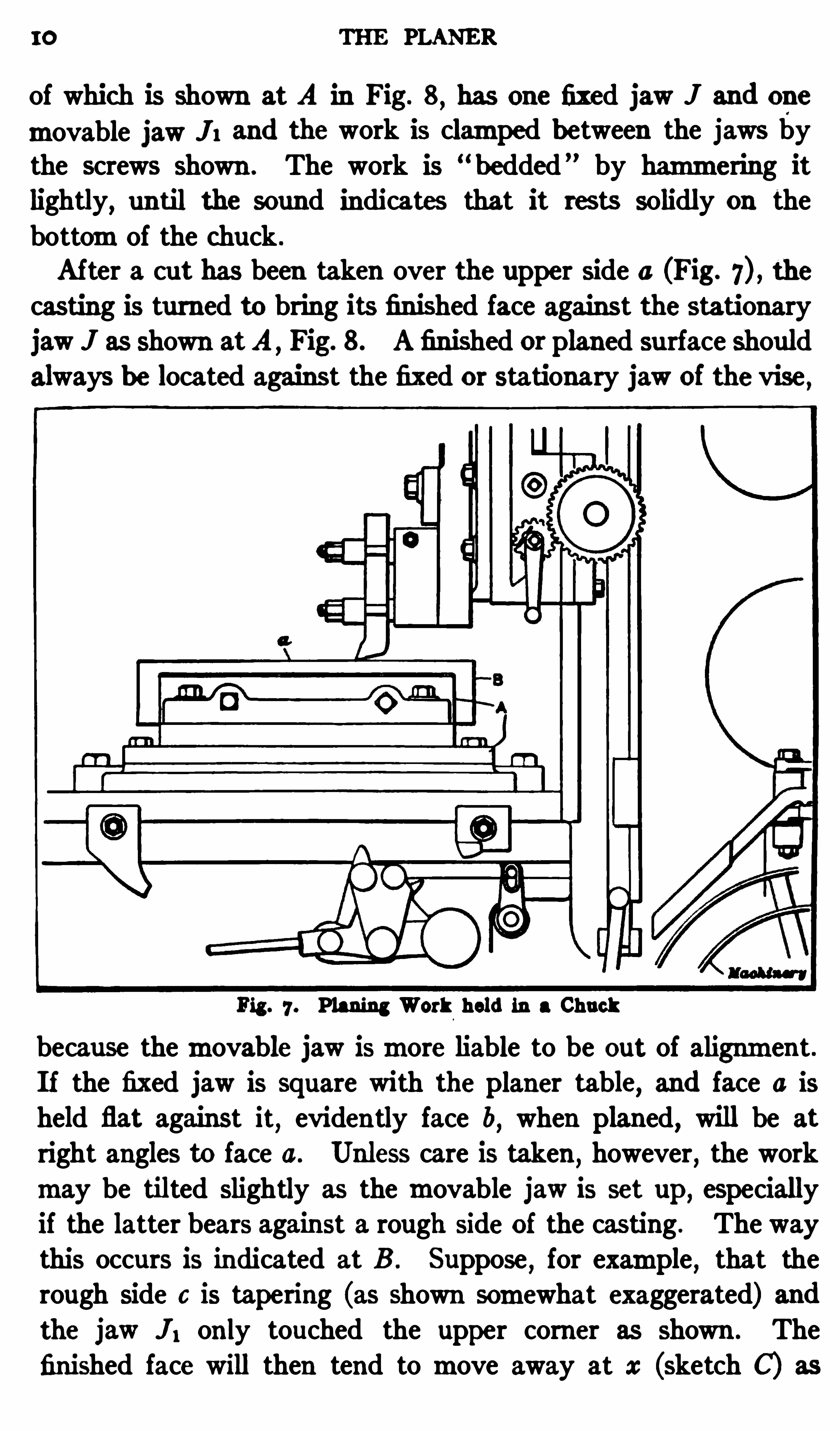
of which is shown at A in Fig. 8,has one fixed jaw J and one
movable jaw J1 and the work is clamped between the jaws bythe screws shown . The work is “
bedded ” by hammering itlightly
,until the sound indicates that it rests solidly on the
bottomof the chuck .
After a cut has been taken over the upper side a (Fig. the
casting is turned to bring its finished face against the stationary
jaw J as shown atA,Fig. 8. A finished or planed surface should
always be located against the fixed or stationary jaw of the vise ,
Fig. 7 . Planing Work held in a Chuck
because themovable jaw ismore liable to be out of alignment .If the fixed jaw is square with the planer table
,and face a is
held flat against it, evidently face b, when planed, will be at
right angles to face 0. Unless care is taken,however
,the work
may be tilted slightly as the movable jaw is set up, especiallyif the latter bears against a rough side of the casting . The waythis occurs is indicated at B . Suppose
,for example , that the
rough side 6 is tapering (as shown somewhat exaggerated) andthe jaw " ; only touched the upper corner as shown . Thefinished face will then tend to move away at x (sketch C) as
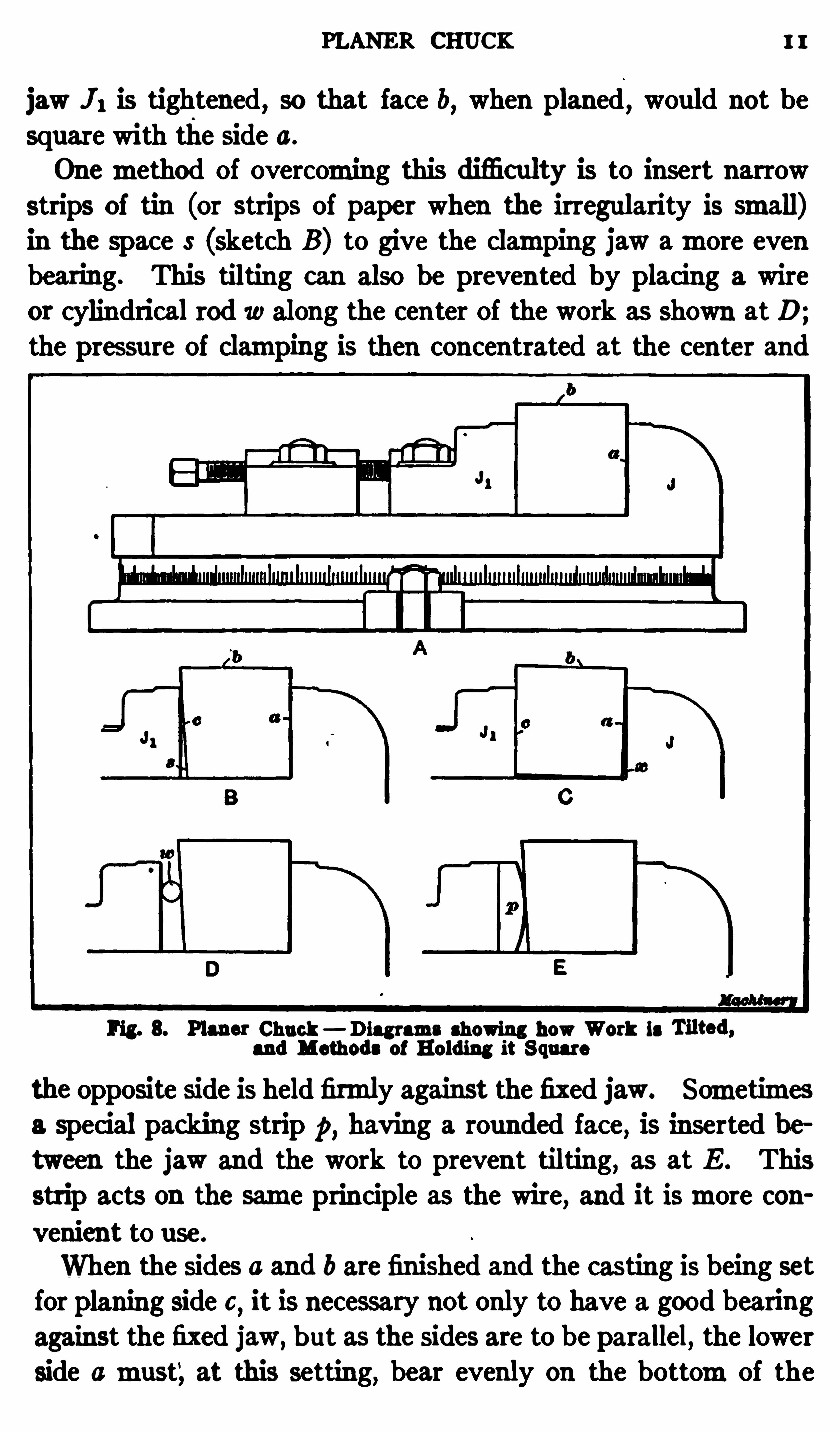
PLANER CHUCK I I
jaw 11 is tightened, so that face b, when planed , would not be
square with the side a.
Onemethod of overcoming this difi culty is to insert narrowstrips of tin (or strips of paper when the irregularity is small)in the space S (sketch B ) to give the clamping jaw amore evenbearing. This tilting can also be prevented by placing a wire
or cylindrical rod 10 along the center of the work as shown atD;the pressure of clamping is then concentrated at the center and
Fig. 8. Plans: Chuck Diagrams showing how Work is
and Methods of Holding it S quare
the opposite side is held firmly against the fixed jaw. Sometimesa special packing strip p, having a rounded face, is inserted be
tween the jaw and the work to prevent tilting, as at E . This
strip acts on the same principle as the wire, and it ismore convenient to use.
When the sides 0 and b are fin ished and the casting is being set
for planing side 0 it is necessary not only to have a good bearing
against the fixed jaw,b ut as the sides are to be parallel, the lower
side amust‘, at this setting, bear evenly on the bottomof the
12 THE PLANER
chuck . A simple method of determining when work is firmlybedded is as follows: P lace strips of thin paper beneath each
end of the work, and after tightening the chuck and hammeringthe casting lightly to give it a good bearing, try to withdraw the
paper strips. I f both are held tightly, evidently the casting
rests on the chuck and the upper side will be planed parallel,provided the chuck itself is true.
The foregoingmethod of planing a block square and parallel,by holding it in a chuck, is not given as one conducive to accu
racy, but rather to illustrate some of the points which should be
observed when clamping work in a planer chuck. I f consider
able acc uracy were required, the block could be held to better
advantage by fastening it directly to the table with spec ial
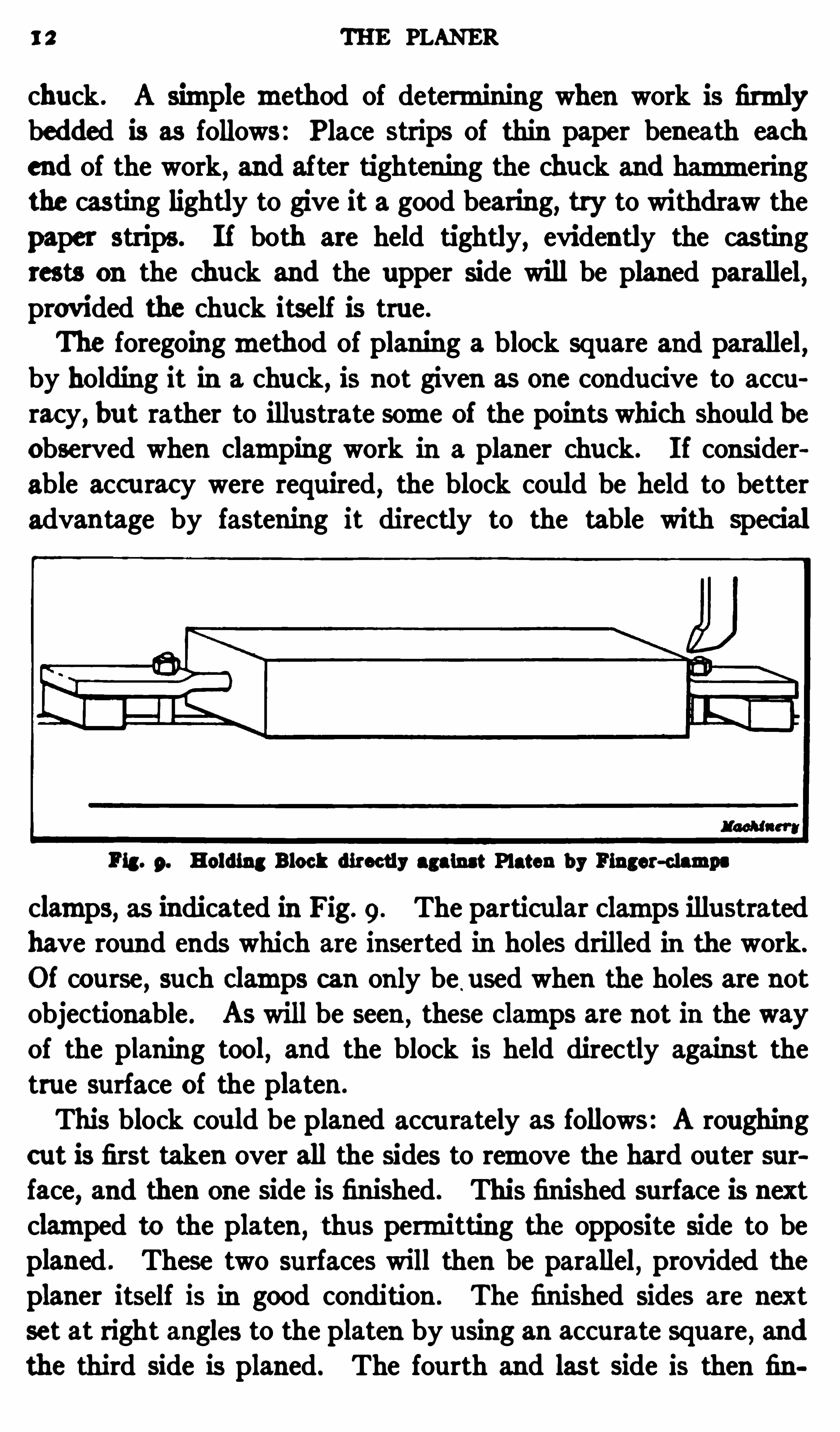
P ig . 9. Holding Block directly against Platen by Finger-clamps
clamps, as indicated in Fig. 9. The particular clamps illustratedhave round ends which are inserted in holes drilled in the work.
Of course , such clamps can only be.used when the holes are not
objectionable . As will be seen ,these clamps are not in the way
of the planing tool,and the block is held directly against the
true surface of the platen .
This block could be planed acc urately as follows: A roughingcut is first taken over all the sides to remove the hard ou ter surface, and then one side is finished. This finished surface is nextclamped to the platen
,thus permitting the opposite side to be
planed . These two surfaces will then be parallel,provided the
planer itself is in good condition . The finished sides are nextset at right angles to the platen by using an accurate square
,and
the third side is planed. The fourth and last side is then fin
DOUBLE-HEAD PLANER 13
ished with the third side clamped against the platen . By thismethod of holding the work, itwould be easier to secure accurateres ults than by using a chuck; a chuck
,however
,is often very
convenient for holding small parts .
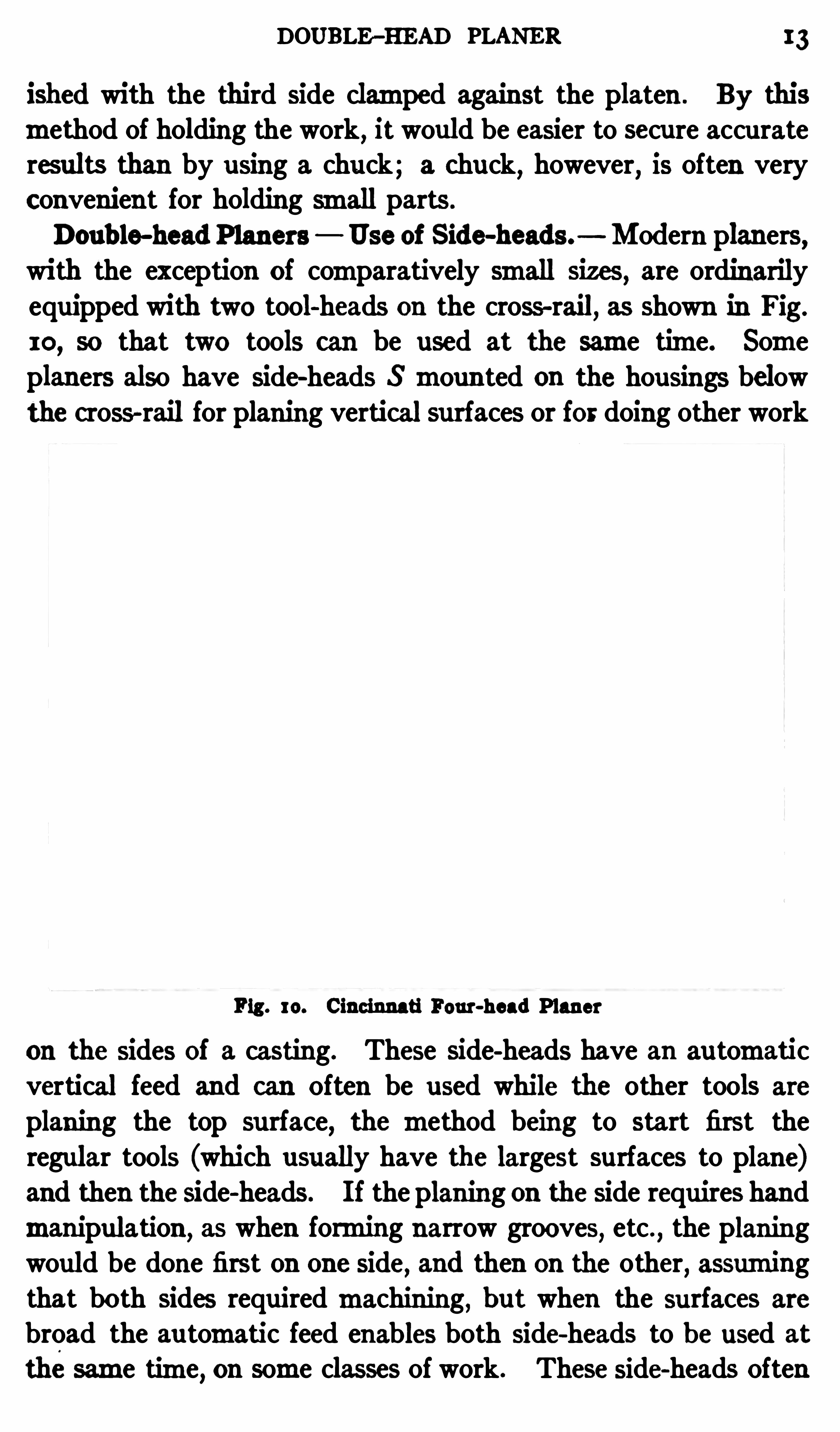
Doub le-head Planers Use of Side-heads. Modern planers,
with the exception of comparatively small sizes, are ordinarily
equipped with two tool-heads on the cross-rail, as shown in Fig.
10, so that two tools can be used at the same time. Some
planers also have side-heads S moun ted on the housings belowthe cross-rail for planing vertical surfaces or for doing other work
Fig . 10. Cincinnati Four-head Planer
on the sides Of a casting. These side-heads have an automati cvertical feed and can Often be used while the other tools are
planing the top surface,the method being to start first the
regular tools (which usually have the largest surfaces to plane)and then the side-heads . I f the planing on the side requires handmanipulation
,as when forming narrow grooves, etc .
,the planing
would be done first on one side, and then on the other,assuming
that both sides requiredmachining, but when the surfaces are
broad the au tomatic feed enables both side-heads to be used at
thesame time, on some classes of work. These side-heads Often
14 THE PLANER
greatly reduce the time required for planing and they alsomakeit possible to finish some parts at one setting, whereas the workwould have to be set up in one or two diflerent positions if aplaner withou t side-heads were used.
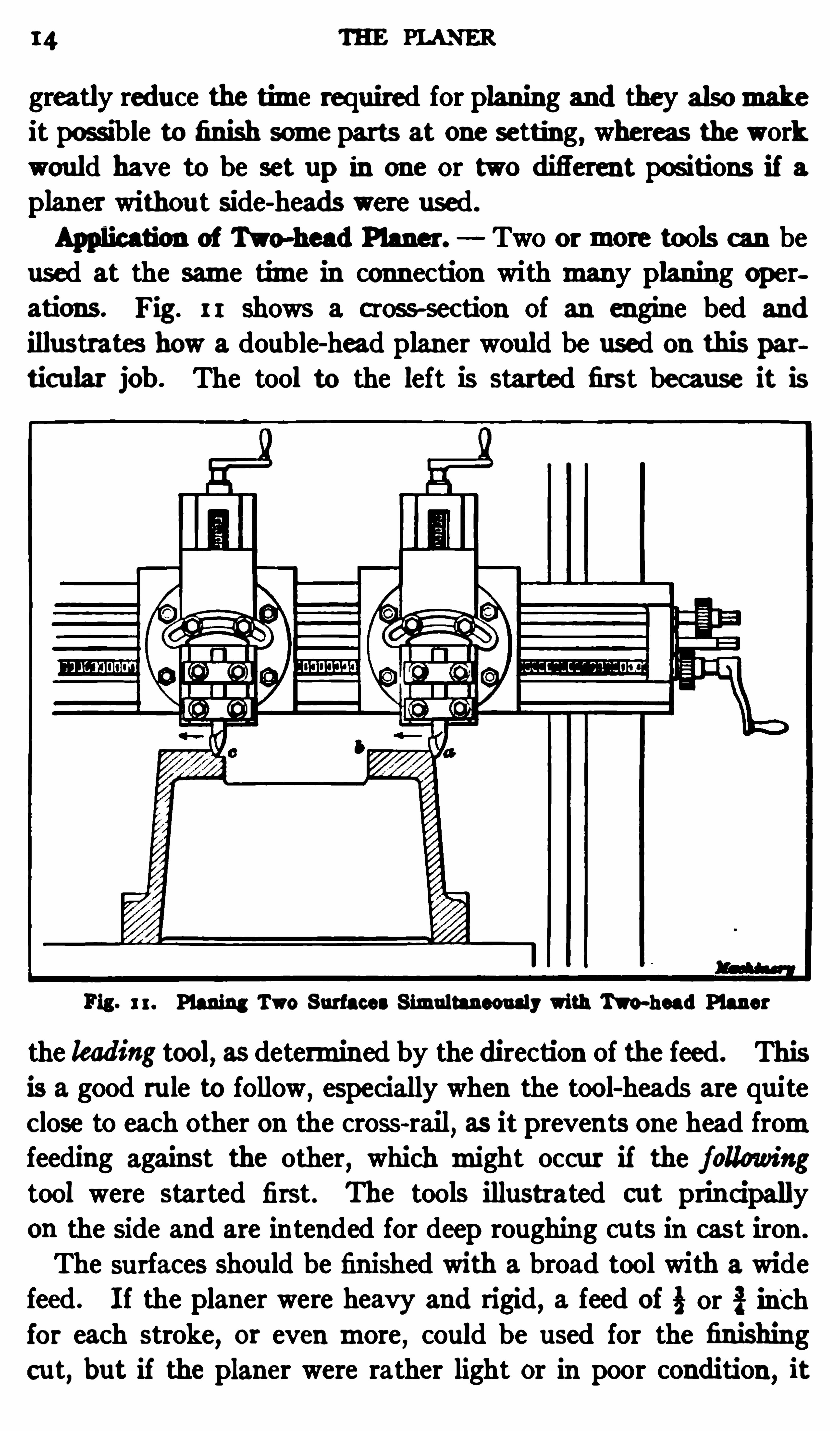
Application of Two-head Planer. Two ormore tools c an beused at the same time in connection with many planing operations. Fig. I I shows a cross-sec tion of an engine bed and
illustrates how a double-head planer would be used on this par
ticular job . The tool to the left is started first because it is
Fig. 1r. Planing Two Surfaces Simultaneously with Two-head Planer
the leading too", as determined by the direction of the feed. Thisis a good rule to follow , especially when the tool-heads are quite
Close to each other on the cross-rail, as it prevents one head fromfeeding against the other, which might occur if the followingtool were started first. The tools illustrated cut principally
on the side and are in tended for deep roughing cu ts in cast iron .
The surfaces should be finished with a broad tool with a widefeed. I f the planer were heavy and rigid
,a feed of i or inch
for each stroke,or even more , could be used for the finishing
cut, but if the planer were rather light or in poor condition , it
USE OF SIDE—HEAD 15
might be neces sary to reduce the feed to 1; inch or less to avoidchatter . It is impossible to give any fixed rule for the amountof feed as this is governed not only by the planer itself
,but also
by the rigidity of the work when set up for planing, the hardnessof themetal, etc. Thefinal cut should be taken by a single toolto insure finishing both sides to the same height. This tool
should be fed by power froma to b,and then rapidly by hand
fromb to c for finishing the opposite side . The use of two tools
for rough planing greatly reduces the time required formachining work of this kind .
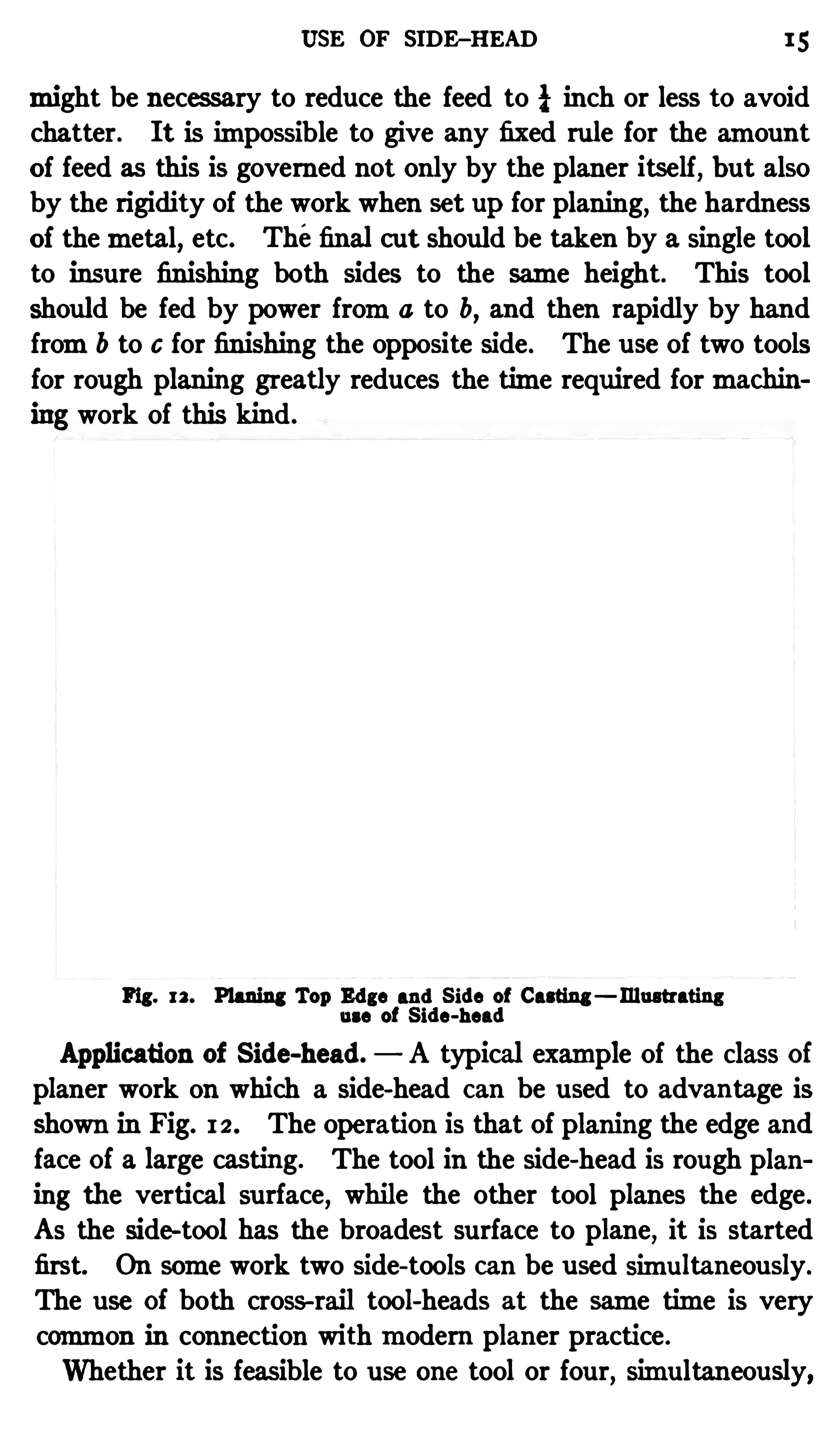
Fig. rz. Planing Top Edge and S ide of Casting — Illustratinguse of S ide-head
Application of Side-head. A typical example of the Class ofplaner work on which a side-head can be used to advantage is
shown in Fig. 12 . The operation is that of planing the edge andface of a large casting. The tool in the side-head is rough plan
ing the vertical surface, while the other tool planes the edge .
As the side-tool has the broadest surface to plane,it is started
first. On some work two side-tools can be used simu ltaneously.
The use of both cross- rail tool-heads at the same time is verycommon in connection withmodern planer practice .
Whether it is feasible to use one tool or four, simultaneously,
16 THE PLANER
depends altogether on the shape of the work and the locationOf the surfaces to bemachined . Very often only one tool canbe used
,and
,occasionally
,four tools can be operated at the
same time,provided
,of course
,the planer is equ ipped with four
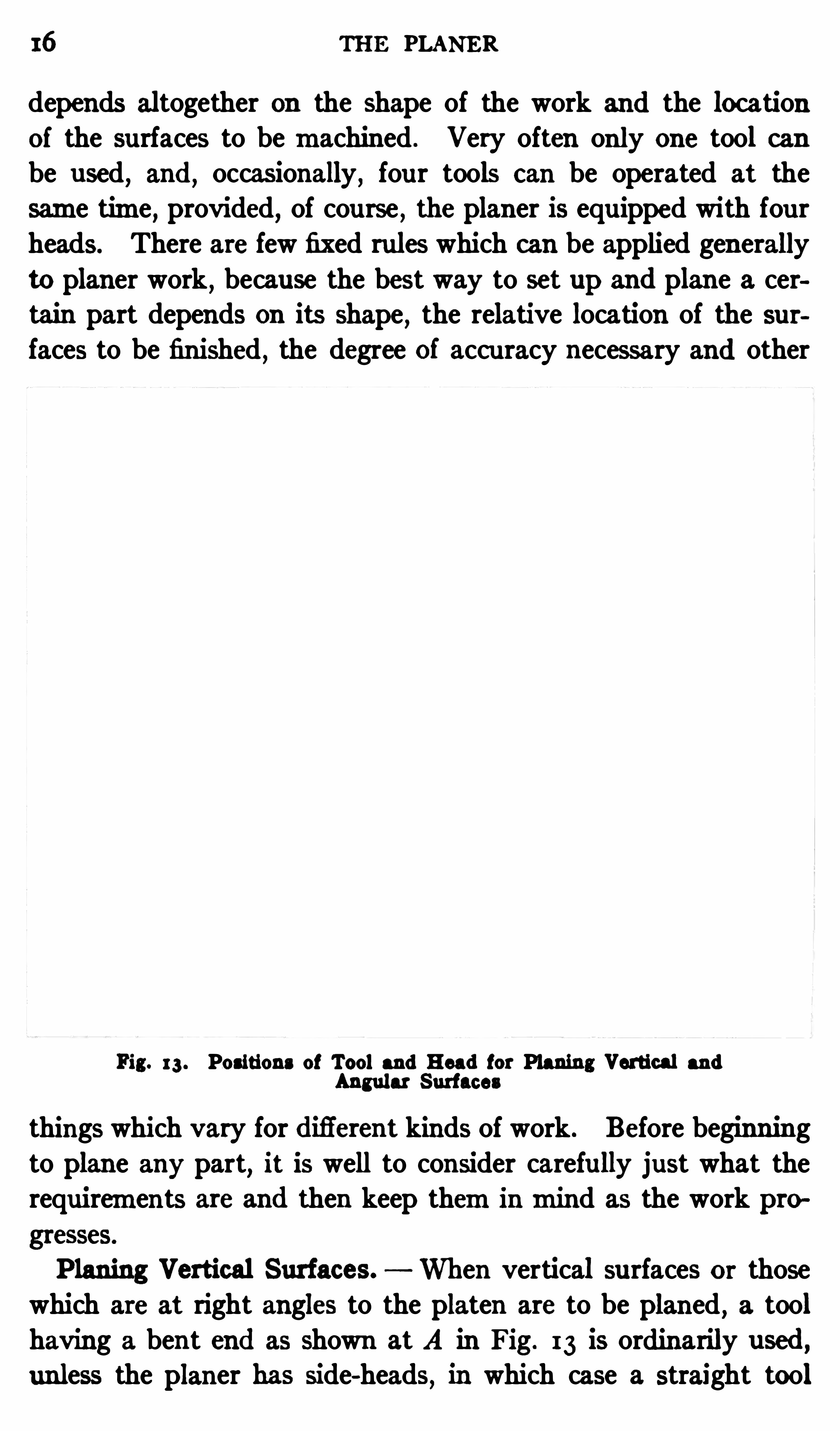
heads. There are few fixed rules which can be applied generallyto planer work , because the best way to set up and plane a certain part depends on its shape
,the relative location of the sur
faces to be finished,the degree of accu racy necessary and other
Fig. 13 . Positions of Tool and Head for Planing Vertical and
Angular Surfaces
things which vary for difierent kinds of work. Before beginningto plane any part, it is well to consider carefully just what therequirements are and then keep theminmind as the work pro
gresses.
P laning Vertical Surfaces. When vertical surfaces or thosewhich are at right angles to the platen are to be planed , a tool
having a bent end as shown at A in Fig. 13 is ordinarily used ,unless the planer has side-heads
,in which case a straight tool

18 THE PLANER
the slide shmld be at right angls to the platm. I ts position ,
however, can be determinedmore aomratc ly by holding the b ladeof a square which rcsts on thé platen against one side of the
tool-slide, as it is difi c ult to set graduation lines to exac tly coin
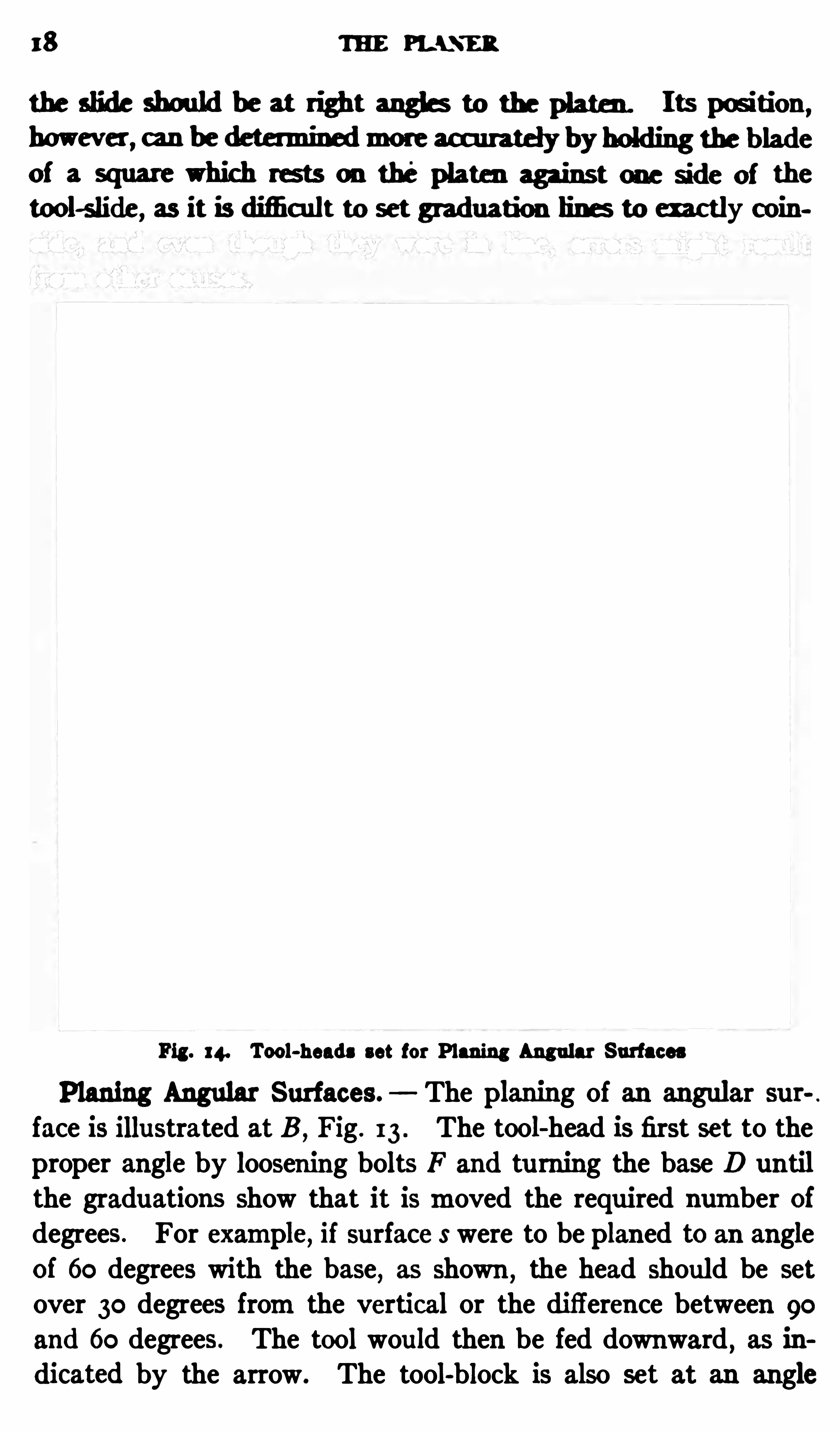
Fig. I 4. Tool-heads set for Planing Angu lar Surfaces
Planing Angular Surfaces. The planing of an angular sur
face is illustrated at B ,Fig. 13 . The tool-head is first set to the
proper angle by loosening bolts F and tu rning the base D untilthe graduations Show that it ismoved the required number ofdegrees. For example, if surface s were to be planed to an angle
of 60 degrees with the base, as shown , the head should be set
over 30 degrees fromthe vertical or the difference between goand 60 degrees. The tool would then be fed downward , as in
dicated by the arrow. The tool-block is also set at an angle
CLAMPING METHODS 19
with slide S ,when planing angular surfaces, so that the tool will
swing clear on the return stroke . The top of the block shouldalways be turned awayf romthe surface to beplaned, which appliesto the planing of either vertical or angular surfac es when usingthe cross-rail head.
An example of angular work is illustrated in Fig. 14, whichshows a planer arranged for planing the V—shaped ways or guideson the bottomof a planer platen . Both tool slides are set tothe required angle for planing one side Of each vee . As thereare two tool-heads, both vees can ,
of course,be planed simu lta
neously . The sides of the platen are also planed at the samesetting by tools held in the side-heads.
Holding Work on the P laner. A great deal of the work doneon a planer is very simple as far as the actual planing is con
cerned,but often considerable skill and ingenuity are required
in setting parts on a planer and clamping themin the bestmanner. There are three important points that should be considered when doing work of this kind . First
,the casting or
forgingmust be held securely to prevent its being shifted by thethrust of the cut; second, the work should not be sprung out ofshape by the clamps; and third , the workmust be held in sucha position that it will be possible to finish all the surfaces thatrequire planing
,in the right relation with one another. Pre
quently a little planning before the setting-up” operation will
avoid considerable worry afterwards,to say nothing of spoiled
work.
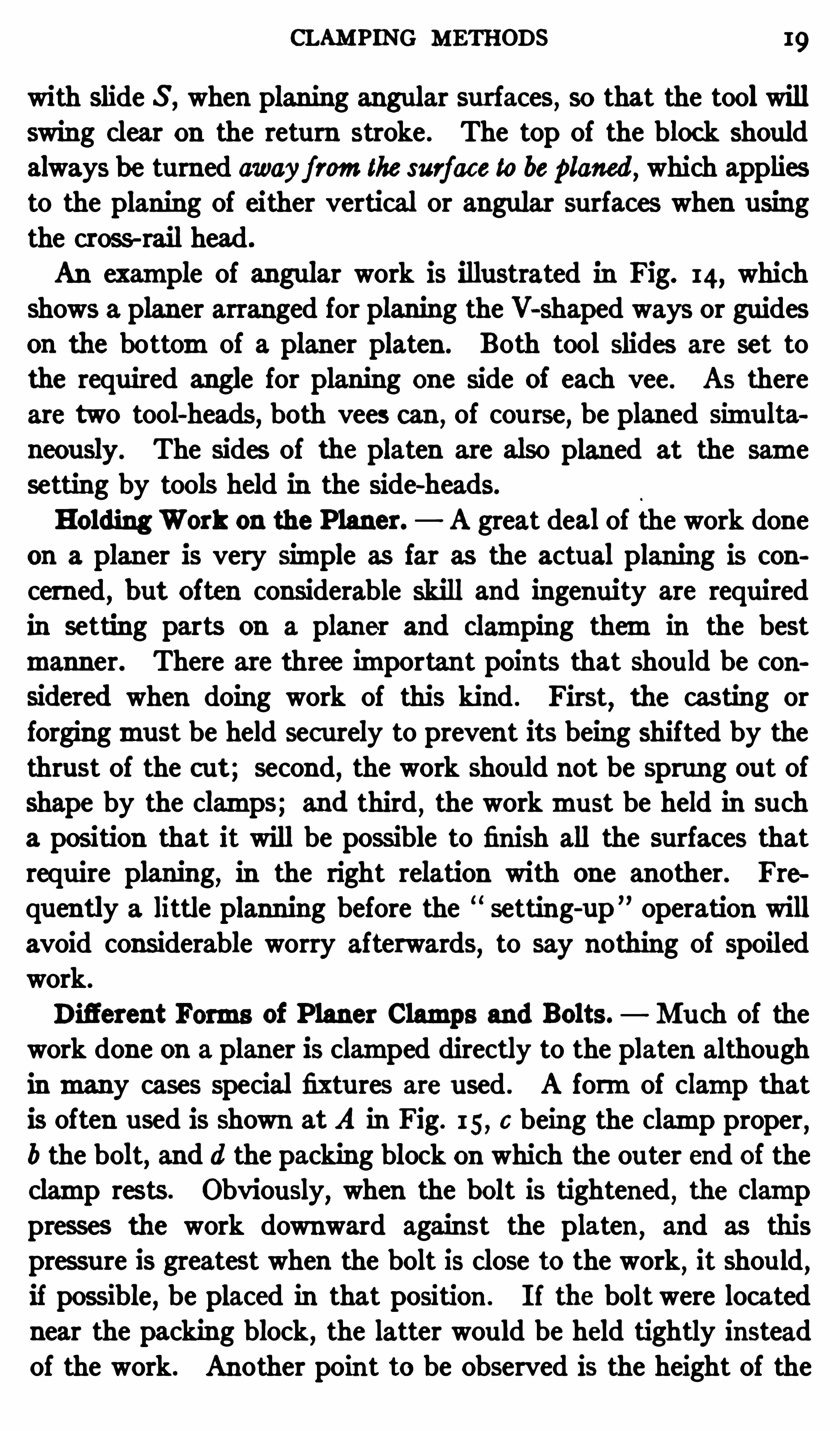
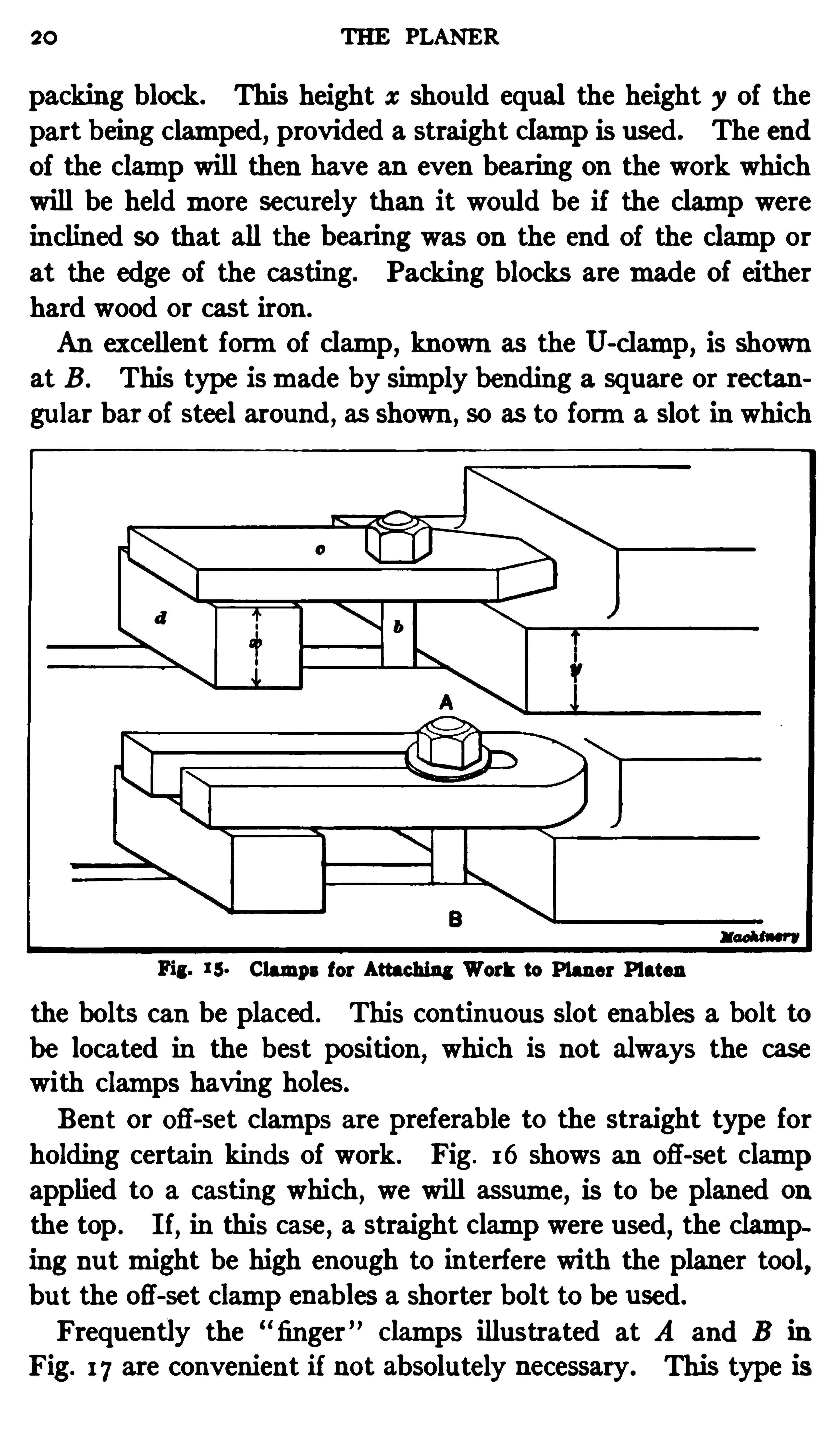
Difierent Forms of P laner Clamps and Bolts. Mu ch of thework done on a planer is clamped directly to the platen although
inmany cases special fixtures are used . A formof clamp thatis often used is shown at A in Fig. I 5 , 0 being the Clamp proper,b the bolt, and d the packing block on which the ou ter end of theclamp rests. Obviously, when the bolt is tightened, the Clamppresses the work downward against the platen
,and as this
pressure is greatest when the bolt is close to the work, it should ,if possible
,be placed in that position . I f the bolt were located
near the packing block , the latter would be held tightly insteadof the work. Another point to be Observed is the height of the
20 THE PLANER
packing block. This height as should equal the height y of thepart being clamped , provided a straight clampis used. The end
of the clamp will then have an even bearing on the work whichwill be held more securely than it would be if the clamp wereinclined so that all the hearing was on the end of the clamp orat the edge of the casting. Packing blocks aremade Of eitherhard wood or cast iron .
An excellent formof clamp,known as the U-clamp , is shown
at B . This type ismade by simply bending a square or rec tangu lar bar of steel around , as shown , SO as to forma slot in which
Fig. rs. Clamps for Attaching Work to Planer Platen
the bolts can be placed . This continuous slot enables a bolt tobe located in the best position
,which is not always the case
with clamps having holes.
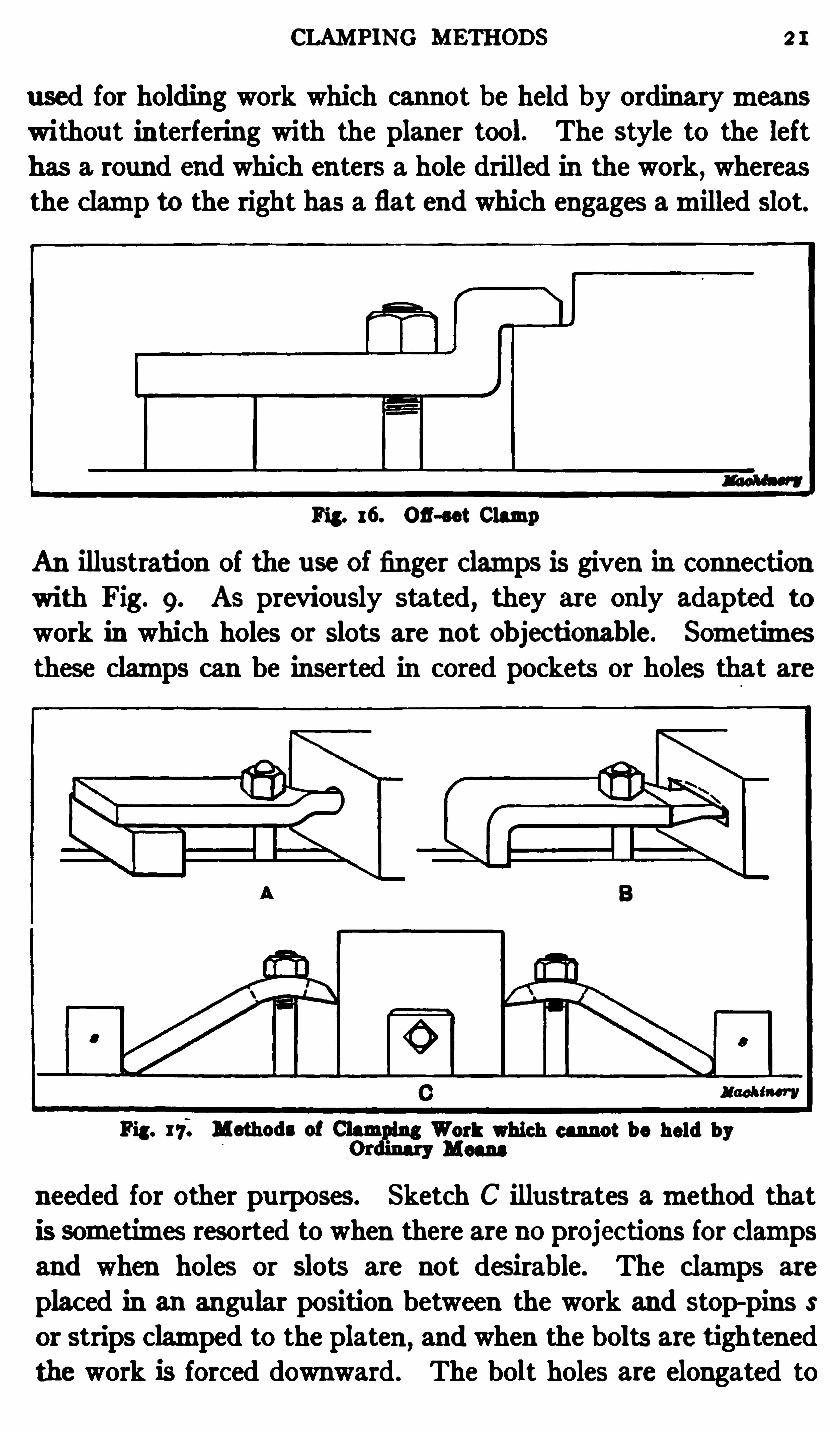
Bent or off -set clamps are preferable to the straight type for
holding certain kinds of work. Fig . I 6 shows an off -set Clampapplied to a casting which, we will assume, is to be planed on
the top . I f, in this case , a straight Clamp were used
,the clamp
ing nutmight be high enough to interfere with the plan er tool,
but the ofl-set clamp enables a shorter bolt to be used.
Frequently the “finger ” Clamps illustrated at A and B in
Fig. 17 are convenient if not absolutely necessary. This type is
CLAMPING METHODS 2 I
used for holding work which cannot be held by ordinarymeanswithout interfering with the planer tool. The style to the left
has a round end which enters a hole drilled in the work,whereas
the clamp to the right has a flat end which engages amilled slot.
Fig. 16. 03 -3“ Clamp
An illustration of the use of finger clamps is given in connectionwith Fig. 9. As previously stated
,they are only adapted to
work in which holes or slots are not Ob jec tionab le. Sometimesthese clamps can be inserted in cored pockets or holes that are
Fig. 17 . Methods of ClamOrmy
wort which cannot be held by
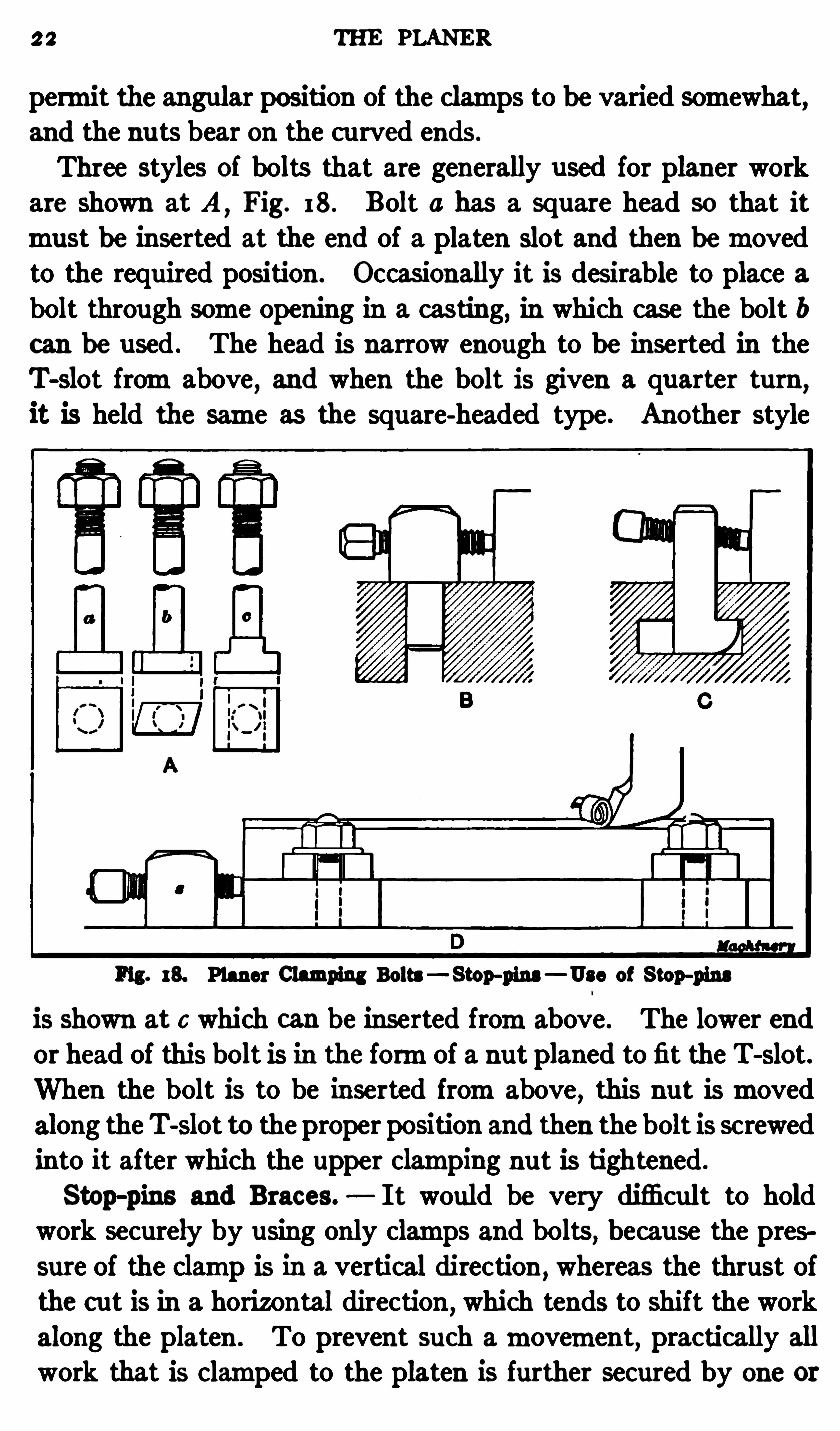
needed for other purposes. Sketch C illustrates amethod thatis sometimes resorted to when there are no projections for clampsand when holes or slots are not desirable . The clamps are
placed in an angular position between the work and stop-pins Sor strips clamped to the platen
,and when the bolts are tightened
the work is forced downward. The bolt holes are elongated to
2 2 THE PLANER
permit the angular position of the clamps to be varied somewhat,and the nu ts bear on the cu rved ends .
Three styles of bolts that are generally used for planer workare shown at A
,Fig. 18. Bolt a has a square head so that it
must be inserted at the end of a platen slot and then bemovedto the required position . Occasionally it is desirable to place abolt through some opening in a casting, in which case the bolt bcan be used . The head is narrow enough to be inserted in theT-slot fromabove
,and when the bolt is given a quarter turn
,
it is held the same as the square-headed type . Another style
Fig. 18. Planer Clamping Bolts— Stop-fins — Use of Stop-fins
is shown at c which can be inserted fromabove. The lower endor head of this bolt is in the formof a nut planed to fit the T-slot.
When the bolt is to be inserted fromabove , this nut ismovedalong theT-slot to the proper position and then the bolt is screwedinto it after which the upper clamping nut is tightened .
Stop-pins and Brac es. I t would be very difficult to hold
work securely by using only clamps and bolts,because the pres
sure of the clamp is in a vertical direction,whereas the thrust of
the cut is in a horizontal direction,which tends to shift the work
along the platen . To prevent such amovement,practically all
work that is clamped to the platen is further secured by one or
CLAMPING METHODS 3
more stop-pins S , which are placed at one end of the part beingplaned as indicated at D
, Fig. 18. These pins are generallymade in two styles, one of which has a shank that fits the holesin the planer platen as shown at B
, and the other an end whichenters the T-slot as at C. By having one type for holes and
another for T-slots, the stop-pins can be located in practicallyany position . After the pins are inserted in the platen
,the
screws shown are adjusted against the work. Stop-pins are
ordinarily placed at one end of the work to take the thrust ofthe cut, and sometimes they are needed along the sides to pre
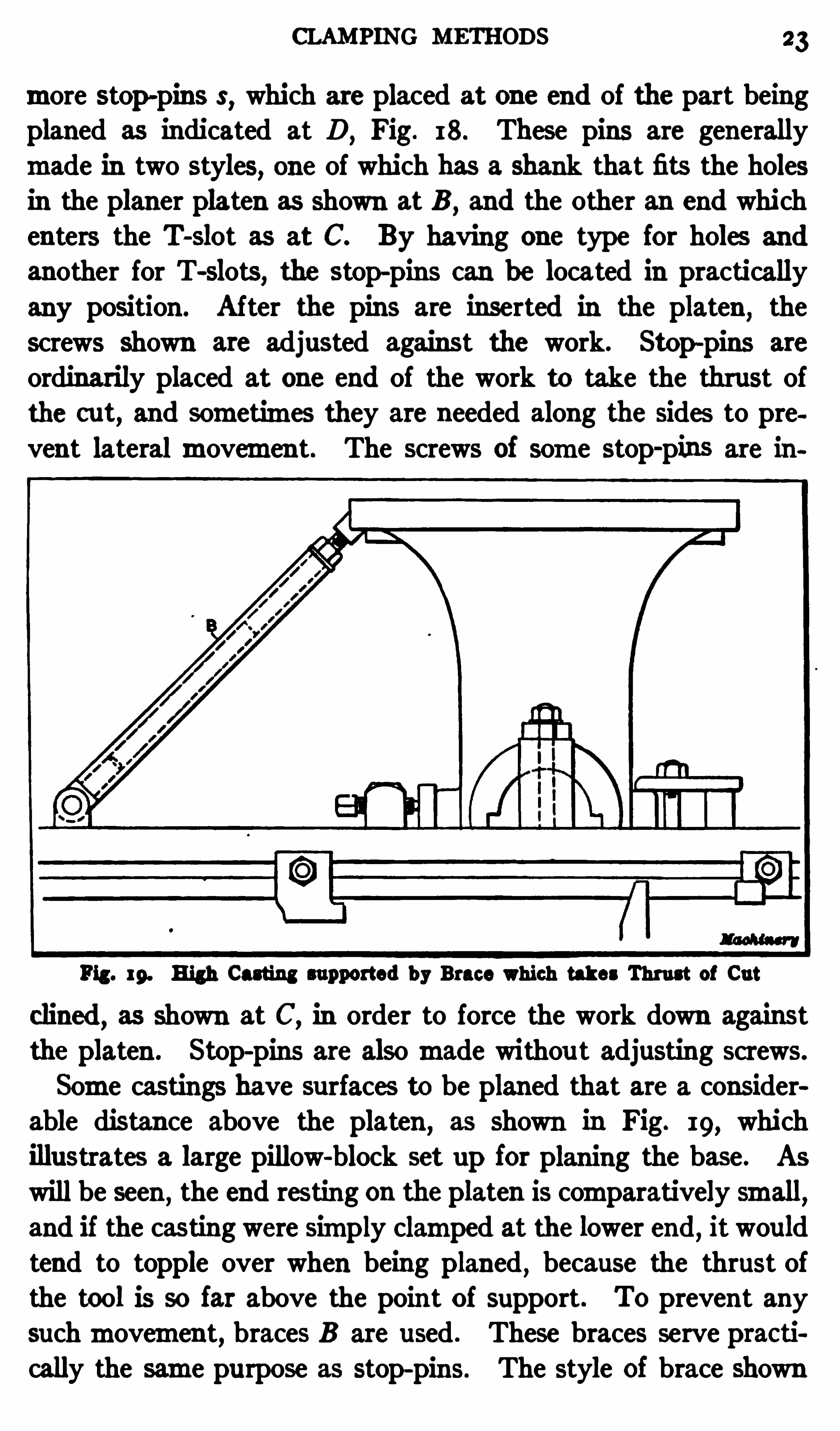
vent lateralmovement. The screws of some stop-pins are in
Fig. rp. High Casting supported by Brace which takes Thrust of Cut
clined, as shown at C
,in order to force the work down against
the platen . Stop-pins are alsomade withou t adjusting screws.
Some castings have surfaces to be planed that are a considerable distance above the platen
,as shown in Fig. 19, which
illustrates a large pillow-block set up for planing the base. AS
will be seen,the end restin g on the platen is comparatively small,
and if the casting were simply clamped at the lower end,itwould
tend to topple over when being planed , because the thrust ofthe tool is so far above the point of support . To prevent anysuchmovement, braces B are used . These braces serve practically the same purpose as stop-pins. The style of brace shown
24 THE PLANER
has a hinged pin in its lower end which enters a hole in theplaten
, and the body of the brace 15 a piece of heavy pipe. At
the‘
upper end there is an adjustable fork-shaped piece whichengages the work, and the hinged joint at the lower end enablesthe brace to be placed at any angle. In some Shops woodenblocks are used as braces. The arrangement of these braces and
the number employed for any given case depend of course on theShape and size of the casting, and this also applies to the use of
stop-pins and clamps. The location of all braces and clampingappliances should be determined by considering the strains towhich the part will be subjected during the planing operation .
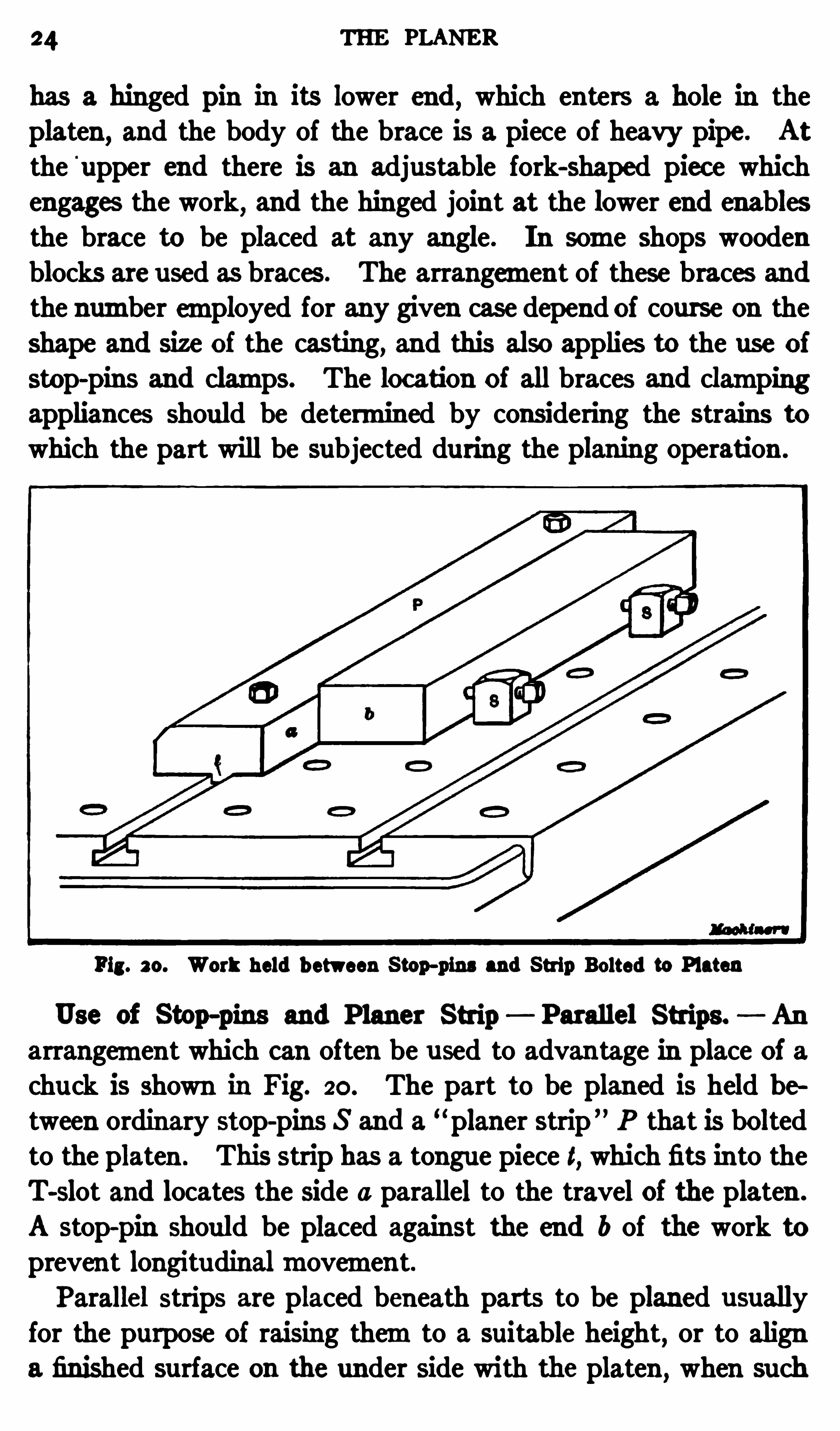
Pig. so. Work held b etween Stop-pins and Strip Bolted to Platen
Use of Stop-pins and P laner Strip Parallel Strips. An
arrangement which can often be used to advantage in place of achuck is shown in Fig. 20. The part to be planed is held between ordinary stop-pins S and a
“planer strip ” P that is boltedto the platen . This strip has a tongue piece t, which fits into theT-slot and locates the side a parallel to the travel of the platen .
A stop-pin should be placed against the end b of the work toprevent longitudinalmovement.Parallel strips are placed beneath parts to be planed usually
for the purpose of raising themto a suitable height,or to align
a finished surface on the under side with the platen,when such

26 THE PLANER
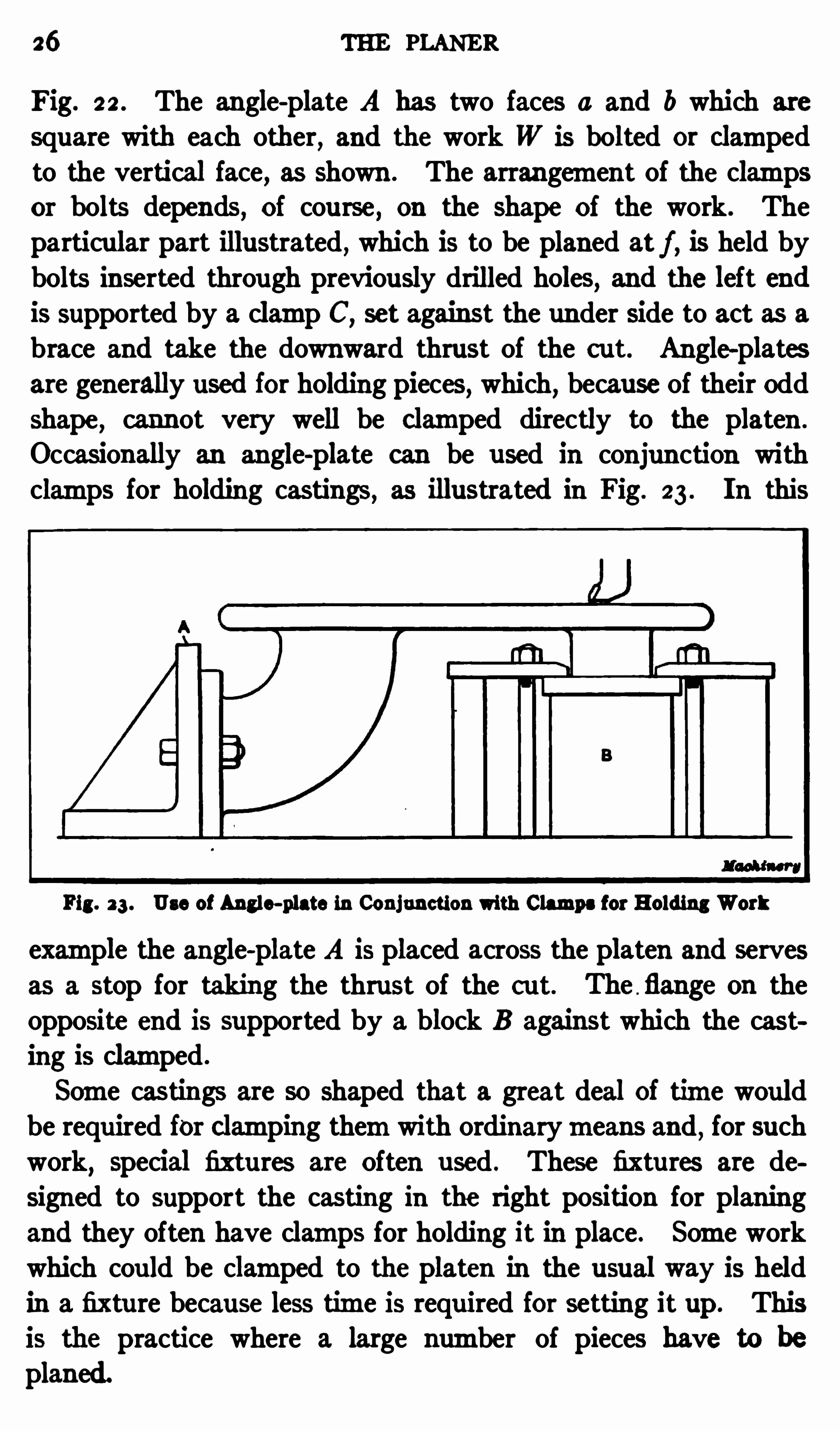
Fig. 22 . The angle-plate A has two faces a and b which are
square with each other, and the work W is bolted or clampedto the vertical face, as shown . The arrangement of the clampsor bolts depends, of course , on the shape of the work. Theparticular part illustrated , which is to be planed at f , is held bybolts inserted through previously drilled holes, and the left end
is supported by a clamp C,set against the under Side to act as a
brace and take the downward thrust of the cut. Angle-plates
are generally used for holding pieces, which, because of their Odd
shape, cannot very well be c lamped directly to the platen .
Occasionally an angle-plate can be used in conjunction withclamps for holding castings, as illustrated in Fig. 23 . In this
Fig. 3 3 . Use of Angle-plate in Conjunction with Clamps for Holding Work
example the angle-plate A is placed across the platen and servesas a stop for taking the thrust of the cut. The flange on theopposite end is supported by a block B against which the casting is clamped .
Some castings are so shaped that a great deal of time wouldbe required for Clamping themwith ordinarymeans and
,for such
work,special fixtures are Often used . These fixtures are de
signed to support the casting in the right position for planingand they often have clamps for holding it in place. Some workwhich could be clamped to the platen In the usual way is heldin a fixtu re because less time is required for setting it up. Thisis the practice where a large number of pieces have to be
planed.
CLAMPING METHODS 2 7
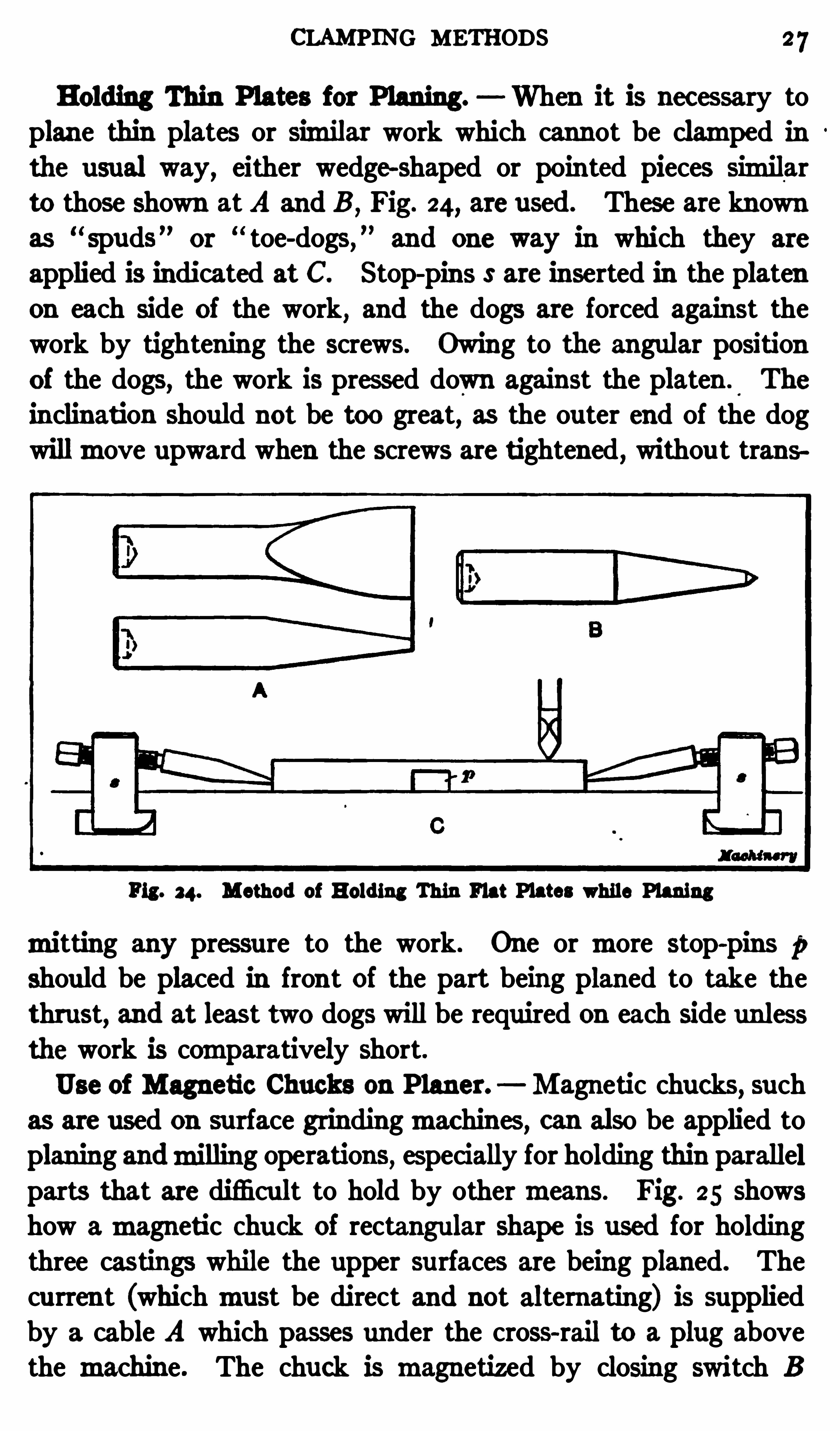
Holding Thin P lates for Planing. When it is nec essary toplane thin plates or similar work which cannot be clamped inthe usual way, either wedge-shaped or pointed pieces similarto those shown atA and B
,Fig. 24, are used . These are known
as spuds or toe-dogs, and one way in which they are
applied is indicated at C. Stop-pins S are inserted in the platen
on each side of the work,and the dogs are forced against the
work by tightening the screws. Owing to the angular position
of the dogs, the work is pressed down against the platen.
The
inclination should not be too great, as the outer end of the dogwillmove upward when the screws are tightened , withou t trans
Pig. 34. Method of Holding Thin Flat Plates while Planing
mitting any pressure to the work. One or more stop-pins 1:
should be placed in front of the part being planed to take the
thrust, and at least two dogs will be required on each side unless
the work is comparatively short.
Use of Magneti c Chucks on P laner. Magnetic chucks, such
as are used on su rface grindingmac hines, can also be applied toplaning andmilling operations, especially for holding thin parallelparts that are difficult to hold by othermeans. Fig. 25 showshow amagneti c Chu ck of rectangular shape is used for holdingthree castings while the upper surfaces are being planed. Thecurren t (whichmust be direct and not alternating) is suppliedby a cable A which passes under the cross-rail to a plug abovethe machine. The chuck is magnetized by closing switch B
28 THE PLANER
which is a duplex type . In order to demagnetize the chuckface
,open the switch andmove the handle un til the switch bars
nearly come into con tact with the posts on the opposite end;then quicklymove the switch bars in and out of contact with
the posts . Thismovement, if timed correctly, will remove themagnetismleft by the previousmagneti c charge. I f the contact
should be too long, the chuck will simply become oppositely
Fig. 3 5 . Walker Magnetic Chuck applied to Planing Operation
charged and in such a case , it can be discharged again bymovingthe switch in and out Of contact with the opposite posts .
The castings are held against end-wisemovement by the stripC which takes the thrust Of the cut. Slotted clamps D are also
used to stay the work laterally. When a number Of pieces are
held on the Chuck at one time, it is advisable to separate themwith strips of non-magnetic material. I ron or steel parts can
be held on magnetic chucks, and the gripping power dependsupon the amount Of surface in contact with the Chuck face.
CLAMPING METHODS 29
Imbedding Work in P laster of Paris or Wax. Sometimes itis necessary to plane thin parts which cannot be held onmagneticchucks because they aremade of some non-magnetic material,such as bronze , or because they are so irregular in Shape thatthere is not sufficient surface in contact with the Chuck face tohold the work securely. In such cases, itmay be advisable toimbed the work in plaster of Paris, especial ly if the parts are
flexible and liable to be sprung out of shape and it is impossibleto use ordinary clamps. A mixture of melted bees-wax and
‘
rosin in about equal proportions is also used for this purpose.
One ormore pieces are placed in a box-shaped enclosure and
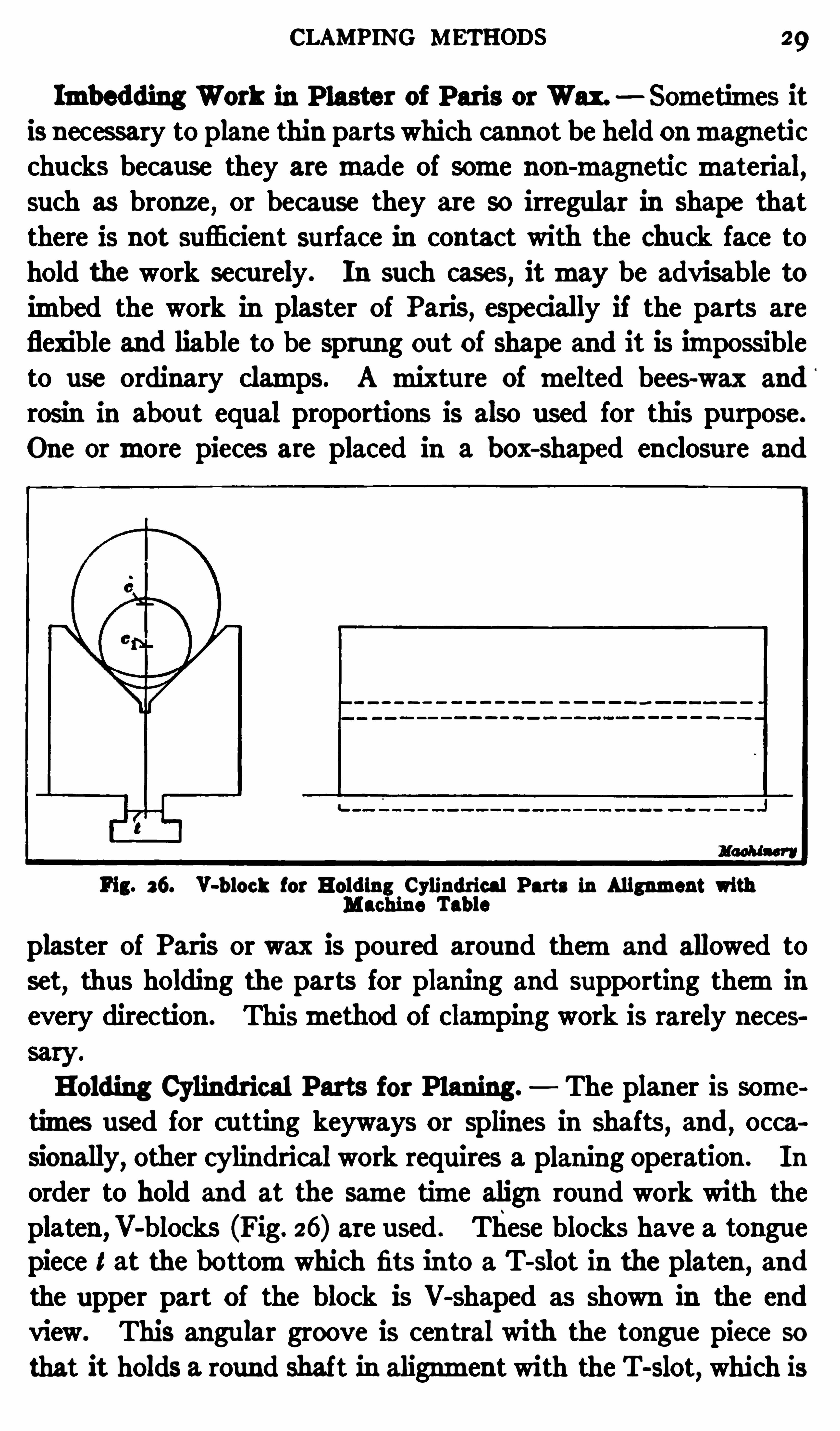
Fig. 26. V-b lock for Holding Cylindrical Parts in AlignmentMachine Tab le
plaster of Paris or wax is poured around themand allowed toset
,thus holding the parts for planing and supporting themin
every direction . Thismethod Of clamping work is rarely neces
Holding Cylindrical Parts for Planing. The planer is sometimes used for cutting keyways or splines in shafts, and , occa
sionally, other cylindrical work requires a planing operation . In
order to hold and at the same time align round work with theplaten ,V-blocks (Fig. 26) are used . These blocks have a tonguepiece t at the bottomwhich fits into a T-slot in the platen
,and
the upper part of the block is V-shaped as shown in the end
view. This angular groove is central with the tongue piece so
that it holds a round shaft in alignment with the T-slot, which is
30 THE PLANER
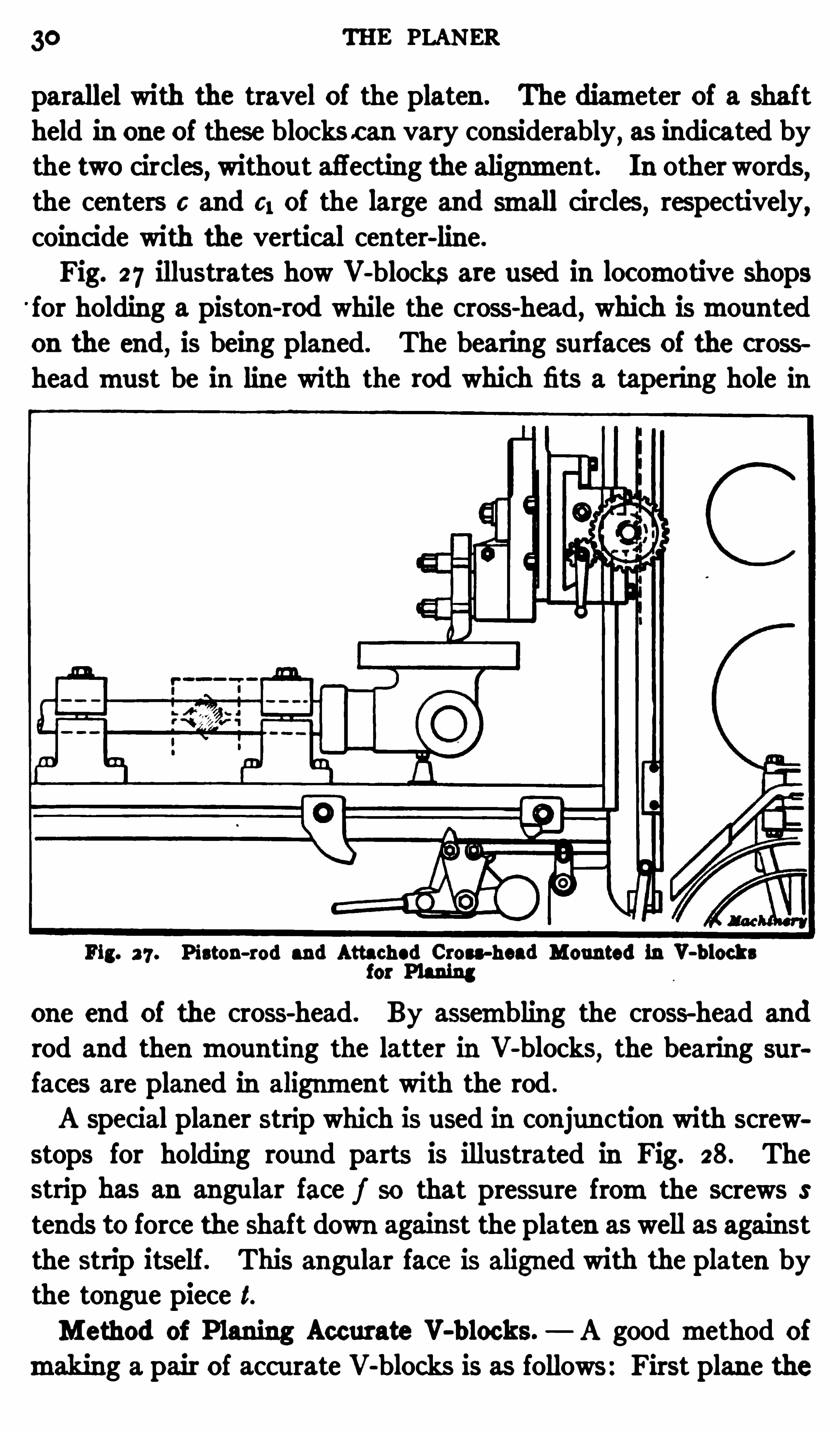
parallel with the travel of the platen . The diameter of a shaftheld in one of these blocks c an vary considerably, as indicated bythe two circles
,withou t affecting the alignment. In other words,
the centers c and 6; of the large and small circles, respectively,coincide with the vertical center-line.
Fig. 27 illustrates how V-blocks are used in loc omotive shopsfor holding a piston-rod while the cross-head, which ismountedon the end, is being planed. The bearing surfaces of the crossheadmust be in line with the rod which fits a tapering hole in
Fig. 2 7 . Piston-rod and Attached Cross-head Mounted in V-b locksfor Planing
one end of the cross-head. By assembling the cross-head and
rod and thenmounting the latter in V-blocks,the bearing
faces are planed in alignment with the rod .
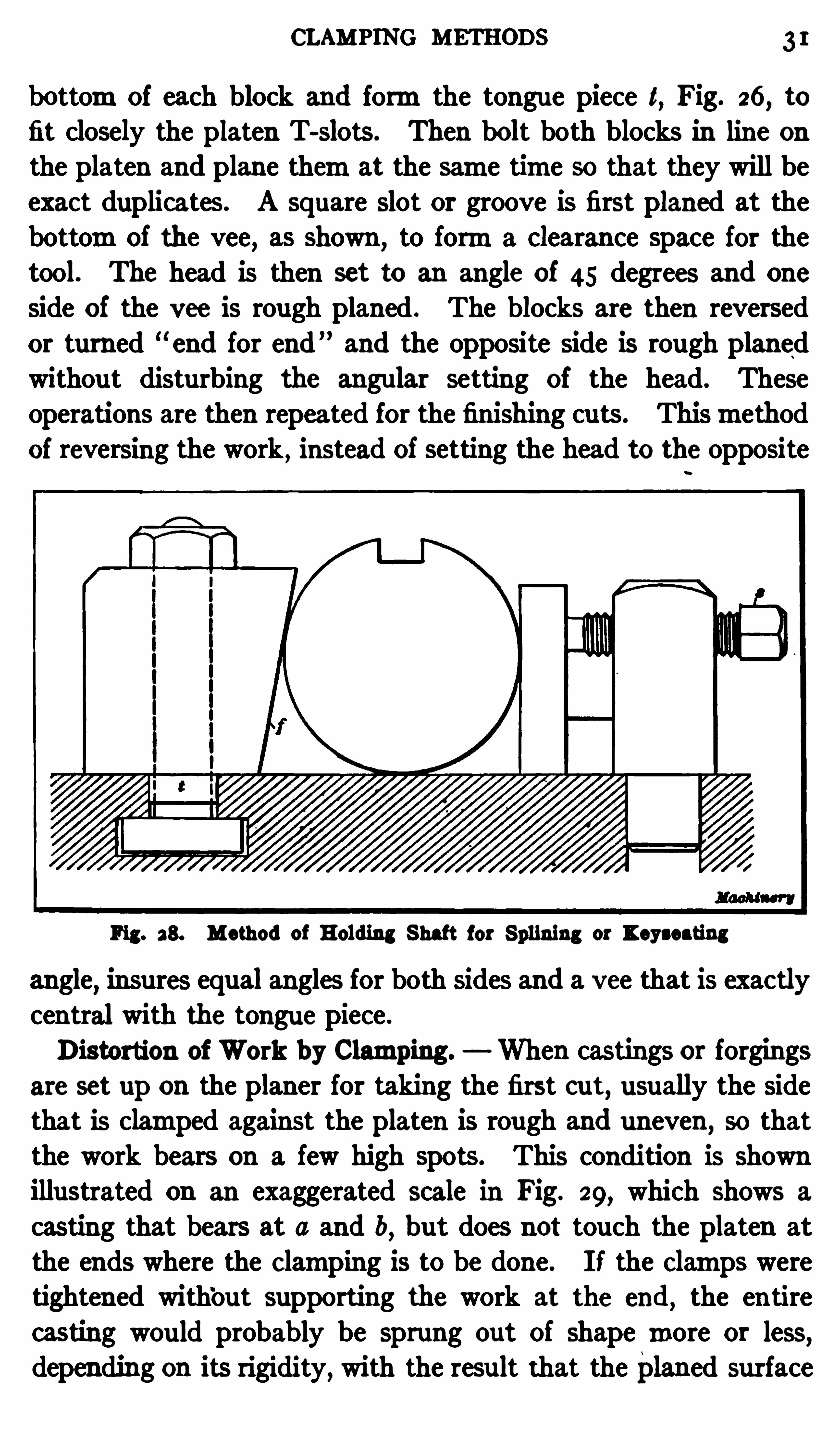
A spec ial planer strip which is used in conjunction with screwstops for holding round parts is illustrated in Fig. 28. Thestrip has an angular face f so that pressure fromthe screws S
tends to force the shaft down against the platen as well as againstthe strip itself. This angular face is aligned with the platen bythe tongue piece t.Method of P laning Accurate V-b locks. A good method of
making a pair of accurate V-blocks is as follows : First plane the
CLAMPING METHODS I
bottomof each block and formthe tongue piece t, Fig. 26
,to
fit closely the platen T-slots . Then bolt both blocks in line onthe platen and plane themat the same time so that they will beexact duplicates . A square slot or groove is first planed at thebottomof the vee, as shown
,to forma clearance space for the
tool. The head is then set to an angle of 45 degrees and one
side of the vee is rough planed . The blocks are then reversed
or turned end for end and the opposite side is rough planedwithout disturbing the angular setting of the head. Theseoperations are then repeated for the finishing cuts . Thismethodof reversing the work , instead of setting the head to the opposite
Fig. 38. Method of Holding Shaft for Splining or I eyseating
angle,insures equal angles for both sides and a vee that is exactly
central with the tongue piece .
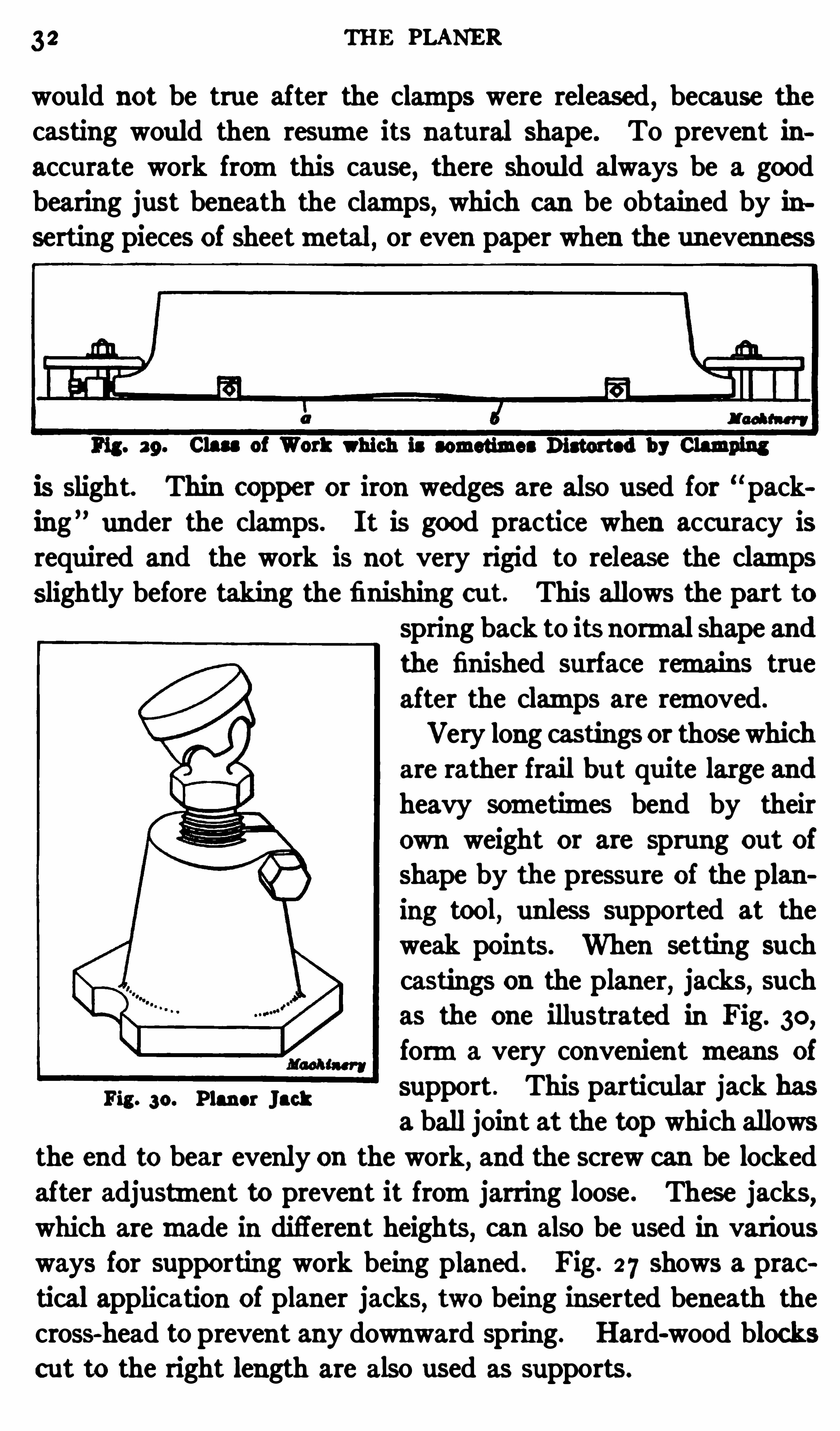
Distortion of Work by Clamping. When cas tings or forgingsare set up on the planer for taking the first cut, usually the sidethat is clamped against the platen is rough and uneven , so thatthe work bears on a few high Spots. This condition is shownillustrated on an exaggerated scale in Fig. 29, which shows a
casting that bears at a and b,but does not touch the platen at
the ends where the c lamping is to be done. I f the c lamps weretightened with
‘out supporting the work at the end,the entire
casting would probably be sprung out of shape more or less,depending on its rigidity, with the result that the planed surface
3 2 THE PLANER
would not be true after the clamps were released,because the
casting would then resume its natural shape. To prevent inaccurate work fromthis cause , there should always be a goodbearing just beneath the clamps, which can be obtained by inserting pieces of sheetmetal, or even paper when the unevenness
is slight. Thin COpper or iron wedges are also used for packing under the clamps. I t is good practice when accuracy isrequired and the work is not very rigid to release the clampsslightly before taking the finishing cu t. This allows the part to
spring back to its normal shape andthe finished surface remains trueafter the clamps are removed.
Very long castings or those whichare rather frail but quite large andheavy sometimes bend by theirown weight or are sprung out of
shape by the pressu re of the planing tool, unless supported at theweak points. When setting suchcastings on the planer, jacks, suchas the one illustrated in Fig. 30,
forma very convenient means of
Fig. 30. PM “ "acksupport . This particular jack hasa ball joint at the top which allows
the end to bear evenly on the work, and the screw can be lockedafter adjustment to prevent it fromjarring loose . These jacks
,
which aremade in different heights, can also be used in various
ways for supporting work being planed . Fig. 2 7 shows a praetical application of planer jacks, two being inserted beneath thecross-head to prevent any downward spring. Hard-wood blockscut to the right length are also used as supports .

34
then finished, they would tend to remain true , though slight
changes might occur even then . Because of this tendency todistortion as the result of internal stresses, all work, especially if
not rigid, should be rough-planed before any finishing cu ts are
taken . Of course, such a change of shape does not alwaysoc cur, because the stressesmay be comparatively slight and theplaned surface so small in proportion to the size of the castingthat distortion is impossible. When great accuracy is required ,it is the practice in some shops to rough plane the casting and
then allow it to season for several weeks before taking the
finishing c uts. This seasoning period is to allow the stresses
Fig. 3a. DiagramIllustrating Points Relating to Position of Work
to become adjusted so that little or no Change will occu r after
all the surfaces are finished.
Locating Work with Relation to Surfaces to be Planed.
Another important point in setting work is to locate it so that
all surfaces to be planed can be finished to the required dimensions. On some work it is also desirable to have a planed partfairly true with a surface which remains rough
,either to secure
a neater finish or formore important reasons. Therefore,when
either a casting or forging is being set up on the planer,it should
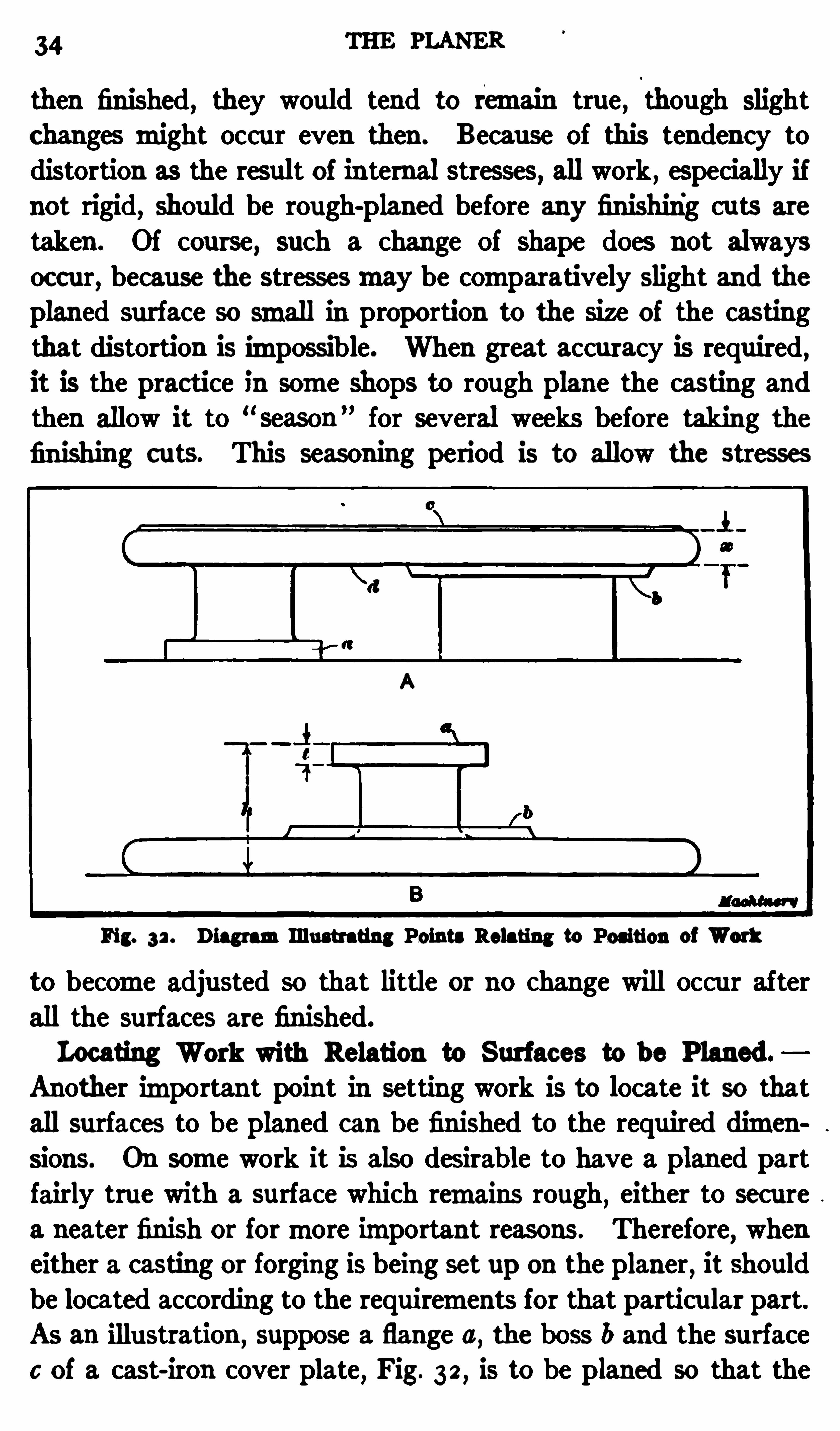
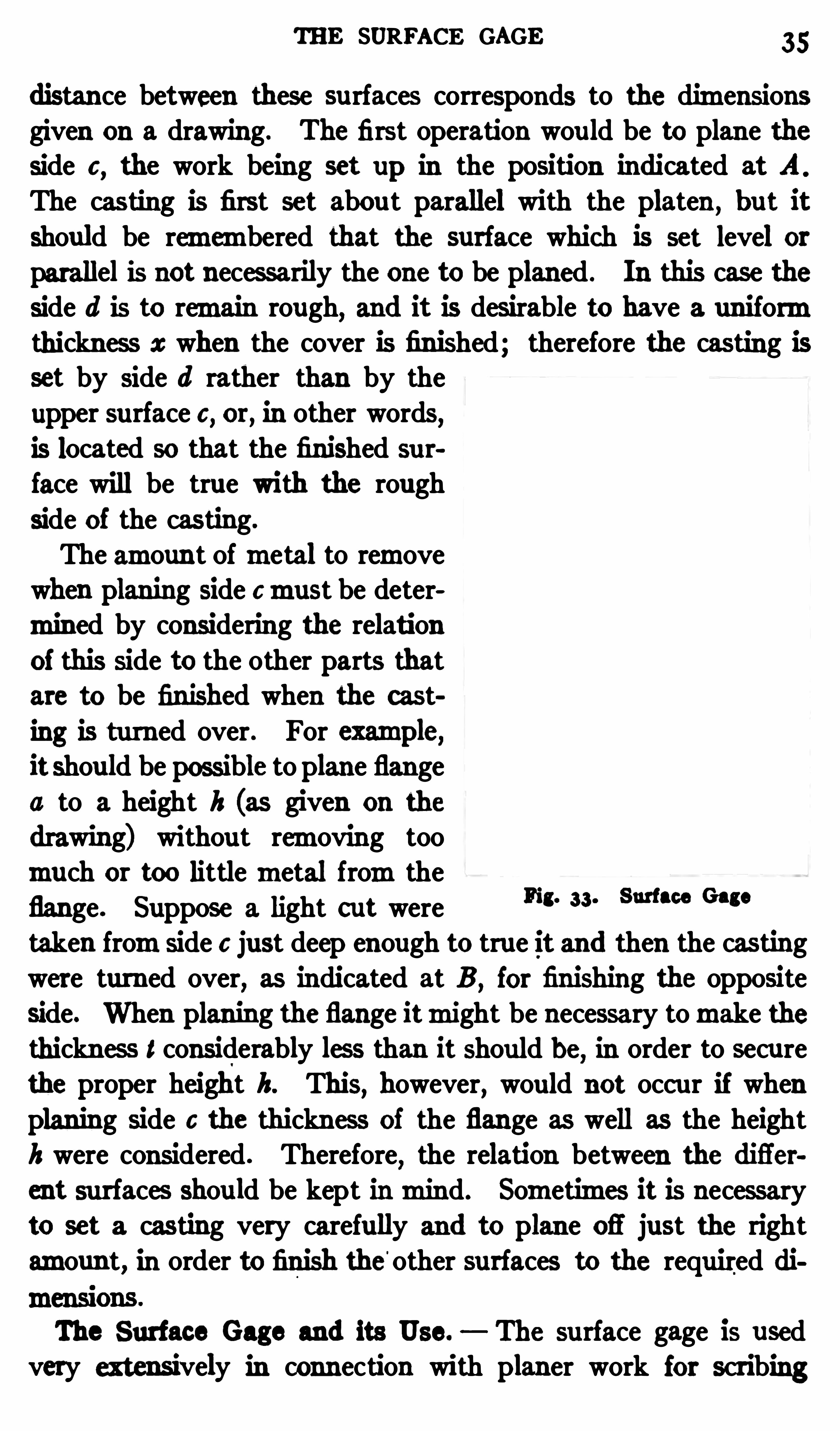
be located according to the requirements for that particu lar part.As an illustration ,
suppose a flange a, the boss b and the surface
0 of a cast-iron cover plate, Fig. 32 , is to be planed so that the
THE SURFACE GAGE 35
distance between these surfaces corresponds to the dimensionsgiven on a drawing. The first operation wou ld be to plane theside 6
,the work being set up in the position indicated at A
The casting is first set abou t parallel with the platen, but it
should be remembered that the surface which is set level orparallel is not necessarily the one to be planed . In this case theside d is to remain rough, and it is desirable to have a uniformthickness at when the cover is finished; therefore the casting isset by side (1 rather than by the
upper surface c , or, in other words,is located so that the finished surface will be true with the rough
side of the cas ting.
The amount ofmetal to removewhen planing side 6must be determined by considering the relationoi this side to the other parts that
are to be finished when the cast
ing is turned over . For examme,it shou ld be possible to plane flange
a to a height h (as given on the
drawing) without removing too
much or too littlemetal fromtheflange. Suppose a light cut weretaken fromside c just deep enough to true it and then the castingwere turned over, as indicated at B ,
for finishing the opposite
side. When planing the flange itmight be necessary tomake thethickness l considerably less than it Should be, in order to secure
the proper height h. This, however, would not occ ur if whenplaning side 6 the thickness of the flange as well as the height
h were considered . Therefore,the relation between the difier
ent surfaces shou ld be kept inmind. Sometimes it is necessaryto set a casting very carefully and to plane ofl
'
just the right
amoun t, in order to finish the'
other surfaces to the required di
mensions .
The Surface Gage and its Use. The surface gage is usedvery extensively in connection with planer work for scribing
Fig. 33 . Surface Gage
36 THE PLANER
lines to Show the location of finished surfaces, and also for settingparts parallel with the platen . This tool, which is shown in
Fig. 33 , has a rather heavy base on which ismounted a rod R
carrying a pointer or scriber S . The latter can be adjusted in or
out and it also can be moved to any position along the rod.
Af ter the scriber or pointer has been set to abou t the right height,it can be set accurately to the position desired by turning screw
A which gives a fine adjustment. There are two pins B in thebase which can be pushed down when it is necessary to keep
the gage in line with the edge of a plate or the side of aT-slot.
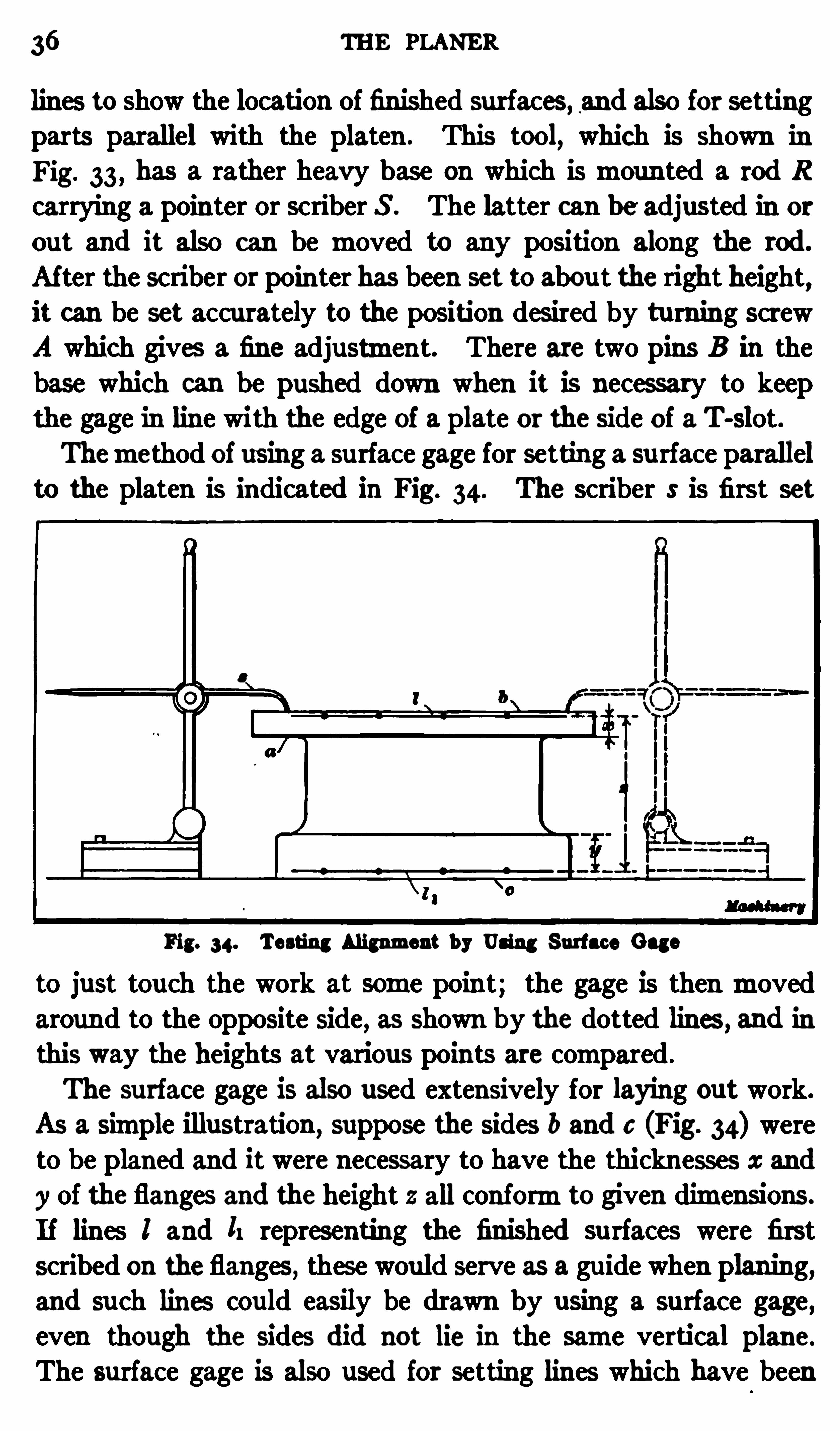
Themethod of using a surface gage for setting a surface parallelto the platen is indicated in Fig. 34. The scriber S is first set
Fig. 34. Testing Alignment by Using Surface Gage
to just touch the work at some point; the gage is then movedaround to the opposite side, as shown by the dotted lines , and in
this way the heights at various points are compared .
The surface gage is also used extensively for laying out work.
As a simple illustration ,suppose the sides b and c (Fig. 34) were
to be planed and it were necessary to have the thicknesses x and
y of the flanges and the height 2 all conformto given dimensions.
I f lines I and ll representing the finished su rfaces were first
scribed on theflanges, these would serve as a guide when planing,and such lines could easily be drawn by using a surface gage ,even though the sides did not lie in the same vertical plane.
The surface gage is also used for setting lines which have been
PLANER TOOLS 37
scribed on the work and represent the location of finished sur
faces , parallel with the planer platen .
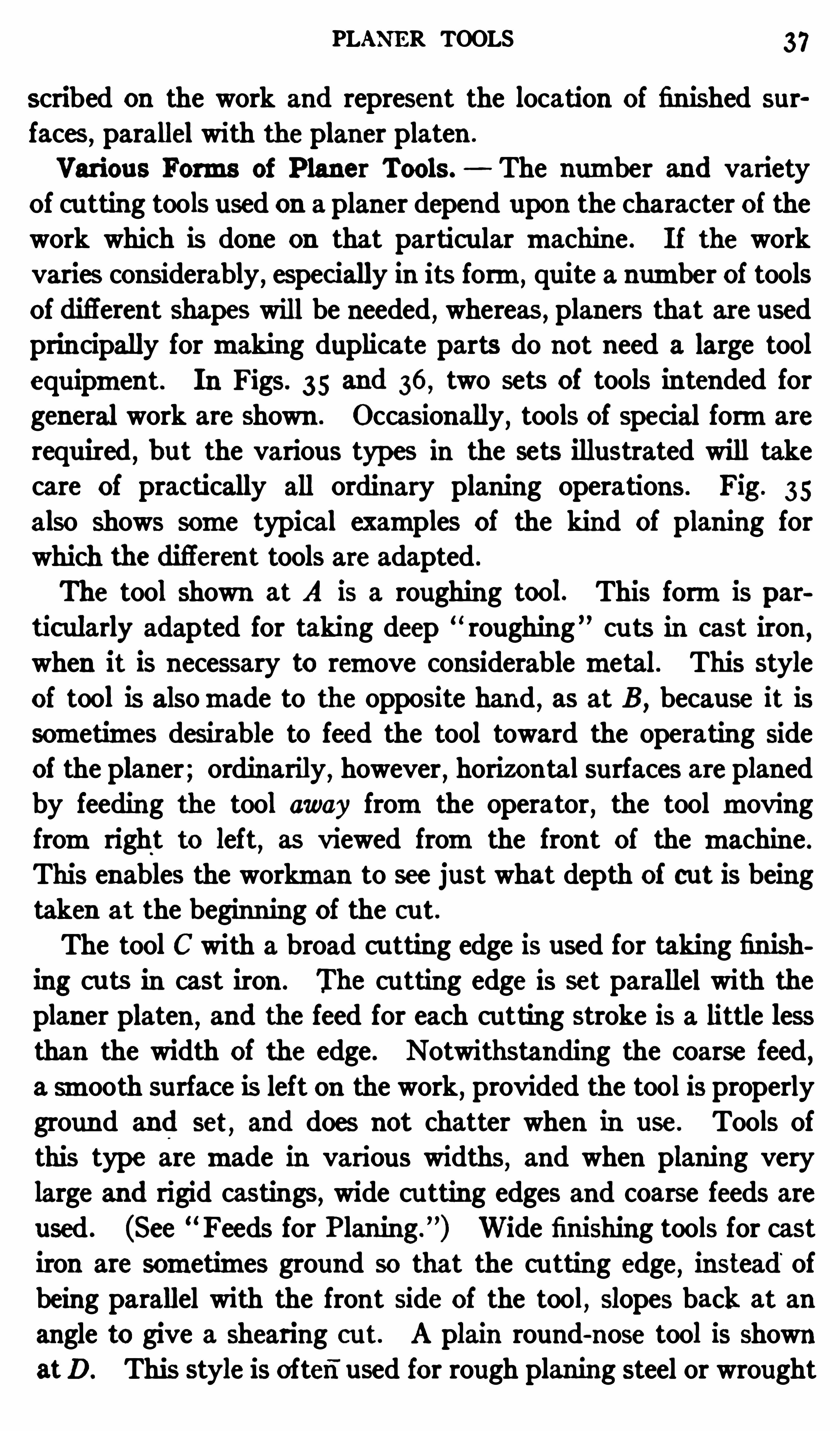
Various Forms of P laner Tools . The number and varietyOf cu tting tools used on a planer depend upon the character of thework which is done on that particu lar machine . I f the workvaries considerably, espec ially in its form,
quite a number of toolsOf diflerent shapes will be needed , whereas , planers that are usedprincipally formaking duplicate parts do not need a large tool
equipment. In Figs. 35 and 36 , two sets of tools intended for
general work are shown . Occasionally, tools of special formare
required,but the various types in the sets illustrated will take
care of practically all ordinary planing operations. Fig . 35
also shows some typical examples of the kind of planing forwhich the diflerent tools are adapted .
The tool shown at A is a roughing tool. This formis particularly adapted for taking deep “ roughing cu ts in cast iron
,
when it is necessary to remove considerablemetal. This styleof tool is alsomade to the opposite hand , as at B ,
because it issometimes desirable to feed the tool toward the operating sideof the planer; ordinarily, however , horizontal surfaces are planedby feeding the tool away fromthe operator
,the tool moving
fromright to left,as viewed fromthe front of the machine .
This enables the workman to see just what depth of cut is beingtaken at the beginn ing of the cu t.
The tool C with a broad cu tting edge is used for taking finishing cu ts in cast iron . The cutting edge is set parallel with theplaner platen ,
and the feed for each cu tting stroke is a little lessthan the width of the edge . Notwithstanding the coarse feed
,
a smooth surface is left on the work, provided the tool is properlyground and set
,and does not chatter when in use. Tools of
this type aremade in various widths, and when planing verylarge and rigid castings, wide cu tting edges and coarse feeds areused . (See
“ Feeds for P laning”
) Wide finishing tools for castiron are sometimes ground so that the cu tting edge
,instead of
being parallel with the front side of the tool,slopes back at an
angle to give a shearing cu t. A plain round-nose tool is shownatD. This style is often
"
used for rough planing steel or wrought
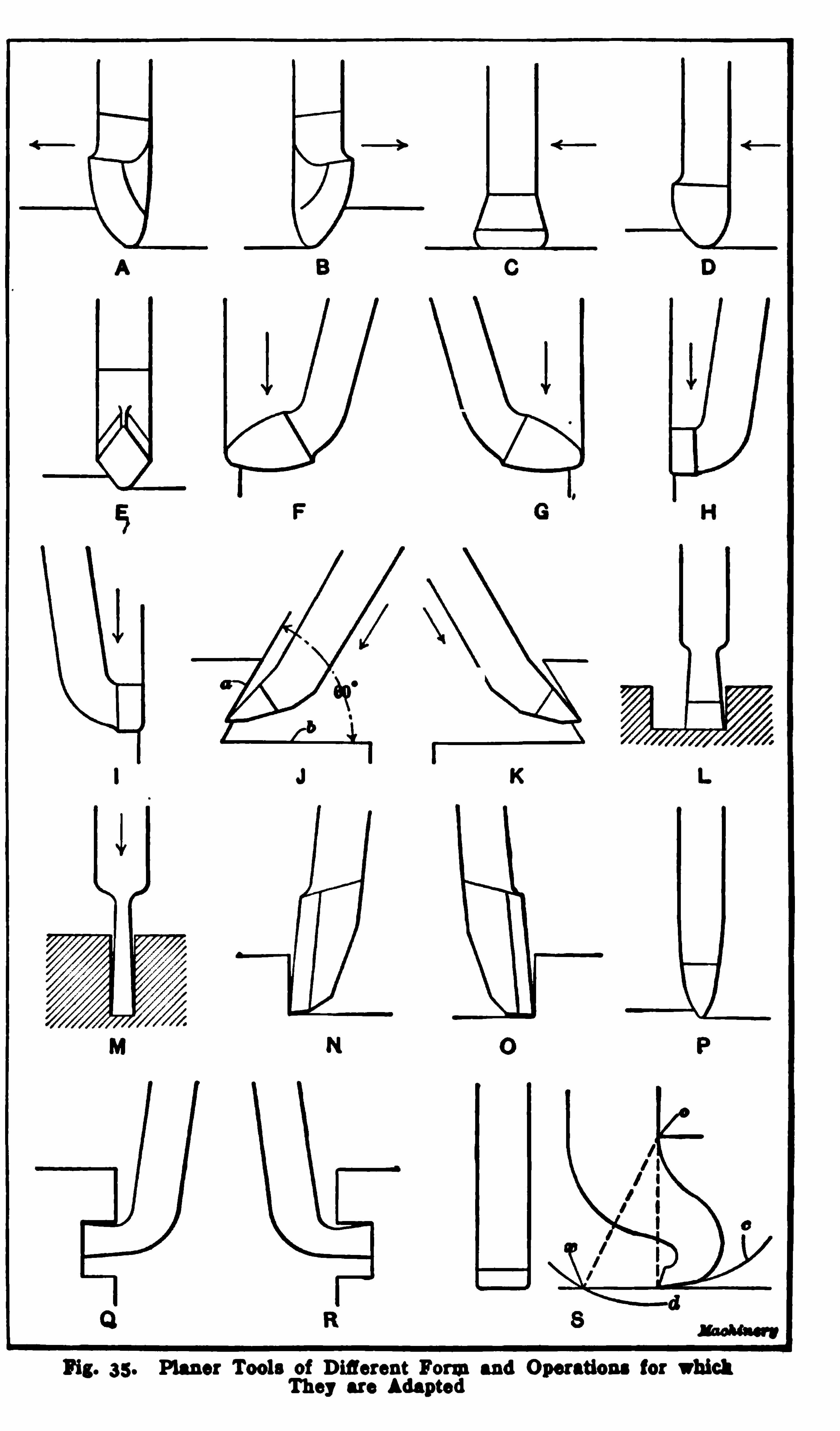
Fig. 35 . Planer Tools of Diflerent Formand Operations for whichThey are Adapted
PLANER TOOLS 39
iron . I t can also be made into a finishing tool for the samemetals by grinding the nose or tip end flat. The width of theflat cu tting edge ismuch less, however, than for cast-iron finishing tools, because if very broad edges and feeds were used when
planing steel, there would be danger of the tool gouging into thework. Steel ofiers a greater resistance to cu tting than cast ironand that is why broad tools tend to gouge in ,
espec ially if thetool is not held rigidly to prevent its springing downward. ToolE
, which is known as a diamond point, is also used for roughplaning steel or iron and for taking light cu ts .
The bent tools F and G are used for planing either verticalsurfaces or those which are at a considerable angle with theplaten . These are right and left-side roughing tools
,and they
are adapted to either cast iron or steel. They can also be usedfor finishing steel. Finishing tools for vertical or angular castiron surfaces are shown at H and I . These have wide cuttingedges to permit coarse finishing feeds. Vertical surfaces can
often be planed to better advantage by using a straight tool inthe side-head, when the planer is so equipped. Right and leftangle tools are shown at J and K . This style of tool is for plan
ing angular surfaces which, by reason of their relation to hori
zontal or other surfaces , can only be finished by a tool having a
formsimilar to that illustrated . A typical example of the kindof angular planing requiring the use of an angle tool is indicated
in the illustration . Af ter finishing side a,the horizontal surface
b (fromwhich a roughing cu t should have been taken previously)could be planed by feeding the same tool horizontally.
A square-nose tool is shown at L . This is used for cu tting
slots and squaring corners, and the same style of tool ismade indiflerent widths. A narrow square nose or
“parting ” tool is
shown at M . I t is adapted to cu tting narrow grooves, and can
also be used for cu tting a part in two ,provided the depth does
not exceed the length of the narrow cu tting end. Right and
left side-tools are shown at N and 0. These can frequently be
used to advantage on vertical or angular surfaces. A tool forplaning brass is shown at P . I t has a narrow rounded cu ttingedge and is verymuch like a brass tu rning tool. For finishing
40 THE PLANER
cuts in brass,tools having narrow flat ends are often used .
Right and left,bent
,square-nose tools are shown at " and R .
Such tools are used for cu tting grooves or slots in vertical sur
faces and for similar operations .
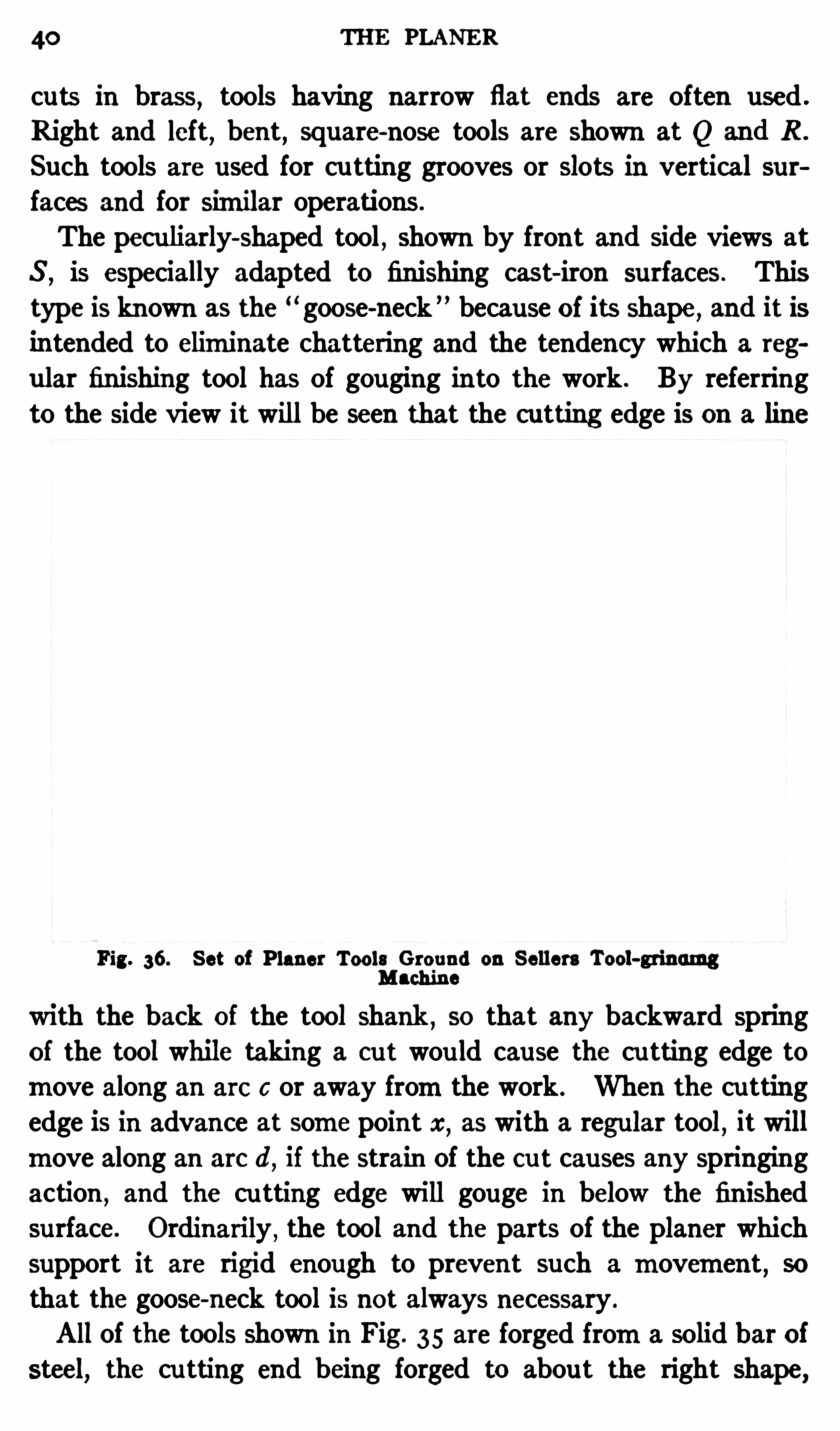
The peculiarly-shaped tool, shown by front and Side views at
S ,is especially adapted to finishing cast-iron surfaces . This
type is known as the goose-neck ” because of its Shape, and it isintended to eliminate chattering and the tendency which a reg
ular finishing tool has of gouging into the work . By referring
to the side view it will be seen that the cutting edge is on a line
Fig. 36. Set of Planer Tools Ground on Sellers Tool-grinurngMachine
with the back of the tool shank,so that any backward spring
of the tool while taking a cu t wou ld cause the cu tting edge to
move along an arc c or away fromthe work . When the cu ttingedge is in advance at some point x
,as with a regular tool, it will
move along an arc d,if the strain Of the cu t causes any springing
action , and the cu tting edge will gouge in below the finished
surface. Ordinarily,the tool and the parts of the planer which
support it are rigid enough to prevent such a movement,so
that the goose-neck tool is not always necessary .
All of the tools shown in Fig. 35 are forged froma solid bar of
steel, the cu tting end being forged to abou t the right shape,

42 THE PLANER
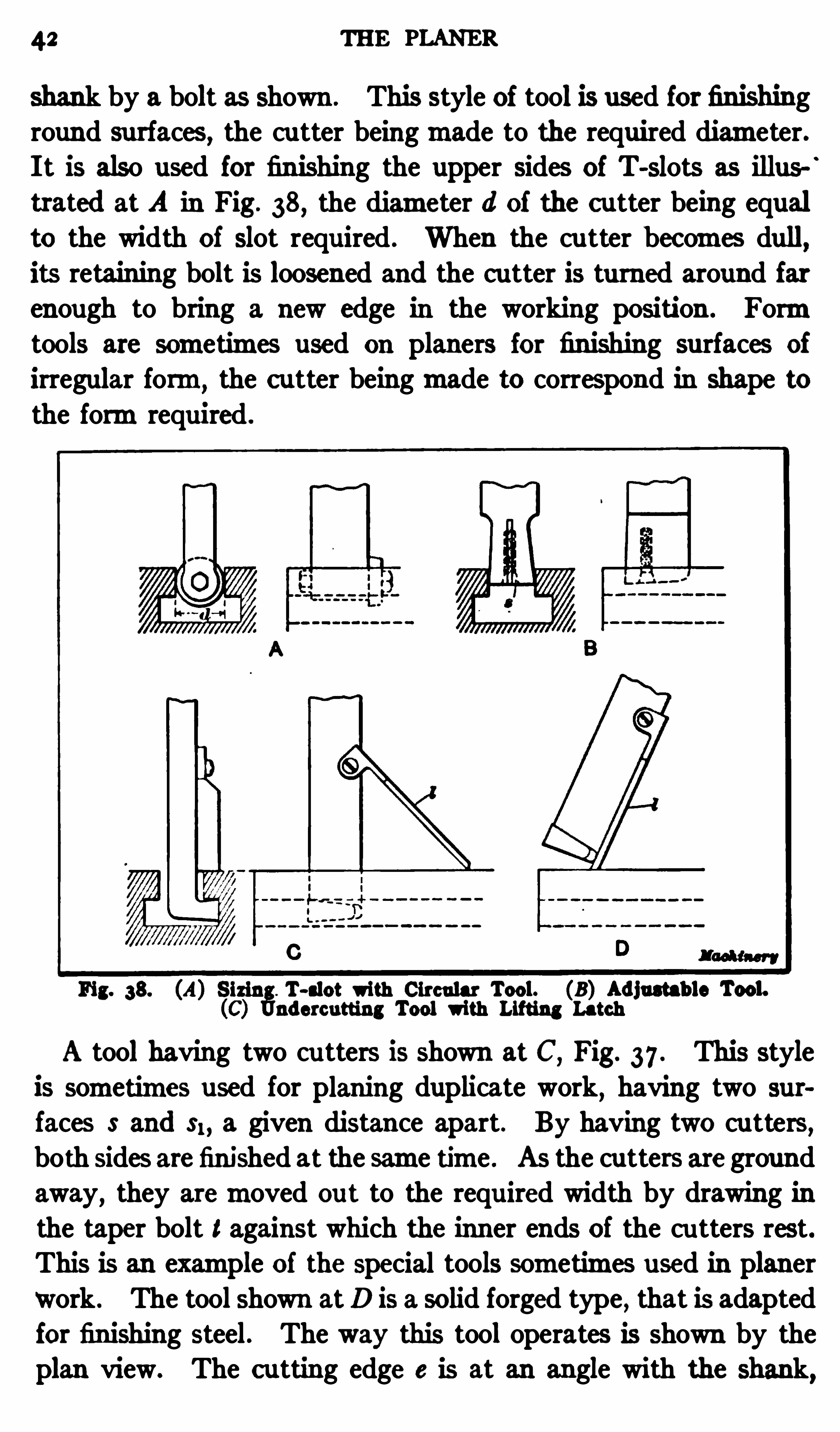
shank by a bolt as shown . This style of tool is used for finishinground surfaces, the cutter beingmade to the required diameter.I t is also used for finishing the upper sides of T-slots as illus
trated at A in Fig. 38, the diameter d of the c utter being equal
to the width of slot required . When the cu tter bec omes dull,its retaining bolt is loosened and the c utter is turned around farenough to bring a new edge in the working position . Formtools are sometimes used on planers for finishing surfaces of
irregular form the c utter beingmade to correspond In shape to
the formrequi red .
Fig. 38. (A) Sirin . T-slot with Circular Tool. (8 ) Adjustab le Tool.(C) nderc utting Tool with Lifting Latch
A tool having two cu tters is shown at C,Fig. 37 . This style
is sometimes used for planing duplicate work, having two sur
faces S and $1, a given distance apart. By having two cutters,both sides arefinished at the same time . As the cutters are ground
away, they aremoved ou t to the requ ired width by drawing in
the taper bolt 1against which the inner ends of the cu tters rest.This is an example of the special tools sometimes used in planerwork . The tool shown atD is a solid forged type , that is adaptedfor finishing steel. The way this tool operates is shown by theplan view. The c utting edge e is at an angle with the shank,
PLANER TOOLS 43
and as the workmoves in the direction shown by the arrow, the
comer or edge e removes a light shaving and leaves a smoothsurface . The edge is cu rved slightly, as shown by the side view,
so that the cutting is done at the center. By using soda water,
or even plain water, while planing, a bright su rface is Obtained.
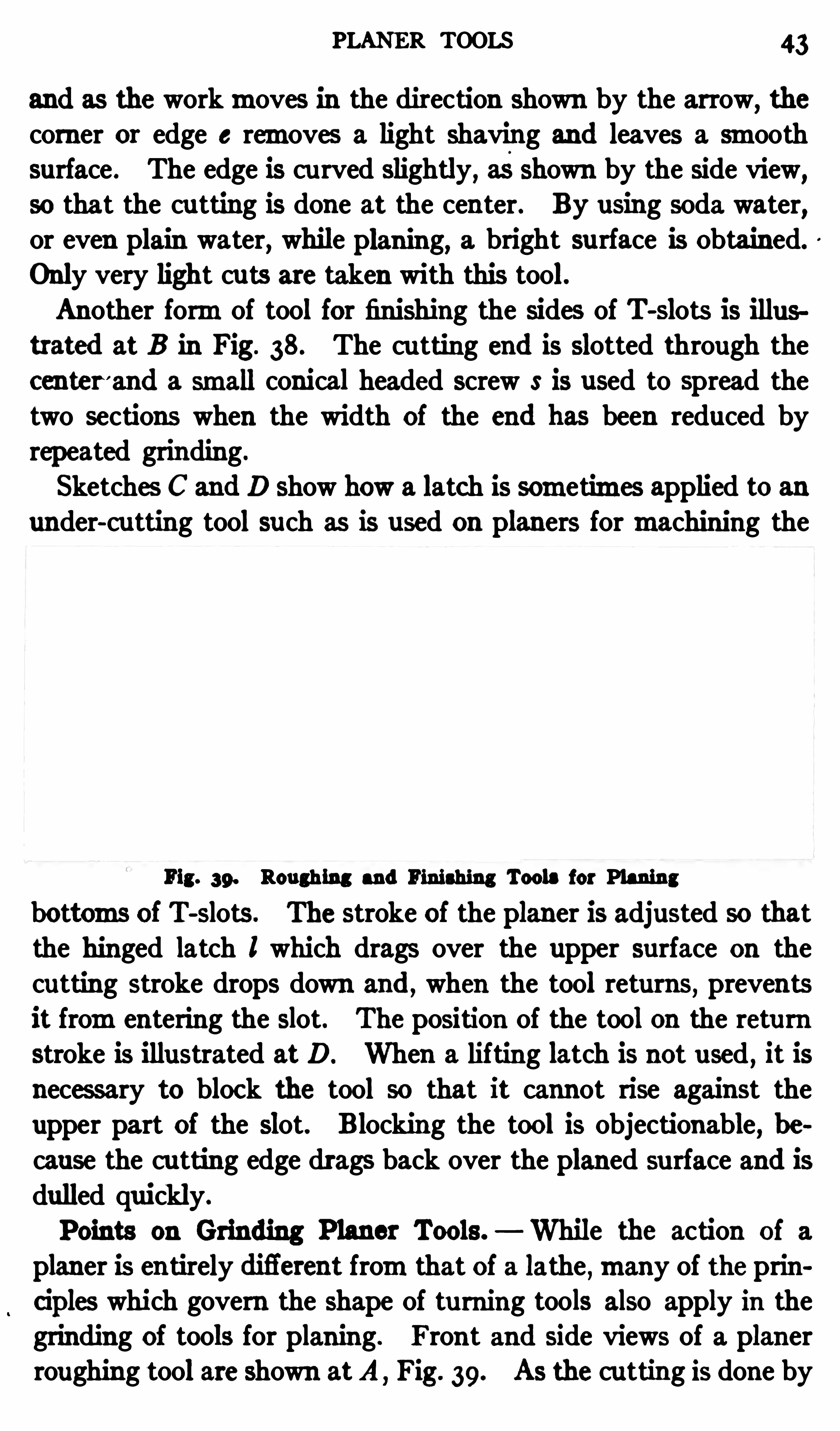
Only very light cuts are taken with this tool.Another formof tool for finishing the sides of T-slots is illus
trated at B in Fig. 38. The cu tting end is slotted through thecenter
'and a small conical headed screw S is used to spread the
two sections when the width of the end has been reduced byrepeated grinding.
Sketches C and D show how a latch is sometimes applied to anunder-cu tting tool such as is used on planers formachining the
Fig. 39. Roughing and Finishing Tools for Planingbottoms of T-slots . The stroke of the planer is adjusted so thatthe hinged latch l which drags over the upper surface on thecutting stroke drops down and , when the tool returns, prevents
it fromentering the slot. The position of the tool on the return
stroke is illustrated at D. When a lifting latch is not u sed , it isneces sary to block the tool so that it cannot rise against theupper part of the slot. B locking the tool is objectionable, be
cause the cu tting edge drags back over the planed su rface and is
dulled quickly.
Points on Grinding Planer Tools. While the action of a
planer is entirely difl'
erent fromthat of a lathe ,many of the principles which govern the shape of turning tools also apply in thegrinding of tools for planing. Front and side views of a planerroughing tool are shown atA Fig. 39. As the cu tting is done by
44 THE PLANER
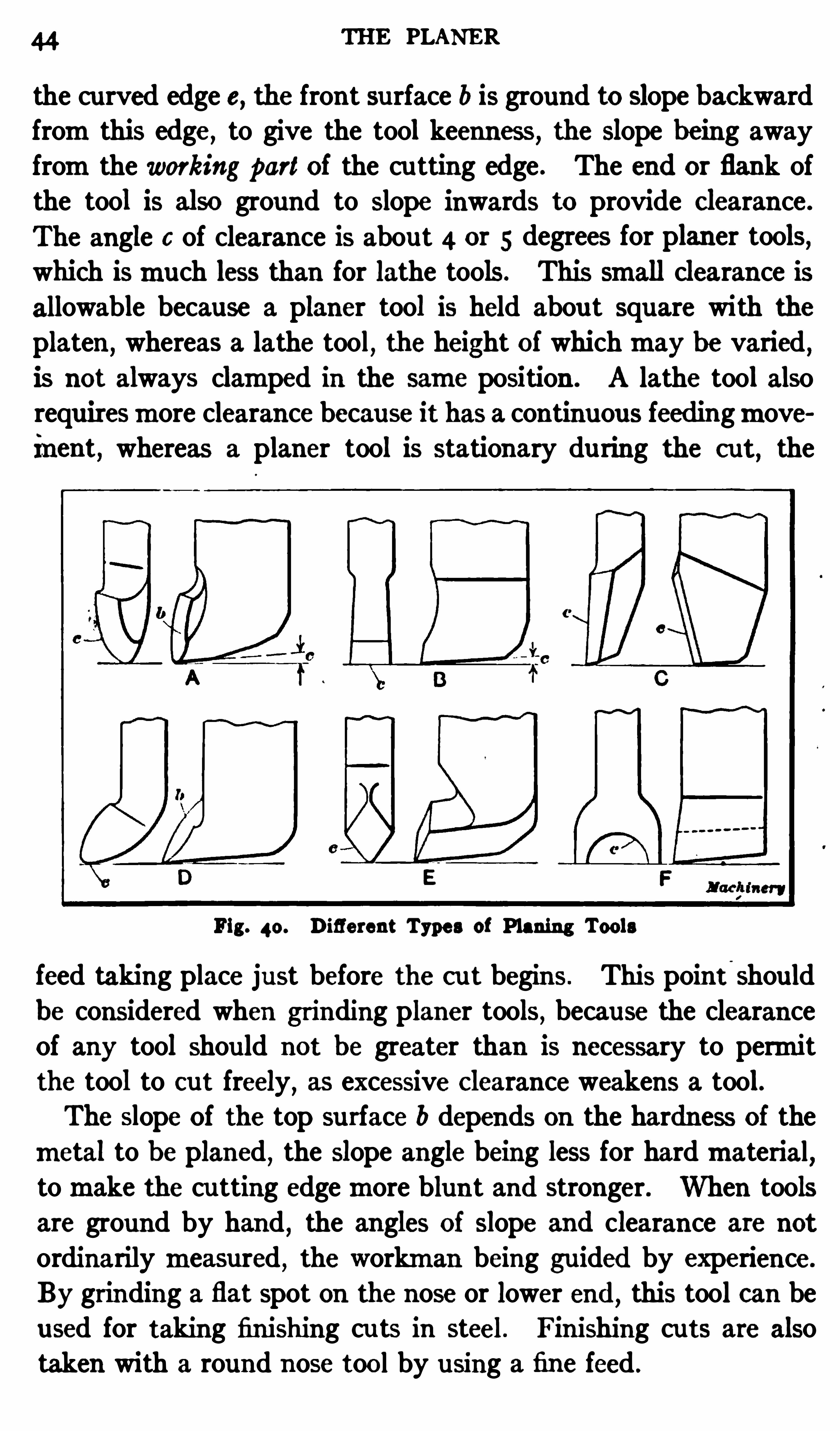
the curved edge e, the front su rface b is ground to slope backwardfromthis edge, to give the tool keenness, the slope being awayfromthe working part of the cu tting edge . The end or flank ofthe tool is also ground to slope inwards to provide c learance.
The angle 6 of clearance is about 4 or 5 degrees for plan er tools,which ismuch less than for lathe tools. This small clearance isallowable because a planer tool is held abou t square with the
platen,whereas a lathe tool, the height of whichmay be varied ,
is not always clamped in the same position . A lathe tool alsorequiresmore clearance because it has a continuous feedingmoveinent, whereas a planer tool is stationary du ring the cut, the
Fig. 40. Diflerent Types of Planing Tools
feed taking place just before the cu t begins . This point-
Should
be considered when grinding planer tools, because the clearanceOf any tool shou ld not be greater than is necessary to permitthe tool to cut freely
,as excessive Clearance weakens a tool.
The slope Of the top surface b depends on the hardness of the
metal to b e planed , the slope angle being less for hardmaterial,tomake the cu tting edgemore blunt and stronger. When toolsare ground by hand , the angles Of slope and clearance are not
ordinarilymeasured , the workman being guided by experience.
By grinding a flat spot on the nose or lower end , this tool can beused for taking finishing cu ts in steel. Finishing cuts are alsotaken with a round nose tool by u sing a fine feed .
PLANER TOOLS 43
The edge e of the cast-iron finishing tool B should be groundstraight by testing it with a small straight edge or scale . Thecomers should also be rounded Slightly
, as shown ,as a square
corner on the leading side will dull quickly . The illustrationshows clearly the shape of the tool. Tool A Fig. 40 ,
is shapedsomewhat like a side tool except that cutting edge e is cu rved .
The face b slopes away fromedge e and the end is given a slightclearance c . The square-nose tool, seen atB ,
cuts along its loweredge e, and is given Clearance c on the end and sides, as shown inthe two views. The lower edge is the widest part Of the cu ttingend
,the sides sloping inward in both a vertical and horizontal
direction,which prevents the tool frombinding as it moves
through a narrow slot.The side-tool C c uts along edge e
,which
,as the side view
shows, Slopes backward . P laner side-tools are not alwaysmadein this way, but it is a good form,
as the sloping edge starts a
cut gradually, whereas a vertical edge takes the full width Ofthe c ut suddenly
, thus producing a greater shock. As too"D isused for vertical planing
,the cu tting is done by edge e; hence
face b should slope back fromedge e. The diamond point E isground with a narrow rounded poin t; this type of tool is usefulwhen a light c ut is necessary
,either because the work cannot b e
held secu rely for planing or for some other reason . The formtool F is used for rounding edges . Tools of this type are sharpened by grinding on the front face only
,in order to retain the
curved edge. When sharpening other than formed tools, thegrinding is done both on the face and end, because a sharp edgecan be secu redmore quickly by this method.
Reference has beenmade to the grinding of these few types oftoolsmerely to point out some of the principles connected withthe grinding of planing tools. When the principle of tool grinding is understood, the various tools required, whether regular orspecial in form, can be ground withou t difli culty . One thingthat should be remembered when grinding a tool is that it doesnot pay to force the tool too hard against the grinding wheel
,
as is Often done in attempting to sharpen the tool quickly. Thetool Shou ld be ground with amoderate pressure, and it Shou ld
46 THE PLANER
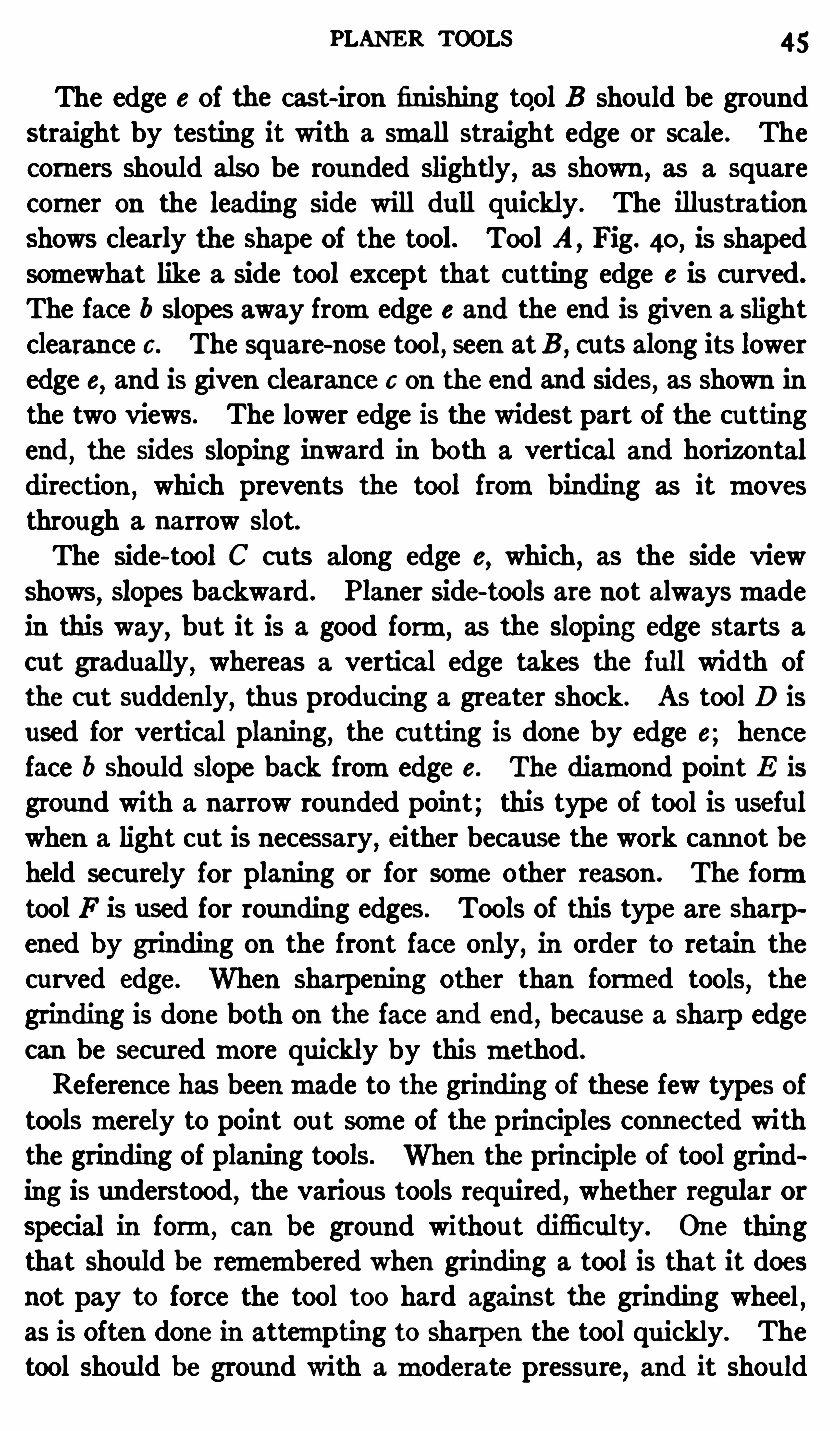
be withdrawn frequently when forming a flat surface to preventexcessive heating and burning Of the tool. The grinding wheelshould always be supplied with plenty of cooling water.Multiple or Gang Planing. When a number Of duplicate
parts have to be planed,much time can Often be saved by arrang
ing the castings in a straight row along the platen so that theycan all be planed at the same time . This method enables a
number Of parts to be finishedmore quickly than would be possi
Fig. 41. An Example of Gang Planing
b le bymachining themseparately, and it also insures duplicate
work. An example Of mu ltiple or gang planing is shown in
Fig. 41 . The particular castings illustrated are the “ saddles ” Ofplaner tool-heads and eight are being planed at the same time.
Both tool-heads are in use,and the top surfaces and sides of the
castings are finished at this setting .
This method of planing cannot always b e employed to ad
vantage as the shape of the work or location of the surfaces to be
GANG PLANING 47
machined sometimesmakes gang planing impracticable and evenimpossible. I f the castings are so shaped that there will beconsiderable space between the surfaces to be planed
,when they
are placed in a row,somuch timemight be wasted while the tool
was passin g between the differen t surfaces that it would bebetter to plane each part separately . Some castings al so havelugs or other projections whichmake it impossible for the toolto pass fromone to the other withou t being raised to clear the
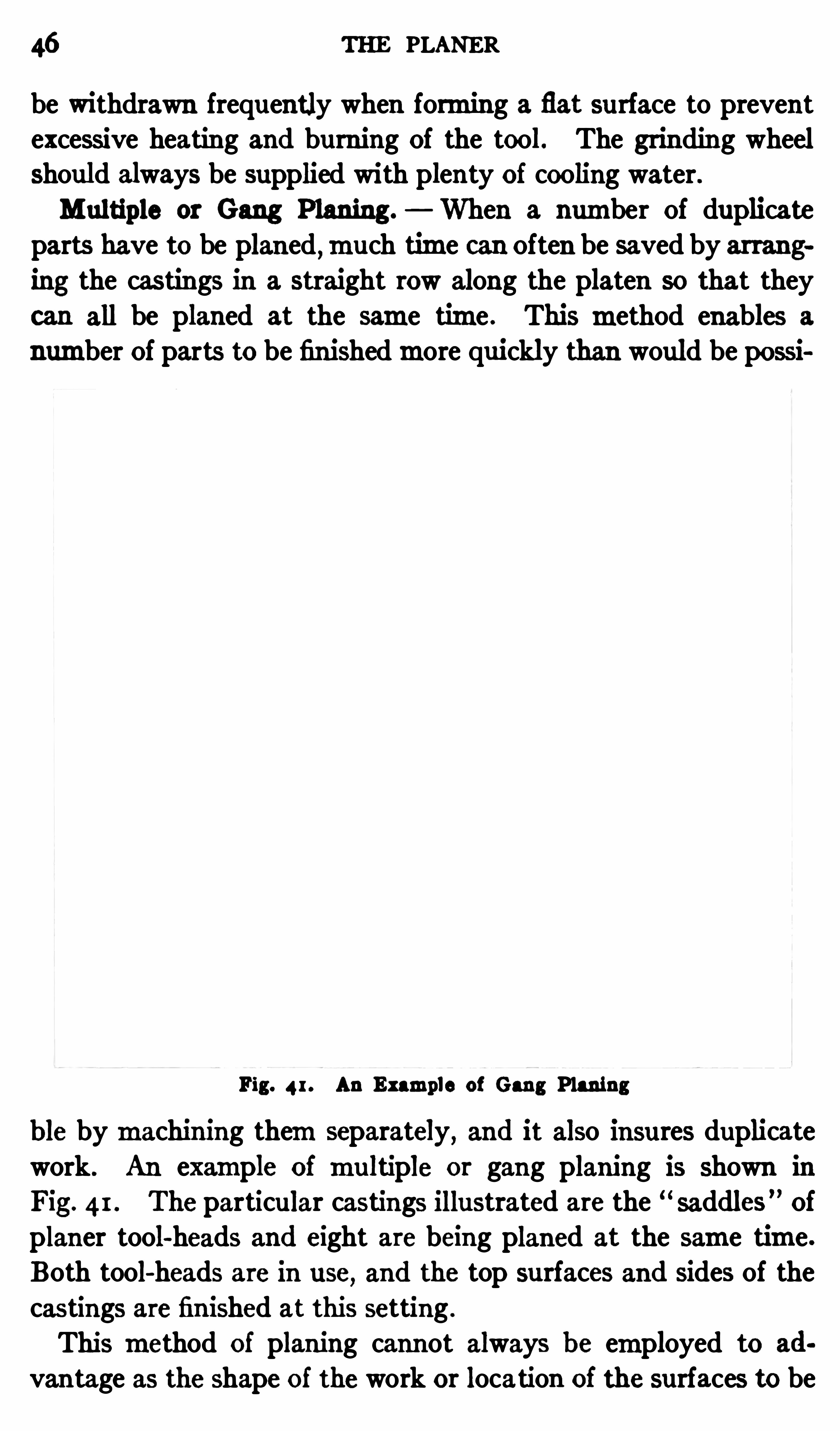
Fig. 42 . Twenty Connecting-rods b eing Planed Simultaneously
obstruction . On the other hand, when castings are qu ite symmetrical in formand the surfaces are so located that the planingtool can pass fromone to the other with a continuous stroke,the gangmethod of planing insu res a uniformproduct and greatlyreduces the time required formachining.
Another example of gang planing is shown in Fig. 42 . Twentyengine c onnecting-rods are clamped to the platen and the twoheads of the planer are working on the bosses at each end Of the
rod, the operation being that of planing the sides. The rods
48 THE PLANER
are placed against one another,with every alternate rod reversed ,
to bring a large and small end together, in order tomake a straightline Of castings . The entire string of castings is prevented fromshifting along the table by two stop-pins at the end
,and they
are held down on the platen by a series Of straps or clamps alongthe center. These connecting-rods are steel castings; the planerhas a cu tting speed of 40 feet perminu te with a 3 inch depth Ofc ut and a transverse feed Of 3
32
“ inch per stroke .
Castings that are finished by gang planing are often held inSpecial fixtures
,especially if they are of irregular shape and not
readily clamped directly to the planer table.
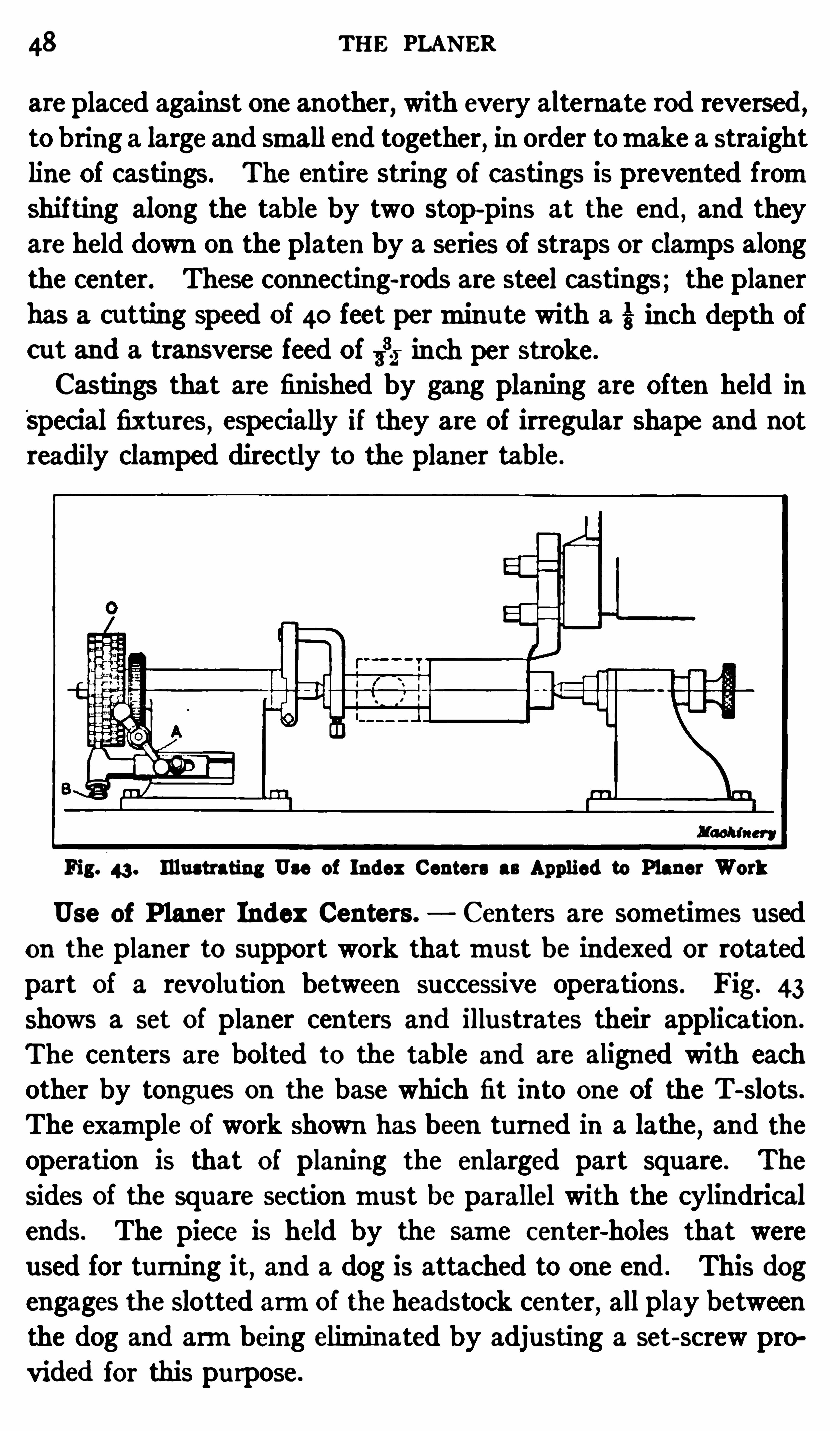
Fig. 43 . Illustrating Use of Index Centers as Applied to Planer Work
Use of Planer Index Centers. Centers are sometimes used
on the planer to support work thatmust be indexed or rotatedpart of a revolu tion between successive operations. Fig. 43
shows a set of planer centers and illustrates their application .
The centers are bolted to the table and are aligned with eachother by tongues on the base which fit into one Of the T-slots.
The example of work shown has been turned in a lathe,and the
operation is that of planing the enlarged part square . The
sides of the square section must be parallel with the cylindricalends. The piece is held by the same c enter-holes that were
used for turning it, and a dog is attached to one end . This dogengages the slotted armof the headstock center, all play between
the dog and armbeing eliminated by adjusting a set-screw pro
vided for this purpose.

so THE PLANER
first make a cast-iron or sheet-steel templet corresponding tothe cu rvature required . This templet is then clamped against
one end of the work (usually the end at the beginning Of thecutting stroke) and the planing is done by manipulating thehorizontal and cross-feeds so that the tool follows the ou tlineOf the templet. If the hand feeding is done carefully and thefinishing tool is ground to correspond in a general way with thecurvature to be planed , fairly accurate results can be obtainedby this method . Special attachments are commonly used forplaning curved surfaces
,especially when duplicate parts are
required . Some of the attachments that have been used forc ircular planing are described in the following
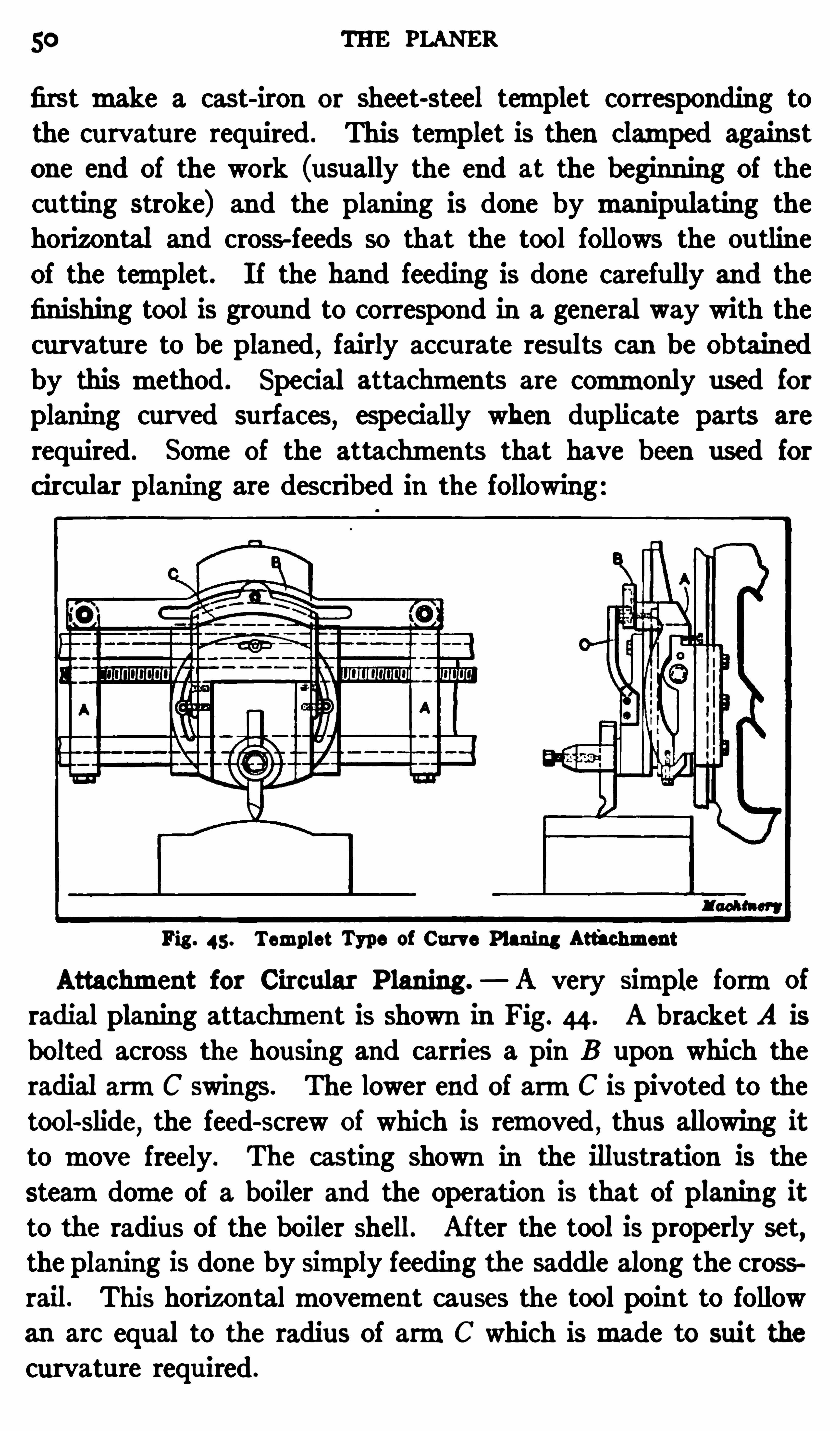
Fig . 45 . Templet Type of Curve Planing Att'
achment
Attachment for Circular P laning. A very simple formOf
radial planing attachment is shown in Fig. 44 . A bracket A isbolted across the housing and carries a pin B upon which theradial armC swings. The lower end of armC is pivoted to thetool-slide
,the feed-screw of which is removed
,thus allowing it
to move freely. The casting shown in the illustration is the
steamdome of a boiler and the operation is that Of planing itto the radius Of the boiler shell. Af ter the tool is properly set,
the planing is done by simply feeding the saddle along the crossrail. This horizontalmovement causes the tool point to followan are equal to the radius Of armC which ismade to suit thecurvature required .
CIRCULAR PLANING ATTACHMENTS 31
Templet Type of Curve P laning Attachment. An attachment for planing work of a convex or concave shape is shownin Fig. 45 . This attachment consists principally of four parts;namely
,the two side brackets A a templet B which conforms
to the curvature to be planed,and the double-armed leader C
which is attached to the tool-slide. The side brackets are pro
vided with bosses at the top in order to hold the templet so thatit will clear the planer head (see end view) , thus allowing the
Fig. 46. Miner-Boswell Radius Plan ing Attachment for Machining Links, etc.
saddle to bemoved along the cross-rail . The templet, which ismachined to the required formon a profile or slotter
,is attached
to the brackets A by bolts. The double-armed leader C has a
roller at the topwhich engages a slot in the templet, thus irnparting a verticalmovement to the tool-slide when the saddle is fedhorizontally along the cross-rail.
When using this attachment, the power feedmay be engaged,and as the tool is automatically raised or lowered , Obviously it
will plane a surface corresponding to the cu rvature Of the slot
in the templet. As will be seen by referring to the end view,
5 2 THE PLANER
the brackets A fit over the top gu ide on the cross-rail and are
fastened in position by set-screws at the rear. Separate retain
ing pieces are fitted to the bottomof each bracket, these beingbolted in place after the fixture is mounted on the rail . This
attachment, or somemodification of it, is especially adapted for
planing a number Of duplicate parts .
Radius P laning Attachment. In locomotive shops where thecurved links for the valvemechanisms have to be machined , aplaner is Often used
,and various attachments have been designed
Fig. 47 . Elevation and Plan of Radius Planing Attachment
for this purpose. One Of these, known as the Aliner-Boswellradius planing attachment
,is illustrated in Figs. 46 and 47 .
This attachment has a plateA which is fixed to the planer tableand on this plate there is a square projecting block B . Thisblock fits into a cross slot in the ring C
,which has an annular
bearing in the top plate D. The latter forms the work table,and it is attached to a radial bar that passes through a doubletrunnioned bearing mounted in an adjustable stand E . Thering C is kept down by a central plate
,as shown
,and the work
table is provided with a retaining ring F .
SPIRAL PLANING ATTACHMENTS 53
Themovement of the planer table is transmitted by the squareblock B to ring C
,which , in turn , imparts a Circularmovement
to the work table; this is accompanied by a lateralmovementOf ring C with relation to the square driving block. With this
arrangement the driving power is transmitted to the work tablein the direction of the reciprocatingmovement Of the planer, andthe thrust of the tool’s cut is also along parallel lines . Owingto the small amount of stress imposed on the radial bar, thelatter is made of tubing and is comparatively light . The at
tachment is adjusted for planing diflerent radii by shifting standE and its bearing along the bar at right-angles to the planertable . The link to be planed can quickly be located in the fixture by a center-linemarked upon the chuck.
P rior to planing the curved slot,the sides of the link areplaned ,
the edgesmilled , and the clearances for the planing tools drilledand slotted . The work is then placed on the attachment andthe slot is rough planed by using two parting tools simultaneously. These tools cut narrow slots on each Side , and the centralpart of the slot is removed in the formof a solid block. Afterthe link is roughed out in thismanner
, the slot is finished by side
tools. This attachment can also be u sed for planing quadrants,dies
,etc.
Attachments for P laning Spiral Flutes. The spirally-flutedor corrugated rolls
,such as are used in flourmills
,rubbermills,
etc.,are often machined on the planer by the use Of special
attachments such as are illustrated in Figs. 48, 49 and 50 . Theattachment shown in Fig. 48 is a simple design that is often used
,
the construction beingmodified somewhat in diflerent shops tosuit the nature of the work. The journals of the roll to be flu tedaremounted in special V-blocks held in a T-Slot Of the planertable. Straps or clamps are bolted across the topOf each journal,tightly enough to eliminate all play b ut still permit the roll torevolve . Attached to the end of the roll shaft there is an index
plate B containing asmany equally-spaced notches as there areflutes to be cut. At the side of the index plate there is an armCthat is connec ted to the index plate by plunger D. An exten
sion of this armrests upon the inclined bar E which is attached
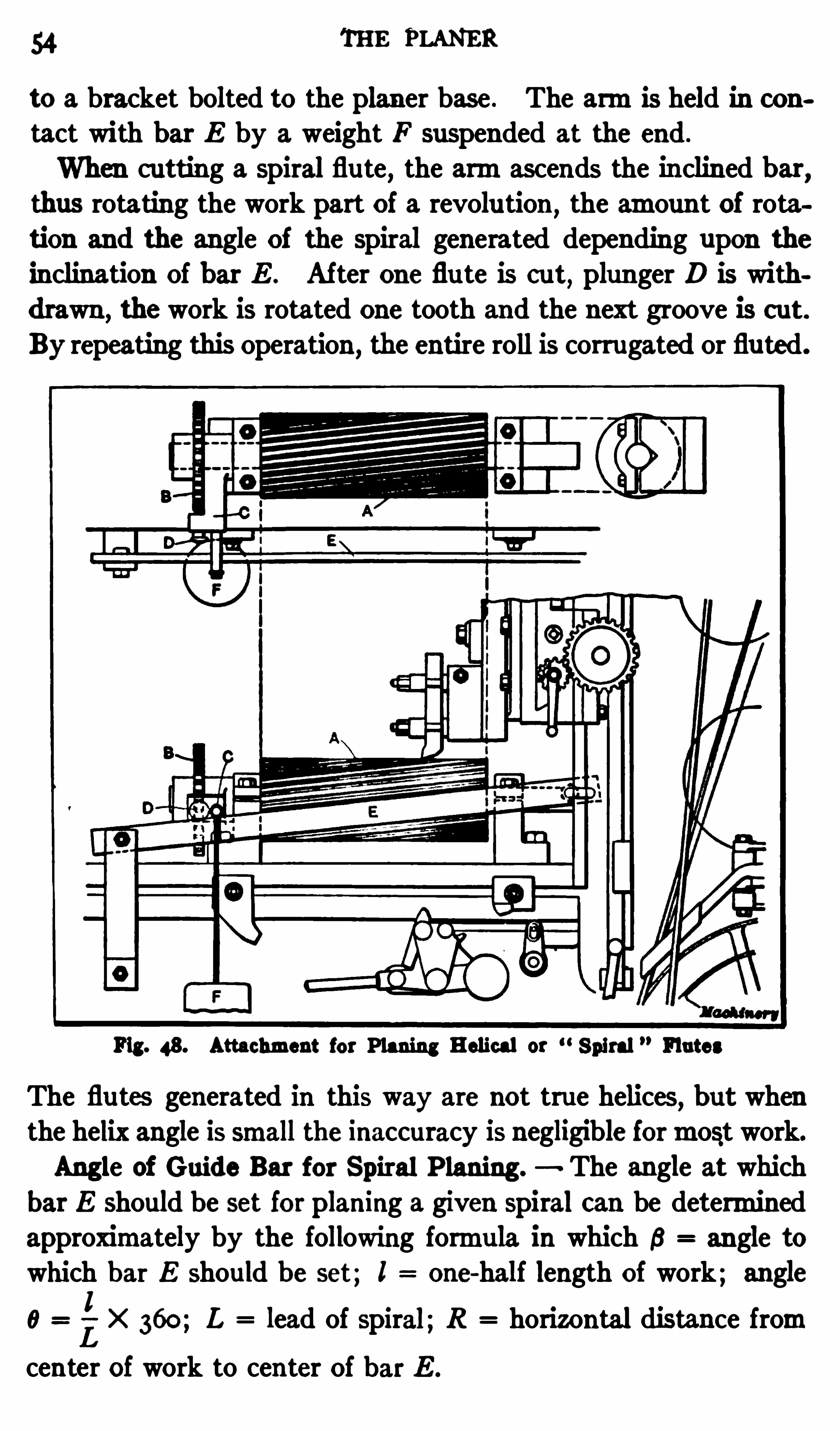
54 THE PLANER
to a bracket bolted to the planer base . The armis held in con
tact with bar E by a weight F suspended at the end .
When cutting a spiral flute, the armascends the inclined bar,
thus rotating the work part of a revolu tion ,the amount of rota
tion and the angle of the spiral generated depending upon theinclination Of bar E . Af ter one flu te is cut
, plunger D is with
drawn ,the work is rotated one tooth and the next groove is cut.
By repeating this Operation , the entire roll is corrugated or flu ted.
Fig. 48. Attachment for Planing Helical or Spiral Flutes
The flutes generated in this way are not true helices, but whenthe helix angle is small the inaccuracy is negligible formost work.
Angle of Guide Bar for Spiral P laning. The angle at whichbar E should be set for planing a given spiral can be determinedapproximately by the following formula in which 6 angle towhich bar E should be set; I one-half length of work; angle
x 360; L lead of spiral;R horizontal distance fromL
center of work to center Of bar E .
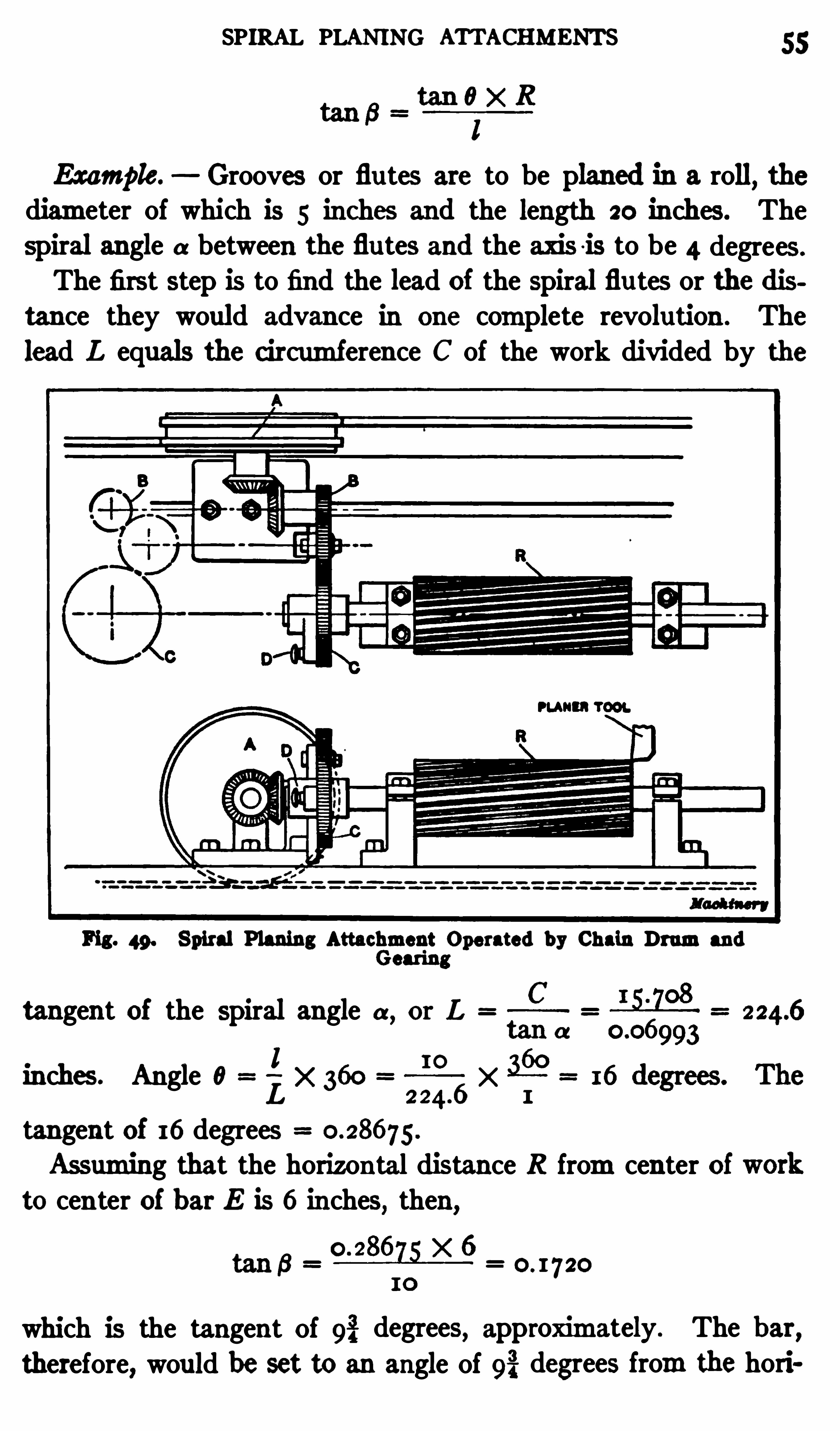
SPIRAL PLANING ATTACHMENTS 55
Example. Grooves or flutes are to be planed in a roll,the
diameter of which is 5 inches and the length 20 inches. Thespiral angle a between the flu tes and the axis i s to be 4 degrees.
The first step is to find the lead of the spiral flu tes or the distance they would advance in one complete revolution . The
lead L equals the circumference C of the work divided by the
Fig. 49. Spiral Planing Attaclément Operated by Chain Drumandcaring
tangent of the spiral angle a,or L
1 I OInches. Angle 0
LX
tangent Of 16 degreesAssuming that the horizontal distance R fromcenter of
to cen ter of bar E is 6 inches, then,
which is the tangent Of 9% degrees, approximately . The bar,therefore, would be set to an angle of 9% degrees fromthe hori
56 THE PLANER
zontal. The angular position cou ld be gaged quite accuratelyeither by using an ordinary protractor placed on parallels ex
tending fromthe planer table , or by using a graduated protractorhead and level such as are provided with combination squares.
Spiral P laning Attachments of the Geared Type . The at
tachment shown in Fig. 49 is given a rotarymovemen t for spiralplaning bymeans Of a drumA around which chains are wound.
One of these chains is fastened to a support at the left and theother to a support at the right
,and as the table reciprocates
,
Fig. 50. Planing Spiral Corrugations in Flour M ill Roll by Use ofGeared Attachment
the drumis rotated part Of a revolution,first in one direction
and then in the other . This rotary movement is transmittedto the roll R ,
through the bevel and spur gearing shown in theplan view . The journals of the roll to be fluted are held in Vblocks fitted with straps or clamps adjusted to eliminate playb ut allow a free rotarymovement . The spur gear C attachedto the end of the work arbor or journal
,as the casemay be , has
concentric rows of holes drilled in the side and the work isindexed after each successive groove is cut, by withdrawingplunger D and engaging it with the next succeeding hole . The

58 THE PLANER
width of the point or end of the rack tool (before the comers arerounded) equals the linear pitchmultiplied byExpres sing these rules as formulas ,
d h
w p t p
The radius r of the comers Of the tool equals one-seventh thewidth x of the space between the rack teeth at the top or alongthe addendumline.
Indexing the Tool when Planing Racks. When planing theteeth
,the tool is indexed a distance equal to the linear pitch 1)
Fig. 5 1. Diagrams showing Rack Planing Tools and Formation ofRack Teeth
either by means of amicrometer dial and the cross- feed screw
or by the use Of a positive locating device attached to the crossrail. Some planets havemicrometer dials on the feed-screw foradjusting the tool by direct measu rement, and if the planer isin good condition ,
quite accu rate results can be Obtained by thismethod of spacing the tool when cutting rack teeth
, althoughcare should be taken to avoid errors due to lostmotion betweenthe sc rew and feed-nut, bymoving the tool continuously in one
direction whenmaking an adjustment. When using themicrometer dial;it is well to set it to zero beforemaking each adjust
ment. The distance that the tool is indexed can then be read
direct fromthe zero mark,which tends to prevent mistakes
thatmight otherwise bemade. When a planer is not equipped
PLANING RACKS 59
with feed dials, special dials are sometimes applied for rackcutting.
To avoid the possibility Of error whenmeasuring the indexingmovement of the tool by using the cross-feed screw
,a special
indexing bar is sometimes attached to the cross-rail,especially
when a number of duplicate racks are to be planed . This barhas notches or teeth of the same pitch as the rack teeth to becut, and the planer tool-head is located positively by a pin or
plunger on the saddle which engages the notches in the fixedindexing bar.
Fig. 5 2 . Planing Teeth in Steel Racks for Frog and Switch Planers
Another very simple but positivemethod of indexing the tool
is to clamp a stop on the cross- rail in such a position that when
the saddle is against the stop the tool will be set for planing the
first tooth space; when the first space is cut, the stop is set ahead
of the saddle a distance equal to the pitch of the rack,by using
a gage. The saddle is then moved up to this stop for planingthe next tooth space , and this operation of adjusting the stopby the gage and locating the saddle against it is repeated for
each successive tooth.
60 THE PLANER
It is advisable when cutting rack teeth on the planer to have
an adjustable screw stop for down feed; then when the stop is
set correctly , all of the teeth can easily be planed to a uniformdepth. If the automatic down feed is used , it should be dis
engaged before the full depth is reached so that the tool-slide can
be fed against the stop by hand.
To avoidmaking a formtool for finishing rack teeth, a cir
cular cu tter, such as is used when milling racks 15 sometimesemployed when planing the teeth. The cutter Is bolted to a
shank held in the tool-holder, with one of the teeth in the lowestposition to ac t as a planer tool. Of course , this cutter must
Fig. 53 . Suc c essive Tools Used in Cutting S teel Rack Teeth
correspond to the pitch of the rack teeth , and , according to theB . S . systemfor involu te cutters, it should be a No. 1 form
,
as this number is adapted for cutting gearing varying froma
r35-tooth gear to a rack.
P laning Steel Racks. A practical example of rack cuttingon a planer is shown in Fig. 52 . These racks are used on the
Cincinnati frog-and-switch planets, and aremade of steel forgings instead of cast iron, because of the heavy class of work doneon a planer of this type . The rack ismade in sections and whenthe teeth are being cut, these sections are clamped to the planertable as shown in the illustration . The racks aremade from
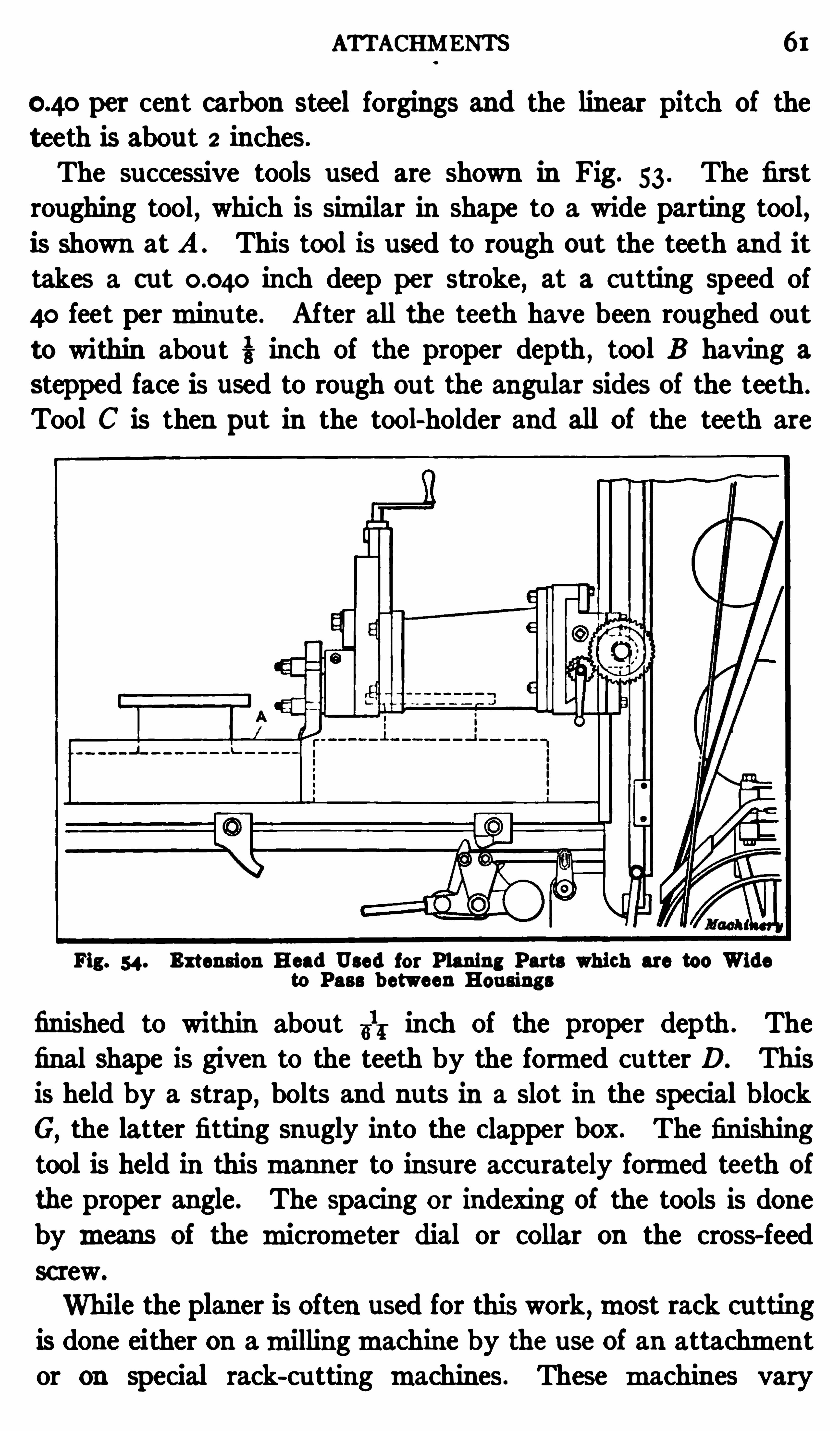
ATTACHMENTS 61
per cent carbon steel forgings and the linear pitch of theteeth is about 2 inches.
The successive tools used are shown in Fig. 53 . The firstroughing tool, which is similar in Shape to a wide parting tool,is Shown at A . This tool is used to rough out the teeth and it
takes a cut inch deep per stroke, at a cu tting speed of
40 feet perminu te . After all the teeth have been roughed out
to within about 3 inch of the proper depth , tool B having a
stepped face is used to rough out the angular sides of the teeth .
Tool C is then put in the tool-holder and all of the teeth are
Fig. 54. Extension Head Used for Planing Parts which are too Wideto Pass b etween Housings
finished to within abou t 31; inch of the proper depth . The
final shape is given to the teeth by the formed cutter D. Thisis held by a strap, bolts and nuts in a slot in the special blockG
,the latter fitting snugly into the clapper box . The finishn
tool is held in thismanner to insure accurately formed teeth of
the proper angle. The spacing or indexing of the tools is doneby means of the micrometer dial or collar on the cross-feed
screw.
While the planer is Often used for this work,most rack cutting
is done either on amillingmachine by the use of an attachmentor on special rack-cu tting machines. These machines vary
62 THE PLANER
greatly as to size and design al though most of themformthe
teeth by amilling proces s .
Extension Tool-head. When a great variety of work is done
on aplaner , spec ial attachments are occasionally needed. Fig. 54
shows how a planer can be arranged formachining a casting Athat is too wide to pass between the housings when placed lengthwise across the table, for planing the end. The tool is held in an
extension head to locate it far enough forward to prevent thework fromstriking the housings when at the extreme end of
Fig. 5 5 . Floor Stand or Independent Housing for Special PlaningOperations
the cutting stroke. This extension is fastened to the saddle inplace of the swiveling base, and the regular tool-slide is attachedto its outer end .
E xtension tools that are long enough to reach across the workare also used for planing parts that will not pass between the
housings,but themore rigid extension head
, shown in the illustration ,
is preferable .
Floor Stand 01 Independent Housing. Another method of
planing a casting that is too large to pass between the housingsis illustrated in Fig. 55 . The su rface to be planed is too wideto use an extension head, and the tool is held on a special floor
OPEN-SIDE PLANER 63
stand that is bolted to a T-slotted base-plate secured to the
foundation . The stroke Of the planer (as far as its position is
concerned) is adjusted with reference to the tool of this auxiliaryfloor stand , the latter being set far enough forward to provideroomfor the work between the tool and planer housing. Thefloor stand or
“independent housing
,shown in the illustration ,
has an automatic feed operated fromthe planer feedmechanism.
Auxiliary equipment of this kindmakes it possible to handle a
large range Of work on one or two planers, which is especiallydesirable in some shops.
Open-side Planers. The open-side type of planer has a
massive column on only one Side Of the table so that the oppositeside is open and unobstructed
,which greatly increases the range
Of the machine. The cross-rail or beamupon which the toolheads aremounted is Of very rigid design and has a broad bearing su rface on the column to prevent deflection due to the thrustOf the cut. The Chief advantage of an Open-side planer is thatit can be used formachining large castings which could not be
handled on a two-housing planer of ordinary size, as well as forgeneral planing Operations.
Fig. 56 shows a typical example of open-side planer work.
The large casting being planed is the vertical column for anotheropen-side planer . The operation is that ofmachining a pad on
top for the motor bracket, and planing the end . The pad is
finished by a tool held in one Of the cross-rail tool-heads A and
the end su rface is planed by a tool held in side-head B . I f a
casting of this size were machined on a two-housing type of
planer,the distance between the housings would have to be
8 feet 8 inches, but with the open-Side design, the end of thework Simply projects beyond the table as the illustration shows.
When an exceptionally long casting must be held at right
angles to the table, the ou ter or overhanging end is generally
supported on an auxiliary rolling table which is supplied with
some open-side planers. This table is set parallel with the
planer and consists Of a series of rollers upon which ismountedan I -beamthat supports the work and travels to and fro with
the planer table.
64 THE PLANER
The driving and feedingmechanismof an open-side planer issimilar to that used on other types and the stroke is also con
trolled by the position Of dogs or tappets attached to the side ofthe platen . The particu lar planer shown in Fig. 56 is driven by
amotor C,which is connected by belts with countershaft D.
The latter transmi ts themotion by open and cross-belts to theplaner driving shaft at the base Of the column . The cross-rail
Fig. 56. Cleveland Open-side Planer and Examis of Work for whichthis Type of Planer is Adapted
p
can be adjusted vertically by power to suit the height Of the partbeing planed .
P laning Cast-steel Loc omotive Frames. The machining of
a locomotive frame is a good example of the application Of theplaner to large heavy parts requi ring rapid machining ratherthan skillfu l and accurate work. Fig. 5 7 shows how two caststeel frames are planed at the same time
,in the "uniata shops Of
the P ennsylvania Railroad . These shops have,under normal
conditions, a capacity for building a complete locomotive every

66 THE PLANER
day, and this rate is sometimes exceeded , so that themachiningof frames is
.
an everyday occurrence . Practically all of thelocomotives built in these shops at the present time are equippedwith cast-steel frames instead of wrought-iron frames
,which
were used almost exclusively a few years ago. Frames that arecast aremuch cheaper than the forged type and another advantage of using cast steel is that pads or other projections can be
easily and neatly formed on the frame pattern .
The cast-steel frames are usually warped more or les s as
they come fromthe foundry, owing to unequal cooling,and
it is necessary to straighten themprior to machining. Thisstraightening is done under a large steamhammer . The frameis heated sufi ciently to insure a permanent set
” when straightened, and it is made approximately straight by giving it a fewblows with the hammer . The work is then ready for the first
machining operation which is that of planing the sides and
edges .
Two frames or sections are planed simultaneously on a very
rigid planer having five tool-heads. Fig. 57 shows thismachinetaking a roughing cut over the sides Of two frames . The work
is held on the platen by screw-stops and toe-dogs or “spuds
which are placed in an inclin ed position to force the work down.
Stops are also set against the frames at themost advantageouspositions to take the longitudinal thrust Of the cut. Part Of the
time , all five planing tools are at work , the three tool-heads on
the cross-rai l being used to plane the sides of the two sections,while the right and left side-heads plane the edges. The three
upper tools are started so that each rough planes abou t one-third
of the surface formed by the two castings . In this way theroughing is, Of course , done in much less time than would berequired if an ordinary two-head machine were employed . AS
many of these castings have spongy ,sandy spots
,blow-holes or
similar defec ts on the Cope side, a generous allowance is left forplaning in order to remove all porousmaterial.Owing to the power Of thismachine , very heavy cu ts can be
taken ,as indicated in the illustration . The planer is motor
driven ,andmomentarily asmuch as 90 horsepower is required
PLANING CYLINDERS 67
for driving, owing to the heavy hogging cu ts which are taken
in the tough cast steel. When roughing,‘
the tools frequently
cut to a depth of fromi to inch with a feed of 136 inch. The
average depth of cut for the five tools, however, would be somewhat less than the figures given . After the three heads on thecross-rail are started
,the right and left Side-heads are set. for
planing the edges. The work is set up for rough-planing the
first side, with the top edge of each sec tion outward . This isdone so that the top edges can be finished with reference to padsfor braces or brackets which are. located on the inside Of the topand bottomrails of the frames.
After the roughing cu ts on one side are completed , the finishingcuts are taken with broad flat tools which are given a feed varying fromI inch to 1} inch per stroke. Only two Of the cross-railheads are used for finishing, so that each frame can be planedby a continuous c ut in order to Obtain a smooth surface freefromridges. The frames are next tu rned over for roughing andfinishing the opposite side. The bottomedge of each frame isnow in the outward position
,thus permitting the ends of the
pedestals to be rough-planed. The finishing tools are set forplaning the second side by means Of a post or height gage towhich the cutting edges are adjusted . In this way the properthickness is quickly Obtained, although a fixed caliper gage isused to check this dimension . After the sides and edges havebeen planed, the inside faces Of the jaws are finished in a large
P laning Locomotive Cylinders. The cylinders of locomotivesvary considerably in their general arrangement
,and the exact
method Of planing themdepends, Of course , upon the design.
The various operations referred to represent the practice at the
"uniata shops Of the P ennsylvania Railroad. The style of
cylinder now used almost exclusively on the new locomotivesbuilt by this company is the single-expansion piston-valve type.
The first machining operation on a cylinder casting is that Ofboring the cylinder proper. After the cylinder is bored
,the
various surfaces on the saddle are planed.
By the use of an ingenious set Of fixtures, the castings are
THE PLANER
PLANING CYLINDERS 69
quickly and ac curately set up for the planing Operations. Figs.
58 and 59 show diflerent views Of the work mounted on thefixtures. Three cylinders are placed in a row and planed simultaneously, and the fixtures are so arranged that the bores ofthe various cylinders are aligned with one another and with theplaner platen . These fixtures consist Of heavy brackets or
standards B (see Fig. 60) having flanges as shown . The end
brackets have a single flange, whereas the two which comebetween the cylin ders are double flanged . There is a centralpocket A in each flange face , and the distance fromthese pocketsto the base is exactly the same for each bracket. Each of theconical disks C which engage the counterbores Of the cylindershas a cylindrical boss on the rear side which fits into any Of thecentral pockets AWhen a cylinder is to be set up for planing, one of these conical
disks is clamped in each end of the counterbore by a bolt passingfromone disk to the other. The brackets are also bolted to theplaner platen in the proper position . The distance between thebrackets is governed by the length between the outer faces ofthe disks after the latter are bolted in place, and the centralpockets A are all brought into alignment, laterally, by tonguepieces on the base of each bracket. The cylinder is next picked
up by a crane and lowered until the disks have en tered betweenthe brackets . The temporary holding bolt for the disks is thenremoved and the work is lowered until the cylindrical bosses
on the disks, which slide through the vertical slots D, rest in the
central pockets A Of the fixtures. When three cylindrical cast
ings have been set up in this way, the center line or axis of each
cylinder bore will be in alignment.The valve chamber is next set vertically with relation to the
cen ter Of the cylinder . TO Obtain this setting, a spider F ,
Fig. 59, is placed in the valve chamber and its hub is centeredwith the bore of the valve chamber by using hermaphroditecalipers. The casting is then adjusted vertically by the smallsupporting jacks seen in Fig. 58, until this center is the requireddistance below the center of the cylinder, as shown by an ordinary
su rface gage . The height fromthe platen to the cen ter Of the
70 THE PLANER
cylinder bore is accurately ascertained beforehand and remainsconstant for a given size fixture .
After the three castings are set as described, clamping pieceswhich fit in the slots D
,Fig. 60
,are tightened against the hubs
of the conical disks by clamps E . The cylinders are furthersecured by a long tie-bolt G which extends through the three
castings and holds both the work and fixtures rigidly together.
Fig. 59. Another View of Cylinder Planing Operation Illustratedin Fig. 58
By referring to the illustrations, it will be seen that these fixturesmake it possible to hold the three cylinders with very few Clamps.These fixtures have not only effected a considerable reduction inthe time required for setting the cylinders prior to planing, butthey also insure accurate and uniformwork.
After the cylinders are set as described,the top surface I
(Fig. 59) which forms the joint between the right and left-handcylinders is rough-planed by using the two tool-heads . This
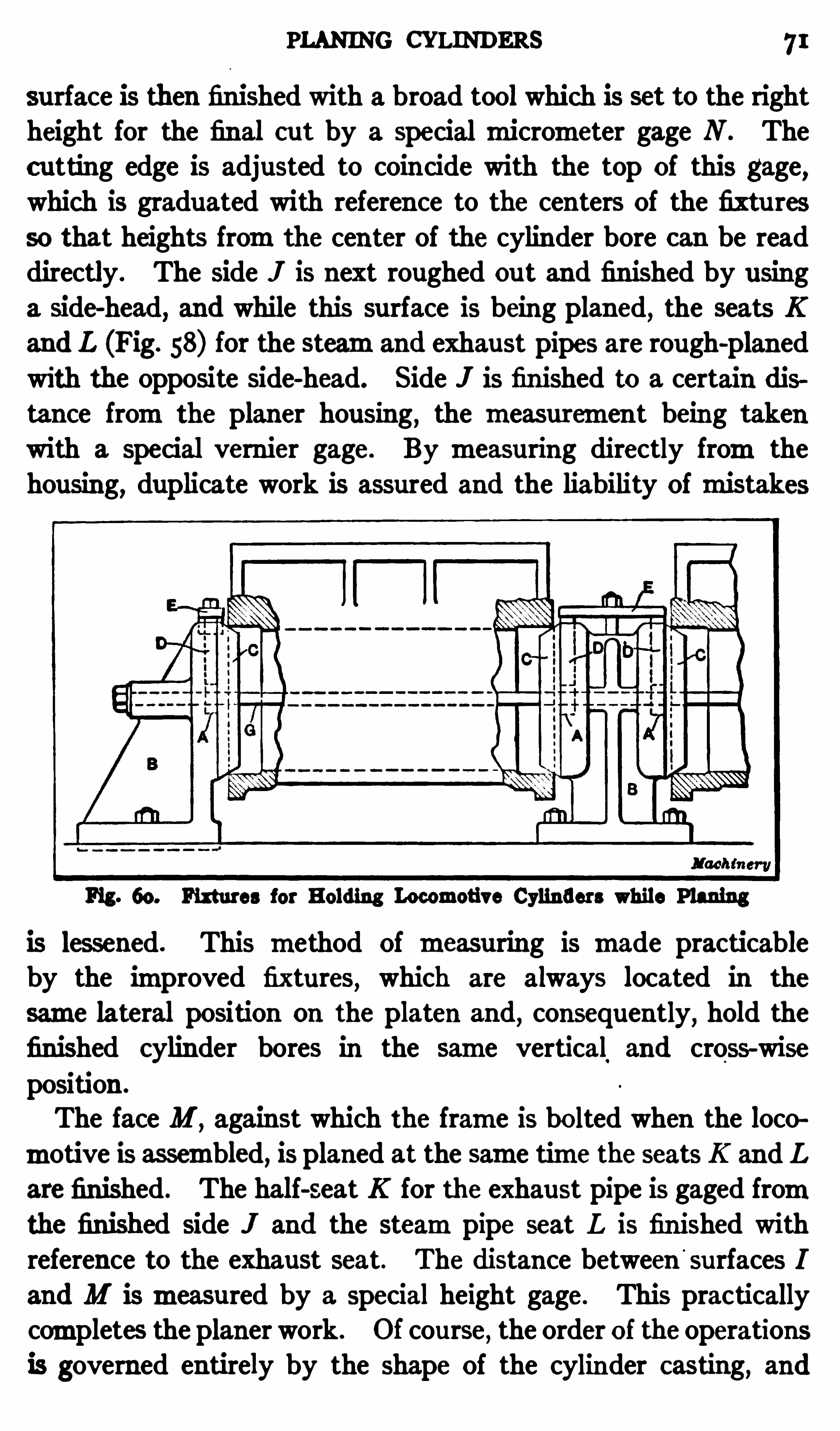
PLANING CYLINDERS 71
surface is then finished with a broad tool which is set to the rightheight for the final cut by a special micrometer gage N . Thecutting edge is adjusted to coincide with the top of this gage,which is graduated with reference to the centers Of the fixtu resso that heights fromthe center of the cylinder bore can be readdirectly. The side I is next roughed ou t and finished by usinga side-head, and while this surface is being planed
,the seats K
and L (Fig. 58) for the steamand exhaust pipes are rough-planedwith the opposite side-head. Side J is finished to a certain distance fromthe planer housing
,the measuremen t being taken
with a special vernier gage. By measuring directly fromthehousing, duplicate work is assured and the liability Ofmistakes
Fig . 60. Fixtures for Holding Locomotive Cylinders while Planing
is lessened. This method Of measuring is made practicableby the improved fixtures
,which are always located in the
same lateral position on the platen and, consequently, hold the
finished cylinder bores in the same vertical and cross-wise
position .
The face M ,against which the frame is bolted when the loco
motive is assembled, is planed at the same time the seats K and L
are finished . The half-seat K for the exhaust pipe is gaged fromthe finished side I and the steampipe seat L is finished withreference to the exhaust seat. The distance between
'
surfaces I
and M ismeasured by a special height gage. This practicallycompletes the planer work. Of course, the order of the operations
is governed entirely by the shape Of the cylinder Casting, and
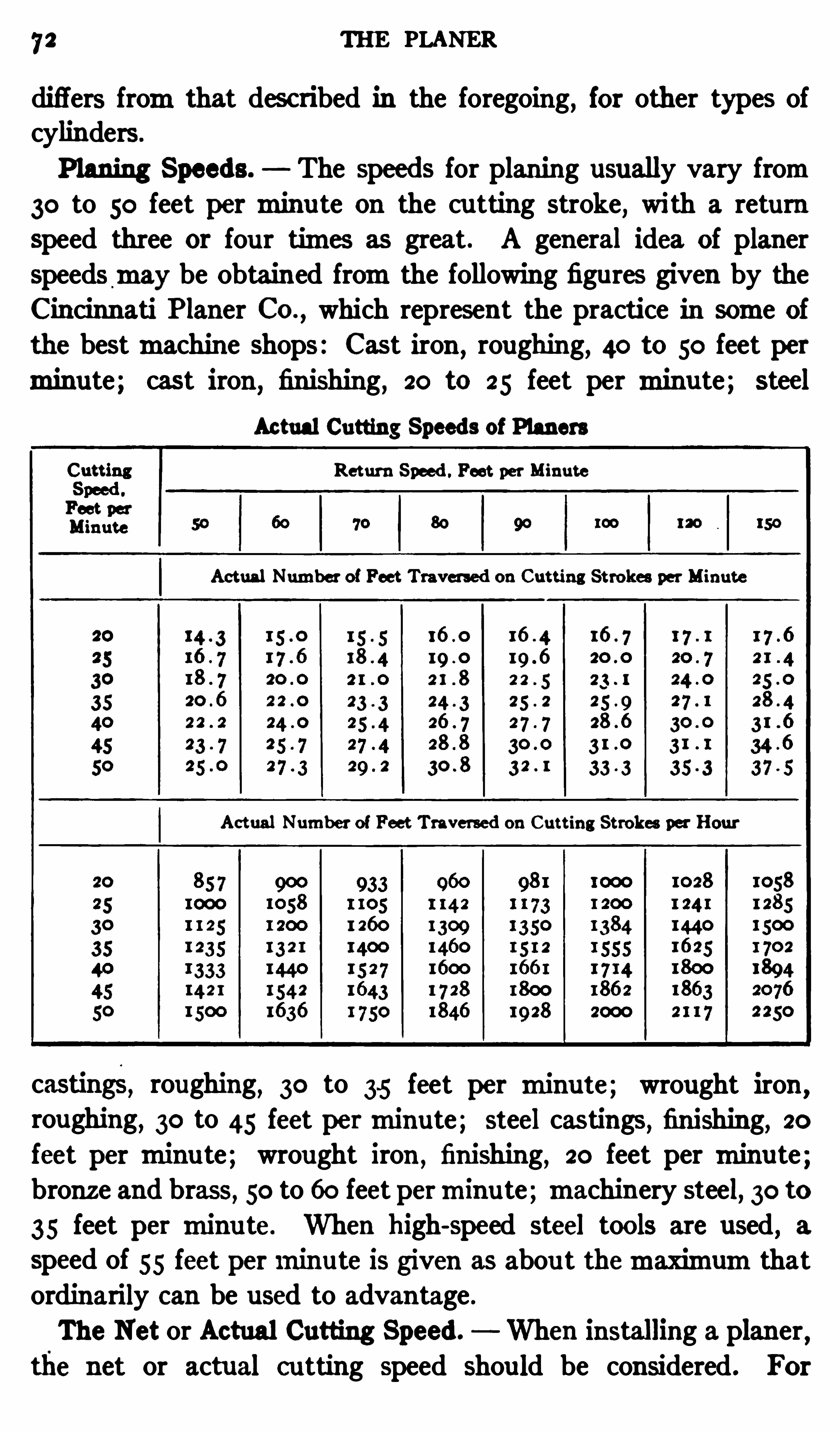
72 THE PLANER
differs fromthat desc ribed in the foregoing, for other types ofcylinders .
Planing Speeds. The speeds for planing usually vary from30 to 50 feet perminu te on the cu tting stroke
,with a return
speed three or fou r times as great . A general idea of planerspeedsmay be Obtained fromthe following figures given by theCincinnati P laner CO.
,which represent the practice in some of
the bestmachin e shops: Cast iron ,roughing, 40 to 50 feet per
minute; cast iron , fin ishing, 20 to 25 feet per minu te; steel
Ac tual Cutting Speeds of Planers
Return Speed . Feet per Minute
Ac tual Number of Feet Traversed on Cutting Strokes per Minute
Actual Number of Feet Traversed on Cutting Strokes per Hour
castings, roughing, 30 to 35 feet per minute; wrought iron ,roughing
, 30 to 45 feet perminute; steel castings,fin ishing, 20
feet per minu te; wrought iron ,finishing
, 20 feet per minute;bronze and brass, 50 to 60 feet perminu te;machinery steel, 30 to35 feet per minu te. When high-speed steel tools are used , a
speed of 55 feet perminute is given as abou t themaximumthatordinarily c an be used to advantage .
The Net or Actual Cutting Speed. When installing a planer ,the net or actual c utting speed should be considered. For

74 THE PLANER
driving pulleys because the principal power loss at reversal is
due to the energy stored in the revolving pulleys; hence whenlighter pulleys are used
,there is less kinetic energy for a given
speed and less power is required at the point of reversal.
Fig. 61. Cincinnati Variab le-speed Belt-driven Planer
Feeds for P laning. The feed of a planing tool varies widelyfor difl
'
erent kinds of material and classes of work. I t is alsogoverned by the depth of cut
,the nature Of the cut (whether
roughing or finishing) , and by the rigidity Of the work whenclamped in position for planing. Feeds ordinarily vary from115 to 3 inch when taking deep roughing cu ts in steel, and from3 to 1
36 inch for rough-planing cast iron . When taking light
ELECTRICALLY—DRIVEN PLANER 75
finishing cu ts in cast iron ,a broad tool having a flat edge is
commonly used and the feed ordinarily varies from"} to 3 inchper stroke. When planing large, rigid castings a feed as coarseas or 1 inch per stroke is Often used .
Variab le-speed Drives for P laners. Many planers can onlybe Operated at one cu tting speed
,the driving pulleys being pro
portioned to give a speed that will be abou t right for averageconditions. A change of two ormore speeds
,however
,is very
desirable,because the cu tting speed should be varied to suit
the material being planed or the nature Of the cut. Many
modern planers have a variable-speed drivingmechanism.
A planer Of the variable-speed type is shown in Fig. 61 .
The belt pulley A transmits power to the driving pu lleys B and
C,through gearing enclosed in speed-box D. The speeds are
changed by levers E which control the position Of the slidinggears in the speed-box. This particu larmachine has fou r speedchanges. The speed variator is also u sed on motor-drivenplaners, themotor beingmounted on top Of the housing . Whena variety Of speeds is unnecessary
,a two-speed countershaft is
Often used .
Electri cally-c ontrolled Drive for P laners. The planer illus
trated in Fig. 62 is a variable-speed type driven by a reversing
motor. The speed chan ges are obtained by an electrical controller and a pilot switch. There are twelve cutting speedsranging from2 5 to 50 feet perminute and twelve return speedsranging from50 to 100 feet perminute. These speed changes
are varied by turning two handwheels on the‘
front of the controller case. These handwheels have dials graduated to Show
the various speeds.
In the Operation Of the planer, the point Of reversal is controlledby dogs similar to those on a belt-driven planer. At the instant
of reversal, a pilot switch is thrown by one of the dogs and thecontroller Short Circuits the armature through suitable resistance,causing themotor to ac t as a generator and consequently as a
powerful electric brake on the planer table . When the speed
of themotor has been reduced to a predetermined amount, thearmature current is reversed and the table starts on the next
76 THE PLANER
succeeding stroke. This sequence Of Operations takes place at
the end of each table stroke,whether on the cu tting or return
movement and is entirely au tomatic, being regulated by thecontroller.The pilot switch
,whichmay be operated fromeither side of
the planer, takes the place of the belt-shifting device on beltdriven planers. By manipulating the pilot switch, two speeds
Fig. 62 . Niles-Bement-Pond Planer with Reversing Motor Drive
in either direction are Obtained . One Of these speeds corresponds
to that forwhich the controller is set,and the other is a slow speed
which is useful when setting work or for slowing down whencutting hardmaterial. The planer shown in the illustration isequipped with a pendant switch which is suspended froman
overhead bracket and hangs above the table. This Switch can
bemoved to any convenient position andmay be used to controlthemovement Of the table fromeither side Of themachine.
DOUBLE—CUTTING PLANERS 77
Doub le-cutting P laners. Many attempts have been madeto design a plan er that would cut with equal eflic iency on both
the forward and return strokes. One Objection has been thattwo tools could not be used on some Classes of work , owing tothe lack Of clearance at the end Of the stroke; consequently,when using a planer having an equal speed of the table in bothdirections
,the absence Of a quick return on the idle stroke greatly
discounted,if not entirely Ofl-set
,the advantages gained on
work where double cutting cou ld be employed . In order to overcome this Objeetion ,
a double-cutting planer has been developedby an English concern
,that is equ ipped with a variable-speed
motor drive and a small auxiliary motor for such operationsas feeding and traversing the tools. With this arrangement, theforward and return strokes can be made either at a uniformspeed or the return stroke can be increased when required .
Another design of planer has also been introduced having a
belt drive,by means of which the same flexibility as regards
the rate of speed Of the return stroke c an be obtained. Themethod of holding the double-cutting tools is to fasten themback to back and exactly in line.
Evidently,if planers are to bemade double cu tting, the suc
cessful design must be qu ite difl'erent fromthat of ordinaryplaners in order to secure equal support for the tool when cutting
in both directions . The single-stroke planer is designed to takeamaximumcut in one direction only
,and a radical changemust
bemade in its design before it will be possible to plane eflicientlyin both directions. When the tool-head is clamped to the faceof a cross-rail
,which
,in turn
,is clamped to the face of the hous
ing, Obviously, the stresses produced in these parts when a cut
is taken in one direction are quite diflerent fromthose producedwhen the cut is in the other direction . In one case there is a
tendency to compress all of the parts solidly together, thus
giving a firmsupport to the cutting tool,whereas in the other,
the tendency is to pull all the joints apart, thus depriving the
tool Of the firmness Of its support and increasing the tendency
to chatter.
CHAPTER II
THE SHAPER AND SLOTTER
THE shaper, like the planer, is used principally for producing
flat or plane surfaces, bu t it is intended for smaller work than isordinarily done on a planer . The shaper is preferable to theplaner for work within its capacity because it is less cumbersometo handle and quicker in itsmovement . The action Of a stand
ard shaper,when in use
,is quite diflerent fromthe planer; in
fact,its operation is just the reverse, as the toolmoves back
and forth across the work, which remains stationary,except
for a slight feedingmovement for each stroke.
General Description of a Shaper. A shaper Of typical de
sign is shown ih Fig. 1 . The principal parts are the base andcolumn B and C; the table T which has a vise V for holdingwork; and the ramR which carries a planing tool in tool-post Iand is given a reciprocatingmotion by a crankmechanisminsidethe column . The work-table ismounted on a saddle or crossslide D, and it c an bemoved along the cross-rail A by turningthe lead-screw L with a crank or by an automatic feedingmechanIsm. The cross-rail c an be adjusted vertically on the face of thec olumn to accommodate work Of various heights
,and the tool
slide F with the tool c an be fed downward by handle E .
Shaper Driving Mechanism. The driving mechanismfor
the ramis shown in the sectional views, Fig. 2 . Shaft S on
which the driving pulley ismounted is conn ected through gearing with crank gear C. This gear carries a crank-pin or block Bwhich engages a slot in the armN
,and this arm,
in turn,connects
with the ramR and is pivoted at its lower end . As the crankgear rotates, an oscillatingmotion is given to armN which imparts a reciprocatingmovement to the ram. The amount thatthe armmoves and , consequently, the stroke of the ram
,is
governed by the position Of the crank-block B which can be ad
78
CRANK—SHAPER 79
justed toward or fromthe center of the gear by shaf t 0. Thisshaft connects through spur and bevel gears with a screw thatengages the crank-block
,as shown in the cross-section to the
left. The stroke can be changed while the shaper is inmotion ,
and the pointer G,as it travels along the stationary scale H ,
shows the length of the stroke in inches (see also Fig. I )
Fig. 1. Cincinnati Back-geared Crank-shaper
The position of the stroke can also be varied (while themachine is inmotion) by turning handwheel I which causes screwK to rotate and shifts the position of block L with relation tothe ram. Before making this adjustment
,block L
,which is
ordinarily c lamped to the ram,is loosened by tu rning lever M .
Bymeans Of this adjustment for the position of the stroke,the
tool ismade tomove back and forth over that part of the workthat requires planing, whereas the stroke adjustment serves to

80 THE SHAPER

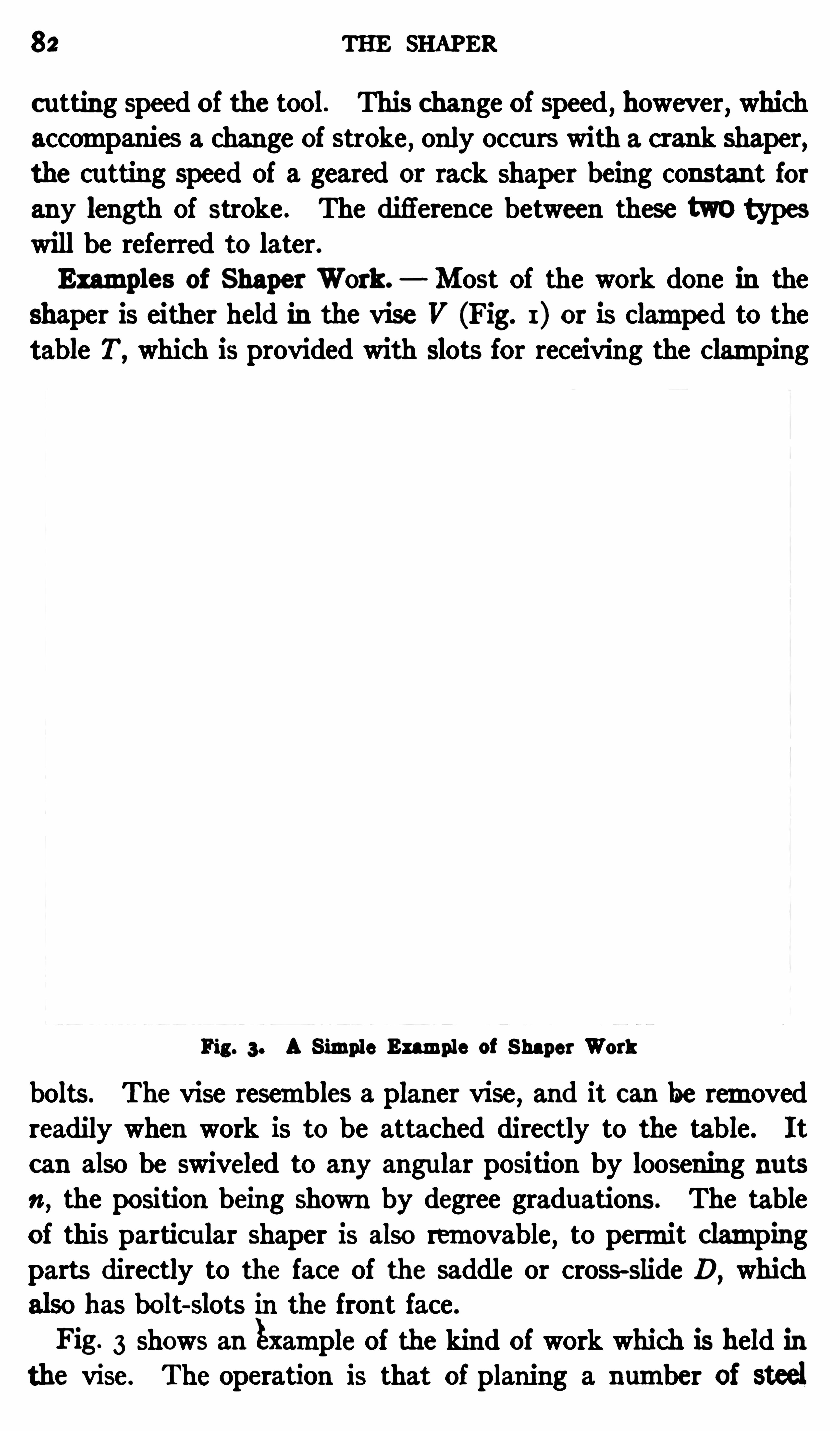
82 THE SHAP ER
c utting speed of the tool. This change of speed,however, which
accompan ies a change of stroke , only occurs with a crank shaper,the cutting speed Of a geared or rack shaper being constant for
any length of stroke . The diflerence between these two typeswill be referred to later.
Examples of Shaper Work . Most Of the work done in the
shaper is either held in the vise V (Fig. 1) or is clamped to thetable T,
which is provided with slots for receiving the clamping
Fig. 3. A S imple Example of Shaper Work
bolts . The vise resembles a planer vise,and it can be removed
readily when work is to be attached directly to the table. It
can also be swiveled to any angular position by loosening nutsn , the position being shown by degree graduations . The tableof this particu lar shaper is also removable
,to permit c lamping
parts directly to the face Of the saddle or cross-slide D,which
also has bolt-slots in the front face.
Fig. 3 shows an Example Of the kind of work which is held inthe vise. The operation is that of planing a number of steel
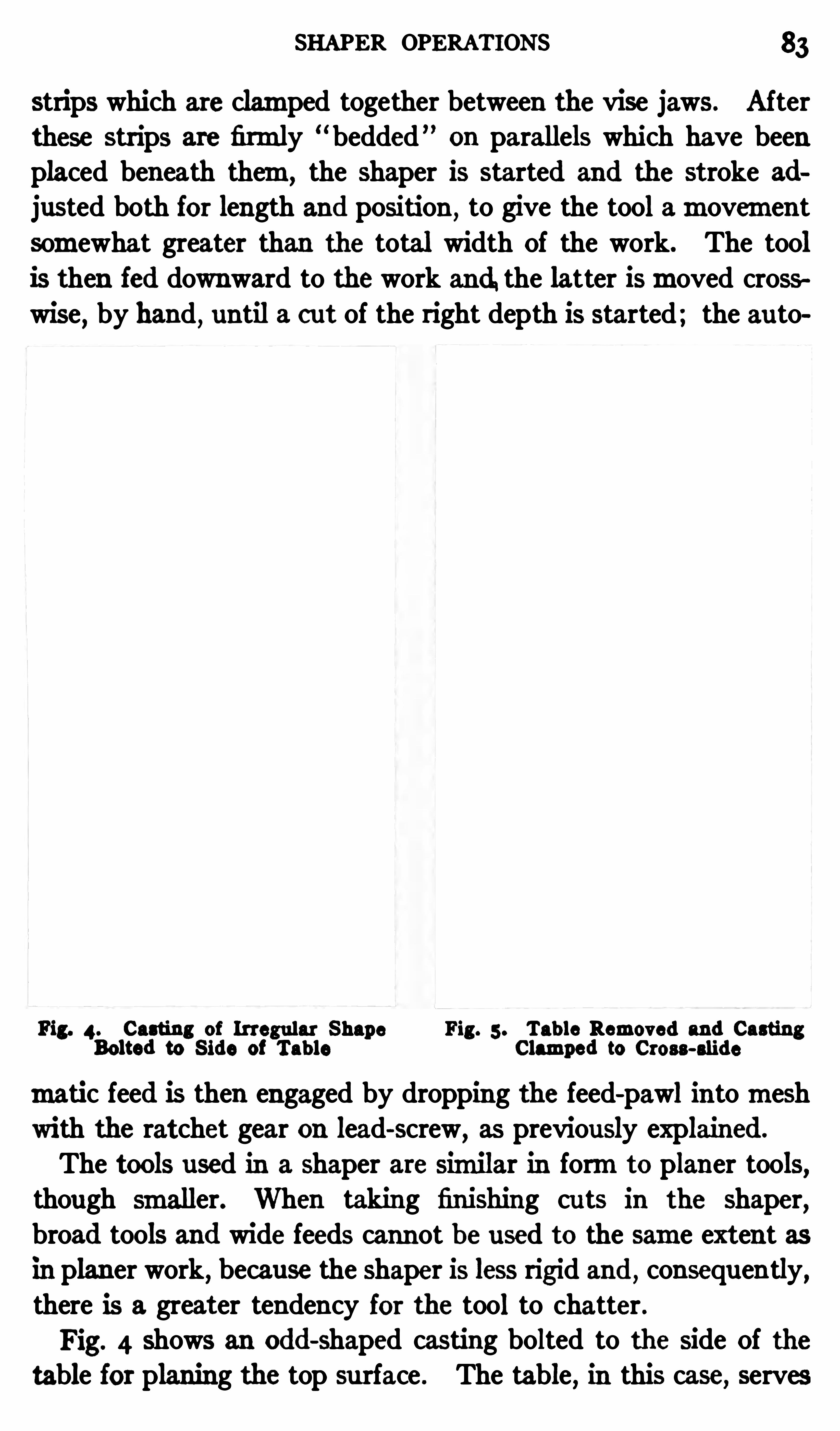
SHAPER OPERATIONS 3
strips which are clamped together between the vise jaws. Afterthese strips are firmly “ bedded ” on parallels which have beenplaced beneath them, the shaper is started and the stroke ad
justed both for length and position,to give the tool amovement
somewhat greater than the total width Of the work. The toolis then fed downward to thework and.the latter ismoved crosswise, by hand , until a cut of the right depth is started; the au to
Fig. 4. Casting of Irregular Shape Fig. 5 . Tab le Removed and CastingBolted to S ide of Tab le Clamped to Cross-slide
matic feed is then engaged by dropping the feed-pawl intomeshwith the ratchet gear on lead-screw
,as previously explained.
The tools used in a shaper are similar in formto planer tools,though smaller. When taking finishing cuts in the shaper
,
broad tools and wide feeds cannot b e used to the same extent asin planer work, because the shaper is less rigid and , consequently,there is a greater tendency for the tool to chatter .
Fig. 4 shows an odd-shaped casting bolted to the side Of the
table for planing the top su rface . The table,in this case, serves
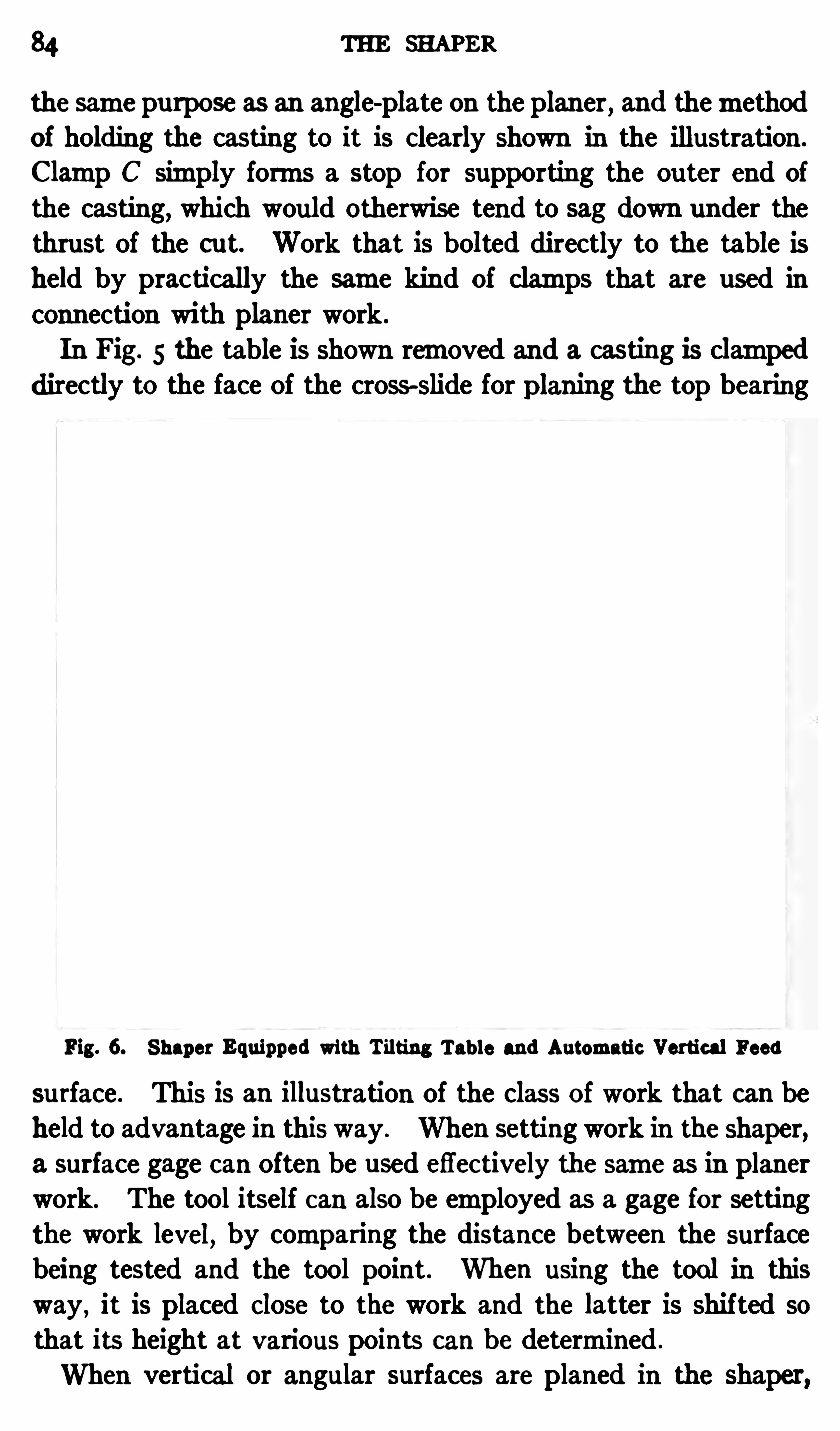
84 THE SHAPER
the same purpose as an angle-plate on the planer , and themethodof holding the casting to it is Clearly shown in the illustration .
Clamp C simply forms a stop for supporting the ou ter end of
the casting,which would otherwise tend to sag down under the
thrust Of the cut. Work that is bolted directly to the table is
held by practically the same kind of clamps that are used in
connection with planer work .
In Fig. 5 the table is shown removed and a casting is clampeddirectly to the face Of the cross-slide for planing the top bearing
Fig. 6. Shaper Equipped with Tilting Tab le and Automatic Vertical Feed
su rface . This is an illustration Of the class Of work that can beheld to advantage in this way. When setting work in the shaper,a surface gage can Often be used efl
'
ec tively the same as in planerwork. The tool itself can also be employed as a gage for setting
the work level, by comparing the distance between the surfacebeing tested and the tool point . When using the tool in this
way , it is placed Close to the work and the latter is shifted so
that its height at various points can be determined .
When vertical or angular surfaces are planed in the shaper,
AD"USTABLE SHAPER TABLES 85
the tool block is swiveled SO that the top Of the block inclinesaway fromthe surface being planed , to avoid any interferencewith the tool on the return stroke, as explained in connectionwith planer work. The entire tool-head can also be set to anyangle for planing angular surfaces, by loosening locking bolt h
(Fig. I ) , and its position is shown by degree graduations. SomeShapers have an automatic vertical feed for the tool as well asan au tomatic horizontal feed for the work
,but most Shapers
are not so equipped,the tool being fed vertically by hand . Both
the horizontal and vertical feed-screws.
Of themachine , shown inFig. 1
,have graduated collars which are used when it is desired
to feed the tool down or crosswise a definite amount. Thesecollars have graduations representing amovement of inch ,and they can Often be used to advantage for adjusting the tools.
Tilting Tab le for Shaper. The detail view,Fig. 6
,shows a
shaper equipped with a tilting table A which is very convenientfor planing tapering parts. The table swings about the bolts orpivots B on each Side
,and it is held at whatever anglemay be
required by the slotted arms C which are bolted to the sides ofthemain table . The workmay be held either in a vise or bebolted directly to the table . When planing tapering parts that
are held between index centers, the tilting table enables the centers to be kept in linewith each other
,which is especially desirable
when indexing is necessary . The cause of the inaccuracy resulting fromindexing with the centers out of line is explained inthe paragraph headed “Milling Taper Flutes
,
”Chapter IV.
The shaper illustrated in Fig. 6 also has an automatic verticalfeed for the tool-slide. The ratchet feed lever Dwhich transmitsmotion to the feed-screw is operated by an adjustable tappet E ,
as the rammoves back and forth. The au tomatic vertical feedis very convenient, especially formachining wide surfaces .
Swiveling Shaper Tab le. The shaper shown in Fig. 7 has a
table which swivels through an arc Of 90 degrees about a hori
zontal axis. The angular position of the table is shown by a
graduated dial D. This swiveling feature is useful especially in
connection with tool and diemaking for planing surfaces at anangle.
86 THE SHAPER
Circular Planing Attachment. The machine illustrated inFig. 7 is also provided with an attachment for circular, concaveplaning. A cu rved su rface is produced as the tool-head and toolare turned about a horizontal axis by the au tomatic feedingmechanismshown . A rotarymovement is derived fromwormgearing A located just back of tool-slide
,thewormbeing turned
intermittently by a ratchet lever B which is connected to itthrough gearing. This ratchet lever is operated by engagementwith the adjustable tappet C.
Fig. 7 . Shaper having Swiveling Tab le and Con cave Attachment
There are also shaper attachments for convex cylindricalplaning
,commonly known as circular or cone mandrels . The
attachment consists Of a base-plate which is bolted to the tableand has two uprights. Between these uprights there is an
arbor which carries two conical bushings for holding parts havingdrilled or bored holes . The arbor and work is given a rotarymovement bymeans of wormgearing at the end , which, in turn,
MOTOR—DRIVEN SHAPER 87
is operated by a feed mechanism. Other attachments are
sometimes used on the shaper in order to adapt it to a widerrange Of work, although the ones referred to are themost common types .
Motor-driven Shaper. Many modern shapers,as well as
other machine tools, are driven by a direct-connected electricmotor instead Of transmitting the power froman overheadcountershaft to a cone pulley on the machine. By having a
Fig. 8. Gould Eb erhardt Shaper having Variab le-speed ElectricM otor Drive
motor drive, the machine can be operated independently,and
overhead belting is eliminated, thus leaving a clear space fortraveling c ranes . An electrically driven shaper is shown in
Fig. 8. Themotor A is a variable-speed type and is connectedto the driving shaft Of the shaper by a silent chain enclosed in
guard B . Variations in speed are obtained electrically bymeansof the combination starting box and field rheostat C.
On some Shapers, a constant-speed motor is used and the
Speed changes are Obtained mechanically by shifting gears in
88 THE SHAPER
a gear box, through which motion is transmitted . The gear
box construction is also found on some belt-driven Shapers,in
which case a single belt pulley is used instead of a cone pulley.
The long curved lever D controls a clutch and brakemechanismfor starting and stopping themachine independently Of themotor. Shifting the lever in one direction starts the shaper,and moving it in the opposite direction stops the ramat any
part Of the stroke.
Fig. 9. M orton Draw-cut Shaper
Morton Draw-c ut Shaper. The shaper illustrated in Fig. 9
differs fromthe ordinary type in that the tool cu ts when it ismoving towards the column of themachine. In other words
,
the tool is pulled or drawn through the metal on the cuttingstroke instead Of being pushed . For this reason the name“ draw-cut
”is applied to a shaper of this type. The planing
tool is,Of course , set with the cutting edge reversed . Themm
of thismachine is driven by a rack and gearing, and the recipro

90 THE SHAPER
which has an all-geared drive . The driving mechanismof a
rack shaper is similar to that of a spur-gear type of planer. Theramhas a rack on its under side and it is driven by a gear whichmeshes with this rack. Themovement of the ramis reversedeither by open and cross-belts which are alternately shifted on
tight and loose pulleys,or by friction clu tches which alternately
engage the forward and return pulleys. The length of thestroke is controlled by adjustable tappets .
Special Types of Shapers. Shapers Of special types are alsobuilt in a number Of diflerent designs which are varied to suitcertain classes Of work . These differ fromthe standard types
either in the motion of the ramrelative to the work table or
in having a greater range Of adjustment which adapts themtowork which could not be handled in an ordinary shaper.A shaper is shown in Fig. 10
,which is provided with a cross
traverse for the tool-head . The advantage of this feature, for
certain classes Of work,is indicated by the illustration . The
regular table has been removed,and the end Of a 20-ton steel
roll is being planed . The traversing head enables horizontalcu ts to be taken over the work which remains stationary . ThisShaper is a special design built by Gould Eberhardt, and itcan be used to advantage on large
,unwieldy parts such as the
one illustrated .
P ratt Whitney Vertical Shaper. The machine shown inFig. 1 1 resembles a slotter in many respects
,b ut it is known as
a vertical shaper and is adapted for classes Of work that are
done on horizontal Shapers and regu lar slottingmachines. The
work table Of this shaper can be given a transverse , longitudinal,or rotarymovement. The ramwhich carries the planing or slotting toolmoves vertically while the table is fed either by hand or
au tomatically, in whatever direction is required . The transversefeed is eflec ted by Shaft A , the longitudinal feed by screw B ,
and
the rotary feed by Shaft C. Power 18 transmitted to the feed
power being transmitted through a crank at G and shaft H to
the feed pawl and ratchet shown In the illustration .The vari
VERTICAL SHAPER 91
ous power feeds are engaged by sliding pinions I,J and K into
mesh. When these pinions are in the ou tward position ,the
power feed is disengaged and when they are,
pushed inward, thepower feed is operative. The direction of the feed is controlledby pushing in or pulling out the knob L . The feeding action
Fig. 11. Pratt Whitney Vertical Shaper
takes place when the ramis at the upper end Of its travel and thetool is c lear Of the work. Micrometer dials are provided for
making accurate adjustments, and the periphery of the rotary
table is graduated in degrees.
Themechanismfor operating the ramis driven by wormgearing and with this exception it is similar to the drivingmecha
92 THE SHAPER
nismused on the P ratt 81 Whitney horizontal shaper. The ramcan be set perpendicu lar to the table
,or at an angle , as shown
in Fig. 1 2,for slotting dies
,etc . The ramismounted in an inde
pendent bearing, the upper part of which is pivoted on a trunnionthat enables the bearing and the ramto be set in an angularposition , which is indicated by degree graduations. The strokeOf the ramis indicated by the graduated dial M , and the rammay be stopped and started independently Of the countershaftby a friction clu tch controlled through lever P .
Fig. 12 . Angular Adjustment of Fig. 13 . RamHead SwiveledRamon Vertical Shaper through 90 Degrees
The tool is held in a slotted toolpost carried in a clapper whichpermits the tool to clear the work on the return stroke, the sameas on a horizontal shaper. When exceptionally long toolsmustbe used on internal work
,the clapper c an be clamped rigidly to
the head. The tool-head can be swiveled to four diflerent positions
,one of which is shown in Fig. 13 , so that the tool can be
set for planing diflerent sides without changing the position Of
the rotary table and by simply using the transverse or longitudinal feedingmovement, thus insu ring accu racy between the surfaces . Work can Often be completed at one setting on a shaperof this type and itmay be used formachining concave, convexor irregular surfaces.

94 THE SHAPER
shaper ram, a milling and drilling spindle,and suitable speed
and feed-changingmechanisms . Themilling spindle and shaperramhave universal adjustments so that tools can be presented
to the work at any desired angle. Fig. 15 shows the shaper
ramset in a horizontal position .
The machine is driven froma constant-speed clutch pulley
at the rear, which transmits the power through a double cone
of spur gears to themain head . The latter carries bevel gears
Fig. 15 . Shaper Ramof Cochrane-B ly Universal Shaper Set in a
Horizontal Position
for driving both the shaper ramandmilling spindles . The cones
of spur gears provide means for varying the speeds,and the
speed changes are effected bymeans Of a lever on the right-handside Of the column . The end of this lever swings around a graduated quadrant which shows the number of ramstrokes perminute for any one Of the five positions . The shaper ramhas aquick return and the strokes can b e adjusted from0 to 6 inches.
The ramis equipped with amechanismwhich provides a positiverelief for the tool on the upward or return stroke .
Themilling spindle revolves either to the right or left. It has
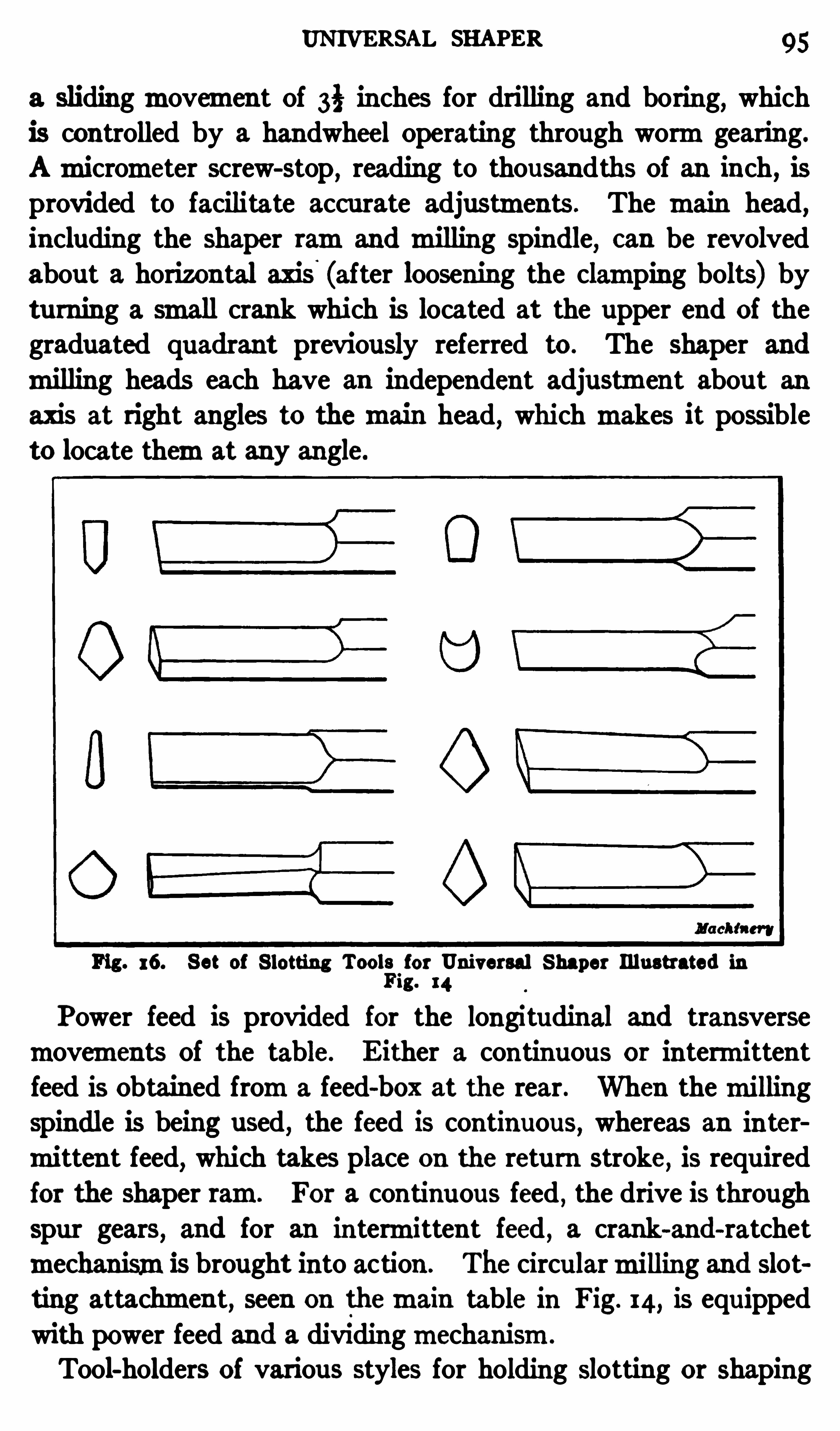
UNI VERSAL SHAPER 95
a slidingmovement Of 3§ inches for drilling and boring,which
is controlled by a handwheel Operating through wormgearing.
Amicrometer screw-stop,reading to thousandths Of an inch, is
provided to facilitate accurate adjustments . The main head,including the shaper ramand milling spindle
, can be revolvedabout a horizontal axis (after loosening the clamping bolts) byturning a small crank which is located at the upper end of thegraduated quadrant previously referred to . The shaper and
milling heads each have an independent adjustment abou t anaxis at right angles to themain head, which makes it possibleto locate themat any angle.
Fig. 16. Set of S lotting Tool;for Universal Shaper Illustrated in1g. 14
Power feed is provided for the longitudinal and transverse
movements Of the table. E ither a continuous or intermittentfeed is Obtained froma feed-box at the rear . When themillingspindle is being used, the feed is continuous, whereas an inter
mittent feed, which takes place on the return stroke, is required
for the shaper ram. For a continuous feed , the drive is through
spur gears, and for an intermittent feed , a crank-and-ratchet
mechanism13 brought into action . The circularmilling and slotting attachment, seen On themain table In Fig. 14, is equipped
with power feed and a dividingmechanism.
Tool-holders of various styles for holding Slotting or shaping
96 THE SHAPER
tools can be attac hed to the tool-head. Fig. 16 shows a set ofstandard slotting tools such as are used when shaping out smalldies
,for cutting internal keyways, etc . The shaper toolpost
is used when the machine is working either as a horizontalshaper (as shown in Fig. 15) or as a vertical shaper.The universal features of this machine, in conjunction with
the various tools which can be used,make it possible tomachine
Fig. 17 . Shaper Equipped with Fixture for Generating HelicalClutch Teeth
a large variety of such work as blanking and forging dies,punches, forming tools, such as are used in turret lathes
,auto
matic machines, etc.,jigs
,especially when shaping
,milling and
boring operations are required,and similar classes Of work.
Shaper Attachment for Machining Clutches. The shaper
attachments previously referred to c an be used for diflerent
classes of work, but occasionally a special attachment is designed formachining only one class Of work. An attachment of

98 THE SLO'ITER
at points corresponding to the faces of the teeth and to a depthrepres ented by the lowest position Of the arbor carrying theclutch . The slotting tool is then replaced by a narrow planingtool which generates helical or spiral teeth as the spindle rotates.
Good results both as to output and accuracy are Obtained withthis simple fixture . The c lu tches are well machined and can
be used withou t fu rther finishing.
The Slotting Machine. The slotting machine or slotter,as it is commonly called, is a verticalmachine used for finishing slots or other enclosed parts which could not be finished bythe tool of a horizontalmachine like the planer or shaper. The
slotter is also used for various other classes of work,requiring
flat or curved surfaces, which can bemachined to better advantage by a tool whichmoves vertically.
The ramR Of the slotter, to which the planing or slotting toolis attached (see Fig. has a vertical reciprocatingmovementat right angles to the work table. This verticalmovement isObtained froma crank disk D which is connected to the slotterramby a link and is driven by a cone pulley P and the largegearing seen at the rear. The tool is fastened to the end of theramby the clamps shown ,
and the work is secured to the platenT. There are two sets Of clamps on the ramso that the tool
c an be held in a vertical Or horizontal position . The tools used
for keyseating or finishing narrow slots are held in a verticalposition ,
whereas larger slots or su rfaces which can readily bereached are planed by a tool held horizontally against the end
of the ram.
The platen T can bemoved crosswise along the saddle S and
the latter c an be traversed at right angles along the bed . In
additi on ,the platen can be rotated about its center for slotting
circular surfaces . These three movements can be effected byhand or power . The lengthwise adjustment on the bed is
eflected by turning squared shaft A with a crank; similarly,squared shaft B is used formoving the platen crosswise . Theplaten is rotated by tu rning shaft C. The au tomati c power feedfor these three movements is derived fromthe camE on theinner side Of the large driving gear . This camis engaged by a
CONSTRUCTION OF A SLOTrER 99 ,
roller on the end of lever F and , whenever the ramor tool is at
the top of its stroke,an irregular place in the camtrack causes
lever F to osc illate . Thismovement is transmitted by connecting link and shaft G at the side of the bed to the Slotted crank
E . This crank tu rns the large gear I slightly for each stroke
of the ram,bymeans of a ratchet disk carrying a double-ended
pawl K which engages the gear . Gear I , in turn ,transmi ts the
Fig. 19. Betta S lotting Machine
movement through the intermediate gears Shown to either of
the three feed shafts . I f a power feed along the bed is wanted,
gear I is placed on the feed-Shaft A as Shown in the illustration .
On the other hand, if a cross-feed is desired, gear I is inserted onshaft B and, similarly, the rotary feed is obtained by placingthis same gear on shaft C. The amount of feed is varied bychanging the position of the crankpin at H
, and the direction of
the feed is reversed by shifting the double-ended pawl K .
The stroke of the ramis varied by adjusting the crankpin of
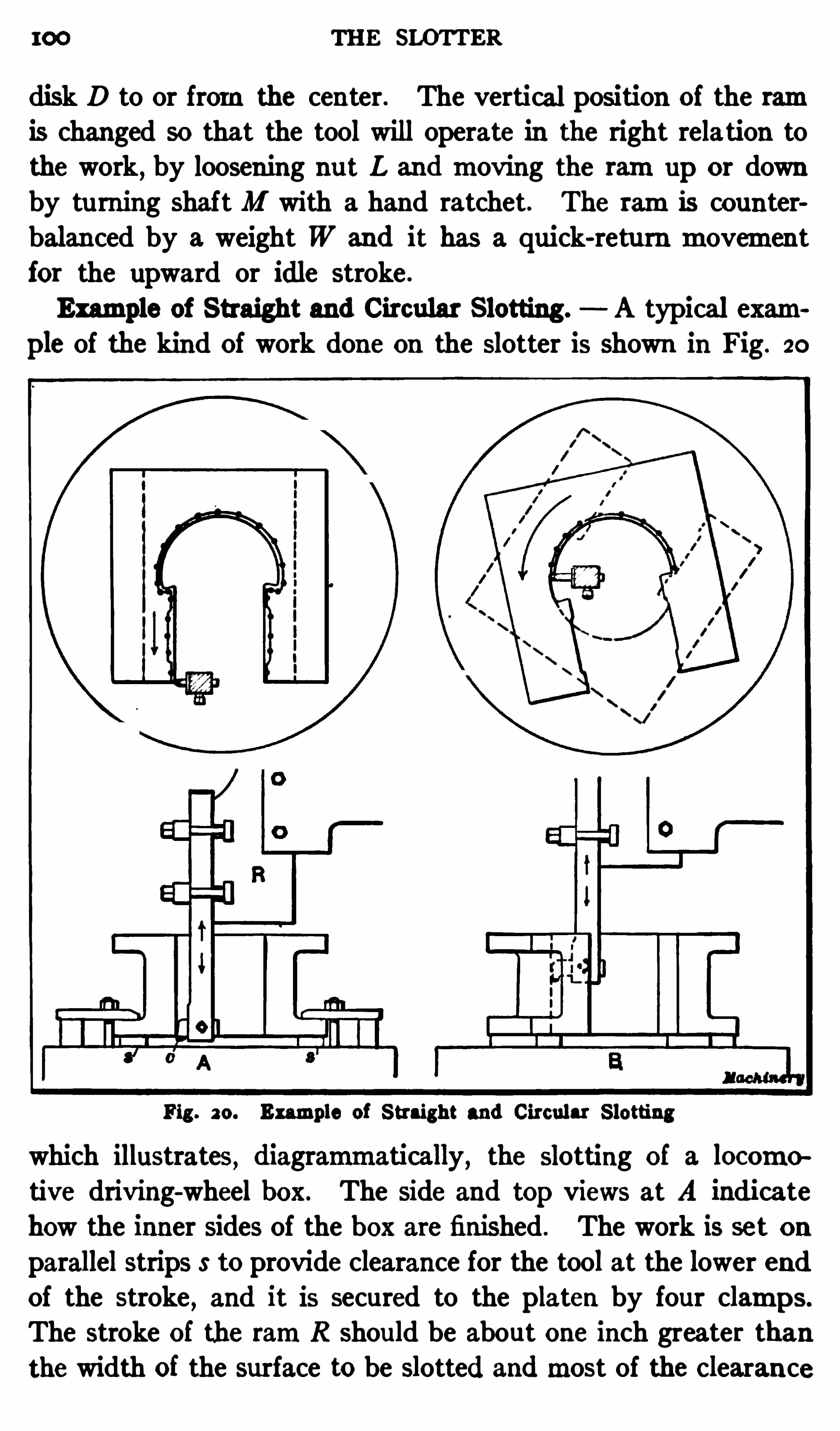
100 THE SLO’
I‘
TER
disk D to or fromthe center. The vertical position of the ramis changed so that the tool will operate in the right relation tothe work, by loosening nut L and moving the ramup or downby tu rning shaft M with a hand ratchet. The ramis counterbalan ced by a weight W and it has a quick-retu rn movementfor the upward or idle stroke .
Example of Straight and Circular Slotting . A typical example of the kind Of work done on the slotter is shown in Fig. 20
Fig . 20. Example of Straight and Circular Slotting
which illustrates, diagrammatically, the slotting of a locomotive driving-wheel box. The side and top views at A indicatehow the inner sides of the b ox are finished . The work is set onparallel strips S to provide clearance for the tool at the lower endOf the stroke
, and it is secured to the platen by four clamps.
The stroke Of the ramR should be about one inch greater than
the width of the surface to be slotted andmost of the Clearance

102 THE SLUI‘TER
Slotting an Engine.
Connecting-rod. Fig. 2 1 shows how a
slotter is used formachining the rectangular opening in the endof a connecting-rod
,into which the bearing brasses are af ter
wards fitted . P rior to the Slotting operation, the sides of the
rod are finished by planing ormilling. A row of holes is thendrilled in the solid end of the rod just inside the lines laid out for
Fig. 2 1 . S lotting End of Engine Connecting-10d on a Dill Slotter
the rectangu lar opening, and the interior part is removed in theformof a solid block . The rod is then clamped to the slottertable upon two parallels which provide a clearance space for thetool at the lower end of the stroke . The long sides are slottedby using the longitudinal feed and the short sides bymeans ofthe cross- feed . The tool, Of course , is turned in the toolpost
SLOTTER OPERATIONS 103
to face the difl'
erent surfaces as they are slotted . When using atool-holder of the type shown , on work of this kind , it is necessaryto replace it with another formof tool for finishing the corners.
The style of tool shown at B , Fig. 22 , could be used , becausethe cu tting edge is at an angle Of 45 degrees to the shank .
Ordinarily, when using the slotter tomachine surfaces whichare at right angles to each other
,the table is fed first laterally
and then longitudinally or vice versa,but in this case, owing to
the size and weight of the rod, the lengthwise cu ts are taken by
feeding the tool-head of the slotter, the work remaining stationary except when machining the end surfaces. This feeding ofthe tool is possible with the particularmake of slotter shown as
it has a traveling head, so that the tool can be given a feedingmovement when slotting a part which is large and cumbersome.
When slotting heavy ,overhanging castings Or forgings, such
as the one illustrated , the outer end should be supported, andusually it is advisable to mount the supports on two pairs of
rollers arranged one above the other and at right angles, so thatthe work can easily be fed in a lateral or lengthwise direction.
The supportmay consist simply of blocks with the rollers interposed between them, although special supporting stands equipped
with rollers are often used . Bymeans of roller supports , very
large castings can be machined on the slotter. The support
should be just high enough to hold the part level, thus relieving
the table of the excessive load to which it would be subjected if
no support were used .
The Dill Slotter. The slotter shown in Fig. 2 1 diflers in
several respec ts fromthe one illustrated in Fig. 19. As previ
ouslymentioned , it has a traveling head which permits cu ts tobe taken by feeding the tool instead of the work. The ramand'
tool can also be set close to the column or some distance awayfromit, depending upon the nature of the work. When bothtable feeds are used , the traveling head is clamped in the desiredposition . The machine has a quick traverse for moving thehead or table rapidly in any direction ,
when considerable adjust
ment is required . This quick traverse is operated by a lever
located at the side of themachine. The automatic feedingmove
104 THE SLOTrER
mentmay be either intermittent or continuous, the intermitten tfeed taking place at the top of the stroke and the continuous feedthroughout the cu tting stroke . The intermittent feed is theproper one to use formost work
,but the continuous feed is use
ful, especially for finishing the ends of narrow slots
,which require
a long slender tool. The intermittent feed is used un til the toolreaches the end of the slot; the continuous feed is then engaged,thus causing the feed to take place gradually throughout thelength of the stroke in order to overcome the spring of the tooland square the end Of the slot.
On the crank disk of this slotter there is a stroke indicatorwhich shows the length of stroke for which themachine is set.This is Simply a pointer having a curved end which is held incontact with the crankpin bushing by a spring . As the pin
is adjusted to or fromthe center, the pointer ismoved a propor
tional amount by the curved end and the stroke is indicated by
a suitable scale on the edge of the crank disk. The cu tter bar
or ramis fitted in an adjustable guide which can be raised or
lowered by a crank handle to the position where it will give theramthe best support. The tool is held in a relief apron to prevent the cu tting edge fromdragging over the slotted surface onthe upward stroke .
Slotter Tools. Some of the tools used in the slotter are
illustrated in Fig . 2 2 . Those shown at A,B and C are forged
fromthe solid bar and have cu tting edges formed on the ends,whereas tool D consists of a heavy bar in which a small cutter tis inserted . Tools A and B are used principally for slotting
interior surfaces, where there is little roomfor the tool to operate.
For exterior slotting, or whenever there is plenty of room,tool
D is preferable because it ismore rigid .
The cu tting end of tool B is inclined to the right or left (asindicated by the end view) for working in corners, etc . Theposition of tool D,
which has a round shank k,can be varied by
turning it in clamps at the upper end which hold it to the slotterram. Many tools Of this type have square shanks so that special
Clamps are not required . The cu tter t is held by set-screw c inapivoted
,spring-relief block which allows the tool point to swing

CHAPTER I I I
CONSTRUCTION AND USE OF PLAIN MILLING MACHINE
MILLINGmachines are used for a great variety of operations ,andmany types have been designed formilling certain classes Ofwork to the best advantage . Themillingmachine was originallydeveloped in armories for manufacturing the small irregularshaped parts used in the construction of fire-arms
,and themill
ing process is still employed very extensively in the productionof similar work, especially when intricate profiles are required
and thepartsmust be interchangeable . M illingmachines arealso
widely used at the present time formilling many large castingsor forgings, which were formerly finished exc lusively by planing;in fact
,it is sometimes difficult to determine whether certain parts
should be planed ormilled in order to secure the best results.
Surfaces aremilled by one or more circular cutters having a
number of teeth or cu tting edges which successivelymill awaythe metal as the cutter rotates. These cutting edges may bestraight and parallel to the axis of the cutter for milling flatsurfaces, or theymay be inclined to it for forming an angular
shaped groove or surface,or theymay have an irregular outline
corresponding to the shape or profile of the parts which are to bemilled by them. An end view of a cylindrical or “plain ” cu tter
is shown in Fig. 1,which illustrates
,diagrammatically
,one
method of producing a flat surface by milling. The cu tter Crotates as Shown by the arrow
,b ut remains in one position,
while the work W,which is held on the table of themillingmachine and is adjusted vertically to give the required depth Ofcut
,slowly feeds to the left in a horizontal direction . Each
tooth on the periphery of the cutter removes a chip every revolution ,
and,as the workmoves along
, a flat surface is formed .
The function of the milling machine is to rotate the cutterand , at the same time, automatically feed the work in the rs
106
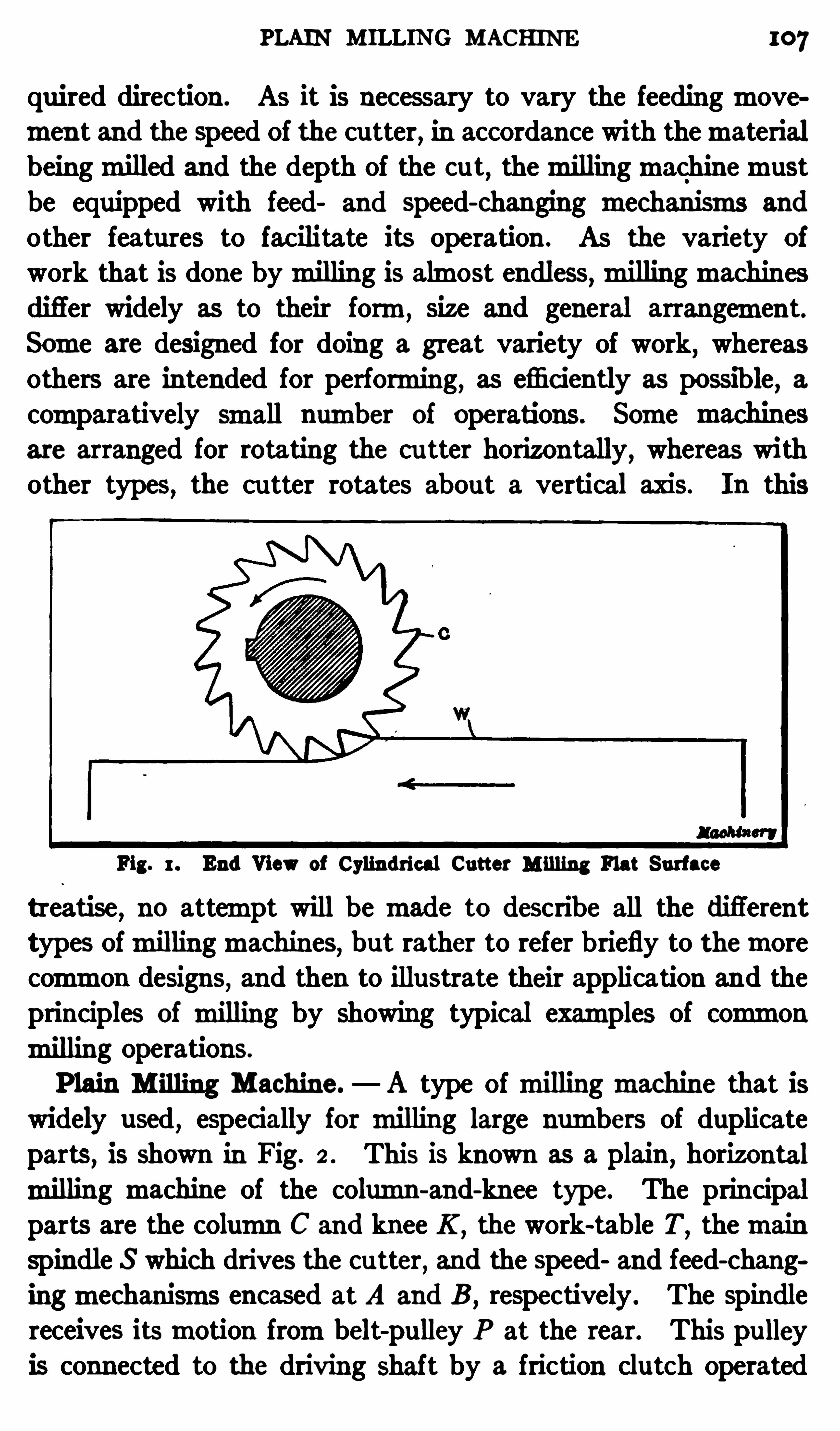
PLAIN M ILLING MACHINE 107
quired direction . As it is nec essary to vary the feedingmovemen t and the speed of the cu tter
,in accordance with thematerial
beingmilled and the depth of the cu t,themillingmachinemust
be equipped with feed and speed- changing mechanisms and
other features to facilitate its operation . As the variety of
work that is done bymilling is almost endless,millingmachines
differ widely as to their form,size and general arrangement.
Some are designed for doing a great variety of work, whereasothers are intended for performing
,as emciently as possible
, a
comparatively small number Of operations. Some machinesare arranged for rotating the cu tter horizontally
,whereas with
other types,the cu tter rotates about a vertical axis. In this
Fig. 1. End View of Cylindri cal Cutter M illing Flat Surface
treatise,no attempt will be made to describe all the difl
'
erent
types ofmillingmachines,b ut rather to refer briefly to themore
common designs, and then to illustrate their application and theprinciples of milling by showing typical examples of commonmilling operations.
P lain M illing Machine.— A type ofmillingmachine that is
widely used,especially for milling large numbers of duplicate
parts, is shown In Fig. 2 . This is known as a plain,horizontal
milling machine of the column-and-knee type. The principalparts are the column C and knee K
,the work-table T
,themain
spindle S which drives the cu tter, and the speed and feed-chang
ingmechanisms encased at A and B ,respectively . The spindle
receives itsmotion frombelt-pulley P at the rear. This pu lley
is connected to the driving shaft by a friction clutch Operated
108 M ILLING MACHINES
by lever M which is used for starting and stopping themachine.When the friction clutch is engaged , power is transmitted tothemain spindle S through gearing, and, by varying the combination of this gearing, the required speed changes are obtained .
KneeK is free to slide vertically on the front face.of the column ,
and it carries saddle Z and the table T. The saddle has an ih
Fig. 2 . Cincinnati Plain M illing Machine
and-out or crossmovement on the knee,and the table can be
traversed at right-angles to the axis Of the spindle. Either ofthese threemovements
,that is
,the longitudinal
, c ross, and verticalmovements can be effected by hand or power. The handmovements are used principally for adjusting the table and workto the required position when starting a cut, whereas the automatic power feed is employed whenmilling. The hand-crank D

MILLING MACHINES
or table , asmay be required . The table feed is engaged or disengaged by lever Y and it is controlled by another lever locatedat " , but not seen in the illustration . The direction in whichlever " is inclined fromthe vertical determines the direction Ofthe table feed . For instance
,if it is Shifted to the right the table
will travel toward the right,and vice versa. This lever " also
controls any feed that happens to be engaged , as well as the table
feed. Lever X engages either the vertical or cross-feeds, andall of the feedingmovements can be controlled by lever R bymeans of which they are reversed .
The rate or amoun t Of feed per revolution Of the cutter canbe varied by the levers and handwheel on case B
,There are
16 changes, and an index-plate shows what the rate of feed isfor any position of the levers. The longitudinal
,cross or ver
tical feeding movements can be au tomatically stopped at any
predetermined point by the trip-plungers l,c and v
,respectively.
These plungers are operated by dogs which can be adjusted sothat the au tomatic trip will operate after the cut is completed.
The dogs H and H1, for the table feed , are clamped to the frontof the table as shown . One Of these dogs trips the feed by lift
ing the plunger and the other by depressing it. Amovementof the plunger in either direction disengages a clu tch at G and
places it in a neutral position . This is the same clutch that isoperated by feed-reverse lever R . The au tomatic trip mechanismis a very convenient feature , as it prevents feeding too far,andmakes themachinemore independent Of the operator.The principal features of a plainmillingmachine, so far as the
operation Of themachine is concerned , have now been described ,but it Should be remembered that while plainmachines of othermakes have the speed and feed-changingmechanisms , au tomatictrips
,etc.
, the arrangement of these parts varies in differentdesigns . When the construction of onemachine is thoroughlyunderstood , however, the changes in other designs in the location Of the speed and feed-control levers
,and the functi ons of
the diflerent parts , can readily be understood.
Adjusting and Operating a Milling Machine. Before amillingmachine can be used , it is necessary
,Of course , to arrange
M ILLING OPERATIONS 111
it for doing the work in hand,which includes moun ting the
cutter in position,and adjusting the driving and feed mecha
nisms for giving the proper speed to the cutter and feed to thework. The part to bemilledmust also be securely attached tothe
'machine, so that it can be fed against the revolving cutterby moving the table in whatever direction may be required.
The way amillingmachine is arranged,and the kind Of cutter
used depends on the nature of themilling operation .
The character of the work, and other considerations which
will be referred to later , also aflect the speed and feed , as well’
as
Fig. 3 . M illing a Small Rectangular Block
themethod of clamping the work to the table; hence , judgmentand experience are needed to properly decide the questions thatarise in connection wi th milling practice
,and no definite rules
ormethods Of procedure can be given . We Shall explain ,how
ever,in a general way, howmillingmachines are arranged and
used under varying conditions, by giving illustrated descriptionscovering typical examples of work representing the variousclasses that aremachined by themilling process .
A~very simple example ofmilling is shown in Fig. 3 , the operation being that ofmilling a flat su rface on top of a steel block
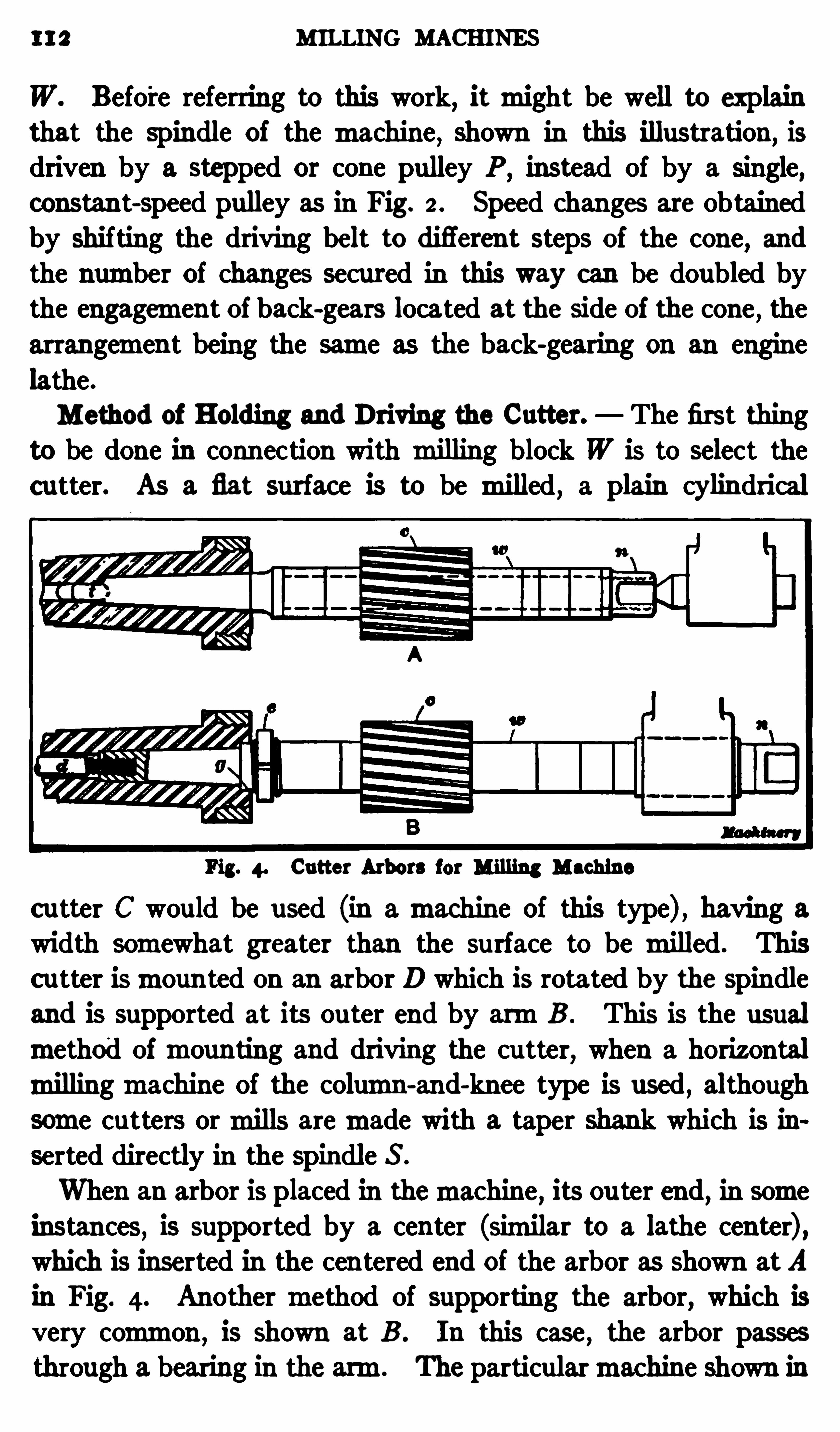
112 MILLING MACHINES
W. Befo'
re referring to this work, itmight be well to explainthat the spindle of the machine, shown in this illustration, isdriven by a stepped or cone pulley P ,
instead Of by a single,constant-speed pulley as in Fig. 2 . Speed changes are obtainedby shifting the driving belt to difl
'
erent steps of the cone,and
the number of changes secured in this way can be doubled bythe engagement of back-gears located at the side of the cone
,the
arrangement being the same as the back-gearing on an engine
lathe.
Method of Holding and Driving the Cutter. The first thing
to be done in connection with milling block W is to selec t the
cutter. As a flat surface is to be milled , a plain cylindrical
Fig. 4. Cutter Arbors for Milling Machine
c utter C would be used (in amachine Of this type) , having awidth somewhat greater than the surface to be milled. Thisc utter ismounted on an arbor D which Is rotated by the spindle
and is supported at its outer end by armB . This is the usual
method ofmounting and driving the cu tter, when a horizontalmillingmachine Of the column-and-knee type is used , although
some cutters ormills aremade with a taper shank which is in
serted directly in the spindle S .
When an arbor is placed in themachine , its ou ter end, in someinstances, is supported by a center (similar to a lathe center) ,which is inserted in the centered end of the arbor as shown atA
in Fig. 4. Another method Of supporting the arbor, which is
very common,is Shown at B . In this case , the arbor passes
through a bearing in the arm. The particularmachine shown in

MILLING MACHINES
of the cut. Some parts are also sprung out of shape by applyingthe clamps improperly or by omitting to place supports under
some weak or flexible section; as a result , themilled surface is
not true after the clamps are removed and the cas ting springs
back to its natural shape. Generally speaking, work shouldbe clamped more securely formilling than for planing, becausethe pressure Of the cut, when milling, is usually greater thanwhen planing, although this depends altogether upon the depth
of the cu t and the size Of the cutter.
Milling Machine Vises. Three types of milling machinevises which are commonly used are shown In Fig. 5 . The one
Fig. 5 . Milling Machine Vises
illustrated at A is called a plain vise. I t is held to the table bya screw which passes through the vise bed and threads into a
nut inserted into one of the table T-slots. This same style isalso made with flanges so that it can be secured by ordinaryc lamps. The vise Shown at B has a swiveling base and it canbe adjusted to any angle in a horizontal plane, the position beingshown by graduations. This adjustment is used for angularmilling. The vise shown at C is known as the universal type.I t can be swiveled in a horizontal plane and can be set at anyangle up to 90 degrees in a vertical plane, the position ,
in eithercase, being Shown by graduations. The hinged knee whichgives the vertical adjustment can be clamped rigidly by the nuton the end of the bolt forming the hinge, and by bracing levers
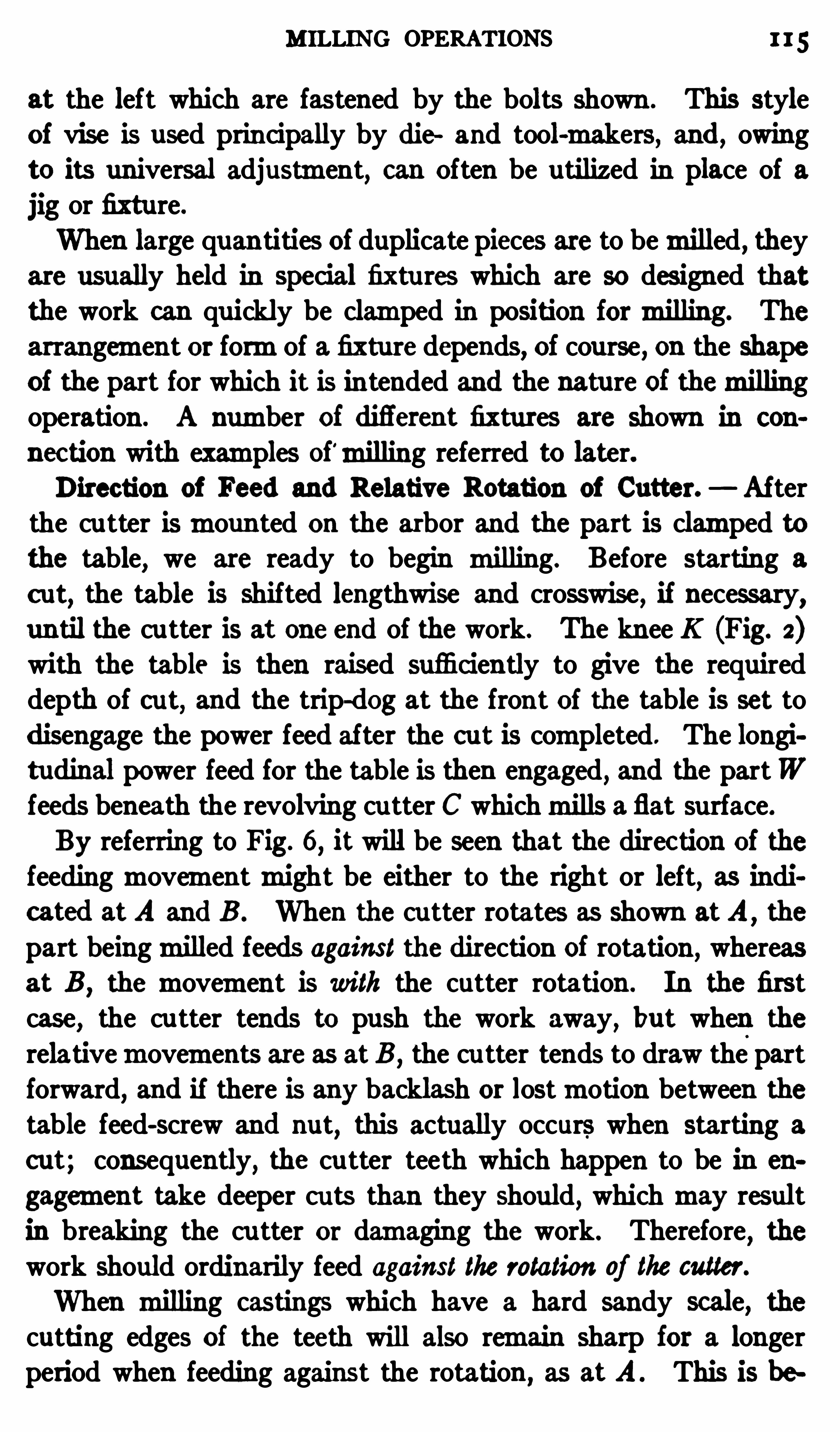
MILLING OPERATIONS 115
at the left which are fastened by the bolts shown . This styleof vise is used prin cipally by die and tool-makers, and , owingto its universal adjustment, can Often be utilized in place of ajig or fixture.
When large quan tities of duplicate pieces are to bemilled , theyare usually held in special fixtu res which are so designed thatthe work can quickly be clamped in position formilling. The
arrangement or formof a fixtu re depends, of course, on the shapeof the part for which it is in tended and the nature of themillingoperation . A number of difl
'
erent fixtures are shown in con
nec tion with examples Of'milling referred to later.Direction of Feed and Relative Rotation of Cutter. Af ter
the cu tter ismoun ted on the arbor and the part is clamped tothe table, we are ready to begin milling. Before starting a
c ut, the table is shifted lengthwise and crosswise, if necessary,un til the cu tter is at one end of the work. The knee K (Fig. 2)with the table is then raised sufficiently to give the requireddepth of cut, and the trip-dog at the front of the table is set todisengage the power feed after the cut is completed. The longitudinal power feed for the table is then engaged, and the partWfeeds beneath the revolving cu tter C whichmills a flat surface.By referring to Fig. 6
,it will be seen that the direc tion of the
feedingmovementmight be either to the right or left, as indicated at A and B . When the cu tter rotates as Shown atA
,the
part beingmilled feeds against the direction Of rotation , whereas
at B ,the movement is with the cutter rotation . In the first
case, the cu tter tends to push the work away,but when the
relativemovements are as at:B ,the cu tter tends to draw the part
forward, and if there is any backlash or lostmotion between thetable feed-screw and nut
,this actually occurs when starting a
cut; consequently, the cu tter teeth which happen to be in en
gagement take deeper cu ts than they should, which may resultin breaking the cu tter or damaging the work. Therefore
,the
work should ordinarily feed against the rotation of the cutter.
When milling castings which have a hard sandy scale, thecutting edges of the teeth will also remain sharp for a longerperiod when feeding against the rotation ,
as at A . This is be
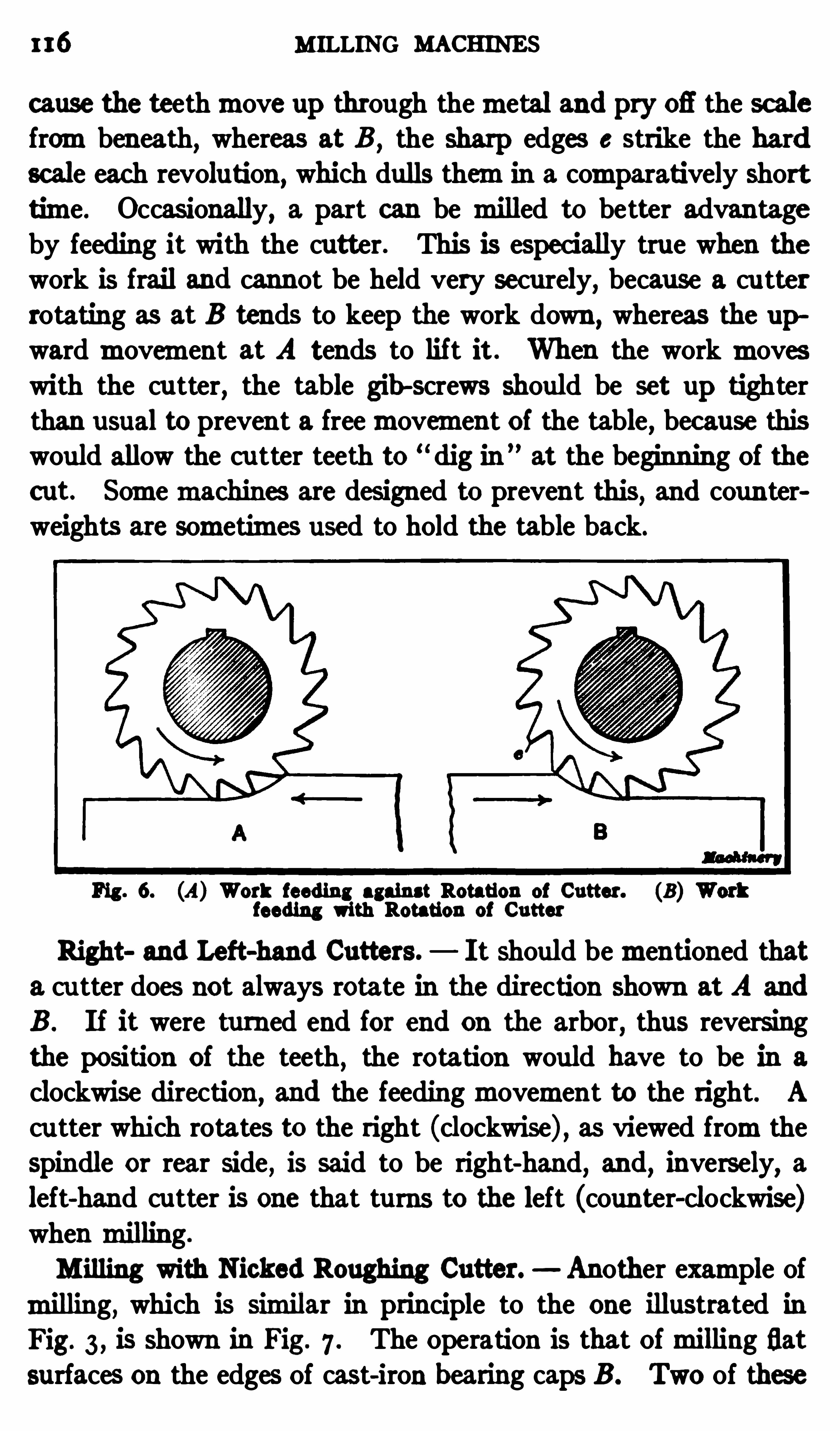
116 MILLING MACHINES
cause the teethmove up through themetal and pry 06 the scalefrombeneath
,whereas at B ,
the sharp edges c strike the hardscale each revoluti on
,which dulls themin a comparatively short
time. Occasionally,a part can be milled to better advantage
by feeding it with the cutter. This is especially true when thework is frail and cannot be held very securely, because a cu tter
rotating as at B tends to keep the work down ,whereas the up
wardmovement at A tends to lif t it When the work moveswith the cutter, the table gib -screws should be set up tighterthan usual to prevent a freemovement of the table, because thiswould allow the cu tter teeth to “
dig in”at the beginning Of the
c ut. Somemachines are designed to prevent this, and coun terweights are sometimes used to hold the table back.
Fig . 6. (A) Work feeding against Rotation of Cutter. (B)feeding with Rotation of Cutter
Right and Left-hand Cutters. I t should bementioned thata cu tter does not always rotate in the direction shown at A and
B . If it were turned end for end on the arbor, thus reversingthe position of the teeth
,the rotation would have to be in a
clockwise direction , and the feedingmovement to the right. A
cu tter which rotates to the right (clockwise) , as viewed fromtheSpindle or rear side
,is said to be right-hand
,and
, inversely, aleft-hand cutter is one that turns to the left (counter-clockwise)when milling.
M illing with Nicked Roughing Cutter. Another example ofmilling, which is similar in principle to the one illustrated inFig. 3 , is Shown in Fig. 7 . The Operation is that Ofmilling flatsurfaces on the edges Of cast-iron bearing caps B . Two of these

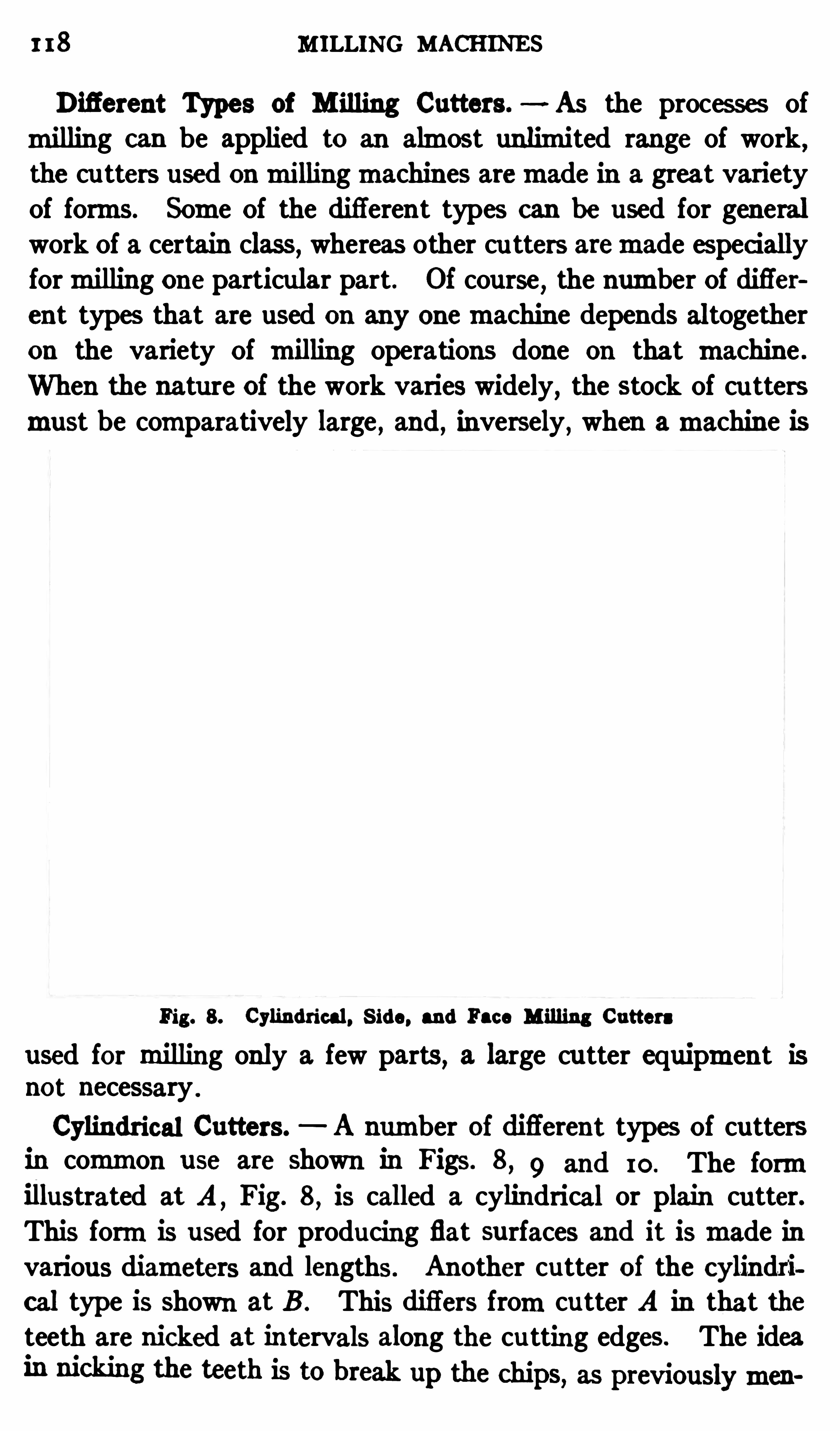
1 18 MILLING MACHINES
Difierent Types of M illing Cutters. As the processes ofmilling can be applied to an almost unlimited range of work ,
the cu tters used onmillingmachines aremade in a great varietyof forms. Some Of the di fferent types can be used for generalwork Of a certain class
,whereas other cu tters aremade especi ally
formilling one particular part . Of course,the number Of difl'er
ent types that are used on any onemachine depends altogetheron the variety Of milling operations done on that machine .
When the nature of the work varies widely, the stock of cu ttersmust be comparatively large , and, inversely , when amachine is
Fig. 8. Cylindrical. S ide, and Face M illing Cutters
used for milling only a few parts, a large cutter equipment is
not necessary .
Cylindrical Cutters. A number Of diflerent types Of cuttersin common use are shown in Figs . 8
, 9 and 10. The formillustrated at A
, Fig. 8, is called a cylindrical or plain cutter.
This formis used for producing flat surfaces and it ismade invarious diameters and lengths. Another cutter of the cylindrical type is Shown at B . This difl
'
ers fromcu tter A in that theteeth are nicked at in tervals along the cu tting edges.
The idea
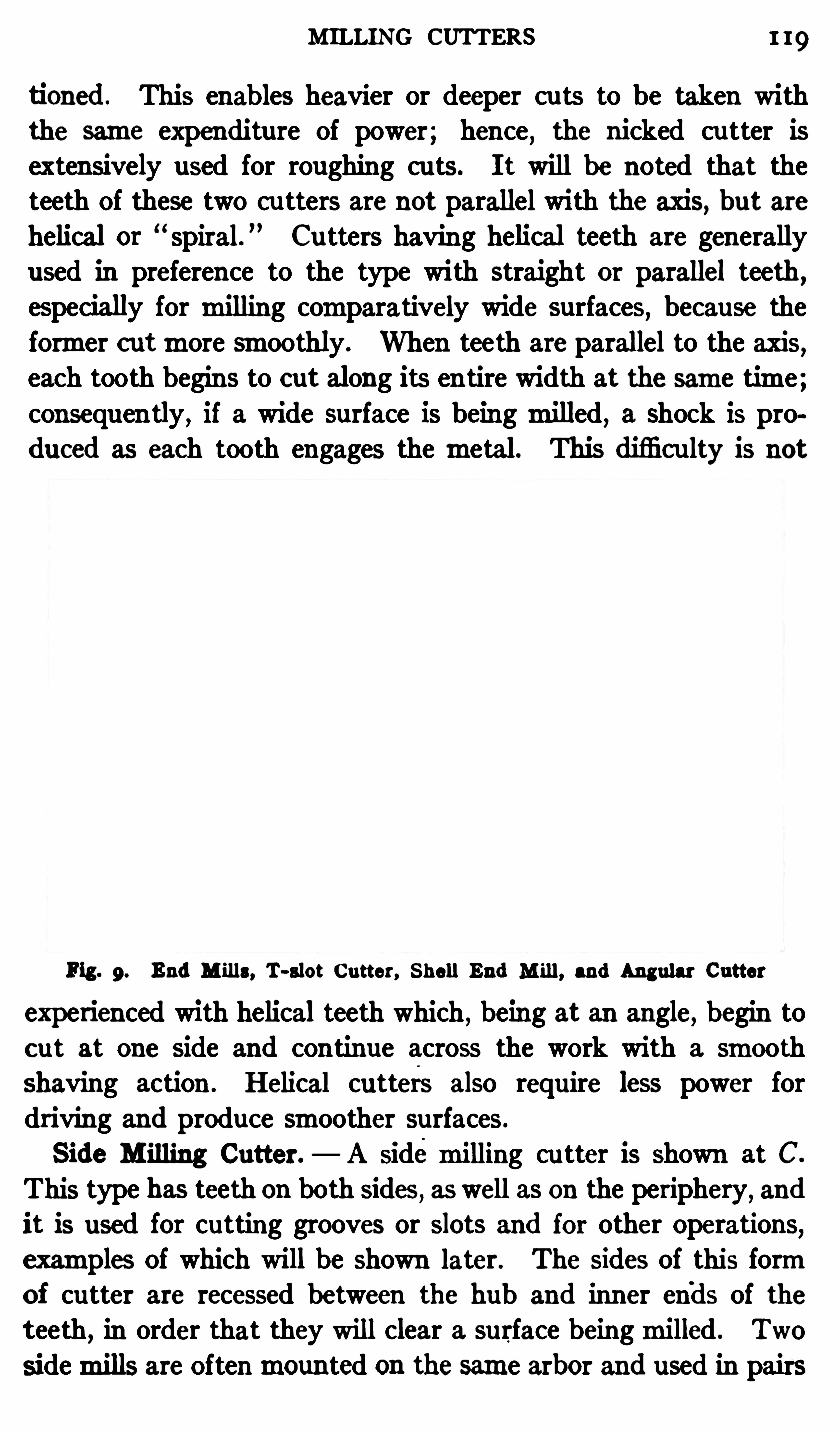
MILLING CUTTERS 1 19
tioned . This enables heavier or deeper cu ts to be taken withthe same expenditure of power; hence, the nicked cu tter isextensively used for roughing cu ts . I t will be noted that theteeth of these two cu tters are not parallel with the axis, but are
helical or spiral. Cu tters having helical teeth are generallyused in preference to the type with straight or parallel teeth ,
especially for milling comparatively wide surfaces,because the
former cutmore smoothly. When teeth are parallel to the axis,each tooth begins to cut along its en tire width at the same time;consequen tly, if a wide surface is beingmilled, a Shock is produced as each tooth engages the metal. This difi culty is not
Fig. 9. End M ills, T-slot Cutter, Shell End M ill , and Angular Cutter
experienced with helical teeth which , being at an angle, begin toc ut at one side and continue across the work with a smoothshaving action . Helical cutters also require less power fordriving and produce smoother surfaces.
Side M illing Cutter. A sidemilling cu tter is Shown at C.
This type has teeth on both Sides , as well as on the periphery, andit is used for cutting grooves or Slots and for other operations,examples Of which will be shown later. The sides of this formOf cutter are recessed between the hub and inner ends of the
teeth, in order that they will clear a surface beingmilled . Two
sidemills are oftenmounted on the same arbor and used in pairs
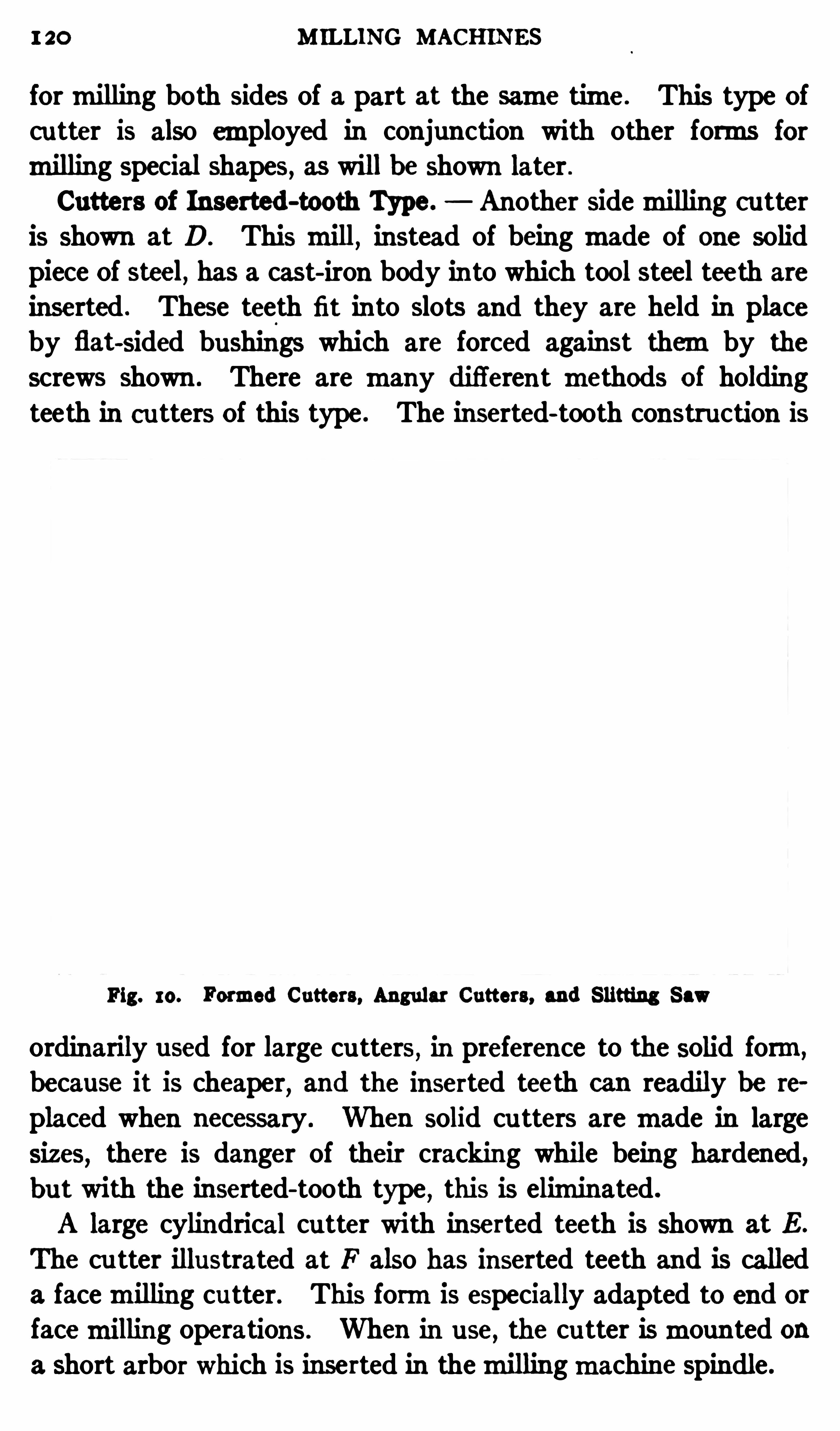
1 20 M ILLING MACHINES
formilling both sides of a part at the same time. This type Ofcu tter is also employed in conjunction with other forms formilling special Shapes, as will be Shown later .
Cutters of Inserted-tooth Type. Another sidemilling cutteris shown at D. This mill, instead of being made of one solidpiece Of steel, has a cast- iron body into which tool steel teeth are
inserted . These teeth fit in to slots and they are held in placeby flat-sided bushings which are forced against themby the
screws shown . There are many different methods of holding
teeth in cutters Of this type . The inserted- tooth construction is
Fig. 10. Formed Cutters, Angular Cutters, and Slitting Saw
ordinarily used for large cu tters,in preference to the solid form,
because it is cheaper, and the inserted teeth can readily be te
placed when necessary . When solid cu tters aremade in largesizes
, there is danger of their cracking while being hardened,but with the inserted- tooth type , this is eliminated.
A large cylindrical cu tter with inserted teeth is shown at E .
The cu tter illustrated at F also has inserted teeth and is calleda facemilling cutter. This formis especially adapted to end or
facemilling operations . When in use, the cu tter ismounted ona short arbor which is inserted in themillingmachine spindle .

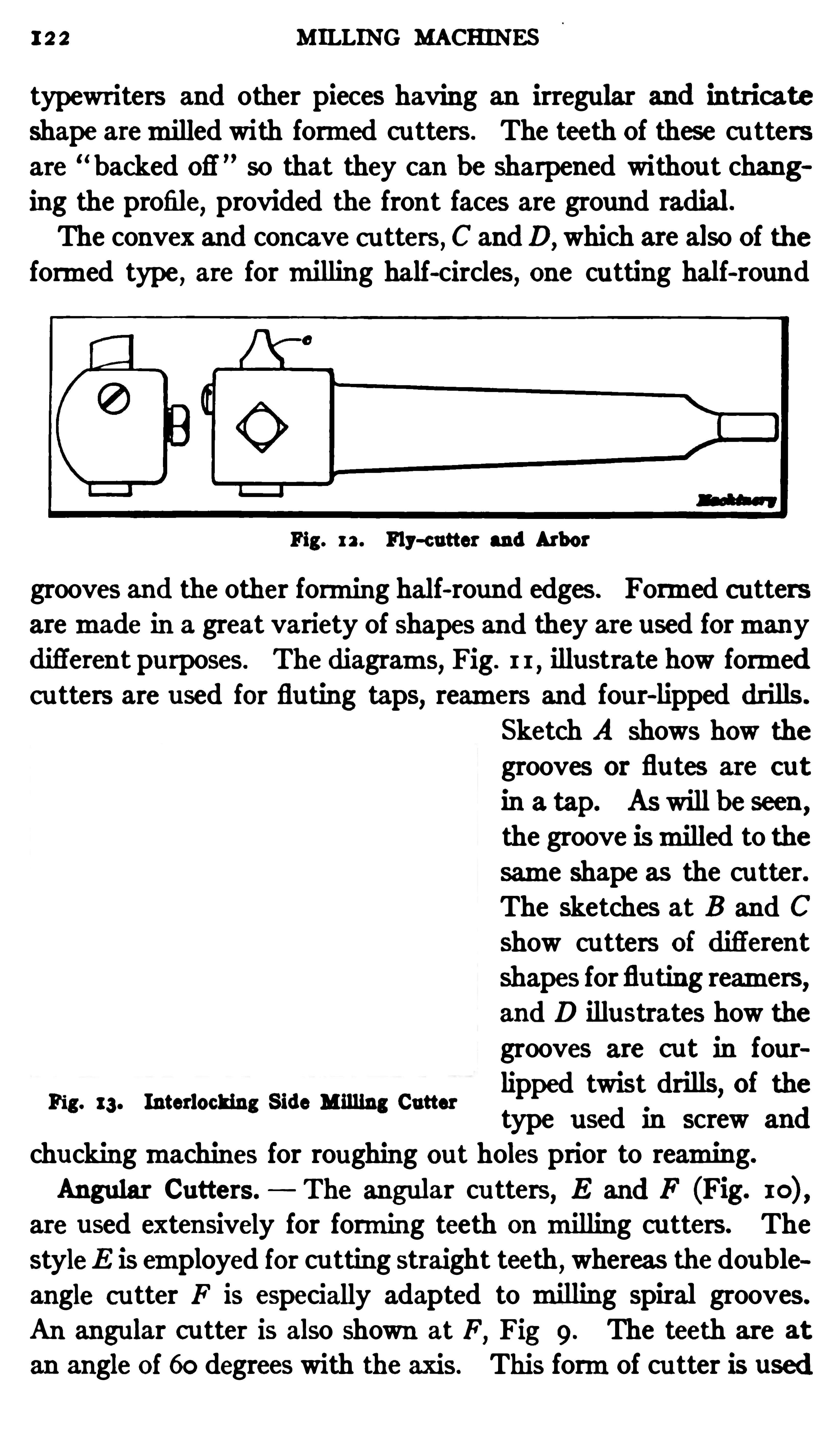
12 2 MILLING MACHINES
typewriters and other pieces having an irregular and intrieate
shape aremilled with formed cu tters . The teeth Of these cu tters
are“ backed Ofi
'
so that they can be sharpened withou t changing the profile, provided the front faces are ground radial.
The convex and concave c utters , C andD, which are also Of the
formed type , are formilling half-circles, one cutting hal f-round
Fig. 12 . Fly-cutter and Arbor
grooves and the other forming half-round edges . Formed cuttersaremade in a great variety of shapes and they are used formanydifl
'
erent purposes. The diagrams,Fig. 1 1
,illustrate how formed
c utters are used for fluting taps, reamers and four-lipped drills .
Sketch A Shows how the
grooves 01 flu tes are cut
in a tap. As will be seen ,
the groove ismilled to thesame shape as the cu tter.The sketches at B and C
show cu tters of difl'
erent
shapes forflu ting reamers,and D illustrates how thegrooves are c ut in fourlipped twist drills, of thetype used in screw and
chuckingmachines for roughing out holes prior to reaming.
Angular Cutters. The angular cu tters, E and F (Fig.
are u sed extensively for forming teeth on milling cu tters. ThestyleE is employed for cu tting straight teeth
,whereas the double
angle cutter F is especially adapted to milling spiral grooves.
An angular c utter is also shown at F,Fig 9. The teeth are at
an angle Of 60 degrees with the axis . This formof cu tter is used
Fig. 13. Interlocking Side Milling Cutter
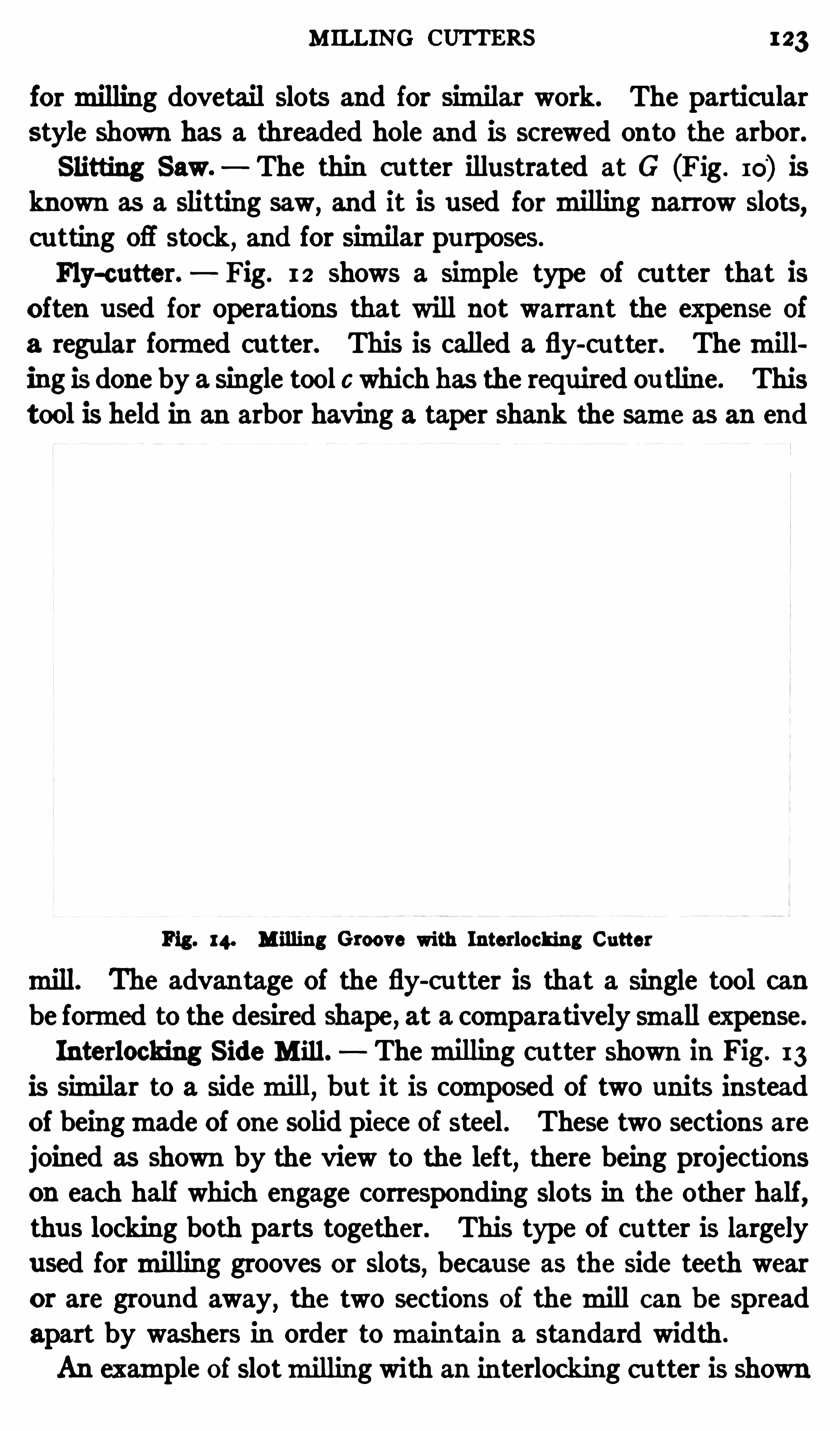
M ILLING CUTTERS 123
formilling dovetail slots and for Similar work. The particu larstyle shown has a threaded hole and is screwed onto the arbor.Slitting Saw. The thin c utter illustrated at G (Fig . 10) is
known as a slitting saw,and it is used formilling narrow slots
,
cu tting Ofl stock,and for similar pu rposes.
Fly-cutter. Fig. 12 shows a Simple type Of cu tter that is
often used for operations that will not warrant the expense of
a regular formed cutter. This is called a fly-cu tter. Themill
ing is done by a single tool c which has the required ou tline. Thistool is held in an arbor having a taper shank the same as an end
Fig. 14. M illing Groove with Interlocking Cutter
mill. The advan tage Of the fly-c utter is that a single tool canbe formed to the desired shape , at a comparatively small expense.
Interlocking Side M ill . Themilling cu tter shown in Fig . 13
is similar to a sidemill,but it is composed Of two units instead
of beingmade Of one solid piece of steel. These two sections arejoined as shown by the view to the left, there being projectionson each half which engage corresponding slots in the other half,thus locking both parts together. This type Of cutter is largely
used formilling grooves 01 Slots,because as the side teeth wear
or are ground away,the two sections Of themill can b e spread
apart by washers in order tomaintain a standard width .
An example Of slotmilling with an interlocking c utter is shown
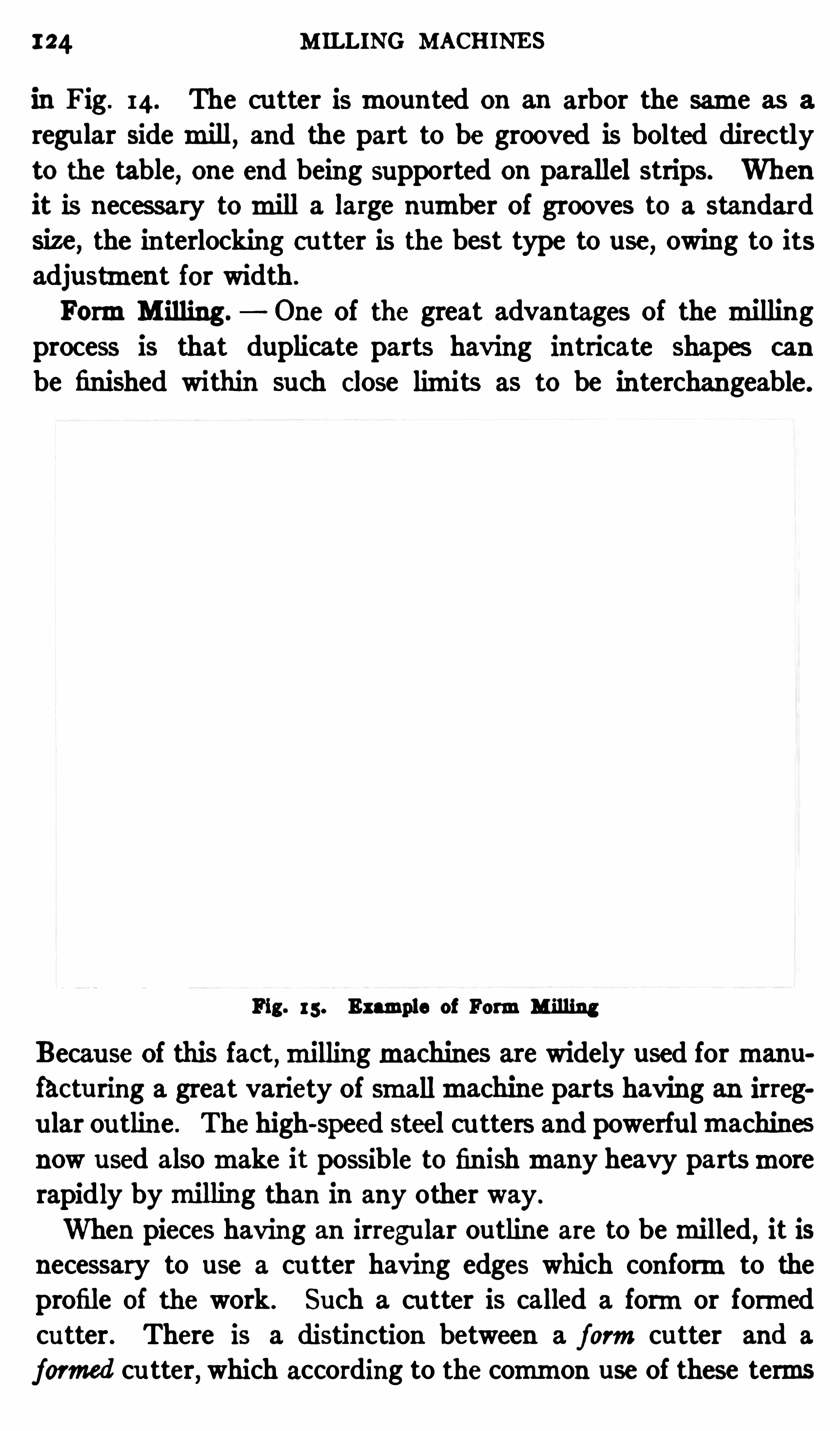
124 M ILLING MACHINE S
in Fig. 14. The cu tter ismounted on an arbor the same as a
regular sidemill, and the part to be grooved is bolted directlyto the table
,one end being supported on parallel strips. When
it is necessary tomill a large number of grooves to a standard
Size, the interlockn cutter is the best type to use, owing to itsadjustment for width .
FormM illing. One Of the great advantages of the millingprocess is that duplicate parts having intricate shapes can
be finished within such Close limits as to be interchangeable.
Fig. 15 . Example of FormMilling
Becau se Of this fact,millingmachines are widely used formanu
fac turing a great variety of smallmachine parts having an irregu lar ou tline . The high-Speed steel cu tters and powerfu lmachinesnow used alsomake it possible to finishmany heavy partsmorerapidly bymilling than in any other way.
When pieces having an irregular outline are to bemilled, it isnecessary to use a cu tter having edges which conformto theprofile of the work . Such a cu tter is called a formor formedcutter . There is a distinction between a formcu tter and a
formed cu tter, which according to the common use of these terms

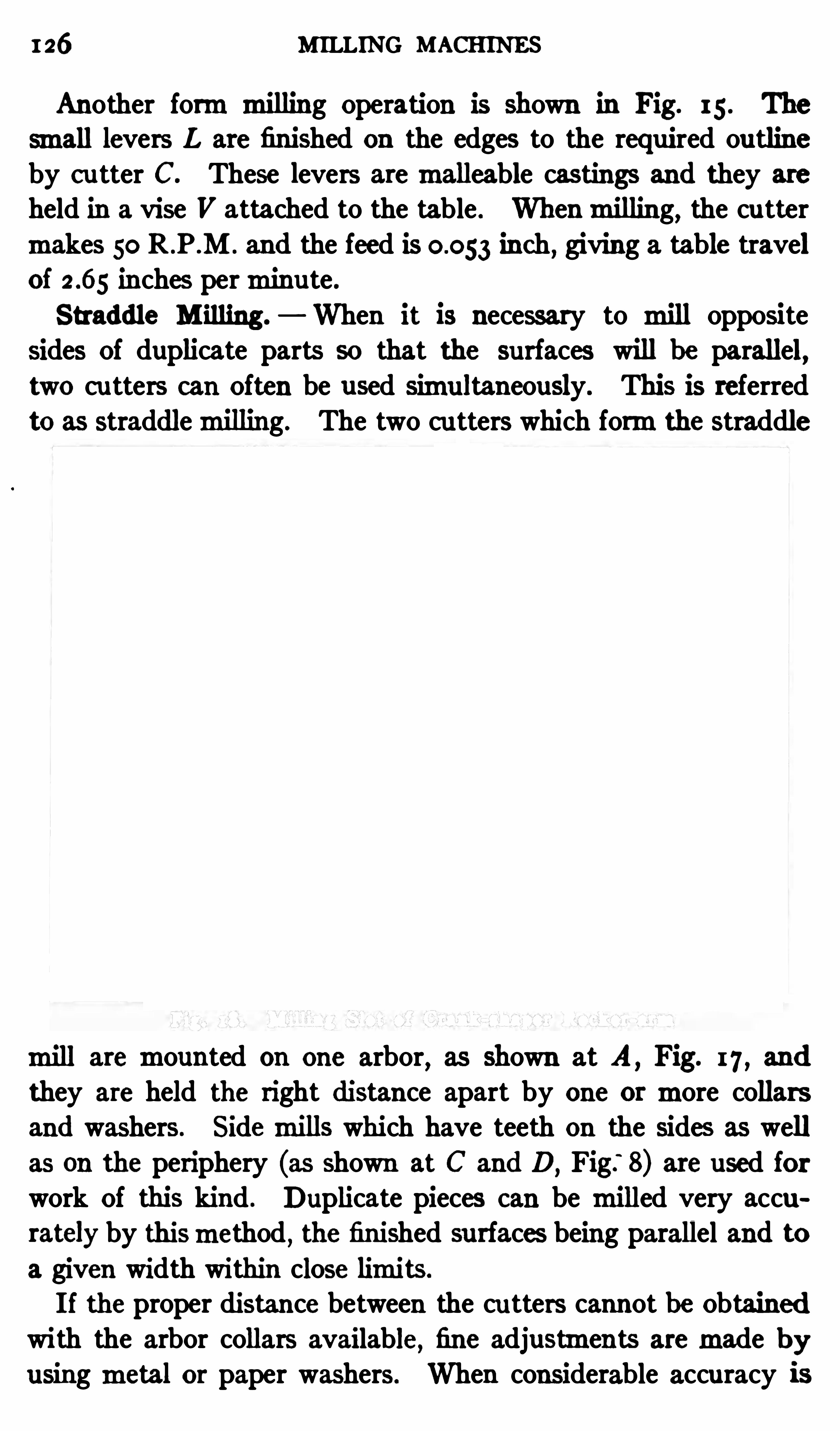
126 MILLING MACHINES
Another formmilling Operation is shown in Fig. 15 . The
small levers L are finished on the edges to the required ou tlineby c utter C. These levers aremalleable castings and they are
held in a vise V attached to the table . Whenmilling,the cutter
makes 50 R .P .M . and the feed is inch,giving a table travel
of inches perminute .
Straddle M illing. When it is necessary to mill oppositesides Of duplicate parts so that the surfaces will be parallel,two cu tters can Often be used simultaneously. This is referred
to as straddlemilling. The two cu tters which formthe straddle
mill aremounted on one arbor,as shown at A
, Fig. 17 , and
they are held the right distance apart by one ormore collarsand washers. Sidemills which have teeth on the sides as well
as on the periphery (as shown at C and D,Fig.
‘
8) are used forwork Of this kind . Duplicate pieces can be milled very accu
rately by thismethod , the finished surfaces being parallel and to
a given width within close limits.
I f the proper distance between the cu tters cannot be Obtainedwi th the arbor collars available
,fine adjustments aremade b y
using metal or paper washers. When considerable accuracy is
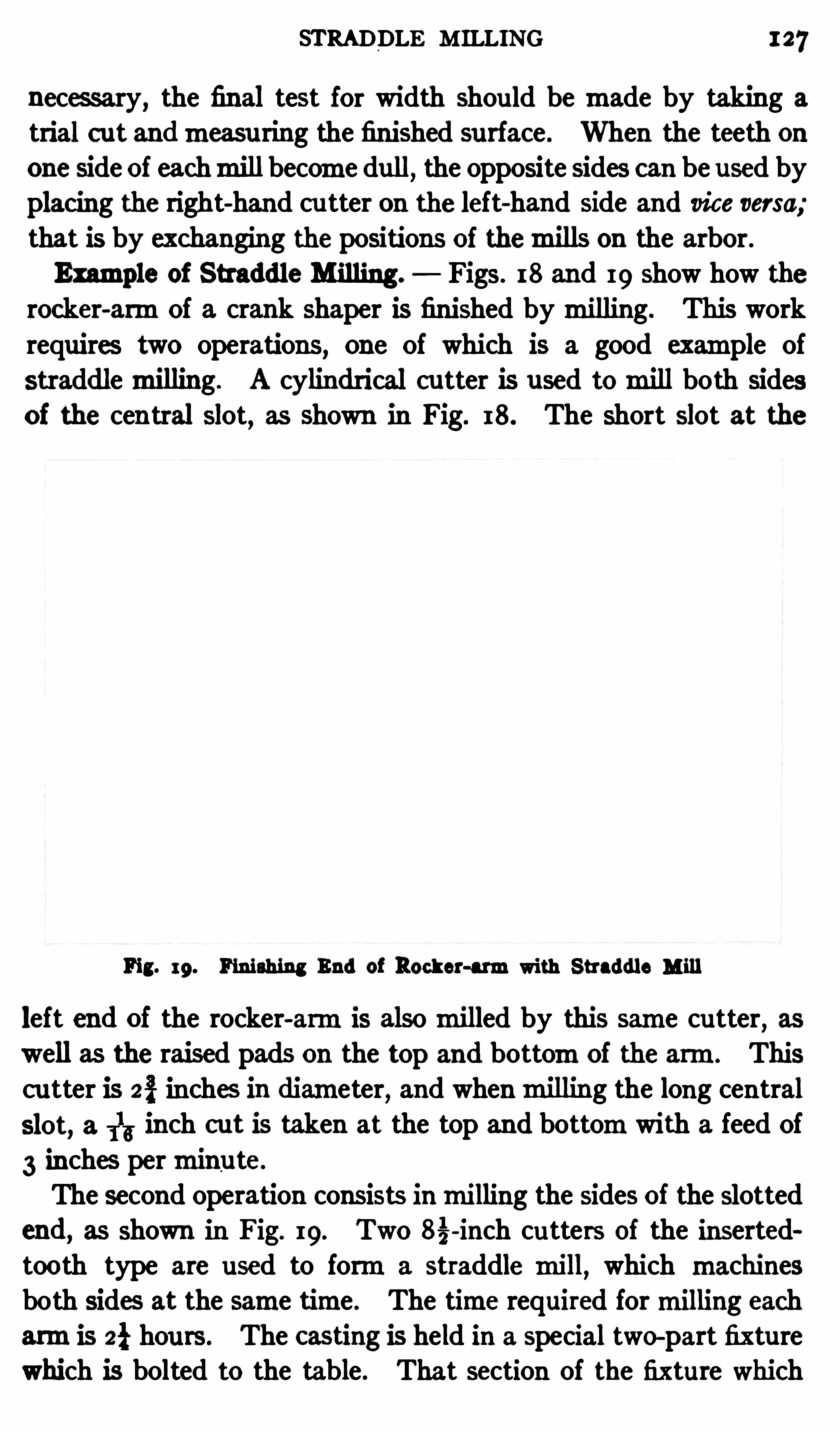
STRADDLE M ILLING 127
necessary, the final test for width should be made by taking a
trial c ut andmeasu ring the finished surface . When the teeth onone Side of eachmill become dull
,the opposite sides can be used by
placing the right-hand cu tter on the left-hand Side and vice versa;
that is by exchanging the positions of themills on the arbor.Example of Straddle Milling. Figs. 18 and 19 Show how the
rocker-armOf a crank shaper is finished bymilling. This work
requires two operations, one Of which is a good example ofstraddlemilling. A cylindrical cu tter is used tomill both sidesof the central slot, as shown in Fig. 18. The short slot at the
Fig. 19. Finishing End of Rocker-armwith Straddle Mill
left end of the rocker-armis alsomilled by this same cutter, aswell as the raised pads on the top and bottomOf the arm. Thiscu tter is 23 inches in diameter, and whenmilling the long centralSlot, a 1
13 inch cut is taken at the top and bottomwith a feed Of
3 inches perminu te.
The second operation consists inmilling the sides of the slottedend, as shown in Fig. 19. Two 83-inch cu tters of the insertedtooth type are used to forma straddle mill
,which machines
both sides at the same time . The time required formilling eacharmis 23 hou rs. The castn is held in a special two-part fixture
which is bolted to the table. That section of the fixture which
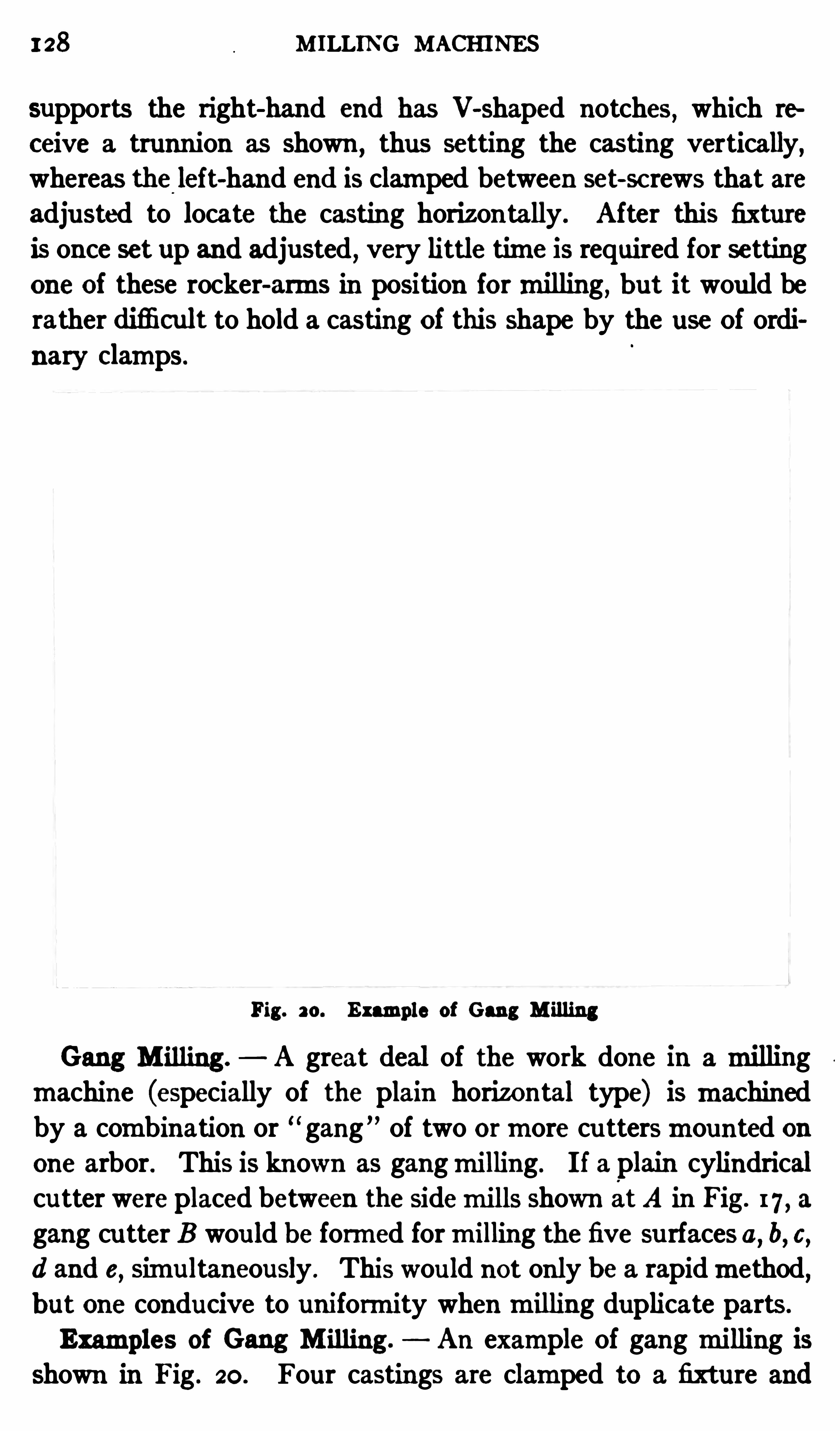
128 M ILLING MACHINES
supports the right-hand end has V-shaped notches,which te
ceive a trunnion as shown,thus setting the casting vertically,
whereas the left-hand end is clamped between set-sc rews that areadjusted to locate the casting horizontally. After this fixture
is once set upand adjusted , very little time is required for settingone of these rocker-arms in position formilling , b ut it would berather difli cult to hold a casting of this shape by the use Of ordi
nary Clamps.
Fig. 20. Example of Gang M illing
Gang M illing. A great deal of the work done in amillingmachine (especially of the plain horizontal type) is machinedby a combination or “ gang ” of two ormore cu ttersmounted onone arbor. This is known as gangmilling. I f a plain cylindrical
cutter were placed between the sidemills Shown atA in Fig. 17 , a
gang cu tter B wou ld be formed formilling the five su rfaces a,b,c,
d and e,Simultaneously . This wou ld not only be a rapidmethod,
b ut one conducive to uniformity whenmilling duplicate parts .
Examples of Gang M illing. An example Of gangmilling isshown in Fig. 20 . Four castings are clamped to a fixture and

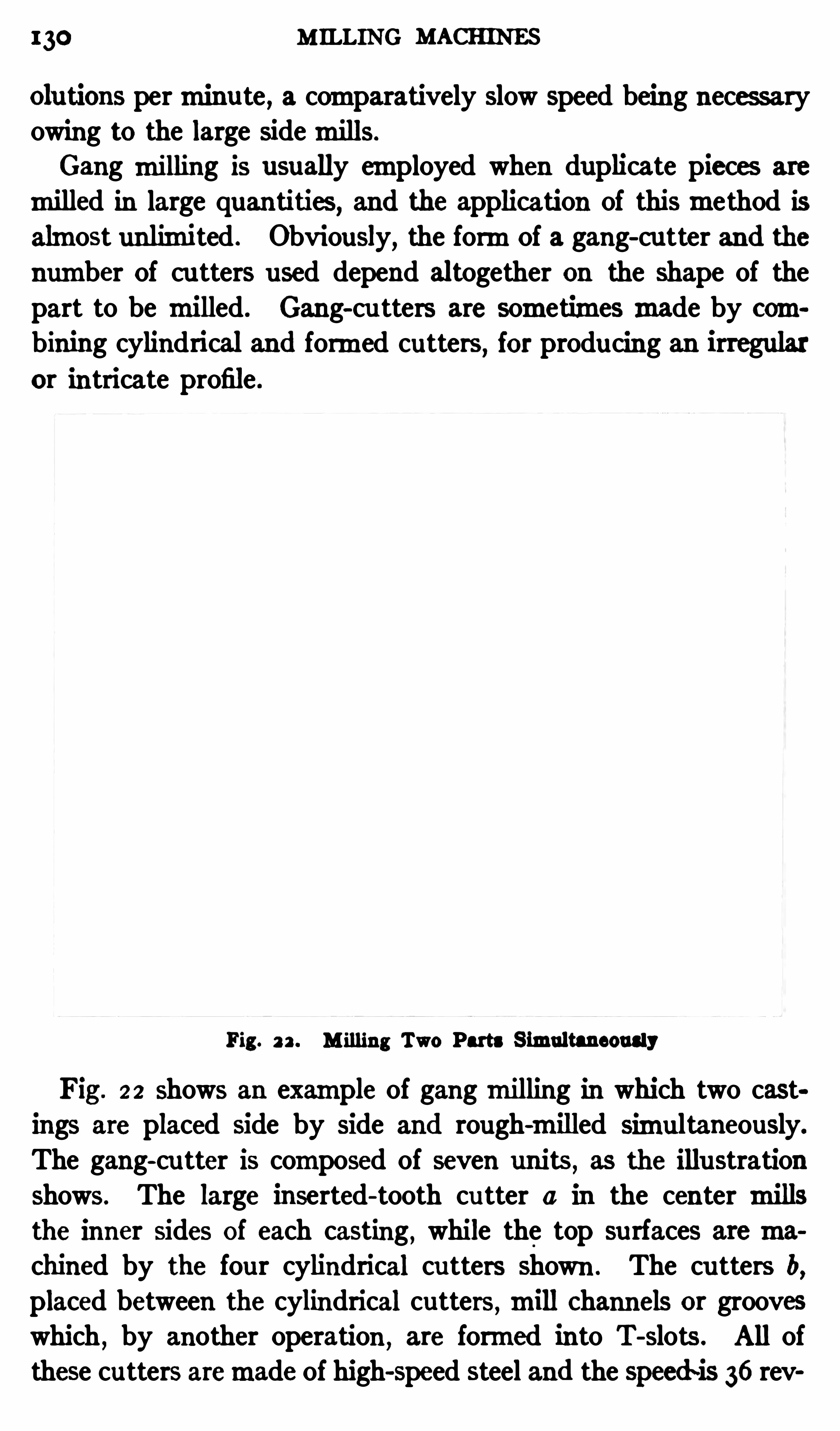
130 M ILLING MACHINES
olutions perminute , a comparatively slow speed being necessaryowing to the large sidemills.
Gang milling is usually employed when duplicate pieces are
milled in large quantities, and the application of thismethod isalmost unlimited . Obviously, the formOf a gang-cu tter and thenumber Of cu tters used depend altogether on the Shape of thepart to be milled. Gang-cu tters are sometimesmade by combining cylindrical and formed cutters , for producing an irregularor intricate profile .
Fig. 2 2 . M illing Two Parts S imultaneously
Fig. 2 2 shows an example of gangmilling in which two castings are placed Side by side and rough-milled simultaneously.
The gang-cu tter is composed of seven units,as the illustration
shows. The large inserted- tooth cu tter a in the center millsthe inner sides Of each casting , while the top su rfaces aremachined by the four cylindrical cutters shown . The cu tters b,placed between the cylindrical cutters
,mill Channels or grooveswhich
,by another operation , are formed into T-slots . All of
these cutters aremade of high-speed steel and the speed~is 36 rev
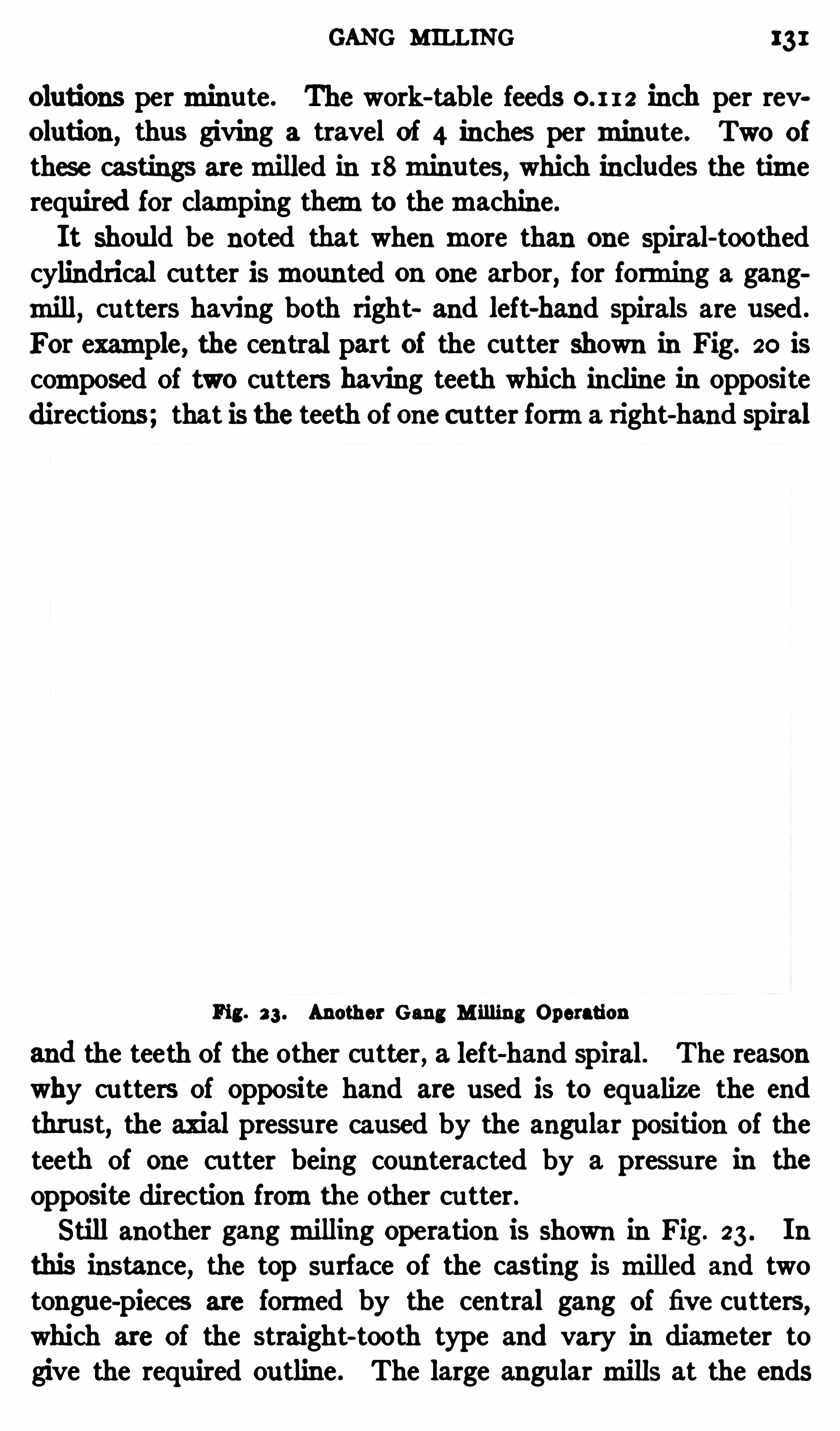
GANG MILLING 131
Olutions perminute. The work-table feeds 0. I I 2 inch per revolution , thus giving a travel of 4 inches per minute . Two of
thes e castings aremilled in 18minu tes,which includes the time
required for clamping themto themachine.
It should be noted that when more than one spiral-toothedcylindrical cu tter ismounted on one arbor
,for forming a gang
mill,cutters having both right and left-hand spirals are used .
For example, the central part of the cutter shown in Fig. 20 is
composed Of two cu tters having teeth which incline in oppositedirections; that is the teeth of one cutter forma right-hand spiral
Fig. 23 . Another Gang M illing Operation
and the teeth Of the other cutter , a left-hand spiral. The reason
why cutters of opposite hand are used is to equalize the end
thrust, the axial pressure caused by the angular position of the
teeth of one cu tter being coun teracted by a pressure in the
Opposite direction fromthe other cu tter.
Still another gangmilling Operation is shown in Fig. 23 . In
this instance, the top surface of the casting is milled and twotongue-pieces are formed by the central gang of five cutters
,
which are Of the straight-tooth type and vary in diameter togive the required outline . The large angularmills at the ends
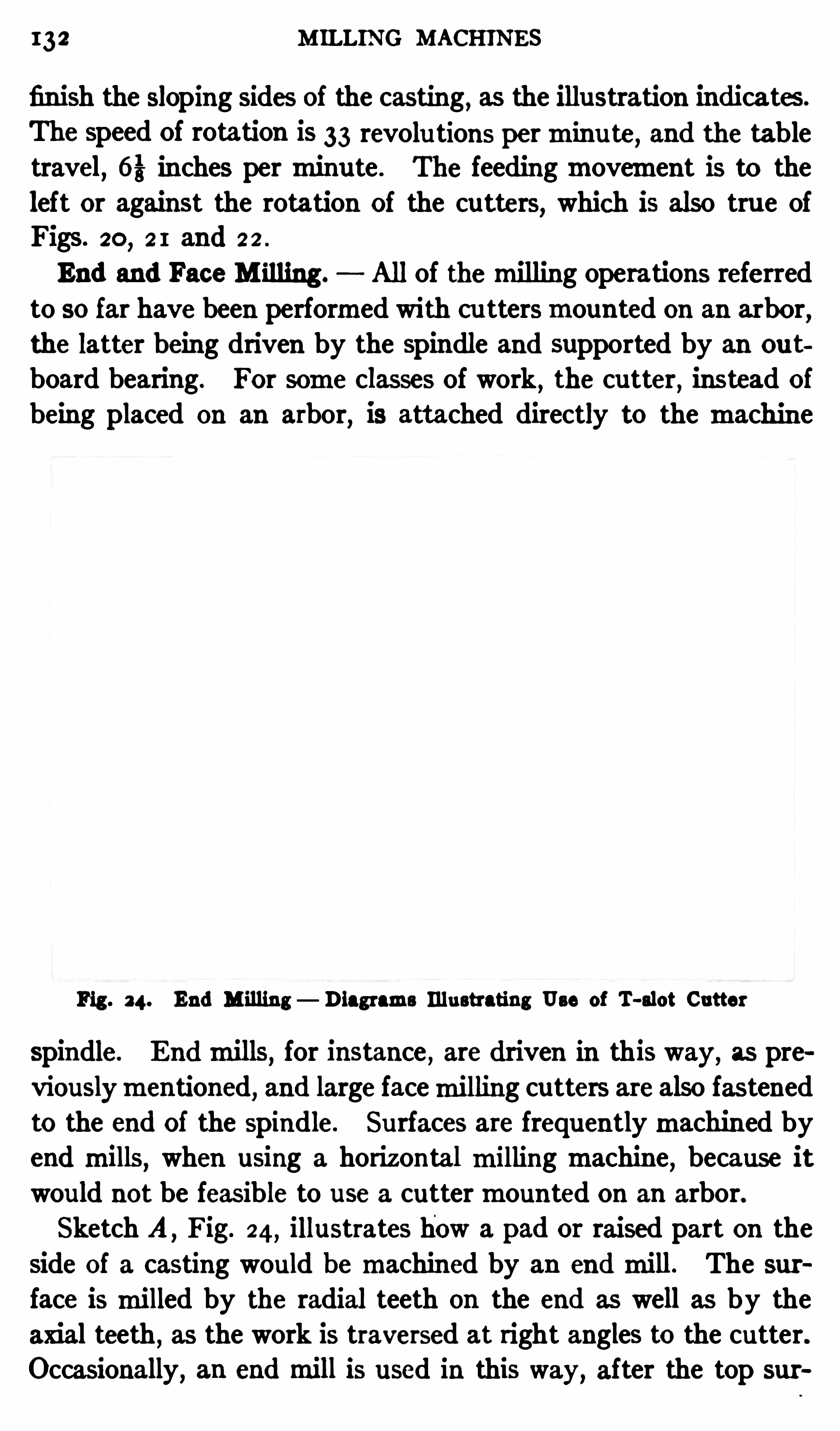
M ILLING MACHINES
finish the sloping sides of the casting, as the illustration indicates.
The speed Of rotation is 33 revolu tions perminu te, and the tabletravel, 63 inches perminu te . The feedingmovement is to theleft or against the rotation of the cutters
,which is also true of
Figs. 20,2 1 and 2 2 .
End and Face M illing. All of themilling operations referredto so far have been performed with cu ttersmounted on an arbor
,
the latter being driven by the spindle and supported by an ou t
board bearing. For some classes of work,the cutter
,instead of
being placed on an arbor, is attached directly to the machine
Fig . 24. End Milling Diagrams Illustrating Use of T-slot Cutter
spindle. Endmills,for instance , are driven in this way, as pre
viouslymentioned, and large facemilling cutters are also fastenedto the end of the spindle. Surfaces are frequentlymachined byend mills
,when using a horizontalmilling machine
,because it
would not be feasible to use a cuttermounted on an arbor.
Sketch A ,Fig. 24, illustrates how a pad or raised part on the
side Of a casting would bemachined by an endmill. The sur
face ismilled by the radial teeth Ou the end as well as by the
axial teeth , as the work is traversed at right angles to the cutter.
Occasionally, an endmill is used in this way, after the top sur

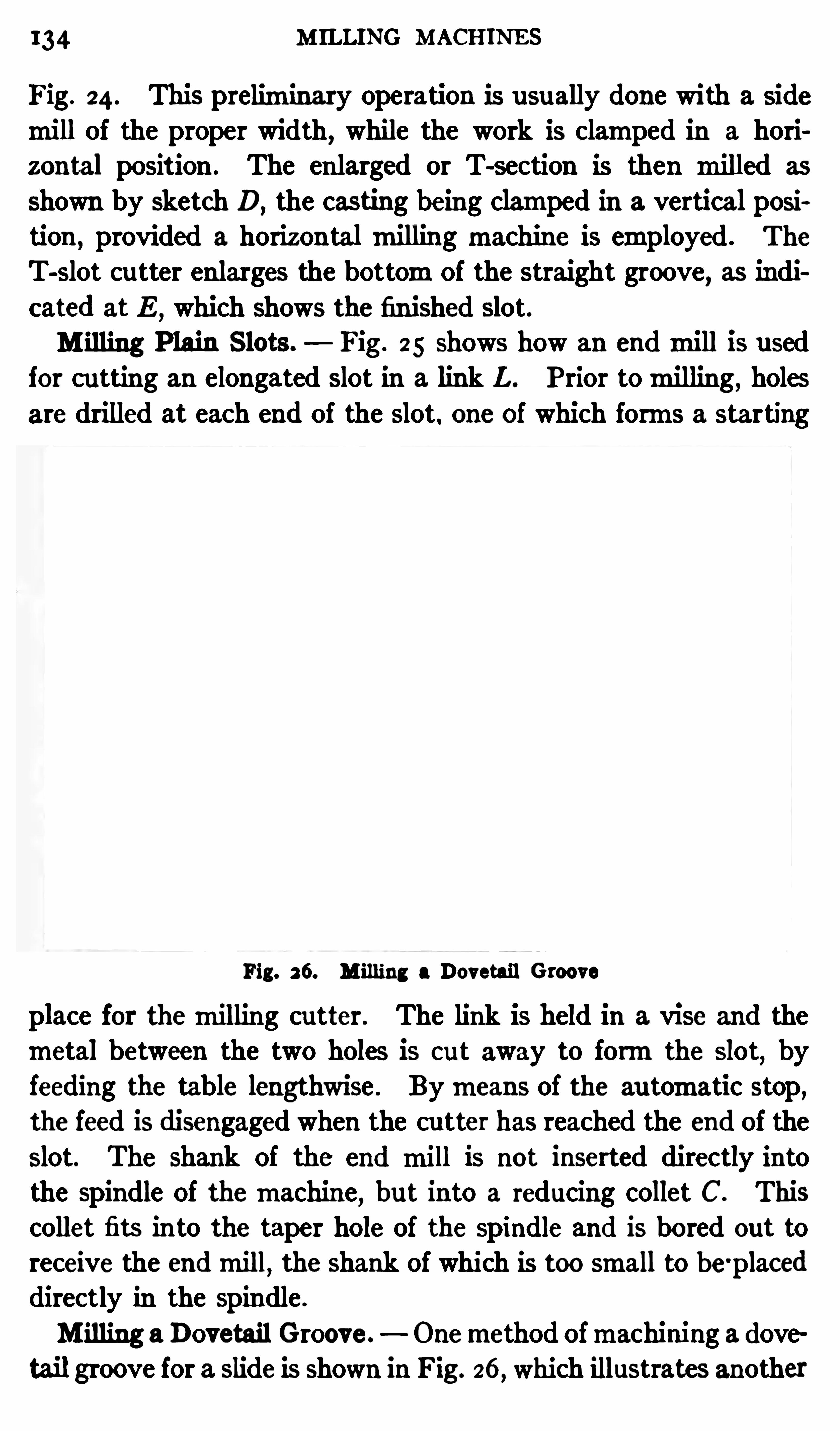
134 M ILLING MACHINES
Fig. 24 . This preliminary Operation is usually done with a side
mill of the proper width, while the work is clamped in a hori
zontal position . The enlarged or T-section is then milled as
shown by sketch D,the casting being clamped in a vertical posi
tion,provided a horizontal milling machine is employed . The
T-slot cutter enlarges the bottomOf the straight groove, as indicated at E
,which shows the finished slot.
M illing P lain S lots. Fig . 25 shows how an endmill is usedfor cu tting an elongated slot in a link L . P rior tomilling, holesare drilled at each end Of the slot. one of which forms a starting
Fig. 26. M illing a Dovetail Groove
place for themilling cutter. The link is held in a vise and themetal between the two holes is c ut away to formthe slot
,by
feeding the table lengthwise . Bymeans of the au tomatic stop,the feed is disengaged when the cu tter has reached the end Of theslot. The shank Of the end mill is not inserted directly intothe spindle Of themachine
,but into a reducing collet C. This
collet fits in to the taper hole of the Spindle and is bored out toreceive the endmill
,the Shank of which is too small to be'placed
directly in the spindle .
M illing aDovetail Groove. Onemethod Ofmachining a clovetail groove for a Slide is shown in Fig. 26, which illustrates another
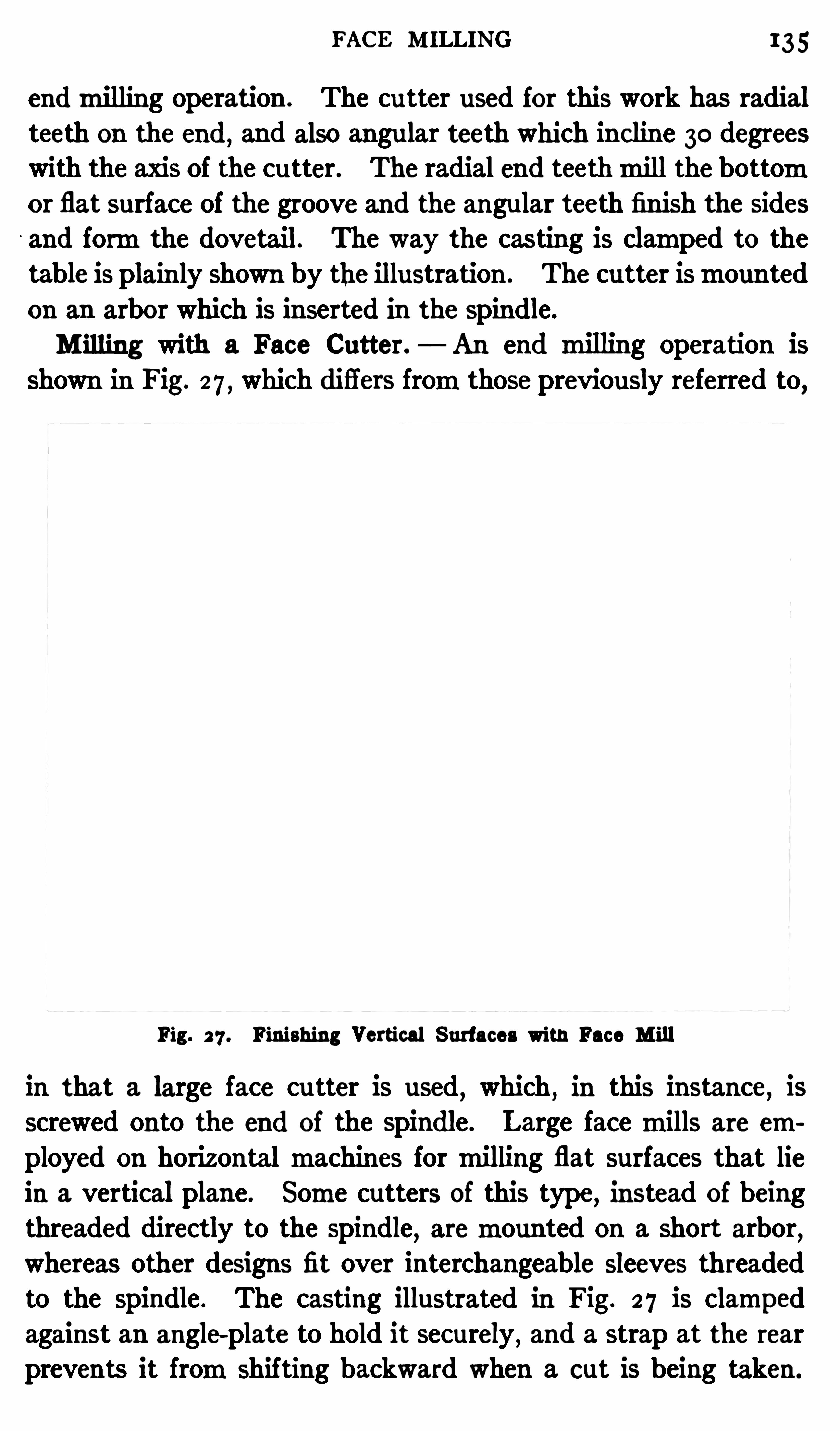
FACE M ILLING 135
endmilling operation . The cu tter used for this work has radial
teeth on the end , and also angular teeth which in c line 30 degreeswith the axis Of the cu tter. The radial end teethmill the bottomor flat surface of the groove and the angular teeth finish the sides
and formthe dovetail. The way the cas ting is clamped to thetable is plainly Shown by the illustration . The cu tter ismountedon an arbor which is inserted in the spindle.
M illing with a Face Cutter. An end milling operation isshown in Fig. 27 , which difl
'
ers fromthose previously referred to,
Fig. 2 7 . Finishing Vertical Surfaces with Face M ill
in that a large face cu tter is used,which
,in this instance, is
screwed onto the end of the spindle . Large face mills are employed on horizontal machines formilling flat surfaces that liein a vertical plane. Some cutters Of this type
,instead of being
threaded directly to the spindle, aremounted on a short arbor,whereas other designs fit over interchangeable Sleeves threadedto the spindle . The casting illustrated in Fig. 2 7 is clampedagainst an angle-plate to hold it securely , and a strap at the rearprevents it fromshifting backward when a cut is being taken.
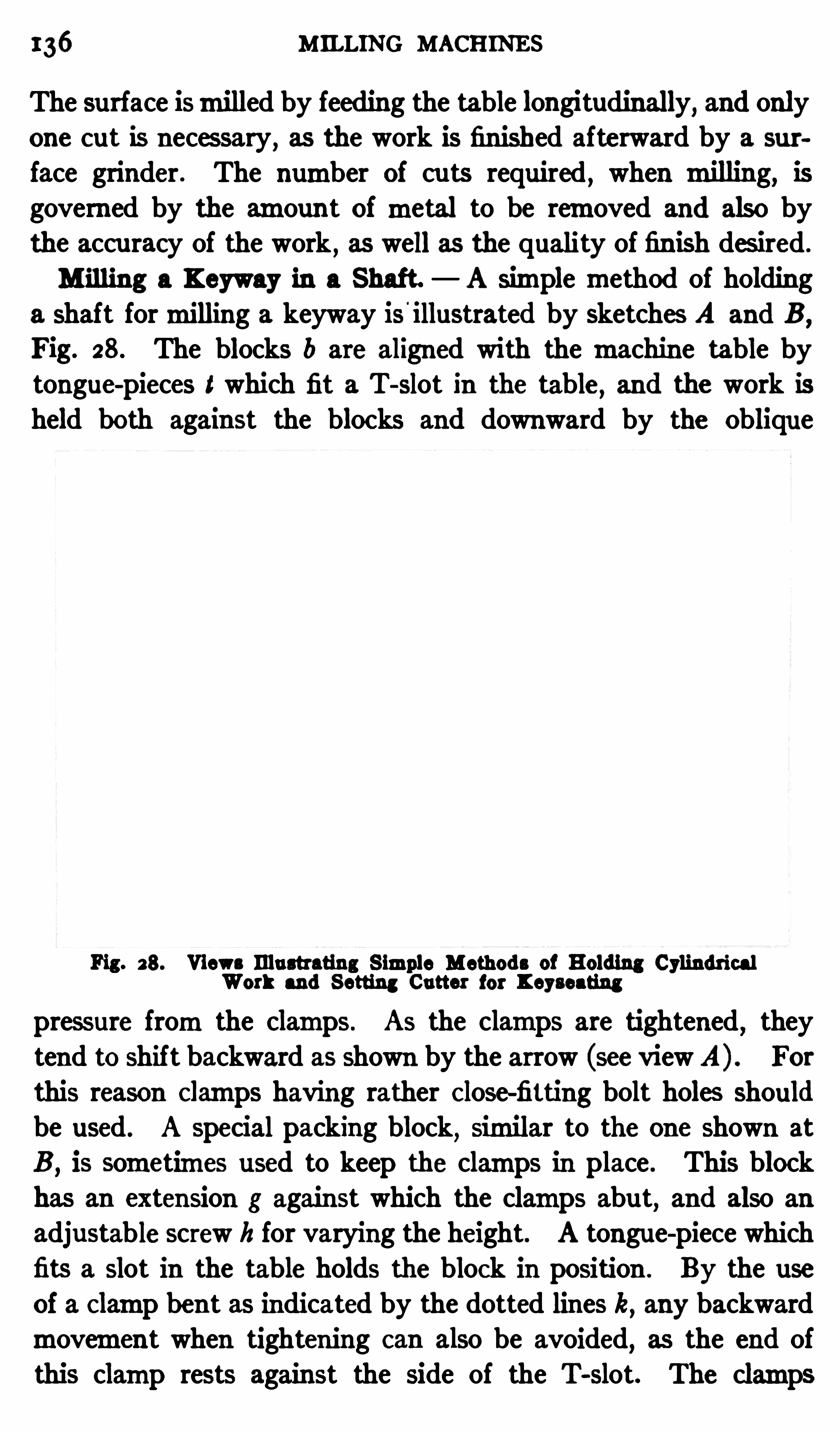
136 MILLING MACHINES
The surface ismilled by feeding the table longitudinally,and only
one cut is necessary, as the work is finished afterward by a sur
face grinder . The number of cu ts required,when milling, is
governed by the amount of metal to be removed and also by
the accuracy of the work , as well as the quality of fin ish des ired .
M illing a Keyway in a Shaft. A simple method of holdinga Shaft formilling a keyway is '
illustrated by Sketches A and B,
Fig. 28. The blocks b are aligned with the machine table bytongue-pieces t which fit a T- Slot in the table
,and the work is
held both against the blocks and downward by the Oblique
Fig. 28. Views Illustrating S imple Methods of Holding CylindricalWork and Setting Cutter for Keyseating
pressure fromthe clamps . As the clamps are tightened,they
tend to Shift backward as Shown by the arrow (see view A) . For
this reason Clamps having rather Close-fitting bolt holes should
be used . A special packing block,similar to the one Shown at
B,is sometimes used to keep the clamps in place . This block
has an extension g against which the clamps abu t, and also an
adjustable screw h for varying the height. A tongue-piece whichfits a Slot in the table holds the block in position . By the useof a Clamp bent as indicated by the dotted lines k, any backwardmovement when tightening can also be avoided
,as the end of
this clamp rests against the Side of the T-slot. The clamps

38 MILLING MACHINES
of the shaft; then set the dial of the elevating screw to zero .
Next sink the cutter to the total depth of the keyway,which
equals the depth d at the side, plus the height a of the arc . Thisheight a can be determined by the following formu la
in which r radius of shaft, and 10 width of keyway.
Example. I f the shaft radius is I i“ inch , thewidth of the keyseat inch
,and the depth at the side 3 inch , what is the total
depth asmeasured fromthe top of the ar c "
r . 25 V r .5 inch .
The total depth then equals or inch .
Therefore the cutter,after being set to graze the top of the shaft,
would be sunk to a depth of inch,the depth beingmeasured
by the graduated dial of the elevating screw .
Speeds for M illing. The proper speed for the cu tter, and thefeedingmovement of the work for each revolu tion of the cutter,are governed bymany different factors. The speed of the cutterdepends largely upon the kind ofmaterial beingmilled. Obvi
ously, tool steel cannot be cu t as fast as soft machine steel orcast iron
,whereas brass c an be cu t at a much higher speed .
The condition of the cutter also afiec ts the speed,it being possible
to operate a sharp cutter faster than a du ll one,because the dull
edges generate an excessive amount of heat . When millingsteel 0r wrought iron
,the application of a lubricant to the cutter
enables higher speeds to be used .
A general idea of the speeds that are feasible when using
carbon-steel cu ttersmay be obtained fromthe following figureswhich represent the velocity (in feet perminute) at the circumference of the cu tter. For taking roughing cu ts in cast iron
,
40 feet perminute; inmachine steel, 60 feet perminute; in toolsteel
,25 feet per minute; and in brass
, 75 feet per minute.
Finishing cuts are taken at speeds varying from50 to 55 feet forcast iron ; 75 to 80 feet formachine steel; 30 to 35 feet for toolsteel; and 95 to 100 feet for brass. These figu res are not givenas representing themaximumspeeds that can be used success
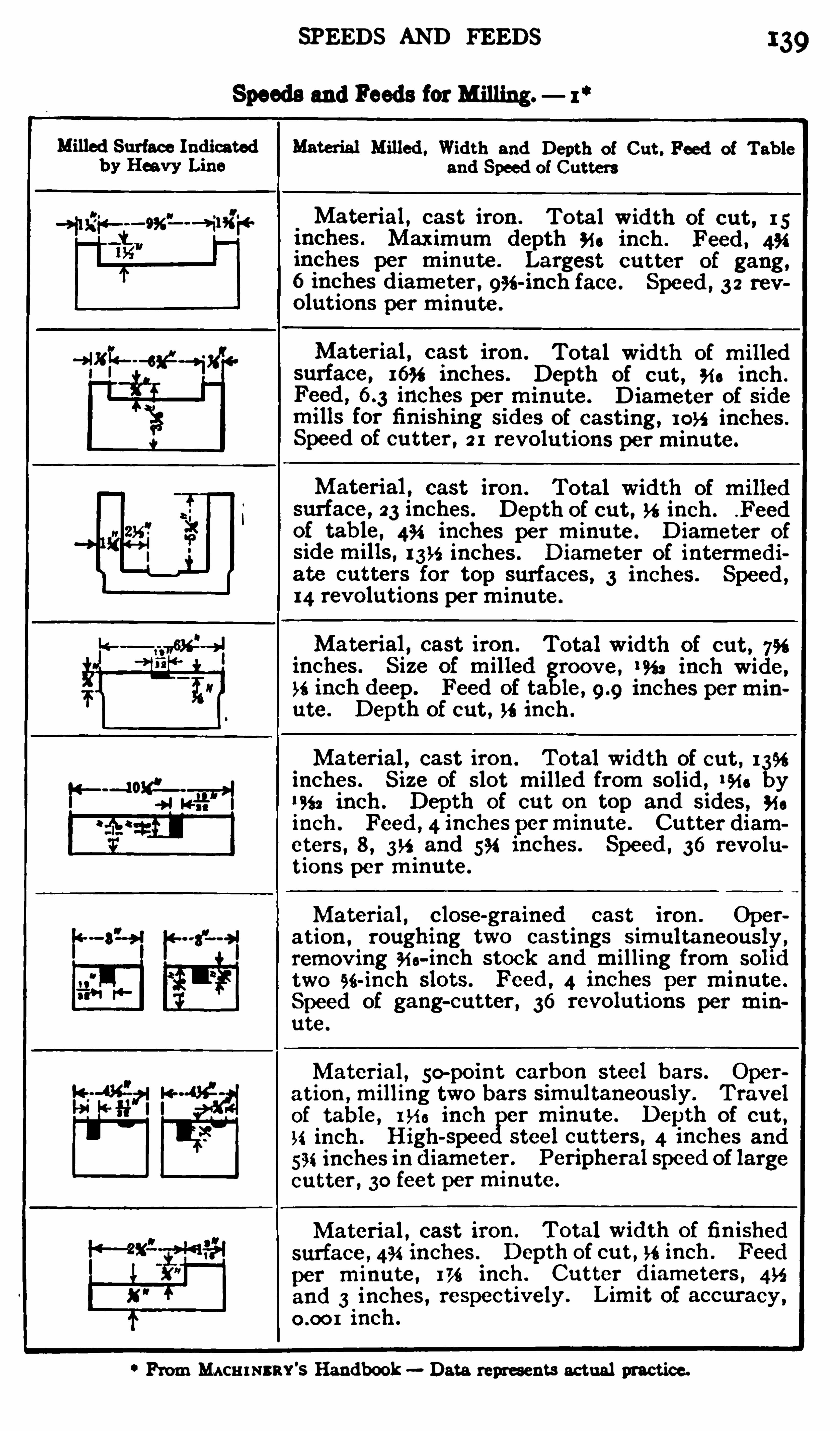
SPEEDS AND FEEDS
Speeds and Feeds forMilling.
PromMACH I NSRY'S Handbook Data represents ac tual practice.
39
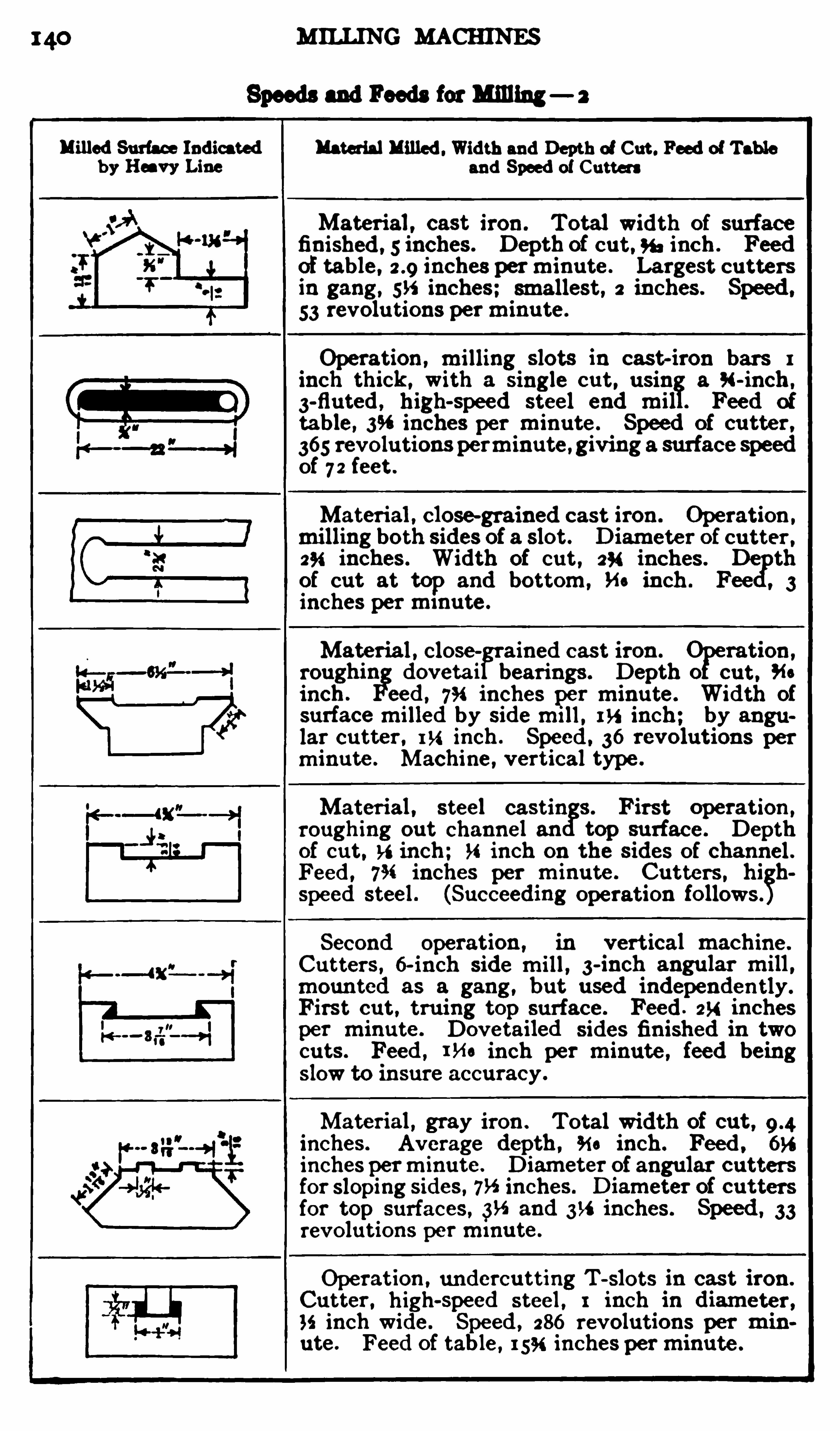
140 MILLING MACHINES
Speeds and Feeds for Milling— 2
“illed Surfac e Indicatedb y Heavy Line
Material Milled .Width and Depth of Cut. Feed of Tab le
and Speed of Cutters
Material , c ast iron . Total width of surfac efinished , s inc hes . Depth of out “, inc h . Feedof table, inc hes perminute. Largest c utters
in gang , 535 inc hes; smallest, 2 in ches . Speed ,
53 revolu tions perminu te.
Operation , milling slots in c ast-iron bars 1
inc h thic k , with a single out, u sin a 94-inch ,
3-fluted , high-speed steel end mil . Feed of
table, 3“ inches per minute. Speed of c u tter ,
365 revolutions perminute, giving a surfac e speedof 7 2 feet .
Material , c lose-grained c ast iron . Operation ,
milling both sides of a slot. Diameter of c utter ,294 inches . Width of c ut , 294 inc hes . D
gnb
of c ut at top and bottom, Ho inch . Fee 3inches perminute.
Material , c lose ained c ast iron . ration ,
roughin doveta i bearings . Depth 0 c ut.minch. eed , 754 inches per minu te. Width of
surfac emilled by sidemi ll , 1“ inc h; by angu
lar c utter , 154 inch. Speed . 36 revolutions per
minute. Machine, vertic al type.
Material , steel c astin 3 . First operation ,
roughing out channel an top surfac e. Depthof c ut, inch; 34 inch on the sides of channel .
Feed , 7% inches per minu te. Cutters , hi hspeed steel . (Suc c eeding Operation follows"Sec ond operation , in vertic al mac hine.
Cu tters , 6-inch side mill , 3-inch angu lar mill ,mounted as a gang , b ut used independently.
First c ut, tru ing top surfac e. Feed . 254 in ches
per minute. Dovetailed sides finished in two
ou ts . Feed , me in ch per minute, feed beingslow to insure ac c urac y .
Material , gray iron . Total width of out ,inches . Average depth , an inch. Feed , 654
inches perminute. Diameter of angu lar c uttersfor sloping sides , 7” inches . Diameter of c uttersfor top surfac es , 3“ and inches. Speed , 33revolu tions perminu te.
Operation , underc u tting T-slots in c ast iron .
Cutter , high-speed steel , 1 inch in diameter ,35 inch wide. Speed , 286 revolutions per minute. Feed of table, 15% inc hes perminute.

142 MILLING MACHINES
fully, even with ordinary carbon c utters,and with high-speed
steel cu tters they can be doubled, owing to the superior cu ttingqualities of high-speed steel.Feeds for M illing . The distance that the work feeds per
revolution of the cuttermust be varied to su it conditions. Whenmilling cu tters were first made, they had fine, closely-spacedteeth between which the chips clogged
,thus preventing any
cu tting action except with fine feeds . Modern cu tters,however
,
have much coarser teeth and, consequently, deeper cuts and
heavier feeds can be used . Aside fromthe question of cu tterdesign
,the feed is affected by the width and depth of the cu t
,
the kind of material being milled, the quality of the finish re
quired,the rigidity of the work and the power of themachine.
As a general rule,a relatively low cu tting speed and a heavy feed
is used for roughing, whereas for finishing, the speed is increased
and the feed diminished. The data given in connection with
some of the examples of milling referred to in this treatise willshow
,in a general way, what speeds and feeds are practicable
when using a well-built machine and modern cu tters. The
tables Speeds and Feeds for M illing ” also contain considerabledata taken fromactual practice.
Lub ricants for M illing . A lubricant that has been exten
sively used for milling is made in the following proportionsI pound of sal soda (carbonate of soda) , I quart of lard oil, I
quart of soft soap , and enough water tomake 10 or I 2 gallons.
Thismixture is boiled for one-half hour, preferably by passinga steamcoil through it. The soap and soda in this solution improve the lubricating quality and also prevent the su rfaces fromrusting. Lard oil and animal or fish oils are also used as a lub ri
cant, and some manu facturers mix mineral oil with lard orfish oil. The soda solu tion or some of the commercial lubricantson themarket aremuch cheaper than o il andmore generally used .
The lubricant is usually applied to the cu tter through a pipe or
spou t which can be adjusted to the proper position . Somemachines have a special pump for supplying the lubricant, andothers are equipped with a can fromwhich the lubricant flowsto the cu tter by gravity . Cast iron and brass aremilled dry.
CHAPTER IV
APPLICATION OF UNIVERSAL MILLING MACHINE AND
SP IRAL HEAD
THE millingmachine illustrated in Fig. I is referred to as a
universal type, because it is adapted to such a wide variety of
milling operations. The general construction is similar to thatof a plainmillingmachine , although the universal type has certain adjustments and attachments which make it possible tomill a greater variety of work . On the other hand , the plain
machine ismore simple,and
,for a given size
,more rigid in con
struction; hence, it is better adapted formilling large numbersof duplicate parts in connection withmanu facturing operations.
The universalmachine has a column C, a knee K which can be
moved vertically on the column ,and a tablewith cross and longi
tudinal adjustmen ts the same as amachine of the plain type.There is a difierence
,however
,in themethod ofmoun ting the
table on the knee. As explained in Chapter I I I , the table of a
plain machine is carried by a saddle which is free tomove in a
crosswise direction,whereas
,the table’s line of motion is at
right angles to the spindle. The table of a universal machinealso has thesemovements, and, in addition
,it can be fed at an
angle to the spindle by swiveling saddle Z on clamp-bed B,which
is interposed between the saddle and knee. The circular baseof the saddle has degree graduations which show the angle at
which the table is set. When the zeromark of these graduations
coincides with the zeromark on the clamp-bed,the table is at
right angles to the spindle . The saddle is held rigidly to theclamp-bed , in whatever position itmay be set
, by bolts which
must be loosened before making an adjustment. The u tility
of this angular adjustment will be explained later in connectionwith examples of universalmilling operations.
The feed motion is derived fromthe main spindle, which is143
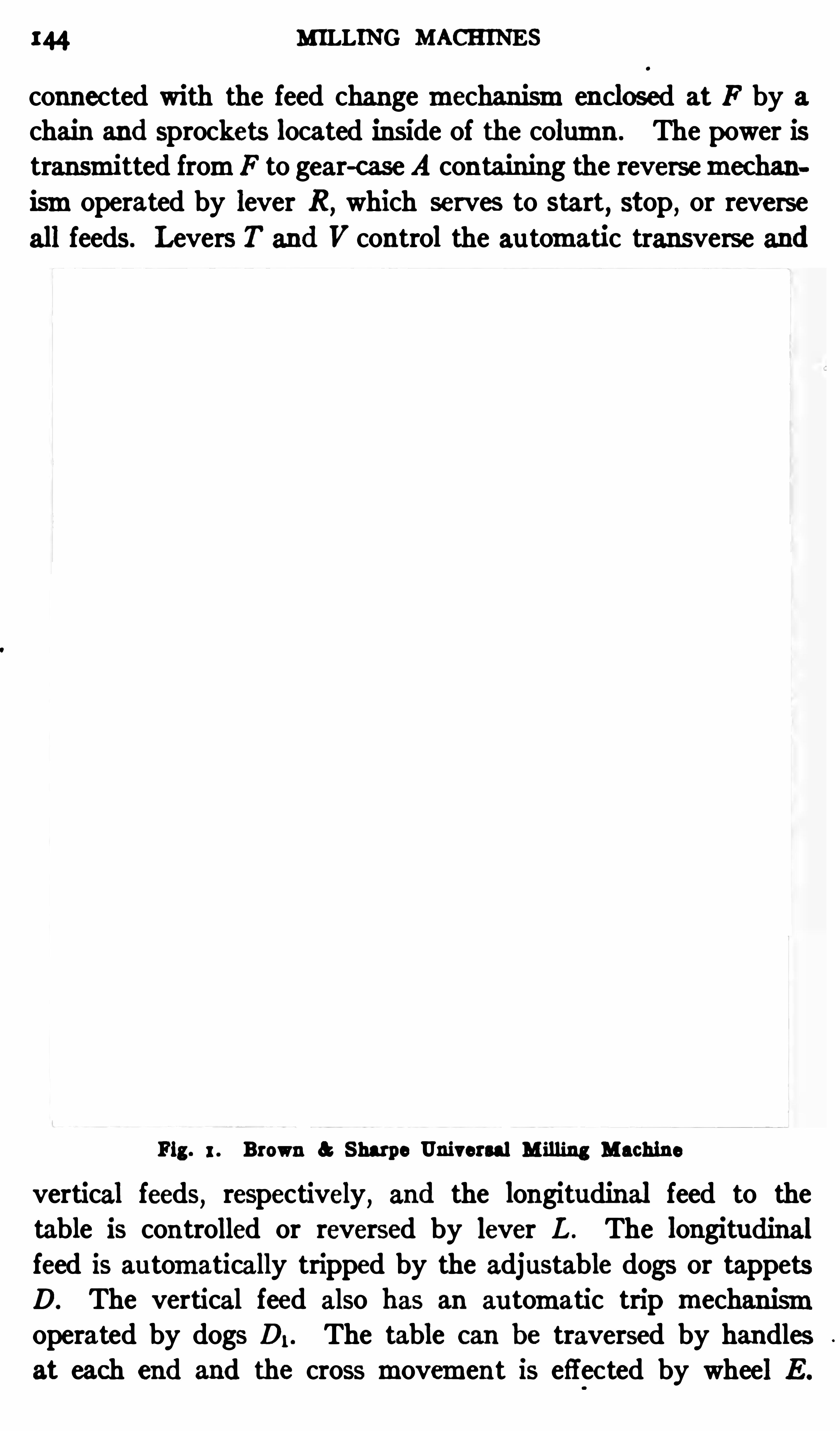
x44 MILLING MACHINES
connected with the feed changemechanismenclosed at F by a
chain and Sprockets located inside of the column . The power istransmitted fromF to gear-case A containing the reversemechanismoperated by lever R ,
which serves to start, stop , or reverse
all feeds. Levers T and V control the au tomatic transverse and
Fig. 1 . Brown a Sharpe Universal M illing Machine
vertical feeds, respectively, and the longitudinal feed to thetable is controlled or reversed by lever L . The longitudinalfeed is au tomatically tripped by the adjustable dogs or tappetsD. The vertical feed also has an au tomatic trip mechanismoperated by dogs D, . The table can be traversed by handlesat each end and the cross movement is effec ted by wheel E .

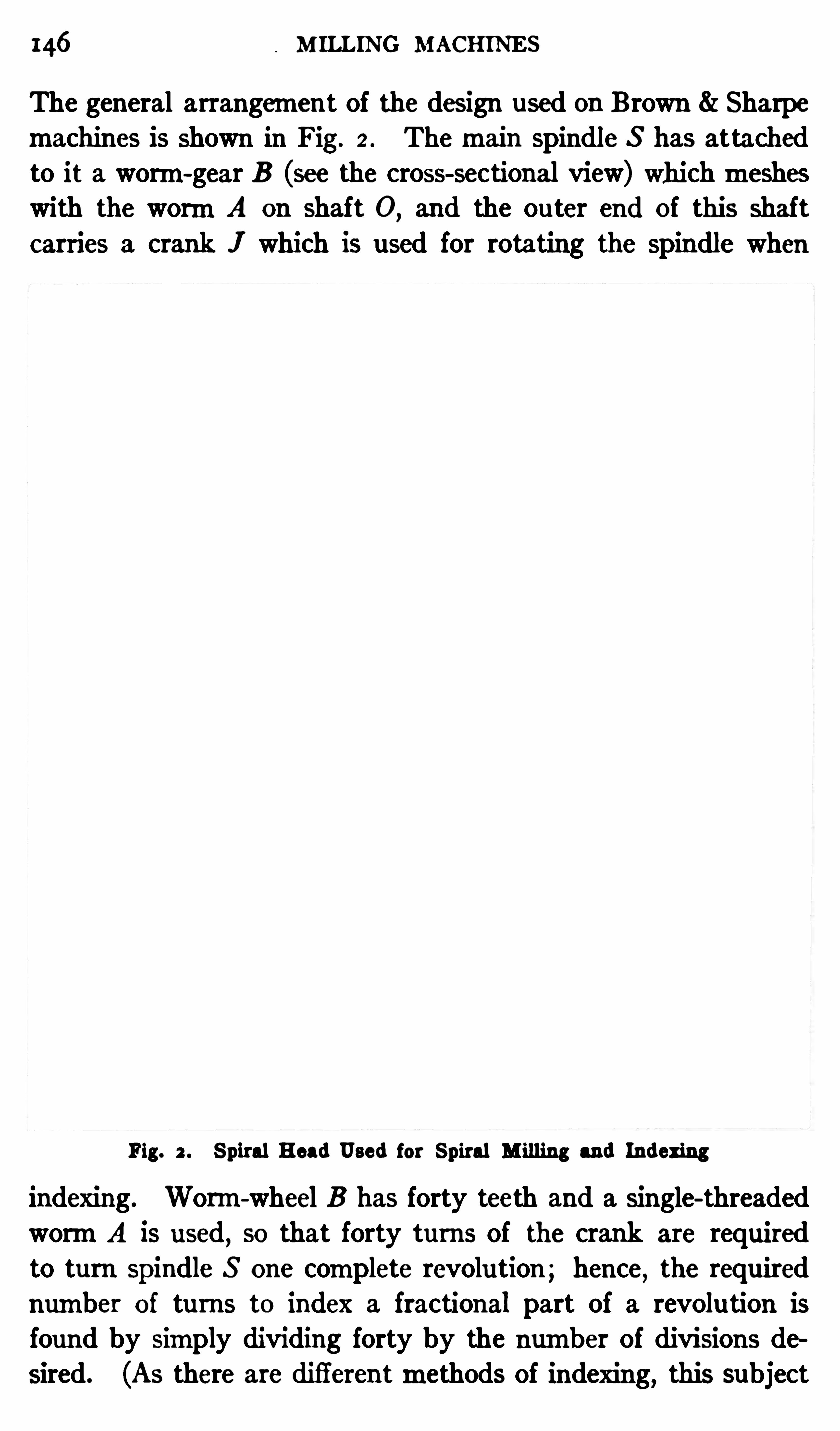
146 M ILLING MACHINES
The general arrangement of the design used on Brown Sharpe
machines is shown in Fig. 2 . Themain spindle S has attachedto it a worm-gear B (see the cross-sectional view) whichmesheswith the wormA on shaft 0
,and the ou ter end of this shaft
carries a crank I which is used for rotating the spindle when
Fig. 2 . Spiral Head Used for Spiral M illing and Indexing
indexing. Worm-wheel B has forty teeth and a single-threadedwormA is used, so that forty turns of the crank are requiredto turn Spindle S one complete revolu tion ; hence, the requirednumber of turns to index a fractional part of a revolution isfound by Simply dividing forty by the number of divisions desired. (As there are difierentmethods of indexing, this subject
SP IRAL HEAD 47
is referred to separately to avoid confusion .) In order to turn
crank J a definite amount, a plate I is used , having several concentric rows of holes that are spaced equidistant in each separaterow . When indexing , spring-plunger P is withdrawn by pullingout knob I and the crank is rotated asmany holes asmay berequired . The number of holes in each circle of the index platevaries
, and the plunger is set in line with any circle by adjustingthe crank radially. One index plate can be replaced by anotherhaving a difierent series of holes , when this is necessary in orderto obtain a certain division .
Sometimes it is desirable to rotate the spindle S independentlyof crank J and the wormgearing; then wormA is disengagedfromworm-wheel B . This disengagement is efiec ted by tu rningknob E abou t one—quarter of a revolu tion in a reverse directionto that indicated by the arrow stamped on it
,thus loosening nut
G which holds eccentri c bushing H . Both knobs E and F are
then turned at the same time , which rotates bushing H and
throws wormA out ofmesh. The wormis re-engaged by tuming knobs E and F in the direction of the arrow; knob E shou ld
then be tightened with a pin wrench . The wormis disengagedin this way when it is desired to index rapidly by hand , and whenthe number of divisions required can be obtained by using plateC . This plate is attached to the spindle and contains a circle ofholes which are engaged by pin D,
operated by lever D, (seec ross-section) . This direct method of indexing can often beused when milling flu tes in reamers
,taps
,etc .
,but
,as only a
limited number of divisions can be obtained,it is necessary to
use crank J and index plate I formost indexing operations.
When the spiral head is used in connection with themilling ofhelical grooves (which are commonly but erroneously called
spiral grooves) , themain spindle S is rotated slowly by changegears as the work feeds past the c utter. These change gears
(which are not shown in this illustration) transmitmotion fromthe table feed-screw L to shaft W
,which
,in turn
,drives spindle
S through spiral gears,Spur gears and the wormgearing A and
B . For themethod of determining what size gears to use for
milling a helix of given lead see“Helical Milling.
”
148 MILLING MACHINES
There is one other featu re of the spiral head which should bereferred to
,and that is the angular adjustment of the main
spindle. I t is necessary for some classes of taper work to set
the spindle at an angle with the table, and this adjustment ismade by loosening bolts K and turning the circular body T inits base. The angle to which the head is set is Shown by graduations reading to i a degree . The Spindle of this particular headcan be set to any angle between 10 degrees below the horizontaland 5 degrees beyond the perpendicu lar. This adjustment isneeded whenmilling taper work whichmust be set at an anglewith the table.
The footstock M,which is used in connection with the spiral
head when milling parts that are supported between centers, is
also adjustable so that the centers 0 and 61 can be aligned whenmilling flutes in taper reamers, etc. The footstock center is set
in line with center 6,when the latter is in a horizontal position ,
by two taper pins on the rear side. When it is desired to set
the center at an angle,these pins are removed and the nu ts
shown are loosened; the center can then be elevated or depressedby turning a nut at the rear, whichmoves the center through arack and pinion .
Workmounted between the centers is caused to rotate withthe spindle
,either when indexing or when cu tting helical grooves,
by a dog which engages driver plate d. The tail of the dogshould be confined by a set-screw e, to prevent any rockingmovement of the work.
Spiral heads of difierentmakes vary more or less in their
arrangement,which is also true ofmillingmachines , or, in fact,
of any othermachine tools. Machines or attachments of a giventype
,however
, usually have the same general features, and ifone or two typical designs are understood, it is M paratively
easy to become familiar with othermakes. Of course, the operator of anymachine tool should be acquainted with its generalconstruction
, b ut it is more important to have a clear understanding of its application to various kinds of work.
Use of the Spiral Head . The spiral head is ordinarily usedfor such work as milling the teeth in milling cutters, fiuting

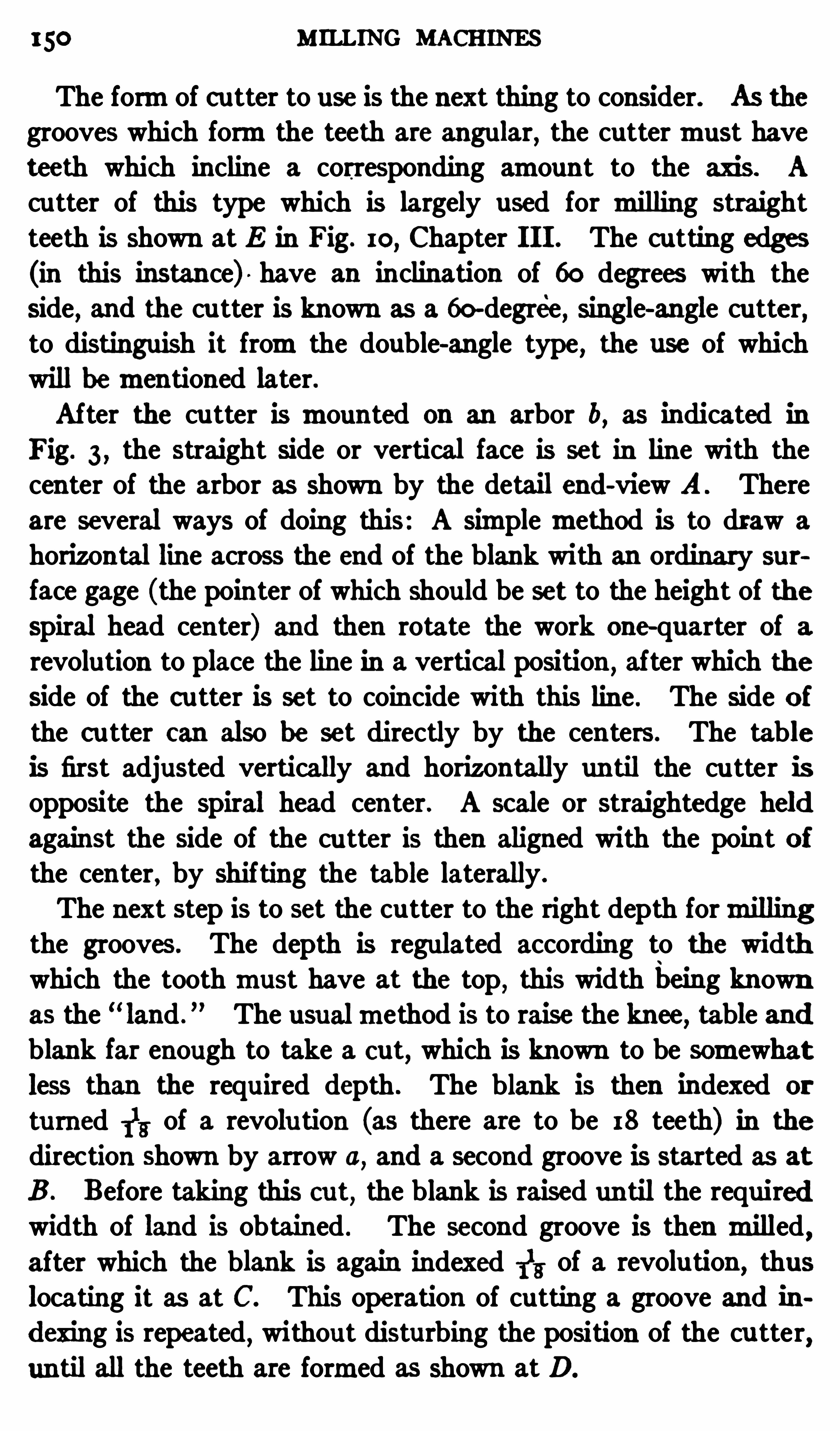
150 MILLING MACHINES
The formof cutter to use is the next thing to consider. As the
grooves which formthe teeth are angular, the cuttermust haveteeth which incline a corresponding amount to the axis. A
cu tter of this type which is largely used for milling straightteeth is Shown at E in Fig. 10, Chapter I I I . The cutting edges
(in this instance) have an inclination of 60 degrees with theside, and the cu tter is known as a 60-degree, single-angle cutter,to distinguish it fromthe double-angle type , the use of whichwill bementioned later.After the cu tter is mounted on an arbor b, as indicated in
Fig. 3 , the straight side or vertical face is set in line with thecenter of the arbor as shown by the detail end-view A . There
are several ways of doing this: A simplemethod is to draw a
horizontal line across the end of the blank with an ordinary sur
face gage (the pointer of which should be set to the height of the
spiral head center) and then rotate the work one-quarter of arevolution to place the line in a vertical position ,
after which theside of the cutter is set to coincide with this line . The side ofthe cu tter can also be set directly by the centers. The tableis first adjusted vertically and horizontally until the cu tter isopposite the spiral head center. A scale or straightedge heldagainst the side of the cu tter is then aligned with the point ofthe center , by shifting the table laterally.
The next step is to set the cu tter to the right depth formillingthe grooves. The depth is regulated according to the widthwhich the toothmust have at the top , this width being knownas the “ land .
” The usualmethod is to raise the knee, table andblank far enough to take a cut, which is known to be somewhatless than the required depth . The blank is then indexed or
tu rned 11; of a revolu tion (as there are to be I 8 teeth) in the
direction Shown by arrow 0,and a second groove is started as at
B . Before taking this cut, the blank is raised until the requiredwidth of land is obtained . The second groove is then milled ,after which the blank is again indexed 1
13 of a revolu tion , thus
locating it as at C. This operation of cu tting a groove and indexing is repeated
,without disturbing the position of the cu tter,
until all the teeth are formed as shown at D.
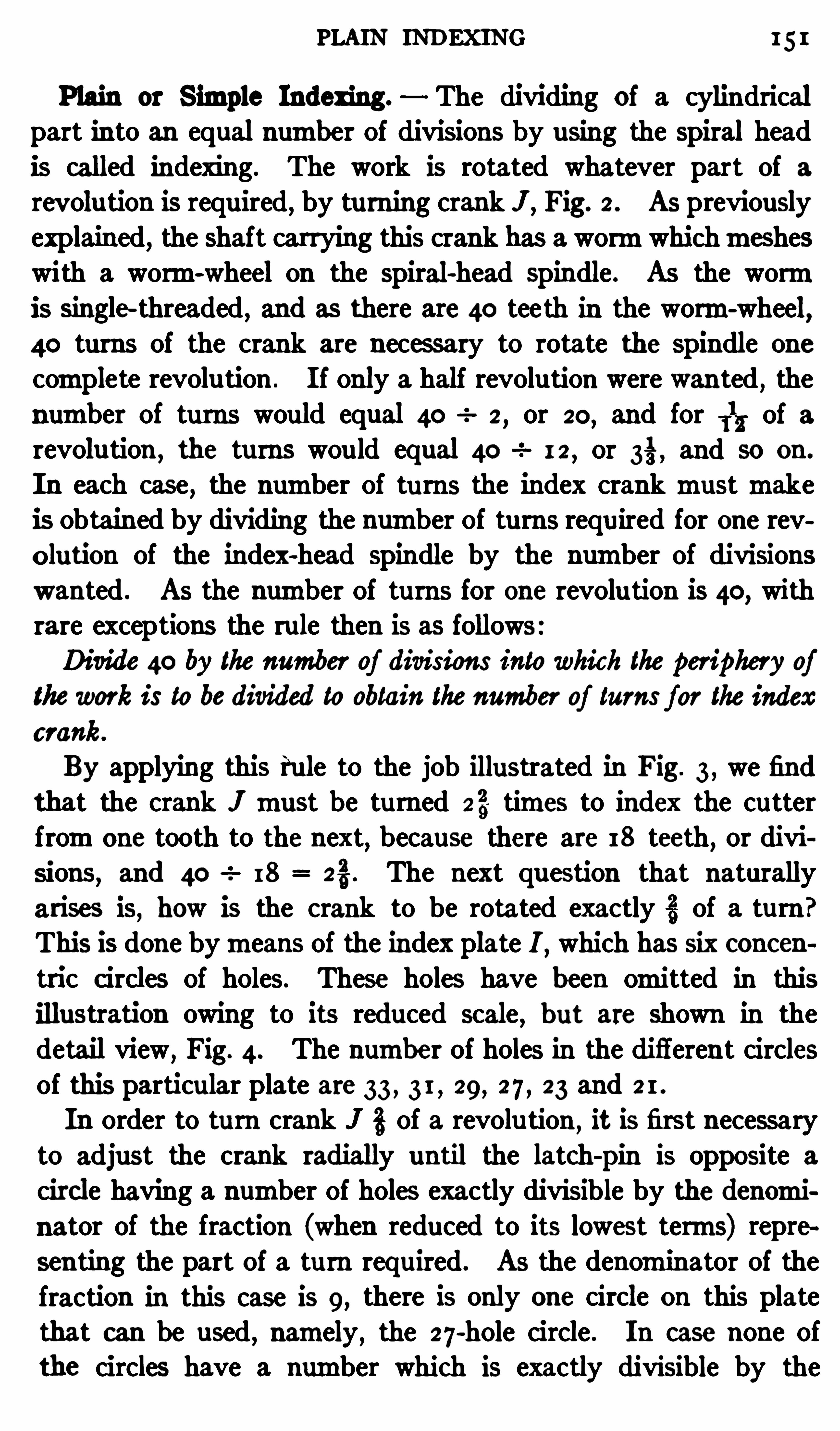
PLAIN INDEXING 15 1
Plain or Simple Indexing. The dividing of a cylindricalpart into an equal number of divisions by using the spiral head
is called indexing. The work is rotated whatever part of a
revolu tion is required, by turning crank " , Fig. 2 . As previouslyexplained, the shaft carrying this crank has a wormwhichmesheswith a worm-wheel on the spiral-head spindle. As the wormis single-threaded , and as there are 40 teeth in the worm-wheel
,
40 turns of the crank are necessary to rotate the Spindle one
complete revolu tion . I f only a half revolu tion were wanted , the
number of turns would equal 40 2,or 20, and for 1
1, of a
revolu tion ,the turns would equal 40 I 2
,or and so on .
In each case , the number of tu rns the index crankmustmakeis obtain ed by dividing the number of turns required for one revolution of the index-head Spindle by the number of divisionswanted . As the number of turns for one revolu tion is 40, withrare exceptions the rule then is as follows:Divide 40 by the number of divisions into which the periphery of
thework is to be divided to obtain the number of turns for the indexcrank.
By applying this rule to the job illustrated in Fig. 3 , we find
that the crank I must be tu rned 23 times to index the cutterfromone tooth to the next, because there are I 8 teeth
,or divi
sions, and 40 I 8 The next question that naturally
arises is, how is the crank to be rotated exactly § of a turn"This is done bymeans of the index plate I , which has six conc en
tric c ircles of holes. These holes have been omitted in thisillustration owing to its reduced scale , b ut are shown in thedetail view,
Fig. 4. The number of holes in the different circlesof this particular plate are 33 , 3 1 , 29, 27 , 23 and 2 1 .
In order to turn crank J 3 of a revolu tion ,it is first necessary
to adjust the crank radially until the latch-
pin is opposite a
circle having a number of holes exactly divisible by the denominator of the fraction (when reduced to its lowest terms) represen ting the part of a turn required . As the denominator of thefraction in this case is 9, there is only one circle on this platethat can be used
,namely
,the 27
-hole circle . In case none of
the circles have a number which is exactly divisible by the
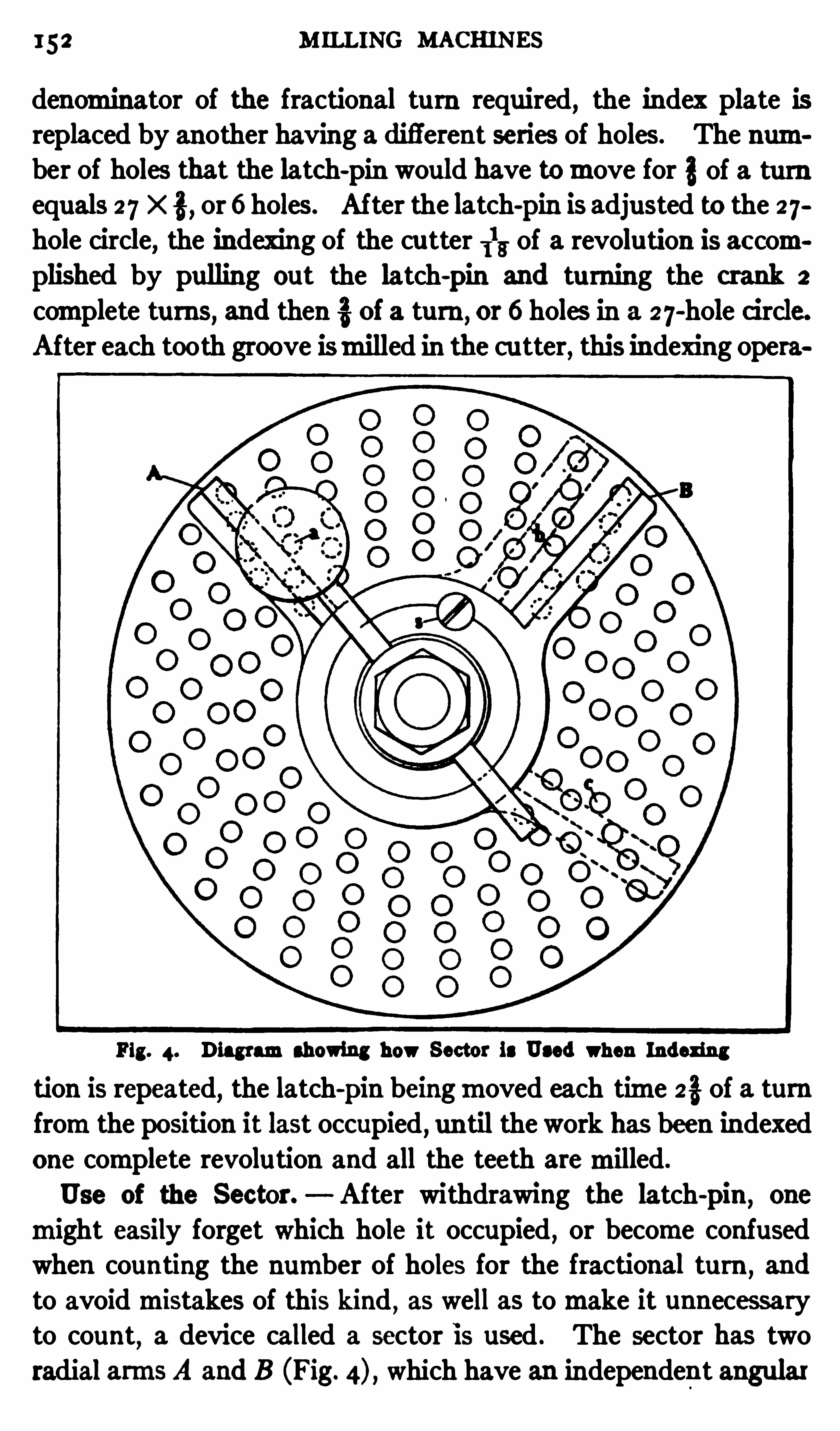
152 M ILLING MACHINES
denominator of the fractional tu rn required,the index plate is
replaced by another having a difi'
erent series of holes. The number of holes that the latch-pin would have tomove for 3of a tu rnequals 27 X or 6 holes. After the latch-pin is adjusted to the 27hole circle, the indexing of the cutter 1
13 of a revolution is aecom
plished by pulling out the latch-pin and turning the crank 2
complete turns, and then of a turn , or 6 holes in a 2 7-hole Circle.
After each tooth groove ismilled in the cu tter, this indexing opera
Fig. 4. Diagramshowing how Sector is Used when Indexing
tion is repeated,the latch-
pin beingmoved each time 2% of a turnfromthe position it last occupied
,un til the work has been indexed
one complete revolution and all the teeth aremilled.
Use of the Sector. After withdrawing the latch-
pin ,one
might easily forget which hole it occupied , or become confusedwhen counting the number of holes for the fractional turn , and
to avoidmistakes of this kind , as well as tomake it unnecessaryto count
,a device called a sector is used . The sector has two
radial arms A and B (Fig. which have an independent angular

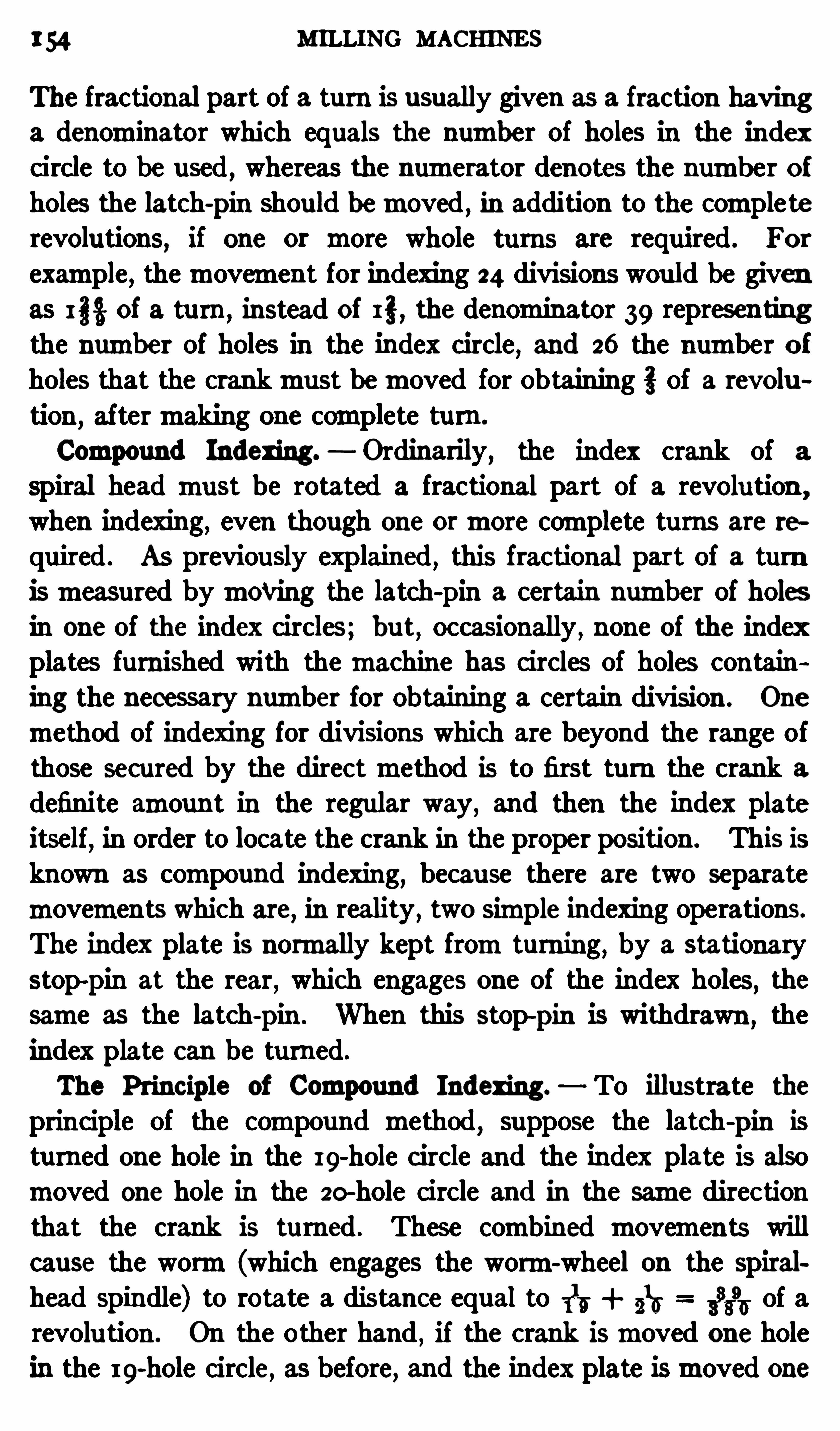
154 MILLING MACHINE S
The fractional part of a turn is usually given as a fraction havinga denominator which equals the number of holes in the indexcircle to be used , whereas the numerator denotes the number ofholes the latch-
pin should bemoved , in addition to the completerevolutions, if one or more whole tu rns are required . For
example, themovement for indexing 24 divisions would be givenas I §% of a tu rn ,
instead of I ", the denominator 39 represen tingthe number of holes in the index c ircle, and 26 the number ofholes that the crankmust bemoved for obtaining of a revolu
tion,aftermaking one complete tu rn .
Compound Indexing. Ordinarily, the index crank of a
spiral head must be rotated a fractional part of a revolu tion ,
when indexing, even though one ormore complete turns are te
quired . As previously explained , this fractional part of a turn
ismeasured bymoiring the latch-
pin a certain number of holesin one of the index circles; bu t, occasionally , none of the indexplates furnished with themachine has circles of holes containing the necessary number for obtaining a certain division . One
method of indexing for divisions which are beyond the range ofthose secured by the directmethod is to first turn the crank a
definite amount in the regular way, and then the index plateitself
,in order to locate the crank in the proper position . This is
known as compound indexing, because there are two separate
movements which are, in reality , two simple indexing operations.
The index plate is normally kept fromturning, by a stationary
stop-pin at the rear , which engages one of the index holes,the
same as the latch-
pin . When this stop-pin is withdrawn ,the
index plate can be turned.
The Princ iple of Compound Indexing. To illustrate the
principle of the compound method,suppose the latch-
pin is
tu rned one hole in the I 9-hole c ircle and the index plate is also
moved one hole in the 20-hole circle and in the same directionthat the crank is turned . These combined movements willcause the worm(which engages the worm-wheel on the spiralhead spindle) to rotate a distance equal to 115 2
10 3
3395 of a
revolu tion . On the other hand , if the crank ismoved one hole
in the 19-hole circle, as before, and the index plate ismoved one
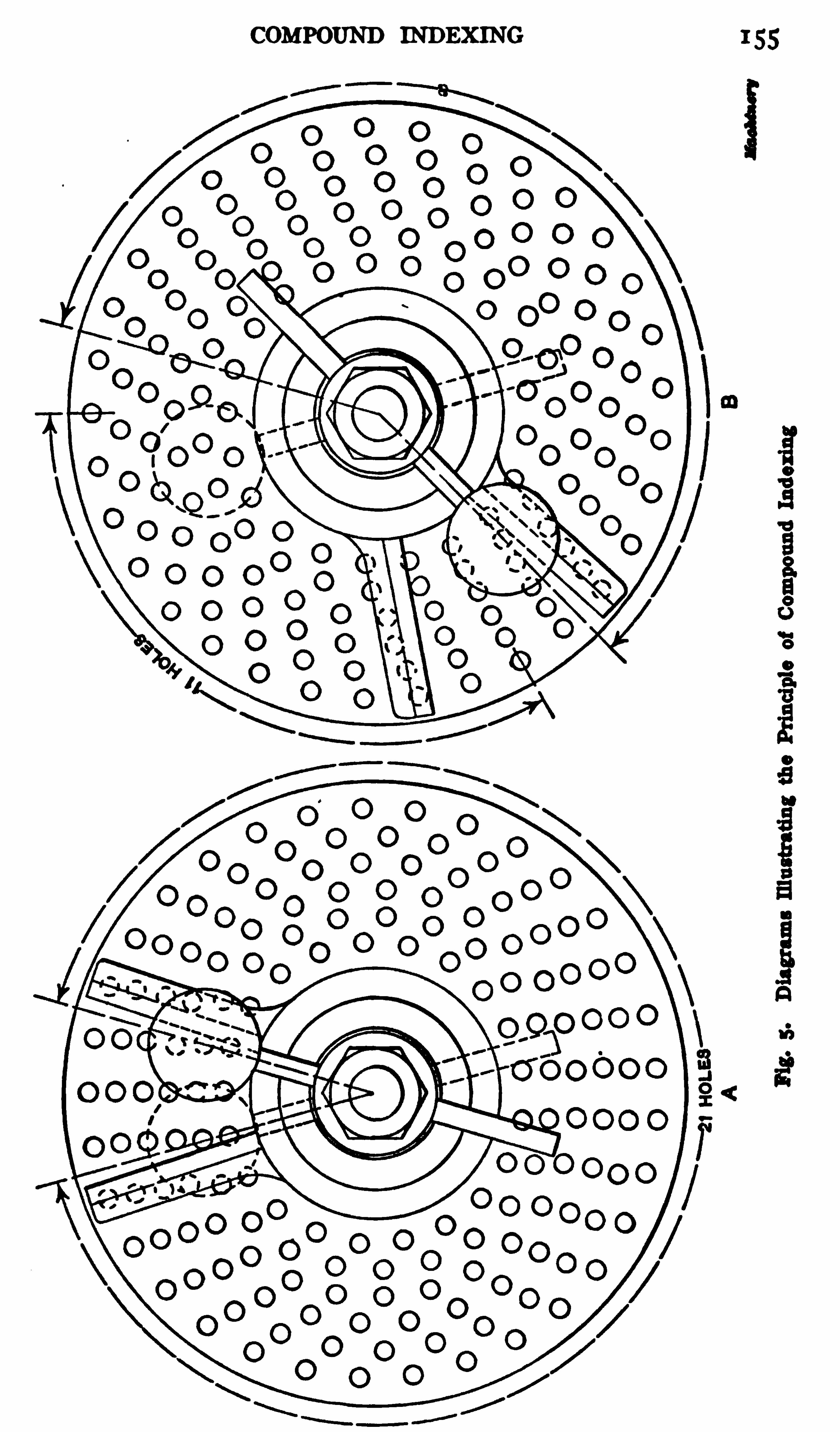
156 MILLING MACHINES
hole in the 20-hole circle , but in the opposite direction, the rotationof the wormwill equal 115 5
15 7h revolution. By the
simplemethod of indexing, it would be necessary to use a circlehaving 380 holes to obtain these movements , but by rotatingboth the index plate and crank the proper amount, either in thesame or opposite directions, asmay be required , it is possible tosecure divisions beyond the range of the simple or direct system.
Example of Compound Indexing. To illustrate the use of
the compound method,suppose 69 divisions were required .
In order to index the work 315 revolu tion ,it is necessary tomove
the crank of a turu and thiswould require a circle having 69 holes, if the simplemethod ofindexing were employed , but by the compound system
,this
division can be obtained by using the 23 and 33-hole circles
,
which are found on one of the three standard plates furnishedwith Brown Sharpe spiral heads. The method of indexing315 revolu tion by the compound systemis as follows: The crankis firstmoved to the right 2 1 holes in the 23-hole circle, as indicated at A in Fig. 5 and it is left in this position; then the stop
pin at the rear,which engages the 33-hole c ircle of the index
plate,is withdrawn ,
and the plate is turned backward , or to theleft
,I I holes in the 33-hole c ircle. This rotation of the plate
also carries the crank to the left, or fromthe position shown bythe dotted lines atB ,
to that shown by the full lines, so that afterturning the plate backward , the crank ismoved fromits originalposition a distance x which is equal to 3} H; 33 which isthe fractional part of a turn the crankmustmake , in order toindex the work 6
16 of.a revolution .
Indexing by Using Simple and Compound Systems. Sometimes the simplemethod of indexing can be used to advantage
in conjunction with the compound system. For example, ifwe want to cut a 96
-tooth gear, every other tooth can be out
first by using the Simple method and indexing for 48 teeth,which would require amovement of r5 holes in an 18-hole circle.
When half of the tooth spaces have been cut, the work is in
dexed 316of a revolu tion by the compoundmethod , for locating
the cuttermidway between the spaces previouslymilled. The

158 MILLING MACHINES
44 holes in the 23-hole c ircle , and the index plate is moved
backward 44 holes in the 33-hole c ircle . The movement can
also be forward 44 holes in the 33-hole circle and backward 44holes in the 23
-hole c ircle,withou t afiec ting the res ult. The
movements obtained by the foregoing rule are expressed in
compound indexing tables in the formof fractions, as for example :$3 a. The numerators represent the number of holes
indexed and the denominators the circles used, whereas, theand signs show that themovements of the crank and indexplate are opposite in direction .
These fractions can often be reduced and simplified so that itwill not be necessary tomove somany holes, by adding somenumber to themalgebraically. The number is chosen by trial ,and its sign should be opposite that of the fraction to which it is
added. Suppose , for example , we add a fraction representing
one complete turn , to each of the fractions referred to; we thenhave
— i-t“
Z i't i i
+ 3“ 33
I f the indexing is governed by these simplified fractions, thecrank is moved forward 2 1 holes in the 23
-hole circle and the
plate is turned backward I I holes in the 33-hole circle , insteadofmoving 44 holes , as stated . The resu lt is the same in eachcase bu t the smaller movements are desirable
,especially for
the Index plate,because it is easier to coun t I I holes than 44
holes. For this reason the fractions given in index tables are
Simplified in this way. Ordinarily,the number of circles to
use and the required number ofmovements tomake when indexing is determined by referring to a table, as this eliminates all
calcu lations and lessens the chance of error .Difierential Indexing. One of the improved indexing
systems, which is applied to the universal milling machinesbuilt by the B rown Sharpe M fg. CO.
,is known as the difi
'
er
ential method . This systemis the same in principle as compound indexing , but difiers fromthe latter in that the indexplate is rotated by suitable gearing which connects it to the
DIFFERENTIAL INDEXING 159
spiral-head spindle, as shown in Figs. 6 and 7 . This rotation
or difierentialmotion of the index plate takes place when thecrank is turned
,the platemoving either in the same direction
as the crank or opposite to it, asmay be required . The resultis that the actualmovement of the crank ,
at every indexing, iseither greater or less than its movement with relation to theindex plate.
Thismethod of turning the index plate by gearing instead ofby handmakes it possible to obtain any division liable to arisein practice
,by using
one circle of holes andsimp ly tu rn in g theindex crank in one
direction,the same as
for plain indexing. As
the hand movementof the plate and thecounting of holes ise l imi n a t e d , t h echances of error are
also greatly reduced .
The proper sizedgears to use formov
Fig. 6. Index Head Geared for DiflerentialIng the Index plate
Imam"
the required amoun twould ordinarily be determined by referring to a table which
accompanies the machine . This table (a small part of whichis illustrated in Fig. 8) gives all divisions fromI to 382 and
includes both plain and difierential indexing; that is, it showswhat divisions can be obtained by plain indexing
, and alsowhen it is necessary to use gears and the difierential system.
For example, if I 30 divisions are requ ired , the 39-hole indexcircle is used and the crank ismoved I 2 holes (see fourth columnof table) but no gears are required. For I 3 I divisions a 40-toothgear is placed on the worm-Shaft and a 28- tooth gear ismountedon the spindle . These two gears are connected by the 44-toothidler gear, which serves to rotate the plate in the same direction
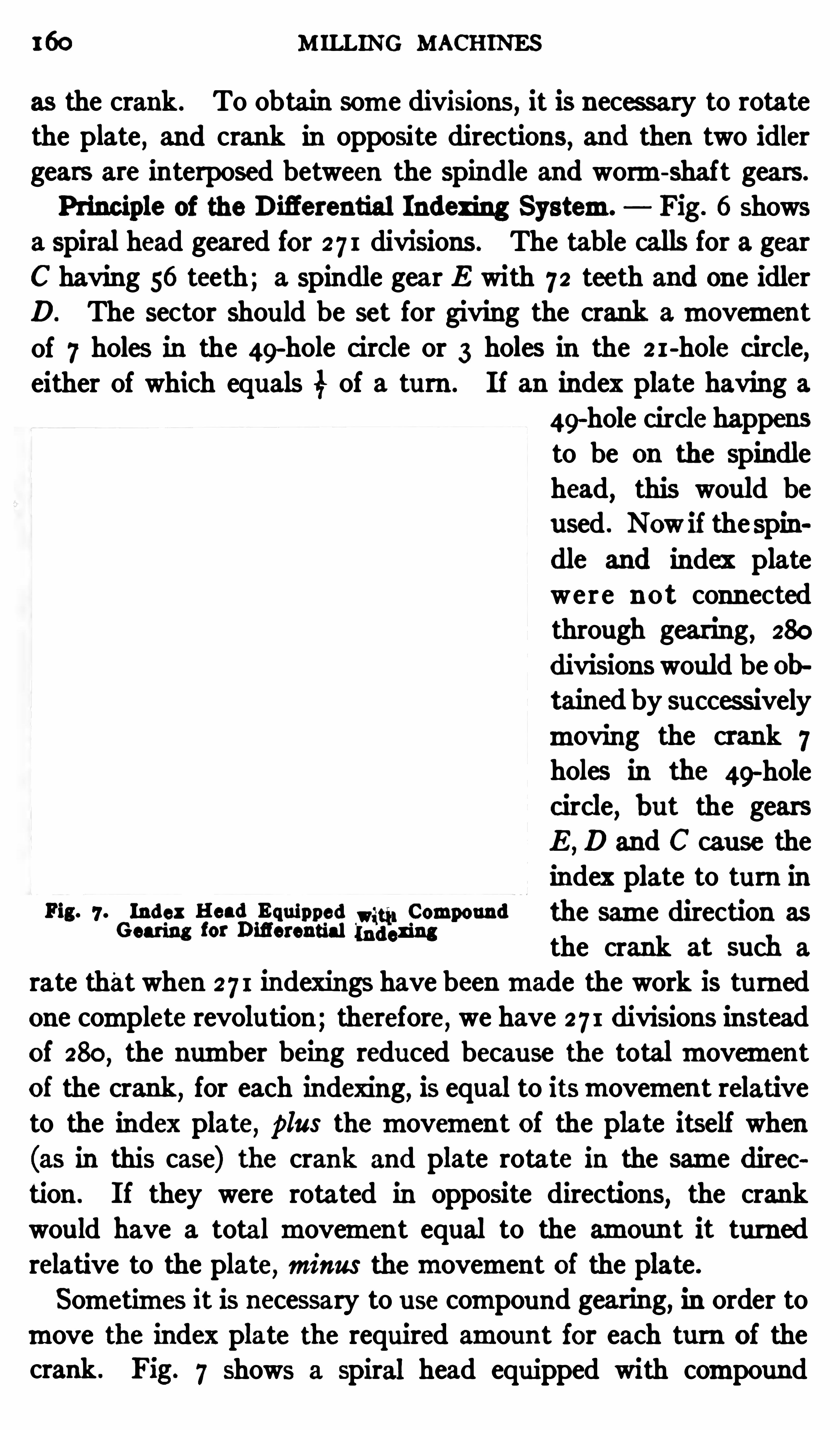
160 M ILLING MACHINES
as the crank. To obtain some divisions , it is necessary to rotatethe plate
,and crank in opposite directions, and then two idler
gears are interposed between the spindle and worm-shaft gears.
Principle of the Difierential Indexing System. Fig. 6 shows
a spiral head geared for 2 7 1 divisions . The table calls for a gear
C having 56 teeth; a spindle gear E with 72 teeth and one idlerD. The sector should be set for giving the crank amovementof 7 holes in the 49-hole circle or 3 holes in the 2 1-hole c ircle,either of which equals 3 of a turn . I f an index plate having a
49-hole circle happens
to be on the spindlehead
,this would be
used . Now if the spin
dle and index platewere n ot connectedthrough gearing, 280
divisionswould be obtained by successivelymoving the crank 7holes in the 49
-holec ircle
,b ut the gears
E,D and C cau se the
index plate to turn inFig. 7 .
02333;If”) 1323331333 12131
;Iglo
‘
mpound the same direction as
the crank at such a
rate that when 2 7 1 indexings have beenmade the work is tu rnedone complete revolution;therefore, we have 27 1 divisions insteadof 280
, the number being reduced because the totalmovementof the crank
,for each indexing
,is equal to itsmovemen t relative
to the index plate, plus themovement of the plate itself when
(as in this case) the crank and plate rotate in the same dircetion . I f they were rotated in opposite directions, the crankwould have a total movement equal to the amount it turnedrelative to the plate
,minus themovement of the plate.
Sometimes it is necessary to u se compound gearing, in order tomove the index plate the required amount for each turn of thecrank . Fig. 7 shows a spiral head equipped with compound

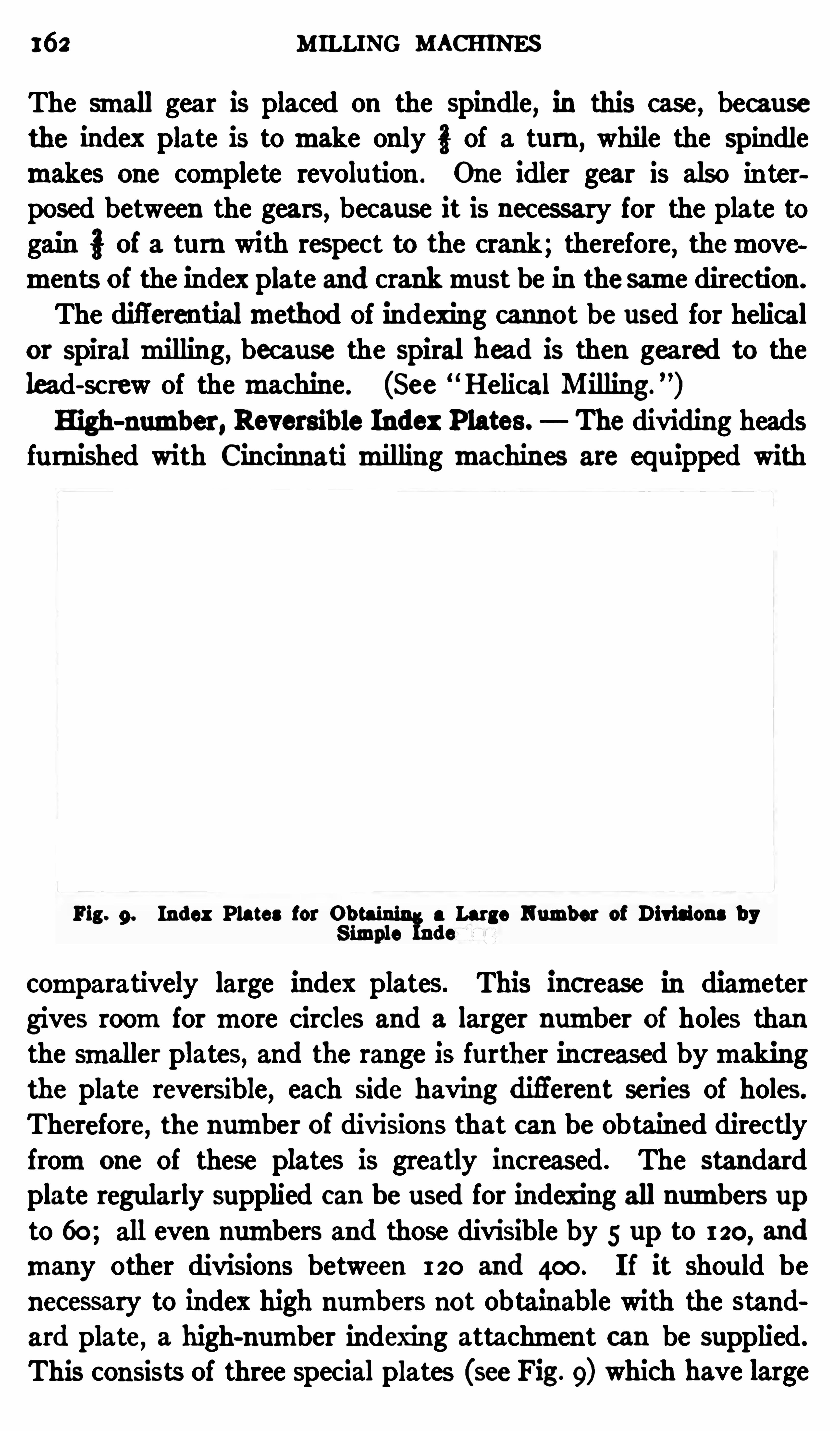
162 MILLING MACHINES
The small gear is placed on the spindle, in this case , becausethe index plate is tomake only of a turn, while the spindlemakes one complete revolution . One idler gear is also in terposed between the gears, because it is necessary for the plate togain of a turn with respect to the crank; therefore, themovements of the index plate and crankmust be in thesame direction.
The difl'
erentialmethod of indexing cannot be used for helicalor Spiralmilling, because the spiral hea d is then geared to thelead-screw of themachine. (See Helical Milling
”
)High-number, Reversib le Index Plates. The dividing heads
furnished with Cincinnati milling machines are equ ipped with
Fig. 9. Index Plates for 0b a Large Number of Divisions b yS imple de
comparatively large index plates. This inc rease in diametergives roomfor more circles and a larger number of holes thanthe smaller plates, and the range is further increased bymakingthe plate reversible, each side having difi
'
erent series of holes.
Therefore, the number of divisions that can be obtained directlyfromone of these plates is greatly increased . The standardplate regularly supplied can be used for indexing all numbers upto 60; all even numbers and those divisible by 5 up to 120, and
many other divisions between 120 and 400. I f it should be
necessary to index high numbers not obtainable with the standard plate, a high-number indexing attachment can be supplied.
This consists of three special plates (see Fig. 9) which have large
ANGULAR INDExING 163
numbers of holes and difierent series on each side. They can
be used for indexing all numbers up to and including 200; all
even numbers and those divisible by 5 up to and including 400.
Owing to the range of the standard plate , the high-number attachment is only needed in rare instances
,for ordinarymilling
machine work.
Angular Indexing. Sometimes it is desirable to index a certain number of degrees instead of a fractional part of a revolu
tion . As there are 360 degrees in a circle and 40 turns of theindex crank are required for one revolu tion of the spiral-head
Spindle, one turn of the crank must equal 3133" 9 degrees.
Therefore,two holes in an 18-hole circle, or three holes in a 27
hole c ircle, is equivalent to a one-degree movement, as this isi of a turn . If we wan t to index 35 degrees, the number of turnsthe c rank must make equals 35 9
é or three completeturns and 8 degrees. As amovement of two holes in an 18-holecircle equals one degree, amovement of 16 holes is required for8 degrees. I f we want to index 1 13 degrees, the one-half degreemovement is obtained by turning the crank one hole in the 18
hole circle, after the 11 degrees have been indexed by makingone complete revolu tion (9 degrees) , and four holes (2 degrees) .Similarly, one and one-third degree can be indexed by using the27
-hole circle, three holes being required to index one degree, andone hole, one-third degree .
When it is necessary to index tominu tes, the requiredmovement can be determined by dividing . the total number ofminutes represented by one turn of the index crank, or 540 (9 X 60
by the number ofminu tes to be indexed. For example,
to index 16minutes requires approximately 31; turn (540 16
34, nearly) , or a movement of one hole in a 34-hole circle.
As the 33-hole circle is theonenearest to 34, this could be used andthe error would be very small.Rule for Angular Indexing. The following is a general rule
for the approximate indexing of angles, assuming that fortyrevolutions of the index crank are required for one turn of thespiral-head spindleDivide 540 by the number of minutes to be indexed. If the
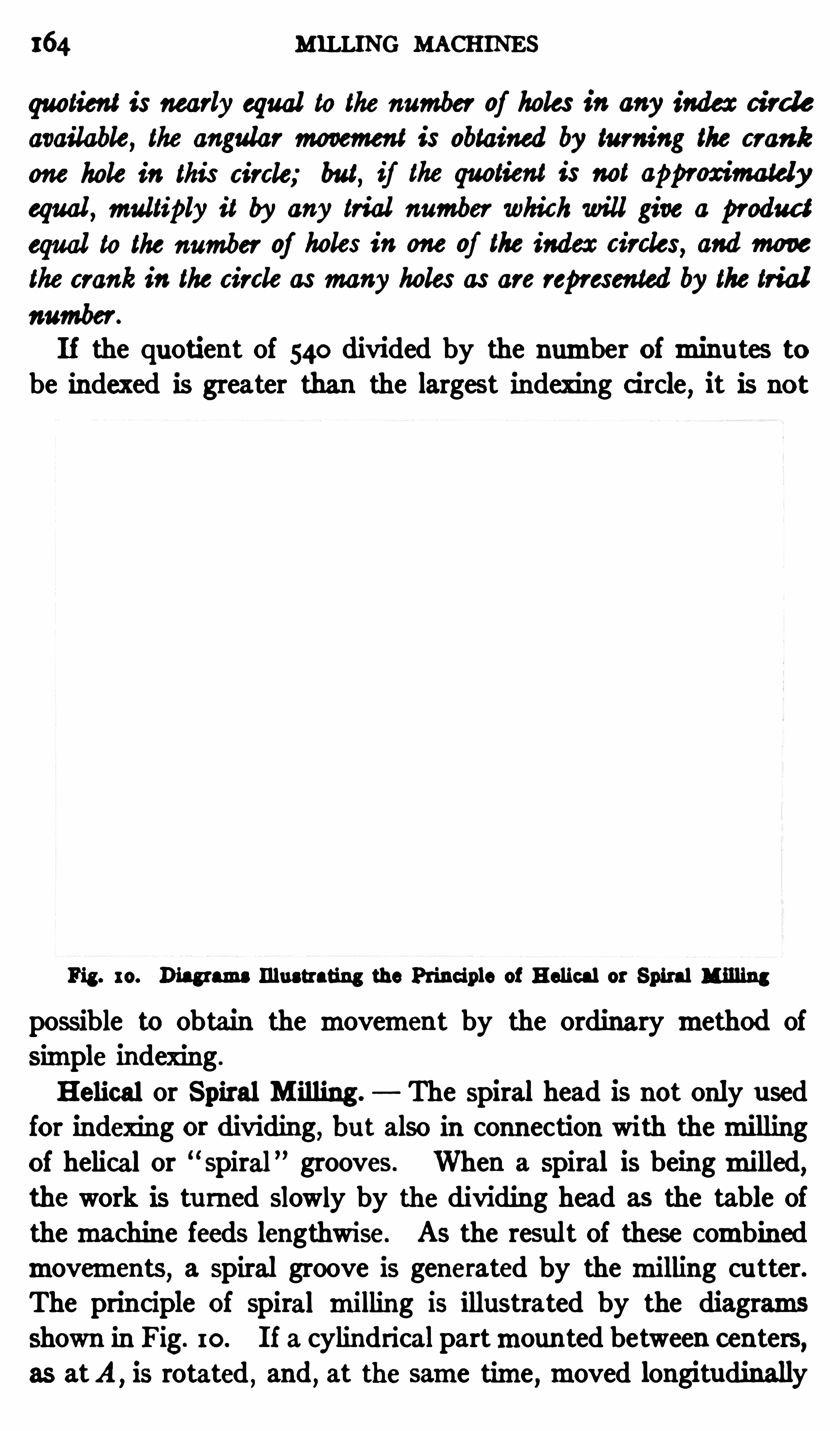
164 MILLING MACHINES
quotient is nearly equal to the number of holes in any index circle
available, the angular movement is obtained by turning the crank
one hole in this circle; but, if the quotient is not approximatelyequal , multiply it by any trial number which will give a produc t
equal to the number of holes in one of the index c ircles,andmove
the crank in the circle asmany holes as are represented by the trialnumber.
I f the quotient of 540 divided by the number of minu tes tobe indexed is greater than the largest indexing c ircle
,it is not
Fig. 10. Diagrams Illustrating the Principle of Helical or Spiral Milling
possible to obtain the movement by the ordinary method ofSimple indexing .
Helical or Spiral M illing . The spiral head is not only u sedfor indexing or dividing, but also in connection with themillingof helical or “
spiral ” grooves . When a spiral is beingmilled,the work is tu rned Slowly by the dividing head as the table ofthemachine feeds lengthwise. As the result of these combinedmovements
, a spiral groove is generated by the milling cu tter.The principle of spiral milling is illustrated by the diagramsshown in Fig. 10 . I f a cylindrical partmounted between centers,as atA
,is rotated
,and
,at the same time ,moved longitudinally


66 MILLING MACHINES
SPIRAL M ILLING 167
Example of Spiral M illing. As an example of spiralmilling,suppose we have a cylindrical cu tter blank 3} inches in diameterin which right-hand spiral teeth are to bemilled
, as indicated inFig. 12
,which Shows the cutter after the teeth have beenmilled.
The blank is firstmounted on an arbor which is placed betweenthe centers with a driving dog attached . The arbor should fittightly into the hole of the blank so that both will rotate as one
Fig. 12 . Universal Machine arranged for Spiral M illing
piece, and it is also necessary to take up all play between the
driving dog and faceplate .
The spiral head is next geared to the feed-sc rew. I f a tableof change-gears is available, it will Show what gears are needed ,provided the lead of the spiral is known . A small section of oneof these tables is reproduced in Fig. 13 to
'
illustrate the arrangement . Suppose the lead given on the drawing is 48 inches; then

168 MILLING MACHINES
this figure (or the nearest one to it) is found in the column headed,“Lead in Inches,
”and the four numbers to the right of and in
line with 48 indicate the number of teeth in the four gears tobe used . The numbers opposite 48 are 72 , 24, 64 and 40,
re
spec tively, and the position for each of these gears is shown bythe headings above the columns. As 72 is in the column headedGear onWorm,
”a gear d (see also Fig. 1 1) of this size is placed
on shaft W. The latter is referred to as the worm-shaft, al
though,strictly speaking, the worm-shaft W1 is the one which
Fig . 13 . Part of Tab le showing Gear Comb inations to use for
ob taining Spirals of Diderent Lead
carries the indexing crank and worm. The first gear c placed on
the stud E has 24 teeth , as shown by the table, and the secondgear b on the same stud has 64 teeth , whereas gear a on the sc rewhas 40 teeth.
After these gears are placed in t heir respective positions, the
first and second gears c and b on stud E are adjusted tomeshproperly with gears a and d by changing the position of the supporting yoke I’ . As a right-hand spiral is to bemilled, whichmeans that it advances by twisting or tu rning to the right, anidler gear is not used with the design of spiral head shown .
Whenmilling a left-hand spiral, it is necessary to insert an idlergear in the train of gears (as at i , Fig. 12
, Chapter V) , to rotate

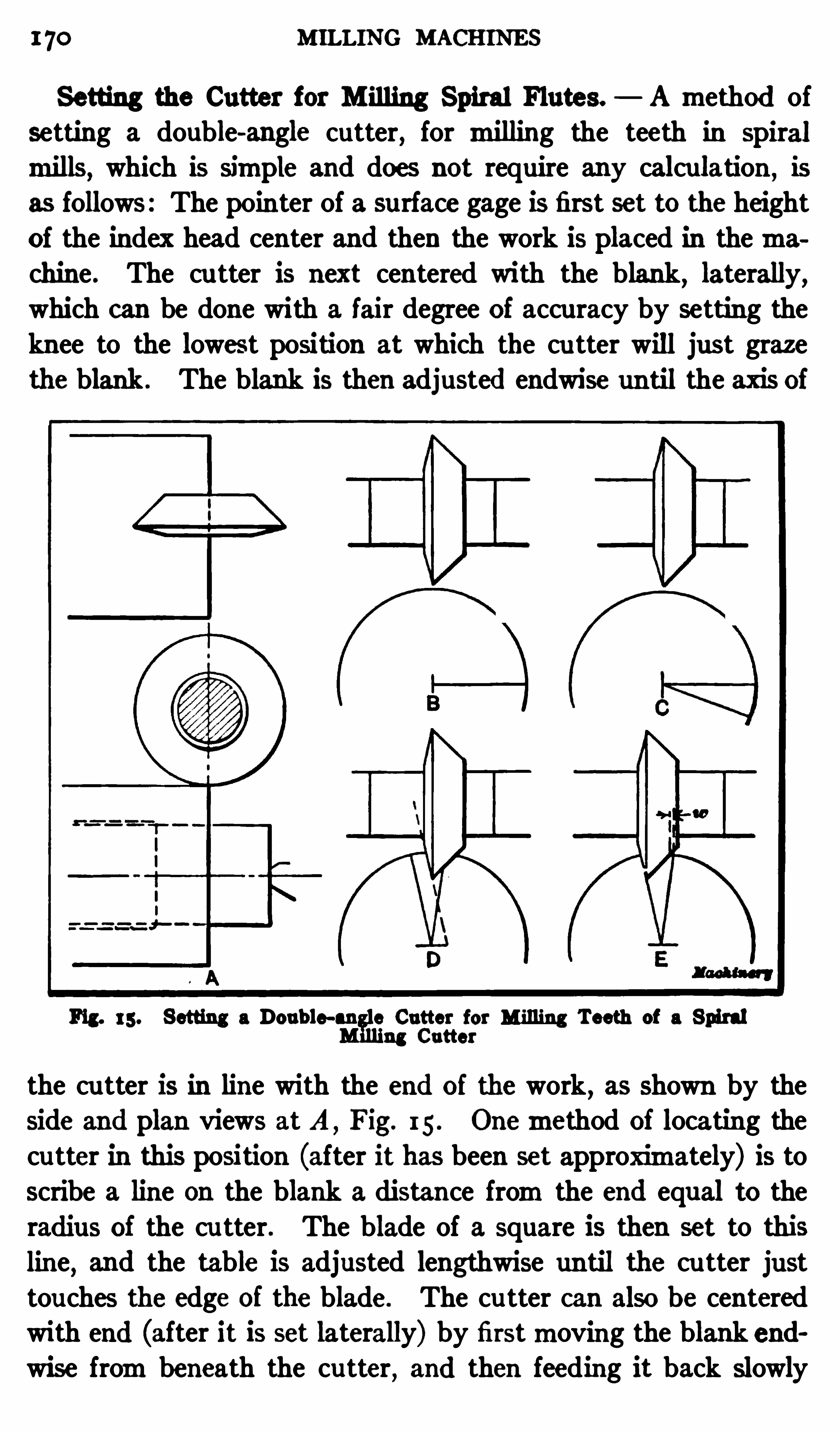
170 MILLING MACHINES
Setting the Cutter for M illing Spiral Flutes. A method ofsetting a double-angle cutter, for milling the teeth in Spiralmills, which is Simple and does not require any calcu lation , is
as follows: The pointer of a surface gage is first set to the height
of the index head center and then the work is placed in themachine . The cu tter is next centered with the blank
,laterally,
which can be done with a fair degree of accuracy by setting theknee to the lowest position at which the cu tter will just graze
the blank . The blank is then adjusted endwise until the axis of
Fig. 15 . Setting a Doub le-an e Cutter for Milling Teeth of a Spiralng Cutter
the cu tter is in line with the end of the work, as shown by the
side and plan views at A,Fig. 15 . Onemethod of locating the
cu tter in this position (after it has been set approximately) is toscribe a line on the blank a distance fromthe end equal to theradius of the cu tter. The blade of a square is then set to thisline, and the table is adjusted lengthwise until the cu tter justtouches the edge of the blade. The cu tter can also be centeredwith end (after it is set laterally) by firstmoving the blank endwise frombeneath the cutter
,and then feeding it back slowly
SPIRAL M ILLING 17 1
until a tissue paper feeler Shows that it just touches the comerof the blank . The relation between the cu tter and blank willthen be as Shown at A .
The table is next set to the angle of the spiral (as explainedlater) but its lengthwise position Should not be changed . Thesurface gage
,set as previously described , is then used to scribe
lines which represent one of the tooth spaces on the end of theblank where the cut is to start. This is done by first drawing ahorizontal line as at B . This line is then indexed downwardan amount equal to one of the tooth spaces , and another horizontal line is drawn as at C. The last line scribed is then indexed 90 1 2 degrees
,which locates itparallelwith the 12-degree
Side of the cu tter, as atD. The work is then adjusted laterally,
and vertically by elevating the knee, until the cu tter is so lo
cated that the 1 2-degree side cuts close to the scribed line, and,
at the same time,the required width of land w (see sketch E ) is
left between the top edge of the groove and the line representingthe front face of the next tooth .
Af ter the cu tter is centered,as at A ,
the longitudinal positionof the blank shou ld not be changed until the cu tter is set as at
E , because any lengthwise adjustment of the work would beaccompanied by a rotarymovement (as the spiral head is gearedto the table feed-screw) and the position of the lines on the end
would be changed .
Setting the Tab le to Angle of Spiral . The table of themachinemust also be set to the same angle that the spiral grooveswillmake with the axis of the work . This is done by looseningthe bolts which normally hold the saddle to the clamp-bed
,and
swinging the table around to the right position , as shown by thedegree graduations on the base of the saddle . The reason for
setting the work to this angle is to locate the cu tter in line withthe spiral grooves which are to bemilled by it. I f the cutterwere not in line with the spiral, the shape of the grooves would
not correspond with the shape of the cutter.The angle to which the table should be set, or the spiral angle,
varies according to the diameter of the work and lead of thespiral. AS the diameter of the cu tter illustrated in Fig. 1 2 is
1 72 M ILLING MACHINES
3} inches and the lead of the spiral is 48 inches, the angle is 12
degrees. The direction in which the table is turned dependsupon whether the spiral is right or left-hand . For a right-handspiral the right-hand end of the table should bemoved towardthe rear
,whereas if the spiral is left-hand, the left-hand end of
the table ismoved toward the rear.Milling Spiral Flutes. After the table of themachine is Set
to the requ ired angle and the saddle is clamped in position,the
work is ready to be milled . The actual milling of the spiralgrooves is practically the same as though they were straight orparallel to the axis. When a groove is milled
,it is well to
either lower the table slightly or turn the cu tter to su ch a positionthat the teeth will not drag over the work , when returning for
another cu t, to prevent scoring ormarring the finished groove.
If the work-table is lowered,it is returned to its original position
by referring to the dial on the elevating screw .
After each successive groove is cut,the work is indexed by
turning the indexing crank in the regular way. This operation
ofmilling a groove and indexing is repeated until all the teeth
are finished . I t should be mentioned that the difl'
erential
method of indexing cannot be employed in connec tion with Spiralwork
,because with this systemof indexing the worm-Shaft of
the spiral head is geared to the spindle. When milling spiralgrooves
,the position of the cu tter with relation to the work
should be such that the rotary movement for producing theSpiral will be toward that side of the cu tter which has thegreater angle. To illustrate
,the blank A
,Fig. 14, should turn
(as Shown by the arrow) toward the 48-degree Side of the cu tter,
as this tends to produce a smoother groove .
Calculating Change-gears for Spiral M illing . As was ex
plained in connection with Fig. 10,the lead of a Spiral cut in a
milling machine depends on the relation between the rotary
speed of the work and its longitudinal movement, and theserelative speeds are controlled by the change-gears a, b, c and d,
Fig. 1 1 , which connect the table feed-screw L with shaft W.
I f the combination of change-gears is such that 20 turns of sc rew
L are requ ired for one revolu tion of spindle S ,and the screw has

174 MILLING MACHINES
numbers of teeth in available gears. Suppose 8 is chosen for
the secondmultiplier; we then have
i x i = i
The set of fractions obtained in this way, that is, H; and i i :represents the gears to use formilling a spiral having a lead of12 inches . The numerators equal the number of teeth in thedriven gears , and the denominators the number of teeth in the
driving gears . If numbers oc cu rred in either fraction which didnot correspond with the number of teeth in any of the changegears available
,the fraction should bemultiplied by some other
trial number until the desired result is obtained .
Relative Positions of the Change-gears . When the gears forcu tting a given Spiral are known ,
it remains to plac e theminthe proper place on themachine , and in order to do this, the distinction between driving and driven gears should be understood.
The gear a (Fig. 1 1) on the feed-screw is a driver and gear b,which is rotated by it
,is driven . Similarly , gear c is a driver
and gear d is driven . As the numerators of the fractions represent driven gears
,one having either 7 2 or 32 teeth (in this in
stance) should be placed on shaft W. Then a driving gear witheither 40 or 48 teeth is placed on stud E and the remainingdriven gear is afterwardsmounted on the same stud . The otherdriving gear is next placed on the screw L and yoke Y is adjusteduntil the gears mesh properly . The spiral head will then begeared for a lead of 1 2 inches
,the gear on the wormhaving 72
teeth,the first gear on the stud having 40 teeth , the second gear
having 32 teeth , and the gear on the screw having 48 teeth .
E ither the driving or driven gears could be transposed withoutchanging the lead of the spiral. For example, the driven gearwith 32 teeth could be placed on shaft W and the one having
72 teeth could be used as a second gear on the stud, if such an
arrangement were more convenient. As previously stated,a
reverse or idler gear is inserted in the train when cutting lefthand spirals
,bu t it does not affect the ratio of the gearing.
Determining the Helix or Spiral Angle. When the changegears for a given Spiral have been selected, the next step is to
SP IRAL MILLING 175
determine the angle to which the table of themachinemust beset in order to bring the milling cu tter in line with the spiral.This angle equals the angle that the spiralmakes with its axis
and it depends upon the lead of the spiral and the diameter ofthe cylindrical part to bemilled . The angle of a spiral can bedetermined graphically by drawing a right-angle triangle as
shown by sketch C,Fig. 10 . If the length e of one side equals
the circumference of the cylinder on which the Spiral is to begenerated, and the base L equals the lead, the angle a will bethe spiral angle . If such a triangle is wrapped around the
cylinder, the hypothenuse will follow a helical curve,as the
illustration indicates .
Another way of determining the angle of a spiral is to first getthe tangen t of the angle by dividing the circumference of thework by the lead of the spiral. When the tangent is known ,
thecorresponding angle is found by referring to a table of naturaltangents. For example
,if the circumference e is 1 2 inches
, and
the lead L is 48 inches, the tangen t equals 13 and the
angle a corresponding to this tangent is abou t 14 degrees. Evi
dently, if the circumference is increased or diminished, therewill be a corresponding change in angle a provided the lead Lremains the same. For that reason
,the ou ter circumference
is not always taken when calculating the spiral angle. The
angle for setting the table when cu tting spiral gears in amillingmachine is determined by taking the diameter either at the
pitch circle,or at some point between the pitch circle and the
bottoms of the teeth , rather than the ou tside diameter, in orderto sec ure teeth of the proper Shape .
Cutting Spiral Grooveswith an EndMill.— When a spiral groovehaving parallel sides is required it shou ld be cutwith an endmillas illustrated in Fig. 16. If an attempt were made to mill agroove of this kind by u sing a Sidemillmounted on an arbor, thegroove would not have parallel sides
,because the side teeth of the
mill would not clear the groove; in other words, they wou ld cu t
away the sides owing to the rotarymovement of the work and
forma groove having a greater width at the top than at the bot
tom. This can be overcome,however
,by using an endmill.
176 M ILLING MACHINES
Themachine is geared for the required lead of spiral, as pre
viously explained , and the work is adjusted vertically until its
axis is in the same horizontal plane as the center of the endmill.With the machine illustrated , this vertical adjustment can beobtained bymoving the knee up until its top surface coincides
with a line on the columnmarked center; the index head centerswill then be at the same height as the axis of themachine spindle.Use of Chuck on the Spiral Head. I t is often nec essary to
use a Spiral-head in connection withmilling of parts which can
Fig. 16. M illing a Spiral Groove with an End M ill
not be held between centers and must be attached directly tothe spiral-head spindle. A common method of holding work ofthis kind is to place it in a chuckwhich is screwed on to the spiralhead spindle. An example of chu ck work is shown in Fig. 17 .
The operation is that of milling a square head on bolt B . As
the illustration shows,the Spiral-head spindle is set in a vertical
position . This is done by loosening the clamp bolts C and tuming the head 90 degrees, as Shown by the graduations on thefron t Side. These bolts shou ld afterwards be tightened.

178 MILLING MACHINES
Spiral-head spindle . The footstock center is used to supportwork of this class whenever feasible . When it is neces sary to
hold a part true with a bored hole,arbors of the expanding type
are often used . These have a taper shank which fits the taper
hole in the spindle, and the ou ter end is so arranged that it canbe expanded tightly into the hole in the work . Small chucks ofthe collet type are sometimes used for holding small parts
,in
stead oi a jaw chuck.
Attachments for the M illing Machine. The range of amillingmachine or the variety of work it is capable of doing can be
greatly extended by the use of special attachments . Many of
these are designed to enable a certain type ofmillingmachine toperformoperations that ordinarily would be done on a differen t
machine; in other words, the attachment temporarily convertsone type of machine into another. There are quite a numberof different attachments for themillingmachine, some of whichare rarely used in the average Shop. There are, however, threetypes that are quite common; namely, the vertical spindlemilling attachment, the slotting attachment and the circular milling and dividing attachment.Vertical M illing Attachment. The way a vertical spindle
milling attachment is applied to a horizontalmillingmachine isshown in Fig. 18. The base of the attachment is securelyclamped to the column of the machine by four bolts and the
ou ter end is inserted in the regular arbor support. The spindle
is driven through bevel gears connecting with a horizontal Shaft
inserted in themain spindle of themachine . The spindle of
this particular attachment can be set at any angle in a verticalor horizontal plane, and its position is Shown by graduationsreading to degrees.
For the operation illustrated , which is that ofmilling the edgeof the steel block shown
,the spindle is set at an angle of 45 de
grees fromthe vertical. The block is held in an ordinary vise
and it is fed past the cu tter by using the cross-feed. The oppositeedge ismilled by Simply swinging the spindle 45 degrees to theright of the vertical. Vertical attachments are used in connec
tion with horizontalmachines whenever it is desirable to have
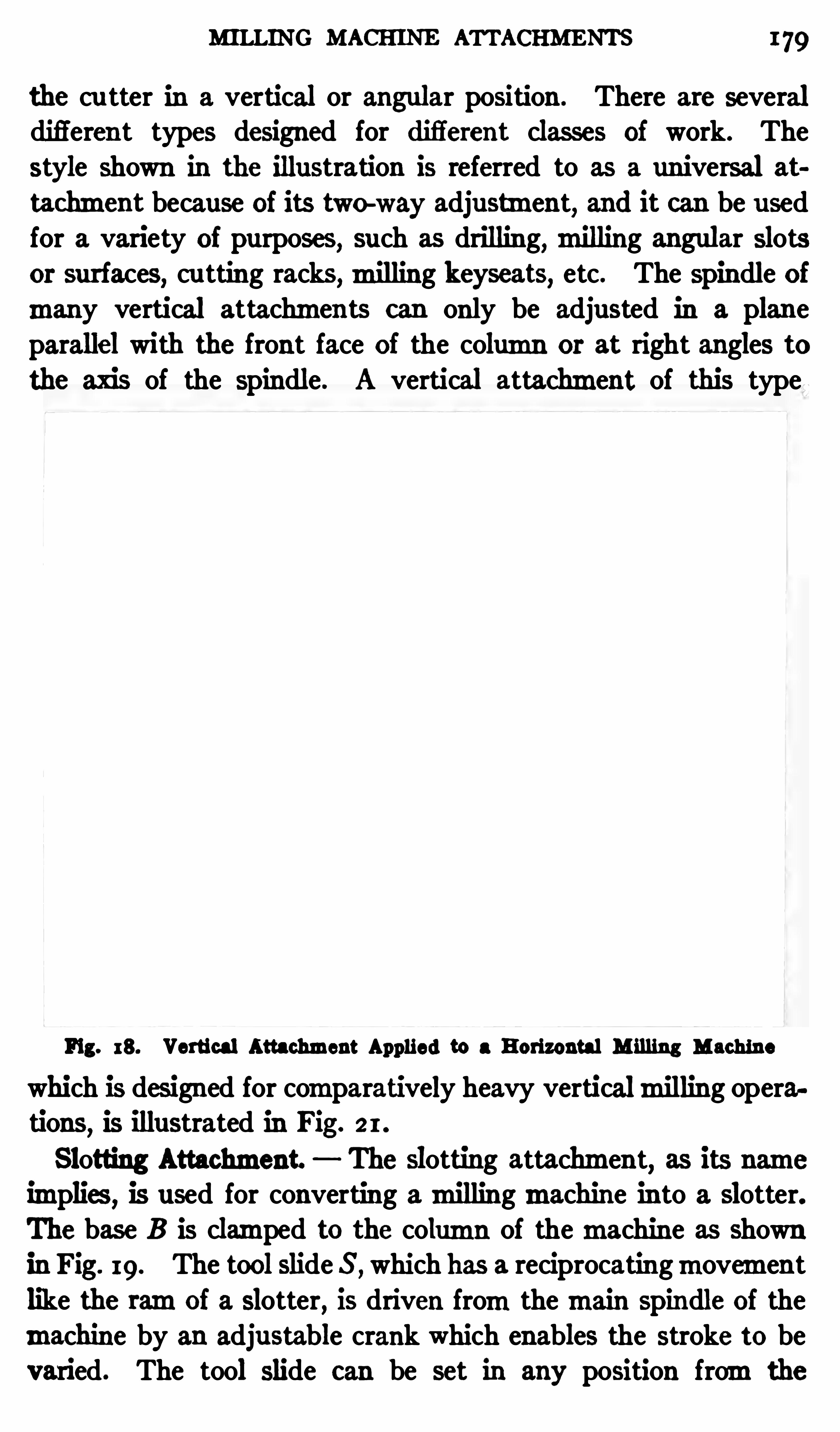
MILLING MACHINE ATTACHMENTS 179
the cu tter in a vertical or angular position . There are severaldifferent types designed for diflerent classes of work. The
style shown in the illustration is referred to as a universal at
tachment because of its two-way adjustment,and it can be u sed
for a variety of purposes,such as drilling,milling angu lar slots
or surfaces,cu tting racks,milling keyseats, etc. The spindle of
many vertical attachments can only be adjusted in a planeparallel with the front face of the column or at right angles to
the axis of the spindle. A vertical attachment of this type
Fig. 18. Vertical Attachment Applied to a Horizontal M illing Machine
which is designed for comparatively heavy verticalmilling operations
,is illustrated in Fig. 2 1 .
Slotting Attachment. The Slotting attachment, as its name
implies,is used for converting amillingmachine in to a slotter.
The base B is clamped to the column of themachine as shownin Fig. 19. The tool slide S ,
which has a reciprocatingmovementlike the ramof a slotter, is driven fromthemain spindle of themachine by an adjustable crank which enables the stroke to bevaried. The tool Slide can be set in any position fromthe
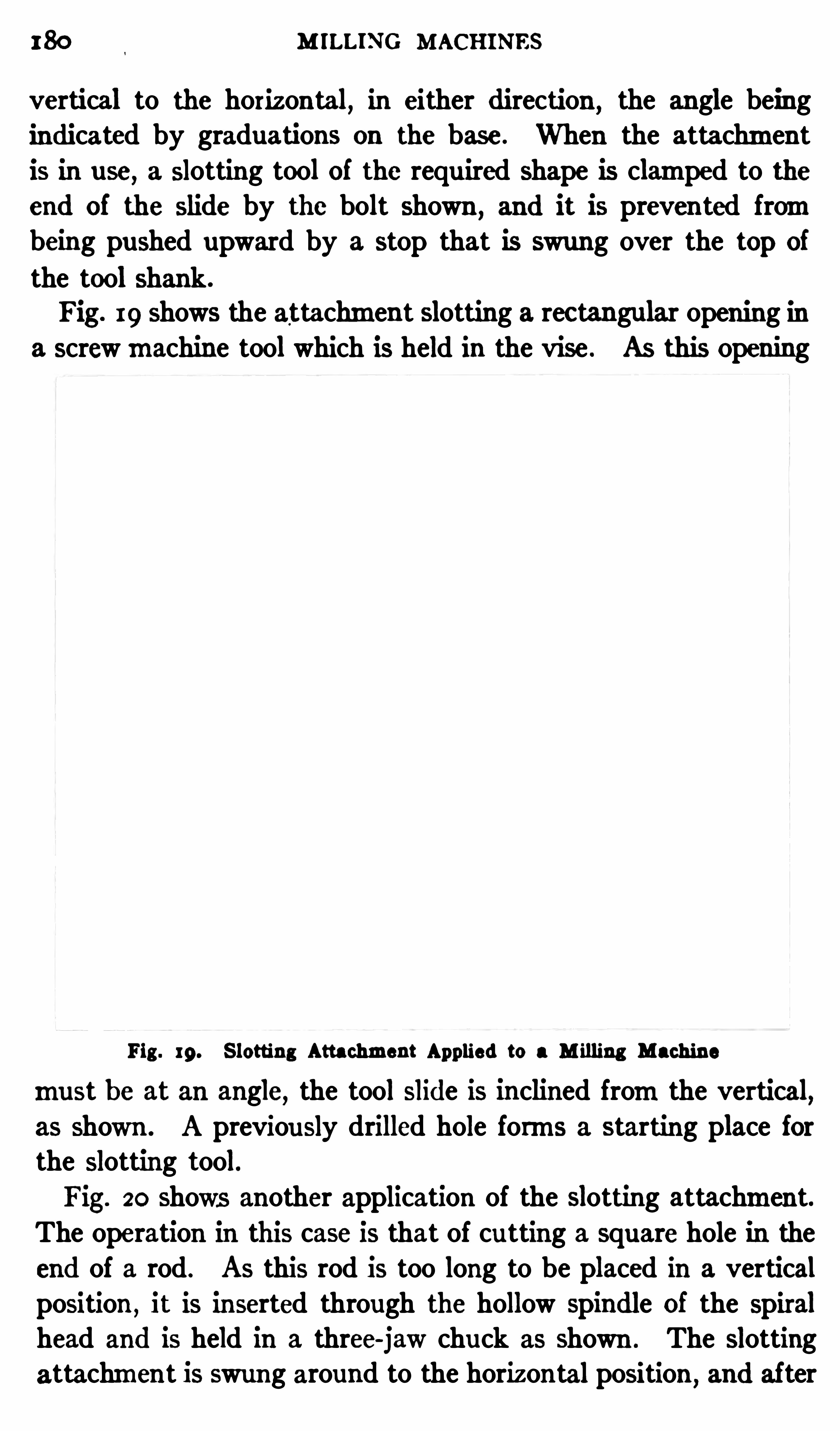
180 M ILLING MACHINES
vertical to the horizontal, in either direction , the angle being
indicated by graduations on the base. When the attachmentis in use
,a slotting tool of the requ ired shape is clamped to the
end of the slide by the bolt shown ,and it is preven ted from
being pushed upward by a stop that is swung over the top of
the tool shank.
Fig. 19 shows the attachment slotting a rec tangular opening ina screwmachine tool which is held in the vise . AS this Opening
Fig . 19. S lotting Attachment Applied to a M illing Machine
mu st be at an angle,the tool Slide is inclined fromthe vertical,
as shown . A previously drilled hole forms a starting place forthe slotting tool.Fig. 20 shows another application of the Slotting attachment.
The operation in this case is that of cu tting a square hole in theend of a rod . As this rod is too long to be placed in a verticalposition ,
it is inserted through the hollow spindle of the spiralhead and is held in a three-jaw chuck as shown . The Slottingattachment is swung around to the horizontal position
,and after

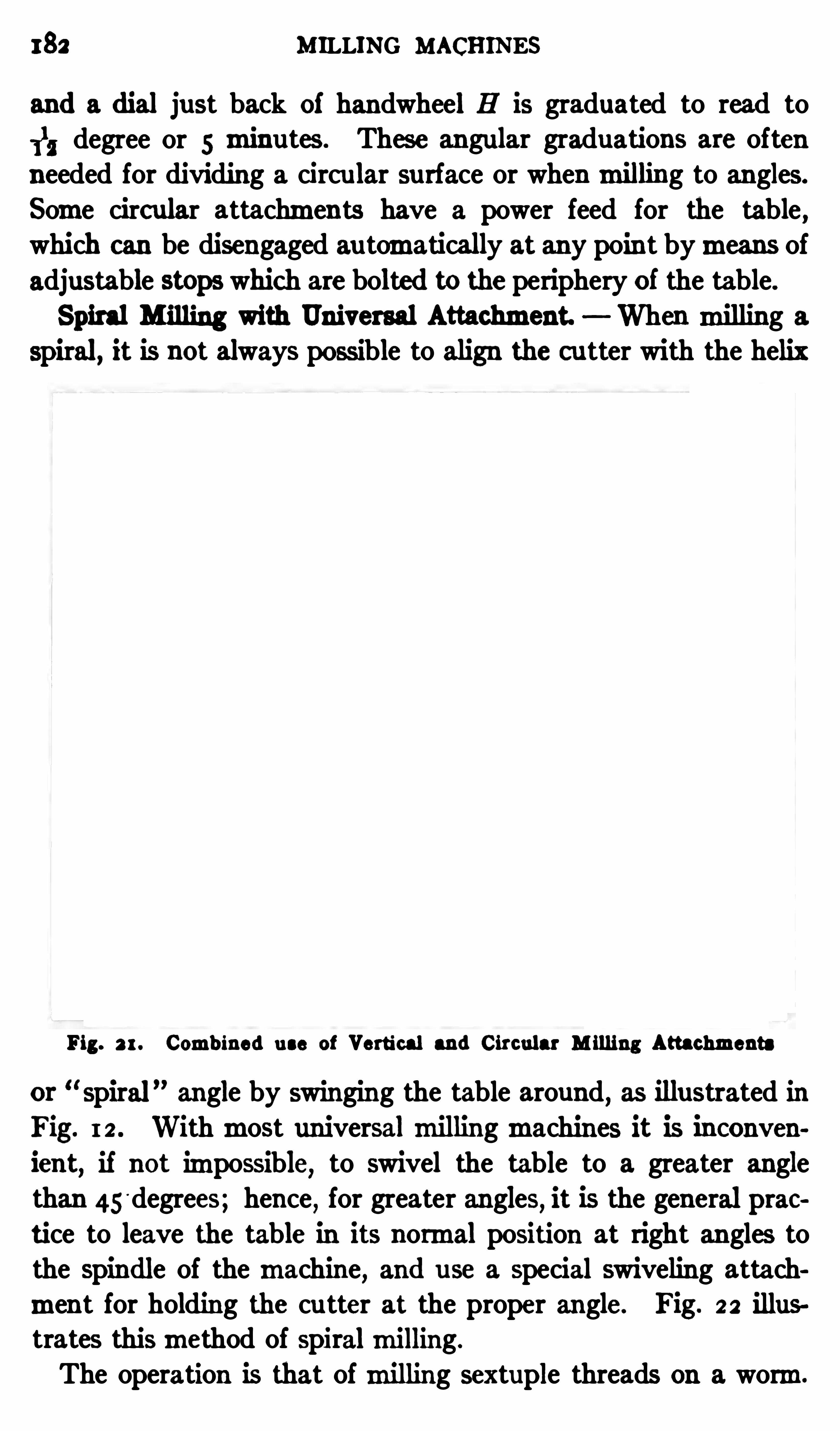
182 MILLING MACHINES
and a dial just back of handwheel H is graduated to read to
11, degree or 5 minutes . These angular graduations are often
needed for dividing a circu lar surface or whenmilling to angles.
Some circular attachments have a power feed for the table ,which can be disengaged au tomatically at any poin t bymeans ofadjustable stOps which are bolted to the periphery of the table.
Spiral Milling with Universal Attachment. When milling a
spiral, it is not always possible to align the cutter with the helix
Fig. 2 1 . Comb ined u se of Vertical and Circular M illing Attachments
or spiral angle by swinging the table around, as illustrated in
Fig. I 2 . Withmost universalmillingmachines it is inconvenient
,if not impossible
,to swivel the table to a greater angle
than 45'degrees; hence for greater angles, it is the general prac
tice to leave the table In its normal position at right angles tothe spindle of themachine, and u se a special swiveling attachment for holding the cu tter at the proper angle. Fig. 2 2 illus
trates thismethod of spiralmilling.
The operation is that ofmilling sextuple threads on a worm.
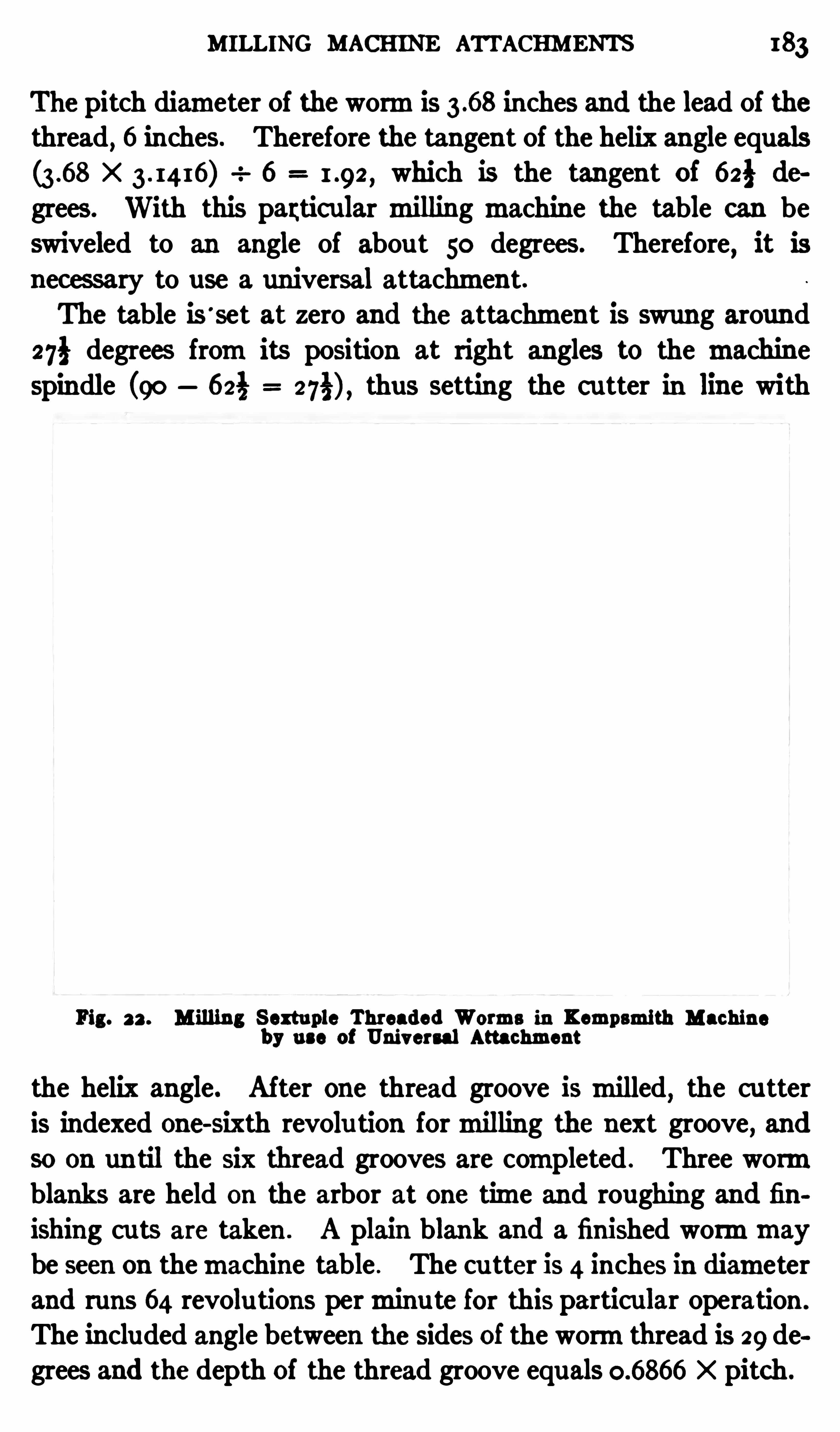
MILLING MACHINE ATTACHMENTS 183
The pitch diameter of thewormis inches and the lead of thethread
, 6 inches. Therefore the tangent of the helix angle equalsX 6 which is the tangent of 62} de
grees. With this partic ular milling machine the table can beswiveled to an angle of abou t 50 degrees. Therefore, it is
necessary to use a universal attachment.The table is ’
set at zero and the attachment is swung around
27} degrees fromits position at right angles to the machinespindle (90 623 thus setting the c utter in line with
Fig. 22 . Milling S extuple Threaded Worms in Kempsmlth Machineby use of Universal Attachment
the helix angle. After one thread groove ismilled,the cu tter
is indexed one-sixth revolu tion formilling the next groove, and
so on un til the Six thread grooves are completed . Three wormblanks are held on the arbor at one time and roughing and finishing cu ts are taken . A plain blank and a finished wormmaybe seen on themachine table . The cu tter is 4 inches in diameterand runs 64 revolu tions perminu te for this particu lar operation .
The included angle between the sides of the wormthread is 29 degrees and the depth of the thread groove equals X pitch.
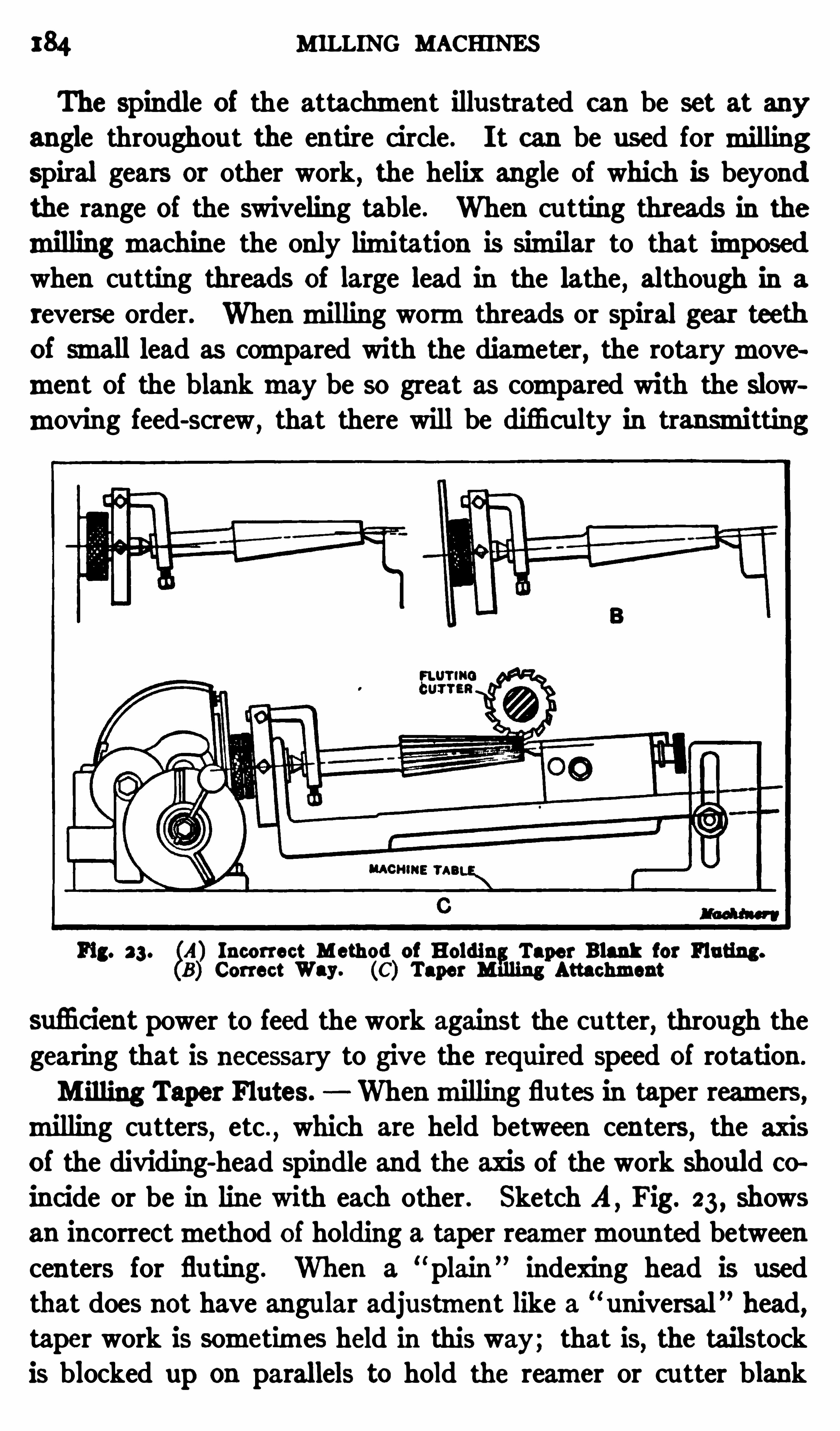
184 MILLING MACHINES
The spindle of the attachment illustrated can be set at any
angle throughout the entire circle. I t can be used formillingspiral gears or other work, the helix angle of which Is beyond
the range of the swiveling table . When cu tting threads in the
millingmachine the only limitation is similar to that imposedwhen cutting threads of large lead in the lathe , although in a
reverse order. Whenmilling wormthreads or Spiral gear teethof small lead as compared with the diameter, the rotarymovement of the blankmay be so great as compared with the slowmoving feed-screw
,that there will be difficu lty in transmitting
Fig. 23. 5A) Incorrect M ethod of Holdin Taper Blank for Fluting.
B) Correct Way. (C) Taper MfiIing Attachment
sufi cient power to feed the work against the cu tter,through the
gearing that is necessary to give the required speed of rotation .
Milling Taper Flutes. Whenmilling flu tes in taper reamers,milling cu tters
,etc .
,which are held between centers
,the axis
of the dividing-head spindle and the axis of the work should co
incide or be in line with each other . Sketch A ,Fig. 23 , Shows
an incorrectmethod of holding a taper reamermounted betweencenters for fluting. When a
“ plain ”indexing head is used
that does not have angular adjustment like a “universal” head,
taper work is sometimes held in this way; that is, the tailstockis blocked up on parallels to hold the reamer or cu tter blank

186 MILLING MACHINES
same amount for each indexing and equal flutes aremilled;moreover, there is no movement of the dog relative to the driver
plate.
A simplemethod of aligning the reamer or cutter blank withthe dividing-head spindle is as follows : P lace the dog in a
vertical position and adjust it un til the end of the tail or driv
ing armjust touches the driver plate at the top; then index thedriver plate one-half revolution and againmake a test. If there
is space between the dog and driver plate, the tailstock center
is too high; inversely, if the dog bears heavily at the bottom,
the tailstock center is too low and should be adjusted accordingly
to secure an even contact at both top and bottom.
TaperMilling Attachment. Sketch C,Fig. 23 , shows a special
attachment for tapermilling. With this attachment, alignmentbetween the dividing-head spindle
,work
,and tailstock center is
assured and the desired angular setting can be obtained easily.
One end of the attachment is secured to the spindle of the dividing head and the Opposite end is bolted to a slotted knee
clamped to the table of themachine. This knee is graduatedto correspond with the graduations on the spiral head . Thefootstock of the attachment can be adjusted along a T-slot tosuit the length of the work . An attachment of this kind is
especially desirable when there is considerable tapermilling tobe done .
In determining the angular position of the work and dividinghead for milling taper reamers
,etc .
,the number of angles in
volved usually makes the calculation difficult and,ordinarily,
the setting can be obtained by the “c ut-and-try ”method in less
time than is required to compute the angle . When using a
single-angle cu tter for flu ting reamers, the angle of inclinationcan be determined by using the rule given in the paragraphheaded “M illing Angular Cu tters .
Multiple Index Centers. Multiple index centers are oftenused in preference to the single-spindle type
,for such operations
as fluting taps and reamers ,milling nu ts, cu tting small gears, orfor similar work . A design of multiple index center that iscommon has three parallel spindles which are geared together
COMPENSATING DOG OR DRIVER 187
and are indexed in unison . There are also three footstock cen ters
in alignment with the dividing-head spindles . Obviously, withcenters of this type three reamers or other parts can bemilledat the same time by using a gang of three cutters. For taper
milling,multiple index centers aremade with an independent
base or table which can be elevated to the required angle,the
same as the taper attachment illustrated at C in Fig. 23 .
Compensating Dog or Driver. When a taper part is heldbetween centers as illustrated at A , Fig. 23 , it is well to use
what is known as a compensating dog or driver,instead of the
ordinary type , in order to securemore accu rate indexing. The
Fig. 3 5 . Compensating Di'iver which Practically Eliminates Errorwhen Indexing Taper Work
compensating dog,which is illustrated in Fig. 25, has a forked
armwhich is secu red to the dividing-head spindle. This armisengaged by a ball-shaped partmounted on the cylindrical endof the driver. The latter is clamped in such a position that thecenter of the cylindrical driving end is approximately in linewith the end of the work. The ball fits closely between the
curved surfaces of the forked armand adjusts itself as the relation between the driver and armchange owing to the angularitybetween the axes of the work and the index spindle. The forkedarmc an b e adjusted to take up all play between the ball and thecurved surfaces of the slot which it engages . As the driving is
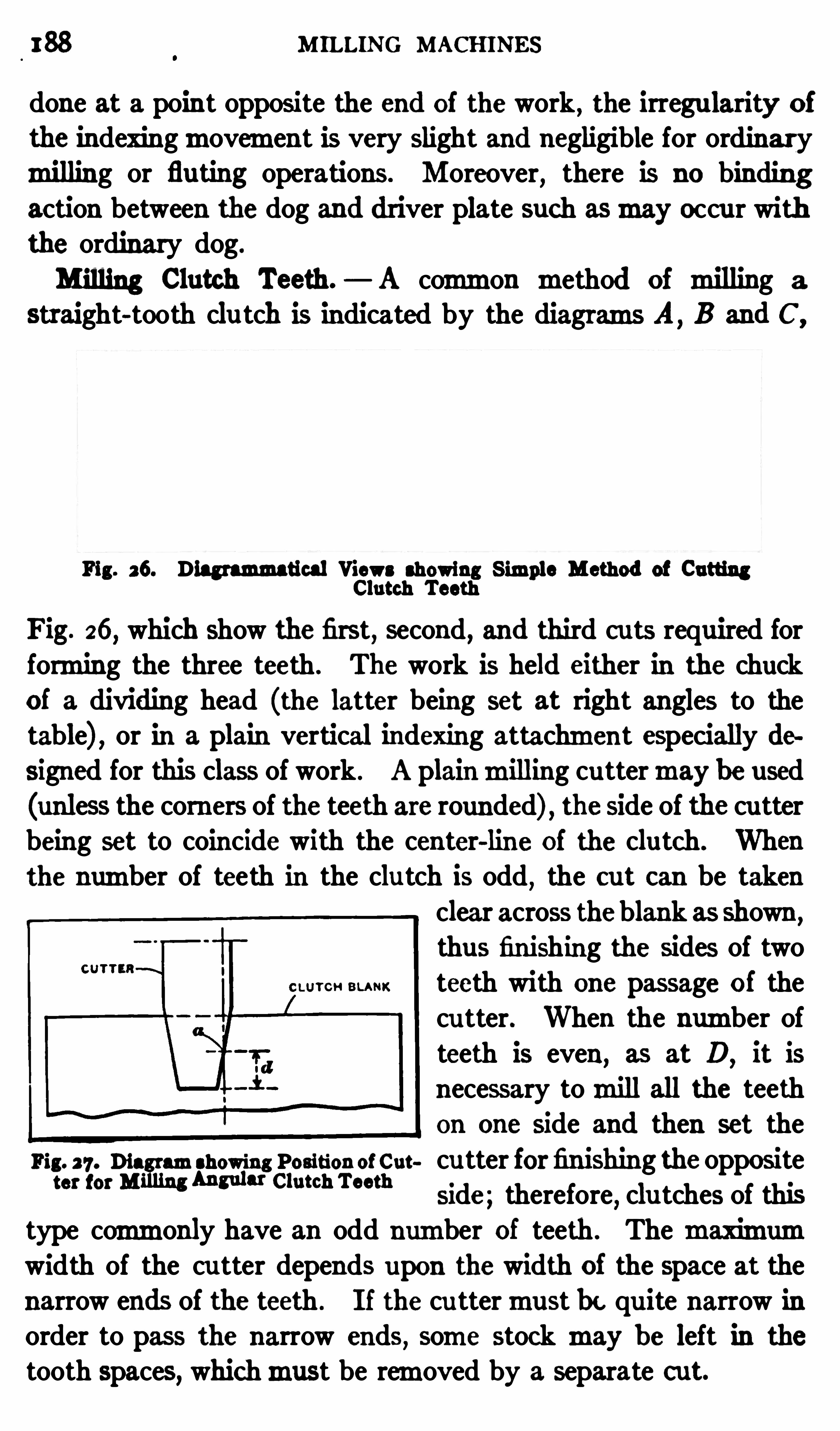
188 M ILLING MACHINES
done at a point opposite the end of the work, the irregularity of
the indexingmovement is very slight and negligible for ordinarymilling or fluting operations. Moreover
,there is no binding
action between the dog and driver plate such asmay occur withthe ordinary dog.
Milling Clutch Teeth. A common method of milling a
straight-tooth clu tch is indicated by the diagrams A,B and C ,
Fi 26. Diagrammatical Views showing S im e Method of Cutting8Clutch Teeth
pi
Fig. 26, which Show the first, second, and third cu ts required forforming the three teeth . The work is held either in the chuck
of a dividing head (the latter being set at right angles to thetable) , or in a plain vertical indexing attachment especially designed for this class of work . A plainmilling cu ttermay be used(unless the comers of the teeth are rounded) , the side of the cu tterbeing set to coincide with the center-line of the clutch. Whenthe number of teeth in the clu tch is odd
,the out can be taken
clear across theblank as shown ,
thus fin ishing the sides of twoteeth with one passage of thecu tter. When the number ofteeth is even, as at D
,it is
necessary tomill all the teethon one side and then set the
Fig. 27 . Dia amshowing Position of Cut cu tter forfinishing the oppositet" mM Mm“ emchTm”
side; therefore, clu tches of thistype commonly have an odd number of teeth . The maximumwidth of the cu tter depends upon the width of the space at the
narrow ends of the teeth . I f the cu ttermust be qu ite narrow inorder to pass the narrow ends
,some stock may be left in the
tooth spaces, whichmust be removed by a separate c ut.

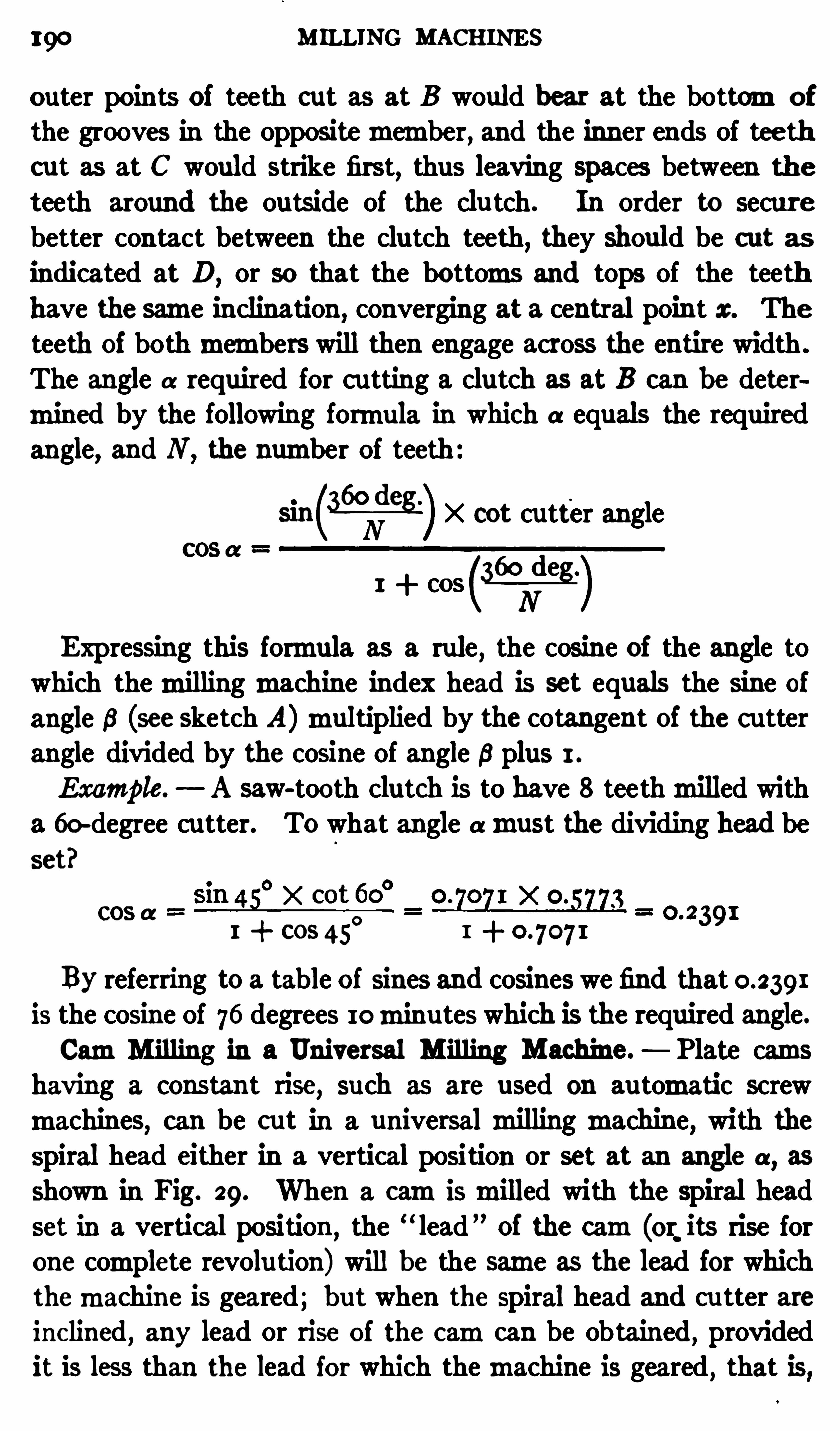
190 MILLING MACHINES
outer points of teeth cut as at B would hear at the bottomof
the grooves in the Oppositemember, and the inner ends of teethcut as at C would strike first
,thus leaving spaces between the
teeth around the outside of the clu tch . In order to securebetter contact between the clutch teeth
, they should be cut asindicated at D
, or so that the bottoms and tops of the teethhave the same inclination , converging at a central point x. The
teeth of bothmembers will then engage across the entire width .
The angle a required for c utting a clutch as at B can be determined by the following formula in which a equals the required
angle, and N ,the number of teeth
meg-97325) X cot cutter angle
1 + cases )Expressing this formula as a rule
,the cosine of the angle to
which themillingmachine index head is set equals the sine ofangle 6 (see sketch A)multiplied by the cotangent of the c utterangle divided by the cosine of angle 8 plus 1 .
Example. A saw-tooth clutch is to have 8 teethmilled witha 60-degree cutter. T0 what angle amust the dividing head beset"
COS aI cos 45
°
1
By referring to a table of sines and cosines we find thatis the cosine of 76 degrees 10minu tes which is the required angle.CamMilling in 9. Universal Milling Machine. P late cams
having a constant rise,such as are used on automatic screw
machines, can be cut in a universalmillingmachine,with the
spiral head either in a vertical position or set at an angle a,as
Shown in Fig. 29. When a camismilled with the spiral head
set in a vertical position,the “
lead ” of the cam(01_ its rise forone complete revolu tion) will be the same as the lead for whichthemachine is geared; but when the spiral head and cu tter areinc lined, any lead or rise of the camcan be obtained
,provided
it is less than the lead for which themachine is geared , that is,
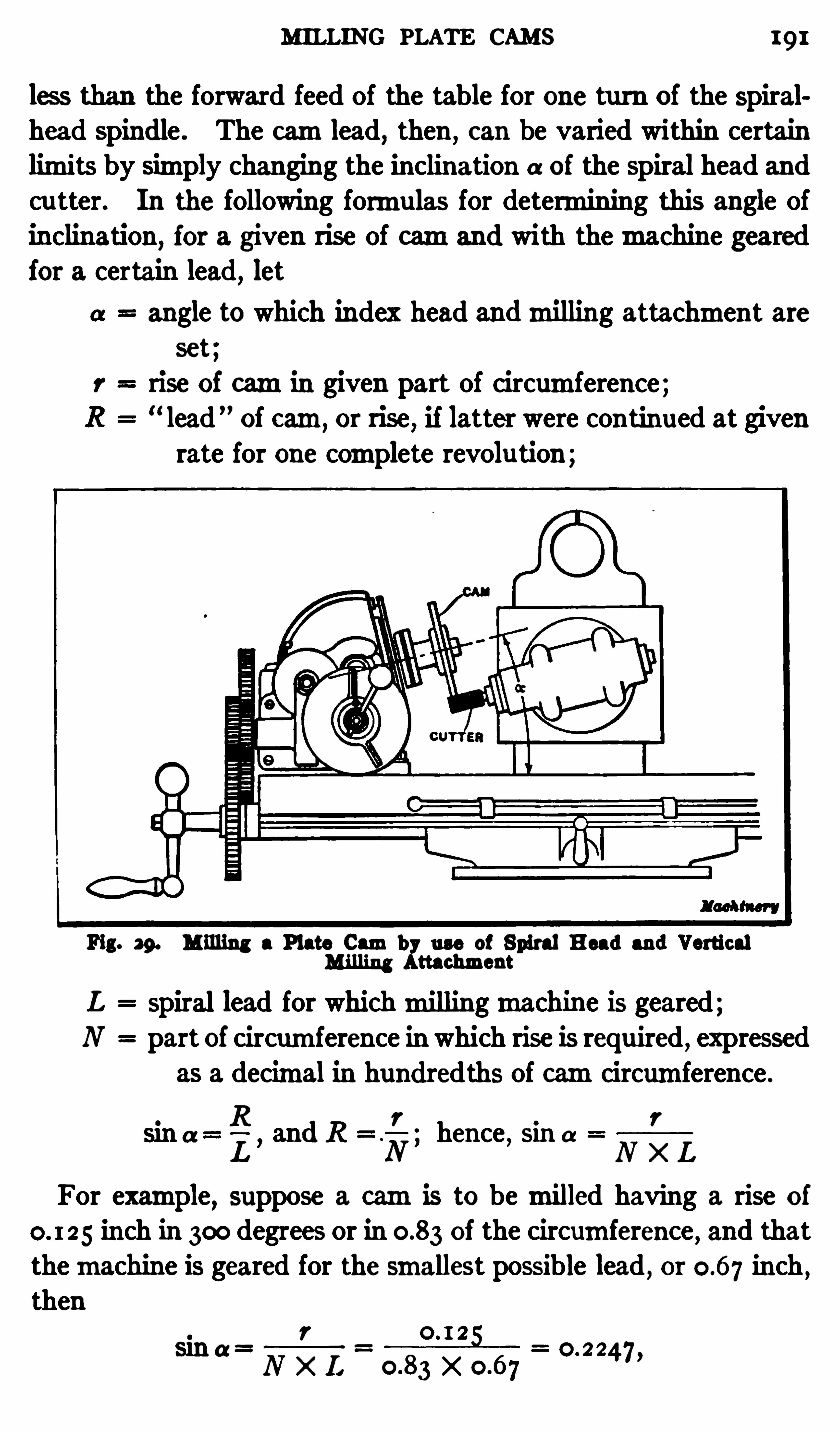
MILLING PLATE CAMS 191
les s than the forward feed of the table for one turn of the spiralhead spindle . The camlead, then ,
can be varied within certainlimits by simply changing the inclination a of the spiral head andcu tter. In the following formulas for determining this angle ofinclination , for a given rise of camand with themachine gearedfor a certain lead
,let
angle to which index head andmilling attachment areset;
rise of camin given part of circumference;“lead ” of cam
,or rise
,if latter were continued at given
rate for one complete revolu tion ;
Fig. 29. M illing a Plate Cambl
use of Spiral Head and VerticalM illing ttachment
L spiral lead for whichmillingmachine is geared;N part of circumference in which rise is required , expressed
as a decimal in hundredths of camcircumference .
R r r
L’and R '
N’hence
,sma
N X L
For example,suppose a camis to bemilled having a rise of
inch in 300 degrees or in of the circumference,and that
themachine is geared for the smallest possible lead , or inch,
thenr
N X L Xsin a =
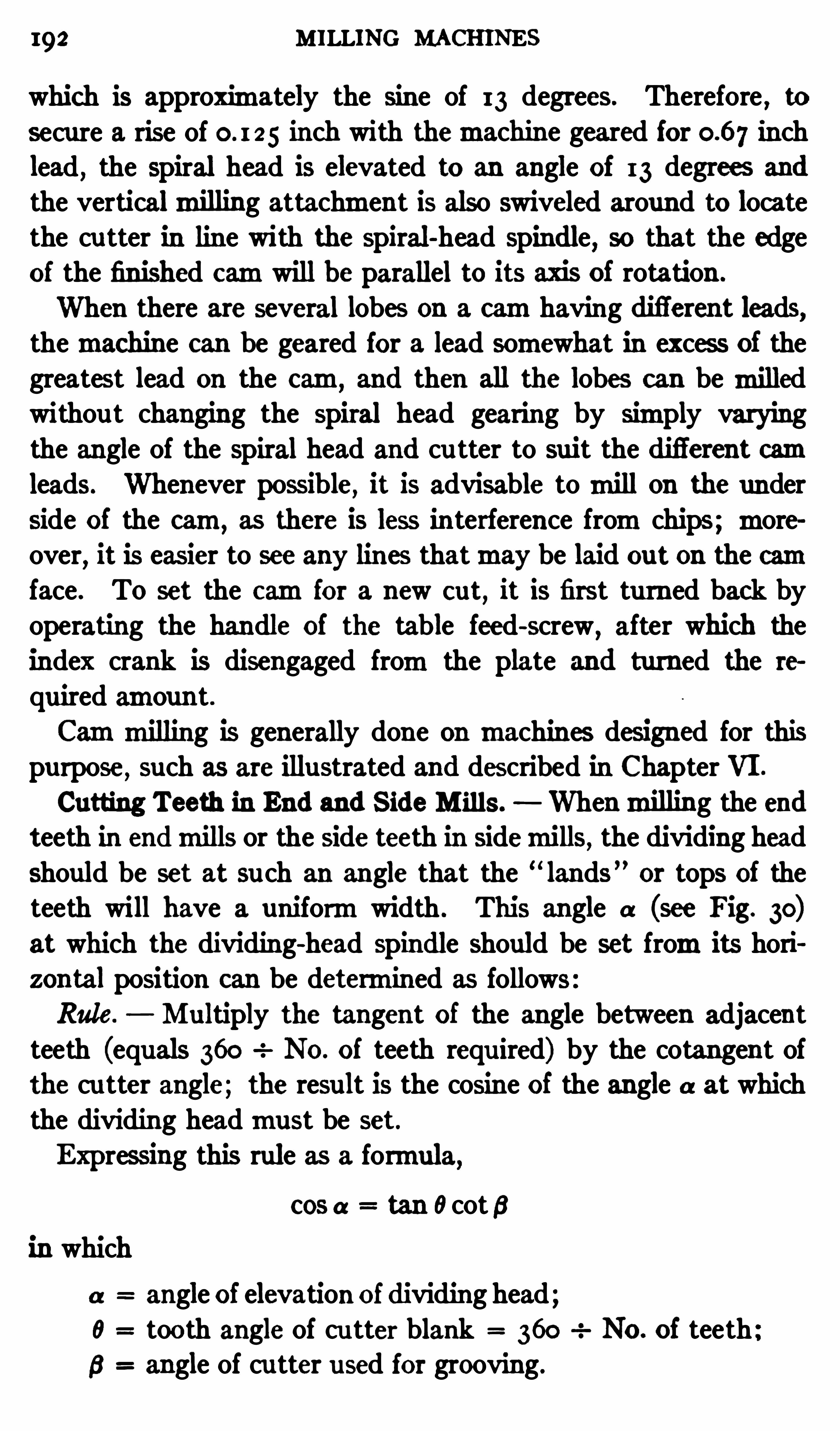
192 MILLING MACHINES
which is approximately the Sine of I 3 degrees. Therefore,to
secure a rise of 5 inch with themachine geared for inchlead
,the Spiral head is elevated to an angle of I 3 degrees and
the verticalmilling attachment is also swiveled around to locatethe cutter in line with the spiral -head spindle
,so that the edge
of the finished camwill be parallel to its axis of rotation .
When there are several lobes on a camhaving difl'erent leads,themachine can be geared for a lead somewhat in excess of thegreatest lead on the cam and then all the lobes can bemilledwithou t changing the spu d head gearing by Simply varyingthe angle of the spiral head and cu tter to suit the diflerent camleads. Whenever possible, it is advisable tomill on the under
Side of the cam,as there is less interference fromchips;more
over,it is easier to see any lines thatmay be laid out on the cam
face. T0 set the camfor a new cut, it is first tu rned back byoperating the handle of the table feed-screw
,after which the
index crank is disengaged fromthe plate and turned the re
quired amount .
Cammilling is generally done on machines designed for thispurpose
,such as are illustrated and described in Chapter VI .
Cutting Teeth in End and S ide M ills. Whenmilling the endteeth in endmills or the side teeth in Sidemills, the dividing headshould be set at su ch an angle that the “
lands ” or tops of theteeth will have a uniformwidth . This angle a (see Fig. 30)at which the dividing-head Spindle should be set fromits horizontal position can be determined as follows:Rule. Mu ltiply the tangent of the angle between adjacent
teeth (equals 360 No. of teeth requ ired) by the cotangent ofthe cu tter angle; the result is the cosine of the angle a at whichthe dividing headmust be set.
Expressing this rule as a formula,cos a tan 0cotB
in which
a angle of elevation of dividing head;0 tooth angle of cu tter blank 360 No. of teeth
6 angle of cu tter used for grooving.

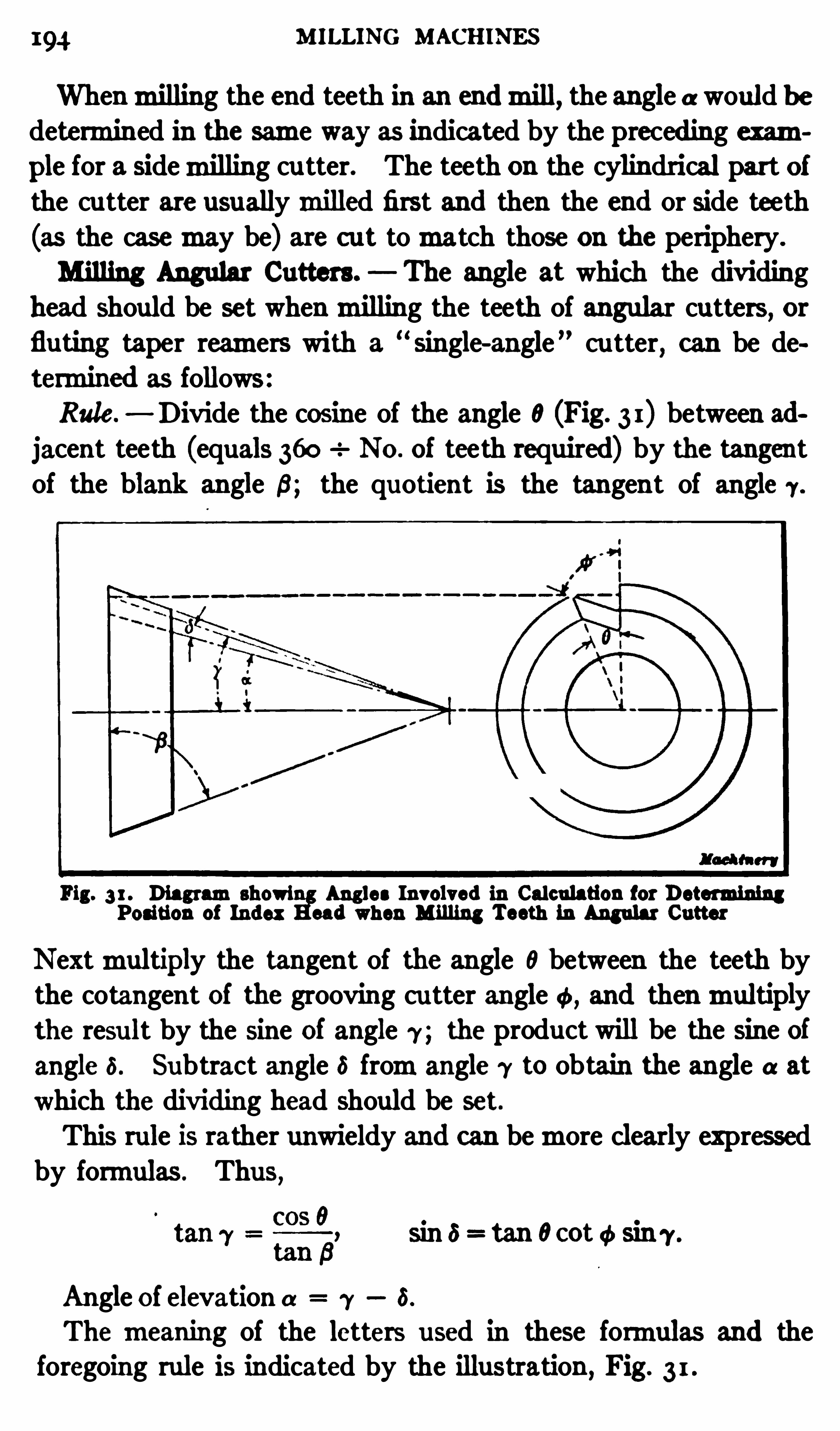
4 M ILLING MACHINES
Whenmilling the end teeth in an endmill, the angle aswould bedetermined in the same way as indicated by the preceding example for a sidemilling cu tter. The teeth on the cylindrical part ofthe cutter are usuallymilled first and then the end or side teeth(as the casemay be) are c ut tomatch those on the periphery.
Milling Angular Cutters. The angle at which the div iding
head should be set whenmilling the teeth of angular cutters, orfluting taper reamers with a
“single-angle ” cu tter
, can be de
termined as follows:Rule.
— Divide the cosine of the angle 0(Fig. 3 1) between adjacent teeth (equals 360 No . of teeth required) by the tangentof the blank angle 8; the quotient is the tangent of angle 7 .
Fig. 3 1 . Diagramsho Angles Involved in Calculation for DetPosition of Index sad when Milling Teeth in Angular Cutter
Nextmultiply the tangent of the angle 0between the teeth bythe cotangent of the grooving cu tter angle and thenmultiplythe resu lt by the Sine of angle 7 ; the product will be the sine of
angle 5 . Subtract angle 6 fromangle 7 to obtain the angle a at
which the dividing head should be set.
This rule is rather unwieldy and can bemore clearly expressedby formulas . Thus
,
sin 6= tan 0cot ¢ sin 7 .
Angle of elevation (1 7 6.
Themeaning of the letters used in these formulas and theforegoing rule is indicated by the illustration , Fig. 3 1 .
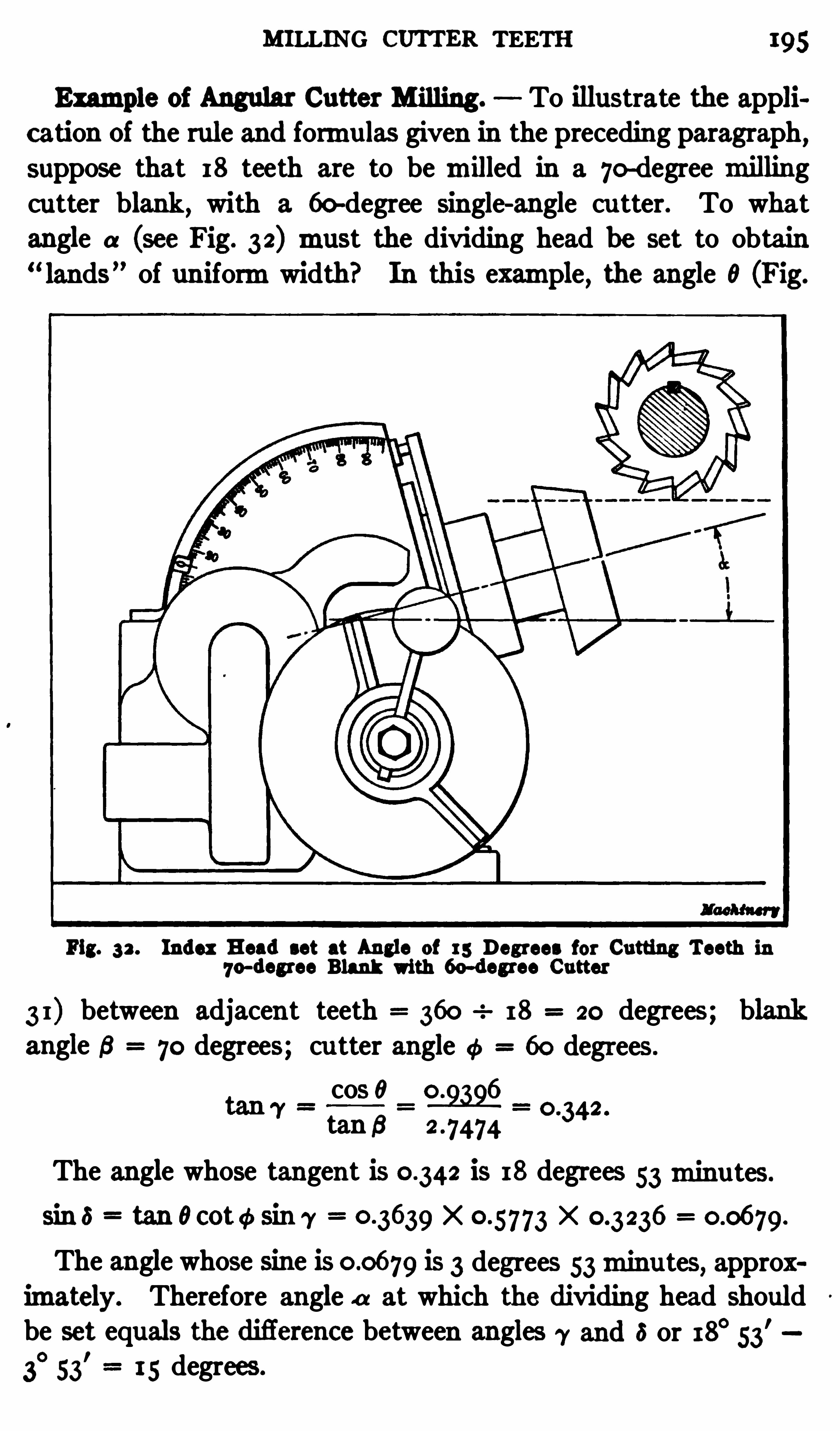
MILLING CUTTER TEETH 195
Example of Angular Cutter Milling . To illustrate the appii
cation of the rule and formulas given in the preceding paragraph,suppose that 18 teeth are to be milled in a 70
-degreemillingcutter blank, with a 60-degree single-angle cu tter. To what
angle a (see Fig. 32) must the dividing head he set to obtain“lands” of uniformwidth" In this example
, the angle 0 (Fig.
Fig. 32 . Index Head set at Angle of 15 Degrees for Cutting Teeth in7o—deg1ee Blank with 6o-deg1ee Cutter
3 1) between adjacent teeth 360 18 20 degrees; blankangle 6 70 degrees; cu tter angle a 60 degrees .
cos o0 . 2 .
tan s 2 -747434
The angle whose tangent is is 18 degrees 53minu tes.
sin e tan 0cot¢ sin 7 x X
The angle whose sine is is 3 degrees 53minu tes, approximately. Therefore angle a at which the dividing head Shouldbe set equals the difierence between angles 7 and 5 or 18° 53
'
3°
53'
15 degrees
CHAPTER V
GEAR CUTTING IN THE MILLING MACHINE
SPUR, spiral, and bevel gears are cut ordinarily in spec ial gearcu ttingmachines, but themillingmachine is often used in shops
not equ ipped with specialmachines, or for cu tting gears of odd
sizes, especially when only a small number are required .
Cutting a Spur Gear. Fig. 1 illustrates how a small spurgear is cut in the milling machine . The gear blank is firstbored and tu rned to the correct ou tside diameter and then it ismounted on an arbor which is placed between the centers of thedividing head. An arbor having a taper shank which fits thedividing-head spindle is a good formto use for gear work. I f
an ordinary arbor with centers in both ends is employed , all playbetween the driving dog and faceplate should be taken up toinsure accu rate indexing.
Cutter to use for Spur Gears. The type of cu tter that isused for milling the teeth of spur gears is shown in Fig. 2 .
This style of cutter ismanu factured in various sizes for gearsof difierent pitch. The teeth of these cutters have the sameshape or profile as the tooth Spaces of a gear of correspondingpitch; therefore , the cu tter to use depends upon the pitch ofthe gear to be cut. The number of teeth in the gearmust alsobe considered, because the Shape or profile of the teeth of a
small gear is not exactly the same as the shape of the teeth of alarge gear of corresponding pitch .
The cu ttersmanufactured by the Brown Sharpe Mfg. CO.,
for cu tting gears according to the involute system, aremade in
eight difl'
erent sizes for each pitch. These cu tters are numberedfrom1 to 8 and the different numbers are adapted for gears ofthe following sizes. Cu tter No. I
,for gears having teeth vary
ing from135 to a rack; No . 2,gears with from55 to 134 teeth;
No. 3 , from35 to 54 teeth; No . 4 , from26 to 34 teeth; No. 5,196

198 MILLING MACHINES
position B and it is adjusted to barely touch or pinch a thintissue paper “ feeler ” j held between the arbor and the corner ofthe cu tter . The dial of the elevating screw is now set at zero
,
and the horizontal distance between positions A and B should benoted by referring to the cross-feed dial. For convenience thiswill be called dimension No. 1 as indicated by the illustration .
The arbor is next lowered and returned to position A hori
zontally, the vertical position not being particular . The arboris then raised un til the elevating screw dial is again at zero,after which it ismoved to position C, or un til it just touches a
tissue paper feeler” as
Fig. 2 . Cutter for M illing the Fig . 3 . Method of setting Cutter CentralTeeth of Spur Gears with Arbor
No . 2 is next noted by referring to the cross-feed dial; this isadded to dimension No. 1 and the sumis divided by 2 to getdimension No. 3 . The arbor is then returned to position A
(as far as the horizontal location is concerned) after which it islowered far enough to clear the cu tter and thenmoved inward adistance equal to dimension No. 3 , which is the central position.
This operation can be performed more quickly than described .
Whenmaking the adjustments, all dial readings should be takenat the end of the inward or upwardmovements
,to avoid errors
due to backlash or lostmotion in the elevating or feed-sc rews.
Testing P osition of Cutter. Amethod of testing the positionof a gear c utter, when considerable accu racy is required , is as
MILLING SPUR GEARS 199
follows: First mill a tooth Space in a trial blank having the
same diameter as the gear blank, and then ,withou t changing
theposition of the cu tter, remove the blank fromthe work arborand turn it end for end . The blank Should be loose on the arbor
to permit feeding it back so that the cu tter will enter the tooth
space previouslymilled. The cu tter is then revolved Slowly byhand
,in order tomark its position in the slot. I f it is set exactly
c entral, the second cu t will follow the first, but if it is not central,somemetal will be removed fromthe top of the space on one sideand the bottomon the other . In order to center the cu tter, it
should be moved laterally toward that side of the tooth fromwhich stock wasmilled at the top
,by adjusting the gear blank.
Another trial c ut is then taken and the test repeated. Whenthe cu tter is set, the saddle should be clamped in position .
Setting the Cutter to Depth. The next step is to set thecutter formilling tooth spaces of the proper depth. I f the outside diameter of the gear blank is acc urate, this can be done byfirst adjusting the blank upward until the revolving cu tter justgrazes its surface. The dial of the elevating screw is then set
at zero, af ter which the blank ismoved horizontally to clear thecu tter, and then vertically the required amount
,as shown by
the micrometer dial . This vertical adjustment should equalthe total depth of the tooth space
,which can b e found by
dividing the constant by the diametral pitch of the gear.For example, if the diametral pitch is 12
,the depth of the tooth
Space241—51 inch . After the blank has been raised12
this amount,the gear teeth are formed by feeding the blank hor
izontally and indexing after each tooth space ismilled . Aboutone quarter of the teeth have been milled in the gear blankshown in Fig. 1 . The accuracy of the gear
,assuming that the
cu tter is properly made, will depend largely upon setting thecu tter central and to the proper depth. When the depth is
gaged fromthe ou tside of the blank, the diameter of the lattershould be ac curate, as otherwise the teeth will not have the correct thickness. This diameter can be found by adding 2 to the
number of teeth and dividing by the diametral pitch.
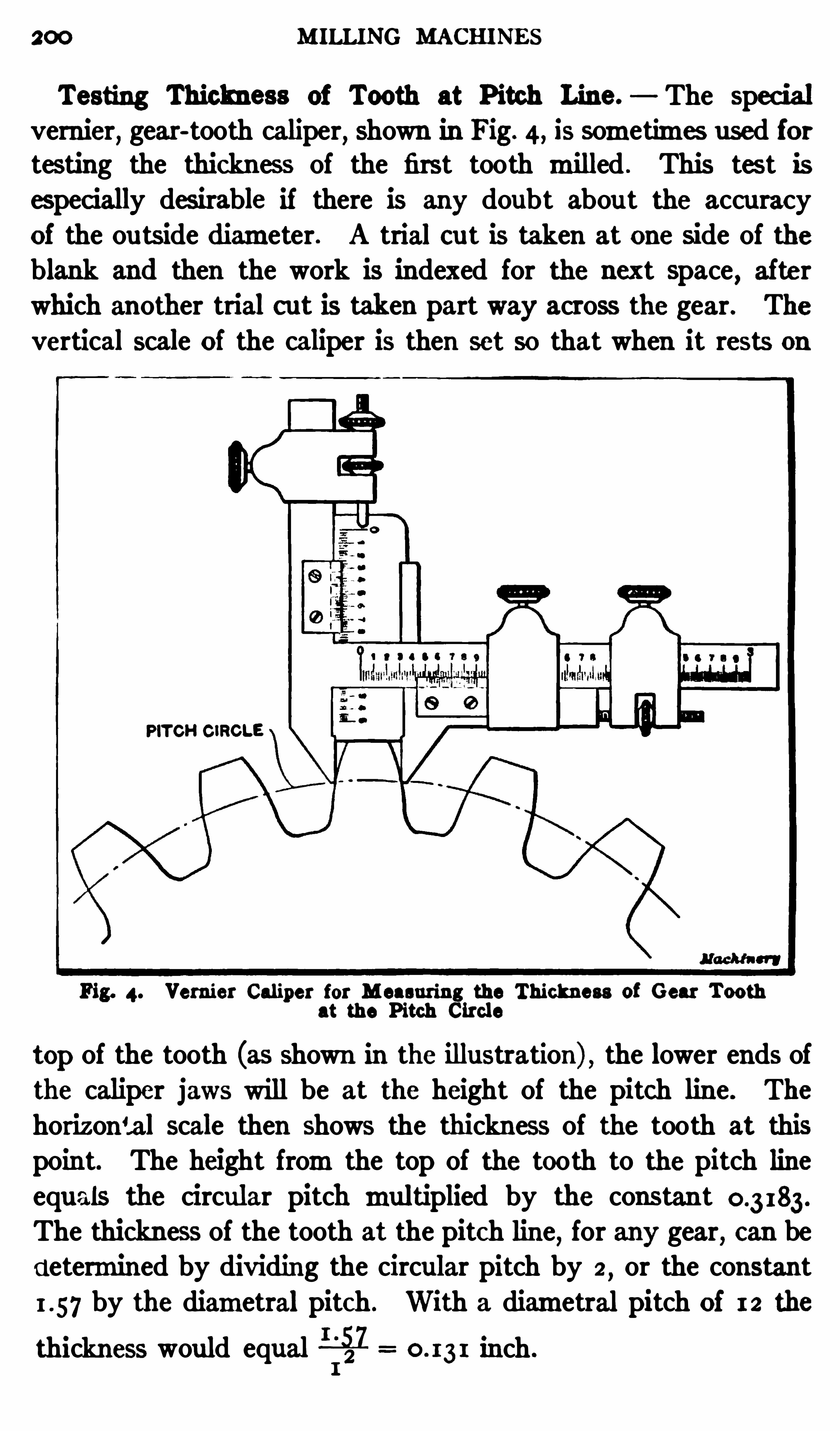
200 M ILLING MACHINE S
Testing Thickness of Tooth at P itch Line. The spec ialvernier
,gear-tooth caliper
,Shown in Fig. 4, is sometimes used for
testing the thickness of the first tooth milled . This tes t isespecially desirable if there is any doubt abou t the accuracy
of the ou tside diameter. A trial cut is taken at one side of theblank and then the work is indexed for the next space
,after
which another trial cut is taken part way across the gear. The
vertical scale of the caliper is then set so that when it rests on
PITCH CiRGLE
Fig. 4. Vernier Caliper for M easuring the Thickness of Gear Toothat the Pitch Circle
top of the tooth (as shown in the illustration) , the lower ends ofthe caliper jaws will be at the height of the pitch line . The
horizontal scale then Shows the thickness of the tooth at thispoint. The height fromthe top of the tooth to the pitch lineequals the circular pitch multiplied by the constantThe thickness of the tooth at the pitch line
,for any gear, can be
d etermined by dividing the circular pitch by 2,or the constant
by the diametral pitch . With a diametral pitch of 12 the
thickness would equal 5521 inch.

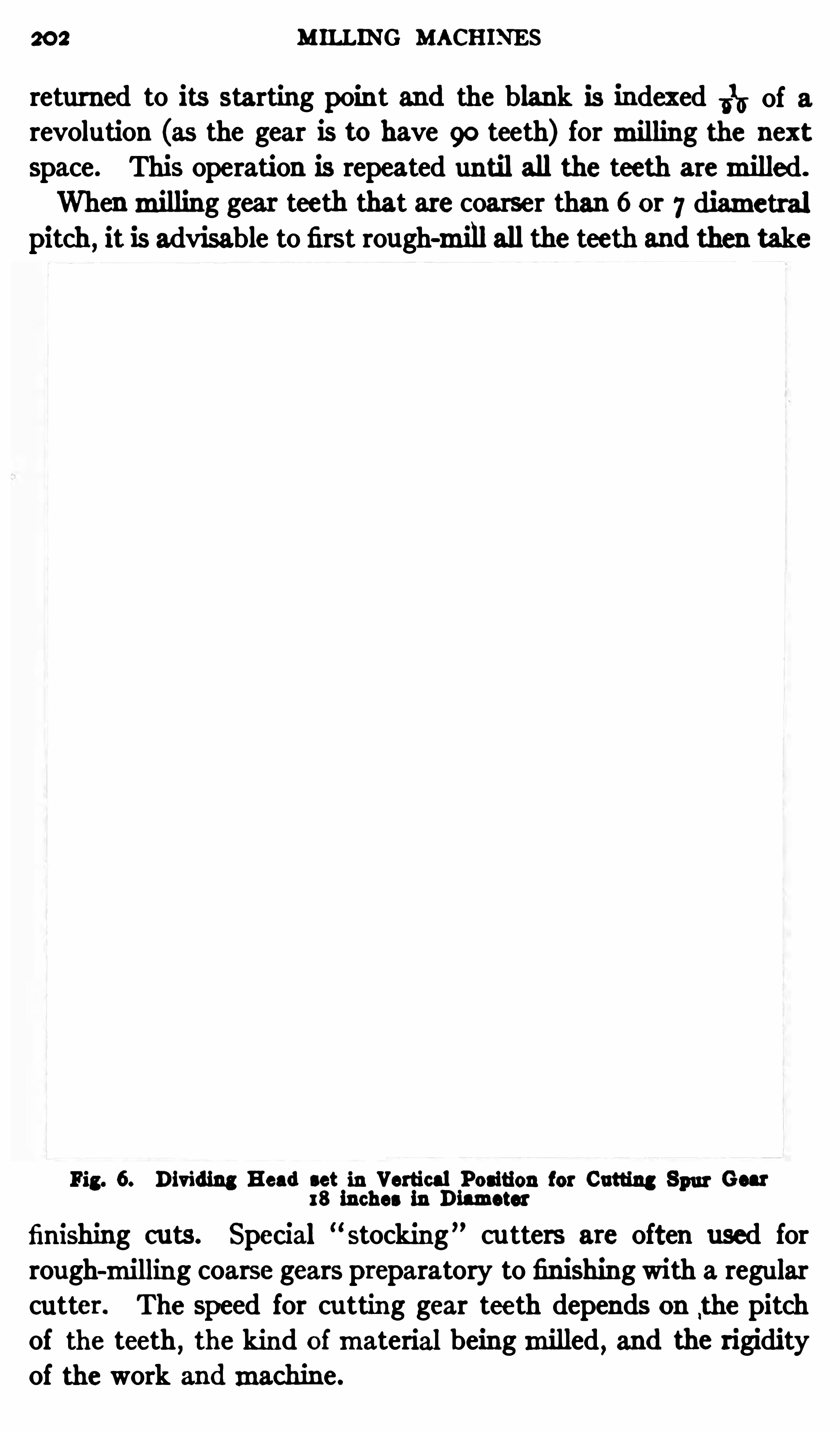
202 M ILLING MACHINES
returned to its starting poin t and the blank is indexed 1516 of a
revolution (as the gear is to have 90 teeth) formilling the nextspace. This operation is repeated until all the teeth aremilled.
Whenmilling gear teeth that are coarser than 6 or 7 diametralpitch
,it is advisable to first rough-mill all the teeth and then take
Pi 6. Dividing Head set in Vertical Position for Cutting 8 Gear18 inches in Diameter W
finishing c uts . Special “stocking” cu tters are often used for
rough-milling coarse gears preparatory to finishing with a regularcutter. The speed for cutting gear teeth depends on ,
the pitchof the teeth
,the kind ofmaterial beingmilled , and the rigidity
of the work andmachine.
MI LLING SPUR GEARS 203
When the diameter of a gear is referred to, it is understood to
mean the pitch dimeter or diameter of the pitch circle , and not
the ou tside diameter. The diametral pitch is the number ofteeth to each inch of pitch diameter, and the circular pitch isthe distance fromthe center of one tooth to the center of thenext,measured along the pitch line .
Gear Cutting Attachment When it is necessary to cut comparatively large spur gears on amillingmachine , a gear cu ttingattachment is preferable to the regular dividing head . Thisattachment, in its usual form, is similar to a dividing head, butis larger and heavier in construction . If the gear is too largeto clear themachine table when mounted between the centers
(as illustrated in Fig. the centers are sometimes raised farenough to provide roomfor the gear blank by placing parallelblocks beneath the index head and tail-center. I f the gearblank is so large that it will not pass under the cutter arbor withthe table in its lowest position ,
itmay be possible to cut the gearby using an under-cu tting attachment.” The centers are raisedfar enough to provide roomfor the cutter beneath the gear, andthe arbor is supported by a special out-board bearing.
Fig. 6 illustrates a simplemethod of cu tting a spur gear whichis too large to be held between the centers on a horizontal arbor.Instead of increasing the swing of the centers by placing parallelblocks beneath them,
the dividing-head spindle is set in a verticalposition . The gear blank is held on a short arbor inserted in
the spindle and the rimis supported to take the downward
thrust of the cu t,by two vertical studs or rods placed on the
cu tting side, as the illustration shows. Whenmilling the teeth,the gear blank is fed up against the cu tter by using the powervertical feed . The spur gear shown in this illustration has teeth
of 5 diametral pitch and is 18 inches in diameter.Cutting Spur Gear on Circular Attachment. Fig. 7 illus
trates how a circ ularmilling attachment is sometimes used for
holding a comparatively large gear whilemilling the teeth . Thegear is clamped in a horizontal position and it is centered bythe finished bore of the hub which fits over a plug inserted in the
central hole of the table.
204 MILLING MACHINES
The cu tter,which is held on the regu lar arbor, forms the
tooth spaces as the table is fed vertically by power. I t will be
noted that this particular attachment is equipped with an index
plate. By holding a large gear on the circular attachment, therimis more rigidly supported than when the gear is held on
an arbormounted between the centers of a dividing head.
Fig. 7 . Cutting Spur Gear b y use of Circular M illing Attachment
Rack Cutting in the M illing Machine.—Themethod of cut
ting a rack in themilling machine by the use of a rack- cuttingattachment is illustrated in Fig. 8 . This attachment is secu relyclamped to the face of themachine column and its cu tter spindleis parallel with the table . The spindle is driven fromthemainspindle of the machine through bevel and spu r gearing. Therack teeth are formed by cu tting tooth spaces straight across therack blank (using the au tomatic transverse feed) and after each

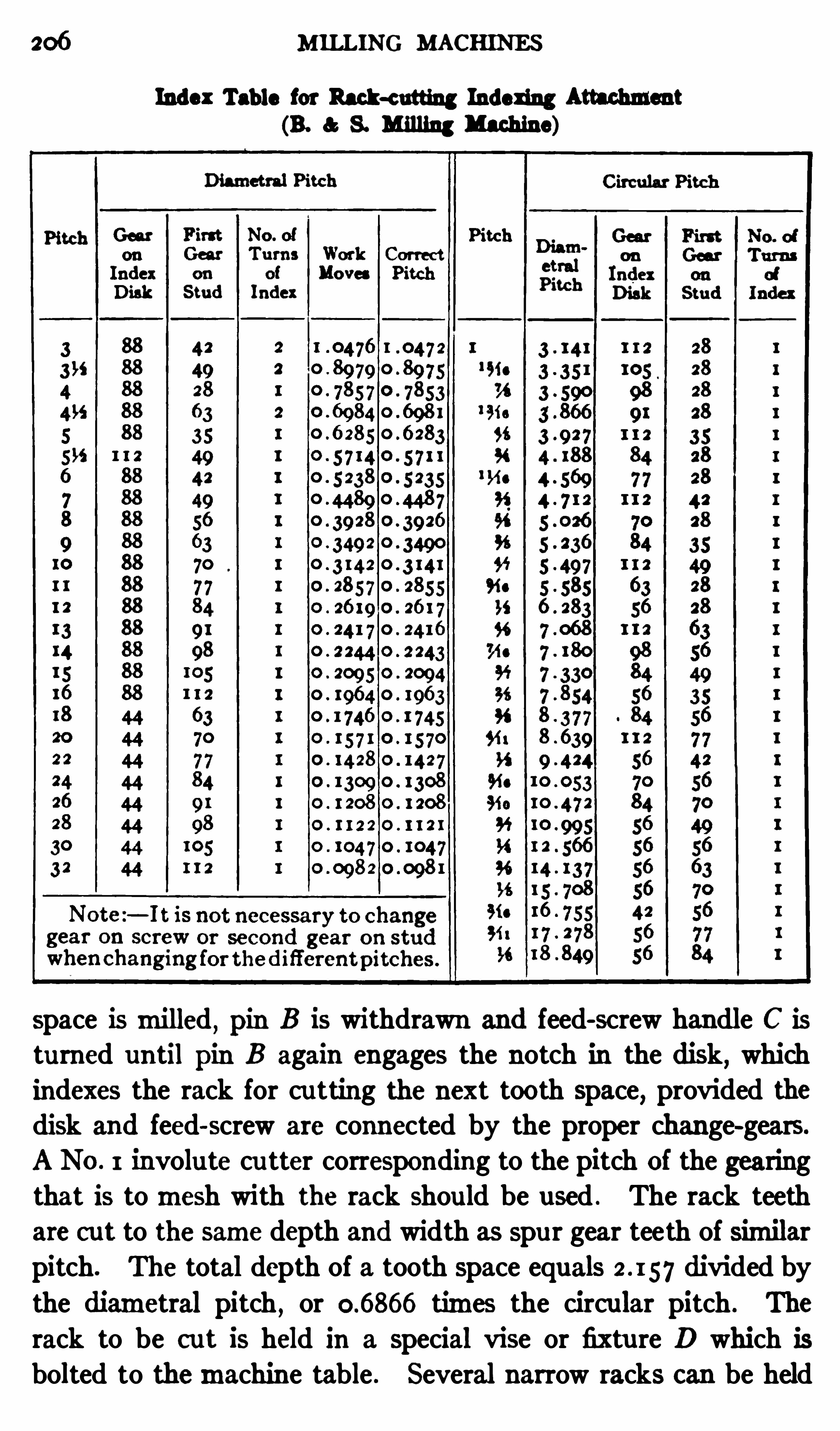
206 MILLING MACHINES
Index Table for Rack-c utting Indexing Attachnmnt(B. S. Milling Machine)
space ismilled, pin B is withdrawn and feed-screw handle C is
turned until pin B again engages the notch in the disk, whichindexes the rack for cu tting the next tooth space
,provided the
disk and feed-screw are connected by the proper change-gears.
A No . 1 involute cu tter corresponding to the pitch of the gearingthat is tomesh with the rack should be used . The rack teethare cut to the same depth and width as spu r gear teeth of similarpitch. The total depth of a tooth space equals divided by
the diametral pitch,or times the circu lar pitch . The
rack to be cu t is held in a special vise or fixtu re D which is
bolted to themachine table . Several narrow racks can be held
MILLING WORM—WHEELS 207
in this fixture at the same time and the teeth be cut simultaneously.
The accompanying table shows what change-gears should beused for indexing difierent pitches. The left half of the tableis used when the diametral pitch of the rack teeth is given .
This pitch, which is listed in the first column,corresponds to the
diametral pitch of the gear which is to mesh with the rack.
The right half of the table is for circu lar pitches,the pitch in
this case being equal to the center-to-center distance between
adjacent rack teeth. This table also gives the number of turnsfor the indexing disk; with but three exceptions all pitches areindexed by a single turn of the disk. The gear E (Fig. 8) nextto the indexing disk
,and the first gear on the stud (which is
the onemeshing with gear E ) are the only gears which requirechanging for difi
'
erent pitches.
Gashing and Hob b ing a Worm-wheel. The universalmillingmachine is sometimes used for cu tting the teeth in wormwheels
,although when there ismuch of this work to be done,
regular gear-cu tting machines are generally used . The wormitself shou ld be finished first, as it can be used advantageously
for testing the center distance when bobb ing the worm-wheel.
We shall assume that the wormhas been made,and that the
wheel blank has been tu rned to the required size .
The teeth of the worm-wheel are formed by two operations,which are illustrated in Figs . 9 and 10 . First it is necessary togash the blank and then the teeth are finished by hobbing.
Gashing consists in cu tting teeth around the periphery of the
b lank, which are approximately the shape of the finished teeth.
This is done, preferably, by the use of an involu te gear cutter
of a number and pitch corresponding to the number and pitchof the teeth in the wheel. If a gear cu tter is not available , a
plain milling c utter,the thickness of which shou ld not exceed
three-tenths of the circu lar pitch,may be used . The corners ofthe teeth of the cu tter shou ld be rounded , as otherwise the fillets
of the finished teeth will be partly removed .
As the wormwhichmeshes with and drives the worm-wheel is
simmy a short screw,it will be apparent that if the axes of the
208 M ILLING MACHINES
worm-wheel and wormare to be at right angles to each other,the teeth of the wheel must be cu t at an angle to its axis
,in
order tomesh with the threads of the worm. After the dividinghead and tailstock have been clamped to the table and the
cu tter has been fastened on its arbor, the table is adjusted un til
the centers of the dividing head and the center of the cutter
lie in the same vertical plane . If the cu tter used has a cente
Fig . 9. Gashing a Worm-wheel in a Univeraal M illing Machine
line around its periphery , the table can be set by raising ithighenough to bring the index head center in line with the cutter;the table can then be adjusted laterally until the center coin
c ides wi th the center- line on the cu tter. When the table is set,it should be clamped to the knee slide.
The blank to be gashed is pressed on a true-running arbor
which ismounted between the centers of the dividing head and

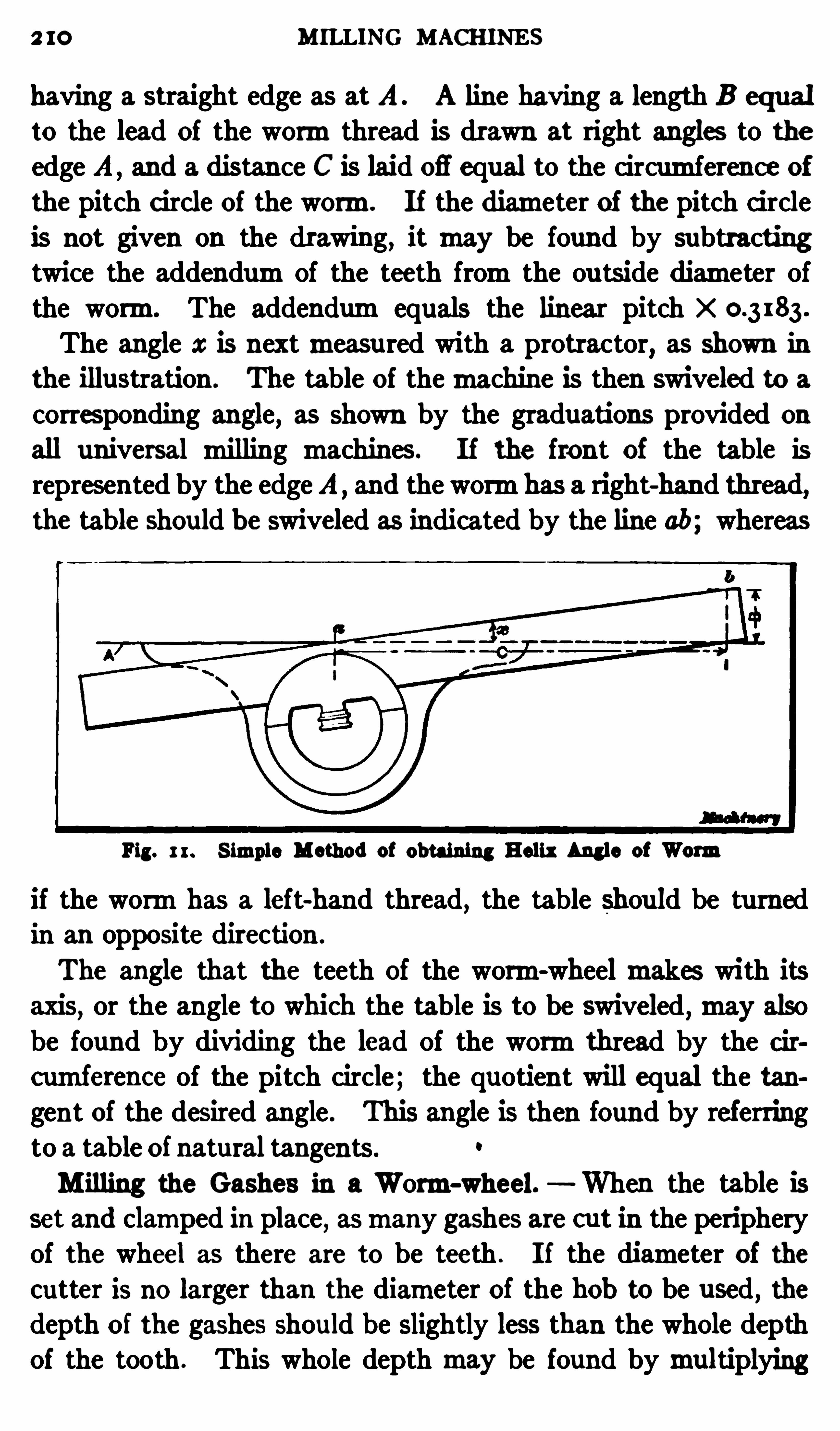
2 I O MILLING MACHINES
having a straight edge as at A A line having a length B equal
to the lead of the wormthread is drawn at right angles to the
edge A , and a distance C is laid 06 equal to the circumference of
the pitch c ircle of the worm. I f the diameter of the pitch circleis not given on the drawing, itmay be found by subtractingtwice the addendumof the teeth fromthe ou tside diameter ofthe worm. The addendumequals the linear pitch xThe angle a: is nextmeasured with a protractor
,as shown in
the illustration . The table of themachine is then swiveled to a
corresponding angle, as shown by the graduations provided on
all universal milling machines. If the front of the table is
repres ented by the edgeA and the wormhas a right-hand thread,the table should be swiveled as indicated by the line ab; whereas
Fig. 1 1. S imple Method of obtaining Helix Angle of Worm
if the wormhas a left-hand thread, the table should be tu rnedin an opposite direction .
The angle that the teeth of the worm-wheelmakes with itsaxis
, or the angle to which the table is to be swiveled ,may also
be found by dividing the lead of the wormthread by the circumference of the pitch circle; the quotient will equal the tangent of the desired angle . This angle is then found by referringto a table of natural tangents .
0
M illing the Gashes in a Worm-wheel. When the table isset and clamped in place, asmany gashes are cut in the peripheryof the wheel as there are to be teeth . I f the diameter of thecutter is no larger than the diameter of the hob to be used
,the
depth of the gashes should be slightly less than the whole depthof the tooth . This whole depthmay be found bymultiplying
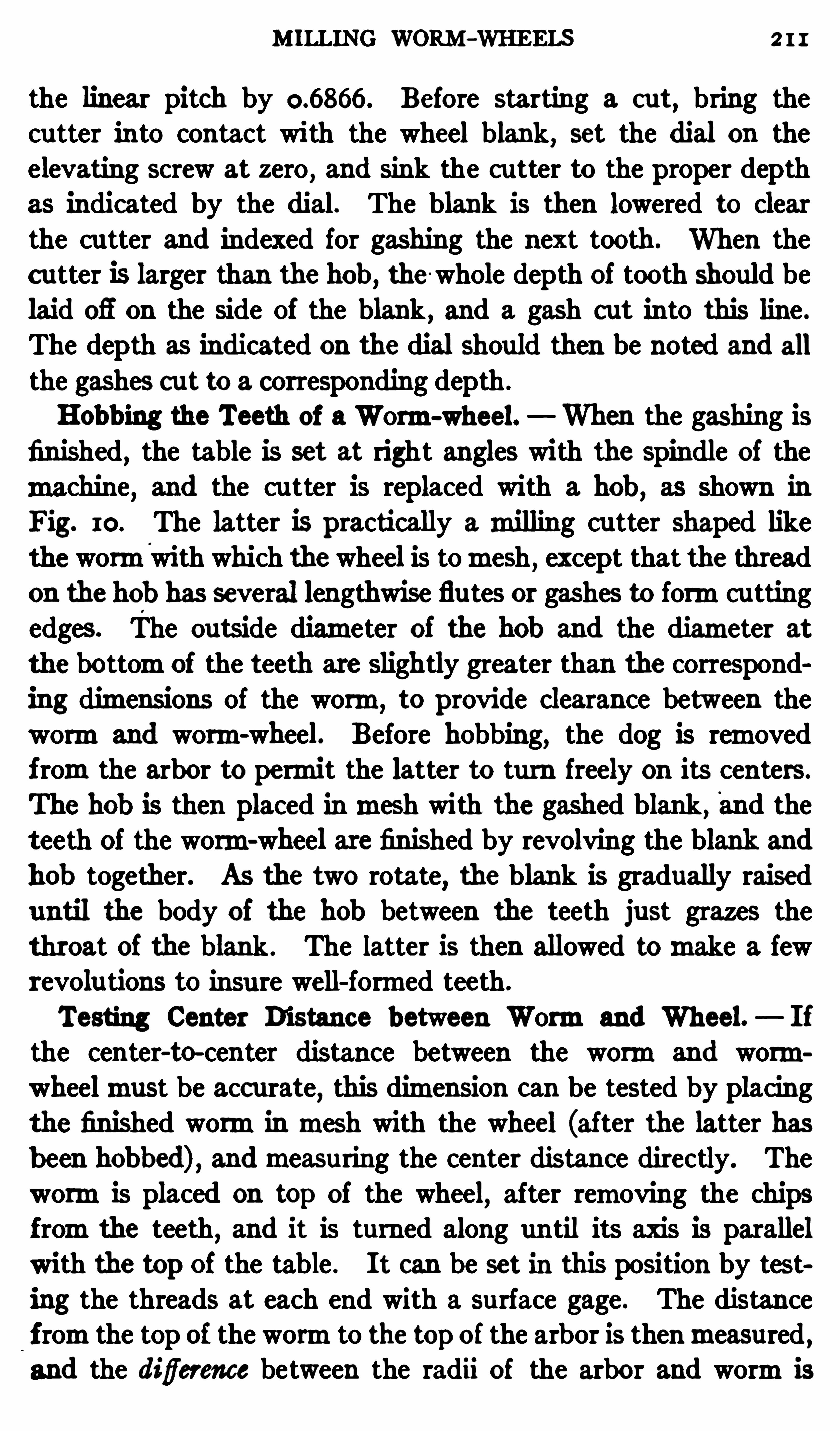
M ILLING WORM-WHEELS 2 I I
the linear pitch by Before starting a cut, bring thecu tter into contact with the wheel blank, set the dial on theelevating screw at zero
,and sink the cu tter to the proper depth
as indicated by the dial. The blank is then lowered to clearthe cu tter and indexed for gashing the next tooth. When thec utter is larger than the hob , the whole depth of tooth should be
laid 03 on the side of the blank , and a gash cut into this line .
The depth as indicated on the dial should then be noted and all
the gashes cut to a corresponding depth .
B obb ing the Teeth of aWorm-wheel. When the gashing is
finished, the table is set at right angles with the spindle of the
machine, and the cu tter is replaced with a hob , as shown in
Fig. 10. The latter is practically amilling cutter shaped liketheworm
'
with which thewheel is tomesh , except that the threadon the hob has several lengthwise flutes or gashes to formcu ttingedges. The outside diameter of the hob and the diameter atthe bottomof the teeth are slightly greater than the correspond
ing dimensions of the worm,to provide clearance between the
wormand worm-wheel. Before hobbing, the dog is removedf romthe arbor to permit the latter to turn freely on its centers.
The hob is then placed inmesh with the gashed blank, and theteeth of the worm-wheel are finished by revolving the blank and
hob together. As the two rotate, the blank is gradually raiseduntil the body of the hob between the teeth just grazes thethroat of the blank . The latter is then allowed tomake a fewrevolutions to insure well-formed teeth.
Testing Center Distance between Wormand Wheel. I f
the center-to-center distance between the wormand wormwheelmust be acc urate
,this dimension can be tested by placing
the finished wormin mesh with the wheel (after the latter hasb een bobbed) , andmeasuring the center distance directly. Thewormis placed on top of the wheel
,after removing the chips
fromthe teeth, and it is turned along until its axis is parallel
with the top of the table . I t can be set in this position by testing the threads at each end with a surface gage. The distancefromthe top of the wormto the topof the arbor is thenmeasured ,and the diflerence between the radii of the arbor and wormis
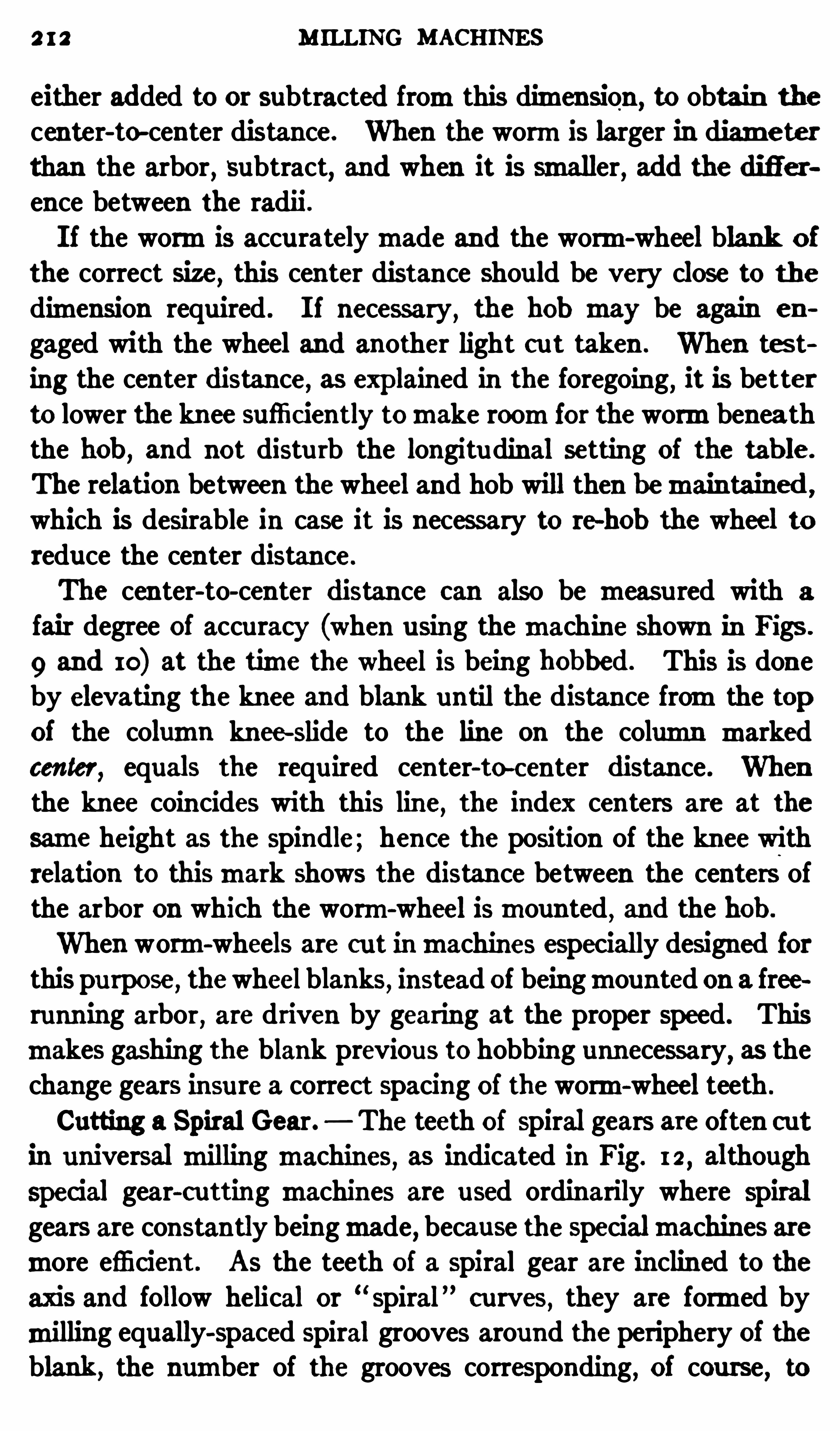
2 I 2 M ILLING MACHINES
either added to or subtracted fromthis dimension,to obtain the
center-to-center distance. When the wormis larger in diameterthan the arbor, subtract, and when it is smaller, add the difference between the radii .
I f the wormis accuratelymade and the worm-wheel blank o f
the correct size , this center distance should be very close to the
dimension required . I f necessary,the hob may be again en
gaged with the wheel and another light out taken . When tes ting the center distance as explained in the foregoing, it is better
to lower the knee sufficrently tomake roomfor the wormbenea ththe hob , and not distu rb the longitudinal setting of the tab le .
The relation between thewheel and hob will then bemaintained ,
which is desirable in case it is nec essary to te-hob the wheel to
reduce the center distance.
The center-to-center distance can also be measu red with a
fair degree of accuracy (when u sing themachine shown in Figs .
9 and 10) at the time the wheel is being b obbed . This is doneby elevating the knee and blank until the distance fromthe topof the column knee-slide to the line on the column markedcenter
,equals the requ ired center-to-center distance . When
the knee coincides with this line, the index centers are at the
same height as the spindle; hence the position of the knee wi
th
relation to thismark shows the distance between the centers ofthe arbor on which the worm-wheel ismounted
,and the hob .
When worm-wheels are cu t inmachines especially designed forthis purpose, thewheelblanks, instead of beingmounted on a freerunn ing arbor
,are driven by gearing at the proper speed. This
makes gashing the blank previous to hobbing unnecessary, as thechange gears insure a correct spacing of the worm-wheel teeth .
Cutting a Spiral Gear. The teeth of spiral gears are often c utin universal milling machines
,as indicated in Fig. 12
,although
special gear-cutting machines are used ordinarily where spiralgears are constantly beingmade, because the specialmachines aremore efficient. As the teeth of a spiral gear are inclined to the
axis and follow helical or “spiral” curves
,they are formed by
milling equally-spaced spiral grooves around the periphery of theblank ,
the number of the grooves corresponding , of course, to

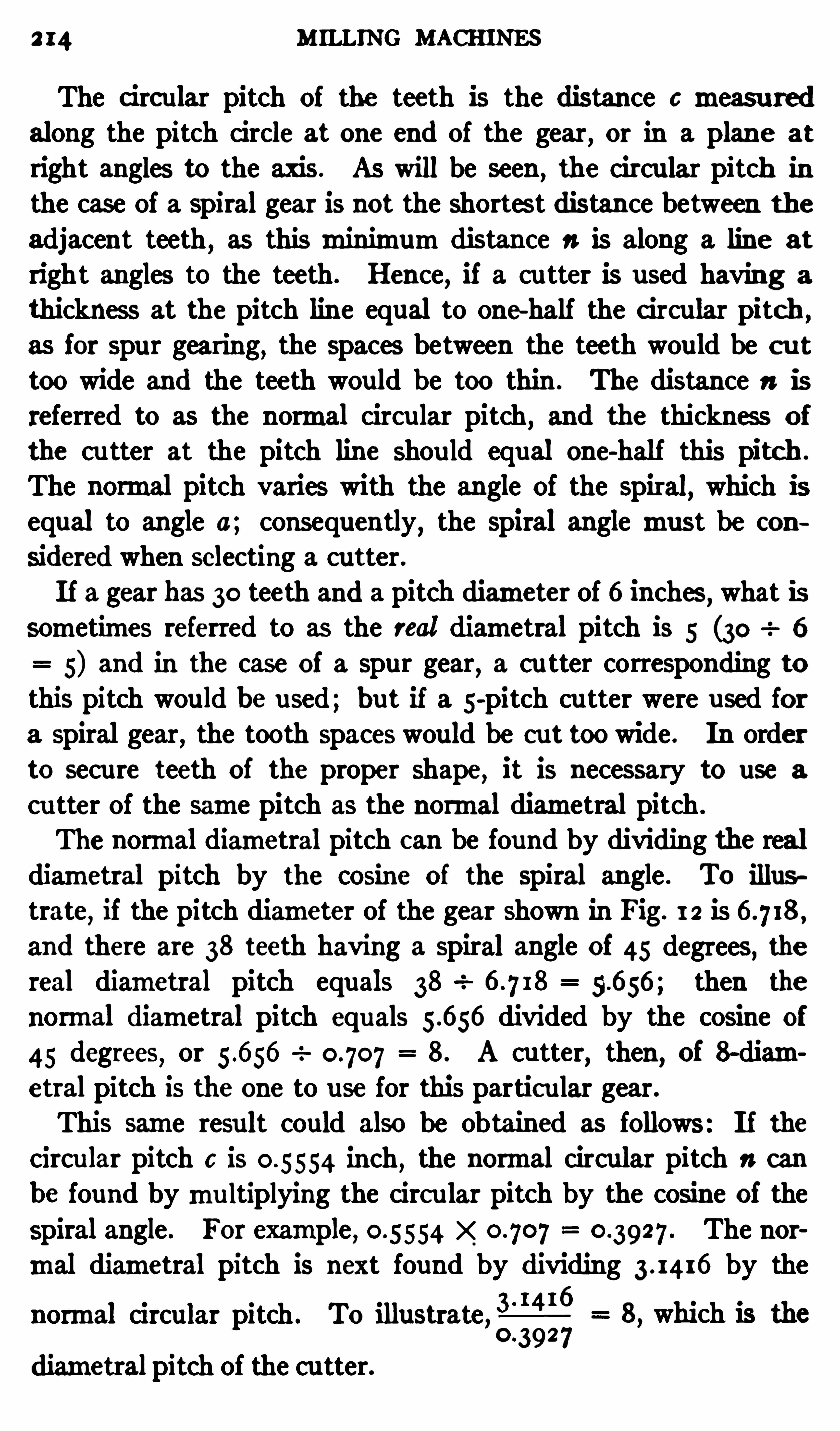
2 14 MILLING MACHINES
The c ircular pitch of the teeth is the distance 0measu redalong the pitch circle at one end of the gear
,or in a plane at
right angles to the axis . AS will be seen ,the circular pitch in
the case of a Spiral gear is not the shortes t distance between the
adjacent teeth , as this minimumdistance 11 is along a line at
right angles to the teeth . Hence,if a cu tter is used having a
thickness at the pitch line equal to one half the c ircular pitch ,
as for spur gearing,the spaces between the teeth would be c u t
too wide and the teeth would be too thin . The distance 11 isreferred to as the normal circu lar pitch , and the thickness of
the cu tter at the pitch line shou ld equal one-half this pitch .
The normal pitch varies with the angle of the spiral,which is
equal to angle a; consequently, the spiral angle must be con
sidered when selecting a cutter.If a gear has 30 teeth and a pitch diameter of 6 inches
,what is
sometimes referred to as the real diametral pitch is 5 (30 6
5) and in the case of a spur gear,a cu tter corresponding to
this pitch wou ld be used; but if a 5-pitch cu tter were used for
a spiral gear,the tooth spaces would be cut too wide . In order
to secure teeth of the proper Shape, it is necessary to use a
cu tter of the same pitch as the normal diametral pitch .
The normal diametral pitch can be found by dividing the realdiametral pitch by the cosine of the spiral angle . To illus
trate,if the pitch diameter of the gear Shown in Fig. 1 2 is
and there are 38 teeth having a spiral angle of 45 degrees, thereal diametral pitch equals 38 56 then the
normal diametral pitch equals divided by the cosine of
45 degrees, or 8. A cutter,then
, of 8—diametral pitch is the one to use for this partic ular gear .This same resu lt could also be obtained as follows : If the
circu lar pitch c is inch,the normal circular pitch 1: can
be found bymu ltiplying the circ ular pitch by the cosine of thespiral angle . For example
,The nor
mal diametral pitch is next found by dividing by the
normal circular pitch . To illustrate,2 8, which is the
diametral pitch of the cu tter.
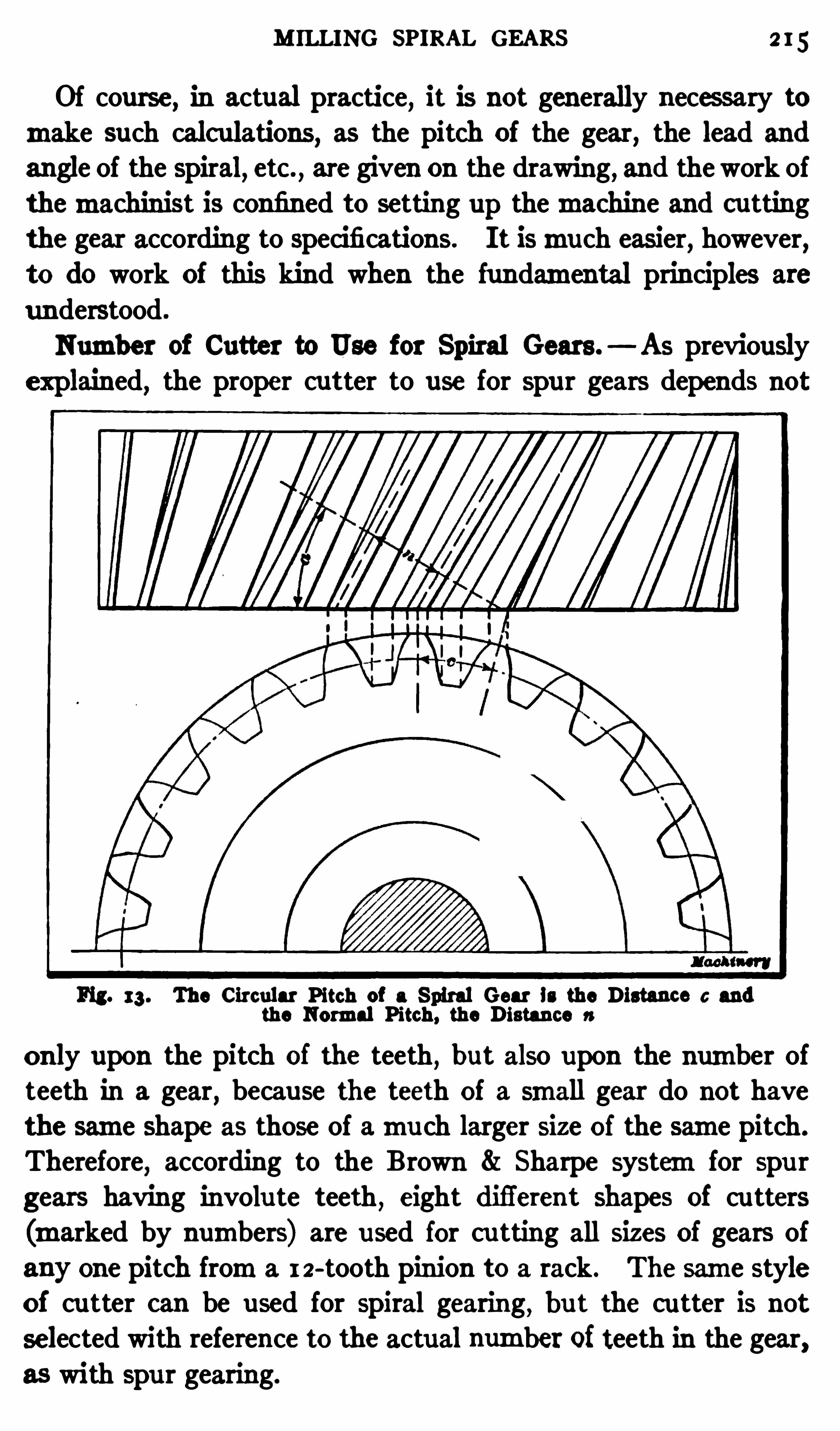
M ILLING SP IRAL GEARS 2 15
Of course, in actual practice, it is not generally neces sary tomake such calculations , as the pitch of the gear, the lead and
an gle of the spiral, etc ., are given on the drawing
, and the work of
themachinist is confined to setting up themachine and cutting
the gear according to specifications. I t ismuch easier,however
,
to do work of this kind when the fundamental principles are
understood .
Number of Cutter to Use for Spiral Gears. As previously
explained, the proper cutter to use for spu r gears depends not
Fig. 13 . The Circular Pitch of a Spiral Gear is the Distance c andthe Normal Pitch, the Distance 11
only upon the pitch of the teeth, but also upon the number ofteeth in a gear, because the teeth of a small gear do not have
the same shape as those of amu ch larger size of the same pitch.
Therefore,according to the B rown 81 Sharpe systemfor spu r
gears having involu te teeth , eight difi'
erent shapes of cu tters
(marked by numbers) are u sed for cu tting all sizes of gears of
any one pitch froma 1 2-tooth pinion to a rack. The same styleof cutter can be used for Spiral gearing
,bu t the cu tter is not
selected with reference to the actual number of teeth in the gear,as with spu r gearing.
2 16 MILLING MACHINES
By r eferring to the list of cutters given in the paragraphheaded “
Cu tter to use for Spur Gears,it will be seen tha t a
No. 3 would be used for a spur gear having 38 teeth . A spiral
gear with 38 teeth, however, might requ ire a cutter of someother number, because of the angular position of the teeth.
I f the actual number of teeth in a spiral gear is divided by the
c ube of the cosine of the tooth angle,the quotient will represen t
the number of teeth for which the cu tter Should be selected ,
according to the systemfor spu r gears. If we assume that agear is to have 38 teeth cut at an angle of 45 degrees, then the
cutter to use would be determined as follows: The cosine of
38107 . The
08 535
list of cutters previously referred to calls for a No. 2 cu tter forspur gears having any number of teeth between 55 and 134;
hence,that is the c utter to use for a spiral gear having 38 teeth
and a tooth angle of 45 degrees. I t will be understood that thisnumber has nothing to do with the pitch of the cu tter, which isdetermined as previously explained; it is simply that one of theeight cutters (according to the B . S . system) which ismadeformilling gears having numbers of teeth between 55 and 134.
The number obtained by the foregoing rule is much largerthan the actual number of teeth in the Spiral gear . This isbecause a line at right angles to the teeth
,along which the nor
mal pitch ismeasu red , has a larger radius of curvature than thepitch circle of the gear (strictly speaking, the termradius is incorrectly used
,as this line is a helix and not a circle) and the
cu rvature increases or diminishes for corresponding changes inthe spiral angle . Therefore
,the number of teeth for which the
cu tter is selected depends upon the angle of the spiral, as well
as the actual number of teeth in the gear . As the angle becomessmaller, the diflerence between the normal and circular pitchesalso diminishes until, in the case of Spur gears
,the normal and
c ircular pitches are equal.
Gearing the Machine for Spiral Milling. The change-gears
a,b,c and d, Fig . 1 2
,connect the spiral head and table feed—screw
and rotate the gear blank as the table feeds lengthwise, in order
45 degrees is and 38

2 18 MILLING MACHINES
getting the tangent and then the corresponding angle froma
table of tangents . For example,if the pitch diameter of the
gear is and the lead of the spiral is 20 inches,the tan gen t
6will equalW and is the tangen t of
35 degrees, which is the angle to which the table is set fromthe
normal position at right angles to the spindle .
The table is adjusted by loosening the bolts which ordinarilyhold it to the clamp-bed and swiveling it around until the 35
degree graduation on the circular base coincides with the station
ary zeromark . Before setting the table to the spiral angle, thecu tter should be located directly over the center of the gearblank . An accu ratemethod of centering a cutter of this kindwas described in connection with Fig. 3 .
M illing the Spiral Teeth. The teeth of a spiral gear are
proportioned fromthe normal pitch and not the c ircular pitch.
The whole depth of the tooth,that is the depth of each cut
,can
be found by dividing the constant by the normal diametralpitch of the gear; the latter, as will be recalled, corresponds tothe pitch of the cutter. The thickness of the gear at the pitchline equals divided by the normal diametral pitch . Aftera c ut is completed the cu tter Should be prevented fromdraggingover the teeth when being returned for another cut. This can
be done by lowering the blank slightly or by stopping themachine and turning the cu tter to such a position that the teeth
will not touch the work . I f the gear has teeth coarser than 10
or 12 diametral pitch,it is well to c ut twice around; that is,
take a roughing and a finishn cu t.
When pressing a spiral gear blank on the arbor,it Should be
remembered that spiral gears aremore likely to slip when beingcu t than spu r gears. This is because the tooth grooves are at anangle and the pressure of the cu t tends to rotate the blank on
the arbor .
Milling Bevel Gears. Small bevel gears are occasionally
c ut in the milling machine with a formed cu tter, but as the
cu rve of a bevel gear tooth changes throughou t its length, obvi
ously a formed cu tter having a fixed cu rve will not produce teeth
MILLING BEVEL GEARS
of the theoretically correct shape. The inaccu racy,however, is
not so pronounced when the teeth are small,but the milling
process is unsatisfactory for forming teeth of coarse pitch,espec ially if the gears are to revolve rapidly when in u se.
When a bevel gear is cut bymilling, the gear blank ismountedon an arbor inserted in the dividing-head Spindle , and the latteris set to the cu tting angle as shown in Fig. 14. A formed cutter
Fig. 14. Milling Machine arranged for Cutting a Bevel Gear
is used, and it is necessary to take two cu ts through each tooth
space, with the gear blank slightly off Center,first on one side
and then on the other, to obtain a tooth of approximately thecorrect form. The gear blank is also rotated proportionatelyto obtain the proper tooth thickness at the large and small ends.
The different steps or operations connected with cutting a bevel
gear are as follows : setting the blank to the cutting angle;
2 20 M ILLING MACHINES
selecting the cu tter; taking a trial cu t; determining the amountof ofiset; andmilling the teeth . These difierent operations will
be referred to in the order given .
Angular Position of Bevel Gear Blank — The angle a (see Fig.
15) at which the dividing-head spindle should be set formillingthe teeth equals the pitch cone angle 19, minus the addendumangle 0 of the tooth . Ordinarily, the cu tting angle for bevel
gears equals the pitch cone angle minus the dedendumangle;when cu tting the teeth bymilling with a formed cutter, the firs trule is preferable as it gives a uniformclearance at the bottomof the tooth spaces and a somewhat closer approximation to
the theoretically correct tooth shape .
For bevel gears with shafts at right angles, the tangent of the
pitch cone angle of the pinion is found by dividing the numberof teeth in the pinion by the number of teeth in the gear; thetangent of the pitch cone angle of the gear equals the numberof teeth in the gear divided by the number of teeth in the pinion;the tangent of the addendumangle equals the addendumdividedby the pitch cone radius; the addendumequals divided bythe diametral pitch .
Selecting Cutter for Bevel Gears. The Standard bevel gearc utter ismade thinner than the standard spu r gear cutter be
cause itmust pass through the narrow tooth spaces at the innerends of the teeth . For 14§~ degree involu te teeth there are
eight cu tters numbered fromone to eight for each pitch and
suitable for cutting bevel gears froma twelve-tooth pinion to a
crown gear. The c utter to u se,in any case , must not only be
of the required diametral pitch but the right number in the
series. The number of the cutter depends upon the number ofteeth in the gear or pinion . When cu tting miter gears, onlyone cutter is needed , but if one gear is larger than the other,two cutters of the same pitch bu t of different numbersmay berequired.
The number of teeth for which to select the cu tter is not theactual number of teeth in the gear
, but is found as follows:Divide the actual number of teeth in the gear by the cosine ofthe pitch cone angle. For example
,what cutter would be used

2 22 MILLING MACHINES
as shown at A in Fig. 15 . The dial of the elevating screw is
then set to zero and the table is elevated an amoun t dequal tothe whole depth of the tooth. This depth will not be exactlyright
, as it shou ld be measu red along the back edge e of the
tooth, but the error due to this slight angle is negligible. (The
whole depth diametral pitch or circular pitch XHaving thus cen tered the cu tter and set it to depth ,
two tooth spaces should be cut, thus forming a tooth upon whichtrial cu ts can bemade to obtain the proper relation between thecu tter and work formilling the remainder of the teeth .
Amount of Ofi-set for Milling Bevel Gear Teeth. Instead of
milling the teeth with the cu tter in a central position ,it is set
03 center slightly on first one side and then the other, in orderto formteeth which are nearer the correct shape . The amountthat the gear blank or cu tter should be off -set is usually deter
mined by trial . For the first trial cut the ofi-set should equal
abou t 5 or 6 per cen t of the tooth thickness on the pitch line at
the large end. The trial tooth is first moved away fromthe
cu tter an amoun t equal to the off -set,as indicated by arrow b,
Fig. 15 ; the dividing-head spindle is then rotated, as shown by
arrow bl , far enough to align the small end of the tooth space
previously c ut with the cutter. The first trial cut is then
taken,after which the blank is indexed to bring the second
tooth space into position . The blank is next set over on the
opposite side of the central position (as indicated by arrow 0)the same amount as for thefirst trial cu t, thusmoving the oppositeface of the trial tooth away fromthe cu tter. The dividinghead spindle is again rotated as shown by arrow 01, to return
the trial tooth toward the cutter until the latter is aligned withthe small end of the tooth space, as before . The second trial
cut is then taken .
The thickness of the trial tooth at the pitch line is nowmeasured with a vernier gear-tooth caliper, or a fixed gage, the
measurements being taken at the large and small ends. If thethickness at both ends is too great
,rotate the tooth toward
the cutter and take trial cu ts until the proper thickness at
either the large or small end is obtained. I f the large end of
MILLING EEVEL GEARS 223
the tooth is of the right thickness and the small end is too thick,the blank was off-set too much. Inversely, if the small end iscorrect and the large end too thick , the blank was not set
enough ofi cen ter and, in either case
,its position should be
changed accordingly. A trial off-set of 5 or 6 per cent of thetooth thickness at the large end probably will not be enough ,so that two or three trial cu ts will have to be taken on eachside of the tooth before the right amoun t of ofi-set is found .
Milling the Bevel Gear Teeth. When the off -set is determined
,tooth spaces aremilled around the gear blank by cu tting
a space and then indexing for each successive cut. The cu tteris then off-set on the opposite side
,the blank is rotated far enough
tomill teeth of the required width, and another series of cu ts is
taken around the gear. Fromthe foregoing, it will be seen
that the gear blank is off-set to produce a tooth shape that is
approximately correct, and it is rotated by turning the spindle
of the dividing head tomill a tooth of the right thickness. The
number of holes it was necessary tomove the index pin betweenthe first and second series of c uts to get the correct tooth thickness should be recorded; then if duplicate gears are to be cut
,
itwill only be necessary to off-set the blank the required amount,take a series of c uts around it
,off-set the blank on the opposite
side of the center-line, rotate the index crank the required number of holes as determined when cu tting the first gear
,and finish
the teeth by a second series of cu ts .
When milling cast-iron gears coarser than abou t 5 diametralpitch
,it is advisable to first cut central spaces clear around
the gear and then finish the sides by separate cuts,going around
the gear three times. These central cuts are sometimes takenby using a roughing or “
stocking ” cutter. When milling steelgears, the central cuts are usually taken .
When cu tting bevel gears of fine pitch and large diamaer,
the adjustment obtained by moving the indexing crank (formilling the teeth to the required thickness) may not be fine
enough; that is, one hole in the index circlemay not rotate theblank far enough
,whereas if the pin is engaged in the next
hole,the blank will be turned too far
,thus milling too thin a
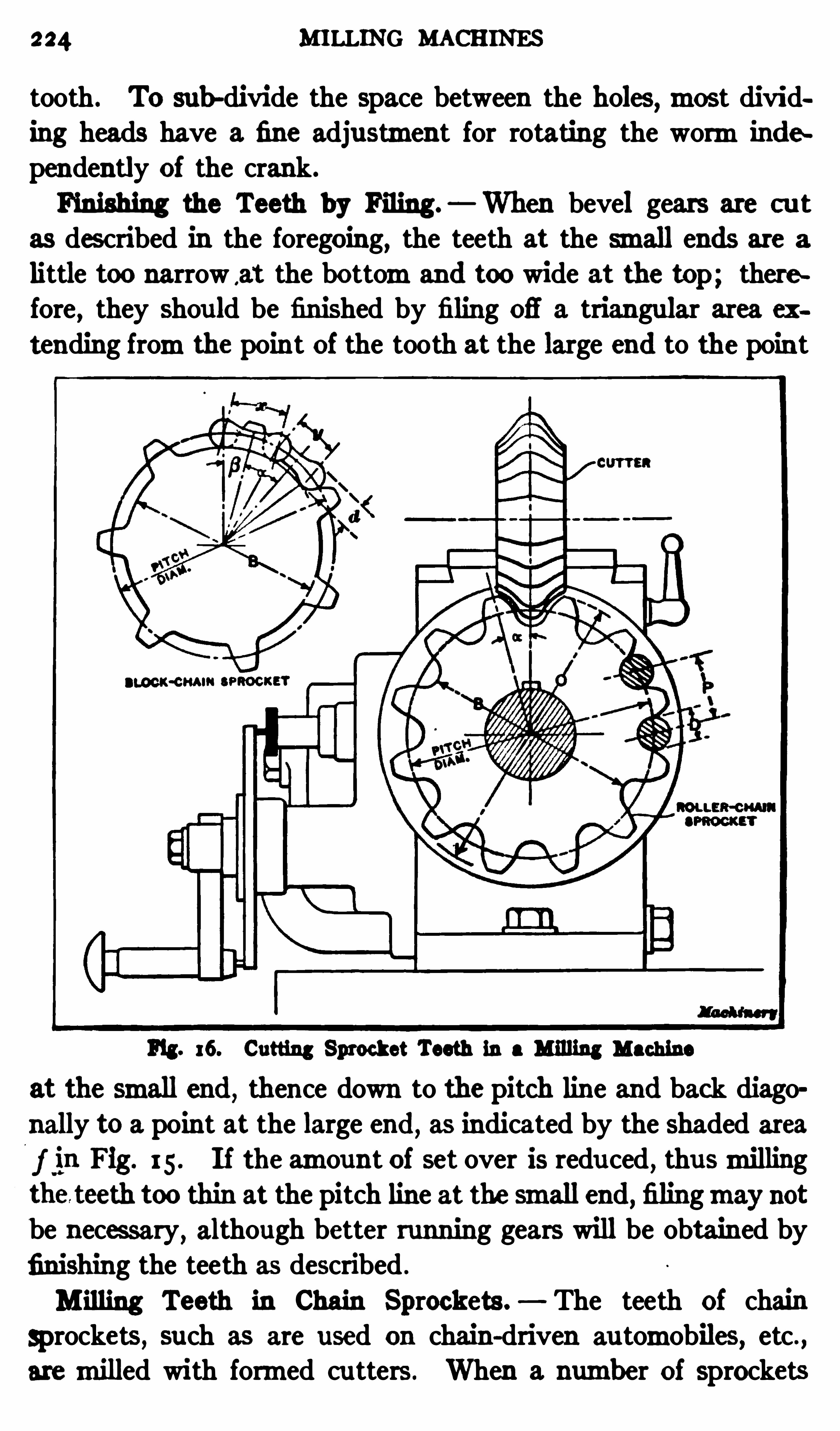
224 MILLING MACHINES
tooth . To sub-divide the space between the holes,most divid
ing heads have a fine adjustment for rotating the wormindependently of the crank.
Finishing the Teeth by Filing— When bevel gears are cu t
as des cribed in the foregoing, the teeth at the small ends are a
little too narrow ,at the bottomand too wide at the top; therefore , they shou ld be finished by filing ofi
'
a triangular area ex
tending fromthe point of the tooth at the large end to the point
Fig. 16. Cutting Sprocket Teeth in a Milling Machine
at the small end, thence down to the pitch line and back diagonally to a point at the large end, as indicated by the Shaded area
f in Fig. I 5 . If the amount of set over is redu ced, thusmillingthe teeth too thin at the pitch line at the small end, filingmay notbe necessary
, although better running gears will be obtained by
finishing the teeth as described .
Milling Teeth in Chain Sprockets . The teeth of chain
Sprockets , such as are used on chain-driven au tomobiles, etc.
aremilled with formed cu tters . When a number of sprockets

226 MILLING MACHINES
ance, and , if the latter kind is used , the sprocket Should bemilledas follows : First
, cut the teeth in the usualmanner; then re
volve the sprocket an amount equal to the pitch line clearancedes ired and take an additional series of cuts around the sprocket.
Cutter for Sprockets . A number of sprocket cu tters are
made for each pitch the same as for spur gears, and in order toobtain a tooth adapted for high speeds
,it is the common practice
to use cu tters made for fewer teeth than the number in thesprocket to be cut. In this way, the teeth are made morerounding
,which facilitates engagement and disengagement of
the chain rollers. When using B rown 81 Sharpe cu tters, the
cutter numbers for different numbers of teeth are as follows:To cut a 9
-tooth sprocket,use the cu tter marked 8 teeth; to
cut a I o-tooth sprocket, use cu ttermarked 9 teeth; for an 11
tooth sprocket,use cuttermarked 10
—1 1 teeth; for a I 2-tooth
sprocket a 10—1 1 tooth cu tter; for a 13
-tooth sprocket, a 12—13
tooth cu tter; for 14 and 15-tooth sprockets
, use a cutter
marked 1 2-13 teeth; for 16 17 and 18- tooth sprockets , a
cu ttermarked 14 to 16 teeth; for 19 to 25-tooth Sprockets, a
cu ttermarked 17 to 20 teeth; for a 26—tooth Sprocket and over,use cu ttermarked 2 1 to 34 teeth .
Chain SprocketDiameters. The pitch diameter of a sprocketwheel for a roller chain equals the pitch of the chain P Sin
of angle a (see Fig. Angle a 180 degrees number ofteeth. The base diameter B pitch diameter diameter Dof chain roller. The ou tside diameter for sprockets of 17 teethand over equals pitch diameter diameter D of chain roller.
The ou tside diameter of smaller sprockets Should be reduced
from31; to 4 inch, depending upon the pitch of the chain and
number of teeth in the sprocket. This is done so that the
sprocket teeth will readily clear the chain rollers at high speeds.
I f the chain pitch varies from5‘ to ii inch, reduce the diameter115 inch for 8 to 1 2-tooth Sprockets
, and 313 inch for 13 to 16
tooth sprockets. I f the chain pitch is between 1 and 2 in ches,reduce the ou tside diameter 31, inch for 8 to 1 2-tooth sprockets
and 113 inch for 13 to 16-tooth sprockets .
For block-center chains the pitch diameter equals the pitch x of
M ILLING SPROCKET TEETH 2 2 7
the side links sine B (see detail sketch in upper left-handcorner
, Fig. The tangent of B sine a (y x cos a ) .
Angle a 180 degrees number of teeth . Base diameterpitch diameter d; ou tside diameter pitch diameter d;
d diameter of round part of chain block.
Example of Sprocket M illing . AS a practical example ofsprocketmilling, suppose a 12-tooth roller-chain sprocket is tobe cut for a chain of I -inch pitch and having rollers inchin diameter. AS previously explained, the pitch diameter isfound by dividing the pitch of the chain by the sine of angle a
(see Fig. a1n 15 degrees. Sine 15 degrees
1hence pi tch di ameter
The base diameter B inches; theou tside diameter 0 .5625 5 inches. In
obtaining this ou tside diameter, 5 inch is subtracted owingto the small size of the sprocket. (This is done to provideextra clearance between the teeth and chain rollers as explainedin the preceding paragraph.)The B . S . cu tter ordinarily used for a 12-tooth sprocket
would be one marked 10—1 1 teeth. The depth of the toothspace for a Sprocket having over 16 or 17 teeth would equal thediameter of the chain roller. For smaller sprockets
,however
,
this depth is somewhat less as the teeth aremade shorter. The
total depth equals one-half the difierenc e between the ou tside
and base diameters, which, in this example, equals°1
2°1
0.5 inch. Therefore when milling the teeth,the cu tter
,
after being set directly over the center of the sprocket blank,
is set to this depth when taking the fin ishing cut.
When turning the sprocket blank, the width of the teeth at
the pitch line should be from51; to 39; inch less than the length
of the chain rollers to provide sidewise clearance, and the teeth
should be chamfered or rounded fromthe pitch line outward
to the points. This chamf ering or rounding is important because if the chain sways while running and the sprockets are notac curately aligned
,the chamfered ends easily engage the chain.
inches .
CHAPTER VI
VERTICAL, HORIZ ONTAL AND SPECIAL MILLING MACHINES
WHEN an end mill is driven directly by inserting it in thespindle of amillingmachine of the horizontal type, it is difficultto mill some su rfaces, espec ially if much hand manipulation isrequired, because themill Operates on the rear side where it cannot readily be seen when one is in the required position for con
trolling themachine. Moreover, it is frequently necessary toclamp the work against an angle-plate to locate it in a vertical
position or at right-angles to the end mill, when the latter isdriven by a horizontal spindle. In order to overcome thes eobjectionable features special vertical milling attachments are
used to convert a horizontalmachine temporarily into a verticaltype . These vertical attachments are very useful, especiallywhen the Shop equipment is comparatively small and a horizontalmachinemust be employed formilling a greatmany difierentparts , but where there is a great deal of work that requires endmilling, it is better to use amachine having a vertical spindle.
Construction of a Vertical Milling Machine. A verticalspindlemillingmachine is shown in Fig. I . The part to bemilledis attached to table T and the cutter is driven by the verticalspindle S ,
so that it is always in plain view. This is partienlarly desirable whenmilling an irregular ou tline, or any part thatrequires close attention . The table of this machine has longitudinal, crosswise and verticalmovements , all of which can be
efl'
ec ted either by hand or by the au tomatic power feeds. The
spindle and the slide which supports the lower end can also befed vertically, within certain limits , by hand or power. I t shouldbe mentioned thatmillingmachines o f this type do not always
have vertical movements for both the spindle and table . In
some designs the table , instead of being carried by a sliding kneeK ,ismounted on a fixed part of the base which extends forward
228

230 MILLING M ACHINES
lever C, and lev er D doubles it again , thus giving a total of sixteen speeds . The direction of rotation is reversed by lever B .
The power feeds for the table are varied by the levers seen
attached to the feed-box F . The feedmotion is transmitted to a
reversing box on the side of the knee, by a teles c oping Shaft, thesame as with a horizontal machine. Lever R may be used to
start,stop or reverse the automatic table feeds; lever V controls
the verticalmovement of the knee and table; and lever N thecross-movement. The table is reversed by lever L at the front,the reversing lever R not being used for this purpose.The handwheelG is for raising and lowering the table , and the
smaller wheel E is for the transverse adjustmen t. Bymeans ofhandwheel J the table can be given a fast or Slowmovement, orthe wheel c an be disconnected entirely, a clu tch in the center ofthe hub being used tomake thes e changes. The handwheels E
and C can also be disengaged fromtheir shafts by knobs in thecenter of each wheel. This is done to preven t the table frombeing shifted after an adjustment ismade, in case the workmanshould accidentally turn one of the wheels.
The vertical feed for the spindle head is also varied by the
mechanismat F , the required motion being transmitted to thetop of themachine by a chain and sprockets which drive wormshaft W. This worm-shaft is connected with the upper sprocketthrough a clutch controlled by lever I This same clu tch is alsoOperated by adjustable stops clamped into T-slots in the side ofthe Spindle head , for au tomatically disengaging the vertical feedat any predetermined ‘point. Shaft W transmits the feeding
movement to the spindle,through wormgearing and a pinion
shaft " , and lever O engages or disengages the worm-wheel withthis pinion shaft. When the worm-wheel is disengaged the
large handwheel at the side of the columnmay be used to raise orlower the Spindle rapidly , and , at other times, the small bandwheel at the front gives a slow feedingmovement.Example of Vertical M illing . The vertical milling machine
illustrated in Fig. I is shown at work in Fig. 2 . The casting C,
which is beingmilled , is the saddle of amillingmachine , and theOperation is that of finishing the dovetail ways for the table.
EXAM PLES OF VERTICAL M ILLING 23 1
The ways on the under side have already beenmilled and thisfinished part is held by a plate or fixture F , having a slide similarto the knee upon which the saddle will be mounted when as
sembled.
The cu tter used for this job has radial end teeth formilling theflat or bottomsurfaces
,and angular teeth for finishing the dove
tail. The cutter revolves in a fixed position , and the slide is
Fig . 2 . Example of M illing on Vertical M illing Machine
milled by feeding the table endwise after it is adjusted to theproper vertical and crosswise positions. The fixture ismade intwo parts
,and the top section can be swiveled slightly so that
the dovetail can bemilled tapering on one side for the gib which
is inserted afterward . The top part of the fixtu re is located in
the proper position whenmilling either the straight or taper side ,b y a pin which passes through the upper and lower plates.
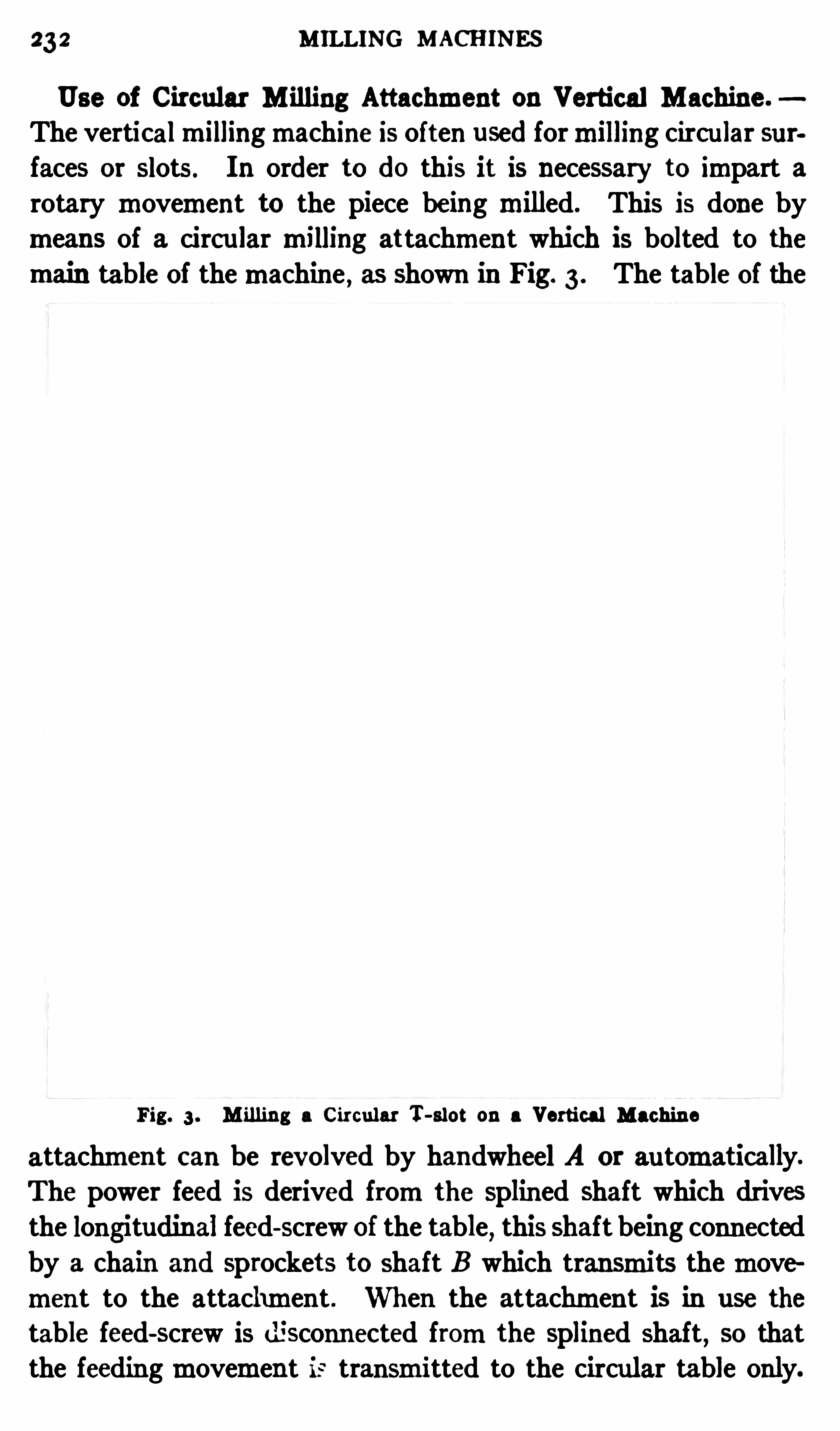
232 MILLING MACHINES
Use of Circular M illing Attachment on Vertical Machine.
The verticalmillingmachine is often used formilling circu lar surfaces or slots. In order to do this it is necessary to impart arotary movement to the piece being milled. This is done bymeans of a circular milling attachment which is bolted to themain table of themachine , as Shown in Fig. 3 . The table of the
Fig. 3 . M illing a Circular T-slot on a Vertical Machine
attachment c an be revolved by handwheel A or automatically.
The power feed is derived fromthe splined shaft which drives
the longitudinal feed-screw of the table,this shaft being connected
by a chain and Sprockets to shaft B which transmits themovement to the attachment . When the attachment is in use the
table feed-screw is disconnected fromthe splined shaft,so that
the feedingmovement is transmitted to the circular table only.

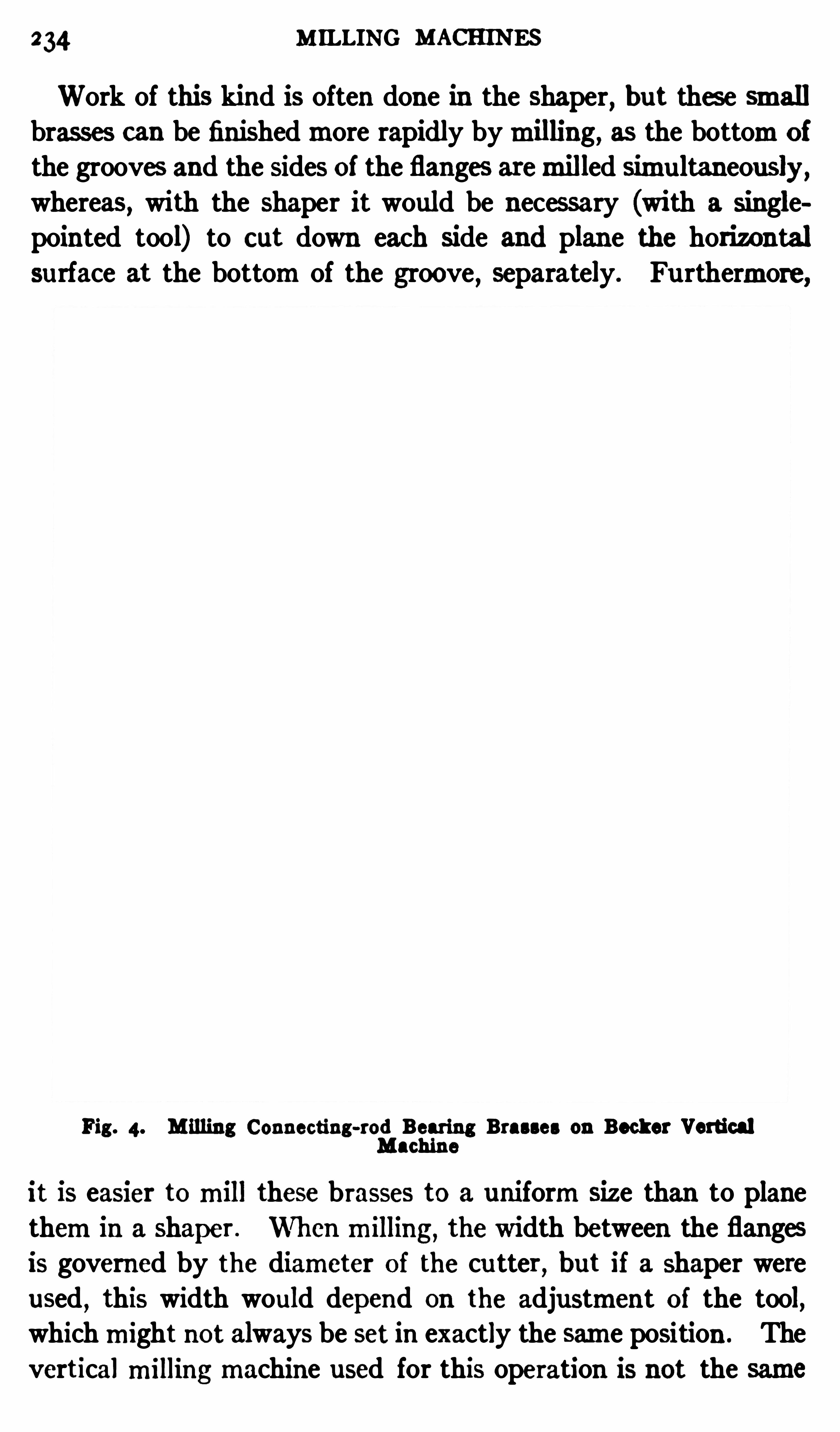
234 M ILLING MACHINES
Work of this kind is often done in the shaper, but thes e smallbrasses can be finishedmore rapidly bymilling, as the bottomof
the grooves and the sides of the flanges aremilled simultaneously ,whereas, with the Shaper it would be necessary (with a Singlepointed tool) to c ut down each Side and plane the horizontalsurface at the bottomof the groove , separately. Fu rthermore,
Fig. 4. M illing Connecting-rod Bearing Brasses on Becker VerticalMachine
it is easier tomill these brasses to a uniformSize than to planethemin a shaper . Whenmilling, the width between the flangesis governed by the diameter of the cu tter
,but if a shaper were
used , this width would depend on the adjustment of the tool,whichmight not always be set in exactly the same position . Theverticalmillingmachine used for this operation is not the same
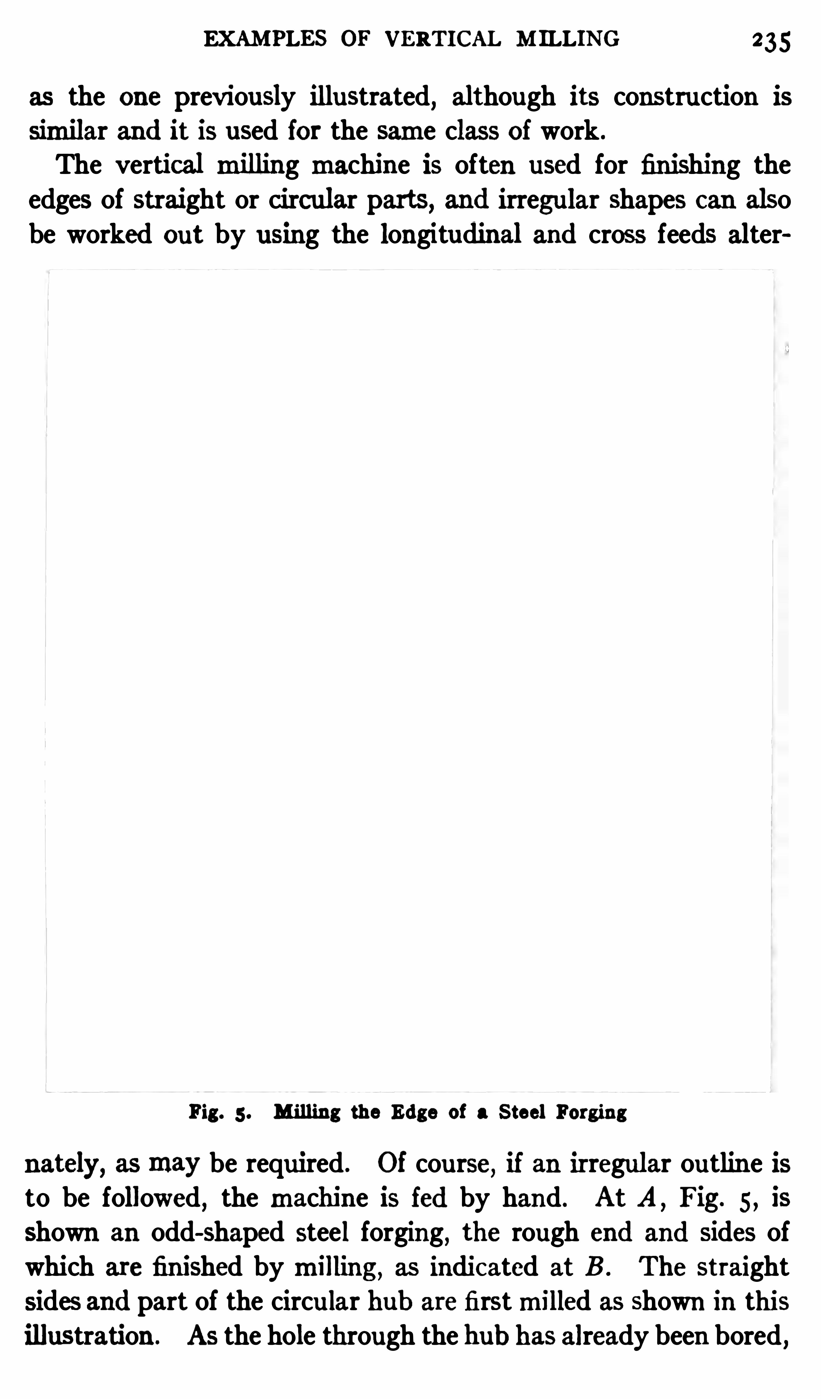
EXAMPLES OF VERTICAL M ILLING 235
as the one previously illustrated, although its construction is
Similar and it is used for the same class of work .
The vertical milling machine is often used for finishing theedges of straight or circular parts, and irregular shapes c an alsobe worked out by using the longitudinal and cross feeds alter
Fig. 5 . M illing the Edge of a S teel Forging
nately, asmay be required . Of course, if an irregular outline isto be followed
,the machine is fed by hand. At A ,
Fig. 5 , is
Shown an odd-shaped steel forging, the rough end and sides ofwhich are finished bymilling , as indic ated at B . The straightsides and part of the circu lar hub are firstmilled as shown in this
illustration . AS the hole through the hub has already been bored ,
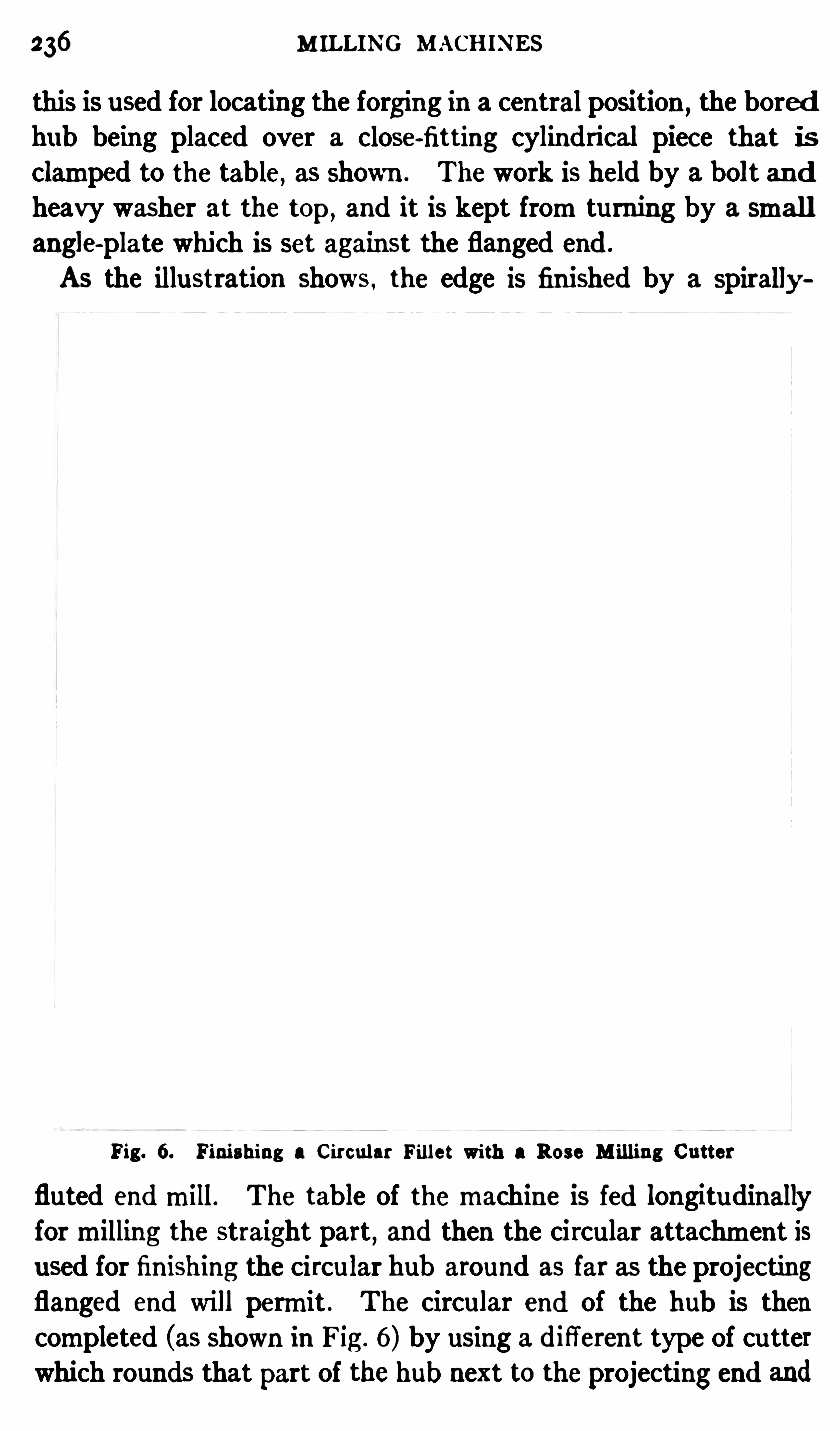
236 M ILLING MACHINES
this is used for locating the forging in a central position,the bored
hub being placed over a close-fitting cylindrical piec e that isclamped to the table, as shown . The work is held by a bolt andheavy washer at the top,
and it is kept fromturnn by a smallangle-plate which is set against the flanged end .
As the illustration shows , the edge is finished by a spirally
Fig. 6. Finishing a Circular Fillet with a Rose M illing Cutter
fluted endmill. The table of themachine is fed longitudinallyformilling the straight part , and then the circular attachment isused for finishing the circular hub around as far as the projectingflanged end will permit . The circular end of the hub is thencompleted (as shown in Fig . 6) by using a difierent type of cutter
which rounds that part of the hub next to theprojecting end and

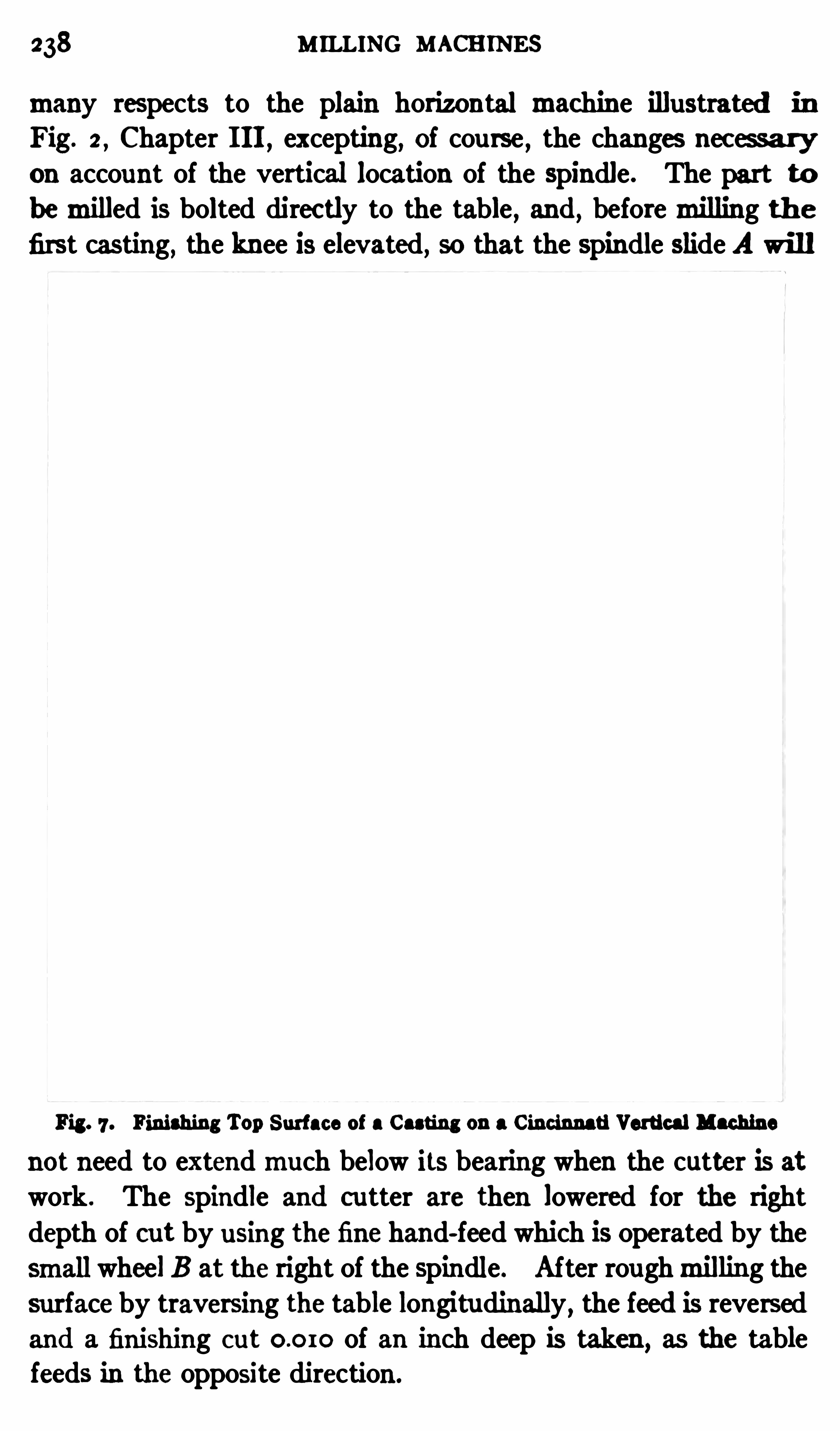
238 MILLING MACHINES
many respects to the plain horizontal machine illustrated in
Fig. 2 , Chapter I II , excepting, of course , the changes nec essa ryon account of the vertical location of the spindle. The part tobemilled is bolted direc tly to the table , and , beforemilling th efirst casting, the knee is elevated, so that the spindle slide A will
Fig. 7 . Finishing Top Surface of a Casting on a Cincinnati Vertical Machine
not need to extendmuch below its bearing when the cutter is atwork . The Spindle and cutter are then lowered for the right
depth of cut by using the fine hand-feed which is Operated by thesmall wheel B at the right of the Spindle. After roughmilling thesurface by traversing the table longitudinally
,the feed is reversed
and a finishing c ut of an inch deep is taken , as the tablefeeds in the opposite direction .
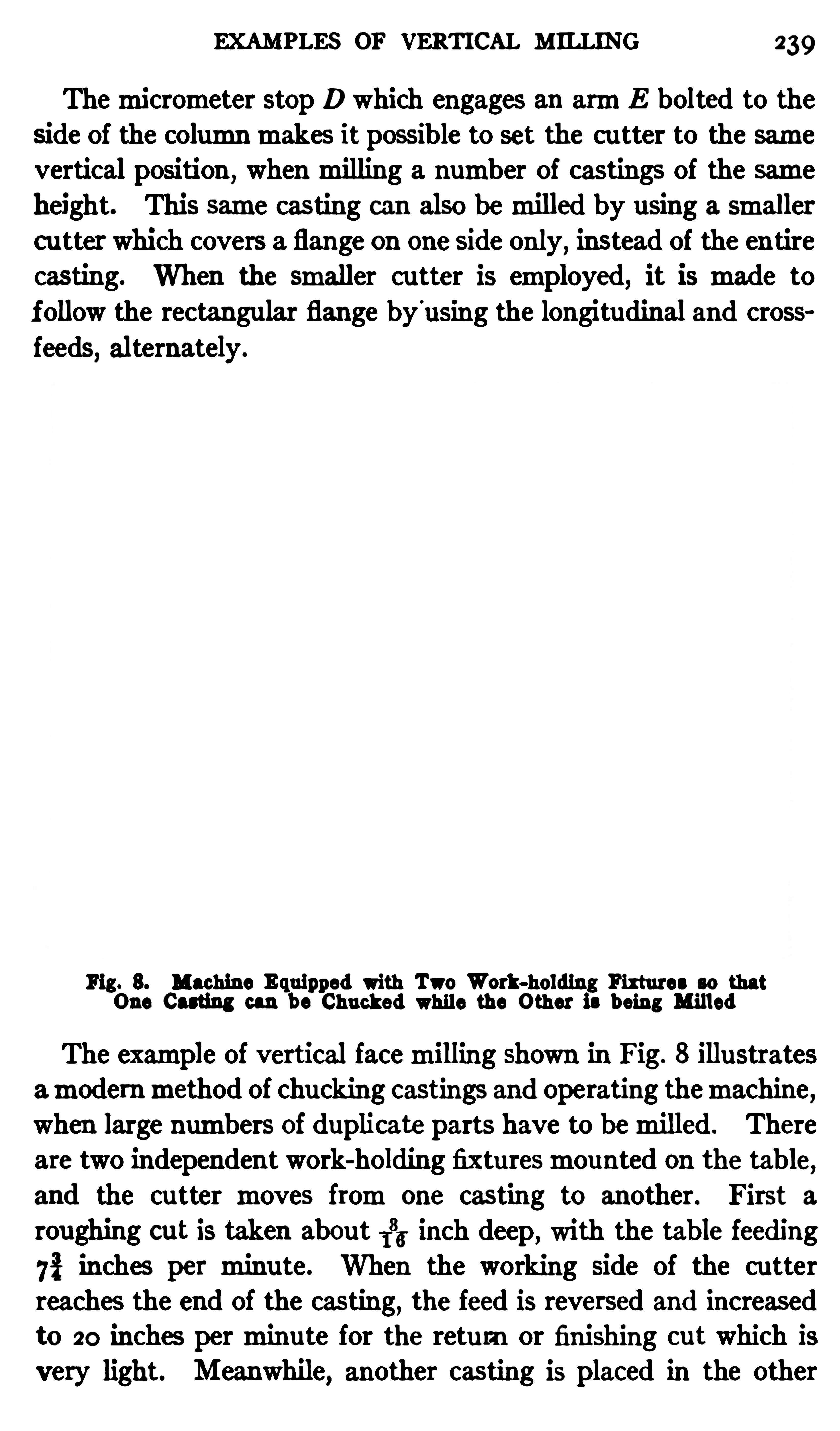
EXAMPLES OF VERTICAL MILLING 239
Themicrometer stop D which engages an armE bolted to theside of the columnmakes it possible to set the cu tter to the samevertical position ,
whenmilling a number of castings of the sameheight. This same casting can also bemilled by using a smallercutter which covers a flange on one Side only, instead of the entirecasting. When the smaller cutter is employed, it is made tof ollow the rectangular flange byusing the longitudinal and cross
feeds, alternately .
Fig. 8. Machine Equipped with Two Work-holding Fixtures so thatOne Casting can be Chucked while the Other is being Milled
The example of vertical facemilling shown in Fig. 8 illustratesamodernmethod of chucking castings and operating themachine ,when large numbers of duplicate parts have to bemilled . There
are two independent work-holding fixturesmounted on the table,
and the cutter moves fromone casting to another . First a
roughing cut is taken about 133 inch deep, with the table feeding
75} inches per minu te. When the working side of the cutterreaches the end of the casting, the feed is reversed and increasedto 20 inches perminute for the return or finishing out which is
very light. Meanwhile, another casting is placed in the other
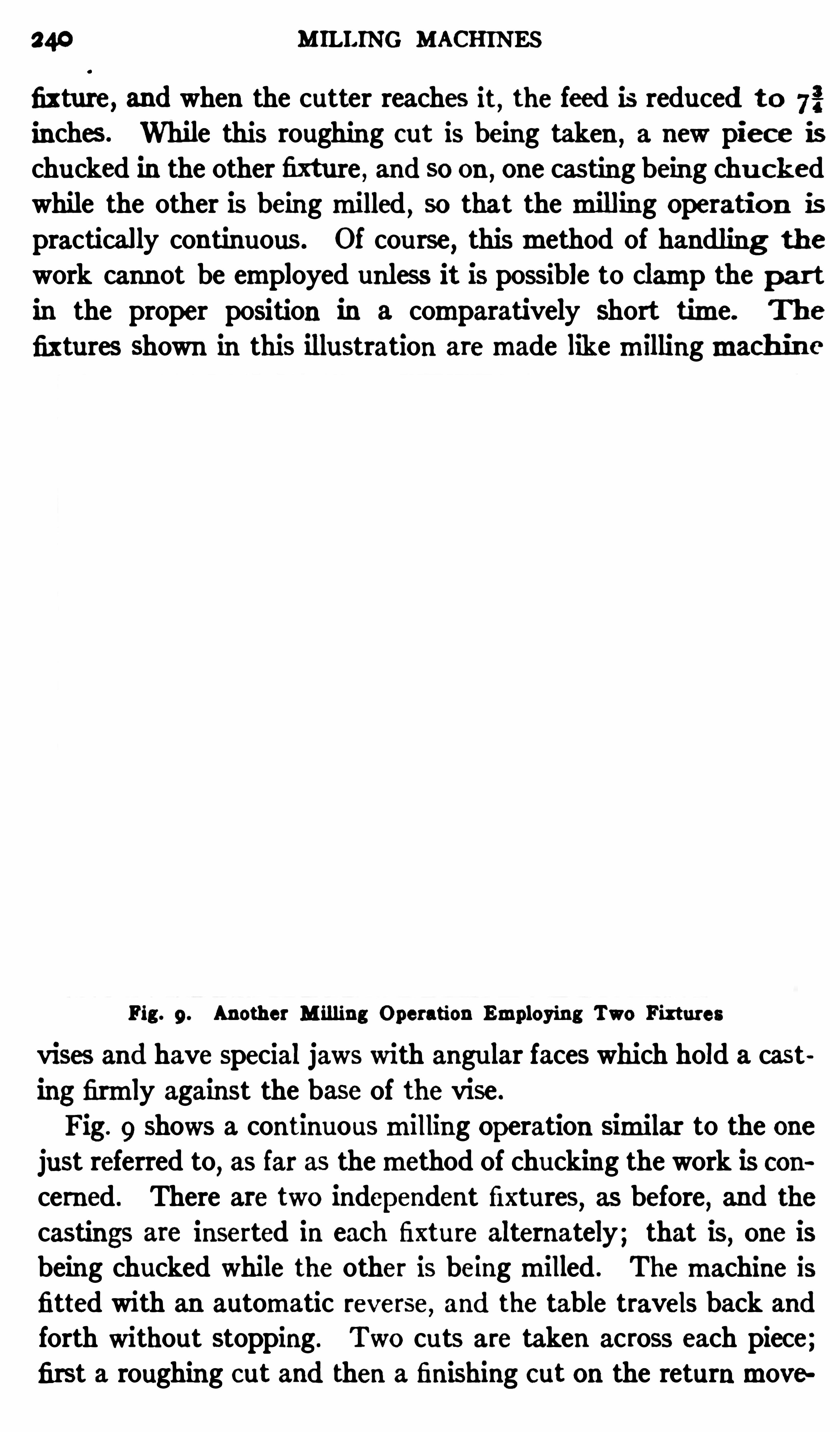
240 MILLING MACHINES
fixture , and when the cutter reaches it, the feed is reduced to 72inches. While this roughing cut is being taken
,a new piec e is
chucked in the other fixture , and so on , one casting being chu c kedwhile the other is beingmilled
,so that themilling Operatio n is
practically continuous. Of cou rse,thismethod of handling the
work cannot be employed unless it is possible to clamp the par tin the proper position in a comparatively Short time. The
fixtures Shown in this illustration aremade likemillingmach in e
Fig. 9. Another M illing Operation Employing Two Fixtures
vises and have Special jaws with angular faces which hold a cast
ing firmly against the base of the vise .
Fig. 9 shows a continuousmilling Operation similar to the onejust referred to
,as far as themethod of chucking the work is con
cerned . There are two independent fixtures, as before, and the
castings are inserted in each fixture alternately; that is, one isbeing chucked while the other is beingmilled . Themachine isfitted with an automatic reverse, and the table travels back and
forth without stopping . Two cuts are taken across each piece;first a roughing c ut and then a finishn c ut on the returnmove

242 MILLING MACHINES
such a position that the row of forgings will pass beneath therear side of the cutter which then faces the top surfaces . AS thefinished parts come around to the front of themachine, they are
removed by the operator and replaced by rough forgings withou tstopping themachine, so that themilling operation is practicallycontinuous .
A fixture for continuous circ ularmillingmust be des igned so
that the work can be removed quickly and without stopping therotation of the table. In this instance , the forgings are locatedin the fixture by pins and they are held by the pivoted clampsShown . The inner surfac es of these clamps have fine teeth and
are eccentric to the pivot about which the clamps swivel, so thatthe forging is either released or gripped Simply by turning theclamp in one direction or the other.The face cutter used for this operation has high-speed steel
inserted blades and takes an average depth of cut of about 3 inch.
While themilling cu tter is at work, a streamof cooling lubricantflows onto it fromthe jointed pipe seen to the left of the Spindle.
In order to catch the lubricant as it falls fromthe table,the latter
is surrounded by a flanged pan .
Die-sinking Machine. The die-sinking machine,Shown in
Fig. 1 1,is a type of vertic al-spindle millingmachine especially
designed for the use of diemakers inmilling out the impressionsin drop forging dies , etc .
, or for finishing recesses of circ ular or
irregular shape. The part to be milled is held in a vise on the
machine table which has lateral, longitudinal, vertical and rotaryfeeding movements effected by the handwheels shown . As die
irnpressions are usually very irregular in form,the feedingmove
ments of thework-table are controlled entirely by hand , because,formostwork, the cuttermust bemade to follow a line the dircetion of which changes constantly so that an automatic feed wouldbe useles s. The handwheel at the front is for the lateralmovement, the one at the left side is for the longitudinalmovement,and the small wheel placed at an angle is for rotating the table.The large pilot wheel at the side of the knee is for feeding the
table vertically.
The cutters used for die-Sinking aremade in a great variety of
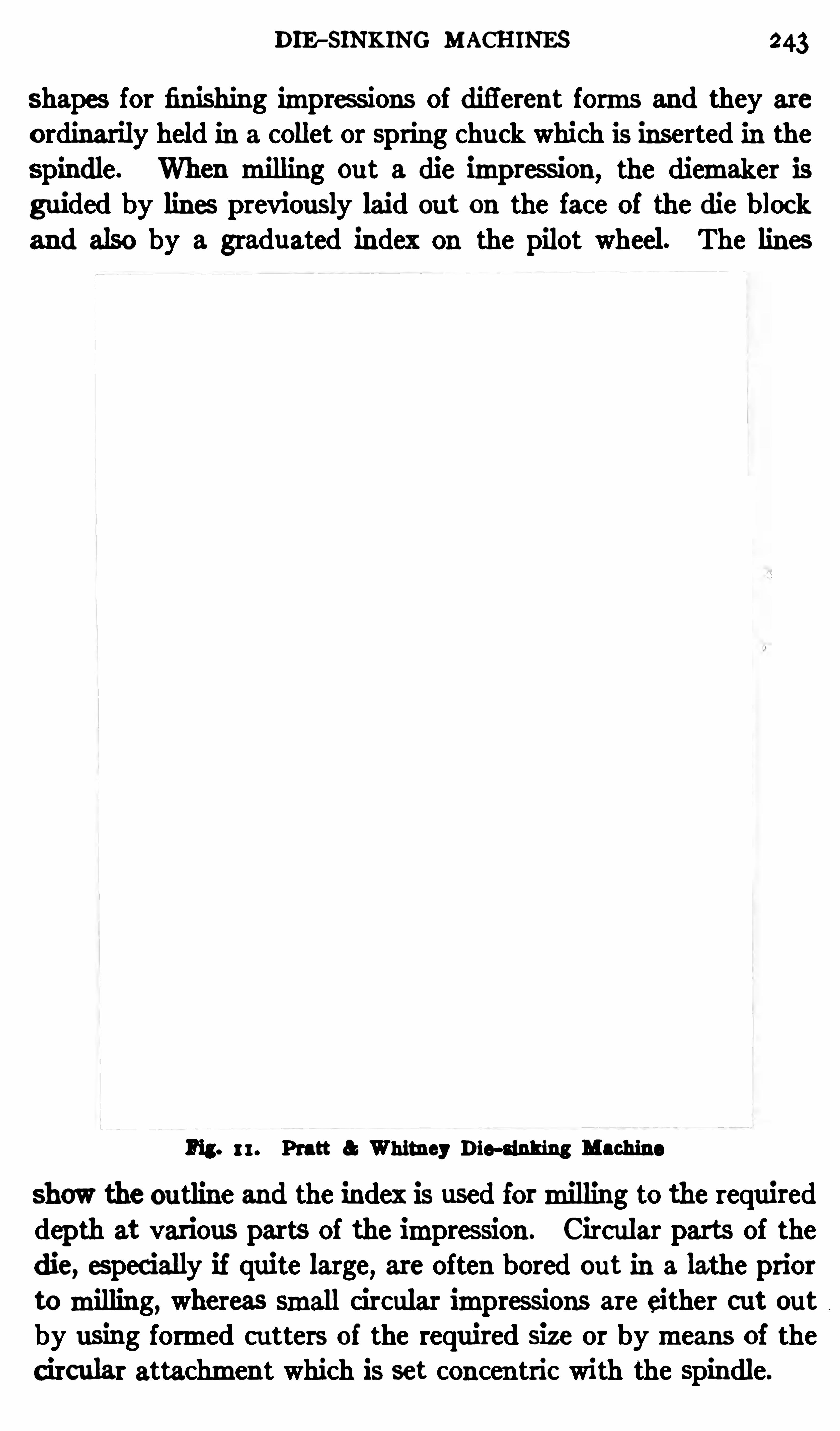
DIE - SINKING MACHINES 243
shapes for finishing impressions of diflerent forms and they are
ordinarily held in a collet or spring chuck which is inserted in thespindle. When milling out a die immession , the diemaker isguided by lines previously laid out on the face of the die blockand also by a graduated index on the pilot wheel. The lines
Fig. 11. Pratt a Whitney Die-sinking Machine
Show the outline and the index is used formilling to the requireddepth at various parts of the impression . Circular parts of the
die, especially if quite large, are often bored out in a lathe prior
tomilling, whereas small circular impressions are either cut outby using formed cu tters of the required size or bymeans of the
c ircular attachment which is set concen tric with the spindle.
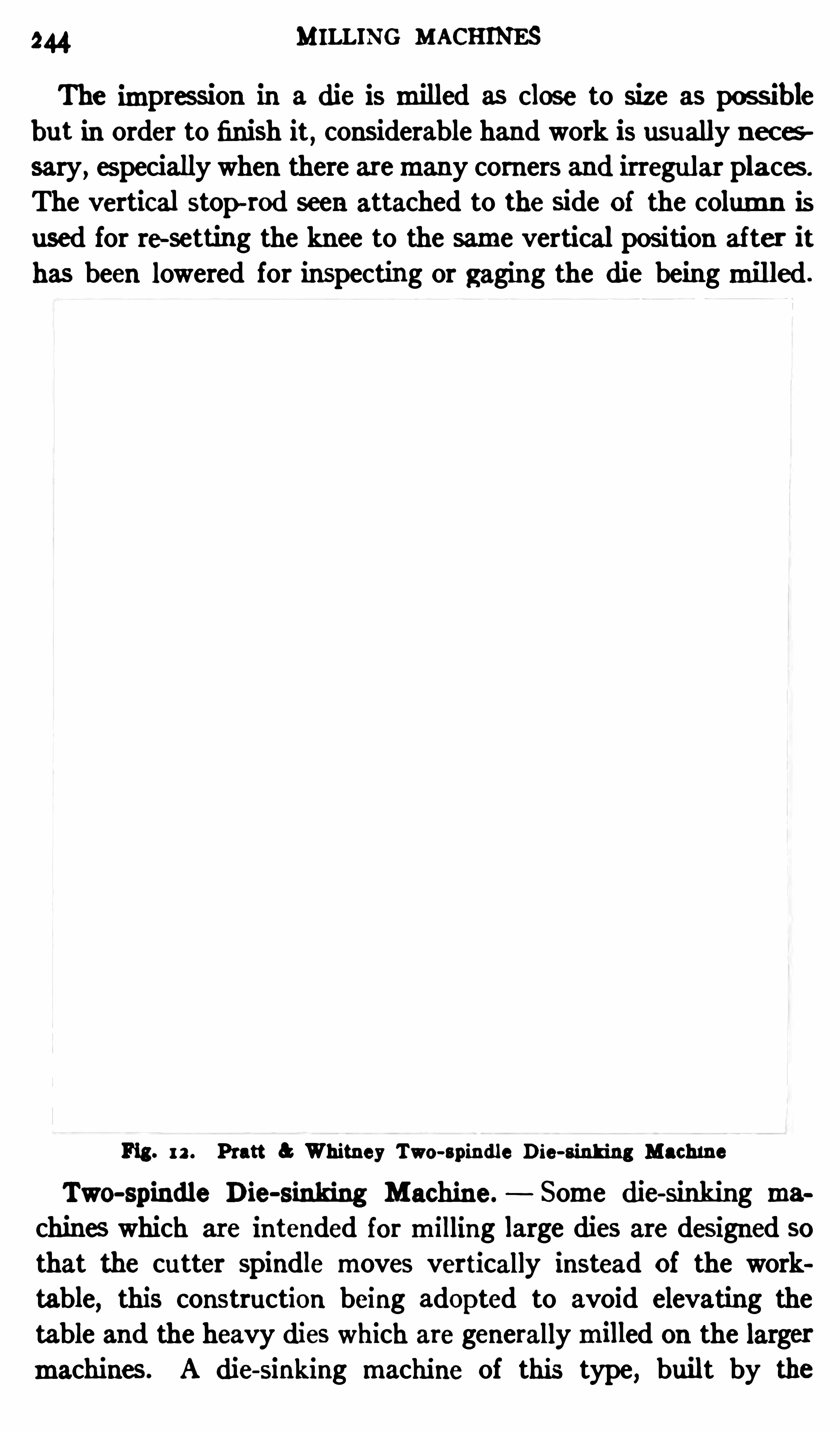
244 MILLING MACHINES
The impres sion in a die is milled as close to size as possib le
but in order to finish it, considerable hand work is usually nec es
sary, especially when there aremany corners and irregular places .
The vertical stop-rod seen attached to the Side of the column isused for re setting the knee to the same vertical position af ter it
has been lowered for inspecting or gaging the die beingmilled .
Fig. 12 . Pratt Whitney Two-spindle Die-Sinking Machine
Two-spindle Die-sinking Machine. Some die-sinking machines which are intended formilling large dies are designed sothat the cutter spindle moves vertically instead of the worktable, this construction being adopted to avoid elevating thetable and the heavy dies which are generallymilled on the largermachines . A die-sinking machine of this type
,built by the

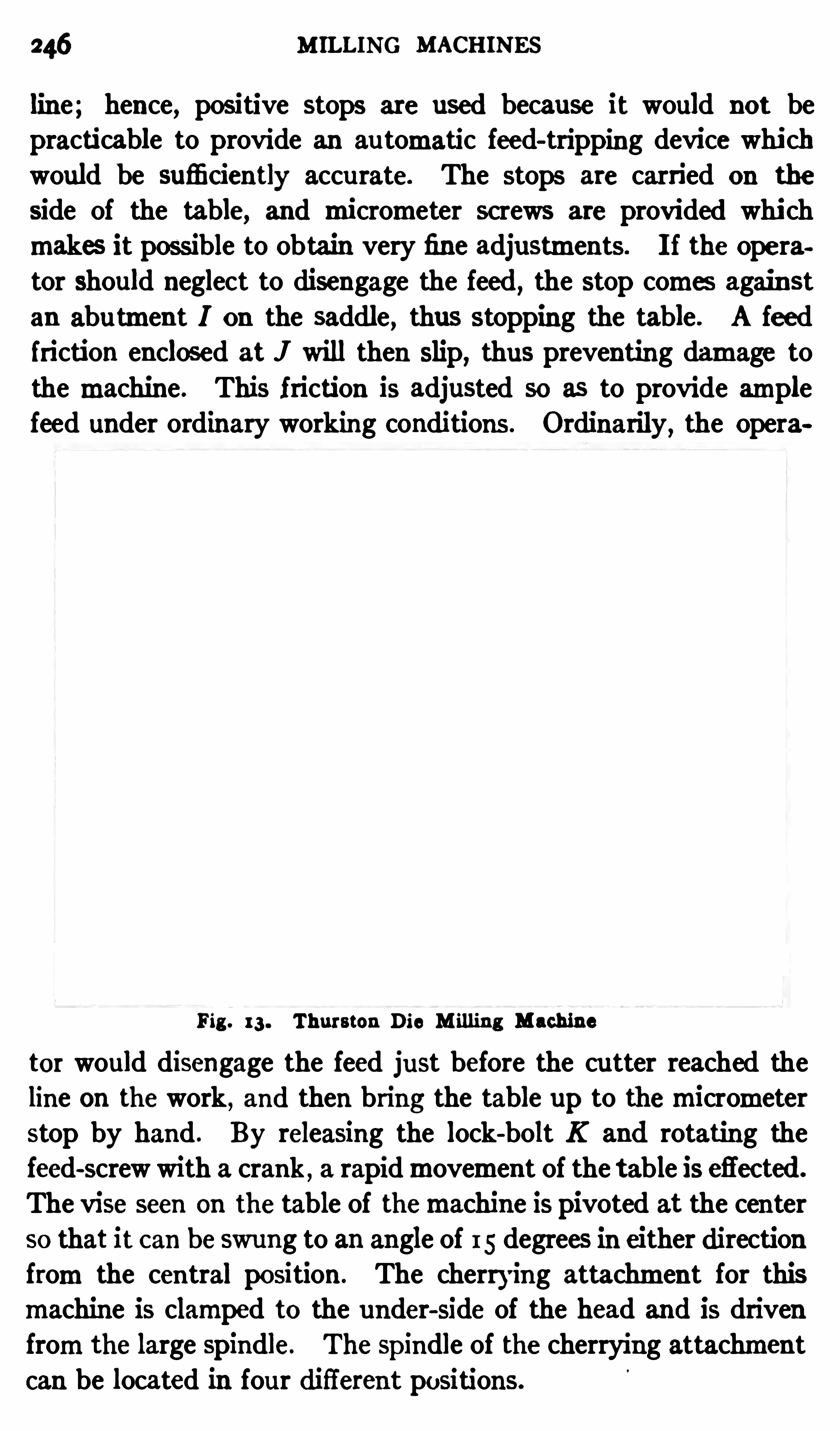
246 MILLING MACHINES
line; hence, positive stops are used because it would not bepracticable to provide an au tomatic feed-tripping device whichwould be sufi ciently accu rate. The stops are carried on the
side of the table, and micrometer screws are provided which
makes it possible to obtain very fine adjustments. I f the Operator should neglect to disengage the feed
,the stop comes again st
an abutment I on the saddle, thus stopping the table . A feedfriction enclosed at J will then slip, thus preventing damage tothe machine. This friction is adjusted so as to provide amplefeed under ordinary working conditions . Ordinarily , the Opera
Fig . 13 . Thurston Die M illing Machine
tor would disengage the feed just before the cutter reached theline on the work ,
and then bring the table up to themicrometerstop by hand . By releasing the lock-bolt K and rotating thefeed-screw with a crank , a rapidmovement of the table is efiected .
The vise seen on the table of themachine is pivoted at the centerso that it can be swung to an angle of 15 degrees in either directionfromthe central position. The cherrying attachment for thismachine is clamped to the under-Side of the head and is drivenfromthe large Spindle. The Spindle of the cherrying attachmentcan be located in four difl
'
erent positions.
DIE-SINKING MACHINES 247
Under-cutting Die M illing Machine. This is a type of diemillingmachine having a cu tter which is driven frombeneath thework-table, and extends up into the die Opening instead of beingheld by a spindle fromabove
,in the usualmanner. One advan
tage of this construction is that lines on the die face showing theou tline or contour of the die opening are not obstructed by thec u tter or Spindle. One design of under-cut diemillingmachineis shown in Fig. 13 . Thismachine is intended formilling variousforms of blanking dies, trimming dies, etc. The die to bemilledis held on a table which is carried by cross and longitudinal slides.
The cutter spindle projects upward through the die opening, andby manipulating the handles which operate the two slides
,the
work is fed against themilling cutter in the required direction .
The vertical Spindle is adjustable, and the cutter projects throughan opening in the chuck in which the die is clamped. The cuttermay either be straight, or tapered to suit the amount of clearancerequired in the die.
Whenmilling out a die Opening,it is nec essary to drill a hole
through the die to forma starting place for the cutter. The
latter is then fed around the outline of the die Opening, as pre
viouslymentioned ,and the entire center is removed in the form
of a solid block . The raising and lowering of the cu tter-Slide is
eflec ted by means of the lower handle seen at the front of the
machine. The upper handle at the fron t and the one at the right
end of the machine control the crOSS and longitudinal movements, respec tively . There is a pointer on themachine whichremains in a fixed position with reference to the cutter
,so that
when the latter is operating below the su rface of the die,the
pointer indicates its exact position . The entire frame of the
machine is mounted on trunnions SO that the work can be in
c lined to any desired position ,in order to give the Operator the
best possible light on the surface of the die.
Combined Horizontal and Verti cal Machine. The millingmachine, a detailed view of which is shown in Fig. 14, has bothvertical and horizontal spindles which forman in tegral part ofthe machine. These spindles may b e run independently or in
unison ,so that themachine is adapted for either vertical or hori
248 MILLING MACHINES
zontalmilling and on some classes of work both Spindles a n b e
used at the same time . The illustration Shows how twenty-six eas t
links aremilled . The vertical spindlemachines fourteen links onthe flat side, whereas the horizontal spindlemills twelve links onthenarrow edge, both the verticalandhorizontal spindles operatingsimultaneously. Two 16-inch facemilling cu tters are used and
the depth of cut for each cutter varies fromi to 115 inch. As will
be seen , the links are held in special fixtures in double rows.
Thismachine is of the column-and-knee type , the work-tablebeing carried by a knee whichmay be adjusted vertically on the
Fig. 14. Ingersoll Comb ined Horizontal and Vertical Milling MachineBoth Spindles in Operation
column . The table has automatic longitudinal, transverse and
vertical feeding movements,all of which are reversible. The
rate of table feed as well as the spindle speed c an be varied withinwide limits bymeans of change gears which are shifted by controllevers at the side of themachine. Themachine is driven either bymotor or a single constant-speed belt pu lley at the rearwhich transmitsmotion to each spindle by shafts and connec ting gearing.
P rofiling Machines. A profilingmachine or profiler is a
type of verticalmillingmachine which is largely used formakingparts of guns , pistols, typewriters , sewingmachines and for simi

2 50 M ILLING MACHI NES
two cutter spindles A and B are carried by a saddle tha t ismounted on a cross-rail, as Shown . One Spindle is used for taking roughing cu ts and the other for finishing cuts . The saddle
is traversed along the cross-rail by handle E for locating ei therspindle in the working position
,whereas handle D is used for
moving the table along theways of the bed at right angles to the
cross-rail. Each spindle is carried by a vertical Slide and is
lowered to the working position by a hand lever at the top. The
spindles can be set in the required vertical position each time a
new part is profiled by means of plungers or stop-rods operatedby handles H. These plungers slide out and engage notches in
the strips G which are attached to the spindle slide and are ad
justed in accordance with the position required for the cutter.
When one cuthas been taken ,the locating plunger for that spindle
is withdrawn ; the spindle is then quickly forced upward by a
spring, far enough for the cutter to clear the work so that theother spindle c an bemoved over to the working position withou tdelay.
AS the cutters used for profilemilling are usually quite small,they revolve rapidly . The spindles of the machine illustratedare driven through spiral gearing froma horizontal Shaf t to whichcone pu lley C is attached . The spindles of some profilers are
driven directly by belts,especially when exceptionally high
speeds are necessary , and also by universally-jointed verticalshafts which transmitmotion froman overhead countershaft tothemachine.
Example of P rofileMilling . The profilingmachine illustratedin Fig. 15 is arranged for milling the ou tside of a rifle trigger
guard . When the machine is in operation ,one of the former
pins AI or B 1 (depending upon which cu tter is being used) isbrought into contact with the former plate ormodel F attachedto the work-table. The pin which is clamped to the cutterspindle slide andmoves with it is thenmade to follow the outline of the former plate by manipu lating the lateral and longitudinal feeds, handles D and E being used for this purpose. In
this way ,the cutter ismade to follow a path which corresponds
to the Shape of the former plate, thus reproducing this formon
PROFILING 25 1
the work . Roughing and finishing cu ts are taken by bringingfirst the roughing cu tter spindle and then the one carrying the
finishing cutter into contact with the former, each Spindle beingset in the correct vertical position by the stop-rods operated by
handles H.
The edge of the former plate is beveled or tapered and the pin
has a corresponding taper,so that the cu tter can be adjusted
laterally,within certain limits
,by simply adjusting the former
pin vertically. For instance,if when setting up themachine it
is desired tomove the cutter a little toward the work for taking
Fig . 16. Profiling Inside of Finger Lever for a Repeating Rifle
a deeper cut,this can be done by raising the pin slightly; a
smaller part of the taper will then come into contact with thebeveled edge of the former plate so that the relation betweenthe work and cutter is changed .
The Operation of a profiler is comparatively simple after it isproperly set and adjusted
,b utmany of thework-holding fixtures
and former plates required for certain classes of work are ln
genious and interesting. The following examples of profilingwill illustrate , in a general way, the nature and variety of workwhich is done on machines of this type . These examples are
Operations on rifle and pistol parts and represent the practice at
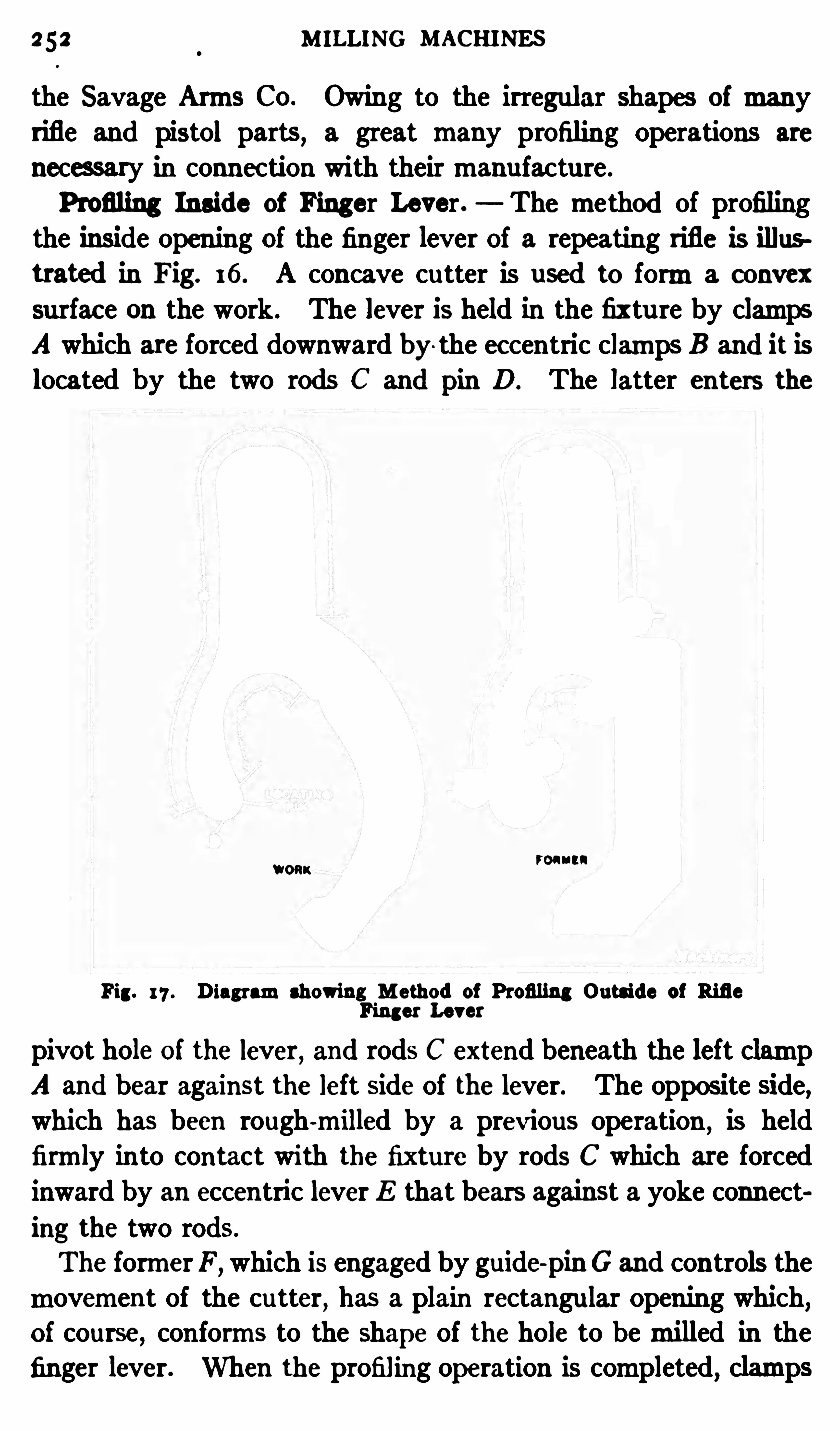
2 52 M ILLING MACHINES
the Savage Arms Co. Owing to the irregular Shapes of manyrifle and pistol parts , a great many profiling Operations are
necessary in connection with theirmanufacture .
Profiling Inside of Finger Lever. The method of profilingthe inside opening of the finger lever of a repeating rifle is illustrated in Fig. 16. A concave cutter is used to forma convexsurfac e on the work . The lever is held in the fixtu re by clampsA which are forced downward by the ec centric clamps B and it is
located by the two rods C and pin D. The latter enters the
WORK7
Fig. 17 . Diagramshowing M ethod of Profiling Outside of RifleFinger Lever
pivot hole of the lever, and rods C extend beneath the left clampA and bear against the left side of the lever. The opposite side,which has been rough-milled by a previous Operation , is held
firmly in to contact with the fixture by rods C which are forced
inward by an eccentric lever E that bears against a yoke connect
ing the two rods .
The formerF ,which is engaged by guide-
pin G and controls the
movement of the cutter , has a plain rectangular Opening which,of course, conforms to the shape of the hole to bemilled in thefinger lever. When the profiling operation is completed, clamps

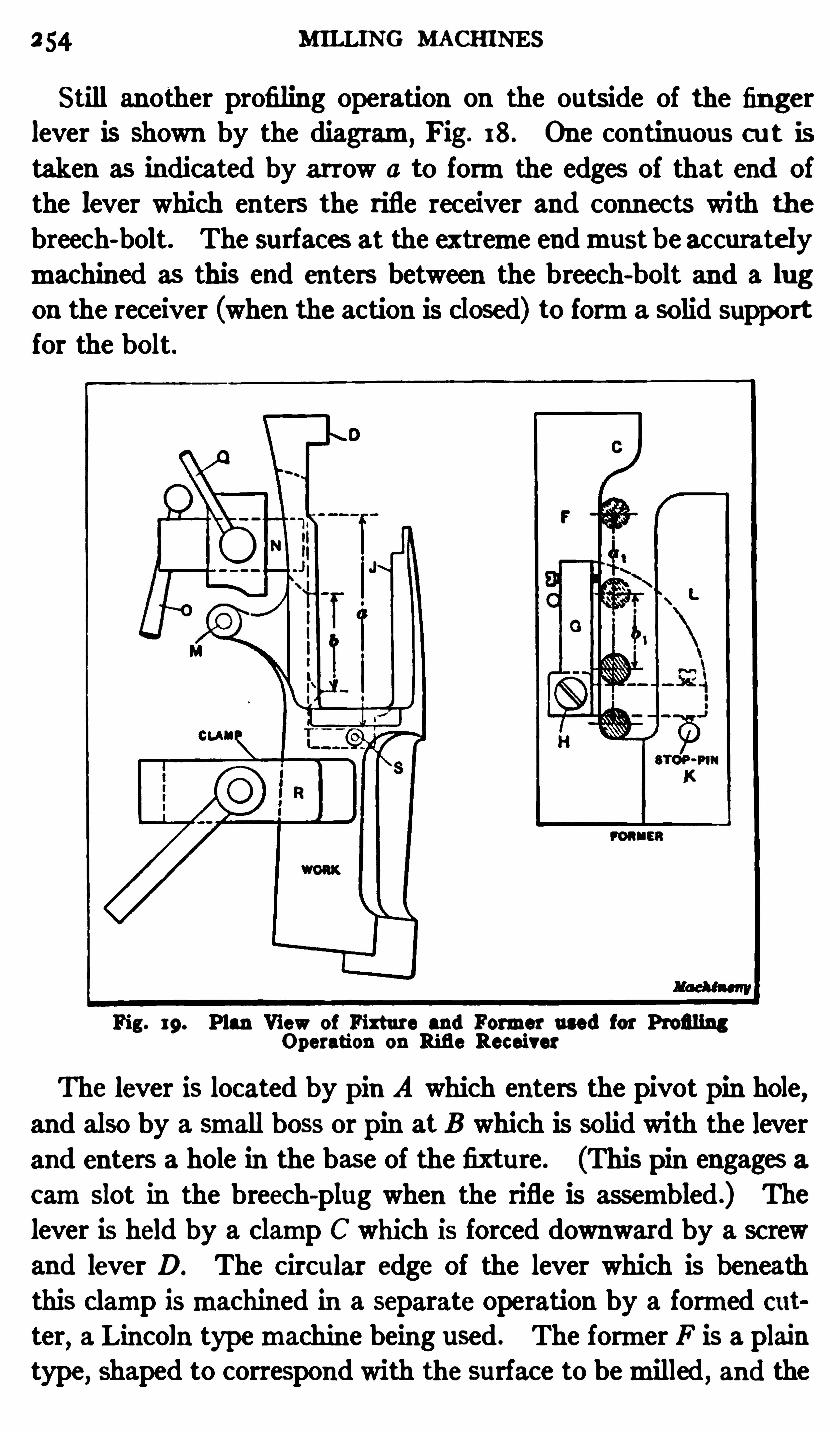
MILLING MACHINES
Still an other profiling operation on the outside of the fingerlever is Shown by the diagram,
Fig. 18. One continuous cu t istaken as indicated by arrow 0 to formthe edges of that end ofthe lever which enters the rifle receiver and connects with the
breech-bolt. The surfaces at the extreme endmust be accuratelymachined as this end enters between the breech-bolt and a lug
on the receiver (when the action is closed) to forma solid supportfor the bolt.
Fig. 19. Plan View of Fixture and Former used for ProfilingOperation on Rifle Receiver
The lever is located by pin A which enters the pivot pin hole,and also by a small boss or pin at B which is solid with the lever
and enters a hole in the base of the fixture. (This pin engages a
c amslot in the breech-plug when the rifle is assembled .) The
lever is held by a clamp C which is forced downward by a screw
and lever D. The circular edge of the lever which is beneaththis clamp ismachined in a separate operation by a formed cut
ter,a Lincoln typemachine being used. The former F is a plain
type,shaped to correspond with the surface to bemilled , and the
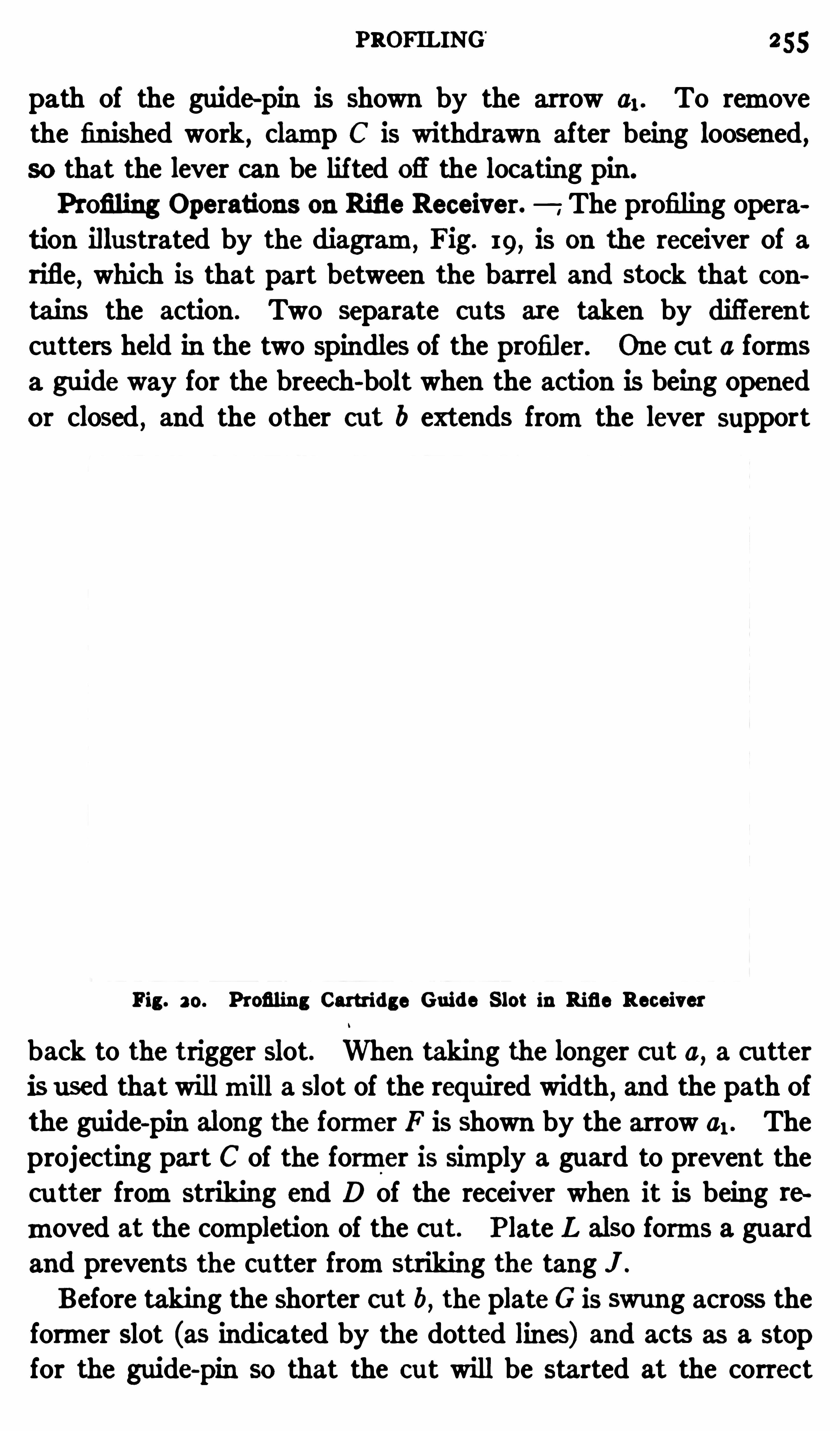
PROFILING’
255
path of the guide-pin is shown by the arrow 01. To removethe finished work
,clamp C is withdrawn after being loosened,
so that the lever can be lif ted ofl the locating pin .
Profiling Operations on Rifle Receiver. The profiling opera
tion illustrated by the diagram, Fig. 19, is on the receiver of arifle, which is that part between the barrel and stock that contains the action . Two separate cu ts are taken by diflerent
cu tters held in the two spindles of the profiler. One cut 0 formsa gu ide way for the breech-bolt when the action is being Openedor closed
, and the other cut b extends fromthe lever support
Fig . 20. Profiling Cartri dge Guide S lot in Rifle Receiver
back to the trigger slot. When taking the longer cu t a, a cutter
is used that willmill a Slot of the required width,and the path of
the guide-pin along the former F is Shown by the arrow 01. Theprojecting part C of the former is simply a guard to prevent thecu tter fromstriking end D of the receiver when it is being re
moved at the completion of the cu t. P late L also forms a guardand prevents the cu tter fromstriking the tang " .
Before taking the Shorter cut b , the plateG is swung across theformer slot (as indicated by the dotted lines) and acts as a stopfor the guide-pin SO that the cut will be started at the correct
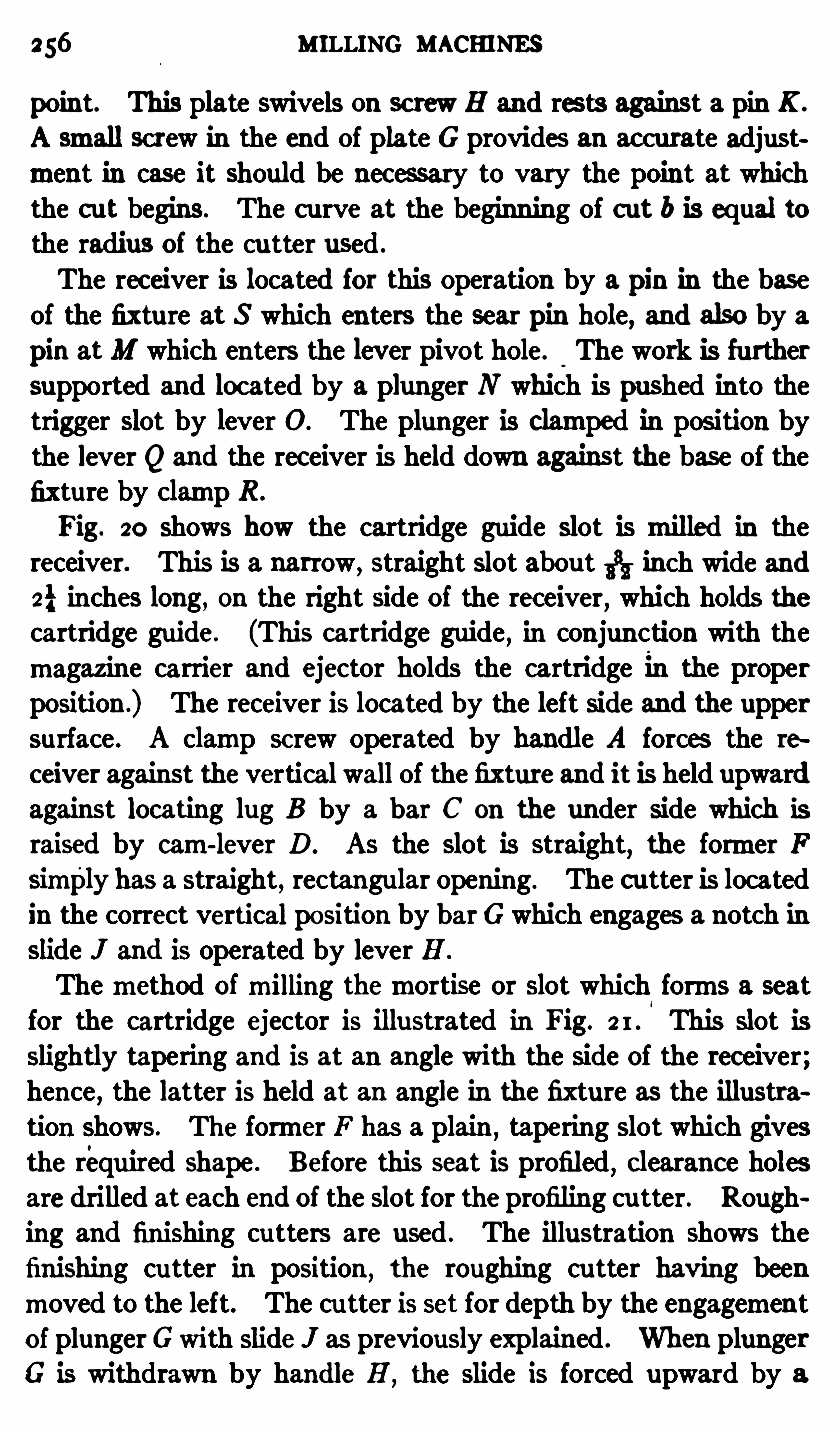
256 MILLING MACHINES
point. This plate swivels on screw H and rests against a pin K .
A small screw in the end of plate G provides an ac curate adjustment in case it Should be nec essary to vary the point at whichthe c ut begins. The c urve at the beginning of cut b is equal tothe radius of the cu tter used .
The rec eiver is located for this operation by a pin in the baseof the fixture at S which enters the sear pin hole, and also by a
pin atM which enters the lever pivot hole. The work is furthersupported and located by a plunger N which is pushed into thetrigger Slot by lever O. The plunger is clamped in position bythe lever " and the rec eiver is held down against the base of the
fixture by clamp R .
Fig. 20 Shows how the cartridge guide Slot is milled in thereceiver. This is a narrow,
straight slot abou t 55; inch wide and
2} inches long , on the right Side of the receiver, which holds thecartridge guide. (This cartridge guide , in conjun ction with themagazine carrier and ejector holds the cartridge in the properposition .) The receiver is located by the left Side and the upper
surface . A clamp sc rew operated by handle A forces the re
ceiver against the vertical wall of the fixture and it is held upwardagainst locating lug B by a b ar C on the under Side which israised by cam-lever D. AS the Slot is straight
,the former F
sirnply has a straight , rectangular opening . The cutter is locatedin the correct vertical position by barGwhich engages a notch in
Slide J and is operated by lever H .
Themethod ofmilling themortise or Slot which forms a seatfor the cartridge ejector is illustrated in Fig. This Slot is
slightly tapering and is at an angle with the Side of the receiver;hence , the latter is held at an angle in the fixture as the illustration Shows. The former F has a plain
,tapering Slot which gives
the required Shape . Before this seat is profiled,c learance holes
are drilled at each end of the slot for the profiling cu tter. Rough
ing and finishing cutters are used . The illustration shows the
finishing cu tter in position ,the roughing cu tter having been
moved to the left. The cu tter is set for depth by the engagementof plunger Gwith Slide J as previously explained . When plunger
G is withdrawn by handle H ,the slide is forced upward by a

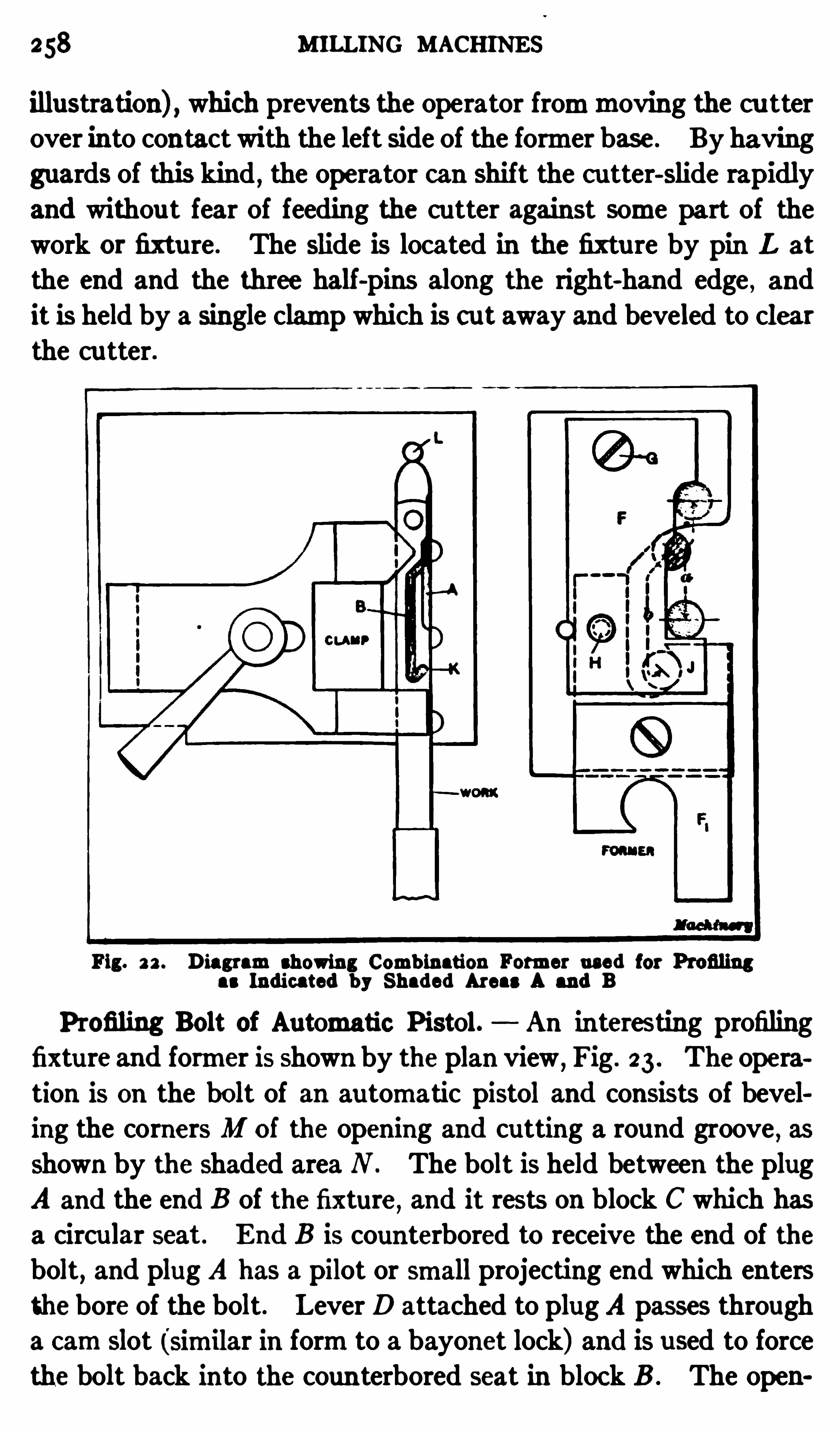
258 MILLING MACHINES
illustration) , which prevents the operator frommoving the cu tterover into contact with the left side of the former base. By having
guards of this kind , the operator can shift the cutter-Slide rapidly
and withou t fear of feeding the cutter against some part of thework or fixture . The Slide is located in the fixtu re by pin L at
the end and the three half -pins along the right-hand edge , and
it is held by a single clamp which is cu t away and beveled to clearthe cutter.
Fig. 2 2 . Diagramshowing Comb ination Former used for Profilingas Indicated b y Shaded Areas A and B
P rofiling Bolt of Automatic P istol. An interesting profiling
fixture and former is shown by the plan view ,Fig. 23 . The opera
tion is on the bolt of an automatic pistol and consists of beveling the corners M of the opening and cutting a round groove
,as
Shown by the Shaded area N . The bolt is held between the plug
A and the end B of the fixture, and it rests on block C which has
a circular seat. End B is counterbored to receive the end of thebolt
,and plug A has a pilot or small projecting end which enters
the bore of the bolt. Lever D attached to plug A passes through
a camSlot (similar in formto a bayonet lock) and is used to forcethe bolt back into the coun terbored seat in block B . The open
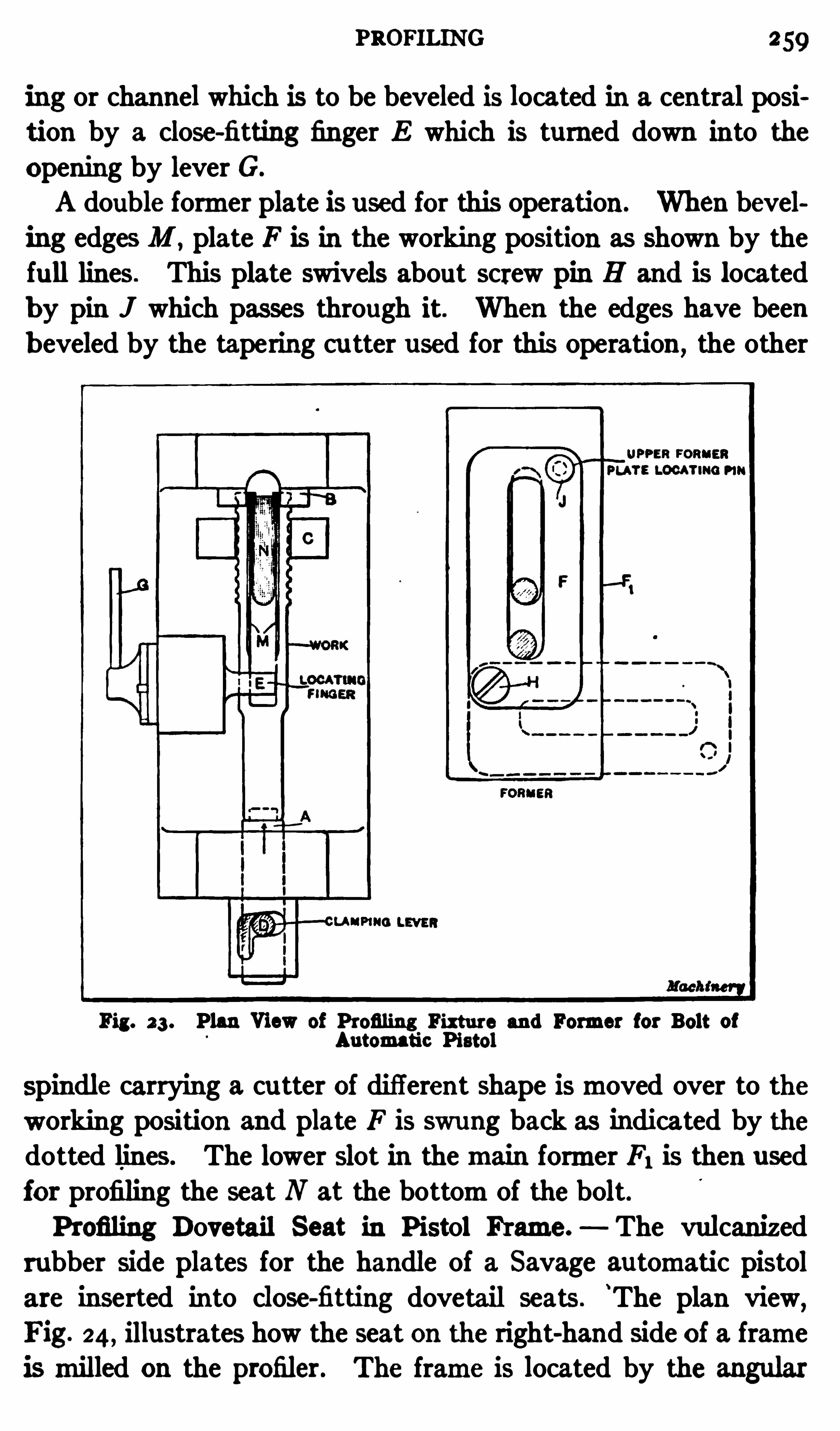
PROFILING 259
ing or channel which is to be beveled is located in a central posi
tion by a close-fitting finger E which is turned down into the
Opening by lever G.
A double former plate is used for this operation . When bevel
ing edges M , plate F is in the working position as Shown by thefu ll lines . This plate swivels about screw pin H and is locatedb y pin J which passes through it. When the edges have beenb eveled by the tapering cu tter used for this operation ,
the other
Fig. 23 . Plan View of Profiling Fixture and Former for Bolt ofAutomatic Pistol
spindle carrying a cu tter of different shape ismoved over to theworking position and plate F is swung back as indicated by thedotted lines . The lower slot in themain former F1 is then usedfor profiling the seat N at the bottomof the bolt.P rofiling Dovetail Seat in P istol Frame. The vulcanized
rubber Side plates for the handle of a Savage automatic pistolare inserted into close-fitting dovetail seats .
‘
The plan view,
Fig. 24 , illustrates how the seat on the right-hand Side of a frameismilled on the profiler. The frame is located by the angular
MILLING MACHINES
strip A and the boss B on the Side of the frame , which enters acircu lar seat in the projecting lug shown . The frame is clampedagainst the bottomof the fixture by two hook c lamps C and C1.
These clamps enter themagazine opening and the lower ends
are attached to a connecting bar that is forced downward by a
camlever D. To insure c ontact between the frame and the endstrip A ,
bolt C and the work is forced against A (as indicated bythe arrow) by tightening clamp E .
The path followed by the cu tter is Shown by arrow 0 and the
movement of the guide-pin along the former F is indicated by
Fig. 24. Fixture and Former for Profiling Dovetail Seat in S ide ofPistol Frame
arrow b . Roughing and finishing cu ts are taken . The cutters
are small and revolve very rapidly . The actual time requiredfor taking one of these dovetail cuts is only abou t five seconds.
The former F is open on the right-hand Side so the guide-pin can
enter while the cutter is in the working position .
The fixture used formilling the dovetail seat on the oppositeSide of the frame is similar to the one just described , except thatthemethod of locating the work is di ff erent because the circularlocating bosses are on the lower side and enter holes in the base
of the fixture; consequently locating strip A and the auxiliary

262 MILLING MACHINES
cu tter to strike the former along the side K . Themovementof the guide-pin around the former is indicated by the dottedline 6 .
Indexing h pe of Profiling Fixture. A profiling fixture of therevolving or indexing type is Shown in Fig. 26. The operationis that ofmilling the top and bottomends of themagazine opening in the pistol frame, to a depth of abou t i inch. The frame islocated on the circular faceplate of the fixture by the locatingbosses previously referred to , and it is held by a T-head clampbolt A which passes through it and is tightened by the handle B .
Fig. 26. Indexing Type of Profiling Fixture
When one end of themagazine ismilled , plunger C is withdrawnand armDwith the work is tu rned a half revolu tion by swingingarmD over to the opposite side of the fixture, where plunger C
engages another hole, thus locating the frame for the operationon the opposite end of the magazine opening. The profilingoperation is Simply that of forming a plain rectangular surface,former F being used to guide the cutter. The metal betweenthese milled surfaces at the ends is afterwards removed by a
Shaving operation in the shaper .
P rofiling with Indexing Former Plate. The profiling Operation illustrated in Fig. 27 is that of forming the sear trip seat in
PROFILING 263
an au tomatic pistol frame, and the surfaces above the sear tripseat . The nature of the operation is illustrated by the diagramsA ,B and C. The sear trip seat, which is abou t inch deep
, is
formed by two separate cuts as Shown by the sketches A and B ;
the surfaces above this seat, which are represented by the shadedarea at C, are thenmilled .
A c utter in one Spindle is used for the sear trip seat, and anotherc u tter in the other spindle for milling the top su rfaces. The
Fig. 2 7 . Profiling Operation requiring an Indexing Former Plate
former plate F contains two guide-pin holes G and H . Hole Gis used when profiling the seat (as at A and B ) and hole H for
the other operation ,the former plate F being indexed to locate
either of these holes in the working position . This plate swivels
abou t the screw pin D and is located by the spring plunger Ewhich enters holes J and K in the former base .
The frame to be profiled is held against an angle-plate (attached to the base of the fixture) by T-head clamp bolt L which
64 M ILLING MACHINES
passes through the frame and is tightened by lever M . Circular
locating bosses on the side of the frame engage holes in the ang leplate and locate the frame In the proper position . Whenmillingthe seat , the former plate IS in the position shown In the illustra
tion; that is , with plunger E engaging hole " ,thus loc ating the
former hole G in the working position . The cutter is droppeddown to the proper depth by the vertical locating device for the
spindle Slide . The guide-pin is then traversed around hole G,
but when the cu tter reaches corner a (see Sketch A) themovement is continued along a straight line , as indicated by the arrows ,thus forming a rectangular slot as the diagramshows.
The auxiliary plate N on the former is then swung across the
end of hole G, as Shown by the dotted lines, thus blanking off
this end . The seat is then finished as at B . If plate N were
not used and the gu ide-
pin simply followed the slot in the former ,the corner at 0 would be rounding instead of square . The end
of the plate N , however, causes the guide-pin and cu tter tomovestraight in ,
thusmilling a square corner.
When the sear trip seat is finished , plunger E is withdrawn andthe plate is indexed to loc ate hole H in the working position ,
plunger E being engaged with hole K . A cutter in the opposite spindle , which is located at a higher level, is then used to
mill the upper surfaces as indicated by the Shaded areas insketch C.
In practically all of the profiling operations desc ribed in theforegoing, both roughing and finishing cuts are taken . Someof the roughing cu ts are quite heavy , but the light finishing cutswhich follow insure accurate and smooth surfaces .
Semi-automatic Profiler. In armories, etc.,where large
numbers of irregular-shaped partsmust bemilled, semi-automaticprofilingmachines are used to some extent in place of the handoperated type previously described . The P ratt Whitneymachine is illustrated in Fig. 28. The head in which the cutter
Spindles aremounted is stationary while themachine is operating, and the required formor contour is obtained by themovement of the table . The latter is carried at the front end of a
swingn armwhich is journaled in the bed between the uprights .

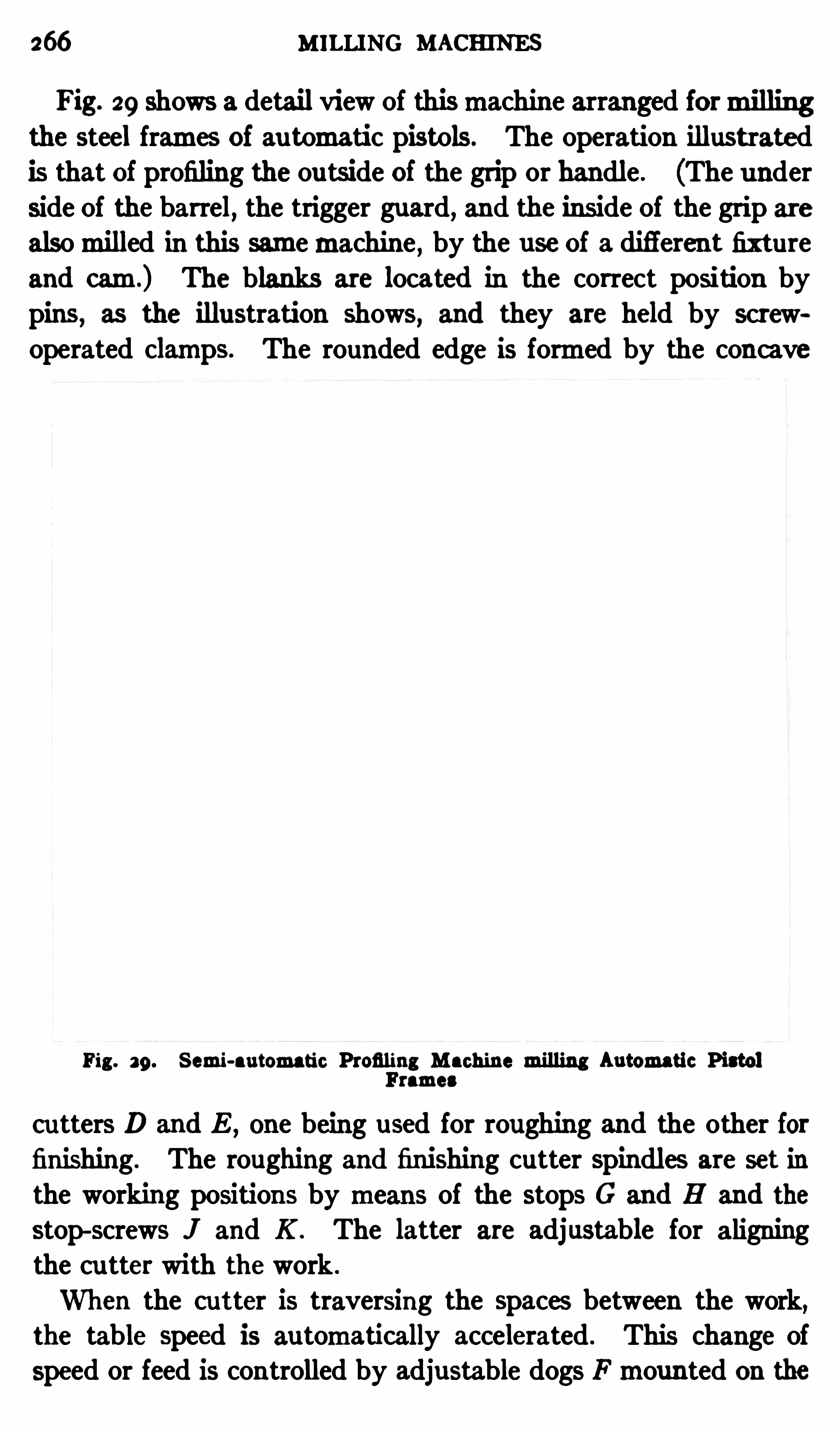
266 MILLING MACHINES
Fig. 29 shows a detail view of thismachine arranged formillingthe steel frames of automatic pistols. The operation illustrated
is that of profiling the outside of the grip or handle . (The underSide of the barrel, the trigger guard, and the inside of the grip are
alsomilled in this samemachine , by the use of a difierent fixtureand cam.) The blanks are located in the correct position bypins, as the illustration shows, and they are held by screwoperated clamps. The rounded edge is formed by the concave
Fig. 29 . S emi-automatic Profiling Machine milling Automatic Pistolramea
cu tters D and E , one being used for roughing and the other forfinishing . The roughing and finishing cutter Spindles are set in
the working positions by means of the stops G and H and the
stop-screws J and K . The latter are adjustable for aligningthe cu tter with the work .
When the cutter is traversing the spaces between the work,the table speed is au tomatically accelerated . This change of
Speed or feed is controlled by adjustable dogs Fmounted on the
LINCOLN-TYPE M ILLING MACHINE 267
periphery of the table . After the parts are rough-milled by one
of the cu tters, the other spindle is placed in the operating position for finishing the surfaces . The speed of table rotation or
the feed can be varied bymeans of a change-gearmechanism.
The Spindle Speeds can also be varied to suit the Size of themilling cu tters and thematerial beingmilled .
M illing Master Camfor Semi-automatic Profiler. When a
master camor former A Fig. 28, is required for profiling a certainpart, it is produced as follows: Roller B ,
against which the cambears when themachine is in operation ,
is replaced with amillingc utter of the same Size. The spindle of the cutter is connectedby a belt with themain shaft and amodel of the work is locatedin the fixture. A former pin of the same size as the roller andcu tter is then inserted in the cutter Spindle and placed in contact
with themodel. The camblank attached to the table is then
milled as the table feeds around . The cutter is revolved by an
independent drive . The former pin in the spindle does not
rotate while the c amis beingmilled . Several cu ts are usuallyrequired for this operation .
Lincoln Type of M illing Machine. The milling machineshown in Fig. 30 is intended especially formanufacturing; thatis
,it is not adapted to a great variety ofmilling operations but
is designed formachining large numbers of duplicate parts. The
construction is very rigid b ut comparatively simple,and , there
fore, this style ofmachine is preferable to themore complicateddesigns for work within its range. Millingmachines
,having the
same general construction as the one illustrated , are often referred
to as the Lincoln type . As will be noted , the work-table A ,
instead of being carried by an adjustable knee , is mounted on
the solid bed of themachine and the ou ter arbor-support is alsobolted directly to the bed . This construction gives a very rigid
support both for the work and cutter . The work is usually held
in a fixture or vise attached to the table , and themilling is doneas the table feeds longitudinally .
The table is not adjustable vertically, but the spindle-head B
with the Spindle can be raised or lowered as may be required.
This vertical adjustment of the spindle-head is effected by turning
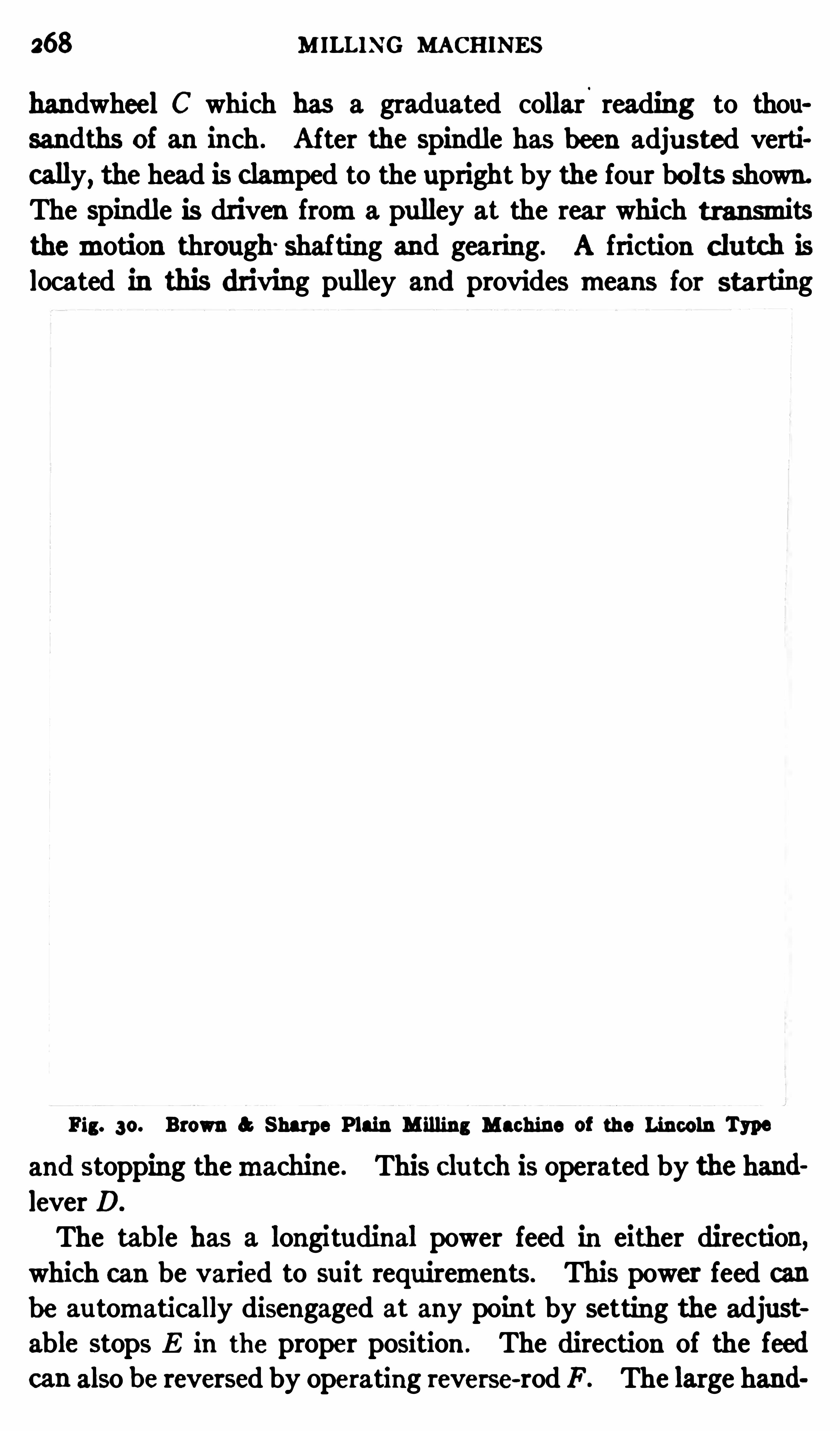
268 M ILLING MACHINES
handwheel C which has a graduated collar.
reading to thou
sandths of an inch . After the Spindle has been adju sted verti
cally, the head is c lamped to the upright by the four bolts shown.
The Spindle is driven froma pulley at the rear which transmitsthemotion through Shafting and gearing. A friction c lutch is
located in this driving pulley and provides means for starting
Fig. so. Brown a Sharpe Plain M illing Machine of the Lincoln Type
and stopping themachine . This c lu tch is operated by the hand
lever D.
The table has a longitudinal power feed in either direction,which can be varied to suit requirements. This power feed canbe au tomatically disengaged at any point by setting the adjustable stops E in the proper position . The direction of the feedcan also be reversed by operating reverse-rod F . The large hand

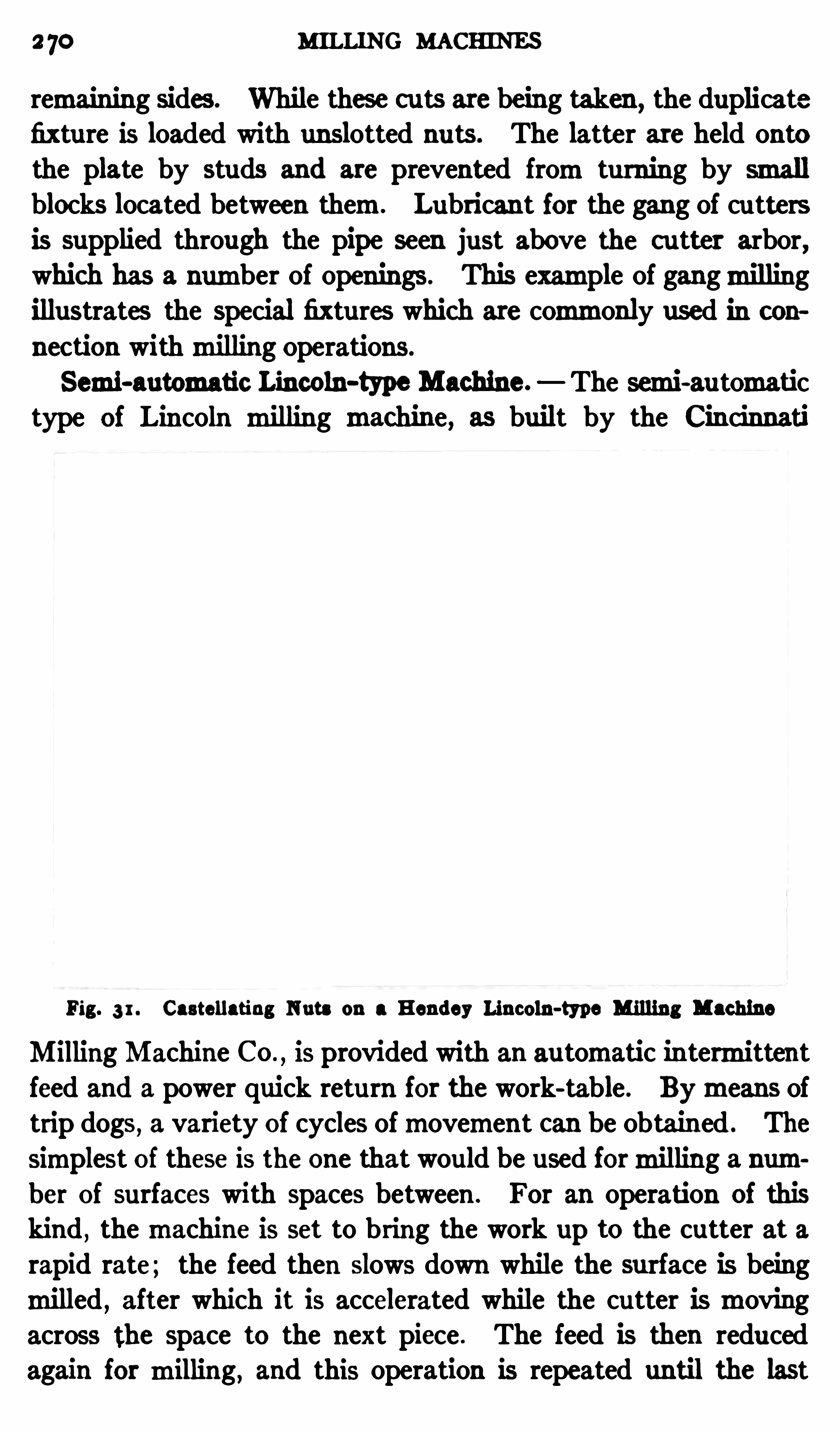
2 70 MILLING MACHINES
remaining sides . While these cuts are being taken , the duplicate
fixture is loaded with unslotted nu ts. The latter are held ontothe plate by studs and are prevented fromturning by smallblocks located between them. Lubricant for the gang of cutters
is supplied through the pipe seen just above the cutter arbor,which has a number of openings . This example of gangmillingillustrates the special fixtures which are commonly used in con
nec tion withmilling Operations.
Semi-automatic Lincoln-type Machine. The semi-au tomatictype of Lincoln milling machine, as built by the Cincinnati
Fig. 3 1 . Castellatiug Nuta on a Hendey Lincoln-type Milling Machine
Milling Machine CO.,is provided with an au tomatic intermittent
feed and a power quick return for the work-table . Bymeans oftrip dogs , a variety of cycles ofmovement can be obtained . The
Simplest of these is the one that would be used formilling a number of surfaces with spaces between . For an operation of thiskind , themachine is set to bring the work up to the cutter at arapid rate; the feed then slows down while the surface is beingmilled , after which it is accelerated while the cutter is movingacross the space to the next piece . The feed is then reducedagain for milling , and this operation is repeated until the last
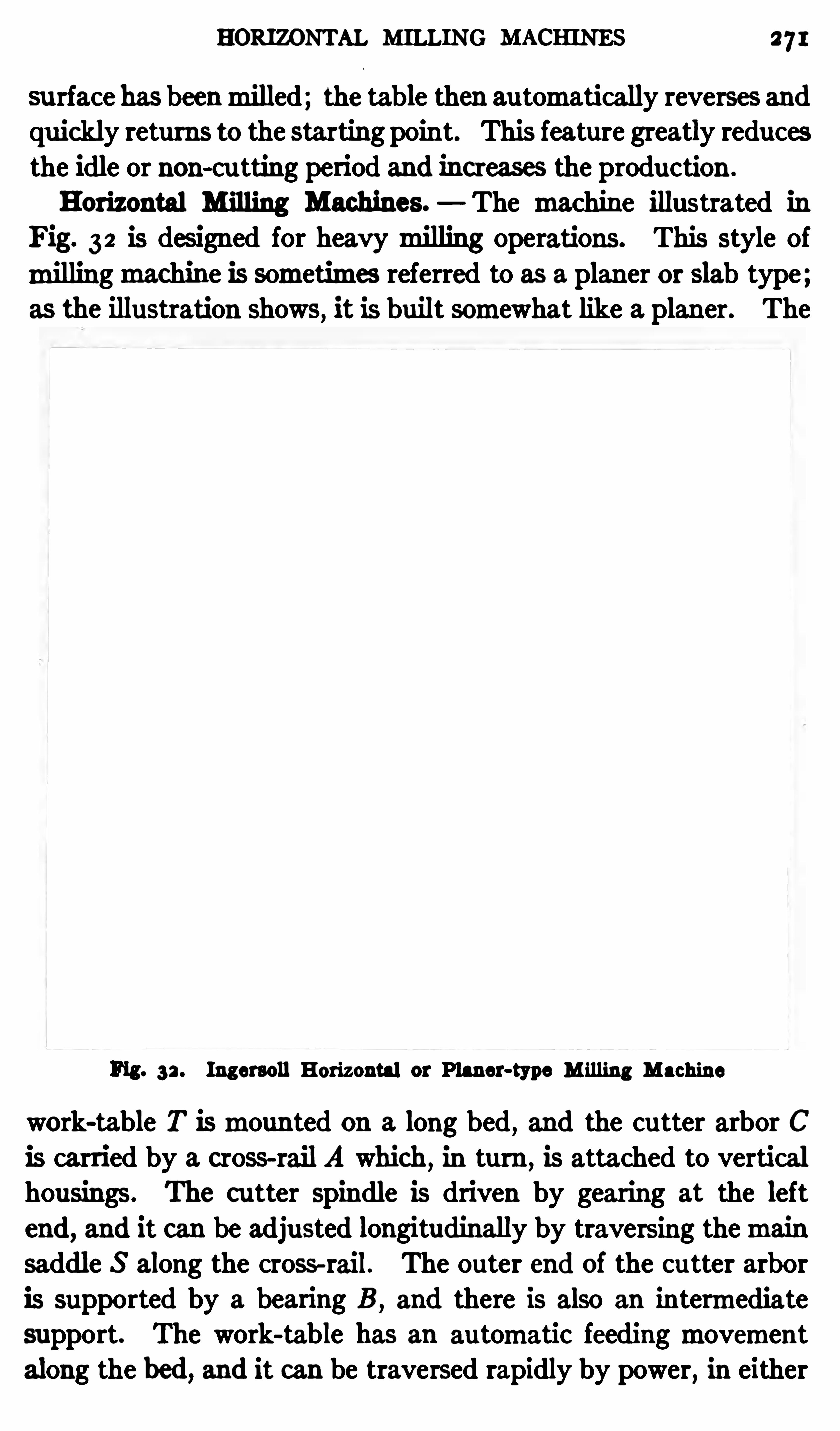
HORI Z ONTAL MILLING MACHINES 271
su rface has beenmilled; the table then au tomatically reverses andquickly returns to the starting point. This feature greatly reducesthe idle or non-cu tting period and increases the production .
Horizontal Milling Machines. The machine illustrated inFig. 32 is des igned for heavymilling operations. This style ofmillingmachine is sometimes referred to as a planer or slab type;as the illustration shows, it is built somewhat like a planer. The
Fig. 32 . Ingersoll Horizontal or Planer-type M illing Machine
work-table T ismounted on a long bed , and the cutter arbor Cis carried by a cross-rail A which, in turn , is attached to verticalhousings. The cutter spindle is driven by gearing at the leftend, and it can be adjusted longitudinally by traversing themainsaddle S along the cross-rail. The outer end of the cutter arbor
is supported by a bearing B , and there is also an intermediatesupport. The work-table has an automatic feedingmovementalong the bed, and it can be traversed rapidly by power, in either
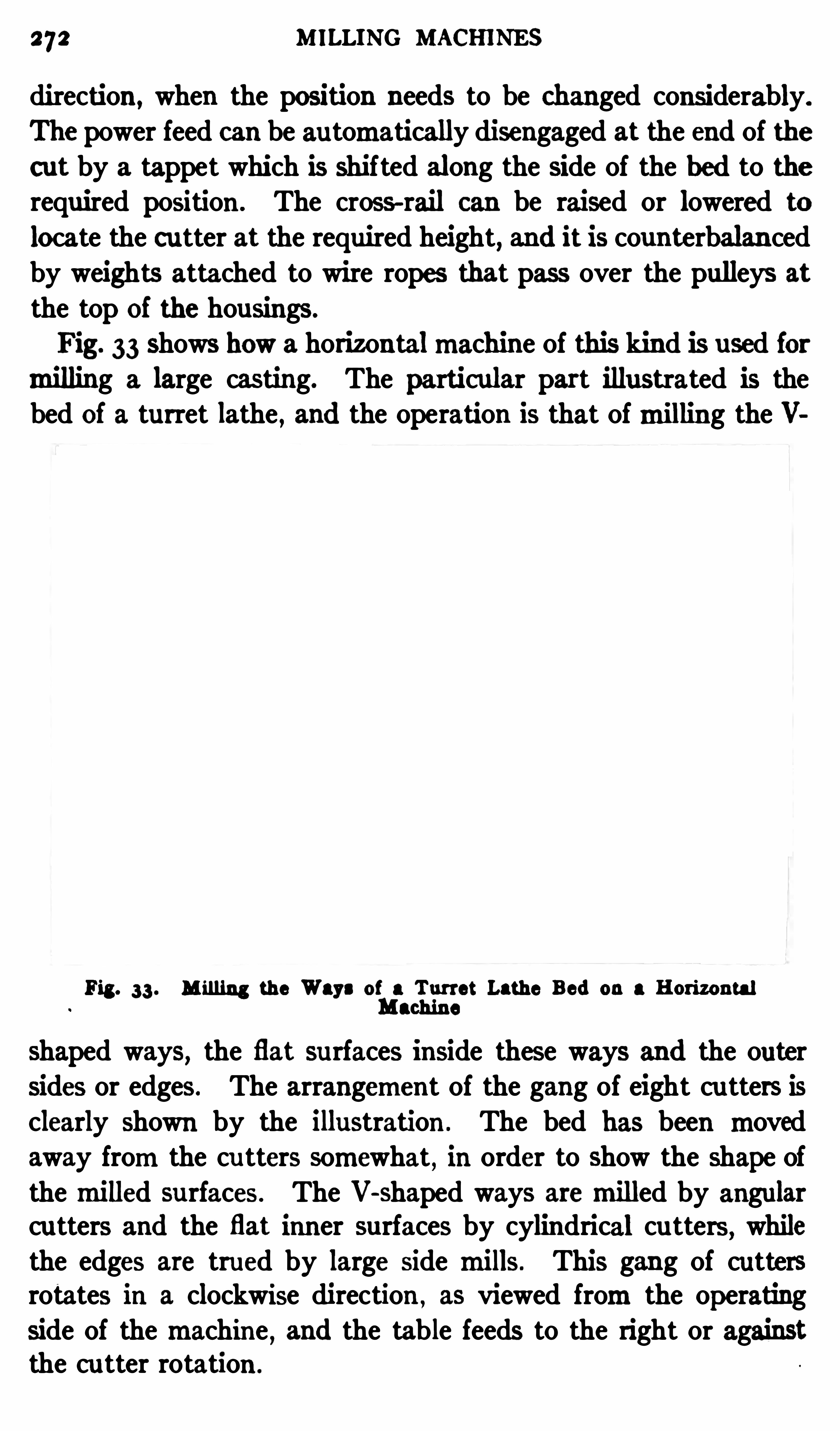
272 MILLING MACHINES
direction , when the position needs to be changed considerably.
The power feed can be automatically disengaged at the end of thecut by a tappet which is shifted along the Side of the bed to therequired position . The cross-rail can be raised or lowered to
locate the cutter at the required height, and it is counterbalancedby weights attached to wire ropes that pass over the pulleys at
the top of the housings .
Fig. 33 shows how a horizontalmachine of this kind is used formilling a large casting. The parti cular part illustrated is thebed of a turret lathe , and the operation is that ofmilling the V
Fig. 33 . M illing the Ways of a Turret Lathe Bed on a HorizontalMachine
shaped ways, the flat surfaces inside these ways and the outersides or edges. The arrangement of the gang of eight cu tters isclearly Shown by the illustration . The bed has been movedaway fromthe cu tters somewhat , in order to Show the shape ofthemilled surfaces . The V-shaped ways aremilled by angularcutters and the flat inner surfaces by cylindrical cu tters, whilethe edges are trued by large Side mills. This gang of cuttersrotates in a clockwise direction , as viewed fromthe operatingside of themachine , and the table feeds to the right or againstthe cu tter rotation .

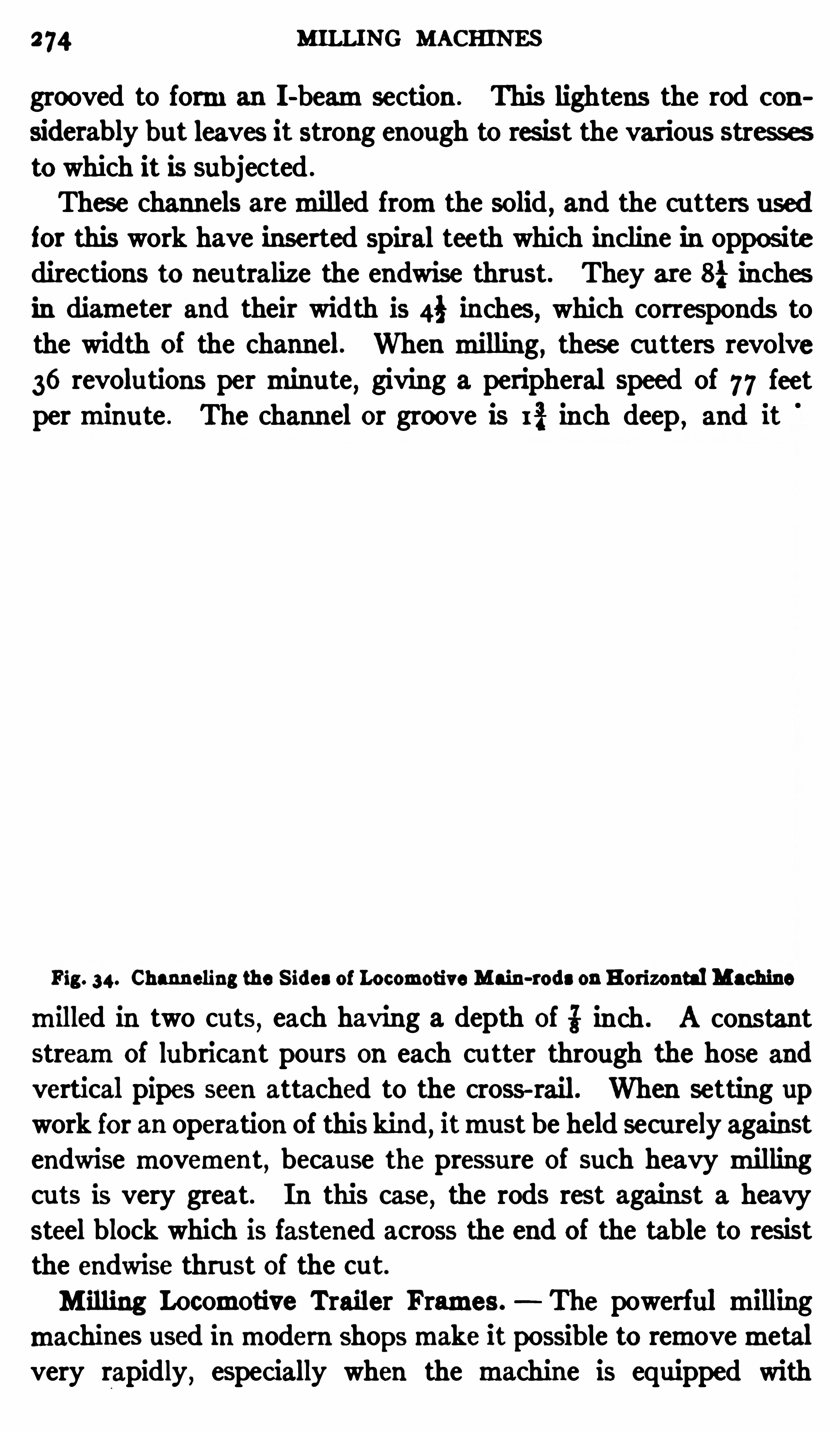
274 MILLING MACHINES
grooved to forman I -beamsection . This lightens the rod con
siderab ly but leaves it strong enough to res ist the various stressesto which it is subjected .
These channels aremilled fromthe solid , and the cutters usedfor this work have inserted spiral teeth which inc line in oppositedirections to neutralize the endwise thrust. They are 8} inchesin diameter and their width is 4} inches, which corresponds tothe width of the channel. When milling , these cutters revolve
36 revolutions per minu te , giving a peripheral Speed of 77 feetperminu te . The channel or groove is I % inch deep , and it
Fig. 34. Channeling the S ides of Locomotive Main-rods on Horizontal Machine
milled in two cuts , each having a depth of i inch . A constantstreamof lubricant pours on each cu tter through the hose andvertical pipes seen attached to the cross- rail. When setting upwork for an operation of this kind , itmust be held securely againstendwise movement , because the pressure of such heavy millingcuts is very great. In this case, the rods rest against a heavy
steel block which is fastened across the end of the table to resistthe endwise thrust of the cut.
M illing Locomotive Trailer Frames . The powerful millingmachines used inmodern Shopsmake it possible to removemetalvery rapidly , espec ially when the machine is equipped with
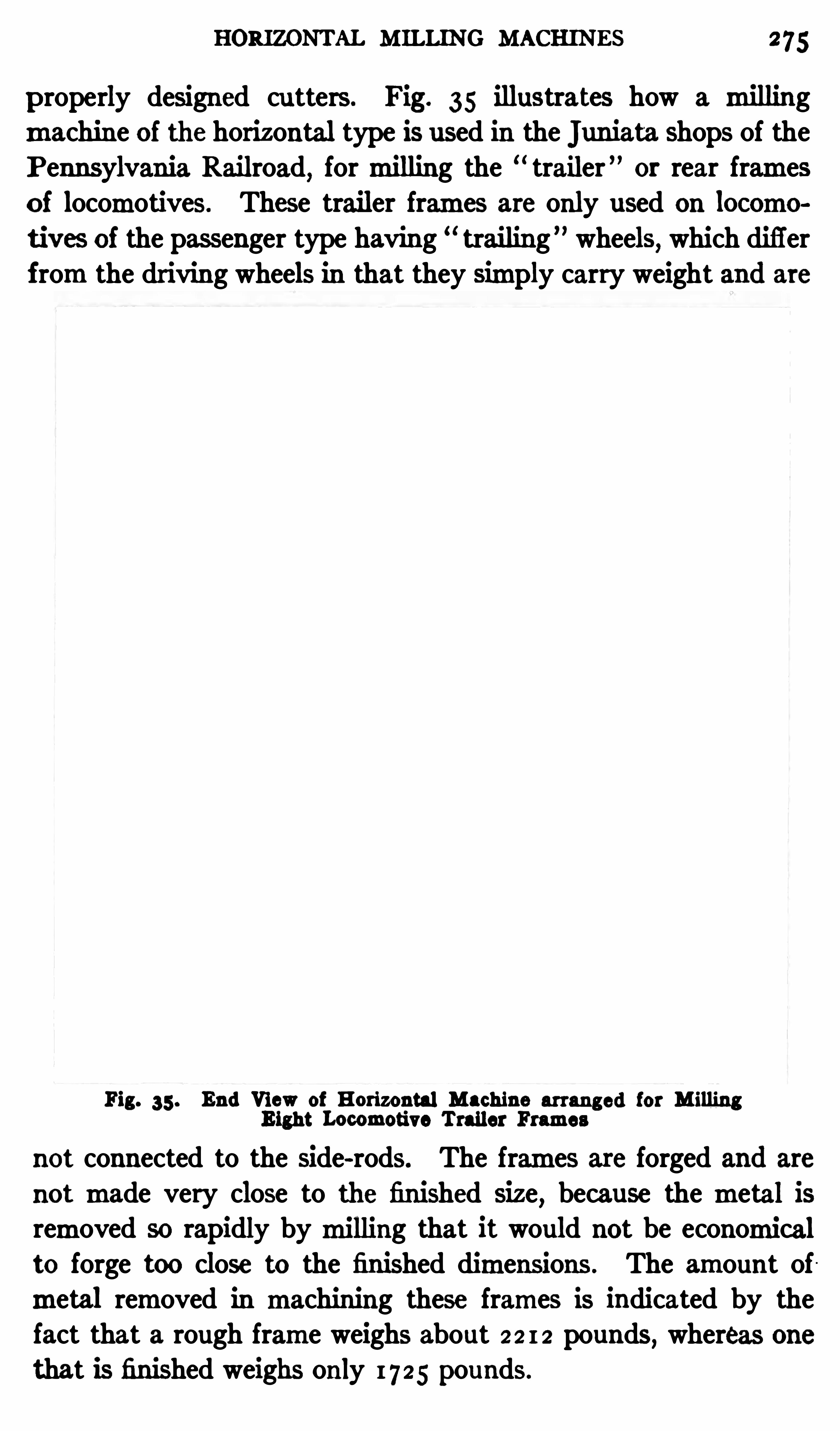
HORI Z ONTAL M ILLING MACHINES 275
properly designed cu tters . Fig. 35 illustrates how a millingmachine of the horizontal type is used in the "uniata Shops of the
P ennsylvania Rai lroad,formilling the trailer ” or rear frames
Of locomotives. These trailer frames are only used on locomotives of the passenger type having trailing ” wheels, which differ
fromthe driving wheels in that they simply carry weight and are
Fig. 35 . End View of Horizontal Machine arranged for M illingEight Locomotive Trailer Frames
not connected to the Side-rods. The frames are forged and are
not made very close to the finished Size,because the metal is
removed so rapidly bymilling that it would not be economicalto forge too close to the finished dimensions . The amount ofmetal removed in machining these frames is indicated by thefact that a rough frame weighs about 2 2 1 2 pounds
,whereas one
that is finished weighs only 1725 pounds.
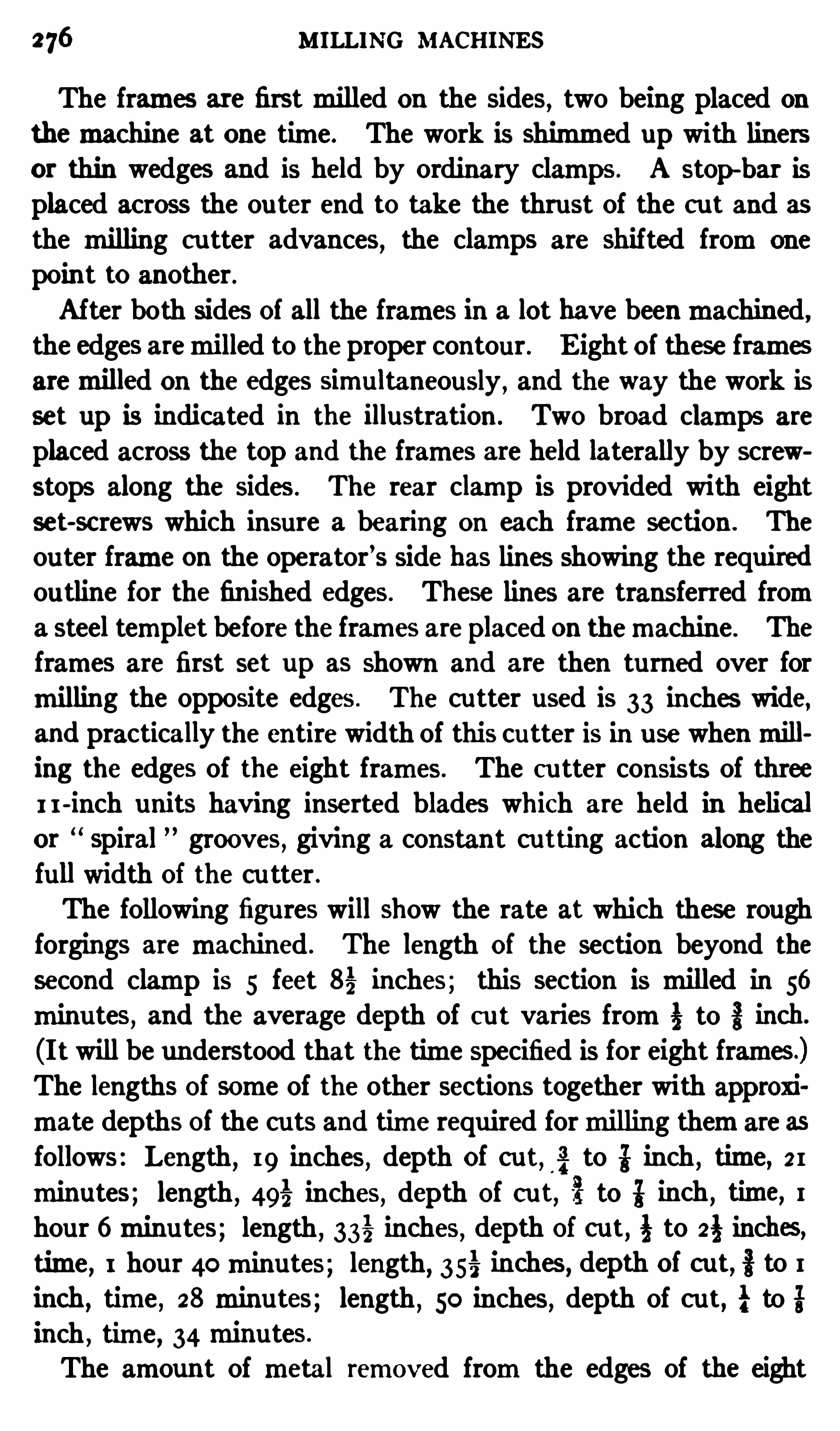
MILLING MACHINES
The frames are firstmilled on the Sides, two being placed on
themachine at one time. The work is Shimmed up with linersor thin wedges and is held by ordinary clamps . A stop-bar isplaced across the ou ter end to take the thrust of the c ut and as
the milling c utter advances,the clamps are shifted fromone
point to another.After both Sides of all the frames in a lot have beenmachined ,
the edges aremilled to theproper contour . E ight of these framesaremilled on the edges simultaneously , and the way the work is
set up is indicated in the illustration . Two broad clamps are
placed across the top and the frames are held laterally by screwstops along the sides . The rear clamp is provided with eightset-sc rews which insure a bearing on each frame section . The
outer frame on the operator’s side has lines Showing the requiredou tline for the finished edges. These lines are transferred froma steel templet before the frames areplaced on themachine . The
frames are first set up as shown and are then turned over for
milling the opposite edges . The cu tter used is 33 inches wide,and practically the entire width of this cutter is in use whenmilling the edges of the eight frames. The cu tter consists of threeI I -inch units having inserted blades which are held in helical
or Spiral grooves , giving a constan t cutting action along thefull width of the cu tter .
The following figures will show the rate at which these roughforgings aremachined . The length of the section beyond the
second clamp is 5 feet 83 inches; this section is milled in 56
minutes, and the average depth of cu t varies from3 to 3 inch.
(I twill be understood that the time specified is for eight frames.)The lengths of some of the other sections together with approxi
mate depths of the cu ts and time required formilling themare as
follows: Length, 19 inches, depth of cut, g to it inch ,
time, 21minutes; length , 495 inches, depth of cu t, 5} to i inch , time, 1hour 6minu tes; length , 333 inches, depth of cut, to 23 inches,time , 1 hour 40minutes; length, 353 inches , depth of cut, § to 1
inch, time , 28minutes; length , 50 inches, depth of c ut, to gl
inch , time, 34minutes.
The amount of metal removed fromthe edges of the eight

278 MILLING MACHINES
cally on the housings , and the vertical heads laterally along thecross-rail. This particularmachine will drive facemills up to 20
inches in diameter.Machines of the same general design are also built with three
heads, one being on the cross-rail and two on the housings, and
there are various othermodifications. Wi th themu ltiple-spindle
Fig . 37 . Three-head Machine M illing AluminumCasting.
machines, the number of spindles used at one time depends, ofcourse, on the nature of the work. For some jobs it is necessaryto use the horizontal spindles
,whereas other parts are milled
by using the horizontal and vertical spindles in combination.
This type ofmachine is very efficient for certain kinds ofmilling.
An example illustrating the nature of the work done on a
MULTIPLE-HEAD MILLING MACHINE 279
multiple-head machine is shown in Fig. 37 . This particularmachine has three heads and a fixed cross-rai l, the latter beingc ast solid with both housings in order to secure amore rigid constru ction . One spindle is carried by the cross-rail and the othertwo aremounted on the front faces of right and left housings.
This general type ofmachine is extensively used formilling thesu rfaces of duplicate parts, such as gasoline engine cylinders,crank cases, etc .
Themilling operation shown is that of finishing the surfacesof aluminumcastings for au tomobile engines . As will be seen ,these castings are clamped to the sides and top of a cast-ironfixture
, and the three rows of castings aremilled simu ltaneouslyas they are fed past the cutters . The cutters at the sides are 14
inches in diameter, and the one attached to the vertical spindlehas a diameter of 10 inches. They are rotated for this operationat a speed of 100 revolutions per minute, and the feed of thetable is 33; inch per revolution of the cu tters, or over 9} inchesper minute . Obviously, it is possible to mill these castingsrapidly after themachine is adjusted .
The principal difficulty inmachining aluminumand aluminumalloys 15 caused by the clogging of the chips which tend to wedgeb etween the teeth of tools , such as milling cutters, etc . Thisdifii culty can be largely avoided by the use of the right kind of
cu tting lubricant . Soap water and kerosene are often used.
The latter enables afine finish to be obtained,provided the cut
ting tool is properly ground . Formilling flat surfaces , it is preferable to use end or facemilling cu tters rather than the cylindricalforms. The cutting edges or corners should be sharp instead ofrounded, and themill will cut better if a high c utting speed and
moderate feed are employed . The depth and width of the cutare ofminor importance . A cu tting speed of 3 25 feet perminuteis practicable
,and from2% to 4 cubic inches of aluminumcan be
removed perminu te .
According to onemanufacturer who'
machines aluminumpartsin large quantities
,the cutting speed for aluminumcan be from
so to 60 per cent faster than the speeds and feeds for cast iron.
The lubricant used by this manu facturer is composed of one
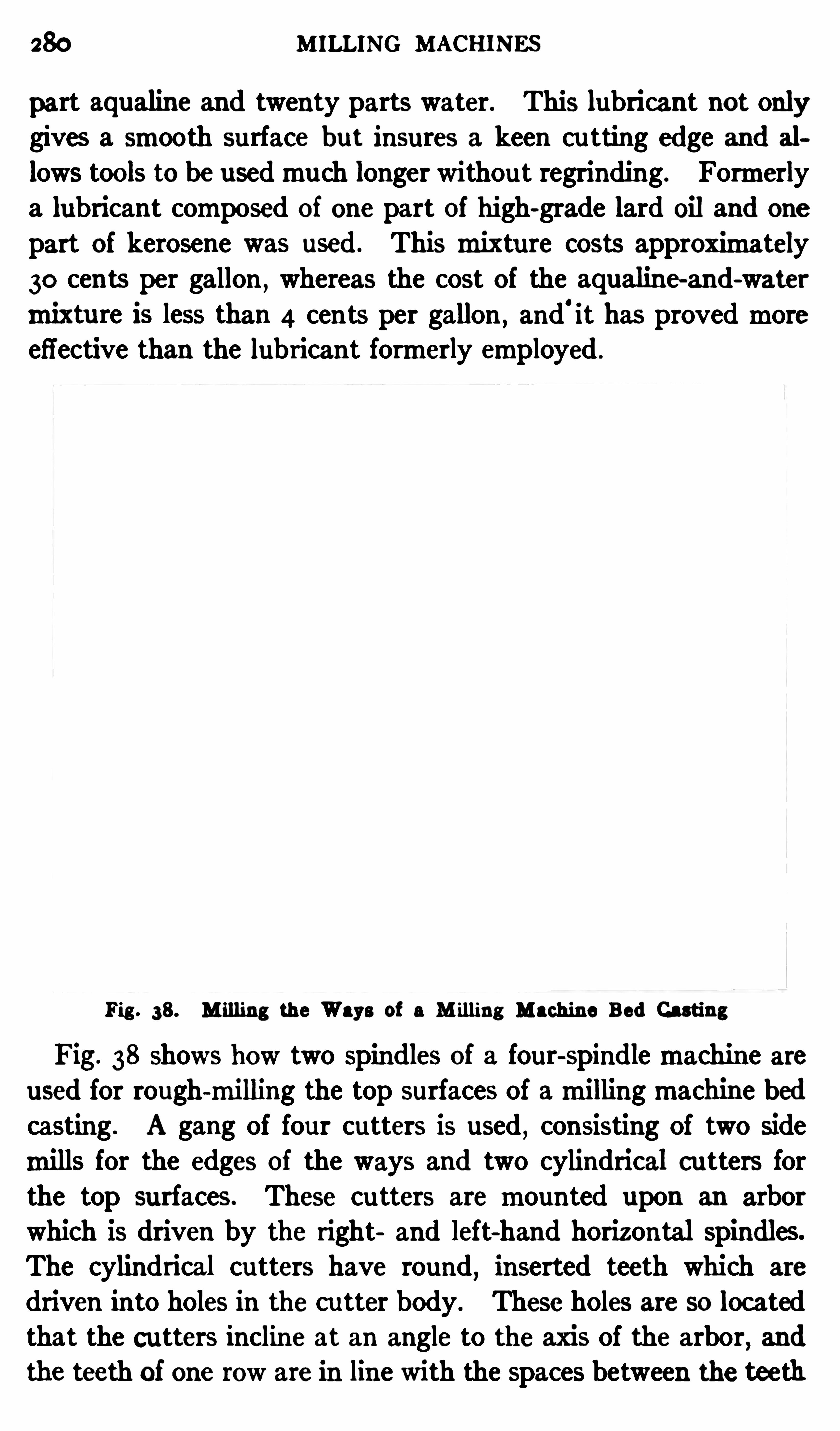
280 MILLING MACHINES
part aqualine and twenty parts water. This lubricant not onlygives a smooth surface but insures a keen cu tting edge and al
lows tools to be usedmuch longer withou t regrinding. Formerlya lubricant composed of one part of high-grade lard oil and one
part of kerosene was used . This mixture costs approximately30 cents per gallon , whereas the cost of the aqualine-and-water
mixtu re is less than 4 cents per gallon , and'it has provedmore
effective than the lubricant formerly employed .
Fig . 38. M illing the Ways of a M illing Machine Bed Casting
Fig. 38 shows how two spindles of a four-spindlemachine areused for rough-milling the top surfaces of amillingmachine bedcasting . A gang of four cutters is used
,consisting of two side
mills for the edges of the ways and two cylindrical c utters forthe top surfaces. These cu tters are mounted upon an arborwhich is driven by the right and left-hand horizontal spindles.
The cylindrical cu tters have round,inserted teeth which are
driven into holes in the cu tter body. These holes are so locatedthat the cutters incline at an angle to the axis of the arbor, and
the teeth of one row are in line with the spaces between the teeth

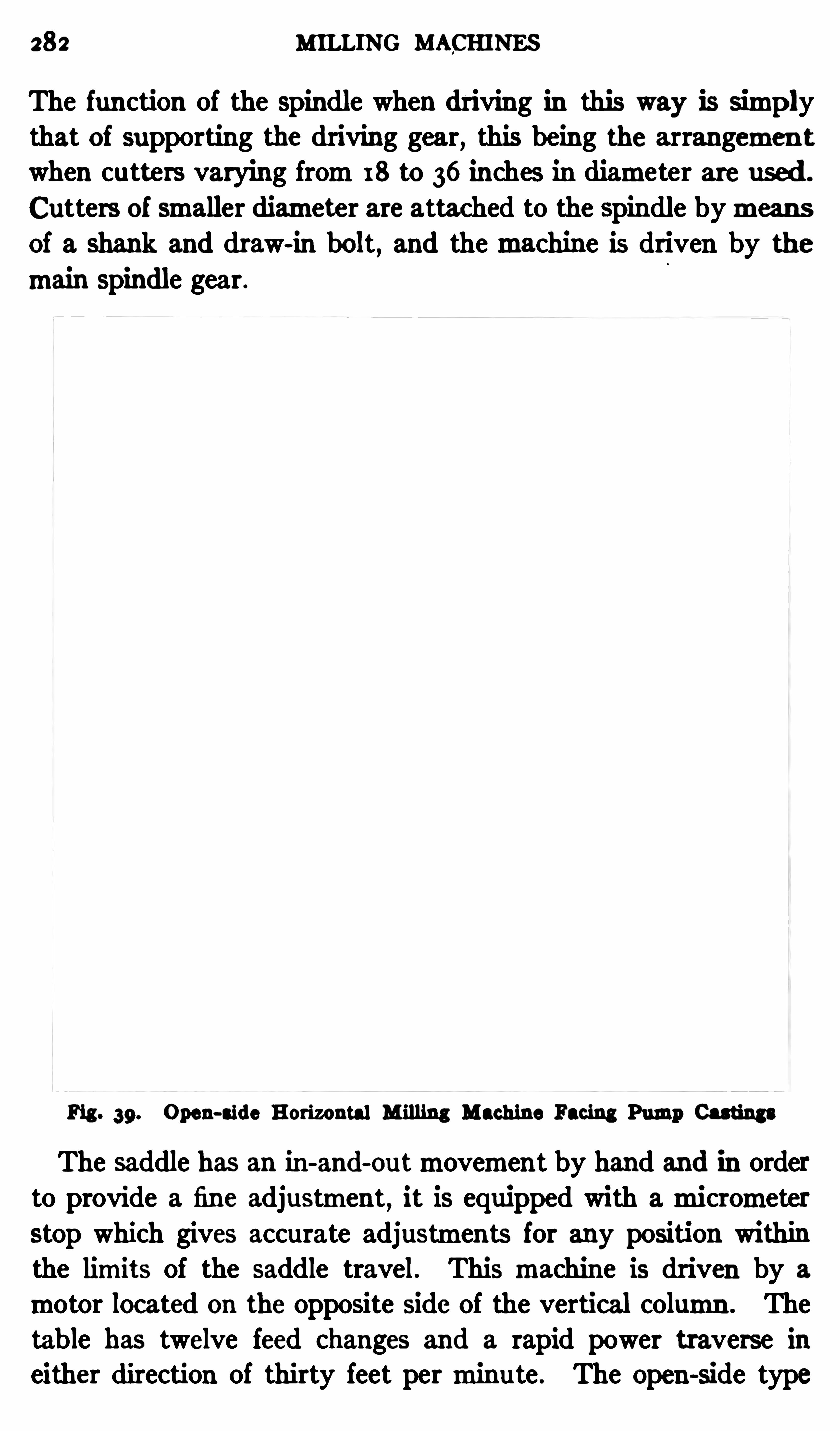
282 MILLING MACHINES
The function of the spindle when driving in this way is simplythat of supporting the driving gear, this being the arrangemen twhen cutters varying from18 to 36 inches in diameter are used .
Cutters of smaller diameter are attached to the spindle bymeansof a shank and draw-in bolt , and themachine is driven by themain Spindle gear .
Fig . 39. Open-aide Horizontal Milling Machine Facing Pump Castings
The saddle has an in-and-outmovement by hand and in orderto provide a fine adjustment
,it is equipped with amicrometer
stop which gives accurate adjustments for any position withinthe limits of the saddle travel. This machine is driven by a
motor located on the opposite side of the vertical column . Thetable has twelve feed changes and a rapid power traverse ineither direction of thirty feet perminute . The open-side type
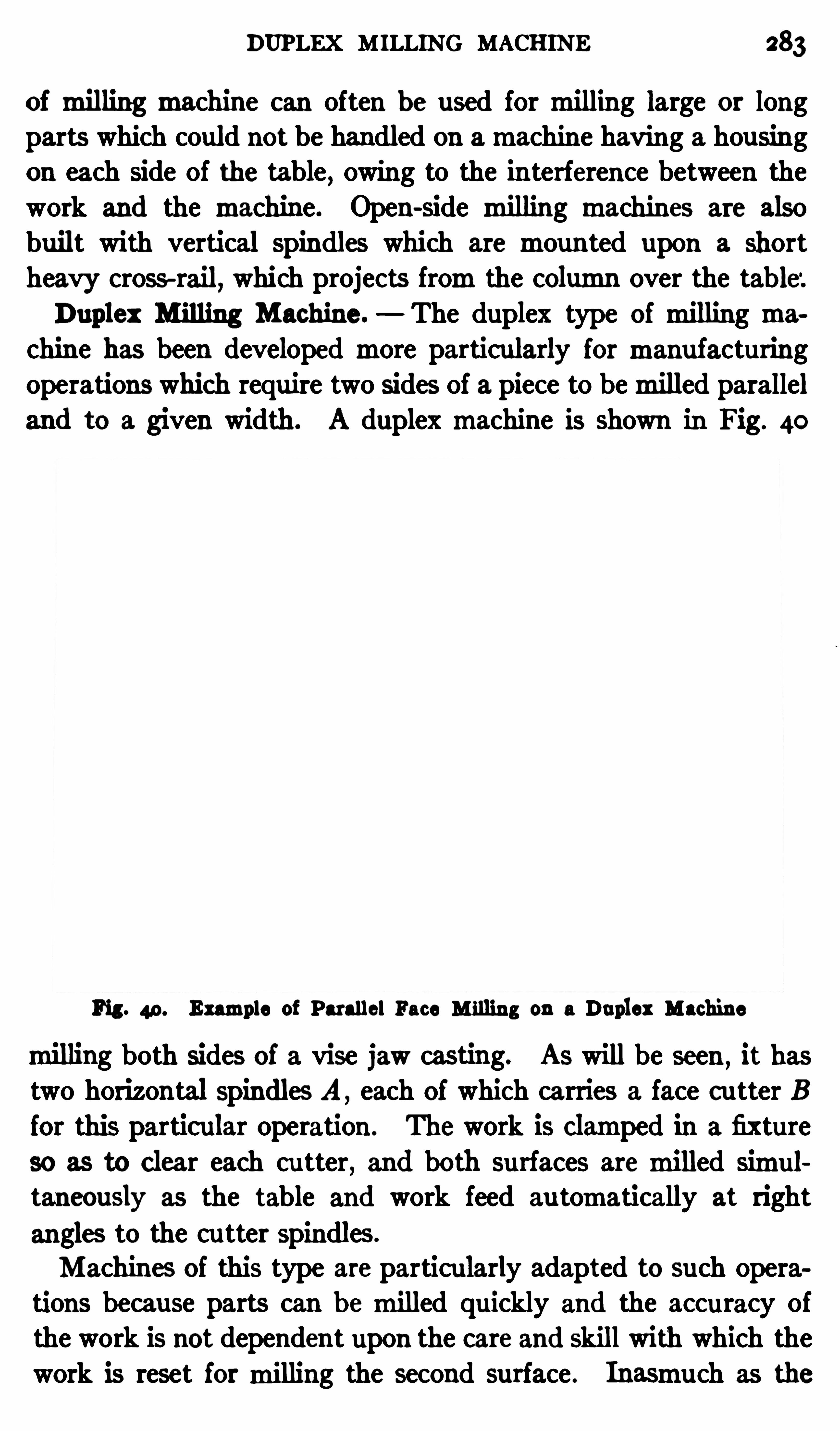
DUPLEX MILLING MACHINE 283
of milling machine can often be used for milling large or longparts which could not be handled on amachine having a housingon each side of the table, owing to the interference between thework and the machine. Open-side milling machines are alsobuilt with vertical spindles which are mounted upon a shortheavy cross-rail, which projects fromthe column over the table:Duplex Milling Machine. The duplex type of milling ma
chine has been developed more particularly for manu facturingoperations which require two sides of a piece to bemilled paralleland to a given width. A duplexmachine is shown in Fig. 40
Fig . 49 . Example of Parallel Face M illing on a Duplex Machine
milling both sides of a vise jaw casting. As will be seen ,it has
two horizontal spindles A ,each of which carries a face c utter B
for this particular operation . The work is clamped in a fixture
so as to clear each cu tter, and both surfaces aremilled simultaneously as the table and work feed au tomatically at right
angles to the cu tter spindles.
Machines of this type are particularly adapted to such operations because parts can b emilled quickly and the accuracy ofthe work is not dependent upon the care and skill with which thework is reset formilling the second surface . Inasmuch as the
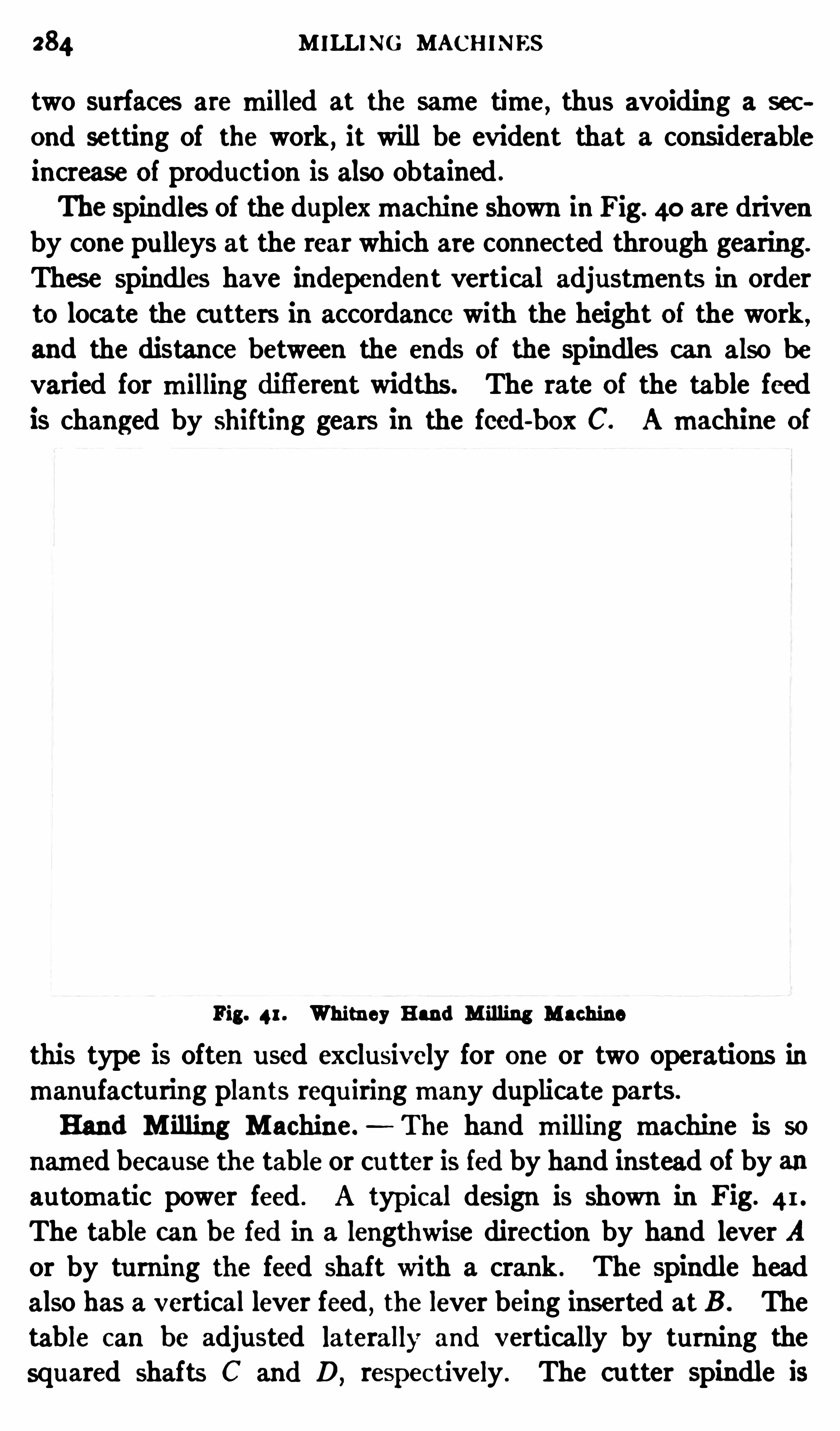
284 M ILLING MACHINES
two surfaces are milled at the same time, thus avoiding a sec
ond setting of the work , it will be evident that a considerableincrease of production is also obtained .
The spindles of the duplexmachine shown in Fig. 40 are drivenby cone pu lleys at the rear which are connected through gearing.
These spindles have independent vertical adjustments in orderto locate the cutters in accordance with the height of the work,
and the distance between the ends of the spindles can also be
varied for milling difi'erent widths. The rate of the table feed
is changed by shifting gears in the feed-box C. Amachine of
Fig. 41. Whitney Hand M illing Machine
this type is often used exclusively for one or two operations in
manu facturing plants requ iringmany duplicate parts.
Hand M illing Machine .- The hand milling machine is so
named because the table or cu tter is fed by hand instead of by anautomatic power feed . A typic al design is shown in Fig. 41.
The table can be fed in a lengthwise direction by hand lever A
or by tu rning the feed shaft with a crank . The spindle headalso has a vertical lever feed
,the lever being inserted at B . The
table can be adjusted laterally and vertically by turning thesquared shafts C and D, respec tively . The cutter spindle is

286 MILLING MACHINES
ordinary profilingmachine, although the construction is difierent.This machine is used for milling disks, face and cylinder camsof various forms, and for all kinds of rotary and irregu lar formmilling. The two tables A and B are driven in unison bymeansof shaf t C and wormgearing. Table A carries the former ormodel and table B the part to bemilled. The cu tter spindle
and its slide ismounted on a c ross-rail, and a former pin D isattached to the slide a certain distance fromthe spindle whichdistance can be varied to suit the work, by adjusting the pin
holder horizontally. When themachine is in operation , pin D
Fig. 43 . M illing Face Camon Garvin Camor FormMilling Machine
bears against the former plate ormodel and, as the table revolves,the cutter is caused tomove laterally so as to reproduce the required outline on thework . At the right-hand end of the drivingshaft C for the tables , there is a reversingmechanismso that thetables can be rotated in whichever direction presents the least
abrupt angles for the former pin and cu tter to pass over. Forinstance, if a camwere beingmilled having a sudden rise at onepoint, the direction of rotation should be such that the formerpin will approach the rise fromthat side which has themostgradual ascent.
CAM MILLING MACHINES 87
Milling a Face Cam. The type of camor formmillingmachine illustrated in Fig. 42 is shown in Fig. 43 arranged formilling a face cam. The unmilled camblank is shown at A and thefinished camatB . The blank is c lamped to the right-hand table
,
as at C, and the former plate E on the table to the left. Boththemodel and work are centered bymeans of bushings which arefitted to holes in the centers of the tables. The pin D on thecu tter slide is held firmly against themodel by counterweight F
,
and the cu tter and pin follow the same path as both tables re
volve in unison . The cutter spindle is adjustable vertically forsetting the cu tter
,bymeans of handwheel G (see also Fig.
and horizontally along the cross-rail by handwheel H ,when set
ting up the machine . Stops are provided for both horizontaland vertical movements . The cross-rail of
”
the machine illustrated in Fig. 42 can be adjusted vertically on the front of theuprights by means of elevating screws that run on ball- thrustbearings. The method of mounting the slide on cross-rail isnoteworthy. The upper horizontal surface of the rail has a
hardened and ground tool-steel ball race carrying a long row ofballs. The opposing surface of the slide has a similar race
,thus
supporting the weight. At the lower edges of the slide and railare two opposed tool-steel surfaces, between which are two rowsof balls that take up the thrust, thus making the slide travel
b ack and forth with little friction , so that the cutting of sharp
angle cams is greatly facilitated .
Whenmilling small parts of irregular shape , sometimes severalc an be placed on the table at one time in order tomill themsu c
cessively. The parts are held near the circumference of the tablein a suitable fixture and a series of duplicate formers is arrangedsimilarly on the other table. Themilling operation is continuous
,the finished part being removed and replaced with rough
blanks while the others are beingmachined .
Milling a Cylinder Cam. The machine shown in Fig. 42
can be used for cutting cylinder or “ barrel” cams by replacingthe circular tables A and B with the attachment K seen on thefloor. The horizontal spindle of this attachment is rotated bygearing connecting with shaft C on themachine . The cylindri
288 MILLING MACHINES
cal former ormas ter camis attached to faceplate L and the camto faceplate M . P in D engages the former , and the cu tter inthe spindlemills grooves of the required cu rvature as the attachment rotates.
Fig. 44 shows a cylinder camattachment in place on another
machine which is similar to the one just described,except for
minor details. Shaft C connects with shaft N by a chain and
Fig. 44 . Milling Cylinder Cams on Garvin Machine
sprocket and shaft N,in turn , drives the horizontal spindle of
the attachment through the wormgearing shown . The cylindri
cal former has c amsurfaces corresponding in shape or curvatureto those requ ired and it is engaged by pin D attached to the cutterslide; hence, the cu ttermills a groove corresponding to the c amsurface engaged by the pin . The mechanismfor driving theattachment is operated by belt O,
and the cu tter spindle is ro

290 MILLING MACHINES
as shown in Fig. 45 . For cu tting cylinder or barrel earns the
mandrel is held in a vertical position as Shown in Fig. 46 , and an
ou tboard support is used for steadying the upper end . Flatformer plates are used for cu tting all types of cams .
Power is transmitted to the work-head by means of a shaft
at the rear of themachine, and the horizontalmovement of thehead along the ways of the bed is eff ected by a screw. The
machine is driven by a single belt pulley at the rear . Speed
Fig. 46. Rowb ottomMachine Milling a Cylinder Cam
changes are obtained by means of a gear box, correspondingvariations being made for the former plate and work arbor
,in
order to retain theproper relation between the cutter and the
cambeing milled . The cutter speed can also be changed to
suit the size of the mill and material being cut. These speedchanges for the cu tter spindle are effected by lever E . The adjustment for the depth to which the cutter enters the work ismade on the work slide
,the squared shaft K being provided for
THREAD MILLING 291
this pu rpose . This shaft has amicrometer collar for acc uratelygaging the depth of themilled groove.
I f necessary , the relative position between the cu tter and c amblank can be varied. Suppose it is desired to alter the positionof the camgroove slightly fromthat arbitrarily fixed by the location of the driving pin which passes through the work into thefaceplate. Thefirst step would be tomove lever L to the neutralposition which disengages the clu tch which drives the workspindle. Lever M is then turned through one-twelfth of a revolution , after which the clu tch is te-engaged by lever L . Thisclu tch has twelve teeth and the result of this operation is to temesh the clutch one tooth ahead of
.
its former position . By
means of gearing in the work head,the resultantmovement of
the camrelative to the cutter amounts to one-fou rth degree.
Thismachine has a pump for supplying lubrican t to the cut
ter, but a strong blast of air for removing the chips and coolingthe cu tter has been found an excellent substitu te for a lubricant
,
even whenmilling steel cams .
Thread M illing. In many lines of manufactu re threadswhich were formerly cut with a single-pointed tool in an enginelathe are now formed bymilling inmachines designed for threadmilling. The thread ismilled by a cutter of the required Shapewhich is set to correspond with the helix angle of the thread .
Somemachines are so designed that the work rotates in a fixed
position and the cu tter slide ismoved along themachine bed bya lead- screw that is connected with the work-spindle throughsuitable change gears. There is also another type of machine
,
the cu tter of°
which rotates in a fixed position while the workrevolves and at the same time feeds forward at a rate proportionalto the lead of the thread beingmilled .
Pratt Whitney Thread Milling Machine . This machine,
which is shown in Fig. 47 , is the type in which the part to bethreaded rotates in a fixed position while the thread ismilled bya cuttermounted on a cu tter head which is fed along the bed at
the proper rate by suitable gearing. The cu tter is set in linewith the angle of the thread bymeans of a wormand worm-gear
adjustment. This particular machine is designed for milling
292 MILLING MACHINES
large screws of coarse pitch , such as elevator worms,worms for
gun mounts and for other heavy threading operations . I t is
driven froma cone pulley (seen at the left-hand end of themachine) which ismounted on the end of a horizontal splined shaftextending along the rear of the bed . Fromthis shaft the cutterspindle , headstock spindle and lead-screw are rotated . Motionis transmitted to the cutter spindle through a vertical telescopicshaft and bevel gears, and to the headstock spindle through a
gear-box which enables the speeds to be varied .
Fig . 47 . Pratt Whitney Thread Milling Machine
The lead-screw,which traverses the carriage and the cutter
head along the bed at the required rate , is rotated through change
gears so that threads or spirals,in a great variety of pitches or
leads, can b emilled . The headstock and the tai lstock spindles
aremade hollow so that work up to 3% inches in diameter canpass through . This featuremakes it possible to mill screws ofalmost any length , provided the overhanging ends are suitablysupported . The part to b e threaded is gripped by a chuck of thedrawback collet type
,in the headstock spindle . Whenever
possible,the ou ter end of the work should be supported by a

294 MILLING MACHINES
the cu tter for depth of cut, and it is provided with amicrometerdial graduated to thousandths of an inch . There is also a stopat C which can be used for locating the cutter in the same position or at the same depth
, either whenmilling duplicate threadsor the grooves ofmu ltiple-threaded worms or screws . The traverse of the carriage is au tomatically controlled by two stopsseen on the rod extending along the front of themachine . The
hand lever D, to which the trip-rod is connected is used to con
Fig . 48 . Lees-Bradner Thread M illing Machine
trol the traverse of the carriage . When this lever is in the neutral
position,as shown ,
the carriage remains stationary , and whenit is thrown to the right , the carriagemoves to the left. Whenthe small stop collar is engaged by the carriage the feed clutchis disconnected; then if a thread were being milled ,
the cutter
would be backed out of the thread groove and lever D thrown tothe left
,thus causing the carriage to return to the starting point
for another cu t. The stop collar at the right of the handwheel
should be set for stopping the return movement at the properpoint, by throwing the lever D to the neutral position .
THREAD MILLING 295
The work is either held on the centers or in a collet chuck at theheadstock end and on a center at the tailstock end. The collet
chuck should be used if possible . The index plate E is for indexing when cutting multiple threads or spiral gears. Thestarting and stopping of themachine is controlled by hand leverF . Whenmilling very fine threads a hob type of cu tter is usedin stead of a regular formed cu tter. A follow-rest is suppliedwi th thismachine for supporting flexible parts . This is attachedto the cutter slide and has an independent side adjustment sothat the work c an be supported either ahead of or behind the
Fig. 49. Universal Thread M illing Machine
cutter . This machine will mill threads or grooves varying inlead from5
16 inch to 96 inches.
Universal Thread M illing Machine. The threadmillingmachine illustrated in Fig. 49 is the type in which the lead-screw
and work revolve and feed forward together, while the thread is
milled by a cu tter rotating in a fixed position . The lead-screw
L ismounted over the center of the bed and in direct line withthe screw that is beingmilled . The latter is gripped in a chuck
mounted upon a carriage which slides along the ways of the bed.
The cutter-head is located at the right-hand end of themachine,
296 M ILLING MACHINES
and the work is supported near the point where themilling cu tteroperates by an expansion bushing or steadyrest.
Themachine is driven by two pulleys A and B ,which transmit
power to the lead-sc rew and cu tter, respectively, by the univer
sally-jointed shafts C and D. Shaft C connects with a shaft on
which a friction roller ismounted , and this roller, in turn , bears
against and rotates disk F. The shaft carrying the friction disktransmits power through a wormto a worm-wheel having a
threaded hub through which the lead-screw passes . A key in
the worm-wheel engages a spline in the lead-screw, thus caus
ing the latter to revolve . The lead-screw also passes through a
split nut, the position of which is fixed so that the rotation of the
lead-screw results in a longitudinal movement. The handle G
serves to engage or disengage the split nut and the lead-screw.
The speed at which the lead-screw rotates can be varied bychanging the radial position of the friction driving roller by
means of a connecting screw and crank. This change does not
aff ect the lead or pitch of the thread beingmilled , b ut serves tovary themilling speed . Difi
'
erent pitches are obtained bymeansof a gear-box on the carriage through whichmotion is transmittedfromthe lead-screw to the work. There is a gear on the end
of the lead-screw which drives , through the gear-box , a large
spur gear located back of the chuck . This last gear of the train
is fastened to a cylindrical part to which the chuck is also at
tached,and it rotates both the chuck and work. Obviously,
the speed at which the work revolves and,consequen tly, the
pitch of the thread that ismilled , depends upon the ratio of thegears in the gear-box. For instance , if the gears were so proportioned that the lead-sc rew and work rotated at the samespeed
,a thread would b emilled having the same lead as the thread
on the lead-screw. I f the work rotated faster than the lead
screw,a finer lead of thread wou ld be obtained, whereas, if it
rotated slower,the lead or pitch would be coarser than that of
the lead-screw.
The cu tter arbor is driven fromshaftD through bevel and Spurgearing, so arranged that the cu tter can be swiveled about a
pivot, 90 degrees either to the right or left of the central posi

298 MILLING MACHINES
it is necessary to take asmany separate cu ts as there are Singleor independent threads or grooves in the screw . For instance
,
a double thread would require two cuts, a triple thread threecu ts
, and so on . In order to hold the blank secu rely and prev en tit fromslipping in the chuck , an auxiliary dog or coupling issecured to the work and fits over one of the chu ck jaws to give a
positive drive.
Fig. 50 illustrates examples of work done on the universalmachine, which can be used not only for threadmilling b ut formany other spiral milling operations. The same general typeofmachine
,illustrated in Fig. 49, is alsomade in a simpler form
which is not equipped wi th a gear-box for varying the pitch of
the threadmilled , b utmust be provided with a lead-screw havinga pitch corresponding to the pitch of the thread to be milled .
This “ duplicating ” type of machine is especially adapted for
milling large numbers of screws of the same pitch . It is providedwith an indexing coupling similar to the one previously referredto
,for use whenmillingmultiple threads.
INDEX
A lina -Boswell radius planing attachmentAluminum,
formofmilling c utter to use for
lubricant to use whenmilling .
Angular cutters ,method ofmilling teethAngular indexing .
Angular planing .
Arbors for holding c utters onmillingmachineAttachment, c ircularmillingc ircularmilling , applied to verticalmachinefor circ ular planing on shaper .
for cutting large gears inmillingmachineformachining clutches on shaper
formilling taperfor planing c urved surfaces
for planing spiral flutes .
Slotting, formillingmachineuniversal
,applied to spiralmilling
verticalmilling
Betts slottingmachineBevel gear, angular position of b lank formilling teethc utting teeth inmillingmachinefinishingmilled teeth by filing .
offset of cutter formilling teethselec ting cutter formilling teeth
Braces and stop-
pins for planer
Brasses for oonnec ting-rod,milling on verticalmachine
Brown Sharpe Lincoln- typemillingmachine
Brown Sharpe universalmilling machineBrowne 8: Sharpe verticalmillingmachine
Cam, cylinder,milling on Garvinmachinefaoe
,milling on Garv inmachine
Cammilling in a universalmillingmachine .
Cammillingmachine, Rowbottomvertical typeCamor formmillingmachine, Garv inCenters, indexing for planer work .
Centering cutter formilling keyway
300 INDEx
Centering c utter with work arborChain sprockets ,method ofmilling teethChange-gears, calculating for helical or spiralmillingfor diflerential indexing
Channeling connecting-rods on horizontalmachineChordal thickness of Spur gear tooth,method of determining
Chuck for planer
planer, points on using
Cincinnati plainmillingmachineCincinnati verticalmillingmachine
Circularmilling, continuousCircularmilling attachmentapplied to verticalmachine
Circular planing attachments
Clamps and bolts for holding work on planer
Clamps, finger, application of .
Clamping , distortion of work caused by
Clamping thin plates for planing .
Clearance angle for planer tools .
Clearance and slope angles for slotter tools
Clutch teeth,methods ofmillingClutches , shaper attachment formachiningCochrane-Bly universal shaper
Compensatingmillingmachine dog or driverCompound indexingrule for determining indexingmovements .
Concave planing attachment for ShaperConnec ting-rod brasses,milling on verticalmachineConnecting-rods , channeling on horizontalmachineContinuous circularmilling .
Crank shaper, general desc ription of .
Cross-head set up for planing
Cross-rail, planer,methods of testing alignmentposition relative to work .
Cutters, angular,method ofmilling teethmethod of centering with work arbor
milling flutes in straight-fluted type
milling , rotation of relative to feed
milling spiral flutes in c utter blankCylinder cammilling on Garv inmachineCylinders,method of planing locomotiveCylindrical parts,methods of holding, on planet

302 INDEX
Helix or spiral angle,method of determiningHobbing and gashing a worm-wheel inmillingmachineHorizontal and verticalmillingmachine, Ingersoll
multiple-spindle type .
open-side type .
Independent housing or planer floor stand
Index centers , applied to planer
Index head equipped with chuck for holding work
Index plates , high-number reversible typeIndex table for rac k-c utting attachmentIndexing, angular or in degrees
Brown Sharpe diflerentialmethod of
by combining simple and compound systemscompoundmethodcompound , rule for determining indexingmovementsdiflerential, determining sizes of change-gears
plain or simplemethoduse of sec tor in connec tion with
Indexing former plate for profiling fixtureIndexing or spira l head , construc tion of
example illustrating application of .
Indexing planing tool when c utting racks
Indexing type of profiling fixture .
Inserted-c utter planing tool .
Interlocking sidemillInternal stresses in castings, distortion caused by
"ack for supporting work on planer
Keywaymilling , centering c utter for
in shafts and other cylindrical work
method of setting cutter to depth
Lincoln-typemilling machine .
semi-automatic design .
Links for valvemotion , attachment for planingLub ricants formilling
INDEX 303
Magnetic chuck applied to planer
M illing , direc tion of feed and relative rotation of c utter
M illing c utters , angular,method ofmilling teeth .
c utting teeth in end and sidemillsdifferent types of .
making spirally-fluted typemilling flutes in straight-fluted typeright and left-hand types
M illingmachine, adjusting and Operating column-and-knee type
plain column-and-knee type
construc tion of vertical type .
‘
difference between plain and universal types .
horizontal duplex designhorizontalmultiple-head type .
horizontal Open-side typehorizontal typeIngersoll, combined horizontal and vertical type
M illing speeds and feeds
Morton draw-c ut shaper
M ultiple—head type ofmillingmachineM ultiple index centers
Multiple or gangmethod of planing
Nicked-tooth milling c utter .
Niles-Bement-Pond planer with reversingmotor drive
Open-side horizontalmillingmachineOpen
-side type of planer
Parallel strips for planer .
P itch of c utter to use for spiral gears
Plainmillingmachine of column-and-knee type
P laners , alignment of cross-railapplication of doub le-head type .
construc tional features of .
different forms of clamps and bolts fordouble-c utting typedouble-head type .
holding castings of irregular shape on
holding work on .
method of adjusting and Operating
Open-side type .
Spiral-geared type .
304 11mm:P laners , use of aide-heads
variable speed drives for . .
Planer chuck ,magnetic type and its application .
Planer index centers, application of .
Planer jack for supporting work .
points on grindingunder-c utting, with lifting latch
various forms of .
holding work for, by imbedding in plaster of Paris or wax
multiple or gangmethod .
P laning curved surfaces
Planing rack teeth
P laning spiral flutes with special attachmentsP laning vertical and angular surfaces
P laning speeds, average.
net or ac tual cutting speed
Pratt Whitney semi-automatic profilingmachinePratt Whitney threadmillingmachinePratt Whitney two-spindle profilingmachinePratt Whitney vertical shaper ”
Profilemilling ,miscellaneous examples ofProfiling with combination former . .
Profiling fixture, indexing typewith indexing former plate
P rofiling fixtures and formers, different types of
P rofilingmachine, Pratt Whitney two-spindle
Rack cutting in themillingmachiRack cutting on the planer .
method of indexing the tool .
Rack-c utting attachment, index table forRadius planing
Reversingmechanismof planer .
Reversingmotor drive for planer .
Rosin and wax, use of for holding planer work
Rowbottomvertical cammillingmachine

306 INDEX
Spur gear.methods of cutting large sizes inmillingmachinesetting cutter to depth of
tes ting thicknes s of tooth at pitch line
Spur gear c utter, tes ting position .
Stop-pins and braces for planer .
Surface gage and its application
Surfacemilling in verticalmachine
Thread millingmachine, Lees-Bradner .
Pratt WhitneyUniversal
Thurston under-cutting diemillingmachineTools for planing , points on grinding
various forms ofTools for slottingmachineTrailer frames , locomotive,milling on horizontalmachineT-slots , c irc ular,milling on vertical machinec utting inmillingmachine
Under-cutting diemillingmachine, ThurstonUnder-c utting planer tool with lifting latch .
Universal attachment applied to spiralmillingUniversal millingmachine, Brown Sharpe .
Universal shaper, Cochrane-BIyUniversal threadmillingmachineUniversal vise formillingmachine
Variable speed drives for planersV-b locks for holding cylindrical parts on planer
V-b locks,method of planing acc urate .
Vertical and horizontalmillingmachine, comb inedVertical cammillingmachine, Rowbottom.
Verticalmilling , examples of t
Verticalmilling attachment .
Verticalmillingmachine, applied to surfacemillingconstruc tion of .
milling a c ircular T-slot
Vertical planing .
tools used for .
Vises for holding work onmillingmachine
Walkermagnetic planer chuck .
Wax and rosin, use of for holding planer work
Whitney hand millingmachine .
Worm-wheel,angle of table for gashing .
gashing and hobbing inmillingmachine 207- 2 1r