milling tools & inserts - techmar
TRANSCRIPT

www.lmtusa.com
Milling Tools & Inserts
Leitz MetalworkingTechnology Group

PERFORMANCETHE
TEAM
www.lmtusa.com
Leitz MetalworkingTechnology Group
The optimal choice of precision cuttingtool offers the best opportunity forincreased productivity. In today’s modern manufacturing environment it is crucialto have an optimal match between tools, machines, materials, and experience.
LMT is a team of specialists offeringtechnical expertise for designing and supplying Total Performance Solutionsfor the metal cutting industry.

1www.lmtusa.com
Table of Contents
Face Milling Cutters
Cat.-No. StyleCutter Bodydoc
(ap max) Page
Nominal-Øx
FMN45 MultiEdge Double 8 ONGU 0505 45° .118" 2.00" – 2.50" 11 Face Milling Cutters 45° ONGU 0606 (3 mm) (32 – 63 mm)
.158" 2.00" – 6.00" 10 (4 mm) (50 – 160 mm)
4.00" – 12.00" 40, 41, Multi-Mill 42
FCT45 Twincut Face Milling OCKX 0606 45° .394" (10 mm) 2.00" – 5.00" 13 and Copying Cutters RCKX 1606 .315" (8 mm) (52 – 160 mm)
XCKX 1606 .354" (9 mm) 4.00" – 12.00" 40, 41, XOKX 1606 .197" (5 mm) Multi-Mill 42
FCT XX Twincut Face Milling OCKX 0606 45° .394" (10 mm) 1.50" – 4.00" 15 Vario and Copying Cutters RCKX 1606 .315" (8 mm) (36 – 125 mm)
w/ Stagged Pocket Design .354" (9 mm) 4.00" – 12.00" 40, 41, .197" (5 mm) Multi-Mill 42
FMT45 Twincut 45° Face Milling SNK_1205 45° .276" 2.00" – 10.00" 20 11250-12 Cutters (7 mm) (40 – 160 mm)
4.00" – 12.00" 40, 41, Multi-Mill 42
SNK_1205 AN
FMV45 Twincut VA Face Milling SNHX1205 45° .197" 2.50" – 6.00" 22 11280 Cutters (5 mm) (50 – 125 mm)
FMH45 ISO 45° Face Milling SEKN 1203 45° .217" 2.00" – 4.00" 25 11172 Cutters SEAN 1203 (5.5 mm) (40 – 100 mm)
SEKR 1203 4.00" – 12.00" 40, 41, Multi-Mill 42
FMH45A SEKN 1204 45° .217" 2.00" – 4.00" 26 11173 SEAN 1204 (5.5 mm) (40 – 100 mm)
SEKR 1204 4.00" – 12.00" 40, 41, Multi-Mill 42
FMH45B ISO 45° Face Milling SEHT 1204 45° .217" 2.00" – 4.00" 28 11171 Cutters SEKW 1204 (5.5 mm) (40 – 100 mm)
4.00" – 12.00" 40, 41, Multi-Mill 42
Inserts

2 www.lmtusa.com
FMT90 90° Twincut Face Milling SPKX 1205 90° .394" 2.00" – 6.00" 30 11260-12 Cutters (10 mm) (50 – 160 mm)
4.00" – 12.00" 40, 41, Multi-Mill 42
FMU90 Univex 90° Face Milling ADHX 1103 90° .410" 2.00" – 3.00" 32 11475-IK Cutters (10.5 mm)
ADHX 12T3 90° .394" 1.575" – 2.50" (10 mm) (40 – 80 mm)
FMU90-IK 90° Univex Premium ADKX 1705 90° .591" 2.00" – 6.00" 36 Face Milling Cutters (15 mm) (40 – 100 mm)
4.00" – 12.00" 40, 41, Multi-Mill 42
FMP90 90° ISO Face Milling APKT 1003 90° .551" 2.00" – 6.00" 38 FMH90 Cutters APHT 1003 (14 mm) (40 – 100 mm)
11415 APKT 1604 4.00" – 12.00" 40, 41, APHT 1604 Multi-Mill 42
MM Multi-Mill Bodies See Cartridge 4.00" – 20.00" 40, 41, and Cartridges Selection 42
1D-HSC PCD Face Milling IT 01 90 .118" – .236" 2.50" – 10.0" 43 Cutters 75 (3 – 6 mm) (63 – 250 mm) (Aluminum Body)
FEED Jet FEED Jet PCD Face 90 .197" 2.00" – 6.00" 47 Milling Cutters 75 (5 mm) (63 – 160 mm) (Steel Body)
Face Milling Cutters
Cat.-No.doc
(ap max) PageNominal-�
Table of Contents
StyleCutter Body Inserts

3www.lmtusa.com
Table of Contents
EMU90 IK Univex Premium 90° ADKX 1103 1.00" – 1.50" 52 End Mills with Internal Coolant ADHX 1103 (20 – 40 mm) ADKX 1705
EMU90 IK 1.00" – 1.50" 53 (20 – 40 mm)
EMU90 Univex 90° End Mills ADHX (16 – 40 mm) 55 11472 ADMX ADKX
EMU90 .500" – 1.50" 56 11473-IK (12 – 40 mm)
ERU90 Univex Roughing End Mills ADHX 1.00" – 2.50" 58 11552 Right Hand Helix ADMX (25 – 32 mm) ADKX
FRU90 2.00" – 2.50" 60 11335 (50 – 63 mm)
EMH90 ISO 90° End Mills APKT 1003 .500" – 1.50" 64 11412 (16 – 25 mm)
APKT 1604 .750" – 1.50" (25 – 40 mm)
End Mills and Shell End Mills
PageNominal-ØCat.-No. StyleCutter Body Inserts

4 www.lmtusa.com
ERT90 Twincut Roughing End Mills SNKX 2.00" – 3.00" 66 11259 Left Hand Helix
ERT90 2.00" – 3.00" 11257 (32 – 63 mm)
ERP90 Roughing End Mills SDMW 322 1.25" – 1.50" 68
11253 Right Hand Helix SPMW 432 2.00"
ADHW 332 1.25" – 1.50"
SDHW 533 2.00"
ERP90 Roughing End Mills SPMT 432 2.00" – 3.00" 70 11253 Right Hand Helix w/Replaceable End Cap
XPMT 150408 2.00" – 3.00"
ESP90 90° Drill Mills CCHX .488" – 1.238" 72 11470 (11.7 – 31.7 mm)
EFZ Bevel Milling Cutters TCMT .630" – 1.26" 74 1148 30° – 45° – 60° (16.0 –33.0 mm)
EFZ45 Bevel Milling Cutters S_MT 1.13" – 1.94" 11483 45° (28.0 – 49.0 mm)
ISO ISO Milling Inserts APKT 77 CCHX ODMW / OFE_ RDH_ / RDK_ SEAN / SEHT / SEK_ / SNHX / SPK_ / SPM_ TCMT / TEAN / TNHF / TP_N
Long Edge End Mills and Specialty Mills
Page
Nominal-ØCat.-No.
Table of Contents
StyleCutter Body Inserts
SEKN 1204 SEHT 1204
APKT 1604
SPMW 432 RDHW
5www.lmtusa.com
Table of Contents
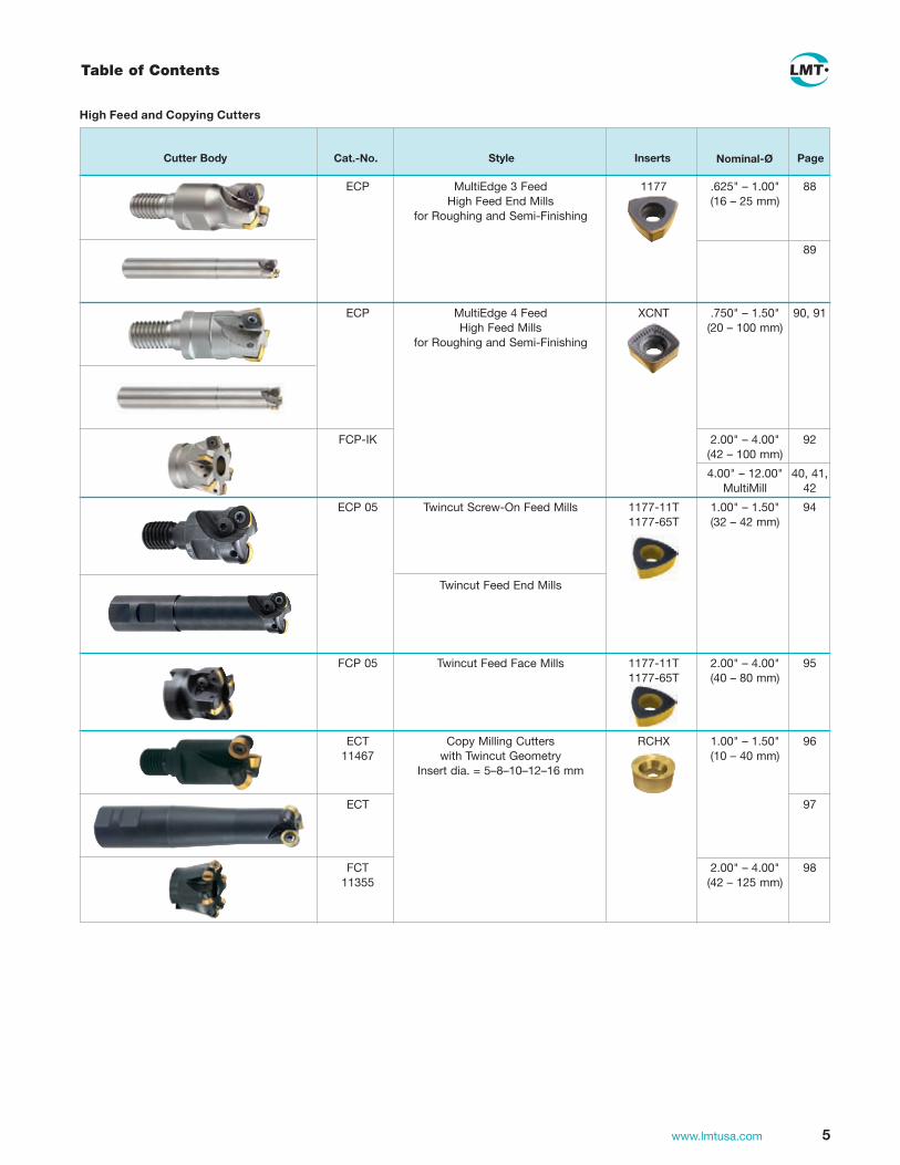
High Feed and Copying Cutters
Page
Nominal-ØCat.-No.
ECP MultiEdge 3 Feed 1177 .625" – 1.00" 88 High Feed End Mills (16 – 25 mm) for Roughing and Semi-Finishing
89
ECP MultiEdge 4 Feed XCNT .750" – 1.50" 90, 91 High Feed Mills (20 – 100 mm) for Roughing and Semi-Finishing
FCP-IK 2.00" – 4.00" 92 (42 – 100 mm)
4.00" – 12.00" 40, 41, MultiMill 42
ECP 05 Twincut Screw-On Feed Mills 1177-11T 1.00" – 1.50" 94 1177-65T (32 – 42 mm)
Twincut Feed End Mills
FCP 05 Twincut Feed Face Mills 1177-11T 2.00" – 4.00" 95 1177-65T (40 – 80 mm)
ECT Copy Milling Cutters RCHX 1.00" – 1.50" 96 11467 with Twincut Geometry (10 – 40 mm) Insert dia. = 5–8–10–12–16 mm
ECT 97
FCT 2.00" – 4.00" 98 11355 (42 – 125 mm)
StyleCutter Body Inserts

6 www.lmtusa.com
High Feed and Copying Cutters
Page
Nominal-ØCat.-No.
ECZ Copy Milling Cutters for RDHX 05-12 1.00" – 1.50" 100 11465 Round Inserts RDHW 16 (8 – 42 mm) Insert dia. = 5–7–8–10–12–16 mm
ECZ 101 11460
FCZ 2.00" – 5.00" 102 11350 (42 – 80 mm)
ECC ACU-Jet Premium RDHX 07-12 1.00" 103 High Precision Copy Cutters RDHW 16 (20 – 42mm)
FCC 2.00" (42 – 66mm)
EBT Ball Nose Copying 1179 (20 – 50 mm) 105 11497 Roughing End Mills with Twincut Geometry
EBT .750" – 2.00" 106 11493 (20 – 40 mm)
EBT Ball Nose Semi-Finshing & Finishing 1179 .625" – 1.25" 108 11432 End Mills with Twincut Geometry (16 – 32 mm)
EBG R Ball Nose Finishing Full depth .375" – 2.00" 111 (HSS body) End Mills profile (12 – 32 mm) z = 2
EBG R .250" – 1.25" 113 (carbide (6 – 32 mm) body)
EBG R THR .375" – 1.00" 114 (8 – 32 mm)
Table of Contents
StyleCutter Body Inserts

7www.lmtusa.com
High Feed and Copying Cutters
Page
Nominal-ØCat.-No.
Table of Contents
StyleCutter Body Inserts
EBG V Flat Bottom & Backdraft Endmills Full depth .500" – 1.00" 121 (HSS body) z = 2 profile (12 – 32 mm)
EBG V .500" – 1.00" 122 (carbide (8 – 32 mm) body)
EBG V THR Full depth .375" – 1.00" 123 profile (8 – 32 mm)
EMZ 90 High Speed Indexable Cutters V_GT .750" – 1.50" 132 for Non-Ferrous Metals and Plastics (20 – 42 mm)
FMZ 90 1.50" – 4.00" 133 (40 – 125 mm)
EHD UFC PCD/CBN Copy End Mill R10 10 42 1.00" – 1.57" 134 (25 – 32mm)
FHD UFC PCD/CBN Copy Face Mill 2.00" – 2.50" (40 – 125mm)
ECG Screw-in Finish-Line CPHX 0803 (20 – 40 mm) 135 Copy Cutter
FCG (42 – 66 mm)
ADT- ADT Solid Carbide .375" – 1.00" 136 Carbide Screw-In Shanks (12 – 20mm)
ADT- ADT Heavy Metal (12 – 20mm) 137 Heavy Metal Screw-In Shanks
ADT-HSS ADT-HSS .750" – 1.25" 138 Screw-In Shanks (16 – 32mm)
ADT-HSS ADT-HSS (25 – 40mm) 139 Extension Screw-In Shanks

8 www.lmtusa.com
Table of Contents
Solid Carbide End Mills
MultiEdge 2 Feed HSC Endmills, LC620T 0° 6535HA 1430C 142 extra short, short, long and extra long Center cutting, 2-flutes
MultiEdge 4 Feed HSC Endmills, LC620T 0° 6535HA 1430C 144 extra short, short, and long 4-flutes
d3
S
olid
car
bid
ece
nter
cut
ting
Mu
ltiE
dg
e 4
fee
d H
SC
. 4-
flu
tes.
ext
ra s
ho
rt,
sho
rt a
nd
lon
g
Cat
.-N
o.14
31 C
Typ
e4F
eed
HS
CS
tand
ard
Fett
e-S
tand
ard
Hel
ix a
ngle
= 0
°S
hank
des
ign
DIN
653
5 H
AC
oatin
gA
LXC
uttin
g m
ater
ial1)
LC62
0ZS
pec
ial f
eatu
res
–
d1
h10
Rth
eol 2
l 1l 3
d3
d2
(h6)
z a p
max
.Id
ent
No
.
extr
a sh
ort
51522192.0
46
55.3
875
5.14.0
43952219
52.0 4
64.4
01
752
5.05
49522193.0
46
3.5
2175
5.26.0
65952219
4.0 4
81.7
61
363
8.08
69522195.0
401
9.8
0227
5.31
017952219
6.0 4
217.01
4238
42.1
21sh
ort
20622192.0
46
55.3
5175
5.14.0
45062219
52.0 4
64.4
5.71
752
5.05
60622193.0
46
3.5
9175
5.26.0
67062219
4.0 4
81.7
42
363
8.08
80622195.0
401
9.8
5.8227
5.31
019062219
6.0 4
217.01
4338
42.1
21lo
ng2162219
3.0 4
63.5
5308
5.26.0
63162219
4.0 4
81.7
0408
38.0
86162219
5.0 4
019.8
5409
5.31
017162219
6.0 4
217.01
05001
42.1
21d2
l 1
l 3l 2
d1
d3
DHC Variable Helix End Mills, LC630T 35°/38° 6535HA 1521C 146 Center Cutting - Metric DIN 6527A/6528
DHC-INOX Variable Helix End Mills, LC630T 6535HB 1522C 147 Center Cutting - Metric DIN 6527B
HSC Line End Mills, Type N, LC620A 20° 6535HA 1410C 148 short, long and extra long LC620T 1412C Center cutting, square end with corner radius or ball nose, machining HSC and hardened steel (up to 52 Rc), 2- and 4-flutes cutter
HSC Line End Mills, Type H, LC620T 20° 6535HA 1450C 149 short, long and extra long 1451C Center cutting, square end with corner radius or ball nose, machining HSC and hardened steel (52 to 65 Rc), 2- and 4-flutes cutter
HSC Flatball End Mill, LC620Q 20° 6535HA 1400C 150 short, long and long reinforced
So
lid c
arb
ide
cent
er c
utti
ng
Fla
tba
ll H
SC
, Z
we
isc
hn
eid
er,
ku
rz,
lan
g u
nd
lan
g v
ers
tärk
tF
latb
all
HS
C,
2-fl
ute
, sh
ort
, lo
ng
an
d lo
ng
re
info
rce
d
Cat
.-N
o.14
00 C
Typ
eN
Sta
ndar
dW
erkn
orm
FE
TTE
Sta
ndar
dH
elix
ang
le20
°S
hank
des
ign
DIN
653
5 H
AC
oatin
gA
L6C
uttin
g m
ater
ial1)
LC62
0QS
pec
ial f
eatu
res
–
d1
h7d
1 h1
0r
±0,
01l 2
l 1l 3
d2 (h
5)z
Iden
t N
o.
sho
rt
41,
54
5714
62
9123
725
5
25
5717
62
9123
726
6
26
5721
62
9123
727
8
38
6327
82
9123
728
10
410
7232
102
9123
729
12
512
8338
122
9123
730
long
6
26
8044
62
9123
785
8
38
9054
82
9123
787
10
410
100
6010
291
2378
8
125
1211
065
122
9123
790
long
rei
nfo
rced
6
26
9027
82
9123
794
8
38
100
3210
291
2379
510
4
1011
035
122
9123
796
12
512
130
3716
291
2379
7
d2
l 1
l 3l 2
d1
r
2-flutes, AL6 coating
AIRline End Mills for finishing, LW630 20° 6535HA 1571 152 for aluminum and thermoplastics
6535HB 1572 also with internal coolant supply 30° IK
AIRline Ball Nose End Mills for finishing, LW630 30° 6535HA 1434 154 for aluminum and thermoplastics
6535HB 1435
l 1
d2
d1
l 2l 3
S
olid
car
bid
eS
uper
-fin
e g
rain
typ
ece
nter
cut
ting
AIR
line
-Sc
ha
ftfr
äse
r, K
ug
els
tirn
, Z
we
isc
hn
eid
er,
lan
g u
nd
ext
ra la
ng
A
IRlin
e e
nd
mill
s, b
all
no
se,
2-fl
ute
, lo
ng
an
d e
xtra
lon
g
Cat
.-N
o.14
3414
35Ty
pe
SH
Sta
ndar
dD
IN 6
527
A/B
Hel
ix a
ngle
= 3
0° R
. H. S
pira
lS
hank
des
ign
DIN
653
5 H
A D
IN 6
535
HB
Coa
ting
–C
uttin
g m
ater
ial1)
LW63
0S
pec
ial f
eatu
res
for
Alu
min
ium
/The
rmop
last
ics
mac
hini
ng
d1
e8l 2
l 1l 3
d2
h6z
Iden
t N
o.
Iden
t N
o.
long
44
5717
62
1110
559
1110
579
55
5718
62
1110
560
1110
580
66
5719
62
1110
561
1110
581
88
6325
82
1110
562
1110
582
1010
7230
102
1110
563
1110
583
1212
8336
122
1110
564
1110
584
1414
8336
142
1110
565
1110
585
1616
8242
162
1110
566
1110
586
1818
9242
182
1110
567
1110
587
2020
104
5420
211
1056
811
1058
8ex
tra
long
44
8028
62
1110
569
1110
589
55
8029
62
1110
570
1110
590
66
8030
62
1110
571
1110
591
88
9044
82
1110
572
1110
592
1010
100
5310
211
1057
311
1059
312
1211
063
122
1110
574
1110
594
1414
110
6314
211
1057
511
1059
516
1613
073
162
1110
576
1110
596
1818
130
7318
211
1057
711
1059
720
2015
089
202
1110
578
1110
598
also with internal coolant supply 30° IK
Technical Section 155
Carbide Grade
Helix angle
l
Shank DIN
Cat.-No.AL2 Plus
Cat.-No.Uncoated
Cat.-No.ALX
Cat.-No.
AL6 Page
Technical Data

Face Milling Cutters

10 www.lmtusa.com
FMN45Application
• Indexable insert with 16 cutting edges (eight cutting edges on each side)
• Large feed rates are possible
• Carbide grades LC225T, LC240T, LC610T
• Cutter available in monobloc version from 2.00" to 6.00" (32mm to 160mm)
• Coolant Fed Body
• Wiper Insert available to achieve better flatness and surface finish
MultiEdge Double 8 Face Milling Cutters
d5
d2
d1
d4
hap
15°
845°1)
3
-5°
15°
1045°1)
4
-5°
FMN45InchIKZ
ONGU0505
ONGU0606
Seepage11forinserts Cutting data recommendations starting page 174For Modular cutter diameters 4.00"-12.00" see Multi-Mill section pages 40-42Multi-Mill Cartridge No. 1028081 Inch Cutters with ONGU 0505 Inserts quoted as Special
d1
CutterBodyNo.
EDPNo.
IdentNo. d4 h d2 d5
apmax
(DOC) z InsertInsertScrew
TorxDriver
2" FMN45 O06.200AA-I 17001 1950420 .630 1.57 .750 1.57 .157 4 ONGU 0606 1045133 1048422
2" FMN45 O06.200AA-IF 17002 1950421 .630 1.57 .750 1.57 .157 6 T20
2.5" FMN45 O06.250AA-I 17005 1950422 .630 1.57 .750 1.97 .157 5 (Torx Plus)
2.5" FMN45 O06.250AA-IF 17006 1950423 .630 1.97 .750 1.97 .157 8
3" FMN45 O06.300AB-I 17007 1950424 .630 1.97 1.00 2.36 .157 7
3" FMN45 O06.300AB-IF 17008 1950425 .630 1.97 1.00 2.36 .157 10
4" FMN45 O06.400AD-I 17009 1950426 .630 1.97 1.50 2.95 .157 9
4" FMN45 O06.400AD-IF 17010 1950427 .630 1.97 1.50 2.95 .157 12
5" FMN45 O06.500AD 17011 1950428 .630 2.48 1.50 3.54 .157 11
5" FMN45 O06.500AD-F 17012 1950429 .630 2.48 1.50 3.54 .157 15
6" FMN45 O06.600AD 17013 1950430 .630 2.48 1.50 5.12 .157 13
6" FMN45 O06.600AD-F 17014 1950431 .630 2.48 1.50 5.12 .157 19
All bodies have internal coolant

11www.lmtusa.com
d1 CutterBodyNo.IdentNo. d4 h d2 d5
apmax
(DOC) z InsertInsertScrew
TorxDriver
32 FMN45 005.032AN-I 1027400 12.7 40 16 32 3 3 ONGU 0505 1045131 1048335
32 FMN45 005.032AN-IF 1027401 12.7 40 16 32 3 4 M4 T15
40 FMN45 005.040AN-I 1027402 12.7 40 22 40 3 4 (Torx Plus)
40 FMN45 005.040AN-IF 1027403 12.7 40 22 40 3 5
50 FMN45 005.050AN-I 1027404 12.7 40 22 40 3 5
50 FMN45 005.050AN-IF 1027405 12.7 40 22 40 3 7
63 FMN45 005.063AN-I 1027406 12.7 40 22 50 3 7
63 FMN45 005.063AN-IF 1027407 12.7 40 22 50 3 9
50 FMN45 006.050AN-I 1027420 16 40 22 40 4 4 ONGU 0606 1045133 1048422
50 FMN45 006.050AN-IF 1027421 16 40 22 40 4 6 T20
63 FMN45 006.063AN-I 1027422 16 40 22 50 4 5 (Torx Plus)
63 FMN45 006.063AN-IF 1027423 16 40 22 50 4 8
80 FMN45 006.080AN-I 1027424 16 50 27 60 4 7
80 FMN45 006.080AN-IF 1027425 16 50 27 60 4 10
100 FMN45 006.100AN-I 1027426 16 50 32 75 4 9
100 FMN45 006.100AN-IF 1027427 16 50 32 75 4 12
125 FMN45 006.125AN 1027428 16 63 40 90 4 11
125 FMN45 006.125AN-F 1027429 16 63 40 90 4 15
160 FMN45 006.160AN 1027430 16 63 40 130 4 13
160 FMN45 006.160AN-F 1027431 16 63 40 130 4 19
Indexable Inserts for MultiEdge Double 8 Face Milling Cutters
LC
280Q
N
LC
280T
T
LC
610Q
LC
240T
LC
230F
LC
225T
LC
225S
LC
630T
LW
240
LW
225
LC
610A
LC
610E
LC
610T
5.56 12.7 4.4 2 (.219) (.500) (.173) (.079)
5.56 12.7 4.4 2 (.219) (.500) (.173) (.079)
6.35 16 6.3 2 (.250) (.630) (.248) (.079)
6.35 16 6.3 2 (.250) (.630) (.248) (.079)
ONGU 0505ANEN
ONGU 0506ANEN-SL
WP WiperONGU
0606ANEN
ONGU 0606ANEN-SL
WP Wiper
FMN45
LC
280Q
N
LC
280T
T
N = 16
10
5400
9
1054
017
1054
014
1054
0181
)
10
5400
8
1054
015
1054
013
1054
0161
) N= Numberof cuttingedges l s d d1 r Cat-No.
ISO-Code
CuttingmaterialsIdentNo.
Forcutter
Cat-No.LC
603Z
s 15°
r
d d1
1) LC610T with additional TiN top layerNote: Wiper Insert has 4 Cutting Edges Per Side
MultiEdge Double 8 Face Milling Cutters
Limited stock of metric products in U.S., please contact Customer Service for availability Cutting data recommendations starting page 174
FMN45Metric
BN
025

12 www.lmtusa.com
FCT45 R/8/12 & MCT45 R/8/12
FCT 45 Features & Benefits• Exclusive TWINCUT geometry
• Large insert grade offering
• Direct pressed inserts in round, 8, 12 and New MultiEdge 4X Serrated Inserts
• Designed for roughing and finishing
• Deep, positive chip grooves
Slot Milling
Plunge Milling
FCT45
FCTXX Vario/FCT45
Profile Milling-Roughing
Face Milling
FCT45
FCTXX Vario/FCT45
Step Milling
Pocket Milling / Ramping
FCTXX Vario/FCT45
FCTXX Vario/FCT45
Chamfer Milling
Shoulder Milling
FCT45
FCT45
Round insert: 8 useable cutting edges
Thick insert
Wide facet width generates superior finishes
Positive locking and locationRelieved front face area for plunge and pocket milling
Special chip forming topography
Cutter body accepts round, 8, 12 and New MultiEdge 4X Serrated Inserts
Cartridge forNew Multi-Mill
MCT45 & MCTXX

13www.lmtusa.com
45° TWINCUT Face Mills
FCT45Application
• Universal milling cutter for face milling of steel, stainless steel and cast iron materials
• Exclusive TWINCUT insert design offers round, 4 sided, and 8 sided for roughing applications
FCT45Inch
See page 16 for Inserts Cutting data recommendations starting page 175For modular cutter diameters 4.00"-12.00" see Multi-Mill section pages 40-42Multi-Mill Cartridge No. 1028077
max doc
d1 Cutter Body No.EDP No.
Ident No.
8edge
12edge d4 h d2 z Insert Insert Insert Insert
Insert Screw
Torx Driver
2.00 FCT45 O06-200AA 50300 1950259 0.157 0.079 0.63 1.57 0.75 4 XOKX RCKX OCKX XCKX 50255 50258
2.50 FCT45 O06-250AA 50302 1950260 0.157 0.079 0.63 1.97 0.75 4 1606 1606 0606 1606 M5 T20
3.00 FCT45 O06-300AB 50304 1950261 0.157 0.079 0.63 1.97 1.00 5
4.00 FCT45 O06-400AD 50306 1950262 0.157 0.079 0.63 1.97 1.50 7
5.00 FCT45 O06-500AD 50308 1950263 0.157 0.079 0.63 2.48 1.50 8
d1 Cutter Body No.Ident No. d4 h d2 d5 z Insert Insert Insert Insert
Insert Screw
Torx Driver
52 FCT45 006.052AN 1041011 16 40 22 40 4 XOKX RCKX OCKX XCKX 1045777 1048344
66 FCT45 006.066AN 1041012 16 50 27 48 5 1606 1606 0606 1606 M5 T20
80 FCT45 006.080AN 1041013 16 50 27 60 6
100 FCT45 006.100AN 1041014 16 50 32 65 7
125 FCT45 006.125AN 1041015 16 63 40 90 8
160 FCT45 006.160AN 4053555 16 63 40 95 9
FCT45Metric
Limited stock of metric products in U.S., please contact Customer Service for availability
d1
d2
h
d4
d5
Max doc 0.157"Max doc 0.079"
See Pages 17 & 18 for Multi Edge 4X XOKX Insert Advantages

14 www.lmtusa.com
FCT XX & MCT XX TWINCUT VARIO
TWINCUT VARIOThe TWINCUT VARIO is an excellent example of how cutting theory can be applied in practice. It successfully incorporates the principle of using two axially and radially offset edges to make the cut. The upper and lower rows of cutting edges each have different angles of approach and cutting depths.
This produces a technically superior chip cross-section with significantly reduced width to height relationship, sharply reducing the cutting forces. Power input can be reduced to between 75% and 85% of previous requirements. The improved dynamics of the VARIO’s twin offset cutting edges make this possible and gives VARIO a competitive advantage.
VARIO cutting tools are far superior to conventional button cutters, as they are quiet-running and reduce vibrations. This makes them especially suitable for machining under less stable conditions.
A major benefit of the Vario’s innovative design is the versatility of the insert pocket. Vario’s pockets will accept both the round and octagonal high-performance inserts.
TWINCUT VARIO Features & Benefits• Broad application range for steel, castings and non-ferrous.
• Option of round or octagonal indexable inserts in same insert
pocket. This flexible design helps reduce overall tooling costs.
• Increased insert thickness provides high feed rates and
shorter machining times.
• Deep molded chip grooves and special design surface
topography, lower horsepower requirements, reduce vibration,
lower operating temperatures, yield superior surfaces, and
extend tool life.
• Stable insert seating prevents insert rotation and allows
precise indexing.
• Either z-axis plunging or ramping is possible making the
Vario ideal for cavity milling and ramping.
• Precision sintered insert with eight effective cutting edges
lower cost per cutting edge.
Milling profi le with round inserts.
TWINCUTVARIO Geometry
ConventionalGeometry
TWINCUT VARIO with OCKX 0606 AD-TRTWINCUT VARIO with RCKX 1606 MO-TR

15www.lmtusa.com
45° TWINCUT Face Mills
FCT XX TWINCUT – VarioApplication
• Universal in application face milling of steel, castings, non-ferrous metals
• Exclusive TWINCUT insert design offers round, and 8 sided for roughing applications
-7°-12°4° 20°
45°1)
4 10
8-Sided
d2
d3+.035
h
-7°-14°
3°18°
16
Round
d3
h
d1
d2
d1
R .343
d3+.035 R .362
FCT XX TWINCUT – VarioInch
d1 Cutter Body No.EDP No.
Ident No. d3 h d2 z Insert Insert
Insert Screw
TorxDriver
1.50 FCTXX R16-150AA 51486 1950270 2.23 1.57 0.75 4 RCKX 1606 OCKX 0606 50255 50258
2.00 FCTXX R16-200AA 51487 1950278 2.73 1.57 0.75 6 M5 T20
2.50 FCTXX R16-250AA 51488 1950279 3.23 1.97 0.75 6
3.00 FCTXX R16-300AB 51489 1950273 3.73 1.97 1.00 8
4.00 FCTXX R16-400AD 51490 1950274 4.73 1.97 1.50 10
See page 16 for Inserts Cutting data recommendations starting page 176For modular cutter diameters 4.00"-12.00" see Multi-Mill section pages 40-42Multi-Mill Vario Cartridge No. 1028079Multi-Mill FCT45 Cartridge No. 1028077
d1 Cutter Body No.Ident No. d3
Insert Dia. d4 h d2 z Insert Insert
Insert Screw
TorxDriver
36 FCTXX R16.036AN 1041016 54.6 16 40 22 4 RCKX 1606 OCKX 0606 1045777 1048344
48 FCTXX R16.066AN 1041026 66 16 50 27 6 M5 T20
50 FCTXX R16.050AN 1041017 68.6 16 50 27 6
60 FCTXX R16.08AN 1041028 80 16 50 27 6
63 FCTXX R16.063AN 1041018 81.6 16 50 27 6
63 FCTXX R16.063AN-F 1041019 81.6 16 50 27 8
80 FCTXX R16.080AN 1041020 98.6 16 50 32 8
100 FCTXX R16.100AN 1041022 118.6 16 50 40 10
125 FCTXX R16.125AN 1041024 143.6 16 63 40 10
Limited stock of metric products in U.S., please contact Customer Service for availability
FCT XX TWINCUT – VarioMetric

16 www.lmtusa.com
MultiEdge Face Milling and Copying Cutters – Indexable Inserts
l s d d1 r
RCKX 1606 MO-TR FCT45FCTXX
FCT45FCTXX
FCT45FCTXX
23�
d1
7�
d s
N = 8
RCKX 1606 MO-TRTwide land
s
d1
l
25�15� 7�
d
N = 8
N = 12
ISO-Code
Ident No. For cutter
LMT-Code LC
240Q
LC
610Q
LC
240T
LC
230F
LC
225T
LC
225S
LC
630S
LC
630T
LC
615E
LC
610T
1055
730
1068
460
1068
464
1054
012
1054
011
1055
677
1068
010
1055
676
1055
708
1055
709
1055
678
1055
689
FCT45FCTXX
N = 4
l
d
s
d1
25�
4�
1054
023
1054
024
1054
021
1054
020
1054
022
LC
280Q
N2)
LC
280T
T1)
XOKX 1606 ZD-TR
OCKX 0606 AD-TR
OCKX 0606 AD-TRTwide land
XCKX 1606 ZDR-TR
Cutting materials
N = Number of cutting edges
1) Roughing geometry with double coatingLC280TT
2) Two colored multi coating for high performance millingLC280QN
16 6.35 16 5.8 0.5 (.630) (.250) (.630) (.228) (.020)
16 6.35 16 5.8 0.5 (.630) (.250) (.630) (.228) (.020)
16 6.35 16 5.8 0.5 (.630) (.250) (.630) (.228) (.020)
16 6.35 16 5.8 0.5 (.630) (.250) (.630) (.228) (.020)
16 6.35 16 5.8 (.630) (.250) (.630) (.228)
16 6.35 16 5.8 (.630) (.250) (.630) (.228)
1055
732
1068
433
1068
431
1068
435
1055
731
1068
013
1054
003
1068
004
1054
001
1054
005
2414
058

17www.lmtusa.com
MultiEdge 4X
MultiEdge 4X Features & Benefits
A characteristic attribute of the new MultiEdge 4Xhigh-performance Milling Tools is the striking cutting edge design of the insert with a total of 12 steps. Thereby a favourable chip division will occur during milling which in combination with MultiC-coating will result in following advantages:
rces
requirements
re tool life
(finish qualities also when roughing due to wiper-edge geometry)
(at version with cut division)
The Inserts are precision-sinterroven cutter bodies FCT45.
1,1
.039
.035
.032
.028
.024
.020
.016
.012
.008
.004
0
Feed
per
to
oth
f z (i
nch)
MultiEdge 4X XOKX
0 .039 .079 .118 .158 .197 .236 .276 .315 .354 .394 .433 axial infeed ap (DOC) - Inch
XOKX1606 RCKX1606 OCKX0606 XCKX1606ap up to .197"4 times usable
ap up to .118"8 times usable
ap up to .158"8 times usable
ap up to .070"12 times usable
Feed per tooth of MultiEdge 4X compared with other inserts shape
MultiEdge 4X: Small chips because of chip division
MultiEdge 4X
ap max. = 5 mm (.197")
ap2 = 3 mm (.118")
ap1 = 1 mm (.039")
200
%
160
140
120
100
80
60
40
20
0
Tool steel1.2312
Cutting data:vc = 575 SFMfz = 0.010 IPT
RCKXP40 TiAIN
Too
l life
MultiEdge 4XXOKX
LC280QN
RCKXK10 TiAIN
MultiEdge 4XXOKX
LC610T
Nodular cast ironGGG60
Cutting data:vc = 690 SFMfz = 0.010 IPT
Tool life compansion
Cut-steps of MultiEdge 4X Insert

18 www.lmtusa.com
Surface quality
MultiEdge 4X vc = 575 SFMXOKX fz = 0.010 IPT
Perthometer M4PDat.Obj.#LT 15 mmRA 0.69 µmRZ 3.92 µmRMAX 4.32 µm
VER 25 µmHOR LC 2.5 mm
Perthometer M4PDat.Obj.#LT 15 mmRA 5.67 µmRZ 19.68 µmRMAX 20.32 µm
VER 25 µmHOR LC 2.5 mm
RCKX vc = 575 SFMfz = 0.010 IPT
Success Story
Milling of Austempered Cast Iron Class 2APPLICATION: Rough and Finish Face Milling in a single pass
CUSTOMER: General Machining Shop
MACHINE: CAT 40 Taper – 30 HP
STARTING SITUATION: Customer was unable to achieve tight surface finish requirements with existing competitors milling tools
PROBLEM: Operation requires both rough and finish face mills to achieve required RMS finish. Customer is also reporting reduced tool life with competitor’s tooling.
SOLUTION: FCT45 Face Mill with XOKX 1606 inserts to rough and finish in one pass
CUSTOMER BENEFIT: Increase in productivity through reduced cycle times and fewer tool changes
TARGET MARKETS: Production shops looking to increase efficiency
TOOL LIFE / EXPECTENCY: Competitor (1-2 parts), LMT (18-20 parts)
CUTTING DATA:• Face Mill: 4.00" FCT45 O06-400AD • Insert: XOKX 1606 ZD TR LC610T • Speed: 350 SFM (334 RPM)• Feed: .012" FPT (28 IPM)• DOC: .125" • WOC: 3.00" • Surface Finish Requirement: 42 RMS

19www.lmtusa.com
TWINCUT Family
Positive Geometry:The cutter is designed with a positive axial rake angle that allows the insert to cleanly and quietly shear the workpiece materials. This not
only reduces horsepower requirements, but actually reduces wear on machine spindle bearings, ball screws and other components.
• Excellent on stainless steels, high temperature alloys and non-ferrous materials
• Extremely smooth cutting action
FMT45
FMT90
Features & Benefits
LMT-FETTE’s exclusive TWINCUT geometry lowers cutting forces
and enables aggressive feed rates.
Double Negative Geometry:The double negative insert position with high positive rake angles
works well on a wide variety of materials, and on a wide variety of
machines as well. The double negative design is exceptionally strong,
offering unsurpassed smooth cutting action. TWINCUT geometry
directs downward pressure on the work piece, thus providing stability.
• Excellent on steels and cast iron
• Large insert seating surface
• Thick insert with rigid cross section
Radially 30°negative
Insert positionAxially 10° positive40° effective
• Large insert thickness• Rigid cross section
• Large rear surface seating area
• Sharp cutting edge• Excellent surface finish• Precision ground inserts
• Large positive rake angles• Deep chip groove
FMV45

20 www.lmtusa.com
45° TWINCUT End Mills/Face Mills
FMT45 (11250-12)Application
• First choice milling cutter for face milling of steel and cast iron materials
• Used in rough and finish milling operations
• Features ramp milling capabilities
45°ap
–15°
17°
FMT45Inch
d1 Cutter Body No.EDP No.
Ident No.
ap
(DOC) d3 h d2 z InsertInsert Screw
TorxDriver
2.00 FMT45 S12-200AA 50310 1950044 0.28 2.56 1.57 0.75 4 SNKX 1205 50256 50258
2.50 FMT45 S12-250AA 50312 1950046 0.28 3.06 1.57 0.75 5 SNKQ 1205 M4.5 T20
3.00 FMT45 S12-300AB 50314 1950048 0.28 3.56 1.97 1.00 5 SNKU 1205
3.00 FMT45 S12-300ABF* 50316 1950048I 0.28 3.56 1.97 1.00 6
4.00 FMT45 S12-400AD 50318 1950050 0.28 4.56 1.97 1.50 7
5.00 FMT45 S12-500AD 50320 1950052 0.28 5.56 2.48 1.50 8
6.00 FMT45 S12-600AD 50322 1950054 0.28 6.56 2.48 1.50 9
8.00 FMT45 S12-800AF 50324 1950205 0.28 8.56 2.48 2.50 12
*Fine Pitch Cutting data recommendations starting page 178See page 21 for Inserts For modular cutter diameters 4.00"-12.00" see Multi-Mill section pages 40-42Multi-Mill Cartridge No. 1028050
d1 Cutter Body No.11250
Ident No.11250-IKIdent No.
ap
(DOC) d3 h d2 z InsertInsert Screw
TorxDriver
40 FMT45 S12.040AN-I 1027300 7 54 40 22 3 SNKX 1205 AN 1045123 1048344
50 FMT45 S12.050AN-I 1027302 7 64 40 22 4 SNKQ 1205 AN M4.5 T20
63 FMT45 S12.063AN-I 1027304 7 77 40 22 5
80 FMT45 S12.080AN(-I) 1027314 1027306 7 94 50 27 6
100 FMT45 S12.100AN(-I) 1027316 1027308 7 114 50 32 7
125 FMT45 S12.125AN(-I) 1027318 1027310 7 139 63 40 8
160 FMT45 S12.160AN(-I) 1027320 1027312 7 174 63 40 9
Limited stock of metric products in U.S., please contact Customer Service for availability
FMT45Metric
d2
d1
d3
h

21www.lmtusa.com
45° TWINCUT End Mills/Face Mills – Indexable Inserts
SNKX 1205 AN1187-10
12.7 5.56 5.2 2 (.500) (.219) (.205) (.078)
b
l s
d1
30°45°
N = 4
MMT45
FMT45
FMT45
FMT45
FMT45
FMT45
N = Number of cutting edges l s d d1 b/r Cat-No.
ISO-Code
Cutting materialsIdent No.
Forcutter
Cat-No. LC
240Q
LC
610Q
LC
240T
LC
240S
LC
230F
LC
225T
LC
225S
LC
630T
LW
240
LW
225
LC
615E
LC
612E
LC
610T
1052
301
1068
007
1052
315
1052
228
8936
5
1052
339
1052
236
12.7 5.44 5.2 2 (.500) (.214) (.205) (.078)
SNKX 1205 AN-T1187-12
b
s
d1
30°45°
l
wide land
wide land
Wiper
N = 4
1052
303
1068
008
1052
314
1052
256
1052
309
5595
5
1052
254
12.7 5.56 5.2 2 (.500) (.219) (.205) (.078)
12.7 5.56 5.2 2 (.500) (.219) (.205) (.078)
SNKX 1205 AN-TR1187-10 TR
SNKX 1205 AN-TT
b
s
d1
30°
l
45°
N = 4
10
5226
0
1052
248
1052
239
1052
237
1052
251
19.05 5.56 12.7 5.2 (.750) (.219) (.500) (.205)
1187-90
s
d1
l
dr
45°
2305
343
12.7 5.56 5.2 2 (.500) (.219) (.205) (.078)
SNKQ 1205 AN1187-13
sl
45° b
d1
N = 8
N = 1
1052
336
1052
304
1052
335
2414
057
1052
305
1055
742
LC
280Q
N2)
b45°
sl
d
30°
d1
N = 8
12.7 5.56 5.2 2 (.500) (.219) (.205) (.078)
SNKU 1205 AN-TR
1052
327
1052
328
1052
329
1) Roughing geometry with double coatingLC280TT
2) Two colored multi coating for high performance millingLC280QN
LC
280T
T1)
LW
610

22 www.lmtusa.com
45° TWINCUT VA Face Mills
17°
10°
doc45°
FMV45 (11280)Application
• High performance positive milling cutter for face milling of stainless, high temperature alloys and non-ferrous materials
• Used in rough and finish milling operations
• Extremely smooth and quiet cutting action
• Designed to work well on low horsepower machines
d2
d1
d3
h
FMV45 Inch
d1
Cutter Body No.
EDP No.
Ident No. doc d3 h d2 z Insert
Insert Screw
Torx Driver
2.50 FMV45 S12-250AA 50356 1950223 0.197 2.93 1.57 0.75 5 SNHX 1205 50256 50258
3.00 FMV45 S12-300AB 50358 1950225 0.197 3.43 1.97 1.00 6 M4.5 T20
4.00 FMV45 S12-400AD 50360 1950227 0.197 4.43 1.97 1.50 7
5.00 FMV45 S12-500AD 50362 1950229 0.197 5.43 2.48 1.50 8
6.00 FMV45 S12-600AD 50364 1950231 0.197 6.43 2.48 1.50 9
See page 23 for inserts Cutting data recommendations starting page 178
FMV45 Metric
d1
Cutter Body No.
Ident No. d3 h d2 z Insert
Insert Screw
Torx Driver
50 FMV45 S12.050AN 1027331 61 40 22 4 SNHX 1205 1045123 1048344
63 FMV45 S12.063AN 1027330 74 40 22 5 M4.5 T20
80 FMV45 S12.080AN 1027332 91 50 27 6
100 FMV45 S12.100AN 1027334 111 50 32 7
125 FMV45 S12.125AN 1027336 136 63 40 8
Limited stock of metric products in U.S., please contact Customer Service for availability

23www.lmtusa.com
LC
240T
LC
240S
LC
230F
LC
225T
LC
225S
LC
630T
LW
240
LW
225
N = 4
FMV45
N = Number of cutting edges l s d d1 b/r Cat-No.
ISO-Code
Ident No. For
cutter
Cat-No. LC
430T
LC
444W
LC
610A
LW
610
LC
610E
LC
610T
LC
603Z
12.7 5.56 5.2 2 (.500) (.219) (.205) (.079)
SNHX 1205 AE1187-18
b
s
d1
30�45�
l
1068
005
1052
306
1067
543
12.7 5.56 5.2 2 (.500) (.219) (.205) (.079)
1067
537SNHX 1205 AESN-BM
b
l s
d1
30�45�
d
N = 4
FMV45 12.7 5.56 5.2 2 (.500) (.219) (.205) (.079)
SNHX 1205 AE-ALC1187-18 ALC
b
s
d1
35�45�
l
1052
255
1052
235
FMV45
45° TWINCUT VA Face Mills – Indexable Inserts
Cutting materials
Note: ALC LW610 High Polish for Aluminum Milling

24 www.lmtusa.com
45° ISO Face Mills
Features & Benefits• High positive cutting geometry
• Quiet cutting action
• High cutting capacity with low horsepower machines or unstable conditions
• ISO indexable inserts
FMH45A • Locking screw (left-hand thread) for
secure clamping
• Thicker inserts for higher feed rates
FMH45B • Torx screw locking
• Thicker inserts for higher feed rates
FMH45• Indexable inserts shims to protect
the steel cutter body
• Locking screw (left-hand thread) for secure clamping

25www.lmtusa.com
45° ISO Face Mills
10°
19°
doc
45°
FMH45 (11172)Application
• General purpose milling cutter for face milling of steel, stainless and non-ferrous materials
• Used in light-duty rough and finish milling operations
• Uses ISO style inserts
• High positive cutting geometry for low horsepower machines
d2
d1
d3
h
FMH45Inch
d1 Cutter Body No.EDP No.
Ident No.
ap
(DOC) d3 h d2 z InsertInsert
Locking ScrewHex Key
2.00 FMH45 S12-200AA 50378 – 0.216 2.51 1.57 0.75 4 SEKN 1203 50652 50264
3.00 FMH45 S12-300AB 50380 – 0.216 3.51 1.97 1.00 5 SEKR 1203 50654 4mm
4.00 FMH45 S12-400AD 50382 – 0.216 4.51 1.97 1.50 6 SEAN 1203 50654
See page 27 for inserts For modular cutter diameters 4.00"-12.00" see Multi-Mill section pages 40-42Multi-Mill Cartridge No. 1028072
Cutting data recommendations starting page 178
Limited stock of metric products in U.S., please contact Customer Service for availability
FMH45Metric
d1 Cutter Body No.Ident No. d3 h d2 z Insert
Insert Locking Screw
Hex Key
40 FMH45 S12.040AN 1027010 53 45 16 3 SEKN 1203 1050904 1048317
50 FMH45 S12.050AN 1027011 63 48 22 4 SEKR 1203 6K-SW4
63 FMH45 S12.063AN 1027012 76 40 22 5 SEAN 1203 1050901
80 FMH45 S12.080AN 1027013 93 50 27 6
100 FMH45 S12.100AN 1027014 113 50 32 6
Insert Shim
Shim Screw
Torx Driver
50578 50580 50582
Insert Shim
Shim Screw
Torx Driver
1050902 1050903 2146539
6K-SWZ

26 www.lmtusa.com
45° ISO Face Mills
10°
19°
doc
45°
FMH45A (11173)Application
• General purpose milling cutter for face milling of steel, stainless and non-ferrous materials
• Used in light-duty rough and finish milling operations
• Uses ISO style inserts
• High positive cutting geometry for low horsepower machines
d2
d1
d3
h
FMH45AInch
d1 Cutter Body No.EDP No.
Ident No. doc d3 h d2 z Insert
Insert Locking Screw
Hex Key
2.00 FMH45A S12-200AA 50384 0.216 2.51 1.57 0.75 4 SEKN 1204 50652 50264
3.00 FMH45A S12-300AB 50386 0.216 3.51 1.97 1.00 5 SEKR 1204 50654 4mm
4.00 FMH45A S12-400AD 50388 0.216 4.51 1.97 1.50 6 50654
See page 27 for Inserts Cutting data recommendations starting page 178For modular cutter diameters 4.00"-12.00" see Multi-Mill section pages 40-42Multi-Mill Cartridge No. 1028040
FMH45AMetric
d1 Cutter Body No.Ident No. d3 h d2 z Insert
Insert Locking Screw
HexKey
40 FMH45A S12.040AN 1027020 53 45 16 3 SEKN 1204 1050904 1048317
50 FMH45A S12.050AN 1027021 63 48 22 4 SEKR 1204 6K-SW4
63 FMH45A S12.063AN 1027022 76 40 22 5 1050901
80 FMH45A S12.080AN 1027023 93 50 27 6
100 FMH45A S12.100AN 1027024 113 50 32 6
Limited stock of metric products in U.S., please contact Customer Service for availability

27www.lmtusa.com
12.7 3.18 12.7 1.4 SEKN 1203AFEN (.500) (.125) (.500) (.055)
12.7 3.18 12.7 1.4 SEAN 1203AFSN (.500) (.125) (.500) (.055) 1193-15
12.7 3.18 12.7 1.4 SEKN 1203AFSN (.500) (.125) (.500) (.055)
12.7 4.76 12.7 1.4 SEKN 1204AFEN (.500) (.187) (.500) (.055)
12.7 4.76 12.7 1.4 SEKN 1204AF (.500) (.187) (.500) (.055)
12.7 4.76 12.7 1.4 SEKN 1204AFSN (.500) (.187) (.500) (.055)
12.7 3.18 12.7 1.4 SEKR 1203AFSN (.500) (.125) (.500) (.055)
12.7 4.76 12.7 1.4 SEKR 1204AFSN (.500) (.187) (.500) (.055)
12.7 3.18 12.7 1.4 SEKR 1203AFSN-BM (.500) (.125) (.500) (.055)
12.7 4.76 12.7 1.4 SEKR 1204AFSN-BM (.500) (.187) (.500) (.055)
FMH45
FMH45A
FMH45
FMH45A
FMH45
FMH45A
N = Number of cutting edges l s d d1 b/r ISO-Code
Cutting materialsIdent No.
Forcutter
Cat-No.
20°
sl
d
b
N = 4
20°
sl
d
N = 4
20°
sl
d
N = 4
LC
610A
LW
610
LC
615E
LC
610T
LC
444W
LC
440T
LC
240Q
LC
240T
LC
230F
LC
225T
LC
225S
LW
240
LW
225
45° ISO Face Mills – Indexable Inserts
1067
526
1067
474
1067
468
1055
643
1067
259
1067
487
1067
470
1067
527
1067
475
1067
486
1067
518
1067
492
1055
650
1055
652
1067
476
1067
479
1067
529
1067
531
1067
471
1067
498
6406
756
6400
580
6400
581
6406
761
6406
762
1067
509
6406
772
6406
771
6406
776
1067
514
1067
508

28 www.lmtusa.com
45° ISO Face Mills
10°
19°
doc
45°
FMH45B (11171)Application
• General purpose milling cutter for face milling of steel, stainless and non-ferrous materials
• Used in light-duty rough and finish milling operations
• Uses ISO style inserts
• Ideal for low horsepower machines
d2
d1
d3
h
FMH45BInch
d1 Cutter Body No.EDP No.
Ident No. doc d3 h d2 z Insert
Insert Screw
TorxDriver
2.00 FMH45B S12-200AA 50372 – 0.216 2.51 1.57 0.75 4 SEHT 1204 50255 50258
3.00 FMH45B S12-300AB 50374 – 0.216 3.51 1.97 1.00 5 SEKW 1204 M5 T20
4.00 FMH45B S12-400AD 50376 – 0.216 4.51 1.97 1.50 6
See page 29 for Inserts Cutting data recommendations starting page 178For modular cutter diameters 4.00"-12.00" see Multi-Mill section pages 40-42Multi-Mill Cartridge No. 1028051
FMH45BMetric
d1 Cutter Body No.Ident No. d3 h d2 z Insert
Insert Screw
TorxDriver
40 FMH45B S12.040AN 1027000 53 45 16 3 SEHT 1204 1045766 1048344
50 FMH45B S12.050AN 1027001 63 48 22 4 SEKW 1204 M5 T20
63 FMH45B S12.063AN 1027002 76 40 22 5
80 FMH45B S12.080AN 1027003 93 50 27 6
100 FMH45B S12.100AN 1027004 113 50 32 6
Limited stock of metric products in U.S., please contact Customer Service for availability
29www.lmtusa.com
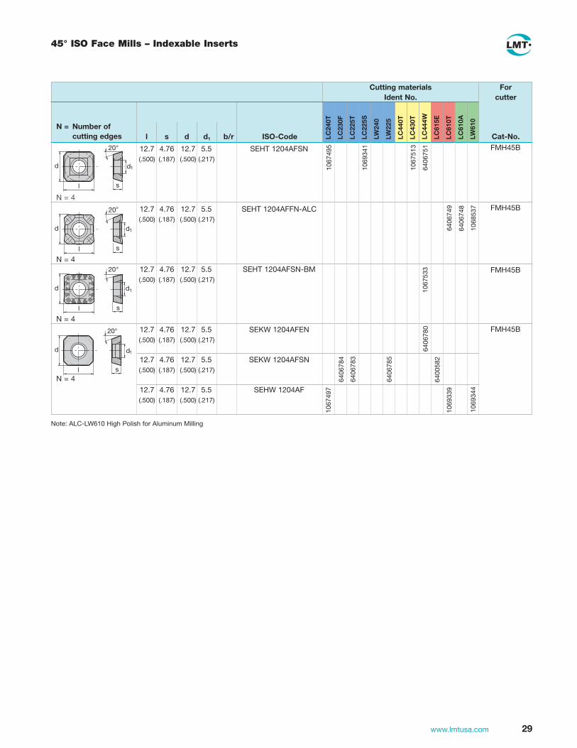
45° ISO Face Mills – Indexable Inserts
12.7 4.76 12.7 5.5 SEHT 1204AFSN (.500) (.187) (.500) (.217)
12.7 4.76 12.7 5.5 SEHT 1204AFFN-ALC (.500) (.187) (.500) (.217)
12.7 4.76 12.7 5.5 SEHT 1204AFSN-BM (.500) (.187) (.500) (.217)
12.7 4.76 12.7 5.5 SEKW 1204AFEN (.500) (.187) (.500) (.217)
12.7 4.76 12.7 5.5 SEKW 1204AFSN (.500) (.187) (.500) (.217)
12.7 4.76 12.7 5.5 SEHW 1204AF (.500) (.187) (.500) (.217)
FMH45B
FMH45B
FMH45B
FMH45B
LC
610A
LW
610
LC
444W
LC
615E
LC
610T
LC
430T
LC
440T
LC
240T
LC
230F
LC
225T
LC
225S
LW
240
LW
225
N = Number of cutting edges l s d d1 b/r ISO-Code
Cutting materialsIdent No.
Forcutter
Cat-No. 20°
s
d1
l
d
N = 4
20°
sl
d d1
N = 4
20°
s
d1
l
d
N = 420°
s
d1
l
d
N = 410
6749
5
1069
341
1067
513
6406
780
6406
784
6406
783
6406
785
6400
582
1069
339
1067
497
1069
344
1068
537
6406
749
1067
533
6406
748
6406
751
Note: ALC-LW610 High Polish for Aluminum Milling

30 www.lmtusa.com
90° TWINCUT Face Mills
Indexable Inserts for 90° TWINCUT Face Mills
FMT90 (11260-12)Application
• All purpose positive milling cutter for face and square shoulder milling of steel and non-ferrous materials
• Used in rough and finish milling operations
7°17°
90°
doc90°
d1
d2
h
1052247
1052246
53797
1052244
1052240
2346047
1052659
1052242
N= Numberof cuttingedges l s d d1 b/r Cat-No.
ISO-Code
CuttingmaterialsIdentNo.
Forcutter
Cat-No.LC240T
LC240S
LC230F
LC225T
LC225S
LC630T
LW240
LW225
LC440T
LC444W
LC610A
LW610
LC612E
LC610T
LC603Z
N = 4
11260-12FMT90MMT90
12.7 5.56 5.2 0.8 (.500) (.219) (.205) (.031)
SPKX 120508 1187-15
s
20�
d1
11�
r
l
FMT90Inch
d1
CutterBodyNo.
EDPNo.
IdentNo. doc h d2 z Insert
InsertScrew
TorxDriver
2.00 FMT90 S12-200AA 50344 1950197 0.390 1.58 0.75 4 SPKX 120508 50256 50258
2.50 FMT90 S12-250AA 50346 1950198 0.390 1.58 0.75 5 M4.5 T20
3.00 FMT90 S12-300AB 50348 1950199 0.390 1.97 1.00 6
4.00 FMT90 S12-400AD 50350 1950201 0.390 1.97 1.50 7
5.00 FMT90 S12-500AD 50352 1950203 0.390 2.48 1.50 8
6.00 FMT90 S12-600AD 50354 1950204 0.390 2.48 1.50 9
For modular cutters diameter 6.00" to 12.00" see MultiMill section on pages 40-42 Cutting data recommendations starting page 178Multi-Mill Cartridge No. 1028055
FMT90Metric
d1
CutterBodyNo.
IdentNo. ap h d2 z Insert
InsertScrew
TorxDriver
50 FMT90 S12.050AN 1027380 10 40 22 4 SPKX 120508 1045123 1048344
63 FMT90 S12.063AN 1027382 10 40 22 5 M4.5 T20
80 FMT90 S12.080AN 1027384 10 50 27 6
100 FMT90 S12.100AN 1027386 10 50 32 7
125 FMT90 S12.125AN 1027388 10 63 40 8
160 FMT90 S12.160AN 1027390 10 63 40 9
Limited stock of metric products in U.S., please contact Customer Service for availability

31www.lmtusa.com
UNIVEX Family
• Rhombic shape for large depth of cut
• Inserts are available with knifesharp cuttings edges for machining soft steels, stainless, and non-ferrous materials
• Precision ground on all sides for minimal total tool runout
• High axial rake angle for low horsepower consumption
• Precise convex grinding of cutting edge assures a straight 90° side wall
• Free cutting action over the length of the insert
• Secure and accurate pocket seating (precision-milled) with three point support
• Convex lands on the corners provide excellent surface finish
Features & BenefitsLMT-FETTE’s UNIVEX double-positive geometry provides smooth cutting action and low horsepower consumption. LMT-FETTE’s UNIVEX
line features double positive geometry with a high axial rake angle. UNIVEX is capable of cutting a true 90° wall, UNIVEX cutters perform
well on steels, stainless and non-ferrous materials and are available in face mills, end mills, long edge helical mills and long edge shell
mills. LMT-FETTE offers integral shank designs: CAT 40 and CAT 50.
• A complete selection of UNIVEX inserts are available in various grades, styles and nose radii

32 www.lmtusa.com
90° UNIVEX Face Mills
FMU90 (11475-IK)Application
• High performance milling cutter for face, slot and square shoulder milling of steel, stainless and non-ferrous materials
• High positive axial rake angle provides quiet and smooth cutting action
90°
doc
12–16°14°
d2
h
d1
l2
FMU90InchIK
d1
CutterBodyNo.
EDPNo.
IdentNo. l2 h d2 z Insert
InsertScrew
TorxDriver
2.00 FMU90 A11-200AAI 54070 4052271 0.41 1.57 0.75 4 ADHX 1103 89979 89978
2.00 FMU90 A11-200AAFI 54071 4052274 0.41 1.57 0.75 5 ADKX 1103 M3 T08
2.50 FMU90 A11-250ABI 54072 4052272 0.41 1.57 1.00 5 ADMX 1103
2.50 FMU90 A11-250ABFI 54073 4052275 0.41 1.57 1.00 6
3.00 FMU90 A11-300ACI 54074 4052273 0.41 1.97 1.25 6
3.00 FMU90 A11-300ACFI 54075 4052276 0.41 1.97 1.25 8
1.58 FMU90 A12-158AA 50416 1950195 0.47 1.42 0.75 4 ADHX 12T3 89974 50259
2.00 FMU90 A12-200AA 50418 1950158 0.47 1.57 0.75 5 ADMX 12T3 M3.5 T15
2.50 FMU90 A12-250AA 50420 1950159 0.47 1.57 0.75 6 ADKX 12T3
Seepages33-34forInserts Cutting data recommendations starting page 186
FMU90Metric
d1
CutterBodyNo.
IdentNo. l2 h d2 z Insert
InsertScrew
TorxDriver
40 FMU90 A12.040AN-I 1039804 12 36 16 4 ADHX 12T306 1045114 1048335
50 FMU90 A12.050AN-I 1039806 12 40 22 5 M3.5 T15
63 FMU90 A12.063AN-I 1039808 12 40 22 6
80 FMU90 A12.080AN-I 1039810 12 50 27 7
Limited stock of metric products in U.S., please contact Customer Service for availability
All bodies have internal coolant

33www.lmtusa.com
LC
240Q
LC
240T
LC
240S
LC
230F
LC
225T
LC
225S
LC
630T
LW
240
LW
225
1068
011
1069
402
1069
459
1068
002
1069
446
2410
308
1069
457
1069
444
1067
541
1069
490
1069
445
1960
072
1960
108
1960
071
1960
070
1960
075
2410
309
1960
074
1960
073
ADHX 110305 ER
1196-82
ADHX 110308 ER
1196-82 R03
ADHX 110315 ER
1196-82 R06
ADHX 110305 ER
1196-82
EMU90IK
EMU90IK
EMU90IK
11.1 3.18 7.94 3.4 0.5 (.437) (.125) (.312) (.134) (.020)
11.1 3.18 7.94 3.4 0.8 (.437) (.125) (.312) (.134) (.031)
11.1 3.18 7.94 3.4 1.5 (.437) (.125) (.312) (.134) (.059)
11.1 3.18 7.94 3.4 0.5 (.437) (.125) (.312) (.134) (.020)
s
15�
5�
d
l
d1
r
N = 2
N = 2
N = 2
N = Number of cutting edges l s d d1 r Cat-No.
ISO-Code
Cutting materialsIdent No.
Forcutter
Cat-No. LC
430T
LC
444W
LW
630
LW
610
LC
610E
LC
610T
11.1 3.18 7.94 3.4 0.5 (.437) (.125) (.312) (.134) (.020)
ADHX 110305 FR-ALC
1196-82 ALC
l
r
d d1
15°
5°
s
1069
534
1069
533
11.1 3.18 7.94 3.4 0.5 (.437) (.125) (.312) (.134) (.020)
11.1 3.18 7.94 3.4 0.8 (.437) (.125) (.312) (.134) (.031)
11.1 3.18 7.94 3.4 1.2 (.437) (.125) (.312) (.134) (.047)
11.1 3.18 7.94 3.4 1.6 (.437) (.125) (.312) (.134) (.063)
ADKX 110305 SR-TR
ADKX 110308 SR-TR
ADKX 110312 SR-TR
ADKX 110316 SR-TR
2413
010
2413
970
2414
000
2413
012
2413
972
2414
001
2413
014
2413
974
2414
002
2413
016
2413
976
2414
003
�
Note: ALC LW610 High Polish for Aluminum Milling
90° UNIVEX Face Mills – Indexable Inserts
1068
011
1069
402
1069
459
1068
002
1069
446
1069
457
1069
444
1067
541
1069
490
1069
445

34 www.lmtusa.com
90° UNIVEX Face Mills – Indexable Inserts
LC
240Q
LC
240T
LC
240S
LC
230F
LC
225T
LC
225S
LC
630T
LW
240
LW
225
N = Number of cutting edges l s d d1 b/r Cat-No.
ISO-Code
Cutting materialsIdent No.
For cutter
Cat-No. LW
630
LW
610
LC
610E
LC
610T
LC
603Z
Note: ALC LW610 High Polish for Aluminum Milling
1960
095
1960
096
1960
094
1960
093
12.7 3.97 9.52 4 0.6 (.500) (.156) (.375) (.157) (.024)
12.7 3.97 9.52 4 1.5 (.500) (.156) (.375) (.157) (.059)
12.7 3.97 9.52 4 2.3 (.500) (.156) (.375) (.157) (.091)
12.7 3.97 9.52 4 0.6 (.500) (.156) (.375) (.157) (.024)
ADHX 12T306 ER 1196-84
ADHX 12T315 ER 1196-84 R06
ADHX 12T323 ER 1196-84 R09
ADMX 12T306 ER 1196-85
s
15�
5�
d
l
d1
r
N = 2
1068
012
1069
403
1069
463
1068
003
1069
750
1069
449
1069
461
1069
447
1067
542
1067
535
1069
492
1069
511
1069
448
1960
092
2413
089
1960
090
1069
526
1069
386
1069
468
1069
530
1069
466
ERU90FMU90FRU90
ERU90FMU90FRU90
1067
535 12.7 3.97 9.52 4 0.6
(.500) (.156) (.375) (.157) (.024)
ADHX 12T306SR-BM 1196-84 B11
12.7 3.97 9.52 4 0.6 (.500) (.156) (.375) (.157) (.024)
ADHX 12T306 FR-ALC
1196-84 ALC
ERU90FMU90FRU90
ERU90FMU90FRU90
l
r
d d1
15°
5°
s
1069
536
1069
535
1055
016
1058
015
1055
014
1055
015
1055
013
1055
018
N = 2
s
d1
l
d
r 15�
12.7 3.97 9.52 4 0.6 (.500) (.156) (.375) (.157) (.024)
ADKX 12T306 ER1196-89
LC
430
T
LC
444W
ADHX & ADHT (Ground)1196-80 1196-82 1196-84
s = +/– 0.001 l = +/– 0.0004 d = +/– 0.0004
ADMX (Direct Pressed)1196-81 1196-83 1196-85
s = +/– 0.001 l = +/– 0.002 d = +/– 0.002
ADKX (Direct Pressed)1196-96
s = +/– 0.001 l = +/– 0.002 d = +/– 0.002
Insert Tolerance
d
l
15�
s
5�r
d1

35www.lmtusa.com
UNIVEX Success Story
Application:Pocketing in a copper anode plate
Customer:General machine construction
Pockets (39 x 35 x 3.5 inches) are cavity machined in copper plates on a machining center.There was an order for 270 parts.
The indexable inserts on a competitors tool were heavily flaked and often broken away.This always happened whenever a chip was dragged through. Damage to the seating of the insertcould not be avoided.
Cutting data:Solution:
Use of our UNIVEX square shoulder facemill 90° Cutting speed: 1345 SFMRotary speed: 2072 RPMFeed rate: 85 IPMWidth of cut: 1.38"Depth of cut: .345"
FMU 90 11475 - IK d1 = 63 mm (2.48"); 6 teethwith insertsADHX 12T306 FR-ALC, LC 610 T1196 - 84 ALC, item no. 1069536
Costs (time saving): Customers benefit:
Higher feed rates and lower wear on the inserts allowed manufacture to beoptimised and high production reliabilityto be achieved.
Initial situation:
FETTE Competitor
cutting speed SFM 1345 985RPM 2072 1447chipload Inch .007 .006Average chipthickness Inch .006 .005feed rate IPM 85 34width of cut [woc] Inch 1.38 .98depth of cut [doc] Inch .345 .472No. of teeth 6 4Chip removal volume in³/min 40 16Tool life in feet 690 217
On an order for 270 items it was possible to save $120,000.
The time saving was greater than 50%.

36 www.lmtusa.com
90° UNIVEX Premium Face Mills
FMU90 (11415-IK)Application
• High performance milling cutter for face, slot and square shoulder milling of steel, stainless and non-ferrous materials
• High positive axial rake angle provides quiet and smooth cutting action
FMU90InchIK
d1
CutterBodyNo.
EDPNo.
IdentNo. l2 h d2 z Insert
InsertScrew
TorxDriver
2.00 FMU90 A17-200AAI 12903 1950280 0.650 1.575 0.750 4 ADKX 89974 50259
2.00 FMU90 A17-200AAIF 12904 1950281 0.650 1.575 0.750 5 1705_ _ M3.5 T15
2.50 FMU90 A17-250ABI 12905 1950282 0.650 1.575 1.000 5
2.50 FMU90 A17-250ABIF 12906 1950283 0.650 1.575 1.000 6
3.00 FMU90 A17-300ACI 12907 1950284 0.650 1.969 1.250 5
3.00 FMU90 A17-300ACIF 12908 1950285 0.650 1.969 1.250 8
4.00 FMU90 A17-400ADI 12909 1950286 0.650 1.960 1.500 6
4.00 FMU90 A17-400ADIF 12910 1950287 0.650 1.990 1.500 9
5.00 FMU90 A17-500ADIF 18801 9187004 0.670 1.970 1.500 9
6.00 FMU90 A17-600AEIF 18804 9186523 0.670 1.970 2.000 10
Seepage37forInserts Cutting data recommendations starting page 180For modular cutter diameters 4.00"-12.00" see Multi-Mill section on pages 40-42 Multi-Mill Cartridge No.1028049
FMU90Metric
d1
CutterBodyNo.
IdentNo. l2 h d2 z Insert
InsertScrew
TorxDriver
40 FMU90 A17.040AN-IF 1045035 16.5 36 16 4 ADKX 1045114 1048335
50 FMU90 A17.050AN-IF 1045036 16.5 40 22 5 1705_ _ M 3.5 T15
63 FMU90 A17.063AN-IF 1045037 16.5 40 22 6
80 FMU90 A17.080AN-IF 1045038 16.5 50 27 8
100 FMU90 A17.100AN-IF 1045039 16.5 50 32 9
Limited stock of metric products in U.S., please contact Customer Service for availability
d2
l2
h
d1
90°
l2
12–16°
14°
All bodies have internal coolant

37www.lmtusa.com
90° UNIVEX Premium Face Mills – Indexable Inserts
LC
240Q
LC
240T
LC
240S
LC
230F
LC
225T
LC
225S
LC
630T
LW
240
LW
225
FMU90
N = 2
N = Number of cutting edges l s d d1 r Cat-No.
ISO-Code
Cutting materialsIdent No.
Forcutter
Cat-No. LC
440T
LC
444W
LC
610A
LW
610
LC
610E
LC
610T
LC
603Z
17.5 5.6 9.62 3.8 0.8 (.689) (.221) (.379) (.150) (.031)
17.5 5.6 9.62 3.8 1.2 (.689) (.221) (.379) (.150) (.047)
17.5 5.6 9.62 3.8 1.6 (.689) (.221) (.379) (.150) (.062)
17.5 5.6 9.62 3.8 2 (.689) (.221) (.379) (.150) (.079)
17.5 5.6 9.62 3.8 3.2 (.689) (.221) (.379) (.150) (.125)
17.5 5.6 9.62 3.8 6.4 (.689) (.221) (.379) (.150) (.250)
ADKX 170508 SR-TR
ADKX 170512 SR-TR
ADKX 170516 SR-TR
ADKX 170520 SR-TR
ADKX 170532 SR-TR
ADKX 170564 SR-TR
2412
980
2413
978
2414
004
2412
982
2413
980
2414
005
2412
984
2413
982
2414
006
2412
986
2413
984
2414
007
2413
228
2413
230
�
Application Examples
Material: 4140 Pre-HardHardness: 27-32 HRC
LMT-Fette UNIVEX PREMIUM End MillCat. Desc. EMU90Ø 1.00" 2 teethwith insertsInsert Grade LC630T
Cutting Datasfm = 1,100rpm = 2,130ipt = .005"ipm = 53woc = .020"doc = .500"
Material: 4140 Pre-HardHardness: 27-32 HRC
LMT-Fette UNIVEX PREMIUM Face Milling CutterFMU90 A17-200Ø 2.00" 5 teethwith insertsInsert Grade LC630T
Cutting Datasfm = 825rpm = 1,600ipt = .006"ipm = 40woc = 1.400"doc = .400"

38 www.lmtusa.com
90° ISO Face Mills
FMP/FMH90 (11145)Application
• General purpose milling cutter for face, edge, slot and square shoulder milling of steel, stainless and non-ferrous materials
• Uses ISO style insert
• Positive cutting action for low horsepower machines
90°
doc
12°
12°
d2
d1
h
doc
FMP/FMH90 Inch
d1
Cutter Body No.
EDP No.
Ident No.
ap
(DOC) h d2 z InsertInsert Screw
Torx Driver
2.00 FMP90-A10-200AA 53870 – 0.330 1.50 0.75 7 APHT 1003
APKT 1003
53886
M2
89978
T8
2.00 FMP90 A16-200AA 50366 – 0.550 1.57 0.75 5 APHT 1604 50257 50259
2.50 FMP90-A16-250AB 53881 – 0.550 1.75 1.00 6 APKT 1604 M4 T15
3.00 FMP90 A16-300AB 50688 – 0.550 1.57 1.00 5
3.00 FMP90 A16-300ABF 89239 – 0.550 1.97 1.00 7
4.00 FMP90 A16-400AD 50370 – 0.550 1.97 1.50 8
5.00 FMP90-A16-500AD 53884 – 0.550 2.00 1.50 9 APHT 1604 53887 50259
6.00 FMP90-A16-600AE 53885 – 0.550 2.50 2.00 10 APKT 1604 M4 T15
FMP/FMH90 Metric
d1
Cutter Body No.
Ident No.
ap
(DOC) h d2 z InsertInsert Screw
Torx Driver
40 FMH90 A10.040AN 1028515 8 40 22 6 APHT 1003 1044972 1048326
50 FMH90 A10.050AN 1028516 8 40 22 7 APKT 1003 M2.5 T8
63 FMH90 A10.063AN 1028517 8 40 22 9
80 FMH90 A10.080AN 1028518 8 50 27 11
40 FMH90 A16.040AN 1028510 14 36 16 4 APHT 1604 1045131 1048335
50 FMH90 A16.050AN 1028511 14 40 22 5 APKT 1604 M4 T15
63 FMH90 A16.063AN 1028512 14 40 22 6
80 FMH90 A16.080AN 1028513 14 50 27 7
100 FMH90 A16.100AN 1028514 14 50 32 8
Limited stock of metric products in U.S., please contact Customer Service for availability
See page 39 for Inserts Cutting data recommendations starting page 178For modular cutter diameters 4.00"-12.00" see Multi-Mill section on pages 40-42Multi-Mill Cartridge No. 1028054

39www.lmtusa.com
10.96 3.5 6.6 2.8 0.5 APKT 100305 (.431) (.138) (.259) (.110) (.020) PDSR-BP
10.96 3.5 6.6 2.8 0.5 APKT 100305 (.431) (.138) (.259) (.110) (.020) PDSR-BM
16.3 5.26 9.52 4.5 0.8 APKT 160408 (.642) (.207) (.375) (.177) (.031) PDSR-BM
10.96 3.5 6.6 2.8 0.5 APHT 100305 (.431) (.138) (.259) (.110) (.020) PDFR-ALC
17.3 5.26 9.52 4.5 0.8 APHT 160408 (.681) (.207) (.375) (.177) (.031) PDFR-ALC
90° ISO Face Mills – Indexable Inserts
N = Number of cutting edges l s d d1 b/r ISO-Code
Cutting materialsIdent No.
Forcutter
N = 2
N = 2
N = 2
d
l
r
s
11°
d1
d
l
r
s
11°
d1
d
l
r
s
11°
d1
Cat-No.
1067
520
1067
522
6413
391
1052
345
6401
077
6401
076
6400
573
16.3 5.26 9.52 4.5 0.8 APKT 160408 (.642) (.207) (.375) (.177) (.031) PDSR-BP
1067
517
1067
507
1067
501
1067
500
6413
391
6401
086
6401
085
1067
512
16.3 5.26 9.52 4.5 1.6 APKT 160416 (.642) (.207) (.375) (.177) (.062) SR-BP
6401
091
8932
2
6401
090
6401
089
16.3 5.26 9.52 4.5 2.4 APKT 160424 (.642) (.207) (.375) (.177) (.094) SR-BP
6401
094
6401
093
6401
092
16.3 5.26 9.52 4.5 3.2 APKT 160432 (.642) (.207) (.375) (.177) (.125) SR-BP
6401
097
6401
096
6401
095
6401
073
6401
074
6401
070
6401
071
1052
343
1052
341
1067
515
1067
506
1067
504
1067
503
FMH90FMP90
FMH90FMP90
FMH90FMP90
FMH90FMP90
FMH90FMP90
FMH90FMP90
Note: ALC LW610 High Polish for Aluminum Milling
LC
240Q
LC
240T
LC
230F
LC
225T
LC
240S
LC
225S
LC
630T
LW
225
LC
440T
LC
444W
LC
615E
LC
610T
LC
610A
LW
610
LW
630

40 www.lmtusa.com
Modular Milling Cutters (Multi-Mill)
Cartridges are set to fixed backstop for general milling applications (as delivered)
Highly secure clamping screw for maximum safety up to 6,500 SFM
One cartridge size fits all diameters of cutter bodies
The distinctively robust design of the LMT-FETTE Multi-Mill allows for optimum performance. Two basic versions are available, course and fine pitch. For your convenience, Multi-Mill has standardized components for all diameters, and one cartridge size fits all diameters. The variable pitch design eliminates chatter and vibration.
Broad insert cartridge offering allows an extensive field of application
- Modular Mills
Differential pitch reduces vibration.
Comes ready to use . . . without adjustment. It is both a rougher and a finisher.
The LMT-FETTE Multi-Mill is the ideal milling cutter for a wide variety of applications. This unique milling cutter system can be used as a 45° face mill or as a square shoulder face mill on most standard milling machines. With button inserts, Multi-Mill can be used as a rougher and/or finisher for molds and dies, welded structures and frames. It can also be used to cut castings. Multi-Mill functions as two tools in one. Using the same cutter body, it can cut both clockwise and counterclockwise with a simple left hand / right hand cartridge change. Now that’s a super-finisher!
Clamped indexableinserts also allowaxial adjustability. One clamp for all
versions.
Cartridge can be axially adjusted within ±.0002".
Available in coarse and fine pitch.

41www.lmtusa.com
Photo EDP Ident Catalog Clamping Description No. No. Description LeadAngle InsertUsed Style Hand
50237 1028072 MMH45S12 45 Deg. SEKN 1203 LEVER RIGHT
TOP CLAMP HAND
50238 1028041 MMH45S15 45 Deg. SEKN 1504
LEVER TOP RIGHT CLAMP HAND
50239 1028040 MMH45A 45 Deg. SE_N 1204
LEVER TOP RIGHT CLAMP HAND
50240 1028051 MMH45B 45 Deg. SEKW 1204
CENTER RIGHT SCREW HAND
50241 1028050 MMT45B 45 Deg. SNKX 1205
CENTER RIGHT SCREW HAND
OCKX 0606
50650 1028077 MCT45 45 Deg.
RCKX 1606 CENTER RIGHT XCKX 1606 SCREW HAND XOKX 1606
16176 1028081 FMN45 45 DEG. ONGU 0606
CENTER RIGHT SCREW HAND
51979 1028079 MCTXX-VARIO 45 Deg.
OCKX 0606 CENTER RIGHT RCKX 1606 SCREW HAND
50243 1028042* MMP75 75 Deg. SP_N 1203 LEVER TOP RIGHT
CLAMP HAND
50244 1028052 MMT87 87 Deg. SNKX 1205
CENTER RIGHT SCREW HAND
50245 1028073* MMH88A 88 Deg. SEKN 1204 LEVER TOP RIGHT
CLAMP HAND
50246 1028053* MMH88B 88 Deg. SEKW 1204 CENTER RIGHT
SCREW HAND
50247 1028055* MMT90 90 Deg. SPKX 1205 CENTER RIGHT
SCREW HAND
50248 1028046* MMP90T16 90 Deg. TPKN 1603 LEVER TOP RIGHT
CLAMP HAND
50249 1028047* MMP90T22 90 Deg. TPKN 2204 LEVER TOP RIGHT
CLAMP HAND
50250 1028054 MMP90 90 Deg. APKT 1604 CENTER RIGHT
SCREW HAND
50251 1028056 MMT R 90 Deg. RCKT 1606 CENTER RIGHT
SCREW HAND
15514 1028049 MCT90 90 Deg. ADKX 1705 CENTER RIGHT
SCREW HAND
16984 9164419 MMHF90 90 Deg. XCNT 1205 CENTER RIGHT
SCREW HAND
Multi-Mill Cartridges
*Non-Stock Items in USAMulti-Mill Bodies on page 42

42 www.lmtusa.com
Multi-Mill Cartridges – Parts and Accessories
EDP Part Number Number
88610 SL1
Anti-Seize Lubricant
Anti-Seize lubricates locking screw threads to prevent seizing caused by extreme temperatures and corrosion in machining operations. Screws should be coated frequently to prevent seizing.
EDP Number Size
88600 T6
89978 T8
11171 T10
50259 T15
50258 T20
88606 T30
88712 8mm Hex
88713 6mm Hex
Torx Drivers & Hex Wrenches
h
d1
d2
MM Body Sold Without Cartridges
d1 Cutter Body No.EDP No.
Ident No. h d2 z
Coarse Pitch4.00 MM BODY 4.0 x 6 50226 1028901 2.48 1.50 6
5.00 MM BODY 5.0 x 6 50227 1028902 2.48 1.50 6
6.00 MM BODY 6.0 x 10 50228 1028903 2.48 1.50 10
8.00 MM BODY 8.0 x 12 50229 1028904 2.48 2.50 12
10.00 MM BODY 10.0 x 14 50230 1028905 2.48 2.50 14
12.00 MM BODY 12.0 x 18 50231 1028906 3.15 2.50 18
16.00 MM BODY 16.0 x 20 50265 1028907* 3.15 2.50 20
20.00 MM BODY 20.0 x 28 50266 1028908* 3.15 2.50 28
Fine Pitch
5.00 MM BODY 5.0 x 8 50232 1028910 2.48 1.50 8
6.00 MM BODY 6.0 x 12 50233 1028911 2.48 1.50 12
8.00 MM BODY 8.0 x 16 50234 1028912 2.48 2.50 16
10.00 MM BODY 10.0 x 20 50235 1028913 2.48 2.50 20
12.00 MM BODY 12.0 x 24 50236 1028914 3.15 2.50 24
16.00 MM BODY 16.0 x 30 50267 1028915* 3.15 2.50 30
20.00 MM BODY 20.0 x 40 50268 1028916* 3.15 2.50 40
See Page 182 for Multi-Mill Assembly Instructions*Quoted Upon Request

43www.lmtusa.com
1D-HSC Aluminum Body Face Milling Cutter
d
1
h
d2
d
Ø 160-250
h
d2
d1
Ø 80-125
63 4 102 – – 63 4 102 – x 80 6 102 – – 80 6 102 – x
1D-MK 063 04 R HSK-A63 6200463 1D-MK 063 04 R HSK-A63 IK 6200464 1D-MK 080 06 R HSK-A63 6200460 1D-MK 080 06 R HSK-A63 IK 6200459
80 6 52 27 x 100 6 52 32 x 100 8 52 32 x 125 8 65 40 x 125 10 65 40 x
1D-MK 080 06 R DIN 6358 IK 6280824 1D-MK 100 06 R DIN 6358 IK 6280825 1D-MK 100 08 R DIN 6358 IK 6200465 1D-MK 125 08 R DIN 6358 IK 6280803 1D-MK 125 10 R DIN 6358 IK 6280823
160 10 63 40 – 160 10 63 40 x 160 12 63 40 – 160 12 63 40 x 200 12 63 60 – 200 12 63 60 x 200 16 63 60 – 200 16 63 60 x 250 16 63 60 – 250 16 63 60 x 250 20 63 60 – 250 20 63 60 x
1D-MK 160 10 R DIN 2079 6280819 1D-MK 160 10 R DIN 2079 IK 6280820 1D-MK 160 12 R DIN 2079 6200461 1D-MK 160 12 R DIN 2079 IK 6200462 1D-MK 200 12 R DIN 2079 6280821 1D-MK 200 12 R DIN 2079 IK 6280822 1D-MK 200 16 R DIN 2079 6280810 1D-MK 200 16 R DIN 2079 IK 6280811 1D-MK 250 16 R DIN 2079 6280817 1D-MK 250 16 R DIN 2079 IK 6280818 1D-MK 250 20 R DIN 2079 6280812 1D-MK 250 20 R DIN 2079 IK 6280813
1
h
d
Ø 63-80
LMT-Code Ident. No. d1 z h d2 IKZ
1D-Axial Insert Adjustment
See pages 183-184 for Assembly InstructionsL/H version and additional tool arbors on request

44 www.lmtusa.com
1D-HSC Milling Face and Angle Milling Cutter
d
h
2
1d
L/H version and additional tool arbors on requestAll images in face milling version
Angle version Face version
Either contour or face milling just by selecting the requested geometry
315 20 80 60 – 315 24 80 60 – 400 24 80 60 – 400 32 80 60 –
1D-MK 315 20 R DIN 2079 6280815 1D-MK 315 24 R DIN 2079 6280806 1D-MK 400 24 R DIN 2079 6280809 1D-MK 400 32 R DIN 2079 6280805
Ø 315-400
LMT-Code Ident No. d1 z h d2 IKZ
80 ● FAS 080 27 A Shower Screw
100 ● FAS 100 32 A Shower Screw 125 ● FAS 125 40 A Shower Screw
160 ● KVD 160 40 A Coolant Disk 200 ● KVD 200 60 A Coolant Disk 250 315 ●● KVD 315 60 A Coolant Disk 400 ●● KVD 400 60 A Coolant Disk
6119384
6119385
6119386
6119398
6119381
6203857
6203858
Coolant Supply (IKZ) – Body Material Aluminium
MC diameter d [mm] Internal coolant supply, IKZ Ident No.
● = included in delivery ●● = on request

45www.lmtusa.com
1D-HSC Milling Cutter – Indexable Inserts
1.0 3.0 6° 0.2 1.0 6.0 6° 0.4 0.7 – 6° 0.2 1.0 6.0 6° 0.4 0.7 – 6° 0.2 1.0 3.0 6° 0.4
IT 01 RP DP* 6126192 IT 02 RP DP* 6126191 IT 03 RP LW 610* 6126189 IT 04 RP DP 6126193 IT 05 RP LW 610 6280903 IT 06 RP DP 6281173
Face-insert
LMT-Code Ident No. B t y r
12.7 12.7 5.5 4.76 12.7 12.7 5.5 4.76 12.7 12.7 5.5 4.76
SEHT 1204 AFFN-ALC LW610 1068537 SEHT 1204 AFFN-ALC LC610A 6406748 SEHT 1204 AFFN-ALC LC610T 1068538
LMT-Code Ident No. l d d1 s
Angle-insert
ADHT 12T306 FR-ALC LW610 1069535 ADHT 12T306 FR-ALC LC610T 1069536
12.7 9.52 4.0 3.97 12.7 9.52 4.0 3.97
LMT-Code Ident No. l d d1 s
1.6 3.0 6° 0.2 1.6 6.0 6° 0.4 1.6 – 6° 0.2 1.6 6.0 6° 0.4 1.6 – 6° 0.2 1.6 3.0 6° 0.4
IT 01 RE DP* 6126205 IT 02 RE DP* 6126204 IT 03 RE LW 610* 6126202 IT 04 RE DP 6126188 IT 05 RE LW 610 6260134 IT 06 RE DP 6281170
LMT-Code Ident No. B t y r
Wiper-insert
– 5.0 6 0.2 – 5.0 6 0.2
IT 01 RV DP* 6126201 IT 02 RV DP 6201952
LMT-Code Ident No. B t y r
ISO-insert in carbide, especially for face milling of aluminium.Note: Additional Inserts on Page 29
ISO-insert in carbide, especially for face milling of aluminium.Note: Additional Inserts on Page 34
46 www.lmtusa.com
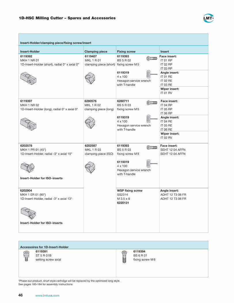
6119393 BS 5 R 03 fixing screw M 5
6119319 4 x 100 Hexagon service wrench with T-handle
Face insert: IT 01 RP IT 02 RP IT 03 RP Angle insert: IT 01 RE IT 02 RE IT 03 RE Wiper insert: IT 01 RV
Insert-Holder
Insert-Holder/clamping piece/fixing screw/insert
Clamping piece Fixing screw Insert
6119392 MKH 1 NR 01 1D-Insert-Holder (short), radial 0° x axial 0°
6119407 MKL 1 R 01 clamping piece (short)
6119393 BS 5 R 02 fixing screw M 5
6119319 4 x 100 Hexagon service wrench with T-handle
Face insert: IT 04 RP IT 05 RP IT 06 RP Angle insert: IT 04 RE IT 05 RE IT 06 RE Wiper insert: IT 02 RV
6119397 MKH 1 NR 02 1D-Insert-Holder (long), radial 0° x axial 0°
6280576 MKL 1 R 02 clamping piece (long)
6280711 BS 5 R 03 fixing screw M 5
6119319 4 x 100 Hexagon service wrench with T-handle
6202578 MKH 1 PR 01 (45°) 1D-Insert-Holder, radial -3° x axial 15°
6202904 MKH 1 ER 01 (90°) 1D-Insert-Holder, radial -3° x axial 13°
6202587 MKL 1 R 03 clamping piece (ISO)
Face insert: SEHT 12 04 AFFN SEHT 12 04 AFFN
Angle insert: ADHT 12 T3 06 FR ADHT 12 T3 06 FR
Accessoires for 1D-Insert-Holder 6119391 ST 5 R 01B setting screw axial
6119394 BS 6 R 01 fixing screw M 6
Insert-Holder for ISO-inserts
Insert-Holder for ISO-inserts
WSP fixing screw SS2314 M 3.5 x 9 6220131
1D-HSC Milling Cutter – Spares and Accessories
*Phase-out product, short style cartridge will be replaced by the optimized long style.See pages 183-184 for assembly instructions

47www.lmtusa.com
FEED Jet PCD Face Mill
The FEED Jet multiple tooth milling cutter offers high precision fine adjustment for producing flat surfaces. The easy to adjust design with high quantity of teeth delivers higher surface quality and reduce burring. Cutter is suitable for roughing and finishing.
Dimensons d3 = d1 + 2mm d1 z h d2 LMT Code Ident-No.
Ø 63
63 8 100 – Feed Jet D063 Z8 L100 HSK-A 63 9124316
Ø 63
63 8 40 ø 22 H6 Feed Jet D063 Z8 L40 DIN 8030-A 9124288
Ø 80
80 10 100 – Feed Jet D080 Z10 L100 HSK-A 63 9124325
Ø 80
80 10 50 ø 27 H6 Feed Jet D080 Z10 L50 DIN 8030-A 9124323
Ø 100
100 12 50 ø 32 H6 Feed Jet D100 Z12 L50 DIN 8030-B 9124328
Ø 125
125 16 63 ø 40 H6 Feed Jet D125 Z16 L63 DIN 8030-C 9124329
See page 185 for assembly instructions1) On request
Application Limits FEED Jet
LMT Code Diameter zmax1) Weight [kg] RPM n [1/min.]
Feed Jet D063 Z8 L100 HSK-A 63 63 8 1.91 18,000Feed Jet D063 Z8 L40 DIN 8030-A 63 8 0.67 18,000Feed Jet D080 Z10 L100 HSK-A 63 80 10 2.62 18,000Feed Jet D080 Z10 L50 DIN 8030-A 80 10 1.23 18,000Feed Jet D100 Z12 L50 DIN 8030-B 100 16 1.78 18,000Feed Jet D125 Z16 L63 DIN 8030-C 125 18 3.08 14,000
Note: Inch sizes quoted upon request
Steel body

48 www.lmtusa.com
Range
Grade LMT Code Ident-No.
DP012 L3.5 / PCD Cartridge 9115413PCD Width=1.6mm (.063")
PCD Height=3.5mm ( .138") Lead Angle 90 Deg.
DP012 L12 / PCD Cartridge 9115565PCD Width=1.6mm (.063")
PCD Height=12.0mm ( .472")Lead Angle 90 Deg.
DP012 L3.5 / PCD Cartridge 9112580PCD Width=1.6mm (.063")
PCD Height=3.5mm ( .138") Lead Angle 75 Deg.
DP028 Wiper / PCD Cartridge 9116145PCD Width=6.0mm (.236")
PCD Height=3.5mm ( .138")Lead Angle 90 Deg.
DP012 PCD Cartridge-Control 9115438PCD Width = 1.6mm (.063")PCD Height = 3.5mm (.138)
Lead Angle 90 Deg.No Wiping Flat on Insert
Surface Finish Controlled by Feed Rate of cutter
DP012 PCD Cartridge-Control 9115014PCD Width = 1.6mm (.063")PCD Height = 3.5mm (.138)
Lead Angle 75 Deg.No Wiping Flat on Insert
Surface Finish Controlled by Feed Rate of cutter
FEED Jet PCD Inserts
3.5 mm
12.0 mm
1.6 mm
1.6 mm
3.5 mm
1.6 mm
3.5 mm
6.0 mm
3.5 mm
1.6 mm
3.5 mm
1.6 mm

49www.lmtusa.com
FEED Jet – Spare Parts
LMT Code Ident-No.
Axial-wedge 9112535
Coolant screw M10x25 for ø 63 9114791
Coolant screw M12x30 for ø 80 9116644
Coolant disc for ø 100 9136417
Coolant disc for ø 125 9113601
Fixing screw DIN 912 M4x20 10.9 6104446
Diff.-screw DS 05 LR 16 9137328
Screw DIN 7991 M4x10 8.8 6103794

50 www.lmtusa.com
Look to LMT for all your precision metalworking needs
• Productive solutions for your
manufacturing problems
• Advanced cutting materials for today’s
production requirements.
• The correct tool for your automotive, aerospace,
or medical fabrication needs.

Face Milling CuttersEnd Mills, Long Edge End Mills, Specialty Mills

52 www.lmtusa.com
90° UNIVEX Premium End Mills
90°
l2
12–16°
14°
EMU90 IKInch
d1
Cutter Body No.
EDP No.
Ident No.
doc l2 l1 l3 d2 z Insert
Insert Screw
Torx Driver
1.00 EMU90 A17-100WEI 12911 1950345 0.650 4.000 1.720 1.000 2 ADKX 1705 89973 50259
1.00 EMU90 A17-100SEI 12912 1950346 0.650 6.000 1.720 1.000 2 M3.5 T15
1.25 EMU90 A17-125WFI 12914 1950348 0.650 4.000 1.720 1.250 2 89974
1.25 EMU90 A17-125SFI 12915 1950349 0.650 6.000 1.720 1.250 2 M3.5
1.25 EMU90 A17-125WFI 12917 1950351 0.650 4.000 1.720 1.250 3
1.25 EMU90 A17-125SCFI 12918 1950352 0.650 6.000 1.720 1.250 3
1.50 EMU90 A17-150WGI 12919 1950353 0.650 4.500 1.720 1.500 3
1.50 EMU90 A17-150SGI 12920 1950354 0.650 6.000 1.720 1.500 3
1.50 EMU90 A17-150WGIF 12922 1950356 0.650 4.500 1.720 1.500 4
1.50 EMU90 A17-150SGIF 12923 1950357 0.650 6.000 1.720 1.500 4
See page 54 for Inserts Cutting data recommendations starting page 180
All bodies have Internal Coolant
EMU90 IK Metric
d1
Cutter Body No.
Ident No. l2 l1 l3 d2 z Insert
Insert Screw
Torx Driver
20 EMU90 A11.020BN-IF 1045046 10.5 86 36 20 2 ADKX 1103 2237513 1048326
25 EMU90 A11.025BN-IF 1045047 10.5 96 40 25 3 M3.0 T8
32 EMU90 A11.032BN-IF 1045048 10.5 110 50 32 5
40 EMU90 A11.040BF-IF 1045049 10.5 110 50 32 6
25 EMU90 A17.025BN-IF 1045050 16.5 96 40 25 2 ADKX 1705 1045114 1048335
32 EMU90 A17.032BN-IF 1045053 16.5 110 50 32 3 M3.5 T15
40 EMU90 A17.040BF-IF 1045054 16.5 110 50 32 4
Limited stock of metric products in U.S., please contact Customer Service for availability
d2
l1
d1
l2
l3
ª DIN 1835 A
d2
l1
d1
l2
l3

53www.lmtusa.com
d2
l1
d1
l2
l3
� DIN 1835 A
DIN 1835 B
d2
l1
d1
l2
l3
90° UNIVEX Premium End Mills
EMU90InchIKZ
EMU90Metric
d1
Cutter Body No.
Ident No.
doc l2 l1 l3 d2 z Insert
Insert Screw
Torx Driver
20 EMU90 A11.020AN-IF 1045040 10.5 200 36 20 2 ADKX 1103 2237513 1048326
25 EMU90 A11.025AN-IF 1045041 10.5 200 40 25 3 ADHX 1103 M3.5 T8
32 EMU90 A11.032AN-IF 1045042 10.5 250 50 32 5 ADMX 1103
25 EMU90 A17.025AN-IF 1045043 16.5 200 40 25 2 ADKX 1705 1045114 1048335
32 EMU90 A17.032AN-IF 1045044 16.5 250 50 32 3 1045114 T15
40 EMU90 A17.040AF-IF 1045045 16.5 250 50 32 4 M3.5
Limited stock of metric products in U.S., please contact Customer Service for availability
d1
Cutter Body No.
EDP No.
Ident No.
doc l2 l1 l3 d2 z Insert
Insert Screw
Torx Driver
1.00 EMU90 A17-100SEI 12913 1950347 0.650 10.00 1.720 1.000 2 ADKX 1705 89973 50259
M3.5 T15
1.25 EMU90 A17-125SFI 12916 1950350 0.650 10.00 1.720 1.000 2 89974
1.50 EMU90 A17-150SGI 12921 1950355 0.650 10.00 1.720 1.250 3 M3.5
All bodies have Internal Coolant
See page 54 for Inserts Cutting data recommendations starting page 180
90°
l2
12–16°
14°
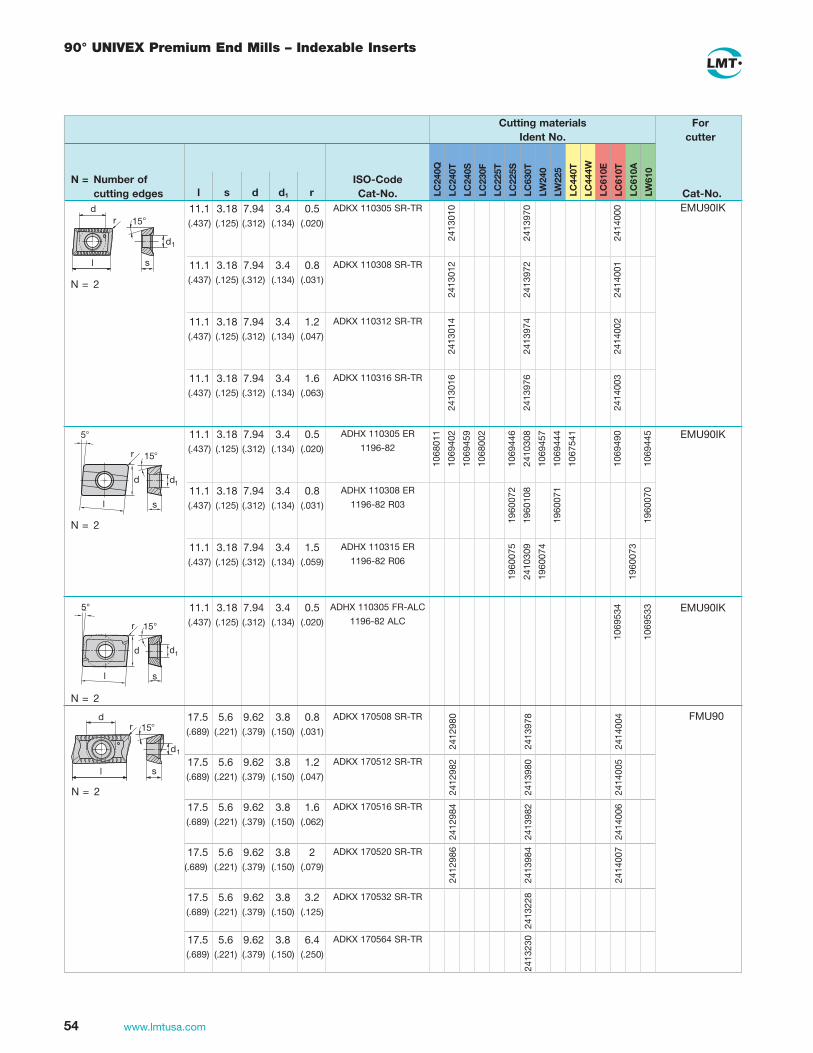
54 www.lmtusa.com
90° Univex Premium end Mills – indexable inserts
LC
240Q
LC
240T
LC
240S
LC
230F
LC
225T
LC
225S
LC
630T
LW
240
LW
225
1068
011
1069
402
1069
459
1068
002
1069
446
2410
308
1069
457
1069
444
1067
541
1069
490
1069
445
1960
072
1960
108
1960
071
1960
070
1960
075
2410
309
1960
074
1960
073
ADHX 110305 ER
1196-82
ADHX 110308 ER
1196-82 R03
ADHX 110315 ER
1196-82 R06
EMU90IK
EMU90IK
EMU90IK
11.1 3.18 7.94 3.4 0.5 (.437) (.125) (.312) (.134) (.020)
11.1 3.18 7.94 3.4 0.8 (.437) (.125) (.312) (.134) (.031)
11.1 3.18 7.94 3.4 1.5 (.437) (.125) (.312) (.134) (.059)
s
15�
5�
d
l
d1
r
N = 2
N = 2
N = 2
N = Number of cutting edges l s d d1 r Cat-No.
ISO-Code
Cutting materialsIdent No.
Forcutter
Cat-No. LC
440T
LC
444W
LC
610A
LW
610
LC
610E
LC
610T
11.1 3.18 7.94 3.4 0.5 (.437) (.125) (.312) (.134) (.020)
ADHX 110305 FR-ALC
1196-82 ALC
l
r
d d1
15°
5°
s
1069
534
1069
533
11.1 3.18 7.94 3.4 0.5 (.437) (.125) (.312) (.134) (.020)
11.1 3.18 7.94 3.4 0.8 (.437) (.125) (.312) (.134) (.031)
11.1 3.18 7.94 3.4 1.2 (.437) (.125) (.312) (.134) (.047)
11.1 3.18 7.94 3.4 1.6 (.437) (.125) (.312) (.134) (.063)
ADKX 110305 SR-TR
ADKX 110308 SR-TR
ADKX 110312 SR-TR
ADKX 110316 SR-TR
2413
010
2413
970
2414
000
2413
012
2413
972
2414
001
2413
014
2413
974
2414
002
2413
016
2413
976
2414
003
�
FMU90
N = 2
17.5 5.6 9.62 3.8 0.8 (.689) (.221) (.379) (.150) (.031)
17.5 5.6 9.62 3.8 1.2 (.689) (.221) (.379) (.150) (.047)
17.5 5.6 9.62 3.8 1.6 (.689) (.221) (.379) (.150) (.062)
17.5 5.6 9.62 3.8 2 (.689) (.221) (.379) (.150) (.079)
17.5 5.6 9.62 3.8 3.2 (.689) (.221) (.379) (.150) (.125)
17.5 5.6 9.62 3.8 6.4 (.689) (.221) (.379) (.150) (.250)
ADKX 170508 SR-TR
ADKX 170512 SR-TR
ADKX 170516 SR-TR
ADKX 170520 SR-TR
ADKX 170532 SR-TR
ADKX 170564 SR-TR
2412
980
2413
978
2414
004
2412
982
2413
980
2414
005
2412
984
2413
982
2414
006
2412
986
2413
984
2414
007
2413
228
2413
230
�

55www.lmtusa.com
UNIVEX Screw-On Type End Mills
90�
l 2
12-16�
14�
d3 d1
l3
l2
d2
d5
EMU90 11472Special Features
• Rhombic shape for large depths of cut
• Convex flat land on the cutting edge corners gives high surface finish
• Accurate 90° angle milling, even with positive setting of the indexable in sert. Convex grinding angle of the cutting edge produces
accurate straight walls of the milled slot, in spite of high positive axial rake angle
• Precision ground on all sides, for excellent for round and face cutting operation
• Special chip groove grinding gives constant positive rake over the entire cutting edge length
• High axial rake angle
• Secure and accurate insert seat with three point support
EMU90 11472Metric
d1
Cutter Body No.
Ident No. l2 l3 d5 d3 d2h6 z Insert
Insert Screw
Torx Driver
16 EMU90 A09.016TD 1039750 9.0 25 12 M 8 8.2 2 ADHX 0903 1044972 1048326
16 EMU90 A09.016TR 1039759 9.0 25 13 M 8 8.5 2 ADMX 0903 M2.5 T8
20 EMU90 A09.020TE 1039751 9.0 26 16 M10 10.2 3 ADKX 0903
20 EMU90 A09.020TS 1039761 9.0 26 18 M10 10.5 3
25 EMU90 A11.025TF 1039752 10.5 33 21 M12 12.5 3 ADHX 1103 2237513 1048326
32 EMU90 A11.032TH 1039753 10.5 43 26 M16 17 4 ADMX 1103 M3.0 T8
40 EMU90 A11.040TH 1039757 10.5 43 34 M16 17 5 ADKX 1103
See pages 61-62 for Inserts Cutting data recommendations starting page 186See pages 136-139 for Screw On ShanksLimited stock of metric products in U.S., please contact Customer Service for availability Inch sizes quoted as specials

56 www.lmtusa.com
UNIVEX End Mills
90°
doc
12–16°
14°
EMU90Application
• High performance end milling cutter for square shoulder and slot milling of steel, stainless and non-ferrous materials
• High positive axial rake angle provides quiet and smooth cutting action
• Standard end mills furnished with external coolant slots
d2d1
l
Weldon Shank
3
docl1
EMU90Inch
EMU90Metric
d1 Cutter Body No.EDP No.
Ident No.
ap
(DOC) l1 l3 d2 z InsertInsert Screw
TorxDriver
0.500 EMU90 A09-050WBI 50390 2304513 0.354 2.50 0.70 0.50 1 ADHX 0903 89972 899780.500 EMU90 A09-050WCI 50392 2304515 0.354 2.50 0.70 0.63 1 ADMX 0903 M2.5 T80.625 EMU90 A09-0625WCI 50394 1950150 0.354 3.00 1.10 0.63 2 ADKX 09030.750 EMU90 A09-075WDI 50396 1950151 0.354 3.25 1.42 0.75 20.750 EMU90 A09-075WDIF 50398 1950165 0.354 3.25 1.42 0.75 30.625 EMU90 A11-0625 WCI 54059 4052263 0.413 3.00 1.22 0.63 1 ADHX 1103 89979 899780.750 EMU90 A11-075 WDI 54060 4052264 0.413 3.25 1.22 0.75 2 ADMX 1103 M3.0 T81.000 EMU90 A11-100WDI 50400 1950200 0.413 3.25 1.22 0.75 3 ADKX 11031.000 EMU90 A11-100WEI 50402 1950152 0.413 3.50 1.57 1.00 31.000 EMU90 A11-100 WEI-060 54062 4052265 0.413 6.00 3.65 1.00 31.000 EMU90 A11-100 WEI-080 54063 4052267 0.413 8.00 5.68 1.00 31.250 EMU90 A11-125WDI 50404 1950202 0.413 3.25 1.22 0.75 41.250 EMU90 A11-125 WFI-0325 54064 4052266 0.413 3.25 1.57 1.25 41.250 EMU90 A11-125WEI 50406 1950153 0.413 3.50 1.57 1.00 41.250 EMU90 A11-125 WFI-060 54065 4052267 0.413 6.00 3.65 1.25 41.250 EMU90 A11-125 WFI-080 54066 4052269 0.413 8.00 5.62 1.25 41.500 EMU90 A11-150WEI 50408 1950207 0.413 3.50 1.57 1.00 41.500 EMU90 A11-150 WGI-035 54067 4052278 0.413 3.50 1.57 1.50 41.500 EMU90 A11-150 WFI-060 54068 4052279 0.413 6.00 3.25 1.50 41.500 EMU90 A11-150 WFI-080 54069 4052270 0.413 8.00 5.20 1.50 4
See pages 61-62 for Inserts Cutting data recommendations starting page 186
d1 Cutter Body No.Ident No.
ap
(DOC) l1 l3 d2 z InsertInsert Screw
TorxDriver
12 EMU90 A09.012BR-I 1039754 9.0 76 28 16 1 ADHX 0903 1044972 104832614 EMU90 A09.014BP-I 1039755 9.0 76 28 16 1 ADMX 0903 M2.5 T816 EMU90 A09.016BN-I 1039756 9.0 76 28 16 2 ADKX 090318 EMU90 A09.018BL-I 1039758 9.0 76 28 16 220 EMU90 A09.020BN-IW 1039775 9.0 86 36 20 220 EMU90 A09.020BN-I 1039760 9.0 86 36 20 322 EMU90 A09.022BL-I 1039762 9.0 86 36 20 325 EMU90 A11.025BI 1039765 10.5 86 36 20 3 ADHX 1103 2237513 1048832625 EMU90 A11.030BN-I 1039764 10.5 96 40 25 3 ADMX 1103 M3.0 T830 EMU90 A11.030BD 1039769 10.5 86 36 20 4 ADKX 110330 EMU90 A11.030BI-I 1039768 10.5 96 40 25 432 EMU90 A11.032BB 1039771 10.5 86 36 20 432 EMU90 A11.032BG-I 2275652 10.5 96 40 25 432 EMU90 A11.032BN-I 1039770 10.5 110 50 32 440 EMU90 A11.040BF-I 1039774 10.5 110 50 32 5
Limited stock of metric products in U.S., please contact Customer Service for availability

57www.lmtusa.com
90° UNIVEX End Mills
90°
doc
12–16°
14°
EMU90Application
• High performance end milling cutter for square shoulder and slot milling of steel, stainless and non-ferrous materials
• High positive axial rake angle provides quiet and smooth cutting action for low horsepower machines
• Available in CAT 40 taper only
d1
docl1
l
CAT 40
3
d1 Cutter Body No. EDPIdentNo.
ap
(DOC) l1 l3ShankTaper z Insert
Insert Screw
TorxDriver
1.00 EMU90 A11-100CA 50410 1950154 0.413 5.50 2.76 40 3 ADKX 1103 89979 89978
1.25 EMU90 A11-125CA 50412 1950155 0.413 6.00 3.27 40 4 ADHX 1103 M3.0 T8
1.50 EMU90 A11-150CA 50414 1950156 0.413 6.25 3.58 40 4 ADMX 1103
EMU90Inch
See pages 61-62 for Inserts Cutting data recommendations starting page 186

58 www.lmtusa.com
90° UNIVEX End Mills
90°12–16°
14°
ERU90Application
• High performance long edge end milling cutter for square shoulder and slot milling of steel, stainless and non-ferrous materials
• Full effective flute design
• High positive axial rake angle provides smooth cutting action and good chip removal
lWeldon Shank
3
d1
l2l1
d2
Note: End cutting inserts are offered in various nose radii. When using larger nose radii inserts, the outside corner of the steel body must be modified, or it will protrude beyond the cutting radius of the insert. Side cutting or periphery inserts must have .020 nose radius or smaller. This .020 radius is necessary for the inserts to overlap and not generate peaks.
d1 Cutter Body No. EDPIdentNo. l2 l3 l1 d2 z
No. Inserts Insert
Insert Screw
TorxDriver
1.00 ERU90 A09-100WE 50422 1950100 0.95 1.75 4.03 1.00 2 6 ADHX 0903 89972 89978
ADMX 0903 M2.5 T8
ADKX 0903
1.25 ERU90 A11-125WF 50424 1950101 1.46 2.25 4.53 1.25 2 8 ADHX 1103 89979 89978
1.50 ERU90 A11-150WG 50426 1950104 1.77 2.75 5.44 1.50 3 15 ADMX 1103 M3.0 T8
ADKX 1103
d1 Cutter Body No.IdentNo. l2 l3 l1 d2 z
No. Inserts Insert
Insert Screw
TorxDriver
25 ERU90 A09.025BI 1042662 16 36 86 20 2 4 ADHX 0903 1044972 1048326
25 ERU90 A09.025BN 1042659 25 44 100 25 2 6 ADMX 0903 M2.5 T8
ADKX 0903
32 ERU90 A11.032BN 1042660 37 55 115 32 2 8 ADHX 1103 2237513
ADMX 1103 M3.0
ADKX 1103
ERU90Inch
ERU90Metric
See pages 61-62 for Inserts Cutting data recommendations starting page 186
Limited stock of metric products in U.S., please contact Customer Service for availability

59www.lmtusa.com
90° UNIVEX Helical End Mills
90°12–16°
14°
ERU90Application
• High performance long edge end milling cutter for square shoulder and slot milling of steel, stainless and non-ferrous materials
• High positive axial rake angle provides smooth cutting action and excellent chip removal
• All-effective fluted design
l2 is the effective cutting length
d1
l1
l2
l
CAT 40CAT 50
3
d1 Cutter Body No. EDPIdentNo. l2 l3 l1
ShankTaper z
No.Inserts Insert
Insert Screw
TorxDriver
CAT 40
1.00 ERU90 A09-100CA 50428 1950070 0.95 2.75 5.44 40 2 6 ADHX 0903 89972 89978
ADMX 0903 M2.5 T8
ADKX 0903
1.25 ERU90 A11-125CA 50430 1950072 1.46 3.13 5.82 40 2 8 ADHX 1103 89979 89978
1.50 ERU90 A11-150CA 50432 1950090 1.77 3.50 6.19 40 3 15 ADMX 1103 M3.0 T8
ADKX 1103
CAT 50
2.00 ERU90 A12-200CB 50434 1950096 2.40 4.50 8.50 50 3 18 ADHX 12T3 89974 50259
2.50 ERU90 A12-250CB 50436 1950098 2.95 5.00 9.00 50 4 28 ADMX 12T3 M3.5 T15
ADKX 12T3
ERU90Inch
Note: End cutting inserts are offered in various nose radii. When using larger nose radii inserts, the outside corner of the steel body must be modified, or it will protrude beyond the cutting radius of the insert. Side cutting or periphery inserts must have .031 nose radius or smaller (for CAT 40) or .024 nose radius or smaller (for CAT 50). This radius is necessary for the inserts to overlap and not generate peaks.
See pages 61-62 for Inserts Cutting data recommendations starting page 186

60 www.lmtusa.com
90° UNIVEX Helical End Mills
FRU90Application
• High performance long edge milling cutter for square shoulder and slot milling of steel, stainless and non-ferrous materials
• High positive axial rake angle provides smooth cutting action and excellent chip removal
• Full effective flute design
• Offered in shell mill style
90°12–16°
14°
*Socket head cap screw NOT furnished with cutter
Note: End cutting inserts are offered in various nose radii. When using larger nose radii inserts, the outside steel body must be modified, or it will protrude beyond the cutting radius of the insert. Side cutting or periphery inserts must have .024 nose radius or smaller. This .024 radius is necessary for the inserts to overlap and not generate peaks.
l2
d2
d1
l1
d1 Cutter Body No. EDPIdentNo. l2 l1 d2 z
No.Inserts Insert
Insert Screw
TorxDriver
2.00 FRU90 A12-200AA200 50438 1950124 1.10 2.00 0.75 3 9 ADHX 12T3 89974 50259
2.00 FRU90 A12-200AA287 50440 1950126 2.00 2.88 0.75 3 15 ADMX 12T3 M3.5 T15
2.50 FRU90 A12-250AB200 50442 1950128 1.25 2.00 1.00 4 12 ADKX 12T3
2.50 FRU90 A12-250AB287 50444 1950130 2.00 2.88 1.00 4 20
d1 Cutter Body No.IdentNo. l2 l1 d2
Arbor ScrewDIN912 z
No.Inserts Insert
Insert Screw
TorxDriver
50 FRU90 A12.050ANS 1035094 28 50 22 M10 x 25 3 9 ADMX 12T3 1045114 1048335
50 FRU90 A12.050AN 1035093 50 71 22 M10 x 40 3 15 ADHX 12T3 M3.5 T15
63 FRU90 A12.063ANS 1035096 32 50 27 M12 x 30 4 12 ADKX 12T3
63 FRU90 A12.063AN 1035095 54 71 27 M12 x 45 4 20
FRU90Inch
FRU90Metric
See pages 61-62 for Inserts Cutting data recommendations starting page 186
Limited stock of metric products in U.S., please contact Customer Service for availability

61www.lmtusa.com
Univex end Mills – indexable inserts
LC
240Q
LC
240T
LC
240S
LC
230F
LC
225T
LC
225S
LC
630T
LW
240
LW
225
N = 2
N = Number of cutting edges l s d d1 r Cat-No.
ISO-Code
Cutting materialsIdent No.
For cutter
Cat-No. LC
430T
LC
444W
LW
630
LC
610A
LW
610
LC
610E
LC
610T
LC
603Z
s
15�
5�
d
l
d1
r
9.52 2.87 6.35 2.8 0.4 (.375) (.113) (.250) (.110) (.016)
9.52 2.87 6.35 2.8 0.8 (.375) (.113) (.250) (.110) (.031) 9.52 2.87 6.35 2.8 1.5 (.375) (.113) (.250) (.110) (.060) 9.52 2.87 6.35 2.8 0.4 (.375) (.113) (.250) (.110) (.016) 11.1 3.18 7.94 3.4 0.5 (.437) (.125) (.313) (.134) (.020) 11.1 3.18 7.94 3.4 0.8 (.437) (.125) (.313) (.134) (.031) 11.1 3.18 7.94 3.4 1.5 (.437) (.125) (.313) (.134) (.060) 11.1 3.18 7.94 3.4 0.5 (.437) (.125) (.313) (.134) (.020)
ADHX 090304 ER 1196-80
ADHX 090308 ER 1196-80 R03
ADHX 090315 ER 1196-80 R06
ADMX 090304 ER 1196-81
ADHX 110305 ER 1196-82
ADHX 110308 ER 1196-82 R03
ADHX 110315 ER 1196-82 R06
ADMX 110305 ER 1196-83
1068
009
1069
401
1069
453
1068
001
1069
443
1069
451
1069
441
1067
540
1069
486
1069
510
1069
442
1960
082
1960
081
1960
080
1960
085
1960
084
1960
083
1069
522
1069
382
1069
454
1069
381
1069
527
1069
452
1068
011
1069
402
1069
459
1068
002
1069
446
1069
457
1069
444
1067
541
1069
490
1069
445
1960
072
1960
071
1960
070
1960
075
1960
074
1960
073
1069
528
1069
384
1069
387
1069
383
1069
529
1069
485
EMU90ERU90
EMU90ERU90
ERU90FRU90
12.7 3.97 9.52 4 0.6 (.500) (.156) (.375) (.157) (.024) 12.7 3.97 9.52 4 1.5 (.500) (.156) (.375) (.157) (.060) 12.7 3.97 9.52 4 2.3 (.500) (.156) (.375) (.157) (.090) 12.7 3.97 9.52 4 0.6 (.500) (.156) (.375) (.157) (.024)
ADHX 12T306 ER 1196-84
ADHX 12T315 ER 1196-84 R06
ADHX 12T323 ER 1196-84 R09
ADMX 12T306 ER 1196-85
1068
012
1069
403
1069
463
1068
003
1069
750
1069
449
1069
461
1069
447
1067
542
1067
535
1069
492
1069
511
1069
448
1960
092
2413
089
1960
090
1960
095
1960
096
1960
094
1960
093
1069
526
1069
386
1069
468
1069
530
1069
466

62 www.lmtusa.com
UNIVEX End Mills – Indexable Inserts
LC
240T
LC
240S
LC
230F
LC
225T
LC
225S
LC
630T
LW
240
LW
225
N = Number of cutting edges l s d d1 r Cat-No.
ISO-Code
Cutting materialsIdent No.
Forcutter
Cat-No. LC
440T
LC
444W
LC
610A
LW
610
LC
610E
LC
610T
LC
603Z
s
d1
l
d
r 15� 9.52 2.87 6.35 2.8 0.4 (.375) (.113) (.250) (.110) (.016)
11.1 3.18 7.94 3.4 0.5 (.437) (.125) (.313) (.134) (.020)
1055
004
1058
013
1055
002
1055
003
1055
001
1055
006
1055
010
1058
014
1055
008
1055
009
1055
007
1055
012
1055
011
EMU90ERU90
l
r
d d1
15°
5°
s
9.52 2.87 6.35 2.8 0.4 (.375) (.113) (.250) (.110) (.016)
11.1 3.18 7.94 3.4 0.5 (.437) (.125) (.313) (.134) (.020)
ADHX 090304FR-ALC1196-80
ADHX 110305FR-ALC1196-82
1069
532
1069
531
1069
534
1069
533
EMU90ERU90
12.7 3.97 9.52 4 0.6 (.500) (.156) (.375) (.157) (.024)
ADKX 12T306PE
1196-89 1055
016
1058
015
1055
014
1055
015
1055
013
1055
018 ERU90
FRU90
12.7 3.97 9.52 4 0.6 (.500) (.156) (.375) (.157) (.024)
ADHX 12T306 FR-ALC1196-84 10
6953
6
1069
535 ERU90
FRU90
ADKX 090304PESR-BP1196-87
ADKX 110305PESR-BP1196-88
FMU90
N = 2
17.5 5.6 9.62 3.8 0.8 (.689) (.221) (.379) (.150) (.031)
17.5 5.6 9.62 3.8 1.2 (.689) (.221) (.379) (.150) (.047)
17.5 5.6 9.62 3.8 1.6 (.689) (.221) (.379) (.150) (.062)
17.5 5.6 9.62 3.8 2 (.689) (.221) (.379) (.150) (.079)
17.5 5.6 9.62 3.8 3.2 (.689) (.221) (.379) (.150) (.125)
17.5 5.6 9.62 3.8 6.4 (.689) (.221) (.379) (.150) (.250)
ADKX 170508 SR-TR
ADKX 170512 SR-TR
ADKX 170516 SR-TR
ADKX 170520 SR-TR
ADKX 170532 SR-TR
ADKX 170564 SR-TR
2412
980
2413
978
2414
004
2412
982
2413
980
2414
005
2412
984
2413
982
2414
006
2412
986
2413
984
2414
007
2413
228
2413
230
�
ALC LW610 has high polish for aluminum milling

63www.lmtusa.com
Features & Benefits• Universal applications
• Face milling, slotting, and shoulder milling
• For a wide range of materials
• Stable indexable inserts
• Large cutting length
• Positive cutting geometry
• High cutting edge stability
EMP90
90° ISO End Mills

64 www.lmtusa.com
EMP90/EMH90 (11412)Metric
d1 Cutter Body No.Ident No.
ap
(DOC) l1 l3 d2 z InsertInsert Screw
TorxDriver
16 EMH90 A10.016BN 1028506 8 76 28 16 2 APKT 1003 1044972 1048326
20 EMH90 A10.020BN 1028507 8 86 36 20 2 APHT 1003 M2.5 T8
25 EMH90 A10.025BI 1028508 8 86 36 20 3
25 EMH90 A16.025BI 1028504 14 86 36 20 2 APKT 1604 1045131 1048335
25 EMH90 A16.025BN 1028501 14 96 40 25 2 M4.0 T15
32 EMH90 A16.032BB 1028505 14 86 36 20 3
32 EMH90 A16.032BN 1028502 14 110 50 32 3
40 EMH90 A16.040BF 1028503 14 110 50 32 4
Limited stock of metric products in U.S., please contact Customer Service for availability
90° ISO End Mills
EMP90/EMH90 (11412)Application
• General purpose milling cutter for face, edge, slot and square shoulder milling of steel, stainless and non-ferrous materials
• Uses ISO style insert
• Positive cutting action for low horsepower machines
90°
doc
12°
12°
d1 Cutter Body No. EDPIdentNo.
ap
(DOC) l1 l2 d2 z InsertInsert Screw
TorxDriver
0.500 EMP90-A10-050WCI 53858 – 0.330 3.00 1.10 0.63 1 APKT 1003 53886 89978
0.500 EMP90-A10-050SCI-XL 53866 – 0.330 4.00 2.10 0.63 1 APHT 1003 M2.5 T8
0.625 EMP90-A10-062WCI 53859 – 0.330 3.00 1.10 0.63 2
0.625 EMP90-A10-062SCI-XL 53867 – 0.330 4.00 2.10 0.63 2
0.750 EMP90-A10-075WDI 53860 – 0.330 3.50 1.47 0.75 2
0.750 EMP90-A10-075WDFI 53861 – 0.330 3.50 1.47 0.75 3
0.750 EMP90-A10-075SDI-XL 53868 – 0.330 5.00 2.97 0.75 2
1.000 EMP90-A10-100WEI 53862 – 0.330 4.00 1.72 1.00 3
1.000 EMP90-A10-100WEFI 53863 – 0.330 4.00 1.72 1.00 4
1.000 EMP90-A10-100SEI-XL 53869 – 0.330 6.00 3.72 1.00 3
1.250 EMP90-A10-125WFI 53864 – 0.330 4.00 1.72 1.25 5
1.500 EMP90-A10-150WFI 53865 – 0.330 4.00 1.72 1.25 6
0.750 EMP90-A16-075WDI 53871 – 0.550 3.50 1.47 0.75 1 APKT 1604 50257 50259
1.000 EMP90-A16-100WEI 53872 – 0.550 4.00 1.71 1.00 2 M4.0 T15
1.000 EMP90-A16-100SEI-XXL 53876 – 0.550 8.00 2.62 1.00 2
1.250 EMP90-A16-125WFI 53873 – 0.550 4.00 1.71 1.25 3
1.250 EMP90-A16-125SFI-XXL 53878 – 0.550 8.00 2.62 1.25 3
1.500 EMP90-A16-150WFI 53874 – 0.550 4.00 – 1.25 3
1.500 EMP90-A16-150WFFI 53875 – 0.550 4.00 – 1.25 4
1.500 EMP90-A16-150SFI-XXL 53879 – 0.550 8.00 – 1.25 3
EMP90/EMH90 (11412)Inch
See page 65 for Inserts Cutting data recommendations starting page 178
d1d2
l1
l3
l2DIN 1835 B

65www.lmtusa.com
90° ISO End Mills – Indexable Inserts
10.96 3.5 6.6 2.8 0.5 APKT 100305 (.431) (.138) (.259) (.110) (.020) PDSR-BP
10.96 3.5 6.6 2.8 0.5 APKT 100305 (.431) (.138) (.259) (.110) (.020) PDSR-BM
16.3 5.26 9.52 4.5 0.8 APKT 160408 (.642) (.207) (.375) (.177) (.031) PDSR-BM
10.96 3.5 6.6 2.8 0.5 APHT 100305 (.431) (.138) (.259) (.110) (.020) PDFR-ALC
17.3 5.26 9.52 4.5 0.8 APHT 160408 (.681) (.207) (.375) (.177) (.031) PDFR-ALC
N = Number of cutting edges l s d d1 b/r ISO-Code
Cutting materialsIdent No.
Forcutter
N = 2
N = 2
N = 2
d
l
r
s
11°
d1
d
l
r
s
11°
d1
d
l
r
s
11°
d1
Cat-No.
1067
520
1067
522
1052
345
6401
077
6401
076
6400
573
16.3 5.26 9.52 4.5 0.8 APKT 160408 (.642) (.207) (.375) (.177) (.031) PDSR-BP
1067
517
1067
507
1067
501
1067
500
6413
391
6401
086
6401
085
1067
512
16.3 5.26 9.52 4.5 1.6 APKT 160416 (.642) (.207) (.375) (.177) (.062) SR-BP
6401
091
8932
2
6401
090
6401
089
16.3 5.26 9.52 4.5 2.4 APKT 160424 (.642) (.207) (.375) (.177) (.094) SR-BP
6401
094
6401
093
6401
092
16.3 5.26 9.52 4.5 3.2 APKT 160432 (.642) (.207) (.375) (.177) (.125) SR-BP
6401
097
6401
096
6401
095
6401
073
6401
074
6401
070
6401
071
1052
343
1052
341
1067
515
1067
506
1067
504
1067
503
FMH90FMP90
FMH90FMP90
FMH90FMP90
FMH90FMP90
FMH90FMP90
FMH90FMP90
ALC LW610 is high polish for aluminum milling
LC
240Q
LC
240T
LC
230F
LC
225T
LC
240S
LC
225S
LC
630T
LW
225
LC
440T
LC
444W
LC
615E
LC
610T
LC
610A
LW
610
LW
630

66 www.lmtusa.com
FRT90Application• Heavy-duty long edge milling cutter used only for edge milling of steel plate, and cast iron materials • Left hand helix provides smooth cutting action • Full effective flute design• Not recommended for face, step or slot milling
l2 is the effective cutting length
87° Face end
–16°17°
90° Peripheral
d1
l2
d2
l1
See page 67 for Inserts Cutting data recommendations starting page 186
FRT90Inch
87° Face end
–16°17°
90° Peripheral
ERT90Application• Heavy-duty long edge end milling cutter used only for edge milling of steel plate, and cast iron materials • Left hand helix provides smooth cutting action • Full-effective flute design• Not recommended for face, step or slot milling • Only offered in CAT 50
l2 is the effective cutting length
d1
l
CAT 50
3
l2l1
90° TWINCUT Helical Mills
d1 Cutter Body No.IdentNo. l2 l1 l3 SK z
No.Inserts Insert
Insert Screw
TorxDriver
32 ERT90 S09.032HA 1027372 47 157.2 106 40 2 14 SNKX 0904 AN 1045114 1048335
40 ERT90 S09.040HA 2346622 54 162.2 118 40 3 24 M3.5 T15
40 ERT90 S09.040HB 1027373 54 207.2 106 50 3 24
50 ERT90 S09.050HB 1027376 61 215.2 118 50 4 36 SNKX 1205 AN 1045123 10487344
50 ERT90 S12.050HB 1027370 62 208 106 50 2 14 M4.5 T20
63 ERT90 S12.063HB 1027371 70 220 118 50 3 24
ERT90Metric
ERT90Inch
Limited stock of metric products in U.S., please contact Customer Service for availability
See page 67 for Inserts Cutting data recommendations starting page 186
Dimensions (inches) Shank No. Eff. No. Euro Insert Torx d1 Cutter Body No. EDP l2 l1 l3 Taper Flutes Inserts Ref. No. Insert Screw Driver
2.00 ERT90 S12-200CB 50606 2.50 8.75 4.75 CAT 50 2 16 1950010 SNKX 1205 50256 50258
2.50 ERT90 S12-250CB 50608 3.00 9.75 5.75 CAT 50 3 27 1950012 M4.5 T20
3.00 ERT90 S12-300CB 50610 4.00 11.75 7.75 CAT 50 3 36 1950014
Dimensions (inches) No. Eff. No. Euro Insert Torx d1 Cutter Body No. EDP l2 l1 d2 Flutes Inserts Ref. No. Insert Screw Driver
2.00 FRT90 S12-200AA 50612 1.10 2.00 0.75 2 6 1950024 SNKX 1205 50256 50258
2.50 FRT90 S12-250AB 50614 1.42 2.00 1.00 3 12 1950026 M4.5 T20
3.00 FRT90 S12-300AD 50616 1.77 2.50 1.50 3 15 1950028

67www.lmtusa.com
b
l s
d1
30°45°
b
s
d1
30�
l
45�
b
s
d1
30°45°
l
b
s
d1
30°
l
45°
LC
240Q
LC
240T
LC
240S
LC
230F
LC
225T
LC
225S
LC
630T
LW
240
LW
225
SNKX 1205 AN1187-10
SNKX 1205 AN-TR1187-10 TR
ERT90
ERT90 12.7 5.56 5.2 2 (.500) (.219) (.205) (.079)
N = 4
N = Number of cutting edges l s d d1 b/r Cat-No.
ISO-Code
Cutting materialsIdent No.
Forcutter
Cat-No. LC
440T
LC
444W
LW
610
LC
612E
LC
610T
LC
615E
1052
301
1052
230
1052
315
1052
228
1052
238
1052
234
8936
5
1052
339
ERT90
ERT90
12.7 5.56 5.2 2 (.500) (.219) (.205) (.079)
N = 410
5226
0
1052
248
1052
239
1052
237
1052
251
12.7 5.44 5.2 2 (.500) (.214) (.205) (.079)
SNKX 1205 AN-T1187-12
wide landN = 4
N = 4
1052
303
1068
008
1052
314
1052
256
1052
309
5595
5
1052
254
SNKX 0904 AN1187-00
9.52 4.76 4.4 1.5 (.375) (.187) (.173) (.059)
1052
316
1068
006
1052
292
1052
317
1052
236
9.52 4.76 4.4 1.5 (.375) (.187) (.173) (.059)
SNKX 0904 AN-TTwide land
ERT90
1055
743
12.7 5.56 5.2 2 (.500) (.219) (.205) (.079)
SNKX 1205 AN-TT
1055
742 ERT90
wide land
1) Roughing geometry with double coatingLC280TT
LC
280T
T1)
TWINCUT Roughing End Mills – Indexable Inserts

68 www.lmtusa.com
90° Long Edge Helical Mills
ERP90Application
• Long edge end milling cutter for square shoulder and slot milling of steel and stainless materials
• Flute clearance provides maximum space for chip removal, air blast always recommended
*No. No. No.
Ident Dimensions (inches) No. Eff. Per. Periphery Face Face End Insert Torx d1 Cutter Body No. EDP No. l2 l1 l3 d2 Flutes Flutes Inserts Insert Inserts Insert Screw Driver
1.25 ERP90 S09 125WF 50446 1950102 1.58 4.53 2.25 1.25 3 1 8 SDMW 322
1 ADHW322 89974 50259
1.50 ERP90 S09 150WF 50448 1950106 1.97 5.51 3.32 1.25 4 2 12 SDMT 322 2 ADMT 322 M3.5 T15
2.00 ERP90 S12 200WH 50450 1950108 2.36 6.23 3.03 2.00 4 2 12 SPMW 432 2 SDHW533 89971 50258
SPMT 432 M4.5 T20
90°
15°
0°
l2 is the effective cutting length
l2
d1
l1O.A.L.
d2
l3
See page 69 for Inserts Cutting data recommendations starting page 186
ERP90Inch

69www.lmtusa.com
Long Edge Mill – Inserts
s
15°
5°
d
l
d1
r
s
15°
5°
d
l
d1
r
s
d1
l
r
15°
15°
s
11°
3°
l
l
d1
r
LC
610A
LC
610T
LW
610
LC
444W
LC
615E
LC
440T
LC
240T
LC
230F
LC
240S
LC
225T
LC
225S
LW
240
LW
225
N = Number of cutting edges l s d d1 b/r ISO-Code
Cutting materialsIdent No.
Forcutter
Cat-No. ERP 90 11453ERP 90 11452
ERP 90 11452
ERP 90 11452
ERP 90 11452
ERP 90 11452ERP 90 11453
15°
s
d1
l
d
r
15°
s
d1
l
d
N = 4
N = 4
N = 2
N = 2
N = 2
12.7 3.18 9.52 4 0.8 ADHW 120308 R (.500) (.125) (.375) (.157) (.031) (ADHW 322) 1196-02
12.7 3.18 9.52 4 0.8 ADMW 120308 R (.500) (.125) (.375) (.157) (.031) (ADHW 322) 1196-06
12.7 3.18 9.52 4 0.8 ADMT 120308 R (.500) (.125) (.375) (.157) (.031) (ADMT 322) 1196-04
16 5 5.2 1 SDMT 160510 (.630) (.197) (.205) (.039) (SDMT 533)
16 5 5.2 1 SDHW 160510SDHW 160510 (.630) (.197) (.205) (.039) SDHX 160510 (SDHX 533)
9.52 3.18 9.52 4 0.8 SDMT 090308 (.375) (.125) (.375) (.157) (.031) (SDMT 322)
9.52 3.18 9.52 4 0.8 SDMW 090308 (.375) (.125) (.375) (.157) (.031) (SDMW 322)
64
0672
6
64
0672
7
10
6916
0
10
6912
7
10
6943
9
64
0673
3
10
6912
6
10
6911
5
10
6910
610
6964
1
2217
296
1069
188
1069
319
88
520
2235
045
1069
317
1069
320
1069
749
1069
311
1069
130
1069
438
1069
313
1069
259
1069
277
1069
153
1069
133
12.7 4.76 12.7 5.2 0.8 SPMT 120408SN (.625) (.187) (.500) (.216) (.031) (SPMT 432) 1196-12
12.7 4.76 12.7 5.2 0.8 SPMT 120408SN-BP (.625) (.187) (.500) (.216) (.031) (SPMT 432)
12.7 4.76 12.7 5.2 0.8 SPMW 120408 (.625) (.187) (.500) (.216) (.031) (SPMW 432) 1196-10
ERP 90
ERP 90
ERP 90
N = 4
N = 4
N = 4
l
d
11°
d1
s
r
l
d
11°
d1
s
45°
l
d
11°
d1
s
r
230
8343
106
9299
106
9301
106
9302
640
6965
105
5660
106
9295
640
6963
640
6962
106
9128
640
6967
106
9437
640
6966
106
9233
640
0590
106
9232
106
9231

70 www.lmtusa.com
90° ISO Long Edge Helical Mills
ERP90Application
• General purpose long edge end milling cutter for square shoulder and slot milling of steel, stainless and non-ferrous materials
• Positive axial rake angle and generous chip gullets provide space for chip removal, air blast always recommended
• Sold as assembled tool with replaceable end cap
90°
20°
0°
l2 is the effective cutting length
Note: End mills furnished with Combo Posi-lock shanks. Posi-lock shanks can also be used in standard weldon shank end mill holders. End mills shipped with insert locking screws, replaceable end cap screw & T20 torx wrench.
* Inserts are staggered in rows; two rows make one effective flute. Only one row cuts to the end. Each insert in that row is spaced so the next adjacent row of inserts cuts in the gap area (with some overlap) to complete the length of cut (and make an effective flute).
l2
d1
l1O.A.L.
d2
l3
.94end caplength
See page 71 for Inserts Cutting data recommendations starting page 186
ERP90Inch
*No. No. No. Rep. EC Soc.
Dimensions (inches) No. Eff. Per. Periphery Face Face End Front Hd. Insert Torx d1 Cutter Body No. EDP l2 l1 l3 d2 Flutes Flutes Inserts Insert Inserts Insert End Cap Screw Screw Driver
2.00 ERP90 S12 200PH 081 89251 4.30 8.10 4.85 2.00 4 2 20 2
2.00 ERP90 S12 200PH 101 89240 6.30 10.10 6.85 2.00 4 2 30 SPMT 2 89245 89312
2.50 ERP90 S12 250PI 083 89252 4.30 8.30 4.80 2.50 4 2 20 120408 2 XPMT 89314 50258 2.50 ERP90 S12 250PI 103 89253 6.30 10.30 6.80 2.50 4 2 30 SPMT 432 2 150408 89246 M5 T15
2.50 ERP90 S12 250PI 123 89254 8.30 12.30 8.80 2.50 4 2 40 SPMW 432 2 89313
2.50 ERP90 S12 250PI 143 89255 10.30 14.30 10.80 2.50 4 2 50 2
3.00 ERP90 S12 300PI 113 89323 7.10 11.30 7.80 2.50 4 2 34 2 89268

71www.lmtusa.com
Long Edge Mill – Inserts
12.7 4.76 12.7 5.2 0.8 XPMT 150408 (.625) (.187) (.500) (.216) (.031) 1196-79
12.7 4.76 12.7 5.2 0.8 XPMW 150408 (.625) (.187) (.500) (.216) (.031) 1179-78
12.7 4.76 12.7 5.2 0.8 SPMT 120408SN (.625) (.187) (.500) (.216) (.031) (SPMT 432) 1196-12
12.7 4.76 12.7 5.2 0.8 SPMT 120408SN-BP (.625) (.187) (.500) (.216) (.031) (SPMT 432)
12.7 4.76 12.7 5.2 0.8 SPMW 120408 (.625) (.187) (.500) (.216) (.031) (SPMW 432) 1196-10
LC
630E
LC
610T
LW
610
LC
444W
LC
615E
LC
240T
LC
230F
LC
240S
LC
225T
LC
225S
LW
240
LW
225
N = Number of cutting edges l s d d1 b/r ISO-Code
Cutting materialsIdent No.
Forcutter
Cat-No.
ERP 9011453
ERP 90 11453
ERP 90 11452
ERP 90
ERP 90
ERP 90
N = 4
N = 2
N = 2
N = 4
N = 4
1069
146
5423
0
8914
0
1011
9
1069
134
1069
436
1069
431
1069
427
9172
713
1069
429
s
11°
d
l
3°
d1
r
s
11°
3°
l
l
d1
r
l
d
11°
d1
s
r
l
d
11°
d1
s
45°
l
d
11°
d1
s
r 2
3083
43
106
9299
106
9301
106
9302
640
6965
105
5660
106
9295
640
6963
640
6962
106
9128
640
6967
106
9437
640
6966
106
9233
640
0590
106
9232
106
9231
LC
630S
LC
435I
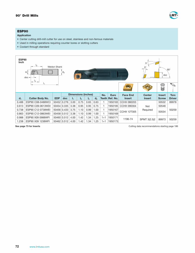
72 www.lmtusa.com
90°
doc
0°
5°
ESP90Application
• Center cutting drill-mill cutter for use on steel, stainless and non-ferrous materials
• Used in milling operations requiring counter bores or slotting cutters
• Coolant through standard
d1 d2
doc
l3
l4l1
Weldon Shank
90° Drill Mills
See page 73 for Inserts Cutting data recommendations starting page 186
ESP90Inch
Dimensions (inches) No. Euro Face End Center Insert Torx d1 Cutter Body No. EDP doc l1 l3 l4 d2 Teeth Ref. No. Insert Insert Screw Driver
0.488 ESP90 C08-0488WCI 50452 0.276 3.00 0.75 0.65 0.63 1 1950183 CCHX 080203 50532 89978
0.613 ESP90 C09-0613WDI 50454 0.335 3.38 0.95 0.95 0.75 1 1950185 CCHX 090304 Not 50546
0.738 ESP90 C12-0738WEI 50456 0.433 3.75 1.10 0.99 1.00 1 1950167 CCHX 12T305
Required 50259
0.863 ESP90 C12-0863WEI 50458 0.512 3.38 1.10 0.99 1.00 1 1950169 50534
0.988 ESP90 X09 0988WFI 50460 0.512 4.00 1.42 1.34 1.25 1+1 1950171 1196-74
SPMT 3(2.5)2
1.238 ESP90 X09 1238WFI 50462 0.512 4.00 1.42 1.34 1.25 1+1 1950173 89973 50259

73www.lmtusa.com
Drill Mill – Indexable Inserts
d d
s
7�
10�
1
sl
r
LC
240T
LC
240S
LC
230F
LC
225T
LC
225S
LC
630T
LW
240
LW
225
N = Number of cutting edges l s d d1 b/r Cat-No.
ISO-Code
Cutting materialsIdent No.
Forcutter
Cat-No. LC
440T
LC
444W
LC
610A
LW
610
LC
610E
LC
610T
LC60
3Z
s
d1
l
r
11�
15� SPMT 09T3081196-24
ESP90 9.52 3.97 4.4 0.8 (.375) (.156) (.173) (.031)
N = 2
1069
340
1069
331
s
7�
10�
l
l
d1
r
7.94 2.78 3.4 0.3 (.313) (.109) (.134) (.012)
9.52 3.18 4.4 0.4 (.375) (.125) (.173) (.016)
12.7 3.97 5.5 0.5 (.500) (.156) (.217) (.020)
CCHX 0802031196-44
CCHX 0903041196-54
CCHX 12T3051196-64
N = 2s = ± 0,025d = ± 0,01
1069
332
1069
325
1069
338
1069
395
1069
390
1069
334
1069
399
ESP90
14.3 3.97 9.52 4.4 0.5 (.563) (.156) (.375) (.173) (.020)
1196-74 ESP90
N = 2s = ± 0,025l = ± 0,01d = ± 0,01
1069
336
1069
410

74 www.lmtusa.com
0°
12°–15°
κ
EFZ45/60Application
• Chamfer-countersinking mills for both manual and CNC machines
• Positive cutting geometry provides free-cutting action on a wide variety of materials
• Available in 45° and 60° chamfer angles
• Uses industry standard inserts
d3 d1 d2
l1κ
l3Weldon Shank
45° / 60° Chamfer End Mills
45°
0°
0°
doc
EFP45Application
• Multiple application chamfer milling cutter for steel, stainless and non-ferrous materials
• Positive cutting action provides smooth and quiet cutting
• Unique design chamfers top and bottom bores; mill “V” grooves; chamfer T slots; and chamfer slots
d2d1d3
l3
l145°
Weldon Shank
ERT90Inch
EFP45Inch
See page 75 for Inserts Cutting data recommendations starting page 186
See page 75 for Inserts Cutting data recommendations starting page 186
Dimensions (inches) No. Euro Insert Torx d1 Cutter Body No. EDP K d3 l1 l3 d2 Teeth Ref. No. Insert Screw Driver
0.05 EFZ45 T11-047WB 50480 0.63 2.16 0.79 0.50 1 1950224 TCMT 110202
0.24 EFZ45 T11-244WC 50482 45° 0.83 3.15 1.26 0.63 2 1950226 89972 89978
0.41 EFZ45 T16-409WE 50484 1.26 3.74 1.26 1.00 2 1950228 TCMT 16T304 89974 50259
0.21 EFZ60 T11-213WB 50486 0.63 2.76 0.79 0.50 1 1950230 TCMT 110202
0.57 EFZ60 T11-567WC 50488 60° 0.98 3.15 1.26 0.63 2 1950232 89972 89978
0.63 EFZ60 T16-630WE 50490 1.26 3.74 1.42 1.00 2 1950233 TCMT 16T304 89974 50259
Dimensions (inches) No. Euro Insert Torx d1 Cutter Body No. EDP d3 l1 l3 d2 Teeth Ref. No. Insert Screw Driver
0.63 EFP45 S09-063WC 50476 1.13 3.35 1.46 0.63 2 1950135S SDMT 090308 60712 50259
1.26 EFP45 S12-126WF 50478 1.94 4.92 2.56 1.25 3 1950136 SPMT 120408 89971 50258

75www.lmtusa.com
Chamfer Mill – Indexable Inserts
9.52 3.18 9.52 4 0.8 SDMT 090308 (.375) (.125) (.375) (.157) (.031) (SDMT 322)
9.52 3.18 9.52 4 0.8 SDMW 090308 (.375) (.125) (.375) (.157) (.031) (SDMW 322)
9.52 3.18 9.52 4 0.8 SPMT 120408SN (.375) (.125) (.375) (.157) (.031) (SPMT 432)
12.7 4.76 12.7 5.2 0.8 SPMT 120408SN-BP (.500) (.187) (.500) (.205) (.031) (SPMT 432)
12.7 4.76 12.7 5.2 0.8 SPMW 120408 (.500) (.187) (.500) (.205) (.031) (SPMW 432)
LC
610A
LC
610T
LW
610
LC
444W
LC
615E
LC
440T
LC
240T
LC
230F
LC
240S
LC
225T
LC
225S
LW
240
LW
225
N = Number of cutting edges l s d d1 b/r ISO-Code
Cutting materialsIdent No.
For cutter
Cat-No. EFZ45
EFZ45
EFZ45
EFZ45
EFZ45
EFZ45T11EFZ60T11EFZ30T16EFZ45T16EFZ60T16
15°
s
d1
l
d
r
15°
s
d1
l
d
N = 4
N = 4
l
d
11°
d1
s
r
l
d
11°
d1
s
45°
N = 4
N = 4
N = 4
l
d
11°
d1
s
r 6
4067
26
640
6727
106
9160
106
9127
106
9439
640
6733
106
9126
106
9115
106
9106
230
8343
106
9299
106
9301
106
9302
640
6965
105
5660
106
9295
640
6963
640
6962
106
9128
640
6967
106
9437
640
6966
106
9233
640
0590
106
9232
106
9231
11 2.4 6.35 2.8 0.2 TCMT 110202 (.433) (.094) (.250) (.110) (.008) 1166-00
16.5 3.97 9.52 4.3 0.4 TCMT 16T304 (.650) (.156) (.375) (.169) (.016) 1166-10
l
d
s
d1
7°r
N = 3
1052
102
1052
105
1056
661
1052
107
1052
103
1052
203
1055
662
1052
109

76 www.lmtusa.com
See our other LMT USA catalogs for your Toolholding, Turning and Threading needs
RotatingToolholders& Accessories
Leitz Metalworking Technology Group
BELIN•BILZ•BOEHLERIT•FETTE•KIENINGER•ONSRUD
Schwerzerspanung
www.boehlerit.com
Heavy duty machining
USA
www.lmtusa.com
Internal ThreadingTechnology
RollsystemeRolling Systems
Leitz Metalworking Technology Group

Face Milling CuttersISO Milling Inserts

78 www.lmtusa.com
ISO Milling Inserts
LC
240Q
LC
240T
LC
230F
LC
225T
LC
240S
LC
225S
LW
240
LW
225
N = Number of cutting edges l s d d1 r Cat-No.
ISO-Code
Cutting materialsIdent No.
Forcutter
Cat-No. LC
440T
LC
430T
LC
444W
LW
610
LW
630
EMH90FMH90
EMH90FMH90MMH90
EMH90FMH90MMH90
EMH90FMH90MMH90
EMH90FMH90MMH90
EMH90FMH90MMH90
ESP90
17.3 5.26 9.52 4.5 0.8 APKT 160408 (.681) (.207) (.375) (.177) (.031) PDSR-BM
1067
522
16.33 4.36 4.5 0.6 APKT 15T306 (.643) (.172) (.177) (.024) PDTR-BP
APKT 15T306 PDSR-BP
17.3 5.26 9.52 4.5 0.8 APKT 160408 (.681) (.207) (.375) (.177) (.031) PDSR-BP
1067
517
1067
507
1067
506
1067
501
1067
500
1067
503
1067
512
1067
515
N = 2
d
l
r
s
11°
d1
N = 2
d
l
r
s
11°
d1
N = 2
rl s
11°
d1
6401
082
17.3 5.26 9.52 4.5 2.4 APKT 160424 (.681) (.207) (.375) (.177) (.094) SR-BP
6401
093
6401
092
6401
094
17.3 5.26 9.52 4.5 3.2 APKT 160432 (.681) (.207) (.375) (.177) (.125) SR-BP
6401
096
6401
095
6401
097
6400
575
10.96 3.5 6.6 2.8 0.5 APKT 100305 (.431) (.138) (.260) (.110) (.020) PDSR-BP
1052
345
1052
343
1052
341
1067
504
10.96 3.5 6.6 2.8 0.5 APKT 100305 (.431) (.138) (.260) (.110) (.020) PDSR-BM
1067
520
N = 2
d
l
r
s
11°
d1
17.3 5.26 9.52 4.5 1.6 APKT 160416 (.681) (.207) (.375) (.177) (.062) SR-BP
6401
090
6401
089
6401
091
7.94 2.78 3.4 0.3 (.313) (.109) (.134) (.012)
9.52 3.18 4.4 0.4 (.375) (.125) (.173) (.016)
12.7 3.97 5.5 0.5 (.500) (.156) (.217) (.020)
CCHX 0802031196-44
CCHX 0903041196-54
CCHX 12T3051196-64
s
7�
10�
l
l
d1
r
N = 2s = ± 0.025d = ± 0.01
1069
332
1069
325
1069
338
1069
395
1069
390
1069
334
1069
399
6401
077
6401
076
6401
086
6401
085
LC
615E
LC
610T
LC
610A

ISO Milling Inserts
79www.lmtusa.com
LC
240Q
LC
240T
LC
230F
LC
225T
LC
240S
LC
225S
LW
240
LW
225
N = Number of cutting edges l s d d1 r Cat-No.
ISO-Code
Cutting materialsIdent No.
Forcutter
Cat-No. LC
440T
LC
430T
LC
444W
LW
610
LW
630
7.4 4.76 18.1 OFEN 070405 (.291) (.187) (.713) SN
N = 8
ds
25°
l
6406
185
6406
184
6400
578
15o
d d1
lr s
N = 8
6.58 5.56 15.88 5.5 0.8 ODMW 060508 (.259) (.219) (.625) (.217) (.031) EN
6.58 5.56 15.88 5.5 0.8 ODMW 060508 (.259) (.219) (.625) (.217) (.031) SN
6406
180
6406
182
6406
181
6400
577
s
25°
dl
N = 8
7.4 4.76 18.1 OFER 070405 (.291) (.187) (.713) SN-BP
6406
188
6406
187
s
25°
d1
dl
7.4 3.97 12.7 4.6 OFEX 05T305 (.291) (.156) (.500) (.181) SN-BP
N = 8
6406
191
6406
190
LC
615E
LC
610T
LC
610A

80 www.lmtusa.com
ISO Milling Inserts
N = Number of cutting edges l s d d1 b/r Cat-No.
ISO-Code
Cutting materialsIdent No.
Forcutter
Cat-No. LC
440T
LC
444W
LW
610
LC
610E
LC
610T
LC
603X
LC
603Z
1068
613
1070
137
1070
135
1070
133
1070
131
1068
623
1070
132
1055
759
1068
607
1070
024
1068
626
1068
615
1068
609
1070
025
1068
662
1068
651
1068
642
1068
660
1068
610
1070
026
1068
706
1068
697
1068
688
1068
704
1068
611
1070
027
1068
742
1068
731
1068
722
1068
740
1055
505
1068
369
1055
639
1055
756
1055
617
1055
613
1055
619
1055
757
1068
612
1070
129
1070
127
1068
621
1055
758
1068
614
1070
147
1070
145
1070
141
1068
625
1070
142
1055
760
1070
159
1070
156
1070
155
1070
160
1055
761
1068
616
1070
167
1070
165
1070
163
1070
161
1068
627
1070
162
1055
762
RDHX 0702 MO1195-11
RDHX 0902 MO1195-21
RDHX 11T3 MO1195-31
RDHX 1504 MO1195-41
RDHX 0501 MO1195-01
RDHX 0702 MO1195-09
RDHW 0802 MO1195-15
RDHW 1003 MO1195-25
RDHW 12T3 MO1195-35
RDHX 12T3 MO1195-36
RDHW 1604 MO1195-45
RDHW 1604 MO-T
ECZ
ECZ
ECZ
ECZFCZ
2.38 7.6 2.8 (.094) (.299) (.110)
2.78 9.6 3.8 (.109) (.378) (.150)
3.97 11.6 5 (.156) (.457) (.197)
4.76 15.6 5.2 (.187) (.614) (.205)
1.5 5 2 (.059) (.197) (.079)
2.38 7 2.7 (.094) (.276) (.106)
2.38 8 2.8 (.094) (.315) (.110)
3.18 10 3.8 (.125) (.394) (.150)
3.97 12 5 (.156) (.472) (.197)
3.97 12 3.8 (.156) (.472) (.150)
4.76 16 5.2 (.187) (.630) (.205)
4.76 16 5.2 (.187) (.630) (.205)
s
15�
d1
d
s
15�
d1
d
1) Roughing geometry with double coatingLC280TT
LC
280T
T1)
LC
240T
LC
240S
LC
230F
LC
225T
LC
225S
LC
630T
LW
240
LW
225
2340
525

ISO Milling Inserts
81www.lmtusa.com
LC
240T
LC
240S
LC
230F
LC
225T
LC
225S
LC
630T
LW
240
LW
225
LC
440T
LC
444W
LC
610A
LW
610
LC
610E
LC
610T
LC
603Z
N = Number of cutting edges l s d d1 b/r Cat-No.
ISO-Code
Cutting materialsIdent No.
Forcutter
Cat-No.
s
15�
d1
d
13�
1055
741
1055
740
1055
739
1070
170
1070
173
1070
172
1055
737
1055
738
1070
176
1070
179
1070
178
1055
736
1070
180
1070
183
1070
182
1) Roughing geometry with double coatingLC280TT
RDKT 0702 MO-TT
RDKT 0802 MO-TT
RDKT 1003 MO-TT
RDKT 1003 MO
RDKT 12T3 MO-TT
RDKX 12T3 MO-TT
RDKX 12T3 MO
RDKT 1604 MO-TT
RDKT 1604 MO
ECZ
ECZFCZ
2.38 7 2.7 (.094) (.276) (.106)
2.38 8 2.8 (.094) (.315) (.110)
3.18 10 3.8 (.125) (.394) (.150)
3.18 10 3.8 (.125) (.394) (.150)
3.97 12 5 (.156) (.472) (.197)
3.97 12 3.8 (.156) (.472) (.150)
3.97 12 3.8 (.156) (.472) (.150)
4.76 16 5.2 (.187) (.630) (.205)
4.76 16 5.2 (.187) (.630) (.205)
LC
280T
T1)

82 www.lmtusa.com
45° ISO Face Mills – Indexable Inserts
12.7 3.18 12.7 1.4 SEKN 1203AFEN (.500) (.125) (.500) (.055)
12.7 3.18 12.7 1.4 SEAN 1203AFSN (.500) (.125) (.500) (.055) 1193-15
12.7 3.18 12.7 1.4 SEKN 1203AFSN (.500) (.125) (.500) (.055)
12.7 4.76 12.7 1.4 SEKN 1204AFEN (.500) (.187) (.500) (.055)
12.7 4.76 12.7 1.4 SEKN 1204AF (.500) (.187) (.500) (.055)
12.7 4.76 12.7 1.4 SEKN 1204AFSN (.500) (.187) (.500) (.055)
12.7 3.18 12.7 1.4 SEKR 1203AFSN (.500) (.125) (.500) (.055)
12.7 4.76 12.7 1.4 SEKR 1204AFSN (.500) (.187) (.500) (.055)
12.7 3.18 12.7 1.4 SEKR 1203AFSN-BM (.500) (.125) (.500) (.055)
12.7 4.76 12.7 1.4 SEKR 1204AFSN-BM (.500) (.187) (.500) (.055)
FMH45
FMH45A
FMH45
FMH45A
FMH45
FMH45A
N = Number of cutting edges l s d d1 b/r ISO-Code
Cutting materialsIdent No.
Forcutter
Cat-No.
20°
sl
d
b
N = 4
20°
sl
d
N = 4
20°
sl
d
N = 4
LC
610A
LW
610
LC
615E
LC
610T
LC
444W
LC
440T
LC
240Q
LC
240T
LC
230F
LC
225T
LC
225S
LW
240
LW
225
1067
526
1067
474
1067
468
1055
643
1067
259
1067
487
1067
470
1067
527
1067
475
1067
486
1067
518
1067
492
1055
650
1055
652
1067
476
1067
479
1067
529
1067
531
1067
471
1068
498
6406
756
6400
580
6400
581
6406
761
6406
762
1067
509
6406
772
6406
771
6406
776
1067
514
1067
508
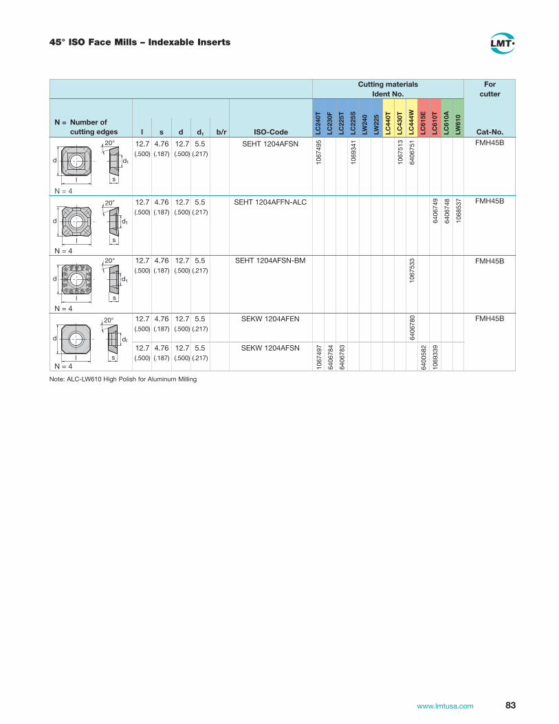
83www.lmtusa.com
45° ISO Face Mills – Indexable Inserts
12.7 4.76 12.7 5.5 SEHT 1204AFSN (.500) (.187) (.500) (.217)
12.7 4.76 12.7 5.5 SEHT 1204AFFN-ALC (.500) (.187) (.500) (.217)
12.7 4.76 12.7 5.5 SEHT 1204AFSN-BM (.500) (.187) (.500) (.217)
12.7 4.76 12.7 5.5 SEKW 1204AFEN (.500) (.187) (.500) (.217)
12.7 4.76 12.7 5.5 SEKW 1204AFSN (.500) (.187) (.500) (.217)
FMH45B
FMH45B
FMH45B
FMH45B
LC
610A
LW
610
LC
444W
LC
615E
LC
610T
LC
430T
LC
440T
LC
240T
LC
230F
LC
225T
LC
225S
LW
240
LW
225
N = Number of cutting edges l s d d1 b/r ISO-Code
Cutting materialsIdent No.
Forcutter
Cat-No. 20°
s
d1
l
d
N = 4
20°
sl
d d1
N = 4
20°
s
d1
l
d
N = 420°
s
d1
l
d
N = 410
6749
5
1069
341
1067
513
6406
780
6406
784
1067
497
6406
783
6400
582
1069
339
1068
537
6406
749
1067
533
6406
748
6406
751
Note: ALC-LW610 High Polish for Aluminum Milling

84 www.lmtusa.com
ISO Milling Inserts
N = Number of cutting edges
l s d d1 b/r ISO-Code
Cutting materialsIdent No.
For cutter
Cat-No. LC
610A
LW
610
LC
612E
LC
610T
LC
440T
LC
430T
LC
444W
LC
240Q
LC
240T
LC
240S
LC
230F
LC
225T
LC
225S
LW
240
LW
225
12.7 3.8 12.7 SPKN 1203 EDSR (.500) (.150) (.500)
12.7 3.8 12.7 SPKN 1203 EDST (.500) (.150) (.500)
15.88 4.76 15.88 SPKN 1504 EDSR (.625) (.187) (.625)
N = 4
10
6662
0
FMV45 12.7 5.56 5.2 2 (.500) (.219) (.205) (.079)
SNHX 1205 AE 1187-18
b
s
d1
30�45�
l
1068
005
1052
306
1052
300
1067
543
12.7 5.56 5.2 2 (.500) (.219) (.205) (.079)
1067
537 SNHX 1205 AESN-BM
b
l s
d1
30�45�
d
N = 4
FMV45 12.7 5.56 5.2 2 (.500) (.219) (.205) (.079)
SNHX 1205 AE-ALC 1187-18 ALC
b
s
d1
35�45�
l
1052
255
1052
235
FMV45
1055
658
1069
538
1069
548
1052
247
1052
246
5379
7
1052
244
2346
047
1052
659
1052
242
N = 4
FMT90
11260-12FMT90MMT90
9.52 4.76 4.4 0.6 (.375) (.187) (.173) (.024)
12.7 5.56 5.2 0.8 (.500) (.219) (.205) (.031)
SPKX 090406 1187-05
SPKX 120508 1187-15s
20�
d1
11�
r
l
l s
d
11°
64
0693
3
64
0693
2
10
6661
9
10
6665
3
64
0693
4
64
0058
5
64
0693
9
64
0693
8
64
0694
0
64
0059
5
MMP75
MMP75
11260-12FMT90MMT90

ISO Milling Inserts
85www.lmtusa.com
l s d d1 r ISO-Code
Cutting materialsIdent No.
Cat-No.
Forcutter
LW
610
LC
615E
LC
610T
LC
444W
LC44
0T
LC
240T
LC
230F
LC
240S
LC
225T
LC
225S
LW
240
LW
225
l s
d
11°
l
d
11°
d1
s
r
l
d
11°
d1
s
r
l
d
11°
d1
s
45°
12.7 3.18 12.7 SPKR 1203 EDSR (.500) (.125) (.500)
6.35 3.18 6.35 3.4 0.4 SPMT 060304 (.250) (.125) (.250) (.134) (.016)
12.7 4.76 12.7 5.2 0.8 SPMT 120408 SN (.500) (.187) (.500) (.205) (.031) 1196-12
12.7 4.76 12.7 5.2 0.8 SPMT 120408 SN-BP (.500) (.187) (.500) (.205) (.031)
12.7 4.76 12.7 5.2 0.8 SPMW 120408 (.500) (.187) (.500) (.205) (.031)
MMP75
EFZ45
EFZ45
EFZ45
N = 4
N = 4
N = 4
N = 4
N = Number of cutting edges
2308
343
1069
299
1069
301
6406
965
1055
660
1069
295
6406
942
6406
941
6406
959
6406
958
6406
963
6406
962
1069
128
6406
967
1069
437
6406
966
1069
233
6400
590
1069
232
1069
231
l
d
11°
d1
s
r 12.7 3.18 12.7 SPKT 120508 (.500) (.125) (.500)
N = 4
6406
946
6406
945

86 www.lmtusa.com
ISO Milling Inserts
l s d d1 r ISO-Code
Cutting materialsIdent No.
Cat-No.
Forcutter
LW
610
LC
615E
LC
610T
LC
444W
LC
440T
LC
240T
LC
230F
LC
240S
LC
225T
LC
225S
LW
240
LW
225
N = Number of cutting edges
N = 3
16.5 3.18 9.52 TPAN 1603 PDR (.650) (.125) (.375) 1172-11
16.5 3.18 9.52 TPKN 1603 PDR (.650) (.125) (.375)
MMP90
l
d
s
11°
1055
320
1055
399
1055
971
1055
319
1055
362
1055
326
22 4.76 12.7 TPKN 2204 PDER (.866) (.187) (.500)
22 4.76 12.7 TPKN 2204 PDSR (.866) (.187) (.500)
MMP90
l
d
s
11°10
5532
3
1055
328
1055
321
1055
327
1055
346
N = 3
l
d
s
d1
7°r
l
d
sr
11 2.4 6.35 2.8 0.2 TCMT 110202 (.433) (.094) (.250) (.110) (.008) 1166-00
16.5 3.97 9.52 4.3 0.4 TCMT 16T304 (.650) (.156) (.375) (.169) (.016) 1166-10
12 4.76 12.7 2 TNHF 1204ANSW (.472) (.187) (.500) (.079) BKL
N = 3
N = 3
22 4.76 12.7 1.6 (.866) (.187) (.500) (.063)
TEAN 2204 ZZ1172-2520°
b
d sl
N = 3
1055
405
1055
401
1055
403
1052
102
1052
105
1056
661
1052
107
1052
103
1052
203
1055
662
1052
109
6400
587
EFZ45T11EFZ60T11EFZ30T16EFZ45T16EFZ60T16

Face Milling CuttersHigh Feed and Copying Cutters

88 www.lmtusa.com
MultiEdge 3 Feed
1048326T08
1044972M2.5
1025001102500510250061025007
ECP X07.016TR028-I ECP X07.020TE030-IECP X07.025TF033ECP X07.025TF033-IF
1177-07T
Torx Driver
Insert ScrewCutter Body No. Ident No. Insert
4°
0°
l1w
ECP 3 FeedSpecial features
• Indexable inserts with 3 cutting edges and large inscribed circle
• Very high feed rates possible (up to 3 mm in steel)
• New generation of PVD-coating MultiC
• Available in different designs: as end mill and Screw-on type Cutter
• High number of teeth even at small diameter
• Indexable Inserts available in coated carbide grades and CBN
• Internal coolant supply
ECPIKZ
Torx Driver
Insert Screw
Cutter Body No. (inches) Ident No. Insert
.625 0.18 1.77 M8 .500 0.04 0.06 2 1.00 0.57 2.95 M12 .827 0.04 0.06 4
ECP X07-063AC630I ECP X07-100AE748IF
10483261048326
10449721044972
9089001 9089003
1177-07T1177-07T
d1 di l3 d3 d2 d5 apmax Rtheo z
d1 di l3 d3 d5 apmax Rtheo z
16 4.8 28 M8 8.5 13 1 1.5 2 20 9 30 M10 10.5 18 1 1.5 3 25 14 33 M12 12.5 21 1 1.5 3 25 14 33 M12 12.5 21 1 1.5 4
See page 89 for Inserts Cutting data recommendations starting page 188See pages 136-139 for Screw-On Shanks
Limited stock of Metric products in U.S. please contact Customer Service for availability
All bodies have internal coolant

89www.lmtusa.com
MultiEdge 3 Feed
MultiEdge 3 Feed – Indexable Inserts
d1 dl l3 l1 d2 apmax Rtheo z
1025025102502610250271025028
ECP X07.016AN160-IECP X07.020AN175-IECP X07.025AN190-IECP X07.025AN190-IF
Torx Driver
Insert ScrewCutter Body No. Ident No. Insert
4°
0°
l1w
ECPIKZ
1048326T08
1044972M2.5
1177-07T 16 4.8 45 160 16 1.0 1.5 2 20 9.0 60 175 20 1.0 1.5 3 25 14.0 75 190 25 1.0 1.5 3 25 14.0 75 190 25 1.0 1.5 4
Torx Driver
Insert Screw
Cutter Body No. (inches)* Ident No. Insert
ECP V07 d1 dl l3 d3 d2 apmax Rtheo z
.625 0.18 6.30 M8 0.625 0.04 0.06 2 ECP X07.063AC630-I1.00 0.57 7.48 M12 1.00 0.04 0.06 4 ECP X07.100AE748-IF
1177-07T 1044972M2.5
1048326T08
90890049089006
Cutting data recommendations starting page 188
1177-07T
N = Number of cutting edges s d d1 r
ECP
ISO-Code Cat-No.
For cutter
LC
240T
LC
230F
LC
225T
LC
225S
LC
630T
LW
240
LC
280Q
N2)
LC
280T
T1)
LC
610T
LC
610W
10
5819
2
1058
193
BN
025
LC
603Z
LW
225
LC
610E
LC
610A
N = 3s = ± 0.02d = ± 0.01
Cutting materialsIdent No.
s
d1
11°
dr
2.78 9.52 3.9 6.0 (.109) (.375) (.154) (.236)
Cat-No.
Limited stock of Metric products in U.S. please contact Customer Service for availability
LC
610Q
All bodies have internal coolant
1) Roughing geometry with double coatingLC280TT
2) Two colored multi coating for high performance millingLC280QN

90 www.lmtusa.com
MultiEdge 4 Feed
1.25 0.66 1.69 M16 0.67 1.13 0.05 0.100 4 ECP V09-125TH169-IF1.50 0.67 1.69 M16 0.67 1.13 0.05 0.100 4 ECP V09-150TH169-I
ECP 4 FeedSpecial features
• Indexable Inserts with 4 cutting edges and large inscribed circle
• Deep chip-groove with topography at face
• New generation of PVD-coating MultiC
• Precision-sintered Indexable Inserts in various sizes
• Exceptionally thick inserts for high feed rates
• Internal coolant supply
d1 dl l3 d3 d2 d5 apmax Rtheo z
Torx Driver
Torx Driver
Insert Screw
Insert Screw
Cutter Body No.
Cutter Body No. (inches)*
Ident No.
Ident No.
Insert
Insert
10250301025031102503210250331025034
XCNT 070308SN-TR
10250351025036102503710250381025039
ECP V07
ECP V09
ECP V091048335
T 151045105
M3.5
1045114M3.5
XCNT 09T312SN-TR
1048326T 08
10451272237513
M3.0
ECP V07ECP V09IKZ
32 17 43 M16 17.0 29 1.2 2.5 3 ECP V09.032TH043-I 32 17 43 M16 17.0 29 1.2 2.5 4 ECP V09.032TH043-IF 35 20 43 M16 17.0 29 1.2 2.5 4 ECP V09.035TH043-I 42 27 43 M16 17.0 29 1.2 2.5 4 ECP V09.042TH043-IW 42 27 43 M16 17.0 29 1.2 2.5 5 ECP V09.042TH043-I
20 6.9 30 M10 10.5 18 1.0 1.5 2 ECP V07.020TS030-I 25 12 33 M12 12.5 21 1.0 1.5 3 ECP V07.025TF033-I 32 19 43 M16 17.0 29 1.0 1.5 3 ECP V07.032TH043-I 32 19 43 M16 17.0 29 1.0 1.5 4 ECP V07.032TH043-IF 35 22 43 M16 17.0 29 1.0 1.5 5 ECP V07.035TH043-I
90890079089008
XCNT070308SN-TR
XCNT09T312SN-TR
10451272237513
M3.0
1045105M3.5
1048326T 08
1048335T 15
ECP V07 d1 dl l3 d3 d2 d5 apmax Rtheo z
90890109095431
0.75 0.24 1.18 M10 0.41 0.67 0.04 0.06 2 ECP V07-075TS118-I1.00 0.49 1.30 M12 0.49 0.83 0.04 0.06 3 ECP V07-100TF130-I
d1di
l3
ap max
d3
Rtheo
d5 d2
www.LMT-tools.com
10
LC28
0QN
LC28
0TT
LC24
0T
LC23
0F
LC22
5T
LC22
5S
LC63
0T
LW24
0
LW22
5
LC61
0A
LC61
0Q
BN
025
LC61
0E
LC61
0T
LC61
0W
MultiEdge 4FeedMultiEdge 4Feed
7,94 3,18 7,94 3,4 0,8
9,52 3,97 9,525 3,8 1,2
12,7 5,56 12,7 5,2 2
XCNT 070308 SN-TR
XCNT 09T312 SN-TR
XCNT 120520 SN-TR
ECP V07
ECP/FCPV09
FCP V12
N = 4s = ± 0,02d = ± 0,01
1058
100
1058
101
1058
102
1058
103
1058
104
1058
105
N = Anzahl derSchneidkanten
N = Number ofcutting edges l s d d1 r Cat-No.
ISO-Code
Schneidstoffsorten Cutting materialsIdent No.
FürFräser
Forcutter
Cat-No. LC60
3Z
0°15°
l1
Rtheo
ECP V07ECP V09IK
20 6,9 30 M10 10,5 18 1 1,5 2 1025030 ECP V07.020TS030-I25 12 33 M12 12,5 21 1 1,5 3 1025031 ECP V07.025TF033-I32 19 43 M16 17 29 1 1,5 3 1025032 ECP V07.032TH043-I32 19 43 M16 17 29 1 1,5 4 1025033 ECP V07.032TH043-IF35 22 43 M16 17 29 1 1,5 5 1025034 ECP V07.035TH043-I
32 17 43 M16 17 29 1,2 2,5 3 1025035 ECP V09.032TH043-I32 17 43 M16 17 29 1,2 2,5 4 1025036 ECP V09.032TH043-IF35 20 43 M16 17 29 1,2 2,5 4 1025037 ECP V09.035TH043-I42 27 43 M16 17 29 1,2 2,5 4 1025038 ECP V09.042TH043-IW42 27 43 M16 17 29 1,2 2,5 5 1025039 ECP V09.042TH043-I
d1 di l3 d3 d2 d5 apmax Rtheo z Ident No.
1048326
1048335
10451272237513
1045105
1045114
XCNT070308SN-TR
XCNT09T312SN-TR
Ident No.Ident No.LMT-CodeECP V07
ECP V09
7°
s
d1
l
r
Rtheo
Schnittwertempfehlungen ab Seite 18 Cutting data recommendations starting page 18
Besondere Merkmale:– Vierschneidige Wendeplatte mit großem Innenkreis– Tiefe Spanmulden mit Spanflächentopographie– Neue PVD Beschichtungsgeneration MultiC– Präzisionsgesinterte Wendeschneidplatten, in verschiedenen Größen– Große Wendeschneidplattendicke
Special features:– Indexable Inserts with 4 cutting edges and inscribed circle– Deep chip-groove with topography at face – New generation of PVD-coating MultiC – Precision-sintered Indexable Inserts, in various sizes– High Insert thickness
2029_MultiEdge 31.08.2005 14:56 Uhr Seite 10
See page 91 for Inserts Cutting data recommendations starting page 189See pages 136-139 for Screw-On Shanks
Limited stock of Metric products in U.S. please contact Customer Service for availability
All bodies have internal coolant

91www.lmtusa.com
MultiEdge 4 Feed
ECPIKZ
Torx Driver
Insert ScrewCutter Body No. Ident No. Insert
1025060102506110250631025064
XCNT 070308SN-TR
XCNT 09T312SN-TR
1045105M3.5
10250651025066
Torx Driver
Insert Screw
Cutter Body No. (inches)* Ident No. Insert
ECP V07
ECP V09
ECP V09
www.LMT-tools.com
11
MultiEdge 4FeedMultiEdge 4Feed
0°15°
l1
Rtheo
FCP V09FCP V12IK
42 27 40 16 29,6 1,2 2,5 4 1025040 FCP V09.042AN-IW42 27 40 16 29,6 1,2 2,5 5 1025041 FCP V09.042AN-I52 37 40 22 39,6 1,2 2,5 5 1025042 FCP V09.052AN-IW52 37 40 22 39,6 1,2 2,5 6 1025043 FCP V09.052AN-I
42 23 40 16 32 1,9 3,5 3 1025045 FCP V12.042AN-IW42 23 40 16 32 1,9 3,5 4 1025046 FCP V12.042AN-I52 33,1 40 22 39,6 1,9 3,5 4 1025047 FCP V12.052AN-IW52 33,1 40 22 39,6 1,9 3,5 5 1025048 FCP V12.052AN-I66 47,1 50 27 50 1,9 3,5 6 1025049 FCP V12.066AN-IW66 47,1 50 27 50 1,9 3,5 7 1025050 FCP V12.066AN-I80 61,2 50 27 60 1,9 3,5 8 1025051 FCP V12.080AN-I
100 81,2 50 32 65 1,9 3,5 10 1025052 FCP V12.100AN-I
d1 di h d2 d5 apmax Rtheo z Ident No.
1048335
1048344
1045114
1045123
XCNT09T312SN-TR
XCNT120520SN-TR
Ident No.Ident No.LMT-Code
d1
d2
h
di
a p m
ax
d5
Rtheo
FCP V09
FCP V12
0°15°
l1
Rtheo
ECP V07ECP V09IK
20 6,9 60 175 20 1 1,5 2 1025060 ECP V07.20AN175-I25 12 75 190 25 1 1,5 3 1025061 ECP V07.20AN190-I32 19 80 210 32 1 1,5 3 1025063 ECP V07.20AN210-I32 19 80 210 32 1 1,5 4 1025064 ECP V07.20AN210-IF
32 17 80 210 32 1,2 2,5 3 1025065 ECP V09.32AN210-I32 17 80 210 32 1,2 2,5 4 1025066 ECP V09.32AN210-IF
d1 di l3 l1 d2 apmax Rtheo z Ident No.
1048326
1048335
10451272237513
1045105
XCNT070308SN-TR
XCNT09T0312SN-TR
Ident No.Ident No.LMT-Code
ap max
l3l1
d2 d1
Rtheo
di
ECP V07
ECP V09
Schnittwertempfehlungen ab Seite 18 Cutting data recommendations starting page 18
2029_MultiEdge 31.08.2005 14:56 Uhr Seite 11
1048326T 08
1048335T 15
d1 dl l3 l1 d2 apmax Rtheo z
d1 dl l3 l1 d2 apmax Rtheo z
90890149089015
9089017
XCNT070308SN-TR
10451272237513
M3.0
1045105M3.5
20 6.9 60 175 20 1.0 1.5 2 ECP V07.020AN175-I 25 12.0 75 190 25 1.0 1.5 3 ECP V07.025AN190-I 32 19.0 80 210 32 1.0 1.5 3 ECP V07.032AN210-I 32 19.0 80 210 32 1.0 1.5 4 ECP V07.032AN210-IF-I
32 17.0 80 210 32 1.2 2.5 3 ECP V09.032AN210-I 32 17.0 80 210 32 1.2 2.5 4 ECP V09.032AN210-IF
1.25 0.66 3.15 8.27 1.25 0.05 0.10 4 ECP V09.125AF827-IF1.50 0.91 3.50 9.00 1.50 0.05 0.10 4 ECP V09.150AF900-IF 9095050
ECP V07
XCNT09T312SN-TR
1048335T 15
10451272237513
M3.0
1048326T 08
0.75 0.24 2.36 6.89 0.75 0.04 0.06 2 ECP V07.075AD689-I1.00 0.49 2.95 7.48 1.00 0.04 0.06 3 ECP V07.100AE748-I
See page 91 for Inserts Cutting data recommendations starting page 189
MultiEdge 4 Feed – Indexable Inserts
Limited stock of Metric products in U.S. please contact Customer Service for availability
XCNT070308 SN-TR
XCNT09T312 SN-TR
XCNT120520 SN-TR
N = Number of cutting edges l s d d1 r
ISO-Code Cat-No.
Cutting materials
Ident No.
For
cutter
LC
610Q
Cat-No. LC
240T
LC
230F
LC
225T
LC
225S
LC
630T
LW
240
LW
225
LC
610E
LC
610T
LC
610W
BN
025
LC
603Z
N = 4s = ± 0.02d = ± 0.01
LC
610A
7.94 3.18 7.94 3.4 0.8 (.312) (.125) (.312) (.134) (.032)
9.52 3.97 9.52 3.8 1.2 (.375) (.156) (.375) (.150) (.047)
12.7 5.56 12.7 5.2 2.0 (.500) (.219) (.500) (.205) (.079)
10
5810
0
1058
101
105
8107
105
8106
1058
104
1058
105
10
5810
8
10
5810
2
1058
103
ECP V07
ECP/FCPV09
FCP V12
1) Roughing geometry with double coatingLC280TT
2) Two colored multi coating for high performance millingLC280QN
LC
280Q
N2)
LC
280T
T1)
All bodies have internal coolant

92 www.lmtusa.com
XCNT070308 SN-TR
XCNT09T312 SN-TR
XCNT120520 SN-TR
N = Number of cutting edges l s d d1 r
ISO-Code Cat-No.
Cutting materials
Ident No.
For
cutter
LC
610Q
Cat-No. LC
240T
LC
230F
LC
225T
LC
225S
LC
630T
LW
240
LW
225
LC
610E
LC
610T
LC
610W
BN
025
LC
603Z
N = 4s = ± 0.02d = ± 0.01
LC
610A
7.94 3.18 7.94 3.4 0.8 (.312) (.125) (.312) (.134) (.032)
9.52 3.97 9.52 3.8 1.2 (.375) (.156) (.375) (.150) (.047)
12.7 5.56 12.7 5.2 2.0 (.500) (.219) (.500) (.205) (.079)
10
5810
0
1058
101
105
8107
105
8106
1058
104
1058
105
10
5810
8
10
5810
2
1058
103
ECP V07
ECP/FCPV09
FCP V12
MultiEdge 4 Feed
d1 dl h d2 d5 apmax Rtheo z
Torx Driver
Insert ScrewCutter Body No. Ident No. Insert
1025040102504110250421025043
XCNT 09T312SN-TR
FCP V09
10250451025046102504710250481025049102505010250511025052
FCP V12
1045114M3.5
XCNT 120520SN-TR
FCP V09FCP V12IKZ
www.LMT-tools.com
11
MultiEdge 4FeedMultiEdge 4Feed
0°15°
l1
Rtheo
FCP V09FCP V12IK
42 27 40 16 29,6 1,2 2,5 4 1025040 FCP V09.042AN-IW42 27 40 16 29,6 1,2 2,5 5 1025041 FCP V09.042AN-I52 37 40 22 39,6 1,2 2,5 5 1025042 FCP V09.052AN-IW52 37 40 22 39,6 1,2 2,5 6 1025043 FCP V09.052AN-I
42 23 40 16 32 1,9 3,5 3 1025045 FCP V12.042AN-IW42 23 40 16 32 1,9 3,5 4 1025046 FCP V12.042AN-I52 33,1 40 22 39,6 1,9 3,5 4 1025047 FCP V12.052AN-IW52 33,1 40 22 39,6 1,9 3,5 5 1025048 FCP V12.052AN-I66 47,1 50 27 50 1,9 3,5 6 1025049 FCP V12.066AN-IW66 47,1 50 27 50 1,9 3,5 7 1025050 FCP V12.066AN-I80 61,2 50 27 60 1,9 3,5 8 1025051 FCP V12.080AN-I
100 81,2 50 32 65 1,9 3,5 10 1025052 FCP V12.100AN-I
d1 di h d2 d5 apmax Rtheo z Ident No.
1048335
1048344
1045114
1045123
XCNT09T312SN-TR
XCNT120520SN-TR
Ident No.Ident No.LMT-Code
d1
d2
h
di
a p m
ax
d5
Rtheo
FCP V09
FCP V12
0°15°
l1
Rtheo
ECP V07ECP V09IK
20 6,9 60 175 20 1 1,5 2 1025060 ECP V07.20AN175-I25 12 75 190 25 1 1,5 3 1025061 ECP V07.20AN190-I32 19 80 210 32 1 1,5 3 1025063 ECP V07.20AN210-I32 19 80 210 32 1 1,5 4 1025064 ECP V07.20AN210-IF
32 17 80 210 32 1,2 2,5 3 1025065 ECP V09.32AN210-I32 17 80 210 32 1,2 2,5 4 1025066 ECP V09.32AN210-IF
d1 di l3 l1 d2 apmax Rtheo z Ident No.
1048326
1048335
10451272237513
1045105
XCNT070308SN-TR
XCNT09T0312SN-TR
Ident No.Ident No.LMT-Code
ap max
l3l1
d2 d1
Rtheo
di
ECP V07
ECP V09
Schnittwertempfehlungen ab Seite 18 Cutting data recommendations starting page 18
2029_MultiEdge 31.08.2005 14:56 Uhr Seite 11
1048335T 15
Torx Driver
Insert Screw
Cutter Body No. (inches)* Ident No. Insert
ECP V09908902190890229089023
XCNT09T312SN-TR
XCNT120520SN-TR
1045114M3.5
1045123M4.5
1048335T 15
ECP V121048344
T 20
42 27 40 16 29.6 1.2 2.5 4 FCP V09.042AN-IW 42 27 40 16 29.6 1.2 2.5 5 FCP V09.042AN-I 52 37 40 22 39.6 1.2 2.5 5 FCP V09.052AN-IW 52 37 40 22 39.6 1.2 2.5 6 FCP V09.052AN-I
42 23 40 16 32 1.9 3.5 3 FCP V12.042AN-IW 42 23 40 16 32 1.9 3.5 4 FCP V12.042AN-I 52 33.1 40 22 39.6 1.9 3.5 4 FCP V12.052AN-IW 52 33.1 40 22 39.6 1.9 3.5 5 FCP V12.052AN-I 66 47.1 50 27 50 1.9 3.5 6 FCP V12.066AN-IW 66 47.1 50 27 50 1.9 3.5 7 FCP V12.066AN-I 80 61.2 50 27 60 1.9 3.5 8 FCP V12.080AN-I 100 81.2 50 32 65 1.9 3.5 10 FCP V12.100AN-I
908902690890279089028908902990890309095685909568690890339089034
d1 dl h d2 d5 apmax Rtheo z
2.00 1.41 1.57 0.75 1.56 0.05 0.10 4 FCP V09.200AA158-IW2.00 1.41 1.57 0.75 1.56 0.05 0.10 5 FCP V09.200AA158-I2.00 1.41 1.57 0.75 1.56 0.05 0.10 6 FCP V09.200AA158-IF
2.00 1.26 1.57 0.75 1.56 0.07 0.14 4 FCP V12.200AA158-IW 2.00 1.26 1.57 0.75 1.56 0.07 0.14 5 FCP V12.200AA158-I 2.50 1.76 1.57 1.00 2.00 0.07 0.14 4 FCP V12.250AB158-IW 2.50 1.76 1.57 1.00 2.00 0.07 0.14 6 FCP V12.250AB158-I 2.50 1.76 1.57 1.00 2.00 0.07 0.14 7 FCP V12.250AB158-IF 3.00 2.26 1.97 1.25 2.36 0.07 0.14 5 FCP V12.300AC197-IW 3.00 2.26 1.97 1.25 2.36 0.07 0.14 8 FCP V12.300AC197-I 4.00 3.24 1.97 1.50 3.15 0.07 0.14 7 FCP V12.400AD197-IW 4.00 3.24 1.97 1.50 3.15 0.07 0.14 10 FCP V12.400AD197-I
1048344T 20
1045123M4.5
For modular cutter diameters 4.00"-12.00" see Multi-Mill section on pages 40-42 Cutting data recommendations starting page 189Multi-Mill Cartridge No. 9164419
Limited stock of Metric products in U.S. please contact Customer Service for availability
All bodies have internal coolant
1) Roughing geometry with double coatingLC280TT 2) Two colored multi coating for high performance millingLC280QN
LC
280Q
N2)
LC
280T
T1)

93www.lmtusa.com
MultiEdge 4 Feed – Applications
Indexable Inserts1177-07T XCNT0703 XCNT09T3 XCNT1205
ap max
Tmax
d1 W1 max in ° (degrees).630" 3.5°.787" 1.8° 4.3°.984" 1.2° 2.4°1.26" 1.5° 2.2°1.38" 1.3° 1.8°1.65" 1.3° 2.0°2.047" 1.0° 1.5°2.59" 1.0°3.15" 0.8°3.93" 0.6°
.630"
.787"
.984"1.26"1.38"1.65"2.047"2.59"3.15"3.93"
.787"1.10"1.50"
.039" .031" .039" .059" .020" .020" .024" .031"
Tmax axial drilling depth
1) Maximum recommended ramp angle is ≤0.8° for cutter diameters larger than 3"
ap max maximum cutting depth
apmax
d1
w1max
tmax
Pocketing
Circular Ramping1)
interpolation
3D rough copy milling
Plunge milling
Opening cavity
Indexable Inserts1177-07T XCNT0703 XCNT09T3 XCNT1205 1177-07T XCNT0703 XCNT09T3 XCNT1205 1177-07T XCNT0703 XCNT09T3 XCNT1205
d1 dmin dmax de max
1.02"1.42"1.97"2.20"
1.89"2.13"2.68"3.46"
2.48"3.27"4.41“5.51"7.09"
1.22"1.54"1.93"
1.54"1.93"2.44"2.68"
2.44"2.68"3.23"4.02"
2.48"3.27"4.41“5.51"7.09"
.394"
.551"
.748".512".709".984"1.10"
.945"1.06"1.34“1.73"
1.26"1.65"2.20"2.76"3.54"

94 www.lmtusa.com
ECP/FCP05 TWINCUT Feed High Feed Cutters
32 15.4 43 M16 17 29 1.5 2 2 32 15.4 43 M16 17 29 1.5 2 3 35 18.4 43 M16 17 29 1.5 2 2 35 18.4 43 M16 17 29 1.5 2 3 42 25.4 43 M16 17 29 1.5 2 3
d1 di l3 d3 d2 d5 apmax Rtheo z1048335
T1510451851045114
M3.510250131025014102500810250151025009
ECP05 X65.032TH043-IECP05 X65.032TH043-IF ECP05 X65.035TH043-IECP05 X65.035TH043-IFECP05 X65.042TH043-I
1177-65T
Torx Driver
Insert Screw
Insert ScrewCutter Body No. Ident No. Insert
ECP05 X11.100TF-I 1.00ECP05 X65.125TH-I 1.25ECP05 X65.150TH-I 1.50
104518510512771045114
M3.5
Insert Screw
Insert ScrewInsert
Cutter Body No. (inches)* Ident No.
195032319503241950325
0.600.600.85
1.301.691.69
M12M16M16
0.490.670.67
223
1.001.251.50
0.040.060.06
0.150.080.08
–––
Torx Driver
1048335T15
Rtheo
1177-11T1177-65T
d1 di l3 d3 d2 d5 apmax Rtheo z
d1-di2
w =
ECP 05 THR IKZ
d1di
l3 l1
d2
d3d5
Limited stock of Metric products in U.S. please contact Customer Service for availability
See pages 136-139 for Screw-On Shanks
l1
l3
d2d1
di
Ident No.1045185
T151051277
M3.51177-11TECP05 X11.100WE-080
ECP05 X11.125WF-060ECP05 X11.125WF-080ECP05 X11.150WG-060ECP05 X11.150WG-080ECP05 X65.125WF-060ECP05 X65.125WF-080ECP05 X65.150WG-060ECP05 X65.150WG-080
195031319503141950315195031619503171950334195033519503361950337
d1 dl l3 l1 d2 apmax Rtheo z Ident No.Ident No. ISO-CodeLMT-Code (inches)*1.00 0.60 5.72 8.00 1.00 0.04 0.15 21.25 0.85 3.72 6.00 1.25 0.04 0.15 31.25 0.85 5.72 8.00 1.25 0.04 0.15 31.50 1.10 3.72 6.00 1.50 0.04 0.15 41.50 1.10 5.72 8.00 1.50 0.04 0.15 41.25 0.85 3.31 6.00 1.25 0.06 0.08 21.25 0.85 5.31 8.00 1.25 0.06 0.08 21.50 1.10 3.31 6.00 1.50 0.06 0.08 31.50 1.10 5.31 8.00 1.50 0.06 0.08 3
See page 95 for Inserts Cutting data recommendations starting page 190
ECP05Inch
4°
0°
l1w
Rtheo
d1-di2
w =
4°
0°
l1w
1045114M3.5
1177-65T
All bodies have internal coolant

95www.lmtusa.com
ECP/FCP05 TWINCUT Feed High Feed Cutters
TWINCUT Feed High Feed Cutters – Indexable Inserts
N = 3 s = ± 0.02 d = ± 0.01
N = 3 s = ± 0.025 d = ± 0.01
N = Number of cutting edges s d d1 b r
1177-11T ECP05
ECP05FCP05
2.78 9.52 3.9 6 3.8 (.109) (.375) (.154) (.236) (.150)
3.97 9.52 3.9 25 2 (.157) (.375) (.154) (.984) (.079)
1177-65T
ISO-Code Cat-No.
Cutting materials
Ident No.
For cutter
Cat-No. LC
240T
LC
280T
T
LC
610T
BN
025
1058
190
1058
191
1058
187
1058
174
1058
188
LC
610Q
sd r
d1
7°
sd r
d1
11°
4°
0°
l1w
FCP 05IKZ
40 23.4 40 16 38 1.5 2 3 42 25.4 40 16 38 1.5 2 3 42 25.4 40 16 38 1.5 2 4 50 33.4 40 22 48 1.5 2 4 52 35.4 40 22 48 1.5 2 4 63 46.4 50 27 58 1.5 2 5 66 49.4 50 27 58 1.5 2 5 80 63.4 50 27 58 1.5 2 6
1048335T15
10451851045114M3.5
FCP05 X65.040AN-IFCP05 X65.042AN-IFCP05 X65.042AN-IFFCP05 X65.050AN-IFCP05 X65.052AN-IFCP05 X65.063AN-IFCP05 X65.066AN-IFCP05 X65.080AN-I
1177-65T
Torx Driver
Insert Screw
Insert ScrewInsert
d1
d2
h
di
l1
d5
Rtheo
d1-di2
w =
10250161025002102502110250171025003102501810250041025019
Cutter Body No. Ident No.
10451851051277M3.5
1045114M3.5
1177-11T
1177-65T
Insert Screw
Insert ScrewInsert
Cutter Body No. (inches)* Ident No.
19503261950327195032819503291950318195031919503201950321
1.602.102.603.601.351.852.353.35
1.581.971.971.971.581.971.971.97
0.751.001.251.500.751.001.251.50
––––––––
56784456
2.002.503.004.002.002.503.004.00
0.040.040.040.040.060.060.060.06
0.150.150.150.150.080.080.080.08
Torx Driver
1048335T15
FCP05 X11.200AA-I 2.00FCP05 X11.250AB-I 2.50FCP05 X11.300AC-I 3.00FCP05 X11.400AD-I 4.00FCP05 X65.200AA-I 2.00FCP05 X65.250AB-I 2.50FCP05 X65.300AC-I 3.00FCP05 X65.400AD-I 4.00
d1 di h d2 d5 apmax Rtheo z
d1 di h d2 d5 apmax Rtheo z
Cutting data recommendations starting page 190
Limited stock of Metric products in U.S. please contact Customer Service for availability
All bodies have internal coolant

96 www.lmtusa.com
ECT TWINCUT Screw-On Copy Cutter
d1 d4 l3 d5 d3 d2 z
d1 d4 l3 d5 d3 d2 z
1048434T06
1048326T08
1048326T08
1048335T15
1048344T20
1048344T20
1048344T20
1045604M1.8
1044972M2.5
2237513M3
1045132M4
1045123M4.5
1045777M5
1045123M4.5
RCHX05T1MO
RCHX0702MO
RCHX0803MO
RCHX10T3MO
RCHX1205MO
RCHX1606MO
RCHX 1205RCKT 1205
Torx Driver
Torx Driver
Insert Screw
Insert Screw
Cutter Body No.
Cutter Body No.
Ident No.
Ident No.
EDP No.
Insert
Insert
10 5 28 13 M8 8.5 2 12 5 28 13 M8 8.5 2 16 5 25 13 M8 8.5 4 20 5 26 18 M10 10.5 5 25 5 33 18 M10 10.5 6 32 5 43 29 M16 17.0 7 15 7 23 13 M8 8.5 2 20 7 30 18 M10 10.5 4 16 8 25 13 M8 8.5 2 20 8 26 18 M10 10.5 3 25 8 33 18 M10 10.5 4 20 10 26 18 M10 10.5 2 25 10 33 18 M10 10.5 3 25 10 33 21 M12 12.5 3 30 10 43 29 M16 17.0 4 35 10 43 29 M16 17.0 4 25 12 33 21 M12 12.5 2 32 12 43 29 M16 17.0 3 40 12 43 29 M16 17.0 4 32 16 43 29 M16 17.0 2
1.25 .472 1.65 1.02 M16 .670 3 1.50 .472 1.65 1.14 M16 .670 4
10409951040996104109110410921041093104109410411011041103104104210410951041096104104510410461041100104109710410981041074104106210410641041105
19501841950186
ECT R05.010TR028ECT R05.012TR028ECT R05.016TR025ECT R05.020TS026ECT R05.025TS033ECT R05.032TH043ECT R07.015TR023ECT R07.020TS030ECT R08.016TR025ECT R08.020TS026ECT R08.025TS033ECT R10.020TS026ECT R10.025TS033ECT R10.025TF033ECT R10.030TH043ECT R10.035TH043ECT R12.025TF033ECT R12.032TH043ECT R12.040TH043ECT R16.032TH043
1273412736
ECT R12-125THECT R12-150TH
l3
d1d3d5
d4
d2
See page 99 for Inserts Cutting data recommendations starting page 192See pages 136-139 for Screw-On Shanks
ECT THRMetric
ECT THRInch
ECT Special features
• Large insert thickness, stable cross section, precision ground
all-over on the circumference
• Axially, negative
• Double negative insert position with high positive rake angles, smooth
start of cutting action and low vibration level operation
• Deep chip groove
• Radially, negative
• Relieved front face for plunge milling and heavy die sinking operations
–7°
18°
Limited stock of Metric products in U.S. please contact Customer Service for availability

97www.lmtusa.com
ECT RApplication
• Milling cutter for copy, face, and contour milling of steel, stainless, and cast iron materials
• Features ramping capabilities
• Straight front end (no taper)
–7° 18°
d1 d2
d4l3
l1
Weldon Shank
ECT/FCT TWINCUT Copy End Mills / Face Mills
ECT RInch
d1 Cutter Body No.EDP No.
Weldon Shank/Cyl Shank d4 l1 l3 d2 z Insert
Insert Screw
TorxDriver
.500 ECT R05 050AB033 51012 Cylindrical 0.197 3.30 1.50 0.500 2 RCHX 05T1 MO 50995 88600
.500 ECT R05 050WB033 51013 Weldon 0.197 3.30 1.50 0.500 2 M1.8 T06
.500 ECT R05 050AB040 51014 Cylindrical 0.197 4.00 2.23 0.500 2
.500 ECT R05 050WB040 51015 Weldon 0.197 4.00 2.23 0.500 2
.625 ECT R05 063AC038 51016 Cylindrical 0.197 3.75 1.85 0.625 3
.625 ECT R05 063WC038 51017 Weldon 0.197 3.75 1.85 0.625 3
.625 ECT R05 063AC045 51018 Cylindrical 0.197 4.50 2.56 0.625 3
.625 ECT R05 063WC045 51019 Weldon 0.197 4.50 2.56 0.625 3
.750 ECT R05 075AD053 51020 Cylindrical 0.197 5.31 2.00 0.750 4
.750 ECT R05 075WD053 51021 Weldon 0.197 5.31 2.00 0.750 4
.750 ECT R05 075AD063 51022 Cylindrical 0.197 6.30 3.00 0.750 4
.750 ECT R05 075WD063 51023 Weldon 0.197 6.30 3.00 0.750 4
1.00 ECT R12 100WE 040 89352 Weldon 0.47 4.00 1.72 1.00 2 RCHX 1205 50256 50258
1.00 ECT R12 100WE 060 50584 Weldon 0.47 6.00 3.72 1.00 2 RCKT 1205 M4.5 T20
1.00 ECT R12 100WE 080 10603 Weldon 0.47 8.00 5.77 1.00 2
1.25 ECT R12 125WF 040 50586 Weldon 0.47 4.00 1.72 1.25 3
1.25 ECT R12 125WF 060 10345 Weldon 0.47 6.00 3.72 1.25 2
1.25 ECT R12 125WFF 060 89244 Weldon 0.47 6.00 3.72 1.25 3
1.25 ECT R12 125WF 080 10347 Weldon 0.47 8.00 5.77 1.25 2
1.25 ECT R12 125WFF 080 50588 Weldon 0.47 8.00 5.77 1.25 3
1.50 ECT R12 150WG 060 50590 Weldon 0.47 6.00 3.31 1.50 3
1.50 ECT R12 150WG 080 50592 Weldon 0.47 8.00 5.31 1.50 3
1.50 ECT R12 150WG 100 50594 Weldon 0.47 10.00 7.31 1.50 3
See page 99 for Inserts Cutting data recommendations starting page 192

98 www.lmtusa.com
ECT/FCT TWINCUT Copy Cutters
–7°
18°
d2
d5
d1
d4
h
FCTMetric
d1 Cutter Body No.Ident No. d4 h d2 d5 z Insert
Insert Screw
TorxDriver
42 FCT R10.042AN 1041087 10 40 16 32.0 5 RCHX10T3MO 1045132 1048335
52 FCT R12.052AN 1041051 12 40 22 39.6 5 RCHX1205MO 1045123 1045344
66 FCT R12.066AN 1041055 12 50 27 48.0 6 M4.5 T20
66 FCT R16.066AN 1041058 16 50 27 48.0 5 RCHX1606MO 1045777 1045344
80 FCT R16.080AN 1041060 16 50 27 50.0 6 RCKT 1606 M5 T20
100 FCT R16.100AN 1041073 16 50 32 65.0 6
125 FCT R16.125AN 1041075 16 63 40 90.0 8
FCTInch
See page 99 for Inserts Cutting data recommendations starting page 192For modular cutter diameters 4.00"-12.00" see Multi-Mill section pages 40-42Multi-Mill Cartridge No. 1028056 for RCKT 1606/RCHX 1606 inserts
Limited stock of Metric products in U.S. please contact Customer Service for availability
d1 Cutter Body No.EDP No.
Ident No. d4 h d2 z Insert
Insert Screw
TorxDriver
2.00 FCT R12.200AA 89803 1950040 0.47 1.57 0.75 5 RCHX 1205 1045123 1048344
2.50 FCT R12.250AB 89804 1950042 0.47 1.98 1.00 6 RCKT 1205 M4.5 T20
3.00 FCT R12.300AB 50743 0.47 1.98 1.00 6
2.00 FCT R16.200AA 51011 0.63 1.57 0.75 3 RCHX 1606 1045777 1048344
3.00 FCT R16.300AB 89813 1950182 0.63 1.98 1.00 6 RCKT 1606 M5 T20
3.00 FCT R16.300ABF 53523 0.63 1.98 1.00 7
3.00 FCT R16.300AC 56257 0.63 1.98 1.25 6
4.00 FCT R16.400AD 89800 2346679 0.63 1.98 1.50 7

99www.lmtusa.com
LC
280T
T1)
ECT/FCT TWINCUT Copy Cutters – Inserts
LC
603Z
RCHX 05T1 MO
RCHX 0702 MO
RCHX 0803 MO
RCHX 10T3 MO
RCHX 1205 MO
RCHX 1606 MO
RCHX 1205 MO-TR
RCHX 1606 MO-TR
RCHX 0803 MO-T
RCHX 10T3 MO-T
RCHX 1205 MO-T
RCHX 1205 MO-T
RCHX 1606 MO-T
RCMX 1205 MO-T
RCKT 0803 MO-TT
RCKT 10T3 MO-TT
5 1.98 2.1 (.197) (.079) (.083) 7 2.78 2.8 (.275) (.109) (.110) 8 3.18 3.4 (.315) (.125) (.134) 10 3.97 4.4 (.394) (.156) (.173) 12 5.56 5.2 (.472) (.219) (.205) 16 6.35 5.8 (.630) (.250) (.228)
12 5.56 5.2 (.472) (.219) (.205) 16 6.35 5.2 (.630) (.250) (.205)
ECT
ECT FCT
ECTFCT MCTECT FCT
ECTFCT MCTECT
ECT FCT
ECTFCT MCT ECT FCT
ECT
ECTFCTECTFCT
ECTFCTMCT
N = Number of cutting edges d s d1
ISO-Code Cat-No.
For cutter
Cat-No. LC
240T
LC
240S
LC
225T
LC
225S
LW
240
LW
225
LW
610
LC
610T
1055
635
1068
396
1055
634
1055
612
1055
639
1055
625
1055
750
1068
443
1068
441
1068
442
1068
440
1068
445
1068
444
1055
751
1068
387
1068
378
1068
372
1068
391
1068
374
1055
752
1068
393
1068
388
1068
386
1068
382
1068
380
1068
395
1068
384
1055
753
1068
375
1068
406
1068
405
1068
403
1068
402
1068
377
1068
404
1055
754
1068
379
1068
415
1068
414
1068
411
1068
407
1068
383
1068
413
1055
755
1069
519
1069
517
1069
520
1069
506
1069
501
1069
503
1069
504
1069
509
1068
397
1068
398
1068
399
1068
385
1068
409
1068
408
1068
389
1068
416
2345
947
1068
425
1055
735
1055
734
1055
733
1055
732
12 5.56 5.2 (.472) (.219) (.205) 16 6.35 5.8 (.630) (.250) (.228)
RCKT 1205 MO-TT
RCKT 1606 MO-TT
wide land
d s
d1
7°
23°
d s
d1
7°
23°
d s
d1
7°
23°
8 3.18 3.4 (.315) (.125) (.134) 10 3.97 4.4 (.394) (.156) (.173) 12 5.56 5.2 (.472) (.219) (.205) 12 5.56 5.8 (.472) (.219) (.228) 16 6.35 5.8 (.630) (.250) (.228) 12 5.56 5.2 (.472) (.219) (.205)
8 3.18 3.4 (.315) (.125) (.134) 10 3.97 4.4 (.394) (.156) (.173)
Cutting materials
Ident No.
d s
d1
7°
23°
1) Roughing geometry with double coatingLC280TT

100 www.lmtusa.com
d1 d4 l3 d5 d3 d2 z
Cutter Body No.EDP No.
Ident No. Insert
Insert Screw
Torx Driver
1.00 .394 1.30 0.83 M12 0.490 2 ECZ R10-100TF 12574 1940038 RDHW1003 60712 50259
M3.5 T15
1.25 .472 1.70 1.02 M16 0.670 3 ECZ R12-125TH 12575 1940039 RDHW12T3 50256 50258
1.50 .472 1.70 1.34 M16 0.670 4 ECZ R12-150TH 12576 1940040 M4.5 T20
ECZ Screw In Copy Cutters – ISO
8 5 28 9.7 M6 6.5 1 10 5 18 9.7 M6 6.5 2 12 5 28 13 M8 8.5 3 16 5 28 13 M8 8.5 4 20 5 30 18 M10 10.5 5 12 7 18 9.7 M6 6.5 2 12 7 28 13 M8 8.5 2 15 7 28 13 M8 8.5 2 15 7 23 13 M8 8.5 3 20 7 30 18 M10 10.5 4 25 7 35 21 M12 12.5 5 30 7 43 26 M16 17 5 35 7 43 26 M16 17 6 16 8 28 13 M8 8.5 2 20 8 29 16 M10 10.5 2 20 10 30 18 M10 10.5 2 25 10 35 21 M12 12.5 2 25 10 35 21 M12 12.5 3 30 10 43 29 M16 17 4 35 10 43 29 M16 17 4 42 10 43 29 M16 17 5 24 12 35 21 M12 12.5 2 32 12 43 29 M16 17 3 35 12 43 29 M16 17 3 40 12 43 29 M16 17 4 24 12 35 21 M12 12.5 2 35 12 43 29 M16 17 3 42 12 43 29 M16 17 4 32 16 43 29 M16 17 2
d1 d4 l3 d5 d3 d2 z1048434
T06
1048326T08
1048326T08
1048335T15
1048344T20
1048335T15
1048344T20
1045604M1.8
1044972M2.5
1044972M2.5
1044981M3.5
1045123M4.5
1045105M3.5
1044990M4.5
ECZ R05.008TC028ECZ R05.010TC018ECZ R05.012TR028ECZ R05.016TR028ECZ R05.020TS030ECZ R07.012TC018ECZ R07.012TR028ECZ R07.015TR028ECZ R07.015TR023-FECZ R07.020TS030ECZ R07.025TF035ECZ R07.030TH043ECZ R07.035TH043ECZ R08.016TR028ECZ R08.020TS029ECZ R10.020TS030ECZ R10.025TF035ECZ R10.025TF035ECZ R10.030TH043ECZ R10.035TH043ECZ R10.042TH043ECZ R12.024TF035ECZ R12.032TH043ECZ R12.035TH043ECZ R12.040TH043ECZ R12.024TF035-BECZ R12.035TH043-BECZ R12.042TH043-BECZ R16.032TH043
23091201043211104110923091261043201104321210432191040997104319410432001043207104321310432151043220104322110432021043193104320610432081043209104322210432041043195104321610431971043224104322510432261043210
RDHX0501MO
RDHX0702MO
RDHW0802MO
RDHW1003MO
RDHW12T3MO
RDHX12T3MO
RDHW1604MO
Torx Driver
Insert ScrewCutter Body No. Ident No. Insert
l3
d1d3d5
d4
d2
0°
0°
ECZ THRMetric
ECZ THR Inch
See page 104 for Inserts Cutting data recommendations starting page 192See pages 136-139 for Screw-On Shanks
Cutter suitable for cutting hardened material with LC603Z inserts
Limited stock of Metric products in U.S. please contact Customer Service for availability

101www.lmtusa.com
ECZ Copy Endmills – ISO
20 8 125 69 25 2
25 10 86 36 20 2 25 10 125 69 25 2 25 10 200 144 25 2 32 12 86 36 20 3 32 12 135 75 32 3 32 12 160 100 32 3 40 12 135 75 32 4 40 12 180 120 32 4
d1 d4 l1 l3 d2 d6 z1048326 T81048335 T15
1048344 T20
1044972
1044981M3.5
1045123M4.5
ECZ R08.020BS125
ECZ R10.025BI086ECZ R10.025BN125ECZ R10.025BN200ECZ R12.032BB086ECZ R12.032BN135ECZ R12.032BN160ECZ R12.040BF135ECZ R12.040BF180
1043032
10430391043038104304010430431043042104304410430481043050
RDHW0802MO
RDHW1003MO
RDHW12T3MO
Torx Driver
Insert ScrewCutter Body No. Ident No. Insert
ECZMetric
19
19.223.223.418.528.329.13030
0°
0°
d1 d4 l3 l1 d6 d2 z
Cutter Body No.EDP No.
Ident No. Insert
Insert Screw
Torx Driver
1.00 .394 1.70 4.00 0.85 1.00 2 ECZ R10-100WE040 60882 – RDHW1003 60712 50259
1.00 .394 3.75 6.00 0.97 1.00 2 ECZ R10-100WE060 60883 – M3.5 T15
1.25 .472 1.70 4.00 1.08 1.25 3 ECZ R12-125WF040 60884 – RDHW12T3 50256 50258
1.25 .472 3.66 6.00 1.22 1.25 3 ECZ R12-125WF060 60885 – RDHX12T3 M4.5 T20
1.25 .472 5.70 8.00 1.22 1.25 3 ECZ R12-125WF080 60886 –
ECZ Inch
See page 104 for Inserts Cutting data recommendations starting page 192
d1d6
R2
d2
d4l3
l1
DIN 1835 B
ECZSpecial features:
• For copy milling, radius milling, contour milling of moulds and dies
• Radial and axial clearances enables this milling system to plunge and ramp
• Cat.-No. ECZ also available in extra long length as special designs
Cutter suitable for cutting hardened material with LC603Z inserts
Limited stock of Metric products in U.S. please contact Customer Service for availability

102 www.lmtusa.com
FCZ Copy Facemills – ISO
1048335 T151048335 T151048344 T20
RDHW1003MO
RDHX12T3MO
RDHW12T3MO
RDHW1604MO
TorxDriver
Insert ScrewInsert
42 10 40 16 32 5 52 10 40 22 40 6 52 12 40 22 39.6 5 66 12 50 27 48 6 52 12 40 22 39.6 5 66 12 50 27 48 6 52 16 40 22 39.6 4 66 16 50 27 48 5 80 16 50 27 78 6 100 16 50 32 99.6 7
d1 d4 h d2 d5 z1043227104322810432291043230103740210374041037414103740610374081037412
Cutter Body No. Ident No.FCZ R10.042ANFCZ R10.052ANFCZ R12.052AN-BFCZ R12.066AN-BFCZ R12.052ANFCZ R12.066ANFCZ R16.052ANFCZ R16.066ANFCZ R16.080ANFCZ R16.100AN
FCZ R12.200AAFCZ R12.300ABFCZ R16.400ADFCZ R16.500AD
d1 d4 h d2 d5 z1048344
T201045123
M4.51044990
M4.5
TorxDriver
Insert ScrewInsert
Cutter Body No. (inches)* Ident No.
1940031194003319400351940037
0.470.470.630.63
1.771.971.972.48
0.751.001.501.15
5668
n/an/an/an/a
2.003.004.005.00
RDHW12T3..
RDHW1604
1044981M3.5
1045105M3.5
1045123M4.5
1044990M4.5
FCZ
d2
d1
h
d4
d5
Cutter suitable for cutting hardened material with LC603Z inserts
Limited stock of Metric products in U.S. please contact Customer Service for availability
See page 104 for Inserts Cutting data recommendations starting page 192
0°
0°

103www.lmtusa.com
908289890828979082896908289590828949091058908289390828929082891
Ident No.Cutter Body No. InsertInsert Screw
TorxDriver
ECC
42 12 40 16 32 5 52 12 40 22 40 6 52 16 40 22 48 5 66 16 50 27 60 5 66 16 50 27 48 6
1.00 0.39 1.37 0.82 0.49 M12 3 1.00 0.47 1.37 0.82 0.49 M12 2
FCC R12.042AN 40-05-IFCC R12.052AN 40-06-IFCC R16.052AN 40-05-IFCC R16.066AN 50-05-IFCC R16.066AN 50-06-I
90828909082887908288690910499082878
Cutter Body No.
Cutter Body No. (inches)*
Cutter Body No. (inches)*
1045105M3.5
1044990M4.5
1048344T20
Ident No.
Ident No.
Ident No.
Insert
Insert
Insert
Insert Screw
Insert Screw
Insert Screw
TorxDriver
TorxDriver
LMT-Code
ECC / FCC• All-around cutter for roughing and finishing
• High Runout accuracy (+/– 10 Microns (+/– .0004")
• Maximum no. of teeth
• Smooth and reduced vibration during cutting
• Additional screw for insert fixation from 32
• Internal coolant directed to the cutting edge
20 10 30 18 M10 10.5 2 20 7 30 18 M10 10.5 4 24 12 35 21 M12 12.5 2 25 7 35 21 M12 12.5 5 25 10 35 21 M12 12.5 3 32 12 40 29 M16 17 4 32 16 40 29 M16 17 2 35 12 40 29 M16 17 4 42 12 40 29 M16 17 5
ECC R10.020TH 30-02-IECC R07.020TH 30-03-IECC R12.024TH 35-02-IECC R07.025TH 35-05-IECC R10.025TH 35-03-IECC R12.032TH 40-04-IECC R16.032TH 40-02-IECC R12.035TH 40-04-IECC R12.042TH 40-05-I
10483351048326104833510483261048335
10483441048335
10449811045977104510510459771044981104510510449901045105
RD.. 12
RD.. 16
RD.. 10RD.. 07RD.. 12RD.. 07RD.. 10RD.. 12RD.. 16RD.. 12
ECC R10.1000TH 35-03-IECC R12.1000TH 35-02-I
91119049111905
10449811045105
RD.. 10RD.. 12
1048335T15
l3
d1d3d5
d4
d2
d2
d1
h
d4
d5
2.00 0.47 1.57 0.75 1.57 6 2.00 0.63 1.57 0.75 1.89 5
FCC R12.2000AN 40-06-IFCC R16.2000AN 40-05-I
91119069111907
10451051044990
1048335T15
RD.. 12RD.. 16
d1 d4 l3 d5 d3 d2 z
z
d1 d4 l3 d5 d3 d2
d1 d4 h d2 d5
d1 d4 h d2 d5
z
z
ECC/FCC ACU-Jet Premium Copy Endmills/Facemills
See page 104 for Inserts Cutting data recommendations starting page 192See pages 136-139 for Screw-On Shanks
See page 104 for Inserts Cutting data recommendations starting page 192
FCC

104 www.lmtusa.com
Inserts for Copy Cutters – ISO
LC
603Z
RDKT 0702 MO-TT
RDKT 0802 MO-TT
RDKT 1003 MO-TT
RDKT 1003 MO
RDKT 12T3 MO-TT
RDKX 12T3 MO-TT
RDKX 12T3 MO
RDKT 1604 MO-TT
RDKT 1604 MO
7 2.38 2.7 (.276) (.094) (.106)
8 2.38 2.8 (.315) (.094) (.110)
10 3.18 3.8 (.394) (.125) (.150)
10 3.18 3.8 (.394) (.125) (.150)
12 3.97 5.0 (.472) (.156) (.197)
12 3.97 3.8 (.472) (.156) (.150)
12 3.97 3.8 (.472) (.156) (.150)
16 4.76 5.2 (.630) (.187) (.205)
16 4.76 5.2 (.630) (.187) (.205)
ECZECC ECZ ECC ECZFCZ ECCFCC
ECZECC
FCZECCFCC
N = Number of cutting edges d s d1
Cutting Materials
Ident No.
For Cutter
Cat-No. LC
240T
LC
240S
LC
225S
LW
240
LW
225
LW
610
LC
610T
1055
505
1068
369
1055
639
1055
756
1055
617
1055
619
1055
757
1068
612
1070
129
1070
127
1068
621
1055
758
1068
613
1070
137
1070
135
1070
133
1070
131
1068
623
1070
132
1055
759
1068
614
1070
147
1070
145
1070
141
1068
625
1070
142
1055
760
1070
156
1070
156
1070
155
1070
160
1055
761
1068
616
1070
167
1070
165
1070
163
1070
161
1068
627
1070
162
1055
762
2340
525
1055
741
1055
740
1055
739
1070
170
1070
173
1070
172
1055
737
1055
738
1070
176
1070
179
1070
178
1055
736
1070
180
1070
183
1070
182
s
15°
d1
d
s
15°
d1
d
13°
RDHX 0501 MO RDHX 0702 MO RDHW 0802 MO RDHW 1003 MO RDHW 12T3 MO RDHX 12T3 MO RDHW 1604 MO
RDHW 1604 MO-T
5 1.50 2.0 (.197) (.059) (.079) 7 2.38 2.7 (.276) (.094) (.106) 8 2.38 2.8 (.315) (.094) (.110) 10 3.18 3.8 (.394) (.125) (.150) 12 3.97 5.0 (.472) (.156) (.197) 12 3.97 3.8 (.472) (.156) (.150) 16 4.76 5.2 (.630) (.187) (.205)
16 4.76 5.2 (.630) (.187) (.205)
Cat-No. ISO-Code
1) Roughing geometry with double coatingLC280TT
LC
280T
T1)

105www.lmtusa.com
EBT TWINCUT Ball Nose Screw In Copy Mill
20 10 20 32 10.5 M10 18 25 12.5 24 36 12.5 M12 21 32 16 29 45 17 M16 29 40 20 37 56 21 M20 36 50 25 43 56 25 M24 46
d1 r l2 l3 d2 d3 d5
10483261048335104833510483441048344
10449722237513104511410451231045123
22375131045114104512610457771045777
EBT X12.020TS032EBT X16.025TF036EBT X20.032TH045EBT X25.040TI056EBT X21.050TJ056
10410901041076104107710410781041079
CCMT060204CCMT080308SNKX0904ANSNKX1205ANSNKX1205AN
1179-251179-351179-451179-551179-65
TorxDriver
Insert Screw
Insert ScrewCutter Body No. Ident No. Insert Insert
EBT THR (11497)Metric
20 10 135 30 40 60 79 25 20 10 160 30 40 85 104 25 25 12.5 120 35 54 54 54 25 25 12.5 170 35 50 90 110 32 32 16 150 40 70 70 90 32 32 16 200 40 60 115 130 40 40 20 145 55 80 80 85 32 40 20 200 55 115 115 130 40
d1 r l1 l2 l4 l5 l3 d2
1048326T08
1048335T15
1048335T15
1048344T20
1044972M2.5
2237513M3
1045114M3.5
1045123M4.5
2237513M3
1045114M3.5
1045126M4
1045777M5
EBT X12.020BS135EBT X12.020BS160EBT X16.025BN120EBT X16.025BV170EBT X20.032BN150EBT X20.032BW200EBT X25.040BF145EBT X25.040BN200
10410481041049104106710410681041069104107010410711041072
CCMT060204
CCMT080308
SNKX0904AN
SNKX1205AN
1179-25
1179-35
1179-45
1179-55
TorxDriver
Insert Screw
Insert ScrewCutter Body No. Ident No. Insert Insert
d1
r
l1
l2l4
l5
DIN 1835 B
d2
l3
EBT Twincut Ball Nose Copy Mill
d3d5 d1
l2
l3r
d2
EBTMetric
Limited stock of Metric products in U.S. please contact Customer Service for availability
See page 107 for Inserts Cutting data recommendations starting page 192
–10°+15°
–10°+15°
EBTSpecial features:• Effective z = 2 in ball range 0.4 . d• Rigid cross cutting edge at center• Negative axial angle with positive chipbreaker (skiving cut)• Peripheral inserts, 4 cutting edges• L. H. helix• 2 Form shaping indexable inserts, ground, to be used on both sides
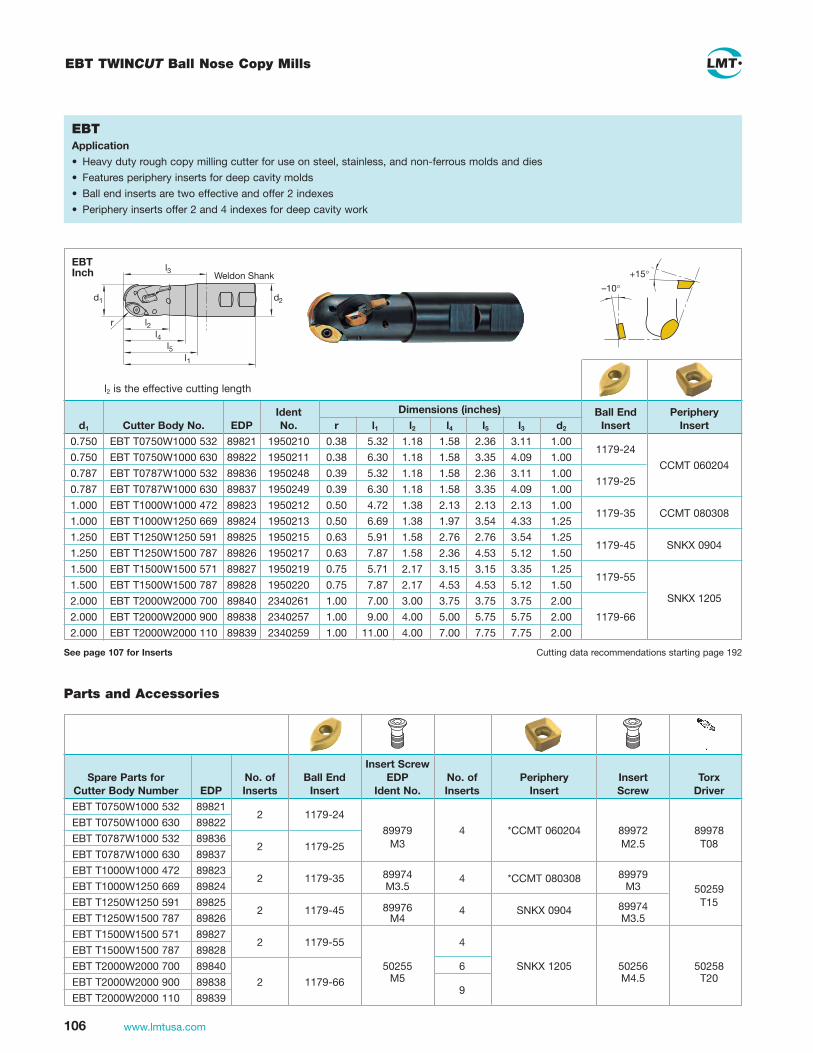
106 www.lmtusa.com
EBTApplication
• Heavy duty rough copy milling cutter for use on steel, stainless, and non-ferrous molds and dies
• Features periphery inserts for deep cavity molds
• Ball end inserts are two effective and offer 2 indexes
• Periphery inserts offer 2 and 4 indexes for deep cavity work
l2 is the effective cutting length
Ident Dimensions (inches) Ball End Periphery d1 Cutter Body No. EDP No. r l1 l2 l4 l5 l3 d2 Insert Insert
0.750 EBT T0750W1000 532 89821 1950210 0.38 5.32 1.18 1.58 2.36 3.11 1.00
0.750 EBT T0750W1000 630 89822 1950211 0.38 6.30 1.18 1.58 3.35 4.09 1.00 1179-24
CCMT 060204
0.787 EBT T0787W1000 532 89836 1950248 0.39 5.32 1.18 1.58 2.36 3.11 1.00
0.787 EBT T0787W1000 630 89837 1950249 0.39 6.30 1.18 1.58 3.35 4.09 1.00 1179-25
1.000 EBT T1000W1000 472 89823 1950212 0.50 4.72 1.38 2.13 2.13 2.13 1.00 CCMT 080308
1.000 EBT T1000W1250 669 89824 1950213 0.50 6.69 1.38 1.97 3.54 4.33 1.25 1179-35
1.250 EBT T1250W1250 591 89825 1950215 0.63 5.91 1.58 2.76 2.76 3.54 1.25 SNKX 0904
1.250 EBT T1250W1500 787 89826 1950217 0.63 7.87 1.58 2.36 4.53 5.12 1.50
1179-45
1.500 EBT T1500W1500 571 89827 1950219 0.75 5.71 2.17 3.15 3.15 3.35 1.25
1.500 EBT T1500W1500 787 89828 1950220 0.75 7.87 2.17 4.53 4.53 5.12 1.50 1179-55
2.000 EBT T2000W2000 700 89840 2340261 1.00 7.00 3.00 3.75 3.75 3.75 2.00 SNKX 1205
2.000 EBT T2000W2000 900 89838 2340257 1.00 9.00 4.00 5.00 5.75 5.75 2.00 1179-66
2.000 EBT T2000W2000 110 89839 2340259 1.00 11.00 4.00 7.00 7.75 7.75 2.00
–10°+15°
Insert Screw Spare Parts for No. of Ball End EDP No. of Periphery Insert Torx Cutter Body Number EDP Inserts Insert Ident No. Inserts Insert Screw Driver
EBT T0750W1000 532 89821
EBT T0750W1000 630 89822 2 1179-24
*CCMT 060204
EBT T0787W1000 532 89836 89979 4
89972 89978
EBT T0787W1000 630 89837 2 1179-25
M3 M2.5 T08
EBT T1000W1000 472 89823 *CCMT 080308
EBT T1000W1250 669 89824 2 1179-35
89974 4
89979
50259 EBT T1250W1250 591 89825
M3.5
SNKX 0904
M3
T15
EBT T1250W1500 787 89826 2 1179-45
89976 4
89974
EBT T1500W1500 571 89827
M4
M3.5
EBT T1500W1500 787 89828 2 1179-55
4
EBT T2000W2000 700 89840 50255 6 SNKX 1205 50256 50258
EBT T2000W2000 900 89838 2 1179-66 M5 9 M4.5 T20
EBT T2000W2000 110 89839
Parts and Accessories
d1
r
l1
l2l4
l5
Weldon Shank
d2
l3
EBT TWINCUT Ball Nose Copy Mills
See page 107 for Inserts Cutting data recommendations starting page 192
EBTInch

107www.lmtusa.com
Ball Nose Copy Roughing End Mills with TWINCUT Geometry – Inserts
N = 2
N = 2 s = ± 0.025 d = ± 0.01
N = 2
N = 4
N = 4
N = 4
SNKX 0904 AN
SNKX 1205 AN
1179-66
SNKX 1205 AN-TR
SNKX 1205 AN-TTwide land
SNKX 1205 AN-Twide land
SNKX 0904 AN-TT
CCMT 060204
CCMT 080308
9.52 4.76 4.4 1.5 (.375) (.187) (.173) (.059) 12.70 5.56 5.2 2.0 (.500) (.219) (.205) (.079)
36.17 6.35 14.30 5.5 24.20 (1.424) (.250) (.563) (.217) (.953)
12.70 5.56 5.2 2.0(.500) (.219) (.205) (.079)
12.70 5.56 5.2 2.0 (.500) (.219) (.205) (.079)
N = Number of cutting edges l s d d1 b/r
Cutting materials
Ident No.
For cutter
LC
240T
LC
240S
LC
225T
LC
225S
LW
240
LW
225
LW
610
LC
610T
1069
560
1069
599
1069
598
1069
562
1960
069
1960
066
1069
563
1069
594
1069
593
1069
564
1069
565
1069
604
1069
603
1069
566
1069
567
1069
610
1069
609
1069
568
1069
569
1069
615
1069
614
1069
685
1052
316
1052
294
1052
292
1052
284
1052
282
1052
317
1052
286
1069
546
1069
549
1052
301
1052
230
1052
315
1052
228
1052
238
1052
232
1052
339
1052
236
1052
248
1052
245
1052
239
1052
237
1052
243
1052
241
1052
251
1052
249
1055
742
1052
303
1052
258
1052
314
1052
256
1052
252
1052
250
1052
309
1052
254
1055
743
1069
497
1069
412
1069
498
1069
499
1069
416
1069
500
6.35 2.38 6.35 2.8 0.4 (.250) (.094) (.250) (.110) (.016)
7.94 3.18 7.94 3.4 0.8 (.312) (.125) (.312) (.134) (.031)
12.70 5.44 5.2 2.0(.500) (.219) (.205) (.079)
9.52 4.76 4.4 1.5 (.375) (.187) (.173) (.059)
l
l
7°s
1°r
d1
b
l s
d1
30°45°
b
s
d1
30°
l
45°
b
s
d1
30°45°
l
s
d1
r
l
d
s
d1
r
l
d
Cat-No.
EBT X
EBT X
EBT X
EBT X
EBT X
1179-25
1179-35
1179-45
1179-55
1179-65
1179-24
ISO-CodeCat-No.
12.79 3.18 7.15 3.5 10 (.504) (.125) (.281) (.138) (.394) 15.99 3.97 8.94 4.1 12.5 (.630) (.156) (.352) (.161) (.492) 20.47 5.08 11.44 4.5 16 (.806) (.200) (.450) (.177) (.630) 25.58 6.35 14.30 5.5 20(1.00) (.250) (.563) (.217) (.787)
21.55 6.35 14.30 5.5 25(.848) (.250) (.563) (.217) (.984)
12.79 3.18 7.15 3.5 9.52 (.504) (.125) (.281) (.138) (.375)
1) Roughing geometry with double coatingLC280TT
LC
280T
T1)
d
l30°
30°
d1
s

108 www.lmtusa.com
EBT TWINCUT Half Moon Ball Nose Copy Mill
EBT Half Moon (11432)Special features:
• Negative axial angle combined with positive groove generates a smooth
skiving cutting action
• Chip forming insert
• 2 indexable inserts, half round, both sides can be used, cylindrically
ground, high accuracy of form on left hand cutters to be used and turned
over 4 times
• Secure and precise clamping
• Stable rear cross-section
-16� 13�
3�
Form B r
d1d2
l3l1
EBT 11432Metric
d1 Cutter Body No.EDP No.
Ident No. r Form d3 l1 l3 d2 z Insert
Insert Screw
TorxDriver
16 EBT R16.016BR086 – 1040911 8 B 86 36 20 2 1179-11 2237513 1048326
16 EBT R16.016AN160 – 1040902 8 A 14 160 55 16 2 M3 T08
16 EBT R16.016AR175 – 1040913 8 B 175 65 20 2
20 EBT R20.020BN086 – 1040927 10 A 17.2 86 36 20 2 1179-21 1045105 1048335
20 EBT R20.020AN175 – 1040904 10 A 17.2 175 60 20 2 M3.5 T15
20 EBT R20.020AS190 – 1040914 10 B 190 80 20 2
20 EBT T20W0750 689NR 89808 1950170 10 A 6.89" 19.05 (.750")
2
20 EBT T20W1000 748TR 89809 1950172 10 B 7.48" 25.4 (1.00")
2
25 EBT R25.025BS190 – 1040929 12.5 A 21.5 86 36 20 2 1179-31 1044963 1048344
25 EBT R25.025AN190 – 1040905 12.5 A 21.5 190 70 25 2 M4.5 T20
25 EBT R25.025AV210 – 1040915 12.5 B 210 100 32 2
25 EBT T25W1000 748NR 89810 1950174 12.5 A 7.48" 25.4 (1.00")
2
25 EBT T25W1250 748NR 89811 1950176 12.5 A 7.48" 25.4 (1.00")
2
30 EBT R30W1250 826NR 60858 1950242 15 A 8.27" 31.75 (1.25")
2 1179-40 1045777 M5
1048344T20
32 EBT R32.032AN210 – 1040906 16 A 28 210 80 32 2 1179-41 1045777 M5 1048344
32 EBT T32W1250 827NR 89812 1950178 16 A 8.27" 31.75 (1.25")
2 T20
Form A
d3
r
d1d2
l3l1
DIN 1835 A
Form A: Straight standard shankForm B: Shank dia. increased
Limited stock of metric products in U.S., please contact Customer Service for availability Cutting data recommendations starting page 192
See page 109 for Inserts

109www.lmtusa.com
EBT TWINCUT Half Moon Ball Nose Copy Mill
d1 Cutter Body No. EDPIdent No. Hand Form Radius OAL
Shank Dia. z Insert
Insert Screw
TorxDriver
0.625 EBT T0625W0625 630NR 89814 1950188 RH A 0.312 6.30 0.625 2 1179-11 2237513 1048326
0.625 EBT T0625W0625 630NL 89829 1950235 LH A 0.312 6.30 0.625 2 M3 T08
0.625 EBT T0625W0625 630TR 89815 1950188 RH B 0.312 6.89 0.750 2
0.625 EBT T0625W0625 630TL 89829 1950236 LH B 0.312 6.89 0.750 2
0.750 EBT T0750W0750 689NR 89816 1950190 RH A 0.375 6.89 0.750 2 1179-20 1045105 1048335
0.750 EBT T0750W0750 689NL 89831 1950237 LH A 0.375 6.89 0.750 2 M3.5 T15
0.750 EBT T0750W1000 748TR 89817 1950191 RH B 0.375 7.48 1.000 2
0.750 EBT T0750W1000 748TL 89832 1950238 LH B 0.375 7.48 1.000 2
1.000 EBT T1000W1000 748NR 89818 1950192 RH A 0.500 7.48 1.000 2 1179-31 1044963 1048344
1.000 EBT T1000W1000 748NL 89833 1950239 LH A 0.500 7.48 1.000 2 M4.5 T20
1.000 EBT T1000W1250 827TR 89819 1950193 RH B 0.500 8.27 1.250 2
1.000 EBT T1000W1250 827TL 89834 1950240 LH B 0.500 8.27 1.250 2
1.250 EBT T1250W1250 827NR 89820 1950194 RH A 0.625 8.27 1.250 2 1179-41 1045777 1048344
1.250 EBT T1250W1250 827NL 89835 1950241 LH A 0.625 8.27 1.250 2 M5 T20
EBT 11432Inch
Cutting data recommendations starting page 192
EBT TWINCUT Half Moon Ball Nose Inserts
d
l
30�
d1
s
N = 2s = ± 0.01l = ± 0.02d = ± 0.01
EBT l s d d1 r Cat-No.
ISO-Code
Cutting materialsIdent No.
Forcutter
Cat-No. LC
240T
LC
240S
LC
225W
LC
225T
LC
225S
LC
630T
LW
240
LW
225
LC
440T
LC
444W
LC
610A
LW
610
LC
610E
LC
610T
LC
603Z
N = Number of cutting edges
1179-11
1179-20(3/4" Cutters Only)
1179-21
1179-31
1179-40(30mm Cutters Only)
1179-41
15.191 3.18 7.04 3.4 8. (.598) (.125) (.277) (.134) (.315)
18.08 3.78 8.38 4.29 9.14 (.712) (.149) (.330) (.169) (.360)
18.989 3.97 8.80 4.2 10 (.748) (.156) (.346) (.165) (.394)
23.736 4.76 11 5.2 12.5 (.394) (.187) (.433) (.205) (.492)
28.473 5.23 13.21 5.51 14.99
(1.121) (.206) (.520) (.217) (.590)
30.382 5.56 14.08 5.8 16(1.196) (.219) (.554) (.228) (.630)
1069
575
1069
617
1069
626
1069
624
1069
577
1069
625
2411
932
1960
055
1960
063
1960
054
1069
551
1960
050
0089
967
1960
052
1069
557
1069
556
1069
589
1069
622
8940
1
1069
636
1069
634
1069
571
1069
635
1069
581
1069
619
1069
579
1069
540
1069
627
1069
583
1069
585
1069
621
1069
633
1069
587
1069
631
Note: 1179-20 Inserts are for 3/4" Cutters Only

110 www.lmtusa.com
Available Cutting Geometries with Applications for GWR/GWV Copy Cutters
Semi-finishing RoughingFinishingPage #LMT Code Geometry ApplicationWPR .. -N
WPR ..-CF
WPR ..-D
WPR ..-DN
WPB ..-N
WPB ..-CF
WPV ..-N
WPV ..-CF
steel, cast steel, high temperature alloys and hardened steel up to 60 HRC
with chip control for long-chipping ferrous metals
steel, cast steel, high temperature alloys
non-ferrous materials, plastics and graphite
steel, cast steel, high temperature alloys and hardened steel up to 60 HRC
with chip control for long-chipping ferrous metals
steel, cast steel, high temperature alloys and hardened steel up to 60 HRC
with chip control for long-chipping ferrous metals
115
120
118–119
118
126–127
128–129
124
125
116
130
131
WPR .. -AR
WPB ..-HF
WPB ..-FB
steel, cast steel, high temperature alloys
high feed cutting of steel, cast steel and high temperature alloys
steel, cast steel, high temperature alloys and hardened steel up to 62 HRc

111www.lmtusa.com
EBG-R Straight Neck Copy Cutter Body – HSS
d1d3
l2
d2
l1
EBG RMetric
EBG RInch
d1 Cutter Body No.Ident No. l1 l2 d2 d3 z Insert
Insert Screw
TorxDriver
12 EBG R12.012AN090 6130568 32 90 12 10.5 2 WPR 12 GWS 12 T20
12 EBG R12.012AN130 6121395 32 130 12 10.5 2
12 EBG R12.012AN150 6121397 46 150 12 10.5 2
16 EBG R16.016AN100 6130569 36 100 16 14 2 WPR 16 GWS 16
16 EBG R16.016AN140 6121385 36 140 16 14 2
16 EBG R16.016AN160 6121387 53 160 16 14 2
20 EBG R20.020AN160 6121382 45 160 20 18 2 WPR 20 GWS 20
20 EBG R20.020AN175 6121375 61 175 20 18 2
25 EBG R25.025AN160 6121367 45 160 25 22.4 2 WPR 25 GWS 25 T30
25 EBG R25.025AN190 6121369 70 190 25 22.4 2
30 EBG R30.030AP175 6200387 56 175 32 27 2 WPR 30 GWS 32
30 EBG R30.030AP210 6121350 80 210 32 27 2
32 EBG R32.032AN175 6121359 56 175 32 28.6 2 WPR 32 GWS 50
32 EBG R32.032AN210 6121361 80 210 32 28.6 2
d1 Cutter Body No. EDPIdent No. l1 l2 d2 d3 z Insert
Insert Screw
TorxDriver
0.375 EBG R0375A0500 090N 88114 6121394 1.34 3.54 0.500 0.34 2 WPR 0375 GWS 10 T15
0.500 EBG R0500A0500 130N 88115 6121396 1.26 5.12 0.500 0.41 2 WPR 0500 GWS 12 T20
0.500 EBG R0500A0500 150N 88116 6121398 1.81 5.91 0.500 0.41 2
0.625 EBG R0625A0625 140N 88117 6121386 1.42 5.51 0.625 0.55 2 WPR 0625 GWS 16 T20
0.625 EBG R0625A0625 160N 88118 6121388 2.09 6.30 0.625 0.55 2
0.750 EBG R0750A0750 160N 88119 6121374 1.77 6.30 0.750 0.71 2 WPR 0750 GWS 20 T20
0.750 EBG R0750A0750 175N 88120 6121376 2.40 6.89 0.750 0.71 2
0.750 EBG R0750A0750 210N 88913 6121366 2.36 8.27 0.750 0.71 2
1.000 EBG R1000A1000 160N 88121 6121368 1.77 6.30 1.000 0.88 2 WPR 1000 GWS 25 T30
1.000 EBG R1000A1000 190N 88122 6121370 2.76 7.48 1.000 0.88 2
1.000 EBG R1000A1000 230N 88898 6121357 3.14 9.06 1.000 0.88 2
1.250 EBG R1250A1250 175N 88125 6121360 2.20 6.89 1.250 1.13 2 WPR 1250 GWS 32
1.250 EBG R1250A1250 210N 88126 6121362 3.15 8.27 1.250 1.13 2
2.000 EBG R2000A2000 330N 88906 6121393 4.92 12.99 2.000 1.77 2 WPR 2000 GWS 50 2146556
Limited stock of metric products in U.S., please contact Customer Service for availability
See pages 115-120 for Inserts Cutting data recommendations starting page 195See page 114 for Insert Screw Specifications

112 www.lmtusa.com
EBG-R-T Tapered Ball Nose Copy Cutter Body – HSS
d1d2
l1l 2
d3
3°
EBG RMetric
d1 Cutter Body No.Ident No. l1 l2 d2 d3 z Insert Insert Insert
Insert Screw
Torx Driver
6 EBG R06.006AR090 6128481 16 90 10 5.3 2 WPR 06 WPV 06 WPB 06 GWS 06 T6
8 EBG R08.008AR085 6130570 50 85 12 7.5 2 WPR 08 WPV 08 WPB 08 GWS 08 T8
8 EBG R08.008AR140 6121409 50 140 12 7.5 2
10 EBG R10.010AP085 6130571 35 85 12 9 2 WPR 10 WPV 10 WPB 10 GWS 10 T15
10 EBG R10.010AP150 6121401 35 150 12 9 2
12 EBG R12.012AR110 6130572 60 110 16 10.5 2 WPR 12 GWS 12 T20
12 EBG R12.012AR160 6121402 60 160 16 10.5 2
16 EBG R16.016AR120 6130573 67 120 20 14 2 WPR 16 GWS 16
16 EBG R16.016AR175 6121403 67 175 20 14 2
20 EBG R20.020AS190 6121404 80 190 25 18 2 WPR 20 GWS 20
25 EBG R25.025AV210 6121405 100 210 32 22.4 2 WPR 25 GWS 25 T30
32 EBG R32.032AW240 6121392 123 240 40 28.6 2 WPR 32 GWS 32
d1 Cutter Body No. EDPIdent No. l1 l2 d2 d3 z Insert Insert Insert
Insert Screw
Torx Driver
0.250 EBG R0250A0375 090T 10525 6128482 1.57 3.54 0.375 0.22 2 WPR 0250 WPV 0250 WPB 0250 GWS 06 T 6
0.312 EBG R0312A0500 140T 88100 6121294 1.97 5.51 0.500 0.30 2 WPR 0312 WPV 0312 WPB 0312 GWS 08 T 8
0.375 EBG R0375A0500 150T 88101 6121295 1.38 5.10 0.500 0.35 2 WPR 0375 WPV 0375 WPB 0375 GWS 10 T 10
0.500 EBG R0500A0625 160T 88102 6121296 2.36 6.30 0.625 0.41 2 WPR 0500 GWS 12 T 20
0.625 EBG R0625A0750 175T 88103 6121297 2.64 6.89 0.750 0.55 2 WPR 0625 GWS 16
0.750 EBG R0750A1000 190T 88104 6121298 3.15 7.48 1.000 0.71 2 WPR 0750 GWS 20
1.000 EBG R1000A1250 210T 88105 6121299 3.94 8.27 1.250 0.88 2 WPR 1000 GWS 25 T 30
1.250 EBG R1250A1500 240T 88106 6121300 4.84 9.45 1.500 1.17 2 WPR 1250 GWS 32
Limited stock of metric products in U.S., please contact Customer Service for availability
See pages 115-120 for Inserts Cutting data recommendations starting page 195See page 114 for Insert Screw Specifications
EBG RInch

113www.lmtusa.com
EBG-R-NC Ball Nose Cutter Body – Carbide
d1d3
l2
d2
l1
EBG RMetric
EBG RInch
d1 Cutter Body No.Ident No.
(IKZ)* Ident No. l1 l2 d2 d3 z Insert Insert
Insert Screw
Torx Driver
6 EBG R06.006AN100-C 6130088 – 20 100 6 5.8 2 WPR 06 WPB 06 GWS 06 T6 6 EBG R06.006AN150-C 6130086 – 70 150 6 5.8 2 WPR 06 WPB 06 GWS 06 6 EBG R06.006AN200-C 6130084 – 100 200 6 5.8 2 WPR 06 WPB 06 GWS 066 EBG R06.006AP100-C 6128437 – 16 100 8 5.3 2 WPR 06 WPB 06 GWS 068 EBG R08.008AN080-C 6131495 – 25 80 8 7.0 2 WPR 08 GWS 08 T88 EBG R08.008AN100-C 6121301 – 25 100 8 7.0 28 EBG R08.008AN150-C 6121284 – 40 150 8 7.0 210 EBG R10.010AN080-C-I 9074942 6131499 35 80 10 8.8 2 WPR 10 GWS 10 T1510 EBG R10.010AN120-C-I 6121285 6130392 35 120 10 8.8 210 EBG R10.010AN150-C-I 6121286 6130393 50 150 10 8.8 212 EBG R12.012AN080-C-I 9074945 6131500 35 80 12 10.5 2 WPR 12 GWS 12 T2012 EBG R12.012AN120-C-I 6121287 6130394 35 120 12 10.5 212 EBG R12.012AN160-C-I 6121288 6130395 50 160 12 10.5 216 EBG R16.016AN100-C-I – 6131501 40 100 16 14.0 2 WPR 16 GWS 16 16 EBG R16.016AN140-C-I – 6130396 40 140 16 14.0 216 EBG R16.016AN175-C-I – 6130397 55 175 16 14.0 220 EBG R20.020AN100-C-I – 6131503 50 100 20 18.0 2 WPR 20 GWS 2020 EBG R20.020AN140-C-I – 6130398 50 140 20 18.0 220 EBG R20.020AN190-C-I 6121292 6130399 75 190 20 18.0 225 EBG R25.025AN160-C-I 6121275 6130400 60 160 25 22.4 2 WPR 25 GWS 25 25 EBG R25.025AN210-C-I 6121276 6130401 90 210 25 22.4 232 EBG R32.032AN190-C 6121277 – 65 190 32 28.6 2 WPR 32 GWS 32 T3032 EBG R32.032AN240-C 6121278 – 105 240 32 28.6 2
d1 Cutter Body No. EDPIdent No. l1 l2 d2 d3 z Insert Insert
Insert Screw
Torx Driver
0.250 EBG R0250A0375 100NC 50269 6128439 1.57 3.94 0.375 0.22 2 WPR 0250 WPB 0250 GWS 06 T60.250 EBG R0250A0250 100NC-40 55504 6131238 1.57 3.94 0.250 0.22 20.250 EBG R0250A0250 150NC-70 55505 6131239 2.76 5.91 0.250 0.22 20.250 EBG R0250A0250 200NC-100 55506 6131240 3.94 7.88 0.250 0.22 20.250 EBG R0250A0250 200NC-14 55507 6131234 0.55 7.88 0.250 0.22 20.312 EBG R0312A0375 100NC 50270 6128633 0.99 3.94 0.375 0.28 2 WPR 0312 WPB 0312 GWS 08 T80.312 EBG R0312A0375 150NC 50271 6128635 1.57 5.91 0.375 0.28 20.312 EBG R0312A0312 200NC-100 55508 6131232 3.94 7.88 0.312 0.28 20.375 EBG R0375A0375 200NC-100 55509 6131236 3.94 7.88 0.375 0.35 2 WPR 0375 WPB 0375 GWS 10 T150.375 EBG R0375A0375 120NC 50272 6128636 1.38 4.73 0.375 0.35 20.375 EBG R0375A0375 150NC 50273 6128638 1.97 5.91 0.375 0.35 20.500 EBG R0500A0500 120NC 50274 6128639 1.38 4.73 0.500 0.42 2 WPR 0500 WPB 0500 GWS 12 T200.500 EBG R0500A0500 160NC 50275 6128641 1.97 6.30 0.500 0.42 20.625 EBG R0625A0625 140NC 50276 6128642 1.58 5.52 0.625 0.63 2 WPR 0625 WPB 0625 GWS 160.625 EBG R0625A0625 175NC 50277 6128644 2.17 6.89 0.625 0.63 20.750 EBG R0750A0750 140NC 50278 6128645 1.58 5.52 0.750 0.71 2 WPR 0750 WPB 0750 GWS 200.750 EBG R0750A0750 190NC 50279 6128647 2.96 7.48 0.750 0.71 21.000 EBG R1000A1000 160NC 50280 6128648 2.37 6.30 1.000 0.89 2 WPR 1000 WPB 1000 GWS 25 T301.000 EBG R1000A1000 210NC 50281 6128650 3.55 8.27 1.000 0.89 21.250 EBG R1250A1250 190NC 50282 6128651 2.56 7.48 1.250 1.13 2 WPR 1250 WPB 1250 GWS 321.250 EBG R1250A1250 240NC 50283 6128653 4.14 9.45 1.250 1.13 2
Limited stock of metric products in U.S., please contact Customer Service for availability *IKZ=Internal Coolant Supply
See Pages 115-120 for Inserts Cutting data recommendations starting page 195See page 114 for Insert Screw Specifications

114 www.lmtusa.com
Tool type
Ident No. Screw GRT GWR GWV
SA 40115 manual --- ---
6260409 GWS 06 --- 1 1
6119572 GWS 08 --- 2 2
6119571 GWS 10 --- 3 3
6119559 GWS 12 --- 4 4
6119560 GWS 16 --- 5 5
6119561 GWS 20 --- 6 6
6119562 GWS 25 6.5 6.5 6.5
6119563 GWS 32 6.5 6.5 6.5
Torque in Nm
EBG-R THR Screw-On Heads
EBG R.../ EBG V... Torque Requirements
Torque in Nm
d3 d1
l1
l2
d5 d2
Product optimization by shortened, compact version
EBG RMetric
d1 Cutter Body No.Ident No. l1 l2 d2 d3 d5 z IKZ Insert Insert Insert
Insert Screw
TorxDriver
8 EBG R08.008TC025 6131455 25 39.5 6.5 M6 10 2 WPR 08 WPV 08 WPB 08 GWS 08 T 8
10 EBG R10.010TC025 6131457 25 39.5 6.5 M6 10 2 WPR 10 WPV 10 WPB 10 GWS 10 T15
12 EBG R12.012TR025 6131451 25 39.5 6.5 M6 10 2 WPR 12 GWS 12 T20
12 EBG R12.012TR026-I 6131459 26 43.5 8.5 M8 13 2 x WPR 12 GWS 12
16 EBG R16.016TR026-I 6131461 26 43.5 8.5 M8 13 2 x WPR 16 GWS 16
20 EBG R20.020TS030-I 6131463 30 49.5 10.5 M10 18 2 x WPR 20 GWS 20
25 EBG R25.025TF040-I 6131465 40 62.0 12.5 M12 21 2 x WPR 25 GWS 25 T30
32 EBG R32.032TH045-I 6131470 45 69.0 17.0 M16 30 2 x WPR 32 GWS 32
d1 Cutter Body No. EDPIdent No. l1 l2 d2 d3 d5 z IKZ Insert
Insert Screw
TorxDriver
0.375 EBG R 0375 T0375 13727 9101920 0.984 1.555 0.255 M6 0.393 2 WPR 0375 GWS 10 T15
0.500 EBG R 0500 T0500 13728 9101921 0.984 1.555 0.255 M6 0.393 2 WPR 0500 GWS 12 T20
0.625 EBG R 0625 T0625 13729 9101922 1.023 1.712 0.334 M8 0.511 2 x WPR 0625 GWS 16 T20
0.750 EBG R 0750 T0750 13730 9101924 1.181 1.948 0.413 M10 0.708 2 x WPR 0750 GWS 20 T20
1.000 EBG R 1000 T1000 13731 9101925 1.574 2.440 0.492 M12 0.826 2 x WPR 1000 GWS 25 T30
Limited stock of metric products in U.S., please contact Customer Service for availability
See pages 115-120 for Inserts Cutting data recommendations starting page 195See pages 136-139 for Screw-On Shanks*IKZ=Internal Coolant Supply
EBG RInch

115www.lmtusa.com
Copy inserts WPR-N
WPR 06 N
WPR 08-N
WPR 10-N
WPR 12-N
WPR 16-N
WPR 20-N
WPR 25-N
WPR 30-N
WPR 32-N
N Geometry is for semi-finishing and finishing of steel, cast steel and high temperature alloys up to 60 HRC
Metric
N = Number of cutting edges d s
EBG R 06
EBG R 08
EBG R 10
EBG R 12
EBG R 16
EBG R 20
EBG R 25
EBG R 30
EBG R 32
6 1.6
8 2
10 2.5
12 2.5
16 3
20 3
25 4
30 5
32 5
LMT-Code
Cutting materialsIdent No.
For cutter
LMT-Code LC
240Q
LC
240N
LC
240T
LW
240
LW
610
LC
730Z
LC
610Z
LC
610T
9078
153
6123
050
6127
908
6123
058
6123
048
9074
564
6132
308
6123
047
90
7815
4
6123
157
6282
695
6123
180
6123
155
9074
565
6132
309
6123
172
9078
155
6123
138
6282
696
6123
159
6123
154
9074
566
6131
467
6123
153
613
1686
6123
120
6127
665
6123
140
6123
136
9074
567
6130
735
6123
135
907
8156
6123
107
6127
911
6123
122
612
3118
9074
568
613
1468
6123
117
90
7815
7
6123
084
6128
448
6180
175
6123
100
9074
569
61
3146
9
6123
099
6123
072
6282
697
6123
065
6122
678
909
1928
6200
388
90
7815
8
6127
953
61
2756
2
61
8025
4
6123
077
9074
570
6132
054
6123
076
WPR 0312-N
WPR 0375-N
WPR 0500-N
WPR 0625-N
WPR 0750-N
WPR 1000-N
WPR 1250-N
WPR 2000-N
Inch
N = Number of cutting edges d s LMT-Code
For cutter
LMT-Code LW
610
LC
610T
LC
730T
N = 2
9089
461
9086
604
9086
606
EBG R 0312
EBG R 0375
EBG R 0500
EBG R 0625
EBG R 0750
EBG R 1000
EBG R 1250
EBG R 1250
LW
240
LC
240N
LC
240T
LC
730Q
9078
713
6122
906
6122
904
6122
900
6130
272
9078
714
6122
895
6122
895
6122
898
6130
273
9078
715
6122
886
6122
884
6122
889
6130
274
9078
716
6122
872
6122
879
6122
875
6130
275
6122
859
9086
599
9086
578
6122
735
6122
862
6130
277
9078
717
6122
868
6122
866
6122
871
6130
276
6122
850
6122
848
6122
907
6122
896
6122
887
6122
873
6122
860
6122
869
6122
851
6122
853
6130
278
ds
d
ds
d
N = 2
0.312 0.06
0.375 0.08
0.500 0.10
0.625 0.12
0.750 0.12
1.000 0.16
1.250 0.20
2.000 0.24
LC
730Z

116 www.lmtusa.com
WPR-AR – Copy Inserts
LC
240N
LC
240T
LW
240
LC
630Q
LW
610
LC
610T
LC
610Z
s
d
AR Geometry is for roughing and semi-finishing in steel, cast steel and high temperature alloys
WPR 12-AR
WPR 16-AR
WPR 20-AR
WPR 25-AR
WPR 32-AR
Metric
N = Number of cutting edges d s
EBG R 12
EBG R 16
EBG R 20
EBG R 25
EBG R 32
12 2.5
16 3
20 3
25 4
32 5
LMT-Code
Cutting materialsIdent No.
For cutter
LMT-Code LC
240N
LC
240T
LW
240
LC
630Q
LW
610
LC
610T
LC
610Z
9076
995
6183
222
6183
220
6183
218
9074
078
N = 2
N = 2
N = 2
N = 2
LMT-CodeEBG R 0500
EBG R 0625
EBG R 0750
EBG R 1000
LMT-Code
Inch
N = Number of cutting edges
WPR 0500-AR
WPR 0625-AR 1)
WPR 0750-AR 1)
WPR 1000-AR
.500 .098
.625 .118
.750 .118
1.000 .157
d s
For cutter
9077
903
9073
899
9073
919
9077
910
sd
d
1) Do Not Have Coolant Channels to Cutting EdgeNote: Use holders with IKZ designation to take advantage of inserts with Coolant Channels

117www.lmtusa.com
WPR-AR Application Example
µ-Jet WPR-AR
WPR 16-AR in LC630Q with carbide shank
Dia. 16mm (.630")
Vc = 180 m/min (590 SFM)
Fz = 0,6 mm (.024" IPT)
Ap = 6 mm (.236" DOC)
Ae = 4 mm (.158" WOC)
Material: 1.2344 (4140)
Q = 104.000 mm³/min
= 4 Cu Inch/Min
µ-Jet WPR-AR
Material: 1.2344 (4140)
Dia. = 16mm (.630")
Vc = 326 m/min (1070 SFM)
n = 6500 min–1 (RPM)
vf = 2500 mm/min (100 IPM)
fz = 0,2 mm (.008" FPT)
ap = 3 mm (.118" DOC)
ae = 4 mm (.157" WOC)
The Future of “AR” Geometry-Coolant Channels to Cutting Edge
Test result:
before: after:
WPR-16-CF WPR-16-AR
(LC240T) (LC630Q)
Tool life: 8 min Tool life: 135 min
Increase tool life: +1680%
Air-Jet®
Indexable Inserts withIntegrated Air Cooling
Current “AR” Insert
Coming Soon!

118 www.lmtusa.com
Copy Inserts WPR-D
Metric N = Number of cutting edges d s
EBG R 06
EBG R 08
EBG R 10
EBG R 12
EBG R 16
EBG R 20
EBG R 25
EBG R 32
LMT-Code
Cutting materials
Ident No. For cutter
LMT-Code LW
610
LC
610Q
6131
629
9074
406
6131
302
6132
330
6131
303
6132
329
6131
304
9074
409
6131
305
6132
089
6131
306
9074
410
6131
307
9074
411
WPR 06-DN
WPR 08-DN
WPR 10-DN
WPR 12-DN
WPR 16-DN
WPR 20-DN
WPR 25-DN
WPR 32-DN
EBG R 06
EBG R 08
EBG R 10
EBG R 12
EBG R 16
EBG R 20
EBG R 25
EBG R 32
LC
730Q
LC
610A
9079
231
6131
628
6131
663
6131
294
6131
664
6131
296
6131
666
6131
297
6131
667
6131
298
6131
668
6131
299
6131
669
New helical cutting geometry
WPR…D for semi-finishing and finishing of steel, cast steel and high temperature alloy up to 54 HRC
N = 2
New helical cutting geometry
WPR…DN for semi-finishing and finishing of non-ferrous metals, plastics, graphiteand titanium
N = 2
s
d
s
d
6 1.6
8 2
10 2.5
12 2.5
16 3
20 3
25 4
32 5
6132
363
9079
232
D – Helical Geometry suitable for semi-finishing and finishing in soft materials (Up to 54 Rc)DN – Helical Geometry suitable for semi-finishing and finishing in non-ferrous materials and also in Exotic materials (LW610)
WPR 06-D
WPR 08-D
WPR 10-D
WPR 12-D
WPR 16-D
WPR 20-D
WPR 25-D
WPR 32-D
6 1.6
8 2
10 2.5
12 2.5
16 3
20 3
25 4
32 5
6131
295
6131
665

119www.lmtusa.com
Copy Inserts WPR-D
s
d
s
d
Inch
N = Number of cutting edges
Inch
N = Number of cutting edges
Cutting materials
Cutting materials
Ident No.
Ident No.
For cutter
For cutter
LMT-Code
LMT-Code
New helical cutting geometry
New helical cutting geometry
N = 2
N = 2
WPR…D for semi-finishing and finishing of steel, cast steel and high temperature alloy up to 54 HRC
WPR…DN for semi-finishing and finishing of steel, cast steel and high temperature alloy up to 54 HRC
LW
610
LW
610
LC
610Q
LC
610Q
LC
730Q
LC
730Q
LC
610A
LC
610A
LMT-Code
LMT-Code
d s
d s
WPR 0250-D
WPR 0312-D
WPR 0375-D
WPR 0500-D
WPR 0625-D
WPR 0750-D
WPR 1000-D
WPR 0250-DN
WPR 0312-DN
WPR 0375-DN
WPR 0500-DN
WPR 0625-DN
WPR 0750-DN
WPR 1000-DN
0.250 0.063
0.312 0.08
0.375 0.10
0.500 0.10
0.625 0.12
0.750 0.12
1.000 0.16
0.250 0.063
0.312 0.08
0.375 0.10
0.500 0.10
0.625 0.12
0.750 0.12
1.000 0.16
EBG R 0250
EBG R 0312
EBG R 0375
EBG R 0500
EBG R 0625
EBG R 0750
EBG R 1000
EBG R 0250
EBG R 0312
EBG R 0375
EBG R 0500
EBG R 0625
EBG R 0750
EBG R 1000
D – Helical Geometry suitable for semi-finishing and finishing in soft materials (Up to 54 Rc)DN – Helical Geometry suitable for semi-finishing and finishing in non-ferrous materials and also in Exotic materials (LW610)
6132
289
9078
719
9186
035
6132
288
9078
718
9186
031
9186
899
9152
769
6131
300
9078
720
6131
308
6131
813
9078
721
9186
037
6131
815
9078
722
9186
038
6131
301
9086
600
6131
309
Cutting data recommendations starting page 199
Cutting data recommendations starting page 199

120 www.lmtusa.com
Copy inserts WPR-CF
ds
d
CF Geometry has chip control geometry for roughing and semi-finishing long-chipping ferrous materials
WPR 08-CF
WPR 10-CF
WPR 12-CF
WPR 16-CF
WPR 20-CF
WPR 25-CF
WPR 30-CF
WPR 32-CF
Metric
N = Number of cutting edges d s
EBG R 08
EBG R 10
EBG R 12
EBG R 16
EBG R 20
EBG R 25
EBG R 30
EBG R 32
8 2
10 2.5
12 2.5
16 3
20 3
25 4
30 5
32 5
LMT-Code
Cutting materials
Ident No. For cutter
LMT-Code LC
225N
LC
240N
LC
240T
LW
240
LW
225
LW
610
LC
610T
LC
610W
6122
950
6282
698
6122
958
6122
964
6122
949
6122
963
6123
038
6123
046
6282
700
6123
051
6123
054
6123
044
6123
045
6123
043
6123
028
6123
027
6282
703
6123
030
6123
032
6123
025
6123
026
6123
024
6123
010
6123
009
6282
705
6123
029
6123
015
6123
007
6123
008
6123
006
6122
992
6122
991
6282
709
6123
011
6122
998
6123
005
6122
990
6123
004
6122
988
6122
987
6128
868
6180
001
6122
995
6122
985
6122
986
6122
984
6122
967
6282
712
6122
972
6200
286
6122
966
6122
965
6122
971
6122
970
6282
714
6160
607
6122
974
6122
980
6122
981
6122
979
N = 2
N = Number of cutting edges d s LMT-Code
For cutter
LMT-Code LC
225N
LC
240N
LC
240T
LW
240
LW
225
LW
610
LC
610T
LC
610W
N = 2
6130
282
6122
817
6130
283
6122
808
6130
284
6122
783
6130
045
6122
774
ds
d 0.312
0.375
0.500
0.625
0.750
1.000
1.250
2.000
0.06
0.08
0.10
0.12
0.12
0.16
0.20
0.24
6130
279
6122
842WPR 0312-CF
WPR 0375-CF
WPR 0500-CF
WPR 0625-CF
WPR 0750-CF
WPR 1000-CF
WPR 1250-CF
WPR 2000-CF
EBG R 0312
EBG R 0375
EBG R 0500
EBG R 0625
EBG R 0750
EBG R 1000
EBG R 1250
EBG R 1250
6130
280
6122
830
6130
281
6122
825
Inch

121www.lmtusa.com
EBG-V-N Flat Bottom & Back Draft Cutter Body – HSS
l1l2
d2 d1
d3EBG VMetric
EBG VInch
d1 Cutter Body No.IdentNo. l1 l2 d2 d3 z Insert Insert
Insert Screw
TorxDriver
12 EBG V12.012AN090 6130574 34 92 12 10.5 2 WPB 12 WPV 12 GWS 12 T2012 EBG V12.012AN130 6121399 34 132 12 10.5 212 EBG V12.012AN150 6121383 48 152 12 10.5 216 EBG V16.016AN100 6130575 38 102 16 14 2 WBP 16 WPV 16 GWS 1616 EBG V16.016AN140 6121389 38 142 16 14 216 EBGV16.016AN160 6121391 55 162 16 14 220 EBG V20.020AN160 6121377 47 162 20 18 2 WPR 20 WPV 20 GWS 2020 EBG V20.020AN175 6121379 63 177 20 18 225 EBG V25.024AN160 6121371 47 162 25 22.4 2 WPR 25 WPV 25 GWS 25 T3025 EBG V25.025AN190 6121373 72 192 25 22.4 232 EBG V32.032AN175 6121363 58 177 32 28.6 2 WPV 32 GWS 3232 EBG V32.032AN210 6121364 82 212 32 28.6 2
d1 Cutter Body No. EDPIdentNo. l1 l2 d2 d3 z Insert Insert
Insert Screw
TorxDriver
0.500 EBG V0500A0500 130N 88139 6121400 1.34 5.20 0.500 0.41 2 WPB 0500 WPV 0500 GWS 12 T200.500 EBG V0500A0500 150N 88140 6121384 1.89 5.98 0.500 0.41 20.625 EBG V0625A0625 140N 88141 6121390 1.50 5.51 0.625 0.55 2 WBP 0625 WPV 0625 GWS 160.625 EBG V0625A0625 160N 88142 6121381 2.16 6.30 0.625 0.55 20.750 EBG V0750A0750 160N 88143 6121378 1.85 6.30 0.750 0.71 2 WPR 0750 WPV 0750 GWS 200.750 EBG V0750A0750 175N 88144 6121380 2.48 6.89 0.750 0.71 20.750 EBG V0750A0750 210N 88914 6121365 2.36 8.27 0.750 0.71 21.000 EBG V1000A1000 160N 88145 6121372 1.85 6.30 1.000 0.88 2 WPR 1000 WPV 1000 GWS 25 T301.000 EBG V1000A1000 190N 88146 6121356 2.83 7.48 1.000 0.88 21.000 EBG V1000A1000 230N 88902 6121358 3.14 9.06 1.000 0.88 2
Limited stock of metric products in U.S., please contact Customer Service for availability
See pages 124-131 for Inserts Cutting data recommendations starting page 195See page 123 for Insert Screw Specifications

122 www.lmtusa.com
EBG-V-N Straight Front Flat Bottom & Back Draft Cutter Body – Carbide
l1l2
d2 d1
d3EBG VMetric
EBG VInch
d1 Cutter Body No.IdentNo.
IKZ IdentNo. l1 l2 d2 d3 z Insert Insert
Insert Screw
TorxDriver
8 EBG V08.008AN080-C 6131510 – 27 82 8 7 2 WPB 08 WPV 08 GWS 08 T88 EBG V08.008AN100-C 6130576 – 27 102 8 7 28 EBG V08.008AN150-C 6130577 – 42 152 8 7 210 EBG V10.010AN080-C-I 9074948 6131512 37 82 10 8.8 2 WPB 10 WPV 10 GWS 10 T1510 EBG V10.010AN120-C-I 6130578 6131511 37 122 10 8.8 210 EBG V10.010AN150-C-I 6130579 6131513 52 152 10 8.8 212 EBG V12.012AN080-C-I 9074949 6131514 37 82 12 10.5 2 WPB 12 WPV 12 GWS 12 T2012 EBG V12.012AN120-C-I 6128023 6130402 37 122 12 10.5 212 EBG V12.012AN160-C-I 6128030 6130403 52 162 12 10.5 216 EBG V16.016AN100-C-I – 6131515 42 102 16 14 2 WPB 16 WPV 16 GWS 1616 EBG V16.016AN140-C-I – 6130404 42 142 16 14 216 EBG V16.016AN175-C-I – 6130405 57 177 16 14 220 EBG V20.020AN100-C-I – 6131516 52 102 20 18 2 WPB 20 WPV 20 GWS 2020 EBG V20.020AN140-C-I 6128033 6130406 52 142 20 18 220 EBG V20.020AN190-C-I – 6130407 77 192 20 18 225 EBG V25.025AN160-C-I 6128035 6130408 62 162 25 22.4 2 WPB 25 WPV 25 GWS 25 T3025 EBG V25.025AN210-C-I 6128036 6130409 92 212 25 22.4 232 EBG V32.032AN190-C 6128040 – 67 192 32 28.6 2 WPV 32 GWS 3232 EBG V32.032AN240-C 6128041 – 107 242 32 28.6 2
d1 Cutter Body No. EDPIdentNo. l1 l2 d2 d3 z Insert Insert
Insert Screw
TorxDriver
0.500 EBG V0500A0500 120NC 50286 6128661 1.38 4.73 0.500 0.42 2 WPB 0500 WPV 0500 GWS 12 T20 0.500 EBG V0500A0500 160NC 50287 6128663 1.97 6.30 0.500 0.42 2 0.625 EBG V0625A0625 140NC 50288 6128664 1.58 5.52 0.625 0.56 2 WBP 0625 WPV 0625 GWS 16 0.625 EBG V0625A0625 175NC 50289 6128666 2.17 6.89 0.625 0.56 2 0.750 EBG V0750A0750 140NC 50290 6128667 1.58 5.52 0.750 0.70 2 WPR 0750 WPV 0750 GWS 20 0.750 EBG V0750A0750 190NC 50291 6128690 2.96 6.30 1.000 0.89 2 1.000 EBG V1000A1000 160NC 50292 6128691 2.37 6.30 1.000 0.89 2 WPR 1000 WPV 1000 GWS 25 T30 1.000 EBG V1000A1000 210NC 50293 6128693 3.55 8.27 1.000 0.89 2
Limited stock of metric products in U.S., please contact Customer Service for availability IKZ=Internal Coolant Supply
See pages 124-131 for Inserts Cutting data recommendations starting page 195See page 123 for Insert Screw Specifications

123www.lmtusa.com
EBG-V-THR Screw-On Head
d1
l1
l2
d5 d3
d2
EBG VMetric
EBG VInch
d1 Cutter Body No.Ident No. l1 l2 d2 d3 d5 z IKZ Insert Insert
Insert Screw
Torx Driver
8 EBG V08.008TC025 6131472 25 39.5 6.5 M6 10 2 WPV 08 WPB 08 GWS 08 T 810 EBG V10.010TC025 6131474 25 39.5 6.5 M6 10 2 WPV 10 WPB 10 GWS 10 T1512 EBG V12.012TC025 6131476 25 39.5 6.5 M6 10 2 WPV 12 WPB 12 GWS 12 T2012 EBG V12.012TR028-I 6131478 28 45.5 8.5 M8 13 2 x WPV 12 WPB 12 GWS 1216 EBG V16.016TR028-I 6131480 28 45.5 8.5 M8 13 2 x WPV 16 WPB 16 GWS 1620 EBG V20.020TS032-I 6131482 32 51.5 10.5 M10 18 2 x WPV 20 WPB 20 GWS 2025 EBG V25.025TF042-I 6131484 42 64 12.5 M12 21 2 x WPV 25 WPB 25 GWS 25 T3032 EBG V32.032TH047-I 6131486 47 71 17.0 M16 30 2 x WPV 32 GWS 32
d1 Cutter Body No. EDPIdent No. l1 l2 d2 d3 d5 z IKZ Insert Insert
Insert Screw
Torx Driver
0.375 EBG V 0375 T0375 13732 9101926 0.98 1.555 0.25 M6 0.39 2 WPV 0375 WPB 0375 GWS 10 T150.500 EBG V 0500 T0500 13733 9101927 0.98 1.555 0.25 M6 0.39 2 WPV 0500 WPB 0500 GWS 12 T200.625 EBG V 0625 T0625 13734 9101928 1.10 1.791 0.33 M8 0.51 2 x WPV 0625 WPB 0625 GWS 16 T200.750 EBG V 0750 T0750 13735 9101929 1.26 2.027 0.41 M10 0.71 2 x WPV 0750 WPB 0750 GWS 20 T201.000 EBG V 1000 T1000 13736 9101930 1.65 2.519 0.49 M12 0.83 2 x WPV 1000 WPB 1000 GWS 25 T30
Limited stock of metric products in U.S., please contact Customer Service for availability
See pages 124-131 for Inserts Cutting data recommendations starting page 195See pages 136-139 for Screw-On ShanksIKZ=Internal Coolant Supply
Product optimization by shortened compact version
Tool type
Ident No. Screw GRT GWR GWV
SA 40115 manual --- ---
6260409 GWS 06 --- 1 1
6119572 GWS 08 --- 2 2
6119571 GWS 10 --- 3 3
6119559 GWS 12 --- 4 4
6119560 GWS 16 --- 5 5
6119561 GWS 20 --- 6 6
6119562 GWS 25 6.5 6.5 6.5
6119563 GWS 32 6.5 6.5 6.5
Torque in Nm
EBG R.../ EBG V... Torque Requirements
Torque in Nm

124 www.lmtusa.com
Flat Bottom Inserts WPV-N
N Geometry for semi-finishing and finishing steel, for steel, cast steel, high temperature alloys and hardened steel up to 60 HRC
Metric N = Number of cutting edges d l s r
WPV 08-N
WPV 10-N
WPV 12-N
WPV 16-N
WPV 20-N
WPV 25-N
WPV 32-N
EBG V 08
EBG V 10
EBG V 12
EBG V 16
EBG V 20
EBG V 25
EBG V 32
8 9.5 2 0.6 10 11.5 2.5 0.8 12 14 2.5 1.0 16 16 3 1.3 20 18 3 1.6
25 23.5 4 2.0 32 28 5 2.5
LMT-Code
Cutting materials
Ident No.
For cutter
LMT-Code LC
240N
LC
240T
LC
240Q
LW
240
LW
610
LC
610T
6122
671
6127
912
6122
682
6122
669
6122
668
6122
649
6127
331
6122
672
6122
665
6122
664
6122
643
6127
310
6122
650
6122
641
6122
640
6122
637
6127
657
6122
644
6122
635
6122
634
6122
613
6127
914
6122
638
6122
629
6122
628
6122
607
6127
656
6122
614
6122
605
6122
620
d l s r LMT-Code
For cutter
LMT-Code LC
225N
LC
240N
LW
240
LW
225
LW
610W
LD
P05B
-PC
D
LC
610T
Inch N = Number of cutting edges
6122
597
6127
913
6122
608
6122
595
6122
594
d r90°
l
ds
6127
876
5089
0
6127
785
5089
5
6122
525
5090
2
6127
786
5090
3
6127
787
5090
5
6128
965
5090
4
6127
789
5090
6
6127
788
5079
8
6127
790
5508
4
6127
947
5089
1
6122
509
5089
6WPV 0375-N-2
WPV 0375-N-4
WPV 0500-N-2
WPV 0500-N-4
WPV 0625-N-2
WPV 0625-N-4
WPV 0750-N-2
WPV 0750-N-4
WPV 1000-N-2
WPV 1000-N-4
WPV 1000-N-8
EBG V 0375
EBG V 0500
EBG V 0625
EBG V 0750
EBG V 1000
N = 2
N = 2
0.375 0.45 0.08
0.375 0.45 0.08
0.500 0.55 0.10
0.500 0.55 0.10
0.625 0.62 0.12
0.625 0.62 0.12
0.750 0.70 0.12
0.750 0.70 0.12
1.000 0.92 0.16
1.000 0.92 0.16
1.000 0.92 0.16
0.031
0.062
0.031
0.062
0.031
0.062
0.031
0.062
0.031
0.062
0.125
d r90°
l
ds

125www.lmtusa.com
Flat Bottom Inserts WPV-N-CF
CF Geometry with chip control geometry for roughing and semi-finishing long chipping ferrous materials
Metric N = Number of cutting edges d l s r
WPV 08-N-CF
WPV 10-N-CF
WPV 12-N-CF
WPV 16-N-CF
WPV 20-N-CF
WPV 25-N-CF
WPV 32-N-CF
EBG V 08
EBG V 10
EBG V 12
EBG V 16
EBG V 20
EBG V 25
EBG V 32
LMT-Code
Cutting materials
Ident No.
For cutter
LMT-Code LC
240N
LC
240T
LW
240
LW
610
LC
610T
LC
610W
6122
537
6282
725
6122
538
6122
544
6122
545
6122
543
6122
589
6282
727
6122
598
6122
587
6122
588
6122
586
6122
582
6282
729
6122
590
6122
580
6122
581
6122
579
6122
575
6282
731
6122
583
6122
573
6122
574
6122
572
6122
568
6282
733
6122
576
6122
566
6122
567
6122
565
6122
561
6282
735
6122
569
6122
559
6122
560
6122
558
6122
553
6282
737
6122
546
6122
551
6122
552
6122
550
Inch N = Number of cutting edges d l s r LMT-Code
For cutter
LMT-Code LC
225N
LC
240N
LC
240T
LW
240
LW
225
LW
610
WPV 0500-CF-2
WPV 0500-CF-4
WPV 0625-CF-2
WPV 0625-CF-4
WPV 0750-CF-2
WPV 0750-CF-4
WPV 1000-CF-2
WPV 1000-CF-4
WPV 1000-CF-8
EBG V 0500
EBG V 0625
EBG V 0750
EBG V 1000
6130
285
6130
288
6130
291
6130
286
6130
289
6130
292
6130
287
6130
290
6130
293
8 9.5 2 0.6
10 11.5 2.5 0.8 12 14 2.5 1.0
16 16 3 1.3 20 18 3 1.6
25 23.5 4 2.0 32 28 5 2.5
N = 2
N = 2
0.032
0.063
0.032
0.063
0.032
0.063
0.032
0.063
0.125
0.55
0.55
0.62
0.62
0.70
0.70
0.92
0.92
0.92
0.500
0.500
0.625
0.625
0.750
0.750
1.000
1.000
1.000
0.10
0.10
0.12
0.12
0.12
0.12
0.12
0.16
0.16
d r90°
l
d
s
d r90°
l
d
s

126 www.lmtusa.com
Backdraft Inserts WPB-N
WPB 08-N-06
WPB 08-N-10
WPB 10-N-08
WPB 10-N-10
WPB 12-N-10
WPB 12-N-20
WPB 16-N-10
WPB 16-N-13
WPB 16-N-30
WPB 20-N-10
WPB 20-N-16
WPB 20-N-40
WPB 25-N-10
WPB 25-N-20
WPB 25-N-50
Metric
N = Number of cutting edges
EBG V 08
EBG V 10
EBG V 12
EBG V 16
EBG V 20
EBG V 25
LMT-Code
Cutting materialsIdent No.
For cutter
LMT-Code LC
610T
LW
610
6282
927
6282
921
6282
919
6282
916
6282
928
6282
922
6282
918
6282
917
6129
227
6129
226
6128
106
6128
105
6129
229
6129
228
6282
931
6282
923
6128
110
6128
109
N = 2
d l s r 8 9.5 2 0.6
8 9.5 2 1.0
10 11.5 2.5 0.8
10 11.5 2.5 1.0
12 14 2.5 1.0
12 14 2.5 2.0
16 16 3 1.0
16 16 3 1.3
16 16 3 3.0
20 18 3 1.0
20 18 3 1.6
20 18 3 4.0
25 23.5 4 1.0
25 23.5 4 2.0
25 23.5 4 5.0
N Geometry for semi-finishing and finishing of steel, cast steel and high temperature alloys up to 54 HRC
6129
231
6129
230
6282
930
6282
924
6128
114
6128
113
6129
233
6129
232
6282
929
6282
926
6128
118
6128
117
ds
d r
7°l

127www.lmtusa.com
Backdraft Inserts WPB-N
Inch N = Number of cutting edges LMT-Code LMT-Code L
C61
0T
LW
610
d l s r
6122
370
5426
450
696
6129
886
5426
254
263
6122
376
5426
5
6127
791
5475
7
6127
792
5475
8
6127
793
5426
6
6127
794
5115
0
6122
374
5426
7
6122
362
5426
8
6127
795
5475
9
EBG V 0500
EBG V 0625
EBG V 0750
EBG V 1000
EBG R 0250
EBG R 0375
EBG R 0375
EBG R 0375
0.500
0.500
0.625
0.625
0.750
0.750
1.000
1.000
1.000
WPB 0500-N-2
WPB 0500-N-4
WPB 0625-N-2
WPB 0625-N-4
WPB 0750-N-2
WPB 0750-N-4
WPB 1000-N-2
WPB 1000-N-4
WPB 1000-N-8
WPB 0250-N-2
WPB 0375-N
WPB 0375-N-2
WPB 0375-N-4
N = 2
ds
d r
7°l
0.032
0.063
0.032
0.063
0.032
0.063
0.032
0.063
0.125
0.550
0.550
0.625
0.625
0.700
0.700
0.925
0.925
0.925
0.10
0.10
0.12
0.12
0.12
0.12
0.16
0.16
0.16
N Geometry for semi-finishing and finishing of steel, cast steel and high temperature alloys up to 54 HRC
Cutting materials
Ident No.
For cutter
LD
P05B
-PC
D
0.032
0.010
0.032
0.063
0.063
0.063
0.08
0.08
0.450
0.450
0.250
0.375
0.375
0.375
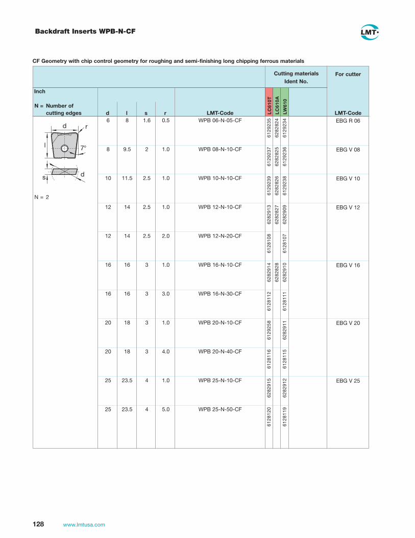
128 www.lmtusa.com
Backdraft Inserts WPB-N-CF
CF Geometry with chip control geometry for roughing and semi-finishing long chipping ferrous materials
WPB 06-N-05-CF
WPB 08-N-10-CF
WPB 10-N-10-CF
WPB 12-N-10-CF
WPB 12-N-20-CF
WPB 16-N-10-CF
WPB 16-N-30-CF
WPB 20-N-10-CF
WPB 20-N-40-CF
WPB 25-N-10-CF
WPB 25-N-50-CF
Inch
N = Number of cutting edges LMT-Code
For cutter
LMT-Code LC
610T
LC
610A
LW
610
6129
235
6282
824
6129
234
6129
237
6282
825
6129
236
6129
239
6282
826
6129
238
6282
913
6282
827
6282
909
6128
108
6128
107
6282
914
6282
828
6282
910
6128
112
6128
111
6129
258
6282
911
6128
116
6128
115
6282
915
6282
912
6128
120
6128
119
d l s r 6 8 1.6 0.5
8 9.5 2 1.0
10 11.5 2.5 1.0
12 14 2.5 1.0
12 14 2.5 2.0
16 16 3 1.0
16 16 3 3.0
20 18 3 1.0
20 18 3 4.0
25 23.5 4 1.0
25 23.5 4 5.0
N = 2
ds
d r
7°l
EBG R 06
EBG V 08
EBG V 10
EBG V 12
EBG V 16
EBG V 20
EBG V 25
Ident No. Cutting materials

129www.lmtusa.com
Copy inserts WPB-N-CF
Inch N = Number of cutting edges d l s r LMT-Code LMT-Code L
C24
0T
LC
610T
LW
610
N = 2
ds
d r
7°l
CF Geometry with chip control geometry for roughing and semi-finishing long chipping ferrous materials
For cutter
0.032
0.063
0.032
0.063
0.032
0.063
0.032
0.063
0.125
0.500
0.500
0.625
0.625
0.750
0.750
1.000
1.000
1.000
WPB 0500-CF-2
WPB 0500-CF-4
WPB 0625-CF-2
WPB 0625-CF-4
WPB 0750-CF-2
WPB 0750-CF-4
WPB 1000-CF-2
WPB 1000-CF-4
WPB 1000-CF-8
EBG V 0500
WPB 0500CF-4
EBG V 0625
EBG V 0750
EBG V 1000
EBG R 0250
EBG R 0375
EBG R 0375
6130
298
6130
872
6130
300
6130
874
6130
301
6130
875
6130
302
6130
876
0.550
0.550
0.625
0.625
0.700
0.700
0.925
0.925
0.925
0.10
0.10
0.12
0.12
0.12
0.12
0.16
0.16
0.16
6130
294
6130
870
6130
879
6130
878
6130
877
6130
295
6128
916
6130
296
6130
869
6130
297
6130
871
6130
299
6130
873
.250 0.063 0.032 WPB 0250-CF-2
.375 0.450 0.080 0.032 WPB 0375-CF-2
.375 0.450 0.080 0.063 WPB 0375-CF-4
Ident No.
Cutting materials
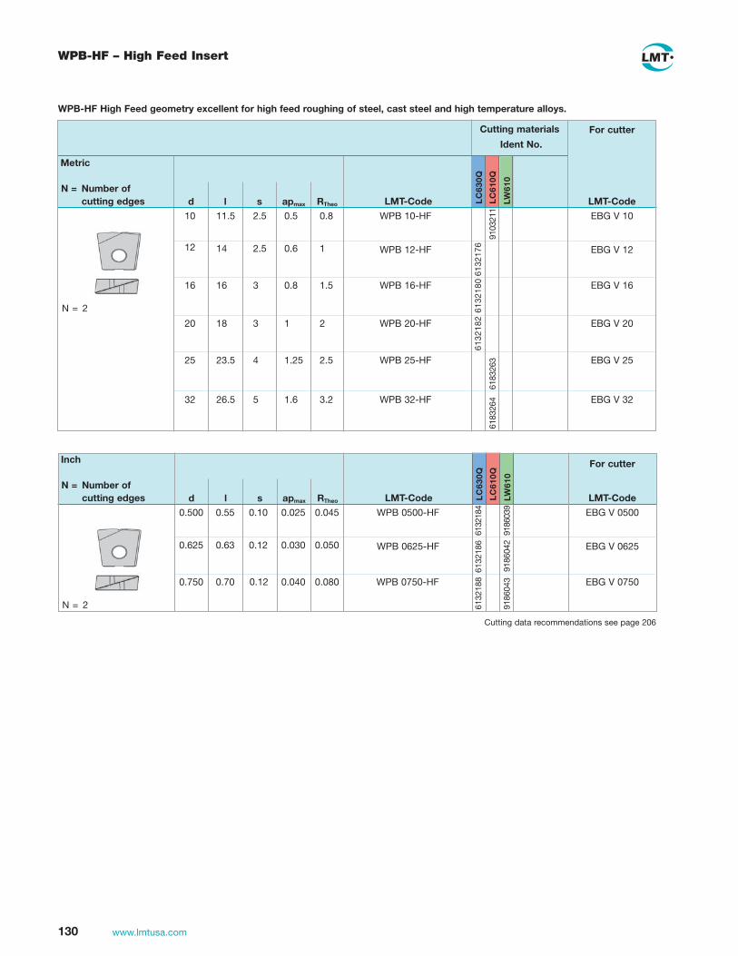
130 www.lmtusa.com
WPB-HF – High Feed Insert
Metric
N = Number of cutting edges
Inch
N = Number of cutting edges
LMT-Code
For cutter
For cutter
LMT-Code LC
630Q
LC
630Q
LC
610Q
LC
610Q
6132
176
N = 2
N = 2
d l s apmax RTheo
6132
180
6132
188
6132
182
6183
264
6183
263
10
12
0.500
0.625
11.5
14
0.55
0.63
2.5
2.5
0.10
0.12
0.5
0.6
0.025
0.030
0.8
1
0.045
0.050
WPB 10-HF
WPB 12-HF
WPB 0500-HF
WPB 0625-HF
EBG V 10
EBG V 12
EBG V 0500
EBG V 0625
16
0.750
16
0.70
3
0.12
0.8
0.040
1.5
0.080
WPB 16-HF
WPB 0750-HF
EBG V 16
EBG V 0750
20 18 3 1 2 WPB 20-HF EBG V 20
25 23.5 4 1.25 2.5 WPB 25-HF EBG V 25
32 26.5 5 1.6 3.2 WPB 32-HF EBG V 32
9103
211
6132
184
9186
039
9186
042
9186
043
LW
610
LW
610
LMT-Code
6132
186
LMT-Code d l s apmax RTheo
WPB-HF High Feed geometry excellent for high feed roughing of steel, cast steel and high temperature alloys.
Cutting data recommendations see page 206
Cutting materials
Ident No.

131www.lmtusa.com
WPB 06-FB-20
WPB 08-FB-30
WPB 10-FB-40
WPB 12-FB-50
WPB 16-FB-70
WPB 20-FB-90
Metric N = Number of cutting edges d l s R
EBG R 10
EBG R 12
EBG R 16
EBG R 20
6 1.6 2
8 2 3
10 11.5 2.5 4 12 14 2.5 5 16 16 3 7 20 18 3 9
LMT-Code
For cutter
LC
240N
LC
240T
LW
240
LW
610
LC
610Z
BN
081
LC
610T
LMT-Code
Inserts Flatball-WPB-FB
WPB-FB Flatball geometry reduces semi-finishing and finishing time with increased step overs in steel, cast steel, high temperature alloys and hardened steel up to 62Rc
EBG R 0500
EBG R 0750
EBG R 1000
Inch N = Number of cutting edges d l s R
0.500 0.551 0.10 0.187 0.750 0.709 0.12 0.312 1.000 0.905 0.16 0.437
LC
240N
LC
240T
LW
240
LW
610
LC
610Z
BN
081
LC
610T
9142
857
9142
858
9142
879
LMT-CodeLMT-Code
WPB 0500 FB 0187
WPB 0750 FB 0312
WPB 1000 FB 0437
WPR-AR (µ-Jet) WPR-FB (FlatBall)
Ball Nose Ball Nose - Torical
Center Ball Nose
Contact pointContact face
Vc: effective
Cutting data recommendations see page 201
Cutting materials
Ident No.
For cutter
9078
091
9078
092
9097
607
9112
332
9112
328
9080
149
9095
870
9097
608
9097
606

132 www.lmtusa.com
EMZ/FMZ Cutters for Non-Ferrous Metals and Plastics
EMZ 90 THRIKZ
20 0.4 30 10 18 M10 10.5 2
25 1.2 40 13.5 21 M12 12.5 2 32 3 50 15 29 M16 17 2 35 3 50 15 29 M16 17 2 42 3 50 15 29 M16 17 3
d1 R l3 l2 d5 d3 d2 h6 z
1048326T8
1048335T15
1044972
10513121045766
EMZ90 V11.020TS030-I
EMZ90 V16.025TF040-IEMZ90 V22.032TH050-IEMZ90 V22.035TH050-IEMZ90 V22.042TH050-I
1043246
1043247104324810432501043249
VPGT 110304-ALM
VPGT 160412-ALMVCGT 220530-ALM
Torx Driver
Insert ScrewCutter Body No. Ident No. Insert
d1 R l3 l2 d5 d3
104497210513121045766
VPGT 110304-ALMVPGT 160412-ALMVCGT 220530-ALM
Torx Driver
Insert ScrewInsert
Cutter Body No. (inches)* Ident No.
0.020.050.120.12
1.181.571.971.97
0.400.530.590.59
M10M12M16M16
0.410.490.670.67
d2h6 z
EMZ 90IKZ
1048326T8
1048335T15
10483261048335
EMZ90 V11.020AJ-I
EMZ90 V16.025AI-IEMZ90 V22.032AG-IEMZ90 V22.035AG-IEMZ90 V22.042AA-I
EMZ90 V11-075SA-IEMZ90 V16-100SA-IEMZ90 V16-100SB-IEMZ90 V16-100WB-IEMZ90 V16-125SB-IEMZ90 V16-125WC-IEMZ90 V16-150SC-IEMZ90 V16-150WC-IEMZ90 V22-125SB-IEMZ90 V22-150SB-I
Torx Driver
Insert ScrewCutter Body No. Ident No. Insert
Overhang and infeed parameters to be choosen in accordance to application.
d1 R l3 l2 l1 d2 z Cutter Body No. (inches)* Ident No. InsertInsert Screw
Torx Driver
90°
l2
25°19°
90°
l2
25°19°
l1
d2
l3
d1
l2R
Rl3l2
d1
d2
d5 d3
1044972
10513121045766
10449721051312
1045766
VPGT 110304-ALM
VPGT 160412-ALMVCGT 220530-ALM
VPGT 110304-ALMVPGT 160412-ALMVPGT 160412-ALMVPGT 160412-ALMVPGT 160412-ALMVPGT 160412-ALMVPGT 160412-ALMVPGT 160412-ALMVCGT 220530-ALMVCGT 220530-ALM
1043242
1043243104324410432511043245
1950290005465119502910054286005429400542870054295005428819502921950293
10483261048335
1950300195030119503021950303
0.710.831.021.02
d1 R l3 l2 l1 d2 z
2222
20 0.4 30 10 175 16 2
25 1.2 40 13.5 200 20 2 32 3.0 50 15 220 25 2 35 3.0 50 15 220 25 2 42 3.0 50 15 220 25 3
0.75 0.02 1.18 0.40 6.75 0.75 2 1.00 0.05 2.00 0.53 8.00 0.75 2 1.00 0.05 1.58 0.53 7.88 1.00 2 1.00 0.05 2.00 0.53 4.28 1.00 2 1.25 0.05 2.00 0.53 8.00 1.00 2 1.25 0.05 2.00 0.53 4.28 1.25 2 1.50 0.05 2.00 0.53 8.00 1.00 2 1.50 0.05 2.00 0.53 4.88 1.25 2 1.25 0.12 2.00 0.59 8.62 1.00 2 1.50 0.12 2.00 0.59 8.62 1.00 2
0.751.001.251.50
EMZ90 V11.075TE-IEMZ90 V16.100TF-lEMZ90 V22 .125TH-IEMZ90 V22 .150TH-l
See page 133 for Inserts Cutting data recommendations starting page 202
See Page 133 for Inserts Cutting data recommendations starting page 202See pages 136-139 for Screw-On Shanks

133www.lmtusa.com
EMZ/FMZ Cutters for Non-Ferrous Metals and Plastics
Cutters for Non-Ferrous Metals and Plastics – Indexable Inserts
VPGT110304-ALM
VPGT160412-ALM
VCGT220530-ALM
EMZ90FMZ90
N = Number of cutting edges l s d d1 r
ISO-Code Cat-No.
Cutting materialsIdent No.
For cutter
Cat-No. LW
610
LC
610T
1069
756
1069
755
1069
758
1069
757
1069
760
1069
759
90°
l2
25°19°
FMZ 90IKZ
d1 R l2 h d2 d5 z1045766
M5
1051312M4
1045766M5
104325310432541043255104325610432571043258
195029400535211950295195029600186800054794195029700547811950298
FMZ90 V22.042AN-IFMZ90 V22.052AN-IFMZ90 V22.066AN-IFMZ90 V22.080AN-IFMZ90 V22.100AN-IFMZ90 V22.125AN-I
FMZ90 V16.150AA-IFMZ90 V16.200AA-IFMZ90 V22.200AA-IFMZ90 V22.250AA-IFMZ90 V22.250FMZ90 V22.300AB-IFMZ90 V22.300ABE-IFMZ90 V22.300ABF-IFMZ90 V22.400AD-I
VCGT 220530-ALM
VPGT 160412-ALM
VCGT 220530-ALM
TorxDriver
Insert ScrewCutter Body No. Ident No. Insert
d1 R l2 h d2 d5 z Cutter Body No. (inches)* Ident No. Insert Ident No. Ident No.
d5
d2
R
l2
h
d1
d
35° l
R
s
d1
7°bei VC_ 15° bei VP_
1048335T15
1048335T15
11.61 3.18 6.35 2.8 0.4 (.457) (.125) (.250) (.110) (.016)
16.60 4.76 9.52 4.4 1.2 (.654) (.187) (.375) (.173) (.047)
22.10 5.56 12.70 5.5 3.0 (.866) (.219) (.500) (.217) (.118)
42 3 15 55 16 32.0 3 52 3 15 55 22 40.0 3 66 3 15 60 27 48.0 4 80 3 15 60 27 60.0 4 100 3 15 65 32 80.0 5 125 3 15 70 40 100.0 6
1.50 0.05 0.53 2.12 0.75 – 3 2.00 0.05 0.53 2.12 0.75 – 4 2.00 0.12 0.59 2.12 0.75 – 3 2.50 0.12 0.59 2.12 0.75 – 4 2.50 0.12 0.59 2.12 1.00 – 4 3.00 0.12 0.59 2.12 1.00 – 3 3.00 0.12 0.59 2.12 1.00 – 4 3.00 0.12 0.59 2.12 1.00 – 5 4.00 0.12 0.59 2.12 1.50 – 5
Cutting data recommendations starting page 202

134 www.lmtusa.com
Indent Dimensions (inches) No. Insert Torx d1 Cutter Body No. No. EDP d2 d4 l1 / h Teeth Insert Screw Driver
1.00 EHD R10 100 SA 6282262 50296 0.75 3.94 2 18574 89978
1.25 EHD R10 125 SB 6282263 50297 1.00 4.73 3
1.50 EHD R10 150 SB 6282264 50298 1.00 4.73 4 R10 10 42 S
2.00 FHD R10 200 AA 6282265 50299 0.75 1.57 5 18575 11171
2.50 FHD R10 250 AA 6282266 50301 0.75 1.57 6
EHD / FHDApplication• Cutter specifically designed for high-speed contouring and face milling of hardened steels, plastic composites, high silicon aluminum
and graphite • Cutter pocket provides secure insert locking and allows 4 indexes (10mm diameter insert) • Cutters manufactured with a run-out accuracy of ± .001" • Inserts are regrindable
EHD/FHD PCD/CBN Copy Face Mills
LMT-Code EDP Ident No. LMT-Code Ident No.
MKL 0 02 B 18574 6280026 DS 04 LR 12C K200527 Differential setting screwMKL 0 03 B 18575 6200041 DS 05 LR 12 C K200528 Differential setting screwT 8, TORX-Screwdriver 6119528
T 10, TORX-Screwdriver 6200042
PCD/CBN Copy Face Mills – Inserts
d s
LMT-Code
R 10 42 S DP 012
R 10 42 SV BN 081
R 10 42 SN BN 081
R 10 42 SN/SV BN 081
sharp
honed
T-land
T-land and honed
Ident No.
6200038
6203893
6203894
6143598
PCD/CBN
PCD
CBN
CBN
CBN
d [mm]
10.0 (.394)
10.0 (.394)
10.0 (.394)
10.0 (.394)
s [mm]
4.2 (.165)
4.2 (.165)
4.2 (.165)
4.2 (.165)
a [°]
11
11
11
11
PCD/CBN Copy Face Mills – Accessories and Spare Parts
h
d4
d1
d3
d2
d1
l1
d3d2
Cutting data recommendations starting page 204
EHD / FHDInch

135www.lmtusa.com
ECG/FCG Finish Line Universal Cutter
Finish Line Universal Cutter – Inserts
Shell Copy CutterMetric
6204
334
6204
103CPHX 080310 S30L62SA 3075 3.18 7.938 1.0
(.125) (.312) (.039)
6204
344CPHX 080310 3.18 7.938 2.0
(.125) (.312) (.079)
s d r ISO-Code Cat-No. LMT-Code LMT-Code
Cutting materialsIdent No.
Insert
LC
610Q
LC
610Z
BN
025
d1 l1 z Cutter Body No. 20 25 2 25 25 3 32 30 4 35 30 4 40 30 5
ECG V08.020TE025-IECG V08.025TF025-IECG V08.032TH030-IECG V08.035TH030-IECG V08.040TH030-I
Ident No. InsertInsert Screw Screw-in extension
62043396204100620410162041026204340
CPHX 080310CPHX 080310CPHX 080310CPHX 080310CPHX 080310
SA3075SA3075S30L62SA3075SA3075
ADT 10 …ADT 12 …ADT 16 …ADT 16 …ADT 16 …
Cutter Body No. 42 16 40 5 52 22 40 6 66 27 50 7
FCG V08.42FN040-IFCG V08.52FN040-IFCG V08.66FN050-I
Ident No. InsertInsert Screw
620434162043426204343
CPHX 080310CPHX 080310CPHX 080310
S30L62SA3075S30L62
d1 d2 h z
d1
h
d2
2dr s
Screw-in Copy CutterMetric
See pages 136-139 for Screw-On Shanks Cutting data recommendations starting page 205
Cutting data recommendations starting page 205
d1
l1

136 www.lmtusa.com
6 6.5 10 9.7 140 53 ADT T06 140 RZ-C 6129285 6 6.5 10 9.7 110 38 ADT T06 110 RZ-C 6129286 6 6.5 12 9.7 162 52 ADT T06 162 RZ-C 6129287 6 6.5 12 9.7 122 37 ADT T06 122 RZ-C 6129288 8 8.5 16 13 177 57 ADT T08 177 RZ-C 6129289 8 8.5 16 13 142 42 ADT T08 142 RZ-C 6129290 10 10.5 20 18 194 78 ADT T10 194 RZ-C 6129291 10 10.5 20 18 144 54 ADT T10 144 RZ-C 6129292 12 12.5 25 21 210 90 ADT T12 210 RZ-C 6129293 12 12.5 25 21 160 60 ADT T12 160 RZ-C 6129294 16 17 32 28 232 99 ADT T16 232 RZ-C 6129295 16 17 32 28 182 59 ADT T16 182 RZ-C 6129296
Cutter Body No. Ident No. Thread Shank M d2 d3 d5 l l2
ADT – Carbide
ThreadM
6 6 8 810101212
Cutter Body No. Ident No.
91119189111919911192091119219111922911192391119249111925
d2 d5
0.26770.26770.35040.35040.43700.43700.51570.5157
0.50000.50000.62500.62500.75000.75001.00001.0000
0.37400.37400.49210.49210.66930.66930.78740.7874
l2
3.03155.00003.93704.92133.70085.66934.09456.0630
ThreadM
ADT T06 110 0375 RZ-CADT T06 140 0375 RZ-CADT T06 122 0500 RZ-CADT T06 162 0500 RZ-CADT T08 142 0625 RZ-CADT T08 177 0625 RZ-CADT T10 144 0750 RZ-CADT T10 194 0750 RZ-CADT T12 160 1000 RZ-CADT T12 210 1000 RZ-C
6 6 6 6 8 810101212
Cutter Body No. Ident No.
9111916911191791119149111915911191291119139111910911191191119089111909
d2
Shankd3 d5
0.26770.26770.26770.26770.35040.35040.43700.43700.51570.5157
0.37500.37500.50000.50000.62500.62500.75000.75001.00001.0000
0.37400.37400.43310.43310.54330.54330.70870.70870.88980.8898
l
4.33075.51184.80316.37805.59066.96855.66937.63786.29928.2677
1.49612.08661.45672.04721.65352.24412.12603.07092.36223.5433
l2 ADT-THR Straight – Inch Shank
ADT-THR Tapered – Inch Shank
ADT T06 125 0500 T-C S.C. ADT T06 175 0500 T-C S.C. ADT T08 150 0625 T-C S.C. ADT T08 175 0625 T-C S.C. ADT T10 150 0750 T-C S.C. ADT T10 200 0750 T-C S.C. ADT T12 160 1000 T-C S.C. ADT T12 210 1000 T-C S.C.
Extensions for Screw-In Type Milling Cutters, Type THR – Carbide
Shankd3
Note: All shanks are h6 tolerance suitable for heat shrinking
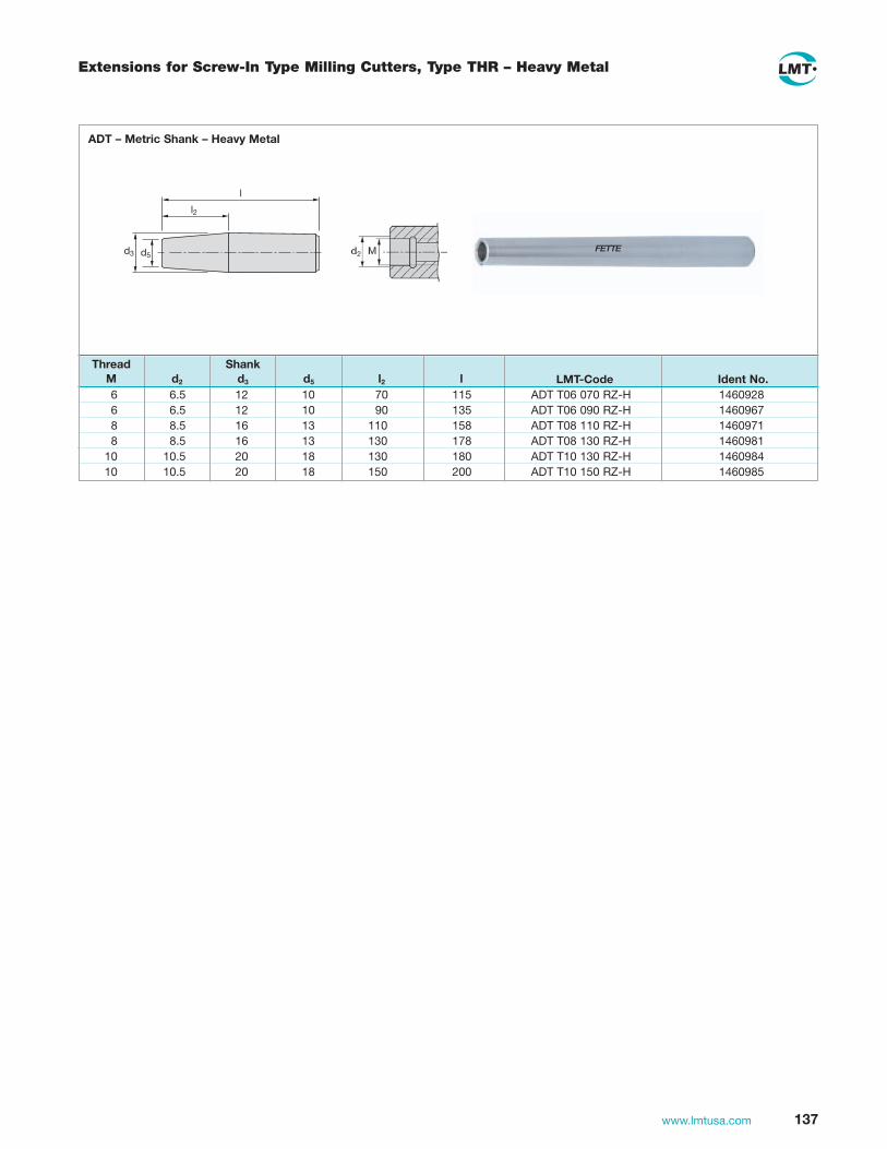
137www.lmtusa.com
6 6.5 12 10 70 115 ADT T06 070 RZ-H 1460928 6 6.5 12 10 90 135 ADT T06 090 RZ-H 1460967 8 8.5 16 13 110 158 ADT T08 110 RZ-H 1460971 8 8.5 16 13 130 178 ADT T08 130 RZ-H 1460981 10 10.5 20 18 130 180 ADT T10 130 RZ-H 1460984 10 10.5 20 18 150 200 ADT T10 150 RZ-H 1460985
Extensions for Screw-In Type Milling Cutters, Type THR – Heavy Metal
LMT-Code Ident No.
FETTE
Thread Shank M d2 d3 d5 l2 l
ADT – Metric Shank – Heavy Metal
d3 d5
l2
l

138 www.lmtusa.com
6 6.5 14 10 16 20 68 ADT T06 068 RZ 1460789 6 6.5 14 10 16 50 98 ADT T06 098 RZ 1460920 6 6.5 18 10 20 75 125 ADT T06 125 RZ 1460922 6 6.5 23 10 25 100 156 ADT T06 156 RZ 1460926 8 8.5 18 13 20 20 70 ADT T08 070 RZ 1460790 8 8.5 18 13 20 50 100 ADT T08 100 RZ 1460929 8 8.5 23 13 25 100 156 ADT T08 156 RZ 1460931 8 8.5 30 13 32 150 210 ADT T08 210 RZ 1460935 10 10.5 18 18 20 20 70 ADT T10 070 RZ 1460791 10 10.5 18 18 20 50 100 ADT T10 100 RZ 1460939 10 10.5 23 18 25 100 156 ADT T10 156 RZ 1460943 10 10.5 30 18 32 150 210 ADT T10 210 RZ 1460945 12 12.5 23 21 25 30 86 ADT T12 086 RZ 1460792 12 12.5 23 21 25 75 135 ADT T12 135 RZ 1460915 12 12.5 30 21 32 125 185 ADT T12 185 RZ 1460917 12 12.5 30 21 32 180 240 ADT T12 240 RZ 1460919 16 17 30 26 32 30 90 ADT T16 090 RZ 1460793 16 17 30 26 32 75 135 ADT T16 135 RZ 1460921 16 17 30 26 32 125 185 ADT T16 185 RZ 1460923 16 17 30 26 32 180 240 ADT T16 240 RZ 1460925
FETTEd2 d5 d6 Md3
l2
l
1)
Thread Shank M d6 d2 d5 d3 l2 l Cutter Body No. Ident No.
ADT – Metric Shank
Dimensions (inches)
Arbor Description EDP M d2 d5 l3 l1 d4
ADT T08 W1000 6280T 12798 M8 0.32 0.48 4.00 6.28 1.00
ADT T08 W1250 8280T 12799 M8 0.32 0.48 6.00 8.28 1.25
ADT T10 W0750 4030T 12800 M10 0.41 0.63 2.00 4.03 0.75
ADT T10 W1000 6280T 12801 M10 0.41 0.63 4.00 6.28 1.00
ADT T10 W1250 8280T 12802 M10 0.41 0.63 6.00 8.28 1.25
ADT T10 W1000 5280T 12803 M12 0.49 0.83 3.00 5.28 1.00
ADT T10 W1250 7280T 12804 M12 0.49 0.83 5.00 7.28 1.25
ADT T10 W1250 9280T 12805 M12 0.49 0.83 7.00 9.28 1.25
ArborsApplication
• HSS Screw-On Extended Length Arbors
Dimensions (inches)
Arbor Description EDP M d2 d5 l3 l1 d4
ADT T16 W1250 5280T 12806 M16 0.67 1.02 3.00 5.28 1.25
ADT T16 W1250 7280T 12807 M16 0.67 1.02 5.00 7.28 1.25
ADT T16 W1250 9280T 12808 M16 0.67 1.02 7.00 9.28 1.25
ADT T16 W1500 5680T 12809 M16 0.67 1.34 3.00 5.68 1.50
ADT T16 W1500 7680T 12810 M16 0.67 1.34 5.00 7.68 1.50
ADT T16 W1500 9680T 12811 M16 0.67 1.34 7.00 9.68 1.50
ADT T16 W1250 3270T 12812 M16 0.67 1.34 1.00 3.27 1.25
d4
l3
d5
l1
d2 M
Extension Arbors for Screw-On Milling Heads
ADT – Inch Shank – HSS
FETTE

139www.lmtusa.com
6 6.5 9.7 25 ADT T06 025 M06 2412415 8 8.5 13 30 ADT T08 030 M08 2412416 10 10.5 18 35 ADT T10 035 M10 1460983 12 12.5 21 40 ADT T12 040 M12 1460975 16 17 29 40 ADT T16 040 M16 1460977
Cutter Body No. Ident No. Thread M d2 d5 l2
ADT-THR
Extension THR-THR
Md2d5
l2
M

140 www.lmtusa.com
Compliment your Mold & Die Tooling with Thermogrip® Shrinking Systems – See Rotating Tool Holder Catalog

Face Milling CuttersSolid Carbide Endmills

142 www.lmtusa.com
MultiEdge 2Feed HSC End Mills
0.2500.2500.3120.3750.500
0.0090.0130.0160.0190.025
1038810390103921039410396
d2 (h6) ap max Length Ident No. d1 Rtheo l2 l1 l3 z d3
22222
short 0.187 0.019 0.075 2.00 0.66 0.16 0.250 0.025 0.104 2.50 0.77 0.21 0.312 0.031 0.120 2.50 0.94 0.26 0.375 0.038 0.136 2.50 1.06 0.31 0.500 0.050 0.167 3.50 1.42 0.42 extra long
ShortShort ShortShort Short
apmax.
1430 C2Feed HSC
λ = 0°DIN 6535 HA
AL2 PlusLC620T
Cat.-No.TypeHelix angleStraight shankCoatingCutting materials
Solid Carbide, center cuttingInch
l1
d2 d1
l2l3
d3 FETTE
Rtheo
0.2500.2500.3120.3750.500
0.0090.0130.0160.0190.025
1038910391103931039510397
22222
0.187 0.019 0.075 3.00 1.50 0.16 0.250 0.025 0.104 3.25 1.75 0.21 0.312 0.031 0.120 3.50 2.10 0.26 0.375 0.038 0.136 4.00 2.25 0.31 0.500 0.050 0.167 4.50 2.50 0.42
Extra LongExtra LongExtra LongExtra LongExtra Long
Material: 4140 Pre-HardHardness: 27-32 HRC
LMT-Fette HSC FEEDTM MillCat. Desc. 1430 HSC FEEDTM MillØ 1/2" 2 fluteCutting Material LC620T
Cutting Datasfm = 1,100rpm = 9,000ipt = .030"ipm = 540woc = .200"doc = .024"
Application Examples
HSC FEED was used instead of a radius end mill for Z-level-roughing of a chissel die.
Feed rate could be doubled to vf (IPM) = 365, without changing speed of
vc (SFM) = 492 and tool life was 4 times higher.
Cutting data recommendations starting on page 206

143www.lmtusa.com
MultiEdge 2Feed HSC End Mills, Extra Short, Short, Long and Extra Long
1 0.1 0.35 40 2 0.8 3 2 0.052 0.2 0.7 40 4 1.6 4 2 0.13 0.3 1 50 6 2.5 6 2 0.154 0.4 1.5 57 8 3.4 6 2 0.25 0.5 2 57 10 4.2 6 2 0.256 0.6 2.5 57 12 5 6 2 0.38 0.8 3 63 16 6.7 8 2 0.410 1 3.5 72 20 8.5 10 2 0.512 1.2 4 83 24 10 12 2 0.614 1.4 4.5 83 28 11.8 14 2 0.7
1300994130099513009961301100130110113011021301103130110413011051301106
1 0.1 0.35 40 4 0.8 3 2 0.05 2 0.2 0.7 40 8 1.6 4 2 0.1 3 0.3 1 57 12 2.5 6 2 0.15 4 0.4 1.5 57 15 3.4 6 2 0.2 5 0.5 2 57 17.5 4.2 6 2 0.25 6 0.6 2.5 57 19 5 6 2 0.3 8 0.8 3 63 24 6.7 8 2 0.410 1 3.5 72 28.5 8.5 10 2 0.512 1.2 4 83 34 10 12 2 0.616 1.6 5.5 92 39 13.5 16 2 0.820 2 7 104 48 17 20 2 1.0
13009971300998130099911101701110171111017211101731110174111017511101761110177
4 0.4 1.5 70 24 3.4 6 2 0.2 5 0.5 2 70 30 4.2 6 2 0.25 6 0.6 2.5 80 35 5 6 2 0.3 8 0.8 3 80 40 6.7 8 2 0.410 1 3.5 90 45 8.5 10 2 0.512 1.2 4 100 50 10 12 2 0.6
130098813009891300990130099113009921300993
4 0.4 1.5 80 34 3.4 6 2 0.2 5 0.5 2 80 37 4.2 6 2 0.25 6 0.6 2.5 80 42 5 6 2 0.3 8 0.8 3 90 51 6.7 8 2 0.410 1 3.5 100 56.5 8.5 10 2 0.512 1.2 4 110 61 10 12 2 0.616 1.6 5.5 130 77 13.5 16 2 0.820 2 7 150 94 17 20 2 1.0
111018011101811110182
11101831110184111018511101861110187
1430 C2Feed HSC
λ = 0°DIN 6535 HA
AL2 PlusLC620T
Cat.-No.TypeHelix angleStraight shankCoatingCutting materials
d1 Rtheo l2 l1 l3 d3 d2 (h6) z ap max. Ident No.
Solid Carbide, center cuttingMetric
l1
d2 d1
l2l3
d3 FETTE
Rtheo
short
long
extra long
extra short
Cutting data recommendations starting on page 206
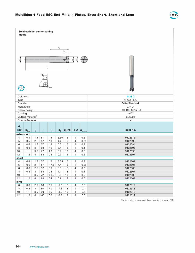
144 www.lmtusa.com
MultiEdge 4 Feed HSC End Mills, 4-Flutes, Extra Short, Short and Long
d3
Solid carbide, center cuttingMetric
Cat.-No. 1431 CType 4Feed HSCStandard Fette-StandardHelix angle = 0°Shank design DIN 6535 HACoating ALXCutting material1) LC620ZSpecial features –
d1 h10 Rtheo l2 l1 l3 d3 d2 (h6) z ap max. Ident No.
extra short51522192.0 4655.3 8755.14.04395221952.0 464.4 017525.0549522193.0 463.5 21755.26.0659522194.0 481.7 613638.0869522195.0 4019.8 02275.310179522196.0 4217.01 423842.121
short20622192.0 4655.3 51755.14.04506221952.0 464.4 5.717525.0560622193.0 463.5 91755.26.0670622194.0 481.7 423638.0880622195.0 4019.8 5.82275.310190622196.0 4217.01 433842.121
long21622193.0 463.553085.26.0631622194.0 481.7040838.0861622195.0 4019.854095.310171622196.0 4217.010500142.121
d2
l1
l3l2
d1d3
Cutting data recommendations starting on page 206

145www.lmtusa.com
DHC End Mills In Operation
7
2
631 5
4
4
DHC Short
DHC Long
1. Shoulder Milling
FETTEDHC-VHM Solid Carbide End Mill – Long
Catalog Number: 1522 Cd1 = 12mm, z = 4Grade: LC630T
Cutting Data:vc = 655 sfm vf = 70 ipmn = 5,300 rpm ae = .354"fz = .0033" fpt ap = .709"
2. Shoulder Milling
FETTEDHC-VHM Solid Carbide End Mill – Short
Catalog Number: 1522 Cd1 = 12mm, z = 4Grade: LC630T
Cutting Data:vc = 655 sfm vf = 199 ipmn = 5,300 rpm ae = .118"fz = .0094" fpt ap = .472"
3. Slot Milling
FETTEDHC-VHM Solid Carbide End Mill – Short
Catalog Number: 1522 Cd1 = 12mm, z = 4Grade: LC630T
Cutting Data:vc = 590 sfm vf = 107 ipmn = 4,775 rpm ae = .472"fz = .0056" fpt ap = .236"
4. Slot Milling
FETTEDHC-VHM Solid Carbide End Mill – Short
Catalog Number: 1522 Cd1 = 12mm, z = 4Grade: LC630T
Cutting Data:vc = 590 sfm vf = 92 ipmn = 4,775 rpm ae = .472"fz = .0048" fpt ap = .472"
5. Slot Milling
FETTEDHC-VHM Solid Carbide End Mill – Long
Catalog Number: 1522 Cd1 = 12mm, z = 4Grade: LC630T
Cutting Data:vc = 590 sfm vf = 45 ipmn = 4,775 rpm ae = .472"fz = .0023" fpt ap = .708"
6. Slot Milling
FETTEDHC-VHM Solid Carbide End Mill – Long
Catalog Number: 1522 Cd1 = 12mm, z = 4Grade: LC630T
Cutting Data:vc = 590 sfm vf = 38.2 ipmn = 4,775 rpm ae = .472"fz = .0020" fpt ap = .944"
7. Shoulder Milling
FETTEDHC-VHM Solid Carbide End Mill – Long
Catalog Number: 1522 Cd1 = 12mm, z = 4Grade: LC630T
Cutting Data:vc = 740 sfm vf = 80 ipmn = 6,000 rpm ae = .020"fz = .0033" fpt ap = .709"
For DHC Endmills See pages 146-147

146 www.lmtusa.com
DHC – End Mills with Variable Helix Angle, 4-flute, Short and Long
l2
d1
l3
l1
d2
21
Edge protection chamfer
d1 b
4 0.15 0.15
6 - 12 0.214 - 20 0.3b
45
Solid carbide, center cutting Metric
Cat.-No. C 2251C 1251Type DHCStandard DIN 6527 A / DIN 6528 DIN 6527 BHelix angle 1 / 2 = 35° / 38°Shank design DIN 6535 HA DIN 6535 HBCoating AL2 PlusCutting material LC630TSpecial features Edge protection chamfer
d1 h10 l2 l1 l3 d2 (h6) .oN tnedI.oN tnedI
short01009110000911684554110091110009116014565210091120009116614576310091130009118028598410091140009110142661101510091150009112162372121610091160009114182574141710091170009116123286161810091180009118143488181910091190009110204290202
long4 8 54 12 6 1110700 11107055 10 54 15 6 1110701 11107066 13 57 21 6 1110223 11102318 19 63 27 8 1110224 1110232
10 22 72 32 10 1110225 111023312 26 83 38 12 1110226 111023414 26 83 38 14 1110227 111023516 32 92 44 16 1110228 111023618 34 92 44 18 1110229 111023720 38 104 54 20 1110230 1110238
Cutting data recommendations starting page 208

147www.lmtusa.com
DHC INOX – End Mills with Variable Helix Angle, 4-flute, Short and Long
λ1λ2
l3l2
d1
l1
d2
Edge protection chamfer
d1 b
4 0.15 0.15
6 - 12 0.214 - 20 0.3b
45
Solid carbide, center cuttingMetric
Cat.-No. C 5651C 5251Type DHC INOXStandard DIN 6527 A / DIN 6528 DIN 6527 BHelix angle 1 / 2 = 41° / 44°Shank design DIN 6535 HA DIN 6535 HBCoating AL2 PlusCutting material LC630TSpecial features Edge protection chamfer
d1 h10 l2 l1 l3 d2 (h6) .oN tnedI.oN tnedI
short25079099107909684554350790902079096014565450790912079096214576550790922079098618598650790932079090102661101750790942079092142372121850790952079094182574141950790962079096123286161060790972079098163488181160790982079090204290202
long7046909693690962145848046909793690965145015904690989369096127531601469099936909872369182146909104690901232722013146909204690921833862214146909304690941833862415146909404690961442923616146909504690981442923817146909604690902454018302
Cutting data recommendations starting page 208
INOX design suited for Stainless Steel and Titanium

148 www.lmtusa.com
HSCline End Mills, Type N, Square End or Ball Nose, Short, up to 52 HRC, for Steel Machining
1410 C
1 1.5 38 2.7 3 2 2 50 3.6 6 3 3 50 5.5 6 4 4 57 14.5 6 4 4 57 14.5 6 5 5 57 21 6 5 5 57 21 6 5 5 57 21 6 6 6 57 21 6 6 6 57 21 6 6 6 57 21 6 6 6 57 21 6 8 8 63 27 8 8 8 63 27 8 8 8 63 27 8 8 8 63 27 8 8 8 63 27 8 10 10 72 32 10 10 10 72 32 10 10 10 72 32 10 10 10 72 32 10 10 10 72 32 10 10 10 72 32 10 12 12 83 38 12 12 12 83 38 12 12 12 83 38 12 12 12 83 38 12 12 12 83 38 12 12 12 83 38 12 16 16 92 44 16 20 20 104 54 20 20 20 104 54 20
1410 C1410 C1410 C1410 C1410 C1410 C1410 C1410 C1410 C1410 C1410 C1410 C
-1410 C1410 C1410 C1410 C
-1410 C1410 C1410 C1410 C1410 C
-1410 C1410 C1410 C1410 C1410 C1410 C1410 C1410 C
112231411223261122338112235011100391110040112236211100411110188111004211223741110044
-1110190112238611100451110046
-11101921110047112239811100481110049
-11101941110050111005111224111110053112242511101971122438
1412 C1412 C1412 C1412 C
-1412 C
--
1412 C---
1412 C----
1412 C-----
1412 C-----
1412 C-
1412 C
1122452112246411224771122490
-1122502
--
1122526---
1122538----
1122550-----
1122562-----
1122574-
1122587
Solid Carbide, center cuttingMetric
1412 C
1410 Cλ= 20°
DIN 6535 HA
1412 Cλ= 20°
DIN 6535 HA
Cat. No. Ident No. Cat. No. Ident No.r0.20.30.40.510.50.610.30.50.81-0.311.52-0.511.31.52-0.511.51.62222.5
r22222222222223333233333233333444
z
LC620T LC620T
l3
d2
l2
r
d1
l1
r
d2
l3
d1
l2
l1
0.51
1.52-
2.5--3---4----5-----6-----8-
10
d1 l2 l1 l3 d2 (h6)
LMT-Code Helix angle Straight shank Cutting material
Cutting data recommendations starting on page 210

149www.lmtusa.com
HSCline End Mills, Typ H, Square End or Ball Nose, Long, 52 – 65 HRC
1450 C
4 4 80 19 6 4 0.5 4 4 80 19 6 4 1 4 4 80 19 6 2 - 5 5 80 44 6 4 0.5 5 5 80 44 6 4 1 5 5 80 44 6 2 - 6 6 80 44 6 4 0.5 6 6 80 44 6 4 1 6 6 80 44 6 2 - 8 8 90 54 8 4 0.5 8 8 90 54 8 4 1 8 8 90 54 8 4 1.5 8 8 90 54 8 4 2 8 8 90 54 8 2 - 10 10 100 60 10 4 0.5 10 10 100 60 10 4 1 10 10 100 60 10 4 1.5 10 10 100 60 10 4 2 10 10 100 60 10 2 - 12 12 110 65 12 4 0.5 12 12 110 65 12 4 1 12 12 110 65 12 4 1.5 12 12 110 65 12 4 2 12 12 110 65 12 2 -
1450 C1450 C
-1450 C
--
1450 C1450 C
-1450 C1450 C1450 C1450 C
-1450 C1450 C1450 C1450 C
-1450 C1450 C1450 C1450 C
-
13012351301236
-13012371301238
-13012391301240
-1301241130124213012431301244
-1301245130124613012471301248
-1301249130125013012511301252
-
1451 C-
1451 C1451 C
-1451 C1451 C
-1451 C1451 C
---
1451 C1451 C
---
1451 C----
1451 C
1301253-
13012541301255
-13012561301257
-13012581301259
---
13012601301261
---
1301262----
1301263
2-2
2.5-
2.53-34---45---5----6
1451 C
LC620T LC620T
1450 Cλ= 20°
DIN 6535 HA
1451 Cλ= 20°
DIN 6535 HA
Cat. No. Ident No. Cat. No. Ident No.r d2
d1 l2 l1 l3 (h6) z r
r
d2
l3
d1
l2
l1l3
d2
l2
r
d1
l1
LMT-Code Helix angle Straight shank Cutting material
Solid Carbide, center cuttingMetric
Cutting data recommendations starting on page 210

150 www.lmtusa.com
Flatball HSC, 2-Flute, Short, Long and Long Reinforced
Solid carbide, center cuttingMetric
Flatball HSC, Zweischneider, kurz, lang und lang verstärktFlatball HSC, 2-flute, short, long and long reinforced
Cat.-No. 1400 CType NStandard Werknorm FETTE StandardHelix angle 20°Shank design DIN 6535 HACoating AL6Cutting material1) LC620QSpecial features –
d1 h7 d1 h10 r ±0.01 l2 l1 l3 d2 (h5) z Ident No.
short 4 1.5 4 57 14 6 2 9123725 5 2 5 57 17 6 2 9123726 6 2 6 57 21 6 2 9123727 8 3 8 63 27 8 2 9123728 10 4 10 72 32 10 2 9123729 12 5 12 83 38 12 2 9123730long
6 2 6 80 44 6 2 9123785 8 3 8 90 54 8 2 9123787 10 4 10 100 60 10 2 9123788 12 5 12 110 65 12 2 9123790long reinforced
6 2 6 90 27 8 2 91237948 3 8 100 32 10 2 9123795
10 4 10 110 35 12 2 912379612 5 12 130 37 16 2 9123797
d2
l1
l3l2
d1
r
Cutting data recommendations starting on page 214

151www.lmtusa.com
Flatball HSC
Cutting data Fette Flatball HSC Competitor 1 Competitor 2
Number of teeth 2 3 4
vc 252 m/min (827 SFM)9500 1/min (6687 RPM)
0.26 mm (.010" FPT)5000 mm/min (196 IPM)
0.3–0.6 mm (.012"-.024" WOC)0.3 mm (.012" DOC)
252 m/min (827 SFM)9500 1/min (6687 RPM)
0.17 mm (.007" FPT)5000 mm/min (196 IPM)
0.3–0.6 mm (.012"-.024" WOC)0.3 mm (.012" DOC)
252 m/min (827 SFM)9500 1/min (6687 RPM)
0.13 mm (.005" FPT)5000 mm/min (196 IPM)
0.3–0.6 mm (.012"-.024" WOC)0.3 mm (.012" DOC)
nfz
vf
ae
ap
Cutting time 2100 min 2100 min 2100 min
Tool life [min] 2800 1800 1800
Surface quality good badbad; tool starts to generale
vibrations after machining ¾
of part only
Form for wheels
Material:St52
Tool:Cat.-No. 1400 C (Flatball HSC)d1 = 12 mm (.472" Dia.)
Cutting material:LC620T
Surface: Finishing
2500
2000
1500
1000
500
0Competitor 2Competitor 1Fette
Flatball HSC
To
ol l
ife[m
in]

152 www.lmtusa.com
AIRline End Mills, with Corner Radius, 2- and 3-Flute, Long
d2h6l3l1l2d1h10 Ident No.Ident No.
internal coolantr + 0.01
0.2500.3750.5000.6250.7501.0000.2500.3750.5000.6250.7501.000
0.2500.3750.5000.6250.7501.0000.2500.3750.5000.6250.7501.000
0.0040.0040.0040.0040.0040.0040.0040.0040.0040.0040.0040.004
0.0040.0040.0040.0040.0040.0040.0040.0040.0040.0040.0040.004
0.6250.8571.1251.2501.5002.0000.6250.8571.1251.2501.5002.000
0.6250.8571.1251.2501.5002.0000.6250.8571.1251.2501.5002.000
2.5003.0003.5004.0004.0004.0002.5003.0003.5004.0004.0004.000
2.5003.0003.5004.0004.0004.0002.5003.0003.5004.0004.0004.000
0.8121.2501.500 1.750 2.1252.7500.8121.2501.500 1.750 2.1252.750
0.8121.2501.500 1.750 2.1252.7500.8121.2501.500 1.750 2.1252.750
0.2500.3750.5000.6250.7501.0000.2500.3750.5000.6250.7501.000
0.2500.3750.5000.6250.7501.0000.2500.3750.5000.6250.7501.000
005372500537260053727005372800537290053730
005373700537380053739005374000537410053742
005375600537200053721005372200537230053734
005373100537320053733005373400537350053736
2 2 3 3 3 32 2 3 3 3 3
2 2 3 3 3 32 2 3 3 3 3
z
l1
d2d1
l2l3
l1
d2d1
l2l3
Cat. No. 1571
Primary Application Aluminum/Thermoplastics
Type SH
Standard DIN 6527 A
Helix Angle λ = 30°
Straight Shank Yes
Coating –
Cutting Materials LW630
Solid carbide, center cutting,Super-fine grain typeInch
Cutting data recommendations starting on page 215
LW630
LC630T

153www.lmtusa.com
AIRline End Mills, with Corner Radius, 2- and 3-Flute
Solid carbide, center cutting,Super-fine grain typeMetric
Cat.-No. 1436 1437Type SHStandard DIN 6527 A/BHelix angle = 20° R. H. Spiral Shank design DIN 6535 HA DIN 6535 HBCoating –Cutting material1) LW630Special features for Aluminium/Thermoplastics machining
d1 h10 r ±0.01 l2 l1 l3 d2 h6 z Ident No. Ident No.
4 0.5 11 57 21 6 2 1110900 11109304 1 11 57 21 6 2 1110901 11109315 0.5 13 57 21 6 2 1110902 11109325 1 13 57 21 6 2 1110903 11109336 0.5 13 57 21 6 2 1110904 11109346 1 13 57 21 6 2 1110905 11109358 0.5 19 63 27 8 2 1110906 11109368 1 19 63 27 8 2 1110907 11109378 1.5 19 63 27 8 2 1110908 1110938
10 1 22 72 32 10 2 1110909 111093910 1.5 22 72 32 10 2 1110910 111094010 2 22 72 32 10 2 1110911 111094112 1 26 83 38 12 3 1110912 111094212 1.5 26 83 38 12 3 1110913 111094312 2 26 83 38 12 3 1110914 111094414 1 26 83 38 14 3 1110915 111094514 2 26 83 38 14 3 1110916 111094614 4 26 83 38 14 3 1110917 111094716 1 32 82 44 16 3 1110918 111094816 2 32 82 44 16 3 1110919 111094916 4 32 82 44 16 3 1110920 111095018 1 32 92 44 18 3 1110921 111095118 2 32 92 44 18 3 1110922 111095218 4 32 92 44 18 3 1110923 111095320 1 38 104 54 20 3 1110924 111095420 2 38 104 54 20 3 1110925 111095520 4 38 104 54 20 3 1110926 111095625 1 45 121 65 25 3 1110927 111095725 2 45 121 65 25 3 1110928 111095825 4 45 121 65 25 3 1110929 1110959
Cutting data recommendations starting on page 215

154 www.lmtusa.com
AIRline End Mills, Ball Nose, 2-Flute, Long and Extra Long
l1
d2 d1
l2l3
Solid carbide, center cutting,Super-fine grain typeMetric
Cat.-No. 1434 1435Type SHStandard DIN 6527 A/BHelix angle = 30° R. H. SpiralShank design DIN 6535 HA DIN 6535 HBCoating –Cutting material1) LW630Special features for Aluminium/Thermoplastics machining
d1 e8 l2 l1 l3 d2 h6 z Ident No. Ident No.
long4 4 57 17 6 2 1110559 11105795 5 57 18 6 2 1110560 11105806 6 57 19 6 2 1110561 11105818 8 63 25 8 2 1110562 1110582
10 10 72 30 10 2 1110563 111058312 12 83 36 12 2 1110564 111058414 14 83 36 14 2 1110565 111058516 16 82 42 16 2 1110566 111058618 18 92 42 18 2 1110567 111058720 20 104 54 20 2 1110568 1110588
extra long4 4 80 28 6 2 1110569 11105895 5 80 29 6 2 1110570 11105906 6 80 30 6 2 1110571 11105918 8 90 44 8 2 1110572 1110592
10 10 100 53 10 2 1110573 111059312 12 110 63 12 2 1110574 111059414 14 110 63 14 2 1110575 111059516 16 130 73 16 2 1110576 111059618 18 130 73 18 2 1110577 111059720 20 150 89 20 2 1110578 1110598
Cutting data recommendations starting on page 215

Technical Data

156 www.lmtusa.com
ISO Insert Designation
Tolerances (inches)
m s d
A ±0.0002
C ±0.0005
E ±0.001
F ±0.0002 ±0.0005
G ±0.001 ±0.005 ±0.001
H ±0.0005 ±0.0005
J ±0.0002
K ±0.0005
L ±0.001
M ±0.005
N ±0.001
U ±0.005
A
(70°–90°)
B
(70°–90°)
C
F
G
(70°–90°)
H
(70°–90°)
J
M
N
(40°–60°)
Q
R
(40°–60°)
T
(40°–60°)
U
(40°–60°)
W
X With special feature to approval drawing
1InsertShape
A
B
C
D
E
H
K
L
M
O
P
R
S
T
V
W
Note 1: In case of more than one angle, always use smallest angle.
2 3ClearanceAngle
αn
A 3°
B 5°
C 7°
D 15°
E 20°
F 25°
G 30°
N 0°
P 11°
O Normal clearance angles, which require a special description.
α n
SeeTable 5
±0.001
Table 4-m
d M, N U
Over Up to .154 .394 ±0.003 ±0.005
.394 .590 ±0.005 ±0.008
.590 .787 ±0.006 ±0.011
.787 1.024 ±0.007 ±0.015
1.024 1.260 ±0.008 ±0.015
Table 5-d
d J, K, L, M U
Over Up to .154 .394 ±0.002 ±0.003
.394 .590 ±0.003 ±0.005
.590 .787 ±0.004 ±0.007
.787 1.024 ±0.005 ±0.001
1.024 1.260 ±0.006 ±0.001
Corner rounding, uneven number of sides
Corner rounding, even number of sides
Chamfered inserts
Cutting Face, Clamp Style
4
d dm
m
d
m
dm
d
s
( ) Cone angle for screw
±0.001
±0.001
1 2 3 4
SeeTable 4
ISO Example S E K N
85°
90°
90°
82°
80°
55°
55°
35°
75°
86°
120°
135°
108°
60°
80°

157www.lmtusa.com
ISO Insert Designation
12 03 AF S N5
Cutting Edge Length
6 7
Thickness
S (Inches)
02 .094
03 .125
T3 .156
04 .187
05 .219
06 .250
07 .312
08 .315
09 .375
Radius inserts
Corner radius-r (Inches)
00 sharp-edged
02 0.007
04 0.015
08 0.031
12 0.047
16 0.062
20 0.078
For chamfer facemilling inserts
Approach angle κr
A 45°
D 60°
E 75°
F 85°
P 90°
Z Special
Cutting Edge Corner
8Cutting Edge Corner*
r
κr
9Direction of Cut*
F E T S K P
Sharp-edged Rounded Chamfered Chamfered and Rounded
Doubled Chamfered
Double Chamfered
and Rounded
R RH cut only L LH cut only N RH and LH cut
* This referenceletter is not always used
l = Length
5 6 7 8 9
A 3°
B 5°
C 7°
D 15°
E 20°
F 25°
G 30°
N 0°
P 11°
O Clearance of face milling edge
A 7 B
BA
L
L
L
l
l
l
l
l
l
l
l06 .25007 .31209 .37511 .43312 .50015 .62516 .64919 .75022 .86625 1.0031 1.2538 1.50

158 www.lmtusa.com
LMT Insert Grades
Description of cutting materials for mold and die industry
Cutting material grades
LC225S HC-P25 PVD-TiCN Plus coated Highly wear-resistant multiple-application grade with high toughness For wet and dry milling of steel, stainless cast steel and cast iron High cutting speeds Low to medium cut depths Low to medium chip load
LC225T HC-P25 PVD TiAIN Al2Plus coated Highly wear-resistant multiple-application grade with high toughness For wet and dry milling of steel, cast steel and cast iron High cutting speeds Low to medium depths of cut Low to medium chip load
LC230F The very tough carbide substrate guarantees this universal steel milling grade’s high machining security for a from soft gummy carbon steels to alloy tool steels and alternative for Austenitic Stainless. A modern MT-CVD multilayer Al2O3 – coating ensures dry machining. An outer TiN layer makes wet machining also possible.
LC240S HC-P40 PVD TiCN Plus coated Wear-resistant grade with high toughness for wet and dry milling of steel, stainless steel, cast steel and cast iron Medium cutting speeds Medium to high chip load
LC240T HC-P40 PVD TiAIN Al2Plus coated Wear-resistant grade with high toughness, for wet and in particular dry milling of steel, cast steel and cast iron Medium to high cutting speeds Medium to high load
LC280QN HC-P40 PVD TiAIN Al2Plus/TiN double coated Wear-resistant grade with high toughness and particularly stable micro-geometry, for wet and particular dry milling of steel
and cast steel, unstable conditions Medium to high cutting speedsHighest chip loadHigh chip load
LC603Z HC-K03 PVD-TiAlN AlX coated Extremely wear-resistant grade, particularly suitable for finishing of cold and hot forming tool steel. Suitable for hard
machining. Also suitable for cast iron and non-ferrous metalsHigh cutting speeds. Low chip-forming cross-sectionsLow to medium chip load
LC610A HC-K10 CVD diamond coated Diamond-coated carbide for graphite machining suitable for roughing and finishing, can be used for 3- and 5-axis as well
as for high speed cutting
LC610Q HC-K 10 PVD- AL Cr N coated Highly wear-resistant coated milling grad with high cutting edge stability for fine machining alloyed and unalloyed tool
steels. High stability and wear-resistance specifically by high temperatures. Suitable for dry machining and high speed cutting up to 54 HRC.Low to medium depths of cutLow to medium chip load
LC610Z HC-K 10 fine-grain PVD TiAIN AIX coated Highly wear-resistant grade with high toughness for wet and dry machining of steel, cast steel, cast iron and non-ferrous
metals. Especially suitable for hard machining of materials > 56 HRC
LC610W HC-K 10 PVD TiCN coated Highly wear-resistant coated milling grade with high cutting edge stability for fine machining of alloyed and unalloyed tool
steels, high-strength materials and cast iron at medium cutting speeds.Low to medium depths of cut Low to medium chip load
LC610T HC-K 10 PVD TiAIN Al2Plus coated Highly wear-resistant coated milling grade with high cutting edge stability for fine machining of alloyed and unalloyed tool
steels, high-strength materials, non-ferrous metals and cast iron at high cutting speeds.Low to medium depths of cut Low to medium chip load

159www.lmtusa.com
LMT Insert Grades
Description of cutting materials for mold and die industry
Cutting material grades
LC620T HC-K20 fine-grain PVD TiAIN Al2Plus coated Highly wear-resistant grade with high toughness for wet and dry machining of steel, cast steel, cast iron and non-ferrous
metals. Suitable also for hard machiningMedium to high cutting speedsMedium depths of cut, Medium tooth feeds
LC620Z HC-K20 fine-grain PVD TiAIN AlX coated Highly wear-resistant grade with high toughness for wet and dry machining of steel, cast steel, cast iron and non-ferrous
metals. Suitable also for hard machiningMedium to high cutting speedsMedium depths of cut, Medium chip load
LC630T HC-K30 TiAIN AL2Plus coated Highly wear-resistant milling grade with high cutting edge stability for machining of alloyed and unalloyed tool steels,
high-strength materials, stainless steels and cast iron at medium cutting speedsMedium depths of cut Medium chip loads
LC630Q HC-K30 PVD-AL Cr N coatedHighly wear-resistant milling grade with high toughness for dry machining alloyed and unalloyed steels up to 54 Rc and cast iron at medium cutting speedsMedium Depths of CutMedium to Heavy Chip loads
LC730Q HC-K30-UF PVD-AL Cr N coated Highly wear-resistant ultra fine grain milling grade with high toughness for dry machining alloyed and unalloyed steels up
to 54 Rc and cast iron at medium cutting speedsMedium Depths of CutMedium to Heavy Chip loads
LC730T HC-K30-UF PVD-TiAlN Al2 Plus coatedHighly wear-resistant ultra fine grain milling grade with high toughness for dry machining alloyed and unalloyed steels up to 54 Rc, high strength materials and cast iron at high cutting speedsMedium Depths of CutMedium to Heavy Chip loads
LC730Z HC-K20 fine-grain PVD TiAIN AIX coated Highly wear-resistant ultra fine grain grade with high toughness for wet and dry machining of steel, cast steel, cast iron and
non-ferrous metals. Suitable also for hard machiningMedium to high cutting speedsMedium depths of cut, Medium chip load
LW225 HW-P25 uncoated Wear-resistant, uncoated multiple-application material with high strength, for wet and dry milling of alloyed materials (cast
iron, in some cases also nodular cast iron)Moderate cutting speedsLow to medium depths of cutLow to medium chip load
LW 240 HW-P40 uncoated Extra-tough uncoated carbide grade for medium to heavy milling of steel and cast steel
Low to medium cutting speedsMedium to high chipFor wet and dry milling
LW 610 HW-K 10 micro-grain uncoated Milling grade with high wear resistance for machining of grey cast iron, aluminium alloys, and non-ferrous metals at
medium to higher cutting speeds, even under unfavourable machining conditions
DP Polycrystalline diamond (PCD) Highly wear-resistant uncoated milling grade for machining of aluminium, bronze, non-ferrous metals, fibre-reinforced
composite materials, plastics, certain ceramics and carbides (soft, prior to sintering) at high cutting speedsLow to medium depths of cut Low to medium chip load
BN Cubical boron nitride (CBN) Very highly wear-resistant uncoated milling grade for machining of hardened materials with HRC >45, cast iron at high
cutting speedsLow to medium depths of cut Low to medium chip load

160 www.lmtusa.com
Insert Grade Designation
LW610F
LW610
LW630F
LC225S
LC444W
LC440T
LC240S
LC240T
LC430T
LC435I
LC630T
LW630F
LC610Z
LC610T
LC225S
LC225T
LC240S
LC230F
LC240T
LC280TT
LC615E
LC610Q
LC610T
LC630S
LC225S
LC630T
C1 40 30 20 10 05 40 30 20 10 05 50 40 30 20 10 05
C2 C3 C4 C5 C5 C5 C5 C6C5 C8ANSIISO
Cla
ssifi
cati
on M
ater
ial
C7C5 C6
SteelStainless
Co
ated
Unc
oat
ed
Cast IronK PM
Toughness
Wear Resistance
Toughness
Wear Resistance
Toughness
Wear Resistance
LC225S
L = LMT
The LMT grade designation system constitutes a simple key. In accordance with ISO standards, it describes the material in an application-oriented way.
Material Code W = Uncoated carbide grades T = Titanium based carbides C = Coated carbide grades
Code for Main Cutting Group 2 = Steel (P) 4 = Stainless (M) 6 = Cast Iron (K)
Toughness according to ISO05-40
Code for Coating Types E = CVD
TiCN/TiC/Al2O3(2X) F = CVD
TiCN/AlO2 AlO3/TiN I = CVD
TiN/TiC/TiN M = Plasma CVD
TiAIN N = PVD
TiN S = PVD
TiCN plus (TiCN/TiN) T = PVD
TiAIN (Multi-layer w/TiN) TT = PVD
TiAIN (Multi-layer w/TiN)/TiN

161www.lmtusa.com
Har
d m
ater
ials
Gre
y ca
st ir
on
Sta
inle
ss
Ste
el
P M K HN
Hig
h te
mpe
ratu
re
mat
eria
ls
S
Group of Materials
Grade
05 15 25 35 45 01 10 20 30 40 50
Range of Applications
HC-P30
HC-M30
HC-P25
HC-M25
HC-K25
HC-P25
HC-P40
HC-M40
HC-P40
HC-M40
HC-P40
HC-K25
HC-P20
HC-K15
HC-M40
HC-M40
HC-K10
HC-K10
HC-P10
HC-M10
HC-K10
HC-K01
1) Also usable for threading
Main application Further application
2) Preferably for dry machining with high cutting speeds
HC-K10
ISO Non
ferr
ous
mat
eria
ls
HC-K03
graphite
LC240T
LC280TTLC280QN
LC240S
LC230F
LC225T
LC444W
LC610E
LC610T
LC610A
LC615E
LC610Q
LC603Z
LC225S 1)
LC630T
LC440T 2)
Coated LMT Milling Grades
HC-K10

162 www.lmtusa.com
Conversion millimeter – inches
Diameters
doc
Multiply ByExample
Legend
To Obtainmeters/seconds
inches
millimeters
5" cutter diameter
8 teeth in cutter
550 sfm
.008 ipt
doc = axial depth of cut woc = radial width of cut
e = spindle efficiency (varies 75% to 90%)
k = a power factor that represents the number of cubic
inches of metal per minutes that can be removed
by one horsepower.
nt = number of effective teeth or inserts in a cutter body
D = cutter diameter
rpm = 3.82 x 550 ÷ 5 = 420
ipm = .008 x 8 x 420 = 26.9
ipr = 26.9 ÷ 420 = .064
SFM (feet/minute)
millimeters
inches
3.281
25.4
.03937
sfm= .262 x rpm x Drpm= 3.82 x sfm ÷ Dipr= ipm ÷ rpmipm= lpt x nt x rpmipt= ipm ÷ (nt x rpm)mrr= doc x woc x ipm = cu. inches/min.HPc= mrr÷ kHPm= hpc ÷ e
Conversion Charts Formulas
Speed
Surface Finish (RA)Chipload IPT
mm1234568
1012141618202532405052636680
100125160200250315400500
inch0.0390.0790.1180.1570.1970.2360.3150.3940.4720.5510.6300.7090.7870.9841.2601.5751.9692.0472.4802.5983.1503.9374.9216.2997.8749.843
12.40215.74819.685
Surface feet per minuterevolutions per minuteinch per revolution(feed rate) inch per minuteinch per tooth (chip load)metal removal rate
horse power at cutterhorse power at motor
mm0.2540.3810.7621.2702.5403.1753.8106.3509.525
12.700
sfm300400500600800
1000120020004000
10000
inch.010.015.030.050.100.125.150.250.375.500
m/min91
122152183244305366610
12193048
mm/T0.0760.1020.1270.1520.1780.2030.2290.2540.2790.305
Inch/T.003.004.005.006.007.008.009.010.011.012
um12.56.33.21.60.80.4
uinch500250125633216
Formulas/Cutting Data Charts
Hardness “K” BHN factor
Work Material“K” Factors
85-200 1.64 201-253 1.58
steel, wrought and cast 254-288 1.28(plain carbon, 287-327 1.10alloy steels, 328-371 .88and tool steels) 372-481 .69 492-550 .59 561-515 .54precipitation, 150-450 1.27-.42hardening stainless steels 150-175 2.27 110-190 2.00cast irons 176-200 1.89(grey, ductile and malleable) 201-250 1.52 251-300 1.27 301-320 1.19stainless steels, wrought 135-275 1.54-.76 and cast (ferritic, austenitic, 288-421 .74-.50 & martensitic)titanium 250-375 1.33-.87high-temperature 200-380 .83-.48 alloys nickel, and cobalt basediron base 180-320 .91-.53nickel alloys 80-360 .91-.53
aluminum alloys 30-150 6.25-3.33 (500kg)
magnesium alloys 40-90 10.0-6.67 (500kg)copper 150 3.33
copper alloys 100-150 3.33 151-240 2.0

163www.lmtusa.com
Hardness Comparison Chart
255 80 76 270 85 80.7 285 90 85.5 305 95 90.2 320 100 95 335 105 99.8 350 110 105 370 115 109 385 120 114 400 125 119 415 130 124 430 135 128 450 140 133 465 145 138 480 150 143 495 155 147 510 160 152 530 165 156 545 170 162 560 175 166 575 180 171 595 185 176 610 190 181 625 195 185 640 200 190 660 205 195 675 210 199 690 215 204 705 220 209 720 225 214 740 230 219 755 235 223 770 240 228 20.3 785 245 233 21.3 800 250 238 22.2 820 255 242 23.1 835 260 247 24 850 265 252 24.8 865 270 257 25.6 880 275 261 26.4 900 280 266 27.1 915 285 271 27.8 930 290 276 28.5 950 295 280 29.2 965 300 285 29.8 995 310 295 31 1030 320 304 32.2 1060 330 314 33.3 1095 340 323 34.4
Tensible Vickers Brinell Rockwell strength Rm hardness hardness hardness N/mm2 HV HB HRC
1125 350 333 35.5 1155 360 342 36.6 1190 370 352 37.7 1220 380 361 38.8 1155 390 371 39.8 1290 400 380 40.8 1320 410 390 41.8 1350 420 399 42.7 1385 430 409 43.6 1420 440 418 44.5 1455 450 428 45.3 1485 460 437 46.1 1520 470 447 46.9 1555 480 (456) 47.7 1595 490 (466) 48.4 1630 500 (475) 49.1 1665 510 (485) 49.8 1700 520 (494) 50.5 1740 530 (504) 51.1 1775 540 (513) 51.7 1810 550 (523) 52.3 1845 560 (532) 53.0 1880 570 (542) 53.6 1920 580 (551) 54.1 1955 590 (561) 54.7 1995 600 (570) 55.2 2030 610 (580) 55.7 2070 620 (589) 56.3 2105 630 (599) 56.8 2145 640 (608) 57.3 2180 650 (618) 57.8 660 58.3 670 58.8 680 59.2 690 59.7 700 60.1 720 61 740 61.8 760 62.5 780 63.3 800 64 820 64.7 840 65.3 860 65.9 880 66.4 900 67 920 67.5 940 68
Tensible Vickers Brinell Rockwell strength Rm hardness hardness hardness N/mm2 HV HB HRC
Tensible strength Rm N/mm2
Vickers hardness HV Diamond pyramid 136°, Test force F = 98 N
Brinell hardness HB 0.102 x F/D2 = 30 N/mm2
Calculated from: HB = 0.95 x HV F = Test force in N, D = Ball diameter in mm
Hardness Rockwell C HRC Diamond cone 120°, Total test force 1471 ± 9 N

164 www.lmtusa.com
H
S
N
K
P
M
Plain Carbon steel 1018, 1025, < 20 520 790 490 720 390 520
Free Machining steel 1212, 12L13 < 20 520 790 490 720 390 520
Structural alloy steel 1040, 4130 < 30 520 790 490 720 390 520
Heat-treatment steel, 4140, 6150 < 30 490 620 430 520 360 460
medium strength 4340, 8740 490 620 430 520 360 460
Cast Steel 52100, 8620 < 30 490 620 430 520 360 460
Caste hardening steel 410, 430F, 440 < 30 - - - - - -
Stainless steel, 4140, 8740 < 30 520 720 430 590 330 460
ferritic 430 590 330 460 260 360
martensitic 390 520 300 430 230 330
Heat treatment steel, A355 28 - 44 - - - - - -High strength
Nitriding Steel H13, D2 28 - 44 390 520 300 430 230 330
Tool Steel 1018, 1025, 28 - 44 390 520 300 430 230 330
Stainless steel, 304, 316 < 30 390 590 - - - -austenitic Maraging steel
Grey cast iron A319, J431 < 27 - - - - - - No. 25B, No. 50B
Alloyed grey cast iron A434, A436-72 < 22 - - - - - -
Nodular cast iron A536 (80-55-06), J434 < 34 490 620 410 540 340 460
Malleable cast iron A220, 50005 < 29 - - - - - - A47,32510
Pure metals, soft Pure Iron, Lead < 20 - - - - - -
Aluminum alloys, 6061, 7050 < 20 - - - - - -long chipping
Aluminum alloys, A356, 4218 < 20 - - - - - -short chipping
Copper alloys, C27200, B-148-52 < 20 - - - - - -long chipping
Copper alloy, < 20 - - - - - -short chipping
Magnesium alloys B94, M11910 - - - - - -
Thermoplastics PVC, Acrylic glass - - - - - -
Duroplastics Durolite, Ampal - - - - - -
Graphite - - - - - -
Titanium alloys, F67, B265 < 29 - - - - - -medium strength
Titanium alloys, Ti-6Al-4V 27 - 44 - - - - - -high strength Alloy
Nickel based alloys 20Cb3 < 29 - - - - - -medium strength
Heat resistant nickel Inconel 718 27 - 44 - - - - - -based alloys high strength
Chilled cast iron Ampco 25 < 20 - - - - - -
Hardened steel 45 - 52 - - - - - -
53 - 59
60 - 65
LC225T, LC225SCutting Data Recommendations
Feed per Tooth (fZ) / SFM
0.003 - 0.006 0.006 - 0.014 0.014 - 0.020
Material Examples Rockwell C
Wet machining Dry machining

165www.lmtusa.com
LC230FCutting Data Recommendations
N
M
K
H
S
P
Plain Carbon steel 1018, 1025, < 20 460 750 360 520 390 660
Free Machining steel 1212, 12L13 < 20 460 750 360 520 390 660
Structural alloy steel 1040, 4130 < 30 460 750 360 520 390 660
Heat-treatment steel, 4140, 6150 < 30 390 560 300 390 390 490 medium strength
Cast Steel 4340, 8740 < 30 390 560 300 390 390 490
Case hardening steel 52100, 8620 < 30 390 560 300 390 390 490
Stainless steel, 410, 430F, 440 < 30
ferritic, 490 520 330 460 430 560
martensitic 360 520 260 360 330 460
Heat treatment steel, 4140, 8740 28 - 44 390 520 260 360 330 460 High strength
Nitriding Steel A355 28 - 44 390 520 260 360 330 460
Tool Steel H13, D2 28 - 44 390 520 260 360 330 460
Stainless steel 304, 316 < 30 260 520 - - - -austenitic
Maraging steel
Grey cast iron A319, J431 < 27 - - - - - - No. 25B, No. 50B
Alloyed grey cast iron A434, A436-72 < 22 - - - - - -
Nodular cast iron A536 (80-55-06), J434 < 34 490 590 310 430 430 520
Malleable cast iron A220, 50005 < 29 - - - - - - A47,32510
Pure metals, soft Pure Iron, Lead < 20 - - - - - -
Aluminum alloys, 6061, 7050 < 20 - - - - - -long chipping
Aluminum alloys, A356, 4218 < 20 - - - - - -short chipping
Copper alloys, C27200, B-148-52 < 20 - - - - - -long chipping
Copper alloy, < 20 - - - - - -short chipping
Magnesium alloys B94, M11910 - - - - - -
Thermoplastics PVC, Acrylic glass - - - - - -
Duroplastics Durolite, Ampal - - - - - -
Graphite - - - - - -
Titanium alloys, F67, B265 < 29 - - - - - -medium strength
Titanium alloys, Ti-6Al-4V 27 - 44 - - - - - -high strength Alloy
Nickel based alloys 20Cb3 < 29 - - - - - -medium strength
Heat resistant nickel Inconel 718 27 - 44 - - - - - -based alloys high strength
Chilled cast iron Ampco 25 < 20
Hardened steel 45 - 52 - - - - - -
53 - 59
60 - 65 - - - - - -
Feed per Tooth (fZ) / SFM
0.003 - 0.006 0.006 - 0.014 0.014 - 0.020
Material Examples Rockwell C
Wet machining Dry machining

166 www.lmtusa.com
H
S
N
K
M
P
Plain Carbon steel 1018, 1025, < 20 690 870 540 720 430 570
Free Machining steel 1212, 12L13 < 20 690 870 540 720 430 570
Structural alloy steel 1040, 4130 < 30 690 870 540 720 430 570
Heat-treatment steel, 4140, 6150 < 30 560 710 440 590 360 480medium strength
Cast Steel 4340, 8740 < 30 560 710 440 590 360 480
Caste hardening steel 52100, 8620 < 30 560 710 440 590 360 480
Stainless steel, 410, 430F, 440 < 30 560 710 440 590 360 480ferriticmartensitic
Heat treatment steel, 4140, 8740 28 - 44 490 620 390 520 310 430High strength
Nitriding Steel A355 28 - 44 490 620 390 520 310 430
Tool Steel H13, D2 28 - 44 490 620 390 520 310 430
Stainless steel 304, 316 < 30 750 950 590 790 480 620austentic
Maraging steel 750 950 590 790 480 620
Grey cast iron A319, J431 < 27 690 870 540 720 430 570 No. 25B, No. 50B
Alloyed grey cast iron A434, A436-72 < 22 560 710 440 590 360 480
Nodular cast iron A536 (80-55-06), J434 < 34 490 620 390 520 310 430
Malleable cast iron A220, 50005 < 29 490 620 390 520 310 430 A47,32510
Pure metals, soft Pure Iron, Lead < 20
Aluminum alloys, 6061, 7050 < 20long chipping
Aluminum alloys, A356, 4218 < 20short chipping
Copper alloys, C27200, B-148-52 < 20long chipping
Copper alloy, < 20Short chipping
Magnesium alloys B94, M11910
Thermoplastics PVC, Acrylic glass
Duroplastics Durolite, Ampal
Graphite
Titanium alloys, F67, B265 < 29medium strength
Titanium alloys Ti-6Al-4V 27 - 44high strength Alloy
Nickel based alloys 20Cb3 < 29 230medium strength
Heat resistant nickel Inconel 718 27 - 44 160based alloys high strength
Chilled cast iron Ampco 25 < 20 160
Hardened steel 45 - 52 160
53 - 59
60 - 65
Feed per Tooth (fZ) / SFM
0.003 - 0.006 0.006 - 0.014 0.014 - 0.020
Material Examples Rockwell C
Wet machining Dry machining
LC240TCutting Data Recommendations

167www.lmtusa.com
H
K
M
P
Unalloyed tool steel 1045, W1 900
Heat – treatable die steels 1212, 12L13 820
Case hardening steels 1040, 4130 900
Full hardening tool steels O2, D2, D3, H13, H11 650
Nitriding steels H13, 6150, A355 Cl C 575
Stainless steel, 316L 820austenitic 304
Maraging steel
Grey cast iron and Alloyed grey cast iron No. 35B 750
Nodular cast iron and Alloyed nodular cast iron 60-40-18 650
Chilled cast iron 590
Hardened steel 45-52 Rc 450
Cutting Data Recommendations for Copying-Cutters for Roughing with LC280TT
Material Examples SFM
LC280TT / LC280QNApplication Data
Ø inch cutter 1.625-3.00 1.625-5.00 .500-1.50 1.00-6.00
Insert RDKT RCKX RDKT SNKT ISO-Code RDHW RCKT RDHW SNKX RDHX OCKX RDHX
Insert Size mm 10 12 16 10 12 16 7 8 10 12 9.52 12.7
Insert Size inch .394 .472 .630 .394 .472 .630 .276 .315 .394 .472 .375 .500
Max ap .098 .118 .197 .098 .118 .197 .059 .098 .098 .118 .197 .276
.010 .016 .018 .010 .016 .018 .012 .010 .010 .016 .016 .020
.005 .006 .008 .005 .006 .008 .004 .004 .005 .006 .006 .006
.016 .016 .016 .012 .016 .016 .010 .012 .014 .016 .020 .024 .012 .012 .012 .010 .012 .012 .006 .008 .010 .012 .010 .012
Cutter Type FCZ FCT ECZ FMT45 FCZ R10 FCT45 FCT45XX ECZR07 FMT45 S09 FCZ R12 ECZ R08 FMT45 S12 FCZ R16 ECZ R10 ECZ R12
Recommended maximum feed per tooth (fZ) for inserts
PMK
H

168 www.lmtusa.com
LC430T, LC440TCutting Data Recommendations
S
M
Austenitic 303, 304, 304L, < 20 260 - 525 229 - 460 316, 316L
316Ti, 318, 321, 347, < 20 230 - 410 165 - 395 348
Austenitic hardened 309, 310S, 630, 230 - 330 J775 (SAE)
Duplex 329 230 - 395(austenitic/ferritic)
Heat resistant alloys
Ni- or Co-basis Inconel 718, Incoloy 925 32 - 38 130 - 230 95 - 195
Titanium alloys:
Alpha- + Beta-alloys Ti -6Al-4V < 32 150 - 195 130 - 180
Austenitic 303, 304, 304L, < 20 820 - 1050 660 - 920 316, 316L, 321, 347
Austenitic hardened 309, 310S, 630, < 20 660 - 920 - J775(SAE)
Duplex 329 < 20 660 - 920 -(Austentic / ferritic)
Dry machining For ferritic and martensitic stainless steels we recommend grade LC230F (preferably dry machining)
M
Feed per Tooth (fZ) / SFM
0.003 - 0.006 0.006 - 0.014
Material Examples Rockwell C
LC444W Cutting Data Recommendations
Wet machining For ferritic and martensitic stainless steels we recommend grade LC230F (preferably dry machining)
Feed per Tooth (fZ) / SFM
0.003 - 0.008 0.009 - 0.016
Material Examples Rockwell C

169www.lmtusa.com
Feed per tooth (fz) Cutting speed (vc)
Roughing Finishing
vc fz fz
Plain carbon steel 1018, 1025
Heat-treatable 4140, 6150die steels
Case hardening 5115, 8620steelsFull hardening 4140, 8740, 4340tools steels
Nitriding steels A355, H13, D2
Stainless steel, 304, 316austenitic
Grey cast iron and A159, J431, G3500, alloyed grey cast iron A436-725
Nodular cast iron and A220, F2000, 5005alloyed nodular cast ironHardened steel
HardnessMaterial
No.ExamplesMaterial
45-52HRC
53-59HRC
60-65HRC
525 .0059 .0078 .0098 787 .004 .0078 .0098
394 .004 .0059 .0078 689 .004 .0078 .0098
– 590 .004 .0078 .0098
d4 = d4 = d4 = .188" to .3125" .375" to .500" > .625"
d4 = d4 = d4 = .188" to .3125" .375" to .500" > .625"
P
M
K
H
LC603Z, LC610Z, LC730ZCutting Data Recommendations
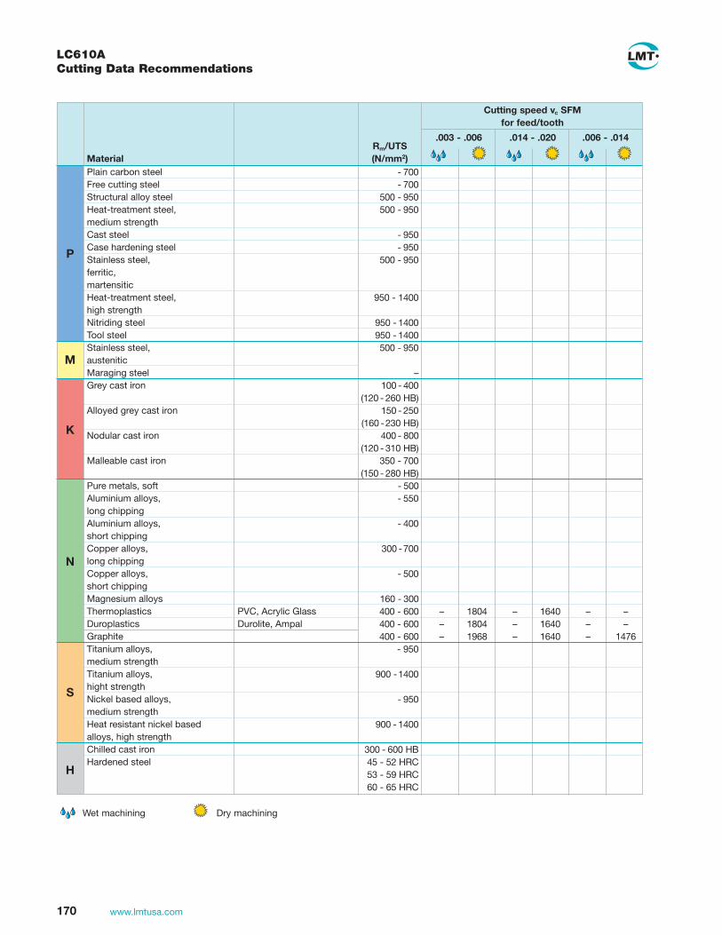
170 www.lmtusa.com
LC610ACutting Data Recommendations
Wet machining Dry machining
Cutting speed vc SFMfor feed/tooth
.003 - .006 .014 - .020 .006 - .014Rm/UTS(N/mm2)
Plain carbon steelFree cutting steelStructural alloy steelHeat-treatment steel, medium strengthCast steelCase hardening steel Stainless steel, ferritic,martensiticHeat-treatment steel, high strengthNitriding steelTool steelStainless steel,austeniticMaraging steelGrey cast iron
Alloyed grey cast iron
Nodular cast iron
Malleable cast iron
Pure metals, softAluminium alloys, long chippingAluminium alloys,short chippingCopper alloys,long chippingCopper alloys,short chippingMagnesium alloysThermoplastics PVC, Acrylic GlassDuroplastics Durolite, AmpalGraphiteTitanium alloys,medium strengthTitanium alloys,hight strengthNickel based alloys,medium strengthHeat resistant nickel basedalloys, high strengthChilled cast ironHardened steel
Material - 700 - 700 500 - 950 500 - 950
- 950 - 950 500 - 950
950 - 1400
950 - 1400 950 - 1400 500 - 950
– 100 - 400 (120 - 260 HB) 150 - 250 (160 - 230 HB) 400 - 800 (120 - 310 HB) 350 - 700 (150 - 280 HB) - 500 - 550 - 400 300 - 700 - 500 160 - 300 400 - 600 – 1804 – 1640 – – 400 - 600 – 1804 – 1640 – – 400 - 600 – 1968 – 1640 – 1476 - 950
900 - 1400
- 950
900 - 1400
300 - 600 HB 45 - 52 HRC 53 - 59 HRC 60 - 65 HRC
P
M
K
N
S
H

171www.lmtusa.com
LC610T, LC610QCutting Data Recommendations
P
M
K
N
S
H
Plain Carbon steel 1018, 1025, < 20 940 1180 740 980 590 790
Free Machining steel 1212, 12L13 < 20 940 1180 740 980 590 790
Structural alloy steel 1040, 4130 < 30 940 1180 740 980 590 790
Heat-treatment steel, 4140, 6150 < 30 940 1180 740 980 590 790medium strength
Cast Steel 4340, 8740 < 30 770 980 740 820 490 660
Caste hardening steel 52100, 8620 < 30 770 980 740 820 490 660
Stainless steel, 410, 430F, 440 < 30 770 980 740 820 490 660ferriticmartensitic
Heat treatment steel, 4140, 8740 28 -44 620 790 490 660 390 520High strength
Nitriding Steel A355 28 - 44 620 790 490 660 390 520
Tool Steel H13, D2 28 -44 620 790 490 660 390 520
Stainless steel, 304, 316 < 30 - - - - - -austenitic
Maraging steel - - - - - -
Grey cast iron A319, J431 < 27 940 1180 740 980 590 790 No. 25B, No. 50B
Alloyed grey cast iron A434, A436-72 < 22 720 910 560 750 460 610
Nodular cast iron A536 (80-55-06), J434 < 34 660 820 520 690 410 560
Malleable cast iron A220, 50005 < 29 660 820 520 690 410 560 A47,32510
Pure metals, soft Pure Iron, Lead < 20 2180 2760 1720 2300 1380 1840
Aluminum alloys, 6061, 7050 < 20 3120 3280 2460 3280 1970 2620long chipping
Aluminum alloys, A356, 4218 < 20 1250 1570 980 1310 790 1050short chipping
Copper alloys, C27200, B-148-52 < 20 3120 3280 2460 3280 1970 2620long chipping
Copper alloy, < 20 1250 1570 980 1310 790 1050short chipping
Magnesium alloys B94, M11910 - 1970 - 1640 - 1310
Thermoplastics PVC, Acrylic glass - 1970 - 1640 - 1310
Duroplastics Durolite, Ampal - 1970 - 1640 - 1310
Graphite - 1970 - 1640 - 1310
Titanium alloys, F67, B265 < 29medium strength
Titanium alloys, Ti-6Al-4V 27 - 44high strength Alloy
Nickel based alloys 20Cb3 < 29 260 300medium strength
Heat resistant nickel Inconel 718 27 - 44 200 230based alloys high strength
Chilled cast iron Ampco 25 < 20 200 230
Hardened steel 45 - 52 260 300
53 - 59 200 230
60 - 65 130 160
Feed per Tooth (fZ) / SFM
0.003 - 0.006 0.006 - 0.014 0.014 - 0.020
Material Examples Rockwell C
Wet machining Dry machining

172 www.lmtusa.com
LC615ECutting Data Recommendations
P
M
K
N
S
H
Plain Carbon steel 1018, 1025, < 20
Free Machining steel 1212, 12L13 < 20
Structural alloy steel 1040, 4130 < 30
Heat-treatment steel, 4140, 6150 < 30medium strength
Cast Steel 4340, 8740 < 30
Caste hardening steel 52100, 8620 < 30
Stainless steel, 410, 430F, 440 < 30ferriticmartensitic
Heat treatment steel, 4140, 8740 28 - 44High strength
Nitriding Steel A355 28 - 44
Tool Steel H13, D2 28 -44
Stainless steel, 304, 316 < 30austenitic
Maraging steel
Grey cast iron A319, J431 < 27 520 1050 430 790 300 590 No. 25B, No. 50B
Alloyed grey cast iron A434, A436-72 < 22 430 820 330 660 260 490
Nodular cast iron A536 (80-55-06), J434 < 34 490 590 390 490 300 430
Malleable cast iron A220, 50005 < 29 490 920 390 690 300 490 A47,32510
Pure metals, soft Pure Iron, Lead < 20
Aluminum alloys, 6061, 7050 < 20long chipping
Aluminum alloys, A356, 4218 < 20short chipping
Copper alloys, C27200, B-148-52 < 20long chipping
Copper alloy, < 20short chipping
Magnesium alloys B94, M11910
Thermoplastics PVC, Acrylic glass
Duroplastics Durolite, Ampal
Graphite
Titanium alloys, F67, B265 < 29medium strength
Titanium alloys, Ti-6Al-4V 27 - 44high strength Alloy
Nickel based alloys 20Cb3 < 29medium strength
Heat resistant nickel Inconel 718 27 - 44based alloys high strength
Chilled cast iron Ampco 25 < 20
Hardened steel 45 - 52
53 - 59
60 - 65
Feed per Tooth (fZ) / SFM
0.003 - 0.006 0.006 - 0.014 0.014 - 0.020
Material Examples Rockwell C
Wet machining Dry machining

173www.lmtusa.com
LC630T, LC730TCutting Data Recommendations
P
M
K
N
S
H
Plain Carbon steel 1018, 1025, < 20 940 1180 740 980 590 790
Free Machining steel 1212, 12L13 < 20 940 1180 740 980 590 790
Structural alloy steel 1040, 4130 < 30 940 1180 740 980 590 790
Heat-treatment steel, 4140, 6150 < 30 940 1180 740 980 590 790medium strength
Cast Steel 4340, 8740 < 30 770 980 740 820 490 660
Caste hardening steel 52100, 8620 < 30 770 980 740 820 490 660
Stainless steel, 410, 430F, 440 < 30 770 980 740 820 490 660ferriticmartensitic
Heat treatment steel, 4140, 8740 28 -44 620 790 490 660 390 520High strength
Nitriding Steel A355 28 - 44 620 790 490 660 390 520
Tool Steel H13, D2 28 -44 620 790 490 660 390 520
Stainless steel, 304, 316 < 30 - - - - - -austenitic
Maraging steel - - - - - -
Grey cast iron A319, J431 < 27 940 1180 740 980 590 790 No. 25B, No. 50B
Alloyed grey cast iron A434, A436-72 < 22 720 910 560 750 460 610
Nodular cast iron A536 (80-55-06), J434 < 34 660 820 520 690 410 560
Malleable cast iron A220, 50005 < 29 660 820 520 690 410 560 A47,32510
Pure metals, soft Pure Iron, Lead < 20 2180 2760 1720 2300 1380 1840
Aluminum alloys, 6061, 7050 < 20 3120 3280 2460 3280 1970 2620long chipping
Aluminum alloys, A356, 4218 < 20 1250 1570 980 1310 790 1050short chipping
Copper alloys, C27200, B-148-52 < 20 3120 3280 2460 3280 1970 2620long chipping
Copper alloy, < 20 1250 1570 980 1310 790 1050short chipping
Magnesium alloys B94, M11910 - 1970 - 1640 - 1310
Thermoplastics PVC, Acrylic glass - 1970 - 1640 - 1310
Duroplastics Durolite, Ampal - 1970 - 1640 - 1310
Graphite - 1970 - 1640 - 1310
Titanium alloys, F67, B265 < 29medium strength
Titanium alloys, Ti-6Al-4V 27 - 44high strength Alloy
Nickel based alloys 20Cb3 < 29 260 300medium strength
Heat resistant nickel Inconel 718 27 - 44 200 230based alloys high strength
Chilled cast iron Ampco 25 < 20 200 230
Hardened steel 45 - 52 260 300
53 - 59 200 230
60 - 65 130 160
Feed per Tooth (fZ) / SFM
0.003 - 0.006 0.006 - 0.014 0.014 - 0.020
Material Examples Rockwell C
Wet machining Dry machining

174 www.lmtusa.com
MultiEdge Double 8 Cutting Data Recommendations
Recommended max. feed per tooth
fz [in] with woc = 0.75 x d1
ONGU0505 ONGU0606
CarbideCutting Speed
docmax = 0.12 inch
docmax = 0.16 inch
Material (N/mm2) DIN Des. Materials Grade Vc (sfm) inch inch
Plain carbon steel 300-500 St 37, St 44 A36, 1005–1029 LC 225 T 650–800 0.018 0.020
500-700 St 52, St 70 A570 LC 240 T
350-500 U- und and R St 37-2 1.0036, 1.0038
Free cutting steel 360-550 9 S 20, 9 SMn 28 1213 0.018 0.020
600-800 45 S 20, 60 S 20 1.0727, 1.0728
Structural alloy steel 500-950 Ck 45 1045 0.016 0.018
26 CrMo 4 4130
P Heat-treatable steel, 500-950 42 CrMo 4 4140 590–660 0.014 0.016
medium strength 50 CrV 4 1.2241
Cast steel -950 GS 40 1.0416 460–530 0.012 0.014
Case hardening steel -950 16 MnCr 5 5115, 8620 460–590 0.012 0.014
Heat-treatable steel, 950-1400 42 CrMo 4 4140 390–530 0.010 0.012
high strength 30 CrNiMo 8 ~8740
Nitriding steel 950-1400 34 CrAl 6 ~6150 390–460 0.010 0.012
Tool steel 950-1400 X 38 CrMoV 5 1 H11 390–460 0.008 0.010
X 155 CrVMo 12 1 D2
Cast iron with flake 100-400 EN-GJL 250 EN-JL-1040 LC 610 T 660–850 0.018 0.020
graphite (120-260 HB) (GG 25) A159, J431
Alloyed cast iron 150-250 EN-GJLA-XNiCr35-2 A436 530–660 0.012 0.014
K (160-230 HB) (GGL-NiCr 35-2)
Cast iron with 400-800 EN-GJS-600 EN-JS-1060 460–590 0.014 0.016
nodular graphite (120-310 HB) (GGG60) (0.7060)
Malleable cast iron 350-700 EN-GJMB-550-4 EN-JL-1160 530–660 0.014 0.016
(150-280 HB) (GTS55) A220
The cutting data indicated are starting values and must be adjusted to the prevailing conditions
The MultiEdge Double 8 was used in replacement of a 45° face milling cutter with inserts having 8 cutting edges, for face milling a guide joint made out of GJS-600. At a speed rate of 590 sfm, tool life could be inreased by 25%. Because of 16-times indexable inserts ONGU0606, the total number of inserts needed was reduced by 50%.
Tool:FMN45 | Dia. = 3 inches, z = 7 TeethMultiEdge Double 8 (ONGU0606) | LC610T
Material:GGG NiSiCr 3552 GGG60-Nodular Iron
Cutting data:vc = 590 sfm n = 720 rpm vf = 71 ipmwoc = 2.4 inchdoc = 0.16 inch

175www.lmtusa.com
Helical InterpolationWhen possible Helical Interpolation is another preferred method of entry into the workpiece when roughing with button style cutters to full cavity depth. (See chart)
A consistent depth of cut and chip load is maintained without the need to dwell on the Z-axis. Once there is a cavity in the workpiece, the cutter can be used as a conventional facemill and rough the part with normal X and Y axis tool paths.
Pocket Milling and Ramp Milling
Circular Milling
Helix angle W1max. for pocket milling (ramping)
Ramping
Ramping is always recommended over plunging when entering the workpiece. Ramp milling minimizes the likelihood of the workpiece material work hardening and improves tool life. Climb milling is recommended with workpiece materials that work harden. This method reduces the heat in the workpiece by dissipating it into the chip.
FCT45 with FCT45 with FCT45 with OCKX 0606 AD-TR XCKX 0606 AD-TR RCKX 1606 MO-TR
Insert Dia. 16mm (.630") 16mm (.630") 16mm (.630")
max.doc. .394 .380 .315
d1 cutter dia. W1max in deg.
2.00 8 7 7
2.50 5.4 4.8 4.8
3.00 4 3.6 3.6
4.00 3 2.7 2.7
5.00 2 2 2
Internal cutting depth Tmax = .158"
Diameter Range for Helical Interpolation in a Recess
d1 dmin dmax
2.00 2.799 4.00
2.50 3.799 5.00
3.00 4.799 6.00
4.00 6.799 8.00
5.00 8.799 10.00
ap1 (doc) .118 with 8 indexed edges max. .060 with 12 indexed edges max. .078 with 8 indexed edges max.
max.doc. .394 .380 .315
ISO-Code OCKX 0606 AD-TR XCKX 1606 DD-TR RCKX 1606 MO-TR
Recommended Maximum Feed per Tooth (fZ)
.017 .017 .017
.015 .015 .015
.008 .008 .008
.015 .015 .015
.014 .014 .014
.012 .012 .012
Catalog No. FCT45 MCT45 FCT 45 MCT45 FCT 45 MCT45
Recommended maximum feed per tooth (fZ) when woc = 3:2 (.67 x d1) d1 = Cutter dia.
FCT45 and MCT45 Face Mills Application Data
P
MN
SK

176 www.lmtusa.com
P
M
K
N
S
Cutting Speed
Recommended Face Milling Copy Milling
Material Brinell (BHN) Grade sfm sfm
*Uncoated LW610 grade, the sfm specified in the table is for this material. **Substitute LC280TT grade in cases where there is a risk of the tool breaking.
Vario
TWINCUT VARIOCutting Data Recommendations
K
Low Carbon Steel (1018, 1025) < 206 525-720 820-980
Plain Carbon Steel (1212, 12L13) 147-280 525-655 600-850
Alloy Steel (1040, 4130) 147-280 LC280TT 460-590 600-850
Cast steel (4340, 8740) < 280 LC240T 460-590 600-850
Carburizing steel (52100, 8620) < 950 LC225S 460-590 600-850
Stainless, ferritic, martensitic 147-280 460-560 500-850400-500 series (410, 430F, 440)
Heat-treatable steel, high-strength (4140) 280-1400 LC280TT 394-492 500-720
Nitralloy steel, heat-treated (A355) 950-1400 LC240T 394-492 500-720
Tool steel (H13, D2) 280-412 LC610T 394-492 500-720
Stainless, austenitic 147-280 LC240T 400-630 400-575200-300 series (303, 304, 316, 316L)
Gray cast iron (A319, J431, No.25B, No.50B) < 120 LC610T 425-690 650-984
Alloyed gray cast iron (No.30B, A436-725) < 75 LC610T 325-525 500-820
Spheroidal graphite iron 120-238 LC610T 325-525 524-984
Malleable cast iron (5005) LC610T 390-690 524-820
Aluminum alloys, short chipping (6061-T6, 7050) 350-700 LW610* 650-980 524-984
Copper alloys, short chipping (C27200, B-148-52) LC225S 650-980 524-984
Magnesium alloys (B94, M11910) < 119 LW610* 650-1300 524-1300
Thermosetting plastics (PVC, Acrylic Glass) < 147
Titanium alloys, medium-strength (F67, B265) 110-275 LW610* 120-250 120-250
Titanium alloys, high-strength (Ti-6Al-4V) 300-350 LW610* 80-170 80-170
Nickel-based alloys, medium-strength < 280 LC225S 90-200 80-200
Highly refractory 266-912 LC225S** 98-165 80-220Nickel-based alloys (Inconel 718)
Chilled cast iron (Ampco 25) 266-412 LC225S* 98-130 80-220

177www.lmtusa.com
a
max.doc. 0.315 0.394
min.doc. 0.079 0.079
ISO-Code RCKX 1606 MO-TR OCKX 0606 AD-TR
Recommended Maximum Feed per Tooth (fZ)
0.018 0.014
0.016 0.012
0.008 0.006
0.016 0.012
0.014 0.012
0.012 0.010
Catalog No. Round Octagonal
Pocket Milling and Ramp Milling
Max. W1 angle when ramping with TWINCUT VARIO
Ramping Ramping is always recommended over plunging when entering the workpiece. Ramp milling minimizes the likelihood of the workpiece material work hardening and improves tool life. Climb milling is recommended with workpiece materials that work harden. This method reduces the hear in the workpiece by dissipating it into the chip.
TWINCUT VARIO with TWINCUT VARIO with RCKX 1606 MO-TR OCKX 0606 AD-TR
d1 inch W1° W1°
1.50 1.3° 1.1°
2.00 1.8° 1.6°
2.50 2.3° 2.1°
3.00 2.8° 2.6°
4.00 3.8° 3.6°
Internal cut depth Tmax = 0.157"
Diameter Range for HelicalInterpolation in One Operation
d1 dmin dmax
1.50 3.06 4.54
2.00 4.06 5.54
2.50 5.06 6.54
3.00 6.06 7.54
4.00 8.06 9.54
Face Milling
a
Universal Milling TWINCUT VARIO Application Data
Circular Milling
P
M
K

178 www.lmtusa.com
N
S
K
M
When setting initial cutting conditions, consider the following:Suggested starting conditions are based on a .100" axial depth of cut. Cutting speed should be adjusted for a greater or lesser depth. Using a cutter with the recommended 3:2 cutter diameter-to-workpiece width ratio will provide a negative angle of entry, allowing the insert to make contact with the workpiece at its strongest point on the cutting edge.
Climb Milling is normally recommended in order to allow the insert to enter with a heavier chip load. This reduces edge build up and dissipates the heat in the chip minimizing workhardening.
Use LC280TT in case of tool breakage, or heavy rough milling operations.
For 87° TWINCUT, reduce roughing and semifinishing chiploads by 40% For 90° TWINCUT, and ISO 90° APKT style cutters reduce roughing and semifinishing chiploads by 45%For Face Milling using ISO 45° insert styles SEAN and SEKN, reduce roughing and finishing chiploads by 30%For UNIVEX data, see pages 171 and 172
P
Cutting Speed Feed Per Starting Hardness (SFM) Range Tooth Starting Feed Per Wet Brinell Rockwell Uncoated Coated Recommended (fZ) Speed Tooth or Material (BHN) (HRC) Carbide Carbide CBN/PCD Grade Range (SFM) (fZ) Dry
Low Carbon Steels < 220 < 19 350-900 LC240T .004-.020 500 .012 D AISI: 1008, 1010, 1018, 400-1100 LC225S/T .004-.014 650 .010 D 1117, 1141
Plain Carbon, 200-300 19-32 300-700 LC240T .003-.018 400 .012 DAlloy and Tool Steels 300-900 LC225S/T .003-.012 500 .009 D AISI: 1045, 4140, 4320, 300-425 32-45 175-400 LC240T .003-.014 300 .008 D 4340,5120, 8620, P-20 250-650 LC225S/T .003-.008 450 .006 D 425-570 45-54 300-500 LC610T .003-.006 350 .004 D 300-800 CBN .003-.006 550 .004 D
Stainless Steels < 330 < 35 200-600 LC240T .003-.012 400 .007 W/D Ferritic-Martensitic 250-650 LC225S/T .003-.009 .450 .005 D 400 to 500 Series 330-450 35-45 150-500 LC225S .003-.006 425 .005 D PH Stainless Steels 150-425 LC240T .004-.011 350 .007 W/D Austenitic 135-275 < 28 250-550 LC240T .004-.012 425 .007 200 to 300 Series 300-600 LC225S/T .004-.009 450 .006 D 300-700 LC610T .003-.008 500 .005 D
Aluminum and other Free-Machining 50-150 700-2000 LW610 .004-.015 1000 .008 W/D Non-Ferrous Materials 1000-12,000 PCD .004-.012 4000 .006 W/DAluminum/High-Silicon 700-1500 LW610 .003-.014 1000 .009 D (12% or higher) 1000-6000 PCD .003-.012 2000 .007 D
Gray Cast Iron 120-320 < 34 300-900 LC610T .003-.009 700 .007 D 300-1100 LC615E 003-.010 850 .007 D
Cast Iron 120-320 < 34 300-800 LC610T .003-.008 500 .006 DDuctile and Malleable 300-1000 LC615E .003-.009 575 .007 D 250-550 LC240T 003-.009 450 .008 D
Cast Iron 400-560 43-55 150-600 LC610T .004-.008 400 .006 DHardened or Chilled 150-675 LC615E .004-.008 475 .006 D 200-900 CBN .003-.008 600 .006 D
Nickel-Base Alloys Annealed 600 series 140-300 < 32 50-220 LC630T/S .002-.006 120 .004 D Inconel, Hastelloy, 50-220 LC240T .002-.008 110 .005 D & Waspaloy
Nickel-Base, Heat Resistant Alloys 300-475 31-49 60-200 LC630S/T .002-.006 95 004 D Annealed Inconel 60-200 LC225S/T .002-.007 90 .004 D 700 Series 60-200 LC240T .002-.008 80 .005 D
Iron-Base, Heat Resistant Alloys 135-320 < 34 80-450 LC630S/T .003-.007 280 004 D Wrought: A-286, Incoloy 80-350 LC225S/T .003-.008 240 .005 D 801, ASTM351 grade 80-300 LC240T .003-.009 210 .006 D HK-30, 40, HT-30
Cobalt 150-425 < 45 75-400 LC630S/T .002-.007 120 .004 DHeat Resistant alloys 75-400 LC225S/T .002-.008 110 .005 D 75-400 LC240T .003-.009 100 .006 D
Titanium-Alloy 110-300 < 32 60-300 90-400 LC240T/LW610 .003-.008 220 .004 W Annealed Ti6Al-4V, 300-350 32-36 60-220 90-300 LC240T/LW610 .003-.007 150 .004 W Ti6Al, Ti98.8, Ti99.9 350-440 36-46 60-180 90-200 LC240T/LW610 .003-.006 130 .004 W
Face Mills – TWINCUT / ISOCutting Data Recommendations

179www.lmtusa.com
.7 x max doc = Maximum insert cutting & ramping depth
(TWINCUT 45° only)
Ramping is always recommended over plunging when entering the work-piece. Ramp milling minimizes the likelihood of the workpiece material work hardening and improves tool life. Climb milling is recommended with workpiece materials that work harden. This method reduces the heat in the workpiece by dissipating it into the chip.
See page 80 for milling formulas.
d
maxdoc
maxdoc
d1
w1
w1
b
d
d1
TWINCUT
UNIVEX
TWINCUT 45° UNIVEX 90°
d (insert ic) .500 .750 .500
b (facet width) .078 .118 -
ap = max doc .276 .394 .425
d1 W1 max d1 W1 max inch mm Degree inch Degree
1.00 25 17.0
1.25 32 12.0
1.50 40 9.0 1.57 1.2
2.00 50 7.0 2.00 0.9
2.50 63 5.0 2.50 0.7
3.00 80 4.0
4.00 100 3.0
5.00 125 2.5
6.00 160 2.0
8.00 200 1.5 2.11
10.00 250 1.2 1.66
W1 = Maximum Ramping Angle
Ramping with TWINCUT 45° and UNIVEX
ap = max doc .216 .216 .216 .275 .394
lead angle 45° 45° 45° 45° 45°
ISO-Code SEHW 1204 AF SEKN 1203 AF SEKN 1204 AF SNKX 1205 AN SNKX 1907 AN
.015 .012 .015 .020 .024
.012 .010 .012 .015 .020
.009 .007 .009 .012 .014
.020 .015 .020 .024 .024
.015 .012 .015 .020 .020
.010 .008 .010 .012 .012
FMH45B 11171 FMH45 11172 FMH45 11173 FMT45 11250-12 FMT45 11250-19 Catalog No. MMH45B S12 MMH45 S12 MMH45A S12 MMT45 S12
Recommended maximum feed per tooth (fZ) when woc = 3:2 (.67 x d1) d1 = Cutter dia.
FMV45 11280 FMT87 11230 FMT90 11260 FMP90 11415 FMU90 11475 Catalog No. MMT90 S12 MMP90 A16
Face Mills – TWINCUT / ISOApplication Data
P
MN
SK
P
MN
SK
ap = max doc .197 .394 .394 .551 .472
lead angle 45° 87° 90° 90° 90°
SNHX 1205 AE SNKX 1205 AN SPKX 120508 APKT 1604 PDR ADHX 12T306
.012 .013 .015 .010 .010
– .012 .012 .008 .008
.007 .010 .009 .006 .006
.020 .016 .0013 .015 .015

180 www.lmtusa.com
N
S
H
K
P
M
Univex Premium – 17mm End Mills and Face Mills 90° Cutting Data Recommendations
Material Material Examples Rockwell C LC630T LC610T LC240T
Plain Carbon Steel 1018, 1025 < 20 660 870 640
Free Machining Steel 1212, 12L13 < 20 660 870 640
Structural Alloy Steel 1040, 4130 < 30 590 870 640
Heat Treatment Steel, 4140, 6150 < 30 520 870 525
medium strength
Cast Steel 4340, 8740 < 30 520 750 525
Caste Hardening Steel 52100, 8620 < 30 520 750 525
Stainless Steel, ferritic 410, 430F, 440 < 30 520 750 525 martensitic
Heat Treatment Steel, 4140, 8740 28 - 44 390 575 460
high strength
Nitriding Steel A355 28 - 44 390 575 460
Tool Steel H13, D2 28 - 44 390 575 460
Stainless Steel, 304, 316
790 – 700
austenitic < 30
Maraging Steel 200 – 700
Grey Cast Iron A319, J431, No. 25B, No. 50B < 27 660 870 640
Alloyed Grey Cast Iron A434, A436-72 < 22 490 675 525
Nodular Cast Iron A536 (80-55-06), J434 < 34 490 610 460
Malleable Cast Iron A220, 50005, A47, 32510 < 29 520 610 460
Pure Metals, Pure Iron, Lead < 20 980 2030 –
soft
Aluminum Alloys, long chipping
6061, 7050 < 20 3280 2750 –
Aluminum Alloys, short chipping
A356, 4218 < 20 980 1150 –
Copper Alloys, long chipping
C27200, B-148-52 < 20 820 2750 –
Copper Alloys, short chipping
< 20 820 1150
–
Magnesium Alloys B94, M11910 1310 1640 –
Thermoplastics PVC, Acrylic glass 820 1640 –
Duroplastics Durolite, Ampal 660 1640 –
Graphite 660 1640 –
Titanium Alloys, medium strength
F67, B265 < 29 260 – –
Titanium Alloys, high strength
Ti-6Al-4V 27 - 44 130 – –
Nickel Based Alloys medium strength
20Cb3 < 29 200 280 230
Heat Resistant Nickel Based Alloys, Inconel 718 27 - 44 100 215 160 high strength
Chilled Cast Iron Ampco 25 < 20 130 215 160
45 - 52 – 280 160
Hardened Steel 53 - 59 – 215 –
60 - 65 – 145 –
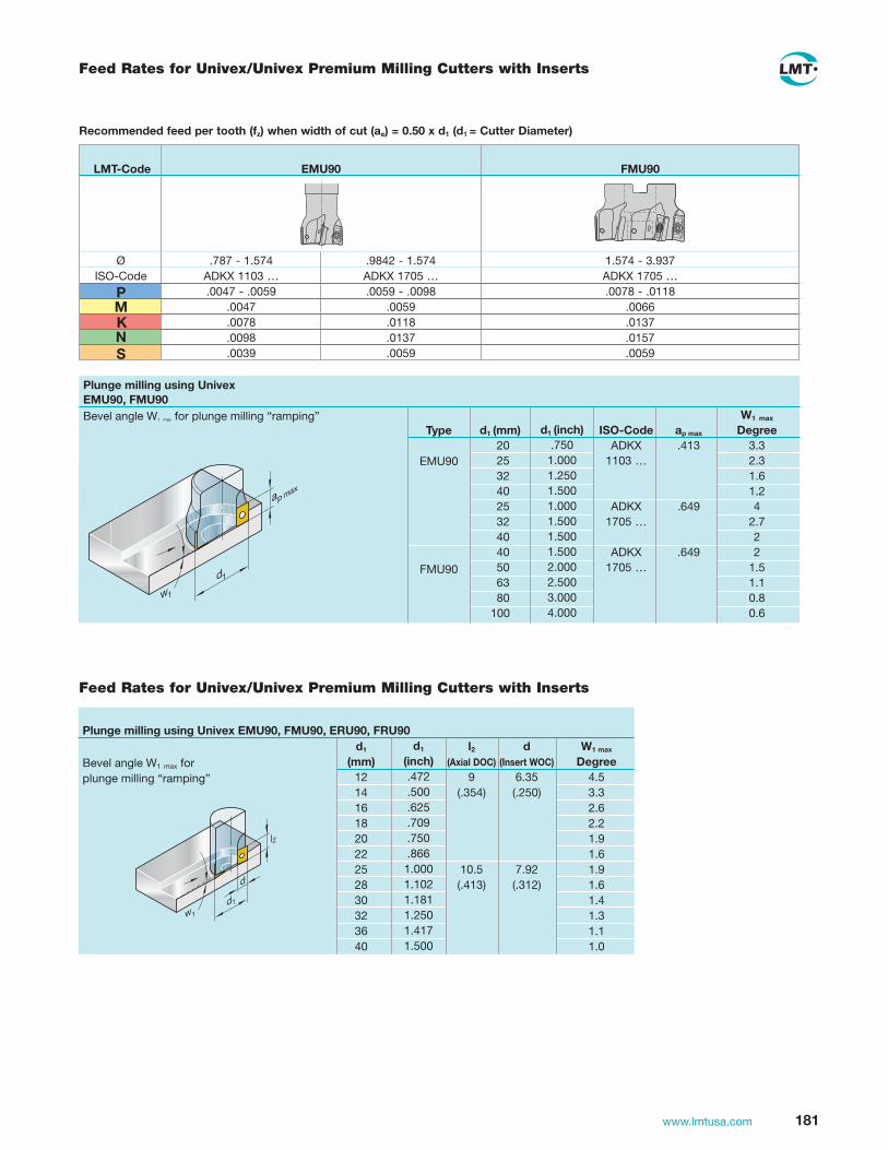
181www.lmtusa.com
d1 l2 d W1 max
(mm) (Axial DOC) (Insert WOC) Degree 12 9 6.35 4.5 14 (.354) (.250) 3.3 16 2.6 18 2.2 20 1.9 22 1.6 25 10.5 7.92 1.9 28 (.413) (.312) 1.6 30 1.4 32 1.3 36 1.1 40 1.0
Feed Rates for Univex/Univex Premium Milling Cutters with Inserts
Plunge milling using Univex EMU90, FMU90, ERU90, FRU90
w1
l2
d1
d
Bevel angle W1 max for plunge milling “ramping”
W1 max
d1 (mm) ISO-Code ap max Degree
20 ADKX .413 3.3 25 1103 … 2.3 32 1.6 40 1.2 25 ADKX .649 4 32 1705 … 2.7 40 2 40 ADKX .649 2 50 1705 … 1.5 63 1.1 80 0.8 100 0.6
Type
EMU90
FMU90
Feed Rates for Univex/Univex Premium Milling Cutters with Inserts
Recommended feed per tooth (fz) when width of cut (ae) = 0.50 x d1 (d1 = Cutter Diameter)
LMT-Code FMU90
Plunge milling using UnivexEMU90, FMU90
ap max
d1
w1
.787 - 1.574ADKX 1103 …
.9842 - 1.574ADKX 1705 …
1.574 - 3.937ADKX 1705 …
.0047 - .0059.0047.0078.0098.0039
.0059 - .0098.0059.0118.0137.0059
.0078 - .0118.0066.0137.0157.0059
Bevel angle W1 max for plunge milling “ramping”
EMU90
ØISO-Code
d1 (inch).7501.0001.2501.5001.0001.5001.5001.5002.0002.5003.0004.000
d1
(inch).472.500.625.709.750.8661.0001.1021.1811.2501.4171.500
PM
NS
K

182 www.lmtusa.com
Load cartridges and pre-torque to 9 inch-lbs.
1
Push cartridges in and adjust down to fixed ground undercut surface with allen wrench as shown.
2
Pre-load all cartridges to 27 inch-lbs.
3
Measure height of all inserts and select highest insert as the established zero point on indicator.
4
Adjust all cartridges up to the established zero point on theindicator that was predetermined by the highest insert
5
Finish torque all cartridges to 310 inch-lbs.
6
ZERO
max= ZERO
0.000
<9 inch-lbs
<9 inch-lbs
27 inch-lbs
310 inch-lbs
Modular Milling Cutters (Multi-Mill) Assembly and Adjustment Instructions

183www.lmtusa.com
21 3
The 1D (1-dimensional) adjustability on milling cutters for HSC-operations (HSC-High Speed Cutting) means, that the inserts’ axial run-out can be individually adjusted and set. The radial insert run-out and the wiper-edge are preset and cannot be adju-sted. When adjusting the milling cutter, the basic cutter materials have to be taken into consideration (aluminium–or steel type). KIENINGER supplies the milling cutters balanced, preadjusted and set in both axial and radial directions.
1D-HSC-Milling Cutter Assembly and Adjustment Instructions
Basic setting: 1. The cartridge (2) together with the previously installed insert (1) has to be screwed into the cutter body. Tighten the cartridge locking screw (3) with a tourque of 4Nm (35 in. Lb), (picture 1). 2. Screw in the insert wedge (5) and tighten it with with 4 Nm tourque (picture 2). 3. Screw in the axial adjusting screw (4) into the cutter body, until it touches the insert cartridge (2), (picture 3) 4. Continue the previously mentioned process steps, until the cutter body is completely loaded with inserts.
Fine tuning: 1. Tuning the axial adjusting screw (4) until all inserts have to been adjusted to approximately 0.02 mm (.0008") below the nominal required setting height (picture 3). This provides for additional axial adjusting travel heigh if required. 2. The locking screw (4) for the insert cartridge has to be tightened with a 10 Nm (88 in. Lb.) tourque (picture 1). 3. For fine tuning, use axial adjusting screw (4), (see picture 3). Important: Do not loosen screws again 4. Check the settings once again.
Please note, inserts cannot be changed individually without adjustment. Should this still be necessary, the hardware hast to be dismantled, cleaned and readjusted. Use torque wrench when loosening the cartridge locking screws (4 + 7).
4 Nm = 35 in. lb. 10 Nm = 88 in. Lb.

184 www.lmtusa.com
1 SW 4 pre-adjustment 4.0 Nm fine-tuning 10.0 Nm 2 SW 4 4.0 Nm
Screw Recommended torque [Nm] Screwdriver Tourques setting
2
1
Optimization of the surface through roughing/finishing adjustment with standard inserts
exchangeable inserts angle-face exchangeable inserts angle-wiper blade exchangeable inserts face-wiper blade
Adjustable in axial direction only
Axial adjustable to nom. measure. Regrinding cannot be compensated. Runout = 0.05 mm. Tools are shipped adjusted and balanced.
63 steel 4 2.1 6283 20000 80 steel 6 2.7 6283 20000 80 aluminium 6 0.7 6283 20000 100 aluminium 6 1.0 6283 20000 100 aluminium 8 1.1 6283 20000 125 aluminium 8 1.8 6283 16000 125 aluminium 10 1.9 6283 16000 160* aluminium 10 2.9 6283 12500 160* aluminium 12 3.0 6283 12500 200* aluminium 12 4.4 6283 10000 200* aluminium 16 4.6 6283 10000 250* aluminium 16 6.9 6283 8000 250* aluminium 20 7.1 6283 8000 315* aluminium 20 13.0 6283 6350 315* aluminium 24 13.2 6283 6350 400* aluminium 24 21.5 6283 5000 400* aluminium 32 21.9 6283 5000
MC diameterd [mm]
No. of teeth z
Body Weight [kg]
speedn [1/min]
cutting speed vc [SFM]
* Weight without coolant disc
1D-HSC-Milling Cutter Assembly and Adjustment Instructions

185www.lmtusa.com
(5)
(4) 2
(5)
(4)
(1)
(3)
(2)
(4)
(3)
Feed-Jet Milling CutterAdjustment Instructions
General
– Make sure that all parts are clean and can be moved easily.Please verify that no damaged or worn parts are assembled.
– Only original KIENINGER components to be used.– Adjustment should only be done with inserts facing up. If the
cutter can not be changed in upright position, go back to the starting point. This always ensures there is a pretension.
Pre-adjustment
– Screw in the thread pin ( 5) into the wedge (4) ; 1 - 1.5 revolutions. Caution: left hand thread!
– Screw in the wedge (4) into the the cutter (1) body as deep as possible.
– Put the cartridge (2) into the cutter (1) body.Tighten the screw slightly.
– Setting the cartridges by turning the threaded pin (5) counter clockwise.Pre-adjust the cartridges to approx 0.01 - max 0.02 mm below the nominal height.
Note:
During height adjustment, screw will become tight (3). In case the screw might become too tight and only excessive torque is needed to move the cartridge, please loosen the clamping screw and re-adjust.
– After pre-adjustment the xing screw (3) have to be tightened with a torque wrench to 3 Nm. An actual moment above 3 Nm can lead to difficulties in the fine adjustement. In this case the xing screw has to be loosen to 3 Nm.
Fine adjustment
– Adjusting to nomial height by turning the thread pin (5) counter clockwise.
– Verify the adjustment. Available adjustment accuracy: 4 µ m– Verify the tightening torque of the cartridge xing screw (3). This
torque must at least 5 Nm. (Higher values are possible see note and do not have to be connected)
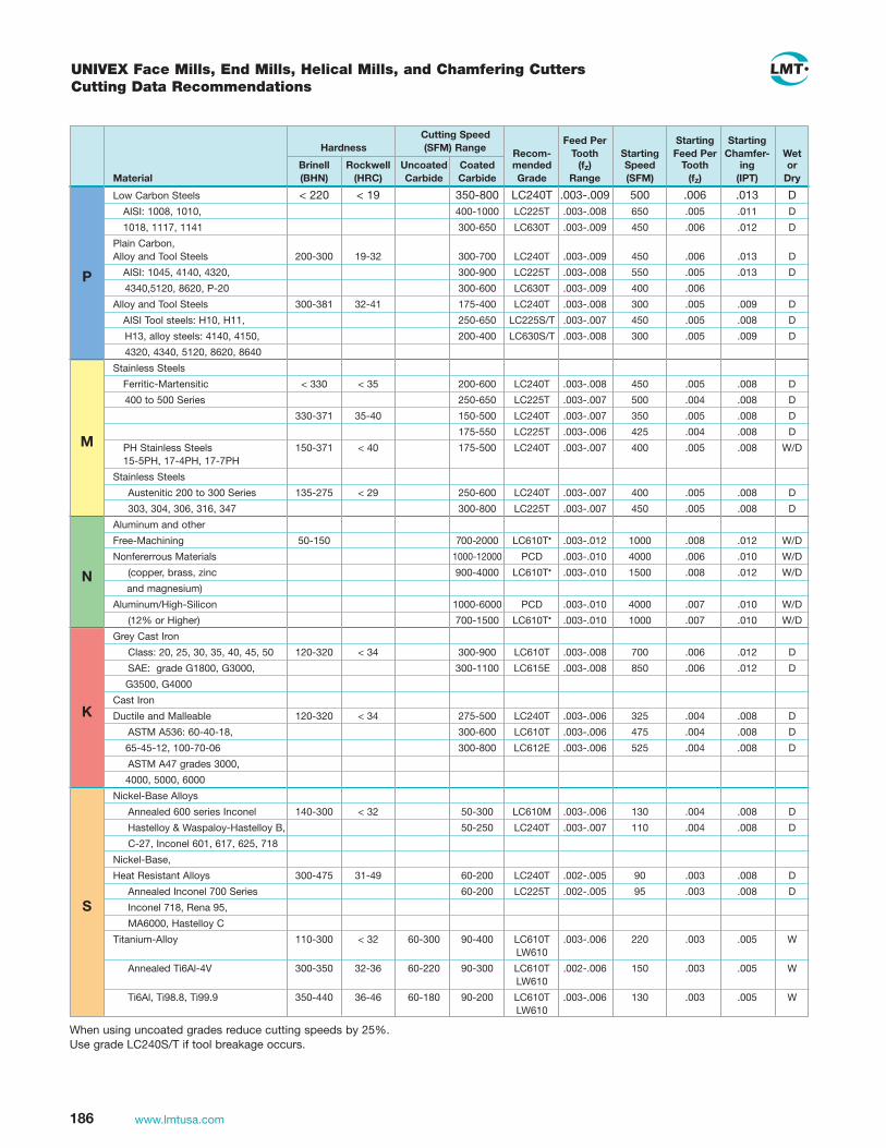
186 www.lmtusa.com
S
K
N
M
P
Cutting Speed Feed Per Starting Starting Hardness (SFM) Range Recom- Tooth Starting Feed Per Chamfer- Wet
Brinell Rockwell Uncoated Coated mended (fZ) Speed Tooth ing or Material (BHN) (HRC) Carbide Carbide Grade Range (SFM) (fZ) (IPT) Dry
Low Carbon Steels < 220 < 19 350-800 LC240T .003-.009 500 .006 .013 D AISI: 1008, 1010, 400-1000 LC225T .003-.008 650 .005 .011 D
1018, 1117, 1141 300-650 LC630T .003-.009 450 .006 .012 D
Plain Carbon, Alloy and Tool Steels 200-300 19-32 300-700 LC240T .003-.009 450 .006 .013 D
AISI: 1045, 4140, 4320, 300-900 LC225T .003-.008 550 .005 .013 D
4340,5120, 8620, P-20 300-600 LC630T .003-.009 400 .006
Alloy and Tool Steels 300-381 32-41 175-400 LC240T .003-.008 300 .005 .009 D
AISI Tool steels: H10, H11, 250-650 LC225S/T .003-.007 450 .005 .008 D
H13, alloy steels: 4140, 4150, 200-400 LC630S/T .003-.008 300 .005 .009 D
4320, 4340, 5120, 8620, 8640
Stainless Steels
Ferritic-Martensitic < 330 < 35 200-600 LC240T .003-.008 450 .005 .008 D
400 to 500 Series 250-650 LC225T .003-.007 500 .004 .008 D
330-371 35-40 150-500 LC240T .003-.007 350 .005 .008 D
175-550 LC225T .003-.006 425 .004 .008 D
PH Stainless Steels 150-371 < 40 175-500 LC240T .003-.007 400 .005 .008 W/D 15-5PH, 17-4PH, 17-7PH
Stainless Steels
Austenitic 200 to 300 Series 135-275 < 29 250-600 LC240T .003-.007 400 .005 .008 D
303, 304, 306, 316, 347 300-800 LC225T .003-.007 450 .005 .008 D
Aluminum and other
Free-Machining 50-150 700-2000 LC610T• .003-.012 1000 .008 .012 W/D
Nonfererrous Materials 1000-12000 PCD .003-.010 4000 .006 .010 W/D
(copper, brass, zinc 900-4000 LC610T• .003-.010 1500 .008 .012 W/D
and magnesium)
Aluminum/High-Silicon 1000-6000 PCD .003-.010 4000 .007 .010 W/D
(12% or Higher) 700-1500 LC610T• .003-.010 1000 .007 .010 W/D
Grey Cast Iron
Class: 20, 25, 30, 35, 40, 45, 50 120-320 < 34 300-900 LC610T .003-.008 700 .006 .012 D
SAE: grade G1800, G3000, 300-1100 LC615E .003-.008 850 .006 .012 D
G3500, G4000
Cast Iron
Ductile and Malleable 120-320 < 34 275-500 LC240T .003-.006 325 .004 .008 D
ASTM A536: 60-40-18, 300-600 LC610T .003-.006 475 .004 .008 D
65-45-12, 100-70-06 300-800 LC612E .003-.006 525 .004 .008 D
ASTM A47 grades 3000,
4000, 5000, 6000
Nickel-Base Alloys
Annealed 600 series Inconel 140-300 < 32 50-300 LC610M .003-.006 130 .004 .008 D
Hastelloy & Waspaloy-Hastelloy B, 50-250 LC240T .003-.007 110 .004 .008 D
C-27, Inconel 601, 617, 625, 718
Nickel-Base,
Heat Resistant Alloys 300-475 31-49 60-200 LC240T .002-.005 90 .003 .008 D
Annealed Inconel 700 Series 60-200 LC225T .002-.005 95 .003 .008 D
Inconel 718, Rena 95,
MA6000, Hastelloy C
Titanium-Alloy 110-300 < 32 60-300 90-400 LC610T .003-.006 220 .003 .005 W LW610
Annealed Ti6Al-4V 300-350 32-36 60-220 90-300 LC610T .002-.006 150 .003 .005 W LW610
Ti6Al, Ti98.8, Ti99.9 350-440 36-46 60-180 90-200 LC610T .003-.006 130 .003 .005 W LW610
When using uncoated grades reduce cutting speeds by 25%. Use grade LC240S/T if tool breakage occurs.
UNIVEX Face Mills, End Mills, Helical Mills, and Chamfering CuttersCutting Data Recommendations

187www.lmtusa.com
* Inserts are staggered in rows; two rows make one effective flute. Only one row cuts to the end. Each insert in that row is spaced so the next adjacent row of inserts cuts in the gap area with some insert overlap to complete the length of cut and make an effective flute.
Inserts overlap (all effective)
nteff. = number of flutes
Inserts do not overlap (half effective)
nteff.* ÷ 2 = number of flutes
rpm = 3.82 x sfm ÷ d
IPM = rpm x nteff. x fz x Mf
rpm = spindle speed fz = feed per tooth nteff. = effective teeth Mf = multiplication factor
Calculation of Feed (IPM) When Applying Long Edge Helical Cutters
Cutter Dia. 2.00-3.00 1.00-2.50 1.00-4.00 0.50-1.50
ISO Code SNKX ADMX APKT ADHX
Recommended Maximum Feed per Tooth (fZ)
.010 .006 .010 .006*
.008 .005 .008 .005*
– .004 – .004*
.012 .010 .010 .010*
.010 .008 .008 .008*
– .004 – .004*
ERT90 11257 ERU90 11552 EMP90 11415 EMU90 11473 Catalog No. FRT90 11259 ERU90 11555 FMP90 11415 EMU90 11474 ERU90 11335
Recommended maximum feed per tooth (fZ) when woc = .5 x d1 (d1 = Cutter dia.)
Cutter Dia. 1.56-2.06 .488-1.238 .630-1.26 1.134-1.941
ISO Code SNKX CCHX TCMT SDM_ and SP__
Recommended Maximum Feed per Tooth (fZ)
.010 .006 .008 .008
.008 .004 .006 .006
.006 – .004 .004
.012 .008 .010 .010
.010 .006 .008 .008
.004 – .003 .003
Catalog No. EMT45 11253 ESP90 11470 EFZ45/60 1148 EFP45 11483
* These recommendations represent the average of the size range offered. These figures are not appropriate for smaller cutter diameters.
End Mill, Face Mill and Helical Mill Application Data
P
P
M
S
M
K
K
S

188 www.lmtusa.com
Feed per toothfz
Cutting speedvc = SFM
LC280QN LC610Qvc fz vc fz
Plain carbon steel
Heat-treatabledie steels
Case hardening steels
Full hardeningtools steels
Nitriding steels
Stainless steel,austenitic
Grey cast iron andalloyed grey cast ironNodular cast iron andalloyed nodular cast ironHardened steel
1018, 1025
4140, 6150
52100, 8620
H13, D2
A355
303, 304, 316
A319, J431, No. 25B, No. 50B
A536 (80-55-06), J434
Ampco 25
MaterialMaterial
No.AISI/SAE(USA Spec) DIN Des.
984 .079 1082 .071
984 .079 1082 .071
787 .063 984 .055
787 .071 984 .063
787 .071 984 .063
721 .063 869 .055
984 .063 1082 .055
787 .063 1993 .055
721 .063 869 .055
721 .063 869 .055
721 .063 869 .055
656 .047 820 .039
656 .047 820 .039
590 .055 721 .047
721 .055 869 .047
590 .055 721 .047
590 .047 721 .039
590 .047 721 .039
492 .055 656 .047
984 .079
984 .063
820 .055
820 .047
820 .039
393
328
295
8201)
8201)
C45W
C105W
40CrMMo7
40CrMnNiMoS8.6
45CrMnNiMo8.6.4
54NiCrMoV6
21MnCr5
X19NiCrMo4
X38CrMoV5.1
X40CrMoV5.1
X38CrMoV5.3
X210Cr12
X155CrVMo12.1
X45NiCrMo4
90MnCrV8
34CrAiNi7
31CrMoV9
14CrMoV6.9
X40CrMoV5.1
X42CrMo13
X36CrMo17
GG25
GG25CrMoV
GGG40
GGG70
GGG70 alloyed
1.1730
1.1545
1.2311
1.2312
1.2738
1.2711
1.2162
1.2764
1.2343
1.2344
1.2367
1.2080
1.2379
1.2767
1.2842
1.8550
1.8519
1.7735
1.2344
1.2083
1.2316
0.6025
0.7040
0.7070
45-52HRC
53-59HRC
60-65HRC
1) Dry cutting with inserts 1177-65 LC240T (Ident No. 1058174)The cutting data indicated are starting values and must be adjusted to the prevailing conditions
P
M
K
H
(inches)
MultiEdge 3 Feed – IndexableCutting Data Recommendations
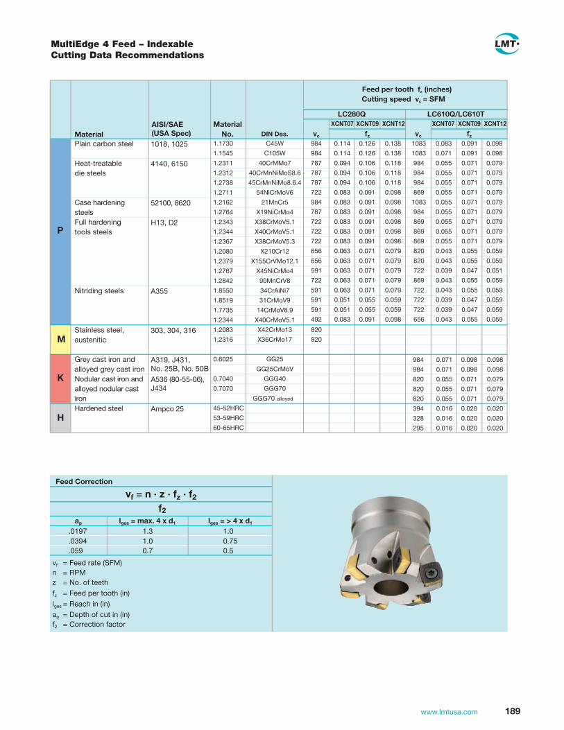
189www.lmtusa.com
Feed per tooth f (inches)z
Cutting speed vc = SFM
LC280Q LC610Q/LC610TXCNT07 XCNT09 XCNT12 XCNT07 XCNT09 XCNT12
vc fz vc fz
Plain carbon steel
Heat-treatabledie steels
Case hardening steelsFull hardeningtools steels
Nitriding steels
Stainless steel,austenitic
Grey cast iron andalloyed grey cast ironNodular cast iron andalloyed nodular cast ironHardened steel
MaterialMaterial
No. DIN Des.984 0.114 0.126 0.138 1083 0.083 0.091 0.098
984 0.114 0.126 0.138 1083 0.071 0.091 0.098
787 0.094 0.106 0.118 984 0.055 0.071 0.079
787 0.094 0.106 0.118 984 0.055 0.071 0.079
787 0.094 0.106 0.118 984 0.055 0.071 0.079
722 0.083 0.091 0.098 869 0.055 0.071 0.079
984 0.083 0.091 0.098 1083 0.055 0.071 0.079
787 0.083 0.091 0.098 984 0.055 0.071 0.079
722 0.083 0.091 0.098 869 0.055 0.071 0.079
722 0.083 0.091 0.098 869 0.055 0.071 0.079
722 0.083 0.091 0.098 869 0.055 0.071 0.079
656 0.063 0.071 0.079 820 0.043 0.055 0.059
656 0.063 0.071 0.079 820 0.043 0.055 0.059
591 0.063 0.071 0.079 722 0.039 0.047 0.051
722 0.063 0.071 0.079 869 0.043 0.055 0.059
591 0.063 0.071 0.079 722 0.043 0.055 0.059
591 0.051 0.055 0.059 722 0.039 0.047 0.059
591 0.051 0.055 0.059 722 0.039 0.047 0.059
492 0.083 0.091 0.098 656 0.043 0.055 0.059
984 0.071 0.098 0.098
984 0.071 0.098 0.098
820 0.055 0.071 0.079
820 0.055 0.071 0.079
820 0.055 0.071 0.079
394 0.016 0.020 0.020
328 0.016 0.020 0.020
295 0.016 0.020 0.020
820
820
C45W
C105W
40CrMMo7
40CrMnNiMoS8.6
45CrMnNiMo8.6.4
54NiCrMoV6
21MnCr5
X19NiCrMo4
X38CrMoV5.1
X40CrMoV5.1
X38CrMoV5.3
X210Cr12
X155CrVMo12.1
X45NiCrMo4
90MnCrV8
34CrAiNi7
31CrMoV9
14CrMoV6.9
X40CrMoV5.1
X42CrMo13
X36CrMo17
GG25
GG25CrMoV
GGG40
GGG70
GGG70 alloyed
1.1730
1.1545
1.2311
1.2312
1.2738
1.2711
1.2162
1.2764
1.2343
1.2344
1.2367
1.2080
1.2379
1.2767
1.2842
1.8550
1.8519
1.7735
1.2344
1.2083
1.2316
0.6025
0.7040
0.7070
45-52HRC
53-59HRC
60-65HRC
ap lges = max. 4 x d1 lges = > 4 x d1
.0197
.0394
.059
1.00.750.5
1.31.00.7
vf = n · z · fz · f2
Feed Correction
f2
vf = Feed rate (SFM)n = RPMz = No. of teeth
fz = Feed per tooth (in)
lges = Reach in (in)
ap = Depth of cut in (in)f2 = Correction factor
P
M
K
H
1018, 1025
4140, 6150
52100, 8620
H13, D2
A355
303, 304, 316
A319, J431, No. 25B, No. 50B
A536 (80-55-06), J434
Ampco 25
AISI/SAE(USA Spec)
MultiEdge 4 Feed – Indexable Cutting Data Recommendations

190 www.lmtusa.com
P
M
K
Unalloyed Carbon Steels A36, 1005–1029, 16–30 800–1000 .070"–.100" 1000-1080 .060"–.088" 1213, 12L14 1030–1055
Alloyed Steels, 4140, 6150, < 30 700–800 .060"–.080" 800–900 .060"–.072"Medium Strength 5115, 8620
Heat Treatable Steel, 4340 30–44 720–790 .060"–.080" 870–1000 .060"–.072"High Strength
Nitriding Steel H13 30–44 490–590 .060"–.080" 655–720 .052"–.072"
Tool Steel A2, D2, P20 30–44 590–720 .060"–.080" 720–870 .052"–.072"
Stainless (Austenitic) 303, 304, 316, Nitronic < 30 700–800 .040"–.060" 750–850 .040"–.052"
Grey Cast Iron, No. 30B, < 30 750–820 .112"–.118" 820–1000 .080"–.100"Alloyed Grey Cast Iron A436–725
Nodular Cast Iron 5005 < 23 550–590 .072"–.080" 770–820 .064"–.072"
Alloyed Nodular Cast Iron 5005 < 16 625–655
LC280TT LC610T
Cutting Feed per Cutting Feed per Material Material Examples HRC Speed (sfm) Tooth (fZ) Speed (sfm) Tooth (fZ)
TWINCUT Feed Mill ECP05/FCP05Cutting Data Recommendations
1) Dry cutting with inserts 1177-65 LC240T (Ident No. 1058174)The cutting data indicated are starting values and must be adjusted to the prevailing conditions

191www.lmtusa.com
de
l1
d1
Tmax
Pocket Milling and Axial Plunging
Circular Milling
Feed Correction
FZ
ap (DOC) Iges max 4 d1 Iges > 4 d1
.020 1.3 1.00
.040 1.0 0.75
.050 0.7 0.50
vf = Feed rate in inches per minute n = RPM z = No. of teeth fz = Feed per tooth in inches lges = Overhang ap = Depth of cut in inches
1177-11T 1177-65T
d1 dmin dmax dmin dmax
1.00 1.41 1.96 – –
1.25 1.91 2.46 1.63 2.38
1.50 2.41 2.96 2.13 2.88
2.00 3.41 3.96 3.13 3.88
2.50 4.41 4.96 4.13 4.88
3.00 5.41 5.96 5.13 5.88
4.00 7.41 7.96 7.13 7.88
1177-11T 1177-65T
l1 .118 .059
Tmax .043 .035
d1 W1 max Degree
1.00 2.9 –
1.25 2.2 4.6
1.50 1.8 2.9
2.00 1.3 1.7
2.50 1.0 1.2
3.00 0.8 0.9
4.00 0.6 0.6
Plunge Milling – 65T
d1 Step width in. fZ (inch)
1.000 .080 .004
1.250 .156 .006
1.500 .197 .008
2.000 .197 .008
2.500 .197 .008
3.000 .197 .008
4.000 .197 .008
TWINCUT Feed Mill ECP05/FCP05 Application Data

192 www.lmtusa.com
P
M
K
N
S
H1) Uncoated grade, value of vc is valid for this grade3) When using liquid coolants.
with roughing end mills or ball nose cutters
with cermet
with roundinserts
Rm/UTS(N/mm2)
AISI/SAE (USA Spec)
Material ExamplesCarbide grade
Cutting speedvc = SFM
Roughing Finishing
Plain carbon steel 1018, 1025Free cutting steel 1212, 12L13Structural alloy 1040, 4130 steelHeat-treatable 4140, 6150steel, medium strengthCast steel 4340, 8740Case hardening steel 52100, 8620Stainless steel, 410, 430F, 440ferritic, martensitic Heat-treatable 4140, 8740 steel, high strengthNitriding steel A355Tool steel H13, D2Stainless steel, 303, 304, 316austenitic
Maraging steel
Grey cast iron A319, J431, No. 25B, No. 50B
Alloyed grey cast A434, A436-72 iron Nodular cast iron A536, (80-55-06),
J434Malleable cast iron A220, 50005, A47, 32510Pure metals, soft Pure Iron, LeadAluminium alloys, 6061-T6, 7050long chippingAluminium alloys, A356, 4218short chippingCopper alloys, C27200long chippingCopper alloys, short chippingMagnesium alloys B94, M11910 Thermoplastics PVC, Acrylic GlassDuroplastics Durolite, AmpalGraphiteTitanium alloys, F67, B265medium strengthTitanium alloys, Ti-6Al-4Vhigh strengthNickel based alloys, 20Cb3medium strengthHeat resistant Inconel 718nickel based alloys,high strengthChilled cast iron Ampco 25
Material - 700 LC240T 984 - 820 721 - 524 984 - 820 1148 - 984
- 700 LC610T 984 - 820 721 - 524 984 - 820 1148 - 984
500 - 950 (Finishing) 984 - 820 721 - 524 984 - 820 1148 - 984
500 - 950 984 - 820 721 - 524 984 - 820 1148 - 984
- 950 984 - 820 721 - 524 984 - 820 1148 - 984
- 950 984 - 820 721 - 524 984 - 820 1148 - 984
500 - 950 984 - 820 721 - 524 984 - 820 1148 - 984
950 - 1400 LC240T 721 - 590 492 - 393 721 - 590 820 - 656
LC610T
950 - 1400 (Finishing) 721 - 590 492 - 393 721 - 590 820 - 656
950 - 1400 721 - 590 492 - 393 721 - 590 820 - 656
500 - 950 LC240T 820 - 1148 820 - 1148 820
(-262)3) (-262)3)
820 - 984 820 - 1148
(-262)3) (-262)3)
100 - 400 LC610T 984 - 721 984 - 656 1148 - 820 984 - 820
(120 - 260 HB)
150 - 250 LC610T 984 - 721 984 - 656 1148 - 820 984 - 820
(100 - 230 HB)
400 - 800 LC610T 984 - 721 984 - 656 1148 - 820 984 - 820
(120 -310 HB)
350 - 700 LC610T 984 - 721 984 - 656 1148 - 820 984 - 820
(150 - 280 HB)
- 500 LC225S 984 - 3281 984 - 3281 1640 - 4921
- 550 LW6101) 984 - 3281 984 - 3281 1640 - 4921
- 400 LW6101) 984 - 721 984 - 721 1148 - 820 984 - 820
300 - 700 LC225S 984 - 3281 984 - 3281 1640 - 4921
- 500 LC225S 984 - 721 984 - 721 1148 - 820 984 - 820
150 - 300 LW6101) 984 - 3281 984 - 3281 1640 - 4921
40 - 70 LW6101) 984 - 3281 984 - 3281 1640 - 4921
20 - 40 LW6101) 984 - 721 984 - 721 1148 - 820 984 - 820
40 - 60 LC6101) 131 - 262 1312 - 2625 1312 - 2625
- 950 LW6101) 131 - 262 131 - 262 131 - 262
900 - 1400 LW6101) 131 - 262 131 - 262 131 - 262
- 950 LC225S 131 - 262 131 - 262 131 - 262
900 - 1400 LC225S 131 - 262 131 - 262 131 - 262
300 - 600 HB LC240T 131 - 262 131 - 262 131 - 262
When using uncoated grades reduce cutting speed by 30%.
Copy Milling Cutters and Ball Nose Copying Cutters – IndexableCutting Data Recommendations

193www.lmtusa.com
Cut Dia. 0.630 0.787 0.984 1.260 0.315 0.394 0.472 0.630 0.787 0.984 1.260
max. ap (DOC) 0.059 .079 .040 .070 .039 .039 .039 .059 .079 .0985 .118
0.006 0.008 0.008 0.010 0.006 0.006 0.006 0.006 0.008 0.008 .0079-.0098
0.003 0.004 0.003 0.004 0.003 0.003 0.003 0.003 0.004 0.004 0.005
0.005 0.006 0.008 0.010 0.004 0.004 0.004 0.005 0.006 0.008 0.010
0.006 0.008 0.010 0.012 0.004 0.004 0.004 0.006 0.008 0.010 0.012
0.005 0.006 0.007 0.008 0.004 0.004 0.004 0.005 0.006 0.007 0.008
Cat.-No. FCZ FCT/FCC ECZ/ECC
Cutter Dia. 42 - 80mm / 1.50 - 3.00 in 42 - 125mm / 1.50 - 5.00 in 8 - 40mm / .312 - 1.50 inISO-Code RDHW RCHX RDHW RDHX RCKT/RCMX RDHX
Feed per tooth and depth of cut tool-dia., indexable insert dia. and unclamped length
EBG TCat.-No. ECT GRT EBT
Cutter Dia. 10 - 40mm / .375 - 1.50 in 25 - 32mm 20 - 50mm / .750 - 2.0 in ISO-Code RCHX CCMT SNKX
FCP EBG R EBG R EBG VCat.-No. EBT ECP ECP GWR THR GWV
Cutter Dia. 16 - 32mm / .625 - 1.25 in 16 - 25mm 20 - 100mm 6 - 32mm / .250 - 1.25 in 12 - 32mm / .500 - 1.25 in ISO-Code Half Moon Insert 1177 XCNT WPR Ball Nose Inserts WPV/WPB Inserts
Insert Dia. 0.394 0.472 0.630 0.394 0.472 0.630 0.197 0.276 0.315 0.394 0.472
max. ap (DOC) 0.098 0.118 0.197 0.098 0.118 0.197 0.031 0.059 0.079 0.118 0.138
0.010 .0118-.0157 .0157-.0177 0.010 .0118-.0157 .0157-.0177 .0098-.0118 .03947-.0118 .0118-.0138 .0087-.0146 .0118-.0157
0.005 0.006 0.008 0.005 0.006 0.008 0.003 0.004 0.005 0.005 0.006
0.010 0.014 0.014 0.010 0.014 0.014 0.008 0.008 0.010 0.012 0.014
0.012 0.016 0.016 0.012 0.016 0.016 0.010 0.010 0.012 0.014 0.016
0.010 0.012 0.012 0.010 0.012 0.012 0.006 0.006 0.008 0.010 0.012
Insert Dia. 0.197 0.315 0.394 0.472 0.250 0.313 0.375 0.500
max. ap (DOC) 0.031 0.079 0.118 0.138
.0098-.0138 .0118-.0138 .0087-.0098 0.012 .0079-.0098 0.008 0.010 0.012 0.014
0.004 0.005 0.005 0.006
0.012 0.010 0.012 0.014 0.012 0.008 0.010 0.012 0.014
0.014 0.012 0.014 0.016 0.016 0.010 0.012 0.014 0.016
0.010 0.008 0.010 0.012 0.010 0.006 0.008 0.010 0.012
Copy Milling CuttersRecommended Maximum Feed per Tooth fz
PMK
SN
PMK
SN
PMK
SN

194 www.lmtusa.com
Maximum angle W1 for ramping Copy Insert Diameter d1 5 (.197") 7 (.276") 8 (.315") 10 (.394") 12 (.472") 16 (.630")
ap max
d 1
d
T max
w 1
Maximum depth of cut for facemilling Insert Dia. 5 (.197") 7 (.276") 8 (.315") 10 (.394") 12 (.472") 16 (.630") ap max (DOC) Roughing .031 .059 .078 .118 .118 .1969 Finishing .012 .020 .030 .039 .039 .039
0.315 8.9° 0.394 6.3° 0.472 4.8° 8.0° 0.591 5.7° 0.630 3.3° 6.3° 0.787 2.5° 3.8° 4.6° 6.3° 0.945 6.3° 0.984 2.9° 2.9° 3.4° 4.6° 5.9° 1.181 2.3° 3.6° 1.260 2.1° 4.2° 6.3° 1.378 1.9° 3.0° 3.7 1.575 3.1° 1.654 2.4° 1.969 2.3° 3.3° 2.047 2.3° 2.480 1.7° 2.5° 2.598 1.7° 2.4° 3.150 1.3° 1.9° 3.937 1.5° 4.921 1.1° Tmax .0196 .0295 .0393 .0492 .059 .0787
ECT/ECZ/FCZ/FCT Copying CuttersMaximum Machining Data
ECT THR
ECZ
FCC

195www.lmtusa.com
GWV Backdraft Cutters
0.472 0.500 0.079 0.031 0.630 0.625 0.118 0.039 0.787 0.750 0.157 0.039 0.984 1.000 0.197 0.059
Maximum depth of cut ap max [in]
GWR Copying Cutters
Diameter mm Inch Roughing Finishing – 0.250 0.125 0.050 0.315 0.312 0.157 0.063 0.394 0.375 0.197 0.079 0.472 0.500 0.236 0.094 0.630 0.625 0.315 0.126 0.787 0.750 0.394 0.157 0.984 1.000 0.492 0.197 1.260 1.250 0.630 0.252
Maximum depth of cut ap max [in]
GWV Flat Bottom Cutters
0.315 0.312 0.079 0.024 0.394 0.375 0.118 0.079 0.472 0.500 0.118 0.094 0.630 0.625 0.157 0.126 0.787 0.750 0.197 0.157 0.984 1.000 0.236 0.197 1.260 1.250 0.315 0.252
Maximum depth of cut ap max [in]
Diameter mm Inch Roughing Finishing
Diameter mm Inch Roughing Finishing
WPB-HF, High feed insert 1) Maximum depth of cut
0.394 0.375 0.020 0.039 0.472 0.500 0.024 0.039 0.630 0.625 0.031 0.059 0.787 0.750 0.039 0.079 0.984 1.000 0.049 0.098 1.250 1.250 0.063 0.118
Diameter mm Inch ap max [in] Rtheo [in]
GWR and GWV Copying Cutters Maximum Machining Data
ds
d

196 www.lmtusa.com
C45WC105W
40CrMnMo740CrMnMoS8.6
40CrMnNiMo8.6.454NiCrMoV6
21MnCr5X19NiCrMo4X38CrMoV5.1X40CrMoV5.1X38CrMoV5.3
X210Cr12X155CrVMo12.1
X45NiCrMo490MnCrV834CrAlNi731CrMoV9
14CrMoV6.9X40CrMoV5.1X42CrMo13X36CrMo17
X6CrNiTi18.10X8CrNiMoTi17.12.2X5CrNiMo17.12.2
X1CrMoTi18.2X8CrNiNb11
(G-)X4CrNi13.4X3NiCrMoTi18.9.5
GG25GG25CrMoV
GGG 40GGG70
GGG70 legiert alloyed
AlZnMgCu2AlSi12
Elektrolyt-Cu Electrolyte copper
BronzeKunststoff Plastics
Plastics
GraphiteTiAl6V4
Ti10V2Fe3Al
0.00590.00590.00590.00590.00590.00590.00590.00590.00390.00390.00390.00390.00390.00390.00390.00390.00390.00390.00390.00310.00310.00310.00310.00310.00310.00310.00310.0031
0.00390.00390.00390.00310.0031
0.00590.00590.0039
0.00390.00590.0059
0.00390.00310.00310.00310.00310.0019
0.0078-.00980.0078-.00980.0078-.00980.0078-.00980.0078-.00980.0078-.00980.0078-.00980.0078-.00980.0078-.00980.0078-.00980.0078-.00980.0078-.00980.0078-.00980.0078-.00980.0078-.00980.0078-.00980.0078-.00980.0078-.00980.0078-.00980.00390.00390.00390.00390.00390.00390.00390.00390.0039
0.00590.00590.00590.00390.0039
0.00590.00590.0047
0.00470.00780.0078
0.00590.00390.00390.00390.00310.0031
0.0059-0.00780.0059-0.00780.0059-0.00780.0059-0.00780.0059-0.00780.0059-0.00780.0059-0.00780.0059-0.00780.0039-0.00590.0039-0.00590.0039-0.00590.0039-0.00590.0039-0.00590.0039-0.00590.0039-0.00590.0039-0.00590.0039-0.00590.0039-0.00590.0039-0.00590.00390.00390.00390.00390.00390.00390.00390.00390.0039
0.00590.0059
0.00780.0078
0.00780.00780.0078
0.00780.01180.0118
0.00780.00390.00390.00390.00390.0031
0.0078-0.01180.0078-0.01180.0078-0.01180.0078-0.01180.0078-0.01180.0078-0.01180.0078-0.01180.0078-0.01180.0059-0.00980.0059-0.00980.0059-0.00980.0059-0.00980.0059-0.00980.0059-0.00980.0059-0.00980.0059-0.00980.0059-0.00980.0059-0.00980.0059-0.00980.00590.00590.00590.00590.00590.00590.00590.00590.0059
0.01180.0118
0.00980.0098
0.00980.00980.0098
0.01180.01570.0157
0.00180.00390.00390.00780.00780.0039
1.17301.15451.23111.23121.27381.27111.21621.27641.23431.23441.23671.20801.23791.27671.28421.85501.85191.77351.23441.20831.23161.45411.45711.44011.45211.48931.43131.2709
0.6025
0.70400.7070
32.581
PUREpoxy resin
45–52 HRC53–59 HRC 60–65 HRC
Feed per toothfz (inches)
(.750"-1.25")Ø 20-32
(.312"-.625") Ø 8-16
(.750"-1.25") Ø 20-32
(.312"-.625") Ø 8-16
Finishing Roughing
DIN Des.Material Material No.
The cutting data indicated are starting values and must be adjusted to the prevailing conditions.
P
M
K
N
S
H
EBG Copying CuttersCutting Data Recommendations
Unalloyed tool steel(1045, 4130)Heat-treatable die steels (4140, 6150)
Case hardening steels(52100, 8620)Full hardening tool steels(H13, D2)
Nitriding steels (A355)
Stainless steels (303, 304, 316, 316L)
Maraging steel
Grey cast iron and alloyed cast iron (A319, J431, No.25B)Nodular cast iron and alloyed nodular cast iron(A536 (80-55-06), J434)
Aluminium and aluminium alloys (6061-T6), 7050Copper and copper alloys(C27200, B-148-52)Non-metallic materialsDuroplastics
Titanium alpha beta alloysTitanium beta alloys (Inconel 718)Hardened steel

197www.lmtusa.com
886853820820787820755755755755689689755755689689689656787
787787722722787787722722
12471247111611161116
295313121312
114819691641
1969295295591492295
755722689689656689623623623623558558623623558558558525656
656656591591656656591591
689689591591591
229711481148
984
656623591591558591525525525525459459525525427427427361
787787656656656
1476820656
5911312984
276236
886853820820787820755755755755689689755755689689689656787
787787722722787787722722
12471247111611161116
295313121312
114819691641
1969295295591492295
787755722722689722656656656656591591656656591591591558
11481148101710171017
1969984984
82019691641
1641230230459361197
738705673673640673607607607607541541607607541541541509
10991099968968968
1969984984
820
1641230230459361197
656656591591558591558492492492492394394394394394394394394
394361361361361361361361
525492459459427459394394394394328328394394295295295262410
410410345345410410345345
525525459459459
787755722722689722656656656656591591656656591591591558
11481148101710171017
1969984984
82019691641
1641230230459361197
459427394394361394328328328328262262328328230230230197295
295262262262262262262262
427394361361328361295295295295230230295295230230230230
427427361361361
LC610A LC610T LC610Q LC610ZLC630QLC730Q LC730T LC610T LC610Q LC240T
LC630QLC730Q LC730T LW240 LW225
Cutting speed
vc [SFM]
Finishing Roughing
3281
EBG Copying CuttersCutting Data Recommendations
656623591591558591525525525525459459525525459459459427558
558558592592558558492492
820820722722722
531422265

198 www.lmtusa.com
1. Selected diameter of tool to be used.
2. Determine Depth of Cut (DOC) to be used.
3. Refer to Figure and Table to find the Effective Cutting Diameter (ECD).
4. Refer to Feed and Speed chart on page 102 to select the surface footage to be used (SFM).
5. Calculate RPM using the ECD and SFM. (SFM x 3.82 / ECD = RPM)
6. Refer to Table to determine Feed Rate Adjustment (FRA).
7. Refer to chart on page 102 and select Inches per Teeth (IPT). Calculate Inches per Minute (IPM). (No Teeth x IPT x RPM x FRA = IPM)
DOC 0.250 0.312 0.375 0.500 0.625 0.750 1.000 1.250 1.500 2.000 0.005 0.070 0.078 0.086 0.099 0.111 0.122 0.141 0.158 0.173 0.200 0.010 0.098 0.110 0.121 0.140 0.157 0.172 0.199 0.223 0.244 0.282 0.020 0.136 0.153 0.169 0.196 0.220 0.242 0.280 0.314 0.344 0.398 0.050 0.200 0.229 0.255 0.300 0.339 0.374 0.436 0.490 0.539 0.624 0.075 0.229 0.267 0.300 0.357 0.406 0.450 0.527 0.594 0.654 0.760 0.100 0.245 0.291 0.332 0.400 0.458 0.510 0.600 0.678 0.748 0.872 0.125 0.250 0.306 0.354 0.433 0.500 0.559 0.661 0.750 0.829 0.968 0.156 0.312 0.370 0.463 0.541 0.609 0.726 0.826 0.916 1.073 0.188 0.375 0.484 0.573 0.650 0.781 0.894 0.993 1.167 0.250 0.500 0.612 0.707 0.866 1.000 1.118 1.323 0.312 0.625 0.739 0.927 1.082 1.218 1.451 0.375 0.750 0.968 1.146 1.299 1.561 0.600 1.000 1.225 1.414 1.732 0.625 1.250 1.479 1.854 0.750 1.500 1.936 1.000 2.000
Calculated Effective Cutting Diameter for Ball Nose Tooling
Inch Insert Diameter
Formulas
SFM = .262 x RPM x Diameter of CutterRPM = 3.82 x SFM ÷ Diameter of CutterIPR = IPM ÷ RPMIPM = IPT x Number Of Teeth x RPMIPT = IPM ÷ (Number Of Teeth x RPM)MRR = Axial DOC x Radial WOC x IPM = in3/minHP (Cutter) = MRR ÷ Power Factor (K)HIFB = (2 x d) – IC
Legend
RPM = Revolutions Per MinuteSFM = Surface Feet Per MinuteIPR = Inches Per RevolutionIPM = Inch Per MinuteIPT = Inches Per Tooth (Chip load)DOC = Depth Of CutMRR = Metal Removal RateHP = Horse PowerHIFB = Helical Interpolation to Flat BottomECD = Effective Cutting DataFRA = Feed Rate Adjustment
DOC 0.250 0.312 0.375 0.500 0.625 0.750 1.000 1.250 0.005 3.6 4.0 4.4 5.0 5.6 6.1 7.1 7.9 0.010 2.6 2.8 3.1 3.6 4.0 4.4 5.0 5.6 0.015 2.1 2.3 2.6 2.9 3.3 3.6 4.1 4.6 0.020 1.8 2.0 2.2 2.6 2.8 3.1 3.6 4.0 0.025 1.7 1.8 2.0 2.3 2.6 2.8 3.2 3.6 0.050 1.2 1.4 1.5 1.7 1.8 2.0 2.3 2.6 0.075 1.1 1.2 1.2 1.4 1.5 1.7 1.9 2.1 0.100 1.1 1.1 1.2 1.4 1.5 1.7 1.8 0.125 1.1 1.2 1.3 1.3 1.4 1.5 0.150 1.1 1.2 1.3 1.4 1.5 0.175 1.1 1.2 1.3 1.4 0.200 1.1 1.3 1.4 0.250 1.2 1.2 0.300 1.1 1.2 0.400 1.1
Feed Rate Adjustment (FRA)
Inch Insert Diameter
3 Axis MillingFeed, Speed, and Diameter Compensation

199www.lmtusa.com
WPR-D – Helical Ball Nose Insert LC610QCutting Data Recommendations
N
S
K
P
M
Feed IPT / SFM Material Material Examples Rockwell C .002" - .012" IPT
Plain Carbon steel 1018, 1025, < 20 1050 1300
Free Machining steel 1212, 12L13 < 20 1050 1300
Structural alloy steel 1040, 4130 < 30 1050 1300
Heat-treatment steel, medium strength
4140, 6150 < 30 1050 1300
Cast Steel 4340, 8740 < 30 850 980
Caste hardening steel 52100, 8680 < 30 850 980
Stainless steel, ferritic martensitic
410, 430F, 440 < 30 850 980
Heat treatment steel, high strength
4140, 8740 28 - 44 680 790
Nitriding Steel A355 28 - 44 680 790
Tool Steel H13, D2 28 - 44 680 790
Stainless steel, austenitic
304, 316 < 30 – –
Maraging steel – –
Grey cast iron A319, J431 No. 25B, No. 50B
< 27
1050 1300
Alloyed grey cast iron A434, A436-72 < 22 800 910
Nodular cast iron A536 (80-55-06), J434 < 34 725 820
Malleable cast iron
A220, 50005 A47,32510
< 29 725 820
Pure metals, soft Pure Iron, Lead < 20 2400 2760
Aluminum alloys, long chipping
6061, 7050 < 20 3120 3280
Aluminum alloys, short chipping
A356, 4218 < 20 1250 1570
Copper alloys, long chipping
C28000, B-148-52 < 20 3120 3280
Copper alloy, short chipping
< 20 1250 1570
Magnesium alloys B94, M11910 – 1570
Thermoplastics PVC, Acrylic glass – 1970
Duroplastics Durolite, Ampal – 1970
Graphite – 1970
Titanium alloys, medium strength
F67, B265 < 29
– –
Titanium alloys, high strength alloy
Ti-6Al-4V 27 - 44
– –
Nickel based alloys, medium strength
20Cb3 < 29 260 300
Heat resistant nickel based alloys, high strength
Inconel 718 27 - 44 200 230
Chilled cast iron Ampco 25 < 20 200 230
45 - 52 260 300
Hardened steel 53 - 59 200 230
60 - 65 130 160
H

200 www.lmtusa.com
AR – Cutting Data Recommendations
AR Geometry Data
LC610Z
Rm < 900 N/mm (27 Rc)2
Structual alloy case hardening and heat-treatable steels
Rm > 900 N/mm
LC610Q is suitable for materials up to 54 Rc
LC610Z is suitable for materials up from 54 Rc to 64 Rc
(27 Rc)2Heat-treatable and tool steels
Grey cast iron
Nodular and malleable cast iron
Rm > 900 N/mm2 (27 Rc)Tool steels
0
For best performance it is recommended to use a HSS shank not carbide
0 .039" .079" .118" .158" axial infeed ap (inch)
Feed
per
to
oth
f z (i
nch) .028"
.024"
.020"
.016"
.012"
.008"
.004"
0
.028"
.024"
.020"
.016"
.012"
.008"
.004"Feed
per
to
oth
f z (i
nch)
0 .039" .079" .118" .158" .197"” .236" .276" axial infeed ap (inch)
LC630Q
Recommended max. feed per tooth in relation to workpiece material and depth of cut
----
---
525-590
525-590525-590525-590
525-590
525-590
590-650
Rm
(N/mm2)
Cutting Speed Vc (SFM)
LC630QVc (SFM)
LC610ZVc (SFM) Material
AISI/SAE(USA Spec)Material Example:
-700-700
500-950500-950
-950-950
500-950
950-1400
950-1400950-1400100-400
150-250
400-800
590-650590-650650-780650-780
650-780650-780650-780
-
---
-
-
-
Plain carbon steel Free cutting steel
Structural alloy steel Heat-treatable steel,
medium strength Cast steel
Case hardening steel Stainless steel,
ferritic, martensitic
Heat-treatable steel, high strength
Nitriding steel Tool steel
Grey cast iron
Alloyed grey cast iron
Nodular cast iron
Malleable cast iron
1018, 10251212, 12L13, 12L141040, 41304140, 6150
4340, 874052100, 8620410, 430F, 440
4140, 8740
A355H13, D2No.20B, No.25B, No.30B, No.35B, No.40B
A434, A436-72
A536 (80-55-06), J434
A220, 50005, A47, 32510
Carbide Grade
P
K

201www.lmtusa.com
WPB-FBCutting Data Recommendations
K
M
P
H
Application Examples
Cutting Speed:vc
= 1300 SFM
Feed:fz = .015"
Depth of Cut:ap = .003"
Step Over:ae = .016"
Cutting Speed:vc
= 2000 SFM
Feed:fz = .024"
Depth of Cut:ap = .010"
Step Over:ae = .008"
WPB 16-FB-70 in LC610Z
WPB 16-FB-70 in BN081
Workpiece:Clipping tool
Material:1.2320 / P20
Cutter:WPB 16-70 in LC610ZEBG R 16.016 AN140-C-I
Tool Life: 660 Minutes
Workpiece:Forming die
Material:Cast steel, partially hardened to 60 HRC
Cutter:WPB 16-70 in BN081, CBNEBG R 16.016 AN140-C-I
Tool Life: 70 Hours
Carbide: LC610Z CBN: BN081
Material Cutting Speed (sfm) Feed Per Tooth (fz) Cutting Speed (sfm) Feed Per Tooth (fz)
Steel, cast steel, stainless 1150-1312 .012"-.016" – – steel, ferritic and martensitic
Stainless steel and cast steel 1000-1150 .008"-.016" – – Austenitic and austenitic/ferritic
Grey cast iron 920-1050 .008"-.016" 1640-2300 .008"-.016" Nodular cast iron, Malleable cast iron
Chilled cast iron – – 820-1000 .008" Hardened steel > 60 HRC
For best results run Flatball in Carbide Shank holderIncrease step over of 50% more than N Geometry possibleMust be programmed using 3D copy milling techniques with a X, Y, X moves simultaneously (45 Degrees on the workpiece)

202 www.lmtusa.com
N
Brinell Cutting Speed (SFM)
Hardness LW610 LC610T*Material (BHN) SFM SFMAluminum Free Machining HB < 80 3280 4920 HB > 80 2620 3280Copper alloys long chipping 820 985Thermoplastics 985 –Aluminum alloys Si < 12% 2620 328 Si ≥ 12%** – 650Copper alloys short chipping 1320 1640Magnesium alloys 1320 –Duroplastics 490 650
Recommended Maximum Feed per Tooth (fZ) for V_GT Inserts
Maximum Feed Per Tooth (fZ)
VPGT1604 . . . VCGT2205 . . .
.014 .020
.012 .016
*LC610T CVD Coated TiAlN
**PCD-tipped inserts upon request.
EMZ90 / FMZ90Cutting Data Recommendations
EMZ90
EMZ90-THRFMZ90

203www.lmtusa.com
dmin – dmax
d1
d1
ap max
w1
Tmax
Pocket Milling and Axial Plunging
Circular Milling
VPGT VCGT
160412-ALM 220530-ALM
ap max .531 .590
Tmax .31 .350
W1 max Degree (Ramp Angle)
1.00 12
1.25 11
1.50 7.5
2.00 6
2.50 4.5
3.00 3.5
4.00 2.5
d1 dmin dmax
1.00 1.40 1.91
1.25 1.64 2.26
1.50 2.34 2.75
2.00 3.18 3.76
2.50 4.23 4.76
3.00 5.28 5.76
4.00 7.07 7.75
Helix angle W1 max and internal depth of cut Tmax
EMZ90 / FMZ90 Application Data
EMZ90

204 www.lmtusa.com
Maximum depth of cut for face milling
Maximum depth of cut ap [in]
R 10 42 S/SV/SNHardened steel .020 - .031Cast iron .039 - .059Aluminium .197Plastic .197
Diameter 0.984 14.0° 1.260 8.0° 1.575 5.5° 1.969 4.0° 2.480 2.7° 3.150 2.0° 3.937 1.5° 4.921 1.2°E
d
d1
R 10 42 S/SV/SN
UFC Universal Face Milling CuttersApplication Options
diameter tooth Maximum RPM cutting speed [inch] [z] n [1/min] vc [SFM] fz = 0.0007 fz = 0.0019 0.984 2 40000 3142 5250 13124 1.260 3 40000 4021 7874 19686 1.575 4 40000 5027 10499 26248 1.969 5 36000 5655 11812 29529 2.480 6 30000 5938 11812 29529
Maximum depth of cut for face milling material ap [inch]Hardened steel .020 - .031 Cast iron .039 - .059 Aluminium .197
Plastic .197
Maximum angle for ramping diameter [inch] 0.984 14 1.378 8 1.574 5.5 1.968 4 2.480 2.7 3.150 2 3.937 1.5 4.921 2
Maximum ramp angle
Max. ramp angle E [°]
feed per toothCutting data recommendations vf [SFM]
UFC Milling CuttersMaximum Machining Data

205www.lmtusa.com
Finish Line CuttersCutting Data Recommendations
K
M
P
S
H
Cutting Speed Coated CBN fz (mm) fz (in)
d1 = d1 =
�20-�66 �.750-�2.60
Material vc (SFM) vc (m/min) LC610Q LC610Z BN025 ap = 1.5 ap = .059
Steel, cast steel, stainless steel, 500 - 1835 150 - 560 � / � � / � � / 0.15-0.5 .006"-.020" ferritic and martensitic � � � � � �
Stainless steel and cast steel, 400 - 1000 120 - 300 � / � � / � � / 0.1-0.35 .004"-.014" austenitic and austenitic/ferritic � � � � � �
Grey cast, iron cast with spheriodal 500 - 1640 150 - 500 � � / 0.15-0.5 .006"-.020" graphite, malleable cast iron � � �
High temperature alloys, super and 400 - 650 120 - 200 � / � � 0.1-0.35 .004"-.014" titanium alloys
Hardened steel and cast steel 130 - 280 (LC610Z) � � / � � / 0.1-0.2 .004"-.008" 100 - 450 (BN025) � � � � � �
� roughing� � semi-finishing� � � finishing
ECG-THR

206 www.lmtusa.com
H
2 Feed HSC MultiEdge and WPB-HFCutting Data Recommendations
K
M
P
LC620T
Material Material Examples HRC Cutting Speed (sfm) Feed Per Tooth (fz)
Unalloyed Carbon Steel
A36, 1005-1029, 16 - 30 800 - 1000 .040
1213, 12L14
Alloyed Steel, 4140, 6150, < 30 800 - 990 .030
medium strength 5115, 8620
Heat Treatable Steel, 4340 30 - 44 720 - 790 .030
high strength
Nitriding Steel H13 30 - 44 490 - 590 .030
Tool Steel A2, D2, P20 30 - 44 590 - 720 .030
Stainless Steel, 303, 304, 316, < 30 700 - 800 .030
austenitic Nitronic
Grey Cast Iron No. 30B < 30 750 - 820 .050
Alloyed Grey Cast Iron A436-725
Nodular Cast Iron 5005 < 23 550 - 590 .040
Alloyed Nodular Cast Iron 5005 < 16 450 - 590 .030
Hardened Steel 45 - 52 754 .0195
656 .016
The cutting data indicated are starting values and must be adjusted to current machining conditions
*We recommend reducing the feed per tooth value with the long length version by 30%.
4 Feed HSC Cutting Data Recommendations
H
P
Feed per toothfz = inches
Cutter diametermm
Cutting speed
vc = SFM
Cutting depth
ap (inch)
Heat-treatabledie steels(4140, 8740)
Full hardeningtools steels(H13, D2)
Nitriding steels(A355)
Hardened steel
Material 787 0.0118 0.0150 0.0177 0.0236 0.0295 0.0354 0.0020 x d1
(= ap max.)
722 0.0118 0.0150 0.0177 0.0236 0.0295 0.0354656 0.0094 0.0118 0.0142 0.0189 0.0236 0.0276656 0.0110 0.0138 0.0165 0.0220 0.0276 0.0335 0.0016 x d1
591 0.0102 0.0130 0.0154 0.0205 0.0256 0.0315
525 0.0094 0.0118 0.0142 0.0189 0.0236 0.0276656 0.0110 0.0138 0.0165 0.0220 0.0276 0.0335 0.0016 x d1
591 0.0102 0.0130 0.0154 0.0205 0.0256 0.0315
525 0.0094 0.0118 0.0142 0.0189 0.0236 0.0276656 0.0063 0.0079 0.0094 0.0126 0.0157 0.0189 0.0016 x d1
591 0.0047 0.0059 0.0071 0.0094 0.0118 0.0142 0.0012 x d1
459 0.0031 0.0039 0.0047 0.0063 0.0079 0.0094 0.0008 x d1
328 0.0024 0.0031 0.0035 0.0047 0.0059 0.0071 0.0004 x d1
4 5 6 8 10 12Material No. 1.23111.23121.27381.27111.23431.20801.23791.27671.85501.85191.77351.234445–52 HRC53–56 HRC57–62 HRC63–67 HRC
40CrMnMo740CrMnMoS8.640CrMnNiMoS8.6.454NiCrMoV6X 38 CrMoV 5 1 X210Cr12X 155 CrVMo 12 1 X 45NiCrMo434CrAlNi731CrMoV914CrMoV6.9X40CrMoV5.1
DIN Des.
FETTE

207www.lmtusa.com
Face Milling
RampingRamp Angle = 1-2°
Pocketing
Circular interpolation 3D rough copy milling
Plunge Milling
ap max
d1
w1
Opening cavity
HSC FeedTM – High Feed, Solid Carbide Roughing End MillsApplication Examples

208 www.lmtusa.com
ae = Width of cut in (in)ap = Depth of cut in (in)d1 = Cutter diameter in (in)f1 = Correction factor for vf
fz = Feed per tooth in (in)n = Speed in min–1
Q = Chip volume in cm3/minvc = Cutting speed in (RPM)vf = Feed rate in (in/min)z = No. of teeth
Feed per toothfz = (inches)
Cutter diameter (mm)
4 5 6 8 10 1214-16
18-20
Cutting speed
vc [SFM] CoolantExample Material No.Material
Rm/UTS
(N/mm2)Plain carbon steel(1018, 1025)
Free cutting steel(1212, 12L13, 12L14)Structural alloy steel(1040, 4130)Heat-treatable steel, medium strength(4140, 6150)Cast steel (4340, 8740)Case hardening steel (52100, 8620)Heat-treatable steel, high strength(4140, 8740)Nitriding steel(A355)Tool steel(H13,D2)Stainless steel, austenitic(303, 304, 316, 316L)
Stainless steel, ferritic, martensitic(431)
Stainless steel, martensitic steel(403, 420, 430)
Grey cast iron (No.20B, No.25B, No.30B, No.35B,No.40B, No.45B)Alloyed grey cast iron
Nodular cast iron(60-40-18, 80-55-06)Malleable cast iron(32510, 40010, 50005)Aluminium alloys, short chipping(6061-T6, 7050)Aluminium alloys, short chipping
Titanium alloys, medium strength(Ti6Al V4)Titanium alloys, hight strength
Nickel based alloys, medium strength(Inconel 718, Hastelloy C, Monel 400)Heat resis. nickel based all., high stren.
*) .071 x d1 for diameter 14, 18, 20
} Reduce the cutting speed vc by 20%
} The cutting speed vc must be increased by 30%
300-500500-700350-500
St 37. St 44St 52. St 70U- and R St 37-2
1.0037. 1.00441.0052. 1.00701.0036. 1.0038
755 .0016 .0024 .0028 .0035 .0043 .0051 .0071 .0087
360-550600-800
9 S 20. 9 SMn 2845 S 20. 60 S 20
1.0711. 1.07151.0727. 1.0728
755 .0016 .0024 .0028 .0087 .0043 .0051 .0071 .0087
500-950Ck 45.26CrMo4
1.11911.7219
656 .0016 .0020 .0024 .0079 .0039 .0047 .0063 .0079
500-95042CrMo4. 50CrV4.
1.7225 1.2241
525 .0016 .0020 .0024 .0079 .0039 .0047 .0063 .0079
-950 GS40 1.0416 427 .0012 .0016 .0020 .0067 .0035 .0039 .0055 .0067-950 16MnCr5 1.7131 525 .0016 .0020 .0024 .0079 .0039 .0047 .0063 .0079
950-140042CrMo4 30CrNiMo8
1.7225 1.6580
394 .0012 .0016 .0020 .0059 .0031 .0035 .0047 .0059
950-1400 34CrAl6 1.8504 361 .0012 .0016 .0020 .0059 .0031 .0035 .0047 .0059
950-1400X38CrMoV5-1 X155 CrVMo12-1
1.2343 1.2379
328 .0012 .0016 .0016 .0055 .0028 .0031 .0043 .0055
500-950X5CrNi18-10 X2CrNiMo17-12-2X6CrNiMoTi17-12
1.4301 1.44041.4571
328 .0008 .0012 .0012 .0039 .0020 .0024 .0031 .0039
500-950X15Cr13 X17CrNi16-2 X35CrMo17
1.4024 1.4057 1.4122
328 .0012 .0016 .0020 .0059 .0031 .0035 .0047 .0059
800-1000X3NiCoMoTi18-9-5 X5CrNrCuNb16-4 X7CrNiAl17-7
1.2709 1.4542 1.4568
394 .0012 .0012 .0016 .0051 .0028 .0031 .0039 .0051
100-400(120-260 HB)
EN-GJL-250(GG25)
EN-JL-1040(0.6025)
591 .0024 .0028 .0031 .0110 .0055 .0067 .0087 .0110
150-250(160-230 HB)
EN-GJLA-XNiCr35-2(GGL-NiCr35-2)
(0.6678) 525 .0020 .0024 .0028 .0094 .0047 .0055 .0075 .0094
400-800(120-310 HB)
EN-GJS-600(GGG60)
EN-JS-1060(0.7060)
492 .0016 .0024 .0028 .0087 .0043 .0051 .0071 .0087
350-700(150-280 HB)
EN-GJMB-550-4(GTS55)
EN-JM-1160(0.8155)
394 .0016 .0024 .0028 .0087 .0043 .0051 .0071 .0087
-400 G-AlSi12 3.2581 984 .0020 .0024 .0031 .0098 .0051 .0059 .0079 .0098
-500 MS58 2.0402 820 .0016 .0020 .0024 .0079 .0039 .0047 .0063 .0079
-950TiAl5Sn2-5TiAl6V4
3.71153.7165
262 .0012 .0012 .0016 .0051 .0028 .0031 .0039 .0051
900-1400 TiAl6Sn2 3.7174 197 .0008 .0012 .0012 .0039 .0020 .0024 .0031 .0039
-950 NiCr12Al6MoNb 2.4670 131 .0012 .0012 .0016 .0051 .0028 .0031 .0039 .0051
900-1400 NiCr19Fe19NbMo Inconel 718 98 .0008 .0012 .0118 .0039 .0020 .0024 .0031 .0039
.0039 · d1
.0098 · d1
.020 · d1
.0295 · d1
.039 · d1
.039 x d1
.059 x d1
.079 x d1*)
.039 x d1
.059 x d1
.079 x d1*)
.039 x d1
.059 x d1
.079 x d1*)
.039 x d1
.059 x d1
.079 x d1*)
.0196 x d1
.039 x d1
.059 x d1
.071
.067
.063
.055
.051
.047
.043
.039
.0314
.0314
.0275
.0236
.0314
.0275
.0236
.079––.079––.051––.039––.0354.0314–
WOCae
DOCap f1 f1
DHClong
DHCshort
vf = n · z · fz · f1
Feed correction factor f1
Dry machining, air-blast cooling is advantageous
Wet machining, sufficient emulsion volume required
N
S1)
P
K
M1)
1) For that materials do not use DHC, please take the DHC INOX
Roughing-Finishing End Mills Type DHC and DHC SLOTCutting Data Recommendations

209www.lmtusa.com
Feed per toothfz = (inches)
Cutter diameter (mm)
4 5 6 8 10 1214-16
18-20
Cutting speed
vc [SFM] CoolantExample Material No.Material
Rm/UTS
(N/mm2)Stainless steel, austenitic
(303, 304, 316Ti, 316L)
Stainless steel, ferritic, martensitic
(431)
Stainless steel, martensitic steel
(403, 420, 430)
Aluminium alloys, short chipping
(6061-T6, 7050, A413.1)
Aluminium alloys, short chipping
Titanium alloys, medium strength
(Ti6Al V4)
Titanium alloys, hight strength
Nickel based alloys, medium strength
Heat resistant nickel based alloys,
high strength
(Inconel 718, Hastelloy C, Monel 400)
500-950
X5CrNi18-10
X2CrNiMo17-12-2
X6CrNiMoTi17-12-2
1.4301
1.44041.4571
328 .0008 .0012 .0012 .0016 .0020 .0024 .0031 .0039
500-950X15Cr13
X17CrNi16-2 X35CrMo17
1.4024 1.4057 1.4122
328 .0012 .0016 .0020 .0059 .0031 .0035 .0047 .0059
800-1000X3NiCoMoTi18-9-5 X5CrNrCuNb16-4X7CrNiAl17-7
1.2709 1.4542 1.4568
394 .0012 .0012 .0016 .0051 .0028 .0031 .0039 .0051
-400 G-AlSi12 3.2581 984 .0020 .0024 .0031 .0098 .0051 .0059 .0079 .0098
-500 MS58 2.0402 820 .0016 .0020 .0024 .0079 .0039 .0047 .0063 .0079
-950TiAl5Sn2-5TiAl6V4
3.71153.7165
262 .0012 .0012 .0016 .0051 .0028 .0031 .0039 .0051
900-1400 TiAl6Sn2 3.7174 197 .0008 .0012 .0012 .0039 .0020 .0024 .0031 .0039
-950 NiCr12Al6MoNb 2.4670 131 .0012 .0016 .0016 .0051 .0028 .0031 .0039 .0051
900-1400 NiCr19Fe19NbMo Inconel 718 98 .0008 .0012 .0012 .0039 .0020 .0024 .0031 .0039
Dry machining, air-blast cooling is advantageous
Wet machining, sufficient emulsion volume required
N
S
M
Roughing-Finishing End Mills Type DHC INOXCutting Data Recommendations
*) .071 x d1 for diameter 14, 18, 20
} Reduce the cutting speed vc by 20%
} The cutting speed vc must be increased by 30%.0039 · d1
.0098 · d1
.020 · d1
.0295 · d1
.039 · d1
.039 x d1
.059 x d1
.079 x d1*)
.039 x d1
.059 x d1
.079 x d1*)
.039 x d1
.059 x d1
.079 x d1*)
.039 x d1
.059 x d1
.079 x d1*)
.0196 x d1
.039 x d1
.059 x d1
.071
.067
.063
.055
.051
.047
.043
.039
.0314
.0314
.0275
.0236
.0314
.0275
.0236
.079––.079––.051––.039––.0354.0314–
WOCae
DOCap f1 f1
DHClong
DHCshort
vf = n · z · fz · f1
Feed correction factor f1
1) For that materials do not use DHC, please take the DHC INOX
ae = Width of cut in (in)ap = Depth of cut in (in)d1 = Cutter diameter in (in)f1 = Correction factor for vf
fz = Feed per tooth in (in)n = Speed in min–1
Q = Chip volume in cm3/minvc = Cutting speed in (RPM)vf = Feed rate in (in/min)z = No. of teeth

210 www.lmtusa.com
Example DIN-No.MaterialRm/UTS(N/mm2)
AIS/SAE (USA Spec)Material Examples
Plain carbon steel 1018, 1025Free cutting steel 1212, 12L13, 12L14Structural alloy steel 1040, 4130
Heat-treatable steel, 4140, 6150medium strengthCast steel 4340, 8740Case hardening steel 52100, 8620Stainless steel, 410, 430F, 440ferritic,martensiticHeat-treatable steel, 4140, 8740high strengthNitriding steel A355Tool steel H13, D2 Stainless steel, 303, 304, 316Ti, 316LausteniticMaraging steel Grey cast iron No.20B, No.25B, No.30B, No.35B, No.40B, No.45BAlloyed grey cast ironNodular cast iron A536, (80-55-06), J434Malleable cast iron 32510, 50005Pure metals, soft
Aluminium alloys, 6061-T6, 7050long chippingAluminium alloys, A431.1short chippingCopper alloys, C27200, B-148-52long chippingCopper alloys,short chippingMagnesium alloys B94, M11910Thermoplastics PVC, Acrylic Glass Duroplastics Durolite, AmpalGraphiteTitanium alloys, F67, B265medium strengthTitanium alloys, high strength Ti-6Al-4VNickel based alloys, 20Cb3medium strengthHeat resistant nickel based Inconel 718alloys, high strengthChilled cast ironHardened steel
St 529 SMn 28Ck 4526 CrMo 442 CrMo 450 CrV 4GS 4016 MnCr 5X 10 Cr 13X 12 CrMoS 17X 35 CrMo 1742 CrMo 430 CrNiMo 834 CrAl 6X 38 CrMoV 5 1X 155 CrVMo 12 1X 5 CrNi 18 10X10 CrNiMo 18 10
GG25
GGL-NiCr 35 2GGG60GTS55Reineisen, Blei pure iron, leadAlMg 3AlZnMgCu 1,5G-AlSi 12
MS63CuAl10NiMS58
G-MgAl9Zn1PVC, Acrylglas PVC, acrylic glassBakelit, MelaminGraphiteTiAl5Sn2,5TiAl6V4TiAl6Sn2NiCr12Al6MoNb
NiCr19Fe19NbMoInconel 718Ni-hard, Ampco
-700-700
500-950
500-950
-950-950
500-950
950-1400
950-1400950-1400
500-950
-550
300-700-500
40-70400-800
(120-310 HB)100-400
(120-260 HB)-400
150-250(160-230 Hb)
-500
160-300350-700
(150-280 HB)20-40
-950
900-140-950
900-1400
300-60045-52 HRC53-59 HRC60-65 HRC
1.00521.07151.11911.72191.72251.22411.04161.71311.40061.41041.41221.72251.65801.85041.23431.23791.43011.45711.27090.6025
0.66780.70600.8155
3.35353.43653.2581
2.03202.09752.0402
3.5912
R85103.71153.71653.71742.4670
The cutting data quoted includes standard values, and must be adjusted to the actual conditions.
P
M
K
N
S
H
HSCline and Milling Cutters Cutting Data Recommendations

211www.lmtusa.com
Solid carbide
Feed per tooth (inch) at cutter dia. Ø d1 fz [mm]coated coated uncoated
HSClineSN50 N N 1 1-2 2-4 4-6 6-10 12-16 > 16
Cutting speedvc = SFM
196919691641
1476
14761312984
1148
984820
787-1312
787-13121969
1641114811483281
3281
2625
3281
2297
3937591
394492
328
6561148984820
689689689
574
367367131
574
574574
131
131505
367367295459
2953
820
656
574
1312820
984
197
131262
197
262
984984984
820
525525197
820
820820
197
197722
525525427656
919
820
98
66
131
0.00120.00120.0012
0.0005
0.00060.00040.0004
0.0005
0.00080.0008
0.0008
0.00120.0012
0.00100.00100.00120.0012
0.0016
0.0012
0.0012
0.0010
0.00160.0020
0.00160.00070.0008
0.00060.0008
0.0006
0.00060.00130.00110.0008
0.00160.00160.0016
0.0079
0.00060.00060.0006
0.0016
0.00160.0016
0.0020
0.00200.0028
0.00220.00220.00280.0024
0.0022
0.0018
0.0018
0.0016
0.00240.0028
0.00240.00200.0016
0.00140.0016
0.0014
0.00080.00130.00110.0009
0.00310.00310.0003
0.0020
0.00200.00160.0016
0.0024
0.00240.0024
0.0028
0.00280.0004
0.00300.00300.00040.0031
0.0030
0.0026
0.0026
0.0024
0.00310.0035
0.00310.00350.0028
0.00260.0028
0.0026
0.00160.00140.00200.0018
0.00390.00390.0039
0.0031
0.00310.00310.0031
0.0031
0.00310.0031
0.0035
0.00350.0005
0.00370.00370.00050.0039
0.0039
0.0035
0.0035
0.0031
0.00390.0043
0.00390.00430.0035
0.00330.0035
0.0033
0.00260.00230.00250.0023
0.00510.00510.0051
0.0039
0.00390.00390.0039
0.0043
0.00430.0043
0.0043
0.00430.0059
0.00470.00470.00590.0047
0.0055
0.0047
0.0047
0.0043
0.00470.0051
0.00470.00550.0043
0.00390.0043
0.0039
0.00310.00270.00340.0032
0.00630.00630.0063
0.0059
0.00470.00470.0047
0.0055
0.00550.0055
0.0051
0.00510.0071
0.00630.00630.00710.0059
0.0079
0.0063
0.0063
0.0059
0.00630.0063
0.00590.00710.0051
0.00470.0051
0.0047
0.00390.00430.00370.0035
0.00080.00080.0008
0.0004
0.00030.00030.0003
0.0004
0.00040.0004
0.0004
0.00040.0006
0.00060.00060.00180.0006
0.0006
0.0004
0.0004
0.0004
0.00080.0012
0.00080.00060.0004
0.00040.0004
0.0004
0.00040.00080.00060.0004
HSCline and Milling Cutters Cutting Data Recommendations

212 www.lmtusa.com
30000
25000
20000
15000
10000
5000
0
R.P
.M S
pee
d n
[mm
/min
]
Cutting speed v [SFM]
0 1640 4921
Ø .787 in
Ø .630 in
Ø .472 in
Ø .393 inØ .315 inØ .236 in
vc 1000π d1
n =
c
-1
Ball Nose Copying Milling Cutter Milling Cutter with corner radius
Ball nose copying milling cutter with depth of cutap < 0.5 · d1
n � vc · 1000
[min–1] 2 · � d1 · ap � ap2
ap � Depth of cut [in]Sd � Cutting circle dia. [in]d1 � Milling Cutter diameter [in]
Sd � 2 · d1 · ap � ap2
Cutter with depth of cutap < 0.5 · d4
n � vc · 1000
[min–1] (d1 � d4 � 2 · d4 · ap � ap
2) · �
d4 � 2 · Corner radius [in]
Sd � d1 � d4 � 2 · d4 · ap � ap2
z � No. of teethfz � Feed/Tooth [in] f � Feed/Revolution [in/u]
Fee
d r
ate
v f [m
m/m
in]
11000
10000
9000
8000
7000
6000
5000
4000
3000
2000
1000
00 10000
f = 1.2 mm/u
15000 20000 25000 300005000
R.P.M. (Speed) n [min–1]
f = 0.8 mm/u f = 0.6 mm/u f = 0.4 mm/u
f = 0.2 mm/u
f = 0.1mm/u
f = fz · z
vf = f · n
Sd
ap
d1 d1
d4
Sd
ap
Diagramfor ap � 0,5 · d4 respectively otherwise see formula below
d1 = Milling Cutter diameter Ø [in]d4 = 2 · Corner radius [in]
Calculating of Cutting Data

213www.lmtusa.com
br
d1
Rth
�
br
r
d1
Rth
�
Rth � a · sinϕ · 1 – 1 – br2
4 · a2
a � 1 d1 � r � r · sinϕ 2
Rth � d1
� d12 � br2
2 4
100
80
60
40
20
00 0.5 1.0 1.5
Sur
face
rou
ghne
ss R
[m
m]
th
Stroke interval br [mm]
d1 = 6 mm• • = 65
HSC End Mill Ball Nose
HSC End Mill Square
r � Corner radiusd1 � Milling Cutter diameter � � Milling Cutter setting angle
HSC End Mill Square
HSC End Mill Ball Nose
Theoretical Surface Roughness Index Rth for High Speed Cutting

214 www.lmtusa.com
Solid Carbide Flatball HSC Cutting Data Recommendations
Material Material No. DIN Des.
Feed per toothfz (Inch)
Cutting speedvc (SFM)
Ø 4-8mm Ø 10–12mm 1400 C
P
Plain carbon steel(1018, 1025)
1.1730 C45W 0.12 0.18 9841.1545 C105W 0.12 0.18 984
Heat-treatable die steels4140, 6150)
1.2311 40CrMnMo7 0.10 0.16 8201.2312 40CrMnMoS8.6 0.10 0.16 8201.2738 40CrMnNiMo8.6.4 0.08 0.14 6561.2711 54NiCrMoV6 0.08 0.14 656
Case hardening steels(52100, 8620)
1.2162 21MnCr5 0.10 0.16 5911.2764 X19NiCrMo4 0.10 0.16 591
Full hardening tool steels(H13, D2)
1.2343 X38CrMoV5.1 0.08 0.13 7221.2344 X40CrMoV5.1 0.08 0.13 7221.2367 X38CrMoV5.3 0.09 0.14 7221.2080 X210Cr12 0.1 0.15 6561.2379 X155CrVMo12.1 0.1 0.15 6561.2767 X45NiCrMo4 0.12 0.17 6561.2842 90MnCrV8 0.12 0.17 722
Nitriding steels(A355)
1.8550 34CrAlNi7 0.08 0.15 6561.8519 31CrMoV9 0.08 0.15 6561.7735 14CrMoV6.9 0.07 0.12 6561.2344 X40CrMoV5.1 0.07 0.12 656
M
Stainless steels, austenitic(303, 304, 316Ti, 316L)
1.2083 X42CrMo13 0.06 0.12 6561.2316 X36CrMo17 0.05 0.10 6561.4571 X8CrNiMoTi17.12.2 6561.4401 X5CrNiMo17.12.2 6561.4521 X1CrMoTi18.2 656
K
Grey cast iron and alloyed cast iron(No.20B, No.25B, No.25B, No.30B, No.35B, No.40B)
EN-JL-1040 (0.6025)
EN-GJL-250(GG25)
0.1 0.17
(0.6678) EN-GJLA-XNiCr35-2(GGL-NiCr35-2)
0.08 0.15
Nodular cast iron and alloyed nodular cast(A536, 80-55-06, J434)
0.7040 GGG 40 0.08 0.150.7070 GGG70 0.06 0.12
GGG70alloyed
0.05 0.10
N
Copper and copper alloysC27200, B-148-52
Elektrolyt-Cu Electrolyte copper
0.08 0.14
Bronze 0.06 0.12 1148Non-metallic materials PUR Plastics 0.15 0.25
1969
S
Titanium alpha beta alloys(Ti-6Al-4V)
TiAl6V4 0.04 0.09
Titanium beta alloys Ti10V2Fe3Al 0.03 0.07
HHardened steel 45–52 HRC 0.05 0.1
722
The cutting data indicated are starting values based and must be adjusted to the prevailing conditions.
ae = d1 – 2 · rap < 0,025 · d1
Face milling Profile finishing
ae = 0.5 · (d1 – 2 · r)ap = 0.02 · d1
ap
ae
d1
ap
ae
d1

215www.lmtusa.com
N
sfm Feed per Tooth Cutting Speed fz at Cutter Diameter d1
Material vc .250 - .394 .472 - .630 > .630
Aluminum 2950 .004 .010 .010
Malleable Alloys
Aluminum 2000 .004 .006 .001
Casting Alloys with < 12%
Aluminum 820 .004 .006 .010
Casting Alloys with > 12%
Soft Plastic 1500 .006 .008 .012
Hard Plastic 1000 .005 .007 .010
Composites 1000 .002 .002 .003
Calculation Formulas
ap = .25 · d1
ae = .25 · d1
ap = .10 · d1
ae = .50 · d1
ap = .25 · d1 for Aluminum
ae = 1 · d1
ap = 2 · d1 for Plastics
Speed
n � vc · 1000 � · d1
f1 � 1.0 f1 � 0.9 f1 � 0.75
Feed Rate
vf � fz · z · n · f1
ae � Width of cut in inchap � Depth of cut in inchd1 � Cutter diameter in inchf1 � Correction factor vf fz � Feed per tooth in inchn � rpm�1
vc � Cutting speed in sfmvf � Feed rate in ipmz � No. of flutes
Feed Rate Correction Factor f1
AIR line® Solid Carbide – High Performance End MillsCutting Data Recommendations

216 www.lmtusa.com
Tool Designation
F M T 4 5 _ S 1 2 - _ 6 0 0 A D _ _
Lead Angle in DegreesXX for variable lead angle (i.e. 1D-HSC milling cutter)
Insert Shape to ISO 513
Insert Size to ISO 513
Shank/Bore Type For F, S, or M A Mounting bore X Special type For E A Shank type to DIN 1835A / DIN6535 A B Shank type to DIN 1835 / DIN 6535 B C CAT-V-Flange D Shank type to DIN 1835 D E Shank type to DIN 1835 E F Hollow taper shank to DIN 69893 G Steep taper to DIN 2080 or NMTB H Steep taper to DIN 69871 or ANSICAT J BT-taper M Morse taper to DIN 228 N NMTB taper P Posi-Lock combination shank S Straight shank T Screw-on type shank (LMT-standard) W Weldon shank X Special type
All Milling Cutters Excluding Ball Nose Copy Mills
- (hyphen))
Shank/Bore Dimension For F, S, M for bore type A A .750" E 2.000" B 1.000" F 2.500" C 1.250" G 3.000" D 1.500" For E shank type C, G, H, J or N A taper 40 D taper 30 B taper 50 E taper 45 C taper 60 For E shank type F A HSK 32 E HSK 80 B HSK 40 F HSK 100 C HSK 50 G HSK 125 D HSK 63 H HSK 160 For E shank type T C M 6 I M 20 D M 8 d2=8.2 J M 24 E M 10 d2=10.2 F M 12 R M 8 d2=8.5 H M 16 S M10 d2=10.5 For E for shank type W, X, P A .375 F 1.25 B .500 G 1.50 C .625 H 2.00 D .750 I 2.50 E 1.00
Tool Geometry C RMC-geometry H High positive geometry N Negative geometry P Positive geometry T TWINCUT-geometry (double negative) U UNIVEX-geometry V TWINCUT-VA geometry (high positive/negative)
Tool Geometry for Type FH Only A 3D-HSC milling cutters B 2D-HSC milling cutters C 1D-HSC milling cutters
Space(for MULTI-MILL: A for SE _N1204-,
B for SE _W1204 - inserts)
Nominal Diameter in inch 6.00" = 600
Additional Features -C carbide shank -E extra close pitch -F fine pitch -I for internal coolant supply -L left hand -R right hand -U undersized insert
Type of Tool FM Face milling cutters FH HSC - milling cutters FR Face roughing mill SM Side milling cutters MM Modular face milling cutters EM End mill EF Chamfer milling cutters ER Roughing end mills ET Thread milling cutters ES Slot drill MC Modular copy milling cutter FC Face mill (HSC) EH End mill (HSC)
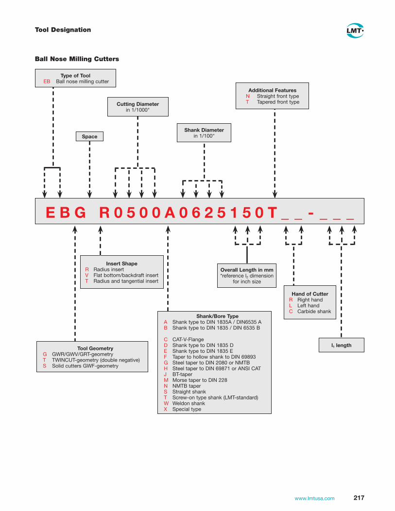
217www.lmtusa.com
Tool Designation
E B G R 0 5 0 0 A 0 6 2 5 1 5 0 T _ _ - _ _ _
Type of Tool EB Ball nose milling cutter
Tool Geometry G GWR/GWV/GRT-geometry T TWINCUT-geometry (double negative) S Solid cutters GWF-geometry
Insert Shape R Radius insert V Flat bottom/backdraft insert T Radius and tangential insert
Shank/Bore Type A Shank type to DIN 1835A / DIN6535 A B Shank type to DIN 1835 / DIN 6535 B
C CAT-V-Flange D Shank type to DIN 1835 D E Shank type to DIN 1835 E F Taper to hollow shank to DIN 69893 G Steel taper to DIN 2080 or NMTB H Steel taper to DIN 69871 or ANSI CAT J BT-taper M Morse taper to DIN 228 N NMTB taper S Straight shank T Screw-on type shank (LMT-standard) W Weldon shank X Special type
Ball Nose Milling Cutters
Overall Length in mm*reference l2 dimension
for inch size
Additional Features N Straight front type T Tapered front type
Space
Cutting Diameter in 1/1000"
Shank Diameter in 1/100"
Hand of Cutter R Right hand L Left hand C Carbide shank
l1 length

218 www.lmtusa.com
Tool Designation
Copy Milling Cutters
E C T R 1 2 - 1 2 5 T H 0 6 6 _
Type of Tool FC Copy milling cutters MC Modular copy mill (MULTI-MILL) EC Copy end mill (not ball nose)
Tool Geometry C RMC-geometry H High positive geometry N Negative geometry P Positive geometry T TWINCUT-geometry (double negative) U UNIVEX-geometry V TWINCUT-VA geometry (high positive/negative) Z Neutral
Insert Shape to ISO 513
- (hyphen)
Space
Shank/Bore Dimension For F, S for shank/bore type A A .750" E 2.00" B 1.00" F 2.50" C 1.25" G 3.00" D 1.50" For shank/bore type C,G,H,J or N A taper 40 D taper 30 B taper 50 E taper 45 C taper 60 For shank/bore type F A HSK 32 E HSK 80 B HSK 40 F HSK 100 C HSK 50 G HSK 125 D HSK 63 H HSK 160 For E for shank/bore type T C M 6 I M 20 D M 8 d2=8.2 J M 24 E M 10 d2=10.2 R M 8 d2=8.5 F M 12 S M10 d2=10.5 H M 16 For E for shank type W, A A .375 E 1.00 B .500 F 1.25 C .625 G 1.50 D .750 H 2.00
Nominal Diameterin inch 1.00" = 100
Insert Size to ISO 513I = insert length
Overall Length in inch
Shank/Bore Type For F, S A Mounting bore X Special type For E A Shank type to DIN 1835A / DIN6535 A B Shank type to DIN 1835 / DIN 6535 B C CAT-V-Flange D Shank type to DIN 1835 D E Shank type to DIN 1835 E F Taper to hollow shank to DIN 69893 G Steep taper to DIN 2080 or NMTB H Steep taper to DIN 69871 or ANSI CAT J BT-taper M Morse taper to DIN 228 N NMTB taper S Straight shank T Screw-on type shank (LMT-standard) W Weldon shank X Special type
Additional Features -A for SE _N1204 inserts -B for SE_W1204 inserts (hole) -C carbide shank -E extra close pitch -F fine pitch -I internal coolant supply -L left hand -R right hand -U undersized insert

219www.lmtusa.com
See our other LMT Catalogs for your Mold & Die, Gear Cutting and Service Needs
www.lmt-tools.com
Fräsen Drehen Bohren Reiben Gewinden SpannenMilling Turning Drilling Reaming Threading Chucking
PräzisionswerkzeugeHauptkatalog Precision ToolsMain Catalogue

www.lmtusa.com 220
Notes
www.lmtusa.com
Leitz MetalworkingTechnology Group
LMT – The Power of 6 Six companies with more than 3,000 employees: this is the Leitz Metalworking TechnologyGroup (LMT). Each company develops and produces precision tools for specific segmentsof the metalworking and plastics processing industries. With its experience and its products,each company is a successful technological leader in its specific working area. Together,LMT’s collective performance potential offers benefits in just about every area of machiningand chip-removal processing.
Belin (France) is a technological leader for high-performance carbide reamers, PCD & CBNhigh-precision grooving mills and solid carbide milling cutters for plastics & aluminum alloys.
Bilz (Germany) operates in the field of tool clamping and is now the leading manufacturerof thread-tapping chucks and the Thermo-Grip® system.
Boehlerit (Austria) is a manufacturer of cutting tool materials for metal, composites, plastics,wood and of carbide for non-cutting applications. Boehlerit has a worldwide reputation forultimate precision in the processing of carbide metals and tools for turning, milling, drilling,bar peeling and chipless forming.
Fette (Germany) has earned an outstanding position as a manufacture of precision milling &hobbing tools and supplies an extensive program of carbide-metal and high-speed steel toolsfor metal and plastics processing, thread rolling systems and thread tapping dies.
Kieninger (Germany) occupies a leading position on the market for special cutting systemsused for more complex bore machining and precision machining work within the die andmold industry and for the machining of engine components for the automotive industry.
Onsrud (USA) specializes in the production of end-milling cutters for high-speed machiningof aluminum, plastics and composite materials in the aerospace industry.

www.lmtusa.com
Milling Tools & Inserts
LMT USA, INC.1997 Ohio StreetLisle, Illinois 60532Toll-Free 800-225-0852 orDirect 630-969-5412Fax 630-969-5492E-mail: [email protected]: www.lmtusa.com
Prin
ted
in U
SA
0
1/09
E
DP
# 18
753
Leitz MetalworkingTechnology Group
Leitz MetalworkingTechnology Group