pj10kps-ca - rvr elettronica
TRANSCRIPT
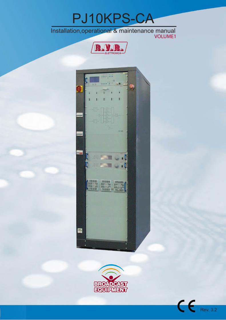
PJ10KPS-CA
Rev. 3.2
Installation,operational & maintenance manualVOLUME1

Notification of intended purpose and limitations of product useThis product is a FM transmitter intended for FM audio broadcasting. It utilisesoperating frequencies not harmonised in the intended countries of use.The user must obtain a license before using the product in intended country ofuse. Ensure respective country licensing requirements are complied with.Limitations of use can apply in respect of operating freuency, transmitter powerand/or channel spacing.
Declaration of ConformityHereby, R.V.R. Elettronica SpA, declares that this FM transmitter is incompliance with the essential requirements and other relevant provisions ofDirective 1999/5/EC.

Waste Electrical or Electronic Equipment(WEEE)
This symbol indicates that you should not discard waste electrical or electro-nic equipment (WEEE) in the trash. For proper disposal, contact your local recycling/reuse or hazardous waste center.
CAUTION
Do discard waste electrical or electronic equipment (WEEE) in the trash. For proper disposal, contact your local recycling/reuse or hazardous waste center.
PJ10KPS-CA
User & Technical Manual IV
Index1.2.3. 3.1 3.1.1 3.1.2 3.2 3.2.1 3.2.24. 4.1 4.2 4.3 4.4 4.55. 5.1 5.1.1 5.1.2 5.1.3 5.1.4 5.1.5 5.1.6 5.1.7 5.1.8 5.1.9 5.1.10 5.1.11 5.1.12 5.1.13 5.2 5.36. 6.1 6.1.1 6.2 6.2.1 6.3 6.3.1 6.3.2 6.4 6.4.1 6.5 6.5.1 6.5.1.1 6.5.2 6.5.3 6.5.4
Preliminary instructions......................................................................Warranty..............................................................................................First Aid...............................................................................................Electric shock treatment.....................................................................If the victim is unconscious.................................................................If the victim is conscious.....................................................................Treatment of electric burns.................................................................Large burns and broken skin..............................................................Minor burns.........................................................................................General Description............................................................................Composition........................................................................................Technical specifications......................................................................Options................................................................................................Operating principles............................................................................Module failure.....................................................................................Control unit (CU)................................................................................LCD Display.......................................................................................Overall status menu............................................................................Select menu........................................................................................Control unit menu...............................................................................Power supply menu............................................................................R.F. combiner menu............................................................................R.F. units menu...................................................................................Alarms menu......................................................................................Service menu......................................................................................Settings menu.....................................................................................Exciters menu.....................................................................................Info menu............................................................................................Release menu....................................................................................Modem menu......................................................................................Buttons, selector switches and LEDs..................................................Alarms.................................................................................................Details principal,Components and Sub-Systems................................Control unit (CU).................................................................................Settings motherboard control unit.......................................................RF module..........................................................................................Settings CPU board (RF Module).......................................................Electromechanical section..................................................................P.S. combiner (PF1ADPSPJ5KM).......................................................P.S. combiner trimmer.........................................................................Parallel interface (INTREMPJ5K).......................................................Interlock dummy load / transmitter......................................................RF Module box...................................................................................Tray fans (CASVTLMPJ10KVC).........................................................PCB fan voltage..................................................................................RF module address............................................................................Power distribution board tray fans (CSALVTL2KWPJ).......................Power supply tray fans.......................................................................
122222222334567101113131314151617171819202122232527303133373839404246474849515254
VUser & Technical Manual
PJ10KPS-CA
6.6 6.6.1 6.6.2 6.7 6.8 6.9 6.10 6.11 6.11.1 6.11.2 6.11.3 7. 7.1 7.28. 8.1 8.2 8.3 8.4 8.5 8.6 8.6.1 8.6.2 8.6.3 8.6.4 8.6.5 8.6.6 8.6.7
Combiner and Splitter.........................................................................RF combiner schematic......................................................................Splitter board trimmers.......................................................................Installation emergency CCU Board (SLCCUEMPJ5K1).....................Services supply...................................................................................PJ10KPS-CA Ventilation.....................................................................Input socket........................................................................................Rejected load......................................................................................Wiring diagrams..................................................................................Settings Absorber misure board (SLADKDIPK5K3)...........................Settings unbalancement measure board............................................GSM Telemetry...................................................................................Dial-up via mobile...............................................................................Alarms..................................................................................................Unpacking,installation and use...........................................................Assembly............................................................................................First start.............................................................................................Preliminary operation.........................................................................Power-on............................................................................................Control unit settings............................................................................Management of the exciters...............................................................Start-up from power-on with exciters in manual mode.......................From OFF to ON with exciters in manual...........................................Automatic changeover........................................................................Phase from ON to OFF.......................................................................Start-up with exciters in automatic mode............................................Audio alarm........................................................................................Protection and alarms.........................................................................
55565758626364656769707275767777797980808282828383848485
1User & Technical Manual
PJ10KPS-CA
1. Preliminary Instructions• General Warnings
This equipment should only be operated, installed and maintained by “trained” or “qualified” personnel who are familiar with risks involved in working on electric and electronic circuits. “Trained” means personnel who have technical knowledge of equipment operation and who are responsible for their own safety and that of other unqualified personnel placed under their supervision when working on the equipment. “Qualified” means personnel who are trained in and experienced with equipment operation and who are responsible for their own safety and that of other unqualified personnel placed under their supervision when working on the equipment.
WARNING: Residual voltage may be present inside the equipment even when the ON/OFF switch is set to Off. Before servicing the equipment, disconnect the power cord or switch off the main power panel and make sure the safety earth connection is connected. Some service situations may require inspecting the equipment with live circuits. Only trained and qualified personnel may work on the equipment live and shall be assisted by a trained person who shall keep ready to disconnect power supply at need.
R.V.R. Elettronica S.r.l. shall not be liable for injury to persons or damage to property resulting from improper use or operation by trained/untrained and qualified/unqualified persons.
WARNING: The equipment is not water resistant. Any water entering the enclosure might impair proper operation. To prevent the risk of electrical shock or fire, do not expose this equipment to rain, dripping or moisture.
Please observe local codes and fire prevention rules when installing and operating this equipment.
WARNING: This equipment contains exposed live parts involving an electrical shock hazard. Always disconnect power supply before removing any covers or other parts of the equipment.
Ventilation slits and holes are provided to ensure reliable operation and prevent overheating; do not obstruct or cover these slits. Do not obstruct the ventilation slits under any circumstances. The product must not be incorporated in a rack unless adequate ventilation is provided or the manufacturer’s instructions are followed closely.
WARNING: This equipment can radiate radiofrequency energy and, if not installed in compliance with manual instructions and applicable regulations, may cause interference with radio communications.
WARNING: This equipment is fitted with earth connections both in the power cord and for the chassis. Make sure both are properly connected.
Operation of this equipment in a residential area may cause radio interference, in which case the user may be required to take adequate measures.
The specifications and data contained herein are provided for information only and are subject to changes without prior notice. R.V.R. Elettronica S.r.l. disclaims all warranties, express or implied.While R.V.R. Elettronica S.r.l. attempts to provide accurate information, it cannot accept responsibility or liability for any errors or inaccuracies in this manual, including the products and the software described herein. R.V.R. Elettronica S.r.l. reserves the right to make changes to equipment design and/or specifications and to this manual at any time without prior notice.
• Notice concerning product intended purpose and use limitations.
This product is a radio transmitter suitable for frequency-modulation audio radio broadcasting. Its operating frequencies are not harmonised in designated user countries. Be fo re opera t ing th i s equ ipmen t , use r mus t obtain a l icence to use radio spectrum from the competent authority in the designated user country. Operating frequency, transmitter power and other characteristics of the transmission system are subject to restrictions as specified in the licence.
2. WarrantyLa R.V.R. Elettronica S.r.l. warrants this product to be free from defects in workmanship and its proper operation subject to the limitations set forth in the supplied Terms and Conditions. Please read the Terms and Conditions carefully, as purchase of the product or acceptance of the order acknowledgement imply acceptance of the Terms and Condit ions. For the latest updated terms and conditions, please visit our web site at WWW.RVR.IT. The web site may be modified, removed or updated for any reason whatsoever without prior notice. The warranty will become null and void in the event the product enclosure is opened, the product is physically damaged, is repaired by unauthorised persons or is used for purposes other than its intended use, as well as in the event of improper use, unauthorised changes or neglect. In the event a defect is found, follow this procedure:
1 Contact the seller or distributor who sold the equipment; provide a description of the problem or malfunction for the event a quick fix is available.
Sellers and Distributors can provide the necessary information to troubleshoot the most frequently encountered problems. Normally, Sellers and Distributors can offer a faster repair service than the Manufacturer would. Please note that Sellers can pinpoint problems due to wrong installation.
2 If your Seller cannot help you, contact R.V.R. Elettronica S.r.l. and describe the problem; if our staff deems it appropriate, you will receive an authorisation to return the equipment along with suitable instructions;
3 When you have received the authorisation, you may return the unit. Pack the unit carefully before shipment; use the original packaging whenever possible and seal the package perfectly. The customer bears all risks of loss (i.e., R.V.R. shall not be liable for loss or damage) until the package reaches the R.V.R. factory. For this reason, we recommend insuring the goods for their full value. Returns must be sent on a C.I.F. basis (PREPAID) to the address stated on the authorisation as specified by the R.V.R. Service Manager.
IMPORTANTThe symbol of lightning inside a triangle placed on the product, evidences the operations for which is necessary gave it full attention to avoid risk of electric shocks.
The symbol of exclamation mark inside a triangle placed on the product, informs the user about the presence of instructions inside the manual that accompanies the equipment, im-portant for the efficacy and the maintenance (repairs).

PJ10KPS-CA
User & Technical Manual 2
Units returned without a return authorisation may be rejected and sent back to the sender.
4 Be sure to include a detailed report mentioning all problems you have found and copy of your original invoice (to show when the warranty period began) with the shipment.
Please send spare and warranty replacement parts orders to the address provided below. Make sure to specify equipment model and serial number, as well as part description and quantity.
R.V.R. Elettronica S.r.l. Via del Fonditore, 2/2c 40138 BOLOGNA ITALY Tel. +39 051 6010506
3. First AidAll personnel engaged in equipment installation, operation and maintenance must be familiar with first aid procedures and routines.
3.1 Electric shock treatment
3.1.1 If the victim is unconscious
Follow the first aid procedures outlined below.
• Lay the victim down on his/her back on a firm surface.
• the neck and tilt the head backwards to free
the airway system (Figure 1).
Figure 1
• If needed, open the victim’s mouth and check for breathing.
• If there is no breathing, start artificial respiration without delay (Figure 2) as follows: tilt the head backwards, pinch the nostrils, seal your mouth around the victim’s mouth and give four fast rescue breaths.
Figure 2
• Check for heartbeat (Figure 3); if there is no heartbeat, begin chest compressions immediately (Figure 4) placing your hands in the centre of the victim’s chest (Figure 5).
Figure 3 Figure 4 Figure 5
• One rescuer: give 2 quick rescue breaths after each 15 compressions.
• Two rescuers: one rescue breath after each 5 compressions.
• Do not stop chest compressions while giving artificial breathing.
• Call for medical help as soon as possible.
3.1.2 If the victim is conscious• Cover victim with a blanket.
• Try to reassure the victim.
• Loosen the victim’s clothing and have him/her lie down.
• Call for medical help as soon as possible.
3.2 Treatment of electric burns
3.2.1 Large burns and broken skin• Cover affected area with a clean cloth or linen.
• Do not break any blisters that have formed; remove any clothing or fabric that is stuck to the skin; apply adequate ointment.
• Administer adequate treatment for the type of accident.
• Get the victim to a hospital as quickly as possible.
• Elevate arms and legs if injured.
If medical help is not available within an hour, the victim is conscious and is not retching, administer a solution of table salt and baking soda (one teaspoon of table salt to half teaspoon of baking soda every 250 ml of water).
Have the victim slowly drink half a glass of solution for four times during a period of 15 minutes.
Stop at the first sign of retching.
Do not administer alcoholic beverages.
3.2.2 Minor burns• Apply cold (not ice cold) strips of gauze or dress
wound with clean cloth.
• Do not break any blisters that have formed; remove any clothing or fabric that is stuck to the skin; apply adequate ointment.
• If needed, have the victim change into clean, dry clothing.
• Administer adequate treatment for the type of accident.
• Get the victim to a hospital as quickly as possible.
• Elevate arms and legs if injured.

PJ10KPS-CA
User & Technical Manual 3
4. General DescriptionThe PJ10KPS-CA is a RF amplifier for frequency modulation sound broadcasting. It is a fully solid-state apparatus of modern design that uses MOSFET as active components in the FM amplifying modules. This chapter briefly describes the machine’s main features.
4.1 CompositionThe PJ10KPS-CA transmitter is made up of modules inserted in a 19” rack. The main appara-tuses are:
• 5x RF amplifier modules at 2.2 kW nominal• 1x Control unit (CU)• 1x Splitter/Input RF• 1x Dummy load
In configuration standard it comes supplied with Rack from 32 unit.Other dimensions of the Rack always from 19” but with various heights (40 unit) are available upon request.
SIDE VIEW
A B C D32U 685 1580 1615 100040U 685 1935 1970 1000
RACK SIZE
(A) (D)
(B) (C)
FRONTAL VIEW
4User & Technical Manual
PJ10KPS-CA
4.2 Technical specifications
**The value can differ in the event comes demanded the rack from 40 units
The amplifier is supplied complete with all its parts, not really "modules", essential for its operation such as the fans for dissipating the heat generated by the machine inside the room and all the accessories for the electrical and RF wiring. As a rule, the amplifier is supplied as a complete transmitter therefore the two FM exciters that it manages will be provided and connected (a service exciter and a spare exciter).
Frequency range: 87.5 to 108.0 MHz without any tuningsNominal RF power: 10,000 WPower supply voltage: 400V ±10% AC Three-phase, 3F+N
230V ±10% AC Three-phase, 3F+N230V ±10% AC Mono-Phase 50/60 Hz
Frequency: 50/60Hz ±2HzExciting power: Max 30 WConsumption: about 14.7 KW TypicalPower factor: > 0.95Efficiency: 68/70 %Weight: 350** kg (rack) - 18 kg (module)Nominal frequency deviation: ± 75 KHz (peak)Maximum frequency deviation: ± 100 KHz (peak)Rated output (load) impedance: 50 ohm unbalancedPermissible VSWR: The permissible VSWR is 1.5:1 with full power with
foldback beyond 1.5:1.Harmonics suppression and spurious: Typically 85 dBRF power output connector size: 1-5/8” with EIA flange (on request 3-1/8” with EIA
flange)Max. frequency tollerance: As per ITU (R)Pilot tone stability: As per ITU (R)Ambient temperature range for operation: 0° C to + 45° CRelative humidity: 95 %, non condensing.Working altitude: Up to 3000 meters AMSL *
* For working heights of over 3000 meters, there are (optionally) two possibilities, according to the particular needs of the site:
• extraction fan air• fans to push the air inside the rack
PJ10KPS-CA
User & Technical Manual 5
Additional important features of the PJ10KPS-CA are as follows:
The amplifier can work as usual even if the control unit is not present. In fact, the control unit may be substituted temporarily with an electromechanical interface by means of which the user may give the ON and OFF commands to the machine. However, in this case all the numeric type information will be missing and the power level remains the last one ena-bled before removing the control unit.
● Immediate power foldback under severe / damaging fault conditions of VSWR. The po-wer of transmitter should automatically come down to a suitable safe design limit, so that the transmitter and its subsystem does not get damaged due to load mis match. Details of fold back to be provided.
●
●
● Each module is controlled by a microprocessor-based card that checks and adjusts its operating mode. The resulting data are transmitted to the control unit.
● The 2.2 kW amplifying modules are implemented by means of plug-in technology: the individual modules may be removed for performing maintenance operations, for instance, without having to turn off the transmitter. The transmitter keeps working at reduced power even if the module has been removed. This operation may be carried out without any risk of damaging the module itself, or the amplifier as a whole, thanks to the control system and to the RF connectors, the power supply and the purposely designed data-exchange. For further information refer to the maintenance section.
The control unit manages the changeover of the two exciters both in automatic and ma-nual mode.
The foldback function, on the VSWR protection, works automatically on bias voltage and PA volta-ge, reducing them to ensure that the machine can work at maximum power, not to damage internal organs (mosfet, combiners and dummy load).
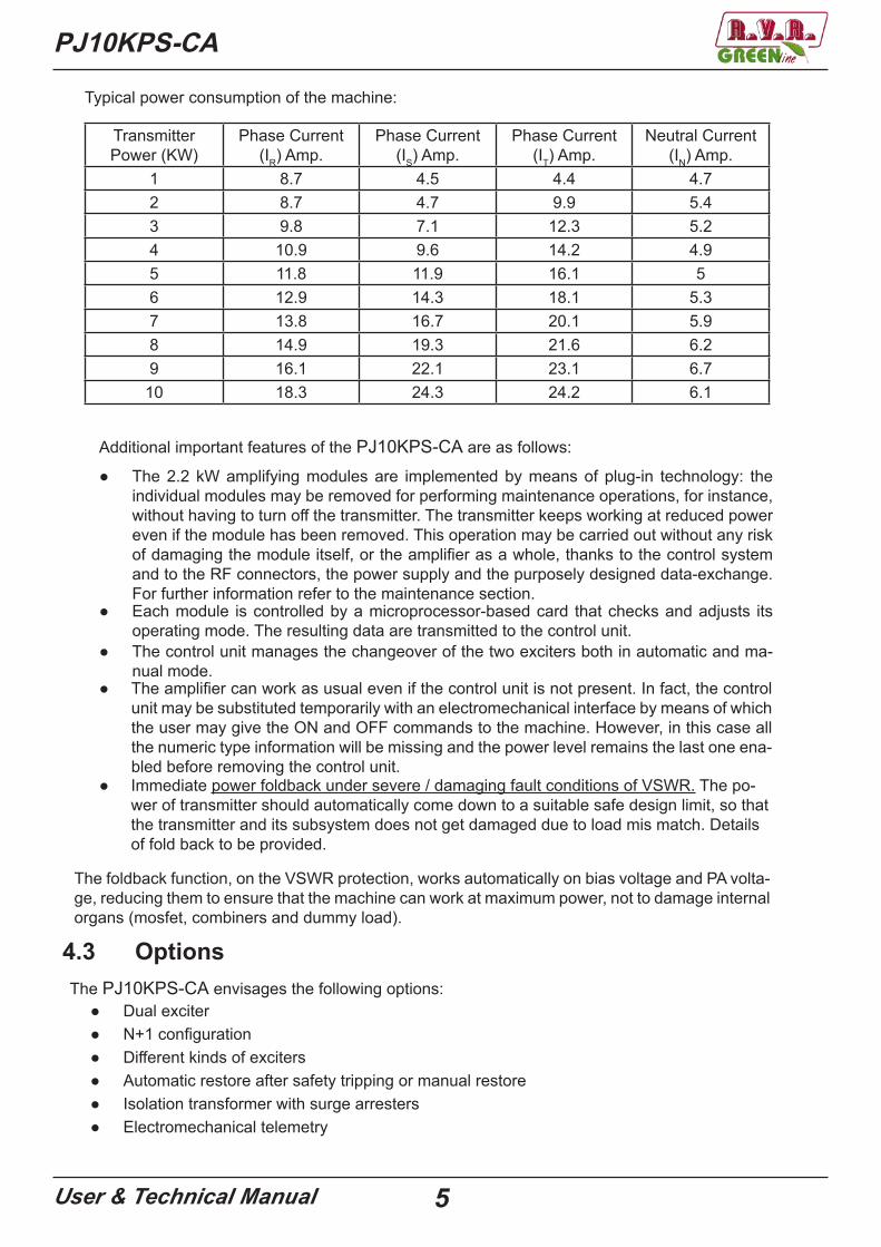
TransmitterPower (KW)
Phase Current(IR) Amp.
Phase Current(IS) Amp.
Phase Current(IT) Amp.
Neutral Current(IN) Amp.
1 8.7 4.5 4.4 4.72 8.7 4.7 9.9 5.43 9.8 7.1 12.3 5.24 10.9 9.6 14.2 4.95 11.8 11.9 16.1 56 12.9 14.3 18.1 5.37 13.8 16.7 20.1 5.98 14.9 19.3 21.6 6.29 16.1 22.1 23.1 6.7
10 18.3 24.3 24.2 6.1
Typical power consumption of the machine:
4.3 Options
● Dual exciterThe PJ10KPS-CA envisages the following options:
● N+1 configuration● Different kinds of exciters● Automatic restore after safety tripping or manual restore● Isolation transformer with surge arresters● Electromechanical telemetry
6User & Technical Manual
PJ10KPS-CA
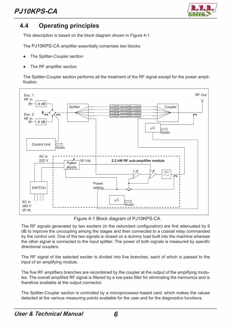
4.4 Operating principlesThis description is based on the block diagram shown in Figure 4-1.
The PJ10KPS-CA amplifier essentially comprises two blocks:
● The Splitter-Coupler section
● The RF amplifier section
The Splitter-Coupler section performs all the treatment of the RF signal except for the power ampli-fication.
-6 dB
-6 dB
Exc. 1RF in
Exc. 2RF in
AC in220 V 50 Vdc
Splitter Coupler
-
Powersupply
C
Control Unit
2.2 kW RF sub-amplifier module
RF Out
C
RS485
RS485
RS485
Powersetting
AC in380 V3F+N
SWITCH
2.2 kW RF sub-amplifier module2.2 kW RF sub-amplifier module2.2 kW RF sub-amplifier module2.2 kW RF sub-amplifier module
Figure 4-1 Block diagram of PJ10KPS-CAThe RF signals generated by two exciters (in the redundant configuration) are first attenuated by 6 dB to improve the uncoupling among the stages and then connected to a coaxial relay commanded by the control unit. One of the two signals is closed on a dummy load built into the machine whereas the other signal is connected to the input splitter. The power of both signals is measured by specific directional couplers.
The RF signal of the selected exciter is divided into five branches, each of which is passed to the input of an amplifying module.
The five RF amplifiers branches are recombined by the coupler at the output of the amplifying modu-les. The overall amplified RF signal is filtered by a low-pass filter for eliminating the harmonics and is therefore available at the output connector.
The Splitter-Coupler section is controlled by a microprocessor-based card, which makes the values detected at the various measuring points available for the user and for the diagnostics functions.
PJ10KPS-CA
User & Technical Manual 7
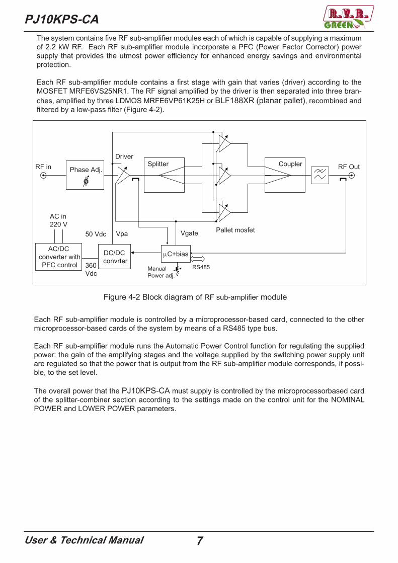
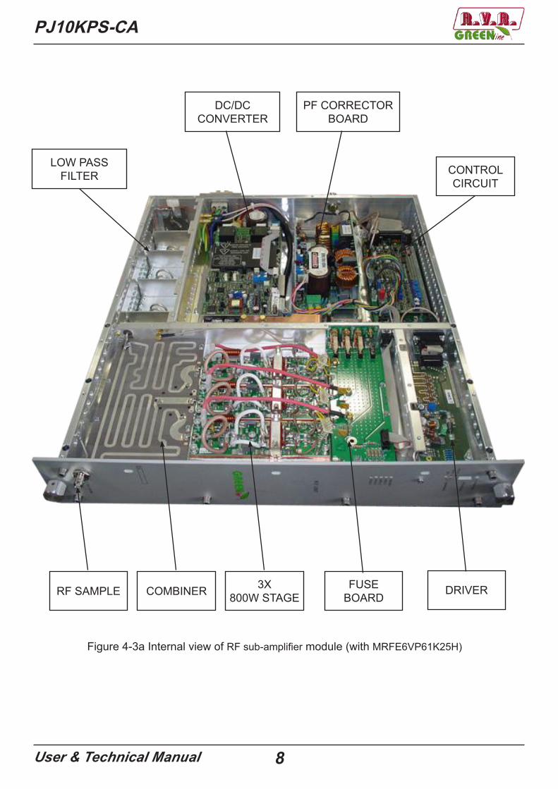
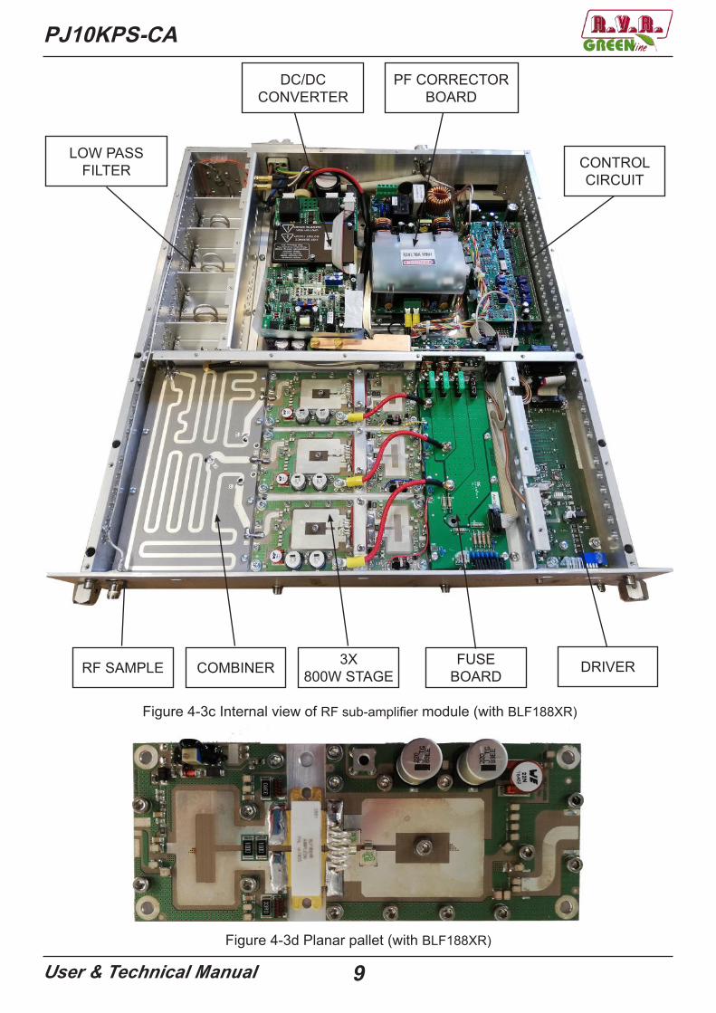
The system contains five RF sub-amplifier modules each of which is capable of supplying a maximum of 2.2 kW RF. Each RF sub-amplifier module incorporate a PFC (Power Factor Corrector) power supply that provides the utmost power efficiency for enhanced energy savings and environmental protection.
Each RF sub-amplifier module contains a first stage with gain that varies (driver) according to the MOSFET MRFE6VS25NR1. The RF signal amplified by the driver is then separated into three bran-ches, amplified by three LDMOS MRFE6VP61K25H or BLF188XR (planar pallet), recombined and filtered by a low-pass filter (Figure 4-2).
RF in
50 Vdc
Splitter Coupler RF Out
RS485
Phase Adj.
C+bias
Vpa
ManualPower adj.
Vgate
AC/DCconverter withPFC control
DC/DCconvrter360
Vdc
AC in220 V
Driver
Pallet mosfet
Figure 4-2 Block diagram of RF sub-amplifier module
Each RF sub-amplifier module is controlled by a microprocessor-based card, connected to the other microprocessor-based cards of the system by means of a RS485 type bus.
Each RF sub-amplifier module runs the Automatic Power Control function for regulating the supplied power: the gain of the amplifying stages and the voltage supplied by the switching power supply unit are regulated so that the power that is output from the RF sub-amplifier module corresponds, if possi-ble, to the set level.
The overall power that the PJ10KPS-CA must supply is controlled by the microprocessorbased card of the splitter-combiner section according to the settings made on the control unit for the NOMINAL POWER and LOWER POWER parameters.
8User & Technical Manual
PJ10KPS-CA
Figure 4-3a Internal view of RF sub-amplifier module (with MRFE6VP61K25H)
LOW PASS FILTER
DC/DCCONVERTER
PF CORRECTORBOARD
CONTROLCIRCUIT
COMBINER 3X800W STAGE
DRIVERFUSEBOARDRF SAMPLE
9User & Technical Manual
PJ10KPS-CA
LOW PASS FILTER
DC/DCCONVERTER
PF CORRECTORBOARD
CONTROLCIRCUIT
COMBINER 3X800W STAGE DRIVERFUSE
BOARDRF SAMPLE
Figure 4-3c Internal view of RF sub-amplifier module (with BLF188XR)
Figure 4-3d Planar pallet (with BLF188XR)
PJ10KPS-CA
User & Technical Manual 10
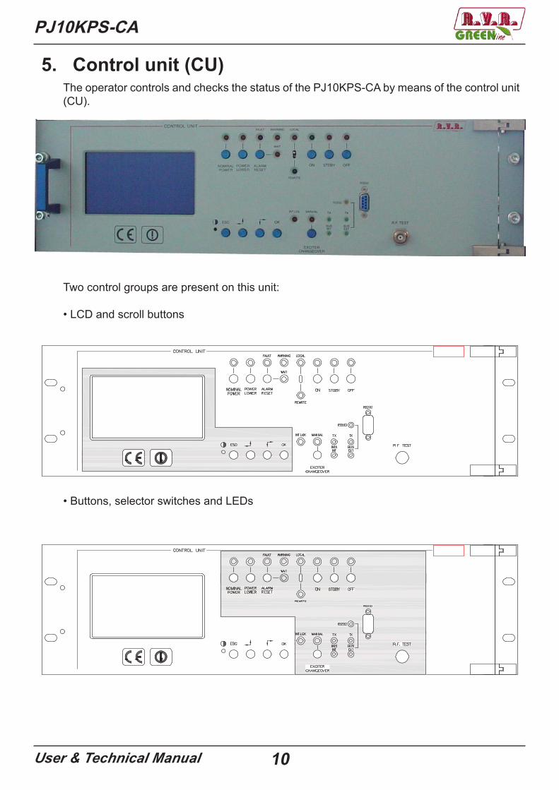
5. Control unit (CU)The operator controls and checks the status of the PJ10KPS-CA by means of the control unit (CU).
Two control groups are present on this unit:
• LCD and scroll buttons
• Buttons, selector switches and LEDs

11User & Technical Manual
PJ10KPS-CA
5.1 LCD DisplayThe operator uses the control software of the transmitter by means of a series of menus that are displayed on the LCD. Four specific keys are provided for scrolling through the menus, performing the settings and giving the commands:
Pulsante DescrizioneOK Click this button to access a sub-menu, to enter the editing mode
or to confirm a modified value.ESC Click this button to exit from a menu or to cancel the modification
of a value.Click this button to scroll inside a menu (to the right or down) or toreduce the value of a parameter being modified.Click this button to scroll inside a menu (to the left or up) or toincrease the value of a parameter being modified.Trimmer for the regulation of the contrast of display the LCD
When the operator is not using the various buttons to navigate, the LCD displays the preset screenful that shows the “Output Power” that it indicates the forward and reflected output power (Figure 5-1).As indicated on the preset screenful, push the ESC button to access at the “Overall Sta-tus” menù (Figure 5-2).
Figure 5-1

PJ10KPS-CA
User & Technical Manual 12
Figure 5-2
Menù Line DescriptionTimer (when enabled)
Indication of the start and stop times of the automatic powerreduction feature - see “Settings” menù
Control unit Status of the control unit (Off or On) and indication of the exciteractually connected to the amplifier (Exct.1 or Exct.2)
Power supply Status of the power supply boardR.F. Combiner Status of the RF combinerR.F. Unit - N Status of the Rf power amplifier number N (1° from the left)Hours Timer counting the hours of operation of the transmitter. For exam-
ple, this indication is useful in order to define when a maintenance operation can be made
By pressing the Esc key as indicated on the last line, you can shift to the exchange screen from which you can have access to the “Select” menu (Figure 5-3).
This menu includes only indications, therefore the user cannot insert any input in its different lines.(Figure 5-2).
5.1.1 Overall Status Menu
13User & Technical Manual
PJ10KPS-CA
Figura 5-3
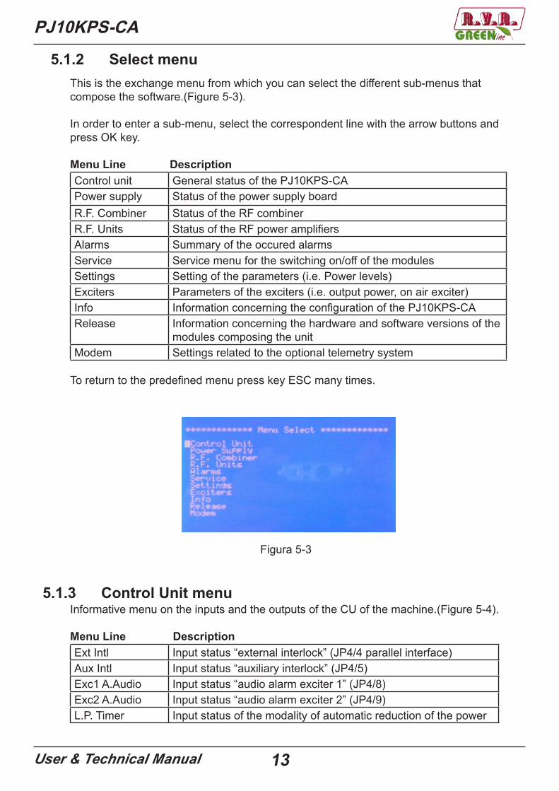
5.1.2 Select menuThis is the exchange menu from which you can select the different sub-menus that compose the software.(Figure 5-3).
In order to enter a sub-menu, select the correspondent line with the arrow buttons and press OK key.
Menu Line DescriptionControl unit General status of the PJ10KPS-CAPower supply Status of the power supply board R.F. Combiner Status of the RF combinerR.F. Units Status of the RF power amplifiersAlarms Summary of the occured alarmsService Service menu for the switching on/off of the modulesSettings Setting of the parameters (i.e. Power levels)Exciters Parameters of the exciters (i.e. output power, on air exciter)Info Information concerning the configuration of the PJ10KPS-CARelease Information concerning the hardware and software versions of the
modules composing the unitModem Settings related to the optional telemetry system
To return to the predefined menu press key ESC many times.
5.1.3 Control Unit menuInformative menu on the inputs and the outputs of the CU of the machine.(Figure 5-4).
Menu Line DescriptionExt Intl Input status “external interlock” (JP4/4 parallel interface)Aux Intl Input status “auxiliary interlock” (JP4/5)Exc1 A.Audio Input status “audio alarm exciter 1” (JP4/8)Exc2 A.Audio Input status “audio alarm exciter 2” (JP4/9)L.P. Timer Input status of the modality of automatic reduction of the power

PJ10KPS-CA
User & Technical Manual 14
Reserve 2 Input status “Reserve 2” (JP8/3)Reserve 3 Input status “Reserve 3” (JP8/4)Reserve 4 Input status “Reserve 4” (JP8/5)Relay Exc Exciters exchange relay status (Off = exciter 1 on air)Exc-1 Mute Exciter 1 interlock status (Off = RF power enabled)Exc-2 Mute Exciter 2 interlock status (Off = RF power enabled)Audio Alarm Output Audio Alarm status (JP47/1)Exc’s Mains Exciters power supply status (On = power supply enabled)Stand_by (In) “Stand by” input line statusStand_by (Out) “Stand by” output line status from the control unitTotal Eff Total efficiency of the machine
Figure 5-4
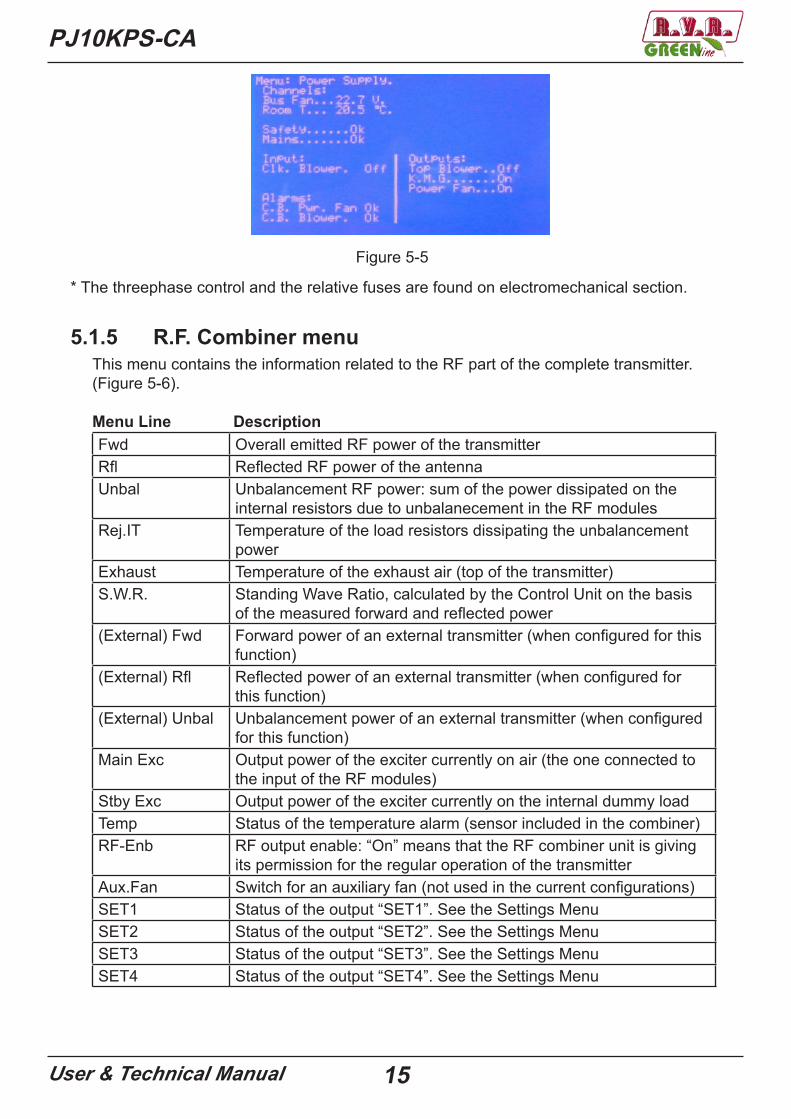
5.1.4 Power supply menuinformative menu of PJ10KPS-CA of the machine (Figure 5-5).
Menu Line DescriptionBus Fan Supply voltage of the fans inputRoom T Temperature of the air at the input of the unitSafety Status of the safety arrest button. On indicates the functioning is
enabled, Alr means the unit was arrested through the buttonMains Status of the main voltage supply. Ok indicates the presence of all
phases and that their sequence is corrected, Alr means that it must verify the presence of all phases,their sequence or the fuse of one or more phases, to protection of the threephase control *
Clk. Blower Indicates the state of thermostat outlet airC.B. Pwr. Fan Indicates the state of motor protection switch input airC.B. Blower Indicates the state of motor protection switch output airTop Blower Indicates the state of the exhaust fanK.M.G. Indicates the status of the contactor general of the machine (not
used)Power Fan Indicates the state of input fan
15User & Technical Manual
PJ10KPS-CA
* The threephase control and the relative fuses are found on electromechanical section.
Figure 5-5
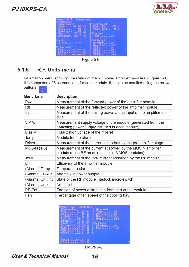
5.1.5 R.F. Combiner menuThis menu contains the information related to the RF part of the complete transmitter.(Figure 5-6).
Menu Line DescriptionFwd Overall emitted RF power of the transmitterRfl Reflected RF power of the antennaUnbal Unbalancement RF power: sum of the power dissipated on the
internal resistors due to unbalanecement in the RF modulesRej.IT Temperature of the load resistors dissipating the unbalancement
powerExhaust Temperature of the exhaust air (top of the transmitter)S.W.R. Standing Wave Ratio, calculated by the Control Unit on the basis
of the measured forward and reflected power(External) Fwd Forward power of an external transmitter (when configured for this
function)(External) Rfl Reflected power of an external transmitter (when configured for
this function)(External) Unbal Unbalancement power of an external transmitter (when configured
for this function)Main Exc Output power of the exciter currently on air (the one connected to
the input of the RF modules)Stby Exc Output power of the exciter currently on the internal dummy loadTemp Status of the temperature alarm (sensor included in the combiner)RF-Enb RF output enable: “On” means that the RF combiner unit is giving
its permission for the regular operation of the transmitterAux.Fan Switch for an auxiliary fan (not used in the current configurations)SET1 Status of the output “SET1”. See the Settings MenuSET2 Status of the output “SET2”. See the Settings MenuSET3 Status of the output “SET3”. See the Settings MenuSET4 Status of the output “SET4”. See the Settings Menu
PJ10KPS-CA
User & Technical Manual 16
Figure 5-6
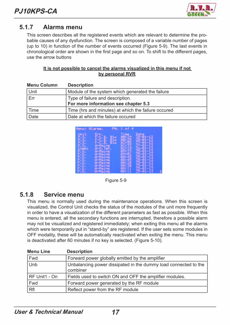
5.1.6 R.F. Units menuInformation menu showing the status of the RF power amplifier modules. (Figure 5-8).It is composed of 5 screens, one for each module, that can be scrolled using the arrow buttons.
Menu Line DescriptionFwd Measurement of the forward power of the amplifier moduleRfl Measurement of the reflected power of the amplifier moduleInput Measurement of the driving power at the input of the amplifier mo-
duleV.P.A. Measurement supply voltage of the module (generated from the
switching power supply included in each module)Bias.V Polarization voltage of the mosfetTemp Module temperatureDriver.I Measurement of the current absorbed by the preamplifier stageMOS-N (1-3) Measurement of the current absorbed by the MOS N amplifier
module (each RF module contains 3 MOS modules)Total I Measurement of the total current absorbed by the RF moduleEff Efficiency of the amplifier module(Alarms) Temp Temperature alarm(Alarms) PS-Alr Anomaly in power supply(Alarms) Unit.Intl State of the RF module interlock micro-switch(Alarms) Unbal Not usedRF-Enb Enabled of power distribution from part of the moduleFan Percentage of fan speed of the cooling tray
Figure 5-8
17User & Technical Manual
PJ10KPS-CA
5.1.7 Alarms menuThis screen describes all the registered events which are relevant to determine the pro-bable causes of any dysfunction. The screen is composed of a variable number of pages (up to 10) in function of the number of events occurred (Figure 5-9). The last events in chronological order are shown in the first page and so on. To shift to the different pages, use the arrow buttons
It is not possible to cancel the alarms visualized in this menu if not by personal RVR
Menu Column DescriptionUnit Module of the system which generated the failureErr Type of failure and description.
For more information see chapter 5.3Time Time (hrs and minutes) at which the failure occuredDate Date at which the failure occured
Figure 5-9
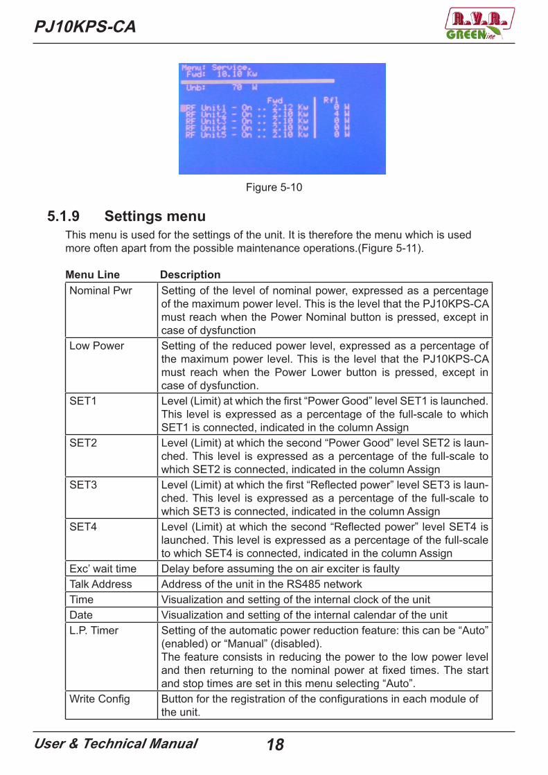
5.1.8 Service menuThis menu is normally used during the maintenance operations. When this screen is visualized, the Control Unit checks the status of the modules of the unit more frequently in order to have a visualization of the different parameters as fast as possible. When this menu is entered, all the secondary functions are interrupted, therefore a possible alarm may not be visualized and registered immediately; when exiting this menu all the alarms which were temporarily put in “stand-by” are registered. If the user sets some modules in OFF modality, these will be automatically reactivated when exiting the menu. This menu is deactivated after 60 minutes if no key is selected. (Figure 5-10).
Menu Line DescriptionFwd Forward power globally emitted by the amplifierUnb Unbalancing power dissipated in the dummy load connected to the
combinerRF Unit1 - On Fields used to switch ON and OFF the amplifier modules.Fwd Forward power generated by the RF moduleRfl Reflect power from the RF module
PJ10KPS-CA
User & Technical Manual 18
Figure 5-10
5.1.9 Settings menuThis menu is used for the settings of the unit. It is therefore the menu which is used more often apart from the possible maintenance operations.(Figure 5-11).
Menu Line DescriptionNominal Pwr Setting of the level of nominal power, expressed as a percentage
of the maximum power level. This is the level that the PJ10KPS-CA must reach when the Power Nominal button is pressed, except in case of dysfunction
Low Power Setting of the reduced power level, expressed as a percentage of the maximum power level. This is the level that the PJ10KPS-CA must reach when the Power Lower button is pressed, except in case of dysfunction.
SET1 Level (Limit) at which the first “Power Good” level SET1 is launched. This level is expressed as a percentage of the full-scale to which SET1 is connected, indicated in the column Assign
SET2 Level (Limit) at which the second “Power Good” level SET2 is laun-ched. This level is expressed as a percentage of the full-scale to which SET2 is connected, indicated in the column Assign
SET3 Level (Limit) at which the first “Reflected power” level SET3 is laun-ched. This level is expressed as a percentage of the full-scale to which SET3 is connected, indicated in the column Assign
SET4 Level (Limit) at which the second “Reflected power” level SET4 is launched. This level is expressed as a percentage of the full-scale to which SET4 is connected, indicated in the column Assign
Exc’ wait time Delay before assuming the on air exciter is faultyTalk Address Address of the unit in the RS485 networkTime Visualization and setting of the internal clock of the unitDate Visualization and setting of the internal calendar of the unitL.P. Timer Setting of the automatic power reduction feature: this can be “Auto”
(enabled) or “Manual” (disabled).The feature consists in reducing the power to the low power level and then returning to the nominal power at fixed times. The start and stop times are set in this menu selecting “Auto”.
Write Config Button for the registration of the configurations in each module ofthe unit.
19User & Technical Manual
PJ10KPS-CA
Figure 5-11
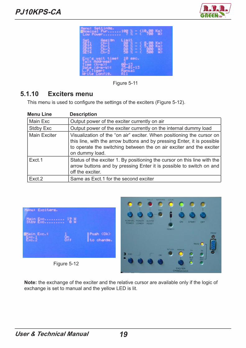
5.1.10 Exciters menuThis menu is used to configure the settings of the exciters (Figure 5-12).
Menu Line DescriptionMain Exc Output power of the exciter currently on airStdby Exc Output power of the exciter currently on the internal dummy loadMain Exciter Visualization of the “on air” exciter. When positioning the cursor on
this line, with the arrow buttons and by pressing Enter, it is possible to operate the switching between the on air exciter and the exciter on dummy load.
Exct.1 Status of the exciter 1. By positioning the cursor on this line with the arrow buttons and by pressing Enter it is possible to switch on and off the exciter.
Exct.2 Same as Exct.1 for the second exciter
Figure 5-12
Note: the exchange of the exciter and the relative cursor are available only if the logic of exchange is set to manual and the yellow LED is lit.

PJ10KPS-CA
User & Technical Manual 20
5.1.11 Info menuThis screen informs the user about the configuration of the transmitter. (Figure 5-13).
Menu Line DescriptionS.N. Serial number of the transmitterTalk Addr. Address of the RS485 port of the transmitter,it must be obligatorily 3Baud Rate Baud rate of the serial portSoftware V. Software version installed in the CUExciter Number of the exciters in the transmitter: this can be “Single” or
“Dual”Cfg. N+1 Configuration of the transmitter as a N+1 systemExternal Checking of the external Fwd, Rfl, Unbal values (Enabled or
Disabled)Reset Safety Reboot the machine after the intervention of the SAFETY alarm. It
must always be “Auto”Polarization The machine is designed to be able to transmit in the future, even
with digital signals. To do this we need to change parameters on both the tensions of active devices, both on the readings of the pa-rameters. Activating the “Analog”, the machine operates in classic analog configuration, putting “Digital” can process and transmit the digital signals.
Figure 5-13
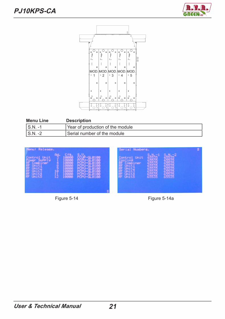
5.1.12 Release menuThis menu is composed of 2 screens, that can be scrolled using the arrow buttons. The first show the address, the kind of configuration, the software version and the hardware version of all the microprocessor boards of the transmitter (Figure 5-14), the second shows the serial numbers of the modules (Figure 5-14a).
Menu Line DescriptionControl unit Information on the CUPower supply Information on the power supplyRF Combiner Information of the RF combinerRF Unit 1 Information on module 1RF Unit 2 Information on module 2RF Unit 3 Information on module 3RF Unit 4 Information on module 4RF Unit 5 Information on module 5
PJ10KPS-CA
User & Technical Manual 21
Figure 5-14 Figure 5-14a
Menu Line DescriptionS.N. -1 Year of production of the moduleS.N. -2 Serial number of the module
22User & Technical Manual
PJ10KPS-CA
Figure 5-15aFigure 5-15
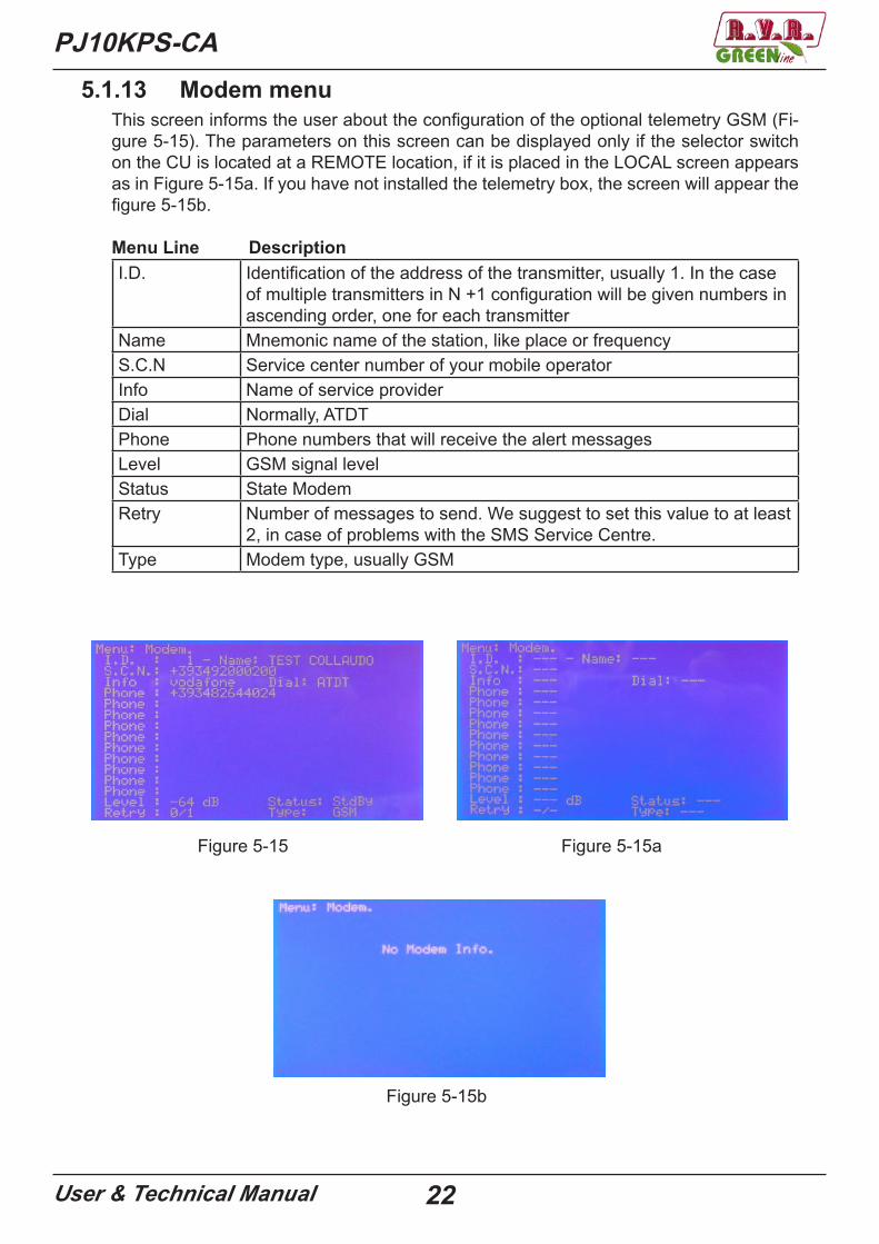
5.1.13 Modem menuThis screen informs the user about the configuration of the optional telemetry GSM (Fi-gure 5-15). The parameters on this screen can be displayed only if the selector switch on the CU is located at a REMOTE location, if it is placed in the LOCAL screen appears as in Figure 5-15a. If you have not installed the telemetry box, the screen will appear the figure 5-15b.
Menu Line DescriptionI.D. Identification of the address of the transmitter, usually 1. In the case
of multiple transmitters in N +1 configuration will be given numbers in ascending order, one for each transmitter
Name Mnemonic name of the station, like place or frequencyS.C.N Service center number of your mobile operatorInfo Name of service providerDial Normally, ATDTPhone Phone numbers that will receive the alert messagesLevel GSM signal levelStatus State ModemRetry Number of messages to send. We suggest to set this value to at least
2, in case of problems with the SMS Service Centre.Type Modem type, usually GSM
Figure 5-15b

PJ10KPS-CA
User & Technical Manual 23
5.2 Buttons, selector switches and LEDsThe typical machine-control operations are performed using the buttons of the control unit’s panel. Specific LEDs correspond to each button and selector switch for indicating the machine’s status.(Figure 5-16).
The functions performed by the controls are as follows:
Funzione DescrizioneOFF Button for turning off the machine. A LED signals that
the machine is OFF. In this status, the exciters and the pumps,are off.
STDBY Button for setting the machine in standby. In this status thetransmitter does not emit any power, but is ready to start thetransmission: the main blower is on, the RF modules are not powered, the exciters are on but locked by means of an inter-lock. The stand-by is used to test the exciters, in fact in ma-nual modality the operator could arrange them in base to the own requirements; coming from an “On” in manual modality, the system does not touch the interlock. Stand-by status is signalled from a LED.In manual and in stand-by the inhibit of the device doesn’t in-tervene on the interlock of the exciters. This could necessary when the apparatus is in configuration n+1 for verify if the exciters are operational.
ON Button for turning on the transmitter. The RF power supply is activated.If the command is set to MANUAL CHANGEOVER EXCITER (led on), exciters will block interlock and have to go through in “exciters menu” of CU to enable them manually.The exciters should deliver a power of at least 15 W to start the transmit-ter.
Figure 5-16

24User & Technical Manual
PJ10KPS-CA
LOC/REM Selector switch for setting the transmitter in remote or local mode. In local mode the buttons and the controls via the me-nus are active. In remote mode the buttons and the controls via the menus are inhibited and the commands may be given only remotely via the parallel interface or via the remote con-trol software.
ALARM RESET Button to reset the alarm type FAULT or WARNING.POWER LOWER Click this button to set the transmitter for supplying the nomi-
nal power level. A specific LED signals this setting. The value that corresponds to the nominal level is set by the operator using the menu settings (see 5.1.9)
NOMINAL POWER Click this button to set the transmitter for supplying the re-duced power level. A specific LED signals this set-ting. The value that corresponds to the reduced level is set by the ope-rator using the menus. (see 5.1.9)
EXCITER CHANGEOVER
Use this button to set the changeover system in manual orautomatic mode. The signaling LED turns on when the ma-nual mode is selected. On performing a changeover, the exci-ter connected to the amplifier is deviated toward the internal dummy load and vice-versa. The operator must use the exci-ters menu to perform the changeover in manual mode.
LED WARNING This LED indicates an attention condition (something is not working properly, but the amplifier is still running)
LED FAULT This LED indicates a fault (the amplifier is blocked, andrequired the intervention of an operator for the restoration)
LED WAIT This LED indicates the status of waiting (the amplifier is tem-porarily disabled, but will be reactivated automatically when the blockage is removed, or after a set period of time depen-ding on the type of protection)
LED INT.LCK This LED indicates an external inhibition. This check is run on the parallel interface (JP4/4)
LED TX-BUS INT These LEDs indicate the activity of the serial bus 485 through which the CU acquires the status every second of the modu-les
LED RS-232 TX-BUS EXT
These LEDs indicate the communication between the CU and a PC connected to the RS-232

PJ10KPS-CA
User & Technical Manual 25
5.3 AlarmsThe menu Alarms of the control unit reports all the events connected to possiblemalfunctioning of the equipment or due to external causes.Each registration contains the reference to the concerned module, the kind of event and its date and hour.
The module that detected the event is indicated by one of the following acronyms:• C.U. (Control Unit)• P.S. (Power supply)• R.F. X (RF module number X - from 1 to 5)• Combi (Combiner/Splitter)
The type of event allows to identify the origin and the consequence of the fault. The first letter of the type of event can be one of the following: W “Wait” event that causes the temporary block of the piece of equipment that will be removed as soon as the problem is solved. R “Retry”, event that causes a temporary block of the piece of equipment, that will effect a restart attempt after a fixed lapse of time. (Max. 8 attempts) F “Fault”, event that causes the block of the equipment and requires the intervetion of an operator for the restart. E “Error”, event that doesn’t cause the interruption of the supply of power, but can reduce the functions of the equipment (e.g cannot be done the changeover fun- ction of the exciters)
The possible event types are listed in the table below.
Code MeaningControl Unit
-E.Intl external interlock-A.Intl ausiliary interlock-Audio-1 audio alarm of exciter 1 is active-Audio-2 audio alarm of exciter 2 is active-L.P.Tmr. Low power timer active-Ris-2 reserve 2 input is active-Ris-3 reserve 3 input is active-Ris-4 reserve 4 input is active-Mute Flt “Mute fault”: the mute commands (i.e. the interlock commands for
the exciters) are not working, they are not connected or the con-nection is wrong
-Xchg Exc a changeover of the exciters has been performed-Cfg. N+1 The machine is in Fault status because three changeover attempts
havebeen performed (N+1 configuration)Power Supply
-Tmp. the air inlet temperature is too high-Mains the phase sequence is not correct-C.B. Top The circuit breaker of the air extractor motor blocked it-C.B. Blw The circuit breaker of the blowers transformer blocked it
26User & Technical Manual
PJ10KPS-CA
Combiner-Fwd forward power above its limit-Rfl reflected power above its limit-O.dvr In overdrive (main exciter)-O.dvr Ld Too much power dissipated on the internal dummy load (stand by
exciter)-Unbal Unbalancement power above its limit-Rej.l.T Overheating of the unbalancement (rejection) load resistors-Exhaust Exhaust overheating-S.W.R. SWR above its limit-Ext.Alr. external alarm for future use
R.F. Unit-Fwd forward power alarm module-Rfl reflected power alarm module-In alarm input power module-Tmp. high temperature alarm-Drv. I driver current above its limit-Mos 1 I high current alarm mos1-Mos 2 I high current alarm mos2-Mos 3 I high current alarm mos3-Eff. efficiency too low-PS-Alr the power supply is not supplied or is broken-O.Tmp. overheating on the module’s heatsink-Unbal unbalancement power above its limit
General-Replay err. wrong answer by the module interrogated-Safety emergency button pressedTime-out the module does not respondDefault Talk Address: 31
default address for configuration
Device not configured
control unit is not configured
Waiting for Retry: xxxx sec.
to reset the pause time, press ok
Start Up in Progress starting upPlease Wait please wait.....
27User & Technical Manual
PJ10KPS-CA
6. Wiring diagrams
Main switch
Breaker module 1 and 2
Breaker module 3 and 4
Breaker module 5 and Services
Exciter 1
Exciter 2
Dummy load
Shuko socket with fuse
Control Unit RF module Emergency button
Electromechanicalsection (sliding)
FRONT VIEW
28User & Technical Manual
PJ10KPS-CA
Splitter
Combiner Module box
Power supply board tray fans
Threephase transformer
orSwitching
transformer for tray fans
REAR AND SIDE VIEW
29User & Technical Manual
PJ10KPS-CA
Input socket RF output GSM telemetry(opz.)
Services supply
IF YOU DO NOT ENTER THE BRIDGE, THE TRANSMITTER WILL NOT TURN ON (SEE CAP. 6.8)
Parallel interface (opz.)
Air hole outputØ=300mm
Slot for the passage of cables
Power supply input
TOP VIEW
PJ10KPS-CA
User & Technical Manual 30
6.1 Control unit (CU)
1
2
N° Description Code Technical annex page
1 Core control unit SLCCUPJ5KM4 12 Motherboard control unit SLCCU1PJ5KM3 6
PJ10KPS-CA
User & Technical Manual 31
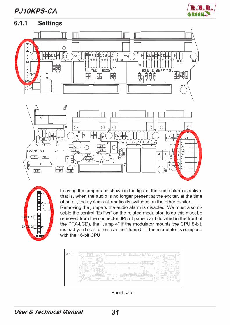
6.1.1 Settings
EXCT. 1
EXCT. 2
Leaving the jumpers as shown in the figure, the audio alarm is active, that is, when the audio is no longer present at the exciter, at the time of on air, the system automatically switches on the other exciter.Removing the jumpers the audio alarm is disabled. We must also di-sable the control “ExPwr” on the related modulator, to do this must be removed from the connector JP8 of panel card (located in the front of the PTX-LCD), the “Jump 4” if the modulator mounts the CPU 8-bit, instead you have to remove the “Jump 5” if the modulator is equipped with the 16-bit CPU.
PTX-LCD
63 / 78Manuale Utente Rev. 3.3 - 31/08/10
13.7 Scheda pannello
Questa scheda, posta nella parte anteriore dell’apparato, funge da interfaccia tra lascheda CPU e le altre schede che costituiscono il PTX-LCD.
Da questa scheda partono e arrivano tutti i segnali provenienti dal: Display LCD,dall’Encoder, dai Led di Segnalazione, dalla Scheda Alimentatore, dalla schedaMother Board Audio e della scheda di telemetria esterna, cioè tutti i segnali checostituiscono l’input/output della scheda CPU.
���
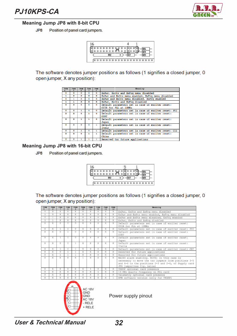
13.7.1 Regolazioni, settaggi ed indicatoriJP8 Posizione relativa dei jumper della scheda pannello.
Panel card
32User & Technical Manual
PJ10KPS-CA
Power supply pinout
4
Meaning Jump JP8 with 8-bit CPU
Meaning Jump JP8 with 16-bit CPU
AC 18VGNDGNDAC 18V- RELE+ RELE
PJ10KPS-CA
User & Technical Manual 33
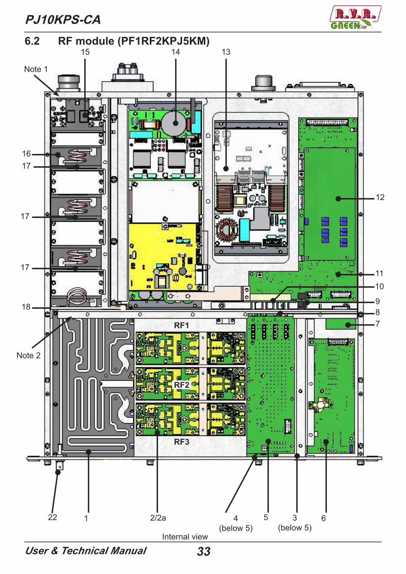
6.2 RF module (PF1RF2KPJ5KM)
1 2/2a 4(below 5)
5 6
789
1011
131415
16
17
18
17
17
12
Note 1
Note 2
Internal view
3(below 5)
22
RF1
RF3
RF2
34User & Technical Manual
PJ10KPS-CA
19
20
21
Note 1 Note 2
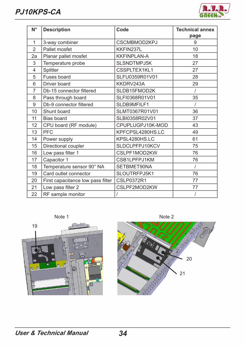
N° Description Code Technical annex page
1 3-way combiner CSCMBMOD2KPJ 92 Pallet mosfet KKFIN237L 10
2a Planar pallet mosfet KKFINPLAN-A 183 Temperature probe SLSNDTMPJ5K 274 Splitter CSSPLTEX1KL1 275 Fuses board SLFU0359R01V01 286 Driver board KKDRV243A 297 Db-15 connector filtered SLDB15FMOD2K /8 Pass through board SLFI0368R01V01 359 Db-9 connector filtered SLDB9MFILF1 /
10 Shunt board SLMT0367R01V01 3611 Bias board SLBI0358R02V01 3712 CPU board (RF module) CPUPLUGPJ10K-MOD 4313 PFC KPFCPSL4280HS.LC 4914 Power supply KPSL4280HS.LC 6115 Directional coupler SLDCLPFPJ10KCV 7516 Low pass filter 1 CSLPF1MOD2KW 7617 Capacitor 1 CSB1LPFPJ1KM 7618 Temperature sensor 90° NA SETBMET90NA /19 Card outlet connector SLOUTRFPJ5K1 7620 First capacitance low pass filter CSLP0372R1 7721 Low pass filter 2 CSLPF2MOD2KW 7722 RF sample monitor / /
PJ10KPS-CA
User & Technical Manual 35
Front view
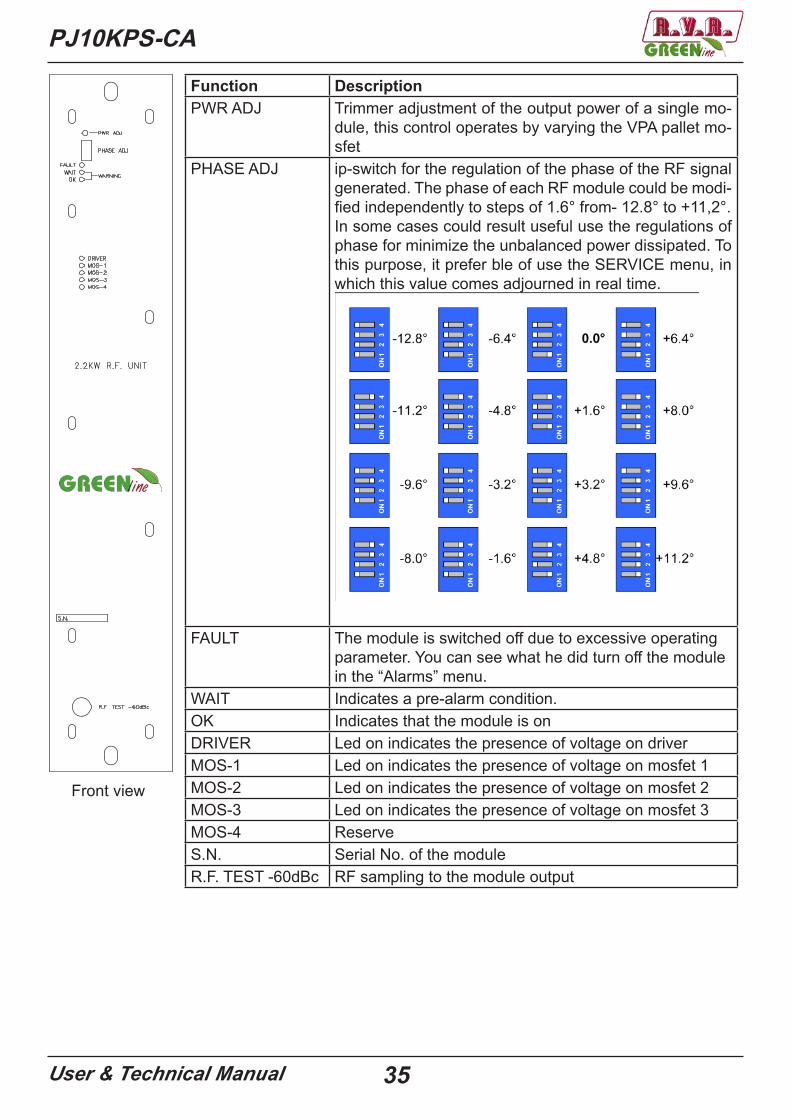
Function DescriptionPWR ADJ Trimmer adjustment of the output power of a single mo-
dule, this control operates by varying the VPA pallet mo-sfet
PHASE ADJ ip-switch for the regulation of the phase of the RF signal generated. The phase of each RF module could be modi-fied independently to steps of 1.6° from- 12.8° to +11,2°.In some cases could result useful use the regulations of phase for minimize the unbalanced power dissipated. To this purpose, it prefer ble of use the SERVICE menu, in which this value comes adjourned in real time.
FAULT The module is switched off due to excessive operating parameter. You can see what he did turn off the module in the “Alarms” menu.
WAIT Indicates a pre-alarm condition.OK Indicates that the module is onDRIVER Led on indicates the presence of voltage on driverMOS-1 Led on indicates the presence of voltage on mosfet 1MOS-2 Led on indicates the presence of voltage on mosfet 2MOS-3 Led on indicates the presence of voltage on mosfet 3MOS-4 ReserveS.N. Serial No. of the moduleR.F. TEST -60dBc RF sampling to the module output
PJ10KPS-CA
User & Technical Manual 36
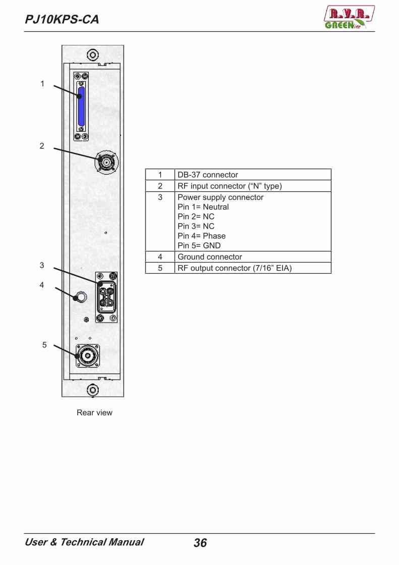
Rear view
1 DB-37 connector2 RF input connector (“N” type)3 Power supply connector
Pin 1= NeutralPin 2= NCPin 3= NCPin 4= PhasePin 5= GND
4 Ground connector5 RF output connector (7/16” EIA)
1
2
3
4
5
PJ10KPS-CA
User & Technical Manual 37
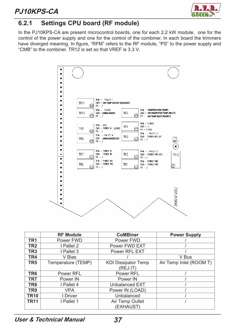
In the PJ10KPS-CA are present microcontrol boards, one for each 2.2 kW module, one for the control of the power supply and one for the control of the combiner. In each board the trimmers have diverged meaning. In figure, “RFM” refers to the RF module, “PS” to the power supply and “CMB” to the combiner. TR12 is set so that VREF is 3.3 V.
AIR TEMP OUTLET (EXHAUST)
UNBALANCED
UNBALANCED EXT.
TEMPERATURE (TEMP)KDI DISSIPATOR TEMP (REJ.IT)AIR TEMP INLET (ROOM T)
6.2.1 Settings CPU board (RF module)
RF Module CoMBiner Power Supply TR1 Power FWD Power FWD / TR2 I Pallet 2 Power FWD EXT / TR3 I Pallet 3 Power RFL EXT / TR4 V Bias / V Bus TR5 Temperature (TEMP) KDI Dissipator Temp
(REJ.IT)Air Temp Inlet (ROOM T)
TR6 Power RFL Power RFL / TR7 Power IN Power IN /TR8 I Pallet 4 Unbalanced EXT / TR9 VPA Power IN (LOAD) /
TR10 I Driver Unbalanced / TR11 I Pallet 1 Air Temp Outlet
(EXHAUST) /

PJ10KPS-CA
User & Technical Manual 38
6.3 Electromechanical section
1
32
N° Description Code Technical annex page
1 Relay interface board
CSRLYINTPJ10K 78
2 Service transformer
TRFSERV10KCV /
3 P.S. combiner
PF1ADPSPJ5KM
SLADPSPJ5KM3 (PS combiner adapter)
CPUPLUGPJ10K-CMB (cpu combiner) CPUPLUGPJ10K-PS (cpu power supply)
80
43
43{

PJ10KPS-CA
User & Technical Manual 39
6.3.1 P.S. combiner (PF1ADPSPJ5KM)
SLADPPSPJ5K3 (PS combiner adapter)
CPUPLUGPJ10K-CMB (cpu combiner)
CPUPLUGPJ10K-PS (cpu power supply)
PJ10KPS-CA
User & Technical Manual 40
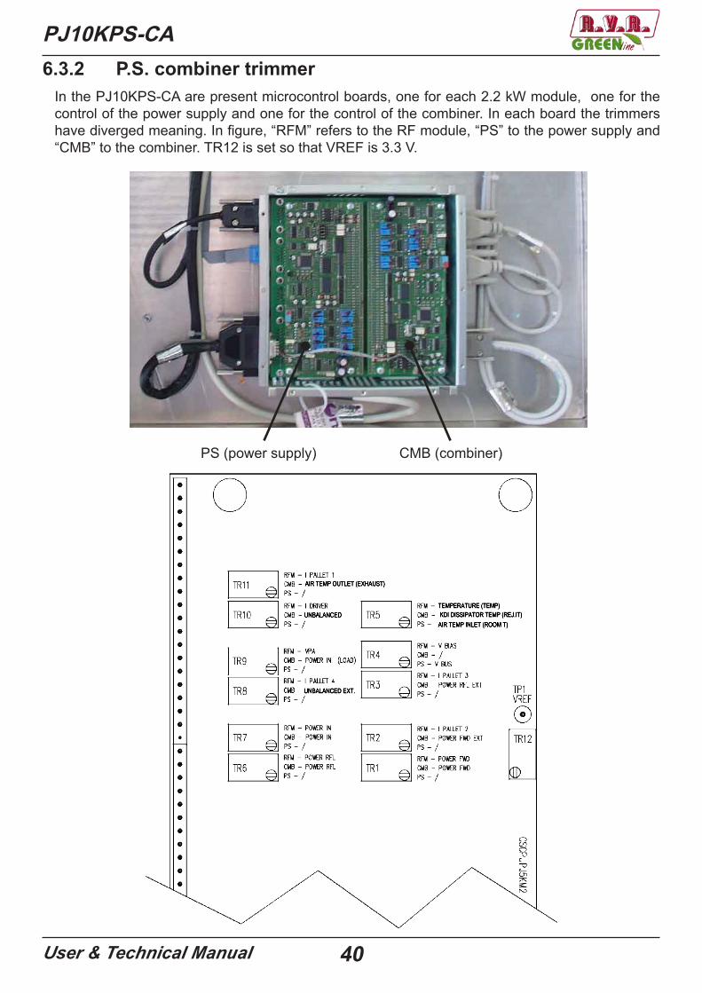
6.3.2 P.S. combiner trimmerIn the PJ10KPS-CA are present microcontrol boards, one for each 2.2 kW module, one for the control of the power supply and one for the control of the combiner. In each board the trimmers have diverged meaning. In figure, “RFM” refers to the RF module, “PS” to the power supply and “CMB” to the combiner. TR12 is set so that VREF is 3.3 V.
PS (power supply) CMB (combiner)
AIR TEMP OUTLET (EXHAUST)
UNBALANCED
UNBALANCED EXT.
TEMPERATURE (TEMP)KDI DISSIPATOR TEMP (REJ.IT)AIR TEMP INLET (ROOM T)

PJ10KPS-CA
User & Technical Manual 41
RF Module CoMBiner Power Supply TR1 Power FWD Power FWD / TR2 I Pallet 2 Power FWD EXT / TR3 I Pallet 3 Power RFL EXT / TR4 V Bias / V Bus TR5 Temperature (TEMP) KDI Dissipator Temp
(REJ.IT)Air Temp Inlet (ROOM T)
TR6 Power RFL Power RFL / TR7 Power IN Power IN /TR8 I Pallet 4 Unbalanced EXT / TR9 VPA Power IN (LOAD) /
TR10 I Driver Unbalanced / TR11 I Pallet 1 Air Temp Outlet
(EXHAUST) /
42User & Technical Manual
PJ10KPS-CA
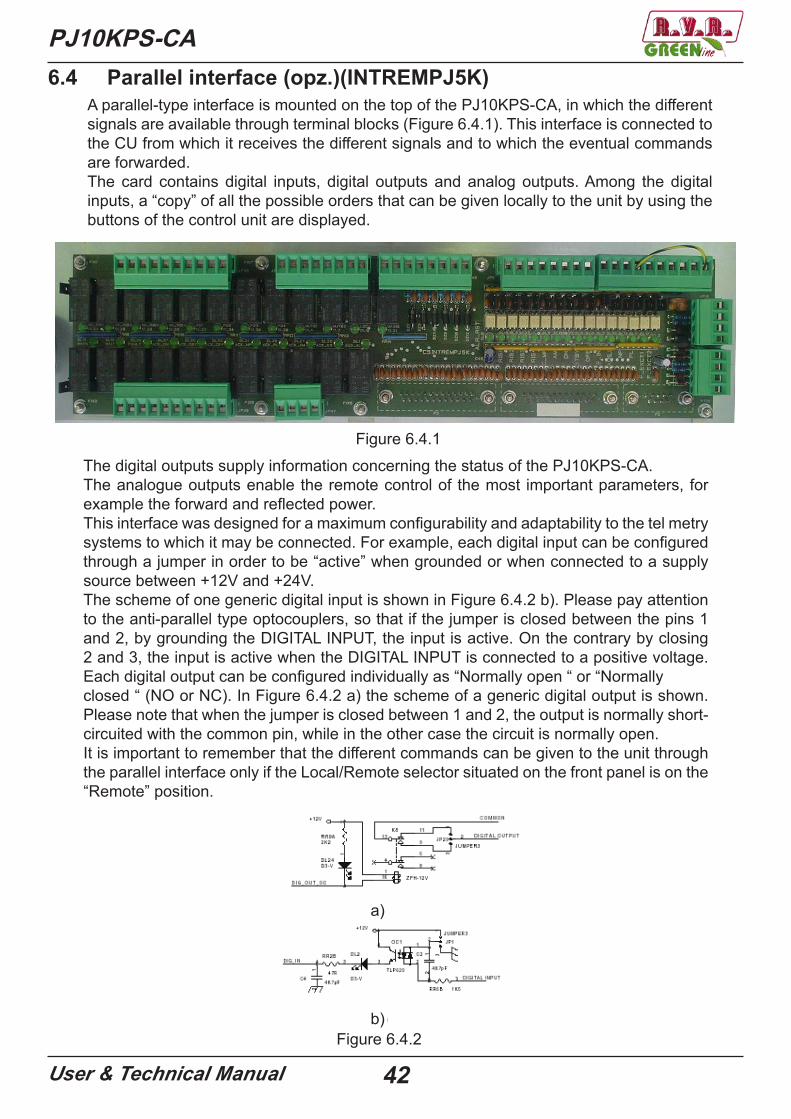
A parallel-type interface is mounted on the top of the PJ10KPS-CA, in which the different signals are available through terminal blocks (Figure 6.4.1). This interface is connected to the CU from which it receives the different signals and to which the eventual commands are forwarded.The card contains digital inputs, digital outputs and analog outputs. Among the digital inputs, a “copy” of all the possible orders that can be given locally to the unit by using the buttons of the control unit are displayed.
The digital outputs supply information concerning the status of the PJ10KPS-CA.The analogue outputs enable the remote control of the most important parameters, for example the forward and reflected power.This interface was designed for a maximum configurability and adaptability to the tel metry systems to which it may be connected. For example, each digital input can be configured through a jumper in order to be “active” when grounded or when connected to a supply source between +12V and +24V.The scheme of one generic digital input is shown in Figure 6.4.2 b). Please pay attention to the anti-parallel type optocouplers, so that if the jumper is closed between the pins 1 and 2, by grounding the DIGITAL INPUT, the input is active. On the contrary by closing 2 and 3, the input is active when the DIGITAL INPUT is connected to a positive voltage.Each digital output can be configured individually as “Normally open “ or “Normally closed “ (NO or NC). In Figure 6.4.2 a) the scheme of a generic digital output is shown. Please note that when the jumper is closed between 1 and 2, the output is normally short-circuited with the common pin, while in the other case the circuit is normally open.It is important to remember that the different commands can be given to the unit through the parallel interface only if the Local/Remote selector situated on the front panel is on the“Remote” position.
Figure 6.4.1
6.4 Parallel interface (opz.)(INTREMPJ5K)
Figure 6.4.2
a)
b)
PJ10KPS-CA
User & Technical Manual 43
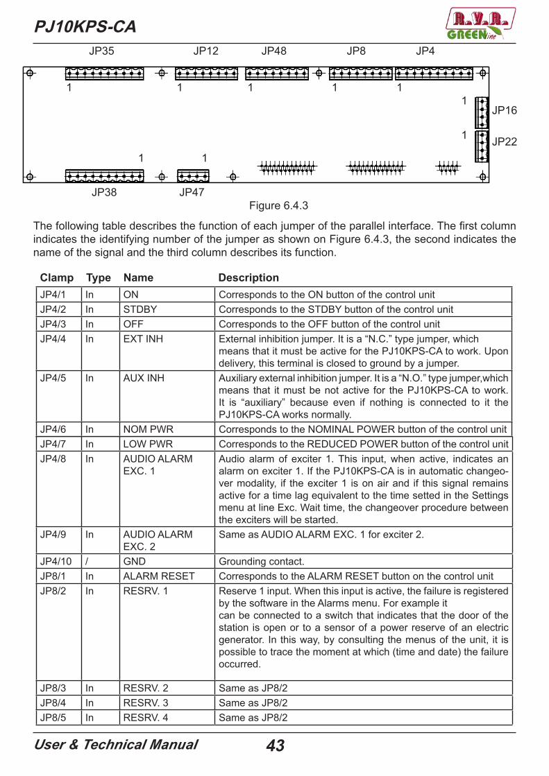
JP35 JP12 JP48 JP8 JP4
JP38 JP47
JP16
JP22
1 1 1 1 11
1
11
Figure 6.4.3
The following table describes the function of each jumper of the parallel interface. The first column indicates the identifying number of the jumper as shown on Figure 6.4.3, the second indicates the name of the signal and the third column describes its function.
JP4/1 In ON Corresponds to the ON button of the control unitJP4/2 In STDBY Corresponds to the STDBY button of the control unitJP4/3 In OFF Corresponds to the OFF button of the control unitJP4/4 In EXT INH External inhibition jumper. It is a “N.C.” type jumper, which
means that it must be active for the PJ10KPS-CA to work. Upon delivery, this terminal is closed to ground by a jumper.
JP4/5 In AUX INH Auxiliary external inhibition jumper. It is a “N.O.” type jumper,which means that it must be not active for the PJ10KPS-CA to work. It is “auxiliary” because even if nothing is connected to it the PJ10KPS-CA works normally.
JP4/6 In NOM PWR Corresponds to the NOMINAL POWER button of the control unit
Clamp Type Name Description
JP4/7 In LOW PWR Corresponds to the REDUCED POWER button of the control unitJP4/8 In AUDIO ALARM
EXC. 1Audio alarm of exciter 1. This input, when active, indicates an alarm on exciter 1. If the PJ10KPS-CA is in automatic changeo-ver modality, if the exciter 1 is on air and if this signal remains active for a time lag equivalent to the time setted in the Settings menu at line Exc. Wait time, the changeover procedure between the exciters will be started.
JP4/9 In AUDIO ALARM EXC. 2
Same as AUDIO ALARM EXC. 1 for exciter 2.
JP4/10 / GND Grounding contact. JP8/1 In ALARM RESET Corresponds to the ALARM RESET button on the control unitJP8/2 In RESRV. 1 Reserve 1 input. When this input is active, the failure is registered
by the software in the Alarms menu. For example itcan be connected to a switch that indicates that the door of the station is open or to a sensor of a power reserve of an electric generator. In this way, by consulting the menus of the unit, it is possible to trace the moment at which (time and date) the failure occurred.
JP8/3 In RESRV. 2 Same as JP8/2JP8/4 In RESRV. 3 Same as JP8/2JP8/5 In RESRV. 4 Same as JP8/2

44User & Technical Manual
PJ10KPS-CAJP8/6 In EXCITER
CHANGEOVER CMD
This command launches the changeover procedure between the exciters. It has the same function as when you press the OK but-ton when selecting line On air exciter in the menuExciters. In order to launch the changeover between the exciters through this command, the manual changeover modality should be formerly selected through the correspondent button on the control unit or through the JP8/7 jumper, having however the unit in “Remote” modality.
JP8/7 In EXCITER CHAN-GEOVER
Corresponds to ther EXCITER CHANGEOVER button of the control unit
JP8/8 / GND GroundJP16/1 Out +12V dc Power source. A maximum of 100 mA can be absorbed between
this jumper and JP16/2. This power source can be used if the user wants to enter the comands following a positive logic (high voltage - active comand)
JP16/2 Out +12V dc Same as JP16/1JP16/3 / GND GroundJP16/4 / GND GroundJP22/1 I/O TX/RX + Bus RS 485. Please note that this serial port is operational
only when the unit is in “Remote” modality.JP22/2 I/O TX/RX - Bus RS 485JP22/3 / LINE TRM Line termination for bus RS 485JP22/4 / LINE TRM Line termination for bus RS 485JP48/1 / GND GroundJP48/2 / GND GroundJP48/3 Out FWD PWR Forward power. Analog output, 3.9V for 5000WJP48/4 Out RFL PWR Reflect power. Analog output, 3.9V for 1200WJP48/5 Out OUT AIR TEMP Temperature of the air at the output of the chimney. Analog ou-
tput, 0V for -50°C, 3.9V for 100°CJP48/6 Out V FAN Supply voltage of the fans.JP48/7 Out EFF. General efficiency. Analog output, 3.9V for 100%, 0V for
0%.JP48/8 Out OUT DAC 6 Reserved for future applications.JP12/1 Out CMN MUTE 1 Common contact MUTE 1 (see JP12/2).JP12/2 Out MUTE 1 MUTE exciter 1. Digital output, active when exciter 1 is inhibited
by the control unit. Like all the digital outputs on the parallele in-terface, it can be configurated through jumper as normally open or normally closed. This output has a common contact dedicated to this function (JP12/1).
JP12/3 Out CMN MUTE 2 Common contact MUTE 2 (see JP12/4).JP12/4 Out MUTE 2 MUTE exciter 2. Digital output, active when exciter 2 is inhibited
by the control unit. This output has a common contact dedicated to this function (JP12/3).
JP12/5 Out CMN LOCAL Common contact LOCAL (see JP12/6).JP12/6 Out LOCAL LOCAL/REMOTE status. Digital output, active when the
PJ10KPS-CA is setted in local modality. This output has a com-mon contact dedicated to this function (JP12/5).
JP12/7 Out CMN MAINS Common contact MAINS (see JP12/8).JP12/8 Out MAINS MAINS alarm, active when are present problems on the alimen-
tation
PJ10KPS-CA
User & Technical Manual 45
JP47/1 Out AUDIO ALARM “AUDIO” alarm (see JP4/8 and JP4/9). This output is activewhen the on air exciter is in audio alarm status. This outputhas a common contact dedicated to this function (JP47/2).
JP47/2 Out CMN AUDIO ALARM
Common contact AUDIO ALARM (see JP47/1).
JP47/3 Out CMN RL3 Common contact shared from the outputs JP38/1-10.JP47/4 Out CMN RL3 Parallel contact with JP47/3.JP35/1 Out RESRV. 1 Reserve 1. Digitale output, active when the INPUT RESERVE 1
input (JP8/2) is active. The common contact of this output is RL4 (JP35/5)
JP35/2 Out RESRV. 2 Same as JP35/1, corresponds to INPUT RESERVE 2. The com-mon contact of this output is RL4 (JP35 / 5)
JP35/3 Out RESRV. 3 Same as JP35/1, corresponds to INPUT RESERVE 3. The com-mon contact of this output is RL4 (JP35 / 5)
JP35/4 Out RESRV. 4 Same as JP35/1, corresponds to INPUT RESERVE 4. Thecommon contact of this output RL4 (JP35/5)
JP35/5 Out CMN RL4 Common contact shared between different digital outputs(JP35/1-4)
JP35/6 Out SET1. Digital output, active when the parameter SET1 is active (see menu Settings). The common contact of this output RL5 (JP35/10).
JP35/7 Out SET2. Same as JP36/6, corresponds to SET2. The common contact of this output is RL5 (JP35/10).
JP35/8 Out SET3. Same as JP36/6, corresponds to SET3. The common contact of this output is RL5 (JP35/10).
JP35/9 Out SET4. Similar to JP36/6, related to SET4. The common contact ofthis output is the RL5 (JP35/10).
JP35/10 Out CMN RL5 Common contact shared between the different digital output (JP35/6-9)
JP38/1 Out EXC. ON AIR Digital output, active when the exciter 1 is on air, and not active when the exciter 2 is on air. common contact of this output is the RL3 (JP47/3).
JP38/2 Out AUTO/MAN Digital output, active when the PJ10KPS-CA is in changeover mode as regards the exciters. The common contact of this output is RL3 (JP47/3).
JP38/3 Out LOWER POWER Digital output, active when the PJ10KPS-CA is set for the lower power level. Common contact of this output is the RL3(JP47/3).
JP38/4 Out NOMINAL POWER Digital output, active when the PJ10KPS-CA is set for the nominal power level. common contact of this output is the RL3 (JP47/3).
JP38/5 Out OFF Digital output, active when the PJ10KPS-CA is set for the lo-wer power level. The common contact of this output is the RL3 (JP47/3).
JP38/6 Out STDBY Digital output, active when the PJ10KPS-CA is set for the lower power level.The common contact of this output is the RL3(JP47/3).
JP38/7 Out ON Digital output, active when the PJ10KPS-CA is set on ON mode. The common contact of this output is the RL3 (JP47/3).
JP38/8 Out FAULT Digital output, active when the PJ10KPS-CA is set on FAULT mode. The common contact of this output is the RL3 (JP47/3).
JP38/9 Out WAIT Digital output, active when the PJ10KPS-CA is set on WAIT mode. The common contact of this output is the RL3 (JP47/3).
JP38/10 Out WARNING Digital output, active when the PJ10KPS-CA is set on WARNING mode. The common contact of this output is the RL3 (JP47/3).
46User & Technical Manual
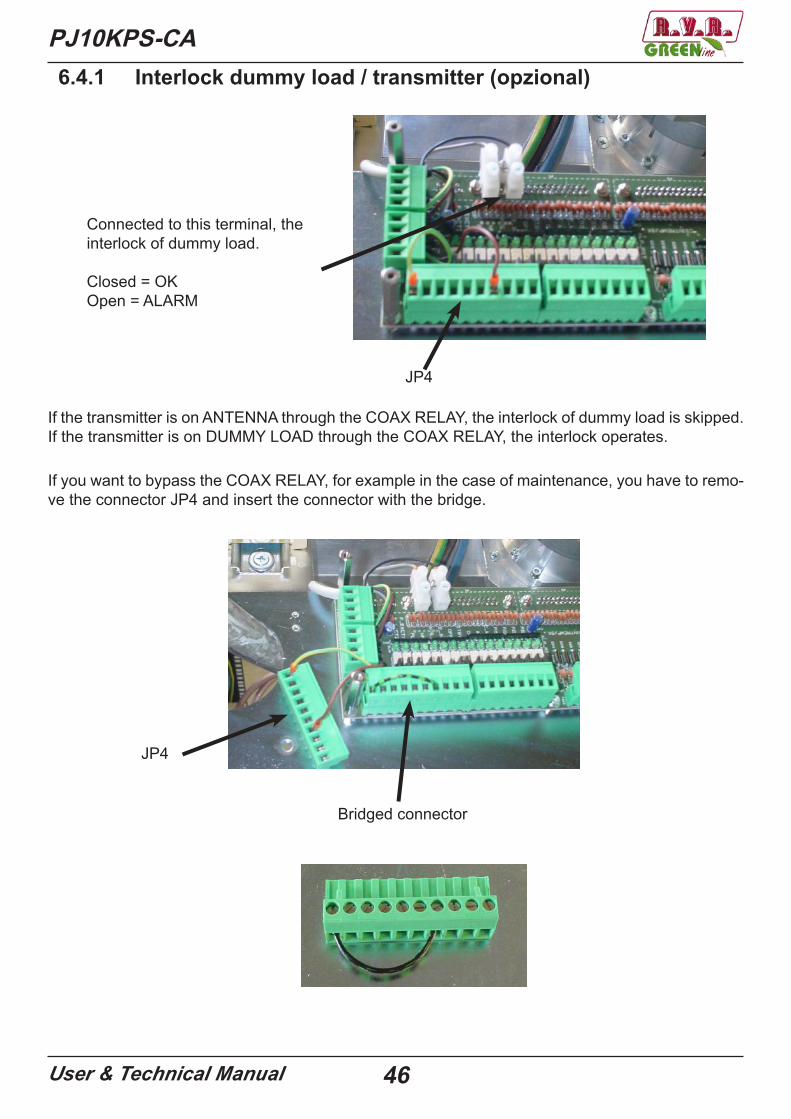
PJ10KPS-CA6.4.1 Interlock dummy load / transmitter (opzional)
Connected to this terminal, the interlock of dummy load.
Closed = OKOpen = ALARM
If the transmitter is on ANTENNA through the COAX RELAY, the interlock of dummy load is skipped.If the transmitter is on DUMMY LOAD through the COAX RELAY, the interlock operates.
If you want to bypass the COAX RELAY, for example in the case of maintenance, you have to remo-ve the connector JP4 and insert the connector with the bridge.
JP4
JP4
Bridged connector
PJ10KPS-CA
User & Technical Manual 47
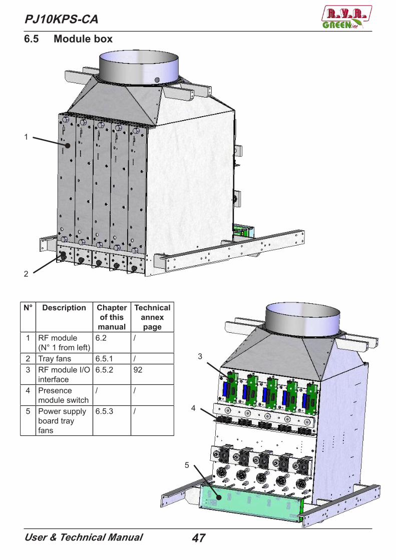
6.5 Module box
1
2
3
4
5
N° Description Chapterof thismanual
Technicalannex page
1 RF module (N° 1 from left)
6.2 /
2 Tray fans 6.5.1 /3 RF module I/O
interface6.5.2 92
4 Presence module switch
/ /
5 Power supply board tray fans
6.5.3 /
PJ10KPS-CA
User & Technical Manual 48
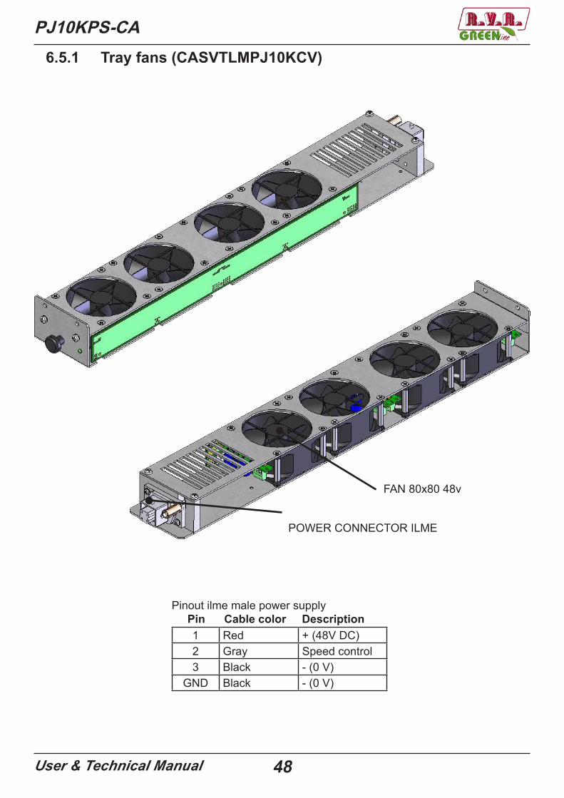
6.5.1 Tray fans (CASVTLMPJ10KCV)
FAN 80x80 48v
POWER CONNECTOR ILME
Pinout ilme male power supply Pin Cable color Description
1 Red + (48V DC)2 Gray Speed control3 Black - (0 V)
GND Black - (0 V)
PJ10KPS-CA
User & Technical Manual 49
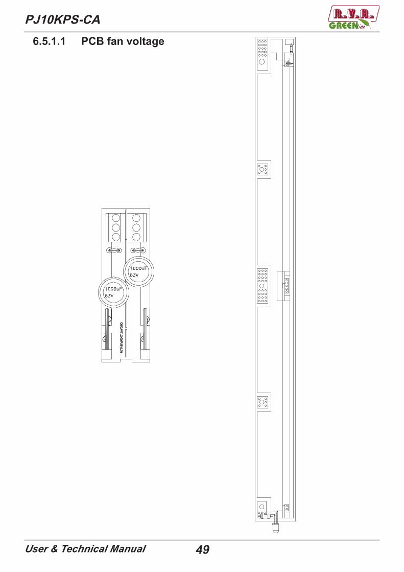
6.5.1.1 PCB fan voltage
PJ10KPS-CA
User & Technical Manual 50
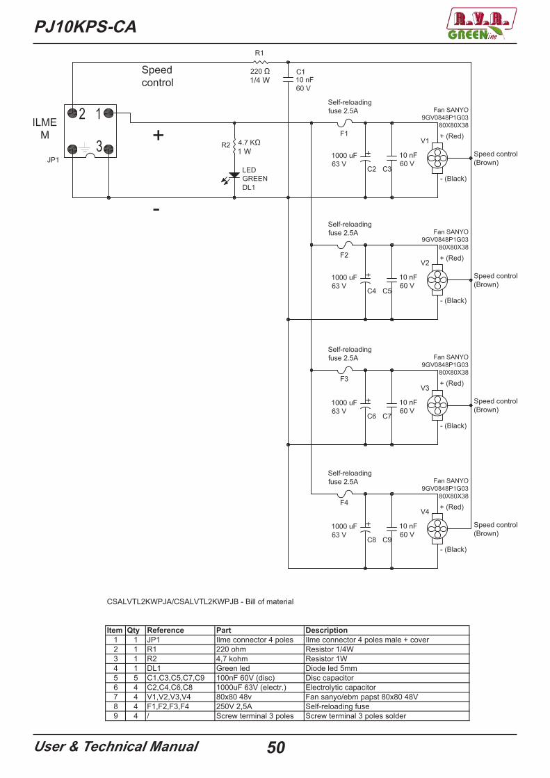
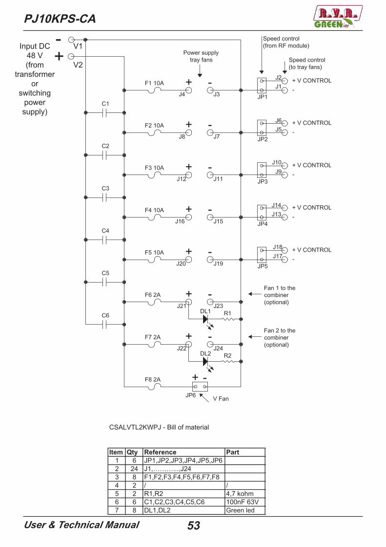
CSALVTL2KWPJA/CSALVTL2KWPJB - Bill of material
Item Qty Reference Part Description1 1 JP1 Ilme connector 4 poles Ilme connector 4 poles male + cover2 1 R1 220 ohm Resistor 1/4W3 1 R2 4,7 kohm Resistor 1W4 1 DL1 Green led Diode led 5mm5 5 C1,C3,C5,C7,C9 100nF 60V (disc) Disc capacitor6 4 C2,C4,C6,C8 1000uF 63V (electr.) Electrolytic capacitor7 4 V1,V2,V3,V4 80x80 48v Fan sanyo/ebm papst 80x80 48V8 4 F1,F2,F3,F4 250V 2,5A Self-reloading fuse9 4 / Screw terminal 3 poles Screw terminal 3 poles solder
PJ10KPS-CA
User & Technical Manual 51
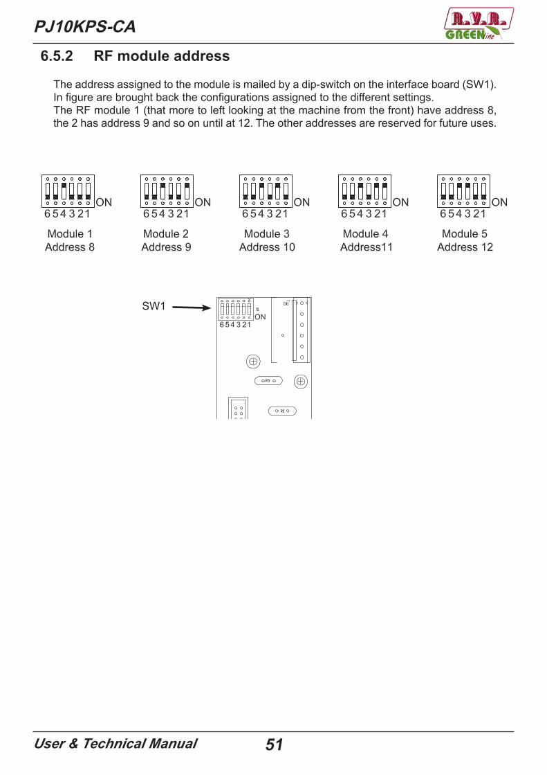
6.5.2 RF module address
The address assigned to the module is mailed by a dip-switch on the interface board (SW1).In figure are brought back the configurations assigned to the different settings.The RF module 1 (that more to left looking at the machine from the front) have address 8, the 2 has address 9 and so on until at 12. The other addresses are reserved for future uses.
SW1

PJ10KPS-CA
User & Technical Manual 52
6.5.3 Power distribution board tray fans (CSALVTL2KWPJ)
PJ10KPS-CA
User & Technical Manual 53
Item Qty Reference Part Description1 6 JP1,JP2,JP3,JP4,JP5,JP6 Morsetto a 2 poli a saldare per stampato2 24 J1,………...,J24 Faston maschio a saldare3 8 F1,F2,F3,F4,F5,F6,F7,F8 Portafusibile da stampato4 2 / / Coperchio per portafusibile5 2 R1,R2 4,7 kohm Resistenza 1W6 6 C1,C2,C3,C4,C5,C6 100nF 63V Condensatore in poliestere7 8 DL1,DL2 led verde Diodo led 5mm
CSALVTL2KWPJ - Bill of material
Green led
V1
V2
Input DC 48 V(from
transformeror
switchingpower supply)

PJ10KPS-CA
User & Technical Manual 54
6.5.4 Power supply tray fans
With threephase transformer With switching power supply
Electromechanicalsection
Transformer
Rectifier
Power distribution board
Electromechanicalsection
Switching power supply
Power distribution board
PJ10KPS-CA
User & Technical Manual 55
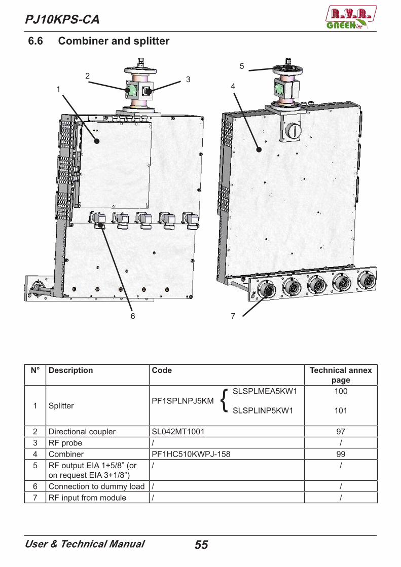
6.6 Combiner and splitter
6 7
4
53
12
N° Description Code Technical annexpage
1 Splitter
SLSPLMEA5KW1PF1SPLNPJ5KM SLSPLINP5KW1
100
101
2 Directional coupler SL042MT1001 973 RF probe / /4 Combiner PF1HC510KWPJ-158 995 RF output EIA 1+5/8” (or
on request EIA 3+1/8”)/ /
6 Connection to dummy load / /7 RF input from module / /
{
PJ10KPS-CA
User & Technical Manual 56
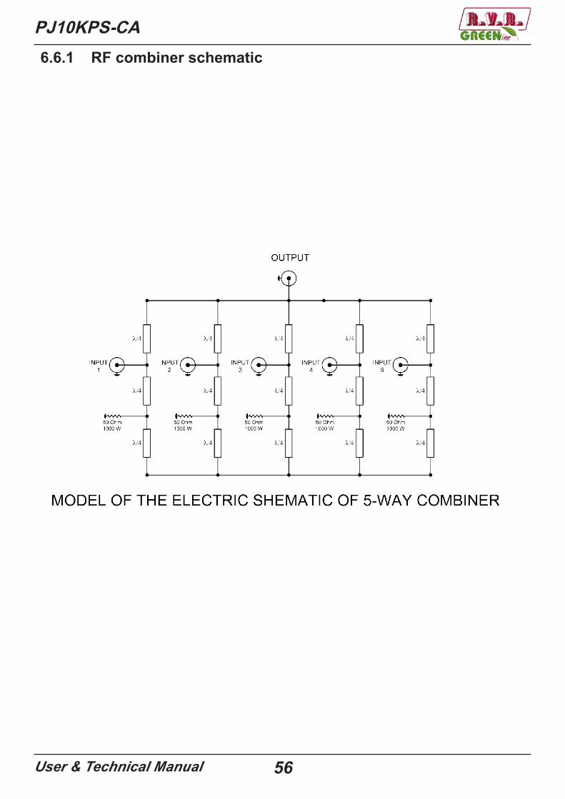
6.6.1 RF combiner schematic
PJ10KPS-CA
User & Technical Manual 57
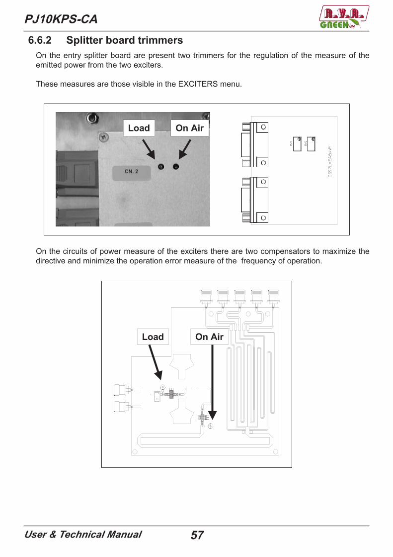
6.6.2 Splitter board trimmersOn the entry splitter board are present two trimmers for the regulation of the measure of the emitted power from the two exciters.
These measures are those visible in the EXCITERS menu.
Load On Air
On the circuits of power measure of the exciters there are two compensators to maximize the directive and minimize the operation error measure of the frequency of operation.
Load On Air
PJ10KPS-CA
User & Technical Manual 58
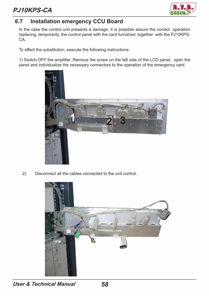
In the case the control unit presents a damage, it is possible assure the correct operation replacing, temporarily, the control panel with the card furnished together with the PJ10KPS-CA.
To effect the substitution, execute the following instructions:
1) Switch-OFF the amplifier. Remove the screw on the left side of the LCD panel, open the panel and individualize the necessary connectors to the operation of the emergency card.
1 2 3
2) Disconnect all the cables connected to the unit control.
6.7 Installation emergency CCU Board
PJ10KPS-CA
User & Technical Manual 59
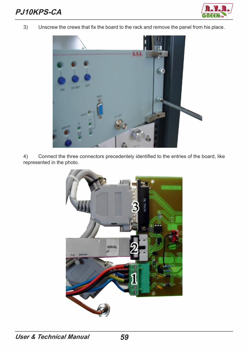
3) Unscrew the crews that fix the board to the rack and remove the panel from his place.
4) Connect the three connectors precedentely identified to the entries of the board, like represented in the photo.
PJ10KPS-CA
User & Technical Manual 60
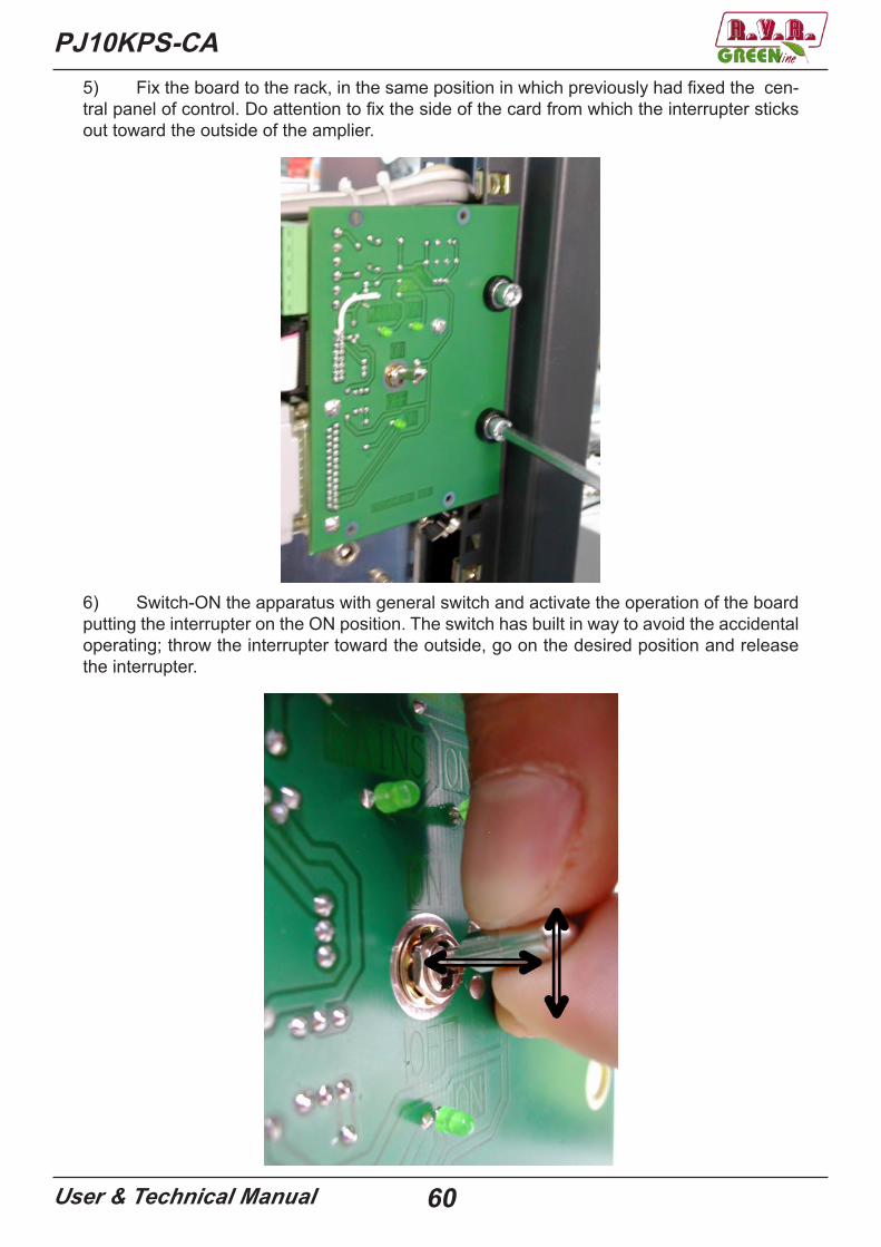
5) Fix the board to the rack, in the same position in which previously had fixed the cen-tral panel of control. Do attention to fix the side of the card from which the interrupter sticks out toward the outside of the amplier.
6) Switch-ON the apparatus with general switch and activate the operation of the board putting the interrupter on the ON position. The switch has built in way to avoid the accidental operating; throw the interrupter toward the outside, go on the desired position and release the interrupter.

PJ10KPS-CA
User & Technical Manual 61
Now the emergency board is operative.
When be used the emergency board, the amplifier acts with the parameters previously adjusted (for example: the level of power). To modify the parameters is necessary use the unit control.

PJ10KPS-CA
User & Technical Manual 62
6.8 Services supplyThe services of PJ10KPS-CA are supplied at 230V through a dedicated transformer.
Between the services, are included the microcontroller cards of RF modules, those of the combiner and power supply and the control unit.
Supplying the services of the PJ10KPS-CA with an UPS (Uninterruptable Power Supply), the machine also in case of absence of mains power can be managed, naturally limitedly to the functions available (for example configuration or interrogation of the alarms registry). The normal configuration of the machine previews that the services are directly supply through the connection to the electrical mains of the machine, in order to insert an UPS is sufficient put it between the VDE on the roof, after have removed the bridge that comes supplied of series.
PJ10KPS-CA
User & Technical Manual 63
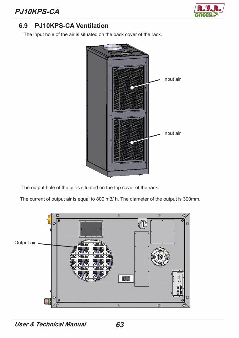
6.9 PJ10KPS-CA Ventilation The input hole of the air is situated on the back cover of the rack.
The output hole of the air is situated on the top cover of the rack.
The current of output air is equal to 800 m3/ h. The diameter of the output is 300mm.
Input air
Input air
Output air
PJ10KPS-CA
User & Technical Manual 64
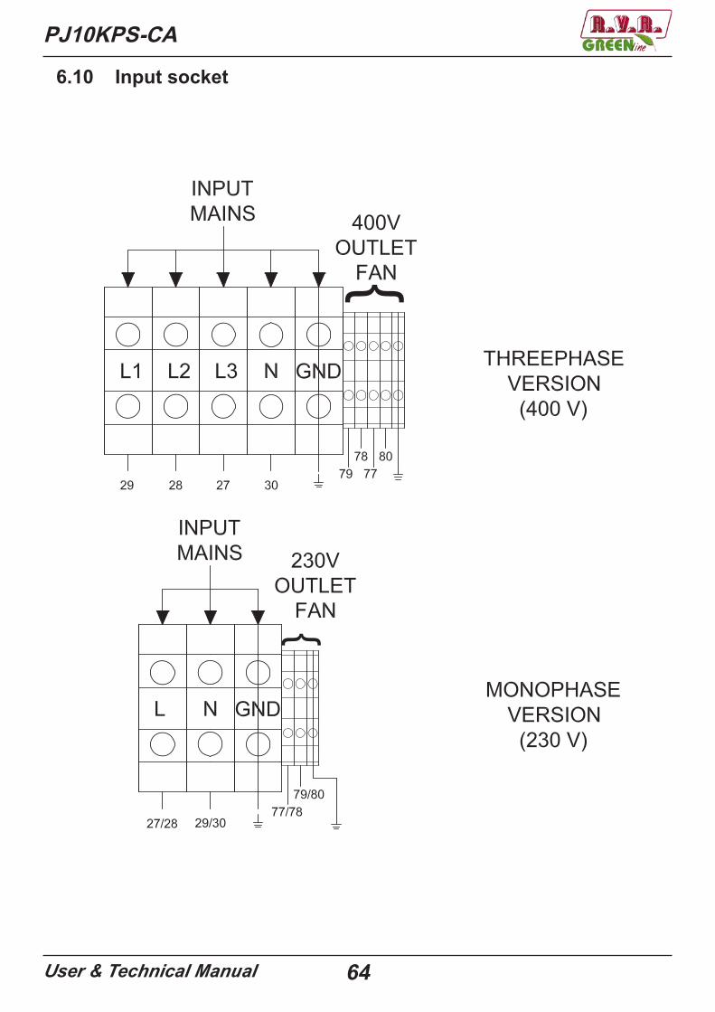
6.10 Input socket
PJ10KPS-CA
User & Technical Manual 65
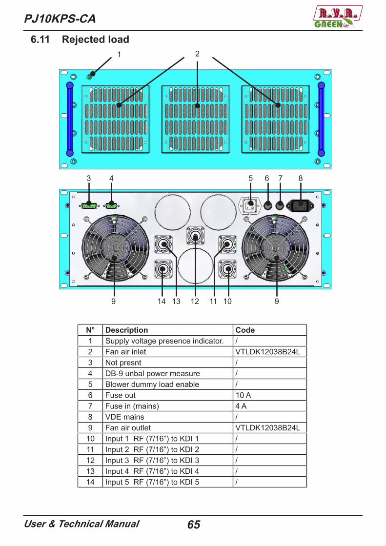
6.11 Rejected load1 2
3 4 5 6 7 8
9 14 13 12 11 10 9
N° Description Code1 Supply voltage presence indicator. /2 Fan air inlet VTLDK12038B24L3 Not presnt /4 DB-9 unbal power measure /5 Blower dummy load enable /6 Fuse out 10 A7 Fuse in (mains) 4 A8 VDE mains /9 Fan air outlet VTLDK12038B24L
10 Input 1 RF (7/16”) to KDI 1 /11 Input 2 RF (7/16”) to KDI 2 /12 Input 3 RF (7/16”) to KDI 3 /13 Input 4 RF (7/16”) to KDI 4 /14 Input 5 RF (7/16”) to KDI 5 /
PJ10KPS-CA
User & Technical Manual 66
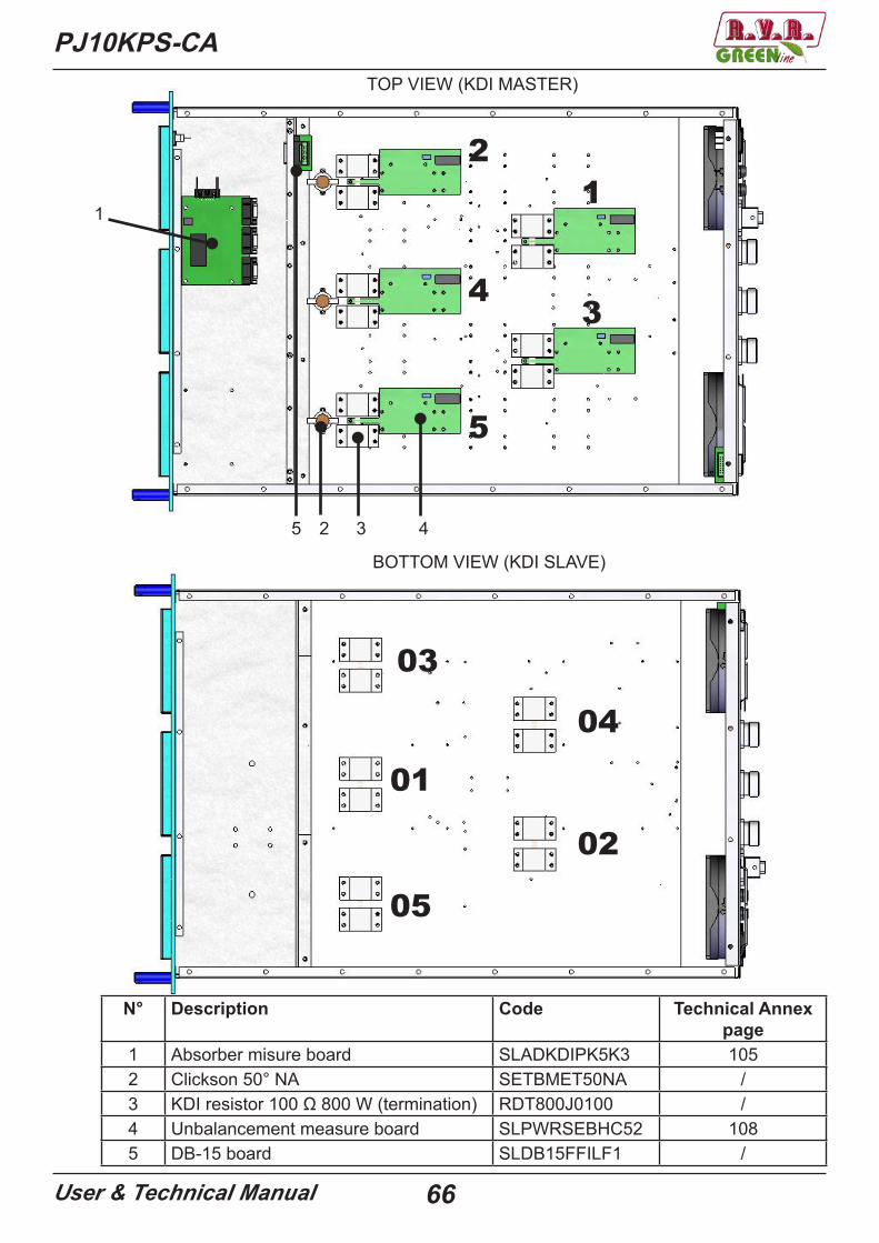
TOP VIEW (KDI MASTER)
BOTTOM VIEW (KDI SLAVE)
1
2 3 4
N° Description Code Technical Annex page
1 Absorber misure board SLADKDIPK5K3 1052 Clickson 50° NA SETBMET50NA /3 KDI resistor 100 Ω 800 W (termination) RDT800J0100 /4 Unbalancement measure board SLPWRSEBHC52 1085 DB-15 board SLDB15FFILF1 /
5
1
3
2
4
5
04
02
03
01
05
PJ10KPS-CA
User & Technical Manual 67
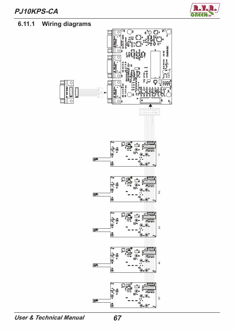
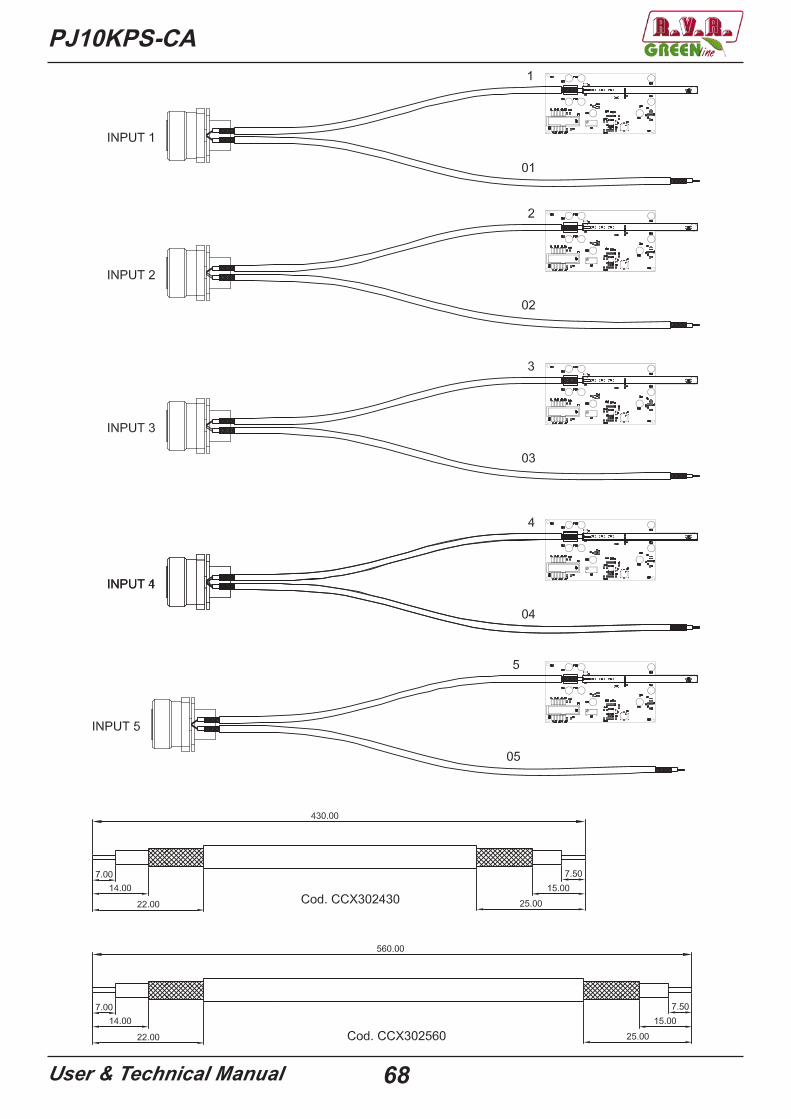
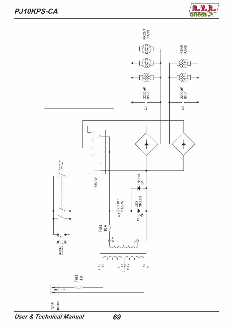
6.11.1 Wiring diagrams
PJ10KPS-CA
User & Technical Manual 68
PJ10KPS-CA
User & Technical Manual 69
PJ10KPS-CA
User & Technical Manual 70
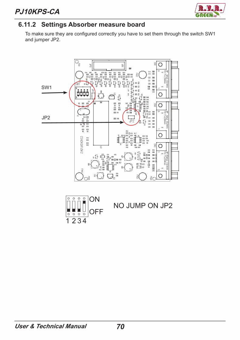
To make sure they are configured correctly you have to set them through the switch SW1 and jumper JP2.
SW1
JP2
6.11.2 Settings Absorber measure board
PJ10KPS-CA
User & Technical Manual 71
6.11.3 Settings Unbalancement measure boardTo make sure they are configured correctly, you must set address of each board.
Address
You have to make a jumper, with tin on:
J1 and J2 for board 1
J3 and J4 for board 2
J5 and J6 for board 3
J7 and J8 for board 4
J9 and J10 for board
PJ10KPS-CA
User & Technical Manual 72
7 GSM TelemetryR.V.R. Elettronica’s plug-in series transmitters, may be optionally fitted with the telemetry device that enables the user to remotely check all the machine’s working parameters and control some of them, and provides the transmitter with the ability to trigger “alarms” when problems arise while the transmitter is on air, possibly sending GSM Short Messages (SMS) to the maintainer’s cellular phone or to any other number stored in the machine’s memory.Telemetry is installed on the top rack of the transmitter, at the rear.
The bottom part of the telemetry contains the following connectors:
RS-485 DB9 male connector for connecting the RS-485 bus from the CUI2C DB9 male connector for connecting the I2C bus from the CU18-0-18 V DB15 male to connect power from the CU
18-0-18 V
RS-485 I2C
73User & Technical Manual
PJ10KPS-CA
The top of the telemetry contains the following connectors:
MODEM RS-232
FUSE 2A
FUSE 2A
RESET/PRG
Pow
er o
nG
ener
al a
larm
sM
odem
pre
sent
Send
msg
Mod
em c
om.
RS-
232
Loca
lW
aitin
g st
art
Modem DB 9 female connector connected to the modem internal GSMRS-232 DB 9 female connector to connect the GSM modem, with telemetry, or
to connect with the PC via RS-232 to the transmitterReset/prg Button to reset the telemetry or programmingFuse 2A Fuse protectionFuse 2A Fuse protectionPower on The LED on indicates that the telemetry is poweredGeneral alarms The LED on indicates that the memory of the telemetry alarms are pre-
sentModem present The LED on indicates that the GSM modem is present and correctly
detected by the telemetrySend sms The LED on indicates that the GSM modem is sending SMS messagesModem com. The LED on indicates that the modem is connectedRS-232 The LED blinks when you connect your PC to the RS-232 telemetry to
communicate with the transmitter using the “Telecon 32bit”Local The LED on indicates that the transmitter is in LOCAL (via the selector
switch on the CCU) and telemetry will not send alert messages or you can remotely connect to the transmitter
Waiting start The LED blinks for about 45 on first boot. During this period, the te-lemetry, it analyzes the whole machine to check status and does not send alerts
SMA connector for GSM an-tenna or external directional antenna
Insert the SIM card slot
Bridge to connect the GSM modem
Note: you need to enter the bridge supplied with the telemetry between the connector MO-DEM and RS-232 to connect the GSM modem, otherwise will not work
Nota: Please note that to fully deploy the features of this telemetry system, the you will need to sign a contract with a GSM service provider including DATA COMMUNICATIONS.

PJ10KPS-CA
User & Technical Manual 74
The use of the telemetry system requires the correct setting of the addresse in the con-nected pieces of equipment, since they communicate on a shared bus.Set the Uart address of exciter 1 to “1”, exciter 2 to “2”.To make this adjustment, from the main menu of the exciter place the cursor light on the “Admin” and click on it.
Scroll down the menu next to the item “GenSt”, click on it and select “Uart Adr.” and set it to 1 on the first exciter (the lower) and 2 on the second (if present).
We must now set the address on the CU, which must be absolutely 3 (this address is alre-ady set to factory).From the main menu (the one that shows the direct and reflected power), press the ESC key and then OK and move the cursor bright, on the “Settings” menu and press OK. Select the line “Talk Address” and press OK, with the UP ‘and DOWN keys’ set the parameter 3.
75User & Technical Manual
PJ10KPS-CA7.1 Dial-up via mobile
The commands that can be sent to the transmitter using SMS messages are as follows:
Every time you send a command must always return back a reply message, to confirm that the command was received and executed.The reply message may arrive within a maximum time of 5 min. After this time the command is void.
WARNING: The transmitter must be in REMOTE otherwise not receive any command.
Comando Risposta Descrizione
INFO
Station: “nome stazione”-ID: “numero identificativo”-FWD: “valore assoluto”-RFL: “valore assoluto”-UNBAL: “valore assoluto”TX On (oppure TX Off oppure TX StdBy)-Low Power / Nom PowerAudio Present / Audio AbsentAlarm Present / Alarm Absent
Informazioni sullo statodel trasmettitore.
TXONStation: “nome stazione”-ID: “numero identificativo”-TX is On -
Accensionetrasmettitore
TXOFFStation: “nome stazione”-ID: “numero identificativo”-TX is Off -
Spegnimentotrasmettitore
LOWPWRStation: “nome stazione”-ID: “numero identificativo”-LowPwr OK-
Attivazione Low Power
NOMPWRStation: “nome stazione”-ID: “numero identificativo”-NomPwr OK-
Attivazione NominalPower
ALARMStation: “nome stazione”-ID: “numero identificativo”-Alarm: “lista allarmi in memoria”
Lista allarmi inmemoria
RESETStation: “nome stazione”-ID: “numero identificativo”-ALARM RESET OK-
Cancellazione allarmiin memoria
Information about the transmitter’s status
Switching on the transmitters
Switching off the transmitters
Low power setting
Nominal power setting
List of the alarms in memory
Resetting the alarms in memory
DescriptionReplyCommand“station name”-
“ID number”-“value”-
“value”“value”
(or TX Off or TX StdBy)-
“station name”-
“station name”-
“station name”-
“station name”-
“station name”-
“station name”-
“ID number”-
“ID number”-
“ID number”-
“ID number”-
“ID number”-
“ID number”-
“List of the alarms in memory”-

PJ10KPS-CA
User & Technical Manual 76
7.2 AlarmsThese are the alarms that the transmitter can send:
1 Foward Power The power has dropped below the value set in SET2 (menu settings of the CU)
2 Reflected Power The power has risen above the value set in SET4 (menu settings of the CU)
3 Unbalanced Power The power on the dummy load has excee-ded the 1000 W
4 No Audio PTX1 No audio input to PTX15 No Audio PTX2 No audio input to PTX26 Mains Fault (only if there is the
UPS)Is no longer the power supply, the transmit-ter is turned off, the UPS takes on the logic control, modulators and telemetry
7 Fault Mod 1 Module 1 has shut down8 Fault Mod 2 Module 2 has shut down9 Fault Mod 3 Module 3 has shut down
10 Fault Mod 4 Module 4 has shut down11 Fault Mod 5 Module 5 has shut down12 Mains OK It is not an alarm, is sent the first time you
turned on the telemetry or when the mains voltage returns
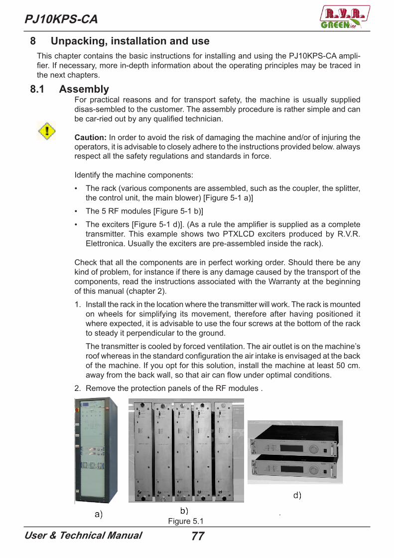
PJ10KPS-CA
User & Technical Manual 77
8 Unpacking, installation and useThis chapter contains the basic instructions for installing and using the PJ10KPS-CA ampli-fier. If necessary, more in-depth information about the operating principles may be traced in the next chapters.
8.1 AssemblyFor practical reasons and for transport safety, the machine is usually supplied disas-sembled to the customer. The assembly procedure is rather simple and can be car-ried out by any qualified technician.
Caution: In order to avoid the risk of damaging the machine and/or of injuring the operators, it is advisable to closely adhere to the instructions provided below. always respect all the safety regulations and standards in force.
Identify the machine components: • The rack (various components are assembled, such as the coupler, the splitter,
the control unit, the main blower) [Figure 5-1 a)]• The 5 RF modules [Figure 5-1 b)]• The exciters [Figure 5-1 d)]. (As a rule the amplifier is supplied as a complete
transmitter. This example shows two PTXLCD exciters produced by R.V.R. Elettronica. Usually the exciters are pre-assembled inside the rack).
Check that all the components are in perfect working order. Should there be any kind of problem, for instance if there is any damage caused by the transport of the components, read the instructions associated with the Warranty at the beginning of this manual (chapter 2).1. Install the rack in the location where the transmitter will work. The rack is mounted
on wheels for simplifying its movement, therefore after having positioned it where expected, it is advisable to use the four screws at the bottom of the rack to steady it perpendicular to the ground.The transmitter is cooled by forced ventilation. The air outlet is on the machine’s roof whereas in the standard configuration the air intake is envisaged at the back of the machine. If you opt for this solution, install the machine at least 50 cm. away from the back wall, so that air can flow under optimal conditions.
2. Remove the protection panels of the RF modules .
Figure 5.1
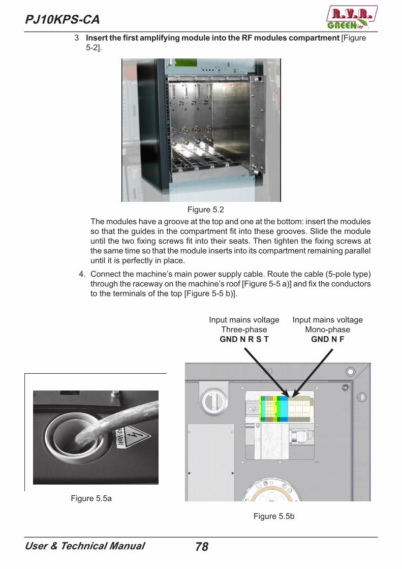
PJ10KPS-CA
User & Technical Manual 78
3 Insert the first amplifying module into the RF modules compartment [Figure 5-2].
Figure 5.2The modules have a groove at the top and one at the bottom: insert the modules so that the guides in the compartment fit into these grooves. Slide the module until the two fixing screws fit into their seats. Then tighten the fixing screws at the same time so that the module inserts into its compartment remaining parallel until it is perfectly in place.
4. Connect the machine’s main power supply cable. Route the cable (5-pole type) through the raceway on the machine’s roof [Figure 5-5 a)] and fix the conductors to the terminals of the top [Figure 5-5 b)].
a) b)Figure 5.5a
Figure 5.5b
Input mains voltageThree-phaseGND N R S T
Input mains voltageMono-phase
GND N F
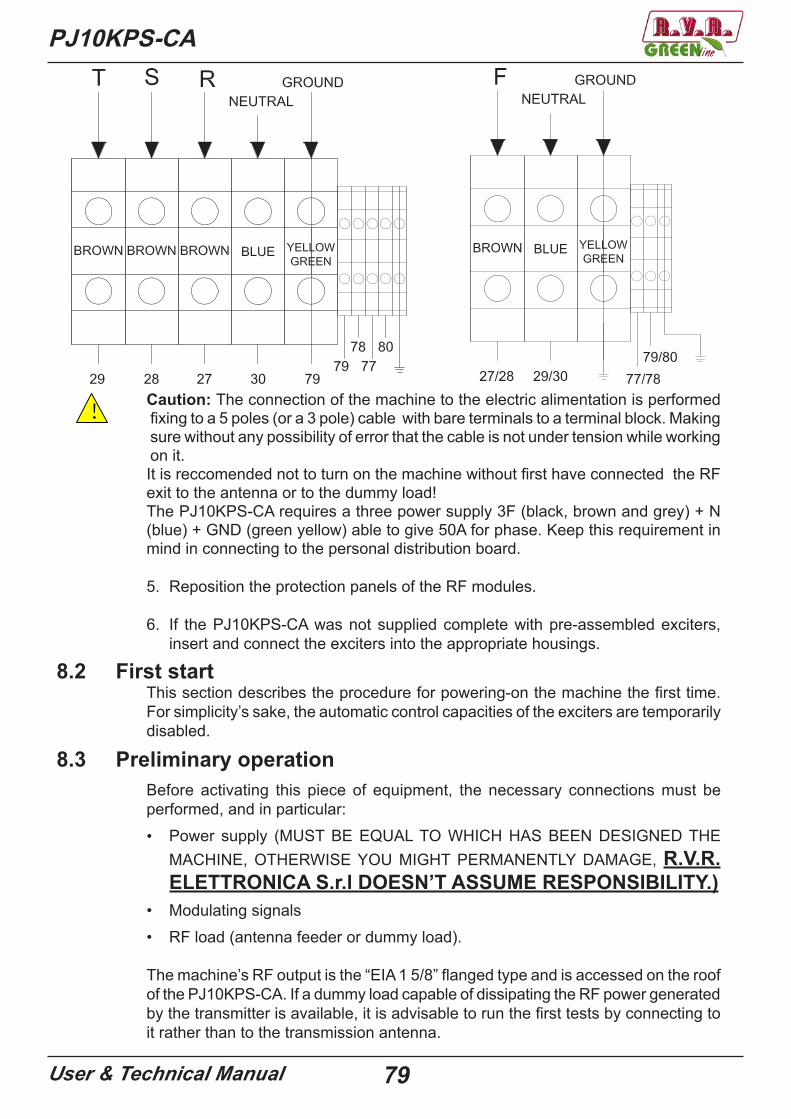
PJ10KPS-CA
User & Technical Manual 79
! Caution: The connection of the machine to the electric alimentation is performed fixing to a 5 poles (or a 3 pole) cable with bare terminals to a terminal block. Making sure without any possibility of error that the cable is not under tension while working on it.It is reccomended not to turn on the machine without first have connected the RF exit to the antenna or to the dummy load!The PJ10KPS-CA requires a three power supply 3F (black, brown and grey) + N (blue) + GND (green yellow) able to give 50A for phase. Keep this requirement in mind in connecting to the personal distribution board.
5. Reposition the protection panels of the RF modules.
6. If the PJ10KPS-CA was not supplied complete with pre-assembled exciters, insert and connect the exciters into the appropriate housings.
8.2 First startThis section describes the procedure for powering-on the machine the first time. For simplicity’s sake, the automatic control capacities of the exciters are temporarily disabled.
8.3 Preliminary operationBefore activating this piece of equipment, the necessary connections must be performed, and in particular:• Power supply (MUST BE EQUAL TO WHICH HAS BEEN DESIGNED THE
MACHINE, OTHERWISE YOU MIGHT PERMANENTLY DAMAGE, R.V.R. ELETTRONICA S.r.l DOESN’T ASSUME RESPONSIBILITY.)
• Modulating signals• RF load (antenna feeder or dummy load).
The machine’s RF output is the “EIA 1 5/8” flanged type and is accessed on the roof of the PJ10KPS-CA. If a dummy load capable of dissipating the RF power generated by the transmitter is available, it is advisable to run the first tests by connecting to it rather than to the transmission antenna.
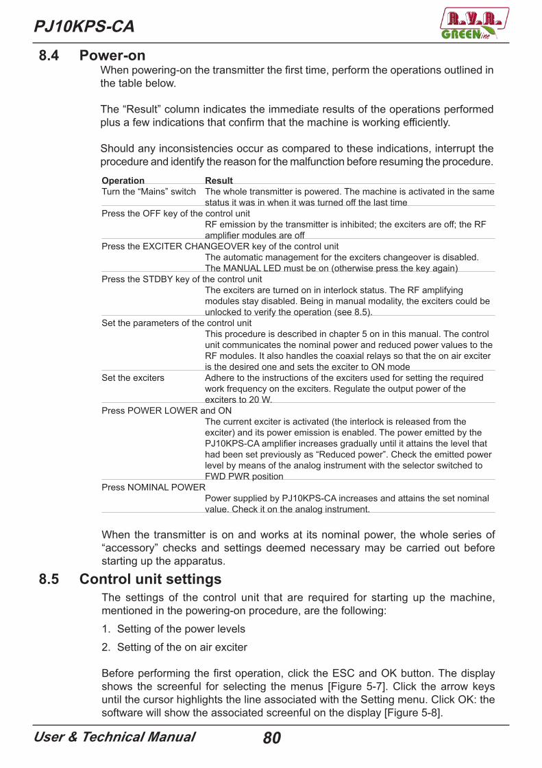
PJ10KPS-CA
User & Technical Manual 80
Operation ResultTurn the “Mains” switch The whole transmitter is powered. The machine is activated in the same
status it was in when it was turned off the last timePress the OFF key of the control unit
RF emission by the transmitter is inhibited; the exciters are off; the RF amplifier modules are off
Press the EXCITER CHANGEOVER key of the control unit The automatic management for the exciters changeover is disabled. The MANUAL LED must be on (otherwise press the key again)
Press the STDBY key of the control unit The exciters are turned on in interlock status. The RF amplifying modules stay disabled. Being in manual modality, the exciters could be unlocked to verify the operation (see 8.5).
Set the parameters of the control unit This procedure is described in chapter 5 on in this manual. The control unit communicates the nominal power and reduced power values to the RF modules. It also handles the coaxial relays so that the on air exciter is the desired one and sets the exciter to ON mode
Set the exciters Adhere to the instructions of the exciters used for setting the required work frequency on the exciters. Regulate the output power of the exciters to 20 W.
Press POWER LOWER and ON The current exciter is activated (the interlock is released from the exciter) and its power emission is enabled. The power emitted by the PJ10KPS-CA amplifier increases gradually until it attains the level that had been set previously as “Reduced power”. Check the emitted power level by means of the analog instrument with the selector switched to FWD PWR position
Press NOMINAL POWER Power supplied by PJ10KPS-CA increases and attains the set nominal value. Check it on the analog instrument.
When the transmitter is on and works at its nominal power, the whole series of “accessory” checks and settings deemed necessary may be carried out before starting up the apparatus.
8.5 Control unit settingsThe settings of the control unit that are required for starting up the machine, mentioned in the powering-on procedure, are the following: 1. Setting of the power levels2. Setting of the on air exciter
Before performing the first operation, click the ESC and OK button. The display shows the screenful for selecting the menus [Figure 5-7]. Click the arrow keys until the cursor highlights the line associated with the Setting menu. Click OK: the software will show the associated screenful on the display [Figure 5-8].
8.4 Power-onWhen powering-on the transmitter the first time, perform the operations outlined in the table below.
The “Result” column indicates the immediate results of the operations performed plus a few indications that confirm that the machine is working efficiently.
Should any inconsistencies occur as compared to these indications, interrupt the procedure and identify the reason for the malfunction before resuming the procedure.

PJ10KPS-CA
User & Technical Manual 81
Figure 5-7 Figure 5-8
On having accessed the Settings menu, use the arrow keys to select the nominal power line (Pwr. Out) and click OK. Use the arrow keys to decrease or increase the indicated percentage value up to the required level. Click OK again to set this value. Repeat the operation for the line associated with the reduced power level (Pwr. Lower).
NB The new power level is transmitted to the combiner module and then stored in EEPROM
only when the ESC button is clicked.
When inside this menu, it is advisable to check the date and time lines and update them if necessary. Note: the date and time are used only for marking the events in the alarms register.
NB The date and time do not need to be updated in the transmitter in order for it to work
efficiently.
On having completed these settings, click ESC to return to the selection screenful.
In order to set the on air exciter, select the Exciters menu [Figure 5-9]. Take into consideration the On Air Exciter line: the number to the right indicates the exciter being used. To change it simply highlight the line and click OK.
To have the correct efficiency of the transmitter, the exciters should stay at 20/22 W, unless stated otherwise indicated on the modulator, depending on the version and frequency. The power of the transmitter should be adjusted from the menu “Settings”.
DO NOT RESPECT THIS COULD DAMAGE THE EQUIPMENT LDMOS, RVR ELETTRONICA S.R.L DISCLAIMS THE WARRANTY.
The exchange of the exciters is assisted from the software, that is when the commutation is carried out , the interlock comes systematized in the correct way independently from like they were. The interlock could be modified also manually in case of necessity.
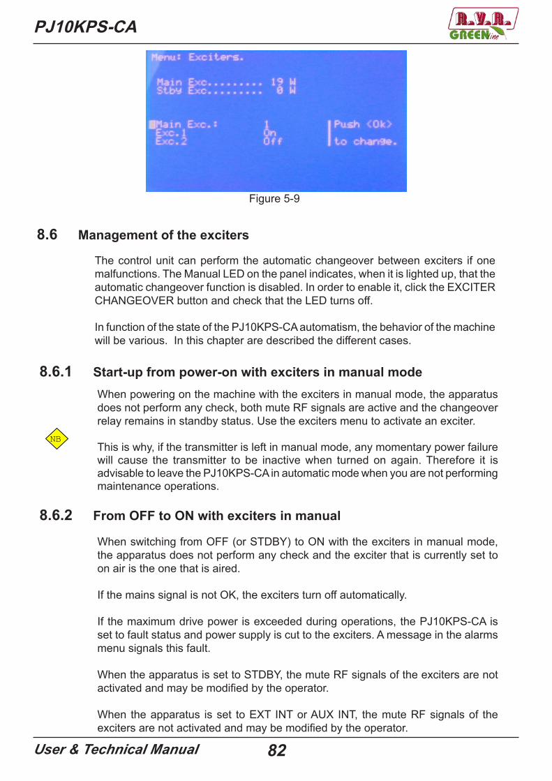
PJ10KPS-CA
User & Technical Manual 82
Figure 5-9
8.6 Management of the exciters
The control unit can perform the automatic changeover between exciters if one malfunctions. The Manual LED on the panel indicates, when it is lighted up, that the automatic changeover function is disabled. In order to enable it, click the EXCITER CHANGEOVER button and check that the LED turns off.
In function of the state of the PJ10KPS-CA automatism, the behavior of the machine will be various. In this chapter are described the different cases.
8.6.1 Start-up from power-on with exciters in manual modeWhen powering on the machine with the exciters in manual mode, the apparatus does not perform any check, both mute RF signals are active and the changeover relay remains in standby status. Use the exciters menu to activate an exciter.
NB This is why, if the transmitter is left in manual mode, any momentary power failure
will cause the transmitter to be inactive when turned on again. Therefore it is advisable to leave the PJ10KPS-CA in automatic mode when you are not performing maintenance operations.
8.6.2 From OFF to ON with exciters in manual
When switching from OFF (or STDBY) to ON with the exciters in manual mode, the apparatus does not perform any check and the exciter that is currently set to on air is the one that is aired.
If the mains signal is not OK, the exciters turn off automatically.
If the maximum drive power is exceeded during operations, the PJ10KPS-CA is set to fault status and power supply is cut to the exciters. A message in the alarms menu signals this fault.
When the apparatus is set to STDBY, the mute RF signals of the exciters are not activated and may be modified by the operator.
When the apparatus is set to EXT INT or AUX INT, the mute RF signals of the exciters are not activated and may be modified by the operator.
PJ10KPS-CA
User & Technical Manual 83
8.6.3 Automatic changeoverWhen the PJ10KPS-CA is in the exciter automatic changeover mode, the power emitted by the on air exciter is checked constantly. If at any time the on air exciter is no longer good (i.e. power drops to below the preset level), the apparatus is kept operational whereas the exciter connected to the internal Dummy Load turns on. If the latter one is good (i.e. it is capable of supplying the required power), then the two exciters are changed over. Instead if the alternative exciter is not good, no changeover takes place, the control unit commands the mute RF of the exciter to Dummy Load, it waits 120 s. and repeats the attempt. This procedure is repeated indefinitely until one of the two exciters is considered to be good.
During the whole length of time during which there is no good exciter, the PJ10KPS-CA keeps the WAIT LED on for signaling this status.
Each exciter is fitted with its own mute RF. On being commanded, the piloting signal must return to zero within 3 seconds at the most. If this does not occur, the fault is recorded by an error message that is entered in the alarms menu.
If the mains signal is not OK, the exciters turn off automatically. If the piloting power exceeds the limit during operations, the PJ10KPS-CA is set to the FAULT status and the power supply of the exciters is turned off. A message in the alarms menu signals the fault. Keep in mind that the operator’s intervention is required to exit from the FAULT status.
If the MAINS signal coming from the bus is not OK, the exciters are all turned off. As soon as the MAINS signal is regular again, the evaluation cycle of the exciters begins (see 8.6.4).
When the apparatus is set to STDBY, the mute RF signals of the exciters are activated and as such both exciters are inhibited. If the ON key is pressed, the system re-evaluates both exciters in the same manner as in the procedure from OFF to ON (see 8.6.4).
When the apparatus is set to EXT INT or AUX INT, the mute RF signals of the exciters are activated and therefore both exciters are inhibited. When the external interlocks are released, the system re-evaluates both exciters as during the phase from OFF to ON (see 8.6.4).
8.6.4 Phase from ON to OFFWhen the apparatus is set to OFF status and you press the ON button, the power supply of the exciters is activated and the logic starts to evaluate the exciters. During the evaluation phase, the WAIT LED stays ON.
When the apparatus is turned OFF, it memorizes the exciter on air. Consequently when the machine restarts it can attempt to restore the previous conditions. On the machine restarting, if the exciter that is to be aired does not attain the preset power level whereas the spare one is operational, the apparatus performs the changeover when the evaluation time (120 s.) expires.

PJ10KPS-CA
User & Technical Manual 84
On the machine restarting, if both exciters do not attain the preset power level, the apparatus airs the one that had been present when the machine was turned off, after the evaluation time has expired.
8.6.5 Start-up with exciters in automatic modeThe sequence run by the PJ10KPS-CA, when the power supply is activated while it is already in ON status and the exciters are in automatic mode, is identical to the one run for switching from OFF to ON. The only difference is that a screenful displays the countdown for determining the fault of the exciters. During this phase the manual/automatic button is inhibited and in order to set the exciters to manual mode you must press the OFF button of the apparatus.
8.6.6 Audio alarmThe control unit of the PJ10KPSCA can manage a fault signal, for each exciter, which normally has an “Audio Alarm” meaning. The control software of the PJ10KPS-CA does not intervene in triggering these signals since they must be checked by the exciters (or by any other connected devices).
The Audio Alarm signals are made up of two inputs for the logical signals on the parallel interface and on the “mute RF” command connector of the exciters.
The control unit manages these signals just like it manages the power good signals:• Each “Audio alarm” signal is associated with its own exciter• If the audio signal, associated with the exciter that is currently on air, enters an
alarm status, the PJ10KPS-CA waits for the time configured in the exciter menu before it attempts the restoring operation
• If the audio of the aired exciter is still in alarm status on the elapsing of the aforesaid time interval, the control unit checks if the audio of the exciter on the dummy load is regular. In this case the changeover between the exciters is performed.
Observe the following differences as compared to the case in which power is missing:• The management of the “Audio alarm” signals is not active during the start-up
phase and during the switching phase from OFF to ON, but only when the exciters are working in automatic.
• In the standard configuration, the aforesaid sequence continues until the audio signal associated with one of the exciters becomes regular again. In the “N+1” configuration, the switching attempt is performed only twice, after which the PJ10KPS-CA enters the fault status.
• An Audio Alarm output is provided on the parallel interface: this signal is activated (with no delays) when the audio of the exciter that is currently on air is in alarm status.
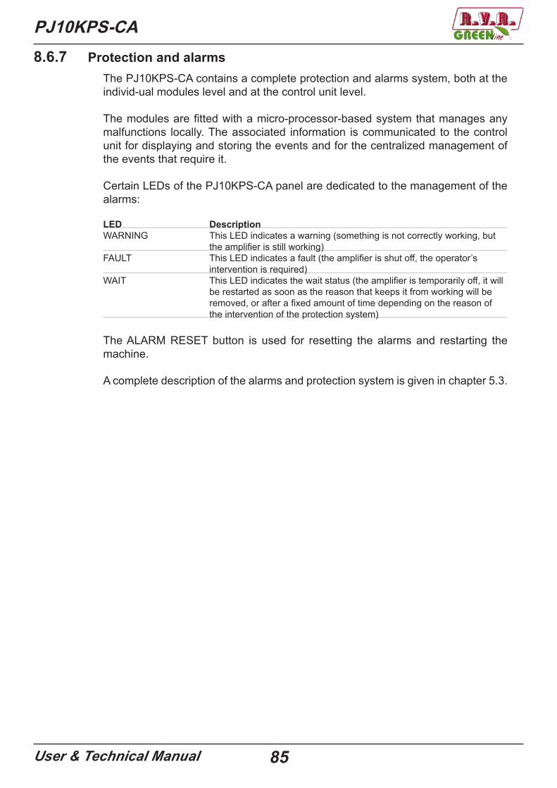
PJ10KPS-CA
User & Technical Manual 85
8.6.7 Protection and alarmsThe PJ10KPS-CA contains a complete protection and alarms system, both at the individ-ual modules level and at the control unit level.
The modules are fitted with a micro-processor-based system that manages any malfunctions locally. The associated information is communicated to the control unit for displaying and storing the events and for the centralized management of the events that require it.
Certain LEDs of the PJ10KPS-CA panel are dedicated to the management of the alarms:
LED DescriptionWARNING This LED indicates a warning (something is not correctly working, but
the amplifier is still working)FAULT This LED indicates a fault (the amplifier is shut off, the operator’s
intervention is required)WAIT This LED indicates the wait status (the amplifier is temporarily off, it will
be restarted as soon as the reason that keeps it from working will be removed, or after a fixed amount of time depending on the reason of the intervention of the protection system)
The ALARM RESET button is used for resetting the alarms and restarting the machine.
A complete description of the alarms and protection system is given in chapter 5.3.

PJ10KPS-CA
User & Technical Manual 86

87User & Technical Manual
PJ10KPS-CA
88User & Technical Manual
PJ10KPS-CA
© Copyright 2014R.V.R. Elettronica S.r.l.Via del Fonditore 2/2c – 40138 Bologna ItaliaTelephone: +39 051 6010506Fax: +39 051 6011104E-mail: [email protected]: www.rvr.it
All rights reservedPrinted and bound in Italy. No part of this manual may be reproduced, memori-zed or transmitted in any form or by any means, electronic or mechanic, inclu-ding photocopying, recording or by any information storage and retrieval system, without written permission of the copyright owner.
Revision HistoryDate Version Reason Editor30/05/2013 2.0 New version Nicolini D.18/07/2013 2.1 Updating Nicolini D.12/09/2013 2.2 Updating Nicolini D.16/10/2013 2.3 Updating Nicolini D.18/09/2013 2.4 Updating Nicolini D.20/09/2013 2.5-2.6-2.7 Special version Nicolini D.11/03/2014 2.8 Updated:
CPU module diagramCPU combiner diagramCPU power supply diagramBias board module diagramRF Power measure board (FWD) diagramRF Power measure board (RFL) diagramDummy load diagram
Nicolini D.
01/04/2014 2.9 Updated:Bias board module diagramRelay interface diagram220/380v wiring diagramLow tension and signal wiring diagram
Nicolini D.
14/05/2014 3.0 Added:PFC (PFCPSL4280) diagramUpdated:Directional coupler (RF module)Various codes boardsBias settings
Nicolini D.
30/07/2015 3.1 Added:Mono-phase versionCreated Technical annex for diagrams
Nicolini D.
09/05/2019 3.2 Added:Planar pallet mosfetUpdated:Various codes boards
Nicolini D.

R.V.R Elettronica S.r.l.Via del Fonditore, 2 / 2cZona Industriale Roveri · 40138 Bologna · Italy Phone: +39 051 6010506 · Fax: +39 051 6011104 e-mail: [email protected] ·web: http://www-rvr-it
The RVR Logo, and others referenced RVR products and services are trademarks of RVR Elettronica S.p.A. in Italy, other countries or both. RVR ® 1998 all rights reserved.
All other trademarks, trade names or logos used are property of their respective owners.
ISO 9001:2000 certifi ed since 2000