general catalog 2009.pdf - r.v.r. elettronica
TRANSCRIPT

TelecomunicazioniFerrara
TELECOMUNICAZIONIFERRARA
RVR GROUP
RVRGROUP
Any product of Telecomumicazioni Ferrara is covered by a 12 (twelve) month warranty (standard).Telecomumicazioni Ferrara S.r.l. extends to the original end-user purchaser all manufacturers warranties which aretransferrable and all claims are to be made directly to Telecomumicazioni Ferrara per indicated procedures.
Warranty shall not include:
1. Connectors;2. Re-shipment of the unit to Telecomumicazioni Ferrara for repair purposes;3. Any unauthorized repair/modification;4. Incidental/consequential damages as a result of any defect;5. Nominal non-incidental defects;6. Re-shipment costs or insurance of the unit or replacement units/parts;
Any damage to the goods must be reported to the carrier in writing on the shipment receipt.
Any discrepancy or damage discovered subsequent to delivery, shall be reported to Telecomumicazioni Ferrara within5 (five) days from delivery date.
To claim your rights under this warranty, you should follow this procedure:
• Contact the dealer or distributor where you purchased the unit. Describe the problem and, so that a possible easysolution can be detected. Dealers and Distributors are supplied with all the information about problems that may occurand usually they can repair the unit quicker than what the manufacturer could do. Very often installing errors arediscovered by dealers.
• If your dealer cannot help you, contact Telecomumicazioni Ferrara and explain the problem. If it is decided to returnthe unit to the factory, Telecomumicazioni Ferrara will mail you a regular authorization with all the necessaryinstructions to sendback the goods.
• When you receive the authorization, you can return the unit. Pack it carefully for the shipment, preferably using theoriginal packing and seal the package perfectly. DO NOT RETURN UNITS WITHOUT OUR AUTHORIZATION AS THEYWILL BE REFUSED.
Be sure to enclose a written technical report where mention all the problems found and a copy of your original invoiceestablishing the starting date of the warranty.
Replacement and warranty parts may be ordered from the following address:
Telecomunicazioni Ferrara S.r.l. RVR ELETTRONICA SPAVia Dei Calzolai, 156 VIA DEL FONDITORE 2 /2c Zona Roveri44036 Francolino (Ferrara) 40138 BOLOGNA ITALY ITALYTel.: +39 0532 72.40.33 Tel.: +39 0516010506Fax: +39 0532 72.48.19 Fax: +39 0516011104E-Mail: [email protected] Email [email protected] http://www.rvr.it
be sure to include the equipment model and serial number as well as part description and part number.
CUSTOMER SEVICE AND TECHNICAL ASSISTANCEThe technical assistance is aviable from Telecomunicazioni Ferrara S.r.l. by letter or prepaid telephone or telegram.Equipment requiring repair or over haul should be sent by common carrier, prepaid, insured and well protect. Do not mailequipment. We can assume no liability for inbound damage and necessary repairs become the obligation of the shipper.Prior arrangement is necessary. Contact the dealer or distributor with all the informations about problems that may occur andusually thay can repair the unit quicker than what the manufacturer could do. Very often installing errors discovered bydealers.If yoy dealer cannot help you, contact Telecomunicazioni Ferrara S.r.l. in Francolino (FE) and explain the problem. If itis decided to return the unit to the factory, Telecomunicazioni Ferrara will mail you a regular authirization with all thenecessary instuctions to send back the goods.
PRODUCT WARRANTY
TelecomunicazioniFerrara
RVR GROUP
RVRGROUP
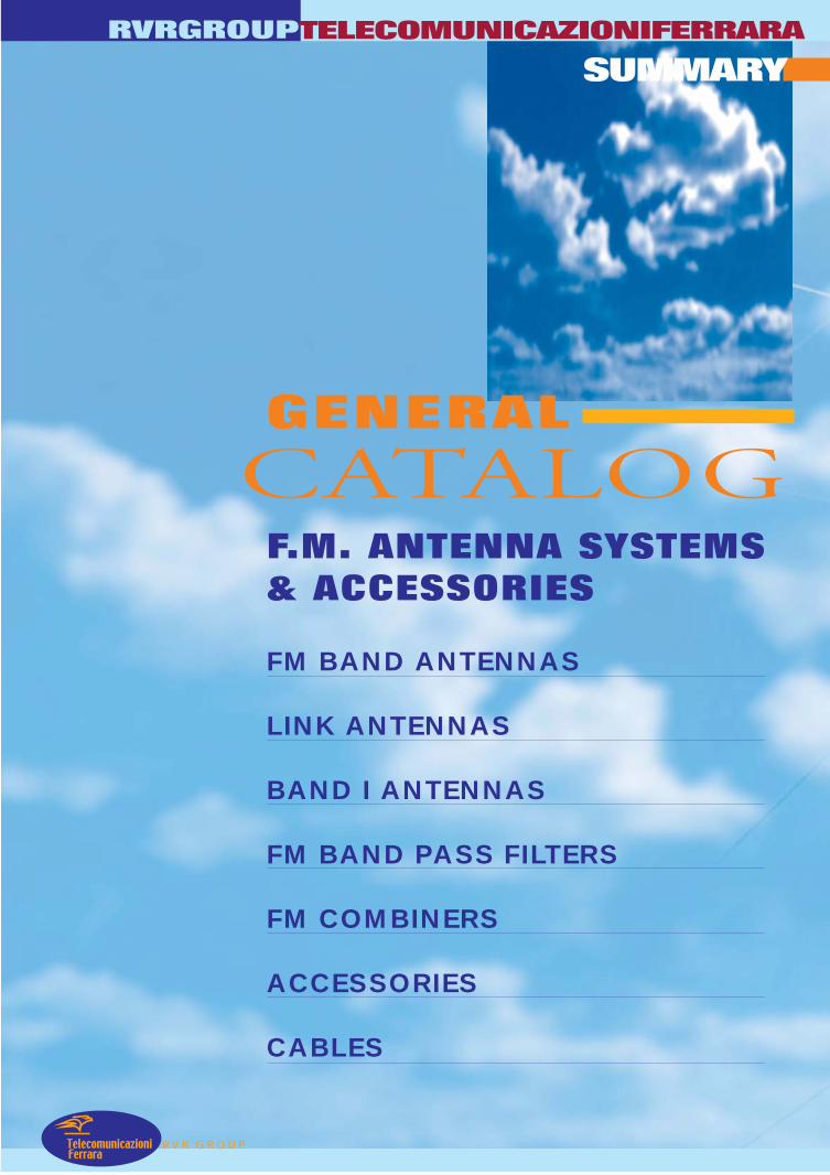
SUMMARY
TelecomunicazioniFerrara
FM BAND ANTENNAS
LINK ANTENNAS
BAND I ANTENNAS
FM BAND PASS FILTERS
FM COMBINERS
ACCESSORIES
CABLES
CATALOGGENERAL
F.M. ANTENNA SYSTEMS& ACCESSORIES
TELECOMUNICAZIONIFERRARA

Telecomunicazioni
TELECOMUNICAZIONIFERRARA
RVR GROUP
RVRGROUP

RVR GROUP
RVRGROUP
FM BAND ANTENNAS
TelecomunicazioniFerrara
BROAD BAND HORIZONTALAND VERTICALPOLARIZATION ANTENNAS
BROAD BAND CIRCULARPOLARIZATION ANTENNAS
TUNED HORIZONTALAND VERTICALPOLARIZATION ANTENNAS
TUNED CIRCULARPOLARIZATION ANTENNAS
CATALOGGENERAL
TELECOMUNICAZIONIFERRARA

TELECOMUNICAZIONIFERRARA RVRGROUP
Model AJ1FENA BROADBAND LOW COST DIPOLE LOW WEIGHT HIGHT PERFORMANCE • Model A1JFENA – AJ1FEA6 – AJ1FEA7
• Band II dipole
• Broadband 87.5÷108 MHz
• 2 dBd gain
• Vertical polarization
• Omni directional pattern
• Aluminium anticorodal
ELECTRICAL DATA MECHANICAL DATA Frequency range 87.5÷108 MHz Dimensions 1400x900x50 mm
Impedance 50 Ohm Weight 4 kg with hardware mounting
Connectors N (AJ1FENA) – 7/16 female (AJ1FEA6) – 7/8 EIA (AJ1FEA7)
Max Power 800W (N) – 2KW (7/16” - 7/8” EIA) Wind surface 0.05m2
Wind load 9.8 kg (wind speed at 160 km/h – without radome) VSWR ≤ 1.35:1
Max wind velocity 220 km/h.
Polarization Vertical
Gain 2 dB (referred to half-wave dipole) at 98 MHz
Materials External parts: Aluminium anticorodal Internal parts: brass Radome: fiberglass (optional)
Icing protection Feed point radome (optional) Pattern
Omni directional ± 1.5 dB in free space Omni directional ± 3 dB with 100mm diameter pole
Radome (optional)
Color white
Lightning protection All metal parts DC grounded Mounting With special pipe clamps 40÷110 mm diameter
0
30
150
180
210
240
270
300
330
-24
-18
-6
-12
E-plane
P
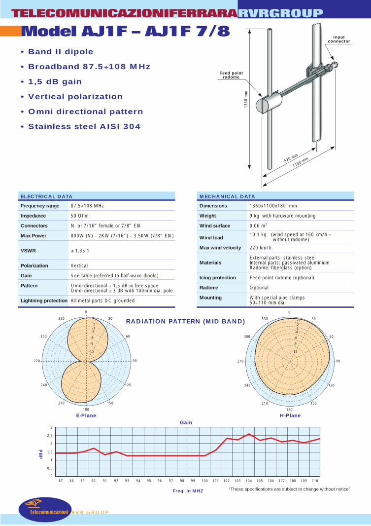
RADIATION PATTERN (MID BAND)
60
90
120
-12
0
30
60
90
120
150
180
210
240
270
300
330
-24
-18
-6
H-plane
Return Loss
Freq. in MHz “These specifications are subject to change without notice”
dB
RVR GROU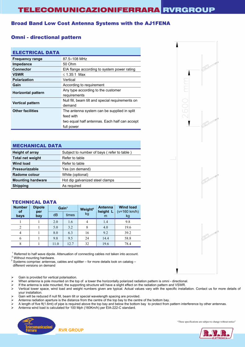
TELECOMUNICAZIONIFERRARA RVRGROUP Broad Band Low Cost Antenna Systems with the AJ1FENA Omni - directional pattern ELECTRICAL DATA Frequency range 87.5÷108 MHz Impedance 50 Ohm Connector EIA flange according to system power rating VSWR ≤ 1.35:1 Max Polarization Vertical Gain According to requirement
Horizontal pattern Any type according to the customer requirements
Vertical pattern Null fill, beam tilt and special requirements on demand
Other facilities
The antenna system can be supplied in split feed with two equal half antennas. Each half can accept full power
MECHANICAL DATA Height of array Subject to number of bays ( refer to table ) Total net weight Refer to table Wind load Refer to table Pressurizzable Yes (on demand) Radome colour White (optional) Mounting hardware Hot dip galvanized steel clamps Shipping As required
TECHNICAL DATA
Gain¹ Number of
bays
Dipole per bay dB times
Weight² kg
Antennaheight L
m
Wind load (v=160 km/h)
kg 1 1 2.0 1.6 4 1.4 9.8 2 1 5.0 3.2 8 4.0 19.6 4 1 8.0 6.3 16 9.2 39.2 6 1 9.8 9.5 24 14.4 58.8 8 1 11.0 12.7 32 19.6 78.4
1 Referred to half wave dipole. Attenuation of connecting cables not taken into account.
2 Without mounting hardware. 3 Systems comprise: antennas, cables and splitter – for more details look on catalog – different versions on demand
Gain is provided for vertical polarisation. When antenna is pole mounted on the top of a tower the horizontally polarized radiation pattern is o If the antenna is side mounted, the supporting structure will have a slight effect on the radiation patte Vertical tower space, wind load and weight numbers given are typical. Actual values vary with the
your installation. Gain will be reduced if null fill, beam tilt or special wavelength spacing are provided. Antenna radiation aperture is the distance from the centre of the top bay to the centre of the bottom A length of five ft(1.6mt) of pipe is required above the top bay and below the bottom bay to protect fr Antenna wind load is calculated for 100 Mph (160Km/h) per EIA-222-C standard.
P
mni - directional. rn and VSWR. specific installation. Contact us for more details of
bay. om pattern interference by other antennas.
“These specifications are subject to change without notice”
RVR GROU
TELECOMUNICAZIONIFERRARA RVRGROUP
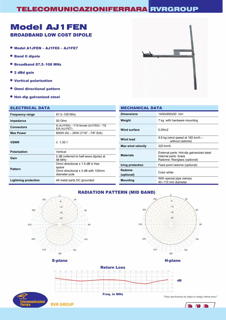
Model AJ1FEN BROADBAND LOW COST DIPOLE • Model A1JFEN – AJ1FE6 – AJ1FE7
• Band II dipole
• Broadband 87.5÷108 MHz
• 2 dBd gain
• Vertical polarization
• Omni directional pattern
• Hot–dip galvanized steel
ELECTRICAL DATA MECHANICAL DATA Frequency range 87.5÷108 MHz Dimensions 1400x900x50 mm
Impedance 50 Ohm Weight 7 kg with hardware mounting
Connectors N (AJ1FEN) – 7/16 female (AJ1FE6) – 7/8 EIA (AJ1FE7)
Max Power 800W (N) – 2KW (7/16” - 7/8” EIA) Wind surface 0.05m2
Wind load 9.8 kg (wind speed at 160 km/h – without radome) VSWR ≤ 1.35:1
Max wind velocity 220 km/h.
Polarization Vertical
Gain 2 dB (referred to half-wave dipole) at 98 MHz
Materials External parts: Hot-dip galvanized steel Internal parts: brass Radome: fiberglass (optional)
Icing protection Feed point radome (optional) Pattern
Omni directional ± 1.5 dB in free space Omni directional ± 3 dB with 100mm diameter pole
Radome (optional)
Color white
Lightning protection All metal parts DC grounded Mounting With special pipe clamps 40÷110 mm diameter
0
30
150
180
210
240
270
300
330
-24
-18
-6
-12
E-plane
P
RADIATION PATTERN (MID BAND)
60
90
120
-12
0
30
60
90
120
150
180
210
240
270
300
330
-24
-18
-6
H-plane
Return Loss
Freq. in MHz “These specifications are subject to change without notice”
dB
RVR GROU
TELECOMUNICAZIONIFERRARA RVRGROUP Broad Band Low Cost Antenna Systems with the AJ1FEN Omni - directional pattern ELECTRICAL DATA Frequency range 87.5÷108 MHz Impedance 50 Ohm Connector EIA flange according to system power rating VSWR ≤ 1.35:1 Max Polarization Vertical Gain According to requirement
Horizontal pattern Any type according to the customer requirements
Vertical pattern Null fill, beam tilt and special requirements on demand
Other facilities
The antenna system can be supplied in split feed with two equal half antennas. Each half can accept full power
MECHANICAL DATA Height of array Subject to number of bays ( refer to table ) Total net weight Refer to table Wind load Refer to table Pressurizzable Yes (on demand) Radome colour White (optional) Mounting hardware Hot dip galvanized steel clamps Shipping As required
TECHNICAL DATA
Gain¹ Number of
bays
Dipole per bay dB times
Weight² kg
Antennaheight L
m
Wind load (v=160 km/h)
kg 1 1 2.0 1.6 7 1.4 9.8 2 1 5.0 3.2 14 4.0 19.6 4 1 8.0 6.3 28 9.2 39.2 6 1 9.8 9.5 42 14.4 58.8 8 1 11.0 12.7 56 19.6 78.4
1 Referred to half wave dipole. Attenuation of connecting cables not taken into account.
2 Without mounting hardware. 3 Systems comprise: antennas, cables and splitter – for more details look on catalog – different versions on demand
Gain is provided for vertical polarisation. When antenna is pole mounted on the top of a tower the horizontally polarized radiation pattern is o If the antenna is side mounted, the supporting structure will have a slight effect on the radiation patte Vertical tower space, wind load and weight numbers given are typical. Actual values vary with the
your installation. Gain will be reduced if null fill, beam tilt or special wavelength spacing are provided. Antenna radiation aperture is the distance from the centre of the top bay to the centre of the bottom A length of five ft(1.6mt) of pipe is required above the top bay and below the bottom bay to protect fr Antenna wind load is calculated for 100 Mph (160Km/h) per EIA-222-C standard.
P
mni - directional. rn and VSWR. specific installation. Contact us for more details of
bay. om pattern interference by other antennas.
“These specifications are subject to change without notice”
RVR GROU
Telecomunicazioni
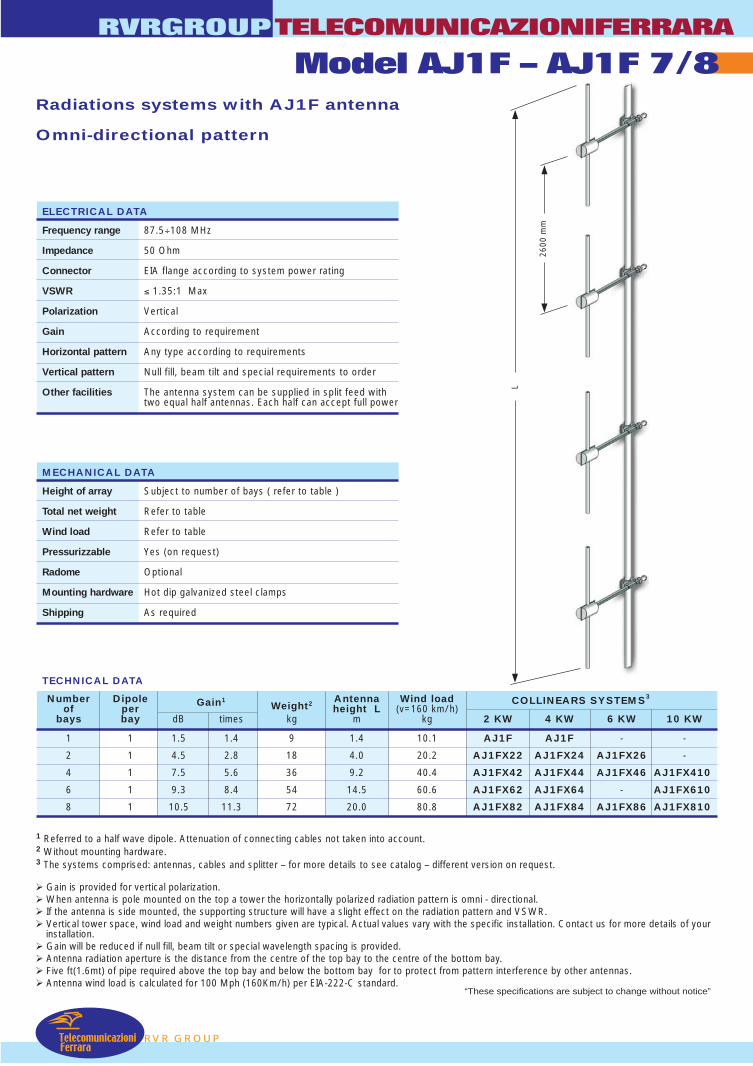
Model AJ1F – AJ1F 7/8TELECOMUNICAZIONIFERRARA
RVR GROUP
RVRGROUP
• Band II dipole
• Broadband 87.5÷108 MHz
• 1,5 dB gain
• Vertical polarization
• Omni directional pattern
• Stainless steel AISI 304
RADIATION PATTERN (MID BAND)
ELECTRICAL DATA
Frequency range 87.5÷108 MHz
Impedance 50 Ohm
Connectors N or 7/16” female or 7/8” EIA
Max Power 800W (N) – 2KW (7/16”) – 3.5KW (7/8” EIA)
VSWR ≤ 1.35:1
Polarization Vertical
Gain See table (referred to half-wave dipole)
Pattern Omni directional ± 1.5 dB in free spaceOmni directional ± 3 dB with 100mm dia. pole
Lightning protection All metal parts DC grounded
E-Plane H-Plane
MECHANICAL DATA
Dimensions 1360x1100x180 mm
Weight 9 kg with hardware mounting
Wind surface 0.06 m2
Wind load10.1 kg (wind speed at 160 km/h –
without radome)
Max wind velocity 220 km/h.
External parts: stainless steelMaterials Internal parts: passivated aluminium
Radome: fiberglass (option)
Icing protection Feed point radome (optional)
Radome Optional
Mounting With special pipe clamps50÷110 mm dia.
180
0
270 90
-1330
300
240
210 150
120
60
30
-2-3-4
-6
-9
-15
180
0
270 90
-1330
300
240
210 150
120
60
30
-2-3-4
-6
-9
-15
970 mm
1100 mm
1360
mm
Feed pointradome
Inputconnector
87 88 89 90 91 92 93 94 95 96 97 98 99 100 101 102 103 104 105 106 107 108
3
2,5
2
1,5
1
0,5
Gain
Freq. in MHZ
109 1100
dB
d
“These specifications are subject to change without notice”
L
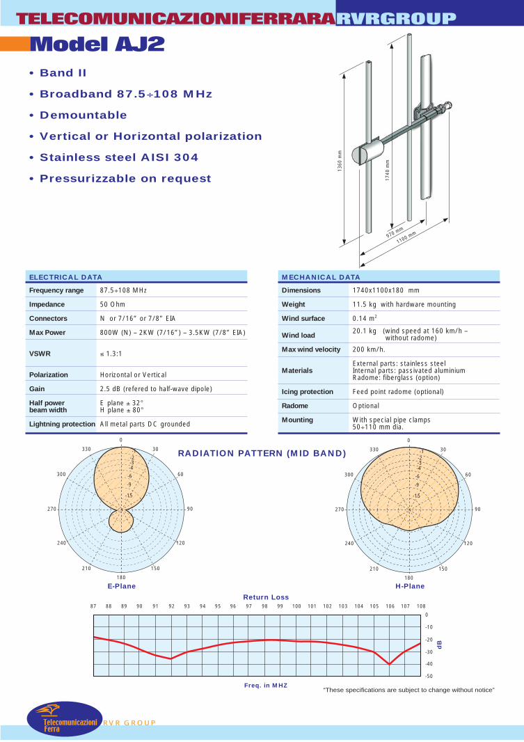
2600
mm
RVR GROUP
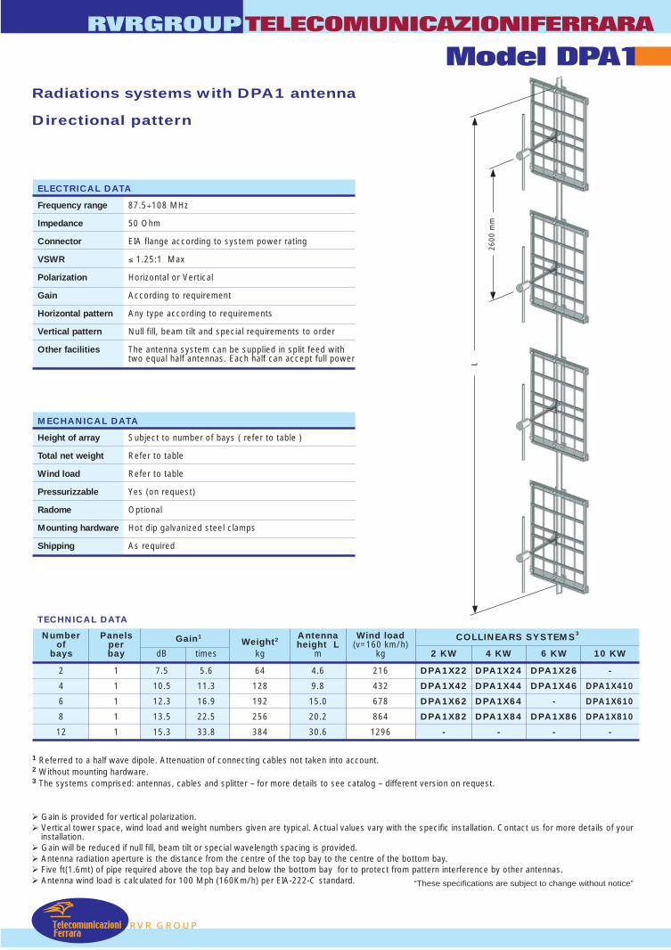
Radiations systems with AJ1F antenna
Omni-directional pattern
Gain is provided for vertical polarization. When antenna is pole mounted on the top a tower the horizontally polarized radiation pattern is omni - directional. If the antenna is side mounted, the supporting structure will have a slight effect on the radiation pattern and VSWR. Vertical tower space, wind load and weight numbers given are typical. Actual values vary with the specific installation. Contact us for more details of your
installation. Gain will be reduced if null fill, beam tilt or special wavelength spacing is provided. Antenna radiation aperture is the distance from the centre of the top bay to the centre of the bottom bay. Five ft(1.6mt) of pipe required above the top bay and below the bottom bay for to protect from pattern interference by other antennas. Antenna wind load is calculated for 100 Mph (160Km/h) per EIA-222-C standard.
1 Referred to a half wave dipole. Attenuation of connecting cables not taken into account.2 Without mounting hardware.3 The systems comprised: antennas, cables and splitter – for more details to see catalog – different version on request.
TECHNICAL DATA
RVRGROUPTELECOMUNICAZIONIFERRARA
Model AJ1F – AJ1F 7/8
Number Dipole Gain1Weight2 Antenna Wind load COLLINEARS SYSTEMS3
of per height L (v=160 km/h)bays bay dB times kg m kg 2 KW 4 KW 6 KW 10 KW
1 1 1.5 1.4 9 1.4 10.1 AJ1F AJ1F - -
2 1 4.5 2.8 18 4.0 20.2 AJ1FX22 AJ1FX24 AJ1FX26 -
4 1 7.5 5.6 36 9.2 40.4 AJ1FX42 AJ1FX44 AJ1FX46 AJ1FX410
6 1 9.3 8.4 54 14.5 60.6 AJ1FX62 AJ1FX64 - AJ1FX610
8 1 10.5 11.3 72 20.0 80.8 AJ1FX82 AJ1FX84 AJ1FX86 AJ1FX810
ELECTRICAL DATA
Frequency range 87.5÷108 MHz
Impedance 50 Ohm
Connector EIA flange according to system power rating
VSWR ≤ 1.35:1 Max
Polarization Vertical
Gain According to requirement
Horizontal pattern Any type according to requirements
Vertical pattern Null fill, beam tilt and special requirements to order
Other facilities The antenna system can be supplied in split feed withtwo equal half antennas. Each half can accept full power
MECHANICAL DATA
Height of array Subject to number of bays ( refer to table )
Total net weight Refer to table
Wind load Refer to table
Pressurizzable Yes (on request)
Radome Optional
Mounting hardware Hot dip galvanized steel clamps
Shipping As required
TelecomunicazioniFerrara
“These specifications are subject to change without notice”
TelecomunicazioniFerra
Model AJ2TELECOMUNICAZIONIFERRARA
RVR GROUP
RVRGROUP
• Band II
• Broadband 87.5÷108 MHz
• Demountable
• Vertical or Horizontal polarization
• Stainless steel AISI 304
• Pressurizzable on request
RADIATION PATTERN (MID BAND)
ELECTRICAL DATA
Frequency range 87.5÷108 MHz
Impedance 50 Ohm
Connectors N or 7/16” or 7/8” EIA
Max Power 800W (N) – 2KW (7/16”) – 3.5KW (7/8” EIA)
VSWR ≤ 1.3:1
Polarization Horizontal or Vertical
Gain 2.5 dB (refered to half-wave dipole)
Half power E plane ± 32°beam width H plane ± 80°
Lightning protection All metal parts DC grounded
E-Plane H-Plane
MECHANICAL DATA
Dimensions 1740x1100x180 mm
Weight 11.5 kg with hardware mounting
Wind surface 0.14 m2
Wind load20.1 kg (wind speed at 160 km/h –
without radome)
Max wind velocity 200 km/h.
External parts: stainless steelMaterials Internal parts: passivated aluminium
Radome: fiberglass (option)
Icing protection Feed point radome (optional)
Radome Optional
Mounting With special pipe clamps50÷110 mm dia.
87 88 89 90 91 92 93 94 95 96 97 98 99 100 101 102 103 104 105 106 107 108
0
-10
-20
-30
-40
-50
dB
Return Loss
Freq. in MHZ
180
0
270 90
-1330
300
240
210 150
120
60
30
-2-3-4
-6
-9
-15
180
0
270 90
-1330
300
240
210 150
120
60
30
-2-3-4
-6
-9
-15
970 mm
1100 mm
1360
mm
1740
mm
“These specifications are subject to change without notice”
RVR GROUP
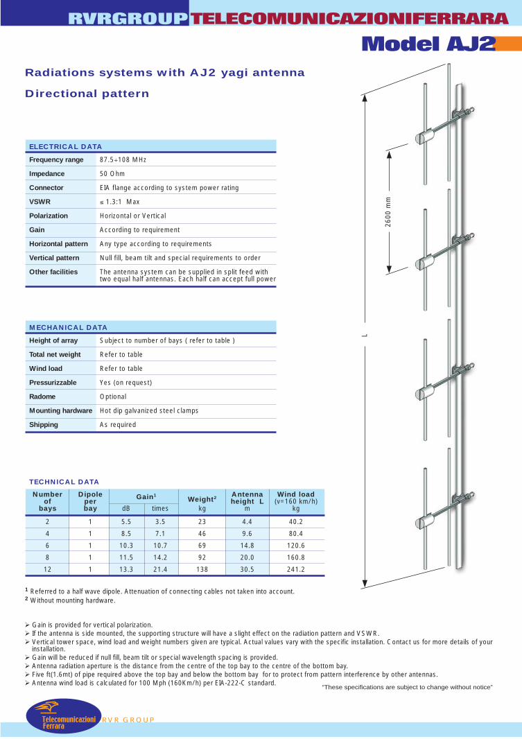
Radiations systems with AJ2 yagi antenna
Directional pattern
Gain is provided for vertical polarization. If the antenna is side mounted, the supporting structure will have a slight effect on the radiation pattern and VSWR. Vertical tower space, wind load and weight numbers given are typical. Actual values vary with the specific installation. Contact us for more details of your
installation. Gain will be reduced if null fill, beam tilt or special wavelength spacing is provided. Antenna radiation aperture is the distance from the centre of the top bay to the centre of the bottom bay. Five ft(1.6mt) of pipe required above the top bay and below the bottom bay for to protect from pattern interference by other antennas. Antenna wind load is calculated for 100 Mph (160Km/h) per EIA-222-C standard.
1 Referred to a half wave dipole. Attenuation of connecting cables not taken into account.2 Without mounting hardware.
TECHNICAL DATA
RVRGROUPTELECOMUNICAZIONIFERRARA
Model AJ2
Number Dipole Gain1Weight2 Antenna Wind load
of per height L (v=160 km/h)bays bay dB times kg m kg
2 1 5.5 3.5 23 4.4 40.2
4 1 8.5 7.1 46 9.6 80.4
6 1 10.3 10.7 69 14.8 120.6
8 1 11.5 14.2 92 20.0 160.8
12 1 13.3 21.4 138 30.5 241.2
ELECTRICAL DATA
Frequency range 87.5÷108 MHz
Impedance 50 Ohm
Connector EIA flange according to system power rating
VSWR ≤ 1.3:1 Max
Polarization Horizontal or Vertical
Gain According to requirement
Horizontal pattern Any type according to requirements
Vertical pattern Null fill, beam tilt and special requirements to order
Other facilities The antenna system can be supplied in split feed withtwo equal half antennas. Each half can accept full power
MECHANICAL DATA
Height of array Subject to number of bays ( refer to table )
Total net weight Refer to table
Wind load Refer to table
Pressurizzable Yes (on request)
Radome Optional
Mounting hardware Hot dip galvanized steel clamps
Shipping As required
TelecomunicazioniFerrara
L
2600
mm
“These specifications are subject to change without notice”

TelecomunicazioniFerra
Model AJ3TELECOMUNICAZIONIFERRARA
RVR GROUP
RVRGROUP
• Band II
• Broadband 87.5÷108 MHz
• Demountable
• Vertical or Horizontal polarization
• Stainless steel AISI 304
• Pressurizzable on request
RADIATION PATTERN (MID BAND)
ELECTRICAL DATA
Frequency range 87.5÷108 MHz
Impedance 50 Ohm
Connectors N or 7/16” or 7/8” EIA
Max Power 800W (N) – 2KW (7/16”) – 3.5KW (7/8” EIA)
VSWR ≤ 1.35:1
Polarization Horizontal or Vertical
Gain 4.0 dB (refered to half-wave dipole)
Half power E plane ± 32°beam width H plane ± 68°
Lightning protection All metal parts DC grounded
E-Plane H-Plane
MECHANICAL DATA
Dimensions 1540x1780x180 mm
Weight 13.5 kg with hardware mounting
Wind surface 0.18 m2
Wind load26.7 kg (wind speed at 160 km/h –
without radome)
Max wind velocity 200 km/h.
External parts: stainless steelMaterials Internal parts: passivated aluminium
Radome: fiberglass (option)
Icing protection Feed point radome (optional)
Radome Optional
Mounting With special pipe clamps50÷110 mm dia.
180
0
270 90
-1330
300
240
210 150
120
60
30
-2-3-4
-6
-9
-15
180
0
270 90
-1330
300
240
210 150
120
60
30
-2-3-4
-6
-9
-15
87 88 89 90 91 92 93 94 95 96 97 98 99 100 101 102 103 104 105 106 107 108
0
-10
-20
-30-35-40
dB
Return Loss
Freq. in MHZ
-5
-15
-25
1540 mm
1360
mm 17
40 m
m
1120
mm
“These specifications are subject to change without notice”

RVR GROUP
Radiations systems with AJ3 yagi antenna
Directional pattern
Gain is provided for vertical polarization. If the antenna is side mounted, the supporting structure will have a slight effect on the radiation pattern and VSWR. Vertical tower space, wind load and weight numbers given are typical. Actual values vary with the specific installation. Contact us for more details of your
installation. Gain will be reduced if null fill, beam tilt or special wavelength spacing is provided. Antenna radiation aperture is the distance from the centre of the top bay to the centre of the bottom bay. Five ft(1.6mt) of pipe required above the top bay and below the bottom bay for to protect from pattern interference by other antennas. Antenna wind load is calculated for 100 Mph (160Km/h) per EIA-222-C standard.
RVRGROUPTELECOMUNICAZIONIFERRARA
Model AJ3
ELECTRICAL DATA
Frequency range 87.5÷108 MHz
Impedance 50 Ohm
Connector EIA flange according to system power rating
VSWR ≤ 1.3:1 Max
Polarization Horizontal or Vertical
Gain According to requirement
Horizontal pattern Any type according to requirements
Vertical pattern Null fill, beam tilt and special requirements to order
Other facilities The antenna system can be supplied in split feed withtwo equal half antennas. Each half can accept full power
MECHANICAL DATA
Height of array Subject to number of bays (refer to table)
Total net weight Refer to table
Wind load Refer to table
Pressurizzable Yes (on request)
Radome Optional
Mounting hardware Hot dip galvanized steel clamps
Shipping As required
TelecomunicazioniFerrara
L
2600
mm
1 Referred to a half wave dipole. Attenuation of connecting cables not taken into account.2 Without mounting hardware.3 The systems comprised: antennas, cables and splitter – for more details to see catalog – different version on request.
TECHNICAL DATA
Number Dipole Gain1Weight2 Antenna Wind load COLLINEARS SYSTEMS3
of per height L (v=160 km/h)bays bay dB times kg m kg 2 KW 4 KW 6 KW 10 KW
2 1 7.0 5.0 27 4.4 53.4 AJ3X22 AJ3X24 AJ3X26 -
4 1 10.0 10.0 54 9.6 106.8 AJ3X42 AJ3X44 AJ3X46 AJ3X410
6 1 11.8 15.0 81 14.8 160.2 AJ3X62 AJ3X64 - AJ3X610
8 1 13.0 20.0 108 20.0 213.6 AJ3X82 AJ3X84 AJ3X86 AJ3X810
12 1 14.8 30.1 138 30.5 320.4 - - - -
“These specifications are subject to change without notice”
TELECOMUNICAZIONIFERRARA RVRGROUP
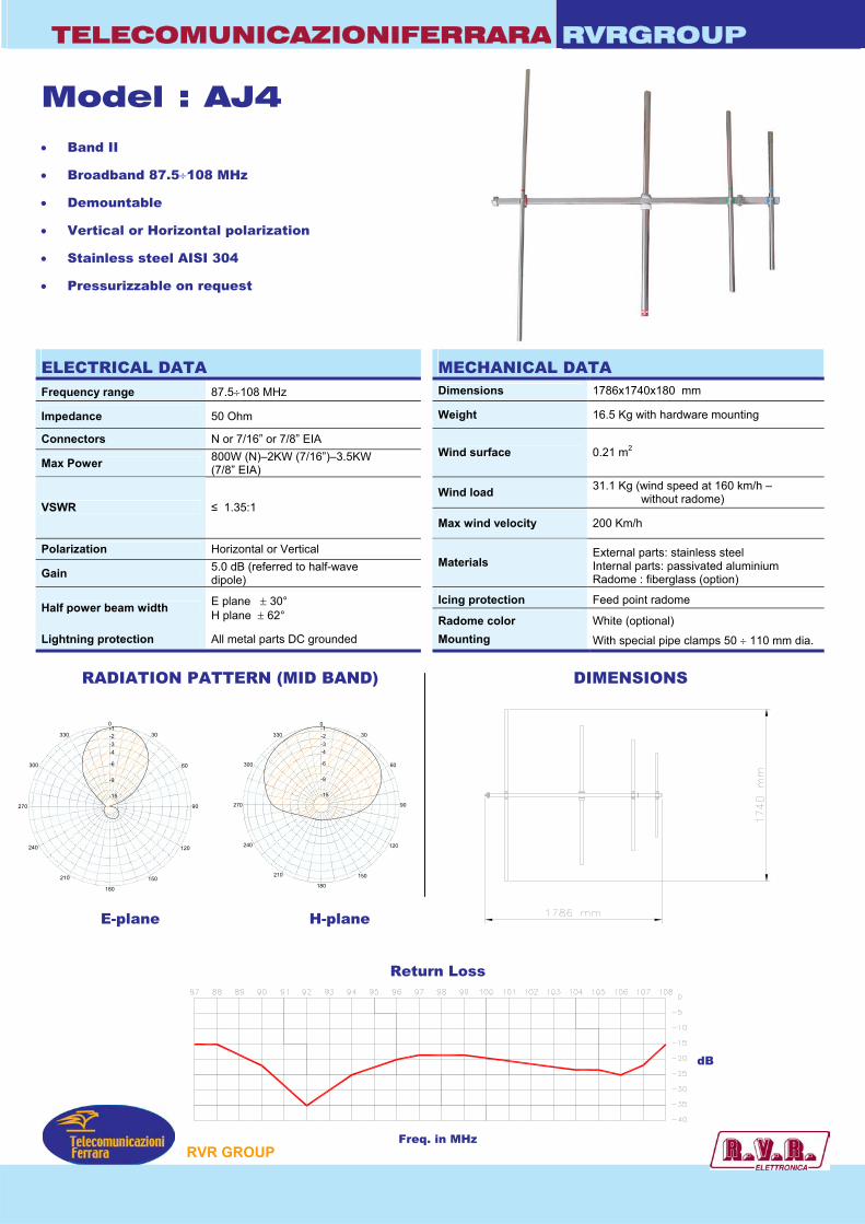
Model : AJ4
• Band II
• Broadband 87.5÷108 MHz
• Demountable
• Vertical or Horizontal polarization
• Stainless steel AISI 304
• Pressurizzable on request
ELECTRICAL DATA MEFrequency range 87.5÷108 MHz Dime
Impedance 50 Ohm Weig
Connectors N or 7/16” or 7/8” EIA
Max Power 800W (N)–2KW (7/16”)–3.5KW (7/8” EIA)
Wind
WindVSWR ≤ 1.35:1
Max w
Polarization Horizontal or Vertical
Gain 5.0 dB (referred to half-wave dipole)
Mate
IcingHalf power beam width E plane ± 30°
H plane ± 62° RadoLightning protection All metal parts DC grounded Moun RADIATION PATTERN (MID BAND)
0
30
60
90
120
150
180
210
240
270
300
330
-9
-6
-15
-4-3-2-1
0
30
60
90
120
150
180
210
240
270
300
330
-9
-6
-15
-4-3-2-1
E-plane H-plane
Return Lo
Freq. in MH
P
CHANICAL DATA
nsions 1786x1740x180 mm
ht 16.5 Kg with hardware mounting
surface 0.21 m2
load 31.1 Kg (wind speed at 160 km/h – without radome)
ind velocity 200 Km/h
rials External parts: stainless steel Internal parts: passivated aluminium Radome : fiberglass (option)
protection Feed point radome
me color White (optional) ting With special pipe clamps 50 ÷ 110 mm dia.
DIMENSIONS
ss
dB
z
RVR GROU
TelecomunicazioniFer
TELECOMUNICAZIONIFERRARA
RVR GROUP
RVRGROUP
• Band II
• Broadband 87.5÷108 MHz
• Demountable
• Vertical or Horizontal polarization
RADIATION PATTERN (MID BAND)
ELECTRICAL DATA
Frequency range 87.5÷108 MHz
Impedance 50 Ohm
Connectors N or 7/16” or 7/8” EIA
Max Power 800W (N) – 2KW (7/16”) – 2.5KW (7/8” EIA)
VSWR ≤ 1.4:1
Polarization Horizontal or Vertical
Gain 7.0 dB (refered to half-wave dipole)
Half power E plane ± 30°beam width H plane ± 45°
Lightning protection All metal parts DC grounded
E-Plane H-Plane
MECHANICAL DATA
Dimensions 2600x1680x150 mm
Weight 15.0 kg
Wind surface 0.27 m2
Wind load 41 kg (wind speed at 160 km/h)
Max wind velocity 140 km/h.
LGPRD: AluminiumMaterials LGPRD/I: Stainless steel
LGPRD/S: Welded version
Mounting With special pipe clamps50÷110 mm dia.
1680
mm
Models: LGPRD-LGPRD/I-LGPRD/S
180
0
270 90
-1330
300
240
210 150
120
60
30
-2-3-4
-6
-9
-15
180
0
270 90
-1330
300
240
210 150
120
60
30
-2-3-4
-6
-9
-15
87 88 89 90 91 92 93 94 95 96 97 98 99 100 101 102 103 104 105 106 107 108
10
8
6
4
2
Gain
Freq. in MHZ
0
dB
d
2600 mm
Inputconnector
“These specifications are subject to change without notice”

RVR GROUP
Radiations systems with LGPRD yagi antenna
Directional pattern
Gain is provided for vertical polarization. If the antenna is side mounted, the supporting structure will have a slight effect on the radiation pattern and VSWR. Vertical tower space, wind load and weight numbers given are typical. Actual values vary with the specific installation. Contact us for more details of your
installation. Gain will be reduced if null fill, beam tilt or special wavelength spacing is provided. Antenna radiation aperture is the distance from the centre of the top bay to the centre of the bottom bay. Five ft(1.6mt) of pipe required above the top bay and below the bottom bay for to protect from pattern interference by other antennas. Antenna wind load is calculated for 100 Mph (160Km/h) per EIA-222-C standard.
RVRGROUPTELECOMUNICAZIONIFERRARA
Models: LGPRD-LGPRD/I-LGPRD/S
ELECTRICAL DATA
Frequency range 87.5÷108 MHz
Impedance 50 Ohm
Connector EIA flange according to system power rating
VSWR ≤ 1.4:1 Max
Polarization Horizontal or Vertical
Gain According to requirement
Horizontal pattern Any type according to requirements
Vertical pattern Null fill, beam tilt and special requirements to order
Other facilities The antenna system can be supplied in split feed withtwo equal half antennas. Each half can accept full power
MECHANICAL DATA
Height of array Subject to number of bays (refer to table)
Total net weight Refer to table
Wind load Refer to table
Mounting hardware Hot dip galvanized steel clamps
Shipping As required
TelecomunicazioniFerrara
L
2600
mm
1 Referred to a half wave dipole. Attenuation of connecting cables not taken into account.2 Without mounting hardware.
TECHNICAL DATA
Number Dipole Gain1Weight2 Antenna Wind load
of per height L (v=160 km/h)bays bay dB times kg m kg
2 1 10.0 10.0 30 4.3 82.0
4 1 13.0 20.0 60 9.5 164.0
6 1 14.8 30.0 90 14.7 246.0
8 1 16.0 40.0 120 20.0 328.0
12 1 17.8 60.0 180 30.3 492.0
“These specifications are subject to change without notice”
TELECOMUNICAZIONIFERRARA RVRGROUP
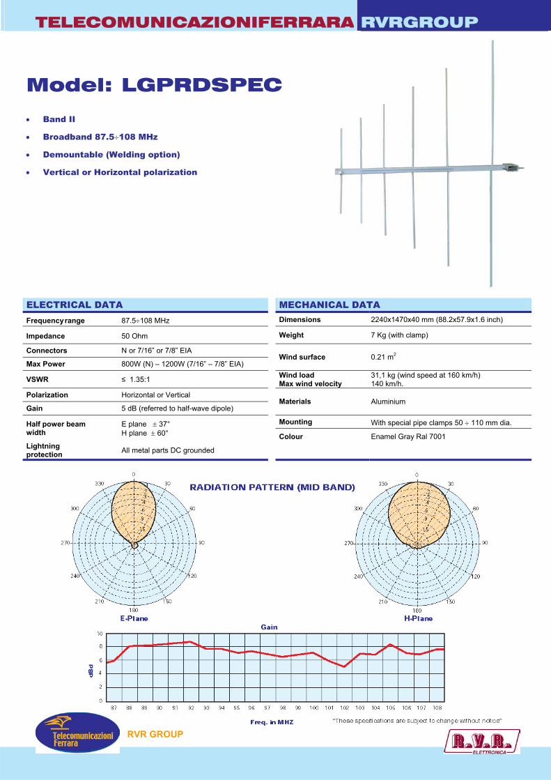
Model: LGPRDSPEC • Band II
• Broadband 87.5÷108 MHz
• Demountable (Welding option)
• Vertical or Horizontal polarization
ELECTRICAL DATA MECHANFrequency range 87.5÷108 MHz Dimensions
Impedance 50 Ohm Weight
Connectors N or 7/16” or 7/8” EIA
Max Power 800W (N) – 1200W (7/16” – 7/8” EIA) Wind surfac
VSWR ≤ 1.35:1 Wind load Max wind ve
Polarization Horizontal or Vertical
Gain 5 dB (referred to half-wave dipole)
Materials Mounting Half power beam
width E plane ± 37° H plane ± 60° Colour
Lightning protection All metal parts DC grounded
P
ICAL DATA
2240x1470x40 mm (88.2x57.9x1.6 inch)
7 Kg (with clamp)
e 0.21 m2
locity 31,1 kg (wind speed at 160 km/h) 140 km/h.
Aluminium
With special pipe clamps 50 ÷ 110 mm dia.
Enamel Gray Ral 7001
RVR GROU
TELECOMUNICAZIONIFERRARA RVRGROUP
2600 m
m
L
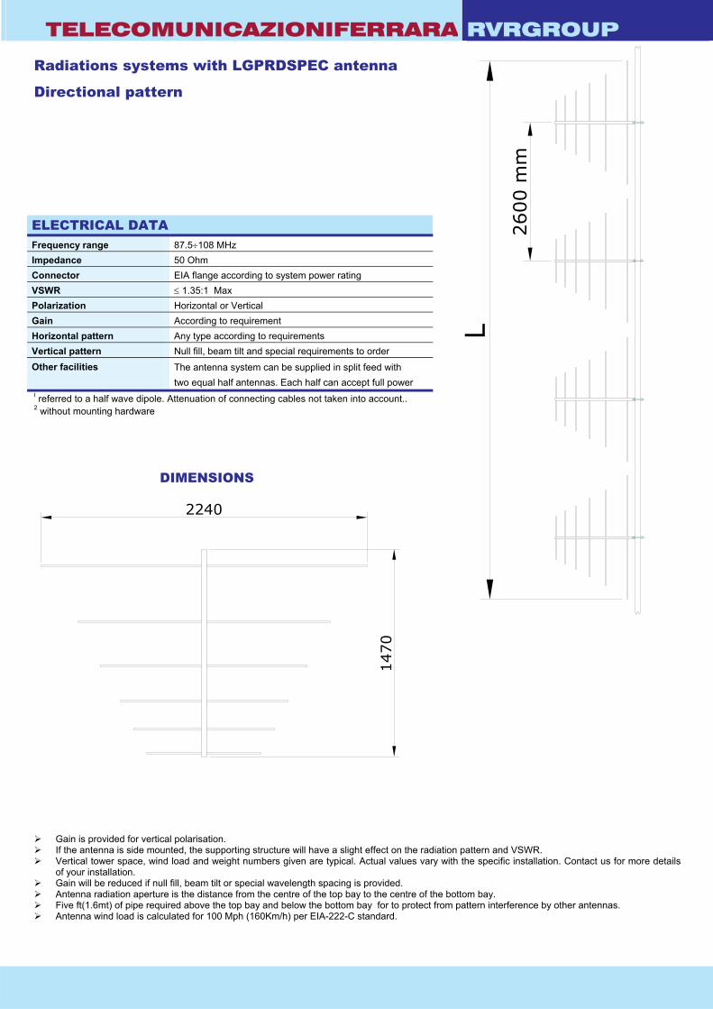
Radiations systems with LGPRDSPEC antenna Directional pattern
ELECTRICAL DATA Frequency range 87.5÷108 MHz Impedance 50 Ohm Connector EIA flange according to system power rating VSWR ≤ 1.35:1 Max Polarization Horizontal or Vertical Gain According to requirement Horizontal pattern Any type according to requirements Vertical pattern Null fill, beam tilt and special requirements to order Other facilities
The antenna system can be supplied in split feed with two equal half antennas. Each half can accept full power
I referred to a half wave dipole. Attenuation of connecting cables not taken into account.. 2 without mounting hardware
DIMENSIONS
1470
2240
Gain is provided for vertical polarisation. If the antenna is side mounted, the supporting structure will have a slight effect on the radiation pattern and VSWR. Vertical tower space, wind load and weight numbers given are typical. Actual values vary with the specific installation. Contact us for more details
of your installation. Gain will be reduced if null fill, beam tilt or special wavelength spacing is provided. Antenna radiation aperture is the distance from the centre of the top bay to the centre of the bottom bay. Five ft(1.6mt) of pipe required above the top bay and below the bottom bay for to protect from pattern interference by other antennas. Antenna wind load is calculated for 100 Mph (160Km/h) per EIA-222-C standard.
TELECOMUNICAZIONIFERRARA RVRGROUP
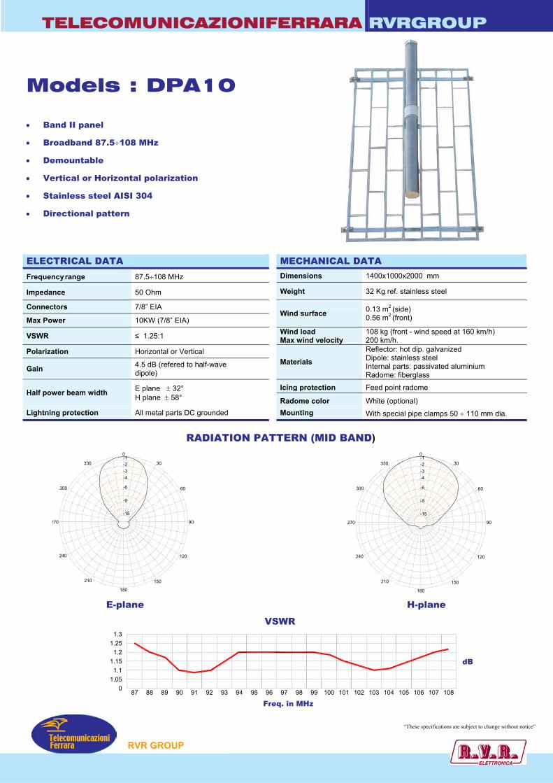
Models : DPA10 • Band II panel
• Broadband 87.5÷108 MHz
• Demountable
• Vertical or Horizontal polarization
• Stainless steel AISI 304
• Directional pattern
ELECTRICAL DATA MECHANICAL DATA
Frequency range 87.5÷108 MHz Dimensions 1400x1000x2000 mm
Impedance 50 Ohm Weight 32 Kg ref. stainless steel
Connectors 7/8” EIA
Max Power 10KW (7/8” EIA) Wind surface 0.13 m2 (side)
0.56 m2 (front)
VSWR ≤ 1.25:1 Wind load Max wind velocity
108 kg (front - wind speed at 160 km/h) 200 km/h.
Polarization Horizontal or Vertical
Gain 4.5 dB (refered to half-wave dipole)
Materials Reflector: hot dip. galvanized Dipole: stainless steel Internal parts: passivated aluminium Radome: fiberglass
Icing protection Feed point radome Half power beam width E plane ± 32°
H plane ± 58° Radome color White (optional) Lightning protection All metal parts DC grounded Mounting With special pipe clamps 50 ÷ 110 mm dia. 0
30
150210
240
270
300
330
-9
-6
-15
-4-3-2-1
180 E-plane
87 88 89 901.05
1.11.15
1.21.25
1.3
P
RADIATION PATTERN (MID BAND)
60
90
120
H-plane
VSWR
dB
0
30
60
90
120
150
180
210
240
270
300
330
-9
-6
-15
-4-3-2-1
0 91 92 93 94 95 96 97 98 99 100 101 102 103 104 105 106 107 108
Freq. in MHz
“These specifications are subject to change without notice”
RVR GROU 22
TELECOMUNICAZIONIFERRARA RVRGROUP
Radiations systems with DPA10 antenna
Directional pattern
TECHNICAL DATA
I referred to a half wave dipole. Attenuation of connecting cables not taken into account.. 2 without mounting hardware 3 the systems comprised: antennas, cables and splitter – for more details to see catalog different version on request Vertical tower space, wind load and weight numbers given are typical. Actual values vary with the
specific installation. Contact us for more details of your installation. Gain will be reduced if null fill, beam tilt or special wavelength spacing is provided. Antenna radiation aperture is the distance from the centre of the top bay to the centre of the bottom bay. Five ft(1.6mt) of pipe required above the top bay and below the bottom bay for to protect from pattern
2600 mm
ELECTRICAL DATA Frequency range 87.5÷108 MHz Impedance 50 Ohm Connector EIA flange according to system power rating VSWR ≤ 1.25:1 Max Polarization Horizontal or Vertical Gain According to requirement Horizontal pattern Any type according to requirements Vertical pattern Null fill, beam tilt and special requirements to order Other facilities
The antenna system can be supplied in split feed with two equal half antennas. Each half can accept full power
MECHANICAL DATA Height of array Subject to number of bays ( refer to table )
Total net weight Refer to table
Wind load Refer to table
Pressurizzable Yes (on request)
Radome colour White (optional)
Mounting hardware Hot dip galvanized steel clamps (option)
Shipping As required
Gain¹ Number of
bays
Dipole per bay dB times
Weight² kg
Antenna height L
m
Wind load (v=160 km/h)
kg
2 1 7.5 5.6 64 4.6 216 4 1 10.5 11.3 128 9.8 432 6 1 12.3 16.9 192 15.0 678 8 1 13.5 22.5 256 20.2 864
12 1 15.3 33.8 384 30.6 1296
interference by other antennas. Antenna wind load is calculated for 100 Mph (160Km/h) per EIA-222-C standard.
“These specifications are subject to change without notice”
P
RVR GROU
87 88 89 90 91 92 93 94 95 96 97 98 99 100 101 102 103 104 105 106 107 108
1,3
1,25
1,2
1,15
1,1
1,05
VSWR
Freq. in MHZ
1
dB
180
0
270 90
-1330
300
240
210 150
120
60
30
-2-3-4
-6
-9
-15
180
0
270 90
-1330
300
240
210 150
120
60
30
-2-3-4
-6
-9
-15
TelecomunicazioniFerrara
Model DPA1TELECOMUNICAZIONIFERRARA
RVR GROUP
RVRGROUP
• Band II panel
• Broadband 87.5÷108 MHz
• Demountable
• Vertical or Horizontal polarization
• Stainless steel AISI 304
• Directional pattern
RADIATION PATTERN (MID BAND)
E-Plane H-Plane
1000 mm
2000 mm
Inputconnector
ELECTRICAL DATA
Frequency range 87.5÷108 MHz
Impedance 50 Ohm
Connectors N or 7/16” or 7/8” EIA
Max Power 800W (N) – 2KW (7/16”) – 3.5KW (7/8” EIA)
VSWR ≤ 1.25:1
Polarization Horizontal or Vertical
Gain 4.5 dB (refered to half-wave dipole)
Half power E plane ± 38°beam width H plane ± 68°
Lightning protection All metal parts DC grounded
MECHANICAL DATA
Dimensions 1400x1000x2000 mm
Weight 32 kg ref. stainless steel
Wind surface 0.13 m2 (side)0.56 m2 (front)
Wind load 108 kg (front - wind speed at 160 km/h)
Max wind velocity 200 km/h.
Reflector: hot dip. galvanizedDipole: stainless steelMaterialsInternal parts: passivated aluminiumRadome: fiberglass (option)
Icing protection Feed point radome (optional)
Radome Optional
Mounting With special pipe clamps 50÷110 mm dia.
1400 mm
“These specifications are subject to change without notice”
L
2600
mm
RVR GROUP
Radiations systems with DPA1 antenna
Directional pattern
Gain is provided for vertical polarization. Vertical tower space, wind load and weight numbers given are typical. Actual values vary with the specific installation. Contact us for more details of your
installation. Gain will be reduced if null fill, beam tilt or special wavelength spacing is provided. Antenna radiation aperture is the distance from the centre of the top bay to the centre of the bottom bay. Five ft(1.6mt) of pipe required above the top bay and below the bottom bay for to protect from pattern interference by other antennas. Antenna wind load is calculated for 100 Mph (160Km/h) per EIA-222-C standard.
1 Referred to a half wave dipole. Attenuation of connecting cables not taken into account.2 Without mounting hardware.3 The systems comprised: antennas, cables and splitter – for more details to see catalog – different version on request.
TECHNICAL DATA
RVRGROUPTELECOMUNICAZIONIFERRARA
Model DPA1
Number Panels Gain1Weight2 Antenna Wind load COLLINEARS SYSTEMS3
of per height L (v=160 km/h)bays bay dB times kg m kg 2 KW 4 KW 6 KW 10 KW
2 1 7.5 5.6 64 4.6 216 DPA1X22 DPA1X24 DPA1X26 -
4 1 10.5 11.3 128 9.8 432 DPA1X42 DPA1X44 DPA1X46 DPA1X410
6 1 12.3 16.9 192 15.0 678 DPA1X62 DPA1X64 - DPA1X610
8 1 13.5 22.5 256 20.2 864 DPA1X82 DPA1X84 DPA1X86 DPA1X810
12 1 15.3 33.8 384 30.6 1296 - - - -
ELECTRICAL DATA
Frequency range 87.5÷108 MHz
Impedance 50 Ohm
Connector EIA flange according to system power rating
VSWR ≤ 1.25:1 Max
Polarization Horizontal or Vertical
Gain According to requirement
Horizontal pattern Any type according to requirements
Vertical pattern Null fill, beam tilt and special requirements to order
Other facilities The antenna system can be supplied in split feed withtwo equal half antennas. Each half can accept full power
MECHANICAL DATA
Height of array Subject to number of bays ( refer to table )
Total net weight Refer to table
Wind load Refer to table
Pressurizzable Yes (on request)
Radome Optional
Mounting hardware Hot dip galvanized steel clamps
Shipping As required
TelecomunicazioniFerrara
“These specifications are subject to change without notice”

87 88 89 90 91 92 93 94 95 96 97 98 99 100 101 102 103 104 105 106 107 108
1,5
1,4
1,3
1,2
1,1
1,0
VSWR
Freq. in MHZ
0,9
dB
180
0
270 90
-1330
300
240
210 150
120
60
30
-2-3-4
-6
-9
-15
180
0
270 90
-1330
300
240
210 150
120
60
30
-2-3-4
-6
-9
-15
TelecomunicazioniFerrara
Model DPA2VTELECOMUNICAZIONIFERRARA
RVR GROUP
RVRGROUP
• Band II panel
• Broadband 87.5÷108 MHz
• Demountable
• Vertical polarization
• Directional pattern
• Suitable as a component in various array
RADIATION PATTERN (MID BAND)
E-Plane H-Plane
1050 mm
2200
mm
Inputconnector
ELECTRICAL DATA
Frequency range 87.5÷108 MHz
Impedance 50 Ohm
Connectors Two input connectorsType N or 7/16” or 7/8” EIA
Max Power 2x800W (N) – 2x2KW (7/16”)2x3.5KW (7/8” EIA)
VSWR ≤ 1.35:1
Polarization Vertical
Gain 7.5 dB (refered to half-wave dipole)
Half power E plane ± 35°beam width H plane ± 32°
Lightning protection All metal parts DC grounded
MECHANICAL DATA
Dimensions 2200x2200x1050 mm
Weight 79 kg ref. stainless steel
Wind surface 0.90 m2 (side)0.22 m2 (front)
Wind load 173,7 kg (front - wind speed at 200 km/h)
Max wind velocity 200 km/h.
Reflector: hot dip. galvanizedDipole: stainless steelMaterialsInternal parts: passivated aluminiumRadome: fiberglass (option)
Icing protection Feed point radome (optional)
Radome Optional
Mounting With special pipe clamps 50÷110 mm dia.
2200 mm
Inputconnector
“These specifications are subject to change without notice”

RVR GROUP
RVRGROUPTELECOMUNICAZIONIFERRARA
Model DPA2V
ELECTRICAL DATA
Frequency range 87.5÷108 MHz
Impedance 50 Ohm
Connector EIA flange according to system power rating
VSWR ≤ 1.35:1 Max
Polarization Vertical
Gain According to requirement
Horizontal pattern Any type according to requirements
Vertical pattern Null fill, beam tilt and special requirements to order
Other facilities The antenna system can be supplied in split feed withtwo equal half antennas. Each half can accept full power
MECHANICAL DATA
Height of array Subject to number of bays ( refer to table )
Total net weight Refer to table
Wind load Refer to table
Pressurizzable Yes (on request)
Radome Optional
Mounting hardware Hot dip galvanized steel clamps
Shipping As required
TelecomunicazioniFerrara
HORIZONTAL PATTERNS WITH 2, 3 AND 4 FACES AT 98 MHz
1200
mm
1200 mm
2400 mm
2400
mm
2400 mm
1200
mm
180
0
270 90
-1330
300
240
210 150
120
60
30
-2-3-4
-6
-9
-15
H-Plane180
0
270 90
-1330
300
240
210 150
120
60
30
-2-3-4
-6
-9
-15
H-Plane180
0
270 90
-1330
300
240
210 150
120
60
30
-2-3-4
-6
-9
-15
H-Plane
Radiations systems with DPA2V panelOmnidirectional or directional patternBalanced or unbalanced splitting powerHigh power systemBroadband 87.5÷108 MHz
“These specifications are subject to change without notice”
TelecomunicazioniFerrara
Model DPA2VTELECOMUNICAZIONIFERRARA
RVR GROUP
RVRGROUP
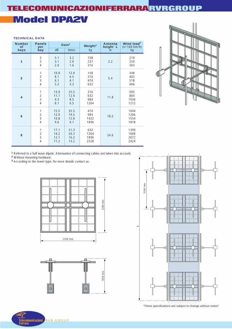
TECHNICAL DATA
Number Panels Gain1Weight2 Antenna Wind load3
of per height L (v=160 km/h)bays bay dB times kg m kg
2 5.1 3.2 158 2101 3 3.1 2.0 237 2.2 259
4 2.0 1.6 316 303
1 10.8 12.0 158 3482 8.1 6.5 316 40223 6.1 4.1 474
5.4518
4 5.2 3.3 632 606
1 13.9 25.5 316 6952 11.1 12.9 632 80443 9.3 8.5 984
11.81036
4 8.1 6.5 1264 1212
1 15.5 35.5 474 10442 12.9 19.5 984 120663 10.8 12.0 1422
18.21554
4 9.6 9.1 1896 1818
1 17.1 51.3 632 13902 14.2 26.3 1264 160883 12.1 16.2 1896
24.62072
4 11.2 13.2 2528 2424
1 Referred to a half wave dipole. Attenuation of connecting cables not taken into account.2 Without mounting hardware.3 According to the tower type, for more details contact us.
2200 mm
2200
mm
1050
mm
3200
mm
L
“These specifications are subject to change without notice”
RVR GROUP
RVRGROUPTELECOMUNICAZIONIFERRARA
TelecomunicazioniFerrara
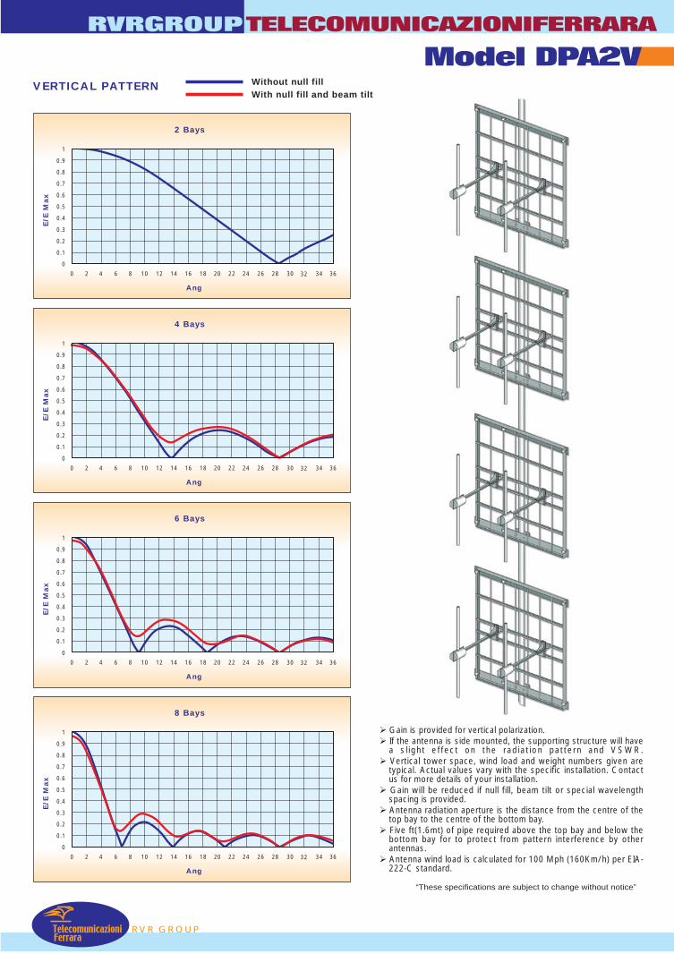
VERTICAL PATTERN
0 2 4 6 8 10 12 14 16 18 20 22 24 26 28 30 32 34 36
1
0.9
0.8
0.7
0.6
0.5
0.4
0.3
0.2
0.1
0
2 Bays
Ang
E/E
Max
0 2 4 6 8 10 12 14 16 18 20 22 24 26 28 30 32 34 36
1
0.9
0.8
0.7
0.6
0.5
0.4
0.3
0.2
0.1
0
6 Bays
Ang
E/E
Max
0 2 4 6 8 10 12 14 16 18 20 22 24 26 28 30 32 34 36
1
0.9
0.8
0.7
0.6
0.5
0.4
0.3
0.2
0.1
0
8 Bays
Ang
E/E
Max
106 107 1080 2 4 6 8 10 12 14 16 18 20 22 24 26 28 30 32 34 36
1
0.9
0.8
0.7
0.6
0.5
0.4
0.3
0.2
0.1
0
4 Bays
Ang
E/E
Max
Gain is provided for vertical polarization. If the antenna is side mounted, the supporting structure will have
a sl ight effect on the radiation pattern and VSWR. Vertical tower space, wind load and weight numbers given are
typical. Actual values vary with the specific installation. Contactus for more details of your installation.
Gain will be reduced if null fill, beam tilt or special wavelengthspacing is provided.
Antenna radiation aperture is the distance from the centre of thetop bay to the centre of the bottom bay.
Five ft(1.6mt) of pipe required above the top bay and below thebottom bay for to protect from pattern interference by otherantennas.
Antenna wind load is calculated for 100 Mph (160Km/h) per EIA-222-C standard.
Without null fillWith null fill and beam tilt
Model DPA2V
“These specifications are subject to change without notice”
180
0
270 90
-1330
300
240
210 150
120
60
30
-2-3-4
-6
-9
-15
180
0
270 90
-1330
300
240
210 150
120
60
30
-2-3-4
-6
-9
-15
RADIATION PATTERN (MID BAND)
E-Plane H-Plane
87 88 89 90 91 92 93 94 95 96 97 98 99 100 101 102 103 104 105 106 107 108
1,3
1,25
1,2
1,15
1,1
1,05
VSWR
Freq. in MHZ
1
dB
TelecomunicazioniFerrara
Model DPA2HTELECOMUNICAZIONIFERRARA
RVR GROUP
RVRGROUP
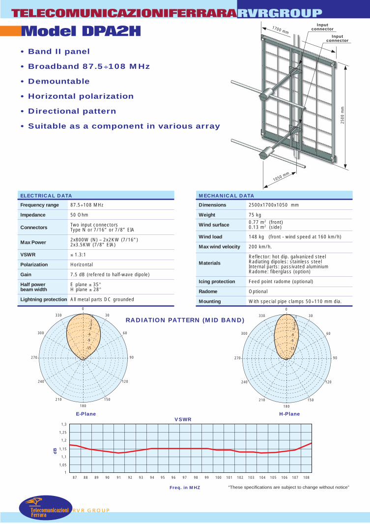
• Band II panel
• Broadband 87.5÷108 MHz
• Demountable
• Horizontal polarization
• Directional pattern
• Suitable as a component in various array
1050 mm
2500
mm
Inputconnector
ELECTRICAL DATA
Frequency range 87.5÷108 MHz
Impedance 50 Ohm
Connectors Two input connectorsType N or 7/16” or 7/8” EIA
Max Power 2x800W (N) – 2x2KW (7/16”)2x3.5KW (7/8” EIA)
VSWR ≤ 1.3:1
Polarization Horizontal
Gain 7.5 dB (refered to half-wave dipole)
Half power E plane ± 35°beam width H plane ± 28°
Lightning protection All metal parts DC grounded
MECHANICAL DATA
Dimensions 2500x1700x1050 mm
Weight 75 kg
Wind surface 0.77 m2 (front)0.13 m2 (side)
Wind load 148 kg (front - wind speed at 160 km/h)
Max wind velocity 200 km/h.
Reflector: hot dip. galvanized steelRadiating dipoles: stainless steelMaterialsInternal parts: passivated aluminiumRadome: fiberglass (option)
Icing protection Feed point radome (optional)
Radome Optional
Mounting With special pipe clamps 50÷110 mm dia.
1700 mm
Inputconnector
“These specifications are subject to change without notice”
1100
mm
1100 mm
2200 mm
1100
mm 2200 mm
2200
mm
RVR GROUP
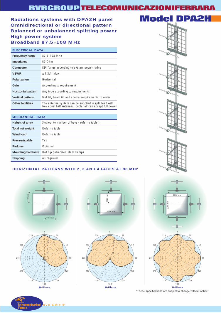
Radiations systems with DPA2H panelOmnidirectional or directional patternBalanced or unbalanced splitting powerHigh power systemBroadband 87.5÷108 MHz
RVRGROUPTELECOMUNICAZIONIFERRARA
Model DPA2H
ELECTRICAL DATA
Frequency range 87.5÷108 MHz
Impedance 50 Ohm
Connector EIA flange according to system power rating
VSWR ≤ 1.3:1 Max
Polarization Horizontal
Gain According to requirement
Horizontal pattern Any type according to requirements
Vertical pattern Null fill, beam tilt and special requirements to order
Other facilities The antenna system can be supplied in split feed withtwo equal half antennas. Each half can accept full power
MECHANICAL DATA
Height of array Subject to number of bays ( refer to table )
Total net weight Refer to table
Wind load Refer to table
Pressurizzable Yes
Radome Optional
Mounting hardware Hot dip galvanized steel clamps
Shipping As required
TelecomunicazioniFerrara
HORIZONTAL PATTERNS WITH 2, 3 AND 4 FACES AT 98 MHz
180
0
270 90
-1330
300
240
210 150
120
60
30
-2-3-4
-6
-9
-15
H-Plane180
0
270 90
-1330
300
240
210 150
120
60
30
-2-3-4
-6
-9
-15
H-Plane180
0
270 90
-1330
300
240
210 150
120
60
30
-2-3-4
-6
-9
-15
H-Plane“These specifications are subject to change without notice”
TelecomunicazioniFerrara
Model DPA2HTELECOMUNICAZIONIFERRARA
RVR GROUP
RVRGROUP
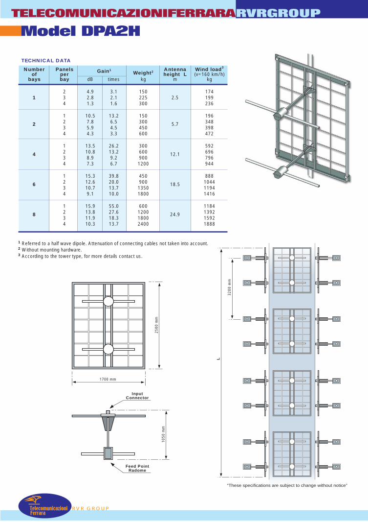
TECHNICAL DATA
Number Panels Gain1Weight2 Antenna Wind load3
of per height L (v=160 km/h)bays bay dB times kg m kg
2 4.9 3.1 150 1741 3 2.8 2.1 225 2.5 199
4 1.3 1.6 300 236
1 10.5 13.2 150 1962 7.8 6.5 300 34823 5.9 4.5 450
5.7398
4 4.3 3.3 600 472
1 13.5 26.2 300 5922 10.8 13.2 600 69643 8.9 9.2 900
12.1796
4 7.3 6.7 1200 944
1 15.3 39.8 450 8882 12.6 20.0 900 104463 10.7 13.7 1350
18.51194
4 9.1 10.0 1800 1416
1 15.9 55.0 600 11842 13.8 27.6 1200 139283 11.9 18.3 1800
24.91592
4 10.3 13.7 2400 1888
1 Referred to a half wave dipole. Attenuation of connecting cables not taken into account.2 Without mounting hardware.3 According to the tower type, for more details contact us.
1700 mm
2500
mm
1050
mm
3200
mm
L
InputConnector
Feed PointRadome
“These specifications are subject to change without notice”
RVR GROUP
RVRGROUPTELECOMUNICAZIONIFERRARA
TelecomunicazioniFerrara
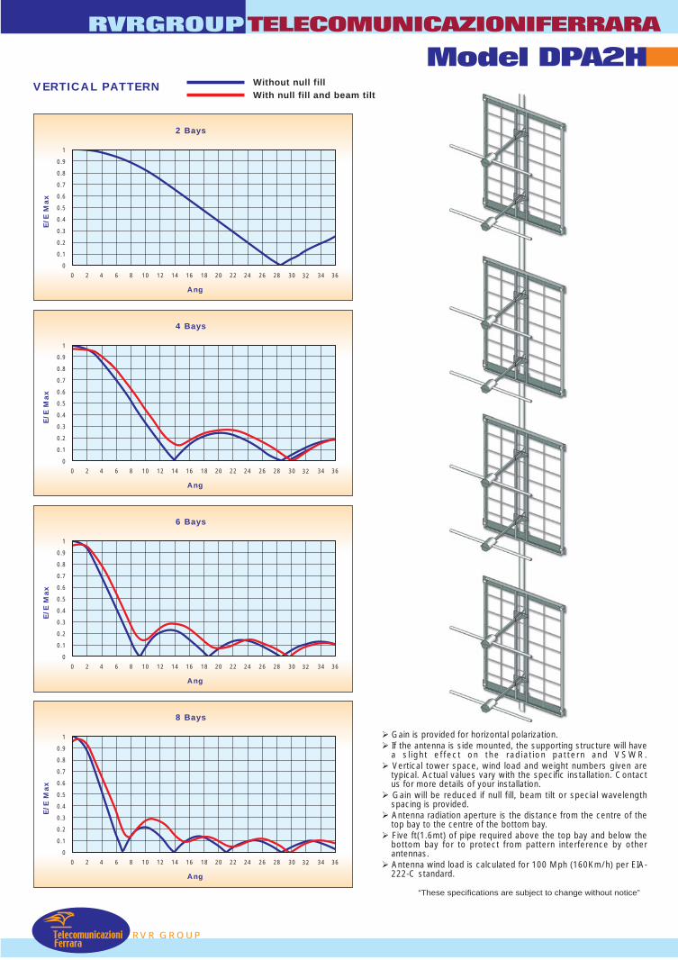
VERTICAL PATTERN
0 2 4 6 8 10 12 14 16 18 20 22 24 26 28 30 32 34 36
1
0.9
0.8
0.7
0.6
0.5
0.4
0.3
0.2
0.1
0
2 Bays
Ang
E/E
Max
0 2 4 6 8 10 12 14 16 18 20 22 24 26 28 30 32 34 36
1
0.9
0.8
0.7
0.6
0.5
0.4
0.3
0.2
0.1
0
6 Bays
Ang
E/E
Max
0 2 4 6 8 10 12 14 16 18 20 22 24 26 28 30 32 34 36
1
0.9
0.8
0.7
0.6
0.5
0.4
0.3
0.2
0.1
0
8 Bays
Ang
E/E
Max
106 107 1080 2 4 6 8 10 12 14 16 18 20 22 24 26 28 30 32 34 36
1
0.9
0.8
0.7
0.6
0.5
0.4
0.3
0.2
0.1
0
4 Bays
Ang
E/E
Max
Gain is provided for horizontal polarization. If the antenna is side mounted, the supporting structure will have
a sl ight effect on the radiation pattern and VSWR. Vertical tower space, wind load and weight numbers given are
typical. Actual values vary with the specific installation. Contactus for more details of your installation.
Gain will be reduced if null fill, beam tilt or special wavelengthspacing is provided.
Antenna radiation aperture is the distance from the centre of thetop bay to the centre of the bottom bay.
Five ft(1.6mt) of pipe required above the top bay and below thebottom bay for to protect from pattern interference by otherantennas.
Antenna wind load is calculated for 100 Mph (160Km/h) per EIA-222-C standard.
Without null fillWith null fill and beam tilt
Model DPA2H
“These specifications are subject to change without notice”

TELECOMUNICAZIONIFERRARA RVRGROUP
Model : DPA2HT • Band II panel
• Broadband 87.5÷108 MHz
• Demountable
• Horizontal polarization
• Directional pattern
• Suitable as a component in various arrays
ELECTRICAL DATA MFrequency range 87.5÷108 MHz Dim
Impedance 50 Ohm We
Connectors Two input connectors of type 7/8” EIA
Max Power 5KW Wi
VSWR ≤ 1.2:1 WiMa
Polarization Horizontal
Gain 6.5 dB (referred to half-wave dipole)
Ma
IciHalf power beamwidth:
E plane ± 40° H plane ± 28 Ra
Lightning protection All metal parts DC grounded Mo
27
RADIATION PATTERN
E-plane
0
30
60
90
120
150
180
210
240
0
300
330
-9
-6
-15
-4-3-2-1
P
ECHANICAL DATA
ensions 2500x1800x1050 mm
ight 75 Kg
nd surface 0.75 m2 (front) 0.18 m2 (side)
nd load x wind velocity
148 kg (wind speed at 160 km/h) 200 km/h.
terials
Reflector: hot dip galvanized steel Radiating dipoles: stainless steel Internal parts: passivated aluminium Radome: fibreglass (option)
ng protection Feed point radome
dome color White (optional) unting With special pipe clamps 50 ÷ 110 mm dia.
(MID BAND)0-1
30
60
90
120
150
180
210
240
270
300
330
-9
-6
-15
-4-3-2
H-plane
“These specifications are subject to change without notice”
RVR GROU
TELECOMUNICAZIONIFERRARA RVRGROUP
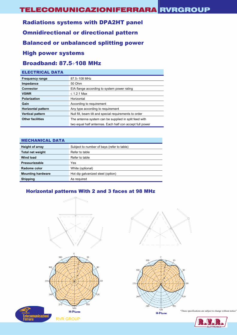
Radiations systems with DPA2HT panel
Omnidirectional or directional pattern
Balanced or unbalanced splitting power
High power systems
Broadband: 87.5÷108 MHz ELECTRICAL DATA Frequency range 87.5÷108 MHz Impedance 50 Ohm Connector EIA flange according to system power rating VSWR ≤ 1.2:1 Max Polarization Horizontal Gain According to requirement Horizontal pattern Any type according to requirement Vertical pattern Null fill, beam tilt and special requirements to order Other facilities
The antenna system can be supplied in split feed with two equal half antennas. Each half con accept full power
MECHANICAL DATA Height of array Subject to number of bays (refer to table)
Total net weight Refer to table
Wind load Refer to table
Pressurizzable Yes
Radome color White (optional)
Mounting hardware Hot dip galvanized steel (option)
Shipping As required
Horizontal patterns With 2 and 3 faces at 98 MHz
P
“These specifications are subject to change without notice”
RVR GROU
TELECOMUNICAZIONIFERRARA RVRGROUP
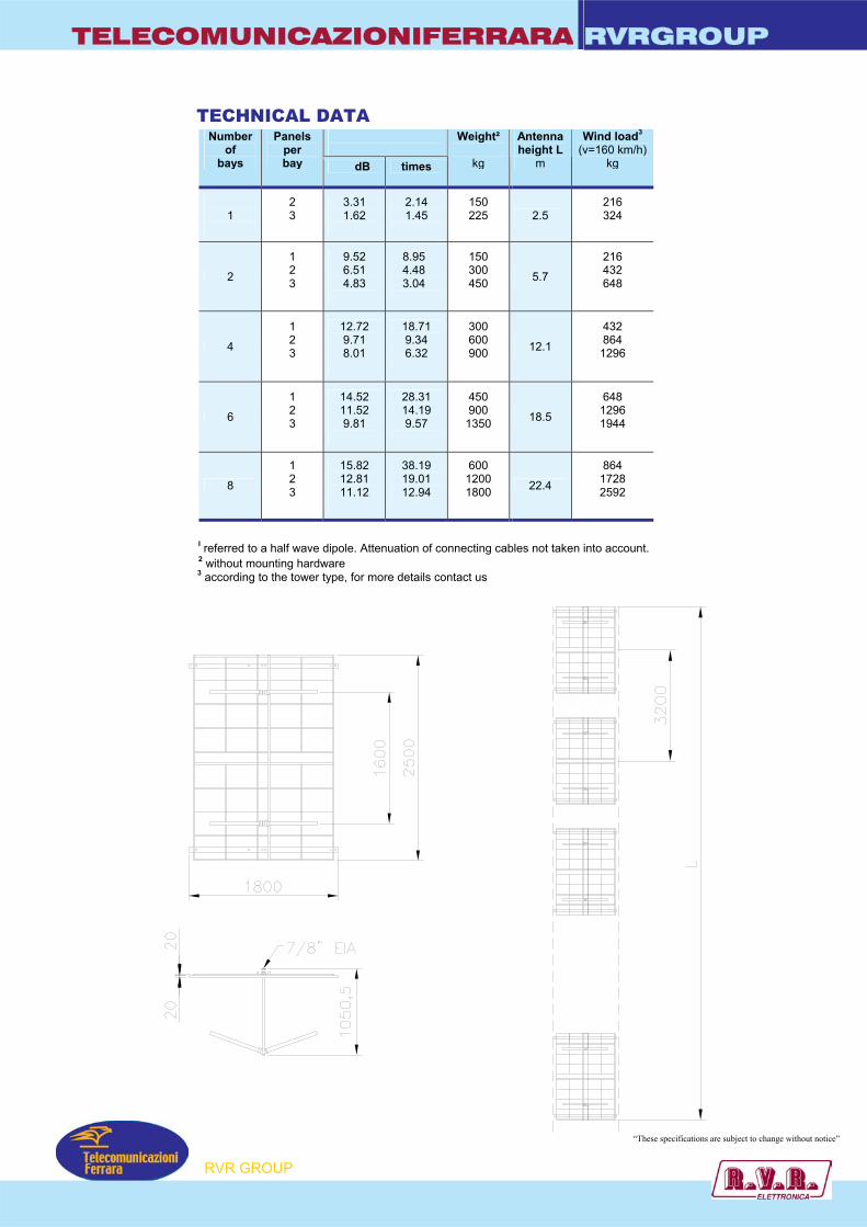
TECHNICAL DATA
Gain¹
Number of
bays
Panels per bay dB times
Weight²
kg
Antenna height L
m
Wind load3
(v=160 km/h) kg
1
2 3
3.31 1.62
2.14 1.45
150 225
2.5
216 324
2
1 2 3
9.52 6.51 4.83
8.95 4.48 3.04
150 300 450
5.7
216 432 648
4
1 2 3
12.72 9.71 8.01
18.71 9.34 6.32
300 600 900
12.1
432 864
1296
6
1 2 3
14.52 11.52 9.81
28.31 14.19 9.57
450 900
1350
18.5
648 1296 1944
8
1 2 3
15.82 12.81 11.12
38.19 19.01 12.94
600 1200 1800
22.4
864 1728 2592
I referred to a half wave dipole. Attenuation of connecting cables not taken into account. 2 without mounting hardware
3 according to the tower type, for more details contact us
“These specifications are subject to change without notice”
RVR GROUP
TELECOMUNICAZIONIFERRARA RVRGROUP
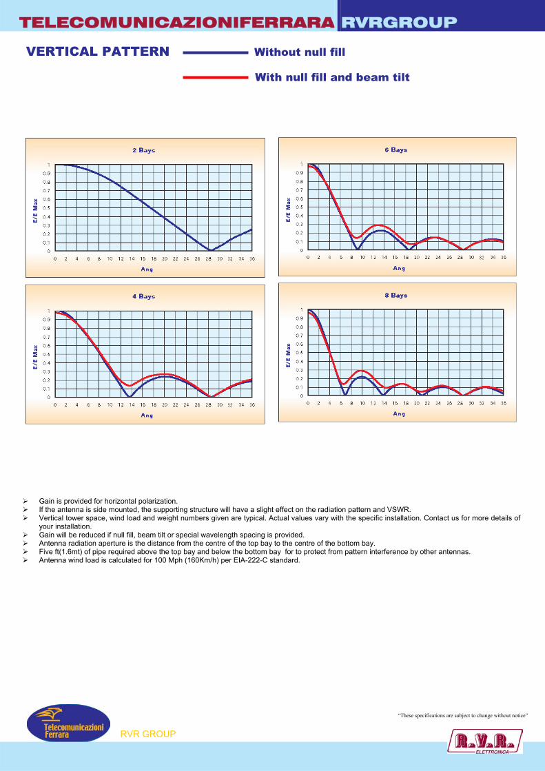
VERTICAL PATTERN Without null fill
With null fill and beam tilt
Gain is provided for horizontal polarization. If the antenna is side mounted, the supporting structure will have a slight effect on the radiation pattern and VSWR. Vertical tower space, wind load and weight numbers given are typical. Actual values vary with the specific installation. Contact us for more details of
your installation. Gain will be reduced if null fill, beam tilt or special wavelength spacing is provided. Antenna radiation aperture is the distance from the centre of the top bay to the centre of the bottom bay. Five ft(1.6mt) of pipe required above the top bay and below the bottom bay for to protect from pattern interference by other antennas. Antenna wind load is calculated for 100 Mph (160Km/h) per EIA-222-C standard.
“These specifications are subject to change without notice”
P
RVR GROU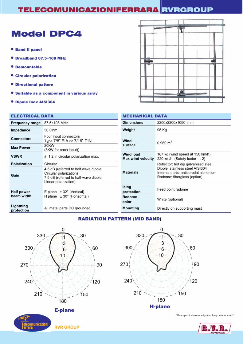
TELECOMUNICAZIONIFERRARA RVRGROUP
106310
30
60
90
120
150180
210
240
270
300
330
106310
30
60
90
120
150180
210
240
270
300
330
Model DPC4 • Band II panel
• Broadband 87.5÷108 MHz
• Demountable
• Circular polarization
• Directional pattern
• Suitable as a component in various array
• Dipole Inox AISI304
ELECTRICAL DATA MECHANICAL DATA
Frequency range 87.5÷108 MHz Dimensions 2200x2200x1050 mm
Impedance 50 Ohm Weight 95 Kg
Connectors Four input connectors Type 7/8” EIA or 7/16” DIN
Max Power 20KW (5KW for each input))
Wind surface 0.960 m2
VSWR ≤ 1.2 in circular polarization max. Wind load Max wind velocity
187 kg (wind speed at 150 km/h) 220 km/h. (Safety factor → 2)
Polarization Circular
Gain 4.5 dB (referred to half wave dipole: Circular polarization) 7.5 dB (referred to half-wave dipole: Linear polarization)
Materials
Reflector: hot dip galvanized steel Dipole: stainless steel AISI304 Internal parts: anticorodal aluminium Radome: fiberglass (option)
Icing protection Feed point radome Half power
beam width E plane ± 32° (Vertical) H plane ± 30° (Horizontal) Radome
color White (optional)
Lightning protection All metal parts DC grounded Mounting Directly on supporting mast
RVR GROUP
“These specifications are subject to change without notice”
RADIATION PATTERN (MID BAND)
E-plane H-plane

TELECOMUNICAZIONIFERRARA RVRGROUP
87 88 89 90 91 92 93 94 95 96 97 98 99 100 101 102 103 104 105 106 107 1080123456
GAIN
RETURN LOSS
Freq. in MHz
“These specifications are subject to change without notice”
RVR GROUP
dBd
TELECOMUNICAZIONIFERRARA RVRGROUP
1200
1200
2400
2400
106310
30
60
90
120
150180
210
240
270
300
330
106310
30
60
90
120
150180
210
240
270
300
330
106310
30
60
90
120
150180
210
240
270
300
330
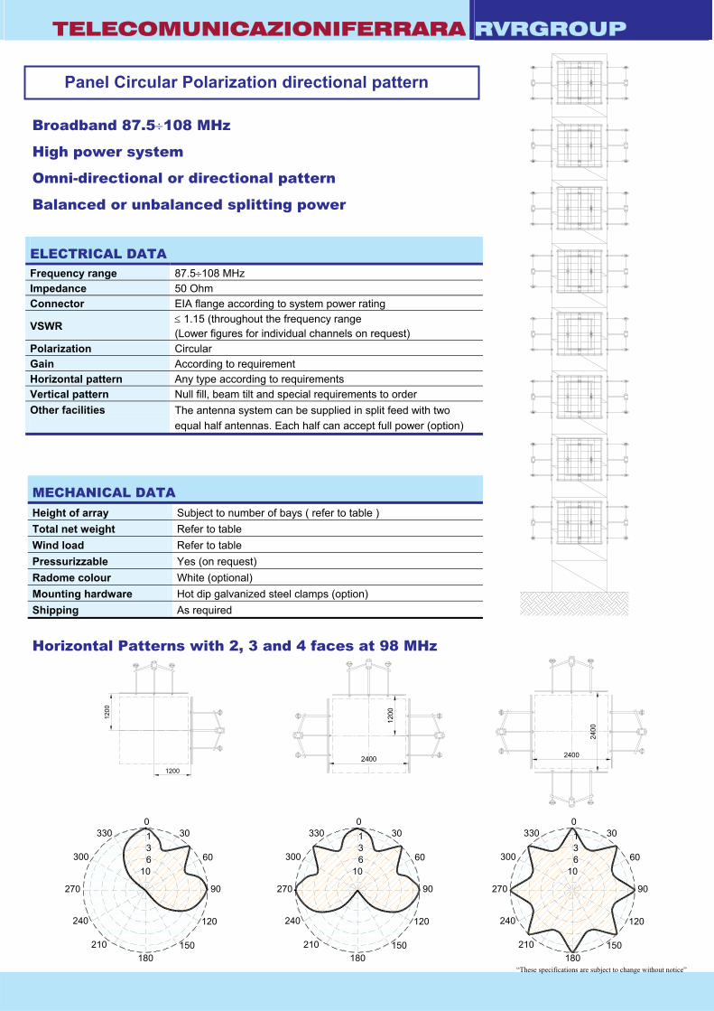
Broadband 87.5÷108 MHz
High power system
Omni-directional or directional pattern
Balanced or unbalanced splitting power
ELECTRICAL DATA Frequency range 87.5÷108 MHz Impedance 50 Ohm Connector EIA flange according to system power rating
VSWR ≤ 1.15 (throughout the frequency range (Lower figures for individual channels on request)
Polarization Circular Gain According to requirement Horizontal pattern Any type according to requirements Vertical pattern Null fill, beam tilt and special requirements to order Other facilities
The antenna system can be supplied in split feed with two equal half antennas. Each half can accept full power (option)
MECHANICAL DATA Height of array Subject to number of bays ( refer to table ) Total net weight Refer to table Wind load Refer to table Pressurizzable Yes (on request) Radome colour White (optional) Mounting hardware Hot dip galvanized steel clamps (option) Shipping As required
Horizontal Patterns with 2, 3 and 4 faces at 98 MHz
Panel Circular Polarization directional pattern
1200
2400
“These specifications are subject to change without notice”
TELECOMUNICAZIONIFERRARA RVRGROUP
3200
3200
3200
L
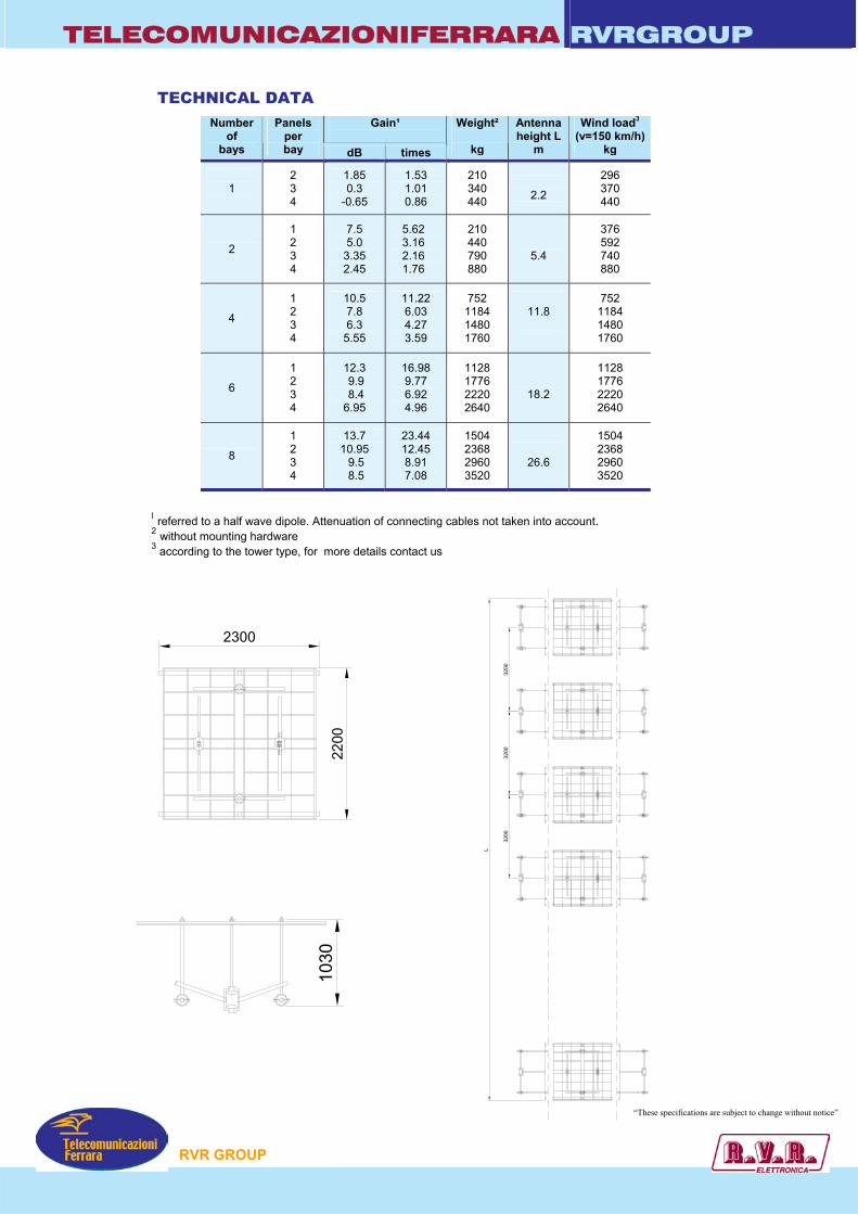
TECHNICAL DATA
I referred to a half wave dipole. Attenuation of connecting cables not taken into account. 2 without mounting hardware 3 according to the tower type, for more details contact us
Gain¹
Number of
bays
Panels per bay dB times
Weight²
kg
Antenna height L
m
Wind load3
(v=150 km/h) kg
1
2 3 4
1.85 0.3
-0.65
1.53 1.01 0.86
210 340 440
2.2
296 370 440
2
1 2 3 4
7.5 5.0
3.35 2.45
5.62 3.16 2.16 1.76
210 440 790 880
5.4
376 592 740 880
4
1 2 3 4
10.5 7.8 6.3
5.55
11.22 6.03 4.27 3.59
752 1184 1480 1760
11.8
752 1184 1480 1760
6
1 2 3 4
12.3 9.9 8.4 6.95
16.98 9.77 6.92 4.96
1128 1776 2220 2640
18.2
1128 1776 2220 2640
8
1 2 3 4
13.7 10.95 9.5 8.5
23.44 12.45 8.91 7.08
1504 2368 2960 3520
26.6
1504 2368 2960 3520
2200
2300
1030
RVR GROUP
“These specifications are subject to change without notice”
TELECOMUNICAZIONIFERRARA RVRGROUP
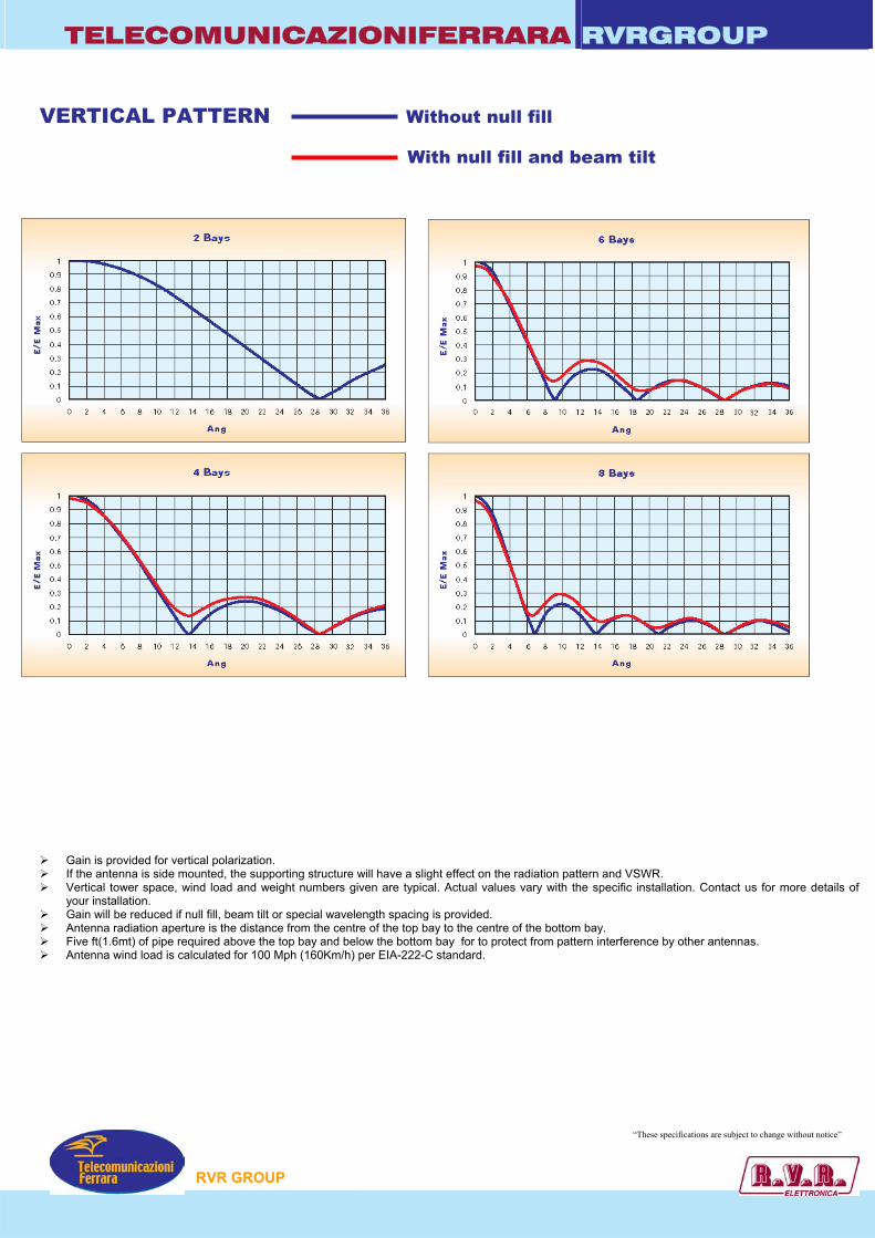
VERTICAL PATTERN Without null fill
With null fill and beam tilt
Gain is provided for vertical polarization. If the antenna is side mounted, the supporting structure will have a slight effect on the radiation pattern and VSWR. Vertical tower space, wind load and weight numbers given are typical. Actual values vary with the specific installation. Contact us for more details of
your installation. Gain will be reduced if null fill, beam tilt or special wavelength spacing is provided. Antenna radiation aperture is the distance from the centre of the top bay to the centre of the bottom bay. Five ft(1.6mt) of pipe required above the top bay and below the bottom bay for to protect from pattern interference by other antennas. Antenna wind load is calculated for 100 Mph (160Km/h) per EIA-222-C standard.
RVR GROUP
“These specifications are subject to change without notice”

180
0
270 90
-1330
300
240
210 150
120
60
30
-2-3-4
-6
-9
-15
180
0
270 90
-1330
300
240
210 150
120
60
30
-2-3-4
-6
-9
-15
TelecomunicazioniFerrara
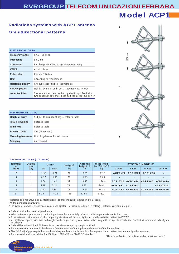
Model ACP1TELECOMUNICAZIONIFERRARA
RVR GROUP
RVRGROUP
• Band II
• Broadband 87.5÷108 MHz
• Demountable
• Circular polarization
• Stainless steel AISI 304
• Pressurizzable on request
RADIATION PATTERN (MID BAND)
ELECTRICAL DATA
Frequency range 87.5÷108 MHz
Impedance 50 Ohm
Connectors N or 7/16” or 7/8” EIA
Max Power 800W (N) – 2KW (7/16”) – 3KW (7/8” EIA)
VSWR ≤ 1.4:1
Polarization Circular
Gain Refer to table
Pattern Omni directional ± 1.5 dB in free spaceOmni directional ± 3 dB with 100mm dia. pole
Lightning protection All metal parts DC grounded
E-Plane H-Plane
MECHANICAL DATA
Dimensions 1560x1150x1150 mm
Weight 13 kg
Wind surface 0.19 m2 (side)0.13 m2 (front)
Wind load 31.1 kg (side - wind speed at 160 km/h) Max wind velocity 220 km/h.
External parts: stainless steelMaterials Internal parts: aluminium treated
Mounting With special pipe clamps 50÷110 mm dia.
87 88 89 90 91 92 93 94 95 96 97 98 99 100 101 102 103 104 105 106 107 108
0
-5
-10
-15
-20
-25
dB
Return Loss
Freq. in MHZ
1560 mm
1340 mm
“These specifications are subject to change without notice”

L
2600
mm
RVR GROUP
Radiations systems with ACP1 antenna
Omnidirectional patterns
Gain is provided for vertical polarization. When antenna is pole mounted on the top a tower the horizontally polarized radiation pattern is omni - directional. If the antenna is side mounted, the supporting structure will have a slight effect on the radiation pattern and VSWR. Vertical tower space, wind load and weight numbers given are typical. Actual values vary with the specific installation. Contact us for more details of your
installation. Gain will be reduced if null fill, beam tilt or special wavelength spacing is provided. Antenna radiation aperture is the distance from the centre of the top bay to the centre of the bottom bay. Five ft(1.6mt) of pipe required above the top bay and below the bottom bay for to protect from pattern interference by other antennas. Antenna wind load is calculated for 100 Mph (160Km/h) per EIA-222-C standard.
1 Referred to a half wave dipole. Attenuation of connecting cables not taken into account.2 Without mounting hardware.3 The systems comprised: antennas, cables and splitter – for more details to see catalog – different version on request.
TECHNICAL DATA (1 Wave)
RVRGROUPTELECOMUNICAZIONIFERRARA
Model ACP1
Number Dipole Gain1Weight2 Antenna Wind load SYSTEMS MODELS3
of per height L (v=160 km/h)bays bay dB times kg m kg 2 KW 4 KW 6 KW 10 KW
2 1 1.50 1.40 26 3.8 62.2 ACP1X22 ACP1X24 ACP1X26 -
3 1 3.30 2.10 39 6.4 93.3 - - - -
4 1 4.50 2.80 52 9.0 124.4 ACP1X42 ACP1X44 ACP1X46 ACP1X410
6 1 6.30 4.20 78 14.2 186.6 ACP1X62 ACP1X64 - ACP1X610
8 1 7.50 5.70 104 19.4 248.8 ACP1X82 ACP1X84 ACP1X86 ACP1X810
12 1 9.30 8.50 156 29.8 373.2 - - - -
ELECTRICAL DATA
Frequency range 87.5÷108 MHz
Impedance 50 Ohm
Connector EIA flange according to system power rating
VSWR ≤ 1.4:1 Max
Polarization Circular/Elliptical
Gain According to requirement
Horizontal pattern Any type according to requirements
Vertical pattern Null fill, beam tilt and special requirements to order
Other facilities The antenna system can be supplied in split feed withtwo equal half antennas. Each half can accept full power
MECHANICAL DATA
Height of array Subject to number of bays ( refer to table )
Total net weight Refer to table
Wind load Refer to table
Pressurizzable Yes (on request)
Mounting hardware Hot dip galvanized steel clamps
Shipping As required
TelecomunicazioniFerrara
“These specifications are subject to change without notice”
2600
mm
L
RVR GROUP
Radiations systems with ACP1 antenna
Omnidirectional patterns
Gain is provided for vertical polarization. When antenna is pole mounted on the top a tower the horizontally polarized radiation pattern is omni - directional. If the antenna is side mounted, the supporting structure will have a slight effect on the radiation pattern and VSWR. Vertical tower space, wind load and weight numbers given are typical. Actual values vary with the specific installation. Contact us for more details of your
installation. Gain will be reduced if null fill, beam tilt or special wavelength spacing is provided. Antenna radiation aperture is the distance from the centre of the top bay to the centre of the bottom bay. Five ft(1.6mt) of pipe required above the top bay and below the bottom bay for to protect from pattern interference by other antennas. Antenna wind load is calculated for 100 Mph (160Km/h) per EIA-222-C standard.
1 Referred to a half wave dipole. Attenuation of connecting cables not taken into account.2 Without mounting hardware.3 The systems comprised: antennas, cables and splitter – for more details to see catalog – different version on request.
TECHNICAL DATA (1/2 Wave)
RVRGROUPTELECOMUNICAZIONIFERRARA
Model ACP1
Number Dipole Gain1Weight2 Antenna Wind load SYSTEMS MODELS3
of per height L (v=160 km/h)bays bay dB times kg m kg 2 KW 4 KW 6 KW 10 KW
2 1 -1.50 0.71 26 2.65 62.2 ACP1X22 ACP1X24 ACP1X26 -
3 1 0.27 1.06 39 4.15 93.3 - - - -
4 1 1.50 1.42 52 5.65 124.4 ACP1X42 ACP1X44 ACP1X46 ACP1X410
6 1 3.28 2.13 78 8.65 186.6 ACP1X62 ACP1X64 - ACP1X610
8 1 4.50 2.84 104 11.65 248.8 ACP1X82 ACP1X84 ACP1X86 ACP1X810
12 1 6.29 4.26 156 17.65 373.2 - - - -
ELECTRICAL DATA
Frequency range 87.5÷108 MHz
Impedance 50 Ohm
Connector EIA flange according to system power rating
VSWR ≤ 1.4:1 Max
Polarization Circular/Elliptical
Gain According to requirement
Horizontal pattern Any type according to requirements
Vertical pattern Null fill, beam tilt and special requirements to order
Other facilities The antenna system can be supplied in split feed withtwo equal half antennas. Each half can accept full power
MECHANICAL DATA
Height of array Subject to number of bays ( refer to table )
Total net weight Refer to table
Wind load Refer to table
Pressurizzable Yes (on request)
Mounting hardware Hot dip galvanized steel clamps
Shipping As required
TelecomunicazioniFerrara
“These specifications are subject to change without notice”
1500
mm
TELECOMUNICAZIONIFERRARA RVRGROUP
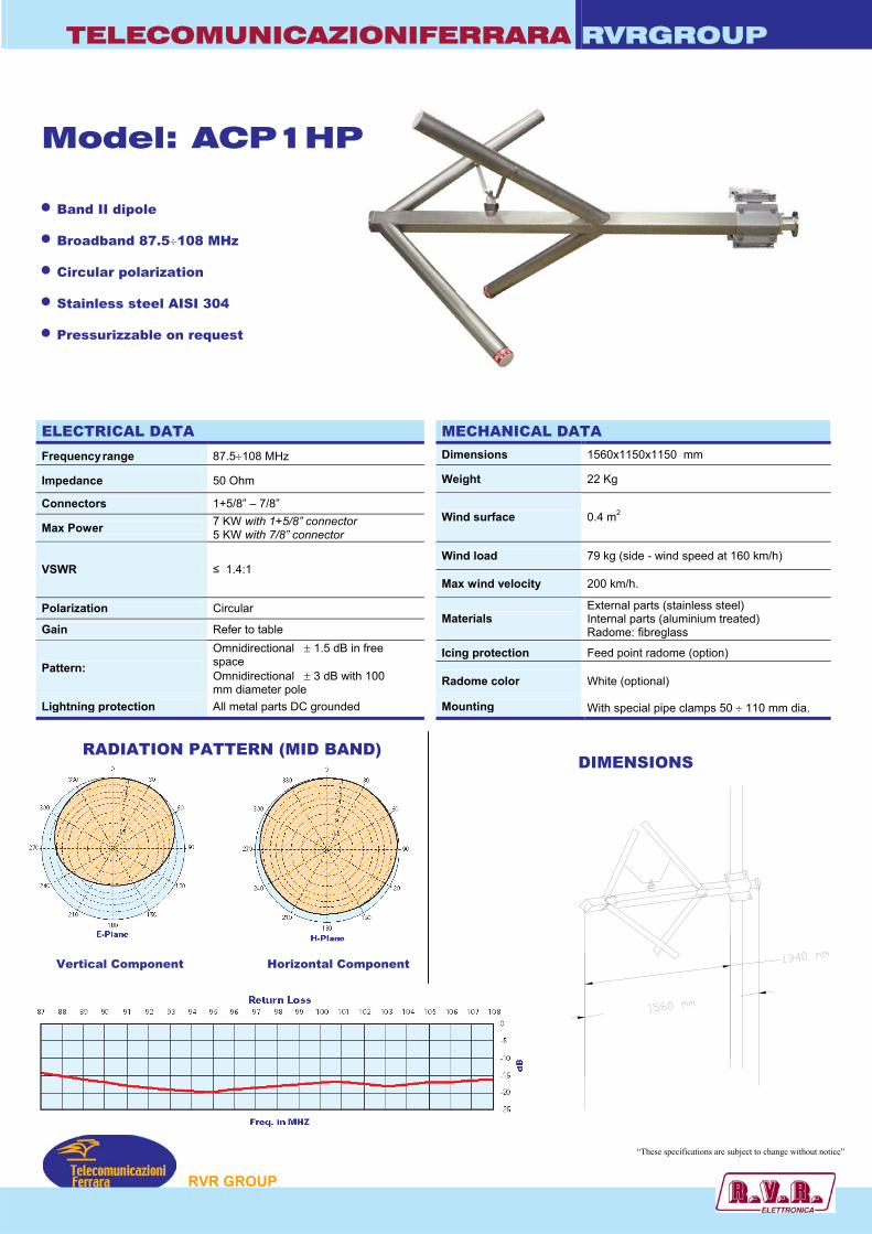
Model: ACP1HP • Band II dipole
• Broadband 87.5÷108 MHz
• Circular polarization
• Stainless steel AISI 304
• Pressurizzable on request
ELECTRICAL DATA MECHANICAL DATA
Frequency range 87.5÷108 MHz Dimensions 1560x1150x1150 mm
Impedance 50 Ohm Weight 22 Kg
Connectors 1+5/8” – 7/8”
Max Power 7 KW with 1+5/8” connector 5 KW with 7/8” connector
Wind surface 0.4 m2
Wind load 79 kg (side - wind speed at 160 km/h) VSWR ≤ 1.4:1
Max wind velocity 200 km/h.
Polarization Circular
Gain Refer to table Materials
External parts (stainless steel) Internal parts (aluminium treated) Radome: fibreglass
Icing protection Feed point radome (option) Pattern:
Omnidirectional ± 1.5 dB in free space Omnidirectional ± 3 dB with 100 mm diameter pole
Radome color White (optional)
Lightning protection All metal parts DC grounded Mounting With special pipe clamps 50 ÷ 110 mm dia.
RADIATION PATTERN (MID BAND) DIMENSIONS
P
“These specifications are subject to change without notice”
RVR GROU
Vertical Component
Horizontal Component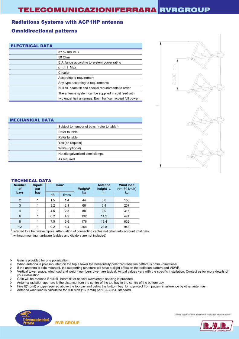
TELECOMUNICAZIONIFERRARA RVRGROUP Radiations Systems with ACP1HP antenna
Omnidirectional patterns
ELECTRICAL DATA Frequency range 87.5÷108 MHz Impedance 50 Ohm Connector EIA flange according to system power rating VSWR ≤ 1.4:1 Max Polarization Circular Gain According to requirement Horizontal pattern Any type according to requirements Vertical pattern Null fill, beam tilt and special requirements to order Other facilities
The antenna system can be supplied in split feed with two equal half antennas. Each half can accept full power
MECHANICAL DATA Height of array Subject to number of bays ( refer to table )
Total net weight Refer to table
Wind load Refer to table
Pressurizzable Yes (on request)
Radome color White (optional)
Mounting hardware Hot dip galvanized steel clamps
Shipping As required
TECHNICAL DATA
Gain¹
Number of
bays
Dipole per bay
dB times
Weight²
kg
Antenna height L
m
Wind load (v=160 km/h)
kg
2 1 1.5 1.4 44 3.8 158 3 1 3.2 2.1 66 6.4 237 4 1 4.5 2.8 88 9.0 316 6 1 6.2 4.2 132 14.2 474 8 1 7.5 5.6 176 19.4 632
12 1 9.2 8.4 264 29.8 948 I referred to a half wave dipole. Attenuation of connecting cables not taken into account total gain. 2 without mounting hardware (cables and dividers are not included) Gain is provided for one polarization. When antenna is pole mounted on the top a tower the horizontally polarized radiation pattern is omni - directional. If the antenna is side mounted, the supporting structure will have a slight effect on the radiation pattern and VSWR. Vertical tower space, wind load and weight numbers given are typical. Actual values vary with the specific installation. Contact us for more details of
your installation. Gain will be reduced if null fill, beam tilt or special wavelength spacing is provided. Antenna radiation aperture is the distance from the centre of the top bay to the centre of the bottom bay. Five ft(1.6mt) of pipe required above the top bay and below the bottom bay for to protect from pattern interference by other antennas. Antenna wind load is calculated for 100 Mph (160Km/h) per EIA-222-C standard.
“These specifications are subject to change without notice”
P
RVR GROU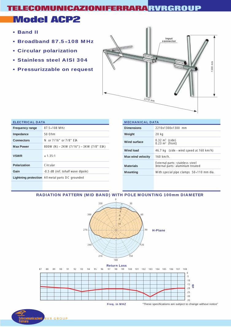
TelecomunicazioniFerrara
Model ACP2TELECOMUNICAZIONIFERRARA
RVR GROUP
RVRGROUP
• Band II
• Broadband 87.5÷108 MHz
• Circular polarization
• Stainless steel AISI 304
• Pressurizzable on request
RADIATION PATTERN (MID BAND) WITH POLE MOUNTING 100mm DIAMETER
ELECTRICAL DATA
Frequency range 87.5÷108 MHz
Impedance 50 Ohm
Connectors N or 7/16” or 7/8” EIA
Max Power 800W (N) – 2KW (7/16”) – 3KW (7/8” EIA)
VSWR ≤ 1.35:1
Polarization Circular
Gain -0.5 dB (ref. tohalf wave dipole)
Lightning protection All metal parts DC grounded
H-Plane
MECHANICAL DATA
Dimensions 2210x1300x1300 mm
Weight 20 kg
Wind surface 0.32 m2 (side)0.23 m2 (front)
Wind load 46.7 kg (side - wind speed at 160 km/h) Max wind velocity 160 km/h.
External parts: stainless steelMaterials Internal parts: aluminium treated
Mounting With special pipe clamps 50÷110 mm dia.
2210 mm
1300
mm
Inputconnector
87 88 89 90 91 92 93 94 95 96 97 98 99 100 101 102 103 104 105 106 107 108
0-5
-10
-15
-20
-25
dB
Return Loss
Freq. in MHZ
-30
-35
180
0
270 90
-1330
300
240
210 150
120
60
30
-2-3-4
-6
-9
-15
“These specifications are subject to change without notice”
L
2600
mm
RVR GROUP
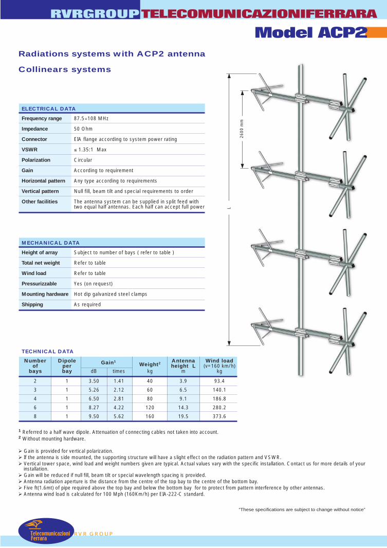
Radiations systems with ACP2 antenna
Collinears systems
Gain is provided for vertical polarization. If the antenna is side mounted, the supporting structure will have a slight effect on the radiation pattern and VSWR. Vertical tower space, wind load and weight numbers given are typical. Actual values vary with the specific installation. Contact us for more details of your
installation. Gain will be reduced if null fill, beam tilt or special wavelength spacing is provided. Antenna radiation aperture is the distance from the centre of the top bay to the centre of the bottom bay. Five ft(1.6mt) of pipe required above the top bay and below the bottom bay for to protect from pattern interference by other antennas. Antenna wind load is calculated for 100 Mph (160Km/h) per EIA-222-C standard.
1 Referred to a half wave dipole. Attenuation of connecting cables not taken into account.2 Without mounting hardware.
TECHNICAL DATA
RVRGROUPTELECOMUNICAZIONIFERRARA
Model ACP2
Number Dipole Gain1Weight2 Antenna Wind load
of per height L (v=160 km/h)bays bay dB times kg m kg
2 1 3.50 1.41 40 3.9 93.4
3 1 5.26 2.12 60 6.5 140.1
4 1 6.50 2.81 80 9.1 186.8
6 1 8.27 4.22 120 14.3 280.2
8 1 9.50 5.62 160 19.5 373.6
ELECTRICAL DATA
Frequency range 87.5÷108 MHz
Impedance 50 Ohm
Connector EIA flange according to system power rating
VSWR ≤ 1.35:1 Max
Polarization Circular
Gain According to requirement
Horizontal pattern Any type according to requirements
Vertical pattern Null fill, beam tilt and special requirements to order
Other facilities The antenna system can be supplied in split feed withtwo equal half antennas. Each half can accept full power
MECHANICAL DATA
Height of array Subject to number of bays ( refer to table )
Total net weight Refer to table
Wind load Refer to table
Pressurizzable Yes (on request)
Mounting hardware Hot dip galvanized steel clamps
Shipping As required
TelecomunicazioniFerrara
“These specifications are subject to change without notice”

TelecomunicazioniFerrara
Model AJ1E – AJ1EBI – AJ1E/INOX – AJ1E/ITTELECOMUNICAZIONIFERRARA
RVR GROUP
RVRGROUP
• High Power Version (H.P.)
• FM Band 87.5÷108 MHz
• Suitable for VHF, Band Iand OIRT Band
• Gamma Match Tuned
• Omni directional pattern
• Vertical polarization
• Light - Low Cost - Demountable
“These specifications are subject to change without notice”
L
H
Inputconnector
W
RADIATION PATTERN (MID BAND)
ELECTRICAL DATA
Frequency range 87.5÷108 MHz
Impedance 50 Ohm
Connectors N or 7/16” female or 7/8” EIA
Max Power 650W (N) – 1300W (7/16” – H.P. Version)
VSWR ≤ 1.1:1 in the operating channel
Polarization Vertical
Gain 1 dB (referred to half-wave dipole)
Pattern Omni directional ± 1.5 dB in free spaceOmni directional ± 3 dB with 100mm dia. pole
Lightning protection No DC grounded
E-Plane H-Plane
MECHANICAL DATA
Dimensions According to the working frequency1380 (H) x 760 (L) x 100 (W) mm at 98 MHz
Weight According to the working frequency(aluminium or stainless steel)
Wind surface 0.05 m2 (at 98 MHz)
Wind load 6.7 kg (wind speed at 160 km/h)
Max wind velocity 200 km/h (AJ1E/IT model)
AJ1E: Aluminium elements and boomAJ1EBI: Aluminium elements and inox boomAJ1E/INOX: Stainless steel elements and boom
Materials AJ1E/IT: Stainless steel elements and boom Tig Welded Version
Teflon insulatorRadome: fiberglass (option)
Icing protection Feed point radome (optional)
Radome Optional
Mounting With special pipe clamps 50÷110 mm dia.
180
0
270 90
-1330
300
240
210 150
120
60
30
-2-3-4
-6
-9
-15
180
0
270 90
-1330
300
240
210 150
120
60
30
-2-3-4
-6
-9
-15
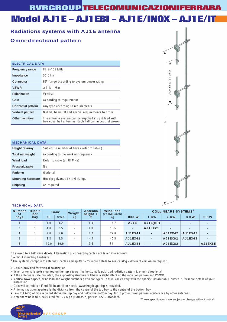
RVR GROUP
Radiations systems with AJ1E antenna
Omni-directional pattern
Gain is provided for vertical polarization. When antenna is pole mounted on the top a tower the horizontally polarized radiation pattern is omni - directional. If the antenna is side mounted, the supporting structure will have a slight effect on the radiation pattern and VSWR. Vertical tower space, wind load and weight numbers given are typical. Actual values vary with the specific installation. Contact us for more details of your
installation. Gain will be reduced if null fill, beam tilt or special wavelength spacing is provided. Antenna radiation aperture is the distance from the centre of the top bay to the centre of the bottom bay. Five ft(1.6mt) of pipe required above the top bay and below the bottom bay for to protect from pattern interference by other antennas. Antenna wind load is calculated for 100 Mph (160Km/h) per EIA-222-C standard.
1 Referred to a half wave dipole. Attenuation of connecting cables not taken into account.2 Without mounting hardware.3 The systems comprised: antennas, cables and splitter – for more details to see catalog – different version on request.
TECHNICAL DATA
RVRGROUPTELECOMUNICAZIONIFERRARA
Model AJ1E – AJ1EBI – AJ1E/INOX – AJ1E/IT
Number Dipole Gain1Weight2 Antenna Wind load COLLINEARS SYSTEMS3
of per height L (v=160 km/h)bays bay dB times kg m kg 800 W 1 KW 2 KW 3 KW 5 KW
1 1 1.0 1.2 - 1.4 6.7 AJ1E AJ1E(HP) - - -
2 1 4.0 2.5 - 4.0 13.5 - AJ1EX21 - - -
4 1 7.0 5.0 - 9.2 27.0 AJ1EX41 - AJ1EX42 AJ1EX43 -
6 1 8.8 8 -.5 14.4 40.5 AJ1EX61 - AJ1EX62 AJ1EX63 -
8 1 10.0 10.0 - 19.6 54 AJ1EX81 - AJ1EX82 - AJ1EX85
ELECTRICAL DATA
Frequency range 87.5÷108 MHz
Impedance 50 Ohm
Connector EIA flange according to system power rating
VSWR ≤ 1.1:1 Max
Polarization Vertical
Gain According to requirement
Horizontal pattern Any type according to requirements
Vertical pattern Null fill, beam tilt and special requirements to order
Other facilities The antenna system can be supplied in split feed withtwo equal half antennas. Each half can accept full power
MECHANICAL DATA
Height of array Subject to number of bays ( refer to table )
Total net weight According to the working frequency
Wind load Refer to table (at 98 MHz)
Pressurizzable No
Radome Optional
Mounting hardware Hot dip galvanized steel clamps
Shipping As required
TelecomunicazioniFerrara
L
2600
mm
(at
98
MH
z)
“These specifications are subject to change without notice”
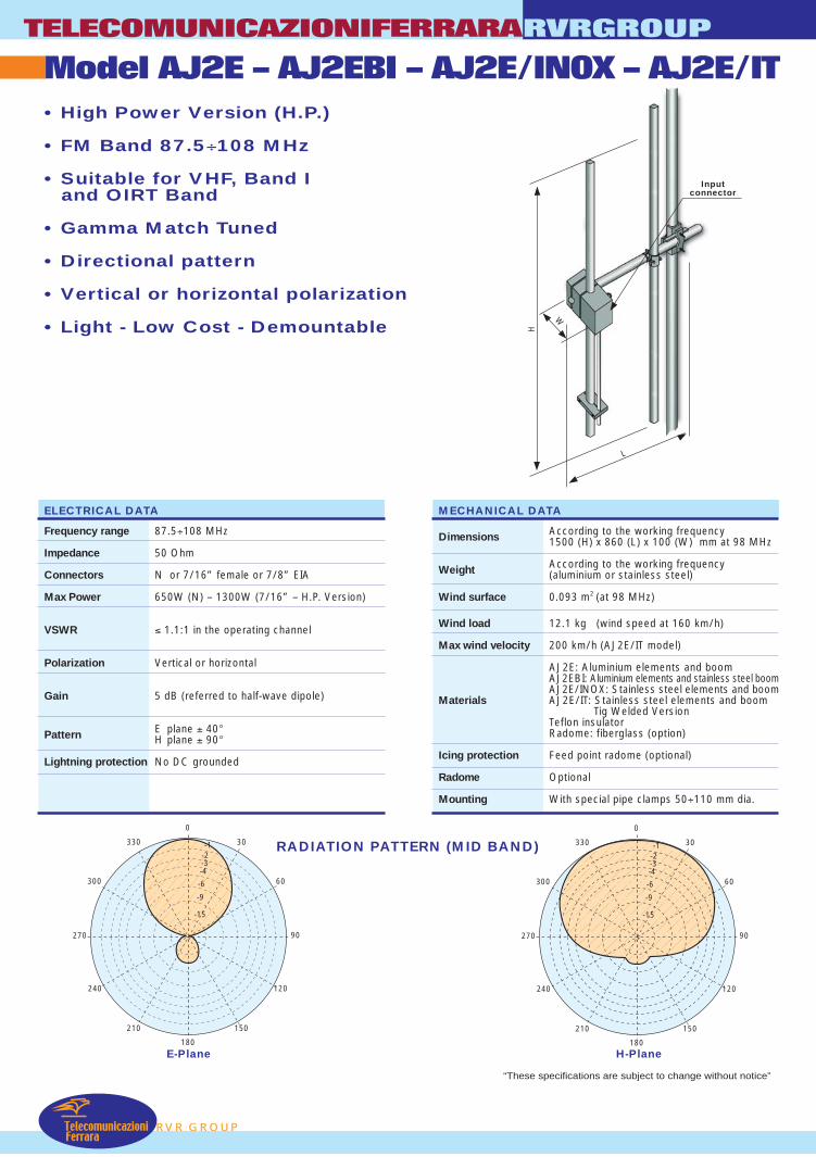
L
H
Inputconnector
W
TelecomunicazioniFerrara
Model AJ2E – AJ2EBI – AJ2E/INOX – AJ2E/ITTELECOMUNICAZIONIFERRARA
RVR GROUP
RVRGROUP
• High Power Version (H.P.)
• FM Band 87.5÷108 MHz
• Suitable for VHF, Band Iand OIRT Band
• Gamma Match Tuned
• Directional pattern
• Vertical or horizontal polarization
• Light - Low Cost - Demountable
RADIATION PATTERN (MID BAND)
ELECTRICAL DATA
Frequency range 87.5÷108 MHz
Impedance 50 Ohm
Connectors N or 7/16” female or 7/8” EIA
Max Power 650W (N) – 1300W (7/16” – H.P. Version)
VSWR ≤ 1.1:1 in the operating channel
Polarization Vertical or horizontal
Gain 5 dB (referred to half-wave dipole)
Pattern E plane ± 40°H plane ± 90°
Lightning protection No DC grounded
E-Plane H-Plane
MECHANICAL DATA
Dimensions According to the working frequency1500 (H) x 860 (L) x 100 (W) mm at 98 MHz
Weight According to the working frequency(aluminium or stainless steel)
Wind surface 0.093 m2 (at 98 MHz)
Wind load 12.1 kg (wind speed at 160 km/h)
Max wind velocity 200 km/h (AJ2E/IT model)
AJ2E: Aluminium elements and boomAJ2EBI: Aluminium elements and stainless steel boomAJ2E/INOX: Stainless steel elements and boom
Materials AJ2E/IT: Stainless steel elements and boom Tig Welded Version
Teflon insulatorRadome: fiberglass (option)
Icing protection Feed point radome (optional)
Radome Optional
Mounting With special pipe clamps 50÷110 mm dia.
180
0
270 90
-1330
300
240
210 150
120
60
30
-2-3-4
-6
-9
-15
180
0
270 90
-1330
300
240
210 150
120
60
30
-2-3-4
-6
-9
-15
“These specifications are subject to change without notice”
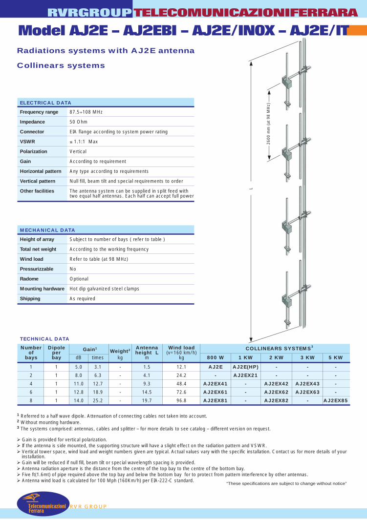
L
2600
mm
(at
98
MH
z)
RVR GROUP
Radiations systems with AJ2E antenna
Collinears systems
Gain is provided for vertical polarization. If the antenna is side mounted, the supporting structure will have a slight effect on the radiation pattern and VSWR. Vertical tower space, wind load and weight numbers given are typical. Actual values vary with the specific installation. Contact us for more details of your
installation. Gain will be reduced if null fill, beam tilt or special wavelength spacing is provided. Antenna radiation aperture is the distance from the centre of the top bay to the centre of the bottom bay. Five ft(1.6mt) of pipe required above the top bay and below the bottom bay for to protect from pattern interference by other antennas. Antenna wind load is calculated for 100 Mph (160Km/h) per EIA-222-C standard.
1 Referred to a half wave dipole. Attenuation of connecting cables not taken into account.2 Without mounting hardware.3 The systems comprised: antennas, cables and splitter – for more details to see catalog – different version on request.
TECHNICAL DATA
RVRGROUPTELECOMUNICAZIONIFERRARA
Model AJ2E – AJ2EBI – AJ2E/INOX – AJ2E/IT
Number Dipole Gain1Weight2 Antenna Wind load COLLINEARS SYSTEMS3
of per height L (v=160 km/h)bays bay dB times kg m kg 800 W 1 KW 2 KW 3 KW 5 KW
1 1 5.0 3.1 - 1.5 12.1 AJ2E AJ2E(HP) - - -
2 1 8.0 6.3 - 4.1 24.2 - AJ2EX21 - - -
4 1 11.0 12.7 - 9.3 48.4 AJ2EX41 - AJ2EX42 AJ2EX43 -
6 1 12.8 18.9 - 14.5 72.6 AJ2EX61 - AJ2EX62 AJ2EX63 -
8 1 14.0 25.2 - 19.7 96.8 AJ2EX81 - AJ2EX82 - AJ2EX85
ELECTRICAL DATA
Frequency range 87.5÷108 MHz
Impedance 50 Ohm
Connector EIA flange according to system power rating
VSWR ≤ 1.1:1 Max
Polarization Vertical
Gain According to requirement
Horizontal pattern Any type according to requirements
Vertical pattern Null fill, beam tilt and special requirements to order
Other facilities The antenna system can be supplied in split feed withtwo equal half antennas. Each half can accept full power
MECHANICAL DATA
Height of array Subject to number of bays ( refer to table )
Total net weight According to the working frequency
Wind load Refer to table (at 98 MHz)
Pressurizzable No
Radome Optional
Mounting hardware Hot dip galvanized steel clamps
Shipping As required
TelecomunicazioniFerrara
“These specifications are subject to change without notice”
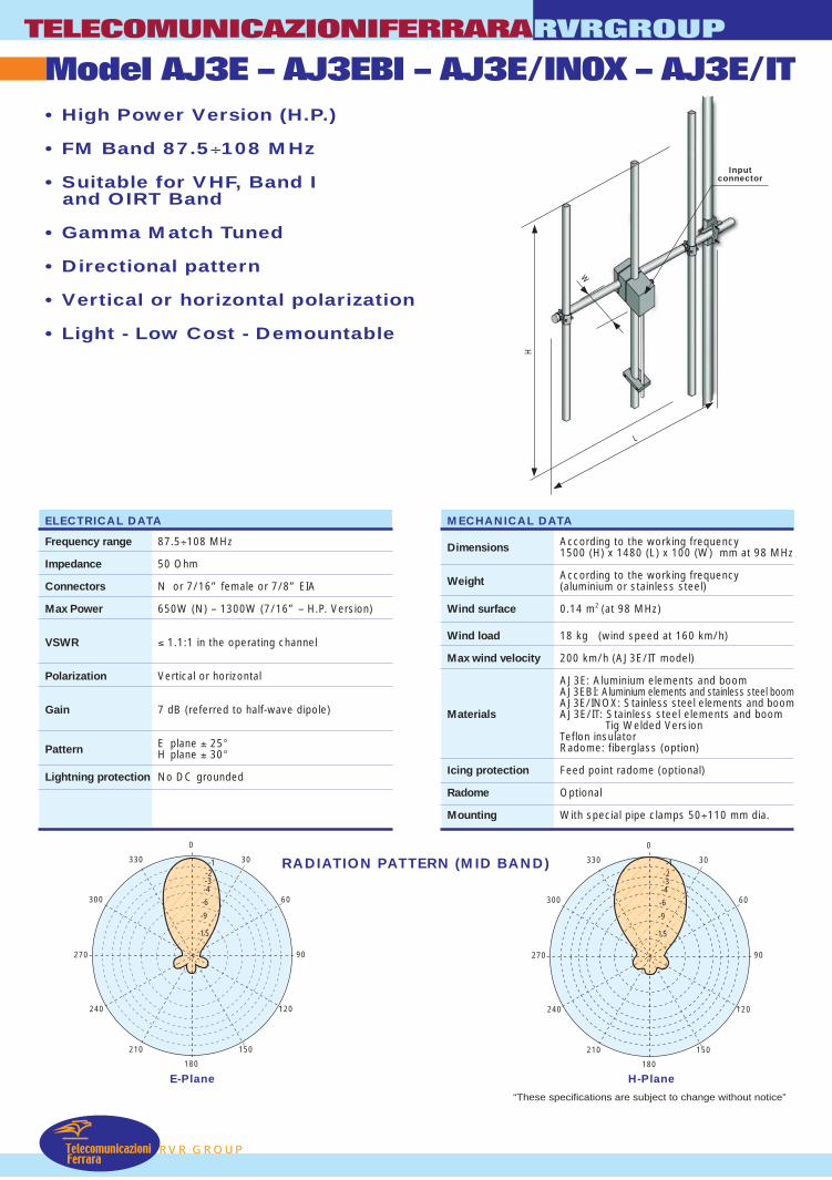
TelecomunicazioniFerrara
Model AJ3E – AJ3EBI – AJ3E/INOX – AJ3E/ITTELECOMUNICAZIONIFERRARA
RVR GROUP
RVRGROUP
• High Power Version (H.P.)
• FM Band 87.5÷108 MHz
• Suitable for VHF, Band Iand OIRT Band
• Gamma Match Tuned
• Directional pattern
• Vertical or horizontal polarization
• Light - Low Cost - Demountable
RADIATION PATTERN (MID BAND)
ELECTRICAL DATA
Frequency range 87.5÷108 MHz
Impedance 50 Ohm
Connectors N or 7/16” female or 7/8” EIA
Max Power 650W (N) – 1300W (7/16” – H.P. Version)
VSWR ≤ 1.1:1 in the operating channel
Polarization Vertical or horizontal
Gain 7 dB (referred to half-wave dipole)
Pattern E plane ± 25°H plane ± 30°
Lightning protection No DC grounded
E-Plane H-Plane
MECHANICAL DATA
Dimensions According to the working frequency1500 (H) x 1480 (L) x 100 (W) mm at 98 MHz
Weight According to the working frequency(aluminium or stainless steel)
Wind surface 0.14 m2 (at 98 MHz)
Wind load 18 kg (wind speed at 160 km/h)
Max wind velocity 200 km/h (AJ3E/IT model)
AJ3E: Aluminium elements and boomAJ3EBI: Aluminium elements and stainless steel boomAJ3E/INOX: Stainless steel elements and boom
Materials AJ3E/IT: Stainless steel elements and boom Tig Welded Version
Teflon insulatorRadome: fiberglass (option)
Icing protection Feed point radome (optional)
Radome Optional
Mounting With special pipe clamps 50÷110 mm dia.
180
0
270 90
-1330
300
240
210 150
120
60
30
-2-3-4
-6
-9
-15
180
0
270 90
-1330
300
240
210 150
120
60
30
-2-3-4
-6
-9
-15
L
Inputconnector
W
H
“These specifications are subject to change without notice”

L
2600
mm
(at
98
MH
z)
RVR GROUP
Radiations systems with AJ3E antenna
Collinears systems
Gain is provided for vertical polarization. If the antenna is side mounted, the supporting structure will have a slight effect on the radiation pattern and VSWR. Vertical tower space, wind load and weight numbers given are typical. Actual values vary with the specific installation. Contact us for more details of your
installation. Gain will be reduced if null fill, beam tilt or special wavelength spacing is provided. Antenna radiation aperture is the distance from the centre of the top bay to the centre of the bottom bay. Five ft(1.6mt) of pipe required above the top bay and below the bottom bay for to protect from pattern interference by other antennas. Antenna wind load is calculated for 100 Mph (160Km/h) per EIA-222-C standard.
1 Referred to a half wave dipole. Attenuation of connecting cables not taken into account.2 Without mounting hardware.3 The systems comprised: antennas, cables and splitter – for more details to see catalog – different version on request.
TECHNICAL DATA
RVRGROUPTELECOMUNICAZIONIFERRARA
Model AJ3E – AJ3EBI – AJ3E/INOX – AJ3E/IT
Number Dipole Gain1Weight2 Antenna Wind load COLLINEARS SYSTEMS3
of per height L (v=160 km/h)bays bay dB times kg m kg 800 W 1 KW 2 KW 3 KW 5 KW
1 1 7.0 5.0 - 1.5 18 AJ3E AJ3E(HP) - - -
2 1 10.0 10.0 - 4.1 36 - AJ3EX21 - - -
4 1 13.0 20.0 - 9.3 72 AJ3EX41 - AJ3EX42 AJ3EX43 -
6 1 14.8 30.0 - 14.5 108 AJ3EX61 - AJ3EX62 AJ3EX63 -
8 1 16.0 40.0 - 19.7 144 AJ3EX81 - AJ3EX82 - AJ3EX85
ELECTRICAL DATA
Frequency range 87.5÷108 MHz
Impedance 50 Ohm
Connector EIA flange according to system power rating
VSWR ≤ 1.1:1 Max
Polarization Vertical
Gain According to requirement
Horizontal pattern Any type according to requirements
Vertical pattern Null fill, beam tilt and special requirements to order
Other facilities The antenna system can be supplied in split feed withtwo equal half antennas. Each half can accept full power
MECHANICAL DATA
Height of array Subject to number of bays ( refer to table )
Total net weight According to the working frequency
Wind load Refer to table (at 98 MHz)
Pressurizzable No
Radome Optional
Mounting hardware Hot dip galvanized steel clamps
Shipping As required
TelecomunicazioniFerrara
“These specifications are subject to change without notice”

L
Inputconnector
W
H
TelecomunicazioniFerrara
Model AJ4E – AJ4EBI – AJ4E/INOX – AJ4E/ITTELECOMUNICAZIONIFERRARA
RVR GROUP
RVRGROUP
• High Power Version (H.P.)
• FM Band 87.5÷108 MHz
• Suitable for VHF, Band Iand OIRT Band
• Gamma Match Tuned
• Directional pattern
• Vertical or horizontal polarization
• Light - Low Cost - Demountable
RADIATION PATTERN (MID BAND)
ELECTRICAL DATA
Frequency range 87.5÷108 MHz
Impedance 50 Ohm
Connectors N or 7/16” female or 7/8” EIA
Max Power 650W (N) – 1300W (7/16” – H.P. Version)
VSWR ≤ 1.1:1 in the operating channel
Polarization Vertical or horizontal
Gain 8 dB (referred to half-wave dipole)
Pattern E plane ± 25°H plane ± 30°
Lightning protection No DC grounded
E-Plane H-Plane
MECHANICAL DATA
Dimensions According to the working frequency1500 (H) x 2090 (L) x 100 (W) mm at 98 MHz
Weight According to the working frequency(aluminium or stainless steel)
Wind surface 0.18 m2 (at 98 MHz)
Wind load 23.3 kg (wind speed at 160 km/h)
Max wind velocity 180 km/h (AJ4E/IT model)
AJ4E: Aluminium elements and boomAJ4EBI: Aluminium elements and stainless steel boomAJ4E/INOX: Stainless steel elements and boom
Materials AJ4E/IT: Stainless steel elements and boom Tig Welded Version
Teflon insulatorRadome: fiberglass (option)
Icing protection Feed point radome (optional)
Radome Optional
Mounting With special pipe clamps 50÷110 mm dia.
180
0
270 90
-1330
300
240
210 150
120
60
30
-2-3-4
-6
-9
-15
180
0
270 90
-1330
300
240
210 150
120
60
30
-2-3-4
-6
-9
-15
“These specifications are subject to change without notice”
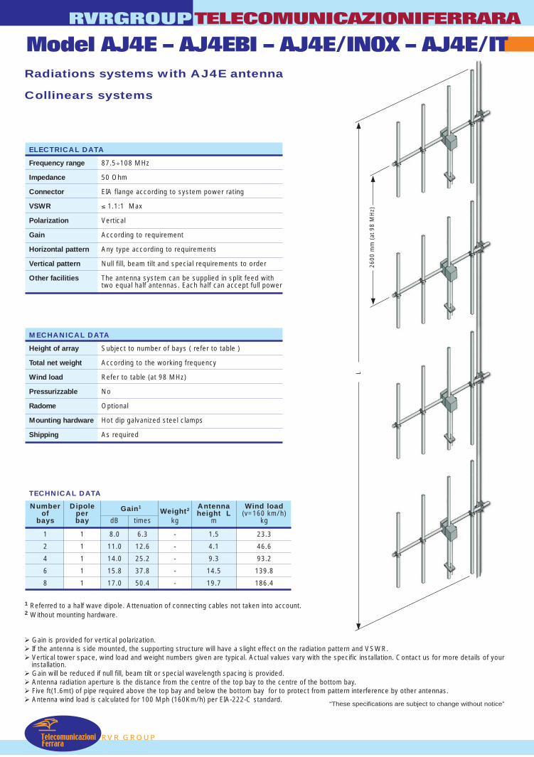
L
2600
mm
(at
98
MH
z)
RVR GROUP
Radiations systems with AJ4E antenna
Collinears systems
Gain is provided for vertical polarization. If the antenna is side mounted, the supporting structure will have a slight effect on the radiation pattern and VSWR. Vertical tower space, wind load and weight numbers given are typical. Actual values vary with the specific installation. Contact us for more details of your
installation. Gain will be reduced if null fill, beam tilt or special wavelength spacing is provided. Antenna radiation aperture is the distance from the centre of the top bay to the centre of the bottom bay. Five ft(1.6mt) of pipe required above the top bay and below the bottom bay for to protect from pattern interference by other antennas. Antenna wind load is calculated for 100 Mph (160Km/h) per EIA-222-C standard.
1 Referred to a half wave dipole. Attenuation of connecting cables not taken into account.2 Without mounting hardware.
TECHNICAL DATA
RVRGROUPTELECOMUNICAZIONIFERRARA
Model AJ4E – AJ4EBI – AJ4E/INOX – AJ4E/IT
Number Dipole Gain1Weight2 Antenna Wind load
of per height L (v=160 km/h)bays bay dB times kg m kg
1 1 8.0 6.3 - 1.5 23.3
2 1 11.0 12.6 - 4.1 46.6
4 1 14.0 25.2 - 9.3 93.2
6 1 15.8 37.8 - 14.5 139.8
8 1 17.0 50.4 - 19.7 186.4
ELECTRICAL DATA
Frequency range 87.5÷108 MHz
Impedance 50 Ohm
Connector EIA flange according to system power rating
VSWR ≤ 1.1:1 Max
Polarization Vertical
Gain According to requirement
Horizontal pattern Any type according to requirements
Vertical pattern Null fill, beam tilt and special requirements to order
Other facilities The antenna system can be supplied in split feed withtwo equal half antennas. Each half can accept full power
MECHANICAL DATA
Height of array Subject to number of bays ( refer to table )
Total net weight According to the working frequency
Wind load Refer to table (at 98 MHz)
Pressurizzable No
Radome Optional
Mounting hardware Hot dip galvanized steel clamps
Shipping As required
TelecomunicazioniFerrara
“These specifications are subject to change without notice”
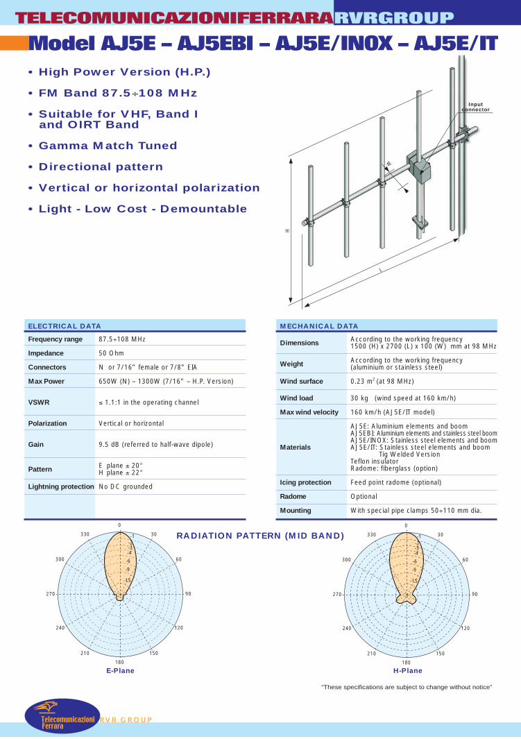
L
Inputconnector
W
H
TelecomunicazioniFerrara
Model AJ5E – AJ5EBI – AJ5E/INOX – AJ5E/ITTELECOMUNICAZIONIFERRARA
RVR GROUP
RVRGROUP
• High Power Version (H.P.)
• FM Band 87.5÷108 MHz
• Suitable for VHF, Band Iand OIRT Band
• Gamma Match Tuned
• Directional pattern
• Vertical or horizontal polarization
• Light - Low Cost - Demountable
RADIATION PATTERN (MID BAND)
ELECTRICAL DATA
Frequency range 87.5÷108 MHz
Impedance 50 Ohm
Connectors N or 7/16” female or 7/8” EIA
Max Power 650W (N) – 1300W (7/16” – H.P. Version)
VSWR ≤ 1.1:1 in the operating channel
Polarization Vertical or horizontal
Gain 9.5 dB (referred to half-wave dipole)
Pattern E plane ± 20°H plane ± 22°
Lightning protection No DC grounded
E-Plane H-Plane180
0
270 90
-1330
300
240
210 150
120
60
30
-2-3-4
-6
-9
-15
180
0
270 90
-1330
300
240
210 150
120
60
30
-2-3-4
-6
-9
-15
MECHANICAL DATA
Dimensions According to the working frequency1500 (H) x 2700 (L) x 100 (W) mm at 98 MHz
Weight According to the working frequency(aluminium or stainless steel)
Wind surface 0.23 m2 (at 98 MHz)
Wind load 30 kg (wind speed at 160 km/h)
Max wind velocity 160 km/h (AJ5E/IT model)
AJ5E: Aluminium elements and boomAJ5EBI: Aluminium elements and stainless steel boomAJ5E/INOX: Stainless steel elements and boom
Materials AJ5E/IT: Stainless steel elements and boom Tig Welded Version
Teflon insulatorRadome: fiberglass (option)
Icing protection Feed point radome (optional)
Radome Optional
Mounting With special pipe clamps 50÷110 mm dia.
“These specifications are subject to change without notice”

L
2600
mm
(at
98
MH
z)
RVR GROUP
Radiations systems with AJ5E antenna
Collinears systems
Gain is provided for vertical polarization. If the antenna is side mounted, the supporting structure will have a slight effect on the radiation pattern and VSWR. Vertical tower space, wind load and weight numbers given are typical. Actual values vary with the specific installation. Contact us for more details of your
installation. Gain will be reduced if null fill, beam tilt or special wavelength spacing is provided. Antenna radiation aperture is the distance from the centre of the top bay to the centre of the bottom bay. Five ft(1.6mt) of pipe required above the top bay and below the bottom bay for to protect from pattern interference by other antennas. Antenna wind load is calculated for 100 Mph (160Km/h) per EIA-222-C standard.
1 Referred to a half wave dipole. Attenuation of connecting cables not taken into account.2 Without mounting hardware.
TECHNICAL DATA
RVRGROUPTELECOMUNICAZIONIFERRARA
Model AJ5E – AJ5EBI – AJ5E/INOX – AJ5E/IT
Number Dipole Gain1Weight2 Antenna Wind load
of per height L (v=160 km/h)bays bay dB times kg m kg
1 1 9.5 8.9 - 1.5 30
2 1 12.5 17.8 - 4.1 60
4 1 15.5 35.6 - 9.3 120
6 1 17.3 53.4 - 14.5 180
8 1 18.5 71.3 - 19.7 240
ELECTRICAL DATA
Frequency range 87.5÷108 MHz
Impedance 50 Ohm
Connector EIA flange according to system power rating
VSWR ≤ 1.1:1 Max
Polarization Vertical
Gain According to requirement
Horizontal pattern Any type according to requirements
Vertical pattern Null fill, beam tilt and special requirements to order
Other facilities The antenna system can be supplied in split feed withtwo equal half antennas. Each half can accept full power
MECHANICAL DATA
Height of array Subject to number of bays ( refer to table )
Total net weight According to the working frequency
Wind load Refer to table (at 98 MHz)
Pressurizzable No
Radome Optional
Mounting hardware Hot dip galvanized steel clamps
Shipping As required
TelecomunicazioniFerrara
“These specifications are subject to change without notice”

TELECOMUNICAZIONIFERRARA RVRGROUP
DETAILED LIST TUNED ANTENNA
STANDARD VERSION ALUMINIUM/INOX CONNECTOR N
S
TANDARD VERSION ALUMINIUM/INOX CONNECTOR 7/16” – 7/8”
CONNECTOR N
SHORT CIRCUIT
EXAMPLE WITH 3 ELEMENTS
CONNECTOR 7/16"
SHORT CIRCUIT
EXAMPLE WITH 3 ELEMENTS
DETAIL CONNECTOR VERSION 7/8”
← DETAIL ELEMENTS ↓
P
DETAIL GAMMA MATCH
“These specifications are subject to change without notice”
RVR GROU
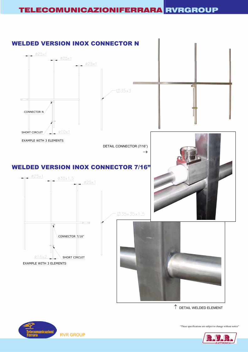
TELECOMUNICAZIONIFERRARA RVRGROUP
CONNECTOR N
SHORT CIRCUIT
EXAMPLE WITH 3 ELEMENTS
WELDED VERSION INOX CONNECTOR N
WELDED VERSION INOX CO
CONNECTOR 7/16"
EXAMPLE WITH 3 ELEMENTS
SHORT CIRCUIT
P
DETAIL CONNECTOR (7/16”)
→
NNECTOR 7/16”
↑ DETAIL WELDED ELEMENT
“These specifications are subject to change without notice”
RVR GROU
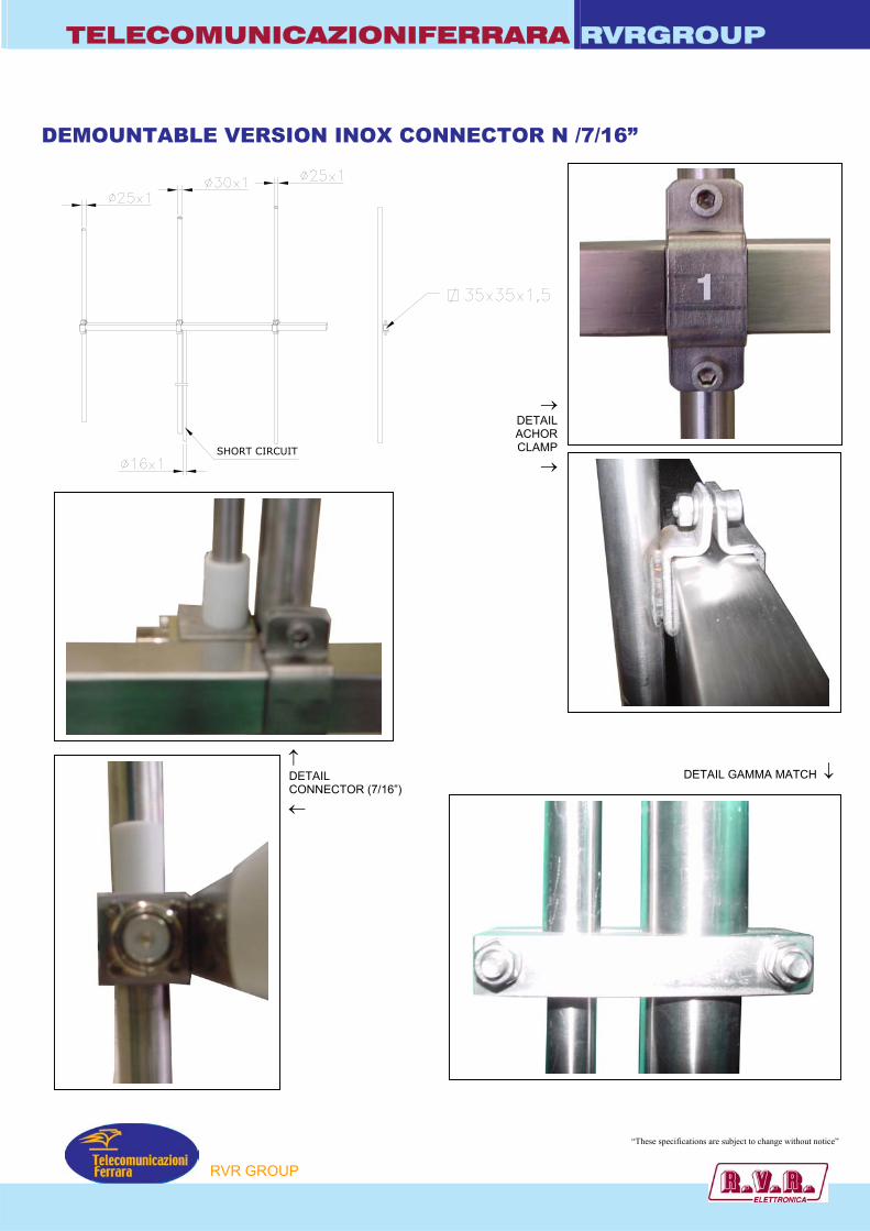
TELECOMUNICAZIONIFERRARA RVRGROUP
DEMOUNTABLE VERSION INOX CONNECTOR N /7/16”
SHORT CIRCUIT
→ DETAILACHORCLAMP
→
DETAIL GAMMA MATCH ↓↑ DETAIL CONNECTOR (7/16”) ←
“These specifications are subject to change without notice”
P
RVR GROU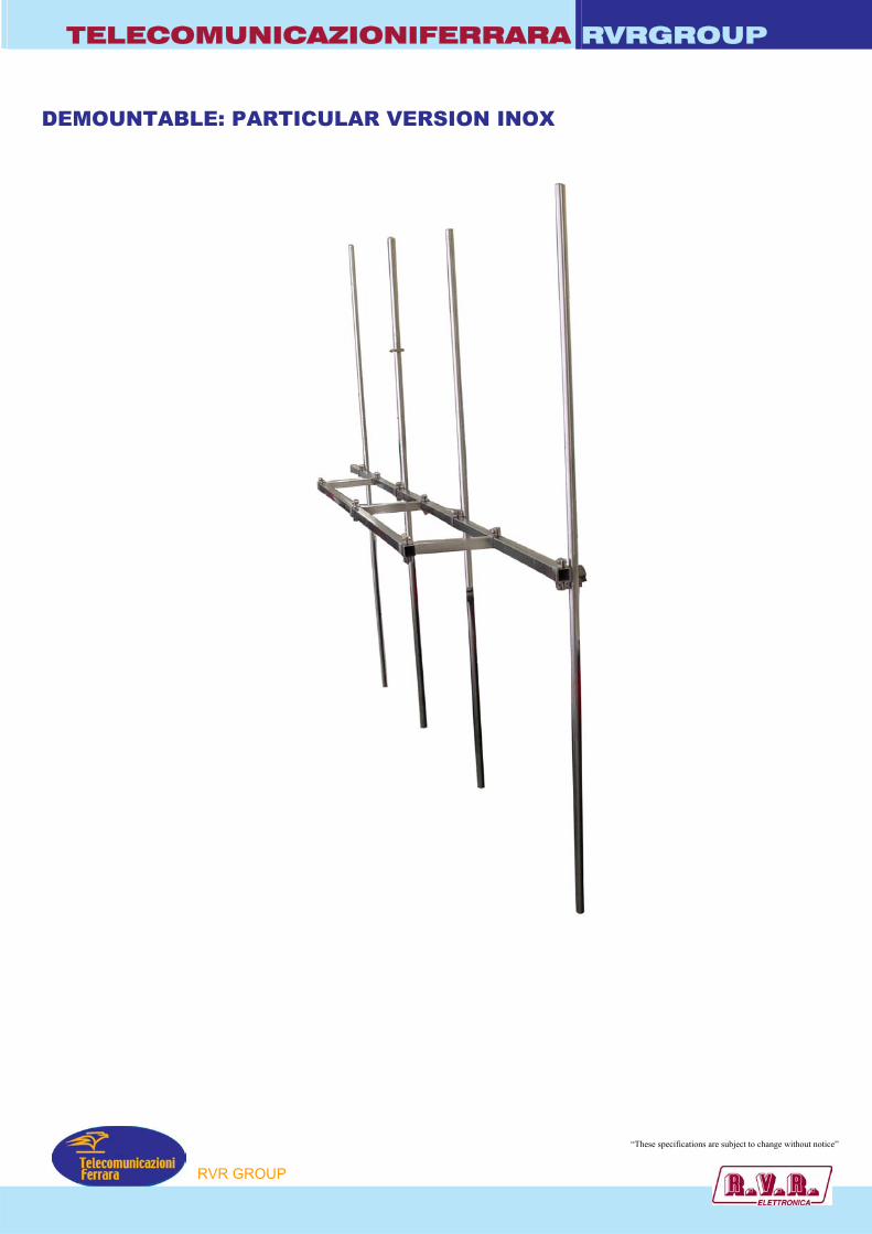
TELECOMUNICAZIONIFERRARA RVRGROUP
DEMOUNTABLE: PARTICULAR VERSION INOX
“These specifications are subject to change without notice”P
RVR GROU
TELECOMUNICAZIONIFERRARA RVRGROUP
OPTION RADOME
4 ELEMENTS
2 ELEMENTS
5 ELEMENTS
DIPOLE
P
3 ELEMENTS
“These specifications are subject to change without notice”
RVR GROU
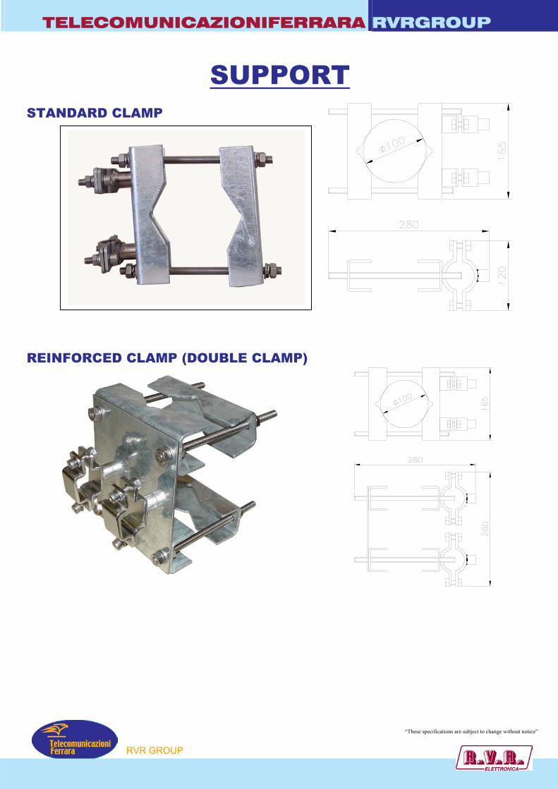
TELECOMUNICAZIONIFERRARA RVRGROUP
SUPPORT
STANDARD CLAMP
REINFORCED CLAMP (DOUBLE CLAMP)
P
“These specifications are subject to change without notice”
RVR GROU

TELECOMUNICAZIONIFERRARA RVRGROUP Model : ACP0H • Band II
• FM Band 87.5÷108 MHz
• Horizontal Polarization
• Omnidirectional Pattern
• Tuned antenna
• No Pressurization Needed
• Economical
• Digital Ready
• Stainless steel AISI 304
ELECTRICAL DATA MECHANICAL DATA
Frequency range 87.5÷108 MHz Dimensions 360x360x100 mm
Impedance 50 Ohm Net Weight 2 Kg without clamp
Wind surface 0.0384 m2 Connectors N female
Wind load 6,5 kg (wind speed at 160 km/h)
Max Power 700W
Max wind velocity 220 km/h.
VSWR ± 100KHz ≤ 1.1:1 Materials External parts: stainless steel, Plexiglas Internal parts: silver plated brass
Polarization Horizontal Gain -0.3 dB (ref.to to half wave dipole)
Mounting With special pipe clamps 50 ÷ 110 mm dia.
Pattern Omnidirectional ±1.5 dB with 100 mm dia. pole
Lightning protection All metal parts DC grounded
Radiations systems with ACP0H antenna
Collinear systems
ELECTRICAL DATA Frequency range 87.5÷108 MHz Impedance 50 Ohm Connector N female VSWR ± 100KHz 1.1:1 in the operating channel Polarization Horizontal Gain Refer to table Horizontal pattern Any type according to requirements Vertical pattern Null fill, beam tilt and special requirements to order Other facilities
The antenna system can be supplied in split feed with two equal half antennas. Each half can accept full power.
MECHANICAL DATA
Height of array Subject to number of bays (refer to table)
Total net weight Refer to table
Wind load Refer to table
Pressurizzable Yes (on request)
Mounting hardware Hot dip galvanized steel clamps
Shipping As required
P
“These specifications are subject to change without notice”
RVR GROU
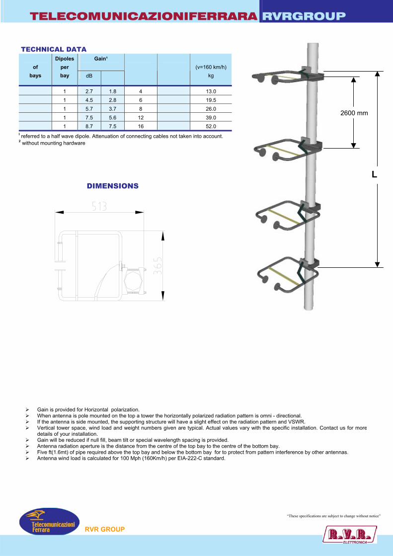
TELECOMUNICAZIONIFERRARA RVRGROUP TECHNICAL DATA
Gain¹
Number of
bays
Dipoles per bay dB times
Weight²
Kg
Antenna height L
m
Wind load (v=160 km/h)
kg
2 1 2.7 1.8 4 2.7 13.0 3 1 4.5 2.8 6 5.3 19.5 4 1 5.7 3.7 8 7.9 26.0 6 1 7.5 5.6 12 13.1 39.0 8 1 8.7 7.5 16 18.3 52.0
L
2600 mm
I referred to a half wave dipole. Attenuation of connecting cables not taken into account. 2 without mounting hardware
Gain is provided forWhen antenna is poIf the antenna is sidVertical tower spacdetails of your instaGain will be reduceAntenna radiation aFive ft(1.6mt) of pipAntenna wind load
DIMENSIONS
Horizontal polarization. le mounted on the top a tower the horizontally polarized radiation pattern is omni - directional. e mounted, the supporting structure will have a slight effect on the radiation pattern and VSWR. e, wind load and weight numbers given are typical. Actual values vary with the specific installation. Contact us for morellation. d if null fill, beam tilt or special wavelength spacing is provided. perture is the distance from the centre of the top bay to the centre of the bottom bay. e required above the top bay and below the bottom bay for to protect from pattern interference by other antennas. is calculated for 100 Mph (160Km/h) per EIA-222-C standard.
“These specifications are subject to change without notice”
P
RVR GROU
TELECOMUNICAZIONIFERRARA RVRGROUP
Model : ACP0 • Band II
• FM Band 87.5÷108 MHz
• Tuned antenna
• True circular polarization
• Stainless steel AISI 304
ELECTRICAL DATA MECHANICAL DATA
Frequency range 87.5÷108 MHz Dimensions 1000x300x800 mm
Impedance 50 Ohm Net Weight 3 Kg without clamp 5.5 Kg with clamp
Connectors N female Wind surface 0.036 m2
Max Power 800W (N female) Wind load 6 kg (wind speed at 160 km/h)
VSWR ± 100KHz ≤ 1.1:1
Max wind velocity 220 km/h.
Polarization Right circular Materials External parts: stainless steel Internal parts: silver plated brass
Gain -3.4 dB Mounting With special pipe clamps 50 ÷ 110 mm dia.
Pattern Omnidirectional ± 1.5 dB in free space Omnidirectional ± 3 dB with 100 mm dia. pole
Lightning protection All metal parts DC grounded
RADIATION PATTERN
(MID BAND)
H-plane
P
DIMENSIONS
“These specifications are subject to change without notice”
RVR GROU
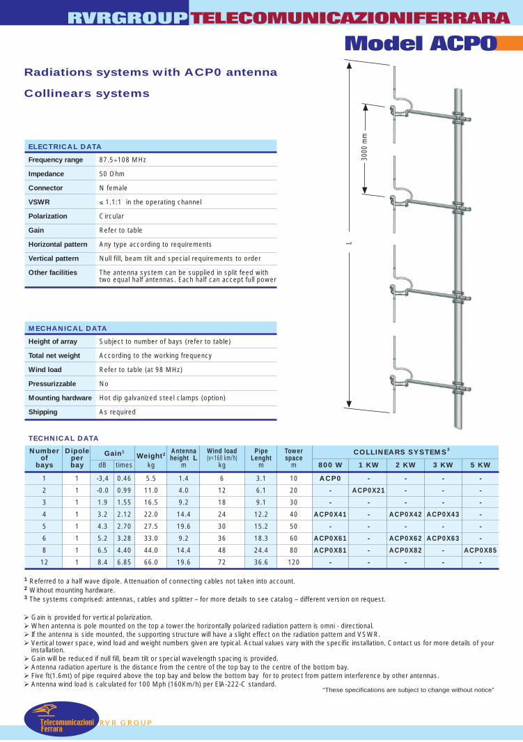
RVR GROUP
Radiations systems with ACP0 antenna
Collinears systems
Gain is provided for vertical polarization. When antenna is pole mounted on the top a tower the horizontally polarized radiation pattern is omni - directional. If the antenna is side mounted, the supporting structure will have a slight effect on the radiation pattern and VSWR. Vertical tower space, wind load and weight numbers given are typical. Actual values vary with the specific installation. Contact us for more details of your
installation. Gain will be reduced if null fill, beam tilt or special wavelength spacing is provided. Antenna radiation aperture is the distance from the centre of the top bay to the centre of the bottom bay. Five ft(1.6mt) of pipe required above the top bay and below the bottom bay for to protect from pattern interference by other antennas. Antenna wind load is calculated for 100 Mph (160Km/h) per EIA-222-C standard.
1 Referred to a half wave dipole. Attenuation of connecting cables not taken into account.2 Without mounting hardware.3 The systems comprised: antennas, cables and splitter – for more details to see catalog – different version on request.
TECHNICAL DATA
RVRGROUPTELECOMUNICAZIONIFERRARA
Model ACP0
Number Dipole Gain1Weight2 Antenna Wind load Pipe Tower COLLINEARS SYSTEMS3
of per height L (v=160 km/h) Lenght spacebays bay dB times kg m kg m m 800 W 1 KW 2 KW 3 KW 5 KW
1 1 -3,4 0.46 5.5 1.4 6 3.1 10 ACP0 - - - -
2 1 -0.0 0.99 11.0 4.0 12 6.1 20 - ACP0X21 - - -
3 1 1.9 1.55 16.5 9.2 18 9.1 30 - - - - -
4 1 3.2 2.12 22.0 14.4 24 12.2 40 ACP0X41 - ACP0X42 ACP0X43 -
5 1 4.3 2.70 27.5 19.6 30 15.2 50 - - - - -
6 1 5.2 3.28 33.0 9.2 36 18.3 60 ACP0X61 - ACP0X62 ACP0X63 -
8 1 6.5 4.40 44.0 14.4 48 24.4 80 ACP0X81 - ACP0X82 - ACP0X85
12 1 8.4 6.85 66.0 19.6 72 36.6 120 - - - - -
ELECTRICAL DATA
Frequency range 87.5÷108 MHz
Impedance 50 Ohm
Connector N female
VSWR ≤ 1.1:1 in the operating channel
Polarization Circular
Gain Refer to table
Horizontal pattern Any type according to requirements
Vertical pattern Null fill, beam tilt and special requirements to order
Other facilities The antenna system can be supplied in split feed withtwo equal half antennas. Each half can accept full power
MECHANICAL DATA
Height of array Subject to number of bays (refer to table)
Total net weight According to the working frequency
Wind load Refer to table (at 98 MHz)
Pressurizzable No
Mounting hardware Hot dip galvanized steel clamps (option)
Shipping As required
TelecomunicazioniFerrara
L
3000
mm
“These specifications are subject to change without notice”
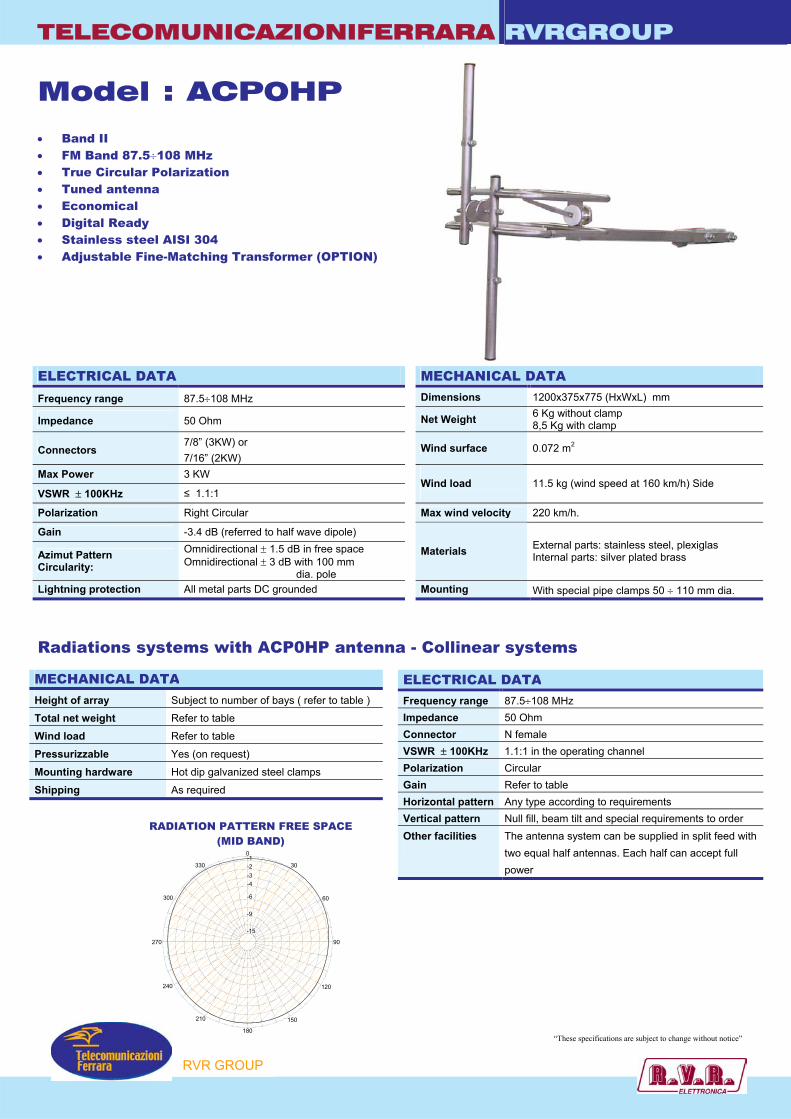
TELECOMUNICAZIONIFERRARA RVRGROUP
Model : ACP0HP • Band II • FM Band 87.5÷108 MHz • True Circular Polarization • Tuned antenna • Economical • Digital Ready • Stainless steel AISI 304 • Adjustable Fine-Matching Transformer (OPTION) ELECTRICAL DATA MECHANICAL DATA
Frequency range 87.5÷108 MHz Dimensions 1200x375x775 (HxWxL) mm
Impedance 50 Ohm Net Weight 6 Kg without clamp 8,5 Kg with clamp
Connectors 7/8” (3KW) or 7/16” (2KW)
Wind surface 0.072 m2
Max Power 3 KW
VSWR ± 100KHz ≤ 1.1:1
Wind load
11.5 kg (wind speed at 160 km/h) Side
Polarization Right Circular Max wind velocity 220 km/h.
Gain -3.4 dB (referred to half wave dipole)
Azimut Pattern Circularity:
Omnidirectional ± 1.5 dB in free space Omnidirectional ± 3 dB with 100 mm dia. pole
Materials External parts: stainless steel, plexiglas Internal parts: silver plated brass
Lightning protection All metal parts DC grounded Mounting With special pipe clamps 50 ÷ 110 mm dia.
Radiations systems with ACP0HP antenna - Collinear systems
ELECTRICAL DATA Frequency range 87.5÷108 MHz Impedance 50 Ohm Connector N female VSWR ± 100KHz 1.1:1 in the operating channel Polarization Circular Gain Refer to table Horizontal pattern Any type according to requirements Vertical pattern Null fill, beam tilt and special requirements to order Other facilities
The antenna system can be supplied in split feed with two equal half antennas. Each half can accept full power
RADIATION PATTERN FREE SPACE (MID BAND)
0
30
60
90
120
150
180
210
240
270
300
330
-9
-6
-15
-4-3-2-1
P
MECHANICAL DATA Height of array Subject to number of bays ( refer to table )
Total net weight Refer to table
Wind load Refer to table
Pressurizzable Yes (on request)
Mounting hardware Hot dip galvanized steel clamps
Shipping As required
“These specifications are subject to change without notice”
RVR GROU
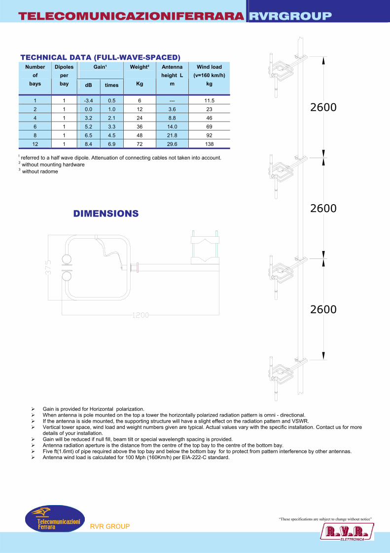
TELECOMUNICAZIONIFERRARA RVRGROUP
2600
2600
2600
TECHNICAL DATA (FULL-WAVE-SPACED)
Gain¹
Number of
bays
Dipoles per bay dB times
Weight²
Kg
Antenna height L
m
Wind load (v=160 km/h)
kg
1 1 -3.4 0.5 6 --- 11.5 2 1 0.0 1.0 12 3.6 23 4 1 3.2 2.1 24 8.8 46 6 1 5.2 3.3 36 14.0 69 8 1 6.5 4.5 48 21.8 92
12 1 8.4 6.9 72 29.6 138
I referred to a half wave dipole. Attenuation of connecting cables not taken into account. 2 without mounting hardware 3 without radome
DIMENSIONS
Gain is provided for Horizontal polarization. When antenna is pole mounted on the top a tower the horizontally polarized radiation pattern is omni - directional. If the antenna is side mounted, the supporting structure will have a slight effect on the radiation pattern and VSWR. Vertical tower space, wind load and weight numbers given are typical. Actual values vary with the specific installation. Contact us for more
details of your installation. Gain will be reduced if null fill, beam tilt or special wavelength spacing is provided. Antenna radiation aperture is the distance from the centre of the top bay to the centre of the bottom bay. Five ft(1.6mt) of pipe required above the top bay and below the bottom bay for to protect from pattern interference by other antennas. Antenna wind load is calculated for 100 Mph (160Km/h) per EIA-222-C standard.
RVR GROUP
“These specifications ar ubject to change without notice”
e s

TelecomunicazioniFerrara
TELECOMUNICAZIONIFERRARA
RVR GROUP
RVRGROUP
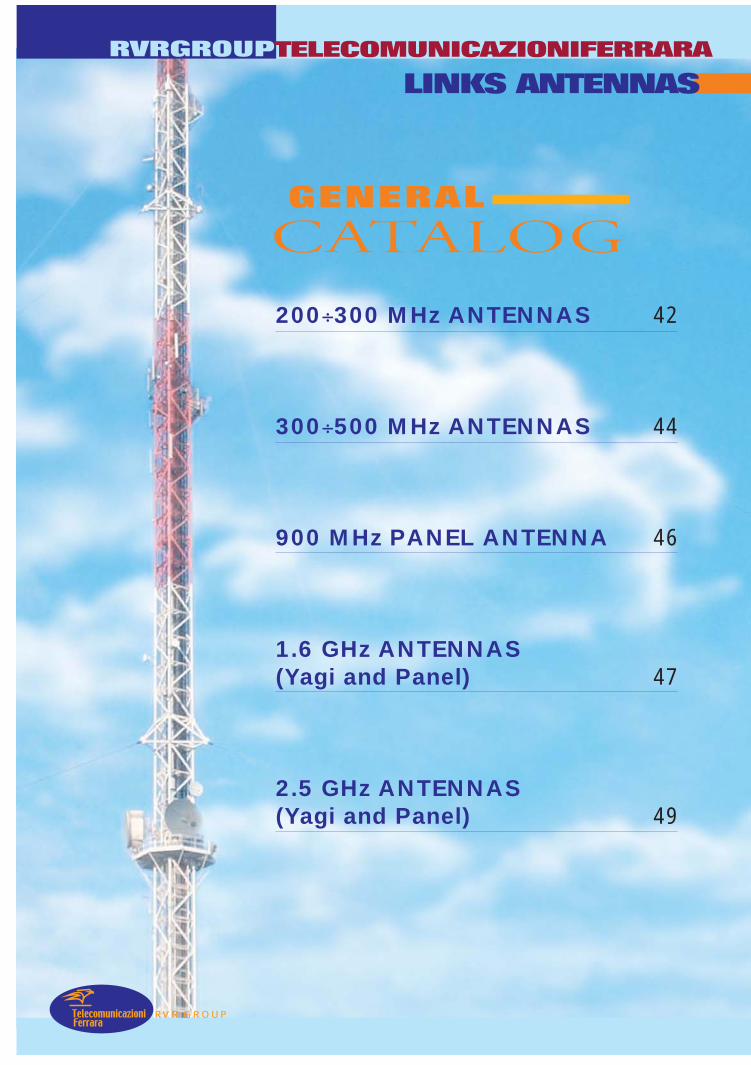
RVR GROUP
RVRGROUP
LINKS ANTENNAS
TelecomunicazioniFerrara
200÷300 MHz ANTENNAS 42
300÷500 MHz ANTENNAS 44
900 MHz PANEL ANTENNA 46
1.6 GHz ANTENNAS(Yagi and Panel) 47
2.5 GHz ANTENNAS(Yagi and Panel) 49
CATALOGGENERAL
TELECOMUNICAZIONIFERRARA

TelecomunicazioniFerrara
Model AR102 – AR102I – AR102ISTELECOMUNICAZIONIFERRARA
RVR GROUP
RVRGROUP
• Yagi Antenna
• 200÷300 MHz
• Gamma Match Tuned
• Vertical or Horizontalpolarization
• Directional Pattern
RADIATION PATTERN (MID BAND)
Gain is provided for vertical polarization. If the antenna is side mounted, the supporting structure will have a slight effect on the radiation pattern and VSWR. Actual values vary with the specific installation. Contact us for more details of your installation. Five ft(1.6mt) of pipe required above the top bay and below the bottom bay for to protect from pattern interference by other antennas. Antenna wind load is calculated for 100 Mph (160Km/h) per EIA-222-C standard.
ELECTRICAL DATA
Frequency range 200÷300 MHz
Impedance 50 Ohm
Connectors N
Max Power 300W (N)
VSWR ≤ 1.1:1 in the working frequency
Polarization Horizontal or Vertical
Gain 12 dB (referred to half-wave dipole)
Pattern E plane ± 20°H plane ± 22°
E-Plane H-Plane
MECHANICAL DATA
Dimensions According to the working frequency(2400 x 590 x 50 mm at 250 MHz)
Weight According to the working frequency andmaterial used (aluminium or stainless steel)
Wind surface 0.17 m2 (at 250 MHz)
Wind load 22 kg (wind speed at 160 km/h)
Max wind velocity 120 km/h (AR102I / AR102IS)
AR102: Aluminium elements and stainless steel boomAR102I: Stainless steel elements and boom
Materials AR102IS: Stainless steel elements and boom Tig Welded
Teflon insulator
Mounting With special pipe clamps 50÷110 mm dia.
180
0
270 90
-1330
300
240
210 150
120
60
30
-2-3-4
-6
-9
-15
180
0
270 90
-1330
300
240
210 150
120
60
30
-2-3-4
-6
-9
-15
“These specifications are subject to change without notice”
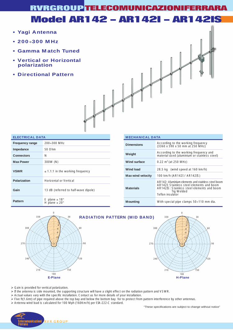
• Yagi Antenna
• 200÷300 MHz
• Gamma Match Tuned
• Vertical or Horizontalpolarization
• Directional Pattern
RADIATION PATTERN (MID BAND)
Gain is provided for vertical polarization. If the antenna is side mounted, the supporting structure will have a slight effect on the radiation pattern and VSWR. Actual values vary with the specific installation. Contact us for more details of your installation. Five ft(1.6mt) of pipe required above the top bay and below the bottom bay for to protect from pattern interference by other antennas. Antenna wind load is calculated for 100 Mph (160Km/h) per EIA-222-C standard.
ELECTRICAL DATA
Frequency range 200÷300 MHz
Impedance 50 Ohm
Connectors N
Max Power 300W (N)
VSWR ≤ 1.1:1 in the working frequency
Polarization Horizontal or Vertical
Gain 13 dB (referred to half-wave dipole)
Pattern E plane ± 18°H plane ± 20°
E-Plane H-Plane
MECHANICAL DATA
Dimensions According to the working frequency(3360 x 590 x 50 mm at 250 MHz)
Weight According to the working frequency andmaterial used (aluminium or stainless steel)
Wind surface 0.22 m2 (at 250 MHz)
Wind load 28.5 kg (wind speed at 160 km/h)
Max wind velocity 100 km/h (AR142I / AR142IS)
AR142: Aluminium elements and stainless steel boomAR142I: Stainless steel elements and boom
Materials AR142IS: Stainless steel elements and boom Tig Welded
Teflon insulator
Mounting With special pipe clamps 50÷110 mm dia.
RVR GROUP
RVRGROUPTELECOMUNICAZIONIFERRARA
Model AR142 – AR142I – AR142IS
TelecomunicazioniFerrara
180
0
270 90
-1330
300
240
210 150
120
60
30
-2-3-4
-6
-9
-15
180
0
270 90
-1330
300
240
210 150
120
60
30
-2-3-4
-6
-9
-15
“These specifications are subject to change without notice”
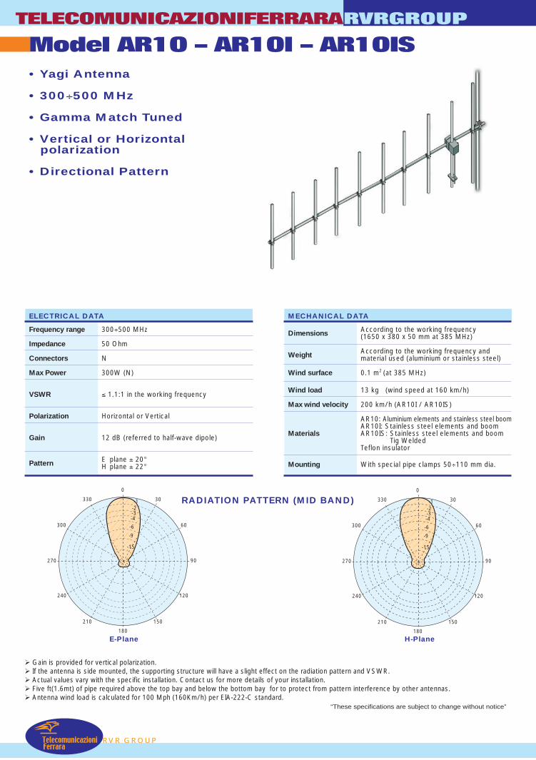
TelecomunicazioniFerrara
Model AR10 – AR10I – AR10ISTELECOMUNICAZIONIFERRARA
RVR GROUP
RVRGROUP
• Yagi Antenna
• 300÷500 MHz
• Gamma Match Tuned
• Vertical or Horizontalpolarization
• Directional Pattern
RADIATION PATTERN (MID BAND)
Gain is provided for vertical polarization. If the antenna is side mounted, the supporting structure will have a slight effect on the radiation pattern and VSWR. Actual values vary with the specific installation. Contact us for more details of your installation. Five ft(1.6mt) of pipe required above the top bay and below the bottom bay for to protect from pattern interference by other antennas. Antenna wind load is calculated for 100 Mph (160Km/h) per EIA-222-C standard.
ELECTRICAL DATA
Frequency range 300÷500 MHz
Impedance 50 Ohm
Connectors N
Max Power 300W (N)
VSWR ≤ 1.1:1 in the working frequency
Polarization Horizontal or Vertical
Gain 12 dB (referred to half-wave dipole)
Pattern E plane ± 20°H plane ± 22°
E-Plane H-Plane
MECHANICAL DATA
Dimensions According to the working frequency(1650 x 380 x 50 mm at 385 MHz)
Weight According to the working frequency andmaterial used (aluminium or stainless steel)
Wind surface 0.1 m2 (at 385 MHz)
Wind load 13 kg (wind speed at 160 km/h)
Max wind velocity 200 km/h (AR10I / AR10IS)
AR10: Aluminium elements and stainless steel boomAR10I: Stainless steel elements and boom
Materials AR10IS: Stainless steel elements and boom Tig Welded
Teflon insulator
Mounting With special pipe clamps 50÷110 mm dia.
180
0
270 90
-1330
300
240
210 150
120
60
30
-2-3-4
-6
-9
-15
180
0
270 90
-1330
300
240
210 150
120
60
30
-2-3-4
-6
-9
-15
“These specifications are subject to change without notice”

• Yagi Antenna
• 200÷300 MHz
• Gamma Match Tuned
• Vertical or Horizontalpolarization
• Directional Pattern
RADIATION PATTERN (MID BAND)
Gain is provided for vertical polarization. If the antenna is side mounted, the supporting structure will have a slight effect on the radiation pattern and VSWR. Actual values vary with the specific installation. Contact us for more details of your installation. Five ft(1.6mt) of pipe required above the top bay and below the bottom bay for to protect from pattern interference by other antennas. Antenna wind load is calculated for 100 Mph (160Km/h) per EIA-222-C standard.
ELECTRICAL DATA
Frequency range 300÷500 MHz
Impedance 50 Ohm
Connectors N
Max Power 300W (N)
VSWR ≤ 1.1:1 in the working frequency
Polarization Horizontal or Vertical
Gain 13 dB (referred to half-wave dipole)
Pattern E plane ± 18°H plane ± 20°
E-Plane H-Plane
MECHANICAL DATA
Dimensions According to the working frequency(2270 x 380 x 50 mm at 385 MHz)
Weight According to the working frequency andmaterial used (aluminium or stainless steel)
Wind surface 0.13 m2 (at 385 MHz)
Wind load 17 kg (wind speed at 160 km/h)
Max wind velocity 200 km/h (AR14I / AR14IS)
AR14: Aluminium elements and stainless steel boomAR14I: Stainless steel elements and boom
Materials AR14IS: Stainless steel elements and boom Tig Welded
Teflon insulator
Mounting With special pipe clamps 50÷110 mm dia.
RVR GROUP
RVRGROUPTELECOMUNICAZIONIFERRARA
Model AR14 – AR14I – AR14IS
TelecomunicazioniFerrara
180
0
270 90
-1330
300
240
210 150
120
60
30
-2-3-4
-6
-9
-15
180
0
270 90
-1330
300
240
210 150
120
60
30
-2-3-4
-6
-9
-15
“These specifications are subject to change without notice”

TelecomunicazioniFerrara
Model PA90TELECOMUNICAZIONIFERRARA
RVR GROUP
RVRGROUP
• Link Panel Antenna
• 870÷960 MHz
• Vertical or Horizontalpolarization
• Directional Pattern
RADIATION PATTERN (MID BAND)
Gain is provided for vertical polarization. If the antenna is side mounted, the supporting structure will have a slight effect on the radiation pattern and VSWR. Actual values vary with the specific installation. Contact us for more details of your installation. Antenna wind load is calculated for 100 Mph (160Km/h) per EIA-222-C standard.
ELECTRICAL DATA
Frequency range 870÷960 MHz
Impedance 50 Ohm
Connectors N
Max Power 100W (N)
VSWR ≤ 1.5:1
Polarization Horizontal or Vertical
Gain 12.5 dB (referred to half-wave dipole)
Half power E plane ± 15°beam width H plane ± 13°
Lightning protection All metal parts DC grounded
E-Plane H-Plane
MECHANICAL DATA
Dimensions 600 x 600 x 130 mm
Weight 3 Kg
Wind surface 0.3 m2
Wind load 45 kg (wind speed at 160 km/h)
Max wind velocity 200 km/h
Internal parts: passivated aluminium, brassMaterials Clamp: hot dip galvanized steel
Radome: PST
Icing protection Radome
Radome color White
Mounting With special pipe clamps 50÷110 mm dia.
180
0
270 90
330
300
240
210 150
120
60
30
-3-10-20 dB
180
0
270 90
330
300
240
210 150
120
60
30
-3-10-20dB
“These specifications are subject to change without notice”

• Yagi Link Antenna
• 1.6 GHz
• Vertical or Horizontalpolarization
• Directional Pattern
RADIATION PATTERN (MID BAND)
E-Plane H-Plane
RVR GROUP
RVRGROUPTELECOMUNICAZIONIFERRARA
Model AR16
TelecomunicazioniFerrara
ELECTRICAL DATA
Frequency range 1635÷1735 MHz
Impedance 50 Ohm
Connectors N
Max Power 100W (N)
VSWR ≤ 1.5:1
Polarization Horizontal or Vertical
Gain 12.5 dB (referred to half-wave dipole)
Half power E plane ± 13°beam width H plane ± 15°
Lightning protection All metal parts DC grounded
MECHANICAL DATA
Dimensions 565 x 160 x 160 mm
Weight 2.4 Kg
Wind surface 0.1 m2
Wind load 13.5 kg (wind speed at 160 km/h)
Max wind velocity 200 km/h
Internal parts: passivated aluminium, brassMaterials Clamp: hot dip galvanized steel
Radome: Plastic
Icing protection Radome
Radome color White
Mounting With special pipe clamps 50÷110 mm dia.
Gain is provided for vertical polarization. If the antenna is side mounted, the supporting structure will have a slight effect on the radiation pattern and VSWR. Actual values vary with the specific installation. Contact us for more details of your installation. Antenna wind load is calculated for 100 Mph (160Km/h) per EIA-222-C standard.
180
0
270 90
330
300
240
210 150
120
60
30
-3-10-20 dB
180
0
270 90
330
300
240
210 150
120
60
30
-3-10-20dB
“These specifications are subject to change without notice”

TelecomunicazioniFerrara
Model PA16TELECOMUNICAZIONIFERRARA
RVR GROUP
RVRGROUP
• Link Panel Antenna
• 1.6 GHz
• Vertical or Horizontalpolarization
• Directional Pattern
RADIATION PATTERN (MID BAND)
Gain is provided for vertical polarization. If the antenna is side mounted, the supporting structure will have a slight effect on the radiation pattern and VSWR. Actual values vary with the specific installation. Contact us for more details of your installation. Antenna wind load is calculated for 100 Mph (160Km/h) per EIA-222-C standard.
ELECTRICAL DATA
Frequency range 1630÷1740 MHz
Impedance 50 Ohm
Connectors N
Max Power 100W (N)
VSWR ≤ 1.5:1
Polarization Horizontal or Vertical
Gain 15 dB (referred to half-wave dipole)
Half power E plane ± 10°beam width H plane ± 10°
Lightning protection All metal parts DC grounded
E-Plane H-Plane
MECHANICAL DATA
Dimensions 485 x 485 x 80 mm
Weight 3 Kg
Wind surface 0.23 m2
Wind load 45 kg (wind speed at 160 km/h)
Max wind velocity 200 km/h
Internal parts: passivated aluminium, brassMaterials Clamp: hot dip galvanized steel
Radome: PST
Icing protection Radome
Radome color White
Mounting With special pipe clamps 50÷110 mm dia.
180
0
270 90
330
300
240
210 150
120
60
30
-3-10-20 dB
180
0
270 90
330
300
240
210 150
120
60
30
-3-10-20dB
“These specifications are subject to change without notice”
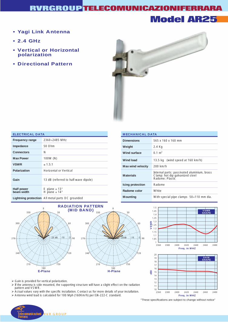
• Yagi Link Antenna
• 2.4 GHz
• Vertical or Horizontalpolarization
• Directional Pattern
RADIATION PATTERN(MID BAND)
E-Plane H-Plane
RVR GROUP
RVRGROUPTELECOMUNICAZIONIFERRARA
Model AR25
TelecomunicazioniFerrara
ELECTRICAL DATA
Frequency range 2360÷2485 MHz
Impedance 50 Ohm
Connectors N
Max Power 100W (N)
VSWR ≤ 1.5:1
Polarization Horizontal or Vertical
Gain 13 dB (referred to half-wave dipole)
Half power E plane ± 13°beam width H plane ± 14°
Lightning protection All metal parts DC grounded
MECHANICAL DATA
Dimensions 565 x 160 x 160 mm
Weight 2.4 Kg
Wind surface 0.1 m2
Wind load 13.5 kg (wind speed at 160 km/h)
Max wind velocity 200 km/h
Internal parts: passivated aluminium, brassMaterials Clamp: hot dip galvanized steel
Radome: Plastic
Icing protection Radome
Radome color White
Mounting With special pipe clamps 50÷110 mm dia.
Gain is provided for vertical polarization. If the antenna is side mounted, the supporting structure will have a slight effect on the radiation
pattern and VSWR. Actual values vary with the specific installation. Contact us for more details of your installation. Antenna wind load is calculated for 100 Mph (160Km/h) per EIA-222-C standard.
180
0
270 90
330
300
240
210 150
120
60
30
-3-10-20 dB
180
0
270 90
330
300
240
210 150
120
60
30
-3-10-20dB
“These specifications are subject to change without notice”
Freq. in MHZ
1.5
1.45
1.4
1,35
1,3
1.25
1.2
1.15
1.1
1.05
12360 2380 2400 2420 2440 2460 2480
VS
WR
Freq. in MHZ
20
19
18
17
16
15
14
13
12
11
102360 2380 2400 2420 2440 2460 2480
dB
I
VSWRSHAPE
GAINSHAPE
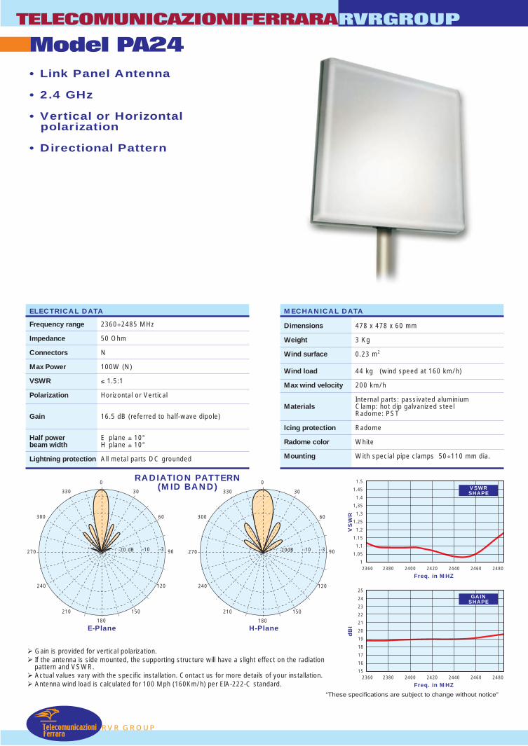
RADIATION PATTERN(MID BAND)
E-Plane H-Plane
TelecomunicazioniFerrara
Model PA24TELECOMUNICAZIONIFERRARA
RVR GROUP
RVRGROUP
• Link Panel Antenna
• 2.4 GHz
• Vertical or Horizontalpolarization
• Directional Pattern
ELECTRICAL DATA
Frequency range 2360÷2485 MHz
Impedance 50 Ohm
Connectors N
Max Power 100W (N)
VSWR ≤ 1.5:1
Polarization Horizontal or Vertical
Gain 16.5 dB (referred to half-wave dipole)
Half power E plane ± 10°beam width H plane ± 10°
Lightning protection All metal parts DC grounded
MECHANICAL DATA
Dimensions 478 x 478 x 60 mm
Weight 3 Kg
Wind surface 0.23 m2
Wind load 44 kg (wind speed at 160 km/h)
Max wind velocity 200 km/h
Internal parts: passivated aluminiumMaterials Clamp: hot dip galvanized steel
Radome: PST
Icing protection Radome
Radome color White
Mounting With special pipe clamps 50÷110 mm dia.
Gain is provided for vertical polarization. If the antenna is side mounted, the supporting structure will have a slight effect on the radiation
pattern and VSWR. Actual values vary with the specific installation. Contact us for more details of your installation. Antenna wind load is calculated for 100 Mph (160Km/h) per EIA-222-C standard.
180
0
270 90
330
300
240
210 150
120
60
30
-3-10-20 dB
180
0
270 90
330
300
240
210 150
120
60
30
-3-10-20dB
“These specifications are subject to change without notice”
Freq. in MHZ
1.5
1.45
1.4
1,35
1,3
1.25
1.2
1.15
1.1
1.05
12360 2380 2400 2420 2440 2460 2480
VS
WR
Freq. in MHZ
25
24
23
22
21
20
19
18
17
16
152360 2380 2400 2420 2440 2460 2480
dB
I
VSWRSHAPE
GAINSHAPE
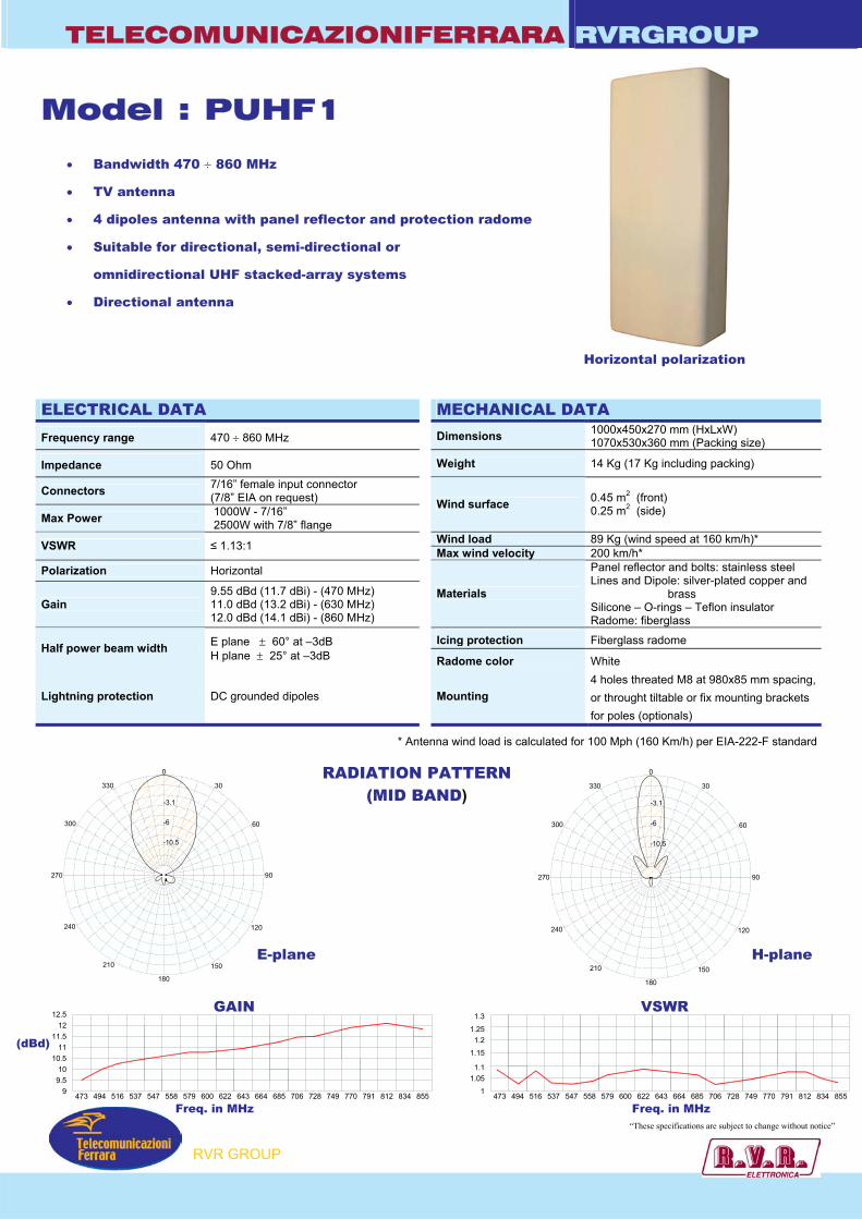
TELECOMUNICAZIONIFERRARA RVRGROUP
0
30
60
90
120
150
180
210
240
270
300
330
-10.5
-6
-3.1
473 494 516 537 547 558 579 600 622 643 664 685 706 728 749 770 791 812 834 85599.510
10.511
11.512
12.5
473 494 516 537 547 558 579 600 622 643 664 685 706 728 749 770 791 812 834 8551
1.051.1
1.15
1.21.25
1.3
Model : PUHF1
• Bandwidth 470 ÷ 860 MHz
• TV antenna
• 4 dipoles antenna with panel reflector and protection radome
• Suitable for directional, semi-directional or
omnidirectional UHF stacked-array systems
• Directional antenna
ELECTRICAL DATA MECHANICAL DATA
Frequency range 470 ÷ 860 MHz Dimensions 1000x450x270 mm (HxLxW) 1070x530x360 mm (Packing size)
Impedance 50 Ohm Weight 14 Kg (17 Kg including packing)
Connectors 7/16” female input connector (7/8” EIA on request)
Max Power 1000W - 7/16” 2500W with 7/8” flange
Wind surface 0.45 m2 (front) 0.25 m2 (side)
Wind load 89 Kg (wind speed at 160 km/h)* VSWR ≤ 1.13:1 Max wind velocity 200 km/h* Polarization Horizontal
Gain 9.55 dBd (11.7 dBi) - (470 MHz) 11.0 dBd (13.2 dBi) - (630 MHz) 12.0 dBd (14.1 dBi) - (860 MHz)
Materials
Panel reflector and bolts: stainless steel Lines and Dipole: silver-plated copper and
brass Silicone – O-rings – Teflon insulator Radome: fiberglass
Icing protection Fiberglass radome Half power beam width E plane ± 60° at –3dB
H plane ± 25° at –3dB Radome color White
Lightning protection DC grounded dipoles Mounting 4 holes threated M8 at 980x85 mm spacing, or throught tiltable or fix mounting brackets for poles (optionals)
RADIATION PATTERN (MID BAND)
* Antenna wind load is calculated for 100 Mph (160 Km/h) per EIA-222-F standard
Horizontal polarization
E-plane H-plane
0
30
60
90
120
150
180
210
240
270
300
330
-10.5
-6
-3.1
RVR GROUP
“These specifications are subject to change without notice”
GAIN VSWR
Freq. in MHz Freq. in MHz
(dBd)
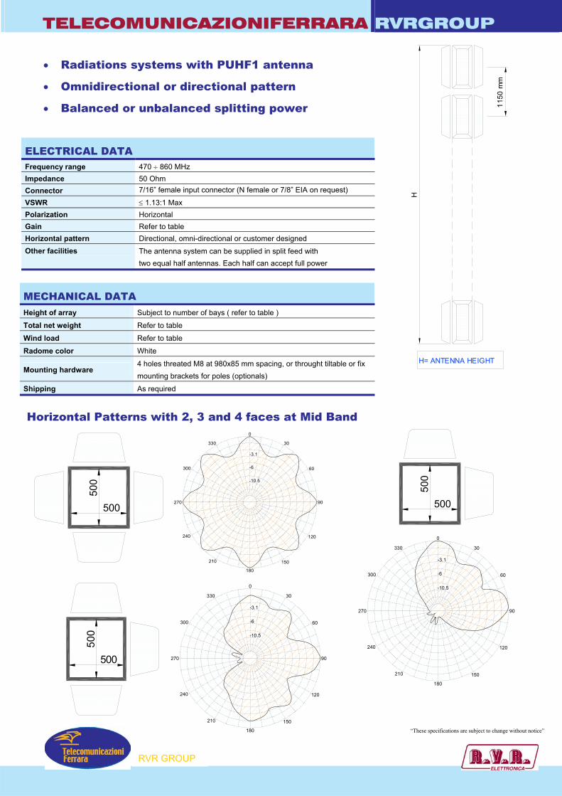
TELECOMUNICAZIONIFERRARA RVRGROUP
0
30
60
90
120
150
180
210
240
270
300
330
-10.5
-6
-3.1
0
30
60
90
120
150
180
210
240
270
300
330
-10.5
-6
-3.1
H= ANTENNA HEIGHT
1150
mm
H
• Radiations systems with PUHF1 antenna
• Omnidirectional or directional pattern
• Balanced or unbalanced splitting power
ELECTRICAL DATA Frequency range 470 ÷ 860 MHz Impedance 50 Ohm Connector 7/16” female input connector (N female or 7/8” EIA on request)
VSWR ≤ 1.13:1 Max Polarization Horizontal Gain Refer to table Horizontal pattern Directional, omni-directional or customer designed Other facilities
The antenna system can be supplied in split feed with two equal half antennas. Each half can accept full power
MECHANICAL DATA Height of array Subject to number of bays ( refer to table )
Total net weight Refer to table
Wind load Refer to table
Radome color White
Mounting hardware 4 holes threated M8 at 980x85 mm spacing, or throught tiltable or fix mounting brackets for poles (optionals)
Shipping As required
Horizontal Patterns with 2, 3 and 4 faces at Mid Band
500
500
500
500
500
500
RVR GROUP
“These specifications are subject to change without notice”
0
30
60
90
120
150
180
210
240
270
300
330
-10.5
-6
-3.1
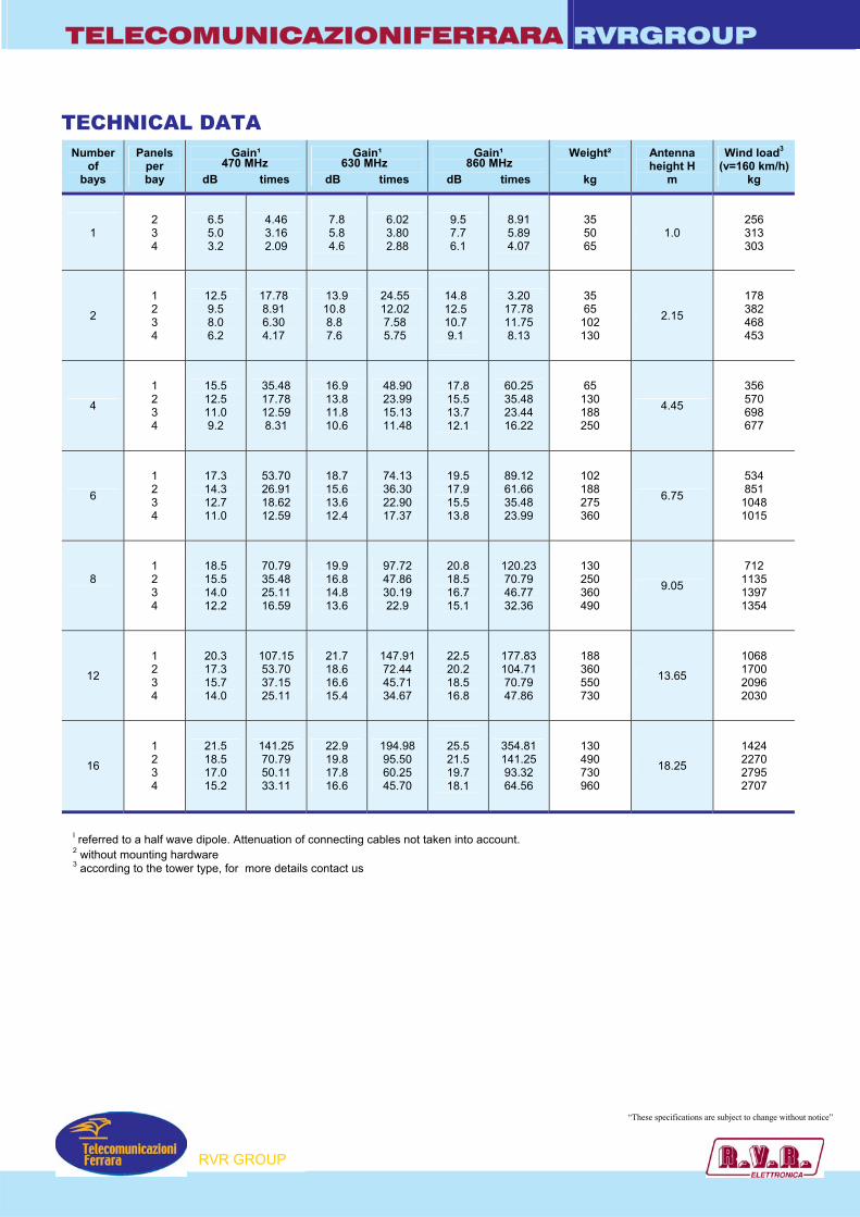
TELECOMUNICAZIONIFERRARA RVRGROUP
TECHNICAL DATA
Number of
bays
Panels per bay
Gain¹
dB times
Gain¹
dB times
Gain¹
dB times
Weight²
kg
Antenna height H
m
Wind load3
(v=160 km/h)kg
1
2 3 4
6.5 5.0 3.2
4.46 3.16 2.09
7.8 5.8 4.6
6.02 3.80 2.88
9.5 7.7 6.1
8.91 5.89 4.07
35 50 65
1.0 256 313 303
2
1 2 3 4
12.5 9.5 8.0 6.2
17.78 8.91 6.30 4.17
13.9 10.8 8.8 7.6
24.55 12.02 7.58 5.75
14.8 12.5 10.7 9.1
3.20 17.78 11.75 8.13
35 65
102 130
2.15
178 382 468 453
4
1 2 3 4
15.5 12.5 11.0 9.2
35.48 17.78 12.59 8.31
16.9 13.8 11.8 10.6
48.90 23.99 15.13 11.48
17.8 15.5 13.7 12.1
60.25 35.48 23.44 16.22
65 130 188 250
4.45
356 570 698 677
6
1 2 3 4
17.3 14.3 12.7 11.0
53.70 26.91 18.62 12.59
18.7 15.6 13.6 12.4
74.13 36.30 22.90 17.37
19.5 17.9 15.5 13.8
89.12 61.66 35.48 23.99
102 188 275 360
6.75
534 851
1048 1015
8
1 2 3 4
18.5 15.5 14.0 12.2
70.79 35.48 25.11 16.59
19.9 16.8 14.8 13.6
97.72 47.86 30.19 22.9
20.8 18.5 16.7 15.1
120.23 70.79 46.77 32.36
130 250 360 490
9.05
712 1135 1397 1354
12
1 2 3 4
20.3 17.3 15.7 14.0
107.15 53.70 37.15 25.11
21.7 18.6 16.6 15.4
147.91 72.44 45.71 34.67
22.5 20.2 18.5 16.8
177.83 104.71 70.79 47.86
188 360 550 730
13.65
1068 1700 2096 2030
16
1 2 3 4
21.5 18.5 17.0 15.2
141.25 70.79 50.11 33.11
22.9 19.8 17.8 16.6
194.98 95.50 60.25 45.70
25.5 21.5 19.7 18.1
354.81 141.25 93.32 64.56
130 490 730 960
18.25
1424 2270 2795 2707
470 MHz 630 MHz 860 MHz
I referred to a half wave dipole. Attenuation of connecting cables not taken into account. 2 without mounting hardware 3 according to the tower type, for more details contact us
RVR GROUP
“These specifications are subject to change without notice”
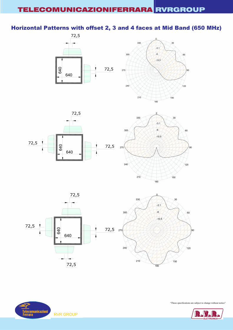
TELECOMUNICAZIONIFERRARA RVRGROUP
0
30
60
90
120
150
180
210
240
270
300
330
-10.5
-6
-3.1
0
30
60
90
120
150
180
210
240
270
300
330
-10.5
-6
-3.1
0
30
60
90
120
150
180
210
240
270
300
330
-10.5
-6
-3.1
640
640
72,5
72,5
640
640
72,5
72,572,5
72,5
640
640
72,5
72,572,5
Horizontal Patterns with offset 2, 3 and 4 faces at Mid Band (650 MHz)
RVR GROUP
“These specifications are subject to change without notice”
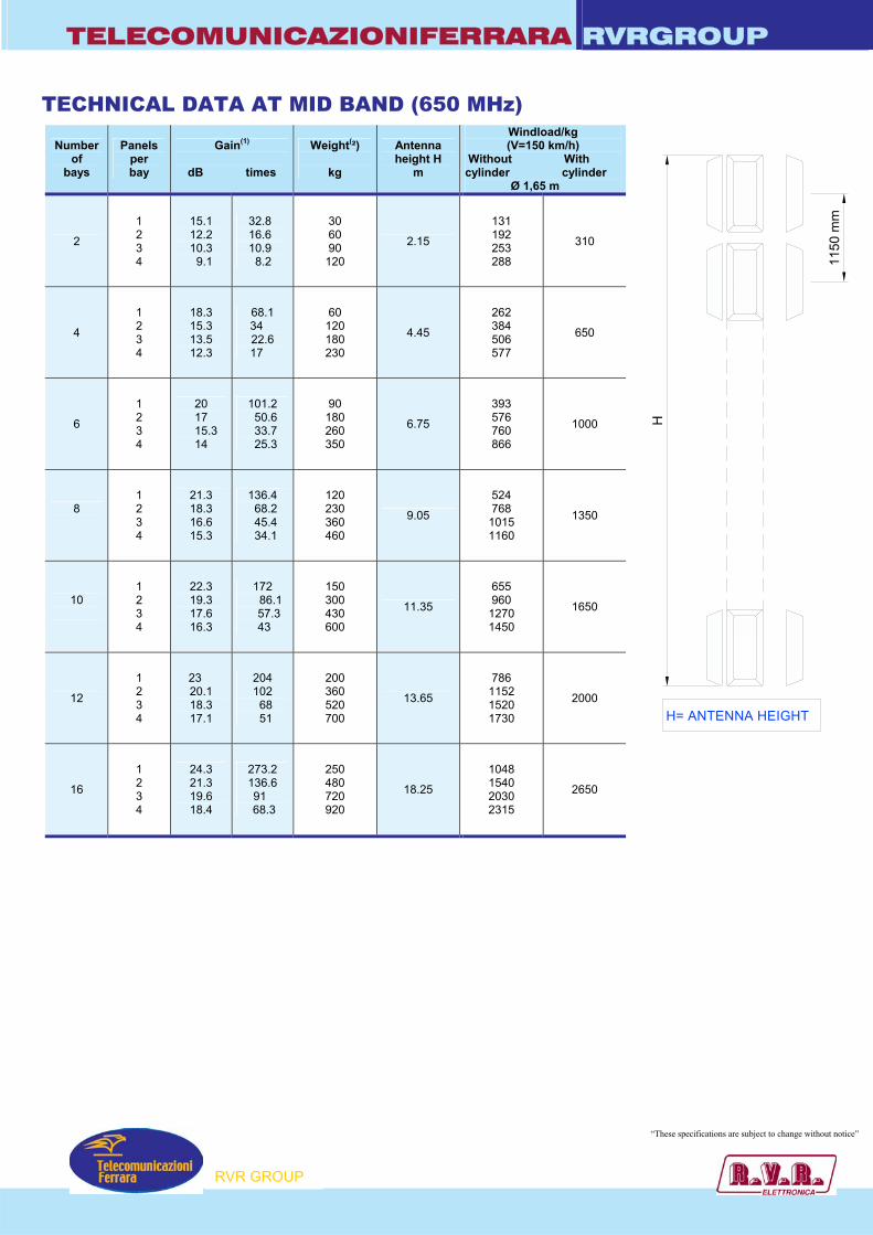
TELECOMUNICAZIONIFERRARA RVRGROUP
TECHNICAL DATA AT MID BAND (650 MHz)
Number of
bays
Panels per bay
Gain(1)
dB times
Weight(²)
kg
Antenna height H
m
Windload/kg(V=150 km/h)
Without With cylinder cylinder Ø 1,65 m
2
1 2 3 4
15.1 12.2 10.3 9.1
32.8 16.6 10.9 8.2
30 60 90
120
2.15
131 192 253 288
310
4
1 2 3 4
18.3 15.3 13.5 12.3
68.1 34
22.6 17
60 120 180 230
4.45
262 384 506 577
650
6
1 2 3 4
20 17
15.3 14
101.2 50.6 33.7 25.3
90 180 260 350
6.75
393 576 760 866
1000
8
1 2 3 4
21.3 18.3 16.6 15.3
136.4 68.2 45.4 34.1
120 230 360 460
9.05
524 768
1015 1160
1350
10
1 2 3 4
22.3 19.3 17.6 16.3
172 86.1 57.3
43
150 300 430 600
11.35
655 960
1270 1450
1650
12
1 2 3 4
23 20.1 18.3 17.1
204 102 68 51
200 360 520 700
13.65
786 1152 1520 1730
2000
16
1 2 3 4
24.3 21.3 19.6 18.4
273.2 136.6
91 68.3
250 480 720 920
18.25
1048 1540 2030 2315
2650
RVR GROUP
“These specifications are subject to change without notice”
H= ANTENNA HEIGHT
1150
mm
H
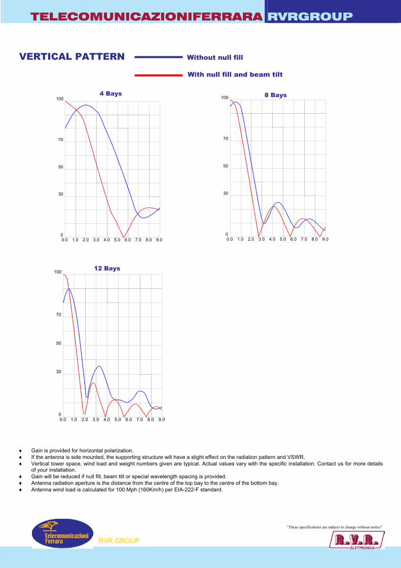
TELECOMUNICAZIONIFERRARA RVRGROUP
0.0 1.0 2.0 3.0 4.0 5.0 6.0 7.0 8.0 9.00
100
70
50
30
0.0 1.0 2.0 3.0 4.0 5.0 6.0 7.0 8.0 9.00
100
70
50
30
0.0 1.0 2.0 3.0 4.0 5.0 6.0 7.0 8.0 9.00
100
70
50
30
VERTICAL PATTERN Without null fill
With null fill and beam tilt
♦ Gain is provided for horizontal polarization. ♦ If the antenna is side mounted, the supporting structure will have a slight effect on the radiation pattern and VSWR. ♦ Vertical tower space, wind load and weight numbers given are typical. Actual values vary with the specific installation. Contact us for more details
of your installation. ♦ Gain will be reduced if null fill, beam tilt or special wavelength spacing is provided. ♦ Antenna radiation aperture is the distance from the centre of the top bay to the centre of the bottom bay. ♦ Antenna wind load is calculated for 100 Mph (160Km/h) per EIA-222-F standard.
4 Bays 8 Bays
12 Bays
RVR GROUP
“These specifications are subject to change without notice”
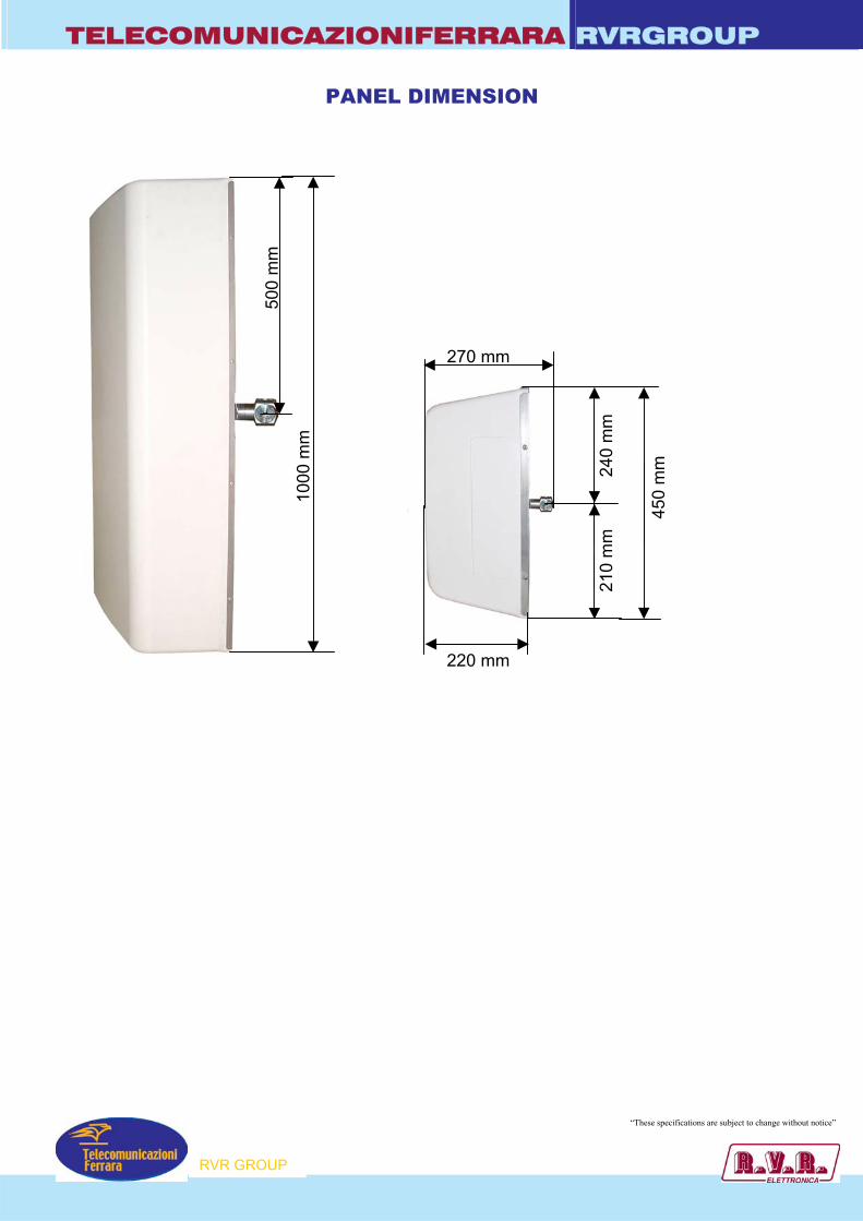
TELECOMUNICAZIONIFERRARA RVRGROUP
PANEL DIMENSION
RVR GROUP
“These specifications are subject to change without notice”
1000
mm
500
mm
220 mm45
0 m
m
240
mm
21
0 m
m
270 mm
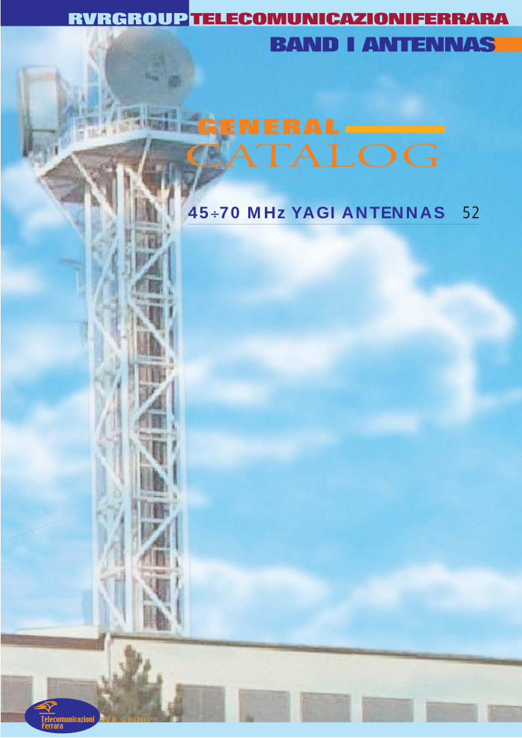
BAND I ANTENNAS
45÷70 MHz YAGI ANTENNAS 52
CATALOGGENERAL
RVR GROUP
RVRGROUPTELECOMUNICAZIONIFERRARA
TelecomunicazioniFerrara
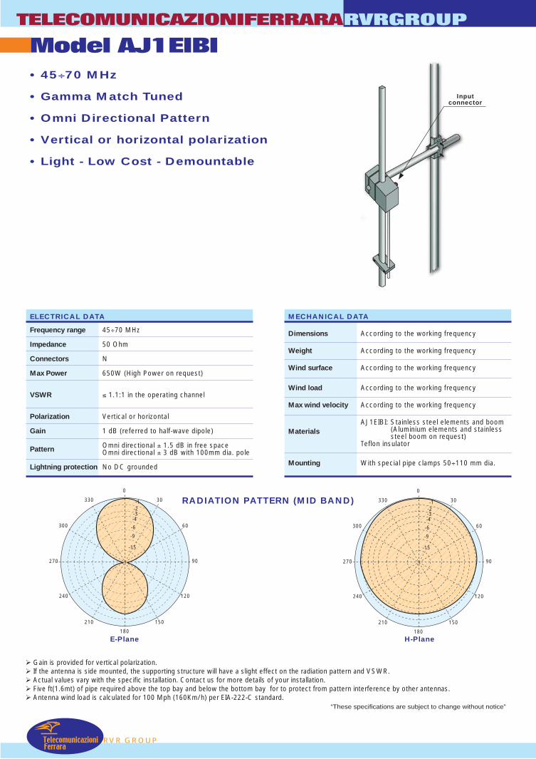
TelecomunicazioniFerrara
Model AJ1EIBITELECOMUNICAZIONIFERRARA
RVR GROUP
RVRGROUP
• 45÷70 MHz
• Gamma Match Tuned
• Omni Directional Pattern
• Vertical or horizontal polarization
• Light - Low Cost - Demountable
RADIATION PATTERN (MID BAND)
Gain is provided for vertical polarization. If the antenna is side mounted, the supporting structure will have a slight effect on the radiation pattern and VSWR. Actual values vary with the specific installation. Contact us for more details of your installation. Five ft(1.6mt) of pipe required above the top bay and below the bottom bay for to protect from pattern interference by other antennas. Antenna wind load is calculated for 100 Mph (160Km/h) per EIA-222-C standard.
ELECTRICAL DATA
Frequency range 45÷70 MHz
Impedance 50 Ohm
Connectors N
Max Power 650W (High Power on request)
VSWR ≤ 1.1:1 in the operating channel
Polarization Vertical or horizontal
Gain 1 dB (referred to half-wave dipole)
Pattern Omni directional ± 1.5 dB in free spaceOmni directional ± 3 dB with 100mm dia. pole
Lightning protection No DC grounded
E-Plane H-Plane
MECHANICAL DATA
Dimensions According to the working frequency
Weight According to the working frequency
Wind surface According to the working frequency
Wind load According to the working frequency
Max wind velocity According to the working frequency
AJ1EIBI: Stainless steel elements and boom (Aluminium elements and stainlessMaterials
steel boom on request)Teflon insulator
Mounting With special pipe clamps 50÷110 mm dia.
180
0
270 90
-1330
300
240
210 150
120
60
30
-2-3-4
-6
-9
-15
180
0
270 90
-1330
300
240
210 150
120
60
30
-2-3-4
-6
-9
-15
Inputconnector
“These specifications are subject to change without notice”

Inputconnector
• 45÷70 MHz
• Gamma Match Tuned
• Vertical or horizontal polarization
• Light - Low Cost - Demountable
RVR GROUP
RVRGROUPTELECOMUNICAZIONIFERRARA
Model AJ2EIBI
TelecomunicazioniFerrara
RADIATION PATTERN (MID BAND)
Gain is provided for vertical polarization. If the antenna is side mounted, the supporting structure will have a slight effect on the radiation pattern and VSWR. Actual values vary with the specific installation. Contact us for more details of your installation. Five ft(1.6mt) of pipe required above the top bay and below the bottom bay for to protect from pattern interference by other antennas. Antenna wind load is calculated for 100 Mph (160Km/h) per EIA-222-C standard.
ELECTRICAL DATA
Frequency range 45÷70 MHz
Impedance 50 Ohm
Connectors N
Max Power 650W (High Power on request)
VSWR ≤ 1.1:1 in the operating channel
Polarization Vertical or horizontal
Gain 5 dB (referred to half-wave dipole)
Pattern E plane ± 40°H plane ± 90°
Lightning protection No DC grounded
E-Plane H-Plane
MECHANICAL DATA
Dimensions According to the working frequency
Weight According to the working frequency
Wind surface According to the working frequency
Wind load According to the working frequency
Max wind velocity According to the working frequency
AJ2EIBI: Stainless steel elements and boom (Aluminium elements and stainlessMaterials
steel boom on request)Teflon insulator
Mounting With special pipe clamps 50÷110 mm dia.
180
0
270 90
-1330
300
240
210 150
120
60
30
-2-3-4
-6
-9
-15
180
0
270 90
-1330
300
240
210 150
120
60
30
-2-3-4
-6
-9
-15
“These specifications are subject to change without notice”
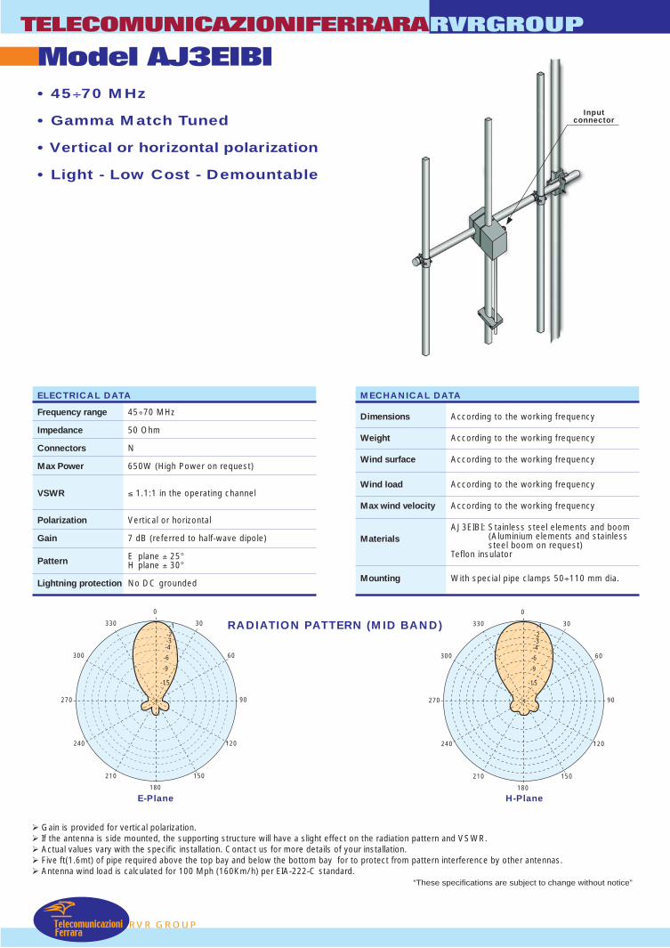
TelecomunicazioniFerrara
Model AJ3EIBITELECOMUNICAZIONIFERRARA
RVR GROUP
RVRGROUP
• 45÷70 MHz
• Gamma Match Tuned
• Vertical or horizontal polarization
• Light - Low Cost - Demountable
RADIATION PATTERN (MID BAND)
Gain is provided for vertical polarization. If the antenna is side mounted, the supporting structure will have a slight effect on the radiation pattern and VSWR. Actual values vary with the specific installation. Contact us for more details of your installation. Five ft(1.6mt) of pipe required above the top bay and below the bottom bay for to protect from pattern interference by other antennas. Antenna wind load is calculated for 100 Mph (160Km/h) per EIA-222-C standard.
ELECTRICAL DATA
Frequency range 45÷70 MHz
Impedance 50 Ohm
Connectors N
Max Power 650W (High Power on request)
VSWR ≤ 1.1:1 in the operating channel
Polarization Vertical or horizontal
Gain 7 dB (referred to half-wave dipole)
Pattern E plane ± 25°H plane ± 30°
Lightning protection No DC grounded
E-Plane H-Plane
MECHANICAL DATA
Dimensions According to the working frequency
Weight According to the working frequency
Wind surface According to the working frequency
Wind load According to the working frequency
Max wind velocity According to the working frequency
AJ3EIBI: Stainless steel elements and boom (Aluminium elements and stainlessMaterials
steel boom on request)Teflon insulator
Mounting With special pipe clamps 50÷110 mm dia.
Inputconnector
180
0
270 90
-1330
300
240
210 150
120
60
30
-2-3-4
-6
-9
-15
180
0
270 90
-1330
300
240
210 150
120
60
30
-2-3-4
-6
-9
-15
“These specifications are subject to change without notice”
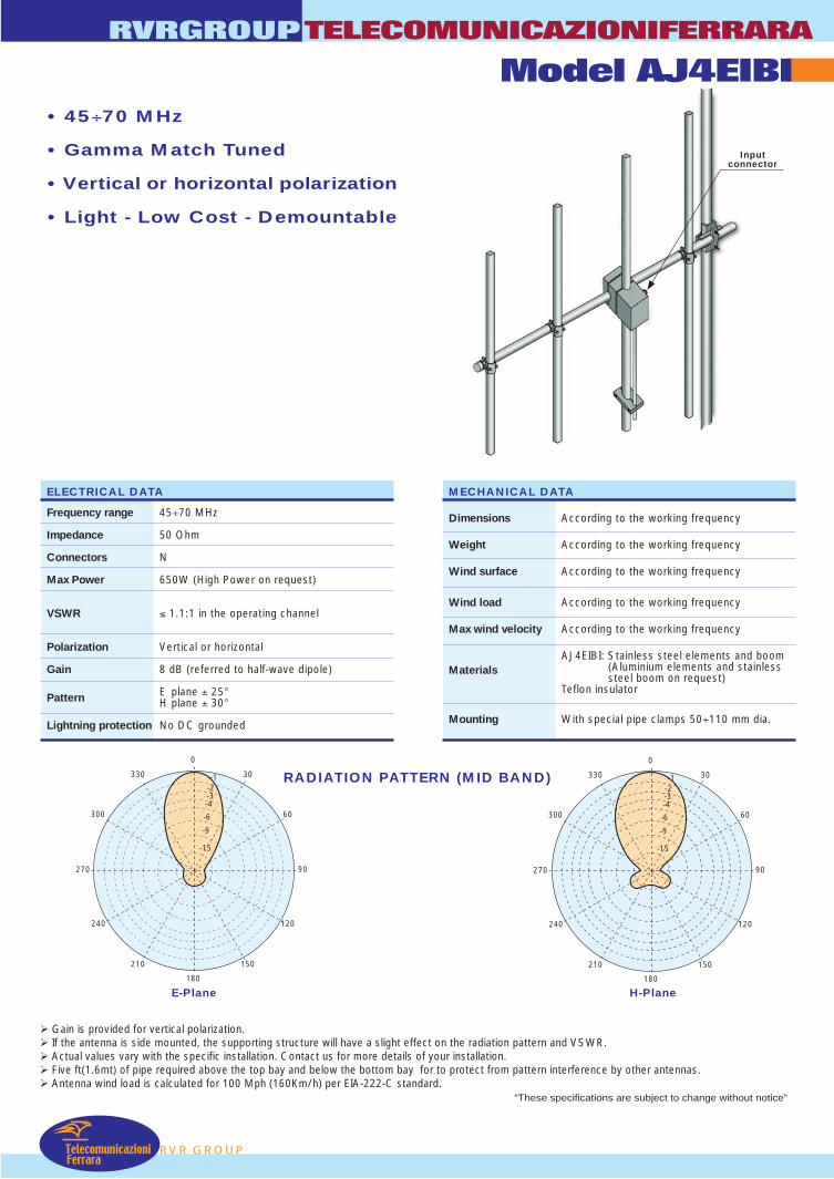
Inputconnector
• 45÷70 MHz
• Gamma Match Tuned
• Vertical or horizontal polarization
• Light - Low Cost - Demountable
RVR GROUP
RVRGROUPTELECOMUNICAZIONIFERRARA
Model AJ4EIBI
TelecomunicazioniFerrara
RADIATION PATTERN (MID BAND)
Gain is provided for vertical polarization. If the antenna is side mounted, the supporting structure will have a slight effect on the radiation pattern and VSWR. Actual values vary with the specific installation. Contact us for more details of your installation. Five ft(1.6mt) of pipe required above the top bay and below the bottom bay for to protect from pattern interference by other antennas. Antenna wind load is calculated for 100 Mph (160Km/h) per EIA-222-C standard.
ELECTRICAL DATA
Frequency range 45÷70 MHz
Impedance 50 Ohm
Connectors N
Max Power 650W (High Power on request)
VSWR ≤ 1.1:1 in the operating channel
Polarization Vertical or horizontal
Gain 8 dB (referred to half-wave dipole)
Pattern E plane ± 25°H plane ± 30°
Lightning protection No DC grounded
E-Plane H-Plane
MECHANICAL DATA
Dimensions According to the working frequency
Weight According to the working frequency
Wind surface According to the working frequency
Wind load According to the working frequency
Max wind velocity According to the working frequency
AJ4EIBI: Stainless steel elements and boom (Aluminium elements and stainlessMaterials
steel boom on request)Teflon insulator
Mounting With special pipe clamps 50÷110 mm dia.
180
0
270 90
-1330
300
240
210 150
120
60
30
-2-3-4
-6
-9
-15
180
0
270 90
-1330
300
240
210 150
120
60
30
-2-3-4
-6
-9
-15
“These specifications are subject to change without notice”
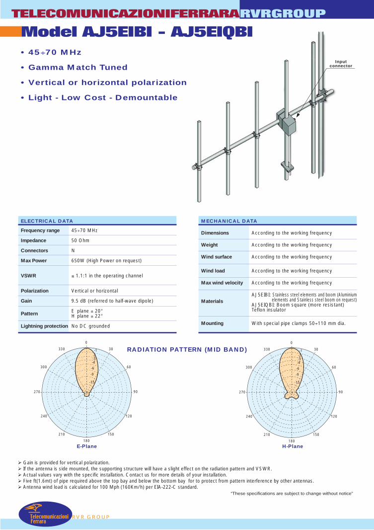
Inputconnector
TelecomunicazioniFerrara
Model AJ5EIBI - AJ5EIQBITELECOMUNICAZIONIFERRARA
RVR GROUP
RVRGROUP
• 45÷70 MHz
• Gamma Match Tuned
• Vertical or horizontal polarization
• Light - Low Cost - Demountable
RADIATION PATTERN (MID BAND)
Gain is provided for vertical polarization. If the antenna is side mounted, the supporting structure will have a slight effect on the radiation pattern and VSWR. Actual values vary with the specific installation. Contact us for more details of your installation. Five ft(1.6mt) of pipe required above the top bay and below the bottom bay for to protect from pattern interference by other antennas. Antenna wind load is calculated for 100 Mph (160Km/h) per EIA-222-C standard.
ELECTRICAL DATA
Frequency range 45÷70 MHz
Impedance 50 Ohm
Connectors N
Max Power 650W (High Power on request)
VSWR ≤ 1.1:1 in the operating channel
Polarization Vertical or horizontal
Gain 9.5 dB (referred to half-wave dipole)
Pattern E plane ± 20°H plane ± 22°
Lightning protection No DC grounded
E-Plane H-Plane
MECHANICAL DATA
Dimensions According to the working frequency
Weight According to the working frequency
Wind surface According to the working frequency
Wind load According to the working frequency
Max wind velocity According to the working frequency
AJ5EIBI: Stainless steel elements and boom (Aluminium elements and Stainless steel boom on request)Materials
AJ5EIQBI: Boom square (more resistant)Teflon insulator
Mounting With special pipe clamps 50÷110 mm dia.
180
0
270 90
-1330
300
240
210 150
120
60
30
-2-3-4
-6
-9
-15
180
0
270 90
-1330
300
240
210 150
120
60
30
-2-3-4
-6
-9
-15
“These specifications are subject to change without notice”
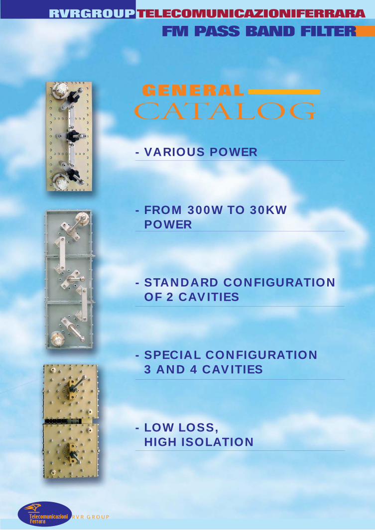
RVR GROUP
RVRGROUPTELECOMUNICAZIONIFERRARA
TelecomunicazioniFerrara
FM PASS BAND FILTER
- VARIOUS POWER
- FROM 300W TO 30KWPOWER
- STANDARD CONFIGURATIONOF 2 CAVITIES
- SPECIAL CONFIGURATION3 AND 4 CAVITIES
- LOW LOSS,HIGH ISOLATION
CATALOGGENERAL
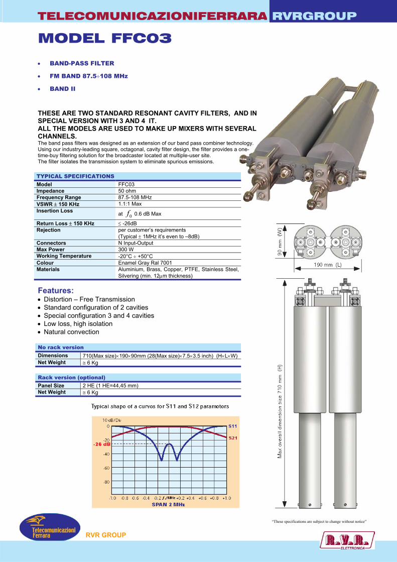
TELECOMUNICAZIONIFERRARA RVRGROUP
MODEL FFC03
• BAND-PASS FILTER
• FM BAND 87.5÷108 MHz
• BAND II
THESE ARE TWO STANDARD RESONANT CAVITY FILTERS, SPECIAL VERSION WITH 3 AND 4 IT. ALL THE MODELS ARE USED TO MAKE UP MIXERS WITH SECHANNELS. The band pass filters was designed as an extension of our band pass combiner tecUsing our industry-leading square, octagonal, cavity filter design, the filter providestime-buy filtering solution for the broadcaster located at multiple-user site. The filter isolates the transmission system to eliminate spurious emissions. TYPICAL SPECIFICATIONS Model FFC03 Impedance 50 ohm Frequency Range 87.5-108 MHz VSWR ± 150 KHz 1.1:1 Max Insertion Loss at 0f 0.6 dB Max
Return Loss ± 150 KHz ≤ -26dB Rejection per customer’s requirements
(Typical ± 1MHz it’s even to –8dB) Connectors N Input-Output Max Power 300 W Working Temperature -20°C ÷ +50°C Colour Enamel Gray Ral 7001 Materials Aluminium, Brass, Copper, PTFE, Stainless Ste
Silvering (min. 12µm thickness)
Features: • Distortion – Free Transmission • Standard configuration of 2 cavities • Special configuration 3 and 4 cavities • Low loss, high isolation • Natural convection No rack version Dimensions 710(Max size)×190×90mm (28(Max size)×7.5×3.5 inch) (H×L×WNet Weight ≅ 6 Kg Rack version (optional) Panel Size 2 HE (1 HE=44,45 mm) Net Weight ≅ 6 Kg
P
AND IN
VERAL
hnology. a one-
el,
)
“These specifications are subject to change without notice”
RVR GROU
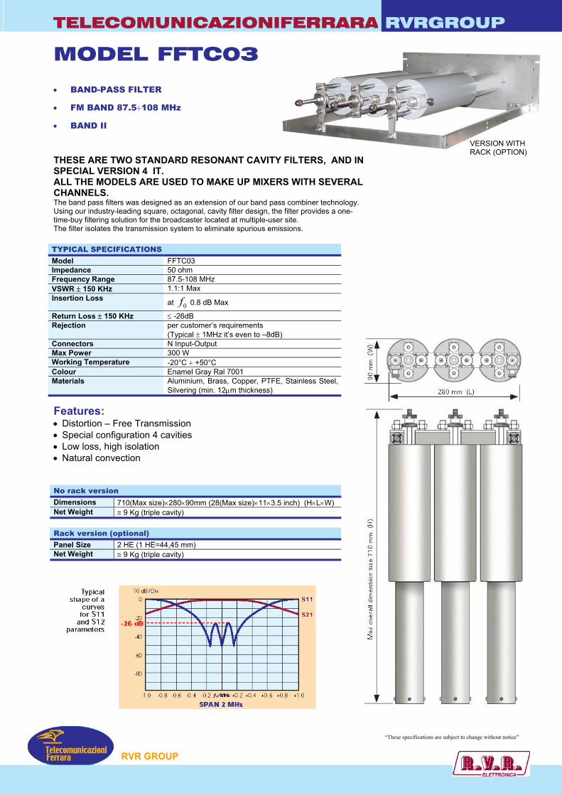
TELECOMUNICAZIONIFERRARA RVRGROUP
MODEL FFTC03
• BAND-PASS FILTER
• FM BAND 87.5÷108 MHz
• BAND II
THESE ARE TWO STANDARD RESONANT CAVITY FILTERS, AND IN SPECIAL VERSION 4 IT.
VERSION WITH RACK (OPTION)
ALL THE MODELS ARE USED TO MAKE UP MIXERS WITH SEVERAL CHANNELS. The band pass filters was designed as an extension of our band pass combiner technology. Using our industry-leading square, octagonal, cavity filter design, the filter provides a one-time-buy filtering solution for the broadcaster located at multiple-user site. The filter isolates the transmission system to eliminate spurious emissions. TYPICAL SPECIFICATIONS Model FFTC03 Impedance 50 ohm Frequency Range 87.5-108 MHz VSWR ± 150 KHz 1.1:1 Max Insertion Loss at 0f 0.8 dB Max
Return Loss ± 150 KHz ≤ -26dB Rejection per customer’s requirements
(Typical ± 1MHz it’s even to –8dB) Connectors N Input-Output Max Power 300 W Working Temperature -20°C ÷ +50°C Colour Enamel Gray Ral 7001 Materials Aluminium, Brass, Copper, PTFE, Stainless Steel,
Silvering (min. 12µm thickness)
Features: • Distortion – Free Transmission • Special configuration 4 cavities • Low loss, high isolation • Natural convection No rack version Dimensions 710(Max size)×280×90mm (28(Max size)×11×3.5 inch) (H×L×W) Net Weight ≅ 9 Kg (triple cavity) Rack version (optional) Panel Size 2 HE (1 HE=44,45 mm) Net Weight ≅ 9 Kg (triple cavity)
“These specifications are subject to change without notice”
P
RVR GROU
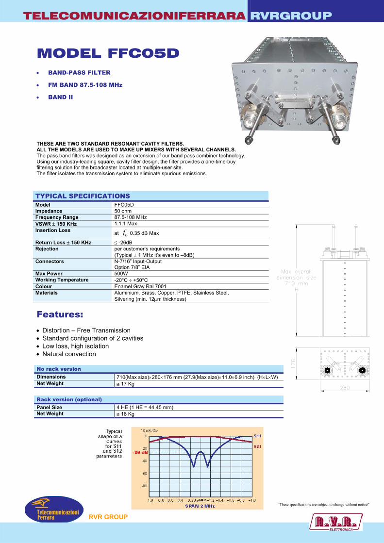
TELECOMUNICAZIONIFERRARA RVRGROUP
MODEL FFC05D • BAND-PASS FILTER
• FM BAND 87.5-108 MHz
• BAND II
THESE ARE TWO STANDARD RESONANT CAVITY FILTERS. ALL THE MODELS ARE USED TO MAKE UP MIXERS WITH SEVERAL CHANNThe pass band filters was designed as an extension of our band pass combiner tecUsing our industry-leading square, cavity filter design, the filter provides a one-timefiltering solution for the broadcaster located at multiple-user site. The filter isolates the transmission system to eliminate spurious emissions. TYPICAL SPECIFICATIONS Model FFC05D Impedance 50 ohm Frequency Range 87.5-108 MHz VSWR ± 150 KHz 1.1:1 Max Insertion Loss at 0f 0.35 dB Max
Return Loss ± 150 KHz ≤ -26dB Rejection per customer’s requirements
(Typical ± 1 MHz it’s even to –8dB) Connectors N-7/16” Input-Output
Option 7/8” EIA Max Power 500W Working Temperature -20°C ÷ +50°C Colour Enamel Gray Ral 7001 Materials Aluminium, Brass, Copper, PTFE, Stainless Ste
Silvering (min. 12µm thickness)
Features: • Distortion – Free Transmission • Standard configuration of 2 cavities • Low loss, high isolation • Natural convection No rack version Dimensions 710(Max size)×280×176 mm (27.9(Max size)×1Net Weight ≅ 17 Kg
Rack version (optional) Panel Size 4 HE (1 HE = 44,45 mm) Net Weight ≅ 18 Kg
P
ELS. hnology. -buy
el,
1.0×6.9 inch) (H×L×W)
“These specifications are subject to change without notice”
RVR GROU
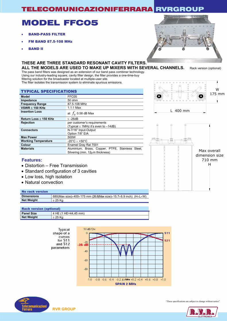
TELECOMUNICAZIONIFERRARA RVRGROUP
MODEL FFC05 • BAND-PASS FILTER
• FM BAND 87.5-108 MHz
• BAND II
THESE ARE THREE STANDARD RESONANT CAVITY FILTERS. ALL THE MODELS ARE USED TO MAKE UP MIXERS WITH SEVERAL CHANNELS. Rack version (optional)The pass band filters was designed as an extension of our band pass combiner technology. Using our industry-leading square, cavity filter design, the filter provides a one-time-buy filtering solution for the broadcaster located at multiple-user site.
L 400 mm
W175 mm
The filter isolates the transmission system to eliminate spurious emissions. TYPICAL SPECIFICATIONS Model FFC05 Impedance 50 ohm Frequency Range 87.5-108 MHz VSWR ± 150 KHz 1.1:1 Max Insertion Loss at 0f 0.58 dB Max
Return Loss ± 150 KHz ≤ -26dB Rejection per customer’s requirements
(Typical ± 1MHz it’s even to –14dB) Connectors N-7/16” Input-Output
Option 7/8” EIA Max Power 500W Working Temperature -20°C ÷ +50°C Colour Enamel Gray Ral 7001 Materials Aluminium, Brass, Copper, PTFE, Stainless Steel,
Silvering (min. 12µm thickness)
Features: • Distortion – Free Transmission • Standard configuration of 3 cavities • Low loss, high isolation • Natural convection No rack version Dimensions 680(Max size)×400×175 mm (26.8(Max size)×15.7×6.9 inch) (H×L×Net Weight ≅ 25 Kg Rack version (optional) Panel Size 4 HE (1 HE=44,45 mm) Net Weight ≅ 25 Kg
P
W
Max overalldimension size
710 mmH
)
“These specifications are subject to change without notice”
RVR GROU
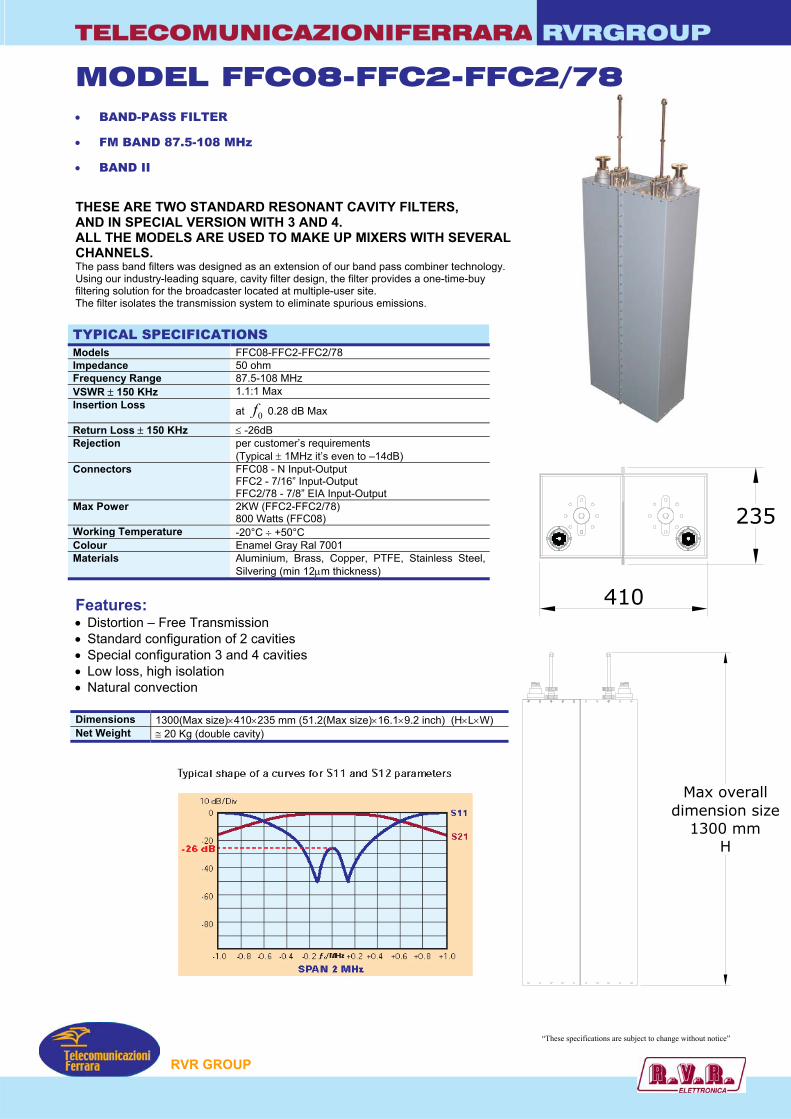
TELECOMUNICAZIONIFERRARA RVRGROUP
MODEL FFC08-FFC2-FFC2/78 • BAND-PASS FILTER
• FM BAND 87.5-108 MHz
• BAND II
THESE ARE TWO STANDARD RESONANT CAVITY FILTERS, AND IN SPECIAL VERSION WITH 3 AND 4. ALL THE MODELS ARE USED TO MAKE UP MIXERS WITH SEVERAL CHANNELS. The pass band filters was designed as an extension of our band pass combiner technology. Using our industry-leading square, cavity filter design, the filter provides a one-time-buy filtering solution for the broadcaster located at multiple-user site. The filter isolates the transmission system to eliminate spurious emissions. TYPICAL SPECIFICATIONS Models FFC08-FFC2-FFC2/78 Impedance 50 ohm Frequency Range 87.5-108 MHz VSWR ± 150 KHz 1.1:1 Max Insertion Loss at 0f 0.28 dB Max
Return Loss ± 150 KHz ≤ -26dB Rejection per customer’s requirements
(Typical ± 1MHz it’s even to –14dB) Connectors FFC08 - N Input-Output
FFC2 - 7/16” Input-Output FFC2/78 - 7/8” EIA Input-Output
Max Power 2KW (FFC2-FFC2/78) 800 Watts (FFC08)
Working Temperature -20°C ÷ +50°C Colour Enamel Gray Ral 7001 Materials Aluminium, Brass, Copper, PTFE, Stainless Steel,
Silvering (min 12µm thickness)
Max overalldimension size
1300 mmH
235
410 Features: • Distortion – Free Transmission • Standard configuration of 2 cavities • Special configuration 3 and 4 cavities • Low loss, high isolation • Natural convection Dimensions 1300(Max size)×410×235 mm (51.2(Max size)×16.1×9.2 inch) (H×L×W) Net Weight ≅ 20 Kg (double cavity)
“These specifications are subject to change without notice”
P
RVR GROU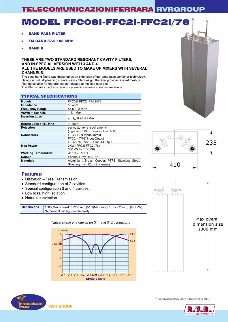
TELECOMUNICAZIONIFERRARA RVRGROUP
MODEL FFC08I-FFC2I-FFC2I/78 • BAND-PASS FILTER
• FM BAND 87.5-108 MHz
• BAND II
THESE ARE TWO STANDARD RESONANT CAVITY FILTERS, AND IN SPECIAL VERSION WITH 3 AND 4. ALL THE MODELS ARE USED TO MAKE UP MIXERS WITH SEVERAL CHANNELS. The pass band filters was designed as an extension of our band pass combiner technology. Using our industry-leading square, cavity filter design, the filter provides a one-time-buy filtering solution for the broadcaster located at multiple-user site. The filter isolates the transmission system to eliminate spurious emissions. TYPICAL SPECIFICATIONS Models FFC08I-FFC2I-FFC2I/78 Impedance 50 ohm Frequency Range 87.5-108 MHz VSWR ± 150 KHz 1.1:1 Max Insertion Loss at 0f 0.28 dB Max
Return Loss ± 150 KHz ≤ -26dB Rejection per customer’s requirements
(Typical ± 1MHz it’s even to –14dB) Connectors FFC08I - N Input-Output
FFC2I - 7/16” Input-Output FFC2I/78 - 7/8” EIA Input-Output
Max Power 2KW (FFC2I-FFC2I/78) 800 Watts (FFCI08)
Working Temperature -20°C ÷ +50°C Colour Enamel Gray Ral 7001 Materials Aluminium, Brass, Copper, PTFE, Stainless Steel,
Silvering (min 12µm thickness)
Features: • Distortion – Free Transmission • Standard configuration of 2 cavities • Special configuration 3 and 4 cavities • Low loss, high isolation • Natural convection Dimensions 1300(Max size)×410×235 mm (51.2(Max size)×16.1×9.2 inch) (H×L×W) n Net Weight 20 Kg (double cavity)
235
410
P
Max overalldimension size
1300 mmH
“These specifications are subject to change without notice”
RVR GROU
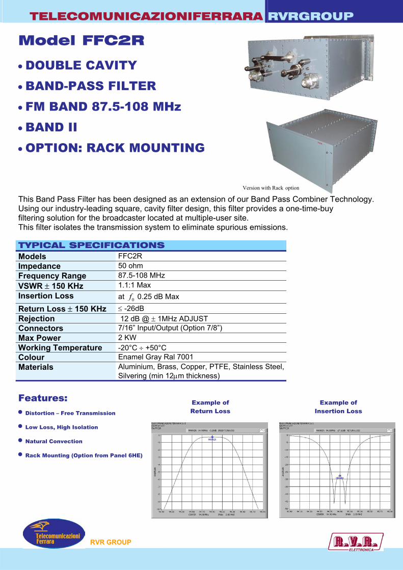
TELECOMUNICAZIONIFERRARA RVRGROUP
Model FFC2R
• DOUBLE CAVITY • BAND-PASS FILTER • FM BAND 87.5-108 MHz • BAND II • OPTION: RACK MOUNTING
Version with Rack option This Band Pass Filter has been designed as an extension of our Band Pass Combiner Technology. Using our industry-leading square, cavity filter design, this filter provides a one-time-buy filtering solution for the broadcaster located at multiple-user site. This filter isolates the transmission system to eliminate spurious emissions. TYPICAL SPECIFICATIONS Models FFC2R Impedance 50 ohm Frequency Range 87.5-108 MHz VSWR ± 150 KHz 1.1:1 Max Insertion Loss at 0f 0.25 dB Max
Return Loss ± 150 KHz ≤ -26dB Rejection 12 dB @ ± 1MHz ADJUST Connectors 7/16” Input/Output (Option 7/8”) Max Power 2 KW Working Temperature -20°C ÷ +50°C Colour Enamel Gray Ral 7001 Materials Aluminium, Brass, Copper, PTFE, Stainless Steel,
Silvering (min 12µm thickness)
Features: Example of Return Loss
Example of Insertion Loss • Distortion – Free Transmission
• Low Loss, High Isolation
• Natural Convection
• Rack Mounting (Option from Panel 6HE)
P
RVR GROU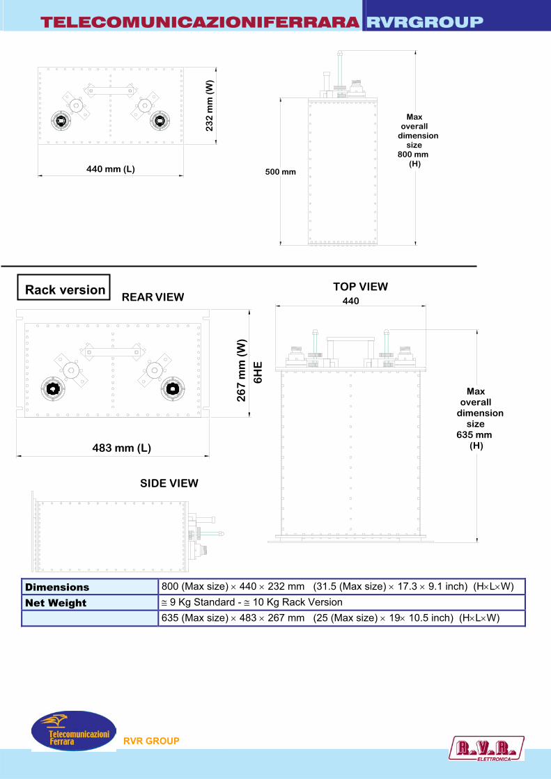
TELECOMUNICAZIONIFERRARA RVRGROUP
500 mm
Maxoverall
dimensionsize
800 mm(H)
440 mm (L)
23
2 m
m (
W)
483 mm (L)
26
7 m
m (
W)
6H
E
(H)
Max
sizedimensionoverall
635 mm
440Rack version
REAR VIEW
SIDE VIEW
TOP VIEW
Dimensions 800 (Max size) × 440 × 232 mm (31.5 (Max size) × 17.3 × 9.1 inch) (H×L×W) Net Weight ≅ 9 Kg Standard - ≅ 10 Kg Rack Version Dimensions whit Rack 635 (Max size) × 483 × 267 mm (25 (Max size) × 19× 10.5 inch) (H×L×W)
P
RVR GROU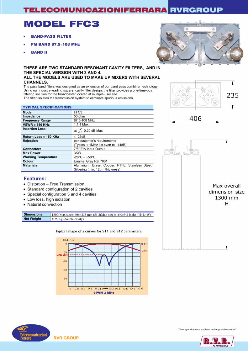
TELECOMUNICAZIONIFERRARA RVRGROUP
MODEL FFC3 • BAND-PASS FILTER
• FM BAND 87.5÷108 MHz
• BAND II
THESE ARE TWO STANDARD RESONANT CAVITY FILTERS, AND IN THE SPECIAL VERSION WITH 3 AND 4. ALL THE MODELS ARE USED TO MAKE UP MIXERS WITH SEVERALCHANNELS. The pass band filters was designed as an extension of our band pass combiner technology. Using our industry-leading square, cavity filter design, the filter provides a one-time-buy filtering solution for the broadcaster located at multiple-user site. The filter isolates the transmission system to eliminate spurious emissions. TYPICAL SPECIFICATIONS Model FFC3 Impedance 50 ohm Frequency Range 87.5-108 MHz VSWR ± 150 KHz 1.1:1 Max Insertion Loss at 0f 0.20 dB Max
Return Loss ± 150 KHz ≤ -26dB Rejection per customer’s requirements
(Typical ± 1MHz it’s even to –14dB) Connectors 7/8” EIA Input-Output Max Power 3KW Working Temperature -20°C ÷ +50°C Colour Enamel Gray Ral 7001 Materials Aluminium, Brass, Copper, PTFE, Stainless Steel,
Silvering (min. 12µm thickness)
Features: • Distortion – Free Transmission • Standard configuration of 2 cavities • Special configuration 3 and 4 cavities • Low loss, high isolation • Natural convection Dimensions 1300(Max size)×406×235 mm (51.2(Max size)×16.0×9.2 inch) (H×L×W) Net Weight ≅ 25 Kg (double cavity)
P
406
235
Max overalldimension size
1300 mmH
“These specifications are subject to change without notice”
RVR GROU

TELECOMUNICAZIONIFERRARA RVRGROUP
235
610
Max overalldimension size
1300 mmH
MODEL FFTC3 • BAND-PASS FILTER
• FM BAND 87.5÷108 MHz
• BAND II
THESE ARE THREE STANDARD RESONANT CAVITY FILTERS, AND IN THE SPECIAL VERSION WITH 4. ALL THE MODELS ARE USED TO MAKE UP MIXERS WITH SEVERAL CHANNELS. The pass band filters was designed as an extension of our band pass combiner technology. Using our industry-leading square, cavity filter design, the filter provides a one-time-buy filtering solution for the broadcaster located at multiple-user site. The filter isolates the transmission system to eliminate spurious emissions. TYPICAL SPECIFICATIONS Model FFTC3 Impedance 50 ohm Frequency Range 87.5-108 MHz VSWR ± 150 KHz 1.1:1 Max Insertion Loss at 0f 0.35 dB Max
Return Loss ± 150 KHz ≤ -26dB Rejection per customer’s requirements
(Typical ± 1MHz it’s even to –16dB) Connectors 7/8” EIA Input-Output (Opt. 1+5/8”) Max Power 3KW Working Temperature -20°C ÷ +50°C Colour Enamel Gray Ral 7001 Materials Aluminium, Brass, Copper, PTFE, Stainless Steel,
Silvering (min. 12µm thickness)
Features: • Distortion – Free Transmission • Standard configuration of 3 cavities • Special configuration 4 cavities • Low loss, high isolation • Natural convection Dimensions 1300(Max size)×610×235 mm (51.2(Max size)×24.0×9.2 inch) (H×L×W) Net Weight ≅ 37 Kg (triple cavity)
RVR GROUP
“These specifications are subject to change without notice”
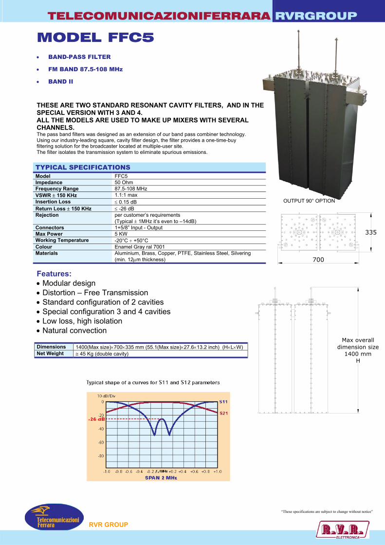
TELECOMUNICAZIONIFERRARA RVRGROUP
MODEL FFC5 • BAND-PASS FILTER
• FM BAND 87.5-108 MHz
• BAND II
THESE ARE TWO STANDARD RESONANT CAVITY FILTERS, AND IN THE SPECIAL VERSION WITH 3 AND 4. ALL THE MODELS ARE USED TO MAKE UP MIXERS WITH SEVERAL CHANNELS. The pass band filters was designed as an extension of our band pass combiner technology. Using our industry-leading square, cavity filter design, the filter provides a one-time-buy filtering solution for the broadcaster located at multiple-user site. The filter isolates the transmission system to eliminate spurious emissions. TYPICAL SPECIFICATIONS Model FFC5 Impedance 50 Ohm Frequency Range 87.5-108 MHz VSWR ± 150 KHz 1.1:1 max Insertion Loss ≤ 0.15 dB Return Loss ± 150 KHz ≤ -26 dB Rejection per customer’s requirements
(Typical ± 1MHz it’s even to –14dB) Connectors 1+5/8” Input - Output Max Power 5 KW Working Temperature -20°C ÷ +50°C Colour Enamel Gray ral 7001 Materials Aluminium, Brass, Copper, PTFE, Stainless Steel, Silvering
(min. 12µm thickness)
OUTPUT 90° OPTION
Features: • Modular design • Distortion – Free Transmission • Standard configuration of 2 cavities • Special configuration 3 and 4 cavities • Low loss, high isolation • Natural convection Dimensions 1400(Max size)×700×335 mm (55.1(Max size)×27.6×13.2 inch) (H×L×W) Net Weight ≅ 45 Kg (double cavity)
P
335
700
Max overalldimension size
1400 mmH
“These specifications are subject to change without notice”
RVR GROU
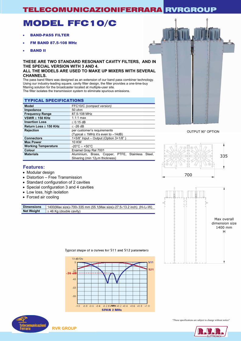
TELECOMUNICAZIONIFERRARA RVRGROUP
Max overalldimension size
1400 mmH
335
700
MODEL FFC10/C • BAND-PASS FILTER
• FM BAND 87.5-108 MHz
• BAND II
THESE ARE TWO STANDARD RESONANT CAVITY FILTERS, AND IN THE SPECIAL VERSION WITH 3 AND 4. ALL THE MODELS ARE USED TO MAKE UP MIXERS WITH SEVERAL CHANNELS. The pass band filters was designed as an extension of our band pass combiner technology. Using our industry-leading square, cavity filter design, the filter provides a one-time-buy filtering solution for the broadcaster located at multiple-user site. The filter isolates the transmission system to eliminate spurious emissions. TYPICAL SPECIFICATIONS Model FFC10/C (compact version) Impedance 50 ohm Frequency Range 87.5-108 MHz VSWR ± 150 KHz 1.1:1 max Insertion Loss ≤ 0.15 dB Return Loss ± 150 KHz ≤ -26 dB Rejection per customer’s requirements
(Typical ± 1MHz it’s even to –14dB) Connectors 1+5/8” Input – Output (Option 3+1/8” ) Max Power 10 KW Working Temperature -20°C ÷ +50°C Colour Enamel Gray Ral 7001 Materials Aluminium, Brass, Copper, PTFE, Stainless Steel,
Silvering (min 12µm thickness)
Features: • Modular design • Distortion – Free Transmission • Standard configuration of 2 cavities • Special configuration 3 and 4 cavities • Low loss, high isolation • Forced air cooling Dimensions 1400(Max size)×700×335 mm (55.1(Max size)×27.5×13.2 inch) (H×L×W) Net Weight ≅ 46 Kg (double cavity)
OUTPUT 90° OPTION
RVR GROUP
“These specifications are subject to change without notice”
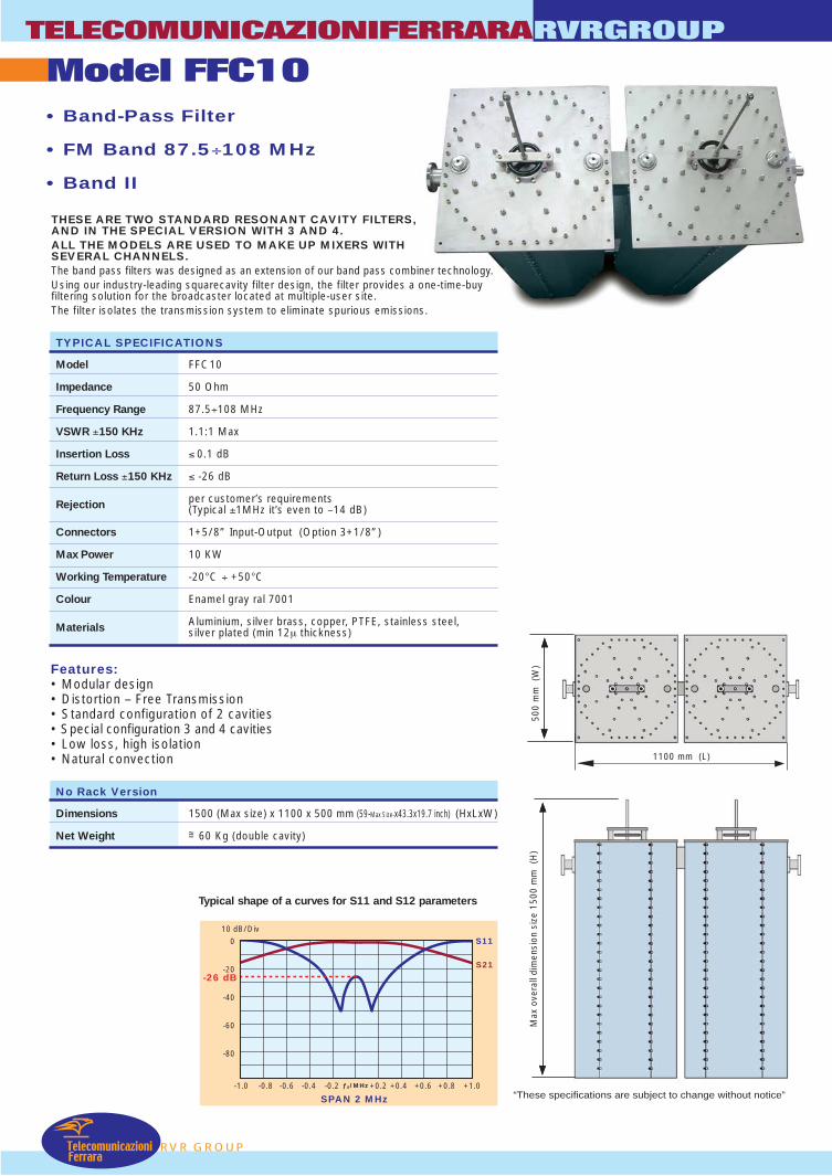
TelecomunicazioniFerrara
Model FFC10TELECOMUNICAZIONIFERRARA
RVR GROUP
RVRGROUP
• Band-Pass Filter
• FM Band 87.5÷108 MHz
• Band II
TYPICAL SPECIFICATIONS
Model FFC10
Impedance 50 Ohm
Frequency Range 87.5÷108 MHz
VSWR ±150 KHz 1.1:1 Max
Insertion Loss ≤ 0.1 dB
Return Loss ±150 KHz ≤ -26 dB
Rejection per customer’s requirements(Typical ±1MHz it’s even to –14 dB)
Connectors 1+5/8” Input-Output (Option 3+1/8”)
Max Power 10 KW
Working Temperature -20°C ÷ +50°C
Colour Enamel gray ral 7001
Materials Aluminium, silver brass, copper, PTFE, stainless steel,silver plated (min 12µ thickness)
THESE ARE TWO STANDARD RESONANT CAVITY FILTERS,AND IN THE SPECIAL VERSION WITH 3 AND 4.ALL THE MODELS ARE USED TO MAKE UP MIXERS WITHSEVERAL CHANNELS.The band pass filters was designed as an extension of our band pass combiner technology.Using our industry-leading squarecavity filter design, the filter provides a one-time-buyfiltering solution for the broadcaster located at multiple-user site.The filter isolates the transmission system to eliminate spurious emissions.
Features:• Modular design• Distortion – Free Transmission• Standard configuration of 2 cavities• Special configuration 3 and 4 cavities• Low loss, high isolation• Natural convection
No Rack Version
Dimensions 1500 (Max size) x 1100 x 500 mm (59-Max Size-x43.3x19.7 inch) (HxLxW)
Net Weight =~ 60 Kg (double cavity)
SPAN 2 MHz
0
-20
-40
-60
-80
-1.0 -0.8 -0.6 -0.4 -0.2
10 dB/DivS11
S21
+1.0+0.8+0.6+0.4+0.2ƒ0/MHz
-26 dB
Typical shape of a curves for S11 and S12 parameters
1100 mm (L)
Max
ove
rall
dim
ensi
on s
ize
1500
mm
(H
)50
0 m
m (
W)
“These specifications are subject to change without notice”

TELECOMUNICAZIONIFERRARA RVRGROUP
MODEL FFC20 • BAND-PASS FILTER
• FM BAND 87.5-108 MHz
• BAND II
THESE ARE TWO STANDARD RESONANT CAWITH 3 AND 4. ALL THE MODELS ARE USED TO MAKE UP MThe pass band filters was designed as an extensUsing our industry-leading square, cavity filter defiltering solution for the broadcaster located at muThe filter isolates the transmission system to elim TYPICAL SPECIFICATIONS Model FFC20 Impedance 50 ohm Frequency Range 87.5-108 MHz VSWR ± 150 KHz 1.1:1 max Insertion Loss ≤ 0.1 dB Return Loss ± 150 KHz ≤ -26 dB Rejection per customer’s requirements
(Typical ± 1MHz it’s even to –Connectors 3+1/8” Input - Output Max Power 20 KW Working Temperature -20°C ÷ +50°C Colour Enamel Gray Ral 7001 Materials Aluminium, Brass, Copper, PT
Silvering (min. 12µm thicknes
Features: • Modular design
• Distortion – Free Transmission
• Standard configuration of 2 cavities
• Special configuration 3 and 4 cavities
• Low loss, high isolation
• Natural convection
P
OUTPUT 90° OPTION
VITY FILTERS, AND IN SPECIAL VERSION
IXERS WITH SEVERAL CHANNELS. ion of our band pass combiner technology. sign, the filter provides a one-time-buy ltiple-user site. inate spurious emissions.
14dB)
FE, Stainless Steel, s)
“These specifications are subject to change without notice”
RVR GROU
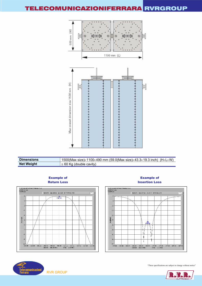
TELECOMUNICAZIONIFERRARA RVRGROUP
Dimensions Net Weight Examp
Return
1500(Max size)×1100×490 mm (59.0(Max size)×43.3×19.3 inch) (H×L×W) ≅ 60 Kg (double cavity)
le of Loss
Example of Insertion Loss
“These specifications are subject to change without notice”
P
RVR GROU
TELECOMUNICAZIONIFERRARA RVRGROUP
MODEL FFC30 • BAND-PASS FILTER
• FM BAND 87.5-108 MHz
• BAND II
OUTPUT 90° THESE ARE TWO STANDARD RESONANT CAVITWITH 3 AND 4. ALL THE MODELS ARE USED TO MAKE UP MIXEThe pass band filters was designed as an extension Using our industry-leading square, cavity filter designfiltering solution for the broadcaster located at multipThe filter isolates the transmission system to elimina TYPICAL SPECIFICATIONS Model FFC30 Impedance 50 ohm Frequency Range 87.5-108 MHz VSWR ± 150 KHz 1.1:1 max Insertion Loss ≤ 0.1 dB Return Loss ± 150 KHz ≤ -26 dB Rejection per customer’s requirements
(Typical ± 1MHz it’s even to –Connectors 3+1/8” Input - Output Max Power 35 KW Working Temperature -20°C ÷ +50°C Colour Enamel Gray Ral 7001 Materials Aluminium, Brass, Copper, P
Silvering (min. 12µm thicknes
Features: • Modular design
• Distortion – Free Transmission
• Standard configuration of 2 cavities
• Special configuration 3 and 4 cavities
• Low loss, high isolation
• Natural convection
P
OPTION
Y FILTERS, AND IN SPECIAL VERSION
RS WITH SEVERAL CHANNELS. of our band pass combiner technology. , the filter provides a one-time-buy le-user site. te spurious emissions.
14dB)
TFE, Stainless Steel, s)
“These specifications are subject to change without notice”
RVR GROU
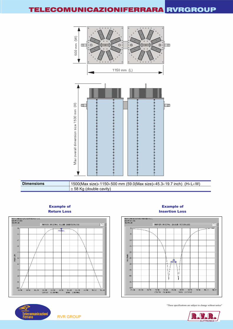
TELECOMUNICAZIONIFERRARA RVRGROUP
Dimensions 1500(Max size)×1150×500 mm (59.0(Max size)×45.3×19.7 inch) (H×L×W) Net Weight ≅ 58 Kg (double cavity)
Example of Return Loss
Example of Insertion Loss
“These specifications are subject to change without notice”
P
RVR GROU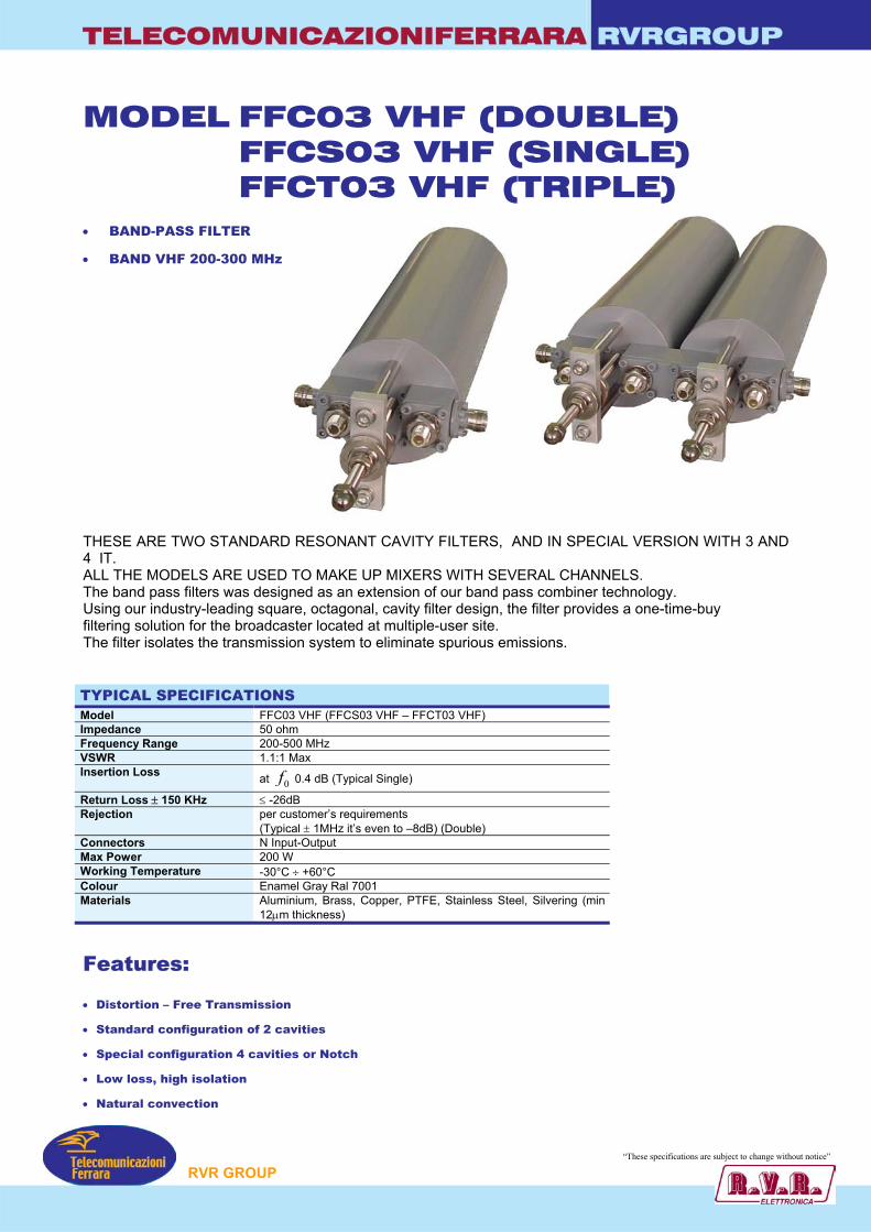
TELECOMUNICAZIONIFERRARA RVRGROUP
MODEL FFC03 VHF (DOUBLE) FFCS03 VHF (SINGLE) FFCT03 VHF (TRIPLE)
• BAND-PASS FILTER
• BAND VHF 200-300 MHz
THESE ARE TWO STANDARD RESONANT CAVITY FILTERS, A4 IT. ALL THE MODELS ARE USED TO MAKE UP MIXERS WITH SEVEThe band pass filters was designed as an extension of our band pasUsing our industry-leading square, octagonal, cavity filter design, thefiltering solution for the broadcaster located at multiple-user site. The filter isolates the transmission system to eliminate spurious emi TYPICAL SPECIFICATIONS Model FFC03 VHF (FFCS03 VHF – FFCT03 VHF) Impedance 50 ohm Frequency Range 200-500 MHz VSWR 1.1:1 Max Insertion Loss at 0f 0.4 dB (Typical Single)
Return Loss ± 150 KHz ≤ -26dB Rejection per customer’s requirements
(Typical ± 1MHz it’s even to –8dB) (Double) Connectors N Input-Output Max Power 200 W Working Temperature -30°C ÷ +60°C Colour Enamel Gray Ral 7001 Materials Aluminium, Brass, Copper, PTFE, Stainless Stee
12µm thickness)
Features: • Distortion – Free Transmission
• Standard configuration of 2 cavities
• Special configuration 4 cavities or Notch
• Low loss, high isolation
• Natural convection
•
P
ND IN SPECIAL VERSION WITH 3 AND
RAL CHANNELS. s combiner technology. filter provides a one-time-buy
ssions.
l, Silvering (min
“These specifications ar ubject to change without notice”
RVR GROU
e s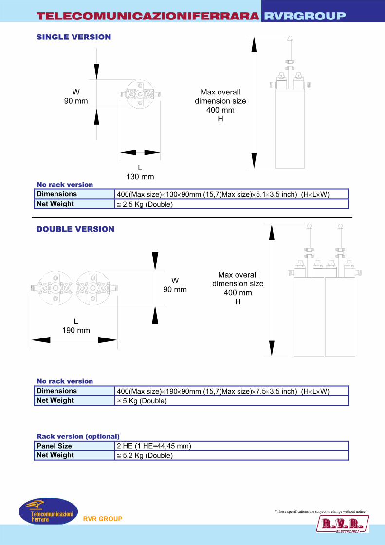
TELECOMUNICAZIONIFERRARA RVRGROUP
SINGLE VERSION
W 90 mm
Max overall dimension size
400 mm H
L 130 mm
No rack version Dimensions 400(Max size)×130×90mm (15,7(Max size) 5.1×3.5 inch) (H×L×W) Net Weight ≅ 2,5 Kg (Double)
DOUBLE VERSION Max over
dimension s400 mm
H
W 90 mm
L
190 mm No rack version Dimensions 400(Max size)×190×90mm (15,7(Max size)Net Weight ≅ 5 Kg (Double) Rack version (optional) Panel Size 2 HE (1 HE=44,45 mm) Net Weight ≅ 5,2 Kg (Double)
P
×
all ize
×7.5×3.5 inch) (H×L×W)
“These specifications ar ubject to change without notice”
RVR GROUe s

TELECOMUNICAZIONIFERRARA RVRGROUP
MODEL FFOC2-UHF • UHF BAND-PASS FILTER
• BAND UHF 474 - 862 MHz
Poles Elliptical Response
These are four standard resonant cavity filters. All the models are used to make up mixers with several chaThe band pass filters was designed as an extension of our bUsing our industry-leading square, octagonal, cavity filter defiltering solution for the broadcaster located at multiple-userThe filter isolates the transmission system to eliminate spuri TYPICAL SPECIFICATIONS Model FFOC2-VHF Impedance 50 ohm Frequency Range 474 - 862 MHz VSWR ± 150 KHz 1.1:1 Max Insertion Loss at 0f < 0.26 dB @ V.C. Ch. 69
at 0f < 0.24 dB @ V.C. Ch. 21
Return Loss ± 150 KHz > 28 dB Group Delay Variation < 30 nS Bandwith 6 to 8 MHz Selectivity > 40 dB @ V.C. –5,5/+11 MHz
> 25 dB @ V.C. +11/+16,5 MHz Connectors 7/16” (In – Out) Max Power 2 KW Working Temperature -20°C ÷ +50°C Temperature Stability < 4 kHz / K Colour Enamel Gray Ral 7001 Materials Aluminium, Brass, Copper, PTFE, Stainl
Silvering (min. 12µm thickness)
Features: • UHF 3 KW analog and 1 digital RMS TV output filter
• 3D electromagnetic CAD exclusive design
• 4 poles elliptical response: two transmission zeros for IMD
• Foreshorten combine resonators structure; iris couplings w
• High selectivity and low loss (Typ. 0.22 dB @ V.C. Ch. 69 G
• Exclusive thermal compensation technology providing high
• Very compact, lightweight (9.1 kg) and extremely reliable
P
nnels. and pass combiner technology. sign, the filter provides a one-time-buy
site. ous emissions.
ess Steel,
suppression
ith fine bandwidth regulation
)
temperature stability (< 4 kHz/K)
“These specifications are subject to change without notice”
RVR GROU
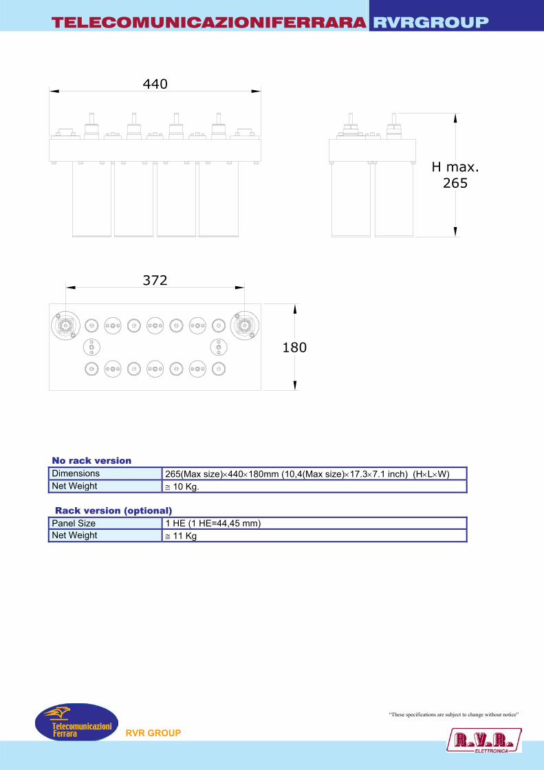
TELECOMUNICAZIONIFERRARA RVRGROUP
180
440
372
H max.265
No rack version Dimensions 265(Max size)×440×180mm (10,4(Max size)×17.3×7.1 inch) (H×L×W) Net Weight ≅ 10 Kg. Rack version (optional) Panel Size 1 HE (1 HE=44,45 mm) Net Weight ≅ 11 Kg
“These specifications are subject to change without notice”
P
RVR GROU 26
TELECOMUNICAZIONIFERRARA RVRGROUP
Model FFQC2-UHF • UHF BAND-PASS FILTER
• Band UHF 474 - 862 MHz
Poles Elliptical Response
These are four standard resonant cavity filters. All the models are used to make up mixers with severalThe band pass filters was designed as an extension of oUsing our industry-leading square, octagonal, cavity filsolution for the broadcaster located at multiple-user siteThe filter isolates the transmission system to eliminate s TYPICAL SPECIFICATIONS Model FFQC2-UHF Impedance 50 ohm Frequency Range 474 - 862 MHz VSWR ± 150 KHz 1.1:1 Max Insertion Loss at 0f < 0.26 dB @ V.C. Ch. 69
at 0f < 0.24 dB @ V.C. Ch. 21
Return Loss ± 150 KHz > 28 dB Group Delay Variation < 30 nS Bandwith 6 to 8 MHz Selectivity > 40 dB @ V.C. –5,5/+11 MHz
> 25 dB @ V.C. +11/+16,5 MHz Connectors 7/16” (In – Out) Max Power 2 KW Working Temperature -20°C ÷ +50°C Temperature Stability < 4 kHz / K Colour Enamel Gray Ral 7001 Materials Aluminium, Brass, Copper, PTFE, S
Silvering (min. 12µm thickness)
Features: • UHF 2 KW analog and 1 digital RMS TV output filter
• 3D electromagnetic CAD exclusive design
• 4 poles elliptical response: two transmission zeros for
• Foreshorten combine resonators structure; iris couplin
• High selectivity and low loss (Typ. 0.22 dB @ V.C. Ch. 6
• Exclusive thermal compensation technology providing
• Very compact, lightweight (9.1 kg) and extremely relia
P
channels. ur band pass combiner technology.
ter design, the filter provides a one-time-buy filtering . purious emissions.
tainless Steel,
IMD suppression
gs with fine bandwidth regulation
9 G)
high temperature stability (< 4 kHz/K)
ble
“These specifications are subject to change without notice”
RVR GROU
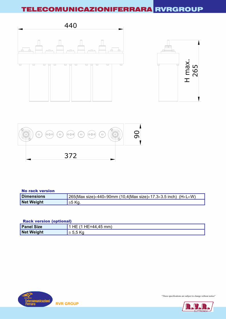
TELECOMUNICAZIONIFERRARA RVRGROUP
H m
ax.
265
440
90
372
No rack version Dimensions 265(Max size)×440×90mm (10,4(Max size)×17.3×3.5 inch) (H×L×W) Net Weight ≅5 Kg. Rack version (optional) Panel Size 1 HE (1 HE=44,45 mm) Net Weight ≅ 5,5 Kg
“These specifications are subject to change without notice”
P
RVR GROU
FM COMBINERS
STAR POINT DIPLEXER 70
STAR POINT TRIPLEXER 82
STAR POINT TETRAPLEXER 90
DOUBLE BALANCEDBRIDGE DIPLEXER 98
CATALOGGENERAL
RVR GROUP
RVRGROUPTELECOMUNICAZIONIFERRARA
TelecomunicazioniFerrara
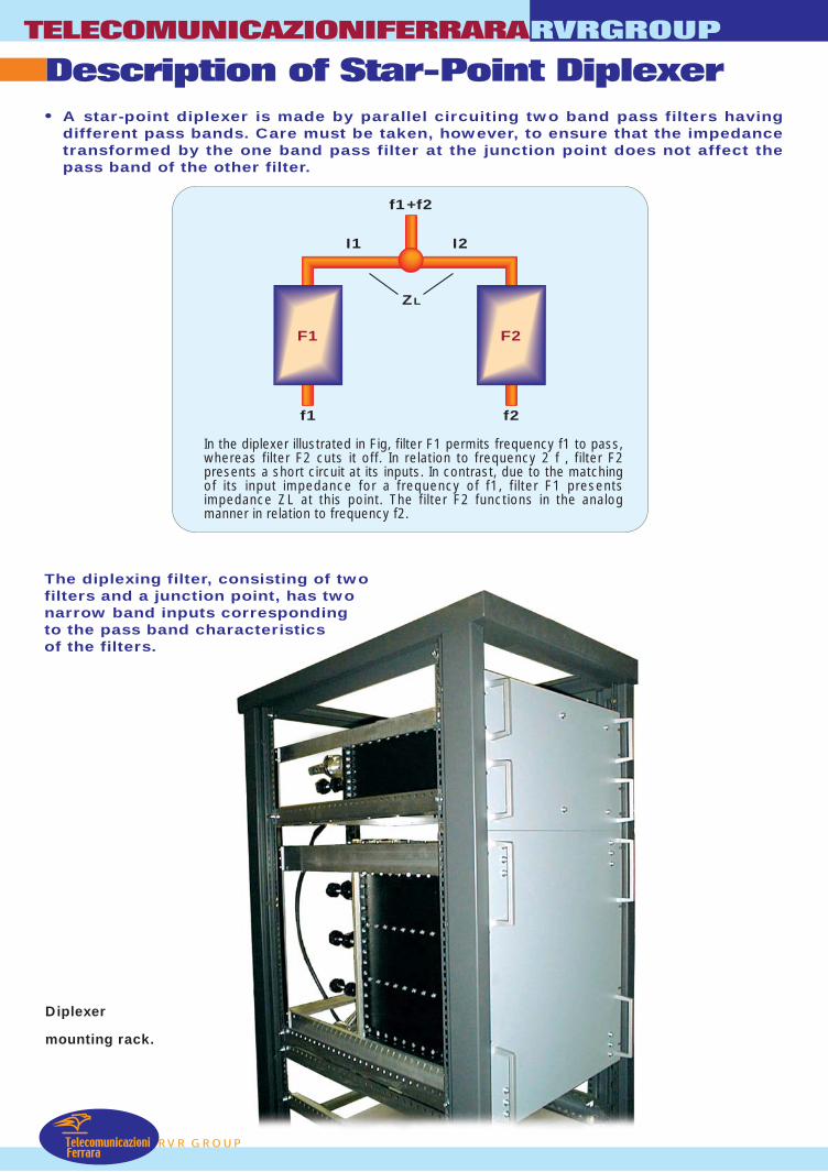
TelecomunicazioniFerrara
Description of Star-Point DiplexerTELECOMUNICAZIONIFERRARA
RVR GROUP
RVRGROUP
• A star-point diplexer is made by parallel circuiting two band pass filters havingdifferent pass bands. Care must be taken, however, to ensure that the impedancetransformed by the one band pass filter at the junction point does not affect thepass band of the other filter.
In the diplexer illustrated in Fig, filter F1 permits frequency f1 to pass,whereas filter F2 cuts it off. In relation to frequency 2 f , filter F2presents a short circuit at its inputs. In contrast, due to the matchingof its input impedance for a frequency of f1, filter F1 presentsimpedance ZL at this point. The filter F2 functions in the analogmanner in relation to frequency f2.
The diplexing filter, consisting of twofilters and a junction point, has twonarrow band inputs correspondingto the pass band characteristicsof the filters.
Diplexer
mounting rack.
F1 F2
f1 f2
I1 I2
f1+f2
ZL
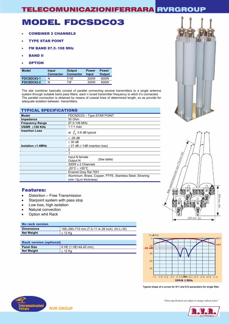
TELECOMUNICAZIONIFERRARA RVRGROUP
MODEL FDCSDC03 • COMBINER 2 CHANNELS
• TYPE STAR POINT
• FM BAND 87.5÷108 MHz
• BAND II
• OPTION
Model Input Connector
Output Connector
Power Input
Power Output
FDCSDC03-1 N 7/16” 300W 600W FDCSDC03-2 N 7/8” 300W 600W
The star combiner basically consist of parallel connecting several transmitters to a single antenna system through suitable band pass filters, each n tuned transmitter frequency to witch it’s connected. The parallel connection is obtained by means of coaxial lines of determined length, so as provide for adequate isolation between transmitters. TYPICAL SPECIFICATIONS Model FDCSDC03 – Type STAR POINT Impedance 50 Ohm Frequency Range 87.5-108 MHz VSWR ±150 KHz 1.1:1 max Insertion Loss at 0f 0.8 dB typical
Return Loss ±150Khz ≤ -26 dB Isolation ±2.5MHz Isolation ±1.4MHz
≥ 30 dB ≥ 27 dB (~1dB insertion loss)
Input Number 2 Output Number 1 Connectors standard Input N female
Output N Max Power 300W x 2 Channels Working Temperature -20°C ÷ +50°C Colour Enamel Gray Ral 7001
Materials Aluminium, Brass, Copper, PTFE, Stainless Steel, Silvering (min 12µm thickness)
(See table)
Features: • Distortion – Free Transmission • Starpoint system with pass stop • Low loss, high isolation • Natural convection • Option whit Rack No rack version Dimensions 185×290×710 mm (7.3×11.4×28 inch) (H×L×W) Net Weight ≅ 12 Kg
Rack version (optional) Panel Size 6 HE (1 HE=44,45 mm) Net Weight ≅ 12 Kg Typical shape of a curv
“The
P
es for S11 and S12 parameters for single filter
se specifications are subject to change without notice”
RVR GROU

TELECOMUNICAZIONIFERRARA RVRGROUP
MODEL FDCSTC03 • COMBINER 2 CHANNELS
• TYPE STAR POINT
• FM BAND 87.5÷108 MHz
• BAND II
• OPTION
Model Input Connector
Output Connector
Power Input
Power Output
FDCSTC03-1 N 7/16” 300W 600W FDCSTC03-2 N 7/8” 300W 600W
VERSION WITH OPTION RACK The star combiner basically consist of parallel connecting several transmitters to a single antenna system through suitable band pass filters, each n tuned transmitter frequency to witch it’s connected. The parallel connection is obtained by means of coaxial lines of determined length, so as provide for adequate isolation between transmitters. TYPICAL SPECIFICATIONS Model FDCSTC03 – Type STAR POINT Impedance 50 Ohm Frequency Range 87.5-108 MHz VSWR ±150 KHz 1.1:1 max Insertion Loss at 0f 0.8 dB typical
Return Loss ±150Khz ≤ -26 dB Isolation ±2.5MHz Isolation ±1.4MHz
≥ 30 dB ≥ 27 dB (~1dB insertion loss)
Input Number 2 Output Number 1 Connectors standard Input N female
Output N Max Power 300W x 2 Channels Working Temperature -20°C ÷ +50°C Colour Enamel Gray Ral 7001
Materials Aluminium, Brass, Copper, PTFE, Stainless Steel, Silvering (min 12µm thickness)
(See table)
Features: • Distortion – Free Transmission • Starpoint system with pass stop • Low loss, high isolation • Natural convection • Option whit Rack No rack version Dimensions 185×380×710 mm (7.3×11.4×28 inch) (H×L×W) Net Weight ≅ 18 Kg (triple cavity)
Rack version (optional) Panel Size 8 HE (1 HE=44,45 mm) Net Weight ≅ 18 Kg (triple cavity) Typical shape of a curves for S11 and S12 parameters for single filter
“These specifications are subject to change without notice”
P
RVR GROU
TELECOMUNICAZIONIFERRARA RVRGROUP
MODEL FDCSTC05 • COMBINER 2 CHANNELS
• TYPE STAR POINT
• RACK VERSION OPTION
• FM BAND 87.5÷108 MHz
• BAND II
• OPTION
The star combiner basically consist of parallel connecting several transmitters to a single antenna system through suitable band pass filters, each on tuned transmitter frequency to witch it’s connected.
The parallel connection is obtained by means of coaxial lines of determined length, s as provide for adequate isolation between transmitters. TYPICAL SPECIFICATIONS Model FDCSTC05 – Type STAR POINT Impedance 50 Ohm Frequency Range 87.5-108 MHz VSWR ±150 KHz 1.1:1 max Insertion Loss at 0f 0.65 dB max
Return Loss ±150Khz ≤ -26 dB Isolation ±1.6MHz ≥ 30 dB No. Input 2 No. Output 1 Connectors standard Input N
Output 7/16 Max Power 600 W × 2 CHANNELS Working Temperature -20°C ÷ +50°C Colour Enamel Gray Ral 7001
Materials Aluminium, Brass, Copper, PTFE, Stainless SteeSilvering (min 12µm thickness)
Features: • Distortion – Free Transmission • Low loss, high isolation • Natural convection Standard version Dimensions 400×350×680 mm (15.7×13.8×26.8 inch) (H×L×W) Net Weight ≅ 40 Kg
Rack version (optional) Panel Size 8 HE (1 HE=44,45 mm) Net Weight ≅ 40 Kg
Model Input Connector
Output Connector
Power Input
Power Output
FDCSTC05-1 7/16” 7/16” 600W 1200W FDCSTC05-2 7/16” 7/8” 600W 1200W
(See table)
di
Typical sh
P
o
l,
Maxoverall
mension size680 mm
400 mm
ape of a curves for S11 and S12 parameters for single f
“These specifications ar ubject to change w
350 mm
ilter
ithout notice”
RVR GROU
e s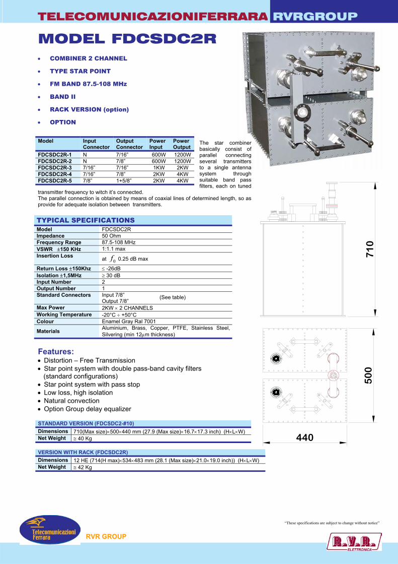
TELECOMUNICAZIONIFERRARA RVRGROUP
710
500
440
MODEL FDCSDC2R • COMBINER 2 CHANNEL
• TYPE STAR POINT
• FM BAND 87.5-108 MHz
• BAND II
• RACK VERSION (option)
• OPTION
The star combiner basically consist of parallel connecting several transmitters to a single antenna system through suitable band pass filters, each on tuned
transmitter frequency to witch it’s connected. The parallel connection is obtained by means of coaxial lines of determined length, so as provide for adequate isolation between transmitters. TYPICAL SPECIFICATIONS Model FDCSDC2R Impedance 50 Ohm Frequency Range 87.5-108 MHz VSWR ±150 KHz 1:1.1 max Insertion Loss at 0f 0.25 dB max
Return Loss ±150Khz ≤ -26dB Isolation ±1,5MHz ≥ 30 dB Input Number 2 Output Number 1 Standard Connectors Input 7/8”
Output 7/8” Max Power 2KW × 2 CHANNELS Working Temperature -20°C ÷ +50°C Colour Enamel Gray Ral 7001
Materials Aluminium, Brass, Copper, PTFE, Stainless Steel, Silvering (min 12µm thickness)
Features: • Distortion – Free Transmission • Star point system with double pass-band cavity filters (standard configurations) • Star point system with pass stop • Low loss, high isolation • Natural convection • Option Group delay equalizer STANDARD VERSION (FDCSDC2-#10) Dimensions 710(Max size)×500×440 mm (27.9 (Max size)×16.7×17.3 inch) (H×L×W) Net Weight ≅ 40 Kg VERSION WITH RACK (FDCSDC2R) Dimensions 12 HE (714(H max)×534×483 mm (28.1 (Max size)×21.0×19.0 inch)) (H×L×W) Net Weight ≅ 42 Kg
Model Input Connector
Output Connector
Power Input
Power Output
FDCSDC2R-1 N 7/16” 600W 1200W FDCSDC2R-2 N 7/8” 600W 1200W FDCSDC2R-3 7/16” 7/16” 1KW 2KW FDCSDC2R-4 7/16” 7/8” 2KW 4KW FDCSDC2R-5 7/8” 1+5/8” 2KW 4KW
(See table)
RVR GROUP
“These specifications are subject to change without notice”
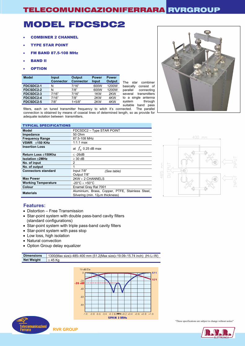
TELECOMUNICAZIONIFERRARA RVRGROUP
MODEL FDCSDC2 • COMBINER 2 CHANNEL
• TYPE STAR POINT
• FM BAND 87.5-108 MHz
• BAND II
• OPTION
The star combiner basically consist of parallel connecting several transmitters to a single antenna system through suitable band pass
filters, each on tuned transmitter frequency to witch it’s connected. The parallel connection is obtained by means of coaxial lines of determined length, so as provide for adequate isolation between transmitters. TYPICAL SPECIFICATIONS Model FDCSDC2 – Type STAR POINT Impedance 50 Ohm Frequency Range 87.5-108 MHz VSWR ±150 KHz 1:1.1 max Insertion Loss at 0f 0.25 dB max
Return Loss ±150Khz ≤ -26dB Isolation ±2MHz ≥ 30 dB No. of input 2 No. of output 1 Connectors standard Input 7/8”
Output 7/8” Max Power 2KW × 2 CHANNELS Working Temperature -20°C ÷ +50°C Colour Enamel Gray Ral 7001
Materials Aluminium, Brass, Copper, PTFE, Stainless Steel, Silvering (min. 12µm thickness)
Features: • Distortion – Free Transmission • Star-point system with double pass-band cavity filters (standard configurations) • Star-point system with triple pass-band cavity filters • Star-point system with pass stop • Low loss, high isolation • Natural convection • Option Group delay equalizer Dimensions 1300(Max size)×485×400 mm (51.2(Max size)×19.09×15.74 inch) (H×L×W) Net Weight ≅ 45 Kg
Model Input Connector
Output Connector
Power Input
Power Output
FDCSDC2-1 N 7/16” 600W 1200W FDCSDC2-2 N 7/8” 600W 1200W FDCSDC2-3 7/16” 7/16” 1KW 2KW FDCSDC2-4 7/16” 7/8” 2KW 4KW FDCSDC2-5 7/8” 1+5/8” 2KW 4KW
(See table)
RVR GROUP
“These specifications are subject to change without notice”
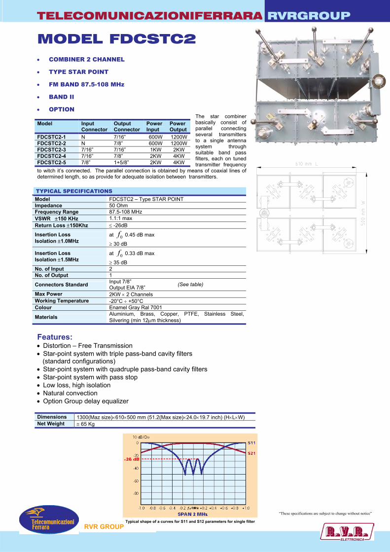
TELECOMUNICAZIONIFERRARA RVRGROUP
MODEL FDCSTC2 • COMBINER 2 CHANNEL
• TYPE STAR POINT
• FM BAND 87.5-108 MHz
• BAND II
• OPTION The star combiner basically consist of parallel connecting several transmitters to a single antenna system through suitable band pass filters, each on tuned transmitter frequency
to witch it’s connected. The parallel connection is obtained by means of coaxial lines of determined length, so as provide for adequate isolation between transmitters. TYPICAL SPECIFICATIONS Model FDCSTC2 – Type STAR POINT Impedance 50 Ohm Frequency Range 87.5-108 MHz VSWR ±150 KHz 1.1:1 max Return Loss ±150Khz ≤ -26dB
Insertion Loss Isolation ±1.0MHz
at 0f 0.45 dB max
≥ 30 dB
Insertion Loss Isolation ±1.5MHz
at 0f 0.33 dB max
≥ 35 dB No. of Input 2 No. of Output 1
Connectors Standard Input 7/8” Output EIA 7/8”
Max Power 2KW × 2 Channels Working Temperature -20°C ÷ +50°C Colour Enamel Gray Ral 7001
Materials Aluminium, Brass, Copper, PTFE, Stainless Steel, Silvering (min 12µm thickness)
Features: • Distortion – Free Transmission • Star-point system with triple pass-band cavity filters (standard configurations) • Star-point system with quadruple pass-band cavity filters • Star-point system with pass stop • Low loss, high isolation • Natural convection • Option Group delay equalizer Dimensions 1300(Maz size)×610×500 mm (51.2(Max size)×24.0×19.7 inch) (H×L×W) Net Weight ≅ 65 Kg
Model Input Connector
Output Connector
Power Input
Power Output
FDCSTC2-1 N 7/16” 600W 1200W FDCSTC2-2 N 7/8” 600W 1200W FDCSTC2-3 7/16” 7/16” 1KW 2KW FDCSTC2-4 7/16” 7/8” 2KW 4KW FDCSTC2-5 7/8” 1+5/8” 2KW 4KW
RVR GROUP
“These specifications are subject to change without notice”
Typical shape of a curves for S11 and S12 parameters for single filter
(See table)
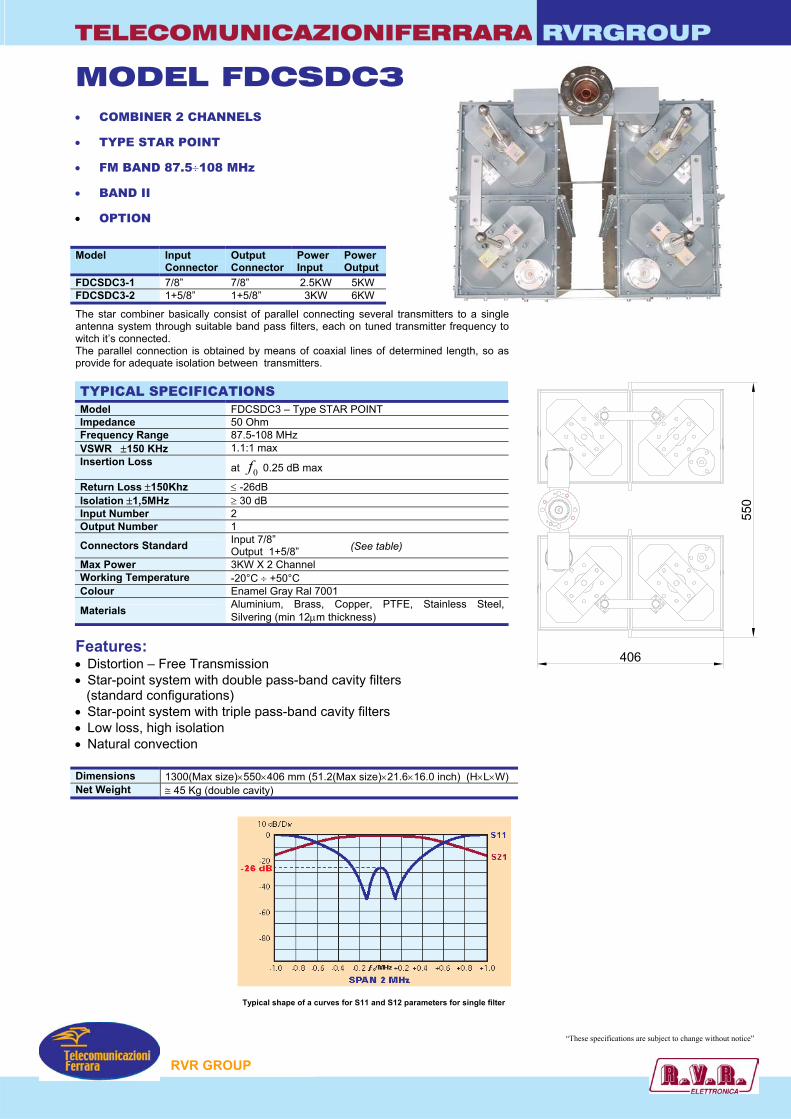
TELECOMUNICAZIONIFERRARA RVRGROUP
MODEL FDCSDC3 • COMBINER 2 CHANNELS
• TYPE STAR POINT
• FM BAND 87.5÷108 MHz
• BAND II
• OPTION
The star combiner basically consist of parallel connecting several transmitters to a single antenna system through suitable band pass filters, each on tuned transmitter frequency to witch it’s connected. The parallel connection is obtained by means of coaxial lines of determined length, so as provide for adequate isolation between transmitters. TYPICAL SPECIFICATIONS Model FDCSDC3 – Type STAR POINT Impedance 50 Ohm Frequency Range 87.5-108 MHz VSWR ±150 KHz 1.1:1 max Insertion Loss at 0f 0.25 dB max
Return Loss ±150Khz ≤ -26dB Isolation ±1,5MHz ≥ 30 dB Input Number 2 Output Number 1
Connectors Standard Input 7/8” Output 1+5/8”
Max Power 3KW X 2 Channel Working Temperature -20°C ÷ +50°C Colour Enamel Gray Ral 7001
Materials Aluminium, Brass, Copper, PTFE, Stainless Steel, Silvering (min 12µm thickness)
Features: • Distortion – Free Transmission • Star-point system with double pass-band cavity filters (standard configurations) • Star-point system with triple pass-band cavity filters • Low loss, high isolation • Natural convection Dimensions 1300(Max size)×550×406 mm (51.2(Max size)×21.6×16.0 inch) (H×L×W) Net Weight ≅ 45 Kg (double cavity)
Model Input Connector
Output Connector
Power Input
Power Output
FDCSDC3-1 7/8” 7/8” 2.5KW 5KW FDCSDC3-2 1+5/8” 1+5/8” 3KW 6KW
(See table)
RVR GROUP
“These specifications are subject to change without notice”
Typical shape of a curves for S11 and S12 parameters for single filter
550
406
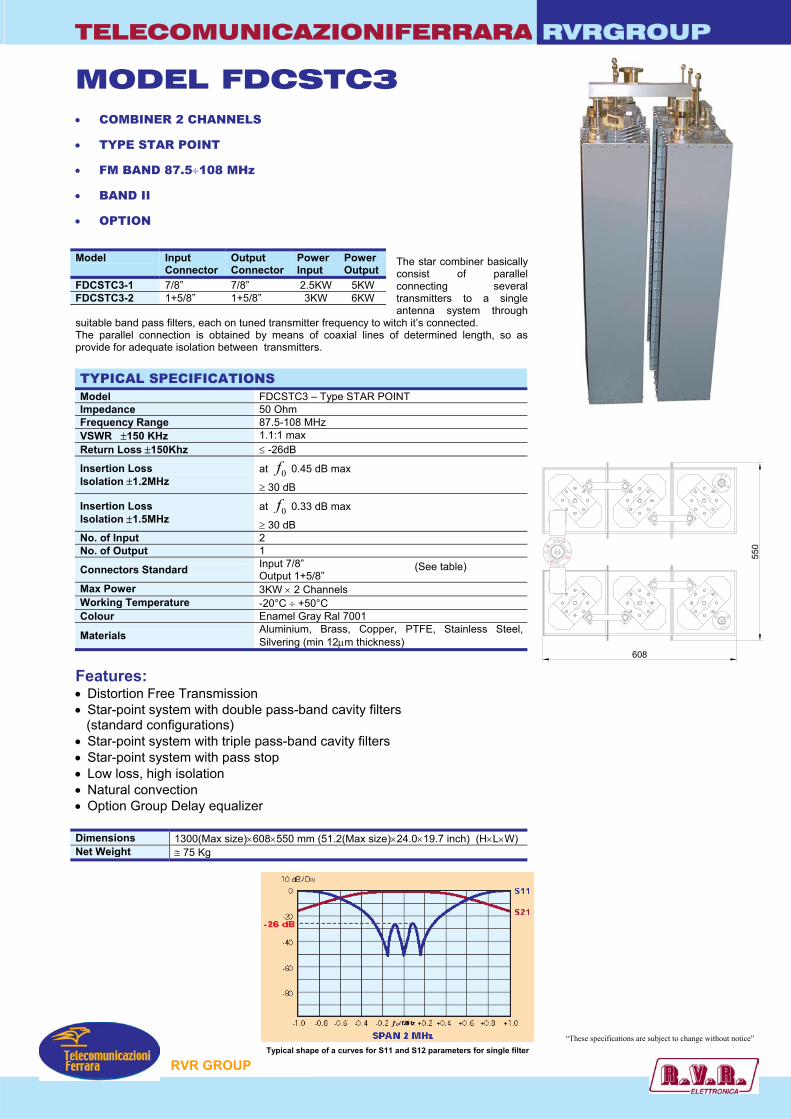
TELECOMUNICAZIONIFERRARA RVRGROUP
550
608
MODEL FDCSTC3 • COMBINER 2 CHANNELS
• TYPE STAR POINT
• FM BAND 87.5÷108 MHz
• BAND II
• OPTION
The star combiner basically consist of parallel connecting several transmitters to a single antenna system through
suitable band pass filters, each on tuned transmitter frequency to witch it’s connected. The parallel connection is obtained by means of coaxial lines of determined length, so as provide for adequate isolation between transmitters. TYPICAL SPECIFICATIONS Model FDCSTC3 – Type STAR POINT Impedance 50 Ohm Frequency Range 87.5-108 MHz VSWR ±150 KHz 1.1:1 max Return Loss ±150Khz ≤ -26dB
Insertion Loss Isolation ±1.2MHz
at 0f 0.45 dB max
≥ 30 dB
Insertion Loss Isolation ±1.5MHz
at 0f 0.33 dB max
≥ 30 dB No. of Input 2 No. of Output 1
Connectors Standard Input 7/8” Output 1+5/8”
Max Power 3KW × 2 Channels Working Temperature -20°C ÷ +50°C Colour Enamel Gray Ral 7001
Materials Aluminium, Brass, Copper, PTFE, Stainless Steel, Silvering (min 12µm thickness)
Features: • Distortion Free Transmission • Star-point system with double pass-band cavity filters (standard configurations) • Star-point system with triple pass-band cavity filters • Star-point system with pass stop • Low loss, high isolation • Natural convection • Option Group Delay equalizer Dimensions 1300(Max size)×608×550 mm (51.2(Max size)×24.0×19.7 inch) (H×L×W) Net Weight ≅ 75 Kg
Model Input Connector
Output Connector
Power Input
Power Output
FDCSTC3-1 7/8” 7/8” 2.5KW 5KW FDCSTC3-2 1+5/8” 1+5/8” 3KW 6KW
(See table)
RVR GROUP
“These specifications are subject to change without notice” Typical shape of a curves for S11 and S12 parameters for single filter
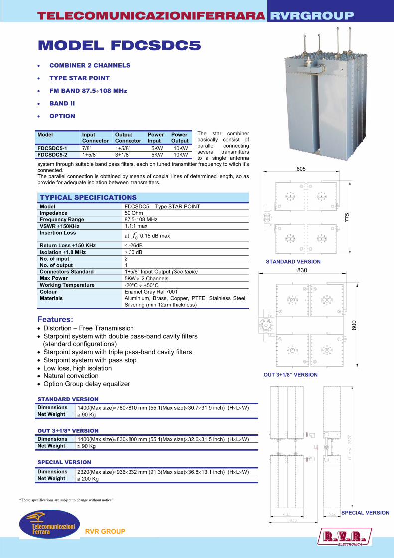
TELECOMUNICAZIONIFERRARA RVRGROUP
MODEL FDCSDC5 • COMBINER 2 CHANNELS
• TYPE STAR POINT
• FM BAND 87.5÷108 MHz
• BAND II
• OPTION
The star combiner basically consist of parallel connecting several transmitters to a single antenna
system through suitable band pass filters, each on tuned transmitter frequency to witch it’s connected. The parallel connection is obtained by means of coaxial lines of determined length, so as provide for adequate isolation between transmitters. TYPICAL SPECIFICATIONS Model FDCSDC5 – Type STAR POINT Impedance 50 Ohm Frequency Range 87.5-108 MHz VSWR ±150KHz 1.1:1 max Insertion Loss at 0f 0.15 dB max
Return Loss ±150 KHz ≤ -26dB Isolation ±1.8 MHz ≥ 30 dB No. of input 2 No. of output 1 Connectors Standard 1+5/8” Input-Output (See table) Max Power 5KW × 2 Channels Working Temperature -20°C ÷ +50°C Colour Enamel Gray Ral 7001 Materials Aluminium, Brass, Copper, PTFE, Stainless Steel,
Silvering (min 12µm thickness)
Features: • Distortion – Free Transmission • Starpoint system with double pass-band cavity filters (standard configurations) • Starpoint system with triple pass-band cavity filters • Starpoint system with pass stop • Low loss, high isolation • Natural convection • Option Group delay equalizer STANDARD VERSION Dimensions 1400(Max size)×780×810 mm (55.1(Max size)×30.7×31.9 inch) (H×L×W) Net Weight ≅ 90 Kg
OUT 3+1/8” VERSION Dimensions 1400(Max size)×830×800 mm (55.1(Max size)×32.6×31.5 inch) (H×L×W) Net Weight ≅ 90 Kg
SPECIAL VERSION
Model Input Connector
Output Connector
Power Input
Power Output
FDCSDC5-1 7/8” 1+5/8” 5KW 10KW FDCSDC5-2 1+5/8” 3+1/8” 5KW 10KW
Dimensions 2320(Max size)×936×332 mm (91.3(Max size)×36.8×13.1 inch) (H×L×W) Net Weight ≅ 200 Kg
775
805
STANDARD VERSION
OUT 3+1/8” VERSION
830
800
SPECIAL VERSION
RVR GROUP
“These specifications are subject to change without notice”
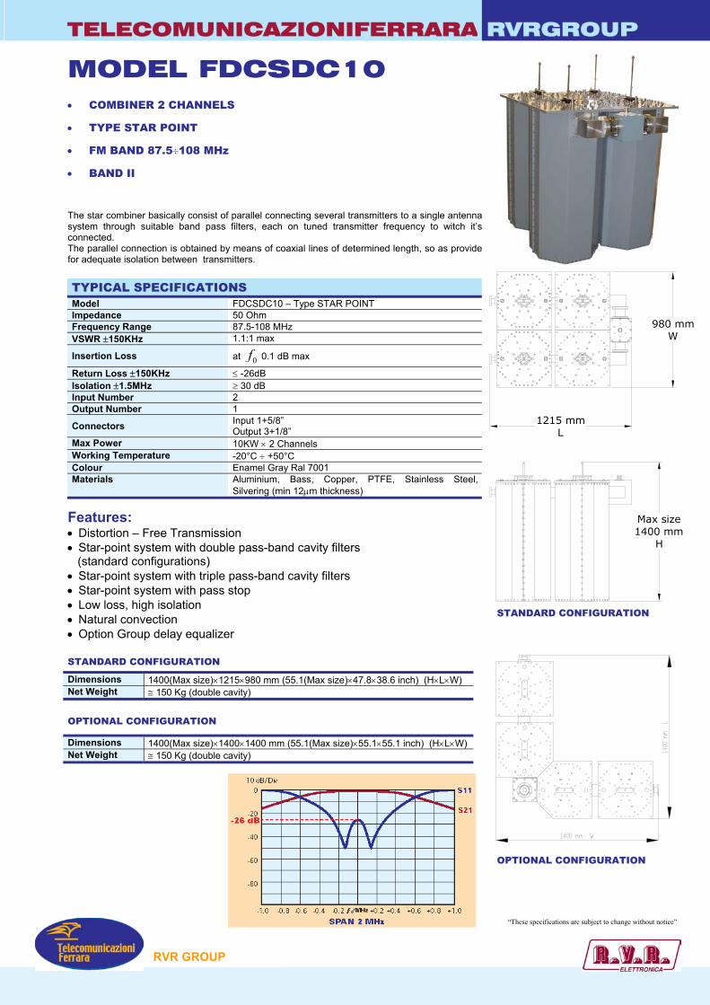
TELECOMUNICAZIONIFERRARA RVRGROUP
Max size1400 mm
H
1215 mmL
980 mmW
MODEL FDCSDC10 • COMBINER 2 CHANNELS
• TYPE STAR POINT
• FM BAND 87.5÷108 MHz
• BAND II
The star combiner basically consist of parallel connecting several transmitters to a single antenna system through suitable band pass filters, each on tuned transmitter frequency to witch it’s connected. The parallel connection is obtained by means of coaxial lines of determined length, so as provide for adequate isolation between transmitters. TYPICAL SPECIFICATIONS Model FDCSDC10 – Type STAR POINT Impedance 50 Ohm Frequency Range 87.5-108 MHz VSWR ±150KHz 1.1:1 max
Insertion Loss at 0f 0.1 dB max
Return Loss ±150KHz ≤ -26dB Isolation ±1.5MHz ≥ 30 dB Input Number 2 Output Number 1
Connectors Input 1+5/8” Output 3+1/8”
Max Power 10KW × 2 Channels Working Temperature -20°C ÷ +50°C Colour Enamel Gray Ral 7001 Materials Aluminium, Bass, Copper, PTFE, Stainless Steel,
Silvering (min 12µm thickness)
Features: • Distortion – Free Transmission • Star-point system with double pass-band cavity filters (standard configurations) • Star-point system with triple pass-band cavity filters • Star-point system with pass stop • Low loss, high isolation • Natural convection • Option Group delay equalizer STANDARD CONFIGURATION
OPTIONAL CONFIGURATION
Dimensions 1400(Max size)×1215×980 mm (55.1(Max size)×47.8×38.6 inch) (H×L×W) Net Weight ≅ 150 Kg (double cavity)
Dimensions 1400(Max size)×1400×1400 mm (55.1(Max size)×55.1×55.1 inch) (H×L×W) Net Weight ≅ 150 Kg (double cavity)
RVR GROUP
“These specifications are subject to change without notice”
STANDARD CONFIGURATION
OPTIONAL CONFIGURATION
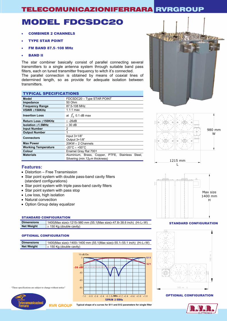
TELECOMUNICAZIONIFERRARA RVRGROUP
Max size1400 mm
H
1215 mmL
980 mmW
MODEL FDCSDC20 • COMBINER 2 CHANNELS
• TYPE STAR POINT
• FM BAND 87.5÷108 MHz
• BAND II
The star combiner basically consist of parallel connecting several transmitters to a single antenna system through suitable band pass filters, each on tuned transmitter frequency to witch it’s connected. The parallel connection is obtained by means of coaxial lines of determined length, so as provide for adequate isolation between transmitters. TYPICAL SPECIFICATIONS Model FDCSDC20 – Type STAR POINT Impedance 50 Ohm Frequency Range 87.5-108 MHz VSWR ±150KHz 1.1:1 max
Insertion Loss at 0f 0.1 dB max
Return Loss ±150KHz ≤ -26dB Isolation ±1.5MHz ≥ 30 dB Input Number 2 Output Number 1
Connectors Input 3+1/8” Output 3+1/8”
Max Power 20KW × 2 Channels Working Temperature -20°C ÷ +50°C Colour Enamel Gray Ral 7001 Materials Aluminium, Brass, Copper, PTFE, Stainless Steel,
Silvering (min.12µm thickness)
Features: • Distortion – Free Transmission • Star point system with double pass-band cavity filters (standard configurations) • Star point system with triple pass-band cavity filters • Star point system with pass stop • Low loss, high isolation • Natural convection • Option Group delay equalizer STANDARD CONFIGURATION
OPTIONAL CONFIGURATION
Dimensions 1400(Max size)×1215×980 mm (55.1(Max size)×47.8×38.6 inch) (H×L×W) Net Weight ≅ 150 Kg (double cavity)
Dimensions 1400(Max size)×1400×1400 mm (55.1(Max size)×55.1×55.1 inch) (H×L×W) Net Weight ≅ 150 Kg (double cavity)
STANDARD CONFIGURATION
OPTIONAL CONFIGURATION
RVR GROUP
“These specifications are subject to change without notice”
Typical shape of a curves for S11 and S12 parameters for single filter
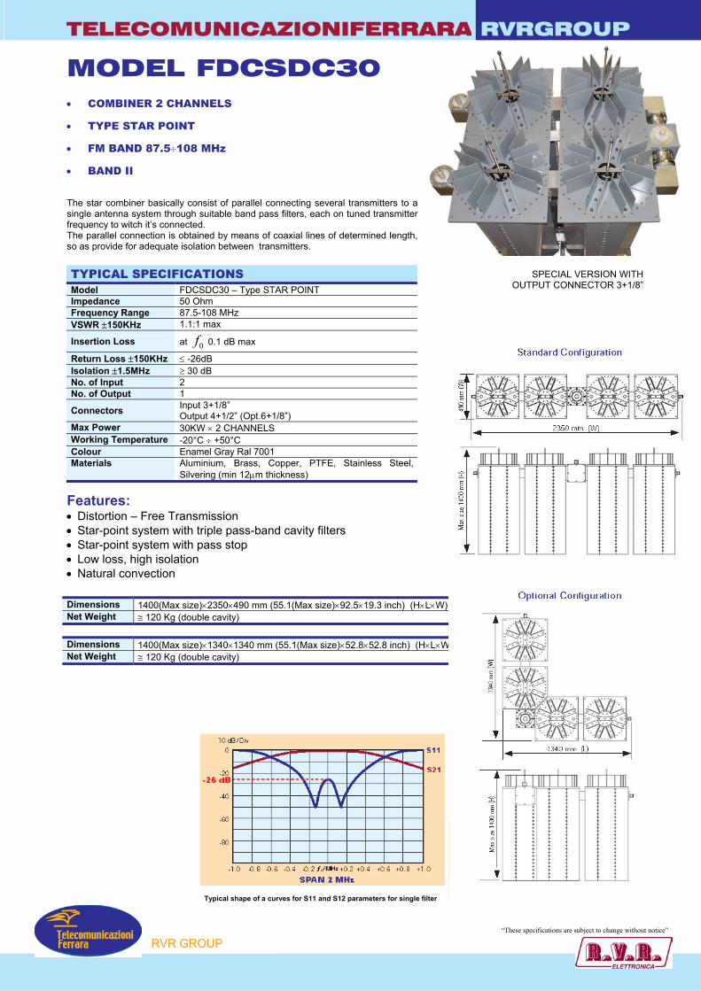
TELECOMUNICAZIONIFERRARA RVRGROUP
MODEL FDCSDC30 • COMBINER 2 CHANNELS
• TYPE STAR POINT
• FM BAND 87.5÷108 MHz
• BAND II
The star combiner basically consist of parallel connecting several transmitters to a single antenna system through suitable band pass filters, each on tuned transmitter frequency to witch it’s connected. The parallel connection is obtained by means of coaxial lines of determined length, so as provide for adequate isolation between transmitters. TYPICAL SPECIFICATIONS Model FDCSDC30 – Type STAR POINT Impedance 50 Ohm Frequency Range 87.5-108 MHz VSWR ±150KHz 1.1:1 max
Insertion Loss at 0f 0.1 dB max
Return Loss ±150KHz ≤ -26dB Isolation ±1.5MHz ≥ 30 dB No. of Input 2 No. of Output 1
Connectors Input 3+1/8” Output 4+1/2” (Opt.6+1/8”)
Max Power 30KW × 2 CHANNELS Working Temperature -20°C ÷ +50°C Colour Enamel Gray Ral 7001 Materials Aluminium, Brass, Copper, PTFE, Stainless Steel,
Silvering (min 12µm thickness)
Features: • Distortion – Free Transmission • Star-point system with triple pass-band cavity filters • Star-point system with pass stop • Low loss, high isolation • Natural convection Dimensions 1400(Max size)×2350×490 mm (55.1(Max size)×92.5×19.3 inch) (H×L×W) Net Weight ≅ 120 Kg (double cavity) Dimensions 1400(Max size)×1340×1340 mm (55.1(Max size)×52.8×52.8 inch) (H×L×W) Net Weight ≅ 120 Kg (double cavity)
Typical shape of a curves for S11 and S12 parameters for single filter
RVR GROUP
“These specifications are subject to change without notice”
SPECIAL VERSION WITHOUTPUT CONNECTOR 3+1/8”
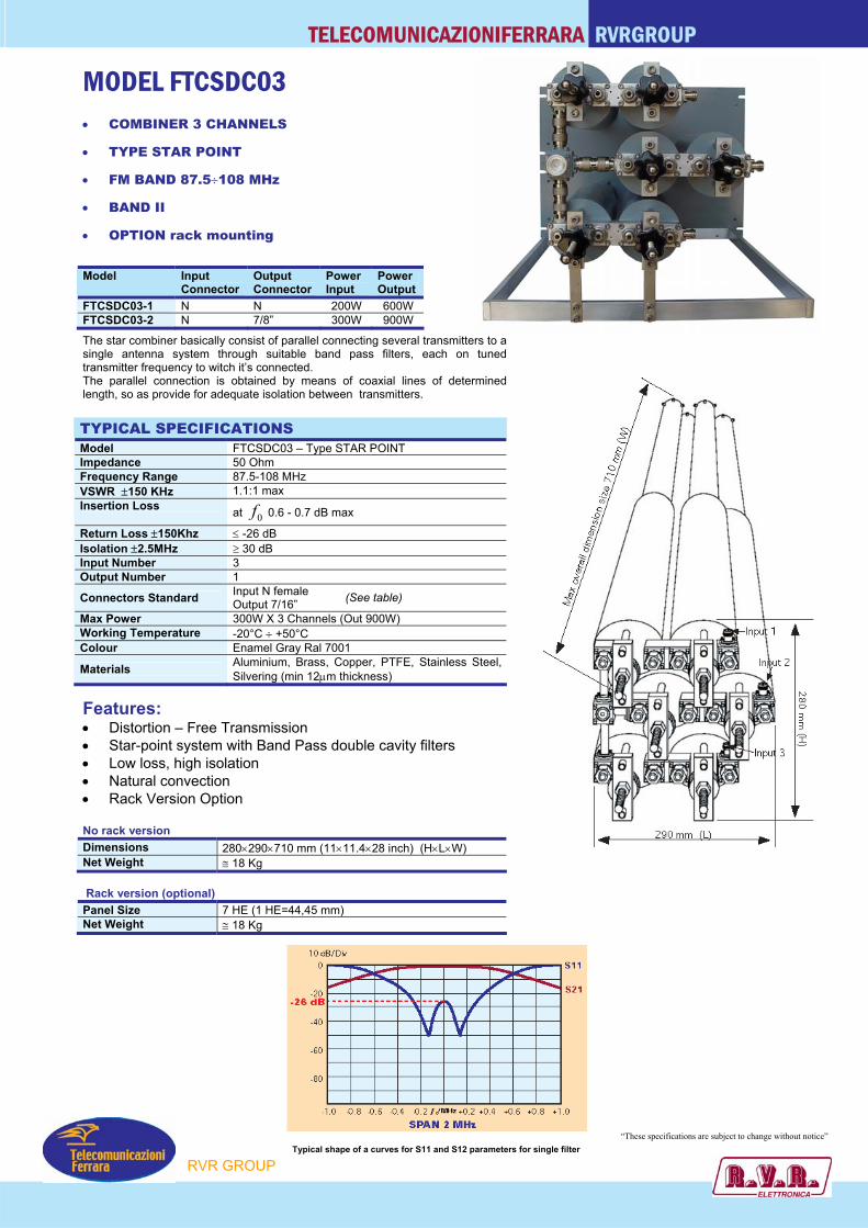
TELECOMUNICAZIONIFERRARA RVRGROUP
MODEL FTCSDC03 • COMBINER 3 CHANNELS
• TYPE STAR POINT
• FM BAND 87.5÷108 MHz
• BAND II
• OPTION rack mounting
The star combiner basically consist of parallel connecting several transmitters to a single antenna system through suitable band pass filters, each on tuned transmitter frequency to witch it’s connected. The parallel connection is obtained by means of coaxial lines of determined length, so as provide for adequate isolation between transmitters. TYPICAL SPECIFICATIONS Model FTCSDC03 – Type STAR POINT Impedance 50 Ohm Frequency Range 87.5-108 MHz VSWR ±150 KHz 1.1:1 max Insertion Loss at 0f 0.6 - 0.7 dB max
Return Loss ±150Khz ≤ -26 dB Isolation ±2.5MHz ≥ 30 dB Input Number 3 Output Number 1
Connectors Standard Input N female Output 7/16”
Max Power 300W X 3 Channels (Out 900W) Working Temperature -20°C ÷ +50°C Colour Enamel Gray Ral 7001
Materials Aluminium, Brass, Copper, PTFE, Stainless Steel, Silvering (min 12µm thickness)
Features: • Distortion – Free Transmission • Star-point system with Band Pass double cavity filters • Low loss, high isolation • Natural convection • Rack Version Option No rack version Dimensions 280×290×710 mm (11×11.4×28 inch) (H×L×W) Net Weight ≅ 18 Kg Rack version (optional) Panel Size 7 HE (1 HE=44,45 mm) Net Weight ≅ 18 Kg
Model Input Connector
Output Connector
Power Input
Power Output
FTCSDC03-1 N N 200W 600W FTCSDC03-2 N 7/8” 300W 900W
(See table)
RVR GROUP
“These specifications are subject to change without notice” Typical shape of a curves for S11 and S12 parameters for single filter

TELECOMUNICAZIONIFERRARA RVRGROUP
RACK VERSION (OPTION)
MODEL FTCSTC03 • COMBINER 3 CHANNELS
• TYPE STAR POINT
• FM BAND 87.5÷108 MHz
• BAND II
• RACK VERSION OPTION
• OPTION
The star combiner basically consist of parallel connecting several transmitters to a single antenna
system through suitable band pass filters, each on tuned transmitter frequency to witch it’s connected. The parallel connection is obtained by means of coaxial lines of determined length, so as provide for adequate isolation between transmitters. TYPICAL SPECIFICATIONS Model FTCSTC03 – Type STAR POINT Impedance 50 Ohm Frequency Range 87.5-108 MHz VSWR ±150KHz 1.1:1 max Insertion Loss at 0f 0.8 dB max (triple cavity)
Return Loss ±150KHz ≤ -26 dB Isolation ±2MHz ≥ 30 dB Input Number 3 Output Number 1
Connectors Input N female Output 7/16” (opt. 7/8” EIA)
Max Power 300 W X 3 Channels Working Temperature -20°C ÷ +50°C Colour Enamel gray ral 7001
Materials Aluminium, Brass, Copper, PTFE, Stainless Steel, Silvering (min. 12µm thickness)
Features: • Distortion – Free Transmission • Star point system with double pass-band cavity filters • Star point system with triple pass-band cavity filters (standard configurations) • Star point system with pass stop • Low loss, high isolation • Natural convection • OPTION Group delay equaliser – Equipment Rack Mounting No rack version Dimensions 280×380×710 mm (280×15×28 inch) (H×L×W) Weight ≅ 27 Kg (triple cavity)
Rack version (optional) Panel Size 8 HE (1 HE=44,45 mm) Weight ≅ 27 Kg (triple cavity)
Model Input Connector
Output Connector
Power Input
Power Output
FTCSTC03-1 N N 200W 600W FTCSTC03-2 N 7/8” 300W 900W
RVR GROUP
“These specifications are subject to change without notice”
Typicalshape of a
curvesfor S11
and S12parameters
for singlefilter
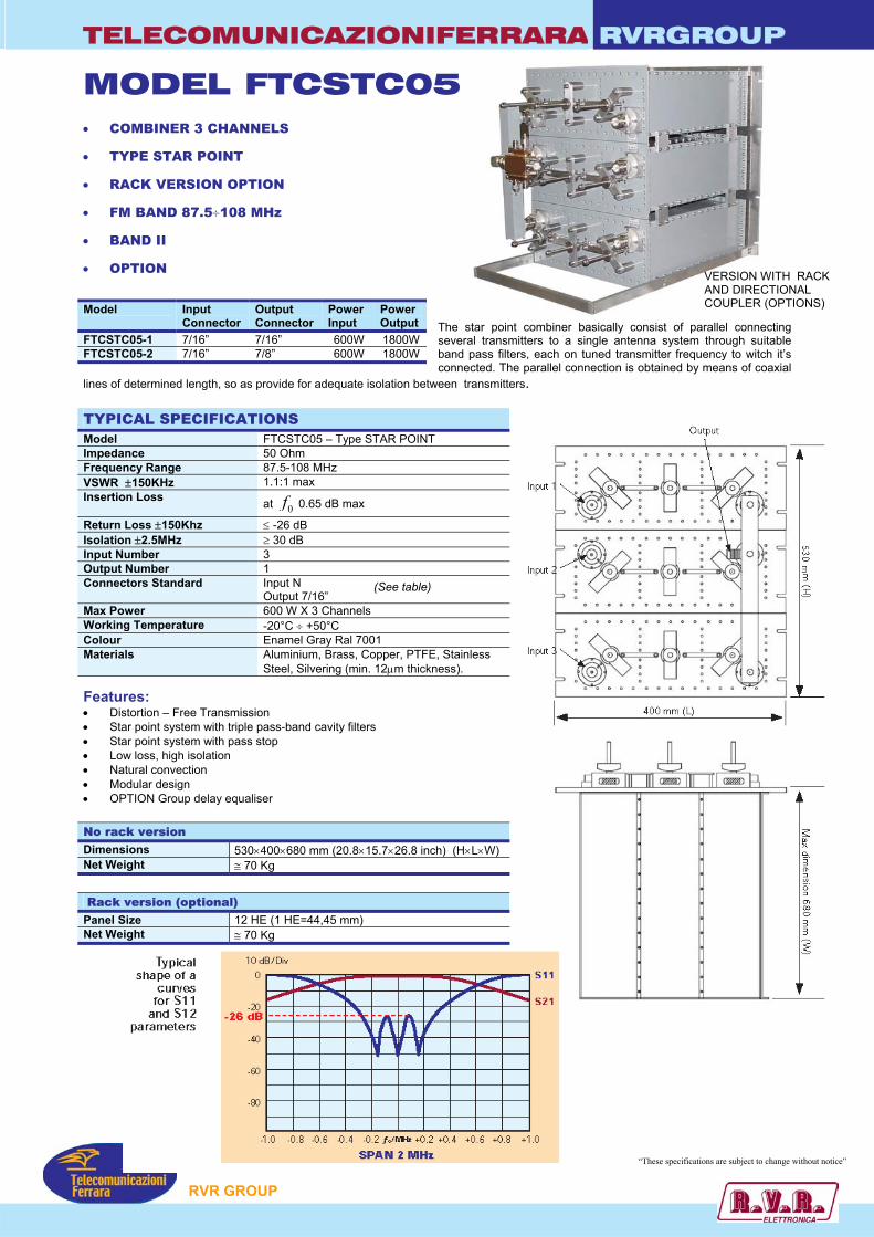
TELECOMUNICAZIONIFERRARA RVRGROUP
MODEL FTCSTC05 • COMBINER 3 CHANNELS
• TYPE STAR POINT
• RACK VERSION OPTION
• FM BAND 87.5÷108 MHz
• BAND II
• OPTION VERSION WITH RACK AND DIRECTIONAL COUPLER (OPTIONS)
The star point combiner basically consist of parallel connecting several transmitters to a single antenna system through suitable band pass filters, each on tuned transmitter frequency to witch it’s connected. The parallel connection is obtained by means of coaxial
lines of determined length, so as provide for adequate isolation between transmitters.
Model Input Connector
Output Connector
Power Input
Power Output
FTCSTC05-1 7/16” 7/16” 600W 1800W FTCSTC05-2 7/16” 7/8” 600W 1800W
TYPICAL SPECIFICATIONS Model FTCSTC05 – Type STAR POINT Impedance 50 Ohm Frequency Range 87.5-108 MHz VSWR ±150KHz 1.1:1 max Insertion Loss at 0f 0.65 dB max
Return Loss ±150Khz ≤ -26 dB Isolation ±2.5MHz ≥ 30 dB Input Number 3 Output Number 1 Connectors Standard Input N
Output 7/16” Max Power 600 W X 3 Channels Working Temperature -20°C ÷ +50°C Colour Enamel Gray Ral 7001 Materials Aluminium, Brass, Copper, PTFE, Stainless
Steel, Silvering (min. 12µm thickness).
(See table)
Features: • Distortion – Free Transmission • Star point system with triple pass-band cavity filters • Star point system with pass stop • Low loss, high isolation • Natural convection • Modular design • OPTION Group delay equaliser No rack version Dimensions 530×400×680 mm (20.8×15.7×26.8 inch) (H×L×W) Net Weight ≅ 70 Kg
Rack version (optional) Panel Size 12 HE (1 HE=44,45 mm) Net Weight ≅ 70 Kg
“These specifications are subject to change without notice”
P
RVR GROU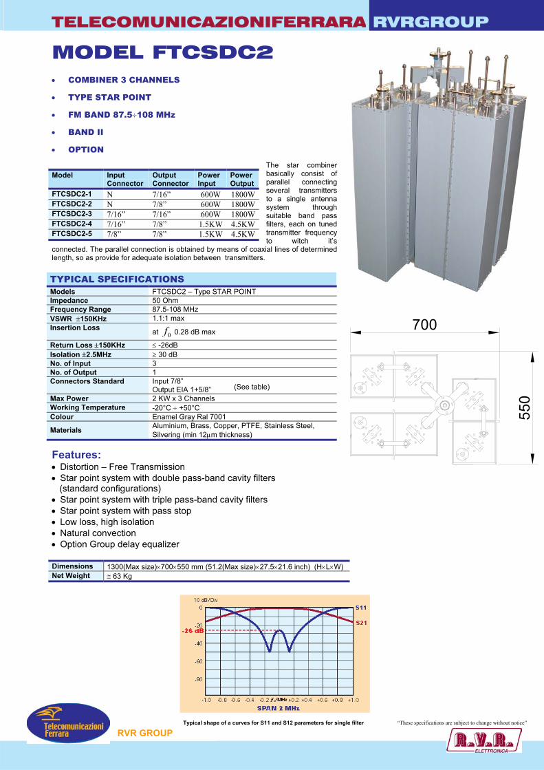
TELECOMUNICAZIONIFERRARA RVRGROUP
MODEL FTCSDC2 • COMBINER 3 CHANNELS
• TYPE STAR POINT
• FM BAND 87.5÷108 MHz
• BAND II
• OPTION
The star combiner basically consist of parallel connecting several transmitters to a single antenna system through suitable band pass filters, each on tuned transmitter frequency to witch it’s
connected. The parallel connection is obtained by means of coaxial lines of determined length, so as provide for adequate isolation between transmitters. TYPICAL SPECIFICATIONS Models FTCSDC2 – Type STAR POINT Impedance 50 Ohm Frequency Range 87.5-108 MHz VSWR ±150KHz 1.1:1 max Insertion Loss at 0f 0.28 dB max
Return Loss ±150KHz ≤ -26dB Isolation ±2.5MHz ≥ 30 dB No. of Input 3 No. of Output 1 Connectors Standard Input 7/8”
Output EIA 1+5/8” Max Power 2 KW x 3 Channels Working Temperature -20°C ÷ +50°C Colour Enamel Gray Ral 7001
Materials Aluminium, Brass, Copper, PTFE, Stainless Steel, Silvering (min 12µm thickness)
Features: • Distortion – Free Transmission • Star point system with double pass-band cavity filters (standard configurations) • Star point system with triple pass-band cavity filters • Star point system with pass stop • Low loss, high isolation • Natural convection • Option Group delay equalizer Dimensions 1300(Max size)×700×550 mm (51.2(Max size)×27.5×21.6 inch) (H×L×W) Net Weight ≅ 63 Kg
Model Input Connector
Output Connector
Power Input
Power Output
FTCSDC2-1 N 7/16” 600W 1800WFTCSDC2-2 N 7/8” 600W 1800WFTCSDC2-3 7/16” 7/16” 600W 1800WFTCSDC2-4 7/16” 7/8” 1.5KW 4.5KWFTCSDC2-5 7/8” 7/8” 1.5KW 4.5KW
(See table)
700
550
RVR GROUP
“These specifications are subject to change without notice” Typical shape of a curves for S11 and S12 parameters for single filter

TELECOMUNICAZIONIFERRARA RVRGROUP
70
0
440
19"
16
HE
MODEL FTCSDC2R • COMBINER 3 CHANNEL
• TYPE STAR POINT
• FM BAND 87.5-108 MHz
• BAND II
• RACK VERSION (option)
• OPTION
The star combiner basically consist of parallel connecting several transmitters to a single antenna system through suitable band pass filters, each on
tuned transmitter frequency to witch it’s connected. The parallel connection is obtained by means of coaxial lines of determined length, so as provide for adequate isolation between transmitters. TYPICAL SPECIFICATIONS Model FTCSDC2R Impedance 50 Ohm Frequency Range 87.5-108 MHz VSWR ±150 KHz 1:1.1 max Insertion Loss at 0f 0.25 dB max
Return Loss ±150Khz ≤ -26dB Isolation ±1,5MHz ≥ 30 dB Input Number 3 Output Number 1 Connectors Standard Input 7/8”
Output 7/8” Max Power 2KW × 3 CHANNELS Working Temperature -20°C ÷ +50°C Colour Enamel Gray Ral 7001
Materials Aluminium, Brass, Copper, PTFE, Stainless Steel, Silvering (min 12µm thickness)
Features: • Distortion – Free Transmission • Star point system with double pass-band cavity filters • Star point system with pass stop • Low loss, high isolation • Natural convection • Option Group delay equalizer • Rack version Option STANDARD VERSION Dimensions 710(Max size)×700×440mm (27.9(Max size)×27.6×17.3 inch) (H×L×W) Net Weight ≅ 60 Kg VERSION WITH RACK Dimensions 16 HE (714(H max) (28.1 (Max size) inch)) Net Weight ≅ 62 Kg
Model Input Connector
Output Connector
Power Input
Power Output
FTCSDC2R-1 N 7/16” 600W 1.8KW FTCSDC2R-2 N 7/8” 600W 1.8KW FTCSDC2R-3 7/16” 7/16” 660W 2KW FTCSDC2R-4 7/16” 7/8” 1650W 5KW FTCSDC2R-5 7/8” 7/8” 1650W 5KW
(See table)
RVR GROUP
“These specifications are subject to change without notice”
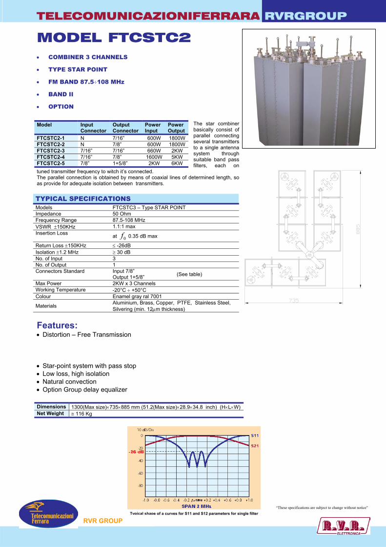
TELECOMUNICAZIONIFERRARA RVRGROUP
MODEL FTCSTC2 • COMBINER 3 CHANNELS
• TYPE STAR POINT
• FM BAND 87.5÷108 MHz
• BAND II
• OPTION
The star combiner basically consist of parallel connecting several transmitters to a single antenna system through suitable band pass filters, each on
tuned transmitter frequency to witch it’s connected. The parallel connection is obtained by means of coaxial lines of determined length, so as provide for adequate isolation between transmitters. TYPICAL SPECIFICATIONS Models FTCSTC3 – Type STAR POINT Impedance 50 Ohm Frequency Range 87.5-108 MHz VSWR ±150KHz 1.1:1 max Insertion Loss at 0f 0.35 dB max
Return Loss ±150KHz ≤ -26dB Isolation ±1.2 MHz ≥ 30 dB No. of Input 3 No. of Output 1 Connectors Standard Input 7/8”
Output 1+5/8” Max Power 2KW x 3 Channels Working Temperature -20°C ÷ +50°C Colour Enamel gray ral 7001
Materials Aluminium, Brass, Copper, PTFE, Stainless Steel, Silvering (min. 12µm thickness)
Features: • Distortion – Free Transmission
• Star-point system with pass stop • Low loss, high isolation • Natural convection • Option Group delay equalizer Dimensions 1300(Max size)×735×885 mm (51.2(Max size)×28.9×34.8 inch) (H×L×W) Net Weight ≅ 116 Kg
Model Input Connector
Output Connector
Power Input
Power Output
FTCSTC2-1 N 7/16” 600W 1800W FTCSTC2-2 N 7/8” 600W 1800W FTCSTC2-3 7/16” 7/16” 660W 2KW FTCSTC2-4 7/16” 7/8” 1600W 5KW FTCSTC2-5 7/8” 1+5/8” 2KW 6KW
(See table)
Typical shape of a curves for S11 and S12 parameters for single filter
RVR GROUP
“These specifications are subject to change without notice”

TELECOMUNICAZIONIFERRARA RVRGROUP
MODEL FTCSDC3 • COMBINER 3 CHANNELS
• TYPE STAR POINT
• FM BAND 87.5÷108 MHz
• BAND II
• OPTION
The star combiner basically consist of parallel
connecting several transmitters to a single antenna system through suitable band pass filters, each on tuned transmitter frequency to witch it’s connected. The parallel connection is obtained by means of coaxial lines of determined length, so as provide for adequate isolation between transmitters. TYPICAL SPECIFICATIONS Models FTCSDC3– Type STAR POINT Impedance 50 Ohm Frequency Range 87.5-108 MHz VSWR ±150KHz 1.1:1 max Insertion Loss at 0f 0.25 dB max
Return Loss ±150KHz ≤ -26dB Isolation ±2.0MHz ≥ 30 dB No. of Input 3 No. of Output 1 Connectors Standard Input EIA 7/8” Output EIA 1+5/8” (See table) Max Power 3KW X 3 Channels Working Temperature -20°C ÷ +50°C Colour Enamel Gray Ral 7001
Materials Aluminium, Brass, Copper, PTFE, Stainless Steel, Silvering (min 12µm thickness)
Features: • Distortion – Free Transmission
• Star-point system with pass stop • Low loss, high isolation • Natural convection • Option Group delay equalizer Dimensions 1300(Max size)×700×550 mm (51.2(Max size)×27.5×21.6 inch) (H×L×W) Net Weight ≅ 75 Kg
Model Input Connector
Output Connector
Power Input
Power Output
FTCSDC3-1 7/8” 7/8” 1.6KW 5KW FTCSDC3-2 1+5/8” 1+5/8” 3KW 9KW
700
550
Typical shape of a curves for S11 and S12 parameters for single filter
RVR GROUP
“These specifications are subject to change without notice”
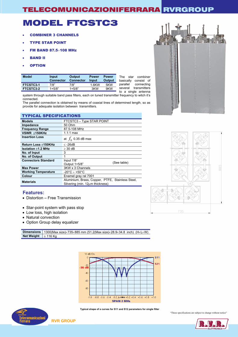
TELECOMUNICAZIONIFERRARA RVRGROUP
MODEL FTCSTC3 • COMBINER 3 CHANNELS
• TYPE STAR POINT
• FM BAND 87.5÷108 MHz
• BAND II
• OPTION
The star combiner basically consist of parallel connecting several transmitters to a single antenna
system through suitable band pass filters, each on tuned transmitter frequency to witch it’s connected. The parallel connection is obtained by means of coaxial lines of determined length, so as provide for adequate isolation between transmitters. TYPICAL SPECIFICATIONS Models FTCSTC3 – Type STAR POINT Impedance 50 Ohm Frequency Range 87.5-108 MHz VSWR ±150KHz 1.1:1 max Insertion Loss at 0f 0.35 dB max
Return Loss ±150KHz ≤ -26dB Isolation ±1.2 MHz ≥ 30 dB No. of Input 3 No. of Output 1 Connectors Standard Input 7/8”
Output 1+5/8” Max Power 3KW x 3 Channels Working Temperature -20°C ÷ +50°C Colour Enamel gray ral 7001
Materials Aluminium, Brass, Copper, PTFE, Stainless Steel, Silvering (min. 12µm thickness)
Features: • Distortion – Free Transmission
• Star-point system with pass stop • Low loss, high isolation • Natural convection • Option Group delay equalizer Dimensions 1300(Max size)×735×885 mm (51.2(Max size)×28.9×34.8 inch) (H×L×W) Net Weight ≅ 116 Kg
Model Input Connector
Output Connector
Power Input
Power Output
FTCSTC3-1 7/8” 7/8” 1.6KW 5KW FTCSTC3-2 1+5/8” 1+5/8” 3KW 9KW
(See table)
RVR GROUP
“These specifications are subject to change without notice” Typical shape of a curves for S11 and S12 parameters for single filter
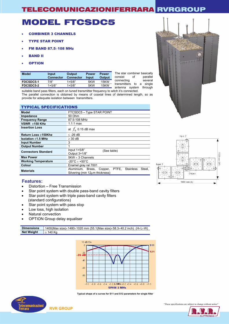
TELECOMUNICAZIONIFERRARA RVRGROUP
MODEL FTCSDC5 • COMBINER 3 CHANNELS
• TYPE STAR POINT
• FM BAND 87.5÷108 MHz
• BAND II
• OPTION
The star combiner basically consist of parallel connecting several transmitters to a single antenna system through
suitable band pass filters, each on tuned transmitter frequency to witch it’s connected. The parallel connection is obtained by means of coaxial lines of determined length, so as provide for adequate isolation between transmitters. TYPICAL SPECIFICATIONS Model FTCSDC5 – Type STAR POINT Impedance 50 Ohm Frequency Range 87.5-108 MHz VSWR ±150 KHz 1.1:1 max Insertion Loss at 0f 0.15 dB max
Return Loss ±150Khz ≤ -26 dB Isolation ±1.5 MHz ≥ 30 dB Input Number 3 Output Number 1
Connectors Standard Input 1+5/8” Output 3+1/8”
Max Power 5KW × 3 Channels Working Temperature -20°C ÷ +50°C Colour Enamel gray ral 7001
Materials Aluminium, Brass, Copper, PTFE, Stainless Steel, Silvering (min 12µm thickness)
Features: • Distortion – Free Transmission • Star point system with double pass-band cavity filters • Star point system with triple pass-band cavity filters (standard configurations) • Star point system with pass stop • Low loss, high isolation • Natural convection • OPTION Group delay equaliser Dimensions 1400(Max size)×1480×1020 mm (55.1(Max size)×58.3×40.2 inch) (H×L×W) Net Weight ≅ 140 Kg
Model Input Connector
Output Connector
Power Input
Power Output
FDCSDC5-1 7/8” 1+5/8” 5KW 15KW FDCSDC5-2 1+5/8” 1+5/8” 5KW 15KW
(See table)
Typical shape of a curves for S11 and S12 parameters for single filter
RVR GROUP
“These specifications are subject to change without notice”
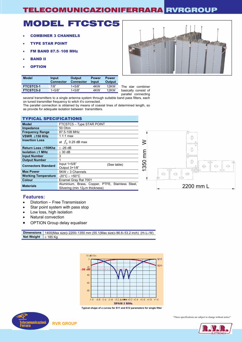
TELECOMUNICAZIONIFERRARA RVRGROUP
MODEL FTCSTC5 • COMBINER 3 CHANNELS
• TYPE STAR POINT
• FM BAND 87.5÷108 MHz
• BAND II
• OPTION
The star combiner basically consist of parallel connecting
several transmitters to a single antenna system through suitable band pass filters, each on tuned transmitter frequency to witch it’s connected. The parallel connection is obtained by means of coaxial lines of determined length, so as provide for adequate isolation between transmitters. TYPICAL SPECIFICATIONS Model FTCSTC5 – Type STAR POINT Impedance 50 Ohm Frequency Range 87.5-108 MHz VSWR ±150 KHz 1.1:1 max Insertion Loss at 0f 0.25 dB max
Return Loss ±150Khz ≤ -26 dB Isolation ±1 MHz ≥ 30 dB Input Number 3 Output Number 1
Connectors Standard Input 1+5/8” Output 3+1/8”
Max Power 5KW × 3 Channels Working Temperature -20°C ÷ +50°C Colour Enamel Gray Ral 7001
Materials Aluminium, Brass, Copper, PTFE, Stainless Steel, Silvering (min 12µm thickness)
Features: • Distortion – Free Transmission • Star point system with pass stop • Low loss, high isolation • Natural convection • OPTION Group delay equaliser Dimensions 1400(Max size)×2200×1350 mm (55.1(Max size)×86.6×53.2 inch) (H×L×W) Net Weight ≅ 185 Kg
Model Input Connector
Output Connector
Power Input
Power Output
FTCSTC5-1 7/8” 1+5/8” 4KW 12KW FTCSTC5-2 1+5/8” 1+5/8” 4KW 12KW
(See table)
Typical shape of a curves for S11 and S12 parameters for single filter
RVR GROUP
“These specifications are subject to change without notice”
1350
mm
W
2200 mm L
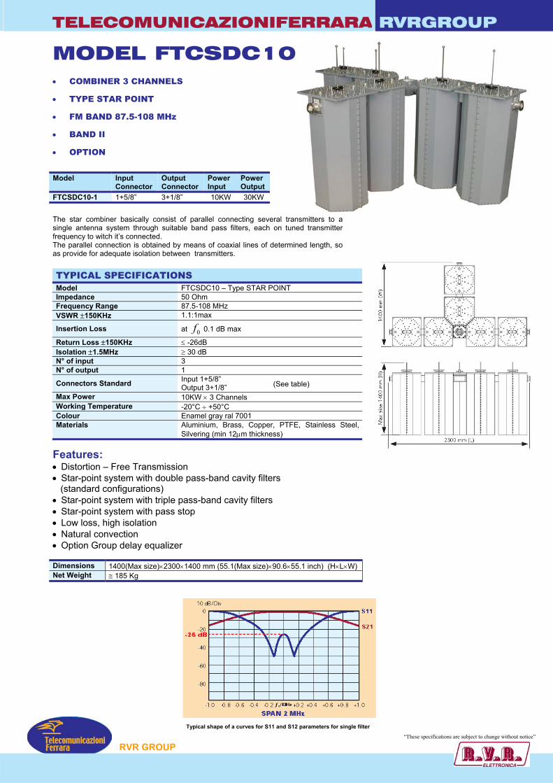
TELECOMUNICAZIONIFERRARA RVRGROUP
MODEL FTCSDC10 • COMBINER 3 CHANNELS
• TYPE STAR POINT
• FM BAND 87.5-108 MHz
• BAND II
• OPTION
Model Input Connector
Output Connector
Power Input
Power Output
FTCSDC10-1 1+5/8” 3+1/8” 10KW 30KW
The star combiner basically consist of parallel connecting several transmitters to a single antenna system through suitable band pass filters, each on tuned transmitter frequency to witch it’s connected. The parallel connection is obtained by means of coaxial lines of determined length, so as provide for adequate isolation between transmitters. TYPICAL SPECIFICATIONS Model FTCSDC10 – Type STAR POINT Impedance 50 Ohm Frequency Range 87.5-108 MHz VSWR ±150KHz 1.1:1max
Insertion Loss at 0f 0.1 dB max
Return Loss ±150KHz ≤ -26dB Isolation ±1.5MHz ≥ 30 dB N° of input 3 N° of output 1
Connectors Standard Input 1+5/8” Output 3+1/8”
Max Power 10KW × 3 Channels Working Temperature -20°C ÷ +50°C Colour Enamel gray ral 7001 Materials Aluminium, Brass, Copper, PTFE, Stainless Steel,
Silvering (min 12µm thickness)
(See table)
Features: • Distortion – Free Transmission • Star-point system with double pass-band cavity filters (standard configurations) • Star-point system with triple pass-band cavity filters • Star-point system with pass stop • Low loss, high isolation • Natural convection • Option Group delay equalizer Dimensions 1400(Max size)×2300×1400 mm (55.1(Max size)×90.6×55.1 inch) (H×L×W) Net Weight ≅ 185 Kg
Typical shape of a curves for S11 and S12 parameters for single filter
“These specification re subject to change without notice”
RVR GROUP s a
TELECOMUNICAZIONIFERRARA RVRGROUP
.
MODEL FTCSTC10 • COMBINER 3 CHANNELS
• TYPE STAR POINT
• FM BAND 87.5-108 MHz
• BAND II
The star combiner basically consist of parallel connecting
several transmitters to a single antenna system through suitable bandpass filters, each on tuned transmitter frequency to witch it’s connected. The parallel connection is obtained by means of coaxial lines of determined length, so as provide for adequate isolation between transmitters. TYPICAL SPECIFICATIONS Model FTCSTC10 – Type STAR POINT Impedance 50 Ohm Frequency Range 87.5-108 MHz VSWR ±150KHz 1.1:1max
Insertion Loss at 0f 0.25 dB max
Return Loss ±150KHz ≤ -26dB Isolation ±1MHz ≥ 30 dB Input Number 3 Output Number 1 Connectors standard Input-Output 3+1/8” (See table) Max Power 10KW × 3 Channels Working Temperature -20°C ÷ +50°C Colour Enamel gray ral 7001 Materials Aluminium, Brass, Copper, PTFE, Stainless Steel,
Silvering (min 12µm thickness)
Features: • Distortion – Free Transmission • Starpoint system with triple pass-band cavity filters • Starpoint system with pass stop • Low loss, high isolation • Natural convection • Option Group delay equalizer Dimensions 1400(Max size)×3350×1920mm (55.1(Max size)×131.9×75.6inch) (H×L×W) Net Weight ≅ 270 Kg
Model Input Connector
Output Connector
Power Input
Power Output
FTCSTC10-1 1+5/8” 3+1/8” 10KW 30KW
RVR GROUP
“These specifications are subject to change without notice”
Typical shape of a curves for S11 and S12 parameters for single filter
3350
1920
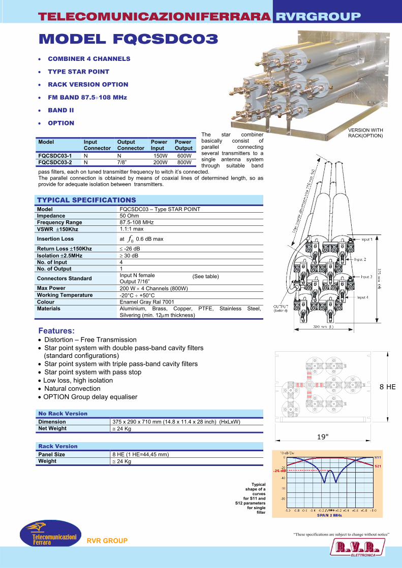
TELECOMUNICAZIONIFERRARA RVRGROUP
MODEL FQCSDC03 • COMBINER 4 CHANNELS
• TYPE STAR POINT
• RACK VERSION OPTION
• FM BAND 87.5÷108 MHz
• BAND II
• OPTION VERSION WITH RACK(OPTION) The star combiner
basically consist of parallel connecting several transmitters to a single antenna system through suitable band
pass filters, each on tuned transmitter frequency to witch it’s connected.
The parallel connection is obtained by means of coaxial lines of determined length, so as provide for adequate isolation between transmitters. TYPICAL SPECIFICATIONS Model FQCSDC03 – Type STAR POINT Impedance 50 Ohm Frequency Range 87.5-108 MHz VSWR ±150Khz 1.1:1 max
Insertion Loss at 0f 0.6 dB max
Return Loss ±150Khz ≤ -26 dB Isolation ±2.5MHz ≥ 30 dB No. of Input 4 No. of Output 1
Connectors Standard Input N female Output 7/16”
Max Power 200 W × 4 Channels (800W) Working Temperature -20°C ÷ +50°C Colour Enamel Gray Ral 7001 Materials Aluminium, Brass, Copper, PTFE, Stainless Steel,
Silvering (min. 12µm thickness) Features: • Distortion – Free Transmission • Star point system with double pass-band cavity filters (standard configurations) • Star point system with triple pass-band cavity filters • Star point system with pass stop • Low loss, high isolation • Natural convection • OPTION Group delay equaliser
Model Input Connector
Output Connector
Power Input
Power Output
FQCSDC03-1 N N 150W 600W FQCSDC03-2 N 7/8” 200W 800W
(See table)
No Rack Version Dimension 375 x 290 x 710 mm (14.8 x 11.4 x 28 inch) (HxLxW) Net Weight ≅ 24 Kg
Rack Version Panel Size 8 HE (1 HE=44,45 mm) Weight ≅ 24 Kg
s
forS12 pa
f
P
19"
8 HE
Typicalhape of a
curves S11 andrametersor single
filter
“These specification re subject to change without notice”
RVR GROU
s a
TELECOMUNICAZIONIFERRARA RVRGROUP
MODEL FQCSTC03 • 4 CHANNELS COMBINER
• STAR POINT TYPE
• FM BAND: 87.5÷108 MHz
• BAND II
• OPTION rack mounting
The Star
Point combiner basically consists of a parallel connection of several transmittersto a single antenna system through suitable band pass filters, each one tuned onthe transmitter frequency to which it’s connected.
Model Input Connector
Output Connector
Power Input
Power Output
FQCSTC03-1 N 7/16” 300W 1200W FQCSTC03-2 N 7/8” 300W 1200W
TYPICAL SPECIFICATIONS Model FQCSTC03 – Type Star Point Impedance 50 Ohm Frequency Range 87.5-108 MHz VSWR ±150Khz 1.1:1 max Insertion Loss at 0f 0.8 dB max Return Loss ±150Khz ≤ -26 dB Isolation ±2MHz ≥ 30 dB Number of Inputs 4 Number of Outputs 1
Standard Connectors Input N female Output N
Max Power 150 W x 4 Channels Working Temperature -20°C ÷ +50°C Colour Enamel Gray Ral 7001 Materials Aluminium, Brass, Copper, PTFE, Stainless Steel,
Silvering (min. 12µm thickness)
(See table)
Features: • Distortion – Free Transmission • Triple Band-Pass Cavity filters • Low Loss, High Isolation • Natural convection • Option whit Rack No rack version Dimensions 405×500×710 mm (15.9×19.7×28 inch) (H×L×W) Weight ≅ 36 Kg
Rack Version Panel Size 8 HE (1 HE=44,45 mm) (534×483 mm (21×19 inch)) Weight ≅ 36 Kg
Typical shape of a curves for S11 and S12 pa
P
rameters for single filter “These specification re subject to change without notice”
RVR GROU
s a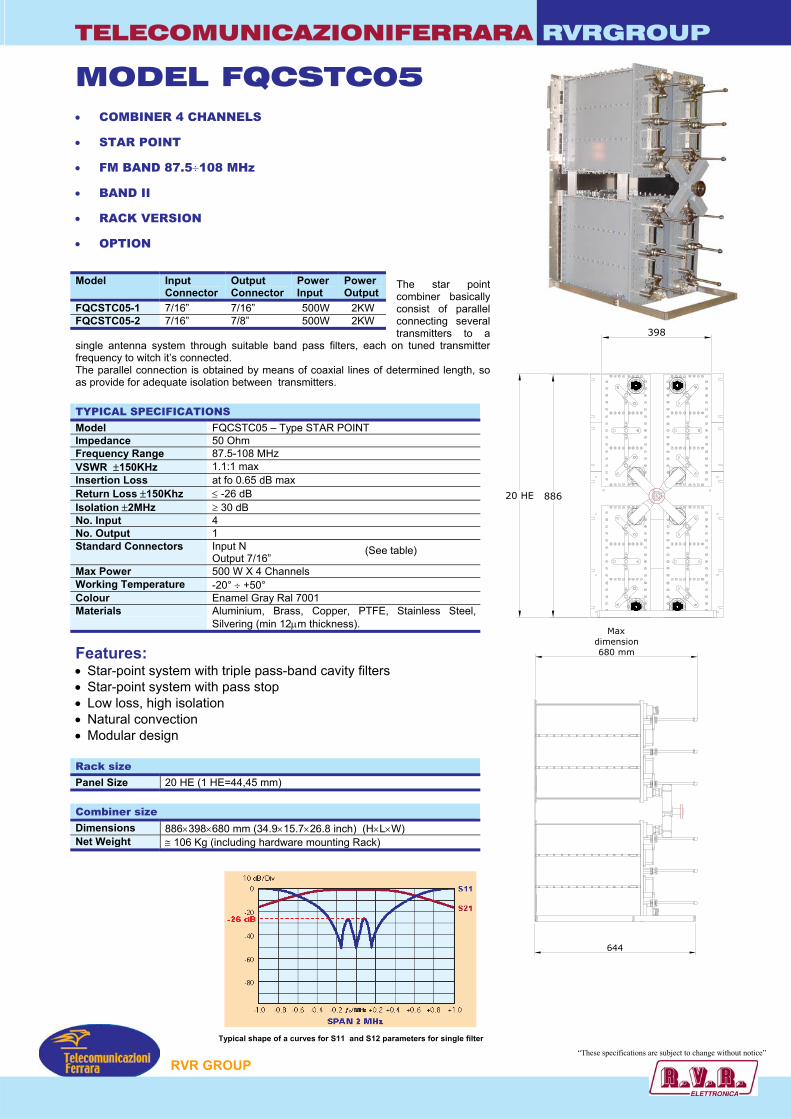
TELECOMUNICAZIONIFERRARA RVRGROUP
MODEL FQCSTC05 • COMBINER 4 CHANNELS
• STAR POINT
• FM BAND 87.5÷108 MHz
• BAND II
• RACK VERSION
• OPTION
The star point combiner basically consist of parallel connecting several transmitters to a
single antenna system through suitable band pass filters, each on tuned transmitter frequency to witch it’s connected.
Model Input Connector
Output Connector
Power Input
Power Output
FQCSTC05-1 7/16” 7/16” 500W 2KW FQCSTC05-2 7/16” 7/8” 500W 2KW
20 HE 886
Maxdimension680 mm
398
The parallel connection is obtained by means of coaxial lines of determined length, so as provide for adequate isolation between transmitters. TYPICAL SPECIFICATIONS Model FQCSTC05 – Type STAR POINT Impedance 50 Ohm Frequency Range 87.5-108 MHz VSWR ±150KHz 1.1:1 max Insertion Loss at fo 0.65 dB max Return Loss ±150Khz ≤ -26 dB Isolation ±2MHz ≥ 30 dB No. Input 4 No. Output 1 Standard Connectors Input N
Output 7/16” Max Power 500 W X 4 Channels Working Temperature -20° ÷ +50° Colour Enamel Gray Ral 7001 Materials Aluminium, Brass, Copper, PTFE, Stainless Steel,
Silvering (min 12µm thickness).
(See table)
Features: • Star-point system with triple pass-band cavity filters • Star-point system with pass stop • Low loss, high isolation • Natural convection • Modular design Rack size Panel Size 20 HE (1 HE=44,45 mm) Combiner size Dimensions 886×398×680 mm (34.9×15.7×26.8 inch) (H×L×W) Net Weight ≅ 106 Kg (including hardware mounting Rack)
644
Typical shape of a curves for S11 and S12 parameters for single filter
“These specification re subject to change without notice”
P
RVR GROU s a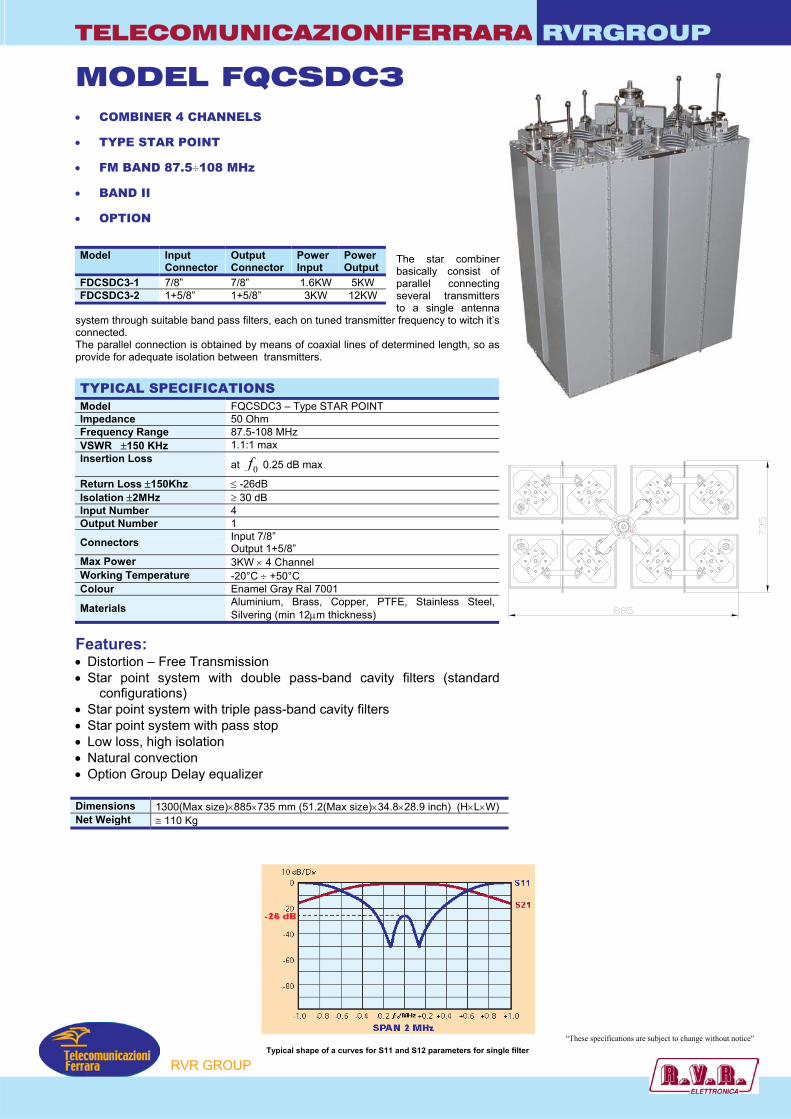
TELECOMUNICAZIONIFERRARA RVRGROUP
MODEL FQCSDC3 • COMBINER 4 CHANNELS
• TYPE STAR POINT
• FM BAND 87.5÷108 MHz
• BAND II
• OPTION
The star combiner basically consist of parallel connecting several transmitters to a single antenna
system through suitable band pass filters, each on tuned transmitter frequency to witch it’s connected.
Model Input Connector
Output Connector
Power Input
Power Output
FDCSDC3-1 7/8” 7/8” 1.6KW 5KW FDCSDC3-2 1+5/8” 1+5/8” 3KW 12KW
The parallel connection is obtained by means of coaxial lines of determined length, so as provide for adequate isolation between transmitters. TYPICAL SPECIFICATIONS Model FQCSDC3 – Type STAR POINT Impedance 50 Ohm Frequency Range 87.5-108 MHz VSWR ±150 KHz 1.1:1 max Insertion Loss at 0f 0.25 dB max
Return Loss ±150Khz ≤ -26dB Isolation ±2MHz ≥ 30 dB Input Number 4 Output Number 1
Connectors Input 7/8” Output 1+5/8”
Max Power 3KW × 4 Channel Working Temperature -20°C ÷ +50°C Colour Enamel Gray Ral 7001
Materials Aluminium, Brass, Copper, PTFE, Stainless Silvering (min 12µm thickness)
Features: • Distortion – Free Transmission • Star point system with double pass-band cavity filters (sta
configurations) • Star point system with triple pass-band cavity filters • Star point system with pass stop • Low loss, high isolation • Natural convection • Option Group Delay equalizer Dimensions 1300(Max size)×885×735 mm (51.2(Max size)×34.8×28.9 inch) (Net Weight ≅ 110 Kg
Typical shape of a curves for S11 and S12 paramete
P
Steel,
ndard
H×L×W)
“These specifications are subject to change without notice” rs for single filter
RVR GROU
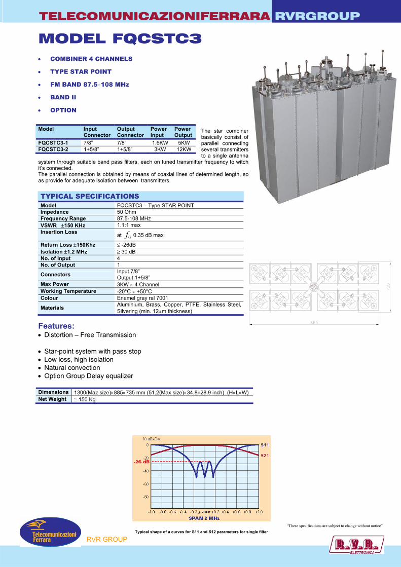
TELECOMUNICAZIONIFERRARA RVRGROUP
MODEL FQCSTC3 • COMBINER 4 CHANNELS
• TYPE STAR POINT
• FM BAND 87.5÷108 MHz
• BAND II
• OPTION
The star combiner basically consist of parallel connecting several transmitters to a single antenna
system through suitable band pass filters, each on tuned transmitter frequency to witch it’s connected. The parallel connection is obtained by means of coaxial lines of determined length, so as provide for adequate isolation between transmitters. TYPICAL SPECIFICATIONS Model FQCSTC3 – Type STAR POINT Impedance 50 Ohm Frequency Range 87.5-108 MHz VSWR ±150 KHz 1.1:1 max Insertion Loss at 0f 0.35 dB max
Return Loss ±150Khz ≤ -26dB Isolation ±1.2 MHz ≥ 30 dB No. of Input 4 No. of Output 1
Connectors Input 7/8” Output 1+5/8”
Max Power 3KW × 4 Channel Working Temperature -20°C ÷ +50°C Colour Enamel gray ral 7001
Materials Aluminium, Brass, Copper, PTFE, Stainless Steel, Silvering (min. 12µm thickness)
Features: • Distortion – Free Transmission • Star-point system with pass stop • Low loss, high isolation • Natural convection • Option Group Delay equalizer Dimensions 1300(Maz size)×885×735 mm (51.2(Max size)×34.8×28.9 inch) (H×L×W) Net Weight ≅ 150 Kg
Model Input Connector
Output Connector
Power Input
Power Output
FQCSTC3-1 7/8” 7/8” 1.6KW 5KW FQCSTC3-2 1+5/8” 1+5/8” 3KW 12KW
RVR GROUP
“These specifications are subject to change without notice” Typical shape of a curves for S11 and S12 parameters for single filter
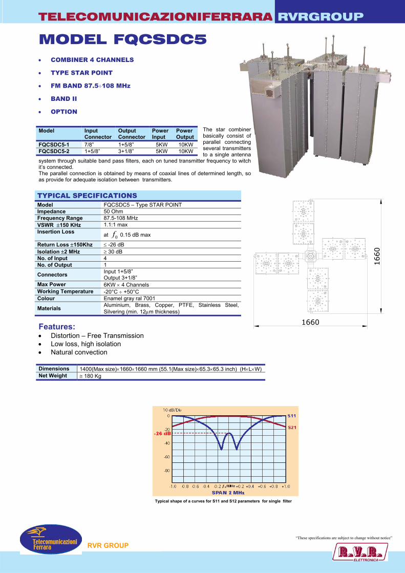
TELECOMUNICAZIONIFERRARA RVRGROUP
1660
1660
MODEL FQCSDC5 • COMBINER 4 CHANNELS
• TYPE STAR POINT
• FM BAND 87.5÷108 MHz
• BAND II
• OPTION
The star combiner basically consist of parallel connecting several transmitters to a single antenna
system through suitable band pass filters, each on tuned transmitter frequency to witch it’s connected. The parallel connection is obtained by means of coaxial lines of determined length, so as provide for adequate isolation between transmitters. TYPICAL SPECIFICATIONS Model FQCSDC5 – Type STAR POINT Impedance 50 Ohm Frequency Range 87.5-108 MHz VSWR ±150 KHz 1.1:1 max Insertion Loss at 0f 0.15 dB max
Return Loss ±150Khz ≤ -26 dB Isolation ±2 MHz ≥ 30 dB No. of Input 4 No. of Output 1
Connectors Input 1+5/8” Output 3+1/8”
Max Power 6KW × 4 Channels Working Temperature -20°C ÷ +50°C Colour Enamel gray ral 7001
Materials Aluminium, Brass, Copper, PTFE, Stainless Steel, Silvering (min. 12µm thickness)
Features: • Distortion – Free Transmission • Low loss, high isolation • Natural convection Dimensions 1400(Max size)×1660×1660 mm (55.1(Max size)×65.3×65.3 inch) (H×L×W) Net Weight ≅ 180 Kg
Model Input Connector
Output Connector
Power Input
Power Output
FQCSDC5-1 7/8” 1+5/8” 5KW 10KW FQCSDC5-2 1+5/8” 3+1/8” 5KW 10KW
RVR GROUP
“These specifications are subject to change without notice”
Typical shape of a curves for S11 and S12 parameters for single filter

TELECOMUNICAZIONIFERRARA RVRGROUP
MODEL FQCSTC5 • COMBINER 4 CHANNELS
• TYPE STAR POINT
• FM BAND 87.5÷108 MHz
• BAND II
• OPTION
The star combiner basically consist of parallel connecting several transmitters to a single antenna
system through suitable band pass filters, each on tuned transmitter frequency to witch it’s connected. The parallel connection is obtained by means of coaxial lines of determined length, so as provide for adequate isolation between transmitters. TYPICAL SPECIFICATIONS Model FQCSTC5 – Type STAR POINT Impedance 50 Ohm Frequency Range 87.5-108 MHz VSWR ±150 KHz 1.1:1 max Insertion Loss at 0f 0.25 dB max
Return Loss ±150Khz ≤ -26 dB Isolation ±1 MHz ≥ 30 dB Input Number 4 Output Number 1
Standard Connectors Input 1+5/8” Output 3+1/8”
Max Power 5KW × 4 Channels Working Temperature -20°C ÷ +50°C Colour Enamel gray ral 7001
Materials Aluminium, Brass, Copper, PTFE, Stainless Steel, Silvering (min 12µm thickness)
Features: • Distortion – Free Transmission
• Star-point system with pass stop • Low loss, high isolation • Natural convection • OPTION Group delay equaliser Dimensions 1400(Max size)×2200×2200 mm (55.1(Max size)×86.6×86.6 inch) (H×L×W) Net Weight ≅ 260 Kg
Model Input Connector
Output Connector
Power Input
Power Output
FQCSTC5-1 7/8” 1+5/8” 3KW 12KW FQCSTC5-2 1+5/8” 1+5/8” 3KW 12KW
Typical shape of a curves for S11 and S12 parameters for single filter
RVR GROUP
“These specifications are subject to change without notice”
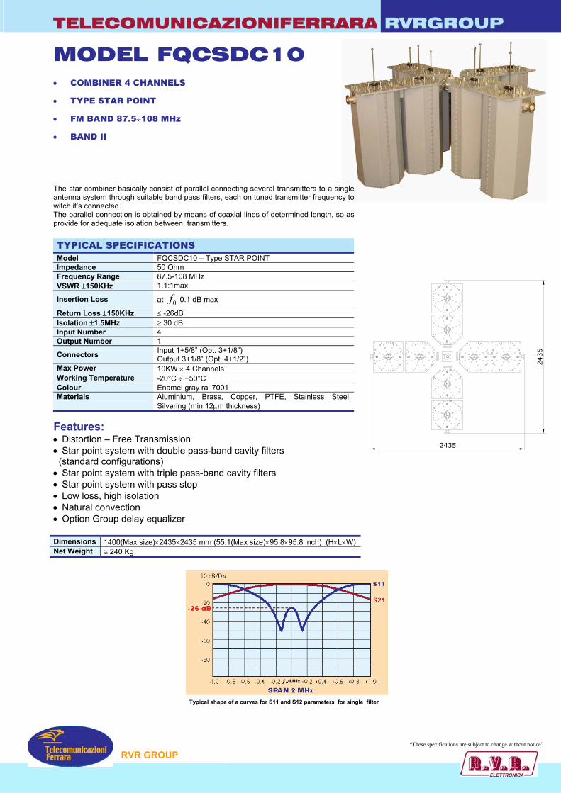
TELECOMUNICAZIONIFERRARA RVRGROUP
2435
2435
MODEL FQCSDC10 • COMBINER 4 CHANNELS
• TYPE STAR POINT
• FM BAND 87.5÷108 MHz
• BAND II
The star combiner basically consist of parallel connecting several transmitters to a single antenna system through suitable band pass filters, each on tuned transmitter frequency to witch it’s connected. The parallel connection is obtained by means of coaxial lines of determined length, so as provide for adequate isolation between transmitters. TYPICAL SPECIFICATIONS Model FQCSDC10 – Type STAR POINT Impedance 50 Ohm Frequency Range 87.5-108 MHz VSWR ±150KHz 1.1:1max
Insertion Loss at 0f 0.1 dB max
Return Loss ±150KHz ≤ -26dB Isolation ±1.5MHz ≥ 30 dB Input Number 4 Output Number 1
Connectors Input 1+5/8” (Opt. 3+1/8”) Output 3+1/8” (Opt. 4+1/2”)
Max Power 10KW × 4 Channels Working Temperature -20°C ÷ +50°C Colour Enamel gray ral 7001 Materials Aluminium, Brass, Copper, PTFE, Stainless Steel,
Silvering (min 12µm thickness)
Features: • Distortion – Free Transmission • Star point system with double pass-band cavity filters (standard configurations) • Star point system with triple pass-band cavity filters • Star point system with pass stop • Low loss, high isolation • Natural convection • Option Group delay equalizer Dimensions 1400(Max size)×2435×2435 mm (55.1(Max size)×95.8×95.8 inch) (H×L×W) Net Weight ≅ 240 Kg
Typical shape of a curves for S11 and S12 parameters for single filter
RVR GROUP
“These specifications are subject to change without notice”
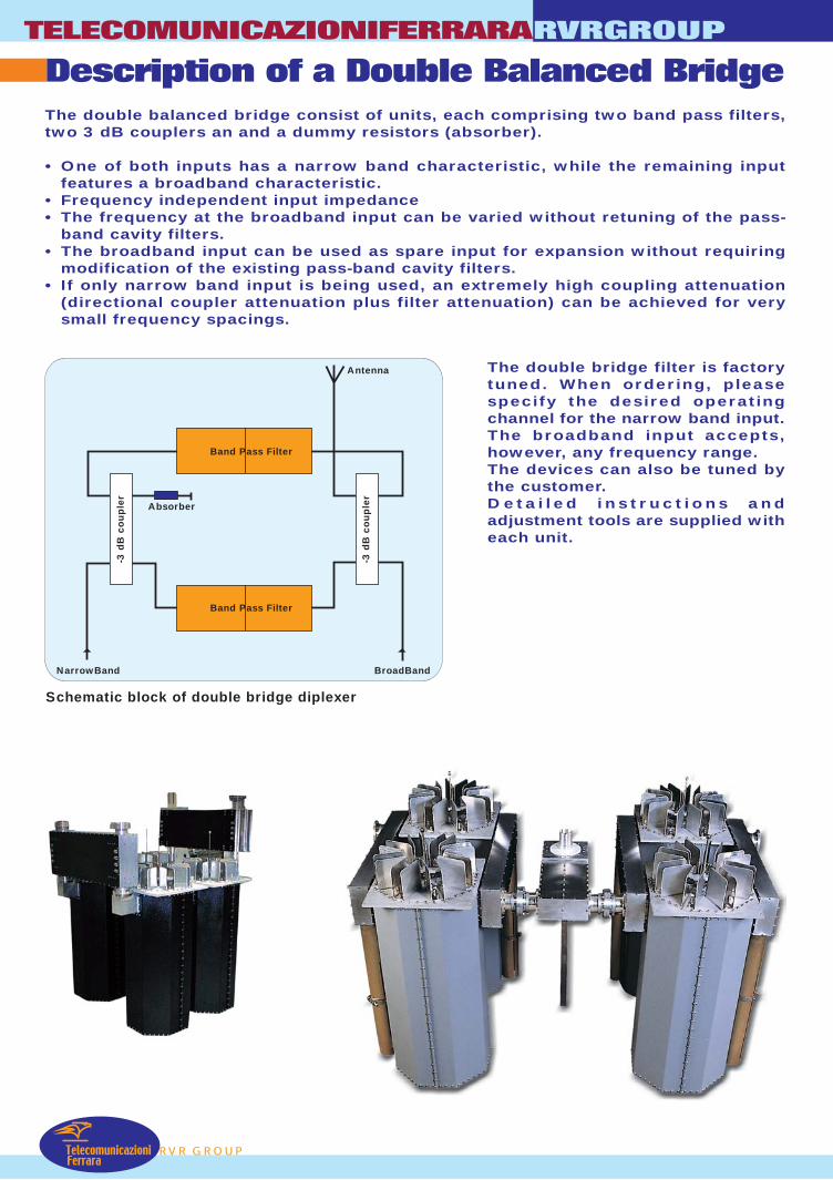
TelecomunicazioniFerrara
Description of a Double Balanced BridgeTELECOMUNICAZIONIFERRARA
RVR GROUP
RVRGROUP
The double balanced bridge consist of units, each comprising two band pass filters,two 3 dB couplers an and a dummy resistors (absorber).
• One of both inputs has a narrow band characteristic, while the remaining inputfeatures a broadband characteristic.
• Frequency independent input impedance• The frequency at the broadband input can be varied without retuning of the pass-
band cavity filters.• The broadband input can be used as spare input for expansion without requiring
modification of the existing pass-band cavity filters.• If only narrow band input is being used, an extremely high coupling attenuation
(directional coupler attenuation plus filter attenuation) can be achieved for verysmall frequency spacings.
Schematic block of double bridge diplexer
The double bridge filter is factorytuned. When ordering, pleasespecify the desired operatingchannel for the narrow band input.The broadband input accepts,however, any frequency range.The devices can also be tuned bythe customer.Deta i led ins t ruct ions andadjustment tools are supplied witheach unit.
Antenna
BroadBandNarrowBand
Band Pass Filter
Absorber
Band Pass Filter
-3 d
B c
oup
ler
-3 d
B c
oup
ler
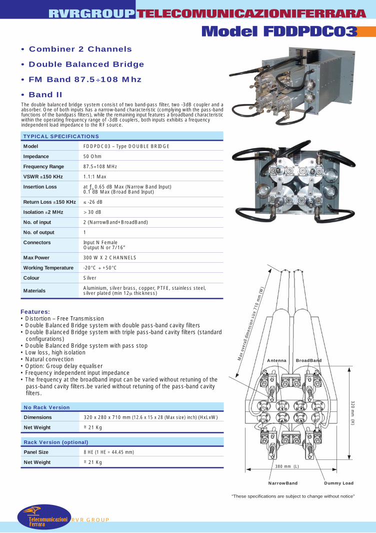
RVR GROUP
RVRGROUPTELECOMUNICAZIONIFERRARA
Model FDDPDC03
TelecomunicazioniFerrara
• Combiner 2 Channels
• Double Balanced Bridge
• FM Band 87.5÷108 Mhz
• Band IIThe double balanced bridge system consist of two band-pass filter, two -3dB coupler and aabsorber. One of both inputs has a narrow-band characteristic (complying with the pass-bandfunctions of the bandpass filters), while the remaining input features a broadband characteristicwithin the operating frequency range of -3dB couplers, both inputs exhibits a frequencyindependent load impedance to the RF source.
Features:• Distortion – Free Transmission• Double Balanced Bridge system with double pass-band cavity filters• Double Balanced Bridge system with triple pass-band cavity filters (standard
configurations)• Double Balanced Bridge system with pass stop• Low loss, high isolation• Natural convection• Option: Group delay equaliser• Frequency independent input impedance• The frequency at the broadband input can be varied without retuning of the
pass-band cavity filters.be varied without retuning of the pass-band cavityfilters.
No Rack Version
Dimensions 320 x 280 x 710 mm (12.6 x 15 x 28 (Max size) inch) (HxLxW)
Net Weight =~ 21 Kg
Rack Version (optional)
Panel Size 8 HE (1 HE = 44.45 mm)
Net Weight =~ 21 Kg
Max
ove
rall
dim
ensi
on s
ize
710
mm
(W
)
BroadBand
Dummy LoadNarrowBand
Antenna
320 mm
(H)
380 mm (L)
“These specifications are subject to change without notice”
TYPICAL SPECIFICATIONS
Model FDDPDC03 – Type DOUBLE BRIDGE
Impedance 50 Ohm
Frequency Range 87.5÷108 MHz
VSWR ±150 KHz 1.1:1 Max
Insertion Loss at ƒ0 0.65 dB Max (Narrow Band Input)0.1 dB Max (Broad Band Input)
Return Loss ±150 KHz ≤ -26 dB
Isolation ±2 MHz > 30 dB
No. of input 2 (NarrowBand+BroadBand)
No. of output 1
Connectors Input N FemaleOutput N or 7/16”
Max Power 300 W X 2 CHANNELS
Working Temperature -20°C ÷ +50°C
Colour Silver
Materials Aluminium, silver brass, copper, PTFE, stainless steel,silver plated (min 12µ thickness)
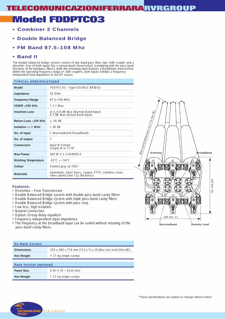
Model FDDPTC03TELECOMUNICAZIONIFERRARARVRGROUP
RVR GROUPTelecomunicazioni
Ferrara
• Combiner 2 Channels
• Double Balanced Bridge
• FM Band 87.5÷108 Mhz
• Band IIThe double balanced bridge system consist of two band-pass filter, two -3dB coupler and aabsorber. One of both inputs has a narrow-band characteristic (complying with the pass-bandfunctions of the bandpass filters), while the remaining input features a broadband characteristicwithin the operating frequency range of -3dB couplers, both inputs exhibits a frequencyindependent load impedance to the RF source.
Features:• Distortion – Free Transmission• Double Balanced Bridge system with double pass-band cavity filters• Double Balanced Bridge system with triple pass-band cavity filters• Double Balanced Bridge system with pass stop• Low loss, high isolation• Natural convection• Option: Group delay equalizer• Frequency independent input impedance• The frequency at the broadband input can be varied without retuning of the
pass-band cavity filters.
No Rack Version
Dimensions 320 x 280 x 710 mm (12.6 x 15 x 28 (Max size) inch) (HxLxW)
Net Weight =~ 27 Kg (triple cavity)
Rack Version (optional)
Panel Size 8 HE (1 HE = 44.45 mm)
Net Weight =~ 27 Kg (triple cavity)
380 mm (L)
Max
ove
rall
dim
ensi
on s
ize
710
mm
(W
)
320 mm
(H)
BroadBand
Dummy LoadNarrowBand
Antenna
“These specifications are subject to change without notice”
TYPICAL SPECIFICATIONS
Model FDDPTC03 – Type DOUBLE BRIDGE
Impedance 50 Ohm
Frequency Range 87.5÷108 MHz
VSWR ±150 KHz 1.1:1 Max
Insertion Loss at ƒ0 0.8 dB Max (Narrow Band Input)0.1 dB Max (Broad Band Input)
Return Loss ±150 KHz ≤ -26 dB
Isolation ±1.8 MHz > 30 dB
No. of input 2 (NarrowBand+BroadBand)
No. of output 1
Connectors Input N FemaleOutput N or 7/16”
Max Power 300 W X 2 CHANNELS
Working Temperature -20°C ÷ +50°C
Colour Enamel gray ral 7001
Materials Aluminium, silver brass, copper, PTFE, stainless steel,silver plated (min 12µ thickness)

TELECOMUNICAZIONIFERRARA RVRGROUP
MODEL FDDPTC05 • Combiner 2 Channels
• Double Balanced Bridge
• FM Band: 87.5÷108 MHz
• Band II
The Double Balanced Bridge System consists of two Band-Pass Filters, two -3dB Couplers aan Absorber. One of the inputs has a narrow-band characteristic (complying with the band-pafunctions of the band-pass filters), while the other input has a broadband characteristic within toperating frequency range of -3dB couplers. Both inputs exhibit a frequency independent loimpedance to the RF source. TYPICAL SPECIFICATIONS Model FDDPTC05AA – Double Bridge Type Impedance 50 Ohm Frequency Range 87.5-108 MHz VSWR ± 150 KHz 1.1:1 max Insertion Loss at 0f 0.65 dB Max Narrow Band Input
at 0f 0.1 dB Max Broad Band Input
Return Loss ± 150 KHz ≤ -26 dB Isolation ± 1.2 MHz N/B B/B ≥ 30 dB
B/B N/B ≥ 40 dB Number of Inputs 2 Number of Outputs 1 Connectors Narrow Band Input N female (Opt. 7/16”)
Broad Band Input N female (Opt.7/16” – 7/8”) Output N (Opt. 7/16” - 7/8”)
Max Power Narrow Band Input 1000 W Broad Band Input 3KW
Working Temperature -20°C ÷ +50°C Colour Enamel Gray Ral 7001 Materials Aluminium, Brass, Copper, PTFE, Stainless Steel,
Silvering (min 12µm thickness)
Features: • Distortion – Free Transmission • Double Balanced Bridge • Frequency Independent Input Impedance • Low Loss, High Isolation • Natural Convection • Frequency at broadband input can be varied without retuning band-pas
cavity filters • Broadband input can be used as spare input for expansion witho
requiring modifications of existing band-pass cavity filters • If narrow band input is the only one being used, an extremely high couplin
attenuation (directional coupler attenuation plus filter attenuation) can bachieved for very small frequency spacing
No rack version Dimensions 680(Max size)×530×350 mm (26.8(Max size)×20.9×13.8 inch) (H×L×W) Net Weight ≅ 60 Kg Rack version (optional) Dimensions 12 HE (1 HE=44.45 mm) Net Weight ≅ 60 Kg
P
nd ss he ad
VERSION WITH RACK AND COUPLER (OPTION)
s
ut
g e
“These specifications are subject to change without notice”
RVR GROU
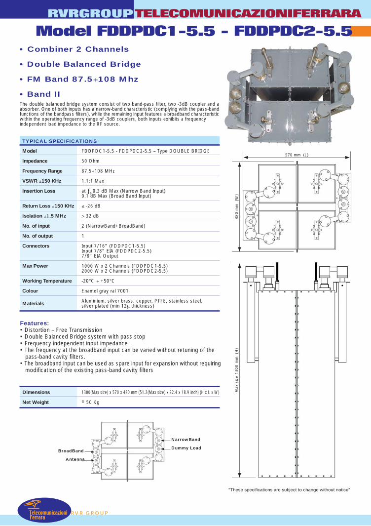
RVRGROUPTELECOMUNICAZIONIFERRARA
Model FDDPDC1-5.5 - FDDPDC2-5.5
TelecomunicazioniFerrara
RVR GROUP
• Combiner 2 Channels
• Double Balanced Bridge
• FM Band 87.5÷108 Mhz
• Band IIThe double balanced bridge system consist of two band-pass filter, two -3dB coupler and aabsorber. One of both inputs has a narrow-band characteristic (complying with the pass-bandfunctions of the bandpass filters), while the remaining input features a broadband characteristicwithin the operating frequency range of -3dB couplers, both inputs exhibits a frequencyindependent load impedance to the RF source.
Features:• Distortion – Free Transmission• Double Balanced Bridge system with pass stop• Frequency independent input impedance• The frequency at the broadband input can be varied without retuning of the
pass-band cavity filters.• The broadband input can be used as spare input for expansion without requiring
modification of the existing pass-band cavity filters
Dimensions 1300(Max size) x 570 x 480 mm (51.2(Max size) x 22.4 x 18.9 inch) (H x L x W)
Net Weight =~ 50 Kg
TYPICAL SPECIFICATIONS
Model FDDPDC1-5.5 - FDDPDC2-5.5 – Type DOUBLE BRIDGE
Impedance 50 Ohm
Frequency Range 87.5÷108 MHz
VSWR ±150 KHz 1.1:1 Max
Insertion Loss at ƒ0 0.3 dB Max (Narrow Band Input)0.1 dB Max (Broad Band Input)
Return Loss ±150 KHz ≤ -26 dB
Isolation ±1.5 MHz > 32 dB
No. of input 2 (NarrowBand+BroadBand)
No. of output 1
Connectors Input 7/16” (FDDPDC1-5.5)Input 7/8” EIA (FDDPDC2-5.5)7/8” EIA Output
Max Power 1000 W x 2 Channels (FDDPDC1-5.5)2000 W x 2 Channels (FDDPDC2-5.5)
Working Temperature -20°C ÷ +50°C
Colour Enamel gray ral 7001
Materials Aluminium, silver brass, copper, PTFE, stainless steel,silver plated (min 12µ thickness)
NarrowBand
Dummy LoadBroadBand
Antenna
“These specifications are subject to change without notice”
480
mm
(W
)
570 mm (L)
Max
siz
e 13
00 m
m (
H)
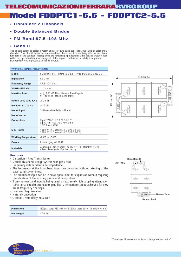
Model FDDPTC1-5.5 - FDDPTC2-5.5TELECOMUNICAZIONIFERRARARVRGROUP
RVR GROUPTelecomunicazioni
Ferrara
• Combiner 2 Channels
• Double Balanced Bridge
• FM Band 87.5÷108 Mhz
• Band IIThe double balanced bridge system consist of two band-pass filter, two -3dB coupler and aabsorber. One of both inputs has a narrow-band characteristic (complying with the pass-bandfunctions of the bandpass filters), while the remaining input features a broadband characteristicwithin the operating frequency range of -3dB couplers, both inputs exhibits a frequencyindependent load impedance to the RF source.
Features:• Distortion – Free Transmission• Double Balanced Bridge system with pass stop• Frequency independent input impedance• The frequency at the broadband input can be varied without retuning of the
pass-band cavity filters.• The broadband input can be used as spare input for expansion without requiring
modification of the existing pass-band cavity filters• If only narrow band input is being used, an extremely high coupling attenuation
(directional coupler attenuation plus filter attenuation) can be achieved for verysmall frequency spacings.
• Low loss, high isolation• Natural convection• Option: Group delay equaliser
TYPICAL SPECIFICATIONS
Model FDDPTC1-5.5 - FDDPTC2-5.5 – Type DOUBLE BRIDGE
Impedance 50 Ohm
Frequency Range 87.5÷108 MHz
VSWR ±150 KHz 1.1:1 Max
Insertion Loss at ƒ0 0.45 dB Max (Narrow Band Input)0.1 dB Max (Broad Band Input)
Return Loss ±150 KHz ≤ -26 dB
Isolation ±1.2 MHz > 30 dB
No. of input 2 (NarrowBand+BroadBand)
No. of output 1
Connectors Input 7/16” (FDDPDC1-5.5)Input 7/8” EIA (FDDPDC2-5.5)7/8” EIA Output
Max Power 1000 W 2 Channels (FDDPDC1-5.5)2000 W 2 Channels (FDDPDC2-5.5)
Working Temperature -20°C ÷ +50°C
Colour Enamel gray ral 7001
Materials Aluminium, silver brass, copper, PTFE, stainless steel,silver plated (min 12µ thickness)
Dimensions 1300(Max size) x 780 x 480 mm (51.2(Max size) x 22.4 x 18.9 inch) (H x L x W)
Net Weight =~ 70 Kg
480
mm
(W
)
780 mm (L)
“These specifications are subject to change without notice”
NarrowBand
Dummy load
BroadBand
Antenna
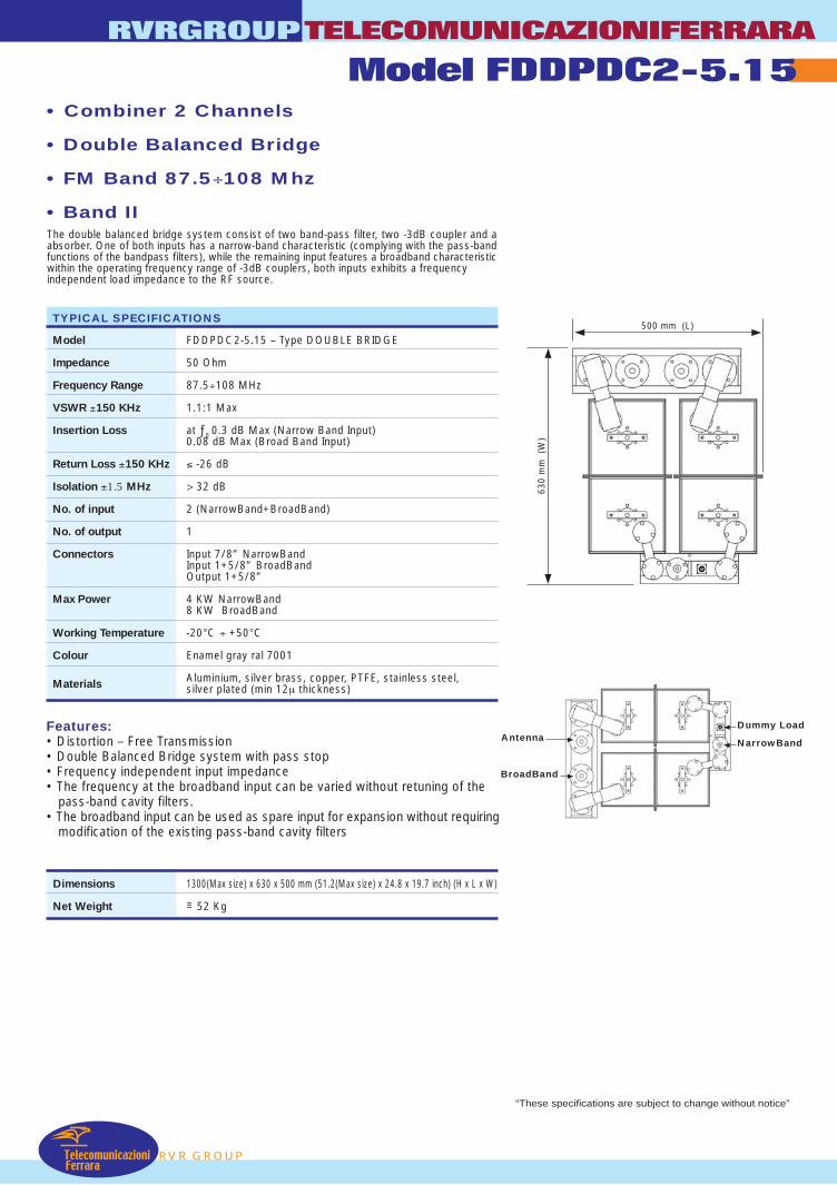
RVR GROUP
RVRGROUPTELECOMUNICAZIONIFERRARA
Model FDDPDC2-5.15
TelecomunicazioniFerrara
• Combiner 2 Channels
• Double Balanced Bridge
• FM Band 87.5÷108 Mhz
• Band IIThe double balanced bridge system consist of two band-pass filter, two -3dB coupler and aabsorber. One of both inputs has a narrow-band characteristic (complying with the pass-bandfunctions of the bandpass filters), while the remaining input features a broadband characteristicwithin the operating frequency range of -3dB couplers, both inputs exhibits a frequencyindependent load impedance to the RF source.
Features:• Distortion – Free Transmission• Double Balanced Bridge system with pass stop• Frequency independent input impedance• The frequency at the broadband input can be varied without retuning of the
pass-band cavity filters.• The broadband input can be used as spare input for expansion without requiring
modification of the existing pass-band cavity filters
Dimensions 1300(Max size) x 630 x 500 mm (51.2(Max size) x 24.8 x 19.7 inch) (H x L x W)
Net Weight =~ 52 Kg
TYPICAL SPECIFICATIONS
Model FDDPDC2-5.15 – Type DOUBLE BRIDGE
Impedance 50 Ohm
Frequency Range 87.5÷108 MHz
VSWR ±150 KHz 1.1:1 Max
Insertion Loss at ƒ0 0.3 dB Max (Narrow Band Input)0.08 dB Max (Broad Band Input)
Return Loss ±150 KHz ≤ -26 dB
Isolation ±1.5 MHz > 32 dB
No. of input 2 (NarrowBand+BroadBand)
No. of output 1
Connectors Input 7/8” NarrowBandInput 1+5/8” BroadBandOutput 1+5/8”
Max Power 4 KW NarrowBand8 KW BroadBand
Working Temperature -20°C ÷ +50°C
Colour Enamel gray ral 7001
Materials Aluminium, silver brass, copper, PTFE, stainless steel,silver plated (min 12µ thickness)
“These specifications are subject to change without notice”
630
mm
(W
)
500 mm (L)
NarrowBand
Dummy Load
BroadBand
Antenna
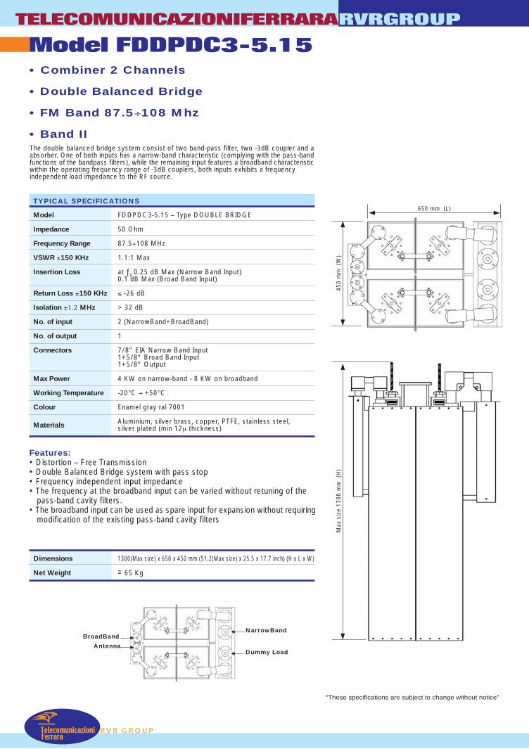
Model FDDPDC3-5.15TELECOMUNICAZIONIFERRARARVRGROUP
RVR GROUPTelecomunicazioni
Ferrara
• Combiner 2 Channels
• Double Balanced Bridge
• FM Band 87.5÷108 Mhz
• Band IIThe double balanced bridge system consist of two band-pass filter, two -3dB coupler and aabsorber. One of both inputs has a narrow-band characteristic (complying with the pass-bandfunctions of the bandpass filters), while the remaining input features a broadband characteristicwithin the operating frequency range of -3dB couplers, both inputs exhibits a frequencyindependent load impedance to the RF source.
Features:• Distortion – Free Transmission• Double Balanced Bridge system with pass stop• Frequency independent input impedance• The frequency at the broadband input can be varied without retuning of the
pass-band cavity filters.• The broadband input can be used as spare input for expansion without requiring
modification of the existing pass-band cavity filters
Dimensions 1300(Max size) x 650 x 450 mm (51.2(Max size) x 25.5 x 17.7 inch) (H x L x W)
Net Weight =~ 65 Kg
TYPICAL SPECIFICATIONS
Model FDDPDC3-5.15 – Type DOUBLE BRIDGE
Impedance 50 Ohm
Frequency Range 87.5÷108 MHz
VSWR ±150 KHz 1.1:1 Max
Insertion Loss at ƒ0 0.25 dB Max (Narrow Band Input)0.1 dB Max (Broad Band Input)
Return Loss ±150 KHz ≤ -26 dB
Isolation ±1.2 MHz > 32 dB
No. of input 2 (NarrowBand+BroadBand)
No. of output 1
Connectors 7/8” EIA Narrow Band Input1+5/8” Broad Band Input1+5/8” Output
Max Power 4 KW on narrow-band - 8 KW on broadband
Working Temperature -20°C ÷ +50°C
Colour Enamel gray ral 7001
Materials Aluminium, silver brass, copper, PTFE, stainless steel,silver plated (min 12µ thickness)
450
mm
(W
)
650 mm (L)
Max
siz
e 13
00 m
m (
H)
“These specifications are subject to change without notice”
NarrowBand
Dummy Load
BroadBand
Antenna
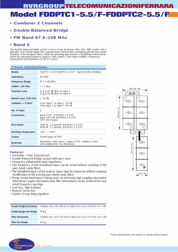
RVRGROUPTELECOMUNICAZIONIFERRARA
Model FDDPTC1-5.5/F-FDDPTC2-5.5/F
TelecomunicazioniFerrara
RVR GROUP
• Combiner 2 Channels
• Double Balanced Bridge
• FM Band 87.5÷108 Mhz
• Band IIThe double balanced bridge system consist of two band-pass filter, two -3dB coupler and aabsorber. One of both inputs has a narrow-band characteristic (complying with the pass-bandfunctions of the bandpass filters), while the remaining input features a broadband characteristicwithin the operating frequency range of -3dB couplers, both inputs exhibits a frequencyindependent load impedance to the RF source.
Features:• Distortion – Free Transmission• Double Balanced Bridge system with pass stop• Frequency independent input impedance• The frequency at the broadband input can be varied without retuning of the
pass-band cavity filters.• The broadband input can be used as spare input for expansion without requiring
modification of the existing pass-band cavity filters• If only narrow band input is being used, an extremely high coupling attenuation
(directional coupler attenuation plus filter attenuation) can be achieved for verysmall frequency spacings.
• Low loss, high isolation• Natural convection• Option: Group delay equaliser
Double Bridge Dimensions 1300(Max size) x 780 x 480 mm (51.2(Max size) x 22.4 x 18.9 inch) (H x L x W)
Double Bridge Net Weight 70 Kg
Filter Dimensions 1300(Max size) x 610 x 235 mm (51.2(Max size) x 22.4 x 18.9 inch) (H x L x W)
Filter Net Weight 35 Kg
TYPICAL SPECIFICATIONS
Model FDDPTC1-5.5/F-FDDPTC2-5.5/F – Type DOUBLE BRIDGE
Impedance 50 Ohm
Frequency Range 87.5÷108 MHz
VSWR ±150 KHz 1.1:1 Max
Insertion Loss at ƒ0 0.45 dB Max on input 1at ƒ0 0.45 dB Max on input 2
Return Loss ±150 KHz ≤ -26 dB
Isolation ±1.5 MHz From input 1 to input 2 33 dBFrom input 2 to input 1 43 dB
No. of input 2
Connectors Input 7/16” (FDDPDC1-5.5/F)Input 7/8” EIA (FDDPDC2-5.5/F)7/8” EIA Output
Max Power 1000 W 2 Channels (FDDPDC1-5.5/F)2000 W 2 Channels (FDDPDC2-5.5/F)
Working Temperature -20°C ÷ +50°C
Colour Enamel gray ral 7001
Materials Aluminium, silver brass, copper, PTFE, stainless steel,silver plated (min 12µ thickness)
“These specifications are subject to change without notice”
480 mm (W)
780
mm
(L)
620
mm
(L)
240 mm (W)
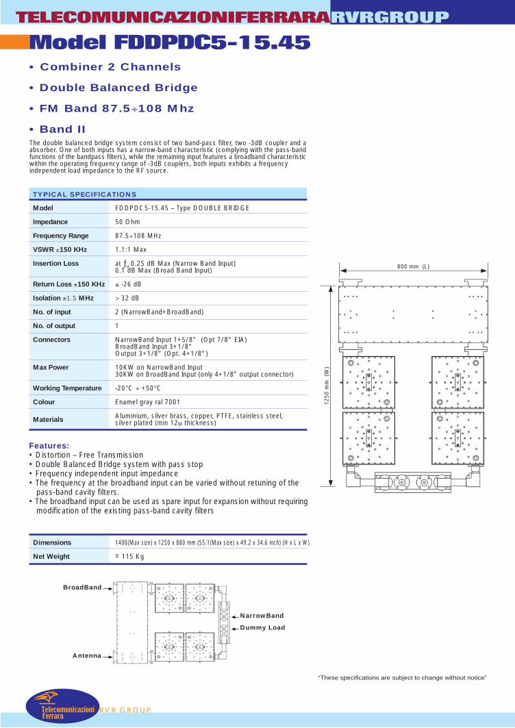
Model FDDPDC5-15.45TELECOMUNICAZIONIFERRARARVRGROUP
TelecomunicazioniFerrara
RVR GROUP
• Combiner 2 Channels
• Double Balanced Bridge
• FM Band 87.5÷108 Mhz
• Band II
Features:• Distortion – Free Transmission• Double Balanced Bridge system with pass stop• Frequency independent input impedance• The frequency at the broadband input can be varied without retuning of the
pass-band cavity filters.• The broadband input can be used as spare input for expansion without requiring
modification of the existing pass-band cavity filters
Dimensions 1400(Max size) x 1250 x 880 mm (55.1(Max size) x 49.2 x 34.6 inch) (H x L x W)
Net Weight =~ 115 Kg
The double balanced bridge system consist of two band-pass filter, two -3dB coupler and aabsorber. One of both inputs has a narrow-band characteristic (complying with the pass-bandfunctions of the bandpass filters), while the remaining input features a broadband characteristicwithin the operating frequency range of -3dB couplers, both inputs exhibits a frequencyindependent load impedance to the RF source.
TYPICAL SPECIFICATIONS
Model FDDPDC5-15.45 – Type DOUBLE BRIDGE
Impedance 50 Ohm
Frequency Range 87.5÷108 MHz
VSWR ±150 KHz 1.1:1 Max
Insertion Loss at ƒ0 0.25 dB Max (Narrow Band Input)0.1 dB Max (Broad Band Input)
Return Loss ±150 KHz ≤ -26 dB
Isolation ±1.5 MHz > 32 dB
No. of input 2 (NarrowBand+BroadBand)
No. of output 1
Connectors NarrowBand Input 1+5/8” (Opt 7/8” EIA)BroadBand Input 3+1/8”Output 3+1/8” (Opt. 4+1/8”)
Max Power 10KW on NarrowBand Input30KW on BroadBand Input (only 4+1/8” output connector)
Working Temperature -20°C ÷ +50°C
Colour Enamel gray ral 7001
Materials Aluminium, silver brass, copper, PTFE, stainless steel,silver plated (min 12µ thickness)
1250
mm
(W
)
800 mm (L)
NarrowBand
Dummy Load
BroadBand
Antenna
“These specifications are subject to change without notice”
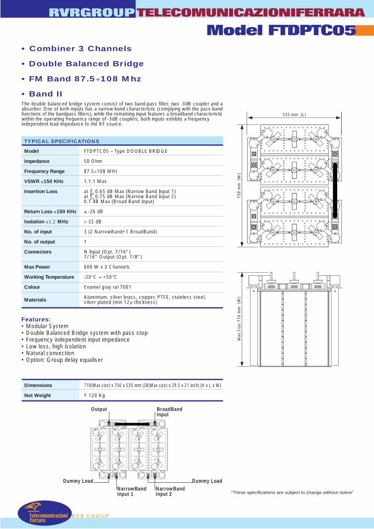
RVRGROUPTELECOMUNICAZIONIFERRARA
Model FTDPTC05
RVR GROUPTelecomunicazioni
Ferrara
• Combiner 3 Channels
• Double Balanced Bridge
• FM Band 87.5÷108 Mhz
• Band IIThe double balanced bridge system consist of two band-pass filter, two -3dB coupler and aabsorber. One of both inputs has a narrow-band characteristic (complying with the pass-bandfunctions of the bandpass filters), while the remaining input features a broadband characteristicwithin the operating frequency range of -3dB couplers, both inputs exhibits a frequencyindependent load impedance to the RF source.
Features:• Modular System• Double Balanced Bridge system with pass stop• Frequency independent input impedance• Low loss, high isolation• Natural convection• Option: Group delay equaliser
Dimensions 710(Max size) x 750 x 535 mm (28(Max size) x 29.5 x 21 inch) (H x L x W)
Net Weight =~ 120 Kg
TYPICAL SPECIFICATIONS
Model FTDPTC05 – Type DOUBLE BRIDGE
Impedance 50 Ohm
Frequency Range 87.5÷108 MHz
VSWR ±150 KHz 1.1:1 Max
Insertion Loss at ƒ0 0.65 dB Max (Narrow Band Input 1)at ƒ0 0.75 dB Max (Narrow Band Input 2)0.1 dB Max (Broad Band Input)
Return Loss ±150 KHz ≤ -26 dB
Isolation ±1.2 MHz > 32 dB
No. of input 3 (2 NarrowBand+1 BroadBand)
No. of output 1
Connectors N Input (Opt. 7/16”)7/16” Output (Opt. 7/8”)
Max Power 600 W x 3 Channels
Working Temperature -20°C ÷ +50°C
Colour Enamel gray ral 7001
Materials Aluminium, silver brass, copper, PTFE, stainless steel,silver plated (min 12µ thickness)
NarrowBandInput 1
NarrowBandInput 2
Dummy LoadDummy Load
BroadBandInput
Output
“These specifications are subject to change without notice”
750
mm
(W
)
535 mm (L)
Max
Siz
e 71
0 m
m (
W)

Model FTDPDC2/1TELECOMUNICAZIONIFERRARARVRGROUP
TelecomunicazioniFerrara
RVR GROUP
• Combiner 3 Channels
• Double Balanced Bridge
• FM Band 87.5÷108 Mhz
• Band IIThe double balanced bridge system consist of two band-pass filter, two -3dB coupler and aabsorber. One of both inputs has a narrow-band characteristic (complying with the pass-bandfunctions of the bandpass filters), while the remaining input features a broadband characteristicwithin the operating frequency range of -3dB couplers, both inputs exhibits a frequencyindependent load impedance to the RF source.
Features:• Modular System• Double Balanced Bridge system with pass stop• Frequency independent input impedance• Low loss, high isolation• Natural convection• Option: Group delay equaliser
Dimensions 1300(Max size) x 1250 x 520 mm (51.2(Max size) x 49.2 x 20.5 inch) (H x L x W)
Net Weight =~ 105 Kg
TYPICAL SPECIFICATIONS
Model FTDPDC2/1 – Type DOUBLE BRIDGE
Impedance 50 Ohm
Frequency Range 87.5÷108 MHz
VSWR ±150 KHz 1.1:1 Max
Insertion Loss at ƒ0 0.5 dB Max (Narrow Band Input 1)at ƒ0 0.4 dB Max (Narrow Band Input 2)0.08 dB Max (Broad Band Input)
Return Loss ±150 KHz ≤ -26 dB
Isolation ±1.2 MHz > 32 dB
No. of input 3 (2 NarrowBand+1 BroadBand)
No. of output 1
Connectors 7/8” Input (Opt. 7/16”)1+5/8” Output
Max Power BroadBand Input + NarrowBand Input 1 5KWNarrowBand Input 2 5KW
Working Temperature -20°C ÷ +50°C
Colour Enamel gray ral 7001
Materials Aluminium, silver brass, copper, PTFE, stainless steel,silver plated (min 12µ thickness)
“These specifications are subject to change without notice”
Dummy LoadInput N/B2
Output 1+5/8” Input B/B
Input N/B1
Dummy Load
520 mm (W)
1250
mm
(L)
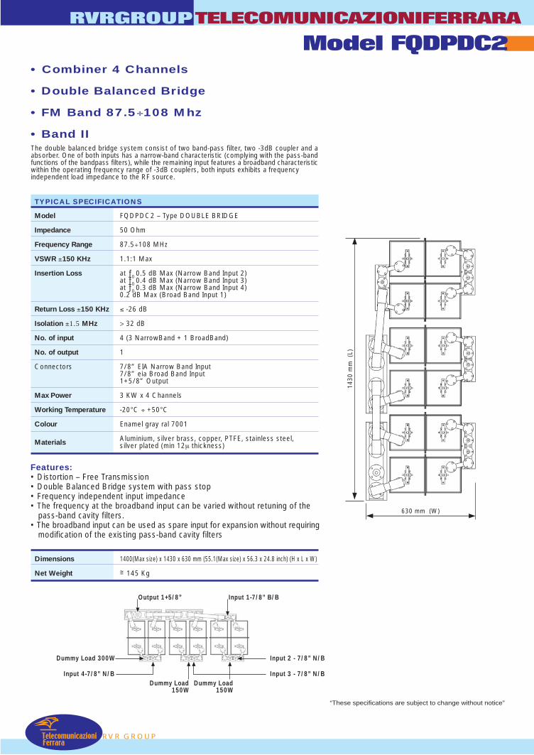
RVRGROUPTELECOMUNICAZIONIFERRARA
Model FQDPDC2
RVR GROUPTelecomunicazioni
Ferrara
• Combiner 4 Channels
• Double Balanced Bridge
• FM Band 87.5÷108 Mhz
• Band IIThe double balanced bridge system consist of two band-pass filter, two -3dB coupler and aabsorber. One of both inputs has a narrow-band characteristic (complying with the pass-bandfunctions of the bandpass filters), while the remaining input features a broadband characteristicwithin the operating frequency range of -3dB couplers, both inputs exhibits a frequencyindependent load impedance to the RF source.
Features:• Distortion – Free Transmission• Double Balanced Bridge system with pass stop• Frequency independent input impedance• The frequency at the broadband input can be varied without retuning of the
pass-band cavity filters.• The broadband input can be used as spare input for expansion without requiring
modification of the existing pass-band cavity filters
Dimensions 1400(Max size) x 1430 x 630 mm (55.1(Max size) x 56.3 x 24.8 inch) (H x L x W)
Net Weight =~ 145 Kg
TYPICAL SPECIFICATIONS
Model FQDPDC2 – Type DOUBLE BRIDGE
Impedance 50 Ohm
Frequency Range 87.5÷108 MHz
VSWR ±150 KHz 1.1:1 Max
Insertion Loss at ƒ0 0.5 dB Max (Narrow Band Input 2)at ƒ0 0.4 dB Max (Narrow Band Input 3)at ƒ0 0.3 dB Max (Narrow Band Input 4)0.2 dB Max (Broad Band Input 1)
Return Loss ±150 KHz ≤ -26 dB
Isolation ±1.5 MHz > 32 dB
No. of input 4 (3 NarrowBand + 1 BroadBand)
No. of output 1
Connectors 7/8” EIA Narrow Band Input7/8” eia Broad Band Input1+5/8” Output
Max Power 3 KW x 4 Channels
Working Temperature -20°C ÷ +50°C
Colour Enamel gray ral 7001
Materials Aluminium, silver brass, copper, PTFE, stainless steel,silver plated (min 12µ thickness)
“These specifications are subject to change without notice”
Output 1+5/8” Input 1-7/8” B/B
Dummy Load 300W
Dummy Load150W
Dummy Load150W
Input 2 - 7/8” N/B
Input 3 - 7/8” N/BInput 4-7/8” N/B
630 mm (W)
1430
mm
(L)
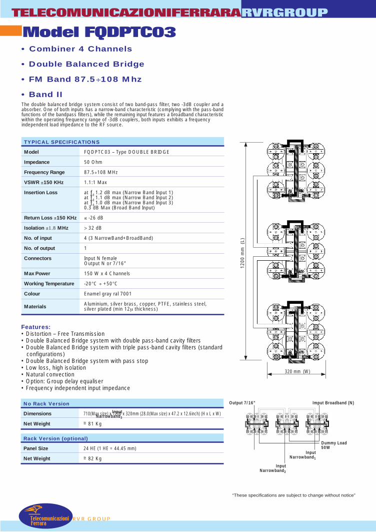
TELECOMUNICAZIONIFERRARARVRGROUP
TelecomunicazioniFerrara
RVR GROUP
• Combiner 4 Channels
• Double Balanced Bridge
• FM Band 87.5÷108 Mhz
• Band IIThe double balanced bridge system consist of two band-pass filter, two -3dB coupler and aabsorber. One of both inputs has a narrow-band characteristic (complying with the pass-bandfunctions of the bandpass filters), while the remaining input features a broadband characteristicwithin the operating frequency range of -3dB couplers, both inputs exhibits a frequencyindependent load impedance to the RF source.
Features:• Distortion – Free Transmission• Double Balanced Bridge system with double pass-band cavity filters• Double Balanced Bridge system with triple pass-band cavity filters (standard
configurations)• Double Balanced Bridge system with pass stop• Low loss, high isolation• Natural convection• Option: Group delay equaliser• Frequency independent input impedance
TYPICAL SPECIFICATIONS
Model FQDPTC03 – Type DOUBLE BRIDGE
Impedance 50 Ohm
Frequency Range 87.5÷108 MHz
VSWR ±150 KHz 1.1:1 Max
Insertion Loss at ƒ0 1.2 dB max (Narrow Band Input 1)at ƒ0 1.1 dB max (Narrow Band Input 2)at ƒ0 1.0 dB max (Narrow Band Input 3)0.3 dB Max (Broad Band Input)
Return Loss ±150 KHz ≤ -26 dB
Isolation ±1.8 MHz > 32 dB
No. of input 4 (3 NarrowBand+BroadBand)
No. of output 1
Connectors Input N femaleOutput N or 7/16”
Max Power 150 W x 4 Channels
Working Temperature -20°C ÷ +50°C
Colour Enamel gray ral 7001
Materials Aluminium, silver brass, copper, PTFE, stainless steel,silver plated (min 12µ thickness)
No Rack Version
Dimensions 710(Max size) x 1200 x 320mm (28.0(Max size) x 47.2 x 12.6inch) (H x L x W)
Net Weight =~ 81 Kg
Rack Version (optional)
Panel Size 24 HE (1 HE = 44.45 mm)
Net Weight =~ 82 Kg
“These specifications are subject to change without notice”
Output 7/16” Imput Broadband (N)
Dummy Load50W
InputNarrowband1
InputNarrowband2
InputNarrowband3
Model FQDPTC03
1200
mm
(L)
320 mm (W)
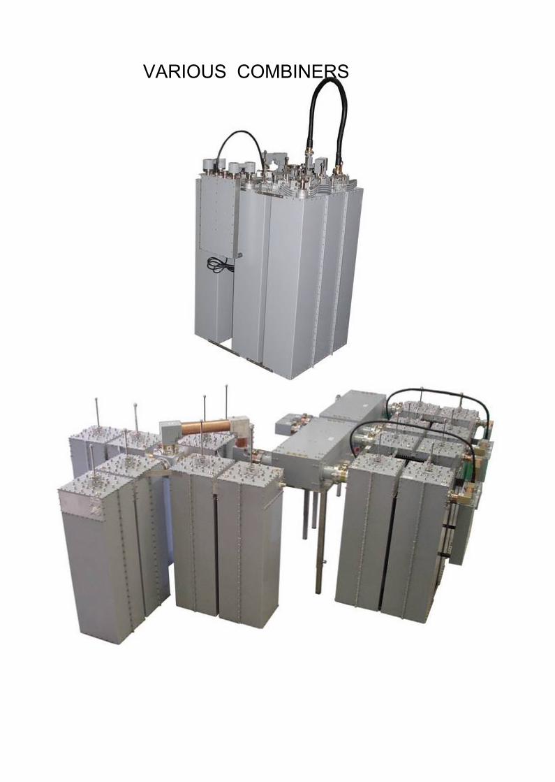
VARIOUS COMBINERS


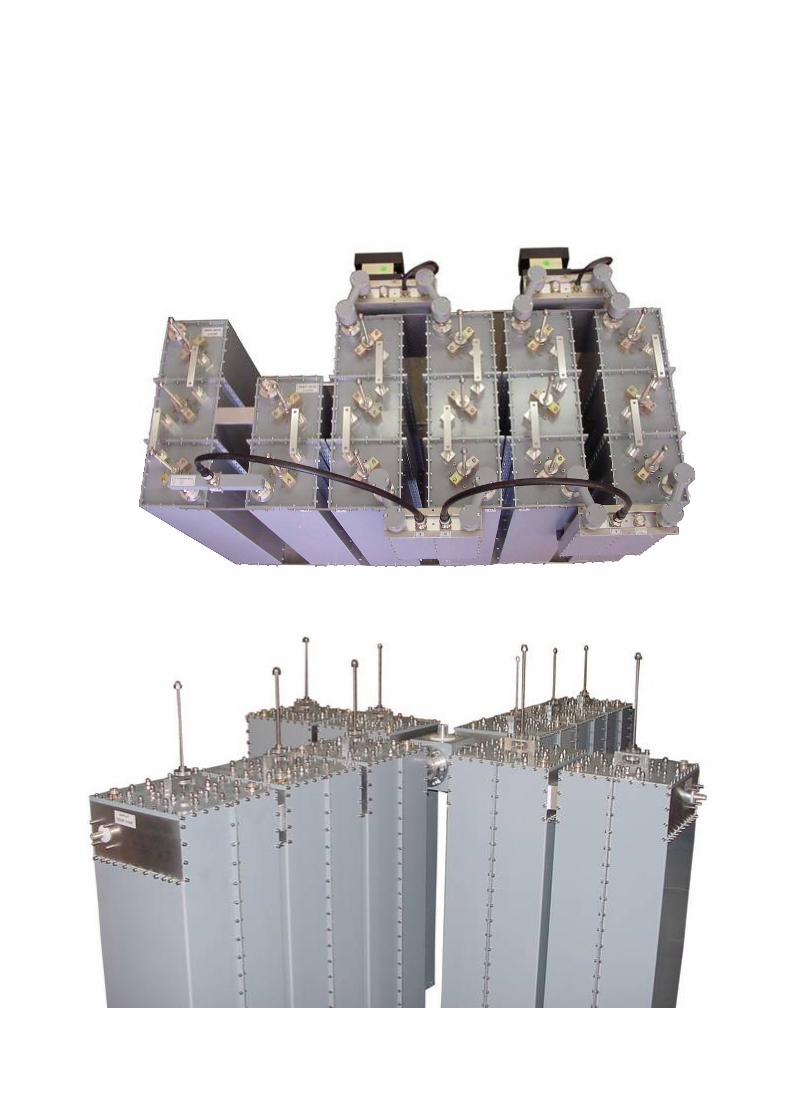
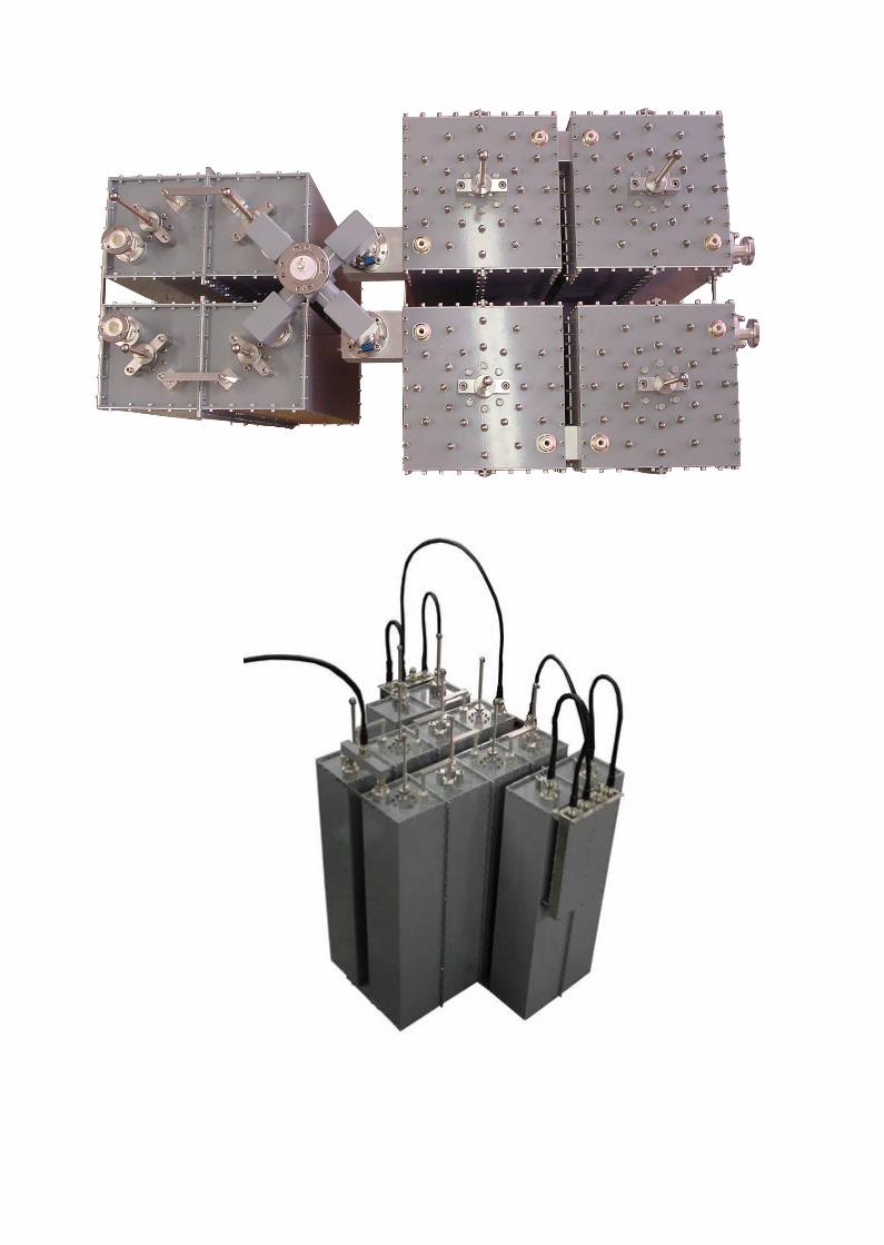

SPLITTERS 114
RF POWER HIJACKER 117
FINE MATCHER 119
FM 3dB COUPLERS 120
CATALOGGENERAL
RVR GROUP
RVRGROUPTELECOMUNICAZIONIFERRARA
TelecomunicazioniFerrara
ACCESSORIES
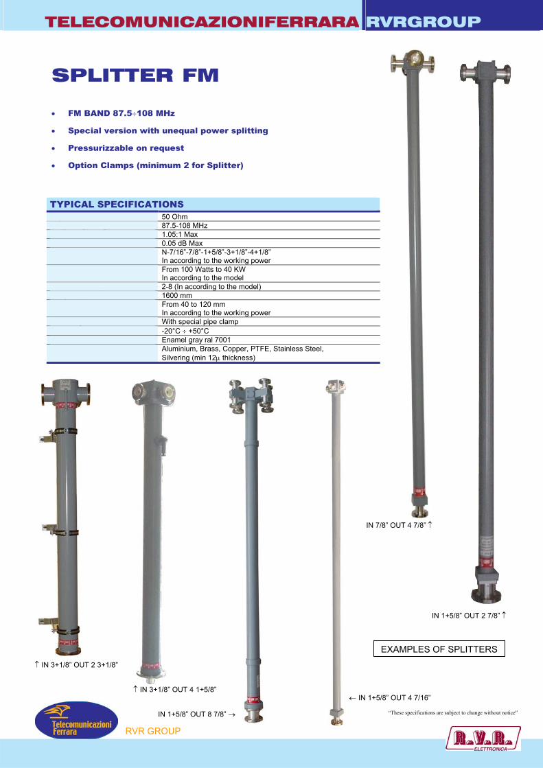
TELECOMUNICAZIONIFERRARA RVRGROUP
IN 1+5/8” OUT 2 7/8” ↑
SPLITTER FM • FM BAND 87.5÷108 MHz
• Special version with unequal power splitting
• Pressurizzable on request
• Option Clamps (minimum 2 for Splitter)
TYPICAL SPECIFICATIONS Impedance 50 Ohm Frequency Range 87.5-108 MHz VSWR 1.05:1 Max Insertion Loss 0.05 dB Max Connectors N-7/16”-7/8”-1+5/8”-3+1/8”-4+1/8”
In according to the working power Max Power Input From 100 Watts to 40 KW
In according to the model Number of outputs 2-8 (In according to the model) Length approx. 1600 mm Diameter external tube From 40 to 120 mm
In according to the working power Mounting With special pipe clamp Working Temperature -20°C ÷ +50°C Colour Enamel gray ral 7001 Materials Aluminium, Brass, Copper, PTFE, Stainless Steel,
Silvering (min 12µ thickness)
P
↑ IN 3+1/8” OUT 4 1+5/8”
IN 1+5/8” OUT 8 7/8” →
↑ IN 3+1/8” OUT 2 3+1/8”
IN 7/8” OUT 4 7/8” ↑
← IN 1+5/8” OUT 4 7/16”
“These specifications are subject to change without notice”
RVR GROU
EXAMPLES OF SPLITTERS
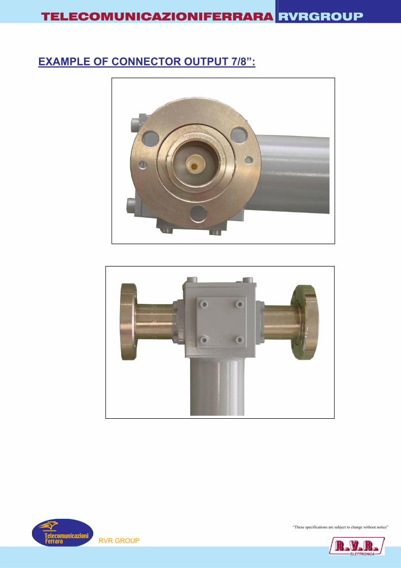
TELECOMUNICAZIONIFERRARA RVRGROUP
EXAMPLE OF CONNECTOR OUTPUT 7/8”:
“These specifications are subject to change without notice”
P
RVR GROU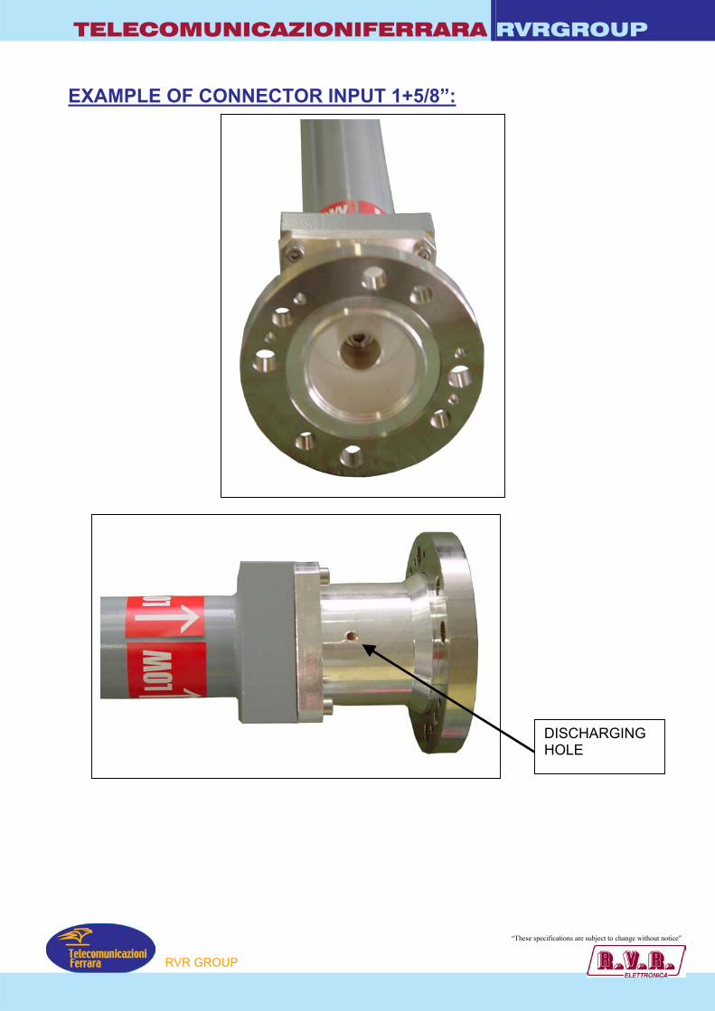
TELECOMUNICAZIONIFERRARA RVRGROUP
EXAMPLE OF CONNECTOR INPUT 1+5/8”:
DISCHARGING HOLE
“These specifications ar ubject to change without notice”
P
RVR GROUe s

TELECOMUNICAZIONIFERRARA RVRGROUP
EXAMPLE OF CONNECTOR INPUT 7/8”:
“These specifications ar ubject to change without notice”
P
RVR GROUe s

TELECOMUNICAZIONIFERRARA RVRGROUP
UNBALACED SPLITTER
• Unbalaced Splitter
• FM Band 87.5 ÷ 108 MHz
• Pressurizzable on request
TYPICAL SPECIFICATIONS Model According to type Impedance 50 Ohm Frequency Range 87,5 - 108 MHz VSWR 1.05 : 1 Max Insertion Loss 0.05 dB Max Connectors According to type Max Power Input From 100W to 40 KW Working Temperature -20°C ÷ +50°C Colour Enamel Gray Ral 7001 Materials Brass, Copper, PTFE, Stainless steel,
Silvering (min. 8µm thickness)
← IN 1+5/8” OUT 4 7/16”
← IN 3+1/8” OUT 12 7/8”
EXAMPLE OF UNBALACED SPLITTER
IN 1+5/8” OUT 8 7/8” →
“These specifications are subject to change without notice”
P
RVR GROU
TELECOMUNICAZIONIFERRARA RVRGROUP
Special Clamp for Splitter (option)
Typical return loss curve for splitter model DV/47/8-7/8
“These specifications are subject to change without notice”
P
RVR GROU
Model DV/2 LINKTELECOMUNICAZIONIFERRARARVRGROUP
RVR GROUPTelecomunicazioni
Ferrara
• Splitter
• For to connect several antennas
• Band 2360÷2485 Mhz
Dimensions 1300(Max size) x 650 x 450 mm (51.2(Max size) x 25.5 x 17.7 inch) (H x L x W)
Net Weight =~ 0.15 Kg
TYPICAL SPECIFICATIONS
Model DV/2 LINK
Impedance 50 Ohm
Frequency Range 2360÷2485 MHz
VSWR 1.15:1 Max
Insertion Loss 0.08 dB Max
Connectors N Input-Output
Max Power 100 Watts
Working Temperature -20°C ÷ +50°C
Colour Enamel gray ral 7001
Materials Aluminium, silver brass, copper, PTFE, stainless steel,silver plated (min 12µ thickness)
58 mm
20 mm
111 mm
1.160
1.156
1.152
1.148
1.144
1.140
1.136
1.132
1.128
1.124
1.120
2.35
2.36
2.37
2.38
2.39 2.4 2.4
12.4
22.4
32.4
42.4
52.4
62.4
72.4
82.4
9
Freq. (MHz)
VSWR
Typical curve for VSWR
“These specifications are subject to change without notice”
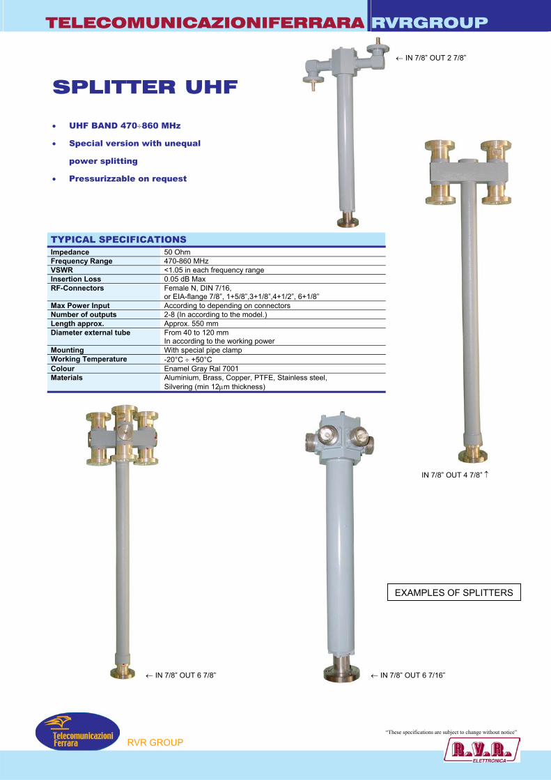
TELECOMUNICAZIONIFERRARA RVRGROUP
SPLITTER UHF • UHF BAND 470÷860 MHz
• Special version with unequal
power splitting
• Pressurizzable on request
TYPICAL SPECIFICATIONS Impedance 50 Ohm Frequency Range 470-860 MHz VSWR <1.05 in each frequency range Insertion Loss 0.05 dB Max RF-Connectors Female N, DIN 7/16,
or EIA-flange 7/8”, 1+5/8”,3+1/8”,4+1/2”,Max Power Input According to depending on connectors Number of outputs 2-8 (In according to the model.) Length approx. Approx. 550 mm Diameter external tube From 40 to 120 mm
In according to the working power Mounting With special pipe clamp Working Temperature -20°C ÷ +50°C Colour Enamel Gray Ral 7001 Materials Aluminium, Brass, Copper, PTFE, Stainl
Silvering (min 12µm thickness)
← IN 7/8” OUT 6 7/8”
P
← IN 7/8” OUT 2 7/8”
6+1/8”
ess steel,
IN 7/8” OUT 4 7/8” ↑
← IN 7/8” OUT 6 7/16”
“These specifications ar ubject to change without notice”
RVR GROU
e sEXAMPLES OF SPLITTERS
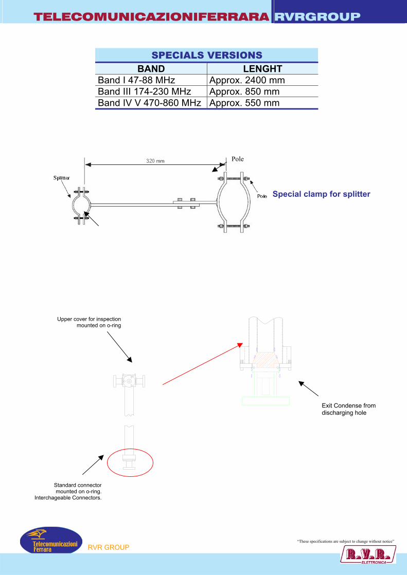
TELECOMUNICAZIONIFERRARA RVRGROUP
SPECIALS VERSIONS BAND LENGHT
Band I 47-88 MHz Approx. 2400 mm Band III 174-230 MHz Approx. 850 mm Band IV V 470-860 MHz Approx. 550 mm
Pole
Special clamp for splitter
Exit Condense from discharging hole
Upper cover for inspectionmounted on o-ring
Standard connectormounted on o-ring.
Interchageable Connectors.
“These specifications ar ubject to change without notice”
P
e s
RVR GROU
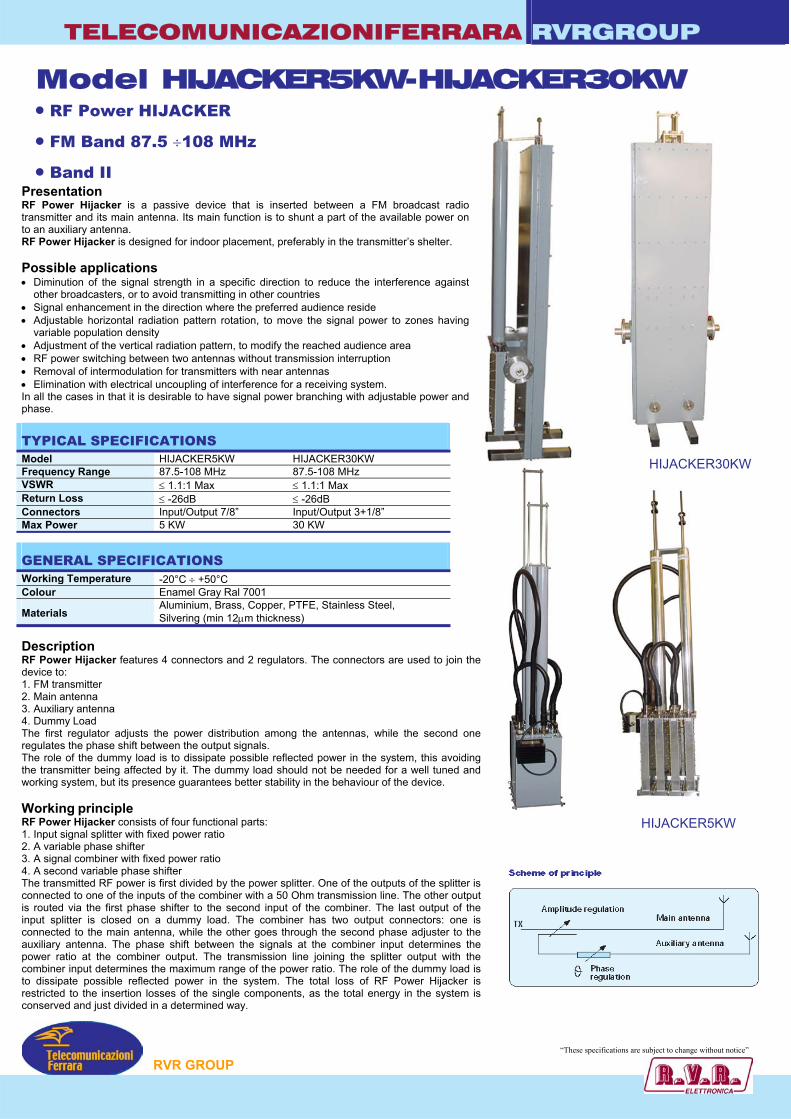
TELECOMUNICAZIONIFERRARA RVRGROUP
Model HIJACKER5KW-HIJACKER30KW • RF Power HIJACKER
W
• FM Band 87.5 ÷108 MHz
• Band II
Presentation RF Power Hijacker is a passive device that is inserted between a FM broadcast radiotransmitter and its main antenna. Its main function is to shunt a part of the available power onto an auxiliary antenna. RF Power Hijacker is designed for indoor placement, preferably in the transmitter’s shelter. Possible applications • Diminution of the signal strength in a specific direction to reduce the interference against
other broadcasters, or to avoid transmitting in other countries • Signal enhancement in the direction where the preferred audience reside • Adjustable horizontal radiation pattern rotation, to move the signal power to zones having
variable population density • Adjustment of the vertical radiation pattern, to modify the reached audience area • RF power switching between two antennas without transmission interruption • Removal of intermodulation for transmitters with near antennas • Elimination with electrical uncoupling of interference for a receiving system. In all the cases in that it is desirable to have signal power branching with adjustable power andphase.
Description RF Power Hijacker features 4 connectors and 2 regulators. The connectors are used to join the device to: 1. FM transmitter 2. Main antenna 3. Auxiliary antenna 4. Dummy Load The first regulator adjusts the power distribution among the antennas, while the second oneregulates the phase shift between the output signals. The role of the dummy load is to dissipate possible reflected power in the system, this avoidingthe transmitter being affected by it. The dummy load should not be needed for a well tuned andworking system, but its presence guarantees better stability in the behaviour of the device. Working principle RF Power Hijacker consists of four functional parts: 1. Input signal splitter with fixed power ratio 2. A variable phase shifter 3. A signal combiner with fixed power ratio 4. A second variable phase shifter The transmitted RF power is first divided by the power splitter. One of the outputs of the splitter isconnected to one of the inputs of the combiner with a 50 Ohm transmission line. The other output is routed via the first phase shifter to the second input of the combiner. The last output of the input splitter is closed on a dummy load. The combiner has two output connectors: one isconnected to the main antenna, while the other goes through the second phase adjuster to theauxiliary antenna. The phase shift between the signals at the combiner input determines thepower ratio at the combiner output. The transmission line joining the splitter output with the combiner input determines the maximum range of the power ratio. The role of the dummy load isto dissipate possible reflected power in the system. The total loss of RF Power Hijacker isrestricted to the insertion losses of the single components, as the total energy in the system is conserved and just divided in a determined way.
P
“These specifications arHIJACKER30K
HIJACKER5KW
ubject to change without notice”
RVR GROU
e sTYPICAL SPECIFICATIONS Model HIJACKER5KW HIJACKER30KW Frequency Range 87.5-108 MHz 87.5-108 MHz VSWR ≤ 1.1:1 Max ≤ 1.1:1 Max Return Loss ≤ -26dB ≤ -26dB Connectors Input/Output 7/8” Input/Output 3+1/8” Max Power 5 KW 30 KW
GENERAL SPECIFICATIONS Working Temperature -20°C ÷ +50°C Colour Enamel Gray Ral 7001
Materials Aluminium, Brass, Copper, PTFE, Stainless Steel, Silvering (min 12µm thickness)

Model HIJACKER5KW-HIJACKER30KWTELECOMUNICAZIONIFERRARARVRGROUP
RVR GROUPTelecomunicazioni
Ferrara
InstallationThe setup of RF Power Hijacker requires appropriate study and design. The installationlocation shall permit the operator to comfortably perform the needed regulations: the preferredlocation is nearby the transmitter, even if there is no need to monitor its parameters during thesetup of the system.There is no requirement about the length of the cable connecting the transmitter with RF PowerHijacker. The initial setup is completed once the main and auxiliary antennas and the dummyload are connected.The power that is dissipated by the dummy load is of little importance unless an antennamalfunction arises: it is up to the system engineer to evaluate the probability and type of theproblems that could affect the antenna system, and to plan out the rating and positioning of thedummy load as a function of it.
Setup directionsThe adjustment of RF Power Hijacker requires the collaboration of an operator that willmanoeuvre the regulators of the device and of a second operator whose role is to monitor theeffect in the field and to drive the operator on site towards the desired result. The operatorswill therefore be in radio or telephone contact.Due to the very nature of the system, RF Power Hijacker cannot be factory-preset, and the bestchoice is just to request the device to be set with minimum power directed to the auxiliaryantenna.The typical regulation process consists of a succession of iterations until the desired result isobtained.The first step of each iteration is to raise the amount of power directed to the auxiliary antenna:the operator in the field will notice the effect of this operation measuring the received fieldstrength.Than, the operator on site will vary the phase of the auxiliary signal along the whole range, whilethe operator in the filed monitors the corresponding variations in the received field. If the phaseregulation doesn’t give satisfactory results, the amount of power shunted to the auxiliary antennais increased, beginning a new iteration.
Theoretical considerationsUsing two antennas to irradiate the RF signal produced by a single transmitter, always resultsin mutual influence in the radiated fields. RF Power Hijacker is helpful to shape the resultingpattern in an useful way from the broadcaster’s point of view.At the receiver, the combination of the signal gives two different effects: the first and usefulone is the enhancement or suppression of signal strength due the phase shift that is regulatedby RF Power Hijacker. The second one, due to the relative delay of the received signals, is theso called multipath interference, resulting in distortion in the received signal and unwanted AMin the field. To reduce the multipath effect, it is important to avoid the use of filters affectingonly one of the transmission paths, and to keep the length of the antenna feeders as similaras possible. It should be noted that the multipath effect could also be present in the directionof the notch of the overall radiation pattern: in this case, the resulting signal would be asuppressed-carrier AM, with lateral spectral lines carrying more energy, the bigger the delayand the deeper the modulation level of the FM signal is.A final consideration about the antennas to be used in conjunction with the RF Power Hijacker:in most cases, the main antenna is already installed, while the auxiliary one has to be chosenin view of the desired result. Since the auxiliary antenna shall normally irradiate a small part ofthe total transmitted power, it can be of smaller size. It’s also important to take into accountthe whole radiation pattern of the selected auxiliary antenna, and to study its effect on the globalradiated field of the system, to avoid the risk of unwanted side-effects affecting the mainaudience area.
Application examples
Received interference suppression in a radio linkIn some cases a radio link can suffer from interference induced by a signal arriving from adirection different from the one of the desired signal. If the normal anti-reflecting receivingsystem or reduced sidelobes antennas are not sufficient to bring the interference below theneeded level, the RF Power Hijacker can be helpful as a sidelobe canceller.In this configuration, an auxiliary directive antenna is installed with its main lobe pointed towardsthe interfering source. The received signal is then routed through the phase shifting channelof the RF Power Hijacker. Adjusting the provided regulators in a proper way, it is possible torender the contributions in the channels due to the interfering signal as having the same amplitudeand opposite phase, thus obtaining suppression levels often well below 40 dB, compared to20-25 dB permitted by traditional systems.The system has a remarkable bandwidth, thanks to the maximum efficiency design of the circuit.The auxiliary antenna can be constituted by one or more elements in different configurations,to obtain the most suitable receiving pattern for the specific application.
Attenuation of the power transmitted in a certain directionIn this case, the desired effect is to reduce the interference caused by a transmitter in an areathat is not intended to be served by it. The auxiliary antenna is pointed in the direction of thearea to be protected, and fed with the signal shunted by the RF Power Hijacker. The regulationsof the RF Power Hijacker will be adjusted so that the resulting radiation pattern will have aminimum in this direction, thanks to the main and auxiliary signals having opposite phase in thedesired direction.
Model Dimension Net Weight
HIJACKER5KW 1500(min)÷2500(max)x430x260 mm (59.1(min)÷98.4(max)x16.9x10.2 inch) (HxLxW) =~ 25 Kg
HIJACKER30KW 1700(min)÷2500(max)x550x350 mm (66.9(min)÷98.4(max)x21.6x13.8 inch) (HxLxW) =~ 30 Kg
Example of antenna system comprising a mainsection of four collinear broadband fm dipolespointed at 0°, and an auxiliary 5 elements yagiauxiliary antenna pointed at 90°, creating anull in the corresponding direction
2500
mm
(M
AX
) H
1500 mm
(MIN
) H
430 mmL
260 mmW
HIJ
AC
KER
5KW
“These specifications are subject to change without notice”
2500
mm
(M
AX
) H
1700 mm
(MIN
) H
550 mmL
350 mmW
HIJ
AC
KER
30K
W
ErOVEST EST
NORD
SUD
10 0.7 0.5 0.3 0.1 -20 -10.5 -6 -3.1 dB0
ERP T.max (KW): 0.006ERP R.max (KW): 0.006
0.0° abbas (T)Guad (dBd): 7.6

TELECOMUNICAZIONIFERRARA RVRGROUP
MODEL FMT12K-FMT30K-FMT40K
FMT12K
• FINE MATCHER
• FM BAND 87.5÷108 MHz
• Band II
• FINE TUNED ANTENNA FOR MINIMUN VSWR
Although the TELECOMUNICAZIONI FERRARA antennas are tuned at the factory to provide a low standing wave ratio for the operating channel, when an antenna is mounted on a conductive metal object such as a tower or a pole its VSWR naturally increases. The fine matcher provides the user a quick and easy way to optimize the antenna for the absolute minimum VSWR and released signal degradation. With this device, tuning can be accomplished in a fraction of the time that it take to tune competitive antennas without having to disassemble the feed-line. Tuning can even be accomplished without loss of system pressure.
FMT40K TYPICAL SPECIFICATIONS
Model FMT12KImpedance 50 ohm Frequency Range 87.5-108Insertion Loss 0.05 dB Connectors Input-Ou
Input-OuInput-Ou
Max Power 12-30-40Working Temperature -20°C ÷ +Colour Enamel G
Materials AluminiuSilvering
P
-
MMatptptpKW5r
m, (m
FMT30K
FMT30K – FMT40K
Hz x
ut 1+5/8” (Opt. 7/8”) FMT12K ut 3+1/8” FMT30K ut 4+1/2” FMT40K
0°C ay Ral 7001 Brass, Copper, PTFE, Stainless Steel, in 12µm thickness)
“These specifications ar ubject to change without notice”
RVR GROU
e s
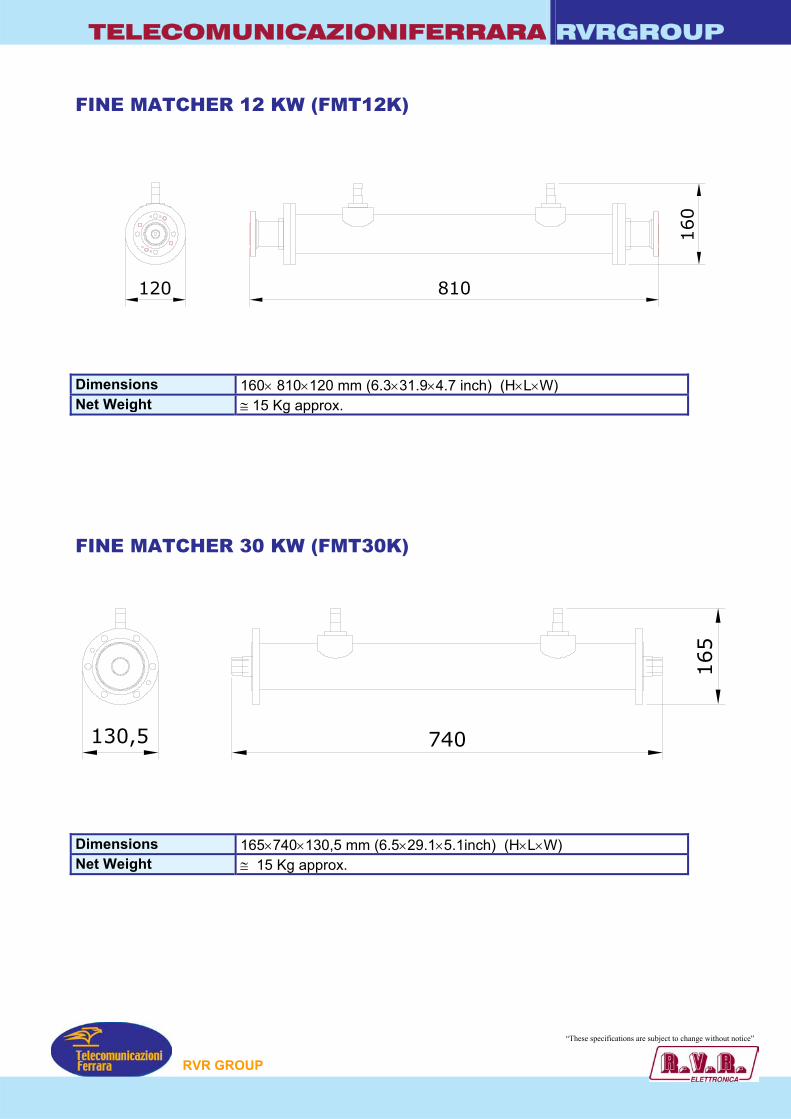
TELECOMUNICAZIONIFERRARA RVRGROUP
FINE MATCHER 12 KW (FMT12K)
810
160
120
Dimensions 160× 810×120 mm (6.3×31.9×4.7 inch) (H×L×W) Net Weight ≅ 15 Kg approx.
FINE MATCHER 30 KW (FMT30K)
740
165
130,5
Dimensions 165×740×130,5 mm (6.5×29.1×5.1inch) (H×L×W) Net Weight ≅ 15 Kg approx.
“These specifications ar ubject to change without notice”
P
RVR GROUe s
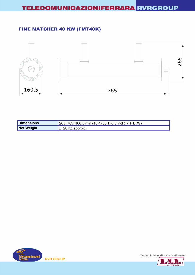
TELECOMUNICAZIONIFERRARA RVRGROUP
FINE MATCHER 40 KW (FMT40K)
765
265
160,5
Dimensions 265×765×160,5 mm (10.4×30.1×6.3 inch) (H×L×W) Net Weight ≅ 20 Kg approx.
“These specification re subject to change without notice”
P
RVR GROUs a

TELECOMUNICAZIONIFERRARA RVRGROUP
IMPEDANCE TRANSFORMER 50Ω - 75Ω
• FM BAND 87.5÷108 MHz
• Pressurizzable on request
• Option Clamps (minimum 2 for Transformer)
TYPICAL SPECIFICATIONS Impedance 50 Ohm Frequency Range 87.5-108 MHz VSWR 1.05:1 Max Insertion Loss 0.05 dB Max Connectors N or 7/8”
In according to the working power Max Power Input From 100 Watts to 5 KW
In according to the model Length approx. 735 mm (with conn. N)
785 mm (with conn. 7/8”) Diameter external tube 40 mm Working Temperature -20°C ÷ +50°C Colour Enamel Gray Ral 7001 Materials Brass, Copper, PTFE, Silvering
CONNECTOR N →
← CONNECTOR 7/8”
5500 ΩΩ 7755 ΩΩ
EXAMPLES OF IMPEDANCE TRANSFORMER
“These specifications are subject to change without notice”
P
RVR GROU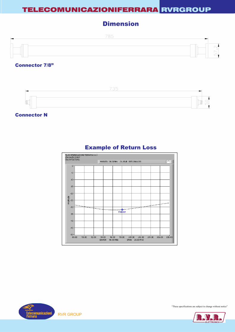
TELECOMUNICAZIONIFERRARA RVRGROUP
Dimension
Connector 7/8”
Connector N
Example of Return Loss
“These specifications are subject to change without notice”
P
RVR GROU
TELECOMUNICAZIONIFERRARA RVRGROUP
MODEL : FFNOT05K - FFNOT2K FFNOT5K - FFNOT10K
• NOTCH FILTER
• FM BAND 87.5÷108 MHz
• BAND II
Notch filter is a STUB
Models InC
FFNOT05K NFFNOT2K 7FFNOT5K 7FFNOT10K 1
TYPICAL SPECIFICATIONS Impedance 5Frequency Range 8VSWR ± 150 KHz 1Insertion Loss aAttenuation 2th harmonic TWorking Temperature -2Colour EMaterials A
S
TUNERS to block 2th .
put onnector
Output Connector
Max. Power
N 500W /16” 7/16” 2KW /8” 7/8” 5KW +5/8” 1+5/8” 10KW
0 Ohm 7.5-108 MHz .1:1 Max t 0f 0.05 dB Max ypical –35dB 0°C ÷ +50°C namel Gray Ral 7001 luminium, Brass, Copper, PTFE, Stainless Steel, ilvering (min. 12µm thickness)
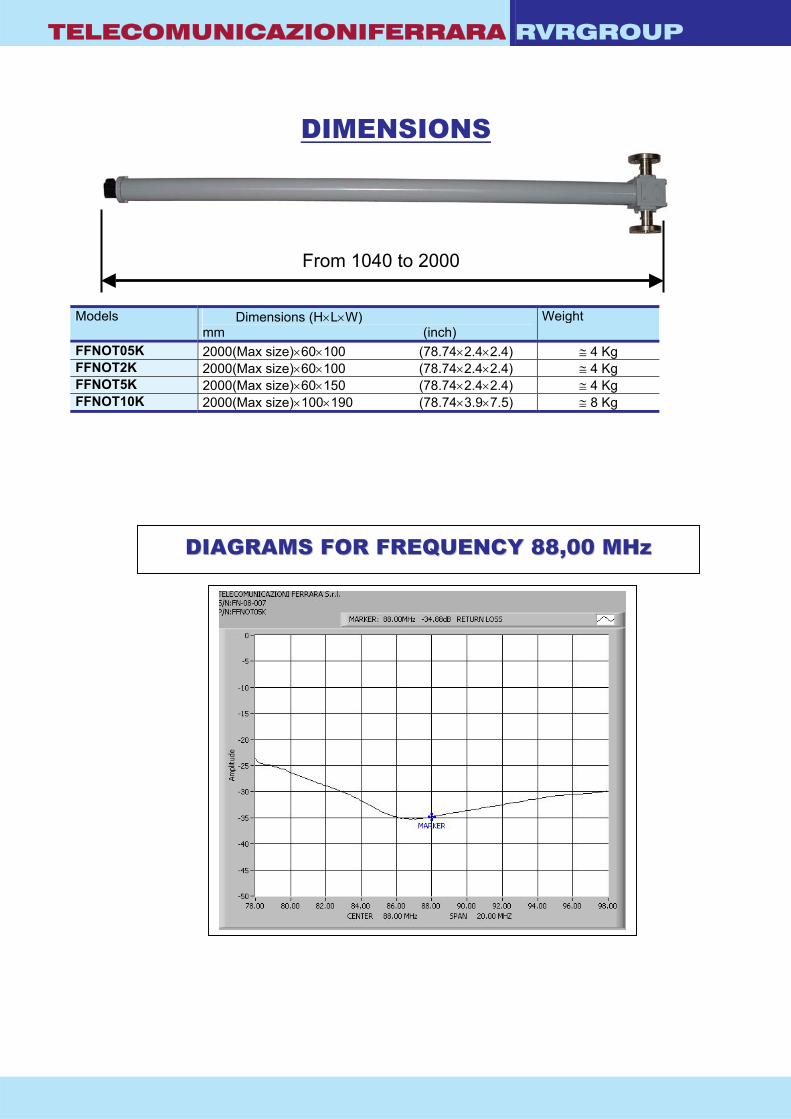
TELECOMUNICAZIONIFERRARA RVRGROUP
DIMENSIONS
M
FFFF
From 1040 to 2000
odels Dimensions (H×L×W) mm (inch)
Weight
FNOT05K 2000(Max size)×60×100 (78.74×2.4×2.4) ≅ 4 Kg FNOT2K 2000(Max size)×60×100 (78.74×2.4×2.4) ≅ 4 Kg FNOT5K 2000(Max size)×60×150 (78.74×2.4×2.4) ≅ 4 Kg FNOT10K 2000(Max size)×100×190 (78.74×3.9×7.5) ≅ 8 Kg
DDIIAAGGRRAAMMSS FFOORR FFRREEQQUUEENNCCYY 8888,,0000 MMHHzz

TELECOMUNICAZIONIFERRARA RVRGROUP
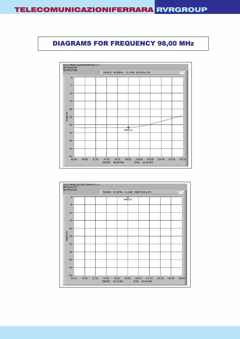
TELECOMUNICAZIONIFERRARA RVRGROUP
DDIIAAGGRRAAMMSS FFOORR FFRREEQQUUEENNCCYY 9988,,0000 MMHHzz
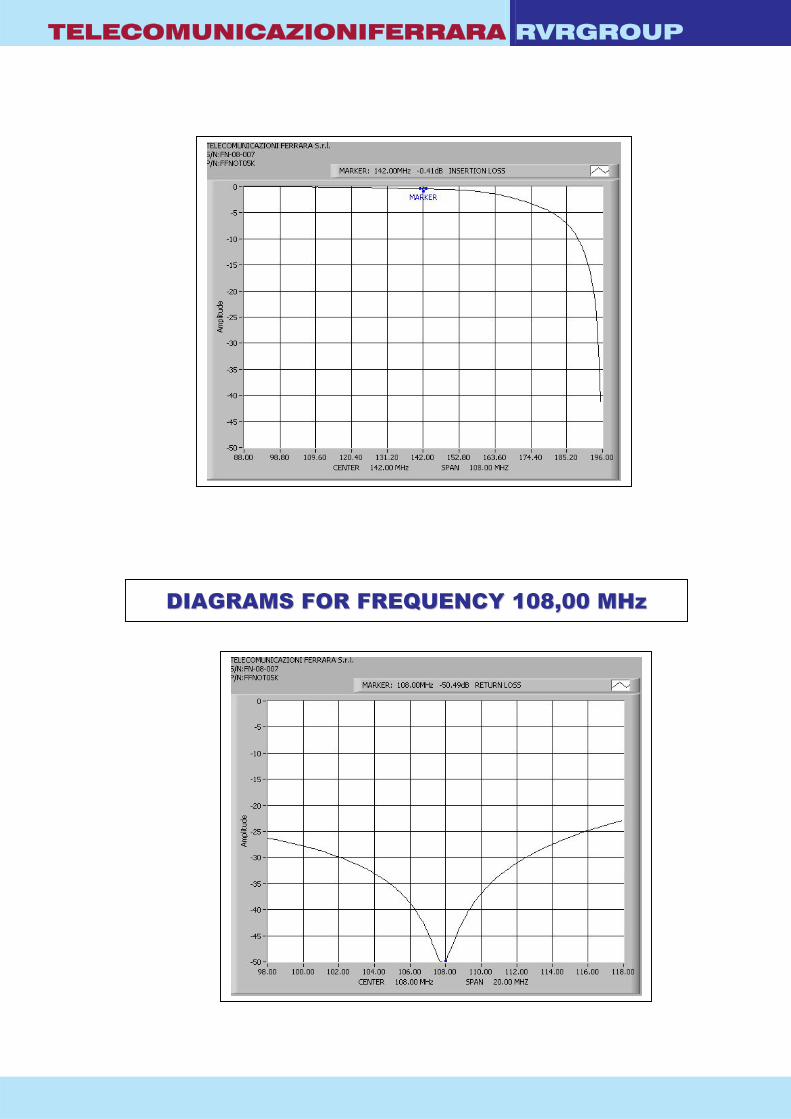
TELECOMUNICAZIONIFERRARA RVRGROUP
DDIIAAGGRRAAMMSS FFOORR FFRREEQQUUEENNCCYY 110088,,0000 MMHHzz

TELECOMUNICAZIONIFERRARA RVRGROUP

TELECOMUNICAZIONIFERRARA RVRGROUP
Model COUP3DB500W - COUP3DB2KW - COUP3DB5KW - COUP3DB10KW - COUP3DB20KW - COUP3DB45KW - COUP3DB80KW - COUP3DB120KW
• -3dB COUPLERS • FM BAND 87.5-108 MHz • BAND II Model: COUP3DB5KW
-3 dB couplers to realize double bridge combiner type
GENERAL SPECIFICATIONS Working Temperature -20°C ÷ +50°C Colour Enamel Gray ral 7001 Materials Aluminium, Brass, Copper, PTFE, Stainless Steel, Silvering (min 12µm thickness)
TYPICAL SPECIFICATIONS Model COUP3DB500W COUP3DB2KW COUP3DB5KW COUP3DB10KW Frequency Range 87.5-108 MHz 87.5-108 MHz 87.5-108 MHz 87.5-108 MHz Directivity ≥ 32dB ≥ 32dB ≥ 32dB ≥ 35dB Impedance 50 ohm 50 ohm 50 ohm 50 ohm VSWR ± 150 KHz 1:1.1 max 1:1.1 max 1:1.1 max 1:1.1 max Return Loss ± 150 KHz ≤ -26 dB ≤ -26 dB ≤ -26 dB ≤ -26 dB Coupling -3 dB ± 0.25 dB -3 dB ± 0.25 dB -3 dB ± 0.25 dB -3 dB ± 0.25 dB Connectors Input – Output N Input N - Output 7/16” Input – Output 7/8” Input - Output 1+5/8” Max Power 500 W 2 KW 5 KW 10 KW
TYPICAL SPECIFICATIONS Model COUP3DB20KW COUP3DB45KW COUP3D80KW COUP3D120KW Frequency Range 87.5-108 MHz 87.5-108 MHz 87.5-108 MHz 87.5-108 MHz Directivity ≥ 35dB ≥ 35dB ≥ 35dB ≥ 35dB Impedance 50 ohm 50 ohm 50 ohm 50 ohm VSWR ± 150 KHz 1:1.1 max 1:1.1 max 1:1.1 max 1:1.1 max Return Loss ± 150 KHz ≤ -26 dB ≤ -26 dB ≤ -26 dB ≤ -26 dB Coupling -3 dB ± 0.25 dB -3 dB ± 0.25 dB -3 dB ± 0.25 dB -3 dB ± 0.25 dB Connectors Input 1+5/8”
Output 3+1/8” Input 3+1/8” Output 4+1/2”
Input – Output 4+1/2” Input 4+1/2” Output 6+1/8”
Max Power 20 KW 45 KW 80 KW 120 KW
“These specifications are subject to change without notice”
RVR GROUP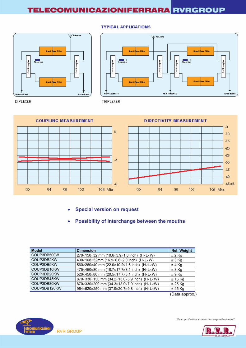
TELECOMUNICAZIONIFERRARA RVRGROUP
• Special version on request
• Possibility of interchange between the mouths
(Data approx.)
Model Dimension Net Weight COUP3DB500W 270×150×32 mm (10.6×5.9×1.3 inch) (H×L×W) ≅ 2 Kg COUP3DB2KW 430×168×52mm (16.9×6.6×2.0 inch) (H×L×W) ≅ 3 Kg COUP3DB5KW 560×260×40 mm (22.0×10.2×1.6 inch) (H×L×W) ≅ 4 Kg COUP3DB10KW 475×450×80 mm (18.7×17.7×3.1 inch) (H×L×W) ≅ 8 Kg COUP3DB20KW 520×450×80 mm (20.5×17.7×3.1 inch) (H×L×W) ≅ 9 Kg COUP3DB45KW 870×330×150 mm (34.2×13.0×5.9 inch) (H×L×W) ≅ 15 Kg COUP3DB80KW 870×330×200 mm (34.3×13.0×7.9 inch) (H×L×W) ≅ 25 Kg COUP3DB120KW 964×520×250 mm (37.9×20.7×9.8 inch) (H×L×W) ≅ 45 Kg
“These specifications are subject to change without notice”
RVR GROUP
TELECOMUNICAZIONIFERRARA RVRGROUP Mechanical specifications for COUP3DB500W
Mechanical specifications for COUP3DB2KW “These specifications are subject to change without notice”
RVR GROUP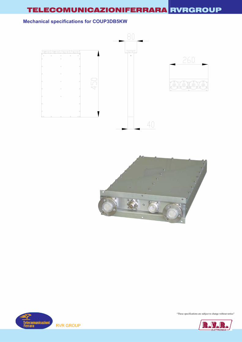
TELECOMUNICAZIONIFERRARA RVRGROUP Mechanical specifications for COUP3DB5KW
“These specifications are subject to change without notice”
RVR GROUP
TELECOMUNICAZIONIFERRARA RVRGROUP Mechanical specifications for COUP3DB10KW
Mechanical specifications for COUP3DB20KW
“These specifications are subject to change without notice”
RVR GROUP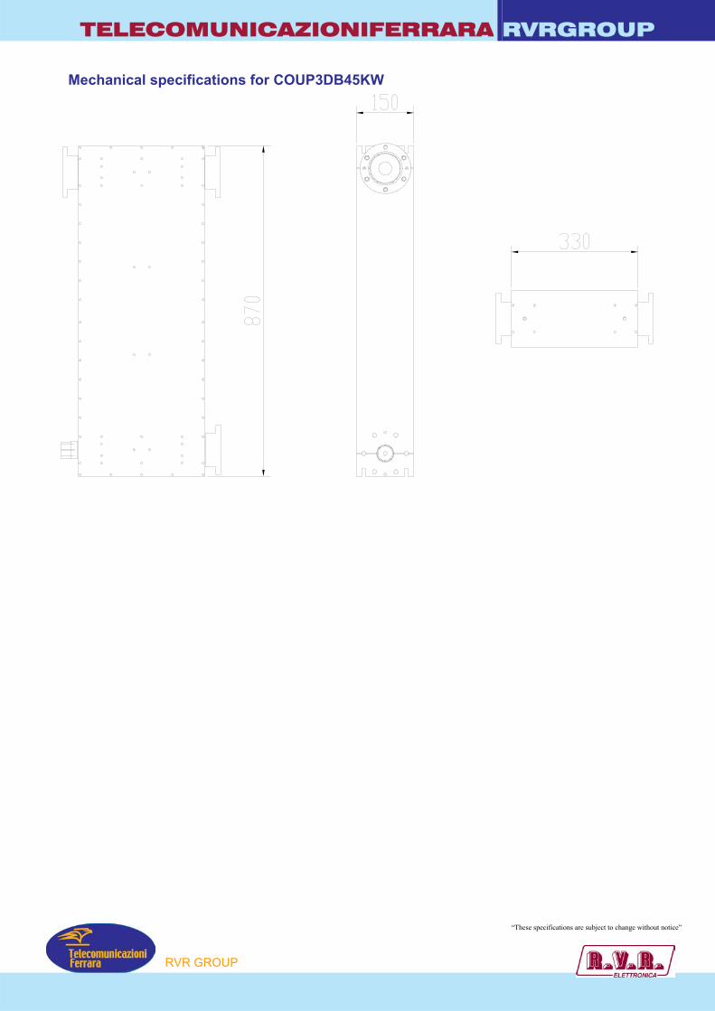
TELECOMUNICAZIONIFERRARA RVRGROUP Mechanical specifications for COUP3DB45KW
“These specifications are subject to change without notice”
RVR GROUP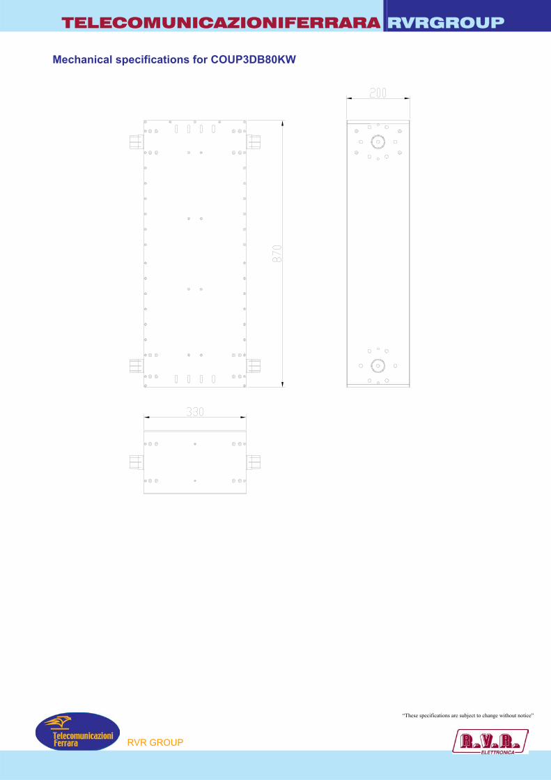
TELECOMUNICAZIONIFERRARA RVRGROUP Mechanical specifications for COUP3DB80KW
“These specifications are subject to change without notice”
RVR GROUP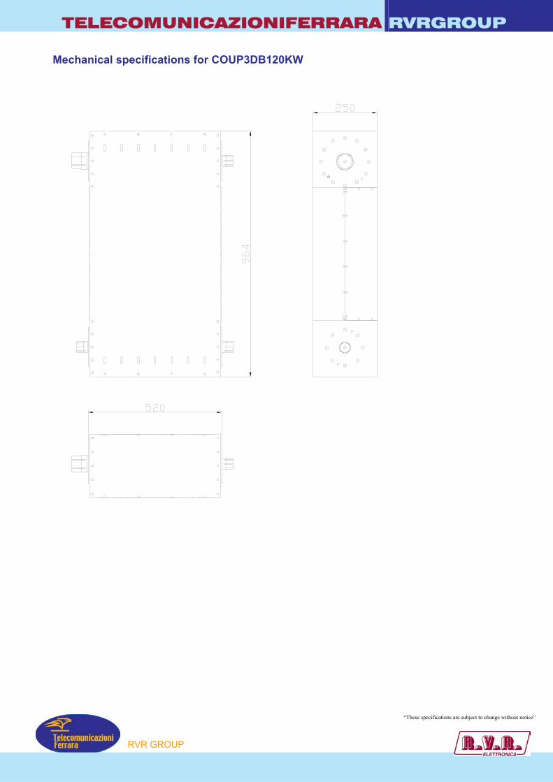
TELECOMUNICAZIONIFERRARA RVRGROUP Mechanical specifications for COUP3DB120KW
“These specifications are subject to change without notice”
RVR GROUP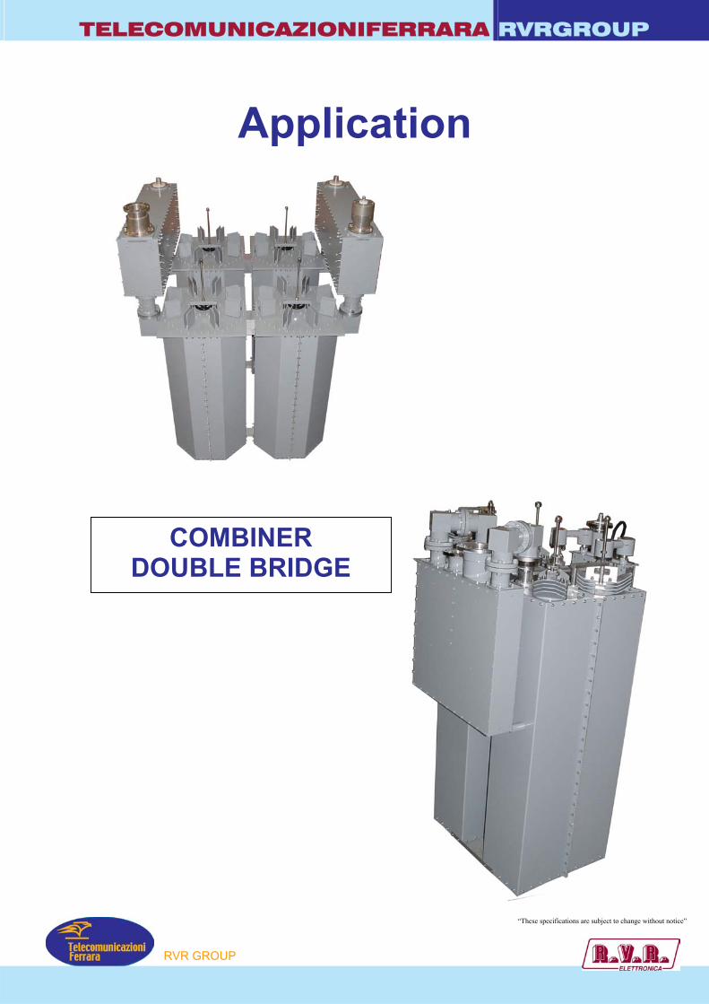
TELECOMUNICAZIONIFERRARA RVRGROUP
Application
COMBINER DOUBLE BRIDGE
“These specifications are subject to change without notice”
RVR GROUP
TELECOMUNICAZIONIFERRARA RVRGROUP
SWITCH LESS COMBINER
“These specifications are subject to change without notice”
RVR GROUP

CABLES and ACCESSORIES 124
CATALOGGENERAL
RVR GROUP
RVRGROUPTELECOMUNICAZIONIFERRARA
TelecomunicazioniFerrara
COAXIAL CABLES
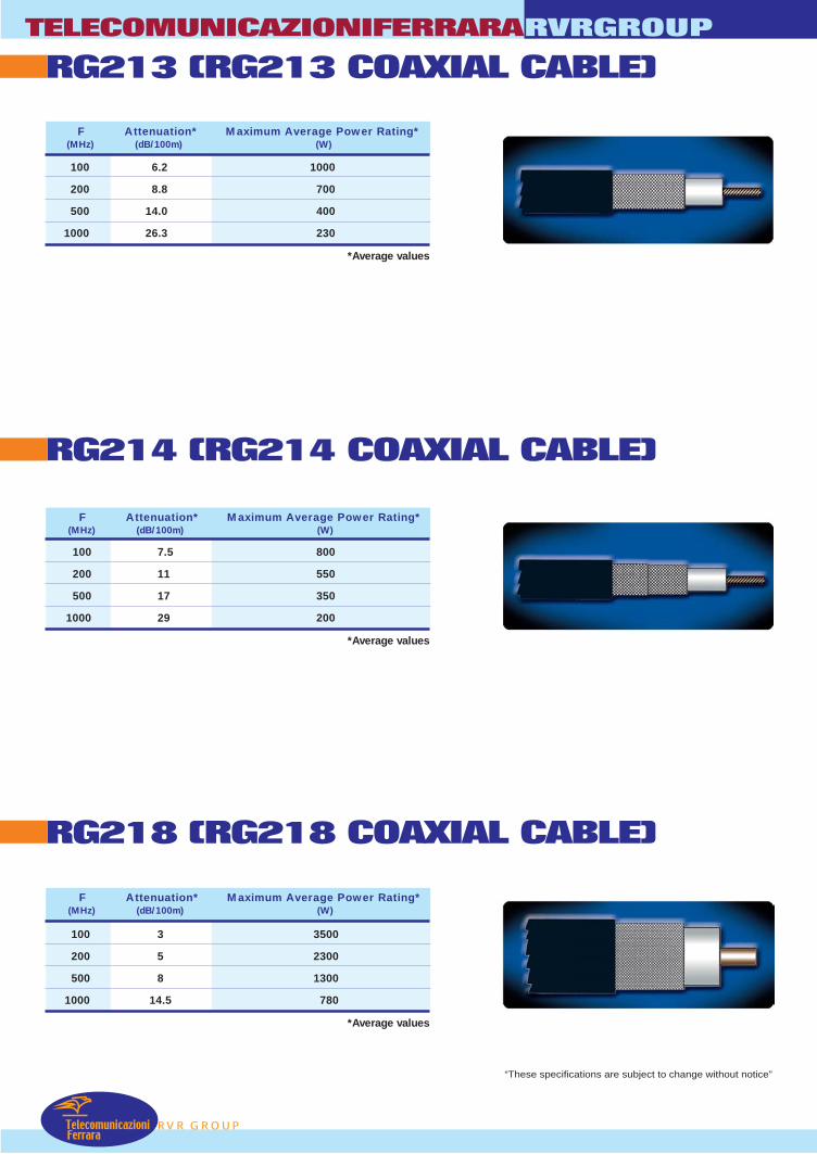
TelecomunicazioniFerrara
TELECOMUNICAZIONIFERRARA
RVR GROUP
RVRGROUP
RG214 (RG214 COAXIAL CABLE)
RG218 (RG218 COAXIAL CABLE)
RG213 (RG213 COAXIAL CABLE)
100
200
500
1000
F Attenuation* Maximum Average Power Rating*(MHz) (dB/100m) (W)
6.2
8.8
14.0
26.3
1000
700
400
230
*Average values
100
200
500
1000
7.5
11
17
29
800
550
350
200
*Average values
100
200
500
1000
3
5
8
14.5
3500
2300
1300
780
*Average values
“These specifications are subject to change without notice”
F Attenuation* Maximum Average Power Rating*(MHz) (dB/100m) (W)
F Attenuation* Maximum Average Power Rating*(MHz) (dB/100m) (W)

RVR GROUP
RVRGROUPTELECOMUNICAZIONIFERRARA
TelecomunicazioniFerrara
CLX7/8” (foam 7/8” COAXIAL CABLE)
CLX1/2” (foam 1/2” COAXIAL CABLE)
CLX1/4” ( foam 1/4” COAXIAL CABLE)
100
200
500
1000
4.5
6
10
15
1500
1200
700
500
*Average values
100
200
500
1000
1.2
1.8
3
4.5
7500
5200
3000
1500
*Average values
100
200
500
1000
2.3
3.3
5
7
3400
2000
1400
900
*Average values
“These specifications are subject to change without notice”
F Attenuation* Maximum Average Power Rating*(MHz) (dB/100m) (W)
F Attenuation* Maximum Average Power Rating*(MHz) (dB/100m) (W)
F Attenuation* Maximum Average Power Rating*(MHz) (dB/100m) (W)
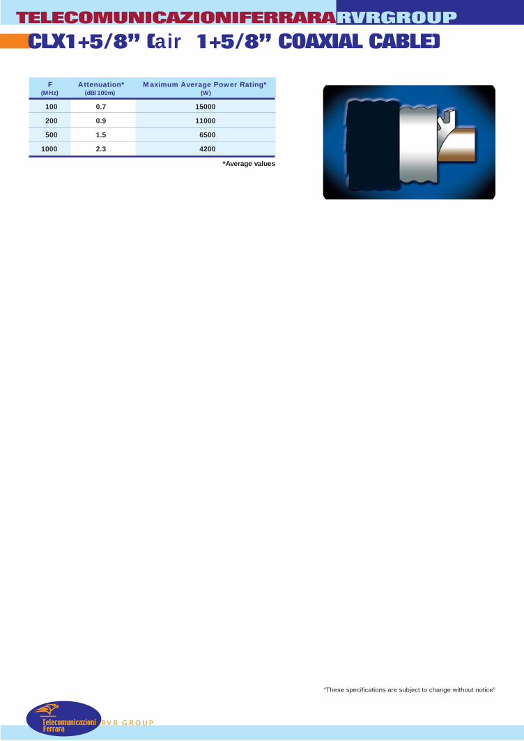
TelecomunicazioniFerrara
TELECOMUNICAZIONIFERRARA
RVR GROUP
RVRGROUP
CLX1+5/8” (air 1+5/8” COAXIAL CABLE)
100
200
500
1000
0.7
0.9
1.5
2.3
15000
11000
6500
4200
*Average values
“These specifications are subject to change without notice”
F Attenuation* Maximum Average Power Rating*(MHz) (dB/100m) (W)
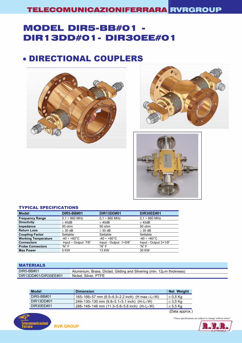
TELECOMUNICAZIONIFERRARA RVRGROUP
MODEL DIR5-BB#01 - DIR13DD#01- DIR30EE#01
• DIRECTIONAL COUPLERS
TYPICAL SPECIFICATIONS Model DIR5-BB#01 DIR13DD#01 Frequency Range 0,1 ÷ 860 MHz 0,1 ÷ 860 MHz Directivity ≥ 40dB ≥ 40dB Impedance 50 ohm 50 ohm Return Loss ≥ 30 dB ≥ 30 dB Coupling Factor Settable Settable Working Temperature -40 ÷ +60°C -40 ÷ +60°C Connectors Input – Output 7/8” Input - Output 1+5/8” Probe Connectors “N” F “N” F Max Power 5 KW 13 KW
MATERIALS DIR5-BB#01 Aluminium, Brass, Diclad, Gilding and DIR13DD#01/DIR30EE#01 Nickel, Silver, PTFE
Model Dimension DIR5-BB#01 165×166×57 mm (6.5×6.5×2.2 inch) DIR13DD#01 249×130×130 mm (9.8×5.1×5.1 inchDIR30EE#01 288×148×148 mm (11.3×5.8×5.8 inc
P
Si
(H) h)
DIR30EE#01 0,1 ÷ 860 MHz ≥ 40dB 50 ohm ≥ 30 dB Settable -40 ÷ +60°C Input - Output 3+1/8” “N” F 30 KW
lvering (min. 12µm thickness)
(Data approx.)
Net Weight max.×L×W) ≅ 0,5 Kg
(H×L×W) ≅ 3,5 Kg (H×L×W) ≅ 5,5 Kg
“These specifications ar ubject to change without notice”
RVR GROU
e s
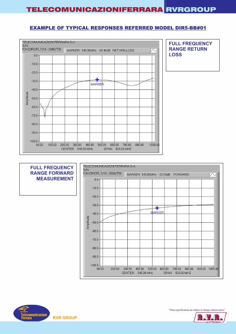
TELECOMUNICAZIONIFERRARA RVRGROUP
EXAMPLE OF TYPICAL RESPONSES REFERRED MODEL DIR5-BB#01
FULL FREQUENCY
RANGE RETURN LOSS
FULL FREQUENCYRANGE FORWARD
MEASUREMENT
P
“These specifications ar ubject to change without notice”
RVR GROU
e s
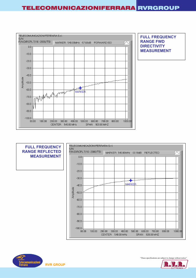
TELECOMUNICAZIONIFERRARA RVRGROUP
FULL FREQUENCY
RANGE FWD DIRECTIVITY MEASUREMENT
FULL FREQUENCYRANGE REFLECTED
MEASUREMENT
P
“These specifications ar ubject to change without notice”
RVR GROU
e s
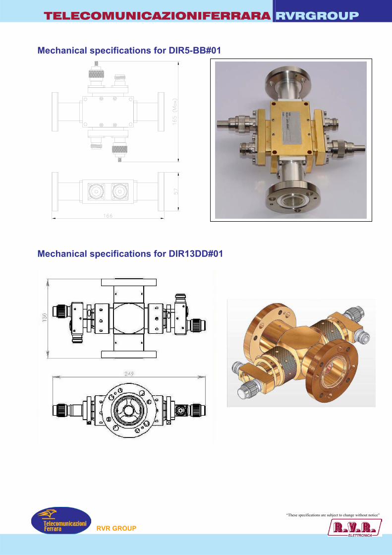
TELECOMUNICAZIONIFERRARA RVRGROUP
Mechanical specifications for DIR5-BB#01 Mechanical specifications for DIR13DD#01
“These specifications ar ubject to change without notice”
P
RVR GROUe s

TELECOMUNICAZIONIFERRARA RVRGROUP Mechanical specifications for DIR30EE#01
“These specification re subject to change without notice”
P
RVR GROUs a
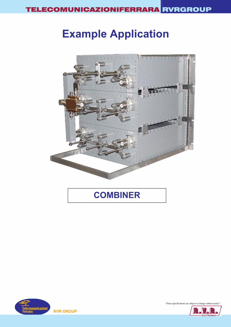
TELECOMUNICAZIONIFERRARA RVRGROUP
Example Application
P
COMBINER
“These specifications ar ubject to change without notice”
RVR GROU
e s

TELECOMUNICAZIONIFERRARA RVRGROUP
MODEL COUPSP05K – COUPSP1K – COUPSP2K – COUPSP12K – COUPSP40K – COUPSP60K
• STARPOINT
• FM BAND 87.5-108 MHz
• BAND II
COUPSP60K
GENERAL SPECIFICATIONS Working Temperature -20°C ÷ +50°C Colour Enamel Gray ral 7001 Materials Aluminium, Brass, Copper, PTFE, Stainless Steel, Silvering (min 12µm thickness)
TYPICAL SPECIFICATIONS Model COUPSP05K COUPSP1K COUPSP2K COUPSP12K Frequency Range 87.5-108 MHz 87.5-108 MHz 87.5-108 MHz 87.5-108 MHz Impedance 50 ohm 50 ohm 50 ohm 50 ohm VSWR 1:1.1 max 1:1.1 max 1:1.1 max 1:1.1 max Insertion Loss 0.02 dB 0.02 dB 0.02 dB 0.01 dB Return Loss ≤ -30 dB ≤ -30 dB ≤ -30 dB ≤ -30 dB N° Input 2 – 3 - 4 2 – 3 - 4 2 – 3 - 4 2 – 3 - 4 N° Output 1 1 1 1 Connectors Input Nf
Output Nf - 7/16” - 7/8”
Input Nf Output Nf - 7/16” - 7/8”
Input 7/16” - 7/8” Output 7/16” - 7/8” - 1+5/8”
Input - Output 1+5/8”
Max Power 800W 800W 2 KW with Out 7/16” 5 KW with Out 7/8” 10 KW with Out 1+5/8”
12 KW
“These specifications are subject to change without notice”
COUPSP12K
TYPICAL SPECIFICATIONS Model COUPSP40K COUPSP60K Frequency Range 87.5-108 MHz 87.5-108 MHz Impedance 50 ohm 50 ohm VSWR ± 150 KHz 1:1.1 max 1:1.1 max Insertion Loss 0.01 dB 0.01 dB Return Loss ± 150 KHz ≤ -30 dB ≤ -30 dB N° Input 2 – 3 - 4 2 – 3 - 4 N° Output 1 1 Connectors Input – Output 3+1/8” Input – Output
4+1/2” Max Power 40 KW 60 KW
P
RVR GROU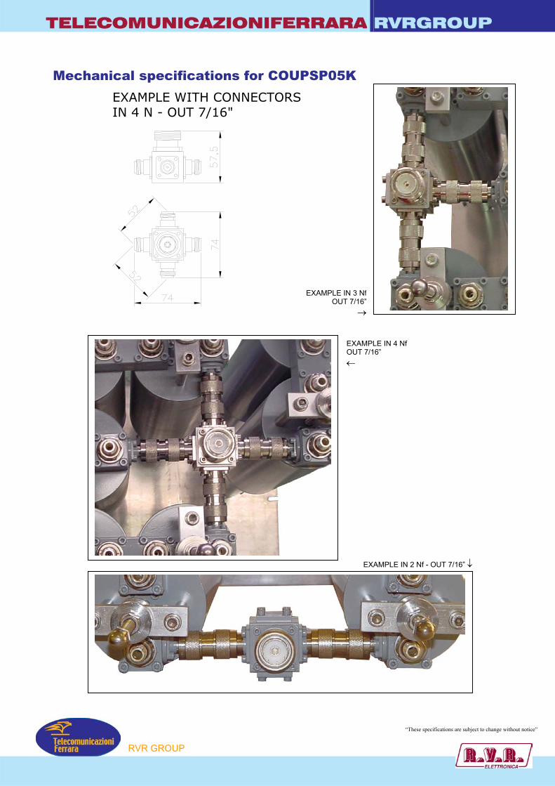
TELECOMUNICAZIONIFERRARA RVRGROUP
Mechanical specifications for COUPSP05K
EXAMPLE WITH CONNECTORSIN 4 N - OUT 7/16"
EXAMPLE IN 3 Nf
OUT 7/16”→
P
EXAMPLE IN 4 Nf OUT 7/16” ←
EXAMPLE IN 2 Nf - OUT 7/16” ↓
“These specifications are subject to change without notice”
RVR GROU
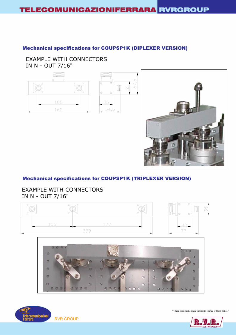
TELECOMUNICAZIONIFERRARA RVRGROUP
Mechanical specifications for COUPSP1K (DIPLEXER VERSION)
EXAMPLE WITH CONNECTORSIN N - OUT 7/16"EXAMPLE WITH CONNECTORSIN N - OUT 7/16"
Mechanical specifications for COUPSP1K (TRIPLEXER VERSION)
“These specifications are subject to change without notice”
P
RVR GROU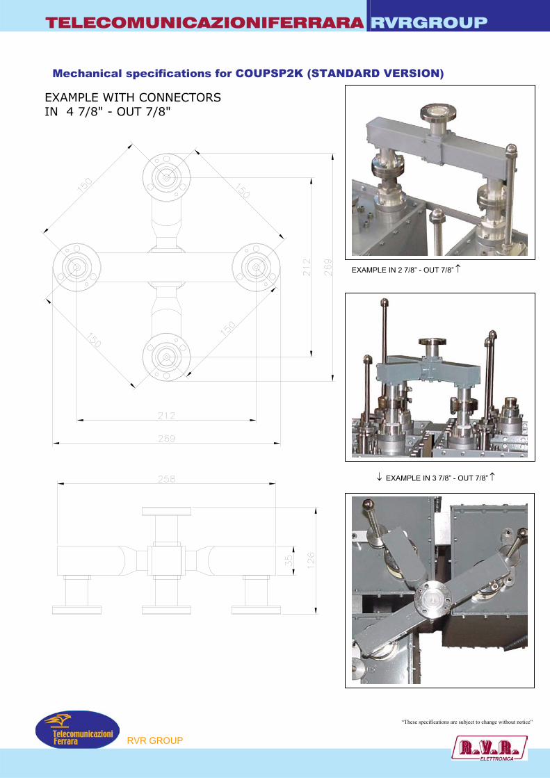
TELECOMUNICAZIONIFERRARA RVRGROUP
Mechanical specifications for COUPSP2K (STANDARD VERSION)
EXAMPLE WITH CONNECTORSIN 4 7/8" - OUT 7/8"
P
EXAMPLE IN 2 7/8” - OUT 7/8” ↑
↓ EXAMPLE IN 3 7/8” - OUT 7/8” ↑
“These specifications are subject to change without notice”
RVR GROU

TELECOMUNICAZIONIFERRARA RVRGROUP
Mechanical specifications for COUPSP2K (COMPACT VERSION)
EXAMPLE WITH CONNECTORSIN 4 7/16" - OUT 7/8"
P
↓ EXAMPLE IN 4 7/8” - OUT 7/8” ↑
“These specifications are subject to change without notice”
RVR GROU
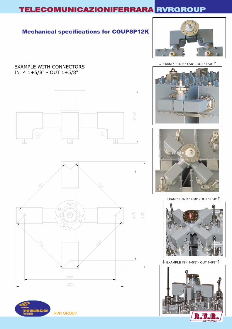
TELECOMUNICAZIONIFERRARA RVRGROUP
Mechanical specifications for COUPSP12K
EXAMPLE WITH CONNECTORSIN 4 1+5/8" - OUT 1+5/8"
P
↓ EXAMPLE IN 2 1+5/8” - OUT 1+5/8” ↑
EXAMPLE IN 3 1+5/8” - OUT 1+5/8” ↑
↓ EXAMPLE IN 4 1+5/8” - OUT 1+5/8” ↑
RVR GROU
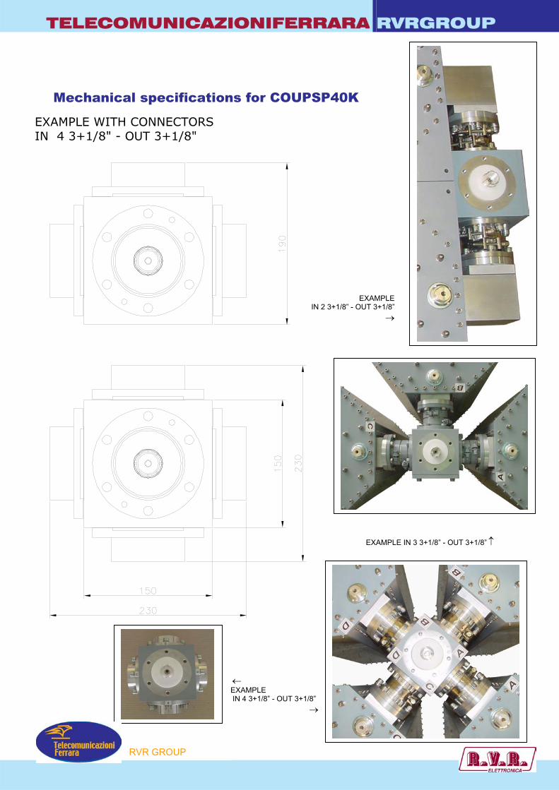
TELECOMUNICAZIONIFERRARA RVRGROUP
EXAMPLE WITH CONNECTORSIN 4 3+1/8" - OUT 3+1/8"
Mechanical specifications for COUPSP40K
IN 2 3+1/8” -
P
← EXAMPLE IN 4 3+1/8” - OUT 3+1/8”
→
EXAMPLEOUT 3+1/8”
→
EXAMPLE IN 3 3+1/8” - OUT 3+1/8” ↑
RVR GROU

TELECOMUNICAZIONIFERRARA RVRGROUP
Mechanical specifications for COUPSP60K
EXAMPLE WITHOUT FLANGE WITH CONNECTORSIN 4 4+1/2" - OUT 4+1/2"
P
“These specifications are subject to change without notice”
RVR GROU

TELECOMUNICAZIONIFERRARA RVRGROUP
Application
STAR
P
EXAMPLE OF POINT COMBINER
“These specifications are subject to change without notice”
RVR GROU
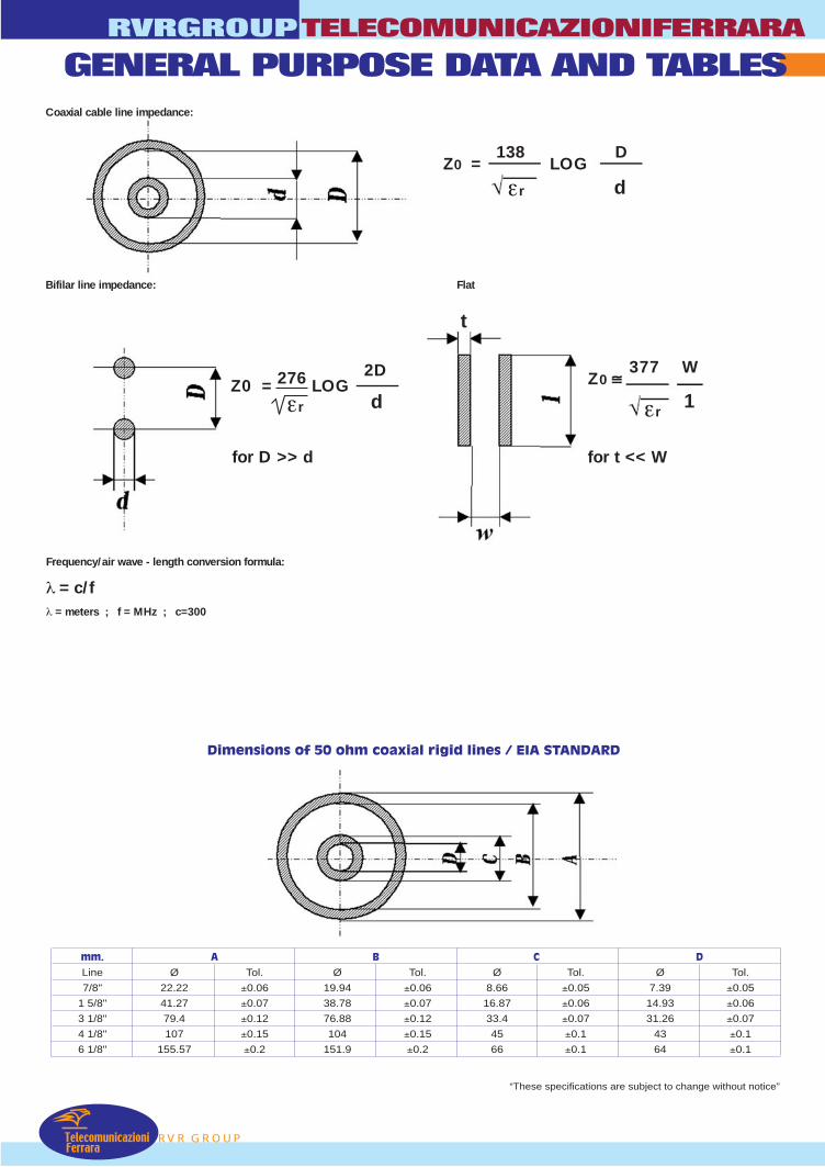
RVR GROUP
RVRGROUPTELECOMUNICAZIONIFERRARA
TelecomunicazioniFerrara
GENERAL PURPOSE DATA AND TABLES
Dimensions of 50 ohm coaxial rigid lines / EIA STANDARD
mm. A B C D
Line Ø Tol. Ø Tol. Ø Tol. Ø Tol.
7/8" 22.22 ±0.06 19.94 ±0.06 8.66 ±0.05 7.39 ±0.05
1 5/8" 41.27 ±0.07 38.78 ±0.07 16.87 ±0.06 14.93 ±0.06
3 1/8" 79.4 ±0.12 76.88 ±0.12 33.4 ±0.07 31.26 ±0.07
4 1/8" 107 ±0.15 104 ±0.15 45 ±0.1 43 ±0.1
6 1/8" 155.57 ±0.2 151.9 ±0.2 66 ±0.1 64 ±0.1
Frequency/air wave - length conversion formula:
λ = c/fλ = meters ; f = MHz ; c=300
Coaxial cable line impedance:
Bifilar line impedance: Flat
Z0 = 138
LOG D
εr d
t
Z0 377
W
1εr
Z0 = 276 LOG 2D
d
for D >> d for t << W
“These specifications are subject to change without notice”
εr
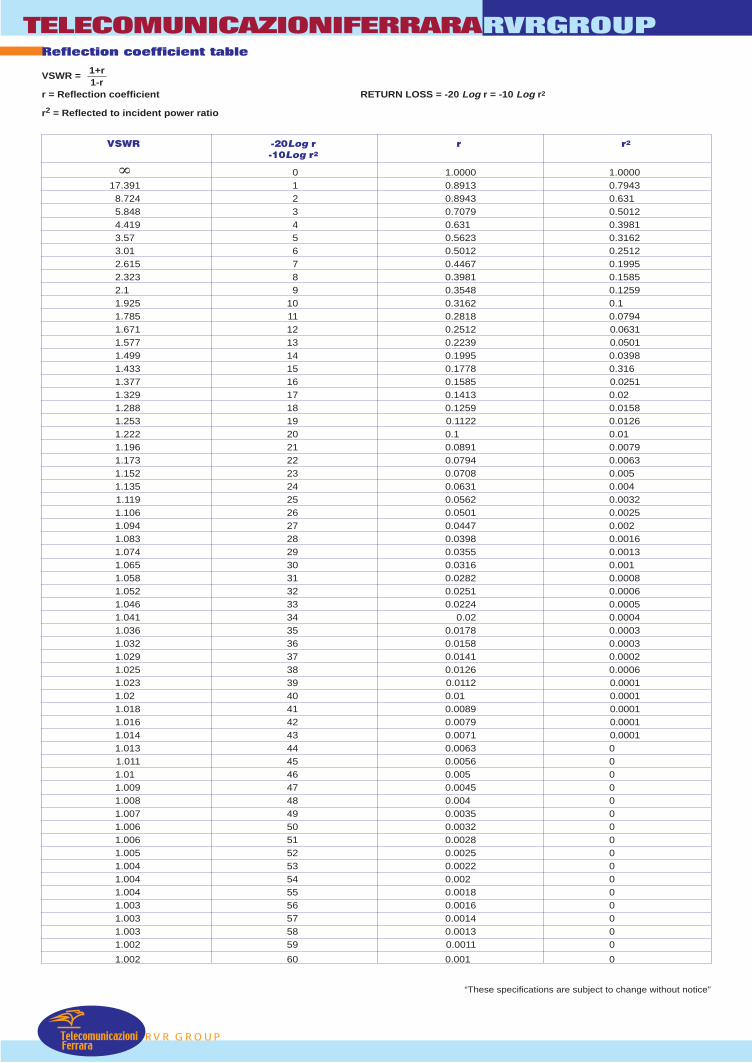
VSWR -20Log r r r2
-10Log r2
0 1.0000 1.000017.391 1 0.8913 0.7943
8.724 2 0.8943 0.6315.848 3 0.7079 0.50124.419 4 0.631 0.39813.57 5 0.5623 0.31623.01 6 0.5012 0.25122.615 7 0.4467 0.19952.323 8 0.3981 0.15852.1 9 0.3548 0.12591.925 10 0.3162 0.11.785 11 0.2818 0.07941.671 12 0.2512 0.06311.577 13 0.2239 0.05011.499 14 0.1995 0.03981.433 15 0.1778 0.3161.377 16 0.1585 0.02511.329 17 0.1413 0.021.288 18 0.1259 0.01581.253 19 0.1122 0.01261.222 20 0.1 0.011.196 21 0.0891 0.00791.173 22 0.0794 0.00631.152 23 0.0708 0.0051.135 24 0.0631 0.0041.119 25 0.0562 0.00321.106 26 0.0501 0.00251.094 27 0.0447 0.0021.083 28 0.0398 0.00161.074 29 0.0355 0.00131.065 30 0.0316 0.0011.058 31 0.0282 0.00081.052 32 0.0251 0.00061.046 33 0.0224 0.00051.041 34 0.02 0.00041.036 35 0.0178 0.00031.032 36 0.0158 0.00031.029 37 0.0141 0.00021.025 38 0.0126 0.00061.023 39 0.0112 0.00011.02 40 0.01 0.00011.018 41 0.0089 0.00011.016 42 0.0079 0.00011.014 43 0.0071 0.00011.013 44 0.0063 01.011 45 0.0056 01.01 46 0.005 01.009 47 0.0045 01.008 48 0.004 01.007 49 0.0035 01.006 50 0.0032 01.006 51 0.0028 01.005 52 0.0025 01.004 53 0.0022 01.004 54 0.002 01.004 55 0.0018 01.003 56 0.0016 01.003 57 0.0014 01.003 58 0.0013 01.002 59 0.0011 0
1.002 60 0.001 0
TelecomunicazioniFerrara
TELECOMUNICAZIONIFERRARA
RVR GROUP
RVRGROUP
“These specifications are subject to change without notice”
Reflection coefficient table
VSWR =
r = Reflection coefficient RETURN LOSS = -20 Log r = -10 Log r2
r2 = Reflected to incident power ratio
∞
1+r1-r

RVR GROUP
RVRGROUPTELECOMUNICAZIONIFERRARA
TelecomunicazioniFerrara
“These specifications are subject to change without notice”
1.0 1.0 0 1.0 1.0
0.989 0.977 0.1 1.012 1.023
0.977 0.955 0.2 1.023 1.047
0.966 0.933 0.3 1.035 1.072
0.955 0.912 0.4 1.047 1.096
0.944 0.891 0.5 1.059 1.122
0.933 0.871 0.6 1.072 1.148
0.923 0.851 0.7 1.084 1.175
0.912 0.832 0.8 1.096 1.202
0.902 0.813 0.9 1.109 1.23
0.891 0.794 1 1.122 1.259
0.871 0.759 1.2 1.148 1.318
0.851 0.724 1.4 1.175 1.38
0.832 0.692 1.6 1.202 1.445
0.813 0.661 1.8 1.23 1.514
0.794 0.631 2 1.259 1.585
0.776 0.603 2.2 1.288 1.66
0.759 0.575 2.4 1.318 1.738
0.741 0.55 2.6 1.349 1.82
0.724 0.525 2.8 1.38 1.905
0.708 0.501 3 1.413 1.995
0.668 0.447 3.5 1.496 2.239
0.631 0.398 4 1.585 2.512
0.596 0.355 4.5 1.679 2.818
0.562 0.316 5 1.778 3.162
0.531 0.282 5.5 1.884 3.548
0.501 0.251 6 1.995 3.981
0.447 0.2 7 2.239 5.012
0.398 0.158 8 2.512 6.31
0.355 0.126 9 2.818 7.943
0.316 0.1 10 3.162 10
0.282 0.079 11 3.548 12.589
0.251 0.063 12 3.981 15.849
0.224 0.05 13 4.467 19.953
0.2 0.04 14 5.012 25.119
0.178 0.032 15 5.623 31.623
0.158 0.025 16 6.31 39.811
0.141 0.02 17 7.079 50.119
0.126 0.016 18 7.943 63.096
0.112 0.013 19 8.913 49.443
0.1 0.01 20 10 100
0.0562 0.003 25 17.8 320
0.0316 0.001 30 31.6 1000
0.0178 0 35 56.2 3200
0.01 0 40 100 10000
0.0056 0 45 178 32000
0.0032 0 50 316 100000
0.001 0 60 1000 1000000
0.0003 0 70 3160 10000000
0.0001 0 80 10000 100000000
0 0 90 31600 1000000000
0 0 100 100000 10000000000
V
Ratio (Down) dB Ratio (Up)Voltage Power Voltage Power
Voltage and power ratios in dB
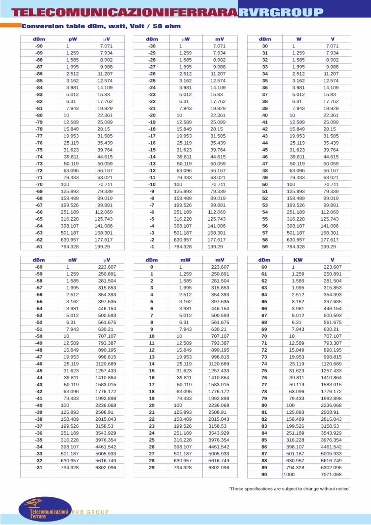
TelecomunicazioniFerrara
TELECOMUNICAZIONIFERRARA
RVR GROUP
RVRGROUP
“These specifications are subject to change without notice”
Conversion table dBm, watt, Volt / 50 ohm
dBm-90
-89
-88
-87
-86
-85
-84
-83
-82
-81
-80
-79
-78
-77
-76
-75
-74
-73
-72
-71
-70
-69
-68
-67
-66
-65
-64
-63
-62
-61
pW1
1.259
1.585
1.995
2.512
3.162
3.981
5.012
6.31
7.943
10
12.589
15.849
19.953
25.119
31.623
39.811
50.119
63.096
79.433
100
125.893
158.489
199.526
251.189
316.228
398.107
501.187
630.957
794.328
µV7.071
7.934
8.902
9.988
11.207
12.574
14.109
15.83
17.762
19.929
22.361
25.089
28.15
31.585
35.439
39.764
44.615
50.059
56.167
63.021
70.711
79.339
89.019
99.881
112.069
125.743
141.086
158.301
177.617
199.29
dBm-30
-29
-28
-27
-26
-25
-24
-23
-22
-21
-20
-19
-18
-17
-16
-15
-14
-13
-12
-11
-10
-9
-8
-7
-6
-5
-4
-3
-2
-1
µW1
1.259
1.585
1.995
2.512
3.162
3.981
5.012
6.31
7.943
10
12.589
15.849
19.953
25.119
31.623
39.811
50.119
63.096
79.433
100
125.893
158.489
199.526
251.189
316.228
398.107
501.187
630.957
794.328
mV7.071
7.934
8.902
9.988
11.207
12.574
14.109
15.83
17.762
19.929
22.361
25.089
28.15
31.585
35.439
39.764
44.615
50.059
56.167
63.021
70.711
79.339
89.019
99.881
112.069
125.743
141.086
158.301
177.617
199.29
dBm30
31
32
33
34
35
36
37
38
39
40
41
42
43
44
45
46
47
48
49
50
51
52
53
54
55
56
57
58
59
W1
1.259
1.585
1.995
2.512
3.162
3.981
5.012
6.31
7.943
10
12.589
15.849
19.953
25.119
31.623
39.811
50.119
63.096
79.433
100
125.893
158.489
199.526
251.189
316.228
398.107
501.187
630.957
794.328
V7.071
7.934
8.902
9.988
11.207
12.574
14.109
15.83
17.762
19.929
22.361
25.089
28.15
31.585
35.439
39.764
44.615
50.059
56.167
63.021
70.711
79.339
89.019
99.881
112.069
125.743
141.086
158.301
177.617
199.29
dBm-60
-59
-58
-57
-56
-55
-54
-53
-52
-51
-50
-49
-48
-47
-46
-45
-44
-43
-42
-41
-40
-39
-38
-37
-36
-35
-34
-33
-32
-31
nW1
1.259
1.585
1.995
2.512
3.162
3.981
5.012
6.31
7.943
10
12.589
15.849
19.953
25.119
31.623
39.811
50.119
63.096
79.433
100
125.893
158.489
199.526
251.189
316.228
398.107
501.187
630.957
794.328
µV223.607
250.891
281.504
315.853
354.393
397.635
446.154
500.593
561.675
630.21
707.107
793.387
890.195
998.815
1120.689
1257.433
1410.864
1583.015
1776.172
1992.898
2236.068
2508.91
2815.043
3158.53
3543.929
3976.354
4461.542
5005.933
5616.749
6302.096
dBm0
1
2
3
4
5
6
7
8
9
10
11
12
13
14
15
16
17
18
19
20
21
22
23
24
25
26
27
28
29
mW1
1.259
1.585
1.995
2.512
3.162
3.981
5.012
6.31
7.943
10
12.589
15.849
19.953
25.119
31.623
39.811
50.119
63.096
79.433
100
125.893
158.489
199.526
251.189
316.228
398.107
501.187
630.957
794.328
mV223.607
250.891
281.504
315.853
354.393
397.635
446.154
500.593
561.675
630.21
707.107
793.387
890.195
998.815
1120.689
1257.433
1410.864
1583.015
1776.172
1992.898
2236.068
2508.91
2815.043
3158.53
3543.929
3976.354
4461.542
5005.933
5616.749
6302.096
V223.607
250.891
281.504
315.853
354.393
397.635
446.154
500.593
561.675
630.21
707.107
793.387
890.195
998.815
1120.689
1257.433
1410.864
1583.015
1776.172
1992.898
2236.068
2508.91
2815.043
3158.53
3543.929
3976.354
4461.542
5005.933
5616.749
6302.096
7071.068
dBm60
61
62
63
64
65
66
67
68
69
70
71
72
73
74
75
76
77
78
79
80
81
82
83
84
85
86
87
88
89
90
KW1
1.259
1.585
1.995
2.512
3.162
3.981
5.012
6.31
7.943
10
12.589
15.849
19.953
25.119
31.623
39.811
50.119
63.096
79.433
100
125.893
158.489
199.526
251.189
316.228
398.107
501.187
630.957
794.328
1000
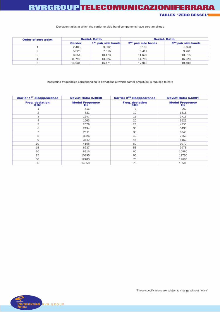
RVR GROUP
RVRGROUPTELECOMUNICAZIONIFERRARA
TelecomunicazioniFerrara
“These specifications are subject to change without notice”
Deviation ratios at which the carrier or side-band components have zero amplitude
Order of zero point
1
2
3
4
5
Deviat. Ratio Deviat. RatioCarrier 2.405
5.520
8.654
11.792
14.931
1ST pair side bands 3.832
7.016
10.173
13.324
16.471
2ND pair side bands 5.136
8.417
11.620
14.796
17.960
3RD pair side bands 6.390
9.761
13.015
16.223
19.409
Modulating frequencies corresponding to deviations at which carrier amplitude is reduced to zero
Carrier 1ST disappearance
Freq. deviationKHz 1 2 3 4 5 6 7 8 9101520253035
Deviat Ratio 2.4048
Modul FrequencyHz416831
1247166320792494291133263742415862378316
103951248014550
Carrier 2ND disappearance
Freq. deviationKHz 51015202530354045505560657075
Deviat Ratio 5.5201
Modul FrequencyHz907
1815271836254530543063407250816090709975
10880117801269013590
TABLES "ZERO BESSEL"
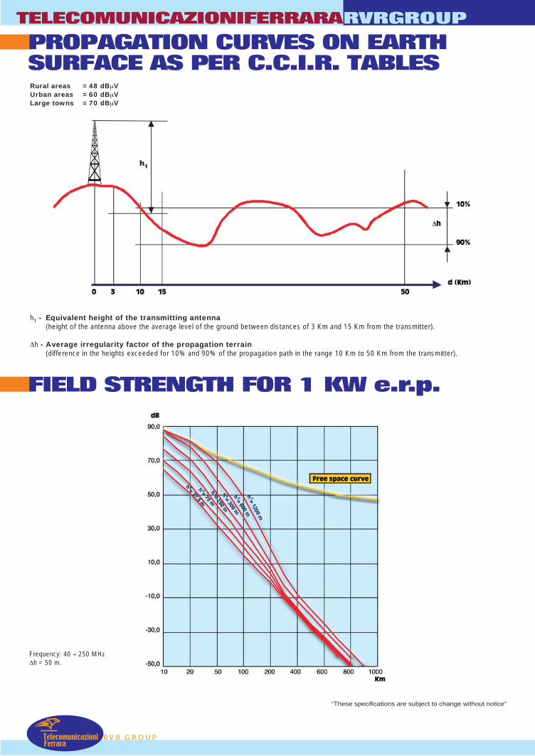
TelecomunicazioniFerrara
TELECOMUNICAZIONIFERRARA
RVR GROUP
RVRGROUP
PROPAGATION CURVES ON EARTHSURFACE AS PER C.C.I.R. TABLESRural areas = 48 dBµVUrban areas = 60 dBµVLarge towns = 70 dBµV
h1 - Equivalent height of the transmitting antenna(height of the antenna above the average level of the ground between distances of 3 Km and 15 Km from the transmitter).
∆h - Average irregularity factor of the propagation terrain(difference in the heights exceeded for 10% and 90% of the propagation path in the range 10 Km to 50 Km from the transmitter).
FIELD STRENGTH FOR 1 KW e.r.p.
“These specifications are subject to change without notice”
Frequency: 40 ÷ 250 MHz∆h = 50 m.
h1
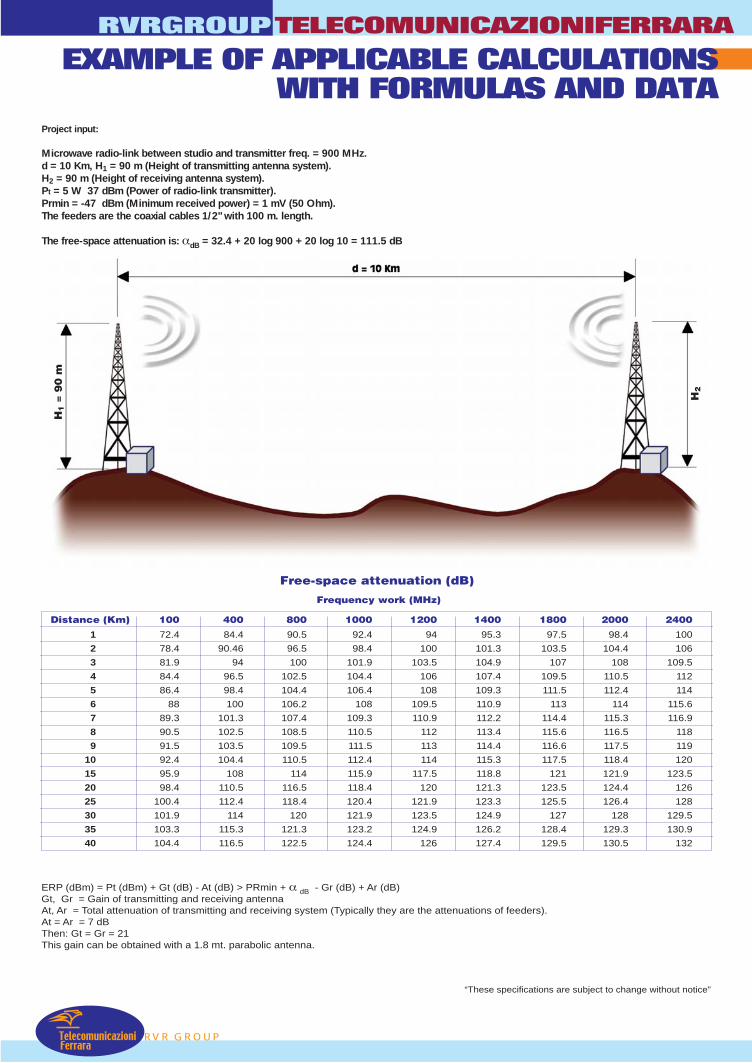
RVR GROUP
RVRGROUPTELECOMUNICAZIONIFERRARA
TelecomunicazioniFerrara
EXAMPLE OF APPLICABLE CALCULATIONSWITH FORMULAS AND DATA
“These specifications are subject to change without notice”
ERP (dBm) = Pt (dBm) + Gt (dB) - At (dB) > PRmin + α dB - Gr (dB) + Ar (dB)Gt, Gr = Gain of transmitting and receiving antennaAt, Ar = Total attenuation of transmitting and receiving system (Typically they are the attenuations of feeders).At = Ar = 7 dBThen: Gt = Gr = 21This gain can be obtained with a 1.8 mt. parabolic antenna.
Project input:
Microwave radio-link between studio and transmitter freq. = 900 MHz.d = 10 Km, H1 = 90 m (Height of transmitting antenna system).H2 = 90 m (Height of receiving antenna system).Pt = 5 W 37 dBm (Power of radio-link transmitter).Prmin = -47 dBm (Minimum received power) = 1 mV (50 Ohm).The feeders are the coaxial cables 1/2" with 100 m. length.
The free-space attenuation is: αdB = 32.4 + 20 log 900 + 20 log 10 = 111.5 dB
H1 =
90
m
H2
Distance (Km) 100 400 800 1000 1200 1400 1800 2000 2400
1 72.4 84.4 90.5 92.4 94 95.3 97.5 98.4 100
2 78.4 90.46 96.5 98.4 100 101.3 103.5 104.4 106
3 81.9 94 100 101.9 103.5 104.9 107 108 109.5
4 84.4 96.5 102.5 104.4 106 107.4 109.5 110.5 112
5 86.4 98.4 104.4 106.4 108 109.3 111.5 112.4 114
6 88 100 106.2 108 109.5 110.9 113 114 115.6
7 89.3 101.3 107.4 109.3 110.9 112.2 114.4 115.3 116.9
8 90.5 102.5 108.5 110.5 112 113.4 115.6 116.5 118
9 91.5 103.5 109.5 111.5 113 114.4 116.6 117.5 119
10 92.4 104.4 110.5 112.4 114 115.3 117.5 118.4 120
15 95.9 108 114 115.9 117.5 118.8 121 121.9 123.5
20 98.4 110.5 116.5 118.4 120 121.3 123.5 124.4 126
25 100.4 112.4 118.4 120.4 121.9 123.3 125.5 126.4 128
30 101.9 114 120 121.9 123.5 124.9 127 128 129.5
35 103.3 115.3 121.3 123.2 124.9 126.2 128.4 129.3 130.9
40 104.4 116.5 122.5 124.4 126 127.4 129.5 130.5 132
Free-space attenuation (dB)
Frequency work (MHz)

TelecomunicazioniFerrara
TELECOMUNICAZIONIFERRARA
RVR GROUP
RVRGROUP
“These specifications are subject to change without notice”
TABLES OF CONVERSION FOR MEASUREMENT UNITS
EQUIVALENCE TABLE FOR WEIGHT UNIT
Units Lb. Oz. stone g kg ton U.S. cwt Brit. cwt U.S. ton Brit. ton1 pound 1 16 0.071 453.6 0.453 _ 0.01 0.009 — —
1 ounce 0.0625 1 0.004 28.35 0.028 — — — — —
1 stone 14 224 1 6350 6.35 0.0063 0.14 0.125 0.007 0.0063
1 g. — 0.0353 — 1 0.001 — — — — —
1 kg. 2.205 35.27 0.157 1000 1 0.001 0.022 0.02 0.0011 0.001
1 ton. 2204.6 35274 157.47 — 1000 1 22.05 19.685 1.1023 0.9842
1 US hundredweight 100 1600 7.143 45359 45.36 0.0454 1 0.8929 0.05 0.0446
1 Brit. hundredweight 112 1792 8 50802 50.8 0.0508 1.12 1 0.056 0.05
1 US. ton 2000 32000 142.9 907190 907.2 0.907 20 17.841 1 0.8929
1 Brit. Ton 2240 35840 160 — 1016 1.016 11.2 20 1.12 1
EQUIVALENCE TABLE FOR SQUARE UNIT
Units sq. yard sq. inch sq. foot cm.2 m2 km2 sq mile acre a ha1 square yard 1 1296 9 8361 0.8361 — — — — —
1 square inch — 1 — 6.452 — — — — — —
1 square foot 0.1111 144 1 929 0.0929 — — — — —
1 cm2 — 0.155 — 1 0.0001 — — — — —
1 m2 1.196 1550 10.76 10000 1 — — — 0.01 —
1 km2 — — — — — 1 0.3861 247.1 10000 100
1 square mile — — — — — 2.59 1 640 — 259
1 acre 4850 — 43640 — 4050 — 0.0016 1 — —
1 a 119.6 — 1076 — 100 — — 0.0247 1 0.01
1 ha — — — — 10000 0.01 0.0039 2.47 100 1
EQUIVALENCE TABLE FOR VOLUME UNIT
Units cu. yard cu. inch cu. foot cm.3 dm3 U.S. gallon Imp.gallon Imp. fl. oz. U.S. fl. oz. Imp. pint1 cubic yard 1 46656 27 — 764.6 202 168.2 26909 25853 1345
1 cubic inch — 1 — 16.39 0.0164 — — 0.5768 0.5541 0.0288
1 cubic foot 0.0370 1728 1 — 28.32 7.481 6.232 996.6 957.5 49.83
1 cm3 — 0.061 — 1 0.001 — — 0.0353 0.0338 —
1 dm3 — 61.02 0.035 1000 1 0.2642 0.22 35.2 33.81 1.76
1 US. gallon — 231 0.1337 3785 3.785 1 0.8327 133.2 128 6.662
1 imp. gallon 277.4 0.1603 4546 4.546 1.201 1 160 153.7 8
1 imp. fl. oz. — 1.734 — 28.41 0.0284 — — 1 0.9607 0.05
US. fl. oz. — 1.805 — 29.57 0.0296 — — 1.041 1 0.052
1 imp. pint — 34.68 0.02 568.2 0.5682 0.1501 0.125 20 19.21 1
EQUIVALENCE TABLE FOR LENGTH UNIT
Units yd. in. ft. cm. m. km. stat. mile. naut. mile.1 yd 1 36 3 91.44 0.914 — — —
1 in 0.028 1 0.083 2.54 0.025 — — —
1 ft 0.333 12 1 30.48. 0.305 — — —
1cm 0.01 0.39 0.03 1 0.01 — — —
1 m 1.094 38.37 3.281 100 1 — — 0.018
1 km 1094 — 3281 — — 1 0.621 0.00054
1 stat. mile 1760 — 5280 — 1609 1.609 1 0.869
1 naut. mile 2027 — 6080 — 1852 1.852 1.152 1
in. = Inch; ft. = Foot; yd. = yard; stat. mile = statute mile; naut. mile = nautical mile..

RVR GROUP
RVRGROUPTELECOMUNICAZIONIFERRARA
TelecomunicazioniFerrara
“These specifications are subject to change without notice”
CONVERSION TABLE OF cm INTO INCHES
cm 0 1 2 3 4 5 6 7 8 90 _ 0.3937 0.7874 1.1811 1.5748 1.9685 2.3622 2.7559 3.1496 3.5433
10 3.9370 4.3307 4.7244 5.1181 5.5118 5.9055 6.2992 6.6929 7.0866 7.4803
20 7.8740 8.2677 8.6614 9.0551 9.4488 9.8425 10.2362 10.6299 11.0236 11.4173
30 11.8110 12.2047 12.5984 12.9921 13.3858 13.7795 14.1732 14.5669 14.9606 15.3543
40 15.7480 16.1417 16.5354 16.9291 17.3228 17.7165 18.1103 18.5040 18.8977 19.2914
50 19.6851 20.0788 20.4725 20.8662 21.2599 21.6536 22.0473 22.4410 22.8347 23.2284
60 23.6221 24.0158 24.4095 24.8032 25.1969 25.5906 25.9843 26.3780 26.7717 27.1654
70 27.5591 27.9528 28.3465 28.7402 29.1339 29.5276 29.9213 30.3150 30.7087 31.1024
80 31.4961 31.8898 32.2835 32.6772 33.0709 33.4646 33.8583 34.2520 34.6457 35.0394
90 35.4331 35.8268 36.2205 36.6142 37.0079 37.4016 37.7953 38.1890 38.5827 38.9764
100 39.3701 39.7638 40.1575 40.5512 40.9449 41.3386 41.7323 42.1260 42.5197 42.9134
CONVERSION TABLE OF INCHES INTO mm
n. 0 1/16 1/8 3/16 1/4 5/16 3/8 7/16 1/2 9/16 5/8 11/16 3/4 13/16 7/8 15/160 0.0 1.6 3.2 4.8 6.4 7.9 9.5 11.1 12.7 14.3 15.9 17.5 19.1 20.6 22.2 23.8
1 25.4 27.0 28.6 30.2 31.7 33.3 34.9 36.5 38.1 39.7 41.3 42.9 44.4 46.0 47.6 49.2
2 50.8 52.4 54.0 55.6 57.1 58.7 60.3 61.9 63.5 65.1 66.7 68.3 69.8 71.4 73.0 74.6
3 76.2 77.8 79.4 81.0 82.5 84.4 85.7 87.3 88.9 90.5 92.4 93.7 95.2 96.8 98.4 100.0
4 101.6 103.2 104.8 106.4 108.0 109.5 111.1 112.7 114.3 115.9 117.5 119.1 120.7 122.2 123.8 125.4
5 127.0 128.6 130.2 131.8 133.4 134.9 136.5 138.1 139.7 141.3 142.9 144.5 146.1 147.6 149.2 150.8
6 152.4 154.0 155.6 157.2 158.8 160.3 161.9 163.5 165.1 166.7 168.3 169.9 171.5 173.0 174.6 176.2
7 177.8 179.4 181.0 182.6 184.2 185.7 187.3 188.9 190.5 192.1 193.7 195.3 196.9 198.4 200.0 201.6
8 203.2 204.8 206.4 208.0 209.6 211.1 212.7 214.3 215.9 217.5 219.1 220.7 222.3 223.8 225.4 227.0
9 228.6 230.2 231.8 233.4 235.0 236.5 238.1 239.7 241.3 242.9 244.5 246.1 247.7 249.2 250.8 252.4
10 254.0 255.6 257.2 258.8 260.4 261.9 263.5 265.1 266.7 268.3 269.9 271.5 273.1 274.6 276.2 277.8
11 279.4 281.0 282.6 284.2 285.7 287.3 288.9 290.5 292.1 293.7 295.3 296.9 298.4 300.0 301.6 303.2
CONVERSION TABLE OF SQUARE FEET INTO m2
P.q. 0 1 2 3 4 5 6 7 8 90 _ 0.09290 0.18581 0.27871 0.37161 0.46451 0.55742 0.65032 0.74322 0.83613
10 0.92903 1.02193 1.11483 1.20774 1.30064 1.39354 1.48645 1.57935 1.67225 1.76515
20 1.85806 1.95096 2.04386 2.13677 2.22967 2.32257 2.41547 2.50838 2.60128 2.69418
30 2.78709 2.87999 2.97289 3.06579 3.15870 3.25160 3.34450 3.43741 3.53031 3.62321
40 3.71612 3.80902 3.90192 3.99482 4.08773 4.18063 4.27353 4.36644 4.45934 4.55224
50 4.64514 4.73805 4.83095 4.92385 5.01676 5.10966 5.20256 5.29546 5.38837 5.48127
60 5.57417 5.66708 5.75998 5.85288 5.94578 6.03869 6.13159 6.22449 6.31740 6.41030
70 6.50320 6.59610 6.68901 6.78191 6.87481 6.96772 7.06062 7.15352 7.24642 7.33933
80 7.43223 7.52513 7.61804 7.71094 7.80384 7.89674 7.98965 8.08255 8.17545 8.26836
90 8.36126 8.45416 8.54706 8.63997 8.73287 8.82577 8.91808 9.01158 9.10448 9.19738
100 9.29029 9.38319 9.47609 9.56900 9.66190 9.75480 9.84770 9.94061 10.0335 10.1264
CONVERSION TABLE OF CUBIC YARDS INTO m3
Y.c. 0 1 2 3 4 5 6 7 8 90 _ 0.76455 1.52911 2.29366 3.05821 3.82276 4.58732 5.35187 6.11642 6.88098
10 7.64553 8.41008 9.17463 9.93919 10.7037 11.4683 12.2338 12.9974 13.7620 14.5265
20 15.2911 16.0556 16.8202 17.5847 18.3493 19.1138 19.8784 20.6429 21.4075 21.1720
30 22.9366 23.7011 24.4657 25.2302 25.9948 26.7594 27.5239 28.2885 29.0530 29.8176
40 30.5831 31.3467 32.1112 32.8758 33.6403 34.4049 35.1694 35.9340 36.6985 37.4631
50 38.2276 38.9922 39.7568 40.5213 41.2859 42.0504 42.8150 43.5795 44.3441 45.1086
60 45.8732 46.6377 47.4023 48.1668 48.9314 49.6959 50.4605 51.2250 51.9896 52.7542
70 53.5187 54.2833 55.0478 55.8124 56.5769 57.3415 58.1060 58.8706 59.6351 60.3997
80 61.1642 61.9288 62.6933 63.4579 64.2224 64.9870 65.7515 66.5161 67.2807 68.0452
90 68.8098 69.5743 70.3389 71.1034 71.8680 72.6325 73.3971 74.1616 74.9262 75.6907
100 76.4553 77.2198 77.9844 78.7489 79.5135 80.2781 81.0426 81.8072 82.5717 83.3363
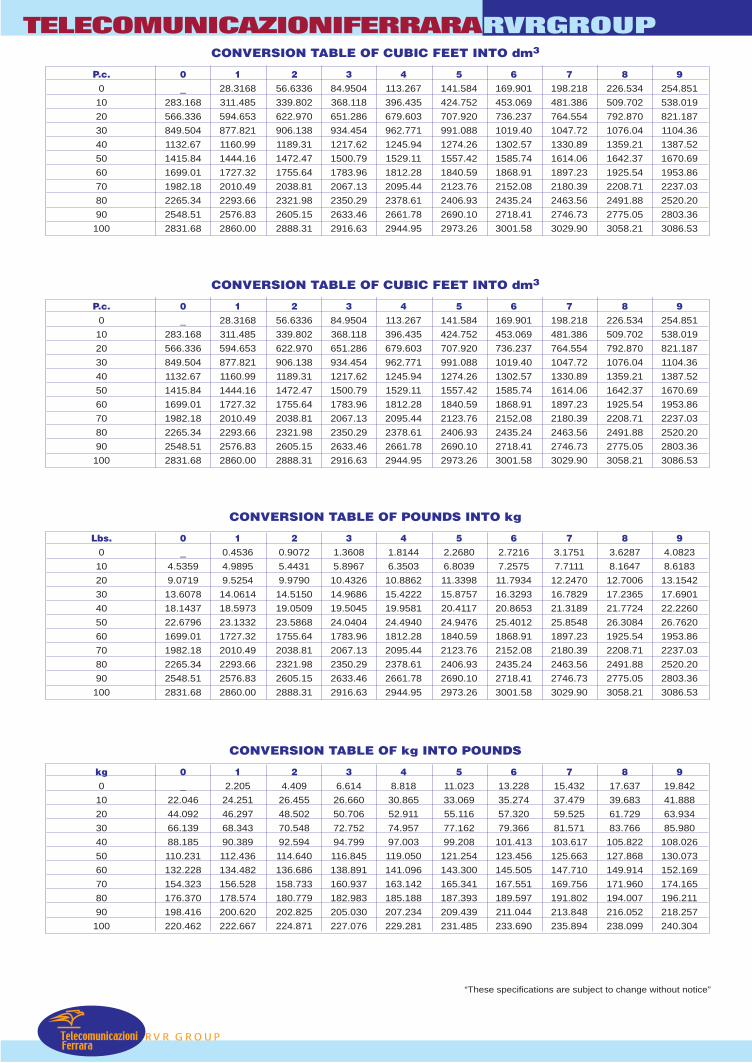
TelecomunicazioniFerrara
TELECOMUNICAZIONIFERRARA
RVR GROUP
RVRGROUP
“These specifications are subject to change without notice”
CONVERSION TABLE OF CUBIC FEET INTO dm3
P.c. 0 1 2 3 4 5 6 7 8 90 _ 28.3168 56.6336 84.9504 113.267 141.584 169.901 198.218 226.534 254.851
10 283.168 311.485 339.802 368.118 396.435 424.752 453.069 481.386 509.702 538.019
20 566.336 594.653 622.970 651.286 679.603 707.920 736.237 764.554 792.870 821.187
30 849.504 877.821 906.138 934.454 962.771 991.088 1019.40 1047.72 1076.04 1104.36
40 1132.67 1160.99 1189.31 1217.62 1245.94 1274.26 1302.57 1330.89 1359.21 1387.52
50 1415.84 1444.16 1472.47 1500.79 1529.11 1557.42 1585.74 1614.06 1642.37 1670.69
60 1699.01 1727.32 1755.64 1783.96 1812.28 1840.59 1868.91 1897.23 1925.54 1953.86
70 1982.18 2010.49 2038.81 2067.13 2095.44 2123.76 2152.08 2180.39 2208.71 2237.03
80 2265.34 2293.66 2321.98 2350.29 2378.61 2406.93 2435.24 2463.56 2491.88 2520.20
90 2548.51 2576.83 2605.15 2633.46 2661.78 2690.10 2718.41 2746.73 2775.05 2803.36
100 2831.68 2860.00 2888.31 2916.63 2944.95 2973.26 3001.58 3029.90 3058.21 3086.53
CONVERSION TABLE OF POUNDS INTO kg
Lbs. 0 1 2 3 4 5 6 7 8 90 _ 0.4536 0.9072 1.3608 1.8144 2.2680 2.7216 3.1751 3.6287 4.0823
10 4.5359 4.9895 5.4431 5.8967 6.3503 6.8039 7.2575 7.7111 8.1647 8.6183
20 9.0719 9.5254 9.9790 10.4326 10.8862 11.3398 11.7934 12.2470 12.7006 13.1542
30 13.6078 14.0614 14.5150 14.9686 15.4222 15.8757 16.3293 16.7829 17.2365 17.6901
40 18.1437 18.5973 19.0509 19.5045 19.9581 20.4117 20.8653 21.3189 21.7724 22.2260
50 22.6796 23.1332 23.5868 24.0404 24.4940 24.9476 25.4012 25.8548 26.3084 26.7620
60 1699.01 1727.32 1755.64 1783.96 1812.28 1840.59 1868.91 1897.23 1925.54 1953.86
70 1982.18 2010.49 2038.81 2067.13 2095.44 2123.76 2152.08 2180.39 2208.71 2237.03
80 2265.34 2293.66 2321.98 2350.29 2378.61 2406.93 2435.24 2463.56 2491.88 2520.20
90 2548.51 2576.83 2605.15 2633.46 2661.78 2690.10 2718.41 2746.73 2775.05 2803.36
100 2831.68 2860.00 2888.31 2916.63 2944.95 2973.26 3001.58 3029.90 3058.21 3086.53
CONVERSION TABLE OF kg INTO POUNDS
kg 0 1 2 3 4 5 6 7 8 90 _ 2.205 4.409 6.614 8.818 11.023 13.228 15.432 17.637 19.842
10 22.046 24.251 26.455 26.660 30.865 33.069 35.274 37.479 39.683 41.888
20 44.092 46.297 48.502 50.706 52.911 55.116 57.320 59.525 61.729 63.934
30 66.139 68.343 70.548 72.752 74.957 77.162 79.366 81.571 83.766 85.980
40 88.185 90.389 92.594 94.799 97.003 99.208 101.413 103.617 105.822 108.026
50 110.231 112.436 114.640 116.845 119.050 121.254 123.456 125.663 127.868 130.073
60 132.228 134.482 136.686 138.891 141.096 143.300 145.505 147.710 149.914 152.169
70 154.323 156.528 158.733 160.937 163.142 165.341 167.551 169.756 171.960 174.165
80 176.370 178.574 180.779 182.983 185.188 187.393 189.597 191.802 194.007 196.211
90 198.416 200.620 202.825 205.030 207.234 209.439 211.044 213.848 216.052 218.257
100 220.462 222.667 224.871 227.076 229.281 231.485 233.690 235.894 238.099 240.304

RVR GROUP
RVRGROUPTELECOMUNICAZIONIFERRARA
TelecomunicazioniFerrara
“These specifications are subject to change without notice”
CONVERSION TABLE OF POUNDS/SQUARE INTO kg/cm2
Lbs. p.q. 0 1 2 3 4 5 6 7 8 90 _ 0.07031 0.14061 0.21092 0.28123 0.35154 0.42184 0.49215 0.56246 0.63276
10 0.70307 0.77338 0.84369 0.91399 0.98430 1.05461 1.12491 1.19522 1.26553 1.33584
20 1.40614 1.47645 1.54676 1.61706 1.68737 1.75768 1.82799 1.89829 1.96860 2.03891
30 2.10921 2.17952 2.24983 2.32014 2.39044 2.46075 2.53106 2.60136 2.67167 2.74198
40 2.81228 2.88259 2.95290 3.02321 3.09351 3.16382 3.23413 3.30443 3.37474 3.44505
50 3.51535 3.58566 3.65597 3.72628 3.79658 3.86689 3.93720 4.00750 4.07781 4.14812
60 4.21843 4.28873 4.35904 4.42935 4.49965 4.56996 4.64027 4.71058 4.78088 4.85119
70 4.92150 4.99180 5.06211 5.13242 5.20273 5.27303 5.34334 5.41365 5.48395 5.55426
80 5.62457 5.69488 5.76518 5.83549 5.90580 5.97610 6.04641 6.11672 6.18702 6.25733
90 6.32764 6.39795 6.46825 6.53856 6.60887 6.67917 6.74948 6.81979 6.89010 6.96040
100 7.03071 7.10102 7.17132 7.24163 7.31194 7.38225 7.45255 7.52286 7.59317 7.66347
CONVERSION TABLE OF kg/cm2 INTO POUNDS/SQUARE
p.q. lbs. 0 1 2 3 4 5 6 7 8 90 _ 14.223 28.447 42.670 56.893 71.117 85.340 99.563 113.787 128.010
10 142.233 156.456 170.680 184.903 199.126 213.350 227.573 241.796 256.020 270.243
20 284.466 298.690 312.913 327.136 341.360 355.583 369.806 384.030 398.253 412.476
30 426.699 440.923 455.146 469.369 483.593 497.816 512.039 526.263 540.486 554.709
40 568.933 583.156 597.379 611.603 625.826 640.049 654.272 668.496 682.719 696.942
50 711.166 725.389 739.612 753.836 768.059 782.282 796.506 810.729 824.952 839.176
60 853.399 867.622 881.846 896.069 910.292 924.515 938.739 952.962 967.185 981.409
70 995.632 1009.86 1024.08 1038.30 1052.53 1066.75 1080.97 1095.20 1109.42 1123.64
80 1137.87 1152.09 1166.31 1180.54 1194.76 1208.98 1223.21 1237.43 1251.65 1265.88
90 1280.10 1294.32 1308.54 1322.77 1336.99 1351.21 1365.44 1379.66 1393.88 1408.11
100 1422.33 1436.55 1450.78 1465.00 1479.22 1493.45 1507.67 1521.89 1536.12 1550.34
mbar 1 10-3 9.87•10-4 1.02•10-2 0.75 10.2 1.45•10-2
bar 103 1 0.987 1.02 750.1 10197 14.5
atm 1013 1.013 1 1.033 760 10332 14.7
at. 980.7 0.981 0.968 1 735.6 10-4 14.22
mm Hg at 0°C Torr 1.3333 1.33•10-3 0.3•10-3 1.36•10-3 1 13.6 1.93•10-2
mm of water 9.8•10-2 9.8•10-5 9.68•103 104 7.4•10-2 1 1.42•10-3
Pounds for square inch. 68.94 6.9•10-2 6.8•10-2 7.03•10-2 51.7 703.3 1
units mbar bar atm at mm Hg mm Pounds forkg/cm2 0°C Torr of water square inches
EQUIVALENCE TABLE FOR PRESSURE UNITS
units cm/s km/h miles/h feet/s feet/min. knotscm/s 1 0.036 0.02237 0.03281 1.9685 0.01943
km/h 27.78 1 0.6214 0.9113 54.68 0.5396
miles/h 44.70 1.609 1 1.467 88 0.8684
feet/s 30.48 1.097 0.6818 1 60 0.5921
feet/min 0.5080 0.01829 0.01136 0.01667 1 0.00987
knots 51.48 1.8532 1.1515 1.6889 101.34 1
EQUIVALENCE TABLE FOR VELOCITY UNITS